A31 - Solicitation Spec-Ft. Brag Grubber Mini-Mall.pdf
832
Army & Air Force Exchange Service Construct New Gruber Mini-Mall Fort Bragg, North Carolina Project Number: 0530-11-000004 3 June 2021 Solicitation Specification Architect Marshall-Waters-Woody Associates, Inc. 1736 E. Sunshine, Suite 311 Springfield, MO 65804 (417) 883-2720 – Phone (417) 883-0161 – Fax [email protected] [email protected] Mechanical / Electrical / Fire Protection Engineer McCoy & Howard Consulting Engineers 413 Main Street P.O. Box 581 Mt. Vernon, IL 62864 (618) 242-0473 - Phone (618) 242-2330 - Fax [email protected] - (electrical) [email protected] - (mechanical) Structural Engineer J.S. Smith Consulting Engineers 1801 W. 32 nd St., Bldg. B, Suite 104 P.O. Box 8102 Joplin, MO 64804 (417) 624-0444 - Phone (417) 624-0430 - Fax [email protected] [email protected] Civil Engineer Calibre Engineering, Inc. 3805 Cherry Avenue Wilmington, NC 28403 (910) 791-4441 – Phone [email protected] [email protected]
-
Upload
khangminh22 -
Category
Documents
-
view
0 -
download
0
Transcript of A31 - Solicitation Spec-Ft. Brag Grubber Mini-Mall.pdf

Army & Air Force Exchange Service
Construct New Gruber Mini-Mall Fort Bragg, North Carolina
Project Number: 0530-11-000004
3 June 2021
Solicitation Specification
Architect Marshall-Waters-Woody Associates, Inc.
1736 E. Sunshine, Suite 311 Springfield, MO 65804
(417) 883-2720 – Phone (417) 883-0161 – Fax
[email protected] [email protected]
Mechanical / Electrical / Fire Protection Engineer McCoy & Howard Consulting Engineers
413 Main Street P.O. Box 581
Mt. Vernon, IL 62864 (618) 242-0473 - Phone
(618) 242-2330 - Fax [email protected] - (electrical)
[email protected] - (mechanical)
Structural Engineer J.S. Smith Consulting Engineers
1801 W. 32nd St., Bldg. B, Suite 104 P.O. Box 8102
Joplin, MO 64804 (417) 624-0444 - Phone
(417) 624-0430 - Fax [email protected] [email protected]
Civil Engineer Calibre Engineering, Inc.
3805 Cherry Avenue Wilmington, NC 28403
(910) 791-4441 – Phone [email protected] [email protected]

CONSTRUCT NEW GRUBER MINI-MALL Specification Index FT. BRAGG, N.C. TOC - 1 P/N: 0530-11-000004
CONSTRUCT NEW GRUBER MINI-MALL FORT BRAGG, NORTH CAROLINA
PROJECT NO. 0530-11-000004 3 JUNE 2021
SOLICITATION
SECTION INDEX
PART 1 SOLICITATION DOCUMENTS
PROPOISAL BID FORM
INSTRUCTIONS TO OFFERORS
GENERAL PROVISIONS INCLUDING ADDITIONAL PROVISIONS
WAGE DETERMINATION
PART 2 SPECIFICATIONS
DIVISION 00 BIDDING REQUIREMENTS
00 04 04 SUBSTITUTIONS
00 08 51 DRAWING INDEX
DIVISION 1 GENERAL REQUIREMENTS
01 10 00 SUMMARY
01 10 17 EXCHANGE FURNISHED & INSTALLED EQUIPMENT
01 10 18 EXCHANGE FURNISHED & CONTRACTOR INSTALLED EQUIPMENT
01 10 60 SAFETY POLICIES AND PROCEDURES
01 10 60.1 SAMPLE SAFETY PLAN
01 10 60.2 SAMPLE CONSTRUCTION HAZARD PLAN
01 13 00 SAFETY REGULATIONS AND CODES
01 13 00.1 WASTE DISPOSAL
01 14 50 CUTTING AND PATCHING
01 25 00 SUBSTITUTION PROCEDURES
01 31 00 PROJECT MANAGEMENT AND COORDINATION
01 32 00 CONSTRUCTION PROGRESS SCHEDULE
01 33 00 SUBMITTAL PROCEDURES
01 33 10 WEATHER TABLE
01 35 43 ENVIRONMENTAL PROTECTION
01 40 00 QUALITY REQUIREMENTS
01 50 00 TEMPORARY FACILITIES AND CONTROLS
01 51 00 TEMPORARY UTILITIES
01 58 00.0 CONSTRUCTION SITE SIGN
01 58 00.1 CONSTRUCTION SITE SIGN DETAIL
01 59 00 FIELD OFFICES AND SHEDS
01 65 00 STARTING OF SYSTEMS
01 65 00 .1 DEPARTMENT OF DEFENSE INSTRUCTION
01 65 00 .4 DD FORM 1354 EXAMPLE
01 71 00 CLEANING
01 77 00 PROJECT CLOSEOUT

CONSTRUCT NEW GRUBER MINI-MALL Specification Index FT. BRAGG, N.C. TOC - 2 P/N: 0530-11-000004
01 78 39 PRJECT RECORD DOCUMENTS
01 91 13 GENERAL COMMISSIONING REQUIREMENTS
DIVISION 2 EXISTING CONDITIONS
02 41 00 SELECTIVE DEMOLITION
DIVISION 3 CONCRETE
03 30 00 CAST-IN-PLACE CONCRETE
03 35 36 NEW CONSTRUCTION POLISHED CONCRETE FLOOR FINISH
03 35 40 INTERIOR CONCRETE SLAB REPAIRS AND JOINT FILLER REPLACEMENT
DIVISION 4 MASONRY
04 20 00 UNIT MASONRY
04 72 00 CAST STONE MASONRY
DIVISION 5 METALS
05 12 00 STRUCTURAL STEEL FRAMING
05 21 00 STEEL JOIST FRAMING
05 31 00 STEEL DECKING
05 40 00 COLD-FORMED METAL FRAMING
05 50 00 METAL FABRICATIONS
DIVISION 6 WOOD, PLASTICS AND COMPOSITES
06 10 00 ROUGH CARPENTRY
06 16 00 SHEATHING
06 40 23 INTERIOR ARCHITECTURAL WOODWORK
DIVISION 7 THERMAL AND MOISTURE PROTECTION
07 19 00 WATER REPELLENTS
07 21 00 THERMAL INSULATION AND VAPOR RETARDER
07 25 00 WEATHER BARRIERS
07 41 13.0 METAL ROOF AND SOFFIT PANELS
07 42 43 COMPOSITE WALL PANELS
07 54 23 POLYVINYL CHLORIDE THERMOPLASTIC (PVC) ROOFING
07 62 00 SHEET METAL FLASHING AND TRIM
07 72 00 ROOF ACCESSORIES
07 84 13 PENETRATION FIRE STOPPING
07 92 00 JOINT SEALANTS
DIVISION 8 OPENINGS
08 11 13 STANDARD STEEL DOORS AND FRAMES
08 11 14 CUSTOM DOORS AND FRAMES
08 14 16 FLUSH WOOD DOORS
08 39 53 STEEL DOOR AND FRAME - BLAST RESISTANT
08 41 13 ALUMINUM ENTRANCES AND STOREFRONTS - NON-BLAST RESISTANT
08 41 13.53 ALUMINUM STOREFRONTS - BLAST RESISTANT

CONSTRUCT NEW GRUBER MINI-MALL Specification Index FT. BRAGG, N.C. TOC - 3 P/N: 0530-11-000004
08 42 29.53 SLIDING AUTOMATIC ENTRANCES - BLAST RESISTANT
08 71 00 DOOR HARDWARE
08 80 00 GLAZING
08 90 00 LOUVERS AND VENTS
DIVISION 9 FINISHES
09 22 16 NON-STRUCTURAL METAL FRAMING
09 29 00 GYPSUM BOARD
09 30 00 TILING
09 51 13 ACOUSTICAL PANEL CEILINGS
09 65 13 RESILIENT BASE AND ACCESSORIES
09 67 23 EPOXY FLOORING
09 68 13 TILE CARPETING
09 90 00 PAINTING
DIVISION 10 SPECIALTIES
10 14 00 SIGNAGE
10 21 13 TOILET COMPARTMENTS
10 26 00 WALL AND DOOR PROTECTION
10 28 00 TOILET, BATH AND LAUNDRY ACCESSORIES
10 44 13 FIRE EXTINGUISHER CABINETS
DIVISION 11 EQUIPMENT
11 40 00 FOOD SERVICE EQUIPMENT
DIVISION 12 FURNISHINGS
12 69 00 ENTRANCE FLOOR MATS AND FRAMES
VOLUME II DIVISION 13 SPECIAL CONSTRUCTION
13 03 50 AIR UNIT
DIVISION 14 CONVEYING EQUIPMENT
NOT USED
DIVISION 21 FIRE SUPPRESSION
21 05 00 COMMON WORK RESULTS FOR FIRE SUPPRESSION
21 13 13 WET PIPE SPRINKLER SYSTEMS
DIVISION 22 PLUMBING
22 00 00 PLUMBING - GENERAL PROVISIONS
22 05 00 COMMON WORK RESULTS FOR PLUMBING
22 05 19 METERS AND GAGES FOR PLUMBING PIPING
22 05 23 GENERAL-DUTY VALVES FOR PLUMBING PIPING
22 05 29 HANGERS AND SUPPORTS FOR PLUMBING PIPING AND EQUIPMENT
22 05 53 IDENTIFICATION FOR PLUMBING PIPING AND EQUIPMENT

CONSTRUCT NEW GRUBER MINI-MALL Specification Index FT. BRAGG, N.C. TOC - 4 P/N: 0530-11-000004
22 07 00 PLUMBING INSULATION
22 11 16 DOMESTIC WATER PIPING
22 11 19 DOMESTIC WATER PIPING SPECIALTIES
22 13 16 SANITARY WASTE AND VENT PIPING
22 13 19 SANITARY WASTE PIPING SPECIALTIES
22 14 13 FACILITY STORM DRAINAGE PIPING
22 14 23 STORM DRAINAGE PIPING SPECIALTIES
22 16 13 FACILITY NATURAL-GAS PIPING
22 34 00 FUEL-FIRED DOMESTIC WATER HEATERS
22 40 00 PLUMBING FIXTURES
DIVISION 23 HVAC
23 00 00 HVAC - GENERAL PROVISIONS
23 05 00 COMMON WORK RESULTS FOR HVAC
23 05 13 COMMON MOTOR REQUIREMENTS FOR HVAC EQUIPMENT
23 05 29 HANGERS AND SUPPORTS FOR HVAC PIPING AND EQUIPMENT
23 05 53 IDENTIFICATION FOR HVAC PIPING AND EQUIPMENT
23 05 95 TESTING, ADJUSTING AND BALANCING FOR HVAC
23 07 00 HVAC INSULATION
23 23 00 REFRIGERANT PIPING AND SPECIALTIES
23 31 13 METAL DUCTS
23 33 00 AIR DUCT ACCESSORIES
23 34 23 FANS
23 37 13 DIFFUSERS, REGISTERS AND GRILLES
23 38 13 COMMERCIAL KITCHEN HOODS
23 74 13 PACKAGED, OUTDOOR, CENTRAL-STATION AIR-HANDLING UNITS
DIVISION 26 ELECTRICAL
26 05 19 BUILDING WIRE AND CABLE
26 05 26 GROUNDING AND BONDING
26 05 29 SUPPORTING DEVICES
26 05 33 CONDUIT
26 05 34 BOXES
26 05 35 CABINETS AND ENCLOSURES
26 05 53 IDENTIFICATION
26 09 25 OCCUPANCY SENSORS
26 24 13 DISTRIBUTION SWITCHBOARDS
26 24 16 PANELBOARDS
26 27 26 WIRING DEVICES
26 28 13 FUSES
26 28 17 ENCLOSED SWITCHES
26 43 13 SURGE PROTECTIVE DEVICES (SPDs)
26 51 00 INTERIOR LUMINAIRES
26 60 00 TESTING

CONSTRUCT NEW GRUBER MINI-MALL Specification Index FT. BRAGG, N.C. TOC - 5 P/N: 0530-11-000004
DIVISION 27 COMMUNICATIONS
27 15 00 TELEPHONE SERVICE, RACEWAYS AND WIRING
DIVISION 28 ELECTRONIC SAFETY AND SECURITY
28 16 00 INTRUSION DETECTION
28 31 11 FIRE ALARM
DIVISION 31 EARTHWORK
31 00 00 EARTHWORK
31 00 01.0 SURFACE INVESTIGATION
31 00 01.1 REPORT OF SUBSURFACE EXPLORATION AND GEOTECHNICAL EVALUATION
31 10 00 EARTHWORK – SITE CLEARING
31 31 16.13 CHEMICAL TERMITE CONTROL
DIVISION 32 EXTERIOR IMPROVEMENTS
32 12 16 HOT MIX ASPHALT (HMA) FOR ROADS
32 13 13.06 PORTLAND CEMENT CONCRETE PAVEMENT FOR ROADS AND SITE FACILITITES
32 16 13 CONCRETE SIDEWALKS AND CURBS AND GUTTERS
32 31 13 CHAIN LINK FENCES AND GATES
32 92 19 SEEDING
32 92 23 SODDING
DIVISION 33 UTILITIES
33 30 00 SANITARY SEWERS
33 40 00 STORM DRAINAGE
33 52 08 CANOPY
33 52 10 FUEL DISPENSING AND UNDERGROUND STORAGE TANK SYSTEMS

CONSTRUCT NEW GRUBBER MINI-MALL Substitutions F.T BRAGG, N.C. 00 04 04 - 1 P/N: 0530-11-000004
SECTION 00 04 04
SUBSTITUTIONS
PART 1 - GENERAL 1.1 CONTRACTING OFFICERS APPROVAL
A. The contract is based on materials and methods described in the contract document. B. The Contracting Officer will consider proposals for substitution of materials, equipment and
methods only when such proposals are accompanied by full and complete technical data and all other information required by the Contracting Officer to evaluate the proposed substitution.
C. Do not substitute materials or equipment, unless such substitution has been specifically approved
for this Work by the Contracting Officer. D. All substitution requests submitted during solicitation (bid phase) must be received by the
Contracting Officer no later thank 10 days prior to solicitation due date. 1.2 “OR EQUAL”
A. Where the phrase “or equal” or “or equal as approved in advance by the Contracting Officer” occurs in the Contract Documents, do not assume that material and equipment will be approved as equal by the Contracting Officer unless the item has been specifically approved for this work by the Contracting Officer.
B. The decision of the Contracting Officer shall be final.
1.3 AVAILABILITY OF SPECIFIED ITEMS
A. Verify prior to bidding that all specified items will be available in time for installation during orderly and timely progress of the Work.
B. In the event specified item or items will not be so available, notify the Contracting Officer prior to
receipt of bids. C. Costs of delays because of non-availability of specified items, when such delays could have been
avoided by the Contractor, will be back-charged as necessary and shall not be borne by EXCHANGE.
1.4 SUBSTITUTIONS FOLLOWING AWARD OF CONTRACT
A. Substitutions for Cause: Not later than 15 days prior to time required for preparation and review of submittals.
B. Substitutions for Convenience: Not allowed.
PART 2 – PRODUCTS (NOT USED)
PART 3 – EXECUTION (NOT USED)
END OF SECTION 00 04 04

CONSTRUCT NEW GRUBER MINI-MALL Drawing Index FT. BRAGG, N.C. 00 08 51 - 1 P/N: 0530-11-000004
DRAWING INDEX
SHEET NUMBER DESCRIPTION
G-001 TITLE / INDEX SHEET
G-002 BUILDING FOOTPRINT / AREA ANALYSIS
G-003 BASE MAP / HAUL ROUTE MAP
G-004 SITE SURVEY (PREPARED BY 4D Surveying)
C-001 NOTES, LEGEND & ABBREVIATIONS
C-100 SITE DEMOLITION PLAN
C-110 SITE & PAVING PLAN
c-111 HORIZONTAL CONTROL PLAN
C-120 SITE GRADING & STORM DRAINAGE PLAN
C-121 SITE GRADING & STORM DRAINAGE PLAN
C-130 EROSION CONTROL PLAN
C-131 EROSION CONTROL PLAN
C-140 OVERALL UTILITY PLAN
C-300 STORM DRAINAGE PROFILES
C-500 DETAILS – SITE
C-501 DETAILS – SITE
C-502 DETAILS - SITE
C-503 DETAILS – EROSION CONTROL
C-504 EROSION CONTROL NOTES
C-505 DETAILS – EROSION CONTROL
C-506 DETAILS – EROSION CONTROL
C-507 DETAILS – STORM WATER
C-508 DETAILS – STORM WATER
CU-100 SITE PLAN – ELECTRICAL
L-100 LANDSCAPE PLAN
L-200 LANDSCAPE DETAILS
LS-100 LIFE SAFETY PLAN
A-100 FLOOR PLAN
A-101 REFLECTED CEILING PLAN
A-102 ROOF PLAN
A-103 DECOR PLAN
A-200 EXTERIOR ELEVATIONS
A-300 BUILDING SECTION / WALL SECTIONS
A-301 WALL SECTIONS
A-302 WALL SECTIONS
A-303 WALL SECTIONS
A-304 WALL SECTIONS

CONSTRUCT NEW GRUBER MINI-MALL Drawing Index FT. BRAGG, N.C. 00 08 51 - 2 P/N: 0530-11-000004
SHEET NUMBER DESCRIPTION
A-305 WALL SECTIONS
A-306 WALL SECTIONS
A-307 WALL SECTIONS
A-400 ENLARGED TOILET PLANS / TOILET ACCESSORIES SCHEDULE / ELEVATIONS
A-401 INTERIOR ELEVATIONS
A-402 INTERIOR ELEVATIONS
A-500 MILLWORK & MISC. EQUIPMENT DETAILS
A-501 DOOR DETAILS
A-502 WINDOW DETAILS
A-503 MISCELLANEOUS DETAILS
A-600 DOOR SCHEDULE / DOOR TYPES / DOOR HARDWARE SCHEDULE
A-601 WINDOW TYPES
A-602 FINISH SCHEDULE / FINISH MATERIALS SCHEDULE / FINISH NOTES
A-603 WALL TYPES
EQ-100 MILLWORK & MISCELLANEOUS EQUIPMENT PLAN / MILLWORK & MISCELLANEOUS
EQUIPMENT SCHEDULE
EQ-101 SNACK AVENUE ENLARGED PLAN / ELEVATIONS
EQ-102 SNACK AVENUE EQUIPMENT SCHEDULE
SC-100 SLIM CHICKENS EQUIPMENT PLAN AND EQUIPMENT SCHEDULE
SC-101 SLIM CHICKENS INTERIOR ELEVATIONS
S-100 STRUCTURAL NOTES
S-200 FOUNDATION PLAN
S-300 FOUNDATION SCHEULE & DETAILS
S-301 FOUNDATION DETAILS
S-302 FOUNDATION DETAILS
S-303 FOUNDATION DETAILS
S-400 ROOF FRAMING PLAN
S-401 FRAMING ELEVATIONS
S-402 BRACING ELEVATIONS
S-403 BRACING ELEVATIONS
S-404 BRACING ELEVATIONS
S-405 BRACING ELEVATIONS
S-406 BRACING ELEVATIONS
S-500 FRAMING SCCHEDULES
S-501 FRAMING DETAILS
S-502 FRAMING DETAILS
S-503 FRAMING DETAILS
GA-100 CANOPY PLAN AND ELEVATIONS
GA-101 CANOPY DETAILS

CONSTRUCT NEW GRUBER MINI-MALL Drawing Index FT. BRAGG, N.C. 00 08 51 - 3 P/N: 0530-11-000004
SHEET NUMBER DESCRIPTION
GC-100 SITE PLAN GASOLINE
GE-101 GASOLINE DETAILS - ELECTRICAL
GE-102 PARTIAL SITE PLAN – GASOLINE TANKS AND DETAILS - ELECTRICAL
GE-103 GASOLINE CANOPY PLANS AND DETAILS
GM-100 PIPING ISOMETERIC DIAGRAMS
GM-200 UST PLAN AND SECTIONS
GM-300 STP SUMP DETAILS
GM-301 STP SUMP DETAILS
GM-500 MISCELLANEOUS DETAILS
GM-600 DISPENSER DETAILS
GM-700 TANK SLAB REINFORCING PLAN AND SECTION
GM-800 BILL OF MATERIALS
M-101 FLOOR PLAN – MECHANICAL
M-201 DETAILS - MECHANICAL
M-301 SYMBOLS & SCHEDULES - MECHANICAL
P-101 BELOW FLOOR PLAN PLUMBING
P-201 ABOVE FLOOR PLAN PLUMBING
P-301 ENLARGED FLOOR PLAN PLUMBING
P-302 ENLARGED FLOOR PLAN PLUMBING
P-303 ENLARGED FLOOR PLAN PLUMBING
P-401 PLUMBING DETAILS
P-501 GENERAL NOTES, SYMBOLS AND SCHEDULES - PLUMBING
FP-100 FLOOR PLAN - FIRE PROTECTION
FP-201 GENERAL NOTES & DETAILS
FA-001 FIRE ALARM & MASS NOTIFICATION SYMBOLS, SCHEDULES & GENERAL NOTES
FA-101 FLOOR PLAN – FIRE ALARM AND MASS NOTIFICATION
E-101 FLOOR PLAN - LIGHTING
E-201 FLOOR PLAN - POWER
E-202 LARGE SCALE PARTIAL PLANS
E-203 LARGE SCALE PARTIAL PLANS
E-301 FLOOR PLAN – COMMUNICATIONS AND INTRUSION DETECTION
E-401 DETAILS & SCHEMATICS
E-402 DETAILS & SCHEMATICS
E-501 RISER DIAGRAM AND FEEDER SCHEDULE
E-502 PANEL SCHEDULES
E-601 ELECTRICAL SYMBOLS & SCHEDULES
E-701 LIGHT FIXTURE SCHEDULE

CONSTRUCT NEW GRUBER MINI-MALL Summary FT. BRAGG, N.C. 01 10 00 - 1 P/N: 0530-11-000004
SECTION 01 10 00
SUMMARY OF PROJECT PART 1 GENERAL 1.1 STATEMENT OF WORK
A. The work covered by these specifications consists of furnishing all plant, supervision, labor, equipment, materials and incidentals necessary to perform all operations required to complete the work, all in accordance with these specifications and the applicable drawings, and subject to the terms and conditions of the contract.
B. The work to be performed is located at Grubber and Graves Road at Ft. Bragg, North
Carolina.
C. Principal Features:
1. The work to be performed in connection with this project includes, but is not limited an Image Upgrade to an existing shopping center.
2. Improvements will include the following:
a. 11,226 s.f. Large Express Prototype with;
• MPA
• Walk-in Freezer / Cooler
• Snack Avenue
• Breakroom
• Office Area b. Slim Chickens Restaurant; c. Grease Trap; d. Public Restroom; e. Delivery Area; f. Storage; g. Indoor Dining for approximately 34 patrons; i. 1 additional concession space; j. Parking and other related site improvements for a complete and usable
facility. D. The Contractor is advised to take note of the following General Provisions of the
Contract: Cleaning up; Material and Workmanship; Accident Prevention; Protection of Existing Vegetation, Structures, Utilities and Improvements; Operation and Storage Areas; Site Investigation; Permits and Responsibilities. Copies of the General Provisions may be obtained from the Contracting Officer.
1.2 SPECIAL BASE REQUIREMENTS
A. Regular business hours during the week for the Department of Public Works are 7:00AM to 4:00PM, Monday through Friday, excluding Federal Holidays. The Contractor shall notify the Installation Military Police prior to performing work after normal business hours.
B. The Contractor is to familiarize themselves with the requirements for gaining daily access
to the base. All workers, subcontractors and material deliveries will require permits to gain site entry.

CONSTRUCT NEW GRUBER MINI-MALL Summary FT. BRAGG, N.C. 01 10 00 - 2 P/N: 0530-11-000004
C. Ft. Bragg may require special access requirements during times of heightened security measures and/or force protection events requiring the Contractor to adjust schedules and access accordingly. Advance notice will be given to the Contractor as soon as possible in the event of such an occurrence.
1.3 UTILITIES (WATER, GAS AND ELECTRICITY)
A. The Contractor must establish temporary service for water and electricity. Temporary service connections will be separately metered. Contractor will be responsible for all service costs. Refer to Section 01 50 00, “Temporary Utilities”.
B. The Contractor shall provide and use the proper backflow prevention devices. The
Contractor shall provide documentation of proper / current certification of the devices and proper / current certification of the installer.
1.4 LAYING OUT WORK
A. Dimensions and elevations indicated in layout of work shall be verified by the Contractor.
Discrepancies between drawings, specifications, and conditions shall be referred to the Contracting Officer in writing for adjustment before work affected is performed. Failure to make such notifications shall place responsibility upon the Contractor to carry out work in a satisfactory and workmanlike manner.
B. The Contractor shall be held responsible for the location and elevation of all the
construction contemplated by the construction documents.
C. Prior to commencing work, the Contractor shall carefully compare and check all Architectural, Structural, Mechanical, and Electrical drawings, each with the other, that in any way affect the locations of elevation of the work to be executed by him, and should any discrepancy be found, he shall immediately report the same to the Contracting Officer for verifications and adjustment. Any duplication of work made necessary by failure or neglect on the Contractor's part to comply with this function shall be done at his sole expense.
D. The drawings accompanying these specifications indicate generally the design and
arrangement of all apparatus, fixtures, accessories, etc. necessary to complete the work required. The exact location or arrangement of equipment is subject to minor changes necessitated by field conditions and shall be made as required without additional cost to EXCHANGE. Measurements shall be verified by actual observations at the construction site, and the Contractor shall be responsible for all work fitting into place in a satisfactory and workmanlike manner meeting the approval of the Contracting Officer.
1.5 EXISTING OVERHEAD OR UNDERGROUND WORK
A. Carefully check the site where this project is to be erected and observe any overhead wires and equipment. Any such work shall be moved, replaced, or protected, as required, whether or not shown or specified.
B. Attention is directed to the existence of pipe and other underground improvements which
are shown on the drawings. All reasonable precautions shall be taken to preserve and protect all such improvements shown on the drawings.
C. Locations of underground lines, shown on the drawings, are based on the best available
sources, but are to be regarded as approximate only. Exercise extreme care in locating and identifying these lines before excavating in adjacent areas.

CONSTRUCT NEW GRUBER MINI-MALL Summary FT. BRAGG, N.C. 01 10 00 - 3 P/N: 0530-11-000004
1.6 INTERRUPTION OF EXISTING UTILITIES SERVICES
A. NOT APPLICABLE.
1.7 EXCAVATION
A. Prior to commencing any excavation work the Contractor shall obtain a valid Excavation Permit, from the Facilities Engineers Office. It shall be the Contractor's responsibility to obtain the necessary signatures and coordination for the permit.
1.8 WELDING PERMIT
A. Prior to commencing any welding, the Contractor shall obtain a welding permit from the Facilities Engineer's or Fire Department.
1.9 BARRICADES AND WARNING DEVICES
A. The Contractor shall provide barricades and lighting devices, in accordance with Manual for Uniform Traffic Control Devices by the State Department of Transportation, latest Edition, at all points of excavation and construction in vehicle traffic areas.
1.10 PROTECTION FOR OPEN FLAME DEVICES
A. When open flame and/or spark producing devices, i.e., acetylene oxygen welding equipment, electric arc welding, etc., are employed for job accomplishment, the following procedures are mandatory:
1. Inspect all surroundings and equipment to insure that combustible substances
are not present in any area where contact of metal at a temperature above the flashpoint of any compound is possible.
2. Ensure that no open containers or spills of combustible substances are present. 3. Ensure that ignition is not possible by conduction, convection, radiation, or
dispersion of molten metal. 4. Proper protection equipment and practices will be used, i.e., fireproof blankets,
wetting of surrounding area, removal o combustible materials where practicable, earth filled backing and portable fire extinguishers of proper type on hand.
5. When the above devices are being used notify the Installation Fire Department 24 hours ahead of usage.
1.11 FIRE PROTECTION
A. The Contractor shall at all times maintain good housekeeping practices to reduce the risk of fire damage. All scrap materials, rubbish, and trash shall be removed daily from in and about the building and shall not be permitted to be scattered on adjacent property.
B. Suitable storage space shall be provided 50 feet minimum outside the building area for
storing flammable materials and paints; no storage will be permitted in the building. Excess flammable liquids being used inside the building shall be kept in closed metal containers and removed from the building during unused periods.
C. A contractor shall provide a fire extinguisher at each location where cutting and welding is
being performed. Where electric or gas welding or cutting is done, interposed shields of incombustible material shall be used to protect against fire damage due to sparks and hot metal. When temporary heating devices are used, a watchman shall be present to cover periods when other workmen are not on the premises.

CONSTRUCT NEW GRUBER MINI-MALL Summary FT. BRAGG, N.C. 01 10 00 - 4 P/N: 0530-11-000004
D. The Contractor shall provide fire extinguishers in accordance with the recommendations of NFPA No. 10 and 241. However, in all cases a minimum of four fire extinguishers shall be available for each building.
E. Fire Codes: The Contractor shall obey all requirements of the National Fire Codes, and
Base/Post Fire Regulations, as they relate to his work on base/post. 1.12 WORK BY OTHERS (IF APPLICABLE)
A. Work not included: Except for such auxiliary work as is shown or specified or is necessary as a part of the construction, the following work is not included in the Contract:
1. Any work shown, but marked "NOT IN CONTRACT" (N.I.C.). 2. Any work indicated to be furnished and installed by the Exchange (EF/EI). 3. Any work indicated to be furnished and installed by the Vendors or
Concessionaires (VF/VI). 1.13 EXCHANGE-FURNISHED AND INSTALLED EQUIPMENT (IF APPLICABLE)
A. See Specification Section 01 10 17: EXCHANGE Furnished and Installed Equipment (EF/EI).
1.14 EXCHANGE FURNISHED-CONTRACTOR INSTALLED EQUIPMENT (IF APPLICABLE)
A. See Specification Section 01 10 18: EXCHANGE Furnished Contractor Installed Equipment (EF/CI).
1.15 LINING OF JOINTS IN FINISH MATERIALS
A. It shall be the responsibility of the Contractor to make certain in the installation of jointed floor, wall, and ceiling and pavement materials that:
1. The joints line through in a straight line and in both directions wherever possible. 2. The joints relate to all openings and breaks in the structure and be symmetrically
placed wherever possible. This includes heating registers, light fixtures, equipment, etc.
3. If, because of the non-related sizes of the various materials and locations of openings, etc., it is not possible to accomplish the above, the Contractor shall meet with the Contracting Officer to determine the most satisfactory arrangement. The Contractor shall establish center lines for all trades.
1.16 INTEGRATING WORK
A. All streets, buildings, and other improvements shall be protected from damage.
B. Contractor's operations shall be confined to the immediate vicinity of the project work and shall not in any way interfere with or obstruct the ingress or egress to and from street or adjacent property.
C. If new work is to be connected to existing work, special care shall be exercised not to
disturb or damage the existing work more than necessary. All damaged work shall be replaced, repaired, and restored to its original condition at no cost to the Exchange Service.
1.17 HEADROOM UNDER PIPES

CONSTRUCT NEW GRUBER MINI-MALL Summary FT. BRAGG, N.C. 01 10 00 - 5 P/N: 0530-11-000004
A. All horizontal runs of plumbing and heating pipes and/or electrical conduit suspended from ceilings shall provide for a maximum headroom clearance, but in no case shall this clearance be less than 7'-0" without written consent from the Contracting Officer. Where piping or conduit is left exposed within a room, the same shall run true to plumb, horizontal or intended planes. Where possible, uniform margins are to be maintained between parallel lines and/or adjacent wall, floor, or ceiling surfaces.
1.18 PATCHING GOVERNMENT-OWNED FACILITIES
A. Government-owned structures, facilities, streets, curbs, walks, etc., that are damaged or removed due to required excavations or other construction work, shall be patched, repaired or replaced, and be left in their original state of repair by the Contractor, to the satisfaction of the Contracting Officer and of authorities having jurisdiction thereof.
1.19 LOCATION OF EQUIPMENT AND PIPING
A. Drawings showing location of equipment, piping, ductwork, etc., are diagrammatic and job conditions shall not always permit their installation in the location shown. When this situation occurs, it shall be brought to the Contracting Officer's attention immediately and the relocation determined in a joint conference. The Contractor will be held responsible for the relocating of any items without first obtaining the Contracting Officer's approval. He shall remove and relocate such items at his own expense if so directed by the Contracting Officer.
1.20 OVERLOADING
A. The Contractor shall be responsible for overloading any part or parts of structures beyond their safe calculated carrying capacities by placing of materials, equipment, tools, machinery, or any other item thereon. No loads shall be placed on floors or roofs before they have attained their permanent and safe strength.
1.21 STANDARDS
A. Any material specified by reference to the number, symbol, or title of a specific standard such as Commercial Standard, a Federal Specification, a trade association standard, or other similar standard shall comply with the requirements in the latest revision thereof, and any amendment or supplement thereto, in effect on the date of invitation for proposals, except as limited to type, class, or grade, or modified in such reference, and except as otherwise indicated.
B. The standard referred to, except as modified in the specifications, shall have full force
and effect as though printed in these specifications. These standards are not furnished to bidders for the reason that the manufacturers and trades involved are assumed to be familiar with their requirements.
1. Where Federal Specifications are referred to as a measure of quality and
standard, they refer to Federal Specifications established by the Procurement Division of the United States Government and are available from the Superintendent of Documents, U.S. Government Printing Office.
2. Where Federal Specification numbers are used, they refer to the latest edition including amendments thereto.
3. Where Commercial Standards are referred to as a measure of quality, standard, and method of fabrication, they refer to Commercial Standards issued by the U.S. Department of Commerce.

CONSTRUCT NEW GRUBER MINI-MALL Summary FT. BRAGG, N.C. 01 10 00 - 6 P/N: 0530-11-000004
4. Where ASTM Serial Numbers are used, they refer to the latest tentative specifications, standards specifications, standards methods, or standard method of testing issued by the American Society for Testing and Materials.
1.22 CERTIFICATE OF CONFORMANCE
A. Except where tests and/or inspections in connection with structural materials are specified or required by applicable laws, rules, and regulations, manufacturer's certificate covering conformance with the requirements of the above mentioned Federal Specifications and Commercial Standards may be acceptable in lieu of such items. Such certificates shall be furnished to the Contracting Officer for all items so specified.
1.23 OCCUPANCY BY THE EXCHANGE
A. EXCHANGE shall reserve the right and privilege of partial occupancy during and prior to the absolute completion of the total work. Access shall be allowed at all times to the Exchange and its own Contractors in the endeavor.
1.24 TESTS AND REPORTS
A. See Specification Section 01 40 00: Testing Services. 1.25 REFERENCES
A. All references to the word "Government" or “Exchange” in the specifications shall mean Army and Air Force Exchange Service (AAFES).
B. Wherever the word "provide" is used in the Contract Documents as a directive, it shall be
interpreted as meaning "provide and install completely and ready for use".
C. Definitions:
1. Vendor: Person or persons selling any material item. 2. Base, Post, Installation or Facility: Location on which Exchange is being
remodeled. 3. Concessionaire: Person who is directly responsible for the lease of and
operation of the concessions such as Beauty Shop, Barber Shop, and Laundry/Dry Cleaners.
4. Architect-Engineer: That person or firm responsible for preparing the working drawings and specifications.
5. AAFES or Exchange: Army and Air Force Exchange Service. 6. Inspection Agency: Project Inspector contracted by EXCHANGE.
1.26 TOXIC MATERIALS
A. Removal or disposal of toxic materials or asbestos is not included in this contract. If the Contractor encounters such materials, he shall immediately notify the Contracting Officer.
1.27 SUBMISSION OF PHOTOGRAPHS
A. Contractor shall submit to the Contracting Officer digital photographs taken on or about the first of every month, showing the general conditions of the work as viewed from the north, south, east, west and interior. Photographs (minimum of 20) must accompany each Application for Payment. Each print shall be identified by date of exposure, project title, The Exchange Project Number, location and direction taken.

CONSTRUCT NEW GRUBER MINI-MALL Summary FT. BRAGG, N.C. 01 10 00 - 7 P/N: 0530-11-000004
PART 2 – PRODUCTS (NOT USED)
PART 3 – EXECUTION (NOT USED) END OF SECTION

CONSTRUCT NEW GRUBER MINI-MALL EXCHANGE Furnished and Installed Equipment (EF/EI) FT. BRAGG, N.C. 01 10 17 - 1 P/N: 0530-11-000004
SECTION 01 10 17
EXCHANGE FURNISHED AND INSTALLED EQUIPMENT (EF/EI) PART 1 GENERAL 1.1 EXCHANGE FURNISHED AND INSTALLED PROPERTY (EF/EI)
A. Property: Property is indicated on the drawings.
B. Schedule: Contractor shall schedule early completion of designated areas for beneficial occupancy by EXCHANGE usage prior to completion of entire project.
C. EXCHANGE will furnish and install equipment as indicated on the Fixture Plan in the
drawings.
D. Contractor's Duties:
1. Provide access for EXCHANGE personnel. 2. Coordinate work and cooperate with the installers of the property so that
installation can be accomplished in accordance with construction schedule. 3. Provide mechanical and electrical connections to equipment and building
systems where indicated on the drawings and in the specification. 4. Provide security of designated areas. 5. Schedule equipment delivery dates and installation times to coordinate with the
overall schedule. Provide EXCHANGE advance notice so equipment can be ordered on time.
E. EXCHANGE Duties:
1. Inspect designated area prior to use and issue statement of acceptance of area
for installation of property. 2. Make final mechanical and electrical connections between property and building
systems where indicated on the drawings and/or in the specifications. 3. Provide custodial services for designated areas during use after beneficial
occupancy. 1.2 DELIVERY DATE CHANGES
A. Requests by Contractor to change designated delivery dates shall be made in writing at least 30 days in advance of the designated delivery date. If the Contractor is not ready to accept delivery of EXCHANGE furnished property the Contractor shall be responsible for storage and redelivery cost. Should EXCHANGE be unable to effect the change, or should the Contractor fail to submit his request within the time stated above, the Contractor's obligation under this contract and as stated herein shall not be relieved and further, the Contractor will have no basis upon which he can file a claim under these conditions.
1.3 EXCHANGE ACTIVITIES AFFECTING PROGRESS OF WORK:
A. Retail Sales Areas: Schedule date of installation of fixtures and possession of these areas 30 days prior to completion of project.
B. Serving Areas & Food Preparation Areas: Schedule date of use and possession of food
preparation serving areas 30 days prior to completion of project.

CONSTRUCT NEW GRUBER MINI-MALL EXCHANGE Furnished and Installed Equipment (EF/EI) FT. BRAGG, N.C. 01 10 17 - 2 P/N: 0530-11-000004
C. MPA: Schedule date of installation of storage shelving and equipment 30 days prior to completion of project.
D. Construction in each area at date scheduled for its use and possession by EXCHANGE
shall be sufficiently complete, in accordance with Contract Documents, so EXCHANGE may occupy the area for the use for which it is intended. Comply with Contract Clauses titled inspection of Construction, and Use and Possession Prior to Completion.
1.4 ACCEPTANCE OF AREAS FOR BENEFICIAL OCCUPANCY
A. Inspection: Prior to acceptance by EXCHANGE of an area for beneficial occupancy, the Contracting Officer will conduct an inspection of the specific area. A list of deficiencies will be provided to the Contractor.
B. Acceptance: If the Contracting Officer determines the specific area is sufficiently
complete for beneficial occupancy by EXCHANGE, the area will be accepted in writing with the exception of the deficiencies listed. The deficiencies listed shall be completed or corrected prior to final acceptance at the completion of the project.
C. Damage: Damage resulting from EXCHANGE' use will not be considered the
Contractor's responsibility.
D. Refer to clause entitled "Final Inspection and Acceptance" of the EXCHANGE "General Provisions".
1.5 MATERIALS AND EQUIPMENT (EF/EI):
A. Equipment or material to be furnished and installed by EXCHANGE is as follows and as indicated on the Drawings: 1. All store shelving and fixtures. 2. Check-out Fixtures and POS. 3. Walk-in coolers and freezers (electrical and mechanical service, connections, lighting and
fire protection by Contractor). 4. Interior graphic signage. 5. Microwaves and refrigerator. 6. ATM Machine. 7. Office furniture. 8. Storage shelving. 9. Satellite Dish. 10. Telephone system equipment. 11. Food Concept Equipment. 12. MPA fixtures and equipment. 13. EAS System 14. Video Kiosk 15. Lockers 16. Safe 17. Recycling Bins 18. Cardboard Bailer 19. CO2 Canisters @ Drink Stations
PART 2 – PRODUCTS – NOT USED
PART 3 - EXECUTION
3.1 FINAL CONNECTIONS:

CONSTRUCT NEW GRUBER MINI-MALL EXCHANGE Furnished and Installed Equipment (EF/EI) FT. BRAGG, N.C. 01 10 17 - 3 P/N: 0530-11-000004
A. All final electrical connections to EXCHANGE furnished and installed equipment shall be made by the Contractor as part of the construction contract. The GC shall construct all openings, furnish and install required sleeves and conduit, and furnish and install all reinforcing, miscellaneous supports, angles, plates, anchors, and bolts necessary to secure EXCHANGE-furnished equipment in place. 1. Final connection for Item #3 above shall be by cooler and freezer vendor.
B. The Contractor shall provide for and cooperate with personnel installing EXCHANGE furnished materials and equipment, should overlap of work occur.
END OF SECTION 01 10 17

CONSTRUCT NEW GRUBER MINI-MALL EXCHANGE Furnished and Contractor Installed Equipment (EF/CI) FT. BRAGG, N.C. 01 10 18 - 1 P/N: 0530-11-000004
SECTION 01 10 18
EXCHANGE FURNISHED CONTRACTOR INSTALLED EQUIPMENT (EF/CI)
PART 1 GENERAL
1.1 EXCHANGE FURNISHED/CONTRACTOR INSTALLED EQUIPMENT (EF/CI):
A. EXCHANGE furnished/Contractor installed equipment shall be handled in accordance with the "Army and Air Force Exchange Service General Provisions" clause entitled "EXCHANGE Furnished Property".
B. EXCHANGE Furnished Equipment: EXCHANGE will furnish the equipment indicated for installation by the Contractor, as follows:
1. EXCHANGE Furnished/Contractor Installed Items:
a. As indicated on Millwork and Miscellaneous Equipment Schedule. b. Food Concept menu boards, signage, specialty lighting and water filter system. c. Exterior Signage. d. Branded Graphics.
1.2 WORK INCLUDED:
A. The material noted below will be furnished by the Exchange and shall be installed by the Contractor. See drawing references to (EF/CI). The Contractor shall provide for and cooperate with personnel furnishing the designated material.
B. All food service equipment must be approved by the National Sanitation Foundation, NSF.
C. See Division 1 for General Requirements.
D. Contractor's Duties: 1. Designate required delivery date for each product. Notify the Contracting Officer in writing
at least 60 days in advance of the date that EXCHANGE furnished equipment and furnishings will be needed.
2. The equipment will be received at the job site by a representative of EXCHANGE who will jointly, with the Contractor, verify condition and quantities. The representative will then effect receipted transfer of custody of the equipment to the Contractor.
3. Unload, handle, store (on-site), protect, uncrate, assemble, install set in final position, align, join, level, and make all utility connections to all items of equipment. Installation shall be performed in accordance with the specifications, equipment plans, and schedules shown on the Drawings and the rough-in drawings provided by EXCHANGE.
4. Construct all openings, furnish and install required sleeves and furnish and install all reinforcing, miscellaneous supports, angles, plates, anchors, and bolts necessary to secure EXCHANGE furnished equipment in place.
5. Repair or replace items damaged as a result of Contractor's operations. 6. Apply finish indicated, if any. 7. The installation shall be complete in all respects, including mechanical and electrical hook
ups, and put into good operating condition.

CONSTRUCT NEW GRUBER MINI-MALL EXCHANGE Furnished and Contractor Installed Equipment (EF/CI) FT. BRAGG, N.C. 01 10 18 - 2 P/N: 0530-11-000004
E. EXCHANGE Duties: 1. Deliver all EXCHANGE furnished items to the job site. Schedule delivery date with
supplier in accordance with Progress Chart. 2. Provide Contractor with installation drawings and instructions.
1.3 DELIVERY:
A. Contractor shall unload, handle, store, protect, uncrate, assemble, set in final position, align, join, and level all Exchange-Furnished material, and shall make all utility connections thereto. EXCHANGE will provide supervision for installation of the material.
B. The material will be received at the job site by a representative of the local EXCHANGE who, together with the Contractor, will jointly verify conditions and quantities. The representative of the local EXCHANGE will then affect receipted transfer of custody of the material to the Contractor. Material damaged by or during construction operations shall be replaced at no additional cost to EXCHANGE.
1.4 FAILURE TO VERIFY:
A. Failure to execute above required verification shall not relieve the Contractor of responsibility for proper installation of the material, which shall be installed without additional cost to EXCHANGE.
1.5 DELIVERY DATE CHANGES:
A. Requests by Contractor to change designated delivery dates shall be made in writing at least 60 days in advance of the designated delivery date. If the Contractor is not ready to accept delivery of EXCHANGE furnished equipment the Contractor shall be responsible for storage and delivery cost. Should EXCHANGE be unable to effect the change, or should the Contractor fail to submit his request within the time stated above, the Contractor's obligation under his contract and as stated herein shall not be relieved and further, the Contractor will have no basis upon which he can file a claim under these conditions.
PART 2 – PRODUCTS – NOT USED
PART 3 - EXECUTION
3.1 INSTALLATION
A. The GC shall construct all openings, furnish and install required sleeves and conduit, and furnish and install all reinforcing, miscellaneous supports, angles, plates, anchors, and bolts necessary to secure EXCHANGE-furnished equipment in place. All final electrical connections to EXCHANGE furnished equipment shall be made by the Contractor as part of the Construction Contract.
END OF SECTION 01 10 18

CONSTRUCT NEW GRUBER MINI-MALL Safety Policies and Procedures FT. BRAGG, N.C. 01 10 60 - 1 P/N: 0530-11-000004
SECTION 01 10 60
SAFETY POLICIES AND PROCEDURES
PART 1 - GENERAL 1.1 SECTION INCLUDES
A. Contractor required health and safety plan.
1. Contractor is responsible for reading the Risk Assessment Plan and following the directions therein.
2. Contractor must maintain OSHA permissible exposure limits related by the risk assessment: That is, 25 ppm (170 mg/cubic meter) during any 8 hour work shift for a 40-hour week
B. Sample Construction Hazard Plan. C. Sample Safety Plan.
1.2 RELATED SECTIONS
A. Submittals - Section 01 33 00 (Construction Hazard Plan, Job Safety and Health Plan, Emergency Response Plan).
B. Record Documents - Section 01 78 39. C. Environmental Protection – Section 01 35 43
1.3 REFERENCES
A. The publications listed below form a part of this specification to the extent referenced. The publications are referred to in the text by the basic designation only.
1. OSHA 1910 R.E.G. - 29CFR, OSHA 1910.120 2. U.S. Army Corps of Engineers Publication. – EM 385-1-1: Safety and Health Requirements
Manual (Most current version). 1.4 SUBMITTALS
A. Submittals for EXCHANGE approval - The following items shall be submitted for EXCHANGE approval:
1. Designation of Safety Representative: The Contractor shall designate in writing a qualified
employee OSHA Trained under 1910.120 responsible for the overall supervision of all accident prevention activities. Duties shall include ensuring applicable safety requirements are incorporated into work methods and inspecting the job site to ensure that safety measures and instructions are actually being applied. This person shall be on site at all times that work is in progress.
2. The Contractor shall be trained/certified in OSHA 1910.120 procedures. All other employees performing site work will meet OSHA 1910 training requirements for their job capacity.

CONSTRUCT NEW GRUBER MINI-MALL Safety Policies and Procedures FT. BRAGG, N.C. 01 10 60 - 2 P/N: 0530-11-000004
B. Submittals for Information Only - The following items shall be Contractor certified:
1. Job Hazard Analysis: Contractor shall develop a job hazard analysis for presentation at the pre-construction conference. The Contractor's job hazard analysis shall list potential hazards that could arise during the course of the work.
2. Job Safety and Health Plan.
a. The Contractor shall develop a Job Safety and Health Plan for presentation at the Pre-construction conference. The Contractor's Safety Plan shall make whatever provisions are necessary to conduct his work in accordance with current OSHA standards.
b. The safety and health plan must specifically address the excavation portion of construction and will be specific to perchloroethylene (tetrachloroethylene) (PCE), and incorporate decontamination procedures for personnel and equipment, continuous vapor monitoring, a prohibition against eating in proximity to the site, and a prohibition against the smoking of tobacco products in the proximity to the site.
c. The following are minimum requirements for the health and safety plan:
1. The Contractor is responsible for all compounds and degradation products addressed by the Risk Assessment Plan.
2. Specialized Designs: Specialized designs will be provided when the situation requires. Examples of such designs include, but are not limited to, vapor barriers in areas of known vapor hazard.
3. Safety Plans: Safety Plans will be the responsibility of the Contractor for construction areas identified by the installation and/or EXCHANGE as areas of known hazards only. These plans are required by 29 CFR 1910 and are the responsibility of the Contractor. This requirement will be coordinated through the Health and Safety Program of the military installation by the Contractor.
4. Minimum Requirements for the Health and Safety Plan are as follows:
(a) Must be kept on site, and must be written. (b) Will contain a hazard analysis (safety and health risk) for each
site task and operation (to be supplied by the installation). (c) Will include employee training (per paragraph (3) of 1910.120). (d) Will include personal protective equipment to be used by
employees for each of the site tasks and operations (paragraph (g) (5) of 1910.120).
(e) Will include provision for medical surveillance (paragraph (f) of 1910.120).
(f) Will include the frequency and types of air monitoring, personal monitoring, environmental sampling techniques, instruments to be used (their maintenance and calibration).
(g) Will include a site control program (per paragraph (d) of 1910.120) to be coordinated with the installation.
(h) Will include a decontamination procedure (per paragraph (k) of 1910.120).
(i) Will include an emergency response plan (per paragraph (1) of 1910.120).
(j) Will include a confined space entry procedure (per 1910.146, 147 or program equivalent).
(k) Will include provision for spill containment (per paragraph (j) of 1910.120).

CONSTRUCT NEW GRUBER MINI-MALL Safety Policies and Procedures FT. BRAGG, N.C. 01 10 60 - 3 P/N: 0530-11-000004
(l) Will include pre-entry briefings (prior to each site task activity) for all employees involved in the task, supervision, or emergency response.
(m) Written verification of adherence to the "plan" by a Safety and Health Supervisor is required (the supervisor must meet the 1910.120 training requirements for supervisors).
(n) Deficiencies will be corrected immediately upon discovery and after consultation with the EXCHANGE Contracting Officer and Installation Safety Office.
d. Hazard Response Plan: The unplanned or non-predicted discovery of such hazards
as transite pipe, contaminated soils, and other possible hazards will be addressed within an Emergency Response Plan (EMR) by all contractors. This requirement will be coordinated through the Health and Safety Program of the military installation by the contractor (sample provided).
e. Material Safety Data Sheets will be maintained at the site for all hazardous materials in use.
1.5 MONTHLY SAFETY MEETINGS
A. The Installation will schedule subsequent safety meetings with Contractor and subcontractor personnel on a monthly basis. The Owner's representative and installation will attend periodically. Minutes of safety meetings shall be prepared and signed by the Contractor. Concurrence signed by Inspection Section and the original submitted to the Contracting Officer for inclusion in the contract file.
1.6 ACCIDENT REPORTING AND RECORD KEEPING
A. Accident reporting and record keeping shall be in accordance with Base requirements. Telephonic reports of injuries or property damage will be made as soon as possible after the incident and will be followed by a copy of an Accident Report.
1.7 LIFE OF CONTRACT REQUIREMENTS
A. The Contractor shall comply with all provisions of this section during the life of the contract. 1.8 HEAD PROTECTION (HARD HATS)
A. All work sites under this contract are designated Hard Hat Areas. The Contractor shall post the area and shall ensure that all personnel, vendors and visitors use hard hats while within the limits of the work site.
PART 2 – PRODUCTS (NOT USED)
PART 3 – EXECUTION (NOT USED)
END OF SECTION 01 10 60

CONSTRUCT NEW GRUBER MINI-MALL Safety Policies and Procedures FT. BRAGG, N.C. 01 10 60.1 - 1 P/N: 0530-11-000004
SAMPLE
SAFETY PLAN 1. APPLICABLE PUBLICATIONS: The publications listed below form a part of this specification and
are referred to in the text by the basic designation only. 1.1 US ARMY CORPS OF ENGINEERS: EM 385-1-1 U.S. Army Corps of Engineers Safety and Health Requirements Manual 1.2 NATIONAL FIRE PROTECTION ASSOCIATION (NFPA): NFPA 70-1993 National Electric Code (NEC) 1.3 SOCIETY OF AUTOMOTIVE ENGINEERS (SAE): J 994-85 Alarm, Backup, Electric-Performance, Test, and Application, Recommended Practice. 2. GENERAL: Work safety is of paramount importance. The Contractor shall comply with the
Contract Clause in the Solicitation entitled ACCIDENT PREVENTION, including the U.S. Army Corps of Engineers Safety and Health Requirements Manual referred to therein in addition to the provisions of this specification.
3. SAFETY PROGRAM: The U.S. Army Corps of Engineers Safety and Health Requirements Manual,
EM 385-1-1, and all subsequent revisions to in the Contract Clause ACCIDENT PREVENTION of this contract, are hereby supplemented as follows:
a. The Contractor shall designate an employee responsible for overall supervision of accident
prevention activities. Such duties shall include:
1. Assuring applicable safety requirements are incorporated in work methods 2. Inspecting the work to ensure that safety measure and instructions are actually applied.
The proposed safety supervisor's name and qualifications shall be submitted in writing for approval
to the Contracting Officer's Representative. This individual must have prior experience as a safety engineer or be able to demonstrate his/her familiarity and understanding of the safety requirements over a prescribed trial period. The safety engineer shall have the authority to act on behalf of the Contractor's general management to take whatever action is necessary to assure compliance with safety requirements. The safety supervisor is required to be on the site when work is being performed.
b. Prior to commencement of any work at a job site, a preconstruction safety meeting shall be held
between the Contractor and the Corps of Engineers Area/Resident Engineer to discuss the Contractor's safety program and in particular to review the following submittals:
1. Contracts Accident Prevention Plan: An acceptable accident prevention plan, written by
the prime contractor for the specific work and implementing in detail the pertinent requirements of EM 385-1-1, shall be submitted for Government approval.

CONSTRUCT NEW GRUBER MINI-MALL Safety Policies and Procedures FT. BRAGG, N.C. 01 10 60.1 - 2 P/N: 0530-11-000004
2. Activity Phase Hazard Analysis Plan: Prior to beginning each major phase of work, an
activity hazard analysis (phase plan) shall be prepared by the Contractor for that phase of work and submitted to the Contracting Officer's Representative for approval. A phase is defined as an operation involving a type of work presenting hazards not experienced in previous operations or where a new subcontractor or work crew is to perform work. The analysis shall address the hazards for each activity performed in the phase and shall present the procedures and safeguards necessary to eliminate the hazards or reduce the risk of an acceptable level.
c. Subsequent jobsite safety meetings shall be held as follows:
1. A safety meeting shall be held at least once a month for all supervisors on the project to
review past activities, to plan ahead for new or changed operations and to establish safe working procedures to anticipate hazards. An outline report of each monthly meeting shall be submitted to the Contracting Officer's Representative.
2. At least one safety meeting shall be conducted weekly, or whenever new crews begin
work, by the appropriate field supervisors or foreman for all workers. An outline report of the meeting giving date, time, attendance, subjects discussed and who conducted it shall be maintained and copies furnished the designated authority on request.
4. ACCIDENTS: Chargeable accidents are to be investigated by both Contractor personnel and the
Contracting Officer. 4.1 ACCIDENT REPORTING, ENG FORM 3394: Section I, paragraph 01.D, of EM 385-1-1 and the
Contract Clause entitled ACCIDENT PREVITION are amended as follows: The prime Contractor shall report on Eng Form 3394, supplied by the Contracting Officer, all injuries to his employees or subcontractors that result in lost time and all damage to property and/or equipment in excess of $2,000 per incident. Verbal notification of such accident shall be made to the Contracting Officer within 72 hours following such accidents. The written report shall include the following:
a. A description of the circumstances leading up to the accident, the cause of the accident, and
corrective measures taken to prevent recurrence. b. A description of the injury and name and location of the medical facility giving examination and
treatment. c. A statement as to whether or not the employee was permitted to return to work after examination
and treatment by the doctor, and if not, an estimate or statement of the number of days lost from work. If there have been days lost from work, state whether or not the employee has been re-examined and declared fit to resume work as of the date of the report.
4.2 OSHA Requirements: 4.2.1 OSHA Log: A copy of the Contractors' OSHA Log of Injuries shall be forwarded monthly to the
Contracting Officer.
A. The Contractor shall comply with all provisions of this section during the life of the contract. 4.2.2 OSHA Inspections: Contractors shall immediately notify the Contracting Officer when an OSHA
Compliance Official (Federal or State Representative) presents his/her credentials and informs the Contractor that the workplace will be inspected for OSHA compliance. Contractors shall also notify the Contracting Officer upon determination that an exit interview will taken place upon completion of an OSHA inspection. (NABSA).

CONSTRUCT NEW GRUBER MINI-MALL Safety Policies and Procedures FT. BRAGG, N.C. 01 10 60.1 - 3 P/N: 0530-11-000004
5. SUBMITTALS FOR GOVERNMENT APPROVAL: Submittals shall be in accordance with Section 01 33 00 CONTRACTOR SUBMITTAL PROCEDURES. All required submittals of items specified in this section shall be for information only, except for those items including, but not limited to, the following which shall be submitted for Government approval:
a. Written designation of safety representative. b. Written project specific accident prevention plan. c. Written activity phase hazard analysis plan.
END OF SAMPLE SAFETY PLAN

CONSTRUCT NEW GRUBER MINI-MALL Sample / Construction Hazard Plan FT. BRAGG, N.C. 1 P/N: 0530-11-000004
SAMPLE
CONSTRUCTION HAZARD PLAN
TO BE ACCOMPLISHED BY THE GENERAL CONTRACTOR FOR CONSTRUCTION AND POSTED IN ALL CONSTRUCTION TRAILERS
SHOULD AN UNPREDICTED DISCOVERY OF A HAZARDOUS MATERIAL OR CONDITION BE MADE DURING CONSTRUCTION THE FOLLOWING SEQUENCE OF ACTIONS IS REQUIRED WHEN THERE IS NO IMMEDIATE THREAT TO LIFE OR PROPERTY
ITEM FIRST ACTION NOTIFY TELEPHONE #
Transite Pipe Crease Activity in 1. BCE area of discovery 2. EXCHANGE Contracting Officer and/or CME 3. EXCHANGE Environmental Engineer when Unable to Contact 1,2 Contaminated Soil Crease Activity in Same as above area of discovery cover with plastic Buried Munitions Crease Activity Same as above UST Same as above Same as above Other Should there be an immediate threat to life or property, the emergency response plan for the installation, which is to be on file at the construction side, is to be followed in every detail. An example of this procedure is the rupture of a fuel line, liquid or natural gas.
END OF SAMPLE CONSTRUCTION HAZARD PLAN

CONSTRUCT NEW GRUBER MINI-MALL Safety Regulations and Codes FT. BRAGG, N.C. 01 13 00 - 1 P/N: 0530-11-000004
SECTION 01 13 00
SAFETY REGULATIONS AND CODES
PART 1 - GENERAL
1.1 REQUIREMENTS INCLUDED
A. Reference Standards.
B. Licenses and Permits
C. Safety.
D. Fire Safety.
E. Affirmative Procurement Program
F. Industrial Ventilation
G. Use of Ionizing Radiation (IR).
H. Use of Lasers.
I. Use of Radioactive Materials
J. Use of Radio Frequency (RF) Radiation.
K. Use of Ultraviolet (UV) Radiation.
L. Protection of Nesting Birds
M. Historical or Cultural Artifacts
N. Ozone Depleting Substances.
O. Lead Base Paint.
P. Cleaning & Debris Control
Q. Nuisance Dumping & Polluting Activities
R. Stormwater Pollution Prevention
S. Excavation at IRP Sites
T. Contaminated Soil
U. Suspected Hazardous Materials
V. Oil-Filled or Impregnated Electrical Components
W. Hazardous Waste Testing

CONSTRUCT NEW GRUBER MINI-MALL Safety Regulations and Codes FT. BRAGG, N.C. 01 13 00 - 2 P/N: 0530-11-000004
X. Hazardous Material Inventory
Y. Spill Response and Reporting
Z. Waste Disposal and Environmental Protection.
1.2 REFERENCE STANDARDS
A. Federal, State and Local Codes and Ordinances take precedence over these Specifications and Drawings where conflicts occur, unless the Drawings or Specifications call for more stringent requirements. Notify the Contracting Officer in writing of conflicts.
B. Comply with all applicable laws, building and construction codes, OSHA Safety and Health Regulations and applicable requirements of any governmental agency under whose jurisdiction this Work is being performed.
C. Obtain a copy of standards referenced in the various Specification Sections. Maintain a copy at the jobsite during execution of Work to which the standard applies.
D. Construction that is not governed by the contract specifications will be governed by the more stringent provisions of the latest published edition or statute adopted edition, of the following applicable codes, regulations and standards.
ADA Americans With Disabilities Act Accessibility Guidelines
AFR Air Force Regulations
ASME American Society of Mechanical Engineers
CFR Code of Federal Regulations
FAR Federal Acquisition Regulations
IBC International Building Code
IMC International Mechanical Code
IPC International Plumbing Code
NEC National Electrical Code
NFPA National Fire Code
OSHA Occupational Safety and Health Act
UFC United Facilities Code
Other applicable codes and standards as applicable or as referenced by the individual specification Sections.

CONSTRUCT NEW GRUBER MINI-MALL Safety Regulations and Codes FT. BRAGG, N.C. 01 13 00 - 3 P/N: 0530-11-000004
1.3 LICENSES AND PERMITS
A. The Contractor shall obtain and maintain current for the duration of this Contract, all required Federal, State and local licenses and permits. All associated fees and taxes shall be paid by the Contractor without additional cost to the Government.
B. Obtain from base security all required vehicle and entry permits.
1.4 SAFETY
A. Comply with all Federal and State regulations concerning safety of personnel and equipment. All Contractor personnel shall wear hard hats and steel toe safety shoes while on the project site. In addition, all personnel shall wear hearing protection (ear muffs or ear plugs) when inside the power plant, excluding office areas, restrooms, break rooms and other “quiet” areas.
B. Ensure that lock out, tag out procedures are established and used as directed by 29 CFR 1910.145. Comply with the lock out, tag out procedures in use by CH&PP personnel. Ensure that contractor’s personnel on site are trained on the government’s procedures.
C. Comply with all safety, traffic and protection requirements in effect on Ft. Bragg. Government will brief the Contractor on these requirements at the preconstruction conference.
D. Work areas in this Project may be classified as “permit-required confined spaces” or “non-permit required confined spaces.” The Contractor’s Certified Industrial Hygienist will determine the confined space status of the Project areas. Regulations and procedures for entry into “permit-required confined spaces” are contained in 29 CFR 1910.146 and 8 AAC 61.010.14. The Contractor is responsible for ensuring the safety of his employees in confined spaces according to these regulations.
E. Confined Space Permit:
1. Provisions for confined space are outlined in 29CFR 1910.146 and ANSIZ117.1 1989 and shall be followed throughout Project.
2. Contact for information regarding confined Space issues is Ground Safety (to be determined at Pre-Construction Conference). However, the Contractor shall process any permits required for confined space through his own safety Manager and Permit Space Program.
F. Provide safety barriers around open excavations, openings in floors and other hazards created by the Contractor’s activities.
G. The Contracting Officer may direct the Contractor to cease activities which, in their opinion, are unsafe.
1.5 FIRE SAFETY
A. Comply with all fire safety and protection requirements in effect on Ft. Bragg. Government will brief the Contractor on these requirements at the preconstruction conference.
B. Prior to beginning any welding, use of open flame device, or any activity that produces
sparks, obtain a “hot work permit” from Installation Fire Department. The permit shall be

CONSTRUCT NEW GRUBER MINI-MALL Safety Regulations and Codes FT. BRAGG, N.C. 01 13 00 - 4 P/N: 0530-11-000004
renewed each day welding or open flame devices will be used.
C. If the contract work requires numerous days of hot work, the Contractor may elect to have one of his on-site personnel designated as a Permit Authorizing Individual (PAI). The Contractor’s PAI may issue hot work permits at the work site, thus avoiding the requirement for daily permits issued by the Fire Department.
D. The Contractor’s PAI shall be the on-site superintendent, a foreman, the Contractor’s Safety Manager, or other individual with sufficient knowledge and experience to recognize unsafe work practices or conditions and having authority to stop work immediately if such unsafe practices or conditions are observed. To be designated as a PAI, a person must schedule and successfully complete PAI certification training offered by the Base Fire Department. PAI certification training is estimated to last 60 to 90 minutes.
E. Fire Department personnel may periodically visit the site to ensure the Contractor is complying with fire safety requirements. A PAI’s certification may be revoked if the PAI has failed to issue permits on days when hot work is performed, or if unsafe practices or conditions are observed.
F. Questions concerning these requirements may be directed to ___________________,
Chief, (Post or Base) _____________________, (phone number) ________________. G. The Contractor shall notify the Fire Department at (phone number) _______________ a
minimum of 48 hours before, and again immediately prior to, temporarily closing any street or paved building access, interrupting water service to any fire hydrant or interrupting the operation of any fire detection, alarm or suppression system. The fire Department shall be immediately notified upon reopening closed areas, restoration of water service to any fire hydrant, or reactivation of any detection, alarm or suppression system. This notification requirement is in addition to other contract requirements.
H. Provide a 10 lb, ABC fire extinguisher at all work stations.
I. Report a fire: Dial 911.
1.6 AFFIRMATIVE PROCUREMENT PROGRAM
A. These standards apply to all new construction, demolition, rehabilitation, alteration, modification, repair, and maintenance of existing facilities.
B. In an effort to comply with the affirmative procurement requirements of Section 6002 of the Resource Conservation Recovery Act (RCRA) and Executive Order 13101, the government strongly promotes the use of the recycled and recovered materials and products identified in the Environmental Protection Agency’s Comprehensive Procurement Guidelines.
C. Recycled and recovered materials and products must be considered first before any other materials and products will be accepted. Recycled and recovered materials and products must be used throughout the project unless they either do not meet the requirements of this specification, delay the progress of the work, or are cost prohibitive.

CONSTRUCT NEW GRUBER MINI-MALL Safety Regulations and Codes FT. BRAGG, N.C. 01 13 00 - 5 P/N: 0530-11-000004
D. Examples of these materials and products are detailed below. These are recommended quantities and represent minimum compliance. The actual requirement is to use the maximum amount of recycled material possible, while meeting the performance specifications.
1.7 INDUSTRIAL VENTILATION
A. Contact the Contracting Officer 10 working days prior to any industrial ventilation systems (systems which control a hazard) being evaluated for acceptance. Advance notification is required by Bioenvironmental Engineering (BE) to allow performance or observation of tests of any new or renovated system prior to initial startup to verify the system will control the hazard. BE will be present for tests of fan speed and rotation, fan motor load, and air flow in all hoods or branches.
1.8 USE OF IONIZING RADIATION (IR)
A. Submit a written request for approval at least 30 calendar days before commencement of activities which require the use of IR generating devices.
B. Submit request to the Base Radiation Safety Officer (RSO) with a courtesy copy to the Contracting Officer. Request shall include:
1. Description/Characteristics:
a. X-ray unit manufacturer b. Model number
Type Material Recycled Material %
Insulation Rock wool Slag 75
Fiberglass Glass cullet 20-25
Loose fill & spray on (cellulose) Postconsumer paper 75
Perlite composition board Postconsumer paper 23
Plastic rigid foam Recovered material 9
Foam-in place Recovered material 5
Glass fiber reinforced Recovered material 6
Phenolic rigid foam Recovered material 5
Wall Board Structural fiberboard 80-100
Laminated paperboard Postconsumer paper 100
Carpet Polyester carpet face fiber Excludes severe wear
applications
25-100
Playground surfaces Rubber or plastic 90-100
Running tracks Rubber or plastic 90-100
Cement/Concrete Concrete & cement Coal fly ash 15-35
Concrete & cement Ground granulated blast furnace
(GGBF)
25-50
Flooring/Patio Patio blocks Plastic or plastic blends 90-100
Patio blocks Rubber or rubber blends 90-100
Floor tiles Rubber 90-100
Floor tiles Plastic 90-100
Landscaping Paper based hydraulic mulch Postconsumer paper 100
Wood based hydraulic mulch Recoverd wood and/or paper 100
Compost 100

CONSTRUCT NEW GRUBER MINI-MALL Safety Regulations and Codes FT. BRAGG, N.C. 01 13 00 - 6 P/N: 0530-11-000004
c. Serial number d. Maximum kVp, mA, Sec e. Ionizing radiation source/emitter (electron tube)
2. The part of the EXCHANGE contract describing work to be done at the base and the inclusive dates of such work.
3. An acknowledgment that the RSO may make initial and periodic checks to ensure the Contractor is following applicable radiological health and safety practices which prevent unnecessary exposures to Post or Base personnel.
1.9 USE OF LASERS
A. Submit a written request for approval at least 30 calendar days before commencement of activities which require the use of a laser.
B. Submit request to the RSO with a courtesy copy to the Contracting Officer. Request shall include:
1. Description/Characteristics:
a. Manufacturer. b. Model. c. Number of same units. d. Serial number(s). e. Laser medium. f. Mode of operation (i.e. continuous wave (CW), single pulse, multiple
pulse). g. Maximum exposure time (train length). h. Ime (sec) & wave length. i. Energy/pulse (J) or CW power (W). j. Pulse repetition frequency. k. Pulse width. l. Beam diameter (at 1/e point). m. Beam divergence (at 1/e point).
2. The part of the EXCHANGE contract describing work to be done and the inclusive dates of such work.
3. An acknowledgment that the RSO may make initial and periodic checks to ensure the contractor is following applicable radiological health and safety practices which prevent unnecessary exposures to Post or Base personnel.
1.10 USE OF RADIOACTIVE MATERIALS (RAM):
A. Prior to bringing RAM onto Ft. Bragg property, the Contractor shall obtain permission from the RSO. To obtain approval, forward an application to the RSO, and a courtesy copy to the Contracting Officer at least 30 calendar days before the planned date for commencement of activities on the installation. Requests shall include:

CONSTRUCT NEW GRUBER MINI-MALL Safety Regulations and Codes FT. BRAGG, N.C. 01 13 00 - 7 P/N: 0530-11-000004
1. A description of the proposed activities on NRC Form 241, Report of Proposed Activities in Non-Agreement States, (the 180-day limitation on the form does not apply to organizations holding an NRC license). Contractors possessing Agreement State Licenses shall also submit an NRC Form 241 to NRC in compliance with 10 CFR 150.21. Contractors requiring more than 180 days of operation per calendar year on the installation shall possess an NRC license.
2. The procedures established to ensure radiological health and safety of Base personnel and the public while on Army or Air Force installations on site and the name of the responsible Contractor representative.
3. A current copy of the applicable NRC, or Agreement State license. Expired licenses are unacceptable. To be valid at the installation, the license must either specifically state the installation by name on the license or state approval for work at temporary job sites anywhere in the United States where the NRC or Agreement State maintains jurisdiction. DOE or DOE prime contractors must provide, in lieu of a license, written certification of their exemption from NRC licensing requirements and cite the applicable exemption of 10 CFR.
4. The part of the EXCHANGE contract describing work to be done and the inclusive dates of such work
5. An acknowledgment that the Base RSO may make periodic checks to ensure the Contractor is following applicable radiological health and safety practices which prevent unnecessary exposures to Army or Air Force personnel and prevent potential contamination of Government property.
1.11 USE OF RADIO FREQUENCY (RF) RADIATION
A. Prior to using equipment generating RF Radiation in excess of seven watts peak power and a frequency of 1000 MHz or greater on Ft. Bragg must submit a written request for approval at least 30 calendar days before commencement of activities which require the use of the RF generating device.
B. Submit request to the RSO, with a courtesy copy to the Contracting Officer. Submittal shall include:
1. Description. 2. Nomenclature. 3. Location of emitters. 4. Quantity. 5. Frequency (Mhz). 6. Pulse width (microsec.). 7. Pulse repetition freq. (pps). 8. Peak power (kW). 9. Antenna size (feet--horizontal/vertical). 10. Antenna band width (degrees-- horizontal/vertical). 11. Antenna gain (dB). 12. Scan rate (rpm).
C. The part of the EXCHANGE contract describing work to be done at the base and the inclusive dates of such work.
D. An acknowledgment that the RSO may make initial and periodic checks to ensure the Contractor is following applicable radiological health and safety practices which prevent unnecessary exposures to Post or Base personnel.

CONSTRUCT NEW GRUBER MINI-MALL Safety Regulations and Codes FT. BRAGG, N.C. 01 13 00 - 8 P/N: 0530-11-000004
1.12 USE OF ULTRAVIOLET (UV) RADIATION
A. Submit a written request for approval at least 30 calendar days before commencement of activities which require the use of UV generating devices on Ft. Bragg.
B. Submit request to the RSO, with a courtesy copy to the Contracting Officer. Request shall include:
1. The part of the EXCHANGE contract describing work to be done at the base and the inclusive dates of such work.
2. An acknowledgment that the RSO may make initial and periodic checks to ensure the Contractor is following applicable radiological health and safety practices which prevent unnecessary exposures to Post or Base personnel.
1.13 PROTECTION OF NESTING BIRDS
A. Federal law prohibits disturbing bird nests containing eggs or birds too young to fly. Harassment of birds to force them to abandon an occupied nest is also illegal. If the Contractor removes nests or harasses birds in violation of federal and state law, the Contractor is responsible for any charges filed by U.S. Fish and Wildlife Service or State of North Carolina and is the liable party.
B. If an occupied bird nest is discovered, the contractor shall cease activities in the vicinity of the bird nest until the young birds are able to fly and leave the nest under their own power.
C. Cliff swallow nests are usually the greatest threat to construction projects. As a general rule, cliff swallows can begin nest construction any time between 10 May and 21 July.
D. The Government is responsible for removing new nests in the vicinity of the work area prior to Notice to Proceed.
E. The Contractor shall be responsible for control of new nest construction after issuance of NTP. The contractor shall survey the work area daily for new nest construction. To avoid project delays, the contractor shall remove all nests discovered before the nests have been completed and occupied.
F. The contractor shall be responsible for any increased cost or delay resulting from a nest constructed and occupied in the work area after NTP has been issued.
1.14 DISCOVERY OF HISTORICAL OR CULTURAL ARTIFACTS
A. Should any historical artifacts or cultural resources be unearthed, stop excavating and immediately notify the Contracting Officer.
1.15 OZONE DEPLETING SUBSTANCES
A. No ozone depleting substances (refrigerants or any other compounds) shall be used in any capacity on this project unless specifically approved by the HazMart.

CONSTRUCT NEW GRUBER MINI-MALL Safety Regulations and Codes FT. BRAGG, N.C. 01 13 00 - 9 P/N: 0530-11-000004
1.16 LEAD BASE PAINT
A. No paint with a lead content of 0.06 percent or greater shall be used in any capacity on this project unless specifically approved by the HazMart.
1.17 CLEANING AND DEBRIS CONTROL
A. During the term of this Contract, the Contractor shall remove any materials and equipment that are not required for the completion of the work as promptly as possible. All debris shall be removed from the site and legally disposed. The Contractor shall take particular care to eliminate any hazards created by his operations.
B. The Contractor is responsible for any damage caused by his debris without additional cost to the Government.
C. The Contractor shall maintain at all times during his work at this Project Site a strict windblown debris control program. This program shall ensure no windblown debris or other debris from his work shall contaminate or interfere with any access to or operation of any facility or any parking area, road or street.
1.18 NUISANCE DUMPING AND POLLUTING ACTIVITIES
A. Polluting, dumping, or discharging of any harmful, nuisance, or regulated materials (such as concrete truck washout, vehicle maintenance fluids, residue from saw cutting operations, solid waste or hazardous substances) into building drains, site drains, streams, waterways, holding ponds or to the ground surface is not permitted. The contractor shall be responsible for any and all damages resulting from dumping or discharges. Further, the Contractor shall conduct activities in such a fashion to avoid creating any legal nuisance, including but not limited to, suppression of noise and dust, control of erosion, and implementation of other measures as necessary to minimize off site impacts of work activities.
B. Fugitive Dust emissions (airborne dust generated by vehicles operating on unpaved surfaces, transfer or transport of dust producing materials, etc.) shall be controlled at the construction site, along haul routes and at staging areas. Water spraying shall be conducted as necessary to minimize fugitive dust generation.
1.19 STORMWATER POLLUTION PREVENTION
A. Prior to clearing, grading or excavating, the Contractor shall obtain a Storm Water Pollution Prevention (SWPP) permit from the __________ Department of Health and a National Pollution Discharge Elimination System (NPDES) permit from the Environmental Protection Agency (EPA). Submit the SWPP Plan to the Contracting Officer for review and approval prior to submitting the plan to NDDOH. Ensure SWPP Plan includes Best management Practices. Additional permits may be required and shall be the responsibility of the Contractor
B. If contaminated ground water is encountered, the contractor must notify (CEV or DPW) immediately via the 24/7 spill phone (to be determined at Pre-Construction Conference).

CONSTRUCT NEW GRUBER MINI-MALL Safety Regulations and Codes FT. BRAGG, N.C. 01 13 00 - 10 P/N: 0530-11-000004
1.20 CONTAMINATED SOIL
A. If unexpected contaminated soil is encountered while performing work, stop work immediately and contact the Contracting officer. Do not resume work until approved by the Contracting Officer.
1.21 SUSPECTED HAZARDOUS MATERIALS
A. Any suspect hazardous materials encountered during demolition or construction shall immediately be brought to the attention of the Contracting Officer’s representative. Work shall not resume until the Contracting Officer is satisfied that the materials are not hazardous. Should they be found to be hazardous, the contractor shall immediately take steps to contain the material, so further damage and contamination does not occur. The contractor shall then submit a proposal for removal.
1.22 OIL-FILLED OR IMPREGNATED ELECTRICAL COMPONENTS
A. Notify (Post or Base Environmental Safety Office and phone number) before demolition or installation of any oil-filled electrical equipment (for example: transformers and regulators). All transformers (both PCB and non-PCB-containing) and light ballasts (unless labeled “No PCBs”) shall be disposed through the (Post or Base) __________________ Hazardous Material and Waste Handling facility.
1.23 HAZARDOUS WASTE TESTING
A. The Contractor shall subject a representative sample of each type of hazardous waste, or potentially hazardous waste, generated to TCLP (Toxic Characteristic Leaching Procedure) testing. Sampling and testing for appropriate metals, and volatile and semi-volatile chemicals shall be performed by an independent test agency that is regularly engaged in the sampling and testing of hazardous materials and waste. Provide the test results to Post or Base Hazardous Waste Facility before transferring the waste to the facility. Refer to the attached Waste Disposal and Borrow Pit Worksheet for additional hazardous waste handling requirements.
1.24 HAZARDOUS MATERIAL INVENTORY
A. Contractor must submit an inventory of all hazardous materials to be used to include quantities. Inventory must be updated at completion of the project to indicate quantities used, spilled, and disposed of, etc.
B. The Contractor shall provide the Hazardous Materials Pharmacy (HazMart) a list and quantity of all hazardous materials that the Contractor intends to bring onto Government property. The Contractor shall provide the HazMart with copies of all MSDSs and an inventory for each Hazardous chemical listed in OSHA Hazard Communication Standard 29 CFR 1910.1200 intended to be used. Each MSDS shall be on file prior to use of the chemical, and shall be maintained for all chemicals. Once the hazardous material is used, its quantity of use shall be reported to the HazMart along with the disposition of the container.

CONSTRUCT NEW GRUBER MINI-MALL Safety Regulations and Codes FT. BRAGG, N.C. 01 13 00 - 11 P/N: 0530-11-000004
C. Submit a completed Hazardous and Related Material Identification Form, and an MSDS for all materials listed on the form and brought on Base, to the (office and phone).
D. If hazardous materials are not in their original container, the container containing the substance must be labeled.
1.25 SPILL RESPONSE AND REPORTING
A. Spills of hazardous waste, hazardous materials or non-regulated substances such as oils, antifreeze, grease, latex paint, hydraulic fluid, etc. shall immediately be reported to (to be determined at Pre-Construction Conference) for reporting purposes to local, state and federal agencies and proper clean-up action. If a spill occurs after normal working hours, or on a weekend or holiday, report spills to the Installation Fire Department and request they contact (to be determined at Pre-Construction Conference).
B. The contractor is encouraged to have a supply of absorbent pads on-site to aid in immediate clean-up of smaller spills, such as oil, coolant or hydraulic fluid leaks from vehicles or equipment.
C. Spill notification placards are to be placed on the job site (CEV or DPW) will provide format and required locations prior to construction.
D. The contractor shall develop a spill plan. The format for the plan will be provided by (CEV or DPW) prior to construction.
1.26 WASTE DISPOSAL AND ENVIRONMENTAL PROTECTION
A. The Contractor shall comply, and ensure that all subcontractors comply, with all Federal, State, local laws, and regulations, ordinances and standards related to environmental pollution control and abatement in effect and the specific requirements stated elsewhere in the Contract Documents.
B. All hazardous wastes as defined in 40 CFR, Part 261, shall be collected and disposed of in accordance with 40 CFR, Parts 260-268, and __________________. The Contractor is responsible for properly storing, marking, labeling, securing and transporting hazardous wastes. All hazardous wastes shall be collected in contractor furnished DOT/UN approved containers and taken to ___________________ Hazardous Waste Facility for disposal. Call the Hazardous Waste Facility prior to transporting wastes to the facility to coordinate delivery of the waste materials. The Contractor shall not store hazardous waste on base for more than 30 days.
C. Any previously unidentified suspected hazardous materials encountered during performance of the work of the contract shall immediately be brought to the attention of the Contracting Officer.
D. All general construction wastes, other than those specifically allowed, or required, to be disposed of on-base shall be legally disposed at an off-base sanitary landfill.
E. Comply with the requirements of “Ft. Bragg Waste Disposal” immediately following this Section.

CONSTRUCT NEW GRUBER MINI-MALL Safety Regulations and Codes FT. BRAGG, N.C. 01 13 00 - 12 P/N: 0530-11-000004
PART 2 – PRODUCTS (NOT USED)
PART 3 – EXECUTION (NOT USED)
END OF SECTION 01 13 00

CONSTRUCT NEW GRUBER MINI-MALL Waste Disposal FT. BRAGG, N.C. 01 13 00.1 - 1 P/N: 0530-11-000004
FORT BRAGG, N.C.
WASTE DISPOSAL
The Contractor shall obtain all permits required by federal, state and local laws for the construction activities involved. The Contractor shall perform all work in such a manner as to minimize the polluting of air, water or land and shall, within reasonable limits, control noise and the disposal of solid waste materials, as well as other pollutants. The Contractor shall ensure that all construction, repair, maintenance operations and practices and waste disposal performed under this contract shall be in strict compliance with all applicable city, county, state and federal environmental laws and regulations.
1. Hazardous and Non-hazardous Waste Disposal: There are no known existing sources of hazardous waste involved with this project. If the Contractor generates or discovers suspected hazardous waste it shall be brought to the immediate attention of the Contracting Officer for review and direction on how to proceed with handling and disposal. As part of the proposed implementation above and prior to on-site construction, the Contractor shall submit for approval, a plan for storing, characterizing and disposing of hazardous and non-hazardous waste materials resulting from the work under this contract. Waste includes, but is not limited to, paint waste, paint equipment cleaners and used paint containers. If any waste material is dumped in unauthorized areas, the Contractor shall remove the materials and restore the area to the condition of the adjacent undisturbed areas. Where directed and approved by the Contracting Officer, contaminated ground shall be excavated, characterized, stored, disposed of and replaced with suitable fill material at the expense of the Contractor. All waste disposal shall be in strict accordance with local, state and federal requirements and regulations. Waste paint, paint equipment cleaners and used paint containers shall be disposed of off base by the Contractor, at the Contractors’ expense. Any soil contaminated through spillage shall be removed and disposed of in accordance with the requirements specified herein. Soil that is required to be removed shall be replaced by similar soil approved by the Contracting Officer.

CONSTRUCT NEW GRUBER MINI-MALL Cutting and Patching FT. BRAGG, N.C. 01 14 50 - 1 P/N: 0530-11-000004
SECTION 01 14 50
CUTTING AND PATCHING
PART 1 - GENERAL 1.1 SECTION INCLUDES
A. Requirements and limitations for cutting and patching of Work. 1.2 RELATED SECTIONS
A. Section 01 10 00 - Summary. B. Section 01 33 00 - Submittals. C. Individual Product Specification Sections:
1. Cutting and patching incidental to work of the section. 2. Advance notification to other sections of openings required in work of those sections. 3. Limitations on cutting structural members.
1.3 SUBMITTALS
A. Submit written request in advance of cutting or alteration which affects:
1. Structural integrity of any element of Project. 2. Integrity of weather exposed or moisture resistant element. 3. Efficiency, maintenance, or safety of any operational element. 4. Visual qualities of sight exposed elements. 5. Work of EXCHANGE or separate contractor.
B. Include in request:
1. Identification of Project. 2. Location and description of affected Work. 3. Necessity for cutting or alteration. 4. Description of proposed Work and Products to be used. 5. Alternatives to cutting and patching. 6. Effect on work of EXCHANGE or separate contractor. 7. Written permission of affected separate contractor. 8. Date and time work will be executed.
PART 2 – PRODUCTS
2.1 MATERIALS
A. Primary Products: Those required for original installation.

CONSTRUCT NEW GRUBER MINI-MALL Cutting and Patching FT. BRAGG, N.C. 01 14 50 - 2 P/N: 0530-11-000004
PART 3 – EXECUTION
3.1 EXAMINATION
A. Examine existing conditions prior to commencing Work, including elements subject to damage or movement during cutting and patching.
B. After uncovering existing Work, assess conditions affecting performance of work. C. Beginning of cutting or patching means acceptance of existing conditions.
3.2 PREPARATION
A. Provide temporary supports to ensure structural integrity of the Work. Provide devices and methods to protect other portions of Project from damage.
B. Provide protection from elements for areas which may be exposed by uncovering work.
3.3 CUTTING
A. Execute cutting and fitting to complete the Work. B. Uncover work to install improperly sequenced work. C. Remove and replace defective or non-conforming work. D. Remove samples of installed work for testing when requested. E. Provide openings in the Work for penetration of mechanical and electrical work. F. Employ skilled and experienced installer to perform cutting for weather exposed and moisture
resistant elements, and sight exposed surfaces. G. Cut rigid materials using masonry saw or core drill. Pneumatic tools not allowed without prior
approval. 3.4 PATCHING
A. Execute patching to complement adjacent Work. B. Fit Products together to integrate with other Work. C. Execute work by methods to avoid damage to other Work, and which will provide appropriate
surfaces to receive patching and finishing. D. Employ original installer to perform patching for weather exposed and moisture resistant elements,
and sight-exposed surfaces. E. Restore work with new Products in accordance with requirements of Contract Documents. F. Fit work air tight to pipes, sleeves, ducts, conduit, and other penetrations through surfaces. G. At penetrations of fire rated walls, partitions, ceiling, or floor construction, completely seal voids with
fire rated material, to full thickness of the penetrated element.

CONSTRUCT NEW GRUBER MINI-MALL Cutting and Patching FT. BRAGG, N.C. 01 14 50 - 3 P/N: 0530-11-000004
H. Refinish surfaces to match adjacent finish. For continuous surfaces, refinish to nearest intersection
or natural break. For an assembly, refinish entire unit. END OF SECTION 01 14 50

CONSTRUCT NEW GRUBER MINI-MALL Substitution Procedures FT. BRAGG, N.C. 01 25 00 - 1 P/N: 0530-11-000004
SECTION 01 25 00
SUBSTITUTION PROCEDURES
PART 1 - GENERAL
1.1 ACTION SUBMITTALS
A. Documentation:
1. Justification. 2. Coordination information. 3. Detailed comparison. 4. Product Data. 5. Samples. 6. Certificates and qualification data. 7. List of similar installations. 8. Material test reports. 9. Research reports. 10. Detailed comparison of Contractor's construction schedule. 11. Cost information. 12. Contractor's certification. 13. Contractor's waiver of rights to additional payment or time.
B. Architect's Action: If necessary, Architect will request additional information within seven days of receipt of a request for substitution. Architect will notify Contractor through EXCHANGE Project Manager of acceptance or rejection within 15 Insert number days of receipt, or ten days of receipt of additional information.
1.2 CONTRACTING OFFICERS APPROVAL
A. The contract is based on materials and methods described in the contract document. B. The Contracting Officer will consider proposals for substitution of materials, equipment and
methods only when such proposals are accompanied by full and complete technical data and all other information required by the Contracting Officer to evaluate the proposed substitution.
C. Do not substitute materials or equipment, unless such substitution has been specifically ap-
proved for this Work by the Contracting Officer. D. Requests for substitution must be made no less than 10 days prior to proposal closing, in which
case the bidder shall not be liable for costs of the Contracting Officers review, or at any time fol-lowing award of Contract, in which case, however, the contractor shall be liable for costs of the Contracting Officer’s review. No further substitutions will be permitted after contract award.
E. Where the phrase “or equal” or “or equal as approved in advance by the Contracting Officer” occurs in the Contract Documents, do not assume that material and equipment will be approved as equal by the Contracting Officer unless the item has been specifically approved for this work by the Contracting Officer.

CONSTRUCT NEW GRUBER MINI-MALL Substitution Procedures FT. BRAGG, N.C. 01 25 00 - 2 P/N: 0530-11-000004
F. The decision of the Contracting Officer shall be final.
1.3 SUBSTITUTIONS FOLLOWING AWARD OF CONTRACT
A. Substitutions for Cause: Not later than 15 days prior to time required for preparation and review of submittals. The submittal must include a justification explaining the rational for the requested substitution.
B. Substitutions for Convenience: Not allowed after contract award.
1.4 AVAILABILITY OF SPECIFIED ITEMS
A. Verify prior to bidding that all specified items will be available in time for installation during or-derly and timely progress of the Work.
B. In the event specified item or items will not be so available, notify the Contracting Officer 10-
days prior to receipt of proposals. C. Costs of delays because of non-availability of specified items, when such delays could have
been avoided by the Contractor, will be back-charged as necessary and shall not be borne by EXCHANGE,
PART 2 - PRODUCTS (NOT USED)
PART 3 - EXECUTION (NOT USED)
END OF SECTION 01 25 00

CONSTRUCT NEW GRUBER MINI-MALL Project Management and Coordination FT. BRAGG, N.C. 01 31 00 - 1 P/N: 0530-11-000004
SECTION 01 31 00
PROJECT MANAGEMENT AND COORDINATION
PART 1 - GENERAL
1.1 REQUESTS FOR INFORMATION (RFIs)
A. RFI Forms: Software-generated form acceptable to Architect and EXCHANGE Project Manager.
B. Architect's Action: Allow seven working days for Architect's response for each RFI.
C. RFI Log: Maintain a tabular log of RFIs. Submit log weekly.
1.2 PROJECT WEB SITE
A. Use EXCHANGE’ Project Web site for project communication and documentation.
B. EXCHANGE to provide up to seven Project Web site user licenses for use of, EXCHANGE's Commissioning Authority, Contractor, Architect, and Architect's consultants. EXCHANGE to provide eight hours of software training at Architect's office for Project Web site users.
C. Project Web site software package:
1. Autodesk, Constructware.
1.3 PRECONSTRUCTION MEETING
A. The Contracting Officer and/or Contracting Officer’s representative will schedule and preside at preconstruction meeting.
B. Attendance Required:
1. Contracting Officers and/or Contracting Officer’s representative and other Headquarters
EXCHANGE representatives. 2. Local and regional EXCHANGE representatives. 3. Installation representative (Engineering, Fire Marshall, Security, etc.) 4. Contractor 5. Major Sub-contractors
C. Agenda:
1. Execution of Notice to Proceed. 2. Distribution of Contract Documents. 3. Submission of list of sub-contractors. 4. Review of EXCHANGE checklist of contract requirements. 5. Discussion of Schedule. 6. Discussion of critical sequencing. 7. Designation of responsible personnel.

CONSTRUCT NEW GRUBER MINI-MALL Project Management and Coordination FT. BRAGG, N.C. 01 31 00 - 2 P/N: 0530-11-000004
8. Processing of field decisions and change orders. 9. Submission of applications for payment. 10. Submittal of shop drawings. 11. Procedures for maintaining record documents. 12. Fire and safety procedures. 13. Security procedures. 14. Accident prevention and reports. 15. Housekeeping procedures. 16. Use of premises
a. Office and storage locations. b. Personnel parking.
17. Major equipment deliveries. 18. Other issues pertinent to completing the contract.
D. Meeting minutes: Minutes will be taken by the A/E and distributed to EXCHANGE, Contractor,
and Installation Engineer. 1.4 PROGRESS MEETINGS
A. The contractor shall schedule and preside at monthly progress meetings. B. The contractor shall make arrangements for meetings, prepare agenda with copies for partici-
pants. C. Location of Meetings: Construction office, or as directed in the notice. D. Attendance Required:
1. Contractor's project manager. 2. Contractor's superintendent. 3. Major sub-contractors and suppliers. 4. EXCHANGE representative (EXCHANGE' option).
E. Agenda:
1. Review minutes of previous meetings. 2. Review of work progress. 3. Field observations, problems and decisions. 4. Identification of problems which impede planned progress. 5. Review of submittals schedule and status of submittals. 6. Review of off-site fabrication and delivery schedules. 7. Maintenance of progress schedule. 8. Corrective measures to regain projected schedules. 9. Coordination of projected progress. 10. Maintenance of quality and work standards. 11. Effect of proposed changes on progress schedule and coordination. 12. Other business relating to work.
F. Meeting Minutes: A/E shall record meeting minutes, and distribute copies to the participants (in-
cluding the EXCHANGE Contracting Officer, within three (3) business days of the meeting.

CONSTRUCT NEW GRUBER MINI-MALL Project Management and Coordination FT. BRAGG, N.C. 01 31 00 - 3 P/N: 0530-11-000004
1.5 PROJECT MEETINGS
A. The Contractor shall schedule and preside at other project meetings when required.
B. Preinstallation Conferences: Conduct a preinstallation conference at Project site before each construction activity that requires coordination with other construction.
1. Attendees: Installer and representatives of manufacturers and fabricators involved in or affected by the installation and its coordination or integration with other materials and installations that have preceded or will follow, shall attend the meeting. Advise Architect and EXCHANGE’ Commissioning Authority of scheduled meeting dates.
2. Agenda: Review progress of other construction activities and preparations for the particular activity under consideration, including requirements for the following:
a. Contract Documents. b. Options. c. Related RFIs. d. Related Change Orders. e. Purchases. f. Deliveries. g. Submittals. h. Review of mockups. i. Possible conflicts. j. Compatibility requirements. k. Time schedules. l. Weather limitations. m. Manufacturer's written instructions. n. Warranty requirements. o. Compatibility of materials. p. Acceptability of substrates. q. Temporary facilities and controls. r. Space and access limitations. s. Regulations of authorities having jurisdiction. t. Testing and inspecting requirements. u. Installation procedures. v. Coordination with other work. w. Required performance results. x. Protection of adjacent work. y. Protection of construction and personnel.
3. Record significant conference discussions, agreements, and disagreements, including required corrective measures and actions.
4. Reporting: Distribute minutes of the meeting to each party present and to other parties requiring information.
5. Do not proceed with installation if the conference cannot be successfully concluded. Initiate whatever actions are necessary to resolve impediments to performance of the Work and reconvene the conference at earliest feasible date.
C. Coordination Meetings: At weekly intervals, in addition to specific meetings held for other purposes.

CONSTRUCT NEW GRUBER MINI-MALL Project Management and Coordination FT. BRAGG, N.C. 01 31 00 - 4 P/N: 0530-11-000004
PART 2 - PRODUCTS (NOT USED)
PART 3 - EXECUTION (NOT USED)
END OF SECTION 01 31 00

CONSTRUCT NEW GRUBER MINI-MALL Construction Progress Documentation FT. BRAGG, N.C. 01 32 00 - 1 P/N: 0530-11-000004
SECTION 01 32 00
CONSTRUCTION PROGRESS DOCUMENTATION PART 1 GENERAL 1.1 SECTION INCLUDES
A. Format
B. Content
C. Revisions to schedules D. Submittals
1.2 RELATED SECTIONS
A. General Provisions of the EXCHANGE Contract for Construction, Article entitled: "Schedule and Progress"
B. Section 01 10 00 - Summary of Project
C. Section 01 33 00 - Submittals
1.4 GENERAL
A. The Contractor-prepared progress chart shall serve as a guide in managing the construc-tion progress.
B. In preparing this system, the scheduling of construction shall be the responsibility of the
Contractor. C. The schedules shall be prepared using the Critical Path Method (CPM).
1.4 FORMAT
A. Prepare schedules as a horizontal bar chart with separate bar for each major portion of work or operation, identifying first workday of each week.
B. The format shall be such to enable the Contracting Officer to evaluate the reasonable-
ness of the proposed schedule and to determine if the actual construction is on schedule. 1.5 CONTENT
A. Show complete sequence of construction by activity with dates for beginning and comple-tion of each element of construction.
B. Identify each item by specification section number.
C. Show accumulated percentage of completion of each item and total percentage of Work
completed as of the first day of each month. D. Indicate delivery dates for EXCHANGE furnished products.

CONSTRUCT NEW GRUBER MINI-MALL Construction Progress Documentation FT. BRAGG, N.C. 01 32 00 - 2 P/N: 0530-11-000004
1.6 REVISIONS TO SCHEDULES
A. Indicate progress of each activity to date of submittal and projected completion date of each activity.
B. Identify activities modified since previous submittal, major changes in scope and other
identifiable changes which could affect the schedule.
C. Provide narrative report with each submittal describing work accomplished during the previous period, the work scheduled for the next period, anticipated problem areas and delays and impact on the schedule. Report corrective action taken or proposed.
1.7 SUBMITTALS
A. Submit a preliminary schedule through the Contracting Officer defining the Contractor's proposed operations for the first sixty (60) of the contract within ten (10) days after date of Notice to Proceed. Indicate the Contractor's general approach for the balance of the project. Include the cost of the activities expected to be completed or partially completed before submission and approval of the complete progress schedule.
B. Upon approval of the preliminary schedule by the Contracting Officer and within thirty
(30) calendar days after the Notice to Proceed, the Contractor shall submit the complete Progress Schedule.
C. Submit revised Progress Schedules with each monthly Application for Payment.
D. Submit the number of opaque reproductions which Contractor requires plus four (4) cop-
ies which will be retained by Contracting Officer. 1.8 DISTRIBUTION
A. Distribute copies of reviewed schedules to project site file, subcontractors, suppliers and other concerned parties.
B. Instruct recipients to promptly report in writing, problems anticipated by projections indi-
cated in schedules. PART 2 PRODUCTS (NOT USED) PART 3 EXECUTION (NOT USED) END OF SECTION 01 32 00

CONSTRUCT NEW GRUBER MINI-MALL Submittal Procedures FT. BRAGG, N.C. 01 33 00 - 1 P/N: 0530-11-000004
SECTION 01 33 00
SUBMITTAL PROCEDURES PART 1 GENERAL 1.1 SECTION INCLUDES
A. Submittal procedures.
B. Construction progress schedules. C. Shop Drawings. D. Samples.
E. Product Data.
F. Certificates.
1.2 RELATED SECTIONS
A. Section 01 10 00 - Summary of Project.
B. Section 01 32 00 - Construction Progress Schedules
C. Section 01 78 39 - Project Record Documents. 1.3 SUBMITTAL PROCEDURES
A. Transmit each submittal with EXCHANGE Form 4450-48, Shop Drawings and Material Approval Submittal.
B. Sequentially number the transmittal form. Revise submittals with original number and a
sequential alphabetic suffix.
C. Identify Project, Contractor, subcontractor or supplier; pertinent drawing and detail num-ber, and specification section number, as appropriate.
D. Apply Contractor's stamp, signed or initialed certifying that review, approval, verification
of products required, field dimensions, adjacent construction work, and coordination of in-formation is in accordance with the requirements of the work and Contract Documents.
E. Schedule submittals to expedite the Project. Transmit submittals to Contracting Officer.
Coordinate submission of related items.
F. Identify variations from Contract Documents and Product or system limitations which may be detrimental to successful performance of the completed Work. Failure to identify such variations will not relieve the Contractor of the responsibility for completing the work in full accordance with the Contract Documents even though such submittals are approved by the Contracting Officer.

CONSTRUCT NEW GRUBER MINI-MALL Submittal Procedures FT. BRAGG, N.C. 01 33 00 - 2 P/N: 0530-11-000004
G. Prior to approval of the material/product submitted, the contractor shall include with the
submittal a written certification that the material/product contains no asbestos. This certif-icate is mandatory before approval will be issued.
H. Provide space for Contractor and Contracting Officer review stamps.
I. When revised for resubmission, identify all changes made since previous submission.
J. Distribute copies of reviewed submittals as appropriate. Instruct parties to promptly re-
port any inability to comply with requirements. 1.4 CONSTRUCTION PROGRESS SCHEDULES
A. Submit preliminary Progress Schedule within ten (10) days of the Notice to Proceed.
B. Submit complete (final) Progress Schedule within thirty (30) days of the Notice to Pro-ceed.
C. Submit monthly revisions of Progress Schedule.
D. Refer to Section 01 32 00 - Construction Progress Documentation, for submittal infor-
mation. 1.5 SHOP DRAWINGS
A. Shop Drawings For Review:
1. Submitted to Contracting Officer for review for the limited purpose of checking for conformance with information given and the design concept expressed in the contract documents.
2. Shop drawings shall be prepared by a qualified detailer. 3. Minimum sheet size for shop drawings shall be 8 1/2" x 11". 4. After review, and distribute copies in accordance with Submittal Procedures arti-
cle above and for record documents purposes described in Section 01 77 00 - Project Closeout.
B. Shop Drawings For Project Close-out:
1. Submitted for the EXCHANGE's benefit during and after project completion.
C. Indicate special utility and electrical characteristics, utility connection requirements, and location of utility outlets for service for functional equipment and appliances.
1. Submit the number of opaque reproductions which Contractor requires, plus
three (four on structural, mechanical, and electrical submittals) copies which will be retained by Contracting Officer.
1.6 SAMPLES
A. Samples For Review:
1. Submitted to Contracting Officer for review for the limited purpose of checking for conformance with information given and the design concept expressed in the contract documents.

CONSTRUCT NEW GRUBER MINI-MALL Submittal Procedures FT. BRAGG, N.C. 01 33 00 - 3 P/N: 0530-11-000004
2. After review, produce duplicates and distribute in accordance with Submittal Pro-cedures article above and for record documents purposes described in Section 01 77 00 - Project Closeout.
B. Samples For Information:
1. Submitted for the Contracting Officer's knowledge as project administrator or for EXCHANGE.
C. Samples For Selection:
1. Submitted to Contracting Officer for aesthetic, color, or finish selection. 2. Submit samples of finishes from the full range of manufacturers' standard colors,
or in custom colors (if so stated in the product specification section), textures, and patterns for Contracting Officer selection.
3. After review, distribute in accordance with Submittal Procedures article above and for record documents purposes described in Section 01 77 00 - Project Closeout.
D. Submit samples to illustrate functional and aesthetic characteristics of the Product, with
integral parts and attachment devices. Coordinate sample submittals for interfacing work.
E. Include identification on each sample, with full Project information.
F. Submit the number of samples specified in individual specification sections; two of which will be retained by Contracting Officer.
G. Reviewed samples which may be used in the Work are indicated in individual specifica-
tion sections.
H. Coordinate sample submittals with respective shop drawings. 1.7 PRODUCT DATA
A. Submit Manufacturer's catalog sheets, brochures, diagrams, schedules, performance charts, specifications, illustrations, and other descriptive data.
B. Product data that relates to shop drawings or samples must be submitted with the re-
spective shop drawings or samples. 1.8 CERTIFICATES
A. When specified in individual specification sections, submit certification by the manufac-turer, installation/application subcontractor, or the Contractor to Contracting Officer, in quantities specified for Product Data.
B. Certify that material or Product conforms to or exceeds specified requirements. Submit
supporting reference data, test results, affidavits, and/or certifications as appropriate. C. Certificates may be recent or previous test results on material or Product, but must be
acceptable to Architect/Engineer.

CONSTRUCT NEW GRUBER MINI-MALL Submittal Procedures FT. BRAGG, N.C. 01 33 00 - 4 P/N: 0530-11-000004
1.9 LIMITATIONS AND CONTRACTOR’S RESPONSIBILITIES
A. Submittals will be reviewed for the limited purpose of checking for conformance with the
design concept and the information shown in the drawing and specifications. These re-views shall not include review of the accuracy for completeness of details. A review shall not indicate that the reviewer has checked the entire system of which the reviewed item is a component. The reviewer shall not be required to review partial submissions.
PART 2 PRODUCTS (NOT USED) PART 3 EXECUTION (NOT USED) END OF SECTION 01 33 00

CONSTRUCT NEW GRUBER MINI-MALL Weather Table FT. BRAGG, N.C. 01 33 10-1 P/N: 0530-11-000004
SECTION 01 33 10 WEATHER TABLE PART 1 - GENERAL 1.1 INFORMATION AND DATA
A. Information and data furnished or referred to in the weather table is furnished for the Contractor's information.
1.2 CONTRACT TIME LIMITS
B. The contract time limits include weather conditions that are shown in the table listed herein.
1.3 TIME EXTENSIONS FOR UNUSUALLY SEVERE WEATHER
A. This provision specifies the procedure for the determination of time extensions for unusually severe weather affecting exterior work in accordance with the Contract. The following listing defines the monthly anticipated adverse weather for the contract period and is based on NOAA data for the geographic location of the project.
B. Weather Table:
MONTHLY ANTICIPATED ADVERSE WEATHER CALENDAR DAYS Construct New Grubber Mini-Mall, Ft. Bragg, NC
JAN FEB MAR APR MAY JUN JUL AUG SEPT OCT NOV DEC 10 9 10 9 9 12 14 12 9 7 8 9
This listing of anticipated adverse weather will constitute the base line monthly weather time evaluations. Throughout the contract each month, actual adverse weather days will be recorded on a calendar basis (including weekends and holidays) and compared to the monthly anticipated adverse weather in this listing. The term "actual adverse weather days" shall include days impacted by actual adverse weather. The number of actual adverse weather days affecting exterior work shall be calculated chronologically from the first to the last day in each month. Adverse weather days must prevent work for 50 percent or more of the contractor's work day and delay work critical to the timely completion of the project. If the number of actual adverse weather days exceeds the number of days anticipated in the above listing, the Contractor may submit in writing to the Contracting Officer a request for a time extension within 30 days of the adverse weather. Based upon the above NOAA data the Contracting Officer will determine if the time extension for the Contractor is warranted. The Contracting Officer will then convert any qualifying delays to calendar days and issue a modification in accordance with the contract. Any Time extensions granted under this provision will be at no cost to the EXCHANGE.
PART 2 – PRODUCTS (NOT USED) PART 3 – EXECUTION (NOT USED) END OF SECTION

CONSTRUCT NEW GRUBER MINI-MALL Environmental Protection FT. BRAGG, N.C. 01 35 43 - 1 P/N: 0530-11-000004
SECTION 01 35 43
ENVIRONMENTAL PROTECTION PART 1 - GENERAL 1.1 SECTION INCLUDES (Scope) A. The work covered by this section consists of furnishing all labor, materials, and equipment and
performing all work required for the prevention of environmental degradation during and as a result of construction operations under this contract. These requirements are in addition to any environmental protection requirements elsewhere in these specifications. For the purpose of this specification, environmental pollution is defined as the presence of chemical, physical, or biological elements or agents, not naturally occurring at the site, which adversely affect human health or welfare; unfavorably alter ecological balances important to human life; affect other species of importance to humans; or degrade the utility of the environment for aesthetic and recreational purposes. The control of environmental pollution by the contractor requires consideration of air, water, and land, and involves noise control, solid waste management and management of radiant energy and radioactive materials, as well as other pollutants. This section also requires the protection of cultural and historic resources.
B. Contractor shall coordinate the work of this section with the work called for under the various
Earthwork and Utilities sections. 1.2 CONTRACTOR'S GENERAL ENVIRONMENTAL COMPLIANCE OBLIGATIONS. Work under this contract is to be performed on a government facility. All environmental rules
applying to contractor operations elsewhere will also apply on the government facility. Contractor (and any subcontractor, agent or representative) shall comply with all Applicable Federal, State, and local laws and regulations providing for environmental protection and pollution control and abatement. These include but are not limited to: the Clean Air Act, Clean Water Act, Resource Conservation and Recovery Act, Comprehensive Environmental Response, Compensation and Liability Act, Toxic Substances Control Act, Federal Insecticide Fungicide and Rodenticide Act, Coastal Zone Management Act, Endangered Species Act, National Historic Preservation Act, Safe Drinking Water Act, Emergency Planning and Community Right-to-Know Act, Oil Pollution Act, Archeological Resources Protection Act, and Pollution Prevention Act. Contractor has the duty to determine for itself where such laws and regulations apply. Although the Contractor may request assistance from the Contracting Officer in delineating applicable environmental laws and regulations, Contractor has an independent responsibility to make its own determination and to do so in a timely fashion.
1.3 FINES OR PENALTIES FOR ENVIRONMENTAL NON-COMPLIANCE. The Contractor shall be responsible for paying any fines or penalties assessed against
EXCHANGE or the installation or the Army or the Air Force for violations of environmental laws or regulations resulting from acts or omissions of the contractor or its employees, subcontractors, or agents. This obligation is in addition to any fines or penalties that may be assessed against the contractor for the same conduct. Contractor may either reimburse these fines or penalties through the Contracting Officer, or with the consent of the Contracting Officer, the Contractor may pay such fines or penalties directly to the regulatory agency or agencies concerned.

CONSTRUCT NEW GRUBER MINI-MALL Environmental Protection FT. BRAGG, N.C. 01 35 43 - 2 P/N: 0530-11-000004
1.4 CONTRACTOR'S LIABILITY FOR ENVIRONMENTAL DAMAGES Contractor agrees to hold harmless and indemnify EXCHANGE (which includes the Army, Air
Force, or other Department of Defense component, as appropriate) for any and all damages of any kind resulting from environmentally harmful activities by the contractor, contractor's employees or agents or subcontractors. "Damages" includes but is not limited to personal injury, property damage (including diminution of value), or death, environmental restoration and response costs, natural resource damages, expert witness and attorney's fees, and reimbursement of any and all expenses incurred to obtain permits as a result of Contractor's failure to identify or obtain permits for itself or EXCHANGE.
1.5 CONTACTS WITH ENVIRONMENTAL REGULATORY OFFICIALS. Contractor shall immediately advise the Contracting Officer and the installation environmental
office of the content of all contacts with federal, state, or local environmental regulators, before, during, and after the performance of this contract concerning the performance of this contract.
PART 2 - PERMITS 2.1 PERMITS FOR EQUIPMENT USED BY CONTRACTOR IN PERFORMING EXCHANGE
CONTRACTS. For equipment used in the performance of this contract, Contractor shall obtain in Contractor's
name and at no additional expense to EXCHANGE, all permits, coordinations, certifications or other regulatory authorization necessary to perform and complete the work required by this contract under applicable environmental laws and regulations. “Applicable environmental laws and regulations" includes but is not limited to: the Clean Air Act, Clean Water Act, Resource Conservation and Recovery Act, Comprehensive Environmental Response, Compensation and Liability Act (CERCLA), Toxic Substances Control Act, Federal Insecticide Fungicide and Rodenticide Act, Coastal Zone Management Act, Endangered Species Act, National Historic Preservation Act, Safe Drinking Water Act, Emergency Planning and Community Right-to-Know Act, Oil Pollution Act, and Pollution Prevention Act and State, County, and Local laws and regulations on the same subjects.
2.2 PERMITS NEEDED FOR CONSTRUCTION, EXCAVATION, MODIFICATION, RENOVATION,
DEMOLITION, INSTALLATION, OR OTHER ALTERATION OF BUILDINGS, STRUCTURES, EQUIPMENT, INSTALLATIONS, REAL PROPERTY OR SYSTEMS
Contractor shall identify all Federal, State, County, or local, permits, coordinations, certifications
or other regulatory authorization requirements under all applicable environmental laws and regulations as defined in (a.) above. Contractor shall then prepare and submit in draft all applicable permit applications, coordinations, notices, or other required filings, together with all supporting data to the contracting officer for review. Permit applications or notifications or other documents that must be submitted by EXCHANGE will be submitted by EXCHANGE, and any documents that must be submitted by the contractor will be returned after review to the contractor for submission. No work requiring permit or other written authorization shall proceed before the Contractor has the permit or authorization or a copy thereof in its possession.

CONSTRUCT NEW GRUBER MINI-MALL Environmental Protection FT. BRAGG, N.C. 01 35 43 - 3 P/N: 0530-11-000004
PART 3 - MATERIALS 3.1 RECYCLED MATERIALS. Materials used in this contract shall be, to the greatest extent practicable and consistent with
financial prudence, made of recycled materials or of materials that are recyclable. Where construction debris such as concrete or asphalt or wood can be recycled, this alternative will be considered.
3.2 ASBESTOS Asbestos will not be used or included in this project. 3.3 POLYCHLORINATED BIPHENYL'S (PCBs) PCBs will not be used or included in this project. 3.4 LEAD-BASED PAINT Lead-based paint will not be used included in this project. 3.5 OZONE-DEPLETING SUBSTANCES. A. "Class I substance," as used in this clause, means any substance designated as class I by the
Environmental Protection Agency (EPA)(40 CFR Part 82), including but not limited to chlorofluorocarbons, halons, carbon tetrachloride, and methyl chloroform.
B. "Class II substance," as used in this clause, means any substance designated as class II by
EPA (40 CFR Part 82), including but not limited to, hydrochlorofluorocarbons. C. As required by 42 USC 7671j(b), c, and (d) and 40 CFR Part 82, Subpart E, the Contractor
shall label products which contain class I or class II ozone-depleting substances or are manufactured with a process that uses class I or class II ozone-depleting substances, or containers of class I or class II ozone-depleting substances, as follows:
"WARNING: Contains (or manufactured with, if applicable) _________*__________, (a) substance(s) which harm(s)public health and the environment by destroying ozone in the upper atmosphere." *The Contractor shall insert the name of the substance(s). D. The contractor shall comply with the applicable requirements of Sections 608 and 609 of the
Clean Air Act (42 USC 7671g, National Recycling and Emission Reduction Program and 7671h, Servicing of Motor Vehicle Air Conditioners) as each or both apply to the contract.
3.6 PESTICIDES Except as may be specified elsewhere in this contract, Contractor will not use or apply
pesticides (such as herbicides or weed-killers, insecticides, or rodenticides) without the specific written prior approval of the Contracting Officer.

CONSTRUCT NEW GRUBER MINI-MALL Environmental Protection FT. BRAGG, N.C. 01 35 43 - 4 P/N: 0530-11-000004
PART 4 - EXECUTION (WORK PRACTICES) 4.1 GENERAL: SITE DISTURBANCE DURING CONSTRUCTION ACTIVITIES. Contractor shall use industry-recognized best management practices to avoid creation of
fugitive dust emissions and to avoid and control storm water runoff from the construction site and any temporary roads that may be used for access to it. Water sprinkling may be used to control dust. Contractor shall perform all work under this contract in such a manner that no pollutants of any kind are released into ditches, storm drains, streams, lakes, or other surface waters on or connected to the site.
4.2 PROTECTION OF WATER RESOURCES A. General: The General Contractor shall not pollute storm drainage, streams, lakes, or reservoirs
with fuels, oils, bitumens, calcium chloride, acids, construction wastes or other harmful materials or pollutants. It is the responsibility of the General Contractor to determine and comply with all applicable federal, state, regional, municipal, and other regulations.
B. Spillage: The General Contractor shall take special measures to prevent chemicals, fuels, oils,
greases, bituminous materials, waste washings, herbicides, cement, and surface drainage from entering public waters. In the event of a spill, the contractor must make all required notifications to federal, state or local authorities and will notify the Contracting Officer immediately.
C. Washing and Curing Water: Water used in aggregate processing, concrete curing, foundation,
and concrete lift clean-up and other waste water shall not be allowed to enter the storm drainage system.
4.3 PROTECTION OF LAND RESOURCES A. General: It is intended that the land resources within the project boundaries and outside the
limits of permanent work performed under this contract be preserved in their present condition or be restored to a condition after completion of construction that will appear to the natural and not detract from the appearance of the project. The General Contractor shall limit his construction activities to areas defined by the Drawings or Specifications.
B. Prevention of Landscape Defacement: Except in areas marked on the plans to be cleared, the
General Contractor shall not deface, remove, cut, injure or destroy trees or shrubs without specific written authority. Trees designated to be saved shall be protected from either excavation or filling within the root zone. No ropes, cables, or guys shall be fastened or attached to any existing trees for anchorage unless specifically authorized by the Contracting Officer. The General Contractor shall in any event be responsible for any damage resulting from such use.
C. Restoration of Landscape Damage: Any trees or other landscape features scarred or damaged
by the General Contractor's equipment or operations shall be restored as nearly as possible to the original condition at the General Contractor's expense. The Contracting Officer will decide what method of restoration shall be used, and whether damaged trees shall be treated and healed or removed and disposed of under requirements for clearing and grubbing (Section 31 10 00). All scars made on trees not designated on the plans to be removed by equipment construction operations, or by the removal of limbs larger than 1-inch in diameter shall be coated immediately with an approved tree wound dressing. All trimming or pruning shall be performed in an approved manner by experienced landscape personnel. Tree trimming with axes shall not be permitted. Trees that are to remain, either within or outside established clearing limits, that are subsequently damaged by the General Contractor and are beyond saving in the opinion of the Contracting Officer, shall be immediately removed and replaced with a nursery-grown tree of the same species.

CONSTRUCT NEW GRUBER MINI-MALL Environmental Protection FT. BRAGG, N.C. 01 35 43 - 5 P/N: 0530-11-000004
4.4 CONTROL OF AIR EMISSIONS. Contractor's actions shall conform to all federal, state, and local requirements for the control of
air emissions during work under this contract. Trucks leaving the site will be brushed or washed to remove all practicable amounts of dust or other material that may become airborne. Contractor will ensure that all internal construction vehicles and equipment used will have the lowest practicable emissions characteristics and be maintained in optimum operating condition for the reduction of air emissions. Where use of electric motors instead of internal combustion engines is feasible, electric motors will be used during construction.
PART 5 – POLLUTION PREVENTION AND WASTE DISPOSAL 5.1 POLLUTION PREVENTION The contractor should use prior planning to find those materials that will minimize the creation
of waste in general and hazardous waste in particular. Recycling should be considered and implemented at every practicable stage of the project.
5.2 WASTE DISPOSAL A. Pollution Prevention: The contractor should use prior planning to find those materials and work
practices that will minimize the creation of waste in general and hazardous waste in particular. B. Hazardous Waste Generation, Handling, and Disposal. Work done under this contract is to be
performed on a government facility. According to rules and procedures of the United States Environmental Protection Agency, the federal facility is required to have a generator identification number under the Resource Conservation and Recovery Act (RCRA) and to be responsible for wastes (as defined under RCRA) produced, managed, stored, disposed on, or transported from the facility. Accordingly, Contractor will, to the greatest extent practicable, use materials, processes, and techniques that will avoid the creation of hazardous waste. Contractor shall prepare and follow a written waste management and disposal plan for all hazardous wastes generated on the site. Prior to generation of any hazardous wastes, contractor will coordinate planned activities regarding hazardous materials and hazardous waste with the Contracting Officer. Contractor shall submit a written waste management plan, through the contracting officer, to installation environmental office. Contractor shall follow this plan once it has been approved by the contracting officer. Under no circumstances will contractor bring onto the site hazardous waste that has been generated elsewhere. All hazardous waste will be properly disposed of by the Contractor in accordance with all federal, state, and local requirements.
C. Disposal of Non-RCRA Wastes. All non-hazardous wastes generated on the site as a result of this contract must be disposed of
properly, in accordance with all federal, state and local requirements. Materials will be recycled whenever practicable. Prior to creation of such wastes, the contractor shall submit to the installation environmental management function, through the Contracting Officer, a plan for disposal of wastes. Such plan shall include the types of waste to be created, how they shall be stored, managed and disposed. Contractor shall follow this plan once it has been approved by the installation and contracting officer. Such wastes will not be created until approved by the Contracting Officer.

CONSTRUCT NEW GRUBER MINI-MALL Environmental Protection FT. BRAGG, N.C. 01 35 43 - 6 P/N: 0530-11-000004
D. Construction Debris.
1. Debris from demolition of existing structures will ordinarily be removed to a location on the
installation, as designated by the installation authorities. 2. If a location on the installation is not available, other sections in this contract may require
the contractor to remove clean construction debris from the site to a location of the contractor’s choosing off the installation. (Site soil or other site media are not covered by this paragraph.) Debris will be recycled or disposed of in accordance with all applicable federal, state and local rules. Such debris must be free of all contamination, including but not limited to, lead paint, asbestos, and insecticides. Prior to removal of any construction debris, that debris must be certified by the installation to be free of contamination and of no value to the United States, and this certification must be provided to the contracting officer. To expedite work, this may be accomplished by a telecopier or other suitable electronic means, however, the original certification form must be provided to the contracting officer. No form is prescribed for this certification so long as all necessary information is provided and the document is signed by an authorized installation representative. However, an example is provided at page 7 and this form may be used. All construction debris removed from the installation must be covered by a certification. The contractor must arrange with the installation POC whether all debris will be covered by one certification or if several certifications will be required.
E. Consolidated Waste Disposal Plans: Contractor may, at contractor’s option, submit for
approval as specified above one consolidated plan for handling hazardous and non-hazardous wastes.
F. Earthwork and Removal of Potentially Contaminated Media: 1. Unless otherwise specified elsewhere in this contract, the site has been inspected and is,
consistent with best professional judgment, free of environmental contamination or pollution. However, work under this contract will be performed on a military installation, where the history of prior military and industrial activities is not necessarily completely known. The following provisions prohibit the removal from the installation of soil or other materials found on site and are included, in an abundance of caution, for the protection of EXCHANGE, the installation, and the contractor.
2. Notwithstanding any other clause in this contract, including but not limited to all standard site work general provisions (02010-02900); no media by-product resulting from site preparation, construction or excavation shall be moved off the post, base, or installation where the construction is occurring. If the construction is off the post, base or installation, no media by-product shall be moved off the construction site.
3. The contractor shall: (1) leave the media in place at the site, subject to appropriate erosion control; or (2) haul the media to and place it at a location on the installation that has been designated either in this contract or in writing by the contracting officer; and (3) if unforeseen difficulties arise, such as excessive quantity of media is generated, the contractor shall advise the contracting officer and shall not remove media from the site without written authorization from the contracting officer.
DEFINITIONS Media - Any soil, water, or air, moved, disturbed or released from a site. The terms hazardous, waste, pollutant, contaminate, substance have the same meanings and usage here
as they commonly do in CERCLA, RCRA, FWPCA, CAA, TSCA, and SDWA respectively."

CONSTRUCT NEW GRUBER MINI-MALL Environmental Protection FT. BRAGG, N.C. 01 35 43 - 7 P/N: 0530-11-000004
INSTALLATION CERTIFICATION FOR CLEAN CONSTRUCTION DEBRIS TO BE REMOVED FROM
EXCHANGE PROJECT SITE
As representative of Ft. Bragg, NC, I am authorized to certify, and hereby do so certify, that the
construction debris to be removed from the EXCHANGE project site at Construct New Grubber Mini-Mall, Ft. Bragg, NC, located at NW Corner of Grubber Road and Graves St., has been inspected and is of no value to the United States and is free of all contamination, including but not limited to: lead paint, asbestos, PCBs, and pesticides.
CERTIFICATION: Signed: ____________________________________________________________ Date:
_________________ Printed Name, Rank or Grade, and Duty Title:
_________________________________________________________ ORIGINAL OF THIS FORM MUST BE PROVIDED TO CONTRACTING OFFICER PART 6 - UNEXPECTED SITE CONDITIONS 6.1 CONTAMINATED SOIL OR GROUNDWATER. Unless otherwise specified elsewhere in this contract, site has been inspected and is,
consistent with best professional judgment, free of environmental contamination or pollution. However, unexpected conditions can always arise. Contractor or subcontractor personnel may encounter soil or groundwater that is suspected to be contaminated, either because of odors, colors, free liquids, unexpected construction debris, or other suspicious conditions. Should this occur, contractor will immediately notify the Contracting Officer and the installation environmental office and take necessary initial measures to protect workers, the site, and other personnel.
6.2 UNEXPECTED ARTIFACTS OR RELICS Should contractor employees in the course of site preparation or other work on this contract
find unexpected historic or archeological remains, such as bones, arrow points, pottery remnants, foundations, or other evidence of previous uses of the site, contractor will cease further site-disturbing activity and immediately notify the Contracting Officer and installation environmental office.
END OF SECTION 01 35 43

CONSTRUCT NEW GRUBER MINI-MALL Quality Requirements FT. BRAGG, N.C. 01 40 00 - 1 P/N: 0530-11-000004
SECTION 01 40 00
QUALITY REQUIREMENTS
PART 1 - GENERAL 1.1 REQUIREMENTS INCLUDED
A. The Contractor shall establish a quality control system to perform sufficient inspection and tests of all items of work, including that of his subcontractor(s) to insure conformation to applicable specifications and drawings with respect to the materials, workmanship, construction, finish and functional performance. Tests of materials and/or special inspections will be made, when required by these specifications, by applicable law, rules and regulations in accordance with respective Sections of the specifications. Where required, the Contractor shall employ and pay for the services of an independent agency to perform specific services and testing. Examples of such services are tests of fill materials, concrete materials, concrete mix design, asphalt concrete laboratory testing of materials proposed and calculations for asphalt concrete mixtures, etc.
B. The Contractor shall arrange and pay for all services and testing which are not specifically indicated
to be provided by EXCHANGE. C. If a material is not required to be field tested, the Contracting Officer may require the supplier to
furnish with each delivery of such material, a certificate bearing legal signature of said supplier, stating that such material complies with specification requirements.
D. If any work or material requiring tests and inspections is executed, enclosed or covered before tests
are made, or test reports distributed, then the Contractor shall, at his own expense, uncover such part of this work or material and keep it uncovered until such tests and inspections have been made and test reports distributed. If work or material so tested and inspected shall not be found to conform to the requirements of the Construction Documents, it shall be deemed and construed to be defective materials or faulty workmanship and the Contractor, at his own expense, shall replace work or material removed and repair all work disturbed thereby.
1.2 EXCHANGE RESPONSIBILITY
A. EXCHANGE will employ and pay for the services of an Independent Testing Agency to perform
specified quality control testing during construction indicated in the following sections:
1. Rough Grading: Section 31 20 00. 2. Utility Excavation: Section 31 20 00. 3. Aggregate Base Course: Section 32 12 16, 32 13 13 and 31 20 00. 4. Backfilling: Section 31 20 00. 5. Flexible Paving Section 32 12 00. 6. Curbs and Gutters: Section 32 13 13. 7. Storm Drainage Utilities: Section 33 30 00. 8. Cast-in-Place Concrete: Section 03 30 00. 9. High Strength Bolted Connections: Section 05 12 00. 10. Field Welding: Section 05 12 00. 11. Testing Adjusting and Balancing for HVAC: Section 23 05 93.

CONSTRUCT NEW GRUBER MINI-MALL Quality Requirements FT. BRAGG, N.C. 01 40 00 - 2 P/N: 0530-11-000004
1.3 CONTRACTORS RESPONSIBILITY
A. Cooperate with the Contracting Officer and laboratory personnel and provide access to work an to manufacturer’s operations. Provide samples of materials to be tested, in required quantities. Furnish casual labor and facilities required to provide access to work to be tested; to obtain and handle samples at the site; to facilitate inspections and tests; and for laboratory’s exclusive use for storage and curing of test samples. Notify laboratory sufficiently in advance of operations to allow for its assignment of personnel and scheduling of tests.
B. The use of EXCHANGE’ or Contractor’s independent testing services shall in no way relieve the
Contractor of his responsibility to furnish materials and construction in full compliance with the plans and specifications.
C. The Contractor shall coordinate with both EXCHANGE and his own testing laboratories so that the
work will be inspected and tested according to contract requirements. This coordinately includes notification of when tests should be taken, easy access to the work, and general cooperation in every way to insure proper control of the work.
D. Upon completion of the project the Contractor shall submit a signed certificate stating tests for this
work were made in accordance with provisions of these specifications and, further, all such tests and reports made were reported as required. This certificate shall list all tests and dates when work was completed.
1.4 AGENCY RESPONSIBILITIES
A. Test samples of mixes submitted by Contractor. B. Provide qualified personnel at site. Cooperate with Contracting Officer and Contractor in
performance of services. C. Perform specified sampling and testing of Products in accordance with specified standards. D. Ascertain compliance of materials and mixes with requirements of Contract Documents. E. Promptly notify Contracting Officer, and Contractor of observed irregularities or non-conformance of
Work or Products. F. Perform additional tests required by Contracting Officer. G. Provide Contracting Officer with three (3) copies of each written test report, and the Contractor each
with one copy of each test report. Each report shall include:
1. Date issued. 2. Project title and number. 3. Testing Laboratory name, address and telephone number. 4. Name and signature of laboratory inspector. 5. Date and time of sampling or inspection. 6. Record of temperature. 7. Date of test. 8. Identification of product and specification section. 9. Location of sample or test in the project. 10. Type of inspection or test. 11. Results of tests and compliance with Contract Documents. 12. Interpretation of test results, when requested by the Contracting Officer.

CONSTRUCT NEW GRUBER MINI-MALL Quality Requirements FT. BRAGG, N.C. 01 40 00 - 3 P/N: 0530-11-000004
H. Upon completion of the project, the testing agency shall prepare a certificate, certified in the presence of a Notary Public, stating testing for this work was conducted in accordance with the provisions of these specifications, and further, all tests and reports were provided for this job were reported as required.
1.5 LIMITS ON TESTING AUTHORITY
A. Agency or laboratory may not release, revoke, alter, or enlarge on requirements of Contract Documents.
B. Agency or laboratory may not approve or accept any portion of the Work. C. Agency or laboratory may not assume any duties of Contractor. D. Agency or laboratory has no authority to stop the Work.
1.6 RELATED REQUIREMENTS
A. Required Submittals Section 01 33 00. B. Related requirements and tests specified in Division 2 through 33.
PART 2 – PRODUCTS (NOT USED)
PART 3 – EXECUTION (NOT USED) END OF SECTION 01 40 00

CONSTRUCT NEW GRUBER MINI-MALL Temporary Facilities and Controls FT. BRAGG, N.C. 01 50 00 - 1 P/N: 0530-11-000004
SECTION 01 50 00
TEMPORARY FACILITIES AND CONTROLS
PART 1 - GENERAL
1.1 RELATED DOCUMENTS
A. Drawings and general provisions of the Contract, including General and Supplementary Conditions and other Division 01 Specification Sections, apply to this Section.
1.2 SUMMARY
A. Section includes requirements for temporary utilities, support facilities, and security and protection facilities.
B. Related Requirements:
1. Section 01 10 00 "Summary" for work restrictions and limitations on utility interruptions. 2. Section 31 23 19 "Dewatering" for disposal of ground water at Project site. 3. Section 32 12 16 "Flexible Paving" for construction and maintenance of asphalt
pavement for temporary roads and paved areas. 4. Section 32 13 13 "Concrete Paving" for construction and maintenance of cement 5. concrete pavement for temporary roads and paved areas.
1.3 USE CHARGES
A. General: Installation and removal of and use charges for temporary facilities shall be included in the Contract Sum unless otherwise indicated. Allow other entities to use temporary services and facilities without cost, including, but not limited to, Owner's construction forces, Architect, occupants of Project, testing agencies, and authorities having jurisdiction.
B. Sewer Service: Pay sewer-service use charges for sewer usage by all entities for construction operations.
C. Water Service: Pay water-service use charges for water used by all entities for construction operations.
D. Electric Power Service: Pay electric-power-service use charges for electricity used by all entities for construction operations.
E. Water and Sewer Service from Existing System: Water from Owner's existing water system is available for use without metering and without payment of use charges. Provide connections and extensions of services as required for construction operations.
F. Electric Power Service from Existing System: Electric power from Owner's existing system is available for use without metering and without payment of use charges. Provide connections and extensions of services as required for construction operations.

CONSTRUCT NEW GRUBER MINI-MALL Temporary Facilities and Controls FT. BRAGG, N.C. 01 50 00 - 2 P/N: 0530-11-000004
G. Sewer, Water, and Electric Power Service: Use charges are specified in Section 011200 "Multiple Contract Summary."
1.4 INFORMATIONAL SUBMITTALS
A. Site Plan: Show temporary facilities, utility hookups, staging areas, and parking areas for construction personnel.
B. Erosion- and Sedimentation-Control Plan: Show compliance with requirements of EPA Construction General Permit or authorities having jurisdiction, whichever is more stringent.
C. Fire-Safety Program: Show compliance with requirements of NFPA 241 and authorities having jurisdiction. Indicate Contractor personnel responsible for management of fire-prevention program.
D. Moisture-Protection Plan: Describe procedures and controls for protecting materials and construction from water absorption and damage.
1. Describe delivery, handling, and storage provisions for materials subject to water absorption or water damage.
2. Indicate procedures for discarding water-damaged materials, protocols for mitigating water intrusion into completed Work, and replacing water-damaged Work.
3. Indicate sequencing of work that requires water, such as sprayed fire-resistive materials, plastering, and terrazzo grinding, and describe plans for dealing with water from these operations. Show procedures for verifying that wet construction has dried sufficiently to permit installation of finish materials.
E. Dust- and HVAC-Control Plan: Submit coordination drawing and narrative that indicates the dust- and HVAC-control measures proposed for use, proposed locations, and proposed time frame for their operation. Identify further options if proposed measures are later determined to be inadequate. Include the following:
1. Locations of dust-control partitions at each phase of work. 2. HVAC system isolation schematic drawing. 3. Location of proposed air-filtration system discharge. 4. Waste handling procedures. 5. Other dust-control measures.
1.5 QUALITY ASSURANCE
A. Electric Service: Comply with NECA, NEMA, and UL standards and regulations for temporary electric service. Install service to comply with NFPA 70.
B. Tests and Inspections: Arrange for authorities having jurisdiction to test and inspect each temporary utility before use. Obtain required certifications and permits.
C. Accessible Temporary Egress: Comply with applicable provisions in the U.S. Architectural & Transportation Barriers Compliance Board's ADA-ABA Accessibility Guidelines.

CONSTRUCT NEW GRUBER MINI-MALL Temporary Facilities and Controls FT. BRAGG, N.C. 01 50 00 - 3 P/N: 0530-11-000004
1.6 PROJECT CONDITIONS
A. Temporary Use of Permanent Facilities: Engage Installer of each permanent service to assume responsibility for operation, maintenance, and protection of each permanent service during its use as a construction facility before Owner's acceptance, regardless of previously assigned responsibilities.
PART 2 - PRODUCTS
2.1 MATERIALS
A. Not Used.
2.2 TEMPORARY FACILITIES
A. Field Offices, General: Prefabricated or mobile units with serviceable finishes, temperature controls, and foundations adequate for normal loading.
B. Common-Use Field Office: Of sufficient size to accommodate needs of Owner, Architect, and construction personnel office activities and to accommodate Project meetings specified in other Division 01 Sections. Keep office clean and orderly. Furnish and equip offices as follows:
1. Furniture required for Project-site documents including file cabinets, plan tables, plan racks, and bookcases.
2. Conference room of sufficient size to accommodate meetings of 10 individuals. Provide electrical power service and 120-V ac duplex receptacles, with no fewer than one receptacle on each wall. Furnish room with conference table, chairs, and 4-foot- (1.2-m-) square tack and marker boards.
3. Drinking water and private toilet. 4. Coffee machine and supplies. 5. Heating and cooling equipment necessary to maintain a uniform indoor temperature of 68
to 72 deg F (20 to 22 deg C). 6. Lighting fixtures capable of maintaining average illumination of 20 fc (215 lx) at desk
height.
C. Storage and Fabrication Sheds: Provide sheds sized, furnished, and equipped to accommodate materials and equipment for construction operations.
1. Store combustible materials apart from building.
2.3 EQUIPMENT
A. Fire Extinguishers: Portable, UL rated; with class and extinguishing agent as required by locations and classes of fire exposures.
B. HVAC Equipment: Unless Owner authorizes use of permanent HVAC system, provide vented, self-contained, liquid-propane-gas or fuel-oil heaters with individual space thermostatic control.
1. Use of gasoline-burning space heaters, open-flame heaters, or salamander-type heating units is prohibited.

CONSTRUCT NEW GRUBER MINI-MALL Temporary Facilities and Controls FT. BRAGG, N.C. 01 50 00 - 4 P/N: 0530-11-000004
2. Heating Units: Listed and labeled for type of fuel being consumed, by a qualified testing agency acceptable to authorities having jurisdiction, and marked for intended location and application.
3. Permanent HVAC System: If Owner authorizes use of permanent HVAC system for temporary use during construction, provide filter with MERV of 8 at each return-air grille in system and remove at end of construction and clean HVAC system as required in Section 017700 "Closeout Procedures".
C. Air-Filtration Units: Primary and secondary HEPA-filter-equipped portable units with four-stage filtration. Provide single switch for emergency shutoff. Configure to run continuously.
PART 3 - EXECUTION
3.1 INSTALLATION, GENERAL
A. Locate facilities where they will serve Project adequately and result in minimum interference with performance of the Work. Relocate and modify facilities as required by progress of the Work.
1. Locate facilities to limit site disturbance as specified in Section 011000 "Summary."
B. Provide each facility ready for use when needed to avoid delay. Do not remove until facilities are no longer needed or are replaced by authorized use of completed permanent facilities.
3.2 TEMPORARY UTILITY INSTALLATION
A. General: Install temporary service or connect to existing service.
1. Arrange with utility company, Owner, and existing users for time when service can be interrupted, if necessary, to make connections for temporary services.
B. Sewers and Drainage: Provide temporary utilities to remove effluent lawfully.
1. Connect temporary sewers as directed by authorities having jurisdiction.
C. Water Service: Install water service and distribution piping in sizes and pressures adequate for construction.
D. Sanitary Facilities: Provide temporary toilets, wash facilities, and drinking water for use of construction personnel. Comply with requirements of authorities having jurisdiction for type, number, location, operation, and maintenance of fixtures and facilities.
E. Heating and Cooling: Provide temporary heating and cooling required by construction activities for curing or drying of completed installations or for protecting installed construction from adverse effects of low temperatures or high humidity. Select equipment that will not have a harmful effect on completed installations or elements being installed.
F. Ventilation and Humidity Control: Provide temporary ventilation required by construction activities for curing or drying of completed installations or for protecting installed construction from adverse effects of high humidity. Select equipment that will not have a harmful effect on

CONSTRUCT NEW GRUBER MINI-MALL Temporary Facilities and Controls FT. BRAGG, N.C. 01 50 00 - 5 P/N: 0530-11-000004
completed installations or elements being installed. Coordinate ventilation requirements to produce ambient condition required and minimize energy consumption.
1. Provide dehumidification systems when required to reduce substrate moisture levels to level required to allow installation or application of finishes.
G. Electric Power Service: Provide electric power service and distribution system of sufficient size, capacity, and power characteristics required for construction operations.
1. Install electric power service overhead or underground unless otherwise indicated. 2. Connect temporary service to Owner's existing power source, as directed by Owner.
H. Lighting: Provide temporary lighting with local switching that provides adequate illumination for construction operations, observations, inspections, and traffic conditions.
1. Install and operate temporary lighting that fulfills security and protection requirements without operating entire system.
2. Install lighting for Project identification sign.
I. Telephone Service: Provide temporary telephone service in common-use facilities for use by all construction personnel. Install one telephone line(s) for each field office.
1. Provide additional telephone lines for the following:
a. Provide a dedicated telephone line for each facsimile machine in each field office.
2. At each telephone, post a list of important telephone numbers.
a. Police and fire departments. b. Ambulance service. c. Contractor's home office. d. Contractor's emergency after-hours telephone number. e. Architect's office. f. Engineers' offices. g. Owner's office. h. Principal subcontractors' field and home offices.
3. Provide superintendent with cellular telephone or portable two-way radio for use when away from field office.
J. Electronic Communication Service: Provide a desktop computer in the primary field office adequate for use by Architect and Owner to access Project electronic documents and maintain electronic communications. Equip computer with not less than the following:
1. Processor: Intel Pentium D or Intel CoreDuo, 3.0 GHz processing speed. 2. Memory: 4 gigabyte. 3. Disk Storage: 300 gigabyte hard-disk drive and combination DVD-RW/CD-RW drive. 4. Display: 22-inch (560-mm) LCD monitor with 256-Mb dedicated video RAM. 5. Full-size keyboard and mouse. 6. Network Connectivity: 10/100BaseT Ethernet. 7. Operating System: Microsoft Windows XP Professional or Microsoft Windows Vista
Business. 8. Productivity Software:

CONSTRUCT NEW GRUBER MINI-MALL Temporary Facilities and Controls FT. BRAGG, N.C. 01 50 00 - 6 P/N: 0530-11-000004
a. Microsoft Office Professional, XP or higher, including Word, Excel, and Outlook. b. Adobe Reader 7.0 or higher. c. WinZip 7.0 or higher.
9. Printer: "All-in-one" unit equipped with printer server, combining color printing, photocopying, scanning, and faxing, or separate units for each of these three functions.
10. Internet Service: Broadband modem, router and ISP, equipped with hardware firewall, providing minimum 384 Kbps upload and 1 Mbps download speeds at each computer.
11. Internet Security: Integrated software, providing software firewall, virus, spyware, phishing, and spam protection in a combined application.
12. Backup: External hard drive, minimum 40 gigabyte, with automated backup software providing daily backups.
3.3 SUPPORT FACILITIES INSTALLATION
A. General: Comply with the following:
1. Provide construction for temporary offices, shops, and sheds located within construction area or within 30 feet (9 m) of building lines that is noncombustible according to ASTM E 136. Comply with NFPA 241.
2. Maintain support facilities until Architect schedules Substantial Completion inspection. Remove before Substantial Completion. Personnel remaining after Substantial Completion will be permitted to use permanent facilities, under conditions acceptable to Owner.
B. Temporary Roads and Paved Areas: Construct and maintain temporary roads and paved areas adequate for construction operations. Locate temporary roads and paved areas as indicated on Drawings.
1. Provide dust-control treatment that is nonpolluting and nontracking. Reapply treatment as required to minimize dust.
C. Temporary Use of Permanent Roads and Paved Areas: Locate temporary roads and paved areas in same location as permanent roads and paved areas. Construct and maintain temporary roads and paved areas adequate for construction operations. Extend temporary roads and paved areas, within construction limits indicated, as necessary for construction operations.
1. Coordinate elevations of temporary roads and paved areas with permanent roads and paved areas.
2. Prepare subgrade and install subbase and base for temporary roads and paved areas according to Section 312000 "Earth Moving."
3. Recondition base after temporary use, including removing contaminated material, regrading, proofrolling, compacting, and testing.
4. Delay installation of final course of permanent hot-mix asphalt pavement until immediately before Substantial Completion. Repair hot-mix asphalt base-course pavement before installation of final course according to Section 321216 "Asphalt Paving."
D. Traffic Controls: Comply with requirements of authorities having jurisdiction.
1. Protect existing site improvements to remain including curbs, pavement, and utilities. 2. Maintain access for fire-fighting equipment and access to fire hydrants.

CONSTRUCT NEW GRUBER MINI-MALL Temporary Facilities and Controls FT. BRAGG, N.C. 01 50 00 - 7 P/N: 0530-11-000004
E. Parking: Provide temporary or use designated areas of Owner's existing parking areas, if available and approved by the Exchange for construction personnel.
F. Dewatering Facilities and Drains: Comply with requirements of authorities having jurisdiction. Maintain Project site, excavations, and construction free of water.
1. Dispose of rainwater in a lawful manner that will not result in flooding Project or adjoining properties or endanger permanent Work or temporary facilities.
2. Remove snow and ice as required to minimize accumulations.
G. Project Signs: Provide Project signs as indicated. Unauthorized signs are not permitted.
1. Identification Signs: Provide Project identification signs as indicated on Drawings. 2. Temporary Signs: Provide other signs as indicated and as required to inform public and
individuals seeking entrance to Project.
a. Provide temporary, directional signs for construction personnel and visitors.
3. Maintain and touchup signs so they are legible at all times.
H. Waste Disposal Facilities: Comply with requirements specified in Section 017419 "Construction Waste Management and Disposal."
I. Waste Disposal Facilities: Provide waste-collection containers in sizes adequate to handle waste from construction operations. Comply with requirements of authorities having jurisdiction. Comply with progress cleaning requirements in Section 017300 "Execution."
J. Lifts and Hoists: Provide facilities necessary for hoisting materials and personnel.
1. Truck cranes and similar devices used for hoisting materials are considered "tools and equipment" and not temporary facilities.
K. Temporary Elevator Use: Use of elevators is not permitted.
L. Temporary Stairs: Until permanent stairs are available, provide temporary stairs where ladders are not adequate.
M. Temporary Use of Permanent Stairs: Use of new stairs for construction traffic will be permitted, provided stairs are protected and finishes restored to new condition at time of Substantial Completion.
3.4 SECURITY AND PROTECTION FACILITIES INSTALLATION
A. Protection of Existing Facilities: Protect existing vegetation, equipment, structures, utilities, and other improvements at Project site and on adjacent properties, except those indicated to be removed or altered. Repair damage to existing facilities.
B. Environmental Protection: Provide protection, operate temporary facilities, and conduct construction as required to comply with environmental regulations and that minimize possible air, waterway, and subsoil contamination or pollution or other undesirable effects.
1. Comply with work restrictions specified in Section 011000 "Summary."

CONSTRUCT NEW GRUBER MINI-MALL Temporary Facilities and Controls FT. BRAGG, N.C. 01 50 00 - 8 P/N: 0530-11-000004
C. Temporary Erosion and Sedimentation Control: Comply with requirements of 2003 EPA Construction General Permit or authorities having jurisdiction, whichever is more stringent and requirements specified in Section 311000 "Site Clearing."
D. Temporary Erosion and Sedimentation Control: Provide measures to prevent soil erosion and discharge of soil-bearing water runoff and airborne dust to undisturbed areas and to adjacent properties and walkways, according to erosion- and sedimentation-control Drawings requirements of 2003 EPA Construction General Permit or authorities having jurisdiction, whichever is more stringent.
1. Verify that flows of water redirected from construction areas or generated by construction activity do not enter or cross tree- or plant- protection zones.
2. Inspect, repair, and maintain erosion- and sedimentation-control measures during construction until permanent vegetation has been established.
3. Clean, repair, and restore adjoining properties and roads affected by erosion and sedimentation from Project site during the course of Project.
4. Remove erosion and sedimentation controls and restore and stabilize areas disturbed during removal.
E. Stormwater Control: Comply with requirements of authorities having jurisdiction. Provide barriers in and around excavations and subgrade construction to prevent flooding by runoff of stormwater from heavy rains.
F. Tree and Plant Protection: Comply with requirements specified in Section 015639 "Temporary Tree and Plant Protection."
G. Tree and Plant Protection: Install temporary fencing located as indicated or outside the drip line of trees to protect vegetation from damage from construction operations. Protect tree root systems from damage, flooding, and erosion.
H. Pest Control: Engage pest-control service to recommend practices to minimize attraction and harboring of rodents, roaches, and other pests and to perform extermination and control procedures at regular intervals so Project will be free of pests and their residues at Substantial Completion. Perform control operations lawfully, using environmentally safe materials.
I. Security Enclosure and Lockup: Install temporary enclosure around partially completed areas of construction. Provide lockable entrances to prevent unauthorized entrance, vandalism, theft, and similar violations of security. Lock entrances at end of each work day.
J. Barricades, Warning Signs, and Lights: Comply with requirements of authorities having jurisdiction for erecting structurally adequate barricades, including warning signs and lighting.
K. Temporary Enclosures: Provide temporary enclosures for protection of construction, in progress and completed, from exposure, foul weather, other construction operations, and similar activities. Provide temporary weathertight enclosure for building exterior.
1. Where heating or cooling is needed and permanent enclosure is incomplete, insulate temporary enclosures.
L. Temporary Partitions: Provide floor-to-ceiling dustproof partitions to limit dust and dirt migration and to separate areas occupied by Owner and tenants from fumes and noise.
1. Construct dustproof partitions with gypsum wallboard with joints taped on occupied side, and fire-retardant-treated plywood on construction operations side.

CONSTRUCT NEW GRUBER MINI-MALL Temporary Facilities and Controls FT. BRAGG, N.C. 01 50 00 - 9 P/N: 0530-11-000004
2. Construct dustproof partitions with two layers of 6-mil (0.14-mm) polyethylene sheet on each side. Cover floor with two layers of 6-mil (0.14-mm) polyethylene sheet, extending sheets 18 inches (460 mm) up the sidewalls. Overlap and tape full length of joints. Cover floor with fire-retardant-treated plywood.
a. Construct vestibule and airlock at each entrance through temporary partition with not less than 48 inches (1219 mm) between doors. Maintain water-dampened foot mats in vestibule.
3. Where fire-resistance-rated temporary partitions are indicated or are required by authorities having jurisdiction, construct partitions according to the rated assemblies.
4. Insulate partitions to control noise transmission to occupied areas. 5. Seal joints and perimeter. Equip partitions with gasketed dustproof doors and security
locks where openings are required. 6. Protect air-handling equipment. 7. Provide walk-off mats at each entrance through temporary partition.
M. Temporary Fire Protection: Install and maintain temporary fire-protection facilities of types needed to protect against reasonably predictable and controllable fire losses. Comply with NFPA 241; manage fire-prevention program.
1. Prohibit smoking in construction areas. 2. Supervise welding operations, combustion-type temporary heating units, and similar
sources of fire ignition according to requirements of authorities having jurisdiction. 3. Develop and supervise an overall fire-prevention and -protection program for personnel
at Project site. Review needs with local fire department and establish procedures to be followed. Instruct personnel in methods and procedures. Post warnings and information.
4. Provide temporary standpipes and hoses for fire protection. Hang hoses with a warning sign stating that hoses are for fire-protection purposes only and are not to be removed. Match hose size with outlet size and equip with suitable nozzles.
3.5 MOISTURE AND MOLD CONTROL
A. Contractor's Moisture-Protection Plan: Avoid trapping water in finished work. Document visible signs of mold that may appear during construction.
B. Exposed Construction Phase: Before installation of weather barriers, when materials are subject to wetting and exposure and to airborne mold spores, protect as follows:
1. Protect porous materials from water damage. 2. Protect stored and installed material from flowing or standing water. 3. Keep porous and organic materials from coming into prolonged contact with concrete. 4. Remove standing water from decks. 5. Keep deck openings covered or dammed.
C. Partially Enclosed Construction Phase: After installation of weather barriers but before full enclosure and conditioning of building, when installed materials are still subject to infiltration of moisture and ambient mold spores, protect as follows:
1. Do not load or install drywall or other porous materials or components, or items with high organic content, into partially enclosed building.
2. Keep interior spaces reasonably clean and protected from water damage. 3. Periodically collect and remove waste containing cellulose or other organic matter. 4. Discard or replace water-damaged material.

CONSTRUCT NEW GRUBER MINI-MALL Temporary Facilities and Controls FT. BRAGG, N.C. 01 50 00 - 10 P/N: 0530-11-000004
5. Do not install material that is wet. 6. Discard, replace, or clean stored or installed material that begins to grow mold. 7. Perform work in a sequence that allows any wet materials adequate time to dry before
enclosing the material in drywall or other interior finishes.
D. Controlled Construction Phase of Construction: After completing and sealing of the building enclosure but prior to the full operation of permanent HVAC systems, maintain as follows:
1. Control moisture and humidity inside building by maintaining effective dry-in conditions. 2. Use permanent HVAC system to control humidity. 3. Comply with manufacturer's written instructions for temperature, relative humidity, and
exposure to water limits.
a. Hygroscopic materials that may support mold growth, including wood and gypsum-based products, that become wet during the course of construction and remain wet for 48 hours are considered defective.
b. Measure moisture content of materials that have been exposed to moisture during construction operations or after installation. Record readings beginning at time of exposure and continuing daily for 48 hours. Identify materials containing moisture levels higher than allowed. Report findings in writing to Architect.
c. Remove materials that can not be completely restored to their manufactured moisture level within 48 hours.
3.6 OPERATION, TERMINATION, AND REMOVAL
A. Supervision: Enforce strict discipline in use of temporary facilities. To minimize waste and abuse, limit availability of temporary facilities to essential and intended uses.
B. Maintenance: Maintain facilities in good operating condition until removal.
1. Maintain operation of temporary enclosures, heating, cooling, humidity control, ventilation, and similar facilities on a 24-hour basis where required to achieve indicated results and to avoid possibility of damage.
C. Operate Project-identification-sign lighting daily from dusk until 12:00 midnight.
D. Temporary Facility Changeover: Do not change over from using temporary security and protection facilities to permanent facilities until Substantial Completion.
E. Termination and Removal: Remove each temporary facility when need for its service has ended, when it has been replaced by authorized use of a permanent facility, or no later than Substantial Completion. Complete or, if necessary, restore permanent construction that may have been delayed because of interference with temporary facility. Repair damaged Work, clean exposed surfaces, and replace construction that cannot be satisfactorily repaired.
1. Materials and facilities that constitute temporary facilities are property of Contractor. Owner reserves right to take possession of Project identification signs.
2. Remove temporary roads and paved areas not intended for or acceptable for integration into permanent construction. Where area is intended for landscape development, remove soil and aggregate fill that do not comply with requirements for fill or subsoil. Remove materials contaminated with road oil, asphalt and other petrochemical compounds, and other substances that might impair growth of plant materials or lawns. Repair or replace

CONSTRUCT NEW GRUBER MINI-MALL Temporary Facilities and Controls FT. BRAGG, N.C. 01 50 00 - 11 P/N: 0530-11-000004
street paving, curbs, and sidewalks at temporary entrances, as required by authorities having jurisdiction.
3. At Substantial Completion, repair, renovate, and clean permanent facilities used during construction period. Comply with final cleaning requirements specified in Section 017700 "Closeout Procedures." END OF SECTION 01 50 00

CONSTRUCT NEW GRUBER MINI-MALL Temporary Utilities FT. BRAGG, N.C. 01 51 00 - 1
P/N: 0530-11-000004
SECTION 01 51 00 TEMPORARY UTILITIES PART 1 GENERAL 1.1 SECTION INCLUDES
A. Temporary Utilities: Electricity, lighting, heat, ventilation, telephone service, water and sanitary facilities.
1.2 RELATED SECTIONS
A. Section 01 59 00 - Field Offices and Sheds.
B. Section 01 77 00 - Project Closeout. 1.3 TEMPORARY ELECTRIC
A. The contractor shall furnish and install a complete, temporary electric service for construction needs throughout the construction period.
1. The temporary electric service shall be a 120/208 volt, 3 phase, 4 wire, 200 amp
service for construction operations. 2. Provide power centers, located such that all points of the construction area can
be reached with extension cords no more than 100 feet long. Provide 20 amp, 120 and 208 volt grounded outlets, for use by all trades, each protected by a circuit breaker.
3. Use of electric resistance heating devices is not permitted. B. Provide and maintain incandescent lighting for construction operations to achieve a
minimum lighting level of five (5) foot candles.
1. Provide branch wiring from power source to distribution boxes with lighting conductors, pigtails, and lamps as required.
2. Provide guarded lighting sockets and lamps. Use 100 watt lamps, minimum. Maintain 110 volts in lighting system.
3. Maintain lighting and provide routine repairs. 4. Permanent building lighting may be utilized during final stages of construction.
C. Field Offices and Sheds: Provide electric service to the field office(s) and shed(s) to meet
the requirements listed in Section 01 59 00 - Field Offices and Sheds.
D. Standards: the temporary electric service shall comply with the National Electric Code. Extension cords used by any and all trades, shall be UL approved. No temporary power is to come from the building.
1.4 TEMPORARY HEATING
A. General: The Contractor shall provide, install and maintain temporary heat in the construction areas throughout the construction period to facilitate the progress of work, protect work against cold, dampness, condensation, and to provide suitable ambient temperatures and humidity levels for proper installation and curing of materials.

CONSTRUCT NEW GRUBER MINI-MALL Temporary Utilities FT. BRAGG, N.C. 01 51 00 - 2
P/N: 0530-11-000004
B. Requirements: The Contractor shall provide and maintain temporary heat meeting the following requirements:
1. As required under each individual specification section for proper placement,
setting, and curling of materials. 2. Maintain a minimum temperature of 40 degrees F. For twenty four (24) hours a
day during placing, setting, and curing of cementations materials. 3. Maintain a minimum temperature of 50 degrees F., or as required under each
individual specification section, for twenty four (24) hours a day, seven (7) days prior to, and during installation of all finish materials, including but not limited to: resilient flooring and base, carpet, paint and wall covering, tile work, acoustic ceilings, and all finish woodwork.
4. Maintain a minimum temperature of 65 degrees F. For twenty four (24) hours a day from the time of placement until beneficial occupancy, for installation all finish materials, including but not limited to: resilient flooring and base, carpet, paint and wall covering, tile work, acoustic ceilings and all finish woodwork.
C. The Contractor will not be charged for a reasonable amount of fuel or energy used by the
existing permanent equipment. The Contractor shall maintain strict conservation measures to prevent waste of fuel or energy.
D. The Contractor shall pay for the fuel consumed by temporary heating devices.
E. Temporary equipment using electric resistance heating is not permitted.
1.6 TEMPORARY COOLING
A. The Contractor is to provide temporary cooling devices as needed to maintain specified conditions for construction operations.
B. The Contractor shall maintain strict conservation measures to prevent waste of fuel or
energy. 1.7 TEMPORARY VENTILATION
A. The Contractor shall provide adequate ventilation to: 1. Aid in curing installed materials. 2. Dispersal of humidity. 3. Ventilation of temporary sanitary facilities. 4. Prevent hazardous accumulations of dust, fumes, mists, vapors, or gases in
areas occupied during construction. 1.8 TELEPHONE SERVICE
A. Provide, maintain, and pay for telephone service to field office at time of project mobilization.
B. Refer to Section 01 59 00 - Field Offices and Sheds.
1.9 TEMPORARY WATER SERVICE
A. Connect to existing water source for construction operations at time of project mobilization.

CONSTRUCT NEW GRUBER MINI-MALL Temporary Utilities FT. BRAGG, N.C. 01 51 00 - 3
P/N: 0530-11-000004
B. The Contractor shall maintain strict conservation measures to prevent waste of water. C. Extend branch piping with outlets located so water is available by hoses with threaded
connections. Provide temporary pipe insulation to prevent freezing. 1.10 TEMPORARY SANITARY FACILITIES
A. Provide and maintain required facilities and enclosures. Existing facility use is not permitted. Provide at time of project mobilization.
B. Furnish, install, and maintain adequate portable chemical toilets for use by construction
personnel.
C. Provide regular maintenance service to maintain clean and sanitary conditions. PART 2 PRODUCTS (NOT USED) PART 3 EXECUTION
3.1 SECURITY AND PROTECTION FACILITIES INSTALLATION
A. Temporary Enclosures: Provide temporary enclosures for protection of construction, in progress and completed, from exposure, foul weather, other construction operations, and similar activities. Provide temporary weathertight enclosure for building exterior.
1. Where heating or cooling is needed and permanent enclosure is not complete, insulate temporary enclosures.
B. Temporary Fire Protection: Install and maintain temporary fire-protection facilities of types needed to protect against reasonably predictable and controllable fire losses. Comply with NFPA 241.
1. Prohibit smoking in construction areas. 2. Supervise welding operations, combustion-type temporary heating units, and similar
sources of fire ignition according to requirements of authorities having jurisdiction. 3. Develop and supervise an overall fire-prevention and -protection program for personnel
at Project site. Review needs with local fire department and establish procedures to be followed. Instruct personnel in methods and procedures. Post warnings and information.
END OF SECTION 01 51 00

CONSTRUCT NEW GRUBER MINI-MALL Construction Site Sign FT. BRAGG, N.C. 01 58 00 - 1 P/N: 0530-11-000004
SECTION 01 58 00
CONSTRUCTION SITE SIGN
PART 1 - GENERAL 1.1 SECTION INCLUDES
A. Construction site sign. B. Maintenance. C. Removal.
1.2 RELATED SECTIONS
A. Section 01 10 00 - Summary. B. Section 01 59 00 - Field Offices and Sheds.
1.3 QUALITY ASSURANCE
A. Design sign and structure to withstand 60 miles/hr (100 km/hr) wind velocity. B. Sign Painter: Experienced as a professional sign painter for minimum three years. C. Finishes, Painting: Adequate to withstand weathering, fading, and chipping for duration of
construction. 1.4 SUBMITTALS
A. Section 01 33 00 – Submittal Procedures: Shop drawings. B. Show content, layout, lettering, color, structure, sizes, and grades of members.
PART 2 - PRODUCTS 2.1 SIGN MATERIALS
A. Structure and Framing: New, wood, structurally adequate. B. Sign Surfaces: Exterior grade plywood with medium density overlay, minimum 3/4 inch (19 mm)
thick, 48 inches x 96 inches. C. Rough Hardware: Galvanized. D. Paint and Primers: Exterior quality, two coats; sign background of color as indicated on the
drawing. E. Lettering: Exterior quality paint, colors as indicated on the drawing.

CONSTRUCT NEW GRUBER MINI-MALL Construction Site Sign FT. BRAGG, N.C. 01 58 00 - 2 P/N: 0530-11-000004
2.2 CONSTRUCTION SITE SIGN
A. One painted project sign of construction, design, and content shown on the next page, location shown on drawings.
PART 3 - EXECUTION 3.1 INSTALLATION
A. Install construction site sign within 30 days after Notice to Proceed. B. Erect at designated location. C. Erect supports and framing on secure foundation, rigidly braced and framed to resist wind loadings. D. Install sign surface plumb and level, with butt joints. Anchor securely. E. Paint exposed surfaces of sign, supports, and framing.
3.2 MAINTENANCE
A. Maintain signs and supports clean, repair deterioration and damage.
3.3 REMOVAL
A. Remove signs, framing, supports, and foundations at completion of Project and restore the area. END OF SECTION 01 58 00

1'-3
1/2
"4
"2
"1
"2
"5
1/2
"5
"3
"5
"4
"
4'-2
"
8'-2"
PROJECT NAME
ARCHITECT'S NAMECITY, STATE
CONTRACTOR'S NAMECITY, STATE
INSTALLATION LOCATION
Alternate

CONSTRUCT NEW GRUBER MINI-MALL Field Offices and Sheds FT. BRAGG, N.C. 01 59 00 - 1 P/N: 0530-11-000004
SECTION 01 59 00
FIELD OFFICES AND SHEDS
PART 1 - GENERAL 1.1 SECTION INCLUDES
A. Temporary field offices and sheds. B. Maintenance and cleaning. C. Removal.
1.2 RELATED SECTIONS
A. Section 01 10 00 - Summary. B. Section 01 50 10 - Temporary Utilities.
PART 2 - PRODUCTS 2.1 MATERIALS, EQUIPMENT, FURNISHINGS
A. Materials, Equipment, Furnishings: Serviceable, new or used, adequate for required purpose. 2.2 CONSTRUCTION
A. Portable or mobile buildings, or buildings constructed with floors raised above ground, securely fixed to foundations, with steps and landings at entrance doors.
B. Construction: Structurally sound, secure, weather tight enclosures for office and storage spaces.
Maintain during progress of Work; remove at completion of Work. C. Temperature Transmission Resistance of Floors, Walls, and Ceilings: Compatible with occupancy
and storage requirements. D. Exterior Materials: Weather resistant, finished in one color acceptable to Contracting Officer. E. Interior Materials in Offices: Sheet type materials for walls and ceilings, pre-finished or painted;
resilient floors and bases. F. Lighting for Offices: 50 ft-C (538 lx) at desk top height, exterior lighting at entrance doors. G. Fire Extinguishers: One 10# standard dry chemical (ABC) type fire extinguisher at each office and
each storage area. H. Interior Materials in Storage Sheds: As required to provide specified conditions for storage of
products.

CONSTRUCT NEW GRUBER MINI-MALL Field Offices and Sheds FT. BRAGG, N.C. 01 59 00 - 2 P/N: 0530-11-000004
2.3 ENVIRONMENTAL CONTROL
A. Heating, Cooling, and Ventilating for Offices: Automatic equipment to maintain 68 degrees F (20 degrees C) heating and 76 degrees F (23 degrees C) cooling.
B. Storage Spaces: Heating and ventilation as needed to maintain Products in accordance with
Contract Documents; adequate lighting for maintenance and inspection of Products. 2.4 CONTRACTOR OFFICE AND FACILITIES
A. Size: For Contractor's needs and to provide space for project meetings. Minimum size: 150 square feet.
B. Telephone: The Contractor shall install, maintain and pay for telephone service for the Contractor's
field office including an answering device and outside bell. C. Internet, E-Mail and Fax: Install, maintain and pay for services for the Contractor's Field Office. D. Furnishings in Meeting Area: Conference table and chairs to seat at least eight persons; racks and
files for Contract Documents, submittals, and project record documents. E. Other Furnishings: Contractor's option. F. Equipment: Six (6) adjustable band protective helmets for visitors, one 10 inch (250 mm) outdoor
weather thermometer and a weather protected bulletin board for posting information required by the contract.
2.5 STORAGE AREAS AND SHEDS
A. Size to storage requirements for products of individual Sections, allowing for access and orderly provision for maintenance and for inspection of products.
PART 3 - EXECUTION 3.1 PREPARATION
A. Fill and grade sites for temporary structures to provide drainage away from buildings. 3.2 INSTALLATION
A. Install office spaces ready for occupancy 15 days after date of Notice to Proceed. B. Employee Residential Occupancy: Not permitted on Installation property.
3.3 MAINTENANCE AND CLEANING
A. Weekly cleaning services for offices; periodic cleaning and maintenance for office and storage areas.
B. Maintain approach walks free of mud, water, and snow.

CONSTRUCT NEW GRUBER MINI-MALL Field Offices and Sheds FT. BRAGG, N.C. 01 59 00 - 3 P/N: 0530-11-000004
3.4 REMOVAL
A. At completion of Work remove buildings, foundations, utility services, and debris. Restore areas. END OF SECTION 01 59 00

CONSTRUCT NEW GRUBER MINI-MALL Starting of Systems FT. BRAGG, N.C. 01 65 00 - 1 P/N: 0530-11-000004
SECTION 01 65 00
STARTING OF SYSTEMS
PART 1 - GENERAL 1.1 SECTION INCLUDES
A. Starting Systems. B. Demonstration and instructions. C. Testing, adjusting and balancing.
1.2 RELATED SECTIONS
A. Section 01 40 00 - Quality Requirements: Manufacturers field reports. B. Section 01 77 00 – Closeout Procedures: System operation and maintenance data and extra
materials. C. Section 23 05 93 - Testing and Balancing: System Commissioning.
1.3 STARTING SYSTEMS
A. Coordinate schedule for start-up of various equipment and systems. B. Notify Contracting Officer seven (7) working days prior to start-up of each item. C. Verify that each piece of equipment or system has been checked for proper lubrication, drive
rotation, belt tension, control sequence, and for conditions which may cause damage. D. Verify tests, meter readings, and specified electrical characteristics agree with those required by the
equipment or system manufacturer. E. Verify that wiring and support components for equipment are complete and tested. F. Execute start-up under supervision of applicable manufacturer's representative and/or Contractors'
personnel in accordance with manufacturers' instructions. G. When specified in individual specification Sections, require manufacturer to provide authorized
representative to be present at site to inspect, check, and approve equipment or system installation prior to start-up, and to supervise placing equipment or system in operation.
H. Submit a written report in accordance with Section 01 33 00 that equipment or system has been
properly installed and is functioning correctly. 1.4 DEMONSTRATION AND INSTRUCTIONS
A. Demonstrate operation and maintenance of products to EXCHANGE and Facility personnel two weeks prior to date of final inspection.
B. Demonstrate project equipment by a qualified representative who is knowledgeable about the
project.

CONSTRUCT NEW GRUBER MINI-MALL Starting of Systems FT. BRAGG, N.C. 01 65 00 - 2 P/N: 0530-11-000004
C. For equipment of systems requiring seasonal operation, perform demonstration for other season
within six months. D. Utilize operation and maintenance manuals as basis for instruction. Review contents of manual
with AFFES/Installation personnel in detail to explain all aspects of operation and maintenance. E. Demonstrate start-up, operation, control adjustment, trouble-shooting, servicing, maintenance, and
shutdown of each item of equipment at agreed time at designated location. F. Prepare and insert additional data in operations and maintenance manuals when need for
additional data becomes apparent during instruction. G. The amount of time required for instruction on each item of equipment and system is that specified
in individual sections.
1.5 TESTING, ADJUSTING AND BALANCING
A. EXCHANGE will appoint, employ, and pay for services of an independent firm to perform testing, adjusting, and balancing.
B. The independent firm will perform services specified in Section 23 05 93. C. Reports will be submitted by the independent firm to the Contracting Officer indicating observations
and results of tests and indicating compliance or non-compliance with the requirements of the Contract Documents.
PART 2 – PRODUCTS (NOT USED)
PART 3 – EXECUTION (NOT USED) END OF SECTION 01 65 00

HQ Army & Air Force Exchange Service Design Criteria Manual EXHIBIT J
SUGGESTED INSTRUCTIONS FOR PREPARING DD FORM 1354 (TRANSFER AND ACCEPTANCE OF MILITARY REAL PROPERTY)
1. The page number and the total number of pages comprising each transfer shall be shown in the space provided at the top
right-hand part of the form. 2. When two or more pages are required, Items 27 through 29 shall be completed only on the final page. In such cases, the
bottom portion of the form shall be torn off of all pages, except the final page, at the line above Items 27 and 28. ITEM 1 - Self – explanatory ITEM 2 - Primarily for Navy use, the district number will be assigned by area or district public works office in accordance with coding pattern set forth in NAVEXOS P-1570, par. 3805-7, Item 6. For Army use, enter appropriate Army Engineer district where construction is performed and/or from which the transfer is made. For transfer of construction to the Air Force, enter appropriate Army Engineer district or the district number assigned by area, or Naval district public works office from which the construction transfer is made. ITEM 4 - For Navy use only, see NAVEXOS P-1570, par. 3805-7, Item 5. ITEM 5 - Enter date of preparation. ITEM 6 – For Army use, enter appropriate Army job and directive number. For Air Force use, enter base job number, as appropriate, when form is used for transfer within the Air Force. ITEM 7 – For Army use, or for transfer of construction to the Air Force, enter separate series of numbers, by fiscal year, for each installation to which real property is transferred; e.g., for FY 1962 show 62-1, 62-2, etc. For Navy use, this serial number will be assigned by respective area or district public works office and will represent the numerical sequence of submissions by respective contract number. ITEM 8 – Insert appropriate contract number. ITEM 9 – Self-explanatory. ITEM 10 – 12: Instructions for Items 2,3 and 4 apply. (not applicable for Air For Use.) ITEM 13 – For Navy use only. Insert the accounting number assigned to or used by the activity named in accordance with Item 9. See NAVEXOS P-1570, par. 3805-7, Item 10. ITEM 14 – For Navy use only. Insert the accounting number assigned to the activity performing the official property accounting for the activity shown in Item 9. See NAVCompt Manual, Vol. 2, Chapter 5, for accounting numbers. ITEM 15 – Insert an “X” in the appropriate box of block (A) to indicate whether the transfer involves new construction, existing facilities or capital improvements to existing facilities. If the “other” category is used, explain in remarks, Item 31. Additionally, insert an “X” in the appropriate box of block (B) to indicate whether transfer is being made at time of beneficial occupancy, physical completion or financial completion (with respect to new construction). If the “other” category is used, explain in remarks, Item 31. ITEM 16 – Enter the code number assigned to identify the project with the appropriate construction authorization law. ITEM 17 – Each single entry will be identified as an item number and this item number will be shown in this column. ITEM 18 – 19: Category Code and Description. Enter the category code and description (see DoD Instruction 4165.3 (reference (a) ) or attachment 1 to enclosure 1 to DoD Instruction 4165.14 (reference (b)) that appropriately describes the primary use for which the facility (buildings, structures, utilities) is designed. Not more than one category code (Item 18) will be listed as a line item (Item 17).
1

HQ Army & Air Force Exchange Service Design Criteria Manual EXHIBIT J
ITEM 20 – Number of Units in terms of buildings or other structures. ITEM 21 – Type – enter type of construction; i.e., “P” for permanent, “S” for semipermanent or “T” for temporary. ITEM 22 – Enter the unit of measure abbreviation, such as “SF” for square feet, etc. (see attachment 2 to enclosure 1 to DoD Instruction 4165.14 (reference (b)). ITEM 23 – Enter total quantity as described In Item 22. ITEM 24 –Indicate by item number, category code, and description the appropriate cost. In those instances where a document is prepared which lists items carrying costs which, in some cases, may be final and in others may be preliminary, each cost figure by line item will carry an alphabetical suffix of (P) for preliminary or (F) for final. ITEM 25 – 31: Self-explanatory. #First amendment (Ch 1, 7/28/67)
2

HQ Army & Air Force Exchange Service Design Criteria Manual EXHIBIT J
TRANSFER AND ACCEPTANCE OF MILITARY REAL PROPERTY PAGE OF PAGES
1. FROM: (Installation/Activity/Service) 2. OPERATING UNIT
3. DIS TRICT CODE
4. OPER ATING AGENCY
5. DATE 6. JOB NUMBER 7. SERIAL NUMBER
7. CONTRACT NUMBER
15. TYPE OF TRANSACTION 1. FROM: (Installation/Activity/Service) 2. OPERATING UNIT
11. DIS-TRICT CODE
12. OPER ATING AGENCY
13. AC COUNTINGNUMBER
14. AC COUNT-OFFICE NUMBER
NEW CONSTR EXISTING FAC CAPITAL IMP OTHER (SPECIFY)
BENF/O PHYSICAL
COM FIN. COM OTHER
(SPECIFY)
16. PROJECT NUMBER
ITEM NO.
17
CATEGORTY CODE
18
FACILITY (category description)
19
NO. OF UNITS
20
TYPE
21
UNIT OF
MEAS
22
TOTAL QUANTITY
23
COST
24
DRAWING NUMBERS
25
REMARKS
26 4165
27. STATEMENT OF COMPLETION: The facilites listed hereon are in accordance with maps, drawings, and specifications and change orders approved by the authorized representative of the using agency except for the deficiencies listed on the reverse side.
28. ACCEPTED BY (Signature) DATE
TRANSFERRED BY (Signature)
Title (Area Engr./Base Engr/ DPWO)
DATE TITLE (Post Engr./Base Engr./Navy Rep.) 29. PROPERTY
VOUCHER NUMBER
DD FORM 1 N0V 61 1354 SUPERSEDES ENG FORMS 290 AND 290B AND NAVDOCKS FORM 2317
4165.40 (Encl 1) N
ov 14, 61
3

HQ Army & Air Force Exchange Service Design Criteria Manual EXHIBIT J
30. CONSTRUCTION DEFICIENCIES
31. REMARKS
This form has been designed and issued for use in connection with the transfer of military real property between the military departments and to or form other government agencies. It supersedes ENG Forms 290 and 290B (formerly used by the Army and Air Force) and NAVDOCKS Form 2317 (formerly used by the Navy). Existing instruction issued by the military departments relative to the preparation of the three superseded forms are applicable to this form to the extent that the various items and
columns on the superseded forms have been retained. Additional instructions, as appropriate, will be promulgated by the military departments in connection with any new items appearing hereon. With the issuance of this DD form, it is not intended that the department shall revise and reprint manuals and directives simply to show the number of this DD form. Such action can be accomplished through the normal course of revision for other reasons.
4

HQ Army & Air Force Exchange Service Design Criteria Manual EXHIBIT J
ITEMS FOR DD FORM 1354 CATEGORY CODES: VERIFY FOR ARMY FACILITIES AND AIR FORCE FACILITIES OF THE SAME DESCRIPTION • • • (ABBREVIATION-NOMENCLATURE) * DESCRIPTION: ARMY AIR FORCE SHOPPING CENTER: (EXCH MAIN RETL) : 740-53 (EXCH SALES STORE) 740111 SHOPPETTE (EXCHANGE BRANCH) :740-50 (EXCH BRANCH) 740382 CLASS SIX (CLASS VI) :740-84 (BSE PACKAGE STORE) 740269 CAR CARE CENTER (EXCH SVC STA) :740-52 (EXCH SVC STN) 740383 BURGER KING (POST RESTAURANT) :740-64 (EXCH CAFE SNK BAR) 722345 CATEGORY CODE DESCRIPTION COST
1. BUILDING SQUARE FOOTAGE: A.RETAIL AREAS:___________SF B. ADMIN/EMPLOYEE AREA_________SF C. MPA:___________SF D. SERVICES ACTIVITIES: ____________________SF E. FOOD ACTIVITIES________SF. F. MALL/PUBLIC TOILETS: ___________________SF G. MERCH. EQUIP. RM______SF H. TOTAL BLDG:___________SF
2. BUILDING $ _____________________ (TOTAL CONTRACT PRICE LESS THE SUM OF THE FOLLOWING) 3. HEATING, VENTILATION & AIR CONDITIONING SYSTEM $ _____________________ TOTAL:_________________TONS
(AR)826-11 OVER 100 TONS (AC PL OV 110 TN) (AF)826123 OVER 100 TONS (A/C PLT OVET 100 TN) (AR)826-12 26-100 TONS (AC PL-26-100 TN) (AF)826122 25-100 TONS (A/C PLT 25<100 TN) (AR)826-13 6-25 TONS (AC PL 6-25- TN) (AF)890121 5-25 TONS (A/C PL 5 TO 25 TN)
4. FIRE PROTECTION SYSTEM (FIRE ALARM SYS) AUTOMATIC SPRINKLER SYSTEM $______________________
(AR)880-50 (AUTO SPNLKR SYS) (AF)880221 (AUTO FR DTECTN SYS) TOTAL:NUMBER OF HEADS______________ FOAM FIRE SPRINKLER SYSTEM (AR)880-60 (AUTO SPNKLR SYS) $______________________ (AF)980235 (DRY CHEM SYS) TOTAL:NUMBER OF HEADS______________ (AR)843-11 FIRE HYDRANTS $______________________ (AF)843315 (FR HYDR)
5. UNDERGROUND ELECTRICAL SYSTEM (INCLUDE. METER $______________________ (AR)812-42 UNGD ELEC DISTR) (AF) (SEC DISTR LNE UG) (AF)890181 (UTIL LNE DUCTS) TOTAL SERVICE TO BUILDING:___________L.F OF____IN. CONDUIT AND_____________CONDUCTOR
5

HQ Army & Air Force Exchange Service Design Criteria Manual EXHIBIT J
ITEMS FOR DD FORM 1354 (CONTINUED)
CATEGORY CODE DESCRIPTION COST 6. ELECTRICAL TRANSFORMER $______________________
(AR)813-60 (TRANSFORMER) (AF)812225 (PRIM DISTR LNE UG) PAD MOUNTED TRANSFORMER____________KVA
7. NATURAL GAS LINE TO BUILDING (INC. METER) $______________________ (AR)824-10 (GAS PIPE LIBE) (AF)824464 (GAS MAINS) TOTAL SERVICE TO BUILDING:____________L.F. OF________IN. PIPE (MATERIAL:_________________)
8. UNDERGROUND TELEPHONE $______________________ (AR)..... (UNDG TELEPHONE) (AF)135583 (TEL DUCT FCLTY) (AF)890181 (UTIL LNE DUCTS) TOTAL SERVICE TO BUILDING: ___________L.F. OF________IN. CONDUIT
9. SANITARY SEWER SYSTEM $______________________ (AR)832-10 (SANITARY SEWER) (AF)932267 (SAN SEWAGE MAIN) TOTAL SERVICE TO BUILDING: ___________L.F. OF________IN. PIPE (MATERIAL: _________________)
10. GREASE INTERCEPTOR $______________________ (AR)833-90 (LOCAL DESCRIPTION) CAPACITY ___________GALLONS
11. STORM SEWER SYSTEM
(AR)871-10 (STORM SEWER) (AF)871183 (STRM DRN DSPL) TOTAL SERVICE TO BUILDING:____________L.F. OF________IN. PIPE (MATERIAL:_________________) TOTAL NUMBER OF DROP INLETS:___________
12. DOMESTIC WATER SYSTEM $______________________ (AR)842-10 (WATER PIPE LN P) (AF)842245 (WTR DISTR MAINS) TOTAL SERVICE TO BUILDING :____________L.F. OF________IN. PIPE (MATERIAL:_________________) (INCLUDING METER & BACK FLOW PREVENTER)
13. LANDSCAPE IRRIGATION SYSTEM $______________________ (INCLUDING METER & BACK FLOW PREVENTER) (AR)871-30 (IRRIGATION FAC) TOTAL NUMBET OF HEADS_________________
14. DUMPSTER ENCLOSURE $______________________ (AR)833-12 (REFUSE COLL BLD) TOTAL AREA:_____________S.F.
6

HQ Army & Air Force Exchange Service Design Criteria Manual EXHIBIT J
ITEMS FOR DD FORM 1354 (CONTINUED)
CATEGORY CODE DESCRIPTION COST 15. PAVING (NON ORGANIZATION VEHICLE PARKING) $______________________
(AR)852-15 (NON ORG VEH PRK) (AF)852262 (VEH PKING N/ORGN) TOTAL ASPHALT PAVING:___________S.Y. OF __________IN. THICK W/_______IN. ________________BASE MATERIAL TOTAL CONCRETE PAVING:_________ S.Y. OF __________IN. THICK W/_______IN. ________________BASE MATERIAL
16. CONCRETE WALKS, SLABS & PADS $______________________ (AR)852-20 (SIDEWALK) (AF)852289 (SIDEWALK) PEDESTRIAN TRAFFIC TOTAL AREA:____________S.F. (EXCLUDING PAVER TILES)
17. CONCRETE CURBS & GUTTERS $______________________ (AR)851-10 (ROADS PAVED) (AF)851143 (CURBS & GUTTERS) TOTAL AREA:____________L.F.
18. EXTERIOR SITE LIGHTING (EXT LIGHTING) $______________________ (AR)812-30 (EXT LIGHTING) (AF)812926 (EXTERIOR AREA LTG) TOTAL NUMBER OF POLES______________________
19. LANDSCAPING (RELATED LAND IMPROV NB) $______________________ (AR)871-75 (RELATED LAND INPROV NB)
20. GASOLINE DISPENSING SYSTEMS $______________________ (AR)411-90 (LOCAL DESCRIPTION) UNDERGROUND STORAGE TANKS: NUMBER OF TANKS:_____ SIZE:______ GALLONS NUMBER OF DISPENSERS:__________ NUMBER OF HOSES:_______________ CANOPY SIZE:______ SF $_________________ KIOSKS: NUMBER________MGFR____________ COST $ ____________________
21. CHAIN LINK FENCING (FENCE OR WALLS) $______________________ (AR)872-10 (FENCE OR WALLS) (AF)872248 (FENCE INTERIOR) TOTAL LINEAR FEET:_______________L.F.
22. TOTAL CONSTRUCTION COSTS: $______________________
7

HQ Army & Air Force Exchange Service Design Criteria Manual EXHIBIT J
ITEMS FOR DD FORM 1354 (CONTINUED)
ADDITIONAL INFORMATION REQUIRED
MECHANICAL SYSTEMS H.V.A.C. UNITS # MANUFACTURER MODEL # CAPACITY SERIAL # ___ 1. 2. 3. 4. EXHAUST FANS # MANUFACTURER MODEL # CAPACITY SERIAL # ___ 1. 2. 3. 4. SUPPLY FANS # MANUFACTURER MODEL # CAPACITY SERIAL # ___ 1. 2. 3. 4. CHILLER BOILER HEAT PUMP ROOFTOP A/C UNITS DOCK LEVELERS DOCK SHELTERS ELECTRICAL DISTRIBUTION PANELS / LIGHT FIXTURES ITEM NO MANUFACTURER MODEL NUMBER QUANTITY DESCRIPTION PLUMBING # MANUFACTURER MODEL # CAPACITY SERIAL # ___ WATER HEATER WATER CLOSET WATER CLOSET (H.C.) URINAL LAVATORY LAVATORY (H.C.) FLOOR SINKS(___#) FLOOR DRAINS(___#) MOP SINK ROOF DRAINS (___#)
8

HQ Army & Air Force Exchange Service Design Criteria Manual EXHIBIT J
ITEMS FOR DD FORM 1354 (CONTINUED)
ADDITIONAL INFORMATION REQUIRED
FIRE PROTECTION SYSTEMS FOR FOOD ACTIVITIES ANSUL CHEMICAL FIRE SUPPRESSION SYSTEM TYPE OF SYSTEM:____________ TOTAL NUMBER OF: HEADS_________ AUTOMAN RELEASE_________ REMOTE MANUAL PULL STATIONS___________ SNAP ACTION ASSEMBLIES__________________ MECHANICAL GAS SHUTOFF VALVES________’
ITEMS REQUIRED IN CLOSE OUT DOCUMENTS 1. GENERAL CONTRACTOR’S TESTING / TRAINING REPORTS: A. TEST AND BALANCE REPORT ON MECHANICAL SYSTEMS B. CERTIFICATION OF GROUNDING (RESISTANCE) POWER TRANSMISSION C. INSTRUCTION / TRAINING SESSIONS ON ALL MECH/ELEC/EQUIPMENT (INCLUDING PARTICIPANTS’ ROSTER) 2. GENERAL CONTRACTOR’S WARRANTY 3. ROOF(S) WARRANTY 4. ELECTRIC WARRANTY 5. HVAC WARRANTY 6. GREENHOUSE WARRANTY 7. TERMITE PROTECTION GUARANTEE 8. GENERAL CONTRACTOR’S STATEMENT ON “NO ASBESTOS BEARING MATERIALS” USED IN CONSTRUCTION
9

TRANSFER AND ACCEPTANCE OF DoD REAL PROPERTYForm ApprovedOMB No. 0704-0188
PAGE OF PAGES
1. FROM (Organization Name) 2. DATE PREPARED (YYYYMMDD)
3. PROJECT/JOB NUMBER
4. SERIAL NUMBER
7. CONTRACT NUMBER(S)
5. TO (Organization - Installation Code and Name) 6. RPSUID/SITENAME/
INSTCODE/INSTNAME
8. TRANSACTION DETAILS
a. METHOD (X all that apply)
ACQUISITION BY CONSTRUCTION
TRANSFER BETWEEN SERVICES
CAPITAL IMPROVEMENT
INVENTORY ADJUSTMENT
PARTIAL ASSET
PLACED-IN-SERVICE
TOTAL ASSET
PLACED-IN-SERVICE
9.ITEMNO.
11.CATEGORY
CODE
12.
CATCODE
DESCRIPTION
13.
TYPE
CODE
14.PRIMARY
UM
15.PRIMARY UM
QUANTITY
18.
COST
22.
ITEM
REMARKS
23. STATEMENT OF COMPLETION. The facilities listed hereon are in accordance with maps, drawings, and specifications and change orders approved by the authorized representative of the using agency except for the deficiencies listed on the reverse side.
24.a. ACCEPTED BY (Typed Name and Signature) b. DATE SIGNED
(YYYYMMDD)
a. TRANSFERRED BY (Typed Name and Signature)
c. TITLE (Area Engr./Base Engr./DPW/Construction Agent)
b. DATE SIGNED
(YYYYMMDD) c. TITLE (DPW/RPAO) 25. PROPERTY
VOUCHER NUMBER
DD FORM 1354, SEP 2009 PREVIOUS EDITION IS OBSOLETE.
b. WHEN/EVENT (X one)
7a. PLACED-IN- SERVICE DATE (YYYYMMDD)
c. TYPE (X one)
DRAFT INTERIMFINAL
10a.FACILITY
NO.
AREA
16.SECONDARY
UM
17.SECONDARYUM QUANTITY
OTHER 19.
FUND
SOURCE
20.
FUND
ORG
21.INTER-
ESTCODE
PLEASE DO NOT RETURN YOUR COMPLETED FORM TO THE ABOVE ORGANIZATION.
The public reporting burden for this collection of information is estimated to average 30 minutes per response, including the time for reviewing instructions, searching existing data sources, gathering and maintaining the data needed, and completing and reviewing thecollection of information. Send comments regarding this burden estimate or any other aspect of this collection of information, including suggestions for reducing the burden, to the Department of Defense, Washington Headquarters Services, Executive ServicesDirectorate, Information Management Division, 1155 Defense Pentagon, Washington, DC 20301-1155 (0704-0188). Respondents should be aware that notwithstanding any other provision of law, no person shall be subject to any penalty for failing to comply with acollection of information if it does not display a currently valid OMB control number.
Adobe Professional 8.0
10b.RPUID

26. CONSTRUCTION DEFICIENCIES (Attach blank sheet for continuations) 27. PROJECT REMARKS (Attach blank sheet for continuations)
INSTRUCTIONS
GENERAL. This form has been designed and issued for use in connection with the transferof military real property between the military departments and to or from other governmentagencies. It supersedes ENG Forms 290 and 290B (formerly used by the Army and AirForce) and NAVDOCKS Form 2317 (formerly used by the Navy). Existing instructions issued by the military departments relative to the preparation of DDForm 1354 are applicable to this revised form to the extent that the various items andcolumns on the superseded forms have been retained. The military departments maypromulgate additional instructions, as appropriate.
For detailed instructions on how to fill out this form, please refer to Unified FacilitiesCriteria (UFC) 1-300-08, dated 16 April 2009 or later.
SPECIFIC DATA ITEMS.
1. From. Name of the transferring agency.
2. Date Prepared. Date of actual preparation. Enter all dates in YYYYMMDD format(Example: March 31, 2010 = 20100331).
3. Project/Job Number. Project number on a DD Form 1391 or Individual Job OrderNumber.
4. Serial Number. Sequential serial number assigned by the preparing organization (e.g., 2010-0001).
5. To. Name and address of the receiving installation, activity, and Service of the RealProperty Accountable Officer (RPAO).
6. RPSUID/SITENAME/INSTCODE/INSTNAME. Real Property Site Unique Identifier andSite Name or Installation Code and Installation Name where the constructed facility islocated.
7. Contract Number(s). Contract number(s) for this project.
7a. Placed-In-Service Date. RPA Placed In Service Date. This is the date the asset isactually placed-in-service.
8. Transaction Details. a. Method of Transaction. Mark (X) as many boxes as apply. b. When/Event. When or event causing preparation of DD Form 1354. X only one box. c. Type. Draft, interim, or final DD Form 1354. X only one box.
9. Item Number. Use a separate item number for each facility, no item number for additionalusages.
10a. Facility Number. Assigned in accordance with the Installation/Base Master Numbering Plan.
10b. RPUID. Real Property Unique Identifier - Identified in Real Property Inventory.
11. Category Code. The category code describes the facility usage.
12. Catcode Description. The category code name which describes the facility usage.
13. Type Code. Construction Type Code - Type of construction: P for Permanent; S for Semi- permanent; T for Temporary.
14. Primary Unit Of Measure. Area unit of measure; use the unit of measure associated with thecategory code selected in 11.
15. Primary Unit of Measure Quantity. The total area for the measure identified in Item 14. Usenegative numbers for demolition.
16. Secondary Unit of Measure. Unit of Measure 2 is the capacity or other measurement unit (e.g.,LF, MB, EA, etc.).
17. Secondary Unit of Measure Quantity. The total capacity/other for the measure identified in Item16.
18. Cost. Cost for each facility; for capital improvements to existing facilities, show amount of increaseonly. If there is no increase for the capital improvement, enter N/A.
19. Fund Source. Enter the Fund Source Code for this item.
20. Funding Organization. Enter the code for the organization responsible for acquiring this facility.
21. Interest Code. RPA Interest Type Code. Enter the code that reflects government interest orownership in the facility.
22. Item Remarks. Remarks pertaining only to the item number identified in Item 9; show costsharing.
23. Statement of Completion. Typed name, signature, title, and date of signature by the responsibletransferring individual or agent.
24. Accepted By. Typed name, signature, title, and date of signature by the RPAO or acceptingofficial.
25. Property Voucher Number. Next sequential number assigned by the RPAO in voucher register.
26. Construction Deficiencies. List construction deficiencies in project during contractor turnoverinspection.
27. Project Remarks. Project level remarks and continuation of blocks.
DD FORM 1354 (BACK), SEP 2009

CONSTRUCT NEW GRUBER MINI-MALL Cleaning FT. BRAGG, N.C. 01 71 00 - 1 P/N: 0530-11-000004
SECTION 01 71 00
CLEANING
PART 1 - GENERAL 1.1 SECTION INCLUDES
A. Progress Cleaning. B. Final Cleaning.
1.2 RELATED SECTIONS
A. General Provisions of the Contract. B. Section 01 10 00 - Summary. C. Section 01 14 50 - Cutting and Patching. D. Section 01 55 00 – Temporary Facilities, Barriers and Controls. E. Individual Specification Sections - Cleaning Requirements.
1.3 SAFETY REQUIREMENTS
A. Standards: Maintain project in accordance with the following safety and insurance standards:
1. The Corps of Engineers Manual, EM 385-1-1, latest edition, entitled: "General Safety Requirements", as referred to in General Provisions, Paragraph: Accident Prevention.
B. O.S.H.A. Standards:
1. The Contractor shall be required to comply with OSHA Requirements in 29 CFR 1926 and
29 CFR in 1910. The OSHA Standards are subject to change, and such changes may affect the Contractor in his performance under the contract. It is the Contractor's responsibility to know such changes, effective dates of changes, and comply with all requirements.
C. Hazards Control:
1. Store volatile wastes in covered metal containers and remove from premises daily. 2. Prevent accumulation of wastes which create hazardous conditions. 3. Provide adequate ventilation during the use of volatile or noxious substances.
D. Conduct cleaning and disposal operations to comply with local ordinances and anti-pollution laws.
1. Do not burn or bury rubbish and waste materials on the installation. 2. Do not dispose of volatile wastes such as mineral spirits, oil, or paint thinner in storm or
sanitary drains. 3. Do not dispose of wastes into streams or waterways.

CONSTRUCT NEW GRUBER MINI-MALL Cleaning FT. BRAGG, N.C. 01 71 00 - 2 P/N: 0530-11-000004
PART 2 - PRODUCTS 2.1 MATERIALS
A. Use only cleaning materials recommended by the manufacturer of the surface to be cleaned. B. Use cleaning materials only on surfaces recommended by cleaning material manufacturer.
PART 3 - EXECUTION 3.1 PROGRESS CLEANING
A. Execute cleaning to ensure that the building, grounds, and public properties are maintained free from accumulations of waste materials and rubbish.
B. Maintain site in a clean and orderly condition. C. Wet down dry materials and rubbish to lay dust and prevent blowing dust. D. Remove waste materials, debris, and rubbish from site and legally dispose of at public or private
dumping areas off of Government property. E. Vacuum clean interior building areas when ready to receive finish painting, and continue cleaning to
eliminate dust. F. Handle materials in a controlled manner with as few handlings as possible; do not drop or throw
materials from heights. Open free-fall chutes are not permitted. G. Schedule cleaning operations so that dust and other contaminants resulting from the cleaning
process will not fall on wet, newly painted surfaces. 3.2 FINAL CLEANING
A. Employ professional cleaners for final cleaning. B. In preparation for substantial completion or occupancy, conduct final inspection of sight-exposed
interior and exterior surfaces and of concealed spaces. C. Remove grease, dust, dirt, stains, temporary labels, fingerprints, and other foreign materials from
sight-exposed interior and exterior finished surfaces; polish surfaces so designated to shine; finish vacuum carpeted and soft surfaces.
D. Repair, patch, and touch-up marred surfaces to specified finish, to match adjacent surfaces. E. Clean debris from roofs, gutters, downspouts, and drainage systems. F. Broom clean paved surfaces; rake clean other surfaces of grounds. G. Clean all glass. H. Replace air conditioning filters if units were operated during construction. I. Clean ducts, blowers, and coils, if air H.V.A.C. units were operated without filters during
construction.

CONSTRUCT NEW GRUBER MINI-MALL Cleaning FT. BRAGG, N.C. 01 71 00 - 3 P/N: 0530-11-000004
J. Maintain cleaning until project, or portion thereof, is occupied by EXCHANGE.
END OF SECTION 01 71 00

CONSTRUCT NEW GRUBER MINI-MALL Project Closeout FT. BRAGG, N.C. 01 77 00 - 1 P/N: 0530-11-000004
SECTION 01 77 00
PROJECT CLOSEOUT
PART 1 - GENERAL 1.1 SECTION INCLUDES:
A. Substantial Completion. B. Final Inspections. C. Closeout Submittals.
1. Operation and Maintenance Manuals. 2. Operation and Maintenance Instruction.
1.2 RELATED SECTIONS:
A. General Provisions of the Contract: Final Acceptance and Payment. B. Section 01 33 00 – Submittal Procedures. C. Section 01 71 00 - Cleaning. D. Section 01 65 00 – Starting of Systems. E. Section 01 72 00 - Project Record Documents.
1.3 SUBSTANTIAL COMPLETION:
A. Preliminary Procedures: Before requesting inspection, complete the following.
1. Contractor's list of incomplete items (punch list) prepared.
a. Submit PDF electronic file. b. Submit paper copies.
2. Owner advised of pending insurance changeover. 3. Warranties, maintenance service agreements, and similar documents submitted. 4. Releases, occupancy permits, and operating certificates submitted. 5. Project Record Documents submitted. 6. Tools, spare parts, and extra materials delivered. 7. Final changeover of locks performed. 8. Startup testing completed. 9. Test/adjust/balance records submitted. 10. Temporary facilities removed. 11. Owner advised of heat and utility changeover. 12. Changeover information for use, operation, and maintenance submitted. 13. Owner's personnel instructed in operation, adjustment, and maintenance of equipment and
systems, including demonstration and training videotapes submitted.

CONSTRUCT NEW GRUBER MINI-MALL Project Closeout FT. BRAGG, N.C. 01 77 00 - 2 P/N: 0530-11-000004
B. Contractor:
1. Submit written certification to Contracting Officer that project, or designated portion of
Project, is substantially complete. 2. Submit list of major items to be completed or corrected.
C. Contracting Officer will make an inspection after receipt of certification. D. Should Contracting Officer consider that work is substantially complete:
1. Contractor shall prepare, and submit to Contracting Officer, a list of items to be completed
or corrected, as determined by the inspection. 2. Contracting Officer will prepare and issue a Certificate of Substantial Completion,
containing:
a. Date of Substantial Completion. b. Contractor's list of items to be completed or corrected, verified, and amended by
Contracting Officer. c. The time within which Contractor shall complete or correct work of listed items. d. Time and date EXCHANGE will assume possession of work or designated portion
thereof. e. Responsibilities of EXCHANGE and Contractor for:
(1) Utilities. (2) Operation of mechanical, electrical, and other systems. (3) Maintenance and cleaning. (4) Security.
f. Signatures of:
(1) Contracting Officer. (2) Contractor.
3. EXCHANGE occupancy of project or designated portion of project:
a. Contractor shall:
(1) Perform final cleaning in accordance with Section 01 71 00.
b. EXCHANGE will occupy project, under provisions stated in Certificate of Substantial Completion.
4. Contractor: Complete work listed for completion or correction, within designated time.
E. Should Contracting Officer consider that work is not substantially complete:
1. He shall immediately notify Contractor, in writing, stating reasons. 2. Contractor: Complete work, and send second written notice to contracting officer, certifying
that project, or designated portion of project, is substantially complete. 3. Contracting Officer will reinspect work.
1.4 FINAL INSPECTION
A. Contractor shall submit written certification that:
1. Contract documents have been reviewed. 2. Project has been inspected for compliance with contract documents.

CONSTRUCT NEW GRUBER MINI-MALL Project Closeout FT. BRAGG, N.C. 01 77 00 - 3 P/N: 0530-11-000004
3. Work has been completed in accordance with Contract Documents. 4. Equipment and systems have been tested in presence of Facility Representatives and are
operational. 5. Project is completed and ready for final inspection.
B. Contracting Officer will make final inspection after receipt of certification. C. Should the Contracting Officer consider that work is finally complete in accordance with
requirements of contract documents, he shall request contractor to make project closeout submittals.
D. Should the Contracting Officer consider that work is not finally complete:
1. He shall notify contractor, in writing, stating reasons. 2. Contractor shall take immediate steps to remedy the stated deficiencies, and send second
written notice to the Contracting Officer certifying that work is complete. 3. The Contracting Officer will reinspect work.
1.5 PROJECT RECORD DOCUMENTS:
A. Project Record Documents: Specified requirements of Section 01 78 39. 1.6 OPERATION AND MAINTENANCE MANUALS:
A. Submit data bound in 8-1/2 x 11 inch text pages, three D side ring binders with durable plastic covers.
B. Prepare binder cover with printed title "Operation and Maintenance Manuals", title of project, and
subject matter of binder when multiple binders are required. C. Internally subdivide the binder contents with permanent page dividers, logically organized as
described below; with tab titling clearly printed under reinforced laminated plastic tabs. D. Contents: Prepare a Table of Contents for each volume, with each product or system description
identified, typed on 20 pound white paper, in three parts as follows:
1. Part 1: Directory, listing names, addresses, and telephone numbers of Contractor, Subcontractors, and major equipment suppliers.
2. Part 2: Operation and maintenance instructions, arranged by system and subdivided by specification section. For each category, identify names, addresses, and telephone numbers of Subcontractors and suppliers. Identify the following:
a. Significant design criteria. b. List of equipment. c. Parts list for each component. d. Operating instructions. e. Value chart. f. Maintenance instructions for equipment and systems. g. Maintenance instructions for finishes, including recommended cleaning methods
and materials, and special precautions identifying detrimental agents.
3. Part 3: Project documents and certificates, including the following:
a. Shop drawings and product data. b. Air and water balance reports.

CONSTRUCT NEW GRUBER MINI-MALL Project Closeout FT. BRAGG, N.C. 01 77 00 - 4 P/N: 0530-11-000004
c. Certificates. d. Photocopies of warranties. e. Training Sessions attendance roster. f. Warrantees.
E. Submit six (6) copies of the operation and maintenance manuals to the Contracting Officer.
1.7 OPERATION AND MAINTENANCE INSTRUCTION:
A. The Contractor shall provide, at his expense, manufacturer's representatives to completely check out all mechanical and electrical systems and items covered by the drawings and specifications. This requirement shall be scheduled just prior to, and during the initial start up. After all systems are functioning properly, the representatives shall instruct Facility Maintenance Personnel in the proper operation and maintenance of each item. In addition to instructions given at the project, the Facility Maintenance Personnel shall be given a classroom instruction course on operation and maintenance of the systems. Training sessions shall be limited to four (4) continuous hours where practical. Schedule additional four (4) hour sessions as required.
1.8 DD FORM 1354:
A. Preparation of DD Form 1354 "Transfer and Acceptance of Military Real Property": At the
conclusion of the project the Contractor will compile and furnish to the Contracting Officer certain costs and quantity data of materials and systems furnished and installed. A list of items for which the costs and quantity data are required will be furnished to the Contractor. Such information will be returned to the Contracting Officer within 10 days from the receipt of the list. Form is attached at the end of Division 1.
1.9 WARRANTY AND EXTENDED WARRANTIES:
A. Upon completion of project, prior to final payment, guarantees required by technical divisions of
Specifications shall be properly executed in quadruplicate by subcontractors and submitted to Contracting Officer. Delivery of guarantees shall not relieve contractor from any obligation assumed under contract.
B. Submit guarantee covering entire project for one year. In addition, where separate guarantees, for
certain portions of work, are for longer periods, General Contractor's guarantee shall be extended to cover such longer periods.
C. Guarantees shall become valid and operative upon issuance of Certificate of Inspection and
Acceptance by EXCHANGE. Guarantees shall not apply to work where damage is a result of abuse, neglect by EXCHANGE, or his successor(s) in interest.
PART 2 – PRODUCTS (NOT USED)
PART 3 – EXECUTION (NOT USED) END OF SECTION 01 77 00

CONSTRUCT NEW GRUBER MINI-MALL Project Record Documents FT. BRAGG, N.C. 01 78 39 - 1 P/N: 0530-11-000004
SECTION 01 78 39
PROJECT RECORD DOCUMENTS
PART 1 - GENERAL 1.1 DESCRIPTION
A. Submittals: Section 01 33 00 – Submittal Procedures. 1.2 RECORD FIELD DATA
A. General: Maintain at job site, two complete sets of Contract Documents. During construction, both sets shall be marked to show all deviations in actual construction from the Contract Documents.
1. Red Markers: Indicate all additions. 2. Green Markers: Indicate all deletions.
B. Record Documents: The drawings shall show, but no be limited to, the following information:
1. Locations and description of any utility lines and other installations of any kind or description known to exist within the construction area. Include dimensions and/or survey coordinates to permanent features.
2. Locations and dimensions of any changes within the building or structure and the accurate location and dimension of all underground utilities and facilities.
3. Correct grade or alignment of roads, structures and utilities if any changes were made from Contract Drawings.
4. Correct elevations if changes were made in site grading. 5. Changes in details of design or additional information obtained from shop drawings
prepared or furnished by the Contractor including, but not limited to:
a. Fabrication erection b. Installation and placing details c. Pipe sizes d. Insulation materials e. Equipment pad dimensions
6. Topography and grades of all drainage. 7. All changes or modifications from the original design. 8. Where contract drawings or specifications allow options, only the option actually used in
the construction shall be shown on the Record Drawings. The option not used shall be deleted.
C. Record Field Data: All deviations shall be shown in the same general detail utilized in the Contract
Documents. Marking of the documents shall continue throughout construction to keep the documents up to date.
1. Additional Data: The Contractor shall maintain the following:
a. Full size marked-up drawings. b. Survey notes c. Sketches

CONSTRUCT NEW GRUBER MINI-MALL Project Record Documents FT. BRAGG, N.C. 01 78 39 - 2 P/N: 0530-11-000004
d. Nameplate data e. Pricing information f. Description and serial number of all equipment
2. Record field data shall be available for inspection by the Contracting Officer whenever
requested and shall be jointly inspected for accuracy and completeness by the Contracting Officer and Contractor. Failure to keep record field data current shall be sufficient justification to withhold a retained percentage from the monthly Application for Payment.
D. Submittal of Record Field Data:
1. Submit two sets to the Contracting Officer a minimum of 20 calendar days prior to the date of final inspection.
2. The Contractor shall make all corrections identified during Contractor Officer review and resubmit corrected data within ten (10) calendar days of receipt.
3. When data is accepted as complete, one set of documents will be returned to the Contractor for completion of the Record Documents.
1.3 RECORD ELECTRONIC FILE DOCUMENTS
A. Electronic File Format: No earlier than 30 days after award, the Contracting Officer will provide one set of AutoCAD electronic file format contract drawings to be used for preparation of Record Drawings.
1. Media: ISO – 9660 CD 2. The Contractor shall verify usability of AutoCAD files and notify the Contracting Officer of
any discrepancies within 30 calendar days of receipt. Any discrepancies will be corrected and files returned to the Contractor.
3. The Contractor shall incorporate all deviations from the original Contract Documents as recorded in the approved “Record Field Data” as indicated in Paragraph 1.2.C above.
4. The Contractor shall also incorporate all written modifications to the Contract Documents which were issued by amendment or contract modification.
5. All revisions and changes shall be incorporated:
a. Items marked deleted shall be deleted. b. Clouds around new items shall be removed.
B. Electronic File Submittal: Submit a complete set of Record Drawings in AutoCAD electronic file
format no later than 30 days after final acceptance. The Record Drawings shall be done in equal quality to the originals, including line work, line weights, lettering and symbols. Identify each drawing with the word “RECORD” in block letters at least 3/8” high above the title block. The date of completion and the words “Revised Record” shall be placed in the revision block above the latest revision notation.
1. Format: AutoCAD Release 2005 ‘DWG’ format. All support files required to display or plot
the files in the same manner as they were developed shall be delivered along with the files, including but not limited to:
a. Font files b. Menu files c. Plotter setup d. Referenced files

CONSTRUCT NEW GRUBER MINI-MALL Project Record Documents FT. BRAGG, N.C. 01 78 39 - 3 P/N: 0530-11-000004
2. Layering: Conform to AIA Standard Document, “CAD Layer Guidelines,” latest version. An explanatory list of which layer is used at which drawing and an explanatory list of all layers which do not conform to the standard AIA CAD Layer Guidelines including any user definable fields permitted by the guidelines shall be provided with each submittal.
3. Electronic File Deliverable Media: ISO 9660 Format CD-ROM. Submit three (3) complete
sets of disks and one complete set of full size reproducible prints taken from the disks. Each disk shall have a clearly marked label stating the Contractor’s firm name, project name and location, submittal type (record) and date. Each submittal shall be accompanied by a hard copy transmittal sheet that contains the above information along with tabulated information about each file as shown below:
Electronic File Name Plate Number Drawing Title
a. Include electronic version of the table.
4. Submit one copy of the CD-Rom and one set of full-size Mylar reproducibles of the drawings to (Building Records staff person) at (Post or Base).
1.4 SUBMITTAL OF FINAL RECORD DRAWINGS
A. Complete and return the final record documents and the approved preliminary record documents to the Contracting Officer within 30 calendar days of final acceptance.
1. All drawings from the original contract documents shall be included, including drawings
where no changes were made. 2. The drawings will be returned to the Contractor if corrections are necessary. 3. The Contractor shall make all corrections and shall return the drawings to the Contracting
Officer within seven (7) calendar days of receipt. 1.5 RECORD DOCUMENT COST
A. All costs incurred by the Contractor in the preparation and furnishing of record documents, including electronic file format, shall be included in the contract price and no separate payment will be made for this work.
1. Approval and acceptance of the final record documents shall be accomplished before final
payment is made to the Contractor. 1.6 SYSTEM ACCEPTANCE TESTING
A. Provide one set of marked-up record drawings at the time of system acceptance testing. These record drawings shall be in addition to the submittal of marked-up record drawings specified elsewhere in the contract.
PART 2 – PRODUCTS (NOT USED)

CONSTRUCT NEW GRUBER MINI-MALL Project Record Documents FT. BRAGG, N.C. 01 78 39 - 4 P/N: 0530-11-000004
PART 3 – EXECUTION (NOT USED) END OF SECTION 01 78 39

CONSTRUCT NEW GRUBER MINI-MALL General Commissioning Requirements FT. BRAGG, N.C. 01 91 13 - 1 P/N: 0530-11-000004
SECTION 01 91 13
GENERAL COMMISSIONING REQUIREMENTS
PART 1 - GENERAL
1.1 SUMMARY
A. Commissioning Team:
1. Members representing contractor, including Project superintendent and subcontractors, installers, suppliers, and specialists.
2. Members representing Owner, including Commissioning Authority (CxA), facility user and operation and maintenance personnel, and Architect and engineering design professionals.
B. EXCHANGE’ Responsibilities:
1. Provide Operating (OPR) and Basis of Design (BoD) documentation. 2. Assign operation and maintenance personnel and schedule them for commissioning
activities.
C. Contractor's Responsibilities: Assign personnel and schedule them for commissioning activities.
D. CxA's Responsibilities:
1. Organize and lead commissioning team. 2. Provide commissioning plan. 3. Convene commissioning team meetings. 4. Provide Project-specific checklists and test procedures. 5. Verify the execution of commissioning process activities using random sampling. 6. Prepare and maintain Issues Log. 7. Prepare and maintain completed construction checklist log. 8. Witness systems, assemblies, equipment, and component startup. 9. Compile test data, inspection reports, and certificates; include them in the systems
manual and commissioning process report.
PART 2 – PRODUCTS (NOT USED)
PART 3 – EXECUTION (NOT USED)
END OF SECTION 01 91 13

Gruber Mini-Mall Demolition Fort Bragg, N.C. 02-41-00 - 1 P/N: 0530-11-000004
SECTION 02 41 00 DEMOLITION
PART 1 - GENERAL
1.1 DESCRIPTION: This section specifies demolition and removal of buildings, portions of buildings, utilities, other structures and debris from trash dumps shown.
1.2 RELATED WORK:
A. Demolition and removal of roads, walks, curbs, and on-grade slabs outside buildings
to be demolished as per plans.
B. Safety Requirements: Section 01 35 26 Safety Requirements Article, ACCIDENT
PREVENTION PLAN (APP).
C. Disconnecting utility services prior to demolition: Section 01 00 00, GENERAL
REQUIREMENTS.
D. Reserved items that are to remain the property of the Government: Section 01
00 00, GENERAL REQUIREMENTS.
1.3 PROTECTION:
A. Perform demolition in such manner as to eliminate hazards to persons and property;
to minimize interference with use of adjacent areas, utilities and structures or
interruption of use of such utilities; and to provide free passage to and from such
adjacent areas of structures. Comply with requirements of GENERAL CONDITIONS
Article, ACCIDENT PREVENTION.
B. Provide safeguards, including warning signs, barricades, temporary fences, warning
lights, and other similar items that are required for protection of all personnel during
demolition and removal operations. Comply with requirements of Section 01 00 00,
GENERAL REQUIREMENTS, Article PROTECTION OF EXISTING VEGETATION,
STRUCTURES, EQUIPMENT, UTILITIES AND IMPROVEMENTS.
C. Maintain fences, barricades, lights, and other similar items around exposed
excavations until such excavations have been completely filled.
D. Provide enclosed dust chutes with control gates from each floor to carry debris to
truck beds and govern flow of material into truck. Provide overhead bridges of
tight board or prefabricated metal construction at dust chutes to protect persons
and property from falling debris.
E. Prevent spread of flying particles and dust. Sprinkle rubbish and debris with water to

Gruber Mini-Mall Demolition Fort Bragg, N.C. 02-41-00 - 2 P/N: 0530-11-000004
keep dust to a minimum. Do not use water if it results in hazardous or objectionable
condition such as, but not limited to; ice, flooding, or pollution. Vacuum and dust the
work area daily.
F. In addition to previously listed fire and safety rules to be observed in performance of
work, include following:
1. No wall or part of wall shall be permitted to fall outwardly from structures.
2. Wherever a cutting torch or other equipment that might cause a fire is used,
provide and maintain fire extinguishers nearby ready for immediate use. Instruct
all possible users in use of fire extinguishers.
3. Keep hydrants clear and accessible at all times. Prohibit debris from
accumulating within a radius of 15 feet of fire hydrants.
G. Before beginning any demolition work, the Contractor shall survey the site and examine
the drawings and specifications to determine the extent of the work. The contractor
shall take necessary precautions to avoid damages to existing items to remain in place,
to be reused, or to remain the property of the Base; any damaged items shall be
repaired or replaced as approved by the Resident Engineer. The Contractor shall
coordinate the work of this section with all other work and shall construct and maintain
shoring, bracing, and supports as required. The Contractor shall ensure that structural
elements are not overloaded and shall be responsible for increasing structural supports
or adding new supports as may be required as a result of any cutting, removal, or
demolition work performed under this contract. Do not overload structural elements.
Provide new supports and reinforcement for existing construction weakened by
demolition or removal works. Repairs, reinforcement, or structural replacement must
have Resident Engineer’s approval.
H. The work shall comply with the requirements of Section 01 57 19,
TEMPORARY ENVIRONMENTAL CONTROLS.
I. The work shall comply with the requirements of Section 01 00 00, GENERAL
REQUIREMENTS.
J. Demolish and remove outside utility service lines shown to be removed.
K. Remove abandoned outside utility lines that would interfere with installation of
new utility lines and new construction.
PART 2 - PRODUCTS (NOT USED)

Gruber Mini-Mall Demolition Fort Bragg, N.C. 02-41-00 - 3 P/N: 0530-11-000004
PART 3 – EXECUTION
3.1 DEMOLITION:
A. Completely demolish and remove buildings and structures, including all
appurtenances related or connected thereto, as noted below:
1. As required for installation of new utility service lines.
2. To full depth within an area defined by hypothetical lines located 1500 mm (5
feet) outside building lines of new structures.
B. Debris, including brick, concrete, stone, metals and similar materials shall become
property of Contractor and shall be disposed of by him daily, off the Base to avoid
accumulation at the demolition site. Materials that cannot be removed daily shall be
stored in areas specified by the Resident Engineer. Break up concrete slabs below
grade that do not require removal from present location into pieces not exceeding 24
inches square to permit drainage. Contractor shall dispose debris in compliance with
applicable federal, state or local permits, rules and/or regulations.
C. In removing buildings and structures of more than two stories, demolish work story by
story starting at highest level and progressing down to third floor level. Demolition of
first and second stories may proceed simultaneously.
D. Remove and legally dispose of all materials, other than earth to remain as part of
project work, from any trash dumps shown. Materials removed shall become property
of contractor and shall be disposed of in compliance with applicable federal, state or
local permits, rules and/or regulations. All materials in the indicated trash dump areas,
including above surrounding grade and extending to a depth of 5 feet below
surrounding grade, shall be included as part of the lump sum compensation for the
work of this section. Materials that are located beneath the surface of the surrounding
ground more than 5 feet, or materials that are discovered to be hazardous, shall be
handled as unforeseen. The removal of hazardous material shall be referred to
Hazardous Materials specifications.
E. Remove existing utilities as indicated or uncovered by work and terminate in a
manner conforming to the nationally recognized code covering the specific utility
and approved by the Resident Engineer. When Utility lines are encountered that are
not indicated on the
drawings, the Resident Engineer shall be notified prior to further work in that area.

Gruber Mini-Mall Demolition Fort Bragg, N.C. 02-41-00 - 4 P/N: 0530-11-000004
3.2 CLEAN-UP:
On completion of work of this section and after removal of all debris, leave site in clean
condition satisfactory to Resident Engineer.
Clean-up shall include off the Base disposal of all items and materials not required to remain property of the Government as well as all debris and rubbish resulting from demolition operations.
- - - E N D- - -

Section 03 30 00 CAST-IN-PLACE CONCRETE
CONSTRUCT NEW GRUBER MINI-MALL Cast-In-Place Concrete FT. BRAGG, N.C. 03 30 00 - 1 P/N: 0530-11-000004
1 GENERAL
1.1 WORK INCLUDES
A. Base Bid:
1. Contractor provide:
a. Concrete building footings and foundations. b. Concrete footings and foundations at trash and recycling enclosure. c. Concrete footing and foundations at elevated and slab-on-grade AST platforms. d. Concrete footings and foundations at monument signage. e. Concrete footings, foundations and pedestals for drive-up equipment. f. Concrete stoop slabs and frost walls. g. Concrete building slabs exposed and polished, concealed by floor finishes or
to receive clear sealer. h. Initial surface finish, curing and protection for normal and polished concrete
building slabs. i. Forming and/or saw cutting and sealing of control joints and expansion joints
for normal and polished concrete building slabs. j. Joint filler strips and joint sealants. k. Concrete equipment and housekeeping pads. l. Grouting under all base plates. m. Concrete filled post hole foundations and concrete fill for pipe bollards. n. Concrete filled post hole foundations for all site signage. o. Formwork. p. Reinforcing. q. Assistance for testing of base course and concrete.
1.2 RELATED WORK
A. Specified Elsewhere:
1. Division 1 – General Requirements. 2. Section 02 31 00 – Subsurface Investigation & Geotechnical Report. 3. Section 03 35 36 – Polished Concrete Floor Finish. 4. Section 04 20 00 – Unit Masonry. 5. Section 05 12 00 – Structural Steel. 6. Section 05 40 00 – Cold-Formed Metal Framing. 7. Section 05 50 00 – Metal Fabrications. 8. Section 06 10 00 – Rough Carpentry. 9. Section 07 21 00 – Building Insulation. 10. Section 07 90 00 – Building Joint Sealers. 11. Division 8 – Doors & Windows. 12. Section 12 48 13 – Floor Mats & Frames. 13. Division 21 – Fire Suppression. 14. Division 22 – Plumbing. 15. Division 23 – HVAC. 16. Division 26 – Electrical. 17. Division 31 – Earthwork. 18. Division 32 – Sitework.

CONSTRUCT NEW GRUBER MINI-MALL Cast-In-Place Concrete FT. BRAGG, N.C. 03 30 00 - 2 P/N: 0530-11-000004
B. Work under this Division but specified elsewhere:
1. Structural steel anchor bolts are installed under this Section and specified in Section 05 12 00, Structural Steel.
2. Joint sealants installed under this Section are specified in Section 07 90 00, Building Joint Sealers. Standard control joints are filled using details in section 033536.
3. Floor mat frames installed in concrete work under this Section are specified in Section 12 48 13, Floor Mats & Frames.
4. Building related excavation, backfill and granular base course work is specified in Division 31, Earthwork.
5. Site related excavation, backfill, grading and paving are specified in Division 31, Earthwork.
1.3 SUBMITTALS
A. General: In addition to the following, comply with submittal requirements in ACI 301.
B. Product Data: For each type of product indicated.
C. Design Mixtures:
1. For each concrete mixture:
a. Submit alternate design mixtures when characteristics of materials, Project conditions, weather, test results, or other circumstances warrant adjustments.
b. Indicate amounts of mixing water to be withheld for later addition at Project site.
D. Shop Drawings:
1. Placing drawings that detail fabrication, bending, and placement. 2. Include bar sizes, lengths, material, grade, bar schedules, stirrup spacing, bent bar
diagrams, bar arrangement, splices and laps, mechanical connections, tie spacing, hoop spacing, and supports for concrete reinforcement.
E. Material Certificates: For each of the following, signed by manufacturers:
1. Cementitious materials. 2. Admixtures. 3. Steel reinforcement and accessories. 4. Waterstops. 5. Curing compounds. 6. Floor and slab treatments. 7. Vapor retarders. 8. Semirigid joint filler. 9. Joint-filler strips. 10. Repair materials.
F. NRMCA Certification: Submit current NRMCA plant certifications for the plant or plants that will supply materials for this project.
G. ACI Certification: Submit current ACI flatwork and finisher certifications for technicians and crew supervisor assigned to perform work on this Project.
H. Floor surface flatness and levelness plan for placement indicating compliance with

CONSTRUCT NEW GRUBER MINI-MALL Cast-In-Place Concrete FT. BRAGG, N.C. 03 30 00 - 3 P/N: 0530-11-000004
specified tolerances.
I. Field quality-control reports.
1.4 QUALITY ASSURANCE
A. Installer Qualifications: A qualified installer employing project assigned personnel qualified as ACI certified flatwork technicians and finishers with a supervisor who is an ACI certified flatwork technician.
B. Manufacturer Qualifications: A firm experienced in manufacturing ready-mixed concrete products and that complies with NRMCA Plant Certification qualifications as well as ASTM C 94/C 94M requirements for production facilities and equipment.
C. Source Limitations: Obtain each type of cement of the same brand from the same manufacturer's plant, obtain aggregate from one source, and obtain all admixtures through one source from a single manufacturer.
D. Comply with ACI 301, "Specification for Structural Concrete," including the following sections, unless modified by requirements in the Contract Documents:
1. "General Requirements." 2. "Formwork and Formwork Accessories." 3. "Reinforcement and Reinforcement Supports." 4. "Concrete Mixtures." 5. "Handling, Placing, and Constructing."
E. Comply with ACI 117, "Specifications for Tolerances for Concrete Construction and Materials.".
2 PRODUCTS
2.1 FORMWORK
A. Furnish formwork and formwork accessories according to ACI 301 “Specifications for Structural Concrete” & ACI 302 “Guide to Concrete Floor and Slab Construction”.
B. Smooth-Formed Finished Concrete: Form-facing panels that will provide continuous, true, and smooth concrete surfaces.
1. Furnish in largest practicable sizes to minimize number of joints. 2. Plywood, metal, or other approved panel materials.
C. Rough-Formed Finished Concrete: Plywood, lumber, metal, or another approved material.
1. Provide lumber dressed on at least two edges and one side for tight fit.
D. Chamfer Strips: Wood, metal, PVC, or rubber strips, 3/4 by 3/4 inch, minimum.
E. Form-Release Agent: Commercially formulated form-release agent that will not bond with, stain, or adversely affect concrete surfaces and will not impair subsequent treatments of concrete surfaces.
1. Formulate form-release agent with rust inhibitor for steel form-facing materials.
F. Form Ties: Factory-fabricated, removable or snap-off metal or glass-fiber-reinforced

CONSTRUCT NEW GRUBER MINI-MALL Cast-In-Place Concrete FT. BRAGG, N.C. 03 30 00 - 4 P/N: 0530-11-000004
plastic form ties designed to resist lateral pressure of fresh concrete on forms and to prevent spalling of concrete on removal.
1. Furnish units that will leave no corrodible metal closer than 1 inch to the plane of exposed concrete surface.
2.2 STEEL REINFORCEMENT
A. Reinforcing Bars: ASTM A 615/A 615M, Grade 60, deformed.
B. Welded Wire Reinforcement: ASTM A1064, plain, fabricated from as drawn steel wire into flat sheets.
C. Bar Supports: Bolsters, chairs, spacers, and other devices for spacing, supporting, and fastening reinforcing bars and welded wire reinforcement in place.
1. Manufacture bar supports from steel wire or plastic according to CRSI's "Manual of Standard Practice," of greater compressive strength than concrete.
2. For concrete surfaces exposed to view where legs of wire bar supports contact forms and in bottom of trench or wall footing cuts use CRSI Class 1 plastic-protected steel wire or CRSI Class 2 stainless-steel bar supports.
2.3 CONCRETE MATERIALS
A. Cementitious Material: Use the following cementitious materials, of the same type, brand, and source throughout Project:
1. Portland Cement: ASTM C 150, Type I or Type III. 2. At Contractor’s option, supplement with the following:
a. Fly Ash: ASTM C 618, Class C or Class F. b. Maximum Content: No more than 15 percent.
B. Normal-Weight Aggregate: ASTM C 33, Class 3S coarse aggregate or better, graded.
1. Provide aggregates from a single source. 2. 1-1/2-inch nominal maximum aggregate size. 3. Fine aggregate free of materials with deleterious reactivity to alkali in cement. 4. Gap graded mixes will not be accepted.
C. Water: ASTM C 94/C 94M; potable.
2.4 ADMIXTURES
A. Air-Entraining Admixture: ASTM C 260. Air-Entrainment is only to be used on slabs where mechanical troweling is not required.
B. Chemical Admixtures:
1. Provide admixtures certified by the manufacturer to be compatible with all other admixtures and that will not contribute water-soluble chloride ions exceeding those permitted in hardened concrete.
2. Do not use calcium chloride or admixtures containing calcium chloride.
a. Water-Reducing Admixture: ASTM C 494/C 494M, Type A.

CONSTRUCT NEW GRUBER MINI-MALL Cast-In-Place Concrete FT. BRAGG, N.C. 03 30 00 - 5 P/N: 0530-11-000004
b. Retarding Admixture: ASTM C 494/C 494M, Type B. c. Water-Reducing and Retarding Admixture: ASTM C 494/C 494M, Type D.
d. High-Range, Water-Reducing Admixture: ASTM C 494/C 494M, Type F. (Only
Mid-Range dosages to be used on slabs to receive Polished Concrete or any Resinous floor finish)
e. High-Range, Water-Reducing and Retarding Admixture: ASTM C 494/ C 494M, Type G. (Only Mid-Range dosages to be used on slabs to receive Polished Concrete or any Resinous floor finish)
f. Plasticizing and Retarding Admixture: ASTM C 1017/C 1017M, Type II.
C. Limit water soluble chloride ion content in hardened concrete to 0-15 percent by weight of cement.
2.5 RELATED MATERIALS
A. Vapor Retarder: Multi-ply reinforced polyethylene sheet, ASTM E 1745, Class C, or polyethylene sheet, ASTM D 4397, not less than 10 mils thick.
B. Joint-Filler Strips: ASTM D 1751, asphalt-saturated cellulosic fiber, or ASTM D 1752, cork or self-expanding cork. In areas to receive Polished Concrete finish a removable top strip system is to be used.
C. Non-Shrink Grout: Nonmetallic, Shrinkage-Resistant Grout: ASTM C 1107, factory-packaged, nonmetallic aggregate grout, non-corrosive and non-staining, mixed with water to consistency suitable for application and a 30-minute working time.
2.6 CONCRETE CURING:
A. STANDARD CURING MATERIALS FOR UNPOLISHED CONCRETE
1. Water Cure: Potable water can be used as a curing method. All methods must be approved in writing prior to placement.
2. Penetrating Dissipating Membrane-Forming Curing Compound: Membrane-forming
curing compound for new building slabs shall be a resin or waxed based product complying with the following with the exception of the “topical” designation: a. ASTM C 309, Type 1, Classes A and B. b. Acceptable Curing Compound Products: Use one of the following
manufacturers and products for curing/sealing polished concrete slabs: 1. Skudo Cure by Skudo Corporation. 2. Or equal approved in advance.
3. Clear, Waterborne, Membrane-Forming Curing Compound: Manufactured for
application to fresh concrete. a. ASTM C 309, Type 1, Class B. Evaporation Retarder: b. Basis of Design Products:
1. Seal-Cure 25 – W.R. Meadows 2. Diamond Clear – Euclid Chemicals 3. Approved Equal
c. VOC Content: Curing and sealing compounds shall comply with all local requirements.

CONSTRUCT NEW GRUBER MINI-MALL Cast-In-Place Concrete FT. BRAGG, N.C. 03 30 00 - 6 P/N: 0530-11-000004
B. POLISHED CONCRETE CURING COMPOUND METHODS & MATERIALS
1. Potable Water Cure: Potable water can be used as a curing method. All methods must be approved in writing prior to placement.
2. Penetrating Dissipating Membrane-Forming Curing Compound: Membrane-forming
curing compound for new polished building slabs exposed to view in final finish shall be a resin or waxed based product complying with the following with the exception of the “topical” designation: a. ASTM C 309, Type 1, Classes A and B.
b. Acceptable Curing Compound Products: Use one of the following
manufacturers and products for curing/sealing polished concrete slabs: 1. Skudo Cure by Skudo Corporation. 2. Or equal approved in advance.
2.7 CONCRETE MIXTURES
A. Comply with ACI 301 requirements for concrete mixtures.
1. Use a qualified independent testing agency for preparing and reporting proposed mix designs.
2. Mix designs shall be provided based on laboratory testing.
B. Normal-Weight Concrete: Prepare design mixes, proportioned according to ACI 301, as follows:
1. Minimum Compressive Strength: As indicated (4000 psi, minimum) at 28 days. 2. All exterior concrete exposed to freeze/thaw cycles or deicers shall have a minimum
strength of 4,500 psi at 28 days with a maximum water-cementitious materials ratio of 0.45 and contain air entrainment admixture as directed by ACI 318.
3. Maximum Water-Cementitious Materials Ratio: 0.50 unless approved in advance. 4. Slump Limit:
a. 4.5 inches, +/- 1 inch at the point of placement. b. 8 inches with verified slump of 2 to 4 inches before adding high-range water-
reducing admixture or plasticizing admixture, plus or minus 1 inch. (Not to be used for slabs to receive Polished Concrete or Resinous floor finishes)
5. Air Content: Maintain within range permitted by ACI 301.
a. Do not allow entrapped air content of floor slabs to receive troweled finishes to exceed 3 percent.
C. Cementitious Materials: Use fly ash, pozzolan, ground granulated blast-furnace slag and silica fume as needed to reduce the total amount of Portland cement, which would otherwise be used and limit percentage, by weight, of cementitious materials other than Portland cement in concrete as follows:
1. Fly Ash: Maximum 15 percent. 2. Combined Fly Ash and Pozzolan: Maximum 20 percent (for slabs not receiving
Polished Concrete or Resinous coatings as the final floor finish.)
2.8 CONCRETE MIXING

CONSTRUCT NEW GRUBER MINI-MALL Cast-In-Place Concrete FT. BRAGG, N.C. 03 30 00 - 7 P/N: 0530-11-000004
A. Ready-Mixed Concrete: Measure, batch, mix, and deliver concrete according to ASTM C 94/C 94M.
1. Furnish batch ticket information.
2. When air temperature is above 90 deg F, reduce mixing and delivery time to 60 minutes.
3 EXECUTION
3.1 FORMWORK
A. Design, construct, erect, brace, and maintain formwork according to ACI 301.
B. Place and secure anchorage devices and other embedded items required for adjoining work that is attached to or supported by cast-in-place concrete.
1. Use setting drawings, templates, diagrams, instructions, and directions furnished with items to be embedded.
2. Install anchor rods, accurately located, to elevations required and complying with tolerances in Section 7.5 of AISC's "Code of Standard Practice for Steel Buildings and Bridges."
3.2 VAPOR RETARDERS
A. Install, protect, and repair vapor retarders according to ASTM E 1643; place sheets in position with longest dimension parallel with direction of pour.
1. Lap joints 6 inches and seal with manufacturer's recommended adhesive or joint tape.
2. Vapor barrier installation is to be on top of the base layer and just below the concrete placement.
3.3 STEEL REINFORCEMENT
A. Comply with CRSI's "Manual of Standard Practice" for fabricating, placing, and supporting reinforcement.
1. Do not cut or puncture vapor retarder. 2. Repair damage and reseal vapor retarder before placing concrete.
B. Clean reinforcement of loose rust and mill scale, earth, ice, and other foreign materials that would reduce bond to concrete.
C. Accurately position, support, and secure reinforcement against displacement.
1. Locate and support reinforcement with bar supports to maintain minimum concrete cover.
2. Do not tack weld crossing reinforcing bars.
D. Set wire ties with ends directed into concrete, not toward exposed concrete surfaces.
E. Install welded wire reinforcement in longest practicable lengths on bar supports spaced to minimize sagging.
1. Lap edges and ends of adjoining sheets at least one mesh spacing.

CONSTRUCT NEW GRUBER MINI-MALL Cast-In-Place Concrete FT. BRAGG, N.C. 03 30 00 - 8 P/N: 0530-11-000004
2. Offset laps of adjoining sheet widths to prevent continuous laps in either direction. Lace overlaps with wire.
3. Supply welded wire reinforcement in flat sheets only.
3.4 JOINTS
A. General:
1. Construct joints true to line with faces perpendicular to surface plane of concrete. 2. Joints to be exposed shall be installed without spalled or raveled edges.
B. Construction Joints: Locate and install so strength and appearance of concrete are not impaired, at locations indicated or as approved by Contracting Officer or designated representative.
C. Contraction Joints in Slabs-on-Grade: All joints must be cut within 24 hours of the placement.
1. Form weakened-plane contraction joints, sectioning concrete into areas as indicated.
2. Construct contraction joints for a depth equal to at least one-fourth of concrete thickness, as follows:
a. Grooved Joints:
1.) Form contraction joints after initial floating by grooving and finishing each edge of joint with groover tool to a radius of 1/8 inch.
2.) Repeat grooving of contraction joints after applying surface finishes. 3.) Eliminate groover marks on concrete surfaces. 4.) No Grooved Joints shall be located in any exposed section that will
have Polished Concrete as the final surface treatment.
b. Sawed Joints: 1.) Form contraction joints with power saws equipped with shatterproof
abrasive or diamond-rimmed blades. 2.) Cut 1/8-inch- wide joints into concrete when cutting action will not tear,
abrade, or otherwise damage surface and before concrete develops random contraction cracks.
3.) Withhold cutting operations until such a time as the edges will not spall and aggregate is not removed by saw cutting.
D. Isolation Joints:
1. Install joint-filler strips at junctions with slabs-on-grade and vertical surfaces, such as column pedestals, foundation walls, grade beams, and other locations, as indicated.
2. Extend joint fillers full width and depth of joint, terminating flush with finished concrete surface, unless otherwise indicated.
3.5 CONCRETE PLACEMENT
A. Comply with ACI 301 for measuring, batching, mixing, transporting, and placing concrete.

CONSTRUCT NEW GRUBER MINI-MALL Cast-In-Place Concrete FT. BRAGG, N.C. 03 30 00 - 9 P/N: 0530-11-000004
B. Do not add water to concrete during delivery, at Project site, or during placement unless approved alternate mix is used as specified in Paragraph 1.4, D., 2.
C. Consolidate concrete with mechanical vibrating equipment.
D. Cold weather placement of concrete shall comply with ACI 306R-88.
E. Hot weather placement of concrete shall comply with ACI 305R-99.
3.6 FINISHING FORMED SURFACES
A. Rough-Formed Finish: As-cast concrete texture imparted by form-facing material with tie holes and defective areas repaired and patched.
1. Remove fins and other projections exceeding 1/2 inch. 2. Apply to concrete surfaces not exposed to public view.
B. Smooth-Formed Finish: As-cast concrete texture imparted by form-facing material, arranged in an orderly and symmetrical manner with a minimum of seams.
1. Repair and patch tie holes and defective areas. 2. Remove fins and other projections exceeding 1/8 inch. 3. Apply to concrete surfaces exposed to public view or indicated to receive a rubbed
finish.
C. Rubbed Finish: Apply the following rubbed finish, defined in ACI 301, to smooth-formed finished as-cast concrete where indicated and at all exposed concrete walls exposed to view in completed Project:
1. Smooth-rubbed finish.
D. Related Unformed Surfaces:
1. At tops of walls, horizontal offsets, and similar unformed surfaces adjacent to formed surfaces, strike off smooth and finish with a texture matching adjacent formed surfaces.
2. Continue final surface treatment of formed surfaces uniformly across adjacent unformed surfaces, unless otherwise indicated.
3.7 FINISHING UNFORMED SURFACES
A. General: Comply with ACI 302.1R for screeding, re-straightening, and finishing operations for concrete surfaces.
1. Do not wet concrete surfaces.
B. Screed surfaces with a straightedge and strike off.
1. Begin initial floating using bull floats or darbies to form a uniform and open-textured surface plane before excess moisture or bleedwater appears on surface.
2. Do not further disturb surfaces before starting finishing operations.
C. Float Finish: Apply float finish to surfaces indicated, to surfaces to receive trowel finish.
D. Trowel Finish: Apply a hard trowel finish to surfaces indicated and to floor and slab surfaces exposed to view or to be covered with resilient flooring, carpet, paint or another thin film-finish coating system.
1. Apply a trowel finish to surfaces exposed to view, to receive Polished Concrete as

CONSTRUCT NEW GRUBER MINI-MALL Cast-In-Place Concrete FT. BRAGG, N.C. 03 30 00 - 10 P/N: 0530-11-000004
a finish or to be covered with resilient flooring, carpet, ceramic or quarry tile set over a cleavage membrane, paint, or another thin-film-finish coating system.
2. Finish surfaces to the following tolerances, according to ASTM E 1155, for a
randomly trafficked floor surface:
a. Specified overall values of flatness, F(F) 35; and of levelness, F(L) 25; with minimum local values of flatness, F(F) 24; and of levelness, F(L) 17; for slabs-on-grade.
b. Specified overall values of flatness for slabs to receive Polished Concrete, Resinous floor finishes or Tile, F(F) 50; and of levelness, F(L) 40; with minimum local values of flatness, F(F) 40; and of levelness, F(L) 30; for slabs-on-grade.
c. All testing shall be completed within 24 hours of the placement completion.
E. Nonslip Broom Finish:
1. Apply a nonslip broom finish to surfaces indicated and to exterior concrete stoop slabs.
2. Immediately after float finishing, slightly roughen surface by brooming with fiber-bristle broom perpendicular to main traffic route.
3.8 STRUCTURAL GROUTING
A. Coordinate grouting work with work of the structural steel erector and the masonry subcontractor.
B. After steel base plates have been set and positioned to the approval of the Contracting Officer or designated representative, install non-shrink grout between supporting concrete or masonry and underside of steel plate.
C. Structural grout shall be mixed per manufacturer’s directions to provide a minimum 28 day compressive strength of 8000 psi.
1. Compact grout between surfaces to ensure that no voids are present when work is complete.
2. Finish edges of grout bed even with base plates and slightly taper sides to supporting structure so as not to interfere with continuation of unit masonry work.
3.9 CONCRETE CURING & PROTECTION
A. General:
1. Protect freshly placed concrete from premature drying and excessive cold or hot temperatures.
2. Comply with ACI 306.1 for cold-weather protection and with ACI 301 for hot-weather protection during curing.
B. Evaporation Retarder:
1. Apply evaporation retarder to concrete surfaces if hot, dry, or windy conditions cause moisture loss approaching 0.2 lb/sq. ft. x h before and during finishing operations.
2. Apply according to manufacturer's written instructions after placing, screeding, and bull floating or darbying concrete, but before float finishing.

CONSTRUCT NEW GRUBER MINI-MALL Cast-In-Place Concrete FT. BRAGG, N.C. 03 30 00 - 11 P/N: 0530-11-000004
C. Begin curing after finishing concrete but not before free water has disappeared from concrete surface.
D. Standard Curing Methods: For concrete not receiving Polished Concrete or Resinous Coatings. Cure standard formed and unformed concrete for at least seven days by one or a combination of the following methods:
1. Moisture Curing: Potable water can be used as a curing method. Keep surfaces continuously moist for not less than seven days with the following materials and methods: All methods must be approved in writing prior to placement.
a. Ponding. Maintain complete coverage of the slab for 7 days. b. Continuous water-fog spray. Keep concrete surfaces continuously wet for 7
days. c. Do not erode or damage the finish. d. Prevent excess water from impacting traffic on in-service roadways
2. Moisture-Retaining-Cover Curing: Cover concrete surfaces with moisture-retaining cover for curing concrete, placed in widest practicable width, with sides and ends lapped at least 12 inches, and sealed per manufacturer’s instructions.
a. Cure for not less than 7 days. b. Absorptive cover, water saturated and kept continuously wet.
1. Acceptable materials for covering concrete surfaces include cotton mats, multiple layers of burlap, or other approved materials that retain water.
c. Visqueen, Polyethylene Sheeting Plastic or any other version of plastic water vapor barriers shall not be used.
d. Cover concrete surfaces and edges with 12-inch lap over adjacent absorptive covers.
e. All edges must be pulled back and re-wetted at least once a day to prevent hydration lines due to drying.
f. Immediately repair any holes or tears during curing period using cover material and waterproof tape.
Water cure options are to be maintained consistently for 7 consecutive days without traffic. Photographic evidence must be provided to the Architect each day showing the approved method has been maintained.
3. Penetrating Dissipating Membrane-Forming Curing Compound: Membrane-forming
curing compound for new building slabs shall be a resin or waxed based product complying with the following with the exception of the “topical” designation: a. ASTM C 309, Type 1, Classes A and B. b. Acceptable Curing Compound Products: Use one of the following
manufacturers and products for curing/sealing polished concrete slabs: 1. Skudo Cure by Skudo Corporation. 2. Or equal approved in advance.
4. Clear, Waterborne, Membrane-Forming Curing Compound: Manufactured for
application to fresh concrete. a. ASTM C 309, Type 1, Class B. Evaporation Retarder: b. Basis of Design Products:
1. Seal-Cure 25 – W.R. Meadows 2. Diamond Clear – Euclid Chemicals

CONSTRUCT NEW GRUBER MINI-MALL Cast-In-Place Concrete FT. BRAGG, N.C. 03 30 00 - 12 P/N: 0530-11-000004
3. Approved Equal c. VOC Content: Curing and sealing compounds shall comply with all local
requirements.
E. Polished Concrete Curing Methods: Cure concrete slabs to be polished for at least seven days by using one of the specified water cure options or the approved penetrating dissipating membrane forming curing compounds.
1. Apply uniformly in continuous operation by power spray or roller according to manufacturer's written instructions.
2. Recoat areas subjected to heavy rainfall within three hours after initial application. 3. Maintain continuity of coating and repair damage during curing period.
4. Verification: Consult with final surface polishing installer to ensure new concrete
slabs to be polished meet requirements for final finishing as specified in Section 03 35 36, Polished Concrete Floor Finish.
F. Protection: Protect concrete slabs-on-grade throughout construction until received by surface finish installer for application of final finishing.
1. Protection methods must be submitted and approved in writing by the Architect. 2. Special care is to be taken to prohibit damage done by equipment, tools and waste
materials 3. All equipment must be diapered and checked daily to limit hydraulic leaks and oil
leaks. 4. Tires should be checked regularly, and all screws and metal items should be
removed to limit damage to the concrete or other surfaces. 5. No pipe cutting or threading is to be completed on the concrete slabs. 6. All slab edges must be protected from vehicle traffic which will cause damage. 7. High traffic areas are to be protected from damage that can effect the final floor
finish.
3.10 FIELD QUALITY CONTROL
A. Testing Agency: AAFES will engage a qualified independent testing and inspecting agency to sample materials, perform tests, and submit test reports to Contracting Officer or designated representative during concrete placement according to requirements specified in this Article.
B. Tests: Perform according to ACI 301.
1. Inspections at project site shall include the following:
a. Steel reinforcement placement. b. Headed bolts and studs. c. Verification of use of specified design mixture.
2. Testing at project site shall include the following:
a. Slump. b. Concrete temperature. c. Air content for both air entrained and non-air entrained concrete per ACI 301. d. Compressive strength.
3. Record the following information on submitted test reports.

CONSTRUCT NEW GRUBER MINI-MALL Cast-In-Place Concrete FT. BRAGG, N.C. 03 30 00 - 13 P/N: 0530-11-000004
a. Date of placement. b. Location of Placement. c. Time of day. d. Outside air temperature (degrees F.). e. Slump (in inches). f. Concrete temperature (degrees F.). g. Air content (%). h. Date received in lab. i. Compressive strength with testing date, age in days and strength in psi.
4. Testing Frequency: One composite sample shall be obtained for each day's pour of each concrete mix exceeding 5 cubic yards but less than 25 cubic yards, plus one set for each additional 50 cubic yards or fraction thereof.
5. Within 24-hours after each pour measure floor slab flatness and levelness according to ASTM E-1155.
3.11 REPAIRS
A. Remove and replace concrete that does not comply with requirements in this Section.
END 03 30 00.

Construct New Gruber Mini-Mall New Construction-Polished Concrete Floor Finish Fort Bragg, NC 03 35-36 - 1 P/N: 0350-11-000004
SECTION 03 35 36
NEW CONSTRUCTION POLISHED CONCRETE FLOOR FINISH
PART 1 GENERAL 1.1 SECTION INCLUDES
A. Installation of polished concrete floor system for new interior concrete floors by dry grinding, application of
concrete densifier, and polishing with various size grit metal-bonded and resin-bonded diamonds to the scheduled specified minimum local and overall gloss values.
B. Application of chemical dye and complementary edge band treatment. 1.2 RELATED SECTIONS
A. Section 01 33 00 – Submittal Procedures.
B. Section 03 30 00 – Cast-in-Place Concrete.
1.3 REFERENCES
A. ASTM D 523 – Standard Test Method for Specular Gloss.
B. ACI 310 “A Guide to Decorative Concrete”.
1.4 SUBMITTALS
A. Comply with Section 01 33 00 – Submittal Procedures.
B. Product Data: 1. Provide manufacturer's equipment product data sheets for:
a. Planetary grinder polishing equipment b. Planetary grinder HEPA dust collection equipment c. Hand tools d. Hand tool dust collection equipment e. Diamond tooling f. High speed propane burnisher g. Polyurea pump h. Joint cutting saw
2. Manufacturer’s chemical and product data sheets for:
a. Liquid reactive surface densifier b. Liquid stain guard treatment c. Joint filler
C. Installer’s Certification: 1. Provide list of 5 projects performed with last three years of similar type, size and complexity.
Submit project names, addresses, contacts and phone numbers for each project. General Contractor is to validate references and polisher’s capabilities prior to submitting bid to AAFES.
2. Applicator Qualifications: Submit letter of certification from each of the following manufacturers of products and equipment specified herein, stating that the applicator is a certified applicator of the

Construct New Gruber Mini-Mall New Construction-Polished Concrete Floor Finish Fort Bragg, NC 03 35-36 - 2 P/N: 0350-11-000004
system and is familiar with proper procedures and installation methods as required by the manufacturer. a. Planetary grinder system b. Liquid reactive surface densifier and stain guard treatment c. Joint filler
D. Pre-Certified Installers
All bidding contractors must have completed our in house certification for this project. Below is a list of pre-approved applicators.
Company Name Number
1) American Concrete Inc. 877-775-0030 2) Budget Maintenance Concrete 610-323-7702 3) Diama-Shield 888-730-4075 4) Industrial Restoration & Coatings 801-866-9896 5) Jeffco Concrete Contractors 800-226-2668 6) Pacific Decorative Concrete 888-776-1111 7) Dynaguard 714-771-7411 8) Premier Concrete Construction 603-654-2471 9) Total Polish Solutions 865-633-5051
**Refer to specifications Division 1 for substitution qualifications. Any potential contractor substitution must have their complete submittal package submitted in writing through a General Contractor a minimum of 10 days prior to bid date to the AAFES Contracting Officer for review and approval.
1.5 QUALITY ASSURANCE
A. Regulatory Requirements: 1. Accessibility Requirements: Comply with applicable requirements of the Americans with Disabilities
Act Accessibility Guidelines (ADAAGs) for Buildings and Facilities; Final Guidelines, revisions, and updates for static coefficient of friction for walkway surfaces.
2. Environmental Requirements: Comply with current Federal and local toxicity and air quality regulations and with Federal requirements on content of lead, mercury, and other heavy metals. Do not use solvents in floor polish products that contribute to air pollution or impact food quality.
B. Pre-installation Meeting:
1. General contractor shall schedule and convene a pre-installation meeting at the project site before start of installation of polished concrete floor system.
2. Meeting to occur only after review and approval of required Sub-contractor submittals and
completion of test panel mock-up, including specified grinding, polishing and dye, joint filling, and specified overall gloss values.
3. Require attendance of parties directly affecting work of this section, including:
a. AAFES Project Manager b. AAFES Store Manager or Assistant Manager c. Project Architect d. Owner’s Polishing Consultant e. General Contractor f. Polishing Subcontractor including Project Manager and Foreman
4. Meeting agenda to include (but not limited to): Review of existing conditions, surface preparation, system installations, field quality control, protection, environmental requirements, coordination with other work, controls to limit damage from dust and field quality control methods and reporting.

Construct New Gruber Mini-Mall New Construction-Polished Concrete Floor Finish Fort Bragg, NC 03 35-36 - 3 P/N: 0350-11-000004
1.6 MOCK-UP
A. Provide polished concrete floor finish mock-up, a minimum of 250 square feet, illustrating completed finish including dye (if required), all specified liquid surface treatments and specified gloss levels.
Mock-up will include properly installed joint treatment in any color for the purpose of judging workmanship. The specific joint color to be used on the project will be selected based on the color of the completed polished concrete sample.
Half of the sample area should include completed stain protection application and half should be without stain protection for testing purposes.
The sample should also be placed along a wall to allow the sample to include a minimum of 10 feet or edge finishing treatments for the purpose of review per specifications.
B. Locate mock-up where directed by AAFES Project Manager.
C. Accepted mock-up will serve as standard to judge quality and workmanship of completed polished concrete floor finish.
D. Accepted mock-up shall remain as part of finished product.
1.7 PROJECT CONDITIONS
A. Sequence application of concrete polishing after completion of other construction activities that would be damaging to the completed polished concrete finish.
B. Close areas to traffic during and after floor application for time period recommended in writing by manufacturer.
C. Polished Concrete, including the polished concrete sample, should be sequenced to complete after final lighting is in operation to allow for a proper installation.
PART 2 PRODUCTS AND EQUIPMENT 2.1 EQUIPMENT TO BE USED FOR INSTALLATION
A. Floor Grinder: 1. Machinery manufacturer will be HTC, SASE, Concrete Polishing Solutions, Diamatic or
PrepMaster. 2. Type: Multi-orbital, planetary-action, opposing-rotational, 3 or 4 diamond-headed floor grinders. 3. Weight: 850 pounds or more. 4. Grinding Pressure: 600 pounds minimum.
B. Dust Extraction System and pre-separator for grinding/polishing:
Heavy-duty industrial HEPA filtration vacuum system, suitable for extracting and containing large quantities of fine concrete dust (minimum 350 CFM air flow) in conjunction with manufacturer recommended pre-separator: 1. HTC 80ID 2. Pullman-Ermator S36 3. SASE Bull 50 4. Substitutions by Approval Only
C. Diamond Tooling for Initial Grinding and Preparing Floor for Polishing: Tooling manufacturer subject to
submittal review prior to approval. 1. Metal Bonded Diamonds a. Grit Size: 80, and 150.
*Reference Section 3.3 C
D. Diamond Tooling for Polishing Concrete: 1. Resin Bonded, Phenolic Diamonds

Construct New Gruber Mini-Mall New Construction-Polished Concrete Floor Finish Fort Bragg, NC 03 35-36 - 4 P/N: 0350-11-000004
a. Grit Size:100, 200, 400, 800 and 1500 or equivalent. E. Grinding / Polishing Pads for Edges
1. Grit Size: 80, 100, 120, 200, 400, 800, 1500 and 3000. C. Hand Grinder with dust extraction attachment and pads.
D. Joint cutting saw with dust extraction attachment
1. The Mongoose, by Engrave-a-Crete 2. Dust Buggy, by US Saws 3. Hump Back, by Joe Due 4. Substitutions by Approval Only
F. High speed propane burnisher 1. Minimum 27 inch head generating pad speeds of 2,500 RPM or higher. G. Diamond Impregnated Burnisher Pads in 800 grit size only 1. Twister Diamond Cleaning System Pads 2. Diamond Polishing Pads, by Norton 3. SpinFlex Diamond Polishing Pads, by CPS
4. Substitutions by Approval Only
2.3 MATERIALS
A. Penetrating Hardener/Densifier: Clear liquid reactive silicate based. 1. Retroplate 99 by Advanced Floor Products. 2. Consolideck LS, by Prosoco. 3. FGS Permashine by L&M Construction Chemicals. 4. 3DHS Densifier by AmeriPolish 5. Substitutions by Approval Only
B. Protective Penetrating Surface Treatment (Stain Protection):
1. Retro Pel by Advanced Floor Products 2. Protector SB, by Prosoco. 3. Petrotex by L&M Construction Chemicals. 4. SR2 Stain Protector by AmeriPolish. 5. Substitutions by Approval Only
C. Solvent Based dye (where needed for repairs or per plans)
1. AmeriPolish Acetone Solvent Based Dye 2. Prosoco GemTone Dye (Applied with Acetone ONLY) 2. No Substitutions
D. Joint Filler
1. SL/65 Polyurea in complementary color to match Polished Concrete, by VersaFlex Inc. 2. RS65 Polyurea in complementary color to match Polished Concrete, by Metzger McGuire 3. HT-PE65 Polyurea in complementary color to match Polished Concrete, by Hi-Tech Systems 4. Colors to be matched as closely as possible using a chip set match provided by the owners
polishing consultant. Manufacturer to produce product to match this color selection.
Low Viscosity Crack and Spall Repair (Where necessary due to concrete conditions)
1. Quick-Mender XO in complementary matching color, by VersaFlex 2. Rapid Refloor in complementary matching color, by Metzger McGuire 3. TX3 in complementary matching color, by Hi-Tech Systems 4. Substitutions be Approval Only 5. Colors to be reviewed and approved by AAFES Project Manager or Polished Concrete Consultant
in mock-up.

Construct New Gruber Mini-Mall New Construction-Polished Concrete Floor Finish Fort Bragg, NC 03 35-36 - 5 P/N: 0350-11-000004
PART 3 EXECUTION 3.1 EXAMINATION
A. Examine floor to receive polished concrete floor system.
B. Notify the Project Manager of conditions that would adversely affect installation or subsequent use prior to commencement of polishing.
C. Do not begin surface preparation or installation until conditions are corrected and approved.
3.2 SURFACE PREPARATION
A. Protection: Protect surrounding areas and adjacent surfaces from the following: 1. Minimal accumulation of dust from grinding and polishing. 2. Contact with overspray of penetrating hardener / densifier. 3. Contact with overspray of protective surface treatment (stain guard) 4. Contact with joint filler
B. Clean Surfaces: Remove dirt, dust, debris, oil, grease, curing agents, bond breakers, paint, coatings, and other surface contaminants which could adversely affect installation of polished concrete floor system.
C. Fill concrete joints in accordance with Section 07900.
3.3 INSTALLATION
A. Install polished concrete floor system in accordance with manufacturer’s instructions at locations indicated on the Drawings.
B. Aggregate Exposure:
1. Fine Aggregate: Mottled salt-and-pepper aggregate exposure.
C. Polished Concrete Floor System
1. Open Slab Surface: a. As required to provide a uniform final polish begin grinding with 80-grit metal bond. Expose
coarse concrete aggregate when required to reach lows spots within floor surface. b. Review condition of floor with AAFES Project Manager. Obtain approval from AAFES Project
Manager if large coarse aggregate is required to be exposed to correct slab deficiencies. Variations to the precise grinding, densifying, polishing and stain guard application are anticipated, but must be discussed and approved in writing by the AAFES Project Manager prior to executing the work.
c. Open-up the concrete by grinding with 80-grit metal-bonded. d. Progressive edge grinding will be necessary with ½” of all vertical abutments, including walls,
cases, columns, posts and racking systems. e. Joint filler shall be flush with surface after grinding and polishing steps. Additional passes
along curled joints may be necessary to even the surfaces and remove joint filler chatter.
2. Remove metal-bonded diamond scratches by grinding with progressively finer metal-bonded diamonds, up to metal bond 150-grit.
3. Apply densifier a. Apply approved densifier to the point of rejection to ensure complete acceptance of the
densifier product at the recommended step per manufacturer’s recommendations.

Construct New Gruber Mini-Mall New Construction-Polished Concrete Floor Finish Fort Bragg, NC 03 35-36 - 6 P/N: 0350-11-000004
4. Floor Polishing: a. Remove 150-grit metal-bonded diamond scratches by grinding with a transitional diamond per
manufacturers recommendation b. Remove transitional resin-bonded diamond scratches by grinding with 100-grit resin-bonded
diamonds. c. Remove 100-grit resin-bonded diamond scratches by grinding with 200-grit resin-bonded
diamonds. d. Remove 200-grit resin-bonded diamond scratches by grinding with 400-grit resin-bonded
diamonds. e. Remove 400-grit resin-bonded diamond scratches by grinding with 800-grit resin-bonded
diamonds. f. Remove 800-grit resin-bonded diamond scratches by grinding with 1500-grit resin-bonded
diamonds.
5. Apply stain guard
a. Apply in accordance with manufacturer’s published instructions. b. Apply first coat per manufacturer’s recommendation (DO NOT OVER APPLY). c. Use applicator pad, pre-wetted with stain guard, to pull material out to create a thin film prior
to drying. d. Remove product completely from areas of over application, as evidenced by surface
streaking, and replace with unused stain guard. e. Apply second coat of stain guard per manufacturer’s instructions.
6. High speed burnish:
a. After each application of stain guard is dry, burnish surface. b. Burnish using approved pads, at a slow movement pace using high speed machine with 800
grit diamond impregnated pads as required to achieve specified gloss requirements. c. Burnish with several passes. Make each progressive pass at 90 degrees from previous pass.
D. Penetrating Dye where indicated on drawings. 1. Apply dye per plans in accordance with manufacturer’s instructions.
E. Exchange Logo
1. Where indicated on drawings install a dyed Exchange logo. Colors are to be as follows a. Blue area is to be AmeriPolish Classic Patriot Blue b. Red 1 is to be AmeriPolish Classic Sepia c. Red 2 is to be sprayed with two colors. First is a 20% strength AmeriPolish Classic
Black. The second color is to be 100% strength AmeriPolish Classic Sepia. 2. The logo is to be laid out using a stencil to allow for color change without the use of decorative
score lines. a. Approved stencil manufacturer is FloorMap Stencil Design.
3. All color transitions are to be installed with clean lines and no bleed.
3.4 FIELD QUALITY CONTROL
A. Inspect completed polished concrete floor system with the Concrete Consultant, Contractor, and Installer.
B. Review procedures with Contracting Officer to correct unacceptable areas of completed polished concrete floor system.
C. Specular Gloss/Reflectance, ASTM D 523:
1. Perform polishing and burnishing work necessary to produce a Specified Overall Gloss Value (SOGV) ≥ 50 prior to applying protective surface treatment, SOGV ≥ 55 after applying protective

Construct New Gruber Mini-Mall New Construction-Polished Concrete Floor Finish Fort Bragg, NC 03 35-36 - 7 P/N: 0350-11-000004
surface treatment, Minimum Local Gloss Value (MLGV) ≥ 40 after applying protective surface treatment as measured using a Horiba IG-320 60 Degree Gloss Checker.
2. Gloss shall be considered as a quantitative value that expresses the degree of reflection when light hits the concrete floor surface. Gloss measurements will be taken independent of ambient lighting and will be taken within a sealed measurement window located beneath the test unit.
3. Collects 12 readings minimum per 10,000 square feet or less, throw out low and high measurements and average remaining measurements. Average shall exceed SOGV. No single measurement on standard concrete areas shall be less than MLGV.
3.5 PROTECTION
A. General Contractor to protect all concrete prior to polishing and protect completed polished concrete floor system from damage until Substantial Completion.
1. Do not allow vehicle and pedestrian traffic on unprotected floor until precautions are taken either with floor protection or vehicle protection.
2. Do not allow construction materials, equipment, and tools on unprotected floor during the curing process as these will cause hydration lines or changes in the final color of the exposed cement.
3. Prohibit parking of construction vehicles on concrete slab. Typical lifts are allowed with protection.
4. If construction equipment must be used for application, diaper all components that might drip oil, hydraulic fluid, or other liquids. Check diapers regularly and replace damaged diapers that would allow leaks.
5. No tire embedments (rocks, nails, screws, etc.) that will scratch or pit slab surface. GC is responsible to check tires regularly and remove any items found. These items will cause damage to the concrete that is visible after polishing.
6. Prohibit all pipe cutting using pipe cutting machinery on concrete slab. 7. Prohibit temporary placement and storage of steel members on concrete slab where they could rust
and stain the concrete. 8. Prohibit acids and acidic detergents from contacting concrete surfaces. 9. Cover concrete floors with drop cloths or use breathable drop cloths during painting. If paint is spilled
on concrete floor, remove paint immediately. 10. Protect slab surface from standing moisture for 72 hours to prevent re-emulsification of surface
treatment prior to cure
B. Immediately remove mortar splatter, spilled liquids, oil, grease, paint, coatings, and other surface contaminants which could adversely affect completed polished concrete floor system.
C. Repair damaged areas of completed polished concrete floor system to satisfaction of Contracting Officer.
END OF SECTION

CONSTRUCT NEW GRUBBER MINI-MALL Interior Conc. Slab Repairs & Joint Filler Replacement Fort BRAGG, NC 03-35-40 - 1 P/N: 0530-11-000004
SECTION 03 35 40
INTERIOR CONCRETE SLAB REPAIRS AND JOINT FILLER REPLACEMENT
PART 1 - GENERAL
1.1 SUMMARY
A. Section Includes: 1. Joint filler removal and replacement, with or without metal keyway.
2. Spalled joint repair or joint with metal keyway (less than 3/4”)
3. Spalled joint repair, joint with metal keyway or self-leveling compound removal (equal to or
greater than 3/4”)
4. Crack repair.
5. Surface defect repair, including pop-outs, spalls, and gouges.
6. Surface embed repair, including cleanouts, in-floor electrical outlets and Walker Duct access holes.
7. Large area surface repair, existing underlayment removal/replacement and delamination repair.
8. Grout coat surface enhancement, including air voids, micro-pin holes, pitting and other shallow
surface deficiencies.
9. Full Grind, Densify and Polish portions of the project not currently indicated on the drawings.
10. Unit Price Repair Worksheet for estimating and bidding purposes. All prospective bidders must
include a completed worksheet included at the end of this specification as part of their bid package. Any bid provided without a completed worksheet may be subject to rejection.
1.2 SUBMITTALS
A. Section 01330 - Submittal Procedures: Procedures for Submittals.
B. Joint Filler Installer Qualification Certification: 1. Submit letter of certification, identifying specific individuals that are currently certified installers of
the specified materials and are familiar with proper procedures and installation methods as required by the specified product manufacturers.
C. Product data for: 1. All products used for repair of existing concrete slab defects.
1.3 QUALITY ASSURANCE
A. AAFES reserves the right to engage the services of a Concrete Consultant to review, observe and inspect the work in progress.

CONSTRUCT NEW GRUBBER MINI-MALL Interior Conc. Slab Repairs & Joint Filler Replacement Fort BRAGG, NC 03-35-40 - 2 P/N: 0530-11-000004
1.4 ENVIRONMENTAL REQUIREMENTS
A. Limit and control damage from excessive dust caused by demolition, preparation, and installation of all Work.
B. Limit and control damage from moisture.
C. All replaced concrete shall be cured a minimum of 21 calendar days prior to joint filler installation.
D. Concrete repair area shall be closed to traffic during preparation and repair for a time as recommended by manufacturer.
PART 2 - PRODUCTS and EQUIPMENT
2.1 MATERIALS
A. Polyurea Joint Filler: Rapid setting, two-component polyurea polymer liquid of 100% solids content, Shore hardness in the 60’s, compatible with construction materials in contact. 1. Colors to be reviewed and approved by AAFES Project Manager or owners Concrete Consultant
in mock-up.
B. Low Viscosity Crack and Spall Repair: 1. Material provided by the same manufacturer as the joint fill matched to the same color. 2. Colors to be reviewed and approved by AAFES Project Manager or owners Concrete Consultant
in mock-up.
C. Wide Area Surface Repairs 1. K521 by Ardex 2. UltraTop PC by Mapei 3. No Substitutions 4. Color after installation to be reviewed and approved by AAFES Project Manager or owners
Concrete Consultant in mock-up.
D. Pin Hole and Surface Pitting Grout Coat 1. Material provided by the same manufacturer as the joint fill matched to the same color. 2. Color after application to be reviewed and approved by AAFES Project Manager or owners
Concrete Consultant in mock-up.
2.2 EQUIPMENT
A. Dust extraction system for grinding/sawing: 1. HEPA filtration vacuum, designed for use with all hand tools when grinding or sawing concrete
(minimum 125CFM air flow). 2. Provide one of the following:
a. Provided by the same manufacturer and made for the grinding equipment. b. Approved equal.
PART 3 - EXECUTION
3.1 EXAMINATION
A. An evaluation of the existing floor slab shall be conducted, identifying all defects. Scope of repairs shall be confirmed by the AAFES Project Manager, Architect of Record, or owners Concrete Consultant prior to commencement of work. Identify scope of work on Floor Polishing Plan specified in other section(s) of Division 3 – Concrete.

CONSTRUCT NEW GRUBBER MINI-MALL Interior Conc. Slab Repairs & Joint Filler Replacement Fort BRAGG, NC 03-35-40 - 3 P/N: 0530-11-000004
B. Repairs are not to be conducted until Unit Price in attached Worksheet has been reviewed and approved by the AAFES Contracting Officer.
C. Repairs exceeding the Estimated Scope of Repairs developed in the attached Worksheet and included in the Base Bid must be approved by the AAFES Contracting Officer prior to executing the work in any new Phase.
3.2 PREPARATION
A. Protect surface of slab immediately adjacent to defect under repair.
3.3 JOINT MILLING AND CAP FILLER REPLACEMENT
A. If existing joint filler is sound and resting on top of saw cut shelf, mill top 1/2” of material and refill with specified Polyurea joint filler. 1. Re-saw the joint to a minimum depth of 1/2” with a dry-cut, vacuum-equipped saw using a slightly
oversized blade. The blade width should be sufficient to encapsulate the widest spall along a given contraction joint segment to produce a sharp corner on each side of the joint with a minimum of two passes through the joint.
2. Refill with polyurea joint filler material from the bottom up, taking care not to entrap large air bubbles per manufacturer’s recommendation. Slightly overfill and shave flush to the surface after the grinding process has been completed.
3. Ensure that after grinding, the joint is cut smooth and flush with the finish floor surface, without concave or intermittent, darkened profile.
3.4 FULL DEPTH JOINT FILLER REPLACEMENT
A. If existing joint filler is loose, easily removed, or able to be forced downward with a hand tool, remove all filler material from joint and refill.
Before After
1/2" min.new filler
Orginal materialbearing onsaw cut shelf
Before After
Fill to Bottomof Original
Saw Cut
Note: if shelf width at base of saw cut is less than 1/4" on either side of joint, minimum required filler depth is 2" placed over compressibel backer rod or bagged silica sand.
Saw cut shelf

CONSTRUCT NEW GRUBBER MINI-MALL Interior Conc. Slab Repairs & Joint Filler Replacement Fort BRAGG, NC 03-35-40 - 4 P/N: 0530-11-000004
1. Re-saw joint full depth with a dry-cut, vacuum-equipped saw using a slightly oversized blade. The blade width should be sufficient to encapsulate the widest spall along a given contraction joint segment to produce a sharp corner on each side of the joint with a minimum of two passes through the joint. Remove all filler material, debris, and laitance.
2. Refill with polyurea joint filler material from the bottom up, taking care not to entrap large air bubbles per manufacturer’s recommendation. Slightly overfill and shave flush to the surface prior to grinding process.
3. Ensure that after grinding, the joint is cut smooth and flush with the finish floor surface, without concave or intermittent, darkened profile.
3.5 NARROW SPALLED JOINT REPAIR OR JOINT WITH METAL KEYWAY (LESS THAN ¾”)
Existing Joint
Various Stages of Joint Breakdown
As Reqd., 3/4" Max.
Sawcut & Remove Concrete
3/4" Depth
A. For joints that are spalled, are constructed with metal keys or have radius tooled edges not exceeding 3/4” in width at slab surface. 1. Re-saw the joint edge to a minimum depth of 3/4” with a dry-cut, vacuum-equipped saw allowing
removal of the widest spall (or top of radius) along a given joint segment to produce a sharp corner on each side of the joint with a minimum of two passes through joint.
2. Clean joint of loose concrete, metal key fragments, joint filler, laitance, dirt, debris, backer rod, etc.
3. Joints must be free of all visible moisture. 4. Ensure filler penetrates the irregular aggregate interlock portion of the sawn contraction joint as
shown below, re-establishing the aggregate interlock that may have been lost due to shrinkage, curling, and lack of reinforcement.
5. Fill joint cavity with specified Polyurea joint filler per manufacturer’s instructions, taking care not to entrap large air bubbles. Overfill joint slightly and shave flush to slab surface after the grinding process has been completed.
3.6 WIDE SPALLED JOINT REPAIR (EQUAL TO OR GREATER THAN ¾”)
A. For joints that are spalled, contain metal key or self-leveling floor material where the damage equals or exceeds 3/4” in width at slab surface.

CONSTRUCT NEW GRUBBER MINI-MALL Interior Conc. Slab Repairs & Joint Filler Replacement Fort BRAGG, NC 03-35-40 - 5 P/N: 0530-11-000004
1. Re-saw the joint edge to a minimum depth of 1/4” with a dry-cut, vacuum-equipped shaver/leveler allowing removal of the widest spall or non-linear keyway along a given joint segment to produce a sharp corner on each side of the joint with a minimum of two passes through joint. Maintain consistent width of repair to within 1/4” in 10 feet.
2. All cuts should be clean straight edges running parallel to the existing joint. If multiple small repair areas are adjacent to each other, create one larger repair that encompasses the issues in one area.
3. Overfill repair cavity with overlay material per manufacturer’s instructions and grind flush to slab surface.
4. After repair has cured, and prior to any traffic on patched surface, re-saw original slab joint(s) 1/2” in depth to honor joint and fill full depth with Polyurea joint filler per manufacturer’s instructions.
3.7 CRACK REPAIR
A. Crack width less than 1/32” without surface spalling. 1. Do not repair. 2. Grout coat may be used to fill thin hairline deficiencies.
B. Cracks from 1/32” to 1/4" in width. 1. Clean crack cavity. 2. Remove loose concrete, dirt and debris from crack with a wire brush or hand grinder with twisted
wire wheel attachment, 12mm minimum depth, insuring crack sidewall is clean. 3. Remove any loose segments, including islands formed by crack, with sharp tool. 4. Use methods that will not widen existing crack. 5. Vacuum crack to remove all dirt, debris and other laitance. 6. Mask slab surface along crack as necessary to minimize overfill. 7. Choose material color that closely matches the adjacent floor. 8. Install low viscosity crack and spall repair material in accordance with manufacturer’s instructions. 9. Repeat until all voids are filled and material crowns slab surface.
a. Do not flood area around crack. b. Watch for bubble formation and out gassing. c. Do not allow material to gel before adding additional material.
10. Shave or grind material flush to surface as stipulated by manufacturer.
3.8 SURFACE SPALLING REPAIR

CONSTRUCT NEW GRUBBER MINI-MALL Interior Conc. Slab Repairs & Joint Filler Replacement Fort BRAGG, NC 03-35-40 - 6 P/N: 0530-11-000004
A. For slab surface that is chipped and spalled, where the deficiency is 1/4" in length or width up to 3 inches in length or width, by 1/2" in depth. 1. Route edge of spall to provide 6mm deep square edge or 30° edge (consult manufacturer’s data
sheet for specific surface preparation instructions). 2. Use small hand grinder with a dry diamond blade and vacuum system attachment. 3. Do not overcut slots into existing slab surface. 4. Clean and prep spalled cavity. 5. Wire brush spalled surface to remove all dirt and laitance. 6. Mask slab at perimeter of spall with tape. 7. Install Low Viscosity Crack and Spall Repair material. 8. Polish over repair area with diamond disks to blend surface. 9. Feather filler material into the adjacent concrete floor surface. 10. With 2000 grit disk and firm pressure, add a few burn marks to mottle surface to blend with
adjacent floor surface. a. NOTE: For inconsistent, varying spalled joints that comply with the measurements in this
section, a form material may be needed to temporarily form and support the vertical face of spalled joint edge. Ensure that the repair material will not adhere to the form and the rigid repair material does not fuse the joint together.
11. For cleanouts, in-floor electric outlets and Walker Duct access plates, over-core around perimeter of existing embed by 12mm in width and depth, then install Low Viscosity Crack and Spall Repair Material.
3.9 BOLT HOLE, CONDUIT REPAIR
A. For slab surfaces containing surface or sub-surface bolts, bolt-hole voids, conduit or subsurface conduit. 1. Recess steel bolt or conduit a minimum of 1/2" below finish floor by either punching or cutting.
a. Check with General Contractor prior to cutting into active electrical or communication conduit.
2. For spall fractured edges less than 30 degrees, square edge to a minimum 1/4" depth with either a drill bit, chisel or edge grinder.
3. The repair should be oriented on the closest control joint or wall so that the lines mimic the straight wall or joint.
4. Clean cavity of all debris and laitance with drill activated, brass wire wheel. Vacuum hole to remove all dirt, debris and other laitance.
5. Dispense Low Viscosity Crack and Spall Repair at moderate pace using steady pressure. Dispense material into void, refilling as necessary to produce slight crown.
6. Grind material flush to slab surface per manufacturer’s instructions.
3.10 LARGE SURFACE REPAIR, UNDERLAYMENT REMOVAL AND REPLACEMENT
FLOOR JOINT
SLAB SURFACE SPALL

CONSTRUCT NEW GRUBBER MINI-MALL Interior Conc. Slab Repairs & Joint Filler Replacement Fort BRAGG, NC 03-35-40 - 7 P/N: 0530-11-000004
A. For slab surfaces containing wide-area irregular rough surfaces greater than 3” in width and length such as irregular coarse aggregate surfaces or surfaces with existing tile or carpet underlayment’s > 1/2" in thickness or surface paste delaminations. 1. Define edge perimeter with diamond masonry wheel or shaver/leveler to produce sharp edge, at
least 1/2" deep. Follow manufacturers recommendations for specific depth. 2. The repair should be oriented on the closest control joint or wall so that the lines mimic the
straight wall or joint. 3. For delaminations test to determine the extent of the delaminated area. From the current edge
extend repair 6” in all directions. Define a square or rectangular repair area and create an edge perimeter. Do not overcut into surrounding surface.
4. Roughen base surface using shaver/leveler to ICRI CSP Level 4 and vacuum clean. 5. Wire brush to remove any small loose material and vacuum again. 6. Mix and install overlay material in accordance with manufacturer’s instructions. 7. Place repair material in floor surface defect, float level or leave slightly proud of existing floor. 8. Grind, color & densify and polish to match adjacent concrete. 9. Re-establish original concrete slab joints by sawing completely through patch and re-filling with
Polyurea joint filler prior to exposure to traffic.
3.11 SMALL SURFACE PITTING, PINHOLE REPAIR, GROUT COAT
A. For surfaces consisting of micro-deficiencies, pin holes, hairline cracks and other surface clutter that impedes the achievement of the specified overall gloss values 1. Clean pitted sections with 90-degree angle grinder equipped with wire wheel to remove all
dirt/laitance. Wheel should be run over defect in multiple directions to ensure proper cleaning. 2. Vacuum prepared pitted sections. 3. Install and disperse grout coat using approved product in accordance with manufacturer’s
directions. 4. Ensure a thin, uniform layer of repair material covers the pitted areas. Refill any low spots as
needed. 5. Grind or polish flush with metal or resin-bond diamonds, ensuring repair material is flush with slab
surface. 6. Repeat repairs in areas as required if repair material pulls out of defects. 7. Apply required applications and polish smooth to meet specified overall gloss values.
3.12 PROTECTION
A. Protect surfaces of finished floor.
B. Prohibit traffic until floor repairs have received final approval by Owner.
ENTER TOTAL AREA TO BE POLISHED: ______________ SQUARE FEET
SLAB SURFACE PITTING

CONSTRUCT NEW GRUBBER MINI-MALL Interior Conc. Slab Repairs & Joint Filler Replacement Fort BRAGG, NC 03-35-40 - 8 P/N: 0530-11-000004
ITEM AREA FROM
ABOVE MULTIPLIER
TOTAL FROM
MULTIPLIER
UNIT RATE INCLUDED IN
BID
TOTAL COST INCLUDED IN
BID
….. SAMPLE CALCULATION ….. NOT PART OF BID …..
Joint Filler Removal and Replacement 36,000 0.14 5014 LF $2.75 / LF $13,788.50
….. DO NOT INCLUDE SAMPLE CALCULATION COST IN BID …..
1. Joint Filler Removal and Replacement ________ 0.14 ________ LF $________ / LF $__________
2. Spalled joint repair or joint with metal keyway (less than 3/4”) ________ 0.08 ________ LF $________ / LF $__________
3. Spalled joint repair, joint with metal keyway or self-leveling compound removal (great than 3/4”) $________ / LF
4. Crack repair ________ 0.03 ________ LF $________ / LF $__________
5a. Surface defect repair, including pop-outs, spalls, and gouges 3/4 – 1-1/2” DIA ________ 0.025 ____ UNITS $_______ / EA $__________
5b. Surface defect repair, including pop-outs, spalls, and gouges 1.1/2 - 3” DIA ________ 0.025 ____ UNITS $_______ / EA $__________
6. Surface embed repair, including cleanouts, in-floor electrical outlets and Walker Duct access holes. ________ 0.001 ____ UNITS $_______ / EA $__________
7. Large surface repair, existing underlayment removal and replacement with 1/2" Polished Overlay. $________ / SF
8. Grout coat surface enhancement, including micro-pin holes, pitting and other shallow surface deficiencies ________ 0.1 _______ SF $________ / SF $__________
9. Full Grind, Densify, Dye and Polish portions of the project not currently indicated on the drawings. $________ / SF
10. Add all relevant columns to create an estimated total for projected repairs
Totals for columns 1, 2, 4, 5a, 5b, 6 & 8
$____________
**The Worksheet above is to be included in the bid.**

CONSTRUCT NEW GRUBBER MINI-MALL Interior Conc. Slab Repairs & Joint Filler Replacement Fort BRAGG, NC 03-35-40 - 9 P/N: 0530-11-000004
END OF SECTION

CONSTRUCT NEW GRUBER MINI-MALL Unit Masonry FT. BRAGG, N.C. 04 20 00 - 1 P/N: 0530-11-000004
SECTION 04 20 00
UNIT MASONRY
PART 1 - GENERAL
1.1 RELATED DOCUMENTS
A. Drawings and general provisions of Contract, including General and Supplementary Conditions and Division 1 Specification Sections, apply to this Section.
1.2 SUMMARY
A. This Section includes the following: 1. Concrete unit masonry. 2. Brick unit masonry.
B. Related Sections: The following sections contain requirements that relate to this Section: 1. Division 7 Section "Flashing and Sheet Metal" for exposed sheet metal flashing installed in
masonry.
C. Products installed but not furnished under this Section include the following: 1. Steel lintels in unit masonry are specified in Division 5 Section "Metal Fabrications". 2. Reglets in masonry joints for metal flashing are specified in Division 7 Section "Flashing and
Sheet Metal".
1.3 SUBMITTALS
A. Product data for each different masonry unit, accessory, and other manufactured product indicated.
B. Shop drawings for special unit masonry shapes in form of cutting and setting drawings showing sizes, profiles, and locations of each shape required.
C. Samples for verification purposes of the following: 1. Full-size units for each different exposed masonry unit required showing full range of
exposed color, texture, and dimensions to be expected in completed construction.
a. Include size variation data verifying that actual range of sizes for CMU falls within ASTM C 216 dimension tolerances for CMU where modular dimensioning is indicated.
2. Aluminum weep holes/vents painted in color to match mortar color. 3. Accessories embedded in the masonry.
D. Material certificates for the following signed by manufacturer and Contractor certifying that each material complies with requirements. 1. Each different cement product required for mortar and grout including name of
manufacturer, brand, type, and weight slips at time of delivery. 2. Each type and size of anchors, ties, and metal accessories.

CONSTRUCT NEW GRUBER MINI-MALL Unit Masonry FT. BRAGG, N.C. 04 20 00 - 2 P/N: 0530-11-000004
E. Hot-weather construction procedures evidencing compliance with requirements specified in referenced unit masonry standard.
F. Qualification data for firms and persons specified in "Quality Assurance" Article to demonstrate their capabilities and experience. Include list of completed projects with project names, addresses, telephone numbers, names of Contracting Officer's and EXCHANGE', and other information specified.
1.4 QUALITY ASSURANCE
A. Unit Masonry Standard: Comply with ACI 530.1/ASCE 6 "Specifications for Masonry Structures," except as otherwise indicated. 1. Revise ACI 530.1/ASCE 6 to exclude Sections 1.4 and 1.7; Parts 2.1.2, 3.1.2, and 4.1.2;
and Articles 1.5.1.2, 1.5.1.3, 2.1.1.1, 2.1.1.2, and 2.3.3.9 and to modify Article 2.1.1.4 by deleting requirement for installing vent pipes and conduits built into masonry.
B. Single-Source Responsibility for Masonry Units: Obtain exposed masonry units of uniform texture and color, or a uniform blend within the ranges accepted for these characteristics, from one manufacturer for each different product required for each continuous surface or visually related surfaces.
C. Single-Source Responsibility for Mortar Materials: Obtain mortar ingredients of uniform quality, including color for exposed masonry, from one manufacturer for each cementitious component and from one source and producer for each aggregate.
D. Mockups: Before installing masonry, construct mockups for each form of construction and finish required to verify selections made under sample submittals and to demonstrate aesthetic effects and qualities of materials and execution. Build mockups to comply with the following requirements, using exposed and concealed materials indicated for the completed work.
1. Locate mockups in the location and of the size indicated or, if not indicated, as directed by
the Contracting Officer. 2. Notify the Contracting Officer seven (7) days in advance of the dates and times when
mockups will be constructed. 3. Demonstrate the proposed range of aesthetic effects and workmanship.
a. Each type of exposed masonry construction in similar relationships to each other as final building configurations.
4. Obtain the Contracting Officer's approval of mockups before proceeding with construction of
wall panels. 5. Maintain mockups during construction in an undisturbed condition as a standard for judging
the completed work. a. When directed, remove mockups from Project site. b. Approved mockups in an undisturbed condition at the time of Substantial Completion
may become part of the completed work.
1.5 DELIVERY, STORAGE, AND HANDLING
A. Deliver masonry materials to project in undamaged condition.
B. Store and handle masonry units off the ground, under cover, and in a dry location to prevent their deterioration or damage due to moisture, temperature changes, contaminants, corrosion, and other causes. If units become wet, do not place until units are in an air-dried condition.

CONSTRUCT NEW GRUBER MINI-MALL Unit Masonry FT. BRAGG, N.C. 04 20 00 - 3 P/N: 0530-11-000004
C. Store cementitious materials off the ground, under cover, and in dry location.
D. Store aggregates where grading and other required characteristics can be maintained and contamination avoided.
E. Store masonry accessories including metal items to prevent corrosion and accumulation of dirt and oil.
1.6 PROJECT CONDITIONS
A. Protection of Masonry: During erection, cover tops of walls, projections, and sills with waterproof sheeting at end of each day's work. Cover partially completed masonry when construction is not in progress. 1. Extend cover a minimum of 24 inches down both sides and hold cover securely in place.
B. Do not apply uniform floor or roof loads for at least 12 hours and concentrated loads for at least 3 days after building masonry walls or columns.
C. Stain Prevention: Prevent grout, mortar, and soil from staining the face of masonry to be left exposed or painted. Remove immediately any grout, mortar, and soil that come in contact with such masonry. 1. Protect base of walls from rain-splashed mud and mortar splatter by means of coverings
spread on ground and over wall surface. 2. Protect sills, ledges, and projections from mortar droppings. 3. Protect surfaces of window and door frames, as well as similar products with painted and
integral finishes from mortar droppings. 4. Protect concrete unit masonry; protect concrete unit masonry of differing surface textures
during installation; extra protection noted is for prevention of staining due to mortar droppings and cleaning of masonry.
D. Hot-Weather Construction: IMIAC-Recommended Practices and Guide Specifications for Hot Weather Masonry Construction.
E. Cold-Weather Construction: IMIAC-Recommended Practices and Guide Specifications for Cold Weather Masonry Construction.
E. Following completion of unit masonry work, General Contractor shall be responsible to provide protection of in place work from damage by other trades.
PART 2 - PRODUCTS
2.1 MATERIALS, GENERAL
A. Comply with referenced unit masonry standard and other requirements specified in this Section applicable to each material indicated.
2.2 CONCRETE MASONRY UNITS
A. General: Comply with requirements indicated below applicable to each form of concrete masonry unit required.
1. Provide special shapes where indicated.

CONSTRUCT NEW GRUBER MINI-MALL Unit Masonry FT. BRAGG, N.C. 04 20 00 - 4 P/N: 0530-11-000004
2. Size: Provide concrete masonry units complying with requirements indicated below for size that are manufactured to specified face dimensions within tolerances specified in the applicable referenced ASTM specification for concrete masonry units.
a. Concrete Masonry Units: Manufactured to specified dimensions of 3/8 inch or less than nominal widths by nominal heights by nominal lengths indicated on drawings and specifications.
3. Provide Type I, moisture-controlled units, integrally colored.
4. Exposed Faces: Manufacturer’s standard color and texture unless otherwise indicated.
a. Where special finishes are indicated, provide units with exposed faces of the following general description matching aggregate color and texture of Architect’s sample.
1) Types: Refer to the exterior elevation sheet for CMU types.
B. Hollow Concrete Masonry Units: ASTM C90, Grade N and as follows:
1. Unit Compressive Strength: minimum 2,000 psi
2. Weight Classification: Medium weight.
3. Integral Water Repellant: Provide units made with liquid polymeric, integral water-repellant admixture that does not reduce flexural bond strength. Units made with integral water repellant admixture, when tested as a wall assembly made with mortar containing integral water-repellant manufacturer’s mortar additive according to ASTM E 514, with test period extended to 24 hours, show no visible water or leaks on the back of the test specimen.
a. Products: Subject to compliance with requirements, provide one of the following:
1) Block Plus W-10; Addiment, Inc. 2) Dry-Block; WR Grace & Co. 3) Rheopel; Master Builders
2.3 BRICK UNITS
A. As scheduled on drawings or approved equal.
B. Face Brick: ASTM C216, Type FBS, Grade SW; color as selected or as shown on drawings.
C. Hollow Facing and Building Brick: ASTM C652, Grade SW, Type HBS; color as selected .
D. Size and Shape: Nominal modular size of 2-1/4" x 3-5/8" x 7-5/8 inches. Provide special units for
90 degree corners, lintels, bullnose corners, and units as indicated on drawings.
2.4 MORTAR AND GROUT MATERIALS
A. Grout Mix: ASTM C476. Compressive strength to be minimum 2000 psi.
B. Portland Cement: ASTM C 150, Type I or II, except Type III may be used for cold-weather construction.

CONSTRUCT NEW GRUBER MINI-MALL Unit Masonry FT. BRAGG, N.C. 04 20 00 - 5 P/N: 0530-11-000004
C. Masonry Cement: ASTM C 91.
D. Ready-Mixed Mortar: Cementitious materials, water, and aggregate complying with requirements specified in this article, combined with set-controlling admixtures to produce a ready-mixed mortar complying with ASTM C 1142.
E. Hydrated Lime: ASTM C 207, Type S.
F. Aggregate for Mortar: ASTM C 144, except for joints less than 1/4 inch use aggregate graded with 100 percent passing the No. 16 sieve.
G. Aggregate for Grout: ASTM C 404.
H. Color: Standard Gray.
I. Water-Repellant Admixture: Liquid water-repellant mortar admixture intended for use with concrete masonry units, containing integral water-repellant by same manufacturer.
J. Water: Clean and potable.
2.5 REINFORCING STEEL
A. General: Provide reinforcing steel complying with requirements of referenced unit masonry standard and this article.
B. Steel Reinforcing Bars: Material and grade as follows: 1. Billet steel complying with ASTM A 615. 2. Grade 60.
2.6 JOINT REINFORCEMENT, TIES AND ANCHORS, GENERAL
A. General: Provide ties and anchors specified in subsequent articles that comply with requirements for metal and size of referenced unit masonry standard and of this article.
B. Galvanized Steel Wire: ASTM A 153, Class B2. 1. Wire Diameter: 0.1875 inch.
C. Galvanized Steel Sheet: ASTM A 153, Class B2.
D. Galvanized Steel Sheet Thickness: As follows: 1. 0.078 inch (14 gage).
E. Manufacturers: Subject to compliance with requirements, provide products by one of the following: 1. AA Wire Products Co. 2. Dur-O-Wal, Inc. 3. Heckman Building Products, Inc. 4. Hohmann & Barnard, Inc. 5. Masonry Reinforcing Corp. of America. 6. National Wire Products Industries. 7. Southern Construction Products, Inc.

CONSTRUCT NEW GRUBER MINI-MALL Unit Masonry FT. BRAGG, N.C. 04 20 00 - 6 P/N: 0530-11-000004
F. Joint Reinforcement: Provide welded wire-units prefabricated with deformed continuous side rods and plain cross rods into straight lengths of not less than 10', with prefabricated corner and tee units, and complying with requirements indicated below.
1. Width: Fabricate joint reinforcement in units with widths of approximately 2" less than the nominal width of walls and partitions as required to provide mortar coverage of not less than 5/8" on joint faces exposed to exterior and 1/2" elsewhere.
2. Wire Size for Side Rods: 0.1875" diameter.
3. Wire size for Cross Rods: 0.1875" diameter.
4. For single-wythe masonry provide Ladder Design type with two or more parallel longitudinal deformed rods welded to cross rods spaced not more than 16" on center.
5. For multi-wythe masonry provide type as follows:
a. Ladder Design type with two or more parallel longitudinal deformed rods welded to cross rods spaced not more than 16" on center.
b. Number of side rods for Composite Construction; One side rod for each face shell of concrete masonry back-up and one rod for brick wythe.
2.7 ADJUSTABLE MASONRY VENEER ANCHORS
A. General: Provide two-piece assemblies allowing vertical or horizontal differential movement between wall and framework parallel to plane of wall, but resisting tension and compression forces perpendicular to it; for attachment over sheathing to metal studs; and with the following structural performance characteristics: 1. Structural Performance Characteristics: Capable of withstanding a 100 lbf load in either
tension or compression without deforming over, or developing play in excess of, 0.05 inch.
B. Steel Framework: For anchorage to steel framework provide manufacturer's standard anchors with crimped 1/4-inch-diameter wire anchor section for welding to steel and triangular-shaped wire tie section sized to extend within 1 inch of masonry face.
C. Steel Drill Screws for Steel Studs: ASTM C 954 except manufactured with hex washer head and neoprene washer; #12 diameter by length required to penetrate steel stud flange by not less than 3 exposed threads, and with the following corrosion protective coating: 1. Organic polymer coating with salt-spray resistance to red rust of more than 800 hours per
ASTM B117.
D. Neoprene Gaskets: Screw-attached masonry veneer anchor manufacturer's standard closed cell neoprene gaskets manufactured to fit behind anchor plate and to prevent moisture from penetrating through screw holes to steel studs behind sheathing.
E. Products: Subject to compliance with requirements, provide one of the following: 1. Screw-Attached Masonry Veneer Anchors:
a. P/A 213/210," Dur-O-Wal, Inc. or approved equal. 2. Seismic Masonry-Veneer Anchors for Veneer Reinforcement:

CONSTRUCT NEW GRUBER MINI-MALL Unit Masonry FT. BRAGG, N.C. 04 20 00 - 7 P/N: 0530-11-000004
a. Seismic D/A 213S; Dur-O-Wal, Inc. b. DW-10-Seismiclip; Hohmann & Barnard, Inc.
3. Steel Drill Screws for Steel Studs:
a. "D/A 807/995" Fastener, Dur-O-Wal, Inc. or approved equal.
2.8 MISCELLANEOUS ANCHORS
A. Unit Type Masonry Inserts in Concrete: Cast iron or malleable iron inserts of type and size indicated.
2.9 POSTINSTALLED ANCHORS
A. Anchors as described below, with capability to sustain, without failure, load imposed within factors of safety indicated, as determined by testing per ASTM E 488, conducted by a qualified independent testing laboratory. 1. Type: Expansion anchors. 2. Corrosion Protection: Carbon steel components zinc plated to comply with ASTM B-633,
Class Fe/Zn 5 for Class SC 1 service condition.
2.10 EMBEDDED FLASHING MATERIALS
A. Laminated Flashing: Manufacturer's standard laminated flashing of type indicated below: 1. Copper-Fabric Laminate: Copper sheet of weight per sq. ft. indicated below, bonded with
asphalt between 2 layers of glass fiber cloth. a. Weight: 3 oz.
2. Application: Use where flashing is fully concealed in masonry.
B. Adhesive for Flashings: Of type recommended by manufacturer of flashing material for use indicated.
C. Products: Subject to compliance with requirements, provide one of the following: 1. Copper Fabric Laminate Flashing:
a. "Copper Fabric," Afco Products Inc. b. "Type FCC-Fabric Covered Copper," Phoenix Building Products. c. "Copper Fabric Flashing," Sandell Manufacturing Co., Inc. d. "York Copper Fabric Flashing," York Manufacturing, Inc.
2.11 MISCELLANEOUS MASONRY ACCESSORIES
A. Nonmetallic Expansion Joint Strips: Premolded filler strips complying with ASTM D 1056, Type 2 (closed cell), Class A (cellular rubber and rubber-like materials with specific resistance to petroleum base oils), Grade 1 (compression-deflection range of 2-5 psi), compressible up to 35 percent, of width and thickness indicated, formulated from the following material: 1. Neoprene.
B. Bond Breaker Strips: Asphalt-saturated organic roofing felt complying with ASTM D 226, Type I (No. 15 asphalt felt).

CONSTRUCT NEW GRUBER MINI-MALL Unit Masonry FT. BRAGG, N.C. 04 20 00 - 8 P/N: 0530-11-000004
C. Weep Holes: Provide the following: 1. Aluminum Weep Hole/Vent: One-piece L-shaped units made to fit in a vertical mortar joint
from sheet aluminum and consisting of a vertical channel with louvers stamped in web and a flat horizontal; painted to comply with Division 9 section "Painting," prior to installation, in color approved by Contracting Officer to match that of mortar.
2. Plastic Weep Hole/Vent: One-piece flexible extrusion manufactured from ultraviolet-resistant polypropylene co-polymer, designed to weep moisture in masonry cavity to exterior, sized to fill head joints with outside face held back 1/8 inch from exterior face of masonry, in color selected from manufacturer's standard.
3. Vinyl Weep Hole/Vent: One-piece offset T-shaped units formed to fit in a vertical mortar joint by injection molding of flexible polyvinyl chloride and consisting of a louvered vertical leg, flexible wings to seal against ends of masonry units, and top flap; in color approved by Contracting Officer to match that of mortar. a. Products: Subject to compliance with requirements, provide one of the following weep
hole/ventilators: 1) Aluminum Weep Hole/Vent:
a) "Wilko Weephole Ventilators," AA Wire Products Co. 2) Plastic Weep Hole/Vent:
a) "Cell Vent," Dur-O-Wal, Inc. 3) Vinyl Weep Hole/Vent:
a) "Williams-Goodco Brick Vent," Williams Products, Inc. D. Cavity Drainage Systems 1. Mortar Dropping Control, Pre-formed plastic mesh, equal to Mortar-Net, 1” x 10”.
2.12 MASONRY CLEANERS
A. Job-Mixed Muriatic Solution: Solution of 1 part muriatic acid and 10 parts clean water, mixed in a nonmetallic container with acid added to water.
B. Job-Mixed Detergent Solution: Solution of trisodium phosphate (1/2-cup dry measure) and laundry detergent (1/2-cup dry measure) dissolved in one gallon of water.
C. Proprietary Acidic Cleaner: Manufacturer's standard-strength, general-purpose cleaner designed for removing mortar/grout stains, efflorescence, and other new construction stains from new masonry surfaces of type indicated below without discoloring or damaging masonry surfaces; expressly approved for intended use by manufacturer of masonry units being cleaned: 1. For masonry not subject to metallic oxidation stains, use formulation consisting of a
concentrated blend of surface-acting acids, chelating, and wetting agents. 2. For dark colored masonry not subject to metallic oxidation stains, use formulation consisting
of a liquid blend of surface-acting acids and special inhibitors. 3. For masonry subject to metallic oxidation stains, use formulation consisting of a liquid blend
of organic and inorganic acids and special inhibitors. 4. Products: Subject to compliance with requirements, provide the following:
a. "Sure Klean No. 600 Detergent", ProSoCo, Inc. b. "Sure Klean No. 101 Lime Solvent", ProSoCo, Inc. c. "Sure Klean Vana Trol", ProSoCo, Inc.

CONSTRUCT NEW GRUBER MINI-MALL Unit Masonry FT. BRAGG, N.C. 04 20 00 - 9 P/N: 0530-11-000004
2.13 MORTAR AND GROUT MIXES
A. General: Do not add admixtures including coloring pigments, air-entraining agents, accelerators, retarders, water repellent agents, antifreeze compounds, or other admixtures, unless otherwise indicated. 1. Do not use calcium chloride in mortar or grout. 2. Limit cementitious materials in mortar to Portland cement-lime.
B. Mortar for Unit Masonry: Comply with ASTM C 270, Proportion Specification, for types of mortar indicated below: 1. For masonry below grade and in contact with earth, and where indicated, use Type S. 2. For exterior, nonloadbearing walls and parapet walls, and for other applications where
another type is not indicated, use Type N. 3. Use latex additive in strict accordance with manufacturer's directions at all head joints where
they occur at sills, parapets, corbels, and other sloping surfaces.
2.14 SOURCE QUALITY CONTROL
A. Concrete Masonry Unit Tests: For each type, class, and grade of concrete masonry unit indicated, units will be tested by qualified independent testing laboratory for strength, absorption, and moisture content per ASTM C 140.
2.15 MASONRY SEALER
A. Siloxane WB Concentrate, ProSoCo, Inc.
B. White Roc 10 WB, Sonneborn Building Products.
C. Enviroseal 7, Hydrozo, Inc.
PART 3 - EXECUTION
3.1 EXAMINATION
A. Examine conditions, with Installer present, for compliance with requirements for installation tolerances and other specific conditions, and other conditions affecting performance of unit masonry. 1. For the record, prepare written report, endorsed by Installer, listing conditions detrimental to
performance of unit masonry.
B. Examine rough-in and built-in construction to verify actual locations of piping connections prior to installation.
C. Do not proceed until unsatisfactory conditions have been corrected.
3.2 INSTALLATION, GENERAL
A. Comply with referenced unit masonry standard and other requirements indicated applicable to each type of installation included in Project.
B. Thickness: Build walls to the actual thickness shown, using units of nominal thickness indicated.

CONSTRUCT NEW GRUBER MINI-MALL Unit Masonry FT. BRAGG, N.C. 04 20 00 - 10 P/N: 0530-11-000004
C. Leave openings for equipment to be installed before completion of masonry. After installation of equipment, complete masonry to match construction immediately adjacent to the opening.
D. Cut masonry units with motor-driven saws to provide clean, sharp, unchipped edges. Cut units as required to provide continuous pattern and to fit adjoining construction. Use full-size units without cutting where possible.
3.3 CONSTRUCTION TOLERANCES
A. Comply with construction tolerances of referenced unit masonry standard.
3.4 LAYING MASONRY WALLS
A. Lay out walls in advance for accurate spacing of surface bond patterns with uniform joint widths and for accurate locating of openings, movement-type joints, returns, and offsets. Avoid the use of less-than-half-size units at corners, jambs, and where possible at other locations.
B. Lay up walls to comply with specified construction tolerances, with courses accurately spaced and coordinated with other construction.
C. Bond Pattern for Exposed Masonry: Lay exposed masonry in the following bond pattern; do not use units with less that nominal 4- inch horizontal face dimensions at corners or jambs. 1. See drawings for detail.
D. Stopping and Resuming Work: In each course, rack back 1/2-unit length for one-half running bond; do not tooth. Clean exposed surfaces of set masonry, wet clay masonry units lightly (if required), and remove loose masonry units and mortar prior to laying fresh masonry.
E. Built-In Work: As construction progresses, build-in items specified under this and other Sections of the Specifications. Fill in solidly with masonry around built-in items.
F. Mortar Bedding: Lay units with completely filled bed and head joints; butter ends with sufficient mortar to fill head joints and shove into place.
G. Jointing: Tool exposed joints slightly concave using a jointer larger than joint thickness, unless otherwise indicated.
H. Joining Existing Masonry: Tooth new masonry into existing masonry at all areas where new & existing brick abut.
3.5 CAVITIES/AIR SPACES
A. Keep cavities/air spaces clean of mortar droppings and other materials during construction. Strike joints facing cavities/air spaces flush.
B. Tie exterior wythe to backup with individual metal ties. Stagger alternate courses.
3.6 HORIZONTAL JOINT REINFORCEMENT
A. General: Provide continuous horizontal joint reinforcement as indicated. Install longitudinal side rods in mortar for their entire length with a minimum cover of 5/8 inch on exterior side of walls, ½ inch elsewhere. Lap reinforcing a minimum of 6 inches.
B. Cut or interrupt joint reinforcement at control and expansion joints, unless otherwise indicated.

CONSTRUCT NEW GRUBER MINI-MALL Unit Masonry FT. BRAGG, N.C. 04 20 00 - 11 P/N: 0530-11-000004
C. Provide continuity at corners and wall intersections by use of prefabricated “L” and “T” sections. Cut and bend reinforcement units as directed by manufacturer for continuity at returns, offsets, column fireproofing, pipe enclosures and other special conditions.
3.7 ANCHORING SINGLE-WYTHE MASONRY VENEER
A. Anchor single-wythe masonry veneer to metal studs with masonry veneer anchors to comply with the following requirements: 1. Fasten each anchor section through sheathing to metal studs with 2 metal fasteners of type
indicated. 2. Embed tie section in masonry joints. Provide not less than 1- inch air space between back
of masonry veneer wythe and face of sheathing. 3. Locate anchor section relative to course in which tie section is embedded to allow maximum
vertical differential movement of tie up and down. 4. Space anchors as indicated but not more than 24 inches o.c. horizontally with not less than
one anchor for each 2 sq. ft. of wall area. Install additional anchors within 1'-0" of openings and at intervals around perimeter not exceeding 8 inches.
5. Install anchors at 12" o.c. horizontally at corbelled ground face bands. 6. Install masonry reinforcing bars as shown on drawings. 7. Install No. 9 gauge horizontal joint reinforcement at all masonry veneer anchors.
B. Install vents at the top of each continuous air space in masonry veneer walls.
3.8 MOVEMENT (CONTROL AND EXPANSION) JOINTS
A. General: Install control and expansion joints in unit masonry where indicated. Build in related items as the masonry progresses. Do not form a continuous span through movement joints unless provisions are made to prevent in-plane restraint of wall or partition movement.
B. Form control joints in concrete masonry as follows: 1. Install preformed compressible neoprene control joint strips.
C. Build in horizontal pressure-relieving joints beneath all shelf angles supporting masonry veneer and attached to structure behind masonry veneer; construct joints by inserting nonmetallic 50 percent compressible joint filler of width required to permit installation of sealant and backer rod specified in Division 7 Section "Joint Sealers".
3.9 LINTELS
A. Install masonry lintels specified in the architectural and structural drawings.
3.10 FLASHING/WEEP HOLES
A. General: Install embedded flashing and weep holes in masonry at shelf angles, lintels, ledges, other obstructions to the downward flow of water in the wall, and where indicated.
B. Prepare masonry surfaces so that they are smooth and free from projections that could puncture flashing. Place through-wall flashing on sloping bed of mortar and cover with mortar. Seal penetrations in flashing with adhesive/sealant/tape as recommended by flashing manufacturer before covering with mortar.

CONSTRUCT NEW GRUBER MINI-MALL Unit Masonry FT. BRAGG, N.C. 04 20 00 - 12 P/N: 0530-11-000004
C. Install flashings as follows: 1. At lintels and shelf angles, extend flashing a minimum of 4 inches into masonry at each end.
Extend flashing from exterior face of outer wythe of masonry, through the outer wythe, turned up a minimum of 4 inches, and through the inner wythe to within 1/2 inches of the interior face of the wall in exposed masonry. Where interior surface of inner wythe is concealed by furring, carry flashing completely through the inner wythe and turn up approximately 2 inches, unless otherwise indicated.
2. At heads and sills, extend flashing as specified above unless otherwise indicated but turn up ends not less than 2 inches to form a pan.
3. Install flashing in masonry veneer walls as specified above but carry flashing up face of sheathing at least 8 inches and behind air infiltration barrier/building paper.
D. Install weep holes in the head joints in exterior wythes of the first course of masonry immediately above embedded flashings and as follows: 1. Form weep holes with product specified in Part 2 of this Section. 2. Space weep holes 24 inches o.c. 3. In uninsulated cavities/air spaces place pea gravel to a height equal to height of first course
but not less than 2 inches immediately above flashing embedded in the wall, as masonry construction progresses, to splatter mortar droppings and to maintain drainage.
E. Install reglets and nailers for flashing and other related construction where shown to be built into masonry.
3.11 REPAIRING, POINTING, AND CLEANING
A. Remove and replace masonry units that are loose, chipped, broken, stained, or otherwise damaged or if units do not match adjoining units. Install new units to match adjoining units and in fresh mortar or grout, pointed to eliminate evidence of replacement.
B. Pointing: During the tooling of joints, enlarge any voids or holes, except weep holes, and completely fill with mortar. Point-up all joints including corners, openings, and adjacent construction to provide a neat, uniform appearance, prepared for application of sealants. 1. Provide tooled joint at brick masonry.
C. Final Cleaning: After mortar is thoroughly set and cured, clean exposed masonry as follows: 1. Remove large mortar particles by hand with wooden paddles and nonmetallic scrape hoes
or chisels. 2. Test cleaning methods on sample wall panel; leave 1/2 panel uncleaned for comparison
purposes. Obtain Contracting Officer's approval of sample cleaning before proceeding with cleaning of masonry.
3. Protect adjacent dissimilar masonry surfaces or precast concrete surfaces from contact with cleaner by covering them with liquid strippable masking agent, polyethylene film, or waterproof masking tape.
4. Wet wall surfaces with water prior to application of cleaners; remove cleaners promptly by rinsing thoroughly with clear water.
5. Clean brick by means of bucket and brush hand-cleaning method described in BIA "Technical Note No. 20 Revised" using the following masonry cleaner:
a. Job-mixed acidic solution. b. Job-mixed detergent solution. c. Proprietary acidic cleaner; apply in compliance with directions of acidic cleaner
manufacturer.

CONSTRUCT NEW GRUBER MINI-MALL Unit Masonry FT. BRAGG, N.C. 04 20 00 - 13 P/N: 0530-11-000004
D. Protection: Provide final protection and maintain conditions, in a manner acceptable to Installer, that ensure unit masonry is without damage and deterioration at time of Substantial Completion.
E. IN PROGRESS PROTECTION: IN ADDITION TO ABOVE REQUIREMENTS, PROTECT ADJACENT DISSIMILAR MASONRY SURFACES OR PRECAST CONCRETE DURING MASONRY WORK OPERATIONS AND THROUGH COURSE OF JOB FROM DAMAGE. PROTECT AGAINST ALL POSSIBLE FORMS OF DAMAGE INCLUDING BUT NOT LIMITED TO CHIPPING, DISCOLORING, CRACKING, SCRATCHING, SPLATTER FROM ADJACENT MATERIAL, ETC. USE PROTECTION MEANS AS APPROPRIATE TO ASSURE THE ABOVE.
3.12 MASONRY SEALING
A. Applied per Manufacturer's recommendations.
END OF SECTION 04 20 00

CONSTRUCT NEW GRUBER MINI-MALL Cast Stone Masonry FORT BRAGG, N.C. 04 72 00 - 1 P/N: 0530-11-000004
SECTION 04 72 00
CAST STONE MASONRY
PART 1 - GENERAL
1.1 RELATED DOCUMENTS
A. Drawings and general provisions of the Contract, including General and Supplementary Conditions and Division 01 Specification Sections, apply to this Section.
1.2 SUMMARY
A. Section Includes:
1. Cast stone trim including the following: a. Wall caps.
B. Related Sections:
1. Section 03 45 00 "Precast Architectural Concrete." 2. Section 04 20 00 "Unit Masonry" for installing cast stone units in unit masonry.
1.3 ACTION SUBMITTALS
A. Product Data: For each type of product indicated.
1. For cast stone units, include construction details, material descriptions, dimensions of individual components and profiles, and finishes.
B. Shop Drawings: Show fabrication and installation details for cast stone units. Include dimensions, details of reinforcement and anchorages if any, and indication of finished faces.
1. Include building elevations showing layout of units and locations of joints and anchors.
C. Samples for Initial Selection: For colored mortar.
D. Samples for Verification:
1. For each color and texture of cast stone required, 10 inches (250 mm) square in size. 2. For colored mortar. Make Samples using same sand and mortar ingredients to be used
on Project.
E. Full-Size Samples: For each color texture and shape of cast stone unit required.
1. Make available for Architect's review at Project site. 2. Make Samples from materials to be used for units used on Project immediately before
beginning production of units for Project. 3. Approved Samples may be installed in the Work.

CONSTRUCT NEW GRUBER MINI-MALL Cast Stone Masonry FORT BRAGG, N.C. 04 72 00 - 2 P/N: 0530-11-000004
1.4 INFORMATIONAL SUBMITTALS
A. Qualification Data: For manufacturer and testing agency.
1. Include copies of material test reports for completed projects, indicating compliance of cast stone with ASTM C 1364.
B. Material Test Reports: For each mix required to produce cast stone, based on testing according to ASTM C 1364, including test for resistance to freezing and thawing.
1. Provide test reports based on testing within previous two years.
1.5 QUALITY ASSURANCE
A. Manufacturer Qualifications: A qualified manufacturer of cast stone units similar to those indicated for this Project, that has sufficient production capacity to manufacture required units, and is a plant certified by the Cast Stone Institute the Architectural Precast Association or the Precast/Prestressed Concrete Institute for Group A, Category AT.
B. Testing Agency Qualifications: Qualified according to ASTM E 329 for testing indicated.
C. Source Limitations for Cast Stone: Obtain cast stone units through single source from single manufacturer.
D. Source Limitations for Mortar Materials: Obtain mortar ingredients of a uniform quality, including color, from one manufacturer for each cementitious component and from one source or producer for each aggregate.
1.6 DELIVERY, STORAGE, AND HANDLING
A. Coordinate delivery of cast stone with unit masonry work to avoid delaying the Work and to minimize the need for on-site storage.
B. Pack, handle, and ship cast stone units in suitable packs or pallets.
1. Lift with wide-belt slings; do not use wire rope or ropes that might cause staining. Move cast stone units, if required, using dollies with wood supports.
2. Store cast stone units on wood skids or pallets with non-staining, waterproof covers, securely tied. Arrange to distribute weight evenly and to prevent damage to units. Ventilate under covers to prevent condensation.
C. Store cementitious materials on elevated platforms, under cover, and in a dry location. Do not use cementitious materials that have become damp.
D. Store mortar aggregates where grading and other required characteristics can be maintained and contamination can be avoided.
1.7 PROJECT CONDITIONS
A. Cold-Weather Requirements: Do not use frozen materials or materials mixed or coated with ice or frost. Do not build on frozen substrates. Comply with cold-weather construction requirements in ACI 530.1/ASCE 6/TMS 602.

CONSTRUCT NEW GRUBER MINI-MALL Cast Stone Masonry FORT BRAGG, N.C. 04 72 00 - 3 P/N: 0530-11-000004
1. Cold-Weather Cleaning: Use liquid cleaning methods only when air temperature is 40 deg F (4 deg C) and above and will remain so until cast stone has dried, but no fewer than seven days after completing cleaning.
B. Hot-Weather Requirements: Comply with hot-weather construction requirements in ACI 530.1/ASCE 6/TMS 602.
PART 2 - PRODUCTS
2.1 CAST STONE MATERIALS
A. General: Comply with ASTM C 1364 and the following:
B. Portland Cement: ASTM C 150, Type I or Type III, containing not more than 0.60 percent total alkali when tested according to ASTM C 114. Provide natural color or white cement as required to produce cast stone color indicated.
C. Coarse Aggregates: Granite, quartz, or limestone complying with ASTM C 33; gradation and colors as needed to produce required cast stone textures and colors.
D. Fine Aggregates: Natural sand or crushed stone complying with ASTM C 33, gradation and colors as needed to produce required cast stone textures and colors.
E. Color Pigment: ASTM C 979, synthetic mineral-oxide pigments or colored water-reducing admixtures; color stable, free of carbon black, nonfading, and resistant to lime and other alkalis.
F. Admixtures: Use only admixtures specified or approved in writing by Architect.
1. Do not use admixtures that contain more than 0.1 percent water-soluble chloride ions by mass of cementitious materials. Do not use admixtures containing calcium chloride.
2. Use only admixtures that are certified by manufacturer to be compatible with cement and other admixtures used.
3. Air-Entraining Admixture: ASTM C 260. Add to mixes for units exposed to the exterior at manufacturer's prescribed rate to result in an air content of 4 to 6 percent, except do not add to zero-slump concrete mixes.
4. Water-Reducing Admixture: ASTM C 494/C 494M, Type A. 5. Water-Reducing, Retarding Admixture: ASTM C 494/C 494M, Type D. 6. Water-Reducing, Accelerating Admixture: ASTM C 494/C 494M, Type E.
G. Reinforcement: Deformed steel bars complying with ASTM A 615/A 615M, Grade 60 (Grade 420). Use galvanized or epoxy-coated reinforcement when covered with less than 1-1/2 inches (38 mm) of cast stone material.
1. Epoxy Coating: ASTM A 775/A 775M. 2. Galvanized Coating: ASTM A 767/A 767M.
H. Embedded Anchors and Other Inserts: Fabricated from stainless steel complying with ASTM A 240/A 240M, ASTM A 276, or ASTM A 666, Type 304.

CONSTRUCT NEW GRUBER MINI-MALL Cast Stone Masonry FORT BRAGG, N.C. 04 72 00 - 4 P/N: 0530-11-000004
2.2 CAST STONE UNITS
A. Regional Materials: Cast stone units shall be manufactured within 500 miles (800 km) of Project site from aggregates and cement that have been extracted, harvested, or recovered, as well as manufactured, within 500 miles (800 km) of Project site.
B. Provide cast stone units complying with ASTM C 1364 using either the vibrant dry tamp or wet-cast method.
1. Provide units that are resistant to freezing and thawing as determined by laboratory testing according to ASTM C 666/C 666M, Procedure A, as modified by ASTM C 1364.
C. Fabricate units with sharp arris and accurately reproduced details, with indicated texture on all exposed surfaces unless otherwise indicated.
1. Slope exposed horizontal surfaces 1:12 to drain unless otherwise indicated. 2. Provide drips on projecting elements unless otherwise indicated.
D. Fabrication Tolerances:
1. Variation in Cross Section: Do not vary from indicated dimensions by more than 1/8 inch (3 mm).
2. Variation in Length: Do not vary from indicated dimensions by more than 1/360 of the length of unit or 1/8 inch (3 mm), whichever is greater, but in no case by more than 1/4 inch (6 mm).
3. Warp, Bow, and Twist: Not to exceed 1/360 of the length of unit or 1/8 inch (3 mm), whichever is greater.
4. Location of Grooves, False Joints, Holes, Anchorages, and Similar Features: Do not vary from indicated position by more than 1/8 inch (3 mm) on formed surfaces of units and 3/8 inch (10 mm) on unformed surfaces.
E. Cure units as follows:
1. Cure units in enclosed moist curing room at 95 to 100 percent relative humidity and temperature of 100 deg F (38 deg C) for 12 hours or 70 deg F (21 deg C) for 16 hours.
2. Keep units damp and continue curing to comply with one of the following:
a. No fewer than five days at mean daily temperature of 70 deg F (21 deg C) or above.
b. No fewer than six days at mean daily temperature of 60 deg F (16 deg C) or above.
c. No fewer than seven days at mean daily temperature of 50 deg F (10 deg C) or above.
d. No fewer than eight days at mean daily temperature of 45 deg F (7 deg C) or above.
F. Acid etch units after curing to remove cement film from surfaces to be exposed to view.
G. Color and Texture: Provide units with fine-grained texture and buff color resembling Indiana limestone.
2.3 MORTAR MATERIALS
A. Provide mortar materials that comply with Section 042000 "Unit Masonry."

CONSTRUCT NEW GRUBER MINI-MALL Cast Stone Masonry FORT BRAGG, N.C. 04 72 00 - 5 P/N: 0530-11-000004
B. Regional Materials: Aggregate for mortar, cement, and lime shall be manufactured within 500 miles (800 km) of Project site from materials that have been extracted, harvested, or recovered, as well as manufactured, within 500 miles (800 km) of Project site.
C. Portland Cement: ASTM C 150, Type I or II, except Type III may be used for cold-weather construction. Provide natural color or white cement as required to produce mortar color indicated.
D. Hydrated Lime: ASTM C 207, Type S.
E. Portland Cement-Lime Mix: Packaged blend of portland cement and hydrated lime containing no other ingredients.
F. Masonry Cement: ASTM C 91.
1. Products: Subject to compliance with requirements, provide one of the following:
a. Capital Materials Corporation; Flamingo Color Masonry Cement. b. Cemex S.A.B. de C.V.; Brikset Type N. c. Essroc, Italcementi Group; Brixment or Velvet. d. Holcim (US) Inc.; Mortamix Masonry Cement Rainbow Mortamix Custom Buff
Masonry Cement White Mortamix Masonry Cement. e. Lafarge North America Inc.; Lafarge Masonry Cement Magnolia Masonry Cement
Trinity White Masonry Cement. f. Lehigh Cement Company; Lehigh Masonry Cement Lehigh White Masonry
Cement. g. National Cement Company, Inc.; Coosa Masonry Cement.
G. Mortar Cement: ASTM C 1329.
1. Products: Subject to compliance with requirements, available products that may be incorporated into the Work include, but are not limited to, the following:
a. Lafarge North America Inc.; Lafarge Mortar Cement or Magnolia Superbond Mortar Cement.
H. Mortar Pigments: Natural and synthetic iron oxides and chromium oxides, compounded for use in mortar mixes and complying with ASTM C 979. Use only pigments with a record of satisfactory performance in masonry mortar.
1. Products: Subject to compliance with requirements, available products that may be incorporated into the Work include, but are not limited to, the following:
a. Davis Colors; True Tone Mortar Colors. b. Lanxess Corporation; Bayferrox Iron Oxide Pigments. c. Solomon Colors, Inc.; SGS Mortar Colors.
I. Aggregate for Mortar: ASTM C 144.
1. For mortar that is exposed to view, use washed aggregate consisting of natural sand or crushed stone.
2. For joints less than 1/4 inch (6 mm) thick, use aggregate graded with 100 percent passing the No. 16 (1.18-mm) sieve.
3. White-Mortar Aggregates: Natural white sand or crushed white stone.

CONSTRUCT NEW GRUBER MINI-MALL Cast Stone Masonry FORT BRAGG, N.C. 04 72 00 - 6 P/N: 0530-11-000004
4. Colored-Mortar Aggregates: Natural sand or crushed stone of color necessary to produce required mortar color.
J. Water: Potable.
2.4 ACCESSORIES
A. Anchors: Type and size indicated, fabricated from Type 304 stainless steel complying with ASTM A 240/A 240M, ASTM A 276, or ASTM A 666.
B. Dowels: 1/2-inch- (12-mm-) diameter, round bars, fabricated from Type 304 stainless steel complying with ASTM A 240/A 240M, ASTM A 276, or ASTM A 666.
C. Proprietary Acidic Cleaner: Manufacturer's standard-strength cleaner designed for removing mortar/grout stains, efflorescence, and other new construction stains from new masonry without discoloring or damaging masonry surfaces. Use product expressly approved for intended use by cast stone manufacturer and expressly approved by cleaner manufacturer for use on cast stone and adjacent masonry materials.
1. Manufacturers: Subject to compliance with requirements, available manufacturers offering products that may be incorporated into the Work include, but are not limited to, the following:
a. Diedrich Technologies, Inc. b. EaCo Chem, Inc. c. ProSoCo, Inc.
2.5 MORTAR MIXES
A. Comply with requirements in Section 042000 "Unit Masonry" for mortar mixes.
B. Do not use admixtures including pigments, air-entraining agents, accelerators, retarders, water-repellent agents, antifreeze compounds, or other admixtures unless otherwise indicated.
1. Do not use calcium chloride in mortar or grout. 2. Use portland cement-lime masonry cement or mortar cement mortar unless otherwise
indicated.
C. Comply with ASTM C 270, Proportion Specification.
1. For setting mortar, use Type S. 2. For pointing mortar, use Type N.
2.6 SOURCE QUALITY CONTROL
A. Engage a qualified independent testing agency to sample and test cast stone units according to ASTM C 1364.
1. Include one test for resistance to freezing and thawing.

CONSTRUCT NEW GRUBER MINI-MALL Cast Stone Masonry FORT BRAGG, N.C. 04 72 00 - 7 P/N: 0530-11-000004
PART 3 - EXECUTION
3.1 EXAMINATION
A. Examine substrates and conditions, with Installer present, for compliance with requirements for installation tolerances and other conditions affecting performance of work.
B. Proceed with installation only after unsatisfactory conditions have been corrected.
3.2 SETTING CAST STONE IN MORTAR
A. Install cast stone units to comply with requirements in Section 042000 "Unit Masonry."
B. Set cast stone as indicated on Drawings. Set units accurately in locations indicated with edges and faces aligned according to established relationships and indicated tolerances.
1. Install anchors, supports, fasteners, and other attachments indicated or necessary to secure units in place.
2. Coordinate installation of cast stone with installation of flashing specified in other Sections.
C. Wet joint surfaces thoroughly before applying mortar or setting in mortar.
D. Set units in full bed of mortar with full head joints unless otherwise indicated.
1. Set units with joints 1/4 to 3/8 inch (6 to 10 mm) wide unless otherwise indicated. 2. Build anchors and ties into mortar joints as units are set. 3. Fill dowel holes and anchor slots with mortar. 4. Fill collar joints solid as units are set. 5. Build concealed flashing into mortar joints as units are set. 6. Keep head joints in coping and other units with exposed horizontal surfaces open to
receive sealant. 7. Keep joints at shelf angles open to receive sealant.
E. Rake out joints for pointing with mortar to depths of not less than 3/4 inch (19 mm). Rake joints to uniform depths with square bottoms and clean sides. Scrub faces of units to remove excess mortar as joints are raked.
F. Point mortar joints by placing and compacting mortar in layers not greater than 3/8 inch (10 mm). Compact each layer thoroughly and allow it to become thumbprint hard before applying next layer.
G. Tool exposed joints slightly concave when thumbprint hard, using a jointer larger than joint thickness unless otherwise indicated.
H. Provide sealant joints at copings and other horizontal surfaces, at expansion, control, and pressure-relieving joints, and at locations indicated.
1. Keep joints free of mortar and other rigid materials. 2. Build in compressible foam-plastic joint fillers where indicated. 3. Form joint of width indicated, but not less than [3/8 inch (10 mm)] [1/2 inch (13 mm)]. 4. Prime cast stone surfaces to receive sealant and install compressible backer rod in joints
before applying sealant unless otherwise indicated. 5. Prepare and apply sealant of type and at locations indicated to comply with applicable
requirements in Section 079200 "Joint Sealants."

CONSTRUCT NEW GRUBER MINI-MALL Cast Stone Masonry FORT BRAGG, N.C. 04 72 00 - 8 P/N: 0530-11-000004
3.3 INSTALLATION TOLERANCES
A. Variation from Plumb: Do not exceed 1/8 inch in 10 feet (3 mm in 3 m), 1/4 inch in 20 feet (6 mm in 6 m), or 1/2 inch (12 mm) maximum.
B. Variation from Level: Do not exceed 1/8 inch in 10 feet (3 mm in 3 m), 1/4 inch in 20 feet (6 mm in 6 m), or 1/2 inch (12 mm) maximum.
C. Variation in Joint Width: Do not vary joint thickness more than 1/8 inch in 36 inches (3 mm in 900 mm) or one-fourth of nominal joint width, whichever is less.
D. Variation in Plane between Adjacent Surfaces (Lipping): Do not vary from flush alignment with adjacent units or adjacent surfaces indicated to be flush with units by more than 1/16 inch (1.5 mm), except where variation is due to warpage of units within tolerances specified.
3.4 ADJUSTING AND CLEANING
A. Remove and replace stained and otherwise damaged units and units not matching approved Samples. Cast stone may be repaired if methods and results are approved by Architect.
B. Replace units in a manner that results in cast stone matching approved Samples, complying with other requirements, and showing no evidence of replacement.
C. In-Progress Cleaning: Clean cast stone as work progresses.
1. Remove mortar fins and smears before tooling joints. 2. Remove excess sealant immediately, including spills, smears, and spatter.
D. Final Cleaning: After mortar is thoroughly set and cured, clean exposed cast stone as follows:
1. Remove large mortar particles by hand with wooden paddles and nonmetallic scrape hoes or chisels.
2. Test cleaning methods on sample; leave one sample uncleaned for comparison purposes. Obtain Architect's approval of sample cleaning before proceeding with cleaning of cast stone.
3. Protect adjacent surfaces from contact with cleaner by covering them with liquid strippable masking agent or polyethylene film and waterproof masking tape.
4. Wet surfaces with water before applying cleaners; remove cleaners promptly by rinsing thoroughly with clear water.
5. Clean cast stone by bucket-and-brush hand-cleaning method described in BIA Technical Notes 20.
6. Clean cast stone with proprietary acidic cleaner applied according to manufacturer's written instructions.
END OF SECTION 04 72 00

CONSTRUCT NEW GRUBER MINI-MALL Structural Steel Framing FORT BRAGG, N.C. 05 12 00 - 1 P/N: 0530-11-000004
SECTION 05 12 00
STRUCTURAL STEEL FRAMING
PART 1 – GENERAL
1.1 SUMMARY
A. Section Includes:
1. Structural steel. 2. Grout.
B. Related Sections:
1. Division 01 Section "Quality Requirements" for independent testing agency procedures and administrative requirements.
2. Division 05 Section "Steel Decking" for field installation of shear connectors through deck.
3. Division 09 painting Sections for surface-preparation and priming requirements.
1.2 DEFINITIONS
A. Structural Steel: Elements of structural-steel frame, as classified by AISC 303, "Code of Standard Practice for Steel Buildings and Bridges."
1.3 SUBMITTALS
A. Product Data: For each type of product indicated.
B. Shop Drawings: Show fabrication of structural-steel components.
1. Include details of cuts, connections, splices, camber, holes, and other pertinent data. 2. Include embedment drawings. 3. Indicate welds by standard AWS symbols, distinguishing between shop and field welds,
and show size, length, and type of each weld. Show backing bars that are to be removed and supplemental fillet welds where backing bars are to remain.
4. Indicate type, size, and length of bolts, distinguishing between shop and field bolts. Identify pre-tensioned and slip-critical high-strength bolted connections.
C. Welding Procedure Specifications (WPSs) and Procedure Qualification Records (PQRs): Provide according to AWS D1.1/D1.1M, "Structural Welding Code - Steel," for each welded joint whether prequalified or qualified by testing, including the following:
1. Power source (constant current or constant voltage). 2. Electrode manufacturer and trade name, for demand critical welds.
D. Welding certificates.
E. Paint Compatibility Certificates: From manufacturers of topcoats applied over shop primers, certifying that shop primers are compatible with topcoats.

CONSTRUCT NEW GRUBER MINI-MALL Structural Steel Framing FORT BRAGG, N.C. 05 12 00 - 2 P/N: 0530-11-000004
F. Product Test Reports: For the following:
1. Bolts, nuts, and washers including mechanical properties and chemical analysis. 2. Direct-tension indicators. 3. Tension-control, high-strength bolt-nut-washer assemblies. 4. Shop primers. 5. Nonshrink grout.
G. Source quality-control reports.
1.4 QUALITY ASSURANCE
A. Welding Qualifications: Qualify procedures and personnel according to AWS D1.1/D1.1M, "Structural Welding Code - Steel."
1. Welders and welding operators performing work on bottom-flange, demand-critical welds shall pass the supplemental welder qualification testing, as required by AWS D1.8. FCAW-S and FCAW-G shall be considered separate processes for welding personnel qualification.
B. Comply with applicable provisions of the following specifications and documents:
1. AISC 303. 2. AISC 341 and AISC 341s1. 3. AISC 360. 4. RCSC's "Specification for Structural Joints Using ASTM A 325 or A 490 Bolts."
1.5 DELIVERY, STORAGE, AND HANDLING
A. Store materials to permit easy access for inspection and identification. Keep steel members off ground and spaced by using pallets, dunnage, or other supports and spacers. Protect steel members and packaged materials from corrosion and deterioration.
1. Do not store materials on structure in a manner that might cause distortion, damage, or overload to members or supporting structures. Repair or replace damaged materials or structures as directed.
B. Store fasteners in a protected place in sealed containers with manufacturer's labels intact.
1. Fasteners may be repackaged provided Owner's testing and inspecting agency observes repackaging and seals containers.
2. Clean and relubricate bolts and nuts that become dry or rusty before use. 3. Comply with manufacturers' written recommendations for cleaning and lubricating
ASTM F 1852 fasteners and for retesting fasteners after lubrication.
1.6 COORDINATION
A. Coordinate selection of shop primers with topcoats to be applied over them. Comply with paint and coating manufacturers' recommendations to ensure that shop primers and topcoats are compatible with one another.

CONSTRUCT NEW GRUBER MINI-MALL Structural Steel Framing FORT BRAGG, N.C. 05 12 00 - 3 P/N: 0530-11-000004
B. Coordinate installation of anchorage items to be embedded in or attached to other construction without delaying the Work. Provide setting diagrams, sheet metal templates, instructions, and directions for installation.
1.7 MATERIALS
A. STRUCTURAL-STEEL MATERIALS
1. Recycled Content of Steel Products: Postconsumer recycled content plus one-half of preconsumer recycled content not less than [25] [50] <Insert number> percent.
2. Recycled Content of Steel Products: Provide products with an average recycled content of steel products so postconsumer recycled content plus one-half of preconsumer recycled content is not less than the following:
a. W-Shapes: 60 percent. b. Channels, Angles, M , S-Shapes: 60 percent. c. Plate and Bar: 25 percent. d. Cold-Formed Hollow Structural Sections: 25 percent. e. Steel Pipe: 25 percent. f. All Other Steel Materials: 25 percent.
3. W-Shapes: ASTM A 992/A 992M. 4. Channels, Angles, M , S-Shapes: ASTM A 36/A 36M. 5. Plate and Bar: ASTM A 36/A 36M. 6. Corrosion-Resisting Structural-Steel Shapes, Plates, and Bars: ASTM A 588/A 588M,
Grade 50 (345). 7. Cold-Formed Hollow Structural Sections: ASTM A 500, Grade B, structural tubing. 8. Corrosion-Resisting Cold-Formed Hollow Structural Sections: ASTM A 847/A 847M,
structural tubing. 9. Steel Pipe: ASTM A 53/A 53M, Type E or S, Grade B.
a. Finish: [Black] [Galvanized] [Black except where indicated to be galvanized]. 10. Steel Castings: ASTM A 216/A 216M, Grade WCB with supplementary requirement S11. 11. Steel Forgings: ASTM A 668/A 668M. 12. Welding Electrodes: Comply with AWS requirements.
B. BOLTS, CONNECTORS, AND ANCHORS
1. High-Strength Bolts, Nuts, and Washers: ASTM A 325 (ASTM A 325M), Type 1.
a. Direct-Tension Indicators: ASTM F 959, Type 325 (ASTM F 959M, Type 8.8), compressible-washer type with plain finish.
2. Unheaded Anchor Rods: ASTM F 1554, Grade 36.
a. Configuration: Straight. b. Nuts: ASTM A 563 (ASTM A 563M) hex carbon steel. c. Washers: ASTM F 436 (ASTM F 436M), Type 1, hardened carbon steel.
3. Headed Anchor Rods: ASTM F 1554, Grade 36, straight.
a. Nuts: ASTM A 563 (ASTM A 563M) hex carbon steel. b. Washers: ASTM F 436 (ASTM F 436M), Type 1, hardened carbon steel.
4. Threaded Rods: ASTM A 193/A 193M, Grade B7.
CONSTRUCT NEW GRUBER MINI-MALL Structural Steel Framing FORT BRAGG, N.C. 05 12 00 - 4 P/N: 0530-11-000004
a. Nuts: ASTM A 563 (ASTM A 563M)hex carbon steel. b. Washers: ASTM F 436 (ASTM F 436M), Type 1, hardened carbon steel.
C. PRIMER 1. Primer: Fabricator's standard lead- and chromate-free, nonasphaltic, rust-inhibiting
primer complying with MPI#79 and compatible with topcoat.
D. GROUT
1. Nonmetallic, Shrinkage-Resistant Grout: ASTM C 1107, factory-packaged, nonmetallic aggregate grout, noncorrosive and nonstaining, mixed with water to consistency suitable for application and a 30-minute working time.
1.8 FABRICATION
A. Structural Steel: Fabricate and assemble in shop to greatest extent possible. Fabricate according to AISC's "Code of Standard Practice for Steel Buildings and Bridges" and AISC 360.
1. Camber structural-steel members where indicated. 2. Fabricate beams with rolling camber up. 3. Identify high-strength structural steel according to ASTM A 6/A 6M and maintain
markings until structural steel has been erected. 4. Mark and match-mark materials for field assembly. 5. Complete structural-steel assemblies, including welding of units, before starting shop-
priming operations.
B. Thermal Cutting: Perform thermal cutting by machine to greatest extent possible.
1. Plane thermally cut edges to be welded to comply with requirements in AWS D1.1/D1.1M.
C. Bolt Holes: Cut, drill, or punch standard bolt holes perpendicular to metal surfaces.
D. Finishing: Accurately finish ends of columns and other members transmitting bearing loads.
E. Cleaning: Clean and prepare steel surfaces that are to remain unpainted according to SSPC-SP 1, "Solvent Cleaning, SSPC-SP 2, "Hand Tool Cleaning, or SSPC-SP 3, "Power Tool Cleaning."
F. Shear Connectors: Prepare steel surfaces as recommended by manufacturer of shear connectors. Use automatic end welding of headed-stud shear connectors according to AWS D1.1/D1.1M and manufacturer's written instructions.
G. Steel Wall-Opening Framing: Select true and straight members for fabricating steel wall-opening framing to be attached to structural steel. Straighten as required to provide uniform, square, and true members in completed wall framing.
H. Welded Door Frames: Build up welded door frames attached to structural steel. Weld exposed joints continuously and grind smooth. Plug-weld fixed steel bar stops to frames. Secure removable stops to frames with countersunk machine screws, uniformly spaced not more than 10 inches (250 mm) o.c. unless otherwise indicated.
I. Holes: Provide holes required for securing other work to structural steel and for other work to pass through steel framing members.

CONSTRUCT NEW GRUBER MINI-MALL Structural Steel Framing FORT BRAGG, N.C. 05 12 00 - 5 P/N: 0530-11-000004
1. Cut, drill, or punch holes perpendicular to steel surfaces. 2. Baseplate Holes: Cut, drill, mechanically thermal cut, or punch holes perpendicular to
steel surfaces. 3. Weld threaded nuts to framing and other specialty items indicated to receive other work.
J. SHOP CONNECTIONS
1. High-Strength Bolts: Shop install high-strength bolts according to RCSC's "Specification for Structural Joints Using ASTM A 325 or A 490 Bolts" for type of bolt and type of joint specified.
a. Joint Type: Snug tightened. 2. Weld Connections: Comply with AWS D1.1/D1.1M and AWS D1.8/D1.8M for tolerances,
appearances, welding procedure specifications, weld quality, and methods used in correcting welding work. a. Assemble and weld built-up sections by methods that will maintain true alignment
of axes without exceeding tolerances in AISC 303 for mill material.
K. SHOP PRIMING
1. Shop prime steel surfaces except the following:
a. Surfaces embedded in concrete or mortar. Extend priming of partially embedded members to a depth of 2 inches (50 mm).
b. Surfaces to be field welded. c. Surfaces to be high-strength bolted with slip-critical connections. d. Surfaces to receive sprayed fire-resistive materials (applied fireproofing). e. Galvanized surfaces.
2. Surface Preparation: Clean surfaces to be painted. Remove loose rust and mill scale and spatter, slag, or flux deposits. Prepare surfaces according to the following specifications and standards:
a. SSPC-SP 2, "Hand Tool Cleaning." b. SSPC-SP 3, "Power Tool Cleaning." c. SSPC-SP 7/NACE No. 4, "Brush-Off Blast Cleaning." d. SSPC-SP 11, "Power Tool Cleaning to Bare Metal." e. SSPC-SP 14/NACE No. 8, "Industrial Blast Cleaning." f. SSPC-SP 6/NACE No. 3, "Commercial Blast Cleaning." g. SSPC-SP 10/NACE No. 2, "Near-White Blast Cleaning." h. SSPC-SP 5/NACE No. 1, "White Metal Blast Cleaning." i. SSPC-SP 8, "Pickling."
3. Priming: Immediately after surface preparation, apply primer according to manufacturer's written instructions and at rate recommended by SSPC to provide a minimum dry film thickness of 1.5 mils (0.038 mm). Use priming methods that result in full coverage of joints, corners, edges, and exposed surfaces.
a. Stripe paint corners, crevices, bolts, welds, and sharp edges. b. Apply two coats of shop paint to surfaces that are inaccessible after assembly or
erection. Change color of second coat to distinguish it from first.
4. Painting: Prepare steel and apply a one-coat, nonasphaltic primer complying with SSPC-PS Guide 7.00, "Painting System Guide 7.00: Guide for Selecting One-Coat Shop Painting Systems," to provide a dry film thickness of not less than 1.5 mils (0.038 mm).

CONSTRUCT NEW GRUBER MINI-MALL Structural Steel Framing FORT BRAGG, N.C. 05 12 00 - 6 P/N: 0530-11-000004
L. GALVANIZING
1. Hot-Dip Galvanized Finish: Apply zinc coating by the hot-dip process to structural steel according to ASTM A 123/A 123M.
a. Fill vent and drain holes that will be exposed in the finished Work unless they will function as weep holes, by plugging with zinc solder and filing off smooth.
b. Galvanize lintels, shelf angles attached to structural-steel frame and located in exterior walls.
1.9 SOURCE QUALITY CONTROL
A. Testing Agency: Owner will engage an independent testing and inspecting agency to perform shop tests and inspections and prepare test reports.
1. Provide testing agency with access to places where structural-steel work is being fabricated or produced to perform tests and inspections.
B. Correct deficiencies in Work that test reports and inspections indicate does not comply with the Contract Documents.
C. Bolted Connections: Shop-bolted connections will be tested and inspected according to RCSC's "Specification for Structural Joints Using ASTM A 325 or A 490 Bolts."
D. Welded Connections: In addition to visual inspection, shop-welded connections will be tested and inspected according to AWS D1.1/D1.1M and the following inspection procedures, at testing agency's option:
1. Liquid Penetrant Inspection: ASTM E 165. 2. Magnetic Particle Inspection: ASTM E 709; performed on root pass and on finished weld.
Cracks or zones of incomplete fusion or penetration will not be accepted. 3. Ultrasonic Inspection: ASTM E 164. 4. Radiographic Inspection: ASTM E 94.
E. In addition to visual inspection, shop-welded shear connectors will be tested and inspected according to requirements in AWS D1.1/D1.1M for stud welding and as follows:
1. Bend tests will be performed if visual inspections reveal either a less-than-continuous 360-degree flash or welding repairs to any shear connector.
2. Tests will be conducted on additional shear connectors if weld fracture occurs on shear connectors already tested, according to requirements in AWS D1.1/D1.1M.
1.10 ERECTION PREPARATION
A. EXAMINATION
1. Verify, with steel Erector present, elevations of concrete- and masonry-bearing surfaces and locations of anchor rods, bearing plates, and other embedments for compliance with requirements.
a. Prepare a certified survey of bearing surfaces, anchor rods, bearing plates, and other embedments showing dimensions, locations, angles, and elevations.

CONSTRUCT NEW GRUBER MINI-MALL Structural Steel Framing FORT BRAGG, N.C. 05 12 00 - 7 P/N: 0530-11-000004
2. Proceed with installation only after unsatisfactory conditions have been corrected.
B. PREPARATION
1. Provide temporary shores, guys, braces, and other supports during erection to keep structural steel secure, plumb, and in alignment against temporary construction loads and loads equal in intensity to design loads. Remove temporary supports when permanent structural steel, connections, and bracing are in place unless otherwise indicated.
a. Do not remove temporary shoring supporting composite deck construction until cast-in-place concrete has attained its design compressive strength.
1.11 ERECTION
A. Set structural steel accurately in locations and to elevations indicated and according to AISC 303 and AISC 360.
B. Base Bearing and Leveling Plates: Clean concrete- and masonry-bearing surfaces of bond-reducing materials, and roughen surfaces prior to setting plates. Clean bottom surface of plates.
1. Set plates for structural members on wedges, shims, or setting nuts as required. 2. Weld plate washers to top of baseplate. 3. Snug-tighten anchor rods after supported members have been positioned and plumbed.
Do not remove wedges or shims but, if protruding, cut off flush with edge of plate before packing with grout.
4. Promptly pack grout solidly between bearing surfaces and plates so no voids remain. Neatly finish exposed surfaces; protect grout and allow to cure. Comply with manufacturer's written installation instructions for shrinkage-resistant grouts.
C. Maintain erection tolerances of structural steel within AISC's "Code of Standard Practice for Steel Buildings and Bridges."
D. Align and adjust various members that form part of complete frame or structure before permanently fastening. Before assembly, clean bearing surfaces and other surfaces that will be in permanent contact with members. Perform necessary adjustments to compensate for discrepancies in elevations and alignment.
1. Level and plumb individual members of structure. 2. Make allowances for difference between temperature at time of erection and mean
temperature when structure is completed and in service.
E. Splice members only where indicated.
F. Do not use thermal cutting during erection unless approved by Architect. .
G. Do not enlarge unfair holes in members by burning or using drift pins. Ream holes that must be enlarged to admit bolts.
H. Shear Connectors: Prepare steel surfaces as recommended by manufacturer of shear connectors. Use automatic end welding of headed-stud shear connectors according to AWS D1.1/D1.1M and manufacturer's written instructions.

CONSTRUCT NEW GRUBER MINI-MALL Structural Steel Framing FORT BRAGG, N.C. 05 12 00 - 8 P/N: 0530-11-000004
1.12 FIELD CONNECTIONS
A. High-Strength Bolts: Install high-strength bolts according to RCSC's "Specification for Structural Joints Using ASTM A 325 or A 490 Bolts" for type of bolt and type of joint specified.
1. Joint Type: Snug tightened.
B. Weld Connections: Comply with AWS D1.1/D1.1M and AWS D1.8/D1.8M for tolerances, appearances, welding procedure specifications, weld quality, and methods used in correcting welding work.
1. Comply with AISC 303 and AISC 360 for bearing, alignment, adequacy of temporary connections, and removal of paint on surfaces adjacent to field welds.
2. Remove backing bars or runoff tabs where indicated, back gouge, and grind steel smooth.
3. Assemble and weld built-up sections by methods that will maintain true alignment of axes without exceeding tolerances in AISC's "Code of Standard Practice for Steel Buildings and Bridges" for mill material.
1.13 FIELD QUALITY CONTROL
A. Testing Agency: Owner will engage a qualified independent testing and inspecting agency to inspect field welds and high-strength bolted connections.
B. Bolted Connections: Bolted connections will be tested and inspected according to RCSC's "Specification for Structural Joints Using ASTM A 325 or A 490 Bolts."
C. Welded Connections: Field welds will be visually inspected according to AWS D1.1/D1.1M.
1. In addition to visual inspection, field welds will be tested and inspected according to AWS D1.1/D1.1M and the following inspection procedures, at testing agency's option:
a. Liquid Penetrant Inspection: ASTM E 165. b. Magnetic Particle Inspection: ASTM E 709; performed on root pass and on
finished weld. Cracks or zones of incomplete fusion or penetration will not be accepted.
c. Ultrasonic Inspection: ASTM E 164. d. Radiographic Inspection: ASTM E 94.
D. In addition to visual inspection, test and inspect field-welded shear connectors according to requirements in AWS D1.1/D1.1M for stud welding and as follows:
1. Perform bend tests if visual inspections reveal either a less-than-continuous 360-degree flash or welding repairs to any shear connector.
2. Conduct tests on additional shear connectors if weld fracture occurs on shear connectors already tested, according to requirements in AWS D1.1/D1.1M.
E. Correct deficiencies in Work that test reports and inspections indicate does not comply with the Contract Documents.

CONSTRUCT NEW GRUBER MINI-MALL Structural Steel Framing FORT BRAGG, N.C. 05 12 00 - 9 P/N: 0530-11-000004
1.14 REPAIRS AND PROTECTION
A. Galvanized Surfaces: Clean areas where galvanizing is damaged or missing and repair galvanizing to comply with ASTM A 780.
B. Touchup Painting: Immediately after erection, clean exposed areas where primer is damaged or missing and paint with the same material as used for shop painting to comply with SSPC-PA 1 for touching up shop-painted surfaces.
1. Clean and prepare surfaces by SSPC-SP 2 hand-tool cleaning or SSPC-SP 3 power-tool cleaning.
C. Touchup Painting: Cleaning and touchup painting are specified in Division 09 painting Sections. PART 2 – PRODUCTS (NOT USED) PART 3 – EXECUTION (NOT USED)
END OF SECTION 05 12 00

CONSTRUCT NEW GRUBER MINI-MALL Steel Joist Framing FORT BRAGG, N.C. 05 21 00 - 1 P/N: 0530-11-000004
SECTION 05 21 00
STEEL JOIST FRAMING
PART 1 - GENERAL
1.1 SUMMARY
A. This Section includes the following:
1. K-series steel joists. 2. Joist girders. 3. Joist accessories.
1.2 SUBMITTALS
A. Product Data: For each type of joist, accessory, and product indicated.
B. Shop Drawings: Show layout, designation, number, type, location, and spacing of joists. Include joining and anchorage details, bracing, bridging, joist accessories; splice and connection locations and details; and attachments to other construction.
C. Welding certificates.
D. Manufacturer certificates.
E. Mill Certificates: For bolts.
F. Field quality-control test and inspection reports.
G. Research/Evaluation reports.
1.3 QUALITY ASSURANCE
A. Manufacturer Qualifications: A manufacturer certified by the Steel Joist Institute (SJI) to manufacture joists complying with SJI standard specifications and load tables.
B. SJI Specifications: Comply with SJI's "Standard Specifications, Load Tables and Weight Tables for Steel Joists and Joist Girders" (hereafter, SJI's "Specifications") that are applicable to types of joists indicated.
C. Welding: Qualify procedures and personnel according to AWS D1.1/D1.1M, "Structural Welding Code - Steel."
1.4 DELIVERY, STORAGE, AND HANDLING
A. Deliver, store, and handle joists as recommended in SJI's "Specifications."
PART 2 - PRODUCTS
2.1 MATERIALS
A. Steel: Comply with SJI's "Specifications" for web and steel-angle chord members.

CONSTRUCT NEW GRUBER MINI-MALL Steel Joist Framing FORT BRAGG, N.C. 05 21 00 - 2 P/N: 0530-11-000004
B. Carbon-Steel Bolts and Threaded Fasteners: ASTM A 307, Grade A, carbon-steel, hex-head bolts and threaded fasteners; carbon-steel nuts; and flat, unhardened steel washers.
1. Finish: Hot-dip zinc coating, ASTM A 153/A 153M, Class C in humid areas such as the Natatorium and plain, uncoated in all other areas.
C. High-Strength Bolts, Nuts, and Washers: ASTM A 325, Type 1, heavy hex steel structural bolts; ASTM A 563 heavy hex carbon-steel nuts; and ASTM F 436 hardened carbon-steel washers.
1. Finish: Hot-dip zinc coating, ASTM A 153/A 153M, Class C in humid areas such as the Natatorium and plain, uncoated in all other areas.
D. Shop Primer: SSPC-Paint 15, Type I, or manufacturer's standard shop primer complying with performance requirements in SSPC-Paint 15, Type I.
E. Finish Coat in Natatorium and Other Humid Areas: Field-applied Sherwin Williams “Sher-Tile HS” two-package, epoxy-polyamine coating or approved equal for all components exposed to view in natatorium and other humid areas. In humid areas not exposed to view (such as above ceilings in locker rooms, etc.), use one-coat epoxy paint. Refer to Division 9 for additional requirements.
2.2 K-SERIES STEEL JOISTS
A. Manufacture steel joists of type indicated according to "Standard Specifications for Open Web Steel Joists, K-Series" in SJI's "Specifications," with steel-angle top- and bottom-chord members, underslung ends, and parallel top chord.
1. Joist Type: K-series steel joists.
B. Steel Joist Substitutes: Manufacture according to "Standard Specifications for Open Web Steel Joists, K-Series" in SJI's "Specifications," with steel-angle or -channel members.
2.3 JOIST GIRDERS
A. Manufacture joist girders according to "Standard Specifications for Joist Girders" in SJI's "Specifications," with steel-angle top- and bottom-chord members and with end and top-chord arrangements as indicated.
2.4 JOIST ACCESSORIES
A. Bridging: Provide bridging anchors and number of rows of horizontal or diagonal bridging of material, size, and type required by SJI's "Specifications" for type of joist, chord size, spacing, and span. Furnish additional erection bridging if required for stability.
B. Bridging: Schematically indicated. Detail and fabricate according to SJI's "Specifications." Furnish additional erection bridging if required for stability.
C. Supply ceiling extensions, either extended bottom-chord elements or a separate extension unit of enough strength to support ceiling construction. Extend ends to within 1/2 inch (13 mm) of finished wall surface, unless otherwise indicated.
D. Supply miscellaneous accessories, including splice plates and bolts required by joist manufacturer to complete joist installation.

CONSTRUCT NEW GRUBER MINI-MALL Steel Joist Framing FORT BRAGG, N.C. 05 21 00 - 3 P/N: 0530-11-000004
2.5 CLEANING AND SHOP PAINTING
A. Shop prime all exterior and interior steel surfaces and structural steel members. Joists and joist girders exposed to humid environments such as in the Natatorium or other humid areas require special shop preparation and priming, as well as special field painting.
B. Surface Preparation: Clean steel per SSPC-SPC-1 and remove loose scale, heavy rust, and other foreign materials from fabricated joists and accessories per SSPC-SPC2 and SSPC-SPC3. Apply two coats of shop primer per manufacturer’s recommended dry film thickness (dft).
C. Field Touch-Up: Immediately after erection, clean field welds, bolted connections and abraded
areas in accordance with SSPC SP-2 or SP-3. The final degree of cleaning shall be equivalent to that specified for SP-6. Remove all weld splatter. Feather edges of sound primer prior to spot priming.
1. Field touch-up primer shall be the same as shop applied primer. Apply primer to pro-
vide 3 dry mils. Field touch-ups of welds shall extend a minimum of 1 inch on each side of the weld.
PART 3 - EXECUTION
3.1 INSTALLATION
A. Do not install joists until supporting construction is in place and secured.
B. Install joists and accessories plumb, square, and true to line; securely fasten to supporting construction according to SJI's "Specifications," joist manufacturer's written recommendations, and requirements in this Section.
1. Before installation, splice joists delivered to Project site in more than one piece.
2. Space, adjust, and align joists accurately in location before permanently fastening.
3. Install temporary bracing and erection bridging, connections, and anchors to ensure that joists are stabilized during construction.
C. Field weld joists to supporting steel bearing plates and framework. Coordinate welding sequence and procedure with placement of joists. Comply with AWS requirements and procedures for welding, appearance and quality of welds, and methods used in correcting welding work.
D. Bolt joists to supporting steel framework using high-strength structural bolts. Comply with Research Council on Structural Connections' "Specification for Structural Joints Using ASTM A 325 or ASTM A 490 Bolts" for high-strength structural bolt installation and tightening requirements.
E. Install and connect bridging concurrently with joist erection, before construction loads are applied. Anchor ends of bridging lines at top and bottom chords if terminating at walls or beams.

CONSTRUCT NEW GRUBER MINI-MALL Steel Joist Framing FORT BRAGG, N.C. 05 21 00 - 4 P/N: 0530-11-000004
3.2 FIELD QUALITY CONTROL
A. Testing Agency: Owner will engage a qualified independent testing and inspecting agency to inspect field welds and bolted connections and to perform field tests and inspections and prepare test and inspection reports.
END OF SECTION 05 21 00

CONSTRUCT NEW GRUBER MINI-MALL Steel Decking FT. BRAGG, N.C. 05 31 00 - 1 P/N: 0530-11-000004
SECTION 05 31 00
STEEL DECKING
PART 1 - GENERAL
1.1 RELATED DOCUMENTS
A. Drawings and general provisions of the Contract, including General and Supplementary
Conditions and Division 1 Specification Sections, apply to this Section. 1.2 SUMMARY
A. This Section includes the following:
1. Roof deck
B. Related Sections include the following:
1. Division 5 Section "Metal Fabrications" for framing deck openings with miscellaneous
steel shapes. 2. Division 9 Section "Painting" for repair of painted deck.
1.3 SUBMITTALS
A. Product Data: For each type of deck, accessory, and product indicated. B. Shop Drawings: Show layout and types of deck panels, anchorage details, reinforcing
channels, pans, deck openings, special jointing, accessories, and attachments to other construction.
C. Product Certificates: Signed by steel deck manufacturers certifying that products furnished
comply with requirements. D. Welding Certificates: Copies of certificates for welding procedures and personnel. E. Product Test Reports: From a qualified testing agency indicating that each of the following
complies with requirements, based on comprehensive testing of current products: 1. Mechanical fasteners.
F. Research/Evaluation Reports: Evidence of steel deck's compliance with building code in
effect for Project, from a model code organization acceptable to authorities having jurisdiction. 1.4 QUALITY ASSURANCE
A. Installer Qualifications: An experienced installer who has completed steel deck similar in
material, design, and extent to that indicated for this Project and whose work has resulted in construction with a record of successful in-service performance.

CONSTRUCT NEW GRUBER MINI-MALL Steel Decking FT. BRAGG, N.C. 05 31 00 - 2 P/N: 0530-11-000004
B. Testing Agency Qualifications: An independent testing agency, acceptable to authorities having jurisdiction, qualified according to ASTM E 329 to conduct the testing indicated, as documented according to ASTM E 548.
C. Welding: Qualify procedures and personnel according to AWS D1.1, "Structural Welding
Code--Steel," and AWS D1.3, "Structural Welding Code--Sheet Steel." D. AISI Specifications: Calculate structural characteristics of steel deck according to AISI's
"Specification for the Design of Cold-Formed Steel Structural Members." 1.5 DELIVERY, STORAGE, AND HANDLING
A. Protect steel deck from corrosion, deformation, and other damage during delivery, storage,
and handling. B. Stack steel deck on platforms or pallets and slope to provide drainage. Protect with a
waterproof covering and ventilate to avoid condensation. PART 2 - PRODUCTS
2.1 MANUFACTURERS
A. Available Manufacturers: Subject to compliance with requirements, manufacturers offering
products that may be incorporated into the Work include, but are not limited to, the following: 1. Steel Deck:
a. BHP Steel Building Products USA Inc. b. Consolidated Systems, Inc. c. Epic Metals Corp. d. Marlyn Steel Products, Inc. e. Nucor Corp.; Vulcraft Div. f. Roof Deck, Inc. g. United Steel Deck, Inc. h. Verco Manufacturing Co. i. Wheeling Corrugating Co.; Div. of Wheeling-Pittsburgh Steel Corp.
2.2 ROOF DECK
A. Steel Roof Deck: Fabricate panels, without top-flange stiffening grooves, to comply with "SDI
Specifications and Commentary for Steel Roof Deck," in SDI Publication No. 29, and the following: 1. Galvanized Steel Sheet: ASTM A 653/A 653M, Structural Steel (SS), Grade A or
better, G60 (ASTM A 653) zinc coating. 2. Deck Profile: See structural drawings for deck requirements.
2.3 ACCESSORIES
A. General: Provide manufacturer's standard accessory materials for deck that comply with
requirements indicated.

CONSTRUCT NEW GRUBER MINI-MALL Steel Decking FT. BRAGG, N.C. 05 31 00 - 3 P/N: 0530-11-000004
1. Piercing Hanger Tabs: Piercing steel sheet hanger attachment devices for use with floor deck.
2. Weld Washers: Uncoated steel sheet, shaped to fit deck rib, 0.0747 inch (1.90 mm) thick, with factory-punched hole of 3/8-inch (9.5-mm) minimum diameter.
3. Flat Sump Plates: Single-piece steel sheet, 0.0747 inch (1.90 mm) thick, of same material and finish as deck. For drains, cut holes in the field.
B. Mechanical Fasteners: Corrosion-resistant, low-velocity, power-actuated or pneumatically
driven carbon-steel fasteners; or self-drilling, self-threading screws. 1. Integral neoprene washers at steel canopy deck.
C. Rib Closure Strips: Vulcanized, closed-cell, synthetic rubber. D. Miscellaneous Sheet Metal Deck Accessories: Steel sheet, minimum yield strength of 33,000
psi (230 MPa), not less than 0.0359-inch (0.91-mm) design uncoated thickness, of same material and finish as deck; of profile indicated or required for application.
E. Steel Sheet Accessories: Steel sheet, of same material, finish, and thickness as deck, unless
otherwise indicated. F. Column Closures, End Closures, Z-Closures, and Cover Plates: Steel sheet, of same
material, finish, and thickness as deck, unless otherwise indicated. G. Galvanizing Repair Paint: SSPC-Paint 20 or DOD-P-21035, with dry film containing a
minimum of 94 percent zinc dust by weight. H. Repair Paint: Lead- and chromate-free rust-inhibitive primer complying with performance
requirements of FS TT-P-664. PART 3 - EXECUTION
3.1 EXAMINATION
A. Examine supporting frame and field conditions for compliance with requirements for
installation tolerances and other conditions affecting performance. 3.2 INSTALLATION, GENERAL
A. Install deck panels and accessories according to applicable specifications and commentary in
SDI Publication No. 30, manufacturer's written instructions, and requirements in this Section. B. Install temporary shoring before placing deck panels, if required to meet deflection limitations. C. Locate decking bundles to prevent overloading of supporting members. D. Place deck panels on supporting frame and adjust to final position with ends accurately
aligned and bearing on supporting frame before being permanently fastened. Do not stretch or contract side-lap interlocks.
E. Place deck panels flat and square and fasten to supporting frame without warp or deflection. F. Cut and neatly fit deck panels and accessories around openings and other work projecting
through or adjacent to decking.
CONSTRUCT NEW GRUBER MINI-MALL Steel Decking FT. BRAGG, N.C. 05 31 00 - 4 P/N: 0530-11-000004
G. Provide additional reinforcement and closure pieces at openings as required for strength, continuity of decking, and support of other work.
H. Comply with AWS requirements and procedures for manual shielded metal arc welding,
appearance and quality of welds, and methods used for correcting welding work. I. Mechanical fasteners may be used in lieu of welding to fasten deck with prior approval of the
structural engineer. Locate mechanical fasteners and install according to deck manufacturer's written instructions.
3.3 ROOF DECK INSTALLATION
A. Refer to structural drawings for deck installation requirements. B. Miscellaneous Roof Deck Accessories: Install ridge and valley plates, finish strips, cover
plates, end closures, and reinforcing channels according to deck manufacturer's written instructions. Weld to substrate to provide a complete deck installation.
3.4 FIELD QUALITY CONTROL
A. Testing: Owner will engage a qualified independent testing agency to perform field quality-
control testing. B. Field welds will be subject to inspection. C. Testing agency will report test results promptly and in writing to Contractor and Contracting
Officer. D. Remove and replace work that does not comply with specified requirements. E. Additional testing and inspecting, at Contractor's expense, will be performed to determine
compliance of corrected work with specified requirements. END OF SECTION 05 31 00

CONSTRUCT NEW GRUBER MINI-MALL Cold-Formed Metal Framing FORT BRAGG, N.C. 05 40 00 - 1 P/N: 0530-11-000004
SECTION 05 40 00
COLD-FORMED METAL FRAMING
PART 1 - GENERAL
1.1 RELATED DOCUMENTS
A. Drawings and general provisions of the Contract, including General and Supplementary Conditions and Division 01 Specification Sections, apply to this Section.
1.2 SUMMARY
A. This Section includes the following: 1. Exterior non-load-bearing wall framing.
1.3 ACTION SUBMITTALS
A. Product Data: For each type of cold-formed metal framing product and accessory indicated.
B. Shop Drawings: Show layout, spacings, sizes, thicknesses, and types of cold-formed metal framing; fabrication; and fastening and anchorage details, including mechanical fasteners. Show reinforcing channels, opening framing, supplemental framing, strapping, bracing, bridging, splices, accessories, connection details, and attachment to adjoining work.
1.4 INFORMATIONAL SUBMITTALS
A. Qualification Data: For testing agency.
B. Welding certificates.
C. Product Test Reports: From a qualified testing agency, unless otherwise stated, indicating that each of the following complies with requirements, based on evaluation of comprehensive tests for current products: 1. Mechanical fasteners. 2. Vertical deflection clips. 3. Horizontal drift deflection clips 4. Miscellaneous structural clips and accessories.
D. Research/Evaluation Reports: For cold-formed metal framing.
1.5 QUALITY ASSURANCE
A. Testing Agency Qualifications: An independent testing agency, acceptable to authorities having jurisdiction, qualified according to ASTM E 329 to conduct the testing indicated.

CONSTRUCT NEW GRUBER MINI-MALL Cold-Formed Metal Framing FORT BRAGG, N.C. 05 40 00 - 2 P/N: 0530-11-000004
B. Product Tests: Mill certificates indicating steel sheet complies with requirements, including base-metal thickness, yield strength, tensile strength, total elongation, chemical requirements, and metallic-coating thickness.
C. Welding: Qualify procedures and personnel according to AWS D1.1/D1.1M, "Structural Welding Code--Steel," and AWS D1.3, "Structural Welding Code--Sheet Steel."
D. Fire-Test-Response Characteristics: Where indicated, provide cold-formed metal framing identical to that of assemblies tested for fire resistance per ASTM E 119 by a testing and inspecting agency acceptable to authorities having jurisdiction.
E. AISI Specifications and Standards: Comply with AISI's "North American Specification for the Design of Cold-Formed Steel Structural Members" and its "Standard for Cold-Formed Steel Framing - General Provisions."
1. Comply with AISI's "Standard for Cold-Formed Steel Framing - Truss Design." 2. Comply with AISI's "Standard for Cold-Formed Steel Framing - Header Design."
F. Comply with AISI's "Standard for Cold-Formed Steel Framing - Prescriptive Method for One and Two Family Dwellings."
1.6 DELIVERY, STORAGE, AND HANDLING
A. Protect cold-formed metal framing from corrosion, deformation, and other damage during delivery, storage, and handling.
B. Store cold-formed metal framing, protect with a waterproof covering, and ventilate to avoid condensation.
PART 2 - PRODUCTS
2.1 MANUFACTURERS
A. Available Manufacturers: Subject to compliance with requirements, manufacturers offering cold-formed metal framing that may be incorporated into the Work include, but are not limited to, the following:
1. Allied Studco. 2. AllSteel Products, Inc. 3. California Expanded Metal Products Company. 4. Clark Steel Framing. 5. Consolidated Fabricators Corp.; Building Products Division. 6. Craco Metals Manufacturing, LLC. 7. Custom Stud, Inc. 8. Dale/Incor. 9. Design Shapes in Steel. 10. Dietrich Metal Framing; a Worthington Industries Company. 11. Formetal Co. Inc. (The). 12. Innovative Steel Systems. 13. MarinoWare; a division of Ware Industries. 14. Quail Run Building Materials, Inc. 15. SCAFCO Corporation.

CONSTRUCT NEW GRUBER MINI-MALL Cold-Formed Metal Framing FORT BRAGG, N.C. 05 40 00 - 3 P/N: 0530-11-000004
16. Southeastern Stud & Components, Inc. 17. Steel Construction Systems. 18. Steeler, Inc. 19. Super Stud Building Products, Inc. 20. United Metal Products, Inc.
2.2 MATERIALS
A. Recycled Content of Steel Products: Postconsumer recycled content plus one-half of preconsumer recycled content not less than 25 percent.
2.3 EXTERIOR NON-LOAD-BEARING WALL FRAMING
A. Steel Studs: Manufacturer's standard C-shaped steel studs, of web depths indicated, punched, with stiffened flanges, as indicated on structural drawings.
B. Steel Track: Manufacturer's standard U-shaped steel track, of web depths indicated, unpunched, with unstiffened flanges, as indicated on structural drawings:
C. Double Deflection Tracks: Manufacturer's double, deep-leg, U-shaped steel tracks, consisting of nested inner and outer tracks; unpunched, with unstiffened flanges.
1. Outer Track: Of web depth to allow free vertical movement of inner track, with flanges designed to support horizontal and lateral loads and transfer them to the primary structure.
2. Inner Track: Of web depth indicated.
2.4 FRAMING ACCESSORIES
A. Fabricate steel-framing accessories from steel sheet, ASTM A 1003/A 1003M, Structural Grade, Type H, metallic coated, of same grade and coating weight used for framing members.
B. Provide accessories of manufacturer's standard thickness and configuration, unless otherwise indicated, as follows:
1. Supplementary framing. 2. Bracing, bridging, and solid blocking. 3. Stud kickers. 4. Hole reinforcing plates. 5. Backer plates.
2.5 ANCHORS, CLIPS, AND FASTENERS
A. Steel Shapes and Clips: ASTM A 36/A 36M, zinc coated by hot-dip process according to ASTM A 123/A 123M.
B. Anchor Bolts: ASTM F 1554, Grade 36, threaded carbon-steel hex-headed bolts, and carbon-steel nuts; and flat, hardened-steel washers; zinc coated by hot-dip process according to ASTM A 153/A 153M, Class C.

CONSTRUCT NEW GRUBER MINI-MALL Cold-Formed Metal Framing FORT BRAGG, N.C. 05 40 00 - 4 P/N: 0530-11-000004
C. Mechanical Fasteners: ASTM C 1513, corrosion-resistant-coated, self-drilling, self-tapping steel drill screws.
1. Head Type: Low-profile head beneath sheathing, manufacturer's standard elsewhere.
D. Welding Electrodes: Comply with AWS standards.
2.6 MISCELLANEOUS MATERIALS
A. Galvanizing Repair Paint: ASTM A 780.
B. Cement Grout: Portland cement, ASTM C 150, Type I; and clean, natural sand, ASTM C 404. Mix at ratio of 1 part cement to 2-1/2 parts sand, by volume, with minimum water required for placement and hydration.
C. Nonmetallic, Nonshrink Grout: Premixed, nonmetallic, noncorrosive, nonstaining grout containing selected silica sands, portland cement, shrinkage-compensating agents, and plasticizing and water-reducing agents, complying with ASTM C 1107, with fluid consistency and 30-minute working time.
D. Shims: Load bearing, high-density multimonomer plastic, nonleaching.
E. Sealer Gaskets: Closed-cell neoprene foam, 1/4 inch (6.4 mm) thick, selected from manufacturer's standard widths to match width of bottom track or rim track members.
2.7 FABRICATION
A. Fabricate cold-formed metal framing and accessories plumb, square, and true to line, and with connections securely fastened, according to referenced AISI's specifications and standards, manufacturer's written instructions, and requirements in this Section.
1. Fabricate framing assemblies using jigs or templates. 2. Cut framing members by sawing or shearing; do not torch cut. 3. Fasten cold-formed metal framing members by welding, screw fastening, clinch
fastening, or riveting as standard with fabricator. Wire tying of framing members is not permitted.
a. Comply with AWS D1.3 requirements and procedures for welding, appearance and quality of welds, and methods used in correcting welding work.
b. Locate mechanical fasteners and install according to Shop Drawings, with screw penetrating joined members by not less than three exposed screw threads.
4. Fasten other materials to cold-formed metal framing by welding, bolting, or screw fastening, according to Shop Drawings.
B. Reinforce, stiffen, and brace framing assemblies to withstand handling, delivery, and erection stresses. Lift fabricated assemblies to prevent damage or permanent distortion.
C. Fabrication Tolerances: Fabricate assemblies level, plumb, and true to line to a maximum allowable tolerance variation of 1/8 inch in 10 feet (1:960) and as follows:

CONSTRUCT NEW GRUBER MINI-MALL Cold-Formed Metal Framing FORT BRAGG, N.C. 05 40 00 - 5 P/N: 0530-11-000004
1. Spacing: Space individual framing members no more than plus or minus 1/8 inch (3 mm) from plan location. Cumulative error shall not exceed minimum fastening requirements of sheathing or other finishing materials.
2. Squareness: Fabricate each cold-formed metal framing assembly to a maximum out-of-square tolerance of 1/8 inch (3 mm).
PART 3 - EXECUTION
3.1 EXAMINATION
A. Examine supporting substrates and abutting structural framing for compliance with requirements for installation tolerances and other conditions affecting performance.
1. Proceed with installation only after unsatisfactory conditions have been corrected.
3.2 PREPARATION
A. Before sprayed fire-resistive materials are applied, attach continuous angles, supplementary framing, or tracks to structural members indicated to receive sprayed fire-resistive materials.
B. After applying sprayed fire-resistive materials, remove only as much of these materials as needed to complete installation of cold-formed framing without reducing thickness of fire-resistive materials below that are required to obtain fire-resistance rating indicated. Protect remaining fire-resistive materials from damage.
C. Install load bearing shims or grout between the underside of wall bottom track or rim track and the top of foundation wall or slab at stud or joist locations to ensure a uniform bearing surface on supporting concrete or masonry construction.
D. Install sealer gaskets to isolate the underside of wall bottom track or rim track and the top of foundation wall or slab at stud or joist locations.
3.3 INSTALLATION, GENERAL
A. Cold-formed metal framing may be shop or field fabricated for installation, or it may be field assembled.
B. Install cold-formed metal framing according to AISI's "Standard for Cold-Formed Steel Framing - General Provisions" and to manufacturer's written instructions unless more stringent requirements are indicated.
C. Install shop- or field-fabricated, cold-formed framing and securely anchor to supporting structure.
1. Screw, bolt, or weld wall panels at horizontal and vertical junctures to produce flush, even, true-to-line joints with maximum variation in plane and true position between fabricated panels not exceeding 1/16 inch (1.6 mm).
D. Install cold-formed metal framing and accessories plumb, square, and true to line, and with connections securely fastened.

CONSTRUCT NEW GRUBER MINI-MALL Cold-Formed Metal Framing FORT BRAGG, N.C. 05 40 00 - 6 P/N: 0530-11-000004
1. Cut framing members by sawing or shearing; do not torch cut. 2. Fasten cold-formed metal framing members by welding, screw fastening, clinch
fastening, or riveting. Wire tying of framing members is not permitted.
a. Comply with AWS D1.3 requirements and procedures for welding, appearance and quality of welds, and methods used in correcting welding work.
b. Locate mechanical fasteners and install according to Shop Drawings, and complying with requirements for spacing, edge distances, and screw penetration.
E. Install framing members in one-piece lengths unless splice connections are indicated for track or tension members.
F. Install temporary bracing and supports to secure framing and support loads comparable in intensity to those for which structure was designed. Maintain braces and supports in place, undisturbed, until entire integrated supporting structure has been completed and permanent connections to framing are secured.
G. Do not bridge building expansion and control joints with cold-formed metal framing. Independently frame both sides of joints.
H. Install insulation, specified in Division 07 Section "Thermal Insulation," in built-up exterior framing members, such as headers, sills, boxed joists, and multiple studs at openings, that are inaccessible on completion of framing work.
I. Fasten hole reinforcing plate over web penetrations that exceed size of manufacturer's standard punched openings.
J. Erection Tolerances: Install cold-formed metal framing level, plumb, and true to line to a maximum allowable tolerance variation of 1/8 inch in 10 feet (1:960) and as follows:
1. Space individual framing members no more than plus or minus 1/8 inch (3 mm) from plan location. Cumulative error shall not exceed minimum fastening requirements of sheathing or other finishing materials.
3.4 EXTERIOR NON-LOAD-BEARING WALL INSTALLATION
A. Install continuous tracks sized to match studs. Align tracks accurately and securely anchor to supporting structure as indicated.
B. Fasten both flanges of studs to top and bottom track, unless otherwise indicated.
C. Set studs plumb, except as needed for diagonal bracing or required for nonplumb walls or warped surfaces and similar requirements.
D. Install horizontal bridging in wall studs, spaced in rows indicated on Shop Drawings but not more than 48 inches (1220 mm) apart. Fasten at each stud intersection.
1. Top Bridging for Single Deflection Track: Install row of horizontal bridging within 12 inches (305 mm) of single deflection track. Install a combination of flat, taut, steel sheet straps of width and thickness indicated and stud or stud-track solid blocking of width and thickness matching studs. Fasten flat straps to stud flanges and secure solid blocking to stud webs or flanges.
a. Install solid blocking at centers indicated on Shop Drawings.

CONSTRUCT NEW GRUBER MINI-MALL Cold-Formed Metal Framing FORT BRAGG, N.C. 05 40 00 - 7 P/N: 0530-11-000004
2. Bridging: Cold-rolled steel channel, welded or mechanically fastened to webs of punched studs.
3. Bridging: Combination of flat, taut, steel sheet straps of width and thickness indicated and stud-track solid blocking of width and thickness to match studs. Fasten flat straps to stud flanges and secure solid blocking to stud webs or flanges.
4. Bridging: Proprietary bridging bars installed according to manufacturer's written instructions.
E. Install miscellaneous framing and connections, including stud kickers, web stiffeners, clip angles, continuous angles, anchors, fasteners, and stud girts, to provide a complete and stable wall-framing system.
3.5 FIELD QUALITY CONTROL
A. Testing: Owner will engage a qualified independent testing and inspecting agency to perform field tests and inspections and prepare test reports.
B. Field and shop welds will be subject to testing and inspecting.
C. Testing agency will report test results promptly and in writing to Contractor and Architect.
D. Remove and replace work where test results indicate that it does not comply with specified requirements.
E. Additional testing and inspecting, at Contractor's expense, will be performed to determine compliance of replaced or additional work with specified requirements.
3.6 REPAIRS AND PROTECTION
A. Galvanizing Repairs: Prepare and repair damaged galvanized coatings on fabricated and installed cold-formed metal framing with galvanized repair paint according to ASTM A 780 and manufacturer's written instructions.
B. Provide final protection and maintain conditions, in a manner acceptable to manufacturer and Installer, that ensure that cold-formed metal framing is without damage or deterioration at time of Substantial Completion.
END OF SECTION 05 40 00

CONSTRUCT NEW GRUBER MINI-MALL Metal Fabrications FT. BRAGG, N.C. 05 50 00 - 1 P/N: 0530-11-000004
SECTION 05 50 00
METAL FABRICATIONS
PART 1 - GENERAL
1.1 RELATED DOCUMENTS
A. Drawings and general provisions of Contract, including General and Supplementary Conditions and Division 1 Specification Sections, apply to work of this Section.
1.2 SUMMARY
A. This section includes the following metal fabrications: 1. Miscellaneous framing and supports for the following:
a. Masonry lintels. b. Overhead grilles. c. Overhead sectional doors.
2. Miscellaneous steel trim. 3. Pipe bollards. 4. Steel roof ladder. 5. Rough hardware. 6. Bike rack units.
B. Related Sections: The following sections contain requirements that relate to this section: 1. Division 5 Section "Structural Steel" for structural steel framing system components. 2. Division 5 Section "Formed Metal Fabrications" for sheet metal fabrications and
accessories. 3. Division 10 Section "Wall Surface Protection Systems" for stainless steel corner guards and
bumper rails.
1.3 SUBMITTALS
A. General: Submit the following in accordance with Conditions of Contract and Division 1 Specification Sections.
B. Product data for products used in miscellaneous metal fabrications, including paint products and grout.
C. Shop drawings detailing fabrication and erection of each metal fabrication indicated. Include plans, elevations, sections, and details of metal fabrications and their connections. Show anchorage and accessory items. Provide templates for anchors and bolts specified for installation under other sections. 1. Where installed metal fabrications are indicated to comply with certain design loadings,
include structural computations, material properties, and other information needed for structural analysis that has been signed and sealed by the qualified professional engineer who was responsible for their preparation.

CONSTRUCT NEW GRUBER MINI-MALL Metal Fabrications FT. BRAGG, N.C. 05 50 00 - 2 P/N: 0530-11-000004
D. Samples representative of materials and finished products as may be requested by Contracting Officer.
E. Welder certificates signed by Contractor certifying that welders comply with requirements specified under "Quality Assurance" article.
F. Qualification data for firms and persons specified in "Quality Assurance" article to demonstrate their capabilities and experience. Include list of completed projects with project name, addresses, names of Contracting Officer and AAFES, and other information specified.
1.4 QUALITY ASSURANCE
A. Fabricator Qualifications: Firms experienced in successfully producing metal fabrications similar to that indicated for this Project, with sufficient production capacity to produce required units without causing delay in the Work.
B. Installer Qualifications: Arrange for installation of metal fabrications specified in this section by same firm that fabricated them.
C. Qualify welding processes and welding operators in accordance with AWS D1.1 "Structural Welding Code - Steel," D1.3 "Structural Welding Code - Sheet Steel", and D1.2 "Structural Welding Code - Aluminum." 1. Certify that each welder has satisfactorily passed AWS qualification tests for welding
processes involved and, if pertinent, has undergone recertification.
D. Engineer Qualifications: Professional engineer licensed to practice in jurisdiction where project is located and experienced in providing engineering services of the kind indicated that have resulted in the successful installation of metal fabrications similar in material, design, and extent to that indicated for this Project.
1.5 PROJECT CONDITIONS
A. Field Measurements: Check actual locations of walls and other construction to which metal fabrications must fit, by accurate field measurements before fabrication; show recorded measurements on final shop drawings. Coordinate fabrication schedule with construction progress to avoid delay of Work.
PART 2 - PRODUCTS
2.1 FERROUS METALS
A. Metal Surfaces, General: For metal fabrications exposed to view upon completion of the Work, provide materials selected for their surface flatness, smoothness, and freedom from surface blemishes. Do not use materials whose exposed surfaces exhibit pitting, seam marks, roller marks, rolled trade names, roughness, and, for steel sheet, variations in flatness exceeding those permitted by reference standards for stretcher-leveled sheet.
B. Steel Plates, Shapes, and Bars: ASTM A 36.
C. Steel Bars for Gratings: ASTM A 569 or ASTM A 36.
D. Wire Rod for Grating Cross Bars: ASTM A 510.
E. Steel Tubing: Product type (manufacturing method) and as follows:

CONSTRUCT NEW GRUBER MINI-MALL Metal Fabrications FT. BRAGG, N.C. 05 50 00 - 3 P/N: 0530-11-000004
1. Cold-Formed Steel Tubing: ASTM A 500, grade as indicated below:
a. Grade B, unless otherwise indicated or required for design loading. b. For exterior installations and where indicated, provide tubing with hot-dip galvanized
coating per ASTM A 53.
F. Uncoated Steel Sheet: Commercial quality, product type (method of manufacture) as follows: 1. Cold-Rolled Steel Sheet: ASTM A 366.
G. Steel Pipe: ASTM A 53; finish, type, and weight class as follows: 1. Black finish, unless otherwise indicated. 2. Hot dipped galvanized finish for exterior installations and where indicated. Black finish
elsewhere. 3. Type S, Grade A, standard weight (schedule 40), unless otherwise indicated, or another
grade or weight or both required by structural loads.
H. Brackets, Flanges and Anchors: Cast or formed metal of the same type material and finish as supported rails, unless otherwise indicated.
I. Welding Rods and Bare Electrodes: Select in accordance with AWS specifications for the metal alloy to be welded.
2.2 GROUT AND ANCHORING CEMENT
A. Nonshrink Metallic Grout: Premixed, factory-packaged, ferrous aggregate grout complying with CE CRD-C 621, specifically recommended by manufacturer for heavy duty loading applications of type specified in this section.
B. Nonshrink Nonmetallic Grout: Premixed, factory-packaged, nonstaining, noncorrosive, nongaseous grout complying with CE CRD-C 621. Provide grout specifically recommended by manufacturer for interior and exterior applications of type specified in this section.
C. Products: Subject to compliance with requirements, provide one of the following: 1. Nonshrink Metallic Grouts:
a. "Metox RM"; Chem-Masters Corp. b. "Hi Mod Grout"; Euclid Chemical Co. c. "Embeco 885 and 636"; Master Builders. d. "Ferrolith G Redi-Mix and G-NC"; Sonneborn Building Products Div., Rexnord
Chemical Products, Inc. e. "Stonecrete MG1"; Stonhard, Inc.
2. Nonshrink Nonmetallic Grouts:
a. "Bonsal Construction Grout"; W.R. Bonsal Co. b. "Diamond-Crete Grout"; Concrete Service Materials Co. c. "Euco N-S Grout"; Euclid Chemical Co. d. "Kemset"; Chem-Masters Corp. e. "Crystex"; L & M Construction Chemicals, Inc. f. "Masterflow 713"; Master Builders. g. "Sealtight 588 Grout"; W.R. Meadows, Inc. h. "Sonogrout"; Sonneborn Building Products Div., Rexnord Chemical Products, Inc. i. "Stoncrete NM1"; Stonhard, Inc. j. "Five Star Grout"; U.S. Grout Corp.

CONSTRUCT NEW GRUBER MINI-MALL Metal Fabrications FT. BRAGG, N.C. 05 50 00 - 4 P/N: 0530-11-000004
k. "Vibropruf #11"; Lambert Corp.
2.3 FASTENERS
A. General: Provide zinc-coated fasteners for exterior use or where built into exterior walls. Select fasteners for the type, grade, and class required.
2.4 PAINT
A. Shop Primer for Ferrous Metal: Manufacturer's or fabricator's standard, fast-curing, lead-free, universal modified alkyd primer selected for good resistance to normal atmospheric corrosion, for compatibility with finish paint systems indicated, and for capability to provide a sound foundation for field-applied topcoats despite prolonged exposure complying with performance requirements of FS TT-P-645.
B. Galvanizing Repair Paint: High zinc dust content paint for regalvanizing welds in galvanized steel, with dry film containing not less than 94 percent zinc dust by weight, and complying with DOD-P-21035 or SSPC-Paint-20.
C. Bituminous Paint: Cold-applied asphalt mastic complying with SSPC-Paint 12 except containing no asbestos fibers.
2.5 FABRICATION, GENERAL
A. Form metal fabrications from materials of size, thickness, and shapes indicated but not less than that needed to comply with performance requirements indicated. Work to dimensions indicated or accepted on shop drawings, using proven details of fabrication and support. Use type of materials indicated or specified for various components of each metal fabrication.
B. Form exposed work true to line and level with accurate angles and surfaces and straight sharp edges.
C. Allow for thermal movement resulting from the following maximum change (range) in ambient temperature in the design, fabrication, and installation of installed metal assemblies to prevent buckling, opening up of joints, and overstressing of welds and fasteners. Base design calculations on actual surface temperatures of metals due to both solar heat gain and nighttime sky heat loss. 1. Temperature Change (Range): 100 deg F (55.5 deg C).
D. Shear and punch metals cleanly and accurately. Remove burrs.
E. Ease exposed edges to a radius of approximately 1/32 inch, unless otherwise indicated. Form bent-metal corners to smallest radius possible without causing grain separation or otherwise impairing work.
F. Remove sharp or rough areas on exposed traffic surfaces.
G. Weld corners and seams continuously to comply with AWS recommendations and the following: 1. Use materials and methods that minimize distortion and develop strength and corrosion
resistance of base metals. 2. Obtain fusion without undercut or overlap. 3. Remove welding flux immediately. 4. At exposed connections, finish exposed welds and surfaces smooth and blended so that no
roughness shows after finishing and contour of welded surface matches those adjacent.

CONSTRUCT NEW GRUBER MINI-MALL Metal Fabrications FT. BRAGG, N.C. 05 50 00 - 5 P/N: 0530-11-000004
H. Form exposed connections with hairline joints, flush and smooth, using concealed fasteners wherever possible. Use exposed fasteners of type indicated or, if not indicated, Phillips flat-head (countersunk) screws or bolts. Locate joints where least conspicuous.
I. Provide for anchorage of type indicated; coordinate with supporting structure. Fabricate and space anchoring devices to provide adequate support for intended use.
J. Shop Assembly: Preassemble items in shop to greatest extent possible to minimize field splicing and assembly. Disassemble units only as necessary for shipping and handling limitations. Use connections that maintain structural value of joined pieces. Clearly mark units for reassembly and coordinated installation.
K. Cut, reinforce, drill and tap miscellaneous metal work as indicated to receive finish hardware, screws, and similar items.
L. Fabricate joints that will be exposed to weather in a manner to exclude water, or provide weep holes where water may accumulate.
2.6 MISCELLANEOUS FRAMING AND SUPPORTS
A. General: Provide steel framing and supports for applications indicated or which are not a part of structural steel framework, as required to complete work.
B. Fabricate units to sizes, shapes, and profiles indicated and required to receive adjacent other construction retained by framing and supports. Fabricate from structural steel shapes, plates, and steel bars of welded construction using mitered joints for field connection. Cut, drill, and tap units to receive hardware, hangers, and similar items.
C. Galvanize miscellaneous framing and supports in the following locations: 1. Exterior locations.
2.7 MISCELLANEOUS STEEL TRIM
A. Provide shapes and sizes indicated for profiles shown. Unless otherwise indicated, fabricate units from structural steel shapes, plates, and steel bars, with continuously welded joints and smooth exposed edges. Use concealed field splices wherever possible. Provide cutouts, fittings, and anchorages as required for coordination of assembly and installation with other work.
B. Galvanize miscellaneous framing and supports in the following locations: 1. Exterior locations.
2.8 PIPE BOLLARDS
A. Fabricate pipe bollards from Schedule 40 galvanized steel pipe.
B. Fill bollards with concrete and form convex top to shed water. Set in concrete foundation as indicated.
C. Paint bollards Base standard color.
2.9 CAGE LADDERS
A. General: Cage ladder with Roof Hatch Rail Extensions.

CONSTRUCT NEW GRUBER MINI-MALL Metal Fabrications FT. BRAGG, N.C. 05 50 00 - 6 P/N: 0530-11-000004
1. Comply with ANSI A14.3, unless otherwise indicated. 2. Equal to Model 531 as manufactured by O’Keefe’s Inc.
B. Siderails: Heavy Duty Tubular Side Rails assembled from two interlocking aluminum extrusions no less than 1/8” (3mm) wall thickness by 3 inch (76mm) wide. Construction shall be self-locking, stainless steel fasteners, full penetration TIG welds and clean, smooth and burr-free surfaces.
C. Rungs: Not less than 1-1/4 inches (32mm) in section and 18-3/8 inches 467mm) long, formed from tubular aluminum extrusions. Squared and deeply serrated on all sides.
1.Rungs shall withstand a 1,500 pound (454 kg) load without deformation or failure.
D. Support each ladder at top and bottom and not more than 60 inches (1500 mm) o.c. Size brackets to support design loads specified in ANSI A14.3.
E. Ladder Safety Cage:
1. Fabricate ladder safety cages to comply with authority having jurisdiction. Assemble by welding. Spacing of primary hoops, secondary hoops and vertical bars shall not exceed that required code.
2. Safety cage hoops and vertical bars: 3/16 inch (5mm) by 2 inches (51mm) aluminum bar.
3. Bottom of cage to begin at 8’-0” above finish floor.
2.10 LOOSE STEEL LINTELS
A. Fabricate loose structural-steel lintels from steel angles and shapes of size indicated for openings and recesses in masonry walls and partitions at locations indicated.
B. Weld adjoining members together to form a single unit where indicated.
C. Size loose lintels to provide bearing length at each side of openings equal to one-twelfth of clear span, but not less than 8 inches (200 mm), unless otherwise indicated.
D. Galvanize and paint loose steel lintels located in exterior walls.
2.11 FINISHES, GENERAL
A. Comply with NAAMM "Metal Finishes Manual" for recommendations relative to application and designations of finishes.
B. Finish metal fabrications after assembly.
2.12 STEEL AND IRON FINISHES
A. Galvanizing: For those items indicated for galvanizing, apply zinc-coating by the hot-dip process compliance with the following requirements: 1. ASTM A 153 for galvanizing iron and steel hardware. 2. ASTM A 123 for galvanizing both fabricated and unfabricated iron and steel products made
of uncoated rolled, pressed, and forged shapes, plates, bars, and strip 0.0299 inch thick and heavier.

CONSTRUCT NEW GRUBER MINI-MALL Metal Fabrications FT. BRAGG, N.C. 05 50 00 - 7 P/N: 0530-11-000004
B. Preparation for Shop Priming: Prepare uncoated ferrous metal surfaces to comply with minimum requirements indicated below for SSPC surface preparation specifications and environmental exposure conditions of installed metal fabrications: 1. Exteriors (SSPC Zone 1B): SSPC-SP6 "Commercial Blast Cleaning." 2. Interiors (SSPC Zone 1A): SSPC-SP3 "Power Tool Cleaning."
C. Apply shop primer to uncoated surfaces of metal fabrications, except those with galvanized finish or to be embedded in concrete, sprayed-on fireproofing, or masonry, unless otherwise indicated. Comply with requirements of SSPC-PA1 "Paint Application Specification No. 1" for shop painting.
PART 3 - EXECUTION
3.1 PREPARATION
A. Coordinate and furnish anchorages, setting drawings, diagrams, templates, instructions, and directions for installation of anchorages, including concrete inserts, sleeves, anchor bolts, and miscellaneous items having integral anchors that are to be embedded in concrete or masonry construction. Coordinate delivery of such items to project site.
3.2 INSTALLATION, GENERAL
A. Fastening to In-Place Construction: Provide anchorage devices and fasteners where necessary for securing miscellaneous metal fabrications to in-place construction; include threaded fasteners for concrete and masonry inserts, toggle bolts, through-bolts, lag bolts, wood screws, and other connectors as required.
B. Cutting, Fitting, and Placement: Perform cutting, drilling, and fitting required for installation of miscellaneous metal fabrications. Set metal fabrication accurately in location, alignment, and elevation; with edges and surfaces level, plumb, true, and free of rack; and measured from established lines and levels.
C. Provide temporary bracing or anchors in formwork for items that are to be built into concrete masonry or similar construction.
D. Fit exposed connections accurately together to form hairline joints. Weld connections that are not to be left as exposed joints, but cannot be shop welded because of shipping size limitations. Do not weld, cut, or abrade the surfaces of exterior units which have been hot-dip galvanized after fabrication, and are intended for bolted or screwed field connections.
E. Field Welding: Comply with AWS Code for procedures of manual shielded metal-arc welding, appearance and quality of welds made, methods used in correcting welding work, and the following: 1. Use materials and methods that minimize distortion and develop strength and corrosion
resistance of base metals. 2. Obtain fusion without undercut or overlap. 3. Remove welding flux immediately. 4. At exposed connections, finish exposed welds and surfaces smooth and blended so that no
roughness shows after finishing and contour of welded surface matches those adjacent.
3.3 INSTALLATION OF BOLLARDS
A. Anchor bollards in concrete as indicated.
B. Installation of Steel Guard Rails

CONSTRUCT NEW GRUBER MINI-MALL Metal Fabrications FT. BRAGG, N.C. 05 50 00 - 8 P/N: 0530-11-000004
1. Adjust railings prior to anchoring to ensure matching alignment at abutting joints. Space posts as indicated. Plumb posts in each direction. Secure posts to building construction as follows:
a. Anchor posts in concrete by means of pipe sleeves preset and anchored into concrete. Insert posts into sleeves, fill annular space between post and sleeve with nonshrink, non-metallic grout, mixed and placed to comply with anchoring material manufacturer’s directions.
b. Anchor posts to steel with direct welding to support.
3.4 ADJUSTING AND CLEANING
A. Touch-Up Painting: Immediately after erection, clean field welds, bolted connections, and abraded areas of shop paint, and paint exposed areas with same material as used for shop painting to comply with SSPC-PA 1 requirements for touch-up of field painted surfaces. 1. Apply by brush or spray to provide a minimum dry film thickness of 2.0 mils.
B. For galvanized surfaces clean welds, bolted connections and abraded areas and apply galvanizing repair paint to comply with ASTM A 780.
END OF SECTION 05 50 00

CONSTRUCT NEW GRUBER MINI-MALL Rough Carpentry FT. BRAGG, N.C. 06 10 00 - 1 P/N: 0530-11-000004
SECTION 06 10 00
ROUGH CARPENTRY
PART 1 - GENERAL
1.1 SUMMARY
A. This Section includes the following:
1. Gypsum sheathing
2. Plywood wall surfacing. 3. Wood grounds, nailers, and blocking. 4. Wood furring. 5. Building wrap. 6. Plywood wainscot.
B. Related Sections: The following Sections contain requirements that relate to this Section:
1. Division 6 Section "Interior Architectural Woodwork" for interior woodwork specially fabricated for this Project.
1.2 DEFINITIONS
A. Rough carpentry includes carpentry work not specified as part of other Sections and generally
not exposed, unless otherwise specified.
1.3 SUBMITTALS
A. General: Submit the following in accordance with Conditions of Contract and Division 1
Specification Sections.
B. Wood treatment data as follows including chemical treatment manufacturer's instructions for handling, storing, installation, and finishing of treated material: 1. For each type of preservative treated wood product include certification by treating plant
stating type of preservative solution and pressure process used, net amount of preservative retained, and compliance with applicable standards.
2. For water-borne treated products include statement that moisture content of treated materials was reduced to levels indicated prior to shipment to project site.
3. For fire-retardant-treated wood products include certification by treating plant that treated material complies with specified standard and other requirements.
4. Material test reports from qualified independent testing laboratory indicating and interpreting test results relative to compliance of fire-retardant-treated wood products with requirements indicated.
5. Warranty of chemical treatment manufacturer for each type of treatment.
1.4 DELIVERY, STORAGE, AND HANDLING
A. Delivery and Storage: Keep materials under cover and dry. Protect against exposure to weather and contact with damp or wet surfaces. Stack lumber as well as plywood and other panels; provide for air circulation within and around stacks and under temporary coverings including polyethylene and similar materials.

CONSTRUCT NEW GRUBER MINI-MALL Rough Carpentry FT. BRAGG, N.C. 06 10 00 - 2 P/N: 0530-11-000004
1. For lumber and plywood pressure treated with waterborne chemicals, place spacers between each bundle to provide air circulation.
PART 2 - PRODUCTS
2.1 LUMBER, GENERAL
A. Lumber Standards: Furnish lumber manufactured to comply with PS 20 "American Softwood Lumber Standard" and with applicable grading rules of inspection agencies certified by American Lumber Standards Committee's (ALSC) Board of Review.
B. Inspection Agencies: Inspection agencies and the abbreviations used to reference them with lumber grades and species include the following:
1. RIS - Redwood Inspection Service. 2. NLGA - National Lumber Grades Authority (Canadian). 3. SPIB - Southern Pine Inspection Bureau. 4. WCLIB - West Coast Lumber Inspection Bureau. 5. WWPA - Western Wood Products Association.
C. Grade Stamps: Provide lumber with each piece factory-marked with grade stamp of inspection agency evidencing compliance with grading rule requirements and identifying grading agency, grade, species, moisture content at time of surfacing, and mill.
1. For exposed lumber furnish pieces with grade stamps applied to ends or back of each piece; or omit grade stamps entirely and provide certificates of grade compliance issued by inspection agency.
D. Nominal sizes are indicated, except as shown by detail dimensions. Provide actual sizes as required by PS 20, for moisture content specified for each use.
1. Provide dressed lumber, S4S, unless otherwise indicated. 2. Provide seasoned lumber with 19 percent maximum moisture content at time of
dressing and shipment for sizes 2 inches or less in nominal thickness, unless otherwise indicated.
2.2 MISCELLANEOUS LUMBER
A. General: Provide lumber for support or attachment of other construction including cant strips, bucks, nailers, blocking, furring, grounds, stripping, and similar members.
B. Fabricate miscellaneous lumber from dimension lumber of sizes indicated and into shapes shown.
C. Moisture content: 19 percent maximum for lumber items not specified to receive wood preservative treatment.
D. Grade: "Standard" grade light-framing-size lumber of any species or board-size lumber as required. "No. 3 Common" or "Standard" grade boards per WCLIB or WWPA rules or "No. 2 Boards" per SPIB rules.
2.3 CONSTRUCTION PANELS
A. Construction Panel Standards: Comply with PS 1 "U.S. Product Standard for Construction and Industrial Plywood" for plywood construction panels and, for products not manufactured under
CONSTRUCT NEW GRUBER MINI-MALL Rough Carpentry FT. BRAGG, N.C. 06 10 00 - 3 P/N: 0530-11-000004
PS 1 provisions, with APA PRP-108.
B. Trademark: Furnish construction panels that are each factory-marked with APA trademark evidencing compliance with grade requirements.
C. Size and Grade: 4x8x5/8" APA A-C plugged exposure 1.
2.4 CONSTRUCTION PANELS FOR BACKING
A. Plywood Backing Panels: For mounting electrical or telephone equipment, provide fire- retardant-treated plywood panels with grade designation, APA C-D PLUGGED EXPOSURE 1, in thickness indicated, or, if not otherwise indicated, not less than 15/32 inch.
2.5 GYPSUM SHEATHING
A. Gypsum Sheathing Board with Water-Resistant Core: Gypsum sheathing board consisting of noncombustible gypsum core incorporating a water-resistant material, surfaced on face, back, and long edges with water-repellent paper; complying with ASTM C 79 and requirements indicated below:
1. Type: Regular (not Type X). 2. Edge and End Configuration: Square at 5/8", T & G for 1/2". 3. Thickness: 1/2" or 5/8" as indicated. 4. Size: 2 feet by 8 feet. 5. Size: 4 feet by 8 feet.
B. Products: Subject to compliance with requirements, provide one of the following:
1. Gypsum Sheathing Board with Water-Resistant Core, Regular Type:
a. "Centex American Gypsum Sheathing," Centex American Gypsum Co. b. "Gyproc Gypsum Sheathing," Domtar Gypsum Co. c. "G-P Gypsum Sheathing," Georgia-Pacific Corp. d. "Gold Bond Gypsum Sheathing," Gold Bond Building Products Div., National
Gypsum Co. e. "USG Gypsum Sheathing," United States Gypsum Co. f. “Dens-Glas Gold”, Georgia Pacific Corp.
2.6 FASTENERS
A. General: Provide fasteners of size and type indicated that comply with requirements specified in this article for material and manufacture.
1. Where rough carpentry is exposed to weather, in ground contact, or in area of high relative humidity, provide fasteners with a hot-dip zinc coating per ASTM A 153 or of AISI Type 304 stainless steel.
B. Nails, Wire, Brads, and Staples: FS FF-N-105.
C. Power Driven Fasteners: National Evaluation Report NER-272.
D. Wood Screws: ANSI B18.6.1.
E. Lag Bolts: ANSI B18.2.1.
F. Bolts: Steel bolts complying with ASTM A 307, Grade A; with ASTM A 563 hex nuts and where
indicated, flat washers.

CONSTRUCT NEW GRUBER MINI-MALL Rough Carpentry FT. BRAGG, N.C. 06 10 00 - 4 P/N: 0530-11-000004
2.7 PRESERVATIVE WOOD TREATMENT BY PRESSURE PROCESS
A. General: Where lumber orplywood is indicatedas preservative-treated wood or is specified herein to be treated, comply with applicable requirements of AWPA Standards C2 (Lumber) and C9 (Plywood). Mark each treated item with the AWPB or SPIB Quality Mark Requirements.
B. Pressure-treat above-ground items with water-borne preservatives to a minimum retention of 0. 25.pcf. For interior uses, after treatment, kiln-dry lumber and plywood to a maximum moisture content, respectively, of 19 percent and 15 percent. Treat indicated items and the following:
1. Wood cants, nailers, curbs, equipment support bases, blocking, stripping, and similar members in connection with roofing, flashing, vapor barriers, and waterproofing.
2. Wood sills, sleepers, blocking, furring, stripping, and similar concealed members in contact with masonry or concrete.
3. Wood framing members less than 18 inches above grade. 4. Wood floor plates installed over concrete slabs directly in contact with earth.
C. Pressure-treat wood members in contact with the ground or fresh water with water-borne preservatives to a minimum retention of 0.40 pcf.
D. Complete fabrication of treated items prior to treatment, where possible. If cut after treatment, coat cut surfaces to comply with AWPA M4. Inspect each piece of lumber or plywood after drying and discard damaged or defective pieces.
E. Fire-Retardant-Treated Plywood
1. General: Where fire-retardant-treated materials are indicated, use materials complying with requirements in this article that are acceptable to authorities having jurisdiction and with fire-test-response characteristics specified as determined by testing identical products per test method indicated by a qualified testing agency.
2. Fire-Retardant-Treated Plywood by Pressure Process: Products with a flame-spread index of 25 or less when tested according to ASTM E 84, and with no evidence of significant progressive combustion when the test is extended an additional 20 minutes, and with the flame front not extending more than 10.5 feet (3.2 m) beyond the centerline of the burners at any time during the test. a. Use treatment that does not promote corrosion of metal fasteners. b. Exterior Type: Treated materials shall comply with requirements specified above for
fire-retardant-treated plywood by pressure process after being subjected to accelerated weathering according to ASTM D 2898. Use for exterior locations and where indicated.
c. Interior Type A: Treated materials shall have a moisture content of 28 percent or less when tested according to ASTM D 3201 at 92 percent relative humidity. Use where exterior type is not indicated.
d. Design Value Adjustment Factors: Treated lumber plywood shall be tested according ASTM D 5516 and design value adjustment factors shall be calculated according to ASTM D 6305. Span ratings after treatment shall be not less than span ratings specified. For roof sheathing and where high-temperature fire- retardant treatment is indicated, span ratings for temperatures up to 170 deg F (76 deg C) shall be not less than span ratings specified.
3. Kiln-dry material after treatment to a maximum moisture content of 15 percent. Do not use material that is warped or does not comply with requirements for untreated material.
4. Identify fire-retardant-treated plywood with appropriate classification marking of qualified testing agency.
5. Application: Treat plywood indicated on Drawings, and the following:
a. Wall sheathing within 48 inches (1220 mm) of fire walls.

CONSTRUCT NEW GRUBER MINI-MALL Rough Carpentry FT. BRAGG, N.C. 06 10 00 - 5 P/N: 0530-11-000004
b. Subflooring and underlayment for raised platforms.
6. Fire-retardant treated plywood sheathing/decking is not allowed on the roof. 2.8 BUILDING WRAP
A. Building Wrap: Air-retarder sheeting made from polyolefins; cross-laminated films, woven strands, or spun-bonded fibers; coated or uncoated; with or without perforations; and complying with ASTM E 1677, Type I.
1. Thickness: Not less than 3 mils (0.08 mm). 2. Permeance: Not less than 10 perms (575 ng/Pa x s x sq. m). 3. Flame-Spread Index: 25 or less per ASTM E 84. 4. Allowable Exposure Time: Not less than three months. 5. Products:
a. Celotex Corporation (The); Building Products Division. b. DuPont (E. I. du Pont de Nemours and Company). c. Parsec, Inc. d. Raven Industries, Inc. e. Reemay, Inc. f. Simplex Products. g. Sto-Cote Products, Inc. h. Tenneco Building Products.
B. Building Wrap Tape: Pressure-sensitive plastic tape recommended by building wrap manufacturer for sealing joints and penetrations in building wrap.
2.9 PLYWOOD WAINSCOT
A. Plywood Wainscot: For wall protection in stock rooms and other areas indicated on the drawings: 1. APA C-D plywood. 2. Exposure 1. 3. 5/8” thick. 4. Paint ready. 5. Size: 4’ x 8’. 6. Mounted vertically to achieve 8’-0” height of wainscoting.
PART 3 - EXECUTION
3.1 INSTALLATION, GENERAL
A. Discard units of material with defects that impair quality of rough carpentry construction and that are too small to use in fabricating rough carpentry with minimum joints or optimum joint arrangement.
B. Set rough carpentry to required levels and lines, with members plumb and true to line and cut and fitted.
C. Fit rough carpentry to other construction; scribe and cope as required for accurate fit. Correlate location of furring, nailers, blocking, grounds, and similar supports to allow attachment of other construction.

CONSTRUCT NEW GRUBER MINI-MALL Rough Carpentry FT. BRAGG, N.C. 06 10 00 - 6 P/N: 0530-11-000004
D. Securely attach rough carpentry work to substrate by anchoring and fastening as indicated.
E. Countersink nail heads on exposed carpentry work and fill holes.
F. Use common wire nails, unless otherwise indicated. Use finishing nails for finish work. Select fasteners of size that will not penetrate members where opposite side will be exposed to view or will receive finish materials. Make tight connections between members. Install fasteners without splitting of wood; predrill as required.
3.2 WOOD GROUNDS, NAILERS, BLOCKING, AND SLEEPERS
A. Install wood grounds, nailers, blocking, and sleepers where shown and where required for screeding or attachment of other work. Form to shapes as shown and cut as required for true line and level of work to be attached. Coordinate location with other work involved.
B. Attach to substrates as required to support applied loading. Countersink bolts and nuts flush with surfaces, unless otherwise indicated. Build into masonry during installation of masonry work. Where possible, anchor to formwork before concrete placement.
C. Install permanent grounds of dressed, preservative treated, key-beveled lumber not less than 1-1/2 inches wide and of thickness required to bring face of ground to exact thickness of finish material involved. Remove temporary grounds when no longer required.
3.3 GYPSUM SHEATHING
A. General: Install gypsum board sheathing where shown. Fasten to exterior face of stud framing for exterior walls. Keep perimeter fasteners 3/8 inch from edges and ends of board units. Fit boards tightly against each other and around openings.
B. Install 2-foot by 8-foot sheathing horizontally with long edges at right angles to studs. Abut ends of boards over centers of studs and stagger end joints of adjacent boards not less than one stud spacing, two where possible. Screw to each support to comply with manufacturer's recommended spacing, but install not less than 4 fasteners per each 2-foot width per stud if framing is diagonally braced, or not less than 7 fasteners per 2-foot width per stud if not braced.
C. Install 4-foot by 8-foot or longer sheathing vertically with long edges parallel to, and centered over, studs. Install solid wood blocking where end joints do not bear against framing sills or plates. Screw to each support to comply with manufacturer's recommended spacing, but space fasteners not more than 4 inches o.c. around perimeter at edge and end supports and 8 inches o.c. at intermediate supports.
3.4 BUILDING WRAP
A. Cover all gypsum sheathing with building wrap as follows:
1. Apply building wrap as indicated in manufacturer’s instructions. Apply horizontally with 2-inch overlap and 6-inch end lap. Fasten to sheathing with corrosion resistant staples.
END OF SECTION 06 10 00

CONSTRUCT NEW GRUBER MINI-MALL Sheathing FT. BRAGG, N.C. 06 16 00 - 1 P/N: 0530-11-000004
SECTION 06 16 00
SHEATHING
PART 1 - GENERAL
1.1 RELATED DOCUMENTS
A. Drawings and general provisions of the Contract, including General and Supplementary Conditions and Division 01 Specification Sections, apply to this Section.
1.2 SUMMARY
A. Section Includes:
1. Wall sheathing. 2. Roof sheathing. 3. Sheathing joint and penetration treatment.
B. Related Requirements:
1. Division 06 Section "Rough Carpentry" for plywood backing panels. 2. Division 07 Section "Weather Barriers" for water-resistive barrier applied over wall
sheathing.
1.3 ACTION SUBMITTALS
A. Product Data: For each type of process and factory-fabricated product. Indicate component materials and dimensions and include construction and application details.
1. Include data for wood-preservative treatment from chemical treatment manufacturer and certification by treating plant that treated plywood complies with requirements. Indicate type of preservative used and net amount of preservative retained.
2. Include data for fire-retardant treatment from chemical treatment manufacturer and certification by treating plant that treated plywood complies with requirements. Include physical properties of treated materials.
3. For fire-retardant treatments, include physical properties of treated plywood both before and after exposure to elevated temperatures, based on testing by a qualified independent testing agency according to ASTM D 5516.
4. For products receiving a waterborne treatment, include statement that moisture content of treated materials was reduced to levels specified before shipment to Project site.
5. Include copies of warranties from chemical treatment manufacturers for each type of treatment.
1.4 INFORMATIONAL SUBMITTALS
A. Evaluation Reports: For following products, from ICC-ES:
1. Preservative-treated plywood.

CONSTRUCT NEW GRUBER MINI-MALL Sheathing FT. BRAGG, N.C. 06 16 00 - 2 P/N: 0530-11-000004
2. Fire-retardant-treated plywood. 3. Foam-plastic sheathing.
1.5 QUALITY ASSURANCE
A. Testing Agency Qualifications: For testing agency providing classification marking for fire-retardant-treated material, an inspection agency acceptable to authorities having jurisdiction that periodically performs inspections to verify that the material bearing the classification marking is representative of the material tested.
1.6 DELIVERY, STORAGE, AND HANDLING
A. Stack panels flat with spacers beneath and between each bundle to provide air circulation. Protect sheathing from weather by covering with waterproof sheeting, securely anchored. Provide for air circulation around stacks and under coverings.
PART 2 - PRODUCTS
2.1 PERFORMANCE REQUIREMENTS
A. Fire-Test-Response Characteristics: For assemblies with fire-resistance ratings, provide materials and construction identical to those of assemblies tested for fire resistance per ASTM E 119 by a testing and inspecting agency acceptable to authorities having jurisdiction.
1. Fire-Resistance Ratings: Indicated by design designations from UL's "Fire Resistance Directory." GA-600, "Fire Resistance Design Manual."
2.2 WOOD PANEL PRODUCTS
A. Certified Wood: For the following wood products, provide materials produced from wood obtained from forests certified by an FSC-accredited certification body to comply with FSC STD-01-001, "FSC Principles and Criteria for Forest Stewardship":
1. Plywood. 2. Oriented strand board. 3. Fiberboard wall sheathing. 4. Particleboard underlayment. 5. Hardboard underlayment.
B. Plywood: Either DOC PS 1 or DOC PS 2 unless otherwise indicated.
C. Oriented Strand Board: DOC PS 2.

CONSTRUCT NEW GRUBER MINI-MALL Sheathing FT. BRAGG, N.C. 06 16 00 - 3 P/N: 0530-11-000004
D. Thickness: As needed to comply with requirements specified, but not less than thickness indicated.
E. Factory mark panels to indicate compliance with applicable standard.
2.3 PRESERVATIVE-TREATED PLYWOOD
A. Preservative Treatment by Pressure Process: AWPA U1; Use Category UC2[ for interior construction not in contact with the ground, Use Category UC3b for exterior construction not in contact with the ground, and Use Category UC4a for items in contact with the ground].
1. Preservative Chemicals: Acceptable to authorities having jurisdiction and containing no arsenic or chromium.
B. Mark plywood with appropriate classification marking of an inspection agency acceptable to authorities having jurisdiction.
C. Application: Treat items indicated on Drawings and plywood in contact with masonry or concrete or used with roofing, flashing, vapor barriers, and waterproofing.
2.4 FIRE-RETARDANT-TREATED PLYWOOD
A. General: Where fire-retardant-treated materials are indicated, use materials complying with
requirements in this article that are acceptable to authorities having jurisdiction and with fire-
test-response characteristics specified as determined by testing identical products per test
method indicated by a qualified testing agency.
B. Fire-Retardant-Treated Plywood by Pressure Process: Products with a flame-spread index of 25
or less when tested according to ASTM E 84, and with no evidence of significant progressive
combustion when the test is extended an additional 20 minutes, and with the flame front not
extending more than 10.5 feet (3.2 m) beyond the centerline of the burners at any time during
the test.
1. Use treatment that does not promote corrosion of metal fasteners.
2. Exterior Type: Treated materials shall comply with requirements specified above for
fire-retardant-treated plywood by pressure process after being subjected to accelerated
weathering according to ASTM D 2898. Use for exterior locations and where indicated.
3. Interior Type A: Treated materials shall have a moisture content of 28 percent or less
when tested according to ASTM D 3201 at 92 percent relative humidity. Use where
exterior type is not indicated.
4. Design Value Adjustment Factors: Treated lumber plywood shall be tested according
ASTM D 5516 and design value adjustment factors shall be calculated according to
ASTM D 6305. Span ratings after treatment shall be not less than span ratings specified.
C. Kiln-dry material after treatment to a maximum moisture content of 15 percent. Do not use
material that is warped or does not comply with requirements for untreated material.

CONSTRUCT NEW GRUBER MINI-MALL Sheathing FT. BRAGG, N.C. 06 16 00 - 4 P/N: 0530-11-000004
D. Identify fire-retardant-treated plywood with appropriate classification marking of qualified
testing agency.
E. Application: Treat plywood indicated on Drawings, and the following:
1. Wall sheathing within 48 inches (1220 mm) of fire walls.
F. Plywood sheathing/decking is not allowed on the roof.
2.5 WALL SHEATHING
A. Plywood Wall Sheathing: Exterior, Structural I sheathing.
1. Nominal Thickness: Not less than 1/2 inch (13 mm).
B. Paper-Surfaced Gypsum Wall Sheathing: ASTM C 1396/C 1396M, gypsum sheathing; with
water-resistant-treated core and with water-repellent paper bonded to core's face, back, and long
edges.
1. Manufacturers: Subject to compliance with requirements, available manufacturers
offering products that may be incorporated into the Work include, but are not limited to,
the following:
a. American Gypsum.
b. G-P Gypsum Corporation.
c. LaFarge North America Inc.
d. National Gypsum Company.
e. Temple-Inland Inc.
f. United States Gypsum Co.
2. Type and Thickness: Regular, Type X, 5/8 inch (15.9 mm)] thick.
3. Edge and End Configuration: square ends.
4. Size: [24 by 96 inches (610 by 2438 mm) for horizontal] [48 by 96 inches (1219 by
2438 mm) for vertical and 48 by 108 inches (1219 by 2743 mm) for vertical installation.
C. Cellulose Fiber-Reinforced Gypsum Sheathing: ASTM C 1278/C 1278M, gypsum sheathing.
1. Product: Subject to compliance with requirements, provide "Fiberock Sheathing with
Aqua-Tough" by United States Gypsum Co.
2. Type and Thickness: [Regular, 1/2 inch (13 mm)] [Type X, 5/8 inch (15.9 mm)] thick.
3. Size: [48 by 96 inches (1219 by 2438 mm)] [48 by 108 inches (1219 by 2743 mm)]
[48 by 120 inches (1219 by 3048 mm)] [1200 by 2400 mm] [1200 by 2750 mm] [1200
by 3050 mm].
D. Cementitious Backer Units: ASTM C 1325, Type A.
1. Products: Subject to compliance with requirements, provide one of the following
available products that may be incorporated into the Work include, but are not limited to,
the following:
a. C-Cure; C-Cure Board 990.

CONSTRUCT NEW GRUBER MINI-MALL Sheathing FT. BRAGG, N.C. 06 16 00 - 5 P/N: 0530-11-000004
b. Custom Building Products; Wonderboard.
c. FinPan, Inc.; Util-A-Crete Concrete Backer Board.
d. USG Corporation; DUROCK Cement Board.
2. Thickness: As indicated.
2.6 FASTENERS
A. General: Provide fasteners of size and type indicated that comply with requirements specified
in this article for material and manufacture.
1. For roof and wall sheathing, provide fasteners with hot-dip zinc coating complying with
ASTM A 153/A 153M of Type 304 stainless steel.
B. Nails, Brads, and Staples: ASTM F 1667.
C. Power-Driven Fasteners: NES NER-272.
D. Wood Screws: ASME B18.6.1.
E. Screws for Fastening Wood Structural Panels to Cold-Formed Metal Framing: ASTM C 954,
except with wafer heads and reamer wings, length as recommended by screw manufacturer for
material being fastened.
1. For wall and roof sheathing panels, provide screws with organic-polymer or other
corrosion-protective coating having a salt-spray resistance of more than 800 hours
according to ASTM B 117.
F. Screws for Fastening Gypsum Sheathing to Cold-Formed Metal Framing: Steel drill screws, in
length recommended by sheathing manufacturer for thickness of sheathing to be attached, with
organic-polymer or other corrosion-protective coating having a salt-spray resistance of more
than 800 hours according to ASTM B 117.
1. For steel framing less than 0.0329 inch (0.835 mm) thick, use screws that comply with
ASTM C 1002.
2. For steel framing from 0.033 to 0.112 inch (0.84 to 2.84 mm) thick, use screws that
comply with ASTM C 954.
G. Screws for Fastening Oriented-Strand-Board-Surfaced, Polyisocyanurate-Foam Sheathing to
Metal Roof Deck: Steel drill screws, in type and length recommended by sheathing
manufacturer for thickness of sheathing to be attached, with organic-polymer or other
corrosion-protective coating having a salt-spray resistance of more than 800 hours according to
ASTM B 117. Provide washers or plates if recommended by sheathing manufacturer.
2.7 SHEATHING JOINT-AND-PENETRATION TREATMENT MATERIALS
A. Sealant for [Paper-Surfaced] Gypsum Sheathing: Elastomeric, medium-modulus, neutral-
curing silicone joint sealant compatible with joint substrates formed by gypsum sheathing and
other materials, recommended by sheathing manufacturer for application indicated and

CONSTRUCT NEW GRUBER MINI-MALL Sheathing FT. BRAGG, N.C. 06 16 00 - 6 P/N: 0530-11-000004
complying with requirements for elastomeric sealants specified in Division 07 Section "Joint
Sealants."
2.8 MISCELLANEOUS MATERIALS
A. Adhesives for Field Gluing Panels to Framing: Formulation complying with [APA AFG-01]
[ASTM D 3498] that is approved for use with type of construction panel indicated by
manufacturers of both adhesives and panels.
1. Adhesives shall have a VOC content of [50] [70] <Insert value> g/L or less when
calculated according to 40 CFR 59, Subpart D (EPA Method 24). 2. Adhesives shall comply with the testing and product requirements of the California
Department of Health Services' "Standard Practice for the Testing of Volatile Organic Emissions from Various Sources Using Small-Scale Environmental Chambers."
PART 3 - EXECUTION
3.1 INSTALLATION, GENERAL
A. Do not use materials with defects that impair quality of sheathing or pieces that are too small to use with minimum number of joints or optimum joint arrangement. Arrange joints so that pieces do not span between fewer than three support members.
B. Cut panels at penetrations, edges, and other obstructions of work; fit tightly against abutting construction unless otherwise indicated.
C. Securely attach to substrate by fastening as indicated, complying with the following:
1. NES NER-272 for power-driven fasteners. 2. Table 2304.9.1, "Fastening Schedule," in ICC's "International Building Code." 3. Table R602.3(1), "Fastener Schedule for Structural Members," and Table R602.3(2),
"Alternate Attachments," in ICC's "International Residential Code for One- and Two-Family Dwellings."
D. Use common wire nails unless otherwise indicated. Select fasteners of size that will not fully penetrate members where opposite side will be exposed to view or will receive finish materials. Make tight connections. Install fasteners without splitting wood.
E. Coordinate wall and roof sheathing installation with flashing and joint-sealant installation so these materials are installed in sequence and manner that prevent exterior moisture from passing through completed assembly.
F. Do not bridge building expansion joints; cut and space edges of panels to match spacing of structural support elements.
G. Coordinate sheathing installation with installation of materials installed over sheathing so sheathing is not exposed to precipitation or left exposed at end of the workday when rain is forecast.

CONSTRUCT NEW GRUBER MINI-MALL Sheathing FT. BRAGG, N.C. 06 16 00 - 7 P/N: 0530-11-000004
3.2 WOOD STRUCTURAL PANEL INSTALLATION
A. General: Comply with applicable recommendations in APA Form No. E30, "Engineered Wood Construction Guide," for types of structural-use panels and applications indicated.
B. Fastening Methods: Fasten panels as indicated below:
1. Wall and Roof Sheathing:
a. Nail to wood framing. Apply a continuous bead of glue to framing members at edges of wall sheathing panels.
b. Screw to cold-formed metal framing. c. Space panels 1/8 inch (3 mm) apart at edges and ends.
3.3 GYPSUM SHEATHING INSTALLATION
A. Comply with GA-253 and with manufacturer's written instructions.
1. Fasten gypsum sheathing to wood framing with [nails] [or] [screws]. 2. Fasten gypsum sheathing to cold-formed metal framing with screws. 3. Install boards with a 3/8-inch (9.5-mm) gap where non-load-bearing construction abuts
structural elements. 4. Install boards with a 1/4-inch (6.4-mm) gap where they abut masonry or similar materials
that might retain moisture, to prevent wicking.
B. Apply fasteners so heads bear tightly against face of sheathing, but do not cut into facing.
C. Horizontal Installation: Install sheathing with V-grooved edge down and tongue edge up. Interlock tongue with groove to bring long edges in contact with edges of adjacent boards without forcing. Abut ends of boards over centers of studs, and stagger end joints of adjacent boards not less than one stud spacing. Attach boards at perimeter and within field of board to each steel stud.
1. Space fasteners approximately 8 inches (200 mm) o.c. and set back a minimum of 3/8 inch (9.5 mm) from edges and ends of boards.
2. For sheathing under stucco cladding, boards may be initially tacked in place with screws if overlying self-furring metal lath is screw-attached through sheathing to studs immediately after sheathing is installed.
D. Vertical Installation: Install board vertical edges centered over studs. Abut ends and edges of each board with those of adjacent boards. Attach boards at perimeter and within field of board to each stud.
1. Space fasteners approximately 8 inches (200 mm) o.c. and set back a minimum of 3/8 inch (9.5 mm) from edges and ends of boards.
2. For sheathing under stucco cladding, boards may be initially tacked in place with screws if overlying self-furring metal lath is screw-attached through sheathing to studs immediately after sheathing is installed.
E. Seal sheathing joints according to sheathing manufacturer's written instructions.
1. Apply elastomeric sealant to joints and fasteners and trowel flat. Apply sufficient amount of sealant to completely cover joints and fasteners after troweling. Seal other penetrations and openings.

CONSTRUCT NEW GRUBER MINI-MALL Sheathing FT. BRAGG, N.C. 06 16 00 - 8 P/N: 0530-11-000004
2. Apply glass-fiber sheathing tape to glass-mat gypsum sheathing joints and apply and trowel silicone emulsion sealant to embed entire face of tape in sealant. Apply sealant to exposed fasteners with a trowel so fasteners are completely covered. Seal other penetrations and openings.
3.4 CEMENTITIOUS BACKER UNIT INSTALLATION
A. Install panels and treat joints according to ANSI A108.11 and manufacturer's written instructions for type of application indicated.
3.5 FIBERBOARD SHEATHING INSTALLATION
A. Comply with ASTM C 846 and with manufacturer's written instructions.
B. Fasten fiberboard sheathing panels to intermediate supports and then at edges and ends. Use galvanized roofing nails[ or galvanized staples]; comply with manufacturer's recommended spacing and referenced fastening schedule. Drive fasteners flush with surface of sheathing and locate perimeter fasteners at least 3/8 inch (9.5 mm) from edges and ends.
C. Install sheathing vertically with long edges parallel to, and centered over, studs. Install solid wood blocking where end joints do not occur over framing. Allow 1/8-inch (3-mm) open space between edges and ends of adjacent units. Stagger horizontal joints if any.
D. Cover sheathing as soon as practical after installation to prevent deterioration from wetting.
END OF SECTION 06 16 00

CONSTRUCT NEW GRUBER MINI-MALL Interior Architectural Woodwork FT. BRAGG, N.C. 06 40 23 - 1 P/N: 0530-11-000004
SECTION 06 40 23
INTERIOR ARCHITECTURAL WOODWORK PART 1 - GENERAL 1.1 SUMMARY
A. This Section includes the following:
1. Plastic-laminate and solid surfacing countertops. 2. Plastic laminate cabinets. 3. Manufactured panels.
B. Related Sections: The following Sections contain requirements that relate to this Section:
1. Division 5 Section “Metal Fabrications”.
1.2 SUBMITTALS
A. General: Submit each item in this Article according to the Conditions of the Contract and
Division 1 Specification Sections. C. Shop drawings showing location of each item, dimensioned plans and elevations, large-scale
details, attachment devices, and other components. 1. Show locations and sizes of furring, blocking, and hanging strips, including concealed
blocking and reinforcing specified in other Sections. D. Samples for initial selection of the following in the form of manufacturer's color charts
consisting of actual units or sections of units showing the full range of colors, textures, and patterns available for each type of material indicated. 1. Plastic laminates.
E. Samples for verification of the following: 1. Laminate-clad panel products, 8 by 10 inches (200 by 250 mm), for each type, color,
pattern, and surface finish, with separate samples of unfaced panel product used for core.
1.3 QUALITY ASSURANCE
A. Fabricator Qualifications: Firm experienced in producing architectural woodwork similar to
that indicated for this Project and with a record of successful in-service performance, as well as sufficient production capacity to produce required units without delaying the Work.
B. Quality Standard: Except as otherwise indicated, comply with the following standard:
1. AWI Quality Standard: "Architectural Woodwork Quality Standards" of the Architectural
Woodwork Institute for grades of interior architectural woodwork, construction, finishes, and other requirements.

CONSTRUCT NEW GRUBER MINI-MALL Interior Architectural Woodwork FT. BRAGG, N.C. 06 40 23 - 2 P/N: 0530-11-000004
1.4 DELIVERY, STORAGE, AND HANDLING A. Protect woodwork during transit, delivery, storage, and handling to prevent damage, soilage,
and deterioration. B. Do not deliver woodwork until painting and similar operations that could damage, soil, or
deteriorate woodwork have been completed in installation areas. If woodwork must be stored in other than installation areas, store only in areas whose environmental conditions meet requirements specified in "Project Conditions."
1.5 PROJECT CONDITIONS
A. Environmental Limitations: Do not deliver or install woodwork until building is enclosed, wet-
work is completed, and HVAC system is operating and will maintain temperature and relative humidity at occupancy levels during the remainder of the construction period.
B. Field Measurements: Where woodwork is indicated to be fitted to other construction, check
actual dimensions of other construction by accurate field measurements before fabrication, and show recorded measurements on final shop drawings. Coordinate fabrication schedule with construction progress to avoid delaying the Work. 1. Verify locations of concealed framing, blocking, reinforcements, and furring that support
woodwork by accurate field measurements before being enclosed. Record measurements on final shop drawings.
1.6 COORDINATION
A. Coordinate sizes and locations of framing, blocking, furring, reinforcements, and other related
units of Work specified in other Sections to ensure that interior architectural woodwork can be supported and installed as indicated.
PART 2 - PRODUCTS 2.1 MATERIALS
A. General: Provide materials that comply with requirements of the AWI quality standard for
each type of woodwork and quality grade indicated and, where the following products are part of interior woodwork, with requirements of the referenced product standards that apply to product characteristics indicated:
1. Medium-Density Fiberboard: ANSI A208.2.
B. Formaldehyde Emission Level for Medium-Density Fiberboard: Comply with requirements of
NPA 9. C. High-Pressure Decorative Laminate: NEMA LD 3, grades as indicated, or if not indicated, as
required by woodwork quality standard. 1. Available Manufacturers: Subject to compliance with requirements, manufacturers
offering high-pressure decorative laminates that may be incorporated in the Work include, but are not limited to, the following: a. Formica Corporation. b. Laminart. c. Nevamar Corp. d. Ralph Wilson Plastics Co. e. Pionite.

CONSTRUCT NEW GRUBER MINI-MALL Interior Architectural Woodwork FT. BRAGG, N.C. 06 40 23 - 3 P/N: 0530-11-000004
D. Adhesive for Bonding Plastic Laminate: Contact cement. E. Solid-Surfacing Material: Homogeneous solid sheets of filled plastic resin complying with
material and performance requirements in ANSI Z124.3, for Type 5 or Type 6, without a precoated finish.
1. Products: See Finishes Legend.
2.2 INSTALLATION MATERIALS
A. Screws: Select material, type, size, and finish required for each use. Comply with
ASME B18.6.1 for applicable requirements. 1. For metal framing supports, provide screws as recommended by metal-framing
manufacturer. B. Nails: Select material, type, size, and finish required for each use. Comply with FS FF-N-105
for applicable requirements. C. Anchors: Select material, type, size, and finish required for each substrate for secure
anchorage. Provide nonferrous metal or hot-dip galvanized anchors and inserts on inside face of exterior walls and elsewhere as required for corrosion resistance. Provide toothed steel or lead expansion bolt devices for drilled-in-place anchors.
2.3 FABRICATION, GENERAL
A. Interior Woodwork Grade: Provide interior woodwork complying with the referenced quality
standard and of the following grade: 1. Grade: Custom.
B. Fabricate woodwork to dimensions, profiles, and details indicated. C. Complete fabrication, including assembly, finishing, and hardware application, before
shipment to Project site to maximum extent possible. Disassemble components only as necessary for shipment and installation. Where necessary for fitting at site, provide ample allowance for scribing, trimming, and fitting.
D. Shop-cut openings, to maximum extent possible, to receive hardware, appliances, plumbing
fixtures, electrical work, and similar items. Locate openings accurately and use templates or roughing-in diagrams to produce accurately sized and shaped openings. Smooth edges of cutouts and, where located in countertops and similar exposures, seal edges with a water-resistant coating.
2.4 PLASTIC LAMINATE COUNTERTOPS A. Quality Standard: Comply with AWI Section 400 requirements for countertops.
1. Grade: Custom.
B. Type of Top: High-pressure decorative laminate complying with the following:
1. Grade: GP-50, 0.050-inch (1.270-mm) nominal thickness.

CONSTRUCT NEW GRUBER MINI-MALL Interior Architectural Woodwork FT. BRAGG, N.C. 06 40 23 - 4 P/N: 0530-11-000004
2. Colors, Patterns, and Finishes: Provide materials and products that result in colors and textures of exposed laminate surfaces complying with the following requirements: a. See colors noted in Finishes Legend.
3. Edge Treatment: Same as laminate cladding on horizontal surfaces. 4. Core Material: Medium-density particleboard.
2.5 LAMINATE-CLAD CABINETS (PLASTIC-COVERED CASEWORK)
A. Quality Standard: Comply with AWI Section 400 requirements for laminate-clad cabinets.
1. Grade: Custom.
B. AWI Type of Cabinet Construction: Flush overlay. C. Laminate Cladding for Exposed Surfaces: High-pressure decorative laminate complying with
the following requirements:
1. Horizontal Surfaces Other than Tops: GP-50, 0.050-inch (1.270-mm) nominal thickness.
2. Vertical Surfaces: GP-28, 0.028-inch (0.711-mm) nominal thickness. 3. Edges: GP-28, 0.028-inch (0.711-mm) nominal thickness where noted. 3 mm PVC
matching laminate color unless otherwise noted. D. Materials for Semiexposed Surfaces: Provide surface materials indicated below:
1. Surfaces Other than Drawer Bodies: Thermoset decorative overlay. (Melamine) 2. Drawer Sides and Backs: Thermoset decorative overlay. (Melamine) 3. Drawer Bottoms: Thermoset decorative overlay. (Melamine)
E. Colors, Patterns and Finishes: Provide materials and products that result in colors and
textures of exposed laminate surfaces complying with the following requirements: 1. See Finishes Legend.
2.6 CABINET HARDWARE AND ACCESSORY MATERIALS
A. Cabinet Hardware Schedule: Refer to schedule below for cabinet hardware required for architectural cabinets.
B. Hardware Standard: documents indicate size, profiles and functional requirements of cabinet
hardware and are based on products of specific manufacturers. Other listed manufacturer's products with equal performance characteristics, as judged by the Contracting Officer, will be acceptable. Subject to compliance with requirements, provide hardware by one of the following to match products as scheduled:
1. Accuride. 2. Blum. 3. Bobrick. 4. Corbin. 5. D. Mockett & Co., Inc. 6. Hallmack. 7. Ives. 8. Knape & Vogt. 9. Lawrence. 10. National Lock Co.

CONSTRUCT NEW GRUBER MINI-MALL Interior Architectural Woodwork FT. BRAGG, N.C. 06 40 23 - 5 P/N: 0530-11-000004
11. Stanley.
C. Exposed Hardware Finishes: For exposed hardware, provide finish that complies with BHMA A156.18 for BHMA code number indicated.
1. Satin Stainless Steel BHMA 630.
D. For concealed hardware provide manufacturer's standard finish that complies with product class requirements of BHMA A156.9.
E. Cabinet Hardware Schedule: Performance requirements for required cabinet hardware is as
defined by reference to specific manufacturer's product numbers and as follows:
1. Cabinet Door Hinges: Concealed type with horizontal adjustment for 130 to 175 opening, self-closing, all steel construction. Julius Blum, Inc.: H "A" FELE.
2. Drawer Slides: Equip each drawer with side-mounted, full extension, ball bearing nylon roller drawer slides with load capacity of 75 lbs. for drawers with face height less than 8 inches, 150 lbs. for drawers with face over 8 inches (Accuride or Knape & Vogt).
3. Cabinet Locks: Provide standard pin type locks at all cabinets, one per room keyed separately and remainder keyed alike within each room unless directed otherwise. Subject to compliance with requirements, provide products as manufactured by National or Corbin.
4. Cabinet Shelf Supports: Knape & Vogt No. 255 with No. 256 clips. 5. Grommets: 2" outside diameter for countersinking into countertop. Color to match
countertop. D. Mockett & Co., Inc. 6. Silencers: Provide resilient silencers at all doors and drawer fronts. 7. Pulls: Stanley wire pulls 4483-1/2 US 10B at all doors and drawers. 8. Adjustable Shelf Standards and Supports:
a. For 24" maximum depth shelves: Knape & Vogt: 87 heavy duty wall standard; 186/187 heavy duty wall bracket.
2.7 SHOP FINISHING
A. Quality Standard: Comply with AWI Section 1500, unless otherwise indicated. B. General: Priming and finishing of interior architectural woodwork required to be performed at
fabrication shop are specified in this section. Refer to Division 9 Section "Painting" for material and application requirements for woodwork.
C. Preparations for Finishing: Comply with referenced quality standard for sanding, filling
countersunk fasteners, sealing concealed surfaces, and similar preparations for finishing architectural woodwork as applicable to each unit of work.
1. Backpriming: Apply one coat of sealer or primer, compatible with finish coats, to
concealed surfaces of woodwork. Apply two coats to back of paneling and to end-grain surfaces. Concealed surfaces of plastic-laminate-clad woodwork do not require backpriming when surfaced with plastic laminate, backing paper, or thermoset decorative overlay.
PART 3 - EXECUTION 3.1 PREPARATION

CONSTRUCT NEW GRUBER MINI-MALL Interior Architectural Woodwork FT. BRAGG, N.C. 06 40 23 - 6 P/N: 0530-11-000004
A. Condition woodwork to average prevailing humidity conditions in installation areas before installing.
B. Before installing architectural woodwork, examine shop-fabricated work for completion and
complete work as required, including back priming and removal of packing. 3.2 INSTALLATION
A. Quality Standard: Install woodwork to comply with AWI Section 1700 for the same grade
specified in Part 2 of this Section for type of woodwork involved. B. Install woodwork plumb, level, true, and straight with no distortions. Shim as required with
concealed shims. Install to a tolerance of 1/8 inch in 96 inches (3 mm in 2400 mm) for plumb and level (including tops).
C. Scribe and cut woodwork to fit adjoining work and refinish cut surfaces or repair damaged
finish at cuts. D. Anchor woodwork to anchors or blocking built in or directly attached to substrates. Secure to
grounds, stripping and blocking with countersunk, concealed fasteners and blind nailing as required for complete installation.
E. Tops: Anchor securely to base units and other support systems as indicated. Caulk space
between backsplash and wall with specified sealant. 1. Install countertops with no more than 1/8 inch in 96-inch (3 mm in 2400-mm) sag, bow,
or other variation from a straight line. 2. Secure backsplashes to tops with concealed metal brackets at 16 inches (400 mm) o.c.
3.3 ADJUSTING AND CLEANING
A. Repair damaged and defective woodwork where possible to eliminate functional and visual
defects; where not possible to repair, replace woodwork. Adjust joinery for uniform appearance.
B. Clean woodwork on exposed and semiexposed surfaces. Touch up shop-applied finishes to
restore damaged or soiled areas. 3.4 PROTECTION
A. Provide final protection and maintain conditions in a manner acceptable to fabricator and
Installer that ensures that woodwork is without damage or deterioration at the time of Substantial Completion.
END OF SECTION 06 40 23

CONSTRUCT NEW GRUBER MINI-MALL Water Repellents FT. BRAGG, N.C. 07 19 00 - 1 P/N: 0530-11-000004
SECTION 07 19 00
WATER REPELLENTS
PART 1 - GENERAL
1.1 RELATED DOCUMENTS
A. Drawings and general provisions of the Contract, including General and Supplementary Conditions and Division 01 Specification Sections, apply to this Section.
1.2 SUMMARY
A. Section includes penetrating anti-graffiti treatments for the following vertical and horizontal surfaces:
1. Cast-in-place concrete. 2. Concrete unit masonry. 3. Clay brick masonry.
B. Related Sections:
1. Division 04 Section "Unit Masonry" for integral water-repellent admixture for unit masonry assemblies.
1.3 PERFORMANCE REQUIREMENTS
A. General Performance: Water repellents shall meet performance requirements indicated without failure due to defective manufacture, fabrication, or installation.
1. Water Repellents: Comply with performance requirements specified, as determined by preconstruction testing substrate assemblies representing those indicated for this Project.
B. Water Absorption: Minimum 90 percent reduction of water absorption after 24 hours in comparison of treated and untreated specimens.
1. Cast-in Place Concrete: ASTM C 642. 2. Concrete Masonry Units: ASTM C 140. 3. Clay Brick: ASTM C 67.
C. Water-Vapor Transmission: Comply with one or both of the following:
1. Maximum 10 percent reduction in rate of vapor transmission in comparison of treated and untreated specimens, according to ASTM E 96/E 96M.
2. Minimum 80 percent water-vapor transmission in comparison of treated and untreated specimens, according to ASTM D 1653.
D. Water Penetration and Leakage through Masonry: Minimum 90 percent reduction in leakage rate in comparison of treated and untreated specimens, according to ASTM E 514.

CONSTRUCT NEW GRUBER MINI-MALL Water Repellents FT. BRAGG, N.C. 07 19 00 - 2 P/N: 0530-11-000004
E. Durability: Maximum 5 percent loss of water-repellent properties after 2500 hours of weathering according to ASTM G 154 in comparison to water-repellent-treated specimens before weathering.
F. Chloride-Ion Intrusion in Concrete: NCHRP Report 244, Series II tests.
1. Reduction of Water Absorption: 80 percent. 2. Reduction in Chloride Content: 80 percent.
1.4 PRECONSTRUCTION TESTING
A. Preconstruction Testing: Installed water repellents shall comply with performance requirements indicated, as evidenced by reports based on Project-specific preconstruction testing of existing substrate assemblies by a qualified testing agency.
1. Select sizes and configurations of assemblies to adequately demonstrate capability of water repellents to comply with performance requirements.
2. In addition to verifying performance requirements, use test applications to verify manufacturer's written instructions for application procedure and optimum rates of product application to substrate assemblies.
3. Notify Architect seven days in advance of the dates and times when assemblies will be tested.
1.5 ACTION SUBMITTALS
A. Product Data: For each type of product indicated.
1. Include manufacturer's printed statement of VOC content. 2. Include manufacturer's recommended number of coats for each type of substrate and
spreading rate for each separate coat.
1.6 INFORMATIONAL SUBMITTALS
A. Qualification Data: For qualified Applicator.
B. Product Certificates: For each type of water repellent, from manufacturer.
C. Preconstruction Testing Reports: For water-repellent-treated substrates.
D. Field quality-control reports.
E. Warranty: Special warranty specified in this Section.
1.7 QUALITY ASSURANCE
A. Applicator Qualifications: An employer of workers trained and approved by manufacturer.
B. Mockups: Apply water repellent to each type of substrate required.
1. Locate each test application as directed by Architect. 2. Size: 25 sq. ft. (2.3 sq. m).

CONSTRUCT NEW GRUBER MINI-MALL Water Repellents FT. BRAGG, N.C. 07 19 00 - 3 P/N: 0530-11-000004
3. Final approval by Architect of color and water-repellent application will be from test applications.
C. Preinstallation Conference: Conduct conference at Project site.
1.8 PROJECT CONDITIONS
A. Limitations: Proceed with application only when the following existing and forecasted weather and substrate conditions permit water repellents to be applied according to manufacturers' written instructions and warranty requirements:
1. Concrete surfaces and mortar have cured for not less than 28 days. 2. Ambient temperature is above 40 deg F (4.4 deg C) and below 100 deg F (37.8 deg C)
and will remain so for 24 hours. 3. Substrate is not frozen and substrate-surface temperature is above 40 deg F (4.4 deg C)
and below 100 deg F (37.8 deg C). 4. Rain or snow is not predicted within 24 hours. 5. Not less than 24 hours have passed since surfaces were last wet. 6. Windy conditions do not exist that might cause water repellent to be blown onto
vegetation or surfaces not intended to be treated.
1.9 WARRANTY
A. Special Warranty: Manufacturer's standard form in which Applicator agree(s) to repair or replace materials that fail to maintain water repellency specified in "Performance Requirements" Article within specified warranty period.
1. Warranty Period: Five years from date of Substantial Completion.
PART 2 - PRODUCTS
2.1 PENETRATING ANTI GRAFFITI COATING
A. Silane/Siloxane-Blend, Penetrating Water Repellent: Clear, silane and siloxane blend with 400 g/L or less of VOCs.
1. Products: Basis of Design is “Farishield” from Fabrikem. Subject to conformance with Division 1 Requirements and compliance with properties of the listed product, other manufacturer’s may be considered.
a. Fabrishield PR-60: CIP and Precast Concrete. b. Fabrishield PR-61: Clay Brick. c. Fabrishield PR-63: Concrete Block.
2. Location: All listed exterior substrates exposed to view except sidewalks.

CONSTRUCT NEW GRUBER MINI-MALL Water Repellents FT. BRAGG, N.C. 07 19 00 - 4 P/N: 0530-11-000004
PART 3 - EXECUTION
3.1 EXAMINATION
A. Examine substrates, areas, and conditions, with Applicator present, for compliance with requirements and conditions affecting performance of the Work.
1. Verify that surfaces are clean and dry according to water-repellent manufacturer's requirements. Check moisture content in three representative locations by method recommended by manufacturer.
2. Inspect for previously applied treatments that may inhibit penetration or performance of water repellents.
3. Verify that there is no efflorescence or other removable residues that would be trapped beneath the application of water repellent.
4. Verify that required repairs are complete, cured, and dry before applying water repellent.
B. Test pH level according to water-repellent manufacturer's written instructions to ensure chemical bond to silica-containing or siliceous minerals.
C. Proceed with installation only after unsatisfactory conditions have been corrected.
3.2 PREPARATION
A. Cleaning: Before application of water repellent, clean substrate of substances that could impair penetration or performance of product according to water-repellent manufacturer's written instructions and as follows:
1. Cast-in-Place Concrete and Concrete Unit Masonry: Remove oil, curing compounds, laitance, and other substances that inhibit penetration or performance of water repellents according to ASTM E 1857.
2. Clay Brick Masonry: ASTM D 5703.
B. Protect adjoining work, including mortar and sealant bond surfaces, from spillage or blow-over of water repellent. Cover adjoining and nearby surfaces of aluminum and glass if there is the possibility of water repellent being deposited on surfaces. Cover live vegetation.
C. Coordination with Mortar Joints: Do not apply water repellent until pointing mortar for joints adjacent to surfaces receiving water-repellent treatment has been installed and cured.
D. Coordination with Sealant Joints: Do not apply water repellent until sealants for joints adjacent to surfaces receiving water-repellent treatment have been installed and cured.
1. Water-repellent work may precede sealant application only if sealant adhesion and compatibility have been tested and verified using substrate, water repellent, and sealant materials identical to those required.
3.3 APPLICATION
A. Manufacturer's Field Service: Engage a factory-authorized service representative to inspect the substrate before application of water repellent and to instruct Applicator on the product and application method to be used.
CONSTRUCT NEW GRUBER MINI-MALL Water Repellents FT. BRAGG, N.C. 07 19 00 - 5 P/N: 0530-11-000004
B. Apply a heavy-saturation coating of water repellent, on surfaces indicated for treatment, using low pressure spray with a fan-type spray nozzle as recommended by the manufacturer to the point of saturation. Apply coating in dual passes of uniform, overlapping strokes. Remove excess material; do not allow material to puddle beyond saturation. Comply with manufacturer's written instructions for application procedure unless otherwise indicated.
C. Apply a second saturation coating, repeating first application. Comply with manufacturer's written instructions for limitations on drying time between coats and after rainstorm wetting of surfaces between coats. Consult manufacturer's technical representative if written instructions are not applicable to Project conditions.
3.4 FIELD QUALITY CONTROL
A. Testing of Water-Repellent Material: Owner reserves the right to invoke the following procedure at any time and as often as Owner deems necessary during the period when water repellent is being applied:
1. Owner may engage the services of a qualified testing agency to sample water-repellent material being used. Samples of material delivered to Project site will be taken, identified, sealed, and certified in presence of Contractor.
2. Testing agency may perform tests for compliance of water-repellent material with product requirements.
3. Owner may direct Contractor to stop applying water repellents if test results show material being used does not comply with product requirements. Contractor shall remove noncomplying material from Project site, pay for testing, and correct deficiency of surfaces treated with rejected materials, as approved by Architect..
B. Coverage Test: In the presence of Architect, hose down a dry, repellent-treated surface to verify complete and uniform product application. A change in surface color will indicate incomplete application.
1. Notify Architect seven days in advance of the dates and times when surfaces will be tested.
2. Reapply water repellent until coverage test indicates complete coverage.
3.5 CLEANING
A. Immediately clean water repellent from adjoining surfaces and surfaces soiled or damaged by water-repellent application as work progresses. Correct damage to work of other trades caused by water-repellent application, as approved by Architect.
B. Comply with manufacturer's written cleaning instructions.
END OF SECTION 07 19 00

CONSTRUCT NEW GRUBER MINI-MALL Building Insulation and Vapor Barrier FT. BRAGG, N.C. 07 21 00 - 1 P/N: 0530-11-000004
SECTION 07 21 00
BUILDING INSULATION AND VAPOR RETARDER
PART 1 - GENERAL
1.1 RELATED DOCUMENTS
A. Drawings and general provisions of Contract, including General and Supplementary Conditions and Division 1 Specification Sections, apply to this Section.
1.2 SUMMARY
A. This Section includes the following: 1. Foundation wall insulation (supporting backfill). 2. Building insulation in batt form. 3. Closed Cell Foam insulation (as Contractor’s option).
B. Related Sections: The following sections contain requirements that relate to this section: 1. Division 9 Section indicated below for sound attenuation insulation installed as part of metal-
framed wall and partition assemblies:
a. "Gypsum Board."
1.3 DEFINITIONS
A. Thermal Resistivity: Where the thermal resistivity of insulation products are designated by "r-values," they represent the reciprocal of thermal conductivity (k-values). Thermal conductivity is the rate of heat flow through a homogenous material exactly 1 inch thick. Thermal resistivities are expressed by the temperature difference in degrees F between the two exposed faces required to cause one BTU to flow through one square foot per hour at mean temperatures indicated.
1.4 SUBMITTALS
A. General: Submit the following in accordance with Conditions of Contract and Division 1 Specification Sections.
B. Product data for each type of insulation product specified.
C. Product test reports from and based on tests performed by qualified independent testing laboratory evidencing compliance of insulation products with requirements including r-values (aged values for plastic foam insulations), fire performance characteristics, perm ratings, water absorption ratings, and other properties, based on comprehensive testing of current products.
1.5 DELIVERY, STORAGE, AND HANDLING
A. Protect insulation materials from physical damage and from deterioration by moisture, soiling, and other sources. Store inside and in a dry location. Comply with manufacturer's recommendations for handling, storage, and protection during installation.
B. Protect plastic insulation as follows:

CONSTRUCT NEW GRUBER MINI-MALL Building Insulation and Vapor Barrier FT. BRAGG, N.C. 07 21 00 - 2 P/N: 0530-11-000004
1. Do not expose to sunlight, except to extent necessary for period of installation and
concealment. 2. Protect against ignition at all times. Do not deliver plastic insulating materials to project site
ahead of installation time. 3. Complete installation and concealment of plastic materials as rapidly as possible in each
area of construction.
PART 2 - PRODUCTS
2.1 MANUFACTURERS
A. Manufacturers: Subject to compliance with requirements, provide insulation products of one of the following: 1. Extruded Polystyrene Board Insulation:
a. Amoco Foam Products Co. b. DiversiFoam Products. c. Dow: The Dow Chemical Company. d. UC Industries, Inc.
2. Manufacturers of Glass Fiber Insulation:
a. CertainTeed Corp. b. Knauf Fiber Glass GmbH. c. Manville: Building Insulations Div., Manville Sales Corp. d. Owens/Corning Fiberglas Corp.
2.2 INSULATING MATERIALS
A. General: Provide insulating materials that comply with requirements and with referenced standards.
B. Extruded Polystyrene Board Insulation: Rigid, cellular polystyrene thermal insulation with closed-cells and integral high density skin, formed by the expansion of polystyrene base resin in an extrusion process to comply with ASTM C 578 for type indicated; with 5-year aged r-values of 5.4 and 5 at 40 and 75 deg F (4.4 and 23.9 deg C), respectively; and as follows: 1. Type IV, 1.6 pcf min. density, unless otherwise indicated. 2. Surface Burning Characteristics: Maximum flame spread and smoke developed values of
75 and 450, respectively.
C. Faced Mineral Fiber Blanket/Batt Insulation: Thermal insulation produced by combining mineral fibers of type described below with thermosetting resins to comply with ASTM C 665 for Type III, Class A (blankets with reflective vapor-retarder membrane facing with flame spread of 25 or less); foil-scrim-kraft or foil-scrim-polyethylene vapor-retarder membrane on one face, and as follows: 1. Mineral Fiber Type: Fibers manufactured from glass. 2. Surface Burning Characteristics: Maximum flame spread and smoke developed values of
25 and 50, respectively. 3. Flanged Units: Provide blankets/batts fabricated with facing incorporating 4-inch-wide
flanges along their edges for attachment to framing members.

CONSTRUCT NEW GRUBER MINI-MALL Building Insulation and Vapor Barrier FT. BRAGG, N.C. 07 21 00 - 3 P/N: 0530-11-000004
D. Unfaced Mineral-Fiber Blanket Insulation: ASTM C 665, Type I (blankets without membrane facing); consisting of fibers manufactured from glass; with maximum flame-spread and smoke-developed indices of 25 and 50, respectively; passing ASTM E 136 for combustion characteristics.
E. Closed Cell Foam Insulation
1. Acceptable Manufacturers:
a. Core Foam (www.cfifoam.com)
b. Demilec USA (www.demilecusa.com)
c. NCFI Polyurethanes (www.ncfi.com)
d. Polymaster, Inc. (www.polymaster.com)
e. Thermal Corp of America (www.thermcofoam.com)
2. Foamed-In-Place Insulation:
a. Type: Two component, plastic resin and catalyst, cold setting foam, closed cell.
b. R-value: 6.8 per inch at 75 degrees F, tested to ASTM C177 or ASTM C518.
c. No CFC or HCFC emissions and total formaldehyde emissions less than 1 percent, cured
for 7 days and tested to ASTM D5116 for 24 hours.
d. Maximum volatile organic compound (VOC) content: 50 grams per liter.
2.3 VAPOR RETARDERS
A. Polyethylene Vapor Retarder: ASTM D 4397, 6.0 mils thick, with a maximum permeance rating of 0.13 perms.
2.4 AUXILIARY INSULATING MATERIALS
A. Adhesive for Bonding Insulation: Product with demonstrated capability to bond insulation or mechanical anchors securely to substrates indicated without damaging or corroding either insulation, anchors, or substrates.
PART 3 - EXECUTION
3.1 EXAMINATION
A. Examine substrates and conditions with Installer present, for compliance with requirements of the Sections in which substrates and related work are specified and to determine if other conditions affecting performance of insulation are satisfactory. Do not proceed with installation of insulation until unsatisfactory conditions have been corrected.
3.2 PREPARATION
A. Clean substrates of substances harmful to insulations or vapor retarders, including removal of projections that might puncture vapor retarders.

CONSTRUCT NEW GRUBER MINI-MALL Building Insulation and Vapor Barrier FT. BRAGG, N.C. 07 21 00 - 4 P/N: 0530-11-000004
3.3 INSTALLATION, GENERAL
A. Comply with insulation manufacturer's instructions applicable to products and application indicated. If printed instructions are not available or do not apply to project conditions, consult manufacturer's technical representative for specific recommendations before proceeding with installation of insulation.
B. Extend insulation full thickness as indicated to envelop entire area to be insulated. Cut and fit tightly around obstructions, and fill voids with insulation. Remove projections that interfere with placement.
C. Apply a single layer of insulation of required thickness, unless otherwise shown or required to make up total thickness.
3.4 INSTALLATION OF PERIMETER AND UNDER-SLAB INSULATION
A. On vertical surfaces, set units in adhesive applied in accordance with manufacturer's instructions. Use type of adhesive recommended by manufacturer of insulation.
3.5 INSTALLATION OF GENERAL BUILDING INSULATION
A. Seal joints between closed-cell (nonbreathing) insulation units by applying adhesive, mastic, or sealant to edges of each unit to form a tight seal as units are shoved into place. Fill voids in completed installation with adhesive, mastic, or sealant as recommended by insulation manufacturer.
B. Set vapor retarder faced units with vapor retarder to warm side of construction, except as otherwise indicated. Do not obstruct ventilation spaces, except for firestopping. 1. Tape joints and ruptures in vapor retarder, and seal each continuous area of insulation to
surrounding construction to ensure airtight installation.
C. Install mineral-fiber blankets in cavities formed by framing members according to the following requirements:
1. Use blanket widths and lengths that fill the cavities formed by framing members. If more than one length is required to fill cavity, provide lengths that will produce a snug fit between ends.
2. Place blankets in cavities formed by framing members to produce a friction fit between edges of insulation and adjoining framing members.
3. For metal-framed wall cavities where cavity heights exceed 96 inches (2438 mm), support unfaced blankets mechanically and support faced blankets by taping stapling flanges to flanges of metal studs.
3.6 INSTALLATION OF VAPOR RETARDERS
A. General: Extend vapor retarder to extremities of areas to be protected from vapor transmission. Secure in place with adhesives or other anchorage system as indicated. Extend vapor retarder to cover miscellaneous voids in insulated substrates, including those filled with loose fiber insulation.
B. Seal overlapping joints in vapor retarders with adhesives or tape per vapor retarder manufacturer's printed directions. Seal butt joints and fastener penetrations with tape of type recommended by vapor retarder manufacturer. Locate all joints over framing members or other solid substrates.

CONSTRUCT NEW GRUBER MINI-MALL Building Insulation and Vapor Barrier FT. BRAGG, N.C. 07 21 00 - 5 P/N: 0530-11-000004
C. Firmly attach vapor retarders to substrates with mechanical fasteners or adhesives as recommended by vapor retarder manufacturer.
D. Seal joints caused by pipes, conduits, electrical boxes, and similar items penetrating vapor retarders with tape of type recommended by vapor retarder manufacturer to create an airtight seal between penetrating objects and vapor retarder.
E. Repair any tears or punctures in vapor retarders immediately before concealment by other work. Cover with tape or another layer of vapor retarder.
F. Provide strip of vapor retarder at exterior wall where interior wall framing intersects to maintain continuous vapor retarder envelope at all locations.
3.7 PROTECTION
A. General: Protect installed insulation and vapor retarders from damage due to harmful weather exposures, physical abuse, and other causes. Provide temporary coverings or enclosures where insulation will be subject to abuse and cannot be concealed and protected by permanent construction immediately after installation.
END OF SECTION 07 21 00

CONSTRUCT NEW GRUBER MINI-MALL Weather Barriers FT. BRAGG, N.C. 07 25 00 - 1 P/N: 0530-11-000004
SECTION 07 25 00
WEATHER BARRIERS
PART 1 - GENERAL
1.1 RELATED DOCUMENTS
A. Drawings and general provisions of the Contract, including General and Supplementary Conditions and Division 01 Specification Sections, apply to this Section.
1.2 SUMMARY
A. Section Includes:
1. Building paper. 2. Building wrap. 3. Flexible flashing.
B. Related Requirements:
1. Division 06 Section "Sheathing" for sheathing joint and penetration treatment.
1.3 ACTION SUBMITTALS
A. Product Data: For each type of product.
1. For building wrap, include data on air and water-vapor permeance based on testing according to referenced standards.
1.4 INFORMATIONAL SUBMITTALS
A. Evaluation Reports: For water-resistive barrier and flexible flashing, from ICC-ES.
1.5 PERFORMANCE REQUIREMENTS
A. Building Paper: ASTM D 226, Type 1 (No. 15 asphalt-saturated organic felt), unperforated.
B. Building Paper: Water-vapor-permeable, asphalt-saturated kraft building paper.
1. Water vapor transmission not less than 35 g/sq. m x 24 hr per ASTM D 779. 2. Water resistance not less than 1 hour per ASTM F 1249.
CONSTRUCT NEW GRUBER MINI-MALL Weather Barriers FT. BRAGG, N.C. 07 25 00 - 2 P/N: 0530-11-000004
PART 2 - PRODUCTS
2.1 WATER-RESISTIVE BARRIER
A. Building Wrap: ASTM E 1677, Type I air barrier; with flame-spread and smoke-developed indexes of less than 25 and 450, respectively, when tested according to ASTM E 84; UV stabilized; and acceptable to authorities having jurisdiction.
1. Products: Subject to compliance with requirements, provide one of the following:
a. Dow Chemical Company (The); Styrofoam Weathermate Plus Brand Housewrap. b. DuPont (E. I. du Pont de Nemours and Company); Tyvek CommercialWrap. c. Ludlow Coated Products; Barricade Building Wrap. d. Pactiv, Inc.; GreenGuard Classic Wrap. e. Raven Industries Inc.; Fortress Pro Weather Protective Barrier. f. Reemay, Inc.; Typar HouseWrap.
2. Water-Vapor Permeance: Not less than 500 g through 1 sq. m of surface in 24 hours per ASTM E 96/E 96M, Desiccant Method (Procedure A).
3. Air Permeance: Not more than 0.004 cfm/sq. ft. at 0.3-inch wg (0.02 L/s x sq. m at 75 Pa) when tested according to ASTM E 2178.
4. Allowable UV Exposure Time: Not less than three months.
B. Building-Wrap Tape: Pressure-sensitive plastic tape recommended by building-wrap manufacturer for sealing joints and penetrations in building wrap.
2.2 MISCELLANEOUS MATERIALS
A. Flexible Flashing: Composite, self-adhesive, flashing product consisting of a pliable, butyl rubber or rubberized-asphalt compound, bonded to a high-density polyethylene film, aluminum foil, or spunbonded polyolefin to produce an overall thickness of not less than 0.025 inch (0.6 mm).
1. Products: Subject to compliance with requirements, provide one of the following:
a. DuPont (E. I. du Pont de Nemours and Company); DuPont Flashing Tape. b. Grace Construction Products, a unit of W. R. Grace & Co. - Conn.; Vycor Butyl Self
Adhered Flashing. c. Raven Industries Inc.; Fortress Flashshield. d. Carlisle Coatings & Waterproofing; CCW-705-TWF Thru-Wall Flashing. e. Grace Construction Products, a unit of W. R. Grace & Co. - Conn.; Vycor Plus
Self-Adhered Flashing.
B. Primer for Flexible Flashing: Product recommended by manufacturer of flexible flashing for substrate.
C. Nails and Staples: ASTM F 1667.

CONSTRUCT NEW GRUBER MINI-MALL Weather Barriers FT. BRAGG, N.C. 07 25 00 - 3 P/N: 0530-11-000004
PART 3 - EXECUTION
3.1 WATER-RESISTIVE BARRIER INSTALLATION
A. Cover exposed exterior surface of sheathing with water-resistive barrier securely fastened to framing immediately after sheathing is installed.
B. Cover sheathing with water-resistive barrier as follows:
1. Cut back barrier 1/2 inch (13 mm) on each side of the break in supporting members at expansion- or control-joint locations.
2. Apply barrier to cover vertical flashing with a minimum 4-inch (100-mm) overlap unless otherwise indicated.
C. Building Wrap: Comply with manufacturer's written instructions.
1. Seal seams, edges, fasteners, and penetrations with tape. 2. Extend into jambs of openings and seal corners with tape.
3.2 FLEXIBLE FLASHING INSTALLATION
A. Apply flexible flashing where indicated to comply with manufacturer's written instructions.
1. Prime substrates as recommended by flashing manufacturer. 2. Lap seams and junctures with other materials at least 4 inches (100 mm) except that at
flashing flanges of other construction, laps need not exceed flange width. 3. Lap flashing over water-resistive barrier at bottom and sides of openings. 4. Lap water-resistive barrier over flashing at heads of openings. 5. After flashing has been applied, roll surfaces with a hard rubber or metal roller to ensure
that flashing is completely adhered to substrates.
3.3 INSTALLATION
A. Building Paper: Apply horizontally with a 2-inch (50-mm) overlap and a 6-inch (150-mm) end lap; fasten to sheathing with galvanized staples or roofing nails.
END OF SECTION 07 25 00

CONSTRUCT NEW GRUBER MINI-MALL Metal Roof Panels FT. BRAGG, N.C. 07 41 13 - 1 P/N: 0530-11-000004
SECTION 07 41 13
METAL ROOF PANELS (STANDING SEAM)
PART 1 - GENERAL
1.1 RELATED DOCUMENTS
A. Drawings and general provisions of Contract, including General and Supplementary Conditions and Division 1 Specification Sections, apply to this Section.
1.2 SUMMARY
A. This Section includes manufactured roof panels of the following types:
1. Standing seam roof panels to be factory formed and field assembled.
B. Related Sections: The following sections contain requirements that relate to this Section:
1. Division 5 Sections for structural and light gage framing. 2. Division 7 Section "Insulation" for wall insulation. 3. Division 7 Section "Sheet Metal Flashing and Trim" for roof and/or wall flashing and
other sheet metal work. 4. Division 9 Section "Gypsum Board" for soffit suspension system.
1.3 SYSTEM PERFORMANCE REQUIREMENTS A. Provide certified test results by a recognized testing laboratory or agency in accordance with
specified test methods for each system. B. Air Infiltration: Provide roof panel system with no air leakage when tested in accordance
with ASTM E 1680 at pressure differentials up to 1.57 psf. C. Water Penetration: Provide roof panel systems with no water penetration as defined in the
test method when tested in accordance with ASTM E 1646 at an inward static air pressure differential of not less than 6.24 psf and not more than 12.0 psf.
1.4 SUBMITTALS
A. General: Submit the following in accordance with Conditions of Contract and Division 1 Specification Sections.
B. Product data including manufacturer's product specifications, standard details, certified
product test results, installation instructions, and general recommendations, as applicable to materials and finishes for each component and for total panel system.
C. Samples for initial selection purposes in form of manufacturer's color chips showing full
range of colors, textures, and patterns available for roof panels with factory-applied finishes. D. Shop Drawings showing layouts of panels on roofs and soffits, details of edge conditions,
joints, corners, panel profiles, supports, anchorages, trim, flashings, closures, and special details. Distinguish between factory and field assembly work.

CONSTRUCT NEW GRUBER MINI-MALL Metal Roof Panels FT. BRAGG, N.C. 07 41 13 - 2 P/N: 0530-11-000004
1.5 QUALITY ASSURANCE A. Installer Qualifications: Engage an experienced installer who has completed metal wall and
roof panel projects similar in material, design and extent to that indicated for this Project and with a record of successful in-service performance.
B. Wind Uplift: Provide roof panel system including supports meeting requirements of
Underwriters Laboratories, Inc. for Class 90 wind uplift resistance. C. Field Measurements: Where possible, prior to fabrication of panels, take field
measurements of structure or substrates to receive panel system. Allow for trimming panel units where final dimensions cannot be established prior to fabrication.
1.6 DELIVERY, STORAGE AND HANDLING
A. Deliver panels and other components so they will not be damaged or deformed. Package
panels for protection against damage during transportation or handling. B. Handling: Exercise care in unloading, storing and erecting wall panels to prevent bending,
warping, twisting and surface damage. C. Stack materials on platforms or pallets, covered with tarpaulins or other suitable
weathertight and ventilated covering store panels to ensure dryness. Do not store panels in contact with other materials that might cause staining, denting or other surface damage.
1.7 PROJECT CONDITIONS
A. Field Measurements: Verify location of structural members and openings in substrates by field measurements before fabrication and indicate measurements on Shop Drawings. Coordinate fabrication schedule with construction progress to avoid delaying the Work.
1.8 WARRANTY
A. Finish Warranty: Furnish panel manufacturer's written warranty covering failure of the factory-applied exterior finish on metal wall and roof panels within the warranty period. This warranty shall be in addition to and not a limitation of other rights the Owner may have against the Contractor under the Contract Documents. 1. Warranty period for factory-applied exterior finishes on roof panels is 20 years after the
date of Substantial Completion.
PART 2 – PRODUCTS
2.1 MANUFACTURERS
A. Manufacturer: Subject to compliance with requirements, provide standing seam roof panels
by one of the following: 1. Steel Roof Panels:
a. AEP-Span. b. Allied Roof System. c. Architectural Panels, Inc. d. ASC Pacific, Inc. e. Atas Aluminum Corp. f. Berridge Manufacturing Co. g. Butler Manufacturing Co.

CONSTRUCT NEW GRUBER MINI-MALL Metal Roof Panels FT. BRAGG, N.C. 07 41 13 - 3 P/N: 0530-11-000004
h. Cheney Flashing Company. i. ECI Building Components, Inc. j. Fashion, Inc. k. Flexospan. l. Inryco Architectural Products. m. Metal Building Components, Inc. (MBCI). n. Merchant & Evans, Inc. ("Zip-Rib"). o. Molenco. p. Morin Building Products Co., Inc. q. MM Systems Corp. r. Petersen Aluminum Corp. s. H.H. Robertson Company. t. E.G. Smith Construction Products, Inc. u. Steelite, Inc. v. Vincent Metals. w. Vin-Cor Steel Corp.
2.2 STANDING SEAM ROOF PANELS PRODUCTS
A. AEP Span, Snap Seam System.
B. Alumax, "Snap-on Standing Seam System", 18-inch.
C. Merchant and Evans, "No. 305 Standing Seam Panel", 16-inch.
D. Zip Rib Division of Merchant and Evans, "Zip Rib", 16-inch.
E. MM Systems, "Standing Seam Classic Design Series 145", 14-1/2 inch.
2.3 MATERIALS AND COMPONENTS
A. Commercial quality galvanized steel sheet: comply with ASTM A526 with G90 coating complying with ASTM A525.
B Sealants and Gaskets: Manufacturer's standard type suitable for use with installation of metal roofing; non-staining; skinning, non-shrinking and non-sagging; ultra-violet and ozone resistant for exterior applications; color to match exposed metal.
C. Fasteners: Manufacturer's standard type to suit applications; with soft neoprene washers; galvanized in accordance with ASTM A 153; finished to match metal panels where exposed.
D. Powder Actuated Fasteners: Galvanized in accordance with ASTM A 153, with soft neoprene washers, finished to match metal panels where exposed.
E. Internal and External Corners: Same materials, gage and finish as panels; profile to suit system; brake formed to required angles. Mitered internal corners, back braced with sheet stock, to maintain continuity of profile.
F. Trim, Closure Pieces, Cap, Fascias, Infills, Flashings and Accessories: Same material, gage, and where exposed, of same finish as metal panels, brake formed to required profiles.
G. Underlayment: ASTM D 1970, Self-Adhereing Sheet Underlayment, Polyethylene Faced.

CONSTRUCT NEW GRUBER MINI-MALL Metal Roof Panels FT. BRAGG, N.C. 07 41 13 - 4 P/N: 0530-11-000004
H. Touch-up Paint: As recommended by manufacturer.
I. Bituminous Paint: Asphaltic type of composition recommended by panel manufacturer.
J. Snow Guards: Polycarbonate snow guards by Alpine Snowguards.com. Model #30CL, pad style. Apply to sloped metal roofs over greater than 1 in 12 slope per manufacturers recommendations.
2.4 METAL FINISHES
A. General: At standing seam roof panels, apply coatings either before or after forming and fabricating panels, as required by coating process and as required for maximum coating performance capability. Protect coating either by application of strippable film or by packing plastic film or other suitable material between panels in a manner to properly protect the finish. Furnish air-drying spray finish in matching color for touch-up. 1. Color: Refer to the exterior Finish Legend on the exterior elevation sheets for roofing
color.
B. Fluoropolymer Coating: Manufacturer's standard two-coat, thermo- cured, full-strength 70 percent "Kynar 500" coating consisting of a primer and a minimum 0.75-mil dry film thickness with a total minimum dry film thickness of 0.9 mil and 30 percent reflective gloss when tested in accordance with ASTM D 523.
1. Durability: Provide coating that has been field tested under normal range of weathering conditions for minimum of 20 years without significant peel, blister, flake, chip, crack, or check in finish; without chalking in excess of No. 8 in accordance with ASTM D 659; and without fading in excess of 5 NBS units.
2.5 MISCELLANEOUS MATERIALS
A. Fasteners: Self-tapping screws, bolts, nuts, self-locking rivets, self-locking bolts, end-welded studs, and other suitable fasteners designed to withstand design loads.
1. Use aluminum, corrosion-resistant steel, or stainless steel fasteners for exterior application and galvanized or cadmium- plated fasteners for interior applications.
2. Provide exposed fasteners with heads matching color of wall panel by means of plastic caps or factory-applied coating.
3. Locate and space exposed fasteners in true vertical and horizontal alignment. Use proper tools to obtain controlled uniform compression.
B. Accessories: Except as indicated as work of another specification section, provide components required for a complete roof panel system, including trim, copings, fascias, gravel stops, mullions, sills, corner units, ridge closures, clips, seam covers, battens, flashings, gutters, louvers, sealants, gaskets, fillers, closure strips, and similar items. Match materials and finishes of panels.
2.6 UNDERLAYMENT MATERIALS
A. Self-Adhering Sheet Underlayment, Polyethylene Faced: ASTM D 1970, minimum of 40-mil- (1.0 mm) thick, slip-resisting, polyethylene-film-reinforced top surface laminated to SBS-modified asphalt adhesive, with release paper backing; cold applied.

CONSTRUCT NEW GRUBER MINI-MALL Metal Roof Panels FT. BRAGG, N.C. 07 41 13 - 5 P/N: 0530-11-000004
1. Products:
a. Carlisle Coatings & Waterproofing, Div. of Carlisle Companies Inc.; Dri-Start "A."
b. Grace, W. R. & Co.; Grace Ice and Water Shield. c. Henry Company; Perma-Seal PE. d. Johns Manville International, Inc.; Roof Defender. e. NEI Advanced Composite Technology; AC Poly Ice and StormSeal. f. Owens Corning; WeatherLock M. g. Polyguard Products, Inc.; Polyguard Deck Guard. h. Protecto Wrap Company; Rainproof TM. i. SafSeal Innovations; SafSeal 7740.
2.7 PANEL FABRICATION
A. Panel profiles to match the following:
1. Roof Panel: AEP-Span “Snap Seam".
B. General: Fabricate and finish panels and accessories at the factory to greatest extent possible, by manufacturer's standard procedures and processes, as required to fulfill indicated performance requirements demonstrated by laboratory testing. Comply with indicated profiles and dimensional requirements and with structural requirements.
C. Apply bituminous coating or other permanent separation materials on concealed panel surfaces where panels would otherwise be in direct contact with substrate materials that are non compatible or could result in corrosion or deterioration of either material or finishes.
2.8 ROOF PANELS
A. Standing Seam Roof Panels: Manufacturer's standard factory-formed standing-seam roof panel system designed for mechanical attachment of panels to roof purlin using a concealed clip.
1. Clips: Provide 16-gage (0.0598-inch) stainless steel panel clips designed to meet negative load requirements.
B. Refer to exterior finish legend on the exterior elevation sheet or schedule for roofing color.
C. Fasteners: Self-tapping screws, bolts, nuts, self-locking rivets and bolts, end-welded studs and other suitable fasteners designed to withstand design loads.
1. Use stainless-steel fasteners for exterior applications. 2. Provide exposed fasteners with heads matching color of panel by means of plastic
caps or factory-applied coating. 3. Provide metal-backed neoprene washers under heads of exposed fasteners located
on weather side of panels.
D. Accessories: Unless otherwise specified, provide components required for a complete wall panel assembly including trim, copings, fasciae, mullions, sills, corner units, clips, seam covers, flashings, louvers, sealants, gaskets, fillers, closure strips and similar items. Match materials and finishes of panels.
1. Exterior Closure Strips shall be extruded, manufacturer’s standard dry type material. No wet seal sealants shall be acceptable with the gasket specified system with the exception of interface details with adjoining systems. Cut or pre mold to match configuration of panels. Provide closure strips where indicated or necessary to ensure weather tight construction.

CONSTRUCT NEW GRUBER MINI-MALL Metal Roof Panels FT. BRAGG, N.C. 07 41 13 - 6 P/N: 0530-11-000004
2. Sealing Tape: Pressure-sensitive, 100 percent solids, polyisobutylene compound sealing tape with release paper backing. Provide permanently elastic, non sag, nontoxic, non staining tape.
3. Joint Sealant: One-part elastomeric polyurethane, polysulfide or silicone-rubber sealant as recommended by panel manufacturer.
E. Bituminous Coating: Cold-applied asphalt mastic, SSPC-Paint 12, compounded for 15-mil (0.4-mm) dry film thickness per coat, unless otherwise indicated. Provide inert-type non corrosive compound free of asbestos fibers, sulfur components and other deleterious impurities.
F. Fabrication
1. General: Fabricate and finish panels and accessories at the factory to greatest extent possible, by manufacturer’s standard procedures and processes, as necessary to fulfill indicated performance requirements demonstrated by laboratory testing. Comply with indicated profiles and with dimensional and structural requirements.
2. Apply bituminous coating or other permanent separation materials on concealed panel surfaces where panels would otherwise be in direct contact with substrate materials that are non compatible or could result in corrosion or deterioration of either materials or finishes.
3. Fabricate panel joints with captive gaskets or separator strips that provide a tight seal and prevent metal-to-metal contact, in a manner that will minimize noise from movements within panel assembly.
PART 3 - EXECUTION
3.1 PANEL SUPPORTS AND ANCHORAGE
A. Girts, purlin, and other secondary structural panel support members and anchorage shall be installed in accordance with AISC Manual of Steel Construction "Code of Standard Practice."
3.2 PANEL INSTALLATION
A. General: Comply with manufacturers' instructions and recommendations for installation, as applicable to project conditions and supporting substrates. Anchor panels and other components of the work securely in place, with provisions for thermal and structural movement.
1. Field cutting of exterior panels by torch is not permitted. 2. Install roof panels with concealed fasteners.
3. Install roof panels over one ply of felt installed from lower edge up with at least 3-inch side laps and 4-inch end laps..
B. Accessories: Install components required for a complete roof or wall panel system, including trim, copings, fascias, gravel stops, mullions, sills, corner units, ridge closures, clips, seam covers, battens, flashings, gutters, louvers, sealants, gaskets, fillers, closure strips, and similar items.
C. Joint Sealers: Install gaskets, joint fillers, and sealants where indicated and where required for weatherproof performance of panel systems. Provide types of gaskets, sealants, and fillers indicated or, if not otherwise indicated, types recommended by panel manufacturer.

CONSTRUCT NEW GRUBER MINI-MALL Metal Roof Panels FT. BRAGG, N.C. 07 41 13 - 7 P/N: 0530-11-000004
1. Provide weatherseal under ridge cap. Flash and seal roof panels at eave and rake with rubber, neoprene, or other closures to exclude weather.
2. Refer to other sections of these specifications for product and installation requirements applicable to joint sealers.
D. Standing Seam Roof Panel System: Fasten panels to supports with concealed clip in accordance with the manufacturer's instructions.
1. Install clips at each support with self-drilling/self-tapping fasteners. 2. Install z-clips to structural decking through faced insulation. 3. At end laps of panels, install tape caulk between panels.
E. Installation Tolerances: Shim and align panel units within installed tolerance of 1/4 inch in 20'-0" on level/plumb/slope and location/line as indicated, and within 1/8-inch offset of adjoining faces and of alignment of matching profiles.
3.3 UNDERLAYMENT INSTALLATION
A. Self-Adhering Sheet Underlayment: Install self-adhering sheet underlayment, wrinkle free, on roof deck. Comply with low-temperature installation restrictions of underlayment manufacturer if applicable. Install at locations indicated below, lapped in direction to shed water. Lap sides not less than 3-1/2 inches (89 mm). Lap ends not less than 6 inches (150 mm) staggered 24 inches (600 mm) between courses. Roll laps with roller. Cover underlayment within seven days.
1. Eaves: Extend from edges of eaves 60 inches minimum. Cover hip 24” each side of hip line.
3.4 CLEANING AND PROTECTION
A. Damaged Units: Replace panels and other components of the work that have been damaged or have deteriorated beyond successful repair by means of finish touch-up or similar minor repair procedures.
B. Cleaning: Remove temporary protective coverings and strippable films (if any) as soon as each panel is installed. Upon completion of panel installation, clean finished surfaces as recommended by panel manufacturer, and maintain in a clean condition during construction.
END OF SECTION 07 41 13

CONSTRUCT NEW GRUBER MINI-MALL Composite Wall Panels FT. BRAGG, N.C. 07 42 43 - 1 P/N: 0530-11-000004
SECTION 07 42 43
COMPOSITE WALL PANELS
1.1 SUMMARY
A. Factory-formed, metal-faced composite wall panels with thin thermoplastic cores.
1.2 PERFORMANCE REQUIREMENTS
A. General Performance: Metal-faced composite wall panel assemblies shall comply with performance requirements without failure due to defective manufacture, fabrication, installation, or other defects in construction.
B. Delegated Design: Design metal-faced composite wall panel assembly, including comprehensive engineering analysis by a qualified professional engineer, using performance requirements and design criteria indicated.
C. Air Infiltration: Air leakage through assembly of not more than 0.06 cfm/sq. ft. (0.3 L/s per sq.m of wall area when tested according to ASTM E 283 at the following test-pressure difference:
1. Test-Pressure Difference: 1.57 lbf/sq. ft. (75 Pa).
D. Water Penetration Under Static Pressure: No water penetration when tested according to ASTM E 331 at the following test-pressure difference:
1. Test-Pressure Difference: 6.24 lbf/sq. ft. (300 Pa).
E. Structural Performance: Provide metal-faced composite wall panel assemblies capable of withstanding the effects of the following loads and stresses within limits and under conditions indicated, based on testing according to ASTM E 330:
1. Wind Loads: Determine loads based on the following minimum design wind pressures:
a. Uniform pressure of 30 lbf/sq. ft. (1436 Pa) acting inward or outward unless noted otherwise on Drawings.
2. Deflection Limits: Metal-faced composite wall panel assemblies shall withstand wind loads with horizontal deflections no greater than 1/175 of the span at the perimeter and 1/60 of the span anywhere in the panel.
F. Thermal Movements: Allow for thermal movements from ambient and surface temperature changes by preventing buckling, opening of joints, overstressing of components, failure of joint sealants, failure of connections, and other detrimental effects. Base calculations on surface temperatures of materials due to both solar heat gain and nighttime-sky heat loss.
1. Temperature Change (Range): 120 deg F (67 deg C), ambient; 180 deg F (100 deg C), material surfaces.

CONSTRUCT NEW GRUBER MINI-MALL Composite Wall Panels FT. BRAGG, N.C. 07 42 43 - 2 P/N: 0530-11-000004
1.3 QUALITY ASSURANCE
A. Mockups: Build mockups to verify selections made under sample submittals and to demonstrate aesthetic effects and set quality standards for fabrication and installation.
1. Build mockup of typical wall corner panel, including soffit, as shown on Drawings; approximately one bay wide by one story high by full thickness, including supports, attachments, and accessories.
a. Include four-way joint for metal-faced composite wall panels.
2. Conduct water-spray test of mockup of metal-faced composite wall panel assembly, testing for water penetration according to AAMA 501.2.
3. Approval of mockups does not constitute approval of deviations from the Contract Documents contained in mockups unless Architect specifically approves such deviations in writing.
1.4 WARRANTY
A. Special Warranty: Manufacturer's standard form in which manufacturer agrees to repair or replace components of metal-faced composite wall panel assemblies that fail in materials or workmanship within specified warranty period.
1. Failures include, but are not limited to, the following:
a. Structural failures, including rupturing, cracking, or puncturing. b. Deterioration of metals and other materials beyond normal weathering.
2. Warranty Period: Two years from date of Substantial Completion.
B. Special Warranty on Panel Finishes: Manufacturer's standard form in which manufacturer agrees to repair finish or replace metal-faced composite wall panels that show evidence of deterioration of factory-applied finishes within specified warranty period.
1. Exposed Panel Finish: Deterioration includes, but is not limited to, the following:
a. Color fading more than 5 Hunter units when tested according to ASTM D 2244. b. Chalking in excess of a No. 8 rating when tested according to ASTM D 4214. c. Cracking, checking, peeling, or failure of paint to adhere to bare metal.
2. Finish Warranty Period: 20 years from date of Substantial Completion.
1.5 MATERIALS
A. Miscellaneous Metal Framing: Subgirts base or sill angles or channels hat-shaped, rigid furring channels and cold-rolled furring channels.
1.6 PRODUCTS
A. Metal-Faced Composite Wall Panels:
1. Material: Aluminum faced.

CONSTRUCT NEW GRUBER MINI-MALL Composite Wall Panels FT. BRAGG, N.C. 07 42 43 - 3 P/N: 0530-11-000004
2. Thickness: 0.157 inch (4 mm). 3. Exterior Finish: Clear anodized. 4. Thickness: Nominal 2 inches. 5. Equal to ALPOLIC-PE Aluminum Composite Dry-Seal panels
1.7 INSTALLATION
A. Installation Method: Clip or Track support.
1.8 FIELD QUALITY CONTROL
A. Testing: By Owner engaged agency.
B. Water Penetration: Test areas of installed system indicated on Drawings for compliance with system performance requirements according to ASTM E 1105 at minimum differential pressure of 20 percent of inward-acting, wind-load design pressure as defined by SEI/ASCE 7, but not less than 6.24 lbf/sq. ft. (300 Pa).
C. Water-Spray Test: After completing the installation of 75-foot- (23-m-) by-2-story minimum area of metal-faced composite wall panel assembly, test assembly for water penetration according to AAMA 501.2 in a 2-bay area directed by Architect.
D. Manufacturer's Field Service: Engage a factory-authorized service representative to inspect, test, and adjust completed metal-faced composite wall panel installation, including accessories.
E. Metal-faced composite wall panels will be considered defective if they do not pass tests and inspections.
F. Additional tests and inspections, at Contractor's expense, will be performed to determine compliance of replaced or additional work with specified requirements.
G. Prepare test and inspection reports.
END OF SECTION 07 42 43

CONSTRUCT NEW GRUBER MINI-MALL Polyvinyl Chloride Thermoplastic (PVC) Roofing FT. BRAGG, N.C. 07 54 23 - 1 P/N: 0530-11-000004
SECTION 07 54 23
POLYVINYL CHLORIDE THERMOPLASTIC (PVC) ROOFING
PART 1 - GENERAL
1.1 RELATED DOCUMENTS
A. Drawings and general provisions of the Contract, including General and Supplementary Conditions and Division 1 Specification Sections, apply to this Section.
1.2 SUMMARY
A. This Section includes the following:
1. Mechanically fastened membrane roofing system. 2. Roof insulation. 3. Walkway pads.
B. Related Sections include the following:
1. Division 6 Section "Rough Carpentry" for wood nailers, curbs, and blocking. 2. Division 7 Section "Sheet Metal Flashing and Trim" for metal roof penetration flashings,
flashings, and counterflashings. 3. Division 15 for roof drains.
1.3 DEFINITIONS
A. Roofing Terminology: Refer to ASTM D 1079 and glossary of NRCA's "The NRCA Roofing and Waterproofing Manual" for definition of terms related to roofing work in this Section.
1.4 PERFORMANCE REQUIREMENTS
A. General: Provide installed roofing membrane and base flashings that remain watertight; do not permit the passage of water; and resist specified uplift pressures, thermally induced movement, and exposure to weather without failure.
B. Material Compatibility: Provide roofing materials that are compatible with one another under conditions of service and application required, as demonstrated by roofing membrane manufacturer based on testing and field experience.
C. FMG Listing: Provide roofing membrane, base flashings, and component materials that comply with requirements in FMG 4450 and FMG 4470 as part of a membrane roofing system and that are listed in FMG's "Approval Guide" for Class 1 or noncombustible construction, as applicable. Identify materials with FMG markings.
1. Fire/Windstorm Classification: Class 1A-90.

CONSTRUCT NEW GRUBER MINI-MALL Polyvinyl Chloride Thermoplastic (PVC) Roofing FT. BRAGG, N.C. 07 54 23 - 2 P/N: 0530-11-000004
1.5 SUBMITTALS A. Product Data: For each type of product indicated.
B. Shop Drawings: For roofing system. Include plans, elevations, sections, details, and attachments to other Work.
1. Base flashings and membrane terminations. 2. Tapered insulation, including slopes.
C. Samples for Verification: For the following products:
1. 12-by-12-inch (300-by-300-mm) square of sheet roofing, of color specified, including T-shaped side and end lap seam.
2. 12-by-12-inch (300-by-300-mm) square of roof insulation. 3. 12-by-12-inch (300-by-300-mm) square of walkway pads or rolls. 4. 12-inch (300-mm) length of metal termination bars.
D. Installer Certificates: Signed by roofing system manufacturer certifying that Installer is approved, authorized, or licensed by manufacturer to install roofing system.
E. Manufacturer Certificates: Signed by roofing manufacturer certifying that roofing system complies with requirements specified in "Performance Requirements" Article.
1. Submit evidence of meeting performance requirements.
F. Qualification Data: For Installer and manufacturer.
G. Product Test Reports: Based on evaluation of comprehensive tests performed by manufacturer and witnessed by a qualified testing agency, for components of roofing system.
H. Research/Evaluation Reports: For components of membrane roofing system.
I. Maintenance Data: For roofing system to include in maintenance manuals.
J. Warranties: Special warranties specified in this Section.
K. Inspection Report: Copy of roofing system manufacturer's inspection report of completed roofing installation.
1.6 QUALITY ASSURANCE
A. Manufacturer Qualifications: A qualified manufacturer that has FMG approval for membrane roofing system identical to that used for this Project.
B. Source Limitations: Obtain components for membrane roofing system from or approved by roofing membrane manufacturer.

CONSTRUCT NEW GRUBER MINI-MALL Polyvinyl Chloride Thermoplastic (PVC) Roofing FT. BRAGG, N.C. 07 54 23 - 3 P/N: 0530-11-000004
C. Fire-Test-Response Characteristics: Provide membrane roofing materials with the fire-test-response characteristics indicated as determined by testing identical products per test method below by UL, FMG, or another testing and inspecting agency acceptable to authorities having jurisdiction. Materials shall be identified with appropriate markings of applicable testing and inspecting agency.
1. Fire-Resistance Ratings: ASTM E 119, for fire-resistance-rated roof assemblies of which roofing system is a part.
1.7 DELIVERY, STORAGE, AND HANDLING
A. Deliver roofing materials to Project site in original containers with seals unbroken and labeled with manufacturer's name, product brand name and type, date of manufacture, and directions for storing and mixing with other components.
B. Store liquid materials in their original undamaged containers in a clean, dry, protected location and within the temperature range required by roofing system manufacturer. Protect stored liquid material from direct sunlight.
1. Discard and legally dispose of liquid material that cannot be applied within its stated shelf life.
C. Protect roof insulation materials from physical damage and from deterioration by sunlight, moisture, soiling, and other sources. Store in a dry location. Comply with insulation manufacturer's written instructions for handling, storing, and protecting during installation.
D. Handle and store roofing materials and place equipment in a manner to avoid permanent deflection of deck.
1.8 PROJECT CONDITIONS
A. Weather Limitations: Proceed with installation only when existing and forecasted weather conditions permit roofing system to be installed according to manufacturer's written instructions and warranty requirements.
1.9 WARRANTY
A. Special Warranty: Manufacturer's standard form, with no dollar limitation, in which manufacturer agrees to repair or replace components of membrane roofing system that fail in materials or workmanship within specified warranty period. Failure includes roof leaks.
1. Special warranty includes roofing membrane, base flashings, roof insulation, fasteners, walkway products and other components of membrane roofing system.
2. Warranty Period: 20 years from date of Substantial Completion.

CONSTRUCT NEW GRUBER MINI-MALL Polyvinyl Chloride Thermoplastic (PVC) Roofing FT. BRAGG, N.C. 07 54 23 - 4 P/N: 0530-11-000004
PART 2 - PRODUCTS
2.1 MANUFACTURERS
A. Manufacturers: Basis of this Specifications is Firestone PVC XR subject to compliance with requirements, products from the following will be considered:
1. Genflex. 2. Carlisle SynTec Incorporated. 3. Firestone Building Products Company. 4. GAF. 5. Versico “Veriweld”. 6. Sika Sarnafil.
2.2 POLYVINYL CHLORIDE THERMOPLASTIC ROOFING MEMBRANE
A. Fabric-Reinforced Polyvinyl Chloride Thermoplastic (PVC) Type III Sheet: Uniform, flexible sheet with Polyester scrim reinforced, and as follows:
1. Thickness: 80 mils nominal. 2. Exposed Face Color: White. 3. Physical Properties:
a. Breaking Strength: 225 lbf (1 kN); ASTM D 751, grab method. b. Elongation at Break: 15 percent; ASTM D 751. c. Tearing Strength: 55 lbf (245 N) minimum; ASTM D 751, Procedure B. d. Brittleness Point: Minus 40 deg F (minus 40 deg C) ASTM D2137. e. Ozone Resistance: No cracks after sample, wrapped around a 3-inch- (75-mm-)
diameter mandrel, is exposed for 166 hours to a temperature of 104 deg F (40 deg C) and an ozone level of 100 pphm (100 mPa); ASTM D 1149.
f. Resistance to Heat Aging: 90 percent minimum retention of breaking strength, elongation at break, and tearing strength after 166 hours at 240 deg F (116 deg C); ASTM D 573.
g. Water Absorption: Less than 4 percent mass change after 166 hours' immersion at 158 deg F (70 deg C); ASTM D 471.
h. Linear Dimension Change: Plus or minus 2 percent; ASTM D 1204.
4. Manufacturing shall provide a protection board.
2.3 AUXILIARY MATERIALS
A. General: Auxiliary materials recommended by roofing system manufacturer for intended use and compatible with membrane roofing.
1. Liquid-type auxiliary materials shall meet VOC limits of authorities having jurisdiction.
B. Sheet Flashing: Manufacturer's standard polyvinyl chloride thermoplastic sheet flashing, 60 mils thick, minimum, of same color as sheet membrane.
C. Bonding Adhesive: Manufacturer's standard bonding adhesive.

CONSTRUCT NEW GRUBER MINI-MALL Polyvinyl Chloride Thermoplastic (PVC) Roofing FT. BRAGG, N.C. 07 54 23 - 5 P/N: 0530-11-000004
1. Adhesive appropriate for bonding one layer of insulation to another.
D. Metal Termination Bars: Manufacturer's standard predrilled bars, approximately 1 by 1/8 inch (25 by 3 mm) thick; with anchors.
E. Metal Battens: Manufacturer's standard, approximately 1 inch (25 mm) wide by 0.05 inch (1.3 mm) thick, prepunched.
F. Miscellaneous Accessories: Provide pourable sealers, preformed cone and vent sheet flashings, preformed inside and outside corner sheet flashings, T-joint covers, termination reglets, cover strips, and other accessories.
G. Fasteners: Factory-coated steel fasteners and metal or plastic plates meeting corrosion-resistance provisions in FMG 4470, designed for fastening membrane to substrate and acceptable to membrane roofing system manufacturer.
2.4 ROOF INSULATION
A. General: Provide preformed roof insulation boards that comply with requirements and referenced standards, selected from manufacturer's standard sizes and of thicknesses indicated. Average R-values of 30 on roof.
B. Polyisocyanurate Board Insulation: (First Layer) ASTM C 1289, Type II, felt or glass-fiber mat facer on both major surfaces.
1. Medium Density: 20 lb./cu. ft. 2. Average R-Values of 30 on roof plan. Tapered insulation can be used in the calculations
for the overall average R-38 value. 3. Thickness: 2-1/2” layers – 5” overall minimum thickness. 4. Average R-Valves of 30 on roof plan. Tapered insulation can be used in the calculations
for the overall average R-30 value.
C. Insulation must be manufactured within 500 miles of project site.
2.5 INSULATION ACCESSORIES
A. General: Roof insulation accessories recommended by insulation manufacturer for intended use and compatible with membrane roofing.
B. Fasteners: Factory-coated steel fasteners and metal or plastic plates meeting corrosion-resistance provisions in FMG 4470, designed for fastening roof insulation to substrate, and acceptable to roofing system manufacturer.
PART 3 - EXECUTION
3.1 EXAMINATION
A. Examine substrates, areas, and conditions, with Installer present, for compliance with the following requirements and other conditions affecting performance of roofing system:

CONSTRUCT NEW GRUBER MINI-MALL Polyvinyl Chloride Thermoplastic (PVC) Roofing FT. BRAGG, N.C. 07 54 23 - 6 P/N: 0530-11-000004
1. Verify that roof openings and penetrations are in place and set and braced and that roof drains are securely clamped in place.
2. Verify that wood blocking, curbs, and nailers are securely anchored to roof deck at penetrations and terminations and that nailers match thicknesses of insulation.
3. Verify that surface plane flatness and fastening of steel roof deck comply with requirements in Division 5 Section "Steel Deck."
4. Proceed with installation only after unsatisfactory conditions have been corrected.
3.2 PREPARATION
A. Clean substrate of dust, debris, moisture, and other substances detrimental to roofing installation according to roofing system manufacturer's written instructions. Remove sharp projections.
B. Prevent materials from entering and clogging roof drains and conductors and from spilling or migrating onto surfaces of other construction. Remove roof-drain plugs when no work is taking place or when rain is forecast.
C. Complete terminations and base flashings and provide temporary seals to prevent water from entering completed sections of roofing system at the end of the workday or when rain is forecast. Remove and discard temporary seals before beginning work on adjoining roofing.
3.3 INSULATION INSTALLATION
A. Coordinate installing membrane roofing system components so insulation is not exposed to precipitation or left exposed at the end of the workday.
B. Comply with membrane roofing system manufacturer's written instructions for installing roof insulation.
C. Install tapered insulation under area of roofing to conform to slopes indicated.
D. Install two or more layers of insulation under area of roofing to achieve required thickness. Where overall insulation thickness is 2 inches (50 mm) or greater, install 2 or more layers with joints of each succeeding layer staggered from joints of previous layer a minimum of 6 inches (150 mm) in each direction.
E. Trim surface of insulation where necessary at roof drains so completed surface is flush and does not restrict flow of water.
F. Install insulation with long joints of insulation in a continuous straight line with end joints staggered between rows, abutting edges and ends between boards. Fill gaps exceeding 1/4 inch (6 mm) with insulation.
1. Cut and fit insulation within 1/4 inch (6 mm) of nailers, projections, and penetrations.
G. Mechanically Fastened Insulation: Install each layer of insulation and secure to deck using mechanical fasteners specifically designed and sized for fastening specified board-type roof insulation to deck type.
1. Fasten insulation according to requirements in FMG’s “Approval Guide” for specified Windstorm Resistance Classification.

CONSTRUCT NEW GRUBER MINI-MALL Polyvinyl Chloride Thermoplastic (PVC) Roofing FT. BRAGG, N.C. 07 54 23 - 7 P/N: 0530-11-000004
3.4 MECHANICALLY FASTENED ROOFING MEMBRANE INSTALLATION
A. Install roofing membrane over area to receive roofing according to roofing system manufacturer's written instructions. Unroll roofing membrane and allow to relax before installing.
B. Mechanically fasten roofing membrane securely at terminations, penetrations, and perimeter of roofing.
C. Apply roofing membrane with side laps shingled with slope of roof deck where possible.
D. Seams: Clean seam areas, overlap roofing membrane, and hot-air weld side and end laps of roofing membrane according to manufacturer's written instructions to ensure a watertight seam installation.
1. Test lap edges with probe to verify seam weld continuity. Apply lap sealant to seal cut edges of roofing membrane.
2. Verify field strength of seams a minimum of twice daily and repair seam sample areas. 3. Repair tears, voids, and lapped seams in roofing membrane that does not meet
requirements.
E. Spread sealant or mastic bed over deck drain flange at deck drains and securely seal roofing membrane in place with clamping ring.
F. In-Splice Attachment: Secure one edge of roofing membrane using fastening plates or metal battens centered within membrane splice and mechanically fasten roofing membrane to roof deck. Field-splice seam.
3.5 BASE FLASHING INSTALLATION
A. Install sheet flashings and preformed flashing accessories and adhere to substrates according to membrane roofing system manufacturer's written instructions.
B. Apply bonding adhesive to substrate and underside of sheet flashing at required rate and allow to partially dry. Do not apply bonding adhesive to seam area of flashing.
C. Flash penetrations and field-formed inside and outside corners with sheet flashing.
D. Clean seam areas and overlap and firmly roll sheet flashings into the adhesive. Weld side and end laps to ensure a watertight seam installation.
E. Terminate and seal top of sheet flashings and mechanically anchor to substrate through termination bars.
3.6 FIELD QUALITY CONTROL
A. Final Roof Inspection: Arrange for roofing system manufacturer's technical personnel to inspect roofing installation on completion and submit report to Architect.
1. Notify Architect or Owner 48 hours in advance of date and time of inspection.
B. Repair or remove and replace components of membrane roofing system where test results or inspections indicate that they do not comply with specified requirements.

CONSTRUCT NEW GRUBER MINI-MALL Polyvinyl Chloride Thermoplastic (PVC) Roofing FT. BRAGG, N.C. 07 54 23 - 8 P/N: 0530-11-000004
C. Additional testing and inspecting, at Contractor's expense, will be performed to determine compliance of replaced or additional work with specified requirements.
3.7 PROTECTING AND CLEANING
A. Protect membrane roofing system from damage and wear during remainder of construction period. When remaining construction will not affect or endanger roofing, inspect roofing for deterioration and damage, describing its nature and extent in a written report, with copies to Architect and Owner.
B. Correct deficiencies in or remove membrane roofing system that does not comply with requirements, repair substrates, and repair or reinstall membrane roofing system to a condition free of damage and deterioration at time of Substantial Completion and according to warranty requirements.
END OF SECTION 07 54 23

CONSTRUCT NEW GRUBER MINI-MALL Sheet Metal Flashing and Trim FT. BRAGG, N.C. 07 62 00 - 1 P/N: 0530-11-000004
SECTION 07 62 00
SHEET METAL FLASHING AND TRIM
PART 1 - GENERAL
1.1 RELATED DOCUMENTS
A. Drawings and general provisions of the Contract, including General and Supplementary Conditions and Division 1 Specification Sections, apply to this Section.
1.2 SUMMARY
A. This Section includes the following sheet metal flashing and trim:
1. Manufactured reglets. 2. Formed low-slope roof flashing and trim. 3. Formed wall flashing and trim. 4. Formed equipment support flashing. 5. Fascias, gutters and downspouts. 6. Door and window closures. 7. Stainless steel closure strips (walk-in units). 8. Over Flo roof scuppers.
B. Related Sections include the following:
1. Division 4 Section "Unit Masonry Assemblies" for installing through-wall flashing, reglets, and other sheet metal flashing and trim.
2. Division 6 Section "Rough Carpentry" for wood nailers, curbs, and blocking. 3. Division 7 Section "Metal Roof Panels" for factory-formed metal roof panels, roof
drainage and flashing and trim not part of sheet metal flashing and trim. 4. Division 7 Section "Joint Sealants" for field-applied sheet metal flashing and trim
sealants.
1.3 PERFORMANCE REQUIREMENTS
A. General: Install sheet metal flashing and trim to withstand wind loads, structural movement, thermally induced movement, and exposure to weather without failing, rattling, leaking, and fastener disengagement.
B. Fabricate and install roof edge flashing and copings capable of resisting the following forces according to recommendations in FMG Loss Prevention Data Sheet 1-49:
1. Wind Zone 1: For velocity pressures of 21 to 30 lbf/sq. ft. (1.00 to 1.44 kPa): 60-lbf/sq. ft. (2.87-kPa) perimeter uplift force, 90-lbf/sq. ft. (4.31-kPa) corner uplift force, and 30-lbf/sq. ft. (1.44-kPa) outward force.

CONSTRUCT NEW GRUBER MINI-MALL Sheet Metal Flashing and Trim FT. BRAGG, N.C. 07 62 00 - 2 P/N: 0530-11-000004
C. Thermal Movements: Provide sheet metal flashing and trim that allow for thermal movements resulting from the following maximum change (range) in ambient and surface temperatures by preventing buckling, opening of joints, hole elongation, overstressing of components, failure of joint sealants, failure of connections, and other detrimental effects. Provide clips that resist rotation and avoid shear stress as a result of sheet metal and trim thermal movements. Base engineering calculation on surface temperatures of materials due to both solar heat gain and nighttime-sky heat loss.
1. Temperature Change (Range): 120 deg F (67 deg C), ambient; 180 deg F (100 deg C), material surfaces.
D. Water Infiltration: Provide sheet metal flashing and trim that do not allow water infiltration to building interior.
1.4 SUBMITTALS
A. Product Data: For each type of product indicated. Include construction details, material descriptions, dimensions of individual components and profiles, and finishes.
B. Samples for Verification: For each type of exposed finish required, prepared on Samples of size indicated below:
1. Sheet Metal Flashing: 12 inches (300 mm) long. Include fasteners, cleats, clips, closures, and other attachments.
2. Trim: 12 inches (300 mm) long. Include fasteners and other exposed accessories.
1.5 QUALITY ASSURANCE
A. Sheet Metal Flashing and Trim Standard: Comply with SMACNA's "Architectural Sheet Metal Manual." Conform to dimensions and profiles shown unless more stringent requirements are indicated.
1.6 DELIVERY, STORAGE, AND HANDLING
A. Deliver sheet metal flashing materials and fabrications undamaged. Protect sheet metal flashing and trim materials and fabrications during transportation and handling.
B. Unload, store, and install sheet metal flashing materials and fabrications in a manner to prevent bending, warping, twisting, and surface damage.
C. Stack materials on platforms or pallets, covered with suitable weathertight and ventilated covering. Do not store sheet metal flashing and trim materials in contact with other materials that might cause staining, denting, or other surface damage.

CONSTRUCT NEW GRUBER MINI-MALL Sheet Metal Flashing and Trim FT. BRAGG, N.C. 07 62 00 - 3 P/N: 0530-11-000004
1.7 COORDINATION
A. Coordinate installation of sheet metal flashing and trim with interfacing and adjoining construction to provide a leakproof, secure, and noncorrosive installation.
PART 2 - PRODUCTS
2.1 SHEET METALS
A. Prepainted, Metallic-Coated Steel Sheet: Steel sheet metallic coated by the hot-dip process and prepainted by the coil-coating process to comply with ASTM A 755/A 755M.
1. Zinc-Coated (Galvanized) Steel Sheet: ASTM A 653/A 653M, G90 (Z275) coating designation; structural quality.
2. Exposed Finishes: Apply the following coil coating:
a. High-Performance Organic Finish: Prepare, pretreat, and apply coating to exposed metal surfaces to comply with coating and resin manufacturers' written instructions.
1) Fluoropolymer 2-Coat System: Manufacturer's standard 2-coat, thermocured system consisting of specially formulated inhibitive primer and fluoropolymer color topcoat containing not less than 70 percent polyvinylidene fluoride resin by weight; complying with physical properties and coating performance requirements of AAMA 2604, except as modified below:
a) Humidity Resistance: 1000 hours. b) Salt-Spray Resistance: 1000 hours.
2) Color: See Finish Legend at end of Finish Schedule 09 00 00 and exterior finish chart on exterior elevation drawing sheet.
2.2 ROOF DRAINAGE SHEET METAL FABRICATIONS
A. Hanging Gutters: Fabricate to cross section indicated, complete with end pieces, outlet tubes, and other accessories as required. Fabricate in minimum 96-inch- (2400-mm-) long sections. Furnish flat-stock gutter spacers and gutter brackets fabricated from same metal as gutters, of size recommended by SMACNA but not less than twice the gutter thickness. Fabricate expansion joints, expansion-joint covers, gutter bead reinforcing bars, and gutter accessories from same metal as gutters.
1. Gutter Style: F. 2. Expansion Joints: Butt type. 3. Gutters with Girth up to 15 Inches (380 mm): Fabricate from the following material:
a. Prepainted, Metallic-Coated Steel: 0.0217 inch (0.55 mm) thick. b. Color: See Finishes Legend and finish chart on exterior elevation drawing sheet.

CONSTRUCT NEW GRUBER MINI-MALL Sheet Metal Flashing and Trim FT. BRAGG, N.C. 07 62 00 - 4 P/N: 0530-11-000004
B. Downspouts: Fabricate rectangular downspouts complete with mitered elbows. Furnish with metal hangers, from same material as downspouts, and anchors.
1. Manufactured Hanger Style: SMACNA PG.1.81, Figure 1-35H. 2. Fabricate downspouts from the following material:
a. Prepainted, Metallic-Coated Steel: 0.0217 inch (0.55 mm) thick. b. Color: See Finishes Legend and finish chart on exterior elevation drawing sheet.
2.3 MISCELLANEOUS MATERIALS
A. General: Provide materials and types of fasteners, solder, welding rods, protective coatings, separators, sealants, and other miscellaneous items as required for complete sheet metal flashing and trim installation.
B. Fasteners: Wood screws, annular threaded nails, self-tapping screws, self-locking rivets and bolts, and other suitable fasteners designed to withstand design loads.
1. Exposed Fasteners: Heads matching color of sheet metal by means of plastic caps or factory-applied coating.
2. Fasteners for Flashing and Trim: Blind fasteners or self-drilling screws, gasketed, with hex washer head.
3. Spikes and Ferrules: Same material as gutter; with spike with ferrule matching internal gutter width.
C. Solder for Zinc: ASTM B 32, 60 percent lead and 40 percent tin with low antimony, as recommended by manufacturer.
D. Sealing Tape: Pressure-sensitive, 100 percent solids, polyisobutylene compound sealing tape with release-paper backing. Provide permanently elastic, nonsag, nontoxic, nonstaining tape.
E. Elastomeric Sealant: ASTM C 920, elastomeric polymer sealant; of type, grade, class, and use classifications required to seal joints in sheet metal flashing and trim and remain watertight.
F. Butyl Sealant: ASTM C 1311, single-component, solvent-release butyl rubber sealant, polyisobutylene plasticized, heavy bodied for hooked-type expansion joints with limited movement.
G. Bituminous Coating: Cold-applied asphalt mastic, SSPC-Paint 12, compounded for 15-mil (0.4-mm) dry film thickness per coat. Provide inert-type noncorrosive compound free of asbestos fibers, sulfur components, and other deleterious impurities.
H. Asphalt Roofing Cement: ASTM D 4586, asbestos free, of consistency required for application.
2.4 MANUFACTURED SHEET METAL FLASHING AND TRIM
A. Reglets: Units of type, material, and profile indicated, formed to provide secure interlocking of separate reglet and counterflashing pieces, and compatible with flashing indicated with factory- mitered and -welded corners and junctions.
1. Available Manufacturers:

CONSTRUCT NEW GRUBER MINI-MALL Sheet Metal Flashing and Trim FT. BRAGG, N.C. 07 62 00 - 5 P/N: 0530-11-000004
a. Fry Reglet Corporation. b. Hickman, W. P. Company. c. Keystone Flashing Company, Inc.
2. Material: Galvanized steel, 0.0187 inch (0.5 mm) thick. 3. Surface-Mounted Type: Provide with slotted holes for fastening to substrate, with
neoprene or other suitable weatherproofing washers, and with channel for sealant at top edge.
4. Masonry Type: Provide with offset top flange for embedment in masonry mortar joint. 5. Flexible Flashing Retainer: Provide resilient plastic or rubber accessory to secure flexible
flashing in reglet where clearance does not permit use of standard metal counterflashing or where Drawings show reglet without metal counterflashing.
6. Counterflashing Wind-Restraint Clips: Provide clips to be installed before counterflashing to prevent wind uplift of counterflashing lower edge.
2.5 FABRICATION, GENERAL
A. General: Custom fabricate sheet metal flashing and trim to comply with recommendations in SMACNA's "Architectural Sheet Metal Manual" that apply to design, dimensions, metal, and other characteristics of item indicated. Shop fabricate items where practicable. Obtain field measurements for accurate fit before shop fabrication.
B. Fabricate sheet metal flashing and trim in thickness or weight needed to comply with performance requirements, but not less than that specified for each application and metal.
C. Fabricate sheet metal flashing and trim without excessive oil canning, buckling, and tool marks and true to line and levels indicated, with exposed edges folded back to form hems.
1. Seams for Other Than Aluminum: Fabricate nonmoving seams in accessories with flat-lock seams. Tin edges to be seamed, form seams, and solder.
D. Sealed Joints: Form nonexpansion but movable joints in metal to accommodate elastomeric sealant to comply with SMACNA recommendations.
E. Expansion Provisions: Where lapped or bayonet-type expansion provisions in the Work cannot be used, form expansion joints of intermeshing hooked flanges, not less than 1 inch (25 mm) deep, filled with mastic sealant concealed within joints.
F. Conceal fasteners and expansion provisions where possible on exposed-to-view sheet metal flashing and trim, unless otherwise indicated.
G. Fabricate cleats and attachment devices from same material as accessory being anchored or from compatible, noncorrosive metal.
1. Thickness: As recommended by SMACNA's "Architectural Sheet Metal Manual" and FMG Loss Prevention Data Sheet 1-49 for application but not less than thickness of metal being secured.

CONSTRUCT NEW GRUBER MINI-MALL Sheet Metal Flashing and Trim FT. BRAGG, N.C. 07 62 00 - 6 P/N: 0530-11-000004
2.6 LOW-SLOPE ROOF SHEET METAL FABRICATIONS
A. Copings: Fabricate in minimum 96-inch- (2400-mm-) long, but not exceeding 10-foot- (3-m-) long, sections. Fabricate joint plates of same thickness as copings. Furnish with continuous cleats to support edge of external leg and drill elongated holes for fasteners on interior leg. Miter corners, seal, and solder or weld watertight.
1. Joint Style: Butt, with 6-inch- (150-mm-) wide exposed cover plates. 2. Fabricate copings from the following material:
a. Prepainted, Metallic-Coated Steel: 0.0396 inch (1.0 mm) thick.
3. Color: See finish chart on exterior elevation drawing sheet.
B. Roof Edge Flashing and Fascia: Fabricate in minimum 10-foot- (3-m-) long, sections. Furnish with 6-inch- (150-mm-) wide joint back-up plates.
1. Joint Style: Butt, with 12-inch- (300-mm-) wide concealed backup plate. 2. Fabricate from the following material: Pre-painted, Metallic-coated Steel: .0336 inch
thick.
C. Roof and Roof to Wall Transition, Roof to Sheet Metal Roof Edging Transition: Fabricate from the following material:
1. Prepainted, Metallic-Coated Steel: 0.0336 inch (0.85 mm) thick.
D. Base Flashing: Fabricate from the following material:
1. Prepainted, Metallic-Coated Steel: 0.0276 inch (0.7 mm) thick.
E. Counterflashing: Fabricate from the following material:
1. Prepainted, Metallic-Coated Steel: 0.0217 inch (0.55 mm) thick.
F. Flashing Receivers: Fabricate from the following material:
1. Prepainted, Metallic-Coated Steel: 0.0217 inch (0.55 mm) thick.
G. Roof-Penetration Flashing: Fabricate from the following material:
1. Stainless Steel: 0.0187 inch (0.5 mm).
2.7 MISCELLANEOUS SHEET METAL FABRICATIONS
A. Equipment Support Flashing: Fabricate from the following material:
1. Prepainted, Metallic-Coated Steel: 0.0276 inch (0.7 mm) thick.

CONSTRUCT NEW GRUBER MINI-MALL Sheet Metal Flashing and Trim FT. BRAGG, N.C. 07 62 00 - 7 P/N: 0530-11-000004
2.8 FINISHES
A. Comply with NAAMM's "Metal Finishes Manual for Architectural and Metal Products" for recommendations for applying and designating finishes.
B. Protect mechanical and painted finishes on exposed surfaces from damage by applying a strippable, temporary protective covering before shipping.
C. Appearance of Finished Work: Variations in appearance of abutting or adjacent pieces are acceptable if they are within one-half of the range of approved Samples. Noticeable variations in the same piece are not acceptable. Variations in appearance of other components are acceptable if they are within the range of approved Samples and are assembled or installed to minimize contrast.
D. Color: In general, match color of adjacent building materials. Also, see finish chart on exterior elevation drawing sheet.
PART 3 - EXECUTION
3.1 EXAMINATION
A. Examine substrates, areas, and conditions, with Installer present, to verify actual locations, dimensions and other conditions affecting performance of work.
1. Verify that substrate is sound, dry, smooth, clean, sloped for drainage, and securely anchored.
2. Proceed with installation only after unsatisfactory conditions have been corrected.
3.2 INSTALLATION, GENERAL
A. General: Anchor sheet metal flashing and trim and other components of the Work securely in place, with provisions for thermal and structural movement. Use fasteners, solder, welding rods, protective coatings, separators, sealants, and other miscellaneous items as required to complete sheet metal flashing and trim system.
1. Torch cutting of sheet metal flashing and trim is not permitted.
B. Metal Protection: Where dissimilar metals will contact each other or corrosive substrates, protect against galvanic action by painting contact surfaces with bituminous coating or by other permanent separation as recommended by fabricator or manufacturers of dissimilar metals.
1. Coat side of sheet metal flashing and trim with bituminous coating where flashing and trim will contact wood, ferrous metal, or cementitious construction.
2. Underlayment: Where installing metal flashing directly on cementitious or wood substrates, install a course of felt underlayment and cover with a slip sheet or install a course of polyethylene underlayment.
3. Bed flanges in thick coat of asphalt roofing cement where required for waterproof performance.

CONSTRUCT NEW GRUBER MINI-MALL Sheet Metal Flashing and Trim FT. BRAGG, N.C. 07 62 00 - 8 P/N: 0530-11-000004
C. Install exposed sheet metal flashing and trim without excessive oil canning, buckling, and tool marks.
D. Install sheet metal flashing and trim true to line and levels indicated. Provide uniform, neat seams with minimum exposure of solder, welds, and elastomeric sealant.
E. Install sheet metal flashing and trim to fit substrates and to result in watertight performance. Verify shapes and dimensions of surfaces to be covered before fabricating sheet metal.
1. Space cleats not more than 12 inches (300 mm) apart. Anchor each cleat with two fasteners. Bend tabs over fasteners.
F. Expansion Provisions: Provide for thermal expansion of exposed flashing and trim. Space movement joints at a maximum of 10 feet (3 m) with no joints allowed within 24 inches (600 mm) of corner or intersection. Where lapped or bayonet-type expansion provisions cannot be used or would not be sufficiently watertight, form expansion joints of intermeshing hooked flanges, not less than 1 inch (25 mm) deep, filled with elastomeric sealant concealed within joints.
G. Fasteners: Use fasteners of sizes that will penetrate substrate not less than 1-1/4 inches (32 mm) for nails and not less than 3/4 inch (19 mm) for wood screws.
1. Galvanized or Prepainted, Metallic-Coated Steel: Use stainless-steel fasteners.
H. Seal joints with elastomeric sealant as required for watertight construction.
1. Where sealant-filled joints are used, embed hooked flanges of joint members not less than 1 inch (25 mm) into sealant. Form joints to completely conceal sealant. When ambient temperature at time of installation is moderate, between 40 and 70 deg F (4 and 21 deg C), set joint members for 50 percent movement either way. Adjust setting proportionately for installation at higher ambient temperatures. Do not install sealant-type joints at temperatures below 40 deg F (4 deg C).
2. Prepare joints and apply sealants to comply with requirements in Division 7 Section "Joint Sealants."
I. Soldered Joints: Clean surfaces to be soldered, removing oils and foreign matter. Pretin edges of sheets to be soldered to a width of 1-1/2 inches (38 mm) except where pretinned surface would show in finished Work.
1. Do not solder prepainted, metallic-coated steel sheet. 2. Pretinning is not required for lead. 3. Where surfaces to be soldered are lead coated, do not tin edges, but wire brush lead
coating before soldering. 4. Do not use open-flame torches for soldering. Heat surfaces to receive solder and flow
solder into joints. Fill joints completely. Completely remove flux and spatter from exposed surfaces.
J. Gutters: Join sections with riveted and soldered or lapped and sealed joints. Attach gutters to eave with gutter hangers spaced not more than 4 feet (1.2 m) o.c. using manufacturer’s standard fasteners. Provide end closures and seal watertight with sealant. Provide for thermal expansion.

CONSTRUCT NEW GRUBER MINI-MALL Sheet Metal Flashing and Trim FT. BRAGG, N.C. 07 62 00 - 9 P/N: 0530-11-000004
K. Downspouts: Join sections with 1-1/2-inch (38-mm) telescoping joints. Provide fasteners designed to hold downspouts securely 1 inch (25 mm) away from walls; locate fasteners at top and bottom and at approximately 60 inches (1500 mm) o.c. in between.
1. Provide elbows at base of downspouts to direct water away from building. 2. Tie downspouts to underground drainage system indicated.
3.3 ROOF FLASHING INSTALLATION
A. General: Install sheet metal roof flashing and trim to comply with performance requirements, sheet metal manufacturer's written installation instructions, and SMACNA's "Architectural Sheet Metal Manual." Provide concealed fasteners where possible, set units true to line, and level as indicated. Install work with laps, joints, and seams that will be permanently watertight.
B. Copings: Anchor to resist uplift and outward forces according to recommendations in FMG Loss Prevention Data Sheet 1-49 for specified wind zone and as indicated.
1. Interlock exterior bottom edge of coping with continuous cleats anchored to substrate at 24-inch (600-mm) centers.
C. Pipe or Post Counterflashing: Install counterflashing umbrella with close-fitting collar with top edge flared for elastomeric sealant, extending a minimum of 4 inches (100 mm) over base flashing. Install stainless-steel draw band and tighten.
D. Counterflashing: Coordinate installation of counterflashing with installation of base flashing. Insert counterflashing in reglets or receivers and fit tightly to base flashing. Extend counterflashing 4 inches (100 mm) over base flashing. Lap counterflashing joints a minimum of 4 inches (100 mm) and bed with elastomeric sealant.
1. Secure in a waterproof manner by means of anchor and washer at 36-inch (900-mm) centers.
E. Roof-Penetration Flashing: Coordinate installation of roof-penetration flashing with installation of roofing and other items penetrating roof. Install flashing as follows:
1. Turn lead flashing down inside vent piping, being careful not to block vent piping with flashing.
2. Seal with elastomeric sealant and clamp flashing to pipes penetrating roof except for lead flashing on vent piping.
3.4 WALL FLASHING INSTALLATION
A. General: Install sheet metal wall flashing to intercept and exclude penetrating moisture according to SMACNA recommendations and as indicated. Coordinate installation of wall flashing with installation of wall-opening components such as windows, doors, and louvers.
B. Reglets: Installation of reglets is specified in Division 4 Section "Unit Masonry Assemblies."

CONSTRUCT NEW GRUBER MINI-MALL Sheet Metal Flashing and Trim FT. BRAGG, N.C. 07 62 00 - 10 P/N: 0530-11-000004
3.5 MISCELLANEOUS FLASHING INSTALLATION A. Equipment Support Flashing: Coordinate installation of equipment support flashing with
installation of roofing and equipment. Weld or seal flashing with elastomeric sealant to equipment support member.
3.6 CLEANING AND PROTECTION
A. Clean and neutralize flux materials. Clean off excess solder and sealants.
B. Remove temporary protective coverings and strippable films as sheet metal flashing and trim are installed. On completion of installation, clean finished surfaces, including removing unused fasteners, metal filings, pop rivet stems, and pieces of flashing. Maintain in a clean condition during construction.
C. Replace sheet metal flashing and trim that have been damaged or that have deteriorated beyond successful repair by finish touchup or similar minor repair procedures.
END OF SECTION 07 62 00

CONSTRUCT NEW GRUBER MINI-MALL Roof Accessories FT. BRAGG, N.C. 07 72 00 - 1 P/N: 0530-11-000004
SECTION 07 72 00
ROOF ACCESSORIES
PART 1 - GENERAL
1.1 RELATED DOCUMENTS
A. Drawings and general provisions of the Contract, including General and Supplementary Conditions and Division 01 Specification Sections, apply to this Section.
1.2 SUMMARY
A. Section Includes:
1. Roof curbs. 2. Equipment supports. 3. Roof hatches. 4. Roof walkways.
B. Related Sections:
1. Division 05 Section "Metal Fabrications" for metal vertical ladders, ships' ladders, and stairs for access to roof hatches.
2. Division 07 low-slope roofing Sections for roofing accessories. 3. Division 07 Section "Sheet Metal Flashing and Trim" for shop- and field-formed metal
flashing, roof-drainage systems, roof expansion-joint covers, and miscellaneous sheet metal trim and accessories.
4. Division 23 Section "HVAC Power Ventilators" for power roof-mounted ventilators.
1.3 PERFORMANCE REQUIREMENTS
A. General Performance: Roof accessories shall withstand exposure to weather and resist thermally induced movement without failure, rattling, leaking, or fastener disengagement due to defective manufacture, fabrication, installation, or other defects in construction.
1.4 ACTION SUBMITTALS
A. Product Data: For each type of roof accessory indicated. Include construction details, material descriptions, dimensions of individual components and profiles, and finishes.
B. Shop Drawings: For roof accessories. Include plans, elevations, keyed details, and attachments to other work. Indicate dimensions, loadings, and special conditions. Distinguish between plant- and field-assembled work.
C. Samples: For each exposed product and for each color and texture specified, prepared on Samples of size to adequately show color.

CONSTRUCT NEW GRUBER MINI-MALL Roof Accessories FT. BRAGG, N.C. 07 72 00 - 2 P/N: 0530-11-000004
1.5 INFORMATIONAL SUBMITTALS
A. Coordination Drawings: Roof plans, drawn to scale, and coordinating penetrations and roof-mounted items. Show the following:
1. Size and location of roof accessories specified in this Section. 2. Method of attaching roof accessories to roof or building structure. 3. Other roof-mounted items including mechanical and electrical equipment, ductwork,
piping, and conduit. 4. Required clearances.
B. Warranty: Sample of special warranty.
1.6 CLOSEOUT SUBMITTALS
A. Operation and Maintenance Data: For roof accessories to include in operation and maintenance manuals.
1.7 COORDINATION
A. Coordinate layout and installation of roof accessories with roofing membrane and base flashing and interfacing and adjoining construction to provide a leakproof, weathertight, secure, and noncorrosive installation.
B. Coordinate dimensions with rough-in information or Shop Drawings of equipment to be supported.
1.8 WARRANTY
A. Special Warranty on Painted Finishes: Manufacturer's standard form in which manufacturer agrees to repair finishes or replace roof accessories that show evidence of deterioration of factory-applied finishes within specified warranty period.
1. Fluoropolymer Finish: Deterioration includes, but is not limited to, the following:
a. Color fading more than 5 Hunter units when tested according to ASTM D 2244. b. Chalking in excess of a No. 8 rating when tested according to ASTM D 4214. c. Cracking, checking, peeling, or failure of paint to adhere to bare metal.
2. Finish Warranty Period: 20 years from date of Substantial Completion.
PART 2 - PRODUCTS
2.1 METAL MATERIALS
A. Zinc-Coated (Galvanized) Steel Sheet: ASTM A 653/A 653M, G90 (Z275) coating designation.
1. Factory Prime Coating: Where field painting is indicated, apply pretreatment and white or light-colored, factory-applied, baked-on epoxy primer coat, with a minimum dry film thickness of 0.2 mil (0.005 mm).

CONSTRUCT NEW GRUBER MINI-MALL Roof Accessories FT. BRAGG, N.C. 07 72 00 - 3 P/N: 0530-11-000004
2. Exposed Coil-Coated Finish: Prepainted by the coil-coating process to comply with ASTM A 755/A 755M. Prepare, pretreat, and apply coating to exposed metal surfaces to comply with coating and resin manufacturers' written instructions.
a. Two-Coat Fluoropolymer Finish: AAMA 621. System consisting of primer and fluoropolymer color topcoat containing not less than 70 percent PVDF resin by weight.
3. Baked-Enamel or Powder-Coat Finish: Immediately after cleaning and pretreating, apply manufacturer's standard two-coat, baked-on finish consisting of prime coat and thermosetting topcoat, with a minimum dry film thickness of 1 mil (0.025 mm) for topcoat. Comply with coating manufacturer's written instructions for applying and baking to achieve a minimum dry film thickness of 2 mils (0.05 mm).
4. Concealed Finish: Pretreat with manufacturer's standard white or light-colored acrylic or polyester-backer finish consisting of prime coat and wash coat, with a minimum total dry film thickness of 0.5 mil (0.013 mm).
B. Aluminum-Zinc Alloy-Coated Steel Sheet: ASTM A 792/A 792M, AZ50 (AZM150) coated.
1. Factory Prime Coating: Where field painting is indicated, apply pretreatment and white or light-colored, factory-applied, baked-on epoxy primer coat, with a minimum dry film thickness of 0.2 mil (0.005 mm).
2. Exposed Coil-Coated Finish: Prepainted by the coil-coating process to comply with ASTM A 755/A 755M. Prepare, pretreat, and apply coating to exposed metal surfaces to comply with coating and resin manufacturers' written instructions.
a. Two-Coat Fluoropolymer Finish: AAMA 621. System consisting of primer and fluoropolymer color topcoat containing not less than 70 percent PVDF resin by weight.
3. Baked-Enamel or Powder-Coat Finish: Immediately after cleaning and pretreating, apply manufacturer's standard two-coat, baked-on finish consisting of prime coat and thermosetting topcoat, with a minimum dry film thickness of 1 mil (0.025 mm) for topcoat. Comply with coating manufacturer's written instructions for applying and baking to achieve a minimum dry film thickness of 2 mils (0.05 mm).
4. Concealed Finish: Pretreat with manufacturer's standard white or light-colored acrylic or polyester-backer finish consisting of prime coat and wash coat, with a minimum total dry film thickness of 0.5 mil (0.013 mm).
C. Aluminum Sheet: ASTM B 209 (ASTM B 209M), manufacturer's standard alloy for finish required, with temper to suit forming operations and performance required.
1. Mill Finish: As manufactured. 2. Factory Prime Coating: Where field painting is indicated, apply pretreatment and white or
light-colored, factory-applied, baked-on epoxy primer coat, with a minimum dry film thickness of 0.2 mil (0.005 mm).
3. Clear Anodic Finish: AAMA 611, AA-M12C22A41, Class I, 0.018 mm or thicker. 4. Color Anodic Finish: AAMA 611, AA-M12C22A42/A44, Class I, 0.018 mm or thicker. 5. Exposed Coil-Coated Finish: Prepare, pretreat, and apply coating to exposed metal
surfaces to comply with coating and resin manufacturers' written instructions.
a. Two-Coat Fluoropolymer Finish: AAMA 620. System consisting of primer and fluoropolymer color topcoat containing not less than 70 percent PVDF resin by weight.

CONSTRUCT NEW GRUBER MINI-MALL Roof Accessories FT. BRAGG, N.C. 07 72 00 - 4 P/N: 0530-11-000004
6. Baked-Enamel or Powder-Coat Finish: AAMA 2603 except with a minimum dry film thickness of 1.5 mils (0.04 mm). Comply with coating manufacturer's written instructions for cleaning, conversion coating, and applying and baking finish.
7. Concealed Finish: Pretreat with manufacturer's standard white or light-colored acrylic or polyester-backer finish consisting of prime coat and wash coat, with a minimum total dry film thickness of 0.5 mil (0.013 mm).
D. Aluminum Extrusions and Tubes: ASTM B 221 (ASTM B 221M), manufacturer's standard alloy and temper for type of use, finished to match assembly where used, otherwise mill finished.
E. Copper Sheet: ASTM B 370, manufacturer's standard temper.
F. Stainless-Steel Sheet and Shapes: ASTM A 240/A 240M or ASTM A 666, Type 304.
G. Steel Shapes: ASTM A 36/A 36M, hot-dip galvanized according to ASTM A 123/A 123M unless otherwise indicated.
H. Steel Tube: ASTM A 500, round tube.
I. Galvanized-Steel Tube: ASTM A 500, round tube, hot-dip galvanized according to ASTM A 123/A 123M.
J. Steel Pipe: ASTM A 53/A 53M, galvanized.
2.2 MISCELLANEOUS MATERIALS
A. General: Provide materials and types of fasteners, protective coatings, sealants, and other miscellaneous items required by manufacturer for a complete installation.
B. Cellulosic-Fiber Board Insulation: ASTM C 208, Type II, Grade 1, thickness as indicated.
C. Glass-Fiber Board Insulation: ASTM C 726, thickness as indicated.
D. Polyisocyanurate Board Insulation: ASTM C 1289, thickness as indicated.
E. Wood Nailers: Softwood lumber, pressure treated with waterborne preservatives for aboveground use, acceptable to authorities having jurisdiction, containing no arsenic or chromium, and complying with AWPA C2; not less than 1-1/2 inches (38 mm) thick.
F. Bituminous Coating: Cold-applied asphalt emulsion complying with ASTM D 1187.
G. Underlayment:
1. Felt: ASTM D 226, Type II (No. 30), asphalt-saturated organic felt, nonperforated. 2. Polyethylene Sheet: 6-mil- (0.15-mm-) thick polyethylene sheet complying with
ASTM D 4397. 3. Slip Sheet: Building paper, 3-lb/100 sq. ft. (0.16-kg/sq. m) minimum, rosin sized.
H. Fasteners: Roof accessory manufacturer's recommended fasteners suitable for application and metals being fastened. Match finish of exposed fasteners with finish of material being fastened. Provide nonremovable fastener heads to exterior exposed fasteners. Furnish the following unless otherwise indicated:

CONSTRUCT NEW GRUBER MINI-MALL Roof Accessories FT. BRAGG, N.C. 07 72 00 - 5 P/N: 0530-11-000004
1. Fasteners for Zinc-Coated or Aluminum-Zinc Alloy-Coated Steel: Series 300 stainless steel or hot-dip zinc-coated steel according to ASTM A 153/A 153M or ASTM F 2329.
2. Fasteners for Aluminum Sheet: Aluminum or Series 300 stainless steel. 3. Fasteners for Copper Sheet: Copper, hardware bronze, or passivated Series 300
stainless steel. 4. Fasteners for Stainless-Steel Sheet: Series 300 stainless steel.
I. Gaskets: Manufacturer's standard tubular or fingered design of neoprene, EPDM, PVC, or silicone or a flat design of foam rubber, sponge neoprene, or cork.
J. Elastomeric Sealant: ASTM C 920, elastomeric silicone polymer sealant as recommended by roof accessory manufacturer for installation indicated; low modulus; of type, grade, class, and use classifications required to seal joints and remain watertight.
K. Butyl Sealant: ASTM C 1311, single-component, solvent-release butyl rubber sealant; polyisobutylene plasticized; heavy bodied for expansion joints with limited movement.
L. Asphalt Roofing Cement: ASTM D 4586, asbestos free, of consistency required for application.
2.3 ROOF CURBS
A. Roof Curbs: Internally reinforced roof-curb units capable of supporting superimposed live and dead loads, including equipment loads and other construction indicated on Drawings; with welded or mechanically fastened and sealed corner joints, integral metal cant, and integrally formed deck-mounting flange at perimeter bottom.
1. Manufacturers: Subject to compliance with requirements, provide products by one of the following:
a. AES Industries, Inc. b. Curbs Plus, Inc. c. Custom Solution Roof and Metal Products. d. Greenheck Fan Corporation. e. LM Curbs. f. Metallic Products Corp. g. Milcor Inc.; Commercial Products Group of Hart & Cooley, Inc. h. Pate Company (The). i. Roof Products, Inc. j. Safe Air of Illinois. k. Thybar Corporation. l. Vent Products Co., Inc.
B. Size: Coordinate dimensions with roughing-in information or Shop Drawings of equipment to be supported.
C. Loads: Verify loads of actual equipment provided.
D. Material: Zinc-coated (galvanized) steel sheet, 0.079 inch (2.01 mm) thick.
1. Finish: Two-coat fluoropolymer. 2. Color: Match Architect's sample.
E. Material: Aluminum sheet, 0.090 inch (2.28 mm) thick.
CONSTRUCT NEW GRUBER MINI-MALL Roof Accessories FT. BRAGG, N.C. 07 72 00 - 6 P/N: 0530-11-000004
1. Finish: Two-coat fluoropolymer. 2. Color: Match Architect's sample.
F. Construction:
1. Insulation: Factory insulated with 1-1/2-inch- (38-mm-) thick glass-fiber board insulation. 2. Liner: Same material as curb, of manufacturer's standard thickness and finish. 3. Factory-installed wood nailer at top of curb, continuous around curb perimeter. 4. On ribbed or fluted metal roofs, form deck-mounting flange at perimeter bottom to
conform to roof profile. 5. Fabricate curbs to minimum height of 12 inches (300 mm) unless otherwise indicated. 6. Top Surface: Level around perimeter with roof slope accommodated by sloping the deck-
mounting flange. 7. Sloping Roofs: Where roof slope exceeds 1:48, fabricate curb with perimeter curb height
tapered to accommodate roof slope so that top surface of perimeter curb is level. Equip unit with water diverter or cricket on side that obstructs water flow.
8. Security Grille: Provide where indicated.
2.4 EQUIPMENT SUPPORTS
A. Equipment Supports: Internally reinforced metal equipment supports capable of supporting superimposed live and dead loads, including equipment loads and other construction indicated on Drawings; with welded or mechanically fastened and sealed corner joints, stepped integral metal cant raised the thickness of roof insulation, and integrally formed deck-mounting flange at perimeter bottom.
1. Manufacturers: Subject to compliance with requirements, provide products by one of the following:
a. AES Industries, Inc. b. Curbs Plus, Inc. c. Custom Solution Roof and Metal Products. d. Greenheck Fan Corporation. e. LM Curbs. f. Milcor Inc.; Commercial Products Group of Hart & Cooley, Inc. g. Pate Company (The). h. Roof Products, Inc. i. Thybar Corporation. j. Vent Products Co., Inc.
B. Size: Coordinate dimensions with roughing-in information or Shop Drawings of equipment to be supported.
C. Loads: Verify with equipment provided.
D. Material: Zinc-coated (galvanized) steel sheet, 0.079 inch (2.01 mm) thick.
1. Finish: Two-coat fluoropolymer. 2. Color: As selected by Architect from manufacturer's full range.
E. Material: Aluminum sheet, 0.090 inch (2.28 mm) thick.
1. Finish: Two-coat fluoropolymer. 2. Color: As selected by Architect from manufacturer's full range.
CONSTRUCT NEW GRUBER MINI-MALL Roof Accessories FT. BRAGG, N.C. 07 72 00 - 7 P/N: 0530-11-000004
F. Construction:
1. Insulation: Factory insulated with 1-1/2-inch- (38-mm-) thick cellulosic-fiber board insulation.
2. Liner: Same material as equipment support, of manufacturer's standard thickness and finish.
3. Factory-installed continuous wood nailers 5-1/2 inches (140 mm) wide at tops of equipment supports.
4. Metal Counterflashing: Manufacturer's standard, removable, fabricated of same metal and finish as equipment support.
5. On ribbed or fluted metal roofs, form deck-mounting flange at perimeter bottom to conform to roof profile.
6. Fabricate equipment supports to minimum height of 12 inches (300 mm) unless otherwise indicated.
7. Sloping Roofs: Where roof slope exceeds 1:48, fabricate each support with height to accommodate roof slope so that tops of supports are level with each other. Equip supports with water diverters or crickets on sides that obstruct water flow.
8. Security Grille: Provide where indicated.
2.5 ROOF HATCH
A. Roof Hatches: Metal roof-hatch units with lids and insulated double-walled curbs, welded or mechanically fastened and sealed corner joints, continuous lid-to-curb counterflashing and weathertight perimeter gasketing, stepped integral metal cant raised the thickness of roof insulation, and integrally formed deck-mounting flange at perimeter bottom.
1. Manufacturers: Subject to compliance with requirements, provide products by one of the following:
a. AES Industries, Inc. b. Babcock-Davis. c. Bilco Company (The). d. Bristolite Skylights. e. Custom Solution Roof and Metal Products. f. Dur-Red Products. g. Hi Pro International, Inc. h. J. L. Industries, Inc. i. Metallic Products Corp. j. Milcor Inc.; Commercial Products Group of Hart & Cooley, Inc. k. Naturalite Skylight Systems; Vistawall Group (The). l. Nystrom. m. O'Keeffe's Inc. n. Pate Company (The). o. Precision Ladders, LLC.
B. Type and Size: Thermally broken, single-leaf lid. Size as indicated on drawings.
C. Loads: Minimum 40-lbf/sq. ft. (1.9-kPa) external live load and 20-lbf/sq. ft. (0.95-kPa) internal uplift load.
D. Hatch Material: Zinc-coated (galvanized) steel sheet, 0.079 inch (2.01 mm) thick.
1. Finish: Two-coat fluoropolymer. 2. Color: As selected by Architect from manufacturer's full range.

CONSTRUCT NEW GRUBER MINI-MALL Roof Accessories FT. BRAGG, N.C. 07 72 00 - 8 P/N: 0530-11-000004
E. Hatch Material: Aluminum sheet, 0.090 inch (2.28 mm) thick.
1. Finish: Two-coat fluoropolymer. 2. Color: As selected by Architect from manufacturer's full range.
F. Construction:
1. Insulation: Polyisocyanurate board. 2. Hatch Lid: Opaque, insulated, and double walled, with manufacturer's standard metal
liner of same material and finish as outer metal lid. 3. Hatch Lid: Glazed, insulated, and double walled, with manufacturer's standard metal
liner of same material and finish as outer metal lid. 4. Curb Liner: Manufacturer's standard, of same material and finish as metal curb. 5. On ribbed or fluted metal roofs, form flange at perimeter bottom to conform to roof profile. 6. Fabricate curbs to minimum height of 12 inches (300 mm) unless otherwise indicated. 7. Sloping Roofs: Where slope or roof deck exceeds 1:48, fabricate curb with perimeter
curb height that is tapered to accommodate roof slope so that top surfaces of perimeter curb are level. Equip hatch with water diverter or cricket on side that obstructs water flow.
G. Hardware: Stainless-steel spring latch with turn handles, butt- or pintle-type hinge system, and padlock hasps inside and outside.
1. Provide two-point latch on lids larger than 84 inches (2130 mm).
H. Ladder-Assist Post: Roof-hatch manufacturer's standard device for attachment to roof-access ladder.
1. Operation: Post locks in place on full extension; release mechanism returns post to closed position.
2. Height: 42 inches (1060 mm) above finished roof deck. 3. Material: Steel tube. 4. Post: 1-5/8-inch- (41-mm-) diameter pipe. 5. Finish: Manufacturer's standard baked enamel or powder coat.
a. Color: As selected by Architect from manufacturer's full range.
2.6 PREFORMED FLASHING SLEEVES
A. Exhaust Vent Flashing: Double-walled metal flashing sleeve or boot, insulation filled, with integral deck flange, 12 inches (300 mm) high, with removable metal hood and slotted metal collar.
1. Manufacturers: Subject to compliance with requirements, provide products by one of the following:
a. Custom Solution Roof and Metal Products. b. Thaler Metal USA Inc.
2. Metal: Aluminum sheet, 0.063 inch (1.60 mm) thick. 3. Diameter: Varies. 4. Finish: Manufacturer's standard.
B. Vent Stack Flashing: Metal flashing sleeve, uninsulated, with integral deck flange.

CONSTRUCT NEW GRUBER MINI-MALL Roof Accessories FT. BRAGG, N.C. 07 72 00 - 9 P/N: 0530-11-000004
1. Manufacturers: Subject to compliance with requirements, provide products by one of the following:
a. Custom Solution Roof and Metal Products. b. Milcor Inc.; Commercial Products Group of Hart & Cooley, Inc. c. Thaler Metal USA Inc.
2. Metal: Aluminum sheet, 0.063 inch (1.60 mm) thick. 3. Height: 13 inches (330 mm). 4. Diameter: Varies. 5. Finish: Manufacturer's standard.
2.7 GENERAL FINISH REQUIREMENTS
A. Comply with NAAMM's "Metal Finishes Manual for Architectural and Metal Products" for recommendations for applying and designating finishes.
B. Appearance of Finished Work: Noticeable variations in same piece are not acceptable. Variations in appearance of adjoining components are acceptable if they are within the range of approved Samples and are assembled or installed to minimize contrast.
PART 3 - EXECUTION
3.1 EXAMINATION
A. Examine substrates, areas, and conditions, with Installer present, to verify actual locations, dimensions, and other conditions affecting performance of the Work.
B. Verify that substrate is sound, dry, smooth, clean, sloped for drainage, and securely anchored.
C. Verify dimensions of roof openings for roof accessories.
D. Proceed with installation only after unsatisfactory conditions have been corrected.
3.2 INSTALLATION
A. General: Install roof accessories according to manufacturer's written instructions.
1. Install roof accessories level, plumb, true to line and elevation, and without warping, jogs in alignment, excessive oil canning, buckling, or tool marks.
2. Anchor roof accessories securely in place so they are capable of resisting indicated loads.
3. Use fasteners, separators, sealants, and other miscellaneous items as required to complete installation of roof accessories and fit them to substrates.
4. Install roof accessories to resist exposure to weather without failing, rattling, leaking, or loosening of fasteners and seals.
B. Metal Protection: Protect metals against galvanic action by separating dissimilar metals from contact with each other or with corrosive substrates by painting contact surfaces with bituminous coating or by other permanent separation as recommended by manufacturer.

CONSTRUCT NEW GRUBER MINI-MALL Roof Accessories FT. BRAGG, N.C. 07 72 00 - 10 P/N: 0530-11-000004
1. Coat concealed side of uncoated aluminum roof accessories with bituminous coating where in contact with wood, ferrous metal, or cementitious construction.
2. Underlayment: Where installing roof accessories directly on cementitious or wood substrates, install a course of felt underlayment and cover with a slip sheet, or install a course of polyethylene sheet.
3. Bed flanges in thick coat of asphalt roofing cement where required by manufacturers of roof accessories for waterproof performance.
C. Roof Curb Installation: Install each roof curb so top surface is level.
D. Equipment Support Installation: Install equipment supports so top surfaces are level with each other.
E. Roof-Hatch Installation:
1. Install roof hatch so top surface of hatch curb is level. 2. Verify that roof hatch operates properly. Clean, lubricate, and adjust operating
mechanism and hardware. 3. Attach safety railing system to roof-hatch curb. 4. Attach ladder-assist post according to manufacturer's written instructions.
F. Preformed Flashing-Sleeve Installation: Secure flashing sleeve to roof membrane according to flashing-sleeve manufacturer's written instructions.
G. Seal joints with elastomeric or butyl sealant as required by roof accessory manufacturer.
3.3 REPAIR AND CLEANING
A. Galvanized Surfaces: Clean field welds, bolted connections, and abraded areas and repair galvanizing according to ASTM A 780.
B. Touch up factory-primed surfaces with compatible primer ready for field painting according to Division 09 painting Sections.
C. Clean exposed surfaces according to manufacturer's written instructions.
D. Clean off excess sealants.
E. Replace roof accessories that have been damaged or that cannot be successfully repaired by finish touchup or similar minor repair procedures.
END OF SECTION 07 72 00

CONSTRUCT NEW GRUBER MINI-MALL Penetration Firestopping FT. BRAGG, N.C. 07 84 13 - 1 P/N: 0530-11-000004
SECTION 07 84 13
PENETRATION FIRESTOPPING
PART 1 - GENERAL
1.1 RELATED DOCUMENTS
A. Drawings and general provisions of the Contract, including General and Supplementary Conditions and Division 01 Specification Sections, apply to this Section.
1.2 SUMMARY
A. Section Includes:
1. Penetrations in fire-resistance-rated walls.
1.3 ACTION SUBMITTALS
A. Product Data: For each type of product indicated.
B. Product Schedule: For each penetration firestopping system. Include location and design designation of qualified testing and inspecting agency.
1. Where Project conditions require modification to a qualified testing and inspecting agency's illustration for a particular penetration firestopping condition, submit illustration, with modifications marked, approved by penetration firestopping manufacturer's fire-protection engineer as an engineering judgment or equivalent fire-resistance-rated assembly.
1.4 INFORMATIONAL SUBMITTALS
A. Qualification Data: For qualified Installer.
B. Installer Certificates: From Installer indicating penetration firestopping has been installed in compliance with requirements and manufacturer's written recommendations.
C. Product Test Reports: Based on evaluation of comprehensive tests performed by a qualified testing agency, for penetration firestopping.
1.5 QUALITY ASSURANCE
A. Installer Qualifications: A firm experienced in installing penetration firestopping similar in material, design, and extent to that indicated for this Project, whose work has resulted in construction with a record of successful performance. Qualifications include having the necessary experience, staff, and training to install manufacturer's products per specified requirements. Manufacturer's willingness to sell its penetration firestopping products to Contractor or to Installer engaged by Contractor does not in itself confer qualification on buyer.

CONSTRUCT NEW GRUBER MINI-MALL Penetration Firestopping FT. BRAGG, N.C. 07 84 13 - 2 P/N: 0530-11-000004
B. Fire-Test-Response Characteristics: Penetration firestopping shall comply with the following requirements:
1. Penetration firestopping tests are performed by a qualified testing agency acceptable to authorities having jurisdiction.
2. Penetration firestopping is identical to those tested per testing standard referenced in "Penetration Firestopping" Article. Provide rated systems complying with the following requirements:
a. Penetration firestopping products bear classification marking of qualified testing and inspecting agency.
b. Classification markings on penetration firestopping correspond to designations listed by the following:
1) UL in its "Fire Resistance Directory."
C. Preinstallation Conference: Conduct conference at Project site.
1.6 PROJECT CONDITIONS
A. Environmental Limitations: Do not install penetration firestopping when ambient or substrate temperatures are outside limits permitted by penetration firestopping manufacturers or when substrates are wet because of rain, frost, condensation, or other causes.
B. Install and cure penetration firestopping per manufacturer's written instructions using natural means of ventilations or, where this is inadequate, forced-air circulation.
1.7 COORDINATION
A. Coordinate construction of openings and penetrating items to ensure that penetration firestopping is installed according to specified requirements.
B. Coordinate sizing of sleeves, openings, core-drilled holes, or cut openings to accommodate penetration firestopping.
C. Notify Owner's testing agency at least seven days in advance of penetration firestopping installations; confirm dates and times on day preceding each series of installations.
PART 2 - PRODUCTS
2.1 MANUFACTURERS
A. Manufacturers: Subject to compliance with requirements, available manufacturers offering products that may be incorporated into the Work include, but are not limited to, the following:
1. Grace Construction Products. 2. Hilti, Inc. 3. Johns Manville. 4. RectorSeal Corporation. 5. 3M Fire Protection Products. 6. Tremco, Inc.; Tremco Fire Protection Systems Group.

CONSTRUCT NEW GRUBER MINI-MALL Penetration Firestopping FT. BRAGG, N.C. 07 84 13 - 3 P/N: 0530-11-000004
7. USG Corporation.
2.2 PENETRATION FIRESTOPPING
A. Provide penetration firestopping that is produced and installed to resist spread of fire according to requirements indicated, resist passage of smoke and other gases, and maintain original fire-resistance rating of construction penetrated. Penetration firestopping systems shall be compatible with one another, with the substrates forming openings, and with penetrating items if any.
B. Penetrations in Fire-Resistance-Rated Walls: Provide penetration firestopping with ratings determined per ASTM E 814 or UL 1479, based on testing at a positive pressure differential of 0.01-inch wg (2.49 Pa).
1. Fire-resistance-rated walls include fire walls. 2. F-Rating: Not less than the fire-resistance rating of constructions penetrated.
C. W-Rating: Provide penetration firestopping showing no evidence of water leakage when tested according to UL 1479.
D. Exposed Penetration Firestopping: Provide products with flame-spread and smoke-developed indexes of less than 25 and 450, respectively, as determined per ASTM E 84.
E. VOC Content: Penetration firestopping sealants and sealant primers shall comply with the following limits for VOC content when calculated according to 40 CFR 59, Subpart D (EPA Method 24):
1. Sealants: 250 g/L. 2. Sealant Primers for Nonporous Substrates: 250 g/L. 3. Sealant Primers for Porous Substrates: 775 g/L.
F. Low-Emitting Materials: Penetration firestopping sealants and sealant primers shall comply with the testing and product requirements of the California Department of Health Services' "Standard Practice for the Testing of Volatile Organic Emissions from Various Sources Using Small-Scale Environmental Chambers."
G. Accessories: Provide components for each penetration firestopping system that are needed to install fill materials and to maintain ratings required. Use only those components specified by penetration firestopping manufacturer and approved by qualified testing and inspecting agency for firestopping indicated.
1. Permanent forming/damming/backing materials, including the following:
a. Slag-wool-fiber or rock-wool-fiber insulation. b. Sealants used in combination with other forming/damming/backing materials to
prevent leakage of fill materials in liquid state. c. Fire-rated form board. d. Fillers for sealants.
2. Temporary forming materials. 3. Substrate primers. 4. Collars. 5. Steel sleeves.
CONSTRUCT NEW GRUBER MINI-MALL Penetration Firestopping FT. BRAGG, N.C. 07 84 13 - 4 P/N: 0530-11-000004
2.3 FILL MATERIALS
A. Cast-in-Place Firestop Devices: Factory-assembled devices for use in cast-in-place concrete floors and consisting of an outer metallic sleeve lined with an intumescent strip, a radial extended flange attached to one end of the sleeve for fastening to concrete formwork, and a neoprene gasket.
B. Latex Sealants: Single-component latex formulations that do not re-emulsify after cure during exposure to moisture.
C. Firestop Devices: Factory-assembled collars formed from galvanized steel and lined with intumescent material sized to fit specific diameter of penetrant.
D. Intumescent Composite Sheets: Rigid panels consisting of aluminum-foil-faced elastomeric sheet bonded to galvanized-steel sheet.
E. Intumescent Putties: Nonhardening dielectric, water-resistant putties containing no solvents, inorganic fibers, or silicone compounds.
F. Intumescent Wrap Strips: Single-component intumescent elastomeric sheets with aluminum foil on one side.
G. Mortars: Prepackaged dry mixes consisting of a blend of inorganic binders, hydraulic cement, fillers, and lightweight aggregate formulated for mixing with water at Project site to form a nonshrinking, homogeneous mortar.
H. Pillows/Bags: Reusable heat-expanding pillows/bags consisting of glass-fiber cloth cases filled with a combination of mineral-fiber, water-insoluble expansion agents, and fire-retardant additives. Where exposed, cover openings with steel-reinforcing wire mesh to protect pillows/bags from being easily removed.
I. Silicone Foams: Multicomponent, silicone-based liquid elastomers that, when mixed, expand and cure in place to produce a flexible, nonshrinking foam.
J. Silicone Sealants: Single-component, silicone-based, neutral-curing elastomeric sealants of grade indicated below:
1. Grade: Pourable (self-leveling) formulation for openings in floors and other horizontal surfaces, and nonsag formulation for openings in vertical and sloped surfaces, unless indicated firestopping limits use of nonsag grade for both opening conditions.
2.4 MIXING
A. For those products requiring mixing before application, comply with penetration firestopping manufacturer's written instructions for accurate proportioning of materials, water (if required), type of mixing equipment, selection of mixer speeds, mixing containers, mixing time, and other items or procedures needed to produce products of uniform quality with optimum performance characteristics for application indicated.

CONSTRUCT NEW GRUBER MINI-MALL Penetration Firestopping FT. BRAGG, N.C. 07 84 13 - 5 P/N: 0530-11-000004
PART 3 - EXECUTION
3.1 EXAMINATION
A. Examine substrates and conditions, with Installer present, for compliance with requirements for opening configurations, penetrating items, substrates, and other conditions affecting performance of the Work.
B. Proceed with installation only after unsatisfactory conditions have been corrected.
3.2 PREPARATION
A. Surface Cleaning: Clean out openings immediately before installing penetration firestopping to comply with manufacturer's written instructions and with the following requirements:
1. Remove from surfaces of opening substrates and from penetrating items foreign materials that could interfere with adhesion of penetration firestopping.
2. Clean opening substrates and penetrating items to produce clean, sound surfaces capable of developing optimum bond with penetration firestopping. Remove loose particles remaining from cleaning operation.
3. Remove laitance and form-release agents from concrete.
B. Priming: Prime substrates where recommended in writing by manufacturer using that manufacturer's recommended products and methods. Confine primers to areas of bond; do not allow spillage and migration onto exposed surfaces.
C. Masking Tape: Use masking tape to prevent penetration firestopping from contacting adjoining surfaces that will remain exposed on completion of the Work and that would otherwise be permanently stained or damaged by such contact or by cleaning methods used to remove stains. Remove tape as soon as possible without disturbing firestopping's seal with substrates.
3.3 INSTALLATION
A. General: Install penetration firestopping to comply with manufacturer's written installation instructions and published drawings for products and applications indicated.
B. Install forming materials and other accessories of types required to support fill materials during their application and in the position needed to produce cross-sectional shapes and depths required to achieve fire ratings indicated.
1. After installing fill materials and allowing them to fully cure, remove combustible forming materials and other accessories not indicated as permanent components of firestopping.
C. Install fill materials for firestopping by proven techniques to produce the following results:
1. Fill voids and cavities formed by openings, forming materials, accessories, and penetrating items as required to achieve fire-resistance ratings indicated.
2. Apply materials so they contact and adhere to substrates formed by openings and penetrating items.
3. For fill materials that will remain exposed after completing the Work, finish to produce smooth, uniform surfaces that are flush with adjoining finishes.
CONSTRUCT NEW GRUBER MINI-MALL Penetration Firestopping FT. BRAGG, N.C. 07 84 13 - 6 P/N: 0530-11-000004
3.4 IDENTIFICATION
A. Identify penetration firestopping with preprinted metal or plastic labels. Attach labels permanently to surfaces adjacent to and within 6 inches (150 mm) of firestopping edge so labels will be visible to anyone seeking to remove penetrating items or firestopping. Use mechanical fasteners or self-adhering-type labels with adhesives capable of permanently bonding labels to surfaces on which labels are placed. Include the following information on labels:
1. The words "Warning - Penetration Firestopping - Do Not Disturb. Notify Building Management of Any Damage."
2. Contractor's name, address, and phone number. 3. Designation of applicable testing and inspecting agency. 4. Date of installation. 5. Manufacturer's name. 6. Installer's name.
3.5 FIELD QUALITY CONTROL
A. Owner will engage a qualified testing agency to perform tests and inspections.
B. Where deficiencies are found or penetration firestopping is damaged or removed because of testing, repair or replace penetration firestopping to comply with requirements.
C. Proceed with enclosing penetration firestopping with other construction only after inspection reports are issued and installations comply with requirements.
3.6 CLEANING AND PROTECTION
A. Clean off excess fill materials adjacent to openings as the Work progresses by methods and with cleaning materials that are approved in writing by penetration firestopping manufacturers and that do not damage materials in which openings occur.
B. Provide final protection and maintain conditions during and after installation that ensure that penetration firestopping is without damage or deterioration at time of Substantial Completion. If, despite such protection, damage or deterioration occurs, immediately cut out and remove damaged or deteriorated penetration firestopping and install new materials to produce systems complying with specified requirements.
3.7 PENETRATION FIRESTOPPING SCHEDULE
A. For each location where a fire-resistance-rated floor or wall assembly is penetrated, provide a UL-listed through-penetration firestop system selected from the applicable UL number range listed below that complies with Section 07 84 13 - Through Penetration Firestop Systems and is suitable for the penetration conditions indicated for the Project.

CONSTRUCT NEW GRUBER MINI-MALL Penetration Firestopping FT. BRAGG, N.C. 07 84 13 - 7 P/N: 0530-11-000004
Construction Conditions Manufacturers Product Installation Spec.
A. Metal pipe or conduit through framed walls
Metacaulk
Metacaulk
Bio Fireshield
3M
950
835
Biostop 500
CP2SWB
WL 1026
WL 1034
MP2GWB
UL System 147A
B. Metal pipe or conduit through concrete and masonry walls and floors
Metacaulk
Metacaulk
BioFireshield
3M
950
835
100, 200
CP2SWB
CAJ 1035
WJ1013
MP2 CNF
UL System 319
C. Insulated metal pipe through framed walls
Metacaulk
BioFireshield
3M
3M
7000
Biostop 500
FS195
CP25N/S
WL 5057
IMP2GWB
UL System 147
UL System 147
D. Insulated metal pipe through concrete and Masonry walls and floors
Metacaulk
BioFireshield
3M
1000
Biostop 500
See Mfg
CAJ 5077
IMP2CNF
UL System 91, 152,
E. Plastic Pipe through framed walls
Metacaulk
Metacaulk
BioFireshield
3M
3M
1000
WRAPSTRIP
Biostop500
FS195
CP25N/S
WL 2104
WL 2106
PPCSIGWB
UL System 148
SP389
F. Plastic Pipe through concrete and masonry walls and floors
Metacaulk
Biofireshield
3M
3M
880
Mfg Spec
CS195
FS195
UL System 64
G. Cable Tray through concrete and masonry walls and floors
Metacaulk
Biofireshield
3M
Mortar
Mortar
CP25N/S
W7CI
CBL36NW
UL Sys. 105 or 66
(G2) Cable tray through Framed walls
Metacaulk
Biofireshield
3M
Mortar
Mortar
Appropriate UL system or Architectural System
Manufacturer Spec
CS195 UL System 557
(G3) Alternately, terminate cable tray prior to firewall designer modify
Metacaulk
Biofireshield
Appropriate UL system or Architectural Detail
Manufacturers spec

CONSTRUCT NEW GRUBER MINI-MALL Penetration Firestopping FT. BRAGG, N.C. 07 84 13 - 8 P/N: 0530-11-000004
Construction Conditions Manufacturers Product Installation Spec.
H. Telephone, fiber optic and oth-er small miscellaneous con-ductors through Framed wall.
Metacaulk
Biofireshield
3M
950
Biostop 500
CP25N/S
WL 8001
Mfg Spec
UL System 149
* See UL Listing or Manufacturer's Specifications for associated components not listed (i.e., sleeves, col-lars, mineral wool, etc.)
** Insulated cable, bus ducts, glass pipe, and other penetrations and construction conditions not listed above shall be firestopped with an approved UL system as defined by the Fire Resistance Directory.
END OF SECTION 07 84 13

CONSTRUCT NEW GRUBERMINI-MALL Joint Sealants FT. BRAGG, N.C. 07 92 00 - 1 P/N: 0530-11-000004
SECTION 07 92 00
JOINT SEALANTS
PART 1 - GENERAL
1.1 SUMMARY
A. This Section includes joint sealants for the following locations:
1. Exterior joints in vertical surfaces and nontraffic horizontal surfaces as indicated below:
a. Control joints in masonry walls. b. Control and expansion joints in cast-in-place concrete. c. Perimeter joints between adjacent materials and frames of doors and windows. d. Other joints as indicated.
2. Exterior joints in horizontal traffic surfaces as indicated below:
a. Control, expansion, and isolation joints in cast-in-place concrete slabs. b. Other joints as indicated.
3. Interior joints in vertical surfaces and horizontal nontraffic surfaces as indicated below:
a. Control and expansion joints on exposed interior surfaces of exterior walls. b. Perimeter joints of exterior openings where indicated. c. Tile control and expansion joints. d. Perimeter joints between interior wall surfaces and frames of interior doors. e. Perimeter joints of plumbing fixtures. f. Other joints as indicated.
4. Interior joints in horizontal traffic surfaces as indicated below:
a. Control and expansion joints in cast-in-place concrete slabs. b. Other joints as indicated.
B. Related Sections: The following Sections contain requirements that relate to this Section:
1. Division 7 Section "Flashing and Sheet Metal" for sealing joints related to flashing and
sheet metal for roofing. 2. Division 8 "Glass and Glazing" for sealants used in glazing. 3. Division 9 Section "Gypsum Drywall" for sealing concealed perimeter joints of gypsum
board partitions to reduce sound transmission. 4. Division 9 Section "Acoustical Ceilings" for sealing edge moldings at perimeter of
acoustical ceilings. 5. Division 9 Section "Tile" for sealing tile joints.
1.2 SYSTEM PERFORMANCE REQUIREMENTS
A. Provide elastomeric joint sealants that have been produced and installed to establish and to
maintain watertight and airtight continuous seals without causing staining or deterioration of joint substrates.

CONSTRUCT NEW GRUBERMINI-MALL Joint Sealants FT. BRAGG, N.C. 07 92 00 - 2 P/N: 0530-11-000004
B. Provide joint sealants for interior applications that have been produced and installed to establish and maintain airtight continuous seals that are water resistant and cause no staining or deterioration of joint substrates.
1.3 SUBMITTALS
A. General: Submit the following in accordance with Conditions of Contract and Division 1
Specification Sections. B. Product data from manufacturers for each joint sealant product required. C. Certification by joint sealant manufacturer that sealants plus the primers and cleaners required
for sealant installation comply with local regulations controlling use of volatile organic compounds.
D. Samples for initial selection purposes in form of manufacturer's standard bead samples,
consisting of strips of actual products showing full range of colors available, for each product exposed to view.
E. Certificates from manufacturers of joint sealants attesting that their products comply with
specification requirements and are suitable for the use indicated. F. Product test reports for each type of joint sealants indicated, evidencing compliance with
requirements specified.
1.4 QUALITY ASSURANCE A. Single Source Responsibility for Joint Sealant Materials: Obtain joint sealant materials from a
single manufacturer for each different product required. 1.5 DELIVERY, STORAGE, AND HANDLING
A. Deliver materials to Project site in original unopened containers or bundles with labels
indicating manufacturer, product name and designation, color, expiration period for use, pot life, curing time, and mixing instructions for multicomponent materials.
B. Store and handle materials in compliance with manufacturer's recommendations to prevent
their deterioration or damage due to moisture, high or low temperatures, contaminants, or other causes.
1.6 PROJECT CONDITIONS
A. Environmental Conditions: Do not proceed with installation of joint sealants under the
following conditions: 1. When ambient and substrate temperature conditions are outside the limits permitted by
joint sealant manufacturer. 2. When joint substrates are wet.
B. Joint Width Conditions: Do not proceed with installation of joint sealants where joint widths
are less than allowed by joint sealant manufacturer for application indicated. C. Joint Substrate Conditions: Do not proceed with installation of joint sealants until
contaminants capable of interfering with their adhesion are removed from joint substrates.

CONSTRUCT NEW GRUBERMINI-MALL Joint Sealants FT. BRAGG, N.C. 07 92 00 - 3 P/N: 0530-11-000004
1.7 SEQUENCING AND SCHEDULING A. Sequence installation of joint sealants to occur not less than 21 nor more than 30 days after
completion of waterproofing, unless otherwise indicated. PART 2 - PRODUCTS
2.1 MATERIALS, GENERAL
A. Compatibility: Provide joint sealants, joint fillers, and other related materials that are
compatible with one another and with joint substrates under conditions of service and application, as demonstrated by sealant manufacturer based on testing and field experience.
B. Colors: Provide color of exposed joint sealants to comply with the following:
1. Provide selections made by Contracting Officer from manufacturer's full range of
standard colors for products of type indicated. 2.2 ELASTOMERIC JOINT SEALANTS
A. Elastomeric Sealant Standard: Provide manufacturer's standard chemically curing
elastomeric sealants that comply with ASTM C 920 and other requirements indicated on each Elastomeric Joint Sealant Data Sheet at end of this Section, including those requirements referencing ASTM C 920 classifications for Type, Grade, Class, and Uses.
B. Exterior joints in vertical surfaces and nontraffic horizontal surfaces.
1. Multi-Part Nonsag Urethane Sealant: Use NT, Type M, Grade NS, Class 25 and complying with uses NT M,A and as applicable to joint substrates indicated, O.
2. One-Part Nonsag Polysulfide Sealant: Type S, Grade NS, Class 25, uses NT, M, G, A
and as applicable to joint substrates indicated, O. C. Exterior and interior joints in horizontal traffic surfaces.
1. Multi-Part Pourable Urethane Sealant: Use T, Type M, Grade P, Class 25 and
complying with requirements for uses T, M, G, A and as applicable to joint substrates indicated, O.
D. Interior joints in vertical surfaces and horizontal nontraffic surfaces:
1. One-Part Mildew-Resistant Silicone Sealant: Type S; Grade NS; Class 25; Uses NT,
G, A, and, as applicable to nonporous joint substrates indicated, O; formulated with fungicide; intended for sealing interior joints with nonporous substrates and subject to in-service exposure to conditions of high humidity and temperature extremes.
E. Available Products: Subject to compliance with requirements, elastomeric sealants which may
be incorporated in the Work included, but are not limited to, the following:
1. One-Part Nonsag Polysulfide Sealant:
a. "Chem-Calk 100"; Bostik Construction Products Div. b. "PRC Rubber Caulk 7000" Product Research & Chemical Corp. c. "GC-9 Sythacalk"; Pecora Corp.

CONSTRUCT NEW GRUBERMINI-MALL Joint Sealants FT. BRAGG, N.C. 07 92 00 - 4 P/N: 0530-11-000004
d. "Sonolastic Two-Part"; Sonneborn Building Products Div., Rexnord Chemical Products, Inc.
2. One-Part Mildew-Resistant Silicone Sealant:
a. "Dow-Corning 786"; Dow Corning Corp. b. "SCS 1702 Sanitary"; General Electric Co. c. "863 #345 White"; Pecora Corp. d. "Rhodorsil 6B White"; Rhone-Poulenc Inc. e. "Proglaze White"; Tremco Corp. f. "OmniPlus"; Sonneborn Building Products Div., Rexnord Chemical Products Inc.
3. Multi-Part Nonsag Urethane Sealant for Use NT:
a. "Chem-Calk 500"; Bostik Construction Products Div. b. "Dualthane"; W.R. Meadows. c. "Dynatrol II"; Pecora Corp. d. "Sonolastic NP 2"; Sonneborn Building Products Div., Rexnord Chemical
Products Inc. e. "Dymeric"; Tremco Inc.
4. Multi-Part, Pourable, Urethane Sealant for Use T:
a. "Chem-Calk 500"; Bostik Construction Products Div. b. "Pourthane"; W.R. Meadows, Inc. c. "NR-200 Urexpan"; Pecora Corp. d. "SonolasticPaving Joint Sealer"; Sonneborn Building Products Div., Rexnord
Chemical Products Inc. e. "THC-900"; Tremco Inc.
2.3 LATEX JOINT SEALANTS
A. Interior joints in gypsum wall board and woodwork. B. General: Provide manufacturer's standard one-part, nonsag, mildew-resistant, paintable latex
sealant of formulation indicated that is recommended for exposed applications on interior and protected exterior locations and that accommodates indicated percentage change in joint width existing at time of installation without failing either adhesively or cohesively.
C. Acrylic-Emulsion Sealant: Provide product complying with ASTM C 834 that accommodates
joint movement of not more than 5 percent in both extension and compression for a total of 10 percent.
D. Silicone Emulsion Sealant: Provide product complying with ASTM C 834 and, except for
weight loss measured per ASTM C 792, with ASTM C 920 that accommodates joint movement of not more than 25 percent in both extension and compression for a total of 50 percent.
E. Products: Subject to compliance with requirements, provide one of the following:
1. Acrylic-Emulsion Sealant:
a. "AC-20," Pecora Corp. b. "Sonolac," Sonneborn Building Products Div., ChemRex, Inc. c. "Tremco Acrylic Latex 834," Tremco, Inc.

CONSTRUCT NEW GRUBERMINI-MALL Joint Sealants FT. BRAGG, N.C. 07 92 00 - 5 P/N: 0530-11-000004
2. Silicone-Emulsion Sealant: "Trade Mate Paintable Glazing Sealant," Dow Corning Corp.
2.4 ACOUSTICAL JOINT SEALANTS
A. Acoustical Sealant: Manufacturer's standard nonsag, paintable, nonstaining latex sealant
complying with ASTM C 834 and the following requirements: 1. Product is effective in reducing airborne sound transmission through perimeter joints
and openings in building construction as demonstrated by testing representative assemblies per ASTM E 90.
2. Product has flame spread and smoke developed ratings of less than 25 per ASTM E 84.
B. Acoustical Sealant for Concealed Joints: Manufacturer's standard, nondrying, nonhardening,
nonskinning, nonstaining, gunnable, synthetic rubber sealant recommended for sealing interior concealed joints to reduce transmission of airborne sound.
C. Products: Subject to compliance with requirements, provide one of the following:
1. Acoustical Sealant:
a. "SHEETROCK Acoustical Sealant," United States Gypsum Co. b. "AC-20 FTR Acoustical and Insulation Sealant," Pecora Corp.
2. Acoustical Sealant for Concealed Joints:
a. "BA-98," Pecora Corp. b. "Tremco Acoustical Sealant," Tremco, Inc.
2.5 JOINT SEALANT BACKING
A. General: Provide sealant backings of material and type that are nonstaining; are compatible
with joint substrates, sealants, primers and other joint fillers; and are approved for applications indicated by sealant manufacturer based on field experience and laboratory testing.
B. Plastic Foam Joint Fillers: Preformed, compressible, resilient, nonstaining, nonwaxing,
nonextruding strips of flexible plastic foam of material indicated below and of size, shape, and density to control sealant depth and otherwise contribute to producing optimum sealant performance: 1. Open-cell polyurethane foam. 2. Closed-cell polyethylene foam, nonabsorbent to liquid water and gas, nonoutgassing in
unruptured state. 3. Any material indicated above.
C. Bond-Breaker Tape: Polyethylene tape or other plastic tape as recommended by sealant
manufacturer for preventing sealant from adhering to rigid, inflexible joint filler materials or joint surfaces at back of joint where such adhesion would result in sealant failure. Provide self-adhesive tape where applicable.

CONSTRUCT NEW GRUBERMINI-MALL Joint Sealants FT. BRAGG, N.C. 07 92 00 - 6 P/N: 0530-11-000004
2.6 MISCELLANEOUS MATERIALS
A. Primer: Material recommended by joint sealant manufacturer where required for adhesion of
sealant to joint substrates indicated, as determined from preconstruction joint sealant-substrate tests and field tests.
B. Cleaners for Nonporous Surfaces: Chemical cleaners acceptable to manufacturers of
sealants and sealant backing materials, free of oily residues or other substances capable of staining or harming in any way joint substrates and adjacent nonporous surfaces, and formulated to promote optimum adhesion of sealants with joint substrates.
C. Masking Tape: Nonstaining, nonabsorbent material compatible with joint sealants and
surfaces adjacent to joints. PART 3 - EXECUTION
3.1 EXAMINATION
A. Examine joints indicated to receive joint sealants, with Installer present, for compliance with
requirements for joint configuration, installation tolerances, and other conditions affecting joint sealant performance. Do not proceed with installation of joint sealants until unsatisfactory conditions have been corrected.
3.2 PREPARATION
A. Surface Cleaning of Joints: Clean out joints immediately before installing joint sealants to
comply with recommendations of joint sealant manufacturer and the following requirements: 1. Remove all foreign material from joint substrates that could interfere with adhesion of
joint sealant, including dust, paints (except for permanent, protective coatings tested and approved for sealant adhesion and compatibility by sealant manufacturer), old joint sealants, oil, grease, waterproofing, water repellents, water, surface dirt, and frost.
2. Clean concrete, masonry, unglazed surfaces of ceramic tile, and similar porous joint substrate surfaces by brushing, grinding, blast cleaning, mechanical abrading, or a combination of these methods to produce a clean, sound substrate capable of developing optimum bond with joint sealants. Remove loose particles remaining from above cleaning operations by vacuuming or blowing out joints with oil-free compressed air.
3. Remove laitance and form release agents from concrete. 4. Clean metal, glass, porcelain enamel, glazed surfaces of ceramic tile, and other
nonporous surfaces with chemical cleaners or other means that do not stain, harm substrates, or leave residues capable of interfering with adhesion of joint sealants.
B. Joint Priming: Prime joint substrates where indicated or where recommended by joint sealant
manufacturer based on preconstruction joint sealant-substrate tests or prior experience. Apply primer to comply with joint sealant manufacturer's recommendations. Confine primers to areas of joint sealant bond; do not allow spillage or migration onto adjoining surfaces.
C. Masking Tape: Use masking tape where required to prevent contact of sealant with adjoining
surfaces that otherwise would be permanently stained or damaged by such contact or by cleaning methods required to remove sealant smears. Remove tape immediately after tooling without disturbing joint seal.

CONSTRUCT NEW GRUBERMINI-MALL Joint Sealants FT. BRAGG, N.C. 07 92 00 - 7 P/N: 0530-11-000004
3.3 INSTALLATION OF JOINT SEALANTS
A. General: Comply with joint sealant manufacturer's printed installation instructions applicable
to products and applications indicated, except where more stringent requirements apply. B. Sealant Installation Standard: Comply with recommendations of ASTM C 1193 for use of joint
sealants as applicable to materials, applications, and conditions indicated. C. Acoustical Sealant Application Standard: Comply with recommendations of ASTM C 919 for
use of joint sealants in acoustical applications as applicable to materials, applications, and conditions indicated.
D. Installation of Sealant Backings: Install sealant backings to comply with the following
requirements: 1. Install joint fillers of type indicated to provide support of sealants during application and
at position required to produce the cross-sectional shapes and depths of installed sealants relative to joint widths that allow optimum sealant movement capability. a. Do not leave gaps between ends of joint fillers. b. Do not stretch, twist, puncture, or tear joint fillers. c. Remove absorbent joint fillers that have become wet prior to sealant application
and replace with dry material. 2. Install bond breaker tape between sealants where backer rods are not used between
sealants and joint fillers or back of joints. E. Installation of Sealants: Install sealants by proven techniques that result in sealants directly
contacting and fully wetting joint substrates, completely filling recesses provided for each joint configuration, and providing uniform, cross-sectional shapes and depths relative to joint widths that allow optimum sealant movement capability. Install sealants at the same time sealant backings are installed.
F. Tooling of Nonsag Sealants: Immediately after sealant application and prior to time skinning
or curing begins, tool sealants to form smooth, uniform beads of configuration indicated, to eliminate air pockets, and to ensure contact and adhesion of sealant with sides of joint. Remove excess sealants from surfaces adjacent to joint. Do not use tooling agents that discolor sealants or adjacent surfaces or are not approved by sealant manufacturer. 1. Provide concave joint configuration per Figure 5A in ASTM C 1193, unless otherwise
indicated. 3.4 CLEANING
A. Clean off excess sealants or sealant smears adjacent to joints as work progresses by
methods and with cleaning materials approved by manufacturers of joint sealants and of products in which joints occur.

CONSTRUCT NEW GRUBERMINI-MALL Joint Sealants FT. BRAGG, N.C. 07 92 00 - 8 P/N: 0530-11-000004
3.5 PROTECTION
A. Protect joint sealants during and after curing period from contact with contaminating
substances or from damage resulting from construction operations or other causes so that they are without deterioration or damage at time of Substantial Completion. If, despite such protection, damage or deterioration occurs, cut out and remove damaged or deteriorated joint sealants immediately so that and installations with repaired areas are indistinguishable from original work.
END OF SECTION 07 92 00

CONSTRUCT NEW GRUBER MINI-MALL Standard Steel Doors and Frames FT. BRAGG, N.C. 08 11 13 - 1 P/N: 0530-11-000004
SECTION 08 11 13
STANDARD STEEL DOORS AND FRAMES
PART 1 - GENERAL
1.1 RELATED DOCUMENTS
A. Drawings and general provisions of Contract, including General and Supplementary Conditions and Division 1 Specification Sections, apply to this Section.
1.2 SUMMARY
A. This Section includes the following products manufactured in accordance with SDI Recommended Standards: 1. Doors: Seamless, hollow or composite construction standard steel doors for interior and
exterior locations. 2. Frames: Pressed steel frames for doors, pocket doors, transoms, sidelights, mullions,
interior glazed panels, and other interior and exterior openings of following type:
a. Welded unit type. 3. Provide factory primed doors and frames to be field painted.
B. Painting primed doors and frames is specified in Division 9 Section "Painting."
C. Door hardware is specified in another Division 8 Section.
D. Glass and Glazing are specified in another Division 8 Section.
1.3 SUBMITTALS
A. General: Submit the following in accordance with Conditions of Contract and Division 1 Specification Sections.
B. Product data for each type of door and frame specified, including details of construction, materials, dimensions, hardware preparation, core, label compliance, sound ratings, profiles, and finishes.
C. Shop drawings showing fabrication and installation of standard steel doors and frames. Include details of each frame type, elevations of door design types, conditions at openings, details of construction, location and installation requirements of door and frame hardware and reinforcements, and details of joints and connections. Show anchorage and accessory items. 1. Provide schedule of doors and frames using same reference numbers for details and
openings as those on contract drawings. 2. Indicate coordinate of glazing frames and stops with glass and glazing requirements.
D. Samples for initial selection purposes in form of manufacturer's color charts showing full range of colors available for factory-finished doors and frames.

CONSTRUCT NEW GRUBER MINI-MALL Standard Steel Doors and Frames FT. BRAGG, N.C. 08 11 13 - 2 P/N: 0530-11-000004
1.4 QUALITY ASSURANCE
A. Provide doors and frames complying with Steel Door Institute "Recommended Specifications Standard Steel Doors and Frames" ANSI/SDI-100 and as herein specified.
B. Fire-Rated Door Assemblies: Units that comply with NFPA 80, are identical to door and frame assemblies tested for fire-test-response characteristics per ASTM E 152, and are labeled and listed by UL, Warnock Hersey, or another testing and inspecting agency acceptable to authorities having jurisdiction. 1. Temperature-Rise Rating: Where indicated, provide doors that have a temperature-rise
rating of 450 deg F (250 deg C) maximum in 30 minutes of fire exposure.
1.5 DELIVERY, STORAGE, AND HANDLING
A. Deliver doors and frames cardboard-wrapped or crated to provide protection during transit and job storage. Provide additional protection to prevent damage to finish of factory-finished doors and frames.
B. Inspect doors and frames upon delivery for damage. Minor damages may be repaired provided refinished items are equal in all respects to new work and acceptable to Contracting Officer; otherwise, remove and replace damaged items as directed.
C. Store doors and frames at building site under cover. Place units on minimum 4-inches high wood blocking. Avoid use of non-vented plastic or canvas shelters which could create humidity chamber. If cardboard wrapper on door becomes wet, remove carton immediately. Provide 1/4-inches spaces between stacked doors to promote air circulation.
PART 2 - PRODUCTS
2.1 ACCEPTABLE MANUFACTURERS
A. Manufacturer: Subject to compliance with requirements, provide standard steel doors and frames by one of the following: 1. Standard Steel Doors and Frames:
a. Amweld Building Products, Inc. b. Ceco Corp. c. Copco Door Co. d. Curries Company. e. Deansteel Manufacturing Co. f. Fenestra Corp. g. Kewanee Corp. h. Mesker Door Co. i. Pioneer Industries. j. Premier Products, Inc. (Formerly Dittco). k. Republic Builders Products. l. Steelcraft Manufacturing Co.

CONSTRUCT NEW GRUBER MINI-MALL Standard Steel Doors and Frames FT. BRAGG, N.C. 08 11 13 - 3 P/N: 0530-11-000004
2.2 MATERIALS
A. Hot-Rolled Steel Sheets and Strip: Commercial quality carbon steel, pickled and oiled, complying with ASTM A 569 and ASTM A 568.
B. Cold-Rolled Steel Sheets: Commercial quality carbon steel, complying with ASTM A 366 and ASTM A 568.
C. Galvanized Steel Sheets: Zinc-coated carbon steel sheets of commercial quality, complying with ASTM A 526, or drawing quality, ASTM A 642, hot dipped galvanized in accordance with ASTM A 525, with A60 or G60 coating designation, mill phosphatized.
D. Supports and Anchors: Fabricate of not less than 18-gage sheet steel; galvanized where used with galvanized frames.
E. Inserts, Bolts, and Fasteners: Manufacturer's standard units. Where items are to be built into exterior walls, hot-dip galvanize in compliance with ASTM A 153, Class C or D as applicable.
F. Shop Applied Paint: Apply after fabrication. 1. Primer: Rust-inhibitive enamel or paint, either air-drying or baking, suitable as a base for
specified finish paints complying with ANSI A224.1, "Test Procedure and Acceptance Criteria for Prime Painted Steel Surfaces for Steel Doors and Frames."
2.3 DOORS
A. General: Provide doors of sizes, thicknesses, and designs indicated.
B. Interior Doors: Provide 1-3/4 inch (44.4 mm) thick doors complying with requirements indicated below by referencing ANSI 250.8 for level and model and ANSI A250.4 for physical-endurance level:
1. Level 2 and Physical Performance Level B (Heavy Duty), Model 2 (Seamless).
C. Exterior Doors: Provide 1-3/4 inch (44.4 mm) thick doors complying with requirements indicated below by referencing ANSI A250.8 for level and model and ANSI A250.4 for physical-endurance level:
1. Level 3 and Physical Performance Level A (Extra Heavy Duty), Model 2 (Seamless). 2. Thermal-Rated (Insulated) Doors: Where indicated, provide doors fabricated with
thermal-resistance value (R-value) of not less than 6.0 deg F x h x sq. ft./Btu (1.057 K x sq. m/W) when tested according to ASTM C 1363.
2.4 FRAMES
A. General: Provide steel frames for doors, transoms, sidelights, relights and other openings that comply with ANSI A250.8 and with details indicated for type and profile. Conceal fastenings, unless otherwise indicated.
B. Frames of 0.053-inch- (1.3-mm-) (16 gauge) thick steel sheet for:
1. Door openings wider than 48 inches (1220 mm). 2. Level 2 steel doors.
C. Frames of 0.075-inch- (14 gauge) thick steel sheet for:

CONSTRUCT NEW GRUBER MINI-MALL Standard Steel Doors and Frames FT. BRAGG, N.C. 08 11 13 - 4 P/N: 0530-11-000004
1. Level 3 steel doors.
D. Door Silencers: Except on weather-stripped frames, fabricate stops to receive three silencers on strike jambs of single-door frames and two silencers on heads of double-door frames.
E. Plaster Guards: Provide 0.016-inch- (0.4-mm-) thick, steel sheet plaster guards or mortar boxes to close off interior of openings; place at back of hardware cutouts where mortar or other materials might obstruct hardware operation.
F. Supports and Anchors: Fabricated from not less than 0.042-inch- (1.0-mm-) thick, electrolytic zinc-coated or metallic-coated steel sheet.
1. Wall Anchors in Masonry Construction: 0.177-inch- (4.5-mm-) diameter, steel wire complying with ASTM A 510 (ASTM A 510M) may be used in place of steel sheet.
G. Inserts, Bolts, and Fasteners: Manufacturer's standard units. Where zinc-coated items are to be built into exterior walls, comply with ASTM A 153/A 153M, Class C or D as applicable.
2.5 FABRICATION
A. Fabricate steel door and frame units to be rigid, neat in appearance and free from defects, warp or buckle. Wherever practicable, fit and assemble units in manufacturer's plant. Clearly identify work that cannot be permanently factory-assembled before shipment, to assure proper assembly at project site. Comply with ANSI/SDI-100 requirements. 1. Internal Construction: Manufacturer's standard honeycomb, polyurethane, polystyrene,
unitized steel grid, vertical steel stiffeners, or rigid mineral fiber core with internal sound deadener on inside of face sheets where appropriate in accordance with SDI standards.
2. Clearances: Not more than 1/8 inch at jambs and heads except between non-fire-rated pairs of doors not more than 1/4 inch. Not more than 3/4 inch at bottom.
B. Thermal-Rated (Insulating) Assemblies: At exterior locations and elsewhere as shown or scheduled, provide doors fabricated as thermal-insulating door and frame assemblies and tested according to ASTM C236 or ASTM C 976 on fully operable door assemblies. 1. Unless otherwise indicated, provide thermal-rated assemblies with U-value rating of 0.41
Btu/sq. ft. x h x deg F (2.33 W/sq. m x K) or better.
C. Fabricate exposed faces of doors and panels, including stiles and rails of nonflush units, from only cold-rolled steel.
D. Tolerances: Comply with SDI 117 "Manufacturing Tolerances Standard Steel Doors and Frames."
E. Fabricate frames, concealed stiffeners, reinforcement, edge channels, louvers and moldings from either cold-rolled or hot-rolled steel.
F. Fabricate exterior doors, panels, and frames from galvanized sheet steel in accordance with SDI-112. Close top and bottom edges of exterior doors as integral part of door construction or by addition of minimum 16-gage inverted steel channels.
G. Exposed Fasteners: Unless otherwise indicated, provide countersunk flat or oval heads for exposed screws and bolts.

CONSTRUCT NEW GRUBER MINI-MALL Standard Steel Doors and Frames FT. BRAGG, N.C. 08 11 13 - 5 P/N: 0530-11-000004
H. Hardware Preparation: Prepare doors and frames to receive mortised and concealed hardware in accordance with final Door Hardware Schedule and templates provided by hardware supplier. Comply with applicable requirements of ANSI A115 Series Specifications for door and frame preparation for hardware. 1. For concealed overhead door closers, provide space, cutouts, reinforcing and provisions for
fastening in top rail of doors or head of frames, as applicable.
I. Reinforce doors and frames to receive surface-applied hardware. Drilling and tapping for surface-applied hardware may be done at project site.
J. Locate hardware as indicated on final shop drawings or, if not indicated, in accordance with "Recommended Locations for Builder's Hardware on Standard Steel Doors and Frames," published by Door and Hardware Institute.
K. Shop Painting: Clean, treat, and paint exposed surfaces of steel door and frame units, including galvanized surfaces. 1. Clean steel surfaces of mill scale, rust, oil, grease, dirt, and other foreign materials before
application of paint. 2. Apply shop coat of prime paint of even consistency to provide a uniformly finished surface
ready to receive finish paint.
L. Glazing Stops: Minimum 20 gage steel. 1. Provide screw applied removable glazing beads on inside of glass, louvers, and other
panels in doors.
PART 3 - EXECUTION
3.1 INSTALLATION
A. General: Install standard steel doors, frames, and accessories in accordance with final shop drawings, manufacturer's data, and as herein specified.
B. Placing Frames: Comply with provisions of SDI-105 "Recommended Erection Instructions For Steel Frames," unless otherwise indicated. 1. Except for frames located at existing concrete, masonry or drywall installations, place
frames prior to construction of enclosing walls and ceilings. Set frames accurately in position, plumbed, aligned, and braced securely until permanent anchors are set. After wall construction is completed, remove temporary braces and spreaders leaving surfaces smooth and undamaged.
2. In metal stud partitions, install at least 3 wall anchors per jamb at hinge and strike levels. In closed steel stud partitions, attach wall anchors to studs with screws.
C. Door Installation: Fit hollow metal doors accurately in frames, within clearances specified in ANSI/SDI-100.
3.2 ADJUST AND CLEAN
A. Prime Coat Touch-up: Immediately after erection, sand smooth any rusted or damaged areas of prime coat and apply touch-up of compatible air-drying primer.

CONSTRUCT NEW GRUBER MINI-MALL Standard Steel Doors and Frames FT. BRAGG, N.C. 08 11 13 - 6 P/N: 0530-11-000004
B. Protection Removal: Immediately prior to final inspection, remove protective plastic wrappings from prefinished doors.
C. Final Adjustments: Check and readjust operating hardware items, leaving steel doors and frames undamaged and in complete and proper operating condition.
END OF SECTION 08 11 13
CONSTRUCT NEW GRUBER MINI-MALL Custom Doors and Frames FT. BRAGG, N.C. 08 11 14 - 1 P/N: 0530-11-000004
SECTION 08 11 14
CUSTOM DOORS AND FRAMES
PART 1 - GENERAL
1.1 RELATED DOCUMENTS
A. Drawings and general provisions of Contract, including General and Supplementary Conditions and Division 1 Specification Sections, apply to this Section.
1.2 SUMMARY
A. This Section includes custom-fabricated, commercial-quality steel doors and frames for doors and related openings, hollow metal panels, and louvers in these doors and frames.
B. Related Sections: The following sections contain requirements that relate to this Section: 1. Division 8 Section "Door Hardware" for door hardware installed in doors and frames. 2. Division 9 Section "Painting" for field painting of doors and frames. 3. Division 8 Section “Hollow Metal Doors and Frames”.
C. Products furnished but not installed under this Section include special doors and frames.
1.3 SUBMITTALS
A. General: Submit the following in accordance with Conditions of Contract and Division 1 Specification Sections.
B. Product Data: Manufacturer's specifications for fabrication and installation, including data substantiating that products comply with requirements.
C. Shop Drawings: For fabrication and installation of custom steel doors and frames work. Include details of each frame type, elevations of door design types, conditions at openings, details of construction, location and installation requirements of finish hardware and reinforcements, and details of joints and connections. 1. Provide a schedule of doors and frames using same reference numbers for details and
openings as those on the Contract Drawings.
D. Samples representing at least the minimum construction of doors and frames required for Project. 1. Doors showing vertical edge construction, top, and bottom construction; insulation, face
stiffeners, hinge and other applied hardware reinforcement. Include louver section and glazing stops where applicable.
2. Frames showing profile, welded corner joint, welded hinge reinforcement, dust cover boxes, floor and wall anchors, and silencers. Include panel and louver sections and glazing stops where applicable.

CONSTRUCT NEW GRUBER MINI-MALL Custom Doors and Frames FT. BRAGG, N.C. 08 11 14 - 2 P/N: 0530-11-000004
1.4 QUALITY ASSURANCE
A. Provide custom doors and frames manufactured by a single firm specializing in the production of this type of work, unless otherwise acceptable to the Contracting Officer.
1.5 DELIVERY, STORAGE, AND HANDLING
A. Deliver doors and frames palleted, wrapped, or crated to provide protection during transit and job storage.
B. Inspect doors and frames upon delivery for damage. Minor damages may be repaired provided refinished items are equal in all respects to new work and acceptable to the Contracting Officer; otherwise remove and replace damaged items as directed.
C. Store doors and frames at the building site under cover. Place units on minimum 4-inch-high wood blocking. Avoid the use of nonvented plastic or canvas shelters that could create a humidity chamber. If cardboard wrappers on doors become wet, remove cartons immediately. Provide 1/4-inch spaces between stacked doors to promote air circulation.
PART 2 - PRODUCTS
2.1 MANUFACTURERS
A. Available Manufacturers: Subject to compliance with requirements, manufacturers offering products that may be incorporated in the Work include, but are not limited to, the following:
B. Manufacturers: Subject to compliance with requirements, provide products by one of the following: 1. Custom Doors and Frames:
a. Eliason b. Frommelt c. Chase Industries
2.2 MATERIALS
A. Supports and Anchors: Fabricate of not less than 16-gage sheet metal. Galvanize after fabrication units to be built into exterior walls, complying with ASTM A 153, Class B.
B. Inserts, Bolts, and Fasteners: Manufacturer's standard units, except hot-dip galvanize items to be built into exterior walls, complying with ASTM A 153, Class C or D as applicable.
C. Shop-Applied Paint: Rust-inhibitive enamel or paint, either air-drying or baking, suitable as base for specified finish paints on steel surfaces.
2.3 DOORS
A. Provide one of the following: 1. Eliason "Easy Swing" Partition Doors, Type SCP 6. 2. Frommelt Rigid Impact Traffic Doors, Model 3604. 3. Chase Industries Core Doors, Model SC-3002.

CONSTRUCT NEW GRUBER MINI-MALL Custom Doors and Frames FT. BRAGG, N.C. 08 11 14 - 3 P/N: 0530-11-000004
B. Traffic doors shall be double-acting/self-closing type (using gravity-type hinges) of 3/4" thick solid-core construction, furnished complete with the following: 1. Vision panels of acrylic plastic. 2. Laminated plastic cladding on all exposed door surfaces. 3. Minimum 18 gauge, 30" high stainless steel impact panels both sides of door.
2.4 FABRICATION, GENERAL
A. Finish Hardware Preparation: As follows: 1. Prepare doors and frames to receive finish hardware, including cutouts, reinforcing,
mortising, drilling, and tapping in accordance with final Finish Hardware Schedule and templates provided by hardware supplier. Comply with applicable requirements of ANSI A 115 series specifications for door and frame preparation for hardware.
2. Reinforce doors and frames to receive surface-applied hardware. Drilling and tapping for surface-applied finish hardware may be done at project site.
3. Locate finish hardware as shown on final shop drawings, or if not shown, in accordance with "Recommended Locations for Builder's Hardware for Custom Steel Doors and Frames," published by Door and Hardware Institute.
B. Shop Painting: Clean, treat, and paint exposed surfaces of steel doors and frames, including galvanized surfaces, but excluding stainless steel surfaces. 1. Clean steel surfaces of mill scale, rust, oil, grease, dirt, and other foreign materials before
application of paint. 2. Apply pretreatment to cleaned metal surfaces, using cold phosphate solution (SSPC-PT2),
hot phosphate solution (SSPC-PT4), or basic zinc chromate-vinyl butyryl solution (SSPC-PT3).
3. Apply shop coat of prime paint within time limits recommended by pretreatment manufacturer. Apply a smooth coat of even consistency to provide a uniform dry film thickness of not less than 0.7 mils.
PART 3 - EXECUTION
3.1 INSTALLATION
A. Frames: Provide custom steel frames for doors, transoms, side lights, borrowed lights, and other openings, of size and profile as indicated. 1. Install frames and accessories in accordance with shop drawings, manufacturer's data, and
as herein specified. 2. Placing Frames: Set frames accurately in position, plumbed, aligned, and braced securely
until permanent anchors are set. After wall construction is complete, remove temporary braces and spreaders, leaving surfaces smooth and undamaged.
a. Make field splices in frames as detailed on final shop drawings, welded and finished to
match factory work. b. Remove spreader bars only after frames or bucks have been properly set and secured.
B. Door: Fit non-fire-rated doors accurately in their respective frames.

CONSTRUCT NEW GRUBER MINI-MALL Custom Doors and Frames FT. BRAGG, N.C. 08 11 14 - 4 P/N: 0530-11-000004
3.2 ADJUST AND CLEAN
A. Final Adjustments: Check and readjust operating hardware items just prior to final inspection. Leave work in complete and proper operating condition. Remove and replace defective work, including doors or frames that are warped, bowed, or otherwise unacceptable.
B. Prime Coat Touch-Up: Immediately after erection, sand smooth any rusted or damaged areas of prime coat and apply touch-up of compatible air-drying primer.
C. Stainless Steel Touch-Up: Immediately after erection, smooth any abraded areas of stainless steel and polish to match undamaged finish.
END OF SECTION 08 11 14

CONSTRUCT NEW GRUBER MINI-MALL Flush Wood Doors FT. BRAGG, N.C. 08 14 16 - 1 P/N: 0530-11-000004
SECTION 08 14 16
FLUSH WOOD DOORS
PART 1 - GENERAL
1.1 RELATED DOCUMENTS
A. Drawings and general provisions of the Contract, including General and Supplementary Conditions and Division 1 Specification Sections, apply to this Section.
1.2 SUMMARY
A. This Section includes the following:
1. Solid-core doors with wood-veneer faces. 2. Factory finishing flush wood doors. 3. Factory machining for hardware.
B. Related Sections include the following:
1. Division 8 Section "Hollow Metal Steel Doors and Frames" for metal door frames. 2. Division 8 Section "Glazing" for glass view panels in flush wood doors. 3. Division 8 Section "Door Hardware".
1.3 SUBMITTALS
A. Product Data: For each type of door. Include details of core and edge construction and trim for openings. Include factory-finishing specifications.
B. Shop Drawings: Indicate location, size, and hand of each door; elevation of each kind of door; construction details not covered in Product Data; location and extent of hardware blocking; and other pertinent data.
1. Indicate dimensions and locations of mortises and holes for hardware. 2. Indicate dimensions and locations of cutouts. 3. Indicate requirements for veneer matching. 4. Indicate doors to be factory finished and finish requirements.
C. Samples for Verification:
1. Factory finishes applied to actual door face materials, approximately 8 by 10 inches (200 by 250 mm), for each material and finish. For each wood species and transparent finish, provide set of three samples showing typical range of color and grain to be expected in the finished work.
2. Corner sections of doors, approximately 8 by 10 inches (200 by 250 mm), with door faces and edgings representing typical range of color and grain for each species of veneer and solid lumber required. Finish sample with same materials proposed for factory-finished doors.

CONSTRUCT NEW GRUBER MINI-MALL Flush Wood Doors FT. BRAGG, N.C. 08 14 16 - 2 P/N: 0530-11-000004
3. Frames for light openings, 6 inches (150 mm) long, for each material, type, and finish required.
1.4 QUALITY ASSURANCE
A. Source Limitations: Obtain flush wood doors through one source from a single manufacturer.
B. Quality Standard: Comply with AWI's "Architectural Woodwork Quality Standards Illustrated." Provide AWI Quality Certification Labels or an AWI letter of licensing for Project indicating that doors comply with requirements of grades specified.
1.5 DELIVERY, STORAGE, AND HANDLING
A. Protect doors during transit, storage and handling to prevent damage, soiling, warping and deterioration. Protect doors from direct sunlight. Comply with requirements of referenced standard and manufacturer's written instructions.
B. Package doors individually in cardboard cartons and wrap bundles of doors in plastic sheeting. Separate packing materials in accordance with Waste Management Plan and place in designated areas for recycling.
C. Mark each door on top and bottom rail with opening number used on Shop Drawings.
1.6 PROJECT CONDITIONS
A. Environmental Limitations: Do not deliver or install doors until building is enclosed, wet work is complete, and HVAC system is operating and will maintain temperature and relative humidity at occupancy levels during the remainder of the construction period.
1.7 WARRANTY
A. General Warranty: Door manufacturer's warranty specified in this Article shall not deprive the Owner of other rights the Owner may have under other provisions of the Contract Documents and shall be in addition to and run concurrent with, other warranties made by the Contractor under requirements of the Contract Documents.
B. Special Warranty: Manufacturer's standard form, signed by manufacturer, Installer, and Contractor, in which manufacturer agrees to repair or replace doors that are defective in materials or workmanship, have warped (bow, cup, or twist) more than 1/4 inch (6.4 mm) in a 42-by-84-inch (1067-by-2134-mm) section, or show telegraphing of core construction in face veneers exceeding 0.01 inch in a 3-inch (0.25 mm in a 75-mm) span.
1. Warranty shall also include installation and finishing that may be required due to repair or replacement of defective doors.
2. Warranty shall be in effect from date of Substantial Completion for the life of the installation.
PART 2 - PRODUCTS

CONSTRUCT NEW GRUBER MINI-MALL Flush Wood Doors FT. BRAGG, N.C. 08 14 16 - 3 P/N: 0530-11-000004
2.1 MANUFACTURERS
A. Manufacturers: Subject to compliance with requirements, provide products by one of the following:
1. Flush Wood Doors:
a. Algoma Hardwoods Inc. b. Eggers Industries; Architectural Door Division. c. GRAHAM Manufacturing Corp. d. Haley Brothers, Inc. e. Lynden Door, Inc. f. Vancouver Door Company, Inc. g. VT Industries Inc. h. Weyerhaeuser Company. i. Western Oregon Door, Inc.
2.2 DOOR CONSTRUCTION, GENERAL
A. Doors for Transparent Finish:
1. Grade: Premium, with Grade A faces. 2. Species and Cut: Red oak, plain sliced. 3. Match between Veneer Leaves: Slip match. 4. Assembly of Veneer Leaves on Door Faces: Balance match. 5. Pair and Set Match: Provide for doors hung in same opening or separated only by
mullions. 6. Stiles: Applied wood edges of same species as faces and covering edges of crossbands.
2.3 SOLID-CORE DOORS
A. Particleboard Cores: Comply with the following requirements:
1. Particleboard: ANSI A208.1, Grade LD-2. 2. Blocking: Provide wood blocking in particleboard-core doors as follows:
a. 5-inch (125-mm) top-rail blocking, in doors indicated to have closers. b. 5-inch (125-mm) bottom-rail blocking, in doors indicated to have kick, mop, or
armor plates. c. 5-inch (125-mm) midrail blocking, in doors indicated to have exit devices.
B. Interior Veneer-Faced Doors:
1. Core: Particleboard. 2. Construction: Five or seven plies with stiles and rails bonded to core, then entire unit
abrasive planed before veneering.
2.4 LIGHT FRAMES
A. Wood Beads for Light Openings in Wood Doors:

CONSTRUCT NEW GRUBER MINI-MALL Flush Wood Doors FT. BRAGG, N.C. 08 14 16 - 4 P/N: 0530-11-000004
1. Wood Species: Same species as door faces. 2. Profile: Manufacturer's standard shape. 3. At 20-minute, fire-rated, wood-core doors, provide wood beads and metal glazing clips
approved for such use.
2.5 FABRICATION
A. Factory fit doors to suit frame-opening sizes indicated, with the following uniform clearances and bevels, unless otherwise indicated:
1. Comply with clearance requirements of referenced quality standard for fitting.
B. Factory machine doors for hardware that is not surface applied. Locate hardware to comply with DHI-WDHS-3. Comply with final hardware schedules, door frame Shop Drawings, DHI A115-W series standards, and hardware templates.
1. Coordinate measurements of hardware mortises in metal frames to verify dimensions and alignment before factory machining.
C. Openings: Cut and trim openings through doors to comply with applicable requirements of referenced standards for kind(s) of door(s) required.
1. Light Openings: Trim openings with moldings of material and profile indicated.
2.6 FACTORY FINISHING
A. General: Comply with AWI's "Architectural Woodwork Quality Standards Illustrated” for factory finishing.
B. Finish doors at factory.
C. Transparent Finish:
1. Grade: Premium. 2. Finish: AWI System TR-6 catalyzed polyurethane. 3. Effect: Open-grain finish. 4. Sheen: Satin.
PART 3 - EXECUTION
3.1 EXAMINATION
A. Examine doors and installed door frames before hanging doors.
1. Verify that frames comply with indicated requirements for type, size, location, and swing characteristics and have been installed with level heads and plumb jambs.
2. Reject doors with defects.
B. Proceed with installation only after unsatisfactory conditions have been corrected.

CONSTRUCT NEW GRUBER MINI-MALL Flush Wood Doors FT. BRAGG, N.C. 08 14 16 - 5 P/N: 0530-11-000004
3.2 INSTALLATION
A. Hardware: For installation, see Division 8 Section "Door Hardware."
B. Manufacturer's Written Instructions: Install doors to comply with manufacturer's written instructions, referenced quality standard, and as indicated.
C. Factory-Fitted Doors: Align in frames for uniform clearance at each edge.
D. Factory-Finished Doors: Restore finish before installation if fitting or machining is required at Project site.
E. Job-Fitted Doors: Align and fit doors in frames with uniform clearances and bevels as indicated below; do not trim stiles and rails in excess of limits set by manufacturer or permitted for fire-rated doors. Machine doors for hardware. Seal edges of doors, edges of cutouts, and mortises after fitting and machining.
1. Clearances: Provide 1/8 inch (3.2 mm) at heads, jambs, and between pairs of doors. Provide 1/8 inch (3.2 mm) from bottom of door to top of decorative floor finish or covering unless otherwise indicated. Where threshold is shown or scheduled, provide 1/4 inch (6.4 mm) from bottom of door to top of threshold unless otherwise indicated.
a. Comply with NFPA 80 for fire-rated doors.
2. Bevel non-fire-rated doors 1/8 inch in 2 inches (3-1/2 degrees) at lock and hinge edges. 3. Bevel fire-rated doors 1/8 inch in 2 inches (3-1/2 degrees) at lock edge; trim stiles and
rails only to extent permitted by labeling agency.
3.3 ADJUSTING
A. Operation: Rehang or replace doors that do not swing or operate freely.
B. Finished Doors: Replace doors that are damaged or do not comply with requirements. Doors may be repaired or refinished if work complies with requirements and shows no evidence of repair or refinishing.
C. Protect doors as recommended by door manufacturer to ensure that wood doors are without damage or deterioration at the time of Substantial Completion.
END OF SECTION 08 14 16

CONSTRUCT NEW GRUBER MINI-MALL Blast Resistant Steel Door and Frame Assemblies FT. BRAGG, N.C. 08 39 53 - 1 P/N: 0530-11-000004
SECTION 08 39 53
BLAST RESISTANT STEEL DOOR AND FRAME ASSEMBLIES
PART 1 GENERAL
1.1 SECTION INCLUDES
A. Blast-resistant non-rated pressed steel frames.
B. Blast resistant non-rated steel swing doors.
C. Factory- supplied and installed hinges and latching devices.
D. Glazed lite blast resistant steel frames.
E. Factory supplied installed glass and glazing.
1.2 RELATED SECTIONS
A. Section 07 92 00 - Joint Sealing: Caulking between doors and adjacent construction.
B. Section 08 71 10 - Door Hardware - General.
C. Section 09 91 15 - Painting: Field painting of doors and frames.
1.3 REFERENCES
A. ASTM A36/A36M-05 - Standard Specification for Carbon Structural Steel.
B. ASTM A653/A653M-06 - Standard Specification for Steel Sheet, Zinc-Coated (Galvanized) or Zinc-Iron Alloy-Coated (Galvannealed) by the Hot-Dip Process.
C. ASTM A1011/A1011M-07 Standard Specification for Steel, Sheet and Strip, Hot-Rolled, Carbon, Structural, High-Strength Low-Alloy, High-Strength Low-Alloy with Improved Formability, and Ultra-High Strength.
D. UFC 3-340-02 - Structures to Resist the Effects of Accidental Explosions.
E. ASCE – Design of Blast Resistant Buildings in Petrochemical Facilities.
F. PIP STC01018 – Blast Resistant Building Design Criteria.
G. ASTM E330-02 - Standard Test Method for Structural Performance of Exterior Windows, Doors, Skylights and Curtain Walls by Uniform Static Air Pressure Difference.
H. ASTM F2247 – Standard Test Method for Metal Doors Used in Blast Resistant Applications (Equivalent Static Load Method).
I. ASTM E1300 – Determining Load Resistance of Glass in Buildings

CONSTRUCT NEW GRUBER MINI-MALL Blast Resistant Steel Door and Frame Assemblies FT. BRAGG, N.C. 08 39 53 - 2 P/N: 0530-11-000004
J. ASTM F2248 – Specifying an Equivalent 3-Second Duration Design Loading for Blast Resistant Glazing Fabricated with Laminated Glass.
K. ASTM F1642 – Standard Test Method for Glazing and Glazing Systems Subject to Airblast Loadings.
L. Canadian Steel Door Manufacturers Association (CSDMA), Selection and Usage Guide for Steel Doors and Frames, 1990.
M. HMMA 802-92 - Manufacturing of Hollow Metal Doors and Frames.
N. HMMA 840-99 - Installation and Storage of Hollow Metal Doors and Frames.
O. NFPA 80-07 - Standard for Fire Doors and Other Opening Protectives.
P. UL10C-98 Standards for Positive Pressure Fire Tests of Door Assemblies.
1.4 PERFORMANCE REQUIREMENTS
A. Per UFC 4-010-1 Category 2, medium with standoff distances shown on the site plan.
1.5 REGULATORY REQUIREMENTS
A. Installed Door and Frame Assembly: Conform to NFPA 80 for fire rated class as scheduled.
1.6 SUBMITTALS
A. Section 01 33 00: Submission procedures.
B. Product Data: Provide product data on door construction and frame.
C. Shop Drawings: Indicate door and frame elevations, internal reinforcement, anchor types, closure methods, location of cut-outs for hardware, and cut-outs for glazing.
D. Samples: Submit manufacturer's door finish samples, as well as manufacturer’s frame corner sample.
E. Test Data:
1. Submit independent test data from a recognized licensed laboratory indicating compliance with the blast-resistance requirements.
2. When blast resistance is not supported by prototype tests, design calculations by a licensed professional engineer shall be accepted.
1.7 QUALITY ASSURANCE
A. Perform Work to requirements of HMMA (Hollow Metal Manufacturers Association) standards.
B. Manufacturer: Minimum 5 years documented experience manufacturing blast resistant door and frame assemblies.

CONSTRUCT NEW GRUBER MINI-MALL Blast Resistant Steel Door and Frame Assemblies FT. BRAGG, N.C. 08 39 53 - 3 P/N: 0530-11-000004
C. Pre-installation Meeting: Convene a pre-installation meeting 2 weeks before start of installation of door and frame assemblies. Require attendance of parties directly affecting work of this section, including contractor, architect, installer, and manufacturer's representative. Review installation and coordination with other work.
1.8 DELIVERY, STORAGE AND PROTECTION
A. Comply with HMMA 840.
B. Weld minimum two temporary jamb spreaders per frame prior to shipment.
C. Remove doors and frames from wrappings or coverings upon receipt on site and inspect for damage.
D. Store in vertical position, spaced with blocking to permit air circulation between components.
E. Store materials out of water and covered to protect from damage.
F. Clean and touch up scratches or disfigurement caused by shipping or handling with zinc-rich primer.
1.9 WARRANTY
A. Manufacturer's Limited Warranty: Five (5) years from date of supply, covering material and workmanship.
PART 2 PRODUCTS
2.1 MANUFACTURERS
A. Basis of Design: AMBICO Limited.
B. Substitutions: Refer to Section 01 25 00.
2.2 MATERIALS
A. Sheet Steel: Galvanized steel to ASTM A653/A653M.
1. Coating designation (G90) for exterior door assemblies.
B. Reinforcement: To CSA G40.20/G40.21, coating designation to ASTM A653/A653M.
C. Structural Plate: Hot rolled steel to ASTM A1011.
2.3 ACCESSORIES
A. Hinges: Heavy weight butt type to be factory supplied and pre-installed.
B. Glazing Stops: Formed galvanized steel channel, mitred corners; prepared for countersink style tamperproof screws.

CONSTRUCT NEW GRUBER MINI-MALL Blast Resistant Steel Door and Frame Assemblies FT. BRAGG, N.C. 08 39 53 - 4 P/N: 0530-11-000004
C. Glass: Type as tested to achieve fire and blast performance ratings. Glazing to be factory supplied and preinstalled.
D. Primer: Rust inhibitive zinc chromate.
E. Threshold and perimeter seals to be factory supplied.
F. Door Hardware: Mortise lock, Exit device to be factory supplied.
2.4 FABRICATION
A. Manufacture doors and in accordance with performance requirements in Section 1.4 and HMMA 802-92 - Manufacturing of Hollow Metal Doors and Frames.
B. Steel Doors, Swing Type:
1. Sheet steel faces, thickness, design, and core suitable to achieve specified blast performance.
2. Blast resistant construction, longitudinal edges welded, filled and sanded with no visible edge seams.
3. Top and Bottom Channels: Inverted, recessed, welded steel channels. 4. Astragals: Metal astragals for double doors designed to conform with blast pressure rating. 5. Weld structural steel channels flush to top and bottom of door. 6. Weld hardware reinforcement plates in place.
C. Steel Frames: Swing Type
1. Sheet steel and metal thickness appropriate to maintain door blast and fire ratings, mitred corners.
2. Factory assemble and weld frames. 3. Mullions for Double Doors: Removable type. 4. Provide three single silencers for single doors [and mullions of double doors] on strike side,
and two single silencers on frame head at double doors without mullions. 5. Install glazing and door silencers. 6. Hinges and latching devices to be factory supplied and pre-installed. 7. Sliding doors to be provided with door hangers, guides, and track which will be supplied
loose by the door manufacturer. 8. Affix permanent metal nameplates to door and frame, indicating manufacturer's name, door
tag, model number, and performance rating.
2.5 PRE-INSTALLATION OF SWINGING DOOR HARWARE
A. Hinges and latching device to be supplied complete with door and frame in conformance with blast resistant requirements of project.
B. Hinges and latching device shall be factory pre-installed on the door and frame assembly.
2.6 PRE-INSTALLATION OF GLAZING
A. Glazing shall be designed in conformance with 1.4.
B. Glazing shall be factory supplied and pre-installed.

CONSTRUCT NEW GRUBER MINI-MALL Blast Resistant Steel Door and Frame Assemblies FT. BRAGG, N.C. 08 39 53 - 5 P/N: 0530-11-000004
2.7 FINISHES
A. Factory Finish: Factory applied zinc chromate primer to be applied to all exposed surfaces touch-up only, where product has been welded and ground smooth.
PART 3 EXECUTION
3.1 INSTALLATION
A. Install components including doors, frames, and hardware in accordance with manufacturer’s written instructions.
B. Install doors and frames to HMMA 840 standards and in accordance with NFPA 80, and local authority having jurisdiction.
C. Coordinate with masonry, gypsum board, concrete wall construction for anchor placement.
D. Set frames plumb, square, level and at correct elevation.
E. Allow for deflection to ensure that structural loads are not transmitted to frame.
F. Adjust operable parts for correct clearances and function.
G. Finish paint in accordance with Section 09 90 00.
3.2 ERECTION TOLERANCES
A. Installation tolerances of installed frame for squareness, alignment, twist and plumbness are to be no more than ± 1/16in (1.5mm) in compliance with HMMA 841.
3.3 FIELD QUALITY CONTROL
A. Provide qualified manufacturer's representative to instruct installers on the proper installation and adjustment of door assemblies.
B. Provide manufacturer's representative to inspect door installation, and test minimum ten (10) cycles of operation. Correct any deficient doors.
3.4 SCHEDULE
A. Blast Resistant Door and Frame Assembly Schedule:
END OF SECTION

CONSTRUCT NEW GRUBER MINI-MALL Aluminum Entrances and Storefronts FT. BRAGG, N.C. 08 41 13 - 1 P/N: 0530-11-000004
SECTION 08 41 13
ALUMINUM ENTRANCES AND STOREFRONTS
(NON-BLAST RESISTANT) PART 1 - GENERAL 1.1 SUMMARY
A. This Section includes the following:
1. Interior storefront systems.
B. Related sections include the following:
1. Division 7 Section "Joint Sealants" for joint sealants installed as part of aluminum
entrance and storefront systems. 2. Division 8 Section "Hardware" for Door Hardware. 4. Division 8 Section "Glazing" for glass and glazing.
1.2 SYSTEM DESCRIPTION
A. General: Provide aluminum entrance and storefront systems capable of withstanding loads and
thermal and structural movement requirements indicated without failure, based on testing manufacturer's standard units in assemblies similar to those indicated for this Project. Failure includes the following: 1. Air infiltration and water penetration exceeding specified limits. 2. Framing members transferring stresses, including those caused by thermal and structural
movement, to glazing units. B. Wind Loads: Provide storefront systems, including anchorage, capable of withstanding wind-
load design pressures calculated according to requirements of authorities having jurisdiction or the American Society of Civil Engineers' ASCE 7, "Minimum Design Loads for Buildings and Other Structures," 6.4.2, "Analytical Procedure," whichever are more stringent. 1. Deflection of framing members in a direction normal to wall plane is limited to 1/175 of
clear span or 3/4 inch (19 mm), whichever is smaller, unless otherwise indicated. 2. Static-Pressure Test Performance: Provide storefront systems that do not evidence
material failures, structural distress, failure of operating components to function normally, or permanent deformation of main framing members exceeding 0.2 percent of clear span when tested according to ASTM E 330. a. Test Pressure: 150 percent of inward and outward wind-load design pressures. b. Duration: As required by design wind velocity; fastest 1 mile (1.609 km) of wind for
relevant exposure category. C. Seismic Loads: Provide entrance and storefront systems, including anchorage, capable of
withstanding the effects of earthquake motions calculated according to requirements of authorities having jurisdiction or ASCE 7, "Minimum Design Loads for Buildings and Other Structures," Section 9, "Earthquake Loads," whichever are more stringent.

CONSTRUCT NEW GRUBER MINI-MALL Aluminum Entrances and Storefronts FT. BRAGG, N.C. 08 41 13 - 2 P/N: 0530-11-000004
D. Dead Loads: Provide entrance- and storefront-system members that do not deflect an amount which will reduce glazing bite below 75 percent of design dimension when carrying full dead load. 1. Provide a minimum 1/8-inch (3.18-mm) clearance between members and top of glazing
or other fixed part immediately below. 2. Provide a minimum 1/16-inch (1.59-mm) clearance between members and operable
windows and doors. E. Live Loads: Provide entrance and storefront systems, including anchorage, that accommodate
the supporting structures' deflection from uniformly distributed and concentrated live loads indicated without failure of materials or permanent deformation.
1. Frames, mullions and window hardware must resist a static load of 7 kilopascals (1 lb.
per sq. in.) applied to the surface of the glazing. Frame and mullion deformations shall not exceed 1/160 of the unsupported member lengths.
2. Provide a minimum frame height of 25 mm (1-in). Design frame connections to surrounding walls to resist a combined ultimate loading of a tension force of 35 kN/m (200lbs-in.) and a sheer force of 13 kN/m (75lbs-in.).
F. Air Infiltration: Provide entrance and storefront systems with permanent resistance to air
leakage through fixed glazing and frame areas of not more than 0.06 cfm/sq. ft. (0.3 L/s/sq. m) of fixed wall area when tested according to ASTM E 283 at a static-air-pressure difference of 1.57 lbf/sq. ft. (75.2 Pa).
G. Water Penetration: Provide entrance and storefront systems that do not evidence water
leakage through fixed glazing and frame areas when tested according to ASTM E 331 at minimum differential pressure of 20 percent of inward-acting wind-load design pressure as defined by ASCE 7, "Minimum Design Loads for Buildings and Other Structures," but not less than 6.24 lbf/sq. ft. (299 Pa). Water leakage is defined as follows: 1. Uncontrolled water infiltrating systems or appearing on systems' normally exposed
interior surfaces from sources other than condensation. Water controlled by flashing and gutters that is drained back to the exterior and cannot damage adjacent materials or finishes is not water leakage.
H. Thermal Movements: Provide entrance and storefront systems, including anchorage, that
accommodate thermal movements of systems and supporting elements resulting from the following maximum change (range) in ambient and surface temperatures without buckling, damaging stresses on glazing, failure of joint sealants, damaging loads on fasteners, failure of doors or other operating units to function properly, and other detrimental effects. 1. Temperature Change (Range): 120 deg F (67 deg C), ambient; 180 deg F (100 deg C),
material surfaces. I. Structural-Support Movement: Provide entrance and storefront systems that accommodate
structural movements including, but not limited to, sway and deflection. J. Dimensional Tolerances: Provide entrance and storefront systems that accommodate
dimensional tolerances of building frame and other adjacent construction. 1.3 SUBMITTALS
A. Product Data: For each product specified. Include details of construction relative to materials,
dimensions of individual components, profiles, and finishes.

CONSTRUCT NEW GRUBER MINI-MALL Aluminum Entrances and Storefronts FT. BRAGG, N.C. 08 41 13 - 3 P/N: 0530-11-000004
B. Shop Drawings: For entrance and storefront systems. Show details of fabrication and installation, including plans, elevations, sections, details of components, provisions for expansion and contraction, and attachments to other work. 1. For entrance systems, include hardware schedule and indicate operating hardware types,
quantities, and locations. 2. Details for construction and attachment demonstrating compliance with UFC
requirements. D. Installer Certificates: Signed by manufacturer certifying that installers comply with specified
requirements. E. Sealant Compatibility and Adhesion Test Reports: From sealant manufacturer, indicating that
materials forming joint substrates and joint-sealant backings have been tested for compatibility and adhesion with sealants; include joint sealant manufacturers' written interpretation of test results relative to sealant performance and recommendations for primers and substrate preparation needed to obtain adhesion.
F. Product Test Reports: Based on evaluation of tests performed by manufacturer and witnessed
by a qualified independent testing agency, indicate compliance of entrance and storefront systems with requirements based on comprehensive testing of current systems.
G. Samples for Verification Purposes: 6” long, sample of frame material showing cross-section,
thermal break construction and color. 1.4 QUALITY ASSURANCE
A. Installer Qualifications: Engage an experienced installer to assume engineering responsibility
and perform work of this Section who has specialized in installing entrance and storefront systems similar to those required for this Project and who is acceptable to manufacturer.
B. Source Limitations: Obtain each type of entrance and storefront system through one source
from a single manufacturer. C. Product Options: Drawings indicate size, profiles, and dimensional requirements of entrance
and storefront systems and are based on the specific systems indicated. Other manufacturers' systems with equal performance characteristics may be considered. Refer to Division 1 Section "Substitutions." 1. Do not modify intended aesthetic effect, as judged solely by Contracting Officer, except
with Contracting Officer's approval and only to the extent needed to comply with performance requirements. Where modifications are proposed, submit comprehensive explanatory data to Contracting Officer for review.
D. Welding Standards: Comply with applicable provisions of AWS D1.2, "Structural Welding Code-
-Aluminum." 1.5 PROJECT CONDITIONS
A. Field Measurements: Verify dimensions by field measurements before fabrication and indicate
measurements on Shop Drawings. Coordinate fabrication schedule with construction progress to avoid delaying the Work.
PART 2 - PRODUCTS

CONSTRUCT NEW GRUBER MINI-MALL Aluminum Entrances and Storefronts FT. BRAGG, N.C. 08 41 13 - 4 P/N: 0530-11-000004
2.1 MANUFACTURERS
A. Manufacturers: Subject to compliance with requirements, provide products by one of the
following: 1. Butler Manufacturing Company; Vistawall Architectural Products. 2. EFCO Corporation. 3. International Aluminum Corporation; U.S. Aluminum. 4. Kawneer Company, Inc. 5. YKK AP America Inc. 6. Arcadia 7. Capitol Aluminum and Glass Corporation. 8. Old Castle Building Envelope. 9. Pacific Aluminum Co.
2.2 MATERIALS
A. Aluminum: Alloy and temper recommended by manufacturer for type of use and finish
indicated, complying with the requirements of standards indicated below. 1. Sheet and Plate: ASTM B 209 (ASTM B 209M). 2. Extruded Bars, Rods, Shapes, and Tubes: ASTM B 221 (ASTM B 221M). 3. Extruded Structural Pipe and Tubes: ASTM B 429. 4. Bars, Rods, and Wire: ASTM B 211 (ASTM B 211M). 5. Welding Rods and Bare Electrodes: AWS A5.10.
B. Steel Reinforcement: Complying with ASTM A 36 (ASTM A 36M) for structural shapes, plates,
and bars; ASTM A 611 for cold-rolled sheet and strip; or ASTM A 570 (ASTM A 570M) for hot-rolled sheet and strip.
C. Glazing as specified in Division 8 Section "Glazing." D. Glazing Gaskets: Manufacturer's standard pressure-glazing system of black, resilient glazing
gaskets, setting blocks, and shims or spacers, fabricated from an elastomer of type and in hardness recommended by system and gasket manufacturer to comply with system performance requirements. Provide gasket assemblies that have corners sealed with sealant recommended by gasket manufacturer.
E. Secondary Sealant: For use as weatherseal, compatible with structural silicone sealant and
other system components with which it comes in contact, and that accommodates a 50 percent increase or decrease in joint width at the time of application when measured according to ASTM C 719.
1. Color: Black. 2. Use neutral-cure silicone sealant with insulating-glass units.
F. Framing system gaskets, sealants, and joint fillers as recommended by manufacturer for joint
type. G. Sealants and joint fillers for joints at perimeter of storefront systems as specified in Division 7
Section "Joint Sealants." H. Bituminous Paint: Cold-applied asphalt-mastic paint complying with SSPC-Paint 12
requirements, except containing no asbestos, formulated for 30-mil (0.762-mm) thickness per coat.
2.3 COMPONENTS

CONSTRUCT NEW GRUBER MINI-MALL Aluminum Entrances and Storefronts FT. BRAGG, N.C. 08 41 13 - 5 P/N: 0530-11-000004
A. Framing: 2" x 4-1/2" nominal dimension, non-thermally broken; flush glazing stops; glazed to
outside face of frame. B. Doors: Provide manufacturer’s standard 1-3/4-inch- (44.5-mm-) thick glazed doors with
minimum 0.125-inch- (3.2-mm-) thick, extruded tubular rail and stile members. Mechanically fasten corners with reinforcing brackets that are deep penetration and fillet welded or that incorporate concealed tie-rods.
1. Glazing stops and Gaskets: Provide manufacturer’s standard snap-on extruded-
aluminum glazing stops and preformed gaskets, non-removable at exterior. 2. Stile Design: Medium stile; 5 inch (127 mm) nominal width. 3. Reinforce doors for automatic swing operation as specified in Door Hardware Section 08
71 00.’ 4. Thermal Construction: High-performance plastic connectors separate aluminum
members exposed to the exterior from members exposed to the interior. 5. Glass as scheduled on drawings .
C. Brackets and Reinforcements: Provide manufacturer's standard brackets and reinforcements
that are compatible with adjacent materials. Provide nonstaining, nonferrous shims for aligning system components.
D. Fasteners and Accessories: Manufacturer's standard corrosion-resistant, nonstaining,
nonbleeding fasteners and accessories compatible with adjacent materials. 1. Reinforce members as required to retain fastener threads. 2. Do not use exposed fasteners, except for hardware application. For hardware
application, use countersunk Phillips flat-head machine screws finished to match framing members or hardware being fastened, unless otherwise indicated.
E. Concrete and Masonry Inserts: Hot-dip galvanized cast-iron, malleable-iron, or steel inserts
complying with ASTM A 123 or ASTM A 153 requirements. F. Concealed Flashing: Manufacturer's standard corrosion-resistant, nonstaining, nonbleeding
flashing, compatible with adjacent materials, and of type recommended by manufacturer. G. Weather Stripping: Manufacturer's standard replaceable weather stripping as follows:
1. Compression Weather Stripping: Molded neoprene complying with ASTM D 2000
requirements or molded PVC complying with ASTM D 2287 requirements. 2. Sliding Weather Stripping: Wool, polypropylene, or nylon woven pile with nylon-fabric or
aluminum-strip backing complying with AAMA 701 requirements. 2.4 HARDWARE
A. See Section 08 71 00 Door Hardware.
2.5 FABRICATION
A. General: Fabricate components that, when assembled, will have accurately fitted joints with
ends coped or mitered to produce hairline joints free of burrs and distortion. After fabrication, clearly mark components to identify their locations in Project according to Shop Drawings. 1. Fabricate components for screw-spline frame construction.

CONSTRUCT NEW GRUBER MINI-MALL Aluminum Entrances and Storefronts FT. BRAGG, N.C. 08 41 13 - 6 P/N: 0530-11-000004
B. Forming: Form shapes with sharp profiles, straight and free of defects or deformations, before finishing.
C. Prepare components to receive concealed fasteners and anchor and connection devices. D. Fabricate components to drain water passing joints and condensation and moisture occurring or
migrating within the system to the exterior. E. Welding: Weld components to comply with referenced AWS standard. Weld before finishing
components to greatest extent possible. Weld in concealed locations to greatest extent possible to minimize distortion or discoloration of finish. Remove weld spatter and welding oxides from exposed surfaces by descaling or grinding.
F. Glazing Channels: Provide minimum clearances for thickness and type of glass indicated
according to FGMA's "Glazing Manual." H. Metal Protection: Where aluminum will contact dissimilar metals, protect against galvanic action
by painting contact surfaces with primer or by applying sealant or tape recommended by manufacturer for this purpose. Where aluminum will contact concrete or masonry, protect against corrosion by painting contact surfaces with bituminous paint.
I. Storefront: Fabricate framing in profiles indicated for flush glazing (without projecting stops).
Provide subframes and reinforcing of types indicated or, if not indicated, as required for a complete system. Factory assemble components to greatest extent possible. Disassemble components only as necessary for shipment and installation.
J. Entrances: Fabricate door framing in profiles indicated. Reinforce as required to support
imposed loads. Factory assemble door and frame units and factory install hardware to greatest extent possible. Reinforce door and frame units as required for installing hardware indicated. Cut, drill and tap for factory-installed hardware before finishing components.
1. Reinforce for automatic swing operators as specified in Section 08 71 00.
2.6 ALUMINUM FINISHES
A. General: Comply with NAAMM's "Metal Finishes Manual for Architectural and Metal Products"
for recommendations relative to applying and designating finishes. B. Appearance of Finished Work: Variations in appearance of abutting or adjacent pieces are
acceptable if they are within one-half of the range of approved Samples. Noticeable variations in the same piece are not acceptable. Variations in appearance of other components are acceptable if they are within the range of approved Samples and are assembled or installed to minimize contrast.
C. Finish designations prefixed by AA conform to the system established by the Aluminum
Association for designating aluminum finishes. D. Class I, Clear Anodic Finish: AA-M12C22A42/A44 (Mechanical Finish: Nonspecular as
fabricated; Chemical Finish: Etched, medium matte; Anodic Coating: Architectural Class I, or electrolytically deposited coating 0.018 mm or thicker) complying with AAMA 606.1 or AAMA 608.1. 1. Color: Clear Anodized.
2.7 STEEL PRIMING

CONSTRUCT NEW GRUBER MINI-MALL Aluminum Entrances and Storefronts FT. BRAGG, N.C. 08 41 13 - 7 P/N: 0530-11-000004
A. General: Comply with NAAMM's "Metal Finishes Manual for Architectural and Metal Products" for recommendations relative to applying primer.
B. Surface Preparation: Perform manufacturer's standard cleaning operations to remove dirt, oil,
grease, or other contaminants that could impair paint bond. Remove mill scale and rust, if present, from uncoated steel.
C. Priming: Apply manufacturer's standard corrosion-resistant primer immediately after surface
preparation and pretreatment. PART 3 - EXECUTION 3.1 EXAMINATION
A. Examine areas, with Installer present, for compliance with requirements for installation
tolerances and other conditions affecting performance of entrance and storefront systems. Do not proceed with installation until unsatisfactory conditions have been corrected.
3.2 INSTALLATION
A. General: Comply with manufacturer's written instructions for protecting, handling, and installing
entrance and storefront systems. Do not install damaged components. Fit frame joints to produce hairline joints free of burrs and distortion. Rigidly secure nonmovement joints. Seal joints watertight.
B. Metal Protection: Where aluminum will contact dissimilar metals, protect against galvanic action
by painting contact surfaces with primer or by applying sealant or tape recommended by manufacturer for this purpose. Where aluminum will contact concrete or masonry, protect against corrosion by painting contact surfaces with bituminous paint.
C. Install components to drain water passing joints and condensation and moisture occurring or
migrating within the system to the exterior. D. Set continuous sill members and flashing in a full sealant bed to provide weathertight
construction, unless otherwise indicated. Comply with requirements of Division 7 Section "Joint Sealants."
E. Install framing components plumb and true in alignment with established lines and grades
without warp or rack of framing members. F. Install entrances plumb and true in alignment with established lines and grades without warp or
rack. Lubricate operating hardware and other moving parts according to hardware manufacturers' written instructions. 1. Install surface-mounted hardware according to manufacturer's written instructions using
concealed fasteners to greatest extent possible. G. Install glazing to comply with requirements of Division 8 Section "Glazing," unless otherwise
indicated. H. Install secondary-sealant weatherseal according to sealant manufacturer's written instructions
to provide weatherproof joints. Install joint fillers behind sealant as recommended by sealant manufacturer.

CONSTRUCT NEW GRUBER MINI-MALL Aluminum Entrances and Storefronts FT. BRAGG, N.C. 08 41 13 - 8 P/N: 0530-11-000004
I. Install perimeter sealant to comply with requirements of Division 7 Section "Joint Sealants," unless otherwise indicated.
J. Erection Tolerances: Install storefront systems to comply with the following maximum
tolerances: 1. Variation from Plane: Limit variation from plane or location shown to 1/8 inch in 12 feet (3
mm in 3.7 m); 1/4 inch (6 mm) over total length. 2. Alignment: Where surfaces abut in line, limit offset from true alignment to 1/16 inch (1.5
mm). Where surfaces meet at corners, limit offset from true alignment to 1/32 inch (0.8 mm).
3. Diagonal Measurements: Limit difference between diagonal measurements to 1/8 inch (3 mm).
3.3 ADJUSTING AND CLEANING
A. Adjust doors and hardware to provide tight fit at contact points and weather stripping, smooth
operation and weathertight closure. B. Remove excess sealant and glazing compounds, and dirt from surfaces.
3.4 PROTECTION
A. Provide final protection and maintain conditions, in a manner acceptable to manufacturer and
Installer, that ensure storefront systems are without damage or deterioration at the time of Substantial Completion.
END OF SECTION 08 41 13

CONSTRUCT NEW GRUBER MINI-MALL Aluminum Storefronts (Blast Resistant) FT. BRAGG, N.C. 08 41 13.53 - 1 P/N: 0530-11-000004
SECTION 08 41 13.53
ALUMINUM STOREFRONTS (BLAST RESISTANT)
PART 1 - GENERAL 1.1 SUMMARY
A. This Section includes the following:
1. Exterior storefront systems for blast resistant glazing.
B. Related sections include the following:
1. Division 7 Section "Joint Sealants" for joint sealants installed as part of aluminum
entrance and storefront systems. 2. Division 8 Section "Hardware" for Door Hardware. 3. Division 8 Section "Glazing" for glass and glazing. 4. Division 8 Section “Sliding Automatic Entrances (Blast Resistant)”.
1.2 SYSTEM DESCRIPTION
A. General: Provide aluminum entrance and storefront systems capable of withstanding loads and
thermal and structural movement requirements indicated without failure, based on testing manufacturer's standard units in assemblies similar to those indicated for this Project. Failure includes the following: 1. Air infiltration and water penetration exceeding specified limits. 2. Framing members transferring stresses, including those caused by thermal and structural
movement, to glazing units.
B. Force Protection: Exterior system must comply with UFC 4-010-01, part B-3.1.2. C. Glazing: Physically and thermally isolate glazing from framing members. D. Dead Loads: Provide entrance- and storefront-system members that do not deflect an amount
which will reduce glazing bite below 75 percent of design dimension when carrying full dead load. 1. Provide a minimum 1/8-inch (3.18-mm) clearance between members and top of glazing
or other fixed part immediately below. 2. Provide a minimum 1/16-inch (1.59-mm) clearance between members and operable
windows and doors. E. Exterior System Live Loads: Provide entrance and storefront systems, including anchorage,
that accommodate the supporting structures' deflection from uniformly distributed and concentrated live loads indicated without failure of materials or permanent deformation.
1. Storefront (IG500 Test):
• Design 65 psf (1.59)
• Structural +/- 97.5 psf (195 mph).

CONSTRUCT NEW GRUBER MINI-MALL Aluminum Storefronts (Blast Resistant) FT. BRAGG, N.C. 08 41 13.53 - 2 P/N: 0530-11-000004
F. Air Infiltration: Provide entrance and storefront systems with permanent resistance to air leakage through fixed glazing and frame areas of not more than1.00 cfm/sq. ft. of fixed wall area at a static-air-pressure difference of 6.24 lbf/sq. ft. per IG 500 Test.
G. Water Penetration: Provide entrance and storefront systems that do not evidence water
leakage through fixed glazing and frame areas when tested according to ASTM E 331. No water penetration at test pressure of 12 psf per IG 500 Test. Water leakage defined as follows: 1. Uncontrolled water infiltrating systems or appearing on systems' normally exposed
interior surfaces from sources other than condensation. Water controlled by flashing and gutters that is drained back to the exterior and cannot damage adjacent materials or finishes is not water leakage.
H. Thermal Movements: Provide entrance and storefront systems, including anchorage, that
accommodate thermal movements of systems and supporting elements resulting from the following maximum change (range) in ambient and surface temperatures without buckling, damaging stresses on glazing, failure of joint sealants, damaging loads on fasteners, failure of doors or other operating units to function properly, and other detrimental effects. 1. Temperature Change (Range): 120 deg F (67 deg C), ambient; 180 deg F (100 deg C),
material surfaces. I. Structural-Support Movement: Provide entrance and storefront systems that accommodate
structural movements including, but not limited to, sway and deflection. J. Forced Entry Resistance: Shall be tested with a 300 lb. force applied to the active door panel
simultaneously with a 150 lb. force applied in both perpendicular directions to the 300 lb. force. K. Blast Test: Shall be tested in accordance with DoD, GSA and ASTM test proceeds. Three (3)
test units 96” x 96” made up of a 3’ x 7’ door, 5’ x 6’ sidelite, 5’ x 2’ sidelite and transom passed:
• 4.4 psi
• 32 psi – msec impulse
• 19 msec duration
• DoD response – High and medium
• GSA response – Condition 1 and 2
• ASTM response – No hazard and minimal hazard L. Dimensional Tolerances: Provide entrance and storefront systems that accommodate
dimensional tolerances of building frame and other adjacent construction.
1.3 SUBMITTALS
A. Product Data: For each product specified. Include details of construction relative to materials,
dimensions of individual components, profiles, and finishes. B. Shop Drawings: For storefront systems. Show details of fabrication and installation, including
plans, elevations, sections, details of components, provisions for expansion and contraction, and attachments to other work.
C. Installer Certificates: Signed by manufacturer certifying that installers comply with specified
requirements. D. Sealant Compatibility and Adhesion Test Reports: From sealant manufacturer, indicating that
materials forming joint substrates and joint-sealant backings have been tested for compatibility and adhesion with sealants; include joint sealant manufacturers' written interpretation of test

CONSTRUCT NEW GRUBER MINI-MALL Aluminum Storefronts (Blast Resistant) FT. BRAGG, N.C. 08 41 13.53 - 3 P/N: 0530-11-000004
results relative to sealant performance and recommendations for primers and substrate preparation needed to obtain adhesion.
E. Product Test Reports: Based on evaluation of tests performed by manufacturer and witnessed
by a qualified independent testing agency, indicate compliance of entrance and storefront systems with requirements based on comprehensive testing of current systems.
1.4 QUALITY ASSURANCE
A. Installer Qualifications: Engage an experienced installer to assume engineering responsibility
and perform work of this Section who has specialized in installing entrance and storefront systems similar to those required for this Project and who is acceptable to manufacturer.
B. Source Limitations: Obtain each type of storefront system through one source from a single
manufacturer. C. Product Options: Drawings indicate size, profiles, and dimensional requirements of storefront
systems and are based on the specific systems indicated. Other manufacturers' systems with equal performance characteristics may be considered. Refer to Division 1 Section "Substitutions." 1. Do not modify intended aesthetic effect, as judged solely by Contracting Officer, except
with Contracting Officer's approval and only to the extent needed to comply with performance requirements. Where modifications are proposed, submit comprehensive explanatory data to Contracting Officer for review.
2. Whenever substitute products are to be considered, supporting technical literature, samples, drawings and performance data must be submitted ten (10) days prior to bid in order to make a valid comparison of the products involved. Test reports certified by an independent test laboratory must be made available upon request.
D. Welding Standards: Comply with applicable provisions of AWS D1.2, "Structural Welding Code-
-Aluminum." 1.5 PROJECT CONDITIONS
A. Field Measurements: Verify dimensions by field measurements before fabrication and indicate
measurements on Shop Drawings. Coordinate fabrication schedule with construction progress to avoid delaying the Work.
PART 2 - PRODUCTS 2.1 BASIS OF DESIGN
A. Drawings and specifications are based on the Series BR604 and BR606 systems as
manufactured by United States Aluminum. Products from the following manufacturers may be considered if submitted in accordance with Division 1 requirements and compliance with this specification section:
1. Arcadia, Inc. 2. CMI Architectrual 3. EFCO Corporation 4. Kawneer North America; an Alcoa company 5. Pittco Architectural Metals, Inc. 6. Tubelite 7. United States Aluminum 8. Vistawall Architectural Products; The Vistawall Group; a Bluescope Steel company 9. YKK AP America, Inc.

CONSTRUCT NEW GRUBER MINI-MALL Aluminum Storefronts (Blast Resistant) FT. BRAGG, N.C. 08 41 13.53 - 4 P/N: 0530-11-000004
2.2 MATERIALS A. Aluminum: Alloy and temper recommended by manufacturer for type of use and finish
indicated, complying with the requirements of standards indicated below. 1. Sheet and Plate: ASTM B 209 (ASTM B 209M). 2. Extruded Bars, Rods, Shapes, and Tubes: ASTM B 221 T5 temper (ASTM B 221M). 3. Extruded Structural Pipe and Tubes: ASTM B 429. 4. Bars, Rods, and Wire: ASTM B 211 (ASTM B 211M). 5. Welding Rods and Bare Electrodes: AWS A5.10. 6. Fasteners shall be aluminum, stainless steel or zinc plated steel per ASTM A164.
B. Steel Reinforcement: Complying with ASTM A 36 (ASTM A 36M) for structural shapes, plates,
and bars; ASTM A 611 for cold-rolled sheet and strip; or ASTM A 570 (ASTM A 570M) for hot-rolled sheet and strip.
C. Glazing as specified in Division 8 Section "Glazing", 1 5/16” thick insulating laminated glass
units. D. Glazing Gaskets: Manufacturer's standard pressure-glazing system of black, resilient glazing
gaskets, setting blocks, and shims or spacers, fabricated from an elastomer of type and in hardness recommended by system and gasket manufacturer to comply with system performance requirements. Provide gasket assemblies that have corners sealed with sealant recommended by gasket manufacturer.
E. Secondary Sealant: For use as weatherseal, compatible with structural silicone sealant and
other system components with which it comes in contact, and that accommodates a 50 percent increase or decrease in joint width at the time of application when measured according to ASTM C 719.
1. Color: Black. 2. Use neutral-cure silicone sealant with insulating-glass units.
F. Framing system gaskets, sealants, and joint fillers as recommended by manufacturer for joint
type. G. Sealants and joint fillers for joints at perimeter of entrance and storefront systems as specified
in Division 7 Section "Joint Sealants." H. Bituminous Paint: Cold-applied asphalt-mastic paint complying with SSPC-Paint 12
requirements, except containing no asbestos, formulated for 30-mil (0.762-mm) thickness per coat.
2.3 COMPONENTS
A. Framing: 2-1/2" x 6" nominal dimension, flush glazing stops; internal weep drainage, glazed to
outside face of frame. B. Brackets and Reinforcements: Provide manufacturer's standard brackets and reinforcements
that are compatible with adjacent materials. Provide nonstaining, nonferrous shims for aligning system components.
C. Fasteners and Accessories: Manufacturer's standard corrosion-resistant, nonstaining,
nonbleeding fasteners and accessories compatible with adjacent materials. 1. Reinforce members as required to retain fastener threads.

CONSTRUCT NEW GRUBER MINI-MALL Aluminum Storefronts (Blast Resistant) FT. BRAGG, N.C. 08 41 13.53 - 5 P/N: 0530-11-000004
2. Do not use exposed fasteners, except for hardware application. For hardware application, use countersunk Phillips flat-head machine screws finished to match framing members or hardware being fastened, unless otherwise indicated.
D. Concrete and Masonry Inserts: Hot-dip galvanized cast-iron, malleable-iron, or steel inserts
complying with ASTM A 123 or ASTM A 153 requirements. E. Concealed Flashing: Manufacturer's standard corrosion-resistant, nonstaining, nonbleeding
flashing, compatible with adjacent materials, and of type recommended by manufacturer. F. Weather Stripping: Manufacturer's standard replaceable weather stripping as follows:
1. Compression Weather Stripping: Molded neoprene complying with ASTM D 2000
requirements or molded PVC complying with ASTM D 2287 requirements. 2. Sliding Weather Stripping: Wool, polypropylene, or nylon woven pile with nylon-fabric or
aluminum-strip backing complying with AAMA 701 requirements.
2.4 MATERIALS
A. Aluminum: Alloy and temper recommended by manufacturer for type of use and finish indicated.
1. Sheet and Plate: ASTM B 209 (ASTM B 209M). 2. Extruded Bars, Rods, Profiles, and Tubes: ASTM B 221 (ASTM B 221M). 3. Extruded Structural Pipe and Tubes: ASTM B 429. 4. Structural Profiles: ASTM B 308/B 308M. 5. Welding Rods and Bare Electrodes: AWS A5.10/A5.10M.
B. Steel Reinforcement: Manufacturer's standard zinc-rich, corrosion-resistant primer, complying with SSPC-PS Guide No. 12.00; applied immediately after surface preparation and pretreatment. Select surface preparation methods according to recommendations in SSPC-SP COM and prepare surfaces according to applicable SSPC standard.
1. Structural Shapes, Plates, and Bars: ASTM A 36/A 36M. 2. Cold-Rolled Sheet and Strip: ASTM A 1008/A 1008M. 3. Hot-Rolled Sheet and Strip: ASTM A 1011/A 1011M.
2.5 FRAMING SYSTEMS
A. Framing Members: Manufacturer's standard extruded-aluminum framing members of thickness required and reinforced as required to support imposed loads.
1. Construction: Nonthermal. 2. Glazing System: Retained mechanically with gaskets on four sides. 3. Glazing Plane: Center.
B. Brackets and Reinforcements: Manufacturer's standard high-strength aluminum with nonstaining, nonferrous shims for aligning system components.
C. Fasteners and Accessories: Manufacturer's standard corrosion-resistant, nonstaining, nonbleeding fasteners and accessories compatible with adjacent materials.
1. Use self-locking devices where fasteners are subject to loosening or turning out from thermal and structural movements, wind loads, or vibration.
2. Reinforce members as required to receive fastener threads.

CONSTRUCT NEW GRUBER MINI-MALL Aluminum Storefronts (Blast Resistant) FT. BRAGG, N.C. 08 41 13.53 - 6 P/N: 0530-11-000004
D. Concrete and Masonry Inserts: Hot-dip galvanized cast-iron, malleable-iron, or steel inserts, complying with ASTM A 123/A 123M or ASTM A 153/A 153M.
E. Concealed Flashing: Dead-soft, 0.018-inch- (0.457-mm-) thick stainless steel, ASTM A 240/A 240M of type recommended by manufacturer.
F. Framing System Gaskets and Sealants: Manufacturer's standard, recommended by manufacturer for joint type.
2.6 GLAZING SYSTEMS
A. Glazing: As specified in Division 8 Section "Glazing."
B. Glazing Gaskets: Manufacturer's standard compression types; replaceable, molded or extruded, of profile and hardness required to maintain watertight seal.
C. Spacers and Setting Blocks: Manufacturer's standard elastomeric type.
D. Glazing Sealants: For structural-sealant-glazed systems, as recommended by manufacturer for joint type, and as follows:
1. Weatherseal Sealant: ASTM C 920 for Type S, Grade NS, Class 25, Uses NT, G, A, and O; single-component neutral-curing formulation that is compatible with structural sealant and other system components with which it comes in contact; recommended by structural-sealant, weatherseal-sealant, and aluminum-framed-system manufacturers for this use.
2.7 HARDWARE
A. See Section 08 71 00 Door Hardware.
2.8 FABRICATION
A. General: Fabricate components that, when assembled, will have accurately fitted joints with
ends coped or mitered to produce hairline joints free of burrs and distortion. After fabrication, clearly mark components to identify their locations in Project according to Shop Drawings.
B. Forming: Form shapes with sharp profiles, straight and free of defects or deformations, before
finishing. C. Prepare components to receive concealed fasteners and anchor and connection devices. D. Fabricate components to drain water passing joints and condensation and moisture occurring or
migrating within the system to the exterior. E. Welding: Weld components to comply with referenced AWS standard. Weld before finishing
components to greatest extent possible. Weld in concealed locations to greatest extent possible to minimize distortion or discoloration of finish. Remove weld spatter and welding oxides from exposed surfaces by descaling or grinding.
F. Glazing Channels: Provide minimum clearances for thickness and type of glass indicated
according to FGMA's "Glazing Manual." G. Metal Protection: Where aluminum will contact dissimilar metals, protect against galvanic action
by painting contact surfaces with primer or by applying sealant or tape recommended by manufacturer for this purpose. Where aluminum will contact concrete or masonry, protect against corrosion by painting contact surfaces with bituminous paint.

CONSTRUCT NEW GRUBER MINI-MALL Aluminum Storefronts (Blast Resistant) FT. BRAGG, N.C. 08 41 13.53 - 7 P/N: 0530-11-000004
H. Storefront: Fabricate framing in profiles indicated for flush glazing (without projecting stops).
Provide subframes and reinforcing of types indicated or, if not indicated, as required for a complete system. Factory assemble components to greatest extent possible. Disassemble components only as necessary for shipment and installation.
2.11 ALUMINUM FINISHES
A. General: Comply with NAAMM's "Metal Finishes Manual for Architectural and Metal Products"
for recommendations relative to applying and designating finishes. B. Appearance of Finished Work: Variations in appearance of abutting or adjacent pieces are
acceptable if they are within one-half of the range of approved Samples. Noticeable variations in the same piece are not acceptable. Variations in appearance of other components are acceptable if they are within the range of approved Samples and are assembled or installed to minimize contrast.
C. Finish designations prefixed by AA conform to the system established by the Aluminum
Association for designating aluminum finishes. D. Class I, Color Anodic Finish: AA-M12C22A42/A44 (Mechanical Finish: Nonspecular as
fabricated; Chemical Finish: Etched, medium matte; Anodic Coating: Architectural Class I, integrally colored or electrolytically deposited color coating 0.018 mm or thicker) complying with AAMA 606.1 or AAMA 608.1. 1. Color: Dark bronze.
2.12 ACCESSORY MATERIALS
A. Integral Sunshade-Outrigger/Single Blade System: An aluminum sun shade (consisting of out-riggers, louvers, and fascia) that is anchored directly to the vertical curtain wall mullions. Out riggers shall be painted. Louvers and fascia shall be anodized, color: ________.
PART 3 - EXECUTION 3.1 EXAMINATION
A. Examine areas, with Installer present, for compliance with requirements for installation
tolerances and other conditions affecting performance of entrance and storefront systems. Do not proceed with installation until unsatisfactory conditions have been corrected.
3.2 INSTALLATION
A. General: Comply with manufacturer's written instructions for protecting, handling, and installing
entrance and storefront systems. Do not install damaged components. Fit frame joints to produce hairline joints free of burrs and distortion. Rigidly secure nonmovement joints. Seal joints watertight.
B. Metal Protection: Where aluminum will contact dissimilar metals, protect against galvanic action
by painting contact surfaces with primer or by applying sealant or tape recommended by manufacturer for this purpose. Where aluminum will contact concrete or masonry, protect against corrosion by painting contact surfaces with bituminous paint.
C. Install components to drain water passing joints and condensation and moisture occurring or
migrating within the system to the exterior.

CONSTRUCT NEW GRUBER MINI-MALL Aluminum Storefronts (Blast Resistant) FT. BRAGG, N.C. 08 41 13.53 - 8 P/N: 0530-11-000004
D. Set continuous sill members and flashing in a full sealant bed to provide weathertight construction, unless otherwise indicated. Comply with requirements of Division 7 Section "Joint Sealants."
E. Install framing components plumb and true in alignment with established lines and grades
without warp or rack of framing members. F. Install glazing to comply with requirements of Division 8 Section "Glazing," unless otherwise
indicated. G. Install secondary-sealant weatherseal according to sealant manufacturer's written instructions
to provide weatherproof joints. Install joint fillers behind sealant as recommended by sealant manufacturer.
H. Install perimeter sealant to comply with requirements of Division 7 Section "Joint Sealants,"
unless otherwise indicated. I. Erection Tolerances: Install entrance and storefront systems to comply with the following
maximum tolerances: 1. Variation from Plane: Limit variation from plane or location shown to 1/8 inch in 12 feet (3
mm in 3.7 m); 1/4 inch (6 mm) over total length. 2. Alignment: Where surfaces abut in line, limit offset from true alignment to 1/16 inch (1.5
mm). Where surfaces meet at corners, limit offset from true alignment to 1/32 inch (0.8 mm).
3. Diagonal Measurements: Limit difference between diagonal measurements to 1/8 inch (3 mm).
3.3 ADJUSTING AND CLEANING
A. Remove excess sealant and glazing compounds, and dirt from surfaces.
3.4 PROTECTION
A. Provide final protection and maintain conditions, in a manner acceptable to manufacturer and
installer, which ensure entrance and storefront systems are without damage or deterioration at the time of Substantial Completion.
END OF SECTION 08 41 13.53

CONSTRUCT NEW GRUBER MINI-MALL Sliding Automatic Entrances (Blast Resistant) FT. BRAGG, N.C. 08 42 29.53 - 1 P/N: 0530-11-000004
SECTION 08 42 29.53
SLIDING AUTOMATIC ENTRANCES (BLAST RESISTANT)
PART 1 - GENERAL 1.1 RELATED DOCUMENTS
A. Drawings and general provisions of the Contract, including General and Supplementary
Conditions and Division 1 Specification Sections, apply to this Section.
1.2 SUMMARY
A. This Section includes the following types of automatic entrances:
1. Blast resistant exterior and interior, bi-parting, sliding automatic entrances. B. Related Sections:
1. Division 7 Sections for caulking to the extent not specified in this section. 2. Division 8 Section "Door Hardware" for hardware to the extent not specified in this
Section. 3. Division 28 Section “Electronic Safety and Security” for controls not specified in this
section. 4. Division 26 Sections for electrical connections including conduit and wiring for power to,
and control of, sliding automatic entrances.
1.3 REFERENCES
A. General: Standards listed by reference, including revisions by issuing authority, form a part of this specification section to extent indicated. Standards listed are identified by issuing authority, authority abbreviation, designation number, title or other designation established by issuing authority. Standards subsequently referenced herein are referred to by issuing authority abbreviation and standard designation.
B. Underwriters Laboratories (UL):
1. UL 325 – Standard for Door, Drapery, Gate, Louver, and Window Operators and Systems.
C. General Services Administration (GSA):
1. Building Classifications Level C 2. Test Protocol GSA-TS01-2003
D. Unified Facilities Criteria (UFC):
1. UFC 4-010-1 DoD Antiterrorism Standards for New and Existing Buildings
E. American National Standards Institute (ANSI) / Builders’ Hardware Manufacturers Association (BHMA):
1. ANSI/BHMA A156.10: Standard for Power Operated Pedestrian Doors. 2. ANSI/BHMA A156.5: Standard for Auxiliary Locks and Associated Products
F. American Society for Testing and Materials (ASTM):

CONSTRUCT NEW GRUBER MINI-MALL Sliding Automatic Entrances (Blast Resistant) FT. BRAGG, N.C. 08 42 29.53 - 2 P/N: 0530-11-000004
1. ASTM B221 - Standard Specification for Aluminum and Aluminum-Alloy Extruded Bars, Rods, Wire, Profiles, and Tubes.
2. ASTM B209 - Standard Specification for Aluminum and Aluminum-Alloy Sheet and Plate 3. ASTM E283 - Standard Test Method for Determining the Rate of Air Leakage Through
Exterior Windows, Curtain Walls, and Doors Under Specified Pressure Differences Across the Specimen
4. ASTM E330 - Standard Test Method for Structural Performance of Exterior Windows, Curtain Walls, and Doors by Uniform Static Air Pressure Difference
5. ASTM E331 - Standard Test Method for Water Penetration of Exterior Windows, Skylights, Doors, and Curtain Walls by Uniform Static Air Pressure Difference
G. American Association of Automatic Door Manufacturers (AAADM):
H. National Fire Protection Association (NFPA):
1. NFPA 101 – Life Safety Code. 2. NFPA 70 – National Electric Code.
I. National Association of Architectural Metal Manufacturers (NAAMM):
1. Metal Finishes Manual for Architectural and Metal Products.
J. American Architectural Manufacturers Association (AAMA):
1. AAMA 607.1 - Clear Anodic Finishes for Architectural Aluminum. 2. AAMA 611 Voluntary Specification for Anodized Architectural Aluminum. 3. AAMA 701 Voluntary Specification for Pile Weatherstripping and Replaceable
Fenestration Weatherseals.
1.4 DEFINITIONS
A. Activation Device: Device that, when actuated, sends an electrical signal to the door operator to open the door.
B. Safety Device: Device that prevents a door from opening or closing, as appropriate. 1.5 PERFORMANCE REQUIREMENTS
A. General: Provide automatic entrance door assemblies capable of withstanding structural loads
and thermal movements based on testing manufacturer's standard units in assemblies similar to those indicated for this Project.
B. Thermal Movements: Provide automatic entrances that allow for thermal movements resulting from the following maximum change (range) in ambient and surface temperatures by preventing buckling, opening of joints, overstressing of components, failure of joint sealants, failure of connections, and other detrimental effects. Base engineering calculation on surface temperatures of materials due to both solar heat gain and nighttime-sky heat loss.
1. Temperature Change (Range): 120 deg F (67 deg C), ambient; 180 deg F (100 deg C), material surfaces.
C. Operating Range: Minus 30 deg F (Minus 34 deg C) to 130 deg F (54 deg C).

CONSTRUCT NEW GRUBER MINI-MALL Sliding Automatic Entrances (Blast Resistant) FT. BRAGG, N.C. 08 42 29.53 - 3 P/N: 0530-11-000004
D. Opening-Force Requirements for Egress Doors: Not more than 50 lbf (222 N) required to manually set door in motion if power fails, and not more than 15 lbf (67 N) required to open door to minimum required width.
E. Closing-Force Requirements: Not more than 30 lbf (133 N) required to prevent door from closing.
F. Sliding automatic entrances specified with automatic locking shall be designed to function as follows:
1. Entrances shall be normally closed and locked by automatic locking system with exterior motion activation system disabled. Interior motion activation system to remain enabled; free egress.
2. Upon signal from exterior secure activation device, sliding automatic entrances will unlock and open enabling motion activation system. Entrance will be held open as long as an object or pedestrian remains in the activation or safety zones.
3. Once all activation and safety zones have cleared the entrance will close and re-lock, returning to normal state.
G. Structural properties of components:
1. Deflection limitations
a. The deflection of any framing member in a direction normal to the plane of the wall when subjected to the specified design loads shall not exceed l/175 of its clear span or 3/4 inch (19 mm) whichever is less.
b. For cantilevers, the span shall be taken as two times the distance between anchor centerline and end of cantilever.
c. The deflection shall not exceed 50% of the nominal joint width at sealant joints occurring between framing members and relatively stiff building elements, or less if required by sealant manufacturer.
d. Upon reversal of load direction at magnitudes up to and including 1.5 times design pressures, slippage at fastened and/or clamped connections shall not exceed 1/8 inch (3 mm).
e. Glass deflection at full design load shall not exceed 1/100 of its span, or 3/4 inch (19 mm) whichever is less.
f. Metal panel deflection shall not exceed 1/90 of its span or 3/4 inch (19 mm) whichever is less. The span shall be taken as the lesser of the distances between the horizontal or vertical support members.
2. Structural design criteria and testing requirements.
a. The work shall be designed to withstand the design loads and pressures specified herein. Compliance shall be demonstrated by calculatons performed in accordance with accepted engineering practice.
b. The work shall be designed to conform to ASTM E 330. Inward and outward acting test pressures shall be equal to 1.5 times the inward and outward acting design pressures to demonstrate a safety factor of 1.5 design pressures. Satisfactory performance at these loads shall mean no glass breakage, no permanent damage to fasteners or anchors, hardware, parts or actuating mechanisms; no malfunction of windows; no permanent deformation of main framing members in excess of 0.2% of their clear span.
CONSTRUCT NEW GRUBER MINI-MALL Sliding Automatic Entrances (Blast Resistant) FT. BRAGG, N.C. 08 42 29.53 - 4 P/N: 0530-11-000004
H. Air Infiltration: The work shall be designed to conform to ASTM E 283. Differential static
pressure shall be 6.24 psf (299 Pa). Any chamber leakage shall be accurately determined, not estimated. Air leakage of the fixed wall area shall not exceed 0.06 cfm (1.7 l/m) per 1 sf (929 scm) of exterior surface.
I. Water penetration
1. The system shall be designed to conform to ASTM E 331 using a static pressure differential of 8 psf (383 Pa).
2. Water penetration, in this specification, is defined as the appearance of uncontrolled water, other than condensation, on the indoor face of any part of the work.
3. Provision shall be made to weep any water entering the system, other than condensation, to the exterior of the window.
J. The glazed framing system and its anchorage shall be designed to withstand normal recognized testing criteria to accept seismic movement without structural failure or glass breakage.
K. Blast Rating
1. The complete system, framing, glazing and panels is designed to comply with GSA Level C and UFC 4-010-01.
2. Proof of certification will be by structural engineering calculations for each job specific requirements. The structural engineering calculations shall confirm the structural capacity of the proposed opening to support the blast loads impacting the entrance system and related components. If calculations determine the need for additional structural support, supplemental support shall be provide under separate relevant sections.
1.6 SUBMITTALS
A. General: Submit the following in accordance with Conditions of the Contract and Division 1 Specification Sections.
B. Shop Drawings: Include plans, elevations, sections, details, hardware mounting heights, and attachments to other work.
C. Engineering Calculations: When required by the architect, submit engineering calculations and supporting product data as required to confirm compliance with 1.05 Performance Requirements. Calculations shall be prepared in accordance with common, accepted engineering practice and shall conform to appropriate design rules of the referenced standards and building ordinances. All documents are to bear the seal of a licensed engineer. Calculations shall include:
1. Material specifications and properties. 2. The derivation of member properties. 3. Analyses of stress and deflections for all structural elements, connections and
anchorages. 4. Dimensioned drawings of extrusion shapes where required to support calculations 5. Safety Factors
D. Color Samples for selection of factory-applied color finishes.
E. Closeout Submittals:
1. Owner’s Manual. 2. Warranties.

CONSTRUCT NEW GRUBER MINI-MALL Sliding Automatic Entrances (Blast Resistant) FT. BRAGG, N.C. 08 42 29.53 - 5 P/N: 0530-11-000004
1.7 QUALITY ASSURANCE
A. Installer Qualifications: Manufacturer's authorized representative who is trained for installation
and maintenance of units required for this Project.
B. Manufacturer Qualifications: A qualified manufacturer with a company certificate issued by AAADM.
C. Certifications: Automatic sliding door systems shall be certified by the manufacturer to meet performance design criteria in accordance with the following standards:
1. ANSI/BHMA A156.10. 2. NFPA 101. 3. UL 325 4. GSA Building Classification Level C, Test Protocol GSA-TS01-2003. 5. UFC 4-010-1.
D. Source Limitations: Obtain automatic entrance door assemblies through one source from a
single manufacturer.
E. Product Options: Drawings indicate sizes, profiles, and dimensional requirements of automatic entrance door assemblies and are based on the specific system indicated. Refer to Division 1 Section "Product Requirements."
F. Electrical Components, Devices, and Accessories: Listed and labeled as defined in NFPA 70, Article 100, by a testing agency acceptable to authorities having jurisdiction, and marked for intended use.
G. Emergency-Exit Door Requirements: Comply with requirements of authorities having jurisdiction for automatic entrances serving as a required means of egress.
1.8 PROJECT CONDITIONS
A. Field Measurements: General Contractor shall verify openings to receive automatic entrance door assemblies by field measurements before fabrication and indicate measurements on Shop Drawings.
B. Mounting Surfaces: General Contractor shall verify all surfaces to be plumb, straight and secure; substrates to be of proper dimension and material.
C. Other trades: General Contractor shall advise of any inadequate conditions or equipment. 1.9 COORDINATION
A. Templates: Check Shop Drawings of other work to confirm that adequate provisions are made
for locating and installing automatic entrances to comply with indicated requirements.
B. Building Structure: Review and confirm structural capacity of entrance substrate as required for proper frame anchoring.
C. Electrical System Roughing-in: Coordinate layout and installation of automatic entrance door
assemblies with connections to power supplies, remote activation devices, and security access control system. See Division 28 [13] Section “Electronic Safety and Security” for controls not provided under this section.

CONSTRUCT NEW GRUBER MINI-MALL Sliding Automatic Entrances (Blast Resistant) FT. BRAGG, N.C. 08 42 29.53 - 6 P/N: 0530-11-000004
D. System Integration: Integrate sliding automatic entrances with other systems as required for a complete working installation.
1. Provide electrical interface control capability for operation of sliding automatic entrances by secure activation system on doors with electric locking.
1.10 WARRANTY
A. Automatic Entrances shall be free of defects in material and workmanship for a period of one (1)
year from the date of substantial completion.
B. During the warranty period the Owner shall engage a factory-trained technician to perform service and affect repairs. A safety inspection shall be performed after each adjustment or repair and a completed inspection form shall be submitted to the Owner.
C. During the warranty period all warranty work, including but not limited to emergency service, shall be performed during normal working hours.
PART 2 - PRODUCTS 2.1 AUTOMATIC ENTRANCES
A. Manufacturer: Basis-of-Specification is Stanley Access Technologies; Dura-Shield™ Blast High
Security Series sliding automatic entrances.
B. Substitutions: Subject to compliance with the requirements of this section and Division 1, assemblies from Besam-USA may be considered.
2.2 MATERIALS
A. Aluminum: Alloy and temper recommended by manufacturer for type of use and finish indicated.
1. Headers: 6063-T6. 2. Framing, stiles and rails: 6105-T5 3. Extruded Bars, Rods, Profiles, and Tubes: ASTM B 221. 4. Sheet and Plate: ASTM B 209.
B. Sealants and Joint Fillers: Performed under Division 7 Section "Joint Sealants".
2.3 AUTOMATIC ENTRANCE DOOR ASSEMBLIES
A. General: Provide manufacturer's standard automatic entrance door assemblies including doors,
sidelights, framing, headers, carrier assemblies, roller tracks, door operators, activation and safety devices, and accessories required for a complete installation.
B. Sliding Automatic Entrances:
1. Bi-Part sliding doors:
a. Configuration: Two sliding leaves and two full sidelights. b. Traffic Pattern: Two-way. c. Emergency Breakaway Capability: Fly Open Box. d. Mounting: Between jambs.

CONSTRUCT NEW GRUBER MINI-MALL Sliding Automatic Entrances (Blast Resistant) FT. BRAGG, N.C. 08 42 29.53 - 7 P/N: 0530-11-000004
2.4 COMPONENTS
A. Framing Members: Manufacturer's standard extruded aluminum reinforced as required to support imposed loads.
1. Nominal Size: 2 1/2 inch by 6 inch (63.5 mm by 152.4 mm). B. Stile and Rail Doors and Sidelights: Manufacturer's standard 2 3/8 inch (60.3 mm) thick glazed
doors with extruded-aluminum tubular stile and rail members. Incorporate concealed tie-rods that span full length of top and bottom rails or mechanically fasten corners with reinforcing brackets that are welded.
1. Glazing Stops and Gaskets: Extruded-security aluminum stops and gaskets. 2. Stile Design: 2 3/4 inch (70 mm) to 5 inch (127 mm) nominal width. 3. Top Rail Design: 2 3/4 inch (70 mm) nominal height 4. Bottom Rail Design: 2 3/4 inch (70 mm) to 8 1/2 inch (216 mm) nominal height. 5. Muntin Bars: Horizontal tubular rail member for each door; 1 5/8 inch (41 mm) nominal
height.
C. Glazing: Provide insulated and laminated glazing units for sliding automatic entrances in composed of the following elements:
1. 1/4 inch (6 mm) clear tempered Low E glass, PPG Sungate 500. 2. Laminate glazing units, 1/8 inch (3 mm) inner and outer panes, clear, heat strengthened
with 0.060 inch (1.5 mm) clear PVB interlayer. 3. 1/2 inch (13 mm) air space.
D. Headers: Fabricated from extruded aluminum and extending full width of automatic entrance
door units to conceal door operators, carrier assemblies, and roller tracks. Provide hinged or removable access panels for service and adjustment of door operators and controls. Secure panels to prevent unauthorized access.
1. Mounting: Surface applied to structural framing system. 2. Capacity: Capable of supporting doors up to 400 lb (182 kg) per leaf over spans up to 14
feet (4.3 m) without intermediate supports.
E. Carrier Assemblies and Overhead Roller Tracks: Manufacturer's standard carrier assembly that allows vertical adjustment of at least 1/8 inch; consisting of urethane with precision steel lubricated ball-bearing wheels, operating on a continuous roller track. Support doors from carrier assembly by 2 inch diameter anti-riser wheels with factory adjusted cantilever and pivot assembly. Minimum four ball-bearing roller wheels and two anti-rise rollers for each active leaf.
1. Minimum Load Wheel Diameter: 2 1/2 inch (64 mm).
F. Thresholds: Manufacturer's standard thresholds as indicated below:
1. Standard extrusion track under sidelights. 2. All thresholds to conform to details and requirements for code compliance.
G. Fasteners and Accessories: Manufacturer's standard corrosion-resistant, non-staining, non-
bleeding fasteners and accessories compatible with adjacent materials.
H. Signage: Provide signage in accordance with ANSI/BHMA A156.10.

CONSTRUCT NEW GRUBER MINI-MALL Sliding Automatic Entrances (Blast Resistant) FT. BRAGG, N.C. 08 42 29.53 - 8 P/N: 0530-11-000004
2.5 DOOR OPERATORS
A. General: Provide door operators of size recommended by manufacturer for door size, weight,
and movement; for condition of exposure; and for long-term, operation under normal traffic load for type of occupancy indicated.
B. Electromechanical Operators: Two (2) self-contained overhead units, 1/4 horsepower minimum,
permanent-magnet DC motors with gear reduction drives, microprocessor controller; and encoder.
1. Operation: Power opening and power closing. 2. Features:
a. Adjustable opening and closing speeds. b. Adjustable back-check and latching. c. Adjustable braking. d. Adjustable hold-open time between 0 and 30 seconds. e. Obstruction recycle. f. On/Off switch to control electric power to operator. g. Energy conservation switch that reduces door-opening width. h. Variable rate open/closed speed control. i. Closed loop speed control with active braking and acceleration. j. Variable obstruction recycle time delay. k. Self adjusting stop position. l. Self adjusting closing compression force. m. Optional Switch to open/Switch to close operation.
3. Mounting: Concealed. 4. Drive System: Synchronous belt type.
C. Electrical service to door operators shall be provided under Division 16 Electrical. Minimum service to be 120 VAC, 10 amps.
2.6 ELECTRICAL CONTROLS
A. Electrical Control System: Electrical control system shall include a microprocessor controller and position encoder. The encoder shall monitor revolutions of the operator shaft and send signals to microprocessor controller to define door position and speed. Systems utilizing external magnets and magnetic switches are not acceptable. A single controller shall be capable of controlling up to two (2) operators per entrance system.
B. Life Cycle Data Counter: The electrical control system shall incorporate a non-re-settable
counter to track door operation cycles.
C. Controller Protection: The microprocessor controller shall incorporate the following features to ensure trouble free operation:
1. Automatic Reset Upon Power Up. 2. Main Fuse Protection. 3. Electronic Surge Protection. 4. Internal Power Supply Protection. 5. Resetable sensor supply fuse protection. 6. Motor Protection, over-current protection.

CONSTRUCT NEW GRUBER MINI-MALL Sliding Automatic Entrances (Blast Resistant) FT. BRAGG, N.C. 08 42 29.53 - 9 P/N: 0530-11-000004
D. Soft Start/Stop: A “soft-start” “soft-stop” motor driving circuit shall be provided for smooth normal opening and recycling.
E. Obstruction Recycle: Provide system to recycle the sliding panels when an obstruction is
encountered during the closing cycle. If an obstruction is detected, the system shall search for that object on the next closing cycle by reducing door closing speed prior to the previously encountered obstruction location, and will continue to close in check speed until doors are fully closed, at which time the doors will reset to normal speed. If obstruction is encountered again, the door will come to a full stop. The doors shall remain stopped until obstruction is removed and operate signal is given, resetting the door to normal operation.
F. Programmable Controller: Microprocessor controller shall be programmable and shall be
designed for connection to a local configuration tool. Local configuration tool shall be software driven and shall be utilized via Palm® handheld interface. The following parameters may be adjusted via the configuration tool.
1. Operating speeds and forces as required to meet ANSI/BHMA A156.10. 2. Adjustable and variable features as specified in 2.05, B., 2. 3. Reduced opening position. 4. Fail Safe/Secure control. 5. Firmware update. 6. Trouble Shooting
a. I/O Status. b. Electrical component monitoring including parameter summary.
7. Software for local configuration tool shall be available as a free download from the sliding automatic entrance manufacturer’s internet site.
2.7 ACTIVATION AND SAFETY DEVICES
A. Motion Sensors: Motion sensors shall be mounted on each side of door header to detect
pedestrians in the activating zone, and to provide a signal to open doors in accordance with ANSI/BHMA A156.10. Units shall be programmable for bi-directional or uni-directional operation and shall incorporate K-band microwave frequency to detect all motion in both directions.
B. Presence Sensors: Presence sensors shall be provided to sense people or objects in the threshold safety zone in accordance with ANSI/BHMA A156.10. Units shall be self-contained, fully adjustable, and shall function accordingly with motion sensors provided. The sensor shall be enabled simultaneously with the door-opening signal and shall emit an elliptical shaped infrared presence zone, centered on the doorway threshold line. Presence sensors shall be capable of selectively retuning to adjust for objects which may enter the safety zone; tuning out, or disregarding, the presence of small nuisance objects and not tuning out large objects regardless of the time the object is present in the safety zone. The door shall close only after all sensors detect a clear surveillance field.
C. Photoelectric Beams: In addition to the threshold sensor include a minimum of two (2) doorway holding beams. Photoelectric beams shall be pulsed infrared type, including sender receiver assemblies for recessed mounting.
2.8 HARDWARE
A. General: Provide units in sizes and types recommended by automatic entrance door and hardware manufacturers for entrances and uses indicated.

CONSTRUCT NEW GRUBER MINI-MALL Sliding Automatic Entrances (Blast Resistant) FT. BRAGG, N.C. 08 42 29.53 - 10 P/N: 0530-11-000004
B. Deadlocks: Manufacturer's standard deadbolt operated by exterior cylinder and interior thumb turn; with minimum 1 inch (25 mm) long throw bolt; ANSI/BHMA A156.5, Grade 1.
1. Cylinders: As specified in Division 8 Section "Door Hardware." 2. Hook Latch: Laminated-steel hook, mortise type, BHMA A156.5, Grade 1.
C. Automatic Locking System: Provide automatic locking hardware on designated doors described
as follows:
1. System shall include a fail-secure electric solenoid locking device with a self contained solid state electronic control factory mounted inside the header.
2. The automatic sliding door(s) shall self latch in the closed position preventing door panels from sliding manually, returning the system to its locked status.
3. During a power interruption:
a. The solenoid lock shall be engaged, preventing the doors from sliding manually. b. Means of egress shall be accomplished by standard emergency breakaway
feature.
D. Fly Open Box: Provide Fly Open Box on designated doors in accordance with the following:
1. Fly Open Box shall be a fully integrated unit designed to fit within the door header and shall be UL listed for operation with the sliding automatic entrances provided herein.
2. Upon main power interruption to the door:
a. The Fly Open Box shall supply power to the operator of the sliding automatic entrance door.
b. The Fly Open Box shall provide one open or close operation.
3. Fly Open Box shall be configured for connection to a fire alarm system such that a signal from the fire alarm will open doors until fire alarm signal is terminated.
E. Control Switch: Provide manufacturer’s standard rotary switch mounted on the interior jamb to
allow for full control of the automatic entrance door. Rotary switch shall be keyed on entrances with automatic locking. Controls to include, but are not limited to:
1. Power On/Off 2. One-way traffic 3. Reduced Opening 4. Open/Closed/Automatic
F. Sliding Weather Stripping: Manufacturer's standard replaceable components complying with
AAMA 701; made of wool, polypropylene, or nylon woven pile with nylon-fabric or aluminum-strip backing.
G. Weather Sweeps: Manufacturer's standard adjustable nylon brush sweep mounted to underside of door bottom.
2.9 FABRICATION
A. General: Factory fabricates automatic entrance door assembly components to designs, sizes, and thickness indicated and to comply with indicated standards.
1. Form aluminum shapes before finishing. 2. Use concealed fasteners to greatest extent possible.

CONSTRUCT NEW GRUBER MINI-MALL Sliding Automatic Entrances (Blast Resistant) FT. BRAGG, N.C. 08 42 29.53 - 11 P/N: 0530-11-000004
a. Where fasteners are subject to loosening or turning out from thermal and structural movements, wind loads, or vibration, use self-locking devices.
b. Reinforce members as required to receive fastener threads.
B. Framing: Provide automatic entrances as prefabricated assemblies.
1. Fabricate tubular and channel frame assemblies with manufacturer's standard mechanical or welded joints. Provide sub-frames and reinforcement as required for a complete system to support required loads.
2. Perform fabrication operations in manner that prevents damage to exposed finish surfaces.
3. Form profiles that are sharp, straight, and free of defects or deformations. 4. Prepare components to receive concealed fasteners and anchor and connection devices. 5. Fabricate components with accurately fitted joints with ends coped or mitered to produce
hairline joints free of burrs and distortion.
C. Doors: Factory fabricated and assembled in profiles indicated. Reinforce as required to support imposed loads and for installing hardware.
D. Door Operators: Factory fabricated and installed in headers, including adjusting and testing.
E. Glazing: Fabricate framing with minimum glazing edge clearances for thickness and type of glazing indicated.
F. Hardware: Factory install hardware to the greatest extent possible; remove only as required for final finishing operation and for delivery to and installation at Project site.
2.10 ALUMINUM FINISHES
A. General: Comply with NAAMM Metal Finishes Manual for Architectural and Metal Products for recommendations for applying and designing finishes. Finish designations prefixed by AA comply with system established by Aluminum Association for designing finishes.
B. Class II, Clear Anodic Finish: AA-M10C22A31 Mechanical Finish: as fabricated; Chemical
Finish: etched, medium matte; Anodic Coating: Architectural Class II, clear coating 0.40 mils minimum complying with AAMA 611-98, and the following:
1. AAMA 607.1 2. Applicator must be fully compliant with all applicable environmental regulations and
permits, including wastewater and heavy metal discharge.
PART 3 - EXECUTION
3.1 INSPECTION
A. Examine conditions for compliance with requirements for installation tolerances, header support, and other conditions affecting performance of automatic entrances. Proceed with installation only after unsatisfactory conditions have been corrected.
3.2 INSTALLATION
A. General: Do not install damaged components. Fit frame joints to produce joints free of burrs
and distortion. Rigidly secure non-movement joints.

CONSTRUCT NEW GRUBER MINI-MALL Sliding Automatic Entrances (Blast Resistant) FT. BRAGG, N.C. 08 42 29.53 - 12 P/N: 0530-11-000004
B. Entrances: Install automatic entrances plumb and true in alignment with established lines and
grades without warp or rack of framing members and doors. Anchor securely in place.
1. Install surface-mounted hardware using concealed fasteners to greatest extent possible. 2. Set headers, carrier assemblies, tracks, operating brackets, and guides level and true to
location with anchorage for permanent support.
C. Door Operators: Connect door operators to electrical power distribution system as specified in Division 16 Sections.
D. Glazing: Glaze sliding automatic entrance door panels in accordance with, published recommendations of glass product manufacturer, and sliding automatic entrance manufacturer’s instructions.
E. Sealants: Comply with requirements specified in Division7 Section "Joint Sealants" to provide weather tight installation.
3.3 FIELD QUALITY CONTROL
A. Testing Services: Factory Trained Installer shall test and inspect each automatic entrance door
to determine compliance of installed systems with applicable ANSI standards.
3.4 ADJUSTING
A. Adjust door operators, controls, and hardware for smooth and safe operation, for weather-tight closure, and complying with requirements in ANSI/BHMA A156.10.
3.5 CLEANING AND PROTECTION
A. Clean glass and aluminum surfaces promptly after installation. Remove excess glazing and sealant compounds, dirt, and other substances. Repair damaged finish to match original finish. Comply with requirements in Division 8 Section “Glazing”, for cleaning and maintaining glass.
END OF SECTION 08 42 29.53

CONSTRUCT NEW GRUBER MINI-MALL Door Hardware FT. BRAGG, N.C. 08 71 00 - 1 P/N: 0530-11-000004
SECTION 08 71 00
DOOR HARDWARE
PART 1 - GENERAL 1.1 SECTION INCLUDES
A. This Section includes items known commercially as finish or door hardware that are required for swing, sliding, and folding doors, except special types of unique hardware specified in the same sections as the doors and door frames on which they are installed.
1.2 RELATED SECTIONS
A. Related Sections: The following Sections contain requirements that relate to this Section:
1. Division 8 Section "Hollow Metal Steel Doors and Frames" for hardware used with hollow
metal frames. 2. Division 8 Section "Flush Wood Doors" for factory prefitting and factory premachining of
doors for door hardware. 3. Division 8 Section "Aluminum-Framed Entrances and Storefronts" for aluminum entrance
doors. 1.3 RELATED WORK SPECIFIED ELSEWHERE A. Section 06 40 23 Interior Architectural Woodwork. 1.4 REFERENCES
A. AWI (Architectural Woodwork Institute) – Architectural Woodwork Quality Standards B. BHMA (Builders Hardware Manufacturers Association) C. DHI (Door and Hardware Institute) D. NFPA 80 – Fire Doors and Windows E. NFPA 101 – Life Safety Code F. NFPA 252 – Fire Tests of Door Assemblies G. UL 10B – Safety Fire Tests of Door Assemblies
1.5 SUBMITTALS FOR REVIEW
A. General: Submit the following in accordance with Conditions of Contract and Division 1 Specification sections.
1. Final Hardware Schedule Content: Based on hardware indicated, organize schedule into
"hardware sets" indicating complete designations of every item required for each door or opening. Include the following information:
a. Type, style, function, size, and finish of each hardware item. b. Name and manufacturer of each item.

CONSTRUCT NEW GRUBER MINI-MALL Door Hardware FT. BRAGG, N.C. 08 71 00 - 2 P/N: 0530-11-000004
c. Fastenings and other pertinent information. d. Location of each hardware set cross referenced to indications on Drawings both on
floor plans and in door and frame schedule. e. Explanation of all abbreviations, symbols, and codes contained in schedule. f. Mounting locations for hardware. g. Door and frame sizes and materials.
1.6 SUBMITTALS AT PROJECT CLOSEOUT
A. Maintenance Data: Include data on operating hardware, lubrication requirements and inspection procedures related to preventative maintenance.
B. Keys: Deliver with identifying tags to local facility EXCHANGE General Manager by security
shipment direct from hardware supplier. C. Warranty: Submit manufacturer warranty and ensure forms have been completed in
EXCHANGE’s name and registered with manufacturer. 1.7 QUALITY ASSURANCE
A. Single Source Responsibility: Obtain each type of hardware (latch and lock sets, hinges, closers, etc.) from a single manufacturer.
B. Supplier Qualifications: A recognized architectural door hardware supplier, with warehousing
facilities in the Project's vicinity, that has a record of successful in-service performance for supplying door hardware similar in quantity, type, and quality to that indicated for this Project and that employs an experienced architectural hardware consultant (AHC) who is available to Owner, Architect, and Contractor, at reasonable times during the course of the Work, for consultation.
C. Fire-Rated Openings: Provide door hardware for fire-rated openings that complies with NFPA
Standard No. 80 and requirements of authorities having jurisdiction. Provide only items of door hardware that are listed and are identical to products tested by UL, Warnock Hersey, FM, or other testing and inspecting organization acceptable to authorities having jurisdiction for use on types and sizes of doors indicated in compliance with requirements of fire-rated door and door frame labels. If automatic self-latching bolts, coordinators, and astragals are required they shall be furnished.
D. Submit fire test data showing compliance with UBC Std. 7-2 and supplemental “S” label
requirements. E. Hardware: Coordinate products used during fire tests meeting UBC 7-2 and ICBO AC84,
including component gasket system for “S” labeled openings. All hardware must provide an acceptable means of egress to the Building Official.
1.5 PRODUCT HANDLING
A. Tag each item, or package separately, with identification related to final hardware schedule, and include basic installation instructions with each item or package.
B. Deliver all hardware to the General Contractor in a timely manner to ensure orderly progress of
the total work.

CONSTRUCT NEW GRUBER MINI-MALL Door Hardware FT. BRAGG, N.C. 08 71 00 - 3 P/N: 0530-11-000004
C. The General Contractor shall receive, take charge of, and distribute hardware at the building. General Contractor shall provide and arrange temporary shelving for the storage of all hardware.
PART 2 – PRODUCTS 2.1 MANUFACTURERS
A. Manufacturers: Subject to compliance with requirements, provide products by one of the following. Submittals for approved substitutions must be received no later than 10 days before bid date. Only requests for substitutions submitted by a distributor firm will be considered. No substitutions will be allowed after bid opening.
1. Hinges: Unless otherwise noted provide 5-knuckle, button tip, full mortise template type
butts with non-rising pins, plain or ball-bearing as indicated. Provide non-removable pins for all out-swinging doors with locksets.
a. Bommer Industries, Inc. b. Hager Hinge Co. c. Ives, Div. Ingersoll-Rand d. McKinney Products Co. e. Stanley Hardware, Div. Stanley Works.
2. Key Control System:
a. Key Control Systems, Inc. b. Telkee Inc.
3. Locks: Locks and latches shall be full mortise type 1000, grade 1, in accordance with BHMA/ANSI A156.13 All locks shall be have interchangeable cores. All cylinders shall be provided with temporary construction cores.
a. Best Access Systems b. Falcon Lock, Div. Ingersoll-Rand Door Hardware Group c. Arrow Lock, Div. Assa Abloy Group
4. Cylinders:
a. Best Access Systems b. Falcon Lock, Div. Ingersoll-Rand Door Hardware Group c. Arrow Lock, Div. Assa Abloy Group
5. Bolts:
a. Triangle Brass Manufacturing Company (Trimco) b. Ives, Div. Ingersoll-Rand Door Hardware Group c. Rockwood Mfg. Company
6. Overhead Closers / Auto. Operators:
a. LCN Closers, Div. Ingersoll-Rand Door Hardware Group b. Norton Door Closers, Div. Yale Security Group

CONSTRUCT NEW GRUBER MINI-MALL Door Hardware FT. BRAGG, N.C. 08 71 00 - 4 P/N: 0530-11-000004
7. Door Control Devices:
a. Rockwood Mfg. Company b. Ives, Div. Ingersoll-Rand Door Hardware Group c. Triangle Brass Manufacturing Company (Trimco).
8. Door Trim Units:
a. Rockwood Mfg. Company b. Ives, Div. Ingersoll-Rand Door Hardware Group c. Triangle Brass Manufacturing Company (Trimco).
9. Kick, Mop, and Armor Plates:
a. Rockwood Mfg. Company b. Ives, Div. Ingersoll-Rand Door Hardware Group c. Triangle Brass Manufacturing Company (Trimco).
10. Door Stripping and Seals:
a. National Guard Products, Inc. b. Pemko Manufacturing Co., Inc. c. Reese Enterprises, Inc.
11. Thresholds:
a. National Guard Products, Inc. b. Pemko Manufacturing Co., Inc. c. Reese Enterprises, Inc.
12. Automatic Drop Seals:
a. National Guard Products, Inc. b. Pemko Manufacturing Co., Inc. c. Reese Enterprises, Inc.
13. Astragals:
a. National Guard Products, Inc. b. Pemko Manufacturing Co., Inc. c. Reese Enterprises, Inc.
14. Exit Devices: Exit devices shall be modern style ANSI A156.3 grade 1.
a. Von Duprin, Div. Ingersoll-Rand Hardware Group b. Sargent, Div. Assa Abloy c. Precision Hardware, Inc.

CONSTRUCT NEW GRUBER MINI-MALL Door Hardware FT. BRAGG, N.C. 08 71 00 - 5 P/N: 0530-11-000004
2.2 SCHEDULED HARDWARE
A. Requirements for design, grade, function, finish, size, and other distinctive qualities of each type of finish hardware are indicated in the "Hardware Schedule" at the end of this Section. Products are identified by using hardware designation numbers of the following:
1. Butts and Hinges: Stanley Hardware 2. Locks: Best Access Systems 3. Exit/Panic Devices: Von Duprin, Div Ingersoll-Rand Hardware Group 4. Push/Pull Units: Rockwood Mfg. Co. 5. Overhead Closers: LCN Closers, Div Ingersoll-Rand Hardware Group 6. Door Controls: Glynn-Johnson, Div Ingersoll-Rand Hardware Group 7. Door Controls: Ives, Div Ingersoll-Rand Hardware Group 8. Door Stripping and Seals: Pemko Manufacturing Co., Inc. 9. Continuous Hinges: Pemko Manufacturing Co., Inc. 10. Bolts: Ives, Div Ingersoll-Rand Hardware Group 11. Exit Alarms: Detex Corporation 12. Door Viewers: Du Seung Trading Corporation
2.3 LOCK CYLINDERS AND KEYING
A. All cylinders shall be keyed as directed by Owner, integrated into Grandmaster key system. B. All cylinders shall be factory keyed and master keyed as directed.
2.4 ELECTRONIC HARDWARE
A. Provide a complete description of how each electronic hardware system should function. B. Provide complete wiring diagrams, riser drawings and installation instructions for each system.
2.5 HARDWARE SETS
A. Hardware sets indicate quantity, item, manufacturer and product designation, size, and finish or color, as applicable.
B. Refer to Hardware Schedule on drawings.
PART 3 - EXECUTION 3.1 INSTALLATION:
Mount hardware units at heights indicated in Recommended Locations for Builders Hardware for Standard Steel Doors and Frames" by the Door and Hardware Institute, except as specifically indicated or required to comply with governing regulations, and except as may be otherwise directed by Architect.
Install each hardware item in compliance with the manufacturer's instructions and recommendations. Wherever cutting and fitting is required to install hardware onto or into surfaces which are later to be painted or finished in another way, coordinate removal, storage and reinstallation or application of surface protections with finishing work specified in the Division-9

CONSTRUCT NEW GRUBER MINI-MALL Door Hardware FT. BRAGG, N.C. 08 71 00 - 6 P/N: 0530-11-000004
sections. Do not install surface-mounted items until finishes have been completed on the substrate. Set units level, plumb and true to line and location. Adjust and reinforce the attachment substrate as necessary for proper installation and operation.
Drill and counter sink units which are not factory prepared for anchorage fasteners. Space fasteners and anchors in accordance with industry standards.
Set thresholds for exterior doors in full bed of butyl-rubber or polyisobutylene mastic sealant.
3.2 ADJUST AND CLEAN:
Final Adjustment: Wherever hardware installation is made more than one month prior to acceptance or occupancy of a space or area, return to the work during the week prior to acceptance or occupancy, and make final check and adjustments of all hardware items in such space or area. Clean operating items as necessary to restore proper function and finish of hardware and doors. Adjust door control devices to compensate for final operation of heating and ventilation equipment.
Instruct Owner's personnel in proper adjustment and maintenance of hardware and hardware finish during the final adjustment of hardware.
Continued Maintenance Service: Approximately six months after the acceptance of hardware in each area, the Installer, accompanied by the representative of the latch and lock manufacturer, shall return to the project and re-adjust every item of hardware to restore proper function of doors and hardware. Consult with and instruct Owner's personnel in recommended additions to the maintenance procedures. Replace hardware items which have deteriorated or failed due to faulty design, materials, or installation of hardware units. Prepare a written report of current and predictable problems (of substantial nature) in the performance of the hardware.
END SECTION 08 71 00

CONSTRUCT NEW GRUBER MINI-MALL Glazing FT. BRAGG, N.C. 08 80 00 - 1 P/N: 0530-11-000004
SECTION 08 80 00
GLAZING
PART 1 - GENERAL
1.1 SUMMARY
A. This Section includes glazing for the following products, including those specified in other
Sections where glazing requirements are specified by reference to this Section: 1. Storefront framing and doors. 2. Vision Lites.
1.2 DEFINITIONS
A. Manufacturer is used in this Section to refer to a firm that produces primary glass or fabricated
glass as defined in the referenced glazing standard. B. Deterioration of Insulating Glass: Failure of the hermetic seal under normal use due to causes
other than glass breakage and improper practices for maintaining, and cleaning insulating glass. Evidence of failure is the obstruction of vision by dust, moisture, or film on the interior surfaces of glass. Improper practices for maintaining and cleaning glass do not comply with the manufacturer's directions.
1.3 PERFORMANCE REQUIREMENTS
A. General: Provide glazing systems capable of withstanding normal thermal movement and wind and impact loads (where applicable) without failure, including loss or glass breakage attributable to the following: defective manufacture, fabrication, and installation; failure of sealants or gaskets to remain watertight and airtight; deterioration of glazing materials; or other defects in construction.
B. Glass Design: Glass thicknesses indicated on the drawings and in the schedule at the end of this Section are minimums and are for detailing only. Confirm glass thicknesses by analyzing Project loads and in-service conditions. Provide glass lites for various size openings in nominal thicknesses indicated, but not less than thicknesses and in strengths (annealed or heat treated) required to meet or exceed the following criteria:
1. Glass Thicknesses: Select minimum glass thicknesses to comply with ASTM E 1300, according to the following requirements:
a. Specified Design Wind Loads: Determine design wind loads applicable to Project from basic wind speed indicated in miles per hour (meters per second) at 33 feet (10 m) above grade, according to ASCE 7, "Minimum Design Loads for Buildings and Other Structures": Section 6.4.2, "Analytic Procedure," based on mean roof heights above grade indicated on Drawings or if not indicated, wind speed of 70 mph, exposure by design pressure 15 psf.
b. Probability of Breakage for Vertical Glazing: 8 lites per 1000 for lites set vertically or not more than 15 degrees off vertical and under wind action for load duration of 60 seconds or less.

CONSTRUCT NEW GRUBER MINI-MALL Glazing FT. BRAGG, N.C. 08 80 00 - 2 P/N: 0530-11-000004
c. Maximum Lateral Deflection: For the following types of glass supported on all four edges, provide thickness required that limits center deflection at design wind pressure to 1/50 times the short side length or 1 inch (25 mm), whichever is less.
1) For monolithic-glass lites heat treated to resist wind loads. 2) For insulating glass. 3) For laminated-glass lites.
d. Minimum Glass Thickness for Exterior Lites: Not less than 6 mm.
C. Thermal Movements: Provide glazing that allows for thermal movements resulting from the following maximum change (range) in ambient and surface temperatures acting on glass framing members and glazing components. Base engineering calculation on surface temperatures of materials due to both solar heat gain and nighttime-sky heat loss.
1. Temperature Change (Range): 120 deg F (67 deg C), ambient; 180 deg F (100 deg C), material surfaces.
1.4 SUBMITTALS
A. General: Submit the following according to Conditions of Contract and Division 1 Specification
Sections. C. Product data for each glass product and glazing material indicated. D. Product certificates signed by glazing materials manufacturers certifying that their products
comply with specified requirements. 1. Separate certifications are not required for glazing materials bearing manufacturer's
permanent labels designating type and thickness of glass, provided labels represent a quality control program of a recognized certification agency or independent testing agency acceptable to authorities having jurisdiction.
E. Compatibility test report from manufacturer of insulating glass edge sealant indicating that
glass edge sealants were tested for compatibility with other glazing materials including sealants, glazing tape, gaskets, setting blocks, and edge blocks.
1.5 QUALITY ASSURANCE
A. Glazing Publications: Comply with published recommendations of glass product
manufacturers and organizations below, except where more stringent requirements are indicated. Refer to these publications for glazing terms not otherwise defined in this Section or in referenced standards. 1. FGMA Publications: "FGMA Glazing Manual." 2. LSGA Publications: "LSGA Design Guide." 3. SIGMA Publications: TM-3000 "Vertical Glazing Guidelines."
B. Safety Glass: Products complying with ANSI Z97.1 and testing requirements of 16 CFR
Part 1201 for Category II materials.
1. Provide safety glazing at locations required in the 2003 IBC Section 2406. C. Insulating Glass Certification Program: Provide insulating glass units permanently marked
either on spacers or at least one component lite of units with appropriate certification label of inspecting and testing agency indicated below:

CONSTRUCT NEW GRUBER MINI-MALL Glazing FT. BRAGG, N.C. 08 80 00 - 3 P/N: 0530-11-000004
1. Insulating Glass Certification Council (IGCC).
D. Glazier Qualifications: Engage an experienced glazier who has completed glazing similar in
material, design, and extent to that indicated for Project with a record of successful in-service performance.
E. Single-Source Responsibility for Glass: Obtain glass from one source for each product
indicated below: 1. Primary glass of each (ASTM C 1036) type and class indicated. 2. Laminated glass of each (ASTM C 1172) kind indicated. 3. Insulating glass of each construction indicated.
F. Single-Source Responsibility for Glazing Accessories: Obtain glazing accessories from one
source for each product and installation method indicated. G. Design Standard: All glazing shall be designed to criteria as set forth in Chapter 24 of the
2003 edition of the International Building Code. 1.6 DELIVERY, STORAGE, AND HANDLING
A. Protect glazing materials to comply with manufacturer's directions and as needed to prevent
damage to glass and glazing materials from condensation, temperature changes, direct exposure to sun, or other causes.
B. Where insulating glass units will be exposed to substantial altitude changes, comply with
insulating glass fabricator's recommendations for venting and sealing to avoid hermetic seal ruptures.
1.7 PROJECT CONDITIONS
A. Do not proceed with glazing when ambient and substrate temperature conditions are outside
the limits permitted by glazing materials manufacturer or when glazing channel substrates are wet from rain, frost, condensation, or other causes.
B. Install liquid sealants at ambient and substrate temperatures above 40 deg F (4.4 deg C).
1.8 WARRANTY
A. General: Warranties specified in this Article shall not deprive AAFES of other rights AAFES
may have under other provisions of the Contract Documents and will be in addition to and run concurrent with other warranties made by the Contractor under requirements of the Contract Documents.

CONSTRUCT NEW GRUBER MINI-MALL Glazing FT. BRAGG, N.C. 08 80 00 - 4 P/N: 0530-11-000004
B. Manufacturer's Warranty on Insulating Glass: Submit written warranty signed by manufacturer
of insulating glass agreeing to furnish replacements for insulating glass units that deteriorate as defined in "Definitions" article, f.o.b. point of manufacture, freight allowed Project site, within specified warranty period indicated below. Warranty covers only deterioration due to normal conditions of use and not to handling, installing, protecting, and maintaining practices contrary to glass manufacturer's published instructions. 1. Warranty Period: Manufacturer's standard but not less than 10 years after date of
Substantial Completion. PART 2 - PRODUCTS
2.1 MANUFACTURERS
A. Manufacturers: Subject to compliance with requirements, glass products as manufactured by
one of the following companies may be used. 1. AFG Industries, Inc. 2. Saint-Gobain. 3. Ford Glass Division. 4. LOF Glass, Inc. 5. Guardian Industries Corp. 6. PPG Industries, Inc.
2.2 PRIMARY FLOAT GLASS PRODUCTS
A. Float Glass (Symbol "F"): ASTM C 1036, Type I (transparent glass, flat), Class 1 (clear) float
glass, and Quality q3 (glazing select). B. Assembled Units: Refer to requirements for sealed insulating glass units for performance
characteristics of assembled units relative to visible light transmittance, U-values, shading coefficient, and visible reflectance.
2.3 HEAT-TREATED FLOAT GLASS PRODUCTS, GENERAL
A. Fabrication Process: By vertical (tong-held) or horizontal (roller-hearth) process, at
manufacturer's option, except provide horizontal process where indicated as tongless or free of tong marks.
2.4 HEAT-TREATED FLOAT GLASS
A. Uncoated, Clear, Heat-Treated Float Glass (Symbol "T"): ASTM C 1048, Condition A
(uncoated surfaces), Type I (transparent glass, flat), Class 1 (clear), Quality q3 (glazing select), kind FT (fully tempered).
1. ¼” thick. 2. ¾” thick at butt-glazed mall windows as indicated.
B. Accessories:
1. Slotted Hardware: Garcy No. 1747. 2. Corner Trim: Garcy No. 2006.

CONSTRUCT NEW GRUBER MINI-MALL Glazing FT. BRAGG, N.C. 08 80 00 - 5 P/N: 0530-11-000004
2.5 INSULATING GLASS PRODUCTS A. Use at all exterior locations. B. Sealed Insulating Glass Units: Preassembled units consisting of organically sealed lites of
glass separated by dehydrated air spaces complying with ASTM E 774 and with other requirements indicated. 1. For properties of individual glass lites making up units, refer to requirements specified in
this Section applicable to types, classes, kinds, and conditions of glass products comprising lites of insulating glass units.
2. Provide heat-treated, uncoated float glass of kind indicated or, if not otherwise indicated, Kind HS (heat strengthened) where recommended by manufacturer to comply with system performance requirements specified and Kind FT (fully tempered) where safety glass is designated or required.
3. U-values are expressed as Btu/hour x sq. ft. x deg F. C. Air Space Width: Nominal size measured perpendicularly from surfaces of glass lites at unit's
edge. D. Spacer Specifications: Aluminum with mill or clear-anodized finish.
1. Dessicant: Either molecular sieve or silica gel or blend of both. 2. Corner Construction: Manufacturer's standard corner construction.
E. Low-E Insulating Glass IG: Provide low-emissivity insulating-glass units complying with the
following at all exterior locations: 1. Products: Provide the following:
a. PPG-Sungate 100 Low E. b. Provide on second surface.
2. Overall Unit Thickness: 1” thick.
3. Interspace Content: Air. a. At storefront curtainwall and automatic entrance doors 1/2" thick nominal.
4. Indoor Lite:
a. Storefront Curtainwall and Automatic Entrance Doors: Kind FT Fully Tempered, ¼” thick.
5. Outdoor Lite: Kind FT Fully Tempered, ¼” thick
a. Class 1 (clear). F. Low-E Insulating Glass IG Blast Resistant: Provide low-emissivity insulating-glass units
complying with the following at all exterior locations: 1. Products: Provide the following:
a. PPG-Sungate 100 Low E. b. Provide on second surface.
2. Overall Unit Thickness: 1-5/16” thick.
3. Interspace Content: Air. a. At storefront curtainwall and automatic entrance doors 1/2" thick nominal.

CONSTRUCT NEW GRUBER MINI-MALL Glazing FT. BRAGG, N.C. 08 80 00 - 6 P/N: 0530-11-000004
4. Indoor Lite: a. Storefront Curtainwall and Automatic Entrance Doors: 9/16” clear laminated
(.060 clear pvb).
5. Outdoor Lite: Kind FT Fully Tempered, ¼” thick a. Class 1 (clear).
2.6 ELASTOMERIC GLAZING SEALANTS A. General: Comply with sealant and glass manufacturer's recommendations for selecting
glazing sealants and tapes that are suitable for applications indicated and conditions existing at time of installation: 1. Compatibility: Select glazing sealants and tapes of proven compatibility with other
materials they will contact, including glass products, seals of insulating glass units, and glazing channel substrates, under conditions of installation and service, as demonstrated by testing and field experience.
2. Colors: Provide color of exposed joint sealants to match adjacent surfaces to be sealed. Refer uncertain areas to Contracting Officer; colors will be will selected from manufacturer's full range of standard colors.
B. Elastomeric Glazing Sealant Standard: Provide manufacturer's standard chemically curing,
elastomeric sealants that comply with ASTM C 920 requirements for Type, Grade, Class and Uses suitable for conditions shown and as recommended by manufacturer.
2.7 GLAZING TAPES
A. Back-Bedding Mastic Glazing Tape: Preformed, butyl-based elastomeric tape with a solids
content of 100 percent, nonstaining and nonmigrating in contact with nonporous surfaces, with or without spacer rod as recommended by tape and glass manufacturers for application indicated, packaged on rolls with a release paper backing, and complying with AAMA 800 for product type provided.
B. Expanded Cellular Glazing Tape: Closed-cell, polyvinyl chloride foam tape, factory coated
with adhesive on both surfaces, packaged on rolls with release liner protecting adhesive, and complying with AAMA 800 for product 810.5.
2.8 GLAZING GASKETS
A. Dense Compression Gaskets: Molded or extruded gaskets of material indicated below,
complying with standards referenced with name of elastomer indicated below, and of profile and hardness required to maintain watertight seal: 1. EPDM, ASTM C 864.
2.9 MISCELLANEOUS GLAZING MATERIALS
A. General: Provide products of material, size, and shape complying with referenced glazing
standard, requirements of manufacturers of glass and other glazing materials involved for glazing application indicated, and with a proven record of compatibility with surfaces contacted in installation.
B. Cleaners, Primers and Sealers: Type recommended by sealant or gasket manufacturer. C. Setting Blocks: Elastomeric material with a Shore A durometer hardness of 85 plus or minus
5.

CONSTRUCT NEW GRUBER MINI-MALL Glazing FT. BRAGG, N.C. 08 80 00 - 7 P/N: 0530-11-000004
D. Spacers: Elastomeric blocks or continuous extrusions with a Shore A durometer hardness required by glass manufacturer to maintain glass lites in place for installation indicated.
E. Edge Blocks: Elastomeric material of hardness needed to limit glass lateral movement (side-
walking). 2.10 FABRICATION OF GLASS AND OTHER GLAZING PRODUCTS
A. Fabricate glass and other glazing products in sizes required to glaze openings indicated for
Project, with edge and face clearances, edge and surface conditions, and bite complying with recommendations of product manufacturer and referenced glazing standard as required to comply with system performance requirements.
PART 3 - EXECUTION
3.1 EXAMINATION
A. Examine glass framing, with glazier present, for compliance with the following:
1. Manufacturing and installation tolerances, including those for size, squareness, offsets
at corners. 2. Presence and functioning of weep system. 3. Minimum required face or edge clearances. 4. Effective sealing between joints of glass-framing members.
B. Do not proceed with glazing until unsatisfactory conditions have been corrected.
3.2 PREPARATION
A. Clean glazing channels and other framing members receiving glass immediately before
glazing. Remove coatings that are not firmly bonded to substrates. 3.3 GLAZING, GENERAL
A. Comply with combined recommendations of manufacturers of glass, sealants, gaskets, and
other glazing materials, except where more stringent requirements are indicated, including those in referenced glazing publications.
B. Glazing channel dimensions as indicated on Drawings provide necessary bite on glass,
minimum edge and face clearances, and adequate sealant thicknesses, with reasonable tolerances. Adjust as required by Project conditions during installation.
C. Protect glass from edge damage during handling and installation as follows:
1. Use a rolling block in rotating glass units to prevent damage to glass corners. Do not
impact glass with metal framing. Use suction cups to shift glass units within openings; do not raise or drift glass with a pry bar. Rotate glass lites with flares or bevels on bottom horizontal edges so edges are located at top of opening, unless otherwise indicated by manufacturer's label.
2. Remove damaged glass from Project site and legally dispose of off site. Damaged glass is glass with edge damage or other imperfections that, when installed, weaken glass and impair performance and appearance.
D. Apply primers to joint surfaces where required for adhesion of sealants, as determined by
preconstruction sealant-substrate testing.

CONSTRUCT NEW GRUBER MINI-MALL Glazing FT. BRAGG, N.C. 08 80 00 - 8 P/N: 0530-11-000004
E. Install elastomeric setting blocks in sill rabbets, sized and located to comply with referenced
glazing standard, unless otherwise required by glass manufacturer. Set blocks in thin course of compatible sealant suitable for heel bead.
F. Do not exceed edge pressures stipulated by glass manufacturers for installing glass lites. G. Provide spacers for glass sizes larger than 50 united inches (length plus height) as follows:
1. Locate spacers inside, outside, and directly opposite each other. Install correct size
and spacing to preserve required face clearances, except where gaskets and glazing tapes are used that have demonstrated ability to maintain required face clearances and comply with system performance requirements.
2. Provide 1/8-inch minimum bite of spacers on glass and use thickness equal to sealant width. With glazing tape, use thickness slightly less than final compressed thickness of tape.
H. Provide edge blocking to comply with requirements of referenced glazing publications, unless
otherwise required by glass manufacturer. I. Set glass lites in each series with uniform pattern, draw, bow, and similar characteristics.
3.4 TAPE GLAZING
A. Position tapes on fixed stops so that when compressed by glass their exposed edges are flush
with or protrude slightly above sightline of stops. B. Install tapes continuously but not in one continuous length. Do not stretch tapes to make them
fit opening. C. Where framing joints are vertical, cover these joints by applying tapes to heads and sills first
and then to jambs. Where framing joints are horizontal, cover these joints by applying tapes to jambs and then to heads and sills.
D. Place joints in tapes at corners of opening with adjoining lengths butted together, not lapped.
Seal joints in tapes with compatible sealant approved by tape manufacturer. E. Do not remove release paper from tape until just before each lite is installed. F. Center glass lites in openings on setting blocks and press firmly against tape by inserting
dense compression gaskets formed and installed to lock in place against faces of removable stops. Start gasket applications at corners and work toward centers of openings.
G. Apply cap bead of elastomeric sealant over exposed edge of tape.
3.5 SEALANT GLAZING (WET)
A. Install continuous spacers between glass lites and glazing stops to maintain glass face
clearances and to prevent sealant from extruding into glass channel weep systems until sealants cure. Secure spacers in place and in position to control depth of installed sealant relative to edge clearance for optimum sealant performance.
B. Force sealants into glazing channels to eliminate voids and to ensure complete wetting or
bond of sealant to glass and channel surfaces. C. Tool exposed surfaces of sealants to provide a substantial wash away from glass. Install
pressurized gaskets to protrude slightly out of channel to eliminate dirt and moisture pockets.
CONSTRUCT NEW GRUBER MINI-MALL Glazing FT. BRAGG, N.C. 08 80 00 - 9 P/N: 0530-11-000004
3.6 PROTECTION AND CLEANING A. Protect exterior glass from breakage immediately after installation by attaching crossed
streamers to framing held away from glass. Do not apply markers to glass surface. Remove nonpermanent labels, and clean surfaces.
B. Protect glass from contact with contaminating substances resulting from construction
operations including weld splatter. If, despite such protection, contaminating substances do come into contact with glass, remove them immediately as recommended by glass manufacturer.
C. Examine glass surfaces adjacent to or below exterior concrete and other masonry surfaces at
frequent intervals during construction, but not less than once a month, for build-up of dirt, scum, alkali deposits, or stains, and remove as recommended by glass manufacturer.
D. Remove and replace glass that is broken, chipped, cracked, abraded, or damaged in any way,
including natural causes, accidents and vandalism, during construction period. E. Wash glass on both faces in each area of Project not more than 4 days prior to date
scheduled for inspections that establish date of Substantial Completion. Wash glass as recommended by glass manufacturer.
3.7 GLASS SCHEDULE (Refer to Drawings (Sheet A-600) for drawing coordination on door
schedules.)
SYMBOL TYPE LOCATION (Where indicated and: )
F Float Glass Typical interior ¼" Clear except where otherwise noted
T/L Safety Glass Interior doors & where required by IBC ¼" Clear 2406 and at shelving.
IG 1" insulating, Exterior, typical except where otherwise Clear, low E coated indicated. Tempered, Low E coated where required by IBC 2406 adjacent to doors; 5/8" in doors. IGBR 1-5/16” insulating Blast resistant storefront & doors. Clear laminated
END OF SECTION 08 80 00

CONSTRUCT NEW GRUBER MINI-MALL Louvers and Vents FT. BRAGG, N.C. 08 90 00 - 1 P/N: 0530-11-000004
SECTION 08 90 00
LOUVERS AND VENTS PART 1 - GENERAL
1.1 RELATED DOCUMENTS
A. Drawings and general provisions of the Contract, including General and Supplementary Conditions and Division 01 Specification Sections, apply to this Section.
1.2 SUMMARY
A. This Section includes the following:
1. Fixed, fixed-metal wall louvers. 2. Bird screens.
B. Related Sections include the following:
1. Division 7 Section "Joint Sealants" for sealants installed in perimeter joints between
louver frames and adjoining construction. 2. Division 8 Section "Steel Doors and Frames" for louvers in hollow-metal doors and
frames. 3. Division 15 Sections for louvers that are a part of mechanical equipment.
1.3 DEFINITIONS
A. Louver Terminology: Definitions of terms for metal louvers contained in AMCA 501 apply to this
Section, unless otherwise defined in this Section or in referenced standards. B. Standard Free Area: Free area of a louver 48 inches (1220 mm) wide by 48 inches (1220 mm)
high, identical to that provided. C. Maximum Standard Airflow: Airflow at point of beginning water penetration through a louver 48
inches (1220 mm) wide by 48 inches (1220 mm) high, identical to that provided. D. Drainable-Blade Louver: Louver designed to collect and drain water to exterior at sill by means
of gutters in front edges of blades and channels in jambs and mullions. 1.4 PERFORMANCE REQUIREMENTS
A. Structural Performance: Provide exterior metal louvers capable of withstanding the effects of
loads and stresses from wind and normal thermal movement without evidencing permanent deformation of louver components including blades, frames, and supports; noise or metal fatigue caused by louver blade rattle or flutter; or permanent damage to fasteners and anchors. 1. Wind Load: Uniform pressure (velocity pressure) of 20 lbf/sq. ft. (960 Pa), acting inward
or outward.

CONSTRUCT NEW GRUBER MINI-MALL Louvers and Vents FT. BRAGG, N.C. 08 90 00 - 2 P/N: 0530-11-000004
2. Thermal Movements: Provide louvers that allow for thermal movements resulting from the following maximum change (range) in ambient and surface temperatures by preventing buckling, opening of joints, overstressing of components, and other detrimental effects: a. Temperature Change (Range): 120 deg F (67 deg C), ambient; 180 deg F (100
deg C), material surfaces. B. Air-Performance, Water-Penetration, and Air-Leakage Ratings: Provide louvers complying with
performance requirements indicated, as demonstrated by testing manufacturer's stock units 48 inches (1220 mm) wide by 48 inches (1220 mm) high. Test units according to AMCA 500. 1. Perform testing on unpainted, cleaned, degreased units. 2. Perform water-penetration testing on louvers without screens.
1.5 SUBMITTALS
A. Product Data: For each type of product specified. B. Shop Drawings: For louver units and accessories. Include plans; elevations; sections; and
details showing profiles, angles, and spacing of louver blades. Show unit dimensions related to wall openings and construction; free area for each size indicated; profiles of frames at jambs, heads, and sills; and anchorage details and locations.
C. Samples for Verification: Of each type of metal finish required, prepared on Samples of same
thickness and material indicated for final Work. Where finishes involve normal color and texture variations, include Sample sets showing the full range of variations expected.
D. Product Test Reports: Indicate compliance of products with requirements based on
comprehensive testing of current products. 1.6 QUALITY ASSURANCE
A. Source Limitations: Obtain louvers and vents through one source from a single manufacturer
where alike in one or more respects regarding type, design, or factory-applied color finish. B. SMACNA Standard: Comply with SMACNA's "Architectural Sheet Metal Manual"
recommendations for fabrication, construction details, and installation procedures.
1.7 PROJECT CONDITIONS
A. Field Measurements: Verify louver openings by field measurements before fabrication and
indicate measurements on Shop Drawings. Coordinate fabrication schedule with construction progress to avoid delaying the Work.
PART 2 - PRODUCTS

CONSTRUCT NEW GRUBER MINI-MALL Louvers and Vents FT. BRAGG, N.C. 08 90 00 - 3 P/N: 0530-11-000004
2.1 MANUFACTURERS
A. Manufacturers: Basis-of-Specification is Industrial Louvers Model “450-XP”. Subject to
compliance with requirements, other manufacturers offering products that may be considered if submitted in accordance with Division 1 requirements are: 1. American Warming and Ventilating, Inc. 2. Ruskin Manufacturing; Tomkins Industries, Inc. 3. Air Balance, Inc. 4. Arolite. 5. Airoline. 6. Construction Specialties.
B. Products: Subject to compliance with requirements, provide one of the products indicated for
each designation in the Louver Schedule at the end of Part 3. 2.2 MATERIALS
A. Aluminum: ASTM B221; extruded shape; prefinished with shop applied flouropolymer
polyvinylidene fluoride finish. B. Bird Screen: Aluminum mesh. C. Fasteners: 300 series stainless steel, unless otherwise indicated. Do not use metals that are
incompatible with joined materials. 1. Use types and sizes to suit unit installation conditions. 2. Use Phillips flat-head screws for exposed fasteners, unless otherwise indicated.
D. Anchors and Inserts: Of type, size, and material required for loading and installation indicated.
Use stainless steel anchors and inserts for exterior installations and elsewhere as needed for corrosion resistance. Use toothed stainless steel or expansion bolt devices for drilled-in-place anchors.
2.3 FABRICATION, GENERAL
A. Assemble louvers in factory to minimize field splicing and assembly. Disassemble units as
necessary for shipping and handling limitations. Clearly mark units for reassembly and coordinated installation.
B. Maintain equal louver blade spacing to produce uniform appearance. C. Fabricate frames, including integral sills, to fit in openings of sizes indicated, with allowances
made for fabrication and installation tolerances, adjoining materials' tolerances, and perimeter sealant joints. 1. Frame Type: Channel type, unless otherwise indicated.
D. Include supports, anchorages, and accessories required for complete assembly. E. Provide vertical mullions of type and at spacings indicated, but not more than recommended by
manufacturer, or 72 inches (1830 mm) o.c., whichever is less. At horizontal joints between louver units, provide horizontal mullions, unless continuous vertical assemblies are indicated.
F. Provide sill extensions and loose sills made of same material as louvers where indicated or
required for drainage to exterior and to prevent water penetrating to interior.

CONSTRUCT NEW GRUBER MINI-MALL Louvers and Vents FT. BRAGG, N.C. 08 90 00 - 4 P/N: 0530-11-000004
G. Join frame members to one another and to fixed louver blades with fillet welds concealed from
view, unless otherwise indicated or size of louver assembly makes bolted connections between frame members necessary.
H. Join frame members to one another and to fixed louver blades with fillet welds, threaded
fasteners, or both, as standard with louver manufacturer, concealed from view; unless otherwise indicated or size of louver assembly makes bolted connections between frame members necessary.
2.4 FIXED, EXTRUDED ALUMINUM LOUVERS
A. Louver Construction: Provide fixed-blade louvers with frames and blades formed from metal
indicated. B. Horizontal, Drainable, Louvers:
1. Louver Depth: 4 inches. 2. Frame and Blade Material: Aluminum; material thickness of 0.081 inch.
2.5 LOUVER SCREENS
A. General: Provide each exterior louver with louver screens complying with the following
requirements: 1. Screening Type: Aluminum bird screening ½ inch (13-mm) square mesh, 0.063 inch
(1.60 mm) wire. B. Secure screens to louver frames with stainless-steel machine screws, spaced a maximum of 6
inches (150 mm) from each corner and at 12 inches (300 mm) o.c. C. Louver Screen Frames: Fabricate screen frames with mitered corners to louver sizes indicated
and to comply with the following requirements: 1. Metal: Same kind and form of metal as indicated for louver to which screens are
attached. 2. Finish: Same finish as louver frames to which louver screens are attached. 3. Type: Rewirable frames with a driven spline or insert for securing screen mesh.
D. Louver Screening for aluminum louvers.
2.6 FINISHES, GENERAL
A. Comply with NAAMM’s “Metal Finishes Manual for Architectural and Metal Products” for
recommendations for applying and designating finishes.
2.7 ALUMINUM FINISHES
A. High-Performance Organic Finish: 2-coat fluoropolymer finish complying with AAMA 2604 and containing not less than 50 percent PVDF resin by weight in color coat. Prepare, pretreat and apply coating to exposed metal surfaces to comply with coating and resin manufacturers’ written instructions. 1. Color and Gloss: Custom color as selected by Architect, to match adjacent surfaces.

CONSTRUCT NEW GRUBER MINI-MALL Louvers and Vents FT. BRAGG, N.C. 08 90 00 - 5 P/N: 0530-11-000004
PART 3 - EXECUTION 3.1 PREPARATION
A. Coordinate Setting Drawings, diagrams, templates, instructions, and directions for installation of
anchorages that are to be embedded in concrete or masonry construction. Coordinate delivery of such items to Project site.
3.2 INSTALLATION
A. Locate and place louver units level, plumb, and at indicated alignment with adjacent work. B. Use concealed anchorages where possible. Provide brass or lead washers fitted to screws
where required to protect metal surfaces and to make a weathertight connection. C. Form closely fitted joints with exposed connections accurately located and secured. D. Provide perimeter reveals and openings of uniform width for sealants and joint fillers, as
indicated. E. Repair finishes damaged by cutting, welding, soldering, and grinding. Restore finishes so no
evidence remains of corrective work. Return items that cannot be refinished in the field to the factory, make required alterations, and refinish entire unit or provide new units.
F. Install concealed gaskets, flashings, joint fillers, and insulation, as louver installation
progresses, where weathertight louver joints are required. Comply with Division 7 Section "Joint Sealants" for sealants applied during louver installation.
3.3 EXCESS MATERIALS AND WASTE
A. Recycling: Separate and recycle all waste materials in accordance with the Contractor's waste
management plan and to the extent economically feasible. This includes metal banding, pallets, and other shipping materials in addition to waste resulting from installation operations.
3.4 ADJUSTING, CLEANING, AND PROTECTING
A. Test operation of adjustable louvers and adjust as needed to produce fully functioning units that
comply with requirements. B. Periodically clean exposed surfaces of louvers and vents that are not protected by temporary
covering to remove fingerprints and soil during construction period. Do not let soil accumulate until final cleaning.
C. Before final inspection, clean exposed surfaces with water and a mild soap or detergent not
harmful to finishes. Thoroughly rinse surfaces and dry. D. Protect louvers and vents from damage during construction. Use temporary protective
coverings where needed and approved by louver manufacturer. Remove protective covering at the time of Substantial Completion.

CONSTRUCT NEW GRUBER MINI-MALL Louvers and Vents FT. BRAGG, N.C. 08 90 00 - 6 P/N: 0530-11-000004
E. Restore louvers and vents damaged during installation and construction so no evidence remains of corrective work. If results of restoration are unsuccessful, as determined by Architect, remove damaged units and replace with new units. 1. Clean and touch up minor abrasions in finishes with air-dried coating that matches color
and gloss of, and is compatible with, factory-applied finish coating. END OF SECTION 08 90 00

CONSTRUCT NEW GRUBER MINI-MALL Non-Load Bearing Steel Framing FT. BRAGG, N.C. 09 22 16 - 1 P/N: 0530-11-000004
SECTION 09 22 16
NON-LOAD-BEARING STEEL FRAMING
PART 1 - GENERAL
1.1 RELATED DOCUMENTS
A. Drawings and general provisions of the Contract, including General and Supplementary Conditions and Division 1 Specification Sections, apply to this Section.
1.2 SUMMARY
A. This Section includes non-load-bearing steel framing members for the following applications:
1. Interior framing systems (e.g., supports for partition walls, framed soffits, furring, etc.). 2. Interior suspension systems (e.g., supports for ceilings, suspended soffits, etc.).
B. Related Sections include the following:
1. Division 5 Section "Cold-Formed Metal Framing" for exterior and interior load-bearing and exterior non-load-bearing wall studs; floor joists; roof rafters and ceiling joists; and roof trusses.
2. Division 7 Section "Building Insulation" for insulation installed with Z-shaped furring members.
1.3 SUBMITTALS
A. Product Data: For each type of product indicated.
PART 2 - PRODUCTS
2.1 NON-LOAD-BEARING STEEL FRAMING, GENERAL
A. Framing Members, General: Comply with ASTM C 754 for conditions indicated.
1. Steel Sheet Components: Comply with ASTM C 645 requirements for metal, unless otherwise indicated.
2. Protective Coating: ASTM A 653/A 653M, G40 (Z120), hot-dip galvanized, unless otherwise indicated.
2.2 SUSPENSION SYSTEM COMPONENTS
A. Tie Wire: ASTM A 641/A 641M, Class 1 zinc coating, soft temper, 0.0625-inch- (1.59-mm-) diameter wire, or double strand of 0.0475-inch- (1.21-mm-) diameter wire.

CONSTRUCT NEW GRUBER MINI-MALL Non-Load Bearing Steel Framing FT. BRAGG, N.C. 09 22 16 - 2 P/N: 0530-11-000004
B. Hanger Attachments to Concrete:
1. Anchors: Fabricated from corrosion-resistant materials with holes or loops for attaching wire hangers and capable of sustaining, without failure, a load equal to 5 times that imposed by construction as determined by testing according to ASTM E 488 by an independent testing agency.
a. Type: Postinstalled, chemical anchor, Postinstalled, expansion anchor.
2. Powder-Actuated Fasteners: Suitable for application indicated, fabricated from corrosion-resistant materials with clips or other devices for attaching hangers of type indicated, and capable of sustaining, without failure, a load equal to 10 times that imposed by construction as determined by testing according to ASTM E 1190 by an independent testing agency.
C. Wire Hangers: ASTM A 641/A 641M, Class 1 zinc coating, soft temper, 0.162-inch (4.12-mm) diameter.
D. Carrying Channels: Cold-rolled, commercial-steel sheet with a base-metal thickness of 0.0538 inch (1.37 mm) and minimum 1/2-inch- (12.7-mm-) wide flanges.
1. Depth: As indicated or required by conditions of installation.
E. Furring Channels (Furring Members):
1. Cold-Rolled Channels: 0.0538-inch (1.37-mm) bare-steel thickness, with minimum 1/2-inch- (12.7-mm-) wide flanges, 3/4 inch (19.1 mm) deep.
2. Hat-Shaped, Rigid Furring Channels: ASTM C 645, 7/8 inch (22.2 mm) deep.
a. Minimum Base Metal Thickness: 0.0179 inch (0.45 mm).
3. Resilient Furring Channels: 1/2-inch- (12.7-mm-) deep members designed to reduce sound transmission.
a. Configuration: Asymmetrical or hat shaped.
F. Grid Suspension System for Ceilings: ASTM C 645, direct-hung system composed of main beams and cross-furring members that interlock.
1. Available Products: Subject to compliance with requirements, products that may be incorporated into the Work include, but are not limited to, the following:
2. Products: Subject to compliance with requirements, provide one of the following:
a. Armstrong World Industries, Inc.; Drywall Grid Systems. b. Chicago Metallic Corporation; 660-C Drywall Furring System. c. USG Corporation; Drywall Suspension System.
2.3 STEEL FRAMING FOR FRAMED ASSEMBLIES
A. Steel Studs and Runners: ASTM C 645.
1. Minimum Base-Metal Thickness: 0.027 inch (0.7 mm). 0.0312 inch (0.79 mm) for framing supporting ceramic tile substrates.

CONSTRUCT NEW GRUBER MINI-MALL Non-Load Bearing Steel Framing FT. BRAGG, N.C. 09 22 16 - 3 P/N: 0530-11-000004
2. Depth: As indicated or required by conditions of installation.
B. Slip-Type Head Joints: Where indicated, provide one of the following:
1. Single Long-Leg Runner System: ASTM C 645 top runner with 2-inch- (50.8-mm-) deep flanges in thickness not less than indicated for studs, installed with studs friction fit into top runner and with continuous bridging located within 12 inches (305 mm) of the top of studs to provide lateral bracing.
2. Double-Runner System: ASTM C 645 top runners, inside runner with 2-inch- (50.8-mm-) deep flanges in thickness not less than indicated for studs and fastened to studs, and outer runner sized to friction fit inside runner.
3. Deflection Track: Steel sheet top runner manufactured to prevent cracking of finishes applied to interior partition framing resulting from deflection of structure above; in thickness not less than indicated for studs and in width to accommodate depth of studs.
a. Available Products: Subject to compliance with requirements, products that may be incorporated into the Work include, but are not limited to, the following:
1) Steel Network Inc. (The); VertiClip SLD or VertiTrack VTD Series. 2) Superior Metal Trim; Superior Flex Track System (SFT).
C. Flat Strap and Backing Plate: Steel sheet for blocking and bracing in length and width indicated.
1. Minimum Base-Metal Thickness: 0.0179 inch (0.45 mm).
D. Hat-Shaped, Rigid Furring Channels: ASTM C 645.
1. Minimum Base Metal Thickness: 0.0179 inch (0.45 mm). 2. Depth: 7/8 inch (22.2 mm).
E. Cold-Rolled Furring Channels: 0.0538-inch (1.37-mm) bare-steel thickness, with minimum 1/2-inch- (12.7-mm-) wide flanges.
1. Depth: 3/4 inch (19.1 mm). 2. Furring Brackets: Adjustable, corrugated-edge type of steel sheet with minimum bare-
steel thickness of 0.0312 inch (0.79 mm). 3. Tie Wire: ASTM A 641/A 641M, Class 1 zinc coating, soft temper, 0.0625-inch- (1.59-
mm-) diameter wire, or double strand of 0.0475-inch- (1.21-mm-) diameter wire.
F. Z-Shaped Furring: With slotted or nonslotted web, face flange of 1-1/4 inches (31.8 mm), wall attachment flange of 7/8 inch (22.2 mm), minimum bare-metal thickness of 0.0179 inch (0.45 mm), and depth required to fit insulation thickness indicated.
2.4 AUXILIARY MATERIALS
A. General: Provide auxiliary materials that comply with referenced installation standards.
1. Fasteners for Metal Framing: Of type, material, size, corrosion resistance, holding power, and other properties required to fasten steel members to substrates.
B. Isolation Strip at Exterior Walls: Provide the following:

CONSTRUCT NEW GRUBER MINI-MALL Non-Load Bearing Steel Framing FT. BRAGG, N.C. 09 22 16 - 4 P/N: 0530-11-000004
1. Asphalt-Saturated Organic Felt: ASTM D 226, Type I (No. 15 asphalt felt), nonperforated.
PART 3 - EXECUTION
3.1 EXAMINATION
A. Examine areas and substrates, with Installer present, and including welded hollow-metal frames, cast-in anchors, and structural framing, for compliance with requirements and other conditions affecting performance.
1. Proceed with installation only after unsatisfactory conditions have been corrected.
3.2 PREPARATION
A. Suspended Assemblies: Coordinate installation of suspension systems with installation of overhead structure to ensure that inserts and other provisions for anchorages to building structure have been installed to receive hangers at spacing required to support the Work and that hangers will develop their full strength.
3.3 INSTALLATION, GENERAL
A. Installation Standard: ASTM C 754, except comply with framing sizes and spacing indicated.
1. Portland Cement Plaster Assemblies: Also comply with requirements in ASTM C 1063 that apply to framing installation.
2. Gypsum Board Assemblies: Also comply with requirements in ASTM C 840 that apply to framing installation.
B. Install supplementary framing, and blocking to support fixtures, equipment services, heavy trim, grab bars, toilet accessories, furnishings, or similar construction.
C. Install bracing at terminations in assemblies.
D. Do not bridge building control and expansion joints with non-load-bearing steel framing members. Frame both sides of joints independently.
3.4 INSTALLING SUSPENSION SYSTEMS
A. Install suspension system components in sizes and spacings indicated on Drawings, but not less than those required by referenced installation standards for assembly types and other assembly components indicated.
B. Isolate suspension systems from building structure where they abut or are penetrated by building structure to prevent transfer of loading imposed by structural movement.
C. Suspend hangers from building structure as follows:

CONSTRUCT NEW GRUBER MINI-MALL Non-Load Bearing Steel Framing FT. BRAGG, N.C. 09 22 16 - 5 P/N: 0530-11-000004
1. Install hangers plumb and free from contact with insulation or other objects within ceiling plenum that are not part of supporting structural or suspension system.
a. Splay hangers only where required to miss obstructions and offset resulting horizontal forces by bracing, countersplaying, or other equally effective means.
2. Where width of ducts and other construction within ceiling plenum produces hanger spacings that interfere with locations of hangers required to support standard suspension system members, install supplemental suspension members and hangers in the form of trapezes or equivalent devices.
a. Size supplemental suspension members and hangers to support ceiling loads within performance limits established by referenced installation standards.
3. Wire Hangers: Secure by looping and wire tying, either directly to structures or to inserts, eye screws, or other devices and fasteners that are secure and appropriate for substrate, and in a manner that will not cause hangers to deteriorate or otherwise fail.
4. Do not attach hangers to steel roof deck. 5. Do not attach hangers to rolled-in hanger tabs of composite steel floor deck. 6. Do not connect or suspend steel framing from ducts, pipes, or conduit.
D. Seismic Bracing: Sway-brace suspension systems with hangers used for support.
E. Grid Suspension Systems: Attach perimeter wall track or angle where grid suspension systems meet vertical surfaces. Mechanically join main beam and cross-furring members to each other and butt-cut to fit into wall track.
F. Installation Tolerances: Install suspension systems that are level to within 1/8 inch in 12 feet (3 mm in 3.6 m) measured lengthwise on each member that will receive finishes and transversely between parallel members that will receive finishes.
3.5 INSTALLING FRAMED ASSEMBLIES
A. Where studs are installed directly against exterior masonry walls or dissimilar metals at exterior walls, install isolation strip between studs and exterior wall.
B. Install studs so flanges within framing system point in same direction.
1. Space studs as follows:
a. Single-Layer Application: 24 inches (610 mm) o.c., unless otherwise indicated. b. Multilayer Application: 24 inches (610 mm) o.c., unless otherwise indicated. c. Tile backing panels: 24 inches (610 mm) o.c., unless otherwise indicated.
C. Install tracks (runners) at floors and overhead supports. Extend framing full height to structural supports or substrates above suspended ceilings, except where partitions are indicated to terminate at suspended ceilings. Continue framing around ducts penetrating partitions above ceiling.
1. Slip-Type Head Joints: Where framing extends to overhead structural supports, install to produce joints at tops of framing systems that prevent axial loading of finished assemblies.

CONSTRUCT NEW GRUBER MINI-MALL Non-Load Bearing Steel Framing FT. BRAGG, N.C. 09 22 16 - 6 P/N: 0530-11-000004
2. Door Openings: Screw vertical studs at jambs to jamb anchor clips on door frames; install runner track section (for cripple studs) at head and secure to jamb studs.
a. Install two studs at each jamb, unless otherwise indicated. b. Install cripple studs at head adjacent to each jamb stud, with a minimum 1/2-inch
(12.7-mm) clearance from jamb stud to allow for installation of control joint in finished assembly.
c. Extend jamb studs through suspended ceilings and attach to underside of overhead structure.
3. Other Framed Openings: Frame openings other than door openings the same as required for door openings, unless otherwise indicated. Install framing below sills of openings to match framing required above door heads.
4. Sound-Rated Partitions: Install framing to comply with sound-rated assembly indicated.
D. Direct Furring:
1. Attach to concrete or masonry with stub nails, screws designed for masonry attachment, or powder-driven fasteners spaced 24 inches (610 mm) o.c.
E. Z-Furring Members:
1. Erect insulation (specified in Division 7 Section "Building Insulation") vertically and hold in place with Z-furring members spaced 24 inches (610 mm) o.c.
2. Except at exterior corners, securely attach narrow flanges of furring members to wall with concrete stub nails, screws designed for masonry attachment, or powder-driven fasteners spaced 24 inches (600 mm) o.c.
3. At exterior corners, attach wide flange of furring members to wall with short flange extending beyond corner; on adjacent wall surface, screw-attach short flange of furring channel to web of attached channel. At interior corners, space second member no more than 12 inches (300 mm) from corner and cut insulation to fit.
F. Installation Tolerance: Install each framing member so fastening surfaces vary not more than 1/8 inch (3 mm) from the plane formed by faces of adjacent framing.
END OF SECTION 09 22 16

CONSTRUCT NEW GRUBER MINI-MALL Gypsum Board FT. BRAGG, N.C. 09 29 00 - 1 P/N: 0530-11-000004
SECTION 09 29 00
GYPSUM BOARD
PART 1 - GENERAL
1.1 RELATED DOCUMENTS
A. Drawings and general provisions of the Contract, including General and Supplementary Conditions and Division 1 Specification Sections, apply to this Section.
1.2 SUMMARY
A. This Section includes the following:
1. Interior gypsum board.
B. Related Sections include the following:
1. Division 5 Section "Cold-Formed Metal Framing" for load-bearing steel framing that supports gypsum board.
2. Division 7 Section "Building Insulation" for insulation and vapor retarders installed in assemblies that incorporate gypsum board.
3. Division 9 Section "Non-Load-Bearing Steel Framing" for non-structural framing and suspension systems that support gypsum board.
4. Division 9 Section "Ceramic Tile" for cementitious backer units installed as substrates for ceramic tile.
5. Division 9 painting Sections for primers applied to gypsum board surfaces.
1.3 SUBMITTALS
A. Product Data: For each type of product indicated.
B. Samples: For the following products:
1. Trim Accessories: Full-size Sample in 12-inch- (300-mm-) long length for each trim accessory indicated.
1.4 STORAGE AND HANDLING
A. Store materials inside under cover and keep them dry and protected against damage from weather, condensation, direct sunlight, construction traffic, and other causes. Stack panels flat to prevent sagging.
1.5 PROJECT CONDITIONS
A. Environmental Limitations: Comply with ASTM C 840 requirements or gypsum board manufacturer's written recommendations, whichever are more stringent.
B. Do not install interior products until installation areas are enclosed and conditioned.

CONSTRUCT NEW GRUBER MINI-MALL Gypsum Board FT. BRAGG, N.C. 09 29 00 - 2 P/N: 0530-11-000004
C. Do not install panels that are wet, those that are moisture damaged, and those that are mold damaged.
1. Indications that panels are wet or moisture damaged include, but are not limited to, discoloration, sagging, or irregular shape.
2. Indications that panels are mold damaged include, but are not limited to, fuzzy or splotchy surface contamination and discoloration.
PART 2 - PRODUCTS
2.1 PANELS, GENERAL
A. Size: Provide in maximum lengths and widths available that will minimize joints in each area and that correspond with support system indicated.
2.2 INTERIOR GYPSUM BOARD
A. General: Complying with ASTM C 36/C 36M or ASTM C 1396/C 1396M, as applicable to type of gypsum board indicated and whichever is more stringent. 1. Manufacturers: Subject to compliance with requirements, provide products by one of the
following:
a. American Gypsum Co. b. G-P Gypsum. c. National Gypsum Company. d. PABCO Gypsum. e. USG Corporation.
B. Regular Type:
1. Thickness: 5/8 inch (15.9 mm). 2. Long Edges: Tapered.
C. Type X:
1. Thickness: 5/8 inch (15.9 mm). 2. Long Edges: Tapered.
D. Moisture- and Mold-Resistant Type: With moisture- and mold-resistant core and surfaces.
1. Core: 5/8 inch (15.9 mm), Type X. 2. Long Edges: Tapered. 3. Location: At Custodial Rooms, Toilet Rooms and Kitchen Prep and Serving Areas.
Install even where gypsum board is covered by ceramic tile, FRP, Stainless Steel or MDF.
2.3 TRIM ACCESSORIES
A. Interior Trim: ASTM C 1047.
1. Material: Galvanized or aluminum-coated steel sheet or rolled zinc.

CONSTRUCT NEW GRUBER MINI-MALL Gypsum Board FT. BRAGG, N.C. 09 29 00 - 3 P/N: 0530-11-000004
2. Shapes:
a. Cornerbead. b. LC-Bead: J-shaped; exposed long flange receives joint compound. c. L-Bead: L-shaped; exposed long flange receives joint compound. d. U-Bead: J-shaped; exposed short flange does not receive joint compound. e. Expansion (control) joint.
2.4 JOINT TREATMENT MATERIALS
A. General: Comply with ASTM C 475/C 475M.
B. Joint Tape:
1. Interior Gypsum Wallboard: Paper.
C. Joint Compound for Interior Gypsum Wallboard: For each coat use formulation that is compatible with other compounds applied on previous or for successive coats.
1. Prefilling: At open joints and damaged surface areas, use setting-type taping compound. 2. Embedding and First Coat: For embedding tape and first coat on joints, fasteners, and
trim flanges, use drying-type, all-purpose compound. 3. Fill Coat: For second coat, use drying-type, all-purpose compound. 4. Finish Coat: For third coat, use drying-type, all-purpose compound.
2.5 AUXILIARY MATERIALS
A. General: Provide auxiliary materials that comply with referenced installation standards and manufacturer's written recommendations.
B. Laminating Adhesive: Adhesive or joint compound recommended for directly adhering gypsum panels to continuous substrate.
1. Use adhesives that have a VOC content of 50 g/L or less when calculated according to 40 CFR 59, Subpart D (EPA Method 24).
C. Steel Drill Screws: ASTM C 1002, unless otherwise indicated.
1. Use screws complying with ASTM C 954 for fastening panels to steel members from 0.033 to 0.112 inch (0.84 to 2.84 mm) thick.
2. For fastening cementitious backer units, use screws of type and size recommended by panel manufacturer.
D. Sound Attenuation Blankets: ASTM C 665, Type I (blankets without membrane facing) produced by combining thermosetting resins with mineral fibers manufactured from glass, slag wool, or rock wool.
E. Acoustical Sealant: As specified in Division 7 Section "Joint Sealants."
F. Thermal Insulation: As specified in Division 7 Section "Building Insulation."
G. Vapor Retarder: As specified in Division 7 Section "Building Insulation."

CONSTRUCT NEW GRUBER MINI-MALL Gypsum Board FT. BRAGG, N.C. 09 29 00 - 4 P/N: 0530-11-000004
PART 3 - EXECUTION
3.1 EXAMINATION
A. Examine areas and substrates, with Installer present, and including welded hollow-metal frames and framing, for compliance with requirements and other conditions affecting performance.
B. Examine panels before installation. Reject panels that are wet, moisture damaged, and mold damaged.
C. Proceed with installation only after unsatisfactory conditions have been corrected.
3.2 APPLYING AND FINISHING PANELS, GENERAL
A. Comply with ASTM C 840.
B. Install ceiling panels across framing to minimize the number of abutting end joints and to avoid abutting end joints in central area of each ceiling. Stagger abutting end joints of adjacent panels not less than one framing member.
C. Install panels with face side out. Butt panels together for a light contact at edges and ends with not more than 1/16 inch (1.5 mm) of open space between panels. Do not force into place.
D. Locate edge and end joints over supports, except in ceiling applications where intermediate supports or gypsum board back-blocking is provided behind end joints. Do not place tapered edges against cut edges or ends. Stagger vertical joints on opposite sides of partitions. Do not make joints other than control joints at corners of framed openings.
E. Form control and expansion joints with space between edges of adjoining gypsum panels.
F. Cover both faces of support framing with gypsum panels in concealed spaces (above ceilings, etc.), except in chases braced internally.
1. Unless concealed application is indicated or required for sound, fire, air, or smoke ratings, coverage may be accomplished with scraps of not less than 8 sq. ft. (0.7 sq. m) in area.
2. Fit gypsum panels around ducts, pipes, and conduits. 3. Where partitions intersect structural members projecting below underside of floor/roof
slabs and decks, cut gypsum panels to fit profile formed by structural members; allow 1/4- to 3/8-inch- (6.4- to 9.5-mm-) wide joints to install sealant.
G. Isolate perimeter of gypsum board applied to non-load-bearing partitions at structural abutments, except floors. Provide 1/4- to 1/2-inch- (6.4- to 12.7-mm-) wide spaces at these locations, and trim edges with edge trim where edges of panels are exposed. Seal joints between edges and abutting structural surfaces with acoustical sealant.
H. Attachment to Steel Framing: Attach panels so leading edge or end of each panel is attached to open (unsupported) edges of stud flanges first.
I. STC-Rated Assemblies: Seal construction at perimeters, behind control joints, and at openings and penetrations with a continuous bead of acoustical sealant. Install acoustical sealant at both faces of partitions at perimeters and through penetrations. Comply with ASTM C 919 and with

CONSTRUCT NEW GRUBER MINI-MALL Gypsum Board FT. BRAGG, N.C. 09 29 00 - 5 P/N: 0530-11-000004
manufacturer's written recommendations for locating edge trim and closing off sound-flanking paths around or through assemblies, including sealing partitions above acoustical ceilings.
3.3 APPLYING INTERIOR GYPSUM BOARD
A. Install interior gypsum board in the following locations:
1. Regular Type: Vertical surfaces, unless otherwise indicated. 2. Type X: Where required for fire-resistance-rated assembly. 3. High-Impact Type: Where indicated. 4. Moisture- and Mold-Resistant Type: On walls receiving ceramic tile.
B. Single-Layer Application:
1. On ceilings, apply gypsum panels before wall/partition board application to greatest extent possible and at right angles to framing, unless otherwise indicated.
2. On partitions/walls, apply gypsum panels horizontally (perpendicular to framing), unless otherwise indicated or required by fire-resistance-rated assembly, and minimize end joints.
a. Stagger abutting end joints not less than one framing member in alternate courses of panels.
b. At stairwells and other high walls, install panels horizontally, unless otherwise indicated or required by fire-resistance-rated assembly.
3. On Z-furring members, apply gypsum panels vertically (parallel to framing) with no end joints. Locate edge joints over furring members.
4. Fastening Methods: Apply gypsum panels to supports with steel drill screws.
C. Multilayer Application:
1. On ceilings, apply gypsum board indicated for base layers before applying base layers on walls/partitions; apply face layers in same sequence. Apply base layers at right angles to framing members and offset face-layer joints 1 framing member, 16 inches (400 mm) minimum, from parallel base-layer joints, unless otherwise indicated or required by fire-resistance-rated assembly.
2. On partitions/walls, apply gypsum board indicated for base layers and face layers vertically (parallel to framing) with joints of base layers located over stud or furring member and face-layer joints offset at least one stud or furring member with base-layer joints, unless otherwise indicated or required by fire-resistance-rated assembly. Stagger joints on opposite sides of partitions.
3. On Z-furring members, apply base layer vertically (parallel to framing) and face layer either vertically (parallel to framing) or horizontally (perpendicular to framing) with vertical joints offset at least one furring member. Locate edge joints of base layer over furring members.
4. Fastening Methods: Fasten base layers and face layers separately to supports with screws.
D. Laminating to Substrate: Where gypsum panels are indicated as directly adhered to a substrate (other than studs, joists, furring members, or base layer of gypsum board), comply with gypsum board manufacturer's written recommendations and temporarily brace or fasten gypsum panels until fastening adhesive has set.

CONSTRUCT NEW GRUBER MINI-MALL Gypsum Board FT. BRAGG, N.C. 09 29 00 - 6 P/N: 0530-11-000004
3.4 APPLYING TILE BACKING PANELS
A. Water-Resistant Gypsum Backing Board: Install at showers, tubs, and where indicated. Install with 1/4-inch (6.4-mm) gap where panels abut other construction or penetrations.
B. Glass-Mat, Water-Resistant Backing Panel: Comply with manufacturer's written installation instructions and install at locations indicated to receive tile. Install with 1/4-inch (6.4-mm) gap where panels abut other construction or penetrations.
C. Areas Not Subject to Wetting: Install regular-type gypsum wallboard panels to produce a flat surface except at showers, tubs, and other locations indicated to receive water-resistant panels.
D. Where tile backing panels abut other types of panels in same plane, shim surfaces to produce a uniform plane across panel surfaces.
3.5 INSTALLING TRIM ACCESSORIES
A. General: For trim with back flanges intended for fasteners, attach to framing with same fasteners used for panels. Otherwise, attach trim according to manufacturer's written instructions.
B. Control Joints: Install control joints at locations indicated on Drawings and according to ASTM C 840.
C. Interior Trim: Install in the following locations:
1. Cornerbead: Use at outside corners. 2. LC-Bead: Use at exposed panel edges. 3. U-Bead: Use at exposed panel edges.
3.6 FINISHING GYPSUM BOARD
A. General: Treat gypsum board joints, interior angles, edge trim, control joints, penetrations, fastener heads, surface defects, and elsewhere as required to prepare gypsum board surfaces for decoration. Promptly remove residual joint compound from adjacent surfaces.
B. Prefill open joints and damaged surface areas.
C. Apply joint tape over gypsum board joints, except those with trim having flanges not intended for tape.
D. Gypsum Board Finish Levels: Finish panels to levels indicated below and according to ASTM C 840:
1. Level 1: Ceiling plenum areas, concealed areas, and where indicated. 2. Level 2: Panels that are substrate for tile. 3. Level 4: At panel surfaces that will be exposed to view, unless otherwise indicated.
a. Primer and its application to surfaces are specified in other Division 9 Sections.
E. Glass-Mat, Water-Resistant Backing Panels: Finish according to manufacturer's written instructions.

CONSTRUCT NEW GRUBER MINI-MALL Gypsum Board FT. BRAGG, N.C. 09 29 00 - 7 P/N: 0530-11-000004
3.7 PROTECTION
A. Protect installed products from damage from weather, condensation, direct sunlight, construction, and other causes during remainder of the construction period.
B. Remove and replace panels that are wet, moisture damaged, and mold damaged.
1. Indications that panels are wet or moisture damaged include, but are not limited to, discoloration, sagging, or irregular shape.
2. Indications that panels are mold damaged include, but are not limited to, fuzzy or splotchy surface contamination and discoloration.
END OF SECTION 09 29 00

CONSTRUCT NEW GRUBER MINI-MALL Tiling FT. BRAGG, N.C. 09 30 00 - 1 P/N: 0530-11-000004
SECTION 09 30 00
TILING
PART 1 - GENERAL
1.1 SUMMARY
A. This Section includes porcelain and ceramic tile products on walls and floors in toilet and locker rooms. Substrates include cementitious backer board and concrete masonry at walls and at floors, concrete slabs-on-grade and suspended concrete slabs. Materials include the following:
1. Porcelain tile. 2. Glazed wall tile. 3. Elastomeric Joint Sealant in tile fields. 4. Tile cleaner and sealer. 5. Mortar & Grout.
B. Related Sections include the following:
1. Division 3 Section "Cast-In-Place Concrete" for slab finishes specified for tile over concrete substrates.
1.2 PERFORMANCE REQUIREMENTS
A. Static Coefficient of Friction: For tile installed on walkway surfaces, provide products with the following values as determined by testing identical products per ASTM C 1028:
1. Level Surfaces: Minimum 0.6.
1.3 SUBMITTALS
A. Product Data: For each type of tile, mortar, grout, and other products specified.
B. Grout Samples for Initial Selection: Manufacturer's color charts consisting of actual sections of grout showing the full range of colors available for each type of grout indicated.
C. Samples for Verification: Of each item listed below, prepared on Samples of size and construction indicated. Where products involve normal color and texture variations, include Sample sets showing the full range of variations expected.
1. Each type and composition of tile and for each color and texture required, at least 12 inches (300 mm) square, mounted on braced cementitious backer units, and with grouted joints using product complying with specified requirements and approved for completed work in color or colors selected by Architect.
2. Full-size units of each type of trim and accessory for each color required. 3. Stone thresholds in 6-inch (150-mm) lengths. 4. Metal edge strips in 6-inch (150-mm) lengths.

CONSTRUCT NEW GRUBER MINI-MALL Tiling FT. BRAGG, N.C. 09 30 00 - 2 P/N: 0530-11-000004
1.4 QUALITY ASSURANCE
A. Installer Qualifications: Engage an experienced installer who has completed tile installations similar in material, design, and extent to that indicated for this Project and with a record of successful in-service performance.
B. Source Limitations for Tile: Obtain each color, grade, finish, type, composition, and variety of tile from one source with resources to provide products from the same production run for each contiguous area of consistent quality in appearance and physical properties without delaying the Work.
C. Source Limitations for Setting and Grouting Materials: Obtain ingredients of a uniform quality for each mortar, adhesive, and grout component from a single manufacturer and each aggregate from one source or producer.
D. Source Limitations for Other Products: Obtain each of the following products specified in this Section from one source and by a single manufacturer for each product:
1. Cementitious backer units. 2. Joint sealants. 3. Waterproofing.
1.5 DELIVERY, STORAGE, AND HANDLING
A. Deliver and store packaged materials in original containers with seals unbroken and labels intact until time of use. Comply with requirement of ANSI A137.1 for labeling sealed tile packages.
B. Prevent damage or contamination to materials by water, freezing, foreign matter, and other causes.
1.6 PROJECT CONDITIONS
A. Environmental Limitations: Do not install tile until construction in spaces is completed and ambient temperature and humidity conditions are being maintained to comply with referenced standards and manufacturer's written instructions.
1.7 EXTRA MATERIALS
A. Deliver extra materials to Owner. Furnish extra materials described below that match products installed, are packaged with protective covering for storage, and are identified with labels describing contents.
1. Tile and Trim Units: Furnish quantity of full-size units equal to 3 percent of amount installed, for each type, composition, color, pattern, and size indicated.
2. Obtain a written receipt from the Owner’s Representative, to include in Closeout Documents.
PART 2 - PRODUCTS
2.1 MANUFACTURERS
A. Products: Basis of Specification is Dal Tile Company and Crossville Ceramics products indicated in the ceramic tile installation schedules and in the Finishes Legends located on individual drawing sheets.

CONSTRUCT NEW GRUBER MINI-MALL Tiling FT. BRAGG, N.C. 09 30 00 - 3 P/N: 0530-11-000004
B. Manufacturers: Subject to compliance with requirements, and properties of the specified products, including color selection, products by the following will be considered if submitted before Bids are received in accordance with the Instructions to Bidders:
1. Tile Products:
a. American Marrazzi Tile, Inc. b. American Olean Tile Co. c. Dal-Tile Corporation. d. Florida Tile Industries, Inc. e. Mannington Ceramic Tile. f. Monarch Tile, Inc. g. Quarry Tile Company. h. United States Ceramic Tile Company.
2. Tile-Setting and -Grouting Materials:
a. American Olean Tile Company. b. Custom Building Products. c. Dal-Tile Corporation. d. DAP, Inc. e. Laticrete International, Inc.
2.2 PRODUCTS, GENERAL
A. ANSI Ceramic Tile Standard: Provide tile that complies with ANSI A137.1, "Specifications for Ceramic Tile," for types, compositions, and other characteristics indicated.
1. Provide tile complying with Standard Grade requirements, unless otherwise indicated.
B. ANSI Standards for Tile Installation Materials: Provide materials complying with ANSI standards referenced in "Setting Materials" and "Grouting Materials" articles.
C. Colors, Textures, and Patterns: Where manufacturer's standard products are indicated for tile, grout, and other products requiring selection of colors, surface textures, patterns, and other appearance characteristics, provide specific products or materials complying with the following requirements:
1. Match colors, textures, and patterns indicated by referencing manufacturer's standard designations for these characteristics.
2. Provide tile trim and accessories as indicated in the Schedule.
D. Factory Blending: For tile exhibiting color variations within the ranges selected during Sample submittals, blend tile in the factory and package so tile units taken from one package show the same range in colors as those taken from other packages and match approved Samples.
E. Mounting: Where factory-mounted tile is required, provide back- or edge-mounted tile assemblies as standard with manufacturer, unless another mounting method is indicated.
2.3 TILE PRODUCTS
A. Porcelain Floor Tile: Provide flat tile complying with the following requirements:
1. See Finishes Legend and Schedule on individual drawing sheets for description and location.

CONSTRUCT NEW GRUBER MINI-MALL Tiling FT. BRAGG, N.C. 09 30 00 - 4 P/N: 0530-11-000004
B. Glazed Wall Tile: Provide flat tile complying with the following requirements:
1. See Finishes Legend and Schedule on individual drawing sheets for description and location.
C. Porcelain “SlimLite” Wall Panels: Provide flat tile complying with the following requirements:
1. See Finishes Legend and Schedule on individual drawing sheets for description and location.
D. Trim Units: Provide tile trim units to match characteristics of adjoining flat tile and to comply with the following requirements:
1. Size: As indicated, coordinated with sizes and coursing of adjoining flat tile where applicable.
2. Shapes: As indicated on the Drawings or if not indicated, as follows, selected from manufacturer's standard shapes:
a. Provide coved base at unglazed floor tile. b. Wainscot Cap for Thin-Set Mortar Installations: Surface bullnose. c. External Corners for Thin-Set Mortar Installations: Surface bullnose/metal corner
trim as indicated in Finish Legends and on drawing sheets. d. Internal Corners: Field-butted square corners, except with coved base and cap
angle pieces designed to member with stretcher shapes. e. Tapered Transition Tile: Shape designed to effect transition between thickness of
tile floor and adjoining floor finishes of different thickness, tapered to provide a reduction in thickness from 1/2 to 1/4 inch (12.7 to 6.35 mm) across nominal 4-inch (100-mm) dimension.
2.4 SETTING MATERIALS
A. Portland Cement Mortar Installation Materials: Provide materials complying with ANSI A108.1A and as specified below:
1. Latex additive (water emulsion) described below, serving as replacement for part or all of gaging water, of type specifically recommended by latex additive manufacturer for use with job-mixed Portland Cement and aggregate mortar bed.
a. Latex Additive: Manufacturer's standard.
B. Latex-Portland Cement Mortar: ANSI A118.4, composed as follows:
1. Prepackaged Dry-Mortar Mix: Factory-prepared mixture of Portland Cement; dry, redispersible, ethylene vinyl acetate additive; and other ingredients to which only water needs to be added at Project site.
a. For wall applications, provide nonsagging, latex-portland cement mortar complying with ANSI A118.4 for mortar of this type defined in Section F-2.1.2.
2.5 GROUTING MATERIALS
A. Latex-Portland Cement Grout: ANSI A118.6 for materials described in Section H-2.4, composed as follows:

CONSTRUCT NEW GRUBER MINI-MALL Tiling FT. BRAGG, N.C. 09 30 00 - 5 P/N: 0530-11-000004
1. Factory-Prepared, Dry-Grout Mixture: Factory-prepared mixture of portland cement; dry, redispersible, ethylene vinyl acetate additive; and other ingredients to produce the following:
a. Unsanded grout mixture for joints 1/8 inch (3.2 mm) and narrower. b. Color: See Finish Schedule.
B. Floor Grout: Two-component, chemical resistant, non-saging epoxy grout which is water cleanable; grout shall comply with ANSI A118.3. Colors as indicated in Finishes Legend on individual drawing sheets. The following manufacturers and products are approved:
1. Laticrete International “Latapoxy SP-100 Stainless Epoxy Grout (Series 700)”. 2. Mapei, Inc. “Kerapoxy 400 100% Solids Epoxy Grout”. 3. Bostik Construction Products “Hydroment Colo-Poxy”. 4. Custom Building Products “100% Solids Epoxy Grout”.
2.6 ELASTOMERIC SEALANTS
A. General: Provide manufacturer's standard chemically curing, elastomeric sealants of base polymer and characteristics indicated that comply with applicable requirements of Division 7 Section "Joint Sealants."
B. One-Part, Mildew-Resistant Silicone Sealant: ASTM C 920; Type S; Grade NS; Class 25; Uses NT, G, A, and, as applicable to nonporous joint substrates indicated, O; formulated with fungicide, intended for sealing interior ceramic tile joints and other nonporous substrates that are subject to in-service exposures of high humidity and temperature extremes.
1. Provide at joints of ceramic wall tile and ceiling surface, around pipe penetrations, plumbing fixtures and trim.
2. Provide at perimeter of toilet room accessories such as grab bars, towel bars, paper and soap dispensers provided on or within walls in accordance with UBC, 1997 Edition, Section 807.1.2
C. Multipart, Pourable Urethane Sealant for Use T: ASTM C 920; Type M; Grade P; Class 25; Uses T, M, A, and, as applicable to joint substrates indicated, O.
1. Provide at control joints in floors where indicated, or if not indicated, over control joints in substrates and at 30-feet maximum spacing.
D. Products: Subject to compliance with requirements, provide one of the following:
1. One-Part, Mildew-Resistant Silicone Sealants:
a. Dow Corning 786; Dow Corning Corporation. b. Sanitary 1700; GE Silicones. c. Pecora 898 Sanitary Silicone Sealant; Pecora Corp. d. Rhodorsil 6B White; Rhone-Poulenc, Inc. e. Tremsil 600 White; Tremco, Inc.
2. Multipart, Pourable Urethane Sealants:
a. Chem-Calk 550; Bostik. b. Vulkem 245; Mameco International, Inc. c. NR-200 Urexpan; Pecora Corp. d. THC-900; Tremco, Inc.

CONSTRUCT NEW GRUBER MINI-MALL Tiling FT. BRAGG, N.C. 09 30 00 - 6 P/N: 0530-11-000004
2.7 MISCELLANEOUS MATERIALS
A. Trowelable Underlayments and Patching Compounds: Latex-modified, portland-cement-based formulation provided or approved by manufacturer of tile-setting materials for installations indicated.
B. Cementitious Backer Units: ANSI A118.9 or ASTM C1325 ½ inch (12.7 mm) thick.
C. Metal Edge Strips: White-zinc-alloy terrazzo strips, 1/8 inch (3.2 mm) wide at top edge with integral provision for anchorage to mortar bed or substrate, unless otherwise indicated.
D. Tile Cleaner: A neutral cleaner capable of removing soil and residue without harming tile and grout surfaces, specifically approved for materials and installations indicated by tile and grout manufacturers.
E. Tile Sealer: Aqua Mix “Sealer’s Choice 15 Gold.”
1. Description: No-sheen, water-based penetrations sealer. 2. Application: Two coats in accordance with manufacturer’s recommendations.
F. Sheet Membrane Crack Isolation / Joint Bridging: 1. Full coverage required. 2. Fully embed sheet membrane into bonding material 3. Basis of Design: Noble Company, Noble Sea., CIS.
a. 0.030 mil, CPE sheet membrane, ANSI 118.12 “high performance” with non-woven fabric laminated on both sides.
b. Dal-Tile, Sal-Seal, CIS. c. USG Durock Brand Tile Membrane d. Latricrete Blue92 Anti-Fracture Membrane.
2.8 MIXING MORTARS AND GROUT
A. Mix mortars and grouts to comply with referenced standards and mortar and grout manufacturers' written instructions.
B. Add materials, water, and additives in accurate proportions.
C. Obtain and use type of mixing equipment, mixer speeds, mixing containers, mixing time, and other procedures to produce mortars and grouts of uniform quality with optimum performance characteristics for installations indicated.
PART 3 - EXECUTION
3.1 EXAMINATION
A. Examine substrates, areas, and conditions where tile will be installed, with Installer present, for compliance with requirements for installation tolerances and other conditions affecting performance of installed tile.
1. Verify that substrates for setting tile are firm; dry; clean; free from oil, waxy films, and curing compounds; and within flatness tolerances required by referenced ANSI A108 series of tile installation standards for installations indicated.

CONSTRUCT NEW GRUBER MINI-MALL Tiling FT. BRAGG, N.C. 09 30 00 - 7 P/N: 0530-11-000004
2. Verify that installation of grounds, anchors, recessed frames, electrical and mechanical units of work, and similar items located in or behind tile has been completed before installing tile.
3. Verify that joints and cracks in tile substrates are coordinated with tile joint locations; if not coordinated, adjust latter in consultation with Architect.
B. Do not proceed with installation until unsatisfactory conditions have been corrected.
3.2 PREPARATION
A. Remove coatings, including curing compounds, and other substances that contain soap, wax, oil, or silicone and are incompatible with tile-setting materials by using a terrazzo or concrete grinder, a drum sander, or a polishing machine equipped with a heavy-duty wire brush.
B. Provide concrete substrates for tile floors installed with dry-set or latex-portland cement mortars that comply with flatness tolerances specified in referenced ANSI A108 series of tile installation standards for installations indicated.
1. Use trowelable leveling and patching compounds per tile-setting material manufacturer's written instructions to fill cracks, holes, and depressions.
2. Remove protrusions, bumps, and ridges by sanding or grinding.
C. Blending: For tile exhibiting color variations within the ranges selected during Sample submittals, verify that tile has been blended in the factory and packaged so tile units taken from one package show the same range in colors as those taken from other packages and match approved Samples. If not factory blended, either return to manufacturer or blend tiles at Project site before installing.
3.3 INSTALLATION, GENERAL
A. ANSI Tile Installation Standards: Comply with parts of ANSI A108 series of tile installation standards in "Specifications for Installation of Ceramic Tile" that apply to types of setting and grouting materials and to methods indicated in ceramic tile installation schedules.
B. TCA Installation Guidelines: TCA's "Handbook for Ceramic Tile Installation." Comply with TCA installation methods indicated in ceramic tile installation schedules.
C. Extend tile work into recesses and under or behind equipment and fixtures to form a complete covering without interruptions, unless otherwise indicated. Terminate work neatly at obstructions, edges, and corners without disrupting pattern or joint alignments.
D. Accurately form intersections and returns. Perform cutting and drilling of tile without marring visible surfaces. Carefully grind cut edges of tile abutting trim, finish, or built-in items for straight aligned joints. Fit tile closely to electrical outlets, piping, fixtures, and other penetrations so plates, collars, or covers overlap tile.
E. Jointing Pattern: Lay tile in grid pattern, unless otherwise indicated. Align joints when adjoining tiles on floor, base, walls, and trim are the same size. Lay out tile work and center tile fields in both directions in each space or on each wall area. Adjust to minimize tile cutting. Provide uniform joint widths, unless otherwise indicated.
1. For tile mounted in sheets, make joints between tile sheets the same width as joints within tile sheets so joints between sheets are not apparent in finished work.
F. Lay out tile wainscots (if indicated) to next full tile beyond dimensions indicated.

CONSTRUCT NEW GRUBER MINI-MALL Tiling FT. BRAGG, N.C. 09 30 00 - 8 P/N: 0530-11-000004
G. Expansion Joints: Locate expansion joints and other sealant-filled joints, including control, contraction, and isolation joints, where indicated during installation of setting materials, mortar beds, and tile. Do not saw-cut joints after installing tiles.
1. Locate joints in tile surfaces directly above joints in concrete substrates. 2. Prepare joints and apply sealants to comply with requirements of Division 7 Section "Joint
Sealants."
H. Grout tile to comply with the requirements of the following tile installation standards:
1. For ceramic tile grouts (sand-portland cement, dry-set, commercial Portland Cement, and latex-Portland Cement grouts), comply with ANSI A108.10.
3.4 FLOOR TILE INSTALLATION
A. General: Install tile to comply with requirements in the Ceramic Tile Floor Installation Schedule, including those referencing TCA installation methods and ANSI A108 series of tile installation standards.
B. Joint Widths: Install tile on floors with the following joint widths:
1. Porcelain Tile: 1/4 inch.
C. Metal Edge Strips: Install at locations indicated or where exposed edge of tile flooring meets carpet, wood, or other flooring that finishes flush with top of tile.
3.5 WALL TILE INSTALLATION
A. Install types of tile designated for wall installations to comply with requirements in the Ceramic Tile Wall Installation Schedule, including those referencing TCA installation methods and ANSI setting-bed standards.
B. Joint Widths: Install tile on walls with the following joint widths:
1. Glazed Wall Tile: 1/16 inch. 2. Porcelain “SlimLite” Panels: 1/16”.
C. Exterior Corner Trim: Install at locations where tile wraps exterior corners to finished height of tile. Product as indicated in Finish Legend on individual drawing sheets.
3.6 CLEANING AND PROTECTING
A. Cleaning: On completion of placement and grouting, clean all ceramic tile surfaces so they are free of foreign matter.
1. Remove latex-portland cement grout residue from tile as soon as possible. 2. Unglazed tile may be cleaned with acid solutions only when permitted by tile and grout
manufacturer's written instructions, but no sooner than 10 days after installation. Protect metal surfaces, cast iron, and vitreous plumbing fixtures from effects of acid cleaning. Flush surface with clean water before and after cleaning.
B. Finished Tile Work: Leave finished installation clean and free of cracked, chipped, broken, unbonded, and otherwise defective tile work.

CONSTRUCT NEW GRUBER MINI-MALL Tiling FT. BRAGG, N.C. 09 30 00 - 9 P/N: 0530-11-000004
C. Provide final protection and maintain conditions, in a manner acceptable to manufacturer and Installer that ensure tile is without damage or deterioration at the time of Substantial Completion.
1. When recommended by tile manufacturer, apply a protective coat of neutral protective cleaner to completed tile walls and floors. Protect installed tile work with kraft paper or other heavy covering during construction period to prevent staining, damage, and wear.
2. Prohibit foot and wheel traffic from tiled floors for at least 7 days after grouting is completed.
D. Before final inspection, remove protective coverings and rinse neutral cleaner from tile surfaces.
3.7 CERAMIC TILE INSTALLATION SCHEDULE
A. Ceramic Tile Floor Installation. Comply with the following:
1. Tile Type: Porcelain tile over concrete slabs. Provide products according to the Finishes Legend on individual drawing sheet.
2. Provide according to TCA Installation Method F113, Thinset.
a. Latex Portland Cement mortar, ANSI A118.4. b. Latex Portland Cement grout, ANSI A118.6.
B. Ceramic Wall Tile over Cementitious Backer Units: Comply with the following:
1. Tile Type: Ceramic wall tile. Provide products according to the Finishes Legend on individual drawing sheets.
2. Provide according to TCA Installation Method W244.
a. Latex Portland cement mortar, ANSI A118.4. b. Latex Portland cement grout, ANSI A118.6.
END OF SECTION 09 30 00

CONSTRUCT NEW GRUBER MINI-MALL Acoustical Panel Ceilings FT. BRAGG, N.C. 09 51 13 - 1 P/N: 0530-11-000004
SECTION 09 51 13
ACOUSTICAL PANEL CEILINGS
PART 1 - GENERAL
1.1 SUMMARY
A. This Section includes acoustical panels and exposed suspension systems for ceilings.
B. Related Sections include the following:
1. Division 7 Section "Joint Sealants" for acoustical sealants.
1.2 DEFINITIONS
A. AC: Articulation Class.
B. CAC: Ceiling Attenuation Class.
C. LR: Light Reflectance coefficient.
D. NRC: Noise Reduction Coefficient.
1.3 SUBMITTALS
A. Product Data: For each type of product indicated.
B. Samples for Verification: For each component indicated and for each exposed finish required, prepared on Samples of size indicated below.
1. Acoustical Panel: Set of 6-inch- (150-mm-) square Samples of each type, color, pattern, and texture.
C. Maintenance Data: For finishes to include in maintenance manuals.
1.4 QUALITY ASSURANCE
A. Source Limitations:
1. Acoustical Ceiling Panel: Obtain each type through one source from a single manufacturer.
2. Suspension System: Obtain each type through one source from a single manufacturer.
B. Seismic Standard: Provide acoustical panel ceilings designed and installed to withstand the effects of earthquake motions according to the following:
1. Standard for Ceiling Suspension Systems Requiring Seismic Restraint: Comply with ASTM E 580.

CONSTRUCT NEW GRUBER MINI-MALL Acoustical Panel Ceilings FT. BRAGG, N.C. 09 51 13 - 2 P/N: 0530-11-000004
2. UBC Standard 25-2, "Metal Suspension Systems for Acoustical Tile and for Lay-in Panel Ceilings."
1.5 DELIVERY, STORAGE, AND HANDLING
A. Deliver acoustical panels, suspension system components, and accessories to Project site in original, unopened packages and store them in a fully enclosed, conditioned space where they will be protected against damage from moisture, humidity, temperature extremes, direct sunlight, surface contamination, and other causes.
B. Before installing acoustical panels, permit them to reach room temperature and a stabilized moisture content.
C. Handle acoustical panels carefully to avoid chipping edges or damaging units in any way.
1.6 PROJECT CONDITIONS
A. Environmental Limitations: Do not install acoustical panel ceilings until spaces are enclosed and weatherproof, wet work in spaces is complete and dry, work above ceilings is complete, and ambient temperature and humidity conditions are maintained at the levels indicated for Project when occupied for its intended use.
1.7 COORDINATION
A. Coordinate layout and installation of acoustical panels and suspension system with other construction that penetrates ceilings or is supported by them, including light fixtures, HVAC equipment, fire-suppression system, and partition assemblies.
PART 2 - PRODUCTS
2.1 MANUFACTURERS
A. In other Part 2 articles where titles below introduce lists, the following requirements apply for product selection:
1. Products: Subject to compliance with requirements, provide one of the products specified.
2.2 ACOUSTICAL PANELS, GENERAL
A. Acoustical Panel Standard: Provide manufacturer's standard panels of configuration indicated that comply with ASTM E 1264 classifications as designated by types, patterns, acoustical ratings, and light reflectances, unless otherwise indicated.
1. Mounting Method for Measuring NRC: Type E-400; plenum mounting in which face of test specimen is 15-3/4 inches (400 mm) away from test surface per ASTM E 795.
2.3 WATER-FELTED, MINERAL-BASE ACOUSTICAL PANELS FOR ACOUSTICAL PANEL CEILING

CONSTRUCT NEW GRUBER MINI-MALL Acoustical Panel Ceilings FT. BRAGG, N.C. 09 51 13 - 3 P/N: 0530-11-000004
A. Products: USG Interiors 562 Fissured.
B. Classification: Class A.
C. Color: White.
D. LR: .81.
E. NRC: .55.
F. CAC: 35
G. Edge Detail: Square.
H. Thickness: 5/8”.
I. Size: 2’ x 4’.
J. Location: See Finishes Legend and Finish Schedule on individual drawing sheets for location.
2.4 GYPSUM BOARD PANELS, VINYL LAMINATED FACE WITH SEALED BACK AND EDGES FOR ACOUSTICAL PANEL CEILING
A. Products: USG Sheetrock Brand lay-in ceiling panel, vinyl.
B. Color: White.
C. LR: .77.
D. NRC: 0.
E. CAC: 35.
F. Edge Detail: Square.
G. Thickness: 1/2”.
H. Size: 2’ x 2’.
I. Location: See Finishes Legend and Finish Schedule on individual drawing sheets for location.

CONSTRUCT NEW GRUBER MINI-MALL Acoustical Panel Ceilings FT. BRAGG, N.C. 09 51 13 - 4 P/N: 0530-11-000004
2.5 METAL SUSPENSION SYSTEMS, GENERAL A. Metal Suspension System Standard: Provide manufacturer's standard direct-hung metal
suspension systems of types, structural classifications, and finishes indicated that comply with applicable requirements in ASTM C 635.
B. Finishes and Colors, General: Comply with NAAMM's "Metal Finishes Manual for Architectural and Metal Products" for recommendations for applying and designating finishes. Provide manufacturer's standard factory-applied finish for type of system indicated.
C. Attachment Devices: Size for five times the design load indicated in ASTM C 635, Table 1, "Direct Hung," unless otherwise indicated.
D. Wire Hangers, Braces, and Ties: Provide wires complying with the following requirements:
1. Zinc-Coated Carbon-Steel Wire: ASTM A 641/A 641M, Class 1 zinc coating, soft temper. 2. Size: Select wire diameter so its stress at three times hanger design load (ASTM C 635,
Table 1, "Direct Hung") will be less than yield stress of wire, but provide not less than 0.106-inch- (2.69-mm-) diameter wire.
E. Seismic Struts: Manufacturer's standard compression struts designed to accommodate seismic forces.
F. Seismic Clips: Manufacturer's standard seismic clips designed and spaced to secure acoustical panels in-place.
G. Impact Clips: Where indicated, provide manufacturer's standard impact-clip system designed to absorb impact forces against acoustical panels.
2.6 METAL SUSPENSION SYSTEM FOR ACOUSTICAL PANEL CEILING
A. Manufacturers:
1. Armstrong World Industries, Inc. 2. Celotex Corporation 3. Chicago Metallic Corp. 4. USG Interiors, Inc.
B. Steel Suspension Systems:
1. USG DONN-DX Grid 15/16”.
C. Aluminum Suspension Systems:
1. USG DONN-DXLA 15/16”.
2.7 METAL EDGE MOLDINGS AND TRIM
A. Manufacturers:
1. Armstrong World Industries, Inc. 2. Celotex Corporation; Architectural Ceilings Marketing Dept. 3. Chicago Metallic Corporation.

CONSTRUCT NEW GRUBER MINI-MALL Acoustical Panel Ceilings FT. BRAGG, N.C. 09 51 13 - 5 P/N: 0530-11-000004
4. USG Interiors, Inc.
B. Roll-Formed Sheet-Metal Edge Moldings and Trim: Type and profile indicated or, if not indicated, manufacturer's standard moldings for edges and penetrations that fit acoustical panel edge details and suspension systems indicated; formed from sheet metal of same material, finish, and color as that used for exposed flanges of suspension system runners.
1. For lay-in panels with reveal edge details, provide stepped edge molding that forms reveal of same depth and width as that formed between edge of panel and flange at exposed suspension member.
2. For circular penetrations of ceiling, provide edge moldings fabricated to diameter required to fit penetration exactly.
2.8 ACOUSTICAL SEALANT
A. Products: See Section 07 92 00.
PART 3 - EXECUTION
3.1 EXAMINATION
A. Examine substrates, areas, and conditions, including structural framing to which acoustical panel ceilings attach or abut, with Installer present, for compliance with requirements specified in this and other Sections that affect ceiling installation and anchorage and with requirements for installation tolerances and other conditions affecting performance of acoustical panel ceilings.
B. Proceed with installation only after unsatisfactory conditions have been corrected.
3.2 PREPARATION
A. Measure each ceiling area and establish layout of acoustical panels to balance border widths at opposite edges of each ceiling. Avoid using less-than-half-width panels at borders, and comply with layout shown on reflected ceiling plans.
3.3 INSTALLATION, GENERAL
A. General: Install acoustical panel ceilings to comply with UBC Standard 25-2 and seismic requirements indicated, per manufacturer's written instructions and CISCA's "Ceiling Systems Handbook."
B. Suspend ceiling hangers from building's structural members and as follows:
1. Install hangers plumb and free from contact with insulation or other objects within ceiling plenum that are not part of supporting structure or of ceiling suspension system.
2. Splay hangers only where required to miss obstructions; offset resulting horizontal forces by bracing, countersplaying, or other equally effective means.

CONSTRUCT NEW GRUBER MINI-MALL Acoustical Panel Ceilings FT. BRAGG, N.C. 09 51 13 - 6 P/N: 0530-11-000004
3. Where width of ducts and other construction within ceiling plenum produces hanger spacings that interfere with location of hangers at spacings required to support standard suspension system members, install supplemental suspension members and hangers in form of trapezes or equivalent devices. Size supplemental suspension members and hangers to support ceiling loads within performance limits established by referenced standards and publications.
4. Secure wire hangers to ceiling suspension members and to supports above with a minimum of three tight turns. Connect hangers directly either to structures or to inserts, eye screws, or other devices that are secure and appropriate for substrate and that will not deteriorate or otherwise fail due to age, corrosion, or elevated temperatures.
5. Do not attach hangers to steel deck tabs. 6. Do not attach hangers to steel roof deck. Attach hangers to structural members. 7. Space hangers not more than 48 inches (1200 mm) o.c. along each member supported
directly from hangers, unless otherwise indicated; provide hangers not more than 8 inches (200 mm) from ends of each member.
C. Install edge moldings and trim of type indicated at perimeter of acoustical ceiling area and where necessary to conceal edges of acoustical panels.
1. Apply acoustical sealant in a continuous ribbon concealed on back of vertical legs of moldings before they are installed.
2. Screw attach moldings to substrate at intervals not more than 16 inches (400 mm) o.c. and not more than 3 inches (75 mm) from ends, leveling with ceiling suspension system to a tolerance of 1/8 inch in 12 feet (3.2 mm in 3.66 m). Miter corners accurately and connect securely.
3. Do not use exposed fasteners, including pop rivets, on moldings and trim.
a. Pop rivets acceptable at 9/16” grid only. Painted to match grid.
D. Install suspension system runners so they are square and securely interlocked with one another. Remove and replace dented, bent, or kinked members.
E. Install acoustical panels with undamaged edges and fit accurately into suspension system runners and edge moldings. Scribe and cut panels at borders and penetrations to provide a neat, precise fit.
1. For square-edged panels, install panels with edges fully hidden from view by flanges of suspension system runners and moldings.
2. For reveal-edged panels on suspension system runners, install panels with bottom of reveal in firm contact with top surface of runner flanges.
3. Paint cut edges of panel remaining exposed after installation; match color of exposed panel surfaces using coating recommended in writing for this purpose by acoustical panel manufacturer.
3.4 CLEANING
A. Clean exposed surfaces of acoustical panel ceilings, including trim, edge moldings, and suspension system members. Comply with manufacturer's written instructions for cleaning and touchup of minor finish damage. Remove and replace ceiling components that cannot be successfully cleaned and repaired to permanently eliminate evidence of damage.
END OF SECTION 09 51 13

CONSTRUCT NEW GRUBER MINI-MALL Resilient Wall Base and Accessories FT. BRAGG, N.C. 09 65 13 - 1 P/N: 0530-11-000004
SECTION 09 65 13
RESILIENT WALL BASE AND ACCESSORIES
PART 1 - GENERAL
1.1 SUMMARY
A. This Section includes the following:
1. Resilient wall base. 2. Reducer strips.
1.2 SUBMITTALS
A. Product Data: For each type of product specified. B. Samples for Verification: In manufacturer's standard sizes, but not less than 12 inches (300
mm) long, of each product color and pattern specified. C. Product Certificates: Signed by manufacturers of resilient wall base and accessories certifying
that each product furnished complies with requirements.
1.3 QUALITY ASSURANCE A. Installer Qualifications: Engage an experienced installer to perform work of this Section who
has specialized in installing resilient products similar to those required for this Project and with a record of successful in-service performance.
B. Source Limitations: Obtain each type and color of product specified from one source with
resources to provide products of consistent quality in appearance and physical properties without delaying the Work.
C. Fire-Test-Response Characteristics: Provide products with the following fire-test-response
characteristics as determined by testing identical products per test method indicated below by a testing and inspecting agency acceptable to authorities having jurisdiction. 1. Critical Radiant Flux: 0.45 W/sq. cm or greater when tested per ASTM E 648. 2. Smoke Density: Maximum specific optical density of 450 or less when tested per
ASTM E 662.
1.4 DELIVERY, STORAGE, AND HANDLING A. Deliver products to Project site in manufacturer's original, unopened cartons and containers,
each bearing names of product and manufacturer, Project identification, and shipping and handling instructions.
B. Store products in dry spaces protected from the weather, with ambient temperatures maintained
between 50 and 90 deg F (10 and 32 deg C). C. Move products into spaces where they will be installed at least 48 hours before installation,
unless longer conditioning period is recommended in writing by manufacturer.

CONSTRUCT NEW GRUBER MINI-MALL Resilient Wall Base and Accessories FT. BRAGG, N.C. 09 65 13 - 2 P/N: 0530-11-000004
1.5 PROJECT CONDITIONS
A. Maintain a temperature of not less than 70 deg F (21 deg C) or more than 95 deg F (35 deg C)
in spaces to receive resilient products for at least 48 hours before installation, during installation, and for at least 48 hours after installation, unless manufacturer's written recommendations specify longer time periods. After postinstallation period, maintain a temperature of not less than 55 deg F (13 deg C) or more than 95 deg F (35 deg C).
B. Do not install products until they are at the same temperature as the space where they are to be
installed. C. For resilient products installed on traffic surfaces, close spaces to traffic during installation and
for time period after installation recommended in writing by manufacturer. D. Coordinate resilient product installation with other construction to minimize possibility of damage
and soiling during remainder of construction period. Install resilient products after other finishing operations, including painting, have been completed.
1.6 EXTRA MATERIALS
A. Furnish extra materials described below that match products installed and that are packaged with protective covering for storage and identified with labels describing contents.
1. Resilient Wall Base and Accessories: Furnish not less than 10 linear feet (3 linear m) for every 500 linear feet (150 linear m) or fraction thereof, of each type, color, pattern, and size of resilient product installed.
PART 2 - PRODUCTS
2.1 MANUFACTURER
A. Basis-of-Design product is Johnsonite wall base. Color as indicated in the Finish Legend. Subject to compliance with Division 1 Requirements, and this specification section, products from other manufacturer’s may be considered.
2.2 RESILIENT WALL BASE
A. Rubber Wall Base: Products complying with FS SS-W-40, Type I and with requirements
specified by reference to manufacturers product as listed. 1. Color and Pattern: See Finishes Legend. 2. Style: Cove with top-set toe. 3. Minimum Thickness: 1/8 inch (3.2 mm). 4. Height: 4 inches (101.6 mm) and 6 inches (152.5 mm). 5. Lengths: Cut lengths 48 inches (1219.2 mm) long or coils in lengths standard with
manufacturer, but not less than 96 feet (29.26 m). 6. Outside Corners: Job formed. 7. Inside Corners: Job formed. 8. Surface: Smooth.
2.3 RESILIENT ACCESSORIES
A. Rubber Accessories: Products complying with requirements specified below.

CONSTRUCT NEW GRUBER MINI-MALL Resilient Wall Base and Accessories FT. BRAGG, N.C. 09 65 13 - 3 P/N: 0530-11-000004
B Color and Pattern: As selected by Architect from manufacturer's full range of colors and patterns produced for resilient accessories complying with requirements indicated.
C. Product Types: Provide resilient accessories for the project including but not limited to the
following types: 1. Reducer strip for resilient flooring. Carpet to concrete. Vinyl tile or VCT to concrete,
carpet to VCT or vinyl tile. 2.4 INSTALLATION ACCESSORIES
A. Trowelable Leveling and Patching Compounds: Latex-modified, portland-cement-based
formulation provided or approved by resilient product manufacturer for applications indicated. B. Adhesives: Water-resistant type recommended by manufacturer to suit resilient products and
substrate conditions indicated. PART 3 - EXECUTION
3.1 EXAMINATION
A. Examine substrates, areas, and conditions where installation of resilient products will occur,
with Installer present, for compliance with manufacturer's requirements, including those for maximum moisture content. Verify that substrates and conditions are satisfactory for resilient product installation and comply with requirements specified. Do not proceed with installation until unsatisfactory conditions have been corrected.
3.2 PREPARATION
A. General: Comply with manufacturer's written installation instructions for preparing substrates
indicated to receive resilient products. B. Use trowelable leveling and patching compounds, according to manufacturer's written
instructions, to fill cracks, holes, and depressions in substrates. C. Remove coatings, including curing compounds, and other substances that are incompatible with
adhesives and that contain soap, wax, oil, or silicone, using mechanical methods recommended by manufacturer. Do not use solvents.
D. Broom and vacuum clean substrates to be covered immediately before installing resilient
products. After cleaning, examine substrates for moisture, alkaline salts, carbonation, or dust. Do not proceed with installation until unsatisfactory conditions have been corrected.
3.3 INSTALLATION
A. General: Install resilient products according to manufacturer's written installation instructions. B. Apply resilient wall base to walls, columns, pilasters, casework and cabinets in toe spaces, and
other permanent fixtures in rooms and areas where base is required. 1. Install wall base in lengths as long as practicable without gaps at seams and with tops of
adjacent pieces aligned.

CONSTRUCT NEW GRUBER MINI-MALL Resilient Wall Base and Accessories FT. BRAGG, N.C. 09 65 13 - 4 P/N: 0530-11-000004
2. Tightly adhere wall base to substrate throughout length of each piece, with base in continuous contact with horizontal and vertical substrates.
3. Do not stretch base during installation. 4. On masonry surfaces or other similar irregular substrates, fill voids along top edge of
resilient wall base with manufacturer's recommended adhesive filler material. 5. Form outside corners on job, from straight pieces of maximum lengths possible, without
whitening at bends. Shave back of base at points where bends occur and remove strips perpendicular to length of base that are only deep enough to produce a snug fit without removing more than half the wall base thickness.
6. Form inside corners on job, from straight pieces of maximum lengths possible, by cutting an inverted V-shaped notch in toe of wall base at the point where corner is formed. Shave back of base where necessary to produce a snug fit to substrate.
C. Place resilient products so they are butted to adjacent materials and bond to substrates with
adhesive. Install reducer strips at edges of flooring that would otherwise be exposed. D. Apply resilient products to stairs as indicated and according to manufacturer's written
installation instructions. 3.4 EXCESS MATERIALS AND WASTE
A. Recycling: Separate and recycle all waste materials in accordance with the Contractor's waste
management plan and to the extent economically feasible. This includes metal banding, pallets, and other shipping materials in addition to waste resulting from installation operations.
3.5 CLEANING AND PROTECTING
A. Perform the following operations immediately after installing resilient products:
1. Remove adhesive and other surface blemishes using cleaner recommended by resilient
product manufacturers. 2. Sweep or vacuum horizontal surfaces thoroughly. 3. Do not wash resilient products until after time period recommended by resilient product
manufacturer. 4. Damp-mop or sponge resilient products to remove marks and soil.
B. Protect resilient products against mars, marks, indentations, and other damage from
construction operations and placement of equipment and fixtures during the remainder of construction period. Use protection methods indicated or recommended in writing by resilient product manufacturer. 1. Cover resilient products installed on floors with undyed, untreated building paper until
inspection for Substantial Completion. END OF SECTION 09 65 13

CONSTRUCT NEW GRUBER MINI-MALL Epoxy Flooring FT. BRAGG, N.C. 09 67 23 - 1 P/N: 0530-11-000004
SECTION 09 67 23
EPOXY FLOORING
PART 1 - GENERAL
1.1 SUMMARY
A. Section Includes: 1. Liquid applied epoxy and aggregate floor finish. 2. Divider strips.
B. Related Sections:
1. Division 01:Administrative, procedural, and temporary work requirements.
1.2 REFERENCES
A. ASTM International (ASTM): 1. C307 – Standard Test Method for Tensile Strength of Chemical-Resistant Mortars,
Grouts, and Monolithic Surfaces. 2. C413 – Standard Test Method for Absorption of Chemical-Resistant Mortars, Grouts, and
Monolithic Surfaces. 3. C579 – Standard Test Method for Compressive Strength of Chemical-Resistant Mortars,
Grouts, and Monolithic Surfaces. 4. C580 – Standard Test Method for Flexural Strength and Modulus of Elasticity of
Chemical-Resistant Mortars, Grouts, and Monolithic Surfaces. 5. C1028 – Standard Test Method for Static Coefficient of Friction of Ceramic Tile and Other
Like Surfaces by the Horizontal Dynamometer Pull-Meter Method. 6. D635 – Standard Test Method for Rate of Burning and/or Extent and Time of Burning of
Self-Supporting Plastics in a Horizontal Position. 7. D1044 – Standard Test Method for Resistance of Transparent Plastic Materials to
Abrasion. 8. D2047 – Standard Test Method for Static Coefficient of Friction of Polish-Coated Floor
Surfaces as Measured by the James Machine. 9. D2240 – Standard Test Method for Rubber Property – Durometer Hardness (Apparatus:
Shore Type D Durometer). 10. D4258 – Standard Practice for Surface Cleaning Concrete for Coating. 11. D4259 – Standard Practice for Abrading Concrete. 12. D4541 – Standard Test Method for Pull-Off Strength of Coatings Using Portable
Adhesion Testers. 13. F1869 – Standard Test Method for Measuring Moisture Vapor Emission Rate of Concrete
Subfloor Using Anhydrous Calcium Chloride.
1.3 SUBMITTALS
A. Submittals for Review: 1. Shop Drawings: Indicate room or space dimensions and location of dividers. 2. Product Data: Provide data on specified products, describing physical and performance
characteristics.

CONSTRUCT NEW GRUBER MINI-MALL Epoxy Flooring FT. BRAGG, N.C. 09 67 23 - 2 P/N: 0530-11-000004
3. Samples: a. 6 x 6 inch flooring samples showing available colors in each color.
B. Quality Control Submittals: 1. Certificates of Compliance: Certification from an independent testing laboratory that
flooring meets fire hazard classification requirements.
C. Sustainable Design Submittals: 1. Regional Materials.
D. Closeout Submittals: 1. Maintenance Data: Include maintenance procedures, recommended maintenance
materials, procedures for stain removal, repairing surface, and suggested schedule for cleaning.
1.4 QUALITY ASSURANCE
A. Installer Qualifications: 1. Minimum 10 years documented experience in work of this Section. 2. Approved by flooring manufacturer.
B. Fire Hazard Classification: Self-extinguishing, tested to ASTM D635 with maximum 0.25 inch extent of burning.
C. Static Coefficient of Friction: Minimum 0.60, tested to ASTM C1028 in dry condition.
1.5 DELIVERY, STORAGE, AND HANDLING
A. Maintain minimum temperature of 55 degrees F in storage area unless otherwise instructed by manufacturer.
B. Store materials in installation area for 3 days prior to installation to achieve temperature stability.
1.6 PROJECT CONDITIONS
A. Maintain ambient temperature required by manufacturer 3 days prior to, during, and for 24 hours after installation of materials.
1.7 WARRANTIES
A. Furnish manufacturers and applicator’s 5 year warranty providing coverage against floor delamination from substrate and degradation of surface finish.
PART 2 - PRODUCTS
2.1 MANUFACTURERS
A. Acceptable Manufacturers:

CONSTRUCT NEW GRUBER MINI-MALL Epoxy Flooring FT. BRAGG, N.C. 09 67 23 - 3 P/N: 0530-11-000004
1. Dura-Flex, Inc. (www.dur-a-flex.com)
2. RBC Industries, Inc. (www.rbcepoxy.com)
3. Stonhard, Inc. (www.stonhard.com)
B. Substitutions: Under provisions of Division 01.
2.2 MATERIALS
A. Resinous Flooring: 1. Binder: 100% solid epoxy, colored with mineral filler. Refer to Finish Schedule on
Drawings for color. 2. Aggregate: Small quartz chips, granular, ceramic coated. Refer to Finish Schedule on
Drawings for color. 3. Top Coat: Epoxy, clear. 4. Flooring System: Conform to the following:
PROPERTY TEST METHOD RESULT
Tensile Strength ASTM C307 Minimum 2000 PSI
Compressive Strength ASTM C579 Minimum 10,000 PSI
Flexural Strength ASTM C580 Minimum 4300 PSI
Bond Strength ASTM D4541 Minimum 400 PSI
Water Absorption ASTM C413 Maximum 0.1 percent
Hardness ASTM D2240 85 to 90 durometer
Abrasion Resistance ASTM D1044 Maximum weight loss of 0.1 grams per 1000 cycles
Impact Resistance Gardner Impact Tester Minimum 160 inch pounds without cracking, chipping, or delamination
Coefficient of Friction ASTM D2047 0.75
2.3 ACCESSORIES
A. Cove Strips: Type recommended by flooring manufacturer.
B. Subfloor Filler: White, premixed, latex based, type recommended by flooring material manufacturer.
C. Primers, Adhesives, and Sealers: Types recommended by flooring manufacturer.

CONSTRUCT NEW GRUBER MINI-MALL Epoxy Flooring FT. BRAGG, N.C. 09 67 23 - 4 P/N: 0530-11-000004
PART 3 - EXECUTION
3.1 EXAMINATION
A. Verify that concrete floors have cured a minimum 28 days and do not exhibit negative alkalinity, carbonization, or dusting.
3.2 PREPARATION
A. Remove subfloor ridges and bumps. Fill low spots, cracks, joints, holes, and other defects with filler.
B. Prepare concrete substrates to receive flooring system by shot blasting to requirements of ASTM D4259.
C. Test substrate for moisture content to ASTM F1869; do not install flooring until moisture emission level is acceptable to flooring manufacturer.
D. Apply primer to substrate surfaces.
3.3 INSTALLATION
A. Floor System to be equal to Poly-Crete MDB, ¼ inch thickness, Slip Resistant.
B. Cove to be equal to Poly-Crete WR & TF Cove.
C. Install cove strip at floor to wall junction.
D. Apply flooring in accordance with manufacturer’s instructions to minimum thickness of 3/16 inch.
E. Apply first coat of binder resin and allow to dry.
F. While binder is still wet, uniformly broadcast aggregate over wet binder.
G. After first coat has cured, apply second coat using same techniques as first coat.
H. Finish to smooth level surface.
I. After second coat has cured, apply top coat.
J. Cove flooring at vertical suraces to a height of 6 inches.
3.4 PROTECTION
A. Prohibit traffic on floor finish for 48 hours after installation.
END OF SECTION 09 68 13

CONSTRUCT NEW GRUBER MINI-MALL Tile Carpeting FT. BRAGG, N.C. 09 68 13 - 1 P/N: 0530-11-000004
SECTION 09 68 13
TILE CARPETING
PART 1 - GENERAL
1.1 RELATED DOCUMENTS
A. Drawings and general provisions of the Contract, including General and Supplementary Conditions and Division 1 Specification Sections, apply to this Section.
1.2 SUMMARY
A. This Section includes modular, tufted carpet tile.
B. Related Sections include the following:
1. Division 9 Section " Resilient Base and Accessories" for resilient wall base and accessories installed with carpet tile.
2. Division 12 Section “Entrance Floor Mats and Frames”.
1.3 SUBMITTALS
A. Product Data: For each type of product indicated. Include manufacturer's written data on physical characteristics, durability, and fade resistance. Include installation recommendations for each type of substrate.
B. Shop Drawings: Show the following:
1. Columns, doorways, enclosing walls or partitions, built-in cabinets, and locations where cutouts are required in carpet tiles.
2. Existing flooring materials to be removed. 3. Existing flooring materials to remain. 4. Transition details to other flooring materials.
C. Samples: For each of the following products and for each color and texture required. Label each Sample with manufacturer's name, material description, color, pattern, and designation indicated on Drawings and in schedules.
1. Carpet Tile: Full-size Sample. 2. Exposed Edge, Transition, and other Accessory Stripping: 12-inch- (300-mm-) long
Samples.
D. Product Test Reports: Based on evaluation of comprehensive tests performed by a qualified testing agency.
E. Maintenance Data: For carpet tiles to include in maintenance manuals. Include the following:
1. Methods for maintaining carpet tile, including cleaning and stain-removal products and procedures and manufacturer's recommended maintenance schedule.

CONSTRUCT NEW GRUBER MINI-MALL Tile Carpeting FT. BRAGG, N.C. 09 68 13 - 2 P/N: 0530-11-000004
2. Precautions for cleaning materials and methods that could be detrimental to carpet tile.
F. Warranty: Special warranty specified in this Section.
1.4 QUALITY ASSURANCE
A. Installer Qualifications: An experienced installer who is certified by the Floor Covering Installation Board or who can demonstrate compliance with its certification program requirements.
B. Fire-Test-Response Characteristics: Provide products with the critical radiant flux classification indicated in Part 2, as determined by testing identical products per ASTM E 648 by an independent testing and inspecting agency acceptable to authorities having jurisdiction.
1.5 DELIVERY, STORAGE, AND HANDLING
A. Comply with CRI 104, Section 5, "Storage and Handling."
1.6 PROJECT CONDITIONS
A. Comply with CRI 104, Section 7.2, "Site Conditions; Temperature and Humidity" and Section 7.12, "Ventilation."
B. Environmental Limitations: Do not install carpet tiles until wet work in spaces is complete and dry, and ambient temperature and humidity conditions are maintained at the levels indicated for Project when occupied for its intended use.
C. Do not install carpet tiles over concrete slabs until slabs have cured and are sufficiently dry to bond with adhesive and concrete slabs have pH range recommended by carpet tile manufacturer.
D. Where demountable partitions or other items are indicated for installation on top of carpet tiles, install carpet tiles before installing these items.
1.7 WARRANTY
A. Special Warranty for Carpet Tiles: Manufacturer's standard form in which manufacturer agrees to repair or replace components of carpet tile installation that fail in materials or workmanship within specified warranty period.
1. Limited Lifetime Modular Warranty. 2. Lifetime Static.
1.8 EXTRA MATERIALS
A. Furnish extra materials described below, before installation begins, that match products installed and that are packaged with protective covering for storage and identified with labels describing contents.

CONSTRUCT NEW GRUBER MINI-MALL Tile Carpeting FT. BRAGG, N.C. 09 68 13 - 3 P/N: 0530-11-000004
1. Carpet Tile: Full-size units equal to 5 percent of amount installed for each type indicated, but not less than 10 sq. yd. (8.3 sq. m).
PART 2 - PRODUCTS
2.1 CARPET TILE
A. Basis of this Specification is J & J Invision – Broken Slate 7950M commercial carpet. Subject to compliance with the requirements and properties of the product listed, including acceptable color and texture.
1. Carpet tile shall meet the testing and product requirements of the Carpet and Rug Institute Green Label Plus program.
B. Description:
1. Construction: Textured pattern loop. 2. Face Weight: 35 oz./sq. yd. 3. Gauge: 1/12. 4. Stitches per Inch: 11.0. 5. Pile Height Average: 0.150 inch. 6. Fiber System: Ultron nylon BCF. 7. Dye Method: Beck Dyed. 8. Protection Treatment: ProTex (soil release). 9. Color and Style as indicated in Finishes Legend on individual drawing sheets. 10. Size: 24” x 24”. 11. Installation: Brick Ashlar.
2.2 INSTALLATION ACCESSORIES
A. Trowelable Leveling and Patching Compounds: Latex-modified, hydraulic-cement-based formulation provided or recommended by carpet tile manufacturer.
B. Adhesives: Water-resistant, mildew-resistant, nonstaining, pressure-sensitive type to suit products and subfloor conditions indicated, that complies with flammability requirements for installed carpet tile and is recommended by carpet tile manufacturer for releasable installation.
1. VOC Limits: Provide adhesives with VOC content not exceeding 50 g/L.:
PART 3 - EXECUTION
3.1 EXAMINATION
A. Examine substrates, areas, and conditions, with Installer present, for compliance with requirements for maximum moisture content, alkalinity range, installation tolerances, and other conditions affecting carpet tile performance. Examine carpet tile for type, color, pattern, and potential defects.
1. Remove any remaining pieces of previous floor finish.

CONSTRUCT NEW GRUBER MINI-MALL Tile Carpeting FT. BRAGG, N.C. 09 68 13 - 4 P/N: 0530-11-000004
B. Concrete Subfloors: Verify that concrete slabs comply with ASTM F 710 and the following:
1. Slab substrates are dry and free of curing compounds, sealers, hardeners, and other materials that may interfere with adhesive bond. Determine adhesion and dryness characteristics by performing bond and moisture tests recommended by carpet tile manufacturer.
2. Subfloor finishes comply with requirements specified in Division 3 Section "Cast-in-Place Concrete" for slabs receiving carpet tile.
3. Subfloors are free of cracks, ridges, depressions, scale, and foreign deposits.
C. Proceed with installation only after unsatisfactory conditions have been corrected.
3.2 PREPARATION
A. General: Comply with CRI 104, Section 6.2, "Site Conditions; Floor Preparation," and with carpet tile manufacturer's written installation instructions for preparing substrates indicated to receive carpet tile installation.
B. Use trowelable leveling and patching compounds, according to manufacturer's written instructions, to fill cracks, holes, depressions, and protrusions in substrates. Fill or level cracks, holes and depressions 1/8 inch (3 mm) wide or wider and protrusions more than 1/32 inch (0.8 mm), unless more stringent requirements are required by manufacturer's written instructions.
C. Remove coatings, including curing compounds, and other substances that are incompatible with adhesives and that contain soap, wax, oil, or silicone, without using solvents. Use mechanical methods recommended in writing by carpet tile manufacturer.
D. Clean metal substrates of grease, oil, soil and rust, and prime if directed by adhesive manufacturer. Rough sand painted metal surfaces and remove loose paint. Sand aluminum surfaces, to remove metal oxides, immediately before applying adhesive.
E. Broom and vacuum clean substrates to be covered immediately before installing carpet tile.
3.3 INSTALLATION
A. General: Comply with CRI 104, Section 14, "Carpet Modules," and with carpet tile manufacturer's written installation instructions.
B. Installation Method: As recommended in writing by carpet tile manufacturer.
C. Maintain dye lot integrity. Do not mix dye lots in same area.
D. Cut and fit carpet tile to butt tightly to vertical surfaces, permanent fixtures, and built-in furniture including cabinets, pipes, outlets, edgings, thresholds, and nosings. Bind or seal cut edges as recommended by carpet tile manufacturer.
E. Extend carpet tile into toe spaces, door reveals, closets, open-bottomed obstructions, removable flanges, alcoves, and similar openings.
F. Maintain reference markers, holes, and openings that are in place or marked for future cutting by repeating on finish flooring as marked on subfloor. Use nonpermanent, nonstaining marking device.

CONSTRUCT NEW GRUBER MINI-MALL Tile Carpeting FT. BRAGG, N.C. 09 68 13 - 5 P/N: 0530-11-000004
G. Install pattern as shown on drawings, parallel to walls and borders.
H. Stagger joints of carpet tiles so carpet tile grid is offset from access flooring panel grid. Do not fill seams of access flooring panels with carpet adhesive; keep seams free of adhesive.
3.4 CLEANING AND PROTECTION
A. Perform the following operations immediately after installing carpet tile:
1. Remove excess adhesive, seam sealer, and other surface blemishes using cleaner recommended by carpet tile manufacturer.
2. Remove yarns that protrude from carpet tile surface. 3. Vacuum carpet tile using commercial machine with face-beater element.
B. Protect installed carpet tile to comply with CRI 104, Section 16, "Protection of Indoor Installations."
C. Protect carpet tile against damage from construction operations and placement of equipment and fixtures during the remainder of construction period. Use protection methods indicated or recommended in writing by carpet tile manufacturer.
END OF SECTION 09 68 13

CONSTRUCT NEW GRUBER MINI-MALL Painting FT. BRAGG, N.C. 09 90 00 - 1 P/N: 0530-11-000004
SECTION 09 90 00
PAINTING
PART 1 - GENERAL
1.1 SUMMARY
A. This Section includes surface preparation, painting and finishing of exposed interior and exterior items and surfaces as defined in the Master Painters Institute (MPI) Architectural Painting Man-ual and the following:
1. Surface preparation, priming and finish coats specified in this Section are in addition to shop-priming and surface treatment specified under other Sections.
2. Special Preparation and repainting of existing surfaces.
B. Related Sections: The following Sections contain requirements that relate to this Section:
1. Division 7 Section "Sealants" for caulking of interior joints at or adjacent to surfaces to be painted.
2. Division 5 Section, "Metal Fabrications" for shop-priming ferrous metal. 3. Division 8 Section, "Steel Door and Frames" for shop-priming steel doors and frames.
C. Paint exposed surfaces whether or not colors are designed in schedules, except where a sur-face or material is specifically indicated not to be painted or is to remain natural. Where an item or surface is not specifically mentioned, paint the same as similar adjacent materials or surfac-es. If color or finish is not designated, the Architect will select from standard colors or finishes available.
1. Painting includes field-painting exposed bare and covered pipes and ducts, hangers, ex-posed steel and iron work and primed metal surfaces of mechanical and electrical equipment.
2. In general, conduit, ducts, piping and like material exposed in a room or area scheduled to be painted shall be painted, same color as the adjacent surface unless otherwise indi-cated.
3. Painting includes field natural finishing of wood doors.
D. Painting is not required on prefinished items (except as noted), finished metal surfaces, con-cealed surfaces, operating parts and labels.
1. Prefinished items not to be painted include the following factory-finished components: a. Acoustic materials. b. Plastic laminated architectural casework. c. Finished mechanical and electrical equipment. d. Light fixtures. e. Switchgear. f. Distribution cabinets. g. Prefinished toilet compartments.
2. Concealed surfaces not to be painted include wall or ceiling surfaces in inaccessible are-as.

CONSTRUCT NEW GRUBER MINI-MALL Painting FT. BRAGG, N.C. 09 90 00 - 2 P/N: 0530-11-000004
3. Finished metal surfaces not to be painted include:
a. Anodized aluminum b. Stainless steel and Chromium plate. c. Copper, bronze and brass
4. Operating parts not to be painted include moving parts of operating equipment such as the following:
a. Valve and damper operators b. Linkages c. Sensing devices d. Motor and fan shafts
5. Labels: Do not paint over Underwriters Laboratories, Factory Mutual or other code-required labels or equipment name, identification, performance rating or nomenclature plates.
1.2 SUBMITTALS
A. General: Submit the following in accordance with Conditions of the Contract and Division 1 Specification Sections.
B. Product data for each paint system specified, including block fillers and primers.
1. Provide the manufacturer's technical information including label analysis and instructions for handling, storage and application of each material proposed for use.
2. List each material and cross-reference the specific coating, finish system and application. Identify each material by the manufacturer's catalog number and general classification.
3. Submit Material Safety Data Sheets to Owner's Representative at least two weeks before material is delivered to the site.
C. Samples for Verification Purposes: Provide samples of each color and material to be applied, with texture to simulate actual conditions on representative samples of the actual substrate.
1. Provide stepped samples, defining each separate coat, including block fillers and pri-mers. Use representative colors when preparing samples for review. Resubmit until re-quired sheen, color and texture are achieved.
2. Provide a list of material and application for each coat of each sample. Label each sam-ple as to location and application.
3. Submit samples on the following substrates for the Architect's review of color and texture only.
a. Gypsum Board: Submit two 8-inch-square samples for each color and finish. b. Painted Wood: Submit two 12-inch square samples of each color and material on
hardboard. c. Natural Finish Wood: Submit two 12-inch-square samples of each color and mate-
rial on wood of species indicated for finish. d. Ferrous Metal: Submit two 4-inch-square samples of flat metal and two 8-inch-
long samples of solid metal for each color and finish.

CONSTRUCT NEW GRUBER MINI-MALL Painting FT. BRAGG, N.C. 09 90 00 - 3 P/N: 0530-11-000004
1.3 QUALITY ASSURANCE
A. Applicator Qualifications: Engage an experienced applicator who has completed painting sys-tem applications similar in material and extent to those indicated for the Project that have re-sulted in a construction record of successful in-service performance.
B. Single-Source Responsibility: Provide primers and other undercoat paint produced by same manufacturer as finish coats. Use only thinners approved by paint manufacturer, and use only within recommended limits.
C. Coordination of Work: Review other sections of these specifications in which prime paints are to be provided to ensure compatibility of total coatings system for various substrates. Upon re-quest from other trades, furnish information or characteristics of finish materials provided for use, to ensure compatible prime coats are used.
D. Paint Grade: ‘Premium’ as defined by the MPI.
E. Employ only qualified journeymen in this painting and decorating work; apprentices may be em-ployed on the project to work under the direction of qualified journeymen.
F. Conform to the standards contained in the Master Painters Institute Architectural Painting Specification Manual, latest edition (hereafter referred to as MPI Painting Specification Manual) for all painting products including preparation and application of materials. MPI Painting Speci-fication Manual as issued by the local MPI Accredited Quality assurance Association having ju-risdiction.
G. All paint manufacturers and products used shall be as listed under the “Approved Products” section of the MPI Architectural Painting Specification Manual.
1.4 BENCHMARK SAMPLES (MOCK-UPS)
A. Provide a full-coat benchmark finish sample for each interior and exterior coating and color re-quired. Comply with procedures specified in PDCA P5. Duplicate finish of approved sample Submittals.
1. Architect will select one surface to represent surfaces and conditions for application of each type of coating and color.
a. Wall Surfaces: Provide samples on at least 100 sq. ft. of each new and existing wall.
2. Apply benchmark samples, according to requirements for the completed Work. Provide required sheen, color and texture on each surface.
a. After finishes are accepted, Architect will use the surface to evaluate coating sys-tems of a similar nature.
3. Final approval of colors will be from benchmark samples.

CONSTRUCT NEW GRUBER MINI-MALL Painting FT. BRAGG, N.C. 09 90 00 - 4 P/N: 0530-11-000004
1.5 DELIVERY, STORAGE AND HANDLING
A. Deliver materials to the job site in the manufacturer's original, unopened packaged and contain-ers bearing manufacturer's name and label, and the following information:
1. Product name or title of material. 2. Product description (generic classification or binder type) 3. Manufacturer's stock number and date of manufacture. 4. Contents by volume, for pigment and vehicle constituents. 5. Thinning instructions. 6. Application instructions. 7. Color name and number.
B. Store materials not in use in tightly covered containers in a well-ventilated area at a minimum ambient temperature of 45 deg F (7 deg C). Maintain containers used in storage in a clean condition, free of foreign materials and residue.
1. Protect from freezing. Keep storage area neat and orderly. Remove oily rags and waste daily. Take necessary measures to ensure that workers and work areas are protected from fire and health hazards resulting from handling, mixing and application.
1.6 JOB CONDITIONS
A. Apply water-based paints only when the temperature of surfaces to be painted and surrounding air temperatures are between 50 deg F (10 deg C) and 90 deg F (32 deg C).
B. Apply solvent-thinned paints only when the temperature of surfaces to be painted and surround-ing air temperature are between 45 deg F (7 deg C) and 95 deg F (35 deg C).
C. Do not apply paint in snow, rain, fog or mist; or when the relative humidity exceeds 85 percent; or at temperatures less than 5 deg F (3 deg C) above the dew point; or to damp or wet surfaces.
1. Painting may continue during inclement weather if surfaces and areas to be painted are enclosed and heated within temperature limits specified by the manufacturer during ap-plication and drying periods.
D. Do not proceed with any work under this Section unless a lighting level of a minimum of 15 can-dlepower per square foot is provided on the surfaces to be finished.
PART 2 - PRODUCTS
2.1 MANUFACTURERS
A. All materials (primers, paints, coatings, varnishes, stains, lacquers, fillers, thinners, solvents, etc.) shall be in accordance with the MPI Architectural Painting Specification Manual “Approved Product” listing and shall be from a single manufacturer for each system used.
B. Other paint materials such as linseed oil, shellac, etc. shall be the highest quality product of an approved manufacturer listed in the MPI Architectural Painting Specification Manual and shall be compatible with other coating materials as required.

CONSTRUCT NEW GRUBER MINI-MALL Painting FT. BRAGG, N.C. 09 90 00 - 5 P/N: 0530-11-000004
C. All materials and paints shall be lead and mercury free and shall have low VOC content where possible.
D. Manufacturer: Provide products according to the manufacturer and product identification listed in the paint schedules below. Subject to conformance with requirements and properties of the products listed, products of the following manufacturers will be considered.
1. Benjamin Moore & Co. (Moore) 2. Columbia Paint Co. (Columbia) 3. Fuller (Fuller) 4. Parker Paint Mfg. Company (Parker) 5. PPG Industries, Pittsburgh Paints (PPG) 6. Rodda Paint Co. (Rodda) 7. The Sherwin-Williams Company (S-W)
2.2 PAINT MATERIALS, GENERAL
A. Material Compatibility: Provide block fillers, primers, finish coat materials and related materials that are compatible with one another and the substrates indicated under conditions of service and application, as demonstrated by the manufacturer based on testing and field experience.
B. Material Quality: Provide the manufacturer's product as specified. Paint material containers not displaying manufacturer's product identification shall not be brought to the job site.
C. Paints shall comply with Green Seal Standard GS-11 points.
D. Chemical Components of Field-Applied Interior Paints and Coatings: Provide products that comply with the following limits for VOC content, exclusive of colorants added to a tint base, when calculated according to 40 CFR 59, Subpart D (EPA Method 24) and the following chemi-cal restrictions; these requirements do not apply to primers or finishes that are applied in a fab-rication or finishing shop:
1. Flat Paints and Coatings: VOC not more than 50 g/L. 2. Non-Flat Paints and Coatings: VOC not more than 150 g/L. 3. Anti-Corrosive Coatings: VOC not more than 250 g/L. 4. Varnishes and Sanding Sealers: VOC not more than 350 g/L. 5. Stains: VOC not more than 250 g/L. 6. Aromatic Compounds: Paints and coatings shall not contain more than 1.0 percent by
weight total aromatic compounds (hydrocarbon compounds containing one or more ben-zene rings).
7. Restricted Components: Paints and coatings shall not contain any of the following:
a. Acrolein. b. Acrylonitrile. c. Antimony. d. Benzene. e. Butyl benzyl phthalate. f. Cadmium. g. Di (2-ethylhexyl) phthalate. h. Di-n-butyl phthalate. i. Di-n-octyl phthalate. j. 1, 2-dicholorbenzene. k. Diethyl phthalate. l. Dimethyl phthalate.

CONSTRUCT NEW GRUBER MINI-MALL Painting FT. BRAGG, N.C. 09 90 00 - 6 P/N: 0530-11-000004
m. Ethylbenzene. n. Formaldehyde.
2.3 COLOR SCHEDULE
A. Where colors are identified by product names and numbers, provide perfect color match to the listed colors. See "P" numbers in the Finishes Legend and Finish Schedule and the finish chart on the exterior elevation drawing.
2.4 GLOSS
A. MPI Gloss and Sheet Standards are now as follows: Gloss @ 60 Sheen @ 85
1. Gloss Level 1: A traditional matte finish – flat Max. 5 units Max. 10 units 2. Gloss Level 2: A high side sheen flat – ‘a velvet-like’ finishMax. 10 units 10 – 35 units 3. Gloss Level 3: A traditional ‘eggshell-like’ finish 10 – 25 units 10 – 35 units 4. Gloss Level 4: A ‘satin-like’ finish 20 – 35 units Min. 35 units 5. Gloss Level 5: A traditional semi-gloss 35 – 70 units 6. Gloss Level 6: A traditional gloss 70 – 85 units 7. Gloss Level 7: A high gloss More than 85 units
2.5 PAINT SCHEDULE
A. Interior Surfaces: Paint interior surfaces in accordance with the following MPI Architectural Painting Specification Manual requirements:
1. Concrete Horizontal Surfaces: Exposed floors.
a. INT.3.2G: Concrete Floor Sealer (water-based).
2. Metal Fabrications: For steel exposed to view.
a. INT 5.1B: High performance acrylic (Gloss Level 5) finish.
3. Galvanized Metal: Doors, frames, miscellaneous steel, pipes, ducts, etc.
a. INT 5.3B: High performance acrylic (Gloss Level 5) finish.
4. Dressed Lumber: Including trim, casings, etc.
a. INT 6.3A: Latex (Gloss Level 3) finish.
5. Gypsum Board: Gypsum wallboard, drywall, “sheet rock type material,” etc.
a. INT 9.2B: High performance acrylic (Gloss Level 3, except in Toilet Rooms, Cus-todial Rooms, IDF Rooms, Tech. Closets and Electrical Room where Level 5 is re-quired. Gloss Level 2 at ceilings except for Gloss Level 5 where Gloss Level 5 is required on walls) finish.
6. Concrete Masonry Units:
a. Int 4.2.D: High Performance Architectural Latex; (gloss level 3) finish.

CONSTRUCT NEW GRUBER MINI-MALL Painting FT. BRAGG, N.C. 09 90 00 - 7 P/N: 0530-11-000004
PART 3 - EXECUTION
3.1 EXAMINATION
A. Examine substrates and conditions under which painting will be performed for compliance with paint application requirements. Surfaces receiving paint must be thoroughly dry before paint is applied.
1. Do not begin to apply paint until unsatisfactory conditions have been corrected. 2. Start of painting will be construed as the Applicator's acceptance of surfaces and condi-
tions within a particular area.
3.2 PREPARATION
A. General: Remove hardware and hardware accessories, plates, machined surfaces, lighting fix-tures and similar items already installed that are not to be painted, or provide surface-applied protection prior to surface preparation and painting. Remove these items, if necessary, to com-pletely paint the items and adjacent surfaces. Following completion of painting operations in each space or area, have items reinstalled by workers skilled in the trades involved.
B. Cleaning: Before applying paint or other surface treatment, clean the substrates of substances that could impair the bond of the various coatings. Remove oil and grease prior to cleaning. Schedule cleaning and painting so dust and other contaminants from the cleaning process will not fall on wet, newly painted surfaces.
C. Surface Preparation: Clean and prepare surfaces to be painted according to the manufacturer's instructions for each particular substrate condition and as specified.
1. Provide barrier coats over incompatible primers or remove and reprime. Notify Architect in writing about anticipated problems using the specified finish-coat material with sub-strates primed by others.
2. Wood: Clean surfaces of dirt, oil and other foreign substances with scrapers, mineral spirits and sandpaper as required. Sand surfaces exposed to view smooth and dust off.
a. Scrape and clean small, dry, seasoned knots, and apply a thin coat of white shel-lac or other recommended knot sealer before applying primer. After priming, fill holes and imperfections in finish surfaces with putty or plastic wood filler. Sand smooth when dried.
b. Prime, stain or seal wood to be painted immediately upon delivery. Prime edges, ends, faces, undersides and backsides of wood including cabinets, trim, counters, cases and paneling.
c. When transparent finish is required, backprime with spar varnish. d. Backprime paneling on interior partitions where masonry, plaster or other wet wall
construction occurs on backside. e. Seal tops, bottoms and cutouts of primed or unprimed wood doors with a heavy
coat of varnish, primer or sealer immediately upon delivery.
3. Ferrous Metals: Clean ungalvanized ferrous metal surfaces that have not been shop-coated; remove oil, grease, dirt, loose mill scale, and other foreign substances. Use sol-vent or mechanical cleaning methods that comply with recommendations of the Steel Structures Painting Council (SSPC).

CONSTRUCT NEW GRUBER MINI-MALL Painting FT. BRAGG, N.C. 09 90 00 - 8 P/N: 0530-11-000004
a. Touch up bare areas and shop-applied prime coats that have been damaged. Wire-brush, clean with solvents recommended by the paint manufacturer, and touch up with the same primer as the shop coat.
4. Galvanized Surfaces: Clean galvanized surfaces with nonpetroleum-based solvents so that the surface is free of oil and surface contaminants. Remove pretreatment from gal-vanized sheet metal fabricated from coil stock by mechanical methods.
5. Cementitious Materials: Prepare concrete, cement plaster and reinforced concrete panel surfaces to be painted. Remove efflorescence, chalk, dust, dirt, grease, oils and release agents. Roughen as required to remove glaze. If hardeners or sealers have been used to improve curing, use mechanical methods of surface preparation.
a. Use abrasive blast-cleaning methods if recommended by the coating manufactur-er.
b. Determine alkalinity and moisture content of surfaces by performing appropriate tests. If surfaces are sufficiently alkaline to cause the finish coating to blister and burn, correct this condition before coating application. Do not paint surfaces where moisture content exceeds that permitted in the manufacturer's printed directions.
3.3 ADDITIONAL REQUIREMENTS FOR EXISTING SURFACES SCHEDULED FOR REPAINT
A. General: Reference is made to the MPI Architectural Painting Specification Manual for the ter-minology used to describe the existing conditions. This information is not intended to permit or encourage the Bidder/Contractor to forgo site visits and inspections to determine actual condi-tions before the Contract is awarded.
3.4 MATERIALS PREPARATION
A. General: Carefully mix and prepare paint materials according to manufacturer's directions.
1. Maintain containers used in mixing and applying paint in a clean condition, free of foreign materials or residue.
2. Stir material before application to produce a mixture of uniform density; stir as required during application. Do not stir surface film into material. Remove film and, if necessary, strain material before using.
3. Use only thinners approved by the paint manufacturer and only within recommended lim-its.
B. Tinting: Tint each undercoat a lighter shade to facilitate identification of each coat where multi-ple coats of the same material are applied. Tint undercoats to match the color of the finish coat, but provide sufficient differences in shade of undercoats to distinguish each separate coat.
3.5 APPLICATION
A. General: Apply paint according to manufacturer's directions. Use applicators and techniques best suited for substrate and type of material being applied.
B. Do not paint over dirt, rust, scale, grease, moisture, scuffed surfaces or conditions detrimental to formation of a durable paint film.
1. Paint surface treatments and finishes are indicated in the schedules. 2. Provide finish coats that are compatible with primers used.

CONSTRUCT NEW GRUBER MINI-MALL Painting FT. BRAGG, N.C. 09 90 00 - 9 P/N: 0530-11-000004
3. The number of coats and the film thickness required are the same regardless of the ap-plication method. Do not apply succeeding coats until the previous coats has cured as recommended by the manufacturer. Sand between applications where sanding is re-quired to produce a smooth even surface according to the manufacturer's directions.
4. Apply additional coats if undercoats, stains or other conditions show through final coat of paint until paint film is of uniform finish, color and appearance. Give special attention to ensure that surfaces, including edges, corners, crevices, welds and exposed fasteners receive a dry film thickness equivalent to that of flat surfaces.
5. The term exposed surfaces includes areas visible when permanent or built-in fixtures, convector covers, covers for finned tube radiation, grilles and similar components are in place. Extend coating in these areas, as required, to maintain the system integrity and provide desired protection.
6. Paint surfaces behind movable equipment and furniture the same as similar exposed sur-faces. Before the final installation of equipment, paint surfaces behind permanently fixed equipment or furniture with prime coat only.
7. Paint interior surfaces of ducts, where visible through registers or grilles, with a flat, non-specular black paint.
8. Paint back sides of access panels and removable or hinged covers to match exposed surfaces.
9. Omit primer on metal surfaces that have been shop-primed and touch-up painted. 10. Paint unfinished wood cleats, underside of casework, desk tops and similar items.
C. Scheduling Painting: Apply first coat to surfaces that have been cleaned, pretreated, or other-wise prepared for painting as soon as practicable after preparation and before subsequent sur-face deterioration.
1. Allow sufficient time between successive coats to permit proper drying. Do not recoat un-til paint has dried to where it feels firm, does not deform or feel sticky under moderate thumb pressure and where application of another coat of paint does not cause the under-coat to lift or lose adhesion.
D. Application Procedures: Apply paints and coatings by brush, roller, spray or other applicators according to the manufacturer's directions and requirements of the surface to be painted.
1. Brushes: Use brushes best suited for the material applied. 2. Rollers: Use rollers of carpet, velvet back or high-pile sheep's wool as recommended by
the manufacturer for the material and texture required. 3. Spray Equipment: Use airless spray equipment with orifice size and recommended by
the manufacturer for the material and texture required.
E. Minimum Coating Thickness: Apply materials no thinner than the manufacturer's recommended spreading rate. Provide the total dry film thickness of not less than 4.0 mils for the entire system of prime and finish coats for three coat work, or 2.5 mils where two coat work is specified.
F. Prime Coats: Before applying finish coats, apply a prime coat of material, as recommended by the manufacturer, to material that is required to be painted or finished and that has not been prime-coated by others. Recoat primed and sealed surfaces where evidence of suction spots or unsealed areas in first coat appears, to ensure a finish coat with no burn-through or other de-fects due to insufficient sealing.
G. Stipple Enamel Finish: Roll and redistribute paint to an even and fine texture. Leave no evi-dence of rolling such as laps, irregularity in texture, skid marks or other surface imperfections.

CONSTRUCT NEW GRUBER MINI-MALL Painting FT. BRAGG, N.C. 09 90 00 - 10 P/N: 0530-11-000004
H. Pigmented (Opaque) Finishes: Completely cover to provide a smooth, opaque surface of uni-form finish, color, appearance and coverage. Cloudiness, spotting, holidays, laps, brush marks, runs, sags, ropiness or other surface imperfections will not be acceptable.
I. Transparent (Clear) Finishes: Use multiple coats to produce a glass-smooth surface film of even luster. Provide a finish free of laps, cloudiness, color irregularity, runs, brush marks, or-ange peel, nail holes or other surface imperfections.
1. Provide satin finish for final coats.
J. Completed Work: Match approved samples for color, texture and coverage. Remove, refinish or repaint work not complying with specified requirements.
3.6 CLEANING
A. Cleanup: At the end of each work day, remove empty cans, rags, rubbish and other discarded paint materials from the site.
1. After completing painting, clean glass and paint-spattered surfaces. Remove spattered paint by washing and scraping. Be careful not to scratch or damage adjacent finished surfaces.
3.7 PROTECTION
A. Protect work of other trades, whether being painted or not, against damage by painting. Correct damage by cleaning, repairing or replacing and repainting as acceptable to the Architect.
B. Provide "Wet Paint" signs to protect newly painted finishes. Remove temporary protective wrappings provided by others to protect their work after completing painting operations.
1. At completion of construction activities of other trades, touch up and restore damaged or defaced painted surfaces.
END OF SECTION 09 90 00

Gruber Mini-Mall Signage Fort Bragg, N.C. 10-14-00 - 1 P/N: 0530-11-000004
SECTION 10 14 00 (SECTION 10400) - SIGNAGE
PART 1 - GENERAL
1.1 SUMMARY
A. This Section includes:
1. Plastic Signage.
2. Metal Signage.
B. Related Sections:
1. 09 90 00 (09900) – Painting & Coating: Painted graphics and signage.
1.2 SUBMITTALS
A. Product data. Unless otherwise indicated, submit the following for each type of product
provided under work of this Section:
1. Recycled Content:
a. Indicate recycled content; indicate percentage of pre-consumer and post-
consumer recycled content per unit of product.
b. Indicate relative dollar value of recycled content product to total dollar
value of product included in project.
c. If recycled content product is part of an assembly, indicate the
percentage of recycled content product in the assembly by weight.
d. If recycled content product is part of an assembly, indicate relative dollar
value of recycled content product to total dollar value of assembly.
2. Local/Regional Materials:
a. Sourcing location(s): Indicate location of extraction, harvesting, and
recovery; indicate distance between extraction, harvesting, and recovery
and the project site.
b. Manufacturing location(s): Indicate location of manufacturing facility;
indicate distance between manufacturing facility and the project site.
c. Product Value: Indicate dollar value of product containing local/regional
materials; include materials cost only.
d. Product Component(s) Value: Where product components are sourced
or manufactured in separate locations, provide location information for
each component. Indicate the percentage by weight of each component
per unit of product.
B. Submit environmental data in accordance with Table 1 of ASTM E2129 for products
provided under work of this Section.
A. Operating And Maintenance Manuals Submittals:

Gruber Mini-Mall Signage Fort Bragg, N.C. 10-14-00 - 2 P/N: 0530-11-000004
a. Verify that plastic products, including plastic components in assemblies,
to be incorporated into the Project are labeled in accordance with ASTM
D1972. Where products are not labeled, provide product data indicating
polymeric information in Operation and Maintenance Manual.
1) Products made from compositions containing a single filler,
reinforcing, or other modifying material in a concentration of
more than one percent by mass shall be marked with the
abbreviated term for the polymer, followed by a dash, then the
abbreviated term or symbol for the additive, with its percentage
by mass, arranged as shown in the example and set off with
brackets. For example, a polypropylene containing 30 mass
percentage of mineral powder use would be labeled: >PP-
MD30<
PART 2 - PRODUCTS
2.1 MATERIALS
A. Plastic Signs and supports: Plastic fabrications as specified in Section 06 60 00 (06600)
– Plastic Fabrications, and as follows:
Verify with manufacturer for product availability and recycled content.
1. Recycled Content: Minimum 80 percent post-consumer recycled content.
B. Aluminum Signs:
1. Recycled Content: Minimum 25 percent post-consumer recycled content.
C. Steel posts and supports:
1. Recycled Content: Minimum 16 percent post-consumer recycled content.
PART 3 - EXECUTION
END OF SECTION

CONSTRUCT NEW GRUBER MINI-MALL Toilet Compartments FT. BRAGG, N.C. 10 21 13 - 1 P/N: 0530-11-000004
SECTION 10 21 13
TOILET COMPARTMENTS
PART 1 - GENERAL 1.1 SUMMARY
A. This Section includes toilet compartments and screens as follows:
1. Type: Solid plastic. 2. Compartment Style: Overhead braced and floor anchored. 3. Screen Style: Wall hung.
B. Related Sections include the following:
1. Division 10 "Toilet and Bath Accessories" for toilet paper holders, grab bars, purse
shelves, and similar accessories. 1.2 SUBMITTALS
A. Product Data: For each type and style of toilet compartment and screen specified. Include
details of construction relative to materials, fabrication, and installation. Include details of anchors, hardware, and fastenings.
B. Shop Drawings: For fabrication and installation of toilet compartment and screen assemblies.
Include plans, elevations, sections, details, and attachments to other work. 1. Show locations of reinforcement and cutouts for compartment-mounted toilet
accessories. C. Samples for Verification: Of each compartment or screen color and finish required, prepared on
6-inch- (150-mm-) square Samples of same thickness and material indicated for Work. 1.3 PROJECT CONDITIONS
A. Field Measurements: Verify dimensions in areas of installation by field measurements before
fabrication and indicate measurements on Shop Drawings. Coordinate fabrication schedule with construction progress to avoid delaying the Work.
PART 2 - PRODUCTS 2.1 MANUFACTURERS
A. Solid plastic toilet compartments and urinal screens: Subject to compliance with requirements.
Basis of this specification is Scranton Products “Hiny Hiders” solid plastic partitions. 1. Accurate Partitions Corporation. 2. All American Metal Corp. 3. Ampco Products, Inc. 4. Bobrick Washroom Equipment, Inc. 5. Capitol Partitions, Inc. 6. Crane Plumbing; Sanymetal. 7. General Partitions Mfg. Corp.

CONSTRUCT NEW GRUBER MINI-MALL Toilet Compartments FT. BRAGG, N.C. 10 21 13 - 2 P/N: 0530-11-000004
8. Global Steel Products Corp. 9. Metpar Corp. 10. Partition Systems, Inc.; Columbia Partitions. 11. Scranton Products.
2.2 MATERIALS
A. General: Provide materials that have been selected for surface flatness and smoothness.
Exposed surfaces that exhibit pitting, seam marks, roller marks, stains, discolorations, telegraphing of core material, or other imperfections on finished units are unacceptable.
B. Pilaster Shoes and Sleeves (Caps): ASTM A 666, Type 302 or 304 stainless steel, not less
than 0.0312 inch (0.8 mm) thick and 3 inches (75 mm) high, finished to match hardware. C. Stirrup Brackets: Manufacturer's standard ear or U-brackets for attaching panels and screens
to walls and pilasters of the following material: 1. Material: Chrome-plated, nonferrous, cast zinc alloy (zamac) or clear-anodized
aluminum. D. Full-Height (Continuous) Brackets: Manufacturer's standard design for attaching panels and
screens to walls and pilasters of the following material: 1. Material: Clear-anodized aluminum.
E. Hardware and Accessories: Manufacturer's standard design, heavy-duty operating hardware
and accessories of the following material: 1. Material: Chrome-plated, nonferrous, cast zinc alloy (zamac) or clear-anodized
aluminum. F. Overhead Bracing: Manufacturer's standard continuous, extruded-aluminum head rail with
antigrip profile in manufacturer's standard finish.
G. Anchorages and Fasteners: Manufacturer's standard exposed fasteners of stainless steel or chrome-plated steel or brass, finished to match hardware, with theft-resistant-type heads. Provide sex-type bolts for through-bolt applications. For concealed anchors, use hot-dip galvanized or other rust-resistant, protective-coated steel.
2.3 FABRICATION
A. General: Provide standard doors, panels, screens, and pilasters fabricated for compartment
system. Provide units with cutouts and drilled holes to receive compartment-mounted hardware, accessories, and grab bars, as indicated. 1. Provide internal reinforcement in metal units for compartment-mounted hardware,
accessories, and grab bars, as indicated. B. Toilet Compartments: Floor supported, headrail braced type solid plastic compartments of
types and manufacturers as follows, or approved equal. Basis of Design is Scranton Products.
1. Acurate Partitions Corporation “Floor Anchored/Overhead braced”. 2. Global “Floor Anchored/Overhead braced”. 3. Knickerbocker “Floor Anchored/Overhead braced”. 4. Sanymetal “Floor Anchored/Overhead braced”. 5. General Partitions Corporation “Floor Anchored/Overhead braced”. 6. Flush-Metal Partitions “Floor Anchored/Overhead braced”.

CONSTRUCT NEW GRUBER MINI-MALL Toilet Compartments FT. BRAGG, N.C. 10 21 13 - 3 P/N: 0530-11-000004
7. Scranton Products “Floor Anchored/Overhead Braced”.
C. Urinal Screens: Wall hung solid plastic, 24 inches by 48 inches, of types and manufacturers as follows, or approved equal. Basis of Design is Scranton Products.
1. Acurate Partitions Corporation “Wall Hung”. 2. Global “Wall Hung”. 3. Knickerbocker “type WH”. 4. Sanymetal “Type C”. 5. General Partitions Corporation “WHF-3”. 6. Flush-Metal Partitions “Type WH”. 7. Scranton Products.
D. Concealed Anchorage Reinforcement: Minimum 12 gage galvanized steel sheet. E. Overhead-Braced-and-Floor-Anchored Compartments: Provide manufacturer's standard
corrosion-resistant supports, leveling mechanism, fasteners, and anchors at pilasters to suit floor conditions. Make provisions for setting and securing continuous head rail at top of each pilaster. Provide shoes at pilasters to conceal supports and leveling mechanism.
F. Wall-Hung Screens: Provide units in sizes indicated of same construction and finish as
compartment panels, unless otherwise indicated. 1. Provide solid plastic screens with integral full-height flanges for attachment to wall.
G. Doors: Unless otherwise indicated, provide 24-inch- (610-mm-) wide in-swinging doors for
standard toilet compartments and 36-inch- (914-mm-) wide out-swinging doors with a minimum 32-inch- (813-mm-) wide clear opening for compartments indicated to be handicapped accessible. 1. Hinges: Manufacturer's standard self-closing type that can be adjusted to hold door open
at any angle up to 90 degrees. 2. Latch and Keeper: Manufacturer's standard surface-mounted latch unit with combination
rubber-faced door strike and keeper designed for emergency access. Provide units that comply with accessibility requirements of authorities having jurisdiction at compartments indicated to be handicapped accessible.
3. Coat Hook: Manufacturer's standard combination hook and rubber-tipped bumper, sized to prevent door from hitting compartment-mounted accessories.
4. Door Bumper: Manufacturer's standard rubber-tipped bumpers at out-swinging doors or entrance screen doors.
5. Door Pull: Manufacturer's standard unit that complies with accessibility requirements of authorities having jurisdiction at out-swinging doors. Provide units on both sides of doors at compartments indicated to be handicapped accessible.
2.4 SPECIAL FEATURES
A. Reinforcing: Provide special reinforcing in core construction of panels scheduled to receive
grab bars. Design reinforcement to support grab bars under a minimum 300 pound shear load at each connection point.
B. Provide stainless steel loop door pulls on each side of door to handicap stall and next adjacent stall if applicable. Doors to stalls with pulls to open outward.
2.5 TYPE AND COLOR:
A. See Finishes Legend.

CONSTRUCT NEW GRUBER MINI-MALL Toilet Compartments FT. BRAGG, N.C. 10 21 13 - 4 P/N: 0530-11-000004
PART 3 - EXECUTION 3.1 INSTALLATION
A. General: Comply with manufacturer's written installation instructions. Install units rigid, straight,
plumb, and level. Provide clearances of not more than 1/2 inch (13 mm) between pilasters and panels and not more than 1 inch (25 mm) between panels and walls. Secure units in position with manufacturer's recommended anchoring devices. 1. Secure panels to walls and panels with not less than 2 stirrup brackets attached near top
and bottom of panel. Locate wall brackets so holes for wall anchors occur in masonry or tile joints. Align brackets at pilasters with brackets at walls.
B. Overhead-Braced-and-Floor-Anchored Compartments: Secure pilasters to floor and level,
plumb, and tighten. Secure continuous head rail to each pilaster with not less than 2 fasteners. Hang doors and adjust so tops of doors are parallel with overhead brace when doors are in closed position.
C. Screens: Attach with anchoring devices according to manufacturer's written instructions and to
suit supporting structure. Set units level and plumb and to resist lateral impact. 3.2 EXCESS MATERIALS AND WASTE
A. Recycling: Separate and recycle all waste materials in accordance with the Contractor's waste
management plan and to the extent economically feasible. This includes metal banding, pallets, and other shipping materials in addition to waste resulting from installation operations.
3.3 ADJUSTING AND CLEANING
A. Hardware Adjustment: Adjust and lubricate hardware according to manufacturer's written
instructions for proper operation. Set hinges on in-swinging doors to hold open approximately 30 degrees from closed position when unlatched. Set hinges on out-swinging doors and swing doors in entrance screens to return to fully closed position.
B. Provide final protection and maintain conditions that ensure toilet compartments and screens
are without damage or deterioration at the time of Substantial Completion. END OF SECTION 10 21 13

CONSTRUCT NEW GRUBER MINI-MALL Wall and Door Protection Systems FT. BRAGG, N.C. 10 26 00 - 1 P/N: 0530-11-000004
SECTION 10 26 00
WALL AND DOOR PROTECTION SYSTEMS
PART 1 - GENERAL
1.1 RELATED DOCUMENTS
A. Drawings and general provisions of Contract, including General and Supplementary Conditions and Division 1 Specification Sections, apply to this Section.
1.2 SUMMARY
A. This Section includes the following types of wall surface protection systems: 1. Wall protection systems.
a. Corner guards.
B. Related Sections: The following Sections contain requirements that relate to this Section: 1. Wood blocking and grounds for corner guards are included in Division 6 Section
"Rough Carpentry." 2. Stainless steel mop plates, kick plates, and armor plates are included in Division 8
Section "Door Hardware."
1.3 SUBMITTALS
A. General: Submit the following in accordance with Conditions of the Contract and Division 1 Specification Sections.
C. Product data for each wall surface protection system component and installation accessory required, including installation methods for each type of substrate. Provide written data on each required component including physical characteristics, such as durability, resistance to fading, and flame resistance.
1.4 QUALITY ASSURANCE
A. Installer Qualifications: Engage an experienced Installer who has previously installed wall surface protection systems similar in material, design, and extent to the systems indicated for this Project.
B. Impact Strength: Provide wall surface protection system components with a minimum impact resistance of 16 ft. lbs per sq. ft. when tested in accordance with ASTM D 256 (Izod impact, ft. lbs per inch notch).
C. Single Source Responsibility: Obtain each color, grade, finish, and type of wall surface protection system component from a single source with resources to provided products of consistent quality in appearance and physical properties without delaying progress of the Work.

CONSTRUCT NEW GRUBER MINI-MALL Wall and Door Protection Systems FT. BRAGG, N.C. 10 26 00 - 2 P/N: 0530-11-000004
1.5 DELIVERY, STORAGE, AND HANDLING
A. Deliver materials to Project site in original factory wrappings and containers, clearly labeled with identification of manufacturer, brand name, quality or grade, and fire hazard classification.
1.6 MAINTENANCE
A. Maintenance Instructions: Provide the manufacturer's instructions for maintenance of installed work. Include recommended methods and frequency for maintaining optimum condition under anticipated traffic and use conditions. Include precautions against cleaning materials and methods that may be detrimental to finishes and performance.
B. Replacement Materials: After completion of work, deliver not less than 2 percent of each type, color, and pattern of wall surface protection materials and components. Include accessory components as required. Replacement materials shall be from the same production run as materials installed. Package replacement materials with protective covering, identified with appropriate labels.
PART 2 - PRODUCTS
2.1 MANUFACTURERS
A. Manufacturers: Subject to compliance with requirements, provide products by one of the following: 1. American Floor Products Co., Inc. 2. Balco, Inc. 3. Brown Manufacturing Co. 4. Construction Specialties, Inc. 5. K. J. Miller Corporation. 6. A. R. Nelson Co., Inc. 7. Pawling Corporation. 8. Tepromark International, Inc. 9. Tri-Guards, Inc. 10. Tubular Specialties. 11. Wilkinson Company, Inc. 12. McCue Corporation.
2.2 MATERIALS
A. Polycarbonate Plastic Sheet: Abrasion-resistant, clear, transparent polycarbonate plastic sheet with an impact resistant rating of 16 ft. lb. per inch tested in accordance with ASTM D 256.
B. Fasteners for Corner Guards: Provide aluminum, nonmagnetic stainless steel, or other noncorrosive metal screws, bolts, and other fasteners compatible with aluminum components, hardware, anchors, and other items being fastened. Use theft-proof fasteners where exposed to view.

CONSTRUCT NEW GRUBER MINI-MALL Wall and Door Protection Systems FT. BRAGG, N.C. 10 26 00 - 3 P/N: 0530-11-000004
2.3 CORNER GUARDS
A. Stainless-Steel Corner Guards: Paper-covered, satin-finish, 0.0625-inch (1.6-mm) minimum, stainless-steel sheet corner guards; height as indicated. Provide 90-degree turn, unless otherwise indicated; and formed edges. Stainless steel plate Type 304 minimum 0.625 inches thick. 1. Provide corner guards in shapes, as noted below and as detailed on the drawings.
a. Wing Size: 1-1/2 by 1-1/2 inches. b. Mounting Method: Screw attached. c. Corner Radius: 1/8 inch (3.2 mm). d. Height: Provide corner guards on all outside corners to heights at the area
locations specified below:
1) MPA – to 8’-0” above finished floor. 2) Food Court, Mall and other locations – to 10’-0” above finished floor.
B. Polycarbonate Corner Guards: Provide clear scratch resistant polycarbonate corner
guards, height as indicated. Provide 90 turn, unless otherwise indicated. 1. Size: 1-1/2” x 1-1/2”. 2. Mounting: Screw attached. 3. Corner Radius: 1/8”. 4. Height: 10’-0”. 5. Location: Retail all outside corners.
2.4 FABRICATION
A. General: Fabricate wall and door protection systems to comply with requirements indicated for design, dimensions, details, finish, and member sizes, including wall thicknesses of components.
B. Preassemble components in the shop to the greatest extent possible to minimize field assembly. Disassemble only as necessary for shipping and handling.
C. Fabricate components with tight seams and joints with exposed edges rolled. Provide surfaces free of evidence of wrinkling, chipping, uneven coloration, dents, and other imperfections. Fabricate members and fittings to produce flush, smooth, and rigid hairline joints.
D. Brackets, Flanges, Fittings, and Anchors: Provide wall brackets, flanges, miscellaneous fittings, and anchors for interconnection of members to other construction.
E. Provide inserts and other anchorage devices for connecting components to concrete or masonry. Fabricate anchoring devices to be capable of withstanding imposed loads. Coordinate anchoring devices with the supporting structure.
PART 3 - EXECUTION
3.1 EXAMINATION
A. Examine areas and conditions in which wall surface protection components and wall protection systems will be installed.

CONSTRUCT NEW GRUBER MINI-MALL Wall and Door Protection Systems FT. BRAGG, N.C. 10 26 00 - 4 P/N: 0530-11-000004
1. Complete all finishing operations, including painting, before beginning installation of
wall surface protection system materials.
B. Do not proceed with installations until unsatisfactory conditions have been corrected.
3.2 PREPARATION
A. General: Prior to installation, clean substrate to remove dust, debris, and loose particles.
3.3 INSTALLATION
A. General: Install wall surface protection units plumb, level, and true to line without distortions. 1. Do not use materials with chips, cracks, voids, stains, or other defects that might be
visible in the finished work.
3.4 CLEANING
A. General: Immediately upon completion of installation, clean plastic covers and accessories using a standard ammonia based household cleaning agent. Clean metal components in accordance with the manufacturer's recommendations.
B. Remove excess adhesive using methods and materials recommended by manufacturer.
C. Remove surplus materials, rubbish, and debris resulting from installation upon completion of work and leave areas of installation in neat, clean condition.
END OF SECTION 10 26 00

CONSTRUCT NEW GRUBER MINI-MALL Toilet and Bath Accessories FT. BRAGG, N.C. 10 28 00 - 1 P/N: 0530-11-000004
SECTION 10 28 00
TOILET AND BATH ACCESSORIES
PART 1 - GENERAL
1.1 SUMMARY
A. This Section includes toilet and dressing room accessory items as follows: 1. Automatic paper towel dispenser. 2. Grab bars. 3. Sanitary disposal unit. 4. Soap dispenser. 5. Mirrors. 6. Diaper changing station. 7. Child protection seat. 8. Toilet tissue dispensers. 9. Folding and fixed shelves. 10. Seat cover dispensers. 11. Recessed trash receptacles. 12. Robe hooks 13. Mop and broom holder. 14. Under sink pipe covers.
1.2 SUBMITTALS A. General: Submit the following according to Conditions of Contract and Division 1
Specifications Sections. B. Product data for each toilet accessory item specified, including construction details relative to
materials, dimensions, gages, profiles, mounting method, specified options, and finishes. C. Schedule indicating types, quantities, sizes, and installation locations (by room) for each toilet
accessory item to be provided for project. D. Setting drawings where cutouts are required in other work, including templates, substrate
preparation instructions, and directions for preparing cutouts and installing anchorage devices. 1.3 QUALITY ASSURANCE
A. Single-Source Responsibility: Provide products of same manufacturer for each type of
accessory unit and for units exposed to view in same areas, unless otherwise acceptable to the Contracting Officer.
1.4 PROJECT CONDITIONS
A. Coordination: Coordinate accessory locations, installation, and sequencing with other work to
avoid interference with and ensure proper installation, operation, adjustment, cleaning, and servicing of toilet accessory items.

CONSTRUCT NEW GRUBER MINI-MALL Toilet and Bath Accessories FT. BRAGG, N.C. 10 28 00 - 2 P/N: 0530-11-000004
1.5 WARRANTY
A. Special Project Warranty: Submit a written warranty executed by mirror manufacturer,
agreeing to replace any mirrors that develop visible silver spoilage defects within warranty period.
B. Warranty Period: 5 years from date of Substantial Completion. C. The warranty shall not deprive AAFES of other rights AAFES may have under other provisions
of the Contract Documents and will be in addition to and run concurrent with other warranties made by the Contractor under requirements of the Contract Documents.
PART 2 - PRODUCTS
2.1 ACCEPTABLE MANUFACTURERS
A. Manufacturers: Subject to compliance with requirements, provide toilet accessories by one of
the following: 1. Bobrick Washroom Equipment, Inc. 2. Bradley Corporation. 3. Georgia Pacific.
2.2 MATERIALS, GENERAL
A. Stainless Steel: AISI Type 302/304, with polished No. 4 finish, 0.034-inch (22-gage) minimum
thickness. B. Sheet Steel: Cold-rolled, commercial quality ASTM A 366, 0.04-inch (20-gage) minimum.
Surface preparation and metal pretreatment as required for applied finish. C. Galvanized Steel Sheet: ASTM A 527, G60. D. Chromium Plating: Nickel and chromium electro-deposited on base metal, ASTM B 456, Type
SC 2. E. Mirror Glass: Nominal 6.0-mm (0.23-inch) thick, conforming to ASTM C 1036, Type I, Class 1,
Quality q2, and with silvering, electro-plated copper coating, and protective organic coating. F. Galvanized Steel Mounting Devices: ASTM A 153, hot-dip galvanized after fabrication. G. Fasteners: Screws, bolts, and other devices of same material as accessory unit, or of
galvanized steel where concealed.
2.3 PAPER TOWEL DISPENSER (EF/CI) A. Georgia Pacific #59462 EnMotion Wall Mount Automated Touchless Towel Dispenser.
2.4 GRAB BARS (CF/CI)
A. Stainless Steel Type: Provide grab bars with wall thickness not less than 0.05 inch (18 gage)
and as follows: 1. Mounting: Concealed, manufacturer's standard flanges and anchorages. 2. Clearance: 1-1/2-inch clearance between wall surface and inside face of bar. 3. Gripping Surfaces: Smooth, satin finish.

CONSTRUCT NEW GRUBER MINI-MALL Toilet and Bath Accessories FT. BRAGG, N.C. 10 28 00 - 3 P/N: 0530-11-000004
4. Heavy-Duty Size: Outside diameter of 1-1/2 inches. 2.5 SANITARY NAPKIN DISPOSAL UNITS (CF/CI)
A. Bobrick #B-254 Surface Mount.
2.6 SOAP DISPENSERS (EF/CI)
A. Eco Lab Kay touch free dispenser.
2.7 MIRROR UNITS (CF/CI) A. Standard Stainless Steel Framed Mirror Units: Fabricate frame with channel shapes not less
than 0.04 inch (20 gage), with square corners carefully mitered to hairline joints and mechanically interlocked. Provide in Type 430 bright polished finish.
2.8 CHILDCARE ACCESSORIES (EF/CI) A. Diaper Changing Station:
1. “Koala Kare”; KB200-05; horizontal, wall mounted, white granite color.
B. Diaper-pack vendor.
1. “Koala Kare” KB143-SS, recessed. C. Child-protection seat.
1. “Koala Kare” KB102-00, creame color, 150 lbs static weight.
2.9 TOILET TISSUE DISPENSERS (EF/CI)
A. Georgia Pacific #56790 Compact Vertical Double Roll Coreless Tissue Dispenser.
2.10 FOLD DOWN PURSE SHELF (CF/CI)
2.12 SEAT COVER DISPENSER (EF/CI)
A. Georgia Pacific #57710 Safe-T-Gard ½ Fold.
2.13 WASTE RECEPTACLE (CF/CI)
A. Bobrick #B-43644 Contura Series Recessed Waste Receptacle with Liner Mate.
2.14 ROBE HOOKS (CF/CI) A. Product: Bobrick B-2116. B. One at each toilet compartment.
CONSTRUCT NEW GRUBER MINI-MALL Toilet and Bath Accessories FT. BRAGG, N.C. 10 28 00 - 4 P/N: 0530-11-000004
2.15. MOP AND BROOM HOLDER (CF/CI)
A. Provide mop and broom holder complying with the following: 1. Products: Bobrick B-223x36. 2. Holder: 36-inch- long unit fabricated of minimum nominal 1.2-mm- thick, stainless-steel
hat channel with four spring-loaded, rubber, cam-type, mop/broom holders. 3. Mounting Height: 54 inches above finished floor, centered over mop sinks. 4. Location: Provide quantity 6 at each Janitor Room.
2.16. UNDERSINK PROTECTIVE PIPE COVERS (CF/CI)
A. Provide molded cell vinyl covers at wheelchair accessible lavatory P-trap and angle valve
assemblies. Covers shall be ADA conforming and antimicrobial:
1. Products: True Bro “Lavguard”. 2. Nominal Wall Thickness: 1/8”. 3. Finish: Smooth High Gloss. 4. Color: White. 5. Thermal Conductivity: 1.17 K plus dead air space.
2.17 FABRICATION A. General: No names or labels are permitted on exposed faces of toilet and bath accessory
units. On either interior surface not exposed to view or on back surface, provide identification of each accessory item either by a printed, waterproof label or a stamped nameplate indicating manufacturer's name and product model number.
B. Surface-Mounted Toilet Accessories, General: Except where otherwise indicated, fabricate
units with tight seams and joints, exposed edges rolled. Hang doors or access panels with continuous stainless steel piano hinge. Provide concealed anchorage wherever possible.
C. Recessed Toilet Accessories, General: Except where otherwise indicated, fabricate units of
all-welded construction, without mitered corners. Hang doors or access panels with full-length, stainless steel piano hinge. Provide anchorage that is fully concealed when unit is closed.
D. Framed Mirror Units, General: Fabricate frames for glass mirror units to accommodate wood,
felt, plastic, or other glass edge protection material. Provide mirror backing and support system that will permit rigid, tamperproof glass installation and prevent moisture accumulation, as follows: 1. Provide galvanized-steel backing sheet, not less than 0.034 inch (22 gage) and full
mirror size, with nonabsorptive filler material. Corrugated cardboard is not an acceptable filler material.
E. Keys: Provide universal keys for access to toilet accessory units requiring internal access for
servicing, resupply, etc. Provide minimum of six keys to AAFES' representative. PART 3 - EXECUTION
3.1 INSTALLATION
A. Install toilet accessory units according to manufacturers' instructions, using fasteners
appropriate to substrate as recommended by unit manufacturer. Install units plumb and level, firmly anchored in locations and at heights indicated.
CONSTRUCT NEW GRUBER MINI-MALL Toilet and Bath Accessories FT. BRAGG, N.C. 10 28 00 - 5 P/N: 0530-11-000004
B. Secure mirrors to walls in concealed, tamperproof manner with special hangers, toggle bolts,
or screws. Set units plumb, level, and square at locations indicated, according to manufacturer's instructions for type of substrate involved.
C. Install grab bars to withstand a downward load of at least 250 lbf, complying with ASTM F 446.
3.2 ADJUSTING AND CLEANING
A. Adjust toilet accessories for proper operation and verify that mechanisms function smoothly.
Replace damaged or defective items. B. Clean and polish all exposed surfaces strictly according to manufacturer's recommendations
after removing temporary labels and protective coatings. END OF SECTION 10 28 00

CONSTRUCT NEW GRUBER MINI-MALL Toilet and Bath Accessories FT. BRAGG, N.C. 10 28 00 - 6 P/N: 0530-11-000004

CONSTRUCT NEW GRUBER MINI-MALL Fire Protection Specialties FT. BRAGG, N.C. 10 44 13 - 1 P/N: 0530-11-000004
SECTION 10 44 13
FIRE-PROTECTION SPECIALTIES
PART 1 - GENERAL
1.1 RELATED DOCUMENTS
A. Drawings and general provisions of the Contract, including General and Supplementary Conditions and Division 1 Specification Sections, apply to this Section.
1.2 SUMMARY
A. This Section includes the following:
1. Portable fire extinguishers. 2. Fire-protection cabinets in non-rated walls for the following:
a. Portable fire extinguishers.
3. Fire-protection accessories.
1.3 SUBMITTALS
A. Product Data: Include construction details, material descriptions, dimensions of individual components and profiles, and finishes for fire-protection specialties.
1. Fire Extinguishers: Include rating and classification. 2. Cabinets: Include roughing-in dimensions, details showing mounting methods,
relationships of box and trim to surrounding construction, door hardware, cabinet type, trim style, and panel style.
B. Samples for Initial Selection: Manufacturer's color charts consisting of units or sections of units showing the full range of colors, textures, and patterns available for each type of cabinet finish indicated.
C. Samples for Verification: For each type of exposed cabinet finish required, prepared on Samples of size indicated below and of same thickness and material indicated for the Work. If finishes involve normal color and texture variations, include sample sets showing the full range of variations expected.
1. Size: 6-by-6-inch- (150-by-150-mm-) square Samples.
1.4 QUALITY ASSURANCE
A. NFPA Compliance: Fabricate and label fire extinguishers to comply with NFPA 10, "Standard for Portable Fire Extinguishers."

CONSTRUCT NEW GRUBER MINI-MALL Fire Protection Specialties FT. BRAGG, N.C. 10 44 13 - 2 P/N: 0530-11-000004
B. Fire Extinguishers: Listed and labeled for type, rating, and classification by an independent testing agency acceptable to authorities having jurisdiction.
1. Provide extinguishers listed and labeled by FM.
PART 2 - PRODUCTS
2.1 MANUFACTURERS
A. Available Manufacturers: Subject to compliance with requirements, manufacturers offering products that may be incorporated into the Work include, but are not limited to, the following:
1. Portable Fire Extinguishers (Basis of Specification – Larsen's Manufacturing Co., Series "MP"):
a. General Fire Extinguisher Corporation. b. J.L. Industries, Inc. c. Larsen's Manufacturing Company.
2. Fire-Protection Cabinets (Basis of Specification – Larsen's Manufacturing Co., "Architectural Series": (semi-recessed) AL 2409-6R; Fire Extinguisher Bracket No. 821; SC.
a. General Accessory Manufacturing Co. b. J.L. Industries, Inc. c. Larsen's Manufacturing Company.
2.2 MATERIALS
A. Cold-Rolled Steel Sheet: Carbon steel, complying with ASTM A 366/A 366M, commercial quality, stretcher leveled, temper rolled.
B. Aluminum: Alloy and temper recommended by aluminum producer and manufacturer for type of use and finish indicated, and as follows:
1. Sheet: ASTM B 209 (ASTM B 209M). 2. Extruded Shapes: ASTM B 221 (ASTM B 221M).
2.3 PORTABLE FIRE EXTINGUISHERS
A. General: Provide fire extinguishers of type, size, and capacity for each cabinet and other locations indicated.
B. Multipurpose Dry-Chemical Type: UL-rated #10 ABC, 5-lb (2.3-kg) nominal capacity, in enameled-steel container.
C. Class K at Food Prep Areas. 6 liter.

CONSTRUCT NEW GRUBER MINI-MALL Fire Protection Specialties FT. BRAGG, N.C. 10 44 13 - 3 P/N: 0530-11-000004
2.4 FIRE-PROTECTION CABINETS A. Cabinet Construction: Provide manufacturer's standard box (tub), with trim, frame, door, and
hardware to suit cabinet type, trim style, and door style indicated. Weld joints and grind smooth. Miter and weld perimeter door frames.
1. Cabinet Metal: Aluminum sheet.
B. Cabinet Type: Suitable for the following:
1. Fire extinguisher.
C. Cabinet Mounting: Suitable for the following mounting conditions:
1. Semirecessed: Cabinet box partially recessed in walls of shallow depth to suit style of trim indicated. RC-1 and RC-Rated.
D. Cabinet Trim Style: Fabricate cabinet trim in one piece with corners mitered, welded, and ground smooth.
1. Exposed Trim: One-piece combination trim and perimeter door frame overlapping surrounding wall surface with exposed trim face and wall return at outer edge (backbend).
a. Rolled-Edge Trim: 2-1/2-inch (64-mm) backbend depth.
E. Cabinet Trim Material: Aluminum.
F. Door Material: Aluminum.
G. Door Style: Manufacturer's standard design, as follows:
1. Solid opaque panel with frame.
H. Door Construction: Fabricate doors according to manufacturer's standards, of materials indicated, and coordinated with cabinet types and trim styles selected.
1. Provide minimum 1/2-inch- (13-mm-) thick door frames, fabricated with tubular stiles and rails, and hollow-metal design.
I. Door Hardware: Provide manufacturer's standard door-operating hardware of proper type for cabinet type, trim style, and door material and style indicated. Provide either lever handle with cam-action latch, or exposed or concealed door pull and friction latch. Provide concealed or continuous-type hinge permitting door to open 180 degrees.
2.5 ACCESSORIES
A. Mounting Brackets: Manufacturer's standard steel, designed to secure extinguisher, of sizes required for types and capacities of extinguishers indicated, with plated or baked-enamel finish.
1. Provide brackets for extinguishers located in cabinets.
2. Provide wall brackets for extinguishers not located in cabinets.

CONSTRUCT NEW GRUBER MINI-MALL Fire Protection Specialties FT. BRAGG, N.C. 10 44 13 - 4 P/N: 0530-11-000004
B. Identification: Provide lettering to comply with authorities having jurisdiction for letter style, color, size, spacing, and location. Locate as indicated by Architect.
1. Identify bracket-mounted extinguishers with the words "FIRE EXTINGUISHER" in red letter decals applied to wall surface.
2. Identify fire extinguisher in cabinet with the words "FIRE EXTINGUISHER" applied to door.
2.6 COLORS AND TEXTURES
A. Colors and Textures: As indicated by referencing manufacturer's designations.
2.7 FINISHES, GENERAL
A. Comply with NAAMM's "Metal Finishes Manual for Architectural and Metal Products" for recommendations for applying and designating finishes.
B. Protect mechanical finishes on exposed surfaces from damage by applying a strippable, temporary protective covering before shipping.
C. Appearance of Finished Work: Variations in appearance of abutting or adjacent pieces are acceptable if they are within one-half of the range of approved Samples. Noticeable variations in the same piece are not acceptable. Variations in appearance of other components are acceptable if they are within the range of approved Samples and are assembled or installed to minimize contrast.
2.8 ALUMINUM FINISHES
A. Finish designations prefixed by AA comply with the system established by the Aluminum Association for designating aluminum finishes.
B. Class II, Clear Anodic Finish: AA-M12C22A31 (Mechanical Finish: nonspecular as fabricated; Chemical Finish: etched, medium matte; Anodic Coating: Architectural Class II, clear coating 0.010 mm or thicker) complying with AAMA 607.1.
PART 3 - EXECUTION
3.1 EXAMINATION
A. Examine walls and partitions for suitable framing depth and blocking where recessed and semirecessed cabinets are to be installed.
B. Examine fire extinguishers for proper charging and tagging.
1. Remove and replace damaged, defective, or undercharged units.
C. Proceed with installation only after unsatisfactory conditions have been corrected.

CONSTRUCT NEW GRUBER MINI-MALL Fire Protection Specialties FT. BRAGG, N.C. 10 44 13 - 5 P/N: 0530-11-000004
3.2 INSTALLATION
A. Comply with manufacturer's written instructions for installing fire-protection specialties.
B. Install in locations and at mounting heights indicated or, if not indicated, at heights acceptable to authorities having jurisdiction.
1. Prepare recesses for cabinets as required by type and size of cabinet and trim style. 2. Fasten cabinets to structure, square and plumb.
3.3 ADJUSTING, CLEANING, AND PROTECTION
A. Adjust cabinet doors that do not swing or operate freely.
B. Refinish or replace cabinets and doors damaged during installation.
C. Provide final protection and maintain conditions that ensure that cabinets and doors are without damage or deterioration at the time of Substantial Completion.
END OF SECTION 10 44 13

CONSTRUCT NEW GRUBER MINI-MALL Food Service Equipment (EF/CI) FT. BRAGG, N.C. 11 40 00 - 1 P/N: 0530-11-000004
SECTION 11 40 00
FOOD SERVICE EQUIPMENT (EF/CI)
PART 1 - GENERAL
1.1 SECTION INCLUDES
A. Built in food equipment, walk-in refrigeration, hoods.
1.2 PRODUCTS INSTALLED BUT NOT FURNISHED UNDER THIS SECTION A. Section 01 10 00 - Summary. B. Sections 01 10 17 and 01 10 18: Owner Furnished Equipment.
1.3 RELATED SECTIONS A. Division 22 Section - Plumbing Piping. B. Division 22 Section - Plumbing Specialties: Grease interceptor. C. Division 23 Section - Food Service Ventilation Systems
1.4 REFERENCES A. ASTM A167 - Stainless and Heat-resisting Chromium-nickel Steel Plate, Sheet and Strip. B. ANSI/AWS D1.1 - Structural Welding Code. C. ASTM A446 - Steel Sheet, Zinc-Coated (Galvanized) by the Hot-Dip Process, Structural
(Physical) Quality. D. ASTM C1036 - Flat Glass. E. ASTM C1048 - Heat-Treated Flat Glass - Kind HS, Kind FT Coated and Uncoated Glass. F. NEMA LD3 - High Pressure Decorative Laminates. G. NFPA - National Fire Protection Association: appliances. H. NFPA 96 - Removal of Smoke and Grease Laden Vapors from Commercial Cooking
Equipment. I. NGA - National Gas Association: appliances. J. NSF - National Sanitation Foundation: appliances.

CONSTRUCT NEW GRUBER MINI-MALL Food Service Equipment (EF/CI) FT. BRAGG, N.C. 11 40 00 - 2 P/N: 0530-11-000004
1.5 PERFORMANCE REQUIREMENTS A. Load Supporting Components: Reinforced frame support system and surfaces [where
indicated] so that surfaces may safely support a load of 200 lbs concentrated on one square foot (one sq m) in any area on the component surface, with no indentation showing on surface, and with permanent set not exceeding 0.005 inches (0.127 mm).
1.6 SUBMITTALS A. Submit under provisions of Section 01 33 00. B. Shop Drawings: Indicate in large scale detail, fabricated equipment showing construction
methods, type and gage of metal, hardware and fittings, plan front elevation, a minimum of one cross-section, and utility requirements as to types and sizes and locations. Illustrate complicated parts of typical items in cut-away perspective. For control systems, indicate service connections, characteristics, and wiring diagrams.
C. Product Data: Provide data on appliances; indicate configuration, sizes, materials,
finishes, locations, and utility connections and locations. D. Samples: Submit two (2) samples, 6" x 6" inch in size illustrating equipment and finish. E. Manufacturer's Installation Instructions: Indicate special procedures, perimeter conditions
requiring special attention. F. Manufacturer's Certificate: Certify that Products meet or exceed UL and specified
requirements.
1.7 OPERATION AND MAINTENANCE DATA A. Submit under provisions of Section 01 78 23. B. Operation Data: Provide operating data for the specified equipment. C. Maintenance Data: Provide lubrication and periodic maintenance requirement schedules.
1.8 QUALITY ASSURANCE A. Perform Work as follows: 1. Cooler and Freezer Units: Listed by Underwriters Laboratories, Inc. (UL)
standards. 2. Electrical Wiring and Components and Self-contained Refrigeration Systems:
Conform to Underwriters' Laboratories, Inc (UL) standards. 3. Exhaust Hoods: NFPA 96. 4. Fabricated Equipment: Shall be installed in accordance with the following codes:
NFPA - National Fire Protection Association requirements, NGA - National Gas Association requirements, NSF - National Sanitation Foundation requirements.
1.9 QUALIFICATIONS A. Fabricator: Company specializing in performing the work of this section with minimum

CONSTRUCT NEW GRUBER MINI-MALL Food Service Equipment (EF/CI) FT. BRAGG, N.C. 11 40 00 - 3 P/N: 0530-11-000004
five (5) years experience.
1.10 REGULATORY REQUIREMENTS A. Conform to applicable code for utility requirements. B. Products Requiring Electrical Connection: Listed and classified by Underwriters'
Laboratories, Inc., as suitable for the purpose specified and indicated.
1.11 PRE-INSTALLATION CONFERENCE A. Convene one week prior to commencing work of this section, under provisions of Section
01 31 00.
1.12 DELIVERY, STORAGE, AND HANDLING A. Deliver, store, protect and handle products to site under provisions of Section 01 60 00. B. Store products clear of floor in a manner to prevent damage. C. Coordinate size of access and route to place of installation.
1.13 SCHEDULING A. Schedule work under the provisions of Section 01 31 00. B. Schedule Work to immediately follow installation of utilities and precede installation of
room finishes.
1.14 COORDINATION A. Coordinate the work with location and placement of utilities. Coordinate characteristics of
utilities with requirements of food service equipment.
1.15 WARRANTY A. Provide five (5) year warranty under provisions of Section 01 73 00. B. Warranty: Include replacement or repair of scheduled equipment, refrigerant and
compressors, including disconnection of defective unit, and connection of replacement unit.
PART 2 - PRODUCTS
2.1 EQUIPMENT SCHEDULE A. Equipment Schedule: Refer to drawing.

CONSTRUCT NEW GRUBER MINI-MALL Food Service Equipment (EF/CI) FT. BRAGG, N.C. 11 40 00 - 4 P/N: 0530-11-000004
B. Provide rough-in hardware, supports and connections, attachment devices, closure trim,
and accessories.
2.2 MATERIALS A. Sheet Steel: ASTM A446, 1.25 oz/sq ft (380 g/sq m) galvanized coating. B. Stainless Steel: ASTM A167, Type 304 commercial grade, No. 4 finish. C. Sealants: Silicone, bacteria resistant type.
2.3 FABRICATION - GENERAL A. Fabricate sheet material for work surfaces, facings, shelves, and drain boards of straight
lengths in one continuous sheet when less than 12 ft (3.5 m) in length. Fit and attach integral sinks. Weld metal joints for lengths over 12 ft (3.5 m).
B. Weld and form edges, ends, and joints smooth. Grind welds of stainless steel smooth
and flush ; polish to match adjacent surfaces. C. Cut and drill components for service outlets and fixtures. D. Fix leg mounted units by dowelling to floor with 1/4 inch (6 mm) stainless steel pins,
where vibration or oscillation is anticipated. E. Provide stainless steel legs with adjustable feet. Fasten legs to equipment securely and
rigidly. F. Install nylon button feet on bearing surface of any item positioned on a finished surface. G. Isolate rotating or reciprocating machinery to prevent noise and vibration. H. Provide indirect drain piping from equipment to terminate over nearest waste receptor. I. Accommodate site installation of other services or equipment. J. Shop assemble work where possible. K. Stainless Steel Fastenings and Fittings: Bolt and screw with countersunk flat heads at
visible or accessible surfaces. Use concealed fastenings where possible.
2.4 METAL WALL PANELS A. Trimark, custom stainless steel mill finish. Contact: Lisa Wood 816-746-5077.
2.5 FINISHES A. All Components: Shop pre-finish. B. Metal (Except Stainless Steel): Degrease and phosphate etch, prime and apply minimum

CONSTRUCT NEW GRUBER MINI-MALL Food Service Equipment (EF/CI) FT. BRAGG, N.C. 11 40 00 - 5 P/N: 0530-11-000004
two coats factory baked epoxy enamel, color as selected. C. Stainless Steel: No. 4 finish. D. Bituminous Paint: Sound deaden internal surfaces of metal work and underside of metal
counters.
PART 3 - EXECUTION
3.1 EXAMINATION A. Verify ventilation outlets, service connections, and supports are correct and in required
location. B. Verify that electric power is available and of the correct characteristics.
3.2 INSTALLATION A. Install items in accordance with manufacturers' instructions. B. Insulate to prevent electrolysis between dissimilar metals. C. Weld and grind joints in steel work tight, without open seams, where necessary due to
limitations of sheet sizes or installation requirements. D. Sequence installation and erection to ensure correct mechanical and electrical utility
connections are achieved. E. Cut, fit, and patch where necessary. Provide cutting and patching of items of this section
required for installation or services of equipment. F. Cut and drill components for service outlets, fixtures, and fittings. G. Use anchoring devices appropriate for equipment and expected usage. H. Provide sealant to achieve clean joint with adjacent building finishes and between
abutting components.
3.3 ADJUSTING A. Adjust work under provisions of Section 01 65 00. B. Adjust equipment and apparatus to ensure proper working order and conditions. C. Remove and replace equipment creating excessive noise or vibration.
3.4 CLEANING A. Clean work under provisions of 01 71 00.

CONSTRUCT NEW GRUBER MINI-MALL Food Service Equipment (EF/CI) FT. BRAGG, N.C. 11 40 00 - 6 P/N: 0530-11-000004
B. Remove masking or protective covering from stainless steel and other finished surfaces. C. Wash and clean equipment. D. Polish glass, plastic, hardware and accessories, fixtures and fittings.
3.5 DEMONSTRATION A. Provide systems demonstration under provisions of Section 01 65 00. B. Test equipment prior to demonstration. C. At completion of work, provide qualified and trained personnel to demonstrate operation
of each item of equipment and instruct Owner in operating procedures and maintenance. D. Individual Performing Demonstration: Fully knowledgeable of all operating and service
aspects of equipment.
3.6 PROTECTION OF FINISHED WORK A. Protect finished Work. B. Remove protective coverings from pre-finished work.
END OF SECTION 11 40 00

CONSTRUCT NEW GRUBER MINI-MALL Entry Floor Mats FT. BRAGG, N.C. 12 69 00 - 1 P/N: 0530-11-000004
SECTION 12 69 00
ENTRY FLOOR MATS PART 1 - GENERAL 1.1 RELATED DOCUMENTS
A. Drawings and general provisions of the Contract, including General and Supplementary
Conditions and Division 1 Specification Sections, apply to this Section. 1.2 SUMMARY
A. This Section includes the following:
1. Surface applied floor mats of the following type:
a. Roll-up mats. B. Related Sections: The following Sections contain requirements that relate to this Section:
1. Division 3 Sections for concrete work, including forming, placing, and finishing concrete
floor slabs. C. Products furnished but not installed under this Section include frames for floor mats to be set
on concrete floor slabs. 1.3 SUBMITTALS
A. General: Submit the following according to the Conditions of the Contract and Division 1
Specification Sections. B. Product data for each type of floor mat and frame specified, including manufacturer's
specifications and installation instructions, details of construction relative to materials, dimensions of individual components, profiles, and finishes.
C. Samples for verification showing color selection and mat type.
1.4 PROJECT CONDITIONS
A. Field Measurements: Check actual blocked-out openings in floors by accurate field
measurements before fabricating frames and mats; show recorded measurements on final shop drawings. Coordinate fabrication schedule with construction progress to avoid a delay of the Work.
B. Field Measurements: Check actual framed openings for mats by accurate field measurements
before fabrication; show recorded measurements on final shop drawings. Coordinate fabrication schedule with construction progress to avoid a delay of the Work. 1. Where field measurements cannot be made without delaying the Work, guarantee
opening dimensions and proceed with fabrication without field measurements. Coordinate floor construction to ensure that actual opening dimensions correspond to guaranteed dimensions.

CONSTRUCT NEW GRUBER MINI-MALL Entry Floor Mats FT. BRAGG, N.C. 12 69 00 - 2 P/N: 0530-11-000004
1.5 QUALITY ASSURANCE
A. Single-Source Responsibility: Obtain floor mats from one source of a single manufacturer.
PART 2 - PRODUCTS 2.1 MANUFACTURERS
A. Available Manufacturers: Subject to compliance with requirements, manufacturers offering
products that may be incorporated in the Work include, but are not limited to, the following: B. Manufacturers: Subject to compliance with requirements, provide products by one of the
following: 1. Roll-up Mats:
a. AFCO-USA b. Cactus Mat Mfg. Company. c. Consolidated Plastics Co., Inc. d. Construction Specialties, Inc. e. Mats, Inc. f. R.C. Musson Rubber Company. g. Tennessee Mat Company, Inc. h. Pawling Corporation
2.2 METAL FRAME MATERIALS
A. Extruded Aluminum: ASTM B 221, alloy 6061-G6 or alloy 6063-T5, T6 or T52 as standard
with manufacturer. 2.3 FLOOR MATS
A. General: Provide colors, patterns and profiles of materials, including metals and metal
finishes indicated or specified. If not indicated, provide colors, patterns and profiles selected by Architect from manufacturer’s standards.
B. Roll-up Mats: Design is based on Rol-Dek Model EM-800, from Pawling, Inc.
1. Rails: Hinged aluminum, extruded profile, non-perforated; assembled at 1-7/8 inches on center.
2. Resilient pads: Continuous co-extruded vinyl support cushion secured to each rail to reduce noise and movement.
3. Tread inserts: Maxi-Tuft Long Wear nylon carpet (MLW); inserts 1 inch wide, spaced 1-1/2 inches on center; tufted, 5/32 inch pile, 100 percent polyamide nylon fibers with 100 mil vinyl backing; 35 oz/sq. yd. pile weight with 80 Dtex tetralobal fiber design, tufted at 78,000 fibers per square meter; minimum static coefficient of friction, 0.49 dry, 0.77 wet; treads positively secured into rails or an equal tread insert from another approved manufacturer.
4. Overall depth: 7/16 inch. 5. Colors:
a. Rails: Anodized Clear. b. Tread Inserts: Charcoal.
2.5 FABRICATION
A. General: Where possible, verify sizes by field measurement before shop fabrication.

CONSTRUCT NEW GRUBER MINI-MALL Entry Floor Mats FT. BRAGG, N.C. 12 69 00 - 3 P/N: 0530-11-000004
B. Floor Mats: Shop fabricate units to greatest extent possible in sizes as indicated. If not otherwise indicated, provide single unit for each mat installation; do not exceed manufacturer’s recommended maximum sizes for units that area removed for maintenance and cleaning. Where joints in mats are necessary, space symmetrically and away from normal traffic lanes. Miter corner joints in framing elements with hairline joints or provide prefabricated corner units without joints.
C. With manufacturer’s standard protective coating, coat surfaces of aluminum frames that will
contact cementitious material. 2.6 FINISHES, GENERAL
A. Comply with NAAMM’s “Metal Finishes Manual for Architectural and Metal Products” for
recommendations for applying and designating finishes. B. Protect mechanical finishes on exposed surfaces from damage by applying a strippable,
temporary protective covering before shipping.
2.7 ALUMINUM FINISHES A. Finish designations prefixed by AA comply with the system established by the Aluminum
Association for designating aluminum finishes. B. Anodic Coating: Architectural Class II, clear coating 0.010 mm or thicker) complying with
AAMA 611.
PART 3 - EXECUTION 3.1 EXAMINATION
A. Examine substrates, floor conditions and floor recesses for compliance with requirements for
location, sizes and other conditions affecting installation of floor mats and frames. 1. Proceed with installation only after unsatisfactory conditions have been corrected.
3.2 INSTALLATION
A. Install recessed mat frames to comply with manufacturer’s written instructions. Set mat tops
at height recommended by manufacturer for most effective cleaning action; coordinate top of mat surfaces with bottom of doors that swing across mats to provide clearance between door and mat.
1. Install necessary shims, spacers and anchorages for proper location and secure attachment of
frames. 2. Install grout and fill around frames and, if required to set mat tops at proper elevations, in
recesses under mats. Finish grout and fill smooth and level. 3.3 PROTECTION
A. After completing frame installation and concrete work, provide temporary filler of plywood or
fiberboard in recesses and cover frames with plywood protective flooring. Maintain protection until construction traffic has ended and Project is near Substantial Completion.
END OF SECTION 12 69 00

CONSTRUCT NEW GRUBER MINI-MALL Air Unit FT. BRAGG, N.C. 13 03 50 - 1 P/N: 0530-11-000004
SECTION 13 03 50 AIR UNIT PART 1 GENERAL 1.1 SECTION INCLUDES: A. All labor, equipment and material and incidentals to furnish and install an air/water unit
and area lighting unit to include concrete pad where shown on the drawings and described herein:
1.2 RELATED SECTIONS
A. Cast-in-Place Concrete: Section 03 30 00.
B. Site Air Lines: Division 2. C. Division 26: Electrical.
1.3 QUALITY ASSURANCE A. Units shall be the product of a manufacturer with a minimum of 20 years documented
experience in the design and fabrication of air/water units.
B. Electrical devices factory installed within the unit shall be UL listed. Factory installed wiring system shall bear UL label certifying compliance with the National Electric Code.
C. Verify all dimensions shown on the drawings.
1.4 SUBMITTALS
A. Furnish complete manufacture’s literature to the Contracting Officer for approval prior to installation.
1.5 PRODUCT DELIVERY, STORAGE AND HANDLING A. Deliver items in manufacturer's original protective packaging. B. Handle so as to prevent damage to finished surface. C. Maintain protective covers on all items until installation is complete. PART 2 PRODUCTS 2.1 AIR UNIT
A. Duro Manufacturing, Inc Pedestal Mounted Air Service unit. Model No. 95-A.
B. Unit features shall include:
1. Cabinet. Top and base cast aluminum. Surround stainless steel. Split front cover
with lock. Aluminum hose guides with nylon rollers. Side panel door removable by lock and key for servicing of compressor.

CONSTRUCT NEW GRUBER MINI-MALL Air Unit FT. BRAGG, N.C. 13 03 50 - 2 P/N: 0530-11-000004
2. Compressor. Compressor no oil with permanently lubricated bearings at connecting rods, continues duty, thermally protected UL listed motor.
3. Operational Features. A pressure control switch controls compressor. Turns on at 70 psi and off at 100 psi. Unloading valve is operated by the pressure switch to assure free start. Include with the pressure-switch, is a dial face gauge, safety valve and shut off valve.
2.9 CONCRETE PAD
A. Pad shall be a minimum size of 10” greater that the manufacture’s recommended layout of the air/water and area lighting units. Pad shall have a minimum thickness of 1’- 6” with reinforcement.
B. Concrete shall conform to ACI 301.
C. Reinforcement shall conform to ASTM A185.
PART 3 EXECUTION 3.1 INSTALLATION
A. Footings shall be placed in conformance with CRSI 63 and 67. Anchor bolts and templates shall be galvanized steel in accordance with manufacture’s recommendations.
B. Install air unit in accordance with manufacture’s recommendations.
3.2 ADJUST AND CLEAN
A. After installation, make final adjustments to ensure unit is in properly operating. B. After final adjustment, all metal surfaces shall be cleaned in accordance with the
manufacturer’s recommendations. C. Leave work area clean and free of debris. END OF SECTION 13 03 50

CONSTRUCT NEW GRUBER MINI-MALL COMMON WORK RESULTS FOR FIRE SUPPRESSION FT. BRAGG, N.C. 21 05 00-1 P/N: 0530-11-0000004
SECTION 21 05 00
COMMON WORK RESULTS FOR FIRE SUPPRESSION
PART 1 - GENERAL
1.1 RELATED DOCUMENTS
A. General administrative and procedural requirements for the fire suppression installations.
B. General Provisions of the contract, including Division 00 and Division, shall apply to Division 21 specifications sections.
1.2 SUMMARY
A. Section Includes:
1. Piping materials and installation instructions common to most piping systems. 2. Mechanical sleeve seals. 3. Sleeves. 4. Escutcheons. 5. Grout. 6. Equipment installation requirements common to equipment sections. 7. Painting and finishing. 8. Concrete bases. 9. Supports and anchorages.
1.3 DEFINITIONS
A. Finished Spaces: Spaces other than mechanical and electrical equipment rooms, furred spaces, pipe chases, unheated spaces immediately below roof, spaces above ceilings, unexcavated spaces, crawlspaces, tunnels, and walk-in cooler/freezer.
B. Exposed, Interior Installations: Exposed to view indoors. Examples include finished occupied spaces and mechanical equipment rooms.
C. Exposed, Exterior Installations: Exposed to view outdoors or subject to outdoor ambient temperatures and weather conditions. Examples include rooftop locations.
D. Concealed, Interior Installations: Concealed from view and protected from physical contact by building occupants. Examples include above ceilings and in chases.
E. Concealed, Exterior Installations: Concealed from view and protected from weather conditions and physical contact by building occupants but subject to outdoor ambient temperatures. Examples include installations within unheated shelters.
F. The following are industry abbreviations for rubber materials:
1. EPDM: Ethylene-propylene-diene terpolymer rubber. 2. NBR: Acrylonitrile-butadiene rubber.
1.4 SUBMITTALS
A. Product Data: For the following:

CONSTRUCT NEW GRUBER MINI-MALL COMMON WORK RESULTS FOR FIRE SUPPRESSION FT. BRAGG, N.C. 21 05 00-2 P/N: 0530-11-0000004
1. Mechanical sleeve seals. 2. Escutcheons.
B. Welding certificates.
1.5 QUALITY ASSURANCE
A. Steel Support Welding: Qualify processes and operators according to AWS D1.1, "Structural Welding Code--Steel."
B. Steel Pipe Welding: Qualify processes and operators according to ASME Boiler and Pressure Vessel Code: Section IX, "Welding and Brazing Qualifications."
1. Comply with provisions in ASME B31 Series, "Code for Pressure Piping." 2. Certify that each welder has passed AWS qualification tests for welding
processes involved and that certification is current.
C. Electrical Characteristics for Fire-Suppression Equipment: Equipment of higher electrical characteristics may be furnished provided such proposed equipment is approved in writing and connecting electrical services, circuit breakers, and conduit sizes are appropriately modified. If minimum energy ratings or efficiencies are specified, equipment shall comply with requirements.
1.6 DELIVERY, STORAGE, AND HANDLING
A. Deliver pipes and tubes with factory-applied end caps. Maintain end caps through shipping, storage, and handling to prevent pipe end damage and to prevent entrance of dirt, debris, and moisture.
B. Store plastic pipes protected from direct sunlight. Support to prevent sagging and bending.
1.7 COORDINATION
A. Arrange for pipe spaces, chases, slots, and openings in building structure during progress of construction, to allow for fire-suppression installations.
B. Coordinate installation of required supporting devices and set sleeves in poured-in-place concrete and other structural components as they are constructed.
C. Coordinate requirements for access panels and doors for fire-suppression items requiring access that are concealed behind finished surfaces. Access panels and doors are specified in Section 08 31 13, "Access Doors and Frames."
PART 2 - PRODUCTS
2.1 MANUFACTURERS
A. In other Part 2 articles where subparagraph titles below introduce lists, the following requirements apply for product selection:
1. Manufacturers: Subject to compliance with requirements, provide products by the manufacturers specified.

CONSTRUCT NEW GRUBER MINI-MALL COMMON WORK RESULTS FOR FIRE SUPPRESSION FT. BRAGG, N.C. 21 05 00-3 P/N: 0530-11-0000004
2.2 PIPE, TUBE, AND FITTINGS
A. Refer to individual Division 21 piping Sections for pipe, tube, and fitting materials and joining methods.
B. Pipe Threads: ASME B1.20.1 for factory-threaded pipe and pipe fittings.
2.3 JOINING MATERIALS
A. Refer to individual Division 21 piping Sections for special joining materials not listed below.
B. Pipe-Flange Gasket Materials: Suitable for chemical and thermal conditions of piping system contents.
1. ASME B16.21, nonmetallic, flat, asbestos-free, 1/8-inch (3.2-mm) maximum thickness unless thickness or specific material is indicated. a. Full-Face Type: For flat-face, Class 125, cast-iron and cast-bronze
flanges. b. Narrow-Face Type: For raised-face, Class 250, cast-iron and steel
flanges.
2. AWWA C110, rubber, flat face, 1/8 inch (3.2 mm) thick, unless otherwise indicated; and full-face or ring type, unless otherwise indicated.
C. Flange Bolts and Nuts: ASME B18.2.1, carbon steel, unless otherwise indicated.
D. Welding Filler Metals: Comply with AWS D10.12 for welding materials appropriate for wall thickness and chemical analysis of steel pipe being welded.
2.4 MECHANICAL SLEEVE SEALS
A. Description: Modular sealing element unit, designed for field assembly, to fill annular space between pipe and sleeve.
1. Manufacturers: a. Advance Products & Systems, Inc. b. Calpico, Inc. c. Metraflex Co. d. Pipeline Seal and Insulator, Inc.
2. Sealing Elements: EPDM interlocking links shaped to fit surface of pipe. Include type and number required for pipe material and size of pipe.
3. Pressure Plates: Carbon steel. Include two for each sealing element. 4. Connecting Bolts and Nuts: Carbon steel with corrosion-resistant coating of
length required to secure pressure plates to sealing elements. Include one for each sealing element.
2.5 SLEEVES
A. Galvanized-Steel Sheet: 0.0239-inch minimum thickness; round tube closed with welded longitudinal joint.
B. Steel Pipe: ASTM A 53, Type E, Grade B, Schedule 40, galvanized, plain ends.

CONSTRUCT NEW GRUBER MINI-MALL COMMON WORK RESULTS FOR FIRE SUPPRESSION FT. BRAGG, N.C. 21 05 00-4 P/N: 0530-11-0000004
C. Cast Iron: Cast or fabricated "wall pipe" equivalent to ductile-iron pressure pipe, with plain ends and integral waterstop, unless otherwise indicated.
D. Stack Sleeve Fittings: Manufactured, cast-iron sleeve with integral clamping flange. Include clamping ring and bolts and nuts for membrane flashing.
1. Underdeck Clamp: Clamping ring with set screws.
2.6 ESCUTCHEONS
A. Description: Manufactured wall and ceiling escutcheons and floor plates, with an ID to closely fit around pipe, tube, and insulation of insulated piping and an OD that completely covers opening.
B. One-Piece, Deep-Pattern Type: Deep-drawn, box-shaped brass with polished chrome-plated finish.
C. One-Piece, Stamped-Steel Type: With set screw or spring clips and chrome-plated finish.
D. Split-Plate, Stamped-Steel Type: With concealed hinge, set screw or spring clips, and chrome-plated finish.
E. One-Piece, Floor-Plate Type: Cast-iron floor plate.
F. Split-Casting, Floor-Plate Type: Cast brass with concealed hinge and set screw.
2.7 GROUT
A. Description: ASTM C 1107, Grade B, nonshrink and nonmetallic, dry hydraulic-cement grout.
1. Characteristics: Post-hardening, volume-adjusting, nonstaining, noncorrosive, nongaseous, and recommended for interior and exterior applications.
2. Design Mix: 5000-psi (34.5-MPa), 28-day compressive strength. 3. Packaging: Premixed and factory packaged.
PART 3 - EXECUTION
3.1 PIPING SYSTEMS - COMMON REQUIREMENTS
A. Install piping according to the following requirements and Division 21 Sections specifying piping systems.
B. Drawing plans, schematics, and diagrams indicate general location and arrangement of piping systems. Indicated locations and arrangements were used to size pipe and calculate friction loss, expansion, pump sizing, and other design considerations. Install piping as indicated unless deviations to layout are approved on Coordination Drawings.
C. Install piping in concealed locations, unless otherwise indicated and except in equipment rooms and service areas.
D. Install piping indicated to be exposed and piping in equipment rooms and service areas at right angles or parallel to building walls. Diagonal runs are prohibited unless specifically indicated otherwise.

CONSTRUCT NEW GRUBER MINI-MALL COMMON WORK RESULTS FOR FIRE SUPPRESSION FT. BRAGG, N.C. 21 05 00-5 P/N: 0530-11-0000004
E. Install piping above accessible ceilings to allow sufficient space for ceiling panel removal.
F. Install piping to permit valve servicing.
G. Install piping at indicated slopes.
H. Install piping free of sags and bends.
I. Install fittings for changes in direction and branch connections.
J. Install piping to allow application of insulation.
K. Select system components with pressure rating equal to or greater than system operating pressure.
L. Install escutcheons for penetrations of walls, ceilings, and floors according to the following:
1. New Piping: a. Piping with Fitting or Sleeve Protruding from Wall: One-piece, deep-
pattern type. b. Chrome-Plated Piping: One-piece, cast-brass type with polished
chrome-plated finish. c. Insulated Piping: One-piece, stamped-steel type with spring clips. d. Bare Piping at Wall and Floor Penetrations in Finished Spaces: One-
piece, cast-brass type with polished chrome-plated finish. e. Bare Piping at Wall and Floor Penetrations in Finished Spaces: One-
piece, stamped-steel type. f. Bare Piping at Ceiling Penetrations in Finished Spaces: One-piece,
stamped-steel type or split-plate, stamped-steel type with concealed hinge and set screw.
g. Bare Piping in Unfinished Service Spaces: One-piece, stamped-steel type with concealed hinge and set screw or spring clips.
h. Bare Piping in Equipment Rooms: One-piece, stamped-steel type with set screw or spring clips.
i. Bare Piping at Floor Penetrations in Equipment Rooms: One-piece, floor-plate type.
M. Sleeves are not required for core-drilled holes.
N. Permanent sleeves are not required for holes formed by removable PE sleeves.
O. Install sleeves for pipes passing through concrete and masonry walls and concrete floor and roof slabs.
P. Install sleeves for pipes passing through concrete and masonry walls, gypsum-board partitions, and concrete floor and roof slabs.
1. Cut sleeves to length for mounting flush with both surfaces. a. Exception: Extend sleeves installed in floors of mechanical equipment
areas or other wet areas 2 inches above finished floor level. Extend cast-iron sleeve fittings below floor slab as required to secure clamping ring if ring is specified.
2. Install sleeves in new walls and slabs as new walls and slabs are constructed.

CONSTRUCT NEW GRUBER MINI-MALL COMMON WORK RESULTS FOR FIRE SUPPRESSION FT. BRAGG, N.C. 21 05 00-6 P/N: 0530-11-0000004
3. Install sleeves that are large enough to provide 1/4-inch annular clear space between sleeve and pipe or pipe insulation. Use the following sleeve materials: a. Steel Pipe Sleeves: For pipes smaller than NPS 6. b. Steel Sheet Sleeves: For pipes NPS 6 and larger, penetrating gypsum-
board partitions. c. Stack Sleeve Fittings: For pipes penetrating floors with membrane
waterproofing. Secure flashing between clamping flanges. Install section of cast-iron soil pipe to extend sleeve to 2 inches above finished floor level. Refer to Section 07 62 00, "Sheet Metal Flashing and Trim" for flashing. 1) Seal space outside of sleeve fittings with grout.
4. Except for underground wall penetrations, seal annular space between sleeve and pipe or pipe insulation, using joint sealants appropriate for size, depth, and location of joint. Refer to Section 07 92 00, "Joint Sealants" for materials and installation.
Q. Aboveground, Exterior-Wall Pipe Penetrations: Seal penetrations using sleeves and mechanical sleeve seals. Select sleeve size to allow for 1-inch annular clear space between pipe and sleeve for installing mechanical sleeve seals.
1. Install steel pipe for sleeves smaller than 6 inches in diameter. 2. Install cast-iron "wall pipes" for sleeves 6 inches and larger in diameter. 3. Mechanical Sleeve Seal Installation: Select type and number of sealing
elements required for pipe material and size. Position pipe in center of sleeve. Assemble mechanical sleeve seals and install in annular space between pipe and sleeve. Tighten bolts against pressure plates that cause sealing elements to expand and make watertight seal.
R. Underground, Exterior-Wall Pipe Penetrations: Install cast-iron "wall pipes" for sleeves. Seal pipe penetrations using mechanical sleeve seals. Select sleeve size to allow for 1-inch annular clear space between pipe and sleeve for installing mechanical sleeve seals.
1. Mechanical Sleeve Seal Installation: Select type and number of sealing elements required for pipe material and size. Position pipe in center of sleeve. Assemble mechanical sleeve seals and install in annular space between pipe and sleeve. Tighten bolts against pressure plates that cause sealing elements to expand and make watertight seal.
S. Verify final equipment locations for roughing-in.
T. Refer to equipment specifications in other Sections of these Specifications for roughing-in requirements.
3.2 PIPING JOINT CONSTRUCTION
A. Join pipe and fittings according to the following requirements and Division 21 Sections specifying piping systems.
B. Ream ends of pipes and tubes and remove burrs. Bevel plain ends of steel pipe.
C. Remove scale, slag, dirt, and debris from inside and outside of pipe and fittings before assembly.

CONSTRUCT NEW GRUBER MINI-MALL COMMON WORK RESULTS FOR FIRE SUPPRESSION FT. BRAGG, N.C. 21 05 00-7 P/N: 0530-11-0000004
D. Threaded Joints: Thread pipe with tapered pipe threads according to ASME B1.20.1. Cut threads full and clean using sharp dies. Ream threaded pipe ends to remove burrs and restore full ID. Join pipe fittings and valves as follows:
1. Apply appropriate tape or thread compound to external pipe threads unless dry seal threading is specified.
2. Damaged Threads: Do not use pipe or pipe fittings with threads that are corroded or damaged. Do not use pipe sections that have cracked or open welds.
E. Welded Joints: Construct joints according to AWS D10.12, using qualified processes and welding operators according to Part 1 "Quality Assurance" Article.
F. Flanged Joints: Select appropriate gasket material, size, type, and thickness for service application. Install gasket concentrically positioned. Use suitable lubricants on bolt threads.
3.3 CONCRETE BASES
A. Concrete Bases: Anchor equipment to concrete base according to equipment manufacturer's written instructions and according to seismic codes at Project.
1. Construct concrete bases of dimensions indicated, but not less than 4 inches (100 mm) larger in both directions than supported unit.
2. Install dowel rods to connect concrete base to concrete floor. Unless otherwise indicated, install dowel rods on 18-inch (450-mm) centers around the full perimeter of the base.
3. Install epoxy-coated anchor bolts for supported equipment that extend through concrete base, and anchor into structural concrete floor.
4. Place and secure anchorage devices. Use supported equipment manufacturer's setting drawings, templates, diagrams, instructions, and directions furnished with items to be embedded.
5. Install anchor bolts to elevations required for proper attachment to supported equipment.
6. Install anchor bolts according to anchor-bolt manufacturer's written instructions. 7. Use 3000-psi, 28-day compressive-strength concrete and reinforcement as
specified in Section 03 30 00,"Cast-in-Place Concrete."
3.4 ERECTION OF METAL SUPPORTS AND ANCHORAGES
A. Refer to Section 05 50 00, "Metal Fabrications" for structural steel.
B. Cut, fit, and place miscellaneous metal supports accurately in location, alignment, and elevation to support and anchor fire-suppression materials and equipment.
C. Field Welding: Comply with AWS D1.1.
3.5 GROUTING
A. Mix and install grout for fire-suppression equipment base bearing surfaces, pump and other equipment base plates, and anchors.
B. Clean surfaces that will come into contact with grout.
C. Provide forms as required for placement of grout.

CONSTRUCT NEW GRUBER MINI-MALL COMMON WORK RESULTS FOR FIRE SUPPRESSION FT. BRAGG, N.C. 21 05 00-8 P/N: 0530-11-0000004
D. Avoid air entrapment during placement of grout.
E. Place grout, completely filling equipment bases.
F. Place grout on concrete bases and provide smooth bearing surface for equipment.
G. Place grout around anchors.
H. Cure placed grout.
END OF SECTION

CONSTRUCT NEW GRUBER MINI-MALL WET PIPE SPRINKLER SYSTEMS FT. BRAGG, N.C. 21 13 13-1 P/N: 0530-11-0000004
SECTION 21 13 13
WET PIPE SPRINKLER SYSTEMS
PART 1 - GENERAL
1.1 RELATED DOCUMENTS
A. General administrative and procedural requirements for the sprinkler installations.
B. General Provisions of the contract, including Division 00 and Division, shall apply to Division 21 specifications sections.
1.2 SUMMARY
A. Section Includes:
1. Pipes, fittings, and specialties for wet sprinkler systems. 2. Fire-protection valves. 3. Fire-department connections. 4. Sprinklers. 5. Alarm devices. 6. Pressure gages. 7. Delegated Design Services for wet sprinkler systems.
1.3 RELATED WORK
A. Related Sections:
1. Section 09 9123, “Interior Painting.” 2. Section 21 0500, “Common Work Results for Fire Suppression.” 3. Division 26 Electrical.
1.4 DEFINITIONS
A. Standard-Pressure Sprinkler Piping: Wet-pipe sprinkler system piping designed to operate at working pressure of 175 psig maximum.
B. QFPE: Qualified Fire Protection Engineer as defined by UFC 3-600-01 8 August 2016, with Change 4 dated 7 February 2020.
1.5 SYSTEM DESCRIPTIONS
A. Wet-Pipe Sprinkler System: Automatic sprinklers are attached to piping containing water that is connected to water supply through alarm valve. Water discharges immediately from sprinklers when they are opened. Sprinklers open when heat melts fusible link or destroys frangible device.
1.6 PERFORMANCE REQUIREMENTS
A. Standard-Pressure Piping System Component: Listed for 175-psig minimum working pressure.

CONSTRUCT NEW GRUBER MINI-MALL WET PIPE SPRINKLER SYSTEMS FT. BRAGG, N.C. 21 13 13-2 P/N: 0530-11-0000004
B. Delegated Design: Contractor’s QFPE shall design sprinkler system(s) using performance requirements and design criteria indicated. Contractor’s QFPE shall perform construction inspections and witness sprinkler system hydrostatic testing and final testing.
1. Contractor shall perform flow test at location directed by QFPE.
C. Sprinkler system design shall be approved by authorities having jurisdiction.
1. Margin of Safety for Available Water Flow and Pressure: 10 percent, including losses through water-service piping, valves, and backflow preventers.
2. Maximum Protection Area per Sprinkler: Per UL listing. 3. Total Combined Hose-Stream Demand Requirement:
a. 250 gpm, 60 minutes.
D. Seismic Performance: Sprinkler piping shall withstand the effects of earthquake motions determined according to NFPA 13 and ASCE/SEI 7.
1.7 SUBMITTALS
A. Product Data: For each type of product indicated. Include rated capacities, operating characteristics, electrical characteristics, and furnished specialties and accessories. Product data cut sheets shall be sealed by the contractor’s QFPE per UFC 3-600-01.
B. Shop Drawings: For wet-pipe sprinkler systems. Working plans as defined by NFPA 13, including plans, elevations, sections, details, and attachments to other work, prepared by a NICET Level III technician, sealed by the contractor’s QFPE.
1. Wiring Diagrams: For power, signal, and control wiring.
C. Delegated-Design Submittal: For sprinkler systems indicated to comply with performance requirements and design criteria, including hydraulic analysis data signed and sealed by the QFPE responsible for their preparation.
D. Coordination Drawings: Sprinkler systems, drawn to scale, on which the following items are shown and coordinated with each other, using input from installers of the items involved:
1. Domestic water piping. 2. HVAC ductwork. 3. Items penetrating finished ceiling include the following:
a. Lighting fixtures. b. Air outlets and inlets.
E. Qualification Data: For qualified Installer and QFPE.
F. Welding certificates.
G. Fire-hydrant flow test report.
H. Field Test Reports and Certificates: Contractor’s QFPE shall witness and interpret test results for compliance with performance requirements and as described in NFPA 13. Include "Contractor's Material and Test Certificate for Aboveground Piping."
I. Field quality-control reports.

CONSTRUCT NEW GRUBER MINI-MALL WET PIPE SPRINKLER SYSTEMS FT. BRAGG, N.C. 21 13 13-3 P/N: 0530-11-0000004
J. Operation and Maintenance Data: For sprinkler specialties to include in emergency, operation, and maintenance manuals.
K. Water Quality Test Report: For suitability of water for using schedule 10 piping.
1.8 QUALITY ASSURANCE
A. Installer Qualifications:
1. Installer's responsibilities include designing, fabricating, and installing sprinkler systems and providing professional engineering services needed to assume engineering responsibility. Base calculations on results of fire-hydrant flow test. a. Engineering Responsibility: Working plans and calculations shall be
prepared by a NICET Level III technician overseen by the QFPE. Field test reports shall be signed by a qualified fire protection engineer as defined by UFC 3-600-01. Witness testing as required by UFC 3-600-01 and NFPA 13.
B. Welding Qualifications: Qualify procedures and operators according to ASME Boiler and Pressure Vessel Code.
C. Electrical Components, Devices, and Accessories: Listed and labeled as defined in NFPA 70, by a qualified testing agency, and marked for intended location and application.
D. NFPA Standards: Sprinkler system equipment, specialties, accessories, installation, and testing shall comply with the following:
1. NFPA 13, "Installation of Sprinkler Systems." 2. NFPA 24, "Installation of Private Fire Service Mains and Their Appurtenances."
E. Military Standards: Sprinkler system equipment, specialties, accessories, installation and testing shall comply with the following:
1. UFC 3-600-01 “Fire Protection Engineering for Facilities” dated 8 August 2016, with Revision 4, 7 February 2020..
1.9 COORDINATION
A. Coordinate layout and installation of sprinklers with other construction that penetrates ceilings, including light fixtures, HVAC equipment, and partition assemblies.
1.10 EXTRA MATERIALS
A. Furnish extra materials that match products installed and that are packaged with protective covering for storage and identified with labels describing contents.
1. Sprinkler Cabinets: Finished, wall-mounted, steel cabinet with hinged cover, and with space for minimum of six spare sprinklers plus sprinkler wrench. Include number of sprinklers required by NFPA 13 and sprinkler wrench. Include separate cabinet with sprinklers and wrench for each type of sprinkler used on Project.

CONSTRUCT NEW GRUBER MINI-MALL WET PIPE SPRINKLER SYSTEMS FT. BRAGG, N.C. 21 13 13-4 P/N: 0530-11-0000004
PART 2 - PRODUCTS
2.1 PIPING MATERIALS
A. Comply with requirements in "Piping Schedule" Article for applications of pipe, tube, and fitting materials, and for joining methods for specific services, service locations, and pipe sizes.
2.2 STEEL PIPE AND FITTINGS
A. Schedule 40, Black-Steel Pipe: ASTM A 53/A 53M, Grade B. Pipe ends may be factory or field formed to match joining method.
B. Schedule 10, Black-Steel Pipe: ASTM A 135 or ASTM A 795/A 795M, Schedule 10, plain end.
C. Black-Steel Pipe Nipples: ASTM A 733, made of ASTM A 53/A 53M, standard-weight, seamless steel pipe with threaded ends.
D. Uncoated, Gray-Iron Threaded Fittings: ASME B16.4, Class 125, standard pattern.
E. Malleable- or Ductile-Iron Unions: UL 860.
F. Cast-Iron Flanges: ASME 16.1, Class 125.
G. Steel Flanges and Flanged Fittings: ASME B16.5, Class 150.
H. Steel Welding Fittings: ASTM A 234/A 234M and ASME B16.9.
I. Grooved-Joint, Steel-Pipe Appurtenances:
1. Manufacturers: Subject to compliance with requirements, provide products by one of the following: a. Anvil International, Inc. b. Tyco Fire & Building Products LP. c. Victaulic Company.
2. Pressure Rating: 175 psig minimum. 3. Uncoated, Grooved-End Fittings for Steel Piping: ASTM A 47/A 47M, malleable-
iron casting or ASTM A 536, ductile-iron casting; with dimensions matching steel pipe.
4. Grooved-End-Pipe Couplings for Steel Piping: AWWA C606 and UL 213, rigid pattern, unless otherwise indicated, for steel-pipe dimensions. Include ferrous housing sections, EPDM-rubber gasket, and bolts and nuts.
2.3 PIPING JOINING MATERIALS
A. Pipe-Flange Gasket Materials: ASME B16.21, nonmetallic and asbestos free.
1. Class 125, Cast-Iron Flanges and Class 150, Bronze Flat-Face Flanges: Full-face gaskets.
2. Class 250, Cast-Iron Flanges and Class 300, Steel Raised-Face Flanges: Ring-type gaskets.

CONSTRUCT NEW GRUBER MINI-MALL WET PIPE SPRINKLER SYSTEMS FT. BRAGG, N.C. 21 13 13-5 P/N: 0530-11-0000004
B. Metal, Pipe-Flange Bolts and Nuts: ASME B18.2.1, carbon steel unless otherwise indicated.
C. Welding Filler Metals: Comply with AWS D10.12M/D10.12 for welding materials appropriate for wall thickness and chemical analysis of steel pipe being welded.
2.4 LISTED FIRE-PROTECTION VALVES
A. General Requirements:
1. Valves shall be UL listed or FM approved. 2. Minimum Pressure Rating for Standard-Pressure Piping: 175 psig (1200 kPa).
B. Ball Valves:
1. Manufacturers: Subject to compliance with requirements, provide products by one of the following: a. Anvil International, Inc. b. Victaulic Company.
2. Standard: UL 1091 except with ball instead of disc. 3. Valves NPS 1-1/2 (DN 40) and Smaller: Bronze body with threaded ends. 4. Valves NPS 2 and NPS 2-1/2 (DN 50 and DN 65): Bronze body with threaded
ends or ductile-iron body with grooved ends. 5. Valves NPS 3 (DN 80): Ductile-iron body with grooved ends.
C. Bronze Butterfly Valves:
1. Manufacturers: Subject to compliance with requirements, provide products by one of the following: a. Global Safety Products, Inc. b. Milwaukee Valve Company.
2. Standard: UL 1091. 3. Pressure Rating: 175 psig (1200 kPa). 4. Body Material: Bronze. 5. End Connections: Threaded.
D. Iron Butterfly Valves:
1. Manufacturers: Subject to compliance with requirements, provide products by one of the following: a. Kennedy Valve; a division of McWane, Inc. b. Milwaukee Valve Company. c. NIBCO INC. d. Tyco Fire & Building Products LP. e. Victaulic Company.
2. Standard: UL 1091. 3. Pressure Rating: 175 psig (1200 kPa). 4. Body Material: Cast or ductile iron. 5. Style: Lug or wafer. 6. End Connections: Grooved.

CONSTRUCT NEW GRUBER MINI-MALL WET PIPE SPRINKLER SYSTEMS FT. BRAGG, N.C. 21 13 13-6 P/N: 0530-11-0000004
E. Check Valves:
1. Manufacturers: Subject to compliance with requirements, provide products by one of the following: a. AFAC Inc. b. American Cast Iron Pipe Company; Waterous Company Subsidiary. c. Anvil International, Inc. d. Clow Valve Company; a division of McWane, Inc. e. Crane Co.; Crane Valve Group; Crane Valves. f. Crane Co.; Crane Valve Group; Jenkins Valves. g. Crane Co.; Crane Valve Group; Stockham Division. h. Kennedy Valve; a division of McWane, Inc. i. Milwaukee Valve Company. j. Mueller Co.; Water Products Division. k. NIBCO INC. l. Potter Roemer. m. Reliable Automatic Sprinkler Co., Inc. n. Tyco Fire & Building Products LP. o. Victaulic Company. p. Viking Corporation.
2. Standard: UL 312. 3. Pressure Rating: 250 psig. 4. Type: Swing check. 5. Body Material: Cast iron. 6. End Connections: Flanged or grooved.
F. Indicating-Type Butterfly Valves:
1. Manufacturers: Subject to compliance with requirements, provide products by one of the following: a. Anvil International, Inc. b. Fivalco Inc. c. Global Safety Products, Inc. d. Kennedy Valve; a division of McWane, Inc. e. Milwaukee Valve Company. f. NIBCO INC. g. Shurjoint Piping Products. h. Tyco Fire & Building Products LP. i. Victaulic Company.
2. Standard: UL 1091. 3. Pressure Rating: 175 psig minimum. 4. Valves NPS 2 and Smaller:
a. Valve Type: Ball or butterfly. b. Body Material: Bronze. c. End Connections: Threaded.
5. Valves NPS 2-1/2 and Larger: a. Valve Type: Butterfly. b. Body Material: Cast or ductile iron. c. End Connections: Flanged, grooved, or wafer.
6. Valve Operation: Integral electrical, 115-V ac, prewired, two-circuit, supervisory switch indicating device.

CONSTRUCT NEW GRUBER MINI-MALL WET PIPE SPRINKLER SYSTEMS FT. BRAGG, N.C. 21 13 13-7 P/N: 0530-11-0000004
2.5 TRIM AND DRAIN VALVES
A. General Requirements:
1. Standard: UL's "Fire Protection Equipment Directory" listing or "Approval Guide," published by FM Global, listing.
2. Pressure Rating: 175 psig minimum.
B. Angle Valves:
1. Manufacturers: Subject to compliance with requirements, provide products by one of the following: a. Fire Protection Products, Inc. b. United Brass Works, Inc.
C. Ball Valves:
1. Manufacturers: Subject to compliance with requirements, provide products by one of the following: a. Conbraco Industries, Inc.; Apollo Valves. b. Fire-End & Croker Corporation. c. Fire Protection Products, Inc. d. Milwaukee Valve Company. e. NIBCO INC. f. Tyco Fire & Building Products LP. g. Victaulic Company. h. Watts Water Technologies, Inc.
2.6 SPRINKLER SPECIALTY PIPE FITTINGS
A. Branch Outlet Fittings:
1. Manufacturers: Subject to compliance with requirements, provide products by one of the following: a. Anvil International, Inc. b. National Fittings, Inc. c. Tyco Fire & Building Products LP. d. Victaulic Company.
2. Standard: UL 213. 3. Pressure Rating: 175 psig minimum. 4. Body Material: Ductile-iron housing with EPDM seals and bolts and nuts. 5. Type: Mechanical-T and -cross fittings. 6. Configurations: Snap-on and strapless, ductile-iron housing with branch outlets. 7. Size: Of dimension to fit onto sprinkler main and with outlet connections as
required to match connected branch piping. 8. Branch Outlets: Grooved, plain-end pipe, or threaded.
2.7 SPRINKLERS
A. Manufacturers: Subject to compliance with requirements, provide products by one of the following:
1. Globe Fire Sprinkler Corporation.

CONSTRUCT NEW GRUBER MINI-MALL WET PIPE SPRINKLER SYSTEMS FT. BRAGG, N.C. 21 13 13-8 P/N: 0530-11-0000004
2. Reliable Automatic Sprinkler Co., Inc. 3. Tyco Fire & Building Products LP. 4. Victaulic Company. 5. Viking Corporation.
B. General Requirements:
1. Standard: UL's "Fire Protection Equipment Directory" listing or "Approval Guide," published by FM Global, listing.
2. Pressure Rating for Residential Sprinklers: 175 psig maximum. 3. Pressure Rating for Automatic Sprinklers: 175 psig minimum.
C. Automatic Sprinklers with Heat-Responsive Element:
1. Early-Suppression, Fast-Response Applications: UL 1767. 2. Nonresidential Applications: UL 199. 3. Characteristics: "Ordinary" temperature classification rating unless otherwise
indicated or required by application.
D. Sprinkler Finishes:
1. Chrome plated. 2. Bronze. 3. Painted.
E. Sprinkler Escutcheons: Materials, types, and finishes for the following sprinkler mounting applications. Escutcheons for concealed, flush, and recessed-type sprinklers are specified with sprinklers.
1. Ceiling Mounting: White finished steel, two piece, with 1-inch vertical adjustment. 2. Sidewall Mounting: Plastic, white finish, one piece, flat.
F. Sprinkler Guards:
1. Manufacturers: Subject to compliance with requirements, provide products by one of the following: a. Reliable Automatic Sprinkler Co., Inc. b. Tyco Fire & Building Products LP. c. Victaulic Company. d. Viking Corporation.
2. Standard: UL 199. 3. Type: Wire cage with fastening device for attaching to sprinkler.
2.8 ESCUTCHEONS
A. General: Manufactured ceiling, floor, and wall escutcheons and floor plates.
B. One-Piece, Stamped-Steel Escutcheons: Chrome-plated finish with set-screw.
C. Split-Plate, Stamped-Steel Escutcheons: Chrome-plated finish with concealed hinge, set-screw.
D. One-Piece Floor Plates: Cast-iron flange with holes for fasteners.

CONSTRUCT NEW GRUBER MINI-MALL WET PIPE SPRINKLER SYSTEMS FT. BRAGG, N.C. 21 13 13-9 P/N: 0530-11-0000004
E. Split-Casting Floor Plates: Cast brass with concealed hinge.
2.9 SLEEVES
A. Cast-Iron Wall Pipe Sleeves: Cast or fabricated of cast iron and equivalent to ductile-iron pressure pipe, with plain ends and integral waterstop unless otherwise indicated.
B. Galvanized-Steel-Sheet Sleeves: 0.0239-inch (0.6-mm) minimum thickness; round tube closed with welded longitudinal joint.
C. Galvanized-Steel-Pipe Sleeves: ASTM A 53/A 53M, Type E, standard weight, zinc coated, plain ends.
2.10 ALARM DEVICES
A. Alarm device types shall match piping and equipment connections.
B. Electrically Operated Alarm Bell:
1. Standard: UL 464. 2. Type: Vibrating, metal alarm bell. 3. Size: 6 inch minimum diameter. 4. Finish: Red enamel factory finish, suitable for outdoor use. 5. Electrical Components, Devices, and Accessories: Listed and labeled as defined
in NFPA 70, by a qualified testing agency, and marked for intended location and application.
C. Water-Flow Indicators:
1. Standard: UL 346. 2. Water-Flow Detector: Electrically supervised. 3. Components: Two single-pole, double-throw circuit switches for isolated alarm
and auxiliary contacts, 7 A, 125-V ac and 0.25 A, 24-V dc; complete with factory-set, field-adjustable retard element to prevent false signals and tamperproof cover that sends signal if removed.
4. Type: Paddle operated. 5. Pressure Rating: 250 psig. 6. Design Installation: Horizontal or vertical.
D. Valve Supervisory Switches:
1. Standard: UL 346. 2. Type: Electrically supervised. 3. Components: Single-pole, double-throw switch with normally closed contacts. 4. Design: signals that controlled valve is in other than fully open position. 5. Electrical Components, Devices and Accessories: Listed and labeled as defined
in NFPA 70, by a qualified testing agency, and marked for intended location and application.
2.11 PRESSURE GAGES
A. Standard: UL 393.
B. Dial Size: 3-1/2 to 4-1/2 inch diameter.

CONSTRUCT NEW GRUBER MINI-MALL WET PIPE SPRINKLER SYSTEMS FT. BRAGG, N.C. 21 13 13-10 P/N: 0530-11-0000004
C. Pressure Gage Range: 0-250-psig minimum.
D. Label: Include “WATER” label on dial face.
PART 3 - EXECUTION
3.1 PREPARATION
A. Perform fire-hydrant flow test according to NFPA 13 and NFPA 291. Use results for system design calculations required in "Quality Assurance" Article.
B. Report test results promptly in writing.
3.2 PIPING INSTALLATION
A. Locations and Arrangements: Drawing plans, schematics, and diagrams indicate general location and arrangement of piping. Install piping as indicated, as far as practical.
1. Deviations from approved working plans for piping require written approval from authorities having jurisdiction. File written approval with Architect before deviating from approved working plans.
B. Piping Standard: Comply with requirements for installation of sprinkler piping in NFPA 13.
C. Install seismic restraints on piping. Comply with requirements for seismic-restraint device materials and installation in NFPA 13.
D. Use listed fittings to make changes in direction, branch takeoffs from mains, and reductions in pipe sizes.
E. Install unions adjacent to each valve in pipes NPS 2 and smaller.
F. Install flanges, flange adapters, or couplings for grooved-end piping on valves, apparatus, and equipment having NPS 2-1/2 and larger end connections.
G. Install "Inspector's Test Connections" in sprinkler system piping, complete with shutoff valve, and sized and located according to NFPA 13.
H. Install sprinkler piping with drains for complete system drainage.
I. Install hangers and supports for sprinkler system piping according to NFPA 13. Comply with requirements for hanger materials in NFPA 13.
J. Fill sprinkler system piping with water.
3.3 JOINT CONSTRUCTION
A. Install couplings, flanges, flanged fittings, unions, nipples, and transition and special fittings that have finish and pressure ratings same as or higher than system's pressure rating for aboveground applications unless otherwise indicated.
B. Install unions adjacent to each valve in pipes NPS 2 and smaller.

CONSTRUCT NEW GRUBER MINI-MALL WET PIPE SPRINKLER SYSTEMS FT. BRAGG, N.C. 21 13 13-11 P/N: 0530-11-0000004
C. Install flanges, flange adapters, or couplings for grooved-end piping on valves, apparatus, and equipment having NPS 2-1/2 and larger end connections.
D. Ream ends of pipes and tubes and remove burrs. Bevel plain ends of steel pipe.
E. Remove scale, slag, dirt, and debris from inside and outside of pipes, tubes, and fittings before assembly.
F. Flanged Joints: Select appropriate gasket material in size, type, and thickness suitable for water service. Join flanges with gasket and bolts according to ASME B31.9.
G. Threaded Joints: Thread pipe with tapered pipe threads according to ASME B1.20.1. Cut threads full and clean using sharp dies. Ream threaded pipe ends to remove burrs and restore full ID. Join pipe fittings and valves as follows:
1. Apply appropriate tape or thread compound to external pipe threads. 2. Damaged Threads: Do not use pipe or pipe fittings with threads that are
corroded or damaged.
H. Welded Joints: Construct joints according to AWS D10.12M/D10.12, using qualified processes and welding operators according to "Quality Assurance" Article.
1. Shop weld pipe joints where welded piping is indicated. Do not use welded joints for galvanized-steel pipe.
I. Steel-Piping, Cut-Grooved Joints: Cut square-edge groove in end of pipe according to AWWA C606. Assemble coupling with housing, gasket, lubricant, and bolts. Join steel pipe and grooved-end fittings according to AWWA C606 for steel-pipe joints.
J. Steel-Piping, Roll-Grooved Joints: Roll rounded-edge groove in end of pipe according to AWWA C606. Assemble coupling with housing, gasket, lubricant, and bolts. Join steel pipe and grooved-end fittings according to AWWA C606 for steel-pipe grooved joints.
K. Dissimilar-Material Piping Joints: Make joints using adapters compatible with materials of both piping systems.
3.4 VALVE AND SPECIALTIES INSTALLATION
A. Install listed fire-protection valves, trim and drain valves, specialty valves and trim, controls, and specialties according to NFPA 13 and authorities having jurisdiction.
3.5 SPRINKLER INSTALLATION
A. Install sprinklers in suspended ceilings in center of narrow dimension of acoustical ceiling panels.
B. Install dry-type sprinklers with water supply from heated space. Do not install pendent or sidewall, wet-type sprinklers in areas subject to freezing.
3.6 ESCUTCHEON INSTALLATION
A. Install escutcheons for penetrations of walls, ceilings, and floors.
B. Escutcheons for New Piping:

CONSTRUCT NEW GRUBER MINI-MALL WET PIPE SPRINKLER SYSTEMS FT. BRAGG, N.C. 21 13 13-12 P/N: 0530-11-0000004
1. Piping with Fitting or Sleeve Protruding from Wall: One piece, deep pattern. 2. Bare Piping at Wall and Floor Penetrations in Finished Spaces: One piece,
stamped steel with set-screw or spring clips. 3. Bare Piping at Ceiling Penetrations in Finished Spaces: One piece or split plate,
stamped steel with set-screw. 4. Bare Piping in Unfinished Service Spaces: One piece, stamped steel with spring
clips. 5. Bare Piping in Equipment Rooms: One piece, [stamped steel with set-screw or
spring clips. 6. Bare Piping at Floor Penetrations in Equipment Rooms: One-piece floor plate.
3.7 SLEEVE INSTALLATION
A. General Requirements: Install sleeves for pipes and tubes passing through penetrations in floors, partitions, roofs, and walls.
B. Sleeves are not required for core-drilled holes.
C. Permanent sleeves are not required for holes formed by removable PE sleeves.
D. Cut sleeves to length for mounting flush with both surfaces unless otherwise indicated.
E. Install sleeves in new partitions, slabs, and walls as they are built.
F. For interior wall penetrations, seal annular space between sleeve and pipe or pipe insulation using joint sealants appropriate for size, depth, and location of joint. Comply with requirements for joint sealants in Section 07 92 00, "Joint Sealants."
G. For exterior wall penetrations above grade, seal annular space between sleeve and pipe using joint sealants appropriate for size, depth, and location of joint. Comply with requirements for joint sealants in Section 07 92 00, "Joint Sealants."
H. For exterior wall penetrations below grade, seal annular space between sleeve and pipe using sleeve seals.
I. Seal space outside of sleeves in concrete slabs and walls with grout.
J. Install sleeves that are large enough to provide 1/4-inch annular clear space between sleeve and pipe or pipe insulation unless otherwise indicated.
3.8 IDENTIFICATION
A. Install labeling and pipe markers on equipment and piping according to requirements in NFPA 13 and UFC 3-600-01.
3.9 FIELD QUALITY CONTROL
A. Perform tests and inspections. Delegated design fire protection engineer shall witness hydrostatic and operational tests and sign test reports.
B. Tests and Inspections:
1. Leak Test: After installation, charge systems and test for leaks. Repair leaks and retest until no leaks exist.

CONSTRUCT NEW GRUBER MINI-MALL WET PIPE SPRINKLER SYSTEMS FT. BRAGG, N.C. 21 13 13-13 P/N: 0530-11-0000004
2. Test and adjust controls and safeties. Replace damaged and malfunctioning controls and equipment.
3. Flush, test, and inspect sprinkler systems according to NFPA 13, "Systems Acceptance" Chapter.
4. Coordinate with fire-alarm tests. See section 28 31 11.
C. Sprinkler piping system will be considered defective if it does not pass tests and inspections.
D. Prepare test and inspection reports.
3.10 CLEANING
A. Clean dirt and debris from sprinklers.
B. Remove and replace sprinklers with paint other than factory finish.
3.11 PIPING SCHEDULE
A. Sprinkler specialty fittings may be used, downstream of control valves, instead of specified fittings.
B. Standard-pressure, wet-pipe sprinkler system, NPS 2 and smaller, shall be the following:
1. Schedule 40, black-steel pipe with threaded ends; uncoated, gray-iron threaded fittings; and threaded joints.
C. Standard-pressure, wet-pipe sprinkler system, NPS 2-1/2 and larger, shall be the following:
1. Schedule 10, black-steel pipe with roll-grooved ends; uncoated, grooved-end fittings for steel piping; grooved-end-pipe couplings for steel piping; and grooved joints if water analysis shows water is non-corrosive.
3.12 SPRINKLER SCHEDULE
A. Use sprinkler types in subparagraphs below for the following applications:
1. Rooms without Ceilings: Upright sprinklers. 2. Rooms with Suspended Ceilings: Recessed sprinklers. 3. Wall Mounting: Sidewall sprinklers. 4. Spaces Subject to Freezing: Pendent, dry sprinklers.
B. Provide sprinkler types in subparagraphs below with finishes indicated.
1. Recessed Sprinklers: Factory painted white, with bright factory painted white escutcheon.
2. Upright: Brass. 3. Sidewall: Factory painted white, with bright factory painted white escutcheon. 4. Dry Pendent: Chrome. 5. Dry Sidewall: Chrome.
END OF SECTION

CONSTRUCT NEW GRUBER MINI-MALLs General Provisions – Plumbing FT. BRAGG, N.C. 22 00 00-1 P/N: 0530-11-0000004
SECTION 22 00 00
PLUMBING – GENERAL PROVISIONS
PART 1 - GENERAL
1.1 CONDITIONS AND REQUIREMENTS
A. Refer to BIDDING REQUIREMENTS, CONDITIONS OF THE CONTRACT, SUPPLEMENTARY CONDITIONS and DIVISION 01 of these specifications, which govern work under DIVISION 22. Refer to other sections of these specifications for additional related requirements.
1.2 SCOPE OF REQUIREMENTS
A. The work covered by Division 22 of the specifications shall include but not be limited to:
1. Furnishing all materials and supplying all labor, equipment and services to install the complete mechanical system as shown on the accompanied drawings and specified herein.
1.3 DESCRIPTION OF WORK
A. The contract documents including specifications and construction drawings are intended to provide all material and labor to install complete plumbing systems for the building.
B. Every effort has been made on the design to meet or exceed the minimum requirements of the Codes; therefore, unless Contractor before signing his Contract, shall have notified the Architect, in writing, of any items in conflict with said Codes, he shall thereafter make any minor adjustments necessary to meet said Codes at no cost to the Owner.
C. The Contractor shall refer to the architectural interior detail, floor plans, elevations, and the structural and other Contract Drawings and he shall coordinate his work with that of the other trades to avoid interference. The plans are diagrammatic and show generally the locations of the equipment and are not to be scaled; all dimensions shall be checked at the building.
D. The Contractor shall comply with the project close-out requirements as detailed in General Requirements of Division 01.
1.4 DESCRIPTION OF BID DOCUMENTS
A. Specifications:
1. Specifications, in general, describe quality and character of materials and equipment.
2. Specifications are of simplified form and include incomplete sentences.
B. Drawings:
1. Drawings in general are diagrammatic and indicate sizes, locations, connections to equipment and methods of installation.
2. Scaled and figured dimensions are approximate and are for estimating purposes only.

CONSTRUCT NEW GRUBER MINI-MALLs General Provisions – Plumbing FT. BRAGG, N.C. 22 00 00-2 P/N: 0530-11-0000004
3. Before proceeding with work check and verify all dimensions.
4. Assume all responsibility for fitting of materials and equipment to other parts of equipment and structure.
5. Make adjustments that may be necessary or requested in order to resolve space problems, preserve headroom, and avoid architectural openings, structural members and work of other trades.
6. If any part of Specifications or Drawings appears unclear or contradictory, apply to Architect or Engineer for his interpretation and decision as early as possible.
1.5 CODES PERMITS AND FEES
A. Plumbing shall be in accordance with the following:
1. 2018 International Plumbing Code.
2. The Contractor at his expense shall obtain permits and inspections required for the mechanical work on this project. Deliver all inspection certificates to the Owner’s Representative prior to final acceptance of the work.
3. Contractor shall pay all costs levied by utility companies and/or governing agencies associated with gas connections and include these costs within his bid. This shall include but not be limited to tap fees, service mains, meter, and vault charges.
1.6 DEFINITIONS
A. The terms “The Contractor”, when used in Division 22 shall mean the Contractor for plumbing work.
B. The term “Owners Representative” as used in Division 22 generally refers to the Architect or his designated representative in accordance with the General Conditions.
C. The term “Provide” shall mean furnish and install.
1.7 SAFETY AND PROTECTION
A. Safety Measures: The Engineer has not been retained to provide design and construction services relating to the Contractor’s safety precautions, or means, methods, techniques, sequences or procedures required for the Contractor to perform his work. The Contractor shall be solely and completely responsible for conditions of the job site, including safety of all persons and property during performance of the work. This requirement applies continuously and is not limited to normal working hours. Provide all required safety measures and consult with the State or Federal safety inspector for interpretation whenever in doubt as to whether safe conditions do or do not exist or whether compliance with State or Federal regulations exist.
B. Head protection: Where pipe hangers, equipment support angles, etc., are exposed in access ways for any maintenance, cover all such potentially injurious protrusions less than 7’-0” above the floor with padding; secure and permanently fasten, and finish to match adjacent finishes.
1.8 GUARANTEE
A. The Plumbing equipment and installation shall be guaranteed for a period of one (1) year from the date of acceptance unless and individual item or specification is otherwise noted

CONSTRUCT NEW GRUBER MINI-MALLs General Provisions – Plumbing FT. BRAGG, N.C. 22 00 00-3 P/N: 0530-11-0000004
as longer. The Contractor shall make-good at his own expense all defects in his work, and/or equipment furnished by him, which shall develop at any time during the one year guarantee period and shall stand any expense of cutting and patching and repairing made necessary by his corrections of unsatisfactory work or equipment operation.
PART 2 - PRODUCTS
2.1 DUCTWORK AND PIPING COORDINATION
A. Prior to installation of the new Division 22 systems, the Contractor shall coordinate the proposed installation with the Architectural and Structural requirements, and all other trades (including HVAC, Fire Protection, Electrical, Ceiling Suspension and Tile systems), and provide reasonable maintenance access requirements.
B. Provide means of access to all valves, dampers, controllers, operable devices and other apparatus which may require adjustment or servicing.
C. Verify in field exact size, location, invert, and clearances regarding all existing material, equipment and apparatus, and advise the Owners Representative of any discrepancies between that indicated on the Drawings and that existing in the field prior to any installation. Contractor shall be responsible for all costs associated with the removal or relocation of installed systems that have been installed without prior notification of the Owners Representative.
2.2 SHOP DRAWINGS AND SUBMITTALS
A. Submit Shop Drawings and Product Data per the requirements of Section 013300 Submittals Procedures.
B. See individual Division 22 specification sections for additional submittal requirements.
C. Submittals of Product Data shall be bound in a black 3-ring binder with the project name on the cover. Data within this binder shall be arranged as follows:
1. Provide index tabs for each specification section in the same order and using the same name as appears in the Specifications.
2. Data shall be black and white, on 8 ½” x 11” or 11” x 17”, single, one-sided sheets suitable for copying. Diagrams and drawings larger than 11” x 17” shall be submitted in reproducible form (translucent bond paper).
3. Drawings and catalog data must be clean, neat copies. Fax material or other poor quality copies will not be acceptable.
D. If material or equipment is not as specified or submittal is not complete, it will be rejected. Only completed submittal including all applicable specification sections will be reviewed.
E. Indicate manufacturer, trade name and model number. Include copies of applicable brochure or catalogue material. Indicate sizes, types, model numbers, ratings, capacities and options actually being proposed.
F. Include dimensional data for roughing in and installation, and technical data sufficient to confirm that equipment meets requirements of drawings and specifications.
G. Include wiring, piping and service connection data, motor sizes complete with voltage ratings and schedules.

CONSTRUCT NEW GRUBER MINI-MALLs General Provisions – Plumbing FT. BRAGG, N.C. 22 00 00-4 P/N: 0530-11-0000004
H. Submit five (5) copies of each shop drawing. The Engineer will retain one stamped copy, one will be provided to the Architect, one will be provided to the owner and a two stamped copies will be returned to the Contractor. The Contractor shall be responsible for distribution of required number of reviewed copies to parties other than the Owner’s Representative(s).
2.3 RECORD DRAWINGS
A. Refer to Division 01.
B. Keep on site, an extra set of drawings and specifications recording changes and deviations daily. Return these drawings to the Owner’s Representative at the completion of the Project. These drawings shall not be used for any other purposes.
2.4 OPERATING AND MAINTENANCE MANUALS
A. Refer to Section 017800 Closeout Submittals.
B. See individual Division 22 specification sections for additional Operating and Maintenance Manual requirements.
2.5 OPERATION AND MAINTENANCE TRAINING/STARTUP
A. Instruct the Owners representative(s) in operation and maintenance of mechanical systems utilizing the Operation and Maintenance Manual.
B. Individuals present shall include Contractors, subcontractors and equipment factory representatives. These individuals shall assist in instruction and start-up.
C. Instruction period shall occur after final inspection when systems are properly working.
D. Prepare statement and check list to be included in the Operation and Maintenance Manual. This Statement shall read as follows:
“The Contractor, associated factory representatives and subcontractors, have started each system and the total system and have proved their normal operation to the Owner’s representative and have instructed him in the operation and maintenance thereof.” Owner’s Representative Contractor
2.6 EQUIPMENT AND MATERIALS – STANDARDS/CODES
A. Materials used under this Contract, unless specifically noted otherwise, shall be new and of the latest and most current model line produced by the manufacturer. Each item of equipment shall conform to the latest Standard Specifications of the American Society for Testing Materials and shall conform to any applicable standards of the United States Department of Commerce.
B. Instruct the Owners representative(s) in operation and maintenance of mechanical systems utilizing the Operation and Maintenance Manual. Motor and equipment name

CONSTRUCT NEW GRUBER MINI-MALLs General Provisions – Plumbing FT. BRAGG, N.C. 22 00 00-7 P/N: 0530-11-0000004
plates as well as applicable UL and AGA labels shall be in place when the Project is turned over to the Owner.
C. All electrically driven or connected equipment shall be provided with UL or equivalent label and/or listing in accordance with the requirements of the NEC.
D. All control panels shall be provided with UL or equivalent Label and/or listing in accordance with the requirements of the NEC an applicable local codes.
2.7 EQUIPMENT/MATERIAL SUBSTITUTIONS
A. Refer to Section 012500 Substitution Procedures for product prior approval and substitution requirements.
B. Throughout these specifications and drawings, various materials, equipment, apparatus, etc., are specified or scheduled by manufacturer, brand name, type or catalog number. Such designation is to establish standards of desired quality and construction and shall be the basis of design and the bid.
C. Submit proposals to supply alternative materials or equipment in writing, in accordance with Section 012500 Substitution Procedures.
D. Equipment manufacturers listed in individual sections are approved alternatives for this project and are subject to requirements of drawings and specifications. Revisions required to adapt alternatives shall be the responsibility of the Contractor.
E. Products furnished other than the (basis of design) shall have similar electrical characteristics as the scheduled or specified equipment. Contractor shall be responsible for any electrical changes caused by products not in accordance with this requirement.
2.8 EQUIPMENT PROTECTION AND CLEAN-UP
A. Protect equipment and materials in storage on site, during and after installation until final acceptance. Leave factory covers in place and take special precautions to prevent entry of foreign material into working parts and duct systems.
B. Protect equipment with polyethylene covers and crates.
C. Operate, drain and flush bearings and refill with change of lubricant before final acceptance.
D. Protect bearings and shafts during installation. Grease shafts and sheaves to prevent corrosion. Provide extended nipples for lubrication.
E. Ensure that existing equipment is carefully dismantled and not damaged or lost. Do not re-use existing materials and equipment unless specifically indicated.
PART 3 - EXECUTION
3.1 LOCATIONS
A. Coordination of Division 22 equipment and systems to the available space, with other trades. The access routes through the construction shall be the Contractor’s responsibility.

CONSTRUCT NEW GRUBER MINI-MALLs General Provisions – Plumbing FT. BRAGG, N.C. 22 00 00-8 P/N: 0530-11-0000004
B. Drawings are diagrammatic. Make offsets, transitions, and changes in direction of pipes and ducts, as required to maintain proper headroom and pitch of sloping lines and avoid structural, electrical, pipe and duct interference’s whether or not indicated on Drawings. Furnish fittings, etc., as required to make these offsets, transitions and changes in direction at no additional cost to the Owner.
C. Determine exact route and location of ducts and coordinate and obtain approval for changes from the layout indicated on the drawings with the Owner’s Representative prior to fabrication.
D. Locations of equipment and devices, as shown on the drawings, are approximate unless dimensioned. Verify the physical dimensions of each item of mechanical equipment to fit the available space and promptly notify the Owner’s Representative prior to roughing-in if conflicts appear.
E. All wiring, equipment, ductwork, tubing, etc., shall be concealed within building construction unless otherwise noted, or in mechanical rooms.
F. Arrange pipes and equipment to permit ready access to starters, motors, control components, and to clear openings of doors and access panels.
3.2 CUTTING AND PATCHING
A. All cutting and patching of new and existing construction required for the installation of systems and equipment specified in Division 22 shall be the responsibility of the Division 22 Contractor. All cutting shall be accomplished with masonry saws, drills or similar equipment to provide neat uniform openings.
B. Patch and repair walls, floors, ceilings and roof with materials of same quality and appearance as adjacent surfaces unless otherwise shown. Surface finishes shall exactly match existing finishes of same materials. All patching shall meet the approval of the Owner’s Representative.
C. All cutting and patching made necessary to repair defective equipment, defective workmanship or be neglect of this Contractor to properly anticipate his requirements shall be included in Division 22.
D. Cut carefully to minimize necessity for repairs to existing work. Do not cut beams, columns, or trusses or other structural members without the Owner Representative’s written approval.
E. Cutting, patching, repairing, and replacing pavement, sidewalks, roads, and curbs to permit installation of work specified or indicated under this Division is responsibility of Division 22.
3.3 SCHEDULING
A. It is understood that while drawings are to be followed as closely as circumstances permit, the Contractor shall be responsible for installation of systems according to the true intent and meaning of Contract Documents. Anything not clear or in conflict will be explained by making application to Owner’s Representative. Should conditions arise where certain changes would be advisable, secure approval from Owner’s Representative for those changes before proceeding with work.

CONSTRUCT NEW GRUBER MINI-MALLs General Provisions – Plumbing FT. BRAGG, N.C. 22 00 00-9 P/N: 0530-11-0000004
B. Coordinate with the work of various trades when installing interrelated work. Before installation of mechanical items, make proper provision to avoid interference’s. Changes required in work specified in Division 22 caused by neglect to do so shall be made at no cost to Owner.
C. Furnish and install inserts and supports required by Division 22 unless otherwise noted. Furnish sleeves, inserts, supports, and equipment that are an integral part of other Divisions of the Work to those involved in sufficient time to be built into construction as the Work proceeds. Locate these items and see that they are properly installed. Expense resulting from improper location or installation of items above shall be borne under Division 22.
3.4 EXISTING UTILITIES
A. The locations of existing concealed lines and connection points have been indicated as closely as possible from available information. The Contractor shall assume that such connection points are within a Ten foot (10') radius of the indicated location. Where connection points are not within this radius, the Contractor shall contact the Owner’s Representative for a decision before proceeding or may proceed at his own expense.
B. Connection points to existing work shall be located and verified prior to starting new work.
C. Prior to commencing any excavation or ditching activity, the Contractor shall verify the exact location and inverts of all existing utilities and connection points in the area of his proposed excavation. Notify Owner’s representative for further direction if actual inverts will not allow the proper installation of new work.
D. The Contractor shall be responsible for damages, which might be caused by his failure to exactly locate and preserve underground utilities.
3.5 PROJECT FINALIZATION & STARTUP
A. Upon completion of the equipment and systems installation and connections, the Contractor shall assemble all major equipment factory representatives and subcontractors together for system start-up and Owner instructional period.
B. These individuals shall assist in start-up and check out of their systems and shall remain at the site until the system operation is acceptable and understood to the Owner's maintenance and/or operation personnel.
C. To provide acceptance of operation and instruction by the Owner's representative, the Contractor shall prepare a written statement of acceptance explaining same for the Owner's signature.
The statement should read as follows: "I, the Contractor, associated factory representative and subcontractor, have started each system and the total system and have proved their normal operation to the Owner's representative and have instructed him in the operation and maintenance thereof." Owner's Representative Contractor

CONSTRUCT NEW GRUBER MINI-MALLs General Provisions – Plumbing FT. BRAGG, N.C. 22 00 00-10 P/N: 0530-11-0000004
D. Copies of this acceptance shall be sent to the Engineer and the Architect and one copy shall be put in each maintenance manual.
3.6 PUNCH LIST PROCEDURES
A. The Contractor shall notify the Owner’s Representative in wiring when the project is ready for punch lists. After punch lists are complete, written notice must be forwarded to the Owner’s Representative requesting final checkout.
B. At the time of final observation, the project foreman shall accompany the observation party and shall remove access panels as required, to allow complete observation of the entire mechanical system.
END OF SECTION

CONSTRUCT NEW GRUBER MINI-MALL Common Work Results for Plumbing FT. BRAGG, N.C. 22 05 00- 1 P/N: 0530-11-0000004
SECTION 22 05 00
COMMON WORK RESULTS FOR PLUMBING
PART 1 - GENERAL
1.1 SUMMARY
A. This Section includes the following:
1. Piping materials and installation instructions common to most piping systems. 2. Dielectric fittings. 3. Sleeves. 4. Escutcheons. 5. Plumbing demolition. 6. Equipment installation requirements common to equipment sections. 7. Supports and anchorages. 8. Access doors.
1.2 DEFINITIONS
A. Finished Spaces: Spaces other than plumbing and electrical equipment rooms, furred spaces, pipe chases, unheated spaces immediately below roof, spaces above ceilings, unexcavated spaces, crawlspaces, and tunnels.
B. Exposed, Interior Installations: Exposed to view indoors. Examples include finished occupied spaces and plumbing equipment rooms.
C. Exposed, Exterior Installations: Exposed to view outdoors or subject to outdoor ambient temperatures and weather conditions. Examples include rooftop locations.
D. Concealed, Interior Installations: Concealed from view and protected from physical contact by building occupants. Examples include above ceilings and in chases.
E. Concealed, Exterior Installations: Concealed from view and protected from weather conditions and physical contact by building occupants but subject to outdoor ambient temperatures. Examples include installations within unheated shelters.
PART 2 - PRODUCTS
2.1 PIPE, TUBE, AND FITTINGS
A. Refer to individual Division 22 piping Sections for pipe, tube, and fitting materials and joining methods.
B. Pipe Threads: ASME B1.20.1 for factory-threaded pipe and pipe fittings.

CONSTRUCT NEW GRUBER MINI-MALL Common Work Results for Plumbing FT. BRAGG, N.C. 22 05 00- 2 P/N: 0530-11-0000004
2.2 JOINING MATERIALS
A. Refer to individual Division 22 piping Sections for special joining materials not listed below.
B. Pipe-Flange Gasket Materials: ASME B16.21, nonmetallic, flat, asbestos-free, 1/8-inch maximum thickness unless thickness or specific material is indicated.
C. Solder Filler Metals: ASTM B 32, lead-free alloys. Include water-flushable flux according to ASTM B 813.
D. Brazing Filler Metals: AWS A5.8, BCuP Series or BAg1, unless otherwise indicated.
2.3 DIELECTRIC FITTINGS
A. Description: Combination fitting of copper alloy and ferrous materials with threaded, solder-joint, plain, or weld-neck end connections that match piping system materials.
B. Insulating Material: Suitable for system fluid, pressure, and temperature.
C. Dielectric Unions: Factory-fabricated, union assembly, for 250-psig minimum working pressure at 180 deg F.
D. Dielectric Flanges: Factory-fabricated, companion-flange assembly, for 150- or 300-psig minimum working pressure as required to suit system pressures.
E. Dielectric Couplings: Galvanized-steel coupling with inert and noncorrosive, thermoplastic lining; threaded ends; and 300-psig minimum working pressure at 225 deg F.
F. Dielectric Nipples: Electroplated steel nipple with inert and noncorrosive, thermoplastic lining; plain, threaded, or grooved ends; and 300-psig minimum working pressure at 225 deg F.
2.4 SLEEVES
A. Galvanized-Steel Sheet: 0.0239-inch minimum thickness; round tube closed with welded longitudinal joint.
B. Steel Pipe: ASTM A 53, Type E, Grade B, Schedule 40, galvanized, plain ends.
C. Cast Iron: Cast or fabricated "wall pipe" equivalent to ductile-iron pressure pipe, with plain ends and integral waterstop, unless otherwise indicated.
2.5 ESCUTCHEONS
A. Description: Manufactured wall and ceiling escutcheons and floor plates, with an ID to closely fit around pipe, tube, and insulation of insulated piping and an OD that completely covers opening.
B. One-Piece, Deep-Pattern Type: Deep-drawn, box-shaped brass with polished chrome-plated finish.
C. One-Piece, Cast-Brass Type: With set screw.

CONSTRUCT NEW GRUBER MINI-MALL Common Work Results for Plumbing FT. BRAGG, N.C. 22 05 00- 3 P/N: 0530-11-0000004
1. Finish: Polished chrome-plated.
D. Split-Casting, Cast-Brass Type: With concealed hinge and set screw.
1. Finish: Polished chrome-plated.
PART 3 - EXECUTION
3.1 PIPING SYSTEMS - COMMON REQUIREMENTS
A. Install piping according to the following requirements and Division 22 Sections specifying piping systems.
B. Drawing plans, schematics, and diagrams indicate general location and arrangement of piping systems. Indicated locations and arrangements were used to size pipe and calculate friction loss, expansion, pump sizing, and other design considerations. Install piping as indicated unless deviations to layout are approved on Coordination Drawings.
C. Install piping in concealed locations, unless otherwise indicated and except in equipment rooms and service areas.
D. Install piping indicated to be exposed and piping in equipment rooms and service areas at right angles or parallel to building walls. Diagonal runs are prohibited unless specifically indicated otherwise.
E. Install piping above accessible ceilings to allow sufficient space for ceiling panel removal.
F. Install piping to permit valve servicing.
G. Install piping at indicated slopes.
H. Install piping free of sags and bends.
I. Install fittings for changes in direction and branch connections.
J. Install piping to allow application of insulation.
K. Select system components with pressure rating equal to or greater than system operating pressure.
L. Install escutcheons for penetrations of walls, ceilings, and floors.
M. Install sleeves for pipes passing through concrete and masonry walls, gypsum-board partitions, and concrete floor and roof slabs.
N. Verify final equipment locations for roughing-in.
O. Refer to equipment specifications in other Sections of these Specifications for roughing-in requirements.

CONSTRUCT NEW GRUBER MINI-MALL Common Work Results for Plumbing FT. BRAGG, N.C. 22 05 00- 4 P/N: 0530-11-0000004
3.2 PIPING JOINT CONSTRUCTION
A. Join pipe and fittings according to the following requirements and Division 22 Sections specifying piping systems.
B. Ream ends of pipes and tubes and remove burrs. Bevel plain ends of steel pipe.
C. Remove scale, slag, dirt, and debris from inside and outside of pipe and fittings before assembly.
D. Soldered Joints: Apply ASTM B 813, water-flushable flux, unless otherwise indicated, to tube end. Construct joints according to ASTM B 828 or CDA's "Copper Tube Handbook," using lead-free solder alloy complying with ASTM B 32.
E. Brazed Joints: Construct joints according to AWS's "Brazing Handbook," "Pipe and Tube" Chapter, using copper-phosphorus brazing filler metal complying with AWS A5.8.
F. Threaded Joints: Thread pipe with tapered pipe threads according to ASME B1.20.1. Cut threads full and clean using sharp dies. Ream threaded pipe ends to remove burrs and restore full ID. Join pipe fittings and valves as follows:
1. Apply appropriate tape or thread compound to external pipe threads unless dry seal threading is specified.
2. Damaged Threads: Do not use pipe or pipe fittings with threads that are corroded or damaged. Do not use pipe sections that have cracked or open welds.
3.3 PIPING CONNECTIONS
A. Make connections according to the following, unless otherwise indicated:
1. Install unions, in piping NPS 2 and smaller, adjacent to each valve and at final connection to each piece of equipment.
2. Wet Piping Systems: Install dielectric coupling and nipple fittings to connect piping materials of dissimilar metals.
3.4 EQUIPMENT INSTALLATION - COMMON REQUIREMENTS
A. Install equipment to allow maximum possible headroom unless specific mounting heights are not indicated.
B. Install equipment level and plumb, parallel and perpendicular to other building systems and components in exposed interior spaces, unless otherwise indicated.
C. Install plumbing equipment to facilitate service, maintenance, and repair or replacement of components. Connect equipment for ease of disconnecting, with minimum interference to other installations. Extend grease fittings to accessible locations.
D. Install equipment to allow right of way for piping installed at required slope.
3.5 ERECTION OF METAL SUPPORTS AND ANCHORAGES
A. Refer to Division 05 Section "Metal Fabrications" for structural steel.

CONSTRUCT NEW GRUBER MINI-MALL Common Work Results for Plumbing FT. BRAGG, N.C. 22 05 00- 5 P/N: 0530-11-0000004
B. Cut, fit, and place miscellaneous metal supports accurately in location, alignment, and elevation to support and anchor plumbing materials and equipment.
C. Field Welding: Comply with AWS D1.1.
3.6 ACCESS DOORS
A. Access doors to match surrounding surface, provided with recess to accept matching finish. Provide UL rated doors in fire rated construction.
B. Provide 12”x12” access doors for maintenance or adjustments purposes for all mechanical system components including valves, volume dampers, fire dampers, fire/smoke dampers, clean outs, traps and controls.
C. Refer to Section 083100 "Access Doors and Panels.”
END OF SECTION

CONSTRUCT NEW GRUBER MINI-MALL Meters and Gages for Plumbing Piping FT. BRAGG, NC 22 05 19- 1 P/N: 0530-11-0000004
SECTION 22 05 19
METERS AND GAGES FOR PLUMBING PIPING
PART 1 - GENERAL
1.1 SUMMARY
A. Section Includes:
1. Thermometers. 2. Gages.
1.2 SUBMITTALS
A. Product Data: For each type of product indicated.
PART 2 - PRODUCTS
2.1 METAL-CASE, LIQUID-IN-GLASS THERMOMETERS
A. Case: Die-cast aluminum or brass, 7 inches (178 mm) long.
B. Tube: Red or blue reading, organic-liquid filled, with magnifying lens.
C. Tube Background: Satin-faced, nonreflective aluminum with permanently etched scale markings.
D. Window: Glass or plastic.
E. Connector: Adjustable, 360 degrees in horizontal plane, with locking device.
F. Stem: Copper-plated steel, aluminum, or brass for thermowell installation and of length to suit installation.
G. Accuracy: Plus or minus 1 percent of range or plus or minus 1 scale division to maximum of 1.5 percent of range.
2.2 BIMETALLIC-ACTUATED DIAL THERMOMETERS
A. Description: Direct-mounting, bimetallic-actuated dial thermometers complying with ASME B40.3.
B. Case: Dry or Liquid-filled type, stainless steel with 5-inch (127-mm) diameter.
C. Element: Bimetal coil.
D. Dial: Satin-faced, nonreflective aluminum with permanently etched scale markings.

CONSTRUCT NEW GRUBER MINI-MALL Meters and Gages for Plumbing Piping FT. BRAGG, NC 22 05 19- 2 P/N: 0530-11-0000004
E. Pointer: Red or other dark-color metal.
F. Window: Glass or plastic.
G. Ring: Stainless steel.
H. Connector: Adjustable angle type.
I. Stem: Metal, for thermowell installation and of length to suit installation.
J. Accuracy: Plus or minus 1 percent of range or plus or minus 1 scale division to maximum of 1.5 percent of range.
2.3 THERMOWELLS
A. Manufacturers: Same as manufacturer of thermometer being used.
B. Description: Pressure-tight, socket-type metal fitting made for insertion into piping and of type, diameter, and length required to hold thermometer.
2.4 PRESSURE GAGES
A. Direct-Mounting, Dial-Type Pressure Gages: Indicating-dial type complying with ASME B40.100.
1. Case: Liquid-filled type, drawn steel or cast aluminum, 4-1/2-inch (114-mm) diameter. 2. Pressure-Element Assembly: Bourdon tube, unless otherwise indicated. 3. Pressure Connection: Brass, NPS 1/4 (DN 8), bottom-outlet type unless back-outlet type
is indicated. 4. Movement: Mechanical, with link to pressure element and connection to pointer. 5. Dial: Satin-faced, non-reflective aluminum with permanently etched scale markings. 6. Pointer: Red or other dark-color metal. 7. Window: Glass or plastic. 8. Ring: Metal. 9. Accuracy: Grade A, plus or minus 1 percent of middle half 10. Vacuum-Pressure Range: 30-in. Hg of vacuum to 15 psig of pressure (100 kPa of
vacuum to 103 kPa of pressure). 11. Range for Fluids under Pressure: Two times operating pressure.
B. Pressure-Gage Fittings:
1. Valves: NPS 1/4 (DN 8) brass or stainless-steel needle type. 2. Snubbers: ASME B40.5, NPS 1/4 (DN 8) brass bushing with corrosion-resistant, porous-
metal disc of material suitable for system fluid and working pressure.
PART 3 - EXECUTION
3.1 THERMOMETER APPLICATIONS
A. Install liquid-in-glass or bimetallic-actuated dial thermometers in the outlet of each domestic hot-water storage tank.

CONSTRUCT NEW GRUBER MINI-MALL Meters and Gages for Plumbing Piping FT. BRAGG, NC 22 05 19- 3 P/N: 0530-11-0000004
B. Provide the following temperature ranges for thermometers:
1. Domestic Hot Water: 30 to 180 deg F, with 2-degree scale divisions (Minus 1 to plus 82 deg C, with 1-degree scale divisions).
2. Domestic Cold Water: 0 to 100 deg F, with 2-degree scale divisions (Minus 18 to plus 38 deg C, with 1-degree scale divisions).
3.2 GAGE APPLICATIONS
A. Install dry-case-type pressure gages for discharge of each pressure-reducing valve.
B. Install liquid-filled-case-type pressure gages at suction and discharge of each pump.
3.3 INSTALLATIONS
A. Install direct-mounting thermometers and adjust vertical and tilted positions.
B. Install thermowells with socket extending one-third of diameter of pipe and in vertical position in piping tees where thermometers are indicated.
C. Install direct-mounting pressure gages in piping tees with pressure gage located on pipe at most readable position.
D. Install needle-valve and snubber fitting in piping for each pressure gage.
E. Install thermometers and gages adjacent to machines and equipment to allow service and maintenance for thermometers, gages, machines, and equipment.
F. Adjust faces of thermometers and gages to proper angle for best visibility.
END OF SECTION

CONSTRUCT NEW GRUBER MINI-MALL FT. BRAGG, N.C. General-Duty Valves for Plumbing Piping P/N: 0530-11-0000004 22 05 23 - 1
SECTION 22 05 23
GENERAL-DUTY VALVES FOR PLUMBING PIPING
PART 1 - GENERAL
1.1 SUMMARY
A. Section Includes:
1. Brass ball valves. 2. Bronze ball valves. 3. Bronze swing check valves.
B. Related Sections:
1. Division 22 Plumbing piping Sections for specialty valves applicable to those Sections only.
2. Division 22 Section "Identification for Plumbing Piping and Equipment" for valve tags and schedules.
1.2 SUBMITTALS
A. Product Data: For each type of valve indicated.
1.3 QUALITY ASSURANCE
A. Source Limitations for Valves: Obtain each type of valve from single source from single manufacturer.
B. ASME Compliance: ASME B16.10 and ASME B16.34 for ferrous valve dimensions and design criteria.
PART 2 - PRODUCTS
2.1 GENERAL REQUIREMENTS FOR VALVES
A. Refer to Plumbing valve schedule articles for applications of valves.
B. Valve Pressure and Temperature Ratings: Not less than indicated and as required for system pressures and temperatures.
C. Valve Sizes: Same as upstream piping unless otherwise indicated.
D. Valve Actuator Types: 1. Handlever: For quarter-turn valves NPS 6 (DN 150) and smaller.

CONSTRUCT NEW GRUBER MINI-MALL FT. BRAGG, N.C. General-Duty Valves for Plumbing Piping P/N: 0530-11-0000004 22 05 23 - 2
E. Valves in Insulated Piping: With 2-inch (50-mm) stem extensions and the following features: 1. Ball Valves: With extended operating handle of non-thermal-conductive material, and
protective sleeve that allows operation of valve without breaking the vapor seal or disturbing insulation.
F. Valve-End Connections: 1. Solder Joint: With sockets according to ASME B16.18. 2. Threaded: With threads according to ASME B1.20.1.
2.2 BRASS BALL VALVES
A. Two-Piece, Regular-Port, Brass Ball Valves with Stainless-Steel Trim:
1. Description:
a. Standard: MSS SP-110. b. SWP Rating: 150 psig (1035 kPa). c. CWP Rating: 600 psig (4140 kPa). d. Body Design: Two piece. e. Body Material: Brass or bronze. f. Ends: Threaded. g. Seats: PTFE or TFE. h. Stem: Stainless steel. i. Ball: Stainless steel, vented. j. Port: Regular.
2.3 BRONZE BALL VALVES
A. Two-Piece, Full-Port, Bronze Ball Valves with Bronze Trim:
1. Description:
a. Standard: MSS SP-110. b. SWP Rating: 150 psig (1035 kPa). c. CWP Rating: 600 psig (4140 kPa). d. Body Design: Two piece. e. Body Material: Bronze. f. Ends: Threaded. g. Seats: PTFE or TFE. h. Stem: Bronze. i. Ball: Chrome-plated brass. j. Port: Full.
B. Two-Piece, Full-Port, Bronze Ball Valves with Stainless-Steel Trim:
1. Description:
a. Standard: MSS SP-110. b. SWP Rating: 150 psig (1035 kPa). c. CWP Rating: 600 psig (4140 kPa). d. Body Design: Two piece. e. Body Material: Bronze.

CONSTRUCT NEW GRUBER MINI-MALL FT. BRAGG, N.C. General-Duty Valves for Plumbing Piping P/N: 0530-11-0000004 22 05 23 - 3
f. Ends: Threaded. g. Seats: PTFE or TFE. h. Stem: Stainless steel. i. Ball: Stainless steel, vented. j. Port: Full.
2.4 BRONZE SWING CHECK VALVES
A. Class 125, Bronze Swing Check Valves with Bronze Disc:
1. Description:
a. Standard: MSS SP-80, Type 3. b. CWP Rating: 200 psig (1380 kPa). c. Body Design: Horizontal flow. d. Body Material: ASTM B 62, bronze. e. Ends: Threaded. f. Disc: Bronze.
PART 3 - EXECUTION
3.1 EXAMINATION
A. Examine valve interior for cleanliness, freedom from foreign matter, and corrosion. Remove special packing materials, such as blocks, used to prevent disc movement during shipping and handling.
B. Operate valves in positions from fully open to fully closed. Examine guides and seats made accessible by such operations.
C. Examine threads on valve and mating pipe for form and cleanliness.
D. Examine mating flange faces for conditions that might cause leakage. Check bolting for proper size, length, and material. Verify that gasket is of proper size, that its material composition is suitable for service, and that it is free from defects and damage.
E. Do not attempt to repair defective valves; replace with new valves.
3.2 VALVE INSTALLATION
A. Install valves with unions or flanges at each piece of equipment arranged to allow service, maintenance, and equipment removal without system shutdown.
B. Locate valves for easy access and provide separate support where necessary.
C. Install valves in horizontal piping with stem at or above center of pipe.
D. Install valves in position to allow full stem movement.
CONSTRUCT NEW GRUBER MINI-MALL FT. BRAGG, N.C. General-Duty Valves for Plumbing Piping P/N: 0530-11-0000004 22 05 23 - 4
E. Install swing check valves for proper direction of flow and in horizontal position with hinge pin level.
3.3 ADJUSTING
A. Adjust or replace valve packing after piping systems have been tested and put into service but before final adjusting and balancing. Replace valves if persistent leaking occurs.
3.4 GENERAL REQUIREMENTS FOR VALVE APPLICATIONS
A. If valve applications are not indicated, use the following:
1. Shutoff Service: Ball valves. 2. Throttling Service: Ball valves. 3. Pump-Discharge Check Valves:
a. NPS 2 (DN 50) and Smaller: Bronze swing check valves with bronze or nonmetallic disc.
B. If valves with specified SWP classes or CWP ratings are not available, the same types of valves with higher SWP classes or CWP ratings may be substituted.
C. Select valves, except wafer types, with the following end connections:
1. For Copper Tubing, NPS 2 (DN 50) and Smaller: Threaded ends or solder-joint valve-end.
2. For Copper Tubing, NPS 2-1/2 to NPS 4 (DN 65 to DN 100): Flanged ends.
3.5 DOMESTIC, HOT- AND COLD-WATER VALVE SCHEDULE
A. Pipe NPS 3 (DN 50) and Smaller:
1. Bronze and Brass Valves: May be provided with solder-joint ends instead of threaded ends.
2. Ball Valves: Two piece, regular port, brass or bronze with bronze trim. 3. Bronze Swing Check Valves: Class 125, nonmetallic disc..
END OF SECTION 22 05 23

CONSTRUCT NEW GRUBER MINI-MALL FT. BRAGG, N.C. Hangers and Supports for Plumbing Piping and Equipment P/N: 0530-11-0000004 22 05 29 - 1
SECTION 22 05 29
HANGERS AND SUPPORTS FOR PLUMBING PIPING AND EQUIPMENT
PART 1 - GENERAL
1.1 SUMMARY
A. This Section includes the following:
1. Steel pipe hangers and supports. 2. Trapeze pipe hangers. 3. Metal framing systems. 4. Thermal-hanger shield inserts. 5. Fastener systems. 6. Equipment supports.
B. See Division 05 Section "Metal Fabrications" for structural-steel shapes and plates for trapeze hangers for pipe and equipment supports.
1.2 DEFINITIONS
A. Terminology: As defined in MSS SP-90, "Guidelines on Terminology for Pipe Hangers and Supports."
1.3 PERFORMANCE REQUIREMENTS
A. Design supports for multiple pipes capable of supporting combined weight of supported systems, system contents, and test water.
B. Design equipment supports capable of supporting combined operating weight of supported equipment and connected systems and components.
C. Design seismic-restraint hangers and supports for piping and equipment and obtain approval from authorities having jurisdiction.
1.4 SUBMITTALS
A. Product Data: For the following:
1. Steel pipe hangers and supports. 2. Thermal-hanger shield inserts.
B. Shop Drawings: Show fabrication and installation details for the following:
1. Trapeze pipe hangers. Include Product Data for components. 2. Metal framing systems. Include Product Data for components. 3. Equipment supports.

CONSTRUCT NEW GRUBER MINI-MALL FT. BRAGG, N.C. Hangers and Supports for Plumbing Piping and Equipment P/N: 0530-11-0000004 22 05 29 - 2
C. Welding certificates.
1.5 QUALITY ASSURANCE
A. Welding: Qualify procedures and personnel according to ASME Boiler and Pressure Vessel Code: Section IX.
PART 2 - PRODUCTS
2.1 STEEL PIPE HANGERS AND SUPPORTS
A. Description: MSS SP-58, Types 1 through 58, factory-fabricated components. Refer to Part 3 "Hanger and Support Applications" Article for where to use specific hanger and support types.
B. Galvanized, Metallic Coatings: Pregalvanized or hot dipped.
C. Nonmetallic Coatings: Plastic coating, jacket, or liner.
D. Padded Hangers: Hanger with fiberglass or other pipe insulation pad or cushion for support of bearing surface of piping.
2.2 TRAPEZE PIPE HANGERS
A. Description: MSS SP-69, Type 59, shop- or field-fabricated pipe-support assembly made from structural-steel shapes with MSS SP-58 hanger rods, nuts, saddles, and U-bolts.
2.3 METAL FRAMING SYSTEMS
A. Description: MFMA-3, shop- or field-fabricated pipe-support assembly made of steel channels and other components.
B. Coatings: Manufacturer's standard finish, unless bare metal surfaces are indicated.
C. Nonmetallic Coatings: Plastic coating, jacket, or liner.
2.4 THERMAL-HANGER SHIELD INSERTS
A. Description: 100-psig- (690-kPa-) minimum, compressive-strength insulation insert encased in sheet metal shield.
B. Insulation-Insert Material for Cold Piping, ASTM C 533, Type I calcium silicate or ASTM C 552, Type II cellular glass with vapor barrier.
C. Insulation-Insert Material for Hot Piping: Water-repellent treated, ASTM C 533, Type I calcium silicate or ASTM C 552, Type II cellular glass.
D. For Trapeze or Clamped Systems: Insert and shield shall cover entire circumference of pipe.

CONSTRUCT NEW GRUBER MINI-MALL FT. BRAGG, N.C. Hangers and Supports for Plumbing Piping and Equipment P/N: 0530-11-0000004 22 05 29 - 3
E. For Clevis or Band Hangers: Insert and shield shall cover lower 180 degrees of pipe.
F. Insert Length: Extend 2 inches (50 mm) beyond sheet metal shield for piping operating below ambient air temperature.
2.5 FASTENER SYSTEMS
A. Mechanical-Expansion Anchors: Insert-wedge-type zinc-coated or stainless steel, for use in hardened portland cement concrete with pull-out, tension, and shear capacities appropriate for supported loads and building materials where used.
2.6 EQUIPMENT SUPPORTS
A. Description: Welded, shop- or field-fabricated equipment support made from structural-steel shapes.
2.7 MISCELLANEOUS MATERIALS
A. Structural Steel: ASTM A 36/A 36M, steel plates, shapes, and bars; black and galvanized.
B. Grout: ASTM C 1107, factory-mixed and -packaged, dry, hydraulic-cement, nonshrink and nonmetallic grout; suitable for interior and exterior applications.
1. Properties: Nonstaining, noncorrosive, and nongaseous. 2. Design Mix: 5000-psi (34.5-MPa), 28-day compressive strength.
PART 3 - EXECUTION
3.1 HANGER AND SUPPORT APPLICATIONS
A. Specific hanger and support requirements are specified in Sections specifying piping systems and equipment.
B. Comply with MSS SP-69 for pipe hanger selections and applications that are not specified in piping system Sections.
C. Use hangers and supports with galvanized, metallic coatings for piping and equipment that will not have field-applied finish.
D. Use nonmetallic coatings on attachments for electrolytic protection where attachments are in direct contact with copper tubing.
E. Use padded hangers for piping that is subject to scratching.
F. Horizontal-Piping Hangers and Supports: Unless otherwise indicated and except as specified in piping system Sections, install the following types:
1. Adjustable, Steel Clevis Hangers (MSS Type 1): For suspension of noninsulated or insulated stationary pipes, NPS 1/2 to NPS 30 (DN 15 to DN 750).

CONSTRUCT NEW GRUBER MINI-MALL FT. BRAGG, N.C. Hangers and Supports for Plumbing Piping and Equipment P/N: 0530-11-0000004 22 05 29 - 4
2. Yoke-Type Pipe Clamps (MSS Type 2): For suspension of 120 to 450 deg F (49 to 232 deg C) pipes, NPS 4 to NPS 16 (DN 100 to DN 400), requiring up to 4 inches (100 mm) of insulation.
3. Carbon- or Alloy-Steel, Double-Bolt Pipe Clamps (MSS Type 3): For suspension of pipes, NPS 3/4 to NPS 24 (DN 20 to DN 600), requiring clamp flexibility and up to 4 inches (100 mm) of insulation.
4. Adjustable, Steel Band Hangers (MSS Type 7): For suspension of noninsulated stationary pipes, NPS 1/2 to NPS 8 (DN 15 to DN 200).
5. U-Bolts (MSS Type 24): For support of heavy pipes, NPS 1/2 to NPS 30 (DN 15 to DN 750).
6. Pipe Saddle Supports (MSS Type 36): For support of pipes, NPS 4 to NPS 36 (DN 100 to DN 900), with steel pipe base stanchion support and cast-iron floor flange.
7. Single Pipe Rolls (MSS Type 41): For suspension of pipes, NPS 1 to NPS 30 (DN 25 to DN 750), from 2 rods if longitudinal movement caused by expansion and contraction might occur.
8. Complete Pipe Rolls (MSS Type 44): For support of pipes, NPS 2 to NPS 42 (DN 50 to DN 1050), if longitudinal movement caused by expansion and contraction might occur but vertical adjustment is not necessary.
G. Vertical-Piping Clamps: Unless otherwise indicated and except as specified in piping system Sections, install the following types:
1. Extension Pipe or Riser Clamps (MSS Type 8): For support of pipe risers, NPS 3/4 to NPS 20 (DN 20 to DN 500).
2. Carbon- or Alloy-Steel Riser Clamps (MSS Type 42): For support of pipe risers, NPS 3/4 to NPS 20 (DN 20 to DN 500), if longer ends are required for riser clamps.
H. Hanger-Rod Attachments: Unless otherwise indicated and except as specified in piping system Sections, install the following types:
1. Steel Turnbuckles (MSS Type 13): For adjustment up to 6 inches (150 mm) for heavy loads.
2. Steel Clevises (MSS Type 14): For 120 to 450 deg F (49 to 232 deg C) piping installations.
I. Building Attachments: Unless otherwise indicated and except as specified in piping system Sections, install the following types:
1. Steel or Malleable Concrete Inserts (MSS Type 18): For upper attachment to suspend pipe hangers from concrete ceiling.
2. Top-Beam C-Clamps (MSS Type 19): For use under roof installations with bar-joist construction to attach to top flange of structural shape.
3. Side-Beam or Channel Clamps (MSS Type 20): For attaching to bottom flange of beams, channels, or angles.
4. Center-Beam Clamps (MSS Type 21): For attaching to center of bottom flange of beams. 5. Welded Beam Attachments (MSS Type 22): For attaching to bottom of beams if loads
are considerable and rod sizes are large. 6. C-Clamps (MSS Type 23): For structural shapes. 7. Welded-Steel Brackets: For support of pipes from below, or for suspending from above
by using clip and rod. Use one of the following for indicated loads:
a. Light (MSS Type 31): 750 lb (340 kg). b. Medium (MSS Type 32): 1500 lb (680 kg). c. Heavy (MSS Type 33): 3000 lb (1360 kg).

CONSTRUCT NEW GRUBER MINI-MALL FT. BRAGG, N.C. Hangers and Supports for Plumbing Piping and Equipment P/N: 0530-11-0000004 22 05 29 - 5
8. Side-Beam Brackets (MSS Type 34): For sides of steel or wooden beams. 9. Plate Lugs (MSS Type 57): For attaching to steel beams if flexibility at beam is required.
J. Saddles and Shields: Unless otherwise indicated and except as specified in piping system Sections, install the following types:
1. Steel Pipe-Covering Protection Saddles (MSS Type 39): To fill interior voids with insulation that matches adjoining insulation.
2. Protection Shields (MSS Type 40): Of length recommended in writing by manufacturer to prevent crushing insulation.
3. Thermal-Hanger Shield Inserts: For supporting insulated pipe.
K. Comply with MSS SP-69 for trapeze pipe hanger selections and applications that are not specified in piping system Sections.
L. Comply with MFMA-102 for metal framing system selections and applications that are not specified in piping system Sections.
3.2 HANGER AND SUPPORT INSTALLATION
A. Steel Pipe Hanger Installation: Comply with MSS SP-69 and MSS SP-89. Install hangers, supports, clamps, and attachments as required to properly support piping from building structure.
B. Trapeze Pipe Hanger Installation: Comply with MSS SP-69 and MSS SP-89. Arrange for grouping of parallel runs of horizontal piping and support together on field-fabricated trapeze pipe hangers.
1. Pipes of Various Sizes: Support together and space trapezes for smallest pipe size or install intermediate supports for smaller diameter pipes as specified above for individual pipe hangers.
2. Field fabricate from ASTM A 36/A 36M, steel shapes selected for loads being supported. Weld steel according to AWS D1.1.
C. Metal Framing System Installation: Arrange for grouping of parallel runs of piping and support together on field-assembled metal framing systems.
D. Thermal-Hanger Shield Installation: Install in pipe hanger or shield for insulated piping.
E. Fastener System Installation:
1. Install powder-actuated fasteners in concrete after concrete is placed and completely cured. Use operators that are licensed by powder-actuated tool manufacturer. Install fasteners according to powder-actuated tool manufacturer's operating manual.
2. Install mechanical-expansion anchors in concrete after concrete is placed and completely cured. Install fasteners according to manufacturer's written instructions.
F. Install hangers and supports complete with necessary inserts, bolts, rods, nuts, washers, and other accessories.
G. Equipment Support Installation: Fabricate from welded-structural-steel shapes.

CONSTRUCT NEW GRUBER MINI-MALL FT. BRAGG, N.C. Hangers and Supports for Plumbing Piping and Equipment P/N: 0530-11-0000004 22 05 29 - 6
H. Install hangers and supports to allow controlled thermal and seismic movement of piping systems, to permit freedom of movement between pipe anchors, and to facilitate action of expansion joints, expansion loops, expansion bends, and similar units.
I. Install lateral bracing with pipe hangers and supports to prevent swaying.
J. Install building attachments within concrete slabs or attach to structural steel. Install additional attachments at concentrated loads, including valves, flanges, and strainers, NPS 2-1/2 (DN 65) and larger and at changes in direction of piping. Install concrete inserts before concrete is placed; fasten inserts to forms and install reinforcing bars through openings at top of inserts.
K. Install building attachments in accordance with limitations of structure as per the structural design and component limitations. Do not suspend piping, ductwork or equipment directly off of bare metal roof decking. Provide appropriate cross-bracing as necessary. Do not use eccentric beam clamps on metal bare joists, instead use concentric hangers or bolt through center section.
L. Load Distribution: Install hangers and supports so piping live and dead loads and stresses from movement will not be transmitted to connected equipment.
M. Pipe Slopes: Install hangers and supports to provide indicated pipe slopes and so maximum pipe deflections allowed by ASME B31.1 (for power piping) and ASME B31.9 (for building services piping) are not exceeded.
N. Insulated Piping: Comply with the following:
1. Attach clamps and spacers to piping.
a. Piping Operating above Ambient Air Temperature: Clamp may project through insulation.
b. Piping Operating below Ambient Air Temperature: Use thermal-hanger shield insert with clamp sized to match OD of insert.
c. Do not exceed pipe stress limits according to ASME B31.1 for power piping and ASME B31.9 for building services piping.
2. Install MSS SP-58, Type 39, protection saddles if insulation without vapor barrier is indicated. Fill interior voids with insulation that matches adjoining insulation.
3. Install MSS SP-58, Type 40, protective shields on cold piping with vapor barrier. Shields shall span an arc of 180 degrees.
4. Shield Dimensions for Pipe: Not less than the following:
a. NPS 1/4 to NPS 3-1/2 (DN 8 to DN 90): 12 inches (305 mm) long and 0.048 inch (1.22 mm) thick.
b. NPS 4 (DN 100): 12 inches (305 mm) long and 0.06 inch (1.52 mm) thick. c. NPS 5 and NPS 6 (DN 125 and DN 150): 18 inches (457 mm) long and 0.06 inch
(1.52 mm) thick. d. NPS 8 to NPS 14 (DN 200 to DN 350): 24 inches (610 mm) long and 0.075 inch
(1.91 mm) thick. e. NPS 16 to NPS 24 (DN 400 to DN 600): 24 inches (610 mm) long and 0.105 inch
(2.67 mm) thick.
5. Pipes NPS 8 (DN 200) and Larger: Include wood inserts. 6. Insert Material: Length at least as long as protective shield. 7. Thermal-Hanger Shields: Install with insulation same thickness as piping insulation.

CONSTRUCT NEW GRUBER MINI-MALL FT. BRAGG, N.C. Hangers and Supports for Plumbing Piping and Equipment P/N: 0530-11-0000004 22 05 29 - 7
3.3 EQUIPMENT SUPPORTS
A. Fabricate structural-steel stands to suspend equipment from structure overhead or to support equipment above floor.
B. Grouting: Place grout under supports for equipment and make smooth bearing surface.
C. Provide lateral bracing, to prevent swaying, for equipment supports.
3.4 METAL FABRICATIONS
A. Cut, drill, and fit miscellaneous metal fabrications for trapeze pipe hangers and equipment supports.
B. Fit exposed connections together to form hairline joints. Field weld connections that cannot be shop welded because of shipping size limitations.
C. Field Welding: Comply with AWS D1.1 procedures for shielded metal arc welding, appearance and quality of welds, and methods used in correcting welding work, and with the following:
1. Use materials and methods that minimize distortion and develop strength and corrosion resistance of base metals.
2. Obtain fusion without undercut or overlap. 3. Remove welding flux immediately. 4. Finish welds at exposed connections so no roughness shows after finishing and contours
of welded surfaces match adjacent contours.
3.5 ADJUSTING
A. Hanger Adjustments: Adjust hangers to distribute loads equally on attachments and to achieve indicated slope of pipe.
3.6 PAINTING
A. Touch Up: Clean field welds and abraded areas of shop paint. Paint exposed areas immediately after erecting hangers and supports. Use same materials as used for shop painting. Comply with SSPC-PA 1 requirements for touching up field-painted surfaces.
1. Apply paint by brush or spray to provide minimum dry film thickness of 2.0 mils (0.05 mm).
B. Galvanized Surfaces: Clean welds, bolted connections, and abraded areas and apply galvanizing-repair paint to comply with ASTM A 780.
END OF SECTION 22 05 29

CONSTRUCT NEW GRUBER MINI-MALL FT. BRAGG, N.C. Identification for Plumbing Piping and Equipment P/N: 0530-11-0000004 22 05 53 - 1
SECTION 22 05 53
IDENTIFICATION FOR PLUMBING PIPING AND EQUIPMENT
PART 1 - GENERAL
1.1 SUMMARY
A. Section Includes:
1. Equipment labels. 2. Warning signs and labels. 3. Pipe labels.
1.2 SUBMITTAL
A. Product Data: For each type of product indicated.
PART 2 - PRODUCTS
2.1 EQUIPMENT LABELS
A. Metal Labels for Equipment:
1. Material and Thickness: Anodized aluminum, 0.032-inch (0.8-mm)] minimum thickness, and having predrilled or stamped holes for attachment hardware.
2. Minimum Label Size: Length and width vary for required label content, but not less than 2-1/2 by 3/4 inch (64 by 19 mm).
3. Minimum Letter Size: 1/4 inch (6.4 mm) for name of units if viewing distance is less than 24 inches (600 mm), 1/2 inch (13 mm) for viewing distances up to 72 inches (1830 mm), and proportionately larger lettering for greater viewing distances. Include secondary lettering two-thirds to three-fourths the size of principal lettering.
4. Fasteners: Stainless-steel rivets or self-tapping screws. 5. Adhesive: Contact-type permanent adhesive, compatible with label and with substrate.
B. Plastic Labels for Equipment:
1. Material and Thickness: Multilayer, multicolor, plastic labels for mechanical engraving, 1/16 inch (1.6 mm) thick, and having predrilled holes for attachment hardware.
2. Letter Color: White. 3. Background Color: Black or blue. 4. Maximum Temperature: Able to withstand temperatures up to 160 deg F (71 deg C). 5. Minimum Label Size: Length and width vary for required label content, but not less than
2-1/2 by 3/4 inch (64 by 19 mm). 6. Minimum Letter Size: 1/4 inch (6.4 mm) for name of units if viewing distance is less than
24 inches (600 mm), 1/2 inch (13 mm) for viewing distances up to 72 inches (1830 mm), and proportionately larger lettering for greater viewing distances. Include secondary lettering two-thirds to three-fourths the size of principal lettering.
7. Fasteners: Stainless-steel rivets or self-tapping screws.

CONSTRUCT NEW GRUBER MINI-MALL FT. BRAGG, N.C. Identification for Plumbing Piping and Equipment P/N: 0530-11-0000004 22 05 53 - 2
8. Adhesive: Contact-type permanent adhesive, compatible with label and with substrate.
C. Label Content: Include equipment's Drawing designation or unique equipment number, Drawing numbers where equipment is indicated (plans, details, and schedules), plus the Specification Section number and title where equipment is specified.
D. Equipment Label Schedule: For each item of equipment to be labeled, on 8-1/2-by-11-inch (A4) bond paper. Tabulate equipment identification number and identify Drawing numbers where equipment is indicated (plans, details, and schedules), plus the Specification Section number and title where equipment is specified. Equipment schedule shall be included in operation and maintenance data.
2.2 WARNING SIGNS AND LABELS
A. Material and Thickness: Multilayer, multicolor, plastic labels for mechanical engraving, 1/16 inch (1.6 mm) thick, and having predrilled holes for attachment hardware.
B. Letter Color: White.
C. Background Color: Red.
D. Maximum Temperature: Able to withstand temperatures up to 160 deg F (71 deg C).
E. Minimum Label Size: Length and width vary for required label content, but not less than 2-1/2 by 3/4 inch (64 by 19 mm).
F. Minimum Letter Size: 1/4 inch (6.4 mm) for name of units if viewing distance is less than 24 inches (600 mm), 1/2 inch (13 mm) for viewing distances up to 72 inches (1830 mm), and proportionately larger lettering for greater viewing distances. Include secondary lettering two-thirds to three-fourths the size of principal lettering.
G. Fasteners: Stainless-steel rivets or self-tapping screws.
H. Adhesive: Contact-type permanent adhesive, compatible with label and with substrate.
I. Label Content: Include caution and warning information, plus emergency notification instructions.
2.3 PIPE LABELS
A. General Requirements for Manufactured Pipe Labels: Preprinted, color-coded, with lettering indicating service, and showing flow direction.
B. Pretensioned Pipe Labels: Precoiled, semirigid plastic formed to partially cover circumference of pipe and to attach to pipe without fasteners or adhesive.
C. Self-Adhesive Pipe Labels: Printed plastic with contact-type, permanent-adhesive backing.
D. Pipe Label Contents: Include identification of piping service using same designations or abbreviations as used on Drawings, pipe size, and an arrow indicating flow direction.
1. Flow-Direction Arrows: Integral with piping system service lettering to accommodate both directions, or as separate unit on each pipe label to indicate flow direction.

CONSTRUCT NEW GRUBER MINI-MALL FT. BRAGG, N.C. Identification for Plumbing Piping and Equipment P/N: 0530-11-0000004 22 05 53 - 3
2. Lettering Size: At least 1-1/2 inches (38 mm) high.
PART 3 - EXECUTION
3.1 PREPARATION
A. Clean piping and equipment surfaces of substances that could impair bond of identification devices, including dirt, oil, grease, release agents, and incompatible primers, paints, and encapsulants.
3.2 EQUIPMENT LABEL INSTALLATION
A. Install or permanently fasten labels on each major item of plumbing equipment.
B. Locate equipment labels where accessible and visible.
3.3 PIPE LABEL INSTALLATION
A. Piping Color-Coding: Painting of piping is specified in Division 09 Section "Interior Painting
B. Locate pipe labels where piping is exposed or above accessible ceilings in finished spaces; machine rooms; accessible maintenance spaces such as shafts, tunnels, and plenums; and exterior exposed locations as follows:
1. Near each valve and control device. 2. Near each branch connection, excluding short takeoffs for fixtures and terminal units.
Where flow pattern is not obvious, mark each pipe at branch. 3. Near penetrations through walls, floors, ceilings, and inaccessible enclosures. 4. At access doors, manholes, and similar access points that permit view of concealed
piping. 5. Near major equipment items and other points of origination and termination. 6. Spaced at maximum intervals of 50 feet (15 m) along each run. Reduce intervals to 15
feet (3.8 m) in areas of congested piping and equipment. 7. On piping above removable acoustical ceilings. Omit intermediately spaced labels.
END OF SECTION 22 05 53

CONSTRUCT NEW GRUBER MINI-MALL Plumbing Insulation FT. BRAGG, N.C. 22 07 00 - 1 P/N: 0530-11-0000004
SECTION 22 07 00
PLUMBING INSULATION
PART 1 - GENERAL
1.1 SUMMARY
A. Section Includes:
1. Insulation Materials: a. Mineral or glass fibers.
2. Insulating cements. 3. Adhesives. 4. Mastics. 5. Sealants. 6. Factory-applied jackets. 7. Field-applied fabric-reinforcing mesh. 8. Field-applied jackets. 9. Tapes. 10. Securements.
1.2 SUBMITTALS
A. Product Data: For each type of product indicated.
1.3 QUALITY ASSURANCE
A. Fire-Test-Response Characteristics: Insulation and related materials shall have fire-test-response characteristics indicated, as determined by testing identical products per ASTM E 84, by a testing and inspecting agency acceptable to authorities having jurisdiction. Factory label insulation and jacket materials and adhesive, mastic, tapes, and cement material containers, with appropriate markings of applicable testing and inspecting agency.
1. Insulation Installed Indoors: Flame-spread index of 25 or less, and smoke-developed index of 50 or less.
PART 2 - PRODUCTS
2.1 INSULATION MATERIALS
A. Comply with requirements in Part 3 schedule articles for where insulating materials shall be applied.
B. Products shall not contain asbestos, lead, mercury, or mercury compounds.

CONSTRUCT NEW GRUBER MINI-MALL Plumbing Insulation FT. BRAGG, N.C. 22 07 00 - 2 P/N: 0530-11-0000004
C. Foam insulation materials shall not use CFC or HCFC blowing agents in the manufacturing process.
D. Mineral-Fiber, Preformed Pipe Insulation:
1. Type I, 850 deg F (454 deg C) Materials: Mineral or glass fibers bonded with a thermosetting resin. Comply with ASTM C 547, Type I, Grade A, with factory-applied ASJ-SSL. Factory-applied jacket requirements are specified in "Factory-Applied Jackets" Article.
2.2 INSULATING CEMENTS
A. Mineral-Fiber, Hydraulic-Setting Insulating and Finishing Cement: Comply with ASTM C 449/C 449M.
2.3 ADHESIVES
A. Materials shall be compatible with insulation materials, jackets, and substrates and for bonding insulation to itself and to surfaces to be insulated, unless otherwise indicated.
B. Flexible Elastomeric and Polyolefin Adhesive: Comply with MIL-A-24179A, Type II, Class I.
C. Mineral-Fiber Adhesive: Comply with MIL-A-3316C, Class 2, Grade A.
D. ASJ Adhesive, and FSK and PVDC Jacket Adhesive: Comply with MIL-A-3316C, Class 2, Grade A for bonding insulation jacket lap seams and joints.
E. PVC Jacket Adhesive: Compatible with PVC jacket.
2.4 SEALANTS
A. Joint Sealants:
B. FSK and Metal Jacket Flashing Sealants:
1. Materials shall be compatible with insulation materials, jackets, and substrates. 2. Fire- and water-resistant, flexible, elastomeric sealant. 3. Service Temperature Range: Minus 40 to plus 250 deg F (Minus 40 to plus 121 deg C). 4. Color: Aluminum.
C. ASJ Flashing Sealants, and Vinyl, PVDC, and PVC Jacket Flashing Sealants:
1. Materials shall be compatible with insulation materials, jackets, and substrates. 2. Fire- and water-resistant, flexible, elastomeric sealant. 3. Service Temperature Range: Minus 40 to plus 250 deg F (Minus 40 to plus 121 deg C). 4. Color: White.
2.5 FACTORY-APPLIED JACKETS
A. Insulation system schedules indicate factory-applied jackets on various applications. When factory-applied jackets are indicated, comply with the following:

CONSTRUCT NEW GRUBER MINI-MALL Plumbing Insulation FT. BRAGG, N.C. 22 07 00 - 3 P/N: 0530-11-0000004
1. ASJ: White, kraft-paper, fiberglass-reinforced scrim with aluminum-foil backing; complying with ASTM C 1136, Type I.
2. ASJ-SSL: ASJ with self-sealing, pressure-sensitive, acrylic-based adhesive covered by a removable protective strip; complying with ASTM C 1136, Type I.
3. FSK Jacket: Aluminum-foil, fiberglass-reinforced scrim with kraft-paper backing; complying with ASTM C 1136, Type II.
4. FSP Jacket: Aluminum-foil, fiberglass-reinforced scrim with polyethylene backing; complying with ASTM C 1136, Type II.
5. PVDC Jacket for Indoor Applications: 4-mil- (0.10-mm-) thick, white PVDC biaxially oriented barrier film with a permeance at 0.02 perms (0.013 metric perms) when tested according to ASTM E 96 and with a flame-spread index of 5 and a smoke-developed index of 20 when tested according to ASTM E 84.
6. PVDC Jacket for Outdoor Applications: 6-mil- (0.15-mm-) thick, white PVDC biaxially oriented barrier film with a permeance at 0.01 perms (0.007 metric perms) when tested according to ASTM E 96 and with a flame-spread index of 5 and a smoke-developed index of 25 when tested according to ASTM E 84.
7. Vinyl Jacket: White vinyl with a permeance of 1.3 perms (0.86 metric perms) when tested according to ASTM E 96, Procedure A, and complying with NFPA 90A and NFPA 90B.
2.6 TAPES
A. ASJ Tape: White vapor-retarder tape matching factory-applied jacket with acrylic adhesive, complying with ASTM C 1136.
1. Width: 3 inches (75 mm). 2. Thickness: 11.5 mils (0.29 mm). 3. Adhesion: 90 ounces force/inch (1.0 N/mm) in width. 4. Elongation: 2 percent. 5. Tensile Strength: 40 lbf/inch (7.2 N/mm) in width. 6. ASJ Tape Disks and Squares: Precut disks or squares of ASJ tape.
B. FSK Tape: Foil-face, vapor-retarder tape matching factory-applied jacket with acrylic adhesive; complying with ASTM C 1136.
1. Width: 3 inches (75 mm). 2. Thickness: 6.5 mils (0.16 mm). 3. Adhesion: 90 ounces force/inch (1.0 N/mm) in width. 4. Elongation: 2 percent. 5. Tensile Strength: 40 lbf/inch (7.2 N/mm) in width. 6. FSK Tape Disks and Squares: Precut disks or squares of FSK tape.
2.7 SECUREMENTS
A. Aluminum Bands: ASTM B 209 (ASTM B 209M), Alloy 3003, 3005, 3105, or 5005; Temper H-14, 0.020 inch (0.51 mm) thick, 1/2 inch (13 mm)wide with wing or closed seal.
B. Staples: Outward-clinching insulation staples, nominal 3/4-inch- (19-mm-) wide, stainless steel or Monel.
C. Wire: 0.062-inch (1.6-mm) soft-annealed, stainless steel .

CONSTRUCT NEW GRUBER MINI-MALL Plumbing Insulation FT. BRAGG, N.C. 22 07 00 - 4 P/N: 0530-11-0000004
PART 3 - EXECUTION
3.1 PREPARATION
A. Surface Preparation: Clean and dry surfaces to receive insulation. Remove materials that will adversely affect insulation application.
B. Coordinate insulation installation with the trade installing heat tracing. Comply with requirements for heat tracing that apply to insulation.
C. Mix insulating cements with clean potable water; if insulating cements are to be in contact with stainless-steel surfaces, use demineralized water.
3.2 GENERAL INSTALLATION REQUIREMENTS
A. Install insulation materials, accessories, and finishes with smooth, straight, and even surfaces; free of voids throughout the length of equipment, ducts and fittings, and piping including fittings, valves, and specialties.
B. Install insulation materials, forms, vapor barriers or retarders, jackets, and thicknesses required for each item of equipment, duct system, and pipe system as specified in insulation system schedules.
C. Install accessories compatible with insulation materials and suitable for the service. Install accessories that do not corrode, soften, or otherwise attack insulation or jacket in either wet or dry state.
D. Install insulation with longitudinal seams at top and bottom of horizontal runs.
E. Install multiple layers of insulation with longitudinal and end seams staggered.
F. Do not weld brackets, clips, or other attachment devices to piping, fittings, and specialties.
G. Keep insulation materials dry during application and finishing.
H. Install insulation with tight longitudinal seams and end joints. Bond seams and joints with adhesive recommended by insulation material manufacturer.
I. Install insulation with least number of joints practical.
J. Where vapor barrier is indicated, seal joints, seams, and penetrations in insulation at hangers, supports, anchors, and other projections with vapor-barrier mastic.
1. Install insulation continuously through hangers and around anchor attachments. 2. For insulation application where vapor barriers are indicated, extend insulation on anchor
legs from point of attachment to supported item to point of attachment to structure. Taper and seal ends at attachment to structure with vapor-barrier mastic.
3. Install insert materials and install insulation to tightly join the insert. Seal insulation to insulation inserts with adhesive or sealing compound recommended by insulation material manufacturer.
4. Cover inserts with jacket material matching adjacent pipe insulation. Install shields over jacket, arranged to protect jacket from tear or puncture by hanger, support, and shield.

CONSTRUCT NEW GRUBER MINI-MALL Plumbing Insulation FT. BRAGG, N.C. 22 07 00 - 5 P/N: 0530-11-0000004
K. Apply adhesives, mastics, and sealants at manufacturer's recommended coverage rate and wet and dry film thicknesses.
L. Install insulation with factory-applied jackets as follows:
1. Draw jacket tight and smooth. 2. Cover circumferential joints with 3-inch- (75-mm-) wide strips, of same material as
insulation jacket. Secure strips with adhesive and outward clinching staples along both edges of strip, spaced 4 inches (100 mm) o.c.
3. Overlap jacket longitudinal seams at least 1-1/2 inches (38 mm). Install insulation with longitudinal seams at bottom of pipe. Clean and dry surface to receive self-sealing lap. Staple laps with outward clinching staples along edge at [2 inches (50 mm)] [4 inches (100 mm)] o.c. a. For below ambient services, apply vapor-barrier mastic over staples.
4. Cover joints and seams with tape as recommended by insulation material manufacturer to maintain vapor seal.
5. Where vapor barriers are indicated, apply vapor-barrier mastic on seams and joints and at ends adjacent to duct and pipe flanges and fittings.
M. Cut insulation in a manner to avoid compressing insulation more than 75 percent of its nominal thickness.
N. Finish installation with systems at operating conditions. Repair joint separations and cracking due to thermal movement.
O. Repair damaged insulation facings by applying same facing material over damaged areas. Extend patches at least 4 inches (100 mm) beyond damaged areas. Adhere, staple, and seal patches similar to butt joints.
P. For above ambient services, do not install insulation to the following:
1. Vibration-control devices. 2. Testing agency labels and stamps. 3. Nameplates and data plates. 4. Manholes. 5. Handholes. 6. Cleanouts.
3.3 PENETRATIONS
A. Insulation Installation at Roof Penetrations: Install insulation continuously through roof penetrations.
1. Seal penetrations with flashing sealant. 2. For applications requiring only indoor insulation, terminate insulation above roof surface
and seal with joint sealant. For applications requiring indoor and outdoor insulation, install insulation for outdoor applications tightly joined to indoor insulation ends. Seal joint with joint sealant.
3. Extend jacket of outdoor insulation outside roof flashing at least 2 inches (50 mm) below top of roof flashing.
4. Seal jacket to roof flashing with flashing sealant.

CONSTRUCT NEW GRUBER MINI-MALL Plumbing Insulation FT. BRAGG, N.C. 22 07 00 - 6 P/N: 0530-11-0000004
B. Insulation Installation at Underground Exterior Wall Penetrations: Terminate insulation flush with sleeve seal. Seal terminations with flashing sealant.
C. Insulation Installation at Aboveground Exterior Wall Penetrations: Install insulation continuously through wall penetrations.
1. Seal penetrations with flashing sealant. 2. For applications requiring only indoor insulation, terminate insulation inside wall surface
and seal with joint sealant. For applications requiring indoor and outdoor insulation, install insulation for outdoor applications tightly joined to indoor insulation ends. Seal joint with joint sealant.
3. Extend jacket of outdoor insulation outside wall flashing and overlap wall flashing at least 2 inches (50 mm).
4. Seal jacket to wall flashing with flashing sealant.
D. Insulation Installation at Interior Wall and Partition Penetrations (That Are Not Fire Rated): Install insulation continuously through walls and partitions.
E. Insulation Installation at Fire-Rated Wall and Partition Penetrations: Install insulation continuously through penetrations of fire-rated walls and partitions. Terminate insulation at fire damper sleeves for fire-rated wall and partition penetrations. Externally insulate damper sleeves to match adjacent insulation and overlap duct insulation at least 2 inches (50 mm).
1. Comply with requirements in Division 07 Section "Penetration Firestopping" firestopping and fire-resistive joint sealers.
3.4 GENERAL PIPE INSULATION INSTALLATION
A. Requirements in this article generally apply to all insulation materials except where more specific requirements are specified in various pipe insulation material installation articles.
B. Insulation Installation on Fittings, Valves, Strainers, Flanges, and Unions:
1. Install insulation over fittings, valves, strainers, flanges, unions, and other specialties with continuous thermal and vapor-retarder integrity, unless otherwise indicated.
2. Insulate pipe elbows using preformed fitting insulation or mitered fittings made from same material and density as adjacent pipe insulation. Each piece shall be butted tightly against adjoining piece and bonded with adhesive. Fill joints, seams, voids, and irregular surfaces with insulating cement finished to a smooth, hard, and uniform contour that is uniform with adjoining pipe insulation.
3. Insulate tee fittings with preformed fitting insulation or sectional pipe insulation of same material and thickness as used for adjacent pipe. Cut sectional pipe insulation to fit. Butt each section closely to the next and hold in place with tie wire. Bond pieces with adhesive.
4. Insulate valves using preformed fitting insulation or sectional pipe insulation of same material, density, and thickness as used for adjacent pipe. Overlap adjoining pipe insulation by not less than two times the thickness of pipe insulation, or one pipe diameter, whichever is thicker. For valves, insulate up to and including the bonnets, valve stuffing-box studs, bolts, and nuts. Fill joints, seams, and irregular surfaces with insulating cement.
5. Insulate strainers using preformed fitting insulation or sectional pipe insulation of same material, density, and thickness as used for adjacent pipe. Overlap adjoining pipe insulation by not less than two times the thickness of pipe insulation, or one pipe diameter, whichever is thicker. Fill joints, seams, and irregular surfaces with insulating

CONSTRUCT NEW GRUBER MINI-MALL Plumbing Insulation FT. BRAGG, N.C. 22 07 00 - 7 P/N: 0530-11-0000004
cement. Insulate strainers so strainer basket flange or plug can be easily removed and replaced without damaging the insulation and jacket. Provide a removable reusable insulation cover. For below ambient services, provide a design that maintains vapor barrier.
6. Insulate flanges and unions using a section of oversized preformed pipe insulation. Overlap adjoining pipe insulation by not less than two times the thickness of pipe insulation, or one pipe diameter, whichever is thicker.
7. Cover segmented insulated surfaces with a layer of finishing cement and coat with a mastic. Install vapor-barrier mastic for below ambient services and a breather mastic for above ambient services. Reinforce the mastic with fabric-reinforcing mesh. Trowel the mastic to a smooth and well-shaped contour.
8. For services not specified to receive a field-applied jacket except for flexible elastomeric and polyolefin, install fitted PVC cover over elbows, tees, strainers, valves, flanges, and unions. Terminate ends with PVC end caps. Tape PVC covers to adjoining insulation facing using PVC tape.
9. Stencil or label the outside insulation jacket of each union with the word "UNION." Match size and color of pipe labels.
C. Insulate instrument connections for thermometers, pressure gages, pressure temperature taps, test connections, flow meters, sensors, switches, and transmitters on insulated pipes, vessels, and equipment. Shape insulation at these connections by tapering it to and around the connection with insulating cement and finish with finishing cement, mastic, and flashing sealant.
D. Install removable insulation covers at locations indicated. Installation shall conform to the following:
1. Make removable flange and union insulation from sectional pipe insulation of same thickness as that on adjoining pipe. Install same insulation jacket as adjoining pipe insulation.
2. When flange and union covers are made from sectional pipe insulation, extend insulation from flanges or union long at least two times the insulation thickness over adjacent pipe insulation on each side of flange or union. Secure flange cover in place with stainless-steel or aluminum bands. Select band material compatible with insulation and jacket.
3. Construct removable valve insulation covers in same manner as for flanges except divide the two-part section on the vertical center line of valve body.
4. When covers are made from block insulation, make two halves, each consisting of mitered blocks wired to stainless-steel fabric. Secure this wire frame, with its attached insulation, to flanges with tie wire. Extend insulation at least 2 inches (50 mm) over adjacent pipe insulation on each side of valve. Fill space between flange or union cover and pipe insulation with insulating cement. Finish cover assembly with insulating cement applied in two coats. After first coat is dry, apply and trowel second coat to a smooth finish.
5. Unless a PVC jacket is indicated in field-applied jacket schedules, finish exposed surfaces with a metal jacket.
3.5 MINERAL-FIBER INSULATION INSTALLATION
A. Insulation Installation on Straight Pipes and Tubes:
1. Secure each layer of preformed pipe insulation to pipe with wire or bands and tighten bands without deforming insulation materials.
2. Where vapor barriers are indicated, seal longitudinal seams, end joints, and protrusions with vapor-barrier mastic and joint sealant.

CONSTRUCT NEW GRUBER MINI-MALL Plumbing Insulation FT. BRAGG, N.C. 22 07 00 - 8 P/N: 0530-11-0000004
3. For insulation with factory-applied jackets on above ambient surfaces, secure laps with outward clinched staples at 6 inches (150 mm) o.c.
4. For insulation with factory-applied jackets on below ambient surfaces, do not staple longitudinal tabs but secure tabs with additional adhesive as recommended by insulation material manufacturer and seal with vapor-barrier mastic and flashing sealant.
B. Insulation Installation on Pipe Flanges:
1. Install preformed pipe insulation to outer diameter of pipe flange. 2. Make width of insulation section same as overall width of flange and bolts, plus twice the
thickness of pipe insulation. 3. Fill voids between inner circumference of flange insulation and outer circumference of
adjacent straight pipe segments with mineral-fiber blanket insulation. 4. Install jacket material with manufacturer's recommended adhesive, overlap seams at
least 1 inch (25 mm), and seal joints with flashing sealant.
C. Insulation Installation on Pipe Fittings and Elbows:
1. Install preformed sections of same material as straight segments of pipe insulation when available.
2. When preformed insulation elbows and fittings are not available, install mitered sections of pipe insulation, to a thickness equal to adjoining pipe insulation. Secure insulation materials with wire or bands.
D. Insulation Installation on Valves and Pipe Specialties:
1. Install preformed sections of same material as straight segments of pipe insulation when available.
2. When preformed sections are not available, install mitered sections of pipe insulation to valve body.
3. Arrange insulation to permit access to packing and to allow valve operation without disturbing insulation.
4. Install insulation to flanges as specified for flange insulation application.
3.6 FINISHES
A. Equipment and Pipe Insulation with ASJ or Other Paintable Jacket Material: Paint jacket with paint system identified below and as specified in Division 09 painting Sections.
B. Flexible Elastomeric Thermal Insulation: After adhesive has fully cured, apply two coats of insulation manufacturer's recommended protective coating.
C. Color: Final color as selected by Architect. Vary first and second coats to allow visual inspection of the completed Work.
D. Do not field paint aluminum or stainless-steel jackets.
3.7 FIELD QUALITY CONTROL
A. Perform tests and inspections.
B. Tests and Inspections:

CONSTRUCT NEW GRUBER MINI-MALL Plumbing Insulation FT. BRAGG, N.C. 22 07 00 - 9 P/N: 0530-11-0000004
1. Inspect ductwork, randomly selected by Architect, by removing field-applied jacket and insulation in layers in reverse order of their installation. Extent of inspection shall be limited to one location(s) for each duct system defined in the "Duct Insulation Schedule, General" Article.
2. Inspect field-insulated equipment, randomly selected by Architect, by removing field-applied jacket and insulation in layers in reverse order of their installation. Extent of inspection shall be limited to one location(s) for each type of equipment defined in the "Equipment Insulation Schedule" Article. For large equipment, remove only a portion adequate to determine compliance.
3. Inspect pipe, fittings, strainers, and valves, randomly selected by Architect, by removing field-applied jacket and insulation in layers in reverse order of their installation. Extent of inspection shall be limited to three locations of straight pipe, for each pipe service defined in the "Piping Insulation Schedule, General" Article.
C. All insulation applications will be considered defective Work if sample inspection reveals noncompliance with requirements.
3.8 PIPING INSULATION SCHEDULE, GENERAL
A. Acceptable preformed pipe and tubular insulation materials and thicknesses are identified for each piping system and pipe size range. If more than one material is listed for a piping system, selection from materials listed is Contractor's option.
B. Items Not Insulated: Unless otherwise indicated, do not install insulation on the following:
1. Drainage piping located in crawl spaces. 2. Underground piping. 3. Chrome-plated pipes and fittings unless there is a potential for personnel injury.
3.9 INDOOR PIPING INSULATION SCHEDULE
A. Pipe insulation thickness shall be in accordance with ASHRAE 90.1.
B. Domestic Cold Water:
1. NPS 3/4 and Larger: Insulation shall be: a. Mineral-Fiber, Preformed Pipe Insulation, Type I: 1 inch thick.
C. Domestic Hot Water:
1. NPS 3/4 and Larger: Insulation shall be: a. Mineral-Fiber, Preformed Pipe Insulation, Type I: 1 inch thick.
D. Horizontal primary and secondary roof drain piping shall be insulated with 1” thick Type I insulation.
END OF SECTION

CONSTRUCT NEW GRUBER MINI-MALL Domestic Water Piping FT. BRAGG, N.C. 22 11 16 - 1 P/N: 0530-11-0000004
SECTION 22 11 16
DOMESTIC WATER PIPING
PART 1 - GENERAL
1.1 SUMMARY
A. Section Includes:
1. Under-building slab and aboveground domestic water pipes, tubes, fittings, and specialties inside the building.
2. Flexible connectors.
1.2 PERFORMANCE REQUIREMENTS
A. Seismic Performance: Domestic water piping and support and installation shall withstand effects of earthquake motions determined according to ASCE7.
1.3 SUBMITTALS
A. Product Data: For each type of product indicated.
B. Field quality-control reports.
1.4 QUALITY ASSURANCE
A. Piping materials shall bear label, stamp, or other markings of specified testing agency.
B. Comply with NSF 14 for plastic, potable domestic water piping and components. Include marking "NSF-pw" on piping.
C. Comply with NSF 61 for potable domestic water piping and components.
PART 2 - PRODUCTS
2.1 PIPING MATERIALS
A. Comply with requirements in "Piping Schedule" Article for applications of pipe, tube, fitting materials, and joining methods for specific services, service locations, and pipe sizes.
2.2 COPPER TUBE AND FITTINGS
A. Hard Copper Tube: ASTM B 88, Type L (ASTM B 88M, Type B) water tube, drawn temper. 1. Wrought-Copper Solder-Joint Fittings: ASME B16.22, wrought-copper pressure fittings. 2. Bronze Flanges: ASME B16.24, Class 150, with solder-joint ends. 3. Copper Unions: MSS SP-123, cast-copper-alloy, hexagonal-stock body, with ball-and-
socket, metal-to-metal seating surfaces, and solder-joint or threaded ends. 4. Copper Pressure-Seal-Joint Fittings:

CONSTRUCT NEW GRUBER MINI-MALL Domestic Water Piping FT. BRAGG, N.C. 22 11 16 - 2 P/N: 0530-11-0000004
a. NPS 2 (DN 50) and Smaller: Wrought-copper fitting with EPDM-rubber O-ring seal in each end.
b. NPS 2-1/2 to NPS 4 (DN 65 to DN 100): Cast-bronze or wrought-copper fitting with EPDM-rubber O-ring seal in each end.
B. Soft Copper Tube: ASTM B 88, Type K (ASTM B 88M, Type A water tube, annealed temper.
1. Copper Solder-Joint Fittings: ASME B16.22, wrought-copper pressure fittings.
2.3 PVC PIPE AND FITTINGS
A. Provide C900 PVC piping in compliance with ASUS standards for sprinkler service.
B. Provide SDR 21 PVC piping in compliance with ASUS standards for domestic water service.
2.4 PIPING JOINING MATERIALS
A. Pipe-Flange Gasket Materials: AWWA C110, rubber, flat face, 1/8 inch (3.2 mm) thick or ASME B16.21, nonmetallic and asbestos free, unless otherwise indicated; full-face or ring type unless otherwise indicated.
B. Metal, Pipe-Flange Bolts and Nuts: ASME B18.2.1, carbon steel unless otherwise indicated.
C. Solder Filler Metals: ASTM B 32, lead-free alloys. Include water-flushable flux according to ASTM B 813.
D. Brazing Filler Metals: AWS A5.8/A5.8M, BCuP Series, copper-phosphorus alloys for general-duty brazing unless otherwise indicated.
2.5 TRANSITION FITTINGS
A. Fitting-Type Transition Couplings: Manufactured piping coupling or specified piping system fitting.
B. Sleeve-Type Transition Coupling: AWWA C219.
2.6 DIELECTRIC FITTINGS
A. General Requirements: Assembly of copper alloy and ferrous materials or ferrous material body with separating nonconductive insulating material suitable for system fluid, pressure, and temperature.
B. Dielectric Unions:
1. Description: a. Pressure Rating: 150 psig (1035 kPa) at 180 deg F (82 deg C). b. End Connections: Solder-joint copper alloy and threaded ferrous.
C. Dielectric Flanges:
1. Description:

CONSTRUCT NEW GRUBER MINI-MALL Domestic Water Piping FT. BRAGG, N.C. 22 11 16 - 3 P/N: 0530-11-0000004
a. Factory-fabricated, bolted, companion-flange assembly. b. Pressure Rating: 150 psig (1035 kPa). c. End Connections: Solder-joint copper alloy and threaded ferrous; threaded solder-
joint copper alloy and threaded ferrous.
D. Dielectric-Flange Kits:
1. Description: a. Nonconducting materials for field assembly of companion flanges. b. Pressure Rating: 150 psig (1035 kPa). c. Gasket: Neoprene or phenolic. d. Bolt Sleeves: Phenolic or polyethylene. e. Washers: Phenolic with steel backing washers.
E. Dielectric Couplings:
1. Description: a. Galvanized-steel coupling. b. Pressure Rating: 300 psig (2070 kPa) at 225 deg F (107 deg C). c. End Connections: Female threaded. d. Lining: Inert and noncorrosive, thermoplastic.
F. Dielectric Nipples:
1. Description: a. Electroplated steel nipple complying with ASTM F 1545. b. Pressure Rating: [300 psig (2070 kPa) at 225 deg F (107 deg C)] <Insert pressure
and temperature>. c. End Connections: Male threaded or grooved. d. Lining: Inert and noncorrosive, propylene.
2.7 FLEXIBLE CONNECTORS
A. Stainless-Steel-Hose Flexible Connectors: Corrugated-stainless-steel tubing with stainless-steel wire-braid covering and ends welded to inner tubing.
1. Working-Pressure Rating: Minimum 200 psig (1380 kPa). 2. End Connections NPS 2 (DN 50) and Smaller: Threaded steel-pipe nipple. 3. End Connections NPS 2-1/2 (DN 65) and Larger: Flanged steel nipple.
2.8 GROUT
A. Standard: ASTM C 1107, Grade B, post-hardening and volume-adjusting, dry, hydraulic-cement grout.
B. Characteristics: Nonshrink; recommended for interior and exterior applications.
C. Design Mix: 5000-psi (34.5-MPa), 28-day compressive strength.
D. Packaging: Premixed and factory packaged.
CONSTRUCT NEW GRUBER MINI-MALL Domestic Water Piping FT. BRAGG, N.C. 22 11 16 - 4 P/N: 0530-11-0000004
PART 3 - EXECUTION
3.1 EARTHWORK
A. Comply with requirements in Division 31 Section "Earth Moving" for excavating, trenching, and backfilling.
3.2 PIPING INSTALLATION
A. Drawing plans, schematics, and diagrams indicate general location and arrangement of domestic water piping. Indicated locations and arrangements are used to size pipe and calculate friction loss, expansion, and other design considerations. Install piping as indicated unless deviations to layout are approved on Coordination Drawings.
B. Provide underground sprinkler water service piping from ASUS utility demarcation point (5 feet beyond building) to flange in mechanical room.
C. Provide underground domestic water service piping from ASUS utility demarcation point (5 feet beyond building) into building.
D. Install shutoff valve, hose-end drain valve, strainer, pressure gage, and test tee with valve, inside the building at each domestic water service entrance. Comply with requirements in Division 22 Section "Meters and Gages for Plumbing Piping" for pressure gages and Division 22 Section "Domestic Water Piping Specialties" for drain valves and strainers.
E. Install domestic water piping level without pitch and plumb.
F. Install piping concealed from view and protected from physical contact by building occupants unless otherwise indicated and except in equipment rooms and service areas.
G. Install piping indicated to be exposed and piping in equipment rooms and service areas at right angles or parallel to building walls. Diagonal runs are prohibited unless specifically indicated otherwise.
H. Install piping above accessible ceilings to allow sufficient space for ceiling panel removal, and coordinate with other services occupying that space.
I. Install piping adjacent to equipment and specialties to allow service and maintenance.
J. Install piping to permit valve servicing.
K. Install nipples, unions, special fittings, and valves with pressure ratings the same as or higher than system pressure rating used in applications below unless otherwise indicated.
L. Install piping free of sags and bends.
M. Install fittings for changes in direction and branch connections.
N. Install unions in copper tubing at final connection to each piece of equipment, machine, and specialty.
O. Install thermometers on outlet piping from each water heater. Comply with requirements in Division 22 Section "Meters and Gages for Plumbing Piping" for thermometers.

CONSTRUCT NEW GRUBER MINI-MALL Domestic Water Piping FT. BRAGG, N.C. 22 11 16 - 5 P/N: 0530-11-0000004
3.3 JOINT CONSTRUCTION
A. Ream ends of pipes and tubes and remove burrs. Bevel plain ends of steel pipe.
B. Remove scale, slag, dirt, and debris from inside and outside of pipes, tubes, and fittings before assembly.
C. Threaded Joints: Thread pipe with tapered pipe threads according to ASME B1.20.1. Cut threads full and clean using sharp dies. Ream threaded pipe ends to remove burrs and restore full ID. Join pipe fittings and valves as follows:
1. Apply appropriate tape or thread compound to external pipe threads. 2. Damaged Threads: Do not use pipe or pipe fittings with threads that are corroded or
damaged.
D. Brazed Joints: Join copper tube and fittings according to CDA's "Copper Tube Handbook," "Brazed Joints" Chapter.
E. Soldered Joints: Apply ASTM B 813, water-flushable flux to end of tube. Join copper tube and fittings according to ASTM B 828 or CDA's "Copper Tube Handbook."
F. Pressure-Sealed Joints: Join copper tube and pressure-seal fittings with tools recommended by fitting manufacturer.
G. Copper-Tubing, Push-on Joints: Clean end of tube. Measure insertion depth with manufacturer's depth gage. Join copper tube and push-on-joint fittings by inserting tube to measured depth.
H. Flanged Joints: Select appropriate asbestos-free, nonmetallic gasket material in size, type, and thickness suitable for domestic water service. Join flanges with gasket and bolts according to ASME B31.9.
I. Dissimilar-Material Piping Joints: Make joints using adapters compatible with materials of both piping systems.
3.4 VALVE INSTALLATION
A. General-Duty Valves: Comply with requirements in Division 22 Section "General-Duty Valves for Plumbing Piping" for valve installations.
B. Install drain valves for equipment at base of each water riser, at low points in horizontal piping, and where required to drain water piping. Drain valves are specified in Division 22 Section "Domestic Water Piping Specialties."
1. Hose-End Drain Valves: At low points in water mains, risers, and branches. 2. Stop-and-Waste Drain Valves: Instead of hose-end drain valves where indicated.
3.5 TRANSITION FITTING INSTALLATION
A. Install transition couplings at joints of dissimilar piping.
B. Transition Fittings in Underground Domestic Water Piping:

CONSTRUCT NEW GRUBER MINI-MALL Domestic Water Piping FT. BRAGG, N.C. 22 11 16 - 6 P/N: 0530-11-0000004
1. NPS 1-1/2 (DN 40) and Smaller: Fitting-type coupling. 2. NPS 2 (DN 50) and Larger: Sleeve-type coupling.
C. Transition Fittings in Aboveground Domestic Water Piping NPS 2 (DN 50) and Smaller:
3.6 DIELECTRIC FITTING INSTALLATION
A. Install dielectric fittings in piping at connections of dissimilar metal piping and tubing.
B. Dielectric Fittings for NPS 2 (DN 50) and Smaller: Use dielectric [couplings] [couplings or nipples] [nipples] [unions].
C. Dielectric Fittings for NPS 2-1/2 to NPS 4 (DN 65 to DN 100): Use dielectric flanges.
D. Dielectric Fittings for NPS 5 to NPS 6 (DN 125 to DN 150): Use dielectric flange kits.
3.7 FLEXIBLE CONNECTOR INSTALLATION
A. Install flexible connectors in suction and discharge piping connections to each domestic water pump and in suction and discharge manifold connections to each domestic water booster pump.
B. Install stainless-steel-hose flexible connectors in domestic water piping.
3.8 HANGER AND SUPPORT INSTALLATION
A. Comply with requirements in Division 22 Section "Vibration and Seismic Controls for Plumbing Piping and Equipment" for seismic-restraint devices.
B. Comply with requirements in Division 22 Section "Hangers and Supports for Plumbing Piping and Equipment" for pipe hanger and support products and installation.
1. Vertical Piping: MSS Type 8 or 42, clamps. 2. Individual, Straight, Horizontal Piping Runs:
a. 100 Feet (30 m) and Less: MSS Type 1, adjustable, steel clevis hangers. b. Longer Than 100 Feet (30 m): MSS Type 43, adjustable roller hangers.
3. Base of Vertical Piping: MSS Type 52, spring hangers.
C. Support vertical piping and tubing at base and at each floor.
D. Rod diameter may be reduced one size for double-rod hangers, to a minimum of 3/8 inch (10 mm).
E. Install hangers for copper tubing with the following maximum horizontal spacing and minimum rod diameters:
1. NPS 3/4 (DN 20) and Smaller: 60 inches (1500 mm) with 3/8-inch (10-mm) rod. 2. NPS 1 and NPS 1-1/4 (DN 25 and DN 32): 72 inches (1800 mm) with 3/8-inch (10-mm)
rod. 3. NPS 1-1/2 and NPS 2 (DN 40 and DN 50): 96 inches (2400 mm) with 3/8-inch (10-mm)
rod. 4. NPS 2-1/2 (DN 65): 108 inches (2700 mm) with 1/2-inch (13-mm) rod.

CONSTRUCT NEW GRUBER MINI-MALL Domestic Water Piping FT. BRAGG, N.C. 22 11 16 - 7 P/N: 0530-11-0000004
5. NPS 3 to NPS 5 (DN 80 to DN 125): 10 feet (3 m) with 1/2-inch (13-mm) rod. 6. NPS 6 (DN 150): 10 feet (3 m) with 5/8-inch (16-mm) rod.
F. Install supports for vertical copper tubing every 10 feet (3 m).
G. Support piping and tubing not listed in this article according to MSS SP-69 and manufacturer's written instructions.
3.9 CONNECTIONS
A. Drawings indicate general arrangement of piping, fittings, and specialties.
B. Install piping adjacent to equipment and machines to allow service and maintenance.
C. Connect domestic water piping to exterior water-service piping. Use transition fitting to join dissimilar piping materials.
D. Connect domestic water piping to water-service piping with shutoff valve; extend and connect to the following: 1. Water Heaters: Cold-water inlet and hot-water outlet piping in sizes indicated, but not
smaller than sizes of water heater connections. 2. Plumbing Fixtures: Cold- and hot-water supply piping in sizes indicated, but not smaller
than required by plumbing code. Comply with requirements in Division 22 plumbing fixture Sections for connection sizes.
3. Equipment: Cold- and hot-water supply piping as indicated, but not smaller than equipment connections. Provide shutoff valve and union for each connection. Use flanges instead of unions for NPS 2-1/2 (DN 65) and larger.
3.10 IDENTIFICATION
A. Identify system components. Comply with requirements in Division 22 Section "Identification for Plumbing Piping and Equipment" for identification materials and installation.
B. Label pressure piping with system operating pressure.
3.11 FIELD QUALITY CONTROL
A. Perform tests and inspections.
B. Piping Inspections:
1. Do not enclose, cover, or put piping into operation until it has been inspected and approved by authorities having jurisdiction.
2. During installation, notify authorities having jurisdiction at least one day before inspection must be made. Perform tests specified below in presence of authorities having jurisdiction: a. Roughing-in Inspection: Arrange for inspection of piping before concealing or
closing-in after roughing-in and before setting fixtures. b. Final Inspection: Arrange final inspection for authorities having jurisdiction to
observe tests specified below and to ensure compliance with requirements.

CONSTRUCT NEW GRUBER MINI-MALL Domestic Water Piping FT. BRAGG, N.C. 22 11 16 - 8 P/N: 0530-11-0000004
3. Reinspection: If authorities having jurisdiction find that piping will not pass tests or inspections, make required corrections and arrange for reinspection.
4. Reports: Prepare inspection reports and have them signed by authorities having jurisdiction.
C. Piping Tests:
1. Fill domestic water piping. Check components to determine that they are not air bound and that piping is full of water.
2. Test for leaks and defects in new piping and parts of existing piping that have been altered, extended, or repaired. If testing is performed in segments, submit a separate report for each test, complete with diagram of portion of piping tested.
3. Leave new, altered, extended, or replaced domestic water piping uncovered and unconcealed until it has been tested and approved. Expose work that was covered or concealed before it was tested.
4. Cap and subject piping to static water pressure of 50 psig (345 kPa) above operating pressure, without exceeding pressure rating of piping system materials. Isolate test source and allow to stand for four hours. Leaks and loss in test pressure constitute defects that must be repaired.
5. Repair leaks and defects with new materials and retest piping or portion thereof until satisfactory results are obtained.
6. Prepare reports for tests and for corrective action required.
D. Domestic water piping will be considered defective if it does not pass tests and inspections.
E. Prepare test and inspection reports.
3.12 CLEANING
A. Clean and disinfect potable and non-potable domestic water piping as follows:
1. Purge new piping and parts of existing piping that have been altered, extended, or repaired before using.
2. Use purging and disinfecting procedures prescribed by authorities having jurisdiction; if methods are not prescribed, use procedures described in either AWWA C651 or AWWA C652 or follow procedures described below: a. Flush piping system with clean, potable water until dirty water does not appear at
outlets. b. Fill and isolate system according to either of the following:
1) Fill system or part thereof with water/chlorine solution with at least 50 ppm (50 mg/L) of chlorine. Isolate with valves and allow to stand for 24 hours.
2) Fill system or part thereof with water/chlorine solution with at least 200 ppm (200 mg/L) of chlorine. Isolate and allow to stand for three hours.
c. Flush system with clean, potable water until no chlorine is in water coming from system after the standing time.
d. Submit water samples in sterile bottles to authorities having jurisdiction. Repeat procedures if biological examination shows contamination.
B. Prepare and submit reports of purging and disinfecting activities.
C. Clean interior of domestic water piping system. Remove dirt and debris as work progresses.

CONSTRUCT NEW GRUBER MINI-MALL Domestic Water Piping FT. BRAGG, N.C. 22 11 16 - 9 P/N: 0530-11-0000004
3.13 PIPING SCHEDULE
A. Transition and special fittings with pressure ratings at least equal to piping rating may be used in applications below unless otherwise indicated.
B. Flanges and unions may be used for aboveground piping joints unless otherwise indicated.
C. Under-building-slab, domestic water, building service piping shall be the following:
1. PVC complying with 33 11 00.
D. Aboveground domestic water piping,[NPS 2 (DN 50) and smaller, shall be[ one of] the following:
1. Hard copper tube, ASTM B 88, Type L (ASTM B 88M, Type B) copper solder-joint fittings; and soldered joints.
2. Hard copper tube, ASTM B 88, Type L (ASTM B 88M, Type B); copper pressure-seal-joint fittings; and pressure-sealed joints.
3.14 VALVE SCHEDULE
A. Drawings indicate valve types to be used. Where specific valve types are not indicated, the following requirements apply:
1. Shutoff Duty: Use ball valves for piping NPS 2 and smaller. 2. Throttling Duty: Use ball valves for piping NPS 2 and smaller. 3. Drain Duty: Hose-end drain valves.
B. Use check valves to maintain correct direction of domestic water flow to and from equipment.
END OF SECTION

CONSTRUCT NEW GRUBER MINI-MALL Domestic Water Piping Specialties FT. BRAGG, N.C. 22 11 19 - 1 P/N: 0530-11-0000004
SECTION 22 11 19
DOMESTIC WATER PIPING SPECIALTIES
PART 1 - GENERAL
1.1 SUMMARY
A. This Section includes the following domestic water piping specialties:
1. Vacuum breakers. 2. Temperature-actuated water mixing valves. 3. Strainers. 4. Water hammer arresters.
1.2 PERFORMANCE REQUIREMENTS
A. Minimum Working Pressure for Domestic Water Piping Specialties: 125 psig (860 kPa), unless otherwise indicated.
1.3 SUBMITTALS
A. Product Data: For each type of product indicated.
B. Field quality-control test reports.
C. Operation and maintenance data.
1.4 QUALITY ASSURANCE
A. NSF Compliance:
1. Comply with NSF 14, "Plastics Piping Components and Related Materials," for plastic domestic water piping components.
2. Comply with NSF 61, "Drinking Water System Components - Health Effects; Sections 1 through 9."
PART 2 - PRODUCTS
2.1 VACUUM BREAKERS
A. Pipe-Applied, Atmospheric-Type Vacuum Breakers
1. Standard: ASSE 1001. 2. Size: NPS 1/4 to NPS 3 (DN 8 to DN 80), as required to match connected piping. 3. Body: Bronze. 4. Inlet and Outlet Connections: Threaded.

CONSTRUCT NEW GRUBER MINI-MALL Domestic Water Piping Specialties FT. BRAGG, N.C. 22 11 19 - 2 P/N: 0530-11-0000004
5. Finish: [Rough bronze] [Chrome plated].
B. Hose-Connection Vacuum Breakers
1. Standard: ASSE 1001. 2. Body: Bronze, nonremovable, with manual drain. 3. Outlet Connection: Garden-hose threaded complying with ASME B1.20.7. 4. Finish: Chrome.
2.2 TEMPERATURE-ACTUATED WATER MIXING VALVES
A. Primary, Thermostatic, Water Mixing
1. Standard: ASSE 1017. 2. Pressure Rating: 125 psig (860 kPa). 3. Type: Exposed-mounting or Cabinet-type, thermostatically controlled water mixing valve. 4. Material: Bronze body with corrosion-resistant interior components. 5. Connections: Threaded union inlets and outlet. 6. Accessories: Manual temperature control, check stops on hot- and cold-water supplies,
and adjustable, temperature-control handle. 7. Valve Pressure Rating: 125 psig (860 kPa) minimum, unless otherwise indicated. 8. Valve Finish Rough bronze. 9. Piping Finish: Copper. 10. Cabinet: Factory-fabricated, stainless steel, for [recessed] [surface] mounting and with
hinged, stainless-steel door.
2.3 STRAINERS FOR DOMESTIC WATER PIPING
A. Y-Pattern Strainers
1. Pressure Rating: 125 psig (860 kPa) minimum, unless otherwise indicated. 2. Body: Bronze for NPS 3 and smaller; cast iron with interior lining complying with
AWWA C550 or FDA-approved, epoxy coating and for NPS 3-1/2 and larger. 3. End Connections: Threaded for NPS 2 (DN 50) and smaller; flanged for NPS 2-1/2
(DN 65) and larger. 4. Screen: Stainless steel with round perforations, unless otherwise indicated. 5. Perforation Size:
a. Strainers NPS 2 (DN 50) and Smaller: 0.020 inch (0.51 mm). b. Strainers NPS 2-1/2 to NPS 4 (DN 65 to DN 100): 0.045 inch (1.14 mm). c. Strainers NPS 5 (DN 125) and Larger: 0.10 inch (2.54 mm).
6. Drain: Factory-installed, hose-end drain valve.
2.4 HOSE BIBBS
A. Hose Bibbs
1. Standard: ASME A112.18.1 for sediment faucets. 2. Body Material: Bronze. 3. Seat: Bronze, replaceable.

CONSTRUCT NEW GRUBER MINI-MALL Domestic Water Piping Specialties FT. BRAGG, N.C. 22 11 19 - 3 P/N: 0530-11-0000004
4. Supply Connections: NPS 1/2 or NPS 3/4 (DN 15 or DN 20) threaded or solder-joint inlet.
5. Outlet Connection: Garden-hose thread complying with ASME B1.20.7. 6. Pressure Rating: 125 psig (860 kPa). 7. Vacuum Breaker: Integral, nonremovable, drainable, hose-connection vacuum breaker
complying with ASSE 1011. 8. Finish for Equipment Rooms: Rough bronze, or chrome or nickel plated. 9. Finish for Service Areas: Rough bronze. 10. Finish for Finished Rooms: Chrome or nickel plated. 11. Operation for Equipment Rooms: Wheel handle. 12. Operation for Service Areas: Wheel handle. 13. Operation for Finished Rooms: Operating key. 14. Include operating key with each operating-key hose bibb. 15. Include integral wall flange with each chrome- or nickel-plated hose bibb.
2.5 WATER HAMMER ARRESTERS
A. Water Hammer
1. Standard: ASSE 1010 or PDI-WH 201. 2. Type: Metal bellows or Copper tube with piston. 3. Size: ASSE 1010, Sizes AA and A through F or PDI-WH 201, Sizes A through F.
PART 3 - EXECUTION
3.1 INSTALLATION
A. Refer to Division 22 Section "Common Work Results for Plumbing" for piping joining materials, joint construction, and basic installation requirements.
B. Install temperature-actuated water mixing valves with check stops or shutoff valves on inlets and with shutoff valve on outlet.
1. Install thermometers and water regulators if specified. 2. Install cabinet-type units recessed in or surface mounted on wall as specified.
C. Install Y-pattern strainers for water on supply side of each water pressure-reducing valve, and pump.
D. Install water hammer arresters in water piping according to PDI-WH 201.
E. Piping installation requirements are specified in other Division 22 Sections. Drawings indicate general arrangement of piping and specialties.
F. Equipment Nameplates and Signs: Install engraved plastic-laminate equipment nameplate or sign on or near each of the following:
1. Intermediate atmospheric-vent backflow preventers. 2. Reduced-pressure-principle backflow preventers. 3. Double-check backflow-prevention assemblies. 4. Water pressure-reducing valves. 5. Primary, thermostatic, water mixing valves.

CONSTRUCT NEW GRUBER MINI-MALL Domestic Water Piping Specialties FT. BRAGG, N.C. 22 11 19 - 4 P/N: 0530-11-0000004
G. Distinguish among multiple units, inform operator of operational requirements, indicate safety and emergency precautions, and warn of hazards and improper operations, in addition to identifying unit. Nameplates and signs are specified in Division 22 Section "Identification for Plumbing Piping and Equipment."
3.2 FIELD QUALITY CONTROL
A. Perform the following tests and prepare test reports:
1. Test each reduced-pressure-principle backflow preventer and double-check backflow-prevention assembly according to authorities having jurisdiction and the device's reference standard.
B. Remove and replace malfunctioning domestic water piping specialties and retest as specified above.
3.3 ADJUSTING
A. Set field-adjustable pressure set points of water pressure-reducing valves.
B. Set field-adjustable temperature set points of temperature-actuated water mixing valves.
END OF SECTION

CONSTRUCT NEW GRUBER MINI-MALL Sanitary Waste and Vent Piping FT. BRAGG, N.C. 22 13 16 - 1 P/N: 0530-11-0000004
SECTION 22 13 16
SANITARY WASTE AND VENT PIPING
PART 1 - GENERAL
1.1 SUMMARY
A. This Section includes the following soil and waste, sanitary drainage and vent piping inside the building out to 5 feet beyond the building:
1. Pipe, tube, and fittings. 2. Special pipe fittings.
1.2 PERFORMANCE REQUIREMENTS
A. Components and installation shall be capable of withstanding the following minimum working pressure, unless otherwise indicated:
1. Soil, Waste, and Vent Piping: 10-foot head of water (30 kPa).
1.3 SUBMITTALS
A. Field quality-control inspection and test reports.
1.4 QUALITY ASSURANCE
A. Piping materials shall bear label, stamp, or other markings of specified testing agency.
PART 2 - PRODUCTS
2.1 PIPING MATERIALS
A. Solid-Wall PVC Pipe: ASTM D 2665, solid-wall drain, waste, and vent inside the building; SDR 26 PVC pipe outside the building.
1. PVC Socket Fittings: ASTM D 2665, socket type, made to ASTM D 3311, drain, waste, and vent patterns.
PART 3 - EXECUTION
3.1 PIPING APPLICATIONS
A. Special pipe fittings with pressure ratings at least equal to piping pressure ratings may be used in applications below, unless otherwise indicated.

CONSTRUCT NEW GRUBER MINI-MALL Sanitary Waste and Vent Piping FT. BRAGG, N.C. 22 13 16 - 2 P/N: 0530-11-0000004
B. Flanges and unions may be used on aboveground pressure piping, unless otherwise indicated.
C. Aboveground, soil, waste, and vent piping NPS 4 (DN 100) and smaller shall be any of the following:
1. Solid-wall PVC pipe, PVC socket fittings, and solvent cemented joints.
D. Underground, soil, waste, and vent piping NPS 4 (DN 100) and smaller shall be any of the following: 1. Solid-wall PVC pipe, PVC socket fittings, and solvent-cemented joints.
3.2 PIPING INSTALLATION
A. Provide sanitary sewer piping outside the building to ASUS demarcation point (5 feet beyond the building).
B. Basic piping installation requirements are specified in Division 22 Section "Common Work Results for Plumbing."
C. Install cleanouts at grade and extend to where building sanitary drains connect to building sanitary sewers.
D. Install cast-iron sleeve with water stop and mechanical sleeve seal at each service pipe penetration through foundation wall. Select number of interlocking rubber links required to make installation watertight. Sleeves and mechanical sleeve seals are specified in Division 22 Section "Common Work Results for Plumbing."
E. Install wall penetration system at each service pipe penetration through foundation wall. Make installation watertight. Wall penetration systems are specified in Division 22 Section "Common Work Results for Plumbing."
F. Make changes in direction for soil and waste drainage and vent piping using appropriate branches, bends, and long-sweep bends. Sanitary tees and short-sweep 1/4 bends may be used on vertical stacks if change in direction of flow is from horizontal to vertical. Use long-turn, double Y-branch and 1/8-bend fittings if 2 fixtures are installed back to back or side by side with common drain pipe. Straight tees, elbows, and crosses may be used on vent lines. Do not change direction of flow more than 90 degrees. Use proper size of standard increasers and reducers if pipes of different sizes are connected. Reducing size of drainage piping in direction of flow is prohibited.
G. Lay buried building drainage piping beginning at low point of each system. Install true to grades and alignment indicated, with unbroken continuity of invert. Place hub ends of piping upstream. Install required gaskets according to manufacturer's written instructions for use of lubricants, cements, and other installation requirements. Maintain swab in piping and pull past each joint as completed.
H. Install soil and waste drainage and vent piping at the following minimum slopes, unless otherwise indicated:
1. Building Sanitary Drain: 2 percent downward in direction of flow for piping NPS 3 (DN 80) and smaller; 1 percent downward in direction of flow for piping NPS 4 (DN 100) and larger.
2. Horizontal Sanitary Drainage Piping: 2 percent downward in direction of flow. 3. Vent Piping: 1 percent down toward vertical fixture vent or toward vent stack.

CONSTRUCT NEW GRUBER MINI-MALL Sanitary Waste and Vent Piping FT. BRAGG, N.C. 22 13 16 - 3 P/N: 0530-11-0000004
I. Install PVC soil and waste drainage and vent piping according to ASTM D 2665.
J. Install underground PVC soil and waste drainage piping according to ASTM D 2321.
K. Do not enclose, cover, or put piping into operation until it is inspected and approved by authorities having jurisdiction.
3.3 JOINT CONSTRUCTION
A. Basic piping joint construction requirements are specified in Division 22 Section "Common Work Results for Plumbing."
B. PVC Nonpressure Piping Joints: Join piping according to ASTM D 2665.
3.4 HANGER AND SUPPORT INSTALLATION
A. Pipe hangers and supports are specified in Division 22 Section "Hangers and Supports for Plumbing Piping and Equipment." Install the following:
1. Vertical Piping: MSS Type 8 or Type 42, clamps. 2. Individual, Straight, Horizontal Piping Runs: According to the following:
a. 100 Feet (30 m) and Less: MSS Type 1, adjustable, steel clevis hangers. b. Longer Than 100 Feet (30 m): MSS Type 43, adjustable roller hangers. c. Longer Than 100 Feet (30 m), if Indicated: MSS Type 49, spring cushion rolls.
3. Multiple, Straight, Horizontal Piping Runs 100 Feet (30 m) or Longer: MSS Type 44, pipe rolls. Support pipe rolls on trapeze.
4. Base of Vertical Piping: MSS Type 52, spring hangers.
B. Install supports according to Division 22 Section "Hangers and Supports for Plumbing Piping and Equipment."
C. Support vertical piping and tubing at base and at each floor.
D. Rod diameter may be reduced 1 size for double-rod hangers, with 3/8-inch (10-mm) minimum rods.
E. Support piping and tubing not listed above according to MSS SP-69 and manufacturer's written instructions.
3.5 CONNECTIONS
A. Connect soil and waste piping to exterior sanitary sewerage piping. Use transition fitting to join dissimilar piping materials.
B. Connect drainage and vent piping to the following:
1. Plumbing Fixtures: Connect drainage piping in sizes indicated, but not smaller than required by plumbing code. Refer to Division 22 Section "Sanitary Waste Piping Specialties."
2. Plumbing Fixtures and Equipment: Connect atmospheric vent piping in sizes indicated, but not smaller than required by authorities having jurisdiction.

CONSTRUCT NEW GRUBER MINI-MALL Sanitary Waste and Vent Piping FT. BRAGG, N.C. 22 13 16 - 4 P/N: 0530-11-0000004
3. Plumbing Specialties: Connect drainage and vent piping in sizes indicated, but not smaller than required by plumbing code. Refer to Division 22 Section "Sanitary Waste Piping Specialties."
4. Equipment: Connect drainage piping as indicated. Provide shutoff valve, if indicated, and union for each connection. Use flanges instead of unions for connections NPS 2-1/2 (DN 65) and larger.
3.6 FIELD QUALITY CONTROL
A. During installation, notify authorities having jurisdiction at least 24 hours before inspection must be made. Perform tests specified below in presence of authorities having jurisdiction.
1. Roughing-in Inspection: Arrange for inspection of piping before concealing or closing-in after roughing-in and before setting fixtures.
2. Final Inspection: Arrange for final inspection by authorities having jurisdiction to observe tests specified below and to ensure compliance with requirements.
B. Reinspection: If authorities having jurisdiction find that piping will not pass test or inspection, make required corrections and arrange for reinspection.
C. Reports: Prepare inspection reports and have them signed by authorities having jurisdiction.
D. Test sanitary drainage and vent piping according to procedures of authorities having jurisdiction.
1. Repair leaks and defects with new materials and retest piping, or portion thereof, until satisfactory results are obtained.
2. Prepare reports for tests and required corrective action.
3.7 CLEANING
A. Clean interior of piping. Remove dirt and debris as work progresses.
B. Protect drains during remainder of construction period to avoid clogging with dirt and debris and to prevent damage from traffic and construction work.
C. Place plugs in ends of uncompleted piping at end of day and when work stops.
3.8 PROTECTION
A. Exposed PVC Piping: Protect plumbing vents exposed to sunlight with two coats of water-based latex paint.
END OF SECTION
CONSTRUCT NEW GRUBER MINI-MALL Sanitary Waste Piping Specialties FT. BRAGG, N.C. 22 13 19 - 1 P/N: 0530-11-0000004
SECTION 22 13 19
SANITARY WASTE PIPING SPECIALTIES
PART 1 - GENERAL
1.1 SUMMARY
A. This Section includes the following sanitary drainage piping specialties: 1. Cleanouts. 2. Floor drains. 3. Miscellaneous sanitary drainage piping specialties.
1.2 SUBMITTALS
A. Product Data: For each type of product indicated. Include rated capacities, operating characteristics, and accessories for grease interceptors.
1.3 QUALITY ASSURANCE
A. Drainage piping specialties shall bear label, stamp, or other markings of specified testing agency.
PART 2 - PRODUCTS
2.1 CLEANOUTS
A. Exposed Cast-Iron Cleanouts
1. Standard: ASME A112.36.2M for cast iron for cleanout test tee. 2. Size: Same as connected drainage piping 3. Body Material: Hubless, cast-iron soil pipe test tee as required to match connected
piping. 4. Closure: Countersunk or raised-head plug. 5. Closure Plug Size: Same as or not more than one size smaller than cleanout size.
B. Cast-Iron Floor Cleanouts
1. Standard: ASME A112.36.2M for adjustable housing cleanout. 2. Size: Same as connected branch. 3. Type: Adjustable housing. 4. Body or Ferrule: Cast iron. 5. Closure: Brass plug with straight threads and gasket 6. Adjustable Housing Material: Cast iron with threads. 7. Frame and Cover Material and Finish: Nickel-bronze, copper alloy. 8. Frame and Cover Shape: Round. 9. Top Loading Classification: Medium Duty. 10. Riser: ASTM A 74, Service class, cast-iron drainage pipe fitting and riser to cleanout.

CONSTRUCT NEW GRUBER MINI-MALL Sanitary Waste Piping Specialties FT. BRAGG, N.C. 22 13 19 - 2 P/N: 0530-11-0000004
C. Cast-Iron Wall Cleanouts
1. Standard: ASME A112.36.2M. Include wall access. 2. Size: Same as connected drainage piping. 3. Body: Hubless, cast-iron soil pipe test tee as required to match connected piping. 4. Closure: Countersunk or raised-head plug. 5. Closure Plug Size: Same as or not more than one size smaller than cleanout size. 6. Wall Access: Round, flat, chrome-plated brass or stainless-steel cover plate with screw. 7. Wall Access: Round, nickel-bronze, copper-alloy, or stainless-steel wall-installation
frame and cover.
2.2 FLOOR DRAINS
A. Cast-Iron Floor Drains
1. Standard: ASME A112.6.3. 2. Pattern: Area, Floor, Funnel floor or Sanitary drain. 3. Body Material: Gray iron. 4. Coating on Interior and Exposed Exterior Surfaces: Acid-resistant enamel on sanitary
drains. 5. Sediment Bucket: Required on sanitary drains. 6. Top or Strainer Material: Nickel bronze. 7. Top of Body and Strainer Finish: Nickel bronze or Polished bronze. 8. Top Shape: Round for floor drains. 9. Dimensions of Top or Strainer: See schedule. 10. Top Loading Classification: See schedule. 11. Trap Pattern: Deep-seal P-trap. 12. See schedule on drawings.
2.3 MISCELLANEOUS SANITARY DRAINAGE PIPING SPECIALTIES
A. Hub Drains
1. Description: Shop or field fabricate from Schedule 40 PVC pipe fittings. Include P-trap, hub-and-spigot riser section; and where required, increaser fitting.
2. Size: Same as connected waste piping with increaser fitting of size indicated.
B. Deep-Seal Traps
1. Description: Construct of PVC fittings. 2. Size: Same as connected waste piping.
a. NPS 2 (DN 50): 4-inch- (100-mm-) minimum water seal. b. NPS 2-1/2 (DN 65) and Larger: 5-inch- (125-mm-) minimum water seal.
PART 3 - EXECUTION
3.1 INSTALLATION
A. Refer to Division 22 Section "Common Work Results for Plumbing" for piping joining materials, joint construction, and basic installation requirements.

CONSTRUCT NEW GRUBER MINI-MALL Sanitary Waste Piping Specialties FT. BRAGG, N.C. 22 13 19 - 3 P/N: 0530-11-0000004
B. Install cleanouts in aboveground piping and building drain piping according to the following, unless otherwise indicated:
1. Size same as drainage piping up to NPS 4 (DN 100). Use NPS 4 (DN 100) for larger drainage piping unless larger cleanout is indicated.
2. Locate at each change in direction of piping greater than 45 degrees. 3. Locate at minimum intervals of 50 feet (15 m) for piping NPS 4 (DN 100) and smaller and
100 feet (30 m) for larger piping. 4. Locate at base of each vertical soil and waste stack.
C. For floor cleanouts for piping below floors, install cleanout deck plates with top flush with finished floor.
D. For cleanouts located in concealed piping, install cleanout wall access covers, of types indicated, with frame and cover flush with finished wall.
E. Install floor drains at low points of surface areas to be drained. Set grates of drains flush with finished floor, unless otherwise indicated.
1. Position floor drains for easy access and maintenance. 2. Install floor-drain flashing collar or flange so no leakage occurs between drain and
adjoining flooring. Maintain integrity of waterproof membranes where penetrated. 3. Install individual traps for floor drains connected to sanitary building drain, unless
otherwise indicated.
F. Install roof flashing assemblies on sanitary vents that extend through roof.
G. Assemble open drain fittings and install with top of hub 1 inch (25 mm) above floor.
H. Install deep-seal traps on floor drains and other waste outlets.
I. Install floor-drain, trap-seal primer fittings on inlet to floor drains that require trap-seal primer connection.
1. Exception: Fitting may be omitted if trap has trap-seal primer connection. 2. Size: Same as floor drain inlet.
J. Install grease interceptors, including trapping, venting, and flow-control fitting, according to authorities having jurisdiction and with clear space for servicing. 1. Install cleanout immediately downstream from interceptors not having integral cleanout
on outlet.
K. Install traps on plumbing specialty drain outlets. Omit traps on indirect wastes unless trap is indicated.
L. Install escutcheons at wall, floor, and ceiling penetrations in exposed finished locations and within cabinets and millwork. Use deep-pattern escutcheons if required to conceal protruding pipe fittings.
3.2 CONNECTIONS
A. Piping installation requirements are specified in other Division 22 Sections. Drawings indicate general arrangement of piping, fittings, and specialties.

CONSTRUCT NEW GRUBER MINI-MALL Sanitary Waste Piping Specialties FT. BRAGG, N.C. 22 13 19 - 4 P/N: 0530-11-0000004
B. Install piping adjacent to equipment to allow service and maintenance.
3.3 PROTECTION
A. Protect drains during remainder of construction period to avoid clogging with dirt or debris and to prevent damage from traffic or construction work.
B. Place plugs in ends of uncompleted piping at end of each day or when work stops.
END OF SECTION

CONSTRUCT NEW GRUBER MINI-MALL FT BRAGG, NC Facility Storm Drainage Piping AAFES P/N 0530-11-000004 22 14 13 - 1
SECTION 22 14 13
FACILITY STORM DRAINAGE PIPING
PART 1 - GENERAL
1.1 SUMMARY
A. This Section includes the following storm drainage piping inside the building.
1. Pipe, tube, and fittings. 2. Special pipe fittings.
1.2 PERFORMANCE REQUIREMENTS
A. Components and installation shall be capable of withstanding the following minimum working pressure, unless otherwise indicated:
1. Storm Drainage Piping: 10-foot head of water (30 kPa).
1.3 SUBMITTALS
A. Field quality-control inspection and test reports.
1.4 QUALITY ASSURANCE
A. Piping materials shall bear label, stamp, or other markings of specified testing agency.
B. Comply with NSF 14, "Plastics Piping Systems Components and Related Materials," for plastic piping components. Include marking with "NSF-drain" for plastic drain piping.
PART 2 - PRODUCTS
2.1 PIPING MATERIALS
A. Solid-Wall PVC Pipe: ASTM D 2665, solid-wall drain, waste, and vent.
1. PVC Socket Fittings: ASTM D 2665, made to ASTM D 3311, drain, waste, and vent patterns.

CONSTRUCT NEW GRUBER MINI-MALL FT BRAGG, NC Facility Storm Drainage Piping AAFES P/N 0530-11-000004 22 14 13 - 2
PART 3 - EXECUTION
3.1 PIPING APPLICATIONS
A. Special pipe fittings with pressure ratings at least equal to piping pressure ratings may be used in applications below, unless otherwise indicated.
B. Aboveground storm drainage piping shall be any of the following: 1. Solid-wall PVC pipe, PVC socket fittings, and solvent-welded joints.
C. Underground storm drainage piping shall be any of the following: 1. Solid-wall PVC pipe, PVC socket fittings, and solvent-cemented joints.
3.2 PIPING INSTALLATION
A. Storm sewer and drainage piping outside the building are specified in Division 33 Section "Storm Utility Drainage Piping."
B. Basic piping installation requirements are specified in Division 22 Section "Common Work Results for Plumbing."
C. Install cleanouts at grade and extend to where building storm drains connect to building storm sewers. Cleanouts are specified in Division 22 Section "Storm Drainage Piping Specialties."
D. Install cast-iron sleeve with water stop and mechanical sleeve seal at each service pipe penetration through foundation wall. Select number of interlocking rubber links required to make installation watertight. Sleeves and mechanical sleeve seals are specified in Division 22 Section "Common Work Results for Plumbing."
E. Install wall-penetration-fitting system at each service pipe penetration through foundation wall. Make installation watertight.
F. Make changes in direction for storm piping using appropriate branches, bends, and long-sweep bends. Do not change direction of flow more than 90 degrees. Use proper size of standard increasers and reducers if pipes of different sizes are connected. Reducing size of drainage piping in direction of flow is prohibited.
G. Lay buried building drain piping beginning at low point of each system. Install true to grades and alignment indicated, with unbroken continuity of invert. Place hub ends of piping upstream. Install required gaskets according to manufacturer's written instructions for use of lubricants, cements, and other installation requirements. Maintain swab in piping and pull past each joint as completed.
H. Install storm drainage piping at the following minimum slopes, unless otherwise indicated:
1. Building Storm Drain: 1 percent downward in direction of flow for piping NPS 3 (DN 80) and smaller; 1 percent downward in direction of flow for piping NPS 4 (DN 100) and larger.
2. Horizontal Storm-Drainage Piping: 2 percent downward in direction of flow.
I. Install PVC storm drainage piping according to ASTM D 2665.
J. Install underground PVC storm drainage piping according to ASTM D 2321.

CONSTRUCT NEW GRUBER MINI-MALL FT BRAGG, NC Facility Storm Drainage Piping AAFES P/N 0530-11-000004 22 14 13 - 3
K. Do not enclose, cover, or put piping into operation until it is inspected and approved by authorities having jurisdiction.
3.3 JOINT CONSTRUCTION
A. Basic piping joint construction requirements are specified in Division 22 Section "Common Work Results for Plumbing."
B. PVC Nonpressure Piping Joints: Join piping according to ASTM D 2665. 1.
3.4 HANGER AND SUPPORT INSTALLATION
A. Seismic-restraint devices are specified in Division 22 Section "Vibration and Seismic Controls for Plumbing Piping and Equipment."
B. Pipe hangers and supports are specified in Division 22 Section "Hangers and Supports for Plumbing Piping and Equipment." Install the following:
1. Vertical Piping: MSS Type 8 or Type 42, clamps. 2. Individual, Straight, Horizontal Piping Runs: According to the following:
a. 100 Feet (30 m) and Less: MSS Type 1, adjustable, steel clevis hangers.
3. Multiple, Straight, Horizontal Piping Runs 100 Feet (30 m) or Longer: MSS Type 44, pipe rolls. Support pipe rolls on trapeze.
4. Base of Vertical Piping: MSS Type 52, spring hangers.
C. Install supports according to Division 22 Section "Hangers and Supports for Plumbing Piping and Equipment."
D. Support vertical piping and tubing at base and at each floor.
E. Rod diameter may be reduced 1 size for double-rod hangers, with 3/8-inch (10-mm) minimum rods.
F. Install hangers for cast-iron soil piping with the following maximum horizontal spacing and minimum rod diameters:
1. NPS 1-1/2 and NPS 2 (DN 40 and DN 50): 60 inches (1500 mm) with 3/8-inch (10-mm) rod.
2. NPS 3 (DN 80): 60 inches (1500 mm) with 1/2-inch (13-mm) rod. 3. NPS 4 and NPS 5 (DN 100 and DN 125): 60 inches (1500 mm) with 5/8-inch (16-mm)
rod. 4. NPS 6 (DN 150): 60 inches (1500 mm) with 3/4-inch (19-mm) rod. 5. Spacing for 10-foot (3-m) lengths may be increased to 10 feet (3 m). Spacing for fittings
is limited to 60 inches (1500 mm).
G. Support piping and tubing not listed above according to MSS SP-69 and manufacturer's written instructions.

CONSTRUCT NEW GRUBER MINI-MALL FT BRAGG, NC Facility Storm Drainage Piping AAFES P/N 0530-11-000004 22 14 13 - 4
3.5 CONNECTIONS
A. Connect interior storm drainage piping to exterior storm drainage piping. Use transition fitting to join dissimilar piping materials.
B. Connect storm drainage piping to roof drains and storm drainage specialties.
3.6 FIELD QUALITY CONTROL
A. During installation, notify authorities having jurisdiction at least 24 hours before inspection must be made. Perform tests specified below in presence of authorities having jurisdiction.
1. Roughing-in Inspection: Arrange for inspection of piping before concealing or closing-in after roughing-in.
2. Final Inspection: Arrange for final inspection by authorities having jurisdiction to observe tests specified below and to ensure compliance with requirements.
B. Reinspection: If authorities having jurisdiction find that piping will not pass test or inspection, make required corrections and arrange for reinspection.
C. Reports: Prepare inspection reports and have them signed by authorities having jurisdiction.
D. Test storm drainage piping according to procedures of authorities having jurisdiction.
3.7 CLEANING
A. Clean interior of piping. Remove dirt and debris as work progresses.
B. Protect drains during remainder of construction period to avoid clogging with dirt and debris and to prevent damage from traffic and construction work.
C. Place plugs in ends of uncompleted piping at end of day and when work stops.
END OF SECTION 22 14 13

CONSTRUCT NEW GRUBER MINI-MALL Ft BRAGG, NC Storm Drainage Piping Specialties AAFES P/N 0530-11-000004 22 14 23 - 1
SECTION 22 14 23
STORM DRAINAGE PIPING SPECIALTIES
PART 1 - GENERAL
1.1 SUMMARY
A. This Section includes the following storm drainage piping specialties:
1. Cleanouts. 2. Roof drains. 3. Miscellaneous storm drainage piping specialties.
1.2 SUBMITTALS
A. Product Data: For each type of product indicated.
1.3 QUALITY ASSURANCE
A. Drainage piping specialties shall bear label, stamp, or other markings of specified testing agency.
PART 2 - PRODUCTS
2.1 ROOF DRAINS
A. Cast-Iron Roof Drains
1. Standard: ASME A112.21.2M. 2. Pattern: Balcony, Canopy, Cornice, Roof, or Scupper drain. 3. Body Material: Cast iron. 4. Combination Flashing Ring and Gravel Stop: Required. 5. Dome Material: Cast iron or PE. 6. Extension Collars: Required. 7. Underdeck Clamp: Required. 8. Sump Receiver: Required.
2.2 MISCELLANEOUS STORM DRAINAGE PIPING SPECIALTIES
A. Conductor Nozzles:
1. Description: Bronze body with threaded inlet and bronze wall flange with mounting holes. 2. Size: Same as connected conductor.

CONSTRUCT NEW GRUBER MINI-MALL Ft BRAGG, NC Storm Drainage Piping Specialties AAFES P/N 0530-11-000004 22 14 23 - 2
PART 3 - EXECUTION
3.1 INSTALLATION
A. Refer to Division 22 Section "Common Work Results for Plumbing" for piping joining materials, joint construction, and basic installation requirements.
B. Install cleanouts in aboveground piping and building drain piping according to the following, unless otherwise indicated:
1. Size same as drainage piping up to NPS 4 (DN 100). Use NPS 4 (DN 100) for larger drainage piping unless larger cleanout is indicated.
2. Locate at each change in direction of piping greater than 45 degrees. 3. Locate at minimum intervals of 50 feet (15 m) for piping NPS 4 (DN 100) and smaller and
100 feet (30 m) for larger piping. 4. Locate at base of each vertical soil and waste stack.
C. For floor cleanouts for piping below floors, install cleanout deck plates with top flush with finished floor.
D. For cleanouts located in concealed piping, install cleanout wall access covers, of types indicated, with frame and cover flush with finished wall.
E. Install roof drains at low points of roof areas according to roof membrane manufacturer's written installation instructions. Roof materials are specified in Division 07.
1. Install roof-drain flashing collar or flange so that there will be no leakage between drain and adjoining roofing. Maintain integrity of waterproof membranes where penetrated.
2. Position roof drains for easy access and maintenance.
F. Install conductor nozzles at exposed bottom of conductors where they spill onto grade.
G. Install escutcheons at wall, floor, and ceiling penetrations in exposed finished locations and within cabinets and millwork. Use deep-pattern escutcheons if required to conceal protruding pipe fittings.
3.2 CONNECTIONS
A. Piping installation requirements are specified in other Division 22 Sections. Drawings indicate general arrangement of piping, fittings, and specialties.
3.3 PROTECTION
A. Protect drains during remainder of construction period to avoid clogging with dirt or debris and to prevent damage from traffic or construction work.
B. Place plugs in ends of uncompleted piping at end of each day or when work stops.
END OF SECTION 22 14 23

CONSTRUCT NEW GRUBER MINI-MALL FT. BRAGG, NC Facility Natural-Gas Piping P/N: 0530-11-0000004 22 16 13 - 1
SECTION 22 16 13
FACILITY NATURAL-GAS PIPING
PART 1 - GENERAL
1.1 SUMMARY
A. Section Includes:
1. Pipes, tubes, and fittings. 2. Piping specialties. 3. Piping and tubing joining materials. 4. Valves. 5. Pressure regulators. 6. Natural gas service. Contract ODUS to provide service to building.
1.2 PERFORMANCE REQUIREMENTS
A. Minimum Operating-Pressure Ratings:
1. Piping and Valves: 100 psig (690 kPa) minimum unless otherwise indicated. 2. Service Regulators: 100 psig (690 kPa) minimum unless otherwise indicated.
B. Natural-Gas System Pressure: 2 psig with pressure regulators to less than 0.5 psig (14” wc) at each piece of equipment. Coordinate available gas pressure with Utility Company.
1.3 SUBMITTALS
A. Product Data: For each type of product indicated.
B. Welding certificates.
C. Field quality-control reports.
D. Operation and maintenance data.
1.4 QUALITY ASSURANCE
A. Steel Support Welding Qualifications: Qualify procedures and personnel according to AWS D1.1/D1.1M, "Structural Welding Code - Steel."
B. Pipe Welding Qualifications: Qualify procedures and operators according to ASME Boiler and Pressure Vessel Code.
C. Electrical Components, Devices, and Accessories: Listed and labeled as defined in NFPA 70, by a qualified testing agency, and marked for intended location and application.

CONSTRUCT NEW GRUBER MINI-MALL FT. BRAGG, NC Facility Natural-Gas Piping P/N: 0530-11-0000004 22 16 13 - 2
PART 2 - PRODUCTS
2.1 PIPES, TUBES, AND FITTINGS
A. Steel Pipe: ASTM A 53/A 53M, black steel, Schedule 40, Type E or S, Grade B.
1. Malleable-Iron Threaded Fittings: ASME B16.3, Class 150, standard pattern. 2. Unions: ASME B16.39, Class 150, malleable iron with brass-to-iron seat, ground joint,
and threaded ends.
2.2 PIPING SPECIALTIES
A. Appliance Flexible Connectors:
1. Indoor, Fixed-Appliance Flexible Connectors: Comply with ANSI Z21.24. 2. Indoor, Movable-Appliance Flexible Connectors: Comply with ANSI Z21.69. 3. Outdoor, Appliance Flexible Connectors: Comply with ANSI Z21.75. 4. Corrugated stainless-steel tubing with polymer coating. 5. Operating-Pressure Rating: 0.5 psig (3.45 kPa). 6. End Fittings: Zinc-coated steel. 7. Threaded Ends: Comply with ASME B1.20.1. 8. Maximum Length: 72 inches ((1830 mm).)
B. Y-Pattern Strainers:
1. Body: ASTM A 126, Class B, cast iron with bolted cover and bottom drain connection. 2. End Connections: Threaded ends for NPS 2 (DN 50) and smaller. 3. Strainer Screen: [40] [60]-mesh startup strainer, and perforated stainless-steel basket
with 50 percent free area. 4. CWP Rating: 125 psig (862 kPa).
C. Weatherproof Vent Cap: Cast- or malleable-iron increaser fitting with corrosion-resistant wire screen, with free area at least equal to cross-sectional area of connecting pipe and threaded-end connection.
2.3 JOINING MATERIALS
A. Joint Compound and Tape: Suitable for natural gas.
2.4 MANUAL GAS SHUTOFF VALVES
A. See "Aboveground Manual Gas Shutoff Valve Schedule" Articles for where each valve type is applied in various services.
B. General Requirements for Metallic Valves, NPS 2 (DN 50) and Smaller: Comply with ASME B16.33.
1. CWP Rating: 125 psig (862 kPa). 2. Threaded Ends: Comply with ASME B1.20.1. 3. Dryseal Threads on Flare Ends: Comply with ASME B1.20.3.

CONSTRUCT NEW GRUBER MINI-MALL FT. BRAGG, NC Facility Natural-Gas Piping P/N: 0530-11-0000004 22 16 13 - 3
4. Tamperproof Feature: Locking feature for valves indicated in "Underground Manual Gas Shutoff Valve Schedule" and "Aboveground Manual Gas Shutoff Valve Schedule" Articles.
5. Listing: Listed and labeled by an NRTL acceptable to authorities having jurisdiction for valves 1 inch (25 mm) and smaller.
6. Service Mark: Valves 1-1/4 inches (32 mm) to NPS 2 (DN 50) shall have initials "WOG" permanently marked on valve body.
C. Two-Piece, Full-Port, Bronze Ball Valves with Bronze Trim: MSS SP-110.
1. Body: Bronze, complying with ASTM B 584. 2. Ball: Chrome-plated bronze. 3. Stem: Bronze; blowout proof. 4. Seats: Reinforced TFE; blowout proof. 5. Packing: Threaded-body packnut design with adjustable-stem packing. 6. Ends: Threaded, flared, or socket as indicated in "Underground Manual Gas Shutoff
Valve Schedule" and "Aboveground Manual Gas Shutoff Valve Schedule" Articles. 7. CWP Rating: 600 psig (4140 kPa). 8. Listing: Valves NPS 1 (DN 25) and smaller shall be listed and labeled by an NRTL
acceptable to authorities having jurisdiction.
D. Bronze Plug Valves: MSS SP-78.
1. Body: Bronze, complying with ASTM B 584. 2. Plug: Bronze. 3. Ends: Threaded, socket, as indicated in "Underground Manual Gas Shutoff Valve
Schedule" and "Aboveground Manual Gas Shutoff Valve Schedule" Articles. 4. Operator: Square head or lug type with tamperproof feature where indicated. 5. Pressure Class: 125 psig (862 kPa). 6. Listing: Valves NPS 1 (DN 25) and smaller shall be listed and labeled by an NRTL
acceptable to authorities having jurisdiction. 7. Service: Suitable for natural-gas service with "WOG" indicated on valve body.
2.5 PRESSURE REGULATORS
A. General Requirements:
1. Single stage and suitable for natural gas. 2. Steel jacket and corrosion-resistant components. 3. Elevation compensator. 4. End Connections: Threaded for regulators NPS 2 (DN 50) and smaller.
B. Line Pressure Regulators: Comply with ANSI Z21.80.
1. Body and Diaphragm Case: Cast iron or die-cast aluminum. 2. Springs: Zinc-plated steel; interchangeable. 3. Diaphragm Plate: Zinc-plated steel. 4. Seat Disc: Nitrile rubber resistant to gas impurities, abrasion, and deformation at the
valve port. 5. Orifice: Aluminum; interchangeable. 6. Seal Plug: Ultraviolet-stabilized, mineral-filled nylon. 7. Single-port, self-contained regulator with orifice no larger than required at maximum
pressure inlet, and no pressure sensing piping external to the regulator.

CONSTRUCT NEW GRUBER MINI-MALL FT. BRAGG, NC Facility Natural-Gas Piping P/N: 0530-11-0000004 22 16 13 - 4
8. Pressure regulator shall maintain discharge pressure setting downstream, and not exceed 150 percent of design discharge pressure at shutoff.
9. Overpressure Protection Device: Factory mounted on pressure regulator. 10. Atmospheric Vent: Factory- or field-installed, stainless-steel screen in opening if not
connected to vent piping. 11. Maximum Inlet Pressure: 5 psig (34.5 kPa).
C. Appliance Pressure Regulators: Comply with ANSI Z21.18.
1. Body and Diaphragm Case: Die-cast aluminum. 2. Springs: Zinc-plated steel; interchangeable. 3. Diaphragm Plate: Zinc-plated steel. 4. Seat Disc: Nitrile rubber. 5. Seal Plug: Ultraviolet-stabilized, mineral-filled nylon. 6. Factory-Applied Finish: Minimum three-layer polyester and polyurethane paint finish. 7. Regulator may include vent limiting device, instead of vent connection, if approved by
authorities having jurisdiction. 8. Maximum Inlet Pressure: 5 psig (34.5 kPa).
2.6 DIELECTRIC UNIONS
A. Minimum Operating-Pressure Rating: [150 psig (1034 kPa)] <Insert pressure>.
B. Combination fitting of copper alloy and ferrous materials.
C. Insulating materials suitable for natural gas.
D. Combination fitting of copper alloy and ferrous materials with threaded, brazed-joint, plain, or welded end connections that match piping system materials.
2.7 LABELING AND IDENTIFYING
A. Detectable Warning Tape: Acid- and alkali-resistant, PE film warning tape manufactured for marking and identifying underground utilities, a minimum of 6 inches (150 mm) wide and 4 mils (0.1 mm) thick, continuously inscribed with a description of utility, with metallic core encased in a protective jacket for corrosion protection, detectable by metal detector when tape is buried up to 30 inches (750 mm) deep; colored yellow.
PART 3 - EXECUTION
3.1 OUTDOOR PIPING INSTALLATION
A. Comply with NFPA 54 or the International Fuel Gas Code for installation and purging of natural-gas piping.
B. Drawing plans, schematics, and diagrams indicate general location and arrangement of piping systems. Indicated locations and arrangements are used to size pipe and calculate friction loss, expansion, and other design considerations. Install piping as indicated unless deviations to layout are approved on Coordination Drawings.

CONSTRUCT NEW GRUBER MINI-MALL FT. BRAGG, NC Facility Natural-Gas Piping P/N: 0530-11-0000004 22 16 13 - 5
C. Install piping indicated to be exposed and piping in equipment rooms and service areas at right angles or parallel to building walls. Diagonal runs are prohibited unless specifically indicated otherwise.
D. Locate valves for easy access.
E. Install natural-gas piping at uniform grade of 2 percent down toward drip and sediment traps.
F. Install piping free of sags and bends.
G. Install fittings for changes in direction and branch connections.
H. Verify final equipment locations for roughing-in.
I. Comply with requirements in Sections specifying gas-fired appliances and equipment for roughing-in requirements.
J. Drips and Sediment Traps: Install drips at points where condensate may collect, including service-meter outlets. Locate where accessible to permit cleaning and emptying. Do not install where condensate is subject to freezing.
1. Construct drips and sediment traps using tee fitting with bottom outlet plugged or capped. Use nipple a minimum length of 3 pipe diameters, but not less than 3 inches (75 mm) long and same size as connected pipe. Install with space below bottom of drip to remove plug or cap.
K. Use eccentric reducer fittings to make reductions in pipe sizes. Install fittings with level side down.
L. Connect branch piping from top or side of horizontal piping.
M. Install unions in pipes NPS 2 (DN 50) and smaller, adjacent to each valve, at final connection to each piece of equipment.
N. Do not use natural-gas piping as grounding electrode.
O. Install strainer on inlet of each line-pressure regulator and automatic or electrically operated valve.
3.2 VALVE INSTALLATION
A. Install manual gas shutoff valve for each gas appliance ahead of corrugated stainless-steel tubing or copper connector.
B. Install regulators and overpressure protection devices with maintenance access space adequate for servicing and testing.
3.3 PIPING JOINT CONSTRUCTION
A. Ream ends of pipes and tubes and remove burrs.

CONSTRUCT NEW GRUBER MINI-MALL FT. BRAGG, NC Facility Natural-Gas Piping P/N: 0530-11-0000004 22 16 13 - 6
B. Remove scale, slag, dirt, and debris from inside and outside of pipe and fittings before assembly.
C. Threaded Joints:
1. Thread pipe with tapered pipe threads complying with ASME B1.20.1. 2. Cut threads full and clean using sharp dies. 3. Ream threaded pipe ends to remove burrs and restore full inside diameter of pipe. 4. Apply appropriate tape or thread compound to external pipe threads unless dryseal
threading is specified. 5. Damaged Threads: Do not use pipe or pipe fittings with threads that are corroded or
damaged. Do not use pipe sections that have cracked or open welds.
3.4 CONNECTIONS
A. Connect to utility's gas meter according to utility's procedures and requirements.
B. Install natural-gas piping electrically continuous, and bonded to gas appliance equipment grounding conductor of the circuit powering the appliance according to NFPA 70.
C. Install piping adjacent to appliances to allow service and maintenance of appliances.
D. Connect piping to appliances using manual gas shutoff valves and unions. Install valve within 72 inches (1800 mm) of each gas-fired appliance and equipment. Install union between valve and appliances or equipment.
E. Sediment Traps: Install tee fitting with capped nipple in bottom to form drip, as close as practical to inlet of each appliance.
3.5 LABELING AND IDENTIFYING
A. Comply with requirements in Division 22 Section "Identification for Plumbing Piping and Equipment" for piping and valve identification.
B. Paint outdoor gas piping with two coats of gray rust-proof enamel.
3.6 FIELD QUALITY CONTROL
A. Test, inspect, and purge natural gas according to NFPA 54 or the International Fuel Gas Code and authorities having jurisdiction.
B. Natural-gas piping will be considered defective if it does not pass tests and inspections.
C. Prepare test and inspection reports.
3.7 OUTDOOR PIPING SCHEDULE
A. Aboveground natural-gas piping shall be one of the following:
1. Steel pipe with malleable-iron fittings and threaded joints.

CONSTRUCT NEW GRUBER MINI-MALL FT. BRAGG, NC Facility Natural-Gas Piping P/N: 0530-11-0000004 22 16 13 - 7
3.8 ABOVEGROUND MANUAL GAS SHUTOFF VALVE SCHEDULE
A. Valves for pipe sizes NPS 2 (DN 50) and smaller at service meter shall be one of the following: 1. Two-piece, full-port, bronze ball valves with bronze trim. 2. Bronze plug valve.
B. Distribution piping valves for pipe sizes NPS 2 (DN 50) and smaller shall be one of the following:
1. Two-piece, full-port, bronze ball valves with bronze trim. 2. Bronze plug valve.
C. Valves in branch piping for single appliance shall be one of the following:
1. Two-piece, [full] [regular]-port, bronze ball valves with bronze trim. 2. Bronze plug valve.
3.9 NATURAL GAS SERVICE
A. Contract with ODUS to provide service to the facility.
END OF SECTION 22 16 13

CONSTRUCT NEW GRUBER MINI-MALL Fuel Fired Domestic Water Heaters FT. BRAGG, NC 22 34 00 - 1 P/N: 0530-11-000004
SECTION 22 34 00
FUEL-FIRED DOMESTIC WATER HEATERS
PART 1 - GENERAL
1.1 SUMMARY
A. This Section includes the following fuel-fired water heaters: 1. Commercial, high efficiency, storage, gas water heaters. 2. Water heater accessories.
1.2 SUBMITTALS
A. Product Data: For each type and size of water heater indicated. Include rated capacities, operating characteristics, furnished specialties, and accessories.
B. Shop Drawings: Diagram power, signal, and control wiring.
C. Operation and maintenance data.
D. Warranty.
1.3 QUALITY ASSURANCE
A. Electrical Components, Devices, and Accessories: Listed and labeled as defined in NFPA 70, Article 100, by a testing agency acceptable to authorities having jurisdiction, and marked for intended use.
B. ASME Compliance: Where ASME-code construction is indicated, fabricate and label commercial water heater storage tanks to comply with ASME Boiler and Pressure Vessel Code: Section VIII, Division 1.
C. Comply with NSF 61, "Drinking Water System Components - Health Effects; Sections 1 through 9" for all components that will be in contact with potable water.
1.4 WARRANTY
A. Special Warranty: Manufacturer's standard form in which manufacturer agrees to repair or replace components of fuel-fired water heaters that fail in materials or workmanship within specified warranty period.
1. Failures include, but are not limited to, the following:
a. Structural failures including storage tank and supports. b. Faulty operation of controls. c. Deterioration of metals, metal finishes, and other materials beyond normal use.

CONSTRUCT NEW GRUBER MINI-MALL Fuel Fired Domestic Water Heaters FT. BRAGG, NC 22 34 00 - 2 P/N: 0530-11-000004
2. Warranty Period(s): From date of Substantial Completion:
a. Commercial, Gas Water Heaters: Five years.
PART 2 - PRODUCTS
2.1 COMMERCIAL, GAS WATER HEATERS
A. Commercial, High Efficiency, Storage, Gas Water Heaters: Comply with ANSI Z21.10.3/CSA 4.3.
1. Storage-Tank Construction: ASME-code steel with 150-psig (1035-kPa) working-pressure rating.
a. Tappings: Factory fabricated of materials compatible with tank. Attach tappings to tank before testing.
1) NPS 2 (DN 50) and Smaller: Threaded ends according to ASME B1.20.1. 2) NPS 2-1/2 (DN 65) and Larger: Flanged ends according to ASME B16.5 for
steel and stainless-steel flanges, and according to ASME B16.24 for copper and copper-alloy flanges.
b. Interior Finish: Comply with NSF 61 barrier materials for potable-water tank linings, including extending finish into and through tank fittings and outlets.
2. Factory-Installed, Storage-Tank Appurtenances:
a. Anode Rod: Replaceable magnesium. b. Dip Tube: Provide unless cold-water inlet is near bottom of tank. c. Drain Valve: Corrosion-resistant metal complying with ASSE 1005. d. Insulation: Comply with ASHRAE/IESNA 90.1. Surround entire storage tank
except connections and controls. e. Jacket: Steel with enameled finish. f. Combination Temperature and Pressure Relief Valves: ANSI Z21.22/CSA 4.4.
Include one or more relief valves with total relieving capacity at least as great as heat input, and include pressure setting less than water heater working-pressure rating. Select one relief valve with sensing element that extends into storage tank.
3. Burner: Comply with UL 795 for power-burner water heaters and for natural-gas fuel.
a. Automatic Ignition: ANSI Z21.20, electric, automatic, gas-ignition system.
4. Temperature Control: Adjustable thermostat. 5. Safety Controls: Automatic, high-temperature-limit and low-water cutoff devices or
systems. 6. Special Requirements: NSF 5 construction. 7. Energy Management System Interface: Normally closed dry contacts for enabling and
disabling water heater.

CONSTRUCT NEW GRUBER MINI-MALL Fuel Fired Domestic Water Heaters FT. BRAGG, NC 22 34 00 - 3 P/N: 0530-11-000004
2.2 WATER HEATER ACCESSORIES
A. Drain Pans: Corrosion-resistant metal with raised edge. Provide dimensions not less than base of water heater and include drain outlet not less than NPS 3/4 (DN 20).
B. Piping-Type Heat Traps: If not integral to heater, provide field-fabricated piping arrangement according to ASHRAE/IESNA 90.1.
C. Compression Tank: Fabricated steel with NSF 61 interior lining, butyl-rubber diaphragm and air charging valve
PART 3 - EXECUTION
3.1 WATER HEATER INSTALLATION
A. Install commercial water heaters on concrete bases.
1. Exception: Omit concrete bases for commercial water heaters if installation on stand, bracket, suspended platform, or direct on floor is indicated.
2. Concrete base construction requirements are specified in Division 22 Section "Common Work Results for Plumbing."
B. Install water heaters level and plumb, according to layout drawings, original design, and referenced standards. Maintain manufacturer's recommended clearances. Arrange units so controls and devices needing service are accessible.
C. Install gas water heaters according to NFPA 54.
1. Install gas shutoff valves on gas supplies to gas water heaters without shutoff valves. 2. Install gas pressure regulators on gas supplies to gas water heaters without gas pressure
regulators if gas pressure regulators are required to reduce gas pressure at burner. 3. Install automatic gas valves on gas supplies to gas water heaters, if required for
operation of safety control.
D. Install combination temperature and pressure relief valves in top portion of storage tanks. Use relief valves with sensing elements that extend into tanks. Extend commercial, water-heater, relief-valve outlet, with drain piping same as domestic water piping in continuous downward pitch, and discharge by positive air gap onto closest floor drain.
E. Install water heater drain piping as indirect waste to spill by positive air gap into open drains or over floor drains. Install hose-end drain valves at low points in water piping for water heaters that do not have tank drains. Refer to Division 22 Section "Domestic Water Piping Specialties" for hose-end drain valves.
F. Install thermometer on outlet piping of water heaters. Refer to Division 22 Section "Meters and Gages for Plumbing Piping" for thermometers.
G. Install piping-type heat traps on inlet and outlet piping of water heater storage tanks without integral or fitting-type heat traps.
H. Fill water heaters with water.

CONSTRUCT NEW GRUBER MINI-MALL Fuel Fired Domestic Water Heaters FT. BRAGG, NC 22 34 00 - 4 P/N: 0530-11-000004
3.2 CONNECTIONS
A. Install piping adjacent to water heaters to allow service and maintenance. Arrange piping for easy removal of water heaters.
B. Ground equipment according to Division 26 Section "Grounding and Bonding for Electrical Systems."
C. Connect wiring according to Division 26 Section "Low-Voltage Electrical Power Conductors and Cables."
3.3 FIELD QUALITY CONTROL
A. Engage a factory-authorized service representative to inspect installation, including connections.
B. Perform the following field tests and inspections:
1. Leak Test: After installation, test for leaks. Repair leaks and retest until no leaks exist. 2. Operational Test: After electrical circuitry has been energized, confirm proper operation. 3. Test and adjust controls and safeties. Replace damaged and malfunctioning controls
and equipment.
C. Remove and replace water heaters that do not pass tests and inspections and retest as specified above.
3.4 DEMONSTRATION
A. Engage a factory-authorized service representative to train Owner's maintenance personnel to adjust, operate, and maintain commercial water heaters. Refer to Division 01 Section "Demonstration and Training."
END OF SECTION 22 34 00

CONSTRUCT NEW GRUBER MINI-MALL Plumbing Fixtures FT. BRAGG, N.C. 22 40 00 - 1 P/N: 0530-11-0000004
SECTION 22 40 00
PLUMBING FIXTURES
PART 1 - GENERAL
1.1 SUMMARY
A. This Section includes the following:
1. Faucets for lavatories and sinks. 2. Flushometers. 3. Toilet seats. 4. Protective shielding guards. 5. Fixture supports. 6. Water closets. 7. Lavatories. 8. Kitchen sinks. 9. Service sinks.
1.2 DEFINITIONS
A. ABS: Acrylonitrile-butadiene-styrene plastic.
B. Accessible Fixture: Plumbing fixture that can be approached, entered, and used by people with disabilities.
C. FRP: Fiberglass-reinforced plastic.
D. PMMA: Polymethyl methacrylate (acrylic) plastic.
E. PVC: Polyvinyl chloride plastic.
F. Solid Surface: Nonporous, homogeneous, cast-polymer-plastic material with heat-, impact-, scratch-, and stain-resistance qualities.
1.3 SUBMITTALS
A. Product Data: For each type of product indicated.
B. Shop Drawings: Diagram power, signal, and control wiring.
C. Operation and maintenance data.
1.4 QUALITY ASSURANCE
A. Electrical Components, Devices, and Accessories: Listed and labeled as defined in NFPA 70, Article 100, by a testing agency acceptable to authorities having jurisdiction, and marked for intended use.

CONSTRUCT NEW GRUBER MINI-MALL Plumbing Fixtures FT. BRAGG, N.C. 22 40 00 - 2 P/N: 0530-11-0000004
B. Regulatory Requirements: Comply with requirements in ICC A117.1, "Accessible and Usable Buildings and Facilities"; Public Law 90-480, "Architectural Barriers Act"; and Public Law 101-336, "Americans with Disabilities Act" for plumbing fixtures for people with disabilities.
C. Regulatory Requirements: Comply with requirements in Public Law 102-486, "Energy Policy Act," about water flow and consumption rates for plumbing fixtures.
D. NSF Standard: Comply with NSF 61, "Drinking Water System Components--Health Effects," for fixture materials that will be in contact with potable water.
E. Select combinations of fixtures and trim, faucets, fittings, and other components that are compatible.
F. Comply with the following applicable standards and other requirements specified for plumbing fixtures:
1. Enameled, Cast-Iron Fixtures: ASME A112.19.1M. 2. Porcelain-Enameled, Formed-Steel Fixtures: ASME A112.19.4M. 3. Vitreous-China Fixtures: ASME A112.19.2M.
G. Comply with the following applicable standards and other requirements specified for lavatory and sink faucets:
1. Backflow Protection Devices for Faucets with Side Spray: ASME A112.18.3M. 2. Backflow Protection Devices for Faucets with Hose-Thread Outlet: ASME A112.18.3M. 3. Diverter Valves for Faucets with Hose Spray: ASSE 1025. 4. Faucets: ASME A112.18.1. 5. Hose-Connection Vacuum Breakers: ASSE 1011. 6. Hose-Coupling Threads: ASME B1.20.7. 7. Integral, Atmospheric Vacuum Breakers: ASSE 1001. 8. NSF Potable-Water Materials: NSF 61. 9. Pipe Threads: ASME B1.20.1. 10. Sensor-Actuated Faucets and Electrical Devices: UL 1951. 11. Supply Fittings: ASME A112.18.1. 12. Brass Waste Fittings: ASME A112.18.2.
H. Comply with the following applicable standards and other requirements specified for miscellaneous fittings:
1. Atmospheric Vacuum Breakers: ASSE 1001. 2. Brass and Copper Supplies: ASME A112.18.1. 3. Dishwasher Air-Gap Fittings: ASSE 1021. 4. Manual-Operation Flushometers: ASSE 1037. 5. Plastic Tubular Fittings: ASTM F 409. 6. Brass Waste Fittings: ASME A112.18.2. 7. Sensor-Operation Flushometers: ASSE 1037 and UL 1951.
I. Comply with the following applicable standards and other requirements specified for miscellaneous components: 1. Flexible Water Connectors: ASME A112.18.6. 2. Off-Floor Fixture Supports: ASME A112.6.1M. 3. Pipe Threads: ASME B1.20.1. 4. Plastic Toilet Seats: ANSI Z124.5. 5. Supply and Drain Protective Shielding Guards: ICC A117.1.

CONSTRUCT NEW GRUBER MINI-MALL Plumbing Fixtures FT. BRAGG, N.C. 22 40 00 - 3 P/N: 0530-11-0000004
PART 2 - PRODUCTS
2.1 FIXTURES
A. See schedule on drawings.
PART 3 - EXECUTION
3.1 INSTALLATION
A. Assemble plumbing fixtures, trim, fittings, and other components according to manufacturers' written instructions.
B. Install off-floor supports, affixed to building substrate, for wall-mounting fixtures.
1. Use carrier supports with waste fitting and seal for back-outlet fixtures. 2. Use carrier supports without waste fitting for fixtures with tubular waste piping. 3. Use chair-type carrier supports with rectangular steel uprights for accessible fixtures.
C. Install back-outlet, wall-mounting fixtures onto waste fitting seals and attach to supports.
D. Install floor-mounting fixtures on closet flanges or other attachments to piping or building substrate.
E. Install wall-mounting fixtures with tubular waste piping attached to supports.
F. Install fixtures level and plumb according to roughing-in drawings.
G. Install water-supply piping with stop on each supply to each fixture to be connected to water distribution piping. Attach supplies to supports or substrate within pipe spaces behind fixtures. Install stops in locations where they can be easily reached for operation.
H. Install trap and tubular waste piping on drain outlet of each fixture to be directly connected to sanitary drainage system.
I. Install tubular waste piping on drain outlet of each fixture to be indirectly connected to drainage system.
J. Install flushometer valves for accessible water closets and urinals with handle mounted on wide side of compartment. Install other actuators in locations that are easy for people with disabilities to reach.
K. Install toilet seats on water closets.
L. Install faucet-spout fittings with specified flow rates and patterns in faucet spouts if faucets are not available with required rates and patterns. Include adapters if required.
M. Install water-supply flow-control fittings with specified flow rates in fixture supplies at stop valves.
N. Install faucet flow-control fittings with specified flow rates and patterns in faucet spouts if faucets are not available with required rates and patterns. Include adapters if required.

CONSTRUCT NEW GRUBER MINI-MALL Plumbing Fixtures FT. BRAGG, N.C. 22 40 00 - 4 P/N: 0530-11-0000004
O. Install traps on fixture outlets.
1. Exception: Omit trap on fixtures with integral traps. 2. Exception: Omit trap on indirect wastes, unless otherwise indicated.
P. Install escutcheons at piping wall and ceiling penetrations in exposed, finished locations and within cabinets and millwork. Use deep-pattern escutcheons if required to conceal protruding fittings. Escutcheons are specified in Division 22 Section "Common Work Results for Plumbing."
Q. Seal joints between fixtures and walls, floors, and countertops using sanitary-type, one-part, mildew-resistant silicone sealant. Match sealant color to fixture color. Sealants are specified in Division 07 Section "Joint Sealants."
3.2 CONNECTIONS
A. Piping installation requirements are specified in other Division 22 Sections. Drawings indicate general arrangement of piping, fittings, and specialties.
B. Connect fixtures with water supplies, stops, and risers, and with traps, soil, waste, and vent piping. Use size fittings required to match fixtures.
C. Connect wiring according to Division 26 Section "Low-Voltage Electrical Power Conductors and Cables."
3.3 FIELD QUALITY CONTROL
A. Verify that installed plumbing fixtures are categories and types specified for locations where installed.
B. Check that plumbing fixtures are complete with trim, faucets, fittings, and other specified components.
C. Inspect installed plumbing fixtures for damage. Replace damaged fixtures and components.
D. Test installed fixtures after water systems are pressurized for proper operation. Replace malfunctioning fixtures and components, then retest. Repeat procedure until units operate properly.
3.4 PROTECTION
A. Provide protective covering for installed fixtures and fittings.
B. Do not allow use of plumbing fixtures for temporary facilities unless approved in writing by Owner.
END OF SECTION
CONSTRUCT NEW GRUBER MINI-MALL HVAC – General Provisions FT. BRAGG, N.C. 23 00 00-1 P/N: 0530-11-0000004
SECTION 23 00 00
HVAC – GENERAL PROVISIONS
PART 1 - GENERAL
1.1 CONDITIONS AND REQUIREMENTS
A. Refer to BIDDING REQUIREMENTS, CONDITIONS OF THE CONTRACT, SUPPLEMENTARY CONDITIONS and DIVISION 01 of these specifications, which govern work under DIVISION 23. Refer to other sections of these specifications for additional related requirements.
1.2 SCOPE OF REQUIREMENTS
A. The work covered by Division 23 of the specifications shall include but not be limited to:
1. Furnishing all materials and supplying all labor, equipment and services to install the complete mechanical system as shown on the accompanied drawings and specified herein.
1.3 DESCRIPTION OF WORK
A. The contract documents including specifications and construction drawings are intended to provide all material and labor to install complete plumbing, heating ventilating and air conditioning systems for the building.
B. Every effort has been made on the design to meet or exceed the minimum requirements of the Codes; therefore, unless Contractor before signing his Contract, shall have notified the Architect, in writing, of any items in conflict with said Codes, he shall thereafter make any minor adjustments necessary to meet said Codes at no cost to the Owner.
C. The Contractor shall refer to the architectural interior detail, floor plans, elevations, and the structural and other Contract Drawings and he shall coordinate his work with that of the other trades to avoid interference. The plans are diagrammatic and show generally the locations of the equipment and are not to be scaled; all dimensions shall be checked at the building.
D. The Contractor shall comply with the project close-out requirements as detailed in General Requirements of Division 01.
1.4 DESCRIPTION OF BID DOCUMENTS
A. Specifications:
1. Specifications, in general, describe quality and character of materials and equipment.
2. Specifications are of simplified form and include incomplete sentences.
B. Drawings:
1. Drawings in general are diagrammatic and indicate sizes, locations, connections to equipment and methods of installation.

CONSTRUCT NEW GRUBER MINI-MALL HVAC – General Provisions FT. BRAGG, N.C. 23 00 00-2 P/N: 0530-11-0000004
2. Scaled and figured dimensions are approximate and are for estimating purposes only.
3. Before proceeding with work check and verify all dimensions.
4. Assume all responsibility for fitting of materials and equipment to other parts of equipment and structure.
5. Make adjustments that may be necessary or requested in order to resolve space problems, preserve headroom, and avoid architectural openings, structural members and work of other trades.
6. If any part of Specifications or Drawings appears unclear or contradictory, apply to Architect or Engineer for his interpretation and decision as early as possible.
1.5 CODES PERMITS AND FEES
A. Mechanical work shall be in accordance with the following:
1. 2018 International Mechanical Code.
2. The Contractor at his expense shall obtain permits and inspections required for the mechanical work on this project. Deliver all inspection certificates to the Owner’s Representative prior to final acceptance of the work.
3. Contractor shall pay all costs levied by utility companies and/or governing agencies associated with gas connections and include these costs within his bid. This shall include but not be limited to tap fees, service mains, meter, and vault charges.
1.6 DEFINITIONS
A. The terms “The Contractor”, when used in Division 23 shall mean the Contractor for mechanical work.
B. The term “Owners Representative” as used in Division 23 generally refers to the Architect or his designated representative in accordance with the General Conditions.
C. The term “Provide” shall mean furnish and install.
1.7 TEMPORARY HEATING
A. See Section 015000 Temporary Facilities and Controls.
1.8 SAFETY AND PROTECTION
A. Safety Measures: The Engineer has not been retained to provide design and construction services relating to the Contractor’s safety precautions, or means, methods, techniques, sequences or procedures required for the Contractor to perform his work. The Contractor shall be solely and completely responsible for conditions of the job site, including safety of all persons and property during performance of the work. This requirement applies continuously and is not limited to normal working hours. Provide all required safety measures and consult with the State or Federal safety inspector for interpretation whenever in doubt as to whether safe conditions do or do not exist or whether compliance with State or Federal regulations exist.
B. Head protection: Where pipe hangers, equipment support angles, etc., are exposed in access ways for any maintenance, cover all such potentially injurious protrusions less

CONSTRUCT NEW GRUBER MINI-MALL HVAC – General Provisions FT. BRAGG, N.C. 23 00 00-3 P/N: 0530-11-0000004
than 7’-0” above the floor with padding; secure and permanently fasten, and finish to match adjacent finishes.
1.9 GUARANTEE
A. The Mechanical equipment and installation shall be guaranteed for a period of one (1) year from the date of acceptance unless and individual item or specification is otherwise noted as longer. The Contractor shall make-good at his own expense all defects in his work, and/or equipment furnished by him, which shall develop at any time during the one year guarantee period and shall stand any expense of cutting and patching and repairing made necessary by his corrections of unsatisfactory work or equipment operation.
1.10 DUCTWORK AND PIPING COORDINATION
A. Prior to installation of the new Division 23 systems, the Contractor shall coordinate the proposed installation with the Architectural and Structural requirements, and all other trades (including HVAC, Plumbing, Fire Protection, Electrical, Ceiling Suspension and Tile systems), and provide reasonable maintenance access requirements.
B. Provide means of access to all valves, dampers, controllers, operable devices and other apparatus which may require adjustment or servicing.
C. Verify in field exact size, location, invert, and clearances regarding all existing material, equipment and apparatus, and advise the Owners Representative of any discrepancies between that indicated on the Drawings and that existing in the field prior to any installation. Contractor shall be responsible for all costs associated with the removal or relocation of installed systems that have been installed without prior notification of the Owners Representative.
1.11 SHOP DRAWINGS AND SUBMITTALS
A. Submit Shop Drawings and Product Data per the requirements of Section 013300 Submittals Procedures.
B. See individual Division 23 specification sections for additional submittal requirements.
C. Submittals of Product Data shall be bound in a black 3-ring binder with the project name on the cover. Data within this binder shall be arranged as follows:
1. Provide index tabs for each specification section in the same order and using the same name as appears in the Specifications.
2. Data shall be black and white, on 8 ½” x 11” or 11” x 17”, single, one-sided sheets suitable for copying. Diagrams and drawings larger than 11” x 17” shall be submitted in reproducible form (translucent bond paper).
3. Drawings and catalog data must be clean, neat copies. Fax material or other poor quality copies will not be acceptable.
D. If material or equipment is not as specified or submittal is not complete, it will be rejected. Only completed submittal including all applicable specification sections will be reviewed.
E. Indicate manufacturer, trade name and model number. Include copies of applicable brochure or catalogue material. Indicate sizes, types, model numbers, ratings, capacities and options actually being proposed.

CONSTRUCT NEW GRUBER MINI-MALL HVAC – General Provisions FT. BRAGG, N.C. 23 00 00-4 P/N: 0530-11-0000004
F. Include dimensional data for roughing in and installation, and technical data sufficient to confirm that equipment meets requirements of drawings and specifications.
G. Include wiring, piping and service connection data, motor sizes complete with voltage ratings and schedules.
H. Submit five (5) copies of each shop drawing. The Engineer will retain one stamped copy, one will be provided to the Architect, one will be provided to the owner and a two stamped copies will be returned to the Contractor. The Contractor shall be responsible for distribution of required number of reviewed copies to parties other than the Owner’s Representative(s).
1.12 RECORD DRAWINGS
A. Refer to Division 01.
B. Keep on site, an extra set of drawings and specifications recording changes and deviations daily. Return these drawings to the Owner’s Representative at the completion of the Project. These drawings shall not be used for any other purposes.
1.13 OPERATING AND MAINTENANCE MANUALS
A. Refer to Section 017800 Closeout Submittals.
B. See individual Division 23 specification sections for additional Operating and Maintenance Manual requirements.
1.14 OPERATION AND MAINTENANCE TRAINING/STARTUP
A. Instruct the Owners representative(s) in operation and maintenance of mechanical systems utilizing the Operation and Maintenance Manual.
B. Individuals present shall include Contractors, subcontractors and equipment factory representatives. These individuals shall assist in instruction and start-up.
C. Instruction period shall occur after final inspection when systems are properly working.
D. Prepare statement and check list to be included in the Operation and Maintenance Manual. This Statement shall read as follows:
“The Contractor, associated factory representatives and subcontractors, have started each system and the total system and have proved their normal operation to the Owner’s representative and have instructed him in the operation and maintenance thereof.” Owner’s Representative Contractor
EQUIPMENT AND MATERIALS – STANDARDS/CODES
A. Materials used under this Contract, unless specifically noted otherwise, shall be new and of the latest and most current model line produced by the manufacturer. Each item of equipment shall conform to the latest Standard Specifications of the American Society for Testing Materials and shall conform to any applicable standards of the United States Department of Commerce.

CONSTRUCT NEW GRUBER MINI-MALL HVAC – General Provisions FT. BRAGG, N.C. 23 00 00-7 P/N: 0530-11-0000004
B. Instruct the Owners representative(s) in operation and maintenance of mechanical systems utilizing the Operation and Maintenance Manual. Motor and equipment name plates as well as applicable UL and AGA labels shall be in place when the Project is turned over to the Owner.
C. All electrically driven or connected equipment shall be provided with UL or equivalent label and/or listing in accordance with the requirements of the NEC.
D. All control panels shall be provided with UL or equivalent Label and/or listing in accordance with the requirements of the NEC an applicable local codes.
1.15 EQUIPMENT/MATERIAL SUBSTITUTIONS
A. Refer to Section 012500 Substitution Procedures for product prior approval and substitution requirements.
B. Throughout these specifications and drawings, various materials, equipment, apparatus, etc., are specified or scheduled by manufacturer, brand name, type or catalog number. Such designation is to establish standards of desired quality and construction and shall be the basis of design and the bid.
C. Submit proposals to supply alternative materials or equipment in writing, in accordance with Section 012500 Substitution Procedures.
D. Equipment manufacturers listed in individual sections are approved alternatives for this project and are subject to requirements of drawings and specifications. Revisions required to adapt alternatives shall be the responsibility of the Contractor.
E. Products furnished other than the basis of design shall have similar electrical characteristics as the scheduled or specified equipment. Contractor shall be responsible for any electrical changes caused by products not in accordance with this requirement.
1.16 EQUIPMENT PROTECTION AND CLEAN-UP
A. Protect equipment and materials in storage on site, during and after installation until final acceptance. Leave factory covers in place and take special precautions to prevent entry of foreign material into working parts and duct systems.
B. Protect equipment with polyethylene covers and crates.
C. Operate, drain and flush bearings and refill with change of lubricant before final acceptance.
D. Protect bearings and shafts during installation. Grease shafts and sheaves to prevent corrosion. Provide extended nipples for lubrication.
E. Ensure that existing equipment is carefully dismantled and not damaged or lost. Do not re-use existing materials and equipment unless specifically indicated.
1.17 LOCATIONS
A. Coordination of Division 23 equipment and systems to the available space, with other trades. The access routes through the construction shall be the Contractor’s responsibility.

CONSTRUCT NEW GRUBER MINI-MALL HVAC – General Provisions FT. BRAGG, N.C. 23 00 00-8 P/N: 0530-11-0000004
B. Drawings are diagrammatic. Make offsets, transitions, and changes in direction of pipes and ducts, as required to maintain proper headroom and pitch of sloping lines and avoid structural, electrical, pipe and duct interference’s whether or not indicated on Drawings. Furnish fittings, etc., as required to make these offsets, transitions and changes in direction at no additional cost to the Owner.
C. Determine exact route and location of ducts and coordinate and obtain approval for changes from the layout indicated on the drawings with the Owner’s Representative prior to fabrication.
D. Locations of equipment and devices, as shown on the drawings, are approximate unless dimensioned. Verify the physical dimensions of each item of mechanical equipment to fit the available space and promptly notify the Owner’s Representative prior to roughing-in if conflicts appear.
E. All wiring, equipment, ductwork, tubing, etc., shall be concealed within building construction unless otherwise noted, or in mechanical rooms.
F. Arrange ducts, and equipment to permit ready access to starters, motors, control components, and to clear openings of doors and access panels.
1.18 CUTTING AND PATCHING
A. All cutting and patching of new and existing construction required for the installation of systems and equipment specified in Division 23 shall be the responsibility of the Division 23 Contractor. All cutting shall be accomplished with masonry saws, drills or similar equipment to provide neat uniform openings.
B. Patch and repair walls, floors, ceilings and roof with materials of same quality and appearance as adjacent surfaces unless otherwise shown. Surface finishes shall exactly match existing finishes of same materials. All patching shall meet the approval of the Owner’s Representative.
C. All cutting and patching made necessary to repair defective equipment, defective workmanship or be neglect of this Contractor to properly anticipate his requirements shall be included in Division 23.
D. Cut carefully to minimize necessity for repairs to existing work. Do not cut beams, columns, or trusses or other structural members without the Owner Representative’s written approval.
E. Cutting, patching, repairing, and replacing pavement, sidewalks, roads, and curbs to permit installation of work specified or indicated under this Division is responsibility of Division 23.
1.19 SCHEDULING
A. It is understood that while drawings are to be followed as closely as circumstances permit, the Contractor shall be responsible for installation of systems according to the true intent and meaning of Contract Documents. Anything not clear or in conflict will be explained by making application to Owner’s Representative. Should conditions arise where certain changes would be advisable, secure approval from Owner’s Representative for those changes before proceeding with work.

CONSTRUCT NEW GRUBER MINI-MALL HVAC – General Provisions FT. BRAGG, N.C. 23 00 00-9 P/N: 0530-11-0000004
B. Coordinate with the work of various trades when installing interrelated work. Before installation of mechanical items, make proper provision to avoid interference’s. Changes required in work specified in Division 23 caused by neglect to do so shall be made at no cost to Owner.
C. Furnish and install inserts and supports required by Division 23 unless otherwise noted. Furnish sleeves, inserts, supports, and equipment that are an integral part of other Divisions of the Work to those involved in sufficient time to be built into construction as the Work proceeds. Locate these items and see that they are properly installed. Expense resulting from improper location or installation of items above shall be borne under Division 23.
1.20 PHASING AND SEQUENCE OF WORK
A. Contractor shall be aware that this is a remodel project. There will be occupied areas in the construction areas that must remain operable.
B. Work shall be bid to allow for the remodel nature of this project and the concurrent occupied areas.
C. All systems shall be fully operational to the extent that they are installed at the termination of each phase of the work.
D. System passing through existing, future, or other phase areas shall be installed, if required, to make work installed under the current phase operational.
E. All connections to and disconnection’s from existing utilities shall be coordinated with and approved by the Owner prior to proceeding with the work. Work shall be planned so as to minimize impact to areas not involved in ongoing construction. Where areas not involved in ongoing construction are to be impacted, the contractor shall identify such areas, the extent to which they will be affected and the period of time for which they will be affected. The contractor is advised that the above notification and scheduling requirement may necessitate rescheduling, partial completion and reconnection, overtime work at night or on weekends or delay of the work. Contractor costs incurred due to the above shall be included in the original bid price and shall not be the cause for additional claims or charges to the Owner.
1.21 PROJECT FINALIZATION & STARTUP
A. Upon completion of the equipment and systems installation and connections, the Contractor shall assemble all major equipment factory representatives (Exhaust fans) and subcontractors together for system start-up and Owner instructional period.
B. These individuals shall assist in start-up and check out of their systems and shall remain at the site until the system operation is acceptable and understood to the Owner's maintenance and/or operation personnel.
C. To provide acceptance of operation and instruction by the Owner's representative, the Contractor shall prepare a written statement of acceptance explaining same for the Owner's signature.
The statement should read as follows: "I, the Contractor, associated factory representative and subcontractor, have started each system and the total system and have proved their normal operation to the

CONSTRUCT NEW GRUBER MINI-MALL HVAC – General Provisions FT. BRAGG, N.C. 23 00 00-10 P/N: 0530-11-0000004
Owner's representative and have instructed him in the operation and maintenance thereof." Owner's Representative Contractor
D. Copies of this acceptance shall be sent to the Engineer and the Architect and one copy shall be put in each maintenance manual.
1.22 PUNCH LIST PROCEDURES
A. The Contractor shall notify the Owner’s Representative in wiring when the project is ready for punch lists. After punch lists are complete, written notice must be forwarded to the Owner’s Representative requesting final checkout.
B. At the time of final observation, the project foreman shall accompany the observation party and shall remove access panels as required, to allow complete observation of the entire mechanical system.
END OF SECTION

CONSTRUCT NEW GRUBER MINI-MALL Common Work Results for HVAC FT. BRAGG, N.C. 23 05 00-1 P/N: 0530-11-0000004
SECTION 23 05 00
COMMON WORK RESULTS FOR HVAC
PART 1 - GENERAL
1.1 SUMMARY
A. This Section includes the following:
1. Piping materials and installation instructions common to most piping systems. 2. Sleeves. 3. Escutcheons. 4. Equipment installation requirements common to equipment sections. 5. Supports and anchorages.
1.2 DEFINITIONS
A. Finished Spaces: Spaces other than plumbing and electrical equipment rooms, furred spaces, pipe chases, unheated spaces immediately below roof, spaces above ceilings, unexcavated spaces, crawlspaces, and tunnels.
B. Exposed, Interior Installations: Exposed to view indoors. Examples include finished occupied spaces and plumbing equipment rooms.
C. Exposed, Exterior Installations: Exposed to view outdoors or subject to outdoor ambient temperatures and weather conditions. Examples include rooftop locations.
D. Concealed, Interior Installations: Concealed from view and protected from physical contact by building occupants. Examples include above ceilings and in chases.
E. Concealed, Exterior Installations: Concealed from view and protected from weather conditions and physical contact by building occupants but subject to outdoor ambient temperatures. Examples include installations within unheated shelters.
1.3 QUALITY ASSURANCE
A. Electrical Characteristics for Mechanical Equipment: Equipment of higher electrical characteristics may be furnished provided such proposed equipment is approved in writing and connecting electrical services, circuit breakers, and conduit sizes are appropriately modified. If minimum energy ratings or efficiencies are specified, equipment shall comply with requirements.
PART 2 - PRODUCT
2.1 PIPE, TUBE, AND FITTINGS
A. Refer to individual Division 23 piping Sections for pipe, tube, and fitting materials and joining methods.

CONSTRUCT NEW GRUBER MINI-MALL Common Work Results for HVAC FT. BRAGG, N.C. 23 05 00-2 P/N: 0530-11-0000004
B. Pipe Threads: ASME B1.20.1 for factory-threaded pipe and pipe fittings.
PART 3 - EXECUTION
3.1 PIPING SYSTEMS - COMMON REQUIREMENTS
A. Install piping according to the following requirements and Division 23 Sections specifying piping systems.
B. Drawing plans, schematics, and diagrams indicate general location and arrangement of piping systems. Indicated locations and arrangements were used to size pipe and calculate friction loss, expansion, pump sizing, and other design considerations. Install piping as indicated unless deviations to layout are approved on Coordination Drawings.
C. Install piping in concealed locations, unless otherwise indicated and except in equipment rooms and service areas.
D. Install piping indicated to be exposed and piping in equipment rooms and service areas at right angles or parallel to building walls. Diagonal runs are prohibited unless specifically indicated otherwise.
E. Install piping above accessible ceilings to allow sufficient space for ceiling panel removal.
F. Install piping to permit valve servicing.
G. Install piping at indicated slopes.
H. Install piping free of sags and bends.
I. Install fittings for changes in direction and branch connections.
J. Install piping to allow application of insulation.
K. Select system components with pressure rating equal to or greater than system operating pressure.
L. Install escutcheons for penetrations of walls, ceilings, and floors.
M. Install sleeves for pipes passing through concrete and masonry walls, gypsum-board partitions, and concrete floor and roof slabs.
N. Fire-Barrier Penetrations: Maintain indicated fire rating of walls, partitions, ceilings, and floors at pipe penetrations. Seal pipe penetrations with firestop materials. Refer to Section 07 72 00 "Firestopping" for materials.
O. Verify final equipment locations for roughing-in.
P. Refer to equipment specifications in other Sections of these Specifications for roughing-in requirements.
CONSTRUCT NEW GRUBER MINI-MALL Common Work Results for HVAC FT. BRAGG, N.C. 23 05 00-3 P/N: 0530-11-0000004
3.2 PIPING JOINT CONSTRUCTION
A. Join pipe and fittings according to the following requirements and Division 23 Sections specifying piping systems.
B. Ream ends of pipes and tubes and remove burrs. Bevel plain ends of steel pipe.
C. Remove scale, slag, dirt, and debris from inside and outside of pipe and fittings before assembly.
D. Soldered Joints: Apply ASTM B 813, water-flushable flux, unless otherwise indicated, to tube end. Construct joints according to ASTM B 828 or CDA's "Copper Tube Handbook," using lead-free solder alloy complying with ASTM B 32.
E. Brazed Joints: Construct joints according to AWS's "Brazing Handbook," "Pipe and Tube" Chapter, using copper-phosphorus brazing filler metal complying with AWS A5.8.
3.3 PIPING CONNECTIONS
A. Make connections according to the following, unless otherwise indicated:
1. Install unions, in piping NPS 2 and smaller, adjacent to each valve and at final connection to each piece of equipment.
3.4 EQUIPMENT INSTALLATION - COMMON REQUIREMENTS
A. Install equipment to allow maximum possible headroom unless specific mounting heights are not indicated.
B. Install equipment level and plumb, parallel and perpendicular to other building systems and components in exposed interior spaces, unless otherwise indicated.
C. Install plumbing equipment to facilitate service, maintenance, and repair or replacement of components. Connect equipment for ease of disconnecting, with minimum interference to other installations. Extend grease fittings to accessible locations.
D. Install equipment to allow right of way for piping installed at required slope.
3.5 ERECTION OF METAL SUPPORTS AND ANCHORAGES
A. Refer to Division 05 Section "Metal Fabrications" for structural steel.
B. Cut, fit, and place miscellaneous metal supports accurately in location, alignment, and elevation to support and anchor plumbing materials and equipment.
C. Field Welding: Comply with AWS D1.1.
3.6 ERECTION OF WOOD SUPPORTS AND ANCHORAGES
A. Cut, fit, and place wood grounds, nailers, blocking, and anchorages to support, and anchor plumbing materials and equipment.

CONSTRUCT NEW GRUBER MINI-MALL Common Work Results for HVAC FT. BRAGG, N.C. 23 05 00-4 P/N: 0530-11-0000004
B. Select fastener sizes that will not penetrate members if opposite side will be exposed to view or will receive finish materials. Tighten connections between members. Install fasteners without splitting wood members.
C. Attach to substrates as required to support applied loads.
END OF SECTION

CONSTRUCT NEW GRUBER MINI-MALL Common Motor Requirments for HVAC Equipment FT. BRAGG, N.C. 23 05 13-1 P/N: 0530-11-0000004
SECTION 23 05 13
COMMON MOTOR REQUIREMENTS FOR HVAC EQUIPMENT
PART 1 - GENERAL
1.1 SUMMARY
A. Section includes general requirements for single-phase and polyphase, general-purpose, horizontal, small and medium, squirrel-cage induction motors for use on ac power systems up to 600 V and installed at equipment manufacturer's factory or shipped separately by equipment manufacturer for field installation.
1.2 COORDINATION
A. Coordinate features of motors, installed units, and accessory devices to be compatible with the following:
1. Motor controllers. 2. Torque, speed, and horsepower requirements of the load. 3. Ratings and characteristics of supply circuit and required control sequence. 4. Ambient and environmental conditions of installation location.
PART 2 - PRODUCTS
2.1 GENERAL MOTOR REQUIREMENTS
A. Comply with requirements in this Section except when stricter requirements are specified in HVAC equipment schedules or Sections.
B. Comply with NEMA MG 1 unless otherwise indicated.
2.2 MOTOR CHARACTERISTICS
A. Duty: Continuous duty at ambient temperature of 40 deg C and at altitude of 3300 feet (1000 m) above sea level.
B. Capacity and Torque Characteristics: Sufficient to start, accelerate, and operate connected loads at designated speeds, at installed altitude and environment, with indicated operating sequence, and without exceeding nameplate ratings or considering service factor.
2.3 POLYPHASE MOTORS
A. Description: NEMA MG 1, Design B, medium induction motor.
B. Efficiency: Energy efficient, as defined in NEMA MG 1.

CONSTRUCT NEW GRUBER MINI-MALL Common Motor Requirments for HVAC Equipment FT. BRAGG, N.C. 23 05 13-2 P/N: 0530-11-0000004
C. Service Factor: 1.15.
D. Multispeed Motors: Variable torque.
1. For motors with 2:1 speed ratio, consequent pole, single winding. 2. For motors with other than 2:1 speed ratio, separate winding for each speed.
E. Rotor: Random-wound, squirrel cage.
F. Bearings: Regreasable, shielded, antifriction ball bearings suitable for radial and thrust loading.
G. Temperature Rise: Match insulation rating.
H. Insulation: [Class F] <Insert class>.
I. Code Letter Designation:
1. Motors [15] <Insert number> HP and Larger: NEMA starting Code F or Code G. 2. Motors Smaller than [15] <Insert number> HP: Manufacturer's standard starting
characteristic.
J. Enclosure Material: Cast iron for motor frame sizes [324T] <Insert number> and larger; rolled steel for motor frame sizes smaller than [324T] <Insert number>.
2.4 POLYPHASE MOTORS WITH ADDITIONAL REQUIREMENTS
A. Motors Used with Reduced-Voltage and Multispeed Controllers: Match wiring connection requirements for controller with required motor leads. Provide terminals in motor terminal box, suited to control method.
B. Motors Used with Variable Frequency Controllers: [Ratings, characteristics, and features coordinated with and approved by controller manufacturer.]
1. Windings: Copper magnet wire with moisture-resistant insulation varnish, designed and tested to resist transient spikes, high frequencies, and short time rise pulses produced by pulse-width modulated inverters.
2. Energy- and Premium-Efficient Motors: Class B temperature rise; Class F insulation. 3. Inverter-Duty Motors: Class F temperature rise; Class H insulation. 4. Thermal Protection: Comply with NEMA MG 1 requirements for thermally protected
motors.
2.5 SINGLE-PHASE MOTORS
A. Motors larger than 1/20 hp shall be one of the following, to suit starting torque and requirements of specific motor application:
1. Permanent-split capacitor. 2. Split phase. 3. Capacitor start, inductor run. 4. Capacitor start, capacitor run.
B. Multispeed Motors: Variable-torque, permanent-split-capacitor type.

CONSTRUCT NEW GRUBER MINI-MALL Common Motor Requirments for HVAC Equipment FT. BRAGG, N.C. 23 05 13-3 P/N: 0530-11-0000004
C. Bearings: Prelubricated, antifriction ball bearings or sleeve bearings suitable for radial and thrust loading.
D. Motors 1/20 HP and Smaller: Shaded-pole type.
E. Thermal Protection: Internal protection to automatically open power supply circuit to motor when winding temperature exceeds a safe value calibrated to temperature rating of motor insulation. Thermal-protection device shall automatically reset when motor temperature returns to normal range.
PART 3 - EXECUTION (Not Applicable)
END OF SECTION

CONSTRUCT NEW GRUBER MINI-MALL Hangers and Supports for HVAC Piping and Equipment FT. BRAGG, N.C. 23 05 29 - 1 P/N: 0530-11-0000004
SECTION 23 05 29
HANGERS AND SUPPORTS FOR HVAC PIPING AND EQUIPMENT
PART 1 - GENERAL
1.1 SUMMARY
A. This Section includes the following:
1. Steel pipe hangers and supports. 2. Trapeze pipe hangers. 3. Metal framing systems. 4. Thermal-hanger shield inserts. 5. Fastener systems. 6. Equipment supports.
B. See Division 05 Section "Metal Fabrications" for structural-steel shapes and plates for trapeze hangers for pipe and equipment supports.
C. See Division 23 Section(s) "Metal Ducts” or duct hangers and supports.
1.2 DEFINITIONS
A. Terminology: As defined in MSS SP-90, "Guidelines on Terminology for Pipe Hangers and Supports."
1.3 PERFORMANCE REQUIREMENTS
A. Design supports for multiple pipes capable of supporting combined weight of supported systems, system contents, and test water.
B. Design equipment supports capable of supporting combined operating weight of supported equipment and connected systems and components.
1.4 SUBMITTALS
A. Product Data: For the following:
1. Steel pipe hangers and supports. 2. Thermal-hanger shield inserts.
B. Shop Drawings: Show fabrication and installation details for the following:
1. Trapeze pipe hangers. Include Product Data for components. 2. Metal framing systems. Include Product Data for components. 3. Equipment supports.

CONSTRUCT NEW GRUBER MINI-MALL Hangers and Supports for HVAC Piping and Equipment FT. BRAGG, N.C. 23 05 29 - 2 P/N: 0530-11-0000004
PART 2 - PRODUCTS
2.1 STEEL PIPE HANGERS AND SUPPORTS
A. Description: MSS SP-58, Types 1 through 58, factory-fabricated components. Refer to Part 3 "Hanger and Support Applications" Article for where to use specific hanger and support types.
B. Galvanized, Metallic Coatings: Pregalvanized or hot dipped.
C. Nonmetallic Coatings: Plastic coating, jacket, or liner.
2.2 TRAPEZE HANGERS
A. Description: MSS SP-69, Type 59, shop- or field-fabricated pipe-support assembly made from structural-steel shapes with MSS SP-58 hanger rods, nuts, saddles, and U-bolts.
2.3 METAL FRAMING SYSTEMS
A. Description: MFMA-3, shop- or field-fabricated pipe-support assembly made of steel channels and other components.
B. Coatings: Manufacturer's standard finish, unless bare metal surfaces are indicated.
C. Nonmetallic Coatings: Plastic coating, jacket, or liner.
2.4 THERMAL-HANGER SHIELD INSERTS
A. Description: 100-psig- (690-kPa-) minimum, compressive-strength insulation insert encased in sheet metal shield.
B. Insulation-Insert Material for Cold Piping, ASTM C 533, Type I calcium silicate or ASTM C 552, Type II cellular glass with vapor barrier.
C. Insulation-Insert Material for Hot Piping: Water-repellent treated, ASTM C 533, Type I calcium silicate or ASTM C 552, Type II cellular glass.
D. For Trapeze or Clamped Systems: Insert and shield shall cover entire circumference of pipe.
E. For Clevis or Band Hangers: Insert and shield shall cover lower 180 degrees of pipe.
F. Insert Length: Extend 2 inches (50 mm) beyond sheet metal shield for piping operating below ambient air temperature.
2.5 FASTENER SYSTEMS
A. Powder-Actuated Fasteners: Threaded-steel stud, for use in hardened portland cement concrete with pull-out, tension, and shear capacities appropriate for supported loads and building materials where used.

CONSTRUCT NEW GRUBER MINI-MALL Hangers and Supports for HVAC Piping and Equipment FT. BRAGG, N.C. 23 05 29 - 3 P/N: 0530-11-0000004
B. Mechanical-Expansion Anchors: Insert-wedge-type zinc-coated or stainless steel, for use in hardened portland cement concrete with pull-out, tension, and shear capacities appropriate for supported loads and building materials where used.
2.6 EQUIPMENT SUPPORTS
A. Description: Welded, shop- or field-fabricated equipment support made from structural-steel shapes.
2.7 MISCELLANEOUS MATERIALS
A. Structural Steel: ASTM A 36/A 36M, steel plates, shapes, and bars; black and galvanized.
B. Grout: ASTM C 1107, factory-mixed and -packaged, dry, hydraulic-cement, nonshrink and nonmetallic grout; suitable for interior and exterior applications.
1. Properties: Nonstaining, noncorrosive, and nongaseous. 2. Design Mix: 5000-psi (34.5-MPa), 28-day compressive strength.
PART 3 - EXECUTION
3.1 HANGER AND SUPPORT APPLICATIONS
A. Specific hanger and support requirements are specified in Sections specifying piping systems and equipment.
B. Comply with MSS SP-69 for pipe hanger selections and applications that are not specified in piping system Sections.
C. Use hangers and supports with galvanized, metallic coatings for piping and equipment that will not have field-applied finish.
D. Use nonmetallic coatings on attachments for electrolytic protection where attachments are in direct contact with copper tubing.
E. Horizontal-Piping Hangers and Supports: Unless otherwise indicated and except as specified in piping system Sections, install the following types:
1. Adjustable, Steel Clevis Hangers (MSS Type 1): For suspension of noninsulated or insulated stationary pipes, NPS 1/2 to NPS 30 (DN 15 to DN 750).
2. Yoke-Type Pipe Clamps (MSS Type 2): For suspension of 120 to 450 deg F (49 to 232 deg C) pipes, NPS 4 to NPS 16 (DN 100 to DN 400), requiring up to 4 inches (100 mm) of insulation.
3. Carbon- or Alloy-Steel, Double-Bolt Pipe Clamps (MSS Type 3): For suspension of pipes, NPS 3/4 to NPS 24 (DN 20 to DN 600), requiring clamp flexibility and up to 4 inches (100 mm) of insulation.
4. Adjustable, Steel Band Hangers (MSS Type 7): For suspension of noninsulated stationary pipes, NPS 1/2 to NPS 8 (DN 15 to DN 200).
5. U-Bolts (MSS Type 24): For support of heavy pipes, NPS 1/2 to NPS 30 (DN 15 to DN 750).

CONSTRUCT NEW GRUBER MINI-MALL Hangers and Supports for HVAC Piping and Equipment FT. BRAGG, N.C. 23 05 29 - 4 P/N: 0530-11-0000004
6. Pipe Saddle Supports (MSS Type 36): For support of pipes, NPS 4 to NPS 36 (DN 100 to DN 900), with steel pipe base stanchion support and cast-iron floor flange.
7. Single Pipe Rolls (MSS Type 41): For suspension of pipes, NPS 1 to NPS 30 (DN 25 to DN 750), from 2 rods if longitudinal movement caused by expansion and contraction might occur.
8. Complete Pipe Rolls (MSS Type 44): For support of pipes, NPS 2 to NPS 42 (DN 50 to DN 1050), if longitudinal movement caused by expansion and contraction might occur but vertical adjustment is not necessary.
F. Vertical-Piping Clamps: Unless otherwise indicated and except as specified in piping system Sections, install the following types:
1. Extension Pipe or Riser Clamps (MSS Type 8): For support of pipe risers, NPS 3/4 to NPS 20 (DN 20 to DN 500).
2. Carbon- or Alloy-Steel Riser Clamps (MSS Type 42): For support of pipe risers, NPS 3/4 to NPS 20 (DN 20 to DN 500), if longer ends are required for riser clamps.
G. Hanger-Rod Attachments: Unless otherwise indicated and except as specified in piping system Sections, install the following types:
1. Steel Turnbuckles (MSS Type 13): For adjustment up to 6 inches (150 mm) for heavy loads.
2. Steel Clevises (MSS Type 14): For 120 to 450 deg F (49 to 232 deg C) piping installations.
H. Building Attachments: Unless otherwise indicated and except as specified in piping system Sections, install the following types:
1. Steel or Malleable Concrete Inserts (MSS Type 18): For upper attachment to suspend pipe hangers from concrete ceiling.
2. Top-Beam C-Clamps (MSS Type 19): For use under roof installations with bar-joist construction to attach to top flange of structural shape.
3. Side-Beam or Channel Clamps (MSS Type 20): For attaching to bottom flange of beams, channels, or angles.
4. Center-Beam Clamps (MSS Type 21): For attaching to center of bottom flange of beams. 5. Welded Beam Attachments (MSS Type 22): For attaching to bottom of beams if loads
are considerable and rod sizes are large. 6. C-Clamps (MSS Type 23): For structural shapes. 7. Welded-Steel Brackets: For support of pipes from below, or for suspending from above
by using clip and rod. Use one of the following for indicated loads: a. Light (MSS Type 31): 750 lb (340 kg). b. Medium (MSS Type 32): 1500 lb (680 kg). c. Heavy (MSS Type 33): 3000 lb (1360 kg).
8. Side-Beam Brackets (MSS Type 34): For sides of steel or wooden beams. 9. Plate Lugs (MSS Type 57): For attaching to steel beams if flexibility at beam is required.
I. Saddles and Shields: Unless otherwise indicated and except as specified in piping system Sections, install the following types:
1. Steel Pipe-Covering Protection Saddles (MSS Type 39): To fill interior voids with insulation that matches adjoining insulation.
2. Protection Shields (MSS Type 40): Of length recommended in writing by manufacturer to prevent crushing insulation.
3. Thermal-Hanger Shield Inserts: For supporting insulated pipe.

CONSTRUCT NEW GRUBER MINI-MALL Hangers and Supports for HVAC Piping and Equipment FT. BRAGG, N.C. 23 05 29 - 5 P/N: 0530-11-0000004
J. Comply with MSS SP-69 for trapeze pipe hanger selections and applications that are not specified in piping system Sections.
K. Comply with MFMA-102 for metal framing system selections and applications that are not specified in piping system Sections.
L. Use powder-actuated fasteners or mechanical-expansion anchors instead of building attachments where required in concrete construction.
3.2 HANGER AND SUPPORT INSTALLATION
A. Steel Pipe Hanger Installation: Comply with MSS SP-69 and MSS SP-89. Install hangers, supports, clamps, and attachments as required to properly support piping from building structure.
B. Trapeze Pipe Hanger Installation: Comply with MSS SP-69 and MSS SP-89. Arrange for grouping of parallel runs of horizontal piping and support together on field-fabricated trapeze pipe hangers.
1. Pipes of Various Sizes: Support together and space trapezes for smallest pipe size or install intermediate supports for smaller diameter pipes as specified above for individual pipe hangers.
2. Field fabricate from ASTM A 36/A 36M, steel shapes selected for loads being supported. Weld steel according to AWS D1.1.
C. Metal Framing System Installation: Arrange for grouping of parallel runs of piping and support together on field-assembled metal framing systems.
D. Thermal-Hanger Shield Installation: Install in pipe hanger or shield for insulated piping.
E. Fastener System Installation:
1. Install powder-actuated fasteners in concrete after concrete is placed and completely cured. Use operators that are licensed by powder-actuated tool manufacturer. Install fasteners according to powder-actuated tool manufacturer's operating manual.
2. Install mechanical-expansion anchors in concrete after concrete is placed and completely cured. Install fasteners according to manufacturer's written instructions.
F. Install hangers and supports complete with necessary inserts, bolts, rods, nuts, washers, and other accessories.
G. Equipment Support Installation: Fabricate from welded-structural-steel shapes.
H. Install hangers and supports to allow controlled thermal and seismic movement of piping systems, to permit freedom of movement between pipe anchors, and to facilitate action of expansion joints, expansion loops, expansion bends, and similar units.
I. Install lateral bracing with pipe hangers and supports to prevent swaying.
J. Install building attachments within concrete slabs or attach to structural steel. Install additional attachments at concentrated loads, including valves, flanges, and strainers, NPS 2-1/2 (DN 65) and larger and at changes in direction of piping. Install concrete inserts before concrete is placed; fasten inserts to forms and install reinforcing bars through openings at top of inserts.

CONSTRUCT NEW GRUBER MINI-MALL Hangers and Supports for HVAC Piping and Equipment FT. BRAGG, N.C. 23 05 29 - 6 P/N: 0530-11-0000004
K. Install building attachments in accordance with limitations of structure as per the structural design and component limitations. Do not suspend piping, ductwork or equipment directly off of bare metal roof decking. Provide appropriate cross-bracing as necessary. Do not use eccentric beam clamps on metal bare joists, instead use concentric hangers or bolt through center section.
L. Load Distribution: Install hangers and supports so piping live and dead loads and stresses from movement will not be transmitted to connected equipment.
M. Pipe Slopes: Install hangers and supports to provide indicated pipe slopes and so maximum pipe deflections allowed by ASME B31.1 (for power piping) and ASME B31.9 (for building services piping) are not exceeded.
N. Insulated Piping: Comply with the following:
1. Attach clamps and spacers to piping. a. Piping Operating above Ambient Air Temperature: Clamp may project through
insulation. b. Piping Operating below Ambient Air Temperature: Use thermal-hanger shield
insert with clamp sized to match OD of insert. c. Do not exceed pipe stress limits according to ASME B31.1 for power piping and
ASME B31.9 for building services piping.
2. Install MSS SP-58, Type 39, protection saddles if insulation without vapor barrier is indicated. Fill interior voids with insulation that matches adjoining insulation.
3. Install MSS SP-58, Type 40, protective shields on cold piping with vapor barrier. Shields shall span an arc of 180 degrees.
4. Shield Dimensions for Pipe: Not less than the following: a. NPS 1/4 to NPS 3-1/2 (DN 8 to DN 90): 12 inches (305 mm) long and 0.048 inch
(1.22 mm) thick. b. NPS 4 (DN 100): 12 inches (305 mm) long and 0.06 inch (1.52 mm) thick. c. NPS 5 and NPS 6 (DN 125 and DN 150): 18 inches (457 mm) long and 0.06 inch
(1.52 mm) thick.
5. Insert Material: Length at least as long as protective shield. 6. Thermal-Hanger Shields: Install with insulation same thickness as piping insulation.
3.3 EQUIPMENT SUPPORTS
A. Fabricate structural-steel stands to suspend equipment from structure overhead or to support equipment above floor.
B. Grouting: Place grout under supports for equipment and make smooth bearing surface.
C. Provide lateral bracing, to prevent swaying, for equipment supports.
3.4 METAL FABRICATIONS
A. Cut, drill, and fit miscellaneous metal fabrications for trapeze pipe hangers and equipment supports.
B. Fit exposed connections together to form hairline joints. Field weld connections that cannot be shop welded because of shipping size limitations.

CONSTRUCT NEW GRUBER MINI-MALL Hangers and Supports for HVAC Piping and Equipment FT. BRAGG, N.C. 23 05 29 - 7 P/N: 0530-11-0000004
C. Field Welding: Comply with AWS D1.1 procedures for shielded metal arc welding, appearance and quality of welds, and methods used in correcting welding work, and with the following:
1. Use materials and methods that minimize distortion and develop strength and corrosion resistance of base metals.
2. Obtain fusion without undercut or overlap. 3. Remove welding flux immediately. 4. Finish welds at exposed connections so no roughness shows after finishing and contours
of welded surfaces match adjacent contours.
3.5 ADJUSTING
A. Hanger Adjustments: Adjust hangers to distribute loads equally on attachments and to achieve indicated slope of pipe.
3.6 PAINTING
A. Touch Up: Clean field welds and abraded areas of shop paint. Paint exposed areas immediately after erecting hangers and supports. Use same materials as used for shop painting. Comply with SSPC-PA 1 requirements for touching up field-painted surfaces.
1. Apply paint by brush or spray to provide minimum dry film thickness of 2.0 mils (0.05 mm).
B. Galvanized Surfaces: Clean welds, bolted connections, and abraded areas and apply galvanizing-repair paint to comply with ASTM A 780.
END OF SECTION

CONSTRUCT NEW GRUBER MINI-MALL Identification for HVAC Piping and Equipment FT BRAGG, N.C. 23 05 53 - 1 P/N: 0530-11-0000004
SECTION 23 05 53
IDENTIFICATION FOR HVAC PIPING AND EQUIPMENT
PART 1 - GENERAL
1.1 SUMMARY
A. Section Includes:
1. Equipment labels. 2. Warning signs and labels. 3. Pipe labels. 4. Duct labels.
1.2 SUBMITTAL
A. Product Data: For each type of product indicated.
PART 2 - PRODUCTS
2.1 EQUIPMENT LABELS
A. Metal Labels for Equipment:
1. Material and Thickness: Anodized aluminum, 0.032-inch (0.8-mm)] minimum thickness, and having predrilled or stamped holes for attachment hardware.
2. Minimum Label Size: Length and width vary for required label content, but not less than 2-1/2 by 3/4 inch (64 by 19 mm).
3. Minimum Letter Size: 1/4 inch (6.4 mm) for name of units if viewing distance is less than 24 inches (600 mm), 1/2 inch (13 mm) for viewing distances up to 72 inches (1830 mm), and proportionately larger lettering for greater viewing distances. Include secondary lettering two-thirds to three-fourths the size of principal lettering.
4. Fasteners: Stainless-steel rivets or self-tapping screws. 5. Adhesive: Contact-type permanent adhesive, compatible with label and with substrate.
B. Plastic Labels for Equipment:
1. Material and Thickness: Multilayer, multicolor, plastic labels for mechanical engraving, 1/16 inch (1.6 mm) thick, and having predrilled holes for attachment hardware.
2. Letter Color: White. 3. Background Color: Black or blue. 4. Maximum Temperature: Able to withstand temperatures up to 160 deg F (71 deg C). 5. Minimum Label Size: Length and width vary for required label content, but not less than
2-1/2 by 3/4 inch (64 by 19 mm). 6. Minimum Letter Size: 1/4 inch (6.4 mm) for name of units if viewing distance is less than
24 inches (600 mm), 1/2 inch (13 mm) for viewing distances up to 72 inches (1830 mm), and proportionately larger lettering for greater viewing distances. Include secondary lettering two-thirds to three-fourths the size of principal lettering.

CONSTRUCT NEW GRUBER MINI-MALL Identification for HVAC Piping and Equipment FT BRAGG, N.C. 23 05 53 - 2 P/N: 0530-11-0000004
7. Fasteners: Stainless-steel rivets or self-tapping screws. 8. Adhesive: Contact-type permanent adhesive, compatible with label and with substrate.
C. Label Content: Include equipment's Drawing designation or unique equipment number, Drawing numbers where equipment is indicated (plans, details, and schedules), plus the Specification Section number and title where equipment is specified.
D. Equipment Label Schedule: For each item of equipment to be labeled, on 8-1/2-by-11-inch (A4) bond paper. Tabulate equipment identification number and identify Drawing numbers where equipment is indicated (plans, details, and schedules), plus the Specification Section number and title where equipment is specified. Equipment schedule shall be included in operation and maintenance data.
2.2 WARNING SIGNS AND LABELS
A. Material and Thickness: Multilayer, multicolor, plastic labels for mechanical engraving, 1/16 inch (1.6 mm) thick, and having predrilled holes for attachment hardware.
B. Letter Color: White.
C. Background Color: Red.
D. Maximum Temperature: Able to withstand temperatures up to 160 deg F (71 deg C).
E. Minimum Label Size: Length and width vary for required label content, but not less than 2-1/2 by 3/4 inch (64 by 19 mm).
F. Minimum Letter Size: 1/4 inch (6.4 mm) for name of units if viewing distance is less than 24 inches (600 mm), 1/2 inch (13 mm) for viewing distances up to 72 inches (1830 mm), and proportionately larger lettering for greater viewing distances. Include secondary lettering two-thirds to three-fourths the size of principal lettering.
G. Fasteners: Stainless-steel rivets or self-tapping screws.
H. Adhesive: Contact-type permanent adhesive, compatible with label and with substrate.
I. Label Content: Include caution and warning information, plus emergency notification instructions.
2.3 PIPE LABELS
A. General Requirements for Manufactured Pipe Labels: Preprinted, color-coded, with lettering indicating service, and showing flow direction.
B. Pretensioned Pipe Labels: Precoiled, semirigid plastic formed to partially cover circumference of pipe and to attach to pipe without fasteners or adhesive.
C. Self-Adhesive Pipe Labels: Printed plastic with contact-type, permanent-adhesive backing.
D. Pipe Label Contents: Include identification of piping service using same designations or abbreviations as used on Drawings, pipe size, and an arrow indicating flow direction.

CONSTRUCT NEW GRUBER MINI-MALL Identification for HVAC Piping and Equipment FT BRAGG, N.C. 23 05 53 - 3 P/N: 0530-11-0000004
1. Flow-Direction Arrows: Integral with piping system service lettering to accommodate both directions, or as separate unit on each pipe label to indicate flow direction.
2. Lettering Size: At least 1-1/2 inches (38 mm) high.
2.4 DUCT LABELS
A. Material and Thickness: Multilayer, multicolor, plastic labels for mechanical engraving, 1/16 inch (1.6 mm) thick, and having predrilled holes for attachment hardware.
B. Letter Color: White.
C. Background Color: Blue, Yellow or Green.
D. Maximum Temperature: Able to withstand temperatures up to 160 deg F (71 deg C).
E. Minimum Label Size: Length and width vary for required label content, but not less than 2-1/2 by 3/4 inch (64 by 19 mm).
F. Minimum Letter Size: 1/4 inch (6.4 mm) for name of units if viewing distance is less than 24 inches (600 mm), 1/2 inch (13 mm) for viewing distances up to 72 inches (1830 mm), and proportionately larger lettering for greater viewing distances. Include secondary lettering two-thirds to three-fourths the size of principal lettering.
G. Fasteners: Stainless-steel rivets or self-tapping screws
H. Adhesive: Contact-type permanent adhesive, compatible with label and with substrate.
I. Duct Label Contents: Include identification of duct service using same designations or abbreviations as used on Drawings, duct size, and an arrow indicating flow direction.
1. Flow-Direction Arrows: Integral with duct system service lettering to accommodate both directions, or as separate unit on each duct label to indicate flow direction.
2. Lettering Size: At least 1-1/2 inches (38 mm) high.
PART 3 - EXECUTION
3.1 PREPARATION
A. Clean piping and equipment surfaces of substances that could impair bond of identification devices, including dirt, oil, grease, release agents, and incompatible primers, paints, and encapsulants.
3.2 EQUIPMENT LABEL INSTALLATION
A. Install or permanently fasten labels on each major item of mechanical equipment.
B. Locate equipment labels where accessible and visible.

CONSTRUCT NEW GRUBER MINI-MALL Identification for HVAC Piping and Equipment FT BRAGG, N.C. 23 05 53 - 4 P/N: 0530-11-0000004
3.3 PIPE LABEL INSTALLATION
A. Piping Color-Coding: Painting of piping is specified in Division 09 Section "Interior Painting
B. Locate pipe labels where piping is exposed or above accessible ceilings in finished spaces; machine rooms; accessible maintenance spaces such as shafts, tunnels, and plenums; and exterior exposed locations as follows:
1. Near each valve and control device. 2. Near each branch connection, excluding short takeoffs for fixtures and terminal units.
Where flow pattern is not obvious, mark each pipe at branch. 3. Near penetrations through walls, floors, ceilings, and inaccessible enclosures. 4. At access doors, manholes, and similar access points that permit view of concealed
piping. 5. Near major equipment items and other points of origination and termination. 6. Spaced at maximum intervals of 50 feet (15 m) along each run. Reduce intervals to 15
feet (3.8 m) in areas of congested piping and equipment. 7. On piping above removable acoustical ceilings. Omit intermediately spaced labels.
3.4 DUCT LABEL INSTALLATION
A. Install plastic-laminated or self-adhesive duct labels with permanent adhesive on air ducts in the following color codes:
1. Blue: For cold-air supply ducts. 2. Yellow: For hot-air supply ducts. 3. Green: For exhaust-, outside-, relief-, return-, and mixed-air ducts. 4. ASME A13.1 Colors and Designs: For hazardous material exhaust.
B. Locate labels near points where ducts enter into concealed spaces and at maximum intervals of 50 feet (15 m) in each space where ducts are exposed or concealed by removable ceiling system. Do not label ducts that are exposed to view in finished spaces without ceilings.
END OF SECTION

CONSTRUCT NEW GRUBER MINI-MALL Testing, Adjusting, and Balancing of HVAC Systems FT. BRAGG, N.C. 23 05 95 - 1 P/N: 0530-11-0000004
SECTION 23 05 95
TESTING, ADJUSTING, AND BALANCING OF HVAC SYSTEMS PART 1 - GENERAL 1.1 SECTION INCLUDES
A. The HVAC systems will be tested and balanced by an independent testing and balancing (TAB) agency under separate contract with AAFES.
PART 2 - PRODUCTS - NOT APPLICABLE PART 3 - EXECUTION 3.1 TESTING, ADJUSTING, AND BALANCING OF HVAC SYSTEMS
The HVAC systems will be tested and balanced by an independent testing and balancing agency that is certified by AABC or NEBB.
A. The independent air testing and balancing agency (TAB) shall perform the balancing and
testing of the HVAC in accordance with the procedures of AABC or NEBB to analyze, balance, adjust and test air and water moving equipment, air and water distribution systems including kitchen exhaust hood systems.
B. The HVAC Contractor shall put all heating, ventilating and air conditioning systems and
equipment into operation and shall continue the operation of same during each working day of testing and balance and shall place the automatic temperature control system in satisfactory operation before the TAB agency shall begin work.
C. Prior to the final acceptance of the HVAC systems by the Contracting Officer, the
Contractor shall allow the TAB agency to schedule this work in cooperation with other trades involved and comply with the completion date of the project.
D. The Contractor shall make available to the TAB agency a complete copy of shop drawing
submittal data on mechanical equipment including performance curves (fans and pumps, chillers, air distribution devices, etc.) necessary to test and balance the HVAC systems.
E. The Contractor shall schedule the following necessary personnel:
1. Automatic Temperature Control Manufacturer's Service Representative to set
adjustments of automatic operated damper and devices to operate as specified, and/or noted, including setting of all controls for proper calibrations.
2. Mechanics - To operate, adjust, replace or repair the HVAC equipment that is found requiring any change/replacement in the pulleys, belts, dampers, valves, etc., of Contractors furnished and installed equipment.
3. Electrician - To assist in any problems resulting from any of the power or control wiring installation, including replacement of starters, and heater elements.
F. The Contractor shall make any changes in pulleys, belts and dampers or the addition of dampers as required for correct balance of the system as recommended by TAB agency, at no cost to Owner/Government.

CONSTRUCT NEW GRUBER MINI-MALL Testing, Adjusting, and Balancing of HVAC Systems FT. BRAGG, N.C. 23 05 95 - 2 P/N: 0530-11-0000004
G. The Contractor shall make all necessary corrections within 48 hours upon notification of TAB agency of the deficiencies requiring adjustment, (piece-meal correction is not acceptable) and within 10 working days for items that require replacement or installation.
H. The Contractor shall leave all strainers clean and all air filters replaced prior to the start of
testing and balancing activity.
I. If the Contractor had scheduled the TAB agency to perform the work and the HVAC systems are not ready to be tested and balanced, any additional cost required to extend the TAB work shall be at the Contractor's expense.
END OF SECTION

CONSTRUCT NEW GRUBER MINI-MALL HVAC Insulation FT. BRAGG, N.C. 23 07 00 - 1 P/N: 0530-11-0000004
SECTION 23 07 00
HVAC INSULATION
PART 1 - GENERAL
1.1 SUMMARY
A. Section Includes:
1. Insulation Materials: a. Mineral or glass fibers. b. Flexible elastomeric.
2. Insulating cements. 3. Adhesives. 4. Mastics. 5. Sealants. 6. Factory-applied jackets. 7. Field-applied fabric-reinforcing mesh. 8. Tapes. 9. Securements. 10. Corner angles.
B. Related Sections: 1. Division 23 Section "Metal Ducts" for duct liners.
1.2 SUBMITTALS
A. Product Data: For each type of product indicated.
1.3 QUALITY ASSURANCE
A. Fire-Test-Response Characteristics: Insulation and related materials shall have fire-test-response characteristics indicated, as determined by testing identical products per ASTM E 84, by a testing and inspecting agency acceptable to authorities having jurisdiction. Factory label insulation and jacket materials and adhesive, mastic, tapes, and cement material containers, with appropriate markings of applicable testing and inspecting agency.
1. Insulation Installed Indoors: Flame-spread index of 25 or less, and smoke-developed index of 50 or less.
2. Insulation Installed Outdoors: Flame-spread index of 75 or less, and smoke-developed index of 150 or less.

CONSTRUCT NEW GRUBER MINI-MALL HVAC Insulation FT. BRAGG, N.C. 23 07 00 - 2 P/N: 0530-11-0000004
PART 2 - PRODUCTS
2.1 INSULATION MATERIALS
A. Comply with requirements in Part 3 schedule articles for where insulating materials shall be applied.
B. Products shall not contain asbestos, lead, mercury, or mercury compounds.
C. Products that come in contact with stainless steel shall have a leachable chloride content of less than 50 ppm when tested according to ASTM C 871.
D. Insulation materials for use on austenitic stainless steel shall be qualified as acceptable according to ASTM C 795.
E. Foam insulation materials shall not use CFC or HCFC blowing agents in the manufacturing process.
F. Flexible Elastomeric: Closed-cell, sponge- or expanded-rubber materials. Comply with ASTM C 534, Type I for tubular materials and Type II for sheet materials.
G. Mineral-Fiber Blanket Insulation: Mineral or glass fibers bonded with a thermosetting resin. Comply with ASTM C 553, Type II and ASTM C 1290, Type I with factory-applied vinyl jacket. Factory-applied jacket requirements are specified in "Factory-Applied Jackets" Article.
H. Mineral-Fiber Board Insulation: Mineral or glass fibers bonded with a thermosetting resin. Comply with ASTM C 612, Type IA or Type IB. For duct and plenum applications, provide with factory-applied ASJ.
2.2 INSULATING CEMENTS
A. Mineral-Fiber, Hydraulic-Setting Insulating and Finishing Cement: Comply with ASTM C 449/C 449M.
2.3 ADHESIVES
A. Materials shall be compatible with insulation materials, jackets, and substrates and for bonding insulation to itself and to surfaces to be insulated, unless otherwise indicated.
B. Cellular-Glass, Phenolic, Polyisocyanurate, and Polystyrene Adhesive: Solvent-based resin adhesive,
C. Flexible Elastomeric and Polyolefin Adhesive: Comply with MIL-A-24179A, Type II, Class I.
D. Mineral-Fiber Adhesive: Comply with MIL-A-3316C, Class 2, Grade A.
E. ASJ Adhesive, and FSK and PVDC Jacket Adhesive: Comply with MIL-A-3316C, Class 2, Grade A for bonding insulation jacket lap seams and joints.
F. PVC Jacket Adhesive: Compatible with PVC jacket.

CONSTRUCT NEW GRUBER MINI-MALL HVAC Insulation FT. BRAGG, N.C. 23 07 00 - 3 P/N: 0530-11-0000004
2.4 MASTICS
A. Materials shall be compatible with insulation materials, jackets, and substrates; comply with MIL-C-19565C, Type II.
B. Vapor-Barrier Mastic: Water based; suitable for indoor and outdoor use on below ambient services.
1. Water-Vapor Permeance: ASTM E 96, Procedure B, 0.013 perm (0.009 metric perm) at 43-mil (1.09-mm) dry film thickness.
2. Service Temperature Range: Minus 20 to plus 180 deg F (Minus 29 to plus 82 deg C). 3. Solids Content: ASTM D 1644, 59 percent by volume and 71 percent by weight. 4. Color: White.
C. Breather Mastic: Water based; suitable for indoor and outdoor use on above ambient services.
1. Water-Vapor Permeance: ASTM F 1249, 3 perms (2 metric perms) at 0.0625-inch (1.6-mm) dry film thickness.
2. Service Temperature Range: Minus 20 to plus 200 deg F (Minus 29 to plus 93 deg C). 3. Solids Content: 63 percent by volume and 73 percent by weight. 4. Color: White.
2.5 SEALANTS
A. Joint Sealants:
B. FSK and Metal Jacket Flashing Sealants:
1. Materials shall be compatible with insulation materials, jackets, and substrates. 2. Fire- and water-resistant, flexible, elastomeric sealant. 3. Service Temperature Range: Minus 40 to plus 250 deg F (Minus 40 to plus 121 deg C). 4. Color: Aluminum.
C. ASJ Flashing Sealants, and Vinyl, PVDC, and PVC Jacket Flashing Sealants:
1. Materials shall be compatible with insulation materials, jackets, and substrates. 2. Fire- and water-resistant, flexible, elastomeric sealant. 3. Service Temperature Range: Minus 40 to plus 250 deg F (Minus 40 to plus 121 deg C). 4. Color: White.
2.6 FACTORY-APPLIED JACKETS
A. Insulation system schedules indicate factory-applied jackets on various applications. When factory-applied jackets are indicated, comply with the following:
1. ASJ: White, kraft-paper, fiberglass-reinforced scrim with aluminum-foil backing; complying with ASTM C 1136, Type I.
2. ASJ-SSL: ASJ with self-sealing, pressure-sensitive, acrylic-based adhesive covered by a removable protective strip; complying with ASTM C 1136, Type I.
3. FSK Jacket: Aluminum-foil, fiberglass-reinforced scrim with kraft-paper backing; complying with ASTM C 1136, Type II.
4. FSP Jacket: Aluminum-foil, fiberglass-reinforced scrim with polyethylene backing; complying with ASTM C 1136, Type II.

CONSTRUCT NEW GRUBER MINI-MALL HVAC Insulation FT. BRAGG, N.C. 23 07 00 - 4 P/N: 0530-11-0000004
5. Vinyl Jacket: White vinyl with a permeance of 1.3 perms (0.86 metric perms) when tested according to ASTM E 96, Procedure A, and complying with NFPA 90A and NFPA 90B.
2.7 FIELD-APPLIED FABRIC-REINFORCING MESH
A. Woven Polyester Fabric: Approximately 1 oz./sq. yd. (34 g/sq. m) with a thread count of 10 strands by 10 strands/sq. inch (4 strands by 4 strands/sq. mm), in a Leno weave, for duct, equipment, and pipe.
2.8 TAPES
A. ASJ Tape: White vapor-retarder tape matching factory-applied jacket with acrylic adhesive, complying with ASTM C 1136.
1. Width: 3 inches (75 mm). 2. Thickness: 11.5 mils (0.29 mm). 3. Adhesion: 90 ounces force/inch (1.0 N/mm) in width. 4. Elongation: 2 percent. 5. Tensile Strength: 40 lbf/inch (7.2 N/mm) in width. 6. ASJ Tape Disks and Squares: Precut disks or squares of ASJ tape.
B. FSK Tape: Foil-face, vapor-retarder tape matching factory-applied jacket with acrylic adhesive; complying with ASTM C 1136.
1. Width: 3 inches (75 mm). 2. Thickness: 6.5 mils (0.16 mm). 3. Adhesion: 90 ounces force/inch (1.0 N/mm) in width. 4. Elongation: 2 percent. 5. Tensile Strength: 40 lbf/inch (7.2 N/mm) in width. 6. FSK Tape Disks and Squares: Precut disks or squares of FSK tape.
2.9 SECUREMENTS
A. Aluminum Bands: ASTM B 209 (ASTM B 209M), Alloy 3003, 3005, 3105, or 5005; Temper H-14, 0.020 inch (0.51 mm) thick, 1/2 inch wide with wing or closed seal.
B. Insulation Pins and Hangers:
1. Metal, Adhesively Attached, Perforated-Base Insulation Hangers: Baseplate welded to projecting spindle that is capable of holding insulation, of thickness indicated, securely in position indicated when self-locking washer is in place. Comply with the following requirements: a. Baseplate: Perforated, galvanized carbon-steel sheet, 0.030 inch (0.76 mm) thick
by 2 inches (50 mm) square. b. Spindle: Stainless steel, fully annealed, 0.106-inch- (2.6-mm-) diameter shank,
length to suit depth of insulation indicated. c. Adhesive: Recommended by hanger manufacturer. Product with demonstrated
capability to bond insulation hanger securely to substrates indicated without damaging insulation, hangers, and substrates.

CONSTRUCT NEW GRUBER MINI-MALL HVAC Insulation FT. BRAGG, N.C. 23 07 00 - 5 P/N: 0530-11-0000004
2. Nonmetal, Adhesively Attached, Perforated-Base Insulation Hangers: Baseplate fastened to projecting spindle that is capable of holding insulation, of thickness indicated, securely in position indicated when self-locking washer is in place. Comply with the following requirements: a. Baseplate: Perforated, nylon sheet, 0.030 inch (0.76 mm) thick by 1-1/2 inches
(38 mm) in diameter. b. Spindle: Nylon, 0.106-inch- (2.6-mm-) diameter shank, length to suit depth of
insulation indicated, up to 2-1/2 inches (63 mm). c. Adhesive: Recommended by hanger manufacturer. Product with demonstrated
capability to bond insulation hanger securely to substrates indicated without damaging insulation, hangers, and substrates.
3. Self-Sticking-Base Insulation Hangers: Baseplate welded to projecting spindle that is capable of holding insulation, of thickness indicated, securely in position indicated when self-locking washer is in place. Comply with the following requirements: a. Baseplate: Galvanized carbon-steel sheet, 0.030 inch (0.76 mm) thick by 2 inches
(50 mm) square. b. Spindle: [Copper- or zinc-coated, low carbon steel] [Aluminum] [Stainless steel],
fully annealed, 0.106-inch- (2.6-mm-) diameter shank, length to suit depth of insulation indicated.
c. Adhesive-backed base with a peel-off protective cover.
4. Insulation-Retaining Washers: Self-locking washers formed from 0.016-inch- (0.41-mm-) thick, [galvanized-steel] [aluminum] [stainless-steel] sheet, with beveled edge sized as required to hold insulation securely in place but not less than 1-1/2 inches (38 mm) in diameter. a. Protect ends with capped self-locking washers incorporating a spring steel insert to
ensure permanent retention of cap in exposed locations.
5. Nonmetal Insulation-Retaining Washers: Self-locking washers formed from 0.016-inch- (0.41-mm-) thick nylon sheet, with beveled edge sized as required to hold insulation securely in place but not less than 1-1/2 inches (38 mm) in diameter.
C. Staples: Outward-clinching insulation staples, nominal 3/4-inch- (19-mm-) wide, stainless steel or Monel.
D. Wire: 0.062-inch (1.6-mm) soft-annealed, stainless steel.
2.10 CORNER ANGLES
A. PVC Corner Angles: 30 mils (0.8 mm) thick, minimum 1 by 1 inch (25 by 25 mm), PVC according to ASTM D 1784, Class 16354-C. White or color-coded to match adjacent surface.
B. Aluminum Corner Angles: 0.040 inch (1.0 mm) thick, minimum 1 by 1 inch (25 by 25 mm), aluminum according to ASTM B 209 (ASTM B 209M), Alloy 3003, 3005, 3105 or 5005; Temper H-14.

CONSTRUCT NEW GRUBER MINI-MALL HVAC Insulation FT. BRAGG, N.C. 23 07 00 - 6 P/N: 0530-11-0000004
PART 3 - EXECUTION
3.1 PREPARATION
A. Surface Preparation: Clean and dry surfaces to receive insulation. Remove materials that will adversely affect insulation application.
B. Coordinate insulation installation with the trade installing heat tracing. Comply with requirements for heat tracing that apply to insulation.
C. Mix insulating cements with clean potable water; if insulating cements are to be in contact with stainless-steel surfaces, use demineralized water.
3.2 GENERAL INSTALLATION REQUIREMENTS
A. Install insulation materials, accessories, and finishes with smooth, straight, and even surfaces; free of voids throughout the length of equipment, ducts and fittings, and piping including fittings, valves, and specialties.
B. Install insulation materials, forms, vapor barriers or retarders, jackets, and thicknesses required for each item of equipment, duct system, and pipe system as specified in insulation system schedules.
C. Install accessories compatible with insulation materials and suitable for the service. Install accessories that do not corrode, soften, or otherwise attack insulation or jacket in either wet or dry state.
D. Install insulation with longitudinal seams at top and bottom of horizontal runs.
E. Install multiple layers of insulation with longitudinal and end seams staggered.
F. Do not weld brackets, clips, or other attachment devices to piping, fittings, and specialties.
G. Keep insulation materials dry during application and finishing.
H. Install insulation with tight longitudinal seams and end joints. Bond seams and joints with adhesive recommended by insulation material manufacturer.
I. Install insulation with least number of joints practical.
J. Where vapor barrier is indicated, seal joints, seams, and penetrations in insulation at hangers, supports, anchors, and other projections with vapor-barrier mastic.
1. Install insulation continuously through hangers and around anchor attachments. 2. For insulation application where vapor barriers are indicated, extend insulation on anchor
legs from point of attachment to supported item to point of attachment to structure. Taper and seal ends at attachment to structure with vapor-barrier mastic.
3. Install insert materials and install insulation to tightly join the insert. Seal insulation to insulation inserts with adhesive or sealing compound recommended by insulation material manufacturer.
4. Cover inserts with jacket material matching adjacent pipe insulation. Install shields over jacket, arranged to protect jacket from tear or puncture by hanger, support, and shield.

CONSTRUCT NEW GRUBER MINI-MALL HVAC Insulation FT. BRAGG, N.C. 23 07 00 - 7 P/N: 0530-11-0000004
K. Apply adhesives, mastics, and sealants at manufacturer's recommended coverage rate and wet and dry film thicknesses.
L. Install insulation with factory-applied jackets as follows:
1. Draw jacket tight and smooth. 2. Cover circumferential joints with 3-inch- (75-mm-) wide strips, of same material as
insulation jacket. Secure strips with adhesive and outward clinching staples along both edges of strip, spaced 4 inches (100 mm) o.c.
3. Overlap jacket longitudinal seams at least 1-1/2 inches (38 mm). Install insulation with longitudinal seams at bottom of pipe. Clean and dry surface to receive self-sealing lap. Staple laps with outward clinching staples along edge at [2 inches (50 mm)] [4 inches (100 mm)] o.c. a. For below ambient services, apply vapor-barrier mastic over staples.
4. Cover joints and seams with tape as recommended by insulation material manufacturer to maintain vapor seal.
5. Where vapor barriers are indicated, apply vapor-barrier mastic on seams and joints and at ends adjacent to duct and pipe flanges and fittings.
M. Cut insulation in a manner to avoid compressing insulation more than 75 percent of its nominal thickness.
N. Finish installation with systems at operating conditions. Repair joint separations and cracking due to thermal movement.
O. Repair damaged insulation facings by applying same facing material over damaged areas. Extend patches at least 4 inches (100 mm) beyond damaged areas. Adhere, staple, and seal patches similar to butt joints.
P. For above ambient services, do not install insulation to the following:
1. Vibration-control devices. 2. Testing agency labels and stamps. 3. Nameplates and data plates. 4. Manholes. 5. Handholes. 6. Cleanouts.
3.3 PENETRATIONS
A. Insulation Installation at Roof Penetrations: Install insulation continuously through roof penetrations.
1. Seal penetrations with flashing sealant. 2. For applications requiring only indoor insulation, terminate insulation above roof surface
and seal with joint sealant. For applications requiring indoor and outdoor insulation, install insulation for outdoor applications tightly joined to indoor insulation ends. Seal joint with joint sealant.
3. Extend jacket of outdoor insulation outside roof flashing at least 2 inches (50 mm) below top of roof flashing.
4. Seal jacket to roof flashing with flashing sealant.

CONSTRUCT NEW GRUBER MINI-MALL HVAC Insulation FT. BRAGG, N.C. 23 07 00 - 8 P/N: 0530-11-0000004
B. Insulation Installation at Underground Exterior Wall Penetrations: Terminate insulation flush with sleeve seal. Seal terminations with flashing sealant.
C. Insulation Installation at Aboveground Exterior Wall Penetrations: Install insulation continuously through wall penetrations.
1. Seal penetrations with flashing sealant. 2. For applications requiring only indoor insulation, terminate insulation inside wall surface
and seal with joint sealant. For applications requiring indoor and outdoor insulation, install insulation for outdoor applications tightly joined to indoor insulation ends. Seal joint with joint sealant.
3. Extend jacket of outdoor insulation outside wall flashing and overlap wall flashing at least 2 inches (50 mm).
4. Seal jacket to wall flashing with flashing sealant.
D. Insulation Installation at Interior Wall and Partition Penetrations (That Are Not Fire Rated): Install insulation continuously through walls and partitions.
3.4 GENERAL PIPE INSULATION INSTALLATION
A. Requirements in this article generally apply to all insulation materials except where more specific requirements are specified in various pipe insulation material installation articles.
B. Insulation Installation on Fittings, Valves, Strainers, Flanges, and Unions:
1. Install insulation over fittings, valves, strainers, flanges, unions, and other specialties with continuous thermal and vapor-retarder integrity, unless otherwise indicated.
2. Insulate pipe elbows using preformed fitting insulation or mitered fittings made from same material and density as adjacent pipe insulation. Each piece shall be butted tightly against adjoining piece and bonded with adhesive. Fill joints, seams, voids, and irregular surfaces with insulating cement finished to a smooth, hard, and uniform contour that is uniform with adjoining pipe insulation.
3. Insulate tee fittings with preformed fitting insulation or sectional pipe insulation of same material and thickness as used for adjacent pipe. Cut sectional pipe insulation to fit. Butt each section closely to the next and hold in place with tie wire. Bond pieces with adhesive.
4. Insulate valves using preformed fitting insulation or sectional pipe insulation of same material, density, and thickness as used for adjacent pipe. Overlap adjoining pipe insulation by not less than two times the thickness of pipe insulation, or one pipe diameter, whichever is thicker. For valves, insulate up to and including the bonnets, valve stuffing-box studs, bolts, and nuts. Fill joints, seams, and irregular surfaces with insulating cement.
5. Insulate strainers using preformed fitting insulation or sectional pipe insulation of same material, density, and thickness as used for adjacent pipe. Overlap adjoining pipe insulation by not less than two times the thickness of pipe insulation, or one pipe diameter, whichever is thicker. Fill joints, seams, and irregular surfaces with insulating cement. Insulate strainers so strainer basket flange or plug can be easily removed and replaced without damaging the insulation and jacket. Provide a removable reusable insulation cover. For below ambient services, provide a design that maintains vapor barrier.
6. Insulate flanges and unions using a section of oversized preformed pipe insulation. Overlap adjoining pipe insulation by not less than two times the thickness of pipe insulation, or one pipe diameter, whichever is thicker.

CONSTRUCT NEW GRUBER MINI-MALL HVAC Insulation FT. BRAGG, N.C. 23 07 00 - 9 P/N: 0530-11-0000004
7. Cover segmented insulated surfaces with a layer of finishing cement and coat with a mastic. Install vapor-barrier mastic for below ambient services and a breather mastic for above ambient services. Reinforce the mastic with fabric-reinforcing mesh. Trowel the mastic to a smooth and well-shaped contour.
8. For services not specified to receive a field-applied jacket except for flexible elastomeric and polyolefin, install fitted PVC cover over elbows, tees, strainers, valves, flanges, and unions. Terminate ends with PVC end caps. Tape PVC covers to adjoining insulation facing using PVC tape.
9. Stencil or label the outside insulation jacket of each union with the word "UNION." Match size and color of pipe labels.
C. Insulate instrument connections for thermometers, pressure gages, pressure temperature taps, test connections, flow meters, sensors, switches, and transmitters on insulated pipes, vessels, and equipment. Shape insulation at these connections by tapering it to and around the connection with insulating cement and finish with finishing cement, mastic, and flashing sealant.
D. Install removable insulation covers at locations indicated. Installation shall conform to the following:
1. Make removable flange and union insulation from sectional pipe insulation of same thickness as that on adjoining pipe. Install same insulation jacket as adjoining pipe insulation.
2. When flange and union covers are made from sectional pipe insulation, extend insulation from flanges or union long at least two times the insulation thickness over adjacent pipe insulation on each side of flange or union. Secure flange cover in place with stainless-steel or aluminum bands. Select band material compatible with insulation and jacket.
3. Construct removable valve insulation covers in same manner as for flanges except divide the two-part section on the vertical center line of valve body.
4. When covers are made from block insulation, make two halves, each consisting of mitered blocks wired to stainless-steel fabric. Secure this wire frame, with its attached insulation, to flanges with tie wire. Extend insulation at least 2 inches (50 mm) over adjacent pipe insulation on each side of valve. Fill space between flange or union cover and pipe insulation with insulating cement. Finish cover assembly with insulating cement applied in two coats. After first coat is dry, apply and trowel second coat to a smooth finish.
5. Unless a PVC jacket is indicated in field-applied jacket schedules, finish exposed surfaces with a metal jacket.
3.5 FLEXIBLE ELASTOMERIC INSULATION INSTALLATION
A. Seal longitudinal seams and end joints with manufacturer's recommended adhesive to eliminate openings in insulation that allow passage of air to surface being insulated.
B. Insulation Installation on Pipe Flanges:
1. Install pipe insulation to outer diameter of pipe flange. 2. Make width of insulation section same as overall width of flange and bolts, plus twice the
thickness of pipe insulation. 3. Fill voids between inner circumference of flange insulation and outer circumference of
adjacent straight pipe segments with cut sections of sheet insulation of same thickness as pipe insulation.
4. Secure insulation to flanges and seal seams with manufacturer's recommended adhesive to eliminate openings in insulation that allow passage of air to surface being insulated.

CONSTRUCT NEW GRUBER MINI-MALL HVAC Insulation FT. BRAGG, N.C. 23 07 00 - 10 P/N: 0530-11-0000004
C. Insulation Installation on Pipe Fittings and Elbows:
1. Install mitered sections of pipe insulation. 2. Secure insulation materials and seal seams with manufacturer's recommended adhesive
to eliminate openings in insulation that allow passage of air to surface being insulated.
D. Insulation Installation on Valves and Pipe Specialties:
1. Install preformed valve covers manufactured of same material as pipe insulation when available.
2. When preformed valve covers are not available, install cut sections of pipe and sheet insulation to valve body. Arrange insulation to permit access to packing and to allow valve operation without disturbing insulation.
3. Install insulation to flanges as specified for flange insulation application. 4. Secure insulation to valves and specialties and seal seams with manufacturer's
recommended adhesive to eliminate openings in insulation that allow passage of air to surface being insulated.
3.6 MINERAL-FIBER INSULATION INSTALLATION
A. Blanket Insulation Installation on Ducts and Plenums: Secure with adhesive and insulation pins.
1. Apply adhesives according to manufacturer's recommended coverage rates per unit area, for50 percent coverage of duct and plenum surfaces.
2. Apply adhesive to entire circumference of ducts and to all surfaces of fittings and transitions.
3. Install either capacitor-discharge-weld pins and speed washers or cupped-head, capacitor-discharge-weld pins on sides and bottom of horizontal ducts and sides of vertical ducts as follows: a. On duct sides with dimensions 18 inches (450 mm) and smaller, place pins along
longitudinal centerline of duct. Space 3 inches (75 mm) maximum from insulation end joints, and 16 inches (400 mm) o.c.
b. On duct sides with dimensions larger than 18 inches (450 mm), place pins 16 inches (400 mm) o.c. each way, and 3 inches (75 mm) maximum from insulation joints. Install additional pins to hold insulation tightly against surface at cross bracing.
c. Pins may be omitted from top surface of horizontal, rectangular ducts and plenums.
d. Do not overcompress insulation during installation. e. Impale insulation over pins and attach speed washers. f. Cut excess portion of pins extending beyond speed washers or bend parallel with
insulation surface. Cover exposed pins and washers with tape matching insulation facing.
4. For ducts and plenums with surface temperatures below ambient, install a continuous unbroken vapor barrier. Create a facing lap for longitudinal seams and end joints with insulation by removing 2 inches (50 mm) from 1 edge and 1 end of insulation segment. Secure laps to adjacent insulation section with 1/2-inch (13-mm) outward-clinching staples, 1 inch (25 mm) o.c. Install vapor barrier consisting of factory- or field-applied jacket, adhesive, vapor-barrier mastic, and sealant at joints, seams, and protrusions. a. Repair punctures, tears, and penetrations with tape or mastic to maintain vapor-
barrier seal. b. Install vapor stops for ductwork and plenums operating below 50 deg F (10 deg C)
at 18-foot (5.5-m) intervals. Vapor stops shall consist of vapor-barrier mastic

CONSTRUCT NEW GRUBER MINI-MALL HVAC Insulation FT. BRAGG, N.C. 23 07 00 - 11 P/N: 0530-11-0000004
applied in a Z-shaped pattern over insulation face, along butt end of insulation, and over the surface. Cover insulation face and surface to be insulated a width equal to 2 times the insulation thickness but not less than 3 inches (75 mm).
5. Overlap unfaced blankets a minimum of 2 inches (50 mm) on longitudinal seams and end joints. At end joints, secure with steel bands spaced a maximum of 18 inches (450 mm) o.c.
6. Install insulation on rectangular duct elbows and transitions with a full insulation section for each surface. Install insulation on round and flat-oval duct elbows with individually mitered gores cut to fit the elbow.
7. Insulate duct stiffeners, hangers, and flanges that protrude beyond insulation surface with 6-inch- (150-mm-) wide strips of same material used to insulate duct. Secure on alternating sides of stiffener, hanger, and flange with pins spaced 6 inches (150 mm) o.c.
3.7 FINISHES
A. Duct, Equipment, and Pipe Insulation with ASJ or Other Paintable Jacket Material: Paint jacket with paint system identified below and as specified in Division 09 painting Sections.
B. Flexible Elastomeric Thermal Insulation: After adhesive has fully cured, apply two coats of insulation manufacturer's recommended protective coating.
C. Color: Final color as selected by Architect. Vary first and second coats to allow visual inspection of the completed Work.
D. Do not field paint aluminum or stainless-steel jackets.
3.8 FIELD QUALITY CONTROL
A. Perform tests and inspections.
B. Tests and Inspections:
1. Inspect ductwork, randomly selected by Architect, by removing field-applied jacket and insulation in layers in reverse order of their installation. Extent of inspection shall be limited to one location(s) for each duct system defined in the "Duct Insulation Schedule, General" Article.
2. Inspect field-insulated equipment, randomly selected by Architect, by removing field-applied jacket and insulation in layers in reverse order of their installation. Extent of inspection shall be limited to one location(s) for each type of equipment defined in the "Equipment Insulation Schedule" Article. For large equipment, remove only a portion adequate to determine compliance.
3. Inspect pipe, fittings, strainers, and valves, randomly selected by Architect, by removing field-applied jacket and insulation in layers in reverse order of their installation. Extent of inspection shall be limited to three locations of straight pipe, for each pipe service defined in the "Piping Insulation Schedule, General" Article.
C. All insulation applications will be considered defective Work if sample inspection reveals noncompliance with requirements.

CONSTRUCT NEW GRUBER MINI-MALL HVAC Insulation FT. BRAGG, N.C. 23 07 00 - 12 P/N: 0530-11-0000004
3.9 DUCT INSULATION SCHEDULE, GENERAL
A. Plenums and Ducts Requiring Insulation:
1. Indoor, concealed supply and outdoor air.
B. Items Not Insulated: 1. Metal ducts with duct liner of sufficient thickness to comply with energy code and
ASHRAE/IESNA 90.1. 2. Factory-insulated flexible ducts. 3. Factory-insulated plenums and casings. 4. Flexible connectors. 5. Vibration-control devices. 6. Factory-insulated access panels and doors.
3.10 INDOOR DUCT AND PLENUM INSULATION SCHEDULE
A. Comply with ASHRAE 90.1 for required insulation thicknesses. 1. Insulate concealed supply air and tempered outdoor air ductwork with 2” thick, ¾ lb
density fiberglass blanket insulation with FSK jacket.
3.11 PIPING INSULATION SCHEDULE, GENERAL
A. Acceptable preformed pipe and tubular insulation materials and thicknesses are identified for each piping system and pipe size range. If more than one material is listed for a piping system, selection from materials listed is Contractor's option.
3.12 INDOOR PIPING INSULATION SCHEDULE
A. Pipe insulation thickness shall be in accordance with ASHRAE 90.1. 1. Insulate ice machine liquid and hot gas piping with 1” thick elastomeric insulation. 2. Insulate condensate drain piping with ½” thick elastomeric insulation.
3.13 OUTDOOR PIPING INSULATION SCHEDULE
A. Pipe insulation thickness shall be in accordance with ASHRAE 90.1. 1. Insulate ice machine liquid and hot gas piping with 1” thick elastomeric insulation with UV
protectant finish.
END OF SECTION

CONSTRUCT NEW GRUBER MINI-MALL Refrigerant Piping and Specialties FT. BRAGG, N.C. 23 23 00 - 1 P/N: 0530-11-0000004
SECTION 23 23 00
REFRIGERANT PIPING AND SPECIALTIES
PART 1 - GENERAL 1.1 WORK INCLUDES
A. Piping.
B. Refrigerant.
C. Moisture and liquid indicators.
D. Valves.
E. Filter-driers. 1.2 REFERENCES
A. ARI 710 - Liquid Line Dryers.
B. ARI 730 - Flow-Capacity Rating and Application of Suction-Line Filters and Filter-Driers
C. ARI 750 - Thermostatic Refrigerant Expansion Valves.
D. ARI 760 - Solenoid Valves for Use With Volatile Refrigerants.
E. ASHRAE 15 - Safety Code for Mechanical Refrigeration.
F. ASHRAE 34 - Number Designation of Refrigerants.
G. ASME - Boiler and Pressure Vessel Codes, SEC 9 - Qualification Standard for Welding and Brazing Procedures, Welders, Brazers, and Welding and Brazing Operators.
H. ASME B16.22 - Wrought Copper and Copper Alloy Solder Joint Pressure Fittings. I. ASME B16.26 - Cast Copper Alloy Fittings For Flared Copper Tubes.
J. ASME B31.5 - Refrigeration Piping.
K. ASTM B280 - Seamless Copper Tube for Air Conditioning and Refrigeration Field Service.
L. ASTM F708 - Design and Installation of Rigid Pipe Hangers.
M. AWS A5.8 - Brazing Filler Metal.
N. MSS SP58 - Pipe Hangers and Supports - Materials, Design and Manufacturer.
O. MSS SP69 - Pipe Hangers and Supports - Selection and Application.
P. MSS SP89 - Pipe Hangers and Supports - Fabrication and Installation Practices.

CONSTRUCT NEW GRUBER MINI-MALL Refrigerant Piping and Specialties FT. BRAGG, N.C. 23 23 00 - 2 P/N: 0530-11-0000004
1.3 SYSTEM DESCRIPTION
A. Provide refrigerant piping from ice machine to remote condenser. Where more than one piping system material is specified ensure system components are compatible and joined to ensure the integrity of the system is not jeopardized. Provide necessary joining fittings. Ensure flanges, union, and couplings for servicing are consistently provided.
B. Provide pipe hangers and supports in accordance with MSS SP69 unless indicated otherwise.
C. Liquid Indicators:
1. Use line size liquid indicators in main liquid line leaving condensing unit.
D. Valves:
1. Use service valves on suction and discharge of compressors. 2. Use gage taps at compressor inlet and outlet.
E. Filter-Driers:
1. Use in systems utilizing hermetic and semi-hermetic compressors.
1.5 SUBMITTALS
A. Submit under provisions of Division 01.
B. Product Data: Provide general assembly of specialties, including manufacturers catalogue information. Provide manufacturers catalog data including load capacity.
C. Test Reports: Indicate results of leak test, acid test.
1.6 PROJECT RECORD DOCUMENTS
A. Submit under provisions of Division 01.
B. Record exact locations of equipment and refrigeration accessories on record drawings. 1.7 QUALIFICATIONS
A. Installer: Company specializing in performing the work of this section with minimum 3 years experience.
1.8 REGULATORY REQUIREMENTS
A. Conform to ASME B31.9 for installation of piping system.
B. Products Requiring Electrical Connection: Listed and classified by UL, as suitable for the purpose indicated.
C. All refrigeration work shall be done by certified Technicians in accordance with Federal Register
40CFR, Part 82, subpart F. 1.9 DELIVERY, STORAGE, AND HANDLING

CONSTRUCT NEW GRUBER MINI-MALL Refrigerant Piping and Specialties FT. BRAGG, N.C. 23 23 00 - 3 P/N: 0530-11-0000004
A. Deliver, store, protect and handle products to site.
B. Deliver and store piping and specialties in shipping containers with labeling in place.
C. Protect piping and specialties from entry of contaminating material by leaving end caps and plugs in place until installation.
D. Dehydrate and charge components such as piping and receivers, seal prior to shipment, until
connected into system. PART 2 - PRODUCTS 2.1 PIPING
A. Copper Tubing: ASTM B280, Type ACR hard drawn or annealed.
1. Fittings: ASME B16.22 wrought copper. 2. Joints: Braze, AWS A5.8 BCuP silver/phosphorus/copper alloy with melting range 1190 to
1480 degrees F.
B. Pipe Supports and Anchors:
1. Conform to MSS SP58, MSS SP69, and MSS SP89. 2. Hangers for Pipe Sizes 1/2 to 1-1/2 Inch: Adjustable swivel, split ring. 3. Hangers for Pipe Sizes 2 Inches and Over: Carbon steel, adjustable, clevis. 4. Multiple or Trapeze Hangers: Steel channels with welded spacers and hanger rods. 5. Wall Support for Pipe Sizes to 3 Inches: Cast iron hook. 6. Vertical Support: Steel riser clamp. 7. Copper Pipe Support: Carbon steel ring, adjustable, copper plated. 8. Hanger Rods: Mild steel threaded both ends, threaded one end, or continuous threaded.
2.2 REFRIGERANT
A. Refrigerant: ASHRAE 34:
1. R-410A, or as required by ice machine.
B. Ozone-Depleting Substances:
1. Class I Substance, as used in this clause, means any substance designated as class 1 by the Environmental Protection Agency (EPA) 40 CFR Part 82), including but not limited to chlorofluorocarbons, halons, carbon tetrachloride, and methyl chloroform.
2. Class II Substance, as used in this clause, means any substance designated as class II by EPA (40 CFR Part 82), including but not limited to, hydrochlorofluorocarbons.
3. As required by 42 USC 767j (b), (c), and (d) and 40 CFR Part 82, Subpart E, the Contractor shall label products which contain class I or class II ozone depleting substances or are manufactured with a process that uses class I or class II ozone depleting substances, or containers of class I or class II ozone depleting substances, as follows:
WARNING: Contains (or manufactured with, if applicable) _______________, (a) substance(s) which harm(s) public health and the environment by destroying ozone in the upper atmosphere. The Contractors shall insert the name of the substance(s).
C. Refrigeration Equipment and Air Conditioners: for Contracts for services for maintenance, repair, or

CONSTRUCT NEW GRUBER MINI-MALL Refrigerant Piping and Specialties FT. BRAGG, N.C. 23 23 00 - 4 P/N: 0530-11-0000004
disposal of any equipment using class I or class II ozone depleting substances as a refrigerant, such as refrigerators, chillers, freezers, or air conditioners, including motor vehicle air conditioners: The contractor shall comply with the applicable requirements of Sections 608 and 609 of the Clean Air Act (42 USC 7671g, National Recycling and Emission Reduction Program and 7671h, Servicing of Motor Vehicle Air Conditioners) as each or both apply to the contract.
D. Use of Recycled Materials: To the greatest extent practicable, contractor shall use recycled
materials and materials and equipment that are recyclable. 2.3 MOISTURE AND LIQUID INDICATORS
A. Indicators: Single port type, UL listed, with copper or brass body, solder ends, sight glass, color coded paper moisture indicator and plastic cap; for maximum working pressure of 500 psig, and maximum temperature of 200 degrees F.
2.4 VALVES
A. Ball Valves:
1. Two piece forged brass body with Teflon ball seals and copper tube extensions, brass seal cap, chrome plated ball, stem with neoprene ring stem seals; for maximum working pressure of 500 psig and maximum temperature of 300 degrees F.
B. Service Valves:
1. Forged brass body with copper stubs, brass caps, removable valve core, flared or solder ends, for maximum pressure of 500 psig.
2.5 FILTER-DRIERS
A. Permanent filter driers: 1. Comply with ARI 730.
PART 3 - EXECUTION 3.1 PREPARATION
A. Ream pipe and tube ends. Remove burrs.
B. Remove scale and dirt on inside and outside before assembly.
C. Prepare piping connections to equipment with flanges or unions. 3.2 INSTALLATION
A. Install refrigeration specialties in accordance with manufacturer's instructions.
B. Route piping in orderly manner parallel to building structure, and maintain gradient.
C. Install piping to conserve building space and not interfere with use of space.
D. Group piping whenever practical at common elevations and locations. Slope piping one percent in direction of oil return.
E. Install piping to allow for expansion and contraction without stressing pipe, joints, or connected

CONSTRUCT NEW GRUBER MINI-MALL Refrigerant Piping and Specialties FT. BRAGG, N.C. 23 23 00 - 5 P/N: 0530-11-0000004
equipment.
F. Pipe Hangers and Supports: 1. Install in accordance with ASTM B31.5, ASTM F708 and MSS SP89. 2. Support horizontal piping as scheduled. 3. Install hangers to provide minimum 1/2 inch space between finished covering and adjacent
work. 4. Place hangers within 12 inches of each horizontal elbow. 5. Support vertical piping at every floor. Support riser piping independently of connected
horizontal piping. 6. Where several pipes can be installed in parallel and at same elevation, provide multiple or
trapeze hangers. 7. Provide copper plated hangers and supports for copper piping.
G. Arrange piping to return oil to compressor. Provide traps and loops in piping, and provide double
risers as required. Slope horizontal piping 0.40 percent in direction of flow.
H. Provide clearance for installation of insulation and access to valves and fittings.
I. Provide access to concealed valves and fittings. Coordinate size and location of access doors with other trades.
J. Flood piping system with nitrogen when brazing.
K. Where pipe support members are welded to structural building frame, brush clean, and apply one
coat of zinc rich primer to welding.
L. Prepare unfinished pipe, fittings, supports, and accessories ready for finish painting. Refer to Division 09.
M. Follow ASHRAE 15 procedures for charging and purging of systems and for disposal of refrigerant.
N. Install piping in compliance with equipment manufacturer’s instructions.
O. Fully charge completed system with refrigerant after testing.
P. Provide electrical connection to solenoid valves. Refer to Division 26. Q. Install flower cooler and ice machine condenser, and associated piping in compliance with
manufacturers requirements.
3.3 FIELD QUALITY CONTROL
A. Field inspection and testing will be performed under provisions of Division 01.
B. Test refrigeration system in accordance with ASME B31.5.
C. Pressure test system with dry nitrogen to 200 psig. Perform final tests at 27 inches vacuum and 200 psig using electronic leak detector. Test to no leakage.
3.4 SCHEDULES
A. Pipe Hanger Spacing: HANGER ROD

CONSTRUCT NEW GRUBER MINI-MALL Refrigerant Piping and Specialties FT. BRAGG, N.C. 23 23 00 - 6 P/N: 0530-11-0000004
PIPE SIZE MAX. HANGER SPACING DIAMETER Inches Feet Inches 1/2 to 1-1/4 6.5 3/8 1-1/2 to 2 10 3/8 2-1/2 to 3 10 1/2
END OF SECTION

CONSTRUCT NEW GRUBER MINI-MALL Metal Ducts FT. BRAGG, N.C. 23 31 13 - 1 P/N: 0530-11-0000004
SECTION 23 31 13
METAL DUCTS
PART 1 - GENERAL
1.1 SUMMARY
A. Section Includes:
1. Rectangular ducts and fittings. 2. Round ducts and fittings. 3. Sheet metal materials. 4. Sealants and gaskets. 5. Hangers and supports. 6. Hood exhaust ductwork. 7. Duct liner.
B. Related Sections:
1. Division 23 Section "Testing, Adjusting, and Balancing for HVAC" for testing, adjusting, and balancing requirements for metal ducts.
2. Division 23 Section "Air Duct Accessories" for dampers, sound-control devices, duct-mounting access doors and panels, turning vanes, and flexible ducts.
1.2 PERFORMANCE REQUIREMENTS
A. Delegated Duct Design: Duct construction, including sheet metal thicknesses, seam and joint construction, reinforcements, and hangers and supports, shall comply with SMACNA's "HVAC Duct Construction Standards - Metal and Flexible" and performance requirements and design criteria indicated.
1. Static-Pressure Classes: a. Supply Ducts (Upstream from Air Terminal Units): 2-inch wg (500 Pa). b. Supply Ducts (Downstream from Air Terminal Units): 1-inch wg (250 Pa). c. Supply Ducts (in Mechanical Equipment Rooms): 2-inch wg (500 Pa). d. Return Ducts (Negative Pressure): 1-inch wg (250 Pa). e. Exhaust Ducts (Negative Pressure): 1-inch wg (250 Pa).
2. Leakage Class: a. Round Supply-Air Duct: 3 cfm/100 sq. ft. at 1-inch wg (0.14 L/s per sq. m at 250
Pa). b. Rectangular Supply-Air Duct: 6 cfm/100 sq. ft. at 1-inch wg (0.29 L/s per sq. m at
250 Pa). c. Flexible Supply-Air Duct: 6 cfm/100 sq. ft. at 1-inch wg (0.29 L/s per sq. m at 250
Pa).
B. Hood exhaust ductwork shall be fabricated and installed in compliance with NFPA 96 and International Mechanical Code.

CONSTRUCT NEW GRUBER MINI-MALL Metal Ducts FT. BRAGG, N.C. 23 31 13 - 2 P/N: 0530-11-0000004
1.3 SUBMITTALS
A. Product Data: For each type of product indicated.
B. Shop Drawings:
1. Fabrication, assembly, and installation, including plans, elevations, sections, components, and attachments to other work.
2. Factory- and shop-fabricated ducts and fittings. 3. Duct layout indicating sizes, configuration, and static-pressure classes. 4. Elevation of top of ducts. 5. Dimensions of main duct runs from building grid lines. 6. Fittings. 7. Reinforcement and spacing. 8. Seam and joint construction. 9. Penetrations through fire-rated and other partitions. 10. Equipment installation based on equipment being used on Project. 11. Locations for duct accessories, including dampers, turning vanes, and access doors and
panels. 12. Hangers and supports, including methods for duct and building attachment[,seismic
restraints, and vibration isolation.
C. Delegated-Design Submittal:
1. Sheet metal thicknesses. 2. Joint and seam construction and sealing. 3. Reinforcement details and spacing. 4. Materials, fabrication, assembly, and spacing of hangers and supports.
PART 2 - PRODUCTS
2.1 RECTANGULAR DUCTS AND FITTINGS
A. General Fabrication Requirements: Comply with SMACNA's "HVAC Duct Construction Standards - Metal and Flexible" based on indicated static-pressure class unless otherwise indicated.
B. Transverse Joints: Select joint types and fabricate according to SMACNA's "HVAC Duct Construction Standards - Metal and Flexible," Figure 1-4, "Transverse (Girth) Joints," for static-pressure class, applicable sealing requirements, materials involved, duct-support intervals, and other provisions in SMACNA's "HVAC Duct Construction Standards - Metal and Flexible."
C. Longitudinal Seams: Select seam types and fabricate according to SMACNA's "HVAC Duct Construction Standards - Metal and Flexible," Figure 1-5, "Longitudinal Seams - Rectangular Ducts," for static-pressure class, applicable sealing requirements, materials involved, duct-support intervals, and other provisions in SMACNA's "HVAC Duct Construction Standards - Metal and Flexible."
D. Elbows, Transitions, Offsets, Branch Connections, and Other Duct Construction: Select types and fabricate according to SMACNA's "HVAC Duct Construction Standards - Metal and Flexible," Chapter 2, "Fittings and Other Construction," for static-pressure class, applicable sealing requirements, materials involved, duct-support intervals, and other provisions in SMACNA's "HVAC Duct Construction Standards - Metal and Flexible."

CONSTRUCT NEW GRUBER MINI-MALL Metal Ducts FT. BRAGG, N.C. 23 31 13 - 3 P/N: 0530-11-0000004
E. Fabricate return ductwork with 1” thick, 3 lb density internal fiberglass liner with airside protectant finish. Duct sizes indicated on plans are interior clear.
2.2 ROUND DUCTS AND FITTINGS
A. General Fabrication Requirements: Comply with SMACNA's "HVAC Duct Construction Standards - Metal and Flexible," Chapter 3, "Round, Oval, and Flexible Duct," based on indicated static-pressure class unless otherwise indicated.
B. Transverse Joints: Select joint types and fabricate according to SMACNA's "HVAC Duct Construction Standards - Metal and Flexible," Figure 3-2, "Transverse Joints - Round Duct," for static-pressure class, applicable sealing requirements, materials involved, duct-support intervals, and other provisions in SMACNA's "HVAC Duct Construction Standards - Metal and Flexible."
1. Transverse Joints in Ducts Larger Than 60 Inches (1524 mm) in Diameter: Flanged.
C. Longitudinal Seams: Select seam types and fabricate according to SMACNA's "HVAC Duct Construction Standards - Metal and Flexible," Figure 3-1, "Seams - Round Duct and Fittings," for static-pressure class, applicable sealing requirements, materials involved, duct-support intervals, and other provisions in SMACNA's "HVAC Duct Construction Standards - Metal and Flexible."
1. Fabricate round ducts larger Than 90 inches (2286 mm) in diameter with butt-welded longitudinal seams.
D. Tees and Laterals: Select types and fabricate according to SMACNA's "HVAC Duct Construction Standards - Metal and Flexible," Figure 3-4, "90 Degree Tees and Laterals," and Figure 3-5, "Conical Tees," for static-pressure class, applicable sealing requirements, materials involved, duct-support intervals, and other provisions in SMACNA's "HVAC Duct Construction Standards - Metal and Flexible."
E. Hood Exhaust Ductwork: Prefabricated UL listed black steel round exhaust ductwork complying with NFPA 96 and International Mechanical Code.
2.3 SHEET METAL MATERIALS
A. General Material Requirements: Comply with SMACNA's "HVAC Duct Construction Standards - Metal and Flexible" for acceptable materials, material thicknesses, and duct construction methods unless otherwise indicated. Sheet metal materials shall be free of pitting, seam marks, roller marks, stains, discolorations, and other imperfections.
B. Galvanized Sheet Steel: Comply with ASTM A 653/A 653M.
1. Galvanized Coating Designation: [G60 (Z180)] [G90 (Z275)]. 2. Finishes for Surfaces Exposed to View: Mill phosphatized.
C. Reinforcement Shapes and Plates: ASTM A 36/A 36M, steel plates, shapes, and bars; black and galvanized.
1. Where black- and galvanized-steel shapes and plates are used to reinforce aluminum ducts, isolate the different metals with butyl rubber, neoprene, or EPDM gasket materials.

CONSTRUCT NEW GRUBER MINI-MALL Metal Ducts FT. BRAGG, N.C. 23 31 13 - 4 P/N: 0530-11-0000004
D. Tie Rods: Galvanized steel, 1/4-inch (6-mm) minimum diameter for lengths 36 inches (900 mm) or less; 3/8-inch (10-mm) minimum diameter for lengths longer than 36 inches (900 mm).
2.4 SEALANT AND GASKETS
A. General Sealant and Gasket Requirements: Surface-burning characteristics for sealants and gaskets shall be a maximum flame-spread index of 25 and a maximum smoke-developed index of 50 when tested according to UL 723; certified by an NRTL.
B. Two-Part Tape Sealing System:
1. Tape: Woven cotton fiber impregnated with mineral gypsum and modified acrylic/silicone activator to react exothermically with tape to form hard, durable, airtight seal.
2. Tape Width: 4 inches (102 mm). 3. Sealant: Modified styrene acrylic. 4. Water resistant. 5. Mold and mildew resistant. 6. Maximum Static-Pressure Class: 10-inch wg (2500 Pa), positive and negative. 7. Service: Indoor and outdoor. 8. Service Temperature: Minus 40 to plus 200 deg F (Minus 40 to plus 93 deg C). 9. Substrate: Compatible with galvanized sheet steel (both PVC coated and bare), stainless
steel, or aluminum.
C. Water-Based Joint and Seam Sealant:
1. Application Method: Brush on. 2. Solids Content: Minimum 65 percent. 3. Shore A Hardness: Minimum 20. 4. Water resistant. 5. Mold and mildew resistant. 6. VOC: Maximum 75 g/L (less water). 7. Maximum Static-Pressure Class: 10-inch wg (2500 Pa), positive and negative. 8. Service: Indoor or outdoor. 9. Substrate: Compatible with galvanized sheet steel (both PVC coated and bare), stainless
steel, or aluminum sheets.
D. Flanged Joint Sealant: Comply with ASTM C 920.
1. General: Single-component, acid-curing, silicone, elastomeric. 2. Type: S. 3. Grade: NS. 4. Class: 25. 5. Use: O.
E. Flange Gaskets: Butyl rubber, neoprene, or EPDM polymer with polyisobutylene plasticizer.
F. Round Duct Joint O-Ring Seals:
1. Seal shall provide maximum leakage class of 3 cfm/100 sq. ft. at 1-inch wg (0.14 L/s per sq. m at 250 Pa) and shall be rated for 10-inch wg (2500-Pa) static-pressure class, positive or negative.
2. EPDM O-ring to seal in concave bead in coupling or fitting spigot. 3. Double-lipped, EPDM O-ring seal, mechanically fastened to factory-fabricated couplings
and fitting spigots.

CONSTRUCT NEW GRUBER MINI-MALL Metal Ducts FT. BRAGG, N.C. 23 31 13 - 5 P/N: 0530-11-0000004
2.5 HANGERS AND SUPPORTS
A. Hanger Rods: Electrogalvanized, all-thread rods or galvanized rods with threads painted with zinc-chromate primer after installation.
B. Strap and Rod Sizes: Comply with SMACNA's "HVAC Duct Construction Standards - Metal and Flexible," Table 4-1 (Table 4-1M), "Rectangular Duct Hangers Minimum Size," and Table 4-2, "Minimum Hanger Sizes for Round Duct."
C. Steel Cables for Galvanized-Steel Ducts: Galvanized steel complying with ASTM A 603.
D. Steel Cable End Connections: Cadmium-plated steel assemblies with brackets, swivel, and bolts designed for duct hanger service; with an automatic-locking and clamping device.
E. Duct Attachments: Sheet metal screws, blind rivets, or self-tapping metal screws; compatible with duct materials.
F. Trapeze and Riser Supports:
1. Supports for Galvanized-Steel Ducts: Galvanized-steel shapes and plates.
PART 3 - EXECUTION
3.1 DUCT INSTALLATION
A. Drawing plans, schematics, and diagrams indicate general location and arrangement of duct system. Indicated duct locations, configurations, and arrangements were used to size ducts and calculate friction loss for air-handling equipment sizing and for other design considerations. Install duct systems as indicated unless deviations to layout are approved on Shop Drawings and Coordination Drawings.
B. Install ducts according to SMACNA's "HVAC Duct Construction Standards - Metal and Flexible" unless otherwise indicated.
C. Install round ducts in maximum practical lengths.
D. Install ducts with fewest possible joints.
E. Install factory- or shop-fabricated fittings for changes in direction, size, and shape and for branch connections.
F. Unless otherwise indicated, install ducts vertically and horizontally, and parallel and perpendicular to building lines.
G. Install ducts close to walls, overhead construction, columns, and other structural and permanent enclosure elements of building.
H. Install ducts with a clearance of 1 inch (25 mm), plus allowance for insulation thickness.
I. Route ducts to avoid passing above electrical panels and switchboards.
J. Where ducts pass through non-fire-rated interior partitions and exterior walls and are exposed to view, cover the opening between the partition and duct or duct insulation with sheet metal

CONSTRUCT NEW GRUBER MINI-MALL Metal Ducts FT. BRAGG, N.C. 23 31 13 - 6 P/N: 0530-11-0000004
flanges of same metal thickness as the duct. Overlap openings on four sides by at least 1-1/2 inches (38 mm).
K. Where ducts pass through fire-rated interior partitions and exterior walls, install fire dampers. Comply with requirements in Division 23 Section "Air Duct Accessories" for fire and smoke dampers.
L. Protect duct interiors from moisture, construction debris and dust, and other foreign materials. Comply with SMACNA's "Duct Cleanliness for New Construction Guidelines."
M. Install hood exhaust ductwork in compliance with NFPA 96 and International Mechanical Code.
3.2 SEAM AND JOINT SEALING
A. Seal duct seams and joints for duct static-pressure and leakage classes specified in "Performance Requirements" Article, according to SMACNA's "HVAC Duct Construction Standards - Metal and Flexible," Table 1-2, "Standard Duct Sealing Requirements," unless otherwise indicated.
B. Seal Classes: Comply with SMACNA's "HVAC Duct Construction Standards - Metal and Flexible," Table 1-2, "Standard Duct Sealing Requirements."
3.3 HANGER AND SUPPORT INSTALLATION
A. Comply with SMACNA's "HVAC Duct Construction Standards - Metal and Flexible," Chapter 4, "Hangers and Supports."
B. Building Attachments: Concrete inserts, powder-actuated fasteners, or structural-steel fasteners appropriate for construction materials to which hangers are being attached.
C. Hanger Spacing: Comply with SMACNA's "HVAC Duct Construction Standards - Metal and Flexible," Table 4-1 (Table 4-1M), "Rectangular Duct Hangers Minimum Size," and Table 4-2, "Minimum Hanger Sizes for Round Duct," for maximum hanger spacing; install hangers and supports within 24 inches (610 mm) of each elbow and within 48 inches (1200 mm) of each branch intersection.
D. Hangers Exposed to View: Threaded rod and angle, cable, or channel supports.
E. Support vertical ducts with steel angles or channel secured to the sides of the duct with welds, bolts, sheet metal screws, or blind rivets; support at each floor and at a maximum intervals of 16 feet (5 m).
F. Install upper attachments to structures. Select and size upper attachments with pull-out, tension, and shear capacities appropriate for supported loads and building materials where used.
3.4 CONNECTIONS
A. Make connections to equipment with flexible connectors complying with Division 23 Section "Air Duct Accessories."

CONSTRUCT NEW GRUBER MINI-MALL Metal Ducts FT. BRAGG, N.C. 23 31 13 - 7 P/N: 0530-11-0000004
B. Comply with SMACNA's "HVAC Duct Construction Standards - Metal and Flexible" for branch, outlet and inlet, and terminal unit connections.
3.5 DUCT SCHEDULE
A. Intermediate Reinforcement:
1. Galvanized-Steel Ducts: Galvanized steel.
B. Elbow Configuration:
1. Rectangular Duct: Comply with SMACNA's "HVAC Duct Construction Standards - Metal and Flexible," Figure 2-2, "Rectangular Elbows." a. Velocity 1000 fpm (5 m/s) or Lower:
1) Radius Type RE 1 with minimum 0.5 radius-to-diameter ratio. 2) Mitered Type RE 4 without vanes.
b. Velocity 1000 to 1500 fpm (5 to 7.6 m/s): 1) Radius Type RE 1 with minimum 1.0 radius-to-diameter ratio. 2) Radius Type RE 3 with minimum 0.5 radius-to-diameter ratio and two vanes. 3) Mitered Type RE 2 with vanes complying with SMACNA's "HVAC Duct
Construction Standards - Metal and Flexible," Figure 2-3, "Vanes and Vane Runners," and Figure 2-4, "Vane Support in Elbows."
c. Velocity 1500 fpm (7.6 m/s) or Higher: 1) Radius Type RE 1 with minimum 1.5 radius-to-diameter ratio. 2) Radius Type RE 3 with minimum 1.0 radius-to-diameter ratio and two vanes. 3) Mitered Type RE 2 with vanes complying with SMACNA's "HVAC Duct
Construction Standards - Metal and Flexible," Figure 2-3, "Vanes and Vane Runners," and Figure 2-4, "Vane Support in Elbows."
2. Round Duct: Comply with SMACNA's "HVAC Duct Construction Standards - Metal and Flexible," Figure 3-3, "Round Duct Elbows." a. Minimum Radius-to-Diameter Ratio and Elbow Segments: Comply with
SMACNA's "HVAC Duct Construction Standards - Metal and Flexible," Table 3-1, "Mitered Elbows." Elbows with less than 90-degree change of direction have proportionately fewer segments. 1) Velocity 1000 fpm (5 m/s) or Lower: 0.5 radius-to-diameter ratio and three
segments for 90-degree elbow. 2) Velocity 1000 to 1500 fpm (5 to 7.6 m/s): 1.0 radius-to-diameter ratio and
four segments for 90-degree elbow. 3) Velocity 1500 fpm (7.6 m/s) or Higher: 1.5 radius-to-diameter ratio and five
segments for 90-degree elbow.
b. Round Elbows, 12 Inches (305 mm)] and Smaller in Diameter: Stamped or pleated.
c. Round Elbows, 14 Inches (356 mm) and Larger in Diameter: Standing seam or Welded.
C. Branch Configuration:
1. Rectangular Duct: Comply with SMACNA's "HVAC Duct Construction Standards - Metal and Flexible," Figure 2-6, "Branch Connections." a. Rectangular Main to Rectangular Branch: 45-degree entry.

CONSTRUCT NEW GRUBER MINI-MALL Metal Ducts FT. BRAGG, N.C. 23 31 13 - 8 P/N: 0530-11-0000004
b. Rectangular Main to Round Branch: Spin in.
2. Round: Comply with SMACNA's "HVAC Duct Construction Standards - Metal and Flexible," Figure 3-4, "90 Degree Tees and Laterals," and Figure 3-5, "Conical Tees." Saddle taps are permitted in existing duct. a. Velocity 1000 fpm (5 m/s) or Lower: 90-degree tap. b. Velocity 1000 to 1500 fpm (5 to 7.6 m/s): Conical tap. c. Velocity 1500 fpm (7.6 m/s) or Higher: 45-degree lateral.
3.6 TESTING
A. Hood exhaust ductwork shall be leak tested in compliance with International Mechanical Code.
END OF SECTION

CONSTRUCT NEW GRUBER MINI-MALL Air Duct Accessories FT. BRAGG, N.C. 23 33 00 - 1 P/N: 0530-11-0000004
SECTION 23 33 00
AIR DUCT ACCESSORIES
PART 1 - GENERAL
1.1 SUMMARY
A. Section Includes: 1. Manual volume dampers. 2. Flange connectors. 3. Turning vanes. 4. Flexible connectors. 5. Flexible ducts. 6. Duct accessory hardware.
1.2 SUBMITTALS
A. Product Data: For each type of product indicated.
B. Operation and maintenance data.
1.3 QUALITY ASSURANCE
A. Comply with NFPA 90A, "Installation of Air Conditioning and Ventilating Systems," and with NFPA 90B, "Installation of Warm Air Heating and Air Conditioning Systems."
B. Comply with AMCA 500-D testing for damper rating.
PART 2 - PRODUCTS
2.1 MATERIALS
A. Comply with SMACNA's "HVAC Duct Construction Standards - Metal and Flexible" for acceptable materials, material thicknesses, and duct construction methods unless otherwise indicated. Sheet metal materials shall be free of pitting, seam marks, roller marks, stains, discolorations, and other imperfections.
B. Galvanized Sheet Steel: Comply with ASTM A 653/A 653M.
1. Galvanized Coating Designation: [G60 (Z180)] [G90 (Z275)]. 2. Exposed-Surface Finish: Mill phosphatized.
C. Reinforcement Shapes and Plates: Galvanized-steel reinforcement where installed on galvanized sheet metal ducts; compatible materials for aluminum and stainless-steel ducts.
D. Tie Rods: Galvanized steel, 1/4-inch (6-mm) minimum diameter for lengths 36 inches (900 mm) or less; 3/8-inch (10-mm) minimum diameter for lengths longer than 36 inches (900 mm).

CONSTRUCT NEW GRUBER MINI-MALL Air Duct Accessories FT. BRAGG, N.C. 23 33 00 - 2 P/N: 0530-11-0000004
2.2 MANUAL VOLUME DAMPERS
A. Standard, Steel, Manual Volume Dampers:
1. Standard leakage rating. 2. Suitable for horizontal or vertical applications. 3. Frames:
a. Hat-shaped, galvanized or stainless-steel channels, 0.064-inch (1.62-mm) minimum thickness.
b. Mitered and welded corners. c. Flanges for attaching to walls and flangeless frames for installing in ducts.
4. Blades: a. Multiple or single blade. b. Parallel- or opposed-blade design. c. Stiffen damper blades for stability. d. Galvanized or stainless-steel, 0.064 inch (1.62 mm) thick.
5. Blade Axles: Galvanized steel or stainless steel. 6. Bearings:
a. Molded synthetic or stainless-steel sleeve. b. Dampers in ducts with pressure classes of 3-inch wg (750 Pa) or less shall have
axles full length of damper blades and bearings at both ends of operating shaft.
7. Tie Bars and Brackets: Galvanized steel.
B. Damper Hardware:
1. Zinc-plated, die-cast core with dial and handle made of 3/32-inch- (2.4-mm-) thick zinc-plated steel, and a 3/4-inch (19-mm) hexagon locking nut.
2. Include center hole to suit damper operating-rod size. 3. Include elevated platform for insulated duct mounting.
2.3 FLANGE CONNECTORS
A. Description: Add-on or roll-formed, factory-fabricated, slide-on transverse flange connectors, gaskets, and components.
B. Material: Galvanized steel.
C. Gage and Shape: Match connecting ductwork.
2.4 TURNING VANES
A. Turning Vanes for Metal Ducts: Curved blades of galvanized sheet steel; support with bars perpendicular to blades set; set into vane runners suitable for duct mounting.
1. Acoustic Turning Vanes: Fabricate airfoil-shaped aluminum extrusions with perforated faces and fibrous-glass fill.
B. Manufactured Turning Vanes for Nonmetal Ducts: Fabricate curved blades of resin-bonded fiberglass with acrylic polymer coating; support with bars perpendicular to blades set; set into vane runners suitable for duct mounting.

CONSTRUCT NEW GRUBER MINI-MALL Air Duct Accessories FT. BRAGG, N.C. 23 33 00 - 3 P/N: 0530-11-0000004
C. General Requirements: Comply with SMACNA's "HVAC Duct Construction Standards - Metal and Flexible"; Figures 2-3, "Vanes and Vane Runners," and 2-4, "Vane Support in Elbows."
D. Vane Construction: Single wall for ducts up to 48 inches (1200 mm) wide and double wall for larger dimensions.
2.5 FLEXIBLE CONNECTORS
A. Materials: Flame-retardant or noncombustible fabrics.
B. Coatings and Adhesives: Comply with UL 181, Class 1.
C. Metal-Edged Connectors: Factory fabricated with a fabric strip 5-3/4 inches (146 mm) wide attached to 2 strips of 2-3/4-inch- (70-mm-) wide, 0.028-inch- (0.7-mm-) thick, galvanized sheet steel or 0.032-inch- (0.8-mm-) thick aluminum sheets. Provide metal compatible with connected ducts.
D. Indoor System, Flexible Connector Fabric: Glass fabric double coated with neoprene.
1. Minimum Weight: 26 oz./sq. yd. (880 g/sq. m). 2. Tensile Strength: 480 lbf/inch (84 N/mm) in the warp and 360 lbf/inch (63 N/mm) in the
filling. 3. Service Temperature: Minus 40 to plus 200 deg F (Minus 40 to plus 93 deg C).
2.6 FLEXIBLE DUCTS
A. Insulated, Flexible Duct: UL 181, Class 1, 2-ply vinyl film supported by helically wound, spring-steel wire; fibrous-glass insulation; polyethylene vapor-barrier film.
1. Pressure Rating: 10-inch wg (2500 Pa) positive and 1.0-inch wg (250 Pa) negative. 2. Maximum Air Velocity: 4000 fpm (20 m/s). 3. Temperature Range: Minus 10 to plus 160 deg F (Minus 23 to plus 71 deg C). 4. Insulation thickness: 1”.
B. Flexible Duct Connectors:
1. Clamps: Stainless-steel band with cadmium-plated hex screw to tighten band with a worm-gear action in sizes 3 through 18 inches (75 through 460 mm), to suit duct size.
2. Non-Clamp Connectors: Liquid adhesive plus tape or adhesive plus sheet metal screws.
2.7 DUCT ACCESSORY HARDWARE
A. Instrument Test Holes: Cast iron or cast aluminum to suit duct material, including screw cap and gasket. Size to allow insertion of pitot tube and other testing instruments and of length to suit duct-insulation thickness.
B. Adhesives: High strength, quick setting, neoprene based, waterproof, and resistant to gasoline and grease.

CONSTRUCT NEW GRUBER MINI-MALL Air Duct Accessories FT. BRAGG, N.C. 23 33 00 - 4 P/N: 0530-11-0000004
PART 3 - EXECUTION
3.1 INSTALLATION
A. Install duct accessories according to applicable details in SMACNA's "HVAC Duct Construction Standards - Metal and Flexible" for metal ducts and in NAIMA AH116, "Fibrous Glass Duct Construction Standards," for fibrous-glass ducts.
B. Install duct accessories of materials suited to duct materials; use galvanized-steel accessories in galvanized-steel and fibrous-glass ducts, stainless-steel accessories in stainless-steel ducts, and aluminum accessories in aluminum ducts.
C. Install volume dampers at points on supply, return, and exhaust systems where branches extend from larger ducts. Where dampers are installed in ducts having duct liner, install dampers with hat channels of same depth as liner, and terminate liner with nosing at hat channel.
1. Install steel volume dampers in steel ducts.
2. Install volume dampers in branch ducts to diffusers even when diffusers have volume dampers.
D. Set dampers to fully open position before testing, adjusting, and balancing.
E. Install test holes at fan inlets and outlets and elsewhere as indicated.
F. Install flexible connectors to connect ducts to equipment.
G. Connect terminal units to supply ducts directly or with maximum 12-inch (300-mm) lengths of flexible duct. Do not use flexible ducts to change directions.
H. Connect diffusers to low-pressure ducts directly or with maximum 72-inch (1500-mm) lengths of flexible duct clamped or strapped in place.
I. Connect flexible ducts to metal ducts with draw bands.
J. Install duct test holes where required for testing and balancing purposes.
3.2 FIELD QUALITY CONTROL
A. Tests and Inspections:
1. Operate dampers to verify full range of movement. 2. Inspect locations of access doors and verify that purpose of access door can be
performed. 3. Operate fire dampers to verify full range of movement and verify that proper heat-
response device is installed. 4. Inspect turning vanes for proper and secure installation.
END OF SECTION

CONSTRUCT NEW GRUBER MINI-MALL Air Duct Accessories FT. BRAGG, N.C. 23 34 23 - 1 P/N: 0530-11-0000004
SECTION 23 34 23
FANS PART 1 - GENERAL 1.1 RELATED DOCUMENTS
A. Drawings and general provisions of the Contract, including General and Supplementary Conditions and Division 1 Specification Sections, apply to this Section.
1.2 WORK INCLUDES
A. All materials, equipment, tools, labor, etc. required to complete the installation of the fans as shown on the drawings and as specified.
1.3 SUBMITTALS
A. General: Submit the following in accord with Division 01.
B. Product data for selected models, including specialties, accessories; and the following:
1. Certified fan performance curves with system operating conditions indicated. 2. Certified fan sound power ratings. 3. Motor ratings and electrical characteristics plus motor and fan accessories. 4. Materials gages and finishes, including color charts. 5. Dampers, including housings, linkages, and operators.
C. Maintenance data for fans, for inclusion in Operation and Maintenance Manual specified in
Division 01. 1.4 QUALITY ASSURANCE
A. UL Compliance: Fans and components shall be UL listed and labeled.
B. Nationally Recognized Testing Laboratory and NEMA Compliance (NRTL): Fans and components shall be NRTL listed and labeled. The term "NRTL" shall be as defined in OSHA Regulation 1910.7.
C. NEMA Compliance: Motors and electrical accessories shall comply with NEMA standards.
D. Electrical Component Standard: Components and installation shall comply with NFPA 70
"National Electrical Code." 1.5 DELIVERY, STORAGE AND HANDLING
A. Lift and support units with the manufacturer's designated lifting or supporting points.
B. Disassemble and reassemble units as required for movement into the final location following manufacturer's written instructions.
C. Deliver fan units as a factory-assembled unit to the extent allowable by shipping limitations,
with protective crating and covering. 1.6 SEQUENCING AND SCHEDULING

CONSTRUCT NEW GRUBER MINI-MALL Air Duct Accessories FT. BRAGG, N.C. 23 34 23 - 2 P/N: 0530-11-0000004
A. Coordinate the installation of roof curbs, equipment supports, and roof penetrations specified
in Division 07.
B. Coordinate the size and location of structural steel support members. PART 2 - PRODUCTS 2.1 MANUFACTURERS
A. Subject to compliance with requirements, provide products by one of the following. 1. Cook. 2. Greenheck. 3. CaptiveAire.
2.2 FANS, GENERAL
A. General: Provide fans that are factory fabricated and assembled, factory tested, and factory finished, with indicated capacities and characteristics.
B. Fans and Shafts: Statically and dynamically balanced and designed for continuous
operation at the maximum rated fan speed and motor horsepower. 1. Fan Shafts: Turned, ground, and polished steel designed to operate at no more than
70 percent of the first critical speed at the top of the speed range of the fan's class. 2.3 CENTRIFUGAL ROOF VENTILATORS
A. Description: Direct driven centrifugal fans consisting of housing, wheel, fan shaft, bearings, motor and disconnect switch, drive assembly, and accessories.
B. Housing: Heavy-gage, removable, aluminum dome top, and outlet baffle, and venturi inlet cone.
C. Fan Wheel: Aluminum hub and wheel with backward-inclined blades. D. Accessories:
1. Disconnect Switch: Nonfusible type, with thermal overload protection mounted inside fan housing, factory wired through internal aluminum conduit.
2. Bird Screens: Removable, ½ inch mesh, aluminum or brass wire. 3. Dampers: Counterbalanced, parallel blade, backdraft dampers mounted in wall
sleeve; factory set to close when fan stops. 4. Roof Curb: Prefabricated aluminum curb with internal insulation. 5. Hood exhaust fans: Provide hinged curb cap with restraining cables or angles;
NEMA 3R external disconnect; UL 762 listing; grease trap; and other accessories as scheduled and required for code compliance.
PART 3 - EXECUTION 3.1 EXAMINATION
A. Examine areas and conditions, with Installer present, for compliance with requirements for installation tolerances, housekeeping pads, and other conditions affecting performance of

CONSTRUCT NEW GRUBER MINI-MALL Air Duct Accessories FT. BRAGG, N.C. 23 34 23 - 3 P/N: 0530-11-0000004
fans.
B. Do not proceed until unsatisfactory conditions have been corrected. 3.2 INSTALLATION, GENERAL
A. Install fans level and plumb, in accordance with manufacturer's written instructions. Support units as described below, using the vibration control devices indicated. Vibration control devices are specified in Division 23.
B. Arrange installation of units to provide access space around air handling units for service and
maintenance. 3.3 CONNECTIONS
A. Duct installations and connections are specified in other Division 23 sections. Make final duct connections with flexible connections.
B. Electrical Connections: The following requirements apply:
1. Electrical power wiring is specified in Division 26. 2. Temperature control wiring and interlock wiring are specified in Section 23 0900. 3. Grounding: Connect unit components to ground in accordance with the National
Electrical Code. 3.4 ADJUSTING, CLEANING, AND PROTECTING
A. Adjust damper linkages for proper damper operation.
B. Clean unit cabinet interiors to remove foreign material and construction dirt and dust. Vacuum clean fan wheel and cabinet.
END OF SECTION

CONSTRUCT NEW GRUBER MINI-MALL Diffusers, Registers and Grills FT. BRAGG, N.C. 23 37 13 - 1 P/N: 0530-11-0000004
SECTION 23 37 13
DIFFUSERS, REGISTERS, AND GRILLES
PART 1 - GENERAL
1.1 SUMMARY
A. This Section includes ceiling- and wall-mounted diffusers, registers, and grilles.
1.2 SUBMITTALS
A. Product Data: For each product indicated, include the following:
1. Data Sheet: Indicate materials of construction, finish, and mounting details; and performance data including throw and drop, static-pressure drop, and noise ratings.
2. Diffuser, Register, and Grille Schedule: Indicate Drawing designation, room location, quantity, model number, size, and accessories furnished.
PART 2 - PRODUCTS
2.1 DIFFUSERS, GRILLES AND REGISTERS
A. See the schedule on the drawings.
B. Manufacturers. Subject to compliance with specifications, provide products by one of the following: 1. Titus. 2. Price. 3. Krueger.
PART 3 - EXECUTION
3.1 INSTALLATION
A. Install diffusers, registers, and grilles level and plumb.
B. Ceiling-Mounted Outlets and Inlets: Drawings indicate general arrangement of ducts, fittings, and accessories. Air outlet and inlet locations have been indicated to achieve design requirements for air volume, noise criteria, airflow pattern, throw, and pressure drop. Make final locations where indicated, as much as practicable. For units installed in lay-in ceiling panels, locate units in the center of panel. Where architectural features or other items conflict with installation, notify Architect for a determination of final location.
C. Install diffusers, registers, and grilles with airtight connections to ducts and to allow service and maintenance of dampers, air extractors, and fire dampers.

CONSTRUCT NEW GRUBER MINI-MALL Diffusers, Registers and Grills FT. BRAGG, N.C. 23 37 13 - 2 P/N: 0530-11-0000004
3.2 ADJUSTING
A. After installation, adjust diffusers, registers, and grilles to air patterns indicated, or as directed, before starting air balancing.
END OF SECTION

CONSTRUCT NEW GRUBER MINI-MALL Commercial Kitchen Hoods FT BRAGG, NC 23 38 13 - 1 P/N: 0530-11-000004
SECTION 23 38 13
COMMERCIAL KITCHEN HOODS
PART 1 - GENERAL
1.1 RELATED DOCUMENTS
A. Drawings and general provisions of the Contract, including General and Supplementary Conditions and Division 00 and 01 Specification Sections, apply to this Section.
1.2 WORK INCLUDES
A. Section includes Type I and Type II commercial-kitchen hoods.
1.3 DEFINITIONS
A. Listed Hood: A hood, factory fabricated and tested for compliance with UL 710 by a testing agency acceptable to authorities having jurisdiction.
B. Standard Hood: A hood, usually field fabricated, that complies with design, construction, and performance criteria of applicable national and local codes.
C. Type I Hood: A hood designed for grease exhaust applications.
D. Type II Hood: A hood designed for heat and steam removal and for other non-grease applications.
1.4 SUBMITTALS
A. Product Data: For the following:
1. Standard hoods. 2. Filters/baffles. 3. Fire-suppression systems. 4. Lighting fixtures.
B. Shop Drawings: 1. Show cooking equipment plan and elevation to confirm minimum code-required
overhang. 2. Indicate performance, exhaust and makeup air airflow, and pressure loss at actual
Project-site elevation. Provide UL-710 listing for hood at airflows indicated. 3. Show control cabinets. 4. Show fire-protection cylinders, piping, actuation devices, and manual control devices. 5. Include diagrams for power, signal, and control wiring. 6. Piping Diagrams: Detail fire-suppression piping and components and differentiate
between manufacturer-installed and field-installed piping. Include roughing-in requirements for drain connections. Show cooking equipment plan and elevation to illustrate fire-suppression nozzle locations. Fire suppression plan shall be sealed by a QFPE as defined by UFC 3-600-01.

CONSTRUCT NEW GRUBER MINI-MALL Commercial Kitchen Hoods FT BRAGG, NC 23 38 13 - 2 P/N: 0530-11-000004
PART 2 - PRODUCTS
2.1 HOOD MATERIALS
A. Stainless-Steel Sheet: ASTM A 666, Type 304.
1. Minimum Thickness: 20 gage. 2. Finish: Comply with SSINA's "Finishes for Stainless Steel" for recommendations for
applying and designating finishes. a. Finish shall be free from tool and die marks and stretch lines and shall have
uniform, directionally textured, polished finish indicated, free of cross scratches. Grain shall run with long dimension of each piece.
B. Sealant: ASTM C 920; Type S, Grade NS, Class 25, Use NT. Elastomeric sealant shall be NSF certified for commercial-kitchen hood application. Sealants, when cured and washed, shall comply with requirements in 21 CFR 177.2600, for use in areas that come in contact with food.
1. Color: As selected by Architect from manufacturer's full range. 2. Backer Rod: Closed-cell polyethylene, in diameter larger than joint width.
2.2 GENERAL HOOD FABRICATION REQUIREMENTS
A. Welding: Use welding rod of same composition as metal being welded. Use methods that minimize distortion and develop strength and corrosion resistance of base metal. Make ductile welds free of mechanical imperfections such as gas holes, pits, or cracks.
1. Welded Butt Joints: Full-penetration welds for full-joint length. Make joints flat, continuous, and homogenous with sheet metal without relying on straps under seams, filling in with solder, or spot welding.
2. Grind exposed welded joints flush with adjoining material and polish to match adjoining surfaces.
3. Where fasteners are welded to underside of equipment, finish reverse side of weld smooth and flush.
4. Coat concealed stainless-steel welded joints with metallic-based paint to prevent corrosion.
5. After zinc-coated steel is welded, clean welds and abraded areas and apply SSPC-Paint 20, high-zinc-dust-content, galvanizing repair paint to comply with ASTM A 780/A 780M.
B. For metal butt joints, comply with SMACNA's "Kitchen Ventilation Systems & Food Service Equipment Guidelines."
C. Where stainless steel is joined to a dissimilar metal, use stainless-steel welding material or fastening devices.
D. Form metal with break bends that are not flaky, scaly, or cracked in appearance; where breaks mar uniform surface appearance of material, remove marks by grinding, polishing, and finishing.
E. Sheared Metal Edges: Finish free of burrs, fins, and irregular projections.
F. In food zones, as defined in NSF, fabricate surfaces free from exposed fasteners.
G. Cap exposed fastener threads, including those inside cabinets, with stainless-steel lock washers and stainless-steel cap (acorn) nuts.

CONSTRUCT NEW GRUBER MINI-MALL Commercial Kitchen Hoods FT BRAGG, NC 23 38 13 - 3 P/N: 0530-11-000004
H. Fabricate pipe slots on equipment with turned-up edges sized to accommodate service and utility lines and mechanical connections.
I. Fabricate enclosures, including panels, housings, and skirts, to conceal service lines, operating components, and mechanical and electrical devices including those inside cabinets unless otherwise indicated.
J. Fabricate equipment edges and backsplashes according to SMACNA's "Kitchen Ventilation Systems & Food Service Equipment Guidelines."
K. Fabricate enclosure panels to ceiling and wall as follows:
1. Fabricate panels on all exposed side(s) with same material as hood, and extend from ceiling to top of hood canopy and from canopy to wall.
2. Wall Offset Spacer: Minimum of 3 inches.
2.3 TYPE I EXHAUST HOOD FABRICATION
A. Manufacturer: Captiveaire, unless scheduled otherwise on plans.
B. Weld all joints exposed to grease with continuous welds, and make filters/baffles or grease extractors and makeup air diffusers easily accessible for cleaning.
1. Fabricate hoods according to NSF 2, "Food Equipment." 2. Hoods shall be listed and labeled, according to UL 710, by a testing agency acceptable to
authorities having jurisdiction. 3. Hoods shall be designed, fabricated, and installed according to NFPA 96. 4. Include access panels as required for access to fire dampers and fusible links. 5. Duct Collars: Minimum 0.0598-inch- thick stainless steel at least 3 inches long,
continuously welded to top of hood and at corners.
C. Hood Style: as scheduled.
D. Filters/Baffles: Removable, stainless-steel. Fabricate stainless steel for filter frame and removable collection cup and pitched trough. Exposed surfaces shall be pitched to drain to collection cup. Filters/baffles shall be tested according to UL 1046, "Safety for Grease Filters for Exhaust Ducts," by an NRTL acceptable to authorities having jurisdiction.
E. Lighting Fixtures: Surface-mounted, incandescent fixtures and lamps with lenses sealed vapor tight. Wiring shall be in conduit on hood exterior. Provide fixtures as scheduled.
1. Light switches shall be mounted on front panel of hood canopy.
F. Hood Controls: Hood-mounted control cabinet, fabricated of stainless steel.
1. Exhaust Fan: On-off switches shall start and stop the exhaust fan. Interlock exhaust fan with fire-suppression system to operate fan(s) during fire-suppression-agent release and to remain in operation until manually stopped. Include red pilot light to indicate fan operation. Motor starters shall comply with Division 26.
2. Provide factory mounted controls complying with International Mechanical Code to start exhaust fan on temperature rise inside the hood.

CONSTRUCT NEW GRUBER MINI-MALL Commercial Kitchen Hoods FT BRAGG, NC 23 38 13 - 4 P/N: 0530-11-000004
2.4 TYPE II EXHAUST HOOD FABRICATION
A. Manufactured: Captiveaire, unless scheduled otherwise.
B. Fabricate hoods according to NSF 2, "Food Equipment."
C. Fabricate hoods to comply with SMACNA's "HVAC Duct Construction Standards: Metal and Flexible."
D. Condensate Hood Baffles: Removable, stainless-steel baffles to drain into a hood drain trough, and stainless-steel drain piping.
E. Lighting Fixtures: Surface-mounted, incandescent fixtures and lamps with lenses sealed vapor tight. Wiring shall be installed in stainless-steel conduit on hood exterior. Provide fixtures as scheduled.
2.5 WET-CHEMICAL FIRE-SUPPRESSION SYSTEM
A. Manufacturer: Ansul, unless scheduled otherwise.
B. Description: Engineered distribution piping designed for automatic detection and release or manual release of fire-suppression agent by hood operator. Fire-suppression system shall be listed and labeled for complying with NFPA 17A, "Wet Chemical Extinguishing Systems," by a qualified testing agency acceptable to authorities having jurisdiction.
1. Steel Pipe, NPS 2 and Smaller: ASTM A 53/A 53M, Type S, Grade A, Schedule 40, plain ends.
2. Malleable-Iron Threaded Fittings: ASME B16.3, Classes 150 and 300. 3. Piping, fusible links and release mechanism, tank containing the suppression agent, and
controls shall be factory installed. Controls shall be in stainless-steel control cabinet mounted on hood. Furnish manual pull station for wall mounting. Exposed piping shall be covered with chrome-plated aluminum tubing. Exposed fittings shall be chrome plated.
4. Liquid Extinguishing Agent: Noncorrosive, low-pH liquid. 5. Furnish electric-operated gas shutoff valve with clearly marked open and closed indicator
for field installation. 6. Provide remote manual pull station, with label. 7. Provide set of dry contacts for fire alarm system by Division 28.
PART 3 - EXECUTION
3.1 EXAMINATION
A. Examine substrates and conditions, with Installer present, for compliance with requirements for installation tolerances and other conditions affecting performance of the Work.
B. Examine roughing-in for piping systems to verify actual locations of piping connections before equipment installation.
C. Proceed with installation only after unsatisfactory conditions have been corrected.
3.2 INSTALLATION
A. Coordinate equipment layout and installation with adjacent Work, including lighting fixtures, HVAC equipment, plumbing, and fire-suppression system components.

CONSTRUCT NEW GRUBER MINI-MALL Commercial Kitchen Hoods FT BRAGG, NC 23 38 13 - 5 P/N: 0530-11-000004
B. Install hoods and associated services with clearances and access for maintaining, cleaning, and servicing hoods, filters/baffles, grease extractor, and fire-suppression systems according to manufacturer's written instructions and requirements of authorities having jurisdiction.
C. Make cutouts in hoods where required to run service lines and to make final connections, and seal openings according to UL 1978.
D. Securely anchor and attach items and accessories to walls, floors, or bases with stainless-steel fasteners unless otherwise indicated.
E. Install hoods to operate free from vibration.
F. Install seismic restraints according to SMACNA's "Kitchen Ventilation Systems & Food Service Equipment Guidelines," Appendix A, "Seismic Restraint Details."
G. Install trim strips and similar items requiring fasteners in a bed of sealant. Fasten with stainless-steel fasteners at 48 inches o.c. maximum.
H. Install sealant in joints between equipment and abutting surfaces with continuous joint backing unless otherwise indicated. Provide airtight, watertight, vermin-proof, sanitary joints.
I. Install lamps, with maximum recommended wattage, in equipment with integral lighting.
J. Set initial temperatures and calibrate sensors.
K. Set field-adjustable switches.
3.3 CONNECTIONS
A. Where installing piping adjacent to hoods, allow space for service and maintenance.
B. Connect ducts according to requirements in NFPA 96 and International Mechanical Code. Install flexible connectors on makeup air supply duct. Weld exhaust-duct connections with continuous liquidtight joint.
C. Install fire-suppression piping for remote-mounted suppression systems according to NFPA 17A, "Wet Chemical Extinguishing Systems."
3.4 FIELD QUALITY CONTROL
A. Testing Agency: Engage a qualified testing agency to perform tests and inspections.
B. Perform the following tests and inspections:
1. Test each equipment item for proper operation. Repair or replace equipment that is defective, including units that operate below required capacity or that operate with excessive noise or vibration.
2. Test and adjust controls and safeties. Replace damaged and malfunctioning controls and equipment.
3. Test liquid-carrying components for leaks. Repair or replace leaking components. 4. Perform hood performance tests required by authorities having jurisdiction. 5. Perform fire-suppression system performance tests required by authorities having
jurisdiction. QFPE that sealed shop drawings shall witness testing unless waived by local AHJ.

CONSTRUCT NEW GRUBER MINI-MALL Commercial Kitchen Hoods FT BRAGG, NC 23 38 13 - 6 P/N: 0530-11-000004
6. Provide all material and labor required to conduit tests.
C. Commercial-kitchen hoods will be considered defective if they do not pass tests and inspections.
D. Prepare test and inspection reports.
3.5 DEMONSTRATION
A. Train AAFES and Military maintenance personnel to adjust, operate, and maintain commercial-kitchen hoods.
END OF SECTION

CONSTRUCT NEW GRUBER MINI-MALL PACKAGED, OUTDOOR, CENTRAL STATION AIR HANDLING UNITS FT. BRAGG, N.C. 23 74 13 - 1 P/N: 0530-11-0000004
SECTION 23 74 13
PACKAGED, OUTDOOR, CENTRAL-STATION AIR-HANDLING UNITS
PART 1 - GENERAL
1.1 RELATED DOCUMENTS
A. Drawings and general provision of the Contract, including General and Supplementary Conditions and Division 01 Specification Sections, apply to this Section
1.2 SUMMARY
A. This section includes:
1. Provide and install packaged, outdoor, central-station air-handling units (rooftop units) with the following components and accessories, where specified. a. Direct-expansion cooling. b. Gas furnace. c. Hot gas reheat coil (where scheduled). d. Enthalpy economizer controller and dampers. e. Roof curb. f. Miscellaneous steel at curb and duct openings.
1.3 DEFINITIONS
A. DDC: Direct-digital controls.
B. ECM: Electrically commutated motor.
C. RTU: Rooftop unit. As used in this Section, this abbreviation means packaged, outdoor, central-station air-handling units. This abbreviation is used regardless of whether the unit is mounted on the roof or on a concrete base on ground.
D. Supply-Air Fan: The fan providing supply air to conditioned space. "Supply air" is defined as the air entering a space from air-conditioning, heating, or ventilating apparatus.
E. Supply-Air Refrigerant Coil: Refrigerant coil in the supply-air stream to absorb heat (provide cooling) during cooling operations. "Supply air" is defined as the air entering a space from air-conditioning, heating, or ventilating apparatus.
F. DOAS: Dedicated outdoor air system.
1.4 SUBMITTALS
A. Comply with Division 1.
B. Product Data: Include manufacturer's technical data for each RTU, including rated capacities, dimensions, required clearances, characteristics, furnished specialties, and accessories.

CONSTRUCT NEW GRUBER MINI-MALL PACKAGED, OUTDOOR, CENTRAL STATION AIR HANDLING UNITS FT. BRAGG, N.C. 23 74 13 - 2 P/N: 0530-11-0000004
C. Shop Drawings: Detail equipment assemblies and indicate dimensions, weights, loads, required clearances, method of field assembly, components, and location and size of each field connection.
1. Wiring Diagrams: Power, signal, and control wiring.
D. Operation and Maintenance Data: For RTUs to include in emergency, operation, and maintenance manuals. Comply with Division 1.
E. Warranty: Special warranty specified in this Section.
1.5 QUALITY ASSURANCE
A. ARI Compliance:
1. Comply with ARI 210/240 and ARI 340/360 for testing and rating energy efficiencies for RTUs.
2. Comply with ARI 270 for testing and rating sound performance for RTUs.
B. ASHRAE Compliance:
1. Comply with ASHRAE 15 for refrigeration system safety. 2. Comply with ASHRAE 33 for methods of testing cooling and heating coils. 3. Comply with applicable requirements in ASHRAE 62.1-2004, Section 5 -
"Systems and Equipment" and Section 7 - "Construction and Startup."
C. ASHRAE/IESNA 90.1 Compliance: Applicable requirements in ASHRAE/IESNA 90.1, Section 6 - "Heating, Ventilating, and Air-Conditioning."
D. NFPA Compliance: Comply with NFPA 90A and NFPA 90B.
E. UL Compliance: Comply with UL 1995.
F. Electrical Components, Devices, and Accessories: Listed and labeled as defined in NFPA 70, Article 100, by a testing agency acceptable to authorities having jurisdiction, and marked for intended use.
1.6 WARRANTY
A. Special Warranty: Manufacturer's standard form in which manufacturer agrees to replace components of RTUs that fails in materials or workmanship within specified warranty period.
1. Warranty Period for Compressors: Manufacturer's standard, but not less than five years from date of Substantial Completion.
2. Warranty Period for Gas Furnace Heat Exchangers: Manufacturer's standard, but not less than 10 years from date of Substantial Completion (DOAS only).

CONSTRUCT NEW GRUBER MINI-MALL PACKAGED, OUTDOOR, CENTRAL STATION AIR HANDLING UNITS FT. BRAGG, N.C. 23 74 13 - 3 P/N: 0530-11-0000004
PART 2 - PRODUCTS
2.1 MANUFACTURERS
A. Manufacturers: Subject to compliance with requirements, provide products by one of the following:
1. Carrier. 2. Trane. 3. Daikin. 4. York.
2.2 CASING
A. General Fabrication Requirements for Casings: Formed and reinforced insulated panels, fabricated to allow removal for access to internal parts and components, with joints between sections sealed. Access to fans, filters and controls shall be through hinged panels with tool-less fasteners.
B. Exterior Casing Material: Galvanized steel with factory-painted finish, with pitched roof panels and knockouts with grommet seals for electrical and piping connections and lifting lugs.
C. Casing Insulation and Adhesive: Comply with NFPA 90A or NFPA 90B.
1. Materials: ASTM C 1071, Type I. 2. Thickness: 1 inch (25 mm). 3. Liner materials shall have air-stream surface coated with an erosion- and
temperature-resistant coating or faced with a plain or coated fibrous mat or fabric.
4. Liner Adhesive: Comply with ASTM C 916, Type I.
D. Condensate Drain Pans: Formed sections of galvanized steel sheet, a minimum of 2 inches (50 mm) deep, and complying with ASHRAE 62.1-2004.
1. Drain Connections: Threaded nipple. 2. Pan-Top Surface Coating: Corrosion-resistant compound.
E. Airstream Surfaces: Surfaces in contact with the airstream shall comply with requirements in ASHRAE 62.1.
2.3 FANS
A. Supply-Air Fans: Centrifugal; with permanently lubricated, single-speed motor installed on an adjustable fan base resiliently mounted in the casing.
B. Condenser-Coil Fan: Propeller, mounted on shaft of permanently lubricated motor.
2.4 COILS
A. Supply-Air Refrigerant Coil and Hot Gas Heat Reclaim Coil:

CONSTRUCT NEW GRUBER MINI-MALL PACKAGED, OUTDOOR, CENTRAL STATION AIR HANDLING UNITS FT. BRAGG, N.C. 23 74 13 - 4 P/N: 0530-11-0000004
1. Aluminum plate fin and seamless copper tube in steel casing with equalizing-type vertical distributor.
2.5 REFRIGERANT CIRCUIT COMPONENTS
A. Number of Refrigerant Circuits: Two for units exceeding 5 nominal tons.
B. Compressor: Hermetic scroll, mounted on vibration isolators; with internal overcurrent and high-temperature protection, internal pressure relief, and crankcase heater.
C. Refrigeration Specialties:
1. Refrigerant: 410A. 2. Expansion valve with replaceable thermostatic element. 3. Refrigerant filter/dryer. 4. Manual-reset high-pressure safety switch. 5. Automatic-reset low-pressure safety switch. 6. Minimum off-time relay. 7. Automatic-reset compressor motor thermal overload. 8. Brass service valves installed in compressor suction and liquid lines. 9. Low-ambient kit.
2.6 AIR FILTRATION
A. Minimum arrestance according to ASHRAE 52.1, and a minimum efficiency reporting value (MERV) according to ASHRAE 52.2. 1. Pleated: Minimum MERV 8. 2. Depth: 2” pleated disposable.
2.7 GAS FURNACE
A. Description: Factory assembled, piped, and wired; complying with ANSI Z21.47 and NFPA 54.
B. Burners: Stainless steel (DOAS) or aluminized steel.
1. Fuel: Natural gas. 2. Ignition: Electronically controlled electric spark or hot-surface igniter with flame
sensor.
C. Heat-Exchanger and Drain Pan: Aluminized or stainless steel.
D. Power Vent: Integral, motorized centrifugal fan interlocked with gas valve.
E. Safety Controls:
1. Gas Control Valve: Two stage. 2. Gas Train: Single-body, regulated, redundant, 24-V ac gas valve assembly
containing pilot solenoid valve, pilot filter, pressure regulator, pilot shutoff, and manual shutoff.

CONSTRUCT NEW GRUBER MINI-MALL PACKAGED, OUTDOOR, CENTRAL STATION AIR HANDLING UNITS FT. BRAGG, N.C. 23 74 13 - 5 P/N: 0530-11-0000004
2.8 DAMPERS
A. Outdoor Air Dampers: Low leakage parallel- or opposed-blade galvanized-steel dampers mechanically fastened to cadmium plated or galvanized-steel operating rod in reinforced cabinet.
2.9 ELECTRICAL POWER CONNECTION
A. Provide for single connection of power to unit with unit-mounted disconnect switch accessible from outside unit and control-circuit transformer with built-in overcurrent protection.
1. Provide through the base connection. 2. Provide unit mounted disconnect.
2.10 CONTROLS
A. Programmable thermostat for standard rooftop units.
B. Factory mounted unitary controller with remote control panel for DOAS units. Controller shall provide constant supply air temperature and relative humidity based on temperature and humidity sensors in the supply air stream. Remote panel shall provide local monitoring of unit operation, time scheduling, and adjustment of supply air conditions.
2.11 ACCESSORIES
A. Hail guards of galvanized steel, painted to match casing.
B. Roof Curb: Full perimeter sheet metal curb with wood nailer; neoprene sealing strips, and internal insulation. Slope to match roof.
C. Enthalpy economizer controller, sensors, dampers, and actuators.
PART 3 - EXECUTION
3.1 EXAMINATION
A. Examine substrates, areas, and conditions, with Installer present, for compliance with requirements for installation tolerances and other conditions affecting performance of RTUs.
B. Examine roughing-in for RTUs to verify actual locations of piping and duct connections before equipment installation.
C. Examine roofs for suitable conditions where RTUs will be installed.
D. Proceed with installation only after unsatisfactory conditions have been corrected.
3.2 INSTALLATION
A. Roof Curb: Install curb level and secure, according to NRCA's "Low-Slope Membrane Roofing Construction Details Manual," Illustration "Raised Curb Detail for Rooftop Air

CONSTRUCT NEW GRUBER MINI-MALL PACKAGED, OUTDOOR, CENTRAL STATION AIR HANDLING UNITS FT. BRAGG, N.C. 23 74 13 - 6 P/N: 0530-11-0000004
Handling Units and Ducts." Install RTUs on curbs and coordinate roof penetrations and flashing with roof construction specified in Division 07 Section "Roof Accessories." Secure RTUs to upper curb rail, and secure curb base to roof framing or concrete base with anchor bolts.
B. Unit Support: Install unit level on structural curbs. Coordinate wall penetrations and flashing with wall construction. Secure RTUs to structural support with anchor bolts.
3.3 CONNECTIONS
A. Install condensate drain, minimum connection size, with trap and indirect connection to nearest roof drain.
B. Install piping adjacent to RTUs to allow service and maintenance.
1. Gas Piping: Comply with applicable requirements in Division 22. Connect gas piping to burner, full size of gas train inlet, and connect with union and shutoff valve with sufficient clearance for burner removal and service.
C. Duct installation requirements are specified in other Division 23 Sections. Drawings indicate the general arrangement of ducts. The following are specific connection requirements:
1. Install ducts to termination at top of roof curb. 2. Remove roof decking only as required for passage of ducts. Do not cut out
decking under entire roof curb. 3. Connect supply ducts to RTUs with flexible duct connectors specified in
Division 23 Section "Air Duct Accessories."
3.4 STARTUP SERVICE
A. Engage a factory-authorized service representative to perform startup service.
B. Complete installation and startup checks according to manufacturer's written instructions and do the following:
1. Inspect for visible damage to unit casing. 2. Inspect for visible damage to furnace combustion chamber. 3. Inspect for visible damage to compressor, coils, and fans. 4. Inspect internal insulation. 5. Verify that labels are clearly visible. 6. Verify that clearances have been provided for servicing. 7. Verify that controls are connected and operable. 8. Verify that filters are installed. 9. Clean condenser coil and inspect for construction debris. 10. Clean furnace flue and inspect for construction debris. 11. Connect and purge gas line. 12. Remove packing from vibration isolators. 13. Inspect operation of barometric relief dampers. 14. Verify lubrication on fan and motor bearings. 15. Inspect fan-wheel rotation for movement in correct direction without vibration and
binding. 16. Adjust fan belts to proper alignment and tension. 17. Start unit according to manufacturer's written instructions.

CONSTRUCT NEW GRUBER MINI-MALL PACKAGED, OUTDOOR, CENTRAL STATION AIR HANDLING UNITS FT. BRAGG, N.C. 23 74 13 - 7 P/N: 0530-11-0000004
a. Start refrigeration system. b. Do not operate below recommended low-ambient temperature. c. Complete startup sheets and attach copy with Contractor's startup report.
18. Inspect and record performance of interlocks and protective devices; verify sequences.
19. Operate unit for an initial period as recommended or required by manufacturer. 20. Perform the following operations for both minimum and maximum firing. Adjust
burner for peak efficiency. a. Measure gas pressure on manifold. b. Inspect operation of power vents. c. Measure combustion-air temperature at inlet to combustion chamber. d. Measure flue-gas temperature at furnace discharge.
21. Adjust and inspect high-temperature limits. 22. Inspect outdoor-air dampers for proper stroke and interlock with return-air
dampers. 23. After startup and performance testing and prior to Substantial Completion,
replace existing filters with new filters.
3.5 CLEANING AND ADJUSTING
A. After completing system installation and testing, adjusting, and balancing RTU and air-distribution systems, clean filter housings and install new filters.
3.6 DEMONSTRATION
A. Train Owner maintenance personnel to adjust, operate, and maintain rooftop air handling units.
B. Provide morning and evening training sessions.
END OF SECTION

CONSTRUCT NEW GRUBER MINI-MALL Telephone Service, Raceways and Wiring FT. BRAGG, N.C. 27 15 00-1 P/N: 0530-11-000004
SECTION 27 15 00
TELEPHONE SERVICE, RACEWAYS AND WIRING PART 1 - GENERAL 1.1 SECTION INCLUDES
A. Telephone service raceways and cables. B. Equipment and terminal backboards, building entrance terminals, and gas tube
protectors.
1.2 REFERENCES A. TIA 569-D Commercial Building Standard for Telecommunications Pathways and
Spaces. C. 2017 Fort Bragg NEC Installation Design Guide. D. TIA-569-D Telecommunications Pathways and Spaces. E. UFC_3-580-01 Telecommunications Interior Infrastructure Planning and Design, with
Change 1. F. TIA-607-C Generic Telecommunications Bonding and Grounding for Customer Premises. D. National Fire Protection Association (NFPA). NFPA 70 - National Electrical Code.
1.3 SYSTEM DESCRIPTION A. Telephone Service Entrance Raceway: Provide nonmetallic conduits with innerduct from
existing communications manhole MH6H1 to building service. Provide concrete encasement per detail on drawing sheet CU-101. Provide one 3” Maxcell innerduct between existing communications manholes MH6H1 and building service.
B. Service Cable: Provide 25 pair exchange grade copper cable and 12-strand single-mode fiberoptic cable from existing communications manhole building demarcation point t0 existing communications manhole MH6h1. Install per Ft. Bragg NEC requirements. Splicing and all terminations to be witnessed by Ft Bragg NEC.
C. Premises Wiring: AAFES furnished / AAFES installed. D. Accessories: Connector blocks, building entrance terminals, gas tube protectors, etc. E. Grounding. Bond telephone / data equipment to system ground bus adjacent to
switchboard. Use # AWG green insulated copper conductor. F. Telephone / data system equipment shall be AAFES furnished / AAFES installed by
Exponent Systems.
1.4 SUBMITTALS
A. Product Data: For each type of product indicated.

CONSTRUCT NEW GRUBER MINI-MALL Telephone Service, Raceways and Wiring FT. BRAGG, N.C. 27 15 00-2 P/N: 0530-11-000004
1. For fiber optic and copper pair type cable, include the following installation data for each type used:
a. Nominal OD. b. Minimum bending radius. c. Maximum pulling tension.
B. Shop Drawings:
1. Shop drawings shall be reviewed and stamped by a Registered Communications Distribution Designer (RCDD).
2. System Labeling Schedules: Electronic copy of labeling schedules, in Excel or MS word format.
3. System Labeling Schedules: Electronic copy of labeling schedules that are part of the cabling and asset identification system of the software.
4. Cabling administration drawings and printouts. 5. Wiring diagrams to show typical wiring schematics, including the following:
a. Cross-connects. b. Patch panels. c. Patch cords.
6. Cross-connects and patch panels. Detail mounting assemblies and show elevations and physical relationship between the installed components.
C. Qualification Data: For Installer, qualified layout technician, installation supervisor, and field inspector.
D. Source quality-control reports.
E. Field quality-control reports.
F. Maintenance Data: For splices and connectors to include in maintenance manuals.
G. Submittals shall be made to A/E first until comments are agreed to by contractors. Approved submittal from A/E shall be submitted to installation NEC PM for any additional comments. Installation NEC shall review and issue comments on A/E approved shop drawings. Installation NEC comments shall be reviewed by contractor and A/E before proceeding with any work.
1.5 PROJECT RECORD DOCUMENTS
A. Submit under provisions of Division 01 – Project Record and Closeout Documents. B. Record actual locations and sizes of raceways and outlets.
1.6 QUALITY ASSURANCE A. Perform Work in accordance with Fort Bragg NEC IDC rules and regulations.
B. All telecommunications ISP/OSP drawings shall be reviewed and stamped by a
Registered Communications Distribution Designer (RCDD). C. Installer Qualifications: Cabling Installer must have personnel certified by BICSI on staff.

CONSTRUCT NEW GRUBER MINI-MALL Telephone Service, Raceways and Wiring FT. BRAGG, N.C. 27 15 00-3 P/N: 0530-11-000004
1. Layout Responsibility: Preparation of Shop Drawings and Cabling Administration Drawings, Cabling Administration Drawings, and field-testing program development by an RCDD.
2. Installation: Installation shall be completed by BICSI certified technicians. 3. Installation Supervision: Installation shall be under the direct supervision of a Level 2
Installer, who shall be present at all times when Work of this Section is performed at Project site.
4. Testing Supervisor: Currently certified by BICSI as an RCDD to supervise on-site testing.
D. Testing Agency Qualifications: An NRTL.
1. Testing Agency's Field Supervisor: Currently certified by BICSI as an RCDD to supervise on-site testing.
E. Surface-Burning Characteristics: As determined by testing identical products according to ASTM E 84 by a qualified testing agency. Identify products with appropriate markings of applicable testing agency.
F. Electrical Components, Devices, and Accessories: Listed and labeled as defined in NFPA 70, by a qualified testing agency, and marked for intended location and application.
G. Telecommunications Pathways and Spaces: Comply with TIA/EIA-569-D.
H. Grounding: Comply with ANSI-J-STD-607-C.
1.7 QUALIFICATIONS
A. All supervisors assigned to the installation of this system or any of its components shall
have a minimum Technician certification from BICSI
B. All installers assigned to the installation of the system or any of its components shall have a minimum Level 1 installer certification from BICSI.
C. All supervisors and installers shall also have factory certification from each equipment
manufacturer they are required to install and test. Refer to Fort Bragg NEC IDC, paragraph 3.2.
1.8 REGULATORY REQUIREMENTS
A. Conform to requirements of NFPA 70 B. Furnish Products listed and classified by Underwriters Laboratories, Inc. as suitable for
purpose specified and indicated.
1.9 SUBMITTALS FOR REVIEW A. Division 01 - Submittals: Procedure for submittals. B. Product data: for cables and accessories. C. Test: Manufacturer’s certified on-reel test results. D. Samples: Provide 12" sample of each cable type. Choose samples to show all
information printed on jacket.

CONSTRUCT NEW GRUBER MINI-MALL Telephone Service, Raceways and Wiring FT. BRAGG, N.C. 27 15 00-4 P/N: 0530-11-000004
E. Test Results.
1.10 DELIVERY, STORAGE, AND HANDLING
A. Test cables upon receipt at Project site.
1. Test optical fiber cables to determine the continuity of the strand end to end. Use optical loss test set.
2. Test optical fiber cables while on reels. Use an optical time domain reflectometer to verify the cable length and locate cable defects, splices, and connector, including the loss value of each. Retain test data and include the record in maintenance data.
1.11 COORDINATION
A. Coordinate layout and installation of telecommunications pathways and cabling with RCDD and Ft. Bragg NEC.
B. Coordinate telecommunications outlet/connector locations with location of power receptacles at each work area.
C. Coordinate connection to existing cables at manhole MH6H1 with NEC.
D. NEC shall witness all aspects of service cable installation and splicing. Coordinate installation of raceways, mandelling, cable preparation and installation with NEC minimum one week prior to installation.
PART 2 - PRODUCTS 2.1 TELEPHONE TERMINATION BACKBOARDS
A. Refer to TIA-569-D and Fort Bragg NEC IDC, paragraph 5.2.
B. Material: Type A-C plywood. Mount with “A” side exposed. Do not paint. Ft Bragg NEC
representative shall verify A-C rating on site prior to installation of plywood. C. Size: 4ft x 8ft x ¾” thick. Mount with 8ft side vertical.
2.2 TELEPHONE CABLES A. Premise cabling forward of base data rack shall be AAFES furnished / AAFES installed.
See elevation detail on sheet E-301. B. Building service cable shall be contractor furnished / Contractor installed 24 AWG
copper, number of pairs as indicated on plans. Cable shall be jelly filled with rodent resistant black outer jacket. Cable shall have a bonded aluminum shield. Cable shall meet REA specifications for type PE exchange grade cable.
2.3 JACKS – AAFES FURNISHED / AAFES INSTALLED
2.4 PATCH PANELS – AAFES FURNISHED / AAFES INSTALLED

CONSTRUCT NEW GRUBER MINI-MALL Telephone Service, Raceways and Wiring FT. BRAGG, N.C. 27 15 00-5 P/N: 0530-11-000004
2.5 ACCESSORIES
A. Provide the following components for terminations of cables: 1. Building Entrance Terminals: ATT&T #188ENAI series with cover and splice
chamber. Do not fill with jelly. Refer to Fort Bragg NEC IDC, Appendix A. 2. Gas Tube Protectors: a. Standard Service: ATT&T #4B1-EW (black)]. b. Special Circuits: AT&T #4B3-EW (red). For fire alarm, intrusion
detection, and remote signaling. 3. Wiring Blocks: 110AW1 series with legs. 4. Connecting Blocks: 110C-4 (4 pair). 5. Designation strips indicating correct cable and pair count on wiring blocks. 6. Splice Cases: Re-enterable, stainless steel. 3M or equal. 7. Wall mounted data cabinet with CIPHER lock and accessible sides. 8. 24 port Fiber Optic Patch Panel. 9. 48 Port Copper Cable Patch Panel.
B. Cable Support: NRTL labeled for support of Category 6 cabling, designed to prevent degradation of cable performance and pinch points that could damage cable.
1. Support brackets with cable tie slots for fastening cable ties to brackets. 2. Lacing bars, spools, J-hooks, and D-rings. 3. Straps and other devices.
2.6 OPTICAL FIBER CABLE
A. Manufacturers: Subject to compliance with requirements, available manufacturers offering products that may be incorporated into the Work include, but are not limited to, the following:
1. Berk-Tek; a Nexans company. 2. CommScope, Inc. 3. Corning Cable Systems. 4. General Cable Technologies Corporation. 5. Mohawk; a division of Belden CDT. 6. Nordex/CDT; a subsidiary of Cable Design Technologies. 7. Optical Connectivity Solutions Division; Emerson Network Power. 8. Superior Essex Inc. 9. SYSTIMAX Solutions; a CommScope, Inc. brand. 10. 3M. 11. Tyco Electronics/AMP Netconnect; Tyco International Ltd.
B. Description: Armored, Single mode, 50/125 micrometer, 12 strand fiber, nonconductive, tight buffer, optical fiber cable.
1. Comply with ICEA S-83-596 for mechanical properties. 2. Comply with TIA/EIA-568-B.3 for performance specifications. 3. Comply with ICEA S-87-640 for outside plant standards. 4. Comply with TIA/EIA-492AAAA-A for detailed specifications. 5. Listed and labeled by an NRTL acceptable to authorities having jurisdiction as complying
with UL 444, UL 1651, and NFPA 70 for the following types: a. Plenum Rated, Nonconductive: Type OFNP, complying with NFPA 262.

CONSTRUCT NEW GRUBER MINI-MALL Telephone Service, Raceways and Wiring FT. BRAGG, N.C. 27 15 00-6 P/N: 0530-11-000004
b. Riser Rated, Nonconductive: Type OFNR, complying with UL 1666. 6. Maximum Attenuation: 3.50 dB/km at 850 nm; 1.5 dB/km at 1300 nm. 7. Minimum Modal Bandwidth: 160 MHz-km at 850 nm; 500 MHz-km at 1300 nm.
C. Jacket:
1. Jacket Color: Orange for 50/125-micrometer cable. 2. Cable cordage jacket, fiber, unit, and group color shall be according to TIA/EIA-598-B. 3. Imprinted with fiber count, fiber type, and aggregate length at regular intervals not to exceed
40 inches. 4. All cable shall be clearly identified on the outside jacket as being RoHS compliant.
2.7 OPTICAL FIBER CABLE HARDWARE
A. Manufacturers: Subject to compliance with requirements available manufacturers offering products that may be incorporated into the Work include, but are not limited to, the following:
1. American Technology Systems Industries, Inc. 2. Berk-Tek; a Nexans company. 3. Corning Cable Systems. 4. Dynacom Corporation. 5. Hubbell Premise Wiring. 6. Molex Premise Networks; a division of Molex, Inc. 7. Nordex/CDT; a subsidiary of Cable Design Technologies. 8. Optical Connectivity Solutions Division; Emerson Network Power. 9. Siemon Co. (The). 10. Tyco.
B. Cross-Connects and Patch Panels: Modular panels housing multiple-numbered, duplex cable connectors.
1. Number of Connectors per Field: One for each fiber of cable or cables assigned to field, plus spares and blank positions adequate to suit specified expansion criteria.
C. Cable Connecting Hardware:
1. Comply with Optical Fiber Connector Intermateability Standards (FOCIS) specifications of TIA/EIA-604-2, TIA/EIA-604-3-A, and TIA/EIA-604-12. Comply with TIA/EIA-568-B.3.
2. Quick-connect, simplex and duplex, Type LC connectors. Insertion loss not more than 0.75 dB.
3. Type SFF connectors may be used in termination racks, panels, and equipment packages.
2.8 GROUNDING
A. Refer to Fort Bragg NEC IDC, Figures B-15 through B-17 and TIA-607-C for equipment and cabinet grounding.
B. Provide a single point ground for all communication’s electronic equipment. Ground shall be by a copper ground plate width x length of terminal board. Install ground plate along bottom edge of terminal board. Connect ground riser with #1 AWG directly connected to

CONSTRUCT NEW GRUBER MINI-MALL Telephone Service, Raceways and Wiring FT. BRAGG, N.C. 27 15 00-7 P/N: 0530-11-000004
ground plate with no taps. Resistance shall be 10 ohms or less measured from main ground point.
2.9 IDENTIFICATION PRODUCTS
A. Comply with TIA/EIA-606-C and UL 969 for labeling materials, including label stocks, laminating adhesives, and inks used by label printers.
B. Comply with requirements of Ft Bragg NEC for SANECFB labeling requirements.
2.10 CABLE MANAGEMENT SYSTEM
A. Manufacturers: Subject to compliance with requirements available manufacturers offering products that may be incorporated into the Work include, but are not limited to, the following:
B. Basis-of-Design Product: Subject to compliance with requirements, provide or comparable product by one of the following:
1. iTRACS Corporation. 2. Telsoft Solutions.
C. Description: Computer-based cable management system, with integrated database and graphic capabilities.
D. Document physical characteristics by recording the network, TIA/EIA details, and connections between equipment and cable.
E. Information shall be presented in technical drawings.
1. AutoCAD drawing software shall be used as drawing and schematic plans software.
2.11 SOURCE QUALITY CONTROL
A. Testing Agency: Engage a qualified testing agency to evaluate cables.
B. Factory test UTP and optical fiber cables on reels according to TIA/EIA-568-B.1.
C. Factory test UTP cables according to TIA/EIA-568-B.2.
D. Factory test multimode optical fiber cables according to TIA/EIA-526-14-A and TIA/EIA-568-B.3.
E. Cable will be considered defective if it does not pass tests and inspections. Prepare test and inspection reports
PART 3 - EXECUTION 3.1 GENERAL INSTALLATION

CONSTRUCT NEW GRUBER MINI-MALL Telephone Service, Raceways and Wiring FT. BRAGG, N.C. 27 15 00-8 P/N: 0530-11-000004
A. Stub minimum 1” conduit (or larger where indicated) from each outlet location up to roof level. Provide bushing at end of conduit.
B. Support raceways, backboards, and cabinets under the provisions of Section 26 05 29. D. Install termination backboards plumb and attach securely to building wall at each corner. E. All discrepancies must be retested/inspected, and the results certified correct, in writing,
by the Fort Bragg NEC representative prior to any final acceptance.
3.2 INSTALLATION OF CABLES
A. Comply with NECA 1.
B. General Requirements for Cabling:
1. Comply with TIA/EIA-568-B.1. 2. Comply with BICSI ITSIM, Ch. 6, "Cable Termination Practices." 3. Install 110-style IDC termination hardware unless otherwise indicated. 4. Consolidation points may be used only for making a direct connection to telecommunications
outlet/connectors:
a. Do not use consolidation point as a cross-connect point, as a patch connection, or for direct connection to workstation equipment.
b. Locate consolidation points for UTP at least 49 feet from communications equipment room.
5. Terminate conductors; no cable shall contain unterminated elements. Make terminations only at indicated outlets, terminals, cross-connects, and patch panels.
6. Cables may not be spliced. Secure and support cables at intervals not exceeding 30 inches and not more than 6 inches from cabinets, boxes, fittings, outlets, racks, frames, and terminals.
7. Install lacing bars to restrain cables, to prevent straining connections, and to prevent bending cables to smaller radii than minimums recommended by manufacturer.
8. Bundle, lace, and train conductors to terminal points without exceeding manufacturer's limitations on bending radii, but not less than radii specified in BICSI ITSIM, "Cabling Termination Practices" Chapter. Install lacing bars and distribution spools.
9. Do not install bruised, kinked, scored, deformed, or abraded cable. Do not splice cable between termination, tap, or junction points. Remove and discard cable if damaged during installation and replace it with new cable.
10. Cold-Weather Installation: Bring cable to room temperature before dereeling. Heat lamps shall not be used for heating.
11. In the communications equipment room, install a 10-foot- long service loop on each end of cable.
12. Pulling Cable: Comply with BICSI ITSIM, Ch. 4, "Pulling Cable." Monitor cable pull tensions.
C. Optical Fiber Cable Installation:
1. Comply with TIA/EIA-568-B.3. 2. Cable may be terminated on connecting hardware that is rack or cabinet mounted
D. Open-Cable Installation:

CONSTRUCT NEW GRUBER MINI-MALL Telephone Service, Raceways and Wiring FT. BRAGG, N.C. 27 15 00-9 P/N: 0530-11-000004
1. Install cabling with horizontal and vertical cable guides in telecommunications spaces with terminating hardware and interconnection equipment.
2. Suspend UTP cable not in a wireway or pathway a minimum of 8 inches above ceilings by cable supports not more than 24 inches apart.
3. Cables shall not be run through structural members or in contact with pipes, ducts, or other potentially damaging items.
E. Group connecting hardware for cables into separate logical fields.
F. Separation from EMI Sources:
1. Comply with BICSI TDMM 12th Edition and TIA/EIA-569-A for separating unshielded copper voice and data communication cable from potential EMI sources, including electrical power lines and equipment.
2. Separation between open communications cables or cables in nonmetallic raceways and unshielded power conductors and electrical equipment shall be as follows:
a. Electrical Equipment Rating Less Than 2 kVA: A minimum of 5 inches. b. Electrical Equipment Rating between 2 and 5 kVA: A minimum of 12 inches. c. Electrical Equipment Rating More Than 5 kVA: A minimum of 24 inches.
3. Separation between communications cables in grounded metallic raceways and unshielded power lines or electrical equipment shall be as follows:
a. Electrical Equipment Rating Less Than 2 kVA: A minimum of 2-1/2 inches. b. Electrical Equipment Rating between 2 and 5 kVA: A minimum of 6 inches. c. Electrical Equipment Rating More Than 5 kVA: A minimum of 12 inches.
4. Separation between communications cables in grounded metallic raceways and power lines and electrical equipment located in grounded metallic conduits or enclosures shall be as follows:
a. Electrical Equipment Rating Less Than 2 kVA: No requirement. b. Electrical Equipment Rating between 2 and 5 kVA: A minimum of 3 inches. c. Electrical Equipment Rating More Than 5 kVA: A minimum of 6 inches.
5. Separation between Communications Cables and Electrical Motors and Transformers, 5 kVA or HP and Larger: A minimum of 48 inches.
6. Separation between Communications Cables and Fluorescent Fixtures: A minimum of 5 inches.
3.3 IDENTIFICATION
A. Identify system components, wiring, and cabling complying with TIA/EIA-606-A. Comply with requirements for identification specified in Division 26 Section Identification for Electrical Systems.
B. Using cable management system software specified in Part 2, develop Cabling Administration Drawings for system identification, testing, and management. Use unique, alphanumeric designation for each cable and label cable, jacks, connectors, and terminals to which it connects with same designation. At completion, cable and asset management software shall reflect as-built conditions.

CONSTRUCT NEW GRUBER MINI-MALL Telephone Service, Raceways and Wiring FT. BRAGG, N.C. 27 15 00-10 P/N: 0530-11-000004
C. Comply with requirements in Division 09 Section PAINTING AND COATINGS for painting backboards. For fire-resistant plywood, do not paint over manufacturer's label.
D. Paint and label colors for equipment identification shall comply with TIA/EIA-606. Cable Schedule: Post in prominent location in each equipment room and wiring closet. List incoming and outgoing cables and their designations, origins, and destinations. Protect with rigid frame and clear plastic cover. Furnish an electronic copy of final comprehensive schedules for Project.
E. Cabling Administration Drawings: Show building floor plans with cabling administration-point labeling. Identify labeling convention and show labels for telecommunications closets, backbone pathways and cables, entrance pathways and cables, terminal hardware and positions, horizontal cables, work areas and workstation terminal positions, grounding buses and pathways, and equipment grounding conductors. Follow convention of TIA/EIA-606-A. Furnish electronic record of all drawings, in software and format selected by Government.
F. Cable and Wire Identification:
1. Label each cable within 4 inches of each termination and tap, where it is accessible in a cabinet or junction or outlet box, and elsewhere as indicated.
2. Each wire connected to building-mounted devices is not required to be numbered at device if color of wire is consistent with associated wire connected and numbered within panel or cabinet.
3. Exposed Cables and Cables in Cable Trays and Wire Troughs: Label each cable at intervals not exceeding 15 feet.
4. Label each terminal strip and screw terminal in each cabinet, rack, or panel.
a. Individually number wiring conductors connected to terminal strips and identify each cable or wiring group being extended from a panel or cabinet to a building-mounted device shall be identified with name and number of particular device as shown.
b. Label each unit and field within distribution racks and frames.
5. Identification within Connector Fields in Equipment Rooms and Wiring Closets: Label each connector and each discrete unit of cable-terminating and connecting hardware. Where similar jacks and plugs are used for both voice and data communication cabling, use a different color for jacks and plugs of each service.
6. Uniquely identify and label work area cables per Ft Bragg NEC and SANECFB PM.
G. Labels shall be preprinted or computer-printed type with printing area and font color that contrasts with cable jacket color but still complies with requirements in TIA/EIA-606-A.
1. Cables use flexible vinyl or polyester that flex as cables are bent.
3.4 FIELD QUALITY CONTROL
A. Perform tests and inspections with qualified personnel.
B. Tests and Inspections:
1. Visually inspect UTP and optical fiber cable jacket materials for NRTL certification markings. Inspect cabling terminations in communications equipment rooms for compliance with color-coding for pin assignments and inspect cabling connections for compliance with TIA/EIA-568-B.1.
2. Visually confirm marking of outlets, cover plates, outlet/connectors, and patch panels.

CONSTRUCT NEW GRUBER MINI-MALL Telephone Service, Raceways and Wiring FT. BRAGG, N.C. 27 15 00-11 P/N: 0530-11-000004
3. Visually inspect cable placement, cable termination, grounding and bonding, equipment and patch cords, and labeling of all components.
4. Test UTP backbone copper cabling for DC loop resistance, shorts, opens, intermittent faults, and polarity between conductors. Test operation of shorting bars in connection blocks. Test cables after termination but not cross-connection.
a. Test instruments shall meet or exceed applicable requirements in TIA/EIA-568-B.2. Perform tests with a tester that complies with performance requirements in "Test Instruments (Normative)" Annex, complying with measurement accuracy specified in "Measurement Accuracy (Informative)" Annex. Use only test cords and adapters that are qualified by test equipment manufacturer for channel or link test configuration.
5. Optical Fiber Cable Tests:
a. Test instruments shall meet or exceed applicable requirements in TIA/EIA-568-B.1. Use only test cords and adapters that are qualified by test equipment manufacturer for channel or link test configuration.
b. Link End-to-End Attenuation Tests:
1) Horizontal and multimode backbone link measurements: Test at 850 or 1300 nm in 1 direction according to TIA/EIA-526-14-A, Method B, One Reference Jumper.
2) Attenuation test results for backbone links shall be less than 2.0 dB. Attenuation test results shall be less than that calculated according to equation in TIA/EIA-568-B.1.
6. UTP Performance Tests:
a. Test for each outlet and MUTOA. Perform the following tests according to TIA/EIA-568-B.1 and TIA/EIA-568-B.2:
1) Wire map. 2) Length (physical vs. electrical, and length requirements). 3) Insertion loss. 4) Near-end crosstalk (NEXT) loss. 5) Power sum near-end crosstalk (PSNEXT) loss. 6) Equal-level far-end crosstalk (ELFEXT). 7) Power sum equal-level far-end crosstalk (PSELFEXT). 8) Return loss. 9) Propagation delay. 10) Delay skew.
7. Optical Fiber Cable Performance Tests: Perform optical fiber end-to-end link tests according to TIA/EIA-568-B.1 and TIA/EIA-568-B.3.
C. Document data for each measurement. Data for submittals shall be printed in a summary report. Transferred from the instrument to the computer, saved as text files, and printed and submitted.
D. End-to-end cabling will be considered defective if it does not pass tests and inspections.
E. Prepare test and inspection reports. All testing shall be completed and witnessed by NEC representative. Schedule testing with NEC a minimum of 7 days in advance. Formal test results shall be submitted to NEC for their approval and information. Include final version of test results with O & M information.

CONSTRUCT NEW GRUBER MINI-MALL Telephone Service, Raceways and Wiring FT. BRAGG, N.C. 27 15 00-12 P/N: 0530-11-000004
F. All work shall be observed and accepted by installation NEC representatives. Notify NEC of installation schedule minimum of 7 days before starting installation. At no time shall any of work be covered up or completed without NEC prior written acceptance of the completed installation.
END OF SECTION 27 15 00

CONSTRUCT NEW GRUBER MINI-MALL Fire Alarm and Mass Notification Systems FT. BRAGG, N.C. 28 31 76-1 P/N: 0530-11-000004
DIVISION 28 - ELECTRICAL SECTION 28 31 76 – FIRE ALARM AND MASS NOTIFICATION SYSTEMS
PART 1 - GENERAL
1.1 SUMMARY
A. Section Includes:
1. Fire Alarm / Mass Notification Control Panel. 2. Alarm / Mass Notification Transceiver. 3. Strobe power supplies. 4. Booster amplifiers. 5. Local Operator Consoles 6. Remote annunciators. 7. Activation stations. 8. Speakers. 9. Alarm devices. 10. Conductors and cables. 11. Surge protection.
1.2 DEFINITIONS
A. FA/MNS: Fire Alarm/Mass Notification System.
B. FMCP: Combined Fire Alarm/Mass Notification Panel
C. FACP: Fire alarm control panel.
D. XMTR: Fire Alarm / Mass Notification Transceiver.
E. ACU: Autonomous mass notification control panel.
F. LOC: Local operating console.
G. UFC: Unified Facilities Criteria.
H. LED: Light-emitting diode.
I. NICET: National Institute for Certification in Engineering Technologies.
J. Definitions in NFPA 72 apply to fire alarm terms used in this Section.
K. AHJ: Authority Having Jurisdiction is an individual responsible for review, inspection, and/or approval of a system and shall include the fire marshal or host installation engineer. For this project, the AHJ shall be Ft. Bragg fire department.
L. INWS: Installation Notification and Warning System.

CONSTRUCT NEW GRUBER MINI-MALL Fire Alarm and Mass Notification Systems FT. BRAGG, N.C. 28 31 76-2 P/N: 0530-11-000004
1.3 REFERENCES
A. All references shall be of the latest edition. Fire alarm and mass notification system shall comply with applicable requirements of the documents listed below in paragraph 1.3, and shall have proper labelling, listing, and approval.
B. Factory Mutual (FM):
1. FM AG Approval Guide
C. Unified Facilities Criteria:
1. UFC 3-600-01 Fire Protection Engineering for Facilities. 2. UFC 3-601-02 Operation and Maintenance: Inspection, Testing, and Maintenance of Fire
Protection Systems. 3. UFC 4-021-01 Design and O&M: Mass Notification.
D. National Fire Protection Association (NFPA):
1. NFPA 13 Standard for the Installation of Sprinkler Systems. 2. NFPA 30A Code for Motor Fuel Dispensing Facilities and Repair Garages. 3. NFPA 70 National Electrical Code. 4. NFPA 72 National Fire Alarm Code. 5. NFPA 90A Standard for the Installation of Air Conditioning and Ventilating Systems. 6. NFPA 96 Standard for Ventilation Control and Fire Protection of Commercial Cooking
Operations. 7. NFPA 101 Life Safety Code. 8. NFPA 170 Standard for Fire Safety and Emergency Symbols
E. Underwriters' Laboratories, Inc. (UL): Appropriate UL equipment standards:
1. UL 864 Control Panels. 2. UL 268 Smoke Detectors. 3. UL 268A Smoke Detectors (HVAC). 4. UL 38 Manually Actuated Signaling Boxes. 5. UL 346 Water Flow Indicators for Fire Protection Signaling. 6. UL 1971, Standard for Visual Signaling Appliances.
F. Building Codes:
1. International Building Code. 2. International Fire Code. 3. UL 2572, Standard for Control and Communications Units for Mass Notification Systems.
G. State and Local Building Codes as adopted and/or amended by The Ft. Bragg Authority Having Jurisdiction (AHJ).
H. ADA, and/or State and local equivalency standards as adopted by The Ft. Bragg Authority Having Jurisdiction.
1.4 SYSTEM DESCRIPTION
A. The United States Military has developed provisions for Mass Notification of personnel in the event of threats. Threats could vary from land attacks, sea attacks, chemical attacks,

CONSTRUCT NEW GRUBER MINI-MALL Fire Alarm and Mass Notification Systems FT. BRAGG, N.C. 28 31 76-3 P/N: 0530-11-000004
radiological attacks, fires, and other threats of the life and safety of building occupants. Mass notification is the capability to provide real-time information to all building occupants or personnel in the immediate vicinity of a building during emergency situations. To reduce the risk of mass casualties, there must be a timely means to notify building occupants of threats and what should be done in response to those threats. Pre-recorded and live voice emergency messages are required to provide this capability.
B. Noncoded, analog-addressable system; automatic sensitivity control of certain smoke detectors; and multiplexed signal transmission. Signal communication within the premises shall be by hard-wired circuits
C. The FMCP shall be interfaced to mute the existing building Public Address and Music System during fire and / or mass notification events. Tones and voice messages initiated by the FMCP shall mute all other programs such as music, paging, or prerecorded commercial announcements.
D. All equipment furnished shall be new and the latest state of the art products by manufacturers, engaged in the manufacturing and sale of UL listed fire detection and/or communication devices for over five years.
E. The system as specified is subject to review, full testing, and approval by each of the Authorities Having Jurisdiction, and shall be turned over to AAFES in an operational condition.
F. In the interest of job coordination and responsibilities the installing contractor shall contract with a single supplier, to the maximum extent possible, for equipment, engineering, programming, inspection, and testing.
G. The Contractor shall provide a representative as requested for project meetings such as to assist in coordination of crafts.
1.5 PERFORMANCE REQUIREMENTS
A. Comply with all referenced documents.
B. FA/MNS signal initiation shall be by one or more of the following devices:
1. Manual pull stations 2. Smoke detectors 3. Automatic sprinkler system water flow and valve supervision. 4. Exhaust hood fire extinguishing system operation. 5. Gasoline system Petro Power Center. 6. Switches located with the main and any remote microphones 7. Switches and / or microphones located with the main FMCP and LOC’s.
C. FA/MNS activation shall initiate the following actions:
1. Sound an audible alarm and display a custom screen/message defining the specific alarm point initiating the alarm.
2. Log to the system history archives all activity pertaining to the alarm condition. 3. Display action initiated on the FMCP and on remote alarm annunciators. 4. A signal dedicated to sprinkler system water flow alarm shall not be silenced while the
sprinkler system is flowing at a rate of flow equal to a single head.

CONSTRUCT NEW GRUBER MINI-MALL Fire Alarm and Mass Notification Systems FT. BRAGG, N.C. 28 31 76-4 P/N: 0530-11-000004
5. HVAC shut down accomplished by system operated relay-base control modules per local requirements. Duct smoke detectors shall initiate the general fire alarm and shall cause the building to be evacuated.
6. Food equipment shutdown accomplished by system operated relay-base control modules connected to relays or contactors provided under Division 26.
7. Gasoline equipment shutdown accomplished by system operated relay-base control modules connected to relays provided under Division 26.
8. Initiate the appropriate visual alert and pre-recorded message for the respective alert switch activated.
9. Emergency messages shall override each other based on priority. Contractor shall verify message priority with Ft. Bragg AHJ.
10. Fire signals shall latch and not end automatically and shall continue until manually reset. Other messages shall automatically end after 10 minutes unless silenced earlier.
11. The same strobes shall be used for Fire and Mass Notification messages. Strobes shall have clear lenses marked “ALERT.” Strobes must stop flashing for the duration of a higher priority mass notification message. When the message times out, or is silenced, strobes and audible tones shall continue.
12. Transmit the signal to the remote monitoring station.
D. Upon activation of a supervisory signal, the following shall take place or be provided:
1. Display the origin of the supervisory condition report at the FMCP and remote alarm annunciators.
2. Activate supervisory audible and dedicated visual signals. 3. Provide a means for silencing a supervisory signal shall be permitted only if it is key
operated, located in a locked enclosure, or arranged to provide equivalent protection against unauthorized use. Such a means shall be permitted only if it transfers the supervisory indication to a lamp or other visible indicator and subsequent supervisory signals in other zones cause the supervisory notification appliance(s) to re-sound.
4. Provide a supervisory signal if the fire alarm message is overridden during simultaneous fire and terrorist events. The supervisory signal shall be annunciated at the FMCP and any remote fire alarm annunciators and shall be transmitted to the fire department. The visual annunciation of the separate supervisory signal shall be distinctly labeled or otherwise clearly identified.
5. Record within system history the initiating device and time of occurrence of the event. 6. Transmit the signal to the remote monitoring station.
E. Upon activation of a trouble signal, the following shall take place or be provided:
1. Display the origin of the trouble condition report at the FMCP and remote alarm annunciators.
2. Activate trouble audible and visual signals at the control panel and remote annunciators. 3. Silence audible signals via a trouble acknowledge switch. 4. Trouble reports for primary system power failure to the master control shall be optionally
delayed for a period of time not greater than 200 seconds. Trouble conditions that have been restored to normal shall be automatically removed from the trouble display queue and not require operator intervention. This feature shall be software selectable and shall not preclude the logging of trouble events to the historical file.
5. Record within system history, the occurrence of the event, the time of occurrence and the device initiating the event.
6. Transmit the signal to the remote monitoring station.
F. System Trouble and Supervisory Signal Actions: Initiate audible and visual signals at the main panels and remote annunciators.

CONSTRUCT NEW GRUBER MINI-MALL Fire Alarm and Mass Notification Systems FT. BRAGG, N.C. 28 31 76-5 P/N: 0530-11-000004
G. Power and Voltage Limitations:
1. Battery capacity calculations. Battery size shall be a minimum of 125 percent of the calculated requirement.
2. Power supplies shall be sized to furnish the total connected load in a worst-case condition plus 25 percent spare capacity. (i.e. 4A supply x .25 spare = 1A reserve.)
3. The power supplies shall be capable of accepting 120/240 VAC, 50/60 Hz. 4. Voltage drop calculations for wiring runs demonstrating worst-case condition. Unless
otherwise approved by AAFES’s Designated Representative, voltage drop calculations shall be performed using the Lump-Sum or Point to Point approach. Calculations must include and clearly indicate wire length out and back to panel. Calculations shall be provided for alarm indicating device circuits.
5. Device current values for voltage drop calculations shall be based on the lowest nameplate voltage or 85% of secondary power when using batteries. (i.e. current values at a voltage of 20.4 volts shall be used when available rather than current values for 24 volts.)
6. Notification Appliance Circuit (NAC) design shall incorporate a 25 percent spare capacity for future expansion.
7. End-of-line voltage reading will be required for each circuit and must have a 25 percent spare capacity. (i.e. 24V circuit – 21V nameplate = 3 volt drop x 0.25 spare = 0.75 volt safety factor required.)
8. In no case shall alarm indicating device circuits be designed or measured to have an end-of-line voltage below 20 volts or the manufactures nameplate voltage, whichever is higher.
1.6 SUBMITTALS
A. Product Data: For each type of product indicated.
B. Shop Drawings: Five copies of all submittals shall be submitted to the Contracting Officer for review. The contractor shall include the following information in submittals.
1. Shop Drawings shall be prepared, sealed, and signed by a Design Fire Protection
Engineer (DFPE) per UFC 3-600-01. The DFPE will be hired by the contractor with all costs for the DFPE services to be included in the contractor’s bid.
2. Drawing symbols shall be per NFPA 170. 3. System Operation Description: Detailed description for this Project, including method of
operation and supervision of each type of circuit and sequence of operations for manually and automatically initiated system inputs and outputs. Manufacturer's standard descriptions for generic systems are not acceptable.
4. Device Address List: Coordinate with final system programming. 5. Control input/output Matrix. 6. System riser diagram showing complete point-to-point diagrams and conduit layouts with
device addresses, conduit sizes, and cable and wire types and sizes. 7. Wiring Diagrams: Power, signal, and control wiring. Include diagrams for equipment and
for system with all terminals and interconnections identified. Show wiring color code. Show both internal wiring for each type of device and interconnections between each type of equipment.
8. Show layout, configuration, and terminations for annunciators and local operator consoles (LOC).
9. Batteries: Size calculations. 10. Elevation Details: Details shall be provided showing mounting of wall and ceiling devices.
Where exposed or pocketed ceilings are involved, specific dimensioned details of detector and notification devices shall be provided.

CONSTRUCT NEW GRUBER MINI-MALL Fire Alarm and Mass Notification Systems FT. BRAGG, N.C. 28 31 76-6 P/N: 0530-11-000004
11. Device Mounting Details: Details of device back-box requirements shall be provided. 12. Floor Plans: Indicate final outlet locations showing address of each addressable device.
Show size and route of cable and conduits.
C. Cut Sheets, Calculations, and Other Design Documents: Each set of shop drawings shall be accompanied with supportive submittal documentation. This documentation shall be quality bound and shall be organized and numerically tabbed into the following sections.
1. Control Panels, Power Supplies, Local Operator Consoles (LOC’s), and Annunciators. 2. Detection Devices. 3. Audio/Visual Devices. 4. System Components, Modules and Relays. 5. Battery Calculations and cut sheets (summary of results shall also be on plans). 6. Voltage Calculations (summary of results shall also be on plans). 7. Compatibility Listings (matrix, table, or info showing device compatibility). 8. Operating Instructions for entire System. (This will include a copy of what will be posted
adjacent to FMCP.) 9. Manufacturers Inspection instructions and other maintenance criteria from NFPA 72 and
UFC 3-601-02. 10. Designer and installer certificates. (Documents prepared by a PE do not require a
certificate but are required to be sealed.) 11. Acoustical intelligibility calculations achieving minimum CIS and DBA.
D. Qualification Data: Copies of certificates for installers and documenting approved manufacture representation shall be provided.
E. Field quality control test reports.
F. Operation and Maintenance Data: For fire alarm system to include in emergency, operation, and maintenance manuals. Comply with NFPA 72, Appendix A, recommendations for Operating and Maintenance Procedure (O & M) manual. Include abbreviated operating instructions for mounting at the FMCP.
G. Submittals to Authorities Having Jurisdiction: In addition to distribution requirements for submittals specified in Division 01 Administrative Requirements, make an identical submittal to Ft. Bragg AHJ. To facilitate review, include copies of annotated Contract Drawings as needed to depict component locations. Resubmit if required to make clarifications or revisions to obtain approval. On receipt of comments from authorities having jurisdiction, submit them to Contracting Officer for review.
H. Documentation: 1. Approval and Acceptance: Provide the "Record of Completion" form according to
NFPA 72 to Ft. Bragg AHJ and authorities having jurisdiction. 2. Record of Completion Documents: Provide the "Permanent Records" according to
NFPA 72 to Ft. Bragg AHJ. Format of the written sequence of operation shall be the optional input/output matrix. a. Hard copies on paper to Ft. Bragg AHJ.
I. A copy of these fire alarm specifications shall be included with all submittal packages including those to AAFES, and Ft. Bragg AHJ.
J. Incomplete submittals shall be returned without review, unless previously approved by the Contracting Officer.

CONSTRUCT NEW GRUBER MINI-MALL Fire Alarm and Mass Notification Systems FT. BRAGG, N.C. 28 31 76-7 P/N: 0530-11-000004
K. Provide sound intelligibility analysis calculations to demonstrate compliance with UFC 4-021-01.
1.7 QUALITY ASSURANCE
A. Electrical Components, Devices, and Accessories: Listed and labeled as defined in NFPA 70, Article 100, by a testing agency acceptable to authorities having jurisdiction, and marked for intended use.
B. Qualifications:
1. Submit copies of all required Licenses and Bonds as required in the State having jurisdiction to the Contracting Officer upon award of contract, and AHJ upon request.
2. Employ a registered Fire Protection Engineer with proven experience in fire alarm systems. This individual shall make regular site visits as necessary to oversee the system installation. This individual will be held accountable for system oversight, code compliance, and quality of installation. This requirement shall apply to the fire alarm contractor and all other contractors installing portions of the system such as wiring and/or devices by an electrical contractor. Qualified individual shall immediately provide evidence of qualification upon request.
3. At least one NICET Level II Fire Alarm Technician shall be present and have oversight at all times fire alarm equipment and/or wiring is being installed. This requirement shall apply to the fire alarm contractor and any other contractor installing portions of the system such as wiring and/or devices by an electrical contractor. Technician shall immediately provide evidence of qualification upon request.
4. Fire alarm shop drawings shall be prepared and signed by a Fire Protection Engineer with proven and documented experience/training in fire alarm system design and codes. Plans not prepared by the Fire Protection Engineer or under the direct supervision (same employment) of the Fire Protection Engineer shall not be approved. Design documents prepared by a Professional Engineer shall bear a seal and signature of the engineer.
5. The State approved or licensed fire alarm contractor whose name appears on the system and who is responsible for system warranty and service shall have sole authority to establish installation responsibilities. Thus, if any portion is to be wired or installed by a separate contractor (such as an electrical contractor), then the fire alarm contractor will by contract select and warrant such contractor. An electrical or other contractor not licensed by the state and/or not meeting qualification requirements of this Specification shall not dictate installation conditions for this system.
1.8 REGULATORY REQUIREMENTS
A. Factory Mutual (FM).
1. FM AG Approval Guide.
PART 2 - PRODUCTS
2.1 MANUFACTURERS
A. Manufacturers: Subject to compliance with requirements, manufacturers offering products that may be incorporated into the Work include, but are not limited to, the following:

CONSTRUCT NEW GRUBER MINI-MALL Fire Alarm and Mass Notification Systems FT. BRAGG, N.C. 28 31 76-8 P/N: 0530-11-000004
1. Fire Alarm and Mass Notification control panels:
a. Cooper Wheelock by Eaton. b. Gamewell FCI; a GE-Honeywell Company. c. Notifier; a GE-Honeywell Company. d. Siemens Building Technologies, Inc.; a Cerberus Division. e. Monaco Enterprises Inc. f. Edwards Systems Technology
2. Wire and Cable:
a. Comtran Corporation. b. General Cable Carol Brand. c. Rockbestos-Suprenant Cable Corporation; a Marmon Group Company. d. West Penn Wire/CDT; a division of Cable Design Technologies.
3. Audible and Visual Signals: (Devices used must be compatible with control panel)
a. Cooper Wheelock by Eaton. b. Gamewell FCI; a GE-Honeywell Company. c. NOTIFIER; a GE-Honeywell Company. d. Siemens Building Technologies, Inc.; a Cerberus Division. e. SimplexGrinnell LP; a Tyco International Company. f. Edwards Systems Technology g. Gentex Corporation. h. System Sensor; a GE-Honeywell Company.
2.2 FMCP
A. General Description:
1. The system shall be a multi channel voice evacuation system incorporating user selectability of minimum of 8 distinct sounds for tone signaling, and the incorporation of a digital voice module for prerecorded messaging. The AHJ shall determine the number and content of pre-recorded messages. The system shall incorporate microphone override. The system shall have the capability of utilizing a remote microphone station with redundant controls of the evacuation system control panel.
2. Contractor shall coordinate with the AHJ prior to programming of the system to ensure latest Fort Bragg standard for messages is followed. Example messages are available in UFC 4-021-01.
3. A handheld microphone shall be provided and, upon activation, shall take priority over any tone signal, recorded message or remote microphone operation in progress, while maintaining the strobe NAC Circuits activation.
4. The system shall be capable of interconnection to provide two-way communication with an Installation-Wide Notification and Warning System (INWS).
5. Shall be capable of remote functions via a RS-232 or RS-485 interface. 6. Modular, power-limited design with electronic modules, UL 864 listed. 7. All addressable initiation devices shall use rotary dial to set addresses and communicate
device identity and status. a. Smoke sensors shall additionally communicate sensitivity setting and allow for
adjustment of sensitivity at the FMCP.

CONSTRUCT NEW GRUBER MINI-MALL Fire Alarm and Mass Notification Systems FT. BRAGG, N.C. 28 31 76-9 P/N: 0530-11-000004
b. Temperature sensors shall additionally test for and communicate the sensitivity range of the device.
8. Addressable control circuits for operation of mechanical equipment, food equipment, and gasoline equipment.
9. FMCP shall be housed in a metal cabinet. Cabinet shall be lockable. Top of cabinet shall be mounted no higher than 72” inches above finish floor.
B. Alphanumeric Display and System Controls: Arranged for interface between human operator at the FMCP and addressable system components including annunciation and supervision. Display alarm, supervisory, and component status messages and the programming and control menu.
1. Annunciator and Display: Liquid-crystal type, three line(s) of 160 characters, minimum or
multifunction touch screen. 2. Keypad: Arranged to permit entry and execution of programming, display, and control
commands; and to indicate control commands to be entered into the system for control of smoke-detector sensitivity and other parameters.
C. Circuits:
1. Signaling Line Circuits: NFPA 72, Class A. 2. Notification-Appliance Circuits: NFPA 72, Class A for speakers, Class A for strobes. 3. Actuation of alarm notification appliances including emergency voice communications,
and actuation shall occur within 10 seconds after the activation of an initiating device. 4. Electrical monitoring for the integrity of wiring external to the FMCP for mechanical
equipment, gasoline equipment, and food equipment shutdown is not required, provided a break in the circuit will cause mechanical equipment and food equipment to shut down.
5. Notification-Appliance Circuit: Operation shall sound in a temporal pattern complying with ANSI S3.41, in addition to a voice message.
6. Power Supply for Supervision Equipment: Supply for audible and visual equipment for supervision of the ac power shall be from a dedicated dc power supply, and power for the dc component shall be from the non-filtered emergency power source.
7. Alarm Silencing, Trouble, and Supervisory Alarm Reset: Manual reset at the FMCP and remote annunciators, after initiating devices are restored to normal.
8. Silencing-switch operation halts alarm operation of notification appliances and activates an "alarm silence" light. Continue to display the identity of the alarm device.
9. Subsequent alarm signals from other devices reactivate notification appliances until silencing switch is operated again.
10. When alarm-initiating devices return to normal and system reset switch is operated, notification appliances operate again until alarm silence switch is reset.
D. Remote Smoke-Detector Sensitivity Adjustment: Controls shall select specific addressable smoke detectors for adjustment, display their current status and sensitivity settings, and control of changes in those settings. Allow controls to be used to program repetitive, time-scheduled, and automated changes in sensitivity of specific detector groups. Record sensitivity adjustments and sensitivity-adjustment schedule changes in system memory and make a print-out of the final adjusted values on the system printer.
E. Transmission to Remote Alarm Receiving Station: Automatically transmit alarm, trouble, and supervisory signals to a remote station through the Monaco reporting system. Provide a separate Federal Systems transceiver compatible with Ft. Bragg installation design guide to connect to base wide giant voice system.

CONSTRUCT NEW GRUBER MINI-MALL Fire Alarm and Mass Notification Systems FT. BRAGG, N.C. 28 31 76-10 P/N: 0530-11-000004
F. Service Modem: Ports shall be RS-232 for system printer and for connection to a dial-in terminal unit.
1. The dial-in port shall allow remote access to the FMCP for programming changes and system diagnostic routines. Access by a remote terminal shall be by encrypted password algorithm.
G. Function of Amplifier: 1. Minimum of four (4) of alarm channels for automatic, simultaneous transmission of
different announcements to different zones, or for manual transmission of announcements by use of the central-control microphone. Amplifiers shall be UL 1711 listed.
2. Allow the application of and evacuation signal to indicated number of zones. 3. Programmable tone and message sequence selection. 4. Standard digitally recorded messages for each required message. 5. Generate tones to be sequenced with audio messages of the type recommended by
NFPA 72 and that are compatible with tone patterns of the notification-appliance circuits of the FACP.
6. Preamplifiers, amplifiers, and tone generators shall automatically transfer to backup units, on primary equipment failure.
H. Primary Power: 24Vdc and 70vdc obtained from 120Vac non-filtered emergency power source and a power-supply module. Initiating devices, notification appliances, signaling lines, trouble signal, supervisory signal, and supervisory and digital alarm communicator transmitter shall be powered by the 24Vdc source.
1. The alarm current draw of the FMCP system shall not exceed 80 percent of each respective power-supply module ratings.
2. 120V branch circuit(s) serving fire alarm equipment shall have a dedicated circuit breaker. Provide a red label at circuit breakers and identify it with "FIRE ALARM CIRCUIT." Provide a handle lock on circuit breakers serving FMCP, radio transceiver. strobe power supplies, and booster amplifiers.
I. Secondary Power: 24Vdc supply system with batteries and automatic battery charger and an automatic transfer switch.
1. Batteries: Sealed lead calcium. 2. Battery and Charger Capacity: Comply with NFPA 72. 3. Secondary Power Capacity:
a. Provide minimum 48 hours standby power followed by 60 minutes in full alarm. b. Provide 60 minutes of alarm (combined Fire Alarm and Mass Notification panel) at
the maximum connected load when operating in standby power.
J. Surge Protection: 1. Install surge protection on normal ac power for the FMCP, each power supply, and all
accessories. Comply with Section 26 43 13 - Surge Protective Devices for auxiliary panel SPD’s
2. Install SPD’s recommended by FMCP manufacturer. Install SPD’s and isolation modules on all system wiring external to the building housing the FMCP. This shall include power, telephone, and radio transceiver wiring.
K. Instructions: Computer printout or typewritten instruction card mounted behind a plastic or glass cover in a stainless-steel or aluminum frame. Include interpretation and describe appropriate response for displays and signals. Briefly describe the functional operation of the system under normal, alarm, and trouble conditions.
L. The system programming shall be turned over to the installation AHJ. Programming will allow for Ft. Bragg maintenance technicians to modify and reprogram system as needed in the

CONSTRUCT NEW GRUBER MINI-MALL Fire Alarm and Mass Notification Systems FT. BRAGG, N.C. 28 31 76-11 P/N: 0530-11-000004
future. Manufacturer shall turn over all security keys needed to access and modify software. See paragraph 3.9 FINAL SYSTEM TRAINING below. Provide a lockable wall mounted document box adjacent to the FMCP, and store programming instructions therein.
2.3 MANUAL ACTIVATION STATIONS
A. Description: UL 38 listed; non-break glass type finished in red with the word FIRE in raised white letters. Station shall show visible indication of operation. Mount on recessed outlet box; if indicated as surface mounted, provide manufacturer's surface back box.
1. Double-action mechanism requiring two actions to initiate an alarm, pull-lever type. With integral addressable module, arranged to communicate manual-station status (normal, alarm, or trouble) to the FMCP.
2. Station Reset: Key. (Wrenches shall not be permitted to reset manual stations). 3. Indoor Protective Shield: Factory-fabricated clear polycarbonate plastic enclosure, hinged
at the top to permit lifting for access to initiate an alarm. Lifting the cover will not actuate an audible horn. Locate only in public areas.
2.4 MICROPHONES:
A. Microphones shall incorporate microphone override of any tone generation or prerecorded messages.
B. Microphones shall be fully supervised from the FMCP.
2.5 LOCAL OPERATING CONSOLE (LOC)
A. Comply with Host Installation and UFC 4-021-01 requirements. In case of conflict, Host Installation requirements shall govern.
B. Flush mount LOC in metal cabinet having hinged door with roller type latch (non-locking)
C. Provide a Push-To-Talk microphone to emulate microphone operation in FMCP.
D. Provide redundant controls and system status indicators of the FMCP.
E. Provide minimum of eight (8) manual pushbuttons to initiate pre-recorded messages. Exact number of messages and message content shall be determined by Host Installation AHJ.
F. Provide pushbutton switch with normally open contact and red mushroom operator to shut down HVAC equipment, food equipment, and gasoline equipment in accordance with UFC 4-010-01. Interlock pushbutton load contact with FA/MNS through a monitor module or other means. Program FA/MNS to shut down all HVAC equipment upon operation of pushbutton and to simultaneously send a supervisory signal to the remote monitoring station. Pushbutton operation shall not sound the general fire alarm.
G. Install LOC such that microphone and pushbutton mounting heights meet ADA application guide requirements and no higher than 48 inches above finish floor.
H. Provide placard meeting UFC requirements outside LOC enclosure. Placard shall read “HVAC Emergency Shutdown”

CONSTRUCT NEW GRUBER MINI-MALL Fire Alarm and Mass Notification Systems FT. BRAGG, N.C. 28 31 76-12 P/N: 0530-11-000004
I. Duplicate annunciator functions of the FMCP for alarm, supervisory, and trouble indications and manual switching functions including acknowledging, silencing, resetting, and testing.
J. This unit shall meet UL Standard 864, FCC Part 15 requirements.
K. A building floor plan shall be provided (behind Plexiglas or similar material) at the annunciator location. The floor plan shall indicate all rooms by name and number including the locations of stairs. The floor plan shall show all devices and their programmed address to assist first responders in finding the device(s) in alarm.
2.6 SYSTEM SMOKE and HEAT DETECTORS
A. General Description: 1. UL 268 listed, operating at 24-Vdc, nominal. 2. Addressable smoke detectors and heat detectors. 3. Integral Addressable Module: Arranged to communicate detector status (normal, alarm,
or trouble) to the FMCP. 4. Plug-in Arrangement: Detector and associated electronic components shall be mounted
in a plug-in module that connects to a fixed base. Provide terminals in the fixed base for connection of building wiring.
5. Self-Restoring: Detectors do not require resetting or readjustment after actuation to restore them to normal operation.
6. Integral Visual-Indicating Light: LED type. Indicating detector has operated and power-on status.
7. Remote Control: Unless otherwise indicated, detectors shall be analog-addressable type, individually monitored at the FMCP for calibration, sensitivity, and alarm condition, and individually adjustable for sensitivity from the FMCP. a. Rate-of-rise temperature characteristic shall be selectable at the FMCP for 15 or
20 deg F per minute. b. Fixed-temperature sensing shall be independent of rate-of-rise sensing and shall
be settable at the FMCP to operate at 135 deg F for normal areas and 195 deg F for high temperature areas such as gasoline canopy
c. Provide multiple levels of detection sensitivity for each sensor.
B. Photoelectric Smoke Detectors: 1. Sensor: LED or infrared light source with matching silicon-cell receiver. 2. Detector Sensitivity: Between 2.5 and 3.5 percent/foot smoke obscuration when tested
according to UL 268A.
2.7 NOTIFICATION APPLIANCES
A. Description: Equipped for mounting as indicated and with screw terminals for system connections.
1. Combination Devices: Factory-integrated audible and visible devices in a single-mounting assembly.
B. Visible Alarm Devices: Xenon or LED strobe lights listed under UL 1971. 1. Strobes shall have a clear lens with a white trim faceplate marked “ALERT”. The same
strobes shall notify building occupants of fire alarms and other events audibly announced by the mass notification system. All strobes shall be synchronized.
2. Rated Light Output: As indicated on the Drawings. 3. Strobe Leads: Factory connected to screw terminals.

CONSTRUCT NEW GRUBER MINI-MALL Fire Alarm and Mass Notification Systems FT. BRAGG, N.C. 28 31 76-13 P/N: 0530-11-000004
C. Manufacturer shall provide wall mount devices and ceiling mount devices. Devices shall be installed as indicated on Drawings.
D. Voice/Tone Speakers:
1. UL 1480 listed. 2. Range Units: Rated 1/4, 1/2, 1, 2 watts. Speakers shall produce a nominal sound
pressure level of 84 dB at 10 ft. Frequency response shall be a minimum of 400 to 4000 Hz.
3. Mounting: Flush; bi-directional. Backs of speakers shall be sealed to protect the speaker cone from damage and dust.
4. Matching Transformers: Tap range matched to the acoustical environment of the speaker location.
5. Device shall be trimmed in white unless indicated on Drawings. 6. Speaker circuits to be 70 VDC.
E. Speakers shall be capable of multiple alert tones.
F. Evacuation / Alert Signage
1. Semi-Flush mounting, LED-type sign with “Announcement” and “Evacuate” messages. 24VDC power supply with reverse polarity supervisory circuit. Signs shall be wired for fire alarm system signal content illumination for this project.
a. Eaton #LEMD-M b. Kingfisher #KFLEMD c. Approved equal
2.8 SPRINKLER SYSTEM REMOTE INDICATORS
A. Remote status and alarm indicator and test stations, with LED indicating lights shall be furnished under Division 13 and installed under Division 28.
1. Light is connected to flash when the associated device is in an alarm or trouble mode. 2. Lamp is flush mounted in a single-gang wall plate. 3. A red, laminated, phenolic-resin identification plate at the indicating light identifies, in
engraved white letters, the device initiating as required by the signal and room where the smoke detector or valve is located. For water-flow switches, the identification plate also designates protected spaces downstream from the water-flow switch.
2.9 ADDRESSABLE INTERFACE DEVICE
A. Monitor Module: listed for use in providing a system address for listed alarm-initiating devices for wired applications with normally open contacts.
B. Relay Base Control Module: Pilot duty with 125V, 1A load contact which shall change state when the general alarm is sounded or when pre-programmed conditions are met.

CONSTRUCT NEW GRUBER MINI-MALL Fire Alarm and Mass Notification Systems FT. BRAGG, N.C. 28 31 76-14 P/N: 0530-11-000004
2.10 REMOTE POWER SUPPLIES
A. Provide remote power supply for fire alarm strobes. Power supply shall have NEMA 1 enclosure and shall provide four 24VDC, 3A Class A circuits. Power supplies shall have sealed batteries and a two-rate charger. Battery capacity shall be 48 minutes of alarm and 60 hours of supervision plus minimum 25% spare capacity.
2.11 GUARDS FOR PHYSICAL PROTECTION
A. Description: Welded wire mesh or polycarbonate of size and shape for the manual station, smoke detector, strobe, or other device requiring protection. Any device located in Receiving/Staging area shall be protected as such.
B. Manual pull station shall have tamper proof cover equivalent to STI Stopper II without sounder.
2.12 MASS NOTIFICATION SYSTEM ACCESS
A. System shall be capable of broadcasting pre-recorded or real-time messages from the FMCP and LOC’s.
2.13 WIRE AND CABLE
A. Wiring Voltages shall not be mixed in any junction box, housing, or device, except those containing power supplies and control relays. System field wiring shall be solid copper and installed in metallic conduit or electrical metallic tubing, except that rigid plastic conduit may be used under slab-on-grade. Conductors shall be color coded. Conductors used for the same functions shall be similarly color coded. Wiring code color shall remain uniform throughout the circuit. Pigtail or T-tap connections to signaling circuits, supervisory alarm circuits, and notifications appliance circuits are prohibited.
B. Wiring shall conform to NFPA 70 Article 760.
1. Wiring for 120 Vac power shall be No. 12 AWG minimum. 2. Wiring for SLC circuits and strobe circuits shall be copper conductor, circuit integrity cable, UL listed FPL, and comply with UL 1424 and UL 2196 for 2-hour rating. SLC circuit cable shall be minimum of 16 AWG. Strobe circuit cable shall be minimum of 14 AWG. Provide cable in accordance with the manufacturer’s requirements. 3. Wiring for evacuation speakers shall be 2 conductor, shielded, copper conductor, U.L. listed for use with fire alarm / mass notification systems. Minimum 16 AWG. Provide cable in accordance with the manufacturer’s requirements.
2.14 AS-BUILT PLAN CABINET
A. An As-Built plan cabinet shall be installed with every new FA/MNS system installation or replacement. The purpose of the cabinet is to provide a secured location for all documentation related to the system. This will aid in future servicing and modifications to the system.
1. The plan cabinet shall be sized and contain approved plans, specifications, manuals, test reports, service reports, computer disk, and a hard copy printout of the system logic/programming.
2. The cabinet shall be keyed the same as the fire alarm panel.

CONSTRUCT NEW GRUBER MINI-MALL Fire Alarm and Mass Notification Systems FT. BRAGG, N.C. 28 31 76-15 P/N: 0530-11-000004
3. The cabinet shall be located as shown on plans, adjacent to the FMCP, or there shall be signage on the FMCP indicating where the plan cabinet is located.
4. There shall be room for future documentation such as inspection and testing reports or system expansions.
B. The cabinet shall be neatly and clearly labeled "As Built Drawings" and shall be equal to the DBXD As Built Cabinets manufactured by Space Age Electronics (26¼”x235/8”).
2.15 FIRE ALARM MONITORING
A. Provide a Monaco BTXM Radio-frequency transceiver and antenna compatible with the installation-wide fire reporting system (verify frequency). Transceiver shall have a minimum of 16 zones and be expandable to 32 zones. Coordinate zone labeling with AHJ prior to final system programming. Connect the system to installation-wide fire reporting system
B. This equipment shall be capable of transmitting to the monitoring service the device type that is in Alarm, Supervisory, and Trouble conditions.
C. Water-flow signals shall be specifically received by the monitoring service as water flow alarms.
D. All costs for revision of supervising station head-end programming to accommodate the changes to, of, or in addition to this building, shall be included in contractor’s bid.
E. Contractor shall conduct a signal reception survey and advise the A/E if extraordinary (antenna length higher than 10ft above the roof) means are required for the Monaco equipment to send or receive signals to the base equipment. See paragraph 3.1K below.
2.16 GIANT VOICE INTERFACE
A. Provide a Federal Signal Radio-frequency Model UVRI-B UltraVoice Indoor Remote Interface
Controller compatible with the installation-wide Giant Voice system (verify frequency).
PART 3 - EXECUTION
3.1 EQUIPMENT INSTALLATION
A. Connect FMCP, amplifiers, and strobe power supplies to non-filtered emergency power source.
B. Smoke detectors shall not be installed until the construction cleanup of all trades is complete per NFPA 72. Any smoke detector that has been installed prior to the construction cleanup of all trades and without prior written approval of the engineer and local AHJ shall be marked in a permanent manner that will prevent it from re-use. Replace such detectors prior to commissioning of the system and/or turning over to AAFES. Such detectors shall be replaced at the sole expense of the installing contractor. Subject to approval of the engineer and local AHJ this may exclude services, which do not create air-born particles such as telephone/network services, and modular furniture installation.
1. Orange shipping covers, rubber gloves, tape, or other devices shall not be used to try and get around these basic requirements.

CONSTRUCT NEW GRUBER MINI-MALL Fire Alarm and Mass Notification Systems FT. BRAGG, N.C. 28 31 76-16 P/N: 0530-11-000004
C. Manual pull stations located in public areas that require a tamper resistant cover shall be located on walls such that a 3-inch clearance on each side and 4-inch clearance above and below from other switches, window openings, door frames, etc. is maintained.
D. Notification Devices: 1. Install wall mounted devices not less than 80 inches to bottom of device or 6 inches
below the ceiling, but not higher than 96 inches. Ceiling mounted audible devices at same location or in combination with visible devices are permitted
2. Ceiling mounted devices shall be permitted with coverage per NFPA 72 tables. All visible alarm indicating devices within the same viewing area shall be synchronized.
3. In large, high ceiling areas devices may be suspended on rigidly supported threaded conduit.
E. Install wall mounted alarm initiating devices and indicating devices on flush-mounted back boxes.
F. Remote Indicating Stations for Duct Smoke Detectors: Locate in public space near the device they monitor.
G. Control panels shall be mounted in a neat, orderly, and space-limiting manner. Details in drawings shall be used as a guide and represent allotted space.
H. FMCP: Surface mount with tops of cabinets not more than 72 inches above the finished floor.
I. LOC/Annunciator: Install annunciators with display centerline not more than 60 inches above the finished floor. Install LOC’s such that the top of the highest activation switch is 48 inches or less above the finished floor.
J. Transceiver: Mount top of transceiver at 72” AFF.
K. Mount bottom of antenna above roof to achieve proper signal reception and transmission. Contractor shall provide a signal test to determine required antenna height.
L. Mount antenna to building structure within line of sight to Ft. Bragg remote receiving equipment. Use mounting arrangement and substrate connection that will resist 100-mph wind load with a 1.3 gust factor without damage. Follow antenna manufacturer’s instructions for mounting and grounding of antenna. Antenna installer shall demonstrate the forward and reflected power of the antenna prior to acceptance. Provide coaxial cable in metal conduit between transceiver and antenna. Avoid sharp bends in conduit and cable.
M. No portion of a FA/MNS fire alarm system shall be installed prior to having plans on site that have been reviewed, approved, and stamped by the Contracting Officer, and AHJ. This includes wiring. Approved stamped plans shall be on site at all times while the system is in the installation stage.
3.2 BACK BOXES
A. All speakers shall be installed in at least a 4-inch square deep box with extension ring to limit potential damage to wiring.
3.3 WIRING INSTALLATION
A. Install wiring according to the following:

CONSTRUCT NEW GRUBER MINI-MALL Fire Alarm and Mass Notification Systems FT. BRAGG, N.C. 28 31 76-17 P/N: 0530-11-000004
1. NECA 1 2. TIA/EIA 568-A 3. NEC Article 760
B. Wiring Method: Install wiring in raceway according to Division 26 Section Raceway and Boxes for Electrical Systems.
1. FA/MNS circuits and equipment control wiring associated with the FA/MNS system shall be installed in a dedicated raceway system. This system shall not be used for any other wire or cable.
2. Raceway system shall be minimum 3/4 inch EMT Type. 3. FA/MNS conduit shall be factory-colored red. In exposed ceiling areas, conduit may be
painted to match surroundings finish color, but provide 3/4 inch red bands every 10 feet on center. Painted couplings shall satisfy this requirement.
C. Each circuit entering or exiting the building shall be protected with surge protection. This includes 24vdc, 70vdc, 120vac, and telephone circuits serving the fire alarm system. Fire alarm initiating circuits extending beyond the building shall be protected by isolation modules.
D. Wiring within Enclosures: Separate power-limited and non-power-limited conductors as recommended by the manufacturer. Install conductors parallel with or at right angles to sides and back of the enclosure. Bundle, lace, and train conductors to terminal points with no excess. Connect conductors that are terminated, spliced, or interrupted in any enclosure associated with the fire alarm system to terminal blocks. Mark each terminal according to the system's wiring diagrams. Make all connections with approved crimp-on terminal spade lugs, pressure-type terminal blocks, or plug connectors.
E. Cable Taps: Use numbered terminal strips in junction, pull, and outlet boxes, cabinets, or equipment enclosures where circuit connections are made. Cables shall be continuous and free of splices between terminal equipment and devices, and between devices.
F. Color-Coding: Color-code fire alarm conductors differently from the normal building power wiring.
G. Wiring to Remote Alarm Transmitting Device: 1-inch conduit between the FMCP and the transceiver. Install number of conductors and electrical supervision for connecting wiring as needed to suit monitoring function.
3.4 IDENTIFICATION
A. Identify system components, wiring, cabling, and terminals according to Section 26 05 53 – Electrical Identification.
B. Paint FA/MNS system junction boxes and covers red.
C. Each conductor shall be identified as shown on the drawings at each end and at terminal points with wire markers. Attach permanent wire markers within 2 inches of the wire termination. Marker legends shall be visible.
D. Install instructions frame in a location visible from the FMCP.
E. Power supplies disconnect: Label "FIRE ALARM CIRCUIT.” Provide red colored breaker lock per NFPA 70 and NFPA 72.

CONSTRUCT NEW GRUBER MINI-MALL Fire Alarm and Mass Notification Systems FT. BRAGG, N.C. 28 31 76-18 P/N: 0530-11-000004
3.5 GROUNDING
A. Ground the FMCP and associated circuits; comply with IEEE 1100. Install a ground wire from main service system ground to the FMCP. See Section 26 05 26 – Grounding and Bonding.
3.6 FIELD QUALITY CONTROL
A. Contractor Pre-Testing and Record of Completion Testing: 1. This section covers contractor pre-testing and documentation by the installing contractor
that shall be conducted before any commissioning inspection or AHJ testing is scheduled.
2. Wiring runs shall be tested for continuity, short circuits and grounds before any system devices are installed or energized.
3. Provide the service of a competent, factory-trained engineer or technician authorized by the manufacturer of the equipment to technically supervise and participate during all of the adjustments and tests for the system. All testing shall be in accordance with NFPA 72.
4. Automatic detectors shall not be installed or in-place when the HVAC systems are first turned on. All HVAC systems shall be run sufficiently to remove loose dust and debris. Failure to protect detectors may result in detector replacement per this Specification.
5. Audibility testing shall not be conducted until all doors, windows, walls, ceilings, and carpeting are in place.
6. All alarm initiating devices shall be observed and logged for correct address and sensitivity. These devices and their bases shall be tagged with adhesive tags located in an area not visible when installed, showing the initials of the installing technician and date.
7. Computer/labeler generated labels with the address number only may be installed on the exterior of the device as long as the background is clear and installed in a quality manner. This will assist in the inspection, testing, maintenance, and troubleshooting of the system.
8. All smoke detectors shall be commissioned using canned smoke or a method that will functionally test the smoke chamber. The use of magnets for commission testing of smoke detectors is Strictly Prohibited.
9. Detectors that show to be dirty through system sensitivity testing shall be replaced. 10. A systematic record shall be maintained of all readings using schedules or charts of tests
and measurements. Areas shall be provided on the logging form for readings, dates and witnesses.
11. The installing contractor shall make instruments, tools and labor required to conduct the system tests available.
12. The following equipment shall be a minimum for conducting the tests: a. Ladders, scaffolds, or lifts as required to access all installed equipment. b. Multimeter for reading voltage, current and resistance. c. Two-way radios, flashlights, screwdrivers, measuring tapes. d. A manufacturer recommended device for measuring airflow through air duct smoke
detector sampling assemblies. e. Calibrated decibel meter. f. Calibrated manometer. g. Calibrated Intelligibility testing equipment, including a sound masking device and
listening stations similar to NTI-Audio XL2 with TalkBox.
B. At a minimum, the following tests shall be conducted and documented: 1. Turn each sprinkler system flow valve two full turns and verify proper supervisory alarm
at the FMCP and remote annunciators. 2. Verify activation of all flow switches under approved flowing conditions.

CONSTRUCT NEW GRUBER MINI-MALL Fire Alarm and Mass Notification Systems FT. BRAGG, N.C. 28 31 76-19 P/N: 0530-11-000004
3. Open and short signaling line circuits and verify that the trouble signal actuates. 4. Open and short Notification Appliance Circuits and verify that trouble signal actuates. 5. Ground all circuits and verify response of trouble signals. 6. Check presence and audibility of tone throughout building spaces. This includes
measuring dBA levels and CIS scores. 7. While system is in normal condition, check installation, supervision, and operation of all
intelligent smoke detectors using the Walk Test feature. 8. Each of the alarm conditions that the system is required to detect shall be introduced on
the system. Verify the proper receipt and the proper processing of the signal at the FMCP and the correct activation of the control points.
9. Each alarm indicating device circuit shall be tested under standby/battery power. End-of-line voltage readings for class A circuits shall be taken at the FMCP. Any strobe circuit that measures less than 20 volts dc shall be considered as failing the design. Note: Some systems incorporating synchronizing modules can impair results. If the module cannot be bypassed for voltage readings, the manufacturer shall be contacted for guidance.
C. When the system is equipped with optional features, the manufacturer's manual shall be consulted to determine the proper testing procedures. This is intended to address such items as verifying controls performed by individually addressed or grouped devices, sensitivity monitoring, verification functionality and similar.
3.7 ACCEPTANCE TESTING
A. Coordination with other agencies:
1. Test Fire Alarm/Mass Notification system concurrently with HVAC system, exhaust hood
fire suppression system, and gasoline system after remote signaling capability has been made operational. Performance testing must include all peripheral functions of the FA/MNS system such as shutdown of ventilating equipment, shutdown of food preparation equipment, shutdown of gasoline system, signaling capability to remote monitoring station, and the receipt and broadcast of installation-wide voice messages from the Host Installation broadcast system. Do not proceed with tests until all systems are operational.
2. Notify interested parties including AHJ, HVAC sub-contractor, fire suppression system sub-contractor, and gasoline subcontractor a minimum of 14 calendar days before the scheduled test date.
3.8 FINAL DOCUMENTATION
A. Final documentation shall be supplied to AAFES and Ft. Bragg AHJ, and shall include but not be limited to the following:
1. System record (as-built) drawings and wiring details including one set of reproducible drawings, and a CD ROM with copies of the record drawings in AUTOCAD .dwg format for use in a CAD drafting program.
2. System Operating, Installation and Maintenance Manuals. 3. System matrix showing input signals to output commands. 4. Provide a copy of the FMCP system programming on a CD-ROM. 5. System Record of Completion, Emergency Communications Systems Supplementary
Record of Completion, Power Systems Supplementary Record of Completion, Notification Power Panel Supplementary Record of Completion, and documentation per NFPA 72 Chapter 7.

CONSTRUCT NEW GRUBER MINI-MALL Fire Alarm and Mass Notification Systems FT. BRAGG, N.C. 28 31 76-20 P/N: 0530-11-000004
6. Intelligibility testing scores with locations receivers were placed marked on a floor plan.
B. A copy of all above materials and documentation shall be provided in the as-built plan cabinet.
3.9 FINAL SYSTEM TRAINING
A. On-site training:
1. Prior to on-site training, contractor shall place system in full and complete working order.
2. Contractor shall familiarize AAFES and their representative with location of all FA/MNS panels, modules, devices, wire routing, and plan cabinet contents.
3. Contractor shall furnish detailed system training as follows: a. A simplified training manual on system operation unique to the system shall be
prepared and presented to manual shall cover key items and day-to-day operation. Such manual shall be presented in a professional and legible format such as that provided through use of a Microsoft PowerPoint, or Microsoft Word.
b. AAFES shall be provided with at least 3 hard-copies and an electronic format that can be edited through commonly available software.
c. The training program shall be presented such that new maintenance personnel can be readily trained over the life of the system.
d. Training in the receipt, handling and acknowledgment of alarms. This shall include emphasis that alarms shall not be silenced until after a complete and thorough investigation has been conducted. If there is a hazard, then only the fire department is authorized to silence an alarm.
e. Sequence of operation for all interconnected systems. f. Training in the system operation including manual control of output functions from
the system control panel. g. The total training on-site training requirement shall be a minimum of 2 hours but
shall be sufficient to cover all items specified. The contractor shall provide two such training sessions.
3.10 ADJUSTING AND FOLLOW-UP
A. Occupancy Adjustments: When requested within 12 months of date of Substantial Completion, provide on-site assistance in adjusting system to suit actual occupied conditions. Provide up to two visits to project outside normal occupancy hours for this purpose.
B. Follow-Up Tests and Inspections: After date of Substantial Completion, test the fire alarm system complying with testing and visual inspection requirements in NFPA 72. Perform tests and inspections listed for three monthly, and one quarterly, periods. AAFES shall be encouraged to participate in these services. Following training outlined within this Specification, AAFES should be considered qualified for monthly and quarterly tests and inspection of the system.
C. Annual Test and Inspection: Eleven months after date of Substantial Completion, test the Fire Alarm/Mass Notification system complying with the testing and visual inspection requirements in NFPA 72. Perform tests and inspections listed for monthly, quarterly, semiannual, and annual periods. Use forms developed for initial tests and inspections. Include follow-up

CONSTRUCT NEW GRUBER MINI-MALL Fire Alarm and Mass Notification Systems FT. BRAGG, N.C. 28 31 76-21 P/N: 0530-11-000004
intelligibility testing to confirm speaker performance. AAFES should be encouraged to participate in these services as reinforcement of system operability.
3.11 WARRANTY AND SERVICES
A. The Contractor shall warrant the entire system for a period of one year. The warranty shall begin with the completion of the commissioning testing or when beneficial use to AAFES is determined and so documented.
B. If a test for an AHJ has been scheduled and is cancelled without sufficient notice to modify a travel schedule without financial penalties, or the system fails to pass all requirements of this Specification resulting in a re-inspection, the AHJ reserves the right to bill the Contractor for expenses incurred as a result thereof. Such expenses may include travel, transportation, lodging, meals, and daily wages. Daily wages shall not exceed $800 per day.
3.12 AS-BUILT DOCUMENTS
A. Provide the following as-built documents:
1. Fire alarm plans showing all fire alarm system components and their addresses.
2. Fire alarm riser diagram showing all fire alarm components.
3. Fire alarm legend.
4. Fire alarm notes.
5. Battery calculations.
B. Provide documents electronically on a CD and also in hard copy form with floor plans no smaller than 1/16” = 1’-0”. Deliver documents to Ft. Bragg AHJ and obtain hand receipt for inclusion into O&M manual.
END OF SECTION

Gruber Mini-Mall Earthwork Fort Bragg, N.C. 31-00-00 - 1 P/N: 0530-11-000004
SECTION 31 00 00 EARTHWORK
PART 1 GENERAL
1.1 REFERENCES
The publications listed below form a part of this specification to the extent referenced. The publications are referred to within the text by the basic designation only.
AMERICAN SOCIETY FOR TESTING AND MATERIALS (ASTM)
ASTM C 136 (2006) Standard Test Method for Sieve Analysis of Fine and
Coarse Aggregates
ASTM C 33 (2003) Standard Specification for Concrete Aggregates
AMERICAN WELDING SOCIETY (AWS)
AWS D1.1/D1.1M (2006; Errata 2006) Structural Welding Code - Steel
ASTM INTERNATIONAL (ASTM)
ASTM D 1140 (2000) Amount of Material in Soils Finer than the No. 200 (75- micrometer) Sieve
ASTM D 1556 (2000) Density and Unit Weight of Soil in Place by the Sand-
Cone Method
ASTM D 1557 (2002e1) Standard Test Methods for Laboratory Compaction Characteristics of Soil Using Modified Effort (56,000 ft-lbf/ft3) (2700 kN-m/m3)
ASTM D 2167 (1994; R 2001) Density and Unit Weight of Soil in Place by
the Rubber Balloon Method
ASTM D 2487 (2006) Soils for Engineering Purposes (Unified Soil Classification System)
ASTM D 2922 (2005) Density of Soil and Soil-Aggregate in Place by Nuclear
Methods (Shallow Depth)
ASTM D 2937 (2004) Density of Soil in Place by the Drive-Cylinder Method
ASTM D 3017 (2005) Water Content of Soil and Rock in Place by Nuclear Methods (Shallow Depth)
ASTM D 422 (1963; R 2002e1) Particle-Size Analysis of Soils
ASTM D 4253 (2000; R 2006) Maximum Index Density and Unit Weight of
Soils Using a Vibratory Table
ASTM D 4318 (2005) Liquid Limit, Plastic Limit, and Plasticity Index of Soils

Gruber Mini-Mall Earthwork Fort Bragg, N.C. 31-00-00 - 2 P/N: 0530-11-000004
1.2 DEFINITIONS
1.2.1 Satisfactory Materials
Satisfactory materials comprise any materials classified by ASTM D 2487 as GC, GP-GC, GM-GC, SC, SW-SC, SP-SC, and CL with a plasticity index in the range of 4 to 12. Satisfactory materials for grading shall be comprised of stones less than 8 inches except for fill materials for pavements which shall be comprised of stones less than 3 inches in any direction.
1.2.2 Unsatisfactory Materials
Materials which do not comply with the requirements for satisfactory materials are unsatisfactory. Unsatisfactory materials also include man-made fills; trash; refuse; backfills from previous construction; and material classified as satisfactory which contains root and other organic matter or frozen material. The Contracting Officer shall be notified of any contaminated materials.
1.2.3 Cohesionless and Cohesive Materials
Cohesionless materials include materials classified in ASTM D 2487 as GW, GP, SW, and SP. Cohesive materials include materials classified as GC, SC, ML, CL, MH, and CH. Materials classified as GM and SM be identified as cohesion only when the fines are non plastic. Testing required for classifying materials, in accordance with ASTM D 4318, ASTM C 136, ASTM D 422, and ASTM D 1140.
1.2.4 Degree of Compaction
The degree of compaction shall be defined as the percentage of the maximum laboratory dry density obtained by the test procedure presented in ASTM D 1557 or ASTM D 4253. ASTM D 1557 shall be used for soils containing 15 percent or more passing the No. 200 sieve (fines). ASTM D 4253 shall be used for soils containing 5 percent or fewer fines. The maximum laboratory dry density for soils containing between 5 and 15 percent fines shall be determined by the above procedures yielding the highest laboratory dry density. The degrees of compaction shall be expressed as a percentage of the maximum laboratory dry density obtained by the appropriate procedures as defined above.
1.2.5 Topsoil
Material suitable for topsoils obtained from excavations is defined as: Natural, friable soil representative of productive, well-drained soils in the area, free of subsoil, stumps, rocks larger than one inch diameter, brush, weeds, toxic substances, and other material detrimental to plant growth.
1.2.6 Hard/Unyielding Materials
Weathered rock, dense consolidated deposits, or conglomerate materials which are not included in the definition of “rock” with stones greater than 3 inch in any dimension or as defined by the pipe manufacturer, whichever is smaller. These materials usually require the use of heavy excavation equipment, ripper teeth, or jack hammers for removal.
1.2.7 Rock
Solid homogeneous interlocking crystalline material with firmly cemented, laminated, or foliated masses or conglomerate deposits, neither of which can be removed without systematic drilling and blasting, drilling and the use of expansion jacks or feather wedges, or the use of backhoe-mounting

Gruber Mini-Mall Earthwork Fort Bragg, N.C. 31-00-00 - 3 P/N: 0530-11-000004
pneumatic hole punchers or rock breakers; also large boulders, buried masonry, or concrete other than pavement exceeding ½ cubic yard in volume. Removal of hard material will not be considered rock excavation because of intermittent drilling and blasting that is performed merely to increase production.
1.2.8 Unstable Material
Unstable material shall consist of materials too wet to properly support the utility pipe, conduit, or appurtenant structure.
1.2.9 Select Granular Material
1.2.9.1 General Requirements
Select granular material shall consist of materials classified as GW, GP, SW, or SP, by ASTM D 2487 where indicated.
1.2.10 Initial Backfill Material
Initial backfill consists of select granular material or satisfactory materials free from rocks 3 inches or larger in any dimension or free from rocks of such size as recommended by the pipe manufacturer, whichever is smaller. When the pipe is coated or wrapped for corrosion protection, free the initial backfill material of stones larger than 1 inch in any dimension or as recommended by the pipe manufacturer, whichever is smaller.
1.2.11 Non-Expansive Soils
Non-expansive fill shall be satisfactory materials that are classifies as SC, SM, SW, CL, GC and GM (by the USCS) and has a plasticity index in the range of 4 to 12.
1.3 SUBMITTALS
Government approval is required for submittals with a "G" designation; submittals not having a "G" designation are for Contractor Quality Control approval. The following shall be submitted in accordance with Section 01 33 00, SUBMITTAL PROCEDURES:
SD-03 Product Data
Utilization of Excavated Material;
Procedure and location for disposal of unused satisfactory material. Proposed source of borrow material. Notification of encountering rock in the project.
Stormwater, sewer and electric trenching requirements
SD-06 Test Reports
Testing Borrow Site testing

Gruber Mini-Mall Earthwork Fort Bragg, N.C. 31-00-00 - 4 P/N: 0530-11-000004
1.4 SUBSURFACE DATA
Subsurface soil boring logs are in the site’s geotechnical investigation report. The subsurface investigation report and samples of materials taken from subsurface investigations may be examined at the Design/ Build Contractors Office. These data represent the best subsurface information available; however, variations may exist in the subsurface between boring locations.
1.5 CLASSIFICATION OF EXCAVATION
No consideration will be given to the nature of the materials, and all excavation will be designated as unclassified excavation.
PART 2 PRODUCTS
2.1 BURIED WARNING AND IDENTIFICATION TAPE
Polyethylene plastic warning tape manufactured specifically for warning and identification of buried utility lines. Provide tape on rolls, 3 inch minimum width, color coded as specified below for the intended utility with warning and identification imprinted in bold black letters continuously over the entire tape length. Warning and identification to read, "CAUTION, BURIED (intended service) LINE BELOW" or similar wording. Color and printing shall be permanent, unaffected by moisture or soil.
Warning Tape Color Codes
Red: Electric Yellow: Gas, Oil; Dangerous Materials Orange: Telephone and Other Communications Blue: Water Systems Green: Sewer Systems
2.1.1 Detectable Warning Tape for Non-Metallic Piping
Polyethylene plastic tape conforming to the width, color, and printing requirements specified above. Minimum thickness of the tape shall be 0.004 inch. Tape shall have a minimum strength of 1500 psi lengthwise and 1,250 psi crosswise. Tape shall be manufactured with integral wires, foil backing, or other means of enabling detection by the metal detector when tape is buried up to 36 inches deep. Encase metallic element of the tape in a protective jacket or provide with other means of corrosion protection.
2.2 DETECTION WIRE FOR NON-METALLIC PIPING
Detection wire shall be insulated single strand, solid copper with a minimum of 12 AWG.
2.3 CAPILLARY WATER BARRIER
Capillary Water Barrier shall consist of clean, poorly graded crushed rock, crushed gravel, or uncrushed gravel placed beneath a building slab with or without a vapor barrier to cut off the capillary flow of pore water to the area immediately below.

Gruber Mini-Mall Earthwork Fort Bragg, N.C. 31-00-00 - 5 P/N: 0530-11-000004
2.4 UTILITY BEDDING AND COVER
2.4.1 Sewer and Storm Drain Lines
2.4.1.1 Bedding and Cover
Bedding and cover shall “3/8 inch screening” which shall be well-graded gravels and sands, gravel-sand mixtures as supplied by Richard Spur Quarry.
2.4.2 Water Lines
2.4.2.1 Bedding and Cover
a. Bedding and cover shall be Bank Run Sand classified as SP, SW, or SM conforming to ASTM D 2487 meeting the following requirements:
1. Less than 15 percent passing #200 sieve when tested in accordance with ASTM D 1140.
2. Materials passing #40 sieve shall meet the following requirements when tested in accordance with ASTM D 4318.
PART 3 EXECUTION
3.1 STRIPPING OF TOPSOIL
Topsoil shall be stripped to a depth of 4 inches. Topsoil shall be transported and deposited in stockpiles convenient to areas that are to receive application of the topsoil later, or at locations indicated or specified. Topsoil shall be kept separate from other excavated materials, brush, litter, objectionable weeds, roots, stones larger than 2 inches in diameter, and other materials that would interfere with planting and maintenance operations.
3.2 GENERAL EXCAVATION
The Contractor shall perform excavation of every type of material encountered within the limits of the project to the lines, grades, and elevations indicated and as specified. Grading shall be in conformity with the typical sections shown and the tolerances specified in paragraph FINISHING. Satisfactory excavated materials shall be transported to and placed in fill or embankment within the limits of the work. Unsatisfactory materials encountered within the limits of the work shall be excavated below grade and replaced with satisfactory material as directed. Such excavated material and the satisfactory material ordered as replacement shall be included in excavation. Unsatisfactory excavated material shall be disposed of in designated waste or spoil areas. During construction, excavation and fill shall be performed in a manner and sequence that will provide proper drainage at all times.
3.2.1 Ditches, Gutters, and Channel Changes
Excavation of ditches, gutters, and channel changes shall be accomplished by cutting accurately to the cross sections, grades, and elevations shown. Ditch and gutters shall not be excavated below grade shown. Excessive open ditch or gutter excavation shall be backfilled with satisfactory, thoroughly compacted, material or with suitable stone of cobble to grades shown. Material excavated shall be disposed of as shown or as directed, except that in no case shall material be deposited less than 4 feet from the edge of a ditch. The Contractor shall maintain excavations free from detrimental quantities of leaves, brush, sticks, trash, and other debris until final acceptance of the work.

Gruber Mini-Mall Earthwork Fort Bragg, N.C. 31-00-00 - 6 P/N: 0530-11-000004
3.2.2 Drainage Structures
Excavations shall be made to the lines, grades, and elevations shown, or as directed. Trenches and foundation pits shall be of sufficient size to permit the placement and removal of forms for the full length and width of structure footings and foundations as shown. Rock or other hard foundation material shall be cleaned of loose debris and cut to a firm, level stepped, or serrated surface. Loose disintegrated rock and thin strata shall be removed. When concrete or masonry is to be placed in an excavated area, the bottom of the excavation shall not be disturbed.
3.2.3 Drainage
Provide for the collection and disposal of surface and subsurface water encountered during construction. Completely drain construction site during periods of construction to keep soil materials sufficiently dry. The Contractor shall establish/ construct storm drainage features at the earliest stages of site development, and throughout construction grade the construction area to provide positive surface water runoff away and other drainage features and equipment as required to maintain dry soils. It is the responsibility of the Contractor to assess the soil and ground water conditions presented by the plans and specifications and to employ necessary measures to permit construction to proceed.
3.2.4 Trench Excavation Requirements
Trench shall be excavated as recommended by the manufacturer of the pipe to be installed. Trench excavation for storm water, sanitary sewer and water drainage shall meet the recommendation of the section. Where no manufacturer's installation manual is available, trench walls shall be made vertical. Trench walls shall be shored, cut back to a stable slope, or provided with equivalent means of protection for employees who may be exposed to moving ground or cave in, in accordance with OSHA and meet requirements of the COE "Safety Manual" EM 385-1-1. Trench walls, which are cut back, shall be excavated to at least the angle of repose of the soil. The trench width below the top of pipe shall not exceed 24 inches plus pipe outside diameter (O.D.) for pipes of less than 24 inches inside diameter and shall not exceed 914 mm (36 inches) plus pipe outside diameter for sizes larger than 24 inches inside diameter.
3.2.4.1 Bottom Preparation
The bottoms of trenches shall be accurately graded to provide uniform bearing and support for the bottom quadrant of each section of the pipe. Bell holes shall be excavated to the necessary size at each joint or coupling to eliminate point bearing. Remove stones of 2 inches or greater in any dimension, or as recommended by the pipe manufacturer and Geotechnical Report, whichever is smaller, to avoid point bearing.
3.2.4.2 Removal of Unyielding Material
Where unyielding material is encountered in the bottom of the trench, such material shall be removed 4 inches below the required grade and replaced with suitable materials as provided in paragraph BACKFILLING AND COMPACTION.
3.2.4.3 Removal of Unstable Material
Where unstable material is encountered in the bottom of the trench, such material shall be removed to the depth directed and replace it to the proper grade with select granular material as provided in paragraph BACKFILLING AND COMPACTION.
3.2.4.4 Excavation for Appurtenances

Gruber Mini-Mall Earthwork Fort Bragg, N.C. 31-00-00 - 7 P/N: 0530-11-000004
Excavation for manholes, catch-basins, inlets, or similar structures shall be of sufficient size to permit the placement and removal of forms for the full length and width of structure footings and foundations as shown. Removal of unstable material shall be as specified above. When concrete is to be placed in an excavated area, special care shall be taken not to disturb the bottom of the excavation.
3.2.4.5 Jacking, Boring, and Tunneling
Unless otherwise indicated, provide excavation by open cut except that sections of a trench may be jacked, bored, or tunneled if it crosses existing roads.
3.2.5 Underground Utilities
For work immediately adjacent to or for excavations exposing a utility or other buried obstruction, excavate by hand. Start hand excavation on each side of the indicated obstruction and continue until the obstruction is uncovered lines.
3.2.6 Structural Excavation
Ensure that footing subgrades have been inspected prior to concrete placement.
3.3 SHORING
3.3.1 General Requirements
The Contractor shall submit a Shoring and Sheeting plan 15 days prior to starting work. Submit drawings and calculations, certified by a registered professional engineer, describing the methods for shoring and sheeting of excavations. Shoring, including sheet piling, shall be furnished and install as necessary to protect workmen, banks, adjacent paving, structures, and utilities. Shoring, bracing, and sheeting shall be removed as excavations are backfilled, in a manner to prevent caving.
3.4 GROUND SURFACE PREPARATION
3.4.1 General Requirements
Unsatisfactory material in surfaces to receive fill or in excavated areas shall be removed and replaced satisfactory materials in accordance with the subsurface exploration. The surface shall be scarified to a depth of 8 inches for building and building area, driveway area, parking lot area, and street areas, before the fill is started. Sloped surfaces steeper than 1 vertical to 4 horizontal shall be plowed, stepped, benched, or broken up to a minimum depth of 6 inches, pulverized, and compacted to the specified density.
3.4.2 Frozen Material
Material shall not be placed on surfaces that are muddy, frozen, or contain frost. Compaction shall be accomplished by sheepsfoot rollers, pneumatic-tired rollers, steel-wheeled rollers, or other approved equipment aerated as necessary to provide the moisture content that will readily facilitate obtaining the specified compaction with the equipment used. Minimum subgrade density shall be as specified in paragraph TESTING.
3.5 UTILIZATION OF EXCAVATED MATERIALS
Unsatisfactory materials removed from excavations shall be disposed of in landscape areas. Satisfactory material removed from excavations shall be used, insofar as practicable, in the

Gruber Mini-Mall Earthwork Fort Bragg, N.C. 31-00-00 - 8 P/N: 0530-11-000004
construction of fills, embankments, subgrades, shoulders, bedding (as backfill), and for similar purposes. No excavated material shall be disposed of to obstruct the flow of any stream, endanger a partly finished structure, impair the efficiency or appearance of any structure, or be detrimental to the completed work in any way.
3.6 BURIED TAPE AND DETECTION WIRE
3.6.1 Buried Warning and Identification Tape
Provide buried utility lines with utility identification tape. Bury tape 12 inches below finished grade; under pavements and slabs, bury tape 6 inches below top of subgrade.
3.6.2 Buried Detection Wire
Bury detection wire directly above non-metallic piping at a distance not to exceed 12 inches. above the top of pipe. The wire shall extend continuously from manhole to manhole. Should the wire become broken, splice with an underground waterproof manufactured connector for this application. The ends of the wire shall terminate inside the manholes at each end of the pipe, with a minimum of 3 inches of wire, coiled, remaining accessible in each manhole. The wire shall remain insulated over its entire length. The wire shall enter manholes between the top of the corbel and the frame, and extend up through the chimney seal between the top of the corbel and the frame, and extended up through the chimney seal between the frame and the chimney seal.
3.7 BACKFILLING AND COMPACTION
Backfill adjacent to any and all types of structures shall be placed and compacted to at least 90 percent laboratory maximum dry density as determined by ASTM D 1557 for cohesive materials or 95 percent laboratory maximum dry density as determined by ASTM D 4253 for cohesionless materials to prevent wedging action or eccentric loading upon or against the structure. Ground surface on which backfill is to be placed shall be prepared as specified in paragraph SURFACE PREPARATION. Compaction requirements for backfill materials in conform to the applicable portions of paragraphs PREPARATION OF GROUND SURFACE FOR EMBANKMENTS, and SUBGRADE PREPARATION, and Section 33 40 01 STORM DRAINAGE. Compaction shall be accomplished by sheepsfoot rollers, pneumatic-tired rollers, steel-wheeled rollers, vibratory compactors, or other approved equipment.
3.7.1 Trench Backfill
Trenches shall be backfilled to the grade shown. The trench shall be backfilled to 12 inches. above the top of pipe prior to performing the required pressure tests. The trench shall not be backfilled until all specified tests are performed.
3.7.1.1 Replacement of Unyielding Material
Unyielding material removed from the bottom of the trench shall be replaced with select granular material or initial backfill material.
3.7.1.2 Replacement of Unstable Material
Unstable material removed from the bottom of the trench or excavation shall be replaced with select granular material placed in layers not exceeding 6 inches loose thickness.
3.7.2 Backfill for Appurtenances
After the manhole, catch basin, inlet, or similar structure has been constructed and the concrete has

Gruber Mini-Mall Earthwork Fort Bragg, N.C. 31-00-00 - 9 P/N: 0530-11-000004
been allowed to cure for 7 days, backfill shall be placed in such a manner that the structure is not be damaged by the shock of falling earth. The backfill material shall be deposited and compacted as specified for final backfill, and shall be brought up evenly the backfill evenly on all sides of the structure to prevent eccentric loading and excessive stress.
3.8 SPECIAL REQUIREMENTS
Trenching requirements for both excavation and backfill relating to specific utilities are as follows:
3.8.1 Water Lines
Trenches shall be in accordance with Section 33 11 00 WATER DISTRIBUTION requirements.
3.8.2 Bore Holes
Mechanically bore holes and case through the soil with a cutting head on a continuous auger mounted inside the casing pipe. Weld lengths of pipe together in accordance with AWS D1.1/D1.1M. Do not use water or other fluids in connection with the boring operation.
3.8.3 Rip-Rap Construction
Construct rip-rap in accordance with Georgia Department of Transportation Specifications, GDOT Section 603 for Type 3 – Plain Rip-Rap in the areas indicated. Trim and dress indicated areas to conform to cross sections, lines and grades shown within a tolerance of 0.1 foot.
3.9 EMBARKMENTS
3.9.1 Earth Embankments
Earth embankments shall be constructed from satisfactory materials free of organic or frozen material and rocks with any dimension greater than 2 inches. The material shall be placed in successive horizontal layers of loose material not more than 8 inches in depth per the recommendations of the geotechnical report. Each layer shall be spread uniformly on a soil surface that has been moistened or aerated as necessary, and scarified or otherwise broken up so that the fill will bond with the surface on which it is placed. After spreading each layer shall, be plowed or otherwise broken up; moistened or aerate as necessary; thoroughly mixed; and compacted to at least 90 percent laboratory maximum density for cohesionless materials as required by ASTM D 1557. Compaction requirements for the upper portion of earth embankments forming subgrade for pavements shall be identical with those requirements specified in paragraph SUBGRADE PREPARATION. Compaction shall be accomplished by sheepsfoot compactors, or other approved equipment.
3.10 SUBGRADE PREPARATION
3.10.1 Proof Rolling
Proof rolling shall be done on an exposed subgrade free of surface water (wet conditions resulting from rainfall) which would promote degradation of an otherwise acceptable subgrade. Proofs will the existing subgrade of the road with a truck with a rear axle load of approximately 16,000 pounds per axle. Operate the truck in a systematic manner to ensure passes over all areas. Notify the Contacting Officer a minimum of 3 days prior to proof rolling. Rutting or pumping of material shall be undercut as required by the Soils Engineer and approved by the Contracting Officer.
3.10.2 Construction

Gruber Mini-Mall Earthwork Fort Bragg, N.C. 31-00-00 - 10 P/N: 0530-11-000004
Subgrade Preparation, Fills, Embankment,
ASTM D 1557 Cohesive Soils
Cohesionless Soils
and Backfills Compaction Requirements (Percentage of Max. Dry Density And conform with ASTM D 1557)
Compactions Requirements
Structures & Building
90
95
Streets and Paved Areas
90
95 Sidewalks 85 90 Grassed Areas 85 90
Subgrade shall be shaped to line, grade, and cross section, and compacted as specified. This operation shall include plowing, and any moistening or aerating required to obtain specified compaction for this operation. Soft or otherwise unsatisfactory material shall be removed and replaced with satisfactory excavated material or other approved material as directed. Rock encountered in the cut section shall be excavated to a depth of 6 inches below finished grade for the subgrade. Low areas resulting from removal of unsatisfactory material or excavation of rock shall be brought up to required grade with satisfactory materials, and the entire subgrade shall be shaped to line, grade, and cross section and compacted as specified. The elevation of the finish subgrade shall not vary more than 0.05 foot from the established grade and cross section.
3.10.3 Compaction
Compaction shall be accomplished by sheepsfoot rollers, pneumatic-tired rollers, steel-wheeled rollers, vibratory compactors, or other approved equipment.
Moisture should be maintained up until placement of concrete or asphalt, especially in structural areas, to prevent shrinkage (and subsequent post-construction swell) of the soil.
Subgrade shall be compacted in accordance with the following table:
Slabs
3.11 FINISHING
The surface of excavations, embankments, and subgrades shall be finished to a smooth and compact surface in accordance with the lines, grades, and cross sections or elevations shown. The degree of finish for graded areas shall be within 0.1 foot of the grades and elevations indicated except that the degree of finish for subgrades shall be specified in paragraph SUBGRADE PREPARATION. Gutters and ditches shall be finished in a manner that will result in effective drainage. The surface of areas to be turfed shall be finished to the smoothness suitable for application of turfing materials. Settlement or washing that occurs in graded, topsoiled, or backfilled areas prior to acceptance of the work shall be repaired and grades re-established to the required elevations and slopes.
3.11.1 Subgrade and Embankments
During construction, embankments and excavations shall be kept shaped and drained. Ditches and drains along subgrade shall be maintained to drain effectively at all times. The finished subgrade shall not be disturbed by traffic or other operation and shall be protected and maintained by the Contractor in a satisfactory condition until ballast, sub base, base, or pavement is placed. The storage or stockpiling of materials on the finished subgrade will not be permitted. No subgrade, base course, ballast, sub

Gruber Mini-Mall Earthwork Fort Bragg, N.C. 31-00-00 - 11 P/N: 0530-11-000004
base, base surfacing, pavement, or ballast be placed on a muddy, spongy, or frozen subgrade.
3.11.2 Capillary Water Barrier
Capillary water barrier under concrete floor and area-way slabs on grade shall be the subgrade and shall be compacted with a minimum of two passes of a hand-operated plate-type vibratory compactor.
3.11.3 Grading Around Structures
Areas within 10 feet outside of each building and structure line shall be constructed true-to-grade, shape to drain, and shall be maintained free of trash and debris until final inspection has been completed and the work has been accepted.
3.12 PLACING TOPSOIL
On areas to receive topsoil, the compacted subgrade soil shall be scarified to a depth of 2 inches for bonding of topsoil with subsoil. Topsoil then shall be spread evenly to a thickness of 4 inches. and graded to the elevations and slopes shown. Topsoil shall not be spread when frozen or excessively wet or dry.
3.13 TESTING
Testing shall be performed by an approved commercial testing laboratory currently listed as approved by the COE Materials Test Center or by the Contractor subject to approval. Field in-place density shall be determined in accordance with ASTM D 1556, ASTM D 2167, and ASTM D 2922. When ASTM D 2922 is used, check the calibration curves shall be checked and adjusted using only the sand cone method as described in ASTM D 1556. ASTM D 2922 results in a wet unit weight of soil and when using this method ASTM D 3017 shall be used to determine the moisture content of the soil. The calibration curves furnished with the moisture gauges shall also be checked along with density calibration checks as described in ASTM D 3017; the calibration of both the density and moisture gauges shall be made at the beginning of a job on each different type of material encountered and at intervals as directed by the Contracting Officer. ASTM D 2937, Drive Cylinder Method shall be used only for soft, fine-grained, cohesive soils. When test results indicate that compaction is not as specified, the material shall be removed, replaced and recompacted to meet specification requirements. Tests on recompacted areas shall be performed to determine conformance with specification requirements. The following number of tests, if performed at the appropriate time, will be the minimum acceptable for each type operation.
3.13.1 Fill and Backfill Material Gradation
One test per 1,000 cubic yards stockpiled or in-place source material. Gradation of fill and backfill material shall be determined in accordance with ASTM C 136, ASTM D 422, ASTM D 1140.
3.13.2 In-Place Densities
a. One test per 5,000 square feet, or fraction thereof, of each lift of fill or backfill areas
compacted by other than hand-operated machines.
b. One test per 250 square feet, or fraction thereof, of each list of full or backfill areas compacted by hand-operated machines.
c. One test per 5,000 square feet, or fraction thereof, of each lift of embankment.
3.13.3 Check Tests on In-Place Densities

Gruber Mini-Mall Earthwork Fort Bragg, N.C. 31-00-00 - 12 P/N: 0530-11-000004
If ASTM D 3017 is used, the nuclear results shall be checked by ASTM D 2216 at a ratio of 1:8. The check tests for density and moisture shall take place at the same location as a nuclear test.
3.13.4 Moisture Contents
In the stockpile, excavation, perform a minimum of two tests per day per type of material or source of material being placed during stable weather conditions shall be performed. During unstable weather, tests shall be made as dictated by local conditions and approved by the Contracting Officer.
3.13.5 Optimum Moisture and Laboratory Maximum Density
Tests shall be made for each type material or source of material including borrow material to determine the optimum moisture and laboratory maximum density values. One representative test per 1,000 cubic yards of fill and backfill, or when any change in material occurs which may affect the optimum moisture content or laboratory maximum density.
3.13.6 Tolerance Tests for Subgrades
Continuous checks on the degree of finish specified in paragraph SUBGRADE PREPARATION shall be made during construction of the subgrades.
3.14 DISPOSITION OF SURPLUS MATERIAL
Surplus material or other soil material not required or suitable for filling or backfilling, and brush, refuse, stumps, roots, and timber shall be removed from Government property.
-- END OF SECTION --

CONSTRUCT NEW GRUBBER MINI MALL Subsoil Investigation Fort Bragg, N.C. 31 00 10 - 1 P/N: 0530-11-0000004
SECTION 31 00 01 SUBSOIL INVESTIGATION
PART 1 - GENERAL 1.1 SUBSOIL INVESTIGATION (SOIL BORINGS)
A. The soils borings bound herein were obtained for use in design of pavements, sub-grade preparations and foundations. The information is shown for the offeror’s benefit; however, offeror must take cognizance of the possible variation of soil conditions within the areas to be excavated.
B. Contractor shall assume responsibility for any conclusions indicated by data and shall
employ his own experts to analyze available information and shall be responsible for any consequences of acting on conclusion obtained. The Architects, Engineers or Owners do not guarantee continuity of conditions indicated at borings locations and are not responsible for information contained or not contained herein.
C. Full report was prepared by: Building & Earth Sciences, LLP 610 Spring Branch Road Dunn, North Carolina 28334 (910) 292-2085
END OF SECTION 31 00 01

REPORT OF SUBSURFACE EXPLORATION AND GEOTECHNICAL EVALUATION
GRUBER MINI*MALL FORT BRAGG, NORTH CAROLINA
BUILDING & EARTH PROJECT NUMBER: RD150043
PREPARED FOR: MARSHALL*WATERS*WOODY ASSOCIATES
PREPARED BY:
DATE: MARCH 27, 2015
EXHIBIT "H"EXHIBIT "E"Exhibit "F"
Owner
Typewriter
SECTION 31 00 01.1 REPORT OF SUBSURFACE EXPLORATION AND GEOTECHNICAL EVALUATION

March 27, 2015
MarshallGWatersGWoody Associates Plaza Towers 1736 East Sunshine, Suite #311 Springfield, Missouri 65809 Attn: Mr. Steve Guilliams Subject: Report of Subsurface Exploration and Geotechnical Evaluation
Gruber MiniGMall Fort Bragg, North Carolina Building & Earth Sciences Project Number RD150043
Mr. Guilliams: Building and Earth Sciences, LLP, has completed our subsurface exploration and geotechnical engineering evaluation for the proposed MiniGMall located on Gruber Road, at the intersection of Graves Road at Fort Bragg, North Carolina. We performed our explorations and evaluation to observe the general subsurface conditions at the site and to address geotechnical aspects of the proposed construction including site preparation considerations and recommendations for foundation design. The recommendations in this report are based on physical reconnaissance and observation of the site, and classification of samples obtained from five soil test borings and five handGauger/DCPs conducted at the site. Confirmation of the anticipated subsurface conditions during construction is an essential part of geotechnical services. We appreciate the opportunity to provide consultation services for the proposed project. If you have any questions regarding the information in this report or need any additional information, please call us. Respectfully Submitted, BUILDING & EARTH SCIENCES, LLP Kurt A. Miller, P.E. Mark Nolen, P.E. NC Branch Manager Senior Geotechnical Engineer

TABLE OF CONTENTS
1.0 EXECUTIVE SUMMARY ........................................................................................................................... 1
2.0 PROJECT DESCRIPTION .......................................................................................................................... 2
3.0 SCOPE OF SERVICES ................................................................................................................................ 3
4.0 SITE DESCRIPTION ................................................................................................................................... 4
5.0 SITE GEOLOGY ........................................................................................................................................... 5
6.0 SUBSURFACE EXPLORATION ............................................................................................................... 6
7.0 SUBSURFACE CONDITIONS .................................................................................................................. 7
7.1 SURFACE CONDITIONS .................................................................................................................... 7
7.2 EXISTING FILL SOILS ........................................................................................................................... 7
7.3 COASTAL PLAIN DEPOSITS ............................................................................................................. 7
7.4 GROUNDWATER .................................................................................................................................. 8
7.5 AUGER REFUSAL .................................................................................................................................. 8
8.0 LABORATORY ANALYSIS ....................................................................................................................... 9
8.1 DESCRIPTION OF SOILS eVISUALGMANUAL PROCEDUREf eASTM D 2488f ......................... 10
8.2 NATURAL MOISTURE CONTENT eASTM D 2216f ................................................................ 10
8.3 WASH # 200 TEST eASTM D 422f ............................................................................................... 10
8.4 ATTERBERG LIMITS eASTM D 4318f .......................................................................................... 10
8.5 MODIFIED PROCTOR eASTM D 1557f ...................................................................................... 11
9.0 SITE GRADING CONSIDERATIONS ................................................................................................. 12
9.1 SITE PREPARATION ......................................................................................................................... 12
9.2 SUBGRADE EVALUATION AND PREPARATION .................................................................... 12
9.3 STRUCTURAL FILL ............................................................................................................................ 13
9.4 UTILITY TRENCH BACKFILL ........................................................................................................... 14
9.5 GROUNDWATER/GROUND MODIFICATION ........................................................................ 14
9.6 WET WEATHER CONSTRUCTION ............................................................................................... 14
9.7 DRAINAGE CONSIDERATION ...................................................................................................... 14

9.8 EXCAVATION CONSIDERATIONS .............................................................................................. 14
10.0 FOUNDATION RECOMMENDATIONS ......................................................................................... 15
11.0 SEISMIC CONSIDERATIONS ............................................................................................................ 17
11.1 INTERNATIONAL BUILDING CODE SITE CLASS ................................................................. 17
11.2 SEISMIC DESIGN PARAMETERS ............................................................................................... 17
12.0 PAVEMENT RECOMMENDATIONS ............................................................................................... 18
12.1 SUBGRADE SUPPORT ................................................................................................................... 18
12.2 ESTIMATED TRAFFIC ..................................................................................................................... 18
12.3 PAVEMENT DESIGN SPECIFICATIONS ................................................................................... 18
12.4 FLEXIBLE PAVEMENT .................................................................................................................... 19
13.0 SUBGRADE REHABILITATION ......................................................................................................... 21
14.0 FLOOR SLABS ........................................................................................................................................ 22
15.0 CONSTRUCTION MONITORING .................................................................................................... 23
16.0 CLOSING ................................................................................................................................................. 24
APPENDIX I ASFE Geotechnical Report Information APPENDIX II Figure 1 – Site Location Map Figure 2 – Geology Map
Figure 3 – Boring Location Map APPENDIX III Soil Classification Chart and Boring Logs APPENDIX IV Laboratory Data
APPENDIX V Kessler Dynamic Cone Penetrometer Logs

Gruber Road MiniGMall Page 1 of 24 Project Number RD150043 March 27, 2015
1.0 EXECUTIVE SUMMARY
The subsurface exploration and geotechnical engineering evaluation was performed to define the general conditions that should be considered during the design and preparation of the site. The following is a brief summary of the field exploration including our findings, conclusions, and recommendations. Refer to subsequent sections within the report for a detailed discussion of these topics.
We understand a barracksGtype building was recently demolished at the site. The grades at the site have been rough graded and sod currently covers the entire construction area. Below the new sod, our borings generally encountered existing fill soils. The fill soils are most likely a result of previous construction as well as the recent demolition. The fill soils consist of silty sand and were encountered to depths of about 1.5 and 3.5 feet across the site. These existing fill soils are generally loose to medium dense, and contain varying amounts of gravel. Some of the handGauger borings advanced in the pavement areas encountered refusal on larger pieces of gravel and concrete, and were not able to be advanced to the full 5Gfoot depth, as planned. Below the existing fill soils, materials typical of the Coastal Plain Formation were encountered. The Coastal Plain soils generally classify as silty sand eUSCS SMf with layers of poorly graded sand with silt eUSCS SPGSMf. Groundwater was not encountered at the time of drilling.
All vegetation, topsoil, and deleterious materials should be removed from the proposed construction areas. Once this is completed, all structural areas of the site epavement and building areasf should be compacted with a heavy roller then proofrolled with a loaded tandemGaxle dump truck prior to placement of fill or construction of buildings or pavements. Any areas exhibiting soft zones and/or pumping during proofrolling will need to be stabilized, which could include undercutting and backfilling or the use of geotextile fabric. Because existing fill soils are present at the site, we also recommend test pits be excavated across the site to confirm the fill conditions encountered at the test locations adequately represent the fill soils across the site.
We understand the structures will have maximum column loads of approximately 50 kips and maximum wall loads of 2.5 kips per linear foot. Based on these loads, the information gathered from our subsurface explorations, and the results of our laboratory tests, the buildings can bear on a shallow foundation system with an allowable bearing capacity of 2,000 pounds per square foot.
Based on the soils encountered at the site, we recommend that the pavement be designed using a CBR of 8% and 500,000 Equivalent Single Axle Loads eESALf. Accordingly, the parking lot should be constructed to include at least 3 inches of asphalt over 6 inches of aggregate base course eABCf for light duty, and 4 inches of asphalt on 8 inches of ABC for heavy duty areas.

Gruber Road MiniGMall Page 2 of 24 Project Number RD150043 March 27, 2015
2.0 PROJECT DESCRIPTION
Based on information provided by MarshallGWatersGWoody Associates, we understand a new miniGmall will be constructed in the northeast corner of the intersection of Gruber Road and Graves Street at Fort Bragg. The mini mall will include a “Large Express Prototype” convenient store, a Subway, a Barber Shop e2 chairf, two e2f concession stands, fuel pumps with a underground storage tanks, a grease trap, public restrooms, a delivery area, a storage area, and indoor dining for 20 patrons. The building areas will total approximately 15,000 square feet. The covered fuel pump island will have ten travel lanes to access the fuel pumps. There will also be parking for approximately 62 vehicles. The structure will be supported on a shallow foundations system, and we expect load bearing masonry walls. We estimate maximum column loads of 50 kips and maximum wall loads of 2.5 kips per linear foot. If actual loading conditions exceed our anticipated loads, Building & Earth Sciences should review the proposed structural design and its effects on our recommendations for foundation design. The finished floor elevation had not yet been established at the time of this report, but based on the topographic information provided, the site is generally flat with a slight downward slope to the east across the site. Maximum relief across the site and building pad appears to be on the order of 5 feet and 3 feet, respectively. Therefore, we estimate approximately 1 to 3 feet of cut/fill will be required to achieve the finished subgrade elevations. If actual grade changes exceed these assumptions, Building & Earth Sciences should review the grading plan and its effects on our recommendations for site preparation.

Gruber Road MiniGMall Page 3 of 24 Project Number RD150043 March 27, 2015
3.0 SCOPE OF SERVICES
The geotechnical exploration was performed to observe the general subsurface conditions at specific boring locations and to gather data on which to base a geotechnical evaluation. The information gathered from the exploration was evaluated to determine a suitable foundation type for the proposed structures. The information was also evaluated to help determine if any special subgrade preparation procedures will be required during the earthwork phase of the project. This evaluation included soil test borings, laboratory analysis, and geotechnical evaluation appropriate to address the geotechnical aspects of the proposed construction. The results of our evaluation are presented in this report and addresses the following:
• Site geology and potential impact on the site development.
• Summary of existing surface conditions.
• Presentation of laboratory test results.
• Site preparation considerations including material types to be expected at the site and treatment of any encountered unsuitable soils.
• Compaction requirements and recommended criteria to establish suitable material for structural backfill.
• Recommendations to be used for foundation design, including appropriate foundation types, bearing pressures, and depths.
• A description of the current groundwater conditions as observed in the borings. LongGterm monitoring was not included in our scope of work.
• Recommendations for pavement section design.

Gruber Road MiniGMall Page 4 of 24 Project Number RD150043 March 27, 2015
4.0 SITE DESCRIPTION
The area for the proposed building and pavements are currently undeveloped, and have recently been sodded to provide temporary erosion control. Based upon the topographic survey provided, grades at the site range from 399 feet near the southwest corner of the site, and slope downward to the east. The lowest portion of the site is located in the north east corner of the site, with an elevation of approximately 394 feet. The areas north and east of the subject site are predominantly company barracks. The area to the west of the subject parcel is an asphalt parking lot, and the areas south of Gruber Road are maintenance battalion type buildings. Historical development of the site was reviewed using Google Earth’s Historic Aerial Photographs. The earliest map available from Google Earth appears to be from 1993. The proposed construction area appears to have been developed with barracks buildings since that time.

Gruber Road MiniGMall Page 5 of 24 Project Number RD150043 March 27, 2015
5.0 SITE GEOLOGY
The state of North Carolina is divided into geologic belts of similar bedrock or deposit types. According to the “Geologic Map of North Carolina”, dated 1985, published by the North Carolina Department of Natural Resources and Community Development, the subject site is located within the Coastal Plain geologic belt. The Coastal Plain geologic belt is the largest single belt in the state of North Carolina. The Coastal Plain belt consists of a wedge of sedimentary material that has been eroded from the Piedmont formations to the west. The coastal plain deposits are thickest at the east side of the belt along the coast of the Atlantic Ocean and decrease in thickness moving northwest until contacting the Fall Line, which is the contact between the Coastal Plain belt and the belts of the Piedmont formations. The subject site is located on the western portion of the Coastal Plain belt indicating relatively thinner deposits. According to the geologic map, the site is located in a zone labeled “Km”, which is described as the “Middendorf” formation within the Coastal Plain geologic belt. The Middendorf Formation is of Cretaceous age and is described as “Sand, sandstone, and mudstone, gray to pale gray with an orange cast, mottled; clay balls and ironGcemented concretions common, beds laterally discontinuous, crossGbedding common.”

Gruber Road MiniGMall Page 6 of 24 Project Number RD150043 March 27, 2015
6.0 SUBSURFACE EXPLORATION
The subsurface exploration was performed on March 9, 2015, and was completed in general conformance with our proposal RD16087, dated July 24, 2014. The subsurface exploration consisted of advancing five hollow stem auger borings in the building and canopy area of the site, and five hand auger/DCP borings in the pavement areas of the site. The soil boring locations were located in the field using the site plan provided to us and by estimating distances from existing site features. The boring locations shown on the Boring Location Plan attached to this report should be considered approximate. At each boring location, soil samples were obtained at standard sampling intervals with a splitGspoon sampler. The drilling subcontractor augered to the sample depth then placed sampling tools in the open hole. The drilling crew then drove the sampler 18 inches into the ground with a 140Gpound hammer freeGfalling 30 inches. The number of blows required to drive the sampler each 6Ginch increment were recorded. The initial increment is considered the “seating” blows, where the sampler penetrates loose or disturbed soil in the bottom of the borehole. The blows required to penetrate the second and third increments are added together and are referred to as the Standard Penetration Test eSPTf NGValue. The NGValue, when properly evaluated, gives an indication of the soil’s strength and ability to support structural loads. Many factors can affect the SPT NGValue, so this result cannot be used exclusively to evaluate soil conditions. SPT testing was performed in general accordance with ASTM DG1586. Kessler DCP testing was performed in the pavement areas in general accordance with ASTM D6951 by vertically dropping an 17.6 pound weight a distance of 22.6 inches along a push rod, and punching a cone tip through the observed soils to count the number of blows per each 2 inch increment. After performing the Kessler DCP tests, a 4GinchGdiameter bucketGstyle auger with an extendable handle was used to bore to an approximate depth of about 5 feet below the existing grade. The soil types were logged in general accordance with ASTM D2488 and obtained disturbed samples from the auger bucket. Samples from the boring locations were retrieved, labeled, and stored in plastic bags at the jobsite before being transported to our laboratory for analysis. We prepared boring logs summarizing the subsurface conditions at the boring location. The boring logs are attached to this report.

Gruber Road MiniGMall Page 7 of 24 Project Number RD150043 March 27, 2015
7.0 SUBSURFACE CONDITIONS
The subsurface conditions at the site were evaluated by observing and classifying the soil samples obtained from four hollow stem auger borings. The conditions between the boreholes under each structure are assumed to be similar to the conditions encountered at the borehole locations. The following conditions and subsequent recommendations are based on the assumption that significant changes in subsurface conditions do not occur between boreholes. However, anomalous conditions can occur due to the geologic conditions at the site, and it will be necessary to evaluate the assumed conditions during site grading and foundation installation.
7.1 SURFACE CONDITIONS
The borings encountered the newly placed sod at the ground surface. The sod appears to have been placed directly on existing fill soils without the use of a topsoil layer. 7.2 EXISTING FILL SOILS
Below the new sod, the test borings encountered a layer of existing fill soils that were most likely a result of previous construction as well as the recent barracks demolition. The fill soils consist of orangeGred silty sand, and were encountered to depths of about 1.5 and 3.5 feet across the site. These existing fill soils are generally loose to medium dense, and contain varying amounts of gravel, and occasional pieces of concrete debris. Some of the hand auger borings advanced in the pavement areas encountered refusal on the larger pieces of gravel and concrete, and were not able to be advanced to the full 5Gfoot depth. 7.3 COASTAL PLAIN DEPOSITS
Below the topsoil, the test borings generally encountered soils consistent with soils typical of the Coastal Plain deposits as described in Section 5 of this report. The Coastal Plain soils generally classify as silty sand eUSCS SM f with layers of poorly graded sand with silt eUSCS SPGSMf, and clayey sand eUSCS SCf. Our borings encountered these materials to the maximum depth explored of 40 feet below the ground surface. The surface soils are generally loose to dense with SPT N values of 6 to 33 blows per increment in the upper 20 feet. Below this depth the soils improve with SPT N values that range from 34 to 43 blows per increment. Within the pavement areas, we performed Kessler DCP testing to measure the correlated California Bearing Ratio eCBRf value of the insitu soil. This correlated CBR value is a relative measure of the soil in its existing condition and is different than the CBR used for design of the pavement sections. Correlated CBR values less than 5 generally indicate soft and loose soil deposits, which may create issues during mass grading and potentially be unstable when proofrolled. None of the correlated CBR values were
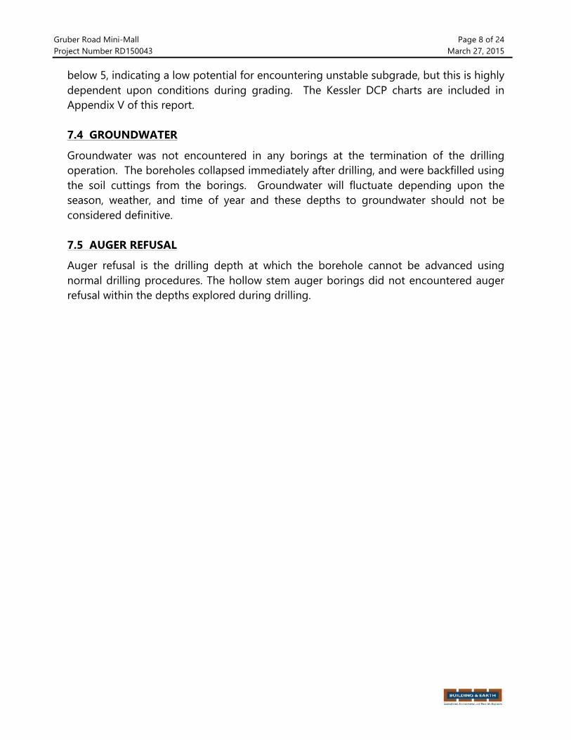
Gruber Road MiniGMall Page 8 of 24 Project Number RD150043 March 27, 2015
below 5, indicating a low potential for encountering unstable subgrade, but this is highly dependent upon conditions during grading. The Kessler DCP charts are included in Appendix V of this report. 7.4 GROUNDWATER
Groundwater was not encountered in any borings at the termination of the drilling operation. The boreholes collapsed immediately after drilling, and were backfilled using the soil cuttings from the borings. Groundwater will fluctuate depending upon the season, weather, and time of year and these depths to groundwater should not be considered definitive. 7.5 AUGER REFUSAL
Auger refusal is the drilling depth at which the borehole cannot be advanced using normal drilling procedures. The hollow stem auger borings did not encountered auger refusal within the depths explored during drilling.

Gruber Road MiniGMall Page 9 of 24 Project Number RD150043 March 27, 2015
8.0 LABORATORY ANALYSIS
Laboratory tests were performed on selected soil samples obtained from the subsurface exploration in order to better classify the encountered soils and to provide correlated engineering properties. Laboratory testing consisted of particle gradation analysis, natural moisture content, and Atterberg Limits testing for selected samples. The results of the laboratory testing are presented on Tables 1, 2, 3, and 4. A brief description of the laboratory tests performed is provided in the following sections.
Table 1: Laboratory Test Results
Boring Designation Sample Depth Zfoot[
Moisture Content Z%[
% Passing #200 Sieve
B1 0G2 10.3 GG B1 2G4 9.4 44.2 B1 4G6 4.3 GG B1 10G12 5.2 GG B2 0G2 12.6 26.6 B2 2G4 10.6 36.5 B2 4G6 12.1 GG B2 18.5G20 9.0 GG B3 0G2 12.2 GG B3 2G4 12.0 GG B3 4G6 13.3 GG B3 8G10 4.5 10.6 B3 13.5G15 10.4 30.0 B4 0G2 11.4 GG B4 2G4 12.4 GG B4 4G6 12.7 GG B4 8G10 14.1 3.1 B5 0G2 9.4 29.2 B5 2G4 9.2 29.7 B5 4G6 15.9 GG B5 8G10 7.9 15.8 B5 18.5G20 9.1 14.0 B5 33.5G35 8.3 17.4

Gruber Road MiniGMall Page 10 of 24 Project Number RD150043 March 27, 2015
Boring Designation
Sample Depth Zfoot[
Liquid Limit
Plastic Limit
Plasticity Index
Soil Classification
B3/B4/B5 0G2 20 17 3 SM
Table 2: Atterberg Limits Testing
Boring Designation Sample Depth Zfoot[
Dry Density at Optimum Zpcf[
Moisture at Optimum Z%[
B3/B4/B5 0 G 2 129.2 9.1
Table 3: Modified Proctor Results
Boring Designation Sample Depth Zfoot[ California Bearing Ratio Z%[ B3/B4/B5 0 G 2 24.0
Table 4: California Bearing Ratio
A brief description of each laboratory test performed is provided in the following sections. 8.1 DESCRIPTION OF SOILS ZVISUAL*MANUAL PROCEDURE[ ZASTM D 2488[
During drilling, the soil samples were visually examined by our engineer and soil descriptions were provided. Representative samples were then selected and tested in accordance with the aforementioned laboratoryGtesting program to determine soil classifications and engineering properties. This data was used to correlate our visual descriptions with the Unified Soil Classification System eUSCSf. 8.2 NATURAL MOISTURE CONTENT ZASTM D 2216[
The natural moisture content is the ratio, expressed as a percentage, of the weight of water in a given amount of soil to the weight of solid particles. 8.3 WASH # 200 TEST ZASTM D 422[
GrainGsize tests were performed to help measure the soil particle size distribution. We measured the amount of material finer than the No. 200 sieve by washing the sample over that particular size sieve. 8.4 ATTERBERG LIMITS ZASTM D 4318[
Atterberg Limits tests were performed to evaluate the soil’s plasticity characteristics. The soil Plasticity Index ePIf is representative of this characteristic and is bracketed by the Liquid Limit eLLf and the Plastic Limit ePLf. The Liquid Limit is the moisture content at which the soil will flow as a heavy viscous fluid. The Plastic Limit is the moisture content
Gruber Road MiniGMall Page 11 of 24 Project Number RD150043 March 27, 2015
at which the soil is between “plastic” and the semiGsolid state. The Plasticity Index ePI = LL G PLf is a frequently used indicator for a soil’s potential for volume change. Typically, a soil’s potential for volume change increases with higher plasticity indices. 8.5 MODIFIED PROCTOR ZASTM D 1557[
The Proctor compaction test is a laboratory method of experimentally measuring the optimal moisture content at which a given soil type will become most dense and achieve its maximum dry density. The test involves compacting five layers of soil in 1/30 cubic foot mold using a 10 pound hammer freeGfalling a distance of 18 inches a total of 25 times per layer. The test results in a maximum dry density, typically reported in pounds per cubic foot, and an optimum moisture content, typically reported as a percentage. The test results are presented in Appendix IV. 8.6 CALIFORNIA BEARING RATIO ZASTM D 1883[ The California Bearing Ratio eCBRf test is a simple strength test that compares the bearing capacity of a material with that of a wellGgraded crushed stone. The CBR value is the ratio between the soil’s resistances to 0.1 inch penetration of a standard piston to the resistance of a well graded and crushed stone to the same penetration. In theory, a high quality crushed rock material should have a CBR of 100. It is primarily intended for, but not limited to, evaluating the strength of cohesive materials having maximum particle sizes less than 19 mm e0.75 in.f. The test results are presented in Appendix IV.

Gruber Road MiniGMall Page 12 of 24 Project Number RD150043 March 27, 2015
9.0 SITE GRADING CONSIDERATIONS
We anticipate cuts on the order of 1 foot on the west side of the building, and fills of up to 2 feet on the east side to create a level building pad. If actual grade changes exceed these assumptions, Building & Earth Sciences should review the grading plan and its effects on our recommendations for site preparation. Recommendations addressing the site conditions are presented in the following sections. 9.1 SITE PREPARATION
All sod, topsoil, pavement, and any other deleterious materials should be removed from the proposed construction areas prior to placing fill or commencing cutting operations to achieve finished grade. Once the site has been stripped, we recommend a series of test pits be excavated across the building pad to confirm the consistency of the existing fill soils. The test pits should be excavated to a depth of 3 to 5 feet below the ground surface, and our Geotechnical Engineer should be present to evaluate the existing fill soils. In the event that large amounts of demolition materials are encountered in the soil structure, it may be necessary to excavate and replace with suitable structural fill soils. Prior to the site preparation activities, the contractor should identify borrow source materials that will be used as structural fill and provide samples to the testing laboratory so that conformance to the requirements of Section 9.3 and appropriate moistureGdensity relationship curves can be determined. 9.2 SUBGRADE EVALUATION AND PREPARATION
Once the site has been prepared, all structural areas of the site epavement and building areasf should be compacted with a heavy roller then proofrolled with a loaded tandemGaxle dump truck prior to placement of fill or construction of buildings or pavements. Any areas exhibiting soft zones and/or pumping during proofrolling will need to be stabilized, which could include undercutting and backfilling or the use of geotextile fabric. We recommend the project geotechnical engineer or a qualified representative observe proofrolling of the near surface soils, test pit excavations by the grading contractor, and perform hand auger borings and dynamic cone penetration testing eif neededf to help in evaluating the condition of the near surface soils at the time of construction.

Gruber Road MiniGMall Page 13 of 24 Project Number RD150043 March 27, 2015
If any construction debris, building remnants, or otherwise unsuitable materials are identified during this evaluation, repairs will be required. Information regarding suitable stabilization methods can be provided during construction based on actual conditions encountered. Areas that require fill placement should be scarified prior to placement of the first lift of fill. The contractor must scarify the upper four inches of the approved subgrade prior to fill placement. Fill lift thicknesses should not exceed eight inches loose measure and should be compacted to the specifications provided in the following section. 9.3 STRUCTURAL FILL
We recommend structural fill at the site be composed of material with a maximum dry density in excess of 100 pounds per cubic foot epcff, Plasticity Index ePIf less than 20, and a Liquid Limit eLLf less than 40. Based on our laboratory tests results, once moisture conditioned, the onGsite soils with the exception of topsoil are suitable for use as structural fill. We recommend that we perform laboratory testing of the proposed import soils to verify their conformance with the above recommendations. Any proposed fill material to be placed at the site should be reviewed by the geotechnical engineer. Structural fill should be compacted to a minimum of 92% of the modified Proctor value and within ±3% of the optimum moisture as determined by ASTM DG1557. Compaction in pavement and structural areas should be increased to 95% criteria and within ±3% of the optimum moisture as determined by ASTM DG1557 in the upper 12 inches. The specifications should state that both density and moisture requirements should be met. The lifts should not exceed 8 inches in thickness emeasured loosef, depending on the compaction equipment used. Commonly used testing frequencies are presented below:
Building Pads one test per 2,500 square feet per lift Pavement Areas one test per 5,000 square feet per lift Utility Trenches one test per 150 linear feet per lift Roadways one test per 100 linear feet per lift
All fill should be placed in horizontal and level lifts. Fill placed against existing slopes should be properly benched into the existing slope to interrupt any slip that may develop from placing new fill over existing soils. Benching should include 2 to 4Gfoot wide cuts into the slope.

Gruber Road MiniGMall Page 14 of 24 Project Number RD150043 March 27, 2015
9.4 UTILITY TRENCH BACKFILL
All new utility trenches must be backfilled with soils as specified for structural fill. It may be necessary to reduce the lift thickness to 4 to 6 inches, in order to achieve compaction using handGoperated equipment. Utility trench backfill should be compacted to a minimum of 92% of the modified Proctor value eASTM DG1557f and within ±3.0% of the optimum moisture content. 9.5 GROUNDWATER/GROUND MODIFICATION
Based on the conditions that were encountered during our site reconnaissance, we do not expect excavations within the upper 15 feet to encounter groundwater. 9.6 WET WEATHER CONSTRUCTION
In general, construction in wet weather can cause soils to become unstable. In addition, excessive movement of construction equipment across the site during wet weather may result in ruts, which will collect rainwater, increasing their instability and prolonging the time required to dry the subgrade soils. During rainy periods, additional effort will be required to properly prepare the site and establish/maintain an acceptable subgrade. Grading contractors typically postpone grading operations during wet weather to wait for conditions that are more favorable. Contractors can typically disk or aerate the upper soils to promote drying during intermittent periods of favorable weather. When deadlines restrict postponement of grading operations, additional measures such as undercutting and replacing saturated soils or chemical stabilization can be utilized to facilitate placement of additional fill material. 9.7 DRAINAGE CONSIDERATION
The potential for soil moisture fluctuations within building areas and pavement subgrades should be reduced to lessen the potential of subgrade movement. Site grading should include positive drainage away from buildings and pavements. Ponding of water adjacent to buildings and pavements could result in soil moisture increases and subsequent heave of the soils. 9.8 EXCAVATION CONSIDERATIONS
The current OSHA guidelines for temporary excavations should be followed for excavation into the soil. Excavated soils should be stockpiled according to OSHA regulations to limit the potential caveGin of soils.

Gruber Road MiniGMall Page 15 of 24 Project Number RD150043 March 27, 2015
10.0 FOUNDATION RECOMMENDATIONS
For the planned building, we estimate the maximum column loads will be approximately 50 kips and the maximum wall loads will be 2.5 kips per linear foot. If the structural loading changes, please contact our office so we can review our calculations. Based on the anticipated loads, the results of our field exploration, laboratory analysis, and conformance with our recommendations in Section 9.0 of this report, the buildings can be supported by conventional shallow foundations dimensioned for maximum allowable soil bearing pressure of 2,000 psf. Total settlement of footings designed and constructed as recommended in this report should be less than 1.0 inch. Differential settlement is expected to be approximately ½ of the total settlement. Even though computed footing dimensions may be less, column footings should be at least 24 inches wide and strip footings should be at least 18 inches wide. These dimensions facilitate hand cleaning of footing subgrades disturbed by the excavation process and the placement of reinforcing steel. They also reduce the potential for localized punching shear failure. All exterior footing bottoms should be at least 18 inches below the lowest adjacent finished grade. Lowest adjacent finished grade may be taken as the bottom of interior slabGonGgrade or the finished exterior grade, excluding landscape topsoil, whichever is lower. The following items should be considered during the preparation of construction documents and foundation installation:
• The geotechnical engineer of record should observe the exposed foundation bearing surfaces prior to concrete placement to verify that the conditions anticipated during the subsurface exploration are encountered.
• All bearing surfaces must be free of soft or loose soil prior to placing concrete.
• Concrete should be placed the same day the excavations are completed and
bearing materials verified by the engineer. If the excavations are left open for an extended period, or if the bearing surfaces are disturbed after the initial observation, then the bearing surfaces should be reGevaluated prior to concrete placement.
• Water should not be allowed to pond in foundation excavations prior to concrete
placement or above the concrete after the foundation is completed.

Gruber Road MiniGMall Page 16 of 24 Project Number RD150043 March 27, 2015
• Wherever possible, the foundation concrete should be placed “neat”, using the sides of the excavations as forms. Where this is not possible, the excavations created by forming the foundations must be backfilled with suitable structural fill and properly compacted.
• The building pad should be sloped to drain away from the building foundations.
• Roof drains should be routed away from the foundation soils. All drains should
be collected in pipes or discharged on pavements to prevent drainage into the subsurface.

Gruber Road MiniGMall Page 17 of 24 Project Number RD150043 March 27, 2015
11.0 SEISMIC CONSIDERATIONS
11.1 INTERNATIONAL BUILDING CODE SITE CLASS
According to the International Building Code e2012f, which references ASCE 7, the site class can be determined by the average shear wave velocity, the average NGValue, or the average undrained shear strength of the soil to a depth of 100 feet.
The average NGvalue method was used to determine the Seismic site classification. Based upon our experience with soils in this region and the results of the N Value method, the subsurface conditions at the site correspond to an ASCE 7, Chapter 20, Table 20.3G1 e2010f seismic site classification “D”, indicating a “stiff soil”.
11.2 SEISMIC DESIGN PARAMETERS
The site is located at approximate Latitude 35.126º and approximate Longitude 79.024º. For this study, the maximum considered earthquake eMCEf ground motions were represented by the spectral response accelerations for 2 percent probability of exceedance ePEf in 50 years, obtained from the 2009 NEHRP Seismic Design Provisions published by the United States Geological Survey eUSGSf. Using the USGS US Seismic Design Maps website at http://earthquake.usgs.gov/designmaps/us/application.php, the MCEs are:
0.2 Sec. Period Mapped Response Acceleration Ss = 0.220
1.0 Sec. Period Mapped Response Acceleration S1 = 0.097
The long and short period site coefficients, Fa and Fv, have also been calculated for this site utilizing the mapped spectral response accelerations shown and are as follows:
0.2 Sec. Period Site Coefficient Fa = 1.60
1.0 Sec. Period Site Coefficient Fv = 2.40
IBC 2012 calculates the MCE mapped spectral response acceleration, short period, as SMS = FaSs; and 1 second as SM1 = FvS1. Design spectral response acceleration parameters SDS and SD1 are then determined by multiplying SMS by SM1 by twoGthirds.
SMS = 0.351 and SDS = 0.234
SM1 = 0.232 and SD1 = 0.155
Conformance to the criteria for seismic design does not constitute any kind of guarantee or assurance that significant structural damage or ground failure will not occur if a maximum level earthquake occurs. The primary goal of seismic design is to protect life and not to avoid all damage, since such design may be economically prohibitive.

Gruber Road MiniGMall Page 18 of 24 Project Number RD150043 March 27, 2015
12.0 PAVEMENT RECOMMENDATIONS
We anticipate new pavement driveways will be constructed to support the new MiniGMall. Also, we understand that the new driveways and parking lot will consist of flexible, asphalt pavement with rigid concrete pavement at the pump island. 12.1 SUBGRADE SUPPORT We prepared our pavement design based on a California Bearing Ratio test on soil acquired from the site. However, because we expect that most of the surface soils at the site will be repaired during the subgrade preparation, and a good portion of the pavements will be located in areas that will receive structural fill, we prepared the following pavement design based on a CBR of ten percent. 12.2 ESTIMATED TRAFFIC On a daily basis, we assume the parking lot will receive approximately 5,000 passenger automobile and 25 delivery trucks passes, and biGweekly fuel deliveries and trash collection. We also assume the parking lot will receive the occasional a fire truck and possibly a tandem axle dump truck traffic. For the purposes of this report, we have estimated traffic loads on the order of 200,000 Equivalent Single Axle Loads eESALsf for light duty pavements and 500,000 ESALs for heavy duty pavements over the 20Gyear design life. Once the actual traffic loading has been established, we should be provided an opportunity to revise our calculations if necessary. 12.3 PAVEMENT DESIGN SPECIFICATIONS The pavement subgrade should be prepared in accordance with the site preparation recommendations presented in Section 9.0 of this report. We have also assumed the design parameters listed in Table 5.
Design Criteria Value Design life eYearsf 20
Terminal Serviceability 2.5
Reliability 85%
Initial Serviceability 4.2
Standard Deviation 0.45 eFlexiblef
Table 5: Assumed Design Parameters

Gruber Road MiniGMall Page 19 of 24 Project Number RD150043 March 27, 2015
All subgrade, base, and pavement construction operations should meet the minimum requirements of the North Carolina Department of Transportation Standard Specifications for Roads and Structures, latest edition. The applicable sections of the specifications are identified as follows:
Title NCDOT Specification Section
Asphalt Concrete Plant Mix Pavements 610
Concrete Pavement 710
Aggregate Base Course 520
Table 6: NCDOT Specification Sections
12.4 FLEXIBLE PAVEMENT The following flexible pavement sections are based on the design parameters presented above:
Thickness Zinch[ Material Description 1.0 Asphalt Concrete Surface Course, NCDOT Type SFG9.5A or 9.5B 2.0 Asphalt Concrete Intermediate Course, NCDOT Type IG19.0B 6.0 Aggregate Base Course, NCDOT 520
Table 7: Light Duty Asphalt Pavement Recommendations
Thickness Zinch[ Material Description 2.0 Asphalt Concrete Surface Course, NCDOT Type SFG9.5A or 9.5B 2.0 Asphalt Concrete Intermediate Course, NCDOT Type IG19.0B 8.0 Aggregate Base Course, NCDOT 520
Table 8: Heavy Duty Asphalt Pavement Recommendations
Heavy Duty Concrete & Dumpster Pad Minimum Recommended
Thickness Zinch[ Description
6.0 Portland Cement Concrete, f’c=4000 psi 8.0 Crushed Aggregate Base, NCDOT 520 8.0 Subgrade compacted to at least 95%, Modified Proctor Table 9: Heavy Duty Concrete Pavement Recommendations
All pavement components must be placed and compacted in accordance with

Gruber Road MiniGMall Page 20 of 24 Project Number RD150043 March 27, 2015
applicable section of the North Carolina Department of Transportation Standard Specifications for Roads and Structures, latest edition. The concrete should be protected against damage caused by moisture loss, rapid temperature fluctuations, and construction traffic after placement. We recommended that the pavements be reinforced to hold the cracks tightly together and restrain their growth.
For rigid pavements, we recommend a jointing plan be developed to control cracking and help preclude surficial migration of water into the base course and subgrade. Additionally, we recommend the joints be sealed in order to further preclude surficial moisture migration into the underlying supporting soils. 12.5 PAVEMENT DRAINAGE AND MAINTENANCE
All pavements should be sloped, approximately ¼Ginch per foot, to provide rapid surface drainage. Water allowed to pond on or adjacent to the pavement could saturate the subgrade and cause premature deterioration of the pavements as a result of loss of strength and stability. Additionally, periodic maintenance of the pavement is required in order to achieve the specified design life. This should include sealing of cracks and joints and by maintaining proper surface drainage to avoid ponding of water on or near the pavement areas.

Gruber Road MiniGMall Page 21 of 24 Project Number RD150043 March 27, 2015
13.0 SUBGRADE REHABILITATION
The subgrade soils often become disturbed during the period between initial site grading and construction of surface improvements. The amount and depth of disturbance will vary with soil type, weather conditions, construction traffic, and drainage. The engineer or qualified representative should evaluate the subgrade soil during final grading and prior to stone placement to verify that the subgrade is suitable to receive pavement base or floor slabs. The final evaluation may include proofrolling or density tests. Subgrade rehabilitation can become a point of controversy when different contractors are responsible for mass and final grading. The construction documents could specifically state the contractor will be responsible for maintaining and rehabilitating the subgrade. Rehabilitation may include wetting, mixing, and reGcompacting soils that have dried excessively or drying soils that have become wet.

Gruber Road MiniGMall Page 22 of 24 Project Number RD150043 March 27, 2015
14.0 FLOOR SLABS
Site grading recommendations presented in Section 9.0 of this report should be followed to provide for subgrade conditions suitable for support of gradeGsupported slabs. We recommend floor slabs for the proposed building be supported on a minimum fourGinch layer of ½Ginch up to 1½Ginch, freeGdraining, gapGgraded gravel, such as AASHTO No. 57 stone, with no more than 5 percent passing the ASTM No. 200 sieve. The purpose of this layer is to help distribute concentrated loads and act as a capillary break for moisture migration through the subgrade soil. This gravel material should be consolidated inGplace with vibratory equipment. With the gravel material, such as AASHTO No. 57 stone, a modulus of subgrade reaction of 150 pci can be used in the design of grade supported building floor slab. Depending on the proposed floor covering, consideration should be given to the use of a polyethylene vapor retarder. If deemed necessary, we recommend a minimum10Gmil thick vapor retarder meeting ASTM E 1745, Class C requirements be placed directly below the slabGonGgrade floors eno sandf. A higher quality vapor retarder eClass A or Bf may be used if desired to further inhibit the migration of moisture through the slabGonGgrade. The vapor retarder should extend to the edge of the slabGonGgrade floors and should be sealed at all seams and penetrations. This vapor retarder will work in conjunction with the four inches of freeGdraining gravel material. The slab should be appropriately reinforced eif requiredf to support the proposed loads.

Gruber Road MiniGMall Page 23 of 24 Project Number RD150043 March 27, 2015
15.0 CONSTRUCTION MONITORING
The recommendations presented in this report are based on information obtained from five soil borings and five handGauger/DCPs subsurface explorations. Field verification of site conditions is an essential part of the services provided by the geotechnical consultant. In order to confirm our recommendations, it will be necessary for Building & Earth personnel to make periodic visits to the site during site grading. We can prepare a proposal for construction monitoring services based on the construction schedule and your risk management preferences. Typical construction monitoring services are listed below. • Periodic observations and consultations by a member of our engineering staff during
site grading.
• Field density tests during structural fill placement.
• Observation and verification of the bearings surfaces exposed after foundation excavation.
• Molding and testing of concrete cylinders.
• Structural steel inspections.
• Sampling of asphalt for mix verification and coring for determination of inGplace thickness and density.

Gruber Road MiniGMall Page 24 of 24 Project Number RD150043 March 27, 2015
16.0 CLOSING
We prepared this report for MarshallGWatersGWoody Associates, specifically for design of the new Gruber Road MiniGMall located on Gruber Road at the intersection of Graves Street at Fort Bragg, North Carolina. The information in this report is not transferable. This report should not be used for a different development on the same property without first being evaluated by our firm. The recommendations in this report were based on the information obtained from our field exploration, laboratory analysis, and engineering judgment regarding conditions between borings. It will be necessary to confirm the anticipated subsurface conditions during construction. This report is intended for use during design and preparation of specifications and may not address all conditions at the site during construction. Contractors reviewing this information should acknowledge that this document is for design information only. An article published by the Geoprofessional Business Association enée ASFEf, titled Important Information About Your Geotechnical Report, has been included in the Appendix. We encourage all individuals to become familiar with the article to help manage risk.

APPENDIX I

Important Information About YourGeotechnical Engineering Report
Subsurface problems are a principal cause of construction delays, cost overruns, claims, and disputes
The following information is provided to help you manage your risks.
Geotechnical Services Are Performed forSpecifi c Purposes, Persons, and ProjectsGeotechnical engineers structure their services to meet the specifi c needs of their clients. A geotechnical engineering study conducted for a civil engineer may not fulfi ll the needs of a construction contractor or even another civil engineer. Because each geotechnical engineering study is unique, each geo-technical engineering report is unique, prepared solely for the client. No one except you should rely on your geotechnical engineering report without fi rst conferring with the geotechnical engineer who prepared it. And no one - not even you - should apply the report for any purpose or project except the one originally contemplated.
Read the Full ReportSerious problems have occurred because those relying on a geotechnical engineering report did not read it all. Do not rely on an executive summary. Do not read selected elements only.
A Geotechnical Engineering Report Is Based onA Unique Set of Project-Specifi c FactorsGeotechnical engineers consider a number of unique, project-specifi c factors when establishing the scope of a study. Typical factors include: the client’s goals, objectives, and risk management preferences; the general nature of the structure involved, its size, and confi guration; the location of the structure on the site; and other planned or existing site improvements, such as access roads, parking lots, and underground utilities. Unless the geotechnical engi-neer who conducted the study specifi cally indicates otherwise, do not rely on a geotechnical engineering report that was:• not prepared for you,• not prepared for your project,• not prepared for the specifi c site explored, or• completed before important project changes were made.
Typical changes that can erode the reliability of an existing geotechnicalengineering report include those that affect:• the function of the proposed structure, as when it’s changed from a parking garage to an offi ce building, or from alight industrial plant to a refrigerated warehouse,
• elevation, confi guration, location, orientation, or weight of the proposed structure,• composition of the design team, or• project ownership.
As a general rule, always inform your geotechnical engineer of project changes - even minor ones - and request an assessment of their impact. Geotechnical engineers cannot accept responsibility or liability for problems that occur because their reports do not consider developments of which they were not informed.
Subsurface Conditions Can ChangeA geotechnical engineering report is based on conditions that existed at the time the study was performed. Do not rely on a geotechnical engineering report whose adequacy may have been affected by: the passage of time; by man-made events, such as construction on or adjacent to the site; or by natu-ral events, such as fl oods, earthquakes, or groundwater fl uctuations. Always contact the geotechnical engineer before applying the report to determine if it is still reliable. A minor amount of additional testing or analysis could prevent major problems.
Most Geotechnical Findings Are ProfessionalOpinionsSite exploration identifi es subsurface conditions only at those points wheresubsurface tests are conducted or samples are taken. Geotechnical engineers review fi eld and laboratory data and then apply their professional judgment to render an opinion about subsurface conditions throughout the site. Actual subsurface conditions may differ-sometimes signifi cantly from those indi-cated in your report. Retaining the geotechnical engineer who developed your report to provide construction observation is the most effective method of managing the risks associated with unanticipated conditions.
A Report’s Recommendations Are Not FinalDo not overrely on the construction recommendations included in your re-port. Those recommendations are not fi nal, because geotechnical engineers develop them principally from judgment and opinion. Geotechnical engineers can fi nalize their recommendations only by observing actual

subsurface conditions revealed during construction. The geotechnical engi-neer who developed your report cannot assume responsibility or liability for the report’s recommendations if that engineer does not perform construction observation.
A Geotechnical Engineering Report Is Subject toMisinterpretationOther design team members’ misinterpretation of geotechnical engineer-ing reports has resulted in costly problems. Lower that risk by having your geotechnical engineer confer with appropriate members of the design team after submitting the report. Also retain your geotechnical engineer to review pertinent elements of the design team’s plans and specifi cations. Contractors can also misinterpret a geotechnical engineering report. Reduce that risk by having your geotechnical engineer participate in prebid and preconstruction conferences, and by providing construction observation.
Do Not Redraw the Engineer’s LogsGeotechnical engineers prepare fi nal boring and testing logs based upon their interpretation of fi eld logs and laboratory data. To prevent errors or omissions, the logs included in a geotechnical engineering report should never be redrawn for inclusion in architectural or other design drawings. Only photographic or electronic reproduction is acceptable, but recognize that separating logs from the report can elevate risk.
Give Contractors a Complete Report andGuidanceSome owners and design professionals mistakenly believe they can make contractors liable for unanticipated subsurface conditions by limiting what they provide for bid preparation. To help prevent costly problems, give con-tractors the complete geotechnical engineering report, but preface it with aclearly written letter of transmittal. In that letter, advise contractors that thereport was not prepared for purposes of bid development and that the report’s accuracy is limited; encourage them to confer with the geotechnical engineer who prepared the report (a modest fee may be required) and/or to conduct ad-ditional study to obtain the specifi c types of information they need or prefer. A prebid conference can also be valuable. Be sure contractors have suffi cient time to perform additional study. Only then might you be in a position to give contractors the best information available to you, while requiring them to at least share some of the fi nancial responsibilities stemming from unantici-pated conditions.
Read Responsibility Provisions CloselySome clients, design professionals, and contractors do not recognize thatgeotechnical engineering is far less exact than other engineering disciplines. This lack of understanding has created unrealistic expectations that have led
to disappointments, claims, and disputes. To help reduce the risk of such outcomes, geotechnical engineers commonly include a variety of explanatory provisions in their reports. Sometimes labeled “limitations” many of these provisions indicate where geotechnical engineers’ responsibilities begin and end, to help others recognize their own responsibilities and risks. Read these provisions closely. Ask questions. Your geotechnical engineer should respond fully and frankly.
Geoenvironmental Concerns Are Not CoveredThe equipment, techniques, and personnel used to perform a geoenviron-mental study differ signifi cantly from those used to perform a geotechnical study. For that reason, a geotechnical engineering report does not usually re-late any geoenvironmental fi ndings, conclusions, or recommendations; e.g., about the likelihood of encountering underground storage tanks or regulated contaminants. Unanticipated environmental problems have led to numerous project failures. If you have not yet obtained your own geoenvironmental in-formation, ask your geotechnical consultant for risk management guidance. Do not rely on an environmental report prepared for someone else.
Obtain Professional Assistance To Deal with MoldDiverse strategies can be applied during building design, construction, op-eration, and maintenance to prevent signifi cant amounts of mold from grow-ing on indoor surfaces. To be effective, all such strategies should be devised for the express purpose of mold prevention, integrated into a comprehensive plan, and executed with diligent oversight by a professional mold prevention consultant. Because just a small amount of water or moisture can lead to the development of severe mold infestations, a number of mold prevention strategies focus on keeping building surfaces dry. While groundwater, wa-ter infi ltration, and similar issues may have been addressed as part of the geotechnical engineering study whose fi ndings are conveyed in-this report, the geotechnical engineer in charge of this project is not a mold prevention consultant; none of the services performed in connection with the geotechnical engineer’s study were designed or conducted for the purpose of mold prevention. Proper implementation of the recommendations conveyed in this report will not of itself be suffi cient to prevent mold from growing in or on the struc-ture involved.
Rely on Your ASFE-Member GeotechnicalEngineer For Additional AssistanceMembership in ASFE/The Best People on Earth exposes geotechnical engi-neers to a wide array of risk management techniques that can be of genuine benefi t for everyone involved with a construction project. Confer with your ASFE-member geotechnical engineer for more information.
8811 Colesville Road/Suite G106, Silver Spring, MD 20910Telephone:’ 301/565-2733 Facsimile: 301/589-2017
e-mail: [email protected] www.asfe.org
Copyright 2004 by ASFE, Inc. Duplication, reproduction, or copying of this document, in whole or in part, by any means whatsoever, is strictly prohibited, except with ASFE’s specifi c written permission. Excerpting, quoting, or otherwise extracting wording from this document is permitted only with the express written permission of ASFE, and only for purposes
of scholarly research or book review. Only members of ASFE may use this document as a complement to or as an element of a geotechnical engineering report. Any other fi rm, individual, or other entity that so uses this document without being anASFE member could be committing negligent or intentional (fraudulent) misrepresentation.
IIGER06045.0M
T h e B e s t P e o p l e o n E a r t h

APPENDIX II

!
Site Location Map BES Project #: RD15043 Client: Marshall Waters Woody Associates Drawing Source: © Google Maps Project: Gruber Mini?Mall
Address: Gruber Road at Graves Street City: Fort Bragg, North Carolina
Figure 1
N
!0.5 0.25 0
Approximate Scale KmileL
SITE
Longstreet Road
Gruber Road
Ardennes Road
Grav
es S
treet
Yadkin Road

Site Geology Map BES Project #: RD150043 Client: Marshall/Waters/Woody Associates Drawing Source: NC Geological Survey Project: Gruber Mini/Mall
Address: Gruber Road at Graves Street City: Fort Bragg, North Carolina
Scale: Not To Scale Figure 2
K-1 K-1
SITE
Inte
rsta
te 9
5 Highway 24
Middendorf Cape Fear Black Creek Yorktown/Duplin Comfort/New Hanover
Key to Geologic Features
Highway 401
N

Site Plan BES Project #: RD15043 Client: Marshall Waters Woods Associates Drawing Source: © Google & Exchange Project: Gruber Mini Mall
Address: Gruber Road at Graves Street City: Fort Bragg, North Carolina
Figure 3 Approximate Scale IfeetK
Approximate Boring Location B1
B1
B2 B3
B5
Grav
es S
treet
Gruber Road
N
100 0 50
B4
DCP1
DCP4
DCP3
DCP5
DCP2
Approximate DCP Location

APPENDIX III

Soil Classification Chart
Major Divisions Symbols Typical Description Graph Letter
Coarse Grained
Soils
Gravel and Gravelly Soils
Clean Gravels GW Well-graded gravels, gravel – sand mixtures, little or no fines
(Little or no fines) GP Poorly-graded gravels, gravel – sand mixtures, little or no fines
More than 50% of coarse fraction is larger than No. 4 sieve
Gravels with Fines GM Silty gravels, gravel – sand – silt mixtures
(Appreciable amount of fines) GC Clayey gravels, gravel – sand – clay mixtures
More than 50% of
material is larger than
No. 200 sieve size
Sand and Sandy Soils
Clean Sands SW Well-graded sands, gravelly sands, little or no fines
(Little or no fines) SP Poorly-graded sands, gravelly sands, little or no fines
More than 50% of coarse fraction is
smaller than No. 4 sieve
Sands with Fines SM Silty sands, sand – silt mixtures
(Appreciable amount of fines) SC Clayey sands, sand – clay mixtures
Fine Grained
Soil
Silts and Clays
Liquid Limit less than 50
ML Inorganic silts and very find sands, rock flour, silty or clayey fine sands or clayey silt with slight plasticity
CL Inorganic clays of low to medium plasticity, gravelly clays, sandy clays, silty clays, lean clays
OL Organic silts and organic silty clays of low plasticity
More than 50% of
material is smaller than No. 200 sieve
size
Silts and Clays
Liquid Limit greater than 50
MH Inorganic silts, micaceous or diatomaceous fine sand, or silty soils
CH Inorganic clays of high plasticity
OH Organic clays of medium to high plasticity, organic silts
Highly Organic Soils PT Peat, humus, swamp soils with high organic contents
Soil Component
Particle Size U.S. Standard
Sieve Size Boulders Larger than 300mm N.A. Cobbles 300mm to 75mm N.A. Gravel 75mm to 4.75mm 3-inch to #4 Sieve Coarse 75mm to 19mm 3-inch to ¾-inch Sieve Fine 19mm to 4.75mm ¾-inch to #4 Sieve Sand 4.75mm to 0.075mm #4 to #200 Sieve Coarse 4.75mm to 2mm #4 to #10 Sieve Medium 2mm to 0.425mm #10 to #40 Sieve Fine 0.425mm to 0.075mm #40 to #200 Sieve Fines Less than 0.075mm Below #200 Sieve Silt Smaller than 5µm N.A. Clay Smaller than 2µm N.A.
Plasticity Chart
10 20 30 40 50 60 70 80 90 100
60
10
20
30
40
50
Liquid Limit (LL)
Pla
stic
ity I
nd
ex (
PI)
7
4CL-ML ML or OL
MH or OHCL or OL
CH or OH
A-Lin
e
Sands and Nonplastic Silts Cohesive – Fine Grained Soil SPT
Penetration (blows / foot)
Relative Density SPT Penetration (blows / foot)
Estimated Consistency
Estimated Range of Unconfined Compressive Strength (tsf)
< 2 Very Soft < 0.25 0 – 4 Very Loose 2 – 4 Soft 0.25 – 0.50
4 – 10 Loose 4 – 8 Medium Stiff 0.50 – 1.00 10 – 30 Medium Dense 8 – 15 Stiff 1.00 – 2.00 30 – 50 Dense 15 – 30 Very Stiff 2.00 – 4.00
> 50 Very Dense > 30 Hard > 4.00

1
2
3
4
5
6
7
8
9
Topsoil (approximately 2 inches with sod)Fill: SILTY SAND (SM): medum dense,moist, orangish red, fine to medium sand withtrace gravelSILTY SAND (SM): medium dense, moist,tan, brown, and orange, fine to medium sand
POORLY GRADED SAND with SILT(SP-SM): medium dense, moist, tan, brown,and orange, fine to medium sand
- loose
- color grades to tan, brown, orange, andyellow
- color grades to white and pale yellow
Boring was terminated at 20 feetNo groundwater was encounteredBoring backfilled upon completion
% Passing #200 Sieve: 44.2
249.8
248.5
246.5
230.0
3-5-5
10-12-13
7-7-7
4-5-4
7-10-12
7-11-15
8-8-10
9-9-10
10-11-14
0.2
1.5
3.5
20.0
Boring Location: Northwest Corner of Building
Auburn, AL
Project Number: RD15043
Standard Penetration Test
BLO
WS
PER
IN
CR
EMEN
T
GROUNDWATER LEVEL IN THE BOREHOLEUNCONFINED COMPRESSIVE STRENGTH ESTIMATE FROM POCKET PENETROMETER TEST
SOIL DESCRIPTION REMARKS
Huntsville, AL Columbus, GA
Designation: B1Sheet 1 of 1
N-Value
20 40 60 80
Date Drilled: 3/9/15
10 20 30 40 Qu (tsf)
N-VALUE% MOISTURE
Qu
Project Location: Fort Bragg, North Carolina
10 20 30 40
Birmingham, AL
GR
APH
IC
RECRQDUD
ELEV
ATI
ON
(ft)
250
245
240
235
230
% Moisture 20 40 60 80
SAMPLE TYPE
Project Name: Gruber Mini MallSA
MPL
E N
O.
UNDISTURBED
RECOVERYROCK QUALITY DESIGNATION
LOG OF BORING 610 Spring Branch RoadDunn, NC 28334
Office: (910) 292-2085 205-836-6300Fax: (910) 292-2087 205-836-9007
www.BuildingAndEarth.com
1 2 3 4
Savannah, GA Raleigh, NC Tulsa, OK Springdale, AR Shreveport, LA Louisville, KY Niceville, FL
1 2 3 4 Atterberg Limits
Qu (tsf)
Drilling Method: Hollow Stem AugerSurface Elevation: 250
REMARKS
Hammer Type: 140 lb. Manual With Cathead
DEP
TH (f
t)D
EPTH
(ft)
SAM
PLE
TYPE
GR
APH
IC
5
10
15
20
STANDARD PENETRATION RESISTANCE (AASHTO T-206)PERCENT NATURAL MOISTURE CONTENT
SOIL DESCRIPTION
N-Value
Atterberg Limits
Equipment Used: CME 450Weather Conditions: Clear
Drill Crew: J&L, Stuart/ChrisLogged By: Dereck Martin, E.I.
LOG
OF
BO
RIN
G 1
RD
1504
3 G
RU
BER
MIN
I MA
LL.G
PJ
BE
SI.G
DT
3/2
7/15

1
2
3
4
5
6
7
8
9
Topsoil (approximately 2 inches with sod)Fill: SILTY SAND (SM): loose, moist,orangish red, fine to medium sand with tracegravel SILTY SAND (SM): medium dense, moist,orangish red, fine to medium sand
- loose to medium dense
- color grades to yellowish orange and tan
- color grades to tan and white
- dense, color grades to tan, white, and red
- medium dense
Boring was terminated at 20 feetNo groundwater was encounteredBoring backfilled upon completion
% Passing #200 Sieve: 26.6
% Passing #200 Sieve: 36.5
249.8
248.5
230.0
2-3-5
6-5-5
6-6-7
2-4-5
4-5-6
6-8-10
10-12-13
9-13-20
9-14-14
0.2
1.5
20.0
Boring Location: Northeast Corner of Building
Auburn, AL
Project Number: RD15043
Standard Penetration Test
BLO
WS
PER
IN
CR
EMEN
T
GROUNDWATER LEVEL IN THE BOREHOLEUNCONFINED COMPRESSIVE STRENGTH ESTIMATE FROM POCKET PENETROMETER TEST
SOIL DESCRIPTION REMARKS
Huntsville, AL Columbus, GA
Designation: B2Sheet 1 of 1
N-Value
20 40 60 80
Date Drilled: 3/9/15
10 20 30 40 Qu (tsf)
N-VALUE% MOISTURE
Qu
Project Location: Fort Bragg, North Carolina
10 20 30 40
Birmingham, AL
GR
APH
IC
RECRQDUD
ELEV
ATI
ON
(ft)
250
245
240
235
230
% Moisture 20 40 60 80
SAMPLE TYPE
Project Name: Gruber Mini MallSA
MPL
E N
O.
UNDISTURBED
RECOVERYROCK QUALITY DESIGNATION
LOG OF BORING 610 Spring Branch RoadDunn, NC 28334
Office: (910) 292-2085 205-836-6300Fax: (910) 292-2087 205-836-9007
www.BuildingAndEarth.com
1 2 3 4
Savannah, GA Raleigh, NC Tulsa, OK Springdale, AR Shreveport, LA Louisville, KY Niceville, FL
1 2 3 4 Atterberg Limits
Qu (tsf)
Drilling Method: Hollow Stem AugerSurface Elevation: 250
REMARKS
Hammer Type: 140 lb. Manual With Cathead
DEP
TH (f
t)D
EPTH
(ft)
SAM
PLE
TYPE
GR
APH
IC
5
10
15
20
STANDARD PENETRATION RESISTANCE (AASHTO T-206)PERCENT NATURAL MOISTURE CONTENT
SOIL DESCRIPTION
N-Value
Atterberg Limits
Equipment Used: CME 450Weather Conditions: Clear
Drill Crew: J&L, Stuart/ChrisLogged By: Dereck Martin, E.I.
LOG
OF
BO
RIN
G 1
RD
1504
3 G
RU
BER
MIN
I MA
LL.G
PJ
BE
SI.G
DT
3/2
7/15

1
2
3
4
5
6
7
8
9
Topsoil (approximately 2 inches with sod)Fill: SILTY SAND (SM): loose, wet, orangishred, fine to medium sand with trace gravel SILTY SAND (SM): dense, moist, orangishred, fine to medium sand
- medium dense
- color grades to reddish brown and tan
POORLY GRADED SAND with SILT(SP-SM): medium dense, moist, tan, orange,and red
- fine to coarse sand
SILTY SAND (SM): medium dense, moist,tan, orange, and red, trace clay
- dense
Boring was terminated at 20 feetNo groundwater was encounteredBoring backfilled upon completion
% Passing #200 Sieve: 10.6
% Passing #200 Sieve: 30.0
249.8
248.5
242.0
236.0
230.0
3-4-5
14-16-14
7-8-9
6-8-9
9-14-15
9-10-12
7-11-11
7-13-15
10-16-20
0.2
1.5
8.0
14.0
20.0
Boring Location: Southwest Corner of Building
Auburn, AL
Project Number: RD15043
Standard Penetration Test
BLO
WS
PER
IN
CR
EMEN
T
GROUNDWATER LEVEL IN THE BOREHOLEUNCONFINED COMPRESSIVE STRENGTH ESTIMATE FROM POCKET PENETROMETER TEST
SOIL DESCRIPTION REMARKS
Huntsville, AL Columbus, GA
Designation: B3Sheet 1 of 1
N-Value
20 40 60 80
Date Drilled: 3/9/15
10 20 30 40 Qu (tsf)
N-VALUE% MOISTURE
Qu
Project Location: Fort Bragg, North Carolina
10 20 30 40
Birmingham, AL
GR
APH
IC
RECRQDUD
ELEV
ATI
ON
(ft)
250
245
240
235
230
% Moisture 20 40 60 80
SAMPLE TYPE
Project Name: Gruber Mini MallSA
MPL
E N
O.
UNDISTURBED
RECOVERYROCK QUALITY DESIGNATION
LOG OF BORING 610 Spring Branch RoadDunn, NC 28334
Office: (910) 292-2085 205-836-6300Fax: (910) 292-2087 205-836-9007
www.BuildingAndEarth.com
1 2 3 4
Savannah, GA Raleigh, NC Tulsa, OK Springdale, AR Shreveport, LA Louisville, KY Niceville, FL
1 2 3 4 Atterberg Limits
Qu (tsf)
Drilling Method: Hollow Stem AugerSurface Elevation: 250
REMARKS
Hammer Type: 140 lb. Manual With Cathead
DEP
TH (f
t)D
EPTH
(ft)
SAM
PLE
TYPE
GR
APH
IC
5
10
15
20
STANDARD PENETRATION RESISTANCE (AASHTO T-206)PERCENT NATURAL MOISTURE CONTENT
SOIL DESCRIPTION
N-Value
Atterberg Limits
Equipment Used: CME 450Weather Conditions: Clear
Drill Crew: J&L, Stuart/ChrisLogged By: Dereck Martin, E.I.
LOG
OF
BO
RIN
G 1
RD
1504
3 G
RU
BER
MIN
I MA
LL.G
PJ
BE
SI.G
DT
3/2
7/15

1
2
3
4
5
6
7
8
9
Topsoil (approximately 2 inches with sod)Fill: SILTY SAND (SM): loose, wet, orangishred, fine to medium sand with trace gravel SILTY SAND (SM): dense, moist, orangishred, fine to medium sand
- color grades to orangish tan
- color grades to yellowish tan
POORLY GRADED SAND (SP): loose,moist, tan, orange, and red
- medium dense to loose, red, and yellowishtan
- loose
Boring was terminated at 20 feetNo groundwater was encounteredBoring backfilled upon completion
% Passing #200 Sieve: 3.1
249.8
248.5
242.0
230.0
2-3-5
7-11-11
7-8-8
4-5-5
4-4-4
4-5-5
4-4-4
5-6-7
5-4-2
0.2
1.5
8.0
20.0
Boring Location: Southeast Corner of Building
Auburn, AL
Project Number: RD15043
Standard Penetration Test
BLO
WS
PER
IN
CR
EMEN
T
GROUNDWATER LEVEL IN THE BOREHOLEUNCONFINED COMPRESSIVE STRENGTH ESTIMATE FROM POCKET PENETROMETER TEST
SOIL DESCRIPTION REMARKS
Huntsville, AL Columbus, GA
Designation: B4Sheet 1 of 1
N-Value
20 40 60 80
Date Drilled: 3/9/15
10 20 30 40 Qu (tsf)
N-VALUE% MOISTURE
Qu
Project Location: Fort Bragg, North Carolina
10 20 30 40
Birmingham, AL
GR
APH
IC
RECRQDUD
ELEV
ATI
ON
(ft)
250
245
240
235
230
% Moisture 20 40 60 80
SAMPLE TYPE
Project Name: Gruber Mini MallSA
MPL
E N
O.
UNDISTURBED
RECOVERYROCK QUALITY DESIGNATION
LOG OF BORING 610 Spring Branch RoadDunn, NC 28334
Office: (910) 292-2085 205-836-6300Fax: (910) 292-2087 205-836-9007
www.BuildingAndEarth.com
1 2 3 4
Savannah, GA Raleigh, NC Tulsa, OK Springdale, AR Shreveport, LA Louisville, KY Niceville, FL
1 2 3 4 Atterberg Limits
Qu (tsf)
Drilling Method: Hollow Stem AugerSurface Elevation: 250
REMARKS
Hammer Type: 140 lb. Manual With Cathead
DEP
TH (f
t)D
EPTH
(ft)
SAM
PLE
TYPE
GR
APH
IC
5
10
15
20
STANDARD PENETRATION RESISTANCE (AASHTO T-206)PERCENT NATURAL MOISTURE CONTENT
SOIL DESCRIPTION
N-Value
Atterberg Limits
Equipment Used: CME 450Weather Conditions: Clear
Drill Crew: J&L, Stuart/ChrisLogged By: Dereck Martin, E.I.
LOG
OF
BO
RIN
G 1
RD
1504
3 G
RU
BER
MIN
I MA
LL.G
PJ
BE
SI.G
DT
3/2
7/15

1
2
3
4
5
6
7
8
9
Topsoil (approximately 2 inches with sod)Fill: SILTY SAND (SM): loose, wet, orangishred, fine to medium sand with trace gravel
- dense
SILTY SAND (SM): medium dense, moist,orangish red, fine to medium sand
- color grades to orange and tan
- loose, pale yellow
CLAYEY SAND (SC): medium dense, moist,pale yellow, orange, and tan, fine to mediumsand SILTY SAND (SM): medium dense, moist,orange, tan, and gray, fine to medium sand
- color grades to tand and reddish brown
% Passing #200 Sieve: 29.2
% Passing #200 Sieve: 29.7
% Passing #200 Sieve: 15.8
% Passing #200 Sieve: 14.0
249.8
246.5
237.5
236.5
228.5
3-7-9
13-14-19
8-7-7
7-6-6
4-5-4
4-3-3
4-5-8
4-5-7
5-6-7
0.2
3.5
12.5
13.5
21.5
Boring Location: Fuel Station, Center
Auburn, AL
Project Number: RD15043
Standard Penetration Test
BLO
WS
PER
IN
CR
EMEN
T
GROUNDWATER LEVEL IN THE BOREHOLEUNCONFINED COMPRESSIVE STRENGTH ESTIMATE FROM POCKET PENETROMETER TEST
SOIL DESCRIPTION REMARKS
Huntsville, AL Columbus, GA
Designation: B5Sheet 1 of 2
N-Value
20 40 60 80
Date Drilled: 3/9/15
10 20 30 40 Qu (tsf)
N-VALUE% MOISTURE
Qu
Project Location: Fort Bragg, North Carolina
10 20 30 40
Birmingham, AL
GR
APH
IC
RECRQDUD
ELEV
ATI
ON
(ft)
250
245
240
235
230
% Moisture 20 40 60 80
SAMPLE TYPE
Project Name: Gruber Mini MallSA
MPL
E N
O.
UNDISTURBED
RECOVERYROCK QUALITY DESIGNATION
LOG OF BORING 610 Spring Branch RoadDunn, NC 28334
Office: (910) 292-2085 205-836-6300Fax: (910) 292-2087 205-836-9007
www.BuildingAndEarth.com
1 2 3 4
Savannah, GA Raleigh, NC Tulsa, OK Springdale, AR Shreveport, LA Louisville, KY Niceville, FL
1 2 3 4 Atterberg Limits
Qu (tsf)
Drilling Method: Hollow Stem AugerSurface Elevation: 250
REMARKS
Hammer Type: 140 lb. Manual With Cathead
DEP
TH (f
t)D
EPTH
(ft)
SAM
PLE
TYPE
GR
APH
IC
5
10
15
20
STANDARD PENETRATION RESISTANCE (AASHTO T-206)PERCENT NATURAL MOISTURE CONTENT
SOIL DESCRIPTION
N-Value
Atterberg Limits
Equipment Used: CME 450Weather Conditions: Clear
Drill Crew: J&L, Stuart/ChrisLogged By: Dereck Martin, E.I.
LOG
OF
BO
RIN
G 1
RD
1504
3 G
RU
BER
MIN
I MA
LL.G
PJ
BE
SI.G
DT
3/2
7/15

10
11
12
13
CLAYEY SAND (SC): dense, moist, gray,fine to medium sand (continued)
- color grades to gray and light orange
SILTY SAND (SM): dense, moist, orange,pale yellow and white , fine to medium sand
Boring was terminated at 40 feetNo groundwater was encounteredBoring backfilled upon completion
% Passing #200 Sieve: 17.4
218.0
210.0
11-18-20
12-16-18
12-17-18
15-19-24
32.0
40.0
Boring Location: Fuel Station, Center
Auburn, AL
Project Number: RD15043
Standard Penetration Test
BLO
WS
PER
IN
CR
EMEN
T
GROUNDWATER LEVEL IN THE BOREHOLEUNCONFINED COMPRESSIVE STRENGTH ESTIMATE FROM POCKET PENETROMETER TEST
SOIL DESCRIPTION REMARKS
Huntsville, AL Columbus, GA
Designation: B5Sheet 2 of 2
N-Value
20 40 60 80
Date Drilled: 3/9/15
10 20 30 40 Qu (tsf)
N-VALUE% MOISTURE
Qu
Project Location: Fort Bragg, North Carolina
10 20 30 40
Birmingham, AL
GR
APH
IC
RECRQDUD
ELEV
ATI
ON
(ft)
225
220
215
210
% Moisture 20 40 60 80
SAMPLE TYPE
Project Name: Gruber Mini MallSA
MPL
E N
O.
UNDISTURBED
RECOVERYROCK QUALITY DESIGNATION
LOG OF BORING 610 Spring Branch RoadDunn, NC 28334
Office: (910) 292-2085 205-836-6300Fax: (910) 292-2087 205-836-9007
www.BuildingAndEarth.com
1 2 3 4
Savannah, GA Raleigh, NC Tulsa, OK Springdale, AR Shreveport, LA Louisville, KY Niceville, FL
1 2 3 4 Atterberg Limits
Qu (tsf)
Drilling Method: Hollow Stem AugerSurface Elevation: 250
REMARKS
Hammer Type: 140 lb. Manual With Cathead
DEP
TH (f
t)D
EPTH
(ft)
SAM
PLE
TYPE
GR
APH
IC
25
30
35
40
STANDARD PENETRATION RESISTANCE (AASHTO T-206)PERCENT NATURAL MOISTURE CONTENT
SOIL DESCRIPTION
N-Value
Atterberg Limits
Equipment Used: CME 450Weather Conditions: Clear
Drill Crew: J&L, Stuart/ChrisLogged By: Dereck Martin, E.I.
LOG
OF
BO
RIN
G 1
RD
1504
3 G
RU
BER
MIN
I MA
LL.G
PJ
BE
SI.G
DT
3/2
7/15

1
2
3
Topsoil (approximately 2 inches with sod)Fill: SILTY SAND (SM): moist, orangish red,fine to medium sand with trace gravelPOORLY GRADED SAND WITH SILT(SP-SM): moist, tan, brown, and orange, fineto medium sand
Boring was terminated at 5 feetNo groundwater was encounteredBoring backfilled upon completion
249.8
248.5
245.0
0.2
1.5
5.0
Boring Location: Northwest Corner of Lot
Auburn, AL
Project Number: RD15043
Auger Cuttings
BLO
WS
PER
IN
CREM
ENT
GROUNDWATER LEVEL IN THE BOREHOLEUNCONFINED COMPRESSIVE STRENGTH ESTIMATE FROM POCKET PENETROMETER TEST
SOIL DESCRIPTION REMARKS
Huntsville, AL Columbus, GA
Designation: DCP1Sheet 1 of 1
N-Value
20 40 60 80
Date Drilled: 2/9/15
10 20 30 40 Qu (tsf)
N-VALUE% MOISTURE
Qu
Project Location: Fort Bragg, North Carolina
10 20 30 40
Birmingham, AL
GRA
PHIC
RECRQDUD
ELEV
ATI
ON
(ft)
250
245
240
235
230
% Moisture 20 40 60 80
SAMPLE TYPE
Project Name: Gruber Mini MallSA
MPL
E N
O.
UNDISTURBED
RECOVERYROCK QUALITY DESIGNATION
LOG OF BORING 610 Spring Branch RoadDunn, North Carolina 28334
Office: (910) 292-2085 205-836-6300Fax: (910) 292-2087 205-836-9007
www.BuildingAndEarth.com
1 2 3 4
Savannah, GA Raleigh, NC Tulsa, OK Springdale, AR Shreveport, LA Louisville, KY Niceville, FL
1 2 3 4 Atterberg Limits
Qu (tsf)
Drilling Method: Hand AugerSurface Elevation: 250
REMARKS
Hammer Type: 17.6 lb. Drop
DEP
TH (f
t)D
EPTH
(ft)
SAM
PLE
TYPE
GRA
PHIC
5
10
15
STANDARD PENETRATION RESISTANCE (AASHTO T-206)PERCENT NATURAL MOISTURE CONTENT
SOIL DESCRIPTION
N-Value
Atterberg Limits
Equipment Used: Kessler DCPWeather Conditions: Clear
Drill Crew: Building & EarthLogged By: Dereck Martin, E.I.
LOG
OF
BOR
ING
1 R
D15
043
GR
UBE
R M
INI M
ALL
KESS
LER
201
5-03
-27.
GPJ
BES
I.GD
T 3
/27/
15

1
2
3
Topsoil (approximately 2 inches with sod)Fill: SILTY SAND (SM): moist, orangish red,fine to medium sand with trace gravelSILTY SAND (SM): moist, orangish red, fineto medium sand
Boring was terminated at 5 feetNo groundwater was encounteredBoring backfilled upon completion
249.8
248.5
245.0
0.2
1.5
5.0
Boring Location: Northeast Corner of Lot
Auburn, AL
Project Number: RD15043
Auger Cuttings
BLO
WS
PER
IN
CREM
ENT
GROUNDWATER LEVEL IN THE BOREHOLEUNCONFINED COMPRESSIVE STRENGTH ESTIMATE FROM POCKET PENETROMETER TEST
SOIL DESCRIPTION REMARKS
Huntsville, AL Columbus, GA
Designation: DCP2Sheet 1 of 1
N-Value
20 40 60 80
Date Drilled: 2/9/15
10 20 30 40 Qu (tsf)
N-VALUE% MOISTURE
Qu
Project Location: Fort Bragg, North Carolina
10 20 30 40
Birmingham, AL
GRA
PHIC
RECRQDUD
ELEV
ATI
ON
(ft)
250
245
240
235
230
% Moisture 20 40 60 80
SAMPLE TYPE
Project Name: Gruber Mini MallSA
MPL
E N
O.
UNDISTURBED
RECOVERYROCK QUALITY DESIGNATION
LOG OF BORING 610 Spring Branch RoadDunn, North Carolina 28334
Office: (910) 292-2085 205-836-6300Fax: (910) 292-2087 205-836-9007
www.BuildingAndEarth.com
1 2 3 4
Savannah, GA Raleigh, NC Tulsa, OK Springdale, AR Shreveport, LA Louisville, KY Niceville, FL
1 2 3 4 Atterberg Limits
Qu (tsf)
Drilling Method: Hand AugerSurface Elevation: 250
REMARKS
Hammer Type: 17.6 lb. Drop
DEP
TH (f
t)D
EPTH
(ft)
SAM
PLE
TYPE
GRA
PHIC
5
10
15
STANDARD PENETRATION RESISTANCE (AASHTO T-206)PERCENT NATURAL MOISTURE CONTENT
SOIL DESCRIPTION
N-Value
Atterberg Limits
Equipment Used: Kessler DCPWeather Conditions: Clear
Drill Crew: Building & EarthLogged By: Dereck Martin, E.I.
LOG
OF
BOR
ING
1 R
D15
043
GR
UBE
R M
INI M
ALL
KESS
LER
201
5-03
-27.
GPJ
BES
I.GD
T 3
/27/
15

1
2
3
Topsoil (approximately 2 inches with sod)Fill: SILTY SAND (SM): wet, orangish red,fine to medium sand with trace gravelSILTY SAND (SM): moist, orangish red, fineto medium sand
Boring was terminated at 5 feetNo groundwater was encounteredBoring backfilled upon completion
249.8
248.5
245.0
0.2
1.5
5.0
Boring Location: Center of Lot
Auburn, AL
Project Number: RD15043
Auger Cuttings
BLO
WS
PER
IN
CREM
ENT
GROUNDWATER LEVEL IN THE BOREHOLEUNCONFINED COMPRESSIVE STRENGTH ESTIMATE FROM POCKET PENETROMETER TEST
SOIL DESCRIPTION REMARKS
Huntsville, AL Columbus, GA
Designation: DCP3Sheet 1 of 1
N-Value
20 40 60 80
Date Drilled: 2/9/15
10 20 30 40 Qu (tsf)
N-VALUE% MOISTURE
Qu
Project Location: Fort Bragg, North Carolina
10 20 30 40
Birmingham, AL
GRA
PHIC
RECRQDUD
ELEV
ATI
ON
(ft)
250
245
240
235
230
% Moisture 20 40 60 80
SAMPLE TYPE
Project Name: Gruber Mini MallSA
MPL
E N
O.
UNDISTURBED
RECOVERYROCK QUALITY DESIGNATION
LOG OF BORING 610 Spring Branch RoadDunn, North Carolina 28334
Office: (910) 292-2085 205-836-6300Fax: (910) 292-2087 205-836-9007
www.BuildingAndEarth.com
1 2 3 4
Savannah, GA Raleigh, NC Tulsa, OK Springdale, AR Shreveport, LA Louisville, KY Niceville, FL
1 2 3 4 Atterberg Limits
Qu (tsf)
Drilling Method: Hand AugerSurface Elevation: 250
REMARKS
Hammer Type: 17.6 lb. Drop
DEP
TH (f
t)D
EPTH
(ft)
SAM
PLE
TYPE
GRA
PHIC
5
10
15
STANDARD PENETRATION RESISTANCE (AASHTO T-206)PERCENT NATURAL MOISTURE CONTENT
SOIL DESCRIPTION
N-Value
Atterberg Limits
Equipment Used: Kessler DCPWeather Conditions: Clear
Drill Crew: Building & EarthLogged By: Dereck Martin, E.I.
LOG
OF
BOR
ING
1 R
D15
043
GR
UBE
R M
INI M
ALL
KESS
LER
201
5-03
-27.
GPJ
BES
I.GD
T 3
/27/
15

1
2
3
Topsoil (approximately 2 inches with sod)Fill: SILTY SAND (SM): wet, orangish red,fine to medium sand with trace gravelSILTY SAND (SM): moist, orangish red, fineto medium sand
Boring was terminated at 5 feetNo groundwater was encounteredBoring backfilled upon completion
249.8
248.5
245.0
0.2
1.5
5.0
Boring Location: Southwest Corner of Lot
Auburn, AL
Project Number: RD15043
Auger Cuttings
BLO
WS
PER
IN
CREM
ENT
GROUNDWATER LEVEL IN THE BOREHOLEUNCONFINED COMPRESSIVE STRENGTH ESTIMATE FROM POCKET PENETROMETER TEST
SOIL DESCRIPTION REMARKS
Huntsville, AL Columbus, GA
Designation: DCP4Sheet 1 of 1
N-Value
20 40 60 80
Date Drilled: 2/9/15
10 20 30 40 Qu (tsf)
N-VALUE% MOISTURE
Qu
Project Location: Fort Bragg, North Carolina
10 20 30 40
Birmingham, AL
GRA
PHIC
RECRQDUD
ELEV
ATI
ON
(ft)
250
245
240
235
230
% Moisture 20 40 60 80
SAMPLE TYPE
Project Name: Gruber Mini MallSA
MPL
E N
O.
UNDISTURBED
RECOVERYROCK QUALITY DESIGNATION
LOG OF BORING 610 Spring Branch RoadDunn, North Carolina 28334
Office: (910) 292-2085 205-836-6300Fax: (910) 292-2087 205-836-9007
www.BuildingAndEarth.com
1 2 3 4
Savannah, GA Raleigh, NC Tulsa, OK Springdale, AR Shreveport, LA Louisville, KY Niceville, FL
1 2 3 4 Atterberg Limits
Qu (tsf)
Drilling Method: Hand AugerSurface Elevation: 250
REMARKS
Hammer Type: 17.6 lb. Drop
DEP
TH (f
t)D
EPTH
(ft)
SAM
PLE
TYPE
GRA
PHIC
5
10
15
STANDARD PENETRATION RESISTANCE (AASHTO T-206)PERCENT NATURAL MOISTURE CONTENT
SOIL DESCRIPTION
N-Value
Atterberg Limits
Equipment Used: Kessler DCPWeather Conditions: Clear
Drill Crew: Building & EarthLogged By: Dereck Martin, E.I.
LOG
OF
BOR
ING
1 R
D15
043
GR
UBE
R M
INI M
ALL
KESS
LER
201
5-03
-27.
GPJ
BES
I.GD
T 3
/27/
15

1
2
3
Topsoil (approximately 2 inches with sod)Fill: SILTY SAND (SM): wet, orangish red,fine to medium sand with trace gravel
SILTY SAND (SM): moist, orangish red, fineto medium sand
Boring was terminated at 5 feetNo groundwater was encounteredBoring backfilled upon completion
249.8
246.5
245.0
0.2
3.5
5.0
Boring Location: Southeast Corner of Lot
Auburn, AL
Project Number: RD15043
Auger Cuttings
BLO
WS
PER
IN
CREM
ENT
GROUNDWATER LEVEL IN THE BOREHOLEUNCONFINED COMPRESSIVE STRENGTH ESTIMATE FROM POCKET PENETROMETER TEST
SOIL DESCRIPTION REMARKS
Huntsville, AL Columbus, GA
Designation: DCP5Sheet 1 of 1
N-Value
20 40 60 80
Date Drilled: 2/9/15
10 20 30 40 Qu (tsf)
N-VALUE% MOISTURE
Qu
Project Location: Fort Bragg, North Carolina
10 20 30 40
Birmingham, AL
GRA
PHIC
RECRQDUD
ELEV
ATI
ON
(ft)
250
245
240
235
230
% Moisture 20 40 60 80
SAMPLE TYPE
Project Name: Gruber Mini MallSA
MPL
E N
O.
UNDISTURBED
RECOVERYROCK QUALITY DESIGNATION
LOG OF BORING 610 Spring Branch RoadDunn, North Carolina 28334
Office: (910) 292-2085 205-836-6300Fax: (910) 292-2087 205-836-9007
www.BuildingAndEarth.com
1 2 3 4
Savannah, GA Raleigh, NC Tulsa, OK Springdale, AR Shreveport, LA Louisville, KY Niceville, FL
1 2 3 4 Atterberg Limits
Qu (tsf)
Drilling Method: Hand AugerSurface Elevation: 250
REMARKS
Hammer Type: 17.6 lb. Drop
DEP
TH (f
t)D
EPTH
(ft)
SAM
PLE
TYPE
GRA
PHIC
5
10
15
STANDARD PENETRATION RESISTANCE (AASHTO T-206)PERCENT NATURAL MOISTURE CONTENT
SOIL DESCRIPTION
N-Value
Atterberg Limits
Equipment Used: Kessler DCPWeather Conditions: Clear
Drill Crew: Building & EarthLogged By: Dereck Martin, E.I.
LOG
OF
BOR
ING
1 R
D15
043
GR
UBE
R M
INI M
ALL
KESS
LER
201
5-03
-27.
GPJ
BES
I.GD
T 3
/27/
15

APPENDIX IV

Client:Project:
Project No.: Figure
Marshall Waters Woody AssociatesGruber Mini Mall
RD150043
SYMBOL SOURCE
NATURAL
USCSSAMPLE DEPTH WATER PLASTIC LIQUID PLASTICITYNO. CONTENT LIMIT LIMIT INDEX
(%) (%) (%) (%)
SOIL DATA
PLA
STI
CIT
Y IN
DE
X
0
10
20
30
40
50
60
LIQUID LIMIT0 10 20 30 40 50 60 70 80 90 100 110
CL-ML
CL or OL
CH or OH
ML or OL MH or OH
Dashed line indicates the approximateupper limit boundary for natural soils
4
7
Liquid and Plastic Limits Test Report
Bulk #2 B3, B4, B5
composite
various 10.5 17 20 3 SM

Client:Project:
Project No.: Figure
Bulk #2 B3, B4, B5 various SM 10.5 17 20 129.2 9.1
Marshall Waters Woody AssociatesGruber Mini Mall
RD150043
USCSSOURCE
NATURAL MAXIMUM OPTIMUMSAMPLE ELEV./ WATER PLASTIC LIQUID DRY MOISTURE
NO. DEPTH CONTENT LIMIT LIMIT DENSITY CONTENT(%) (%) (%) pcf (%)
SOIL DATA
Dry
den
sity
, pcf
70
80
90
100
110
120
130
140
Water content, %
0 5 10 15 20 25 30 35 40
100% SATURATION CURVESFOR SPEC. GRAV. EQUAL TO:
2.82.72.6
Test specification: ASTM D 1557-12 Method A Modified
COMPACTION TEST REPORT

2200 Westinghouse Blvd., Suite 103 • Raleigh, NC 27604 • Phone (919) 876-0405 • Fax (919) 876-0460 • www.geotechnics.net
SINGLE POINT CBR TEST
ASTM D 1883-07
Client Building & Earth Sciences, Inc. Boring No. BULK #2Client Reference RD150043 Depth(ft.) VARIOUSProject No. 2015-638-01 Sample No. B3, B4, B5Lab ID 2015-638-01-01 Visual Description BROWN SANDY
CLAY
CBR VALUE (0.1") 6.5 %CBR VALUE (0.2") 12.2 %
CORRECTED CBR VALUE (0.1") 24.0 %CORRECTED CBR VALUE (0.2") 28.6 %
Tested By SFS Date 3/20/15 Approved By MPS Date 3/25/15page 2 of 2 DCN: CT-S27 REVSI0N: 5 DATE: 11/15/05 Z:\2015 PROJECTS\2015-638 BUILDING & EARTH - RD150043\[2015-638-01-01 GEOJAC 1CBR CORRECTED.xls]SHEET1
0.0
200.0
400.0
600.0
800.0
1000.0
1200.0
0.000 0.100 0.200 0.300 0.400 0.500 0.600 0.700
Pene
trat
ion
Stre
ss (p
si)
Penetration (in)
Penetration Stress vs. Penetration

APPENDIX V

DCP Number:
Location:
Hammer:
Number of Blows
Accumulative Penetration
;mm<
Penetration Blow Set .mm0 [3]
Penetration Blow .mm0 [4]
Hammer Blow Factor [5]
DCP Index [6] CBR .%0 CBR .%0Depth
.inch0 [8]Depth .mm0
[9]
Bearing Capacity .psf 0
[10]
Bearing Capacity .psi0
[11]
62 12 1 12 17.4 17 2.2 56 3465 24.0662 12 1 12 17.4 17 4.6 118 3465 24.0677 15 1 15 13.7 14 4.6 118 2917 20.2677 15 1 15 13.7 14 7.7 195 2917 20.26110 22 1 22 9.2 9 7.7 195 2234 15.51110 22 1 22 9.2 9 12.0 305 2234 15.5190 23 1 23 8.9 9 12.0 305 2199 15.2790 23 1 23 8.9 9 15.6 395 2199 15.2771 18 1 18 11.6 12 15.6 395 2616 18.1671 18 1 18 11.6 12 18.3 466 2616 18.1644 11 1 11 19.9 20 18.3 466 3819 26.5244 11 1 11 19.9 20 20.1 510 3819 26.5225 8 1 8 27.2 27 20.1 510 4798 33.3225 8 1 8 27.2 27 21.1 535 4798 33.3260 8 1 8 30.6 31 21.1 535 5231 36.3360 8 1 8 30.6 31 23.4 595 5231 36.3335 7 1 7 33.0 33 23.4 595 5534 38.4335 7 1 7 33.0 33 24.8 630 5534 38.4338 8 1 8 30.1 30 24.8 630 5175 35.9438 8 1 8 30.1 30 26.3 668 5175 35.9440 8 1 8 28.4 28 26.3 668 4962 34.4640 8 1 8 28.4 28 27.9 708 4962 34.4642 8 1 8 26.9 27 27.9 708 4767 33.1042 8 1 8 26.9 27 29.5 750 4767 33.1050 10 1 10 22.2 22 29.5 750 4130 28.6850 10 1 10 22.2 22 31.5 800 4130 28.6855 11 1 11 19.9 20 31.5 800 3819 26.5255 11 1 11 19.9 20 33.7 855 3819 26.5263 13 1 13 17.1 17 33.7 855 3421 23.7663 13 1 13 17.1 17 36.1 918 3421 23.7692 18 1 18 11.2 11 36.1 918 2546 17.6892 18 1 18 11.2 11 39.8 1010 2546 17.68105 21 1 21 9.6 10 39.8 1010 2310 16.04105 21 1 21 9.6 10 43.9 1115 2310 16.04120 24 1 24 8.3 8 43.9 1115 2102 14.59120 24 1 24 8.3 8 48.6 1235 2102 14.59101 20 1 20 10.1 10 48.6 1235 2376 16.50101 20 1 20 10.1 10 52.6 1336 2376 16.5064 13 1 13 16.8 17 52.6 1336 3378 23.4664 13 1 13 16.8 17 55.1 1400 3378 23.4664 13 1 13 16.8 17 55.1 1400 3378 23.4664 13 1 13 16.8 17 55.1 1400 3378 23.4664 13 1 13 16.8 17 55.1 1400 3378 23.4664 13 1 13 16.8 17 55.1 1400 3378 23.4664 13 1 13 16.8 17 55.1 1400 3378 23.4664 13 1 13 16.8 17 55.1 1400 3378 23.4664 13 1 13 16.8 17 55.1 1400 3378 23.4664 13 1 13 16.8 17 55.1 1400 3378 23.4664 13 1 13 16.8 17 55.1 1400 3378 23.4664 13 1 13 16.8 17 55.1 1400 3378 23.4664 13 1 13 16.8 17 55.1 1400 3378 23.4664 13 1 13 16.8 17 55.1 1400 3378 23.4664 13 1 13 16.8 17 55.1 1400 3378 23.4664 13 1 13 16.8 17 55.1 1400 3378 23.4664 13 1 13 16.8 17 55.1 1400 3378 23.4664 13 1 13 16.8 17 55.1 1400 3378 23.4664 13 1 13 16.8 17 55.1 1400 3378 23.4664 13 1 13 16.8 17 55.1 1400 3378 23.4664 13 1 13 16.8 17 55.1 1400 3378 23.4664 13 1 13 16.8 17 55.1 1400 3378 23.4664 13 1 13 16.8 17 55.1 1400 3378 23.4664 13 1 13 16.8 17 55.1 1400 3378 23.4664 13 1 13 16.8 17 55.1 1400 3378 23.4664 13 1 13 16.8 17 55.1 1400 3378 23.4664 13 1 13 16.8 17 55.1 1400 3378 23.4664 13 1 13 16.8 17 55.1 1400 3378 23.4664 13 1 13 16.8 17 55.1 1400 3378 23.4664 13 1 13 16.8 17 55.1 1400 3378 23.4664 13 1 13 16.8 17 55.1 1400 3378 23.4664 13 1 13 16.8 17 55.1 1400 3378 23.4664 13 1 13 16.8 17 55.1 1400 3378 23.4664 13 1 13 16.8 17 55.1 1400 3378 23.4664 13 1 13 16.8 17 55.1 1400 3378 23.4664 13 1 13 16.8 17 55.1 1400 3378 23.4664 13 1 13 16.8 17 55.1 1400 3378 23.4664 13 1 13 16.8 17 55.1 1400 3378 23.4664 13 1 13 16.8 17 55.1 1400 3378 23.4664 13 1 13 16.8 17 55.1 1400 3378 23.46
#REF! #REF! 1 #REF! #REF! #REF! 55.1 1400 #REF! #REF!#REF! #REF! 1 #REF! #REF! #REF! #REF! #REF! #REF! #REF!
1 12 1 72100 12 100 721 24 1 84100 24 100 841 36100 361 48100 481 60100 60
BES Project #: Address:Soil Type: 3 Project Name: City:
Hammer 1 Client:
1010
1336
1115
3
5668
5855
5
5
5
918
800
5
535
708
4
510466
8
55
44
March 9, 2015
Technician:DCP1
Northwest Corner
5625
395
DCP1Marshall Waters Woods AssociatesKessler DCP in general accordance with ASTM D6951
Gruber Mini Mall Fort Bragg, North Carolina
Log of DCP1RD15043 Gruber Road at Graves Street
5 1400
Kessler DCP Test Results
5595630
5
5
5
1235
750
5
Soil Type:
Date:
118195305
Dereck Martin, E.I.
0"
12"
24"
36"
48"
60"
1.0" 10.0" 100.0"De
pth&(in
ch)&
CBR&(%)&
CH CL All Other Types17.6 pounds 10.1 pounds

DCP Number:
Location:
Hammer:
Number of Blows
Accumulative Penetration
;mm<
Penetration Blow Set .mm0 [3]
Penetration Blow .mm0 [4]
Hammer Blow Factor [5]
DCP Index [6] CBR .%0 CBR .%0Depth
.inch0 [8]Depth .mm0
[9]
Bearing Capacity .psf 0
[10]
Bearing Capacity .psi0
[11]
36 7 1 7 32.0 32 3.3 84 5408 37.5636 7 1 7 32.0 32 4.7 120 5408 37.5635 7 1 7 33.0 33 4.7 120 5534 38.4335 7 1 7 33.0 33 6.1 155 5534 38.4348 10 1 10 23.2 23 6.1 155 4271 29.6648 10 1 10 23.2 23 8.0 203 4271 29.6646 9 1 9 24.3 24 8.0 203 4423 30.7146 9 1 9 24.3 24 9.8 249 4423 30.7161 12 1 12 17.7 18 9.8 249 3511 24.3861 12 1 12 17.7 18 12.2 310 3511 24.3856 11 1 11 19.5 20 12.2 310 3764 26.1456 11 1 11 19.5 20 14.4 366 3764 26.1429 6 1 6 40.8 41 14.4 366 6431 44.6629 6 1 6 40.8 41 15.6 395 6431 44.6665 4 1 4 56.5 57 15.6 395 7996 55.5365 4 1 4 56.5 57 18.1 460 7996 55.5395 10 1 10 23.5 23 18.1 460 4308 29.9195 10 1 10 23.5 23 21.9 555 4308 29.9165 22 1 22 9.3 9 21.9 555 2259 15.6865 22 1 22 9.3 9 24.4 620 2259 15.6855 18 1 18 11.2 11 24.4 620 2553 17.7355 18 1 18 11.2 11 26.6 675 2553 17.7343 4 1 4 69.9 70 26.6 675 9053 62.8743 4 1 4 69.9 70 28.3 718 9053 62.8767 6 1 6 42.5 43 28.3 718 6626 46.0167 6 1 6 42.5 43 30.9 785 6626 46.0190 8 1 8 30.6 31 30.9 785 5231 36.3390 8 1 8 30.6 31 34.4 875 5231 36.3375 11 1 11 20.5 21 34.4 875 3902 27.1075 11 1 11 20.5 21 37.4 950 3902 27.1058 8 1 8 27.3 27 37.4 950 4821 33.4858 8 1 8 27.3 27 39.7 1008 4821 33.4895 14 1 14 15.7 16 39.7 1008 3223 22.3895 14 1 14 15.7 16 43.4 1103 3223 22.3893 13 1 13 16.1 16 43.4 1103 3278 22.7793 13 1 13 16.1 16 47.1 1196 3278 22.7766 9 1 9 23.7 24 47.1 1196 4334 30.1066 9 1 9 23.7 24 49.7 1262 4334 30.1036 7 1 7 32.0 32 49.7 1262 5408 37.5636 7 1 7 32.0 32 51.1 1298 5408 37.5636 7 1 7 32.0 32 51.1 1298 5408 37.5636 7 1 7 32.0 32 51.1 1298 5408 37.5636 7 1 7 32.0 32 51.1 1298 5408 37.5636 7 1 7 32.0 32 51.1 1298 5408 37.5636 7 1 7 32.0 32 51.1 1298 5408 37.5636 7 1 7 32.0 32 51.1 1298 5408 37.5636 7 1 7 32.0 32 51.1 1298 5408 37.5636 7 1 7 32.0 32 51.1 1298 5408 37.5636 7 1 7 32.0 32 51.1 1298 5408 37.5636 7 1 7 32.0 32 51.1 1298 5408 37.5636 7 1 7 32.0 32 51.1 1298 5408 37.5636 7 1 7 32.0 32 51.1 1298 5408 37.5636 7 1 7 32.0 32 51.1 1298 5408 37.5636 7 1 7 32.0 32 51.1 1298 5408 37.5636 7 1 7 32.0 32 51.1 1298 5408 37.5636 7 1 7 32.0 32 51.1 1298 5408 37.5636 7 1 7 32.0 32 51.1 1298 5408 37.5636 7 1 7 32.0 32 51.1 1298 5408 37.5636 7 1 7 32.0 32 51.1 1298 5408 37.5636 7 1 7 32.0 32 51.1 1298 5408 37.5636 7 1 7 32.0 32 51.1 1298 5408 37.5636 7 1 7 32.0 32 51.1 1298 5408 37.5636 7 1 7 32.0 32 51.1 1298 5408 37.5636 7 1 7 32.0 32 51.1 1298 5408 37.5636 7 1 7 32.0 32 51.1 1298 5408 37.5636 7 1 7 32.0 32 51.1 1298 5408 37.5636 7 1 7 32.0 32 51.1 1298 5408 37.5636 7 1 7 32.0 32 51.1 1298 5408 37.5636 7 1 7 32.0 32 51.1 1298 5408 37.5636 7 1 7 32.0 32 51.1 1298 5408 37.5636 7 1 7 32.0 32 51.1 1298 5408 37.5636 7 1 7 32.0 32 51.1 1298 5408 37.5636 7 1 7 32.0 32 51.1 1298 5408 37.5636 7 1 7 32.0 32 51.1 1298 5408 37.5636 7 1 7 32.0 32 51.1 1298 5408 37.5636 7 1 7 32.0 32 51.1 1298 5408 37.5636 7 1 7 32.0 32 51.1 1298 5408 37.5636 7 1 7 32.0 32 51.1 1298 5408 37.56
#REF! #REF! 1 #REF! #REF! #REF! 51.1 1298 #REF! #REF!#REF! #REF! 1 #REF! #REF! #REF! #REF! #REF! #REF! #REF!
1 12 1 72100 12 100 721 24 1 84100 24 100 841 36100 361 48100 481 60100 60
BES Project #: Address:Soil Type: 3 Project Name: City:
Hammer 1 Client:
1008
1262
1103
5
3620
7875
12
3
12
950
785
7
395
675
5
366310
15
55
55
March 9, 2015
Technician:DCP2
Northeast Corner
8455
249
DCP2Marshall Waters Woods AssociatesKessler DCP in general accordance with ASTM D6951
Gruber Mini Mall Fort Bragg, North Carolina
Log of DCP2RD15043 Gruber Road at Graves Street
5 1298
Kessler DCP Test Results
10460555
7
7
12
1196
718
7
Soil Type:
Date:
120155203
Dereck Martin, E.I.
0"
12"
24"
36"
48"
60"
1.0" 10.0" 100.0"De
pth&(in
ch)&
CBR&(%)&
CH CL All Other Types17.6 pounds 10.1 pounds

DCP Number:
Location:
Hammer:
Number of Blows
Accumulative Penetration
;mm<
Penetration Blow Set .mm0 [3]
Penetration Blow .mm0 [4]
Hammer Blow Factor [5]
DCP Index [6] CBR .%0 CBR .%0Depth
.inch0 [8]Depth .mm0
[9]
Bearing Capacity .psf 0
[10]
Bearing Capacity .psi0
[11]
104 21 1 21 9.8 10 3.1 80 2326 16.15104 21 1 21 9.8 10 7.2 184 2326 16.1581 16 1 16 12.9 13 7.2 184 2805 19.4881 16 1 16 12.9 13 10.4 265 2805 19.4861 20 1 20 10.0 10 10.4 265 2365 16.4261 20 1 20 10.0 10 12.8 326 2365 16.42118 30 1 30 6.6 7 12.8 326 1832 12.72118 30 1 30 6.6 7 17.5 444 1832 12.7272 36 1 36 5.3 5 17.5 444 1621 11.2672 36 1 36 5.3 5 20.3 516 1621 11.2692 23 1 23 8.7 9 20.3 516 2165 15.0392 23 1 23 8.7 9 23.9 608 2165 15.0356 28 1 28 7.0 7 23.9 608 1895 13.1656 28 1 28 7.0 7 26.1 664 1895 13.1650 13 1 13 17.3 17 26.1 664 3443 23.9150 13 1 13 17.3 17 28.1 714 3443 23.9146 12 1 12 18.9 19 28.1 714 3683 25.5846 12 1 12 18.9 19 29.9 760 3683 25.5835 9 1 9 25.7 26 29.9 760 4609 32.0135 9 1 9 25.7 26 31.3 795 4609 32.0145 11 1 11 19.4 19 31.3 795 3750 26.0445 11 1 11 19.4 19 33.1 840 3750 26.0445 11 1 11 19.4 19 33.1 840 3750 26.0445 11 1 11 19.4 19 34.8 885 3750 26.0440 10 1 10 22.2 22 34.8 885 4130 28.6840 10 1 10 22.2 22 36.4 925 4130 28.6825 13 1 13 17.3 17 36.4 925 3443 23.9125 13 1 13 17.3 17 37.4 950 3443 23.9160 30 1 30 6.5 6 37.4 950 1812 12.5860 30 1 30 6.5 6 39.8 1010 1812 12.5855 28 1 28 7.1 7 39.8 1010 1917 13.3155 28 1 28 7.1 7 41.9 1065 1917 13.3160 30 1 30 6.5 6 41.9 1065 1812 12.5860 30 1 30 6.5 6 44.3 1125 1812 12.5860 30 1 30 6.5 6 44.3 1125 1812 12.5860 30 1 30 6.5 6 46.7 1185 1812 12.5860 30 1 30 6.5 6 46.7 1185 1812 12.5860 30 1 30 6.5 6 49.0 1245 1812 12.5860 12 1 12 18.1 18 49.0 1245 3558 24.7160 12 1 12 18.1 18 51.4 1305 3558 24.7155 11 1 11 19.9 20 51.4 1305 3819 26.5255 11 1 11 19.9 20 53.5 1360 3819 26.5272 14 1 14 14.7 15 53.5 1360 3075 21.3572 14 1 14 14.7 15 56.4 1432 3075 21.3553 27 1 27 7.4 7 56.4 1432 1965 13.6453 27 1 27 7.4 7 58.5 1485 1965 13.6453 27 1 27 7.4 7 58.5 1485 1965 13.6453 27 1 27 7.4 7 58.5 1485 1965 13.6453 27 1 27 7.4 7 58.5 1485 1965 13.6453 27 1 27 7.4 7 58.5 1485 1965 13.6453 27 1 27 7.4 7 58.5 1485 1965 13.6453 27 1 27 7.4 7 58.5 1485 1965 13.6453 27 1 27 7.4 7 58.5 1485 1965 13.6453 27 1 27 7.4 7 58.5 1485 1965 13.6453 27 1 27 7.4 7 58.5 1485 1965 13.6453 27 1 27 7.4 7 58.5 1485 1965 13.6453 27 1 27 7.4 7 58.5 1485 1965 13.6453 27 1 27 7.4 7 58.5 1485 1965 13.6453 27 1 27 7.4 7 58.5 1485 1965 13.6453 27 1 27 7.4 7 58.5 1485 1965 13.6453 27 1 27 7.4 7 58.5 1485 1965 13.6453 27 1 27 7.4 7 58.5 1485 1965 13.6453 27 1 27 7.4 7 58.5 1485 1965 13.6453 27 1 27 7.4 7 58.5 1485 1965 13.6453 27 1 27 7.4 7 58.5 1485 1965 13.6453 27 1 27 7.4 7 58.5 1485 1965 13.6453 27 1 27 7.4 7 58.5 1485 1965 13.6453 27 1 27 7.4 7 58.5 1485 1965 13.6453 27 1 27 7.4 7 58.5 1485 1965 13.6453 27 1 27 7.4 7 58.5 1485 1965 13.6453 27 1 27 7.4 7 58.5 1485 1965 13.6453 27 1 27 7.4 7 58.5 1485 1965 13.6453 27 1 27 7.4 7 58.5 1485 1965 13.6453 27 1 27 7.4 7 58.5 1485 1965 13.6453 27 1 27 7.4 7 58.5 1485 1965 13.6453 27 1 27 7.4 7 58.5 1485 1965 13.6453 27 1 27 7.4 7 58.5 1485 1965 13.6453 27 1 27 7.4 7 58.5 1485 1965 13.64
#REF! #REF! 1 #REF! #REF! #REF! 58.5 1485 #REF! #REF!#REF! #REF! 1 #REF! #REF! #REF! #REF! #REF! #REF! #REF!
1 12 1 72100 12 100 721 24 1 84100 24 100 841 36100 361 48100 481 60100 60
BES Project #: Address:Soil Type: 3 Project Name: City:
Hammer 1 Client:
Kessler DCP Test Results
4714760
2
2
2
1185
885
2
Soil Type:
Date:
184265326
Dereck Martin, E.I.
2 1485
DCP3Marshall Waters Woods AssociatesKessler DCP in general accordance with ASTM D6951
Gruber Mini Mall Fort Bragg, North Carolina
Log of DCP3RD15043 Gruber Road at Graves Street
Technician:DCP3
Center Parking
8035
444
5
14325
13051360
5
4
608516
4
53
24
March 9, 2015
1065
1245
1125
2
4795
2950
4
4
4
1010
925
2
664
840
0"
12"
24"
36"
48"
60"
1.0" 10.0" 100.0"De
pth&(in
ch)&
CBR&(%)&
CH CL All Other Types17.6 pounds 10.1 pounds

DCP Number:
Location:
Hammer:
Number of Blows
Accumulative Penetration
;mm<
Penetration Blow Set .mm0 [3]
Penetration Blow .mm0 [4]
Hammer Blow Factor [5]
DCP Index [6] CBR .%0 CBR .%0Depth
.inch0 [8]Depth .mm0
[9]
Bearing Capacity .psf 0
[10]
Bearing Capacity .psi0
[11]
74 15 1 15 14.3 14 2.4 60 3009 20.9074 15 1 15 14.3 14 5.3 134 3009 20.9082 16 1 16 12.7 13 5.3 134 2778 19.2982 16 1 16 12.7 13 8.5 216 2778 19.2959 12 1 12 18.4 18 8.5 216 3607 25.0559 12 1 12 18.4 18 10.8 275 3607 25.0569 14 1 14 15.4 15 10.8 275 3181 22.0969 14 1 14 15.4 15 13.5 344 3181 22.09116 12 1 12 18.8 19 13.5 344 3658 25.40116 12 1 12 18.8 19 18.1 460 3658 25.4078 16 1 16 13.5 13 18.1 460 2888 20.0678 16 1 16 13.5 13 21.2 538 2888 20.0667 13 1 13 16.0 16 21.2 538 3256 22.6167 13 1 13 16.0 16 23.8 605 3256 22.6153 11 1 11 20.8 21 23.8 605 3937 27.3453 11 1 11 20.8 21 25.9 658 3937 27.3452 10 1 10 21.2 21 25.9 658 3999 27.7752 10 1 10 21.2 21 28.0 710 3999 27.7740 8 1 8 28.4 28 28.0 710 4962 34.4640 8 1 8 28.4 28 29.5 750 4962 34.4640 8 1 8 28.4 28 29.5 750 4962 34.4640 8 1 8 28.4 28 31.1 790 4962 34.4640 8 1 8 28.4 28 31.1 790 4962 34.4640 8 1 8 28.4 28 32.7 830 4962 34.4633 7 1 7 35.3 35 32.7 830 5803 40.3033 7 1 7 35.3 35 34.0 863 5803 40.3057 6 1 6 41.6 42 34.0 863 6520 45.2857 6 1 6 41.6 42 36.2 920 6520 45.2830 8 1 8 30.6 31 36.2 920 5231 36.3330 8 1 8 30.6 31 37.4 950 5231 36.3350 10 1 10 22.2 22 37.4 950 4130 28.6850 10 1 10 22.2 22 39.4 1000 4130 28.6850 10 1 10 22.2 22 39.4 1000 4130 28.6850 10 1 10 22.2 22 41.3 1050 4130 28.6868 14 1 14 15.7 16 41.3 1050 3218 22.3568 14 1 14 15.7 16 44.0 1118 3218 22.3577 15 1 15 13.7 14 44.0 1118 2917 20.2677 15 1 15 13.7 14 47.0 1195 2917 20.2665 13 1 13 16.5 17 47.0 1195 3336 23.1765 13 1 13 16.5 17 49.6 1260 3336 23.1751 10 1 10 21.7 22 49.6 1260 4063 28.2251 10 1 10 21.7 22 51.6 1311 4063 28.2258 12 1 12 18.8 19 51.6 1311 3658 25.4058 12 1 12 18.8 19 53.9 1369 3658 25.4070 14 1 14 15.2 15 53.9 1369 3144 21.8470 14 1 14 15.2 15 56.7 1439 3144 21.8446 23 1 23 8.7 9 56.7 1439 2165 15.0346 23 1 23 8.7 9 58.5 1485 2165 15.0346 23 1 23 8.7 9 58.5 1485 2165 15.0346 23 1 23 8.7 9 58.5 1485 2165 15.0346 23 1 23 8.7 9 58.5 1485 2165 15.0346 23 1 23 8.7 9 58.5 1485 2165 15.0346 23 1 23 8.7 9 58.5 1485 2165 15.0346 23 1 23 8.7 9 58.5 1485 2165 15.0346 23 1 23 8.7 9 58.5 1485 2165 15.0346 23 1 23 8.7 9 58.5 1485 2165 15.0346 23 1 23 8.7 9 58.5 1485 2165 15.0346 23 1 23 8.7 9 58.5 1485 2165 15.0346 23 1 23 8.7 9 58.5 1485 2165 15.0346 23 1 23 8.7 9 58.5 1485 2165 15.0346 23 1 23 8.7 9 58.5 1485 2165 15.0346 23 1 23 8.7 9 58.5 1485 2165 15.0346 23 1 23 8.7 9 58.5 1485 2165 15.0346 23 1 23 8.7 9 58.5 1485 2165 15.0346 23 1 23 8.7 9 58.5 1485 2165 15.0346 23 1 23 8.7 9 58.5 1485 2165 15.0346 23 1 23 8.7 9 58.5 1485 2165 15.0346 23 1 23 8.7 9 58.5 1485 2165 15.0346 23 1 23 8.7 9 58.5 1485 2165 15.0346 23 1 23 8.7 9 58.5 1485 2165 15.0346 23 1 23 8.7 9 58.5 1485 2165 15.0346 23 1 23 8.7 9 58.5 1485 2165 15.0346 23 1 23 8.7 9 58.5 1485 2165 15.0346 23 1 23 8.7 9 58.5 1485 2165 15.0346 23 1 23 8.7 9 58.5 1485 2165 15.0346 23 1 23 8.7 9 58.5 1485 2165 15.0346 23 1 23 8.7 9 58.5 1485 2165 15.0346 23 1 23 8.7 9 58.5 1485 2165 15.03
#REF! #REF! 1 #REF! #REF! #REF! 58.5 1485 #REF! #REF!#REF! #REF! 1 #REF! #REF! #REF! #REF! #REF! #REF! #REF!
1 12 1 72100 12 100 721 24 1 84100 24 100 841 36100 361 48100 481 60100 60
BES Project #: Address:Soil Type: 3 Project Name: City:
Hammer 1 Client:
Kessler DCP Test Results
5658710
5
5
10
1118
830
5
Soil Type:
Date:
134216275
Dereck Martin, E.I.
5148521439
DCP4Marshall Waters Woods AssociatesKessler DCP in general accordance with ASTM D6951
Gruber Mini Mall Fort Bragg, North Carolina
Log of DCP4RD15043 Gruber Road at Graves Street
Technician:DCP4
Southwest Corner
6025
344
5
13695
12601311
5
5
538460
5
55
105
March 9, 2015
1000
1195
1050
5
5750
4920
5
5
5
950
863
5
605
790
0"
12"
24"
36"
48"
60"
1.0" 10.0" 100.0"De
pth&(in
ch)&
CBR&(%)&
CH CL All Other Types17.6 pounds 10.1 pounds

DCP Number:
Location:
Hammer:
Number of Blows
Accumulative Penetration
;mm<
Penetration Blow Set .mm0 [3]
Penetration Blow .mm0 [4]
Hammer Blow Factor [5]
DCP Index [6] CBR .%0 CBR .%0Depth
.inch0 [8]Depth .mm0
[9]
Bearing Capacity .psf 0
[10]
Bearing Capacity .psi0
[11]
76 25 1 25 7.8 8 2.7 69 2025 14.0676 25 1 25 7.8 8 5.7 145 2025 14.06105 21 1 21 9.6 10 5.7 145 2310 16.04105 21 1 21 9.6 10 9.8 250 2310 16.0454 11 1 11 20.3 20 9.8 250 3877 26.9254 11 1 11 20.3 20 12.0 304 3877 26.9246 5 1 5 52.9 53 12.0 304 7664 53.2246 5 1 5 52.9 53 13.8 350 7664 53.2251 5 1 5 47.1 47 13.8 350 7101 49.3251 5 1 5 47.1 47 15.8 401 7101 49.3257 6 1 6 41.6 42 15.8 401 6520 45.2857 6 1 6 41.6 42 18.0 458 6520 45.2860 6 1 6 39.3 39 18.0 458 6262 43.4960 6 1 6 39.3 39 20.4 518 6262 43.4948 6 1 6 39.3 39 20.4 518 6262 43.4948 6 1 6 39.3 39 22.3 566 6262 43.4948 6 1 6 39.3 39 22.3 566 6262 43.4948 6 1 6 39.3 39 24.2 614 6262 43.4936 7 1 7 32.0 32 24.2 614 5408 37.5636 7 1 7 32.0 32 25.6 650 5408 37.5660 8 1 8 30.6 31 25.6 650 5231 36.3360 8 1 8 30.6 31 28.0 710 5231 36.3354 11 1 11 20.3 20 28.0 710 3877 26.9254 11 1 11 20.3 20 30.1 764 3877 26.9252 10 1 10 21.2 21 30.1 764 3999 27.7752 10 1 10 21.2 21 32.1 816 3999 27.7739 7 1 7 35.9 36 32.1 816 5875 40.8039 7 1 7 35.9 36 33.7 855 5875 40.8055 7 1 7 33.7 34 33.7 855 5615 38.9955 7 1 7 33.7 34 35.8 910 5615 38.9940 10 1 10 22.2 22 35.8 910 4130 28.6840 10 1 10 22.2 22 37.4 950 4130 28.6865 11 1 11 20.3 20 37.4 950 3867 26.8665 11 1 11 20.3 20 40.0 1015 3867 26.8676 10 1 10 23.5 23 40.0 1015 4308 29.9176 10 1 10 23.5 23 43.0 1091 4308 29.9154 9 1 9 24.9 25 43.0 1091 4504 31.2854 9 1 9 24.9 25 45.1 1145 4504 31.2858 12 1 12 18.8 19 45.1 1145 3658 25.4058 12 1 12 18.8 19 47.4 1203 3658 25.4062 12 1 12 17.4 17 47.4 1203 3465 24.0662 12 1 12 17.4 17 49.8 1265 3465 24.0665 13 1 13 16.5 17 49.8 1265 3336 23.1765 13 1 13 16.5 17 52.4 1330 3336 23.1770 14 1 14 15.2 15 52.4 1330 3144 21.8470 14 1 14 15.2 15 55.1 1400 3144 21.8455 11 1 11 19.9 20 55.1 1400 3819 26.5255 11 1 11 19.9 20 57.3 1455 3819 26.5255 11 1 11 19.9 20 57.3 1455 3819 26.5255 11 1 11 19.9 20 57.3 1455 3819 26.5255 11 1 11 19.9 20 57.3 1455 3819 26.5255 11 1 11 19.9 20 57.3 1455 3819 26.5255 11 1 11 19.9 20 57.3 1455 3819 26.5255 11 1 11 19.9 20 57.3 1455 3819 26.5255 11 1 11 19.9 20 57.3 1455 3819 26.5255 11 1 11 19.9 20 57.3 1455 3819 26.5255 11 1 11 19.9 20 57.3 1455 3819 26.5255 11 1 11 19.9 20 57.3 1455 3819 26.5255 11 1 11 19.9 20 57.3 1455 3819 26.5255 11 1 11 19.9 20 57.3 1455 3819 26.5255 11 1 11 19.9 20 57.3 1455 3819 26.5255 11 1 11 19.9 20 57.3 1455 3819 26.5255 11 1 11 19.9 20 57.3 1455 3819 26.5255 11 1 11 19.9 20 57.3 1455 3819 26.5255 11 1 11 19.9 20 57.3 1455 3819 26.5255 11 1 11 19.9 20 57.3 1455 3819 26.5255 11 1 11 19.9 20 57.3 1455 3819 26.5255 11 1 11 19.9 20 57.3 1455 3819 26.5255 11 1 11 19.9 20 57.3 1455 3819 26.5255 11 1 11 19.9 20 57.3 1455 3819 26.5255 11 1 11 19.9 20 57.3 1455 3819 26.5255 11 1 11 19.9 20 57.3 1455 3819 26.5255 11 1 11 19.9 20 57.3 1455 3819 26.5255 11 1 11 19.9 20 57.3 1455 3819 26.5255 11 1 11 19.9 20 57.3 1455 3819 26.5255 11 1 11 19.9 20 57.3 1455 3819 26.5255 11 1 11 19.9 20 57.3 1455 3819 26.5255 11 1 11 19.9 20 57.3 1455 3819 26.52
#REF! #REF! 1 #REF! #REF! #REF! 57.3 1455 #REF! #REF!#REF! #REF! 1 #REF! #REF! #REF! #REF! #REF! #REF! #REF!
1 12 1 72100 12 100 721 24 1 84100 24 100 841 36100 361 48100 481 60100 60
BES Project #: Address:Soil Type: 3 Project Name: City:
Hammer 1 Client:
Kessler DCP Test Results
8566614
8
4
6
1091
764
6
Soil Type:
Date:
145250304
Dereck Martin, E.I.
5145551400
DCP5Marshall Waters Woods AssociatesKessler DCP in general accordance with ASTM D6951
Gruber Mini Mall Fort Bragg, North Carolina
Log of DCP5RD15043 Gruber Road at Graves Street
Technician:DCP5
Southeast Corner
6923
350
5
13305
12031265
5
10
458401
8
55
1010
March 9, 2015
950
1145
1015
10
8650
8855
5
5
5
910
816
6
518
710
0"
12"
24"
36"
48"
60"
1.0" 10.0" 100.0"De
pth&(in
ch)&
CBR&(%)&
CH CL All Other Types17.6 pounds 10.1 pounds

Gruber Mini-Mall Earthwork Fort Bragg, N.C. 31-10-00 - 1 P/N: 0530-11-000004
SECTION 31 10 00
EARTHWORK - CLEARING FOR CIVIL WORKS
PART 1 GENERAL
1.1 UNIT PRICES
1.1.1 Clearing (Timber and Structure)
1.1.1.1 Payment
Payment will be made for costs associated with furnishing plant, labor, materials and equipment, and performing all operations necessary for clearing (timber and structures) as specified.
1.1.1.2 Unit of Measure
Unit of measure: lump sum.
1.2 DEFINITIONS
1.2.1 Trees
The line of demarcation between brush and trees, for the purpose of distinguishing clearing requirements, is that trees, as used, will be considered as that woody growth not falling within the limits of brush as defined below.
1.2.2 Brush
Brush is that growth which is less than 2 inches in diameter measured 6 inches from the ground on the uphill side and is less than 6 feet in height measured from the ground on the uphill side.
1.2.3 Structures
The term "structures" includes buildings or portions thereof, walls, silos, storm or root cellars, cisterns, wells, windmills, pit silos, water towers, etc. Structures shall be removed or filled to the ground surface.
1.3 PROJECT/SITE CONDITIONS
1.3.1 Aesthetics and Pollution Control
1.3.1.1 Ground Areas
All ground areas in the zone of normal pool level fluctuations which are disturbed by clearing operations and which would become subject to erosion will be protected or restored.
1.3.1.2 Construction Roads
All construction roads proposed for use by the Contractor for removing salvaged timber or for access to the work area shall be approved, as to location and alignment, prior to construction. Where such roads are determined to be of no value to project operation or will not serve recreational access needs after project construction, the areas occupied by these roads will be restored as nearly as possible to pre-construction conditions by reasonable grading and seeding of a native cover crop along with the planting of seedling trees if in a tree cover area.

Gruber Mini-Mall Earthwork Fort Bragg, N.C. 31-10-00 - 2 P/N: 0530-11-000004
1.3.2 Existing Conditions
1.3.2.1 Boundaries
The area to be cleared under this contract is divided into two (2) zones having the general limits as defined below and as indicated on the drawings and maps and aerial photographs, which form a part of this contract.
1.3.2.3 Markings of Zones
The 1’ and 5’ contour lines have been established in the field by the Government. Other boundaries are marked by identifiable topographical features or by section or fractional section lines.
1.3.2.4 Zones
The boundaries of the zones are as described in paragraph BOUNDARIES, subparagraphs ZONE 1 and ZONE 2.
1.3.2.5 Fences
1.3.2.5.1 Zone 1
No clearing of fences is required in Zone 1; however, the Contractor may, as an option, remove any or all fence materials from the area and dispose of such materials off the reservoir area.
1.3.2.5.2 Zone 2
All fences in Zone 2, except in those areas where no timber clearing is required, shall be cleared.
1.3.2.6 Structures
Burn combustible materials obtained from removal of structures in accordance with paragraph DISPOSAL OF MATERIAL or dispose of them off the reservoir area. Where filling of structures is required, fill to within 18 inches of the ground surface and made with noncombustible materials such as masonry rubble, and other debris. When all available debris has been used in filling, all remaining unfilled portions, together with the above 18 inches shall be completely filled to the ground surface with earth, borrowed as directed by the Contracting Officer. The top surfaces of fills shall be neat in appearance and smooth enough not to constitute a hazard to persons or livestock.
PART 2 PRODUCTS
Not used
PART 3 EXECUTION
3.1 CLEARING REQUIREMENTS
3.1.1 Brush
The cutting of brush in either zone is not required.

Gruber Mini-Mall Earthwork Fort Bragg, N.C. 31-10-00 - 3 P/N: 0530-11-000004
3.1.2 Zone 2
Remove all trees and stumps, not falling within the classification of brush, to a height not exceeding 6 inches above the ground surface measured on the uphill side.
3.1.3 Equipment
A tree crushing machine may be used at the option of the Contractor in all clearing operations.
3.2 DISPOSAL OF MATERIAL
3.2.1 General
The material cleared from the areas shall be completely removed by transporting from the Government property or burned within the cleared areas unless otherwise approved by the Contracting Officer. All timber from which saw logs, posts, ties or cordwood can be produced will become the property of the Contractor and in the interest of conservation it is required that the Contractor make a reasonable effort to dispose of material for these purposes. The Contractor may cut timber into convenient lengths at the site but approval must be secured prior to the operation of saw mills within the Government lands. In no case shall cleared material be thrown into or left in the creeks or river. After the felling operation has been completed, the timber to be burned must be decked for burning within 30 days. All felled timber shall be completely removed. However, it is intended that all existing down timber in zones one (1) and two (2) will remain in place except solid, floatable material that is larger than 4 inches in diameter (regardless of length) and/or over 8 feet in length (regardless of diameter) shall be disposed of in the manner prescribed for cleared material. Clean-up of floatable debris shall be accomplished by any practical means. The cutting of branches and debris remaining after clean-up, to reduce their length in order to avoid removal, will not be permitted.
3.2.2 Burning
Burning is not permitted on-site.
3.2.3 Burial
In certain cases, such as along drainage channels in remote areas, cleared material may be disposed of by burial in areas designated for disposal of excess excavation or spoil. When this option is used, care will be taken to ensure that all such cleared material will be buried under not less than 18 inches of earth. Approval will be obtained for each area selected for debris disposal for burial prior to beginning such operations. Areas to be used for permanent roadways, levees or embankments will not be used for disposal of material from clearing operations. Areas for disposal of cleared materials by burial will not be located within 300 feet of public road crossings or of project areas to be regularly visited by the public.
3.2.4 Removal from Site
Except as otherwise provided, the Contractor will be permitted to remove felled and trimmed timber from the site of the work. The Contractor will be allowed to stockpile salvaged timber near approved locations. The Government will assume no responsibility for the protection and safekeeping of such material. All stockpiled timber must be removed from Government lands before final acceptance of the work will be made.

Gruber Mini-Mall Earthwork Fort Bragg, N.C. 31-10-00 - 4 P/N: 0530-11-000004
3.3 DEBRIS
Noncombustible debris in excess of that disposed of as set forth in paragraph STRUCTURES shall be disposed of at such locations as may be designated by the Contracting Officer. Debris shall include trash of all kinds.
3.4 MARKETABLE MATERIALS
Any of the cleared materials which the Contractor considers marketable shall become its property and shall be removed from the reservoir area.
-- End of Section --

Gruber Mini-Mall Chemical Termite Control Fort Bragg, N.C. 31-31-16.13 - 1 P/N: 0530-11-000004
SECTION 31 31 16.13
CHEMICAL TERMITE CONTROL
PART 1 GENERAL
1.1 REFERENCES
The publications listed below form a part of this specification to the
extent referenced. The publications are referred to within the text by the
basic designation only.
U.S. DEPARTMENT OF DEFENSE (DOD)
DODI 4150.07 (2008; Change 1-2017; Change 2-2018) DOD
Pest Management Program
1.2 ADMINISTRATIVE REQUIREMENTS
Coordinate work related to final grades, landscape plantings, foundations,
or any other alterations to finished construction which might alter the
condition of treated soils with this specification.
1.3 SUBMITTALS
Government approval is required for submittals with a "G" designation;
submittals not having a "G" designation are [for Contractor Quality Control
approval.][for information only. When used, a designation following the
"G" designation identifies the office that will review the submittal for
the Government.] Submittals with an "S" are for inclusion in the
Sustainability eNotebook, in conformance with Section 01 33 29
SUSTAINABILITY REPORTING. Submit the following in accordance with Section
01 33 00 SUBMITTAL PROCEDURES:
SD-01 Preconstruction Submittals
Termiticide Application Plan; G[, [ ]]
SD-03 Product Data
Termiticides
SD-05 Design Data
Mixing Formulation
SD-06 Test Reports
Soil Moisture
Calibration Test
SD-07 Certificates
Qualifications; G[, [ ]]
Foundation Exterior

Gruber Mini-Mall Chemical Termite Control Fort Bragg, N.C. 31-31-16.13 - 2 P/N: 0530-11-000004
Utilities and Vents
Crawl and Plenum Air Spaces
List of Equipment
SD-08 Manufacturer's Instructions
Termiticides
SD-11 Closeout Submittals
Verification of Measurement
Warranty
Pest Management Report
1.4 QUALITY CONTROL
1.4.1 Regulatory Requirements
Comply with DODI 4150.07 for requirements on Contractor's licensing,
certification, and record keeping. Maintain daily records using the Pest
Management Maintenance Record, DD Form 1532-1, or a computer generated
equivalent, and submit copies of records when requested by the Contracting
Officer. These forms may be obtained from the main web site:
http://www.dtic.mil/whs/directives/forms/eforms/dd1532-1.pdf
1.4.2 Qualifications
For the application of pesticides, use the services of an applicator whose
principal business is pest control. The applicator must be commercially
certified in the state where the work is to be performed as required by
DODI 4150.07. Termiticide applicators must also be certified in the U.S.
Environmental Protection Agency (EPA) pesticide applicator category which
includes structural pest control. Submit a copy of the pest control
business license and pesticide applicator certificates.
1.4.3 Safety Requirements
Formulate, treat, and dispose of termiticides and their containers in
accordance with label directions. Draw water for formulating only from
sites designated by the Contracting Officer, and fit the filling hose with
a backflow preventer meeting local plumbing codes or standards. Perform
filling operations under the direct and continuous observation of a
contractor's representative to prevent overflow. Secure pesticides and
related materials under lock and key when unattended. Ensure that proper
protective clothing and equipment are worn and used during all phases of
termiticide application. Dispose of used pesticide containers off
Government property.
1.5 DELIVERY, STORAGE, AND HANDLING
1.5.1 Delivery
Deliver termiticide material to the site in the original unopened
containers bearing legible labels indicating the EPA registration number,
manufacturer's registered uses and in new or otherwise good condition as

Gruber Mini-Mall Chemical Termite Control Fort Bragg, N.C. 31-31-16.13 - 3 P/N: 0530-11-000004
supplied by the manufacturer or formulator.
1.5.2 Inspection
Inspect termiticides upon arrival at the job site for conformity to type
and quality in accordance with paragraph TERMITICIDES. Each label must
bear evidence of registration under the Federal Insecticide, Fungicide, and
Rodenticide Act (FIFRA), as amended or under appropriate regulations of the
host county. Inspect other materials for conformance with specified
requirements. Remove unacceptable materials from the job site.
1.5.3 Storage
Storage of pesticides on the installation will not be permitted unless it
is written into the contract.
1.5.4 Handling
Handle and mix termiticides in accordance with the manufacturer's label and
SDS, preventing contamination by dirt, water, and organic material. Protect
termiticides from weather elements as recommended by the manufacturer's
label and SDS. Spill kits must be maintained on pest control vehicles and
must be available at the mixing site. Conduct termiticide mixing in an
area with adequate spill containment.
1.6 SITE CONDITIONS
The following site conditions determine the acceptable time of application.
1.6.1 Soil Moisture
Test soils to be treated immediately before application. Test soil
moisture content to a minimum depth of 75 mm 3 inches. The soil moisture
must be as recommended by the termiticide manufacturer. Application of
the termiticide is not permitted when soil moisture content exceeds
manufacturer's recommendations.
1.6.2 Runoff and Wind Drift
Application of termiticide will not be permitted during or immediately
following heavy rains, when conditions may allow runoff, or create an
environmental hazard or when average wind speed exceeds 16 km 10 miles per
hour. Termiticide is not permitted to enter water systems, aquifers, or
endanger humans or animals.
1.7 WARRANTY
Provide a 5 year written warranty against infestations or reinfestations by
subterranean termites of the buildings or building additions constructed
under this contract. Include in the warranty annual inspections of the
buildings or building additions during the warranty period. If live
subterranean termite infestation or subterranean termite damage is
discovered during the warranty period, and the soil and building conditions
have not been altered in the interim:
a. Retreat the site and perform other treatment as may be necessary for
elimination of subterranean termite infestation;
b. Repair damage caused by termite infestation;

Gruber Mini-Mall Chemical Termite Control Fort Bragg, N.C. 31-31-16.13 - 4 P/N: 0530-11-000004
c. Reinspect the building approximately 180 days after the re-treatment.
PART 2 PRODUCTS
2.1 SYSTEM DESCRIPTION
Chemical termite control uses liquid termiticide treatments applied to the
soil to form a continuous chemical barrier in the soil around both sides of
the foundation. The application can be surface applied or rodded and
trenched. This barrier prevents foraging termites from reaching the
foundation and piers. Only the soil adjacent to these foundation elements
is treated.For slab construction (including foundations, patios and
garages), the entire soil (or gravel) surface is treated before the vapor
barrier is installed and the slab poured over it. Soil treatment is
coordinated with all building activities from foundation construction
through final grading of the soil around the building's exterior. In order
for the treatment to be effective, the final phase of the application must
be done after final grading and sometimes after landscaping is completed so
that the treated soil is not disturbed.
2.2 MATERIALS
2.2.1 Termiticides
Provide termiticides currently registered by the EPA or approved for such
use by the appropriate agency of the host county and as approved by the
Contracting Officer. Select non-repellant termiticides for maximum
effectiveness and duration after application. Select a termiticide that
is suitable for the soil and climatic conditions at the project site and
apply at the highest labeled rate. Submit manufacturer's label and Safety
Data Sheet (SDS) for termiticides proposed for use.
PART 3 EXECUTION
3.1 PREPARATION
Eliminate food sources by removing debris from clearing and grubbing and
post construction wood scraps such as ground stakes, form boards, and scrap
lumber from the site, before termiticide application begins.
3.1.1 Verification
Before work starts, verify that final grades are as indicated and smooth
grading has been completed in accordance with Section 31 00 00 EARTHWORK.
Finely grade soil and remove particles larger than 25 mm 1 inch. Compact
soil particles to eliminate soil movement.
3.1.2 Foundation Exterior
If the exterior perimeter treatment is applied when the horizontal barrier
is applied it will be damaged or removed before construction is completed.
The exterior foundation perimeter treatment will have to occur in phases
when any pads, porches, aprons, sidewalks, final grading or landscape
planting are simultaneously involved adjacent to the building foundation.
This treatment area should be coordinated after all major construction but
before any pads, porches, or other items requiring special consideration
are poured adjacent to the foundation walls. Submit written verification
that final grading, landscape planting and other items adjacent to the

Gruber Mini-Mall Chemical Termite Control Fort Bragg, N.C. 31-31-16.13 - 5 P/N: 0530-11-000004
foundation will not disturb treatment of the soil on the exterior sides of
foundation walls, grade beams, and similar structures.
3.1.3 Utilities and Vents
Turn off and block HVAC ducts and vents located in treatment area prior to
application, to protect people and animals from termiticide. Submit
written verification that the HVAC ducts and vents, water and sewer lines,
and plumbing have been turned off or blocked prior to applying termiticide.
3.1.4 Crawl and Plenum Air Spaces
Submit written verification that crawl and plenum air spaces have been
located and identified prior to applying termiticide.
3.1.5 Application Plan
Prior to commencing application of termiticide, submit a Termiticide
Application Plan addressing the following items:
a. proposed sequence of treatment work including dates and times of
application
b. termiticide trade name
c. EPA registration number
d. chemical composition
e. concentration of original and diluted material
f. formulation
g. manufacturer's recommended application rates
h. regional requirements
i. application rate of active ingredients
j. method of application
k. area or volume to be treated
l. amount to be applied
m. copy of the pest control business license
n. copy of the pesticide applicator certificates
3.2 APPLICATION
For areas to be treated, establish complete and unbroken vertical and
horizontal soil poison barriers between the soil and all portions of the
intended structure which may allow termite access to wood and wood related
products. Make applications to crawl spaces in accordance with label
directions. Applications to crawl space areas that are used as plenum air
spaces will not be permitted.
3.2.1 Equipment Calibration and Tank Measurement
Submit a list of equipment to be used. Conduct calibration test on the
application equipment to be used immediately prior to commencement of
termiticide application. Measure the volume and contents of the
application tank. Testing must confirm that the application equipment is
operating within the manufacturer's specifications and meets the specified
requirements. Submit written certification of the equipment calibration
test results within 1 week of testing. Where results from the equipment
calibration and tank measurements tests are unsatisfactory, re-treatment
will be required.
3.2.2 Mixing and Application

Gruber Mini-Mall Chemical Termite Control Fort Bragg, N.C. 31-31-16.13 - 6 P/N: 0530-11-000004
Perform all work related to formulating, mixing, and application
in the presence of the Contracting Officer and a DOD certified
pesticide applicator, Pest Management QAE/PAR, or Integrated Pest
Management Coordinator. Submit mixing formulation:
a. Quantity of pesticide used.
b. Rate of dispersion.
c. Percent of use.
d. Total amount used.
A closed system is recommended as it prevents the termiticide from coming
into contact with the applicator or other persons. Only use water from
designated locations. Fit filling hoses with a backflow preventer meeting
local plumbing codes or standards. Prevent overflow during the filling
operation. Spill kits must be maintained on pest control vehicles and must
be available at the mixing site. Termiticide mixing must be conducted in
an area that has been designated by the Government representative and that
has adequate spill containment. Inspect the application equipment for
applying termiticides prior to each day of use for leaks, clogging, wear,
or damage. Immediately perform repairs on the application equipment to
prevent or eliminate leaks and clogging.
3.2.2.1 Application Method
3.2.2.1.1 Surface Application
Use surface application for establishing horizontal barriers. Apply
surface applicants as a coarse spray and provide uniform distribution over
the soil surface. Termiticide must penetrate a minimum of 25 mm 1 inch
into the soil, or as recommended by the manufacturer. If soils are treated
to a depth less than specified or approved, repeat work performed to the
depth specified at no additional cost to the Government.
3.2.2.1.2 Rodding and Trenching
Use rodding and trenching for establishing vertical soil barriers.
Trenching must be to the depth of the foundation footing. Width of trench
must be as recommended by the manufacturer, or as indicated. Rodding or
other approved method may be implemented for saturating the base of the
trench with termiticide. Backfill the trench immediately after termiticide
has reached maximum penetration as recommended by the manufacturer. If
maximum penetration is not achieved, as recommended by the manufacturer,
repeat work performed to maximum penetration as recommended by the
manufacturer at no additional cost to the Government. Backfill in 150 mm 6
inch rises or layers. Treat each rise or layer with termiticide.
3.2.3 Sampling
The Contracting Officer may draw samples for analysis, at any time and
without prior notice, from stocks at the job site to determine if the
amount of active ingredient specified on the label is being applied. When
analysis, performed by the Government, indicates samples contain less than
the amount of active ingredient specified on the label, repeat work
performed with pesticides conforming to this specification at no additional
cost to the Government.

Gruber Mini-Mall Chemical Termite Control Fort Bragg, N.C. 31-31-16.13 - 7 P/N: 0530-11-000004
3.2.4 Vapor Barriers and Waterproof Membranes
Apply termiticide prior to placement of a vapor barrier or waterproof
membrane.
3.2.5 Placement of Concrete
Place concrete covering treated soils as soon as the termiticide has
reached maximum penetration into the soil as recommended by the
manufacturer.
3.2.6 Clean Up, Disposal, And Protection
Once application has been completed, proceed with clean up and protection
of the site without delay.
3.2.6.1 Clean Up
Clean the site of all material associated with the treatment measures,
according to label instructions, and as indicated. Remove and dispose of
excess and waste material off Government property.
3.2.6.2 Disposal of Termiticide
Dispose of residual termiticides and containers off Government property,
and in accordance with label instructions and EPA criteria.
3.3 FIELD QUALITY CONTROL
3.3.1 Verification of Measurement
Once termiticide application has been completed, measure tank contents to
determine the remaining volume. The total volume measurement of used
contents for the application must equal the application rate established in
the application plan. Submit written verification that the volume of
termiticide used meets the application rate established in the application
plan.
3.3.2 Inspection
3.3.2.1 Technical Representative
Provide a technical representative who is a DOD certified pesticide
applicator or Pest Management Quality Assurance Evaluator (QAE)/Performance
Assessment Representative (PAR). The technical representative must be
present at all meetings concerning treatment measures for subterranean
termites and during treatment application. Contact the Integrated Pest
Management Coordinator prior to starting work.
3.4 CLOSEOUT ACTIVITIES
Upon completion of this work, submit the Pest Management Report DD Form
1532, or an equivalent computer product, to the Integrated Pest Management
Coordinator. This form identifies the target pest, type of operation,
brand name and manufacturer of pesticide, formulation, concentration or
rate of application used.

Gruber Mini-Mall Chemical Termite Control Fort Bragg, N.C. 31-31-16.13 - 8 P/N: 0530-11-000004
3.5 PROTECTION
3.5.1 Protection of Treated Area
Immediately after the application, protect the area from other use by
erecting barricades as required or directed. Provide signage in accordance
with Section 10 14 00.10 EXTERIOR SIGNAGE. Place signage inside the
entrances to crawl spaces and identify the space as treated with
termiticide and not safe for children or animals. Cover treated areas with
plastic if slab is not to be poured immediately following termiticide
application.
3.5.2 Disturbance of Treated Soils
Re-treat soil and fill material disturbed after treatment before placement
of slabs or other covering structures.
-- End of Section --

Gruber Mini-Mall Hot Mix Asphalt for Roads Fort Bragg, N.C. 32-12-16 - 1 P/N: 0530-11-000004
SECTION 32 12 16
HOT-MIX ASPHALT (HMA) FOR ROADS
PART 1 GENERAL
1.1 REFERENCES
The publications listed below form a part of this specification to the extent referenced. The publications are referred to within the text by the basic designation only.
AMERICAN ASSOCIATION OF STATE HIGHWAY AND TRANSPORTATION OFFICIALS (AASHTO)
AASHTO TP53 (2000) Determining Asphalt Content of Hot Mix Asphalt by the
Ignition Method
AMERICAN SOCIETY FOR TESTING AND MATERIALS (ASTM)
ASTM C 136 (2006) Standard Test Method for Sieve Analysis of Fine and Coarse Aggregates
ASTM INTERNATIONAL (ASTM)
ASTM C 566 (1997; R 2004) Standard Test Method for Total Evaporable
Moisture Content of Aggregate by Drying
ASTM D 1461 (1985; R 2006) Moisture or Volatile Distillates in Bituminous Paving Mixtures
ASTM D 1559 (1989) Resistance to Plastic Flow of Bituminous Mixtures
Using Marshall Apparatus
ASTM D 2041 (2003a) Theoretical Maximum Specific Gravity and Density of Bituminous Paving Mixtures
ASTM D 2172 (2005) Quantitative Extraction of Bitumen from Bituminous
Paving Mixtures
ASTM D 2489 (2002) Estimating Degree of Particle Coating of Bituminous- Aggregate Mixtures
ASTM D 2726 (2005a) Bulk Specific Gravity and Density of Non-Absorptive
Compacted Bituminous Mixtures
ASTM D 2950 (2005) Density of Bituminous Concrete in Place by Nuclear Methods
ASTM D 3665 (2006) Random Sampling of Construction Materials
ASTM D 4125 (2005) Asphalt Content of Bituminous Mixtures by the
Nuclear Method

Gruber Mini-Mall Hot Mix Asphalt for Roads Fort Bragg, N.C. 32-12-16 - 2 P/N: 0530-11-000004
ASTM D 5444 (1998) Mechanical Size Analysis of Extracted Aggregate
ASTM D 6307 (2004) Asphalt Content of Hot Mix Asphalt by Ignition Method
ASTM D 995 (1995b; R 2002) Mixing Plants for Hot-Mixed, Hot-Laid Bituminous Paving Mixtures
1.2 DESCRIPTION OF WORK
The work shall consist of pavement courses composed of mineral aggregate and asphalt material heated and mixed in a central mixing plant and placed on a prepared course. HMA designed and constructed in accordance with this section shall conform to the lines, grades, thicknesses, and typical cross sections shown on the drawings. Each course shall be constructed to the depth, section, or elevation required by the drawings and the “Subsurface Exploration” prepared by standard testing or engineering company.
1.3 SUBMITTALS
Government approval is required for submittals with a "G" designation; submittals not having a "G" designation are for Contractor Quality Control approval. The following shall be submitted in accordance with Section 01 33 00 SUBMITTAL PROCEDURES:
SD-03 Product Data
Mix Design
Acceptance test results and pay calculations.
SD-04 Samples
Hot mix asphaltic concrete
Sufficient materials to produce 200 lb of blended mixture for mix design verification.
SD-06 Test Reports
Aggregates
QC Monitoring Aggregate and QC test results.
1.4 ASPHALT PAVERS
Asphalt pavers shall be self-propelled, with an activated screed, heated as necessary, and shall be capable of spreading and finishing courses of hot-mix asphalt which will meet the specified thickness, smoothness, and grade. The paver shall have sufficient power to propel itself and the hauling equipment without adversely affecting the finished surface.
1.4.1 Receiving Hopper
The paver shall have a receiving hopper of sufficient capacity to permit a uniform spreading operation. The screed shall effectively produce a finished surface of the required evenness and texture without

Gruber Mini-Mall Hot Mix Asphalt for Roads Fort Bragg, N.C. 32-12-16 - 3 P/N: 0530-11-000004
tearing, shoving, or gouging the mixture.
1.5 ROLLERS
Rollers shall be in good condition and shall be operated at slow speeds to avoid displacement of the asphalt mixture.
1.6 WEATHER LIMITATIONS
The hot-mix asphalt shall not be placed upon a wet surface or when the surface temperature of the underlying course is less than specified in Table 1.
Table 1. Surface Temperature Limitations of Underlying Course
Mat Thickness, inches Degrees F
3 or greater 40
Less than 3 45
PART 2 PRODUCTS
2.1 HOT MIX ASPHALTIC CONCRETE
Hot-mix asphaltic concrete base course shall conform to Georgia Department of Transportation GDOT Type X and for the surface course GDOT Type X, except stability shall be based on Marshal criteria.
2.2 PRIME COAT
Prime coat shall be SS-1 or SS-1h and conform to the requirements of GDOT.
2.3 TACK COAT
Tack coat shall be SS-1 or SS-1h and conform to the requirements of GDOT.
PART 3 EXECUTION
3.1 PREPARATION OF ASPHALT BINDER MATERIAL
The asphalt cement material shall be heated avoiding local overheating and providing a continuous supply of the asphalt material to the mixer at a uniform temperature.
3.2 PREPARATION OF MINERAL AGGREGATE
The aggregate for the mixture shall be heated and dried prior to mixing. No damage shall occur to the aggregates due to the maximum temperature and rate of heating used. The temperature shall not be lower than is required to obtain complete coating and uniform distribution on the aggregate particles and to provide a mixture of satisfactory workability.
3.3 PREPARATION OF HOT-MIX ASPHALT MIXTURE
The combined materials shall be mixed until the aggregate obtains a uniform coating of asphalt binder and is thoroughly distributed throughout the mixture. Wet mixing time shall be the shortest time that

Gruber Mini-Mall Hot Mix Asphalt for Roads Fort Bragg, N.C. 32-12-16 - 4 P/N: 0530-11-000004
will produce a satisfactory mixture. The wet mixing time will be set to at least achieve 95 percent of coated particles. The moisture content of all hot-mix asphalt upon discharge from the plant shall not exceed 0.5 percent by total weight of mixture as measured by ASTM D 1461.
3.4 PREPARATION OF THE UNDERLYING SURFACE
Immediately before placing the hot mix asphalt, the underlying course shall be cleaned of dust and debris. A prime coat at the Contractor's option shall be placed at a rate of 0.20 to 0.30 gallons per square yard and conform to the requirements of GDOT for retention of the required moisture. A tack coat, if required, between hot-mix asphaltic concrete courses shall be applied at a rate of 0.05 - 0.10 gallons per square yard and conform to the requirements of GDOT.
3.5 TRANSPORTING AND PLACING
3.5.1 Transporting
Hot-mix asphalt shall be transported from the mixing plant to the site in clean, tight vehicles. Hauling over freshly placed material will not be permitted until the material has been compacted as specified, and allowed to cool to 140 degrees F. To deliver mix to the paver, the Contractor shall use a material transfer vehicle which shall be operated to produce continuous forward motion of the paver.
3.5.2 Placing
The mix shall be placed and compacted at a temperature suitable for obtaining density, surface smoothness, and other specified requirements. The speed of the paver shall be regulated to eliminate pulling and tearing of the asphalt mat. Unless otherwise permitted, placement of the mixture shall begin along the centerline of a crowned section or on the high side of areas with a one-way slope. The mixture shall be placed in consecutive adjacent strips. The longitudinal joint in one course shall offset the longitudinal joint in the course immediately below by at least 1 foot; however, the joint in the surface course shall be at the centerline of the pavement. Transverse joints in one course shall be offset by at least 10 feet from transverse joints in the previous course. Transverse joints in adjacent lanes shall be offset a minimum of 10 feet. On isolated areas where irregularities or unavoidable obstacles make the use of mechanical spreading and finishing equipment impractical, the mixture may be spread and luted by hand tools.
3.6 COMPACTION OF MIXTURE
After placing, the mixture shall be thoroughly and uniformly compacted by rolling. The surface shall be compacted as soon as possible without causing displacement, cracking or shoving. The sequence of rolling operations and the type of rollers used shall be at the discretion of the Contractor. Rolling shall continue until the surface is of uniform texture, true to grade and cross section, and the required field density is obtained. In areas not accessible to the roller, the mixture shall be thoroughly compacted with hand tampers. Skin patching will not be allowed.
3.7 JOINTS
The formation of joints shall be made ensuring a continuous bond between the courses and to obtain the required density. All joints shall have the same texture as other sections of the course and meet the requirements for smoothness and grade.
3.7.1 Transverse Joints
The roller shall not pass over the unprotected end of the freshly laid mixture, except when necessary to form a transverse joint. When necessary to form a transverse joint, it shall be made by means of

Gruber Mini-Mall Hot Mix Asphalt for Roads Fort Bragg, N.C. 32-12-16 - 5 P/N: 0530-11-000004
placing a bulkhead or by tapering the course. The tapered edge shall be cut back to its full depth and width on a straight line to expose a vertical face prior to placing material at the joint. In both methods, all contact surfaces shall be given a light tack coat of asphalt material before placing any fresh mixture against the joint.
3.7.2 Longitudinal Joints
Longitudinal joints which are irregular, damaged, uncompacted, cold (less than 175 degrees F at the time of placing adjacent lanes), or otherwise defective, shall be cut back a minimum of 2 inches from the edge with a cutting wheel to expose a clean, sound vertical surface for the full depth of the course. All contact surfaces shall be given a light tack coat of asphalt material prior to placing any fresh mixture against the joint. The Contractor will be allowed to use an alternate method if it can be demonstrated that density, smoothness, and texture can be met.
3.8 CONTRACTOR QUALITY CONTROL
3.8.1 Quality Control Testing
The Contractor shall perform all quality control tests applicable to these specifications. The testing program shall include, but shall not be limited to, tests for the control of asphalt content, aggregate gradation, temperatures, aggregate moisture, moisture in the asphalt mixture, laboratory air voids, stability, flow, in-place density, grade and smoothness.
3.8.1.1 Asphalt Content
A minimum of two tests to determine asphalt content will be performed per lot by one of the following methods: the extraction method in accordance with ASTM D 2172, Method A or B, the ignition method in accordance with the AASHTO TP53 or ASTM D 6307, or the nuclear method in accordance with ASTM D 4125, provided the nuclear gauge is calibrated for the specific mix being used. For the extraction method, the weight of ash, as described in ASTM D 2172, shall be determined as part of the first extraction test performed at the beginning of plant production; and as part of every tenth extraction test performed thereafter, for the duration of plant production. The last weight of ash value obtained shall be used in the calculation of the asphalt content for the mixture.
3.8.1.2 Gradation
Aggregate gradations shall be determined a minimum of twice per lot from mechanical analysis of recovered aggregate in accordance with ASTM D 5444. When asphalt content is determined by the nuclear method, aggregate gradation shall be determined from hot bin samples on batch plants, or from the cold feed on drum mix plants. For batch plants, aggregates shall be tested in accordance with ASTM C 136 using actual batch weights to determine the combined aggregate gradation of the mixture.
3.8.1.3 Temperatures
Temperatures shall be checked at least four times per lot, at necessary locations, to determine the temperature at the dryer, the asphalt cement in the storage tank, the asphalt mixture at the plant, and the asphalt mixture at the job site.
3.8.1.4 Aggregate Moisture
The moisture content of aggregate used for production shall be determined a minimum of once per lot in accordance with ASTM C 566.

Gruber Mini-Mall Hot Mix Asphalt for Roads Fort Bragg, N.C. 32-12-16 - 6 P/N: 0530-11-000004
3.8.1.5 Moisture Content of Mixture The moisture content of the mixture shall be determined at least once per lot in accordance with ASTM D 1461 or an approved alternate procedure.
3.8.1.6 Laboratory Air Voids, Marshall Stability and Flow
Mixture samples shall be taken at least four times per street and compacted into specimens. After compaction, the laboratory air voids of each specimen shall be determined as well as the GDOT Standard Maximum Theoretical Density.
3.8.1.7 In-Place Density
The Contractor shall conduct any necessary testing to ensure the specified density is achieved at a frequency of 3 tests per 1,000 tons. A nuclear gauge may be used to monitor pavement density in accordance with ASTM D 2950and at a rate of one test per .750 tons/lift. Perform check tests on nuclear density valves by obtaining cores for laboratory density tests per ASTM D 2726 at a ratio of 1 per 10. Correlate the nuclear density test to the laboratory density test on cores at the beginning of the project to correct nuclear results until the first check test is performed.
3.8.1.8 Grade and Smoothness
The Contractor shall conduct the necessary checks to ensure the grade and smoothness requirements are met.
3.9 MATERIAL ACCEPTANCE AND PERCENT PAYMENT
3.9.1 Grade
The final wearing surface of pavement shall conform to the elevations and cross sections shown and shall vary not more than 0.05 foot from the plan grade established and approved at site of work. Finished surfaces at juncture with other pavements shall coincide with finished surfaces of abutting pavements. Deviation from the plan elevation will not be permitted in areas of pavements where closer conformance with planned elevation is required for the proper functioning of drainage and other appurtenant structures involved. The final wearing surface of the pavement will be tested for conformance with specified plan grade requirements. The grade will be determined by running lines of levels at intervals of 25 feet, or less, longitudinally and transversely, to determine the elevation of the completed pavement surface. In areas where the grade exceeds the tolerance by more than 50 percent, the Contractor shall remove the surface lift full depth; the Contractor shall then replace the lift with hot-mix asphalt to meet specification requirements. Diamond grinding may be used to remove high spots to meet grade requirements. Skin patching for correcting low areas or planing or milling for correcting high areas will not be permitted.
3.9.2 Smoothness Requirements
a. Straightedge Testing: The finished surfaces of the pavements shall have no abrupt change of 1/4 inch or more, and all pavements shall be within the tolerances of specified in Table 9 when checked with an approved 12 foot straightedge.
Table 9. Straightedge Surface Smoothness--Pavements
Pavement Category Direction of Testing Tolerance, inches

Gruber Mini-Mall Hot Mix Asphalt for Roads Fort Bragg, N.C. 32-12-16 - 7 P/N: 0530-11-000004
ALL Longitudinal 1/4 paved areas Transverse 1/4
3.9.3 Testing Method
After the final rolling, but not later than 24 hours after placement, the surface of the pavement in each entire lot shall be tested by the Contractor in such a manner as to reveal all surface irregularities exceeding the tolerances specified above. If any pavement areas are ground, these areas shall be retested immediately after grinding. The entire area of the pavement shall be tested in both a longitudinal and a transverse direction on parallel lines. The transverse lines shall be 25 feet or less apart. The longitudinal lines shall be at the centerline of each paving lane for lanes less than 20 feet wide and at the third points for lanes 20 feet or wider. Other areas having obvious deviations shall also be tested. Longitudinal testing lines shall be continuous across all joints.
a. Straightedge Testing. The straightedge shall be held in contact with the surface and moved ahead one-half the length of the straightedge for each successive measurement. The amount of surface irregularity shall be determined by placing the freestanding (unleveled) straightedge on the pavement surface and allowing it to rest upon the two highest spots covered by its length, and measuring the maximum gap between the straightedge and the pavement surface in the area between these two high points.
-- END OF SECTION --

Gruber Mini-Mall Hot Mix Asphalt for Roads Fort Bragg, N.C. 32-12-16 - 1 P/N: 0530-11-000004
SECTION 32 13 13.06
PORTLAND CEMENT CONCRETE PAVEMENT FOR ROADS AND SITE FACILITIES
PART 1 GENERAL
1.1 REFERENCES
The publications listed below form a part of this specification to the
extent referenced. The publications are referred to within the text by the
basic designation only.
AMERICAN CONCRETE INSTITUTE (ACI)
ACI 211.1 (1991; R 2009) Standard Practice for
Selecting Proportions for Normal,
Heavyweight and Mass Concrete
ACI 301 (2016) Specifications for Structural
Concrete
ACI 305.1 (2014) Specification for Hot Weather
Concreting
ACI 306.1 (1990; R 2002) Standard Specification for
Cold Weather Concreting
ACI 325.12R (2002; R 2013) Guide for Design of Jointed
Concrete Pavements for Streets and Local
Roads
ACI 330R (2008) Guide for the Design and
Construction of Concrete Parking Lots
AMERICAN WATER WORKS ASSOCIATION (AWWA)
AWWA C215 (2016) Extruded Polyolefin Coatings for
Steel Water Pipe
ASTM INTERNATIONAL (ASTM)
ASTM A184/A184M (2017) Standard Specification for Welded
Deformed Steel Bar Mats for Concrete
Reinforcement
ASTM A615/A615M (2016) Standard Specification for Deformed
and Plain Carbon-Steel Bars for Concrete
Reinforcement
ASTM A775/A775M (2017) Standard Specification for
Epoxy-Coated Steel Reinforcing Bars
ASTM A966/A966M (2015) Standard Test Method for Magnetic
Particle Examination of Steel Forgings
Using Alternating Current
ASTM C1077 (2017) Standard Practice for Agencies

Gruber Mini-Mall Hot Mix Asphalt for Roads Fort Bragg, N.C. 32-12-16 - 2 P/N: 0530-11-000004
Testing Concrete and Concrete Aggregates
for Use in Construction and Criteria for
Testing Agency Evaluation
ASTM C1157/C1157M (2017) Standard Performance Specification
for Hydraulic Cement
ASTM C1260 (2014) Standard Test Method for Potential
Alkali Reactivity of Aggregates
(Mortar-Bar Method)
ASTM C143/C143M (2015) Standard Test Method for Slump of
Hydraulic-Cement Concrete
ASTM C150/C150M (2018) Standard Specification for Portland
Cement
ASTM C1549 (2016) Standard Test Method for
Determination of Solar Reflectance Near
Ambient Temperature Using a Portable Solar
Reflectometer
ASTM C1567 (2013) Standard Test Method for Potential
Alkali-Silica Reactivity of Combinations
of Cementitious Materials and Aggregate
(Accelerated Mortar-Bar Method)
ASTM C1602/C1602M (2018) Standard Specification for Mixing
Water Used in Production of Hydraulic
Cement Concrete
ASTM C171 (2016) Standard Specification for Sheet
Materials for Curing Concrete
ASTM C172/C172M (2017) Standard Practice for Sampling
Freshly Mixed Concrete
ASTM C231/C231M (2017a) Standard Test Method for Air
Content of Freshly Mixed Concrete by the
Pressure Method
ASTM C260/C260M (2010a; R 2016) Standard Specification for
Air-Entraining Admixtures for Concrete
ASTM C309 (2011) Standard Specification for Liquid
Membrane-Forming Compounds for Curing
Concrete
ASTM C31/C31M (2019) Standard Practice for Making and
Curing Concrete Test Specimens in the Field
ASTM C33/C33M (2018) Standard Specification for Concrete
Aggregates
ASTM C494/C494M (2017) Standard Specification for Chemical
Admixtures for Concrete
ASTM C595/C595M (2018) Standard Specification for Blended

Gruber Mini-Mall Hot Mix Asphalt for Roads Fort Bragg, N.C. 32-12-16 - 3 P/N: 0530-11-000004
Hydraulic Cements
ASTM C618 (2019) Standard Specification for Coal Fly
Ash and Raw or Calcined Natural Pozzolan
for Use in Concrete
ASTM C78/C78M (2018) Standard Test Method for Flexural
Strength of Concrete (Using Simple Beam
with Third-Point Loading)
ASTM C94/C94M (2018) Standard Specification for
Ready-Mixed Concrete
ASTM C989/C989M (2018a) Standard Specification for Slag
Cement for Use in Concrete and Mortars
ASTM D6155 (2015) Nontraditional Coarse Aggregate for
Bituminous Paving Mixtures
U.S. DEPARTMENT OF DEFENSE (DOD)
UFC 3-250-01 (2016) Pavement Design for Roads and
Parking Areas
1.2 DESIGN
This materials and construction specification is intended to be used on
projects where the design was completed using UFC 3-250-01 Pavement Design
for Roads, Streets, Walks, and Open Storage Areas, ACI 330R, Guide for the
Design and Construction of Concrete Parking Lots or ACI 325.12R, Guide for
Design of Jointed Concrete Pavements for Streets and Local Roads, or
equivalent.
1.3 SUBMITTALS
Government approval is required for submittals with a "G" designation;
submittals not having a "G" designation are [for Contractor Quality Control
approval.][for information only. When used, a designation following the
"G" designation identifies the office that will review the submittal for
the Government.] Submittals with an "S" are for inclusion in the
Sustainability eNotebook, in conformance with Section 01 33 29
SUSTAINABILITY REPORTING. Submit the following in accordance with Section
01 33 00 SUBMITTAL PROCEDURES:
SD-03 Product Data
Curing Materials; G
Admixtures; G
Dowel; G
Reinforcement; G
Submit a complete list of materials including type, brand and
applicable reference specifications.
Cementitious Materials; G

Gruber Mini-Mall Hot Mix Asphalt for Roads Fort Bragg, N.C. 32-12-16 - 4 P/N: 0530-11-000004
Aggregate; G
Albedo
Provide information identifying the reflectance of the pavement.
SD-04 Samples
Field-Constructed Mockup
SD-05 Design Data
Concrete Mix Design; G
Thirty days minimum prior to concrete placement, submit a mix
design, with applicable tests, for each strength and type of
concrete for approval. Submit a complete list of materials
including type; brand; source and amount of cement, fly ash, slag,
and admixtures; and applicable reference specifications. Provide
mix proportion data using at least three different water-cement
ratios for each type of mixture, which will produce a range of
strength encompassing those required for each class and type of
concrete required. Submittal must clearly indicate where each mix
design will be used when more than one mix design is submitted.
Obtain acknowledgement of approvals prior to concrete placement.
Submit a new mix design for each material source change.
SD-06 Test Reports
Aggregate Tests; G
Concrete Slump Tests; GA
Air Content Tests; G
Flexural Strength Tests; G
Cementitious Materials; G
SD-07 Certificates
Ready-mixed Concrete Plant; G
Batch Tickets; G
Cementitious Materials; G
1.4 DELIVERY, STORAGE, AND HANDLING
ASTM C94/C94M.
1.5 QUALITY ASSURANCE
1.5.1 Ready-mixed Concrete Plant Certification
Unless otherwise approved by the Contracting Officer, ready mixed concrete

Gruber Mini-Mall Hot Mix Asphalt for Roads Fort Bragg, N.C. 32-12-16 - 5 P/N: 0530-11-000004
must be produced and provided by a National Ready-Mix Concrete Association
(NRMCA) certified plant. If a volumetric mobile mixer is used to produce
the concrete, rather than ready-mixed concrete, the mixer(s) must conform
to the standards of the Volumetric Mixer Manufacturers Bureau (VMMB).
Verification must be made by a current VMMB conformance plate affixed to
the volumetric mixer equipment.
1.5.2 Contractor Qualifications
Unless waived by the Contracting Officer, the Contractor must meet one of
the following criteria:
a. Contractor must have at least one National Ready Mixed Concrete
Association (NRMCA) certified concrete craftsman and at least one
American Concrete Institute (ACI) Flatwork Finisher Certified craftsman
on site, overseeing each placement crew during all concrete placement.
b. Contractor must have no less than three NRMCA certified concrete
installers and at least two American Concrete Institute (ACI) Flatwork
Finisher Certified installers, who must be on site working as members
of each placement crew during all concrete placement.
1.5.3 Required Information
Submit copies of laboratory test reports showing that the mix has been
successfully tested to produce concrete with the properties specified and
that mix will be suitable for the job conditions. The laboratory test
reports must include mill test and all other test for cementitious
materials, aggregates, and admixtures. Provide maximum nominal aggregate
size, combined aggregate gradation analysis, percentage retained and
passing sieve, and a graph of percentage retained verses sieve size.
Submit test reports along with the concrete mix design. Sampling and
testing of materials, concrete mix design, sampling and testing in the
field must be performed by a commercial testing laboratory which conforms
to ASTM C1077. The laboratory must be approved in writing by the
Contracting Officer.
1.5.4 Batch Tickets
ASTM C94/C94M. Submit mandatory batch ticket information for each load of
ready-mixed concrete.
1.6.5 Field-Constructed Mockup
Install a minimum 400 square feet to demonstrate typical joints, surface
finish, texture, color, thickness, and standard of workmanship. Test
panels must be placed using the mixture proportions, materials, and
equipment as proposed for the project. Test mock up panels in accordance
with requirements in FIELD QUALITY CONTROL.
When a test panel does not meet one or more of the requirements, the test
panel must be rejected, removed, and replaced at the Contractor's expense.
If the test panels are acceptable, they may be incorporated into the
project with the approval of the Contracting Officer.
PART 2 PRODUCTS
2.1 MATERIALS

Gruber Mini-Mall Hot Mix Asphalt for Roads Fort Bragg, N.C. 32-12-16 - 6 P/N: 0530-11-000004
Cementitious Materials-
Cementitious materials in concrete mix must be 20 to 50 percent
non-Portland cement pozzolanic materials [or slag ]by weight. Provide
test data demonstrating compatibility and performance of concrete
satisfactory to Contracting Officer.
Cement
ASTM C150/C150M, Type I or II [III, for high early concrete] [or V] [low
alkali]or ASTM C595/C595M, Type IS, IP, or P [MS] [MH] [mortar expansion] or
ASTM C1157/C1157M [MS] [HS] [R].
2.1.1.1 Fly Ash and Pozzolan
ASTM C618, Type F, or N. Fly ash certificates must include test results in
accordance with ASTM C618.
2.1.1.2 Ultra Fine Fly Ash and Ultra Fine Pozzolan
Ultra Fine Fly Ash (UFFA) and Ultra Fine Pozzolan (UFP) must conform to
ASTM C618, Class F or N, and the following additional requirements:
a. The strength activity index at 28 days of age must be at least 95
percent of the control specimens.
b. The average particle size must not exceed 6 microns.
2.1.1.3 Slag
ASTM C989/C989M, Slag Cement (formerly Ground Granulated Blast Furnace
Slag) Grade 100 or 120. Certificates must include test results in
accordance with ASTM C989/C989M.
2.1.1.4 Supplementary Cementitious Materials (SCM) Content
The concrete mix must always contain one of the SCMs listed in Table 1
within the range specified therein, whether or not the aggregates are found
to be reactive in accordance with the paragraph ALKALI REACTIVITY TEST".
TABLE 1
SUPPLEMENTARY CEMENTITIOUS MATERIALS CONTENT
Supplementary Cementitious Material Minimum Content
(percent)
Maximum Content
(percent)
Class N Pozzolan and Class F Fly Ash
SiO2 + Al2O3 + Fe2O3 > 70 percent 25 35
SiO2 + A12O3 + Fe2O3 > 80 percent 20 35
SiO2 + A12O3 + Fe2O3 > 90 percent 15 35
UFFA and UFP 7 16

Gruber Mini-Mall Hot Mix Asphalt for Roads Fort Bragg, N.C. 32-12-16 - 7 P/N: 0530-11-000004
GGBF Slag 40 50
2.1.2 Water
Water must conform to ASTM C1602/C1602M. Hot water must not be used unless
approved by the Contracting Officer.
2.1.3 Aggregate
Coarse aggregate must consist of crushed or uncrushed gravel, crushed
stone, or a combination thereof. Provide coarse aggregate with a minimum
of 25 percent recycled porcelain, concrete, stone, or other recycled
material complying with ASTM D6155. Aggregates, as delivered to the
mixers, must consist of clean, hard, uncoated particles. Coarse aggregate
must be washed. Washing must be sufficient to remove dust and other
coatings. Fine aggregate must consist of natural sand, manufactured sand,
or a combination of the two, and must be composed of clean, hard, durable
particles. Both coarse and fine aggregates must meet the requirements of
ASTM C33/C33M.
2.1.3.1 Alkali Reactivity Test
Aggregates to be used in all concrete in projects over 50,000 SF in size
must be evaluated and tested for alkali-aggregate reactivity in accordance
with ASTM C1260. The types of aggregates must be evaluated in a combination
which matches the proposed mix design (including Class F fly ash or GGBF
slag), utilizing ASTM C1567. Test results of the combination must have a
measured expansion of less than 0.08 percent at 28 days. Should the test
data indicate an expansion of greater than 0.08%, the aggregate(s) must be
rejected and new aggregate sources must be submitted for retesting or may
submit additional test results incorporating Lithium Nitrate for
consideration.
ASTM C1567 must be performed as follows to include one of the following
options:
a. Utilize the low alkali Portland cement and Class F fly ash in
combination for the test proportioning. The laboratory must use the
Contractor's proposed percentage of cement and fly ash.
b. Utilize the low alkali Portland cement and ground granulated blast
furnace (GGBF) slag in combination for the test proportioning. The
laboratory must use the Contractor's proposed percentage of cement and
GGBF.
c. Utilize the low alkali Portland cement and Class F fly ash and ground
granulated blast furnace (GGBF) slag in combination for the test
proportioning. The laboratory must use the Contractor's proposed
percentage of cement, fly ash and GGBF.
2.1.3.2 Fine Aggregates
ASTM C33/C33M.
2.1.3.3 Coarse Aggregates

Gruber Mini-Mall Hot Mix Asphalt for Roads Fort Bragg, N.C. 32-12-16 - 8 P/N: 0530-11-000004
ASTM C33/C33M.
2.1.4 Admixtures
ASTM C494/C494M: Type A, water reducing; Type B, retarding; Type C,
accelerating; Type D, water-reducing and retarding; and Type E,
water-reducing and accelerating admixture. Do not use calcium chloride
admixtures. Where not shown or specified, the use of admixtures is subject
to written approval of the Contracting Officer.
ASTM C260/C260M: Air-entraining.
2.1.5 Reinforcement
2.1.5.1 Dowel Bars
Bars must conform to ASTM A615/A615M, Grade 300 for plain billet-steel
bars of the size and length indicated. Remove all burrs and projections
from the bars.
2.1.5.2 Coated Dowel Bars
Bars must conform to ASTM A615/A615M, Grade 300 for plain billet-steel bars
of the size and length indicated. Remove all burrs or projections from the
dowel bars. Coating system must conform to AWWA C215, Type 2. Coat the bars
with a double coat system or an epoxy coating system for resistance to
penetration of oil and salt solutions. The systems must be in
accordance with manufacturer's recommendation for coatings which are not
bondable to concrete. Bond the coating to the dowel bar to resist laps
or folds during movement of the joint. Coating thickness must be 7 mils
minimum and 20 mils maximum.
2.1.5.3 Tie Bars
Bars must be billet or axle steel deformed bars and conform to
ASTM A615/A615M or ASTM A966/A966M Grade 300. Epoxy coated in accordance
with ASTM A775/A775M. 2.1.5.4 Reinforcement Deformed steel bar mats must
conform to ASTM A184/A184M. Bar reinforcement must conform to ASTM
A615/A615M Grade 300.
]2.1.6 Curing Materials
2.1.6.1 White-Burlap-Polyethylene Sheet
ASTM C171, 0.004 inch thick white opaque polyethylene bonded to 10 oz/linear
yard 40 inch wide burlap.
2.1.6.2 Liquid Membrane-Forming Compound
ASTM C309, white pigmented, Type 2, Class B, free of paraffin or petroleum.
2.1.6.3 Liquid Chemical Sealer-Hardener Compound
Compound must be magnesium fluosilicate which when mixed with water seals
and hardens the surface of the concrete. Do not use on exterior slabs
exposed to freezing conditions. Compound must not reduce the adhesion of

Gruber Mini-Mall Hot Mix Asphalt for Roads Fort Bragg, N.C. 32-12-16 - 9 P/N: 0530-11-000004
resilient flooring, tile, paint, roofing, waterproofing, or other material
applied to concrete.
2.1.7 Joint Fillers and Sealants
New joints must match existing alignment.
2.1.8 Biodegradable Form Release Agent
Provide form release agent that is colorless and biodegradable. A minimum
of 87 percent of the total product must be biobased material. Provide
product that does not bond with, stain, or adversely affect concrete
surfaces and does not impair subsequent treatments of concrete surfaces.
Provide form release agent that does not contain diesel fuel,
petroleum-based lubricating oils, waxes, or kerosene.
]2.2 CONCRETE PAVEMENT
2.2.1 Joint Layout Drawings
If jointing requirements on the project drawings are not compatible with
the proposed placement sequence, submit a joint layout plan shop drawing to
the Contracting Officer for approval. No work must be allowed to start
until the joint layout plan is approved. The joint layout plan must
indicate and describe in the detail the proposed jointing plan for
contraction joints, expansion joints, and construction joints, in
accordance with the following:
a. Indicate locations of contraction joints, construction joints, and
expansion joints. Spacing between contraction joints must not exceed
15 feet unless noted otherwise or approved by the Contracting
Officer.
b. The larger dimension of a panel must not be greater than 125% of the
smaller dimension.
c. The minimum angle between two intersecting joints must be 80 degrees,
unless noted otherwise or approved by the Contracting Officer.
d. Joints must intersect pavement-free edges at a 90 degree angle the
pavement edge and must extend straight for a minimum of 1.5 feet from
the pavement edge, where possible.
e. Align joints of adjacent panels.
f. Align joints in attached curbs with joints in pavement when possible.
g. Ensure joint depth, widths, and dimensions are specified.
h. Minimum contraction joint depth must be 1/4 of the pavement thickness.
The minimum joint width must be 1/8 inch.
i. Use expansion joints only where pavement abuts buildings, foundations,
manholes, and other fixed objects.
2.2.2 Albedo

Gruber Mini-Mall Hot Mix Asphalt for Roads Fort Bragg, N.C. 32-12-16 - 10 P/N: 0530-11-000004
Provide a system with a minimum initial Solar Reflectance of at least 0.33
and a 3-year aged of 0.28 as tested in accordance with ASTM C1549.
2.3 CONTRACTOR-FURNISHED MIX DESIGN
Contractor-furnished concrete mix must be designed in accordance with
ACI 211.1 except as modified herein, and the mix design must be as
specified herein under paragraph SUBMITTALS. The concrete must have a
minimum flexural strength of 650 pounds per square inch at 28 days.
The concrete may be air entrained. If air entrainment is used the air
content must be 6.0. Maximum size aggregate for slip forming must be
38 mm 1.5 inches. The slump must be 25 mm to 75 mm one to 3 inches (or
less when slip form is used). For slipformed pavement, at the start of
the project, select a maximum allowable slump which will produce in-
place pavement meeting the specified tolerances for control of edge
slump. The selected slump must be applicable to both pilot and fill-in
lanes.
If the cementitious material is not sufficient to produce concrete of the
flexural strength required it must be increased as necessary, without
additional compensation under the Contract. The cementitious factor must
be calculated using cement, Class F fly ash, and or GGBF slag. The mix
must use a SCM material by weight in accordance with Table 1 in
"Supplementary Cementitious Materials (SCM) Content"
PART 3 EXECUTION
3.1 FORMS
3.1.1 Construction
Construct forms to be removable without damaging the concrete.
3.1.2 Coating
Before placing the concrete, coat the contact surfaces of forms [except
existing pavement sections where bonding is required,] with a non-staining
mineral oil, non-staining form coating compound, biodegradable form release
agent, or two coats of nitro-cellulose lacquer. When using existing
pavement as a form, clean existing concrete and then coat with asphalt
emulsion bondbreaker before concrete is placed.
3.1.3 Grade and Alignment
Check and correct grade elevations and alignment of the forms immediately
before placing the concrete.
3.2 REINFORCEMENT
3.2.1 Dowel Bars
Install bars accurately aligned, vertically and horizontally, at indicated
locations and to the dimensions and tolerances indicated. Before
installation thoroughly grease the sliding portion of each dowel. Dowels
must remain in position during concrete placement and curing.

Gruber Mini-Mall Hot Mix Asphalt for Roads Fort Bragg, N.C. 32-12-16 - 11 P/N: 0530-11-000004
3.2.2 Coated Dowel Bars
Install bars, accurately aligned vertically and horizontally, at indicated
locations and to the dimensions and tolerances indicated. Reject coatings
which are perforated, cracked or otherwise damaged. While handling avoid
scuffing or gouging of the coatings.
3.2.3 Tie Bars
Install bars, accurately aligned horizontally and vertically, at indicated
locations. For slipform construction, insert bent tie bars by hand or
other approved means.
3.2.4 Setting Slab Reinforcement
Reinforcement must be positioned on suitable chairs prior to concrete
placement. At expansion, contraction and construction joints, place the
reinforcement as indicated. Reinforcement, when placed in concrete, must
be free of mud, oil, scale or other foreign materials. Place reinforcement
accurately and wire securely. The laps at splices must be 300 mm 12 inches
minimum and the distances from ends and sides of slabs and joints must be
as indicated.
3.3 MEASURING, MIXING, CONVEYING, AND PLACING CONCRETE
3.3.1 Measuring
ASTM C94/C94M.
3.3.2 Mixing
ASTM C94/C94M, except as modified herein. Begin mixing within 30 minutes
after cement has been added to aggregates. When the air temperature is
greater than 29.4 degrees C 85 degrees F, place concrete within 60 minutes.
With the approval of the Contracting Officer, a hydration stabilizer
admixture meeting the requirements of ASTM C494/C494M Type D, may be used
to extend the placement time to 90 minutes. Additional water may be added
to bring slump within required limits as specified in Section 11.7 of
ASTM C94/C94M, provided that the specified water-cement ratio is not
exceeded.
3.3.3 Conveying
ASTM C94/C94M.
3.3.4 Placing
Follow guidance of ACI 301, except as modified herein. Do not exceed a
free vertical drop of 5 feet from the point of discharge. Deposit concrete
either directly from the transporting equipment or by conveyor on to the
pre-wetted subgrade or subbase, unless otherwise specified. Do not place
concrete on frozen subgrade or subbase. Deposit the concrete between the
forms to an approximately uniform height. Place concrete continuously at a
uniform rate, with minimum amount of segregation, without damage to the
grade and without unscheduled stops except for equipment failure or other
emergencies. If this occurs within 10 feet of a previously placed expansion
joint, remove concrete back to joint, repair any damage to grade, install a

Gruber Mini-Mall Hot Mix Asphalt for Roads Fort Bragg, N.C. 32-12-16 - 12 P/N: 0530-11-000004
construction joint and continue placing concrete only after cause of the
stop has been corrected.
3.3.5 Vibration
Immediately after spreading concrete, consolidate concrete with internal
type vibrating equipment along the boundaries of all slabs regardless of
slab thickness, and interior of all concrete slabs 6 inches or more in
thickness. Limit duration of vibration to that necessary to produce
consolidation of concrete. Excessive vibration will not be permitted.
Vibrators must not be operated in concrete at one location for more than 15
seconds. Vibrating equipment of a type approved by the Contracting Officer
may be used to consolidate concrete in unreinforced pavement slabs less than
6 inches thick.
3.3.5.1 Vibrating Equipment
Operate equipment, except hand-manipulated equipment, ahead of the
finishing machine. Select the number of vibrating units and power of each
unit to properly consolidate the concrete. Mount units on a frame that is
capable of vertical movement and, when necessary, radial movement, so
vibrators may be operated at any desired depth within the slab or be
completely withdrawn from the concrete. Clear distance between
frame-mounted vibrating units that have spuds that extend into the slab at
intervals across the paving lane must not exceed 30 inches.
Distance between end of vibrating tube and side form must not exceed 2
inches. For pavements less than 10 inches thick, operate vibrators at mid-
depth parallel with or at a slight angle to the subbase. For thicker
pavements, angle vibrators toward the vertical, with vibrator tip preferably
about 2 inches from subbase, and top of vibrator a few inches below pavement
surface. Vibrators may be pneumatic, gas driven, or electric, and must be
operated at frequencies within the concrete of not less than 8,000
vibrations per minute. Amplitude of vibration must be such that
noticeable vibrations occur at 1.5 foot radius when the vibrator is inserted
in the concrete to the depth specified.
3.3.6 Cold Weather
Except with authorization, do not place concrete when ambient temperature
is below 5 degrees C 40 degrees F or when concrete is likely to be
subjected to freezing temperatures within 24 hours. When authorized, when
concrete is likely to be subjected to freezing within 24 hours after
placing, heat concrete materials so that temperature of concrete when
deposited is between 65 and 80 degrees F. Methods of heating materials are
subject to approval of the Contracting Officer. Do not heat mixing water
above 165 degrees F. Remove lumps of frozen material and ice from
aggregates before placing aggregates in mixer. Follow practices found in
ACI 306.1.
3.3.7 Hot Weather
Maintain required concrete temperature in accordance with Figure NRMCA
NOMOGRAPH FOR ESTIMATING EVAPORATION RATE ON THE BASIS OF MENZEL FORMULA in
ACI 305.1 to prevent evaporation rate from exceeding 0.2 pound of water
per square foot of exposed concrete per hour. Cool ingredients before
mixing or use other suitable means to control concrete temperature and

Gruber Mini-Mall Hot Mix Asphalt for Roads Fort Bragg, N.C. 32-12-16 - 13 P/N: 0530-11-000004
prevent rapid drying of newly placed concrete. After placement, use fog
spray, apply monomolecular film, or use other suitable means to reduce
the evaporation rate. Start curing when surface of fresh concrete is
sufficiently hard to permit curing without damage. Cool underlying
material by sprinkling lightly with water before placing concrete. Follow
practices found in ACI 305.1.
3.4 PAVING
Pavement must be constructed with paving and finishing equipment utilizing
slipforms.
3.4.1 Consolidation
The paver vibrators must be inserted into the concrete not closer to the
underlying material than 2 inches. The vibrators or tamping units in
front of the paver must be automatically controlled so that they stop
immediately as forward motion ceases. Excessive vibration must not be
permitted. Concrete in small, odd-shaped slabs or in locations
inaccessible to the paver mounted vibration equipment must be vibrated with
a hand-operated immersion vibrator. Vibrators must not be used to
transport or spread the concrete.
3.4.2 Operation
When the paver is operated between or adjacent to previously constructed
pavement (fill-in lanes), provisions must be made to prevent damage to the
previously constructed pavement, including keeping the existing pavement
surface free of debris, and placing rubber mats beneath the paver tracks.
Transversely oscillating screeds and extrusion plates must overlap the
existing pavement the minimum possible, but in no case more than 200 mm 8
inches.
3.4.3 Required Results
The paver-finisher must be operated to produce a thoroughly consolidated
slab throughout, true to line and grade within specified tolerances. The
paver-finishing operation must produce a surface finish free of
irregularities, tears, voids of any kind, and other discontinuities. It
must produce only a minimum of paste at the surface. Multiple passes of
the paver-finisher must not be permitted. The equipment and its operation
must produce a finished surface requiring no hand finishing, other than the
use of cutting straightedges, except in very infrequent instances. No
water, other than true fog sprays (mist), must be applied to the concrete
surface during paving and finishing.
3.4.4 Fixed Form Paving
Forms must be steel, except that wood forms may be used for curves having a
radius of 150 feet or less, and for fillets. Forms may be built up
with metal or wood, added only to the base, to provide an increase in depth
of not more than 25 percent. The base width of the form must be not less
than eight-tenths of the vertical height of the form, except that forms 8
inches or less in vertical height must have a base width not less than the
vertical height of the form. Wood forms for curves and fillets must be
adequate in strength and rigidly braced. Forms must be set on firm
material cut true to grade so that each form section when placed will be

Gruber Mini-Mall Hot Mix Asphalt for Roads Fort Bragg, N.C. 32-12-16 - 14 P/N: 0530-11-000004
firmly in contact with the underlying layer for its entire base. Forms
must not be set on blocks or on built-up spots of underlying material.[
Forms for overlay pavements and for other locations where forms must be set
on existing pavements must be held securely in place with stakes or by
other approved methods. Holes in existing pavements for form stakes must
be carefully drilled without cracking or spalling the existing pavement.
Prior to setting forms for paving operations, demonstrate the proposed form
setting procedures at an approved location and do not proceed further until
the proposed method is approved.] Forms must remain in place at least 12
hours after the concrete has been placed. Forms must be removed without
injuring the concrete.
3.4.5 Slipform Paving
The slipform paver must shape the concrete to the specified and indicated
cross section in one pass, and must finish the surface and edges so that
only a very minimum amount of hand finishing is required. Dowels must not
be installed by dowel inserters attached to the paver or by any other means
of inserting the dowels into the plastic concrete. If a keyway is
required, a 26 gauge thick metal keyway liner must be installed as the
keyway is extruded.
3.4.6 Placing Reinforcing Steel
Reinforcement must be positioned on suitable chairs securely fastened to
the subgrade prior to concrete placement. If reinforcing for Continuously
Reinforced Concrete Pavement (CRCP) is required, the entire operating
procedure and equipment proposed must be submitted for approval at least 30
days prior to proposed start of paving.
3.4.7 Placing Dowels and Tie Bars
Dowels must be installed with alignment not greater than one mm per 1/8
inch per ft. Except as otherwise specified below, location of dowels must be
within a horizontal tolerance of plus or minus 5/8 inch and a vertical
tolerance of plus or minus 3/16 inch. The portion of each dowel intended to
move within the concrete or expansion cap must be painted with one coat of
rust inhibiting primer paint, and then oiled just prior to placement.
Dowels and tie bars in joints must be omitted when the center of the dowel
is located within a horizontal distance from an intersecting joint equal to
or less than one-fourth of the slab thickness.
3.4.7.1 Contraction Joints
Dowels and tie bars in longitudinal and transverse contraction joints
within the paving lane must be held securely in place by means of rigid
metal basket assemblies. The dowels and tie bars must be welded to the
assembly or held firmly by mechanical locking arrangements that will
prevent them from becoming distorted during paving operations. The basket
assemblies must be held securely in the proper location by means of
suitable anchors.
3.4.7.2 Construction Joints-Fixed Form Paving
Installation of dowels and tie bars must be by the bonded-in-place method,

Gruber Mini-Mall Hot Mix Asphalt for Roads Fort Bragg, N.C. 32-12-16 - 15 P/N: 0530-11-000004
supported by means of devices fastened to the forms. Installation by
removing and replacing in preformed holes will not be permitted.
3.4.7.3 Dowels Installed in Hardened Concrete
Installation must be by bonding the dowels into holes drilled into the
hardened concrete. Holes approximately 1/8 inch greater in diameter than
the dowels must be drilled into the hardened concrete. Dowels must be
bonded in the drilled holes using epoxy resin injected at the back of the
hole before installing the dowel and extruded to the collar during
insertion of the dowel so as to completely fill the void around the dowel.
Application by buttering the dowel is not permitted. The dowels must be
held in alignment at the collar of the hole, after insertion and before the
grout hardens, by means of a suitable metal or plastic collar fitted around
the dowel. The vertical alignment of the dowels must be checked by placing
the straightedge on the surface of the pavement over the top of the dowel
and measuring the vertical distance between the straightedge and the
beginning and ending point of the exposed part of the dowel. Where tie
bars are required in longitudinal construction joints of slipform pavement,
bent tie bars must be installed at the paver, in front of the transverse
screed or extrusion plate. If tie bars are required, a standard keyway
must be constructed, and the bent tie bars must be inserted into the
plastic concrete through a 26 gauge thick metal keyway liner. Tie bars
must not be installed in preformed holes. The keyway liner must be
protected and must remain in place and become part of the joint. Before
placement of the adjoining paving lane, the tie bars must be straightened,
without spalling the concrete around the bar.
3.4.7.4 Expansion Joints
Dowels in expansion joints must be installed by the bonded-in-place method
or by bonding into holes drilled in hardened concrete, using procedures
specified above.
3.5 FINISHING CONCRETE
Start finishing operations immediately after placement of concrete. Use
finishing machine, except hand finishing may be used in emergencies and for
concrete slabs in inaccessible locations or of such shapes or sizes that
machine finishing is impracticable. Finish pavement surface on both sides
of a joint to the same grade. Finish formed joints from a securely
supported transverse bridge. Provide hand finishing equipment for use at
all times. Transverse and longitudinal surface tolerances must not exceed
1/4 inch in 10 feet.
3.5.1 Side Form Finishing
Strike off and screed concrete to the required slope and cross-section by a
power-driven transverse finishing machine. Transverse rotating tube or pipe
is not permitted unless approved by the Contracting Officer. Elevation of
concrete must be such that, when consolidated and finished, pavement surface
will be adequately consolidated and at the required grade. Equip
finishing machine with two screeds which are readily and accurately
adjustable for changes in pavement slope and compensation for wear and other
causes. Make as many passes over each area of pavement and at such intervals
as necessary to give proper compaction, retention of coarse aggregate near

Gruber Mini-Mall Hot Mix Asphalt for Roads Fort Bragg, N.C. 32-12-16 - 16 P/N: 0530-11-000004
the finished surface, and a surface of uniform texture, true to grade and
slope. Do not permit excessive operation over an area, which will result in
an excess of mortar and water being brought to the surface.
3.5.1.1 Equipment Operation
Maintain the travel of machine on the forms without lifting, wobbling, or
other variation of the machine which tend to affect the precision of
concrete finish. Keep the tops of the forms clean by a device attached to
the machine. During the first pass of the finishing machine, maintain a
uniform ridge of concrete ahead of the front screed for its entire length.
3.5.1.2 Joint Finish
Before concrete is hardened, correct edge slump of pavement, exclusive of
edge rounding, in excess of 6 mm 0.02 foot. Finish concrete surface on
each side of construction joints to the same plane, and correct deviations
before newly placed concrete has hardened.
3.5.1.3 Hand Finishing
Strike-off and screed surface of concrete to elevations slightly above
finish grade so that when concrete is consolidated and finished pavement
surface is at the indicated elevation. Vibrate entire surface until
required compaction and reduction of surface voids is secured with a
strike-off template.
3.5.1.4 Longitudinal Floating
After initial finishing, further smooth and consolidate concrete by means
of hand-operated longitudinal floats. Use floats that are not less than
3.65 m 12 feet long and 150 mm 6 inches wide and stiffened to prevent
flexing and warping.
3.5.2 Texturing
Before the surface sheen has disappeared and before the concrete hardens,
the surface of the pavement must be given a texture as described herein.
Following initial texturing on the first day of placement, the Placing
Foreman, Contracting Officer representative, and a representative of the
Using Agency must inspect the texturing for compliance with design
requirements. After curing is complete, all textured surfaces must be
thoroughly power broomed to remove all debris. Transverse texturing must
produce grooves in straight lines across each lane within a tolerance of
plus or minus 1/2 inch of a true line. The concrete in areas of recesses
for tie-down anchors, lighting fixtures, and other outlets in the pavement
must be finished to provide a surface of the same texture as the
surrounding area.
3.5.2.1 Burlap Drag Finish
Before concrete becomes non-plastic, finish the surface of the slab by
dragging on the surface a strip of clean, wet burlap measuring from 3 to 10
feet long and 2 feet wider than the width of the pavement. Select
dimension of burlap drag so that at least 3 feet of the material is in
contact with the pavement. Drag the surface so as to produce a finished

Gruber Mini-Mall Hot Mix Asphalt for Roads Fort Bragg, N.C. 32-12-16 - 17 P/N: 0530-11-000004
surface with a fine granular or sandy texture without leaving disfiguring
marks.
3.5.2.2 Brooming
Finish the surface of the slab by brooming the surface with a new wire broom
at least 450 mm 18 inches wide. Gently pull the broom over the surface of
the pavement from edge to edge just before the concrete becomes non-plastic.
Slightly overlap adjacent strokes of the broom. Broom perpendicular to
centerline of pavement so that corrugations produced will be uniform in
character and width, and not more than 2 mm 1/16 inch in depth. Broomed
surface must be free from porous spots, irregularities, depressions, and
small pockets or rough spots such as may be caused by accidentally
disturbing particles of coarse aggregate embedded near the surface.
3.5.3 Edging
At the time the concrete has attained a degree of hardness suitable for
edging, carefully finish slab edges, including edges at formed joints, with
an edge having a maximum radius of 1/8 inch. When brooming is specified for
the final surface finish, edge transverse joints before starting brooming,
then operate broom to obliterate as much as possible the mark left by the
edging tool without disturbing the rounded corner left by the edger. Clean
by removing loose fragments and soupy mortar from corners or edges of slabs
which have crumbled and areas which lack sufficient mortar for proper
finishing. Refill voids solidly with a mixture of suitable proportions
and consistency and refinish. Remove unnecessary tool marks and edges.
Remaining edges must be smooth and true to line.
3.5.4 Repair of Surface Defects
Follow guidance of ACI 301.
3.6 CURING AND PROTECTION
Protect concrete adequately from injurious action by sun, rain, flowing
water, frost, mechanical injury, tire marks and oil stains, and do not
allow it to dry out from the time it is placed until the expiration of the
minimum curing periods specified herein. Use White-Burlap-Polyethylene
Sheet or liquid membrane-forming compound, except as specified otherwise
herein. Do not use membrane-forming compound on surfaces where its
appearance would be objectionable, on surfaces to be painted, where
coverings are to be bonded to concrete, or on concrete to which other
concrete is to be bonded. Maintain temperature of air next to concrete
above 40 degrees F for the full curing periods.
3.6.1 White-Burlap-Polyethylene Sheet
Wet entire exposed surface thoroughly with a fine spray of water, saturate
burlap but do not have excessive water dripping off the burlap and then
cover concrete with White-Burlap-Polyethylene Sheet, burlap side down. Lay
sheets directly on concrete surface and overlap 12 inches. Make sheeting
not less than 18 inches wider than concrete surface to be cured, and weight
down on the edges and over the transverse laps to form closed joints.
Repair or replace sheets when damaged during curing. Check

Gruber Mini-Mall Hot Mix Asphalt for Roads Fort Bragg, N.C. 32-12-16 - 18 P/N: 0530-11-000004
daily to assure burlap has not lost all moisture. If moisture evaporates,
resaturate burlap and re-place on pavement (re-saturation and re-placing
must take no longer than 10 minutes per sheet). Leave sheeting on concrete
surface to be cured for at least 7 days.
3.6.2 Liquid Membrane-Forming Compound Curing
Apply compound immediately after surface loses its water sheen and has a
dull appearance and before joints are sawed. Agitate curing compound
thoroughly by mechanical means during use and apply uniformly in a two-coat
continuous operation by suitable power-spraying equipment. Total coverage
for the two coats must be at least one gallon of undiluted compound 200
square feet. Compound must form a uniform, continuous, coherent film that
will not check, crack, or peel and must be free from pinholes or other
imperfections. Apply an additional coat of compound immediately to areas
where film is defective. Respray concrete surfaces that are subject to
heavy rainfall within 3 hours after curing compound has been applied in the
same manner.
3.6.2.1 Protection of Treated Surfaces
Keep concrete surfaces to which liquid membrane-forming compounds have been
applied free from vehicular traffic and other sources of abrasion for not
less than 72 hours. Foot traffic is allowed after 24 hours for inspection
purposes. Maintain continuity of coating for entire curing period and
repair damage to coating immediately.
3.7 FIELD QUALITY CONTROL
3.7.1 Sampling
The Contractor's approved laboratory must collect samples of fresh concrete
in accordance with ASTM C172/C172M during each working day as required to
perform tests specified herein. Make test specimens in accordance with
ASTM C31/C31M.
3.7.2 Consistency Tests
The Contractor's approved laboratory must perform concrete slump tests in
accordance with ASTM C143/C143M. Take samples for slump determination from
concrete during placement. Perform tests at the beginning of a concrete
placement operation and for each batch (minimum) or every 20 cubic yards
(maximum) of concrete to ensure that specification requirements are met. In
addition, perform tests each time test beams and cylinders are made.
3.7.3 Flexural Strength Tests
The Contractor's approved laboratory must test for flexural strength in
accordance with ASTM C78/C78M. Make four test specimens for each set of
tests. Test two specimens at 7 days, and the other two at 28 days.
Concrete strength will be considered satisfactory when the minimum of the
28-day test results equals or exceeds the specified 28-day flexural
strength, and no individual strength test is less than 3.79 MPa
550 pounds per square inch. If the ratio of the 7-day strength test to the
specified 28-day strength is less than 65 percent, make necessary
adjustments for conformance. Frequency of flexural tests on concrete beams

Gruber Mini-Mall Hot Mix Asphalt for Roads Fort Bragg, N.C. 32-12-16 - 19 P/N: 0530-11-000004
must be not less than four test beams for each 50 cubic yards of concrete,
or fraction thereof, placed. Concrete which is determined to be defective,
based on the strength acceptance criteria therein, must be removed and
replaced with acceptable concrete.
3.7.4 Air Content Tests
Test air-entrained concrete for air content at the same frequency as
specified for slump tests. Determine percentage of air in accordance with
ASTM C231/C231M on samples taken during placement of concrete in forms.
3.7.5 Surface Testing
Surface testing for surface smoothness , edge slump and plan grade must
be performed as indicated below by the Testing Laboratory. The
measurements must be properly referenced in accordance with paving lane
identification and stationing, and a report given to the Contracting
Officer within 24 hours after measurement is made. A final report of
surface testing, signed by a Registered Engineer, containing all surface
measurements and a description of all actions taken to correct
deficiencies, must be provided to the Contracting Officer upon conclusion
of surface testing.
3.7.5.1 Surface Smoothness Requirements
Surface smoothness must be measured every 5 square feet. The finished
surfaces of the pavements must have no abrupt change of 1/8 inch or more,
and all pavements must be within the tolerances specified when checked with
a 4 meter 12 foot straightedge: 1/5 inch longitudinal and 1/4 inch
transverse directions for roads and streets and 1/4 inch for both directions
for other concrete surfaces, such as parking areas.
3.7.5.2 Surface Smoothness Testing Method
The surface of the pavement must be tested with the straightedge to
identify all surface irregularities exceeding the tolerances specified
above. The straightedge must be 3.6 meters 12 feet and be constructed
of aluminum or other lightweight metal and must have blades of box or
box-girder cross section with flat bottom reinforced to ensure rigidity and
accuracy. Straightedges must have handles to facilitate movement on
pavement. The entire area of the pavement must be tested in both a
longitudinal and a transverse direction on parallel lines approximately 4.5
m 15 feet apart. The straightedge must be held in contact with the surface
and moved ahead one-half the length of the straightedge for each successive
measurement. The amount of surface irregularity must be determined by
placing the straightedge on the pavement surface and allowing it to rest
upon the two highest spots covered by its length and measuring the maximum
gap between the straightedge and the pavement surface, in the area between
these two high points.
3.7.6 Plan Grade Testing and Conformance
The surfaces must vary not more than 0.06 foot above or below the plan
grade line or elevation indicated. Each pavement category must be checked
for conformance with plan grade requirements by running lines of levels at
intervals to determine the elevation at each joint intersection.

Gruber Mini-Mall Hot Mix Asphalt for Roads Fort Bragg, N.C. 32-12-16 - 20 P/N: 0530-11-000004
3.7.7 Test for Pavement Thickness
Full depth cores of 4 inch diameter must be taken of concrete
pavement every 10 square feet to measure thickness.
3.7.8 Reinforcement
Inspect reinforcement prior to installation to assure it is free of loose
flaky rust, loose scale, oil, mud, or other objectionable material.
3.7.9 Dowels
Inspect dowel placement prior to placing concrete to assure that dowels are
of the size indicated, and are spaced, aligned and painted and oiled as
specified. Dowels must not deviate from vertical or horizontal alignment
after concrete has been placed by more than 1/8 inch per foot.
-- End of Section --

Gruber Mini-Mall Concrete Sidewalks And Curbs and Gutters Fort Bragg, N.C. 32-16-13 - 1 P/N: 0530-11-000004
SECTION 32 16 13 CONCRETE SIDEWALKS AND CURBS AND GUTTERS 04/08
PART 1 - GENERAL 1.1 REFERENCES
The publications listed below form a part of this specification to the extent referenced. The publications are referred to within the text by the basic designation only.
AMERICAN ASSOCIATION OF STATE HIGHWAY AND TRANSPORTATION OFFICIALS (AASHTO)
AASHTO M 182 (2005; R 2012) Standard Specification for Burlap Cloth Made
from Jute or Kenaf and Cotton Mats
ASTM INTERNATIONAL (ASTM)
ASTM A1064/A1064M (2015) Standard Specification for Carbon-Steel Wire and Welded Wire Reinforcement, Plain and Deformed, for Concrete
ASTM A615/A615M (2015a) Standard Specification for Deformed and Plain
Carbon-Steel Bars for Concrete Reinforcement
ASTM C143/C143M (2012) Standard Test Method for Slump of Hydraulic-Cement Concrete
ASTM C171 (2007) Standard Specification for Sheet Materials for Curing
Concrete
ASTM C172/C172M (2014a) Standard Practice for Sampling Freshly Mixed Concrete
ASTM C173/C173M (2014) Standard Test Method for Air Content of Freshly
Mixed Concrete by the Volumetric Method
ASTM C231/C231M (2014) Standard Test Method for Air Content of Freshly Mixed Concrete by the Pressure Method
ASTM C309 (2011) Standard Specification for Liquid Membrane-Forming
Compounds for Curing Concrete
ASTM C31/C31M (2012) Standard Practice for Making and Curing Concrete Test Specimens in the Field
ASTM C920 (2014a) Standard Specification for Elastomeric Joint Sealants
ASTM D1751 (2004; E 2013; R 2013) Standard Specification for Preformed
Expansion Joint Filler for Concrete Paving and Structural Construction (Nonextruding and Resilient Bituminous Types)

Gruber Mini-Mall Concrete Sidewalks And Curbs and Gutters Fort Bragg, N.C. 32-16-13 - 2 P/N: 0530-11-000004
ASTM D1752 (2004a; R 2013) Standard Specification for Preformed Sponge Rubber Cork and Recycled PVC Expansion
ASTM D5893/D5893M (2010) Cold Applied, Single Component, Chemically Curing
Silicone Joint Sealant for Portland Cement Concrete Pavements
INTERNATIONAL CODE COUNCIL (ICC)
ICC A117.1 (2009) Accessible and Usable Buildings and Facilities
1.4 SYSTEM DESCRIPTION 1.4.1 General Requirements
Provide plant, equipment, machines, and tools used in the work subject to approval and maintained in a satisfactory working condition at all times. The equipment shall have the capability of producing the required product, meeting grade controls, thickness control and smoothness requirements as specified. Use of the equipment shall be discontinued if it produces unsatisfactory results. The Contracting Officer shall have access at all times to the plant and equipment to ensure proper operation and compliance with specifications.
1.5 SUBMITTALS
SD-03 Product Data
Concrete Copies of certified delivery tickets for all concrete used in the construction.
SD-06 Test Reports
Field Quality Control
1.6 ENVIRONMENTAL REQUIREMENTS 1.6.1 Placing During Cold Weather
Do not place concrete when the air temperature reaches 40 degrees F and is falling or is already below that point. Placement may begin when the air temperature reaches 35 degrees F and is rising, or is already above 40 degrees F. Make provisions to protect the concrete from freezing during the specified curing period. If necessary to place concrete when the temperature of the air, aggregates, or water is below 35 degrees F, placement and protection shall be approved in writing. Approval will be contingent upon full conformance with the following provisions. The underlying material shall be prepared and protected so that it is entirely free of frost when the concrete is deposited. Mixing water and aggregates shall be heated as necessary to result in the temperature of the in-place concrete being between 50 and 85 degrees F. Methods and equipment for heating shall be approved. The aggregates shall be free of ice, snow, and frozen lumps before entering the mixer. Covering and other means shall be provided for maintaining the concrete at a temperature of at least 50 degrees F for not less than 72 hours after placing, and at a temperature above freezing for the remainder of the curing period.

Gruber Mini-Mall Concrete Sidewalks And Curbs and Gutters Fort Bragg, N.C. 32-16-13 - 3 P/N: 0530-11-000004
1.6.2 Placing During Warm Weather
The temperature of the concrete as placed shall not exceed 90 degrees F except where an approved retarder is used. The mixing water and/or aggregates shall be cooled, if necessary, to maintain a satisfactory placing temperature. The placing temperature shall not exceed 95 degrees F at any time.
PART 2 - PRODUCTS 2.1 CONCRETE
Provide concrete conforming to the applicable requirements of CDOT Section 601. Concrete shall be CDOT Class P. Maximum size of aggregate shall be 1-1/2 inches. Submit copies of certified delivery tickets for all concrete used in the construction.
2.1.1 Air Content
Mixtures shall have air content by volume of concrete of 5 to 7 percent, based on measurements made immediately after discharge from the mixer.
2.1.2 Slump
The concrete slump shall be 2 inches plus or minus 1 inch where determined in accordance with ASTM C143/C143M.
2.1.3 Reinforcement Steel
Reinforcement bars shall conform to ASTM A615/A615M. Wire mesh reinforcement shall conform to ASTM A1064/A1064M.
2.1.4 Alkali Resistance Portland Cement shall be Type II “low alkali” and shall conform to ASTM C 150.
2.2 CONCRETE CURING MATERIALS 2.2.1 Impervious Sheet Materials
Impervious sheet materials shall conform to ASTM C171, type optional, except that polyethylene film, if used, shall be white opaque.
2.2.2 Burlap
Burlap shall conform to AASHTO M 182. 2.2.3 White Pigmented Membrane-Forming Curing Compound
White pigmented membrane-forming curing compound shall conform to ASTM C309, Type 2. 2.3 CONCRETE PROTECTION MATERIALS
Concrete protection materials shall be a linseed oil mixture of equal parts, by volume, of linseed oil and either mineral spirits, naphtha, or turpentine. At the option of the Contractor, commercially prepared

Gruber Mini-Mall Concrete Sidewalks And Curbs and Gutters Fort Bragg, N.C. 32-16-13 - 4 P/N: 0530-11-000004
linseed oil mixtures, formulated specifically for application to concrete to provide protection against the action of deicing chemicals may be used, except that emulsified mixtures are not acceptable.
2.4 JOINT FILLER STRIPS 2.4.1 Contraction Joint Filler for Curb and Gutter
Contraction joint filler for curb and gutter shall consist of hard-pressed fiberboard. 2.4.2 Expansion Joint Filler, Premolded
Expansion joint filler, premolded, shall conform to ASTM D1751 or ASTM D1752, 1/2 inch thick, unless otherwise indicated.
2.5 JOINT SEALANTS
Joint sealant, cold-applied shall conform to ASTM C920 or ASTM D5893/D5893M. 2.6 FORM WORK
Design and construct form work to ensure that the finished concrete will conform accurately to the indicated dimensions, lines, and elevations, and within the tolerances specified. Forms shall be of wood or steel, straight, of sufficient strength to resist springing during depositing and consolidating concrete. Wood forms shall be surfaced plank, 2 inches nominal thickness, straight and free from warp, twist, loose knots, splits or other defects. Wood forms shall have a nominal length of 10 feet. Radius bends may be formed with 3/4 inch boards, laminated to the required thickness. Steel forms shall be channel-formed sections with a flat top surface and with welded braces at each end and at not less than two intermediate points. Ends of steel forms shall be interlocking and self-aligning. Steel forms shall include flexible forms for radius forming, corner forms, form spreaders, and fillers. Steel forms shall have a nominal length of 10 feet with a minimum of 3 welded stake pockets per form. Stake pins shall be solid steel rods with chamfered heads and pointed tips designed for use with steel forms.
2.6.1 Sidewalk Forms
Sidewalk forms shall be of a height equal to the full depth of the finished sidewalk. 2.6.2 Curb and Gutter Forms
Curb and gutter outside forms shall have a height equal to the full depth of the curb or gutter. The inside form of curb shall have batter as indicated and shall be securely fastened to and supported by the outside form. Rigid forms shall be provided for curb returns, except that benders or thin plank forms may be used for curb or curb returns with a radius of 10 feet or more, where grade changes occur in the return, or where the central angle is such that a rigid form with a central angle of 90 degrees cannot be used. Back forms for curb returns may be made of 1-1/2 inch benders, for the full height of the curb, cleated together. In lieu of inside forms for curbs, a curb "mule" may be used for forming and finishing this surface, provided the results are approved.
PART 3 - EXECUTION 3.1 SUBGRADE PREPARATION

Gruber Mini-Mall Concrete Sidewalks And Curbs and Gutters Fort Bragg, N.C. 32-16-13 - 5 P/N: 0530-11-000004
The subgrade shall be constructed to the specified grade and cross section prior to concrete placement. Subgrade shall be placed and compacted in conformance with Section 31 00 00 EARTHWORK.
3.1.1 Sidewalk Subgrade
The subgrade shall be tested for grade and cross section with a template extending the full width of the sidewalk and supported between side forms.
3.1.2 Curb and Gutter Subgrade
The subgrade shall be tested for grade and cross section by means of a template extending the full width of the curb and gutter. The subgrade shall be of materials equal in bearing quality to the subgrade under the adjacent pavement.
3.1.3 Maintenance of Subgrade
The subgrade shall be maintained in a smooth, compacted condition in conformity with the required section and established grade until the concrete is placed. The subgrade shall be in a moist condition when concrete is placed. The subgrade shall be prepared and protected to produce a subgrade free from frost when the concrete is deposited.
3.2 FORM SETTING
Set forms to the indicated alignment, grade and dimensions. Hold forms rigidly in place by a minimum of 3 stakes per form placed at intervals not to exceed 4 feet. Corners, deep sections, and radius bends shall have additional stakes and braces, as required. Clamps, spreaders, and braces shall be used where required to ensure rigidity in the forms. Forms shall be removed without injuring the concrete. Bars or heavy tools shall not be used against the concrete in removing the forms. Any concrete found defective after form removal shall be promptly and satisfactorily repaired. Forms shall be cleaned and coated with form oil each time before concrete is placed. Wood forms may, instead, be thoroughly wetted with water before concrete is placed, except that with probable freezing temperatures, oiling is mandatory.
3.2.1 Sidewalks
Set forms for sidewalks with the upper edge true to line and grade with an allowable tolerance of 1/8 inch in any 10 foot long section. After forms are set, grade and alignment shall be checked with a 10 foot straightedge. Forms shall have a transverse slope of 1/4 inch per foot with the low side adjacent to the roadway. Side forms shall not be removed for 12 hours after finishing has been completed.
3.2.2 Curbs and Gutters
The forms of the front of the curb shall be removed not less than 2 hours nor more than 6 hours after the concrete has been placed. Forms back of curb shall remain in place until the face and top of the curb have been finished, as specified for concrete finishing. Gutter forms shall not be removed while the concrete is sufficiently plastic to slump in any direction.
3.3 SIDEWALK CONCRETE PLACEMENT AND FINISHING 3.3.1 Formed Sidewalks

Gruber Mini-Mall Concrete Sidewalks And Curbs and Gutters Fort Bragg, N.C. 32-16-13 - 6 P/N: 0530-11-000004
Place concrete in the forms in one layer. When consolidated and finished, the sidewalks shall be of the thickness indicated. After concrete has been placed in the forms, a strike-off guided by side forms shall be used to bring the surface to proper section to be compacted. The concrete shall be consolidated by tamping and spading or with an approved vibrator, and the surface shall be finished to grade with a strike off.
3.3.2 Concrete Finishing
After straight-edging, when most of the water sheen has disappeared, and just before the concrete hardens, finish the surface with a wood or magnesium float or darby to a smooth and uniformly fine granular or sandy texture free of waves, irregularities, or tool marks. A scored surface shall be produced by brooming with a fiber-bristle brush in a direction transverse to that of the traffic, followed by edging.
3.3.3 Edge and Joint Finishing
All slab edges, including those at formed joints, shall be finished with an edger having a radius of 1/8 inch. Transverse joint shall be edged before brooming, and the brooming shall eliminate the flat surface left by the surface face of the edger. Corners and edges which have crumbled and areas which lack sufficient mortar for proper finishing shall be cleaned and filled solidly with a properly proportioned mortar mixture and then finished.
3.3.4 Surface and Thickness Tolerances
Finished surfaces shall not vary more than 5/16 inch from the testing edge of a 10-foot straightedge. Permissible deficiency in section thickness will be up to 1/4 inch.
3.4 CURB AND GUTTER CONCRETE PLACEMENT AND FINISHING 3.4.1 Formed Curb and Gutter
Concrete shall be placed to the section required in a single lift. Consolidation shall be achieved by using approved mechanical vibrators. Curve shaped gutters shall be finished with a standard curb "mule".
3.4.2 Curb and Gutter Finishing
Approved slipformed curb and gutter machines may be used in lieu of hand placement. 3.4.3 Concrete Finishing
Exposed surfaces shall be floated and finished with a smooth wood float until true to grade and section and uniform in texture. Floated surfaces shall then be brushed with a fine-hair brush with longitudinal strokes. The edges of the gutter and top of the curb shall be rounded with an edging tool to a radius of 1/2 inch. Immediately after removing the front curb form, the face of the curb shall be rubbed with a wood or concrete rubbing block and water until blemishes, form marks, and tool marks have been removed. The front curb surface, while still wet, shall be brushed in the same manner as the gutter and curb top. The top surface of gutter and entrance shall be finished to grade with a wood float.
3.4.4 Joint Finishing
Curb edges at formed joints shall be finished as indicated.

Gruber Mini-Mall Concrete Sidewalks And Curbs and Gutters Fort Bragg, N.C. 32-16-13 - 7 P/N: 0530-11-000004
3.4.5 Surface and Thickness Tolerances
Finished surfaces shall not vary more than 1/4 inch from the testing edge of a 10-foot straightedge. Permissible deficiency in section thickness will be up to 1/4 inch.
3.5 SIDEWALK JOINTS
Sidewalk joints shall be constructed to divide the surface into rectangular areas. Transverse contraction joints shall be spaced at a distance equal to the sidewalk width or 5 feet on centers, whichever is less, and shall be continuous across the slab. Longitudinal contraction joints shall be constructed along the centerline of all sidewalks 10 feet or more in width. Transverse expansion joints shall be installed at sidewalk returns and opposite expansion joints in adjoining curbs. Where the sidewalk is not in contact with the curb, transverse expansion joints shall be installed as indicated. Expansion joints shall be formed about structures and features which project through or into the sidewalk pavement, using joint filler of the type, thickness, and width indicated. Expansion joints are not required between sidewalks and curb that abut the sidewalk longitudinally.
3.5.1 Sidewalk Contraction Joints
The contraction joints shall be formed in the fresh concrete by cutting a groove in the top portion of the slab to a depth of at least one-fourth of the sidewalk slab thickness, using a jointer to cut the groove, or by sawing a groove in the hardened concrete with a power-driven saw, unless otherwise approved. Sawed joints shall be constructed by sawing a groove in the concrete with a 1/8 inch blade to the depth indicated. An ample supply of saw blades shall be available on the job before concrete placement is started, and at least one standby sawing unit in good working order shall be available at the jobsite at all times during the sawing operations.
3.5.2 Sidewalk Expansion Joints
Expansion joints shall be formed with 1/2 inch joint filler strips. Joint filler in expansion joints surrounding structures and features within the sidewalk may consist of preformed filler material conforming to ASTM D1752 or building paper. Joint filler shall be held in place with steel pins or other devices to prevent warping of the filler during floating and finishing. Immediately after finishing operations are completed, joint edges shall be rounded with an edging tool having a radius of 1/8 inch, and concrete over the joint filler shall be removed. At the end of the curing period, expansion joints shall be cleaned and filled with cold-applied joint sealant. Joint sealant shall be gray or stone in color The joint opening shall be thoroughly cleaned before the sealing material is placed. Sealing material shall not be spilled on exposed surfaces of the concrete. Concrete at the joint shall be surface dry and atmospheric and concrete temperatures shall be above 50 degrees F at the time of application of joint sealing material. Excess material on exposed surfaces of the concrete shall be removed immediately and concrete surfaces cleaned.
3.5.3 Reinforcement Steel Placement
Reinforcement steel shall be accurately and securely fastened in place with suitable supports and ties before the concrete is placed.
3.6 CURB AND GUTTER JOINTS
Curb and gutter joints shall be constructed at right angles to the line of curb and gutter.

Gruber Mini-Mall Concrete Sidewalks And Curbs and Gutters Fort Bragg, N.C. 32-16-13 - 8 P/N: 0530-11-000004
3.6.1 Contraction Joints
Contraction joints shall be constructed directly opposite contraction joints in abutting portland cement concrete pavements and spaced so that monolithic sections between curb returns will not be less than 5 feet nor greater than 15 feet in length.
a. Contraction joints (except for slip forming) shall be constructed by means of 1/8 inch thick
separators and of a section conforming to the cross section of the curb and gutter. Separators shall be removed as soon as practicable after concrete has set sufficiently to preserve the width and shape of the joint and prior to finishing.
b. When slip forming is used, the contraction joints shall be cut in the top portion of the gutter/curb
hardened concrete in a continuous cut across the curb and gutter, using a power-driven saw. The depth of cut shall be at least one-fourth of the gutter/curb depth and 1/8 inch in width.
3.6.2 Expansion Joints
Expansion joints shall be formed by means of preformed expansion joint filler material cut and shaped to the cross section of curb and gutter. Expansion joints shall be provided in curb and gutter directly opposite expansion joints of abutting Portland cement concrete pavement and shall be of the same type and thickness as joints in the pavement. Where curb and gutter do not abut Portland cement concrete pavement, expansion joints at least 1/2 inch in width shall be provided at intervals not less than 30 feet nor greater than 120 feet. Expansion joints shall be provided in nonreinforced concrete gutter at locations indicated. Expansion joints shall be sealed immediately following curing of the concrete or as soon thereafter as weather conditions permit. Expansion joints and the top 1 inch depth of curb and gutter contraction-joints shall be sealed with joint sealant. The joint opening shall be thoroughly cleaned before the sealing material is placed. Sealing material shall not be spilled on exposed surfaces of the concrete. Concrete at the joint shall be surface dry and atmospheric and concrete temperatures shall be above 50 degrees F at the time of application of joint sealing material. Excess material on exposed surfaces of the concrete shall be removed immediately and concrete surfaces cleaned.
3.7 CURING AND PROTECTION 3.7.1 General Requirements
Protect concrete against loss of moisture and rapid temperature changes for at least 7 days from the beginning of the curing operation. Protect unhardened concrete from rain and flowing water. All equipment needed for adequate curing and protection of the concrete shall be on hand and ready for use before actual concrete placement begins. Protection shall be provided as necessary to prevent cracking of the pavement due to temperature changes during the curing period.
3.7.1.1 Mat Method
The entire exposed surface shall be covered with 2 or more layers of burlap. Mats shall overlap each other at least 6 inches. The mat shall be thoroughly wetted with water prior to placing on concrete surface and shall be kept continuously in a saturated condition and in intimate contact with concrete for not less than 7 days.
3.7.1.2 Impervious Sheeting Method

Gruber Mini-Mall Concrete Sidewalks And Curbs and Gutters Fort Bragg, N.C. 32-16-13 - 9 P/N: 0530-11-000004
The entire exposed surface shall be wetted with a fine spray of water and then covered with impervious sheeting material. Sheets shall be laid directly on the concrete surface with the light-colored side up and overlapped 12 inches when a continuous sheet is not used. The curing medium shall not be less than 18-inches wider than the concrete surface to be cured and shall be securely weighted down by heavy wood planks, or a bank of moist earth placed along edges and laps in the sheets. Sheets shall be satisfactorily repaired or replaced if torn or otherwise damaged during curing. The curing medium shall remain on the concrete surface to be cured for not less than 7 days.
3.7.1.3 Membrane Curing Method
A uniform coating of white-pigmented membrane-curing compound shall be applied to the entire exposed surface of the concrete as soon after finishing as the free water has disappeared from the finished surface. Formed surfaces shall be coated immediately after the forms are removed and in no case longer than 1 hour after the removal of forms. Concrete shall not be allowed to dry before the application of the membrane. If any drying has occurred, the surface of the concrete shall be moistened with a fine spray of water and the curing compound applied as soon as the free water disappears. Curing compound shall be applied in two coats by hand-operated pressure sprayers at a coverage of approximately 200 square feet/gallon for the total of both coats. The second coat shall be applied in a direction approximately at right angles to the direction of application of the first coat. The compound shall form a uniform, continuous, coherent film that will not check, crack, or peel and shall be free from pinholes or other imperfections. If pinholes, abrasion, or other discontinuities exist, an additional coat shall be applied to the affected areas within 30 minutes. Concrete surfaces that are subjected to heavy rainfall within 3 hours after the curing compound has been applied shall be resprayed by the method and at the coverage specified above. Areas where the curing compound is damaged by subsequent construction operations within the curing period shall be resprayed. Necessary precautions shall be taken to ensure that the concrete is properly cured at sawed joints, and that no curing compound enters the joints. The top of the joint opening and the joint groove at exposed edges shall be tightly sealed before the concrete in the region of the joint is resprayed with curing compound. The method used for sealing the joint groove shall prevent loss of moisture from the joint during the entire specified curing period. Approved standby facilities for curing concrete pavement shall be provided at a location accessible to the jobsite for use in the event of mechanical failure of the spraying equipment or other conditions that might prevent correct application of the membrane-curing compound at the proper time. Concrete surfaces to which membrane-curing compounds have been applied shall be adequately protected during the entire curing period from pedestrian and vehicular traffic, except as required for joint-sawing operations and surface tests, and from any other possible damage to the continuity of the membrane.
3.7.2 Backfilling
After curing, debris shall be removed and the area adjoining the concrete shall be backfilled, graded, and compacted to conform to the surrounding area in accordance with lines and grades indicated.
3.7.3 Protection
Completed concrete shall be protected from damage until accepted. Repair damaged concrete and clean concrete discolored during construction. Concrete that is damaged shall be removed and reconstructed for the entire length between regularly scheduled joints. Refinishing the damaged portion will not be acceptable. Removed damaged portions shall be disposed of as directed.
3.7.4 Protective Coating

Gruber Mini-Mall Concrete Sidewalks And Curbs and Gutters Fort Bragg, N.C. 32-16-13 - 10 P/N: 0530-11-000004
Protective coating, of linseed oil mixture, shall be applied to the exposed-to-view concrete surface after the curing period, if concrete will be exposed to de-icing chemicals within 6 weeks after placement. Concrete to receive a protective coating shall be moist cured.
3.7.4.1 Application
Curing and backfilling operation shall be completed prior to applying two coats of protective coating. Concrete shall be surface dry and clean before each application. Coverage shall be by spray application at not more than 50 square yards/gallon for first application and not more than 70 square yards/gallon for second application, except that the number of applications and coverage for each application for commercially prepared mixture shall be in accordance with the manufacturer's instructions. Coated surfaces shall be protected from vehicular and pedestrian traffic until dry.
3.7.4.2 Precautions
Protective coating shall not be heated by direct application of flame or electrical heaters and shall be protected from exposure to open flame, sparks, and fire adjacent to open containers or applicators. Material shall not be applied at ambient or material temperatures lower than 50 degrees F.
3.8 FIELD QUALITY CONTROL
Submit copies of all test reports within 24 hours of completion of the test. 3.8.1 General Requirements
Perform the inspection and tests described and meet the specified requirements for inspection details and frequency of testing. Based upon the results of these inspections and tests, take the action and submit reports as required below, and any additional tests to ensure that the requirements of these specifications are met.
3.8.2 Concrete Testing 3.8.2.1 Strength Testing
Provide molded concrete specimens for strength tests. Samples of concrete placed each day shall be taken not less than once a day nor less than once for every 250 cubic yards of concrete. The samples for strength tests shall be taken in accordance with ASTM C172/C172M. Cylinders for acceptance shall be molded in conformance with ASTM C31/C31M by an approved testing laboratory. Each strength test result shall be the average of 2 test cylinders from the same concrete sample tested at 28 days, unless otherwise specified or approved. Concrete specified on the basis of compressive strength will be considered satisfactory if the averages of all sets of three consecutive strength test results equal or exceed the specified strength, and no individual strength test result falls below the specified strength by more than 500 psi.
3.8.2.2 Air Content
Determine air content in accordance with ASTM C173/C173M or ASTM C231/C231M. ASTM C231/C231M shall be used with concretes and mortars made with relatively dense natural aggregates. Two tests for air content shall be made on randomly selected batches of each class of concrete placed during each shift. Additional tests shall be made when excessive variation in concrete workability is reported by the placing foreman or the Government inspector. If results are out of tolerance, the placing foreman shall be notified, and he shall take appropriate action to have the air content corrected

Gruber Mini-Mall Concrete Sidewalks And Curbs and Gutters Fort Bragg, N.C. 32-16-13 - 11 P/N: 0530-11-000004
at the plant. Additional tests for air content will be performed on each truckload of material until such time as the air content is within the tolerance specified.
3.8.2.3 Slump Test
Two slump tests shall be made on randomly selected batches of each class of concrete for every 250 cubic yards, or fraction thereof, of concrete placed during each shift. Additional tests shall be performed when excessive variation in the workability of the concrete is noted or when excessive crumbling or slumping is noted along the edges of slip-formed concrete.
3.8.3 Thickness Evaluation
The anticipated thickness of the concrete shall be determined prior to placement by passing a template through the formed section or by measuring the depth of opening of the extrusion template of the curb forming machine. If a slip form paver is used for sidewalk placement, the subgrade shall be true to grade prior to concrete placement and the thickness will be determined by measuring each edge of the completed slab.
3.8.4 Surface Evaluation
The finished surface of each category of the completed work shall be uniform in color and free of blemishes and form or tool marks.
3.9 SURFACE DEFICIENCIES AND CORRECTIONS 3.9.1 Thickness Deficiency
When measurements indicate that the completed concrete section is deficient in thickness by more than 1/4 inch the deficient section will be removed, between regularly scheduled joints, and replaced.
3.9.2 High Areas
In areas not meeting surface smoothness and plan grade requirements, high areas shall be reduced either by rubbing the freshly finished concrete with carborundum brick and water when the concrete is less than 36 hours old or by grinding the hardened concrete with an approved surface grinding machine after the concrete is 36 hours old or more. The area corrected by grinding the surface of the hardened concrete shall not exceed 5 percent of the area of any integral slab, and the depth of grinding shall not exceed 1/4 inch. Pavement areas requiring grade or surface smoothness corrections in excess of the limits specified above shall be removed and replaced.
3.9.3 Appearance
Exposed surfaces of the finished work will be inspected by the Government and any deficiencies in appearance will be identified. Areas which exhibit excessive cracking, discoloration, form marks, or tool marks or which are otherwise inconsistent with the overall appearances of the work shall be removed and replaced.
End of Section 32 16 13

CONSTRUCT NEW GRUBBER MINI MALL Chainlink Fences and Gates Fort Bragg, N.C. 32 31 13 - 1 P/N: 0530-11-0000004
SECTION 32 31 13
CHAIN LINK FENCES AND GATES
PART 1 - GENERAL
1.1 RELATED WORK SPECIFIED ELSEWHERE
A. Section 03 30 00 – Cast in Place Concrete.
1.2 QUALITY ASSURANCE
A. Federal Specifications; Latest Issue: RR-F-00191/1,2,3,4 - Fence Post Gates and Accessories
B. American Society for Testing and Materials (ASTM); Latest Publication: A90, A428, A120 and A123 - Zinc and Aluminum Coatings Test
1.3 SUBMITTALS
A. Shop Drawings: Details of fabrication and installation.
B. Manufacturer's Literature:
1. Descriptive data of installation methods and procedures. 2. Standard drawings of fence and gate installation.
C. Certificates: Manufacturer's certification that materials meet specifications requirements.
1.4 PRODUCT DELIVERY, STORAGE AND HANDLING
A. Deliver materials with manufacturer's tags and labels intact.
B. Handle and store so as to avoid damage.
PART 2 - PRODUCTS
2.1 GENERAL
A. Fence components galvanically compatible.
B. All parts shall be hot-dipped galvanized.
C. Privacy slats.

CONSTRUCT NEW GRUBBER MINI MALL Chainlink Fences and Gates Fort Bragg, N.C. 32 31 13 - 2 P/N: 0530-11-0000004
2.2 CHAIN LINK FABRIC
A. FS RR-F-00191/1, Type 1.
B. One piece fabric, full height.
C. Mesh size: 2 inches.
D. Wire diameter: 9 gauge (.148" cove diameter), with .30 oz. zinc coating.
E. See drawings for height.
2.3 PRIVACY SLATS
A. Equal to TUBE Slats by Slat Depot with “Viper Channel” locking bottom rail.
1. Made of high-density polyethylene (HDPE) with ultra-violet inhibitors. 2. To extend full height of fence and/or gate. 3. 1-3/32” wide. 4. Color as indicated on plans.
2.4 GATES
A. FS RR-F-00191/2, Type 1 and 2.
B. Frames:
1. Members: a. Shape: Round b. Material: Zinc coated steel.
2. Construction: Assembled with corner fittings and 3/8 inch steel truss rods.
C. Fabric: Same as fence fabric.
D. Hinges:
1. Type: Standard. 2. Size to accommodate gate frame and post.
E. Latches:
1. Fork or plunger bar type. 2. Operable from either side of gate. 3. Padlock hasp integral part of latch.
F. Keepers:
1. Mechanical keeper for each gate leaf over five feet wide. 2. Secure free end of gate when in full open position. 3. FRAMEWORK 4. Line Posts: FS RR-F-00191/3, Type 1, 2.375" o.d. schedule 40 pipe. 5. Corner and End Posts: 2.875" o.d., Schedule 40 pipe. 6. Top Rails and Braces: FS RR-F-00191/3, Type 2, Class 2, 1.660" o.d. 7. Manufacturer's standard bottom tension wire system: 6 gauge o.d.

CONSTRUCT NEW GRUBBER MINI MALL Chainlink Fences and Gates Fort Bragg, N.C. 32 31 13 - 3 P/N: 0530-11-0000004
8. Equip each gate post (2.875" o.d. schedule 40 pipe), end post and pull post (2.875" o.d. schedule 40 pipe), and both sides of corner posts with brace rails and adjustable 3/8 inch diameter truss rods.
9. Accessories: FS RR-F-0091/4, Types I, VII, and XI. 10. Grout:
a. Non-shrinking expansive grout. b. Minimum 7 day compressive strength 5350 p.s.i.
PART 3 - EXECUTION
3.1 INSPECTION
A. Verify that final grading in fence location is completed without irregularities which would interfere with fence installation.
B. Do not commence work until unsatisfactory conditions have been corrected.
3.2 PREPARATION
A. Measure and lay out completed fence line.
B. Measure parallel to surface of ground.
C. Locate and mark position of posts.
D. Locate line posts as noted on the drawings.
E. Locate corner posts at positions where fence changes direction more than 10 degrees.
3.3 INSTALLATION
A. Posts:
1. Set post in pipe sleeve. 2. Remove all foreign matter from sleeve. 3. Place non-shrinking grout in sleeve to depth of post bottom. 4. Set post plumb to 1/4 inch in 10 feet. 5. Fill hole with non-shrinking grout to 1/4 inch below slab.
B. Fence Fabrics:
1. Stretch fabric tight between terminal posts. 2. Position bottom of fabric approximately 1 inch to 2 inches above ground level at each
post. 3. Cut fabric to form one continuous piece between terminal posts. 4. Attach fabric to terminal post using tension bars and tension band:
a. Thread tension bars through fabric. b. Tension band spacing not to exceed 15 inches o.c.
3.4 ADJUST AND CLEAN
A. Adjust brace rails and tension rods for rigid installation.
B. Tighten hardware, fasteners, and accessories.

CONSTRUCT NEW GRUBBER MINI MALL Chainlink Fences and Gates Fort Bragg, N.C. 32 31 13 - 4 P/N: 0530-11-0000004
C. Remove excess and waste materials from project site.
END OF SECTION 32 31 13

Gruber Mini-Mall Seeding Fort Bragg, N.C. 32-92-19 - 1 P/N: 0530-11-000004
SECTION 32 92 19
SEEDING
08/17
PART 1 GENERAL
1.1 REFERENCES
The publications listed below form a part of this specification to the
extent referenced. The publications are referred to within the text by the
basic designation only.
ASTM INTERNATIONAL (ASTM)
ASTM C602 (2013a) Agricultural Liming Materials
ASTM D4427 (2018) Standard Classification of Peat
Samples by Laboratory Testing
ASTM D4972 (2018) Standard Test Methods for pH of
Soils
U.S. DEPARTMENT OF AGRICULTURE (USDA)
AMS Seed Act (1940; R 1988; R 1998) Federal Seed Act
DOA SSIR 42 (1996) Soil Survey Investigation Report
No. 42, Soil Survey Laboratory Methods
Manual, Version 3.0
1.2 DEFINITIONS
1.2.1 Stand of Turf
95 percent ground cover of the established species.
1.3 RELATED REQUIREMENTS
Section 31 00 00 EARTHWORK and Section 32 05 33 LANDSCAPE ESTABLISHMENT
applies to this section for pesticide use and plant establishment
requirements, with additions and modifications herein.
1.4 SUBMITTALS
Government approval is required for submittals with a "G" designation;
submittals not having a "G" designation are for information only. When
used, a designation following the "G" designation identifies the office
that will review the submittal for the Government. Submittals with an "S"
are for inclusion in the Sustainability eNotebook, in conformance with
Section 01 33 29 SUSTAINABILITY REPORTING. Submit the following in
accordance with Section 01 33 00 SUBMITTAL PROCEDURES:
SD-03 Product Data

Gruber Mini-Mall Seeding Fort Bragg, N.C. 32-92-19 - 2 P/N: 0530-11-000004
Wood Cellulose Fiber Mulch
Fertilizer
Include physical characteristics, and recommendations.
SD-06 Test Reports
Topsoil Composition Tests (reports and recommendations).
SD-07 Certificates
State Certification and Approval for Seed
SD-08 Manufacturer's Instructions
Erosion Control Materials
1.5 DELIVERY, STORAGE, AND HANDLING
1.5.1 Delivery
1.5.1.1 Seed Protection
Protect from drying out and from contamination during delivery, on-site
storage, and handling.
1.5.1.2 Fertilizer Gypsum Sulfur Iron and Lime Delivery
Deliver to the site in original, unopened containers bearing manufacturer's
chemical analysis, name, trade name, trademark, and indication of
conformance to state and federal laws. Instead of containers, fertilizer,
gypsum, Sulphur, iron, and lime may be furnished in bulk with certificate
indicating the above information.
1.5.2 Storage
1.5.2.1 Seed, Fertilizer, Gypsum, Sulfur, Iron, and Lime Storage Store
in cool, dry locations away from contaminants.
1.5.2.2 Topsoil
Prior to stockpiling topsoil, treat growing vegetation with application of
appropriate specified non-selective herbicide. Clear and grub existing
vegetation three to four weeks prior to stockpiling topsoil.
1.5.2.3 Handling
Do not drop or dump materials from vehicles.
1.6 TIME RESTRICTIONS AND PLANTING CONDITIONS
1.6.1 Restrictions
Do not plant when the ground is frozen, snow covered, muddy, or when air

Gruber Mini-Mall Seeding Fort Bragg, N.C. 32-92-19 - 3 P/N: 0530-11-000004
temperature exceeds 90 degrees Fahrenheit.
1.7 TIME LIMITATIONS
1.7.1 Seed
Apply seed within twenty four hours after seed bed preparation.
PART 2 PRODUCTS
2.1 SEED
2.1.1 Classification
Provide State-approved seed of the latest season's crop delivered in original
sealed packages, bearing producer's guaranteed analysis for percentages of
mixtures, purity, germination, weedseed content, and inert material. Label in
conformance with AMS Seed Act and applicable state seed laws. Wet, moldy, or
otherwise damaged seed will be rejected. Field mixes will be
acceptable when field mix is performed on site in the presence of the
Contracting Officer .
2.1.2 Planting Dates
Planting Season Planting Dates
[Season 1] [ ]
[Season 2] [ ]
Temporary Seeding] [ ]
2.1.3 Seed Purity
Botanical
Name
Common
Name
Minimum
Percent
Pure Seed
Minimum Percent
Germination and
Hard Seed
Maximum
Percent Weed
Seed
[ ] [ ] [ ] [ ] [ ]
[ ] [ ] [ ] [ ] [ ]
[ ] [ ] [ ] [ ] [ ]
2.1.4 Seed Mixture by Weight
Planting Season Variety Percent (by
Weight)
[Season 1] [ ] [ ]
[Season 2] [ ] [ ]

Gruber Mini-Mall Seeding Fort Bragg, N.C. 32-92-19 - 4 P/N: 0530-11-000004
[Temporary Seeding] [ ] [ ]
Proportion seed mixtures by weight. Temporary seeding must later be
replaced by Season 1 plantings for a permanent stand of grass. The same
requirements of turf establishment for Season 2 apply for temporary
seeding.
2.2 TOPSOIL
2.2.1 On-Site Topsoil
Surface soil stripped and stockpiled on site and modified as necessary to
meet the requirements specified for topsoil in paragraph COMPOSITION. When
available topsoil must be existing surface soil stripped and stockpiled on-site in accordance with Section 31 00 00 EARTHWORK.
2.2.2 Off-Site Topsoil
Conform to requirements specified in paragraph COMPOSITION. Additional
topsoil must be furnished by the Contractor.
2.2.3 Composition
Containing from 5 to 10 percent organic matter as determined by the topsoil
composition tests of the Organic Carbon, 6A, Chemical Analysis Method
described in DOA SSIR 42. Maximum particle size, 3/4 inch, with maximum 3
percent retained on 1/4 inch screen. The pH must be tested in accordance
with ASTM D4972. Topsoil must be free of sticks, stones, roots, and other
debris and objectionable materials. Other components must conform to the
following limits:
Silt 25-50 percent
Clay 10-30 percent
Sand 20-35 percent
pH 5.5 to 7.0
Soluble Salts 600 ppm maximum
2.3 SOIL CONDITIONERS
Add conditioners to topsoil as required to bring into compliance with
"composition" standard for topsoil as specified herein.
2.3.1 Aluminum Sulfate
Commercial grade.
2.3.2 Sulfur
100 percent elemental

Gruber Mini-Mall Seeding Fort Bragg, N.C. 32-92-19 - 5 P/N: 0530-11-000004
2.3.3 Iron
100 percent elemental
2.3.4 Peat
Natural product of [peat moss] derived from a freshwater site and
conforming to [ASTM D4427] [as modified herein]. Shred and granulate peat
to pass a 12.5 mm 1/2 inch mesh screen and condition in storage pile for
minimum 6 months after excavation.
2.3.5 Sand
Clean and free of materials harmful to plants.
2.3.6 Perlite
Horticultural grade.
2.3.7 Composted Derivatives
Ground bark, nitrolized sawdust, humus or other green wood waste material
free of stones, sticks, and soil stabilized with nitrogen and having the
following properties:
2.3.7.1 Particle Size
Minimum percent by weight passing:
No. 4 mesh screen 95
No. 8 mesh screen 80
2.3.7.2 Nitrogen Content
Minimum percent based on dry weight:
Fir Sawdust 0.7
Fir or Pine Bark 1.0
2.3.9 Gypsum
Coarsely ground gypsum comprised of calcium sulfate dihydrate 80 percent,
calcium 18 percent, sulfur 14 percent; minimum 96 percent passing through
20 mesh screen, 100 percent passing thru 16 mesh screen.
2.3.10 Calcined Clay
Calcined clay must be granular particles produced from montmorillonite clay
calcined to a minimum temperature of C 1200 degrees F. Gradation: A
minimum 90 percent must pass a No. 8 sieve; a minimum 99 percent must be
retained on a No. 60 sieve; and material passing a No. 100 sieve must not
exceed 2 percent. Bulk density: A maximum 40 pounds per cubic foot.
2.4 FERTILIZER
2.4.1 Granular Fertilizer

Gruber Mini-Mall Seeding Fort Bragg, N.C. 32-92-19 - 6 P/N: 0530-11-000004
Organic, granular controlled release fertilizer containing the following
minimum percentages, by weight, of plant food nutrients:
[ ] percent available nitrogen
[ ] percent available phosphorus
[ ] percent available potassium
[ ] percent sulfur
[ ] percent iron
2.4.2 Hydroseeding Fertilizer
Controlled release fertilizer, to use with hydroseeding and composed of
pills coated with plastic resin to provide a continuous release of
nutrients for at least 6 months and containing the following minimum
percentages, by weight, of plant food nutrients.
[ ] percent available nitrogen
[ ] percent available phosphorus
[ ] percent available potassium
[ ] percent sulfur
[ ] percent iron
2.5 MULCH
Mulch must be free from noxious weeds, mold, and other deleterious
materials.
2.5.1 Straw
Stalks from oats, wheat, rye, barley, or rice. Furnish in air-dry
condition and of proper consistency for placing with commercial mulch
blowing equipment. Straw must contain no fertile seed.
2.5.2 Hay
Air-dry condition and of proper consistency for placing with commercial mulch
blowing equipment. Hay must be sterile, containing no fertile seed.
2.5.3 Wood Cellulose Fiber Mulch
Use recovered materials of either paper-based (100 percent post-consumer
content) or wood-based (100 percent total recovered content) hydraulic
mulch. Processed to contain no growth or germination-inhibiting factors
and dyed an appropriate color to facilitate visual metering of materials
application. Composition on air-dry weight basis: 9 to 15 percent
moisture, pH range from 5.5 to 8.2. Use with hydraulic application of grass
seed and fertilizer.
2.6 WATER
Source of water must be approved by Contracting Officer and of suitable
quality for irrigation, containing no elements toxic to plant life.
2.7 EROSION CONTROL MATERIALS

Gruber Mini-Mall Seeding Fort Bragg, N.C. 32-92-19 - 7 P/N: 0530-11-000004
Erosion control material must conform to the following:
2.7.1 Erosion Control Blanket
70 percent agricultural straw/30 percent coconut fiber matrix stitched
with a degradable nettings, designed to degrade within 12 months.
2.7.2 Erosion Control Fabric
Fabric must be knitted construction of polypropylene yarn with uniform mesh
openings 3/4 to 1 inch square with strips of biodegradable paper. Filler
paper strips must have a minimum life of 6 months.
2.7.3 Erosion Control Net
Net must be heavy, twisted jute mesh, weighing approximately 1.22 pounds
per linear yard and 4 feet wide with mesh openings of approximately one
inch square.
2.7.4 Hydrophilic Colloids
Hydrophilic colloids must be physiologically harmless to plant and animal
life without phytotoxic agents. Colloids must be naturally occurring,
silicate powder based, and must form a water insoluble membrane after
curing. Colloids must resist mold growth.
2.7.5 Erosion Control Material Anchors
Erosion control anchors must be as recommended by the manufacturer.
PART 3 EXECUTION
3.1 PREPARATION
3.1.1 EXTENT OF WORK
Provide soil preparation prior to planting (including soil conditioners as
required), fertilizing, seeding, and surface topdressing of all newly
graded finished earth surfaces, unless indicated otherwise, and at all
areas inside or outside the limits of construction that are disturbed by
the Contractor's operations.
3.1.1.1 Topsoil
Provide 4 inches of existing soil to meet indicated finish grade. After
areas have been brought to indicated finish grade, incorporate fertilizer
into soil a minimum depth of 4 inches by disking, harrowing, tilling or
other method approved by the Contracting Officer. Remove debris and
stones larger than 3/4 inch in any dimension remaining on the surface
after finish grading. Correct irregularities in finish surfaces to
eliminate depressions. Protect finished topsoil areas from damage by
vehicular or pedestrian traffic.
3.1.1.2 Soil Conditioner Application Rates

Gruber Mini-Mall Seeding Fort Bragg, N.C. 32-92-19 - 8 P/N: 0530-11-000004
Apply soil conditioners at rates as determined by laboratory soil analysis of
the soils at the job site.
3.1.1.3 Fertilizer Application Rates
Apply fertilizer at rates as determined by laboratory soil analysis of the
soils at the job site.
3.2 SEEDING
3.2.1 Seed Application Seasons and Conditions
Immediately before seeding, restore soil to proper grade. Do not seed when
ground is muddy frozen, snow covered or in an unsatisfactory condition for
seeding. If special conditions exist that may warrant a variance in the
above seeding dates or conditions, submit a written request to the
Contracting Officer stating the special conditions and proposed variance.
Apply seed within twenty four hours after seedbed preparation. Sow seed by
approved sowing equipment. Sow one-half the seed in one direction, and sow
remainder at right angles to the first sowing.
3.2.2 Seed Application Method
Seeding method must be hydroseeding.
3.2.2.3 Hydroseeding
First, mix water and fiber. Wood cellulose fiber, paper fiber, or recycled
paper must be applied as part of the hydroseeding operation. Fiber must be
added at 11.2 kg per 100 square meter 1,000 pounds, dry weight, per acre.
Then add and mix seed and fertilizer to produce a homogeneous slurry. When
hydraulically sprayed on the ground, material must form a blotter like
cover impregnated uniformly with grass seed. Spread with one application
with no second application of mulch.
3.2.3 Mulching
3.2.3.1 Hay or Straw Mulch
Hay or straw mulch must be spread uniformly at the rate of 2 tons per acre.
Mulch must be spread by hand, blower-type mulch spreader, or other approved
method. Mulching must be started on the windward side of relatively flat
areas or on the upper part of steep slopes, and continued uniformly until
the area is covered. The mulch must not be bunched or clumped. Sunlight
must not be completely excluded from penetrating to the ground surface. All
areas installed with seed must be mulched on the same day as the seeding.
Mulch must be anchored immediately following spreading.
3.2.3.2 Mechanical Anchor
Mechanical anchor must be a V-type-wheel land packer; a scalloped-disk land
packer designed to force mulch into the soil surface; or other suitable
equipment.
3.2.3.3 Asphalt Adhesive Tackifier
Asphalt adhesive tackifier must be sprayed at a rate between 10 to 13

Gruber Mini-Mall Seeding Fort Bragg, N.C. 32-92-19 - 9 P/N: 0530-11-000004
gallons per 1000 square feet. Sunlight must not be completely excluded
from penetrating to the ground surface.
3.2.3.4 Non-Asphaltic Tackifier
Hydrophilic colloid must be applied at the rate recommended by the
manufacturer, using hydraulic equipment suitable for thoroughly mixing with
water. A uniform mixture must be applied over the area.
3.2.3.5 Asphalt Adhesive Coated Mulch
Hay or straw mulch may be spread simultaneously with asphalt adhesive
applied at a rate between 10 to 13 gallons per 1000 square feet, using
power mulch equipment which must be equipped with suitable asphalt pump
and nozzle. The adhesive-coated mulch must be applied evenly over the
surface. Sunlight must not be completely excluded from penetrating to the
ground surface.
3.2.4 Rolling
Immediately after seeding, firm entire area except for slopes in excess of
3 to 1 with a roller not exceeding 90 pounds for each foot of roller
width. If seeding is performed with cultipacker-type seeder or by
hydroseeding, rolling may be eliminated.
3.2.5 Erosion Control Material
Install in accordance with manufacturer's instructions, where indicated or
as directed by the Contracting Officer.
3.2.6 Watering
Start watering areas seeded as required by temperature and wind
conditions. Apply water at a rate sufficient to insure thorough wetting
of soil to a depth of 2 inches without run off. During the germination
process, seed is to be kept actively growing and not allowed to dry out.
3.3 PROTECTION OF TURF AREAS
Immediately after turfing, protect area against traffic and other use.
3.4 RESTORATION
Restore to original condition existing turf areas which have been damaged
during turf installation operations at the Contractor's expense. Keep
clean at all times at least one paved pedestrian access route and one paved
vehicular access route to each building. Clean other paving when work in
adjacent areas is complete.
-- End of Section --

Gruber Mini-Mall Seeding Fort Bragg, N.C. 32-92-23 - 1 P/N: 0530-11-000004
SECTION 32 92 23
SODDING
PART 1 GENERAL
1.1 REFERENCES
The publications listed below form a part of this specification to the extent referenced. The publications are referred to within the text by the basic designation only.
ASTM INTERNATIONAL (ASTM)
ASTM C602 (2013a) Agricultural Liming Materials
ASTM D4427 (2018) Standard Classification of Peat
Samples by Laboratory Testing
ASTM D4972 (2018) Standard Test Methods for pH of Soils
TURFGRASS PRODUCERS INTERNATIONAL (TPI)
TPI GSS (1995) Guideline Specifications to
Turfgrass Sodding
U.S. DEPARTMENT OF AGRICULTURE (USDA)
DOA SSIR 42 (1996) Soil Survey Investigation Report No. 42, Soil Survey Laboratory Methods Manual, Version 3.0
1.2 DEFINITIONS
1.2.1 Stand of Turf
100 percent ground cover of the established species.
1.3 RELATED REQUIREMENTS
Section 31 00 00 EARTHWORK, Section 32 92 19 SEEDING applies to this section for pesticide use and plant establishment requirements, with additions and modifications herein.
1.4 SUBMITTALS
Government approval is required for submittals with a "G" designation; submittals not having a "G" designation are for information only. When used, a designation following the "G"

Gruber Mini-Mall Seeding Fort Bragg, N.C. 32-92-23 - 2 P/N: 0530-11-000004
designation identifies the office that will review the submittal for the Government. Submittals with an "S" are for inclusion in the Sustainability eNotebook, in conformance to Section 01 33 29 SUSTAINABILITY REPORTING. Submit the following in accordance with Section 01 33 00 SUBMITTAL PROCEDURES:
SD-03 Product Data
Fertilizer
Include physical characteristics, and recommendations.
SD-06 Test Reports
Topsoil composition tests (reports and recommendations).
SD-07 Certificates
Sod farm certification for sods.
1.5 DELIVERY, STORAGE, AND HANDLING
1.5.1 Delivery
1.5.1.1 Sod Protection
Protect from drying out and from contamination during delivery, on-site storage, and handling.
1.5.1.2 Fertilizer, Gypsum, Sulfur, Iron, and Lime Delivery
Deliver to the site in original, unopened containers bearing manufacturer's chemical analysis, name, trade name, trademark, and indication of conformance to state and federal laws. Instead of containers, Fertilizer, Gypsum, Sulfur, Iron, and Lime may be furnished in bulk with certificate indicating the above information.
1.5.2 Storage
1.5.2.1 Sod Storage
Lightly sprinkle with water, cover with moist burlap, straw, or other approved covering; and protect from exposure to wind and direct sunlight until planted. Provide covering that will allow air to circulate so that internal heat will not develop. Do not store sod longer than 24 hours. Do not store directly on concrete or bituminous surfaces.
1.5.2.2 Topsoil
Prior to stockpiling topsoil, treat growing vegetation with application of appropriate specified non-selective herbicide. Clear and grub existing vegetation three to four weeks prior to stockpiling topsoil.

Gruber Mini-Mall Seeding Fort Bragg, N.C. 32-92-23 - 3 P/N: 0530-11-000004
1.5.2.3 Handling
Do not drop or dump materials from vehicles.
1.6 TIME RESTRICTIONS AND PLANTING CONDITIONS
1.6.1 Restrictions
Do not plant when the ground is frozen, snow covered, muddy, or when air temperature exceeds 90 degrees Fahrenheit.
1.7 TIME LIMITATIONS
1.7.1 Sod
Place sod a maximum of thirty six hours after initial harvesting, in accordance with TPI GSS as modified herein.
PART 2 PRODUCTS
2.1 SODS
2.1.1 Classification
Nursery grown, certified as classified in the TPI GSS. Machine cut sod at a uniform thickness of 19 mm 3/4 inch within a tolerance of 6 mm 1/4 inch, excluding top growth and thatch. Each individual sod piece shall be strong enough to support its own weight when lifted by the ends. Broken pads, irregularly shaped pieces, and torn or uneven ends will be rejected.[Wood pegs and wire staples for anchorage shall be as recommended by sod supplier.]
2.1.2 Purity
Sod species shall be genetically pure, free of weeds, pests, and disease.
2.1.3 Composition
2.1.4.1 Proportion 2.2.1 2.2.1 Classification
Certified, wildflower sod, machine cut at a uniform thickness of one inch within a tolerance of 1/4 inch, excluding top growth. Top growth shall be a maximum height of 3 inches. Each individual wildflower sod piece shall be strong enough to support its own weight when lifted by the ends. Broken pads, irregular shaped pieces, and torn or uneven ends will be rejected. Wood pegs and wire staples for anchorage on slope conditions, three to one or greater, shall be used as recommended by wildflower sod supplier.

Gruber Mini-Mall Seeding Fort Bragg, N.C. 32-92-23 - 4 P/N: 0530-11-000004
2.3 TOPSOIL 2.3.1 On-Site Topsoil
Surface soil stripped and stockpiled on site and modified as necessary to meet the requirements specified for topsoil in paragraph entitled "Composition." When available topsoil shall be existing surface soil stripped and stockpiled on-site in accordance with Section 31 00 00 EARTHWORK.
2.3.2 Off-Site Topsoil
Conform to requirements specified in paragraph entitled "Composition." Additional topsoil shall be furnished by the Contractor.
2.3.3 Composition
Containing from 5 to 10 percent organic matter as determined by the topsoil composition tests of the Organic Carbon, 6A, Chemical Analysis Method described in DOA SSIR 42. Maximum particle size, 3/4 inch, with maximum 3 percent retained on 1/4 inch screen. The pH shall be tested in accordance with ASTM D4972. Topsoil shall be free of sticks, stones, roots, and other debris and objectionable materials. Other components shall conform to the following limits:
Silt 7 to 17 percent
Clay 4 to 12 percent
Sand 70 to 82 percent
pH 5.5 to 7.0
Soluble Salts 600 ppm maximum
2.4 SOIL CONDITIONERS
Add conditioners to topsoil as required to bring into compliance with "composition" standard for topsoil as specified herein.
2.4.1 Lime
Commercial grade hydrate or burnt limestone containing a calcium carbonate equivalent (C.C.E.) as specified in ASTM C602 of not less than percent.
2.4.2 Aluminum Sulfate
Commercial grade.

Gruber Mini-Mall Seeding Fort Bragg, N.C. 32-92-23 - 5 P/N: 0530-11-000004
2.4.3 Sulfur
100 percent elemental
2.4.4 Iron
100 percent elemental
2.4.5 Peat
Natural product of [peat moss] derived from a freshwater site and conforming to ASTM D4427 as modified herein. Shred and granulate peat to pass a 1/2 inch mesh screen and condition in storage pile for minimum 6 months after excavation.
2.4.6 Sand
Clean and free of materials harmful to plants.
2.4.7 Perlite
Horticultural grade.
2.4.8 Composted Derivatives
Ground bark, nitrolized sawdust, humus or other green wood waste material free of stones, sticks, and soil stabilized with nitrogen and having the following properties:
2.4.8.1 Particle Size
Minimum percent by weight passing:
No. 4 mesh screen 95 No. 8 mesh screen 80
2.4.8.2 Nitrogen Content
Minimum percent based on dry weight:
Fir Sawdust 0.7 Fir or Pine Bark 1.0
2.4.9 Gypsum
Coarsely ground gypsum comprised of calcium sulfate dihydrate 91 percent, calcium 22 percent, sulfur 17 percent; minimum 96 percent passing through 20 mesh screen, 100 percent passing thru 16 mesh screen.
2.4.10 Calcined Clay
Calcined clay shall be granular particles produced from montmorillonite clay calcined to

Gruber Mini-Mall Seeding Fort Bragg, N.C. 32-92-23 - 6 P/N: 0530-11-000004
a minimum temperature of 1200 degrees F. Gradation: A minimum 90 percent shall pass a No. 8 sieve; a minimum 99 percent shall be retained on a No. 60 sieve; and a maximum 2 percent shall pass a No. 100 sieve. Bulk density: A maximum 40 pounds per cubic foot.
2.5 FERTILIZER
2.5.1 Granular Fertilizer
Organic granular controlled release fertilizer.
2.6 WATER
Source of water shall be approved by Contracting Officer and of suitable quality for irrigation containing no element toxic to plant life.
PART 3 EXECUTION
3.1 PREPARATION
3.1.1 Extent Of Work
Provide soil preparation (including soil conditioners), fertilizing, and sodding of all newly graded finished earth surfaces, unless indicated otherwise, and at all areas inside or outside the limits of construction that are disturbed by the Contractor's operations.
3.1.2 Soil Preparation
Provide 4 inches of on-site topsoil to meet indicated finish grade. After areas have been brought to indicated finish grade, incorporate fertilizer into soil a minimum depth of 4 inches by disking, harrowing, tilling or other method approved by the Contracting Officer. Remove debris and stones larger than 3/4 inch in any dimension remaining on the surface after finish grading. Correct irregularities in finish surfaces to eliminate depressions. Protect finished topsoil areas from damage by vehicular or pedestrian traffic.
3.1.2.1 Soil Conditioner Application Rates
Apply soil conditioners at rates as determined by laboratory soil analysis of the soils at the job site. ]3.1.2.2 [Fertilizer
3.2 SODDING
3.2.1 Finished Grade and Topsoil
Prior to the commencement of the sodding operation, the Contractor shall verify that finished grades are as indicated on drawings; the placing of topsoil, smooth grading, and compaction requirements have been completed in accordance with Section 31 00 00 EARTHWORK.

Gruber Mini-Mall Seeding Fort Bragg, N.C. 32-92-23 - 7 P/N: 0530-11-000004
The prepared surface shall be a maximum 1 inch below the adjoining grade of any surfaced area. New surfaces shall be blended to existing areas. The prepared surface shall be completed with a light raking to remove from the surface debris and stones over a minimum 5/8 inch in any dimension.
3.2.2 Placing
Place sod a maximum of 36 hours after initial harvesting, in accordance with TPI GSS as modified herein.
3.2.3 Sodding Slopes and Ditches
For slopes 2:1 and greater, lay sod with long edge perpendicular to the contour. For V-ditches and flat bottomed ditches, lay sod with long edge perpendicular to flow of water. Anchor each piece of sod with wood pegs or wire staples maximum 2 feet on center. On slope areas, start sodding at bottom of the slope.
3.2.4 Finishing
After completing sodding, blend edges of sodded area smoothly into surrounding area. Air pockets shall be eliminated and a true and even surface shall be provided. Frayed edges shall be trimmed and holes and missing corners shall be patched with sod.
3.2.5 Rolling
Immediately after sodding, firm entire area except for slopes in excess of 3 to 1 with a roller not exceeding 90 pounds for each foot of roller width.
3.2.6 Watering
Start watering areas sodded as required by daily temperature and wind conditions. Apply water at a rate sufficient to ensure thorough wetting of soil to minimum depth of 6 inches. Run-off, puddling, and wilting shall be prevented. Unless otherwise directed, watering trucks shall not be driven over turf areas. Watering of other adjacent areas or plant material shall be prevented.
3.3 PROTECTION OF TURF AREAS
Immediately after turfing, protect area against traffic and other use.
3.4 RESTORATION
Restore to original condition existing turf areas which have been damaged during turf installation operations. Keep clean at all times at least one paved pedestrian access route and one paved vehicular access route to each building. Clean other paving when work in adjacent areas is complete.
-- End of Section --

Gruber Mini-Mall Sanitary Sewers Fort Bragg, N.C. 33 19 00 - 1 P/N: 0530-11-000004
SECTION 33 30 00
SANITARY SEWERS
PART 1 GENERAL 1.1 REFERENCES
The publications listed below form a part of this specification to the extent referenced. The publications are referred to within the text by the basic designation only.
ASTM INTERNATIONAL (ASTM)
ASTM C 150 (2005) Standard Specification for Portland Cement
ASTM C 270 (2006) Standard Specification for Mortar for Unit Masonry
ASTM C 478 (2006b) Standard Specification for Precast Reinforced
Concrete Manhole Sections
ASTM D 2321 (2005) Standard Practice for Underground Installation of Thermoplastic Pipe for Sewers and Other Gravity-Flow Applications
ASTM D 3034 (2006) Standard Specification for Type PSM Poly(Vinyl
Chloride) (PVC) Sewer Pipe and Fittings
ASTM D 3212 (1996a; R 2003e1) Standard Specification for Joints for Drain
and Sewer Plastic Pipes Using Flexible Elastomeric Seals
ASTM F 477 (2002e1) Standard Specification for Elastomeric Seals (Gaskets) for Joining Plastic Pipe
ASTM F 949 (2003) Poly(Vinyl Chloride) (PVC) Corrugated Sewer Pipe
with a Smooth Interior and Fittings
U.S. GENERAL SERVICES ADMINISTRATION (GSA)
FS A-A-60005 (Basic) Frames,Covers, Gratings, Steps, Sump and Catch Basin, Manhole
UNI-BELL PVC PIPE ASSOCIATION (UBPPA)
UBPPA UNI-B-6 (1998) Recommended Practice for Low-Pressure Air Testing
of Installed Sewer Pipe 1.2 SYSTEM DESCRIPTION
1.2.1 Sanitary Sewer Gravity Pipeline
Provide mains and laterals polyvinyl chloride (PVC) plastic pipe. Provide building connections polyvinyl chloride (PVC) plastic pipe. Provide new and connect to exterior sanitary gravity sewer piping and appurtenances. Provide each system complete and ready for operation. The exterior sanitary gravity sewer system includes equipment, materials, installation, and workmanship as specified herein more than 5 feet outside of building walls.

Gruber Mini-Mall Sanitary Sewers Fort Bragg, N.C. 33 19 00 - 2 P/N: 0530-11-000004
1.3 GENERAL REQUIREMENTS
The construction required herein shall include appurtenant structures and building sewers to points of connection with the building drains 5 feet outside the building to which the sewer system is to be connected. Before, during, and after installation, plastic pipe and fittings shall be protected from any environment that would result in damage or deterioration to the material. Solvents, solvent compounds, lubricants, elastomeric gaskets, and any similar materials required to install the plastic pipe shall be stored in accordance with the manufacturer's recommendation and shall be discarded if the storage period exceeds the recommended shelf life. Solvents in use shall be discarded when the recommended pot life is exceeded.
1.4 SUBMITTALS
Government approval is required for submittals with a "G" designation; submittals not having a "G" designation are for Contractor Quality Control approval. The following shall be submitted in accordance with Section 01 33 00 SUBMITTAL PROCEDURES:
SD-02 Shop Drawings
Drawings
Installation and As-Built drawings, as specified.
Precast concrete manhole Metal items Frames, covers, and gratings
Details, as specified.
SD-03 Product Data
Pipeline materials
Submit manufacturer's standard drawings or catalog cuts.
SD-06 Test Reports
Reports
Test and inspection reports, as specified.
SD-07 Certificates
Portland Cement
Certificates of compliance stating the type of cement used in manufacture of concrete pipe, fittings and precast manholes.
1.5 DELIVERY, STORAGE, AND HANDLING
1.5.1 Delivery and Storage
1.5.1.1 Piping

Gruber Mini-Mall Sanitary Sewers Fort Bragg, N.C. 33 19 00 - 3 P/N: 0530-11-000004
Inspect materials delivered to site for damage; store with minimum of handling.1.5.2 Handling
Handle pipe, fittings, and other accessories in such manner as to ensure delivery to the trench in sound undamaged condition.
1.6 DRAWINGS
Submit As-Built Drawings for the complete sanitary sewer system showing complete detail with all dimensions, both above and below grade, including invert elevation.
PART 2 PRODUCTS
2.1 PIPELINE MATERIALS
Pipe shall conform to the respective specifications and other requirements specified below.
2.1.1 PVC Plastic Gravity Sewer Piping
2.1.1.1 PVC Plastic Gravity Pipe and Fittings
ASTM D 3034, SDR 35, or ASTM F 949 with ends suitable for elastomeric gasket joints.
2.1.1.2 PVC Plastic Gravity Joints and Jointing Material
Joints shall conform to ASTM D 3212. Gaskets shall conform to ASTM F 477.
2.2 CONCRETE MATERIALS
2.2.1 Cement Mortar
Cement mortar shall conform to ASTM C 270, Type M with Type II cement.
2.2.2 Portland Cement
Portland cement shall conform to ASTM C 150, Type II for concrete used in manholes and type optional with the Contractor for cement used in concrete cradle, concrete encasement, and thrust blocking.
2.2.3 Portland Cement Concrete
Portland cement concrete shall conform to ASTM C 94, compressive strength of 3000 psi at 28 days, except for concrete cradle and encasement or concrete blocks for manholes. Concrete used for cradle and encasement shall have a compressive strength of 2500 psi minimum at 28 days.
2.3 MISCELLANEOUS MATERIALS
2.3.1 Precast Concrete Manholes
Precast concrete manhole risers, base sections, and tops shall conform to ASTM C 478; base and first riser shall be monolithic.
2.3.2 Gaskets and Connectors
Gaskets for joints between manhole sections shall conform O-Ring rubber. Resilient connectors for making joints between manhole.

Gruber Mini-Mall Sanitary Sewers Fort Bragg, N.C. 33 19 00 - 4 P/N: 0530-11-000004
2.3.3 Mastic Seals
A mastic seal shall be an accepted method of sealing cast iron covers to precast concrete sections to prevent ground water infiltration into sewer systems with mastic seal.
2.3.4 Metal Items
2.3.4.1 Frames, Covers, and Gratings for Manholes
FS A-A-60005, cast iron; figure numbers shall be as indicated:
Frames and covers shall be cast iron, ductile iron or reinforced concrete. Cast iron frames and covers shall be as indicated or shall be of type suitable for the application, circular, without vent holes. The frames and covers shall have a combined weight of not less than 400 pounds. Reinforced concrete frames and covers shall be as indicated or shall conform to ASTM C 478. The word "Sanitary Sewer" shall be stamped or cast into covers so that it is plainly visible.
PART 3 EXECUTION
3.1 INSTALLATION OF PIPELINES AND APPURTENANT CONSTRUCTION
3.1.1 General Requirements for Installation of Pipelines
These general requirements apply except where specific exception is made in the following paragraphs entitled "Special Requirements."
3.1.1.1 Location
The work covered by this section shall terminate at a point approximately 5 feet from the building. Where the location of the sewer is not clearly defined by dimensions on the drawings, do not lay sewer line closer horizontally than 10 feet to a water main or service line. Where sanitary sewer lines pass above water lines, encase sewer in concrete for a distance of 10 feet on each side of the crossing, or substitute rubber-gasketed pressure pipe for the pipe being used for the same distance. Where sanitary sewer lines pass below water lines, lay pipe so that no joint in the sewer line will be closer than 3 feet, horizontal distance, to the water line.
3.1.1.2 Earthwork
Perform earthwork operations in accordance with Section 31 00 00 EARTHWORK.
a. Provide warning tape per Section 31 00 00 EARTHWORK.
b. Provide trace wire per Section 31 00 00 EARTHWORK.
c. Provide compaction tests for each lift for every 500 feet of length per Section 31 00 00 EARTHWORK.
3.1.1.3 Pipe Laying and Jointing
Inspect each pipe and fitting before and after installation; replace those found defective and remove from site. Provide proper facilities for lowering sections of pipe into trenches. Lay non-pressure pipe with the bell or groove ends in the upgrade direction. Adjust spigots in bells to give a uniform space all around. Blocking or wedging between bells and spigots will not be permitted. Replace by one of the proper dimensions, pipe or fittings that do not allow sufficient space for installation of joint material. At

Gruber Mini-Mall Sanitary Sewers Fort Bragg, N.C. 33 19 00 - 5 P/N: 0530-11-000004
the end of each work day, close open ends of pipe temporarily with wood blocks or bulkheads. Provide batterboards not more than 25 feet apart in trenches for checking and ensuring that pipe invert elevations are as indicated. Laser beam method may be used in lieu of batterboards for the same purpose. Branch connections shall be made by use of regular fittings or solvent cemented saddles as approved. Saddles for PVC pipe shall conform to Table 4 of ASTM D 3034.
3.1.1.4 Connections to Existing Lines
Connect to existing line. Conduct work so that there is minimum interruption of service on existing line.
3.1.2 Special Requirements
3.1.2.1 Installation of PVC Plastic Piping
Install pipe and fittings in accordance with paragraph entitled "General Requirements for Installation of Pipelines" of this section and with the requirements ASTM D 2321 for laying and joining the pipe and fittings. Make joints with the gaskets specified for joints with this piping and assemble in accordance with the requirements of ASTM D 2321 for assembly of joints. Make joints to other pipe materials in accordance with the recommendations of the plastic pipe manufacturer.
3.1.3 Concrete Work
Cast-in-place concrete is included in Section 03 30 00 CAST-IN-PLACE CONCRETE. The pipe shall be supported on a concrete cradle, or encased in concrete where indicated or directed.
3.1.4 Manhole Construction
Construct base slab of use precast concrete base sections. Make inverts in cast-in-place concrete and precast concrete bases with a smooth-surfaced semi-circular bottom conforming to the inside contour of the adjacent sewer sections. For changes in direction of the sewer and entering branches into the manhole, make a circular curve in the manhole invert of as large a radius as manhole size will permit. Precast concrete construction, make joints between manhole sections with the gaskets specified for this purpose; install in the manner specified for installing joints in concrete piping. Make joints between concrete manholes and pipes entering manholes with the resilient connectors specified for this purpose; install in accordance with the recommendations of the connector manufacturer. Where a new manhole is constructed on an existing line, remove existing pipe as necessary to construct the manhole. Cut existing pipe so that pipe ends are approximately flush with the interior face of manhole wall, but not protruding into the manhole. Use resilient connectors as previously specified for pipe connectors to concrete manholes.
3.1.5 Miscellaneous Construction and Installation
3.1.5.1 Connecting to Existing Manholes
Pipe connections to existing manholes shall be made so that finish work will conform as nearly as practicable to the applicable requirements specified for new manholes, including all necessary concrete work, cutting, and shaping. The connection shall be centered on the manhole. Holes for the new pipe shall be of sufficient diameter to allow packing cement mortar around the entire periphery of the pipe but no larger than 1.5 times the diameter of the pipe. Cutting the manhole shall be done in a manner that will cause the least damage to the walls.
3.1.5.2 Metal Work
a. Workmanship and finish: Perform metal work so that workmanship and finish will be equal to
the best practice in modern structural shops and foundries. Form iron to shape and size with

Gruber Mini-Mall Sanitary Sewers Fort Bragg, N.C. 33 19 00 - 6 P/N: 0530-11-000004
sharp lines and angles. Do shearing and punching so that clean true lines and surfaces are produced. Make castings sound and free from warp, cold shuts, and blow holes that may impair their strength or appearance. Give exposed surfaces a smooth finish with sharp well-defined lines and arises. Provide necessary rabbets, lugs, and brackets wherever necessary for fitting and support.
3.2 FIELD QUALITY CONTROL
3.2.1 Field Tests and Inspections
The Contracting Officer will conduct field inspections and witness field tests specified in this section. The Contractor shall perform field tests and provide labor, equipment, and incidentals required for testing. Be able to produce evidence, when required, that each item of work has been constructed in accordance with the drawings and specifications.
3.2.2 Leakage Tests
Test lines for leakage by low-pressure air tests. Prior to testing for leakage, backfill trench up to at least lower half of pipe. When necessary to prevent pipeline movement during testing, place additional backfill around pipe sufficient to prevent movement. When leakage or pressure drop exceeds the allowable amount specified, make satisfactory correction and retest pipeline section in the same manner. Correct visible leaks regardless of leakage test results.
a. Low-pressure air tests: Perform tests as follows:
(1) PVC plastic pipelines: Test in accordance with UBPPA UNI-B-6. Allowable pressure drop shall be as given in UBPPA UNI-B-6. Make calculations in accordance with the Appendix to UBPPA UNI-B-6.
3.2.3 Field Tests for Concrete
Field testing requirements are covered in Section 03 30 00 CAST-IN-PLACE CONCRETE.
-- END OF SECTION --

Gruber Mini-Mall Storm Drainage Fort Bragg, N.C. 33 40 00 - 1 P/N: 0530-11-000004
SECTION 33 40 00
STORM DRAINAGE
PART 1 GENERAL 1.1 REFERENCES
The publications listed below form a part of this specification to the extent referenced. The publications are referred to within the text by the basic designation only.
ASTM INTERNATIONAL (ASTM)
ASTM A 48/A 48M (2003) Standard Specification for Gray Iron Castings
ASTM A 536 (1984; R 2004) Standard Specification for Ductile Iron
Castings
ASTM B 26/B 26M (2005) Standard Specification for Aluminum-Alloy Sand Castings
ASTM C 270 (2006) Standard Specification for Mortar for Unit Masonry
ASTM C 789 (2000) Precast Reinforced Concrete Box Sections for
Culverts, Storm Drains, and Sewer
ASTM D 1556 (2000) Density and Unit Weight of Soil in Place by the Sand- Cone Method
ASTM D 1557 (2002e1) Standard Test Methods for Laboratory Compaction
Characteristics of Soil Using Modified Effort (56,000 ft-lbf/ft3) (2700 kN-m/m3)
ASTM D 2167 (1994; R 2001) Density and Unit Weight of Soil in Place by
the Rubber Balloon Method
ASTM D 2216 (2005) Laboratory Determination of Water (Moisture) Content of Soil and Rock by Mass
ASTM D 2922 (2005) Density of Soil and Soil-Aggregate in Place by Nuclear
Methods (Shallow Depth)
ASTM D 3017 (2005) Water Content of Soil and Rock in Place by Nuclear Methods (Shallow Depth)
ASTM D 3350 (2006) Polyethylene Plastics Pipe and Fittings Materials
1.2 SUBMITTALS
Government approval is required for submittals with a "G" designation; submittals not having a "G" designation are for Contractor Quality Control approval. The following shall be submitted in accordance with Section 01 33 00 SUBMITTAL PROCEDURES:
SD-03 Product Data

Gruber Mini-Mall Storm Drainage Fort Bragg, N.C. 33 40 00 - 2 P/N: 0530-11-000004
Placing Pipe
Printed copies of the manufacturer's recommendations for installation procedures of the material being placed, prior to installation.
1.3 DELIVERY, STORAGE, AND HANDLING
1.3.1 Delivery and Storage
Materials delivered to site shall be inspected for damage, unloaded, and stored with a minimum of handling. Materials shall not be stored directly on the ground. The inside of pipes and fittings shall be kept free of dirt and debris.
1.3.2 Handling
Materials shall be handled in a manner that ensures delivery to the trench in sound, undamaged condition.
PART 2 PRODUCTS
2.1 PIPE FOR CULVERTS AND STORM DRAINS
Pipe for culverts and storm drains shall be of the sizes indicated and shall conform to the requirements specified.
2.1.1 HDPE Pipe
The pipe manufacturer's resin certification indicating the cell classification of PE used to manufacture the pipe shall be submitted prior to installation of the pipe. The cell classification for polyethylene plastic shall apply to each of the seven primary properties of the cell classification limits in accordance with ASTM D 3350.
a. AASHTO M 294, Type S for pipes 12 to 48 inches produced from PE certified by the resin producer as meeting the requirements of ASTM 3350, minimum cell class in accordance with AASHTO M 294. Pipe walls shall have the following properties:
Minimum Minimum Moment Nominal Size Wall Area of Inertia of Wall
(in.) (square in/ft) (in to the 4th/in)
12 1.50 0.024 15 1.91 0.053 18 2.34 0.062 24 3.14 0.116 30 3.92 0.163 36 4.50 0.222 42 4.69 0.543 48 5.15 0.543
2.2 DRAINAGE STRUCTURES
2.2.1 Flared End Sections
Sections shall be of a standard design fabricated from the same material as the pipe.

Gruber Mini-Mall Storm Drainage Fort Bragg, N.C. 33 40 00 - 3 P/N: 0530-11-000004
2.2.2 Reinforced Concrete Box
Cast-in-place structures shall be as shown on the drawings. Concrete shall conform to the following concrete sections.
Boxes subjected to highway loadings shall conform to ASTM C 789.
2.3 MISCELLANEOUS MATERIALS
2.3.1 Concrete
Unless otherwise specified, concrete and reinforced concrete shall conform to the requirements for 3000 psi concrete under Section 03 30 00 CAST-IN-PLACE CONCRETE.
2.3.2 Mortar
Mortar for pipe joints, connections to other drainage structures, and brick or block construction shall conform to ASTM C 270, Type M, except that the maximum placement time shall be 1 hour. The quantity of water in the mixture shall be sufficient to produce a stiff workable mortar. Water shall be clean and free of harmful acids, alkalis, and organic impurities. The mortar shall be used within 30 minutes after the ingredients are mixed with water. The inside of the joint shall be wiped clean and finished smooth. The mortar head on the outside shall be protected from air and sun with a proper covering until satisfactorily cured.
2.3.3 Precast Reinforced Concrete Manholes
Precast reinforced concrete manholes and structures shall conform to ATSM C 478. Joints between precast concrete risers and tops shall be GASKETED JOINTS.
2.3.4 Frame and Cover for Gratings
Frame and cover for gratings shall be cast gray iron, ASTM A 48/A 48M, Class 35B; cast ductile iron, ASTM A 536, Grade 65-45-12; or cast aluminum, ASTM B 26/B 26M, Alloy 356.OT6.
2.4 EROSION CONTROL RIPRAP
Provide non-erodible rock not exceeding 15 inches in its greatest dimension and choked with sufficient small rocks to provide a dense mass with a minimum thickness as indicated.
PART 3 EXECUTION
3.1 EXCAVATION FOR PIPE CULVERTS, STORM DRAINS, AND DRAINAGE STRUCTURES
Excavation of trenches, and for appurtenances and backfilling for culverts and storm drains, shall be in
accordance with the applicable portions of Section 31 00 00 EARTHWORK and the requirements specified below.
3.1.1 Trenching
Shall be in accordance with Section 31 00 00 EARTHWORK.
3.1.2 Removal of Unstable Material
Where wet or otherwise unstable soil incapable of properly supporting the pipe, as determined by the DesingDesign/Build Contractor, is unexpectedly encountered in the bottom of a trench, such material

Gruber Mini-Mall Storm Drainage Fort Bragg, N.C. 33 40 00 - 4 P/N: 0530-11-000004
shall be removed to the depth required and replaced to the proper grade with select granular material, compacted as provided in paragraph BACKFILLING. When removal of unstable material is due to the fault or neglect of the Contractor while performing shoring and sheeting, water removal, or other specified requirements, such removal and replacement shall be performed at no additional cost to the Government.
3.2 BEDDING
The bedding surface for the pipe shall provide a firm foundation of uniform density throughout the entire length of the pipe and shall be in accordance with the manufacturer’s recommendations.
3.2.1 Plastic Pipe Requirements
Bedding for HD pipe shall meet the requirements of ASTM D 2321. Bedding, haunching and initial backfill shall be either Class IB or II material.
3.3 PLACING PIPE
Each pipe shall be thoroughly examined before being laid; defective or damaged pipe shall not be used. Pipelines shall be laid to the grades and alignment indicated. Proper facilities shall be provided for lowering sections of pipe into trenches. Pipe shall not be laid in water, and pipe shall not be laid when trench conditions or weather are unsuitable for such work. Diversion of drainage or dewatering of trenches during construction shall be provided as necessary.
3.3.1 PVC and Ribbed PVC
Laying shall proceed upgrade with spigot ends of bell-and-spigot pipe and tongue ends of tongue-and- groove pipe pointing in the direction of the flow.
3.4 DRAINAGE STRUCTURES
3.4.1 Manholes and Inlets
Construction shall be of reinforced concrete, precast reinforced concrete, complete with frames and covers or gratings. Manhole lids shall be casted with "storm sewer."
3.5 BACKFILLING
3.5.1 Backfilling Pipe in Trenches
After the pipe has been properly bedded, selected material from excavation or borrow, at a moisture content that will facilitate compaction, shall be placed along both sides of pipe in layers not exceeding 12 inches in compacted depth. The backfill shall be brought up evenly on both sides of pipe for the full length of pipe. The fill shall be thoroughly compacted under the haunches of the pipe. Each layer shall be thoroughly compacted with mechanical tampers or rammers. This method of filling and compacting shall continue until the fill has reached an elevation of at least 12 inches above the top of the pipe. The remainder of the trench shall be backfilled and compacted by spreading and rolling or compacted by mechanical rammers or tampers in layers not exceeding 12 inches. Tests for density shall be made as necessary to ensure conformance to the compaction requirements specified below. Untreated sheeting shall not be left in place beneath structures or pavements.
3.5.2 Movement of Construction Machinery
When compacting by rolling or operating heavy equipment parallel with the pipe, displacement of or injury to the pipe shall be avoided. Any damaged pipe shall be repaired or replaced.

Gruber Mini-Mall Storm Drainage Fort Bragg, N.C. 33 40 00 - 5 P/N: 0530-11-000004
3.5.3 Compaction
3.5.3.1 General Requirements
Cohesionless materials include gravels, gravel-sand mixtures, sands, and gravelly sands. Cohesive materials include clayey and silty gravels, gravel-silt mixtures, clayey and silty sands, sand-clay mixtures, clays, silts, and very fine sands. Testing shall be done for each lift at one per every 500 feet per Section 31 00 00 EARTHWORK.
3.5.3.2 Minimum Density
Backfill over and around the pipe and backfill around and adjacent to drainage structures shall be compacted at the approved moisture content to the following applicable minimum density, which will be determined as specified below and as defined in the site’ geotechnical investigation report.
a. Under paved roads, streets, parking areas, and similar-use pavements including adjacent
shoulder areas, the density shall be not less than 90 percent of maximum density for cohesive material and 95 percent of maximum density for cohesionless material, up to the elevation where requirements for pavement subgrade materials and compaction shall control.
b. Under unpaved or turfed traffic areas, density shall not be less than 90 percent of maximum
density for cohesive material and 95 percent of maximum density for cohesionless material.
c. Under nontraffic areas, density shall be not less than that of the surrounding material.
3.5.4 Determination of Density
Tests shall be performed in sufficient number to ensure that specified density is being obtained. Laboratory tests for moisture-density relations shall be made in accordance with ASTM D 1557. Field density tests shall be determined in accordance with ASTM D 2167, ASTM D 2922, ASTM D 1556. When ASTM D 2922 is used, the calibration curves shall be checked and adjusted, if necessary, using the sand cone method as described in paragraph Calibration of the referenced publications. ASTM D 2922 results in a wet unit weight of soil and when using this method ASTM D 3017 shall be used to determine the moisture content of the soil and checked at a 1:8 ratio by ASTM D 1556 and ASTM D 2216. The calibration curves furnished with the moisture gauges shall be checked along with density calibration checks as described in ASTM D 3017 or ASTM D 2922. Test results shall be furnished the Contracting Officer. The calibration checks of both the density and moisture gauges shall be made at the beginning of a job on each different type of material encountered.
-- END OF SECTION --

CONSTRUCT NEW GRUBER MINI-MALL Canopy FT. BRAGG, N.C. 33 52 08 - 1 P/N: 0530-11-0000004
SECTION 33 52 08 CANOPY
PART 1 GENERAL
1.1 SECTION INCLUDES:
A. All labor, equipment and material and incidentals to design, furnish and install a prefabricated/Pre-engineered metal canopy to include footings and lighting where shown on the drawings and described herein:
1.2 RELATED SECTIONS
A. Cast-in-Place Concrete: Division 03.
B. Division 05: Metal Fabrications B. Division 26: Electrical
1.3 QUALITY ASSURANCE A. Structures shall be the product of a manufacturer with a minimum of 20 years documented
experience in the design and fabrication of steel canopies.
B. Electrical devices factory installed within the prefabricated canopy shall be UL listed. Factory installed wiring system shall bear UL Classification label certifying compliance with the National Electric Code.
C. A professional engineer licensed in the State the project is occurring in shall accomplish
structural design. Design shall be accomplished in accordance with latest UFC and IBC building codes.
D. Verify all dimensions shown on drawings by taking field measurements to insure proper fit
and attachment of all component parts. 1.4 SUBMITTALS
A. Furnish complete literature and installation and assembly drawings to the Contracting Officer for approval prior to fabrication and installation to include:
1. Manufacturer's data 2. Drawings shall indicate materials, finish size and methods of fabrication, assembly,
and installation. 3. Calculations for design of the canopy structure and footings shall be submitted for
approval prior to fabrication. A professional engineer in the State the project is occurring in for entire canopy structures and footings shall seal design calculations. A subsurface investigation is presented in Section 31 00 10.
B. Submit color charts illustrating all finish colors and patterns. 1.5 PRODUCT DELIVERY, STORAGE AND HANDLING A. Deliver items in manufacturer's original protective packaging.

CONSTRUCT NEW GRUBER MINI-MALL Canopy FT. BRAGG, N.C. 33 52 08 - 2 P/N: 0530-11-0000004
B. Handle to prevent damage to finished surface. C. Maintain protective covers on all items until installation is complete. PART 2 PRODUCTS 2.1 GENERAL: Use steel and aluminum with recycled content, unless indicated otherwise on Drawings,
or not approved by Contracting Officer 2.2 STRUCTURAL STEEL FRAMING
A. Columns shall be fabricated from hollow structural sections conforming to ASTM A500 Grade B, with minimum yield strength of 46 ksi. ASTM A36 structural steel plate with minimum yield strength of 36 ksi with pre-punched or pre-drilled boltholes shall be used for column top and base plates. Columns shall be provided with electrical access openings, cover plates, conduits and drains per owner requirements.
B. Wide flange beams conforming to ASTM A36 with minimum yield strength of 50 ksi shall be
used as the primary roof-framing members. Other roof-framing members (channel, angle, or tees), if used, shall conform to ASTM A36 with minimum yield strength of 36 ksi. Bracing shall be designed as required by design.
C. Structural steel plate shall conform to ASTM A36 with minimum yield strength of 36 ksi.
D. Structural bolts shall conform to ASTM A325 Specification for High Strength Bolts for
Structural Steel Joints. All structural steel framing members shall be shop fabricated for field bolted assembly, unless otherwise specified on drawing.
E. Anchor bolts shall conform to ASTM A36 with minimum yield strength of 36 ksi. Double nuts
and washers shall be provided with each anchor bolt, with one set to be used for leveling column.
F. All structural steel framing members shall be cleaned to remove loose mill scale and other
foreign matter.
G. After cleaning, all members shall be given one shop coat of rust-inhibitive primer. The primer coat thickness shall be a minimum of 1 mil.
2.3 DECK PANEL
A. Roof deck panels shall conform to ASTM A653 Grade 40 steel with minimum yield strength
of 40 ksi, with a G60 galvanized surface per ASTM A924.
B. Panel profile shall have a minimum thickness of 24 gauge.
C. Panels shall have a finish side coated with a full coat of white polyester paint baked on over an epoxy primer. A white wash coat baked on over an epoxy primer shall protect the interior side of the panel.
D. Panels shall be fastened to the bottom flange of the wide flange purlin beams with a system,
which requires no "through the panel" fasteners.
E. Deck panels shall not be spliced. 2.4 FASCIA SYSTEM

CONSTRUCT NEW GRUBER MINI-MALL Canopy FT. BRAGG, N.C. 33 52 08 - 3 P/N: 0530-11-0000004
A. Kynar Aluminum Composite Material Panels shall be provided with a 4 mm thick pre-finished aluminum composite material substrate. Finish color shall be factory applied. color per EXCHANGE requirements.
B. Fascia outriggers shall be cold formed 2” x 2” x 20 gage steel angles conforming to ASTM
A653 Grade CS with a minimum yield strength of 25 ksi, with a G90 galvanized surface per ASTM A924. 2” x 2” x 18 gauge or 2” x 2” x 1/8 inch structural angle shall be used as required by design. Outrigger spacing per design requirements.
C. There shall be no exposed fasteners on exterior or bottom face of fascia panels.
D. Vertical seams shall be sealed from backside. E. 24 gage flashing shall be used as required by design.
2.5 GUTTER
A. Gutter shall conform to ASTM A653 Grade 40 steel with minimum yield strength of 40 ksi, with a G60 galvanized surface per ASTM A924.
B. Profile shall be at a minimum be 12-inch wide x 4-inch deep, 24 gauge thick.
C. Gutters shall have a finish side coated with a full coat of polyester paint baked on over an
epoxy primer. A white wash coat baked on over an epoxy primer shall protect the interior side of the gutter.
D. Gutter leaders to column drain shall be one of the following options: 3 inch diameter PVC
pipe with a 24 gauge leader cover (dry leader) or an 8 inch wide tapered (4 inch to 6 inch deep) 24 gauge steel leader (wet leader). Larger gutters shall be used where required for proper drainage.
2.6 DOWNSPOUTS
A. External downspouts shall be 3” x 4” roll formed aluminum with watertight locked seams. Exterior side coated with a full coat of polyester paint baked on over an epoxy primer color per EXCHANGE requirements. Eternal downspouts shall be mounted to the face of the column and be of one continuous length. Larger drains shall be used where required for proper drainage.
B. Internal downspouts shall be 3 inch diameter PVC with couplings provided at gutter leader
attachment location and at base of column where attachment to site drainage system is required. Larger drains shall be used where required for proper drainage.
2.7 LIGHTS
A. Lighting layout and fixtures shall be per requirements shown in the plans.
2.8 SIGNS A. Signs and logos shown in the drawings will be furnished and installed by EXCHANGE. Signs
and logos are shown in drawings for information only.
2.9 FOOTINGS
A. Footings shall be designed and installed by the fabricator. Designs shall conform to UFC and IBC building codes. A professional engineer in the State the project is occurring in shall seal

CONSTRUCT NEW GRUBER MINI-MALL Canopy FT. BRAGG, N.C. 33 52 08 - 4 P/N: 0530-11-0000004
design calculations. Calculations shall be submitted for approval prior to placing the footings. Footings shall be reinforced concrete. Subsurface investigation report is presented in 31 00 10.
B. Concrete shall conform to ACI 301.
C. Reinforcement shall conform to ASTM A615.
PART 3 EXECUTION 3.1 INSTALLATION
A. Footings shall be placed in conformance with CRSI 63 and 67. Anchor bolts and templates shall be shipped to owner prior to pouring canopy footings.
B. Structural steel shall be set plumb, square and level in accordance with Erection drawings
provided by the fabricator. Erection of structural steel shall be in accordance with the latest AISC Specifications and Code of Standard Practice. All structural bolts shall be tightened by the turn-of-the-nut method as specified in the latest RCSC Specification for Structural Joints Using ASTM A325 or A490 Bolts.
C. Deck, fascia, and gutter systems, as well as other accessories shall be assembled in
accordance with by the fabricator.
3.2 ADJUST AND CLEAN A. After installation, make final adjustments to ensure all members fit and are aligned properly. B. After final adjustment, all metal surfaces shall be cleaned in accordance with the
manufacturer’s recommendations. C. Leave work area clean and free of debris. END OF SECTION

CONSTRUCT NEW GRUBER MINI-MALL Fuel Dispensing and Underground Storage Tank Systems FT. BRAGG, N.C. 33 52 10 - 1 P/N: 0530-11-0000004
SECTION 33 52 10
FUEL DISPENSING AND UNDERGROUND STORAGE TANK SYSTEMS (AMERON PIPING OPTION)
PART 1 - GENERAL
1.01 DESCRIPTION OF WORK
A . Provide a complete fueling system, including but not limited to underground storage tanks, submersible turbine pumps, electrical wiring, electronic control/monitoring/leak detection system, Stage I vapor recovery systems, vent lines, fill risers, product piping, fittings, valves, caps, unions and necessary appurtenances, as specified, shown on the drawings, and as required for a complete and operating system. The complete fueling system shall include EXCHANGE-furnished, Contractor-installed fuel dispensers and electrical controls for the Point Of Sale system as shown on drawings.
B . The complete operational fuel dispensing system must be successfully tested, certified, and registered, and shall have all necessary permits to conduct sales of fuel. Contractor shall obtain and pay for all required testing, permits, certifications and registrations.
C . Provide complete double-walled product piping system, including secondary containment and accessories as specified, shown on the drawings, and as required to prevent the possibility of contamination of air, soil, water, or groundwater.
D . Install EXCHANGE-furnished electronic fuel dispensing items including dispensers, control consoles, interconnecting devices and accessories furnished by EXCHANGE and as required for a complete and operating system.
E . Provide submersible turbine fuel pumps including pump riser pipe as specified, shown on the drawings, and required for a complete and operating installation. Provide check valves, ball valves, metal flex connectors and shut-off (isolation) valves as required.
F . Provide fiberglass-reinforced plastic (FRP) double-walled underground fuel storage tanks with a wet interstitial space including dead man anchoring system designed and furnished by the tank manufacturer, and sealed turbine pump enclosures as specified, shown on the drawings, and required for a complete and operating system.
G . Provide tank monitoring/inventory control/release detection system including console with alarm capability, automatic tank gauging equipment, electronic line leak detectors for primary piping of double-walled product piping, sensors for all secondary containment (including tanks, piping and dispenser sumps), an overfill alarm with acknowledgement switch, and accessories as specified, shown on the drawings, and required for a complete and operating system. Tank monitoring/inventory control/release detection system shall be the latest model with the most current software and all new components. Tank monitoring/inventory control/release detection system shall be ordered all new from the equipment supplier after award of contract by the EXCHANGE. Use of surplus Tank monitoring/inventory control/release detection system equipment is not allowed.
H . Provide the excavation, trenching, and backfilling required for installation of the fuel system.
I . Contractor shall prepare and pay for all required State, County, and Local permits, applications and registrations or other documents required for the installation and

CONSTRUCT NEW GRUBER MINI-MALL Fuel Dispensing and Underground Storage Tank Systems FT. BRAGG, N.C. 33 52 10 - 2 P/N: 0530-11-0000004
operation of fuel storage and dispensing facilities. This includes preparation of documentation to satisfy the initial notification, notification of any required State or Local inspection authorities, copies of licenses, fuel system experience credentials, manufacturer’s certifications and notification of compliance status requirements under 40 CFR 63.11124. Coordinate the preparation and submission of documents with the Post or Base Environmental Office.
J . Coordinate installation construction with applicable sections within Division 26 - Electrical work.
K . Related work specified elsewhere (as applicable to the project):
1. Utility Excavating 2. Cast-in-Place Concrete 3. Electrical work - Division 26. 4. Waste Disposal
L . Contractor to refer to SECTION 31 00 10 for existing soil conditions.
1.02 QUALITY ASSURANCE
A . Comply with the following codes and standards (use the most recent version):
1. Most recent State UST Technical and Installation standards 2. NFPA No. 30, Flammable and Combustible Liquids Code. 3. NFPA No. 30A, Automotive and Marine Service Station Code. 4. NFPA No. 70, National Electrical Code 5. NFPA No. 329, Handling Underground Release of Flammable and Combustible
Liquids 6. EPA 40 CFR Part 280, Technical Standards and Corrective Action Requirements
for Contracting Officers and Operators of Underground Storage. 7. 40 CFR Part 63 - National Emission Standards for Hazardous Air Pollutants for
Source Categories 8. OSHA 29 CFR Part 1910.106, Flammable and Combustible Liquids. 9. ASTM D4021, Standard Specification for Glass-Fiber-Reinforced Polyester
Underground Petroleum Storage Tanks. 10. UL 79, Power-Operated Pumps for Petroleum Product Dispensing Systems. 11. UL 87, Power-Operated Dispensing Devices for Petroleum Products. 12. UL 567, Pipe Connections for Flammable and Combustible Liquids and LP-Gas. 13. UL 842, Valves for Flammable Fluids. 14. UL 860, Pipe Unions for Flammable and Combustible Fluids and Fire Protection
Service. 15. UL 1238, Control Equipment for Use with Flammable Liquid Dispensing Devices. 16. UL 1316, Glass-Fiber-Reinforced Plastic Underground Storage Tanks for
Petroleum Products. 17. API 1615 Installation of Underground Petroleum Storage Systems. 18. API 1628 A Guide to the Assessment and Remediation of Underground
Petroleum Releases (if a release is expected). 19. California Air Resources Board (CARB) Executive Orders applicable to system. 20. California Air Resources Board (CARB) Test Procedures applicable to system. 21. PEI RP 100 Recommended Practices for Installation of Underground Storage
Systems. 22. PEI RP 300 Recommended Practices for Installation and Testing of Vapor
Recovery Systems at Vehicle Fueling Sites. 23. PEI 400 Recommended Procedures for Testing Electrical Continuity of Fuel-
Dispensing. 24. All other applicable ASTM and UL standards.

CONSTRUCT NEW GRUBER MINI-MALL Fuel Dispensing and Underground Storage Tank Systems FT. BRAGG, N.C. 33 52 10 - 3 P/N: 0530-11-0000004
25. All applicable EPA requirements relating to release detection, spill and overfill prevention, and corrosion protection.
26. All other applicable Local, County, State, and Federal codes, standards, licensing and registration requirements.
27. Manufacturer’s Instructions 28. UL 917, UL listed Non-Metal Pipe 29. PEI RP 1200, Recommended Practices for the Testing and Verification of Spill,
Overfill, Leak Detection and Secondary Containment Equipment
B . Contractor Experience and Licensing:
1. Contractor shall certify that he (or his installation sub-contractor) has at least four years of experience installing retail underground fuel storage tanks and dispensing equipment and holds all certifications or licenses required by the State in which the project is to be constructed. He shall also assure that the designed fuel system shall be installed by skilled workmen, licensed by the State in which the project is constructed and certified by the equipment manufacturers. Contractor’s fuel system installer and fuel system electrician shall have prior experience with retail fuel systems and related equipment. As evidence of this experience, a list of the most recent three fuel system installations performed by this contractor with complete descriptions of the location, the project name, and the equipment installed and date of project shall be submitted to the Contracting Officer prior to award of contract. Contractor Certification of Licensing and Experience. Contractor shall certify that he (or his installation subcontractor) is a certified installer and/or Authorized Service Contractor for the following equipment manufacturers, as applicable to the system being installed:
a. Dresser Wayne. b. Veeder-Root c. Red Jacket d. OPW e. Containment Solutions / Xerxes f. Ameron International
2. Contractor shall also certify that he (or his installation subcontractor) holds all
necessary licenses and manufacturer certifications for construction and installation required under this contract at the project location. These certifications shall be submitted in writing to the Contracting Officer before award of contract. Changing of subcontractors after this certification will require re-certification of the new subcontractor, showing requisite experience and resubmittal to the Contracting Officer prior to the new subcontractor performing any work on the jobsite.
3. Contractor shall certify that the installation of the petroleum-system-related electrical components will be done by an experienced contractor or subcontractor. This petroleum electrical contractor shall have retail fuel electrical system experience with systems similar to those installed under this contract. (Petroleum-system-related components are those essential to the legal operation of the petroleum storage, dispensing, leak detection, and emergency equipment. They include, but are not limited to: dispensers, submersible pumps, pump controllers, leak detection equipment, vapor recovery systems, emergency shut-off switches, controls, and all conduit related to these systems. As evidence of this experience, a list of the most recent five fuel system installations performed by this contractor with complete descriptions of the location, the project name,

CONSTRUCT NEW GRUBER MINI-MALL Fuel Dispensing and Underground Storage Tank Systems FT. BRAGG, N.C. 33 52 10 - 4 P/N: 0530-11-0000004
and the equipment installed and date of project shall be submitted to the Contracting Officer before construction begins. NOTE: It is preferred but not mandatory that the petroleum electrical subcontractor be a subcontractor to the petroleum system installer. If the petroleum electrical installer is a subcontractor of the petroleum systems installer described in 1, above, and worked on the projects submitted under that paragraph, contractor shall so certify and no additional projects need be reported. The contractor shall submit the following Certification of Experience on company letterhead to the Contracting Officer prior to award of the contract:

CONSTRUCT NEW GRUBER MINI-MALL Fuel Dispensing and Underground Storage Tank Systems FT. BRAGG, N.C. 33 52 10 - 5 P/N: 0530-11-0000004
4. The licensed, experienced and manufacturer-certified fuel system installers described in B. 1-3 above shall remain on-site during all active phases of the fuel system installation. Unlicensed, un-experienced and non-manufacturer-certified laborers shall not perform substantial work without a licensed, experienced and manufacturer-certified fuel system installer present.
CERTIFICATION OF FUEL SYSTEM ELECTRICIAN EXPERIENCE
I certify that the fuel system electrical system installation, testing and completion will be
performed by (the installer’s) (my) subcontractor who has experience in the installation of multiple
dispenser retail fuel systems similar to the one required by this contract, including but not limited
to : Multi-Product Dispensers (MPDs), submersible pumps, pump controllers, leak detection
equipment, vapor recovery systems, emergency shut-off switches, modular switchgears and
conduit and wiring related to these systems.
The fuel system electrical contractor for this project holds the following licenses and certifications:
________________________________________________________________________________
________________________________________________________________________________
_________________________________________________________________________________
This contractor has completed the following five projects that included retail fuel-related electrical
systems:
1. _____________________________
2. _____________________________
3. _____________________________
4. _____________________________
5. _____________________________
(Include project name, completion date, location, equipment installed, connected and tested.)
I certify that this information is true and correct,
__________________________________________________________________
Contractor_____________________________________Date________________

CONSTRUCT NEW GRUBER MINI-MALL Fuel Dispensing and Underground Storage Tank Systems FT. BRAGG, N.C. 33 52 10 - 6 P/N: 0530-11-0000004
C . Detailed drawings of proposed departures due to actual field conditions or other causes shall be submitted to the Contracting Officer for coordination of approval. The contractor shall carefully examine the drawings and shall be responsible for the proper fitting of materials and equipment without substantial alteration. Materials and equipment installed in the system shall be suitable for the pressures and temperatures expected to be encountered and suitable to the climate and environmental conditions of the location of the project.
D . Contractor's responsibilities under this quality assurance section include, but are not limited to, the following:
1. Receipt and storage of all items of equipment in a location protected from theft, vandalism, inclement weather, or other damage.
2. Providing required interconnections to product pumps and emergency disconnect systems.
3. Construction of openings, depressions, and sleeves for mechanical and electrical piping and conduit as required.
4. Providing hardware and related items as required to assure that equipment components are properly mounted, securely anchored, adequately ventilated, or where required, are adequately sealed from vapors.
5. Verifying size of components to assure space required for dispensers, consoles and interconnecting devices do not exceed designated space available as indicated on drawings.
6. Determining if unusual conditions or circumstances exist at the site (or in the vicinity of the installation) which could damage the electronic components or circuitry, or otherwise impair the proper function of the system, and incorporating, in such event, the necessary protective devices into the installation.
1.03 SUBMITTALS
A . Submit shop drawings for the following in accordance with Division 01 requirements:
1. Dispenser Sumps 2. Product piping and fittings 3. Pump Sumps 4. Spill Containers 5. Submersible fuel pumps 6. Underground fuel storage tanks 7. Tank monitoring / inventory control / release detection system
B . No work shall be performed without the shop drawings having been approved by Contracting Officer or Contracting Officer’s designee.
C . Contractor shall provide a proposed schedule of the phases of the work for the installation of the fuel storage tanks, piping and dispensing systems.
D . Other underground fuel storage tank submittals shall include:
1. A copy of the tank manufacturer’s float-out calculation and dead men design for each tank at this specific location.
2. Contractor shall submit six copies of shop drawings for each tank of same size. Drawings shall include all critical dimensions and show locations of all fittings and accessories, i.e., man-ways, hold-down straps, etc. All shop drawings shall be submitted at the same time.
3. Contractor shall submit six copies of equipment information from manufacturer's catalog data, installation instructions and calibration charts.

CONSTRUCT NEW GRUBER MINI-MALL Fuel Dispensing and Underground Storage Tank Systems FT. BRAGG, N.C. 33 52 10 - 7 P/N: 0530-11-0000004
4. Two tank conversion charts shall be left with the Facilities Manager upon the completion of construction.
5. Contractor shall reference 3.17 for testing requirements.
E . Fuel System Environmental Compliance Documentation and Records- The following documents or the state or location’s equivalent of these records will be furnished electronically, along with four hard copies, one left at the EXCHANGE General Manager manager’s office, one left at the fuel station manager’s office and one furnished to the contracting officer and one to the installation’s environmental or tanks program manager’s office: 1. UST registration for each tank including any changes to registration (“owner” is
the Installation). (May be USEPA Form 7530 or extension of it.)
2. Other permits (such as Air Operation Permit).
3. Installer Certification of the UST system. (May be EPA Form 7530.)
4. As-built plans with layout of tanks and piping, photos.
5. Third Party Certifications of leak detection systems (equipment or methods).
6. Documentation of corrosion protection, if part of the system.
7. Manufacturer’s manuals (owner’s operator’s and maintenance manuals) for all system components and equipment (including tanks, lines, leak detection components, dispensers, nozzles, etc.).
8. Manufacturer’s warranty documentation for all system components and equipment (including tanks, lines, leak detection components, dispensers, nozzles, etc.)
9. Initial Compliance Test Records (if not included with Installer Certification above).
a. Tanks
b. Lines
c. Stage I (CARB TP 201.1E and TP 201.3)
d. Dispenser Calibration
10. Training Roster for O & M Training given to EXCHANGE associates.
11. Fuel System Final Inspection Report. 12. Digital photographs of main stages of tank installation and other construction
activities, as shown below. Sufficient photographs to adequately document and represent the activity will be taken. Any problems encountered or authorized deviations from the drawings or specifications shall be documented with appropriate photographs. The contractor with submit the photographs via the internet to the EXCHANGE Contracting Officer and Project Manager as well as the A/E’s Fuel System Engineer as soon as possible but not later than 5 business days prior to any scheduled EXCHANGE technical inspection (or 5 business days prior to the final inspection, if documenting work done between the last EXCHANGE technical inspection by the EXCHANGE A-E and the final inspection).

CONSTRUCT NEW GRUBER MINI-MALL Fuel Dispensing and Underground Storage Tank Systems FT. BRAGG, N.C. 33 52 10 - 8 P/N: 0530-11-0000004
13. Four copies plus one electronic copy of a chronological Installation Report of the complete tank system installation construction documenting all major activities related to the installation of the underground storage tanks, piping, dispensing and release detection equipment , Stage I system shall be provided to EXCHANGE Contracting Officer. Contractor’s Installation Report shall include documentation of construction activities and photographs of the construction work in progress. Documentation of specific construction activities shall include, at a minimum the following:
CONSTRUCTION ACTIVITIES
DOCUMENTED BY REMARKS
1 Excavation of Tank Hole Photographs Installation Report
Report shall include measured dimensions of the excavation and details about shoring and site conditions.
2
Final Tank Hole Excavation (with fabric liner as applicable under site specific conditions)
Photographs Installation Report
Report shall include final measured dimensions of the excavation and details about preparation for tank placement.
3
Delivery of the Underground Storage Tanks Shipping manifest Report shall note delivery condition of tanks
4
Air Test of Tanks Upon Delivery (Pre-Installation)
Statement of testing protocol with results of air testing (signed by tank contractor)
Air test must be conducted at 3-5 PSI (air gauge must be equipped with a pressure relief valve set at 5 PSI), and must follow manufacturer’s procedures
5
Dead-man Anchors or Slab Construction Photographs, Field notes in Installation Report
Report shall note size and quantity of rebar used, as well as, final measured dimensions of anchoring devices
6
Placement of Tanks on Clean Backfill Photographs, Field notes in Installation Report
Report shall note placement details to include conditions like wet-hole, caving, amount of backfill beneath the tanks, etc.
7
Tank Hole Excavation Backfilling Operations Photographs, Field notes in Installation report
Report shall indicate how manufacturer’s recommended procedures were followed
8
Installing the Product Lines Photographs Follow piping manufacturer’s procedures
9
Installing the Vapor Recovery Lines Photographs Follow CARB and RP300 procedures
10
Installing the Tank Vent lines Photographs Ensure proper slope of vent lines
11
Air / Soap Testing of All Piping Photographs Field notes (signed)
Air test must follow manufacturer’s procedures (air gauge must be equipped with a pressure relief valve set @ 60 PSIG)
12
Placement of Containment Sumps Photographs Follow sump manufacturer’s procedures
13
Placement of Electrical Conduit Photographs
14
Forming / Pouring Concrete for Canopy Footings Photographs
15 Backfilling the Pipe Chase Photographs Document proper installation of piping
16 Installation of Dispensers Photographs
17
Purging of Product Piping of Air Field notes (signed)
18
Notification of System Testing to Regulators Copy of Notification
19
Calibration of Dispensers Field Notes (signed) Verify proper calibration tolerances
Flow Rate Determination Field Notes (signed) Verify flow rate not to exceed 10 GPM

CONSTRUCT NEW GRUBER MINI-MALL Fuel Dispensing and Underground Storage Tank Systems FT. BRAGG, N.C. 33 52 10 - 9 P/N: 0530-11-0000004
20
21
Certification of Fueling System: Tank & Line Tightness Tests
Test Reports, copy of the Performance Criteria for the Test
Using an EPA third-party certified method
22
Certification of Vapor Recovery System:
Test Reports Following CARB Test Procedures
23
Certification of the Fueling Facility Operators (Training Documentation)
Outline of Course Content & Rosters
24
Installer Certification of UST Installation Affidavit/Oath Signed EPA Form 7530 or State Form
25
Registration of Tank System Copy of Registration Signed EPA Form 7530 or State Form
26
Registration of Vapor Recovery System (as required)
Copy of Registration Signed State Form
27
Warranty/Registration Paperwork for Equipment Copy of Warranty and Registration
F . Contractor shall submit six copies of catalog data of submersible turbine pumps plus one
electronic copy along with proper pump selection, performance chart, and installation, operation and service manuals.
G . Contractor shall submit Documentation of contractor or installer sub-contractor and of petroleum systems electrician’s experience as required in Section 1.02 B above.
H . Contractor shall provide for approval the name of the testing company he will use to perform pressure testing of tanks and piping, and startup compliance testing of the Vapor Recovery system per manufacturers' instruction and as specified in this specification. Contractor-retained testing company shall have a minimum of three years of experience in performing such tests for retail fuel stations and shall be responsible for notifying EXCHANGE of the schedule for testing, following proper testing protocol, and prompt notification of test results. Note: EXCHANGE may retain another independent testing agency to observe and monitor the tanks and piping installation and testing performed by the contractor and his testing agency. EXCHANGE-retained testing agency shall have access to the site, work area, shop drawings and results of testing during the construction period. Any changes or comments recommended by EXCHANGE-retained agency must be approved by the Contracting Officer prior to implementation by the contractor. Any testing conducted by EXCHANGE-retained testing agency is separate and independent of the contractor’s requirements and SHALL NOT be considered a substitute for any tests required to be performed by contractor. The General Contractor’s site superintendent must be notified of any independent testing schedule so that the General Contractor may ensure his representative’s presence during any such test procedure.
I . Contractor shall provide six copies of an Operations and Maintenance (O&M) Manual. This manual will describe all systems and equipment installed by the contractor, including but not limited to: underground storage tanks, piping and distribution lines, tank monitoring and release detection systems, vapor recovery systems, dispensers, and alarms. O&M Manual will list the manufacturers (including addresses and telephone numbers), make, model and serial numbers of all equipment and systems. Photocopies of equipment warranty registrations shall be included in the O&M Manual. The O&M Manual will be written in simple language and will give the operator information necessary to operate and maintain the system. Maintenance that is required but not normally performed by the operator will be so noted. The requirement for an O&M Manual may be met by compiling copies of materials provided by the manufacturers of the systems or equipment. However, if the manufacturer’s materials do not explain how

CONSTRUCT NEW GRUBER MINI-MALL Fuel Dispensing and Underground Storage Tank Systems FT. BRAGG, N.C. 33 52 10 - 10 P/N: 0530-11-0000004
the system or equipment works as installed, Contractor will provide necessary supplemental information.
J . Six copies of the release detection system operation and maintenance manuals shall be provided as follows:
1. The EXCHANGE Service Station Manager. 2. The Local General Manager. 3. The Installation Environmental Office. 4. Three copies to the Contracting Officer for internal distribution.
K . Copies of all documents, permits, applications and registrations required State, County, and Local shall be submitted to the EXCHANGE Contracting Officer and the Base Environmental Office in a report documenting details of the installation.
L . GENERAL CONTRACTOR SHALL PROVIDE AS-BUILT DRAWINGS OF COMPLETE FUELING SYSTEM TO EXCHANGE PROJECT MANAGER AND CONTRACTING OFFICER PRIOR TO TURNING OVER PROJECT.
1.04 UNATTENDED OPERATION
A . Contractor is on notice that the facility to be constructed may be used for 24-hour unattended self-service operation if customer service conditions warrant and all appropriate approvals are obtained.
B . Contractor will use best professional judgment to suggest any other items that may be required by law at the project site for unattended operation or that may facilitate safe and environmentally sound, unattended operation and should identify those items to the Contracting Officer as soon as they are known.
1.05 DRAWINGS
A . Because of the small scale of the drawings, it is not possible to indicate all offsets, fittings and accessories that may be required. The contractor shall carefully investigate the site and job conditions affecting all his work and shall arrange his work accordingly, furnishing such fittings, valves and accessories as may be required to meet such conditions, at no additional cost.
1.06 PROTECTION OF MATERIALS AND EQUIPMENT
A . Open pipe ends and equipment openings shall be closed and protected with caps or plugs (not tape) during installation. Equipment shall be tightly covered and protected against dirt, water, chemical or mechanical injury. Backfill material shall be kept clear of all trash and debris. Dispenser and tank sumps shall be closed or covered to prevent water and construction debris from accumulating within. Underground storage tanks and piping system shall be protected by barricades and construction fencing. Upon completion of all work, the materials and equipment shall be thoroughly cleaned, adjusted and operated. Belts, pulleys, gears, couplings, projecting set screws, keys and other rotating parts shall be fully enclosed or properly guarded.
1.07 WARRANTIES
A . Contractor shall warrant the work specified according to the terms of the General Provisions. In addition, upon acceptance of the fuel dispensing system for beneficial use by EXCHANGE, he shall provide to the Contracting Officer the manufacturer's standard equipment warranty or warranties covering both parts and labor for a minimum period of one year. Warranty service shall be provided promptly upon request within 12 hours on

CONSTRUCT NEW GRUBER MINI-MALL Fuel Dispensing and Underground Storage Tank Systems FT. BRAGG, N.C. 33 52 10 - 11 P/N: 0530-11-0000004
weekdays and 24 hours on weekends. Contractor shall be responsible for the warranty of the equipment he furnished. Contractor is responsible for defects in installation of EXCHANGE-furnished equipment.
B . Fuel storage tanks shall carry a thirty-year warranty against failure from internal or external corrosion and from structural failure. Manufacturer’s installation checklist must be completed and submitted to the manufacturer by the Contractor in order to provide a valid warranty. A photocopy of this document shall be included in the O&M manual and also be provided to the Contracting Officer.
PART 2 - PRODUCTS
2.01 GENERAL
A . Contractor-furnished materials and equipment shall be as specified and/or as shown on the drawings. Equipment shall be the product of manufacturers regularly engaged in the manufacture of such products and shall be of the best quality used for the purpose in commercial practice. Each major component of equipment shall have the manufacturer's name, address, serial number and catalog number on a durable plate securely affixed in a conspicuous place. The nameplate of the distributing agent only will not be acceptable. Substitution of the specified equipment is only acceptable upon review and approval by the Contracting Officer or his authorized agent. To obtain approval, Contractor shall make a written request to the Contracting Officer. Contractor’s request will include or attach all data and information available on the equipment including warranties, guarantees, and UL certifications (if applicable).
B . All tank, piping, sumps, and other fuel system parts and equipment will have all necessary State approvals and be listed as approved for use in North Carolina by the North Carolina Department of Environmental Protection as of the date work in the project commences. It is the contractor’s responsibility to point out in writing to the contracting officer prior to installation, any specified equipment that is not on the approved list as required. The contracting officer will advise the contractor in writing how to resolve the issue.
2.02 PIPING, FITTINGS AND SPECIALTIES
A . All pipes, fittings, appurtenances, man-ways, accessories, and valves shall be provided by the Contractor after submittal to the Contracting Officer of shop drawings showing manufacturer and model number of each.
B . All-metal flex connectors shall be used in all dispenser containment sumps, and be as shown in the drawings with all-metal tubes (no Teflon), hose ends, galvanized malleable iron nipples at both ends affixed with crimped fittings, maximum overall length 24".
C . Aboveground vent piping shall be schedule 40 galvanized steel pipe with 150 lb. malleable iron screw fittings and couplings. Joints shall be connected using appropriate adhesive/sealant compatible with gasoline, alcohol-gasoline blended, and reformulated fuels. Vents shall be a minimum of 12 feet above finished grade or 24 inches above the building exterior wall. Vents shall be mounted (as shown on the drawings) to the building exterior wall or braced to stainless steel or galvanized steel pole which shall extend to 12 inches below the top of the vent. Vents shall be primed and painted with two coats of rust inhibiting paint in a CARB-Approved color that has been approved by both EXCHANGE and the installation.
D . Underground vent and vapor recovery piping (if required) shall be Underwriters Laboratory, Incorporated approved rigid fiberglass-reinforced plastic (FRP) pipe with

CONSTRUCT NEW GRUBER MINI-MALL Fuel Dispensing and Underground Storage Tank Systems FT. BRAGG, N.C. 33 52 10 - 12 P/N: 0530-11-0000004
molded fittings and adapters. Vent and vapor recovery piping shall be Ameron Dualoy 3000/L as manufactured by Ameron International.
E . Provide buried warning tape or line markers for all underground piping to allow for verification of the piping location in the future. Fill piping and vapor recovery risers shall be schedule 40 galvanized steel piping. As a minimum, couplings and fittings shall be 150-pound malleable iron. A thread sealant certified for petroleum service shall be used for all fittings. Sealants certified for methanol and other fuels (for example, Ultra-low Sulfur Diesel (ULSD), ethanol and MTBE blends) shall be used when these substances are to be placed in the UST system. Projects being built where there are containment requirements for fill risers shall comply with that requirement.
F . Contractor shall provide OPW deep burial tank sumps. The tank shall have containment collars. Contractor shall provide man-way covers as shown on the drawings. Each man-way cover will be API color-coded with matching skirt, stabilizer kit and locking mechanism. Lifting tools shall be supplied for each man-way by contractor. An FRP ID plate shall be provided by the manufacturer for each man-way. The ID plates shall specify the tank number, tank capacity, and product type. The man-way cover assembly shall be as shown on the drawings.
2.03 DOUBLE-WALL PRODUCT PIPING AND SECONDARY CONTAINMENT SYSTEM
A . All underground product piping (as shown on the drawings) shall be 2 inch double wall rigid FRP Ameron Dualoy 3000/LCX with bonded clamshell fittings as manufactured by NOV Ameron International.
B . The piping installation shall strictly follow the recommended installation practices described by the manufacturer. The secondary containment pipe shall contain product leaked from the primary product pipe and drain to the sealed pump man-way enclosure for leak detection and recovery of the released product.
1. The primary piping shall be capable of successfully passing an air pressure test at sixty pounds per square inch after bleed back pressure stabilization, which shall be established by bringing the line pressure to sixty pounds per square inch for a minimum of three hours. During the pressurizing period all fittings shall be observed for leaks by applying a soapy water solution. The secondary piping shall be capable of maintaining ten pounds per square inch for a one hour period during integrity testing.
2. The contractor shall follow the manufacturer’s recommendation that after the primary piping has passed a 60 psig pressure test, the product line pressure should be reduced and maintained at a pressure of 25 psig until all paving has been completed, with OPW pressure gauge assemblies in place on each line for daily observation and verification that the pipe is holding pressure.
3. Pressure gauge assemblies for testing shall be calibrated prior to use and be equipped with the proper pressure safety valve as recommended by piping manufacturer’s testing procedures.
C . Termination of product lines shall be within containment sumps with proper sealing of the ends to prevent water, liquid and debris from entering the sumps.
D . All containment sumps shall be capable of passing a hydrostatic water test to ensure that the sumps are product and vapor tight.
2.04 ELECTRONIC FUEL DISPENSING SYSTEM: EXCHANGE - FURNISHED/ CONTRACTOR- INSTALLED

CONSTRUCT NEW GRUBER MINI-MALL Fuel Dispensing and Underground Storage Tank Systems FT. BRAGG, N.C. 33 52 10 - 13 P/N: 0530-11-0000004
A . EXCHANGE shall furnish multi-product, dual-hose type, blending dispensers to the contractor for installation. A Gilbarco control data distribution box as well as an Allied NexGen Equipment isolation board shall be furnished by EXCHANGE and installed by contractor to connect the dispensers as indicated on the drawings. The dispensers shall be delivered directly to the contractor on site. The contractor is responsible for receiving, verifying, storing, uncrating and protecting the equipment. Contractor shall coordinate the delivery and installation dates with contracting officer in advance to meet the construction schedule.
B . EXCHANGE-furnished dispensers will be Dresser Wayne “Ovation” as shown on the drawings. All hoses, nozzles, swivels, safety breakaways and any other hanging hardware shall be provided by the Contractor.
C . A Dresser Wayne service representative under EXCHANGE equipment contract will review and assist the contractor during installation and will perform initial start-up of each dispenser. Actual installation of the dispenser is not the responsibility of this service representative. The general contractor is responsible for providing knowledgeable. certified Wayne equipment installers as well as coordinating the assistance of the Dresser Wayne service representative.
2.05 SUBMERSIBLE TURBINE PUMPS
A . Pumps shall have an explosion-proof motor that is electrically compatible with the local power service and shall carry UL listing. Pumps shall have standard 4" NPT tank fitting. Upper assembly shall contain all functional elements, check valve, air eliminator, expansion relief valve, siphon nozzle and venturi, siphon check valve and pressure test screw. The entire assembly shall be removable. The pump shall have a thermal overcurrent overload protector with automatic reset. Capacitors and electric disconnect shall be accessible. Lower assembly shall consist of permanent split-phase capacitor motor, 25% glass-filled "Celcon" impeller and diffuser. Impeller shall be hydraulically balanced providing a positive and evenly distributed drive. The pumps shall be designed or equipped so that no part of the system shall be subjected to pressure above its allowable working pressure. Pumps shall be designed for Class 1, Group D atmosphere. Pump shall be cooled and lubricated by discharging the pumped fluid into the storage tank regardless of dispensed quantity. An isolation valve (ball valve) shall be installed in an assembly connecting the pump to the product line to facilitate isolation of the product line during tightness testing. The contractor shall size the pumps for 8 to 10.0 gallons per minute flow rate at the nozzles.
B . Manufacturer of Pumps: Red Jacket. No other substitute pumps shall be allowed.
2.06 UNDERGROUND FUEL STORAGE TANKS - DOUBLE-WALL FRP
A . Requirements:
1. Tanks shall be capable of storing gasoline, or gasohol (minimum 50% methanol or ethanol) and ultra low sulfur diesel fuel at ambient underground temperatures.
2. All tanks shall be equipped with a fiberglass, brine-filled, interstitial reservoir. 3. All tanks shall show hold down strap locations. 4. All tanks shall be supplied with manufacture’s designed concrete deadman
anchoring system. 5. Tanks shall be designed to provide hydrostatic monitoring capability. Tanks shall
have one 4" NPT fitting located as per drawings for accessibility to the tank bottom between the primary and secondary walls. This fitting shall have counter-sunk pipe plug provided by manufacturer.

CONSTRUCT NEW GRUBER MINI-MALL Fuel Dispensing and Underground Storage Tank Systems FT. BRAGG, N.C. 33 52 10 - 14 P/N: 0530-11-0000004
6. Provide glass fiber-reinforced plastic anchor straps for each tank. Location and quantities of straps shall be as specified by manufacturer. Straps shall be standard as supplied by the tank manufacturer.
7. Underwriter's Laboratory label shall be permanently affixed to each individual underground storage tank.
8. Provide lifting lugs on all tanks. Lugs shall be capable of withstanding weight of tank with a safety factor of 3-to-1.
9. Tank bottom deflector gauge plates shall be provided under all primary tank fittings to prevent tank damage.
10. Provide containment collar around the tank man-ways. 11. Fiberglass tanks shall have hydrostatic monitoring system. System shall be an
integral part of the tank. 12. Reservoir sensor shall be as specified in paragraph 2.07 of this specification. 13. Hydrostatic monitoring system shall have third party certification that it meets
EPA and NFPA 329 criteria as a precision tank test. The test procedure shall be documented.
B . Manufacturer of Tanks:
1. Containment Solutions 2. Xerxes International
2.07 TANK INVENTORY CONTROL AND RELEASE DETECTION SYSTEM A . Provide Veeder-Root TLS-450PLUS (860091-301) with integral printer and full 8-inch
WVGA LCD color touch screen display as required. The Veeder-Root TLS-450PLUS and all related components shall be purchased new, no less than 3 months since receipt from Gilbarco Veeder-Root. Use of manufacturer's latest model and latest software update is required. The Veeder-Root system consists of tank inventory control, release detection system (for tank, piping, and all sumps), control console, integral printer, tank probes, hydrostatic interstitial tank monitoring probes, sump sensors, fittings, etc., for a complete and operating system. Items below, generally describes minimum requirements for a working system. Part numbers may change or the system configuration may require additional items. Contractor shall ensure that modules, switches, sensors, etc, are adequate for a complete and working system that will meet installation and compliance requirements for the facility as constructed (see below, paragraph 3.18 INSTALLATION OF INVENTORY/LEAK DETECTION SYSTEM).
1. Console — Microprocessor-based standard model console provided with Dual RS-232 Module (Comm Slot 1), 3-Port Ethernet Module (Comm Slot 4) and 2-Port USB Module (Comm Slot 5) communication interface ports with external communication capability for automatic inventory control. Approximate console size 18.4” x 11.5” x 8.5”. The console shall be wall mounted using external mounting tabs, at a height of not more than 5 feet from the floor.
2. Veeder-Root Series 846396-109- HGP MAG Plus magnetostrictive probe, a. 4” Gasoline Float Installation Kit with Phase-Two™ Water Detection 886100-000 b. 4” Diesel Float Installation Kit 846400-001
3. Mag Sump Sensor: Veeder-Root Series 857080-112, with Mounting Brackets 330020-012
4. Digital Pressure Line Leak Detector: Complete assemblies for detecting leaks in product piping. Veeder-Root Series DPLLD 859080-001 for TRJ Red Jacket Pumps connected to controller in the building.
5. Hydrostatic Reservoir Sensor (dual-point): Veeder-Root Series 794380-303 to be incorporated into the integral tank reservoir.
6. Dispenser Mag Sump/Pan Sensor: Veeder-Root Series 857080-111, with Mounting Bracket 330020-012

CONSTRUCT NEW GRUBER MINI-MALL Fuel Dispensing and Underground Storage Tank Systems FT. BRAGG, N.C. 33 52 10 - 15 P/N: 0530-11-0000004
7. Overfill Alarm and Acknowledgement Switch: Veeder-Root Series 790091-001 for the alarm and Series 790095-001 for the acknowledgement switch.
8. Modules ordered separately: a. One Sixteen-Input Universal Probe/Sensor Interface Module 332812-001 b. One Universal Input/Output Interface Module 332813-001. c. One Risk Management Software Enhancement for DPLLD 332972-008 d. One BIR/ Accuchart with EDIM Software Enhancement 333149-001:
9. Console Features: a. Software: The console shall be equipped with TLS-450PLUS Application Software
333545-001 b. Printer: The console shall be equipped with an integral, thermal printer for hard-copy
documentation of reports. Reports shall be printed in rows/columns format. c. Display: The console shall be equipped with 8-inch full WVGA LCD color touch
screen display for on-site viewing of information, programming, operating and reporting functions.
d. Web-Enabled Remote Access e. Context Sensitive Help f. Workflow wizard for streamlined setup g. Customizable user logins with role-based access h. Customizable automatic events for email print reports, relay and pump control i. Remote software download capability when registered with Veeder-Root Services
2.08 DISPENSER, TANK AND PIPING SUMPS
A . The contractor shall furnish and install pump and piping sump/enclosure as shown on the drawings. Depending upon the burial depth of the tanks, the contractor shall furnish and install the appropriate sump with the required extension as directed by the manufacturer. Depending on the presence of high groundwater, the contractor shall ensure the selection of a sump that is designed for keeping water out of the sumps under such high groundwater conditions. The contractor shall furnish and install tank sump accessories including, but not limited to, man-way adapter kit, tank fitting adapters, collar adapter kit, sump access covers, and flexible entry boots for sump as manufactured and designed by the piping manufacturer selected.
B . The sumps and accessories shall be chemically compatible with products to be stored (gasoline, gasoline with 9.5% oxinol, gasoline with 5% methanol and co-solvent, gasoline with 15% ethanol, and gasoline with 20% MTBE as well as ultra low sulfer diesel fuel).
C . All joints, connections, covers, pipe and conduit entries (including angular entries) shall be liquid-tight.
D . Sumps shall not be deformed by backfill pressure or backfilling operations.
E . The contractor shall furnish and install liquid-tight dispenser containment sumps under the product dispensers, to prevent any leaks or spills from escaping into the environment. The dispenser sumps shall be made of non-corrosive material and shall be compatible with the product being dispensed and with the chemicals and conditions found naturally in the underground environment.
F . Dispenser sumps shall be specifically designed for installation with Dresser Wayne dispensers. All required stabilizers for shear valves and pipe entry conduits shall be factory-furnished. All sumps shall be liquid-tight to ground and surface water.
G . Dispenser containment sumps shall be as compatible with the piping system selected.
PART 3 - EXECUTION

CONSTRUCT NEW GRUBER MINI-MALL Fuel Dispensing and Underground Storage Tank Systems FT. BRAGG, N.C. 33 52 10 - 16 P/N: 0530-11-0000004
3.01 INSTALLATION OF DOUBLE-WALL PIPING SYSTEM WITH SECONDARY CONTAINMENT
A . The Contractor shall install the double-wall piping system in strict accordance with manufacturer's recommended installation practices and instructions. Particular attention will be paid to connection of fittings according to manufacturer’s specifications. If the piping manufacturer specifies the use of particular tools to avoid over-tightening of fittings and damage to O-rings, contractor shall obtain and use recommended tools. Hanging hardware for dispensers shall be tested for continuity by experienced and knowledgeable personnel in accordance with PEI/RP-400-12.
B . The interstitial space of the double-wall product line shall be air tested at the pressure recommended by the manufacturer and not to exceed 10 psig and the primary product line shall be tested at 1-1/2 times the operating pressure. The test pressure shall be held for one hour. The contractor shall conduct at least two tests, one at the time of installation, and the other during system startup. The Contractor shall furnish written reports of the test results to the Contracting Officer.
3.02 INSTALLATION OF ALL-METAL FLEXIBLE CONNECTORS
A . All-Metal flexible connectors (flex connectors) are to be installed as indicated on the drawings.
B . Flexible connectors shall be installed so that there is no radial stress or twist in the hose when joints are assembled. Follow manufacturer’s installation instructions.
C . Flex connectors shall be UL-listed for such application and meet the requirements of NFPA 30A for being fire-safe. Teflon-lined flex connectors will not be permitted.
3.03 SLOPING OF VENT LINES AND VAPOR RETURN PIPING
A . A minimum slope of 1/8" per foot (sloping downward toward the tanks) is required for all underground vent and vapor return piping. No less than this minimum slope shall be used within requirements for cover over piping and depth of tanks. Only rigid FRP piping compatible with the fuel stored shall be permitted for vent and vapor return piping. Pipe cover requirements are detailed on the drawings. Piping shall be installed on pre-graded compacted bed material. No support or spacing material other than the bed and backfill will be left in contact with the piping. This method of installation should prevent the possibility of any sags or sumps which might cause any liquid traps in the lines, which will not be permitted.
3.04 INSTALLATION OF TANK FITTINGS, MAN-WAYS AND APPURTENANCES
A . Requirements for Tank Fittings, Man-ways, and Appurtenances:
1. Contractor shall be responsible to provide proper clearance between tank shell and submerged pumps or fill tubes. Contractor shall check the tank diameter at the pump and fill pipe opening and make necessary adjustments to maintain the specified minimum clearance of six inches from the bottom of the tank.
2. When installing spill containment basins at the fill points and Stage I vapor recovery adapters, contractor shall provide a minimum of 3" and a maximum of 6" clearance between the top of the cap and bottom of the man-way cover. Proper clearance shall be provided between the top of the automatic tank gauge and its cover, and the interstitial monitoring probe and its cover.
3. Pump and fill man-ways and/or connecting piping shall be self-supporting and shall not contact the tank. No spacing materials shall be allowed on the top of the tank.

CONSTRUCT NEW GRUBER MINI-MALL Fuel Dispensing and Underground Storage Tank Systems FT. BRAGG, N.C. 33 52 10 - 17 P/N: 0530-11-0000004
4. All man-way covers and lids shall be API color-coded according to the following: Regular unleaded covers shall be white with a black cross, mid-grade unleaded covers shall be blue with a white cross, and high-grade (premium) shall be red with a white cross, ultra low sulfur diesel shall be yellow with a black”U”. Vapor Recovery covers shall be orange. Observation well covers shall be white with a black triangle.
3.05 TRENCHING AND PIPE CHASES
A . Pipe trenches shall be large enough to accommodate the piping, together with sufficient spacing and backfill material to provide protection from damage that might be caused by settlement, abrasion, vibration, expansion, contraction, or foreign materials. Vapor-return piping shall be separated from product piping by at least twice the largest nominal pipe diameter, with at least six inches of distance between the piping and the trench excavation walls. Trenching width shall be sufficient to maintain the clearance between the pipes and side walls as shown on the drawings and of a depth sufficient to provide the proper bed and cover, and pitch of the lines. Note that the minimum cover to finish grade over product lines in paved areas is 12 inches and 18 inches in non-paved areas. Pipe chase in the concrete or asphalt paving shall be constructed as detailed on the drawings and as located on the plot plan. The minimum spacing between adjacent pipes shall be twice the pipe diameter between pipes; however, piping runs shall not be layered. Piping crossover shall be minimized, but where piping runs must cross, the manufacturer's crossover fittings shall be used. Piping shall be installed in a manner that will facilitate testing, resist corrosion, and prevent damage and movement of system components.
3.06 BEDDING AND BACKFILL MATERIAL
A . Pea Gravel: Standard bedding and backfill material shall be a naturally-rounded aggregate, clean and free flowing, with particle size not less than 1/8" or more than 1/2" in diameter. Prior to tank installation, Contractor shall furnish the pea gravel sieve analysis from the supplier to the Contracting Officer.
B . Storage and Handling of Bed/Backfill Material on Site:
1. Contractor shall store these materials so as not to allow bed/backfill material to intermix with any excavated soil or other material on site. Contamination of self-compacting gravel could result in need for mechanical compaction, as the minimum/maximum particle sizes specified are critical for self-compaction.
2. In freezing conditions, material must be kept dry and free of ice. 3. Do not intermix gravel, stone or gravel crushing, or sand in the same excavation
or connected excavations.
C . Poor Soil Conditions/Soils Stabilization and Filter Fabric:
1. Where soils of low bearing capacity are found such as plastic clays or where sand/sand-gravel may be of a free-flowing nature, a separation shall be provided between the pea gravel backfill and the soil to prevent penetration or migration.
2. Contractor shall line the excavation completely with an inert filter fabric, as per manufacturer's recommendations.
3. Approved manufacturers are: a. DuPont "Typar" Style 3401 - 4 oz./Sq. Yd. b. Monsanto "Bidim" C-22 - 4 oz./Sq. Yd. c. Phillips "Supac" Fabric - 4.1 oz./Sq. Yd. d. Celanese "Mirafi" 140 Fabric - 4.1 oz./Sq. Yd.

CONSTRUCT NEW GRUBER MINI-MALL Fuel Dispensing and Underground Storage Tank Systems FT. BRAGG, N.C. 33 52 10 - 18 P/N: 0530-11-0000004
4. Material shall be cut to an appropriate width for the depth and width of the excavation so that there is sufficient material to overlay the top edges of the excavation during installation. Laps of material along the excavation should be a minimum of 2 feet.
D . Bedding of Product Lines: A minimum of six inches deep compacted bed, graded to give the proper slope of depth of pipe runs, shall be laid in the trench before pipe runs are installed. Pipe runs shall be fabricated at grade and installed and properly spaced on the completed bed. After making necessary connections of runs, branches or fittings which shall be made up in the trench, bed material should be placed back under the piping and properly compacted.
3.07 BACKFILLING OF PIPING
A . After satisfactory completion of required testing and observation of piping, backfilling of trenches to subgrade elevation shall be completed. A minimum of six inches of backfill shall be bedded under the piping and minimum of 18 inches of combined cover (including surface paving and backfill material) over the piping is required. Ensure that marking tape or wire (for future location of piping) has been placed in the backfill at this time.
3.08 INSTALLATION OF PUMPS AND CONTROLLERS
A . Pumps shall be installed in accordance with manufacturer’s instructions. Installer shall be familiar with such practices and procedures and shall strictly follow the same during installation.
B . Contractor shall measure the diameter of each tank at each 4" NPT tank fitting.
C . Contractor shall verify length of submersible pump. In any case, there shall be minimum 6" clearance between the tank and the bottom of the pump.
D . Pump shall be installed in 4" tank opening with approved non-setting thread sealant. Sealant shall be compatible/suitable for use with product being stored in the tank.
E . 4" riser pipe shall be tightened and pump shall be lined up with discharge outlet and fuel lines.
F . Electrical connections shall be made with approved fittings to junction box. Install ground wire using standard color codes.
G . Submersible pumps shall not be wired to run continuously.
H . Submersible pumps shall never be used to pump water from the tank.
3.09 INSTALLATION OF UNDERGROUND TANKS
A . Tanks shall be installed in accordance with the manufacturer’s instructions. Only pea gravel not less than 1/8" or more than 1/2" shall be used. Proper burial depth shall be determined by a float-out calculation and shall allow for sloping the piping from the dispensers back to the tanks (minimum depth is 36 inches and maximum depth is 7 feet). Anchoring and tank spacing shall be as shown on the drawings. If there is any conflict between the procedure provided in the specification and manufacturer's instructions, contractor shall contact Contracting Officer prior to proceeding with work. EXCHANGE assumes no responsibility or liability for the consequences of any testing practice.
B . Bottom of excavation and hold-down pad or deadmen should be covered with at least 12 inches of graded and compacted backfill. Install tanks to facilitate removal of water. Carefully place backfill around bottom of one-fourth of tank and tank ends by hand

CONSTRUCT NEW GRUBER MINI-MALL Fuel Dispensing and Underground Storage Tank Systems FT. BRAGG, N.C. 33 52 10 - 19 P/N: 0530-11-0000004
shoveling and tamping to insure full and even support. Place backfill carefully to avoid damage to tanks.
C . During construction and prior to final acceptance, all installed tanks shall be ballasted as required per manufacturer's recommendations. Upon acceptance by EXCHANGE, contractor shall empty the tanks for product fill, disposing of the ballast material in an environmentally safe manner.
3.10 INSTALLATION OF FUEL DISPENSING EQUIPMENT
A . Dispensers shall be mounted on islands that are protected from damage from vehicle collisions by posts, bollards or concrete bumpers as denoted on the plans. Installation shall be in strict compliance with manufacturer's written instructions. If unusual conditions or circumstances exist which could damage or impair the system and the special protective measures required are not covered in these instructions, their installation shall be coordinated directly with the manufacturer. Actual installation of equipment and related components shall be under direct supervision at all times to assure compliance with specified requirements. Shear valves or breakaway devices shall be installed on each product line and on each vapor return line and carefully tested for functioning. Actuation must be free and unobstructed. Shear valves for the product line shall be double-poppetted. Dispenser sumps shall be placed such that the sump edge sets ½ inch above the finished surface of the dispenser island. Dispensers shall be securely bolted to their mounting surface according to the manufacturer’s instructions to ensure proper functioning of the shear valves.
B . Hanging hardware for dispensers shall be tested for continuity by experienced and knowledgeable personnel, in accordance with PEI/RP 400-12.
3.11 INSTALLATION OF INVENTORY/LEAK DETECTION SYSTEM
A . Installation of Veeder-Root tank inventory control and release detection system shall be in strict accordance with manufacturer's recommendations. The Contractor shall retain the services of the nearest authorized Veeder-Root distributor/installer. The name of the nearest distributor can be obtained by contacting Veeder-Root. This distributor shall be responsible for receiving and storing equipment, helping contractor to locate the conduits as shown on the drawings and installing the entire system excluding conduits and power wiring. At the completion of the installation, the contractor and installer shall test and shall certify the entire system. This distributor shall provide warranty for his work excluding hardware failure.
B . Programming shall be in accordance with local operational conditions and applicable regulations. The program shall include, but not limited to, tank and line tightness monitoring, tank level monitoring, interstitial monitoring, tank overfill alarms, tank low level alarms, and tank/dispenser sump monitoring. The contractor shall print a complete Veeder-Root program report and leave with the manager. Programming and operations of the Veeder-Root system shall be documented by a certified Veeder-Root technician. A TLS-450 PLUS system and data backup is also recommended at the initial startup and on a regular schedule if a USB communication ports is installed on the console. The backup is possible using the USB FLASH drive provided with the 450 console.
C . All circuits shall be run in conduit as shown on GE-100 conduit notes. Conduit shall be sealed off and jointed in explosion proof boxes. Conductor runs between all inventory and leak detection equipment, and the Veeder-Root system shall be made with continuous conductors (no splices). Inventory and leak detection circuits shall be in separate conduits for dispenser and pump power runs.
3.12 INSTALLATION OF OVERFILL ALARM AND ACKNOWLEDGMENT SWITCH

CONSTRUCT NEW GRUBER MINI-MALL Fuel Dispensing and Underground Storage Tank Systems FT. BRAGG, N.C. 33 52 10 - 20 P/N: 0530-11-0000004
A . The mounting location for the overfill alarm and acknowledgment switch shall be in the immediate vicinity of the storage tank delivery points and shall be clearly visible to and easily accessible to the fuel delivery driver. Alarm shall activate at 90% of the tank’s actual storage capacity.
3.13 EMERGENCY SHUT-OFF SWITCH
A . Install the master emergency shut-off switch inside the building at the register areas. Add additional emergency shut-off switches outside at a well-lighted locations in accordance with the latest edition of NFPA 30A, Section 6.7. Each switch shall be identified by an all- weather sign with letters at least 1 inch high with text as shown in the drawings. Letters shall be in contrasting color to sign background, and the sign shall be mounted at least 5 feet above ground level. The switch shall be installed in such a manner this it is clearly visible from the dispensers and meets ADA requirements.
B . The emergency shut-off switches shall disconnect power to all dispensers, to all remote pumps serving dispensers, to all associated power, control, and signal circuits, and to all other electrical equipment in the hazardous (classified) locations surrounding the fuel dispensers. Power for the illumination of all dispensing areas will not be affected by the activation of the switch, nor will power for the leak detection system. The switch shall be of such a design or installed in such a way that it cannot be reset by customers. Unless a fire alarm box or automatically self-dialing telephone is located adjacent to the emergency shut-off, activation of the emergency shut-off switch shall transmit an alarm to the fire station or 24 hour security desk or other emergency agency. Contractor shall coordinate with facility officials regarding the final location of the alarm transmittal.
3.14 SYSTEM CHECKING
A . In addition to normal construction observation, three formal system checks shall be conducted. The Contractor shall inform the Contracting Officer and the Architect/Engineer one week in advance of the day and time of each test. Each test shall be performed in the presence of the Contracting Officer and the Architect/Engineer. The Contractor is cautioned that all components of the system being tested shall be, installed, ready, prepared for testing, exposed and in proper operating condition for each testing upon the arrival of the Contracting Officer and Architect/Engineer. All costs associated with retesting or additional visits by the Contracting Officer, Architect/Engineer or other third-party technicians shall be at the expense of the Contractor.
B . The manufacturer’s recommendations for installation, in addition to the codes and standards listed in paragraph 1.02, A of this specification shall be referenced to determine proper installation and procedures for each system check. Documentation of each test (including copies of field notes) shall be provided to Contracting Officer and the Architect/Engineer. EXCHANGE and the Architect/Engineer assume no responsibility or liability for the consequences of any testing practice.
C . The Contractor shall provide laborers and technicians to assist the Contracting Officer and the Architect/Engineer in the system operation and testing. All testing procedures shall be conducted by the Contactor for observation by the Contracting Officer and the Architect/Engineer. At the preconstruction meeting, the Contractor will be provided a copy of the checklist used by the Contracting Officer and the Architect/Engineer for each test. The following system checks shall be conducted:
1. Tank Installation. Observed for proper installation and use of materials in conformance with plans and specifications. Pressure and soap testing of each tank. Tank bedding and deadman placement shall be observed. Bedding material shall be observed for conformance to specifications. Excavation size and

CONSTRUCT NEW GRUBER MINI-MALL Fuel Dispensing and Underground Storage Tank Systems FT. BRAGG, N.C. 33 52 10 - 21 P/N: 0530-11-0000004
maximum burial depth confirmed. Placement of the tanks observed. Backfill of tank excavation observed.
2. Product/Vent Lines and Sumps. Observed for proper installation and use of materials in conformance with plans and specifications. Observation of proper line placement, bedding and slope. Pressure test of the complete piping system prior to backfilling of piping. Soap test all pipe runs including fittings and joints. Water test all dispenser and tank pump sumps.
3. Final System Check: Observed for proper installation and use of materials in conformance with plans and specifications. Observation of dispenser sumps and sensors. Observation of tank pump, fill, vent and hydrostatic systems, sumps and sensors. Observation of Veeder-Root system programming and detection of sensors faults and compliance with Unattended Fueling requirements for STP shutdown when fuel is detected in any sump.
D . At the end of the each system check, all results shall be noted. The Contractor shall provide copies of the manufactures certifications indicating designation as a certified installer, authorized service contractor and technician shall be provided during final system check. Copies of the technician’s certifications (i.e. Veeder-Root) provided shall be from the individuals responsible for installation of the appropriate system component. Full documentation of test results, including the test procedure used (and a copy of the test procedure’s third-party certification) shall be provided to the Contracting Officer and the Architect/Engineer.
E . System checks listed above are not intended to be exhaustive checks or detailed inspections of the work. Therefore, EXCHANGE and the Architect/Engineer assume no responsibility or liability for the completeness or proper installation of the work. The system checks listed above do not relieve the Contractor of responsibilities under this Contract or relieve him of any portion of the system warranty.
3.15 FINAL ITEMS
A . All product piping (including dispensers) shall be bled completely of all trapped air as submerged pumps are tested. System shall be tested for tightness and proper operation of leak detectors and impact valves. At least 300 gallons (100 gallons of each product) of fuel shall be pumped through each nozzle of each dispenser to insure that all trapped air is purged from the product lines.
B . After meter calibration of each dispenser, filters shall be removed and replaced.
C . Flow restriction devices shall be installed if the system is determined to dispense fuel at more than 10 gallons per minute (GPM).
D . Projects constructed where rules require Stage I Vapor Recovery Systems to meet efficiency standards, shall be successfully tested by the contractor according to CARB Test Procedures.
3.16 TESTING
A . During installation and upon completion of installation, the UST system shall be tested in the presence of the Contracting Officer or his representative. This testing shall be conducted using EPA third-party and CARB certified methods as applicable.
B . Testing shall comply with all applicable sections of 40 CFR, Part 63.

CONSTRUCT NEW GRUBER MINI-MALL Fuel Dispensing and Underground Storage Tank Systems FT. BRAGG, N.C. 33 52 10 - 22 P/N: 0530-11-0000004
C . Stage I testing is required since this location may have a gasoline throughput in excess of 100,000 gallons per month. Stage I tests shall include CARB TP 201.1E, and TP 201.3 in addition to any other appropriate tests for the system. Certification of successful testing shall be provided by Contractor and attached to the Notification of Compliance Status referred to in paragraph 1.01I of this section. Contractor is responsible for providing USEPA and applicable State offices notice of this CARB testing at least 60 days prior to conducting this test. Notification shall be in writing or in written electronic format (telephone voice notification is not sufficient).
D . Contractor shall perform and report the results of a full compliance test of the Stage I vapor recovery system as noted below. At a minimum, tank and line tightness tests, and pressure decay tests of the Stage I vapor recovery system shall be performed by the contractor’s tester and a written report documenting all the results shall be provided to the Contracting Officer Following testing and certification, the system shall be shown to function under simulated actual use conditions, demonstrating the function and operation of the equipment. As a condition of acceptance, written certification shall be furnished to the Contracting Officer in evidence of full compliance with the requirements specified herein.
E . Contractor shall direct or conduct tank and line tightness tests by an EPA Third-Party-Certified test method, and documentation of passing these tests will be provided prior to project close-out
F . Contractor shall test and document passing tests for all secondary containment systems, as recommended by the equipment manufacturers or required by applicable regulations. This testing will include secondary containment for tanks, lines, submersible turbine pump (STP) containment, piping sumps, under-dispenser containment (UDC), and spill containment at fill points, as follows.
1. If no state or federal requirements specify tightness tests for STP containment sumps, piping sumps, UDC, or spill containment, contractor shall perform hydrostatic tests.
2. Hydrostatic tests shall be performed as follows. a. UDC, STP and piping sumps must be filled with water to a level above all
containment wall or bulkhead perforations or penetrations. Spill buckets must be filled with water to a level 2” below the drop tube or fill connection opening.
b. Mark the liquid line with paint or other indelible marking device. c. Let stand for one hour, minimum. d. Observe liquid level and record results. e. If an observable drop in liquid level is identified, the containment has
failed this test. Conduct any necessary repairs or replacement and repeat test until successful.
f. Submit a report documenting successful testing to the contracting officer.
3.17 TRAINING OF EXCHANGE PERSONNEL
A . Contractor shall provide total 8 hours of training of EXCHANGE employees on the operation and maintenance of all equipment and systems. Training shall not be conducted during final testing and testing of the tank system, so that the quality of instruction is not compromised. A training attendance roster shall be completed for each training session held. The roster shall indicate the training subject, training date, length of the training class, the name, phone number and signature of the instructor, the name of the company he represents, as well as the full name, office symbol and complete telephone number of each attendee. A copy of class rosters and accompanying photograph of the class attending each session and instructor shall be placed in each copy of the O&M manual.

CONSTRUCT NEW GRUBER MINI-MALL Fuel Dispensing and Underground Storage Tank Systems FT. BRAGG, N.C. 33 52 10 - 23 P/N: 0530-11-0000004
END OF SECTION