SPECIFICATION FOR EFFLUENT TREATMENT PLANT SPEC ...
373
SPECIFICATION FOR EFFLUENT TREATMENT PLANT SPEC. NO. ROS:6278 Rev:0 Eiwi e,,gat 11 11 BHARAT HEAVY ELECTRICALS LIMITED, RANIPET- 632 406. TECHNICAL SPECIFICATION FOR EFFLUENT TREATMENT PLANT YADADRI TPS 5x800MW DAMERACHERLA, NALGONDA DISTRICT 00 09.08.21 AKi -an-xxiL- . ABH „ ,, -- 10 ,, - - SS cA 44,i VNS , Fresh issue Rev.No Date Prepared Checked Approved Remarks 1 of 1251
-
Upload
khangminh22 -
Category
Documents
-
view
0 -
download
0
Transcript of SPECIFICATION FOR EFFLUENT TREATMENT PLANT SPEC ...

SPECIFICATION FOR EFFLUENT TREATMENT PLANT
SPEC. NO. ROS:6278
Rev:0
Eiwie,,gat
11 11
BHARAT HEAVY ELECTRICALS LIMITED, RANIPET- 632 406.
TECHNICAL SPECIFICATION FOR
EFFLUENT TREATMENT PLANT
YADADRI TPS 5x800MW DAMERACHERLA, NALGONDA DISTRICT
00 09.08.21 AKi-an-xxiL- . ABH
„ ,,--10,,-- SS
cA 44,i VNS
, Fresh issue
Rev.No Date Prepared Checked Approved Remarks
1 of 1251

SPECIFICATION FOREFFLUENT TREATMENT PLANT
SPEC.NO.ROS:6278Rev:0
INDEX
S.No. Description Reference PAGE No.1. Technical Specification for
ETPROS 6278 1 - 12
2. E,C&I specification ROS4371 13 - 2823. Special conditions of Contract
(SCC)ROS9065 283 - 288
4. Mandatory spares Annexure-1 289 - 2945. Sub Vendor List Annexure-2 295 - 4826. Quality Plan Annexure-3 483 - 5087. Master Drawing List (MDL) Annexure-4 509 - 5138. PG test procedure Annexure-5 514 - 5269. Drawings/ Documents
attachedAnnexure-6 527 - 608
10. Hoists Specification Annexure-7 609 - 61711. Quality Assurance, Control Annexure-8 618 - 63212. Drawings & Documents to be
submittedAnnexure-9 633 - 634
13. Painting Specification Annexure-10 635 - 64614. Health Safety & Environment
plan (HSE)Annexure-11 647 - 728
15. Additional General Technical requirement
Annexure-12 729 - 749
16. Engineering services Annexure-13 750 - 75717. Project management & site
servicesAnnexure-14 758 - 773
18. Spares, Tools, Tackles & Consumables
Annexure-15 774 - 776
19. Civil specification Annexure-16 777 - 113020. General Specification for
Erection, Commissioning & PG test (ROS 9066)
Annexure-17 1131 - 1139
21. General specification requirements
Annexure-18 1140 - 1248
22. Deviation format Annexure-A 124923. Compliance cum confirmation
scheduleAnnexure-B 1250 - 1251
2 of 1251

SPECIFICATION FOREFFLUENT TREATMENT PLANT
SPEC.NO.ROS:6278Rev:0
SECTION -1
1.0 SCOPE OF INQUIRY/ INTENT OF SPECIFICATION
1.1 The specification is intended to cover design, engineering, manufacture, fabrication, assembly, inspection and testing at vendor's & sub-vendor’s works, painting, mandatory spares along with spares for erection and commissioning, startup and commissioning as required, forwarding, proper packing, shipment and delivery at siteon FOR site basis, unloading, handling & transportation at site , Erection & Commissioning, trial run, complete Civil design & construction drawings, preparation & submission of “As Built” drawings, PG test at site and handing over of EffluentTreatment Plant (ETP) as per the details in different sections / volumes of this specification for 5X800 MW TSGENCO YADADRI TPS, DAMARACHERLA.
1.2 The contractor shall be responsible for providing all material, equipment & services,required to fulfill the intent of ensuring operability, maintainability, reliability andsafety of the complete work indicated in this specification. In addition, Bidder shalltake all necessary additional steps in all stages of execution to ensure that requiredperformance is met with, irrespective of whether it has been specifically listed hereinor not. Bidder shall consider all / any required component / accessory necessary forproper performance of the equipment. Bidder shall assume full responsibility forproviding requisite facilities to complete supply, erection and commissioning of ETP.
1.3 It is not the intent to specify herein all the details of design and manufacture. However, the equipment shall conform in all respects to high standards of design, engineering and workmanship and shall be capable of performing the required duties in a manner acceptable to purchaser who will interpret the meaning of drawings and specifications and shall be entitled to reject any work or material, which in his judgment is not in full accordance herewith.
1.4 The extent of supply under the contract includes all items shown in the drawings, notwithstanding the fact that such items do not figure in the specification or schedules. Similarly, the extent of supply also includes all items mentioned in the specification and /or schedules, notwithstanding the fact that such items do not figure in the drawing.
1.5 The general terms and conditions, instructions to tenderer and other attachment referred to elsewhere in the specification are part of the tender specification. The equipment materials and works covered by this specification are subject to compliance to all attachments referred to in the specification. The bidder shall be responsible for, and governed by all requirements stipulated herein.
1.6 While all efforts have been made to make the specification requirement complete & unambiguous, it shall be bidders’ responsibility to ask for missing information, ensure completeness of specification, to bring out any contradictory / conflicting requirement in different sections of the specification and within a section itself to the notice of BHEL and to seek any clarification on specification requirement in the format enclosed with this specification. In absence of any such clarifications, in case of any contradictory requirement, the more stringent requirement as per interpretation of BHEL/ Customer shall prevail and shall be complied by the bidder without any commercial implication on
3 of 1251

SPECIFICATION FOREFFLUENT TREATMENT PLANT
SPEC.NO.ROS:6278Rev:0
account of the same. Further in case of any missing information in the specification not brought out by the prospective bidders as part of pre-bid clarification, the same shall be furnished by BHEL/ Customer as and when brought to their notice either by the bidder or by BHEL/ customer themselves. However, such requirements shall be binding on the successful bidder without any commercial & delivery implication.
1.7 Deviations, if any, should be very clearly brought out clause by clause in the enclosed schedule; otherwise, it will be presumed that the vendor's offer is strictly in line with NIT specification.
1.8 In case all above requirements are not complied with, the offer may be considered as incomplete and would become liable for rejection.
1.9 Unless specified otherwise, all through the specification, the word contractor shall have same meaning as successful bidder / vendor and Customer /Purchaser / Employer will mean BHEL and / or Customer (TSGENCO: Telangana State Power Generation Corporation Ltd.) including their consultant as interpreted by BHEL in the relevant context.
1.10 The equipment covered under this specification shall not be dispatched unless the same have been finally inspected, accepted and dispatch release issued by BHEL / Customer.
1.11 BHEL’s / Customer’s representative shall be given full access to the shop in which the equipment is being manufactured or tested and all test records shall be made available to him.
4 of 1251

SPECIFICATION FOREFFLUENT TREATMENT PLANT
SPEC.NO.ROS:6278Rev:0
SECTION – 22.0 PROJECT INFORMATION
1 Name of the Project Yadadri Thermal Power Station2 Station Capacity 5x800 MW (Coal Based)3 Owner Telangana State Power Generation
Corporation Limited (TSGENCO)4 Site Location Site is located 7 km from the NH5.
Veerlapalem Village, Damaracherla Mandal, Nalgonda District, Telangana State
5 Latitude 16º 40’19” N6 Longitude 79º 35’ 18” E7 Nearest Town 30km from Miryalaguda and 170 KM from
Hyderabad by road.8 Nearest railway Station 12km Damercherla9 Nearest Airport 130 km Vijayawada
170 km Hyderabad10 Site Conditions
Elevation above MSL 91 mTemperature –Minimum 10ºC during Winter
- Maximum 47ºC during Summer- Design Ambient 50ºC - Ambient
(performance)38ºC
Relative Humidity for design / efficiency
48 – 84 %
Annual Rainfall – Average 753 mm- Maximum 1043 mm- Lowest 383
Mean Wind Speed 8 kmphWind Pressure As per the latest revision of IS 875/1987Siesmic Co-efficient Zone –III, as per IS 1893 (Part-IV)
11 Source of water Source of water is Krishna River near Madachelu area that is about 1 km ie on upstream side of confluence point of Tungapahad Vagu and Krishna River. Water will be pumped through pipe line (of length 7 km) from this point to the project site.
12 Source of Coal The boiler is designed for pulverised coal either 100% imported or 50% imported & 50% indigenous coal.
5 of 1251

SPECIFICATION FOREFFLUENT TREATMENT PLANT
SPEC.NO.ROS:6278Rev:0
SECTION – 33.0 SCOPE OF SUPPLY
This specification is intended to cover the Design, engineering, manufacture, assembly, inspection and testing at manufacturer’s and/or his sub-contractors works, proper packing, delivery at site, transportation, unloading/handling at site, storage at site, site fabrication, site painting, erection including testing/ commissioning at site and performance testing of Effluent treatment plant for 5x800 MW YADADRI TPS including complete Civil design, Electrical, C&I as specified and as necessary.
1. The Broad scope of supply shall be as per following. a. Effluent treatment plant comprising of effluent collection & neutralization from various
areas in Power plant, effluent pumping & distribution to ETP, Central monitoring basin, Oil Water Separator and associated systems, clarifier feed pumps, acid dosing system, alkali dosing system, safety equipment,Clarifier, sludge sump, air blowers for sludge sump, centrifuge feed pumps, centrifuges, clarified water tank, clarified water transfer pumps, basket strainers, flash mixers with tank, flocculators with tank, UF system, Membrane air blowers, UF permeate cum backwash pumps, UF backwash tank, UF CIP tank, UF cleaning pumps, UF dosing systems, UF product water tank, RO feed pumps, Cartridge filters, RO HP pumps, RO system, RO permeate tank, RO permeate pumps, RO CIP tank, RO CIP pumps, RO CIP cartridge filters, RO reject tank, RO reject transfer pumps, RO dosing systems, Clarifier dosing systems (lime, Polyelectrolyte, etc,) and all other equipment and accessories required for complete Effluent treatment plant of Yadadri 5x800MW power plant.
b. The Bidder shall provide the Waste Water Treatment System ensuring the philosophy of 100% recycling of collected / treated effluent for implementation of “Zero Discharge” concept.
c. The Waste Water Treatment System shall fully comply with all requirements and limits specified in Environmental (Protection) Rules, 1986, along with all latest amendments to it, requirements and stipulations of the Central Pollution Control Board (CPCB), Ministry of Environment and Forests (MOEF); Government of India and State Pollution Control Board, for the project, and any other central or local statutory requirements regarding environmental pollution and its abatement.
d. The basic requirements for this project are indicated below for reference. However, it shall be the responsibility of the Bidder to ensure full compliance with the latest amendments of all applicable regulations. Relevant conditions of the permits already obtained / to be obtained for the project shall be passed on to the Bidder. Bidder shall ensure full compliance with the same. The Bidder shall be responsible for obtaining all other necessary consents, licenses and permissions, which are related to design, construction, installation and operation of the plant. These shall be obtained in appropriate time to ensure that the construction and commissioning program can be achieved
e. All the Isolation gates and shutters as required each complete with all accessories shall be provided by Bidder.
f. All integral and interconnected pipe works, valves, strainers, pressure relief valves, instrument stubs, specialties, sumps, gates, all types of pipe supports, pipe racks, pipe bridges etc. for the entire system shall be provided by Bidder.
6 of 1251

SPECIFICATION FOREFFLUENT TREATMENT PLANT
SPEC.NO.ROS:6278Rev:0
g. Necessary piping, fitting, valves, drains, vents, sampling etc, required for the complete ETP. Piping of Effluent from various collection pits shall be considered over existing pipe racks/ pedestals. Location details of individual collection pits, ETP, typical piping routing requirements/ details are attached in Annexure-6 of this specification.
h. All consumables (lubricating oil, inhibitor for oil), spares required for erection, commissioning & PG test of complete system shall be provided by Bidder
2. Electrical The Specification of Electrical items, scope & terminal Points shall be as per Electrical spec. ROS4371.
3. Control & Instrumentation Control & Instrumentation – Refer C & I portion of this specification. ROS4371
4. Scope of Servicesa. Design & engineering of entire Effluent treatment plant (ETP)b. Complete civil design of Entire ETPc. Erection and Commissioning, unloading, storage and handling at site of all equipment of
ETP.d. Arrangement of all the required instrumentations in addition to the erected
instrumentations and tools/reagents required for calibration/recuperation of them as well as the erected instrumentations to carry out trial run, commissioning and Performance Guarantee test shall be in the scope of bidder. The calibration/recuperation shall be in the scope of bidder for these purposes.
e. Pre- Commissioning work such as flushing, hydraulic testing etc. Necessary consumables and instrumentation as required for inspection and testing at works as well as at site including pre-commissioning activities shall be arranged by the successful bidder at their own cost
f. Minor Civil work including chipping of foundation, grouting below base plate for all structures, equipment, grouting of anchor bolts wherever these are not placed in the foundation during casting of foundation itself etc. To the extent possible, vendor shall ensure to supply all foundation bolts timely so as to facilitate placement of these bolts while casting the foundation. Wrapping, coating and protection of all the buried pipe shall be as per IS 10221
g. Supervision of all Civil works of entire Effluent treatment planth. Arrangement of all lubricants, instruments, reagents for carrying out trial run,
commissioning and PG testi. All personnel required during commissioning, trial run and PG Testj. All tools & tackles required for the system shall be provided by Bidder. k. Trial run for requisite periodl. Performance guarantee testingm. Painting of all equipment as per painting specification. Touch up painting at site. Bidder
to note that paint shed shall be finalized during detailed engineering as per customer & BHEL requirement and any variation in the painting schedule as finally approved by customer shall be taken care by bidder without any commercial and delivery implication
n. Preparation of civil assignment drawings i.e. pedestals details; insert plates / embedment’s plates required for supporting pipes and equipment etc. and civil design of
7 of 1251

SPECIFICATION FOREFFLUENT TREATMENT PLANT
SPEC.NO.ROS:6278Rev:0
the complete ETP, effluent collection. In case any modification is required in the civil work already done based on civil inputs given by vendor, rework shall be done at the cost and risk of the vendor.
o. Preparation & submission of all drawings –Mechanical, Civil, E, C&Ip. Preparation of drawings / document / P&ID’s in AutoCAD, 3D modelling software and
providing soft copy of same to BHELq. Material receipt, storage and issue for Erection & Commissioning shall be in Bidder’s
scope. Bidder shall store all high value items under lock & key, using containers only. Required containers shall be arranged by Bidder.
r. Training of plant Owner’s personnel, O&M operators’ personnel on plant operation and maintenance
s. All statutory clearances required, including local Govt. body / municipal offices as applicable shall be in Bidder’s scope
t. Protection of all the erected equipment and instrumentations from any damage or pilferages shall be in bidder scope.
u. Any other service required for making the installation complete in all respect within battery limits and for satisfactory erection & commissioning of the system as well as to meet any statutory requirement relevant to the package, unless specifically EXCLUDED from scope of services.
5. Painting Supply and application of shop painting and final painting at manufacturer's works and at site for the entire system as specified elsewhere in this Bid Document
6. Consumables All consumables (lubricating oil, inhibitor for oil), spares required for erection, commissioning & PG test of complete system shall be provided by Bidder
7. Terminal points a. The details regarding terminal points are provided in Design memorandum, Layout and
P&ID drawings.b. Effluent from various areas of the Power plant will be terminated in the Efflunt collection
pits. c. Installation of Effluent transfer pumps, piping of Effluent to ETP, treatment and
termination of RO permeate water in CW Forebay of Stage-1 shall be in Bidder’s scope.d. ESP/ APH wash water from ESP wash pits shall be pumped & terminated in respective
ASH slurry sump.e. RO reject from ETP shall be disposed in CW blowdown line of Stage-1 leading to AHP/
CHP. Pipe size will be 150NB.f. UF backwash waste, plant drains shall be collected in Backwash waste disposal sump
and pumped back to CMB.g. A provision to terminate excess water from Clarified water tank to storm water drain is
envisaged and will be operated only during monsoonh. Sludge from Clarifier shall be treated in centrifuge. Solid waste from Centrifuge shall be
collected in 1no.trolly (trolley in Bidder’s scope) by Bidder. Further disposal of Solide waste by BHEL/ Customer. Trolley shall be sized for handling sludge per shift.
i. Service air supply (25NB connection) at 5 to 7 kg/cm2 (g) – near ETP.
8 of 1251

SPECIFICATION FOREFFLUENT TREATMENT PLANT
SPEC.NO.ROS:6278Rev:0
j. Service water connection (50NB connection) – near ETP & service water connection (25NB connection) for individual Effluent collection sumps/ lifting stations.
k. Potable water connection (50NB connection) – near ETP.l. Instrument air connection (50NB connection) - near ETP.m. Distribution and piping of Service air, Instrument air, Service water and Potable water
inside ETP area shall be in bidder’s scope.n. Bidder to arrange Drinking water of their own during E&C for their work force.o. Disposal of all debris produced during erection & commissioning from the location to the
identified place shall be in bidder scope.
8. Exclusionsa. Chemicals are excluded from Bidder’s scopeb. All civil work including foundation of equipment by BHEL. However, complete grouting
for equipment, fixing and any concreting inside vessels, etc., shall be in the scope of bidder.
c. Civil Pedestals for pipe supports will be provided by BHEL wherever existing pipe racks are not available. However, auxiliary structure, supports components for piping is in bidder’s scope.
d. BHEL will provide space for ETP pipes in existing pipe racks. Supports for the same in the pipe racks shall be in Bidder’s scope.
e. Air conditioning, ventilation & fire fighting facilities. f. Refer to E, C&I specification for exclusions g. Potable water, service water up to terminal points is by BHEL and further piping and
termination as per requirement is in Vendor scope.
9. Civil a. Complete civil design & civil construction drawings (including building architecture
drawings) required for Effluent treatment plant package. Civil design for Effluent collection pits, effluent piping upto ETP, Effluent treatment plant, & treated effluent transfer shall also be in Bidder’ scope.
b. Also civil works including operating / maintenance platforms and interconnection platforms (if any) with ladders / stairs & handrails, structural supports and hangers for pipes / cables / ducts, crane rails, all embedment’s and inserts with lugs including anchor fasteners, bolts etc., dressing of foundations, grouting of pockets and underpinning of base plates for equipment / structures and fixing supports, filling and finishing of openings in walls, floors, cladding, roof and trenches shall be in Bidder’s scope
10.Material handling requirements a. Bidder shall provide required number of Electric hoist for ETP.b. Capacity of monorail hoists/ crane or chain pulley block wherever indicated are minimum
and capacity of such hoists/ cranes etc. shall be suitable for handling 125% of maximum weight to be handled during erection and maintenance of the equipment in the pump house, buildings etc. as the case may be.
c. Bidder to refer to Hoists specification for guidelines for selecting cranes/ hoists.
9 of 1251

SPECIFICATION FOREFFLUENT TREATMENT PLANT
SPEC.NO.ROS:6278Rev:0
11.Additional notes for Erection & Commissioninga. Water (Raw water) required for construction purposes will be provided at one single point
within the plant area at free of charge for construction purpose and bidder has to make their own arrangement for further distribution by arranging required pipes, valves, pumps, etc.
b. Water (Raw water) for labour colony and staff colony shall be provided at single point on chargeable basis at the prevailing Government Tariff and bidder has to make their own arrangement for further distribution by arranging required pipes, valves, pumps, etc.
c. The construction power (415V, 3 phase) will be provided at a single point for construction purpose at free of charge by BHEL. Construction power shall be provided from the nearest Substation / tapping point within the plant premises. For the purpose of measurement of power consumed, the contractor shall provide Energy meter with valid calibration certificate. Distribution from this source to different locations is to be arranged by the bidder at their cost.
d. For the purpose of planning, contractor shall furnish along with tender the estimated requirement of power (month wise) for execution of work in terms of maximum kW demand.
e. Adequate water less urinals and biotoilet shall be arranged by the contractor within quoted rates, at site of construction with proper disposal arrangement.
f. Storage of electrodes shall be done in an air conditioned / controlled humidity room as per requirement, at their own cost by the contractor.
g. Adequate lighting facilities such as flood lamps, hand lamps and area lighting shall be arranged by the contractor at the site of construction, pre assembly yard and contractor’s material storage area etc. at their cost.
SECTION-44.0 General requirements of specification 1. Approved Design memorandum (Drg.no. 4-WT-060-01389)2. P& ID for ETP System 1-WT-060-015973. Qualification requirement shall be as per tender specification specified elsewhere. 4. Bidder to refer to the specification for list of Mandatory spares and include the same in
scope of supply (Annexure-1). 5. Sub Vendor list shall be as per attached list (Annexure-2). Bidder shall submit the list of
finalized Sub Vendor for all the equipment during contract stage for approval by BHEL. 6. Quality plan shall be as per attached quality plan document (Annexure-3). However,
Bidder shall submit Quality plan for all the equipment supplied, services & works during contract stage for approval by BHEL.
7. Minimum list of drawings shall be as per attached master drawing list (Annexure-4). However, bidder shall submit the list during contract stage for approval by BHEL.
8. Bidder shall submit the PG test procedure for Effluent treatment plant for approval and same shall be followed. Requirements are specified in (Annexure-5)
9. List of reference documents/ drawings which are part of this tender are provided as Annexure-6.
10.Project schedule for Effluent treatment plant shall be submitted by Bidder for approval. However, bidder to ensure to match with the overall project schedule of the BOP packages.
10 of 1251

SPECIFICATION FOREFFLUENT TREATMENT PLANT
SPEC.NO.ROS:6278Rev:0
11.Refer Annexure-7 for Technical requirements for Hoist12.Refer Annexure-8 for Quality Assurance requirements13.Refer Annexure-9 for List of Drawings & Documents to be submitted along with bid and
after award of contract.14.Bidder to refer to Painting Specification Annexure-10 for meeting the requirements of
this package. 15.Bidder to also refer to the General conditions of contract (GCC) and Special conditions
of contract (SCC) (ROS:9065).16.Bidder to refer to Health Safety and Environment plan for Site Operation by
Subcontractors in Annexure-11.17.Refer Annexure-12 for Additional General Technical requirements18.Refer Annexure-13 for Engineering services requirements19.Refer Annexure-14 for Project Management and site services20.Refer Annexure-15 for Spares, Tools, Tackles & Consumables21.Refer Annexure-16 for Civil design specifications22.Refer Annexure-17 for General Specification for Erection & Commissioning.23.Refer Annexure-18 for General specification requirements from TSGENCO
specification.24.Refer Annexure-A Technical Deviation format 25.Refer Annexure-B for Compliance and confirmation schedule26.Bidder to refer to relevant section of specification of Service air. Bidder to integrate with
overall service air distribution piping and ensure distribution to required areas within this plant package.
27.Bidder to consider proper Packaging for shipping and storage at site and the procedure shall be duly submitted to Customer
28.Bidder shall furnish 3D model in editable format to ensure integration with overall 3D model of the Power plant.
29.Bidder shall provide AutoCAD files of all drawings.30.Customer approved Design Philosophy & P&ID attached with this specification is
minimum requirement and to be complied by Bidder. Bidder to design the equipment/system for safe and trouble free operation of Plant to meet the performance duty required by systems.
31.The Effluent treatment plant complete with all accessories shall conform to this technical specification, Design memorandum & PID. The decision of BHEL shall be final in case of any discrepancy.
32.All the instruments shall be supplied along with necessary fittings, accessories, valve manifold, root valves, Canopy & Structural steel as required. Instrument Installation, along with hardware shall be in bidder scope
33.The make shall be as per approved vendor list. The model of various instruments/items/systems shall be subject to approval of owner/purchaser during detailed engineering stage. No commercial implication in this regard shall be acceptable. In case of any conflict or repetition of clauses in the specification, the more stringent requirements among them are to be complied with.
34.Each valve/instrument shall be fitted with a stainless steel or aluminium nameplate indicating the valve/instrument service and reference number in accordance with the approved equipment coding system
11 of 1251

SPECIFICATION FOREFFLUENT TREATMENT PLANT
SPEC.NO.ROS:6278Rev:0
35.All valves above 150NB shall be double flanged. All valves dimension standard shall be as per ASME B16.5 standards.
36.The above given scope is indicative & minimum. Any item/ equipment not indicated above however required for the completeness of the system shall be supplied by bidder without any technical, commercial and delivery implication to BHEL
37.Uniformity of make and type of instruments and control components shall be followed throughout for rationalization of spares’ inventory, except for certain proprietary items where this requirement cannot be met.
SECTION-55.0 PUMPS & PIPING SELECTION CRITERIA
Sl. No.
Pipe Size Velocity in m/sec
Below 50mm 50mm-150mm
200mm & above
1 Pump Suction for Water 1.2-1.5 1.2-1.82 Pump Discharge for Water 1.2-1.8 1.8-2.4 2.1-2.53 Header 1.5-2.4 2.1-2.44 Compressed Air Below
2Kg/cm2(g)15-20 20-30 25-35
5 Compressed Air Above 2Kg/cm2(g)
20-30 25-40 35-45
6 Suction to compressor/Blowers 7-87 Pump Suction for Chemical
Solution1.0-1.2 1.1-1.3
8 Pump Discharge for chemical solution
1.2-1.4 1.3-1.5
GRP PIPES9 For GRP Pipe with negative
suction1.2 (Max) 2 (Max)
10 For GRP Pipe with pressurized suction
1.5 (Max)
11 For GRP Pipe Delivery 2.0 (Max) 2.0 (Max)
SECTION-66.0 IMPORTANT POINTS TO BIDDERS
1. If the vendor has suggestions/requirements of any additional instruments/equipment over & above as shown in the P & ID drawing, the same shall be clearly indicated and suitably covered in the commercial bid also separately.
2. The specification for the instruments/equipment available in the main specification shall be taken for such additional requirements.
12 of 1251

C
OP
YR
IGH
T A
ND
CO
NF
IDE
NT
IAL
Th
e in
form
atio
n o
n th
is d
ocu
men
t is
the
pro
per
ty o
f B
HA
RA
T H
EA
VY
EL
EC
TR
ICA
LS
LIM
ITE
D;
It m
ust
not
be
use
d d
irec
tly
or
indir
ectl
y in a
ny w
ay d
etri
men
tal to
the
inte
rest
of
the
com
pan
y.
BHARAT HEAVY ELECTRICALS LIMITED,
RANIPET- 632 406.
TECHNICAL SPECIFICATION FOR
ELECTRICAL
CONTROL & INSTRUMENTATION
5 X 800MW TSGENCO YADADRI TPS
EFFLUENT TREATMENT PLANT
07.08.2021 AJV MKV VNS Fresh issue
Date Prepared Checked Approved Remarks
13 of 1251

TECHNICAL SPECIFICATION FOR
ELECTRICAL, CONTROL & INSTRUMENTATION
5 X 800MW TSGENCO YADADRI TPS
EFFLUENT TREATMENT PLANT
SPEC NO: ROS 4371
REV NO: 00
PART OF ROS 6278
1. SPECIFIC TECHNICAL REQUIRMENTS (ELECTRICAL):
The equipment and services to be provided by bidder under this specification shall be as detailed
here below but shall not be limited to the following:
a) Services and Equipment as per “Electrical Scope between BHEL and Vendor”. b) Any item/work either supply of equipment or erection material which have not
been specifically mentioned but are necessary to complete the work for trouble
free and efficient operation of the plant shall be deemed to be included within the
scope of this specification. The bidder without any extra charge shall provide the
same.
c) Supply of mandatory spares as specified in the specifications of mechanical
equipment.
d) Electrical load requirement for ETP.
e) All equipment shall be suitable for the power supply fault levels and other
climatic conditions mentioned in the enclosed project information.
f) Bidder to furnish list of makes for each equipment at contract stage, which shall
be subject to customer / BHEL approval without any commercial and delivery
implications to BHEL.
g) Various drawings including GA drg, data sheet as per required format, quality
plans, calculations, test reports, test certificates, operation and maintenance
manuals, characteristic curves, wiring diagrams/schemes etc. shall be furnished
as specified at contract stage. All documents shall be subject to customer / BHEL
approval without any commercial implications to BHEL.
h) Motors shall meet minimum requirement of Electric motor specification (PE-DC-
417-565-E003 Rev. No. 02)
i) Vendor to clearly indicate equipment locations and local routing lengths in their
cable listing furnished to BHEL.
1.1. EQUIPMENT & SERVICES TO BE PROVIDED BY PURCHASER FOR ELECTRICAL
& TERMINAL POINTS:
Refer “Electrical Scope between BHEL and Vendor given as Annexure-I”. 1.2. DOCUMENTS TO BE SUBMITTED ALONG WITH BID
Bidder shall confirm total compliance to the specification without any deviation from the
technical / quality assurance requirements stipulated. In line with this, the bidder as technical offer
shall furnish signed and stamped copies of the following:
a) Standard Deviation Deposition Report/Deviations list attached elsewhere in specification/ Enquiry documents. b) A copy of this sheet “Electrical Scope between BHEL and Vendor” with bidder’s signature and company stamp. c) Electrical load requirement. Technical submittals such as copies of data sheets, drawings, write-up, quality plans, type test
certificates, technical literature etc, are not required during tender stage. Any such submission
even if made, shall not be considered as part of offer.
14 of 1251

TECHNICAL SPECIFICATION FOR
ELECTRICAL, CONTROL & INSTRUMENTATION
5 X 800MW TSGENCO YADADRI TPS
EFFLUENT TREATMENT PLANT
SPEC NO: ROS 4371
REV NO: 00
PART OF ROS 6278
2. SPECIFIC TECHNICAL REQUIREMENTS (C&I):
a) Operation & Control of ETP System shall be from ETP PLC (BIDDER Scope) as well as through
Backup Mimic Control Panel (BIDDER Scope).Detailed specification of PLC (KTPS VOLUME-VI,
SECTION VI) and with respective PLC configuration diagram (4-WT-060-01143) consisting of
master clock interface, dedicated OPC server, operator workstation, engineering workstation,
Laptop, Optic fiber cables, PLB HDPE conduits, Light Interface units, FO patch cords etc are also
part of the specification and bidder shall consider the same.
b) 2 No: of Remote I/Os to be considered for remote sumps. Remote I/O Panels shall be provided
with push buttons, indicating lamps and annunciation system. RIO panels shall be provided as
follows
1. RIO Panel-1 (Located at ESP Control Room Unit#1) takes signals from the
following remote sumps
a) Transformer Yard Oily Waste collection pit-1 (unit#1)
b) Transformer Yard Oily Waste collection pit-2 (unit#2)
c) Transformer Yard Oily Waste collection pit-6 (FGD Transformer)
d) Switchyard Area OWS collection pit
e) FGD control room HVAC softener plant pit #1
f) Central lube oil system pit station #1
g) Auxiliary boiler area collection pit
h) Boiler Area wash pit Unit#1
i) Boiler Area wash pit Unit#2
j) TG Area wash pit Unit#1
k) TG Area wash pit Unit#2
2. RIO Panel-2 (Located at ESP Control Room Unit#5) takes signals from the
following remote sumps
a) Transformer Yard Oily Waste collection pit-3 (unit#3)
b) Transformer Yard Oily Waste collection pit-4 (unit#4)
c) Transformer Yard Oily Waste collection pit-5 (unit#5)
d) Fuel oil Area Oily waste retention pit
e) FGD control room HVAC softener plant pit #2
f) Central lube oil system pit station #2
g) Boiler Area wash pit Unit#3
h) Boiler Area wash pit Unit#4
i) Boiler Area wash pit Unit#4
j) TG Area wash pit Unit#3
k) TG Area wash pit Unit#4
l) TG Area wash pit Unit#5
m) SSF backwash pit stage 2
15 of 1251

TECHNICAL SPECIFICATION FOR
ELECTRICAL, CONTROL & INSTRUMENTATION
5 X 800MW TSGENCO YADADRI TPS
EFFLUENT TREATMENT PLANT
SPEC NO: ROS 4371
REV NO: 00
PART OF ROS 6278
c) Backup Mimic control panel shall have coloured mimic indicating the complete P&ID with push
buttons for pump/blowers/drives, LEDs for drive status,valve positions and tank levels &
annunciation windows.
d) Uninterrupted power supply (UPS in bidder scope) of 2X10 KVA or 2X20 KVA (select nearest
higher rating to the calculated KVA rating) shall be considered. Detailed specification of UPS
(KTPS VOLUME-V B, SECTION XIV) and with respective single line diagram (PE-DG-417-145-
I004 UPS SLD) is also part of the specification and bidder shall consider the same. BHEL shall
provide 3phase 415 VAC power supply feeder from BHEL MCC.
e) Dual redundant Optic fibre communication (OFC) cables preferably of single mode type shall be
considered in bidder’s scope for communication from PLC to Central control room located in main
plant power house area and from PLC to RIO panels. The cables shall be laid through HDPE
conduits of size 25 NB with joint couplers, Optic termination kits/junction boxes so that the
monitoring, control and operation of ETP plant from CCR’s are established as part of
commissioning. A total length of 6 KM of OFC in vendor’s scope.
f) Bidder to include all the instruments (PG, PIT, LIT, FIT, Analysers etc.) as indicated in P&ID as
minimum and as required for the package along with necessary fittings, remote chemical seal
diaphragm accessories and valve manifolds etc. Instruments which are used for protection/CLCS
shall be triple redundant, which are used for interlock and permissive shall be dual redundant
and those used for alarm or indication shall be single. Detailed specification of instruments and
fittings is also part of the specification and bidder shall consider the same.
g) Motor operated valves shall be rated for 415 V three phase only. Refer Drive Control Philosophy
(PE-DM-417-145-I002 Rev 03). Detailed specification of electric actuators is also part of the
specification and bidder shall consider the same.
h) The junction boxes/LIE/LIR/Solenoid Valve boxes for termination of instruments / valve limit
switches/Pneumatic tubings etc are in bidder’s scope. Detailed specification of junction
boxes/LIE/LIR/SOV Boxes are also part of the specification and bidder shall consider the same.
i) All Open-close type pneumatic operated valves shall be provided with limit switch (for both open
and close feedback) and quick exhaust valves. Solenoid valves for operation of these valves shall be
grouped in solenoid valve (SOV) boxes. Detailed specification of Solenoid valve box is provided
elsewhere in this specification. Pneumatic control valves, if any, shall be provide with SMART
positioners and position transmitters. Refer Drive Control Philosophy (PE-ETP-417-145-I002 Rev
03). Positioner shall be Smart type with HART communication protocol, With regulating input as 2
wire 4-20 mA(24 V). Housed in cast aluminium casing (with polyurethane paint); IP65 degree of
protection for enclosure. Material of accessories shall be SS. The allowable drift rate will be +2% of
set point/ hour maximum. The positioner shall be mounted on the actuator. Air filter regulator shall be
provided for each pneumatic control valves.
j) Bidder shall consider supply of Local control panel (LCP) for centrifuge and other areas, as
applicable, to interface between the PLC and the field devices for commands & feedbacks,
16 of 1251

TECHNICAL SPECIFICATION FOR
ELECTRICAL, CONTROL & INSTRUMENTATION
5 X 800MW TSGENCO YADADRI TPS
EFFLUENT TREATMENT PLANT
SPEC NO: ROS 4371
REV NO: 00
PART OF ROS 6278
associated valves and instruments. LCP shall have the provision of command (start/stop,
load/unload) & feedback interface with plant PLC. Detailed specification of LCP is also part of the
specification and bidder shall consider the same. BHEL shall provide 415 VAC supply feeder at a
single point for LCP. Further distribution to various motor shall be in Bidder’s scope. Provision for
separate Terminal block/wiring diagram for power and control blocks of control panel to be ensured.
LCP shall have canopy and all required MCCB/MPCB, relay, contactor, terminals, HMI and
readable/accessible components such as Illuminated push buttons, annunciators. All Push Buttons
shall be illuminated type. 20% spare TB shall be provided and it shall be segregated for considering
voltage level, analog, binary signal, annunciator signal etc. These requirements shall be considered in
addition to that specified in LCP & JUNCTION BOXES SPECIFICATION.
k) Bidder to include necessary VFD drives for speed adjustment in his scope. BHEL shall provide
415 VAC supply feeder at a single point for VFD. Any control supplies other than the above, if
required by VFD, has to be derived by the Bidder and all necessary hardware/software for the same
shall be in bidder’s scope. Bidder to furnish electrical power requirement along with the bid in
prescribed format. Refer to KTPS VOLUME-V A, SECTION XII for detailed VFD specification.
l) Panel dimensions shall be chosen liberally such that double door opening is available at front /rear
or both at front & rear which shall be finalized during detailed engineering by BHEL to
accommodate the panels within plant layout. Maximum single (half door) width acceptable is
600mm.
m) Vendor representative shall be available at site at the time of commissioning of the system and
Vendor to delegate/depute their person/experts as per owner/consultant requirements.
n) The make/model of various instruments/items/systems shall be subject to approval of
owner/purchaser during detailed engineering stage. No commercial implication in this regard shall be
acceptable. In case of any conflict or repetition of clauses in the specification, the more stringent
requirements among them are to be complied with.
o) Mandatory spare to be supplied by bidder.
p) The design, manufacture, inspection, testing, site calibration and installation of all C&I equipment
and systems covered under this specification shall conform to the latest editions of applicable codes
and standards eg. ANSI, ASME, IEEE, ISO, IEC, IGCI, AWS, NFPA, AISC, IGS, SAMA, UBC,
UL, NESC, NEMA, ISA, DIN, VDE, IS etc.
q) For instrument & control cable scope of supply refer ‘Electrical scope sheet between BHEL &
vendor
r) Instrument installation drawings are to be provided by bidder. All instrument fitting and erection
hardware as per instrument installation diagram shall be in bidder’s scope.
17 of 1251

TECHNICAL SPECIFICATION FOR
ELECTRICAL, CONTROL & INSTRUMENTATION
5 X 800MW TSGENCO YADADRI TPS
EFFLUENT TREATMENT PLANT
SPEC NO: ROS 4371
REV NO: 00
PART OF ROS 6278
s) Every panel- mounted instrument, requiring power supply, shall be provided with a pair of easily
replaceable glass cartridge fuses of suitable rating. Every instrument shall be provided with a
grounding terminal and shall be suitably connected to the panel grounding bus.
t) The make of all the items shall be from approved sub-vendor list.
u) Bidder shall provide Cable Schedule in BHEL format provided in Electrical portion of the
specification. Also, cable interconnections detail for complete system shall be in Bidders’ scope.
v) Editable & PDF copy of Drawings/Documents and data to be furnished after award of the
contract:
a. Control & operational write-up for the system, Recommended control scheme/ logic
diagram, Process manuscript for implementation in PLC,List of Drives (Pumps,
Agitators, Motorised valves etc)
b. I/O list (PLC) for each Stage1 & Stage 2
c. GA & wiring diagram of local control panel and its Power Requirement.
d. Local control panel and field instruments quality plan. Local control
panel & instruments data sheet.
e. JB grouping document. f. Cable schedule and cable interconnection drawing
g. Instrument schedule indicating range, operating pressure, flow etc along with
selected make & model.
h. Alarm Schedule,SOE schedule
i. Instrument hook-up diagram.
j. Mandatory spare BOQ
k. Filled up Electrical Load data as per Attached Formats
l. Filled up UPS load list Attached Formats
m. Filled up Motor datasheets as per Attached Formats
n. Filled up Cable Schedule as per Attached Formats
Any other document decided during detailed engineering.
NOTES:
1. All equipment items shall be of latest design with proven on track record from reputed experienced
manufacturers of specified type and range of equipment. The make/model of various
instruments/items/systems and instrument sub-vendor shall be subject to approval of BHEL/Customer
during detailed engineering stage.
2. The above given scope is indicative & minimum. Any item/ equipment not indicated above
however required for the completeness of the system is to be supplied by bidder without any
technical, commercial and delivery implication to BHEL.
3. Documents of C&I System shall be submitted to end user/owner for approval during detail
engineering. Changes, if any, shall be accommodated by the bidder without any price/time
implication.
4. Uniformity of make and type of instruments and control components shall be followed throughout
for rationalization of spares’ inventory, except for certain proprietary items where this requirement
cannot be met.
2.1. HART HAND HELD CALIBRATOR
18 of 1251

TECHNICAL SPECIFICATION FOR
ELECTRICAL, CONTROL & INSTRUMENTATION
5 X 800MW TSGENCO YADADRI TPS
EFFLUENT TREATMENT PLANT
SPEC NO: ROS 4371
REV NO: 00
PART OF ROS 6278
Hand held calibrators (Two nos. for each type) shall be provided for adjustment/
calibration/maintenance of the HART compatible transmitters. The hand held calibrator shall be
suitable for all types of transmitters supplied in the package. If one type of hand held type calibrator is
not suitable for communicating with all types of transmitters, then separate hand held calibrator shall
be provided.
2.2. FIBRE OPTIC CABLE
(4 core, multi-tube, Armoured, Direct Burial 9µm/125µm SM FO cable)
Requirement is for PLB HDPE duct which shall be suitable for underground fibre optic cable
installation by blowing as well as conventional pulling. The PLB HDPE duct shall be suitable for
laying in trenches by directly burying, laying through G.I/RCC hume duct and laying through trench
less digging.
Construction
The PLB HDPE duct shall have two concentric layers viz. outer layer and inner layer. The outer
layer shall be made of HDPE material and the inner layer of solid permanent lubricant. These
concentric layers shall be co-extruded and distinctively visible in cross-section under normal lighting
conditions and generally conform to IS-9938. The colour of the PLB HDPE duct shall be blue with
white stripes. In the finished PLB HDPE duct, the coextruded inner layer of solid permanent
lubricant shall be continuous and integral part with HDPE outer layer and preferably be white in
colour. The inner layer of solid permanent lubricant shall not come out during storage, usage and
throughout the life of the duct. The duct shall be supplied in a continuous length of 1000meter in coil
form, suitable for transportation, installation and handling purposes. The finished duct shall be of
good workmanship such that the duct is free from blisters, shrink holes, flaking, chips, scratches,
roughness, break and other defects. The duct shall be smooth, clean and in round shape, without
eccentricity. The ends shall be cleanly cut and shall be square with axis of the duct.
The base HDPE resin used for manufacturing outer layer of duct shall conform to any grade of IS-
7328 or IS 2530 or to any equivalent standard meeting the following requirement
a) Density (outer and inner layer): 940 to 958kg/m3 at 27°C. The density of completed PLB HDPE
shall not differ by more than 0.003gms/cc from this value when tested as per IS:2530 or IS:7328.
b) Melt Flow Rate (MFR): 0.2 to 1.1 g/10 minutes at 190°C & 5 kg load. Performance requirement -
generally as per IS 4984:1995 / IS 14151 / ASTM D-1693 IS 12235
a) Tensile Strength at Yield: 20 N/mm2 minimum
b) Crush Resistance at approx. 50Kg load, deflection not greater than 10% with load on and
deflection not greater than 2% (after recovery)
c) Impact resistance as per IS:12235 – No crack or split
d) Environmental Stress Crack resistance as per ASTM D-1693 – No failure
General:
The HDPE duct shall in general conform to the following standard and the technical
specifications as applicable
a) IS: 4984 / IS: 2530 / IS:14151/(part1) / IS:9938 / IS:7328 / IS12235(Part-9) /IS:5175
b) TEC-spec no. GR/CDS-08/03/Mar-11 -HDPE duct for use as duct for optical fibre cable.
19 of 1251

TECHNICAL SPECIFICATION FOR
ELECTRICAL, CONTROL & INSTRUMENTATION
5 X 800MW TSGENCO YADADRI TPS
EFFLUENT TREATMENT PLANT
SPEC NO: ROS 4371
REV NO: 00
PART OF ROS 6278
Marking: Manufacture’s name or trade mark, Year of manufacturing, Type of PLB HDPE duct and
size, Running length marking.
Immunity: The cables shall be immune to corrosive element found naturally in the ground.
Life of cable: The minimum expected life of the cable shall be 25 years.
Length of the cable drum: The length can be standard factory length. Care to be taken to minimize
wastage while cutting to length by optimizing drum lengths in line with site requirement. Drum to
have a tolerance of +5%. Proper End plugs to be provided per drum
32/26mm PLB HDPE DUCT
The nominal size of the duct shall be 32mm and shall meet the following requirements.
(i) Outside diameter 32mm + 0.3mm
(ii) Wall thickness 3mm +/-0.2 mm
(iii) Thickness of permanent lubricant >0.2mm
(iv) Lubrication – Permanently lubricated for blowing of Optical fibre cable
(v) Standard length 500m or 1000 meters nominal
COMMON SUPPLY:
i. Push fit Couplers to provide durable airtight joint be provided. QUANTITY –1 No. per 75m
length of Duct
ii. End Plugs 1 No. per 350m and Cable sealing plugs 1 No. per 250m should be included
iii. 2 Nos. each Duct Cutters and C-Spanner to be included per supply.
Manufacturer’s Datasheet and QAP shall be submitted before manufacturing.
Test Certificates for Dimensional conformance, Raw material conformance (Density and flow rate)
and Performance conformance shall be provided with datasheet
Packaging & Forwarding - Acceptable tolerance is +5% per drum per standard packing length.
Vendor shall ensure adequate packaging to protect the drums /other boxes against damage during
transit. Proper End caps to be provided per drum.
2.3. TECHNICAL SPECIFICATION -WATER SYSTEM RELATED SPECIAL
INSTRUMENTS
2.3.1. RESIDUAL CHLORINE ANALYZER (If Applicable)
Type Amperometric
Electrode Platinum / Gold and copper electrode shall be provide with
cell cleaning system
Indication LCD in analyzer panel
Range 0 to 20.0 mg / L (ppm)
Accuracy 2% or better
Sensitivity 0.01 mg / L
Output signal 4-20 mA DC (isolated) into 600 ohms
Alarm annunciation Dual Alarm setpoints (240V AC, 5A) (Field adjustable)
Calibration Zero and span adjustment Final calibration / adjustment of
analyzer to be done at site and duly verified by titration.
Temp. Compensation 0-50 °C
Sample drain Yes
Enclosure Stainless Steel (IP-65)
20 of 1251

TECHNICAL SPECIFICATION FOR
ELECTRICAL, CONTROL & INSTRUMENTATION
5 X 800MW TSGENCO YADADRI TPS
EFFLUENT TREATMENT PLANT
SPEC NO: ROS 4371
REV NO: 00
PART OF ROS 6278
Power supply 240 V AC, 50 Hz, 1 Phase (through UPS)
Accessories Chemical Reagents
2.3.2. DENSITY INDICATOR (if Applicable)
Type Hydrometer Type
Mounting On line
Accuracy +/- 2% of range
Scale Black letter on white scale
End connection PVC flange
2.3.3. DENSITY/ CONCENTRATION METER (If Applicable)
Wetted Part Stainless Steel
Enclosure Stainless Steel (IP-65)
Power Supply 24 V DC
Output signal 4-20 mA DC (isolated) into 600 ohms
Accuracy ±0.001 g/cc
Indication LCD display
Temp. Compensation Integral
Accessories Mounting hardware, integral amplifier (if required), cable
glands, tag plate etc
2.3.4. VARIABLE AREA (MAGNETIC TYPE) METAL TUBE ROTAMETER / FLOW
INDICATING TRANSMITTER(if Applicable)
For flow measurements, the maximum operating flow will be within 70 to 80% of the
Maximum scale range.
Type Online-Flange mounting
Application Chemical medium as per process requirement
Metering Tube Metal Tube with Indicator Box and 4-20mA transmitter output (Two
wire- 24 V DC)
Float MOC SS316/Suitable for the chemical medium handled
MOC of Metal Tube
and Indicator Box Stainless Steel - Weather proof IP 55 construction or better.
Graduated Scale
Engraved black on white background.
The lower-range value shall be considered within 10-15% of the upper
range value.
Value of the nearest range as per Table.
4-20mA output to be configured as LINEAR.
4mA=Lower range value
20mA=Upper range value
Process connection
Pipe Size & MOC of wetted parts: (PVDF lined SS316 tube MOC for
H2So4 & Hcl) (SS316 tube MOC for chemical service.
Flanged connection: ANSI B16.5 Class 150 at both ends. Both inlet and
outlet flanges shall be in same axis.
21 of 1251

TECHNICAL SPECIFICATION FOR
ELECTRICAL, CONTROL & INSTRUMENTATION
5 X 800MW TSGENCO YADADRI TPS
EFFLUENT TREATMENT PLANT
SPEC NO: ROS 4371
REV NO: 00
PART OF ROS 6278
Process flow: Inlet- Down and Outlet-Up.
Temperature Ambient 25 to 35 Deg C
Accuracy +/-2% of Full Scale or better
Power Supply 24 V DC
2.4. TECHNICAL SPECIFICATION –SOLENOID VALVE BOX
2.4.1. GENERAL REQUIREMENTS:
a. Each variant of the SVEB shall be supplied with required no. of Solenoid Valves (SOV),
Air Filter cum Regulator (AFR), tubing with necessary fittings, isolation valves,mounting
fasteners, internal wiring, Terminal Blocks (TBs) etc.
b. The solenoid valve coil wires shall be terminated in a terminal block located inside the
enclosure box.
c. The inlet ports of the solenoid valves shall be connected to a common inlet manifold to
which the air supply shall be made through the AFR.
d. The outlet / vent connections of the solenoid valve shall also be connected using SS 316
double compression type bulkhead tube fittings.
e. Stickers have to be fixed for the SOV to indicate tag number. Separate Tag plates shall be
mounted with plate screws for each outgoing impulse tube .Tag numbers shall be legibly
inscribed on the tag plates.
f. For airline tubing from SOV boxes to pneumatic actuator copper tubes shall be considered.
The copper tube shall have uniform OD of ¼ inch. The copper tubes shall be PVC sheathed.
All the threaded tube fittings offered shall be of the NPT type threading. The fittings to be
used with copper tubes shall be of brass, Compression type. All the above tubing and
necessary fittings are in bidders scope.
2.4.2. TECHNICAL REQUIREMENTS
a.
Enclosure material &
Removable gland plate 4 mm FRP sheet(UV stabilised)
b. Enclosure protection:
IP 65 as per IEC 60529
c.
Terminal block type &
arrangement:
Rail mounted cage-clamp type suitable for conductor size upto 2.5
mm2.
A M6 earthing stud shall be provided
d.
Terminal block
insulating material: Melamine
e.
Terminal block voltage
grade : 650 V (Minimum)
f. Mounting plate SS, minimum 2 mm thickness
g. Door Gasketing: Neoprene gasket 6 mm thick
h. Door Opening: Hinged, lockable type
i. Number of earthing Two. Just above the earthing terminal Symbol to be provided, black
22 of 1251

TECHNICAL SPECIFICATION FOR
ELECTRICAL, CONTROL & INSTRUMENTATION
5 X 800MW TSGENCO YADADRI TPS
EFFLUENT TREATMENT PLANT
SPEC NO: ROS 4371
REV NO: 00
PART OF ROS 6278
2.4.3. TERMINAL BLOCK
Suitable DIN rails along with clamps and screws shall be provided for terminal block mounting .All
terminals are to be numbered serially by suitable identification label of PVC material in white
background with black numbers. Terminal blocks shall be fixed to T.B supporting DIN rail by means
of suitable end plates with screws. Common connections shall be limited to 2 (two) wires per
terminals
Terminal block type & arrangement : suitable for 2.5 sq mm cable, DIN rail mounted, Melamine
type having voltage grade 650 V (Minimum)
2.4.4. SOLENOID VALVE:
a. Quantity As required
b. Type 3/2 or 5/2 or 2 way single coil Solenoid valve (as applicable)
c. Body SS
d. Plunger/trim SS316
e. Coil Enclosure SS316,IP 65
f. Needle valve ¼” to be provided for each SOV
g. Pressure range 4 to 7 Kg/sq. cm
h. Duty Continuous
i. Coil Voltage 24 V DC
j. Class of insulation “ H“
k. Manual override Required for each SOV
l. Shut off class tight shut off
m. Power Low power type Solenoid Valves shall be considered.
2.4.5. AIR FILTER CUM REGULATOR (AFR)
terminals: lines on yellow background
j. All fasteners supplied
SS 316
k. Canopy To be provided
l. Cable entry
Bottom Entry drilled on Cable Gland Plate. Refer Annexure for gland
size. Double compression type Gland in scope of supply of
bidder.
m. Mounting
Mounting brackets and SS fasteners to be provided
23 of 1251

TECHNICAL SPECIFICATION FOR
ELECTRICAL, CONTROL & INSTRUMENTATION
5 X 800MW TSGENCO YADADRI TPS
EFFLUENT TREATMENT PLANT
SPEC NO: ROS 4371
REV NO: 00
PART OF ROS 6278
a. Quantity One for each solenoid valve box
b. Type Automatic Drain
c. Inlet Pressure 4 – 7 Kg / sq. cm
d. Filtering particles > 5 microns
e. Filter Element Sintered bronze
f. Output pressure 0 – 7 Kg / sq. cm
g. Output Gauge Range 0-10 Kg/sq.cm
h. Output Pressure Gauge 50 mm Diameter dial(min)
i. Blow down valve To be provided
j. Air connection Inlet suitable SS316 end fittings to be provided for 1/2” NPT SS tube
2.5. DOCUMENTS TO BE SUBMITTED ALONG WITH BID
Bidder shall confirm total compliance to the specification without any deviation from the
technical / quality assurance requirements stipulated. In line with this, the bidder as technical offer
shall furnish signed and stamped copies of the following:
d) SDDR of Enquiry documents. e) A copy of this sheet “PLC configuration diagram (4-WT-060-01330) & “UPS single line Diagram (PE-DG-417-145-I004)” with bidder’s signature and company stamp. Technical submittals such as copies of data sheets, drawings, write-up, quality plans, type test
certificates, technical literature etc, are not required during tender stage. Any such submission
even if made, shall not be considered as part of offer. 3. LIST OF ENCLOSURES
a) Annexure-I: General Requirements Control & Instrumentation
b) Annexure-II: Field Instrumentation & Analysers Specification
c) Annexure-III: LCP And Junction Boxes Specification
d) Annexure-IV: Erection Hardware
e) Annexure-V: Lt Motor Specification
f) Annexure-VI: Drive Control Philosophy
g) Annexure-VII: Programmable Logic Controller(PLC)
h) Annexure-VIII: Uninterruptible Power Supply(UPS)
i) Annexure-IX: Electric Actuator
j) Annexure-X: Fibre Optic Cable(OFC)
k) Annexure-X1: Variable Frequency Drive
l) Annexure-XII: Electrical Scope Between BHEL And Vendor
m) Annexure-XIII: Electrical Load List Format
n) Annexure-XIV: Standard Quality Plan
o) Annexure-XV: Instrument Schedule Format
p) Annexure-XVI: Cable Schedule Format
24 of 1251

ANNEXURE-I
GENERAL REQUIRMENTS CONTROL & INSTRUMENTATION
25 of 1251

Telangana State Power Generation Corporation Ltd. EPC Bid Document 1x800 MW Kothagudem TPS e-PCT/TS/K/02/2014-15
DEVELOPMENT CONSULTANTS (e-PCT-TS-K-02-2014-15_V-VI_S I.DOC) V VI/S-I : 2
1.00.00 INTENT OF SPECIFICATION
1.01.00 This part of the specification is intended to provide the technical guidelines for the fully coordinated Control & Instrumentation system with auxiliaries and accessories for the 1 x 800 MW Stage VII , Unit # 12 Kothagudem Thermal Power Station for Telangana State Power Generaton Corporation Ltd. (TSGENGO)..The duty of services specified below and in other drawings and documents forming part of this specification are considered required for safe, reliable, trouble free and efficient operation with adequate maintenance facilities as per modern power station practice and as per terms and conditions enumerated in this specification.
1.02.00 The technical specifications that follow serve as the guide specification for the entire C&I as well as the proprietary controls like SG & its integral controls, TG set & its integral controls etc. supplied as part of equipment packages within the contract and also various standalone system controls to be supplied as part of BOP /Offsite plant sub-packages. Interfaces with other external / existing plant systems have also been addressed.
1.03.00 In conformity with the guidelines provided in the specification, the scope of works shall completely cover all the Control & Instrumentation equipment, functions, activities and documentation specified under the accompanying Technical Specifications and shall not be limited to the following:
a) Detailed design and engineering of the manufactured equipment; system integration and system engineering.
b) Complete manufacture including shop testing before shipment.
c) Specifying, procurement, quality inspection of bought-out items from sub-suppliers. Design co-ordination for and integration with bought-out items with sub - suppliers.
d) Coordination, integration & interfaces between the Bidder’s C&I systems and various proprietary , plant auxiliary control systems , C&I systems for BOP/Offsite packages such as, Coal Handling , Ash Handling , Water Treatment plant, Hydrogen Generation Plant , Effluent Treatment Plant Mill reject handling system, Fire protection and detection system, Condensate polishing unit , Compressed air system, Heating Ventilation & Airconditioning unit , Steam and Water Analysis System , Continuous emission monitoring System , Station Electrical system, Switchyard etc., Owner’s central load dispatch centre , other third party / existing unit C& I systems for co ordinated operation and centralized monitoring & limited control.
e) Providing engineering drawings, documents, licensed copy of software and developmental tools, data, instruction, operation and maintenance manual etc. for Owner’s review/ approval / record.
f) Arranging for Owner’s inspection and testing of manufactured as well as bought-out items at the respective works.
g) Packaging and transportation of instruments, equipment, accessories and erection hardware from the manufacturer’s works to the site, including transit insurance.
26 of 1251
6238467
Line
6238467
Line
6238467
Line
6238467
Line
6238467
Line
6238467
Line
6238467
Line
6238467
Line
6238467
Line
6238467
Rectangle
6238467
Rectangle
6238467
Typewriter
DELETED
6238467
Typewriter
DELETED

Telangana State Power Generation Corporation Ltd. EPC Bid Document 1x800 MW Kothagudem TPS e-PCT/TS/K/02/2014-15
DEVELOPMENT CONSULTANTS (e-PCT-TS-K-02-2014-15_V-VI_S I.DOC) V VI/S-I : 3
h) Opening of site office at location provided by Owner.
i) Receipt, storage, preservation of instruments, equipments and erection hardware at the site.DDCMIS and all electronic cabinets shall be kept in the Air conditioning area.
j) Fabrication of site-constructed items.
k) Pre-assembly (if any), erection, testing and commissioning of all the equipment and instruments supplied, in totality.
l) Performing availability tests and Performance and Guarantee tests.
m) Prepare and submit approved & as-built drawings and documents in hard and soft copies.
n) Furnishing of spares, tools and tackle and test instruments.
o) Fulfilling post-commissioning liabilities.
p) Arranging for the training of Owner’s personnel of different categories at manufacturer’s works as well as plant site.
q) Other activities detailed in subsequent sections of the Specification.
r) Any other activity, not mentioned explicitly, but felt essential by Bidder for successful completion of work.
1.04.00 The requirements enumerated in this specification are qualitative in nature and are based on typical configuration of the plant for the purpose of bidding. It shall be the responsibility of Bidder to offer Control & Instrumentation system to meet the actual functional requirements of the plant offered.
1.05.00 The Control and Instrumentation shall be based on state of art microprocessor based Distributed Digital Control and Management Information System (DDCMIS) for the entire main plant covering the total functional requirements of modulating control, sequence control, interlocks & protection, monitoring, alarm, data logging, fault analysis, performance calculation & optimization, maintenance scheduling & machine monitoring & analysis etc. Complete operation and control of Steam Generator, Turbine Generator, Station, unit and Electrical system including metering and auxiliary systems shall be carried out from DDCMIS from a Central Control Room ( CCR). Automatic powerplant control(APC) nd Automatic Burner Control System (ABS) shall be included. Single command operation for automatic startup and shutdown of the plant shall be established.
1.06.00 The control room operator shall be provided with color-graphic displays of the power plant equipment through Large Video screens and TFT monitors; DDCMIS Driven Hardwired Annunciation windows shall be provided on the Unit Control Panel (UCP) cum Backup panel to be located in CCR. In addition, hardwired push button stations will be provided on UCP to ensure fast and reliable tripping of the unit and major auxiliaries in case of emergency. Any other back up instruments for safe shutdown, if any recommended, shall
27 of 1251
6238467
Line
6238467
Line
6238467
Line
6238467
Rectangle
6238467
Rectangle
6238467
Typewriter
DELETED
6238467
Typewriter
DELETED
6238467
Typewriter
DELETED
6238467
Typewriter
DELETED
6238467
Typewriter
DELETED

Telangana State Power Generation Corporation Ltd. EPC Bid Document 1x800 MW Kothagudem TPS e-PCT/TS/K/02/2014-15
DEVELOPMENT CONSULTANTS (e-PCT-TS-K-02-2014-15_V-VI_S I.DOC) V VI/S-I : 4
also be installed on the UCP. Start pushbuttons for some crtical drives on UCP shall also be provided.These drives shall be finalized during detailed engineering.
Soft alarm windows shall also made available and shall be same as it is available on UCP and shall be made in graphic pages. These alarm windows shall pop up the concerned inputs of alarm once operator clicks each window.The color of the latest window shall be such that the operator shall be able to discriminate, 1.07.00 PLC / microprocessor based standalone control and monitoring systems shall
be provided for offsite packages .Opeartor workstations & Back up control panels / desks shall be located in local control room as operator interface . Also suitable servers / soft links (OPC) and time synchronization including all required software & hardware shall be provided for all PLC / microprocessor-based offsite packages for interfacing with plant Master Clock System (MCS) and DDCMIS for monitoring and limited control. Separate OPC server shall be provided for off-site PLCs to export the plant data to MIS / ERP requirement.
1.08.00 All OPC links shall be redundant bidirectional and HAD (Historical Data
Access) - AE (Alarms and Events ) based. In general all softlinks shall be dual redundant.
1.09.00 It is not the intent to completely specify the details of design and construction features herein. Nevertheless, the instruments / equipment and their installation shall conform to high standards of engineering design and workmanship in all respects.
1.10.00 In the event of conflict between requirements of any two clauses of this specification / documents or requirements of different codes / standards specified, the more stringent requirements as per the interpretation of the Owner shall apply.
2.00.00 GENERAL PERFORMANCE REQUIREMENT
2.01.00 Control & Instrumentaion equipment shall be guaranteed to meet the performance, functional and accuracy requirements enumerated in the specification.
2.02.00 Control & Instrumentation equipment shall be guaranteed against manufacturing defect for at least two (2) years from the date of handing over to Owner.
2.03.00 The guaranteed performance criteria shall be met in full during the guarantee period.
2.04.00 Any predictable or planned deterioration and / or obsolescence of equipment shall be clearly brought out in the Bid.
2.05.00 Control & Instrumentation equipment shall be capable of maintaining the specified performance and accuracy standard over the complete regime of operation of main equipment, taking into account the excursion of parameters during emergency or malfunction of main equipment.
28 of 1251
6238467
Line
6238467
Line
6238467
Line
6238467
Line
6238467
Rectangle

Telangana State Power Generation Corporation Ltd. EPC Bid Document 1x800 MW Kothagudem TPS e-PCT/TS/K/02/2014-15
DEVELOPMENT CONSULTANTS (e-PCT-TS-K-02-2014-15_V-VI_S I.DOC) V VI/S-I : 5
2.06.00 In the event of loss of a major plant equipment, controls shall be coordinated to ensure that the plant is automatically brought to a safe holding condition consistent with maintaining maximum safe generation permissible under reduced plant availability.
2.07.00 Control & Instrumentation system shall not impose any limitation or constraint on the operation of the main equipment. It shall be possible to utilize any in-built over capacity in design of an equipment with complete controllability and observability.
2.08.00 The control system shall be designed to prevent abnormal swings due to loss of control power, instrument air, failure of any system component, open/short circuits or any other such failure or degradation in the system and shall drive the plant and equipment to fail safe condition.
2.09.00 All modulating devices shall be in stay put condition during any of the above failures if not otherwise asked in the control philosophy.
2.10.00 Mean Time Between Failure (MTBF) of the instruments shall be considerably higher than the equipment they shall cater to in order to avoid shutdown on account of instrumentation failure.
2.11.00 Bidder shall introduce redundant control equipment or instruments wherever it is felt that the introduction of the same may lead to reduction of downtime of plant and equipment, in addition to the cases clearly identified in the specification.
2.12.00 In cases where continuous monitoring of performance of equipment is envisaged, Bidder shall supply instruments of suitable accuracy class to meet the accuracy requirements of the calculation as per ASME standard.
2.13.00 All instruments and control equipment shall ensure high reliability, low downtime and ease of maintenance.
2.14.00 Protective systems and their safety features shall be guaranteed to ensure the main equipment safety in the event of tripping, maloperation and malfunction.
2.15.00 The performance guarantee shall be on complete system basis as well as on the basis of isolated, individual instrument or component.
2.16.00 Bidder shall replace all instruments failing to meet the performance stipulations of the specification at any stage of the project.
2.17.00 All instruments / equipment shall be capable of performing satisfactorily in continuous commercial operation conforming to all relevant codes and regulatory requirement under the specified environmental conditions.
2.18.00 In general, equipment located in air condition environment shall be capable of operating without any degradation of performance or damage for at least twelve (12) hours to keep the plant in running condition in case failure of air conditioning units. For any equipment or component that cannot conform to this requirement, Bidder shall consider back-up packaged split type air conditioning unit/s.
2.19.00 Trial Operation
29 of 1251

Telangana State Power Generation Corporation Ltd. EPC Bid Document 1x800 MW Kothagudem TPS e-PCT/TS/K/02/2014-15
DEVELOPMENT CONSULTANTS (e-PCT-TS-K-02-2014-15_V-VI_S I.DOC) V VI/S-I : 6
The trial operation shall be conducted by Bidder as per the stipulation of this specification which shall be witnessed and signed off by Owner.
2.20.00 Performance and guarantee test
Bidder shall perform the tests for performance and guarantee as per the stipulations of this specification.
2.21.00 Performance and Guarantee Test Procedure
Bidder shall perform the tests for performance and guarantee as per the stipulations of the specification
Bidder shall guarantee that the Control System shall be responsive and stable and shall maintain the deviation of controlled variables from set point within the limits specified in the specification. Bidder shall operate the unit fully in automatic mode with no intervention from the operator. Bidder shall successfully demonstrate the performance of the Control Systems as per attached table before acceptance and taking over by Owner.
2.22.00 Total System Availability
Bidder shall guarantee the total system availability of 99.7% by selecting suitable components and by judicious incorporation of redundancies.
3.00.00 GENERAL DESIGN REQUIREMENTS
3.01.00 Equipment and system shall be designed and constructed to perform accurately and safely under the environmental and operating conditions described or implied in this specification without undue heating, vibration, wear, corrosion.
3.02.00 Equipment and systems shall be supplied from latest proven product range of reputed experienced manufacturer whose successful performance has been established by a considerable record of satisfactory operation in large capacity coal fired thermal power stations. Bidder shall obtain Owner’s approval for the selected manufacturers for critical items.
3.03.00 The equipment, systems and accessories furnished shall be designed and constructed to meet the all specification requirements and performance specification during the continuous service life of the plant. Equipment or components that cannot meet these requirements shall be identified in the Bid and their expected failure rate be indicated. Otherwise, it shall be deemed that the equipment or components are suitable for the service life of the entire plant.
3.04.00 Bidder shall indicate the year in which the offered models of the instruments and control system have been introduced and how long the commercial production of the same is expected to continue. In any case, Bidder shall ensure supply of spare parts for lifetime of the plant. In case if it is felt by Bidder that certain equipment/components is likely to become obsolete, Bidder shall clearly bring it to the notice of Owner and indicate step proposed to deal with such obsolescence like maintaining “bonded spares” with the manufacturer/s.
30 of 1251

Telangana State Power Generation Corporation Ltd. EPC Bid Document 1x800 MW Kothagudem TPS e-PCT/TS/K/02/2014-15
DEVELOPMENT CONSULTANTS (e-PCT-TS-K-02-2014-15_V-VI_S I.DOC) V VI/S-I : 7
3.05.00 Any part/module of the C&I system which are not listed under recommended spares shall be deemed as having life expectancy not less than the expected life of the plant i.e. 30 years.
3.06.00 Bidder shall supply proven latest version of hardware and software available at the time of system designing. All software user licenses shall be valid for entire life of power plant. User should not have to pay any recurring license fee during the usage period of the system. In case of future up-gradation of software, Bidder shall remain committed to upgrade the supplied system at per with the new version within the warranty period and ensure successful integration of the system without any additional cost to owner. Beyond the warranty period and during the remaining life of the plant, any upgradation in hardware and software shall be brought to the notice of Owner indicating whether it shall be possible to upgrade the system by partially replacing,
3.07.00 All C&I equipment like field instruments eg. transmitters, switches, positioners
etc., shall be of latest models. 3.08.00 For the sake of completeness of the system and in order to ensure desired
performance & safety measures, any hardware or software item felt required, shall be in the scope of Bidder irrespective of their explicit or implicit inclusion in this specification .
3.09.00 All the modules of the control and monitoring system including for DDCMIS /
PLC / Proprietary control system shall be from latest procuct range and from same family only.
4.00.00 GENERAL TECHNICAL REQUIREMENTS
4.01.01 Control & Instrumentation system design will aim at high availability, fuel efficient performance, plant & personnel security and high level of automation with minimum deployment of operational manpower.
4.02.00 Uniformity of make and type of instruments and control components shall be followed throughout for rationalization of spares’ inventory, except for certain proprietary items where this requirement can not be met. Bidder shall , however take the Owner’s approval on the make and type during detailed engineering for such proprietary items .
4.03.00 In general, the plant operation shall not depend on local measurement or local manual operation.
4.04.00 Suggestive Plant Control System Overview Diagram for the DDCMIS is schematically shown in Drawing No. 13A06-DWG-I-0001.
4.05.00 Transmitters shall be SMART type and of unform make . Each SMART equipment shall communicate in the form of analog signal 4-20 mA DC with superimposed digital signal, zero adjustment, calibration and diagnostic from remote location. One no. HART portable communicator for each offsite package and five nos. for BTG and auxiliaries shall be supplied.
In general transmitters shall be used instead of switches.
31 of 1251
6238467
Line
6238467
Line
6238467
Rectangle
6238467
Typewriter
Two
6238467
Line
6238467
Line
6238467
Rectangle
6238467
Typewriter
DELETED

Telangana State Power Generation Corporation Ltd. EPC Bid Document 1x800 MW Kothagudem TPS e-PCT/TS/K/02/2014-15
DEVELOPMENT CONSULTANTS (e-PCT-TS-K-02-2014-15_V-VI_S I.DOC) V VI/S-I : 8
4.06.00 Power supply for Transmitters, contact interrogation, interposing relay and solenoid shall generally be ungrounded 24V D.C only. Power supplies for
interrogation, relay and solenoid shall be provided from the control systems viz. DDCMIS , PLC , proprietary control systems . In all cases redundancy in power modules shall be considered.
4.07.00 When more than one device utilizes the same signal, the signal source shall meet such signal requirement and with proper isolation and without overloading. Short circuiting or grounding of one device shall not have any perceptible influence on any other consumer point nor shall change the transmitter calibration.
4.08.00 Final control device for regulating control shall have pneumatic actuator. Actuators for isolating and inching duty dampers and valves shall be, in general, electrical motor operated. Critical service valves like PRDS , HP/LP bypass , BFP recirculation , Boiler feed control , SH/RH steam temperature , Sootblower pressure control valves shall be of DRAG design with Class VI leakage class. Control valves for HP & LP bypass system , Separator drain control MEFCV shall be hydraulically operated. SMART positioner along with position transmitter (4 - 20 mA output) and limit switches shall be provided for all types of control valves & pneumatic dampers . Hydraulic operated control valves shall also be operated from DDCMIS in addtion to the local control and all the operation parameters for hydralic system shall also to be developed in the DDCMIS with all IOs.
4.09.00 Electronics located outside control room areas shall be tropicalized and enclosed in dust & weatherproof cabinets suitable for the environment.
4.10.00 Local instruments shall be provided in cases where these are required for maintenance, commissioning and recommissioning of major equipment or for calibration and setting of other instruments and for equipment safety. All equipment like field instruments like transmitters, switches, positioners etc., shall be of latest models
4.11.00 In general, instruments installed outdoors and in areas where these may be exposed to Heat , Dust , splashing oil, water, steam etc. shall be mounted in closed type enclosures. For other areas (indoor), open type racks may be used.
4.12.00 Drain from instrument rack/enclosure shall be routed to nearby plant drainage system.
Temperature measurement shall have up scale / down scale drive to protect from process upset in case of sensor failure. Both the elements of duplex temperature sensors shall be terminated to junction boxes. For RTDs ring - tong type lugs shall be used at Junction Boxes ,especially for motor winding temp JB, Motor bearing temperature JB at both motor end and at field local JB end.
4.13.00 In general, for temperature measurements up to 300°C, Platinum resistance
temperature detectors shall be used unless the area is prone to vibration. For temperature measurement above 300°C up to 750°C, Chromel-Alumel (K) type thermocouple shall be used. For high temperature applications, noble-
32 of 1251
6238467
Line
6238467
Rectangle
6238467
Typewriter
DELETED

Telangana State Power Generation Corporation Ltd. EPC Bid Document 1x800 MW Kothagudem TPS e-PCT/TS/K/02/2014-15
DEVELOPMENT CONSULTANTS (e-PCT-TS-K-02-2014-15_V-VI_S I.DOC) V VI/S-I : 9
metal thermocouple (TC) such as Pt Rh-Pt (R) type in inconel sheathed thermowell shall be used. For lower temperature with vibration prone areas Iron Constantan (J) / Chromel constantan (E) type thermocouples shall be used .
4.14.00 Temperature elements shall be in sheath tube and in thermowells of suitable material. Thermowell made of Tungsten carbide shall be used for highly abrasion application. In all flue gas path , thermo wells shall be provided with protecting semicircular SS pipe to protect against erosion
4.15.00 Temperature elements shall be directly connected to their respective input modules through compensating cables. For Boiler Metal temperature measurement Remote I/O or for bulk data acquisition shall be provided for monitoring in DDCMIS.
4.16.00 In general, temperature switching function shall be configured by use of temperature elements and software configured limit value monitors instead of using conventional field mounted temperature switch.
4.17.00 The instruments and control equipment shall be logically grouped in electronic cabinets in functional order for convenient fault location, troubleshooting and maintenance.
4.18.00 Equipment and devices, which require maintenance, shall be suitably located to ensure easy accessibility.
4.19.00 On-line automatic periodic testing, self-checking & diagnostic facility shall be provided with fault indication for easy identification of the faulty module. The system shall continuously check health of the component elements including the stand-by ones and shall permit carrying out of the on-line checks while maintaining safe condition of the plant without endangering the safety of equipment and without influencing the process being controlled.
4.20.00 Failure of equipment used for alarm & trip purposes shall initiate alarm.
4.21.00 Automatic unadministered switchover to standby equipment (such as fan /blower /pump) is foreseen in case of either running equipment is not adequate to maintain the desired process condition or due to tripping of running equipment.
4.22.00 End positions of manually operated suction valves of critical pumps and all other manual operated critical isolation valves shall be monitored & interlocked.
4.23.00 In case of HT motors, winding temperature for each stator winding and bearing temperature of motors & driven equipment shall be monitored for abnormal rise. For monitoring of such temperature in a local panel where no operator station has been provided suitable electronic display device driven by output of DDCMIS / PLC system shall be provided.
4.24.00 Microprocessor based Vibration monitoring and analysis system (VMAS) shall be provided for all HT drives including SG,STG and all BOP drives..
4.25.00 Electrical drives rated at 30 KW or more and for crital drives including all lub oil pumps, fuel oil pumps current rated at less than 30 KW shall be monitored for current in DDCMIS.
33 of 1251
6238467
Line
6238467
Rectangle
6238467
Typewriter
DELETED

Telangana State Power Generation Corporation Ltd. EPC Bid Document 1x800 MW Kothagudem TPS e-PCT/TS/K/02/2014-15
DEVELOPMENT CONSULTANTS (e-PCT-TS-K-02-2014-15_V-VI_S I.DOC) V VI/S-I : 10
4.26.00 Process fluids shall not be piped directly in to Central Control Room (CCR) and Electronicl Equipment Room (EER) areas.
4.27.00 Ergonomically & aesthetically designed furniture viz. control desks & chairs shall be provided for workstations, programming stations, PCs and various peripherals at control room/computer room/equipment room. Furniture shall include documentation racks, tables for laydown etc.
4.28.00 KKS identification system shall be adopted consistent with the plant equipment numbering system.
4.29.00 Steam Generator (SG) Integral Control and Monitoring
4.29.01 Steam Generator (SG) Integral Control shall be synthesized from the same family of hardware as the DDCMIS through redundant controllers and shall integrate seamlessly.
4.29.02 Major Boiler interlock and protections like Burner Management System (BMS) / Furnace safeguard and supervisory system (FSSS) including safety related interlock and protections , Master fuel Trip (MFT) shall be of triple-modular redundant ( I/Os and controllers) configurations and shall be part of DDCMIS . Hardwares related to this system shall be housed in a distinctly separate cabinet set. All trip and interlocking inputs shall be hardwired.
4.29.03 HP bypass control , Secondary Air Damper (SADC), Soot Blower Control and other controls shall be implemented in the DDCMIS.
4.30.00 Turbo Generator (TG) Integral Control and Monitoring
4.30.01 This shall include controls and protective trips functions like Electro Hydraulic Governor (EHG) control, Automatic Turbine Run up System, Automatic Turbine Testing, Turbine Stress Evaluator, Turbine Protective Trip System, Turbine supervisory Instruments, LP Bypass system , Gland Seal Steam System ,Turbine Air Evacuation, TG Cooling water, TG stator coil cooling water, TG H2 / CO2 System, TG Seal Oil system, and Other closed loop & Open loop controls of TG system and auxiliaries related to the integral performance and safety. TG integral Control and Monitoring system shall be implemented in the DDCMIS through redundant controllers . All trip and interlocking inputs shall be hardwired. Safety related interlock and protection functions shall be implemented through two out of three (Triple Modular Redundant - I/Os and controllers) configurations .
4.31.00 Station C&I System
4.31.01 This shall include the control & monitoring of all other balance non-integral functions in SG area, TG area and other Balance of Plant equipment and auxiliaries such as Boiler circulation water, ID fans, FD fans, PA fans, Air preheater, Coordinated master control, Air and flue gas , Blow down , Fuel oil pressurizing pumps, Boiler feed water pumps, Condensate pumps, DM make up pumps, Boiler fill pumps , Condensate transfer pumps, Pressure reducing & de-super heating system , Chemical Dosing , Service /potable , DM water distribution system etc.These shall be implemented through redundant controllers of DDCMIS.
4.31.02 Plant Auxiliaries and Off site Plants Controls
34 of 1251
6238467
Line
6238467
Rectangle
6238467
Typewriter
DELETED
6238467
Typewriter
DELETED
6238467
Typewriter
DELETED
6238467
Typewriter
DELETED
6238467
Typewriter
DELETED
6238467
Typewriter
DELETED
6238467
Typewriter
DELETED
6238467
Typewriter
DELETED

Telangana State Power Generation Corporation Ltd. EPC Bid Document 1x800 MW Kothagudem TPS e-PCT/TS/K/02/2014-15
DEVELOPMENT CONSULTANTS (e-PCT-TS-K-02-2014-15_V-VI_S I.DOC) V VI/S-I : 11
4.31.03 In order to achieve optimum manning of the plant in terms of operating personnel, all auxiliaries like, Generator monitoring and Auxillary Control system , Water system , Effluent Treatment Plant , Mill Reject System, HVAC, Fire Detection and Protection system, DG Set, Swityard SCADA , etc. in addition to their standalone control and monitoring systems , shall also be hooked up to the common DDCMIS network , as detailed in Section V of this volume of this specification ,from the CCR.
4.31.04 CW & ACW pumping system ,Fuel oil system, Filtered water transportation system , DM transportation , Condensate Polishing unit along with regeneration system , Compressed air system along with proprietary control system shall be controlled & operated from DDCMIS workstations as well as from local operator workstations / panels . Remote terminal units shall be provided at appropriate locations for these purpose.
4.31.05 Common DDCMIS nework shall also control and monitor packages envisaged
for PLC based local control systems. Operator workstations shall be provided in CCR for the overall control and monitoring through this netework. Such links (OPC) with Common DDCMIS are largely foreseen as Optical Fiber redundant bidirectional data hiways.
4.32.06 ESP controls shall have Control and Monitoring systems in ESP building and shall have interface with DDCMIS for monitoring.
4.32.07 In general no relay based control system is acceptable. These shall be either DDCMIS or PLC based only.
4.32.00 Electrical Drive Control Interface
4.32.01 Electrical drives shall all be operated from DDCMIS. In order to segregate different voltage levels, interposing relays shall be located at the respective Motor Control Centers or Switch Gears. Interposing relays shall be rated at 24 Volt DC driven directly from DDCMIS. Relay contacts shall actuate the drive contactors. Specification drawing no. 13A07- DWG - I - 0231 shall be referred for Drive interface technique with control systems.
4.34.00 Performance Analysis Diagnostics and Optimisation (PADO)
System
PADO shall be provided for the plant to enhance operational efficiency
4.35.01 Electrical Distribution and Management System (EDMS)
4.35.02 The entire unit and station electrical system within power house area shall be monitored and operated from DDCMIS. For detail requirements , Electrical part of the specification Volume IIF shall be referred.
4.36.00 Master Clock System ( MCS)
4.36.01 GPS based Master Clock System shall be for time synchronization of DDCMIS , PLC based and proprietary control systems
4.37.00 Steam and Water Analysis System ( SWAS)
35 of 1251
6238467
Line
6238467
Typewriter
as applicable as indicated in configuration drawing
6238467
Line
6238467
Line
6238467
Rectangle
6238467
Rectangle
6238467
Rectangle
6238467
Typewriter
DELETED
6238467
Typewriter
DELETED
6238467
Typewriter
DELETED
6238467
Typewriter
DELETED
6238467
Typewriter
DELETED
6238467
Typewriter
DELETED
6238467
Typewriter
DELETED
6238467
Typewriter
DELETED
6238467
Typewriter
DELETED
6238467
Typewriter
DELETED
6238467
Typewriter
DELETED

Telangana State Power Generation Corporation Ltd. EPC Bid Document 1x800 MW Kothagudem TPS e-PCT/TS/K/02/2014-15
DEVELOPMENT CONSULTANTS (e-PCT-TS-K-02-2014-15_V-VI_S I.DOC) V VI/S-I : 12
Continuous analysis shall be done for steam and water services to establish their purity and suitability for long life of different parts of the unit . The measurements shall be carried out at different cycle points of the plant The steam and water analysis system (SWAS) includes all requisite analyzers, sampling system. All data shall be available available in DDCMIS for information.
4.38.00 Alarm Annunciation System
Microprocessor based Annunciation system with windows / facia shall be provided for critical services on UCP in CCR. The annunciation sequence logic will be implemented in DDCMIS / PLC and the annunciation lamps shall be driven by DDCMIS / PLC.
4.39.00 Rotating Machine Condition Monitoring & AnalysisSystem ( RMCMAS) including analysis system.
Continuous monitoring and analysis of the mechanical health of rotating equipment viz, Turbine, Generator & Exciter, BFP drive turbine & pump and all HT motors & their driven equipment shall be performed by proven and state of the art microprocessor based RMCMAS . RMCMAS for TG and HT motor & their driven equipment shall be same and of same family of hardware of Turbine Supervisory Instruments (TSI) / systems and HT drives Vibration Monitoring System .
4.40.00 Close Circuit Television (CCTV) System and Furnace & Flame monitoring System
The CCTV system shall be able to provide surveillance of different locations of the plant. The cameras for furnace and flame monitoring system shall be provided for on line continuous viewing in CCR of the coal / oil flame as well as the condition of furnace internals.
4.41.00 EPABX , PA and Paging System EPABX system shall be provided for establishing point to point
communication amongst offices / plant areas. PA and Paging system shall be meant for public announcement and talk back systems amongst various locations within the plant.
4.42.00 Computerised Maintenance & Inventory Management System (CMIMS)
The system shall have capabilities to document maintenance related functions and shall streamline the entire maintenance activities.
4.43.00 Ambient Air Quality Monitoring System (AAQMS )
This online monitoring system shall be provided to monitor the ambient air and Meteorological Monitoring Parameters .
4.44.00 C&I Laboratory
One state of the art C&I laboratory shall be provided for the day-to-day maintenance / testing and calibration of the C&I equipment of the plant
36 of 1251
6238467
Line
6238467
Rectangle
6238467
Typewriter
DELETED
6238467
Typewriter
DELETED
6238467
Typewriter
DELETED
6238467
Typewriter
DELETED
6238467
Typewriter
DELETED
6238467
Typewriter
DELETED
6238467
Typewriter
DELETED

Telangana State Power Generation Corporation Ltd. EPC Bid Document 1x800 MW Kothagudem TPS e-PCT/TS/K/02/2014-15
DEVELOPMENT CONSULTANTS (e-PCT-TS-K-02-2014-15_V-VI_S I.DOC) V VI/S-I : 13
4.45.00 Local Instruments , Flow Elements and Control Valves
Required local instruments including gauge boards, etc. and Flow Elements , Control valves shall be provided for safe and efficient operation of the plant. .
4.46.00 Erection Hardware
Standard and good engineering practice of international standard shall be adopted throughout. All materials supplied shall be suitable for tropical, dust laden, humid power plant environment and shall be from reputed manufacture.
4.47.00 C&I Cabling
Instrumentation cables shall be copper, overall screened for binary signals and individual pair and overall screened for analog signals. All cables shall be FRLS type ( inner and outer sheath ) ,armored, other than short run cables which may be unarmored. Unarmored cables shall run through conduits.
C&I cable type shall also include FO , Prefab , Coaxial , compensating cable , special cable etc
The screen shall be grounded at the remote panel end at control / equipment room only.
5.00.00 CODES AND STANDARDS
The design, manufacture, inspection, testing, site calibration and installation of all C&I equipment and systems covered under this specification shall conform to the latest editions of applicable codes and standards eg. ANSI, ASME, IEEE, ISO, IEC, IGCI, AWS, NFPA, AISC, IGS, SAMA, UBC, UL, NESC, NEMA, ISA, DIN, VDE , IS etc. Generally, the following latest edition of codes and standards prevailing at the time of award of contract shall be applicable.
1) Temperature Measurement
a) Instrument and apparatus for temperature measurement - ASME PTC 19.3 (1974).
b) Temperature Measurement - Thermocouples - ANSI - MC 96.1 - 1982.
c) Temperature Measurement by electrical resistance thermometers - IS: 2806
d) Thermometer-element-Platinum resistance - IS: 2848 / DIN 43760.
2) Pressure Measurement
a) Instrument and apparatus for pressure measurement - ASME PTC 19.2 (1964).
b) Bourdon tube pressure and vacuum gauges - IS: 3624/1996.
37 of 1251

Telangana State Power Generation Corporation Ltd. EPC Bid Document 1x800 MW Kothagudem TPS e-PCT/TS/K/02/2014-15
DEVELOPMENT CONSULTANTS (e-PCT-TS-K-02-2014-15_V-VI_S I.DOC) V VI/S-I : 14
3) Flow Measurement
a) Instruments and apparatus for flow measurement - ASME PTC 19.5 (1972) Interim supplement, Part-II
b) Measurements of fluid flow in closed conduit - BS 1042.
4) Electronic Measuring Instruments and Control Hardware
a) Automatic null balancing electrical measuring instruments -ANSI C 39.4 (Rev. 1973), IS 9319
b) Safety requirements for electrical and electronic measuring and controlling instrumentation - ANSI C 39.5 / 1974.
c) Compatibility of analog signals for electronic industrial process instruments - ISA-S 50.1: ANSI MC 12.1 / 1975.
d) Dynamic response testing of process control instrumentation - ANSI MC 4.1 (1975) - ISA -S26 (1968).
e) Surge withstand capability (SWC) tests - ANSI C 37.90A (1989), IEC-255.4.
f) Printed circuit boards - IPC TM-650, IEC 326C.
g) General requirements and tests for printed wiring boards - IS-7405 (Part-I)/1973.
h) Edge socket connectors - IEC 130-11.
i) Requirements and methods of testing of wire wrap terminations--DIN 41611 Part-2.
j) Dimensions of attachment plugs and receptacles- ANSI C73-1973.(Supplement ANSI C73a – 1980)
k) Direct Acting Electrical Indicating Instruments - IS - 1248 - 1968
5) Instrument Switches and Contacts
a) Contact Rating - AC services NEMA ICS Part-2 125, A-600
b) Contact Rating - DC services NEMA ICS Part-2 125, N-600
6) Enclosures
a) Enclosures for Industrial Controls and Systems–NEMA ICS-6-110.15 through 110.22
b) Racks, panels and associated equipment -EIA: RS-310-B-1983 (ANSI C83.9 - 1972) / IEC 60947 / IEC 60529
c) Protection Class for Enclosures , Cabinets Control Panels and Desks - IS 2147 1962
38 of 1251

Telangana State Power Generation Corporation Ltd. EPC Bid Document 1x800 MW Kothagudem TPS e-PCT/TS/K/02/2014-15
DEVELOPMENT CONSULTANTS (e-PCT-TS-K-02-2014-15_V-VI_S I.DOC) V VI/S-I : 15
7) Apparatus, Enclosures and Installation Practices in Hazardous Area
a) Classification of hazardous area - NEMA Article 500, Volume-6, 1978./ NFPA Article 500 , Vol.70-1984
b) Electrical Instruments in hazardous dust locations - ISA-RP 12.11.
c) Intrinsically safe apparatus - NFPA Article 493 Volume-4 1978.
d) Purged and pressurized enclosure for electrical equipment in hazardous location - NFPA Article 496 Volume-4, 1982.
8) Sampling System
a) Stainless Steel material of tubing and valves, for sampling system - ASTM A 269-79 GRTO-316.
b) Submerged helical coil heat exchangers for sample coolers -- ASTM D11-98.
c) Steam and water sampling ,conditioning and analysis in the power cycle - ASME PTC - 19.11
d) Standard methods of sampling system - ASTM D 1066-69
9) Annunciators
a) Specifications and guides for the use of general-purpose annunciators - ISA RP 18.1.
b) Surge withstand capability tests -ANSI C37.90 a -1971 and IEEE Standard 472-1974.
10) Interlocks, Protections
a) Relays and relay system associated with electric power apparatus - IEEE Standards 3.13.
b) Surge withstand capability tests - ANSI C37.90 a - 1971 and IEEE Standard 472-1974.
c) General requirements and tests for switching devices for control and auxiliary circuits including contactor relays - IS-6875 (Part-I)/1973.
d) Turbine water damage prevention - ASME-TDP-1-1980.
e) Boiler safety interlocks - NFPA Section 85B, 85D, 85E, 85F, 85G.
f) Installation and operation of Pulverized fuel system - ANSI / NFPA 8503
g) Functional diagramming of Instrument and control systems - SAMA PMS 22.1
h) Digital interface for programmable instrumentation - ANSI / IEEE 488
39 of 1251

Telangana State Power Generation Corporation Ltd. EPC Bid Document 1x800 MW Kothagudem TPS e-PCT/TS/K/02/2014-15
DEVELOPMENT CONSULTANTS (e-PCT-TS-K-02-2014-15_V-VI_S I.DOC) V VI/S-I : 16
11) Control Valves
a) Control valve sizing (Incompressible fluids) - ISA-S39.2 / 1972.
b) Control valve sizing (Compressible fluids) - ISA-S39.4 / 1972.
c) Control Valve seat leakage – ANSI / FCI 70.2
d) Face to face dimensions of Control Valves - ANSI B16.10
e) Control Valve Capacity Test Procedure – ISA – S75.02
12) Process connection Piping and Tubing
a) Seamless Carbon Steel Pipe - ASTM-A-106.
b) Forged carbon steel fittings - ASTM-A-105.
c) Dimensions of fittings - ANSI-B16.11.
d) Code for pressure piping, welding, hydrostatic testing - ANSI-B 31.1.
e) Nomenclature for instrument tube fittings - ISA-RP 42.1 / 1982.
f) Seamless Stainless Steel Tube ASTM A-213 TP 316 / ASTM A-269 TP 316
g) Seamless Alloy Steel Pipe ASTM A 335 P22
h) Seamless Stainless Steel Pipe ASTM A-312 TP 316
i) Forged and Rolled alloy steel pipe flanges , forged fittings , valves and parts ASTM A - 182
j) Pipe fittings of wrought carbon steel and ally steel - ASTM A - 234
k) Composition bronze metal castings ASTM B - 62
l) Seamless copper tube , bright annealed ASTM B- 168
m) Valves flanged and butt welding ends ANSI B 16.34
13) Cables
a) Thermocouple extension wires / cables - ANSI MC96.1.
b) Insulated Wire and Cable for the Transmission and Distribution of Electrical Energy-IPCEA S-61-402
c) Guide for design and installation of cable system in power generating station (insulation, jacket materials) -IEEE Standard 422.
d) Requirements of vertical tray flame test - IEEE 383
e) Standard specification for tinned soft or annealed copper wire for electrical purpose - ASTM B33.
40 of 1251

Telangana State Power Generation Corporation Ltd. EPC Bid Document 1x800 MW Kothagudem TPS e-PCT/TS/K/02/2014-15
DEVELOPMENT CONSULTANTS (e-PCT-TS-K-02-2014-15_V-VI_S I.DOC) V VI/S-I : 17
14) Electronic Cards, Subassemblies and Components
a) Unpackaged
i) Vibration : IEC-68.2.6
ii) Shock : IEC-68.2.27
iii) Drop & Topple : IEC-68.2.31
b) Packaged
Vibration, Drop & Static Compression - NSTA.
c) Electromagnetic Compatibility
i) Electrical Fast Transient : IEC-801.4
ii) Surge Withstand : IEC-255.4
iii) Radiated Electromagnetic Field : IEC-801.3
iv) Electrostatic Discharge : IEC-801.2
v) Electromagnetic Emissions : VDE 0871, Class-B
15) Cable Trays, Conduits
a) Guide for the design and installation of cable system in power generating station (cable trays, support systems, conduits)- IEEE Standard 422, NEMA VE-1, NEC-1981. Test Standards NEMA VE-1-1979.
b) Galvanizing of carbon steel cable trays - ASTM A-386.
Codes and standards as described in different subsections of this specification shall also be followed .
Items such as thermowells, control valves, flow elements and other in line devices in high and medium pressure steam, feed water and similar services, which fall under the purview of Indian Boiler Regulation Act shall be either certified by IBR or shall be certified by authorities acceptable to IBR. It shall be responsibility of Bidder to obtain the necessary approval of the concerned Authority / Chief Inspector of Boilers for the design and design calculations, manufacturing and erection procedure as called for under the IBR Act for all items requiring such certification.
6.00.00 DESIGN CRITERIA
This section lays down the general design criteria to be adapted in designing the Control & Instrumentation system of the plant.
6.01.00 General Requirements
41 of 1251

Telangana State Power Generation Corporation Ltd. EPC Bid Document 1x800 MW Kothagudem TPS e-PCT/TS/K/02/2014-15
DEVELOPMENT CONSULTANTS (e-PCT-TS-K-02-2014-15_V-VI_S I.DOC) V VI/S-I : 18
6.02.00 Instrumentation, control and automation devices and accessories shall be designed with the following considerations:
a) Stable in spite of temperature fluctuations.
b) Able to withstand high humidity.
c) Weather proof.
d) Dust proof.
e) Corrosion resistant.
f) Erosion resistant.
g) Able to withstand high vibration.
h) Easily accessible for operation & maintenance.
6.03.00 Parts subject to high pressure, temperature or other severe duty shall be of materials and construction suitable for the service conditions and long operating life.
6.04.00 Components of instruments, control devices, accessories, piping etc. which contact steam, condensate or boiler feed water shall be manufactured from copper-free materials.
6.05.00 Instrument Accuracy, Standard Scales and Ranges
6.05.01 Instrument Accuracy
Instruments shall meet the following general requirements.
a) Pressure measurement shall be linear with respect to the measured pressure.
b) Flow meter shall meet the specified accuracy criteria when operating between 25 and 100 % of full-scale flow. The accuracy shall include the effect of errors in the differential head measuring device, square root converter and signal generator.
c) Level measurement shall be linear with respect to the measured level based on a water specific gravity of 1.00.
d) Wherever the measured parameter is influenced by process pressure & temperature, required compressibility correction shall be introduced.
6.05.02 Instrument Scale Displays
a) All displays shall be in engineering units. Instrument scales displayed on screen will have graduations with scale divisions based on multiples of 10. The smallest division shall preferably be a whole number approximately 1% of the scale range if not otherwise impracticable.
b) Pressure instrument shall have the unit suffixed with ‘a’ or ‘g’ to
42 of 1251

Telangana State Power Generation Corporation Ltd. EPC Bid Document 1x800 MW Kothagudem TPS e-PCT/TS/K/02/2014-15
DEVELOPMENT CONSULTANTS (e-PCT-TS-K-02-2014-15_V-VI_S I.DOC) V VI/S-I : 19
indicate absolute or gauge pressure, respectively.
c) Scales and charts of all instruments shall have linear graduations
6.05.03 Instrument Ranges
Instrument range shall be selected to have the normal reading, preferably between 50% and 70% of full scale for linear parameters and 70% to 80% for flow measurements. Deviation indicators shall have the null position at mid scale. The normal operating parameter shall be identified with a clear green mark.
6.06.00 Operability & Maintainability
6.06.01 The system shall be designed such that any ‘single-failure’ shall not lead to loss of availability of the plant, alteration in operating routine or degradation of performance. This shall be achieved by judicious introduction of redundancy at all critical levels. The plant operator remains totally transparent to ‘single-failures’.
6.06.02 The system and operator interfaces / consoles shall be designed for the operation of the unit with minimum operational manpower deployment . Bidder shall ensure proper operability and also take into account protections to achieve no accidental maloperations .
6.06.03 The choice of hardware shall take into account sound maintainability principles and techniques and shall not be limited to the following:
a) Standardization of parts.
b) Minimum use for special tools.
c) Modular and hot replacement.
d) Logical grouping of functions.
e) Separate and non-interactive adjustability.
f) Malfunction identification facility through self-diagnostics.
g) Easy removal, replacement and repair.
h) Easy assembly and disassembly.
i) Fool-proof design to preclude improper mounting and installation.
j) Redundancy of critical parts.
k) Unique process equipment vis a vis hardware identifiability by assigning sub-racks / sub-rack sections to specific plant areas.
6.06.04 Intercommunications in between sub-racks and system termination cabinets and in between sub racks and other panels shall be made by prefabricated connectors and cables with mechanical latch.
6.06.05 Adequate test facility shall be incorporated in the design.
43 of 1251

Telangana State Power Generation Corporation Ltd. EPC Bid Document 1x800 MW Kothagudem TPS e-PCT/TS/K/02/2014-15
DEVELOPMENT CONSULTANTS (e-PCT-TS-K-02-2014-15_V-VI_S I.DOC) V VI/S-I : 20
6.07.00 Established Reliability & Availability
6.07.01 The minimum target reliability of each component/module shall be established by taking into consideration its Mean time between failure (MTBF) and Mean time to repair (MTTR), so that availability of the complete system is assured for 99.7%.
6.07.02 In order to establish the target reliability Bidder shall perform necessary availability tests and burn-in tests for major systems. Surge protection for solid state systems, selection of proper materials, manufacturing processes, quality controlled components and parts, adequate derating of electronic components and parts shall be ensured to meet the reliability and life expectancy goals.
6.07.03 Continuous self-checking features shall be incorporated in system design with automatic transfer to healthy/redundant circuits to enhance the reliability of the complete system.
6.08.00 Security and Failure Philosophy
6.08.01 General
It is essential that interlock, protection, supervision and automatic control systems shall have high integrity. Control & Instrumentation system shall meet the following requirements:
a) No single failure shall cause failure of the control.
b) No single fault shall cause the protection system to operate spuriously or cause the protection system to become inoperative.
c) Grouping of the control functions into system blocks shall be such that failure of any one block will only partly degrade the overall system.
d) Control system shall be structured with redundancy so that no single failure within the control system can cause the failure of plant on duty and at the same time cause the standby plant to be unavailable.
e) Due to control system failure if a final control element or plant item does not respond then the control element shall go into a fail safe status.
f) Field wiring for contact interrogation or device control shall be protected such that a fault on the cable does not cause loss of more than a minimum tolerable functionality of the system.
6.08.02 Measurement , Control & Channel Redundancy
To meet the failure and self checking criteria for the control system, measurement redundancy shall be provided for all the critical parameters. Throughout the control system, the security and validity of signals are to be ensured based on the following design principles.
a) Where a plant measurement is to be duplicated or triplicated such signals shall be separately fed to the different input modules.
44 of 1251

Telangana State Power Generation Corporation Ltd. EPC Bid Document 1x800 MW Kothagudem TPS e-PCT/TS/K/02/2014-15
DEVELOPMENT CONSULTANTS (e-PCT-TS-K-02-2014-15_V-VI_S I.DOC) V VI/S-I : 21
b) Signals, after due security and validity checking by means of voting, averaging, median, difference monitoring or similar technique shall be used for control functions.
c) Where duplicated measurements are used, provision shall be there for selecting any one as the duty signal. Continuous monitoring of difference between the signals shall be made.
d) For binary and analog inputs required for protection of SG , TG and major auxiliaries whose non availability may result in loss of generation triple sensing devices shall be provided . Binary and analog inputs , which are required for protection of more than one equipment as well as protection signals for important auxiliaries and HT drives etc. triple sensing devices shall be provided .Also other binary and analog inputs required for CLCS dual sensing devices shall be provided . However,for those binary and analog inputs which are also required for protection in addition to CLCS, triple sensing devices shall be provided.
e) Measurement system, CLCS and OLCS shall all be configured with redundancy at processor modules,communication modules, data bus and power supply modules.Triple redundancy shall be followed as described elsewhere in the specification.All servers shall be dual redundant.
f) Both CLCS & OLCS shall be configured with Redundant I/O channels for
each sensor/signals. Where redundant sensors are provided redundant I/O channels shall be provided for each sensors/signals.
g) Redundant sensors shall be provided for all control applications. For all
closed loop controls (CLCS) triple redundant sensors shall be provided. This will include sensors provided for compensation also. Similarly for critical protection logic requirements triple redundant sensors for 2 out of 3 logic shall also be provided to avoid spurious tripping. For all other control application dual redundant sensors shall be provided.Dual and Triple redundant sensors shall also be provided as described elsewhere in the specification.
h) Signals shall be verified against cable failure / non coincidence monitoring for critical trip signals for SG/TG/ all HT auxiliaries.
6.08.03 Redundancy in input / output modules
1. Redundancy
a) Redundancy in input / output modules for close loop control systems, open loop control system, protection, interlocking and sequential control shall be provided as follows:
i) Wherever redundant sensors are employed each sensor shall be wired to a separate input module so that even if one input module fails, the parameter will be available from the other input module.
ii) If only one sensor is provided then redundant input cards shall be provided and wired accordingly.
iii) Redundant output card shall be provided for the signals from
45 of 1251
6238467
Line
6238467
Line
6238467
Line
6238467
Rectangle
6238467
Typewriter
DELETED

Telangana State Power Generation Corporation Ltd. EPC Bid Document 1x800 MW Kothagudem TPS e-PCT/TS/K/02/2014-15
DEVELOPMENT CONSULTANTS (e-PCT-TS-K-02-2014-15_V-VI_S I.DOC) V VI/S-I : 22
Control System going to final drive control elements.
b) As regards redundancy for drive control functions the following philosophy may be adopted.
i) For open loop control system input /output I/O modules for realizing drive control functions redundancy in input / output and processing modules shall be envisaged for HT drives and critical LT drives .For BMS / FSSS and Turbine Trip system relevant sections elsewhere. Shall be referred.
c) In addition to above, 20% wired input/output spare channel shall be provided for each I/O module.
2. Bidder to note that all I/O ,Processor , network interface, communication modules etc., shall be sourced from their Original Principlal's works.
3. The system shall be provided with extensive diagnostic features so that a system failure can be diagnosed down to the module level giving location and nature of fault. Ease of maintenance and trouble shooting shall be a primary consideration in equipment selection.
4. The system shall provide inherently safe operation under all plant disturbances and component failures so that under no circumstances safety of the plant personnel nor equipment is zeopardized.. The DDCMIS hardware shall be suitably sized to ensure that the implemented scheme meets the desired requirements. The Bidder through detailed calculations shall establish the adequacy of the system selected and demonstrate the same during shop testing and site testing.
6.08.04 Data highway Redundancy
There shall be Redundancy in the system for high reliability of communication. The redundant buses shall work continuously. All communication modules, bus couplers, bus interfaces etc. shall also be hot redundant.
Communication between the operator station and the functional groups of control microprocessors shall be by means of hot redundant data highways. Redundancy failure shall also be indicated in operating station.
All soft links amongst DDCMIS and various PLC / proprietary control systems including MCS shall be redundant bidirectional OPC link.
6.08.05 Redundancy for Power supply unit
All power supply feeders from UPS (in parallel mode having 50% load sharing) or 24 V DC system (in parallel mode having 50% load sharing) shall be redundant with auto changeover in each ACDB/DCDB panel.
6.08.06 Redundancy in Operaotr’s Console
Operators’ Consoles shall have fall back feature . so that in case of failure of any console , its functions can be taken up in an adjacent console and LVS.
6.08.07 Design Of Enclosures
46 of 1251
6238467
Line
6238467
Rectangle
6238467
Typewriter
DELETED

Telangana State Power Generation Corporation Ltd. EPC Bid Document 1x800 MW Kothagudem TPS e-PCT/TS/K/02/2014-15
DEVELOPMENT CONSULTANTS (e-PCT-TS-K-02-2014-15_V-VI_S I.DOC) V VI/S-I : 23
6.08.08 Design of outdoor enclosures shall be weather proof, dust-tight, drip-proof and shall take into account the environmental conditions.
6.08.09 Enclosures shall be adequately sized so that the maximum permissible temperature rise above 50 Deg C ambient is 10 Deg C (maximum).
6.08.10 Enclosures design shall also take into account greatest possible personnel safety.
6.09.00 Electrical Noise Control
6.09.01 Equipment furnished by Bidder shall incorporate necessary techniques to eliminate problems caused by electrical noise interferences and power line borne surges encountered in power plant environment. Equipment, which are vulnerable to electrical noise interference or surge shall be suitably immunized to eliminate possible problems.
6.09.02 Bidder shall be responsible for implementation of the shielding, input balancing, ripple filtration and grounding for field inputs to achieve installation with minimum noise coupling.
6.09.03 Radiated immunity test shall be in accordance to IEC 801.3.
6.10.00 Surge-Protection For Solid State Equipment
6.10.01 All solid-state equipment shall be able to withstand the surges inherent in a powerhouse environment. Equipment shall be designed to successfully withstand surges without damage to components and/or wiring on application of surge wave whose shape and characteristics are defined in ANSI publication C37.90-a (IEEE-472-1974) entitled "Guide for Surge Withstand Capability (SWC) Tests".
6.10.02 To immunize the system against surge, coupling free wheeling diodes, surge suppressors, opto / galvanic isolators shall be used as required.
6.11.00 Burn-In And Elevated Temperature Test
Solid-state equipment / system shall be certified to be tested for a minimum period of 168 hours continuously under power. Solid-state logic systems shall be subject to the elevated temperature test and burn-in test as complete assemblies.
6.12.00 Elevated Temperature Test
a) During the first 48 hours the ambient temperature shall be maintained at 50O C and the equipment shall be made to repeatedly perform operations it will be expected to perform in service with loads on various components being equal to those which will be experienced in actual service.
b) The 48 hours test period shall be continuous but shall be divided into four 12-hour segments. The power supply voltage during each 12 hours segment shall be nominal voltage for 11 hours; followed by 110 percent of nominal voltage for 30 minutes; followed by 90 percent of nominal voltage for 30 minutes.
47 of 1251

Telangana State Power Generation Corporation Ltd. EPC Bid Document 1x800 MW Kothagudem TPS e-PCT/TS/K/02/2014-15
DEVELOPMENT CONSULTANTS (e-PCT-TS-K-02-2014-15_V-VI_S I.DOC) V VI/S-I : 24
c) During the elevated temperature test the cubicle doors shall be kept closed and inside temperature in the zone of highest heat dissipating component /module shall be monitored. Temperature rise inside the cubicle shall not exceed 10 Deg.C above the ambient temperature of 50 Deg.C.
6.13.00 Burn in Test
The 48 hours elevated temperature test shall be followed by 120 hours of burn in test at normal operating temperature. This test shall also be conducted as per above procedure.
6.14.00 Panels, Cubicles and Enclosures
6.15.00 General
a) All panels, cubicles and enclosures shall be furnished complete with integral piping, internal wiring, convenience outlets, internal lighting, grounding, ventilation, space heating, vibration isolating pads and other accessories.
b) Unless otherwise specified cable entry for panels / desks / cabinets shall be through bottom via glanding plate. Fireproof seal shall be used to seal the bottom to prevent entry of dust.
c) Panels and cabinets shall be constructed from steel sheet reinforced as required to provide true surface and adequate support for devices mounted thereon. Thickness of the CRCA steel for UCP / backup panel and other panels/cabinets shall be as described in Section VII of this volume of the specification. Panels and cabinets shall be of adequate strength to support mounted components during shipment and to support a concentrated load of 100 Kilograms on their top after erection.
d) Panel /cabinet shall have eyebolt on top for lifting.
e) Mounting , wiring , powering of all items to be mounted / installed on desks irrespective of the source of procurement shall fall in the scope of erection of Bidder ,this shall include freeissue items furnished by Owner.
6.15.01 Surface Preparation and Painting
Sheet metal exterior steel surfaces shall be sand blasted, ground smooth and painted as specified below:
a) Suitable filler shall be applied to all pits, blemishes and voids in the surface. The filler shall be sanded so that surfaces are level and flat; corners are smooth and even. Exposed raw metal edges shall be ground burr-free. The entire surface shall be blast clean to remove rust and scale. Oil, grease and salts etc. shall be removed from by one or more solvent cleaning methods prior to blasting.
b) Two spray coats of epoxy primer �urface shall be applied to all exterior and interior surfaces, each coat of primer �urface shall be of dry film thickness of 1.5 mil. A minimum of two spray coats of final
48 of 1251

Telangana State Power Generation Corporation Ltd. EPC Bid Document 1x800 MW Kothagudem TPS e-PCT/TS/K/02/2014-15
DEVELOPMENT CONSULTANTS (e-PCT-TS-K-02-2014-15_V-VI_S I.DOC) V VI/S-I : 25
finish color (Catalyzed epoxy or polyurethane) shall be applied to all surface of dry film thickness 2.0 Mil. The finish colors for exterior and interior surfaces shall conform to the following shades:
i) Exterior : Opaline green shade 275 of IS: 5
ii) Interior - Brilliant Glossy White.
c) Paint films, which show sags, cheeks, blisters, teardrops, fat edges or other painting imperfections shall not be acceptable.
6.15.02 Wiring
Wiring within the panels shall conform to NEC standards and shall be factory installed and tested at the works. All interior wiring shall be installed neatly. Features shall not be limited to the following :
a) All spare contacts of relays, switches and push buttons shall be wired up to the terminal blocks.
b) Each wire shall be identified at both ends with wire designation as per approved wiring diagram. Heat shrinkable type ferrules with indelible computerized print shall be used with cross- identification.
c) Wire termination shall be made with insulated sleeve and crimping type lugs. All external connections shall be made with one wire per terminal. Wire shall not be spliced or tapped between terminals. Open-ended terminal lugs shall not be used.
d) Internal wiring shall be terminated uniformly on one side of the terminal block leaving the other side available for termination of outgoing cables.
e) Thermocouple lead wires, analyzer measuring lead wires, or any other lead wires carrying measuring signal of the order of low mili volt or micro volt shall be electrically and physically isolated from other AC and DC wiring.
f) All low-level signal cables shall be separately bundled from control cable.
g) Wires shall be dressed and run in troughs with clamp-on type covers. Wirings shall be neatly bunched in groups by non-metallic cleats or bands. Each group shall be adequately supported along its run to prevent sagging or strain on termination.
h) Shield wires shall be terminated on separately.
i) Common connections shall be limited to two wires per terminal.
j) Wiring to door mounted devices shall be provided with multi-strand wires of (49 strands minimum) adequate loop lengths of hinge-wire so that multiple door openings will not cause fatigue to the conductor.
k) Wiring shall be arranged to enable instruments or devices to be removed and/or serviced without disturbing the wiring. No wire shall be routed across the face or rear of any device in a manner, which will
49 of 1251

Telangana State Power Generation Corporation Ltd. EPC Bid Document 1x800 MW Kothagudem TPS e-PCT/TS/K/02/2014-15
DEVELOPMENT CONSULTANTS (e-PCT-TS-K-02-2014-15_V-VI_S I.DOC) V VI/S-I : 26
impede the opening of covers or obstruct access to leads, terminals or devices.
l) Panel internal wiring shall follow distinct color-coding to segregate different voltage levels viz. 24V DC, 48V, 110V AC, 240V AC, 220V DC etc.
m) Panels /cabinets /desks shall be provided with removable gasketted cable gland plates and cable glands. Split type grommets shall be used for prefab cables.
n) Wire shall be multistranded annealed flexible high purity copper conductor with heat resistant FRLS PVC insulation and shall pass vertical flame test per IPCEAS-1981.
o) Wire sizes used for internal wiring shall not be lower than the followings :
Control wiring (switches, pushbuttons etc.)
: 1.5 Sq.mm
Power supply/receptacle /illumination wiring
: 2.5 sq. mm or higher as per load
4-20mA DC current and low voltage signal upto 48V DC
: 0.5 Sq. mm
p) Identification of conductors shall be done by insulation color-coding identified on drawings or by printed wiring lists.
6.15.03 Grounding
a) System cabinet AC and DC ground shall be electrically isolated from each other and also electrically isolated from the Instrumentation signal ground. All the above ground shall be individually connected to the single point on the ground pit. Dedicated redundant earth pit shall be provided which shall be away from the HV equipment. This earth pit shall not be shared with other electrical equipment ground and shall also be insulated from other electrical system ground to ensure single point grounding of the system. Grounding resistance shall be better than 1.0 ohm. IEEE guideline shall be followed while designing the grounding system.
b) Panels and cabinets shall be provided with a continuous tinned copper ground bus bar of minimum 25 mm x 6 mm cross section, extending along the entire length of the panel / desk / cabinet assembly. The ground bus shall be bolted to the panel structure and effectively ground the entire structure.
c) The panel /desk /enclosure /JB ground shall have two (2) bolt drilling with GI bolts and nuts at each end to connect to GI/ copper flat ground riser by means of insulated copper ground cable of required cross section with lug.
d) Circuits requiring grounding shall be individually and directly connected to the panel ground bus.
50 of 1251

Telangana State Power Generation Corporation Ltd. EPC Bid Document 1x800 MW Kothagudem TPS e-PCT/TS/K/02/2014-15
DEVELOPMENT CONSULTANTS (e-PCT-TS-K-02-2014-15_V-VI_S I.DOC) V VI/S-I : 27
e) For electronic system cabinets, the electronic system ground bus shall be similar but insulated from the cabinet and shall be separately connected to the system ground. Signal cable shields shall be grounded at the panel end only and shall not be left open. The ground in between panels of a shipping section shall be firmly looped.
f) Electrical meters, relays, transmitters and switching devices, operating at a voltage less than 50V may be grounded through the steel structure.
6.16.00 Panel / Cabinet/ Desk/ Enclosures / junction boxes & instruments Environmental Protections
a) Panels, cabinets, desks, distribution boxes, racks ,junction boxes, terminal boxes , instruments and all other field mounted equipment / enclosures shall suit the environmental condition of the area and shall not be inferior than the requirement indicated in the following table.
SL. NO. LOCATION ENCLOSURE TYPE
1. Indoor type non- ventilated enclosure in non-hazardous area IP-54
2. Indoor type ventilated enclosure in non-hazardous area IP -42
3. Enclosure in Air conditioned area IP-32 with suitable canopy at top to prevent ingress of dripping water.
4. Outdoor type in non-hazardous areas
IP-65 with anticorrosion coating.
5. Outdoor in hazardous areas As per requirements of the NEC Code for the location
b) The construction of electrical enclosures located in areas subject to conditions classified in the National Electrical Code (NEC) as hazardous shall be of a type designated suitable for the environment in which they are located.
6.17.00 Terminal Blocks
All ternminal blocks shall be provided complete with all required accessories including .Each terminal shall have LED indication with fuses to indicate and isolate earth faults. Spring-loaded (Cage-clamp type) terminals shall be used for termination of instrumentation cables at field JBs, FTCs and local panels.
7.00.00 METERING BASES AND CHART UNITS
The following system of units shall be followed for various displays and scales unless otherwise mentioned:
51 of 1251

Telangana State Power Generation Corporation Ltd. EPC Bid Document 1x800 MW Kothagudem TPS e-PCT/TS/K/02/2014-15
DEVELOPMENT CONSULTANTS (e-PCT-TS-K-02-2014-15_V-VI_S I.DOC) V VI/S-I : 28
i) Pressure : Kg/cm2
Differential Pressure : mm of H2O column / Kg/cm2
ii) Draught : mm of H2O column
iii) Vacuum : Kg/cm2 (abs)/mm of Hg column
iv) Temperature : Degree Celsius (O C)
v) Flow (Steam, Water) : Tonnes / hr, M3/Hr
vi) Flow (Oil) : M3 / Hr, Liter/Hr
vii) Flow Air : Tonnes / hr / M3 / Hr.
viii) Density : gms / c.c.
ix) Level : Mm /%
x) Conductivity : Siemens / cm
xi) Gas Analyzer : Percentage by weight or as specified in respective case.
xii) Dissolved Oxygen / Silica / Sodium
: ppm /ppb
8.00.00 PROCESS CONNECTION & INSTRUMENT HOOK UP
8.01.00 Instrument connection to the process system (piping, vessel etc.) shall be according to the process & piping specification upto and including the root valves. Root valves shall be installed as close as possible to the piping or vessel.
8.02.00 Each instrument shall have its own independent connection to the process except for instruments located on standpipe. Each instrument shall be connected independently to the standpipe through isolation valve.
8.03.00 Process connection for instruments lines and vessels shall be in accordance to standards such as ASME or other recognized international standards.
9.00.00 POWER SUPPLY SYSTEMS
9.01.00 Instrumentation power supply system shall include all conditioning equipment required to accommodate normal variations in the electrical supply. All panels and cabinets shall accept redundant power feeds from two different sources.
9.02.00 Type of power supply systems envisaged for the various C&I system including DDCMIS are as follows:
240V AC Redundant UPS system for C&I control & monitoring system including DDCMIS , HMIs, Main Plant Field devices / equipment, CCTV, EWLI, CEMS, SWAS , AAQMS etc. and PLC / proprietary control and
52 of 1251
6238467
Line
6238467
Line
6238467
Rectangle
Telangana State Power Generation Corporation Ltd. EPC Bid Document 1x800 MW Kothagudem TPS e-PCT/TS/K/02/2014-15
DEVELOPMENT CONSULTANTS (e-PCT-TS-K-02-2014-15_V-VI_S I.DOC) V VI/S-I : 29
monitoring system ,Training Simulator , RIOs , LCPs for package Systems. Volume V of this specification shall be referred for details requirement of the UPS.
10.00.00 ENVIRONMENTAL CONSIDERATIONS
C&I components shall operate properly with no degradation in expected lifetime or in operation parameter in the normal power plant environment. C&I system shall be designed considering all the operating conditions which may be encountered during installation and operation.
10.01.00 Temperature
10.01.01 Where the environmental extreme exceeds the capabilities of the selected system, Bidder shall take appropriate steps to control the environment.
10.02.00 Humidity
10.02.01 C&I system shall be designed to withstand the humidity limits specified for the project. Condensation shall not be allowed to form in the cabinets nor shall water be allowed to be admitted through conduit entering the cabinets from top or sides.
10.03.00 Atmospheric Contamination
10.03.01 Particulate contamination from fly ash and coal dust and gaseous contaminants such as SO2 and other flue gas constituents in the coal fired plant are foreseen. This hazard shall be taken into design considerations.
10.04.00 Vibration
10.04.01 Design of the systems shall include features such as locking devices, anti vibration pads etc, to withstand vibration. In general, C&I equipment shall be installed away from the vibration zone.
10.05.00 Lightning
10.05.01 Protection against lightning shall be considered by providing proper grounding, metal oxide varistors, spark gap lightning arrestor, optical isolator and isolation transformer.
11.00.00 SECURITY
11.01.00 Door lock shall be provided in all Panels, Cabinets and Enclosures.
11.02.00 System mode key switch or password to prevent tampering of system program.
11.03.00 Redundant elements of the system shall not be exposed to the common hazards. For example routing of the redundant network cable through separate cable raceway, using separate cabinet / separate rack for redundant controller and redundant IO modules.
12.00.00 ACCEPTANCE TESTS
53 of 1251
6238467
Line
6238467
Rectangle
6238467
Typewriter
DELETED

Telangana State Power Generation Corporation Ltd. EPC Bid Document 1x800 MW Kothagudem TPS e-PCT/TS/K/02/2014-15
DEVELOPMENT CONSULTANTS (e-PCT-TS-K-02-2014-15_V-VI_S I.DOC) V VI/S-I : 30
The Bidder shall be required, as part of his Bid, to fully integrate and test all the equipment, included in his Bid and respective Control packages at site and at the manufacturer's works. Owner / Consultants shall witness these tests.
The Bidder shall consider in his Bid the following minimum tests:
(a) Factory Acceptance Test (FAT)
After completion of manufacture of all control and monitoring systems like DDCMIS , PLC, BOP nework PLC , Proprietary control systems , HART management system , RMCMS , MCS , Alarm annunciation system , AAQMS , CEMS , CCTV , Plant telephone System , CMIMS , SWAS , etc. and prior to delivery to site, the manufacturer shall functionally test the assembled system. The integrated test shall be carried out with all input / output cubicles, control processors, data highway, operator’s consoles, Engineer’s console and peripheral devices connected in the specified configuration. The fully configured software shall also be loaded and tested at the same time.
The FAT shall include , as a minimum , the following activities:
• Complete hardware and software inspection;
• Heat cycle run test as per the prevailing standards;
• Functional test of a 100 % of all configured points, logic routines, control functions, graphic displays, reports and logs;
• Demonstration of special calculations (e.g. efficiency calculation, performance calculations etc.);
• Testing of redundancy facilities to demonstrate automatic change over to standby data highway, power supply and control processor etc.;
• Demonstration of displays , logs and system diagnostic facilities;
• Demonstartion of spare capacity
• Demonstration of third party interface
The FAT shall be witnessed by the Owner / Engineer who shall be notified at least three (3) weeks before the commencement of the tests. The system shall have been fully pre-tested by the manufacturer at his works prior to notifying the Owner / Engineer to ensure any component, equipment or system fault have been identified and cleared. The test procedure for the FAT shall be issued to the Owner and agreed prior to notification. All documents / drawings and test equipment shall be available at the manufacturer’s works during the FAT.
The FAT shall include a 72 hour continuous operational run, any equipment fault or failure during this time shall make this part of the test null and void and the test run shall be re-started after rectification of the fault. A test certificate, accompanied by the relevant test results, shall be issued after successful completion of the tests.
54 of 1251

Telangana State Power Generation Corporation Ltd. EPC Bid Document 1x800 MW Kothagudem TPS e-PCT/TS/K/02/2014-15
DEVELOPMENT CONSULTANTS (e-PCT-TS-K-02-2014-15_V-VI_S I.DOC) V VI/S-I : 31
Duration of the FAT shall be at least six weeks for each system .
(b) Site Acceptance Test (SAT)
After installation, connection, integration with other systems and all pre-commissioning checks have been carried out on the complete system, the SAT shall be performed and witnessed by the Owner. The SAT shall include the following as a minimum:
a) Complete hardware , software and installation inspection;
b) Testing of redundancy facilities by simulating data highway, power supplies and control processor failures. All such units shall be tested to demonstrate of the automatic operation of the standby units and initiation of the relevant system alarms;
c) Demonstration of system diagnostic facilities; by the simulation of the appropriate fault conditions. The system fault reporting techniques shall also be demonstrated;
d) Testing of data highway integrity using continuity test equipment based on signal injection / reflection techniques;
e) Demonstration of data logging, displays, sequence of events trending system operation.
f) Pre-commissioning checks shall include the following as a minimum :
i) Calibration of all field instruments, analyzers and equipment, in the scope of supply of this package, at site;
ii) Loop checking, for all open and close loops, between source and destination with manual signal injection as well as from Operating Consoles for entire DDCMIS / PLC/ Proprietary control systems I/Os;
iii) Logic sequence check with the manual signal injection at signal source as well as checking of feed back signals.
All individual configured data points, logic routines, control functions, graphic displays and reporting facilities shall be verified as part of the loop tests.
The Owner shall be notified at least 2 weeks before the commencement of the test. The procedures shall be issued and agreed before notification.
A test certificate accompanied by the relevant test results shall be issued after successful completion of the calibration and test.
55 of 1251
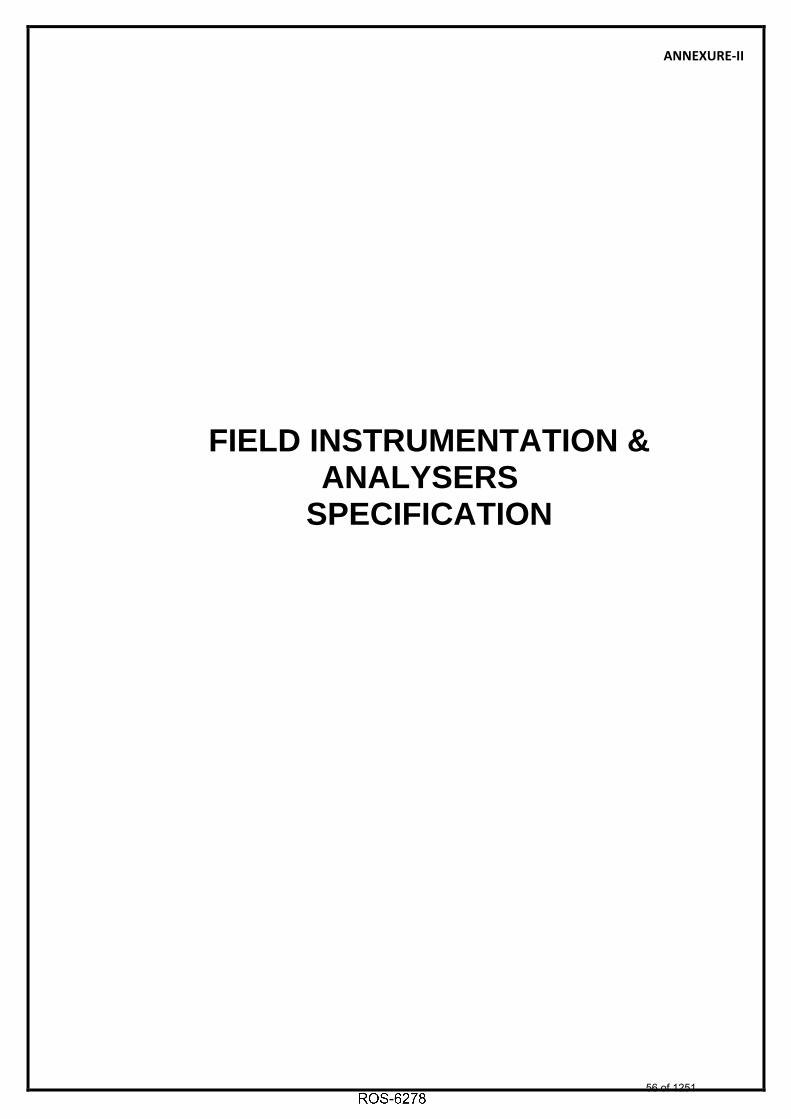
ANNEXURE-II
FIELD INSTRUMENTATION & ANALYSERS
SPECIFICATION
56 of 1251

Telangana State Power Generation Corporation Ltd. EPC Bid Document 1x800 MW Kothagudem TPS e-PCT/TS/K/02/2014-15
DEVELOPMENT CONSULTANTS V VI/S-VII/SS-A: 2(PCT-K-03-2013-14_V-VI_S VII_SS A.DOC)
1.00.00 SPECIFICATION FOR ELECTRONIC TRANSMITTERS
1.01.00 PRESSURE TRANSMITTER
1. Working Principle : Smart (HART Compatible)
2. Type : Microprocessor based, 2 – Wire
3. Output Signal : 4-20 mA DC along with superimposed digital signal
4. Measuring Element : Capsule / Diaphragm
5. Element material : SS-316 (Stainless Steel) or better
6. Static Pressure : 150 % of maximum span continuously, without affecting the calibration
7. Turn-down ratio : 100: 1
8. Span and Zero : Continuous, tamper proof, remote as well locally adjustable with zero elevation and suppression by 100% of span
9. Enclosure Class : IP-65 (Explosion proof for NEC Class-1, Division 1 area)
10. Output Indicator : LCD (Integral indicator of 5 digit display)
11. Nameplate : Tag number, service engraved in SS tag plate
12. Body : SS
13. Operating Voltage : 24V DC
14. Load : 600 Ohms (min.) at 24 Volts D.C.
15. Ambient Temperature : 0 - 50 OC
16. Performance:
:
i. Accuracy � 0.075% of Span or better
Dwg. No. PE-TS-411-145-I881A Page no. 36 of 118
57 of 1251

Telangana State Power Generation Corporation Ltd. EPC Bid Document 1x800 MW Kothagudem TPS e-PCT/TS/K/02/2014-15
DEVELOPMENT CONSULTANTS V VI/S-VII/SS-A: 3(PCT-K-03-2013-14_V-VI_S VII_SS A.DOC)
ii. Repeatability � 0.05% of Span or better
17. Sealing/Isolation : Extended diaphragm (Silicon oil/ Flurolub filled ) with 5 meters SS armoured capillary for corrosive/viscous/solid bearing or slurry type fluid applications
18. Accessories : a. Universal mounting bracket suitable for 2” pipe mounting
b. High tensile carbon steel U- bolts
c. Siphon for steam and hot water services
d. ½” NPT 2-valve stainless steel manifold, constructed from SS316 bar stock
e. Companion flange with nuts, bolts and gaskets
f. ½” NPT cable gland
g. Handheld calibrator
19. Adjustment/Calibration/ Maintenance
: From handheld calibrator/ HART management system
Notes: For primary air/ secondary air/ flue gas applications, DP type transmitters shall be provided for pressure measurement. LVDT type is not acceptable.
1.02.00 DIFFERENTIAL PRESSURE TRANSMITTER / FLOW TRANSMITTER
1. Working Principle : Smart (HART Compatible)
2. Type : Microprocessor based, 2 – Wire
3. Output Signal : 4-20 mA DC along with superimposed digital signal
4. Measuring Element : Capsule / Diaphragm
Dwg. No. PE-TS-411-145-I881A Page no. 37 of 118
58 of 1251

Telangana State Power Generation Corporation Ltd. EPC Bid Document 1x800 MW Kothagudem TPS e-PCT/TS/K/02/2014-15
DEVELOPMENT CONSULTANTS V VI/S-VII/SS-A: 4(PCT-K-03-2013-14_V-VI_S VII_SS A.DOC)
5. Element material : SS-316 (Stainless Steel) or better
6. Static Pressure : 150 % of maximum span continuously,
without affecting the calibration
7. Turn-down ratio : 100: 1
8. Span and Zero : Continuous, tamper proof, remote as well locally adjustable with zero elevation and suppression by 100% of span
9. Enclosure Class : IP-65 (Explosion proof for NEC Class-1, Division 1 area)
10. Output Indicator : LCD (Integral indicator of 5 digit display)
11. Nameplate : Tag number, service engraved in SS tag plate
12. Body : SS
13. Operating Voltage : 24V DC
14. Load : 600 Ohms (min.) at 24 Volts D.C.
15. Ambient Temperature : 0 - 50 OC
16. Performance:
i. Accuracy : � 0.075% of Span or better
ii. Repeatability : � 0.05% of Span or better
17. Sealing/Isolation : Extended diaphragm (Silicon oil/ Flurolub filled ) with 5 meters SS armoured capillary for corrosive/viscous/solid bearing or slurry type fluid applications
18. Accessories : a. Universal mounting bracket suitable for 2” pipe mounting
b. High tensile carbon steel U- bolts
Dwg. No. PE-TS-411-145-I881A Page no. 38 of 118
59 of 1251

Telangana State Power Generation Corporation Ltd. EPC Bid Document 1x800 MW Kothagudem TPS e-PCT/TS/K/02/2014-15
DEVELOPMENT CONSULTANTS V VI/S-VII/SS-A: 5(PCT-K-03-2013-14_V-VI_S VII_SS A.DOC)
c. Siphon for steam and hot water
services
d. ½” NPT 5-valve stainless steel manifold, constructed from SS316 bar stock
e. Companion flange with nuts, bolts and gaskets
f. ½” NPT cable gland
g. Handheld calibrator
19. Adjustment/Calibration/ Maintenance
: From handheld calibrator/ HART management system
1.03.00 Displacer Type Level Transmitters
1. Type : Smart (HART Compatible)
2. Stages of operation : Continuous
3. Material :
4. i. Displacer SS-316
5. ii. Suspension wire SS-316
6. iii. Torque tube housing
SS
7. iv. Torque tube Inconel
8. v. Displacer chamber
SS
9. vi. Transmitter Housing
SS
10. Operating Voltage : 24 V DC
11. Transmission : Microprocessor based, 2-wire
12. Output Signal : 4-20 mA DC along with superimposed digital signal
13. Static / overload : Maximum static pressure without
Dwg. No. PE-TS-411-145-I881A Page no. 39 of 118
60 of 1251

Telangana State Power Generation Corporation Ltd. EPC Bid Document 1x800 MW Kothagudem TPS e-PCT/TS/K/02/2014-15
DEVELOPMENT CONSULTANTS V VI/S-VII/SS-A: 6(PCT-K-03-2013-14_V-VI_S VII_SS A.DOC)
pressure permanent deformation or loss of accuracy
14. Turn-down ratio : 10 : 1 or better
15. Zero & Span : Continuous, tamper proof, remote as well locally adjustable with zero elevation and suppression by 100% of span
16. Enclosure Class : IP-65
17. Output Indicator : LCD type (Integral indicator of 5 digit display)
18. Nameplate : Tag number and Service engraved in stainless steel tag plate
19. Ambient Temperature : 0 - 50 OC
20. Load Impedance : 600 Ohms at 24 Volts (minimum)
21. Process Connection : 2” Flanged
22. Performance - Accuracy
: +_ 0.075 % of span or better
23. Accessories : a) Counter Flange, nuts, bolts, gaskets etc
b) Weights for 5 point calibration of instruments
c) Vent and drain plugs
d) ½” NPT Glands
e) Handheld calibrator
24. Preferred Features : a) Test plug connection and cutout terminals physically separated from other electronics
b) Electronic Damping facility (adjustable)
25. Adjustment/Calibration/ Maintenance
: From handheld calibrator/ HART management system
Dwg. No. PE-TS-411-145-I881A Page no. 40 of 118
61 of 1251

Telangana State Power Generation Corporation Ltd. EPC Bid Document 1x800 MW Kothagudem TPS e-PCT/TS/K/02/2014-15
DEVELOPMENT CONSULTANTS V VI/S-VII/SS-A: 7(PCT-K-03-2013-14_V-VI_S VII_SS A.DOC)
26. Applications : During detail engineering on Owner’s
approval 1.04.00 MASS FLOW METER
1.04.01 SENSOR
1. Measuring Principle : Coriolis Mass flow
2. Primary Element : Flow Tube of 316SS or better
3. Heating Arrangement : Integral
4. Temperature Control : For heavy fuel oil application
5. Process Connection : Flanged of rating as per process requirement
6. Drain : Self-draining facility
7. Enclosure : Stainless steel
8. Accessories : Counter flanges, Mounting nuts, bolts, gaskets etc.
1.04.02 TRANSMITTER
1. Measured quantities : Mass Flow rate, Total Mass Flow, Density
2. Input Signal Processing : Smart (HART compatible)
3. Display : LCD
4. Output : 2 nos. isolated output of 4-20mA DC selectable from four measured quantities
5. Load : < 750 ohms
6. Power supply : 240V AC, 50 Hz
Dwg. No. PE-TS-411-145-I881A Page no. 41 of 118
62 of 1251

Telangana State Power Generation Corporation Ltd. EPC Bid Document 1x800 MW Kothagudem TPS e-PCT/TS/K/02/2014-15
DEVELOPMENT CONSULTANTS V VI/S-VII/SS-A: 8(PCT-K-03-2013-14_V-VI_S VII_SS A.DOC)
7. Turn Down : 100:1
8. Accuracy : +_ 0.2 % of measured value
9. Housing : IP 65 (Explosion proof)
10. Nameplate : Tag number, service engraved in stainless steel tag plate
11. Accessories : a) Handheld calibrator
b) Mounting U-bolts, nuts, bolts, prefab cable etc
c) ½”NPT cable gland
12. Adjustment/Calibration//Maintenance
: From handheld calibrator/ HART management system
13. Applications : Fuel Oil service 1.05.00 RADAR TYPE LEVEL MEASUREMENT
1. Type : Smart (HART Compatible)
2. Antenna : Co axial / guided wave radar / Overspill protection
3. Principle : TDR (Time Domain Reflectometry) 4. Communication : Two wire 4-20mA DC with HART 5. Environmental
temperature : 0 – 50 ºC
6. Enclosure : IP-65 (Explosion proof for NEC Class-1, Division 1 area)
7. Calibration : a) Self calibration with internal reference
: b) Zero & Span calibration 8. Process Connection : External cage mounting
Flanged /screwed 9. Electronic Housing : Epoxy painted Die-Cast aluminium
Dwg. No. PE-TS-411-145-I881A Page no. 42 of 118
63 of 1251

Telangana State Power Generation Corporation Ltd. EPC Bid Document 1x800 MW Kothagudem TPS e-PCT/TS/K/02/2014-15
DEVELOPMENT CONSULTANTS V VI/S-VII/SS-A: 9(PCT-K-03-2013-14_V-VI_S VII_SS A.DOC)
alloy 10. Antenna / Flange
assembly : 316 SS or Hestalloy (as required)
11. Power supply : 24 V DC 12. Output Indicator : LCD 13. Accuracy : 5 mm or 0.1% of probe length 14. Accessories : a) Handheld
calibrator : b) Counter Flange,
nuts, bolts, gaskets etc
: c) ½”NPT cable gland : d) SS Nameplate 15. Adjustment/Calibration/
/Maintenance : From handheld calibrator/ HART
management system
16. Applications : Vessels under vacuum or low pressure applications, solid levels
1.06.00 ULTRASONIC LEVEL TRANSMITTER
1. Type : Microprocessor based, 2-wire, Smart (HART Compatible )
2. Operating Principle : Detection of reflected ultrasonic pulse
3. Output Signal : 4-20 mA DC along with superimposed digital signal
4. Operating frequency : 10 KHz to 50 KHz (typical)
5. Display : LCD
6. Temperature Compensation
: Built in –Programmable
7. Power supply : 24 V DC
8. Enclosure : SS, IP-65 (Explosion proof for NEC Class-1, Division 1 area)
Dwg. No. PE-TS-411-145-I881A Page no. 43 of 118
64 of 1251

Telangana State Power Generation Corporation Ltd. EPC Bid Document 1x800 MW Kothagudem TPS e-PCT/TS/K/02/2014-15
DEVELOPMENT CONSULTANTS V VI/S-VII/SS-A: 10 (PCT-K-03-2013-14_V-VI_S VII_SS A.DOC)
9. Zero & Span : Continuous, tamper proof, remote as
well locally adjustable. It shall be possible to calibrate the instrument without any level in the sump/ tank
10. Accuracy & Repeatability
: 0.15 % of span or better
11. Resolution : 0.1 % of span
12. Operating temp. : Transmitter- 500 C and Sensor - 800 C 13. MOC Sensor : SS-316/Body- PVC and Face –
Polyurethene
14. Mounting : 4” Flanged/ 2” NPT for sensor and Transmitter on panel
15. Accessories : a) Handheld calibrator
b) Weather canopy for protection from direct sunlight and direct rain
c) ½”NPT cable gland
d) All mounting hardware (SS-316), Prefab cable
e) SS Nameplate
16. Diagnosis : On-line
17. Status Indication : Power On, HI, HI-HI, Lo, LO-LO, Fault
18. Output Contacts : 2 SPDT, 230V, 5A
19. Adjustment/Calibration//Maintenance
: From handheld calibrator/ HART management system
20. Applications : Coal Bunker, Water Service etc.
Dwg. No. PE-TS-411-145-I881A Page no. 44 of 118
65 of 1251
Telangana State Power Generation Corporation Ltd. EPC Bid Document 1x800 MW Kothagudem TPS e-PCT/TS/K/02/2014-15
DEVELOPMENT CONSULTANTS V VI/S-VII/SS-A: 11 (PCT-K-03-2013-14_V-VI_S VII_SS A.DOC)
1.07.00 ULTRASONIC FLOW TRANSMITTER
1. Type : Ultrasonic – Clamp On
2. Accuracy : +/- 1 % of reading
3. Repeatability : +/- 0.3 % of reading
4. Rangeability : 400 : 1
5. Output Signal : 4-20 mA DC with HART
6. Measured Parameter : Volumetric flow, Totalized flow and flow Velocity
7. Display : LCD with internal Key Pad (Flow rate & Totalization)
8. Power Supply : 24 V DC (2 Wire)
9. Enclosure : SS (IP- 68 – Submersible)
10. Mounting : SS Chain or Strap
11. Accessories 1. Handheld calibrator
2. ½”NPT cable gland
3. Transducer cable
4. All mounting hardware (SS-316)
5. SS Nameplate
12. Adjustment/Calibration//Maintenance
: From handheld calibrator/ HART management system
13. Applications : Plant water service
Note: Multi-path insertion type (minimum 4 path) Ultrasonic Flow meter shall be provided for Raw water/ Cooling Water flow measurements.
2.00.00 HART HAND HELD CALIBRATOR
Hand held calibrators (5 nos. for each type) shall be provided for adjustment/ calibration/maintenance of the HART compatible
Dwg. No. PE-TS-411-145-I881A Page no. 45 of 118
66 of 1251
6101968
Rectangle
6101968
Typewriter
2

Telangana State Power Generation Corporation Ltd. EPC Bid Document 1x800 MW Kothagudem TPS e-PCT/TS/K/02/2014-15
DEVELOPMENT CONSULTANTS V VI/S-VII/SS-A: 12 (PCT-K-03-2013-14_V-VI_S VII_SS A.DOC)
transmitters. The hand held calibrator shall be suitable for all types of transmitters supplied in the package. If one type of hand held type calibrator is not suitable for communicating with all types of transmitters then separate hand held calibrator will be provided.
3.00.00 PROCESS ACTUATED SWITCHES
3.01.00 PRESSURE SWITCH
1. Type : i. Piston for high pressure
application
ii. Bellow / Diaphragm for low
pressure application
2. Sensing element
material
: SS-316.
All other wetted part SS316
3. Case Material : SSt
4. Setter Scale : Black graduation on white linear scale.
Graduation 0-100% with red pointer for
set points
5. Over range : 150 % of maximum pressure
6. Adjustments : a) Internal Set Point
: b) Differential adjustment
7. End Connection : 1/2" NPT bottom connected
8. Switch configuration : Two SPDT (240V, 5A AC/220V, 0.5A
DC)
9. Switch Type : Snap acting, shock & vibration proof
10. Terminal Block : Suitable for full ring lugs
11. Enclosure Class : IP-65 (Explosion proof for NEC Class-1,
Division 1 area)
12. Performance : a) Repeat accuracy � 1.0%
: b) Accuracy of Setting Indication of
+ 1.5%
13. Ambient temperature : 0 – 50 Deg.C
Dwg. No. PE-TS-411-145-I881A Page no. 46 of 118
67 of 1251

Telangana State Power Generation Corporation Ltd. EPC Bid Document 1x800 MW Kothagudem TPS e-PCT/TS/K/02/2014-15
DEVELOPMENT CONSULTANTS V VI/S-VII/SS-A: 13 (PCT-K-03-2013-14_V-VI_S VII_SS A.DOC)
14. Nameplate : Tag number, service engraved in SS tag
plate
15. Accessories : a) Silicon oil/ Flurolub filled
Remote diaphragm seal with
SS-316 capillary for corrosive/
viscous/ solid bearing or slurry
type fluid applications
b) Snubbers for pulsating fluid
applications
c) Siphons for steam and hot water
services
d) Retention ring and screws for
surface mounting
e) 1/2” NPT 2 Valve SS-316
barstock manifold
f) ½” NPT cable gland
16. Applications : During Detail Engineering on Owner’s
approval
3.02.00 DIFFERENTIAL PRESSURE SWITCH
1. Type : i. Piston for high pressure
application
ii. Bellow / Diaphragm for low
pressure application
2. Sensing element
material
: SS-316.
All other wetted part SS316
3. Case Material : SS
4. Setter Scale : Black graduation on white linear scale.
Graduation 0-100% with red pointer for
set points
5. Over range : 150 % of maximum pressure
Dwg. No. PE-TS-411-145-I881A Page no. 47 of 118
68 of 1251
6238467
Rectangle
6238467
Typewriter
DELETED

Telangana State Power Generation Corporation Ltd. EPC Bid Document 1x800 MW Kothagudem TPS e-PCT/TS/K/02/2014-15
DEVELOPMENT CONSULTANTS V VI/S-VII/SS-A: 14 (PCT-K-03-2013-14_V-VI_S VII_SS A.DOC)
6. Adjustments : a) Internal Set Point
: b) Differential adjustment
7. End Connection : 1/2" NPT bottom/ back connected
8. Switch configuration : Two SPDT (240V, 5A AC/220V, 0.5A
DC)
9. Switch Type : Snap acting, shock & vibration proof
10. Terminal Block : Suitable for full ring lugs
11. Enclosure Class : IP-65 (Explosion proof for NEC Class-1,
Division 1 area)
12. Performance : a) Repeat accuracy � 1.0%
b) Accuracy of Setting Indication of
+ 1.5%
13. Ambient temperature : 0 – 50 Deg.C
14. Nameplate : Tag number, service engraved in SS tag
plate
15. Accessories : a) Silicon oil/ Flurolub filled
Remote diaphragm seal with
SS-316 capillary Diaphragm
seals for corrosive/ viscous/
solid bearing or slurry type fluid
applications
b) Snubbers for pulsating fluid
applications
c) Siphons for steam and hot water
services
d) Retention ring and screws for
surface mounting
e) 1/2” NPT 5 Valve SS-316
barstock manifold
f) ½” NPT cable gland
16. Applications : During Detail Engineering on Owner’s
Dwg. No. PE-TS-411-145-I881A Page no. 48 of 118
69 of 1251
6238467
Rectangle

Telangana State Power Generation Corporation Ltd. EPC Bid Document 1x800 MW Kothagudem TPS e-PCT/TS/K/02/2014-15
DEVELOPMENT CONSULTANTS V VI/S-VII/SS-A: 15 (PCT-K-03-2013-14_V-VI_S VII_SS A.DOC)
approval
3.03.00 LEVEL SWITCH
3.03.01 FLOAT OPERATED
1. Float material : SS-316
2. Wetted parts : SS-316
3. Float chamber : Stainless steel/Carbon steel,
construction welded
4. Float chamber
mounting
: Side mounted
5. Fluid connection : Side – Side
6. Fluid connection size : 1” ANSI RF Flange (rubber line, if
required)
7. Drain : ½ inch NPT with Plug
8. Pressure rating of
chamber
: Minimum 1.5 times of design pressure
9. Repeatability : +/- 1.5 mm or better
10. Switch housing : Stainless Steel
11. Switch housing type : IP- 65
12. Type of switch : Snap acting magnetically operated
hermetically sealed
13. Switch configuration : 2 SPDT (5A, 240 V AC, 0.5A, 220V DC)
14. Accessories : a) Counter flange, nuts
& bolts, suitable
gasket etc.
b) Steel globe type
drain valve
c) ½”NPT cable gland
Dwg. No. PE-TS-411-145-I881A Page no. 49 of 118
70 of 1251
6238467
Rectangle
6238467
Typewriter
DELETED
6238467
Typewriter
DELETED

Telangana State Power Generation Corporation Ltd. EPC Bid Document 1x800 MW Kothagudem TPS e-PCT/TS/K/02/2014-15
DEVELOPMENT CONSULTANTS V VI/S-VII/SS-A: 16 (PCT-K-03-2013-14_V-VI_S VII_SS A.DOC)
d) Stainless steel
nameplate with
alpha-numeric
engraved for service
and tag
15. Application : During Detail Engineering on Owner’s
approval
3.04.00 FLOW SWITCH
1. Type : Paddle /Piston/Disk
2. Wetted part material : Stainless steel or Hastelloy for acidic
application
3. End connection : a) Threaded upto 1” line size with
integral Tee
: b) Flanged for line size > 1 ½”
4. Enclosure material : Stainless Steel
5. Enclosure class : IP 65
6. Switch configuration : 2 SPDT (5A, 240 V AC, 0.5A, 220V DC)
7. Repeatibility : 2%
8. Cable connection : ½”NPTF
9. Accessories : a) Tee, Counter flange, nuts &
bolts, suitable gasket etc
b) ½”NPT cable gland
c) Stainless steel nameplate with
alpha-numeric engraved for
service and tag
3.05.00 RF LEVEL SWITCH
Dwg. No. PE-TS-411-145-I881A Page no. 50 of 118
71 of 1251
6238467
Rectangle
6238467
Rectangle
6238467
Typewriter
DELETED

Telangana State Power Generation Corporation Ltd. EPC Bid Document 1x800 MW Kothagudem TPS e-PCT/TS/K/02/2014-15
DEVELOPMENT CONSULTANTS V VI/S-VII/SS-A: 17 (PCT-K-03-2013-14_V-VI_S VII_SS A.DOC)
1. Type : RADIO FREQUENCY
Sensing probe
2. Material : SS-316
3. Mounting : Threaded
4. Application
Temperature : 250°C (Max.)
Electronic Controller
5. Input Supply Voltage : 240V AC ±10%, 50 Hz.
6. Relay Output : 2 SPDT (240V AC, 5A)
7. Ambient Temperature : 50 °C
8. Enclosure Protection : IP-66
9. Enclosure Housing : SS
10. Local LED Indication :
Normal Level
Power On
Alarm Level
Probe Healthy
11. Switching Repeatability : ±0.5%
12. Accessories :
Co-axial cable for probe connection to
controller
SS Tag plate
½” NPT Cable Glands
13. Application : Solid level
3.06.00 CONDUCTIVITY TYPE LEVEL SWITCH
1. Type : Conductivity discrimination
2. Probe MOC : SS-316
3. Mounting : Flanged on external cage
4. Application
Temperature : 250°C (Max.)
5. Test Pressure : Two times rated pressure
Dwg. No. PE-TS-411-145-I881A Page no. 51 of 118
72 of 1251
6238467
Rectangle
6238467
Typewriter
DELETED

Telangana State Power Generation Corporation Ltd. EPC Bid Document 1x800 MW Kothagudem TPS e-PCT/TS/K/02/2014-15
DEVELOPMENT CONSULTANTS V VI/S-VII/SS-A: 18 (PCT-K-03-2013-14_V-VI_S VII_SS A.DOC)
6. Input Supply Voltage : 240V AC ±10%, 50 Hz.
7. Input :
Four independent channel with
selectable switching threshold for water
conductivity
8. Relay Output : 2 SPDT (240V AC, 5A)
9. Ambient Temperature : 50 °C
10. Enclosure Protection : IP-65 (Explosion proof for NEC Class-1,
Division-1 area)
11. Enclosure Housing : SS
12. Local LED Indication :
HI,LO, HIGH-HIGH, LOW-LOW
Power
Fault
13. Accessories : a)Interconnecting cable from
probe to electronics
b) Mounting accessories
c) External cage
d) Washer & Gasket
e) ½” NPT Cable Glands
f) SS Tag Plate
14. Application : During Detail Engineering on Owner’s
approval
3.07.00 TEMPERATURE SWITCH
1. Type : Bimetallic or gas filled
2. Sensing Element
Material
: SS-316
3. Bulb Material : SS-316
4. Capillary : Stainless Steel armored
Dwg. No. PE-TS-411-145-I881A Page no. 52 of 118
73 of 1251
6238467
Rectangle
6238467
Typewriter
DELETED

Telangana State Power Generation Corporation Ltd. EPC Bid Document 1x800 MW Kothagudem TPS e-PCT/TS/K/02/2014-15
DEVELOPMENT CONSULTANTS V VI/S-VII/SS-A: 19 (PCT-K-03-2013-14_V-VI_S VII_SS A.DOC)
5. Movement Material : Stainless Steel
6. Case material : Stainless Steel with neoprene gasket
and clear glass where applicable cover
conforming to IP-65. (Explosion proof
for NEC Class-1, Division 1 area).
7.. Scale : Black graduation on white linear scale.
Graduation 0-100% with red pointer for
set points
8. Over range Protection : 120 %
9. Instrument connection : Bottom
10. Switch configuration : Two SPDT (240V, 5A AC/220V, 0.5A
DC)
11. Switch type : Snap acting, shock and vibration-proof
12. Adjustability : Internal Set point adjustable over span
range
13. Compensation : a) Capillary compensation with
invar wire throughout the
capillary length
b) Case compensation
14. Performance
a) Scale Accuracy : �1.0 % of full scale
b) Repeatability : < 0.5 % of full range
c) Response time : Less than 40 seconds with thermowell
15. Capillary length : 5 meters (minimum) for local
mounting/15 meters for local panel
mounting
16. Nameplate : Tag number, service engraved in
stainless steel tag plate
17. Accessories : Mounting accessories, ½” NPT cable
gland
18. Applications : During Detail Engineering on Owner’s
Dwg. No. PE-TS-411-145-I881A Page no. 53 of 118
74 of 1251
6238467
Rectangle

Telangana State Power Generation Corporation Ltd. EPC Bid Document 1x800 MW Kothagudem TPS e-PCT/TS/K/02/2014-15
DEVELOPMENT CONSULTANTS V VI/S-VII/SS-A: 20 (PCT-K-03-2013-14_V-VI_S VII_SS A.DOC)
approval
4.00.00 LOCAL INSTRUMENTS 4.01.00 PRESSURE GAUGE AND DIFFERENTIAL PRESSURE GAUGE
1. Type : Bourdon/Bellows/Diaphragm
2. Sensing & Socket : SS-316
3. Movement Material : SS-316
4. Case Material : Stainless steel. IP-65 (Explosion proof
for NEC Class-1, Division 1 area)
5. Dial Size : Generally 150 mm
6. Scale : Black lettering on white in 270 O arc.
7. Window : Shatterproof glass
8. Range Selection : Normal process pressure: 50~70 % of
range
9. Over-range Protection : 125% of maximum range by internal
stop. External stop at zero
10. Adjustment :
For Zero adjustment (Micrometer screw
external)
For Range adjustment (Micrometer
screw internal).
11. Element Connection : Argon welding
12. Process Connection : 1/2" NPT (M) Bottom for local, back for
panel mounting
13. Performance : Accuracy of � 1.0 % of span or better
14. Operating ambient : 0 - 50 OC
15. Safety Feature : Blow out disc /diaphragm at the back
16. Accessories : a)Snubbers for pulsating fluid
application.discharge
b) Stainless steel Diaphragm seals
Dwg. No. PE-TS-411-145-I881A Page no. 54 of 118
75 of 1251

Telangana State Power Generation Corporation Ltd. EPC Bid Document 1x800 MW Kothagudem TPS e-PCT/TS/K/02/2014-15
DEVELOPMENT CONSULTANTS V VI/S-VII/SS-A: 21 (PCT-K-03-2013-14_V-VI_S VII_SS A.DOC)
for corrosive/ viscous/ solid
bearing or slurry type fluid
applications
c)3-Way SS316 Gauge cock for
pressure gauges
d)
5-valve SS316 manifold from
barstock for differential pressure
gauge
e)Siphons for steam and hot
water services
17. Nameplate : Tag number, service engraved in
stainless steel tag plate
4.02.00 LEVEL INDICATOR (FLOAT & BOARD TYPE)
1. Type : Float and Board
2. Float Material : SS-316
3. Float Cable : SS-316
4. Indicator Assembly : Epoxy painted Aluminium
5. Guide wire spring
assembly :
SS-316 (2 Nos.)
6. Guide Wire Anchor : SS-316
7. Scale Board :
Anodized Aluminium with engraved
marking ( Minimum graduation 10mm),
mounting brackets and suitable
hardware required as per tank height
8. Elbow Assembly : Anodized Aluminium
9. Flanges : RF , ANSI 150 , SS (3 Nos.)
10. Accuracy : + 10 mm or better
11. Accessories : All mounting accessories including
counter flange, nuts & bolts, suitable
Dwg. No. PE-TS-411-145-I881A Page no. 55 of 118
76 of 1251

Telangana State Power Generation Corporation Ltd. EPC Bid Document 1x800 MW Kothagudem TPS e-PCT/TS/K/02/2014-15
DEVELOPMENT CONSULTANTS V VI/S-VII/SS-A: 22 (PCT-K-03-2013-14_V-VI_S VII_SS A.DOC)
gasket etc. as applicable, SS Tag plate
4.03.00 GAUGE GLASS
1. Type : Reflex /Transparent
2. Material
Glass : Toughened borosilicate resistant to
thermal shock
Body Material : Carbon Steel Stainless Steel
Enclosure : IP-65 (Explosion proof for NEC Class-1,
Division 1 area)
3. Integral cocks &
valves/Fittings : i. SS 316
4. : ii.
Rubber lined corrosion resistant
stainless steel (for DM/RO
service)
5. Vessel Connection : ANSI Flanged SS316
6. Accessories : i. Integral cocks
ii. Drain Valves
iii.Companion Flanges, Bolts, nuts,
gaskets, SS Tag plate
iv.Illuminating lamps, Mica shield as
required
v. Calibrated scale
7. Pressure rating : Twice the maximum working pressure
8. Temperature : 300 O C
9. Other details :
For larger lengths (greater than
1200mm), additional gauge glasses
shall be provided with minimum of 50
mm overlap.
Dwg. No. PE-TS-411-145-I881A Page no. 56 of 118
77 of 1251

Telangana State Power Generation Corporation Ltd. EPC Bid Document 1x800 MW Kothagudem TPS e-PCT/TS/K/02/2014-15
DEVELOPMENT CONSULTANTS V VI/S-VII/SS-A: 23 (PCT-K-03-2013-14_V-VI_S VII_SS A.DOC)
4.04.00 SLIGHT GLASS
1. Type : Flap-type.
2. End connection : Screwed / Flanged
3. Material
a) Body : SS- 304
b) Cover plate : SS- 304
c) Indicator : SS- 316
4. Sight Glass : Toughened Borosilicate
5. Gasket : Neoprene
6. Bolts & Nuts : High tensile steel.
7. Hydraulic Test
Pressure : 1.5 times maximum working pressure
8. Accessories : Companion Flanges, Bolts, nuts,
gaskets as required, SS Tag plate.
4.05.00 ROTAMETER
1. Type
:
ON-LINE for line upto and including 50
mm NB.
Borosilicate BY-PASS for line size
above 50 NB
2. Metering tube : Toughened Borosilicate
3. Float : SS-316
4. End fittings : SS-316
5. Packing material : Teflon / PTFE
6. Casing : Stainless Steel
7. Gland Rings
/Followers/ Other
wetted parts
: Stainless Steel
8. Orifice Plate : Stainless Steel (for bypass type)
9. Operating
Temperature : 0-50 Deg. c
Dwg. No. PE-TS-411-145-I881A Page no. 57 of 118
78 of 1251

Telangana State Power Generation Corporation Ltd. EPC Bid Document 1x800 MW Kothagudem TPS e-PCT/TS/K/02/2014-15
DEVELOPMENT CONSULTANTS V VI/S-VII/SS-A: 24 (PCT-K-03-2013-14_V-VI_S VII_SS A.DOC)
10. Test Pressure : 200% of maximum operating pressure
11. Scale : 250 mm nominal length
12. Graduation : Direct reading
13. Process Connection :
Flanged (RF) to line size as per ANSI
standards (150#)
14. Tapping : D & D/2
15. Accuracy : +/- 2% of full scale reading
16. Reproducibility : Within 0.5% of instantaneous reading
17. Accessories : SS Tag Plate, orifice plate
5.00.00 TEMPERATURE ELEMENTS & ACCESSORIES
5.01.00 RESISTANCE TEMPERATURE DETECTOR
1. Type : Platinum (Duplex), Ungrounded
2. Platinum (Duplex),
Ungrounded : 100 ohm at 0 OC
3. Base : Wound on ceramic (anti-inductive)
4. Wiring : 3 Wire
5. Protecting Tube
a) O.D. : 6 mm
b) Material : SS-316, Seamless
c) Filling : Magnesium oxide (Purity above 99.4%).
6. Response time : a) 15 sec. (bare).
b) 30 sec. (with thermowell)
7. Calibration : DIN 43760
8. Accuracy : � 0.5%
9. Head
a) Type : IP-65 universal screwed type
Dwg. No. PE-TS-411-145-I881A Page no. 58 of 118
79 of 1251

Telangana State Power Generation Corporation Ltd. EPC Bid Document 1x800 MW Kothagudem TPS e-PCT/TS/K/02/2014-15
DEVELOPMENT CONSULTANTS V VI/S-VII/SS-A: 25 (PCT-K-03-2013-14_V-VI_S VII_SS A.DOC)
b) Material : Stainless Steel
c) Terminal
blocks :
Nickel plated Brass-screw type / silver
plated
d) Cable
connection : ½” NPT gland and grommet
e) Others : Terminal head cover with SS chain and
suitable gasket.
Head of TE to be provided with sufficient
space and arrangement to mount head
mounted temperature transmitter (as
applicable).
10. Accessories : a)
Adjustable nipple-union-nipple
[1/2” Sch 80 X ½” NPT] with
thermowell connection
b)
Compression fittings/unions
c)
Flanges etc. (for flanged
connections only)
d)
Thermowell (As specified
below)
11. Thermowell
connection : ½” NPT (M) or 150 RF Flanged
12. Nameplate :
Tag number, service engraved in
stainless steel tag plate
Dwg. No. PE-TS-411-145-I881A Page no. 59 of 118
80 of 1251

Telangana State Power Generation Corporation Ltd. EPC Bid Document 1x800 MW Kothagudem TPS e-PCT/TS/K/02/2014-15
DEVELOPMENT CONSULTANTS V VI/S-VII/SS-A: 26 (PCT-K-03-2013-14_V-VI_S VII_SS A.DOC)
Note: The specifications for RTDs of winding/ bearing of motor/pump, can be as per their manufacturer standards. The manufacturer shall submit the adequate supporting documents for establishing their standard practice. However, the type of RTD shall be Pt-100.
5.02.00 THERMOCOUPLES
1. Type :
a) 16 SWG wire of Chromel
Alumel) (Type-K)
b) Duplex
c) Ungrounded
2. Protecting Tube
a) O.D. : 6 mm
b) Material : SS-316, Seamless
c) Filling : Magnesium oxide (Purity above 99.4%).
3. Response time : a) < 20 seconds for measurement
b) < 10 seconds for control
4.
Accuracy :
� 1.10 C up to 300 0 C & 0.4% of
measured temperature range above 300 0 C
5. Head
a) Type :
IP-65 universal screwed type
b) Material :
Stainless Steel
c)
Terminal
blocks :
Nickel plated Brass-screw type / silver
plated
d)
Cable
connection :
½” NPT gland and grommet
6. e) Others :
Terminal head cover with SS chain and
suitable gasket.
Dwg. No. PE-TS-411-145-I881A Page no. 60 of 118
81 of 1251

Telangana State Power Generation Corporation Ltd. EPC Bid Document 1x800 MW Kothagudem TPS e-PCT/TS/K/02/2014-15
DEVELOPMENT CONSULTANTS V VI/S-VII/SS-A: 27 (PCT-K-03-2013-14_V-VI_S VII_SS A.DOC)
Head of TE to be provided with sufficient
space and arrangement to mount head
mounted temperature transmitter (as
applicable).
7.
Accessories :
a) Adjustable nipple-union-nipple
[1/2” Sch 80 X ½” NPT] with
thermowell connection
b) Compression fittings/unions
c) Flanges etc. (for flanged
connections only)
d) Thermowell (As specified
below)
8. Thermowell connection : ½” NPT (M) or 150 RF Flanged
9. Nameplate :
Tag number, service engraved in
stainless steel tag plate
5.03.00 TEMPERATURE GAUGE
1. Type : Expansion type (Liquid filled system)
2. Sensing Element
Material : Bourdon – SS-316
3. Bulb and Capillary
Material : SS-316
4. Capillary Tubing :
Inner sheath - solid drawn Material
copper tube
Outer sheath - PVC tube
5. Movement Materials : Stainless Steel / Direct Bourdon tip
connection to pointer spindle
6. Case Material : Stainless Steel stove enameled, black
finish, threaded bezel ring, clear glass
Dwg. No. PE-TS-411-145-I881A Page no. 61 of 118
82 of 1251

Telangana State Power Generation Corporation Ltd. EPC Bid Document 1x800 MW Kothagudem TPS e-PCT/TS/K/02/2014-15
DEVELOPMENT CONSULTANTS V VI/S-VII/SS-A: 28 (PCT-K-03-2013-14_V-VI_S VII_SS A.DOC)
cover conforming to IP 65.
7. Dial size : 150 mm
8. Scale : Black lettering on white background in
270 Deg.C arc
9. Over range protection : 125 percent of FSD
10. Capillary Glanding : 1/2” NPT(M) x compression fitting (SS)
to suit capillary
11. Instrument Connection : Bottom connection for local mounting,
back connection for panel mounting
12. Process Connection : ½” NPT (M) or 150 RF Flanged
13. Extension Neck Length : 50 mm
14. Compensation : a) Capillary compensation
15. : b) Case compensation
16. Performance : a)Accuracy : + /- 1.0 percent of
full scale Deflection
: b)Repeatability : Less than 0.5
percent of full range
: c)Response time: 15 seconds
(max.).
17. Capillary length : 3.0 meters (local) / 15.0 metres (local
panel)
18. Other features : Shatter proof glass
19. Nameplate : Tag number, service engraved in
stainless steel tag plate
20. Accessories : SS316 Thermowell
5.04.00 THERMOWELL
1. Material : SS-316
2. Manufacture : Drilled from bar stock, Hex Head,
Tapered design (As per ASME PTC
19.3)
Dwg. No. PE-TS-411-145-I881A Page no. 62 of 118
83 of 1251

Telangana State Power Generation Corporation Ltd. EPC Bid Document 1x800 MW Kothagudem TPS e-PCT/TS/K/02/2014-15
DEVELOPMENT CONSULTANTS V VI/S-VII/SS-A: 29 (PCT-K-03-2013-14_V-VI_S VII_SS A.DOC)
3. Process connection : M33x2
4. Certification : Not applicable
5. Bore concentricity : +5% of wall thickness
6. Identification mark : Tag number punched on head
7. Surface treatment : Polish after machining
8. Element connection : ½” NPT (M) or 150 RF Flanged
9. Head : Hex
10. Length of the hex head : 31.75 mm (min.)
11. Accessories : SS Plug and chain for test thermo wells
SS Nameplate, Flange with companion
flange & all required accessories for
flanged connections.
Note: Wake frequency calculations shall be furnished for all thermowells for approval.
Thermowells shall be designed such that the resonant frequency is above the exciting frequencies generated by vortex shedding in the process fluid.
5.05.00 METAL TEMPERATURE THERMOCOUPLE
1. Measuring medium : Metal temperature
2. Type : Chromel Alumel (Type-K)
Duplex, Ungrounded
3. Insulation : Mineral Insulation Magnesium Oxide
4. Wire gauge : 16 AWG
5. Protective sheath : SS
6. Protective sheath
diameter
:8 mm O.D.
7. Characteristics : Special limits of error as in ANSI
thermocouple MC 96.01
8. Accessories : ½” BSP SS sliding end connector, weld
pad, clamps of heat resistant steel
Dwg. No. PE-TS-411-145-I881A Page no. 63 of 118
84 of 1251

Telangana State Power Generation Corporation Ltd. EPC Bid Document 1x800 MW Kothagudem TPS e-PCT/TS/K/02/2014-15
DEVELOPMENT CONSULTANTS V VI/S-VII/SS-A: 42 (PCT-K-03-2013-14_V-VI_S VII_SS A.DOC)
1. Type : Hydrometer Type
2. Mounting : On line
3. Accuracy : +/- 2% of range
4. Scale : Black letter on white scale
5. End connection : PVC flange
9.06.00 DENSITY/ CONCENTRATION METER
1. Wetted Part Stainless Steel
2. Enclosure Stainless Steel (IP-65)
3. Power Supply 24 V DC
4. Output signal : 4-20 mA DC (isolated) into 600 ohms
5. Accuracy ±0.001 g/cc
6. Indication : LCD display
7. Temp. Compensation : Integral
8. Accessories Mounting hardware, integral amplifier
(if required), cable glands, tag plate
etc.
10.00.00 SOLENOID VALVES
1. Operating Principle : Electromagnetic (noiseless)
2. Coil voltage rating : 240 V AC /24 V DC (as required)
3. Ways : 2/3/4 way
4. Port size : 1/4" NPT all ports
5. Body : SS bar stock
Trim : SS-316
6. Duty : Suitable for continuous energization
7. Sealing : Airtight and leak proof
8. Ambient Temperature : 0 - 50 O C
Dwg. No. PE-TS-411-145-I881A Page no. 64 of 118
85 of 1251
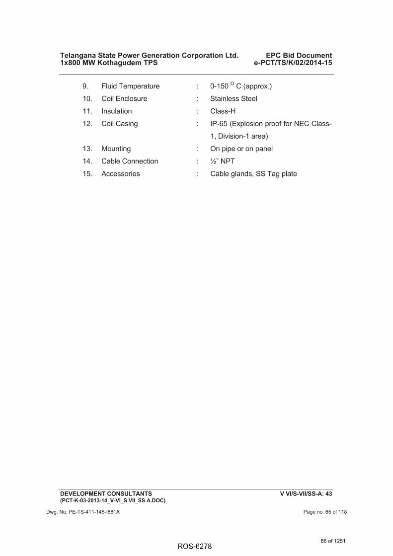
Telangana State Power Generation Corporation Ltd. EPC Bid Document 1x800 MW Kothagudem TPS e-PCT/TS/K/02/2014-15
DEVELOPMENT CONSULTANTS V VI/S-VII/SS-A: 43 (PCT-K-03-2013-14_V-VI_S VII_SS A.DOC)
9. Fluid Temperature : 0-150 O C (approx.)
10. Coil Enclosure : Stainless Steel
11. Insulation : Class-H
12. Coil Casing : IP-65 (Explosion proof for NEC Class-
1, Division-1 area)
13. Mounting : On pipe or on panel
14. Cable Connection : ½” NPT
15. Accessories : Cable glands, SS Tag plate
Dwg. No. PE-TS-411-145-I881A Page no. 65 of 118
86 of 1251

Telangana State Power Generation Corporation Ltd. EPC Bid Document 1x800 MW Kothagudem TPS e-PCT/TS/K/02/2014-15
DEVELOPMENT CONSULTANTS V VI/S-VI/SS-M: 8 (e-PCT-TS-K-02-2014-15_V-VI_S VI_SS M.DOC)
5.01.00 Alarms shall be available in the local monitor in the dry room for each unit covering the entire SWAS system, with repeat facility in DDCMIS.
6.00.00 ANALYZERS
All Analyzers shall be of microprocessor based design. The general technical specification of the analyzers is provided in this section. Bidder in his offer shall indicate the sample flow requirement of each analyzer and the total quantity of cooling water required for the system.
6.01.00 CONDUCTIVITY ANALYZER
A. Sensor
1. Type of Cell : Flow thru’
2. Conductivity Range : As per process
3. Cell Constant : 0.01 / 0.1 / 1.0 depeding upon range
4. Temp. Compensation : Manual and Automatic (Integral) 0-100°C
5. Process Connection : Screwed
6. Wetted Parts : Electrodes-SS 316L/ Insulators KYNAR/ Viton
7. Pressure Rating : 10 kg/cm2
8. Accessories : Vessel (SS 316) with ½” NPT connection
9. Cable : Upto transmitter in flexible conduct
B. Transmitter
1. Type : Microprocessor based, Single stream
2. Mounting : 2” pipe
3. Protection Class : IP-65 or better
4. Output : 4-20 mA DC (isolated)
5. Display : Digital Display in Engineering Unit, Alarm Status.
6. Zero/Span Adjustment : Front Panel Membrane type Keyboard
87 of 1251
6238467
Rectangle
6238467
Typewriter
DELETED

Telangana State Power Generation Corporation Ltd. EPC Bid Document 1x800 MW Kothagudem TPS e-PCT/TS/K/02/2014-15
DEVELOPMENT CONSULTANTS V VI/S-VI/SS-M: 9 (e-PCT-TS-K-02-2014-15_V-VI_S VI_SS M.DOC)
7. Temp. Compensation : Automatic
8. Diagnostic : Self diagnostic for electronics, electrode etc
9. Alarm : Dual set point, hysterisis and time delay adjustable
10. Enclosure : Die cast aluminum, epoxy coated
11. Cable Termination : Internal (cable entry through conduit)
12. Accuracy : ± 1.0 % of measured range
13. Response time : Less than 5 sec
14. Stability : ± 1.0 % of output range / month non-cumulative
15. Accessories : a.2” pipe mounting bracket, Sensor cable with flexible conduit ( as required), ½” NPT Cable Gland, SS Tag plate, For cation conductivity- Dual Ion-Exchange column, resin, etc. (minimum 12 months’ requirements).
b.Retractable type conductivity sensor along with flow chamber and other accessories shall be provided for vacuum application. Transmitter (local) along with 4-20 Ma output to SWAS room & DDCMIS shall also be provided.
6.02.00 pH ANANYER
A. Sensor
1. Type of Cell : Flow thru’
2. Range : 0-14 pH
3. Type of measurement : Combination electrode
4. Temp. Compensation : Manual and Automatic (Integral) 0-100°C
5. Process Connection : Screwed
88 of 1251

Telangana State Power Generation Corporation Ltd. EPC Bid Document 1x800 MW Kothagudem TPS e-PCT/TS/K/02/2014-15
DEVELOPMENT CONSULTANTS V VI/S-VI/SS-M: 10 (e-PCT-TS-K-02-2014-15_V-VI_S VI_SS M.DOC)
6. Measuring Electrode : Glass, high independence, thin electrode in one housing
7. Pressure Rating : 10 kg/cm2
8. Accessories : Vessel (SS 316) with ½” NPT connection
9. Cable : Upto transmitter in flexible conduct
10. Preamplifier : Integral or separate
11. Liquid Junction : Ceramic / Kyner or equivalent
B. Transmitter
1. Type : Microprocessor based, Single stream
2. Mounting : 2” pipe
3. Protection Class : IP-65 or better
4. Output : 4-20 mA DC (isolated)
5. Display : Digital Display in Engineering Unit, Alarm Status.
6. Accuracy : ± 0.2% of FSD or better
7. Response time : Less than 5 sec
8. Stability : ± 0.001 pH /week
9. Repeatability : ± 1% or better
10. Temp. Compensation : Automatic (Pt-100 sensor)
11. Diagnostic : Self diagnostic for “Calibration requried”/ “Calibration O.K.”, electrode checking etc.
12. Alarm : Dual set point, hysterisis and time delay adjustable
13. Enclosure : Die cast aluminum, epoxy coated
14. Cable Termination : Internal (cable entry through conduit)
15. Accessories : 2” pipe mounting bracket, Sensor cable
89 of 1251

Telangana State Power Generation Corporation Ltd. EPC Bid Document 1x800 MW Kothagudem TPS e-PCT/TS/K/02/2014-15
DEVELOPMENT CONSULTANTS V VI/S-VI/SS-M: 11 (e-PCT-TS-K-02-2014-15_V-VI_S VI_SS M.DOC)
with flexible conduit ( as required), ½” NPT Cable Gland, SS Tag plate, , Ultrasonic Electrode Cleaner, Buffer solution tablets
6.03.00 SILICA ANALYZER
1. Type : Colorimetric monitor, gravity / pumped feed Microprocessor based
2. No. of Streams : Multi-stream with atleast one stream as spare
3. Output : 4-20 mA DC (isolated) into 600 ohms
4. Readout : Digital Indicating meter for direct readout
5. Accuracy : ± 1% of F.S.D or better
6. Reproducibility : ± 2% of F.S.D. or better
7. Calibration : Manual & automatic
8. Cycle time : Less than 10 min or better
9. Operating temperature : 0-50 O C
10. Temperature Compensation
: (Pt-100 Sensor)
11. Mounting : 2” pipe
12. Life of light source : 10,000 hours (approx.)
13. Alarm Facility : 2 HI & 2 LO independently adj. over span.
14. Enclosure Protection : IP-65
15. Accessories : Reagent cabinet , Sample strainer, Reagent Reservoir etc., Phenolic name plate, Reagents & consumables, Special cables.
6.04.00 SODIUM ANALYZER ASSEMBLY
1. Type of Cell : Flow Through ion-selection electrode
2. Flow Chamber : Plexi Glass Body or equivalent
90 of 1251

Telangana State Power Generation Corporation Ltd. EPC Bid Document 1x800 MW Kothagudem TPS e-PCT/TS/K/02/2014-15
DEVELOPMENT CONSULTANTS V VI/S-VI/SS-M: 12 (e-PCT-TS-K-02-2014-15_V-VI_S VI_SS M.DOC)
3. Measuring Electrode : Sodium Selective Glass Electrode
4. Output : 4-20 mA DC (isolated) into 600 ohms
5. Temp. Compensation : Automatic upto 45 deg.C
6. Read Out : Digital Indicating meter
7. Accuracy : < 5% of reading
8. Response Time : 2 minutes or better
9. Mounting : Flush Panel
10. Calibration : Automatic
11. Alarm Facility : 2 HI and 2 LO independently adj. over span.
12. Enclosure Protection : IP-65 or better
13. Accessories : Phenolic tag plate, Sample filter, Pressure regulator & flow meter, Automatic calibration kit, Reagents and consumables, Special cables, ½” NPT cable gland.
6.05.00 HYDRAZINE ANALYZER
1. Type : Electrochemical
2. Output : 4-20 mA DC linear
3. Readout : Digital Indicating Meter, linear read-out
4. Accuracy : ± 2% of FSD or better
5. Reproducibility : 2% of FSD or better
6. Drift : 2 ppb/month or better
7. Temp. Compensation : Automatic up to 45 O C
8. Response Time : 1 minutes or better
9. Mounting : Flush Panel
10. Alarm Facility : 2 HI and 2 LO independently adj. over span
91 of 1251
6238467
Rectangle
6238467
Typewriter
DELTED

Telangana State Power Generation Corporation Ltd. EPC Bid Document 1x800 MW Kothagudem TPS e-PCT/TS/K/02/2014-15
DEVELOPMENT CONSULTANTS V VI/S-VI/SS-M: 13 (e-PCT-TS-K-02-2014-15_V-VI_S VI_SS M.DOC)
11. Preferred Feature : 2 Hi and LO alarm LED visible from front , Power supply on/failure LED
12. Enclosure Protection : IP-65/ NEMA 4 or better
13. Accessories : Sample Conditioning kit, Phenolic nameplate, Special cable upto transmitter with flexible conduit Chemical reagents for 12 months, . ½” NPT Cable Glands
6.06.00 DISSOLVED OXYGEN ANALYZER
1. T y p e : Electro-chemical, Microprocessor based.
2. Range : As per process.
3. Type of Cell : Flow through sampling type (continuous)
4. Enclosure : IP-65 or better
5. Output : 4-20 mA DC isolated to a load of 600 Ohms (minimum)
6. Temp.Compensation : Automatic up to 45oC
7. Readout : Digital Indicating meter
8. Accuracy : Better than ± 2% of full scale for Transmitter
9. Sensor Response Time : 90% in 30 seconds or better
10. Mounting : Flush panel
11. Alarm Facility : 2 HI & 2 LO independently adj. over span.
12. Preferred Feature : HI & LO Alarm LED visible from front, Power supply on/failure LED, In-built calibration facility.
13. Accessories : Phenolic nameplate, Special cable upto transmitter with flexible conduit, ½” NPT Cable Glands
6.07.00 CHLORIDE ANALYZER
1. T y p e : Electro-chemical, Microprocessor based.
92 of 1251
6238467
Typewriter
DELTED
6238467
Rectangle
6238467
Typewriter
DELTED
6238467
Typewriter
DELETED

Telangana State Power Generation Corporation Ltd. EPC Bid Document 1x800 MW Kothagudem TPS e-PCT/TS/K/02/2014-15
DEVELOPMENT CONSULTANTS V VI/S-VI/SS-M: 14 (e-PCT-TS-K-02-2014-15_V-VI_S VI_SS M.DOC)
2. Type of cell : Chloride ion selective electrode
3. Enclosure : IP-65 or better
4. Output : 4-20 mA DC isolated to a load of 600 Ohms (minimum)
5. Temp.Compensation : Automatic with Pt 100
6. Ambient temperature : 45ºC
7. Readout : Digital Indicating meter
8. Accuracy : Better than ± 2%
9. Reproducibility : <3%
10. Detection limit : 0.5 mg/ L or better
11. Analysis time : 5 minutes ( max).
12. Cycle time : Adjustable
13. Calibration : Manual or automatic
14. Mounting : Flush panel
15. Alarm : 1 HI, 1 LO & 1 system alarm
16. Control accessories : Sample level detector, Reagent level detector, Calibration solution level detector, Automatic sample, rinse and drain valve, Pump for calibration solution, Pump for reagent solution.
17. Accessories : Reagent solution tank, Calibration solution tank
6.08.00 TURBIDITY ANALYZER
1. T y p e : Nephelometric ( Light reflection principle)
2. Range : 0.001-100 NTU
3. Body : Corrosion resistant polystyrene
4. Enclosure : IP-65 or better
93 of 1251
6238467
Line
6238467
Rectangle

Telangana State Power Generation Corporation Ltd. EPC Bid Document 1x800 MW Kothagudem TPS e-PCT/TS/K/02/2014-15
DEVELOPMENT CONSULTANTS V VI/S-VI/SS-M: 15 (e-PCT-TS-K-02-2014-15_V-VI_S VI_SS M.DOC)
5. Output : 4-20 mA DC isolated to a load of 600 Ohms (minimum)
6. Readout : LCD Display
7. Accuracy : Better than ± 2% of full scale
8. Repeatability : ± 1% of reading or ±0.002 NTU (which ever is greater)
9. Accessories : Phenolic nameplate, Special cable upto transmitter with flexible conduit, ½” NPT Cable Glands, 2” pipe mounting bracket, Calibration kit & standard solution etc.
6.09.00 IRON ANALYZER
1. T y p e : Colorimetric
2. Range : 0-100 ppb, 0-2 ppm
3. Material : Kynar (Probe), Hastelloy C ( Reflector)
4. Enclosure : IP-65 or better
5. Output : 4-20 mA DC isolated to a load of 600 Ohms (minimum), 2NO+NC Contacts
6. Readout : LCD Display
7. Operating Temperature : 45 Deg. C
8. Accessories : As required.
6.10.00 SAMPLE CONDITIONING SYSTEM
Sample conditioning system shall be designed and constructed to receive and condition all samples as required by the respective analyzers. This shall include all conditioning equipment mentioned herein:
a) Sample filtering
b) Primary and final sample cooling and temperature control
c) Pressure reduction and control, as required
d) Flow rate control
e) Pressure and Temperature Protection
94 of 1251
6238467
Rectangle
6238467
Typewriter
DELTED

ANNEXURE-III
LCP AND JUNCTION BOXES SPECIFICATION
95 of 1251

Telangana State Power Generation Corporation Ltd. EPC Bid Document 1x800 MW Kothagudem TPS e-PCT/TS/K/02/2014-15
DEVELOPMENT CONSULTANTS V VI/S-VII/SS-D: 1 (PCT-K-03-2013-14_V-VI_S VII_SS D.DOC)
1.00.00 GENERAL REQUIREMENT 1.01.00 ENCLOSURES FOR INSTRUMENTS AND OTHER EQUIPMENT
1.01.01 All panels, cabinets, distribution boxes, junction boxes, terminal boxes and all other field mounted equipment / enclosures shall have suitable environmental protection as detailed in Section-I of this volume of the specification.
1.02.00 SURFACE PREPARATION & PAINTING
1.02.01 All sheet metal panel/ desk exterior steel surfaces shall be sand blasted, ground smooth and painted as specified below.
1.02.02 Suitable filler shall be applied to all pits, blemishes and voids in the surface. The filler shall be sanded so that surfaces are level and flat; corners are smooth and even. Exposed raw metal edges shall be ground burr-free. The entire surface shall be blast clean to remove rust and scale and all other residue due to the fabrication operation. Oil, grease and salts etc. shall be removed from the panels by one or more solvent cleaning methods prior to blasting.
1.02.03 Two spray coats of inhibitive epoxy primer surfacer shall be applied to all exterior and interior surfaces, each coat of primer surfacer shall be of dry film thickness of 1.5 mil. A minimum of two spray coats of final finish color (Catalyzed epoxy or polyurethane) shall be applied to all surface of dry film thickness 2.0 Mil. The finish colors for exterior and interior surfaces shall conform to the following shades:
� Exterior – Opaline green shade 275 of IS: 5 or equivalent international code..
� Interior - Brilliant White.
1.02.04 Paint films, which show sags, cheeks, blisters, teardrops, fat edges or other painting imperfections, shall not be acceptable.
1.03.00 WIRING
1.03.01 All spare contacts of relays, switches and push buttons shall be wired up to the terminal blocks. All intercommunications between sections of panels/desks shall be furnished.
1.03.02 Each wire shall be identified at both ends with wire designation as per approved wiring diagram. Heat shrinkable type ferrules with indelible computerized ink print shall be used with cross- identification.
1.03.03 All wire termination shall be made with insulated sleeve and crimping type lugs. Wire shall not be spliced or tapped between terminals. Open-ended terminal lugs will not be accepted. Wires shall not be looped around the terminal screws or studs.
96 of 1251

Telangana State Power Generation Corporation Ltd. EPC Bid Document 1x800 MW Kothagudem TPS e-PCT/TS/K/02/2014-15
DEVELOPMENT CONSULTANTS V VI/S-VII/SS-D: 2 (PCT-K-03-2013-14_V-VI_S VII_SS D.DOC)
1.03.04 Internal wiring should be terminated uniformly on one side of the terminal block leaving the other side available for termination of outgoing cables. Internal wiring shall be grouped so that all outgoing wiring to each particular remote location is terminated on adjacent terminal blocks. Interior wiring and jumperings shall be arranged so that external connections can be made from internal side of terminal blocks. Common connections shall be limited to two (2) wires per terminal.
1.03.05 Wiring shall be arranged to ensure free access to all instrument or devices for maintenance. No wire shall be routed across the face or rear of any device in a manner, which will impede the opening of covers or obstruct access to leads, terminals or devices
1.03.06 Wires shall be dressed and run in trays or troughs with clamp-on type covers. Wirings may be neatly bunched in groups by non-metallic cleats or bands. Each group shall be adequately supported along its run to prevent sagging or strain on termination.
1.03.07 Shield wires shall be terminated on separate terminal blocks. Common connections shall be limited to two wires per terminal. Signal circuit shields shall be grounded at the power supply end only or as recommended by manufacturer.
1.03.08 All low level signal cables shall be separately bundled to from control cable and maintained at 300 mm minimum spacing from control bundles.
1.03.09 Panel internal wiring shall follow distinct color-coding to segregate different voltage levels viz. 24V DC, 48V, 110V AC, 240V AC, 220V DC etc.
1.03.10 Thermocouple lead wires, analyzer measuring lead wires, or any other lead wires carrying measuring signal of the order of low milli volt or micro volt shall be electrically and physically isolated from other AC and DC wiring. Shielded wires used in such cases for panel internal wiring shall be continuous and ungrounded with the shield terminated individually and separately in panel terminal block.
1.03.11 Wiring to door mounted devices shall be provided with multi-strand wires of (49 strands minimum) adequate loop lengths of hinge-wire so that multiple door openings will not cause fatigue failure of the conductor.
1.03.12 Internal wiring in factory pre-wired electronic systems cabinets may be installed according to the Contractor's standard wire size, insulation, and method of termination on internal equipment. Insulation for all wiring, including circuit board wiring, back panel wiring, power supply wiring and interconnecting cables between devices shall pass the vertical flame test per IPCEAS-1981. Identification of conductors may be done by insulation color-coding identified on drawings or by printed wiring lists.
97 of 1251

Telangana State Power Generation Corporation Ltd. EPC Bid Document 1x800 MW Kothagudem TPS e-PCT/TS/K/02/2014-15
DEVELOPMENT CONSULTANTS V VI/S-VII/SS-D: 3 (PCT-K-03-2013-14_V-VI_S VII_SS D.DOC)
1.04.00 TERMINAL BLOCKS
1.04.01 All terminal blocks shall be rail mounted/ post mounted type, cage clamp type with high quality non-flammable insulating material of melamine suitable for working temperature of 105 Deg C. The terminal blocks in field mounted junction boxes, instrument enclosures racks etc. shall be suitable for cage clamp connections. The terminal blocks in Control Equipment Room termination/ marshalling cubicles shall be suitable for post mounted cage clamp connection at the field input end. The exact type of terminal blocks to be provided by Bidder shall be subject to Owner.
1.04.02 All terminal blocks shall be provided complete with all required accessories including assembly rail, locking pin and section, end brackets, small partitions, transparent covers, support brackets, distance sleeves, warning level, marking etc. For RTDs ring - tong type lugs shall be used at Junction Boxes.
1.04.03 The characteristics of the terminal blocks shall be as follows.
i) High contact force, independent of conductor cross-section and large contact surface area.
ii) Integrated self-loosening protection to avoid shifting of contact surface that may allow contamination of connection point.
iii) Inspection and maintenance free (resistant to thermal aging and vibration)
iv) Low and constant voltage drop
1.04.04 The insulation of the terminal blocks shall be of suitable thermoplastic material.
1.04.05 The spacing between Terminal blocks channels in panels and cubicles shall be adequate for routing the cable troughs and to allow adequate free workspace for termination and removal of wires. The terminal blocks shall be arranged with atleast 100 mm clearance between two sets of terminal blocks and junction box walls.
1.04.06 Signals of different voltage levels shall be clearly segregated by providing separate rows to each type of signal and by using terminal blocks of different color for each type of signal and by providing barrier strips between them.
1.04.07 Terminal blocks shall be provided with white marking strips / self-adhesive marker cards and where permitted by the safety codes and standards, shall be without covers. Power terminals and high voltage (above 48 volts) terminals shall have protection covers. All terminals shall be provided with permanent terminal identification numbers on both sides.
1.04.08 At least 20% spare unused terminals shall be provided on each terminal block for circuit modifications and for termination of all conductors in a multi-conductor control cable.
98 of 1251

Telangana State Power Generation Corporation Ltd. EPC Bid Document 1x800 MW Kothagudem TPS e-PCT/TS/K/02/2014-15
DEVELOPMENT CONSULTANTS V VI/S-VII/SS-D: 4 (PCT-K-03-2013-14_V-VI_S VII_SS D.DOC)
1.04.09 The bottom of the terminal block shall be at least 200 mm above the cable gland for bottom entry type panels.
1.04.10 For extending 24 V DC supply to panels, the size of the terminals shall be decided based on voltage drop and not based on current.
1.04.11 Other requirements of the terminal blocks are as follows:
i) The last terminal in a rail-mounted assembly shall be closed with an end plate and end bracket.
ii) For visual and electrical separation of terminal groups, partition plates shall be provided, which can be push fitted after forming an assembly.
iii) Design shall permit testing of incoming and outgoing signals by using suitable test plug and socket without disconnecting the cable connections.
iv) It shall be possible to use jumper plugs through the above test plug socket to connect adjacent terminals. Adequate number of short circuit jumper plugs shall be provided for the purpose.
v) Where more than one connection to a terminal block is required, two tier terminals shall be used.
1.05.00 GROUNDING
1.05.01 Separate Protective and Electronic system ground as required shall be provided.
1.05.02 All panels, desks, cabinets shall be provided with a continuous bare copper ground bus (Frame ground), bolted to the panel structure at bottom on both sides and effectively ground the entire structure. The bolts shall face inside of panels.
1.05.03 For electronic system cabinets the electronic system ground bus (Electronic ground) shall be similar but insulated from the cabinet and shall be separately connected to the system ground .The same ground may be used to earth the shield of shielded signal cables, otherwise a separate ground bus shall be provided for connecting the signal cable shields. Cable shields shall be grounded at the panel end only and shall never be left open .The electronic ground between panels of a shipping section shall be firmly looped.
2.00.00 CONTROL DESKS & PANELS 2.01.00 GENERAL
2.01.01 All control desk, panels etc. shall be furnished fully wired with necessary provision for convenience outlets, internal lighting, utility receptacles, grounding, ventilation, space heating, anti-vibration pads, internal piping &
99 of 1251

Telangana State Power Generation Corporation Ltd. EPC Bid Document 1x800 MW Kothagudem TPS e-PCT/TS/K/02/2014-15
DEVELOPMENT CONSULTANTS V VI/S-VII/SS-D: 5 (PCT-K-03-2013-14_V-VI_S VII_SS D.DOC)
accessories as required for completeness of the system.
2.01.02 The design shall conform to the EN ISO 11064 (Ergonomical design of Control Room), Part 1, 2 and 3.
2.01.03 The exact dimensions, material, construction details, grounding, general arrangement etc. shall be as per actual requirement and shall be finalized during detail engineering and subjected to Owner’s approval.
2.01.04 Incoming power supply feeders shall be duplicated. Alarm shall be provided for failure of a power supply feed.
2.01.05 For Control desk/ panel mounted instruments/ devices etc. which are to be powered from UPS, all required conversion of interface equipments/ accessories to make such devices compatible with UPS supply shall be provided. All necessary hardware like input switches/ fuse unit for each feeder as well as switch fuse unit for each instrument/ device on the power supply line shall be provided. From UPS redundant feeders shall be provided wih suitably rated MCB and provision of fast auto changeover of UPS feeders.
2.01.06 Crating of the panels and desks shall be suitable for protection against shock, vibration, inappropriate handling and inclement weather conditions during transportation and warehousing. Mounted equipment shall have adequate protection against damage during handling, transit and storage. Suitable desiccant shall be used inside the packing case.
2.01.07 Nameplate
a) Nameplate shall be provided for instrument or device mounted on the panel.
b) Nameplates for panels shall be provided both in front and rear.
2.02.00 CONTROL DESK
2.02.01 Control desk shall be free standing, floor mounting, table top type with doors at back and shall be constructed of 3 mm thick (minimum) CRCA steel or Aluminium extrusion. Aluminium structure shall be anodized or powder coated paint finish. The top surface of control desk shall be 30 mm (minimum) thick with the top 12 mm (minimum) of acrylic solid surface and the remaining 18 mm of laminated medium density fibre (MDF) board.
2.02.02 Monitors with retractable keyboard shall be provided on the desk. Desk shall be arranged in arc-like shape without any sharp edges. Edges shall be extruded PVC or rounded post-formed laminate.
2.02.03 Desks shall be of modular, scalable and industrially ruggedized design and shall have connections for PA system handsets & telephone sets.
2.02.04 Desks shall have concealed cable trays for wire dressing. Both Horizontal & Side Managers (2 separate horizontal cable routing wire baskets for power & data cables) shall be provided.
100 of 1251

Telangana State Power Generation Corporation Ltd. EPC Bid Document 1x800 MW Kothagudem TPS e-PCT/TS/K/02/2014-15
DEVELOPMENT CONSULTANTS V VI/S-VII/SS-D: 6 (PCT-K-03-2013-14_V-VI_S VII_SS D.DOC)
Each User station will be provided with 2 separate power distribution units (1 for Main line & 1 for UPS line). Each power distribution unit will have 6 points of 5/13 Amp sockets, Mains MCB On/Off Switch & Indicator.
Adequate heat management provision for Exhaust of heat from within the Console Desk Assembly shall be provided. There will be multiple fans provided in the Main Control Desk. Each Fan will be of 230 VAC 250 CFM Ball Bearing based. Ventilation louvers will be provided on both Front & Rear Modesty with special Air Filters. Adequate space for CPU & Other equipments placed with in the desk.
2.02.05 Design shall include Earthing bolts.
2.02.06 Back installed items shall be suitably concealed from front view.
2.02.07 All operator workstations for SG, TG, Auxiliaries & Off-site Plants shall be mounted on this Control Desk. The cabling / wiring between OWS & CPUs, power supply cables etc. shall be aesthetically routed and concealed from view.
2.02.08 HARDWIRED DEVICES ON CONTROL DESK (DRAW OUT SECTION)
Release and Lamp Test push buttons shall be provided for a set of push buttons (decided during detail engineering stage). Depending on the type of control/ function, required number of push buttons/ indicating LEDs & their color, push button stations shall be selected. The size of push button stations shall be 24 x 48 mm or 25 x 50 mm and shall have service inscription details at the front. Emergency push buttons (with cover) shall be mounted on top of Control Desk.
2.03.00 BACK UP PANEL
2.03.01 Construction shall be from CRCA steel of thickness not less than 3mm.
2.03.02 Upright back-up panel shall be provided where hardwired devices shall be mounted on a mosaic grid type console. The mosaic grid tiles shall be of 24 mm x 48 mm (or 25 mm x 50 mm) size, made of heat & flame retardant, self extinguishing and non-hygroscopic material with flat matt finish without glare and non reflecting type.
2.03.03 DDCMIS Back-up Panel (referred as Unit Control Panel-UCP) shall also mount annunciation fascia (minimum 500 nos.) and the flame monitoring cameras along with other hardwired devices as decided during detail engineering stage by Owner. Color coding shall also subject to Owner’s approval.
2.03.04 Colored Mimic for different Off-site plant control systems (as enumerated elsewhere in this specification) and hardwired annunciation system shall also
101 of 1251
6238467
Rectangle
6238467
Typewriter
DELETED

Telangana State Power Generation Corporation Ltd. EPC Bid Document 1x800 MW Kothagudem TPS e-PCT/TS/K/02/2014-15
DEVELOPMENT CONSULTANTS V VI/S-VII/SS-D: 7 (PCT-K-03-2013-14_V-VI_S VII_SS D.DOC)
be mounted on the back up panels.
2.04.00 PANELS/CABINETS
2.04.01 All DDCMIS system modules, power supply components and other Local Control panels (PLC/Relay based) shall be housed in cabinets as specified below.
2.04.02 The cabinet mounted equipments shall be fully assembled, installed in mounting racks, wired and fully tested as per specification requirements and Owner approved drawings prior to shipment to the project site.
2.04.03 The Bidder shall ensure that the cabinets are complete & ready for installation before dispatch from manufacturing works. The installation work at project site for these cabinets shall only involve connections through multi-pair cables from marshalling cabinets (wherever provided) to system cabinets and inter-cabinet/cabinet to Control Desk/ Back up Panel.
2.04.04 All electronic cards, network components, power supply modules etc. located shall be suitably housed in cabinets and shall be neatly arranged in sub-racks. Network components shall be visible in door closed condition (e.g. Glass doors etc.) as approved by Owner.
2.04.05 Bidder shall design the cabinet internal arrangement, floor cutout and cable gland plate such that all the cables entering or leaving the cabinet can be properly glanded in the gland plate.
2.04.06 The packaging density of panels shall be such that the temperature rise within the panels shall never exceed 10°C above ambient even under worst operating conditions. Cooling Fans shall be provided wherever required and this shall be of industrial grade.
2.04.07 TECHNICAL PARTICULARS
1. Material of Construction : Cold Rolled Coal Annealed (CRCA) steel
sheet
2. Thickness of Sheet : a) 2.0 mm for faces supporting instruments / terminals
: b) 1.6 mm for other sides and top
3. Construction : Welded throughout as per approved National Standards
4. Post welding operation : a) Grounding of all welds to smoothness
: b) Rounding of corners
102 of 1251

Telangana State Power Generation Corporation Ltd. EPC Bid Document 1x800 MW Kothagudem TPS e-PCT/TS/K/02/2014-15
DEVELOPMENT CONSULTANTS V VI/S-VII/SS-D: 8 (PCT-K-03-2013-14_V-VI_S VII_SS D.DOC)
: c) Cleaning of weld spatters
5. Panel height : 2300 mm (approx)
6. Corners : 7 mm inner radius
7. Dimensional Tolerances : a) In height & length - 3 mm
b) In height between adjacent sections - 2 mm
c) Total for a group - 6 mm
8. Doors : Double, recessed, turned back edges, full height front & rear
i) Thickness of Sheet : 2 mm
ii) Hinges : Stainless steel
iii) Door latches : Three point type
iv) Door gaskets : Neoprene rubber on fixed frame to result dust proof/weatherproof enclosure
v) Opening of the doors : Outward
vi) Louvers : With removable wire mesh to ensure dust and vermin proof
9. Gland plates : Removable in sections
4 mm thick (bottom)
10. Cable entry : Bottom
11. Hardware : a) Anti vibration pad- 15 mm
b) Predrilled base channel ISMC – 100 or equivalent for all sides
c) Stainless steel buff- finished 2 mm thick kick plate for all sides
d)Stainless steel scratch strips along desk edges fixed with pan-head recessed screws
e) Rubber strips to ensure air
103 of 1251

Telangana State Power Generation Corporation Ltd. EPC Bid Document 1x800 MW Kothagudem TPS e-PCT/TS/K/02/2014-15
DEVELOPMENT CONSULTANTS V VI/S-VII/SS-D: 9 (PCT-K-03-2013-14_V-VI_S VII_SS D.DOC)
tightness between kick plate and finished floor
f) Lifting hook / Eye bolt
g) Drawing pocket
h)Door switch, lamps, thermostat, heaters and industrial grade cooling fans,, illumination fixures
12. Name Plate : Both at front and back surface of the panel
13. Fixing of name plate : Stainless steel pan head screws
14. Name plate material : Laminated phenolic (3 layers)
15. Lettering : Black with white engraved
16. Mounting of terminal blocks :
Vertical angle support bracket tack welded on sheet steel plate, screwed on internal wall of enclosure
2.05.00 FURNITURE
All the furnitures in the Central / Local control Room (s), Engineers’ rooms, Instrument laboratory , SWAS Room & any other rooms with C&I equipments located in different plant buildings under Bidder’s scope shall be included in Bidder’s scope of supply. Bidder shall provide following industrial grade furniture items as a minimum from reputed manufacturers/suppliers meeting International Standards. The furniture shall be modular and latest with ease of operational features. The furniture shall be modern, aesthetically designed, modular, flexible, space saving and future safe.
2.05.01 WORK STATION FURNITURE
Modular work station furniture, suitable for mounting servers & historians, programmer stations, PC based systems, printers (A4/A3 color laserjet) etc. shall be provided.
2.05.02 PC RACK
PC Racks shall be provided to mount CPUs of workstations/PCs of OWS/LVS etc. in control room. For each PC / workstation / monitor at least one chair shall be included.
2.05.03 CHAIRS
104 of 1251

Telangana State Power Generation Corporation Ltd. EPC Bid Document 1x800 MW Kothagudem TPS e-PCT/TS/K/02/2014-15
DEVELOPMENT CONSULTANTS V VI/S-VII/SS-D: 10 (PCT-K-03-2013-14_V-VI_S VII_SS D.DOC)
Industry standard revolving chairs with wheels and with provision for adjustment of height (hydraulically/gas lift) shall be provided for the operators, unit-in-charge & other personnel in control room area. These shall be designed for sitting for long duration such that these are comfortable for the back.
2.05.04 TABLES
Industry standard computer tables shall be provided & shall be as approved by Owner during detailed Engineering. Glass top teak wood horse shoe shaped table with vertical file mounting arrangement (two layers to house approx. 40 Nos of files and lockable drawers at both ends) for Engineering Room shall be provided.
2.05.05 ALMIRAHS
Steel Almirahs shall be provided for keeping documents in the documentation room. Glass doors for each rack shall be provided such that the documents are visible from outside. Size of the rack shall be sufficient to easily fit technical manuals. The exact details shall be approved by Owner during detailed Engineering.
2.05.06 KEYPAD
One keypad per unit shall be provided for the storing of keys of relevant areas of the unit in the control room.
2.05.07 LOCKERS
Suitable lockers shall be provided in the room adjacent to the control room for storing of personal articles of control room personnel. Also, lockers of bigger size shall be provided in documentation Room for storing of personal documents. Details shall be finalized and approved by Employer during detailed engineering.
3.00.00 LVS PANEL
3.01.00 An arc shaped Large Video Screen (LVS) panel shall be supplied for mounting large video screens in number of tiers in various Control rooms as specified elsewhere in this specification.
Biddr shall provide and fix ACP cladding around the LVS screen including covering the LVS back side and LVS stand. The cladding will be from floor finish to 600 mm above LVS screen like a self-standing partition with necessary openings for system requirement. ACP paneling shall be with 304 grade & approx. 0.5 mm mirror finish SS strip.
3.02.00 The profile, dimensions and the general arrangement shall be finalized & approved by Owner during detailed engineering. Recommendations, if any, for the control room lighting in order to ensure continuous proper viewing of the LVS screen by the operator & shift incharge (without any fatigue) shall be
105 of 1251

Telangana State Power Generation Corporation Ltd. EPC Bid Document 1x800 MW Kothagudem TPS e-PCT/TS/K/02/2014-15
DEVELOPMENT CONSULTANTS V VI/S-VII/SS-D: 11 (PCT-K-03-2013-14_V-VI_S VII_SS D.DOC)
clearly brought out by the Contractor in his offer, alongwith all relevant details/basis.
3.03.00 Any other requirement for proper LVS mounting & functioning & viewing shall also be specifically brought out by the Contractor in his offer, along with all relevant details.
4.00.00 LOCAL INSTRUMENT RACK (LIR) & LOCAL INSTRUMENT ENCLOSURE (LIE)
4.01.00 GENERAL
4.01.01 Devices (Transmitters/ Switches) located in the field shall be suitably grouped together to the extent possible and installed in the LIE (Closed Rack) and LIR (Open Rack) in Boiler/TG Building and Off-site plant areas.
4.01.02 Racks and enclosure shall be factory prefabricated & painted and shall complete with internal piping, tubing, manifold, isolation valves, blowdown valves, integral junction box, illumination etc.
4.01.03 No more than six instruments shall be grouped in a single rack / enclosure.
4.01.04 Racks shall be installed above the tapping points for air, flue gas and coal air mixture application whereas for applications such as for water and steam, racks to be installed below the source point.
4.01.05 Attention shall be paid in the layout to avoid air traps in liquid piping and water accumulation in air /gas piping.
4.01.06 Racks used for furnace, flue gas and air application shall be provided with intermittent & continuous air purging
4.01.07 Welding of impulse lines shall comply with the provisions of the latest applicable ANSI Code for Pressure Piping.
4.01.08 Earth stud shall be furnished at rack for safety grounding.
4.02.00 LOCAL INSTRUMENT ENCLOSURE (LIE)
4.02.01 Enclosure shall be free standing type. Racks shall be adequately reinforced to ensure true surfaces and to provide support. Major load - bearing posts shall be suitably supported by gusset plates or moment members.
4.02.02 Enclosure outer shall be constructed from at least 3 mm thick steel plate and epoxy painted to shade gray. Base frame shall be made of ISMC 100 and black colour finish.
4.02.03 2” NB galvanized pipes shall be laid horizontally and supported at two end channels to mount transmitters at accessible height. Center posts or any
106 of 1251

Telangana State Power Generation Corporation Ltd. EPC Bid Document 1x800 MW Kothagudem TPS e-PCT/TS/K/02/2014-15
DEVELOPMENT CONSULTANTS V VI/S-VII/SS-D: 12 (PCT-K-03-2013-14_V-VI_S VII_SS D.DOC)
member, which would reduce access, shall be avoided.
4.02.04 Double leaf interlocking front opening doors with three point locking shall be provided and shall be arranged for maximum possible access to the interior. Key shall be of identical for all enclosures.
4.02.05 Doors shall have concealed quick removal type pinned stainless steel hinges and locking handles. Gaskets shall be used between all mating sections to achieve dust and weather proof enclosure rated for IP-65 including the internal junction box. All enclosures shall have access doors on front side.
4.02.06 Removable type bulkhead plates of thickness not less than 6 mm shall be mounted at the racks with suitable high temperature gasket. Impulse lines within the enclosures shall be properly clamped.
4.02.07 All internal wirings between the instruments and junction box shall run through flexible conduits. No exposed wirings within transmitter racks both open and closed type, is admissible.
4.02.08 Racks shall have a common blowdown drain header, which will connect individual instrument blowdown line after suitable pressure breaking through regulating globe type blowdown valves. Covered funnels shall be used for saturated liquid and steam service, whereas, open funnels may be used for cold liquid services. Header (2” NB ASTM A 106, Sch-80 Gr. C) shall be suitably sloped and shall have one end flanged and extending beyond the rack for connection to plant drain header..
4.02.09 Each rack shall be provided with one receptacle, light fixtures with wire guard and one lighting switch each at instrument & Junction box compartments with wire guard. Lighting switches may be door actuated & mounted inside the panel. Outlet box, switch box and device covers shall be of galvanized stamped steel. Light switches and receptacles shall be installed inside the enclosure on the wall near the latch side of the enclosure door. Light fixtures shall be installed on the ceilings of the enclosures.
4.02.10 Power supplies for miscellaneous devices shall be provided with MCB located within the enclosures. MCB shall be mounted in fuse blocks. Nameplates shall be furnished above the MCB blocks, identifying the devices being served.
4.02.11 Vibration dampeners shall be installed for supporting each enclosure. The loading at each corner of the enclosure shall be determined by actual test weighting when construction is complete to determine the correct length of each dampener for proper loading of the dampener in accordance with manufacturer's recommendations
4.03.00 LOCAL INSTRUMENT RACK (LIR)
4.03.01 Rack shall be free standing type constructed from 6 mm thick steel channel frame provided with a canopy to protect the instrument from dripping water or
107 of 1251

Telangana State Power Generation Corporation Ltd. EPC Bid Document 1x800 MW Kothagudem TPS e-PCT/TS/K/02/2014-15
DEVELOPMENT CONSULTANTS V VI/S-VII/SS-D: 13 (PCT-K-03-2013-14_V-VI_S VII_SS D.DOC)
falling objects and shall be epoxy painted. Canopy shall be of CRCA steel sheet of at least 3 mm thickness.
4.03.02 Rack Major load-bearing posts shall be suitably supported by gusset plates or moment members. Suitable fenders grill shall be welded to the end-posts of the rack to outline a boundary beyond which no mounted equipment shall project to protect instrument from accidental contact during personnel movement. Center posts or any member, which would reduce access, shall be avoided.
4.03.03 2” NB galvanized pipes laid horizontally and supported at two end channels shall be employed at working accessible height for mounting of instruments.
4.03.04 All internal wirings between the instruments and junction box shall run through flexible conduits. No exposed wirings are admissible.
4.03.05 Racks shall have a common blowdown drain header, which will connect individual instrument blowdown line after suitable pressure breaking through regulating globe type blowdown valves. Covered funnels shall be used for saturated liquid and steam service, whereas, open funnels may be used for cold liquid services. Header (2” NB ASTM A 106, Sch-80 Gr. C) shall be suitably sloped and shall have one end flanged and extending beyond the rack for connection to plant drain header..
Each rack shall be provided with one receptacle, one light fixture with wire guard and one lighting switch. Outlet box, switch box and device covers shall be galvanized stamped steel. Light fixtures shall be installed on the canopy of the rack
4.03.06 Power supplies for miscellaneous devices shall be provided with MCB located within the enclosures. MCB shall be mounted in fuse blocks. Nameplates shall be furnished above the MCB blocks, identifying the devices being served.
4.04.00 JUNCTION BOX
1. Type of Enclosure : Dust tight & weatherproof conforming to IP 65
2. Material : 3 mm sheet steel / fiberglass reinforced polyester(UV stabilized)
3. Type of Cover : Solid unhinged with retention chain / Screwed at all four corners
4. Paint : i) Exterior : Opaline green shade 275 of
IS: 5
ii) Interior - Brilliant Glossy White.
108 of 1251

Telangana State Power Generation Corporation Ltd. EPC Bid Document 1x800 MW Kothagudem TPS e-PCT/TS/K/02/2014-15
DEVELOPMENT CONSULTANTS V VI/S-VII/SS-D: 14 (PCT-K-03-2013-14_V-VI_S VII_SS D.DOC)
5. Mounting :
Surface / Two (2) inch Pipe stanchion
(At a dry compartment at one side of the enclosure / rack with front opening type door)
6. Cable Entry : 3 mm (min) Bottom / side Gland plate
7. Gasket : Neoprene
8. Grounding : Brass earth lug with green screw head External-2 nos , Internal-1no. (M6)
9. Number of Drain Holes : Two at bottom capped
10. Identification : Label for JB and Tags for cable
11. Accessories : a)
Rail mounted cage clamp type screwless terminals (suitable for conductor size up to 2.5sq.mm of suitable voltage grade) with markers and 20% spare terminals
b) Cable gland (Brass) & raceways
c) Ferrules & lugs (Brass)
d) Aluminum back panel
e) Canopy at top
f) Mounting brackets
g) bolts and nuts made of brass etc.
109 of 1251

ANNEXURE-IV
ERECTION HARDWARE
110 of 1251

Telangana State Power Generation Corporation Ltd. EPC Bid Document 1x800 MW Kothagudem TPS e-PCT/TS/K/02/2014-15
DEVELOPMENT CONSULTANTS V VI/S-VII/SS-E: 2 (PCT-K-03-2013-14_V-VI_S VII_SS E.DOC)
1.00.00 GENERAL TECHNICAL REQUIREMENTS This section provides the general technical guidelines for the erection materials for instruments. All erection materials shall be of good quality and conform to the operating environment of the corresponding instrument.
However, any item required for erection of Bidder supplied system but not categorically indicated in this section, shall be supplied by the Bidder and all these items shall conform to International / National standards / codes.
1.01.00 Electrical Accessories
Electrical conduit and associated materials shall conform to the requirements of the articles which follow :
a) Rigid Steel Conduit
i) Conduits up to and including 25 mm shall be of 16 SWG and conduits above 25 mm shall be of 14 SWG. Minimum size of conduits shall be 19 mm.
ii) Each piece of conduit shall be straight, free from blister and other defects and covered with capped bushing at both ends.
iii) All rigid conduit couplings and elbows shall be hot dip galvanized rigid mild steel in accordance with IS:9537 Part-I (1980) and Part-II(1981).. The conduit interior and exterior surfaces shall have a continuous zinc coating with an over coat of transparent enamel lacker or zinc chromate. Conduits shall be furnished in standard length of 3 meters, threaded at both ends.
iv) All rigid conduit fittings shall conform to requirements of IS:2667,1976. Galvanised steel fittins shall be used wth steel conduit. All flexible conduit fittings shall be liquid tight, galvanized steel. The end fitting shall be compatiable with the flexible conduit supplied.
b) Flexible Conduit
i) Flexible conduit shall be of three layer construction of very high quality of lead coated steel. Outside and inside layer shall be reinforced with heat resistant material.
ii) Lead coating outside and inside of the conduit steel surface shall provide a non-corrosive characteristic particularly in acidic atmosphere. Besides flexibility, this shall be strong enough to stay at the desired profile without support and shall be durable and strong so as to offer sufficient mechanical protection. It shall also be fully liquid dust and air tight and shall withstand a continuous hydraulic pressure up to 2 Kg/Sq. cm and temperature up to 200 �C.
c) Special Fittings
i) Conduit sealing and fittings shall be provided as required and shall be consistent with the area and equipment with which they are installed.
ii) Double locknuts shall be provided on all conduit terminations not provided with threaded lugs and couplings. Locknuts shall be designed to securely bond the conduit to the enclosure when tightened. Locknuts shall not loosen due to vibration.
111 of 1251

Telangana State Power Generation Corporation Ltd. EPC Bid Document 1x800 MW Kothagudem TPS e-PCT/TS/K/02/2014-15
DEVELOPMENT CONSULTANTS V VI/S-VII/SS-E: 3 (PCT-K-03-2013-14_V-VI_S VII_SS E.DOC)
1.02.00 Electrical Junction Box:
Please refer to Section VII , Subsection – D of this volume of the Specification.
1.03.00 Cable Gland
1. Type : Double compression
2. Entry Thread : NPT / ET
3. Material : Brass
4. Finish : Cadmium Plated.
5. Protection : IP 54 or better
6. Accessories : Neoprene gasket, locknuts, reducers etc
1.04.00 Cable Tray
1. Material : Mild steel, slotted
2. Thickness : not less than 2.0 mm
3. Finish : Hot dip galvanized
4. Perforation : As per MFR standard
5. Cover : Suitable for tray
1.05.00 Process Hook Up Accessories & specification
Material and rating of the hook up items shall suit the piping and fluid condition. Hook up materials shall be IBR certified for applicable cases. Bidder shall furnish hook up drawings and the drawings for open racks & closed racks for owner’s approval.
1.05.01 Seamless Stainless Steel Pipe
1. Reference : ASTM A-312 TP 316
2. Material Grade : TP 316
3. Type : Seamless /Plain end
4. Size : As applicable (e.g.½” NB etc)
5. Schedule : 40
6. Standard Length : 5 meter
1.05.02 Stainless Steel Pipe Fittings
112 of 1251

Telangana State Power Generation Corporation Ltd. EPC Bid Document 1x800 MW Kothagudem TPS e-PCT/TS/K/02/2014-15
DEVELOPMENT CONSULTANTS V VI/S-VII/SS-E: 4 (PCT-K-03-2013-14_V-VI_S VII_SS E.DOC)
1. Reference : ASTM A-182 F 316 / ANSI B16.11
2. Type : Forged
3. Rating : 3000 lbs / 6000 lbs / 9000 lbs
4. Size : To suit related SS pipe.
5. End connection : Generally socket weld
6. Type of Fittings : Reducing coupling, male-female reducer,
straight coupling, equal tee, three piece union, elbow, cap etc.
1.05.03 Seamless Stainless Steel Tube
1. Reference : ASTM A-213 , ASTM A-249 or ASTM A-269
2. Material Grade : TP 316
3. Size : As applicable (e.g.½” OD X 0.083” wall
thickness / ¼” OD X 0.049” wall thickness etc.)
4. Type : Cold drawn annealed, pickled, passivated, de-scaled, hydraulically cleaned seamless tube.
5. Properties : The tube shall be free from scratches and suitable for bending and capable of being flared by hardened and tapered steel pin. The expanded tube shall show no crack or rupture. Hardness shall be RB 80.
6. Test Pressure : 400 Kg/Sq. cm (minimum)
7. Tolerance : � 0.13 mm for outside diameter
: � 15 % for wall thickness
8. Standard Length : 5 meter
9. Test : Flare, Hardness, Ball and Bubble Test
1.05.04 Stainless Steel Tube Fittings
1. Reference : ASTM-A-182
2. Type : Double ferrule double compression
3. Material : 316 Stainless steel forged
4. Ferrule : 316 Stainless Steel
113 of 1251

Telangana State Power Generation Corporation Ltd. EPC Bid Document 1x800 MW Kothagudem TPS e-PCT/TS/K/02/2014-15
DEVELOPMENT CONSULTANTS V VI/S-VII/SS-E: 5 (PCT-K-03-2013-14_V-VI_S VII_SS E.DOC)
5. Type of Fittings : Male / female connector, elbow, cross /equal
tee, straight connector, bulkhead union, ferrule etc. as required to suit installation.
6. Size : To suit SS tubing and NPT end connection
1.05.05 C.S. Pipe
1. Reference : ASTM-A 106 Gr. C
2. Material : Cold drawn seamless black C.S.
3. Type : Seamless / Plain ends
4. Size : As applicable (e.g. ½” NB etc)
5. Schedule : 80, 160, XXS as required
6. Standard Length : 5 meter
1.05.06 C.S. Pipe Fittings
1. Reference : ASTM-A 105 / ANSI B16.11
2. Type : Forged
3. Rating : 3000 lbs / 6000 lbs / 9000 lbs
4. Size : Suitable to related C.S.Pipe
5. End connection : Generally socket weld
6. Type of Fittings : Reducing coupling, male-female reducer,
straight coupling, equal tee, three piece union, elbow, cap etc.
1.05.07 A.S. Pipe
1. Reference : ASTM-A 335 P22 AS PER ANSI B 36.10
2. Material : Cold drawn seamless A.S.
3. Type : Seamless / Plain ends
4. Size : As applicable (e.g. ½” NB etc)
5. Schedule : XXS
6. Standard Length : 5 meter
1.05.08 A.S. Pipe Fittings
114 of 1251
6238467
Rectangle
6238467
Typewriter
DELETED
6238467
Typewriter
DELETED
6238467
Typewriter
DELETED
6238467
Typewriter
DELETED

Telangana State Power Generation Corporation Ltd. EPC Bid Document 1x800 MW Kothagudem TPS e-PCT/TS/K/02/2014-15
DEVELOPMENT CONSULTANTS V VI/S-VII/SS-E: 6 (PCT-K-03-2013-14_V-VI_S VII_SS E.DOC)
1. Reference : ASTM-A 182 F22 AS PER ANSI B 16.11
2. Type : Forged
3. Rating : 9000 lbs
4. Size : Suitable to related A.S.Pipe
5. End connection : Generally socket weld
6. Type of Fittings : Reducing coupling, male-female reducer,
straight coupling, equal tee, three piece union, elbow, cap etc.
1.05.09 G.I.Pipe 1. Reference : IS-1239, Part-I
2. Type : Medium grade, threaded at both ends protected with end caps
3. Material : Continuous ERW galvanized MS pipe
4. General : Pipe shall be galvanized both inside and outside
5. Size : As applicable (e.g 1/2”/3/4”/1” etc.)
1.05.10 G.I.Pipe Fittings 1. Reference : IS-1239, Part-II for material, dimension,
thread etc.
2. Style : Threaded
3. Type of Fittings : Equal tee, three piece union, unequal tee, straight socket, 90 Deg. elbow, reducing socket cap. etc. to suit installation.
4. Size : Suitable to related G.I.Pipe
1.05.11 Carbon Steel Globe Valve
1. Reference : ASTM A-105
2. Type : Globe
3. Construction : Forged Body Cadmium Plated
4. End Connection : As applicable ( eg. ½” Socket Weld etc.)
5. Rating : Cl. 800 / CL. 2500
115 of 1251
6238467
Rectangle

Telangana State Power Generation Corporation Ltd. EPC Bid Document 1x800 MW Kothagudem TPS e-PCT/TS/K/02/2014-15
DEVELOPMENT CONSULTANTS V VI/S-VII/SS-E: 7 (PCT-K-03-2013-14_V-VI_S VII_SS E.DOC)
6. Material : Body - Carbon steel
: Stem - Hardened Steel
: Plug - AISI 316 SS
: Seat- Stainless steel stellited
7. Packing : Teflon / Grafoil as required
8. Yoke : ASTM A105
9. Hand wheel : Carbon steel
10. Design standard : As per ANSI B 16.34
1.05.12 Stainless Steel Globe Valve
1. Reference : ASTM A-182 F316
2. Type : Globe
3. Construction : Forged Body
4. End Connection : As applicable ( eg. ½” Socket Weld etc.)
5. Proof Pressure : 400 Kg/Cm2
6. Material : Body - Stainless steel
: Stem - Hardened Steel
: Plug - AISI 316 SS
: Seat- Stainless steel stellited
7. Packing : Teflon as required
8. Yoke : ASTM A182 F316
9. Handwheel : Carbon steel
10. Design standard : As per ANSI B 16.34
1.05.13 Alloy Steel Globe Valve
1. Reference : ASTM A-182 F22
2. Type : Globe
3. Construction : Forged Body
116 of 1251

Telangana State Power Generation Corporation Ltd. EPC Bid Document 1x800 MW Kothagudem TPS e-PCT/TS/K/02/2014-15
DEVELOPMENT CONSULTANTS V VI/S-VII/SS-E: 8 (PCT-K-03-2013-14_V-VI_S VII_SS E.DOC)
4. End Connection : As applicable ( eg. ½” Socket Weld etc.)
5. Rating : CL. 2500
6. Material : Body - Alloy steel
: Stem - Hardened Steel
: Plug - AISI 316 SS
: Seat- Stainless steel stellited
7. Packing : Grafoil as required
8. Yoke : ASTM A182 F22
9. Handwheel : Carbon steel
10. Design standard : As per ANSI B 16.34
1.05.14 Structural Steel
Steel supports for JB’s, trays; tubes and related equipments shall not be limited to the following:
a) MS Angle
b) MS Channel
c) I-Beam
d) Hexagonal head Bolt & Nut with washer
e) Foundation Bolt & Nut
f) Expansion Bolt
g) Steel Plates / Flats
h) CRCA sheet
i) 50 NB Pipe
j) Pipe clamps, U Bolts & Nuts
k) Checker plate
1.05.15 Condensate Pot
1. Reference : ASTM A182 F22 /ASTM A105
2. Material : Alloy steel / carbon steel as per application
3. Construction : Drilled from barstock
4. End connection : As applicable (e.g 3 nos. ½” socket weld end etc.)
117 of 1251
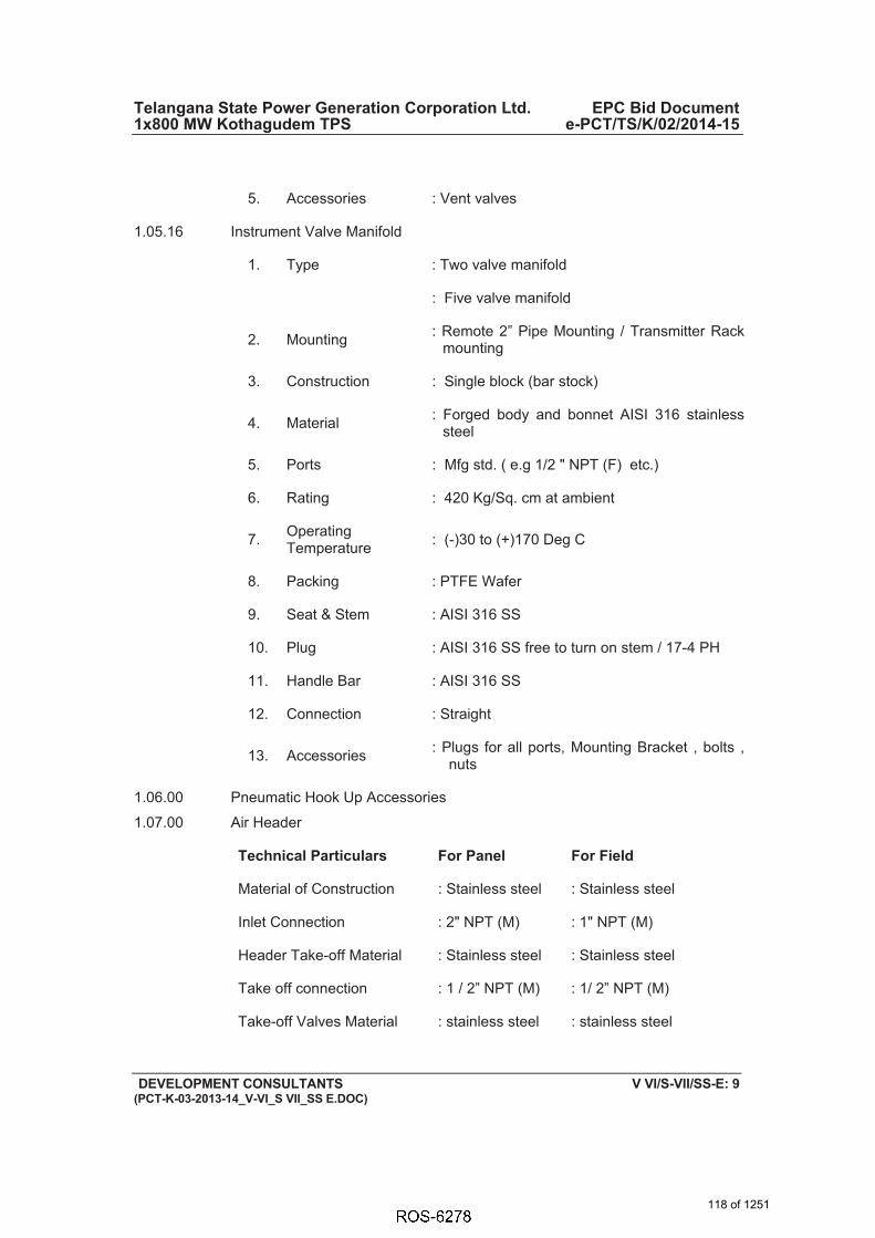
Telangana State Power Generation Corporation Ltd. EPC Bid Document 1x800 MW Kothagudem TPS e-PCT/TS/K/02/2014-15
DEVELOPMENT CONSULTANTS V VI/S-VII/SS-E: 9 (PCT-K-03-2013-14_V-VI_S VII_SS E.DOC)
5. Accessories : Vent valves
1.05.16 Instrument Valve Manifold
1. Type : Two valve manifold
: Five valve manifold
2. Mounting : Remote 2” Pipe Mounting / Transmitter Rack mounting
3. Construction : Single block (bar stock)
4. Material : Forged body and bonnet AISI 316 stainless steel
5. Ports : Mfg std. ( e.g 1/2 " NPT (F) etc.)
6. Rating : 420 Kg/Sq. cm at ambient
7. OperatingTemperature : (-)30 to (+)170 Deg C
8. Packing : PTFE Wafer
9. Seat & Stem : AISI 316 SS
10. Plug : AISI 316 SS free to turn on stem / 17-4 PH
11. Handle Bar : AISI 316 SS
12. Connection : Straight
13. Accessories : Plugs for all ports, Mounting Bracket , bolts , nuts
1.06.00 Pneumatic Hook Up Accessories
1.07.00 Air Header
Technical Particulars For Panel For Field
Material of Construction : Stainless steel : Stainless steel
Inlet Connection : 2" NPT (M) : 1" NPT (M)
Header Take-off Material : Stainless steel : Stainless steel
Take off connection : 1 / 2” NPT (M) : 1/ 2” NPT (M)
Take-off Valves Material : stainless steel : stainless steel
118 of 1251

Telangana State Power Generation Corporation Ltd. EPC Bid Document 1x800 MW Kothagudem TPS e-PCT/TS/K/02/2014-15
DEVELOPMENT CONSULTANTS V VI/S-VII/SS-E: 10 (PCT-K-03-2013-14_V-VI_S VII_SS E.DOC)
Tube Take-off : Tube adapter on valve : Tube adapter on valve
Drain : SS drain valve at lowest point
: SS drain valves at lowest point
119 of 1251

ANNEXURE-V
LT MOTOR SPECIFICATION
120 of 1251

`
5 x 800 MW YADRADRI TPS BASIC TECHNICAL FEATURES
FOR LT MOTORS (FOR BHEL-PEM SCOPE PACKAGES)
Doc. No. PE-DC-417-565-E003
Rev. No. 02
Dated
16-08-2018
Page 2 of 7 1.0 This document covers the basic technical features of low tension (LT) squirrel cage induction AC
motors employed for driving auxiliaries of BHEL-PEM scope packages in 5 x 800 MW YADRADRI TPS.
2.0 CODES AND STANDARDS
All motors shall conform to the latest applicable standards as listed below;
1) Three phase induction motors: IS: 12615, IEC: 60034 2) Single phase AC motors: IS: 996, IEC: 60034 3) Crane duty motors: IS: 3177, IEC: 60034 4) Energy Efficient motors: IS 12615 or IEC: 60034-30 with Efficiency class IE3
3.0 DESIGN REQUIREMENTS 3.1 Service Conditions
The motors will be installed in hot, humid and tropical atmosphere highly polluted at places with coal dust and/or fly ash. For motor installed outdoor and exposed to direct sunrays, the effect of solar heat shall be considered in the determination of the design ambient temperature. The design ambient temperature shall be 50 deg C.
3.2 Supply system and rated voltage of motors 3.2.1 Supply voltage & variations shall be as follows:-
Voltage variation (AC Supply): (+/-) 10%
Frequency variation : (+) 3% to (-) 5% Combined V & F variation : 10% (sum of absolute values)
During starting of large motor, the voltage may drop to 80% of the rated voltage for a period of 60 seconds. All electrical equipment while running shall successfully ride over such period without affecting system performance.
3.2.2 Motors shall be capable of running continuously at rated output for each of the conditions specified. 3.3 Motor Rating
All motors shall be rated for continuous duty. They shall also be suitable for long period of inactivity. LT motor rating at 50 degree C shall have at least 15% margin over the input power requirement of the driven equipment at rated duty point unless stated otherwise in driven equipment specification. The motor characteristics shall match the requirements of the driven equipment so that adequate starting, accelerating, pull up, break down and full load torques are available for the intended service.
3.4 Starting Requirements 3.4.1 Motor shall start smoothly and rapidly. Motor characteristics such as speed, starting torque, break away
torque and starting time shall be properly co-ordinated with the requirements of driven equipment. The
KW rating Supply system Rated voltage of motor Upto 0.2 kW 240V/415 V 240V415 V
Above 0.2 kW & up to 175kW 415 V 415 V
121 of 1251

`
5 x 800 MW YADRADRI TPS BASIC TECHNICAL FEATURES
FOR LT MOTORS (FOR BHEL-PEM SCOPE PACKAGES)
Doc. No. PE-DC-417-565-E003
Rev. No. 02
Dated
16-08-2018
Page 3 of 7
accelerating torque at any speed with the minimum starting voltage shall be at least 10% higher than that of the driven equipment.
3.4.2 Motors shall be capable of starting and accelerating the load with direct on line starting without
exceeding acceptable winding temperature. The limiting value of voltage at rated frequency under which a motor will successfully start and
accelerate to rated speed with load shall be taken to be a constant value of 85 (eighty five) percent rated voltage.
3.4.3 Continuous duty LT motors up to 175 KW Output rating (at 50 deg. C ambient temperature), shall be
Premium efficiency (IE3) as per IEC: 60034-30/ IS: 12615 and the locked rotor current of motors shall as per IS 12615. However, as per system requirement drives rated in the range of 160-210 KW may be considered in either 415V or 3.3 KV
3.4.4 Pump motor subject to reverse rotation shall be designed to withstand the stresses encountered when starting with shaft rotating at 125% rated speed in reverse direction.
3.4.5 The following frequency of starts shall apply
i) Three cold starts in succession with the motor being initially at a temperature not exceeding the ambient temperature.
ii) Two hot starts in succession with the motor being initially at a temperature not exceeding the rated load temperature.
iii) Three equally spread starts in an hour the motor being initially at a temperature not exceeding
the rated load operating temperature (not to be repeated in the second successive hour)
3.4.6 Locked motor withstand time of hot motors at 110% rated voltage shall be as follows: a) For motors with starting time upto 20 sec. - at least 3 sec. more than starting time. b) For motor with starting time above 20 secs but not exceeding 45 secs.
- at least 5.0 sec. more than starting time.
c) For motors with starting time above 45 secs.
- at least 10%. more than starting time. The starting time of the motor referred above is at minimum permissible voltage. Wherever the above
requirements are not complied with, speed switches of approved make & type shall be provided to bypass the locked rotor protection for a pre-selected time during starting of motors. The speed switches shall have one NO & one NC contacts having maximum interrupting capacity of 5 Amps at 240V AC and 0.25 amps at 220 V DC. Hot thermal withstand curve shall have a margin of at least 10% over the full load current of the motor to permit relay setting utilising motor rated capacity.
122 of 1251

`
5 x 800 MW YADRADRI TPS BASIC TECHNICAL FEATURES
FOR LT MOTORS (FOR BHEL-PEM SCOPE PACKAGES)
Doc. No. PE-DC-417-565-E003
Rev. No. 02
Dated
16-08-2018
Page 4 of 7 3.5 Running Requirements 3.5.1 Motor shall run continuously at rated output over the entire range of voltage and frequency variations
as given above. 3.5.2 The motor shall be capable of operating satisfactorily at full load for 5 minutes without injurious heating
with 75% rated voltage at motor terminals. 3.5.3 The motor shall be designed to withstand momentary overload of 60% of full load torque for 15 second
without any damage. 3.6 Stress during bus Transfer 3.6.1 The motor may be subjected to sudden application of 150% rated voltage during bus transfer, due to
the phase difference between the incoming voltage and motor residual voltage.
3.6.2 The motor shall be designed to withstand any torsional and/or high current stresses, which may result, without experiencing any deterioration in the normal life and performance characteristics.
4.0 SPECIFIC REQUIREMENTS 4.1 Enclosure
All motor enclosures for outdoor, semi-outdoor & indoor application shall conform to the degree of protection IP-55 unless otherwise specified. Motor for outdoor or semi-outdoor service shall be of weather-proof construction with canopy. For hazardous area approved type of increased safety enclosure shall be furnished.
4.2 Cooling 4.2.1 The motor shall be self-ventilated type, either totally enclosed fan cooled IC 411(TEFC), totally
enclosed tube ventilated IC 511(TETV) or closed air circuit air- cooled IC 611(CACA). 4.3 Winding and Insulation
All insulated winding shall be of copper. All motors shall have class F insulation but limited to class B temperature rise. Windings shall be impregnated to make them non-hygroscopic and oil resistant.
Tropical Protection
All motors shall have fungus protection involving special treatment of insulation and metal against fungus, insects and corrosion. All fittings and hardware shall be corrosion resistant.
4.4 Bearings
4.4.1 Motor shall be provided with antifriction bearings, unless sleeve bearings are required by the motor
application. Bearings shall be rated for minimum service life of 40,000Hrs.
4.4.2 Vertical shaft motors shall be provided with thrust and guide bearings. Thrust bearing of tilting pad type is preferred.
123 of 1251
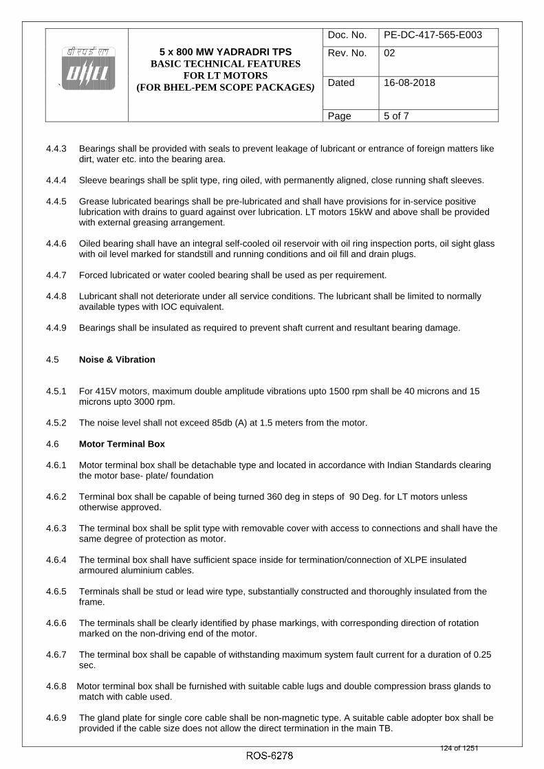
`
5 x 800 MW YADRADRI TPS BASIC TECHNICAL FEATURES
FOR LT MOTORS (FOR BHEL-PEM SCOPE PACKAGES)
Doc. No. PE-DC-417-565-E003
Rev. No. 02
Dated
16-08-2018
Page 5 of 7 4.4.3 Bearings shall be provided with seals to prevent leakage of lubricant or entrance of foreign matters like
dirt, water etc. into the bearing area.
4.4.4 Sleeve bearings shall be split type, ring oiled, with permanently aligned, close running shaft sleeves.
4.4.5 Grease lubricated bearings shall be pre-lubricated and shall have provisions for in-service positive lubrication with drains to guard against over lubrication. LT motors 15kW and above shall be provided with external greasing arrangement.
4.4.6 Oiled bearing shall have an integral self-cooled oil reservoir with oil ring inspection ports, oil sight glass with oil level marked for standstill and running conditions and oil fill and drain plugs.
4.4.7 Forced lubricated or water cooled bearing shall be used as per requirement.
4.4.8 Lubricant shall not deteriorate under all service conditions. The lubricant shall be limited to normally available types with IOC equivalent.
4.4.9 Bearings shall be insulated as required to prevent shaft current and resultant bearing damage.
4.5 Noise & Vibration 4.5.1 For 415V motors, maximum double amplitude vibrations upto 1500 rpm shall be 40 microns and 15
microns upto 3000 rpm.
4.5.2 The noise level shall not exceed 85db (A) at 1.5 meters from the motor.
4.6 Motor Terminal Box
4.6.1 Motor terminal box shall be detachable type and located in accordance with Indian Standards clearing the motor base- plate/ foundation
4.6.2 Terminal box shall be capable of being turned 360 deg in steps of 90 Deg. for LT motors unless
otherwise approved. 4.6.3 The terminal box shall be split type with removable cover with access to connections and shall have the
same degree of protection as motor. 4.6.4 The terminal box shall have sufficient space inside for termination/connection of XLPE insulated
armoured aluminium cables. 4.6.5 Terminals shall be stud or lead wire type, substantially constructed and thoroughly insulated from the
frame. 4.6.6 The terminals shall be clearly identified by phase markings, with corresponding direction of rotation
marked on the non-driving end of the motor. 4.6.7 The terminal box shall be capable of withstanding maximum system fault current for a duration of 0.25
sec. 4.6.8 Motor terminal box shall be furnished with suitable cable lugs and double compression brass glands to
match with cable used. 4.6.9 The gland plate for single core cable shall be non-magnetic type. A suitable cable adopter box shall be
provided if the cable size does not allow the direct termination in the main TB. 124 of 1251

`
5 x 800 MW YADRADRI TPS BASIC TECHNICAL FEATURES
FOR LT MOTORS (FOR BHEL-PEM SCOPE PACKAGES)
Doc. No. PE-DC-417-565-E003
Rev. No. 02
Dated
16-08-2018
Page 6 of 7 4.6.10 Minimum clearances to be provided between phase to phase and phase to earth shall be as under-
Voltage Rating of Motor Minimum Ph-Ph & Ph-Earth clearance 0.415 kV : 25 mm
Note: In case it is not possible to maintain these clearances, the live parts shall be totally insulated from earth and other Phases. Adequate clearances shall be provided for cable connections. 4.7 Grounding
The frame of each motor shall be provided with two separate and distinct grounding pads complete with tapped hole, GI bolts and washer. The cable terminal box shall have a separate grounding pad.
4.8 Rating Plate In addition to the minimum information required by IS, the following information shall be shown on motor rating plate: a) Temperature rise in Deg.C under rated condition and method of measurement. b) Degree of protection. c) Bearing identification no. and Type of lubrication, Quantity and frequency/ time interval d) Location of insulated bearings.
5.0 ACCESSORIES
5.1 SPACE HEATERS
Motor of rating 30 kW and above shall be provided with space heaters, suitably located for easy removal or replacement. The space heater shall be rated 240 V, 1 Phase, 50Hz and sized to maintain the motor internal temperature above dew point when the motor is idle. The minimum cable size for space heater shall be 2.5 sq.mm copper cable.
5.2 DELETED
5.3 INDICATOR/ SWITCH 5.3.1 Dial type local indicator with alarm contacts shall be provided for the following:
Hot and cold air temperature of the closed air circuit for CACA motor.
5.3.2 Alarm switch contact rating shall be minimum 2.0 A at 220V D.C. and 10A at 240V A.C. 5.4 ACCESSORY TERMINAL BOX 5.4.1 All accessory equipment such as space heater, temperature detector, current transformers etc., shall
be wired to and terminated in terminal boxes, separate from and independent of motor (power) terminal box.
5.4.2 Accessory terminal box shall be complete with double compression brass glands and pressure type
terminals to suit owner’s cable connections.
DRAIN PLUG 125 of 1251

`
5 x 800 MW YADRADRI TPS BASIC TECHNICAL FEATURES
FOR LT MOTORS (FOR BHEL-PEM SCOPE PACKAGES)
Doc. No. PE-DC-417-565-E003
Rev. No. 02
Dated
16-08-2018
Page 7 of 7
Motor shall have drain plugs so located that they will drain the water, resulting from the condensation or other causes from all pockets of the motor casing.
5.5 LIFTING PROVISIONS
Motor weighing 25 Kg. or more shall be provided with eyebolt or other adequate provision of lifting.
5.6 DOWEL PINS
The motor shall be designed to permit easy access for drilling holes through motor feet or mounting flange for installation of dowel pins after assembling the motor and driven equipment.
7.0 PAINTING Colour scheme for motors shall be shade 631 of IS-5. 8.0 TESTING 8.1 Type Tests For LT Motors, type test reports for type tests as per IS: 12615/ IEC: 60034 conducted on equipment
similar to those proposed to be supplied shall be submitted. The type Test should have been conducted within last 5 years from enquiry date.
8.2 Routine Tests All motors shall be subjected to routine tests as per IS: 12615/ IEC: 60034 in the presence of customer
or customer representative. 9.0 Variable Frequency Drive motor details:
i) The motor shall be suitable for operation with a solid-state power supply consisting of an
adjustable frequency inverter for speed control. ii) The motor shall be suitable for the current waveforms produced by the power supply including
the harmonics generated by the drive. iii) The Motor shall be designed to operate continuously at any speed over the range 20-100 % of
rated speed. iv) The permitted voltage variation should take into account the steady state voltage drop across
the AC drive and all other system components upstream of the motor. v) Motors required to be transferred to DOL, by-pass mode shall be rated for specified variations
in system line voltage and frequency. Starting current of motor in DOL, bypass mode shall be limited to value in motor specifications.
vi) The motor shall be constructed to withstand torque pulsations resulting from harmonics generated by the solid-state power supply.
vii) The motor insulation shall be designed to accept the applied voltage waveform, within the Vpeak and dv/dt limits as per IEC-61800-4.
viii) The drive manufacturer shall be solely responsible for proper selection of the motor for the given load application and the output characteristics of the drive.
126 of 1251

TITLE
MOTOR
DATA SHEET - C
SPECIFICATION NO. VOLUME II B SECTION D REV NO. 00 DATE 08/09/2010 SHEET 1 OF 7
NAME OF VENDOR SEAL
REV.
NAME SIGNATURE DATE
LT MOTORS A. GENERAL 1. Manufacturer & Country of origin. (Shall be as per approved QA make) 2. Equipment driven by motor 3. Motor type 4. Quantity B. DESIGN AND PERFORMANCE DATA 1. Frame size 2. Type of duty 3. Type of enclosure /Method of cooling/Degree of protection 4. Applicable standard to which motor generally conforms 5. Efficiency class as per IS 12615 6. (a) Whether motor is flame proof Yes/No (b) If yes, the gas group to which it conforms as per IS:2148 7. Type of mounting 8. Direction of rotation as viewed from DE END 9. Standard continuous rating at 40 deg.C. ambient temp. as per Indian Standard (KW) 10. Derated rating for specified normal condition i.e. 50 deg. C ambient temperature (KW) 11. Maximum continuous load demand of driven equipment in KW 12. Rated Voltage (volts) 13. Permissible variation of :
127 of 1251

TITLE
MOTOR
DATA SHEET - C
SPECIFICATION NO. VOLUME II B SECTION D REV NO. 00 DATE 08/09/2010 SHEET 2 OF 7
NAME OF VENDOR SEAL
REV.
NAME SIGNATURE DATE
a. Voltage (Volts) b. Frequency (Hz) c. Combined voltage and frequency 14. Rated speed at rated voltage and frequency(RPM) 15. At rated Voltage and frequency: a. Full load current b. No load current 16. Power Factor at a. 100% load b. NO load c. Starting. 17. Efficiency at rated voltage and frequrecy, a. 100% load b. 75% load c. 50% load 18. Starting current (amps) at a. 100 % voltage b. 85% voltage c. 80% voltage 19. Minimum permissible starting Voltage (Volts) 20. Starting time with minimum permissible voltage a. Without driven equipment coupled b. With driven equipment coupled
128 of 1251

TITLE
MOTOR
DATA SHEET - C
SPECIFICATION NO. VOLUME II B SECTION D REV NO. 00 DATE 08/09/2010 SHEET 3 OF 7
NAME OF VENDOR SEAL
REV.
NAME SIGNATURE DATE
21. Safe stall time with 100% and 110% of rated voltage a. From hot condition b. From cold condition 22. Torques : a. Starting torque at min. permissible voltage(kg-mtr.) b. Pull up torque at rated voltage. c. Pull out torque d. Min accelerating torque (kg.m) available e. Rated torque (kg.m) 23. Stator winding resistance per phase (ohms at 20 Deg.C.) 24. GD2 value of motors 25. No of permissible successive starts when motor is in hot condition 26. Locked Rotor KVA Input 27. Locked Rotor KVA/KW 28. Vibration limit :Velocity (mm/s) 29. Noise level limit (dBA) C. CONSTRUCTIONAL FEATURES 1. Stator winding insulation a. Class & Type b. Winding Insulation Process c. Tropicalised (Yes/No)
129 of 1251

TITLE
MOTOR
DATA SHEET - C
SPECIFICATION NO. VOLUME II B SECTION D REV NO. 00 DATE 08/09/2010 SHEET 4 OF 7
NAME OF VENDOR SEAL
REV.
NAME SIGNATURE DATE
d. Temperature rise over specified maximum ambient temperature of 50 deg C e. Method of temperature measurement f. Stator winding connection 2. Main Terminal Box a. Type b. Location (viewed from NDE side) c. Entry of cables(bottom/side) d. Recommended cable size (To be matched with cable size envisaged by owner) e. Fault level (MVA), Fault level duration (sec) f. Cable glands & lugs details (shall be suitable for power cable) 3. Type of DE/NDE Bearing 4. Motor Paint shade 5. Weight of a. Motor stator (KG) b. Motor Rotor (KG) c. Total weight (KG) D. List of accessories. 1. Space Heaters (Applicable for 30 KW & above motor) (Nos./Power in watts/supply voltage) 2. Terminal Box for Space Heater (Yes/No) 3. Speed switch (Yes/No) No of contacts and contact ratings of speed switch
130 of 1251

TITLE
MOTOR
DATA SHEET - C
SPECIFICATION NO. VOLUME II B SECTION D REV NO. 00 DATE 08/09/2010 SHEET 5 OF 7
NAME OF VENDOR SEAL
REV.
NAME SIGNATURE DATE
4. Insulation of bearing (Yes/No) 5. Noise reducer(Yes/No) 6. Grounding pads i) No and size on motor body ii) Nos on terminal Box 7. Vibration pads i) Nos and size ii) Location 8. Any other fitments E. List of curves. 1. Torque speed characteristic of the motor 2. Thermal withstand characteristic 3. Starting. current Vs. Time 4. Starting. current Vs speed 5. P.F. and Effi. Vs Load F. Additional Data to be filled for each rating of DC Motor 1. Rated armature voltage (Volt) 2. Rated field excitation (Amp) 3. Permissible % variation in voltage 4. Minimum Permissible Starting voltage (volt) 5. At rated voltage i) Full load Armature current.(Amp) ii) Full load Field current (Amp)
131 of 1251

TITLE
MOTOR
DATA SHEET - C
SPECIFICATION NO. VOLUME II B SECTION D REV NO. 00 DATE 08/09/2010 SHEET 6 OF 7
NAME OF VENDOR SEAL
REV.
NAME SIGNATURE DATE
iii) No load Armature current (Amp) 6. Full load Field current (Amp) 7. No load Aramature current (Amp) 8. Minimum permissible field current(Amp) to avoid overspeeding at i) Maximum permissible voltage ii) Rated voltage iii) Minimum Permissible Voltage 9. Resistance (indicative Values) in ohm i) Armature winding (Arm + IP + Series) at 25 deg.C ii) Field Winding at 25 deg. C 10. Inductance (indicative values) i) Armature winding ii) Field winding 11. Value of trimmer resistance (ohm) to be connected in series with the shunt field to obtain rated speed at i) 220 V DC ii) 250 V DC iii) 187 V DC 12. Value of the external resistance (ohm) required to be connected in series with armature during starting only 13. Technical data sheet for external resistance box 14. GA drawing of motor 15. Starting time calculation
132 of 1251

TITLE
MOTOR
DATA SHEET - C
SPECIFICATION NO. VOLUME II B SECTION D REV NO. 00 DATE 08/09/2010 SHEET 7 OF 7
NAME OF VENDOR SEAL
REV.
NAME SIGNATURE DATE
16. Starter resistance design calculation 17. Electrical connection diagram of motor
133 of 1251

134 of 1251
6238467
Typewriter
ANNEXURE-VI

DOCUMENT TITLE DOCUMENT
NUMBER PE-DM-417-145-I002
DRIVE CONTROL PHILOSOPHY (STATION C&I)
REVISION
NUMBER 03 DATE 06.12.2019
PROJECT:5 X 800 MW YADADRI TPS, UNIT # 1 TO 5 SHEET 2 OF 11
FO
RM
No. P
EM
- 6
10
0 -
0
A. DRIVE CONTROL PHILOSOPHY
The control philosophy for different type of Drives is detailed below:
1 Bi-directional drives with Integral Starter (Open/Close duty and inching/regulating duty)
a) All bi-directional drives shall have integral starter. These drives shall be
operable from Remote i.e. from Central Control Room (CCR).
b) Remote manual operation of all drives shall be done from Operator Works Station (OWS/LVS).
c) Remote control commands i.e. open/close generated from DCS shall be issued to Integral Starter through interposing relays, mounted in Integral Starter. For open/close duty bi-directional drives, DCS output command shall be latched in DCS, except for inching duty bi-directional drives where latching is not required.
d) Necessary electrical protections shall be realized at Integral Starter, whereas process interlocks and protection shall be realized in DCS.
e) Following signal exchange shall take place between Integral Starter & DCS.
- Open & close command. - Integral Starter Disturbed (Loss of power supply/Loss of control
supply/ Motor thermostat trip/ Thermal O/L /Local/off/Remote S/S in Local or Off mode/Stop PB optd/Torque open/close cutoff).
- Valve status feedback by means of limit switches (open/close). - Valve status feedback by means of torque switches (open/close). - Valve position feedback (4-20mA) for inching duty drives.
The above signal exchanges are diagrammatically represented in sheet no. 7.
2 Unidirectional LT Drives (Contactor Operated)
a. Unidirectional LT drives shall be operable from Remote i.e. from Central Control Room (CCR). Drives shall be provided with Local Emergency Stop Push Button (EPB). Deleted.
b. Remote manual operation of all drives shall be done from OWS/LVS. Deleted.
c. Remote control commands i.e. start/stop, shall be generated from DCS and shall be issued to MCC through interposing relays mounted in respective MCC. DCS output command shall be latched in MCC. EPB (stay put type), in MCC supplier’s scope, shall be wired directly to MCC to stop the motor irrespective of motor being in remote/local mode. The EPB shall be provided with press to lock and turn to release type, keyless mechanism. Under its locked position, the drive operation shall be inhibited.
2
2
135 of 1251

DOCUMENT TITLE DOCUMENT
NUMBER PE-DM-417-145-I002
DRIVE CONTROL PHILOSOPHY (STATION C&I)
REVISION
NUMBER 03 DATE 06.12.2019
PROJECT:5 X 800 MW YADADRI TPS, UNIT # 1 TO 5 SHEET 3 OF 11
FO
RM
No. P
EM
- 6
10
0 -
0
i. Local Start
d. Necessary electrical protections for the drives shall be realised at MCC, whereas process interlocks and protections shall be realized in DCS.
e. Following signal exchange shall take place between MCC & DCS
i. Drive Start & Stop commands. ii. Drive ON & OFF feedback. iii. MCC disturbed (Thermal O/L /Control supply fail/ EPB operated/
MCC isolated. iv. Deleted.
f. Current transducers, 4-20mA types (in MCC suppliers scope), shall be mounted in the MCC for monitoring the current in DCS for all the drives > 30 KW, for important drives <30 KW including all lube oil pumps. Auxiliary power supply to these transducers shall be provided from the control power supply of the respective MCC.
The above signal exchanges are diagrammatically represented in sheet no. 8. 3 Solenoid Operated Drives
a. Solenoid operated drives shall be operable from remote i.e. CCR only. b. Remote manual operation of all drives shall be done from OWS.
c. Remote control commands i.e. open/close shall be generated from
DCS and shall be issued to the respective solenoid through interposing relays located in Interposing Relay panels.
d. Necessary process interlocks shall be realized in DCS.
e. Following signal exchange shall take place between solenoid operated
drive & DCS
i. Valve open & close command.
ii. Valve status feedback by means of limit switches (open/close), wherever available.
The above signal exchanges are diagrammatically represented in sh. no. 9.
2
136 of 1251

DOCUMENT TITLE DOCUMENT
NUMBER PE-DM-417-145-I002
DRIVE CONTROL PHILOSOPHY (STATION C&I)
REVISION
NUMBER 03 DATE 06.12.2019
PROJECT:5 X 800 MW YADADRI TPS, UNIT # 1 TO 5 SHEET 4 OF 11
FO
RM
No. P
EM
- 6
10
0 -
0
4 HT/LT Unidirectional Drives (Breaker operated).
a. Remote manual operation of Breaker operated drives shall be normally from remote i.e. Station DCS in main Control Room through OWS/LVS and Local/remote selection of drives shall also be done in DDCMIS.
b. Remote/Switchgear (SWGR) selection shall be realized from SWGR mounted R/S selector switch.
c. Following are the operational combinations for breaker operated drives:
- SERVICE POSITION – Drive Operation (Start/Stop) shall be from CCR with R/S (Remote/SWGR) selector switch in Remote position.
-TEST POSITION – SWGR Testing (Start/Stop) from SWGR.
Switchgear mounted ‘Trip/Neutral/Close’ switch shall be provided for testing of switchgear when ‘R/S’ selector switch is selected as ‘SWGR’.
d. Remote control commands i.e. start/stop, pulse type, shall be generated from DCS and shall be issued to Switchgear through interposing relays located in the respective Switchgear. Further there is Local/remote selection in DDCMIS. Local selection in DDCMIS means, command from local PB, provided near the drive, will be executed through DDCMIS whereas in case of remote mode of selection in DDCMIS, the command from OWS will be processed, not through local PB.
e. The EPB shall be wired directly to switchgear to stop the motor irrespective of motor being in remote/local mode. The EPB (stay put type), in SWGR supplier’s scope, shall be provided with press to lock and turn to release type, keyless mechanism. Under its locked position, the drive operation shall be inhibited.
f. Necessary electrical protections for the drive shall be realised at Switchgear, whereas process interlocks and protections are realised in DCS.
2
137 of 1251

DOCUMENT TITLE DOCUMENT
NUMBER PE-DM-417-145-I002
DRIVE CONTROL PHILOSOPHY (STATION C&I)
REVISION
NUMBER 03 DATE 06.12.2019
PROJECT:5 X 800 MW YADADRI TPS, UNIT # 1 TO 5 SHEET 5 OF 11
FO
RM
No. P
EM
- 6
10
0 -
0
g. Following signal exchange shall take place between switchgear and DCS: -
i. Drive Start & Stop commands. ii. Drive ON & OFF status feedback. iii. Switchgear Disturbed (Control power supply fail/Trip coil
Unhealthy). iv. Switchgear Available (Breaker in Service position, Breaker
Spring Charged, Breaker in REMOTE & Master Trip Relay not optd.)
v. Master Trip Relay (86 Relay) operated. vi. Emergency Stop PB operated. vii. Breaker in TEST Position.
viii. Local Start
h. Current transducers, 4-20mA types (in SWGR suppliers scope), shall be mounted in the SWGR for monitoring the current in DCS. Auxiliary power supply to these transducers shall be provided from the control power supply of the respective switchgear.
The above signal exchanges are diagrammatically represented in sh. no. 10.
B. ANALOG DRIVE CONTROL PHILOSOPHY
Analog Drives Control
1.1 A drive control function residing in Distributed Processing Units (DPUs) is used to position the pneumatically operated control valves/Dampers through SMART positioner (for Burner Tilt also). Interlock and protection Open/Close Commands, originating from field or generated internally in Control Logics (ACS), are interfaced with the drive control function residing in processors.
1.2 Control Valve actuator design shall take care of fail safe condition i.e.
bringing valve to full open/full close or stay put mode, on signal (pneumatic/electric) failure.
1.3 Auto/Manual operator control and display for various control loops shall
be provided through OWS, using Analog Displays. 1.4 Analog Displays have following functionality:
Auto/Manual selection with control device “Raise/Lower Buttons”
Set point indication with “Raise/Lower Buttons”
Indication for deviation between set point and measured value
Measured value indication
Final control element portion indicators The above signal exchanges with DCS are diagrammatically represented in
sh.no. 11.
2
138 of 1251

DOCUMENT TITLE DOCUMENT
NUMBER PE-DM-417-145-I002
DRIVE CONTROL PHILOSOPHY (STATION C&I)
REVISION
NUMBER 03 DATE 06.12.2019
PROJECT:5 X 800 MW YADADRI TPS, UNIT # 1 TO 5 SHEET 6 OF 11
FO
RM
No. P
EM
- 6
10
0 -
0
C. CABLE
For interconnection of analog signals (4-20mA) to DDCMIS, in general “armoured” 0.5 sq mm color coded individually and over all screened twisted pair shall be used (F Type). However, for position feedback signals of bidirectional drives and current feedback signals of HT/LT drives 2P, G type cable shall be used as only one analog signal is involved. For interconnection of binary signals (24V DC) to DDCMIS, “armoured” 0.5 sq. mm color coded over all screened twisted pair cable shall be used (G Type).
D. LIST OF CRITICAL DRIVES <30KW WITH CURRENT MEASUREMENT
i. ID Fan sealing air motor ii. Seal Oil Pump iii. AOP motor for hyd. coupling-MDBFP iv. AC / DC Scanner Air Fan v. HP B/P Lube Oil Pump Motor vi. Regenerative Air Heater Main Motor vii. Jacking Oil Pump Drive Motor for BFP’s viii. LOPs of ID/FD/PA Fans ix. All Lube Oil Pumps
3
139 of 1251

140 of 1251
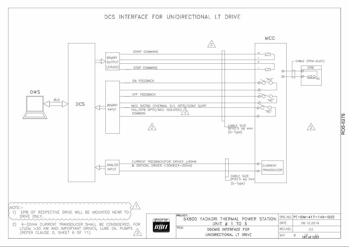
141 of 1251

142 of 1251

143 of 1251

144 of 1251

145 of 1251

ANNEXURE-VII
PROGRAMMABLE LOGIC CONTROLLER (PLC) SPECIFICATION
146 of 1251

Telangana State Power Generation Corporation Ltd. EPC Bid Document 1x800 MW Kothagudem TPS e-PCT/TS/K/02/2014-15
DEVELOPMENT CONSULTANTS V VI/S-VI/SS-A : 2 (e-PCT-TS-K-02-2014-15_V-VI_S VI_SS A.DOC)
VOLUME : VI SECTION-VI
SUB SECTION - A DISTRIBUTED DIGITAL CONTROL
AND MANAGEMENT INFORMATION SYSTEM (DDCMIS)
147 of 1251

Telangana State Power Generation Corporation Ltd. EPC Bid Document 1x800 MW Kothagudem TPS e-PCT/TS/K/02/2014-15
DEVELOPMENT CONSULTANTS V VI/S-VI/SS-A : 3 (e-PCT-TS-K-02-2014-15_V-VI_S VI_SS A.DOC)
1.00.00 GENERAL REQUIREMENTS 1.01.00 Integrated functionally & geographically distributed hierarchical Control
System (both binary and modulating) including data acquisition, historization and Management Information System (MIS) system synthesized from one general family of identical interchangeable multifunction hardware has been envisaged for the plant.
1.02.00 System shall be highly reliable with the availability of not less than 99.7% with adequate redundancy and fault tolerant configuration.
1.03.00 The complete system shall be unitized and connectivity with existing plant DDCMIS shall be envisaged.
1.04.00 Remote input output (RIO) stations as a data concentrator for acquisition and monitoring of Boiler metal temperature and other remote areas are foreseen. RIO shall be industrially ruggedized and if required , shall be provided with integral air conditioner considering the harsh environment.
1.05.00 All auxiliaries like, Generator monitoring and Auxillary Control system , Water system , Effluent Treatment Plant , Mill Reject System, HVAC, Fire Detection and Protection system, DG Set, Switchyard SCADA , etc. in addition to their standalone control and monitoring systems , shall also be monitored in a PLC based Common BOP network Workstations / DDCMIS , as detailed in Section V of this volume of this specification ,from the CCR.Such monitoring links (OPC) with DDCMIS are largely foreseen as Optical Fiber redundant bidirectional data hiways.
1.06.00 CW & ACW pumping system ,Fuel oil system, Filtered water transportation system , DM transportation , Condensate Polishing unit along with regeneration system , Compressed air system along with proprietary control system shall be controlled & operated from DDCMIS workstations as well as from local operator workstations / panels . Remote terminal units shall be provided at appropriate locations for these purpose.
Common DDCMIS network shall also control and monitor packages envisaged for PLC based local control systems. Operator workstations shall be provided in CCR for the overall control and monitoring through this netework. Such links (OPC) with Common DDCMIS are largely foreseen as Optical Fiber redundant bidirectional data hiways.
1.07.00 The control and monitoring hardware and peripherals for the unit shall be located in the Central Control Room (CCR) ,Control Equipment Room (EER) , Computer Room , Shift Charge Room of the unit (all air-conditioned) etc.
148 of 1251
6238467
Line
6238467
Line
6238467
Line
6238467
Line
6238467
Line
6238467
Rectangle
6238467
Rectangle
6238467
Rectangle
6238467
Rectangle
6238467
Typewriter
DELETED
6238467
Typewriter
DELETED
6238467
Typewriter
DELETED
6238467
Typewriter
DELETED
6238467
Typewriter
DELETED

Telangana State Power Generation Corporation Ltd. EPC Bid Document 1x800 MW Kothagudem TPS e-PCT/TS/K/02/2014-15
DEVELOPMENT CONSULTANTS V VI/S-VI/SS-A : 4 (e-PCT-TS-K-02-2014-15_V-VI_S VI_SS A.DOC)
1.08.00 SG and TG control and monitoring through DDCMIS has been elaborated in Section III and IV of this specification.
1.09.00 DDCMIS shall be configured to broadly perform the following basic functions:
a) Automatic sequencing of the start-up, shutdown and load swing of equipment and auxiliaries including group / plant level start-up to minimize operator's intervention under normal operating conditions ensuring safety of man and machine as well as to ensure high plant availability (OLCS & Sequence functions).
b) Automatic regulation of various valves and dampers to achieve guaranteed performance of various controlled variables and to achieve most fuel-efficient operating regime (CLCS functions).
c) Acquisition, alarms, sequence of events, display, real time & history trend, logs, report generation and archiving of plant data and maintain historical data for a defined period (DAS functions).
d) Gateway for collection / distribution of selected data from / to standalone systems like Rotating Machine Condition Monitoring System, Continuous Emissions Monitoring System , PADO , AAQMS etc.
e) Presenting salient plant parameters to plant executives to display the health and condition of the plant and to aid the decision making (MIS functions).
f) Energy management and audit of the plant and equipment by measuring consumption of power of all salient equipment and measurement of fuel, steam, water and all other relevant cost-bearing parameters.
h) Off-line system configuration, simulation of control loops and logics, control loop tuning and debugging.
i) Facility for simulation of control loops / logic.
j) Providing tools for automatic generation of documents like loop & logic diagrams.
1.10.00 DDCMIS shall consist of the following broad sub-systms.
a) Input / Output Subsystem
b) Controller (OLCS & CLCS) Subsystem
c) Data Acquisition Subsystem (DAS)
d) Historical Storage Subsystem
e) Plant optimization & Performance Calculation Station
f) Human Machine & Peripheral Interface (HMI) Subsystem
g) Engineering and Diagnostic Station (ES)
h) Sequence of Event Monitoring Subsystem (SOE)
149 of 1251
6238467
Line
6238467
Line
6238467
Line
6238467
Line
6238467
Line
6238467
Rectangle
6238467
Rectangle
6238467
Rectangle
6238467
Rectangle
6238467
Typewriter
DELETED
6238467
Typewriter
DELETED
6238467
Typewriter
DELETED
6238467
Typewriter
DELETED
6238467
Typewriter
DELETED
6238467
Typewriter
DELETED
6238467
Typewriter
DELETED

Telangana State Power Generation Corporation Ltd. EPC Bid Document 1x800 MW Kothagudem TPS e-PCT/TS/K/02/2014-15
DEVELOPMENT CONSULTANTS V VI/S-VI/SS-A : 5 (e-PCT-TS-K-02-2014-15_V-VI_S VI_SS A.DOC)
i) Management Information System (MIS)
The above sub systems shall be connected together through redundant and fault tolerant real time high speed internal Data Highways through redundant switches. High speed information network shall also be considered at MIS level for reports, logs, history etc.
Mutual interdependence between the subsystems shall be limited to sharing the global database of the plant, which shall be resident at various locations, to facilitate rapid response. The same database will be accessed, shared and updated by various consumers, seamlessly and transparently.
1.11.00 The unit control networks and the station auxiliary network shall be ‘bridged’ into a common high-speed network with authorized data access between the sections.
1.12.00 Web based MIS subsystem with HTML compatible display format for accessing plant graphics / data shall be provided. The system shall support limited access for soft users for viewing the static display of plant information / graphics and at least four premium users viewing the information / plant graphics with automatic refresh of data.
1.13.00 No back-up discrete hardwire based control or hard-manual operation is envisaged for normal operation of the unit. Bidder shall, however, perform a failure analysis to establish that the plant can be shut down safely or can be brought to a safe holding condition without any damage to equipment and/or personnel under the unlikely event of catastrophic failure of DDCMIS. Back-up instruments/ Push Buttons / Lamps necessary to achieve the above condition along with DDCMIS driven microprocessor based window annunciation in Unit control panel (UCP) shall be provided .It has been envisaged that in addition to automatic synchronization through turbine run up system, manual synchronization of generator shall also be provided .
1.14.00 Bidder shall furnish all required equipment and materials including system
hardware and firmware components, peripherals and operator work station, all necessary licensed software platforms - compilers, interpreters, builder packages etc; programming, diagnostic and test routines, instruments and equipment; development of application software, data base, screens, graphics and other functional programs; establishing the network structure, debugging and loading; develop and follow a quality assurance plan, system integration, simulation and checkouts; offering the system for Owner's shop inspection and testing including hardware, software and heat-run tests, packaging for transportation, delivery at plant site, unloading, warehousing, installation, site integration, program loading and documentation, system check-out, interconnection with field inputs, pre-commissioning checking, commissioning including tuning of control loops and put the complete system in operation with necessary site modifications, conduct performance guarantee tests, system availability test and develop as-built documentation.
1.15.00 Bidder shall supply all related documentation including original software manuals, application software manuals, operation and maintenance manuals,
150 of 1251
6238467
Line
6238467
Rectangle
6238467
Typewriter
DELETED
6238467
Typewriter
DELETED
6238467
Typewriter
DELETED

Telangana State Power Generation Corporation Ltd. EPC Bid Document 1x800 MW Kothagudem TPS e-PCT/TS/K/02/2014-15
DEVELOPMENT CONSULTANTS V VI/S-VI/SS-A : 6 (e-PCT-TS-K-02-2014-15_V-VI_S VI_SS A.DOC)
instruction handbooks for graphic and data-base building and other related documents and manuals in hard copies as well as in soft medium. Bidder shall furnish the entire plant database and configuration in as-built condition in DVDs for reloading/ record.
1.16.00 Bidder shall also supply maintenance and trouble shooting tools viz. test instruments, extender cards, DVDs containing programs including virus detection and elimination programs, DVD writers, and DVD for copying, diagnostic programs etc.
1.17.00 Bidder's scope of supply shall include the supply of commissioning and mandatory spares as per guidedelines given in the specification.
1.18.00 Bidder's scope of work shall also include the training of Owner's personnel at original equipment designer / manufacturer’s office and providing the guarantee for the equipment supplied.
1.19.00 Suggested Plant Control System Overview Diagram is illustrated in the Drawing no. 13A07-DWG-I-0110
1.20.00 All wiring to and from field or other cabinets located in and beyond control equipment room, shall be direct and Termination Cabinets in between shall be avoided.
1.21.00 Dual power supply feed shall be considered for all cabinets. 1.22.00 Interposing relays for switchgear unit / MCC, other systems if any shall be
provided in IPR panel. This IPR panel shall be located in Control Equipment room .
1.23.00 The system shall have the capability and facility for expansion through the addition of controller modules, I/O cards, peripherals like Large Video Screen (LVS), operator workstations (OWS), printers etc., while the existing system is fully operational. The system shall have the capability to add any new control loops, groups/subgroups in control system, while the existing system is fully operational.
1.24.00 It shall also be possible to remove/replace any of the redundant controller module without switching off the power to the corresponding rack and this will not result in system disturbance or loss of any controller functions for the other controller. The on-line removal/insertion of controller, I/O modules etc. shall in no way jeopardize safety of plant and personnel.
1.25.00 No single failure either of equipment or power source shall be capable of
rendering any part/system/sub-system of DDCMIS inoperative to any degree. The items which shall be redundant with automatic change-over (including the associated software), as a minimum are CLCS / OLCS Controllers, Communication Controllers, Data Highways, Local / Remote communication highway , Power supply arrangement (feeders, modules) ,Output modules for HT drives, Servers. Sensors shall also be redundant. Detailed Redundant philosophy shall be as stipulated elsewhere in this volume of the specification.
151 of 1251
6238467
Line
6238467
Rectangle
6238467
Typewriter
DELETED
6238467
Typewriter
DELETED

Telangana State Power Generation Corporation Ltd. EPC Bid Document 1x800 MW Kothagudem TPS e-PCT/TS/K/02/2014-15
DEVELOPMENT CONSULTANTS V VI/S-VI/SS-A : 7 (e-PCT-TS-K-02-2014-15_V-VI_S VI_SS A.DOC)
1.26.00 All the signal exchange between various functional groups of each control systems shall be implemented through redundant system bus.
1.27.00 Spare philosophy
The following spare philosophies shall be applicable for all the control and monitoring systems eg. DDCMIS including SOE , PLC , Proprietary Control Systems .
a) 10 % spare channel shall be provided in each type of input / output
.10% hot spare for each type of I/O modules (installed) shall be provided in each functional group . fully wired upto the marshalling/ termination TBs .
b) Wired-in "usable" space for 20% modules along with Field Terminal
assemblies, PCB/Connectors (if any in the offered system) in each of the system cabinets for mounting electronic modules shall be provided by the Bidder for future use.
c) HMI system shall be provided with capacity to handle at least 1 no. of
each type of peripherals/equipments, additionally, like OWS, LVS, printers, PCs etc., over and above already specified, without any additional hardware or software. HMI system data base (if applicable) shall have provision of at least twenty five (25) percent extra points of above mentioned signals.
d) Each controller shall have thirty (30) percent spare functional capacity
to implement additional function blocks, over and above implemented logic/ loops. Further, each controller shall have spare capacity to handle minimum 30% additional inputs/ outputs of each type over and above implemented capacity. Each of the corresponding communication controllers shall also have same spare capacity as that of controller
e) Twenty (20) percent spare relays of each type and rating, mounted
and wired in relay cabinets. All contacts of relays shall be terminated in terminal blocks of relay cabinets. In each of the relay cabinets, 10 % spare terminal blocks shall be provided so that additional relays can be mounted and wired.
f) Twenty (20) percent spare terminal blocks in each marshalling /
termination cabinets.
1.28.00 Printers shall have graphic capability and any printer shall be accessible from any Operating Station. Operating Stations & Printers shall be as per the specification drawing Plant Control System Overview Diagram 13A07-DWG-I-0110
1.29.00 The System shall have the following capabilities, as minimum: -
a) Scan, acquire, validate, time-tag, process, store, update, archive, retrieve and display all analog and digital data and parameter.
152 of 1251
6238467
Line
6238467
Rectangle
6238467
Typewriter
DELETED

Telangana State Power Generation Corporation Ltd. EPC Bid Document 1x800 MW Kothagudem TPS e-PCT/TS/K/02/2014-15
DEVELOPMENT CONSULTANTS V VI/S-VI/SS-A : 8 (e-PCT-TS-K-02-2014-15_V-VI_S VI_SS A.DOC)
b) Monitor real and calculated variables for multi-level alarm conditions.
c) Accept and execute operator’s commands and pre-programmed routines and run-times.
d) Perform all open and closed loop control functions.
e) Display plant mimics, bar-graphs, control faceplates, point description, trend graphs (real time & history) in interactive mode with the operator.
f) Prepare and print logs and reports.
g) Performance calculation based on real-time and manually entered data.
h) Dynamically reconfigure itself on command from engineering station.
i) Run diagnostics, program hang up checks, system checks and routines.
j) System information and diagnostic alarm like failure of I/O module, Multifunction controller, communication modules, node failure, CPU loading, Network loading, workstation diagnostic etc.
k) Dynamic data exchange through OPC with other systems.
1.30.00 Interface with GPS master clock for time synchronization shall be provided.
1.31.00 Security
Multiple security levels with hard and soft key lock shall be provided with two (2) or more at operator levels and one (1) at Engineer level to make it possible to restrict access to critical parameters and minimize the possibility of operator errors.
2.00.00 CONTROL SYSTEM DESCRIPTION 2.01.00 DDCMIS shall be configured such that degradation of performance in the
event of a single failure of control equipment shall be eliminated. However, such failures shall be suitably annunciated to draw the attention of the plant personnel. Multifunction controllers, Communication Processors and Power supply modules (both for control and field supplies) for all open- and closed- loop controls shall be hot redundant to minimize risk arising out of failure. All redundant modules shall be hot- withdrawable and hot-insertable.
2.02.00 Single multi-loop controller pairs shall handle OLCS, CLCS & Sequential functions of specific plant areas as per the functional grouping.
2.03.00 The hardware and software shall be from the latest proven design for real-time environment meeting the pre-qualification requirement of this specification.
2.04.00 Comprehensive automatic diagnostic system shall periodically verify the integrity of the system and shall cause auto-transfer to the stand-by equipment without any loss of data or shall lead to fail-safe situations in case of catastrophic failure of the station with reporting at higher level.
153 of 1251
6238467
Line
6238467
Rectangle
6238467
Typewriter
DELETED
6238467
Typewriter
DELETED

Telangana State Power Generation Corporation Ltd. EPC Bid Document 1x800 MW Kothagudem TPS e-PCT/TS/K/02/2014-15
DEVELOPMENT CONSULTANTS V VI/S-VI/SS-A : 9 (e-PCT-TS-K-02-2014-15_V-VI_S VI_SS A.DOC)
2.05.00 Maximum permissible loading of various components shall be as follows:
a) Multi-loop Multifunction Controller – 50%.
b) Input / Output - 80%
c) Workstation / console – 80%
d) Historical Storage - 75 %
e) Data Highway / communication link – 50%
f) Other computing modules – 60%
2.06.00 Control functions shall be judiciously assigned to various controllers such that,
a) Controllers are uniformly loaded and partitioned as per functionality of the process and equipment.
b) Loops are assigned logically to the controllers so that peer-to-peer active data transactions are kept at minimum and a simple correlation exists between plant equipment / system and corresponding controller.
c) Complete failure of a controller partition can only affect a portion of the plant and equipment and which shall be manageable by the operator without any outage of the unit.
2.07.00 Response time of the control system should be adequate to maintain control over the process under all regimes of operation. Response time shall include the delay and dead time both internal and external. Response time pertaining shall include I/O scan time, data communication time, processing time etc. Maximum permissible time for various functions under worst loading condition are as follows:
a) Scanning rate :
i) Analog signals : 1 sec. for measurement.
ii) Digital signals : 100 ms.
iii) Pulse signals : 100 ms. iv) SOE : 1 ms.
(b) Loop execution time :
i) CLCS : 250 ms. (For all Loops)
ii) OLCS :100 ms. (For all Loops)
(c) Controller output update
154 of 1251
6238467
Line
6238467
Line
6238467
Rectangle
6238467
Rectangle
6238467
Typewriter
DELETED
6238467
Typewriter
DELETED

Telangana State Power Generation Corporation Ltd. EPC Bid Document 1x800 MW Kothagudem TPS e-PCT/TS/K/02/2014-15
DEVELOPMENT CONSULTANTS V VI/S-VI/SS-A : 10 (e-PCT-TS-K-02-2014-15_V-VI_S VI_SS A.DOC)
i) CLCS : every 250 ms. (For all CLCS Loops)
ii) OLCS : every 100 ms (For all OLCS Loops)
(d) Updating rate
i) Analog display : 2 sec. (for measurement) (ii) Analog display : 1 sec. for OLCS/CLCS
(iii) Digital value display :4 sec. (for measurement)
(iv) Digital value display :1 sec. for OLCS/CLCS
(e) Time for display in CRT screen : 1-2 sec. on demand
(f) Keyboard command execution time : 1 sec
Faster response is required for some critical equipment and systems such as Turbine generator control, HP/LP Bypass control, MFT etc. and for those systems, requirements for scan time shall be guided by the respective equipment and systems dynamics.
2.08.00 Manipulation of set point shall be permissible from the Operator’s terminal in incremental mode.
2.09.00 It shall be permissible to transfer a loop from “auto” mode to “manual’ mode or vice versa from operator’s terminal. All such transfers shall be bumpless and procedureless. During transition from “auto” mode to “manual”, the output to the final element shall be maintained until manipulated from the operator’s terminal. Similarly, during transfer from “manual” mode to “auto”; when effected from the operator’s terminal, the auto output shall take-off from the last value and shall regulate the final element in a predetermined and adjustable ramp to final computed value as per the control loop algorithm. This will necessitate continuous auto-tracking between “auto” mode and “manual” mode outputs.
2.10.00 Binary control shall be implemented in hierarchical structure.. 2.11.00 Drive control philosophy shall be as per specification drawing no. 13A07 -
DWG- I - 0110 titled . Typical drive -DDCMIS / PLC.
2.12.00 The drives, which are part of a sequence, shall be operable in sequence mode from Operator’s terminal. In sequence mode, a single command shall initiate predetermined sequence of operation. Following information, as a minimum, shall be available at the monitors.
a) All permissive
b) Start & Stop sequence
c) Start sequence complete
155 of 1251
6238467
Line
6238467
Rectangle
6238467
Typewriter
DELETED

Telangana State Power Generation Corporation Ltd. EPC Bid Document 1x800 MW Kothagudem TPS e-PCT/TS/K/02/2014-15
DEVELOPMENT CONSULTANTS V VI/S-VI/SS-A : 11 (e-PCT-TS-K-02-2014-15_V-VI_S VI_SS A.DOC)
d) Stop sequence complete
e) Sequence fail
f) Stepwise sequential progress of operation indication with permissive for each step to enable the operator that for particular step all permissive are met and the step is executed.
g) Disturbance indication
h) Sequential operation indication on monitor in the form of ladder logic diagram
i) Override of hold-up sequence as per operator’s discretion.
2.13.00 Load Runback Variables
In case of major plant internal disturbance the unit shall carry on operation at a reduced load level and the grid frequency control system shall be taken out of service. The load shall be reduced by the automatic run-back system which reduces or holds the unit load according to the capacity of main auxiliary systems. The failure of any of the few plant systems or plant variable are to be included in the run-back system .These are but not limited to I. D. Fans ,F.D. Fans ,P.A. Fans ,Air preheaters ,Boiler circulation water pumps ,Boiler Feed Water Pumps ,H.P. Feed Heaters ,L.P. Feed Heaters ,Condensate extraction pumps ,Coal Mills ,CW Pumps , Load Shedding etc.
3.00.00 INPUT / OUTPUT SUB SYSTEMS
3.01.00 The system shall have features not limited to the following:
a) Interface with field sensors, Signal conditioning, A/D conversion, Signal validation, Diagnostic, Engineering conversion, Time stamping, Limit value monitor etc.
b) Interface with smart transmitter though smart interface module with optical and galvanic isolation. Alternatively, standalone field bus management system shall be used.
c) Channels individually addressable during routine diagnostic check.
d) Failure reporting.
e) Replaceable under system power on condition.
f) I/O bus and I/O communication processor shall be redundant.
3.02.00 Number of channels in IO module shall not be more than the following:
i) Analog input - 8 channel
ii) Analog output - 8 channel
iii) Binary input - 16 channel ( one changeover contact is equivalent to 2 inputs)
iv) Binary output - 16 channel
156 of 1251
6238467
Line
6238467
Rectangle
6238467
Typewriter
DELETED
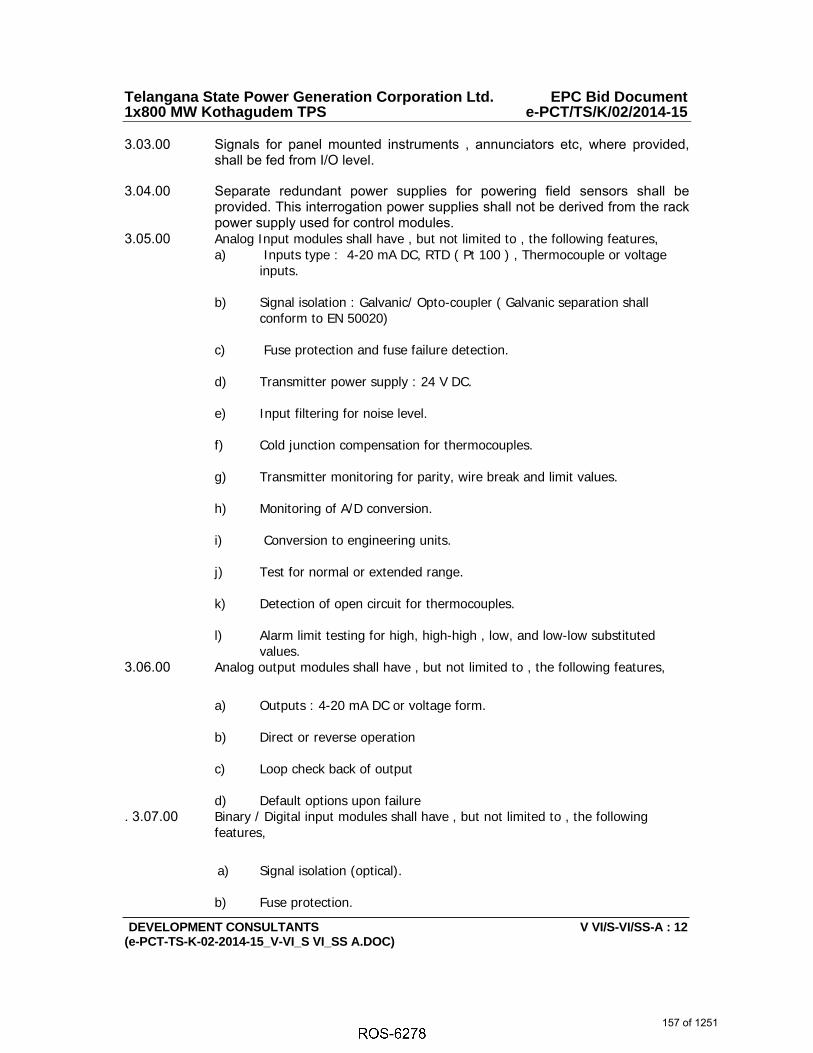
Telangana State Power Generation Corporation Ltd. EPC Bid Document 1x800 MW Kothagudem TPS e-PCT/TS/K/02/2014-15
DEVELOPMENT CONSULTANTS V VI/S-VI/SS-A : 12 (e-PCT-TS-K-02-2014-15_V-VI_S VI_SS A.DOC)
3.03.00 Signals for panel mounted instruments , annunciators etc, where provided, shall be fed from I/O level.
3.04.00 Separate redundant power supplies for powering field sensors shall be provided. This interrogation power supplies shall not be derived from the rack power supply used for control modules.
3.05.00 Analog Input modules shall have , but not limited to , the following features, a) Inputs type : 4-20 mA DC, RTD ( Pt 100 ) , Thermocouple or voltage
inputs. b) Signal isolation : Galvanic/ Opto-coupler ( Galvanic separation shall
conform to EN 50020)
c) Fuse protection and fuse failure detection. d) Transmitter power supply : 24 V DC.
e) Input filtering for noise level.
f) Cold junction compensation for thermocouples.
g) Transmitter monitoring for parity, wire break and limit values. h) Monitoring of A/D conversion.
i) Conversion to engineering units.
j) Test for normal or extended range.
k) Detection of open circuit for thermocouples.
l) Alarm limit testing for high, high-high , low, and low-low substituted
values. 3.06.00 Analog output modules shall have , but not limited to , the following features,
a) Outputs : 4-20 mA DC or voltage form.
b) Direct or reverse operation c) Loop check back of output
d) Default options upon failure
. 3.07.00 Binary / Digital input modules shall have , but not limited to , the following features,
a) Signal isolation (optical).
b) Fuse protection.
157 of 1251
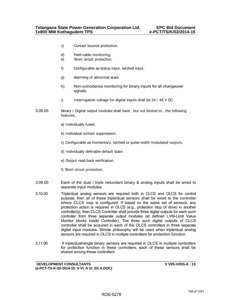
Telangana State Power Generation Corporation Ltd. EPC Bid Document 1x800 MW Kothagudem TPS e-PCT/TS/K/02/2014-15
DEVELOPMENT CONSULTANTS V VI/S-VI/SS-A : 13 (e-PCT-TS-K-02-2014-15_V-VI_S VI_SS A.DOC)
c) Contact bounce protection.
d) Field cable monitoring. e) Short circuit protection. f) Configurable as status input, latched input. g) Alarming of abnormal state. h) Non-coincidence monitoring for binary inputs for all changeover
signals.
i) Interrogation voltage for digital inputs shall be 24 / 48 V DC.
. 3.08.00 Binary / Digital output modules shall have , but not limited to , the following
features, a) Individually fused. b) Individual contact suppression. c) Configurable as momentary, latched or pulse-width modulated outputs. d) Individually definable default state. e) Output read back verification. f) Short circuit protection.
3.09.00 Each of the dual / triple redundant binary & analog inputs shall be wired to separate input modules.
3.10.00 Triple/dual analog sensors are required both in CLCS and OLCS for control purpose, then all of these triple/dual sensors shall be wired to the controller where CLCS loop is configured. If based on the same set of sensors, any protection action is required in OLCS (e.g., protection stop of drive) in another controller(s), then CLCS Controller shall provide three digital outputs for each such controller from three separate output modules (at defined LVM-Limit Value Monitor blocks inside Controller). The three such digital outputs of CLCS controller shall be acquired in each of the OLCS controllers in three separate digital input modules. Similar philosophy will be used when triple/dual analog sensors are required in OLCS in multiple controllers for protection function.
3.11.00 If triple/dual/single binary sensors are required in OLCS in multiple controllers for protection function in these controllers, each of these sensors shall be shared among these controllers
158 of 1251

Telangana State Power Generation Corporation Ltd. EPC Bid Document 1x800 MW Kothagudem TPS e-PCT/TS/K/02/2014-15
DEVELOPMENT CONSULTANTS V VI/S-VI/SS-A : 14 (e-PCT-TS-K-02-2014-15_V-VI_S VI_SS A.DOC)
3.12.00 The input sharing scheme shall be subject to Owner’s approval during detailed engineering.
4.00.00 CONTROLLER SUB SYSTEMS
4.01.00 This shall have the features not limited to the following:
a) Real time multi tasking.
b) Redundant communication ports with speed of 1000 Mbps or more.
c) Deterministic and peer-to-peer Communication with other controllers.
d) Redundant controllers placed separately and no sharing of motherboard.
e) Redundant Controllers, redundant power supply, redundant communication modules.
f) Hot-withdrawable and hot-insertable.
g) RIO and RTU support
h) Processing time of parameter freely configurable.
4.02.00 For CLCS function, controllers shall have system resident library functions including linearizers, characterizers, square root extractors, signal limiter, one-out-of-two selector, Median selection, averaging, PID block, logical functions, Auto / manual selector and other software configured mathematical blocks to be strung together to form the desired strategy for control. Synthesizing, configuring, tuning or adjusting control loops should not involve writing elaborate programs.
4.03.00 CLCS shall act on modulating control valves, dampers, or other regulating devices to achieve stable control action under steady state condition, for load swings in the step / range over the entire load range with permissible variation in parameters and under failure/trip or limiting condition of process equipment.
4.04.00 Open Loop Control System (OLCS) shall perform interlocking, protection,
sequential functions including individual drive control function with their associated safety protection. OLCS shall provide adequate and reliable protection & safeguard for various equipment and shall assist the operator in easy, safe & efficient starting, stopping and tripping of various drives in the plant.
4.05.00 OLCS shall perform drive control functions like permissive, start, stop, auto-start, auto-stop, wait- and step-timing control, drive interface and other related binary functions. It shall also check the drive status feed back like On, Off, Fault, Local & Remote selection, Normal & Trial selection, Switchgear disturbance, Electrical protection operated, Safety interlock operated, standby mode etc. and display on the screen.
4.06.00 For OLCS function, controllers shall have system resident library functions including logic functions, timers, registers, counters, Boolean operators,
159 of 1251

Telangana State Power Generation Corporation Ltd. EPC Bid Document 1x800 MW Kothagudem TPS e-PCT/TS/K/02/2014-15
DEVELOPMENT CONSULTANTS V VI/S-VI/SS-A : 15 (e-PCT-TS-K-02-2014-15_V-VI_S VI_SS A.DOC)
encoders, one-out-of-two selector, two-out-of-three voting system, logical functions, HT/LT drive control and other software configured mathematical blocks to be strung together to form the desired strategy. Synthesizing, configuring or adjusting control loops should not involve writing elaborate programs.
4.07.00 Each Multi-loop controller, interfacing with the redundant control bus, shall cater to a group of related loops and shall have its own in-built communication function.
4.08.00 The system shall have 1:1 redundancy with respect to the processor modules, power supply modules, communication modules and network interface. In redundant controller configuration, “main” and the “hot stand-by” controllers shall be identical in all respects. Any one of the two controllers can be selected as ‘main’ controller. During normal operation, output of the stand by controller shall be disabled. However, standby controller shall receive and update its database from field inputs and main controller.
The system shall be designed in such a manner that in the event of failure of the primary controller, the entire configuration of the failed controller shall be instantaneously and automatically transferred to the back-up controller without operator’s intervention. Mode changeover in either direction shall be bumpless . Simultaneously, a message should appear on the monitors of the Operator's / Engineer's work station indicating the failure. Redundancy of processor / controller shall mean the fulfilment of the following requirements: a) Automatic synchronisation of primary processor/controller of DDCMIS
with secondary processor/controller b) Bumpless switchover to secondary processor/controller of DDCMIS
when the primary fails. c) Automatic program and data equalisation in the event of any on-line
program / edit executed in the primary processor/controller of DDCMIS.
d) Automatic “Forcing Bit” update in the secondary processor/controller
of DDCMIS when any “ Forcing is applied in the primary processor / controller of DDCMIS.
4.09.00 When a controller is put back after removal for maintenance or if a new controller is put in service, there shall be provision for high speed down loading of data from the hot controller without affecting the main highway traffic.
4.10.00 In case of internal diagnostic failure of a multi-loop controller pair, all concerned loops shall trip to manual and drive will go to its fail safe position dictated by the process.
4.11.00 The functional capabilities of the controllers shall not be limited to the following :-
160 of 1251

Telangana State Power Generation Corporation Ltd. EPC Bid Document 1x800 MW Kothagudem TPS e-PCT/TS/K/02/2014-15
DEVELOPMENT CONSULTANTS V VI/S-VI/SS-A : 16 (e-PCT-TS-K-02-2014-15_V-VI_S VI_SS A.DOC)
a) Accepting commands from and providing feedback to Operator’s Terminal.
b) Interact with other subsystems via Control System Bus.
c) Carry out computation.
d) Carry out control actions.
e) Perform binary and sequential operations.
f) Self-monitoring and auto-diagnostic leading to changeover to stand-by and reporting of failure.
g) Program modification and configuration in Boolean form via Engineering Terminal, on line.
h) On line system tuning and setting.
i) Testing and simulation.
j) Capable of accepting IRIG-B or any other standard format time reference signal from external Master clock system and shall be able to synchronise with the time reference of the Master clock system. Also possible to use the same time reference signal for all the equipment throughout the DDCMIS.
4.12.00 Transfer of control mode from automatic to manual and vice-versa shall be procedureless and bumpless by incorporating output tracking facilities.
4.13.00 The controller’s gain shall automatically and accurately adapt to the number of drive units in a given subsystem that are on auto mode to maintain constant loop gain.
4.14.00 Excursion of a control signal beyond acceptable values shall cause the corresponding control loop to trip automatically to manual mode with the control output latching-in at the last value, until manipulated in manual mode.
4.15.00 Controllers shall not act without validation check of the field inputs.
4.16.00 The controller capability shall, as a minimum, include (i) P, PI, PD and PID control functions and their variations (ii) cascade control (iii) feed forward control (iv) On-Off control, (v) Ratio and bias control, (vi) Logical operation. Other advanced control strategy like adaptive & predictive control etc. can be considered for important loops like Furnace Draft, combustion control, FW flow control etc. in addition to SH/RH temperature control .Bidder shall furnish write up on the same. Controller assignment / partitioning shall be judiciously decided considering minimum manageable outage of the equipment /system in case of failure of a functional group. .
4.17.00 Minimum 33 nos. redundant controllers for the unit shall be provided.
Bidder shall furnish his partitioning scheme for Owner’s approval during detailed engineering.
5.00.00 DATA ACQUISITION SUB-SYSTEM
161 of 1251
6238467
Line
6238467
Line
6238467
Rectangle
6238467
Typewriter
DELETED

Telangana State Power Generation Corporation Ltd. EPC Bid Document 1x800 MW Kothagudem TPS e-PCT/TS/K/02/2014-15
DEVELOPMENT CONSULTANTS V VI/S-VI/SS-A : 17 (e-PCT-TS-K-02-2014-15_V-VI_S VI_SS A.DOC)
The system is meant for acquiring the plant data for monitoring purpose shall be implemented in multi-loop processor and shall acquire, process and store the following types of plant data for display, performance calculation and monitoring purpose. Data acquisition subsystem shall also include various gateways capable of acquiring, processing and storing data from third party system data highways.
5.01.00 The Real time Data Highway shall be a high speed communication network with communication speed of 1000 Mbps or more. This data highway shall link all the stations /control nodes in the system in the ring topology so that highest network availability is achieved. Data highway and links shall be hot redundant and fault tolerant.
5.02.00 Information /MIS network shall be of speed of 1000 Mbps or more.
5.03.00 The networks shall be secured from the interconnected private and public networks by incorporating suitable proven hardware and software firewalling and antivirus protection.
5.04.00 Each network element shall have two independent couplers linking the dual data highways. All messages received through dual highways shall be validated individually for error and between themselves for fidelity of both the highways. Faulty data highway shall be automatically isolated, without any loss of data but with appropriate alarm. Erroneous messages shall be flagged and rejected.
5.05.00 Communication protocol shall conform to OPC compliant ISO 7-layer protocol in master less, token ring or token bus (as per IEEE-802.4) or any standard proven & accepted protocol in deterministic mode. In case of Ethernet network, it shall be fast and full duplex type. Extensive error checking or error correcting codes shall be used in these levels to improve the reliability of communication.
6.00.00 HISTORICAL STORAGE UNIT (HSU) 6.01.00 HSU shall augment the global memory in the system and will archive data
and parameters for logs and historical records including trends, alarms and events. These will be used for analysis, data presentation and performance calculation. The historical storage unit shall be a stand-alone unit on the data highway performing as network server.
6.02.00 Hot Redundancy for Historical Storage Unit shall be provided either by dual disc imaging or by dual servers so that failure shall not lead to complete loss of historical data.
6.03.00 While the historical data storage shall be performed in HSU, some invariant application programs / data like mimic diagram (the static part) may be resident in HSU provided the display latency requirements can be fulfilled. The latency between addressing a display to its appearance on screen shall be less than 1 seconds. The latency for historical trend display shall be less than 10 seconds. If these latency criteria cannot be met, the data shall be globally distributed for faster response.
162 of 1251
6238467
Line
6238467
Line
6238467
Rectangle
6238467
Rectangle
6238467
Typewriter
DELETED
6238467
Typewriter
DELETED
6238467
Typewriter
DELETED
6238467
Typewriter
DELETED

Telangana State Power Generation Corporation Ltd. EPC Bid Document 1x800 MW Kothagudem TPS e-PCT/TS/K/02/2014-15
DEVELOPMENT CONSULTANTS V VI/S-VI/SS-A : 18 (e-PCT-TS-K-02-2014-15_V-VI_S VI_SS A.DOC)
6.04.00 Data to be stored in HSU shall include alarm, event list, periodic plant data, selected logs / reports such as start up, trip analysis logs, shift logs, daily logs etc,.
6.05.00 Bidder shall indicate the frequency of data storing and time for retrieval.
6.06.00 Data can be stored in the HSU on exception basis whenever any deviation from last stored data takes place. Module shall also have the capability of storing both snapshots and average value.
6.07.00 System shall be provided with DVD writers for long term data archiving.
6.08.00 Sizing of the HSU shall be carried out in such a way that at least 25% over the installed configured tags can be added in future.
6.09.00 Historical storage should permit trending of analogue inputs with time scale selectable as 1 Sec, 10 Sec, 30 Sec, 1 min, 4 min., 20 min., 2 hours, 8 hours & 24 hours. Vertical scale (parameter range) shall be freely programmable. It shall be possible to map the real time and historical trend on the same trend group display. History data storage shall be for minimum six months and after expiry, data shall be automatically / manually transferred to the external storage device such as DVD writer. Data related to plant life shall be stored in the HSU for the complete plant life.
6.10.00 Logs : (provisional and minimum)
i) Hourly Log - 60 plant data and 10 computed data
ii) Shift Review Log - 40 plant data and 15 computed data
iii) Daily Log - 20 plant data and 15 computed data
iv) Monthly Log - 20 plant data and 15 computed data
v) Yearly Log - 20 plant data and 15 computed data
vi) Alarm Log - 1000 plant data and 15 computed data
vii) S.O.E. Log - 512 Inputs (minimum)
viii) Boiler Start-up Log
(event based /manual)
- 30 Analog, 80 Digital and 10 computed data (1 minute interval for 3 hours / boiler start-up)
ix) Turbine Start-up Log
(event based /manual)
- 30 Analog, 80 Digital and 10 computed data (10 seconds interval for 1 hour / Turbine Start-up)
163 of 1251
6238467
Line
6238467
Rectangle
6238467
Rectangle
6238467
Typewriter
DELETED
6238467
Typewriter
DELETED
6238467
Typewriter
DELETED
6238467
Typewriter
DELETED
6238467
Typewriter
DELETED
6238467
Typewriter
DELETED

Telangana State Power Generation Corporation Ltd. EPC Bid Document 1x800 MW Kothagudem TPS e-PCT/TS/K/02/2014-15
DEVELOPMENT CONSULTANTS V VI/S-VI/SS-A : 19 (e-PCT-TS-K-02-2014-15_V-VI_S VI_SS A.DOC)
x) Synchronization /
Loading Log
(event based /manual)
- 40 Analog, 80 Digital and 15 computed data (10 seconds interval for 1 hour /synchronization)
xi) Generator Trip Log
(event based)
- 40 Analog, 80 Digital and 15 computed data (15 second interval for 15 Minutes / GCB trip or GLR operated)
xii) Turbine Trip Log
(event based)
- 40 Analog, 80 Digital and 15 computed data (15 seconds interval, for 30 Minutes / Turbine trip)
xiii) Boiler Trip Log
(event based)
- 40 Analog, 80 Digital and 15 computed data (15 second interval for 15 Minutes /Boiler trip)
xiv) HP Bypass Log
(event based)
- 20 Analog, 15 Digital and 20 computed data (15 seconds interval, for 30 Minutes /Bypass open)
xv) Pre-Trip & Post Trip Log
- 1 second interval for 10 seconds
xvi) Maintenance logs - For the equipment with motor rating 30 KW and above.
Apart from the above logs, not less than ten other logs are anticipated. Such logs shall comprise of computed data typically like running hours of drive, fuel consumption, water consumption, auxiliary power consumption, maximum metal temperature (about 40 points), calculated values like efficiency & heat rate etc. Logs shall be configurable and reconfigurable at site.
6.11.00 There shall be various other logs corresponding to equipment / drive start-up & trip. Menu of the logs shall be chosen to record parameters related to the drive under consideration.
a) Instantaneous Logs (Manual Actuated and minimum)
i) Boiler : 100 Analog, 10 Computed
ii) Turbine : 50 Analog, 10 Computed
iii) Generator : 50 Analog, 10 Computed
iv) Auxiliaries : 25 Analog, 10 Computed
b) Trends: Analog input trends for at least 300 points with the data rate as follows.
i) Pressure & Vacuum - Once every second
164 of 1251
6238467
Line
6238467
Line
6238467
Line
6238467
Rectangle
6238467
Rectangle
6238467
Typewriter
DELETED

Telangana State Power Generation Corporation Ltd. EPC Bid Document 1x800 MW Kothagudem TPS e-PCT/TS/K/02/2014-15
DEVELOPMENT CONSULTANTS V VI/S-VI/SS-A : 20 (e-PCT-TS-K-02-2014-15_V-VI_S VI_SS A.DOC)
ii) Flow - Once every second
iii) Separator, Hotwell, HP Heater & Deaerator Levels
- Once every 2 seconds
iv) (other levels once every 5 seconds)
v) SH & RH steam temperature - Once every 2 seconds
vi) Other Temperature Once every 5 seconds
vii) SWAS parameters - Once every 2 minute
viii) Vibration - Once every 5 minute
ix) Electrical parameters - Once every second
6.12.00 Alarm Display
At least 1000 alarm points with paging feature shall be provided. Keyboard shall have the function keys such as alarm acknowledge, reset, paging, summary display etc. Format of the alarm page display shall be finalized during detailed engineering.
7.00.00 SEQUENCE OF EVENT (SOE) SOE shall be an integral function with 1 msec. time resolution. Number of SOE points shall not be less Six hundred (600). inputs shall be sourced directly from the primary switches and primary relay / contactors for real time “time-stamping” following tripping of major equipment, sub-systems and the plant as a whole. SOE shall be available on demand at all the operator stations on the network with printing on occurrence of any status change of contact. SOE report shall include a list of major equipment trip in chronological order and also include the points which initiated the SOE collection. Storage capacity for SOE in HSU shall not be less than six months.
8.00.00 ONLINE PERFORMANCE CALCULATIONS & PLANT OPTIMIZATION
8.01.00 Performance calculation
a) Performance calculation shall be executed automatically by retrieving data from the global plant data base or from the HSU and will perform plant efficiency, heat rate and other calculations as per ASME Power Test Code and other relevant standards.
b) The plant performance calculation package shall also embody programs and routines to generate parameters to provide expert guidance to the plant operator. Suitable prompts and guidance messages shall be generated to guide the plant operator towards optimal plant performance.
165 of 1251
6238467
Line
6238467
Line
6238467
Line
6238467
Line
6238467
Rectangle
6238467
Rectangle
6238467
Rectangle
6238467
Typewriter
DELETED
6238467
Typewriter
DELETED

Telangana State Power Generation Corporation Ltd. EPC Bid Document 1x800 MW Kothagudem TPS e-PCT/TS/K/02/2014-15
DEVELOPMENT CONSULTANTS V VI/S-VI/SS-A : 21 (e-PCT-TS-K-02-2014-15_V-VI_S VI_SS A.DOC)
c) Calculations shall use high level language. Calculations shall be made using floating-point arithmetic. The equations shall be changeable on-line at the job site. Calculation results shall automatically be quality coded according to the quality of the inputs. The results of these calculations shall be available through the database for appropriate logs and operator displays.
d) Required curve fitting shall be performed at polynomial exponent for accuracy. Averages used in calculations and/or logging shall be true “load weighted” averages (load weighted with the proper variable to give true averages over the given time period). The ASME Steam Tables shall be employed.
e) The plant performance computation are broadly subdivided into two classes of calculations :
Class (I) - Equipment protection calculations (software generated alarms)
Class (II) - Plant and equipment efficiency and Heat rate calculations.
i) Class-I Calculations
Class-I calculations are made every scan cycle for the purpose of detecting and alarming unit malfunctions. The following lists typical Class-I calculations that shall be required.
• Cold reheat steam approach to saturation temperature.
• Superheat spray outlet approach to saturation temperature.
• Turbine steam metal temperature differences
• Turbine metal temperature rates of change
• Excess air deviation from standard
• Separator water saturation temperature rate of change.
ii) Class-II Calculations
Class-II Calculations shall be performed in the real time for displaying and subsequent logging using data, which is accumulated over a period of time. This time period shall be adjustable from 10 to 60 minutes. The operator shall be able to manually input coal analysis data and other data for Class-II Calculation.
Class-II calculations shall include the following:
• Boiler efficiency (Input/Output & Heat loss)
• Net Turbine heat rate
• Gross Turbine heat rate
• Net unit heat rate
• Gross unit heat rate
166 of 1251
6238467
Line
6238467
Rectangle
6238467
Typewriter
DELETED

Telangana State Power Generation Corporation Ltd. EPC Bid Document 1x800 MW Kothagudem TPS e-PCT/TS/K/02/2014-15
DEVELOPMENT CONSULTANTS V VI/S-VI/SS-A : 22 (e-PCT-TS-K-02-2014-15_V-VI_S VI_SS A.DOC)
• H.P. turbine enthalpy drop /efficiency
• I.P. turbine enthalpy drop /efficiency
• L.P. turbine enthalpy drop /efficiency (using dry exhaust)
• Feed water heater terminal temperature difference
• Feed water heater drain cooler approach
• Condenser performance
• Economizer performance
• Air heater performance
• Deaerator performance.
• Deviation from expected value for each calculation
8.01.01 Apart from Class I & Class II calculations, this sub-system shall also perform the following functions.
a) Running hour computation of different rotating machineries.
b) Cumulative time the TG runs below or above alarm level of steam temperature.
c) SH / RH tube creep life calculation.
d) Cumulative time of any bearing running above alarm level of vibration.
e) Number of Start & Stop of various drives
f) Number of hot, warm and cold starts of the turbine
g) Plant life calculation
h) Variable Alarm Limit Calculation.
i) Revenue calculation
j) Frequency excursion time beyond limit.
k) Plant availability and load factor calculation
l) Operating cost and cost of generation calculation
m) Merit order rating calculation
Bidder shall provide adequate energy metering for auxiliary power consumption of the unit and which shall be used to achieve optimum plant performance.
Provision shall be made for manual resetting of cumulative time computations after overhaul or shut-down.
167 of 1251
6238467
Line
6238467
Rectangle
6238467
Typewriter
DELETED

Telangana State Power Generation Corporation Ltd. EPC Bid Document 1x800 MW Kothagudem TPS e-PCT/TS/K/02/2014-15
DEVELOPMENT CONSULTANTS V VI/S-VI/SS-A : 23 (e-PCT-TS-K-02-2014-15_V-VI_S VI_SS A.DOC)
8.02.00 Plant Performance Analysis, Diagnostic and Data Optimization (PADO)
a) PADO system has been envisaged for the plant to enhance operational efficiency, carry out process and equipment diagnosis to ensure against performance degradation and facilitate optimal controller tuning. The advanced algorithms shall utilize fuzzy logic concept where fixed algorithms do not apply.
b) The system shall combine the thermodynamic models of the plant components with cost & revenue related parameters like electricity sale, amortization, variable and fixed costs.
c) The thermo-economic optimization shall take account of important constraints of operation and shall be able to update on current equipment performance by adjusting model parameters from the database, adaptively. It shall predict and optimize the optimal setting of controllable parameters based on equipment performance. The system shall be enriched with the designed and operational feedback data from manufacturer. It shall also include an off-line manual (“What-if”) analysis tool that will enable the user to conduct model-based analysis of plant operation.
d) To achieve the above objectives, PADO system shall comprise of various modules and which shall not be limited to the followings :
i) Performance analysis and monitoring of systems and components
ii) System and performance diagnostic
iii) Boiler Performance Optimization package including optimized operation of soot blower system
iv) Boiler stress analyzer and service life monitoring
v) System and performance optimization
vi) Regenerative /power cycle performance optimization
vii) Water chemistry management
viii) Emission analysis & monitoring
ix) Merit Order Rating System
x) Miscellaneous Calculations
e) The calculations and analysis shall be based on process signals, equipment status, equipment & system design data and manual input data. Required software modules to achieve the above functions shall be furnished.
g) Performance analysis and monitoring of systems & components
It shall conduct performance evaluation of Heat rate, Plant & Equipment efficiency and Controllable losses in real time for the entire thermal cycle and shall provide answers to “what if” queries for operator interaction and guidance. Performance calculations shall be
168 of 1251
6238467
Line
6238467
Rectangle
6238467
Typewriter
DELETED
6238467
Typewriter
DELETED

Telangana State Power Generation Corporation Ltd. EPC Bid Document 1x800 MW Kothagudem TPS e-PCT/TS/K/02/2014-15
DEVELOPMENT CONSULTANTS V VI/S-VI/SS-A : 24 (e-PCT-TS-K-02-2014-15_V-VI_S VI_SS A.DOC)
carried out at specified intervals based on time-averaged data during steady state operating conditions.
The module shall have the functions not limited to the following:
• Turbine performance evaluation considering efficiency, enthalpies, steam flow and gland leakage flow estimation.
• Boiler performance evaluation considering efficiency, excess air and cleanliness factors of super heater, evaporator, re-heater and economizer.
• Air pre heater performance involving efficiency and pressure losses.
• Condenser performance based on heat duty and heat transfer coefficient and cleanliness factor.
• Deaerator performance.
• Performance of regenerative LP & HP heaters by computing extraction flows, drain flows, terminal temperature difference and drain cooling approach.
• Gross Evaluation of entire thermal cycle covering gross plant heat rate, net plant heat rate and computation of controllable losses.
• “What If” module shall assist the operator to review the impact of incremental changes of the parameters on the performance.
(ii) System and performance Diagnostic
The purpose of System and Performance Diagnosis is to pinpoint root causes of abnormalities in the process and guide the operating personnel to attend the same and thus to avoid possible unit trip, maintaining process parameters within the safe limits and thereby enhancing the life of the equipment
Functions of this module shall not be limited to the following:
• Alerts to the operating personnel about malfunctioning of equipment and process such as high low pressure, temperature, level and vibration.
• Detect degradation of the overall system performance and individual equipment viz. Boiler, Turbine, Condenser, Feed water and Regenerative heating system and suggest corrective action
• Detect instrument degradation for on-line measurements during steady-state operation of the plant.
The module shall be based on expert system which shall draw inferences founded on the knowledge base, on-line measured data and computed performance indices and shall generate recommendations to guide the operator to take corrective action.
169 of 1251
6238467
Line
6238467
Rectangle
6238467
Typewriter
DELETED

Telangana State Power Generation Corporation Ltd. EPC Bid Document 1x800 MW Kothagudem TPS e-PCT/TS/K/02/2014-15
DEVELOPMENT CONSULTANTS V VI/S-VI/SS-A : 25 (e-PCT-TS-K-02-2014-15_V-VI_S VI_SS A.DOC)
(iii) Boiler performance optimization including optimized operation of soot blower system
• Boiler Performance Optimization Module
The module shall predict the performance of boiler under actual operating conditions, which may be different from the design conditions and shall enable operating personnel to improve boiler performance and optimize fuel consumption. The module shall take into consideration the performance of furnace, super heater, economizer, evaporator, air heater, and mills. The module shall also incorporate the complete thermal design model of the boiler capable of both forward and backward computation of complete boiler thermal performance. Boiler thermal design model shall be calibrated to made “Site- specific” based on series of field trials of thermal performance of the boiler during start up and prior to trial operation. Expert system diagnostics feature shall be available for quick identification of the root Cause of deviations from the predicted parameters
• Soot Blowing Optimization Module
This module shall compute the level of slag / soot formation in each heat transfer section of the boiler and convey to the operator the section-wise requirement of soot blowing. The module shall facilitate assessment of extent of fouling of heat recovery surfaces for the steam generator and recommends selective soot blowing for the fouled sections.
(iv) Boiler stress analyzer and service life monitoring
This module shall monitor thermal stresses and assesses residual life in thick-walled components like Separator, final super heater outlet header and reheater outlet header. The software shall compute the thermal stress values and estimate the expended life due to low cycle fatigue and creep. During the boiler start-up and shut-down, the software shall guide the operator to modulate the actions so that the rate of heating or cooling of metal is controlled within the limits.
(v) System and performance optimization
This module shall have the following objectives:
• Heat rate improvement
• Reduced auxiliary power consumption
• Reduction CO and NOx levels
• Cleaner furnace walls and convective pass
The module shall assist in operating the plant under optimum conditions at current load and to obtain the best efficiency. This will be based on individual subsystem optimization in the framework of Rankine cycle optimization. The package shall cover optimization of
170 of 1251
6238467
Line
6238467
Rectangle
6238467
Typewriter
DELETED

Telangana State Power Generation Corporation Ltd. EPC Bid Document 1x800 MW Kothagudem TPS e-PCT/TS/K/02/2014-15
DEVELOPMENT CONSULTANTS V VI/S-VI/SS-A : 26 (e-PCT-TS-K-02-2014-15_V-VI_S VI_SS A.DOC)
Turbine, Condenser, Feed water heaters and Deaerator as well as Boiler Performance Optimization System (BPOS). The system shall recommend optimum controllable parameter settings viz. set point for excess air, Main steam temperature etc. to optimize the process under operating regimes between 50% and 100% load conditions. This module in conjunction with BPOS enables plant optimization as a whole.
(vi) Regenerative cycle performance optimization
This module shall consist of the following:
• The deviation of performance of the turbine cycle
• Actual efficiency of individual stages of turbine.
• Evaluation of LPH and HPH performance by comparing current values to the reference values.
• Heater level evaluation.
(vii) Water chemistry management
It shall monitor the quality of water and steam, at certain predetermined points in the flow path and advise the operator on the actions that have to be taken to sustain their permissible limits. This expert system based diagnosis shall enable the operator to do appropriate chemical dosing, oxygenated water treatment and carry out further investigations as advised by the module.
Software based interactive program shall monitor various parameters of water and steam and warn the operator about any distinct aberration and shall advise on precautionary as well as corrective actions to be taken.
The system shall comprise of “decision trees” and “fault trees” for each parameter to diagnose variations in controlled parameters, in order to find the root cause and advise corrective actions. Program module shall ensure proper dosing chemicals to maintain its chemical balance.
Module shall also assist to minimize make-up water consumption, decrease in consumption of dosing chemicals, prevention of carry-over of impurities into the turbine, decline in degradation of turbine components, lessening of boiler tube scale formation and reduction in energy consumption.
(viii) Emission analysis & monitoring
Emission analysis and monitoring functions shall have the following features ,
Monitoring, tracking and analysing plant emissions such as SO2, NOX, CO, CO2 etc.in real time for all except CO2 which can be calculated.
171 of 1251
6238467
Line
6238467
Rectangle
6238467
Typewriter
DELETED

Telangana State Power Generation Corporation Ltd. EPC Bid Document 1x800 MW Kothagudem TPS e-PCT/TS/K/02/2014-15
DEVELOPMENT CONSULTANTS V VI/S-VI/SS-A : 27 (e-PCT-TS-K-02-2014-15_V-VI_S VI_SS A.DOC)
Monitoring , tracking and analysing ESP & Stack conditions such as temperature, humidity, gas flow rate and opacity.
Emission analysis and monitoring module shall also facilitate obtaining lowest emissions while maintaining combustion efficiency.
It shall monitor and recommend the optimal setting of damper positions to minimize the NOX level at the stack, while maintaining the CO value and un-burnt carbon below the desired permissible limits. It also facilitate to set alarms to highlight conditions that violate pre-defined conditions.
Alarms shall be annunciated whenever values of NOX and CO exceed the specified limit values.
(ix) Miscellaneous Calculations
• Number of Start & Stop of various drives
• Running hour computation of various rotating machines.
• Cumulative time the TG runs below/above alarm level of steam temperature.
• Cumulative time of a bearing running above alarm level of vibration.
• Number of hot, warm and cold starts of the turbine performed
• Plant life calculation
• Revenue calculation
• Frequency excursion time beyond limit.
• Plant availability and load factor calculation
• Unit availability calculation
• Operating cost and cost of generation calculation
• Variable alarm limit calculation
Counter shall have provisions for manual resetting.
f) PADO system shall comprise of hot redundant Servers, Operating Station and Printer. The servers shall acquire live data for calculations through suitable interface from at least three Operating Stations, shall be connected to these servers in a LAN network to display various PADO display screens. System shall be OPC compliant.
g) The system shall be proven as laid down in the specification.
h) Necessary instrumentation required to make the system function & operational shall be provided.
9.00.00 MANAGEMENT INFORMATION SYSTEM (MIS) 9.00.00 MANAGEMENT INFORMATION SYSTEM (MIS)
172 of 1251
6238467
Line
6238467
Rectangle
6238467
Typewriter
DELETED
6238467
Typewriter
DELETED

Telangana State Power Generation Corporation Ltd. EPC Bid Document 1x800 MW Kothagudem TPS e-PCT/TS/K/02/2014-15
DEVELOPMENT CONSULTANTS V VI/S-VI/SS-A : 28 (e-PCT-TS-K-02-2014-15_V-VI_S VI_SS A.DOC)
9.01.00 The complete MIS system including hardware, software, etc., as required shall be provided. This shall acquire dynamic pre configured points and mimics as required by owner. Then these data shall be made available on the plant LAN network for all users with the defined privileges. It shall be capable to acquire any and all the data available in DDCMIS and all the control and monitoring systems (either read or calculated) without any limitation in the standard software like MS-Office etc.
9.02.00 The MIS shall fetch the data from the control and monitoring systems and generate various reports in the owner-approved formats in MS-Office software. The MIS software shall be included to cover all the monitoring required by management to check the plant performance (efficiencies, cost, critical dynamic graphics etc).
9.03.00 MIS shall be able to provide the Plant Operation , Maintenance and environmental information to the management personnel. These shall include , but not limited to , environmental and hazard management information ,equipment maintenance history ,fault cause analysis ,on job information report ,plant operation history ,plant performance details ,any other plant operational data / details .
9.04.00 It will also create and mail the different predefined reports in the predefined formats to the list of recipients at the predefined time. Different reports and different list of recipients shall be possible. It shall also be possible to generate e-mail messages and Cell phone Call with pre-recorded messages and predefined SMS from the system upon predefined events like tripping etc. Many events and many messages shall be possible to be created by the system. It shall also have the feature of providing the information on SMS, viz., if a user (Cell phone number defined in the list) sends a keyword, as SMS to know the plant load, system shall reply with the present plant load. This is only the example, many such requests shall be programmed.
9.05.00 MIS system shall be based on client server and relational data base environment . System shall be suitable for simultaneous use by multiple users.The system envisaged shall be used by 30 nos users. However, the system shall be expandable in future to accommodate additional 20 no users through additional client workstations and user licenses.
9.06.00 The system shall be password protected. It shall be possible to organise system users into groups and each group shall have a separate security profile. It shall be possible to provide additional personal security settings for individuals within a group.
9.07.00 MIS processing shall be achieved through an standalone server interfaced with different plant control systems like plant DDC system, ,all BTG auxiliaries , BOP and PLC based control systems , Proprietary control systems ,Traing Simulator , PADO, CMIMS , for polling of plant operational and performance data, and maintenance details. Plant environmental data shall also be obtained from DDC system. The MIS system server will be connected with station LAN and all user workstations will be connected with the station LAN.
173 of 1251
6238467
Line
6238467
Rectangle
6238467
Typewriter
DELETED
6238467
Typewriter
DELETED
6238467
Typewriter
DELETED
6238467
Typewriter
DELETED
6238467
Typewriter
DELETED
6238467
Typewriter
DELETED
6238467
Typewriter
DELETED

Telangana State Power Generation Corporation Ltd. EPC Bid Document 1x800 MW Kothagudem TPS e-PCT/TS/K/02/2014-15
DEVELOPMENT CONSULTANTS V VI/S-VI/SS-A : 29 (e-PCT-TS-K-02-2014-15_V-VI_S VI_SS A.DOC)
9.08.00 MIS user workstations will be located in different plant buildings and the same shall be connected to the MIS server through Station LAN network. Wherever required same user work stations and printers will be used for MIS & CMIMS .
9.09.00 The system shall have facility to store bulk data for 5 years duration with facility for retrieval of the same. The system shall have facility to share all the data in the hard disk/ back up media and provide user friendly utilities to retrieve and analyze stored data.
9.10.00 The system shall be fed from the plant UPS .The details shall be as per Volume V of this specification.
9.11.00 MIS shall include all hardware and software as required for proper functioning of the system . These shall include , but not limited to , the following:
a) One (1) set of hot redundant Server along with workstation , 24 inch TFT LCD Monitor , Keyboard / Mouse , A4 / A3 Colour Laserjet Printer.
b) Fifty (50) nos. Client workstations along with 24 inch TFT LCD Monitor , Keyboard / Mouse , A4 / A3 Colour Laserjet Printer with each workstation out of which total 10 nos shall be Laptops of latest model.
Where ever required same user work stations (PCs) and printers will be used for MIS & CMIMS.
c) MIS & CMIMS Software with multiple user’s license. d) Bulk data storage and retrieval facility e) Redundant OPC communication links with all necessary hardware and
software. f) Server & User workstations s operating licenses. g) System cables, interconnecting cables to Station LAN switch etc. h) Firewalls
i) 12 no’s of laptops with high end specification , which are to be delivered at TSGENCO head- quarters ,vidyut soudha , Hyderabad for carrying out engineering activities and for the purpose of all types of coordination meeting activities
Minimum technical requirements for the Laptops shall be as follows i) Processor : i7 or latest.
ii) Hard Disk : 2 TB
iii) RAM : 16 GB DDR 3
iv) Screen : 15 inch with touch.
v) Wifi : 802.11 ac OR higher.
174 of 1251
6238467
Line
6238467
Rectangle

Telangana State Power Generation Corporation Ltd. EPC Bid Document 1x800 MW Kothagudem TPS e-PCT/TS/K/02/2014-15
DEVELOPMENT CONSULTANTS V VI/S-VI/SS-A : 30 (e-PCT-TS-K-02-2014-15_V-VI_S VI_SS A.DOC)
vi) Wifi model : Intel Centrino Wireless - AC 3160.
vii) Blue tooth : 4
viii) USB ports : 3
ix) Hard Drive Speed : 5400 pm
x) Graphics Card : Intel HD Graphics 4400
xi) Opearting System : Windows 10 and Office 10 or latest versions.
xii) Softwares : Acrobat Reader Professional 10 , AUTOCAD 10 or latest versions. xiii) Antivirus : Licensed for 4 years.
9.12.00 Hardware and Software technical requirements including for workstations , servers , printers etc. shall be as described elsewhere in this section. All software user licenses shall be valid for entire life of power plant. User should not have to pay any recurring license fee during the usage period of the system. It shall be possible to upgrade the installed system with the latest available version of the software model during the plant life.
9.13.00 The requirements stated above are preliminary. The exact details shall be finalized during detailed engineering. Bidder shall highlight any limitation of the offered MIS for such requirements in the bid
10.00.00 HUMAN MACHINE INTERFACE (HMI) AND PERIPHERALS 10.01.00 Operator’s window to the process shall be various workstations with color 24”
TFT monitors, Keyboard, mouse, dot matrix & colour laserjet printers, Sixty seven (67) inch LVS , multimedia beeper/buzzer etc., multimedia beeper/buzzer etc.
10.02.00 Operator’s terminals shall permit the operation and monitoring of the unit under normal condition and in all emergencies.
10.03.00 Each terminal shall be independent with its hardware including adequate local memory for resident database. The resident data shall be continuously updated at all terminals. Operator station shall have auto reboot feature.
10.04.00 HMIs shall be built for high performance with non-proprietary open system configuration.
10.05.00 Operation shall be menu driven in latest windows environment. Display screens shall be user friendly and no special software knowledge shall be required to operate the system
10.06.00 Each HMI shall be adequate with all operators’ function such as quick access to plant & process. Complete operation of the unit shall be possible from any operator station. Multiple active windows, not less than 4 (four) nos., simultaneously, shall be displayed on the HMI screen.
175 of 1251

Telangana State Power Generation Corporation Ltd. EPC Bid Document 1x800 MW Kothagudem TPS e-PCT/TS/K/02/2014-15
DEVELOPMENT CONSULTANTS V VI/S-VI/SS-A : 31 (e-PCT-TS-K-02-2014-15_V-VI_S VI_SS A.DOC)
10.07.00 Display navigation shall be with least number of keystrokes or steps.
10.08.00 Functional requirements shall be , but not limited to the followings:
a) Issuance of control command like start / stop, set point adjustment, auto / manual, increase / decrease etc.
b) Plant graphic, overview display, area display, loop / drive display, control related displays, other standard displays for monitoring, trending of parameters.
c) Display & print of SOE / Trend / Graphic / System Diagnostic.
d) Alarm display & acknowledgement.
e) Print of screen, logs, operator message, etc.
f) Last command call.
g) Copy & paste.
h) Display of sequential / logic and tag with facility of forcing through suitable password
i) Multiple pop up faceplate for drive control & point detail.
10.09.00 All OWS / LVS shall be fully interchangeable i.e. all operator functions including control, monitoring and operation of any plant area or drive shall be possible from any of the OWS / LVS at any point of time without the necessity of any action like downloading of additional files.
10.10.00 No single failure in HMI shall lead to non-availability of more than one OWS or one LVS. In such an event i.e., single failure leading to non-availability of any OWS/LVS, it shall be possible to operate the entire plant in all regimes of operation including emergency conditions from each of the other available OWS/LVS.
10.11.00 LVS based overview displays shall be provided, which shall be overlaid across all the LVS for viewing as video wall.
10.12.00 Interface Hardware & Software between plant CCTV system & LVS for
monitoring of different plant areas shall also be envisaged.
11.00.00 ENGINEERING AND DIAGNOSTIC STATION
11.01.00 It shall perform programming /configuration of complete system and HMI and perform system diagnostic. System shall be adequately protected with software & hardware locks etc., against any inadvertent and un-authorized access.
11.02.00 It shall be capable of storing data, loading, editing, testing, tuning, and monitoring all the controllers. System shall be complete with monitor, keyboard, mouse and colour LaserJet printer.
176 of 1251
6238467
Line
6238467
Rectangle
6238467
Typewriter
DELETED

Telangana State Power Generation Corporation Ltd. EPC Bid Document 1x800 MW Kothagudem TPS e-PCT/TS/K/02/2014-15
DEVELOPMENT CONSULTANTS V VI/S-VI/SS-A : 32 (e-PCT-TS-K-02-2014-15_V-VI_S VI_SS A.DOC)
11.03.00 Programming technique shall not require any special knowledge on programming and shall be easy to learn. It shall archive all the addresses, setting parameters, screen statistics etc. for future downloading in case any controller/operator’s terminal is replaced by a new one or any data is lost or during rebooting of the system. The unit shall remain on-line and serve as the administrator for the entire network, if required.
11.04.00 Bidder shall also provide minimum of five laptop computers with latest hardware configuration and loaded with suitable operating , application program including licensed softwares as a backup engineering cum programming and configuration station. This loaded laptops shall be handed over by Bidder well in advance of FAT to TSGENCO head- quarters ,vidyut soudha , Hyderabad.
The minimum technical requirements for Laptops shall be as indicated elsewhere in this subsection of the specification.
11.05.00 Each station shall execute the functions not limited to the followings:
a) System configuration
b) Data Base configuration
c) Graphics display generation and modification
d) OLCS/CLCS Control algorithm generation and modification
e) Report/Log configuration and modification
f) System access configuration
g) Downloading of program
h) High level programming language.
11.06.00 Each station shall be equipped with a DVD writer for archiving of the configuration.
11.07.00 The station shall be capable of generating all real time graphics, trends, plots etc, necessary for optimum tuning of the controllers. This feature shall also be duplicated in the operator’s station.
11.08.00 Open loop configuration shall be programmed in the Engineering Terminal in simple Boolean form.
11.09.00 Engineering/ stations of the unit shall also serve as Diagnostic Stations to perform system maintenance functions This shall serve as an aid to the maintenance engineer and supplement various functions available in the engineering terminal for system diagnostics and fault location upto module level identifying location on the panel and sub rack where the fault has occurred. The standard diagnostic displays provided in the engineering cum diagnostic terminal and operator’s terminal shall be identical. The fault may be grouped section-wise or station-wise on the initial screen and subsequent paging should specifically lead to the rack number, card number, type of card etc, so that any fault on the system shall become transparent to the operator and maintenance personnel without approaching individual cubicles for fault finding. These displays shall also be available in OWS / LVS. Individual
177 of 1251
6238467
Line
6238467
Typewriter
one

Telangana State Power Generation Corporation Ltd. EPC Bid Document 1x800 MW Kothagudem TPS e-PCT/TS/K/02/2014-15
DEVELOPMENT CONSULTANTS V VI/S-VI/SS-A : 33 (e-PCT-TS-K-02-2014-15_V-VI_S VI_SS A.DOC)
transmitter signals, their status and selected value for control/ measurement shall also be available on Engineering station / LVS/OWS in the CLCS displays and the popups .The system shall also provide guidance for fault clearance and shall reduce downtime of the system
11.10.00 The system maintenance function shall not be limited to the followings:
a) Station status overview.
b) System alarm message display.
c) Individual station status display.
d) Data base equalization.
e) Date and time setting.
f) Network status display
12.00.00 PLANT OPERATIONAL DISPLAYS
12.01.00 The data presented in plant operational and monitoring displays shall be easily understandable, comprehensive and presented in soothing colors so that prolonged exposure to the screens do not lead to eye fatigue. Screens shall be glare free.
12.02.00 Operational displays shall have distinct header and footer areas allocated to display specific plant parameters, irrespective of the display called up on screen. The header shall typically display in alphanumeric form, the generated MW, MVAR, Frequency, turbine speed, generation demand, time, date etc. The footer may display unacknowledged alarms of the entire unit so that all the plant operators are aware of anomalies within the unit even if the event does not relate to their primary assigned area of responsibility.
12.03.00 There shall be provision for customizing at least 50 additional screens by Owner in future for specific operational convenience. There shall be provision for multiple windows & pop ups. Typical pop-up windows shall tentatively be as follows (i) display of some latest alarms, (ii) window to display messages for illegal key operation, (iii) HELP window to display user defined help messages. Over and above, all screens shall display a fixed header carrying salient information about the plant like MW generation, frequency, time & date, power factor, load demand etc, and an alarm footer to represent any major alarm in the plant
12.04.00 . Control Overview Screen
a) Overview display screen - Display of status & values of all analog control loops in one screen in color graphic form. The display shall present all the controlled parameters in color bar graph representing the value on a 100% span scale and/or the control deviation in a center-zero scale. The color of the scale shall indicate the alarm / healthy / control status of the variables. The point address code shall associate with each bar to enable the operator to select parameter display by direct addressing.
178 of 1251
6238467
Line
6238467
Rectangle
6238467
Typewriter
DELETED
6238467
Typewriter
DELETED

Telangana State Power Generation Corporation Ltd. EPC Bid Document 1x800 MW Kothagudem TPS e-PCT/TS/K/02/2014-15
DEVELOPMENT CONSULTANTS V VI/S-VI/SS-A : 34 (e-PCT-TS-K-02-2014-15_V-VI_S VI_SS A.DOC)
b) Group display screen - group of related control loops, and or measurement parameters and / or related drives displayed in one screen. The display can be in controller face plate form showing the controlled variable, A/M status of the controller; engineering value of measurement parameter on a 100 % span bar graph form; status of binary drives etc. Typically, a group screen shall be composed of 8 parameters or loops.
c) Individual display screen - displaying one control loop, tag number of associated elements, schematic representation of the loop, trend of the controlled variable/s, alarm history, sectional plant sub-system display related to the loop, various settings including tuning parameters, alarm / trip settings etc., representing a complete data bank for the loop. Similarly, for binary drives, the representation shall include a sectional mimic for the drive area, control ladder, status of the drive, tag number, different delay and other settings etc.; all in one screen.
d) Plant sub - system display - mimic diagrams meant for direct operation by vectoring cursor on the screen .The display shall have a fixed part representing the P & I diagram and a dynamic part refreshing parameter values and status of drives. There will be an overall plant sub-system display from which operator shall zoom into the specific area of interest. Additionally, operator shall be able to directly address specific displays by their area identification code. The displays shall be animated to represent changes. Extensive color coding shall be utilized to represent status of drives, alarm conditions, open / close status etc., together with the color coding for various lines carrying different fluids.
e) Flow chart / logic / ladder screens - meant for sequence logic operations to represent the progress of the sequence, time-out conditions, forced or bypass conditions, hang-ups and prompts.
f) Operator’s guidance message screen - displaying process flags and prompts to the operator to assist in selecting course of action in the events of start-up and emergencies.
g) Trend Display - System shall be capable to display at least eight (8) numbers of real time trends with eight (8) different colors per page with selectable time frame to implement variation in resolution. The facility to magnify trend on Y-axis by 1, 2, 5 & 10 and scrolling within the range ±100% shall be provided. Also the facility to magnify X-axis by 1, 2, 4 or 8 and scrolling shall be provided.
h) Screen Partitioning - The system shall be capable to implement screen partitioning to facilitate easy comparison of trending between two or more assigned screens and also display of X-T and X-Y trends on the same page and other combinations as per the requirement of operating personnel.
179 of 1251

Telangana State Power Generation Corporation Ltd. EPC Bid Document 1x800 MW Kothagudem TPS e-PCT/TS/K/02/2014-15
DEVELOPMENT CONSULTANTS V VI/S-VI/SS-A : 35 (e-PCT-TS-K-02-2014-15_V-VI_S VI_SS A.DOC)
i) Multi-windows - The system shall have facility of multi- windows & pop ups to allow related information to be displayed in different windows. The types of windows shall be tentatively as follows :-
a) Alarm window for display of all acknowledged & unacknowledged alarms in different colours. Alarm priority shall also be distinguished by colour.
b) System help window for display of messages corresponding to illegal key operations.
c) Help windows for user defined help messages.
d) Trend window display with trend recording graphs.
e) Faceplate window to display Instrument faceplate of called tag number.
f) Process window for display of process data.
h) MIMIC, System Diagnostic, Engineering menus etc.
13.00.00 ELECTRICAL DISTRIBUTION MANAGEMENT SYSTEM (EDMS) 13.01.00 This system shall be an integral part of DDCMIS.
13.02.00 The purpose of the EDMS is to provide Control and Monitoring of the unit in-plant Electrical Distribution System from unit. Common or station electrical system shall be controlled from assigned terminal.
13.03.00 EDMS shall display the followings as a minimum:
a) Animated single line diagram of the electrical network
b) Alarm summary.
c) Display of analog & digital parameters.
d) Display of breaker status (local/Remote, Service/Test, Spring charge etc.)
e) Display of faceplate.
f) Real time and history trend of all analog and critical digital parameters.
13.04.00 The maximum time taken from issuing a circuit breaker close / open command at the HMI keyboard to observe a change of status on the screen shall not be more than 1.0 Second.
13.05.00 For other technical requirements Electrical sections of this specification shall be referred.
14.00.00 INTERFACE WITH PLC / MICROPROCESSOR BASED PROPRIETARY
CONTROL SYSTEM
180 of 1251
6238467
Rectangle
6238467
Typewriter
DELETED

Telangana State Power Generation Corporation Ltd. EPC Bid Document 1x800 MW Kothagudem TPS e-PCT/TS/K/02/2014-15
DEVELOPMENT CONSULTANTS V VI/S-VI/SS-A : 36 (e-PCT-TS-K-02-2014-15_V-VI_S VI_SS A.DOC)
14.01.00 Redundant and Bidirectional Communication link ( OPC) in between DDCMIS and various control systems including PLC shall be optical fiber based. Fibre optic redundant cables shall run in two physically separate conduits
14.02.00 20 % tag handling capacity over the configured tags shall be kept as spare for future expansion.
15.00.00 HARDWARE & SOFTWARE SPECIFICATION Major hardware and the software general features are indicated below.
Modules shall be environmentally ruggedized and tropicalized.
15.01.00 Hardware Specification
The following requirements are only indicative and minimum technical requirements for Operator’s and Engineering stations , Servers, printers etc,. However, Bidder shall supply the equipment with latest configuration available at the time of detailed engineering and shall furnish the technical particulars during detailed engineering for Owner’s approval.
15.02.00 System Cabinet
General specification for panel and cabinets described elsewhere in this specification shall apply.
a) The modules shall be arranged logically and sequentially in the sub-racks inside the cabinet. Modules associated with a closed loop / open loop controller viz. input cards, output cards etc. shall be housed together with the corresponding controller in the same cabinet.
b) If, after housing a controller with associated cards in a sub rack 25 % or less card slots are left vacant, the same shall not be used to accommodate any card related to any other system. Adjacent slots to dissipative cards shall be left vacant for proper cooling air circulation within the panels. For future modification 10% spare module slots shall be provided to accommodate 10% spare modules specified elsewhere in this specification.
c) If cards related to a particular controller spill over beyond one sub rack at least 4 cards slots shall be kept vacant before cards related to other systems can be placed in the sub rack. Vacant slots shall be covered with blank plates.
d) Cards, in a sub rack, shall be uniformly grouped, type-wise and functionality wise.
15.03.00 Termination & Relay Cabinet
a) In no case the number of terminal blocks accommodated in each section shall exceed 1000. Terminal blocks shall preferably be arranged in four vertical rows in two sidewalls with two sets of cable troughs (one for incoming and one for outgoing) arranged on two sides of the terminal block. At least 20% terminal blocks shall be left as spare. This shall be in addition to the terminal blocks for 20% wired channel.
181 of 1251

Telangana State Power Generation Corporation Ltd. EPC Bid Document 1x800 MW Kothagudem TPS e-PCT/TS/K/02/2014-15
DEVELOPMENT CONSULTANTS V VI/S-VI/SS-A : 37 (e-PCT-TS-K-02-2014-15_V-VI_S VI_SS A.DOC)
b) Terminal assignment in the termination cabinet will be such that cables originating from a field junction box shall be terminated in one termination cabinet only. This will facilitate use of multi-core cable for field wiring. For each incoming cable an additional terminal block shall be provided adjacent to signal wire termination point for termination and continuation of cable screen.
c) Relay used for interfacing with other system shall be modular, plug in type and provided with snap on transparent cover. Rating shall be of 24V DC and shall have at least 2 changeover contacts. All contacts of the relay shall be terminated in terminal blocks. Each relay shall be provided with “Coil on” indication LED and coil protection diode. At least 10% of installed capacity shall be kept as spares.
d) Spare requirement
Bidder shall provide at least 20% or minimum two numbers, whichever are higher, spare channels as hot on rail spares in each configured I / O modules. In addition to this 10% or minimum one number, whichever is higher, extra assigned complete spare I / O modules mounted on rails in sub racks as hot on rail spare for each category of installed I / O modules shall also be provided. Spare modules shall be distributed over each controller group. Spare channel and modules shall be fully wired up to termination cabinets.
15.04.00 Controller
15.04.01 Controller shall be Microprocessor based, multi-loop and multi-function type. Controller shall be based on 32-bit processor. These can be configured from hand-held station through front plug and from Engineering Terminal .Diagnostic features shall include invalid command checking, automatic periodic illegal address detection, routine check and memory parity check, , time - out checking, watch dog report to engineering terminal ,processor status display LED, processor fault.
15.05.00 Operator’s & Engineering Station
1. Processor : Latest , minimum Intel Core i5
2. Configuration : Tower
3. Internal clock : 3.2 GHz (minm.)
4. Architecture : 32 bit
5. Video Card : PCI
6. RAM : 4 GB (Minimum) DDR
7. Hard drive : 500 GB SATA
8. Cache : 512 KB Level 2
182 of 1251

Telangana State Power Generation Corporation Ltd. EPC Bid Document 1x800 MW Kothagudem TPS e-PCT/TS/K/02/2014-15
DEVELOPMENT CONSULTANTS V VI/S-VI/SS-A : 38 (e-PCT-TS-K-02-2014-15_V-VI_S VI_SS A.DOC)
9. CD/DVD Drive : CD - Both Read & Write for OWS. Both CD & DVD Read & Write for ES
10. Audio controller : 16-bit
11. Operating system : Latest , Window
12. Graphic accelerator : 8MB (minm.)
13. Communication ports : 2nos. (minm.) Ethernet ports( 1000 MB) , 4 nos. USB ports ( minm.)
15.06.00 Server including Historical Storage Unit
15.06.01 Two nos. Intel , Xeon 1.9 GHz(minm.) processor with 2 x 4GB (minm.) DDR RAM ,3 nos. 600 GB SAS Hard disk , DVD +/- RW Drive . RAID 5 configuration , Ethernet ports(1000 MB) , Windows ( latest) .
15.07.00 Monitor
1. Type : TFT monitor
2 Screen diagonal : 24 inch flat
3 Display : XGA or better
4 Resolution : 1024 X 768 or better
5 Degree of protection : IP-30
6 External Controls : Brightness, contrast, Horizontal / Vertical amplification & shift
7 Power supply : 240 V, 50 Hz, 1 phase
8 Ambient temperature : 0-50 O C
9 Humidity : 95% non-condensing
10 Version : To suit industrial application
b) Key Board
1. Type : Flat spill proof membrane type or Positive depression type
2. Different keys a) Soft and user defined function keys for software/ programming including text
183 of 1251
6238467
Line
6238467
Rectangle
6238467
Typewriter
(OPC SERVER)

Telangana State Power Generation Corporation Ltd. EPC Bid Document 1x800 MW Kothagudem TPS e-PCT/TS/K/02/2014-15
DEVELOPMENT CONSULTANTS V VI/S-VI/SS-A : 39 (e-PCT-TS-K-02-2014-15_V-VI_S VI_SS A.DOC)
correction, scan rate alteration, zooming/ flashing color selection etc.
b) Panel select keys for alarm summary,
control loop display, overview, trend, graphic, operator guide message etc.
c) Standard Alphanumeric keys
d) Alarm acknowledge keys
e) Cursor keys
f) Mode/loop status switching keys
g) Setting change keys
h) Print-out command keys
i) Other keys as required to operate the system
3. Key lock : Lockable type push button mounted on keyboard
4. Life Expectancy 50 million cycles per key
5. Version : To suit industrial application
c) Laser Printer
1. Type : Laser jet , tabletop, network ready
2. Printer Memory : 256 MB (min.)
3. Speed : Monochrome 24 ppm - A4, Color 6 ppm - A3/A4
4. Resolution : 1200 x 1200 DPI in color
5. No. of color (Basic) : 4 (four) minimum
6. Power supply : 240 V, 50 Hz, 1 phase
7. Ambient temperature : 0-50 Deg C
8. Humidity : 95% non-condensing
184 of 1251

Telangana State Power Generation Corporation Ltd. EPC Bid Document 1x800 MW Kothagudem TPS e-PCT/TS/K/02/2014-15
DEVELOPMENT CONSULTANTS V VI/S-VI/SS-A : 40 (e-PCT-TS-K-02-2014-15_V-VI_S VI_SS A.DOC)
9. Size of paper : Letter, A4, Legal, Ledger, A3
10. Print media : Plain paper, transparencies, thick stock,
glossy stock, envelopes
11. Accessories : Adapters, Connector Cable, Multiplexer
switch (4 point)
15.08.00 Large Video Screen
15.08.01 Bidder shall supply Sixty seven (67) inch or similar Large Video Screen (LVS) display unit in 1 (one) row upright in front of the operator in CCR and local control rooms with seamless integration with DDCMIS for control and monitoring of the plant .Salient plant parameters, plant status, alarms, graphics etc. shall be available in the screen .The System shall be configurable such a way that output of any of the operator station can be directed to any LVS through the controller . The system shall be configured such that any of the operators sitting on the same Ethernet shall be able to work on the LVS sitting at his own position with his local keyboard & mouse in addition to the dedicated Key board of the LVS. This LVS shall be used as an OWS with its own dedicated electronics like Processor, Keyboard and mouse etc. The LVS controller/s shall interface with DDCMIS for monitoring and display of real time information. The quantities shall be as per attached Control System Archtectures and Plant Control System Overview Diagram. a) The system shall display complete and partial overview of the plant,
alarms in the form of normal window appearance, important parameters of the plant and the electrical system in the form of SLD etc.
b) Large Video Screen system shall be based on Digital Light Processing Technology. The software shall have capability to display multiple windows on the screen. The system shall have facility to zoom on any part of the display.
Lamp shall be LED type with lamp life more than 60,000 hours.
c) The LVS . shall have the following minimum features.
1. Cube & Controller : Cube & Controller should be from the same manufacturer.
2. Manufacturing : OEM should have a manufacturing setup in India for Video Walls running successfully for the last 3 years or more.
3. Reputed : The OEM should be an established multinational in the field of video walls and
185 of 1251

Telangana State Power Generation Corporation Ltd. EPC Bid Document 1x800 MW Kothagudem TPS e-PCT/TS/K/02/2014-15
DEVELOPMENT CONSULTANTS V VI/S-VI/SS-A : 41 (e-PCT-TS-K-02-2014-15_V-VI_S VI_SS A.DOC)
Company should have installations around the world.
4. Chip Type : Chip 0.95" Digital Micro Mirror Device
5. Resolution : 1400 x 1050 native DMD chip resolution
6. Light Source Type : LED light source with separate LED array for each colour ( RGB)
7. Brightness ANSI : Minimum 700 Lumens
8. Brightness Uniformity
: ≥ 90 %
9. Dynamic Contrast : 1400000:1 or more
10. Redundant Dual Supply
: Cube should be equipped with built in a
Dual Redundant Power Supply
11. Hot Swappable Power Supply
: Cube should have a Hot swappable Power
Supply In built
12. Control : IP based control to be provided
13. Remote : IR remote control should also be provided
for quick access
14. Screen to Screen Gap
: ≤ 0.2mm
15. Screen Support : Screen should have a Anti Reflective Glass
Backing to prevent bulging
16. Control BD Input Terminal
: Input: 2 x Digital DVI
Input: 1 x HDMI
Input: 1 x 3G-SDI
186 of 1251

Telangana State Power Generation Corporation Ltd. EPC Bid Document 1x800 MW Kothagudem TPS e-PCT/TS/K/02/2014-15
DEVELOPMENT CONSULTANTS V VI/S-VI/SS-A : 42 (e-PCT-TS-K-02-2014-15_V-VI_S VI_SS A.DOC)
Input : 1 x Display Port
Output: 1 x Digital DVI , 1 x 3G-SDI
17. Cooling Inside Cube
: By Means of a heat pipe
18. Maintenance Access
: Rear
19. CONTROLLER :
Display controller : Controller to control Video Walls in a matrix of 5( C) x 1( R) with outputs , video inputs and Universal inputs along with necessary software’s
Processor : Single Quad Core Intel® Xeon/i7 64-bit 2.0
GHz CPU or better Min 4GB
HDD : Min 500 GB Hard Disk
Hard disk Capacity should be upgradable
RAID : :* RAID Support
Networking : * Dual-port Gigabit Ethernet Controller inbuilt
Support for Add on Network adapters
Support for Optical Fiber interface Adapters
Accessories : DVD-R,DVD+RW,, Keyboard, mouse
OS : * Supports 64-bit Operating Systems Windows 7
Power Supply : (1 + 1) Redundant AC-DC high-efficiency
d) All connecting cable and accessories shall be supplied.
e) The display program shall be such that the entire viewing areas of the screens are utilized and sides are not left blank. It shall be possible to
187 of 1251

Telangana State Power Generation Corporation Ltd. EPC Bid Document 1x800 MW Kothagudem TPS e-PCT/TS/K/02/2014-15
DEVELOPMENT CONSULTANTS V VI/S-VI/SS-A : 43 (e-PCT-TS-K-02-2014-15_V-VI_S VI_SS A.DOC)
call up a screensaver display to show Owner’s company logo when the screens are not in active operation.
f) The controller shall also be loaded with DDCMIS software so that in case of failure of all HMI workstations the LVS can be used as an operator workstation.
15.09.00 Managed Switch
Data highway shall be of high speed Ethernet and full duplex configuration. Network shall be built on the Managed Ethernet switches for better control of data traffic & performance and future expansion. Switch configuration shall be redundant with seamless changeover without any upset in the process or equipment. Failure reporting shall be available at HMI. MTBF of the switch shall be more than 20 Years. Configuration shall be automatic.
All Ethernet switches to be used in the plant shall be of same type and shall conform the specification requirements.
Other requirements shall be as follows ,
a) All managed switches shall work in IEC-61850-3 protocol
environment and shall support IEC-62439 standard ring redundancy topology (MRP) and also fast MRP. It shall also support IEC-62439-3 standard PRP& HSR technology with 0 ms recovery time and also support IEC-61850 switch (RSP & MSP switches)
a) Switch shall have the capacity for maximum of 4 Giga bit fiber port
and 24 fast ethernet port.
c) Switch shall act as IGMP-querier and minimum 2 alarm contacts shall be available
d) It shall have High MTBF value e) It shall support ACA adaptor for reconfiguration of the switch in case
of failure to reduce MTTR value to less than one minute and shall have minimum of 4 fibre and 4 copper din rail switch RSPL.
15.10.00 Relays
Relays shall be rated for control supply of 24V / 48 V DC. Each relay shall have two changeover type contacts & the rating of contacts shall be 5 A 240V AC & 0.2A at 220V DC. All the contacts of relays shall be wired upto the cabinet terminal blocks.
15.11.00 Furniture
188 of 1251

Telangana State Power Generation Corporation Ltd. EPC Bid Document 1x800 MW Kothagudem TPS e-PCT/TS/K/02/2014-15
DEVELOPMENT CONSULTANTS V VI/S-VI/SS-A : 44 (e-PCT-TS-K-02-2014-15_V-VI_S VI_SS A.DOC)
Bidder shall include a complete set of furniture for the Control Room and computer Room of ergonomic design from reputed manufacturer especially designed for computer peripherals. The set of furniture shall include but not be limited to control desk, chair, printer table, computer tables etc, all necessary furniture for Computer Room peripherals, cabinets for storage of manuals / booklets/recorder charts, storage racks for special tools/ diskettes and Shift Charge Engineer’s desk/chair/side rack etc.
15.11.01 Following furniture , but not limited to , shall be provided for the Central control room:
a) 10 Nos. and 5 nos. cushioned revolving, independently adjustable seat
and back chairs for mail control desk and common control desk recpectively to be located at CCR and 4 nos. for System Engineering Room/ Engineers.
b) 04 nos. cushioned revolving, independently adjustable seat and back
chairs to be located at Shift charge room.
c) Printer tables.
d) Glass top teak wood / MDF table with lockable drawer at two side and sliding drawer at middle for shift charge room.
e) Glass top teak wood / MDF table with vertical file mounting
arrangement (two layer to house approx. 80 Nos of files and lockable drawers at both end for System Engineering Room
f) Glass top Teak wood / MDF table for System Engineering Room
Engineering stations with drawer at end. g) Any other equipment to be located in control room shall be provided with
tables. h) Glass top Teak wood / MDF table for mounting Operator Station
monitors. 15.11.02 Following furniture , but not limited to , shall be provided for each Local control
room:
a) 4 Nos. cushioned revolving, independently adjustable seat and back chairs.
b) Glass top Teak wood / MDF table for mounting Operator Station
monitors.
c) Printer tables.
189 of 1251
6238467
Oval
6238467
Line
6238467
Line
6238467
Rectangle
6238467
Typewriter
DELETED

Telangana State Power Generation Corporation Ltd. EPC Bid Document 1x800 MW Kothagudem TPS e-PCT/TS/K/02/2014-15
DEVELOPMENT CONSULTANTS V VI/S-VI/SS-A : 45 (e-PCT-TS-K-02-2014-15_V-VI_S VI_SS A.DOC)
d) Glass top Teak wood / MDT table for System Engineering Room / Engineering stations with drawer at end.
e) Glass top teak wood / MDF table with vertical file mounting
arrangement (two layer to house approx. 40 Nos of files and lockable drawers at both end) for System Engineering Room / Engineers.
15.12.00 Software Specification
15.12.01 General
The system shall utilize a readily upgradeable, public domain software platform proven for real-time operation environment at the control and monitoring level overlaid with a relational database program. The desirable features are enumerated below.
a) The operating system shall be suitable for real-time operation both at process as well as HMI end.
b) The software system shall be fully modular.
c) The software shall meet the following general requirements.
i) Simple, easy-to-learn language for editing and on-line operation.
ii) Wide range of peripheral support.
iii) Effective task scheduling and support of multiple priority structure including event based interrupt etc.
iv) Effective debugging.
v) Provision for on-line editing and program development without interrupting on-line functions.
vi) Self-diagnostic routines.
vii) Efficient memory management and effective utilization of system time.
viii) Quick start-up and loading.
ix) Support of multiprogramming and multi-user operation.
15.12.02 Memory Management / Operating System
a) The main memory capacity shall be adequate to minimize swapping.
b) Individual task shall reside in partitions, which can be split into sub-partition for parallel task handling.
c) The operating system shall automatically perform housekeeping functions including file management.
d) Task swapping shall be dynamic.
e) Programs called frequently or requiring rapid access shall remain as resident in main memory.
190 of 1251

Telangana State Power Generation Corporation Ltd. EPC Bid Document 1x800 MW Kothagudem TPS e-PCT/TS/K/02/2014-15
DEVELOPMENT CONSULTANTS V VI/S-VI/SS-A : 46 (e-PCT-TS-K-02-2014-15_V-VI_S VI_SS A.DOC)
f) Individual program partitions shall be suitably linked.
15.12.03 Device Support
The operating system shall support the following devices.
a) CD R/RW /DVD R/RW /Pen drives.
b) Monitors.
c) Printer, key board, mouse/trackball.
d) Random Access Memories.
e) Communication interface (10/100 Base-T Ethernet, TCP/IP etc.)
f) Controller and other 32 bit systems
15.12.04 I / O Management
The I / O Management system shall have the following features.
a) Device independent address processing.
b) Peripheral diagnostic.
c) Retransmission on request.
d) Exclusive, shared and priority mode of device assignment.
e) Flagging of device failure, etc.
15.12.05 Program Development and System Generation
The operator shall have the flexibility to customize or develop program to suit the system requirement.
a) The system generation shall be on-line without interruption to the program under processing.
b) It shall be possible to introduce new programs dynamically.
c) The program development system may include its own assembler, editor, loader etc.
d) The program development process shall be conversational and shall reject faulty or erroneous entry with proper flagging.
e) New programs shall be automatically integrated into the system by interfacing with existing programs.
15.12.06 Power Failure Restart
a) I / O transfer stoppage shall not be abrupt.
b) Provision shall be there for manual restart and auto-restart on resumption of power supply.
c) In case of power failure interrupt the boxing-up sub-routine shall be automatically initiated.
d) In case of power failure, all data including register content, volatile memory content etc. shall be transferred to the bulk memory.
191 of 1251

Telangana State Power Generation Corporation Ltd. EPC Bid Document 1x800 MW Kothagudem TPS e-PCT/TS/K/02/2014-15
DEVELOPMENT CONSULTANTS V VI/S-VI/SS-A : 47 (e-PCT-TS-K-02-2014-15_V-VI_S VI_SS A.DOC)
e) The program status shall be latched.
f) On resumption of supply. Registers shall be loaded and programs shall start from the status where they were latched earlier.
15.12.07 Check Routines & System Failure
On-line diagnostic routine shall be run continuously or periodically, as applicable. Detected failures shall be displayed in monitor & printer. The following checks shall be performed.
a) Peripheral failure.
b) Memory Failure/ Error.
c) Parity Error, Interrupt Error.
d) Program Hang-up.
e) Power Supply Failure.
f) Module Failure.
g) Interface Failure.
h) SC/OC failure
i) Controller Failure
j) Highway failure and communication failure etc.
k) Failure shall lead to graceful degradation of the system.
15.12.07 Database and Database Management
Data shall be keyboard addressable. It shall be safe-guarded against unwanted and unauthorized manipulation of data.
The database management system shall have the following salient features.
a) Open to integrate third party software program, Modular expandability, dynamic partitioning.
b) Sequential and random access to data and files.
c) It shall be possible to update, display, dump (selectively), create, search data by simple keyboard entries.
d) The editing language shall be simple and easy-to-learn type, requiring no detailed programming.
e) Easy to install through windows procedure.
15.12.08 Utility Programs
The utility program shall constitute a modular system. The priority status of lengthy routines shall be as low as to be interrupted from operator’s terminal. Individual functions in the routine shall be amendable. Provision shall be there to initiate utility program from user programs. Broadly, the system shall perform the following functions by utility requests.
a) Selective dumping.
192 of 1251

Telangana State Power Generation Corporation Ltd. EPC Bid Document 1x800 MW Kothagudem TPS e-PCT/TS/K/02/2014-15
DEVELOPMENT CONSULTANTS V VI/S-VI/SS-A : 48 (e-PCT-TS-K-02-2014-15_V-VI_S VI_SS A.DOC)
b) Dump memory (file to file or file to peripheral)
c) Execute a program selectively.
d) Tracing and break-pointing errors.
e) List debug commands and error messages.
f) Change debug input devices.
g) Operation on octal or hexadecimal numbers.
h) Memory search by interactive editor.
i) Reschedule job priorities, etc.
15.12.09 Programming Language
The programming languages shall support Relational Data Base Management in a global and truly distributed Client-Server environment and shall have the following minimum features.
a) Modern high-level block structures type.
b) Powerful, compact syntax.
c) Logical organization that facilitates documentation, modification and maintenance of programs.
d) Early detection of errors at compile and run time.
e) Fast debugging.
f) Improved program reliability.
g) Clearly defined data structure complemented by flexible user- declared data types.
h) Fast execution.
15.12.10 Editing Functions
a) The following editing functions shall be performed on the variable via on-line database editor. The editing of an access to the database shall be by simple English like easy-to-learn language.
b) For analog inputs the variables shall have different scan rate, linearization options, software filtering option etc. and can be assigned externally via the keyboard.
i) Assigning scan frequencies.
ii) Continuous scan and store in working/main memory and display or print-out on demand. Changing the scanning rate for trend display.
iii) Continuous scan, store and printout of values at a specified interval as routine.
iv) Execute immediate scan for a specified interval with or without display and/or print-out.
193 of 1251

Telangana State Power Generation Corporation Ltd. EPC Bid Document 1x800 MW Kothagudem TPS e-PCT/TS/K/02/2014-15
DEVELOPMENT CONSULTANTS V VI/S-VI/SS-A : 49 (e-PCT-TS-K-02-2014-15_V-VI_S VI_SS A.DOC)
v) Assign abbreviated engineering unit in display and print-out along with absolute value.
vi) Assign Hi and Lo alarm limits.
vii) Assign Hi and Lo transducer range limits.
viii) Points to be deleted from and restored to scan status.
ix) Check whether the variable is within a specified limit and at a slow scan rate and immediate restoration of storage status at a higher scan rate in case of anomaly.
x) Specify individual coded sub-routines, which shall be executed when any alarm or return-to-normal message occurs.
xi) Define time averaging of analog inputs.
xii) Assign significant change/increment alarm limits.
xiii) Assign alarm dead bands.
xiv) Assign rate of change alarm limits and dead-bands.
xv) Provision to specify software filtering constant individually.
xvi) Linearization routines by polynomial approximation with specified or adaptive coefficients up to 5th order.
xvii) Assign an alphanumeric point value to each analog input and each calculated point.
xviii) Rounding-off facility when fed to MONITOR, graphic or digital display units.
xix) Serial tabulations on demand in time sequence with HH :MM :SS tag.
xx) Storage of maximum and minimum value amongst specified values or within a specified interval of time.
194 of 1251

Telangana State Power Generation Corporation Ltd. EPC Bid Document 1x800 MW Kothagudem TPS e-PCT/TS/K/02/2014-15
DEVELOPMENT CONSULTANTS V VI/S-VI/SS-B : 1 (e-PCT-TS-K-02-2014-15_V-VI_S VI_SS B.DOC)
VOLUME : VI SECTION-VI
SUB SECTION - B PROGRAMMABLE LOGIC CONTROLER (PLC) /
PROPRIETARY CONTROL SYSTEM
195 of 1251

Telangana State Power Generation Corporation Ltd. EPC Bid Document 1x800 MW Kothagudem TPS e-PCT/TS/K/02/2014-15
DEVELOPMENT CONSULTANTS V VI/S-VI/SS-B : 2 (e-PCT-TS-K-02-2014-15_V-VI_S VI_SS B.DOC)
1.00.00 GENERAL 1.01.00 Each of the relevant BOP areas and different auxiliary systems shall be
provided with dedicated PLC or proprietary control systems for overall operation and control.
1.01.01 The Common DDCMIS network shall also control and monitor the packages envisaged for PLC based local control systems. Operator workstations shall be provided in CCR for the overall control and monitoring of each system through network.
There shall be redundant bidirectional OPC link between this Common DDCMIS network and each Packge PLC including PADO for monitoring / performance activities.
These areas have been indicated with other details in Section-V of this volume of the specification.
1.02.00 These control systems shall conform to high standard of engineering meeting
all applicable codes and standard, design and workmanship and shall meet the functional requirements in all respects and shall be capable of performing satisfactorily in continuous commercial operation under the specified environmental condition.
1.03.00 Further this part of the specification details the common technical and
functional requirements applicable for all the systems unless specified elsewhere in the specification. Only specific requirements are indicated in this section .However ,Bidder shall also adhere to the Section-VI , Subsection A (DDCMIS) of this volume of the specification for other basic and detailed scope & services , philosophy & technical requirements of different hardwares and softwares including response time , loading , interface , redundancy criteria , display , logs ,spares criteria , drawings and document submission etc.
1.04.00 All local PLCs shall be supplied from one manufacturer for all plants and shall
provide single unified hardware and software platform for realizing all the control and monitoring functions.
1.05.00 In general local PLC, ,Proprietary control system by third party system
integrators shall not be allowed and only main PLC/ Proprietary control system manufacturer shall be allowed to do the design engineering , system integration etc. Owner will be the final authority in allowing third party system integrators , if required , for only small applications
1.06.00 Common DDCMIS shall basically control and monitor the BOP package
systems , as detailed in section V of the volume of specification , through the workstations from the Central Control Room (CCR) during normal operation of the plant.. However, local control and monitoring facility of the equipments from the respective package control room and local panels shall also be available. However, if required, based on operator choice, normal and emergency operation from the local PLC system shall also be done. The control room operator shall have also access to common database for all the packages.
196 of 1251
6238467
Line
6238467
Line
6238467
Typewriter
as applicable as indicated in configuration drawing
6238467
Rectangle

Telangana State Power Generation Corporation Ltd. EPC Bid Document 1x800 MW Kothagudem TPS e-PCT/TS/K/02/2014-15
DEVELOPMENT CONSULTANTS V VI/S-VI/SS-B : 3 (e-PCT-TS-K-02-2014-15_V-VI_S VI_SS B.DOC)
1.06.01 The redundant upper level network of each Package PLC system will be connected to redundant server to be located in Plant Engineer’s room. Suitable Fibre optic cable shall be used for redundant interconnections.
1.06.02 The hot redundant Server shall continuously update all the inputs. The
switchover to the hot standby Server shall be smooth and bump less with proper indication to the operator.
1.06.03 In addition to local PLC Workstations , programming activities for control
systems of all the packages including set point change , logic build up & modifications , graphics build up & modifications etc . shall also be achieved through Common DDCMIS network workstation.
1.06.04 Common DDCMIS Network workstations stations, local workstations shall
have access to the processor of the individual package control system for programming. Programming shall not require special computer skills. On the programming console, it shall be possible to do the programming, self-diagnostics, testing of sequence, simulation and any sequence modification.
1.06.05 All the screens as available in the local package monitors will be also
available one to one basis in the Common DDCMIS network screens. Alarm monitoring / reporting, generation of logs, trends, calculations, printing of logs & reports etc. shall be available in local workstations as well as in remote Common DDCMIS network workstations .In case of failure of Common DDCMIS network, control and monitoring of the individual packages shall still be possible from the Operator Work Stations in the respective package control room
1.06.06 There shall be flexibility in operation from CCR Common DDCMIS network
operator workstations. Any of the BOP packages can be controlled and monitored from any of the workstations. .
1.06.07 The system shall permit carrying out of the on-line dynamic test and self-
diagnostic checks while maintaining safe condition and without endangering the safety of equipment without having any influence on the process being controlled.
2.00.00 GENERAL TECHNICAL REQUIREMENTS
2.01.00 Bidders scope of supply shall include , but not limited to , Hot standby local PLC / Proprietary control & monitoring system for each of BOP areas and shall consist of IO cards, remote and Local IO rack, control rack, redundant Power supply modules, redundant communication /networking and interconnection Cables, redundant processor and communication cards, redundant Servers, operator work stations / GUI , LVS , printer, redundant networking hardware, redundant interface hardwares / softwares with DDCMIS , MCS , PADO etc. , system cabinets ,startup, commissioning, mandatory and recommended spares, drawing, documents and training to owner’s personnels at site and at vendors works etc.
2.02.00 All types of programming packages shall be licensed with facility of editing and
configuration. For each of the PLC / proprietary control system, the programming software shall be supplied in a laptop for each package
197 of 1251
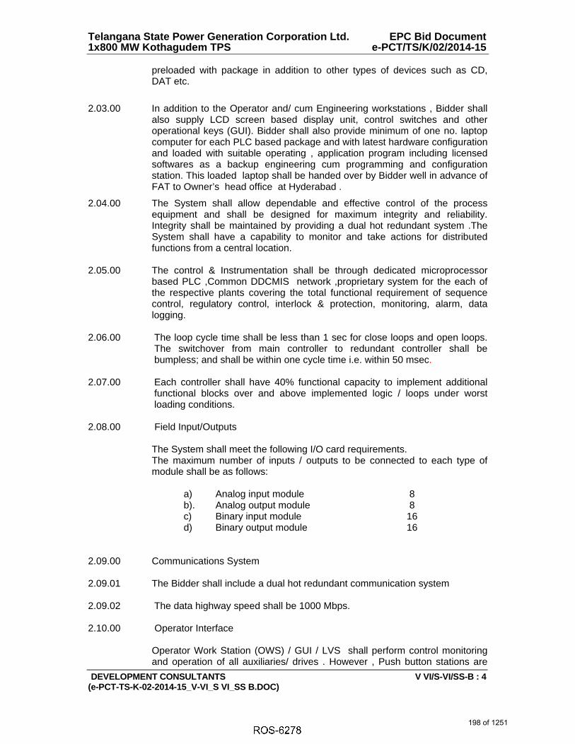
Telangana State Power Generation Corporation Ltd. EPC Bid Document 1x800 MW Kothagudem TPS e-PCT/TS/K/02/2014-15
DEVELOPMENT CONSULTANTS V VI/S-VI/SS-B : 4 (e-PCT-TS-K-02-2014-15_V-VI_S VI_SS B.DOC)
preloaded with package in addition to other types of devices such as CD, DAT etc.
2.03.00 In addition to the Operator and/ cum Engineering workstations , Bidder shall also supply LCD screen based display unit, control switches and other operational keys (GUI). Bidder shall also provide minimum of one no. laptop computer for each PLC based package and with latest hardware configuration and loaded with suitable operating , application program including licensed softwares as a backup engineering cum programming and configuration station. This loaded laptop shall be handed over by Bidder well in advance of FAT to Owner’s head office at Hyderabad .
2.04.00 The System shall allow dependable and effective control of the process equipment and shall be designed for maximum integrity and reliability. Integrity shall be maintained by providing a dual hot redundant system .The System shall have a capability to monitor and take actions for distributed functions from a central location.
2.05.00 The control & Instrumentation shall be through dedicated microprocessor
based PLC ,Common DDCMIS network ,proprietary system for the each of the respective plants covering the total functional requirement of sequence control, regulatory control, interlock & protection, monitoring, alarm, data logging.
2.06.00 The loop cycle time shall be less than 1 sec for close loops and open loops.
The switchover from main controller to redundant controller shall be bumpless; and shall be within one cycle time i.e. within 50 msec.
2.07.00 Each controller shall have 40% functional capacity to implement additional
functional blocks over and above implemented logic / loops under worst loading conditions.
2.08.00 Field Input/Outputs
The System shall meet the following I/O card requirements. The maximum number of inputs / outputs to be connected to each type of module shall be as follows:
a) Analog input module 8 b). Analog output module 8 c) Binary input module 16 d) Binary output module 16 2.09.00 Communications System
2.09.01 The Bidder shall include a dual hot redundant communication system
2.09.02 The data highway speed shall be 1000 Mbps. 2.10.00 Operator Interface
Operator Work Station (OWS) / GUI / LVS shall perform control monitoring and operation of all auxiliaries/ drives . However , Push button stations are
198 of 1251

Telangana State Power Generation Corporation Ltd. EPC Bid Document 1x800 MW Kothagudem TPS e-PCT/TS/K/02/2014-15
DEVELOPMENT CONSULTANTS V VI/S-VI/SS-B : 5 (e-PCT-TS-K-02-2014-15_V-VI_S VI_SS B.DOC)
also to be provided with RIOs as detailed out in Section V of this volume of the specification .
2.11.00 Interface with Common DDCMIS system
Each PLC , proprietary control systems shall be interfaced to Common DDCMIS network with bidirectional OPC link .The link shall be redundant.
2.12.00 PLC shall be of latest version and all the modules like Control modules, communication modules, IO modules, network interface modules etc., modules shall be from the same family of hardwares and softwares and shall be sourced from Bidder’s Original Principlal's works.
2.13.00 PLC shall have also , but not limited to, the following requirements , 2.13.01 I/O LAN Speed shall be minimum 5 Mbps - 100 MBPS on Deterministic LAN. 2.13.02 I/Os shall be Rack based and not Din Rail Mountable . 2.13.03 Processors and I/Os shall be of same family. 2.13.04 Channel Level Diagnostics for DI/DO, AI & AO shall be provided . Each
individual Channel healthiness shall be monitored at workstation / GUI level. 2.13.05 All PLC I/O Rack Power Supplies shall be redundant. Only Bulk power
supply redundancy will not be acceptable. 2.13.06 Processor shall have minimum 256 PID loops execution capability. Minimum
memory shall be 10 MB. It should be 32 Bit. 2.13.07 SOE module (if applicable) must stamp and store 250+ events at card level. 2.13.08 PLC shall store tag details and bit word addresses on upload of logic as well
as tag descriptions. 2.13.09 I/O Bit forcing in Primary to reflect in secondary immediately. (single scan
update) 2.13.09 Remote I/O Rack outside control room shall be on Fiber Optic communication
only. 2.13.10 Processor shall be self learning in case of failure. No need to configure and
program replaced processor. 2.14.00 Operating work stations must be Runtime license/servers. Client server
architecture no acceptable. 2.15.00 Each operator work station must have minimum 8000 tags handling
capability. 2.16.00 Auto Tuning feature of PIDs at PLC controller level shall be available. 2.17.00 Floating IP selection of Controller under PLC processor switchover condition
199 of 1251
6238467
Line

Telangana State Power Generation Corporation Ltd. EPC Bid Document 1x800 MW Kothagudem TPS e-PCT/TS/K/02/2014-15
DEVELOPMENT CONSULTANTS V VI/S-VI/SS-B : 6 (e-PCT-TS-K-02-2014-15_V-VI_S VI_SS B.DOC)
2.18.00 Automatic Program update on secondary on loading to Primary Processor. 2.19.00 Programming facility shall be available from Remote IO stations. 2.20.00 Processor shall support minimum 22000 IO handling capacity in Redundant
configuration. 2.21.00 Online editing of Program shall be possible.
2.22.00 Processors shall be Hot back up. 2.23.00 Automatic synchronization of primary processor/controller of PLC with
secondary processor/controller. 2.24.00 Bumpless switchover to secondary processor/controller of PLC when the
primary fails. 2.25.00 Power supply module redundancy shall be true power supply redundancy 2.26.00 Automatic program and data equalization of primary processor/controller of
PLC. 2.27.00 Automatic ‘Forcing Bit’ update in the secondary processor/controller of PLC
when any Forcing is applied in the primary processor/controller of PLC. (Forcing Bit Table of both the PLCs must be automatically synchronised.)
2.28.00 Communication speed of 5 Mbps between PLC and I/O module network 2.22.00 Softwares
The latest version of all necessary applications and networking software shall be supplied for the system. The software tool shall have facility to interface with third party software packages. Window base operating system shall be provided. The system shall be OPC compliant. Easy upgradation and future expansion facility shall be available. All softwares used shall be licensed versions only. All software user licenses shall be valid for entire life of power plant. User shall not have to pay any recurring license fee during the usage period of the system.
It shall be possible to upgrade the installed system with the latest available version of the software model during the plant life.
2.23.00 Redundant Uninterrupted Power Supplies (UPS) shall be provided for each Local PLC.. UPS specification shall be as per requirements indicated in Section V of this specification.
200 of 1251

BHARAT HEAVY ELECTRICALS LTD.
YADADRI TPS - 5 x 800 MW
TELANGANA STATE POWER GEN. CORPN. LTD.
TATA Consulting Engineers Limited
PLC CONFIGURATION ETP
4-WT-060-01143 (A)
NOTES:
1) INDUSTRIAL GRADE OWS/OEWS & 24'' TFT MONITORS SHALL BE PROVIDED.
2) ALL PLCS SHALL HAVE DUAL HOT REDUNDANT PROCESSOR AND EACH RACK
SHALL HAVE DUAL POWER SUPPLY MODULES, DUAL NETWORK COMMUNICATION
CARDS/MODULE FOR DUAL REDUNDANT RING OR DUAL REDUNDANT STAR NETWORK.
3) REDUNDANT UPS POWER SUPPLY SHALL BE USED FOR PLC
PANEL(S),RIO,BACKUP PANELS, OWS/EWS,4 WIRE INSTRUMENTS AND NETWORK
COMPONENTS.FOR APPLICABLE UPS SCHEME REFER DWG:PE-DG-417-145-I004
4) PLC PANEL SHALL HAVE PROVISION TO ACCEPT TIME SYNC. SIGNAL (NTP/IRIG-B)
FROM MASTER CLOCK SYSTEM.
5) PLC PANEL SHALL HAVE PROVISION FOR DATA EXCHANGE (OPC) WITH PLANT
DCS. NECESSARY OPC CLIENT/SERVER SOFTWARE TO BE PROVIDED IN OPC SERVER.
6) NECESSARY PATCH CORD/CONVERTERS, LIU AT BOTH PLC AND DCS END SHALL
BE IN BIDDER SCOPE FOR OPC LINK TO DDCMIS.
7) PLC SPECIFICATION SHALL BE AS PER KTPS TENDER SPECIFICATION
VOLUME-VI, SECTION VI, SUBSECTION B ONLY
8) PLC PROCESSOR AND IO CARDS/MODULES SHALL BE FROM SAME FAMILY AND
SHALL BE OF LATEST MODEL.
9) UPS SPECIFICATION SHALL BE AS PER KTPS TENDER SPECIFICATION VOLUME-V
B,SECTION XIV.UPS SIGNALS TO PLC SHALL BE THROUGH HARD WIRED AND SOFT
SIGNALS(MODBUS).
10) FIELD INSTRUMENT REDUNDANCY SHALL BE AS PER SPECIFICATION ONLY.
PROTECTION & CLCS: TRIPLE REDUNDANCY; INTERLOCK/ PERMISSIVE: DUAL
REDUNDANCY; MONITORING/ ALARM: SINGLE
11) ALL RTDS/ THERMO COUPLES IF APPLICABLE SHALL BE DUPLEX TYPE AND ALL
TERMINALS SHALL BE WIRED TO RESPECTIVE DCS/ PLC
201 of 1251
AutoCAD SHX Text
24'' (OWS)
AutoCAD SHX Text
HMI IN LCR
AutoCAD SHX Text
COLOUR LASERJET PRINTER
AutoCAD SHX Text
TYPE - A4 /A3 SIZE
AutoCAD SHX Text
PLC PANEL
AutoCAD SHX Text
PROCESSOR
AutoCAD SHX Text
SYSTEM
AutoCAD SHX Text
PROCESSOR
AutoCAD SHX Text
SYSTEM
AutoCAD SHX Text
REDUNDANT PROCESSOR
AutoCAD SHX Text
(HOT STAND BY)
AutoCAD SHX Text
FIELD
AutoCAD SHX Text
FIELD
AutoCAD SHX Text
I/O MODULE
AutoCAD SHX Text
BACK-UP CONTROL PANEL
AutoCAD SHX Text
BACK-UP CONTROL PANEL WITH
AutoCAD SHX Text
- COLORED MIMIC
AutoCAD SHX Text
- PB, LAMPS
AutoCAD SHX Text
- HARDWIRED ANNUNCIATION
AutoCAD SHX Text
Size A4
AutoCAD SHX Text
DRAWING NO.
AutoCAD SHX Text
UNIT: BOILER AUXILIARIES PLANT.
AutoCAD SHX Text
RANIPET - 632 406.
AutoCAD SHX Text
TITLE CARD DRAWING NO.
AutoCAD SHX Text
DEPT GRADE OF SCALE WEIGHT (KG). CWL DRG. NO:
AutoCAD SHX Text
PR:QA:500
AutoCAD SHX Text
9776
AutoCAD SHX Text
NPG
AutoCAD SHX Text
CODE
AutoCAD SHX Text
UNTOL.DIM
AutoCAD SHX Text
NAME SIGN DATE
AutoCAD SHX Text
CODE
AutoCAD SHX Text
U 01
AutoCAD SHX Text
DRN
AutoCAD SHX Text
CHD
AutoCAD SHX Text
APPD
AutoCAD SHX Text
--
AutoCAD SHX Text
ITEM NO. NO. OF
AutoCAD SHX Text
ITEMS
AutoCAD SHX Text
NO.OF
AutoCAD SHX Text
VAR.
AutoCAD SHX Text
REV
AutoCAD SHX Text
02
AutoCAD SHX Text
NTS
AutoCAD SHX Text
AJ
AutoCAD SHX Text
MKV
AutoCAD SHX Text
VNS
AutoCAD SHX Text
VER
AutoCAD SHX Text
A
AutoCAD SHX Text
PROJECT
AutoCAD SHX Text
OWNER
AutoCAD SHX Text
OWNER'S CONSULTANT
AutoCAD SHX Text
CONTRACTOR
AutoCAD SHX Text
CAUTION: The information on this document is the property of SIMA LAB AND BHARAT HEAVY ELECTRICALS LTD. It must not be used directly or indirectly in any way detrimental to the interest of the company.
AutoCAD SHX Text
SUB CONTRACTOR
AutoCAD SHX Text
LEGEND:
AutoCAD SHX Text
PLC - PROGRAMMABLE LOGIC CONTROLLER
AutoCAD SHX Text
DCS - DISTURBUTED CONTROL SYSTEM
AutoCAD SHX Text
UPS - UNINTERRUPTED POWER SUPPLY
AutoCAD SHX Text
OWS/EWS - OPERATOR WORK STATION/ENGINEERING WORK STATION
AutoCAD SHX Text
HMI - HUMAN MACHINE INTERFACE
AutoCAD SHX Text
NTP - NETWORK TIME PROTOCOL
AutoCAD SHX Text
OPC - OLE PROCESS CONTROL
AutoCAD SHX Text
MCCB - MOULDED CASE CIRCUIT BREAKER
AutoCAD SHX Text
MCB - MINIATURE CASE CIRCUIT BREAKER
AutoCAD SHX Text
LCR - LOCAL CONTROL ROOM
AutoCAD SHX Text
CCR - COMMON CONTROL ROOM
AutoCAD SHX Text
24'' (OEWS)
AutoCAD SHX Text
24'' (OWS)
AutoCAD SHX Text
Operator Work
AutoCAD SHX Text
Station
AutoCAD SHX Text
Operator Cum
AutoCAD SHX Text
Operator Work
AutoCAD SHX Text
Station
AutoCAD SHX Text
Engineering Station
AutoCAD SHX Text
24.08.19
AutoCAD SHX Text
24.08.19
AutoCAD SHX Text
24.08.19
AutoCAD SHX Text
REFER NOTE 4
AutoCAD SHX Text
REDUNDANT DATA COMMUNICATION BUS
AutoCAD SHX Text
ETHERNET SWITCHES WITH FIBRE OPTIC PORTS
AutoCAD SHX Text
1
AutoCAD SHX Text
2
AutoCAD SHX Text
INPUT/OUTPUT MODULES
AutoCAD SHX Text
INPUT/OUTPUT MODULES
AutoCAD SHX Text
1
AutoCAD SHX Text
2
AutoCAD SHX Text
DATE
AutoCAD SHX Text
ZONE
AutoCAD SHX Text
REV
AutoCAD SHX Text
CHECKED:
AutoCAD SHX Text
ALTERED:
AutoCAD SHX Text
01
AutoCAD SHX Text
07.11.19
AutoCAD SHX Text
AJV
AutoCAD SHX Text
VNS
AutoCAD SHX Text
REVISIONS MARKED
AutoCAD SHX Text
DATE
AutoCAD SHX Text
ZONE
AutoCAD SHX Text
REV
AutoCAD SHX Text
CHECKED:
AutoCAD SHX Text
ALTERED:
AutoCAD SHX Text
02
AutoCAD SHX Text
AJV
AutoCAD SHX Text
VNS
AutoCAD SHX Text
REVISIONS MARKED
AutoCAD SHX Text
2
AutoCAD SHX Text
2
AutoCAD SHX Text
Laptop
AutoCAD SHX Text
18.02.20
AutoCAD SHX Text
24'' (WS)
AutoCAD SHX Text
OPC Server
AutoCAD SHX Text
2
AutoCAD SHX Text
LIGHT INTERFACE UNIT
AutoCAD SHX Text
CONVERTER
AutoCAD SHX Text
LIGHT INTERFACE UNIT
AutoCAD SHX Text
CONVERTER
AutoCAD SHX Text
FO PATCH CORD
AutoCAD SHX Text
FIBER OPTIC CABLE
AutoCAD SHX Text
PART OF DCS
AutoCAD SHX Text
FIBER OPTIC CABLE
AutoCAD SHX Text
TO BE PLACED IN DCS
AutoCAD SHX Text
PART OF
AutoCAD SHX Text
PLC PANEL
AutoCAD SHX Text
TO BE PLACED
AutoCAD SHX Text
IN PLC PANEL
AutoCAD SHX Text
ETHERNET SWITCHES WITH FIBRE OPTIC PORTS
AutoCAD SHX Text
DDCMIS
AutoCAD SHX Text
BIDIRECTIONAL OPC
AutoCAD SHX Text
LINK TO DDCMIS(TCP/IP)
AutoCAD SHX Text
BIDIRECTIONAL OPC
AutoCAD SHX Text
LINK TO DDCMIS(TCP/IP)
AutoCAD SHX Text
DDCMIS
AutoCAD SHX Text
VENDOR SCOPE
AutoCAD SHX Text
BHEL SCOPE
AutoCAD SHX Text
24'' (OWS)
AutoCAD SHX Text
Operator Work
AutoCAD SHX Text
Station IN CCR1
AutoCAD SHX Text
IN CCR1
AutoCAD SHX Text
2
AutoCAD SHX Text
PT STAGE-II PLC
AutoCAD SHX Text
2
AutoCAD SHX Text
2
AutoCAD SHX Text
(OEWS)
AutoCAD SHX Text
2

ANNEXURE-VIII
UNINTERRUPTIBLE POWER SUPPLY (UPS) SPECIFICATION
202 of 1251

Telangana State Power Generation Corporation Ltd EPC Bid Document 1x800 MW Kothagudem TPS e-PCT/TS/K/02/2014-15
DEVELOPMENT CONSULTANTS V.V-B/S-XIV/1 (e-PCT/TS/K/02/2014-15/V-B/SEC-XIV)
SECTION-XIV
TECHNICAL SPECIFICATION FOR
UNINTERRUPTIBLE POWER SUPPLY 1.00.00 SCOPE OF WORK 1.01.00 Scope of Supply The scope of supply shall include Uninterruptible Power Supply (UPS)
Systems with parallel redundant arrangement as specified below for Main Plant, 400kV Switchyard control room, CHP control room with PLC system & associated RIOs and other PLC based control systems of off-site packages specified elsewhere in the specification.
Two (2) sets of UPS in Main Plant, out of which one (1) set for main TG,
SG,Station, C&I etc of MAIN PLANT systems, 2nd set for common DDCMIS/PLC systems for the PLC/DCS systems of air compressor, online tube cleaning system, HVAC system, fire detection panel in CCR, which are in TG building & OWS systems of Plant Water System, AHP,CHP etc systems ( which are placed in CCR common control desk)
i) Each set of UPS system will consist of :
a. 2x100% capacity static inverter & input isolation transformer
b. 100 % capacity static switches (2 nos.)
c. One manual bypass switch
d. 2x100% capacity float-cum-boost chargers
e. 2x100% capacity UPS system battery (Lead Acid Plante Type) with back up time of 1 hour.
f. One step down transformer; (415 V three phase to 240 V
single phase) for bypass
g. One static voltage regulator
h. Two AC distribution boards (ACDB-1A and ACDB-1B)
i. Interconnecting cable between UPS Equipment, battery and ACDB.
j. Two (2) nos. input output isolation transformer
Any other equipment necessary for complete of the system
ii) One (1) set of special tools and tackle. iii) Mandatory Spare parts.
203 of 1251
6238467
Line
6238467
Line
6238467
Line
6238467
Line
6238467
Line
6238467
Line
6238467
Line
6238467
Rectangle
6238467
Typewriter
DELETED

Telangana State Power Generation Corporation Ltd EPC Bid Document 1x800 MW Kothagudem TPS e-PCT/TS/K/02/2014-15
DEVELOPMENT CONSULTANTS V.V-B/S-XIV/2 (e-PCT/TS/K/02/2014-15/V-B/SEC-XIV)
iv) All relevant drawings, data and instruction manuals. 2.00.00 CODES AND STANDARDS a) All equipment and materials shall be designed, manufactured and
tested in accordance with the latest applicable Indian Standards (IS) except where modified and/or supplemented by this specification.
b) Equipment and materials conforming to any other standard which
ensures equal or better quality may be accepted. In such case, copies of the English version of the standard adopted shall be submitted along with the bid.
c) The electrical installation shall meet the requirements of Indian
Electricity Rules as amended up to date and relevant IS Codes of Practice. In addition, other rules or regulations applicable to the work shall be followed.
3.00.00 DESIGN CRITERIA 3.01.00 Design Basis
a) UPS System provides a regulated and uninterrupted single phase A.C. power, within specified tolerances, to critical station loads during normal and emergency operation. Capacity of inverter output shall be computed by the contractor considering the above requirement. 25% spare margin shall be kept on the total of above requirement.
b) The UPS system excluding its battery shall be installed indoors in A.C.
environment. c) UPS shall be worked at its full capacity even battery is not connected
with the system. d) UPS system shall be compatible for satisfactory and well-coordinated
operation with other related equipment as well as with input and output systems.
e) Energizing or de-energizing any portion of the system serviced by the
UPS shall not cause output changes which will affect the operation or integrity of the remaining portions of the system in any way.
f) The equipment shall be self-protecting against all A.C. and D.C.
transients, voltage surges and steady state abnormal voltages and currents.
g) The circuit protection shall be coordinated with UPS short circuit
capacity and protective device characteristics so that a fault on any circuit shall result in minimum loss of function.
h) All non-interrupting components of UPS system shall be capable of
withstanding the prevailing short circuit current without damage.
204 of 1251

Telangana State Power Generation Corporation Ltd EPC Bid Document 1x800 MW Kothagudem TPS e-PCT/TS/K/02/2014-15
DEVELOPMENT CONSULTANTS V.V-B/S-XIV/3 (e-PCT/TS/K/02/2014-15/V-B/SEC-XIV)
i) All circuit interrupting components shall be capable of withstanding and interrupting the prevailing short circuit currents without damage.
j) The procedure for battery sizing calculation shall be generally as per
relevant IEEE, considering design margin as 15% and aging factor as 1.25
k) For continuous operation at specified ratings, temperature rise of the
various components of UPS system shall be limited to the permissible values stipulated in the relevant standards and/or this specification.
l) The chargers, inverters, static switches, regulating transformers and
voltage stabilizers should be arranged in such a way that any equipment can be fully isolated for maintenance without affecting in any way the operation of other panels/components.
m) The chargers, inverters, static switches, regulating transformers and
voltage stabilizers should be arranged in such a way that any equipment will be fully isolated for maintenance without affecting in any way the operation of other panels/ components.
n) In the A.C. Distribution Board, the Bidder shall provide 10% or
minimum one (1) no. spare feeder of each size and type of the outgoing feeders.
o) All the cooling fans inside the panels shall be of industrial grade only. 3.02.00 System Concept System Concept
a) A.C. power source are available to the UPS system. The system is so designed that its load shall be served without interruption as long as one of the above power sources is available within specified limit of voltage and/or frequency.
The UPS will consist of two physically separate sets of equipment
streams each consisting of the following:
i) One set of converter to convert incoming 240V, 1 Ph, 50 Hz A.C. power to suitable D.C.
ii) One set of suitable Battery Bank to get charged by the above
referred converter and to feed the inverter described below. iii) The Float-cum-Boost charger will be normally ON, supplying
the DC load current and at the same time trickle charging the battery. The characteristics shall be such that if load is high and exceeds the charger capacity, the excess load shall be supplied by the battery.
iv) The Float-cum-Boost charger shall be provided with Solid
State electronic regulators to prevent rising of charging current to avoid thermal runaway of the batteries.
205 of 1251

Telangana State Power Generation Corporation Ltd EPC Bid Document 1x800 MW Kothagudem TPS e-PCT/TS/K/02/2014-15
DEVELOPMENT CONSULTANTS V.V-B/S-XIV/4 (e-PCT/TS/K/02/2014-15/V-B/SEC-XIV)
v) The float-cum-boost charger shall also have provision for float,
equalizing and boost charging the battery through manual selection.
vi) Output of the chargers shall be controlled automatically as well
as manually. AUTO/MANUAL selector switch along with voltage/current setter shall be provided for this purpose.
vii) For ungrounded DC system, suitable ground fault detection
system shall be provided in the battery charger panel to detect ground fault on either polarity for annunciation in charger panel.
viii) The batteries shall be so sized as to meet emergency load
duty cycle requirements for one (1) hour as referred in Annexure-A. All momentary loads shall be treated as one-minute loads.
ix) One set of inverter to take D.C. input from above referred
converter - Battery assembly output and to produce high quality 240V, 1Ph 50 Hz A.C. output power.
x) One set of standby bypass stream consisting of suitable
transformer, voltage stabilizer etc. to produce regulated 240V, 1 Ph. 50 Hz A.C. power from new input 240V, 1 Ph. 50 Hz A.C. power.
xi) One set of static switch, synchronizing circuit to parallel the
above-mentioned Inverter output and bypass stabilized raw power stream.
xii) One UPS A.C. power distribution board with suitable no. of
output feeders.
Two sets of equipment streams as mentioned above will constitute the UPS system. One set of synchronizing equipment and high performance static switch will parallel the above two streams and common output will be taken to loads which can accept only single non-redundant power input source.
For equipment requiring dual redundant input power source, separate cables will be taken from the individual UPS Power Distribution Boards of the above-mentioned two UPS streams.
The system will ensure highest system availability around 99%.
b) Each of the two UPS streams will be of 100% capacity and will
normally work, each sharing 50% load. On failure of any stream, its load gets automatically transferred to the other inverter through static transfer switch.
206 of 1251

Telangana State Power Generation Corporation Ltd EPC Bid Document 1x800 MW Kothagudem TPS e-PCT/TS/K/02/2014-15
DEVELOPMENT CONSULTANTS V.V-B/S-XIV/5 (e-PCT/TS/K/02/2014-15/V-B/SEC-XIV)
c) If one UPS stream is out of service for any reason then the second UPS stream will be working with 100% UPS load.
d) Inside each stream on failure of its converter/battery/inverter assembly
the standby A.C. source will back up to supply the 100% UPS load automatically through static transfer switch.
3.03.00 Layout Criteria
The UPS system will be located indoor. The Contractor shall indicate the space requirement for the equipment offered by them separately for UPS cabinet, UPS battery and UPS distribution board. Battery room ventilation shall be under the scope of the Contractor.
4.00.00 SPECIFIC REQUIREMENTS 4.01.00 Static Inverter a) The static inverters shall be static type consisting of IGBT PWM type
inverter, static filters, integrated control modules including necessary oscillators, voltage regulators, current limiting and surge suppression.
b) The inverter equipment shall include all necessary circuitry and
devices to conform requirements like voltage regulation, soft start, transient recovery, protection, automatic synchronisation, wave shaping, etc. as specified herein.
c) Upon transfer of full load, the inverter output voltage shall not drop
below 80% of nominal voltage during the first half cycle after transfer and 90% of nominal voltage in the next half cycle. The recovery to within 2% of voltage shall be in less than 50 milli-seconds.
d) On occurrence of a fault in branch circuit, the inverter shall be capable
of clearing the highest rated branch circuit fuse in 4 milli-seconds or less.
e) The inverter shall be protected against overload, short circuit, 100%
loss of load, as well as excursions, loss or restoration of D.C. input voltage and synchronising voltage. The overload capacity shall be 125% for 10 mins., 150% for 60 secs. and 300% for 4 msecs.
f) The D.C. input current shall never exceed twice the full load current
except for a short circuit within the inverter. g) For any value of the load and load power factor drawn by the
equipment served, the inverter shall not impose on D.C. source any voltage oscillations in excess of 5 volts (RMS total all frequencies) or any current oscillations in excess of 3 percent (RMS total all frequencies) of the D.C. current at full load.
207 of 1251

Telangana State Power Generation Corporation Ltd EPC Bid Document 1x800 MW Kothagudem TPS e-PCT/TS/K/02/2014-15
DEVELOPMENT CONSULTANTS V.V-B/S-XIV/6 (e-PCT/TS/K/02/2014-15/V-B/SEC-XIV)
h) The inverter will be self protecting against A.C. and D.C. Transients, voltage surges and steady state abnormal voltage and currents likely to be encountered in the plant.
4.02.00 Automatic Synchronisation a) Inverter equipment shall include stable solid state oscillator devices
designed to automatically maintain the inverter output in phase and in synchronism with the stand-by A.C. source.
b) Facility shall be provided for automatic transfer to internal oscillator
operation when the stand-by source frequency is beyond specified limits and the frequency shall be automatically controlled within 50 Hz plus or minus 0.5 Hz when the inverter operates in this mode.
c) Retransfer to stand-by A.C. source for synchronisation shall be
automatic after the stand-by source frequency is restored to permissible limits and remains within this limit for an adjustable time delay period (up to 5 seconds).
d) Provision shall be made for stepless adjustment of synch- disconnect
frequency range from 50 Hz 0.5 Hz to 50 Hz 2 Hz. e) Automatic adjustment of phase relationship between inverter output
and stand-by A.C. source shall be gradual at a controlled slow rate, which shall not exceed one hertz per second.
4.03.00 Static Transfer Switch a) The static transfer switch shall be solid-state type using SCR for
automatic/manual transfer of load from "inverter" to "stand-by" source and vice-versa.
b) Stand-by source can be either of the inverter or A.C. source
depending on whether both the inverters are supplying 50% load each or one of the inverter is carrying 100% load.
c) The transfer time including sensing shall not be more than one-fourth
cycle. Further the transition shall be make-before-break in both directions.
d) The capacity of static transfer switch shall be equal to the continuous
full-load capacity of the inverter. The switch shall be provided with protective devices in both normal and alternate power source.
e) Static transfer switch shall be furnished with contact to alarm failure of
the alternate source or opening of any fuse protecting the static switch.
f) Static transfer switch shall include all necessary circuitry and devices
to meet the functional requirements of transfer initiation, transfer inhibit and re-transfer back to normal as detailed below
g) Transfer Initiation
208 of 1251

Telangana State Power Generation Corporation Ltd EPC Bid Document 1x800 MW Kothagudem TPS e-PCT/TS/K/02/2014-15
DEVELOPMENT CONSULTANTS V.V-B/S-XIV/7 (e-PCT/TS/K/02/2014-15/V-B/SEC-XIV)
i) The transfer of static switch from normal 'Inverter' position to
'stand-by' position shall be initiated by one of the following causes.
Inverter failure and UPS system trouble
Inverter output voltage failure.
Manual push button operation ii) The UPS bus shall be monitored by two voltage detectors. One
fast acting circuit shall be used for detecting a complete and instantaneous voltage loss while the other slower acting averaging circuit with adjustable trip level shall be employed to detect voltage deviation beyond selected limits. Both voltage detector circuits shall automatically initiate operation of transfer switch.
iii) The static switch shall automatic transfer the load from inverter
to stand-by source when the maximum I2t capability of the inverter is reached and when the inverter output drops below 90%.
h) Transfer Inhibit Automatic or manual transfer from inverter to stand-by A.C. source
vice versa shall be inhibited when the inverter frequency is not synchronised to the alternate source.
i) Retransfer to Normal
1) The return to inverter mode shall be manual in all cases.
2) Manual transfer shall be initiated by push button actuation. 4.04.00 Manual By-pass Switch a) Manual by-pass switch is used to isolate any static transfer switch for
maintenance or repair without interruption to the UPS load. b) The switch has also the facility of by-passing both the static transfer
switches during start-up at the option of the operator. c) Switch contact shall be make-before-break type. d) The switch shall have current rating equal to the full load inverter
current and necessary short time load carrying and interrupting capacity to meet the requirement of UPS system.
4.05.00 Battery a) General
209 of 1251

Telangana State Power Generation Corporation Ltd EPC Bid Document 1x800 MW Kothagudem TPS e-PCT/TS/K/02/2014-15
DEVELOPMENT CONSULTANTS V.V-B/S-XIV/8 (e-PCT/TS/K/02/2014-15/V-B/SEC-XIV)
i. Each set of battery shall consist of number of cells assembled together on mounting racks.
ii. The battery shall be flooded cell Lead acid PLANTE type and shall be
suitable for operating satisfactorily in humid and corrosive atmosphere. The batteries will be suitable for float /boost charging and will be suitable for continuous operation.
iii. The equipment shall comply with the requirement of latest revision of
Indian standards issued by BIS (Bureau of Indian Standards): IS: 1652:1991 and IEEE Std. 485 for Lead Acid (Plante) Battery.
In case Indian Standards are not available for any equipment, Standards issued by IEC/BS/VDE/IEEE/NEMA or equivalent shall be applicable.
iv. Autofill system
Bidder to provide complete system for automatic water filling (topping-up) of lead acid plante’ type batteries to avoid spillage of water and acid which spoils environment. The autofill system shall be intelligent and efficient where replenishment of water is done automatically without manual intervention. The water enters the cell through the ‘autofil plug’ and raises the electrolyte to a preset level controlled by the float. The float raises and closes the valve in the plug by a 2.5:1 level action. When the electrolyte level drops the float operated valve will open automatically Bidder to provide the total system including necessary storage tank, pipelines, autofill plugs and all peripherals etc. The material of all parts shall be acid proof plastic material.
b) Technical Requirement
i) The battery shall be heavy duty type suitable for power plant duty with
float duty operation at constant voltage permanently applied to its terminals which is sufficient to maintain the limits of +10% and -15% of the nominal system voltage at any time during the duty cycle in state close to full charge and shall be designed to supply the load in the event of normal power supply failure.
ii) The rated ampere hour capacity of the cell/battery shall be at
reference temperature of 27ºC, constant current discharge at 10 hours rate (C10) for Plante type Battery to meet end cell voltage of the Cell. A design margin of 20% shall be considered.
iii) The battery shall be suitable for being boost charged to fully charged
condition from fully discharged condition within eight (8) hours.
iv) The batteries shall be so sized as to meet emergency load duty cycle requirements for one (1) hour. All momentary loads shall be treated as one-minute loads.
v) For PLANTE type Battery it shall be supplied uncharged for flooded
cell with the electrolyte furnished in a separate non-returnable container. 10% extra electrolyte shall be furnished to cover spillage in transit or during erection.
210 of 1251

Telangana State Power Generation Corporation Ltd EPC Bid Document 1x800 MW Kothagudem TPS e-PCT/TS/K/02/2014-15
DEVELOPMENT CONSULTANTS V.V-B/S-XIV/9 (e-PCT/TS/K/02/2014-15/V-B/SEC-XIV)
vi) Each battery set shall consist of a group of cell electrically connected
in series to attend the nominal voltage level specified on the data sheet. The terminal cells shall be supplied with connectors for termination to the charger. The supplier shall provide inter-cell connectors and related hardware and accessories required for normal operation and maintenance. All cell posts shall be shrouded and connectors insulated. Nickel plated copper shall be furnished to connect up cells of Battery set. For lead acid battery to prevent corrosion all copper/ brass material shall be effectively coated with lead.
vii) Cell container shall be made of heat resistant, tough translucent
polypropylene (SAN) material to make the cell mechanically sturdy and facilitate visual electrolyte level checks for ease in of maintenance.
viii) The cell terminals posts shall be provided with connector bolts and
nuts, made of Nickel plated steel or lead coated copper/brass material to prevent corrosion. The terminals shall be suitable for short circuit current and specified discharge current without damage to cell as a result of terminal heating.
ix) Flame arresting flip-open/ or ceramic vent cap shall be provided on
the cell to avoid explosion and contamination.
x) The following information shall be permanently marked on the cell :
Nominal voltage.
Name or manufacturer/model reference. Rated capacity in ampere hour (Ah) with End Cell Voltage. Voltage for float operation of 27° with tolerance of ±1%. Month and year of manufacture.
xi) Battery racks shall be constructed of best quality teakwood with at
least three (3) coats of electrolyte -resistant paint of approved shade forming a rigid structure. Cell shall be supported on PVC/porcelain/Hard Rubber insulator fixed on the rack with adequate clearance between adjacent cells.
xii) Each set of battery shall be equipped with a automatic battery
condition (Health check) and performance monitoring system. The battery monitoring system shall compare measured figure during a partial discharge against stored characteristics for the type and capacity of the battery. The system shall be able to test, analyse and predict the battery performance, computing remaining capacity and battery efficiency. The automatic battery monitoring system shall compensate for cell temperature and discharge load current throughout the discharge cycle, premature failure of the batteries etc. The system shall have a programmable event log shall be secured in
211 of 1251

Telangana State Power Generation Corporation Ltd EPC Bid Document 1x800 MW Kothagudem TPS e-PCT/TS/K/02/2014-15
DEVELOPMENT CONSULTANTS V.V-B/S-XIV/10 (e-PCT/TS/K/02/2014-15/V-B/SEC-XIV)
the event of total power failure for a period upto six month. In addition to local indication and control the battery monitoring system shall include an RS. 232 output port to enable battery parameters and alarms to be monitored from plant DCS
4.06.00 Float-cum-Boost Charger 4.06.01 The charger shall be solid-state type with full wave fully controlled, bridge
configurations. It shall be suitable for the inverter of IGBT type. 4.06.02 The charger shall be provided with automatic voltage regulation, current
limiting, smoothing filter circuit and soft-start feature. 4.06.03 The charger shall have the provision of float, equalizing and boost charging.
Further the charger shall be suitable for single and parallel operation. 4.06.04 Suitable circuitry shall be provided to ensure that the charging current is
voltage regulated and current limited. 4.06.05 Each charger shall be rated to meet 100% UPS load plus recharge the fully
discharged UPS battery within 8 hours. 4.06.06 Voltage control shall be stepless smooth and continuous. Float & equalizing
control shall have an adjustable range of ± 5%.
For Other details as given in sub-section of Battery & Battery charger specification
4.07.00 Step-down transformer and voltage stabilizer a) A three phase to single phase transformer along with associated
voltage stabilizer shall be furnished with the UPS system. b) The transformer and stabilizer shall be sized for 100% UPS load and
shall coordinate with the largest branch circuit protection device for feeder short circuit current without sacrificing voltage regulation.
c) The voltage stabilizer shall employ silicon solid state circuitry and shall
maintain the specified output voltage for 0 to 100% load with maximum input voltage variation as indicated in the annexure.
d) Provision shall be kept for dead closing of static transfer switch from
stabilizer circuit to inverter when the output of the stabilizer is zero, but at that time the inverters are running.
4.08.00 A.C. Distribution Boards a) The distribution boards shall be fixed type, of modular design in
freestanding gasketted sheet steel enclosure conforming to IP-54. Sheet steel thickness shall be 2 mm minimum.
212 of 1251

Telangana State Power Generation Corporation Ltd EPC Bid Document 1x800 MW Kothagudem TPS e-PCT/TS/K/02/2014-15
DEVELOPMENT CONSULTANTS V.V-B/S-XIV/11 (e-PCT/TS/K/02/2014-15/V-B/SEC-XIV)
b) Each module shall be housed in a separate compartment complete with individual front access door. Working height shall be limited to 1800 mm from floor level.
c) A full height vertical cable alley shall be provided in each panel to
facilitate module wiring. The alley shall be liberally sized and shall have removable cover at the front. Removable back covers shall be provided at the back of the panels.
d) Switches shall be double pole, air break, heavy duty type, capable of
safely making and breaking the full load current of associate circuit. e) Switch handle shall have position indicator and provision of padlocking
in ON & OFF positions. Further it shall be interlocked with access door for safety.
f) Fuses shall be HRC, preferably link type, design to permit easy & safe
replacement. Visible indication shall be provided for indication of fuse. 4.09.00 UPS Cabinets/Enclosures a) The UPS system components shall be housed in a sheet steel
freestanding IP-42 enclosure with all access from the front. Sheet steel thickness shall be 2 mm minimum.
b) The enclosure shall consist of vertical cabinets housing modules in
rack type sub-assemblies, connected mechanically and electrically to form a rigid, self-supporting, metal enclosed structure.
c) The modular units shall be mounted in pull out and/or swing trays.
Each module shall be capable of being easily removed to provide for the ready inspection of major solid-state devices.
d) Vertical wiring trough shall be provided for the entire height of the UPS
cabinet. Cable entry shall be from bottom only. e) Adequate ventilating louvers and screens shall be provided. The top of
the panel shall be protected by a suitable drip cover to prevent entrance of falling liquid and foreign material.
f) If the equipment supplied requires forced air cooling, the cooling
system furnished shall meet the following requirement :
i) Two (2) nos. 100% cooling fans, industrial grade, shall be provided for each vertical panel.
ii) Completely independent duplicate protection, control and wiring systems shall be provided for the cooling fans for redundancy.
iii) The cooling fans shall be powered from the output of the associated inverter. Normally one fan will be running while the other is on stand-by.
213 of 1251

Telangana State Power Generation Corporation Ltd EPC Bid Document 1x800 MW Kothagudem TPS e-PCT/TS/K/02/2014-15
DEVELOPMENT CONSULTANTS V.V-B/S-XIV/12 (e-PCT/TS/K/02/2014-15/V-B/SEC-XIV)
iv) Each cooling fan shall be equipped with an airflow switch having an alarm contact that closes upon failure of airflow.
4.10.00 Alarms a) Solid state audio-visual annunciation system shall be provided for
inverters, static transfer switch, battery charger. b) Alarm facia shall be provided on each charger and inverter panel,
complete with proper actuating devices, circuitry and legends. c) The arrangement shall be such that on occurrence of a fault the
corresponding window will light up and stays lighted until the fault is cleared and reset button pressed.
d) Each time a window lights up a master relay will get energized to
provide group alarm signals for remote DDCMIS alarm system. e) The requirements of indication/metering/alarms are given in the
annexure. f) Alarm contacts shall be rated 0.5 A at 220 V DC and 5A at 240 V A.C. g) All indicating meter shall be digital type with in-built transducers (4-
20mA) for hooking up with DDCMIS. 4.11.00 Lamp / Space Heaters / Receptacles a) The panels shall be provided with :
i) Internal illumination lamp with door switch.
ii) Space heater with thermostat control.
iii) 3-pin 6A receptacle with plug. b) Lamp, heater and receptacle circuits shall have individual switch fuse
units. 4.12.00 Wiring / Cabling a) The panels shall be completely wired up. All wiring shall be done with
flexible, 1100V grade, fire resistance PVC insulated wires with stranded 2.5 Sq.mm. copper conductors and routed through wiring troughs. Each wire shall be ferruled by plastic tube with indelible ink print at both end having terminal block No., terminal number as per approved wiring diagram.
b) Panels shall have removable gland plate for cable entry. All incoming/
outgoing cables shall be terminated in suitable terminal block. c) Control terminal blocks shall be box-clamp type, minimum 10 Sq.mm.
20% spare terminals shall be furnished. 4.13.00 Nameplate
214 of 1251

Telangana State Power Generation Corporation Ltd EPC Bid Document 1x800 MW Kothagudem TPS e-PCT/TS/K/02/2014-15
DEVELOPMENT CONSULTANTS V.V-B/S-XIV/13 (e-PCT/TS/K/02/2014-15/V-B/SEC-XIV)
a) Engraved nameplates shall be provided for each panel and for each
equipment/device mounted on it. b) The material shall be anodised aluminium / lamicoid, 3 mm thick, with
white letters on black background. c) Nameplates shall be held by self-tapping screws. The size of
nameplates shall be approximately 20 mm x 75 mm for equipment and 40 mm x 150 mm for panels.
d) Nameplates for panels shall be provided both on the front and rear. e) Control and meter selection switches shall have integral nameplates.
Nameplates for all other devices shall be located below the respective devices.
f) Instruments and devices mounted on the face of the panels shall also
be identified on the rear with the instrument/device number. The number may be painted on or adjacent to the instrument or device case.
g) Caution notice on suitable metal plate shall be affixed at the back of
each panel. 4.14.00 Grounding a) Normal 3-phase A.C power supply will be grounded at the source. For
grounding other than this, isolation transformer shall be furnished with the U.P.S.
b) The inverter D.C. input and A.C. output shall be electrically isolated
from each other and from cabinet ground. c) Panels shall have fully rated ground bus with two ground terminals,
one at each end. d) Each terminal shall comprise two-bolt drilling M10 G.I. bolts and nuts
to receive ground connection of 50 x 6 mm G.S. flat. e) Separate electronic grounding shall be provided for each UPS system. 4.15.00 Tropical protection a) All equipment accessories and wiring shall have fungus protection,
involving special treatment of insulation and metal against fungus insects and corrosion.
b) Screens of corrosion resistant material shall be furnished on all
ventilating louvers to prevent the entrance of insects.
215 of 1251

Telangana State Power Generation Corporation Ltd EPC Bid Document 1x800 MW Kothagudem TPS e-PCT/TS/K/02/2014-15
DEVELOPMENT CONSULTANTS V.V-B/S-XIV/14 (e-PCT/TS/K/02/2014-15/V-B/SEC-XIV)
4.16.00 Painting Finish paint shall be as per TSGENCO practice. Refer to clause no.1.16.00 of
Section-I, Volume V-A. 5.00.00 TESTS 5.01.00 Shop Tests
5.01.01 Tests on Battery
a) Test for capacity - test for voltage during discharge
b) Ampere hour & watt hour efficiency test
c) Endurance test. 5.01.02 Tests on battery charger
a) Dielectric tests.
b) Voltage regulation check from 0 to 100% load with 10% input voltage variation.
c) Ripple content measurement.
d) Heat run test on current limiting value.
5.01.03 Tests on UPS System
a) Type & routine test for various components.
b) Burning test on PCBS - Assembled PCBS shall be tested at 70C for 72 hours in loaded condition.
c) Rapid temperature cycling test at 70C and 0C for 30 minutes at each temperature - 5 such cycles.
d) Functional tests to demonstrate compliance with all specified requirements and published. Specifications such as frequency, regulation, voltage regulation, current limiting, fuse clearing capability of inverters, demonstration of phase and frequency control of inverter for synchronization with range of adjustments transfer and retransfer of static switches under influence of under voltage and over current, tests on chargers, batteries and other system component to confirm compliance with specification.
6.00.00 DRAWINGS, DATA & MANUALS 6.01.00 To be submitted with the Bid 6.01.01 UPS panels, Battery Charger and Battery layout drawing with dimensions 6.01.02 General Arrangement drawing of UPS panels
216 of 1251

Telangana State Power Generation Corporation Ltd EPC Bid Document 1x800 MW Kothagudem TPS e-PCT/TS/K/02/2014-15
DEVELOPMENT CONSULTANTS V.V-B/S-XIV/15 (e-PCT/TS/K/02/2014-15/V-B/SEC-XIV)
6.01.03 Bill of Material 6.01.04 Schematic drawing of UPS circuits 6.01.05 Battery cell voltage characteristics and data for different discharge rates 6.01.06 Technical leaflets on : a) UPS System b) Battery c) Battery charger d) Inverter e) Static Switch f) Manual bypass Switch 6.01.07 Duty cycle diagram and battery sizing calculation in the format of relevant IS
Standard 6.01.08 Sizing calculation of UPS system, charger main equipment, viz. SCRs,
rectifier transformers etc 6.01.09 Type test certificates for similar equipment. 6.02.00 To be submitted for Owner’s Approval and Distribution All relevant drawings and data pertaining to the equipment like GTP, GA
drawing, BOM, foundation plan, schematic drawing, QAP, sizing calculations, etc shall be submitted by the Bidder for the approval of Owner/Owner’s consultant. Also refer clause no. 1.19.02(u) of Section-I of Volume – V-A: Technical Specifications for Electrical Equipment & Accessories.
217 of 1251

Telangana State Power Generation Corporation Ltd EPC Bid Document 1x800 MW Kothagudem TPS e-PCT/TS/K/02/2014-15
DEVELOPMENT CONSULTANTS V.V-B/S-XIV/16 (e-PCT/TS/K/02/2014-15/V-B/SEC-XIV)
ANNEXURE-A
RATINGS & REQUIREMENTS 1.00.00 STATIC INVERTER 1.01.00 Application : UPS System for Control system, DCS
and other loads as required by Bidder. 1.02.00 Type : Static IGBT PWM type 1.03.00 Duty : Continuous 1.04.00 Enclosure : Sheet steel, IP42 1.05.00 Cooling : Natural convection or forced cooling
using redundant fans. 1.06.00 Design Ambient temperature : 50 Deg.C 1.07.00 Inverter capacity : To be decided by the Bidder 1.08.00 Overload capacity : 300% for 4 m secs. 150% for 60 secs 125% for 10 mins 110% for continuous 1.09.00 Voltage a) Inverter input, Battery output : To be decided by the Bidder b) Nominal output : 240 V, 50 Hz, 1-phase 1.10.00 Voltage Regulation :
a) Steady state (0-100% load at all input voltages and all power factors)
: 1.5%
b) Transient voltage
(On application or removal of 100% load)
: 10%
c) Time to recover from transient
to normal voltage : 50 milliseconds.
218 of 1251

Telangana State Power Generation Corporation Ltd EPC Bid Document 1x800 MW Kothagudem TPS e-PCT/TS/K/02/2014-15
DEVELOPMENT CONSULTANTS V.V-B/S-XIV/17 (e-PCT/TS/K/02/2014-15/V-B/SEC-XIV)
1.11.00 Wave form :
a) Nominal frequency : 50 Hz b) Frequency range for all
conditions of input supplies, loads & temperature occurring simultaneous or in any combination (automatically controlled)
: 0.05 Hz.
c) Synchronisation limits (for
maintenance of synchronism between inverter and standby A.C source)
: 49 Hz to 51 Hz (factory set)
d) Field adjustment range for (c)
above : 50+_ 0.05 Hz to 50+_ 2 Hz
e) Total Harmonic Content : 5% maximum at rated load f) Harmonic content for any
single harmonic : 3% maximum
1.12.00 Rated output current at rated output voltage with current limit not operating a) Current : 200% b) Duration : 100 milliseconds. 1.13.00 Efficiency at full load : 90% or better. (Watt output/watt input) 1.14.00 SCR derating from peak voltage and peak rating : 50% 2.00.00 STATIC SWITCH 2.01.00 Type : Solid-state, SCR 2.02.00 Duty : Continuous 2.03.00 Enclosure : Sheet Steel, IP42 2.04.00 Cooling : Natural convection or forced cooling
using redundant fans. 2.05.00 Ambient Temperature : 50 Deg.C 2.06.00 Capacity a) Continuous : Equal to full load capacity of the inverter.
219 of 1251

Telangana State Power Generation Corporation Ltd EPC Bid Document 1x800 MW Kothagudem TPS e-PCT/TS/K/02/2014-15
DEVELOPMENT CONSULTANTS V.V-B/S-XIV/18 (e-PCT/TS/K/02/2014-15/V-B/SEC-XIV)
b) Overload : 300% for 4 m secs. 150% for 60 secs 125% for 10 mins 110% for continuous c) Peak : 1000% of continuous rating for 5 cycle. 2.07.00 Normal Voltage : 240V, 50 Hz, 1-phase. 2.08.00 Transient Voltage Tolerance : 340V peak above the nominal line
voltage. 2.09.00 Transfer Time : less than 4 m secs. 3.00.00 MANUAL BY-PASS SWITCH/BREAKER 3.01.00 Type : Maintained, make before break. 3.02.00 Voltage : 600V 3.03.00 Rated Current : To meet the system requirement 4.00.00 BATTERY 4.01.00 Application : UPS Battery 4.02.00 Design Ambient Temperature : 50 Deg.C 4.03.00 Type : Lead Acid Plante type 4.04.00 Nos. of Cells per Battery : To be decided by the Bidder 4.05.00 Battery nominal voltage : To be decided by the Bidder 4.06.00 Battery AH rating : Bidder to compute considering 100%
UPS load for 30 minutes followed by 60% UPS load for 30 minutes.
4.07.00 Method of working a) Float charge (Normal) : 2.23 Volts / Cell b) Boost charge : 2.30 Volts / Cell (After complete discharge) c) End cell voltage : 1.80 Volts 4.08.00 Mounting : Steel Rack 4.09.00 Connection : Cables
220 of 1251

Telangana State Power Generation Corporation Ltd EPC Bid Document 1x800 MW Kothagudem TPS e-PCT/TS/K/02/2014-15
DEVELOPMENT CONSULTANTS V.V-B/S-XIV/19 (e-PCT/TS/K/02/2014-15/V-B/SEC-XIV)
5.00.00 BATTERY CHARGER 5.01.00 Charger : Float + Boost 5.02.00 Type : Solid-state, full wave, fully controlled. 5.03.00 Duty : Continuous 5.04.00 Enclosure : Sheet Steel, IP42 5.05.00 Cooling : Natural convection or forced cooling
using redundant fans. 5.06.00 Design Ambient Temperature : 50 Deg.C 5.07.00 A.C. input : a) Supply : 415V, 3-phase, 50 Hz b) Voltage variation : 10% c) Frequency variation : +3% to -5%
d) Combined volt frequency variation : 10% (absolute sum) e) Short-circuit level : 50 KA f) System earthing : Solidly grounded 5.08.00 D.C. output : 100% UPS load plus restoring fully
discharged battery to full charge condition in 8 hours.
5.09.00 Blocking Diode, Peak inverse voltage : 800 V (minimum) 5.10.00 Performance Requirement a) The output voltage of the charger shall be regulated within 1% of the set
value for any load variation from 0 to 100% and A.C input voltage and frequency variation as indicated above in 4.06.00
b) The ripple content in charger D.C. output shall be limited to less than 1%
with battery and less than 2% without battery.
221 of 1251

Telangana State Power Generation Corporation Ltd EPC Bid Document 1x800 MW Kothagudem TPS e-PCT/TS/K/02/2014-15
DEVELOPMENT CONSULTANTS V.V-B/S-XIV/20 (e-PCT/TS/K/02/2014-15/V-B/SEC-XIV)
6.00.00 DISTRIBUTION BOARDS 6.01.00 Type : Fixed, Modular. 6.02.00 Enclosure : Sheet Steel, IP54 6.03.00 Mounting : Free standing (can be attended from both front &
back)
222 of 1251

Telangana State Power Generation Corporation Ltd EPC Bid Document 1x800 MW Kothagudem TPS e-PCT/TS/K/02/2014-15
DEVELOPMENT CONSULTANTS V.V-B/S-XIV/21 (e-PCT/TS/K/02/2014-15/V-B/SEC-XIV)
ANNEXURE-B
SET OF ACCESSORIES TO BE PROVIDED FOR EACH BATTERY BANK
a) One battery log book. b) Two copies of printed instruction sheet. c) One no. cell testing voltmeter (3-0-3 volts) complete with leads. d) One no. rubber syringe type hydrometer suitable for specific gravity
reading. e) Three nos. pocket thermometer. f) One no. thermometer (0 to 100) with specific gravity correction scale. g) One set cell bridging connector. h) Battery racks suitable for accommodating the cells coated with paint. i) Delrin insulator (with 5% extra), rubber pad etc. for rack. j) Two nos. plastic filling bottle for filling up. k) One pair of spanners. l) Two pairs of rubber hand gloves. m) Two nos. cell lifting straps. n) One set of inter cell, inter tie and inter bank connectors as required for
complete installation. o) One cell charger for each set of battery bank (of AH capacity) o) Apron.
p) Goggles. q) ‘No Smoking’ Notice Board
NOTE: Any other accessories if required for satisfactory operation of the
complete battery system shall also be included under the Scope of Contractor without any price implication.
223 of 1251

224 of 1251

225 of 1251

226 of 1251
6238467
Rectangle
6238467
Typewriter
UPS

ANNEXURE-IX
ELECTRIC ACTUATOR SPECIFICATION
227 of 1251

Telangana State Power Generation Corporation Ltd EPC Bid Document 1x800 MW Kothagudem TPS e-PCT/TS/K/02/2014-15
DEVELOPMENT CONSULTANTS V.V-A/S-III: 1 (e-PCT/TS/K/02/2014-15/V-A/SEC-XIII)
VOLUME: V-A
SECTION-III
TECHNICAL SPECIFICATION FOR
ELECTRIC MOTOR ACTUATORS 1.00.00 SCOPE 1.01.00 This Section covers the general requirements of Electric Motor Actuators for
valves/dampers. 1.02.00 All electric motor actuators shall be furnished in accordance with this general
specification and the accompanying driven equipment specification. All the electrical actuators shall be INTEGRAL type only.
2.00.00 STANDARDS 2.01.00 All electrical equipment shall conform to the latest applicable IS, ANSI and
NEMA Standards, except when stated otherwise herein or in driven equipment specification.
2.02.00 Major standards, which shall be followed, are listed below. Other applicable
Indian Standards for any component part even if not covered in the listed standards shall also be followed
i) IS-9334
ii) IS-325 3.00.00 SERVICE CONDITIONS 3.01.00 The actuator shall be suitable for operation in hot, humid and tropical
atmosphere, highly polluted at places with coal dust and/or fly ash. 3.02.00 Unless otherwise noted, electrical equipment/system design shall be based
on the service conditions and auxiliary power supply given in the general specification.
3.03.00 For actuator motor installed outdoor and exposed to direct sun rays, the effect
of solar heat shall be considered in the determination of the design ambient temperature.
4.00.00 RATING 4.01.00 For isolating service, the actuator shall be rated for three successive
open-close operation of the valve/damper or 15 minutes, whichever is longer. 4.02.00 For regulating service, the actuator shall be suitably time-rated for the duty
cycle involved with necessary number of starts per hour, but in no case less than 150 starts per hour.
228 of 1251

Telangana State Power Generation Corporation Ltd EPC Bid Document 1x800 MW Kothagudem TPS e-PCT/TS/K/02/2014-15
DEVELOPMENT CONSULTANTS V.V-A/S-III: 2 (e-PCT/TS/K/02/2014-15/V-A/SEC-XIII)
5.00.00 PERFORMANCE The actuator shall meet the following performance requirements: 5.01.00 Open and close the valve completely and make leak-tight valve closure
without jamming. 5.02.00 Attain full speed operation before valve load is encountered and imparts an
unseating blow to start the valve in motion (hammer blow effect). 5.03.00 Operate the valve stem at standard stem speed and shall function against
design differential pressure across the valve seat. 5.04.00 The motor reduction gearing shall be sufficient to lock the shaft when the
motor is de-energised and prevent drift from torque switch spring pressure. 5.05.00 The entire mechanism shall withstand shock resulting from closing with
improper setting of limit switches or from lodging of foreign matter under the valve seat.
6.00.00 SPECIFIC REQUIREMENT 6.01.00 Construction 6.01.01 The actuator shall essentially comprise the drive motor, torque/ limit switches,
gear train, clutch, hand wheel, position indicator/ transmitter, in-built thermostat for over load protection, space heater and internal wiring.
6.01.02 The actuator enclosure shall be totally enclosed, dust tight, weather-proof
suitable for outdoor use without necessity of any canopy. Degree of protection of enclosure for motor actuator shall be IP-65.
6.01.03 All electrical equipment, accessories and wiring shall be provided with tropical
finish to prevent fungus growth. 6.01.04 The actuator shall be designed for mounting in any position without any
lubricant leakage or operating difficulty. 6.02.00 Motor 6.02.01 The drive motor shall be three phase, squirrel cage, induction machine with
minimum class B insulation and IPW-55 enclosure, designed for high torque and reversing service. Canopy shall be provided for outdoor service.
6.02.02 The motor shall be designed for full voltage direct on-line start, with starting
current limited to 6 times full-load current. 6.02.03 The motor shall be capable of starting at 85 percent of rated voltage and
running at 80 percent of rated voltage at rated torque and 85 percent rated voltage at 33 percent excess rated torque for a period of 5 minutes each.
6.02.04 Motor leads shall be terminated in the limit switch compartment. 6.02.05 Motor actuators for valves/dampers shall be with integral starter with
3phase/3wire, 415V AC and operable from remote.
229 of 1251

Telangana State Power Generation Corporation Ltd EPC Bid Document 1x800 MW Kothagudem TPS e-PCT/TS/K/02/2014-15
DEVELOPMENT CONSULTANTS V.V-A/S-III: 3 (e-PCT/TS/K/02/2014-15/V-A/SEC-XIII)
6.02.06 Earthing terminals shall be provided on either side of the motor. 6.03.00 Limit Switches Each actuator shall be provided with following limit switches: - 6.03.01 2 torque limit switches, one for each direction of travel, self-locking,
adjustable torque type. 6.03.02 4 end-of-travel limit switches, two for each direction of travel. 6.03.03 2 position limit switches, one for each direction of travel, each adjustable at
any position from fully open to fully closed positions of the valve/damper. 6.03.04 Each limit switch shall have 2 NO + 2 NC potential free contacts. Contact
rating shall be 5A at 240V A.C. or 0.5A at 220V D.C. 6.04.00 Hand Wheel Each actuator shall be provided with a hand wheel for emergency manual
operation. The hand wheel shall declutch automatically when the motor is energized.
6.05.00 Position Indicator/Transmitter The actuator shall have: 6.05.01 One (1) built-in local position indicator for 0-100% travel. 6.05.02 One (1) position transmitter, 4-20 mA current signal as position feedback, for
remote indicator. 6.06.00 Space Heater A space heater shall be included in the limit switch compartment suitable for
240V, 1 phase, 50 Hz supply. 6.07.00 Wiring All electrical devices shall be wired up to and terminated in a terminal box. All
wiring shall be done with 1100V grade fire resistance PVC insulated stranded copper conductor of not less than 2.5 Sq.mm cross section. All wiring shall be identified at both ends with ferrules. All the electrical actuators shall have uniform wiring.
6.08.00 Terminal Box The terminal box shall be weather proof, with removable front cover and cable
glands for cable connection. The terminal shall be suitable for connection of 2.5 Sq.mm copper conductor.
7.00.00 ACCESSORIES
230 of 1251

Telangana State Power Generation Corporation Ltd EPC Bid Document 1x800 MW Kothagudem TPS e-PCT/TS/K/02/2014-15
DEVELOPMENT CONSULTANTS V.V-A/S-III: 4 (e-PCT/TS/K/02/2014-15/V-A/SEC-XIII)
As required for the driven equipment, the actuator shall be furnished with
starting equipment mounted on the actuator. This shall include: 7.01.00 One (1) triple pole MCCB 7.02.00 One (1) reversing starter with mechanically interlocked contactors, 3 thermal
overload relays, 2 NO + 2 NC auxiliary contacts for each contactor. 7.03.00 One (1) remote-local selector switch. 7.04.00 CLOSE-STOP-OPEN oil tight push buttons with indication lights. 7.05.00 415/240 V control transformer with primary & secondary fuses. 8.00.00 TEST The actuator and all components thereof shall be subject to tests as per
relevant Standards. In addition, if any special test is called for in equipment specification, the same shall be performed.
9.00.00 DRAWINGS, DATA & MANUALS 9.01.00 Drawings, Data & Manuals shall be submitted in triplicate with the bid and in
quantities and procedures as specified in General Conditions of Contract and/or elsewhere in the specification for approval and subsequent distribution after the issue of 'Letter of Intent'.
9.02.00 To be submitted with Bid
Data sheet for each type of actuator shall be furnished along with internal wiring diagram, suggested control schematic and torque limit switch contact development and manufacturer's catalogues. Drawings, Data & Manuals shall be submitted in triplicate with the bid and in quantities and procedures as specified in General Conditions of Contract and/or elsewhere in the specification for approval and subsequent distribution after the issue of 'Letter of Intent'.
9.03.00 To be submitted for Owner / Purchaser’s Approval and Distribution
All relevant drawings and data pertaining to the equipment like GTP, GA drawing, foundation plan, BOM, control & schematics, QAP, etc. shall be submitted by the Bidder for approval of Owner/Owner’s consultant. Also refer clause no. 1.19.02(u) of Section-I of Volume – V-A: Technical Specifications for Electrical Equipment & Accessories.
231 of 1251

Telangana State Power Generation Corporation Ltd EPC Bid Document 1x800 MW Kothagudem TPS e-PCT/TS/K/02/2014-15
DEVELOPMENT CONSULTANTS V.V-A/S-III: 5 (e-PCT/TS/K/02/2014-15/V-A/SEC-XIII)
ANNEXURE-A
DESIGN DATA
1.0 AUXILIARY POWER SUPPLY Supply Description Consumer L.V. Supply (i) 415V, 3Ø, 3W, 50 Hz Motors above 0.2kW Effectively earthed upto less than 175kW. Fault level 50 kA symm. for 1 sec. (ii) 240V AC/415V AC Motors upto 0.2kW. 240V, 1Ø, 2W, 50 Hz Lighting, Space heat- effectively earthed ing , A.C supply for Contr- ol & protective devices. D.C. Supply 220V, 2W, unearthed D.C. alarm, control & protective devices Fault level 25* kA. for 1 sec. * Indicative only, the actual value will be decided by the Bidder, after substantiating the same by calculation. 2.0 RANGE OF VARIATION A.C. Supply : Voltage : ± 10% Frequency : +3% to -5%. Combined Volt + frequency : 10% (absolute sum) During starting of large motor, the voltage may drop to 80% of the rated voltage for a
period of 60 seconds. All electrical equipment while running shall successfully ride over such period without affecting system performance.
D.C. Supply : Voltage : 187 to 242
232 of 1251

SPECIFICATION
FOR MOTORISED VALVE ACTUATOR
SPECIFICATION NO.:
VOLUME
SECTION
REV. NO. 00 DATE: 06.01.2015
SHEET 1 OF 3
Data Sheet A & B
DATA SHEET-A (TO BE FILLED BY PURCHASER)
DATA SHEET-B
(TO BE FILLED-UP BY BIDDER)
FOR
M N
O. P
EM-6
666-
0
GENERAL*
* PROJECT 1 X 800 MW KOTHAGUDAM TPS
OFFER REFERENCE
* TAG NO. SERVICE
* DUTY � ON / OFF � INCHING
* LINE SIZE (inlet/outlet): MATERIAL
* VALVE TYPE � GLOBE � GATE � REG. GLOBE � BUTTERFLY
* OPENING / CLOSING TIME
* WORKING PRESSURE
AMBIENT CONDITION SHALL BE SUITABLE FOR CONTINUOUS OPERATION UNDER AN AMBIENT TEMP. OF 0-55 DEG C AND RELATIVE HUMIDITY OF 0-95%
VALVE SEAT TEST PRESS BIDDER TO SPECIFY
REQUIRED VALVE TORQUE BIDDER TO SPECIFY
ACTUATOR RATED TORQUE BIDDER TO SPECIFY
CONSTRUCTION AND SIZING
CONSTRUCTION TOTALLY ENCLOSED, DUST TIGHT, WEATHER PROOF,SUITABLE FOR OUTDOOR USE WITHOUT CANOPY, IP:65
MECHANICAL POSITION INDICATOR TO BE PROVIDED FOR 0-100% TRAVEL
BEARINGS DOUBLE SHIELDED, GREASE LUBRICATED ANTI-FRICTION.
GEAR TRAIN FOR LIMIT SWITCH/TORQUE SWITCH OPERATION
METAL (NOT FIBRE GEARS). SELF-LOCKING TO PREVENT DRIFT UNDER TORQUE SWITCH SPRING PRESSURE WHEN MOTOR IS DE-ENERGIZED.
SIZING
OPEN/CLOSE AT RATED SPEED AGAINST DESIGNED DIFFERENTIAL PRESSURE AT 90% OF RATED VOLTAGE. FOR ISOLATING SERVICE THREE SUCCESSIVE OPEN-CLOSE OPERATIONS OR 15 MINS. WHICHEVER IS HIGHER. FOR REGULATING SERVICE - 150 STARTS/HR MINIMUM
HANDWHEEL
* REQUIRED � YES � NO
* ORIENTATION � TOP MOUNTED � SIDE MOUNTED
*TO DISENGAGE AUTOMATICALLY DURING MOTOR OPERATION.
ELECTRIC ACTUATOR
ACTUATOR MAKE/MODEL BIDDER TO SPECIFY MOTOR MAKE / MODEL / TYPE / RATING (KW) BIDDER TO SPECIFY
@ MOTOR TYPE SQUIRREL CAGE INDUCTION MOTOR, STARTING CURRENT LIMITED TO SIX TIMES THE RATED CURRENT-INCLUSIVE OF I.S. TOLERANCE
ACTUATOR APPLICABLE WIRING DIAGRAM
� ENCLOSED � DRG. NO. 3-V-MISC-24227 R00 (INDICATIVE)
COLOUR SHADE � BLUE (RAL 5012), To be decided during detail engg.
PAINT TYPE (## Refer Notes) � ENAMEL � EPOXY � …….
SHAFT RPM BIDDER TO SPECIFY
OLR SET VALUE BIDDER TO SPECIFY
@ STARTING / FULL LOAD CURRENT BIDDER TO SPECIFY
NO. OF REV FOR FULL TRAVEL BIDDER TO SPECIFY
@ PWR SUPP TO MTR / STARTER 415V, 3PH, AC, 3 WIRE
@ CONTROL VOLTAGE REQUIREMENT TO BE DERIVED FROM THE POWER SUPPLY TO THE STARTER � 230 V � 110 V
@ ENCLOSURE CLASS OF MOTOR � IP 65 � FLAME PROOF
Page 526 of 630
THIS IS A PART OF TECHNICAL SPECIFICATION NO.-PE-TS-410-163-A001
233 of 1251
6238467
Rectangle

SPECIFICATION
FOR MOTORISED VALVE ACTUATOR
SPECIFICATION NO.:
VOLUME
SECTION
REV. NO. 00 DATE: 06.01.2015
SHEET 2 OF 3
Data Sheet A & B
DATA SHEET-A (TO BE FILLED BY PURCHASER)
DATA SHEET-B
(TO BE FILLED-UP BY BIDDER)
FOR
M N
O. P
EM-6
666-
0
@ INSULATION CLASS CLASS-F TEMP. RISE LIMITED TO CLASS-B
@ WINDING TEMP PROTECTION � THERMOSTAT (3 Nos.,1 IN EACH PHASE) � ---------------------------------------------------------
SINGLE PHASE / WRONG PHASE SEQUENCE PROTECTION REQUIRED
INTEGRAL STARTER
INTEGRAL STARTER � REQUIRED � NOT REQUIRED
TYPE OF SWITCHING DEVICE � CONTACTORS � THYRISTORS
TYPE � CONVENTIONAL � SMART (NON-INTRUSIVE) IF SMART NOT APPLICABLE
a) SERIAL LINK INTERFACE � INTEGRAL � FIELD MOUNTED
b) SERIAL LINK PROTOCOL � FOUNDATION FIELD-BUS � PROFI-BUS � DEVICE NET �…………
c) SERIAL LINK MEDIA � TWISTED PAIR Cu-CBL � CO-AXIAL Cu-CBL � OFC
d) HAND HELD PROGRAMMER � REQUIRED � NOT REQUIRED e) TYPE OF HAND HELD PROGRAMMER � BLUETOOTH � INFRARED �..............
f) MASTER STATION � REQUIRED � NOT REQUIRED
g) MASTER STN INTRFACE WITH DCS � MODBUS � TCP/IP
h) DETAILS OF SPECIAL CABLE � ENCLOSED � NOT REQUIRED
STEP DOWN CONT. TRANSFORMER � REQUIRED
OPEN / CLOSE PB � REQUIRED � NOT REQUIRED
STOP PB � REQUIRED � NOT REQUIRED
INDICATING LAMPS � REQUIRED � NOT REQUIRED
LOCAL REMOTE S/S � REQUIRED � NOT REQUIRED
STATUS CONTACTS FOR MONITORING � REQUIRED � NOT REQUIRED
INTEGRAL STARTER DISTURBED SIGNAL
REQUIRED (O/L RELAY OPERATED, CONT. /POWER SUPPLY FAILED, S/S IN LOCAL, TORQUE SWITCH OPTD. MID WAY)
INTERPOSING RELAY/OPTO COUPLER (Applicable for integral Starter)
TYPE OF ISOLATING DEVICE � INTERPOSING RELAY � OPTO COUPLER � EITHER
QUANTITY � 2 NOs. � 3 NOs.
DRIVING VOLTAGE � 20.5 – 24V DC � _____________V DC
DRIVING CURRENT � 125mA MAX � _____________mA MAX
LOAD RESISTANCE � > 192 ohms - <25 k ohms � > _______ohms - < __________ohms
TORQUE SWITCH (Not Applicable for Smart Actuator) ($$ Refer Notes)
MFR & MODEL NO. BIDDER TO SPECIFY
OPEN / CLOSE �1 No. �2Nos. / �1 No. �2Nos
CONTACT TYPE 2 NO + 2 NC
RATING 5A 240V AC AND 0.5A 220V DC
CALIBRATED KNOBS(OPEN&CLOSE TS) REQUIRED FOR SETTING DESIRED TORQUE
ACCURACY +3% OF SET VALUE
LIMIT SWITCH (Not Applicable for Smart Actuator) ($$ Refer Notes)
MFR & MODEL NO. BIDDER TO SPECIFY
OPEN : INT : CLOSE �1 No �2 Nos. 2 Nos. (ADJ.) �1 No.
�2Nos.
CONTACT TYPE 2 NO + 2 NC
RATING (AC / DC) 5A 240V AC AND 0.5A 220V DC
Page 527 of 630
THIS IS A PART OF TECHNICAL SPECIFICATION NO.-PE-TS-410-163-A001
234 of 1251
6238467
Rectangle

SPECIFICATION
FOR MOTORISED VALVE ACTUATOR
SPECIFICATION NO.:
VOLUME
SECTION
REV. NO. 00 DATE: 06.01.2015
SHEET 3 OF 3
Data Sheet A & B
DATA SHEET-A (TO BE FILLED BY PURCHASER)
DATA SHEET-B
(TO BE FILLED-UP BY BIDDER)
FOR
M N
O. P
EM-6
666-
0
POSITION TRANSMITTER
POSITION TRANSMITTER � REQUIRED � NOT REQUIRED
MFR & MODEL NO. BIDDER TO SPECIFY
TYPE � ELECTRONIC (2 WIRE) R/I CONVERTER � ELECTRONIC (2 WIRE) CONTACTLESS
SUPPLY � 24V DC � ………
OUTPUT � 4-20mA
ACCURACY + 1% FS
SPACE HEATER
@SPACE HEATER REQUIRED
@ POWER SUPPLY (NON INTEGRAL) 240V AC,1 PH.,50 Hz
@ POWER SUPPLY (INTEGRAL) 240V AC , 1 PH/415/240 V CTRL TRANSFORMER WITH PRIMARY AND SECONDARY FUSES
@ RATING
TERMINAL BOX
ACTUATOR/MOTOR TERMINAL BOX REQUIRED
ENCL CLASS ACTUATOR/MOTOR T.B. @� IP 68 @�………
@ EARTHING TERMINAL REQUIRED
PLUG & SOCKET(9 PIN) (FOR COMMD, LS/TS FEED BACK, PoT)
� REQUIRED � NOT REQUIRED � 2 NOS. � ----------------
CABLE GLANDS
@ POWER CABLE GLAND SIZE:-----------------------
@ SPACE HEATER CABLE GLAND SIZE:-----------------------
OTHER CONTROL CABLE GLANDS-1 � 1No. for BFV of CW PUMP(Cable size 2Px1.5mm2)
OTHER CONTROL CABLE GLANDS-2 QUANTITY & SIZE: 1no., 2.5 sq. mm
WEIGHT TOTAL WEIGHT (ACTUATOR + ACCESSORIES) BIDDER TO SPECIFY _________________ Kg.
NOTES:
1. SCOPE: DESIGN, MANUFACTURE, INSPECTION, TESTING AND DELIVERY TO SITE OF ELECTRIC ACTUATOR FOR INCHING OR OPEN / CLOSE DUTY. 2. CODES & STANDARDS: DESIGN AND MATERIALS USED SHALL COMPLY WITH THE RELEVANT LATEST NATIONAL AND INTERNATION STANDARD. AS A MINIMUM,
THE FOLLOWING STANDARDS SHALL BE COMPLIED WITH: IS-9334, IS-2147, IS-2148, IS-325, IS-2959, IS-4691 AND IS-4722
3. TEMPERATURE RISE SHALL BE RESTRICTED TO 70 DEG. C FOR AMBIENT TEMPERATURE OF 50 DEG C. 4. CABLE GLANDS OF DOUBLE COMPRESSION TYPE, BRASS MATERIAL, WITH NICKEL COATING SHALL BE PROVIDED. 5. THE TORQUE SWITCHES SHALL BE PROVIDED WITH MECHANICAL LATCHING DEVICE TO PREVENT OPERATION WHEN UNSEATING FROM THE END POSITIONS.
THE LATCHING DEVICE SHALL UNLATCH AS SOON AS THE VALVE LEAVES THE END POSITION. IF SUCH PROVISION IS NOT POSSIBLE, THE TORQUE SWITCHES SHALL BE BYPASSED BY END-POSITION LIMIT SWITCHES WHICH OPENS ON VALVE LEAVING END POSITION.THESE LIMIT SWITCHES ARE ADDITIONAL TO THE NUMBER OF LIMIT SWITCHES SPECIFIED ELSEWHERE.
6. THE MOTOR SHALL OPERATE SATISFACTORILY UNDER THE +/- 10% SUPPLY VOLTAGE VARIATION AT RATED FREQUENCY, -5% TO +3% VARIATION IN
FREQUENCY AT RATED SUPPLY VOLTAGE, SIMULTANEOUS VARIATION IN VOLTAGE & FREQUENCY THE SUM OF ABSOLUTE PERCENTAGE NOT EXCEEDING 10%. 7. THE MOTOR SHALL BE SUITABLE FOR DIRECT ON LINE STARTING.
$$ TORQUE SWITCH & LIMIT SWITCH SHALL ACT INDEPENDENT OF EACH OTHER. TANDEM OPERATION IS NOT ACCEPTABLE. ## EPOXY PAINT IS RECOMMENDED FOR COASTAL AREAS.
VENDOR COMPANY SEAL
NAME
SIGNATURE
DATE NOTES* = TO BE FILLED BY MPL (LEAD AGENCY). @= TO BE FILLED BY ES
Page 528 of 630
INSTRUMENT CABLE SIZE FOR ON/OFF DUTY VALVES SHALL BE 8PXO.5 SQMM -ONE CABLE GLAND OF OD SIZE 20 MM.INSTRUMENT CABLE SIZE FOR INCHING DUTY TYPE VALVES SHALL HAVE TWO NO. CABLES (ONENO. 8PXO.5 SQMM AND 2ND 2PXO.5 SQMM) - TWO NO. GLANDS OF OD SIZES 20 MM & 15 MM.
THIS IS A PART OF TECHNICAL SPECIFICATION NO.-PE-TS-410-163-A001
235 of 1251
6238467
Rectangle

Page
529
of 6
30
Con
tact
less
THIS
IS A
PAR
T O
F TE
CH
NIC
AL S
PEC
IFIC
ATIO
N N
O.-P
E-TS
-410
-163
-A00
1
236 of 1251
6238467
Rectangle

ANNEXURE-X
FIBRE OPTIC CABLE SPECIFICATION
237 of 1251

Telangana State Power Generation Corporation Ltd. EPC Bid Document 1x800 MW Kothagudem TPS e-PCT/TS/K/02/2014-15
DEVELOPMENT CONSULTANTS V VI/S-VII/SS-C: 6 (PCT-K-03-2013-14_V-VI_S VII_SS C.DOC)
Core to core- 2.0 KV for 1 min.
Core to screen- 2.0 KV for 1 min.
i) Rodent & Termite repulsion test (Presence of lead shall be confirmed)
23. Colour of core for Instrumentation Cable (As per IS-9938)
PAIR CORE COLOR
1st 1st Blue 1st 2nd Red 2nd 1st Gray 2nd 2nd Yellow 3rd 1st Green 3rd 2nd Brown 4th 1st White 4th 2nd Black
Above 4 Pairs, 4 Pairs making a unit shall have indelible printed colour coded bands like Pink for 1st unit, Orange for 2nd unit and Violet for 3rd unit and so on. In addition band marking, for example single band for 1st. unit, double band for 2nd. unit and so on, shall be provided on each conductor for identification of unit. Band marking on individual core shall be provided at regular intervals not exceeding 50 mm.
1.07.00 Cables near high temperature zone shall be capable of withstanding high temperature and terminated in junction box / panel in normal temperature zone. Teflon insulated and sheathed thermocouple extension cables and copper conductor cables shall be used in high temperature zone. Conductor and sheath shall be extruded FEP (Teflon) as per VDE 0207 Part 6 and ASTMD 2116. These cables shall be pair, multipair, and twisted & shielded.
1.08.00 Control & power Cable
Bidder shall refer to Volume IIF of the electrical specification for detail.
1.09.00 Optical Fiber Cable
Bidder shall supply and install optical fiber cable and all cable accessories and fittings like Light Interface Unit, Surge suppressors, Opto isolators, Interface converters, Fiber Optic Card Cage, Fiber Optic Line Driver, Repeater/ Modem, cable glands, grommets, lugs, termination kits etc on as required basis.
Optical Fiber Cable shall be 4/8/12 core. Each core shall be of ultra pure fused silica glass with UV cure acrylate suitable to withstand temperature between 20 and 80ºC. The cable shall have multiple mono mode fiber. On as required basis so as to avoid usage of any repeaters. . Fiber optic cable shall be of loose buffer tube design with 4 fibers per buffer tube ( minimum). Interstices and buffer tubes shall be filled with water blocking compound such as thixotropic gelly to protect against moisture and vibration.Buffer tube shall
238 of 1251
6238467
Rectangle
6238467
Typewriter
DELEED
6238467
Typewriter
DELETED

Telangana State Power Generation Corporation Ltd. EPC Bid Document 1x800 MW Kothagudem TPS e-PCT/TS/K/02/2014-15
DEVELOPMENT CONSULTANTS V VI/S-VII/SS-C: 7 (PCT-K-03-2013-14_V-VI_S VII_SS C.DOC)
be made of materials like Poly-Butelene Terathylate (PBT). They shall be colored for easy identification.. Buffer tubes shall be stranded around Central Strength Member utilizing Reverse Oscillating Lay ( ROL). Blank fillers shall be used as necessary to maintain circular cable structure.
The central strength member shall be Fiber Reinforced Plastic (FRP) or other material with equivalent mechanical strength to provide both tensile and anti-buckling strength to cable.
The interstices between buffer tube and jacket layers shall be protected from water intrusion by a combination of dry water blocking yarns and tapes. These dry materials shall be easily removable from core during cable preparation without use of cleaning solvent.
In addition to central strength member, additional strengthening substance like aramid yarns shall be applied helically over the cable core to provide additional tensile strength to cable.
The cable shall be of dual jacket and armoured. Inner sheath consists of medium density poly ethelyne extruded over cable core. Two highly visible ripcords are placed under the jacket to aid in sheath removal. Electrolytically chrome plated corrugated steel taped (ECCST) armouring is provided around inner jacket to provide additional cable compression strength and rodent protection. The armour is covered with outer black MDPE sheath with FRLS and UV resistance properties. A ripcord is also placed under neath the armour for easy outer sheathing removal. The cable shall be suitable for a maximum tensile force of 2000N during installation and once installed, a tensile force of 1000N minimum. The compressive strength of cable shall be 3000N minimum and crush resistance 4000N minimum. Minimum bending radius shall be equal to or more than 15D.
Specification for G.652 Monomode Fiber:
Sl. No. Attribute Value
1 Core Diameter 9±1 micrometer
2 Cladding Diameter 125±1 micrometer
3 Cladding non circularity ≤1.0%
4
Attenuation coefficient at
(i) 1290 nm to 1340 nm
(ii) 1525 nm to 1575 nm
<0.36 Db/km
<0.25 Db/km
5
Chromatic dispersion coefficient at
(i) 1310 nm
(ii) 1550 nm
<3.5 ps/ nm.km
<18 ps/ nm.km
6 Polarization Mode Dispersion (PMD) ≤0.5 ps/√km
239 of 1251

Telangana State Power Generation Corporation Ltd. EPC Bid Document 1x800 MW Kothagudem TPS e-PCT/TS/K/02/2014-15
DEVELOPMENT CONSULTANTS V VI/S-VII/SS-C: 8 (PCT-K-03-2013-14_V-VI_S VII_SS C.DOC)
coefficient
7
Mode field diameter at
(i) 1310 nm
(ii) 1550 nm
9.2±0.4 micrometer
10.50±1.0 micrometer
8 Mode field concentrality error ≤0.5 micrometer
9 Proof test ≥1%
10 Fiber Curl ≥ 4.0 m
11 Macro bend test on fiber at 1550 nm ≤0.1 dB
The entire length of the cable shall be marked with the manufacturer name, month and year of manufacture, coded description of the cable based on Telcordia’s(Bellcore) SR-2014 Suggested Optical Cable Code ( SOCC),progressive sequential length marking at every meter interval on outer sheath.
Following tests as per anty approved standards such as FOTP, IEC etc shall be carried out on the cables:
a. Attenuation and dispersion characteristics test
b. Proof test
c. Macro-Bend Resistance Test
d. Mechanical Tests
e. Low and High Temperature Cable Bend Test
f. Impact Resistance Test
g. Compressive Strength Test
h. Tensile Strength Test
i. Cable Twist Test
j. Cable Cyclic Flexing Test
k. Environmental Characteristics Test
l. Temperature Cycling Test
m. Color Performance Test
n. Cable Aging Test
o. Water Penetration Test
p. Lightning Test
q. Routine Test/ Sample Test
r. Site Test ( Continuity and Attenuation)
240 of 1251

Telangana State Power Generation Corporation Ltd. EPC Bid Document 1x800 MW Kothagudem TPS e-PCT/TS/K/02/2014-15
DEVELOPMENT CONSULTANTS V VI/S-VII/SS-C: 9 (PCT-K-03-2013-14_V-VI_S VII_SS C.DOC)
s. FRLS Test
1.10.00 Coaxial Cable
1 Standard : MIL-17G, IS-5026
2 Inner conductor : Tinned copper ( Cu Sn)
3 Size : 0.94 mm dia ( 19 stranded)
4 Dielectric insulation : Cellular foam polyethelyne
5 Overall diameter : 2.95 mm
6 Shielding : Aluminium mylar tape
7 Outer conductor : Cu Sn- Braid, 96% lapping ( Overall dia 3.60 mm)
8 Armoring : Galvanized mild steel
9 Outer sheath : FRLS PVC
10 Temperature range : 85°C
11 Attenuation : Up to max 39.5 Db/100 m
241 of 1251
6238467
Rectangle
6238467
Typewriter
DELETED

ANNEXURE-XI
VARIABLE FREQUENCY DRIVE
242 of 1251

Telangana State Power Generation Corporation Ltd EPC Bid Document 1x800 MW Kothagudem TPS e-PCT/TS/K/02/2014-15
DEVELOPMENT CONSULTANTS (e/PCT/TS/K/02/2014-15/V-A/SEC-XII)
VOLUME : V-A
SECTION-XII
TECHNICAL SPECIFICATION FOR
VARIABLE FREQUENCY DRIVES
243 of 1251

Telangana State Power Generation Corporation Ltd EPC Bid Document 1x800 MW Kothagudem TPS e-PCT/TS/K/02/2014-15
DEVELOPMENT CONSULTANTS (e/PCT/TS/K/02/2014-15/V-A/SEC-XII)
CONTENTS
CLAUSE NO. DESCRIPTION 1.00.00 SCOPE OF SUPPLY 2.00.00 CODES AND STANDARDS 3.00.00 TYPE 4.00.00 PERFORMANCE REQUIREMENT 5.00.00 CONTROL REQUIREMENT 6.00.00 PANEL CONSTRUCTION 7.00.00 COOLING 8.00.00 EQUIPMENT/COMPONENT SPECIFICATION 9.00.00 POWER TRANSFORMER 10.00.00 POWER CONVERTER 11.00.00 DC LINK REACTOR 12.00.00 OUTPUT FILTER 13.00.00 BY PASS FEATURE 14.00.00 CT/PT/METERS 15.00.00 LOCAL MOTOR CONTROL STATIONS 16.00.00 PROTECTION, CONTROL, METERING, INDICATION AND ANNUNCIATION 17.00.00 OPERATOR CONTROL PANEL
244 of 1251

Telangana State Power Generation Corporation Ltd EPC Bid Document 1x800 MW Kothagudem TPS e-PCT/TS/K/02/2014-15
DEVELOPMENT CONSULTANTS (e/PCT/TS/K/02/2014-15/V-A/SEC-XII)
CONTENT [Contd…]
CLAUSE NO. DESCRIPTION 18.00.00 PROTECTIVE FEATURES 19.00.00 CONTROL 20.00.00 INDICATORS 21.00.00 METERING 22.00.00 AUDIO-VISUAL ANNUNCIATION 23.00.00 FAULT DIAGNOSTIC 24.00.00 EXTERNAL POWER SUPPLY FOR AUXILIARY
AND CONTROL CIRCUIT 25.00.00 RELIABILITY FEATURES 26.00.00 MAINTENANCE FEATURE 27.00.00 PAINTING 28.00.00 INSPECTION, TESTING AND ACCEPTANCE 29.00.00 DRAWINGS, DATA & MANUALS
245 of 1251

Telangana State Power Generation Corporation Ltd EPC Bid Document 1x800 MW Kothagudem TPS e-PCT/TS/K/02/2014-15
DEVELOPMENT CONSULTANTS V.V-A /S-XII : 1 (e-PCT/TS/K/02/2014-15/V-A/SEC-XII)
VOLUME : V-A
SECTION-XII
TECHNICAL SPECIFICATION FOR
VARIABLE FREQUENCY DRIVES 1.00.00 SCOPE OF SUPPLY 1.00.01 VFD system shall consist of all components required to meet the
performance, protection, safety and certification criteria of this specification. 1.00.02 Each VFD shall be furnished complete with :- Fittings and accessories.
a. Auxiliary Equipment
b. All supporting steel work and hardwares
1.00.03 One set of special tools and tackles 1.00.04 Mandatory Spare parts 1.00.05 All relevant drawings, data and instruction manuals. 2.00.00 CODES AND STANDARDS DC reactor – IEC 289
HT Circuit Breaker – IEC 56
Motors – IS 325 / IEC 34 / IS 4722
Transformers – IS 2026
Bushings – IS 2099 / IEC 137
Bushing CT – IEC 185 / IS 2705
Semiconductor converter – IEC 146
AC Contactor – IEC 158-1 / VDE 0660
3.00.00 TYPE
System shall be load commutated invertor type, 12-pulse design, having two channels (each channel with six pulse design) for each motor.
4.00.00 PERFORMANCE REQUIREMENTS 4.01.00 The system shall be energy efficient, designed as standard product and shall
provide very high reliability, high power factor, low harmonic distortion and low vibration/ wear/ noise.
4.02.00 The system shall be designed to deliver the motor input current and torque for
the complete speed torque characteristics of the large fan drives like ID Fans
246 of 1251

Telangana State Power Generation Corporation Ltd EPC Bid Document 1x800 MW Kothagudem TPS e-PCT/TS/K/02/2014-15
DEVELOPMENT CONSULTANTS V.V-A /S-XII : 2 (e-PCT/TS/K/02/2014-15/V-A/SEC-XII)
and other motors as specified in the specification elsewhere as per requirement with input supply variation of ± 10% and frequency variation of +5%. It shall be capable of withstanding the thermal and dynamic stresses and the transient mechanical torque, resulting from short circuit.
4.03.00 The drive system shall be designed to operate in one or more of the following
operating modes as to suit characteristics of the driven equipment
i) Variable torque changing as a function of speed i.e. speed squared
ii) Constant torque over a specific speed range
iii) Constant power over a specific speed range where the torque decreases when speed increases
4.04.00 The drive controller shall be equipped with microprocessor based digital
regulator with programmable functions. The power control regulator logic shall provide for an acceleration/deceleration current limit curve and shall be capable of field be separately programmable from 0.1 to 20 seconds.
4.05.00 Each channel and motor rating shall be rated to meet the requirements of
driven equipment. The system shall be designed for linear continuous speed control from 20% to 100% of rated speed and shall be of a modern proven design and fully compatible with excitation system offered.
4.06.00 The Total Harmonic Distortion (THD) of the voltage and current at inverter
output shall be as per IEC 61800-4 and it shall be considered in the design of the motor.
4.07.00 Harmonics at the supply side of the drive system at primary of the main input
transformer shall be restricted within the maximum allowable levels of current and voltage distortion as per recommendations in the latest edition of IEEE-519.
4.08.00 The overload capacity of the controller shall be 150% of rated current of
motor for one minute for constant torque applications, and 115% of rated current for one minute for variable torque application at rated voltage. If the motor load exceeds the limit, the drive shall automatically reduce the frequency and voltage to the motor to guard against overload. If the load demand exceeds the current limit for more than one (1) minute, the drive shall shut down to prevent overheating of the motor and damage to the drive.
4.09.00 During operation, the system shall be capable of developing sufficient torque
under all load condition to respond to a 20% alteration in speed set point within a time limit up to 60 seconds.
4.10.00 The integrator action of the speed set point alteration shall be independently
adjustable for both an upward and downward alteration. The minimum time interval between set point adjustments by the distributed control system shall be considered as 10 second.
4.11.00 The drive shall trip incase the speed exceeds 105% of the maximum
operational speed or reduces to 95% of the minimum operational speed for more than 10 second.
247 of 1251
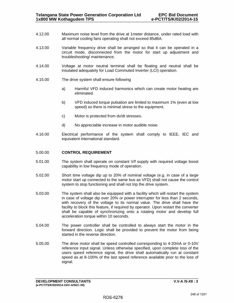
Telangana State Power Generation Corporation Ltd EPC Bid Document 1x800 MW Kothagudem TPS e-PCT/TS/K/02/2014-15
DEVELOPMENT CONSULTANTS V.V-A /S-XII : 3 (e-PCT/TS/K/02/2014-15/V-A/SEC-XII)
4.12.00 Maximum noise level from the drive at 1meter distance, under rated load with
all normal cooling fans operating shall not exceed 85dBA. 4.13.00 Variable frequency drive shall be arranged so that it can be operated in a
circuit mode, disconnected from the motor for start up adjustment and troubleshooting/ maintenance.
4.14.00 Voltage at motor neutral terminal shall be floating and neutral shall be
insulated adequately for Load Commuted Inverter (LCI) operation. 4.15.00 The drive system shall ensure following
a) Harmful VFD induced harmonics which can create motor heating are eliminated.
b) VFD induced torque pulsation are limited to maximum 1% (even at low
speed) so there is minimal stress to the equipment.
c) Motor is protected from dv/dt stresses.
d) No appreciable increase in motor audible noise. 4.16.00 Electrical performance of the system shall comply to IEEE, IEC and
equivalent international standard. 5.00.00 CONTROL REQUIREMENT 5.01.00 The system shall operate on constant V/f supply with required voltage boost
capability in low frequency mode of operation. 5.02.00 Short time voltage dip up to 20% of nominal voltage (e.g. in case of a large
motor start up connected to the same bus as VFD) shall not cause the control system to stop functioning and shall not trip the drive system.
5.03.00 The system shall also be equipped with a facility which will restart the system
in case of voltage dip over 20% or power interrupter for less than 2 seconds, with recovery of the voltage to its normal value. The drive shall have the facility to block this feature, if required by operator. Upon restart the converter shall be capable of synchronizing onto a rotating motor and develop full acceleration torque within 10 seconds.
5.04.00 The power controller shall be controlled to always start the motor in the
forward direction. Logic shall be provided to prevent the motor from being started in the reverse direction.
5.05.00 The drive motor shall be speed controlled corresponding to 4-20mA or 0-10V
reference input signal. Unless otherwise specified, upon complete loss of the users speed reference signal, the drive shall automatically run at constant speed as at 8-100% of the last speed reference available prior to the loss of signal.
248 of 1251

Telangana State Power Generation Corporation Ltd EPC Bid Document 1x800 MW Kothagudem TPS e-PCT/TS/K/02/2014-15
DEVELOPMENT CONSULTANTS V.V-A /S-XII : 4 (e-PCT/TS/K/02/2014-15/V-A/SEC-XII)
5.06.00 It shall be possible to vary the speed of the drive in either manual or auto mode.
Auto/manual selection shall be from VFD panel unless otherwise specified.
With the selector switch in “manual” mode, the operator shall be able to set the speed through keypad, mounted on front of the drive panel or from speed increase/decrease push buttons from the field. Motor operated potentiometer shall be provided as a speed set point device.
With selector switch in “auto” mode, speed of the motor shall be
controlled from a 4-20mA signal, from PLC/DDCMIS system. Necessary equipment like protocol converter as required for interfacing with PLC/DDCMIS shall also be provided in the drive panel.
5.07.00 The required provision for the interface with remote DDCMIS located at
control room shall be either through hardwired connection (with potential free contacts and transducers as described elsewhere in this specification) or serial link.
5.08.00 Drive system shall have provision for interface with upper level automation
such as substation monitoring system or electrical control system. 5.09.00 The closed loop control feedback for the drive system having output
transformer shall be tapped from the secondary side of the output transformer.
6.00.00 PANEL CONSTRUCTION 6.01.00 The panel shall include suitable semi conducting power devices (line
commuted thyristors/Diodes/IGBT). Modules with protective devices, reactors (if required), filters (if required), control circuit, control accessories, indication and annunciation etc, the construction of the panel shall provide effective protection against electromagnetic emissions and shall meet design requirement of integrated standards
6.02.00 Upstream breaker “ON/OFF/TRIP” indications and remote breaker closing
and trip push button shall be provided on the front door. 6.03.00 Safety Interlock shall be provided so that power cabinet can’t be opened
unless the up stream breaker is disconnected, safety-grounding switch is closed and DC link capacitor is discharged. Power source breaker can only be closed once the earthing switch is open and panel door is closed with lock defeat facility.
6.04.00 Duplicate control supply with automatic changeover shall be provided.
Protection shall be provided against AC/DC transients, voltage surge etc. of power and control device.
6.05.00 The drive shall be housed in sheet steel panels fabricated with 2mm thick
cold rolled sheet steel. The panel shall be suitable for indoor installation, if not otherwise specified. The panel shall be free standing with degree of enclosure
249 of 1251
6238467
Line
6238467
Typewriter
PLC
6238467
Rectangle
6238467
Typewriter
Deleted

Telangana State Power Generation Corporation Ltd EPC Bid Document 1x800 MW Kothagudem TPS e-PCT/TS/K/02/2014-15
DEVELOPMENT CONSULTANTS V.V-A /S-XII : 5 (e-PCT/TS/K/02/2014-15/V-A/SEC-XII)
protection as IP-41. The maximum operating height shall be 1800mm approximately.
6.06.00 Bolted un-drilled gland plate shall be provided at bottom. Clamp type
terminals shall be used for connection of all wires up to 10mm2 and terminal for higher sizes shall be bolted type suitable for cable lugs. Minimum space for power cable termination shall be 600mm clear from bottom of the cable gland plate.
6.07.00 Bus bars shall be of electrolytic copper, color coded separately for AC and
DC system. All the live parts shall be sleeved/ shrouded to ensure complete safety to personnel intending to carry out routine inspection by opening the panel doors. All the equipment inside the panel and on the doors shall be provided with suitable nameplate.
6.08.00 All the switches, component and accessories which are essential for normal
and emergency operation shall be mounted on the door and shall be operable externally. All the analog instruments, where provided, shall be switchboard type, back connected; 72x72mm.Scale shall have red mark indicating maximum permissible operating rating.
6.09.00 Each panel shall be provided with illuminating lamp/11W CFL with switch and
fuse. 5/15A, 240V power socket with switch and fuse shall be provided. Each panel shall have space heater with switch fuse and variable setting thermostat.
6.10.00 Copper earth bus of min. 50x6 mm size shall be provided in the panel with
provision for connection to purchaser’s plant earth grid. All the non-metallic components/parts shall be connected to the main earth bus bar. Separate earth bus bar and stud for electronic control system as required shall be provided.
6.11.00 All the metal parts shall be treated so as to ensure efficient anti-corrosive
protection. Hard wares shall be zinc passivated or electrogalvanised. Panel enclosure and structure supports shall be thoroughly cleaned and degreased to remove mill scale and rust etc. Paint shade of external surface shall be as per Section-X of Volume – IIA: Lead Specification.
6.12.00 All panels shall be of same height so as to form a uniform line-up, to give
good aesthetic appearance. 6.13.00 All the control wiring shall be enclosed in plastic/metal channel. Each wire
shall be identified at both ends by self-sticking wire marker tapes of PVC ferrules. Power and control wiring inside the panel shall be done with BIS approved, PVC insulated, fire retardant, copper conductor wire. 1.5mm ² size wire shall normally be used provided the control fuse rating is 10 Amps or less and 2.5mm2 size for control fuse rating above 16A for electrical circuits and 0.7 mm2 for electronic circuits. All wires shall be ferruled and terminals shall be properly numbered, minimum 20% spare terminal shall be provided.
250 of 1251

Telangana State Power Generation Corporation Ltd EPC Bid Document 1x800 MW Kothagudem TPS e-PCT/TS/K/02/2014-15
DEVELOPMENT CONSULTANTS V.V-A /S-XII : 6 (e-PCT/TS/K/02/2014-15/V-A/SEC-XII)
6.14.00 All electronic modules and components shall be accessible from front of panel only. Modular assemblies for both the system control electronic equipment and power electronic equipments shall be used.
6.15.00 All low voltage compartment and cabling shall be electrically and physically
separated from the high voltage compartment. 6.16.00 DC link capacitor and pre charging and discharging circuit shall be preferably
mounted in the rear of the panel. 6.17.00 Suitable removable type hooks shall be provided for lifting the panel. 6.18.00 Perspex type transparent insulating material shall be used for covering live
compartments. 6.19.00 Drive keypad, operator control panel required for control, monitoring and
measurements shall be supplied and installed outside the panel on the front door. It shall be accessible for operation without opening the front door and shall be non-removable type.
6.20.00 All the equipment shall be complete with cable glands, lugs etc. and cable
glands shall be single or double compression type for indoor and outdoor equipment respectively.
7.00.00 COOLING 7.01.00 The drive panel shall be naturally cooled type as per manufacturer’s
standards. If unavoidable, forced type cooling system shall be provided. Cooling system shall include well-dimensioned panel, adequate cooling airflow path, module cooling fan and if necessary, panel-cooling fan shall be considered. Vendor shall ensure that the panel dimensions and the flowpaths have been designed for continuous running at the specified ambient without overheating. For fan cooled drives, redundant ventilating fans (N+1) shall be provided. The VFD panels shall be located in an air-conditioned room.
7.02.00 Necessary starters shall be provided within the VFD panels for the ventilation
fans, any other auxiliary motor etc. The system provided shall be interfaced with drive starting and shut down such that safety interlocks such as start permit from cooling system to drive and trip signal from cooling system to drive in case of cooling system failure etc., shall be incorporated in the overall sequence logic.
7.03.00 MCB for motor space heater, auxiliary power supply if required for local panel,
drive panel space etc. shall be included and mounted in easy accessible location.
8.00.00 EQUIPMENT/COMPONENT SPECIFICATION 8.01.00 Motor
i) The motor shall be suitable for operation with a solid-state power supply consisting of an adjustable frequency inverter for speed control.
251 of 1251

Telangana State Power Generation Corporation Ltd EPC Bid Document 1x800 MW Kothagudem TPS e-PCT/TS/K/02/2014-15
DEVELOPMENT CONSULTANTS V.V-A /S-XII : 7 (e-PCT/TS/K/02/2014-15/V-A/SEC-XII)
ii) The motor shall be suitable for the current waveforms produced by the power supply including the harmonics generated by the drive.
iii) The Motor shall be designed to operate continuously at any speed
over the range 20-100 % of rated speed.
iv) The permitted voltage variation should take into account the steady state voltage drop across the AC drive and all other system components upstream of the motor.
v) Motors required to be transferred to DOL, by-pass mode shall be rated
for specified variations in system line voltage and frequency. Starting current of motor in DOL, bypass mode shall be limited to value in motor specifications.
vi) The motor shall be constructed to withstand torque pulsations
resulting from harmonics generated by the solid-state power supply.
vii) The motor insulation shall be designed to accept the applied voltage waveform, within the Vpeak and dv/dt limits as per IEC-61800-4.
viii) The drive manufacturer shall be solely responsible for proper selection
of the motor for the given load application and the output characteristics of the drive.
Other details shall be as given in specification of Electric motors.
9.00.00 POWER TRANSFORMER
Indoor dry type and shall be suitable for rating complying with system details. Other details as given in sub-section of LT Aux. Transformer specification.
10.00.00 POWER CONVERTER
i) The static power shall consist of a line side power converter for operation as a rectifier and a load side power converter for operation as a fully controlled inverter. Power converter shall be fast switching, most efficient and low loss type.
ii) Adequate short circuit and over voltage protection shall be provided
for the converter and inverter system.
iii) All power converter devices shall include protective devices, snubber networks and dv/dt networks as required.
iv) The current rating of the converter’s semi-conductor components shall
not be less than 120% of the nominal current flowing through the elements at full load of the VFD through the whole speed range.
v) All power diodes shall be of silicon type with minimum Vbo rating as
2.5 times the rated operating voltage.
252 of 1251

Telangana State Power Generation Corporation Ltd EPC Bid Document 1x800 MW Kothagudem TPS e-PCT/TS/K/02/2014-15
DEVELOPMENT CONSULTANTS V.V-A /S-XII : 8 (e-PCT/TS/K/02/2014-15/V-A/SEC-XII)
vi) The power converter circuit shall be designed so that motor can be powered at its full nameplate rating continuously without exceeding its rated temperature rise due to harmonic currents generated by the inverter operation.
vii) The conversion devices and associated heat sinks shall be assembled
such that individual devices can be replaced without requiring the use of any special precautions/tools.
viii) The cooling system of the electronic components, if provided, shall be
monitored and necessary alarms shall be provided to prevent any consequential damage to the power control devices.
ix) Offered system shall also take in account the distance between drive
panel and motor and system shall include all material and accessories to make system suitable for a distance of 350m.
11.00.00 DC LINK REACTOR
i) Smoothing reactors for the DC link shall be designed to sufficiently decouple the rectifier and inverter portion of the converter and to limit fault currents in this circuit.
ii) Reactor shall be air-core type, natural cooling and housed in a
separate enclosure in ventilated room.
iii) Reactor shall be suitable for withstanding earth fault continuously and for operation with the non-sinusoidal current wave shapes and DC components under all operational conditions of the system without exceeding its temperature limits.
iv) Noise level shall not exceed value specified in NEMA TR-1
12.00.00 OUTPUT FILTER
VFD output current waveform should be inherently sinusoidal at all speeds, with harmonic limits as specified in this specification. Output filter shall be provided if required. Output filter capacitors shall be provided with discharge circuits to ensure that all residual stored charge is reduced to less than 50 V DC within 300 seconds after a loss of AC voltage. All capacitor shall be maintenance free and self-healing type. The VFD system shall inherently protect motor from high voltage dv/dt stress, independent of cable length to motor. Output filter shall be an integral part of the VFD system and included within the VFD enclosure.
13.00.00 BYPASS FEATURE
i) Bypass breaker / contactor-HRC fuse complete with protection, annunciation and metering shall be provided.
253 of 1251

Telangana State Power Generation Corporation Ltd EPC Bid Document 1x800 MW Kothagudem TPS e-PCT/TS/K/02/2014-15
DEVELOPMENT CONSULTANTS V.V-A /S-XII : 9 (e-PCT/TS/K/02/2014-15/V-A/SEC-XII)
ii) All Variable frequency drives (VFD) having bypass feature shall have motor protection relay along with necessary control and metering etc. Switching scheme shall be such that in case of drive mal-operation, the motor could be taken on bypass control manually, while the drive could be attended by opening its isolation devices.
iii) Safety interlock between inverter and bypass breaker/contactor shall
be provided such that closing of healthy device is inhibited in case of external fault.
14.00.00 CT/PT/METERS
As required for the system offered and shall be suitable for variable frequency operation.
15.00.00 LOCAL MOTOR CONTROL STATION
i) The local motor control station is to be installed in the field near the motor. Components and accessories that are required in the local motor control station may be mounted on the local field mounted panel envisaged for the driven equipment.
ii) Meters in the local control station shall be suitable for 4-20mA
transducer outputs and shall be calibrated for the actual motor current. Further, the drives with bypass facility, the meters shall be capable of reading bypass full load and starting currents, as well as the drive current.
16.00.00 PROTECTION, CONTROL, METERING, INDICATION & ANNUNCIATION 16.01.00 The system vendor shall provide all the necessary system control, protection;
alarm equipment and metering for the entire drive system and its auxiliary equipment.
16.02.00 Automatic sequence control shall include start-up of cooling system, auxiliary
system of the motor, interlock checking, automatic start and run-up of drive, planned and emergency shutdown. The same shall be processed through microprocessor-based system.
17.00.00 OPERATOR CONTROL PANEL
i) Each drive shall be equipped with a front mounted operator control panel consisting of a backlit alphanumeric display and a keypad with keys for parameterization and adjusting parameter which shall be limited to Start/Stop, Local/Remote, Auto/Manual, Increase/Decrease, menu navigation and protection and measurement parameter selection, etc. Also local operation during maintenance should be possible & the same shall be provided inside the panel.
ii) All parameter names, fault messages, warnings and other information
shall be displayed in complete English words or Standard English abbreviations to allow the user to understand what is being displayed without the use of a manual or cross-reference table. This shall also
254 of 1251

Telangana State Power Generation Corporation Ltd EPC Bid Document 1x800 MW Kothagudem TPS e-PCT/TS/K/02/2014-15
DEVELOPMENT CONSULTANTS V.V-A /S-XII : 10 (e-PCT/TS/K/02/2014-15/V-A/SEC-XII)
be used for the modification of all electrical values, configuration parameters, drive menu parameters, application and activity function access, faults, local control, adjustment storage, self test and diagnostics. Keypad shall be operable with password for changing the protection setting, safety interlock etc. However the parameters such as measurements, setting, and mode of drive etc. Shall be allowed to be viewed without any password.
iii) Operator console shall have facility / port to connect external
hardware such as Lap-Top etc. Console shall have facility for upload and download of all parameter settings from one drive to another identical drive for start up and operation.
iv) Drive system control also have facility to receive tripping signal from
up stream breaker for tripping and also provision for closing upstream breaker after all required process parameters are achieved.
v) User-friendly software for operation and fault diagnostic shall be
loaded in the drive system panel before commissioning.
18.00.00 PROTECTIVE FEATURES
The system offered shall incorporate adequate features, properly coordinated for the drive control and for motor but not limited to the following :
i) Incoming line surge protection. ii) Under / Over voltage protection. iii) Phase loss, phase reversal protection.
iv) Programmable Over current Protection and under load protection.
v) Inverter fault.
vi) Over frequency operation.
vii) Ventilation loss.
viii) Over temperature of equipment.
ix) Over speed of motor.
x) Specific motor protection, including motor winding, bearing
temperatures, over current, Overload, negative phase sequence, locked rotor and earth fault protections etc.
xi) System Earth fault protection.
xii) Over and under frequency, rotor earth fault, field failure protection for
synchronous motor
xiii) Additional protection for drive system
255 of 1251
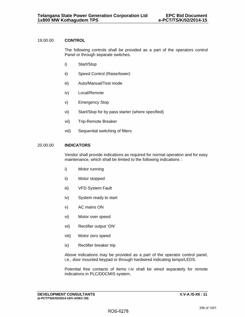
Telangana State Power Generation Corporation Ltd EPC Bid Document 1x800 MW Kothagudem TPS e-PCT/TS/K/02/2014-15
DEVELOPMENT CONSULTANTS V.V-A /S-XII : 11 (e-PCT/TS/K/02/2014-15/V-A/SEC-XII)
19.00.00 CONTROL
The following controls shall be provided as a part of the operators control Panel or through separate switches. i) Start/Stop ii) Speed Control (Raise/lower)
iii) Auto/Manual/Test mode
iv) Local/Remote
v) Emergency Stop
vi) Start/Stop for by pass starter (where specified) vii) Trip-Remote Breaker viii) Sequential switching of filters
20.00.00 INDICATORS
Vendor shall provide indications as required for normal operation and for easy maintenance, which shall be limited to the following indications :
i) Motor running
ii) Motor stopped
iii) VFD System Fault
iv) System ready to start
v) AC mains ON
vi) Motor over speed
vii) Rectifier output ‘ON’
viii) Motor zero speed
ix) Rectifier breaker trip
Above indications may be provided as a part of the operator control panel, i.e., door mounted keypad or through hardwired indicating lamps/LEDS. Potential free contacts of items i-iv shall be wired separately for remote indications in PLC/DDCMIS system.
256 of 1251

Telangana State Power Generation Corporation Ltd EPC Bid Document 1x800 MW Kothagudem TPS e-PCT/TS/K/02/2014-15
DEVELOPMENT CONSULTANTS V.V-A /S-XII : 12 (e-PCT/TS/K/02/2014-15/V-A/SEC-XII)
21.00.00 METERING
Digital display of the following parameters shall be as a part of the Operator Control Panel, selected by the operator.
i) Input AC voltage ii) Input AC frequency
iii) Input AC current
iv) Output voltage
v) Output current VFD / Bypass
vi) Output frequency
vii) Motor thermal state
viii) Drive thermal state
ix) Motor speed
x) Motor energy meter
xi) DC Link voltage
xii) Hour Run
Necessary transducer shall be provided with 4-20mA output for indicating motor speed and motor current in PLC/DDCMIS unless otherwise specified for other parameters.
22.00.00 AUDIO-VISUAL ANNUNCIATIONS
i) The system shall incorporate audio-visual annunciations for protection, for various fault conditions, for the Drive motor, Supply cables, DC Reactor and the Converter, output transformer etc.
ii) Alarms shall also be included for the failure of various auxiliaries
together with identifications of the failing unit, loss of cooling system, various protections devices provided for converter transformer etc.
iii) Audio-visual window annunciations shall be provided on the front of
the panel. All annunciations as required for normal and satisfactorily operation of the drive system shall be included as per vendor standards. These annunciations can be part of operator console panel or separately mounted type.
iv) Vendor shall include audio-visual alarm as required for normal
operations and maintenance of the system but not limited to the following :
257 of 1251

Telangana State Power Generation Corporation Ltd EPC Bid Document 1x800 MW Kothagudem TPS e-PCT/TS/K/02/2014-15
DEVELOPMENT CONSULTANTS V.V-A /S-XII : 13 (e-PCT/TS/K/02/2014-15/V-A/SEC-XII)
1. Rectifier fuse failure
2. Main AC failure
3. Inverter fuse failure
4. Inverter overload
5. Inverter high temperature
6. Cooling system failure
7. Motor failed to start
8. Transformer failure
9. Battery monitoring healthiness
10. Communication and measurement system unhealthy
11. Motor temperature high
12. Harmonic filters monitoring
Common potential free contacts shall be provided for above annunciations and these shall be wired up to terminal block for remote alarm and monitoring.
23.00.00 FAULT DIAGNOSTIC
Fault diagnostic shall be built into the system to supervise the operation and failure of the system. The information regarding failure of any of the system including shut down of the system shall be available for a period of minimum 4 days (96 hours) after a shut down even though no supply would be available to the system. The system may be totally de-energized for maintenance or otherwise. It shall be possible to retrieve the record of events prior to tripping of the system or de-energisation. Auxiliary supply to the system components or to the electronics (firmware) for the diagnostics / display shall be taken care by the manufacturer for this purpose.
24.00.00 EXTERNAL POWER SUPPLY FOR AUXILIARY AND CONTROL CIRCUIT
Auxiliary power supply for devices external to VFD module, space heater supply for Motor, VFD panel space heater, auxiliary power supply for transformers, cubicle 11W CFL lamps etc. shall operate on 240 volts single phase AC provided by purchaser.
All control circuit shall operate at maximum voltage of 240V AC.
Vendor shall include supply of all control transformers, protective devices,
required accessories etc. and any other control supply voltage as required for the system shall be derived from the power supply made available by other.
25.00.00 RELIABILITY FEATURES
The expected lifetime of the drive system shall be 25 years. The system
including all individual components forming part of the system shall have a minimum MTBF of 4 years.
258 of 1251

Telangana State Power Generation Corporation Ltd EPC Bid Document 1x800 MW Kothagudem TPS e-PCT/TS/K/02/2014-15
DEVELOPMENT CONSULTANTS V.V-A /S-XII : 14 (e-PCT/TS/K/02/2014-15/V-A/SEC-XII)
26.00.00 MAINTENANCE FEATURES The controller design shall incorporate the following maintenance features : Modular construction
All components shall be easily accessible
Standard diagnostics to aid maintenance personnel. These shall include LED or alphanumeric displays, test or measurement points.
27.00.00 PAINTING 27.01.00 All metal surfaces shall be thoroughly cleaned and de-greased to remove mill
scale, rust, grease and dirt. Fabricated structures shall be pickled and then rinsed to remove any trace of acid. The under-surface shall be prepared by applying a coat of phosphate paint and a coat of yellow zinc chromate primer. The under-surface shall be made free from all imperfections before undertaking the finishing coat.
27.02.00 After preparation of the under surface, the panel shall be provided with epoxy
based powder coating. Panel finish shall be free from imperfections like pinholes, orange peels, runoff painted.
27.03.00 All unpainted steel parts shall be zinc passivated, cadmium plated or suitably
treated to prevent rust and corrosion. If these parts are moving elements, then these shall be greased.
27.04.00 For paint shade of finish coat, refer Section-X of Volume – IIA: Lead
Specification. 28.00.00 INSPECTION, TESTING AND ACCEPTANCE
28.01.00 During fabrication, the drive shall be subject to inspection by owner, or by an
agency authorized by the owner, to assess the progress of work, as well as to ascertain that only quality raw material is used. The manufacturer shall furnish all necessary information concerning the supply to owner’s inspectors.
28.02.00 All tests shall be carried out at the manufacturer’s works under his care and
expense. The tests shall be witnessed by an inspector of the owner or an agency authorized by the owner. Prior notice of minimum of 4 weeks shall be given to the inspector for witnessing the test.
28.03.00 The routine test shall be conducted on all the drive system. However type test
shall be performed on one system of each rating and type unless otherwise agreed between purchaser and manufacturer. For the purpose of testing, drive system shall include input/output transformer (where applicable), switchgears, converter, filters etc.
28.04.00 The routine and type tests to be performed on the drive system shall be as follows :
259 of 1251

Telangana State Power Generation Corporation Ltd EPC Bid Document 1x800 MW Kothagudem TPS e-PCT/TS/K/02/2014-15
DEVELOPMENT CONSULTANTS V.V-A /S-XII : 15 (e-PCT/TS/K/02/2014-15/V-A/SEC-XII)
Routine Tests
a. Visual Inspection
It involves checking of the various equipments/components fault diagnostic unit, wiring, terminals, earthing ratings etc, in line with the approved drawings and visual inspection shall not be limited to the following;
i) Dimensions and door layout Vis-à-vis the approved drawings ii) Degree of protection of cubicles
iii) Simulation facility of control signals for testing purposes
iv) Memory function of fault diagnostic
v) Voltage/Current rating power semiconductor elements
vi) Cable termination size and number of terminals, cable-
supporting etc.
vii) Accessibility of components
viii) External signals and indication/alarm signals on converter
ix) Earthing of cubicles and cubicle doors b. Insulation Test c. Light load and functional test d. Load characteristics test e. Load duty test
f. Checking of Auxiliary devices g. Checking the properties of the control equipment h. Checking the protective devices
i. Checking of control and functional requirements j. High voltage test
k. Shaft current/bearing insulation l. Automatic restart/re-acceleration
Type Tests
a. Allowable full load current versus speed
260 of 1251

Telangana State Power Generation Corporation Ltd EPC Bid Document 1x800 MW Kothagudem TPS e-PCT/TS/K/02/2014-15
DEVELOPMENT CONSULTANTS V.V-A /S-XII : 16 (e-PCT/TS/K/02/2014-15/V-A/SEC-XII)
b. Efficiency c. Temperature rise
d. EM Immunity
e. EM Emission f. Current sharing g. Voltage division h. Line side current distortion content i. Power factor j. Audible noise k. Torque pulsation l. Motor vibration
m. Dynamic performance n. Current limit and current loop test
o. Speed loop test capability to ride through voltage less than 80% p. Test capability to restart the system and resynchronize converter onto
running motor after a voltage interruption Type test certificate from independent testing agency for similar equipment can be accepted if it is carried out within 5 years from the date of inspection.
29.00.00 DRAWINGS, DATA & MANUALS 29.01.00 Drawings, Data & Manuals shall be submitted in triplicate with the bid and in
quantities and procedures as specified in General Conditions of Contract and/or elsewhere in the specification for approval and subsequent distribution after the issue of 'Letter of Intent'.
29.02.00 To be submitted with the bid :- a. General arrangement drawings showing outline dimensions, cable
entry openings, fixing/foundation details, weights and door openings. b. Bill of materials
d. Type test reports f. General Technical Particulars
261 of 1251

Telangana State Power Generation Corporation Ltd EPC Bid Document 1x800 MW Kothagudem TPS e-PCT/TS/K/02/2014-15
DEVELOPMENT CONSULTANTS V.V-A /S-XII : 17 (e-PCT/TS/K/02/2014-15/V-A/SEC-XII)
29.03.00 To be submitted for Owner / Purchaser’s Approval and Distribution All relevant drawings and data pertaining to the equipment like GTP, GA
drawing, foundation plan, BOM, control & schematics, QAP, etc. shall be submitted by the Bidder for approval of Owner/Owner’s consultant. Also refer clause no. 1.19.02(u) of Section-I of Volume – V-A: Technical Specifications for Electrical Equipment & Accessories.
262 of 1251

ANNEXURE-XII
S.NO DETAILSSCOPE
SUPPLYSCOPE E&C REMARKS
1 415V MCC BHEL BHEL
1. 415 V AC (3 Phase, 3 Wire) supply to motors, 415 V AC (3 Phase, 4 Wire)
supply to other equipment etc. shall be provided by BHEL based on load data
provided by vendor at contract stage for the equipment supplied by vendor as
part of contract.
2. Any other voltage level (AC/DC) required will be derived by the vendor.
2 Local Push Button Station (for motors) BHEL BHEL Located near the motor.
3
Power cables, control cables and screened control cables
for
a) both end equipment in BHEL’s scope
b) both end equipment in vendor’s scope
c) one end equipment in vendor’s scope
BHEL
BHEL
BHEL
BHEL
Vendor
BHEL
1. For 3.b) & c): Sizes of cables required shall be informed by vendor at
contract stage (based on inputs provided by BHEL) in the form of cable listing.
Finalisation of cable sizes shall be done by BHEL.
Vendor shall provide lugs & glands accordingly in his scope.
2. Termination at BHEL equipment terminals by BHEL.
3. Termination at Vendor equipment terminals by Vendor.
4 Junction box for control & instrumentation cable Vendor Vendor Refer C & I portion of specification for philosophy of using junction boxes
5Any special type of cable like compensating, co-axial,
prefab, MICC, fibre optical etc.Vendor Vendor
Refer C&I portion of specification for scope of fibre Optical cables if used
between PLC & DCS.
6
a) Cable trays, accessories & cable trays supporting
system
b) 100/ 50 mm cable trays/ Conduits/ Galvanised steel
cable troughs for local cabling
BHEL
Vendor
BHEL
Vendor
Local cabling from nearby main route cable tray (BHEL scope) to equipment
terminal (vendor’s scope) shall be through 100/ 50 mm. cable trays/ conduits/
Galvanised steel cable troughs, which shall be supplied by vendor.
PROJECT: 5 x 800 MW TSGENCO YADADRI TPS
ELECTRICAL SCOPE BETWEEN BHEL AND VENDOR
PACKAGE: ETP
263 of 1251

7Cable glands ,lugs and bimetallic strip for equipment
supplied by VendorVendor Vendor
1. Double compression Ni-Cr plated brass cable glands
2. Solder less crimping type Aluminium lugs for Aluminium power cables and
heavy duty tinned copper lugs for copper power cables
3. Solder less crimping type heavy duty copper lugs for control cables.
8Conduit and conduit accessories for cabling between
equipments supplied by vendorVendor Vendor
Conduits shall be medium duty, hot dip galvanised cold rolled mild steel rigid
conduit as per IS: 9537.
9 Lighting BHEL BHEL
10 Equipment grounding & lightning protection BHEL BHEL
11 Below grade grounding BHEL BHEL
12 LT Motors with base plate and foundation hardware Vendor VendorMakes shall be subject to customer/ BHEL approval at contract stage. All
motors shall be 3 Phase only.
13 Mandatory spares Vendor - Vendor to quote as per specification.
14 Recommended O & M spares Vendor - Not applicable for this project.
15
Any other equipment/material/service required for
completeness of system but not specified above (to ensure
trouble free and efficient operation of the system).
Vendor Vendor
16
a) Input cable schedules (Control & Screened Control
Cables)
b) Cable interconnection details for above
c) Cable block diagram
Vendor
Vendor
Vendor
-
-
-
Cable listing for Control and Instrumentation Cable (excluding power
cables) in enclosed excel format shall be submitted by vendor during
detailed engineering stage.
17Electrical Equipment , above ground earthing & cable tray
layout drawingsVendor -
For ensuring cabling requirements are met, vendor shall furnish Electrical
equipment layout & cable tray layout drawings (both in print form as well as in
AUTOCAD) of the complete plant (including electrical area) indicating location
and identification of all equipment requiring cabling, and shall incorporate
cable trays routing details marked on the drawing as per PEM interface
comments. Cabling arrangement of the same (wherever overhead cable trays,
trenches, cable ducts, conduits etc.) shall be decided during contract stage.
Electrical equipment layout & cable tray layout drawing shall be subjected to
BHEL/ customer approval without any commercial implications to BHEL.
18 Electrical Equipment GA drawing Vendor - For necessary interface review.
264 of 1251

19 Uninterrupted Power supply Vendor Vendor
415 V AC (3 Phase, 4 Wire) supply to UPS shall be provided by BHEL based
on load data provided by vendor at contract stage for the equipment supplied
by vendor as part of contract. Further cabling to battery racks, UPS to ACDB,
ACDB to field equipment cabling by vendor.
20 PLC System Vendor Vendor
PLC power from ACDB to PLC & signal cabling to field equipment cabling by
vendor. OFC cabling (if applicable as per specification) shall be by vendor.
Electronic earthing cables upto nearest earth pit shall be by vendor.
21 Electric Operated Hoist with isolating switch Vendor Vendor
BHEL will provide one number 415 V(3ph, 4W) supply feeder only up to
isolating switches for crane hoist. Any other voltage level (AC/DC) required will
be derived by the vendor. Motor starter shall be part of crane control panel.
Flexible Power cables(festoon cable)/ shrouded DSL from isolator to hoist &
upto motor shall be supplied by vendor . Earthing arrangement shall be part of
hoist cable. Input Power Cable from MCC supply feeder to isolating switch shall
be in BHEL
scope.
NOTES
:1. Make of all electrical equipments/items supplied shall be reputed make & shall be subject to approval of BHEL/customer after award of contract.
2. All QPs shall be subject to approval of BHEL/customer after award of contract without any commercial implication.
3. In case the requirement of Junction Box arises on account of Power Cable size mis-match due to vendor engineering at later stage, vendor shall supply the Junction Box for
suitable termination.
4. Vendor shall indicate location of Electronic Earth pit in their Civil assignment drawing.
265 of 1251

Annexure-II
NAME PALTE
MAX. CONT.
DEMAND (MCR) R
UN
NIN
G
STA
ND
BY
SIZE CODE Nos
1 2 3 4 5 6 7 8 9 10 11 12 13 14 15 16 17 18 19 20 21 22
NAMESIGN.
VOLT
AG
E C
OD
E*
KKS NO.
LOAD No.REMARKS
FEED
ER C
OD
E*
EMER
. LO
AD
(Y)
LOCATION (Tag. No.)
CABLE
BLO
CK
CA
BLE
D
RG
. No.
CONTROL CODE
DATA ENTERED ON
LOAD TITLE
RATING (KW / A)
UN
IT (U
)/STN
. (S)
CO
NT.
(C)/
INTT
.(I)
STA
RTI
NG
TIM
E> 5
SE
C (Y
)
BOARD NO.
Nos.
PROJECT TITLE
2. ABBREVIATTIONS : * VOLTAGE CODE (7):- (AC) A=11 KV, B=6.6.KV, C= 3.3 KV, D=415 V, E = 240 V (1 PH), F = 110 V (DC) : G =220V, H = 110 V, J = 48 V, K = +24V, L= -24V
: **FEEDER CODE (8) :- U = UNIDIRECTIONAL STARTER, B = BIDIRECTIONAL STARTER, S = SUPPLY FEEDER, D = SUPPLY FEEDER (CONTACTOR CONTROLLED)
DE'S SIGN. & DATE
DATA FILLED UP ONBHEL LOAD DATA(ELECTRICAL)
JOB NO.
RATING & FLC CHECKED FROM MOTOR/VALVE
APPROVED DATASHEET
(Y/N)
FULL LOAD
CURRENT FLC(A)
DEPTT. /SECTION SHEET 1/2 REV. R0SYSTEM / S
NOTES: 1. COLUMN 1 TO 14 & 20 SHALL BE FILLED BY THE REQUISITIONER ( ORIGINATING AGENCY); REMAINING COLUMNS ARE TO BE FILLED UP BY PEM ( ELECTRICAL )
ORIGINATING AGENCY PEM (ELECTRICAL)
266 of 1251
6238467
Rectangle
6238467
Typewriter
ANNEXURE XIII

ANNEXURE-XIV
STANDARD QUALITY PLAN
267 of 1251

ANNEXURE-XIV
STANDARD QUALITY PLAN
STD QUALITY PLAN NO.: PE-QP-999-145-I056
VOLUME
FOR SECTION
LOCAL CONTROL PANEL REV. NO. 01 DATE: 18-02-2020
PEM :: C&I
SHEET
1 OF 7
Sl. Component / Characteristics Checked
* Type/Method Extent Reference Acceptance Format Agency $ Remarks
No. operation Cate of of
documents Norms of
gory
Check
Check
Records
P
W
V
INCOMING
1.0 Sheet Steel (CRCA & 1. Chemical Composition MA Chemical Sample IS:1079Relevant Relevant Test 3 --- 2 IS:1079
HR) analysis IS:513 IS:513standard Certificate standard Relevant
2. Bend Test CR
Mech. test
Sample Relevant
Log Book
2
---
---
IS:1079 IS:1079
IS:513 IS:513 standard standard
3. Surface finish MA Visual 100% Factory Factory Log Book 2 --- ---
Standard / Standard /
Sample Sample
4. Waviness MA Visual 100% Factory No Waviness Log Book 2 --- ---
Standard
5. Thickness MA Measurement 100% BHEL Spec. BHEL Spec. Log Book 2 --- ---
6. Mill marking MA Visual 100% Factory Factory Log Book 2 --- 1 Standard Standard
2.0 Flats / Angles / 1. Dimensions MA Measurement Sample Relevant Relevant Log Book 2 --- --- IS:2062 IS:2062
Channels standard standard 2. Surface Defects MA Visual 100% Factory Factory Log Book 2 --- ---
Standard / Standard /
Sample Sample
3. Straightness MA Measurement 100% Factory Std. Factory Std. Log Book 2 --- ---
4. Mill marking MA
Visual
100% Relevant Relevant
Log Book
2
--- 1
IS:2062 IS:2062
standard standard
3.0 Cables / Wires 1. Visual / Surface defects MA Visual 100% BHEL Spec. BHEL Spec. Log Book 2 --- --- and IS:1554 or IS:1554 or and Relevant and Relevant
IS:694 IS:694
standard standard 2. IR and HV MA Electrical 100% BHEL Spec. BHEL Spec. Log Book 2 --- --- and Relevant and Relevant
IS:1554 or IS:1554 or
IS:694 IS:694 standard standard
LEGEND: * CR - Critical characteristics
$ P - Agency Performing the Test. 1 - BHEL
MA - Major characteristics W - Agency Witnessing the Test. 2 - Vendor
MI - Minor characteristics V - Agency Verifying the Test. 3 - Sub-vendor
THIS DOCUMENT IS PART OF TECHNICAL SPECIFICATION
268 of 1251

ANNEXURE-XIV
STANDARD QUALITY PLAN
STD QUALITY PLAN NO.: PE-QP-999-145-I056
VOLUME IIB
FOR SECTION D
LOCAL CONTROL PANEL REV. NO. 01 DATE: 18-02-2020
PEM :: C&I
SHEET
2
OF
7
Sl. Component / Characteristics Checked
* Type/Method Extent Reference Acceptance Format Agency $ Remarks
No. operation Cate of of
documents Norms of
gory
Check
Check
Records
P
W
V
3. Conductor
a) Resistance MA Electrical 100% BHEL Spec. BHEL Spec. b) Size MA Measurement 100% IS:1554 or IS:1554 or Log Book 2 --- ---
c) Sheet colour MA
Visual
100% and Relevant and Relevant
IS:694 IS:694
standard standard
4. Type / Routine Test MA Verification 100% BHEL Spec. BHEL Spec. Log Book 3 --- 2 Certificates IS:1554 or and IS:1554Relevantor and Relevant
IS:694
IS:694 standard standard
4.0 Electrical 1. Verification at make and CR
Visual
Sample BHEL Spec. BHEL Spec.
Log Book
2
---
---
Components like
Type and BOM and BOM
Annunciator
2. Verification of Test CR
Scrutiny of
100% RelevantIS Relevant IS
Log Book
2
---
---
Transformers
Lamps Certificates Type / Routine standard standard
Switches T.Cs.
Sample+ Relevant standard standard
+ for relay &
3. Operation / Functional CR Electrical Relevant Indian Log Book 2 --- ---
PBs Relevant Indian
check 100%@ & Catalogue &StdCatalogue&Catalogue contactors
Contactors Std & Catalogue
only
Relays
4. I.R. MA Electrical 100% Relevant standard RelevantstandardIndian Log Book 2 --- --- @ for all
Timers Relevant Indian
&StdCatalogue&Catalogue Std & Catalogue components
Space Heaters & Catalogue
except relays
Thermostat
standard
& contactors.
Indicating meters etc.
5. H.V.
MA
Electrical
100% RelevantstandardIndian
Log Book
2
---
---
Relevant Indian
&StdCatalogue&Catalogue Std & Catalogue
& Catalogue
6. Calibration MA Electrical 100% Relevant standard RelevantstandardIndian Log Book 2 --- 1 Relevant Indian
&StdCatalogue&Catalogue Std & Catalogue
& Catalogue
7. Pick up / Drop off Voltage MA Electrical 100% standard RelevantstandardIndian Log Book 2 --- --- Relevant Indian
Std & Catalogue Std & Catalogue
& Catalogue & Catalogue
LEGEND: * CR - Critical characteristics
$ P - Agency Performing the Test. 1 - BHEL
MA - Major characteristics W - Agency Witnessing the Test. 2 - Vendor
MI - Minor characteristics V - Agency Verifying the Test. 3 - Sub-vendor
THIS DOCUMENT IS PART OF SPECIFICATION
269 of 1251

ANNEXURE-XIV
STANDARD QUALITY PLAN
STD QUALITY PLAN NO.: PE-QP-999-145-I056
VOLUME IIB
FOR SECTION D
LOCAL CONTROL PANEL REV. NO. 01 DATE: 18-02-2020
PEM :: C&I
SHEET
3
OF 7
Sl. Component / Characteristics Checked
* Type/Method Extent Reference Acceptance Format Agency $ Remarks
No. operation Cate of of
documents Norms of
gory
Check
Check
Records
P
W
V
5.0 Misc. Components 1. Verification of Type / Make MA Visual Sample BHEL Spec. & BHEL Spec. & Log Book 2 --- ---
like Gaskets, Mfrs. Catalogue Mfrs. Catalogue
Terminal Blocks etc. 2. Surface defects MA
Visual
Sample BHEL Spec. & BHEL Spec. &
Log Book
2
---
---
Mfrs. Catalogue Mfrs. Catalogue
3. IR / HV on Terminal Blocks MA Electrical Sample BHEL Spec. & BHEL Spec. & Log Book 2 --- --- Mfrs. Catalogue Mfrs. Catalogue
IN PROCESS 6.0 Blanking / Bending / 1. Dimensions MI Measurement 100% Approved Mfr. Approved Mfr. Log Book 2 --- ---
Forming drgs. drgs.
2. Surface defects after MA Visual 100% Factory Factory Log Book 2 --- --- bending Standard Standard
7.0 Nibbling / Punching 1. Cutout Sizes MI Measurement 100% Approved Mfr. Approved Mfr. Log Book 2 --- --- drgs. drgs.
2. Deburring MA Visual 100% Approved Mfr. Approved Mfr. Log Book 2 --- --- drgs. drgs.
ASSEMBLY 8.0 Frame Assembly & 1. Dimensions MA Measurement 100% Approved drg. / Approved drg. / Log Book 2 --- 2
Sheet fixing Mfr. Standards Mfr. Standards
2. Alignment MA Measurement 100% Approved drg. / Approved drg. / Log Book 2 --- 2 Mfr. Standards Mfr. Standards
3. Welding Quality MA Visual 100% Approved drg. / Approved drg. / Log Book 2 --- 2 Mfr. Standards Mfr. Standards
4. Surface defects MA Visual 100% Approved drg. / Approved drg. / Log Book 2 --- 2 Mfr. Standards Mfr. Standards
LEGEND: * CR - Critical characteristics
$ P - Agency Performing the Test. 1 - BHEL
MA - Major characteristics W - Agency Witnessing the Test. 2 - Vendor
MI - Minor characteristics V - Agency Verifying the Test. 3 - Sub-vendor
THIS DOCUMENT IS PART OF SPECIFICATION
270 of 1251

ANNEXURE-XIV
STANDARD QUALITY PLAN
STD QUALITY PLAN NO.: PE-QP-999-145-I056
VOLUME IIB
FOR SECTION D
LOCAL CONTROL PANEL REV. NO. 01 DATE: 18-02-2020
PEM :: C&I
SHEET
4
OF 7
Sl. Component / Characteristics Checked
* Type/Method Extent Reference Acceptance Format Agency $ Remarks
No. operation Cate of of
documents Norms of
gory
Check
Check
Records
P
W
V
9.0 Pre-treatment and 1. Pretreatment Process MA Visual 100% Factory Factory Log Book 2 --- 1 Painting Standard & Standard &
RelevantIS:6005 standard RelevantIS:6005 standard
2. Process parameters like MA Measurement Periodic Factory Factory Log Book 2 --- 1 bath temp. concentration Standard & Standard &
etc. RelevantIS:6005standard RelevantIS:6005 standard
3. Dipping / Removal Time MA Measurement 100% Factory Factory Log Book 2 --- 1 Standard & Standard & IS: 6005 RelevantIS:6005 standard
Relevant standard 4. Surface quality after every MA Visual 100% Factory Factory Log Book 2 --- 1
dip Standard & Standard &
IS: 6005 RelevantIS:6005 standard Relevant standard
5. Primer after phosphating MA Visual, 100% Factory Factory Log Book 2 --- 1 Thickness Standard & Standard &
RelevantIS:6005 standard IS: 6005
Relevant standard 6. Putty Application & MA Visual 100% Factory Factory Log Book 2 --- 1
Rubbing after primer Standard & Standard &
RelevantIS:6005standard RelevantIS:6005 standard
7. Paint first coat MA Visual, 100% Factory Factory Log Book 2 --- 1 Thickness Standard & Standard &
RelevantIS:6005 standard RelevantIS:6005 standard
8. Putty Application and MA Visual 100% Factory Factory Log Book 2 --- 1 Rubbing after first coat of Standard & Standard & paint RelevantIS:6005 standard IS: 6005 Relevant standard
9. Paint second coat MA Visual, 100% Factory Factory Log Book 2 --- 1
Thickness, Standard & Standard &
Scratch test RelevantIS:6005 standard RelevantIS:6005 standard
Colour
adhesion
LEGEND: * CR - Critical characteristics
$ P - Agency Performing the Test. 1 - BHEL
MA - Major characteristics W - Agency Witnessing the Test. 2 - Vendor
MI - Minor characteristics V - Agency Verifying the Test. 3 - Sub-vendor
THIS DOCUMENT IS PART OF SPECIFICATION
271 of 1251

ANNEXURE-XIV
STANDARD QUALITY PLAN
FOR LOCAL CONTROL PANEL
PEM :: C&I
STD QUALITY PLAN NO.: PE-QP-999-145-I056 VOLUME IIB
SECTION D
REV. NO. 01 DATE: 18-02-2020
SHEET 5 OF 7
Sl. Component / Characteristics Checked
* Type/Method Extent Reference Acceptance Format Agency $ Remarks
No. operation Cate of of
documents Norms of
gory Check
Check
Records
P
W
V
10. Panel Wiring 1. Wiring Layout MA Visual 100% Approved drgs. Approved drgs. Log Book 2 --- --- & Specs. & Specs.
2. Wiring Termination MA Visual 100% Approved drgs. Approved drgs. Log Book 2 --- --- (Crimped Lugs) & Specs. & Specs.
3. Ferrule numbers MA Visual 100% Approved drgs. Approved drgs. Log Book 2 --- --- & Specs. & Specs.
4. Colour of wiring MA Visual 100% Approved drgs. Approved drgs. Log Book 2 --- 1 & Specs. & Specs.
5. Size of Conductor MA Measurement 100% Approved drgs. Approved drgs. Log Book 2 --- 1 & Specs. & Specs.
11. Component Mounting 1. Correct components MA Visual 100% Approved drgs., Approved drgs., Log Book 2 --- --- Specs. & BOM Specs. & BOM
2. Fixing MA Visual 100% Approved drgs., Approved drgs., Log Book 2 --- --- Specs. & BOM Specs. & BOM
FINAL
12. Final Inspection 1. Workmanship MA Visual 100% Factory Factory Inspection 2 1 1 Standard Standard Report
2. Component layout MA Visual 100% BHEL approved BHEL approved Inspection 2 1 1 At Random (neatness, accessibility & drg. / Spec. drg. / Spec. Report by BHEL,
safety) Mounting / Proper based on
fixing of all components 100 % internal test
reports by
3. Components identification MA Visual
100% BHEL approved BHEL approved
Inspection
2
1
1
Mfr.
Marking / Name plates drg. / Spec. drg. / Spec. Report
LEGEND: * CR - Critical characteristics
$ P - Agency Performing the Test. 1 - BHEL
MA - Major characteristics W - Agency Witnessing the Test. 2 - Vendor
MI - Minor characteristics V - Agency Verifying the Test. 3 - Sub-vendor
THIS DOCUMENT IS PART OF SPECIFICATION
272 of 1251

ANNEXURE-XIV
STANDARD QUALITY PLAN
STD QUALITY PLAN NO.: PE-QP-999-145-I056
VOLUME IIB
FOR SECTION D
LOCAL CONTROL PANEL REV. NO. 01 DATE: 18-02-2020
PEM :: C&I
SHEET
6
OF
7
Sl. Component / Characteristics Checked
* Type/Method Extent Reference Acceptance Format Agency $ Remarks
No. operation Cate of of
documents Norms of
gory
Check Check
Records
P
W
V
5. Dimensions MA Measurement 100% BHEL approved BHEL approved Inspection 2 1 1
drg. / Spec., drg. / Spec., Report
BOM BOM
6. Door functioning MA Functional 100% BHEL approved BHEL approved Inspection 2 1 1 drg. / Spec. drg. / Spec. Report
7. Paint Shade CR Visual 100% BHEL approved BHEL approved Inspection 2 1 1 drg. / Spec. drg. / Spec. Report
8. Paint Thickness CR Measurement 100% BHEL approved BHEL approved Inspection 2 1 1 drg. / Spec. drg. / Spec. Report
9. Workmanship of Gaskets MA Visual 100% Factory Factory Inspection 2 1 1 At Random Standard Standard Report
by BHEL,
10. Wiring Layout MA
Visual 100% BHEL approved BHEL approved Inspection
2
1
1 based on
100 %
drg. drg.
Report
internal test
11. Wire Termination MA
Pulling Sample ----- Firm termination
Inspection
2
1
1 reports by
Mfr.
manually Report
12. Continuity MA Electrical 100% ----- Continuity OK Inspection 2 1 1 Report
LEGEND: * CR - Critical characteristics $ P - Agency Performing the Test. 1 - BHEL
MA - Major characteristics W - Agency Witnessing the Test. 2 - Vendor
MI - Minor characteristics V - Agency Verifying the Test. 3 - Sub-vendor
273 of 1251

ANNEXURE-XIV
STANDARD CHECK LIST FOR C&I INSTRUMENTS
CHECK LIST FOR TRANSMITTER(PIT, DPIT, FIT, LIT, TIT, VIT)
Sl. Test / Checks Quantum Reference Doc. / Agency ** Remarks
No. of check Acceptance Norms M C B
1 CHECKS FOR
P W V
VISUAL.
MODEL/TAG No
2 PROCESS CONNECTION SEE NOTE-1 P W V
3 ACCURACY BELOW P W V
4 REPEATABILITY P W V
5 HYSTERESIS P W V
6 EFFECT OF TEMP VARIATION P W V
ON ACCURACY APPROVED SPEC./
7 SPAN / ZERO ADJUSTMENT DATA SHEETS P W V
8 EFFECT OF SUPPLY VOLTAGE
ONE / TYPE
P W V
VARIATION
9 EFFECT OF LOADING (500 OHM P W V
METERS)
10 HIGH PRESSURE TEST SEE NOTE-1 P W V BELOW
11 BURN-IN TEST ONE / TYPE
P W V
12 DEGREE OF PROTECTION
P W V
13 ACCESSORIES AS APPLICABLE SEE NOTE-1 V V V BELOW
Legend :
** M = Manufacturer / Sub-contractor, C = Contractor / Nominated Inspecting
Agency, B = BHEL, P = Perform, W = Witness, V = Verification
274 of 1251

ANNEXURE-XIV
STANDARD CHECK LIST FOR C&I INSTRUMENTS
CHECK LIST FOR PRESSURE & DP GAUGE
Sl. Test / Checks Quantum Reference Doc. / Agency ** Remarks
No. of check Acceptance Norms M C B
1 CHECK FOR P W V
SENSOR TYPE
DIAL SIZE
MODEL NO/TAG NO
RANGE/SCALE SWITCH CONTACT RATING &
SEE NOTE-1
NOS.
END CONNECTION BELOW
2 CALIBRATION P W V
ACCURACY
REPEATABILITY
SET POINT ADJUSTMENT APPROVED SPEC./
3 OVER PRESSURE & LEAK TEST
DATA SHEETS P W V
4 OPERATION OF PRESSURE. ONE P W V
RELIEF DEVICE
5 REVIEW OF TC FOR FOR LOT V V V
MATERIALS OF SENSOR
MOVEMENT
PROCESS CONNECTION
HOUSING
6 REVIEW OF TC FOR DEGREE TYPE TEST V V V
OF PROTECTION
7
ACCESSORIES AS APPLICABLE
SEE NOTE-1 V V V
BELOW
Legend :
** M = Manufacturer / Sub-contractor, C = Contractor / Nominated Inspecting Agency, B = BHEL, P = Perform, W = Witness, V = Verification
275 of 1251

ANNEXURE-XIV
STANDARD CHECK LIST FOR C&I INSTRUMENTS
CHECK LIST FOR LEVEL GAUGE
Sl. Test / Checks Quantum Reference Doc. / Agency ** Remarks
No. of check Acceptance Norms M C B CHECK FOR P W V
TYPE
1 MODEL/ TAG NO.
DAIL SIZE SEE NOTE-1
RANGE/SCALE
BELOW
END CONNECTION
2 DIMENSIONS, PROCESS
APPROVED SPEC./ P W V
CONNECTION
DATA SHEETS /
3 ACCURACY
P W V
DRWGS
4 MATERIAL TC FOR ONE / LOT P V V
BODY ISO.
VALVE
GAUGE GLASS
5 HYD. TEST SEE NOTE-1 P W V
BELOW
6 ACCESSORIES AS APPLICABLE
P W V
Legend : ** M = Manufacturer / Sub-contractor, C = Contractor / Nominated Inspecting
Agency, B = BHEL, P = Perform, W = Witness, V = Verification
276 of 1251

ANNEXURE-XIV STANDARD CHECK LIST FOR C&I INSTRUMENTS
CHECK LIST FOR ANNUNCIATORS
Sl. Test / Checks Quantum Reference Doc. / Agency ** Remarks
No. of check Acceptance Norms M C B 1
CHECK FOR SEE NOTE-1 P W V
BELOW
TYPE/ MODEL
DIMENSIONS OF HARDWARE
MODULARITY
SEQUENCE
FACIA DETAILS APPROVED SPEC./
2 FUNCTIONAL TEST 100% DATA SHEETS P W V 3 IMMUNE TO STEP VARIATIONS SEE NOTE-1 P W V
IN THE POWER SUPPLY BELOW
4 DEGREE OF PROTECTION FOR TYPE TEST P W V
ENCLOSURE
5 I/R CHECK
SEE NOTE-1 P W V
BELOW
6 RESPONSE P W V
Legend :
** M = Manufacturer / Sub-contractor, C = Contractor / Nominated Inspecting Agency, B = BHEL, P = Perform, W = Witness, V =
Verification
Note :
1. Quantum of check shall be as below : 100 % - By Manufacturer
2. Manufacturer to maintain calibrated instrument having better accuracy than the item under test. Inspecting engineer shall
check the same. 3. Manufacturer to carry out ROUTINE TEST on 100 %. 4. Contractor to provide compliance certificate for tests/checks verified by contractor and submit the same along with test
certificates to be verified by BHEL.
277 of 1251

ANNEXURE - VI
Project : TSGENCO 5X 800 MW YADADRI OPER DESIGN OPER DESIGN OPER DESIGN MAKE MODELREMARK
S
PID Drg. No & Name: PRESS PRESS TEMP TEMP Flow Flow
S.No Tag No. DescriptionLegend/T
YPEQty Scope Drg. Reference Kg/cm2 Kg/cm2 DEGC DEGC m3/hr m3/hr ALARM
INSTRUMENT SCHEDULE FOR WATER CHEMISTRY PACAKAGES- ANNEXURE - VI
MEDIUMMin Inst
Range
Max Inst
Range
Max Inst
Range
Unit
SETPOI
NT TYPE
PROCES
S
CONNE
CTION-
INST
PROCES
S
CONNE
CTION-
PIPING
ELECTRI
CAL
CONNE
CTION
278 of 1251
6238467
Rectangle
6238467
Rectangle
6238467
Typewriter
ANNEXURE-XV

CABLE SCHEDULE FORMAT ANNEXURE III
UNITCABLENO FROM TO PURPOSE CABLE SCOPE (BHEL PEM/ VENDOR) REMARKS CABLESIZE PATHCABLENO TENTATIVE CABLE LENGTH
279 of 1251
6238467
Rectangle
6238467
Typewriter
ANNEXURE-XVI

������� ����� �������
�'4+!��(D!���(�'+(�!���- �)=!� -M!�)
��1#<���������������
��&�����<������������
��&�����<������������
��((��������������(#��
�����������&������
�������������
'(����$����#������F��#���������������
������%�
'(����$�#���������������
������%(�.�� ������
�� !!� ������ ������ �( �( �� !!� ����������!� ������ ������ ( ( ���"� ������
���! ������ �( �( ���� !
����� ��� �( �(
����! �!(
���"�
���!
�����
����!
���"�
�����
���� !
�������
������!
�����"�
�������
��!
�-)!����������<����������(��7:368?>-9�*?58-3�34?88�5-�63-9�C+/�5+>4�,+=-/�?3�=-88�?3�*+:>/+8�*?58-�?,,87*?>7+:�
����+:>/+8�*?58-�37D-3�34?88�5-�3-8-*>-9�C/+A�?5+B-�?3�,-/�/-G67/-A-:>���88�37D-3�A?@�:+>�5-�63-9�
��1#<���(�����������(�.��������� ����������(������������6�������
��������� !����"�#��$#�!$$����������������������������������������������
�%$$�&'� '� (�) �*��'+,-��'
����������������������
26 280 of 1251

Explanatory notes for filling up cable list for routing through WinPath, the cable routing program (developed by Corporate R&D) being used in PEM.
Rev 0 23 February 2015 Page 1 of 2
1. For the purpose of clarity, it may please be noted that the information given in regard to the cables to be routed through WinPath as per the system elaborated below is called “Cable List”, while the term “Cable Schedule” applies to the cable list with routing information added after routing has been carried out.
2. The cable list shall be entered as an MS Excel file in the format as per enclosed template EXT_CAB_SCH_FORMAT.XLS. No blank lines, special characters, header, footer, lines, etc. shall be introduced in the file. No changes shall be made in the title line (first line) of the template.
3. The field properties shall be as under: a. UNITCABLENO: A/N, up to sixteen (16) characters; each cable shall have its own unique,
unduplicated cable number. In case this rule is violated, the cable cannot be taken up for routing.
b. FROM: A/N, up to sixty (60) characters; the “From” end equipment/ device description and location to be specified here. Information in excess of 60 characters will be truncated after 60 characters.
c. TO: A/N, up to sixty (60) characters; the “To” end equipment/ device description and location to be specified here. Information in excess of 60 characters will be truncated after 60 characters.
d. PURPOSE: A/N, up to sixty (60) characters; the purpose (i.e. power cable/ indication/ measurement, etc.) to be specified here. Information in excess of 60 characters will be truncated after 60 characters.
e. REMARKS: A/N, up to forty (40) characters; Any information pertinent to routing to be specified here (e.g., cable number of the cable redundant to the cable number being entered). Information in excess of 40 characters will be truncated after 40 characters.
f. CABLESIZE: A/N, 7 characters exactly as per the codes indicated below shall be specified here. The program cannot route cables described in any other way/ format.
g. PATHCABLENO: Field reserved for utilization by the program. User shall not enter any information here.
4. One list shall be prepared for each system/ equipment (i.e., separate and unique cable lists shall be prepared for each system).
5. The cables shall be described as per the scheme listed below:
A NN A NNN | | | | Cable No. of cores Cable code Cable size Voltage (e.g. 01,03,3H, 07) (See C below) (e.g. 035,185,2.5, 0.5) Code (see B
below) (A) SYSTEM VOLTAGE CODES:
(ac) A = 11KV, B = 6.6KV, C = 3.3KV, D = 415V, E = 240V, F = 110V (dc) G = 220V, H = 110V, J = 48V, K = +24V, L = -24V
(B) CABLE VOLTAGE CODES:
A = 11KV (Power cables)
281 of 1251

Explanatory notes for filling up cable list for routing through WinPath, the cable routing program (developed by Corporate R&D) being used in PEM.
Rev 0 23 February 2015 Page 2 of 2
B = 6.6KV (Power cables) C = 3.3KV (Power cables) D = 1.1KV (LV & DC system power & control cables) E = 0.6KV (0.5 sq. mm. Control cables)
(C) CABLE CODES
PVC Copper A = Armoured FRLS B = Armoured Non-FRLS C = unarmoured FRLS D = Unarmoured Non-FRLS PVC Aluminium E = Armoured FRLS F = Armoured Non-FRLS G = unarmoured FRLS H = Unarmoured Non-FRLS XLPE Copper J = Armoured FRLS K = Armoured Non-FRLS L = unarmoured FRLS M = Unarmoured Non-FRLS XLPE Aluminium N = Armoured FRLS P = Armoured Non-FRLS Q = unarmoured FRLS R = Unarmoured Non-FRLS
S = FIRE SURVIVAL CABLES T = TOUGH RUBBER SHEATH U = OVERALL SCREENED V = PAIRED OVERALL SCREENED W = PAIRED INDIVIDUAL SCREENED Y = COMPENSATING CABLES I = PRE-FABRICATED CABLES Z = JELLY FILLED CABLES
282 of 1251

47-vo-rwl- Special Conditions of Contract
SPEC.NO.ROS: 9065 BEL
REV.: 00
BHARAT HEAVY ELECTRICALS LIMITED,
RANIPET- 632 406
SPECIAL CONDITIONS OF CONTRACT
YADADARI- TPS 5 x 800 MW
DAM ERACHERLA
00 03.02.20 P',0kBH ,), b'' q SS ert Fresh issue
Rev. No Date Prepared Checked Approved Remarks
Page 1 of 6
283 of 1251

Special Conditions of Contract
SPEC.NO.ROS: 9065
REV.: 00
Page 2 of 6
Project Information
Project Name 5 X 800 MW TSGENCO YADADRI TPS
Ultimate Customer
TELANGANA STATE POWER GENERATION CORPORATION LIMITED [TSGENCO]
Location of Plant
Location: At Virlapalem Village, Damaracherla Mandal, Nalgonda District, Telangana State, India. Site is located 7 Kms from NH5. Access by: Nearest Railway Station: 6.5 Km from Damaracherla. Nearest Airport: Vijayawada airport (130 Km) Nearest sea port: Vishakhapatnam Sea Port. Access by road: 30KM from Miryalaguda Latitude: 16° 42'20.40 N. Longitude: 79° 34'41.56 E Elevation above MSL: 85m
Consignee Address (Ship to)
Construction Manager/ BHEL site office C/o Chief Engineer TSGENCO Yadadri Thermal Power Project- 5 X 800 MW, Veerlapalem Village, Damaracherla Mandal, Nalgonda District, Telangana State
Mode of Dispatch
By Road / Rail / Sea on Door Delivery and Freight PrePaid Basis.
Unloading at site By Vendor
Storage at site By Vendor, preferably in a container with lock & key for items like small valves, instruments, panels etc.
Movement of Material within Site
By Vendor
Provision of facilities at Site
Construction Power: Construction Power (3 phase AC 415V) shall be provided free of cost within the plant premises. Construction Water: Construction water shall be provided free of cost within the plant premises. Land for Temporary store (open and closed store): Limited area of land within the plant premises as allotted by M/s.TSGENCO shall be provided free of cost, subject to availability. Land for Labour colony: Land for construction of temporary accommodation may be available free of cost, subject to availability. However, all other infrastructure/facilities as per prevailing statutory norms shall be provided by the bidder at his cost.
284 of 1251

Special Conditions of Contract
SPEC.NO.ROS: 9065
REV.: 00
Page 3 of 6
All facilities like open area development temp. Illumination, temp roads and drains, securities, fire safety equipment etc. shall be in the scope of bidder at his cost. No tree felling should be done without prior approval of TSGENCO. Establishment of Quality control lab for construction works is to be arranged by the bidder at his cost.
Inspection Agency (Domestic supplies)
Vendor shall give inspection call in line with approved QAP / Customer Hold Points to Regional BHEL-CQS center / Third Party Inspection Agency (TPIA) (as informed by BHEL) on “BHEL CQS Website”; with a copy of inspection call to BHEL (respective units) for arranging Customer/Third Party participation (wherever applicable), with an advance notice of 15 days for participation in inspection/ Joint inspection on the proposed date. The MDCC shall be issued by customer based on the BHEL-CQS/TPIA report OR Joint inspection report of BHEL CQS/TPIA & Customer (wherever applicable).
Inspection Agency (Imported supplies)
In case of Imported Supplies advance notice of 30 days for participation in inspection (if applicable, in line with approved QAP / Customer Hold Points) to be given. The Test Certificates & Inspection reports duly accepted by the Foreign Vendor Inspection agency/BHEL/TSGENCO in line with approved QAP/Customer Hold Points shall be submitted to BHEL. The above Inspection reports & Test certificates shall be reviewed by BHEL in line with the Technical Specifications & Approved Data sheets and then sent to customer for their clearance. The customer dispatch clearance (MDCC) will be given to the Foreign Vendor or their representative in India through BHEL after acceptance/clearance of above test certificates by Customer.
Material Receipt Certificate (MRC)
For Packages wherever E&C is in the scope of Vendor, The vendor shall arrange Material Receipt Certificate from the project site, duly signed by Customer and BHEL-Site after receipt & physical verification of the material at site.
Packing, Identification & marking
• The supplier shall include and provide for securely protecting and packing the materials so as to avoid loss or damage during handling & transport by air, sea, rail and road. • All packing shall allow for easy removal and
285 of 1251

Special Conditions of Contract
SPEC.NO.ROS: 9065
REV.: 00
Page 4 of 6
checking at site. Special precaution shall be taken to prevent rusting of steel and iron parts during transit by sea. Gas seals or other materials shall be adopted by the Contractor for protection against moisture during transit. • The number of each package in a shipment shall be shown in fraction, numerator showing number of the package and the denominator showing total number of packages in a lot / consignment. The packages number shall be generally prepared in the sequence in which they will be required for erection. • Each package delivered under the Contract shall be marked by and at the expense of the supplier and such marking must be distinct and in English language (all previous irrelevant markings being carefully obliterated). Such marking shall show the description and quantity of contents, the name and address of consignee, the gross weight and net weight of the package, the name of the Contractor with a distinctive number of mark sufficient for purposes of identification. All markings shall be carried out with such materials as to ensure quickness of drying, fastness and indelibility. Each equipment or parts of equipment shall, when shipped or railed or otherwise dispatched be tagged with reference to the assembly drawings and corresponding part numbers. Each bale or package shall contain a packing note quoting specifically the name of the Contractor, the number and date of contract and the name of the office placing the contract, nomenclature of the stores and include a schedule of parts for each complete equipment giving the part numbers with reference to the assembly drawing and the quantity of each part, drawings nos. and tag numbers. • Rotor bearings should not be used as a support while packing • Besides wherever necessary, packing shall bear a special marking "TOP","BOTTOM", "DO NOT TURN OVER", "KEEP DRY", "HANDLE WITH CARE" etc. • All packing cases, containers (excluding marine container), packing and other similar materials shall be new. • Notwithstanding anything stated in this clause, the Contractor shall be entirely responsible for loss, damage or depreciation or deterioration to the materials & supplies due to faulty and/or insecure packing.
286 of 1251

Special Conditions of Contract
SPEC.NO.ROS: 9065
REV.: 00
Page 5 of 6
• One copy of respective standard manufacturer's erection instruction/operation instruction manual shall be kept in each package/container for immediate reference. • Each and every package box shall be marked with the following, as a minimum: (i). Name and address of Consignee: (ii). Project reference: (iii). Contract No.: (iv). Packing No.: (1/10, 2/10, 3/10 ...... when there are 10 packages for one consignment) (v). Net Weight/Gross Weight: (vi). Port of Loading: (vii). Destination Port: (viii). Packing Mark: [symbols indicating "TOP","BOTTOM", "DO NOT TURN OVER", "KEEP DRY", "HANDLE WITH CARE" etc. (ix). Type of Equipment: "E" (for Equipment supply) "T" (for Tools & Tackles) "S" (for Mandatory Spares) • Two copies of packing list should be kept in case/package No. 1 of each consignment of the goods and four copies in each case (three inside the box and one copy in a special packet at the outer side of the Box).
Commissioning spares
The commissioning spares shall be properly packed separately in separate box and each spare shall be properly tagged giving details (to match the description given in the packing slip) to facilitate their proper identification. Three copies of packing list is to be kept inside the box and one copy in a special packet at the outer side of the Box.
Mandatory Spares The Mandatory spares shall be properly packed separately in separate box indicating Mandatory Spares in bold letters and each spare shall be properly tagged giving details i.e. item number of the equipment in line with the Ultimate Customer Contract & Number per item (to match the description given in the packing slip) to facilitate their proper identification by ultimate customer M/s TSGENCO. Three copies of packing list along with Manufacturing drawing no. Reference, Catalogue reference etc. is to be kept inside the box and one copy in a special packet at the outer side of the Box
Submission of As per Technical specification/ Kickoff meeting.
287 of 1251

Special Conditions of Contract
SPEC.NO.ROS: 9065
REV.: 00
Page 6 of 6
Final Drawing / Documents along with O&M Manual, Type Test Certificates (if any)
“item-rate” items The quantity indicated in the BOQ / Price bid is approximate only and is liable for variation. The quantity of each item may vary to any extent as per requirement. Payment will be as per actual quantity executed as certified by BHEL Engineer. Contractor shall not be eligible for any compensation on this account.
Surplus materials Ownership of any plant and equipment in excess (i.e, surplus material including scrap and commissioning spares) of the requirements for the facilities shall lie with the bidder, upon completion of trial operation or at such earlier time when BHEL and bidder agree that the surplus material / scrap in question are no longer required for the completion of facilities. TSGENCO / BHEL will issue necessary gatepass for taking back the
surplus materials / scrap after such agreement.
Demurrage charges No demurrage charges shall be payable
Penalty for Guaranteed power consumption and performance
As per the Technical specification
HSE guidelines As per Annexure-11
Warranty Warranty for water system packages shall be 12 months from the date of handing over of packages to customer.
Vendor/Sub vendor approval
TSGENCO informed that in view of their previous experience, Chinese vendors to be avoided. Vendor list subject to Customer Approval.
288 of 1251

Annexure -1
LIST OF MANDATORY SPARES
1. Spares for Horizontal Centrifugal Pumps 1.1. Shaft 2 Nos.1.2. Shaft Sleeve 4 Nos.1.3. Impeller 2 Nos.1.4. Impeller locking nut and bolt 8 Nos.1.5. Impeller wear ring 8 Nos.1.6. Casing wear ring 8 Nos.1.7. Oil Seal 8 Nos.1.8. Oil Deflector 6 Nos.1.9. Oil Ring 6 Nos.1.10. Gland Packing 400%1.11. Lantern Ring 6 Nos.1.12. Mech Seal Assembly 2 Nos.
1.13. Stationary/Carbon Packing and O" Ring for Mechanical Seal" 6 Sets
1.14. Oil Level Gauge 6 Nos.1.15. Coupling 4 Nos.1.16. Rubber Bush for Coupling 4 Nos.1.17. O" Rings " 4 Sets1.18. Suction Strainers Element 6 Nos.1.19. Bearing for Pump Motor 4 Sets
2. Spares for Vertical Type Centrifugal Pumps2.1. Complete Bowl assembly 2 Sets2.2. Impeller (s) 2 Sets2.3. Shafts 2 Sets2.4. Casing wearing (s) 2 Sets2.5. Impeller wear ring (s) 2 Sets2.6. Shaft Sleeves 4 Sets2.7. Shaft Couplings 2 Sets2.8. Shaft nuts & keys 2 Sets2.9. Lantern rings 2 Sets2.10. Bell mouth liner 2 Sets2.11. Bearings 2 Sets2.12. Pump motor coupling 2 Sets3. Spares for Screw Pumps3.1. Rotor 2 Nos.3.2. Shaft 2 Nos.3.3. Mechanical seal 2 Nos.3.4. Packing for Stuffing Boxes 400%3.5. Bearing 2 Nos. for each shaft4. Spares for Clarifiers4.1. Flocculator assembly 2 Sets4.2. Gear box for flocculator driver 2 Sets4.3. Gear box for flocculator driver 2 Sets4.4. Gear box for rail drum drive 2 Sets4.5. Oil seals for all type of gear box 10 sets
289 of 1251

4.6. Worm wheel 2 Sets for each type4.7. Worm wheel worm shaft 2 Sets for each type4.8. Coupling complete set 2 Sets for each type5. Spares for Air blowers5.1. Impeller with Shaft 2 Sets5.2. Bearings 2 Sets5.3. Oil seal 10 Sets5.4. Filter 2 Sets6. Spares for Agitators 6.1. Gear Box Unit Complete 2 Nos.
6.2. Bearing for Gear Box Unit 2 Sets
6.3. Coupling complete(Motor/Gearbox andgearbox/agitator) 2 Sets
6.4. Coupling Bolts 2 Sets6.5. Coupling shim pack (if applicable) 8 Sets6.6. Oil seals 8 Sets7. Spares for Valves 7.1. Diaphragm Valves (if applicable)
i) Manual Diaphragm valves10% of total quantity used for each type and size with minimum no. four(4) for each type and size.
ii) Auto Diaphragm valves10% of total quantity used for each type and size with minimum no. four(4) for each type and size.
iii) Spare Diaphragm for above10% of total quantity used for each type and size with minimum no. four(4) for each type and size.
iv) Diaphragm10% of total quantity used for each type and size with minimum no. two (2) for each type and size
7.2. i) Non return valves (NRV) 4 nos. of each size & typeii) Flaps for above NRV 4 nos. of each size
7.3. Gate/Globe/Ball valves/plug valve/needle valve
i) Upto 4”10% of total quantity used for each type and size with minimum no. four(4) for each type and size.
ii) Above 4” 2 nos. each type and size.7.4. Butterfly valve
i) Upto 4”10% of total quantity used for each type and size with minimum no. four(4) for each type and size.
ii) Above 4”” 2 nos. each type and size8. Spares for CPI oil separator8.1. Tube packs 20% of total quantity
290 of 1251
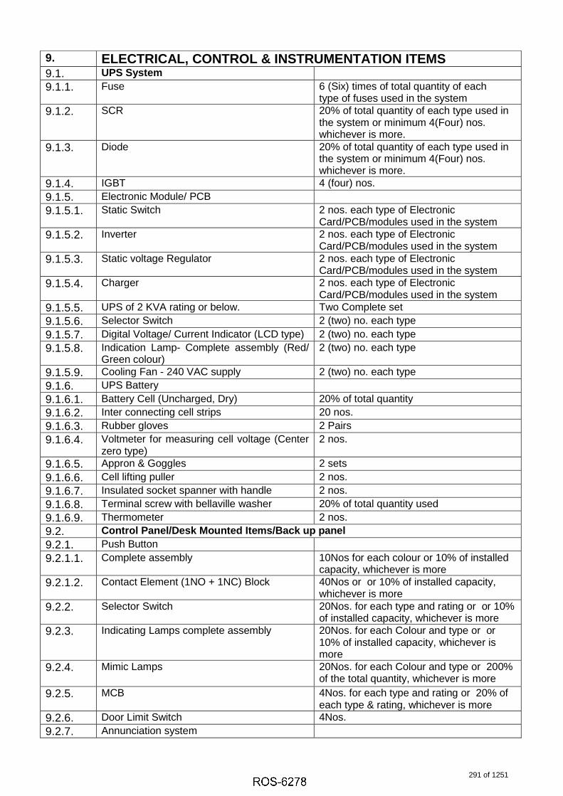
9. ELECTRICAL, CONTROL & INSTRUMENTATION ITEMS9.1. UPS System 9.1.1. Fuse 6 (Six) times of total quantity of each
type of fuses used in the system9.1.2. SCR 20% of total quantity of each type used in
the system or minimum 4(Four) nos.whichever is more.
9.1.3. Diode 20% of total quantity of each type used in the system or minimum 4(Four) nos.whichever is more.
9.1.4. IGBT 4 (four) nos.9.1.5. Electronic Module/ PCB9.1.5.1. Static Switch 2 nos. each type of Electronic
Card/PCB/modules used in the system9.1.5.2. Inverter 2 nos. each type of Electronic
Card/PCB/modules used in the system9.1.5.3. Static voltage Regulator 2 nos. each type of Electronic
Card/PCB/modules used in the system9.1.5.4. Charger 2 nos. each type of Electronic
Card/PCB/modules used in the system9.1.5.5. UPS of 2 KVA rating or below. Two Complete set9.1.5.6. Selector Switch 2 (two) no. each type9.1.5.7. Digital Voltage/ Current Indicator (LCD type) 2 (two) no. each type9.1.5.8. Indication Lamp- Complete assembly (Red/
Green colour)2 (two) no. each type
9.1.5.9. Cooling Fan - 240 VAC supply 2 (two) no. each type9.1.6. UPS Battery9.1.6.1. Battery Cell (Uncharged, Dry) 20% of total quantity9.1.6.2. Inter connecting cell strips 20 nos.9.1.6.3. Rubber gloves 2 Pairs9.1.6.4. Voltmeter for measuring cell voltage (Center
zero type)2 nos.
9.1.6.5. Appron & Goggles 2 sets9.1.6.6. Cell lifting puller 2 nos.9.1.6.7. Insulated socket spanner with handle 2 nos.9.1.6.8. Terminal screw with bellaville washer 20% of total quantity used9.1.6.9. Thermometer 2 nos.9.2. Control Panel/Desk Mounted Items/Back up panel9.2.1. Push Button9.2.1.1. Complete assembly 10Nos for each colour or 10% of installed
capacity, whichever is more9.2.1.2. Contact Element (1NO + 1NC) Block 40Nos or or 10% of installed capacity,
whichever is more9.2.2. Selector Switch 20Nos. for each type and rating or or 10%
of installed capacity, whichever is more9.2.3. Indicating Lamps complete assembly 20Nos. for each Colour and type or or
10% of installed capacity, whichever is more
9.2.4. Mimic Lamps 20Nos. for each Colour and type or 200% of the total quantity, whichever is more
9.2.5. MCB 4Nos. for each type and rating or 20% of each type & rating, whichever is more
9.2.6. Door Limit Switch 4Nos.9.2.7. Annunciation system
291 of 1251

9.2.7.1. Lamp Box with Facia & Lamps (LED type) 50Nos. or 10% of total quantity, whichever is more
9.2.7.2. Hooter 2Nos.9.2.8. Blank Tiles 20% of installed capacity9.2.9. Fuses/ Fuse holder 200% of each type & rating9.3. Electric Actuator/Motorised Valve9.4. 415 V 3 ph integral starter type9.4.1. Complete set of Actuator 2Nos. for each type and rating9.4.2. Limit Switch 6 Nos each type and rating9.4.3. Torque Switch 6 Nos each type and rating9.4.4. Auxiliary Contact 2 nos each type and rating9.4.5. Motor 2 nos each type and rating9.4.6. Complete Seal kit 2Sets for each type and rating9.4.7. Complete O-Ring Set 2Sets9.4.8. Electronic Card Two(2) for each type/make9.4.9. Feedback Assembly (4-20mA) for Inching
typeTwo(2) for each type/make
9.5. Motor9.5.1. 415 Volt Motor (above 30KW Rating upto
200KW)9.5.1.1. End Shield Cover Driving & Non-Driving End 2 Sets for each type and rating of Motor9.5.1.2. Driving End & Non-Driving End Bearing 2 Sets for each type and rating of Motor9.5.1.3. Cooling Fan 2 Sets for each type and rating of Motor9.5.1.4. Motor Space Heater 2 Sets for each type and rating of Motor9.5.1.5. Motor Terminal Block 2 Sets for each type and rating of Motor9.5.1.6. Complete Set of Coupling 2 Sets for each Application9.5.2. 415 Volt Motor (Upto 30KW Rating)9.5.2.1. Driving End & Non-Driving End Bearing 6 Sets for each type and rating of Motor9.5.2.2. Cooling Fan 4 Nos. for each type and rating of Motor9.5.2.3. Motor Terminal Block 10 Nos. for each type and rating of Motor9.5.2.4. Complete Set of Coupling 2 Sets for each Application9.6. Field Instruments9.6.1. Transmitters/ Gauges/Switches etc. along
with relevant accessories20% of total or at least Four (whicheveris higher) for each type along withaccessories.
9.6.2. Temperature Element (RTD/Thermo-couple) with thermowell
100% of each type, range andimmersion length .
9.6.3. Analysers
9.6.3.1. Field sensor 4 nos. of each type/model
9.6.3.2. Field transmitter/ complete electronic unit 2 nos of each type/model
9.6.3.3. Power supply card 2 nos of each type/model
9.6.3.4. Instrumentation hardware 2 nos. each item
9.7. Process Connection Piping (Impulse piping/tubing, sampling piping / tubing & air supply piping as applicable)
9.7.1. Valves of all types 20% of each type, class, size & model
9.7.2. Valve Manifolds (2 way/3 way/5 way) 20% of each type, class, size & model
9.7.3. Fittings 20% of each type, class, size & model
292 of 1251

9.7.4. Filter Regulators 40% of each model
9.8. Large Video Screen
9.8.1. LED Light Source 4 nos. for each LVS
9.8.2. Dust Filter 20% of the total quantity or minimum16 nos. whichever is higher
9.8.3. Graphic Output Card 20% of the total quantity or minimum 2nos. whichever is higher
9.8.4. LAN Card for Controller 20% of the total quantity or minimum 2nos. whichever is higher
9.8.5. Video Input Card CCTV 20% of the total quantity or minimum 2nos. whichever is higher
9.8.6. Controller unit 20% of the total quantityor minimum 2nos. whichever is higher
9.8.7. DVI Cable (10 Mtr.) 4 nos.
9.9. Junction Box
9.9.1. Junction box 20% of total quantity for each size butminimum 4 nos.
9.9.2. Terminals in Terminal blocks 20 nos. of each type
9.10. PLC/ Proprietary Control System
9.10.1. Network cards, Communication Interface cards
10% for each type or but minimum 2no.
9.10.2. I/O Cards (Each type) 10% for each type but minimum 4 nos.
9.10.3. Controller Cards 2 nos.
9.10.4. SER Cards 10% for each type or but minimum 2no
9.10.5. All other Electronic Modules 10% for each type or but minimum 2no.
9.10.6. Relays 20% of total quantity
9.10.7. Power Supply Modules & Power Packs for control system
10% for each type and range butminimum 2 nos.
9.10.8. Network Items (Network switch/ LIU unit/ Transceiver/ FOpatch cord etc.)
20% of total nos. used for each typeand model in the system or minimum4(four) no. whichever is more.
9.10.9. MCB (Miniature case circuit breaker) 20% or minimum 20 nos. whichever is higher for each type and rating.
9.10.10. Fuses 400% or minimum 100 no's for eachtype and rating
9.10.11. Racks for housing I/O & Processor Modules 2(two) no. each type used in thesystem
9.10.12. Prefab interconnecting cables with connectors
20% of total nos. used in the system orminimum 8(Eight) nos. whichever ismore for each type.
9.10.13. Network communication cable with end connectors
20% of total nos. used in the system orminimum 8(Eight) nos. whichever ismore for each type.
293 of 1251

Note:For calculation of spare quantity in % fractional numbers to be rounded up to next higher integer.
9.10.14. I/O bus cables with connectors for remote I/O units
2 nos. of each type & length
9.10.15. Fibre optic cable Converter / Deconverter 2 nos.
9.10.16. Cooling Fans 4 nos. for each cabinet
9.10.17. Loose Connectors 10 nos. of each type
9.10.18. Colour TFT Monitor 2 nos. complete set
9.10.19. Hard Disk Drive for the work Station 2 nos. complete set
9.10.20. Key board , mouse / trackball with connecting cables andplugs
2 nos. each type.
9.10.21. Printers Catriges 4 nos. of each type
9.10.22. SMPS for printers 2 nos. of each type/ rating
9.10.23. SVGA cards for printers 2 nos. of each type
9.10.24. Key Board & Cursor control device 2 nos. of each type
9.10.25. Complete Set of Operators Work Station 2no. complete set
9.10.26. Terminal Block 20% of total nos. used in the systemfor each type and rating.
9.10.27. Read-Write CD/DVD 4 (four) no. complete set
9.10.28. Blank CD/DVD 100 nos.
294 of 1251

SUB-VENDOR LIST
1. Bidder shall follow the attached approved Sub-Vendor list. The Sub Vendor list provided is compiled list of all BHEL units and sufficient Sub-Vendors have been already approved by TSGENCO. No additional Vendors will be entertained for the equipment already available in the Sub-Vendor list.
2. Incase any equipment is not specified in the list, Bidder shall submit the credentials of the Sub Vendors during contract stage for Approval.
3. Credentials shall consist of the following as minimum
a. List of references for similar application b. Minimum 2nos. of Purchase Orders of similar references c. Minimum 2nos. of Performance certificates/ Inspection clearance reports d. Sub Vendor Catalogues
4. Finalized list of Sub Vendors will be submitted to TSGENCO for intimation/ approval/ clearance.
295 of 1251
6045995
Typewriter
Annexure-2

TELANGANA STATE POWER GENERATION CORPORATION LIMITED
(A Govt. of Telangana Undertaking) Vidyut Soudha, Hyderabad - 500082. www.tsgenco.telangana.gov.in
Phone: 040 - 23499261 Fax: 040 - 23499263.
From: The Chief Engineer, Thermal Projects Construction, TSGENCO, Vidyut Soudha, Khairatabad, Hyderabad-500 082. Email ID:[email protected]
M/s Bharat Heavy Electrical Ltd., INDUSTRIAL SYSTEMS GROUP POBox No.1249, Prof CNR Rao Circle, Malleswaram, Banglore-560012. Mail ID: [email protected]
,0, lr.No.CE/TPC/SE-5/EME-09/YTPS(5X800MW)/F.NO.9/D.No.oy 119.0t: .01.2019.
Sir, Sub: TSGENCO - Yadadri TPS(5X800MW) - Approval of additional vendor M/S Tenova india
Pvt Ltd, Chennai for 'Machine Package' - Certain Clarifications-Reg.
Ref: 1.Lr no.CE/TPC/SE-5/EME-09/YTPS( 5x800MW)/F.No.09/D.No.01/19,Dt: 05. 01.2019 2.M/s BHEL Letter Ref: IS-1-15-2001/Additional Vendors-machine, Dt: 08.01.2019
*****
Further to letter communicated by TSGENCO vide reference (l)st cited, and reply by
M/s BHEL on the subject matter vide reference (2)nd cited, it is to clarify that M/s Tenova
India Pvt Ltd is approved for supplying 'Stacker & Reciaimer','Wagon Tippler' only based on
end user certificates but not approved for sourcing machine like Crusher, Screens, Paddle
feeders and Apron feeders from approved vendors of TSGENCO. This is for information and
further necessary action.
Yours faithfully,
\l~~ CHIEF ENGINEER/TPC
Copy to: 1. SE/Tech to the Chairman & Managing Dlrector/TSGENCO/Vidyut Soudha/Hyderabad. 2. Superintending Engineer-3/TPC/TSGENCO/Vidyut Soudha/Hyderabad 3. DE/Tech to the Director (Projects)/TSGENCO/Vidyut Soudha/Hyderabad.
296 of 1251

TELANGANA STATE POWER GENER,ATION CORPOR^ATION I.IMITED(A Govt. Of Telangana Undertaking)
Vidyut Soudha, Hyderabad - 500082.Phone: 040 - 2349926L Fax: 040 - 23499263.
From:Chief Engineer,Thermal Projects Construction,TSGENCO, 3ro Floor, A-Block,Vidyut Soudha, KhiarathabadHyderabad-500 082.cetDctq enco@o rna i | "com
To:M/s BHEVRC Puram,Heavy Power Equipment Plant,R C PuramCONTMCT MANAGEMENT DEPARTM ENTHyderabad - 502 032 , INDIAPh : 040-23 18245 L,Mob : 9491306087
Email: [email protected] Attention:Mr. B. Ravindra nalqk , Dv" Manaqet
Sir,
Subl TSGENCO - Yadadri TPS (5XB00MW) - Approval of New vendors for C&I and Mechanical
items furnished by M/s BHEVRC Puram/Hyderabad- Reg.
Ref: L.M/s BHEVRC Pu ra m/ Hyderabad letter YTPS/VVHYD/00, Dated 26.o7 .zoLB.
2.M/ s TCE Recommendations letter TCE. 1 10054 / PJ/K/ 0L5, dated 13. 1 1.20 1B
**x***
Please refer to the letter 1"' cited above, wherein M/s BHEVR C Puram/Hyderabad has
requested for approval of vendorc for certain C&I and Mechanical items for Yadadri TPS
(5XB00MW). The same was reviewed and TSGENCO hereby accords approval for the vendors.
The list of approved vendors is enclosed as Annexure"
Please note that this approval of vendors for Supply of following list of items does not
absolve Mls BHEL of its responsibility of supplying and conforming to the relevant specifications
and standards as per the terms and conditions of the contract.
Encl: List of TSGENCO Approved Vendors of M/s BHEVR C Puram/Hyd Unit,
Q r.r
Chief Engineer/TPe
Copv communicated to:
1. The Ch ief En g ineer/Construction/YTPs Site/Da meracherla/Na lgonda "
2. FA&CCA ( Res " ) &CFO/TSG EN COlVid yut Soud halHyd era bad
"
3. Superintending Engineer/Tech to The Chairman & Managing Director/TSGENCO/VS/HyE
4" Superintending Engineer/CiviI/YTPS Site/Darneracherla/Nalgonda(Dist.)"
5. Ey CCA, YTPS-II/Co-ordinationlDameracherla/Nalgonda(Dist.)"
6" DElTech to Director (Projects)/TscENCO/Vidyut Soudha/Hyderabad"
7 " SAO/Pay&AceountsffscENCO/Vidyut Soudha/Hyderabad "
8" M/s Tata Consulting Engineers Limited,T3lJ,Sheriff Centreo St" Marks road, Bangalore-
560 001_"
9" TCE, Site office, Room No.323, Vidyut Soudha, Hyderabad
L0"Sri Y"A.Srinivas Rao, BHEVPMG Carnp Office" Vidyut Soudha, Hyderabad"
297 of 1251

$.No.
Name ofSystem/Package
Name of Vendors/Flace TSGENEO
Remarks
T&C VENDORS
l"
ortPURIFIEATION
UNIT
1 "ALFA[AVA|_, PU NE/SWEDEN Approved
2"PALL INDIA PVT. LTD., Mumbai Approved
3" PENNWALT EORPORATION, USA Approved
2SIMPLEX
FILTER
L"EPE PROCESS FITTERS & ACCUMUTATORS, Hyderabad Approved
2. HYDAC TECH NOLOGY GMBH,Germany Approved
3"BOLL & KIRCH FILTERBAU GMBH, Germany Approved
4"HYDAC (INDIA) PVT" LTD", Maharashtra Approved
S.PALL EUROPE LTD. Great Britain Approved
6"PALI- INDIA PW" LTD.,Mumbai Approved
T.FILTER CONCEPT PRIVATE LIMITED, Ahrnedabad. Not Approved
S"GRAND PRIX ENGINEERING PVT. LTD, Haryana. Not Approved
3
EONTROL
VALVES
( PNEUMATIC
ACTUATED)
l.INSTRUMENTATION LTD, PaIaKKad Approved
2.KOSO FLUID CONTROLS PW. LTD.-patakkad Approved
3.EMERSON PROCESS MANAGEMENT, Chennai Approved
4"SEVERN GLOCON INDIA, Chennai Approved
5"KSB MIL CONTROLS LIMITED,THRISSUR(Otder nameMIL COI\TROLS LIMITED)
Approved
6"BOMAFA SPECIAL VALVE SOLUTIONS, Gujarat" Not Approved
PUMPS PRODUET
4DE STARTER
EUBICLES
l.LARSEN & TOUBRO LIMITED, Hyderabad Approved
2"C Al\D S ELECTRiC LIMITED, New Dethi Not Approved
3"INDUSTRIAL EONTROLS & AUTOMATION , Mumbai Not Approved
4.BeH ELECTRIC LTD, Secunderabad"
Approved
Page 1 of 6
AnnexureYADADRI TPS(5X800MW) Approved Vendors List-M/s BHEVR C Puram/Hyderabad
Lr" No"e E/TPC/SE-3 /EME-L4/YTPS/F.Vendors Approval/D" No" os, lL9,Dt: os .OL"ZAL}
QlChief Engineer lTPf'
298 of 1251

Page 2 of 6
AnnexureYADADRI TPS(5X800MW) Approved Vendors List-M/s BHEVR C Puram/Hyderabad
Lr. No. CEITPC/S E- 3 | EME- t4 IYTPS/ F"Vendors ADprova l/ D. N o. o e / L9,D o€ 01.2019
sl"No"
Name ofSystem/Package
Name of Vendors/PlaceTSGENCO
Remarks
5R"C VALVES
FOR BFP
l.CONTROL COMPONENTS INC., USA Approved
2"KSB MIL CONTROLS LIMITED,THRISSUR(Older name
Mrt eoNTRoLS LTMTTED)
Approved
3"HOLTER REGEI-ARMATUREN GMBH & CO. KG,
GERMANY.
Approved
4"DRESSER PRODUITS INDUSTRIELS, FRANCE Approved
5"CONTROL COMPONENT INDIA, CHITTOOR" Not Approved
6.EMERSON PROCESS MANAGEMENT, CHENNAI. Approved
bSUCTION
STRAINER
l.PROCEDYNE ENGINEERS Approved
2"GUJARAT OTOFILT, Approved
3 "JAY-EESH ENGIN EERING COM PANY,M uMbAi, IN DIA Approved
4.FILTERATION ENGINEERS INDIA PVT LTD, MUMBAI,
INDIA
Approved
5"GRANDPRIX ENGINEERING PVT LTD, HaryanA. Not Approved
6.NISAN SCIENTIFIC PROCESS, NAVI MUMBAI Not Approved
T.PATEL HEAT EXCHANGERS, Bhopal Not Approved
7
Multi Disc
Flexible
Couplings forMHI BFPs" 660
to 800MWs
1. EUROFLEX TRANSMISSIONS (INDIA) Approved
2"JOHN CRANE FLEXr BOX (TNDIA) PVT" LTD Approved
3"BIBBY TURBOFLEX., Approved
4,RATHI TURBOFLEX PW. LTD, PUNE. Approved
5.CUBIC TRANSMISSION PVT. LTD, HYDERABAD. Approved
6"KTR COUPLINGS INDIA PW. LTD. Not Approved
8
Connecting
Coupling For
CEP & CWP
l"CUBIC TRANSMISSION PVT. LTD, Approved
2"EUROFLEX TRANSMISSIONS (INDIA), Hyderabad. Approved
3"JOHr\ CRANE FLEXr BOX (rNDrA) PVT. LTD Approved
4"RATHI TURBOFLEX PVT" LTD.,PuNC Approved
5.UNTQUE TRANSMTSSiON (r) pVT LTD,, Approved
Qrr tc. rff4r1Chief Engineer lTPC
299 of 1251

allD.No" oe /19,Dt: oe "0L.20 j.9
sl.No,
Name ofSystemy'Fackage
Name of Vendorsy'Place TSGENEO
Remarks
6.KTR COUPLINGS INDIA PVT" LTD". Pune. Not Approved
PULVERISERS & SWITCHGEAR
9 GrindinE Rolls
1.M/s AIA ENGINEERING, Nagpur Approved
2.M/s AIA ENGINEERING Ahmedabad Approved
3"MAGOTTEAUX INDUSTRIES PVT. LTD", Hyderabad. Not Approved
4"SFIRI BALAJI INDUSTRIAL PRODUCTS LIMITED,
Jaipur" Not Approved
10Bull Ring
SeEments
1"M/s AIA ENGINEERING, Nagpur Approved
2.M/s AIA ENGINEERING Ahmedabad Approved
3.MAGOTTEAUX INDUSTRIES PVT" LTD", Hyderabad. Not Approved
4"SHRI BAI-AJI INDUSTRIAL PRODUCTS LIMITED,
Jaipur" Not Approved
L1
KNIFE GATE
VATVE &ACCESSORIES
l.ASHWATHI CONTROLS PVT" LTD"AHEMDABAD Approved
2"GENERAL ENGINEERING EONSORTIUM, BANGALORE Approved
3"ORBINOX INDIA PVT LTD, INDIA, COIMBATORE. Approved
4"GALAXY CONTROLS PVT LTD, CHENNAI. Approved
5"N/r" Bray Controls India Private Limited- Chennai Approved
6"BACHMANN INDUSTRIES INDIA LTD. ApBroved
T"SURYA VALVES, EF,IENNAI" Not Approved
S.EXPERT ENGINEERING ENTERPRISES, BELGAUM,
KARNATAKA"Not Approved
9,JASH ENGINEERING LIMITED, INDORE" M"P" Not Approved
lO"KEROMIYONS INTEEH PVT tTD, COIMBATORE" Not Approved
1 ]""KRISHNA ENGINEERI|\G EOMPANY, BHOPAL. Not Approved
12"HI-TEC VALVES, CHENNAI. l\ot Approved
L2PLAI\ETARY l.INDIAN OIt CORPN.LTD", FIYDERABAD. Approved
Page 3 of 6
AnnexureYADADRI TP5(5x800MW) Approved vendors List-M/s Bt-tEVR e puram/Hyderabad
?uChief Engineer lTPC
300 of 1251

Lr"No"C EM E- L4IYTPS/ F.Vendors ABorova l/ D " No. a e / 1 9. Dt .0t "20t_9
sl"No.
Name ofSystem/Package
Name of Vendors/PlaceTSGENEO
Remarks
GEARBOX OIL 2"EXXONMOBIL LUBRICANTS PVT LTD, GURGAON. Approved
3.SHELL INDIA MARKETS PRIVATE LIMITED,
MAHARASTHRA.Not Approved
4.CASTROL INDIA LIMITED, MUMBAI" Not Approved
5"HINDUSTAN PETROLEUM CORPN. LTD, CHENNAI. Approved
6.BHARAT P C L, HYDERABAD. Approved
13SPACE
HEATERS
1. ESCORTS LIMITED,WORLI Approved
2"TRANSFORMER MANUFACTURING INDUSTRIAL,
DHARANGADHARA, GUJARAT
Approved
3"EELMESS THERMOSYSTEM TECHNIK GMBH&CO,
GERMANYApproved
4"THERMOPADS PVT LTD,, HYDERABAD" Not Approved
5.THERMEN HEATING TECHNOLOGIES, BANGALORE, Not Approved
6.RASHMI HEATERS PVT. LTD. PUNE. Not Approved
t4AIR CYLINDER
FOR KNIFE
GATE VALVE
1..VEL]AN HYDMIR PVT. LTD, HYDERABAD. Not Approved
2"SALZGITTER HYDRAULICS PVT.LTD, HYDERABAD. Approved
3"FLUIDTECQ PNEUMATICS PVT, LTD, MAHARASTHRA, Not Approved
4.ROTEX MANUFACTURERS & ENGINEERS, THANE,
MAHARASTHRA.Approved
5"ASCO NU MATICS(INDIA), CHENNAT. Not Approved
15
SOLENOID
VALVE FOR
KNIFE GATE
VALVE
I."VELJAN HYDRAIR PVT" LTD, HYDERABAD. Not Approved
2.AVCON CONTROLS PVT. LTD, MUMBAI. Approved
3.FLUIDTECQ PNEUMATICS PVT" LTD, MAHARASTHRA. Not Approved
4.ASCO NUMATICS(IN DrA), CHENNAL Not Approved
16
LIMIT SWITCH
FOR KNIFE
GATE VALVE
1. BCH ELECTRIC LTD, SECUNDERABAD. "
Approved
2"HONEYWELL AUTOMATION INDIA LIMITED, PUNE" Not Approved
3"JAI BALAJI CONTROL GEARS PVT" LTD, CHENNAI" Not Approved
Page 4 of 6
AnnexureYADADRI TPS(5X800MW) Approved Vendors List-M/s BHEUR C Puram/Hyderabad
QlChief Engineer /TPC
301 of 1251

roval/D" No. o6119,Dt: o€ .0L "2OLg
sl.No,
Name ofSystern/Package
Name of Vendors/Place TSGENEO
Remarks
EOMMON ITEMS
L7 DUPLEX FITTER
I"F|YDAC INDIA PVT LTD, Maharashtra Approved
2.EPE PROCESS FILTERS & ACCUMULATORS, Hyderabad Approved
3"PALL INDIA PVT" LTD." Mumbai Approved
4,FILTER CONEEPT PRIVATE LIMITED, GUJARAT" Not Approved
s"GRAND PRIX ENGINEERING PVT" LTD, HARYANA. Not Approved
6"UNIQUE ENGINEERING ENTPS" PVT. LTD,
SEEUNDEMBAD. Not Approved
T,MIKROFLO FILTERS PVT"tTD, HYDERABAD" Not Approved
S.SUPERFLO FITTERS PVT.LTD., MAHARASTHRA. Not Approved
1B
GUIDED WAVE
RADAR LEVEL
TRANSMITTER
I. "ABB GERMANY/ FARI DABAD Approved
2"ABB LIMITED, NASHIK Approved
3"EMERSON PROCESS MGT(I) PVT LTD, Hyderabad, Approved
4. EMERSON PROCESS,USA/NAVI MUMBAI Approved
5"ENDRESS & HAUSER GMBH + CO., GeTmany Approved
6"ENDRESS + FJAUSER (INDIA) PVT. LTD., Maharasthra" Approved
7. EN DRESS+ HAUSER, GERMANY/IN DIA Approved
8. MAGNETROL INTERNATIONAL N.V Approved
g"PUNE TECHTROL PVT tTD, PUNE Approved
lO"SAAB ROSEMOUNTTANK GUAGING , PUNE Approved
1l"V AUTOMAT AND INSTRUMENTS PVT LTD, NEW
DELHI"Not Approved
1 2 "YOKOGAWA, JAPAN/BANGLORE Approved
19LUBE OIt PUMP
(seREW TYPE)
1 "ALEKTON ENGIT\ EERING ll'l DUSTRIES Approved
2"DELTA PD PUMPS PVT LTD, Mumbai Approved
3"tEISTRITZ, GERMAI\Y Approved
Page 5 of 6
AnnexureYADAERI TPS(5X800MW) Approved Vendors List-M/s BHEL/R e Puram/Hyderabad
ehief Engineer lTPA 302 of 1251

Lr. No. CEITPC/S E-3 | EME- L4 IY|PS/ F. Vendors Approva l/ D. No. o# L 9, Dt 0g 0 1.20L9
sl"No.
Name ofSystern/Package
Name of Vendorsy'PlaceTSGENCO
Remarks
4.NETZSCH TECHNOLOGIES INDIA PVT LTD Not Approved
5.SETTIMA MECCANICA SRL Approved
6"TUSHACO PUMP, DAMAN (Note- Tushaco name
changed to Allweiler)
Approved
7,UT PUMPS & SYSTEMS PVT. LIMITED. Approved
20
Resistance
Temperature
Detector (RTD)
&
THERMOCOUPL
ES
M/s BHEVHyderabad
YTPS(5X800MW)
BHEVEDN.
forshall follow
temperature
the approved
elements in
vendors ofline with M/s
27 THERMOWELLS
l.ASHCROFT INDIA PVT LTD-GUJARATH Approved
2.CARLO DYNATECH IN DUSTRIES, Pata NChCTu Not Approved
3. DETRIV INSTRU MENTATION, M UMBAI" Approved
4.GOA INSTRUMENTS INDUSTRIES , GOA Approved
5.H"GURU INSTRUMENTS (SI) PVT LTD ,BANGALORE Approved
6.INDUSTRIAL INSTRUMENTATION, KOLKATA Approved
T.MICRO PRECISION PRODUCTS (P) LTD., Haryana Not Approved
8. PRECISION ENGINEERING INDS,MUM BAI Approved
9.PRECISION MASS PRODUCTS PVT LTD, GUJARAT. Not Approved
IO"PYRO ELECTRIC INSTRUMENTS GOA Approved
1 l.THERMAL INSTRUMENT INDIA, MahATAShITA Approved
12"TM TECHNOMATIC S.R"L, ITALY Not Approved
l3"TOSHNIWAL INDUSTRIES PVT.LTD - AJMER Approved
22 LEVEL GUAGESM/s BHEl/Hyderabad will be requested to follow the approved vendors
of YTPS(5X800MW) for LEVELGUAGES in iine with M/s BHEVEDN"
Page 6 of 6
AnnexureYADADRI TPS(5X800MW) Approved Vendors List-M/s BHEUR C Puram/Hyderabad
QrtPChief Engineer lTPC
303 of 1251

TELANGANA STATE POWER GENERATION CORPORATION LIMITED
(A Govt. Of Telangana Undertaking) Vidyut Soudha, Hyderabad - 500082.
Phone: 040 - 23499261 Fax : 040 - 23499263
From: To : Chief Engineer, Mis BHEL/Ranipet,Boiler Auxiliaries Plant,
Indira Gandhi Industrial Complex, COMMERCIAL DEPARTMENT RANIPET - 632 406. INDIA
Thermal Projects Construction, TSGENCO, 3rd Floor, A-Block, Vidyut Soudha, Khiarathabad Hyderabad-500 082. cet ct enco@ mail.com
Phone :(04172) 284817,Mob :9848265808 Email: mmahesh@bheLin
Kind Attention: Mahesh M, Dy. Manager/Commercial
Lr.No.CE/TPC/SE-3/EME-14/YTPS/F.Vendors ApprovaI/D.No. o 1 /19,Dt: o~ . Ol .1 9
Sir,
Sub: TSGENCO - Yadadri TPS (5X800MW) - Approval of additional Vendors fo r for supplying
of Electrical actuators furnished by M/s BHELjRanipet unit - Reg.
Ref: 1. M/s BHELjRanipet BAP:COMML:R827-R831 & R4L4 :VENDOR LIST:REV-01 , dated
05 .09.2018
2. M/s TCE/Hyderabad vide letter references TCE.ll005A /PJ/K/015, dated 13.11.2018
****** Please refer to the letter 1st cited above, wherein M/s BHELjRanipet has requested for
the following two additional vendors for supplying of Electrical actuators perta ining to Yadadri
TPS (5X800MW) . The same was reviewed and TSGENCO hereby accords approval for the
vendors.
51 . TSGENCO
No. Item Description Vendor proposed/Place
Remarks
Actuators-Electrica I l.ANTRIEB TECHNIK PRIVATE LIMITED, CHENNAI. Approved
1 2.YANGZHOU HENGCHUN ELECTRONICS CO. LTD, (Open/Close type)
JIANGSU, CHINA Not Approved
Please note that this approval of vendors for Supply of following list of items does not
absolve M/s BHEL of its responsib ility of supplying and conforming to the relevant specifications
and standards as per the terms and conditions of the contract .
Yours faithfully,
Chief Engineer ITPC
Copy communicated to:
1. The Chief Engineer/Construction/YTPS Site/Dameracherla/Nalgonda.
2. FA&CCA (Res.)&CFO/TSGENCO/Vidyu t Soudha/ Hyderabad .
3. Superintending Engineer /Tech . to CMD/TSGENCO/Vidyut Soudha/Hyderabad.
4. Superintending Engineer/Civil/YTPS Site/Dameracherla/Nalgonda(Dist.).
5. Dy CCA, YTPS-II/Co-ordination/Dameracherla/ Nalgonda(Dist.) .
304 of 1251

6. DE/Tech to Director (Projects)/TSGENCO/Vidyut Soudha/Hyderabad.
7. SAO/Pay&Accou nts/TSGENCO/Vidyut Soudha/Hydera bad.
8. M/s Tata Consu lting Engineers Limited,73/1 ,Sheriff Centre, St. Marks road , Bangalore-
560 001.
9. TCE, Site office, Room No.323 1 Vidyut Soudha, Hyderabad
10. Sri Y,A,Srinivas Rao l BHELjPMG Camp Office, Vidyut Soudha, Hyderabad.
305 of 1251

TElANGANA STATE POWER GENERATION CORPORATION LIMITED (A Govt , Of Telangana Undertaking)
Vidyut Soudha, Hyderabad - 500082 , Phone: 040 - 23499261 Fax: 040 - 23499263
From : Chief Engineer, Thermal Projects Construction , TSGENCO, 3rd Floor, A-Block, Vidyut Soudha, Khiarathabad Hyderabad-500 082 ,
nrn((lln ma if ,com
To: M/s BHEljTrichy, High Pressure Boiler Plant, Tiruchirappalli -620 014, Tamil Nadu, INDIA. (P) :0431-257-7156, Mob:9406903625,
Email : [email protected]
Kind Attention:Sri RAHUL TOPPO, Dy, Manager. Comml/FB
lr.No,CE/TPC /S E~3 / EME-14/YTPS/F . Vendors Approval/D,No. 0'6 /19,Dt: og .01 .19
Sir,
Sub: TSGENCO - Yadadri TPS (5X800MW) - Approval of Vendors for for CONTROL VALVE
furnished by M/s BHEljTrichy unit - Reg.
Ref: LM/s BHEL/Trichy letter TP/11497/Vendor Listj02 dated 23.07,2018.
2. M/s TCE/Hyderabad letter reference TCE,1l005A /PJ/K/015, dated 13.11.2018.
****** Please refer to the letter cited above, wherein M/s BHEL/Trichy has requested for
approval of vendors for CONTROL VALVE pertaining to Yadadri TPS (5X800MW) . The same was
reviewed and TSGENCO hereby accords approval for the vendors. The list of approved vendors
is enclosed as Annexu re.
Please note that this approval of vendors for Supply of following list of items does not
absolve M/s BHEL of its responsibility of supplying and conforming to the relevant specifications
and standards as per the terms and conditions of the contract .
End: List of TSGENCO Approved Vendors of M/s BHEljTrichy Unit.
Yours faithfully,
Q\)~~P1 Chief Engineer/TPC
Copy communicated to:
1. The Chief Engineer/Construction/YTPS Site/Dameracherla/Nalgonda.
2. FA&CCA (Res .)&CFO/TSGENCO/Vidyut Soudha/Hyderabad.
3. Superintending Engineer /Tech to The Chairman & Managing Director/TSGENCO/ Vidyut
Soudha/Hyderabad .
4. Superintending Engineer/Civil/YTPS Site/Dameracherla/Nalgonda(Dist.).
5. Dy CCA, YTPS-II/Co-ordination/Da meracherla/Nalgonda(Dist,) .
6. DE/Tech to Director (Projects)/TSGENCO/Vidyut Soudha/Hyderabad.
7. SAO/Pay&Accou nts/TSGENCOjVidyut Soudha/Hydera bad .
8. M/s Tata Consulting Engineers Limited ,73/1,Sheriff Centre, St, Marks road, Bangalore-
56000l.
9. TCE, Site office, Room No,323, Vidyut Soudha, Hyderabad
10. Sri Y.A.Srinivas Rao, BHEL/PMG Camp Office, Vidyut Soudha , Hyderabad .
306 of 1251

51.
No.
1
Page 1 of 1
Annexure
M/s BHEL/Trichy Vendor approva l list of CONTROL VALVE for Yadadri TPS(5X800MW)
Lr,No.CE/TPC/SE-3/EME-14/YTPS/f,Vendors Approval/D.No. oe 11 9,Dt ~ O ~ .O1.2019
Item
Description TSGENCO Name of Vendors /Place
Remarks
loGE OIL & GAS INDIA PRIVATE LIMITED. COIMBATORE
India(old name DRESSER VALVE INDIA PRIVATE Approved
LTD,INDIA)
2. KSB MIL CONTROLS LIMITED THIRISSUR DIST, Approved
India(Old name MIL CONTROLS LIMITED)
3 .SEVERN GLOCON INDIA (P) LTD, CHENNAI. India Approved
4.KOSO INDIA PRIVATE LIMITED, India Approved
5.MASCOT VALVES PVT. LTD AHMEDABAD India Not Approved
CONTROL 6.CONTROL COMPONENT INDIA PVT LTD BANGALORE Approved
VALVE India
7 .DRESSER PRODUITS INDUSTRIELS S.A.S France Approved
8 .CONTROL COMPONENTS INC USA Approved
9 .FISHER SANMAR LIMITED India Approved
lO.EMERSON PROCESS MANAGEMENT CHENNAI Approved
CHENNAI. India
l1.INSTRUMENTATION LTD., India Approved
12.FLOWSERVE INDIA CONTROLS PVT.LTD.,India Approved
Chief Engineer/TPC
307 of 1251

TELANGANA STATE POWER GENERATION CORPORATION LIMITED
(A Govt. of Telangana Undertaking)
Vidyut Soudha, Hyderabad - 500082. Phone : 040 - 23499261 Fax: 040 - 23499323 .
From: The Chief Engineer, Thermal Projects Construction, TSGENCO, Vidyut Soudha, Khairatabad, Hyderabad-500 082. Email ID:[email protected]
To: Mis BHEL, Power Sector-Southern Region, Periyar EVR Building,690, Anna Salai, Nandanam, Chennai - 600 035. Phone: 044-28286715 Fax : 044-24323757.
\'"11 . Lr.No.CE/TPC/SE3/EME-15/YTPS(5X800MW)/F.NO. ID.No . 118, Dt: 11-.-12.2018.
Sir,
Sub: TSGENCO - Yadadri TPS(5X800MW) - Proceeding with Tendering for execution of
CHP and AHP civil works as Package A & B of Units 1,2,3,4 & 5 for 5X800 MW
Yadadri Thermal Power Station - Reg.
Ref: 1) Mis BHEL E-mail Letter Dt:24.03.2018.
2) Mis BHEL Letter Ref: BHEL PSSR: YADADRI TPP : 102, Dt :26.11.2018
3) Mis BHEL Letter Ref: BHEL PSSR: YADADRI TPP: 102, Dt:11.12.2018
***** Th is has reference to the letter cited in ref (3) above, wherein Mi s BHEL/PSSR
has informed that they are in the process of floating the tender for execution of CHP
and AHP civil works as Package A & B of Units 1,2,3,4 & 5 for 5X800 MW Yadadri
Thermal Power Station and informed that the tender shall have the provision of Reverse
Auction
In this connection it is to inform that time and again TSGENCO is requesting
Mis BHEL that not resort to Reverse Auction for civi l works which was agreed by
Mis BHEl during finalization of Revised LOI and as per P.O conditions .
Hence the proposal furnished by Mi s BHEL that the above tenders shall have
the provision of Reverse Auction is not acceptable to TSGENCO.
This is for information and further necessary action .
Yours faithfully,
Q\j~~rt
Chief Engineer/TPC
P.T.O
308 of 1251

Copy to: 1. Chief EngineerjConstruction/YTPS/ Dameracheria/Nalgonda(Dt)
2, Chief Engineer/ Civil/Thermal/TSGENCO/VS/Hyderabad
3. Superintending Engineer/CiviI/YTPS(5X800MW)/Dameracherla ,
4 , Superintending Engineer-5/TPC/TSGENCOjVS/Hyderabad,
5, SE fTech, to CMDfTSGENCOjVS/ Hyderabad,
6. DE / Tech, to Director/ Projects/TSGENCOjVSjHyderabad ,
7, ADE j Tech, to Director/Civi l/TSGENCOjVSjHyderabad,
8 . Sri Y.A.Srinivasa Rao,GM(PMG)/BHEL Camp Officej Vidyut SoudhajHyderabad,
9 . Sri HariKrishnan/ GM/BHEL/YTPS Site.
10.M/ s Tata Consulting EngineersLimited, 73/ l,Sheriff Centre, St. Marks road,
Bangalore-560 001. E-Mail id : [email protected].
309 of 1251

TELANGANA STATE POWER GENERATION CORPORATION LIMITED (A Govt. Of Telangana Undertaking)
Vidyut Soudha, Hyderabad - 500082. Phone: 040 - 23499261 Fax: 040 - 23499263
From: Chief Engineer,
To: M/s BHEL/Piping Centre, Commercial Department, 80 GN Road, T Nagar, Chennai - 600 017, Tel: 044-28161278
Thermal Projects Construction, TSGENCO, 3rd Floor, A-Block, Vidyut Soudha, Khiarathabad Hyderabad-500 082. Email: [email protected] cet ct enco@ mail.com
Kind Attention: Mrs. G.V.V VISHNU JYOTI,Manager/Commerclal
Lr.No.CE/TPC/SE- 3/EME- 14/YTPS/F.Vendors Approval/D.No. 10 119,Dt:Qt' .01.2019
Sir,
Sub: TSGENCO - Approval of vendors for C&I and Mechanical items furnished by
M/s BHEL/Piping Centre/Chennai unit - Reg.
Ref: 1. M/s BHEL/PC/Chennai Lr. Ref. YADADRI 5X800MW/7295/7296/7297/7298/7299/
VENDOR APP dated 05.10.18
2. M/s TCE Recommendations Letter reference TCE.ll005A/PJ/K/016, dated 13.11.2018.
****** Please refer to the letters 1st cited above, wherein M/s BHEL/PC/Chennai has requested
for approval of vendors for certain C&I and Mechanical items for Yadadri TPS (5X800MW). The
same was reviewed and TSGENCO hereby accords approval for the vendors. The list of approved
vendors is enclosed as Annexure.
Please note that this approval of vendors for Supply of following list of items does not
absolve M/s BHEL of its responsibility of supplying and conforming to the relevant specifications
and standards as per the terms and conditions of the contract.
Encl: List of TSGENCO Approved Vendors of M/s BHEL/PC/Chennai Unit.
Yours faithfully,
~ \J~~\ Chief Engineer IT PC
Copy communicated to:
1. The Chief Engineer/Construction/YTPS Site/Dameracherla/Nalgonda.
2. FA&CCA (Res.)&CFO/TSGENCO/Vidyut Soudha/Hyderabad.
3. Superintending Engineer /Tech . to CMD/TSGENCO/Vidyut Soudha/Hyderabad .
4. Superintending Engineer/Civil/YTPS Site/Dameracherla/Nalgonda(Dist.) .
5. Dy CCA, YTPS-II/Co-ordination/Dameracherla/Nalgonda(Dist.).
6. DE/Tech to Director (Projects)/TSGENCO/Vidyut Soudha/Hyderabad.
7. SAO/Pay&Accou nts/TSGENCO/Vidyut Soudha/Hyderabad.
8. M/s TCE Limited,73/1,Sheriff Centre, St. Marks road, Bangalore-560 001.
9. TCE, Site office, Room No.323, Vidyut Soudha, Hyderabad
10. Sri Y.A.Srinivas Rao, BHEL/PMG Camp Office, Vidyut Soudha, Hyderabad.
310 of 1251

SI.
No.
1
2
3
Page 1 of 2 Annexure
MIs BEl/PC-Chennai Vendor Approval List lr.No.CE/TPC/SE-3/EME- 14/YTPSIF.Vendors Approval/D.No, to 119,Dt:o(.Ol.2019
Nameof
System! Name of Vendors/Place TSGENCO Remarks
Package
1) PARCOL S.P.A. MILAN Not Approved
2) SHENJIANG VALVE CO LTD ZHEJIANG PROVINCE, PRC Not Approved
,CHINA
3) DAUME REGELARMATUREN ISERMHAGEN, GERMANY Approved
GMBH,
4) SPX FLOW AHEMEDABAD Not Approved
TECHNOLOGY(INDIA)PVT.LTD.,
5) EMERSON PROCESS CHENNAI Approved
MANAGEMENT CHENNAI,
6) MASCOT VALVES PVT. LTD AHMEDABAD Not Approved
7) CONTROL COMPONENT BANGALORE Approved
INDIA PVT LTD
CONTROL 8) LESLIE CONTROLS INC USA Approved
VALVES 9) KOSO INDIA PRIVATE NASHIK. Approved
LIMITED.
10) SEVERN GLOCON INDIA (P) CHENNAI Approved
LTD
11) BOMAFA ARMATUREN GERMANY Approved
GMBH,
12) KSB MIL CONTROLS THIRISSUR DIST Approved
LIMITED,
13) EMET CONTROLS PVT LTD, NASHIK Not Approved
14) R.K.CONTROL THANE Not Approved
INSTRUMENTS PVT. LTD
15) INSTRUMENTATION LTD. KERALA Approved
16) FORBES MARSHALL ARCA CHENNAI Approved
VALVES PVT. LTD
1) S.J.INDUSTRIES CHENNAI Not Approved
2) KISHOR PUMPS PVT LTD PUNE. Approved
Cooling 3) FLOWMORE LTD. GHAZIABAD Approved
Water 4) SAM TURBO INDUSTRY PVT COIMBATORE Approved
Pump LIMITED
5) VARAT PUMP & MACHINERY KOLKATA Approved
PVT LTD
6) SULZER PUMPS INDIA LTD CHENNAI Approved
1) KOSO INDIA PRIVATE LIMITED NASHIK Approved
LP 2) CONTROL COMPONENT
BANGALORE Approved INDIA PVT LTD.
STARTUP 3) EMERSON PROCESS
CONTROL CHENNAI Approved
VALVE MANAGEMENTCH E NN~
4) SHENJIANG VALVE CO LTD, ZHEJIANG PROVINCE,
Not Approved PRC,CHINA
~\) ~~11 Chief EngineerlTPC
311 of 1251

4
5
6
7
8
9
Page 2 of 2 Annexure
MIs BEL/PC-Chennai Vendor Approval List Lr.No.CE/TPC/SE- 3/EME- 14/YTPS/F.Vendors Approval/D.No. 10 /19,Dt: QIj".01.2019
5) KSB MIL CONTROLS LIMITED, THIRISSUR DIST Approved
6) INSTRUMENTATION LTD. KERALA Approved
1) TECHNOMATIC ITALY Not Approved
2) STAR-MECH CONTROLS HADAPSAR, PUNE. Approved
3) VERIS INC CO 80503 USA Not Approved Averaging 4) MICRO PRECISION PRODUCTS
PitotTube (P) LTD TEH & DIST : PALWAL Approved
5) SWITZER PROCESS CHENNAI Approved
INSTRUMENTS
6) MINCO (INDIA) PVT. LTD GOA Approved
1) FLOWSERVE INDIA COIMBATORE Approved
CONTROLS PVT.LTD.
2) CLYDE PUMPS INDIA PVT LTD, GHAZIABAD Approved
3) SAM TURBO INDUSTRY PVT COIMBATORE Approved
CONDENSA LIMITED
TE PUMP- 4) SULZER PUMPS INDIA LTD NAVI MUMBAI Approved
LP 5) PUMPSENSE FLUID KOLKATA Approved
ENGINEERING
6) In CORPORATION INDIA BARODA Approved
PRIVATE LTD
7) KIRLOSKAR BROTHERS LTD PUNE Approved
MIs BHEL/PC-Chennai shall follow the approved vendors of YTPS(5X800MW) for LI RACK in LI RACK
line with MIs BHEL/Trichy.
MIs BHEL/PC-Chennai shall follow the approved vendors of YTPS(5X800MW) for LEVEL LEVEL
SWITCHES in line with MIs BHEL/EDN. SWITCHES
PRESSURE MIs BHEL/PC-Chennai shall follow the approved vendors of YTPS(5X800MW) for PRESSURE
SWITCHES in line with MIs BHEL/EDN. SWITCHES
1) GOA INSTRUMENT GOA
INDUSTRIES PVT LTD Approved .
2) THERMAL INSTRUMENTS VAPI Approved
INDIA PVT LTD
3) BAUMER TECHNOLOGIES VAPI Approved
INDIA PVT.LTD THERMOW
4) GAUGES BOURDON (I) PVT. CHENNAI Approved ELL
LTD
5) PYRO ELECTRIC GOA Approved
INSTRUMENTS GOA P LTD,
6) NESSTECH INSTRUMENTS VAPI Approved
PVT. LTD
7) DETRIV INSTRUMENTATION Mumbai, India Approved
~\l ~1 Chief EngineerITPC
312 of 1251

TELANGANA STATE POWER GENERATION CORPORATION LIMITED
(A Govt. of Telangana Undeftaking)
Vidyut Soudha, Hyderabad - 500082. www.tsgenco.telangana.gov.inPhone: 040 - 2349926t Fax: 040 - 23499263.
From:The Chief Engineer ,Thermal Projects Construction,TSGENCO, Vidyut Soudha,Khairatabad, Hyderabad-500 082.Email ID : cetpctgenco@gmail,com
To:M/s Bharat Heavy Electrical Ltd.,IN DUSTRIAL SYSTEMS GROUPP O Box No.1249, Prof CNR Rao Circle ,Malleswaram, Banglore-560012.Mail ID: [email protected]
KIND ATTENTION: AMIT KUMAR,Sr.Manaqer(pMC)
Lr.No. CE/TPC/SE-3/EME-9/YTPS (5XB00MW)/F.No.vendors/O.ruo.lo1 ltB, Ot:9.tt.ZOt8.
Sir,Sub:-TSGENCO-Yadadri TPS (5XB00MW)-Approval of vendors for Coal Handling Package for 5X800 MW
Yadadri Thermal Power Station for M/s BHEVISG unit - Reg.
Ref: 1) M/s BHEL Letter Ref: BHEL-IS-1-15-2001/CHP,Dt:09.04.2018,
*****
Please refer your letter cited Ref(1) above, wherein M/s BHEL/ISG furnished Coal Handling
Package for 5X800 MW Yadadri Thermal Power Station, The vendors are reviewed and TSGENCO
hereby accords approval for the following vendors for Coal Handling Package for 5X800 MW yadadri
Thermal Power Station.
Vendor List for Coal handlino oackaqe (CHP-Mechanical):
s.NO
Itemdescription
Name of the vendor TSGENCORemarks
1CONVEYOR
PACKAGE
.ARSEN & TOUBRO LTD, ECC DIVN, CHENNAI Aooroved:LECON ENGINEERING COMPANY LTD, VALLABH/IDYANAGAR-GUJRAT Approved
rRF LTD., JAMSHEDPUR ApprovedVICNALLY BHARAT ENGINEERING COMPANY LTD, KOLKATA ApprovedTHYSSENKRUPP INDUSTRIES INDIA PVT LTD, PIMPRI-P['NE Approved:LSMIDTH Private Umited, CHENNAI Approved;ANDVIK ASIA PRIVATE U MITED, KOLKATA ApprovedrHE INDURE PVT., LTD,, NEW DELHI Approved3HEL-ISG, BANAGALORE Approved3engal Tools Limited, KOLKATA Approved3evcon Wayors Pvt Ltd., HYDERABAD Not Aooroved3SBK Engineers Pvt. Ltd. NOIDA Approved)romac Enqineerinq Industries Ltd.,BANGALORE Aoproved
2STACKER &RECLAIMER
-arsen & Toubro, CHENNAI Approved:LECON EPG PROJECTS LIMITED (Formerly Eleeoninqineerinq Co Ltd), VALI-ABHVIDYANAGAR-GUJRAT
Approved
rRF LIMITED, JAMSHEDPUR Approvedvlcnally Bharat Engineering Ltd, KOLKATA Approved(rup Limited, PIMPRI PUNE Approved:LSMIDTH Private Limited, CHENNAI
Approved
313 of 1251
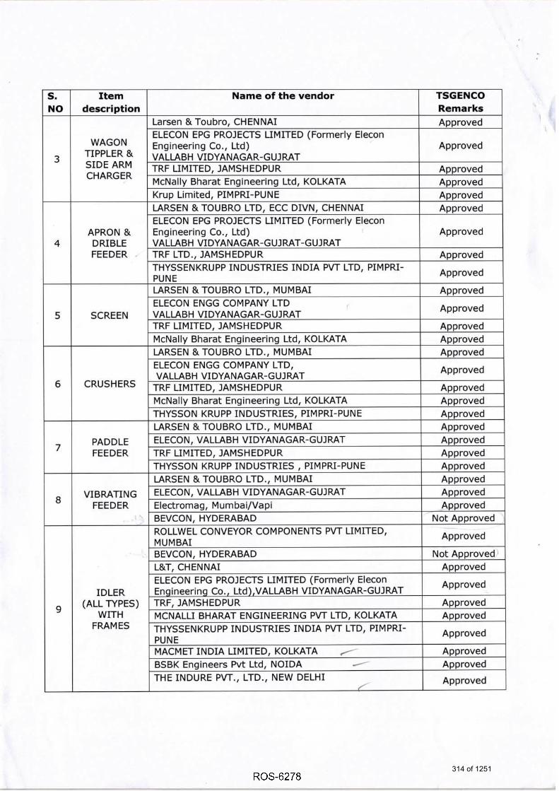
s.NO
Itemdescription
Name of the vendor TSGENCO
Remarks
3
WAGON
TIPPLER &SIDE ARM
CHARGER
Larsen & Toubro, CHENNAI Approved
ELECON EPG PROJECTS LIMITED (Formerly Elecon
Engineering Co,, Ltd)VALLABH VIDYANAGAR-GUJ RAT
Approved
TRF LIMITED, JAMSHEDPUR Approved
McNally Bharat Engineering Ltd, KOLKATA Aooroved
Krup Limited, PIMPRI-PUNE Approved
4
APRON &DRIBLEFEEDER
LARSEN &TOUBRO LTD, ECC DIVN, CHENNAI Approved
ELECON EPG PROJECTS LIMITED (Formerly Elecon
Engineering Co., Ltd)VALI.ABH VIDYANAGAR-G UJ RAT-GUJ RAT
Approved
TRF LTD., JAMSHEDPUR Approved
THYSSENKRUPP INDUSTRIES INDIA PVT LTD, PIMPRI-PUNE
Approved
5 SCREEN
LARSEN & TOUBRO LTD., MUMBAI Approved
ELECON ENGG COMPANY LTD
VALLABH VIDYANAGAR-GUJ RATApproved
TRF LIMITED, JAMSHEDPUR Approved
McNally Bharat Engineering Ltd, KOLKATA Approved
6 CRUSHERS
LARSEN & TOUBRO LTD., MUMBAI Approved
ELECON ENGG COMPANY LTD,
VALLABH VIDYANAGAR-GUJRATApproved
TRF LIMITED, JAMSH EDPUR Approved
McNally Bharat Engineering Ltd, KOLKATA Approved
THYSSON KRUPP INDUSTRIES, PIMPRI-PUNE Approved
7PADDLE
FEEDER
LARSEN & TOUBRO LTD., MUMBAI Aooroved
ELECON, VALLABH VIDYANAGAR-GUJRAT Approved
TRF LIMITED, JAMSH EDPUR Approved
THYSSON KRUPP INDUSTRIES , PIMPRI-PUNE Approved
8VIBRATING
FEEDER
LARSEN & TOUBRO LTD., MUMBAI Approved
ELECON, VALLABH VIDYANAGAR-GUJRAT Approved
Electromag, M umba i/Vapi Aooroved
BEVCON, HYDERABAD Not Approved
9
IDLER(ALL TYPES)
WITHFRAMES
ROLLWEL CONVEYOR COMPONENTS PVT LIMITED,
MUMBAIApproved
BEVCON, HYDERABAD Not Aoproved'
L&T, CHENNAI Approved
ELECON EPG PROJECTS LIMITED (Formerly Elecon
Enqineerinq Co., Ltd),VALLABH VIDYANAGAR-GUJRATApproved
TRF, JAMSHEDPUR Approved
MCNALLI BHARAT ENGINEERING PVT LTD, KOLKATA Approved
THYSSENKRUPP INDUSTRIES INDIA PVT LTD, PIMPRI-
PUNEApproved
MACMET INDIA LIMITED, KOLKATA /. Approved
BSBK Engineers Pvt Ltd, NOIDA e-- Approved
THE INDURE PVT., LTD., NEW DELHI Approved
314 of 1251

s.NO
Itemdescription
Name of the vendor TSGENCO
Remarks
10
Pulleys withPlummer
block,
Bearing
Sets.
$
LARSEN &TOUBRO LTD, ECC DIVN, CHENNAI ApprovedELECON EPG PROJECTS LIMITED (Formerly EteconEngineering Co., Ltd),VALLABH VIDYANAGAR-GUJ RAT
Approved
TRF LTD., JAMSHEDPUR ApprovedMCNALLI BHARAT ENGINEERING PVT LTD, KOLKATA ApprovedTHYSSENKRUPP INDUSTRIES INDIA PVT LTD, PIMPRI-PUNE ApprovedMACMET INDIA LIMITED, KOLKATA ApprovedBSBK Engineers Pvt Ltd, NOIDA ApprovedFLSMIDTH Private Limited, CHENNAI ApprovedBevcon Wayors Pvt Ltd, HYDERABAD Not ApprovedTHE INDURE PW., LTD., NEW DELHI Approved
11
SCRAPPER -
INTERNAL &
EXTERNAL
BMH CONCARE TECHNOLOGIESNAVI MUMBAI
INC,Approved
GOLDEN ENGINEERING INDUSTRIES, BHII.AI ApprovedTHEJO ENGINEERING LTD, CHENNAI ApprovedHosch Equipment, Kolkata ApprovedKaveri Ultra Polymers Ltd. BANGALORE ApprovedMARTIN, PUNE Approved
t2
Belt
Weigher
along with'Panel
THERMO RAMSAY, AUSTRALIA. ApprovedAVERY INDIA LTD., NEW DELHI. ApprovedPOWER BUILD, Limited, GUJARAT ApprovedIPA, BANGALORE ApprovedSchenk Process, CHENNAI ApprovedPRECIA MOLEN, BANGALORE/CHENNAI Approved
13Brake withThruster
SIEG ERI.AN D-BREWS EN, GERMANY. ApprovedSTROM KMFT, MUMBAI ApprovedBCH ELECTRIC LIMITED, BANGALORE ApprovedINDUSTRIES SYNDICATE, KOLKATA. ApprovedSIEMENS INDIA LTD. BANGALORE ApprovedKATEEL ENGINEERING INDUSTRY PLTD. BANGALORE ApprovedElectromg Devices, Mumbai ApprovedIndustrial Components, KOLKATA ApprovedElectromag netic Ind ustries, VADODARA Approved
L4
HERCULES HOISTS LTD. MUMBAI ApprovedEUI URANE:& HOISTS -ELECTRIC
ANDMANUAL
ARMSEL PVT. LTD., BANGALORE ApprovedTRANSPADE ENGINEERS PVT LTD, BANGALORE ApprovedTRACTEL TIRFOR INDIA PVT. LTD. NEW DELHI ApprovedCENTURY CMNE ENGRS PVT. LTD. FARIBABAD ApprovedTUOBRO FURGUSON (TNDIA) pVT. LTD, KOLKATA ApprovedCONSOLIDATE CRANES AND STRUCTURES, PUNE Approved
315 of 1251

s.NO
Item descriptior Name of the vendor TSGENCO
Remarks
15 Electric Hoists /Manual Hoist
WH Brady (Brady & Morris) Approved
16COAL SAMPLING
SYSTEM
ADVANCED SYSTEMS'SAMPLING PVT LTD, KOLKATA Approved
EASTMAN CRUSHER Co. (P) Ltd. KOLKATA Approved
t7BELT
VULCANISING
MACHINE
NILOS, CHENNAI Approved
SV DATTAR, KOLKATA Approved
THEJO ENGINEERING LIMITED, CHENNAI Approved
Chanda & Co, KOLKATA Approved
SYNERGY, KOLKATA Approved
18./
WEIGH BBf,DGE
ABB LIMITED, BANGALORE Approved
AVERY (I) LTD., Ballavgarh Approved
SCHENCK JENSON & NICHOLSON, KOLKATA Approved
SCHENCK PROCESS INDIA LIMITED, CHENNAI Approved
ESSAE DIGITRONICS PRIVATE LIMITED, BANGALORT Approved
IPA, Pvt. Ltd. BANGALORE Approved
19
AIRVO,L--,TAS; LIMITED, MUM BAI. Approved
BLUE STAR LIMITED, MUMBAI. Approved
CONDITIONING
SYSTEM
CARRIER AIRCON DITIONING & REFRIGERATION
LTD, Gurqaon-HaryanaApproved
GODREJ & BOYCE MFG. CO., LTD. BANGALORE Approved
20
Dust Extraction
System along
with Panel
A.p.c. SYSTEMS & PRODUCTq_FW. LTD. KOLKATA Approved
C.DOCTOR & COMPANY PRIVAE LTD.
AHMEDABADApproved
DUSTVEN, BANGALORE Approved
WRC, Anand-Gujarat Approved
BEVCON, BANGALORE Not Approved
2L COMPRESSOR
A ERZEN MACHI.NES-INDIA PVT LTD. VADODARA Approved
ATLAS COPCO, BANGALORE Approved
ELGI, CHENNAI Approved
INGERSOLIRAN D, GURGAON Approved
22VENTILATION
SYSTEM
C. DOCTOR, AHMEDABAD Approved
DUSTVEN PW.L TD. BANGALORE Approved
MESINA, MUMBAI Approved
SK SYSTEMS PRIVATE LIMITED, NEW DELHI Approved
A .P.C. SYSTEMS & PRODUCTS PVT. LTD, KOLKATA Approved
TAP Engineering, CHENNAI $pprovedOSM Projects Pvt. Ltd. NOIDA Not Approved
Wollaque Ventilation and Conditioning Pvt. Ltd.
NOIDAApproved
316 of 1251

s.NO
ftem descriptior Name of the vendor TSGENCO
Remarks
23
DUST
SUPPRESSION &WATER SYSTEM
FOR CHP
SPMYING SYSTEMS INDIA PVT. LTD. BANGALORE ApprovedAPC SYSTEM & PRODUCTS PVT. LTD. KOLKATA ApprovedF. HARLEY, KOLKATA ApprovedTPS INFMSTRUCTURE LTD. NEW DELHI ApprovedCHEMTROLS SAMIL INDIA PW LTD,NAVI MUMBAI
Approved
24
CONVEYOR
BELTING AND
BELT FEEDER
BELTING
PHEONEX YULE, KOLKATA ApprovedSEMPERTMNS, CHENNAI ApprovedFORECH INDIA LTD, KOLKATA ApprovedHINDUSTAN RUBBERS, SILVASA ApprovedNORTHI.AND RUBBER MILLS, NEW DELHI ApprovedORIENTAL RUBBER IN DUSTRIES LTD.,PUN E ApprovedJONSON RUBBER INDUSTRIES, NEW DELHI ApprovedSOMI CONVEYOR BEL TINGS LIMITED, JODHPUR ApprovedNRC INDUSTRIES LIMITED , AMRITSAR Approved
25 ERW PIPES
'STEEL AUTHORITY OF INDIA LTD, ApprovedWELSPUN GUJARAT STAHL ROHERN LTD. MUMBAI ApprovedASIAN 14 ILIS PRIVATE LIMITED, AHMEDABAD ApprovedJotindra Steel & Tubes Ltd. FARIDABAD ApprovedSURYA ROSHNI LIMITED, NEW DELHI ApprovedJCO GAS PIPE LIMITED, NEW DELHI ApprovedRATNAMANI METALS & TUBES LTD, GUJAMT Approved
26 Bearings
Revolvo-GERMANY ApprovedSKF, INDIA ApprovedTIM KEN-GERMANY ApprovedFAG, VADODAM Approved
27Split Type
Bearings
Revolvo-GERMANY ApprovedCooper- GERMANY ApprovedFLSmidth, CHENNAI Approved
28PLUMMER
BLOCKS
Nandy Engineering, HOWRAW ApprovedMASTA, Ahmedabad ApprovedSIMCO, KOLKATA Approved
29 Gear Box
Premium Transmission, Mumbai ApprovedFlender Limited ApprovedElecon Engineering Co. Ltd. VALTABH VIDYANAGAR-GUJRAT
Approved
New Allenbarry Works, Kolkata ApprovedSHANTHI, Coimbatore Approved
30 Fluid Coupling
Premium Transmission, Mumbai ApprovedFluidomat, Indore ApprovedElecon Engineering Co. Ltd.VALLABH VIDYANAGAR-GUJRAT
Approved
Voith, GERMANY Approved
317 of 1251

s.NO
Item descriptior Name of the vendor TSGENCO
Remarks
31
Flexible Gear
Coupling (Low
Speed Coupling)
Elecon Engineering Co. Ltd.VALLABH VIDYANAGAR-GUJRAT
Approved
GBM Mfg. {P} Ltd., Kolkata Approved
Fenner, BANGALORE Approved .
Wellman Wacoma, KOLKATA Approved
32
In-Line Magnetic
Separator /Suspended
Magnet along witl'Panel
Electro-Zavod, KOLKATA Approved
PBL, V,V.NAGAR Approved
Electromag, MUMBAI Approved
E lectrom a g n eti c I n d ustri es, Ba rod a -G uj a rat. Approved
Magnet Industries-KOLKATA Approved
Magnetics Corporation of India,BANGALORE Approved
ERIEZ, UK Approved
33 ElevatorECE, GHAZIABAD Approved
OM EGA Elevators,Bangalore/Ah medabad Approved
34Sump/Water
Pump
KBL, KIRLOSHKER-WADI Approved
SAM, Coiambatore Approved
Metso, Gurgaon-Haryana Approved
M/S Mody Industry Pvt Ltd (M/s WPll LTD groups ofcompany)
Approved
KIRLOSKAR, Bangalore Approved
KSB, NASHIK Approved
BEACON WEIR LTD, CHENNAI Approved
Flowmore Limited, Gurgaon Approved
Kishor Pumps Pvt. Ltd ., Chennai Approved
KUBOTA CORPN., JAPAN Approved
35Metal Detector
along with Panel
PBL, V.V NAGAR Approved
Electromag,MUMBAI Approved
Magnet Industries, KOLKATA Approved
Electrozavod, KOLKATA Approved
Electroma gnetic IndustriesBaroda-Guiarat.
Approved
36 Skirt SealingTega Industries, Kolkata Approved
Kaveri Ultra Polymers, Karnataka Approved
37Rail Clamp of
Trippers
Industrial Components, KOLKATA Approved
Bengal Technocrats Pvt. Ltd., Kolkata Approved
3B
Flap Gate, Flow
Divider, Rod GaJe,
Rack & Pinion
Gate
BSBK Engineers Pvt. Ltd., Kolkata/ Noida Approved
BEVCON, HyderabadNot Approved
39Lubrication
System for SCR
CENLUB, KOLKATAApproved
40 Buffer for SCR Resistoflex Pvt. Ltd. KOLKATA Approved
4l Geared MotorE|econ, VALLABH VIDYANAGAR-GUJRAT Approved
Siemens Ltd, G E_RMANY/Banga lore App-lpved
42 BELT FEEDERS BEVCON, Hyderabad Not Approved
318 of 1251

s.NO
Item description Name of the vendor TSGENCO
Remarks
43
TRAVELLING
TRIPPERS,FIXED
TRIPPERS &
RAILS,COUNTER
WEIGHTS
BEVCON, Hyderabad
Not Approved
44
TRIPPERS,FIXED
TRIPPERS &
Bunker Sealing
Arrangement
BSBK, Kolkata / Noida
Approved
45 Duplex Strainers M/s. Flair Strainers & Filters, Ahmedabad, Gujarat Approved46 Pipes M/s. Jindal (India) Ltd. INDIA Approved47 Pipe fittings M/s. N L Hazra & Son, KOLKATA Approved48 Ventilation fans M/s. SK Systems Private Limited, New Delhi Approved
49
Unitary airfiltration (UAF)
system
M/s. SK Systems Private Limited, New Delhi
Approved
50
Air pressure
regulator & filterwith pressure
gauge
M/s. Asco Numatics (India) Pvt Ltd, CHENNAI
Approved
51
Water pressure
regulator withpressure 9auge
M/s. Asco Numatics (India) Pvt Ltd, CHENNAI
Approved
52 Hydraulic system
M/s Hagglunds, SWEDEN ApprovedM/ s Maha Hydraulics, Chennai ApprovedM/ s Rexroth, Ahmedabad, Gujarat Approved
Please note that this approval of above vendors for the supply of Coal Handling package for5XB00MW Yadadri Thermal Power Station does not absolve M/s BHEL of its responsibility of supplyingand conforming to the relevant specifications and standards as per the terms and conditions of thecontract.
QsCHIEF ENGINEER/TPC
Copy to:1, Executive Director/Civil/Thermal/TSGENCO/VS/Hyderabad.
2. S u peri ntend i n g En g i ne er / Civil /YIPS( 5X800MW)/Da meracherla3. FA & CCA/Accounts/TSGENCO/VS/Hyderabad.
4. SE /Tech. to CMD/TSGENCO/VS/Hyderabad.
5. DE /Tech. to Director/Projects/TScENCO/VS/Hyderabad.6, Sri Y.A.Srinivasa Rao,GM(PMG)/BHEL Camp Office/Vidyut Soudha/Hyderabad.
319 of 1251

,,,a6.E;,---,,,-,,,,,, 4j .......--
- i:Arilt ,,...".....
TELANGANA STATE POWER GENERATION CORPORATION LIMITED
(A Govt. of Telangana Undertaking)
Vidyut Soudha, Hyderabad - 500082. www.tsgenco.telangana.gov.in
Phone: 040 - 23499261 Fax: 040 - 23499263
From: To:
The Chief Engineer, M/s Bharat Heavy Electrical Ltd.,
Thermal Projects Construction, INDUSTRIAL SYSTEMS GROUP
TSGENCO, Vidyut Soudha, P 0 Box No.1249, Prof CNR Rao Circle ,
Khairatabad, Hyderabad-500 082. Malleswaram, Banglore-560012.
Email ID: [email protected] Mail ID: [email protected]
Lr.No.CE/TPC/SE-5 EM&
Sir, Sub: TSGENCO Yadadri TPS(5X800MW) - Approval of additional vendors for 'Machine Package',
'Conveyor Package' of Coal Handling Plant for (5X800 MW) Yadadri Thermal Power Station
furnished by M/s BHEL/ISG - Reg.
Ref: 1. M/s BHEL Letter Ref: IS-1-15-2001/Additional Vendors-machine, Dt: 25.10.2018
2. M/s BHEL Letter Ref: IS-1-15-2001/CHP-Conv.Pkg.addl.Vendors,Dt:29.11.2018
3. Lr.No.CE/TPC/SE3/EME-09/YTPS(5X800MW)/F.No.vendors/D.No.109/18, Dt:9.11.2018
This has reference to the letters 1st & 2nd cited above, wherein M/s BHEL/ISG requested for
approval of additional vendor for 'Machine Package', 'Conveyor Package' of Coal Handling Plant
for (5X800 MW) Yadadri Thermal Power Station. Vide reference 3rd cited certain vendors were
approval accorded by TSGENCO for CHP package. The credentials of vendors are reviewed and
TSGENCO hereby accords approval for the following additional vendors for 'Machine Package',
'Conveyor Package' of Coal Handling Plant.
(a) Machine Package:
S.
No
BHEL proposed vendor Name Approval
requested
TSGENCO Remarks
1 Thyssenkrupp Industries India Pvt, Ltd.
Pune
screens Approved
2 McnallyBharat Engineering Ltd, Kolkata Paddle feeder Not Approved
3 Tenova India Pvt. Ltd, Chennai Machine Package Approved for 'Stacker & Reclaimer' and
'Wagon Tippler'only.
4 M/s Furnance fabrica India Ltd,
Kolkata.
Machine Package Not Approved
5 Hunan Changzhong Machinery Cr Ltd,
China
Machine Package Not Approved
320 of 1251

-2-
(b) Conveyor Package:
S.
No
BHEL proposed vendor Name Approval
requested
TSGENCO Remarks
1 M/s Mecon Limited, Ranchi Conveyor
package
Approved
2 M/s Datang Environment Industry
Group Co .Ltd ,China
Conveyor
package
Not Approved
Please note that this approval of additional vendor for 'Machine Package`, 'Conveyor
Package' of Coal Handling Plant for (5X800 MW) Yadadri Thermal Power Station, does not absolve
M/s BHEL of its responsibility of supplying and conforming to the relevant specifications and
standards as per the terms and conditions of the contract.
Yours faithfully,
CHIEF ENGINEER/TPC
Copy communicated to:
1n The Chief Engineer/Civil/TSGENCO/VS/Hyderabad.
2. The Chief Engineer/Construction/YTPS Site/Dameracherla/Nalgonda. 3. FA&CCA (Res.)&CFO/TSGENCO/Vidyut Soudha/Hyderabad.
Copy to:
1. SE/Tech to the Chairman & Managing Director/TSGENCO/Vidyut Soudha/Hyderabad, 2. Superintending Engineer-3/TPC/VS/Hyderabad. 37 Superintending Engineer/Civil/YTPS Site/Dameracherla/Nalgonda(Dist.).
_\/4. Sri Y.A.Srinivas Rao,GM, BHEL/PMG Camp Office, Vidyut Soudha, Hyderabad.
5, Sri N D Gautam Sr.Deputy General Manager/PMG/ New Delhi 6. DE/Tech to the Director (Projects)/TSGENCO/Vidyut Soudha/Hyderabad. 7. ADE/Tech to the Director/Civil/TSGENCO/VS/Hyderabad.
8, M/s Tata Consulting Engineers Limited,73/1,Sheriff Centre, St. Marks road,
Bangalore-560 001.
9. M/s.TCE, Site office, Room No.323, Vidyut Soudha, Hyderabad
321 of 1251

TELANGANA STATE POWER GENERATION: CORPORATION LIMITED(A Govt. of Telangana Undertaking)
Vidyut Soudha, Hyderabad - 500082. www.tsgenco.telangana.gov.inPhone: 040 - 2349926L Fax: 040 - 23499263.
From:The Chief Engineer,Thermal Projects Construction,TSGENCO, Vidyut Soudha,Khairatabad, Hyderabad-500 082.Email ID: [email protected]
To:M/s Bharat Heavy Electrical Ltd.,INDUSTRIAL SYSTEMS GROUPP O Box No.1249, Prof CNR Rao Circle ,Malleswaram, Banglore-560012.Mail ID: [email protected]
Sir,Sub: TSGENCO - Yadadri TPS(SXBOOMW) - Approval of additional vendors for'Machine Package',
'Conveyor Package' of Coal Handling Plant for (5X800 MW) Yadadri Thermal Power Stationfurnished by M/s BHEL/ISG - Reg.
Ref: 1. M/s BHEL Letter Ref: IS-1-15-2OOt/Additional Vendors-machine, Dt: 25.10.20182. Mls BHEL Letter Ref: IS-L-15-2001/CHP-Conv.Pkg.addl.Vendors,Dt:29.11.20183. Lr.No.CE/TPC/SE3/EME-09/YTPS(5XB00MW)/F.No.vendors/D.No.LOg/78, Dt:9.11.2018
*****
This has reference to the letters 1st & 2nd cited above, wherein M/s BHEVISG requested for
approval of additional vendor for'Machine Package', 'Conveyor Package' of Coal Handling Plant
for (5X800 MW) Yadadri Thermal Power Station. Vide reference 3'd cited certain vendors were
approval accorded by TSGENCO for CHP package. The credentials of vendors are reviewed and
TSGENCO hereby accords approval for the following additional vendors for 'Machine Package',
'Conveyor Package' of Coal Handling Plant.
(a) Machine Package:
s.No
BHEL proposed vendor Name Approvalrequested
TSGENCO Remarks
1 Thyssenkrupp Industries India Pvt, Ltd.Pune
screens Approved
2 McnallyBharat Engineering Ltd, Kolkata Paddle feeder Not Approved
3 Tenova India Pvt. Ltd, Chennai Machine Package Approved for'Stacker& Reclaimer'and'Waqon Tippler'onlv.
4 M/s Furnance fabrica India Ltd,Kolkata.
Machine Package Not Approved
5 Hunan Changzhong Machinery C.Ltd,China
Machine Package Not Approved
322 of 1251

2
(b) Conveyor Package:
s.No
BHEL proposed vendor Name Approvalreouested
TSGENCO Remarks
1 M/s Mecon Limited, Ranchi Conveyorpackage
Approved
2 M/s Datang Environment IndustryGroup Co .Ltd ,China
Conveyorpackage
Not Approved
Please note that this approval of additional vendor for 'Machine Package', 'Conveyor
Package'of Coal Handling Plant for (5X800 MW) Yadadri Thermal Power Station, does not absolve
M/s BHEL of its responsibility of supplying and conforming to the relevant specifications and
standards as per the terms and conditions of the contract.
Yours faithfully,
QttVe:-"ffi^CHIEF ENGINEERITPC
Copy communicated to:
1" The Chief Engineer/Civil/TSGENCO/VS/Hyderabad.
2 " The Ch ief En g i neer/Construction/YTPS S ite/Da meracherla/Na I go nda.
3. FA&CCA (Res.)&CFO/TSGENCo/Vidyut Soudha/Hyderabad.
Copy to:1. SE/Tech to the Chairman & Managing Director/TScENCO/Vidyut Soudha/Hyderabad"2. Superintending Engineer-3/TPC/VS/Hyderabad.3. Superintending Engineer/CiviI/YTPS Site/Dameracherla/Nalgonda(Dist.).4. Sri Y.A.Srinivas Rao,GM, BHEL/PMG Camp Office, Vidyut Soudha, Hyderabad.
5. Sri N D Gautam / Sr.Deputy General Manager/PMG/ New Delhi
6, DE/Tech to the Director (Projects)/TscENCO/Vidyut Soudha/Hyderabad.7. ADE/Tech to the Director/CiviI/TSGENCO/VS/Hyderabad.8" M/s Tata Consulting Engineers Limited,T3ll,Sheriff Centre, St. Marks road,
Bangalore-560 00L.9" M/s.TCE, Site office, Room No.323, Vidyut Soudha, Hyderabad
323 of 1251

TELANGANA STATE POWER GENERATION CORPORATION LIMITED
(A Govt. of Telangana State Undertaking)
From: The Executive Director/TPC A-Block,2nd Floor,TSGENCO, Vidyuth Soudha, Hyderabad-500 082.
VIDYUTH SOUDHA, HYDERABAD-500082. www.tsgenco.telangana.gov.in
Phone:040-23499321, Fax:040-23499323
To:
M/s Bharat Heavy Electricals Limited, Power Sector-Project Engineering Management,
PPEI Building, Sector-16A, Noida. Email 10: [email protected]
Kind Attention:Sri Perminder Singh, AGM.
Lr NO. ED/TPC/SE-3/EME-ll/YTPS/F. PEM Cat Plan / D.No.\ :Q /18,Dt: ~~ .03.2018
Sir,
Sub: TSGENCO - YTPS (5X800MW) - Categorization Plan for PEM BOP/BOI packages (Rev.OO) -
Approval - Reg.
Ref: l.LOI.No.ED/TPC/SE-III/EME-9/YTPS (5X800MW)/D.No.102/17, Dt.17.10.2017.
2. M/s BHEL letter Vide Ref: PS-PEM/PG-IV/TSGENCO/YADADRI/02,Dt:23-02-2018.
* * * * * *
Please refer to your letter 2nd cited above, wherein it was requested for approval of
Categorization Plan for BOP/BOI packages (Rev.OO) of PEM supplied items for YTPS (5x800MW). In
this regard, it is to inform that as per the request of M/s BHEL,PEM the Categorization Plan is
approved and the approved categorization plan is enclosed as Annexure-I.
Encl: As above
Yours faithfully,
y:
EXE
Copy to:
1. Chief Engineer/ Electrical/YTPS Site/ Damara cherla/ Nalgonda Dist.
2. SE/Tech to the Chairman & Managing Director/TSGENCO/VS/Hyderabad.
3. DE/Tech to Director/Projects/TSGENCO/VS/Hyderabad.
4. M/s Tata Consulting Engineers, 73/1, Sheriff Centre, St. Marks Road, Bangalore-560 001.
5. Mr.Y.A.Srinivasa Rao, GM/BHEL Camp Office/Vidyuth Soudha/Hyderabad .
,":;,. -
324 of 1251

'\
ANNEXURE-I
YADADRI (5X800 MW) -TSGENCO Approved Categorization for BHEL- PEM BOI & BOP
packages
23 SERVICE TRANSFORMER I I
STATION LIGHTING SYSTEM II/III 1/11 ** 24 FOR LP, LDBS & FOR LP, LDBS &
FIXTURES-CAT-I FIXTURES-CAT-I
25 TREFOIL CLAMPS II II
Category Code
cable terminatios are to be procured strictly as per L2 schedule as there are low shelf life items
EX
325 of 1251

51.No. Packages Category Code Category Code
proposed approved
COMPRESSED AIR SYSTEM 1/11 1/11 ** For For Compressors,
29 Compressors, Air Air Dryers & Dryers & Receivers- Receivers-CAT -I
CAT-I
30 D/G EOT CRANE ABOVE 45T-150T I I
31 D/G EOT CRANES UPTO 45T II II
32 ELECTRIC HOIST II II
33 ELEVATORS I I
34 FIRE TENDER II I
35 FUEL OIL HANDLING AND STORAGE 1/11 1/11 ** SYSTEM
36 LUBE OIL TRANSFER PUMPS II II
37 MILL REJECT SYSTEM II 1/11 ** 38
MISe. TANKS(SITE FABRICATED) II II ONLY ENGG
39 OXYGEN DOSING SYSTEM II II
40 Single Girder EOT / HOT Misc. Cranes II II
41 VENTILATION SYSTEM II II
42 WEIGH BRIDGE II II
43 AIR RELEASE VALVES II II
44 AIR TRAPS II II
45 ALUMINIUM SHEETS/COILS III III
46 BALL VALVES II II
BUTTERFLY VALVES (STEAM SERVICE) II II 47 For sizes over For sizes over
600NB-CAT-I 600NB-CAT-I
M.E. BELLOWS II II
48 For sizes over For sizes over 600NB-CAT-I 600NB-CAT-I
49 STEAM TRAPS II II
50 STEEL GATE/GLOBE/NR II II VALVES(WATER SYSTEM)
51 THERMAL INSULATION - R- II II MATTRESSES/P-SECN
52 THERMAL INSULATION -ANCILLARY III III MATERIAL
53 APRDS I I
54 COLTCS II I
55 COOLING TOWER I I
56 DEBRIS FILTER II II
57 HEAT EXCHANGER (PLATE TYPE) I I
MISe. PUMPS (HORIZONTAL) I/II
I/II ** For pumps with more
For pumps with 58 more than 75KW
than 75KW power power requirement-
reqUirement-CAT -I. CAT-I.
EXEC
326 of 1251

.j
51. No. Packages Category Code Category Code proposed approved
MISe. PUMPS (VERTICAL) 1/11 1/11 **
For pumps with more For pumps with
59 more than 75KW than 75KW power
power requirement-requirement-CAT -I.
CAT-I.
60 SELF CLEANING STRAINERS II II
61 CONICAL STRAINER II II
62 SUMP PUMPS/SUBMERSIBLE PUMPS II II
63 CONDENSATE POLISHING UNIT II 1/11 ** 64 HYDROGEN GENERATION PLANT II 1/11 ** 65 WORKSHOP EQUIPMENT III 1/11 **
NOTE:
INSPECTION QAP APPROVAL BY INSPECTION BY MDCC BY
CATEGORY
CUSTOMER/CONSULTANT/ CUSTOMER appointed TPIA
I CUSTOMER/CONSULTANT (Final inspection including TSGENCO document review as per approved QAP)
TSGENCO on II
CUSTOMER/CONSULTANT BHEL or BHEL'S TPIA submission of
TC/IR/documents.
Testing by vendor s Quality III BHEL dept. & TCs Shall be submitted BHEL
to BHEL 1/11** BHEL has to submit the Sub-Breakup for Approval.
For the items/Equipments which are not covered in the above list, BHEL has to submit such items to TSGENCO for Approval.
327 of 1251

TELANGANA STATE POWER GENERATION CORPORATION LIMITED
(A Govt. Of Telangana Undertaking)
Vidyut Soudha, Hyderabad - 500082. www.tsgenco.telangana.gov.in
From:
The Chief Engineer,
Thermal Projects Construction,
TSGENCO, Vidyut Soudha,
Khairatabad, Hyderabad-500 082.
E-Mail:[email protected]
Tit M/s BHEL/EDN,
Electronics Division, P.O. Box No.2606,
Mysore Road,
Banglore-560 026.
E-Mail:[email protected]
Lr.No.CE/TPC/421/YTPS (5X800 MW)/C&I-Vendors/D.No /19, Dt: , .07.2019.
Sir,
Sub: TSGENCO - YTPS (5X800MW) - Controls & Instrumentation-Comments on
Additional Vendor approval for supply of Electronic Transmitter as proposed by M/s
BHEL/EDN - Reg.
Ref: 1) Lr. No. CE-PMC/YTPS/VL/AR-43, dt.22.06.2019,
2) M/s TCE email dated:27.06.2019.
* * *
This has reference to the M/s BHEL/EDN request letter (1) cited above regarding additional
vendor approval for supply of Electronic Transmitter for YTPS (5X800MW).
In this regard, it is to inform that after careful review of credentials by TSGENCO and as per
M/s TCE comments vide reference(2) above, M/s Toshniwal Industries Pvt Ltd is here with not
approved as additional vendor for the supply of electronic transmitters for YTPS(5X800MW).
Yours faithfully
Q
1
CHIEF ENGINEER/TPC
Copy communicated to:
1. The Chief Engineer/Construction/YTPS Site/Dameracherla/Nalgonda.
2. SE/Tech to The Chairman & Managing Director/TSGENCO/Vidyut Soudha/Hyderabad.
3. Superintending Engineer/Civil/YTPS Site/Dameracherla/Nalgonda(Dist.).
4. Dy CCA, YTPS-II/Co-ordination/Dameracherla/Nalgonda(Dist.).
5. DE/Tech to Director (Projects)/TSGENCO/Vidyut Soudha/Hyderabad.
6. SAO/Pay&Accounts/TSGENCO/Vidyut Soudha/Hyderabad.
7. M/s Tata Consulting Engineers Limited,73/1,Sheriff Centre, St. Marks road,
Bangalore-560 001.
8. TCE, Site office, Room No.323, Vidyut Soudha, Hyderabad
9. Sri Y.A.Srinivas Rao, BHEL/PMG, Vidyut Soudha, Hyderabad.
328 of 1251

TELANGANA STATE POWER GENERATION CORPORATION LIMITEDVIDYUT SOUDHA::HYDERABAD - 5OOO82.
CI N : U40 1 0 2TG20 1 4SGC094070 Phone : 040 - 2349926 !,F ax: 040-23499263.Web site: www.tsgenco. co. in email id: cetpctgenco@gmail. com
From:Chief Engineer,Thermal Projects Construction,TSGENCO, 3'd Floor, A-Block,Vidyut Soudha, Khiaratha badHyderabad-500 082.cetpctgenco@ gmail.com
to:M/s BHEVTrichy,High Pressure Boiler Plant,Tiruch irappalli-620 014, Tamil Nadu, INDIA.(P) | O43l-257 -7 1 56, Mob : 9406903625,Email: [email protected]
Kind Attention:Sri RAHUL TOPPO, Dv. Manaoer, Comml/FB
Lr,No.CE|TPClSE-3/EME-14/YTPS/F,Vendors Aooroval/D.No. lJ{/2O,Dt: Ze .O6.2O20
Sir,
sub: TSGENCo - Yadadri rPS (5x800MW) - Approval of Additional vendors for Mechanrcal
items furnished by M/s BHEL/Trichy unit - Reg.
Ref: M/s BHEl/Trichy letter fPlLL497 lvendor List/06 dated 21.12.2019.
*t****
Please refer to the letter cited above, wherein M/s BHEVTrichy has requested for
approval of Additional Vendors for lvlechanical items pertaining to Yadadri TPS (5X8O0MW). The
same was reviewed and rsGENco hereby accords approval for the vendors. The list of
approved vendors is enclosed as Annexure.
Please note that this approval of vendors for supply of list of items as per Annexure
does not absolve l4/s BHEVTrichy of its responsibility of supplying and conforming to the
relevant specifications and standards as per the terms and conditions of the contract.
Encl: Annexure
Yours fa ithfully,
Qtry--"-7[/"t'Chief Engineer/TPC
Coov communicated to:
1, The Chief Engineer/Construction/YTPS Site/Dameracherla/Nalgonda.2. FA&CCA (Res.)&CFO/TSGENCO/Vidyut Soudha/Hyderabad.3. superintending Engineer/Tech to The chairman & Managing Director/Tsc ENco/Vidyut
Soud halHydera bad.
4. Superintending Eng ineer/CiviI/YTPS Site/Da meracherla/Nalgonda( Dist. ).5. Dy CCA. YTPS-II/Co-ord ination/Dameracherla/Nalgonda (Dist. ).6. DE/Tech to Director ( Projects)/TscENCo/Vidyut Soudha/Hydera bad.7. SAO/Pay&Accounts/TsGENCO/Vidyut Soudha/Hydera bad.8. M/s Tata Consulting Engineers Limited,T3ll,Sheriff Centre, St. Marks road, Bangatore-
560 001.
9. TCE, Site office, Room No.323, Vidyut Soudha, Hyderabad10. Sri S.Anil Kumar, BHEVPMG Camp Office, Vidyut Soudha, Hyderabad.
329 of 1251
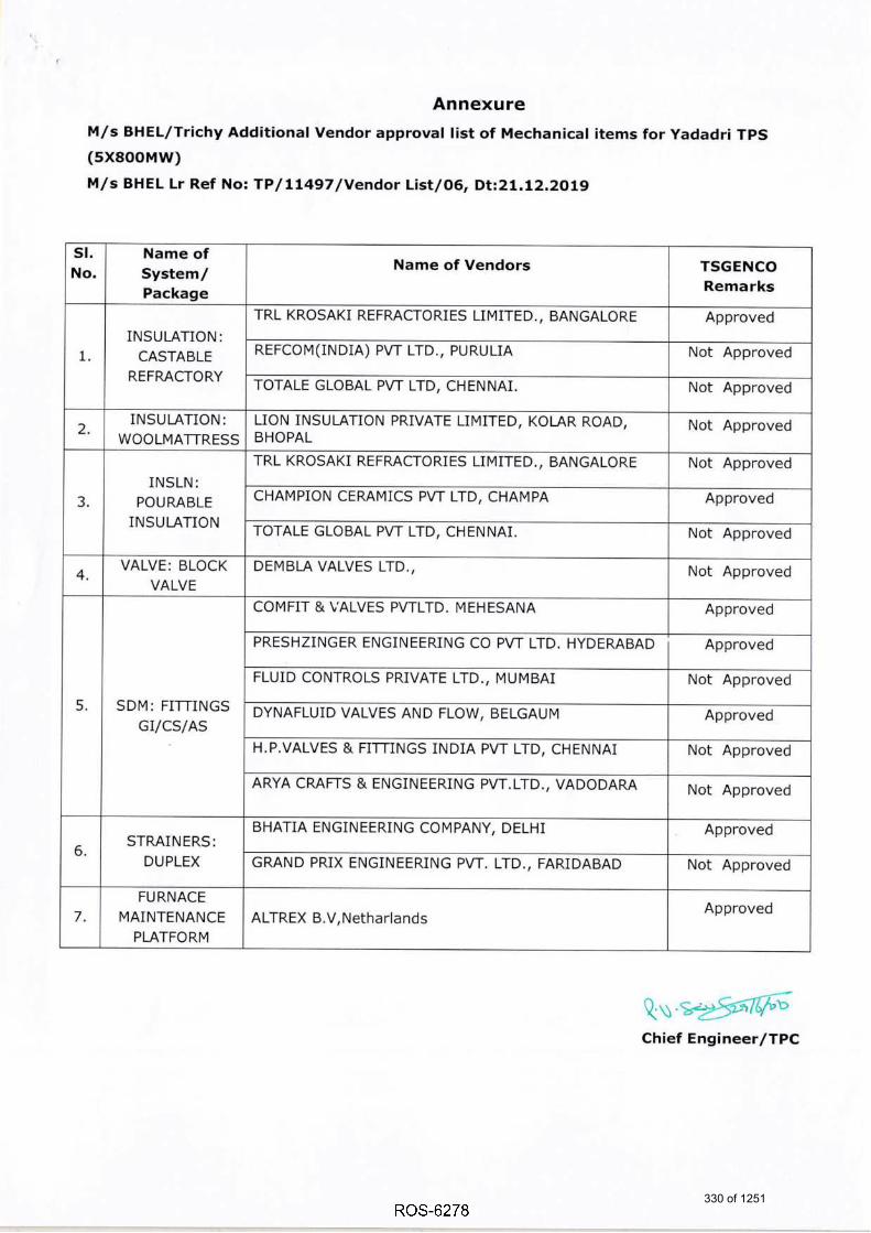
Annexure
M/s BHEL/Trichy Additional Vendor approval list of Mechanical items for yadadri TpS
(sxsooMw)
M/s BHEL Lr Ref No: TP / LL497 lvendor List/O6, Dt;21,12.2019
sl,No.
Name ofSystem/Package
Name of Vendors TSGENCO
Remarks
1.
INSULATION:
CASTABLE
REFRACTORY
TRL KROSAKI REFRACTORIES LIN4ITED., BANGALORE Approved
REFCOM(INDIA) PVT LTD., PURULIA Not Approved
TOTALE GLOBAL PVT LTD, CHENNAI. Not Approved
2.INSULATION:
WOOLN4ATTRESS
L]ON INSULATION PRIVATE LIM]TED, KOLAR ROAD,BHOPAL
Not Approved
INSLN:
POURABLE
INSULATION
TRL KROSAKI REFMCTORIES LIMITED., BANGALORE Not Approved
CHAMPiON CERAIT4ICS PVT LTD, CHAMPA Approved
TOTALE GLOBAL PVT LTD, CHENNAI. Not Approved
4,VALVE: BLOCK
VALVE
DEI\4BLA VALVES LTD., Not Approved
5. SDM: FITTINGS
GI/CS/AS
COMF]T & VALVES PWLTD. MEHESANA Approved
PRESHZINGER ENGINEERING CO PVT LTD. HYDERABAD Approved
FLUID CONTROLS PRIVATE LTD., MUMBAI Not Approved
DYNAFLUID VALVES AND FLOW, BELGAUM Approved
H.P.VALVES & FITTINGS INDIA PVT LTD, CHENNAI Not Approved
ARYA CRAFTS & ENGINEERING PVT.LTD., VADODARA Not Approved
STRAINERS:
DUPLEX
BHATIA ENG]NEERING COI\4PANY, DELHI Approved
GRAND PR]X ENGINEERING PVT. LTD,, FARIDABAD Not Approved
7.
FURNACE
IVlAINTENANCE
PLATFORM
ALTREX B.V.NetharlandsApproved
Qs.:2!6&,r,u
330 of 1251

TELANGANA STATE POWER GENERATION CORPORATION LIMITED(A Govt. Of Telangana Undertaking)
Vidyut Soudha, Hyderabad - 500082.Phone: 040 - 2349926t Fax: 040 - 23499263.
From:The Chief Engineer,Thermal Projects Construction,TSGENCO, 3'd Floor, A-Block,Vidyut Soudha, Khiarathabadl-lyderabad-500 082.cetpctgenco@gma il.com
To:M/s BHEVRC Puram, ,
Heavy Power Equipment Plant,R C PuramCONTMCT MANAGEM ENT D EPARTM ENTHyderabad - 502 032 ,INDIAPh: 040-23 18245 1,Mob:9491306087
Email: [email protected] Attention:Mr, B. ravindra naick, Dy. Manaoer
Lr.No.CE/TPC/SE-3/EME-14/YTPS/F.Vendors Aooroval/D.No.141/18.Dt:23.10.18
Sir,
Sub: TSGENCO - YadadriTPS (5XB00MW) - Approval of Vendors for Electrical , C&I and
Mechanical items furnished by M/s BHEVR c puram/Hyderabad unit - Reg.
Ref: M/s BHEVRC Puram/Hyderabad i?T:!Itor/vvHyD/00,
Dated 26.07.2018.
Please refer to the letter cited above, wherein M/s BHEVR C Puram/Hyderabad has
requested for approval of vendors for certain Electrical , C&I and Mechanical items for
Yadadri TPS (5X800MW). The same was reviewed and TSGENCO hereby accords approval for
the vendors. The list of approved vendors is enclosed as Annexure.
Please note that this approval of vendorc for Supply of followirrg list of items does not
absolve M/s BHEL of its responsibility of supplying and conforming to the relevant specifications
and standards as per the terms and conditions of the contract.
Encl: List of TSGENCO Approved Vendors of M/s BHEVR C puram/Hyd Unit.
Yours faithfully,
Qtr
Coov communicated to:
1. The Ch ief En g i neelConstru ction/YTPS Site/Da meracherla/ Nalgonda.
2. FA&CCA (Res.)&CFO/TSGENCO/VidyuI Soudha/Hyderabad.
3. SE/Tech to The Chairman & Managing DirectorfiScENCO/Vidyut Soudha/Hyderabad.
4. Superintending EngineerlCivil/Y|PS Site/Dameracherla/Nalgonda(Dist.).
5. Dy CCA, YTPS-II/Co-ordination/Dameracherla/Nalgonda(Dist.).
6. DE/Tech to Di rector (Projects)/TscENCO/Vidyut Soudha/Hyderabad.
7 . SAO/Pay&Accou nts/TSGENCO/Vidyut Soud ha/Hydera bad .
B. M/s Tata Consulting Engineers Limited,T3ll,Sheriff Centre, St. Marks road, Bangalore-
560 001.
9. TCE, Site office, Room No.323, Vidyut Soudha, Hyderabad
10. Sri Y.A.Srinivas Rao, BHEVPMG Camp Office, Vidyut Soudha, Hyderabad.
331 of 1251

332 of 1251

Page 1 of 6
Annexure
YADADRI TPS(5X800MW) Approved Vendors List-M/s BHEVR C PuramlHyderabad
Qr
Sl.No.Name of System/
Package
Name of Vendor/Place TSGENCO
Remarks
T&CVENDORS
1 TRANSFER OIL PUMP
I..DELTA P D PUMPS PVT LTD.,MUMBAI Approved
2.HYDAC {lNDlA) PVT. LTD., MaharashtraApproved
3.ALLWEILER INDIA PW LTD(Note-
Tushaco name change to Allweiler)
Approved
4.IDEX INDIA PW LTD Not Approved
2JACKING OIL PUMP
CONSOLE
l.HYDAC (lNDlA) PVT. LTD., Maharashtra. Approved
2.TUSHACO PUMP, DAMAN (Note-
Tushaco name change to Allweiler)
Approved
3.DELTA P D PUMPS PW LTD. Vapi,
Gujarat
Approved
4.|DEX INDIA PW LTD, Mumbai Not Approved
3 TURBINE ENCLOSURE
l.LLOYD INSULATIONS {lNDIA} LTD., New
Delhi
Approved
2.BBM ACOUSTIC INDIA PVT. LTD.,
Pune
Approved
3.lNDl RA INDUSTRI ES, Ranipet Approved
4.ACOUSTICS INDIA PVT LTD., Thiruchirapalli Approved
5.HAROLD INDUSTRIES
(P) LTD, Hyderabad
Approved
6.CREST ENGINEERS {PVT) LIMITED, New
Delhi
Not Approved
4OPEN TYPE TRANSMITTER
RACK
1. KRISHNA INDUSTRI ES, Hyderabad Not Approved
2. PANAM CONTROLS, Secu nderabad Approved
3. NAGARJU NA FABRICATORg Hyderabad Approved
4.GEM PRESSURE SYSTEMS (tNDtA),
Secunderabad
Approved
5 PRESSURE AND L.GAUGES BOURDON lNDlA, Navi Mumbai Approved
Chief Engineer ITPC
333 of 1251

Page 2 of 6
Sl.No.Name of System/
Package
Name of Vendor/PlaceTSGENCO
Remarks
DIFFERENTIAL PRESSURE
SWITCHES
2.PRECISION MASS PRODUCTS PW LTD,
Gandhinagar, Gujarat
Approved
3.TRAFAG CONTROLS INDIA PVT LTD,
Gurgaon
Approved
4.SWITZER PROCESS I NSTRU MENTS,
Chennai.
Approved
6
PRESSURE & DIFF.
PRESSURE
TRANSMITTERS
(ELECT-RONTC - SMART )
I.EMERSON PROCESS MGT {r} PVT LTD,
Secunderabad
Approved
2.ABB LIMITED, HyderabadApproved
3.FUJI ELECTRIC SYSTEMS CO. LTD.,ANDHERI
(EAST)MUMBAI
Approved
4.YOKOGAWA INDIA LIMITED, BangaloreApproved
5.HONEYWELL AUTOMATION INDIA
LIMITED, Pune
Approved
7THERMOMETERS
(BTMETALLTC)
1.GOA INSTRUMENTS INDUSTRIES, Mapusa
,GOA.
Approved
2.ASHCROFT INDIA PVT. LTD-Gujarat,
GANDHINAGAR
Approved
3.H.GURU TNSTRUMENTS(S.l) PVT.LTD,
Bangalore
Approved
4.BAU MER TECH NOLOGIES, VAPIApproved
S.GAUGES BOURDON lNDlA, Navi MumbaiApproved
6.THERMAL INSTRUMENT INDIA"
Maharashtra
Not Approved
T.WALCHANDNAGAR INDUSTRIES
LI M ITE D, D HARWAD, KARNATAKA
Approved
S.NESSTECH INSTRUMENTS PVT LTD, Vapi,
Gujarath
Approved
g.PRECISION MASS PRODUCTS PVT LTD,
Gandhinagar, Gujarat
Approved
8TEMPERATURE
TRANSMITTER
I.EMERSON PROCESS MGT (l) PVT LTD,
Mumbai
Approved
2.ABB LIMITED, HYDApproved
3.YOKOGAWA INDIA LIMITED, BangaloreApproved
Ql@Chief Engineer lTPC
334 of 1251

Sl.No.Name of System/
Package
Name of Vendor/Place TSGENCO
Remarks
4.ENDRESS + HAUSER {lNDlA} PW. LTD.,
Mumbai
Approved
s.HONEYWELL AUTOMATION INDIA
LIMITED, Pune
Approved
9LUBE OIL CONTROL
VALVE (SELF REGULATING
TYPE}
I".SAMSON AG MESS- UND REGELTECHNIK,
Germany
Approved
2.NUOVO PIGNON E SRL. BARI,ITALYApproved
3.SAMSON CONTROLS PVT LTD.,PUNEApproved
4.EMERSON PROCESS MANAGEMENT,
Chennai
Approved
s.NIRMAL INDUSTRIAL CONTROLS PW LTD,
Mumbai
Not Approved
6.RK CONTROL INSTRUMENTS PVT LTD,
Chennai
Not Approved
10 AIR FILTER REGULATORS
I".VEUAN HYDRAIR PW. LTD. Hyderabad Approved
2.ABB LIMITED, Hyderabad Approved
3.SHAVO NORGERN l.PVT.LTD., Mumbai Approved
4. PLACKA INSTRU MENTS I N DlA, Chennai Approved
t7 FRP JUNCTION BOXES
I.BALIGA LIGHTING EQUIPMENT PW. LTD.,
Chennai
Approved
2.DEV| POLYMERS PVT. LTD., Chennai Approved
3.HENSEL ELECIRIC INDIA PW' LTD., Chennai Approved
4.SUCH ITRA I NDUSTRIES, Bangalore Approved
S.MANISHA COMPOSITEK PW. LTD., Pune Approved
6.Arham Hi-Tech Design and Solution,
Mumbai
Not Approved
PUMPS PRODUCT
L2 LIR W]TH TRANSMITTERS
l.PANAM CONTROLS, Hyderabad, INDIAApproved
2.NAGARJUNA FABRICATORS,
Hyderabad, INDIA
Approved
3.INSTRU MENTATION LTD., Palakkad Approved
Page 3 of 6
QuChief Engineer lTPC
335 of 1251

5l.No.Name of System/
Package
Name of VendorlPlaceTSGENCO
Remarks
4.PYROTECH ELECTRONICS PVT.LTD.,
Udaipur, Rajasthan, INDIA
Approved
5.PROCON INSTRUMENTATION PVT.LTD,
Chennai, Tamilnadu, I NDIA
Approved
COMMON ITEMS
13DIFFERENTIAL PRESSURE
TNDTCATOR/ GAUGES
1.A.N. INSTRUMENTS PW. LTD., New Delhi
,INDIA
Approved
2.GOA STATIC INSTRUMENTS, GOAApproved
3.H.GURU TNSTUMENTS (Sr) PVT.LTD,
Bangalore, Karnataka
Approved
4.GENERAL INSTRUMENT CONSORTIUM,
Hyderabad, TELANGANA
Approved
s.GAUGES BOURDON INDIA,NAVI MUMBAIApproved
6. BAU MER TECH NOLOGI ES, MU MBAIApproved
T.SWITZER PROCESS
INSTRUMENTS,CHENNAI
Approved
8.SWITZER INSTRUMENTS LTD,MUMBAI,
Maharashtra
Approved
9.WIKA INSTRUMENTS INDIA PW.LTD,Pune,
INDIA
Approved
IO.PRECISION MASS PRODUCTS PVT LTD,
Gandhinagar, GujaratApproved
II.WALCHANDNAGAR INDUSTRIES LIMITED,
Pune, Maharashtra
Approved
L4LT AC
MOTORS
1.ABB LTD, SecunderabadApproved
2.BHARAT BIJLEE LIMITED, Mumbai Approved
3.CG POWER & INDUSTRIAL SOLUTIONS
LTD,Ahmednagar, MaharashtraApproved
4.CROMPTON GREAVES LTD. Ahmednagar,
Maharashtra
Approved
5.KIRLOSKAR ELECTRIC CO LTD, Bangalore Approved
S.LAXMI HYDRAULICS PVT [D,secunderabad
Approved
T.SIEMENS INDIA LTD, CHENNAIApproved
Page 4 of 6
QsChief Engineer lTPC
336 of 1251

Page 5 of 6
Sl.No.Name of System/
Package
Name of Vendor/PlaceTSGENCO
Remarks
15 PRESSURE GAUGES
1.A.N. INSTRUMENTS PW' LTD., ChennaiApproved
z.ASHCROFT INDIA PVT LTD, GUJARAT Approved
3. BAUMER TECH NOLOGIES, MU MBAI Approved
4.BELLS CONTROLS Ll MITED, Kolkata.Approved
5.BUDENBERG GAUGE CO LTD, UKApproved
6.FORBES MARSHALL (HyD) pVT LIM|TED,
Hyderabad
Approved
T.GAUGES BOURDON INDIA, NAVI MUMBAI Approved
8.GENERAL INSTRUMENT CONSORTIUM
,Mumbai,INDIA
Approved
g.GOA INSTRUMENT INDUSTRIES PVT
LTD,GOA
Approved
1"O.GOA STATIC INSTRUMENTS, GOAApproved
11.H.GURU TNSTRUMENTS (S.tlpVT.LTD,
Bangalore
Approved
12.MANOMETER INDIA PW LTD, THANEApproved
I3.PRECISION MASS PRODUCTS PW LTD,
Gandhinagar, GujaratApproved
I4.THERMAL INSTRUMENT INDIA,
Maharashtra
Not Approved
15.WAREE INSTRUMENTS Ll MITED, Mumbai Approved
1.6.WIKA ALEXANDER WIEGAND GMBH &
CO, Germany
Approved
17.WIKA INSTRUMENTS INDIA PVT.LTD,
Pune
Approved
16
THERMOMETERS &
TEMPERATURE GAUGES
(GAS FTLLED )
]..A.N INSTRUMENTS PVT LTD CHENNAIApproved
z.ASHCROFT I N DIA PVT. LTD-G UJARATHApproved
3. BAU MER TECHNOLOGI ES, VAPIApproved
4.BUDENBERG GAUGE CO LTD, UKApproved
Q\ gds\t56Gfi?Chief Engineer lTPC
337 of 1251

Sl.No.Name of System/
Package
Name of Vendor/PlaceTSGENCO
Remarks
THERMOMETERS &
TEMPERATURE GAUGES
(GAS FTTLED )
S.FoRBES MARSHALL {HYD} PVT LIMTTED,
Hyderabad
Approved
6.GAUGES BOURDON INDIA, NAVI MUMBAIApproved
T.GENERAL INSTRUMENTS CONSORTIUM,
MUMBAI
Approved
8.GOA INSTRUMENTS INDUSTRIES PVT
LTD,GOA
Approved
9.H.GURU TNSTRUMENTS (S.l)PVT.LTD ,
BANGALOREApproved
I0.NESSTECH INSTRUMENTS PVT LTD,Vapi,
GujarathApproved
]"1.NEW SCIENTIFIC REPAIRS TRADING CO,
KOLKATAApproved
I2.PRECISION MASS PRODUCTS PVT LTD,
Gandhinagar, Gujarat
Approved
I3.PRESSURE & TEMPERATURE CONTROL,
KOLKATA
Approved
14.PYRO ELECTRIC INSTRUMENTS GOA
P LTD,GOA
Approved
IS.WALCHANDNAGAR INDUSTRIES LIMITED,
PuneApproved
Page 6 of 6
QrrChief Engineer lTPC
338 of 1251

TETANGANA STATE POWER GENERATION CORPORATION LIMITED(A Govt. Of Telangana Undertaking)
Vidyut Soudha, Hyderabad - 500082.Phone: 040 - 2349926t Fax: 040 - 23499263
From:The Chief Engineer,Thermal Projects Construction,TSGENCO, 3'd Floor, A-Block,Vidyut Soudha, KhiarathabadHyderabad-500 082.cetpctqenco@q ma i | .com
To:M/s BHEL/Ranipet,Boiler Auxiliaries Plant,Indira Gandhi Industrial Complex,COMMERCIAL DEPARTMENTRANIPET .632 406. INDIAPhone : (0 4L7 2) 2848L7,Mob : 9848265808Email : [email protected]
Kind Attention: Mahesh M, Dy. Manager/Commercial
Lr.No.CE/TPC/SE-31EME-14/YTPS/F.Vendors Aooroval/D.No.1421t8,Ot:23.tO.18
Sir,
Subl TSGENCO - Yadadri TPS (5XB00MW) - Approval of Vendors for Electrical , C&I and
Mechanical items furnished by M/s BHEVRanipet unit - Reg.
Ref: 1.M/s BHEL/Ranipet letter BAP:COMML:R827-R831 & R4L4:VENDOR LIST:REV00, Dated
31.07.2018.
2.M/s BHEVRanipet e-Mail dated 18.08.2018(Fordeletion of vendors).
******
Please refer to the letter/e-Mail cited above, wherein M/s BHEVRanipet has requested
for approval of vendors for certain Electrical , C&I and Mechanical items for yadadri TpS
(5X800MW). The same was reviewed and TSGENCO hereby accords approval for the vendors.
The list of approved vendors is enclosed as Annexure.
Please note that this approval of vendors for Supply of following list of items does not
absolve M/s BHEL of its responsibility of supplying and conforming to the relevant specifications
and standards as per the terms and conditions of the contract.
Encl: List of TSGENCO Approved Vendors of M/s BHEVRanipet Unit.
Yours faithfully,
Qrr@Chief Engineer/TPC
Copy communicated to:1 . The Ch ief Eng i nee rlConstructionlYTPs Site/Da meracherla/Na lgonda .
2. FA&CCA (Res.)&CFO/TSGENCO/Vidyut Soudha/Hyderabad.3. SE/Tech to The Chairman & Managing Director/TSGENCO/Vidyut Soudha/Hyderabad.4. Superintending Engineer/CiviI/YTPS Site/Dameracherla/Nalgonda(Dist.).5. Dy CCA, YTPS-Il/Co-ordination/Dameracherla/Nalgonda(Dist.).6. DE/Tech to Di rector (Projects)/TSGENCO/Vidyut Soudha/Hyderabad.7. SAO/Pay&Accounts/TSGENCO/Vidyut Soudha/Hyderabad.B. M/s Tata Consulting Engineers Limited,T3ll,Sheriff Centre, St. Marks road, Bangalore-
560 001.
9. TCE, Site office, Room No.323, Vidyut Soudha, Hyderabad10. sri Y.A.srinivas Rao, BHEVPMG camp office, vidyut soudha, Hyderabad.
339 of 1251

340 of 1251

sl.
No.
Name of
System/
Package
Name of Vendors Place
TSGENCO
Remarks
1
Auxiliary
Control
PaneULT
Main Switch
Board
(Draw Out
Tvpe)
1.BHEL-EPD BEN€ALURU Approved
2.C&S ElectricLimited New Delhi Not Approved
3.Controls and Schematics Limited Hyderabad Approved
4.GE India Industrial Pvt Ltd Bangalore Approved
5.1& T Chennai Approved
6.Nitya Electrocontrols Private Limited Noida Not Approved
7.BCH Electric Limited New Delhi Not Approved
8.UNILEC Engineers Ltd Gurgaon Approved
2
ESP Switch
Gear Panel
(Draw Out
Type)
1.BHEL-EPD BENGALURUApproved
2.C&SElectriclimited New Delhi Not Approved
3.Controls and Schematics Limited Hyderabad Approved
4.GE India lndustrial Pvt Ltd Bangalore Approved
5.1& T Chennai Approved
6.Nitya Electrocontrols Private Limited Noida Not Approved
T.Schneider Electric lndia Pvt Ltd NasikApproved
8.Siemens JOKAApproved
9.BCH Electric Limited New Delhi Not Approved
10.UNlLEC Engineers Ltd GurgaonApproved
3
Lub oil
system for
FANS
{tD, FD &
PA)
l.PSI ENGINEERING SYSTEMS PVT LTD CHENNAIApproved
2.CEN LUB Industries Limited FARIDABADApproved
3. LTNCOLN HELTOS(tN DtA) LTD Bengaluru Approved
4.SOUTHERN LUBRICATIONS PVT LTD BengaluruApproved
5.TA HYDRAULICS PVT LTD Hyderabad Not Approved
6.YUKEN INDIA LTD BENGALURUNot Approved
T.ANANDSHEEL HYDRAULICS PVT LTD Hyderabad Not Approved
S.CENLUB Systems FaridabadNot Approved
Page 1 of 2
AnnexureYADADRI TPS(5X800MW) Approved Vendors List : M/s BHEURanipet
Qu"Chief Engineer lTPC
341 of 1251

Page 2 of 2
9.UNIqUE ENGINEERING ENTERPRISES
PVT LTDHYDERABAD
Not Approved
4
SPACER
COUPLING
FOR
AXIAL FANS
l.CU BIC TRANSMISSIONS PW LTD HYDERABAD Approved
2.DIPL ING HERWARTH REICH GMBH GERMANY Not Approved
3.SEIMENS LTD Chennai Approved
4.ESCO COUPLING & TRANSMISSION PVT
LTD.BENGALURU Not Approved
s. KTR KUPPLUNGSTECHNIK Gmbh GERMANYApproved
6.UNIQUE TRANSMISSION INDIA P LTD. KOLKATAApproved
7.ESCO COUPLINGS NV BELGIUMApproved
S.RATHI TURBOFLEX PW LTD PUNE Approved
5STEAM COIL
AIR PRE
HEATER
1.C DOCTOR INDIA PVT LTD AhmedabadApproved
2.PATEL Ar RTEMP(r NDrA) LTD RAKANPURApproved
3.BARODA EQUIPMENTS & VESSEL PVT
LTDBARODA Approved
4.C DOCTOR &COMPANY LTD Coimbatore Approved
5.CHI NTAMANI THERMAL TECH NOLOGIES
PW LTDPUNE
Not Approved
6.NU WAY HEATRANSFER PVT LTD HYDERABADNot Approved
6AIR
RECEIVER
I.VEESONS ENERGY SYSTEM PVT LTD TIRUCHIRAPALLIApproved
2.PATEL ArR TEMP(lNDtA) LTD RAKANPURApproved
3.PATEL ArR TEMP(tNDtA) LTD MUMBAI Approved
4.C DOCTOR INDIA PVT LTD AHMEDABADApproved
5.PAR ENERGY INFRA PVT.LTD HyderabadApproved
6.AIRCON HANDLING SYSTEMS PW LTD BENGALURUApproved
T.JANTA ENGG & CO FARIDABADApproved
8.SRI RANG INDUSTRIES CoimbatoreApproved
9.BARODA EQUIPMENT &VESSELS PVT
LTDBARODA
Approved
10.KTST Engineers Pvt Ltd SINNAR, NASIK Not Approved
Chief 342 of 1251

TETANGANA STATE POWER GENERATION CORPORATION LIMITED(A Govt. Of Telangana Undertaking)
Vidyut Soudha, Hyderabad - 500082.Phone: 040 - 2349926t Fax: 040 - 23499263
From:The Chief Engineer,Thermal Projects Construction,TSGENCO, 3'd Floor, A-Block,Vidyut Soudha, KhiarathabadHyderabad-500 082.cetpctqenco@q ma i | .com
To:M/s BHEL/Ranipet,Boiler Auxiliaries Plant,Indira Gandhi Industrial Complex,COMMERCIAL DEPARTMENTRANIPET .632 406. INDIAPhone : (0 4L7 2) 2848L7,Mob : 9848265808Email : [email protected]
Kind Attention: Mahesh M, Dy. Manager/Commercial
Lr.No.CE/TPC/SE-31EME-14/YTPS/F.Vendors Aooroval/D.No.1421t8,Ot:23.tO.18
Sir,
Subl TSGENCO - Yadadri TPS (5XB00MW) - Approval of Vendors for Electrical , C&I and
Mechanical items furnished by M/s BHEVRanipet unit - Reg.
Ref: 1.M/s BHEL/Ranipet letter BAP:COMML:R827-R831 & R4L4:VENDOR LIST:REV00, Dated
31.07.2018.
2.M/s BHEVRanipet e-Mail dated 18.08.2018(Fordeletion of vendors).
******
Please refer to the letter/e-Mail cited above, wherein M/s BHEVRanipet has requested
for approval of vendors for certain Electrical , C&I and Mechanical items for yadadri TpS
(5X800MW). The same was reviewed and TSGENCO hereby accords approval for the vendors.
The list of approved vendors is enclosed as Annexure.
Please note that this approval of vendors for Supply of following list of items does not
absolve M/s BHEL of its responsibility of supplying and conforming to the relevant specifications
and standards as per the terms and conditions of the contract.
Encl: List of TSGENCO Approved Vendors of M/s BHEVRanipet Unit.
Yours faithfully,
Qrr@Chief Engineer/TPC
Copy communicated to:1 . The Ch ief Eng i nee rlConstructionlYTPs Site/Da meracherla/Na lgonda .
2. FA&CCA (Res.)&CFO/TSGENCO/Vidyut Soudha/Hyderabad.3. SE/Tech to The Chairman & Managing Director/TSGENCO/Vidyut Soudha/Hyderabad.4. Superintending Engineer/CiviI/YTPS Site/Dameracherla/Nalgonda(Dist.).5. Dy CCA, YTPS-Il/Co-ordination/Dameracherla/Nalgonda(Dist.).6. DE/Tech to Di rector (Projects)/TSGENCO/Vidyut Soudha/Hyderabad.7. SAO/Pay&Accounts/TSGENCO/Vidyut Soudha/Hyderabad.B. M/s Tata Consulting Engineers Limited,T3ll,Sheriff Centre, St. Marks road, Bangalore-
560 001.
9. TCE, Site office, Room No.323, Vidyut Soudha, Hyderabad10. sri Y.A.srinivas Rao, BHEVPMG camp office, vidyut soudha, Hyderabad.
343 of 1251

344 of 1251

sl.
No.
Name of
System/
Package
Name of Vendors Place
TSGENCO
Remarks
1
Auxiliary
Control
PaneULT
Main Switch
Board
(Draw Out
Tvpe)
1.BHEL-EPD BEN€ALURU Approved
2.C&S ElectricLimited New Delhi Not Approved
3.Controls and Schematics Limited Hyderabad Approved
4.GE India Industrial Pvt Ltd Bangalore Approved
5.1& T Chennai Approved
6.Nitya Electrocontrols Private Limited Noida Not Approved
7.BCH Electric Limited New Delhi Not Approved
8.UNILEC Engineers Ltd Gurgaon Approved
2
ESP Switch
Gear Panel
(Draw Out
Type)
1.BHEL-EPD BENGALURUApproved
2.C&SElectriclimited New Delhi Not Approved
3.Controls and Schematics Limited Hyderabad Approved
4.GE India lndustrial Pvt Ltd Bangalore Approved
5.1& T Chennai Approved
6.Nitya Electrocontrols Private Limited Noida Not Approved
T.Schneider Electric lndia Pvt Ltd NasikApproved
8.Siemens JOKAApproved
9.BCH Electric Limited New Delhi Not Approved
10.UNlLEC Engineers Ltd GurgaonApproved
3
Lub oil
system for
FANS
{tD, FD &
PA)
l.PSI ENGINEERING SYSTEMS PVT LTD CHENNAIApproved
2.CEN LUB Industries Limited FARIDABADApproved
3. LTNCOLN HELTOS(tN DtA) LTD Bengaluru Approved
4.SOUTHERN LUBRICATIONS PVT LTD BengaluruApproved
5.TA HYDRAULICS PVT LTD Hyderabad Not Approved
6.YUKEN INDIA LTD BENGALURUNot Approved
T.ANANDSHEEL HYDRAULICS PVT LTD Hyderabad Not Approved
S.CENLUB Systems FaridabadNot Approved
Page 1 of 2
AnnexureYADADRI TPS(5X800MW) Approved Vendors List : M/s BHEURanipet
Qu"Chief Engineer lTPC
345 of 1251

Page 2 of 2
9.UNIqUE ENGINEERING ENTERPRISES
PVT LTDHYDERABAD
Not Approved
4
SPACER
COUPLING
FOR
AXIAL FANS
l.CU BIC TRANSMISSIONS PW LTD HYDERABAD Approved
2.DIPL ING HERWARTH REICH GMBH GERMANY Not Approved
3.SEIMENS LTD Chennai Approved
4.ESCO COUPLING & TRANSMISSION PVT
LTD.BENGALURU Not Approved
s. KTR KUPPLUNGSTECHNIK Gmbh GERMANYApproved
6.UNIQUE TRANSMISSION INDIA P LTD. KOLKATAApproved
7.ESCO COUPLINGS NV BELGIUMApproved
S.RATHI TURBOFLEX PW LTD PUNE Approved
5STEAM COIL
AIR PRE
HEATER
1.C DOCTOR INDIA PVT LTD AhmedabadApproved
2.PATEL Ar RTEMP(r NDrA) LTD RAKANPURApproved
3.BARODA EQUIPMENTS & VESSEL PVT
LTDBARODA Approved
4.C DOCTOR &COMPANY LTD Coimbatore Approved
5.CHI NTAMANI THERMAL TECH NOLOGIES
PW LTDPUNE
Not Approved
6.NU WAY HEATRANSFER PVT LTD HYDERABADNot Approved
6AIR
RECEIVER
I.VEESONS ENERGY SYSTEM PVT LTD TIRUCHIRAPALLIApproved
2.PATEL ArR TEMP(lNDtA) LTD RAKANPURApproved
3.PATEL ArR TEMP(tNDtA) LTD MUMBAI Approved
4.C DOCTOR INDIA PVT LTD AHMEDABADApproved
5.PAR ENERGY INFRA PVT.LTD HyderabadApproved
6.AIRCON HANDLING SYSTEMS PW LTD BENGALURUApproved
T.JANTA ENGG & CO FARIDABADApproved
8.SRI RANG INDUSTRIES CoimbatoreApproved
9.BARODA EQUIPMENT &VESSELS PVT
LTDBARODA
Approved
10.KTST Engineers Pvt Ltd SINNAR, NASIK Not Approved
Chief 346 of 1251

TELANGANA STATE POWER GENERATION CORPORATIOT.{ TIMITED(A Govt. Of Telangana Undertaking)
Vidyut Soudha, Hyderabad - 500082.Phone: 040 - 2349926t Fax: 040 - 23499263
From:The Chief Engineer,Thermal Projects Construction,TSGENCO, 3'o Floor, A-Block,Vidyut Soudha, KhiarathabadHyderabad-500 [email protected]
To:M/s BHEVTrichy,High Pressure Boiler Plant,Tiruchirappalli-620 014, Tamil Nadu, INDIA.(P) : 0a3 1-2 57 -7 L56, Mob : 9406903625,
Email : ltsB$"a@bhel*jr
Kind Attention:Sri RAHUL TOPPO" Dy. Manaoer. CommllrFB
Sir,
Sub: TSGENCO * Yadadri TPS (5XB00MW) - Approval of Vendors for Electrical , C&I and
Mechanical items furnished by M/s BHEVTrichy unit - Reg.
Ref: M/s BHELrIrichy letter TP/LL g7/Vendor List/o2 dated 23.07.201g.
**t***
Please refer to the letter cited above, wherein M/s BHEVTrichy has requested forapprcval of vendors for certain Electrical , C&I and Mechanical items for yadadri TpS
(5XB00MW), The same was reviewed and TSGENCO hereby accords approval for the vendors.
The list of approved vendors is enclosed as Annexure.
Please note that this approval of vendors for Supply of following list of items does not
absolve M/s BHEL of its responsibility of supplying and conforming to the relevant specifications
and standards as per the terms and conditions of the contract.
Encl: List of TSGENCO Approved Vendors of M/s BHEVTrichy Unit.
Qr
Cooy communicated to:
1. The ch ief En g i neer/construction/yrps Site/Da meracherla/Na lgonda.
2. FA&CCA (Res.)&CFO/TSGENCO/Vidyut Soudha/Hyderabad.
3. SE/Tech to The Chairman & Managing Director/TScENCo/Vidyut Soudha/Hyderabad.
4. Superintending Engineey'CiviI/YTPS Site/Dameracherla/Nalgonda(Dist.).
5. Dy CCA, YTPS-II/Co-ordination/Dameracherla/Nalgonda(Dist.).
6. DElTech to Di rector (Projects)/rscENco/vidyut soudha/Hydera bad.
7 . SAO/ Pay&Accou nts/TSG E NCO/Vid yut So ud hal Hyde ra bad .
B. M/s Tata Consulting Engineers Limited,T3ll,Sheriff Centre, St. Marks road, Bangalore-
560 001.
9. TCE, Site office, Room No.323, Vidyut Soudha, Hyderabad
10. sri Y.A.srinivas Rao, BHEVPMG camp office, vidyut soudha, Hyderabad.
Yours faithfully,
Chief Engineer/TPC
347 of 1251

348 of 1251

sl.
No.
Name of
System/PackageName of Vendors/Place
TSGENCO
Remarks
1 BLOCK VALVE
L. I NSTRU MENTATION LTD., I ndia Approved
2.GE OIL & GAS INDIA PRIVATE LIMITED. COTMBATORE India(old
name DRESSERVALVE INDIA PRIVATE LTD,INDtA)Approved
3.R.K.CONTROL INSTRUMENTS PVT.ffD THANE lndia Not Approved
4.SAMSON CONTROLS PRIVATE Ll M|TED,lndia Approved
5.KSB MIL CONTROLS LIMITED , lndia(Old name MtL CONTROLS
LTM|TED )
Approved
6.AVCON CONTROLS PVT.LTD., lndia Approved
7.KOSO INDIA PRIVATE LIMITED. NASHIK. India Not Approved
2INSLN: CERAMIC
WOOL
l..UNIFRAX INDIA LTD Approved
2.SIMOND FIBERTECH RAJKOT. lndia Approved
3.LLOYD INSULATIONS (lNDlA) LIMITED, India Approved
4.MURUGAPPA MORGAN THERMAL CERAMICS L India Approved
s.SHREE CERAMIC FIBERS PVT LTD INDORE. lndia Not Approved
3CASTABLE
REFRACTORY
I.CASTWEL INDUSTRI ES, India Approved
2.MAHAKOSHAL REFRACTORIES PW. LTD, India Approved
3.VISHWAKARMA REFRACTORIS PRIVATE, India Approved
4.CHAMPION CERAMICS PVT LTD, CHAMPA Approved
5.PREMIER REFRACTORIES OF INDIA KATNI lndia Not Approved
6.SHAMDAA CERAMICS PW' LTD., lndia Approved
T.BHASKAR REFRACTORIES&SW PIPES P LTD, India Approved
8.ABS REFRACTORIES PVT.LTD., India Approved
9. I N DUSTRIAL ASSOCIATES, I ndia Approved
10.DALMlA REFRACTORIES LIMITED, India Approved
Il.SOUVENlOR CERAMICS, India Approved
12.OCL INDIA LTD, NEW DELHI Approved
l.3.VISHVA VISHAL ENGINEERING LTD ,lndia Approved
I4.CALDERYS INDIA REFRACTORIES LTD., lndia Approved
15.PKV REFRACTORY PVT LTD, HOSPET lndia Not Approved
4 FLOOR GRILLS
1. I N DIANA GRATINGS PVT.LTD. Approved
2.RATAN PROJECTS & ENGG CO PVT LTD. KOLKATA. lndia Approved
3.GREATWELD ENGINEERNG PVT LTD Approved
4. BHOLARAM STEELS PVT. LTD Approved
5.ANKlT ELECTROGRATING RAIPUR. lndia Approved
6.VINFAB ENGINEERS INDIA PW LTD, India Approved
T.PINAX STEEL INDUSTRIES PVT.LTD Approved
8.GALFAN ENGINEERS PRIVATE LTD Approved
9.PREMIER POWER PRODUCTS {CALCUTTA} KOLKATA. lndia Approved
Page 1 of 6
AnnexureYADADRI TPS(5X800MW) Approved Vendors List-Mls BHEl/Trichy
Qxwr:fi61'qChief Engineer ITPC
349 of 1251

lO.KANADE ANAND UDYOG PW LTD Approved
5INSLN:WOOL
MATTRESS
1. MI NSU LATE MAN U FACTU RI NG COMPANY, JAMSH EDPU R Approved
2.DHANBAD ROCKWOOL INSULATION PVT LTD, JHARKAND Approved
3.HI-TEC ROCKFIBRE LTD, RAJNANDGAON Approved
4.POLYBOND INSULATION PW.LTD., BHILAI India Approved
5.PUNJSTAR INSULATION FIBRE, India Approved
6.POLYBOND PROJECTS PVT LTD BHILAI. India Not Approved
T.GOENKA RocKWooL ( INDIA ) PW LTD., RAIPUR ( C.G) India Approved
8.ROCKWOOL INDUSTRIES NEW DELHI India Approved
9.ROCKWOOL (tNDtA) LTD ,rNDlA Approved
l0.SHREERAM EQUITECH PW' LTD., DISTRICT DURG India Approved
II.THERMOCARE ROCKWOOL { | ) PVT. LTD. RAJNANDGAON India Approved
12.LLOYD ROCKFIBRES LTD lndia Approved
13.MINWOOL ROCK FIBRES LTD India Approved
l4.JAMSHEDPUR MINERAL WOOL MFG.CO., India Approved
6INSLN:POURABLE
INSUL
1. DALMIA REFRACTORIES LTD. Approved
2. I NDUSTRIAL ASSOCIATES. India Approved
3.PREMIER REFRACTORIES OF INDIA KATNI India Not Approved
4.MAHAKOSHAL REFRACTORIES PW. LTD,India Approved
5.ABS REFRACTORI ES PVT. LTD.,lndia Approved
6.CASTWEL I N DUSTRIES, India Approved
T.RAJASTHAN CERAMIC INDUSTRIES, India Approved
S.BHASKAR REFRACTORIES & SW PIPES P LTD, India Approved
7 METAPOLY SHEET
1.MPIL STEEL STRUCTURES LTD., THANE India Not Approved
2.NATIONAL STEEL& AGRO INDUSTRIES Approved
3.MULTTCOLOR STEELS {rNDrA) PVT LTD. Approved
4.METCO ROOF PRIVATE LIMITED Approved
5.LIOYD INSULATIONS (lNDlA) LIMITED, CHENNAI India Approved
6.GOV| N DARAJA MUDALTAR SONS (P)LTD. Approved
T.BANSAL ROOFING PRODUCTS LIMITED Approved
8HEA IGNITOR
ASSY
l.FlVES COMBUSTION SYSTEMS PVT. LTD, lndia Approved
2.TES| SPA ITALY ltaly Not Approved
3.UNISON INDUSTRIES,USA Approved
4.HAMWORTHY COMBUSTION ENGINEERING LTD, UK Approved
S.DURAG INDIA INSTRUMENTATION PVT. L ,India Approved
6. H IN DUSTAN TH ERMOMETERS, AMBALA India Not Approved
9
VALVE:
BUTTERFLY
VALVE
l,.STAFFORD CONTROLS LlMlTED., CHENNAI India Not Approved
2.WElR BDK VALVES-A unit of Weir ,lndia Approved
3.TYCO VALVES & CONTROLS INDIA P LTD , India Approved
4.lNTER VALVE (lNDlA) LTD, India Approved
5.DEMBLA VALVES LTD., THANE India Not Approved
6.MASCOTVALVES PVT. LTD AHMEDABAD lndia Not Approved
T.DELVAL FLOW CONTROLS PVT.LTD. Approved
Page 2 of 6
QuChief Engineer lTPC
350 of 1251

Page 3 of 6
8.GM ENGINEERING PVT LTD RAJKOT. lndia Not Approved
10KNIFE EDGE GATE
VALV
1.BRAY CONTROLS INDIA PVT LTD- CHENNAI. lndia Approved
2.ORBINOX INDIA PVT. LTD.,lndia Approved
3.FOURESS ENGINEERING (l) LTD, India Approved
4.JASH ENGINEERING LIMITED, INDORE lndia Not Approved
S.GALAXY CONTROLS PVT LTD., CHENNAI India Approved
T1SDM:BELLOWS:M
ETALLIC
I..MADRAS HYDRAULIC HOSE PVT LTD CHENNAI lndia Not Approved
2.FLEXATHERM EXPANLLOW PVT LTD, India Approved
3.MB METALLIC BELLOWS PVT. LTD, India Approved
4.FLEXICAN BELLOWS & HOSES (P) LTD ,lndia Approved
5.LONE STAR INDUSTRIES CHENNAI lndia Approved
t2 Multicore Control
Cable
l.CORDS CABLE INDUSTRIES LlMlTED,lndia Approved
2.DELTON CABLES LIMITED, India Approved
3.GUPTA POWER INFRASTRUCTURE LTD KHURDA. lndia Not Approved
4.ASSOCIATED CABLES PW LTD, lndia Approved
S.SPECIAL CABLES PW LTD NEW DELHI. lndia Not Approved
6.PRESTIGE CABLE INDUSTRIES,DELHI India Not Approved
T.THERMOCABLES LIMITED, India Approved
8.THERMO ELECTRIC INTERNATIONAL,NETHERLANDS Approvedg.CMl LIMITED, DELHI India Not Approved
I0.TEMPSENS INSTRUMENTS (l) PVT.LTD., UDAIPUR lndia Not Approved
11.SBEE CABLES (lNDlA) LIMITED BANGALORE India Not Approved
I.2.ADVANCE CABLE TECHNOLOGIES (P) LTD, lndia Approved
I3.CRYSTAL CABLE INDUSTRIES LTD., KOLKATA India Approved
14.MANOJ CABLES LIMITED. DELHI lndia Not Approved
l5.TlRUPATI PLASTOMATICS PVT LTD. JAIPUR. lndia Not Approved
16.SUYOG ELECTRICALS LTD., BARODA lndia Approved
IT.GOYOLENE FIBRES (l) PVT LTD. MUMBAI. India Not Approved
lS.GEMSCAB INDUSTRIES LTD., DIST.ALWAR India Approved
19.MARUDHAR WIRES PRIVATE LIMITED CHENNAI India Not Approved
20.ULTRACAB (lNDlA) LIMITED RAJKoT. India Not Approved
21.KEl INDUSTRIES LIMITED, NEW DELHI lndia Approved
22.POLYCAB WIRE PW. LTD, India Approved
23.T C COMMUNICATIONS PVT LTD.,NEW DELHI Approved
24.DELTON CABLES LIMITED, NEW DELHI India Approved
25.MANSFIELD CABLE COMPANY LTD. NOIDA lndia Not Approved
26.ELKAY TELELINKS LIMITED, FARIDABAD India Not Approved
2T.PARAMOUNT COMMUNICATION LTD, lndia Approved
28.KEC INTERNATIONAL LIMITED, CHENNAI India Approved
29.SPM POWER & TELECOM PVT LTD HYDERABAD. lndia Not Approved
l.PARAMOUNT COMMUNICATION LTD, NEW DELHI India Not Approved
2.sBEE CABLES (lNDlA) LIMITED BANGALORE lndia Not Approved
3.SERVEL UDYOG (P) LTD,tNDIA Approved
QlChief Engineer lTPC
351 of 1251

Page 4 of 6
13 MULTIPAIR
INSTRUMENT
4.GOYOLENE FIBRES (l) PVT LTD. MUMBAI. India Not Approved
5.TEMPSENS INSTRUMENTS (l) PVT.LTD., UDAIPUR Indla Approved
S.ASSOCIATED CABLES PVT LTD, lndia Approved
T.ADVANCE CABLE TECHNOLOGIES (P) LTD, India Approved
8.CMl LIMITED, DELHI India Not Approved
g.TH ERMOCABLES Ll MITED, India Approved
10.POLYCAB, Daman Approved
Il.MANSFlELD CABLE COMPANY LTD. NOIDA lndia Not Approved
12.UNlFLEX CABLES LIMITED , India Approved
l"3.lNCAB, Pune Approved
14.KEl INDUSTRIES LIMITED, lndia Approved
15. KEC I NTERNATIONAL Ll MITED, India Approved
16.T C COMMUNICATIONS PW LTD, India Approved
lT.GEMSCAB I N DUSTRI ES LTD.,lndia Approved
18.SUYOG ELECTRICALS LTD., BARODA lndia Approved
19.GUPTA POWER INFRASTRUCTURE LTD KHURDA. lndia Not Approved
20.DELTON CABLES, Faridabad Approved
2I.SPECIAL CABLES PW LTD, lndia Approved
22.CORDS CABLES, Rajasthan Approved
23.ELKAY TELELINKS LIMITED, India Approved
24. ULTRACAB (lNDlA) LIMITED RAJKOT. India Not Approved
L4CABLE FLAME
SCANNER
I..ADVANCE CABLE TECHNOLOGIES (P) LTD. BANGALORE India Not Approved
2.CORDS CABLE INDUSTRIES LlMITED., India Approved
3.THERMOCABLES LIMITED, India Approved
4.N|CCO CORPORATION LTD, India Approved
5.DEITON CABLES LIMITED, lndia Approved
6.GOYOLENE FIBRES {l) PW LTD. MUMBAI. India Not Approved
15ASH LEVEL
SWITCH
1.NIVO CONTROLS, INDIA Approved
2.FLOWSTAR ENGINEERING PW LTD FARIDABAD. lndia Not Approved
3.ElP ENVIRO LEVEL CONTROLS, India Approved
4.ElP BULK CONTROLS PW.LTD, India Approved
L6CCTV SYSTEM
(Flame viewing)
l.SERTEL ELECTRONICS (P) LTD., CHENNAI India Not Approved
2.TOSH N IWAL I NDUSTRI ES PVT. LTD., lndia Approved
3.DURAG INDIA INSTRUMENTATION PVT. L BANGALORE lndia Approved
4.MtRtON TECHNOLOGTES (tST) LTD , UK Approved
s.DIAMOND POWER SWEDEN AB , SWEDEN Approved
6.TLT ENGG. INDIA PVT.LTD., India Approved
7.HI-TECH SYSTEMS & SERVICES LTD., KOLKATA IndiaNot Approved
17 FLOW NOZZLES
l.MlNco (lNDlA ) PVT. LTD. GoA India Approved
2. I NSTRU MENTATION LTD.,lndia Approved
3.STAR-MECH CONTROL(l) PW. LTD. HADAPSAR, PUNE. lndia Approved
4.MlNCO INDIA FLOW ELEMENTS PVT.LTD MUMBAI. lndia Approved
Chief Engineer lTPC 352 of 1251

Page 5 of 6
5.GENERAL INSTRUMENTS CONSORTIUM, India Approved
6.AS|AN INDUSTRIAL VALVES AND INSTRUM ,tndia Approved
T.M|CRO PRECISION PRODUCTS (P) LTD, India Approved
S.DYNAFLUID VALVESAND FLOW lndia Approved
18GAUGES:DP
GAUGES
I.PRECISION MASS PRODUCTS PW LTD GANDHINAGAR. India Approved
2.WALCHANDNAGAR INDUSTRIES LTD. DHARWAD. India Approved
3.W|KA INSTRUMENTS INDIA PW.LTD, lndia Approved
4,GOA STATIC I NSTRU MENTS,GOA Approved
5.H GURU INSTRUMENTS(SI) P.L[D., India Approved
6.GENERAL INSTRUMENTS CONSORTIUM, India Approved
7.A.N. INSTRUMENTS PVT. Ll MlTED,lndia Approved
8.SWITZER I NSTRU MENT LTD.,INDIA Approved
19GAUGES:PRESSUR
E GAUGE
I.BUDENBERG GAUGE CO LTD., UK Approved
2.GEN ERAL I NSTRU MENTS CONSORTIU M, CH EN NAI Approved
3.PRECISION MASS PRODUCTS PVT LTD GANDHINAGAR. tndia Approved
4.BAUMER TECHNOLOGIES INDIA PW.LTD, India Approved
5.H GURU INSTRUMENTS(S|) p.LTD., BANGALORE Approved
6.WlKA INSTRUMENTS INDIA PW.LTD, India Approved
T.GOATHERMOSTATIC INSTRUMENTS PVT. L ,GOA Approved
S.WALCHANDNAGAR INDUSTRIES LTD. DHARWAD. lndia Approved
9.A.N.INSTRUMENTS PVT. LIMITED, KOLKATA Approved
20TEMPERATURE
GUAGES
l..A.N.INSTRUMENTS PVT. LIMITED, KOLKATA Approved
2.GEN ERAL I NSTRU MENTS CONSORTI U M, CHEN NAI Approved
3.PRECISION MASS PRODUCTS PW LTD GANDHINAGAR. tndia Approved
4.H GURU INSTRUMENTS(SI) P.LTD., India Approved
s.GOA THERMOSTATIC INSTRUMENTS PW. L GOA Approved
6.BAUMER TECHNOLOGIES INDIA PW.LTD, India Approved
7.GOA INSTRUMENT INDUSTRIES PVT LTD, India Approved
8.WALCHANDNAGAR INDUSTRIES LTD. DHARWAD. lndia Approved
2L
LOCAL
INSTRUMENT
ENCLOSURE
l.SAJAS ELECTRICALS. TRICHY lndia Not Approved
2.PRAMMEN INDUSTRIES lndia Approved
3.INSTRUMENTATION LTD., lndia Approved
4.CHEMIN CONTROLS AND PONDICHERY lndia Approved
S.PYROTECH ELECTRONICS P.LTD( UNIT ll) UDAIPUR India Approved
22LOCAL
INSTRUMENT RAC
l.SAJAS ELECTRICAL$ TRICHY India Not Approved
2.PRAMMEN INDUSTRIES lndia Approved
3.INSTRUMENTATION LTD., India Approved
4.CHEMIN CONTROLS AND PONDICHERY India Approved
5.PYROTECH ELECTRONICS P.LTD( UNIT ll UDAIPUR India Approved
23VIBRATION
MONITORING
I.BENTLY NEVADA INC, USA Approved
2.SHINKAWA ELECTRIC CO.LTD., TOKYO Approved
3.ROCKWELL AUTOMATION INDIA LIMITED, SAHIBABAD DIST.
GHAzIABAD.
Approved
4.IRD MECHANALYSIS LIMITED, MUMBAI Approved
q\@Chief Engineer /TPC
353 of 1251

Page 6 of 6
24
XLPE LT
POWER CABLE
I.THERMOCABtES LIMITED, India Approved
2.CMl LIMITED, DELHI India Not Approved
3.PARAMOUNT COMMUNICATION LTD, India Approved
4.MANSFIELD CABLE COMPANY LTD. NOIDA lndia Not Approved
5.KEl INDUSTRIES LIMITED, lndia Approved
6.POLYCAB WIRE PVT. LTD, lndia Approved
T.ADVANCE CABLE TECHNOLOGIES (P) LTD. BANGALORE India Not Approved
8.KEC INTERNATIONAL LIMITED, CHENNAI India Not Approved
9.SBEE cABLES (lNDlA) LIMITED BANGALORE India Not Approved
lO.GEMSCAB INDUSTRIES LTD., India Approved
11.SRlRAM CABLES PVT.LTD., RAJASTHAN- India Not Approved
I2.ASSOCIATED CABLES PVT LTD MUMBAI lndia Not Approved
1"3. ELKAY TELELIN KS Ll MITED, FARI DABAD India Not Approved
14.HAVELLS NEW DELHI Approved
].5. U N IVERSAL CABLES,SATNA Approved
16.GUPTA POWER INFRASTRUCTURE LTD KHURDA. lndia Not Approved
17.DELTON CABLES LIMITED, India Approved
18.CORDS CABLE INDUSTRIES LlMITED., lndia Approved
19.MANOJ CABLES LIMITED. DELHI lndia Not Approved
20.TlRUPAT| PLASTOMATICS PVT LTD. JAIPUR. lndia Not Approved
21.SUYOG ELECTRICALS LTD., BARODA lndia Approved
22.CRYSTAL CABLE INDUSTRIES LTD., KOLKATA India Approved
23.GOYOLENE FIBRES (l) PVT LTD. MUMBAI. India Not Approved
24.PRESTIGE CABLE INDUSTRIES DELHI lndia Not Approved
2S.SPECIAL CABLES PVT LTD NEW DELHI. lndia Not Approved
26.ULTRACAB (lNDlA) LIMITED RAJKOT. India Not Approved
27.APAR INDUSTRIES LTD. MUMBAI lndia Not Approved
25
HANDLING
EQUIPMENT
ELECTRICAL
1.MEGA CRANES INDIA PW LTD COIMBATORE. India Not Approved
2.TECHNO INDUSTRIEt AHMEDABAD lndia Not Approved
3.CU-BUILT ENGINEERS PVT.LTD, PUNE India Not Approved
4.REVA INDUSTRIES LTD., FARIDABAD India Approved
5.GRIP ENGINEERS PW ITD, India Approved
6. U NIVERSAL HOIST-O-FABRI K, India Approved
T.CONSOLIDATED HOISTS PW LIMITED, India Approved
8.MANGLA HOIST PVT ffD NEW DELHI. lndia Not Approved
9.ARMSEL MHE PW LTD lndia Approved
10.POWER BUILD LIMITED lndia. Approved
Q\ I6r"\*dT"[fChief Engineer ITPC
354 of 1251

TELANGANA STATE POWER GENERATION CORPORATION LIMITEDVIDYUT SOUDHA::HYDERABAD - 5OOO82.
CIN : U401 02TG20 14SGC094070 Phone : 040 - 2349926t,F ax: O4A-23499263.Web site: www.tsgenco. co. in email id: cetpctgenco@g ma il. com
From:Chief Engineer,Thermal Projects Construction,TSGENCO, 3'd Floor, A-Block,Vidyutsoudha, KhiarathabadHyderabad-500 082.
to:M/s BHEVRanipet,Boiler Auxilia ries Plant,Indira Ga ndhi Industrial Complex,COMMERCIAL DEPARTMENTMNIPET - 632 406. INDIAPhone : (04172) 284817,Mob :99867 a9325Email: [email protected]
5 trl
Sub: TSGENCO - Yadadri TPS (5X800MW) - Approval of Vendors for Water System pacKage
furnished by M/s BHEVRanipet unit - Reg.
Ref: M/s BHEVRanipet letter BAP:COMML: R4L9:Water package Vendors:RevOO,
Dated 24.07 .2020 .
,<*****
Please refer to the letter cited above, wherein lv/s BHEL/Ranipet has requested for
approval of vendors for Water System Package for Yadadri TpS (5X800MW). The same was
reviewed and TSGENCO hereby accords approval for the vendors. The list of aDproved vendors
is enclosed as Annexure.
Please note that this approval of vendors for supply of list of items as per Annexure
does not absolve 1.4/s BHEL/Ranipet of its responsibility of supplying and conforming to the
relevant specifications and standards as per the terms and conditions of the contract.
Encl: List of TSGENCO Approved Vendors of N4ls BHEL/Ranipet Unit.
Qri'
CHIEF ENGINEER/TPC
Copv communicated tol1. The Chief Engineer/Construction/YTPS Site/Dameracherla/Nalgonda.2. FA&CCA (Res. )&CFO/TSGENCO/Vjdyut Soud halHyderabad.3. SE/Tech to The Chairman & Managing Director/TscENCO/V|dyut Soudha/Hyderabao.4. Superintending Engineer/CiviI/YTPS S ite/Dameracherla/Nalgonda ( Dist. ).5. Dy CCA, YTPS-II/Co-ordination/Dameracherla/Nalgonda(Dist.).6. DE/Tech to Director (Projects)/TSG ENCO/Vidyut Soud ha/Hyderabad.7. SAO/PayMccounts/TSGENCO/VIdyut Soudha/Hyderabad.8. M/s Tata Consulting Engineers Limited,T3ll,Sheriff Centre, St. Marks road. Bangalore-
560 001.
9, TCE, Site office, Room No.323, Vidyut Soudha, Hyderabad10. GM, BHEL/PMG Camp Office, Vidyut Soudha, Hyderabad.
Yours fa ithfully,
355 of 1251

Page 1of L
Annexure
YADADRi TPS(5XB00MW)- Approved Vendors List of Water System package
M/s BHEL/Ranipet
Qrt
sl.No.
Name ofSystem/Package
Name of VendorTSG ENCO
Remarks
1.Pre-treatment pla nt
(PTP)
1. M/s. Clear Water Limited, New Delhi Approved
2. M/s. Gaja Engineering Private Ltd,
HyderabadApproved
3. M/s. Ion Exchange (India) Limited Approved
4. M/s. Effwa Infra & Research Pvt. Ltd,
ThaneNot Approved
2.Dem ineralization
Plant (DMP)
1. M/s. Wipro Enterprises Pvt. Ltd, Mumbai Approved
2. M/s. BGR Energy Systems Ltd., Chennai Approved
3. M/s. Ion Exchange (India) Limited Approved
3.
Cooling WaterTreatment plant
(cwrP)
1. l4/s. Clear Water Limited, New Delhi Approved
2. M/s. Vasu Chemicals LLP, Mumbai Approved
3. M/s. Ion Excbange (India) Limited. Approved
4. M/s. Chembond Water Technologies
Limited, MumbaiApproved
5. M/s. Dew Speciality Chemicals Pvt. Ltd,
NoidaNot Approved
Side StreamFiltration Plant
(SSF)
1.14/s. Clear Water Limited, New Delhi Not Approved
2.M/s. Sureflo Techcon Pvt. Ltd, lvlumbai App roved
3.M/s. Ion Exchange (India) Limited Approved
4.lvlls. IEC Fabchem Limited,Gummudipoondi
Approved
5.14/s. Otokiin clobal Business Limited,M umba i
Approved
Chief Engineer/TPC
356 of 1251

TETANGANA STATE POWER GENERATION CORPORATION TIMITED(A Govt. Of Telangana Undertaking)
Vidyut Soudha, Hyderabad - 500082.Phone: 040 - 2349926L Fax: 040 - 23499263.
From:The Chief Engineer,Thermal Projects Construction,TSGENCO, 3no Floor, A-Block,Vidyut Soudha, KhiarathabadHyderabad-500 082.cetpctaenco(a}oma il.cnm
To:M/s BHEVRC Puram,Heavy Power Equipment Plant,R C PuramCONTRACT MANAGEM ENT DEPARTM ENTHyderabad * 502 032 ,INDIAPh : 040-23 182451,Mob:9491306087
Email; [email protected] Attention:Mr. ..8. ravindra naick, Dv. Manaoer
Lr.No.CE/TPC/SE-3/EME-14/YTPS/F.Vendors AporovallD.No. tOt /18,Dt:zl-.11.18
Sir,
Sub: TSGENCO * Yadadri TPS (5XB00MW) * Additional Vendor approval for SS seamless U
tubes of HP heaters proposed by M/s BHEVR C Puram/Hyder:abad unit * Reg.
Ref: 1). M/s BHEURC Puram/Hyderabad letterYTPS/VLIHYD/00, Dated 26.07.20L8.2)" Lr.No. ED/CE/TPC/SE-3/EME-LA/YTPS/F"Vendors Approva/D.No.111/18, Dt;16.08.183) " M/s BHEL/RC Pu ra m/Hyderabad letter YTPS/VVHYD/HP-0 1, Dated 05.09, 20 18
"
{<**<***
Please refer to the letter 1"t cited above, wherein M/s BHEL/R C Puram/ Hyderabad has
requested for approval of vendors for heat exchangers as "NO BOUGHT OUT ITEMS ARE THEREUNDER THrS CATEGORY. HOWEVER ALt rHE RAW MATERTALS (TUBES, PLATES,TUBESHEET FORGINGS, DISHD ENDS HEMIHEAD ETC) REQUIRED FOR THE HEATEXHCANGERS WHICH ARE UNDER BHEL HYD SCOPE OF SUPPLY WILI BE PROCUREDFROM VENDORSAS PER BHEL PMD" and approval has been accorded vide reference 2nd cited.
Further vide reference 3'd cited, M/s BHEL/R C Puram/Hyderabad requested for approval ofadditional vendor for the above item.
In this connection it is to inform that the approval issued from this office vide ref (2) citedholds good.
Yours faithfully,
RrtCHIEF ENGINEERITPC
Copy communicated to:
1. The Ch ief En g i neer/Con struction/YTPs Site/Da merach erla/ Na lgonda.
2" FA&CCA (Res.)&CFO/TSGENCO/Vidyut Soudha/Hyderabad"
3. SE/Tech to The Chairman & Managing DirectorfiScENCO/Vidyut Soudha/Hyderabad.
4. Superintending Engineer/Civil/YTPS Site/Dameracherla/Nalgonda(Dist.) "
5. Dy CCA, YTFS-II/Co-ordination/Dameracherla/Nalgonda(Dist") "
6" DE/Tech to Di rector (Projects)/TscENCOlVidyut Soud hall-lydera bad "
7 . SAO/Pay&Accounts/TSGENCO/Vidyut Soudha/Hyderabad"
8" M/s Tata Consulting Engineers Limited,T3ll,Sheriff Centre, St" Marks road, Bangalore-560 001.
9" TCE, Site office, Room No.323, Vidyut Soudha, Hyderabad
10. Sri Y.A.Srinlvas Rao, BHEVPMG Camp Office, Vidyut Soudha, l-lyderabad"
357 of 1251

TELANGANA STATE POWER GENERATION CORPORATION LIMITED
(A Govt. of Telangana Undertaking)
Vidyut Soudha, Hyderabad - 500082. Phone: 040 - 23499261.Fax: 040 - 23499323"
Fronr:The Chief Engineer,Thermal Projects Construction,TSGENCO, Vidyut Soudha,Khairatabad, Hyderabad-500 082.Email ID: [email protected]
To:M/s BHEL,Power Sector-Southern Region,Periyar EVR Building,690,Anna Salai, Nandanam,Chennai - 600 035.Phone: 044-282867LsFax: 044-24323757
"
Lr.No"CE ^(^ tr3 -ME-15 vTpS(5X8OOMW) - NO. '\.No. l'll/Lg, Dt: l2-12.201g"
Sir,
Sub: TSGENCO - Yadadri TPS(5X800MW) - ProceedinE with Tendering for execution ofCHP and AHP civil works as Package A & B of Units L,2,3,4 & 5 for 5X800 MW
Yadadri Thermal Power Station - Reg.
Ref : L) M/s BHEL E-mail Letter Dt:24.03.2018.2) M/s Bl-{EL Letter Ref: BHEN- PSSR: YADADRI TPP: 102, Dt:26.1l-,20183) M/s BHEL Letter Ref: BHEI- PSSR: YADADRX TPP: 102, Dt:11.L2.2OL9
*****This has reference to the letter cited in ref (3) above, wherein M/s BHEVPSSR
has informed that they are in the process of floating the tender for execution of CHP
and AHP civil works as Package A & B of Units I,2,3,4 & 5 for 5X800 MW Yadadri
Therrnal Power Station and informed that the tender shall have the provision of Reverse
Auction
In this connection it is to infornn that time and again TSGENCO is requesting
M/s BHEL that not resort to Reverse Auction for civil works which was agreed by
M/s BHEL durinE finalization of Revised [-OI and as per P"O conditions "
l-ience the proposai furnished by M/s BHEt that the above tenders shall have
the provision of Reverse Auction is not aceeptable to TSGEI\CO"
This is for information and further necessary actlon"
Yoirns faithfully,
Q i fe"lg5-ra;'rChEef Engineer{TPC
P"T"O
358 of 1251

Copy to:1 . Ch ief En g i neer/Construction/YTPS/ Da meracherla/N a I gond a ( Dt)
2" Chief Engineer/ Civil/ThermaI/TSGENCO/VS/Hyderabad
3. Su peri ntend in g En g i neer/Civi !/YTPS(5X800 MW)/Da mera cherla.
4" Su peri ntend i n g Eng ineer-sff PCITSG EN COlVS/Hyd era bad.
5" SE f,l-ech" to CMD/TSGENCO/VS/Hyderabad"
6. D E /Tech " to Di recto r/Projects/TSGENCO/VS/Hydera bad.
7" ADE /Tech" to Director/Civil/TSGENCo/Vs/Hyderabad"
8. Sri Y.A.Srinivasa Rao,GM(PMG)/BHEL Camp Office/Vidyut Soudha/Hyderabad.
9. Sri HariKrishnan/GM/Bl-IEVYTPS Site.
10.M/s Tata Consulting Engineerslimited,T3ll,Sheriff Centre, St. Marks road,
Bangalore-560 001. E-Mail id: [email protected].
359 of 1251

From:
TELANGANA STATE POWER GENERATION CORPORATION LIMITED
(A Govt. Of Telangana Undertaking)
Vidyut Soudha, Hyderabad - 500082. www.tsgenco.telangana.gov.in
To:
The Chief Engineer, M/s BHEL/EDN,
Thermal Projects Construction,
TSGENCO, Vidyut Soudha,
Khairatabad, Hyderabad-500 082.
E-Mail:cetpctgenco@gmail .com
Electronics Division, P.O. Box No.2606,
Mysore Road,
Banglore-560 026.
E-Mail:[email protected]
Lr.No.CEITPC/4211YfPS (5X800 MW)fC&I-Vendors/D .No j4S /18. Dt:03 .11.2018
Sir,
Sub: TSGENCO - YfPS (5X800MW) - Approval of Controls & Instrumentation
Sub Vendors for bought out items and Mechanical Lab items of M/s BHEL/EDN
- Reg.
Ref: 1) M/s BHEL/EDN vide Lr.No:CE/PMC/YfPS/VL/AR-09, Dtd :30.05.2018.
2) M/s BHEL/EDN vide Lr.No:CE/PMC/YTPS/VL-Mech/AR-13, Dtd:11.07.2018.
3) M/s BHEL/EDN e-mail dtd: 16.08.2018.
4) M/s TCE e-mail dtd:30.10.2018 and 31.10.2018.
* * *
With reference to the M/s BHEL/EDN's request letters (1) and (2) & e-mail vide
ref(3) cited above ,and M/s TCE Comments cited (4) above, after careful examination,
the Controls & Instrumentation vendors for bought out item and Mechanical Lab items of
M/s BHEL/EDN are hereby approved as per the enclosed Annexure.
Further, the vendor approval for the following System/ Package i.e for
S.No:54 & 72 should have the following technical specifications and are conditional
approved as shown below:
For S.No:54:LCD Projector: Accepted, provided the projector shall have 4K LCD
and SMART features.
360 of 1251

For S.No:72: System Integrators (CCTV+Patrol guard) :The System integrators
should have supplied and completed the IP CCTV system having minimum 150 No's of
cameras in a project of power plant or oil/gas industry.
TSGENCO insists that the complete system shall be in operation atleast for one
year successfully,
Please note that this approval of C&I vendors for M/s BHEL/EDN does not absolve
M/s BHEL of its responsibility of supplying and conforming to the relevant specifications
and standards as per the terms and conditions of the contract.
Ene!: Annexure
Yours faithfully
Q\J~ CHIEF ENGINEER/TPC
Copy communicated to:
1. The Chief Engineer/Construction/YTPS Site/Dameracherla/Nalgonda.
2. SE/Tech to The Chairman & Managing Director/TSGENCO/Vidyut
Soudha/Hyderabad.
3. Superintending Engineer/Civil/YTPS Site/Dameracherla/Nalgonda(Dist.).
4. Dy CCA, YTPS-II/Co-ordination/Dameracherla/Nalgonda(Dist.).
5. DE/Tech to Director (Projects)/TSGENCO/Vidyut Soudha/Hyderabad.
6. SAO/Pay&Accounts/TSGENCO/Vidyut Soudha/Hyderabad.
7. M/s Tata Consulting Engineers Limited,73/1,Sheriff Centre, St. Marks road,
Bangalore-560 001.
8. TCE, Site office, Room No.323, Vidyut Soudha, Hyderabad
9. Sri Y.A.Srinivas Rao, BHEL/PMG, Vidyut Soudha, Hyderabad.
361 of 1251

",
S.No
1
ANNEXURE
Vendor List for Bought Out items of MIs BHEl/EDN for Project: 5 x 800MW Yadadri TPS
Name of S.No System/ Package (Vend
ors)
Instrumentation, 1 Control &.
Compensting / 2 Thermocouple
extension cables 3 (PVC,FRLS
Type) 4
5
6
7
8
9
10
11
12
13
14
15
16
17
18
19
20
21
TSGENCO
Remarks for YTPS
Name of Vendors (5x800MW)
Mis ADVANCE CABLES TECHNOLOGIES, BANGALORE Approved
Apa r industries, Bangalore Not Approved
Mi s SUYOG ELECTRICALS LTD. ALKAPURI, BARODA Approved
Gemscab industries ltd, Bhiwadi Approved
NICCO cables,kolkata Approved
Industrial cables ltd, punjab Not Approved
KEC international ltd, Bangalore Approved
RJR industries, Bangalore Not Approved
Special Cables Pvt Ltd, New Delhi Approved
RJ industrial corporation, Uttarkhand Not Approved
Mis CORDS CABLES, RAJASTHAN Approved
Mis DELTON CABLES,FARIDABAD Approved
Mis GOYOLENE FIBRES ,MUMBAI Approved
Mis ELKAY TELELINKS LTD FARIDABAD, HARYANA Approved
Mis INCAB, PUNE Approved
Mis KEI INDUSTRIES LTD, CHENNAI Approved
Mis T C COMMUNICATION PVT. LTD, NEW DELHI Approved
Mis MANSFIELD CABLES COMPANY LTD. NOIDA, U.P. Approved
Mi s GUPTA POWER INFRASTRUCTURE LTD. Not Approved
BHUBANESWAR
Mis PARAMOUNT CABLES,ALWAR Approved
Mis POLYCAB,DAMAN Approved
Page 1 ~~ ~
Chief Engineer Thermal Projects Constructl,
TSGENCO, Vidyut [Jellr !
Khairatabad, Hyc,--S ),:', 362 of 1251

S.No Name of S.No TSGENCO
System/ Package (Vend Remarks for YTPS
ors) Name of Vendors (5x800MW)
22 Mis THERMO CABLES, HYDERABAD Approved
23 MIS Udey Pyro cables, Vadodara Not Approved
24 Mis CMS Ltd, Faridabad Not Approved
25 Servel India Pvt. Ltd. , New Delhi Not Approved
26 Tempsens Instruments (I) Pvt. Ltd., Udaipur Not Approved
27 Gloster Cables Ltd., Secunderabad Not Approved
28 Devidayal & Mahindra cable Industries, Delhi Not Approved
29 Govind Cable Industries, Ghaziabad Not Approved
2 Control Cable 1 Mis Torrent Power ltd, Gujarat Not Approved
2 MIS SPM Power & Telecom Pvt Ltd, Hyderabad. Not Approved
3 Lead Acid 1 Mis EXIDE INDUSTRIES, KOLKATA Approved Battery (Plante
type) 2 Mis HOPPECKE, GERMANY Approved
4 Master Slave 1 Mis SERTEL, CHENNAI Approved Clock System
2 Mis MASIBUS, GANDHINAGAR. Approved
3 Mis SANDS, CHENNAI Approved
5 Walkie-Talkie 1 Mis Maurya Infotech, Bangalore Approved System
2 Mis Sheetal Wireless, Pune Approved
3 Mis ICONET, Chennai Approved
4 Mis Micromap, Lucknow Approved
5 Mis HARITASA CHECKMATE ELECTRONICS, Not Approved
BANGALORE
Maintenance & Calibration Equipments (Electrical Package) EON - BANGALORE
Item wise Vendors
6 jPortable 1 GE Approved
~~~~ifu~ction ..---: \l\J ~~l illV'
Chief [:r.cineer P 2 -I-~"'\~." ...... ~'r. '-J
age "UU i ic:;1 ,~mJects CCilstructir
TS(:El\lCO, V:C}lut Souciha, !\flCdratab2d, Hyd-500 CG2.
363 of 1251

'I
'.
S.No Name of S.No
System! Package (Vend
ors)
I (;allDratOr 2 (Microprocessor based)
3
4
5
6
7
8
9
10
7 Decade 1
Resistance Box
2
3
8 AC Universal 1
bridge
2
3
4
5
6
7
8
9 Signal Generator 1
2
Fluke
Agilent (Keysight)
Yokogowa
Beamex
Nagman
Wika/Scandura
Aoip France
Time Electronics
Eurotron
Toshniwal
yokogowa
Tinsley
Fluke Amprobe
GW Instek
Aplab
Wayne Kerr
Agilent (Keysight)
Yokogowa
Tinsley
Extech
Fluke
Aplab
TSGENCO
Remarks for YTPS
Name of Vendors (5x800MW)
Page 3
Approved
Approved
Approved
Approved
Not Approved
Approved
Approved
Approved
Approved
Approved
Approved
Approved
Approved
Not Approved
Approved
Approved
Approved
Approved
Approved
Approved
Approved
Approved
Q\l ~ r Chief Engineer
Thermal Projects Construct; TSGENCO, Vid'jut ~~o udr,,
Khairatab2.d, H'JG -52:: Q:" .: 364 of 1251

S.No Name of S.No TSGENCO
System/ Package (Vend Remarks for YTPS
ors) Name of Vendors (5xSOOMW)
3 Yokogawa Approved
4 Tektronix Approved
5 Agilent (Keysight) Approved
10 Hand 1 Fluke- Amprobe Approved Tachometer
2 Extech Approved
3 Line Seiki Not Approved
11 Insulation tester 1 Fluke- Amprobe Approved
of Different
Range 2 Extech Approved
3 Megger Approved
4 Yokogowa Approved
5 Tinsley Approved
6 Motwane Approved
12 Dc Regulated 1 Aplab Approved
power supply
2 Agilent(Keysight) Approved
3 GW Instek Not Approved
13 Stop watch 1 Extech Approved
(Digital Type)
2 casio Approved
3 Fluke-amprobe Approved
14 Continuity 1 Extech Approved
Tester
2 Fluke Amprobe Approved
3 Meco Approved
4 RS Components Approved
365 of 1251

S.No Name of S.No
System/ Package (Vend
ors)
15 Tong Tester 1
2
3
4
5
6
16 High Range Tong 1
Tester
2
3
4
5
6
17 Stabilised Power 1 Supply
2
18 Stroboscope 1
2
3
19 Portable Trend 1
Recorder
2
3
4
5
TSGENCO
Remarks for YTPS
Name of Vendors (5xSOOMW)
Fluke
Yokogawa
Agilent(keysight)
Extech
Nagman
Meco
Fluke
Yokogawa
Ag i lent( keysig ht)
Extech
Nagman
MECO
APLAB
ZEAL
Lutron
Fluke/fluke Amprobe
RS Components
Chino
Yokogowa
shinko
Honeywell
Fuji Electric
Page 5
Approved
Approved
Approved
Approved
Not Approved
Approved
Approved
Approved
Approved
Approved
Not Approved
Approved
Approved
Not Approved
Not Approved
Approved
Approved
Approved
Approved
Approved
Approved
Approved
Q\1 ~ Chief Engineer
Thermal Projects Construct! TSGENCO, Vidyut Soud"' Khairatabco.d, Hyd-500 o:~)._
366 of 1251

S.No Name of S.No
Systeml Package (Vend
ors)
20 Electron ic Test 1 bench Computerised 2 calibration system
3
4
5
6
7
21 Portable digital 1
multimeter
2
3
4
5
6
7
22 Field Transmitter 1
Calibrator
2
3
4
5
6
7
8
Name of Vendors
GE
Scandura/Wika
Convergent Technologies
Nagman
Tinsley
Fluke
Isothermal Technology
Fluke
Yokogawa
Agilent (Keysight)
Extech
Nagman
Meco
Tektronix
Yokogowa
wika/scandura
Fluke
GE
Meriam
ASS
Emerson
Honeywell
Page 6
-Q\I n')~ \\rr
Cnj6Y ~::ncrr;eGr
TheiTn2! Project;' Constructio: TSGEI'-JCO, Vidyut Soudila,
I,hairatabad, Hyd-GOO 082.
"
TSGENCO
Remarks for YTPS
(5xSOOMW)
Approved
Approved
Approved
Not Approved
Approved
Approved
Approved
Approved
Approved
Approved
Approved
Not Approved
Approved
Approved
Approved
Approved
Approved
Approved
Not Approved
Approved
Approved
Approved
367 of 1251

S.No Name of S.No
System! Package (Vend
ors)
23 Soldering Iron 1
2
24 SOLDER SUCKER 1
2
25 Desoldering 1
Station
2
3
26 VARIAC 1
27 Power Pack 1
2
3
4
28 Vibration 1
Anlyzer Balancer
Instrument 2
3
4
5
6
7
8
9
29 Portable Meter 1 Calibrator
Name of Vendors
Soldron
Hakko
Soldron
RS Components
Hakko
Weller
Xytronics
AE
Aplab
Keithly
Tektronix
Agilent(Keysight)
SKF
Mechanylsis Vb series
B&K Vibro Germany
GE Bentley Neveda
Rockwell
Pruftecknic germany
Spm instruments
Masibus Automation
tinsley
Fluke
Page 7
TSGENCO Remarks for YTPS
(5x800MW)
Approved
Approved
Approved
Approved
Approved
Approved
Approved
Approved
Approved
Not Approved
Approved
Approved
Approved
Not Approved
Approved
Approved
Approved
Not Approved
Approved
Not Approved
Not Approved
Approved
Q\J ~ Chief Engineer
Thermal Projects Construct!
TSGENCO, Vidyut ~~ol-,d
f(hail'at.::b3c, Hyo-GJO U, __ 368 of 1251

S.No Name of S.No
System/ Package (Vend
ors)
2 Agilent(Keysight)
3 Yokogowa
4 Tektronix
5 wika/scandura
6 Keithly
7 Meco
30 Digital Cable 1 Ideal
Identification
System 2 KingFisher
3 Fluke
4 RS Components
5 Extech
31 Dual Beam 1 Tektronix Portable Digital Storage 2 Agilent (Keysight) Oscilloscope
3 Yokogawa
4 Rigol
32 Hand Held 1 Agilent(Keysight)
Thermocouple and PT-l00 OHM 2 Fluke Simulator and Indicator
3 Yokogowa
4 Nagman
5 Aoip France
6 Time Electronics
7 GE Druck
Name of Vendors
Page 8
Q\j ~ Chief EnGineer
Therrn2! Project;-'Construction
TSGENCQ, Vic'Iut Soudila l(hairat b;.;:d. !-iyd-GOO 082:
.,
TSGENCO Remarks for VTPS
(5xSOOMW)
Approved
Approved
Approved
Approved
Not Approved
Approved
Not Approved
Not Approved
Approved
Approved
Approved
Approved
Approved
Approved
Not Approved
Approved
Approved
Approved
Not Approved
Approved
Approved
Approved
369 of 1251

S.No Name of S.No
System! Package (Vend
ors)
8
9
33 Insertion And 1
Extraction Tools For Various Pin Numbers 14,16 And 48
34 Rheostats 1
2
3
4
35 Desktop Digital 1
Multimeter
2
3
4
5
6
7
8
36 Phase Sequence 1
Meter
2
3
4
5
37 Frequency Meter 1
Sca nd u ra/wika
Beamex
RS Components
Toshniwal
Time Electronics
Tinsley
lET Labs
Fluke
Agilent(keysight)
Yokogowa
Nagman
Tektronix
Time Electronics
Extech
Keithly
Fluke-Amprobe
Agilent(Keysight)
Yokogowa
Extech
RS Components
Fluke
TSGENCO
Remarks for YTPS
Name of Vendors (5x800MW)
Page 9
Approved
Approved
Approved
Not Approved
Approved
Approved
Approved
Approved
Approved
Approved
Approved
Approved
Approved
Approved
Not Approved
Approved
Approved
Approved
Approved
Approved
Approved
Q\j~ Chief Engineer
Thermal Projects Constructic TSGEI~CO, Vidyu t Soudha. l ~~18.irCtt3L").~:d, 1-1,/lj-GGO Ct~2 .
370 of 1251

S.No Name of S.No
System/ Package (Vend
ors)
2
3
4
5
38 Mini scope Meter 1
2
3
39 Vibration I 1
Sound Level Monitor 2
3
4
40 Portable PH 1 Calibrator
2
3
4
41 Module Tester 1
2
42 Dc Regulated 1
power Source
2
43 Auto 1
Transformer
44 Nickel Cadmium 1
Cell
2
Agilent(Keysight)
Yokogowa
Tektronix
Aplab
Agilent(Keysight)
Yokogowa
Fluke
Fluke-Amprobe
HT Italia
RS Components
Extech
Oakton
Orion
Hanna
Extech
Qmax
Estech
Aplab
Agilent(Keysight)
AE
Eveready
Sony
Name of Vendors
Page 10
Q~~ ChiGf Engineer
r:::!mal Projects Constructio, ,~Cc l ICC, \,"[CYL;t SOL dlla, I\.~~ . ,r ... : ... t ... d. h~ ' 11 - S0 OG2.
-I
TSGENCO
Remarks for YTPS
(5x800MW)
Approved
Approved
Approved
Not Approved
Approved
Approved
Approved
Approved
Not Approved
Approved
Approved
Approved
Approved
Approved
Approved
Approved
Approved
Approved
Approved
Approved
Not Approved
Approved
371 of 1251

S.No Name of S.No
System/Package (Vend
ors)
45 Scanner 1
2
3
46 Torximitor 1
47 Laptop 1
2
3
4
5
48 Portable rnA 1
Calibrator
2
3
4
5
6
7
8
9
10
11
12
49 Table Mounted 1
rnA Calibrator
HP
Cannon
Epson
Sper Scientific
HP
DELL
IBM
Compaq
Lenovo
Fluke
Agilent(Keysight)
GE Druck
Scandura/wika
Nagman
Yokogowa
Time Electronics
Beamex
Eurotron
Tinsley
Aoip France
Extech
Fluke
TSGENCO
Remarks for YTPS
Name of Vendors (5x800MW)
Page 11
Approved
Approved
Not Approved
Approved
Approved
Approved
Not Approved
Not Approved
Approved
Approved
Approved
Approved
Approved
Not Approved
Approved
Approved
Approved
Approved
Approved
Approved
Approved
Approved
Q\J~~ Chief Engineer
Thermal Projects Construd TSGENCO, Vic:!!'" C .
Khairatatnc, h ;. . 372 of 1251

S.No Name of S.No System/ Package (Vend
ors)
2 Agilent (Keysight)
3 GE Druck
4 Scandura/wika
5 Nagman
6 Yokogowa
7 Time Electronics
8 Beamex
9 Eurotron
10 Tinsley
11 Aoip France
12 Extech
50 Portable mV 1 Fluke
Calibrator
2 Ag i lent( Keysig ht)
3 GE Druck
4 Scandura/wika
5 Nagman
6 Yokogowa
7 Time Electronics
8 Beamex
9 Eurotron
10 Tinsley
11 Aoip France
TSGENCO Remarks for YTPS
Name of Vendors (5xSOOMW)
Approved
Approved
Approved
Not Approved
Approved
Approved
Approved
Approved
Approved
Approved
Approved
Approved
Approved
Approved
Approved
Not Approved
Approved
Approved
Approved
Approved
Approved
Approved
~\) ~ Page 12 Chief [ngineer
T:18rmci! Projects Constructior ·f2C.cl\(CO, \,id~/ut Soud!la. l\.:l~~ll ;:::L.::.~~~~;Cc~! i-\~,'I,.~(-C !.-)C: (~C.~~
373 of 1251