SPEC-PPL-CW-01-07-Specification-Irrigation-Capital-Works ...
193
G:\Irrigation Data\A IMS\SPECIFICATIONS\PPL.SPEC\CAPITAL WORKS\SPEC-PPL-CW-01-07 Specification-Irrigation Capital Works Ver7\SPEC-PPL-CW-01-07 Specification- Irrigation Capital Works Ver 7.doc Authorised by >> Brian Walters Version No. >> 1 24/01/2008 Document Maintained by >> Parks Services Page 1 of 81 CAPITAL WORKS IRRIGATION SPECIFICATION >> SPEC-PPL-CW-01 CONTENTS PART A – CONTRACT MANAGEMENT REQUIREMENTS PART B – DESIGN AND INSTALLATION SPECIFICATION PART C - APPENDICES
-
Upload
khangminh22 -
Category
Documents
-
view
0 -
download
0
Transcript of SPEC-PPL-CW-01-07-Specification-Irrigation-Capital-Works ...

CAPITAL WORKS IRRIGATION SPECIFICATION SPEC.PPL.CW.01.07
G:\Irrigation Data\A IMS\SPECIFICATIONS\PPL.SPEC\CAPITAL WORKS\SPEC-PPL-CW-01-07 Specification-Irrigation Capital Works Ver7\SPEC-PPL-CW-01-07 Specification-Irrigation Capital Works Ver 7.doc Authorised by >> Brian Walters Version No. >> 1 24/01/2008 Document Maintained by >> Parks Services Page 1 of 81
CAPITAL WORKS IRRIGATION SPECIFICATION >> SPEC-PPL-CW-01 CONTENTS PART A – CONTRACT MANAGEMENT REQUIREMENTS PART B – DESIGN AND INSTALLATION SPECIFICATION PART C - APPENDICES

CAPITAL WORKS IRRIGATION SPECIFICATION SPEC.PPL.CW.01.07
G:\Irrigation Data\A IMS\SPECIFICATIONS\PPL.SPEC\CAPITAL WORKS\SPEC-PPL-CW-01-07 Specification-Irrigation Capital Works Ver7\SPEC-PPL-CW-01-07 Specification-Irrigation Capital Works Ver 7.doc Authorised by >> Brian Walters Version No. >> 7 12/11/2019 Document Maintained by >> TCC/IPAF Page 1 of 80
DOCUMENT AMENDMENT REGISTER
Version Date Section Page Details Authorised 1.1
2/7/2008 Appendix 14.3 & 14.4
Amendment to drawing notation Brian Walters
2 24/1/2011 Numerous Amendment to
controllers & overall review
Brian Walters
3 05/3/2012 Numerous Amendment to
controllers & overall review
Brian Walters
4 02/5/2012 Appendix 14.4 Removed reference to poly barrel union Brian Walters
5 10/11/15 Part C 68-71 Supplementary Appendices referenced Brian Walters
6 28/2/2019 Numerous Amendments to
drawings & written document
Brian Walters
7 12/11/2019 Numerous Amendments to
drawings & written document
Brian Walters
CAPITAL WORKS IRRIGATION SPECIFICATION SPEC.PPL.CW.01.07
G:\Irrigation Data\A IMS\SPECIFICATIONS\PPL.SPEC\CAPITAL WORKS\SPEC-PPL-CW-01-07 Specification-Irrigation Capital Works Ver7\SPEC-PPL-CW-01-07 Specification-Irrigation Capital Works Ver 7.doc Authorised by >> Brian Walters Version No. >> 7 12/11/2019 Document Maintained by >> TCC/IPAF Page 2 of 80
PART A – CONTRACT MANAGEMENT REQUIREMENTS ------------------- 5
1. INTRODUCTION ------------------------------------------------------------------------------------------------------- 5
2. DEFINITIONS ----------------------------------------------------------------------------------------------------------- 5
3. IRRIGATION DESIGN ------------------------------------------------------------------------------------------------ 5
4. PROCEDURES - CONSTRUCTION PHASE ------------------------------------------------------------------- 5 4.1 PRE START MEETING -------------------------------------------------------------------------------- 5 4.2 INSPECTIONS ------------------------------------------------------------------------------------------- 6 4.3 INSPECTION DOCUMENTATION ------------------------------------------------------------------ 8 4.4 CHANGE TO THE SPECIFICATION AND/OR DESIGN -------------------------------------- 8 4.5 AS CONSTRUCTED DETAILS ---------------------------------------------------------------------- 8
5. PROCEDURES - POST CONSTRUCTION PHASE ---------------------------------------------------------- 9 5.1 PRACTICAL COMPLETION (ON MAINTENANCE) ------------------------------------------- 9 5.2 LODGEMENT OF AS CONSTRUCTED DRAWINGS ---------------------------------------- 10 5.3 DEFECTS LIABILITY PERIOD (ON MAINTENANCE PERIOD) --------------------------- 11 5.4 TESTING ------------------------------------------------------------------------------------------------- 12
6. FINAL COMPLETION (OFF MAINTENANCE) ---------------------------------------------------------------- 13 6.1 FINAL INSPECTION ---------------------------------------------------------------------------------- 13
7. DOCUMENTATION CONVENTIONS ---------------------------------------------------------------------------- 13 7.1 DESIGN PLANS ---------------------------------------------------------------------------------------- 13 7.2 AS CONSTRUCTED DRAWINGS ----------------------------------------------------------------- 15
PART B - DESIGN AND INSTALLATION SPECIFICATION ---------------- 17
8. INTRODUCTION ------------------------------------------------------------------------------------------------------ 17
9. OBJECTIVES OF THIS SPECIFICATION ---------------------------------------------------------------------- 17
10. SCOPE ------------------------------------------------------------------------------------------------------------------ 18
11. LIST OF RELEVANT DOCUMENTS ----------------------------------------------------------------------------- 18
12. EXTERNAL APPROVALS ----------------------------------------------------------------------------------------- 20
13. UNDERGROUND SERVICES ------------------------------------------------------------------------------------- 20
14. QUALIFIED PERSONNEL ----------------------------------------------------------------------------------------- 21 14.1 DESIGN OF IRRIGATION SYSTEMS ------------------------------------------------------------ 21 14.2 INSTALLATION OF IRRIGATION SYSTEMS -------------------------------------------------- 21 14.3 INSTALLATION OF ELECTRICAL COMPONENTS ----------------------------------------- 22 14.4 INSTALLATION OF BACKFLOW DEVICES --------------------------------------------------- 22 14.5 INSPECTION OF IRRIGATION SYSTEMS------------------------------------------------------ 22
15. GENERAL DESIGN REQUIREMENTS ------------------------------------------------------------------------- 23 15.1 GENERAL REQUIREMENT ------------------------------------------------------------------------- 23 15.2 IRRIGATION TYPE REQUIREMENTS ----------------------------------------------------------- 23 15.3 AGRONOMIC REQUIREMENTS ------------------------------------------------------------------ 23 15.4 ENVIRONMENTAL REQUIREMENTS ----------------------------------------------------------- 24

CAPITAL WORKS IRRIGATION SPECIFICATION SPEC.PPL.CW.01.07
G:\Irrigation Data\A IMS\SPECIFICATIONS\PPL.SPEC\CAPITAL WORKS\SPEC-PPL-CW-01-07 Specification-Irrigation Capital Works Ver7\SPEC-PPL-CW-01-07 Specification-Irrigation Capital Works Ver 7.doc Authorised by >> Brian Walters Version No. >> 7 12/11/2019 Document Maintained by >> TCC/IPAF Page 3 of 80
15.5 AUTOMATION REQUIREMENTS ----------------------------------------------------------------- 24 15.6 SEPARATION OF IRRIGATION ZONES -------------------------------------------------------- 25 15.7 SAFETY REQUIREMENTS -------------------------------------------------------------------------- 25
16. IRRIGATION PIPEWORK ------------------------------------------------------------------------------------------ 25 16.1 STANDARDS ------------------------------------------------------------------------------------------- 25 16.2 CLASS OF PIPE --------------------------------------------------------------------------------------- 25 16.3 ENVELOPERS ------------------------------------------------------------------------------------------ 26 16.4 PIPE FITTINGS ----------------------------------------------------------------------------------------- 26 16.5 PIPE INSTALLATION GENERALLY ------------------------------------------------------------- 27 16.6 PVC RUBBER RING JOINTED PIPE – INSTALLATION ------------------------------------ 27 16.7 PVC SOLVENT WELDED JOINT INSTALLATION ------------------------------------------- 28 16.8 POLYETHYLENE PIPE INSTALLATION -------------------------------------------------------- 29 16.9 TRENCHING -------------------------------------------------------------------------------------------- 29 16.10 PIPE BEDDING ----------------------------------------------------------------------------------------- 31 16.11 UNDERGROUND WARNING TAPE -------------------------------------------------------------- 31 16.12 APPROVED BACKFILL TO TRENCHES-------------------------------------------------------- 32 16.13 EXPOSED PIPES -------------------------------------------------------------------------------------- 33 16.14 PROXIMITY TO OTHER SERVICES -------------------------------------------------------------- 33
17. CONTROL SYSTEM ------------------------------------------------------------------------------------------------- 34 17.1 SCOPE ---------------------------------------------------------------------------------------------------- 34 17.2 NETWORK REQUIREMENTS ---------------------------------------------------------------------- 34 17.3 IRRIGATION CONTROLLER SELECTION ----------------------------------------------------- 35 17.4 OPERATING ENVIRONMENT ---------------------------------------------------------------------- 35 17.5 IRRIGATION CONTROLLER SPECIFICATIONS (GENERAL) ---------------------------- 36 17.6 IRRIGATION CONTROLLER SPECIFICATIONS (SPECIFIC) ----------------------------- 38 17.7 CONTROLLER LOCATION ------------------------------------------------------------------------- 45 17.8 CABINET INSTALLATION -------------------------------------------------------------------------- 45 17.9 CONTROLLER CABINET AND CONTROLLER WIRING ----------------------------------- 46
18. FIELD ELECTRICAL WIRING ------------------------------------------------------------------------------------- 47 18.1 CABLE TYPES ----------------------------------------------------------------------------------------- 47 18.2 CABLE INSTALLATION ----------------------------------------------------------------------------- 47 18.3 ELECTRICAL INSPECTION PITS ----------------------------------------------------------------- 49 18.4 ELECTRICAL CONDUITS --------------------------------------------------------------------------- 50 18.5 ELECTRICAL CONDUIT TRENCHING ---------------------------------------------------------- 50
19. WATER METER ASSEMBLY ------------------------------------------------------------------------------------- 51 19.1 DESIGN AND INSTALLATION --------------------------------------------------------------------- 51 19.2 WATER METERS -------------------------------------------------------------------------------------- 53 19.3 MASTER VALVES ------------------------------------------------------------------------------------- 53 19.4 BACKFLOW DEVICES DESIGN AND INSTALLATION ------------------------------------- 54 19.5 ISOLATION VALVES --------------------------------------------------------------------------------- 54 19.6 STRAINER ----------------------------------------------------------------------------------------------- 55 19.7 WATER METER ASSEMBLY INSTALLATION ------------------------------------------------ 55
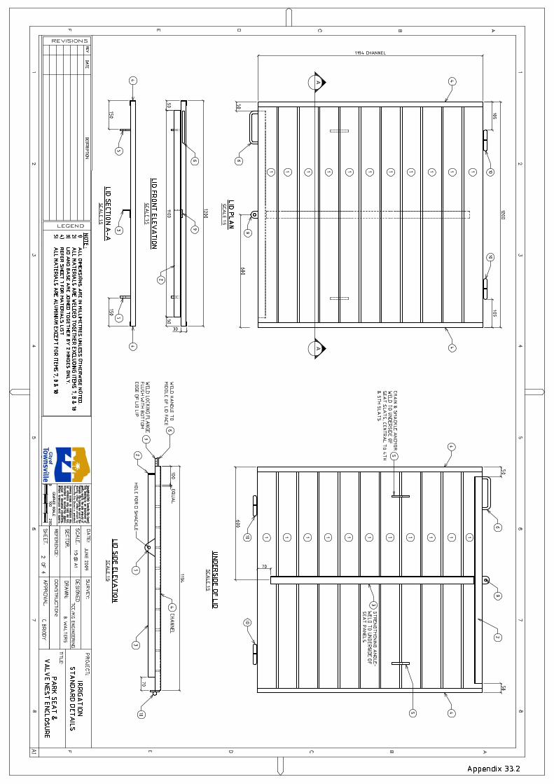
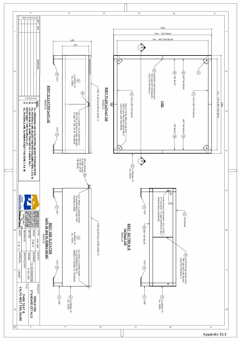
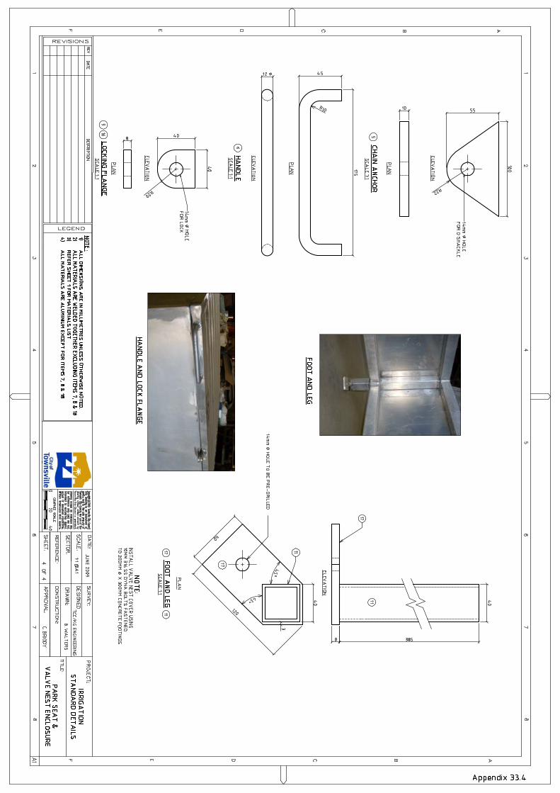
20. VALVE ASSEMBLY -------------------------------------------------------------------------------------------------- 56 20.1 SOLENOID VALVE ASSEMBLIES ---------------------------------------------------------------- 56 20.2 SOLENOID VALVE BOXES------------------------------------------------------------------------- 58 20.3 VALVE NEST ENCLOSURES ---------------------------------------------------------------------- 59
21. SPRINKLER EQUIPMENT ----------------------------------------------------------------------------------------- 60 21.1 SPRINKLER DESIGN --------------------------------------------------------------------------------- 60 21.2 SPRINKLER INSTALLATION ---------------------------------------------------------------------- 62 21.3 BOLLARD SPRINKLER INSTALLATION ------------------------------------------------------- 63
22. COUPLING VALVES ------------------------------------------------------------------------------------------------ 63
CAPITAL WORKS IRRIGATION SPECIFICATION SPEC.PPL.CW.01.07
G:\Irrigation Data\A IMS\SPECIFICATIONS\PPL.SPEC\CAPITAL WORKS\SPEC-PPL-CW-01-07 Specification-Irrigation Capital Works Ver7\SPEC-PPL-CW-01-07 Specification-Irrigation Capital Works Ver 7.doc Authorised by >> Brian Walters Version No. >> 7 12/11/2019 Document Maintained by >> TCC/IPAF Page 4 of 80
22.1 QUICK COUPLING VALVES (QCV) -------------------------------------------------------------- 63 22.2 CAM LOCK VALVES (CLV) ------------------------------------------------------------------------- 63
23. DRIP IRRIGATION EQUIPMENT --------------------------------------------------------------------------------- 63 23.1 DRIP IRRIGATION DESIGN AND INSTALLATION ------------------------------------------ 64
24. SCOUR VALVES ----------------------------------------------------------------------------------------------------- 68 24.1 SCOUR VALVE ASSEMBLIES -------------------------------------------------------------------- 68
25. MAIN LINE AIR VALVES ------------------------------------------------------------------------------------------- 68 25.1 MAIN LINE AIR VALVE ASSEMBLIES ---------------------------------------------------------- 68
26. MAIN LINE ISOLATION --------------------------------------------------------------------------------------------- 68 26.1 MAIN LINE ISOLATION VALVE ASSEMBLIES ----------------------------------------------- 69
27. TEMPORARY IRRIGATION---------------------------------------------------------------------------------------- 69 27.1 DESIGN & INSTALLATION ------------------------------------------------------------------------- 69
28. FERTIGATION --------------------------------------------------------------------------------------------------------- 70
29. EFFLUENT REUSE SYSTEMS ----------------------------------------------------------------------------------- 70 29.1 DESIGN AND INSTALLATION --------------------------------------------------------------------- 70
30. INSTALLATIONS LOCATED IN LANDFILL SITES --------------------------------------------------------- 71 30.1 TRENCHING IN LANDFILL SITES ---------------------------------------------------------------- 71
31. PUMP, FILTRATION & STORAGE TANK SYSTEMS ------------------------------------------------------ 71 31.1 BOOSTER PUMP SYSTEM ------------------------------------------------------------------------- 71 31.2 BORE PUMP SYSTEM ------------------------------------------------------------------------------- 72 31.3 FILTRATION SYSTEM ------------------------------------------------------------------------------- 74 31.4 STORAGE TANK SYSTEM ------------------------------------------------------------------------- 76
PART C - APPENDICES -------------------------------------------------------------- 77
32. APPENDICES---------------------------------------------------------------------------------------------------------- 77
CAPITAL WORKS IRRIGATION SPECIFICATION SPEC.PPL.CW.01.07
G:\Irrigation Data\A IMS\SPECIFICATIONS\PPL.SPEC\CAPITAL WORKS\SPEC-PPL-CW-01-07 Specification-Irrigation Capital Works Ver7\SPEC-PPL-CW-01-07 Specification-Irrigation Capital Works Ver 7.doc Authorised by >> Brian Walters Version No. >> 7 12/11/2019 Document Maintained by >> TCC/IPAF Page 5 of 80
PART A – CONTRACT MANAGEMENT REQUIREMENTS 1. INTRODUCTION
This document (Part A) details the procedures and requirements for the installation and
hand-over to the Superintendent of irrigation systems constructed for The
Superintendent as part of Capital Works Projects. It is to be read in accordance with
associated contract documents.
2. DEFINITIONS
For the purposes of this document the following definitions apply:
Superintendent means – Townsville City Council.
For the duration of each project contract a delegated representative will be nominated on
behalf of The Superintendent as the contact officer, typically the Project Manager for the
project.
Constructor means – a Contractor or an internally resourced Council Capital Works Group. Contractor means – a person or company who has entered into a contract with The
Superintendent to supply and install an irrigation system.
ICC means – Irrigation Central Control
3. IRRIGATION DESIGN
The Irrigation Design Plan shall be approved by the Irrigation Planning Supervisor prior
to the start of any works.
4. PROCEDURES - CONSTRUCTION PHASE 4.1 PRE START MEETING
(a) A meeting for all interested parties involved in the project will be conducted prior to work
commencing on site.
CAPITAL WORKS IRRIGATION SPECIFICATION SPEC.PPL.CW.01.07
G:\Irrigation Data\A IMS\SPECIFICATIONS\PPL.SPEC\CAPITAL WORKS\SPEC-PPL-CW-01-07 Specification-Irrigation Capital Works Ver7\SPEC-PPL-CW-01-07 Specification-Irrigation Capital Works Ver 7.doc Authorised by >> Brian Walters Version No. >> 7 12/11/2019 Document Maintained by >> TCC/IPAF Page 6 of 80
Items to be discussed and/or resolved at the meeting include but are not limited to:-
(i) Relevant personnel contact details.
(ii) Site Specific Workplace Health & Safety Management.
(iii) Constructor to confirm required insurance/fees etc.
(iv) Constructor to present a work and traffic plan for the project. A work Method
Statement and Safety Plan if applicable.
(v) Confirmation of location of existing services.
(vi) Acid sulphate soil potential.
(vii) Soil Erosion and Sediment Controls.
(viii) Confirmation of project timetable
(ix) Confirmation of time frame for The Superintendent to install components or
supply materials if required
(x) Clarification of any item relevant to the successful completion of the project.
(xi) Minutes of meeting shall be recorded by the Superintendent.
(xii) Review of the constructors Inspection Test Plan (ITP) previously submitted to
The Superintendent.
(xiii) Review of the constructors internal quality control documentation previously
submitted to The Superintendent.
(xiv) Review of the constructors internal pre-inspection check list documentation
previously submitted to The Superintendent.
4.2 INSPECTIONS

CAPITAL WORKS IRRIGATION SPECIFICATION SPEC.PPL.CW.01.07
G:\Irrigation Data\A IMS\SPECIFICATIONS\PPL.SPEC\CAPITAL WORKS\SPEC-PPL-CW-01-07 Specification-Irrigation Capital Works Ver7\SPEC-PPL-CW-01-07 Specification-Irrigation Capital Works Ver 7.doc Authorised by >> Brian Walters Version No. >> 7 12/11/2019 Document Maintained by >> TCC/IPAF Page 7 of 80
(a) The Superintendent will undertake inspections of installation work carried out by the
Constructor as construction progresses.
As a minimum, the following items shall be included in the constructors ITP & inspected
by the Superintendent ;-
(i) All main line trenching - After all pipe work, control conduit, control pits, warning
tape & bedding sand is installed and before back filling the trench.
(ii) All drip tube and drip feed/collector pipe work – while drip system is running and
before it is covered by mulch or soil.
(iii) All envelopers – after installation of enveloper pipe & marker tags and prior to
back filling.
(iv) Sprinkler laterals - when pipe is installed and before back filling the trench.
(v) Valve Assemblies – when valve assemblies are installed & before back filling
valve boxes.
(vi) 240v electrical power pits & conduit - when pits & conduit are installed and before
back filling the trench.
(vii) Water meter & backflow / hydrometer assembly – before installation commences
to confirm & approve the position & alignment.
(viii) Controller assembly – before installation commences to confirm & approve the
position & rotation.
(b) The Constructor is responsible for making requests for inspection to The
Superintendent.
(c) The Constructor shall provide a minimum of 24 hours’ notice to the Superintendent prior
to inspection.
CAPITAL WORKS IRRIGATION SPECIFICATION SPEC.PPL.CW.01.07
G:\Irrigation Data\A IMS\SPECIFICATIONS\PPL.SPEC\CAPITAL WORKS\SPEC-PPL-CW-01-07 Specification-Irrigation Capital Works Ver7\SPEC-PPL-CW-01-07 Specification-Irrigation Capital Works Ver 7.doc Authorised by >> Brian Walters Version No. >> 7 12/11/2019 Document Maintained by >> TCC/IPAF Page 8 of 80
(d) Failure by the Constructor to notify the Superintendent of any inspection required, will
result in the works being excavated at the Constructors cost to allow an inspection to be
carried out.
(e) Work on the next construction phase shall not proceed until the works inspected have
been approved by the Superintendent.
4.3 INSPECTION DOCUMENTATION
(a) Following each site inspection, a Site Inspection report will be issued by the
Superintendent.
(b) Work inspected that complies with the specification and the design plans will be
accepted by the Superintendent.
(c) Any work inspected, that does not comply with the specification or the design plans, will
not be accepted by the Superintendent. Items not acceptable will be noted for
rectification.
(d) The constructor is required to rectify these items prior to proceeding to the next
construction phase and shall apply for a re-inspection by the Superintendent on
completion of the rectification work.
4.4 CHANGE TO THE SPECIFICATION AND/OR DESIGN
(a) Change to the Specification and or design shall not be made without approval of the
Superintendent.
A written application for change to the specification and/or design plan must be made by
the Constructor to the Superintendent and authorised by the Superintendent prior to
commencement of work. Any such work shall be inspected by the Superintendent.
4.5 AS CONSTRUCTED DETAILS
(a) As constructed information shall be continuously recorded by the Constructor as
installation or modification work progresses and

CAPITAL WORKS IRRIGATION SPECIFICATION SPEC.PPL.CW.01.07
G:\Irrigation Data\A IMS\SPECIFICATIONS\PPL.SPEC\CAPITAL WORKS\SPEC-PPL-CW-01-07 Specification-Irrigation Capital Works Ver7\SPEC-PPL-CW-01-07 Specification-Irrigation Capital Works Ver 7.doc Authorised by >> Brian Walters Version No. >> 7 12/11/2019 Document Maintained by >> TCC/IPAF Page 9 of 80
(i) Shall include all items listed or referenced in section 7.2
(ii) Shall include all pre-existing irrigation system components remaining in service,
either previously installed or constructed during earlier “staged works”
(iii) Shall include changes to existing As Constructed Drawings where components of
an existing irrigation system have been removed, modified or added
(b) The Constructor is required to supply As Constructed Drawings to The Superintendent.
5. PROCEDURES - POST CONSTRUCTION PHASE
5.1 PRACTICAL COMPLETION (ON MAINTENANCE)
(a) Further to the Special Conditions of Contract. Before Practical Completion and prior to
the commencement of the Defects Liability Period (On Maintenance Period), the
Constructor is required to submit to the Superintendent the following completed
documentation:-
(i) Irrigation Asset Data Collection Form (FORM-PPL-IP-02) – This form contains
information about asset construction, or
(ii) Irrigation Asset Change Form (FORM-PPL-IP-04) – This form contains
information about minor changes to existing asset.
(iii) Irrigation Network Controller Setup Request Form (FORM-PPL-IP-03) – This form
contains information enabling configuration of the controller onto the TCC Irrinet
network. The form shall be submitted to The Superintendent a minimum of
twenty-eight (28) days prior to installation on site.
(iv) Irrigation Program Setup Request Form (FORM-PPL-QS-01) – This form is used
contains information enabling setup of irrigation controller programs in ICC. The
form shall be submitted to The Superintendent a minimum of eight (8) working
days prior to the program start date. After program setup in ICC, The
Superintendent will issue a copy of the program to the Constructor on request.
(v) Irrigation Control Cable Loop Resistance – Test Report Form (FORM-PPL-IP-08)
CAPITAL WORKS IRRIGATION SPECIFICATION SPEC.PPL.CW.01.07
G:\Irrigation Data\A IMS\SPECIFICATIONS\PPL.SPEC\CAPITAL WORKS\SPEC-PPL-CW-01-07 Specification-Irrigation Capital Works Ver7\SPEC-PPL-CW-01-07 Specification-Irrigation Capital Works Ver 7.doc Authorised by >> Brian Walters Version No. >> 7 12/11/2019 Document Maintained by >> TCC/IPAF Page 10 of 80
(vi) Irrigation Station Pressure & Flow Rate – Test Report Form (FORM-PPL-IP-07)
(vii) Irrigation Inspection Checklist (CKLIST-PPL-QS-02)
(viii) Irrigation Pre Practical Completion Q.A Check List (CKLIST-PPL-QA-03)
(ix) Warranty details for all irrigation components with a valve greater than $500.00
excluding GST. This information is required by The Superintendent to assist in
future warranty claims.
(x) Form 7 Notification of responsible person as per Plumbing & Drainage Act 2018,
must be completed by a licensed plumber and submitted to the Hydraulic
Certification unit of the Townsville City Council by email
[email protected] & CC (carbon copy) also
emailed to The Superintendent. Copies of Form 7 are available from the
Queensland Government Web site.
(xi) Form 9 Registration & report on inspection & testing of backflow prevention
devices as per Plumbing & Drainage Act 2018, must be completed by a licensed
plumber and submitted to the Hydraulic Certification unit of the Townsville City
Council by email [email protected] & CC (carbon
copy) also emailed to The Superintendent. Copies of Form 9 are available from
the Queensland Government Web site.
5.2 LODGEMENT OF AS CONSTRUCTED DRAWINGS
(a) Prior to the Defects Liability Period (On Maintenance Period), As Constructed Drawings
shall be submitted to the Superintendent. The Superintendent will review the drawings
and carry out checks to confirm compliance to Clause 4.5.
(b) Drawings requiring amendments or clarifications will be returned to the Constructor with
any amendments or clarifications required clearly noted.
(c) The Constructor shall resubmit amended drawings for approval and acceptance by the
Superintendent.
CAPITAL WORKS IRRIGATION SPECIFICATION SPEC.PPL.CW.01.07
G:\Irrigation Data\A IMS\SPECIFICATIONS\PPL.SPEC\CAPITAL WORKS\SPEC-PPL-CW-01-07 Specification-Irrigation Capital Works Ver7\SPEC-PPL-CW-01-07 Specification-Irrigation Capital Works Ver 7.doc Authorised by >> Brian Walters Version No. >> 7 12/11/2019 Document Maintained by >> TCC/IPAF Page 11 of 80
(d) As Constructed drawings must be approved and accepted by the Superintendent prior to
commencement of the Defects Liability Period (On Maintenance Period).
5.3 DEFECTS LIABILITY PERIOD (ON MAINTENANCE PERIOD)
(a) The Defects Liability period shall be undertaken in accordance with this Clause and the
Special Conditions of Contract.
(b) A minimum Defects Liability Period of 13 weeks applies to all irrigation systems installed
by Constructors.
(c) If applicable the Defects Liability Period for the irrigation system shall be concurrent with
the Defects Liability Period for any associated Landscaping works.
(d) The Defects Liability Period for an Irrigation system shall not commence until:-
(i) all of the documentation nominated in Clause 5.1 and Clause 5.2 is submitted
and approved by the Superintendent; and
(ii) all requirements of the Special Conditions of Contract have been met; and
(iii) if applicable the associated Landscaping works are accepted “On Maintenance”;
and
(iv) the irrigation system has been commissioned & is fully operational; and
(v) all irrigation programs are fully operating via TCC Irrinet ICC with automatic flow
alarm activated; and
(vi) all irrigation programs have run free from any ICC generated alarms for a
continuous period no less than fourteen (14) days; and
(vii) the site has been jointly inspected by the Superintendent and Constructor and
the irrigation system is free of defects (items that do not comply with the
specification or design plan) at the time of inspection.
CAPITAL WORKS IRRIGATION SPECIFICATION SPEC.PPL.CW.01.07
G:\Irrigation Data\A IMS\SPECIFICATIONS\PPL.SPEC\CAPITAL WORKS\SPEC-PPL-CW-01-07 Specification-Irrigation Capital Works Ver7\SPEC-PPL-CW-01-07 Specification-Irrigation Capital Works Ver 7.doc Authorised by >> Brian Walters Version No. >> 7 12/11/2019 Document Maintained by >> TCC/IPAF Page 12 of 80
(e) Following each inspection, the Superintendent will issue an Irrigation Inspection Defects
Report detailing items that do not comply with the specification or design plan.
The Constructor is required to rectify these items and apply for a reinspection when all
rectification work has been completed.
(f) Where more than one reinspection (1 inspection + 1 reinspection) is required, a
reinspection fee of $500 for each further inspection will be issued to the contractor by
The Superintendent.
(g) After reinspection of the rectification work, and if the work is satisfactory to the
Superintendent an Irrigation Inspection Defects Report will be issued with the status
noted as “Ready to Proceed to On Maintenance”.
(h) A Certificate of Practical Completion will be issued by the Superintendent when the
Constructor has met all obligations under the Contract.
5.4 TESTING
(a) During the Defects Liability Period, the Superintendent may access the site to undertake
the following tests :-
(i) Main lines Pressure Test – The main line is pressurized to test for leaks. All
valves are shut and the pressure is taken over a determined length of time.
(ii) Sprinkler Pressure Test – The sprinkler pressure is taken at the nozzle using a
pitot pressure gauge and is then compared to manufacturer recommendations.
(iii) Dripper Pressure Test – Measurement at flushing valves are taken and the
pressure gauged to make sure it conforms to the manufacturer
recommendations. The inlet pressure is then tested under the same conditions
to check it does not exceed 300Kpa.
CAPITAL WORKS IRRIGATION SPECIFICATION SPEC.PPL.CW.01.07
G:\Irrigation Data\A IMS\SPECIFICATIONS\PPL.SPEC\CAPITAL WORKS\SPEC-PPL-CW-01-07 Specification-Irrigation Capital Works Ver7\SPEC-PPL-CW-01-07 Specification-Irrigation Capital Works Ver 7.doc Authorised by >> Brian Walters Version No. >> 7 12/11/2019 Document Maintained by >> TCC/IPAF Page 13 of 80
(iv) Lateral Pressure Loss Test – The first and last sprinklers of the lateral line are
pressure tested. The variation in precipitation is then calculated and compared
with the limits nominated in the Specification.
6. FINAL COMPLETION (OFF MAINTENANCE)
Final Completion shall be managed in accordance with the Special Conditions of
Contract and the provisions of this Clause 6.
6.1 FINAL INSPECTION
(a) Final inspection shall not commence until all irrigation programs have run free from any
ICC generated alarms for a continuous period no less than twenty-eight (28) days.
(b) Following the Final Inspection, the Superintendent will issue an Irrigation Inspection
Defects Report detailing items that do not comply with the specification or design plan.
The Constructor is required to rectify these items and apply for a reinspection when all
rectification work has been completed.
(c) Where more than one reinspection (1 inspection + 1 reinspection) is required, a
reinspection fee of $500 for each further inspection will be issued to the contractor by
The Superintendent
(d) After reinspection of the rectification work, and if the work is satisfactory to the
Superintendent an Irrigation Inspection Defects Report will be issued with the status
noted as “Ready to Proceed to Off Maintenance”.
(e) A Certificate of Final Completion will be issued by the Superintendent when the
Constructor has met all obligations under the Contract.
7. DOCUMENTATION CONVENTIONS
7.1 DESIGN PLANS
(a) Design plans submitted for approval shall be in Autocad format and as a minimum shall
include the following:-

CAPITAL WORKS IRRIGATION SPECIFICATION SPEC.PPL.CW.01.07
G:\Irrigation Data\A IMS\SPECIFICATIONS\PPL.SPEC\CAPITAL WORKS\SPEC-PPL-CW-01-07 Specification-Irrigation Capital Works Ver7\SPEC-PPL-CW-01-07 Specification-Irrigation Capital Works Ver 7.doc Authorised by >> Brian Walters Version No. >> 7 12/11/2019 Document Maintained by >> TCC/IPAF Page 14 of 80
(i) Project Name / Location
(ii) Project Reference Number / Drawing Number / Sheet Number /Sheet Set
Number (i.e. 2 of 4)
(iii) Date of Original Issue & date of revision with reference index letter (i.e. Rev A
13/6/18)
(iv) Drawing Scale
(v) IAA Certification number & stamp
(vi) Designers Name and / or Company
(vii) Drafters Name and / or Company
(viii) Surveyors Name and / or Company
(ix) All roadways are to be named
(x) Standard Plan Legend as shown in Appendix 8.1, Figures 1. The symbols and
line types shown in the Legend are the acceptable convention for design plans to
be used to represent the components of the design. Additional symbols and line
types may be introduced provided they are shown in the Legend on the drawing.
(xi) Valve Key. Each valve must have a Valve Key displaying the relevant
information as shown in Appendix 8.1, Figure 2.
(xii) Sprinkler Key. Each valve must have a Sprinkler Key displaying the relevant
information as shown in Appendix 8.1, Figure 3.
(xiii) Irrigation Design Data. Displaying the relevant information as shown in Appendix
7.1.

CAPITAL WORKS IRRIGATION SPECIFICATION SPEC.PPL.CW.01.07
G:\Irrigation Data\A IMS\SPECIFICATIONS\PPL.SPEC\CAPITAL WORKS\SPEC-PPL-CW-01-07 Specification-Irrigation Capital Works Ver7\SPEC-PPL-CW-01-07 Specification-Irrigation Capital Works Ver 7.doc Authorised by >> Brian Walters Version No. >> 7 12/11/2019 Document Maintained by >> TCC/IPAF Page 15 of 80
(xiv) Irrigation Cabling / Wiring Schedule displaying the relevant information as shown
in Appendix 7.2.
(xv) Design Notes. Relevant design criteria is to be nominated on the drawing: - e.g.
Sprinkler Type A is to be Hunter PGP. All Solenoid valves are to be Hunter ICV.
Descriptions of the Symbols and Line Types used from the Plan Legend.
(xvi) A Locality Plan scaled at 1:5000 shall be provided on the first sheet clearly
showing the location of the work site & labelled with the suburb, street names &
adjacent landmark locations (i.e. school, river or other well-known destination or
community facility etc)
(xvii) A site overview identifying areas of the work site contained within each sheet
number shall be provided on the first sheet, wherever design plans contain more
than 5 sheets in total
(xviii) Intersection of irrigation pipe work. A dot shall be used to indicate a pipe joint
wherever a pipe line intersects with another pipe line. Otherwise lines shall
simply be shown to cross over – as shown in Appendix 8.1, Figure 4
(xix) All parts of the irrigation system scaled in paper space such that all detail is
clearly legible when printed to A3 size paper and at a scale no greater than
1:200.
7.2 AS CONSTRUCTED DRAWINGS
(a) As constructed drawings submitted for approval shall be in Autocad & PDF format and
shall include the following:-
(i) All items listed or referred to in section 7.1
(ii) All items listed or referred to in section 4.5
(iii) The location of all Controllers, Water Meter Assemblies, Main Lines, Lateral lines,
Sprinklers, Drip tube, Drip Supply Header / Flush Collector Pipe, Valves,
Electrical inspection Pits, Envelopers, Water taps, Drinking fountains & Soil
CAPITAL WORKS IRRIGATION SPECIFICATION SPEC.PPL.CW.01.07
G:\Irrigation Data\A IMS\SPECIFICATIONS\PPL.SPEC\CAPITAL WORKS\SPEC-PPL-CW-01-07 Specification-Irrigation Capital Works Ver7\SPEC-PPL-CW-01-07 Specification-Irrigation Capital Works Ver 7.doc Authorised by >> Brian Walters Version No. >> 7 12/11/2019 Document Maintained by >> TCC/IPAF Page 16 of 80
Sensors shall be accurately recorded and shown in the As Constructed drawing
A tolerance of +/- 100mm is acceptable – Refer to Appendix 9.1, Figure 1
(iv) The location of all low voltage (240V) electrical cables, pits, poles, pillars &
switchboards.
(v) A stamp on every sheet, with the business name & contact details of the
Installation Constructor, name of the site Irrigation Construction Supervisor,
Construction Completion Date and As Constructed Plan QA name & date – Refer
to Appendix 9.1, Figure 2.
(vi) Updated base plan reference drawings where changes to the soft/hard landscape
or infrastructure has occurred
(vii) Compliance with the Capital Works Irrigation CAD Specification (SPEC-PPL-IP-
01).
.

CAPITAL WORKS IRRIGATION SPECIFICATION SPEC.PPL.CW.01.07
G:\Irrigation Data\A IMS\SPECIFICATIONS\PPL.SPEC\CAPITAL WORKS\SPEC-PPL-CW-01-07 Specification-Irrigation Capital Works Ver7\SPEC-PPL-CW-01-07 Specification-Irrigation Capital Works Ver 7.doc Authorised by >> Brian Walters Version No. >> 7 12/11/2019 Document Maintained by >> TCC/IPAF Page 17 of 80
PART B - DESIGN AND INSTALLATION SPECIFICATION
8. INTRODUCTION
This specification sets out the scope of work, workmanship standards and the
Constructors responsibilities for the supply and installation of irrigation systems that will
become a Council Asset on handover.
The Irrigation system within Townsville City Council exists solely for the purpose of
providing water to maintain the soil moisture content above the horticultural assets
permanent wilting point and below the soil field capacity. These conditions are required
to maintain the health and growth of the horticultural assets. In addition to this
requirement the Superintendent seeks to minimise maintenance and operational costs
associated with the irrigation systems.
Product and Brand names for components are used is this document to define a
standard and quality acceptable to the Superintendent, with particular emphasis on long
term maintenance requirements. Components other than those specified may only be
used if the components are of equal or better standard of both quality and performance
than those specified and an authorised change has been approved by the
Superintendent. Refer Clause 4.4.
9. OBJECTIVES OF THIS SPECIFICATION
To ensure that irrigation systems are designed to the highest industry standards with the
goal of maximising the efficient usage of water, energy & labour.
To ensure that irrigation systems and components are installed in accordance with the
relevant industry standards and tradesman like workmanship.
To ensure that the irrigation systems and components are installed to a quality and
performance standard acceptable to the Superintendent. Providing reliable & efficient
irrigation systems with extended asset life, reduced maintenance and operational costs
& serviceable components.
CAPITAL WORKS IRRIGATION SPECIFICATION SPEC.PPL.CW.01.07
G:\Irrigation Data\A IMS\SPECIFICATIONS\PPL.SPEC\CAPITAL WORKS\SPEC-PPL-CW-01-07 Specification-Irrigation Capital Works Ver7\SPEC-PPL-CW-01-07 Specification-Irrigation Capital Works Ver 7.doc Authorised by >> Brian Walters Version No. >> 7 12/11/2019 Document Maintained by >> TCC/IPAF Page 18 of 80
10. SCOPE
This specification sets out the requirements for design and installation of irrigation
systems that are connected to the Townsville City Council water supply network.
Irrigation systems that will be connected to an alternative water supply have additional
requirements to this Specification and require separate approval.
11. LIST OF RELEVANT DOCUMENTS
All design and documentation, materials supplied and work carried out shall be in
accordance with the following:-
Australian Standards
AS 3500.0:2003 Plumbing and drainage – Part 0 Glossary of Terms
AS 3500.1:2018 Plumbing and drainage – Part 1 Water services
AS 3500.2:2018 Plumbing and drainage – Part 2 Sanitary plumbing
and drainage
AS 2032 :2006 Installation of PVC pipe systems
AS 2033 :2008 Installation of polyethylene pipe systems
AS 2566.1 :1998 Buried flexible pipelines – Part 1 Structural design
AS 2566.2 :2002 Buried flexible pipelines – Part 2 Installation
AS 4129 :2008 Fittings for polyethylene (PE) pipes for pressure
applications
AS 4130 :2018 Polyethylene pipes for pressure applications
AS 1432 :2004 Copper tubes for plumbing, gas fitting and drainage
applications
AS 1477 :2017 PVC pipes and fittings for pressure applications

CAPITAL WORKS IRRIGATION SPECIFICATION SPEC.PPL.CW.01.07
G:\Irrigation Data\A IMS\SPECIFICATIONS\PPL.SPEC\CAPITAL WORKS\SPEC-PPL-CW-01-07 Specification-Irrigation Capital Works Ver7\SPEC-PPL-CW-01-07 Specification-Irrigation Capital Works Ver 7.doc Authorised by >> Brian Walters Version No. >> 7 12/11/2019 Document Maintained by >> TCC/IPAF Page 19 of 80
AS 2698.1 :1984 Plastic pipes and fittings for irrigation and rural
applications – Part 1 Polyethylene Micro-Irrigation
AS 2698.2 :2000 Plastic pipes and fittings for irrigation and rural
applications – Part 2 Polyethylene rural pipe
AS 2698.3 :1990 Plastic pipes and fittings for irrigation and rural
applications – Part 3 Mechanical joint fittings for use
with polyethylene micro irrigation pipes
AS 2845.1 :2010 Water supply – Backflow prevention devices – Part 1
Materials, design and performance requirements
AS 2845.2 :2010 Water supply – Backflow prevention devices – Part 2
Registered air gaps and registered break tanks
AS 2845.3 :2010 Water supply – Backflow prevention devices – Part 3
Field testing and maintenance of testable devices
AS 2129 :2000 Flanges for pipes and valves and fittings
AS 3000 :2018 Wiring Rules
AS 3008.1.1 :2017 Electrical Installations –Selection of cables - Part 1.1
Cables for alternating voltages up to and including
0.6/1 kV-Typical Australian installation conditions
AS 2053 :2001 Conduits and fittings for electrical installations. (all
Parts)
AS 3808 :2000 Insulating and sheathing materials for electrical
cables
AS 3879:2011 Solvent cements and priming fluids for PVC (PVC-U
and PVC-M) and ABS pipes and fittings
AS 4158:2003 Thermal-bonded polymeric coatings on valves and
fittings for water industry purposes
CAPITAL WORKS IRRIGATION SPECIFICATION SPEC.PPL.CW.01.07
G:\Irrigation Data\A IMS\SPECIFICATIONS\PPL.SPEC\CAPITAL WORKS\SPEC-PPL-CW-01-07 Specification-Irrigation Capital Works Ver7\SPEC-PPL-CW-01-07 Specification-Irrigation Capital Works Ver 7.doc Authorised by >> Brian Walters Version No. >> 7 12/11/2019 Document Maintained by >> TCC/IPAF Page 20 of 80
Industry Guidelines
PIPA POP001 Electrofusion Jointing of PE Pipes & Fittings For
Pressure Applications
Queensland Parliamentary Acts and associated Regulations
Water Act 2000
Electricity Safety Act 2002.
Workplace Health and Safety Act 2011
Authorities
The rules and regulations of the relevant local electricity supply authority.
The rules and regulations of the relevant local water supply authority.
The requirements of any other Authority having jurisdiction over the installation.
The following order of precedence shall apply:-
I. Parliamentary Acts or associated Regulations
II. Supply Authorities
III. The Specification
IV. Australian Standards
V. International Standards
12. EXTERNAL APPROVALS
The Constructor is required to obtain all approvals or certifications necessary for the
completion of works in accordance with the Laws of Australia, Laws of the State of
Queensland, Townsville City Council By-Laws and Ordinances.
13. UNDERGROUND SERVICES

CAPITAL WORKS IRRIGATION SPECIFICATION SPEC.PPL.CW.01.07
G:\Irrigation Data\A IMS\SPECIFICATIONS\PPL.SPEC\CAPITAL WORKS\SPEC-PPL-CW-01-07 Specification-Irrigation Capital Works Ver7\SPEC-PPL-CW-01-07 Specification-Irrigation Capital Works Ver 7.doc Authorised by >> Brian Walters Version No. >> 7 12/11/2019 Document Maintained by >> TCC/IPAF Page 21 of 80
The Constructor is required to determine the location of all existing underground service
locations before commencing any work where trenching, digging or excavation is to take
place.
14. QUALIFIED PERSONNEL
14.1 DESIGN OF IRRIGATION SYSTEMS
All irrigation designs submitted to the Superintendent for approval shall be designed & endorsed
by (CID) Certified Irrigation Designer (Commercial Turf) & include certification number
issued by (IAL) Irrigation Australia Limited.
14.2 INSTALLATION OF IRRIGATION SYSTEMS
(a) A Qualified Irrigation Installer must be nominated as the Irrigation Site Supervisor for the
irrigation construction works at each location.
(b) A Qualified Irrigation Installer shall be qualified and competent in all aspects of irrigation
work, shall have at least 5 years demonstrated experience in the installation of
commercial irrigation systems and;
(c) Shall be conversant with latest version of the Townsville City Council, Capital Works
Irrigation Specification SPEC-PPL-CW.01 and relevant Australian Standards and;
(d) Shall possess either:-
(i) (CII) Certified Irrigation Installer, issued by (IAL) Irrigation Australia Limited
(ii) (CIC) Certified Irrigation Contractor, issued by (IAL) Irrigation Australia Limited
(iii) (CID) Certified Irrigation Designer, issued by (IAL) Irrigation Australia Limited
(e) The nominated irrigation Site Supervisor shall:
(i) Ensure that all irrigation site staff construct all assets to the approved irrigation
construction plans and the specifications contained in this document.

CAPITAL WORKS IRRIGATION SPECIFICATION SPEC.PPL.CW.01.07
G:\Irrigation Data\A IMS\SPECIFICATIONS\PPL.SPEC\CAPITAL WORKS\SPEC-PPL-CW-01-07 Specification-Irrigation Capital Works Ver7\SPEC-PPL-CW-01-07 Specification-Irrigation Capital Works Ver 7.doc Authorised by >> Brian Walters Version No. >> 7 12/11/2019 Document Maintained by >> TCC/IPAF Page 22 of 80
(ii) Attend all inspections outlined in Part A.
(iii) Provide evidence of their qualification and experience to The Superintendent
within 24 hours if requested to do so.
14.3 INSTALLATION OF ELECTRICAL COMPONENTS
(a) The installation of electrical components shall comply with the requirements of AS3000
& Electrical Safety Act 2002.
14.4 INSTALLATION OF BACKFLOW DEVICES
(a) The installation of Backflow Devices shall comply with the requirements of AS3500.
Where required under the Plumbing & Drainage Act 2018, Backflow Device installations
shall be installed by a registered Plumber as defined by that Act.
14.5 INSPECTION OF IRRIGATION SYSTEMS
(a) A Qualified Irrigation Inspector shall be appointed by the Superintendent & must attend
all irrigation site inspections for irrigation construction works, Practical Completion and
Final Completion inspections.
(b) Qualified Irrigation Inspectors shall be qualified and competent in all aspects of irrigation
work, shall have at least 5 years demonstrated experience in the installation of
commercial irrigation systems and;
(c) Shall be conversant with latest version of the Townsville City Council, Capital Works
Irrigation Specification SPEC-PPL-CW.01 and relevant Australian Standards and;
(d) Shall possess either:-
(i) (CII) Certified Irrigation Installer, issued by (IAL) Irrigation Australia Limited
(ii) (CIC) Certified Irrigation Contractor, issued by (IAL) Irrigation Australia Limited
CAPITAL WORKS IRRIGATION SPECIFICATION SPEC.PPL.CW.01.07
G:\Irrigation Data\A IMS\SPECIFICATIONS\PPL.SPEC\CAPITAL WORKS\SPEC-PPL-CW-01-07 Specification-Irrigation Capital Works Ver7\SPEC-PPL-CW-01-07 Specification-Irrigation Capital Works Ver 7.doc Authorised by >> Brian Walters Version No. >> 7 12/11/2019 Document Maintained by >> TCC/IPAF Page 23 of 80
(iii) (CID) Certified Irrigation Designer, issued by (IAL) Irrigation Australia Limited
15. GENERAL DESIGN REQUIREMENTS
15.1 GENERAL REQUIREMENT
Supply an Automatic Irrigation System as specified.
15.2 IRRIGATION TYPE REQUIREMENTS
(a) All turf areas shall be irrigated with pop-up sprinklers, with the follow exclusions;
(i) Subsurface drip irrigation or non-irrigated surface treatment shall be installed into
traffic intersections containing roundabouts, median strips or road reserve areas
instead of pop-up sprinklers, where risk assessment has shown it to be a health
& safety requirement.
(ii) Where a site specific risk assessment has been issued to the Superintendent &
the Superintendent has provided approval.
(b) All garden areas shall to be irrigated with subsurface drip irrigation with the following
exclusions;
(i) Areas containing plants or tree species with known vigorous root systems that
significantly shorten the functional life of drip irrigation such as certain Palms or
Lillie’s, shall be irrigated by pop-up sprinklers.
(ii) Garden beds without formal and hard surface garden edging, including concrete,
paved, timber, recycled plastic, shall be irrigated by pop-up sprinklers.
15.3 AGRONOMIC REQUIREMENTS
(a) Pop-up sprinklers - The total time taken to deliver 7mm of equivalent precipitation where
each station or group of stations (if operated simultaneously) within the irrigation
program is operated consecutively, shall not exceed 7 hours. Maximum irrigation water
window for pop-up sprinklers shall be no more than 7 hours.
CAPITAL WORKS IRRIGATION SPECIFICATION SPEC.PPL.CW.01.07
G:\Irrigation Data\A IMS\SPECIFICATIONS\PPL.SPEC\CAPITAL WORKS\SPEC-PPL-CW-01-07 Specification-Irrigation Capital Works Ver7\SPEC-PPL-CW-01-07 Specification-Irrigation Capital Works Ver 7.doc Authorised by >> Brian Walters Version No. >> 7 12/11/2019 Document Maintained by >> TCC/IPAF Page 24 of 80
(b) Drip irrigation - The total time taken to deliver 7mm of equivalent precipitation where
each station or group of stations (if operated simultaneously) within the irrigation
program is operated consecutively, shall not exceed 7 hours. Maximum irrigation water
window for drip irrigation shall be no more than 7 hours.
(c) The irrigation application rate shall not exceed the infiltration rate of the soil.
15.4 ENVIRONMENTAL REQUIREMENTS
(a) The system shall not have excessive runoff or overspray which may cause erosion,
pollution or weed growth to adjacent native areas and / or storm water drains.
15.5 AUTOMATION REQUIREMENTS
(a) The Irrigation Controller shall be chosen from the units outlined in Table 3, Section
17.3:-
(b) Up to a maximum of six (6) stations may be operated simultaneously (by programming
only) given the follow conditions;
(i) Irrigation Type & Precipitation Rate of the stations to be operated
simultaneously shall be the same or similar.
(ii) The soil type, vegetation, topography & micro-climate of the stations to be
operated simultaneously shall be the same or similar.
(iii) All stations to be operated simultaneously shall supply all sprinkler or drip
irrigation within manufacturers recommended operating pressures.
(c) Only one valve per controller digital output is acceptable.

CAPITAL WORKS IRRIGATION SPECIFICATION SPEC.PPL.CW.01.07
G:\Irrigation Data\A IMS\SPECIFICATIONS\PPL.SPEC\CAPITAL WORKS\SPEC-PPL-CW-01-07 Specification-Irrigation Capital Works Ver7\SPEC-PPL-CW-01-07 Specification-Irrigation Capital Works Ver 7.doc Authorised by >> Brian Walters Version No. >> 7 12/11/2019 Document Maintained by >> TCC/IPAF Page 25 of 80
15.6 SEPARATION OF IRRIGATION ZONES
(a) Irrigation Zones shall be classified in the following vegetation types:
(i) Turf Grass.
(ii) Garden Bed.
(iii) Tree’s (not in a garden bed, i.e. street trees).
(iv) Native Planting.
(b) A single irrigation valve shall water no more than one Irrigation Zone.
15.7 SAFETY REQUIREMENTS
(a) The system shall not have runoff onto roadways, footpaths or other pedestrian areas to
such an extent that it may result in a hazard to traffic and/or pedestrians – refer section
15.2 Irrigation Type Requirements
16. IRRIGATION PIPEWORK
16.1 STANDARDS
(a) All pipes shall be supplied, installed and joined in accordance with these specifications,
the manufacturer’s recommendations and all relevant Australian Standards.
(b) All mainline pipe work shall be Installed with Pakaflex "Irrigation Main Below" warning
tape or approved similar, typically 300mm above mainline pipe
16.2 CLASS OF PIPE
(a) Main line pipes (pressurised) of nominal 80mm diameter and larger shall be no less than
pressure rating PN12, made of material types PVC U, PVC M or PVC O and all Rubber
Ring Jointed (RRJ).

CAPITAL WORKS IRRIGATION SPECIFICATION SPEC.PPL.CW.01.07
G:\Irrigation Data\A IMS\SPECIFICATIONS\PPL.SPEC\CAPITAL WORKS\SPEC-PPL-CW-01-07 Specification-Irrigation Capital Works Ver7\SPEC-PPL-CW-01-07 Specification-Irrigation Capital Works Ver 7.doc Authorised by >> Brian Walters Version No. >> 7 12/11/2019 Document Maintained by >> TCC/IPAF Page 26 of 80
(b) Main line pipes (pressurised) of nominal diameter less than 80mm shall be no less than
pressure rating PN12.5 and made of material type PE100 (Poly pipe).
(c) All lateral line pipes (non pressurised) shall be no less than pressure rating PN8 and
made of material type PE100 (Poly pipe).
(d) Supply line to a drinking fountain or a water tap shall be no smaller than 32mm nominal
diameter, with pressure rating no less than PN12.5 and made of material type PE100
(Poly Pipe). Copper pipe is not acceptable.
(e) Copper pipe to a Water meter, drinking fountain and water tap assemblies shall be
minimum Type B
16.3 ENVELOPERS
(a) All irrigation pipe work installed under pavements (road or other hard surface) shall be
installed in an Enveloper.
(b) All envelopers used to encase irrigation pipes shall be 100mm PN9 PVC SWJ Pipe as
standard unless otherwise approved by The Superintendent.
(c) Enveloper ends shall be sealed with duct tape prior to installation, to stop the ingress of
soil & material from entering the enveloper.
(d) Envelopers ends shall have the outer 50mm sealed with expanded foam after pipe work
or electrical conduits have been installed, to stop the transportation of water and ingress
of soil & material through the enveloper.
(e) A stainless steel marker tag shall be used to easily identify location of envelopers ends.
The tag shall be a minimum of 38mm diameter and 1.6mm thick. Marker tags shall be
nailed, glued or set into the surface of the pavement and engraved with the word
“Irrigation” and recorded on the As Constructed drawings.
16.4 PIPE FITTINGS
(a) All fittings for PVC Pipe shall be minimum Class 18 PVC SWJ.

CAPITAL WORKS IRRIGATION SPECIFICATION SPEC.PPL.CW.01.07
G:\Irrigation Data\A IMS\SPECIFICATIONS\PPL.SPEC\CAPITAL WORKS\SPEC-PPL-CW-01-07 Specification-Irrigation Capital Works Ver7\SPEC-PPL-CW-01-07 Specification-Irrigation Capital Works Ver 7.doc Authorised by >> Brian Walters Version No. >> 7 12/11/2019 Document Maintained by >> TCC/IPAF Page 27 of 80
(b) All fittings for Poly Pipe shall be metric compression fittings, Plasson or Philmac.
(c) All fittings for Low Density Pipe shall be barbed type with all joints fitted with Stainless
Steel Cobra clamps – or approved equivalent.
(d) All threaded fittings except sprinklers shall be sealed using PTFE thread tape and Liquid
Teflon.
16.5 PIPE INSTALLATION GENERALLY
(a) Interior of pipes shall be kept free of dirt and debris at all times.
(b) Where pipe work is left unfinished during installation, the open ends of pipes shall be
sealed off with duct tape or have end caps fitted.
(c) Pipes laid in a common trench shall be separated by a minimum of 100mm except
where otherwise specified within this document – refer Clause 16.10 (d).
(d) Refer to Appendix 13.1, Figures 1 to 6 for pipe alignments for all irrigation works in road
reserves.
16.6 PVC RUBBER RING JOINTED PIPE – INSTALLATION (i.e., Main line pipes of nominal 80mm diameter and larger).
(a) All PVC Rubber Ring Jointed pipe work shall be installed in accordance with the
manufacturer’s recommendations and AS 2032:2006.
(b) All PVC Rubber Ring Jointed pipe work shall be laid in a minimum of 100mm sand
bedding and surround.
(c) All connections and changes of direction horizontally and vertically in Rubber Ring Joint
(RRJ) pipe work shall be installed with concrete thrust blocks.
(d) Thrust block design and size shall follow pipe manufacturers recommendations (“Thrust
Block Design – Pressure Pipeline Fittings” Iplex uPVC Design Manual. Thrust blocks

CAPITAL WORKS IRRIGATION SPECIFICATION SPEC.PPL.CW.01.07
G:\Irrigation Data\A IMS\SPECIFICATIONS\PPL.SPEC\CAPITAL WORKS\SPEC-PPL-CW-01-07 Specification-Irrigation Capital Works Ver7\SPEC-PPL-CW-01-07 Specification-Irrigation Capital Works Ver 7.doc Authorised by >> Brian Walters Version No. >> 7 12/11/2019 Document Maintained by >> TCC/IPAF Page 28 of 80
shall be 15 MPA concrete in accordance with AS2032:2006 & AS2566.2. All thrust
blocks are to be cast in situ against undisturbed ground and shall have neatly formed
sides.
(e) The ends of pipes used for Rubber Ring Joint (RRJ) connections shall have a smooth
chamfer 15 degrees to the outer edge and shall be free of all burrs and rough edges.
Rubber Rings and Lubricant used shall be in accordance with the pipe manufacturer’s
recommendations.
(f) Each pipe length shall be laid in the following direction; water flow runs from the socket
end to the spigot end of the pipe, with the exception of Ring Mains.
(g) Trenches may be curved to avoid obstructions within the pipe manufactures limits of
curvature of the pipe.
16.7 PVC SOLVENT WELDED JOINT INSTALLATION (Main line take-off PVC pipe fittings).
(a) All PVC Solvent Welded Joint pipe work shall be installed in accordance with the
manufacturer’s recommendations and AS 2032:2006.
(b) All PVC Solvent Welded Joints shall be primed and cemented.
(c) Primer and solvent cement shall conform to AS 3879:2011.
(d) Primer is to be “Priming Fluid (red)”.
(e) Solvent is to be “Christy’s PVC Red Hot Blue Glue” or approved Type ‘p’ solvent
cement.
(f) All pipes shall be primed before cementing the joint.
(g) Pipe ends shall be free of all burs and rough edges.
(h) All PVC Solvent Welded Joints shall not be subjected to water pressure for at least
twenty-four (24) hours after cementing the joint.

CAPITAL WORKS IRRIGATION SPECIFICATION SPEC.PPL.CW.01.07
G:\Irrigation Data\A IMS\SPECIFICATIONS\PPL.SPEC\CAPITAL WORKS\SPEC-PPL-CW-01-07 Specification-Irrigation Capital Works Ver7\SPEC-PPL-CW-01-07 Specification-Irrigation Capital Works Ver 7.doc Authorised by >> Brian Walters Version No. >> 7 12/11/2019 Document Maintained by >> TCC/IPAF Page 29 of 80
(i) All Mainline PVC Solvent Welded Joint pipes shall be laid in a minimum of 100mm sand
bedding and surround.
16.8 POLYETHYLENE PIPE INSTALLATION
(a) All Polyethylene Pipe work shall be installed in accordance with the manufacturer’s
recommendations and AS 2033:2008.
(b) Poly pipe shall be laid with sufficient allowance for contraction and expansion of the
pipe.
(c) Pipe ends shall be free of all burs and rough edges and shall be chamfered with the
appropriate tool before jointing.
(d) Polyethylene Tapping Saddles shall only be used to:-
(i) Connect Sprinklers to polyethylene Lateral pipe or
(ii) Connect Drip Tube to polyethylene Header / Collector pipe.
16.9 TRENCHING
(a) All pipe work shall be laid in trenches, with the exception of:-
(i) Pipes which are installed by underground boring or;
(ii) Pipes which are installed above ground due to obstacles i.e. bridges, walls, etc.
(b) Trenches shall:-
(i) Be sufficiently wide to allow adequate working clearance; and
(ii) Be excavated in straight lines between bends or pits; and
CAPITAL WORKS IRRIGATION SPECIFICATION SPEC.PPL.CW.01.07
G:\Irrigation Data\A IMS\SPECIFICATIONS\PPL.SPEC\CAPITAL WORKS\SPEC-PPL-CW-01-07 Specification-Irrigation Capital Works Ver7\SPEC-PPL-CW-01-07 Specification-Irrigation Capital Works Ver 7.doc Authorised by >> Brian Walters Version No. >> 7 12/11/2019 Document Maintained by >> TCC/IPAF Page 30 of 80
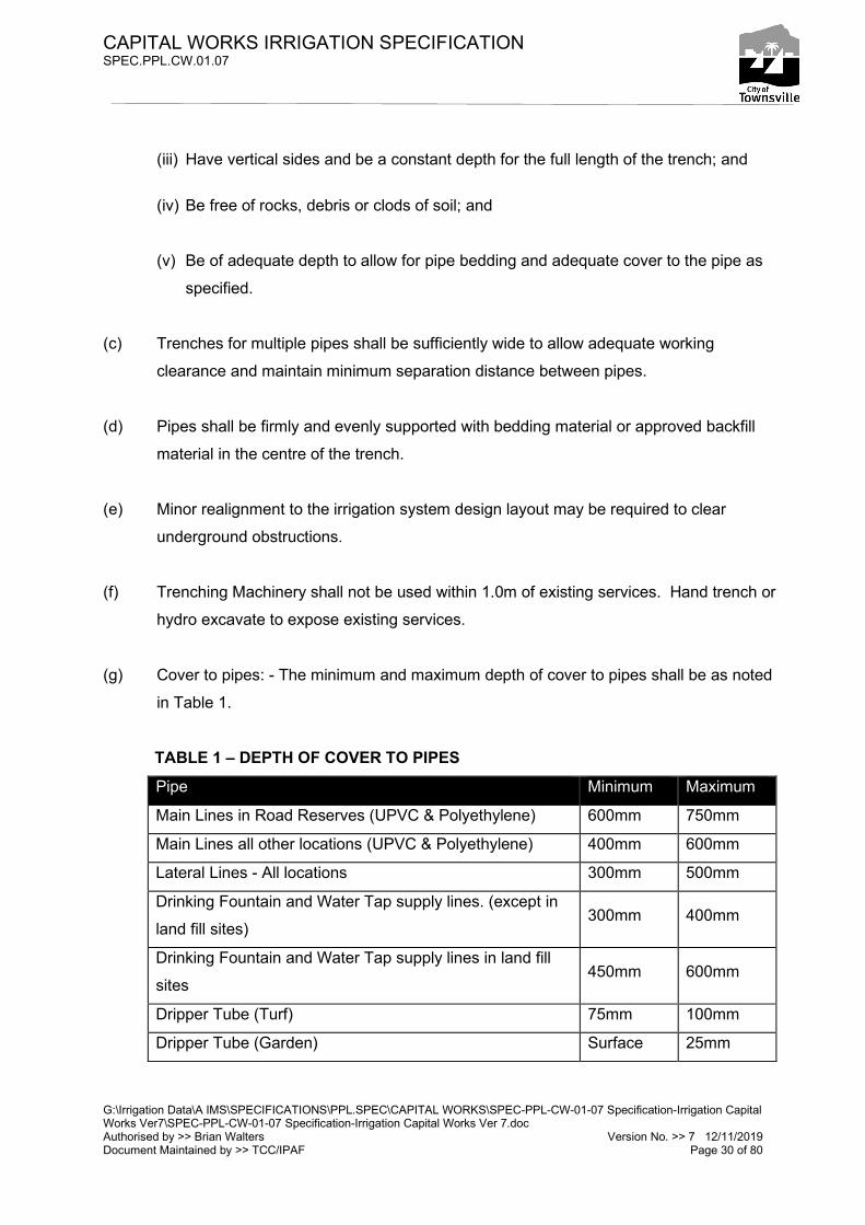
(iii) Have vertical sides and be a constant depth for the full length of the trench; and
(iv) Be free of rocks, debris or clods of soil; and
(v) Be of adequate depth to allow for pipe bedding and adequate cover to the pipe as
specified.
(c) Trenches for multiple pipes shall be sufficiently wide to allow adequate working
clearance and maintain minimum separation distance between pipes.
(d) Pipes shall be firmly and evenly supported with bedding material or approved backfill
material in the centre of the trench.
(e) Minor realignment to the irrigation system design layout may be required to clear
underground obstructions.
(f) Trenching Machinery shall not be used within 1.0m of existing services. Hand trench or
hydro excavate to expose existing services.
(g) Cover to pipes: - The minimum and maximum depth of cover to pipes shall be as noted
in Table 1.
TABLE 1 – DEPTH OF COVER TO PIPES
Pipe Minimum Maximum
Main Lines in Road Reserves (UPVC & Polyethylene) 600mm 750mm
Main Lines all other locations (UPVC & Polyethylene) 400mm 600mm
Lateral Lines - All locations 300mm 500mm
Drinking Fountain and Water Tap supply lines. (except in
land fill sites) 300mm 400mm
Drinking Fountain and Water Tap supply lines in land fill
sites 450mm 600mm
Dripper Tube (Turf) 75mm 100mm
Dripper Tube (Garden) Surface 25mm
CAPITAL WORKS IRRIGATION SPECIFICATION SPEC.PPL.CW.01.07
G:\Irrigation Data\A IMS\SPECIFICATIONS\PPL.SPEC\CAPITAL WORKS\SPEC-PPL-CW-01-07 Specification-Irrigation Capital Works Ver7\SPEC-PPL-CW-01-07 Specification-Irrigation Capital Works Ver 7.doc Authorised by >> Brian Walters Version No. >> 7 12/11/2019 Document Maintained by >> TCC/IPAF Page 31 of 80
Note: Depth of cover is defined as the distance from the top of the pipe to the finished
surface level or from the top of the pipe to the underside of pavement. Refer Appendix
18.1 for Typical Pipe Trench details.
16.10 PIPE BEDDING
(a) A minimum of 100mm sand bedding and surround is required for:-
(i) all main line pipes,
(ii) all enveloper pipe under road pavements,
(iii) all pipes laid on solid rock,
(iv) all pipes where rubble, rocks and /or debris is encountered in the trench,
(v) all potable water lines,
(vi) all electrical conduits.
(b) Bedding sand shall be clean sand with rounded grains free of any rocks, debris and
organic matter and graded such that 100% passes a 4.75mm sieve size.
(c) Pipe work, other than those listed in Clause 16.10 (a) may be laid without sand bedding,
provided the trench,
(i) is free of rubble, rocks and /or debris,
(ii) Is not a shared trench with 2 or more lateral pipes.
(d) Pipe work, other than those listed in Clause 16.10 (a) and where 2 or more lateral pipes
share a common trench containing only lateral pipe, shall be laid with a minimum 50mm
pipe separation and 50mm of sand bedding and surround.
16.11 UNDERGROUND WARNING TAPE
CAPITAL WORKS IRRIGATION SPECIFICATION SPEC.PPL.CW.01.07
G:\Irrigation Data\A IMS\SPECIFICATIONS\PPL.SPEC\CAPITAL WORKS\SPEC-PPL-CW-01-07 Specification-Irrigation Capital Works Ver7\SPEC-PPL-CW-01-07 Specification-Irrigation Capital Works Ver 7.doc Authorised by >> Brian Walters Version No. >> 7 12/11/2019 Document Maintained by >> TCC/IPAF Page 32 of 80
(a) All underground pipe work & control cable conduiting shall have irrigation underground
marker tape installed so that a warning can be given to avoid damage to the service
during subsequent excavation.
(b) Marker tape as per AS 2648.1 1995, shall be installed at approximately 50% of the
depth of cover above the service (pipe or conduit) or any additional mechanical
protection provided for the service.
(c) Irrigation marker tape text shall contain as a minimum the words “Caution” & “Irrigation”
& “Below”
(d) Irrigation marker tape for irrigation systems using potable water, ground water or
river/lake water shall be light blue coloured
(e) Irrigation marker tape for irrigation systems using recycled water shall be lilac coloured
16.12 APPROVED BACKFILL TO TRENCHES
(a) Excavated material may be used as backfill provided that the material is free of rubble,
rocks, debris, organic material and any sharp or solid objects and/or materials that may
damage the pipe over time.
(b) Where material excavated from the trench is unsuitable for backfill, clean sand & loam
shall be used as backfill.
(c) Backfill to trenches shall be compacted with a sheep’s foot roller or vibrating plate
compactor. Completed backfill is to be mounded 25mm higher than the surrounding
surface for the full length of the trench, to allow for further consolidation.
(d) Backfill to trenches under road pavements and pathways shall be crusher dust material
placed in 150mm compacted layers.
(e) On completion of backfilling operations all excess material is to be either reused on site
where possible or shall be removed from the site.
CAPITAL WORKS IRRIGATION SPECIFICATION SPEC.PPL.CW.01.07
G:\Irrigation Data\A IMS\SPECIFICATIONS\PPL.SPEC\CAPITAL WORKS\SPEC-PPL-CW-01-07 Specification-Irrigation Capital Works Ver7\SPEC-PPL-CW-01-07 Specification-Irrigation Capital Works Ver 7.doc Authorised by >> Brian Walters Version No. >> 7 12/11/2019 Document Maintained by >> TCC/IPAF Page 33 of 80
16.13 EXPOSED PIPES
(a) Any exposed pipe shall be constructed of Stainless Steel or lagged copper and shall
comply with AS3500 standards for exposed pipe.
(i) All above ground works are to Conform to Section 5.6 "Support and fixing above
ground" AS3500 Part 1.
(ii) Bracing around the pipes is to be lined with an appropriate material to prevent
damage to the pipe.
(iii) Pipes are to be labelled “potable” or "non potable" in accordance with Australian
Standards.
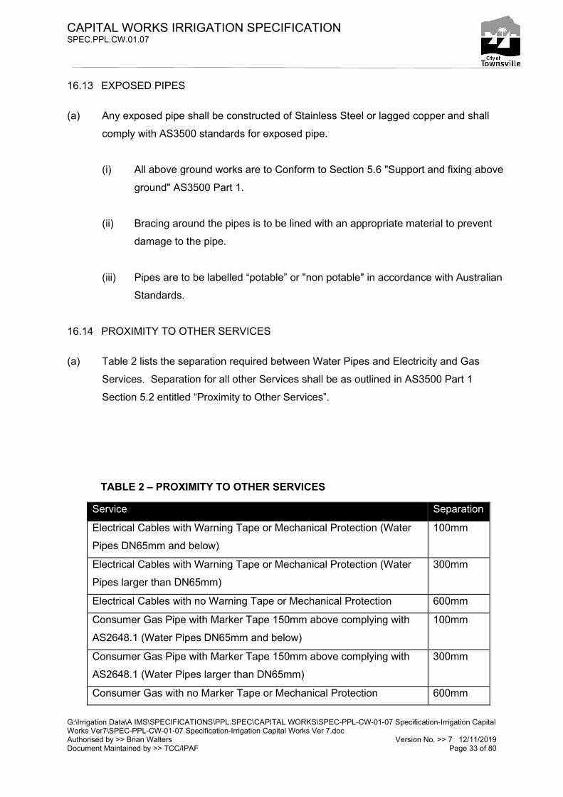
16.14 PROXIMITY TO OTHER SERVICES
(a) Table 2 lists the separation required between Water Pipes and Electricity and Gas
Services. Separation for all other Services shall be as outlined in AS3500 Part 1
Section 5.2 entitled “Proximity to Other Services”.
TABLE 2 – PROXIMITY TO OTHER SERVICES
Service Separation
Electrical Cables with Warning Tape or Mechanical Protection (Water
Pipes DN65mm and below)
100mm
Electrical Cables with Warning Tape or Mechanical Protection (Water
Pipes larger than DN65mm)
300mm
Electrical Cables with no Warning Tape or Mechanical Protection 600mm
Consumer Gas Pipe with Marker Tape 150mm above complying with
AS2648.1 (Water Pipes DN65mm and below)
100mm
Consumer Gas Pipe with Marker Tape 150mm above complying with
AS2648.1 (Water Pipes larger than DN65mm)
300mm
Consumer Gas with no Marker Tape or Mechanical Protection 600mm
CAPITAL WORKS IRRIGATION SPECIFICATION SPEC.PPL.CW.01.07
G:\Irrigation Data\A IMS\SPECIFICATIONS\PPL.SPEC\CAPITAL WORKS\SPEC-PPL-CW-01-07 Specification-Irrigation Capital Works Ver7\SPEC-PPL-CW-01-07 Specification-Irrigation Capital Works Ver 7.doc Authorised by >> Brian Walters Version No. >> 7 12/11/2019 Document Maintained by >> TCC/IPAF Page 34 of 80
17. CONTROL SYSTEM
17.1 SCOPE
(a) This section covers the furnishing of all labour, materials and services for the fabrication,
factory testing, delivery and site installation of the irrigation controller and associated
cabinets.
17.2 NETWORK REQUIREMENTS
(a) Townsville City Council operates an irrigation control system that consists of a Mottech
Irrinet Supervisory Control and Data Acquisition (SCADA) System. This system is
commonly known as the Irrigation Central Control (ICC) System and is located at the
TCC office in Wellington Street Mundingburra. The ICC System communicates to
irrigation controllers throughout the Townsville region over UHF & mobile phone wireless
telemetry communication networks.
(b) All irrigation controllers shall be operated via the ICC System unless an alternative
controller system is approved by The Superintendent
(c) Constructors are required to provide an approved irrigation controller to adequately
service the proposed irrigation system. The Controller shall be selected ensuring it has
capacity & compatibility for both;
(i) Current irrigation system requirements plus any future planned expansion and
(ii) Master valves, pulse water meters, soil moisture sensors, water level sensors,
fertigation or other additional control or monitoring equipment.
(d) Irrinet Controllers listed in Table 3 are approved irrigation controllers.
(e) All irrigation controllers must be capable of communicating with the ICC System across
the telemetry communication network. Each controller must be fitted with an approved
radio transceiver &/or modem and external antenna. The transceiver must have the
correct frequency configuration to communicate on the network.
CAPITAL WORKS IRRIGATION SPECIFICATION SPEC.PPL.CW.01.07
G:\Irrigation Data\A IMS\SPECIFICATIONS\PPL.SPEC\CAPITAL WORKS\SPEC-PPL-CW-01-07 Specification-Irrigation Capital Works Ver7\SPEC-PPL-CW-01-07 Specification-Irrigation Capital Works Ver 7.doc Authorised by >> Brian Walters Version No. >> 7 12/11/2019 Document Maintained by >> TCC/IPAF Page 35 of 80
(f) Each irrigation controller shall be allocated a network address & configuration by TCC
for communication to the ICC System.
(g) All irrigation controller system components shall operate within the ranges specified by
the manufacturer.
17.3 IRRIGATION CONTROLLER SELECTION
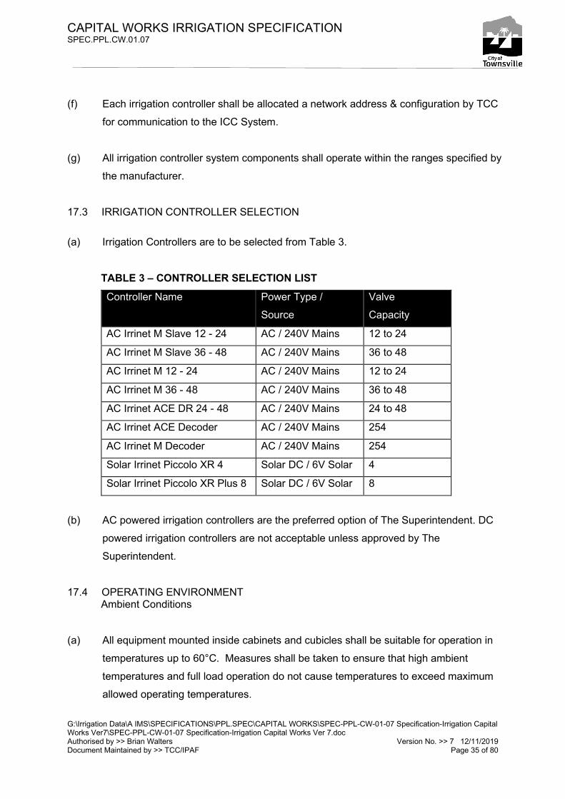
(a) Irrigation Controllers are to be selected from Table 3.
TABLE 3 – CONTROLLER SELECTION LIST Controller Name Power Type /
Source
Valve
Capacity
AC Irrinet M Slave 12 - 24 AC / 240V Mains 12 to 24
AC Irrinet M Slave 36 - 48 AC / 240V Mains 36 to 48
AC Irrinet M 12 - 24 AC / 240V Mains 12 to 24
AC Irrinet M 36 - 48 AC / 240V Mains 36 to 48
AC Irrinet ACE DR 24 - 48 AC / 240V Mains 24 to 48
AC Irrinet ACE Decoder AC / 240V Mains 254
AC Irrinet M Decoder AC / 240V Mains 254
Solar Irrinet Piccolo XR 4 Solar DC / 6V Solar 4
Solar Irrinet Piccolo XR Plus 8 Solar DC / 6V Solar 8
(b) AC powered irrigation controllers are the preferred option of The Superintendent. DC
powered irrigation controllers are not acceptable unless approved by The
Superintendent.
17.4 OPERATING ENVIRONMENT Ambient Conditions
(a) All equipment mounted inside cabinets and cubicles shall be suitable for operation in
temperatures up to 60°C. Measures shall be taken to ensure that high ambient
temperatures and full load operation do not cause temperatures to exceed maximum
allowed operating temperatures.
CAPITAL WORKS IRRIGATION SPECIFICATION SPEC.PPL.CW.01.07
G:\Irrigation Data\A IMS\SPECIFICATIONS\PPL.SPEC\CAPITAL WORKS\SPEC-PPL-CW-01-07 Specification-Irrigation Capital Works Ver7\SPEC-PPL-CW-01-07 Specification-Irrigation Capital Works Ver 7.doc Authorised by >> Brian Walters Version No. >> 7 12/11/2019 Document Maintained by >> TCC/IPAF Page 36 of 80
(b) Where cabinets are to be mounted outdoors, particular consideration shall be given to
minimise heating by direct solar radiation. Where required 304 stainless steel hoods
shall be fitted to limit direct transfer of solar heat into the cabinet.
17.5 IRRIGATION CONTROLLER SPECIFICATIONS (GENERAL)
(a) General Requirements
(i) The irrigation controller cabinet and component parts shall conform in all respects
to the highest standards of design and workmanship and appropriate
requirements of the latest applicable state or local codes.
(ii) When mounting accessories to the back panel, use fine threaded tapped screws.
(iii) The irrigation controller cabinet shall be completely wired, and assembled, with
all devices and controls installed as shown in Appendices 3.1 through 5.10 and
20.1 through 29.2 so that the entire assembly is an operating unit ready for
installation and the wiring of field devices.
(iv) Wiring shall meet the latest requirements of the AS 3000 and applicable
workplace safety codes.
(b) Wiring
(i) All wire shall be 0.5 mm²/PVC-105/ stranded, insulated for 600 V.
(ii) A ‘bootlace ferrule’ shall be used on wires connected to terminals which have
only a screw for securing the wire. Ferrules shall be properly crimped using a
professional crimping tool.
(iii) All manufacturer terminal block wiring shall be restricted to the panel side of the
blocks. The manufacturer shall connect no more than two wires to any terminal
point. The field side of the terminal blocks shall be left completely free of wires
and jumpers. Wiring on terminal blocks shall be so arranged that not more than
one wire to the field side of any terminal point will be connected with the
exception of the earth.
CAPITAL WORKS IRRIGATION SPECIFICATION SPEC.PPL.CW.01.07
G:\Irrigation Data\A IMS\SPECIFICATIONS\PPL.SPEC\CAPITAL WORKS\SPEC-PPL-CW-01-07 Specification-Irrigation Capital Works Ver7\SPEC-PPL-CW-01-07 Specification-Irrigation Capital Works Ver 7.doc Authorised by >> Brian Walters Version No. >> 7 12/11/2019 Document Maintained by >> TCC/IPAF Page 37 of 80
(iv) All multiple common connections shall be wired via bridging links on the terminal
blocks.
(v) Horizontal and vertical wiring between the terminal blocks and the devices shall
be enclosed in ducts except wiring between duct and the device may run
exposed for distances not exceeding 100 mm. Duct loading shall not exceed
75% rated fill at any point.
(vi) All exposed wiring shall be formed neatly with square corners and where
possible, grouped in packs. Each pack shall be bound with plastic cable ties and
be substantially supported throughout its full length.
(vii) Splicing of wires on electrical circuits is not acceptable.
(c) Terminal Blocks
(i) Terminal blocks shall be provided for all wiring which exits the panel. All terminal
blocks shall be DIN rail mounted and of the colour as shown in Appendices 3.1
through 5.10 and 20.1 through 29.2.
(d) Consumer Power
(i) The irrigation control cabinet shall be equipped with a (Clipsal 4CC6 or approved
equivalent) enclosed consumer panel. Consumer power shall be wired direct into
the consumer panel. The consumer panel shall enclose a neutral link and an
earth bus with the panel structure connected to the bus so as to effectively earth
the entire structure. A solder-less clamp-type terminal lug shall be provided at
the end of the earth bus for a 6 mm² stranded earth cable to be attached from the
external earth-stake.
(ii) Whenever the electrical diagrams indicate an earth for a circuit at the panel, a
single wire for each circuit earthed shall be run independently to the earth bus
and fastened thereto using a ring lug and a machine screw inserted in a tapped
hole.
CAPITAL WORKS IRRIGATION SPECIFICATION SPEC.PPL.CW.01.07
G:\Irrigation Data\A IMS\SPECIFICATIONS\PPL.SPEC\CAPITAL WORKS\SPEC-PPL-CW-01-07 Specification-Irrigation Capital Works Ver7\SPEC-PPL-CW-01-07 Specification-Irrigation Capital Works Ver 7.doc Authorised by >> Brian Walters Version No. >> 7 12/11/2019 Document Maintained by >> TCC/IPAF Page 38 of 80
(iii) Earthing of the enclosure & back panel from the consumers panel shall be made
using 4 mm² stranded earth cable.
(iv) The consumer panel shall be wired with a main isolation switch an RCD/MCB
and a suitably rated "Isatrol" mains filter unit, din-rail mounted within the
consumer panel to provide power to the GPOs. One double GPO and one single
GPO are to be mounted on the face cover of the consumer panel. Care shall be
taken when positioning the GPOs not to cover the access screw holes to the
consumer panel.
(v) Each device requiring 240 V AC power shall have an individual line plug and plug
into an allocated GPO on the consumer panel.
(vi) Power will be supplied as a single phase voltage at 50 Hz and 240 V ± 10%.
(vii) All 240V connections are to be tool proof and either housed in the consumer
panel or behind a Protective Cover.
17.6 IRRIGATION CONTROLLER SPECIFICATIONS (SPECIFIC)
(a) AC Irrinet M Slave, AC Irrinet M & AC Irrinet ACE DR.
(i) Each controller maximum valve output is listed in Table 3 including master and
fertigation control.
(ii) The controller shall have as a minimum four (4) inputs, electronic pulse water
meter, rain switch, soil sensor probe (with level 1 & level 2 sensors).
(iii) The general control voltage shall be 24 VAC for controller outputs used for water
valve operation.
(iv) The 24 VAC power is via the PELV system with common tied to earth.
(v) The irrigation controller cabinet layout, dimensions and wiring are shown in
Appendices 5.1 through 5.10 and 20.1 through 29.2.
CAPITAL WORKS IRRIGATION SPECIFICATION SPEC.PPL.CW.01.07
G:\Irrigation Data\A IMS\SPECIFICATIONS\PPL.SPEC\CAPITAL WORKS\SPEC-PPL-CW-01-07 Specification-Irrigation Capital Works Ver7\SPEC-PPL-CW-01-07 Specification-Irrigation Capital Works Ver 7.doc Authorised by >> Brian Walters Version No. >> 7 12/11/2019 Document Maintained by >> TCC/IPAF Page 39 of 80
(vi) The Irrigation controller cabinet shall be a B&R NI (NI06062/S) or (NI06063/S)
with dual key lock (NI030) or approved equivalent as shown within Appendices
5.1 through 5.10 and 20.1 through 29.2. The controller pole, mast and cross arms
shall be coated with 2PAK Epoxy Paint in Heritage Green Colour.
(vii) Control equipment shall be selected from the Preferred Equipment list -
Controller and Telemetry Components within Appendices 5.1 through 5.10 and
20.1 through 29.2, unless otherwise specified by The Superintendent.
(viii) All firmware incorporated in CPUs and other intelligent modules shall be the
latest released version.
(ix) The radio telemetry equipment involves the installation of the following
equipment:-
• TX-3600 GME Transceiver with blind front panel, programmed with TCC
irrigation frequencies; and
• YB6-61 Yagi Antenna, UNV2 mounting bracket and RG58 coax cable
terminated with a N88 N type male connector; and
• PS123 GME Power Supply or DC1224X Aeon UPS (for Irrinet M controllers);
and
• IS50NX Surge Arrestor flange mounted with N type female connectors; and
• RG58 Coax Fly Lead terminated with N88 N type and BNC113 male
connectors; and
• Data Cable connecting controller to transceiver.
(x) The transceiver shall be mounted on the door such that the indicator lights are
visible when the door to the panel is opened. The antenna cable and data cable
are to be feed from the controller via the cabinet ducting towards the door hinge
and onto the door bracket. The transceiver shall be mounted in such a way to

CAPITAL WORKS IRRIGATION SPECIFICATION SPEC.PPL.CW.01.07
G:\Irrigation Data\A IMS\SPECIFICATIONS\PPL.SPEC\CAPITAL WORKS\SPEC-PPL-CW-01-07 Specification-Irrigation Capital Works Ver7\SPEC-PPL-CW-01-07 Specification-Irrigation Capital Works Ver 7.doc Authorised by >> Brian Walters Version No. >> 7 12/11/2019 Document Maintained by >> TCC/IPAF Page 40 of 80
allow for its easy removal. The mounting bracket is to be securely fastened to the
back of the door. All cabling on the door shall be neat and fastened in place by
cable ties, Appendix 26.2, 26.4 & 5.10 refers.
(xi) A Surge Arrestor shall be mounted on the cabinet earth lug and suitably earthed
refer Appendix 27.1 & 5.10. The coax fly lead shall be connected from the
transceiver BNC connector to the “Equipment” side of the surge arrestor. The
coax cable from the antenna will enter the panel and be terminated on the
‘Antenna’ side of the surge arrestor.
(xii) Before the transceiver is powered up a qualified radio technician shall fit the
antenna coax plug and carry out a SWR / radio check and set the modulation
level.
(xiii) The ‘data cable’ shall connect the controller to the transceiver and shall be
secured and neatly run through the ducting.
(xiv) PS123 GME Power Supply 240VAC to 12 VDC is to be mounted on the door
bracket to supply power to the Transceiver and Interposing Relays refer
Appendix 5.5.
(xv) DC1224X Aeon UPS (uninterrupted power supply) 240VAC to 12 VDC is to be
mounted on the door bracket to supply power to the Irrinet CPU memory &
Transceiver, refer Appendices 20.1 through 29.2.
(xvi) A separate 24 V AC power supply shall be provided as shown within Appendices
5.1 through 5.10 and 20.1 through 29.2 :-
• AC Irrinet M, AC Irrinet M Slave & AC Irrinet ACE controllers require 1
Powertech 240V/24V 150VA Transformer part No. MP3045 to be direct
mounted to supply power to the controller and field solenoids.
(xvii) The controller shall have no less than two conduits connecting the cabinet to the
ground. The following conduit types and sizes shall be used:-
CAPITAL WORKS IRRIGATION SPECIFICATION SPEC.PPL.CW.01.07
G:\Irrigation Data\A IMS\SPECIFICATIONS\PPL.SPEC\CAPITAL WORKS\SPEC-PPL-CW-01-07 Specification-Irrigation Capital Works Ver7\SPEC-PPL-CW-01-07 Specification-Irrigation Capital Works Ver 7.doc Authorised by >> Brian Walters Version No. >> 7 12/11/2019 Document Maintained by >> TCC/IPAF Page 41 of 80
• M.D. 50mm Electrical Conduit (24V Control Cable)
• H.D. 25mm Electrical Conduit (240V Power Supply)
(xviii) An Infrared Rain Switch or approved equivalent is to be installed on the controller
pole. Construction details are given in Appendix 29.2. Configure device to
“Tropical + Rain Front Off” refer appendix 29.2.
(b) AC Irrinet ACE Decoder & AC Irrinet M Decoder System Controllers
(i) Irrinet ACE Encoder Controllers & Irrinet M Encoder Controllers are only suitable for
large or complex systems with more than 48 valves
(ii) Detail & specifications for both Controllers, associated Decoder valve equipment
and cabling are available on request to TCC.
(c) Solar Irrinet Piccolo XR
(i) Piccolo XR controller maximum valve output is listed in Table 3 including master
valve control.
(ii) The controller shall have as a minimum four (4) inputs, electronic pulse water
meter, rain switch, soil sensor probe (with level 1 & level 2 sensors)
(iii) The output control voltage used is a DC Pulse through a 2 wire circuit suitable for
activating DC latching coils used for solenoid valve operation - Hunter ICV with
DC coil option or approved equivalent. Piccolo XR output voltage is adjustable to
18V (from the factory default of 12V).
(iv) The controller assembly is powered by a 6 volt sealed lead acid battery which is
charged via a solar panel & regulating semiconductors. Refer Appendix 4.2.
(v) The irrigation controller cabinet layout, dimensions and wiring are shown in
Appendices 4.1 through 4.4.
CAPITAL WORKS IRRIGATION SPECIFICATION SPEC.PPL.CW.01.07
G:\Irrigation Data\A IMS\SPECIFICATIONS\PPL.SPEC\CAPITAL WORKS\SPEC-PPL-CW-01-07 Specification-Irrigation Capital Works Ver7\SPEC-PPL-CW-01-07 Specification-Irrigation Capital Works Ver 7.doc Authorised by >> Brian Walters Version No. >> 7 12/11/2019 Document Maintained by >> TCC/IPAF Page 42 of 80
(vi) The Irrigation controller cabinet shall be a B&R NI (NI03021/S) with single key
lock (NI030) or approved equivalent as shown within Appendices 4.1 through 4.4.
The controller pole, mast and cross arms shall be coated with 2PAK Epoxy Paint
in Heritage Green Colour.
(vii) Control equipment shall be selected from the Preferred Equipment list -
Controller and Telemetry Components within Appendices 4.5, unless otherwise
specified by The Superintendent.
(viii) All firmware incorporated in CPUs and other intelligent modules shall be the
latest released version.
(ix) The radio telemetry equipment involves the installation of the following
equipment:-
• Qty 1, CD51 Whip Antenna (cut to wave length) as per appendix 4.4 with .5M
of RG58 coax cable terminated by a SMA type male connector or
• Qty 1, CD93 whip antenna as per appendix 4.6, with 3.5M of RG58 coax cable
terminated by a SMA type male connector; and
• Qty 1, Antenna Mounting Bracket as appendix 4.4 or 4.6 respectively
(x) The radio telemetry component is integrated within the XR Controller unit. So no
external transceiver is required.
(xi) The antenna coax SMA male plug shall be connected into the XR Controller SMA
socket mounted on the top of the unit.
(xii) Before the XR Controller is powered up a qualified radio technician shall fit the
antenna coax plug and carry out a SWR / radio check on site.
(xiii) A Kyocera Mini Module Solar Panel as detailed in Appendix 4.5 shall be fastened
to the top of the enclosure refer Appendix 4.3. An external grade silicon base
sealant shall be applied to the solar panel perimeter to maintain the enclosure IP
rating.

CAPITAL WORKS IRRIGATION SPECIFICATION SPEC.PPL.CW.01.07
G:\Irrigation Data\A IMS\SPECIFICATIONS\PPL.SPEC\CAPITAL WORKS\SPEC-PPL-CW-01-07 Specification-Irrigation Capital Works Ver7\SPEC-PPL-CW-01-07 Specification-Irrigation Capital Works Ver 7.doc Authorised by >> Brian Walters Version No. >> 7 12/11/2019 Document Maintained by >> TCC/IPAF Page 43 of 80
(xiv) The regulator components shall be installed as detailed in Appendix 4.2 and
tested by an electronics technician prior to final connection of the battery & XR
units.
(xv) A 6V 12 AH SLA Battery is placed inside on the bottom of the enclosure and
connected to the terminal blocks. Refer Appendix 4.1 & 4.2.
(xvi) The controller shall have one 25mm conduit connecting the cabinet to the first
electrical pit.
(d) Solar Irrinet Piccolo XR Plus
(i) XR Plus controller maximum valve output is listed in Table 3 including master valve
control.
(ii) The controller shall have as a minimum four (4) inputs, electronic pulse water meter,
rain switch, soil sensor probe (with level 1 & level 2 sensors)
(iii) The output control voltage used is a DC Pulse through a 2 wire circuit suitable for
activating DC latching coils used for solenoid valve operation - Hunter ICV with
DC Coil option or approved equivalent. Piccolo XR Plus output voltage is
adjustable to 18V (from the factory default of 12V).
(iv) The controller assembly is powered by a 6 volt sealed lead acid battery which is
charged via a solar panel & regulating semiconductors. Refer Appendix 3.2.
(v) The irrigation controller cabinet layout, dimensions and wiring are shown in
Appendices 3.1 through 3.4.
(vi) The Irrigation controller cabinet shall be a B&R NI (NI03021/S) with single key lock
(NI030) or approved equivalent as shown within Appendices 3.1 through 3.4. The
controller pole, mast and cross arms shall be coated with 2PAK Epoxy Paint in
Heritage Green Colour.

CAPITAL WORKS IRRIGATION SPECIFICATION SPEC.PPL.CW.01.07
G:\Irrigation Data\A IMS\SPECIFICATIONS\PPL.SPEC\CAPITAL WORKS\SPEC-PPL-CW-01-07 Specification-Irrigation Capital Works Ver7\SPEC-PPL-CW-01-07 Specification-Irrigation Capital Works Ver 7.doc Authorised by >> Brian Walters Version No. >> 7 12/11/2019 Document Maintained by >> TCC/IPAF Page 44 of 80
(vii) Control equipment shall be selected from the Preferred Equipment list - Controller
and Telemetry Components within Appendices 3.5, unless otherwise specified by
The Superintendent.
(viii) All firmware incorporated in CPUs and other intelligent modules shall be the latest
released version.
(ix) The radio telemetry equipment involves the installation of the following equipment:-
• Qty 1, CD51 Whip Antenna (cut to wave length) as per appendix 3.4 with .5M
of RG58 coax cable terminated by a SMA type male connector or
• Qty 1, CD93 whip antenna as per appendix 3.6, with 3.5M of RG58 coax cable
terminated by a SMA type male connector; and
• Qty 1, Antenna Mounting Bracket as appendix 3.4 or 3.6 respectively
(x) The radio telemetry component is integrated within the XR Plus Controller unit. So
no external transceiver is required.
(xi) The antenna coax SMA male plug shall be connected into the XR Plus Controller
SMA socket mounted on the top of the unit.
(xii) Before the XR Plus Controller is powered up a qualified radio technician shall fit the
antenna coax plug and carry out a SWR / radio check on site.
(xiii) A Kyocera Mini Module Solar Panel as detailed in Appendix 3.5 shall be fastened
to the top of the enclosure refer Appendix 3.3. An external grade silicon base
sealant shall be applied to the solar panel perimeter to maintain the enclosure IP
rating.
(xiv) The regulator components shall be installed as detailed in Appendix 3.2 and
tested by an electronics technician prior to final connection of the battery & XR
units.
CAPITAL WORKS IRRIGATION SPECIFICATION SPEC.PPL.CW.01.07
G:\Irrigation Data\A IMS\SPECIFICATIONS\PPL.SPEC\CAPITAL WORKS\SPEC-PPL-CW-01-07 Specification-Irrigation Capital Works Ver7\SPEC-PPL-CW-01-07 Specification-Irrigation Capital Works Ver 7.doc Authorised by >> Brian Walters Version No. >> 7 12/11/2019 Document Maintained by >> TCC/IPAF Page 45 of 80
(xv) A 6V 12 AH SLA Battery is placed inside on the bottom of the enclosure and
connected to the terminal blocks. Refer Appendix 3.1 & 3.2.
(xvi) The controller shall have one 32mm conduit connecting the cabinet to the first
electrical pit.
17.7 CONTROLLER LOCATION
(a) The final location of the controller shall be determined by taking into consideration all of
the following factors:-
(i) Radio Path Tests (to be carried out by a qualified radio technician) to ensure
reliable communications from the site controller to the ICC network.
(ii) The location shall be clear of large trees or structures that may interfere with the
performance of radio communications, or solar panel. In newly planted areas the
location shall make allowance for future tree growth.
(iii) Safe 24 hour access for maintenance by TCC personnel and equipment.
(iv) The location shall allow access by Motor Vehicle and Elevated Platform (Antenna
Servicing).
(v) The Controller shall not be installed less than 3 metres from a roadway unless
approved by The Superintendent.
17.8 CABINET INSTALLATION
The pre-assembled Controllers shall be installed in the ground as follows:-
(a) The pre-assembled Controller cabinet support post shall be embedded in a 200mm
diameter x 600mm deep hole with a 400mm deep concrete footing (N25 concrete
minimum). The concrete shall be poured up to the underside of the conduits entering
the support post. Covering the conduits in concrete is not acceptable. The Cabinet
CAPITAL WORKS IRRIGATION SPECIFICATION SPEC.PPL.CW.01.07
G:\Irrigation Data\A IMS\SPECIFICATIONS\PPL.SPEC\CAPITAL WORKS\SPEC-PPL-CW-01-07 Specification-Irrigation Capital Works Ver7\SPEC-PPL-CW-01-07 Specification-Irrigation Capital Works Ver 7.doc Authorised by >> Brian Walters Version No. >> 7 12/11/2019 Document Maintained by >> TCC/IPAF Page 46 of 80
shall be installed at a height of 1200mm from the finished ground level to the underside
of the cabinet (1090mm for XR controllers Refer Appendix 4.4).
(b) XR & XR Plus Controller Cabinets are to be orientated with the door side facing north to
maximize the absorption of solar radiation into the solar panel, unless approved by The
Superintendent.
17.9 CONTROLLER CABINET AND CONTROLLER WIRING
(a) All conduits shall be terminated at the controller cabinet with a suitable conduit adaptor.
All conduits shall be sealed with an external grade Butyl Mastic sealant, such as
“Selleys Butyl Mastic” or similar approved to a depth of 25mm into the conduit to prevent
vermin entering the controller cabinet.
(b) Earth stakes shall be located in the electrical pit adjacent the controller. The location of
the earth stake is to be indicated on the As Constructed drawing.
(c) Earth stake connections are to be sealed with cold gal paint.
(d) All field wired cables entering the controller cabinet shall be made secured – in this
instance only by the application of sealant to the conduit end inside the enclosure,
Clause 17.9 (a) refers. From this point on, the double insulation shall be removed from
the cable for ease of wiring to the terminal blocks.
(e) All single insulated cables inside control cabinets shall be loomed together and cable
tied in a neat orderly manner to the panel so that the connections into the terminal strip
are not stressed.
(f) All cables inside the controller cabinet shall be of sufficient length to ensure that all
cores will reach their termination point without any stress or joining of cables.
(g) All field cables inside the controller cabinet shall be of sufficient length to ensure that all
cores will reach the upper & lower most termination points without any stress or joining
of cables.

CAPITAL WORKS IRRIGATION SPECIFICATION SPEC.PPL.CW.01.07
G:\Irrigation Data\A IMS\SPECIFICATIONS\PPL.SPEC\CAPITAL WORKS\SPEC-PPL-CW-01-07 Specification-Irrigation Capital Works Ver7\SPEC-PPL-CW-01-07 Specification-Irrigation Capital Works Ver 7.doc Authorised by >> Brian Walters Version No. >> 7 12/11/2019 Document Maintained by >> TCC/IPAF Page 47 of 80
(h) All cables to be connected within the controller cabinet shall be terminated with a
bootlace ferrule, CABOC BLP 150 or similar approved. Pin lugs are not acceptable.
18. FIELD ELECTRICAL WIRING
18.1 CABLE TYPES
(a) All electrical cabling shall conform to current Australian Standards.
(b) All Cables shall be Tyflo multi-core Irrigation Cables or similar approved with a minimum
core size of 1.5 mm. Table 3 details Cable Specification.
TABLE 4 – MULTICORE CABLE SPECIFICATIONS
(c) All cables shall have an outer sheath of flexible 75°C PVC to AS3808 : 1998, over an
Inner core of a sheath of HDPE, over a multi-strand plain copper wire.
(d) Inner cores are to be readily available in 13 colours namely- Black, Blue, Green, Dark
Brown, Brown, Grey, Light Blue, Orange, Pink, Red, Violet, White and Yellow.
18.2 CABLE INSTALLATION
(a) Hydrometer Cabling - A 5 core cable shall be run continuously from the controller to the
water meter assembly solely for the operation of Master Valve & Pulse Meter. The black
core shall be common, red core shall be Master Valve control and the blue and white
shall be Pulse Meter & Pulse Meter common respectively.
(b) Lateral Valve Solenoid Cabling - An additional 20% of the total number of cables or 2
extra cores (whichever is the greater) shall be provided as spares. Designated spares
shall run from the controller to the furthest most point from the controller in the cable run.
The spares are to be marked at the controller. At the furthest point all spares shall be
Nominal
Core Dia.
Conductor
No. & Size
Amp
Rating
Resistance
Ohms/Km
Number of
Cores
1.5 mm 7/0.50 16 13.6 3,5,7,9,13
2.5 mm 7/0.67 23 7.4 2,7
4 mm 7/0.85 30 4.6 2

CAPITAL WORKS IRRIGATION SPECIFICATION SPEC.PPL.CW.01.07
G:\Irrigation Data\A IMS\SPECIFICATIONS\PPL.SPEC\CAPITAL WORKS\SPEC-PPL-CW-01-07 Specification-Irrigation Capital Works Ver7\SPEC-PPL-CW-01-07 Specification-Irrigation Capital Works Ver 7.doc Authorised by >> Brian Walters Version No. >> 7 12/11/2019 Document Maintained by >> TCC/IPAF Page 48 of 80
connected together and sealed with heat shrink so that a continuity test can be
performed at the controller to confirm the total number of spares.
(c) All extra low voltage cables shall be installed inside a conduit. The conduit size used
shall be a minimum size of 50mm or 2.5 times the combined size of all the cables being
installed, whichever is the greater.
(d) The single insulation on the cable core shall not be cut or damaged when the outer
sheath (double insulation) is removed. All cables shall have the insulation removed from
the cores using appropriate cable strippers. Use of a knife or other sharp blade is not
acceptable.
(e) Cables shall be continuous between electrical inspection pits. Cable joints located
between electrical inspection pits are not acceptable. Cable joints shall be kept to a
minimum and shall only occur at valve take off points.
(f) Where required individual cable cores shall be joined using appropriately sized insulated
crimp links installed with a professional ratchet type crimping tool. To maintain a double
layer of insulation at the joint, ES-2 heat shrink shall be installed over the insulated
crimp link & cable core.
(g) Bare conductors shall not be exposed.
(h) Each individual cable core joint shall be waterproofed by using ES-2 resign filled heat
shrink 3 times the length of the insulated crimp link.
(i) All cut unused cables (spares) shall be sealed using ES-2 resign filled heat shrink.
(j) Cable markers shall be attached to each cable at every electrical inspection pit
indicating the individual cable number as shown on the design plan; refer Clause 7.1
and Appendix 7.2. Cable markers shall be round 38mm diameter aluminium
identification tags or approved similar & commercially available. Numbering shall be
clearly stamped onto one side of the tag using a punch set with 13mm high numerals.
Tags shall be fastened to the appropriate cable using a quality grade plastic cable tie
attached at the mid point of the cable loop.
CAPITAL WORKS IRRIGATION SPECIFICATION SPEC.PPL.CW.01.07
G:\Irrigation Data\A IMS\SPECIFICATIONS\PPL.SPEC\CAPITAL WORKS\SPEC-PPL-CW-01-07 Specification-Irrigation Capital Works Ver7\SPEC-PPL-CW-01-07 Specification-Irrigation Capital Works Ver 7.doc Authorised by >> Brian Walters Version No. >> 7 12/11/2019 Document Maintained by >> TCC/IPAF Page 49 of 80
(k) The Black cable shall be used as the designated common.
(l) All spare cable in electrical inspection pits shall be left full length, individually sealed with
heat shrink and grouped together.
(m) All continuous cable that passes through an electrical inspection pit shall have a loop of
no less than 2m in length and be neatly coiled and tied.
(n) A draw wire is to be left in the conduit from the controller cabinet to the first electrical
inspection pit.
(o) All electrical cable locations shall be recorded on the as constructed drawings.
18.3 ELECTRICAL INSPECTION PITS
(a) Electrical Inspection Pits shall be Heavy Duty rectangular with rounded ends and fitted
with a precast concrete lid, type P1 or P2.
(b) The first electrical inspection pit shall be located a maximum of 1 metre from the
Controller cabinet support base. A draw rope together with the electrical cables is to be
installed in the conduits from the controller to the first electrical pit to allow for future
works.
(c) Electrical Inspection Pits shall be located adjacent to valve boxes and offset from the
main irrigation line a maximum of 200mm as shown in Appendix 17.1 & 17.2.
(d) Electrical Inspection Pits shall be located at changes in direction and no more than 50
metres spacing.
(e) Electrical Inspection Pits shall be installed so that the top of the pit is flush with the
finished surface level and matches the slope of the finished surface level.
(f) All electrical inspection pit locations shall be recorded on the as constructed drawings.
CAPITAL WORKS IRRIGATION SPECIFICATION SPEC.PPL.CW.01.07
G:\Irrigation Data\A IMS\SPECIFICATIONS\PPL.SPEC\CAPITAL WORKS\SPEC-PPL-CW-01-07 Specification-Irrigation Capital Works Ver7\SPEC-PPL-CW-01-07 Specification-Irrigation Capital Works Ver 7.doc Authorised by >> Brian Walters Version No. >> 7 12/11/2019 Document Maintained by >> TCC/IPAF Page 50 of 80
(g) All conduits shall enter at the end of an electrical pit. Side entry of conduits into electrical
pits in not permitted.
(h) All conduits shall enter an electrical pit at no greater than 45 Degrees of the horizontal
centre.
(i) Electrical pits shall not be installed in drainage swales or places where water is collected
during rainfall and irrigation.
(j) Electrical Pits shall not be installed less than 3 metres from the road kerb, unless
approved by The Superintendent.
18.4 ELECTRICAL CONDUITS
(a) All electrical conduit shall conform to current Australian Standards.
(b) All conduit (extra low voltage electrical) buried in ground shall be white M.D.
(c) All electrical conduits that are exposed above ground shall have a protective outer
sheath of polyethylene pipe rating PN12.5. The sheath is to encase the conduit for the
entire length of conduit above ground and for a depth of 150mm minimum below ground.
(d) All electrical conduits that are exposed above ground shall be fixed in place so that they
are vertical and shall be secured firmly to the accessory.
(e) Electrical Conduit above ground shall be adequately secured to avoid damage by grass
cutting operations.
(f) All electrical conduit ends shall be neatly cut and free of burrs or rough edges.
(g) The final 1m of conduit entering an electrical pit shall be M.D. corrugated flexible conduit
which is to be connected to the M.D. PVC Conduit by a Socket, refer Appendix 17.1 &
17.2 for typical construction drawing.
18.5 ELECTRICAL CONDUIT TRENCHING
CAPITAL WORKS IRRIGATION SPECIFICATION SPEC.PPL.CW.01.07
G:\Irrigation Data\A IMS\SPECIFICATIONS\PPL.SPEC\CAPITAL WORKS\SPEC-PPL-CW-01-07 Specification-Irrigation Capital Works Ver7\SPEC-PPL-CW-01-07 Specification-Irrigation Capital Works Ver 7.doc Authorised by >> Brian Walters Version No. >> 7 12/11/2019 Document Maintained by >> TCC/IPAF Page 51 of 80
(a) All electrical conduits shall be laid in trenches and bedded in sand.
(b) Low voltage conduits (240v) shall be installed with continuous electrical warning tape
above the conduit for the entire length of the trench.
(c) Low voltage conduit (240v) shall not be installed in the same trench as irrigation lines.
(d) Extra low voltage conduits (24v) installed in the same trench as irrigation lines shall be
bedded in sand and separated from the irrigation lines by a minimum distance of
100mm.
(e) Depth of Cover to Electrical Conduits from finished surface level or from the underside
of finished pavement level (e.g. pavers or concrete) shall be:-
(i) 300mm minimum - for extra low voltage cables (24v).
(ii) 600mm minimum - for low voltage cables (240v). Refer Appendix 18.1.
(f) Electrical Conduits under roadways shall be a minimum 50mm M.D. Electrical Conduit
encased in a 100mm PN9 PVC enveloper Pipe.
19. WATER METER ASSEMBLY
19.1 DESIGN AND INSTALLATION
Water meter assembly components:
(a) Water Meter Assembly for drinking fountains and taps (potable water):-
(i) POS (point of supply), copper pipe,
(ii) Isolation valve,
(iii) Mechanical water meter.
(b) For irrigation water meter assembly options refer Appendix 10.1 - 10.6

CAPITAL WORKS IRRIGATION SPECIFICATION SPEC.PPL.CW.01.07
G:\Irrigation Data\A IMS\SPECIFICATIONS\PPL.SPEC\CAPITAL WORKS\SPEC-PPL-CW-01-07 Specification-Irrigation Capital Works Ver7\SPEC-PPL-CW-01-07 Specification-Irrigation Capital Works Ver 7.doc Authorised by >> Brian Walters Version No. >> 7 12/11/2019 Document Maintained by >> TCC/IPAF Page 52 of 80
TABLE 5 - ALLOWABLE WATER METER ASSEMBLY COMPONENT SIZE COMBINATIONS Water
Service
T’ville Water
Water Meter
Irrigation
Water Meter
Backflow Master Valve
25mm 25mm
32mm Arad
Multijet
(1 pulse/10L)
25mm 25mm Hunter
ICV*
32mm 32mm
32mm Arad
Multijet
(1 pulse/10L)
32mm 25mm or 40mm
Hunter ICV*
50mm 50mm
Include in
Master Valve
(1 pulse/10L)
50mm 50mm Arad
Hydrometer
50mm 50mm
Honeywell
H5000
(1 pulse/10L)
50mm 50mm Dorot 100
Series
80mm 80mm
Include in
Master Valve
(1 pulse/10L)
80mm 80mm Arad
Hydrometer
80mm 80mm
Honeywell
H5000
(1 pulse/10L)
80mm 50mm Dorot 100
Series
100mm 100mm
Include in
Master Valve
(1 pulse/100L)
100mm 100mm Arad
Hydrometer
100mm 100mm
Honeywell
H5000
(1 pulse/10L)
100mm 50mm Dorot 100
Series
*External Master Valve
(c) All Water Meter Assemblies with a 25mm and 32mm Water Service are to have a
master valve external to the main assembly. Refer Appendix 10.3 & 10.4.
CAPITAL WORKS IRRIGATION SPECIFICATION SPEC.PPL.CW.01.07
G:\Irrigation Data\A IMS\SPECIFICATIONS\PPL.SPEC\CAPITAL WORKS\SPEC-PPL-CW-01-07 Specification-Irrigation Capital Works Ver7\SPEC-PPL-CW-01-07 Specification-Irrigation Capital Works Ver 7.doc Authorised by >> Brian Walters Version No. >> 7 12/11/2019 Document Maintained by >> TCC/IPAF Page 53 of 80
(d) Water Meter Assemblies with a Water Service sized, 50mm, 80mm and 100mm are to
have a master valve as part of the main assembly. Refer Appendix 10.1, 10.2, 10.6 &
10.7.
19.2 WATER METERS
(a) All water meters and pipe work from the town mains to the water meter shall be supplied
and fitted by Townsville Water (A business unit of the Townsville City Council).
(b) The water meter type is selected by the following criteria:-
(i) For Drinking Fountains and Water taps a standard mechanical Water Meters
shall be used.
(ii) For irrigation refer to table 5 for water meter selection relative to the water service
size.
19.3 MASTER VALVES
(a) All irrigation systems shall be fitted with a Master Valve.
(b) The master valve is to be selected by the following criteria:-
(i) All Water Service Assemblies sized 25mm and 32mm shall have an external
master valve installed in a valve box and shall be fitted to the copper tail pipe of
the Backflow device. Refer Appendix 10.3 & 10.4. for installation details.
(ii) All Water Service Assemblies sized, 50mm, 80mm and 100mm shall be fitted
with an assembly mounted Master Valve. The Master Valve as detailed in Table
5 is to consist of either; flange mounted Arad Hydrometer including water (flow)
meter module c/w 24VAC solenoid actuator, or flange mounted Dorot 100 Series
valve c/w 24VAC solenoid actuator, or approved equivalent. Refer Appendix
10.1, 10.2, 10.5, 10.6 & 10.7 for installation details.
CAPITAL WORKS IRRIGATION SPECIFICATION SPEC.PPL.CW.01.07
G:\Irrigation Data\A IMS\SPECIFICATIONS\PPL.SPEC\CAPITAL WORKS\SPEC-PPL-CW-01-07 Specification-Irrigation Capital Works Ver7\SPEC-PPL-CW-01-07 Specification-Irrigation Capital Works Ver 7.doc Authorised by >> Brian Walters Version No. >> 7 12/11/2019 Document Maintained by >> TCC/IPAF Page 54 of 80
19.4 BACKFLOW DEVICES DESIGN AND INSTALLATION
(a) Backflow prevention is to conform to Australian standards AS 2845.1, AS2845.2 and
AS2845.3. Clause 11 refers.
(b) The Backflow device shall be selected on the required size:-
(i) 25mm, 32mm, and 50mm - ValvCheQ System DC03, RP03 or approved similar
to the following specification. The assembly shall be connected with the “ring &
tail” to allow easy removal or replacement of the device in accordance with
AS3500. Main valve and internals shall be of stainless steel construction and to
have pressure rating of 1600 kPa and a temperature rating of 90°C. All internal
parts and elastomers are to be accessible through a top entry point of the main
valve to allow inline maintenance. Valve shall also be fitted with test points with
BSPT threads to allow testing to AS2845.3:2010.
(ii) 80mm and 100mm - ValvCheQ Backflow System RP03 or approved similar to the
following specification. The main valve shall be constructed from ductile iron and
coated with Rilsan Nylon 11 to AS 4158:2003. All internals shall be constructed
from stainless steel and to have pressure rating of 1600 kPa and a temperature
rating of 60°C. Main valve body shall not form part of the wetted check valve
sealing area or mechanism. All internal parts and elastomers are to be
accessible through a top entry point of the main valve to allow inline
maintenance. Valve connection shall be flanged table C to AS4087. Valve shall
also be fitted with test points with BSPT threads to allow testing to
AS2845.3:2010.
(c) The velocity through the Backflow device shall not exceed 2.2 m/s.
(d) All Backflow devices shall be Double Check Valve (DCV) or Reduced Pressure Zone
(RPZ) rating.
19.5 ISOLATION VALVES
(a) All isolation valves fitted to the Water Service Assembly shall be tested and approved to
Australian Standards.
CAPITAL WORKS IRRIGATION SPECIFICATION SPEC.PPL.CW.01.07
G:\Irrigation Data\A IMS\SPECIFICATIONS\PPL.SPEC\CAPITAL WORKS\SPEC-PPL-CW-01-07 Specification-Irrigation Capital Works Ver7\SPEC-PPL-CW-01-07 Specification-Irrigation Capital Works Ver 7.doc Authorised by >> Brian Walters Version No. >> 7 12/11/2019 Document Maintained by >> TCC/IPAF Page 55 of 80
(b) All isolation valves fitted to the Water Service Assembly shall be selected on the
following criteria:-
(i) All Water Meter Assemblies sized 25mm, 32mm and 50mm shall be fitted with
Brass Ball Valves.
(ii) All Water Meter Assemblies sized 80mm and 100mm shall be fitted with Resilient
Seated Gate Valves.
19.6 STRAINER
(a) All Water Meter Assemblies shall be fitted with a brass strainer immediately downstream
of the isolation valve and upstream of the back flow prevention device. Refer Appendix
10.1 to 10.7 for details.
19.7 WATER METER ASSEMBLY INSTALLATION
(a) The water meter assembly shall be supported by the appropriate size Support Stands as
detailed in Appendix 10.5 and set into a concrete footing as detailed in Appendix 10.1 to
10.7. A minimum distance of 300mm from the underside of the back flow prevention
assembly to the finished ground level is required.
(b) A lockable stainless steel sheet metal cover shall be fitted over the water meter and
master valve to prevent vandalism and weather damage. Water meter assembly covers
shall be built from 316 Stainless Steel as detailed in Appendix 31.1 & 31.4.
(i) For Water Meter Assemblies sized 25mm, 32mm, the cover shall be held in place
using U-bolts.
(ii) For Water Meter Assemblies sized 50mm, 80mm and 100mm the cover shall be
fastened between each set of tightened flanges, using flange bolts.
(c) Each cover shall be locked using a standard Council type “A” series keyed pad lock.
CAPITAL WORKS IRRIGATION SPECIFICATION SPEC.PPL.CW.01.07
G:\Irrigation Data\A IMS\SPECIFICATIONS\PPL.SPEC\CAPITAL WORKS\SPEC-PPL-CW-01-07 Specification-Irrigation Capital Works Ver7\SPEC-PPL-CW-01-07 Specification-Irrigation Capital Works Ver 7.doc Authorised by >> Brian Walters Version No. >> 7 12/11/2019 Document Maintained by >> TCC/IPAF Page 56 of 80
(d) Stainless steel covers shall be manufactured to ensure “A” series locks can freely rotate
allowing easy access for unlocking/locking and opening/closing of lid.
(e) A minimum of two (2) recycled plastic bollards shall be provided at each water meter
assembly as directed by The Superintendent, to protect the assembly from vehicle
damage except in garden beds.
(i) Bollards shall be nominal 100mm diameter blue recycled plastic, embedded
450mm minimum into a 350 diameter concrete footing. The top of the bollards
shall be 900mm above finished ground level.
(f) All cables & conduit running from the water meter to the ground shall be encased in a
protective outer polyethylene PE100 PN12.5 rated pipe to provide mechanical protection
from grass cutting operations. The mechanical protection shall be installed vertical to
the ground, with top 100mm above lowest part of the stainless steel cover & bottom
300mm section installed below ground.
(g) Copper Pipes shall be Type B.
(h) All fittings to the Backflow device shall be either copper of brass. PVC or Poly fittings are
not acceptable.
20. VALVE ASSEMBLY
20.1 SOLENOID VALVE ASSEMBLIES
(a) Refer standard drawing Appendix 11.1 – 11.7B, 14.3 & 14.5 - 14.6 for solenoid valve
assembly details
(b) Solenoid Valves assemblies shall be connected to the irrigation main line pipe via a PVC
or Poly tee. Tapping band connections are not acceptable
(c) Ball valve shall be tested and approved to AS 3500 2018 and installed on the upstream
side of the Solenoid valve. A brass barrel union shall separate the Ball valve from the
Solenoid valve to allow for ease of maintenance.
(d) Solenoid valves used shall be sized in accordance with Table 6.
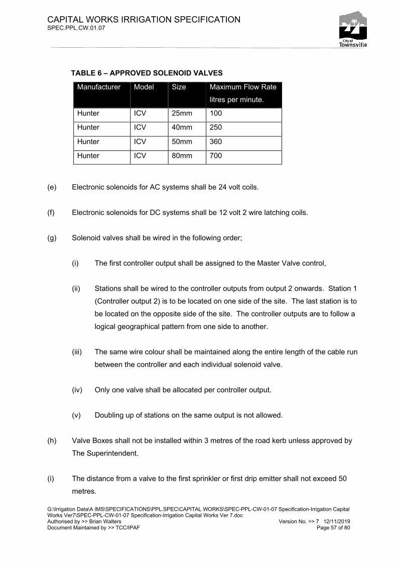
CAPITAL WORKS IRRIGATION SPECIFICATION SPEC.PPL.CW.01.07
G:\Irrigation Data\A IMS\SPECIFICATIONS\PPL.SPEC\CAPITAL WORKS\SPEC-PPL-CW-01-07 Specification-Irrigation Capital Works Ver7\SPEC-PPL-CW-01-07 Specification-Irrigation Capital Works Ver 7.doc Authorised by >> Brian Walters Version No. >> 7 12/11/2019 Document Maintained by >> TCC/IPAF Page 57 of 80
TABLE 6 – APPROVED SOLENOID VALVES
(e) Electronic solenoids for AC systems shall be 24 volt coils.
(f) Electronic solenoids for DC systems shall be 12 volt 2 wire latching coils.
(g) Solenoid valves shall be wired in the following order;
(i) The first controller output shall be assigned to the Master Valve control,
(ii) Stations shall be wired to the controller outputs from output 2 onwards. Station 1
(Controller output 2) is to be located on one side of the site. The last station is to
be located on the opposite side of the site. The controller outputs are to follow a
logical geographical pattern from one side to another.
(iii) The same wire colour shall be maintained along the entire length of the cable run
between the controller and each individual solenoid valve.
(iv) Only one valve shall be allocated per controller output.
(v) Doubling up of stations on the same output is not allowed.
(h) Valve Boxes shall not be installed within 3 metres of the road kerb unless approved by
The Superintendent.
(i) The distance from a valve to the first sprinkler or first drip emitter shall not exceed 50
metres.
Manufacturer Model Size Maximum Flow Rate
litres per minute.
Hunter ICV 25mm 100
Hunter ICV 40mm 250
Hunter ICV 50mm 360
Hunter ICV 80mm 700

CAPITAL WORKS IRRIGATION SPECIFICATION SPEC.PPL.CW.01.07
G:\Irrigation Data\A IMS\SPECIFICATIONS\PPL.SPEC\CAPITAL WORKS\SPEC-PPL-CW-01-07 Specification-Irrigation Capital Works Ver7\SPEC-PPL-CW-01-07 Specification-Irrigation Capital Works Ver 7.doc Authorised by >> Brian Walters Version No. >> 7 12/11/2019 Document Maintained by >> TCC/IPAF Page 58 of 80
20.2 SOLENOID VALVE BOXES
(a) The Valve assembly is to be housed in a Super Heavy-Duty “Hydrant” type lockable
valve box assembly, with steel plate & clip down lock built into the lid.
(b) Valve boxes shall be HR manufactured product or similar approved.
(c) Valve boxes used are to be of adequate size to ensure that there is sufficient space
around the valve assembly to allow for ease of maintenance.
(d) Valve boxes shall not require removal to facilitate maintenance of the valve assembly.
(e) All valve boxes shall be:-
(i) Supported on bricks so that the box does not rest on any pipes; and
(ii) Installed so that the top of the box is flush with the finished turf surface level for
turf areas, or between 50mm to 100mm above the finished mulch surface level
for garden areas; and
(iii) Installed so that the clearance from the underside of the valve box lid to the top of
the stem of the solenoid valve is 100mm maximum – 45mm, refer Appendix 11.1
– 11.7B, 14.3 & 14.5 - 14.6; and
(iv) Installed so that the clearance from the underside of the solenoid valve to the
bottom of the box assembly is at least equal to or greater than 50mm; and
(v) The pipe holes shall be sealed with Geofabric around the openings to prevent the
ingress of foreign material in the valve box; and
(vi) Cutting of valve boxes for entry/exit of pipe work shall be keep to a minimum,
boxes shall not be cut higher than 1/3 its height. Over cut boxes are not
acceptable; and
CAPITAL WORKS IRRIGATION SPECIFICATION SPEC.PPL.CW.01.07
G:\Irrigation Data\A IMS\SPECIFICATIONS\PPL.SPEC\CAPITAL WORKS\SPEC-PPL-CW-01-07 Specification-Irrigation Capital Works Ver7\SPEC-PPL-CW-01-07 Specification-Irrigation Capital Works Ver 7.doc Authorised by >> Brian Walters Version No. >> 7 12/11/2019 Document Maintained by >> TCC/IPAF Page 59 of 80
(vii) Installed in association with its housed components so as not to require
excessive cutting of the valve box to the satisfaction of The Superintendent.
(f) All valve box lids shall be clearly marked with the identification of the contents using the
follow key:-
• IV = Isolation Valve
• AV = Air Valve
• FV = Flush Valve
• MV = Master Valve
• QCV = Quick Coupling Valve
• CLV = Cam Lock Valve
Lateral valve box lids shall be marked with:-
• The 3 digit “ICC number” as supplied by The Superintendent, for example “045”
identifying the Irrinet System number.
(g) Valve Box Lids shall be engraved by using a 50mm high Signet 14474 / 14494 zinc
Stencil Set or approved equivalent as a template. The engraving finish shall be evenly
1.5mm deep at its deepest point and between 4mm to 8mm wide by using an engraver
or router power tool fitted with appropriate bit. Note excessively deep engraving will
weaken valve box lids & is not acceptable.
(h) The finished engraving shall then be painted with a Signet white or black ball marker or
approved equivalent. Use white marker on green valve box lids & black marker on white
box lids.
(i) No valve boxes shall be installed in drainage swales or places where storm water is
collected during rainfall.
(j) Conduit connecting valve boxes with electrical inspection pits and other Valve Boxes is
to be M.D. corrugated flexible conduit of a minimum 500mm and maximum 1500mm in
length - refer Appendix 17.2.
20.3 VALVE NEST ENCLOSURES (a) Refer standard drawings Appendix 33.1 through 33.4 for valve nest enclosure details.

CAPITAL WORKS IRRIGATION SPECIFICATION SPEC.PPL.CW.01.07
G:\Irrigation Data\A IMS\SPECIFICATIONS\PPL.SPEC\CAPITAL WORKS\SPEC-PPL-CW-01-07 Specification-Irrigation Capital Works Ver7\SPEC-PPL-CW-01-07 Specification-Irrigation Capital Works Ver 7.doc Authorised by >> Brian Walters Version No. >> 7 12/11/2019 Document Maintained by >> TCC/IPAF Page 60 of 80
(b) Valve Nest Enclosures may be installed where groups of more than 3 valves can be
located together.
(c) Allowance must be made for larger lateral pipe sizes to offset increased friction losses
where longer lateral pipe lengths are required.
(d) Allowance must be made for increase lateral sizes & quantity leaving the one location.
(e) Where 2 or more laterals leaving a Valve Nest Cover share a common trench, bedding
sand must be used refer section 16.10.
(f) Lateral pipes leaving a Valve Nest Cover must be run parallel in trenches (not twisted).
(g) Valves inside a Valve Nest Cover must be clearly identifiable via round 38mm diameter
aluminium identification tags or approved similar & commercially available. ICC
numbering shall be clearly stamped onto one side of the tag using a punch set with
13mm high numerals. Tags shall be fastened to the appropriate solenoid valve using a
quality grade plastic cable tie.
(h) Electrical cables shall be cable tied to each solenoid valve control valve.
(i) Enclosures shall be fitted with a pad lock & keyed to fit Council “F” series.
(j) Solenoid valves shall be connected to a common copper manifold via individual brass
barrel union & ball valve.
(k) Copper manifolds (from 40mm to 80mm) must be of sufficient size to allow multiple
stations to run simultaneously in program where required.
(l) Copper manifolds pipe work connections must be braze welded.
(m) Copper manifold pipe work crimp connections are not accepted.
(n) Copper manifolds connecting to PVC mainline shall be done via Cop-A-Mate flange or
approved similar, installed 25mm above ground level.
(o) Copper manifolds connecting to Poly mainline shall be done via metric female
compression fitting installed 25mm above ground level.
(p) Install Valve Nest Cover using 10mm 316 S.S dyna bolts fastened to 200mm diameter
by 300mm deep concrete footings poured on site.
(q) Top of concrete footings shall be installed level & 25mm above finished ground level.
21. SPRINKLER EQUIPMENT 21.1 SPRINKLER DESIGN
(a) Sprinklers used shall be in accordance with Table 7.
TABLE 7 – APPROVED SPRINKLERS

CAPITAL WORKS IRRIGATION SPECIFICATION SPEC.PPL.CW.01.07
G:\Irrigation Data\A IMS\SPECIFICATIONS\PPL.SPEC\CAPITAL WORKS\SPEC-PPL-CW-01-07 Specification-Irrigation Capital Works Ver7\SPEC-PPL-CW-01-07 Specification-Irrigation Capital Works Ver 7.doc Authorised by >> Brian Walters Version No. >> 7 12/11/2019 Document Maintained by >> TCC/IPAF Page 61 of 80
Manufacturer Model Type
Hunter I20 Gear Drive
Hunter MPR Rotating Nozzle**
Toro 570Z-P Static
Rainbird 5000 Plus Gear Drive
Rainbird 6504 Gear Drive
Rainbird 1800-SAM Static
Rainbird R-VAN Rotating Nozzle**
** Use on Toro 570 or Rainbird 1800 Body.
(b) Sprinkler Uniformity shall not exceed a Scheduling Coefficient of 1.3 (5% Window)
Appendix 19.1, provides a definition of the Scheduling Coefficient and the process for
calculation.
(c) Where possible individual sprinkler stations shall be fitted with either all full circle
sprinkler arcs or all part circle sprinkler arcs.
(d) All sprinklers on the same valve shall provide “Matched Precipitation”. The ratio of water
supplied shall be even across all arcs of coverage. Sprinklers of different pressure and /
or precipitation rate on the same station are not acceptable.
(e) Sprinkler lateral piping shall be sized so that the pressure variation between any 2 like
sprinklers on a single station shall be less than 20%. (Design loss shall be 10% as
standard).
(f) All sprinklers are to operate at the Manufacturers recommend pressure.
(g) All sprinklers are be fitted with internal check valves from manufacturer.
(h) No water shall be applied to locations where over spray is undesirable, including
adjacent non irrigated areas, roads, footpaths, private property, fences, etc.
(i) On roadway corners, no irrigation shall be applied to the road pavement whilst no
unirrigated area shall exceed 1 metre from the road edge - refer Appendix 16.1.
CAPITAL WORKS IRRIGATION SPECIFICATION SPEC.PPL.CW.01.07
G:\Irrigation Data\A IMS\SPECIFICATIONS\PPL.SPEC\CAPITAL WORKS\SPEC-PPL-CW-01-07 Specification-Irrigation Capital Works Ver7\SPEC-PPL-CW-01-07 Specification-Irrigation Capital Works Ver 7.doc Authorised by >> Brian Walters Version No. >> 7 12/11/2019 Document Maintained by >> TCC/IPAF Page 62 of 80
(j) Sprinklers are to be located to avoid direct & close stream contact with electrical switch
board enclosures, irrigation control cabinets, Ergon transformers, water meter/backflow
assemblies, park furniture, sign posts, tree’s and the like.
21.2 SPRINKLER INSTALLATION
(a) No sprinklers shall be fitted until all main lines, lateral lines and risers have been flushed
clean.
(b) Sprinklers shall be placed 150mm clear from walls, garden edges, pathways and the
back face of concrete kerbs or concrete garden edges.
(c) Sprinklers shall be installed as detailed in Appendix 12.1 Figure 2, slightly above the
finished surface level.
(d) Sprinklers shall be installed plumb unless placed on a slope in which case they shall
match the slope of the surface.
(e) Where directed by The Superintendent, sprinklers in turf areas shall be installed with a
sod of turf (300mm square) placed around them at the finished surface level to help
stabilise the sprinkler & minimise soil ingress into the sprinkler seal.
(f) Sprinklers shall be connected to pipes (lateral lines) via either a tapping saddle or a
BSP/F Tee and a flexible swing hose riser. All swing hose risers shall face downstream
of the solenoid valve. Refer Appendix 12.1.
(g) In locations where soils may be of a corrosive nature, 316 stainless steel bolt & nuts
shall be used on all tapping saddles.
(h) The flexible swing hose riser used shall be either:-
(i) 25mm Safety Yellow industrial hose, with nylon type elbows secured with quality
316 Stainless Steel Hose clamps; OR
(ii) HR Products E-Z riser tube and E-Z riser elbows. (for sprinklers with 15mm and
20mm inlets).
CAPITAL WORKS IRRIGATION SPECIFICATION SPEC.PPL.CW.01.07
G:\Irrigation Data\A IMS\SPECIFICATIONS\PPL.SPEC\CAPITAL WORKS\SPEC-PPL-CW-01-07 Specification-Irrigation Capital Works Ver7\SPEC-PPL-CW-01-07 Specification-Irrigation Capital Works Ver 7.doc Authorised by >> Brian Walters Version No. >> 7 12/11/2019 Document Maintained by >> TCC/IPAF Page 63 of 80
(i) The length of the flexible swing hose riser shall be no less than 300mm and no greater
than 500mm.
(j) Nozzle diffuser screws shall not reduce the wetted throw of a sprinkler by more than
20% of the un-diffused radius of a sprinkler.
21.3 BOLLARD SPRINKLER INSTALLATION
(a) Bollard sprinklers shall be installed where approved by the Superintendent in locations
where sprinklers may be obstructed by plants or plant growth.
(b) Bollard sprinklers shall be assembled & installed as detailed in Appendix 12.2 & 12.3.
22. COUPLING VALVES
22.1 QUICK COUPLING VALVES (QCV)
(a) QCV’s shall be installed as per Appendix 30.3.
(b) QCV’s shall be connected to the main line via a PVC or Poly tee coupling. Connecting
QCV’s to main line with tapping saddles is not allowed.
(c) QCV’s shall have the lid of the valve box clearly marked with an Engraving Tool and
Paint with the letters “QCV”.
22.2 CAM LOCK VALVES (CLV)
(d) CLV’s shall be installed as per Appendix 30.2.
(e) CLV’s shall be connected to the main line via a PVC or Poly tee coupling. Connecting
CLV’s to main line with tapping saddles is not allowed.
(f) CLV’s shall have the lid of the valve box clearly marked with an Engraving Tool and
Paint with the letters “CLV”.
23. DRIP IRRIGATION EQUIPMENT

CAPITAL WORKS IRRIGATION SPECIFICATION SPEC.PPL.CW.01.07
G:\Irrigation Data\A IMS\SPECIFICATIONS\PPL.SPEC\CAPITAL WORKS\SPEC-PPL-CW-01-07 Specification-Irrigation Capital Works Ver7\SPEC-PPL-CW-01-07 Specification-Irrigation Capital Works Ver 7.doc Authorised by >> Brian Walters Version No. >> 7 12/11/2019 Document Maintained by >> TCC/IPAF Page 64 of 80
23.1 DRIP IRRIGATION DESIGN AND INSTALLATION
(a) All Drip Irrigation systems shall be installed with an RPZ Backflow device.
(b) The length of the drip tube shall be determined, based on all drippers along the line
having sufficient pressure to operate 100 Kpa above the pressure compensation point
as nominated by the dripper manufacturer. The maximum allowable drip tube inlet
pressure shall be 300 Kpa.
(c) All drip tube used shall be Netafim XR CNL 14.2mm I.D, 0.4m spacing @1.6lph or
approved equivalent.
(d) The maximum spacing for drip tube is as shown in Table 8.
TABLE 8 - DRIPPER SPACING
(e) Refer Appendix 14.1 and 14.2 for Typical Drip irrigation details.
(f) Pressure compensation shall be fitted to each individual drip irrigation station. The
following three (3) options are acceptable. Refer to the manufactures guideline &
specifications to select the correct drip valve assembly & its components.
(i) Hunter Accu-Sync Pressure Regulator, for 25mm ICV - refer Appendix 14.3;
(ii) Inline Pressure Regulation device, 25mm ICV - refer Appendix 14.5.
(iii) Inline Pressure Regulation device, 40mm ICV - refer Appendix 14.6
(iv) A Disc Filtration system shall be installed immediately up stream of the solenoid
valve in accordance with the manufacturer’s specifications to ensure that the
correct filter area size is selected.
SOIL TYPE LOCATION
Grassed areas Gardens
Loam and Clay Soil 400 mm maximum 500 mm maximum
Sandy Soil 300 mm maximum 400 mm maximum
CAPITAL WORKS IRRIGATION SPECIFICATION SPEC.PPL.CW.01.07
G:\Irrigation Data\A IMS\SPECIFICATIONS\PPL.SPEC\CAPITAL WORKS\SPEC-PPL-CW-01-07 Specification-Irrigation Capital Works Ver7\SPEC-PPL-CW-01-07 Specification-Irrigation Capital Works Ver 7.doc Authorised by >> Brian Walters Version No. >> 7 12/11/2019 Document Maintained by >> TCC/IPAF Page 65 of 80
(v) All disc filters shall be 25mm or 40mm Arkal 120 mesh disc filters with inbuilt up &
down stream pressure test ports.
(g) The Filter, Pressure Regulator valve and Solenoid valve assembly shall be installed in
valve boxes. Barrel Union/s shall be fitted to allow easy removal of the filter & valve for
service or maintenance. Refer Appendix 14.3, 14.5 & 14.6. The constructor must
ensure:-
(i) The filter disc cartridge can be easily replaced.
(ii) The pressure regulator can be easily replaced.
(iii) The solenoid valve can be easily serviced or replaced.
(h) Drip Tube in Turf areas shall be installed:-
(i) As per Appendix 14.7
(i) Drip Tube in Garden areas shall be installed;-
(i) As per Appendix 14.1 & 14.2
(j) Drip Tube shall not be installed;-
(i) Directly into heavy clay or rocky soils & where site soil may cause damage to the
drip tube.
(ii) In areas subject to significant vehicle or pedestrian traffic & where traffic may
cause damage to the drip tube.
(iii) In areas where Clause 15.2 (a) & 15.2 (b) excludes its use.
(k) All drip tube shall terminate to a flushing manifold on the downstream side of the line.
The head loss in the manifold shall be sized to lose no more than 1 metre based on
twice the flow rate of that during normal operation. Each flushing line shall be fitted with
a Ball Valve and 500mm of Industrial Vacuum & Delivery Hose. The Ball Valve shall be

CAPITAL WORKS IRRIGATION SPECIFICATION SPEC.PPL.CW.01.07
G:\Irrigation Data\A IMS\SPECIFICATIONS\PPL.SPEC\CAPITAL WORKS\SPEC-PPL-CW-01-07 Specification-Irrigation Capital Works Ver7\SPEC-PPL-CW-01-07 Specification-Irrigation Capital Works Ver 7.doc Authorised by >> Brian Walters Version No. >> 7 12/11/2019 Document Maintained by >> TCC/IPAF Page 66 of 80
installed to provide easy operation. The Ball Valve shall be positioned in the Valve Box
to prevent the Industrial Vacuum & Delivery Hose from kinking. The hose is to be held
in place with a stainless steel hose clip. See Appendix 14.1 and 14.2 for component
layouts. The valve box shall be sized as follows;
(i) 25mm Ball Valve – Carson or approved equivalent Round Heavy Duty Valve Box.
(ii) 40mm Ball Valves – HR Super Heavy Duty “Hydrant” Type Rectangular Valve
Box.
(l) Air /Vacuum relief valves shall be Bermad Air /Vacuum Relief Valve (Model ARV) and
installed at high point(s) in the dripper layout. The vacuum relief valve shall be installed
in a Carson or approved equivalent round heavy duty valve box. A section of drip tube
shall cross connect all drip tubes to the vacuum relief valve. The Vacuum Relief Valve
shall not be fitted to the supply manifold. See Appendix 14.1 and 14.2 for a typical
Installation.
(m) If the fall in a drip irrigation station exceeds 3 metres:-
(i) Netafim HCNL drip tube shall be used and/or
(ii) Hansen Check Valves (or approved equivalent) shall be fitted to later pipe work.
Drip system sections on each side of the check valve shall be fitted with
independent Flushing Valves and Air/Vacuum Relief Valves.
(n) Each drip Irrigation station shall be fitted with operation indicators. The operation
indicators consist of a Toro 570 150mm pop-up sprinkler fitted with an SST nozzle set to
zero flow, sealed with silicon and installed level with the ground or top of mulch.
Operation indicators shall be installed in each separate section of a drip station and as
per appendix 14.1& 14.2.
(o) Prior to the installation of the drip tube & pipe work, the area to be drip irrigated shall be
soaked with water and allowed to dry. Any resulting subsidence or soil shrinkage shall
be filled with soil up to the finished surface level. The process of soaking with water and
filling to a finished surface shall be repeated until the required surface level is achieved.
Drip tubes may then be laid with the correct cover.

CAPITAL WORKS IRRIGATION SPECIFICATION SPEC.PPL.CW.01.07
G:\Irrigation Data\A IMS\SPECIFICATIONS\PPL.SPEC\CAPITAL WORKS\SPEC-PPL-CW-01-07 Specification-Irrigation Capital Works Ver7\SPEC-PPL-CW-01-07 Specification-Irrigation Capital Works Ver 7.doc Authorised by >> Brian Walters Version No. >> 7 12/11/2019 Document Maintained by >> TCC/IPAF Page 67 of 80
(p) On slopes the drip irrigation tubes shall following the contour lines of the area.
(q) “Snaking” of dripper lines shall be avoided.
(r) The minimum size of supply header or flush collector manifold pipe work is 25mm Low
Density (L.D) Poly Pipe.
(s) Drip tube shall be laid in straight runs inside roundabouts.
(t) For drip tube & pipe work off-set distances from edging & pavement – refer Appendix
14.1.
(u) Drip tube shall only be connected to 25mm Low Density Poly Feeder / Collector Pipe
using FI Tees and either barbed straight, barbed elbow or barbed tee adapters from
Tavlit (3/4inch BSP to 16mm double barbed) with all low density pipe fittings clamped
using Cobra Stainless Steel Clamps or similar approved type. The use of quick start
connectors is not approved by The Superintendent.
(v) Drip tube shall only be connected to 40mm PN 8 Poly Feeder / Collector Pipe using poly
tapping saddles and either barbed straight, barbed elbow or barbed tee adapters from
Tavlit (3/4inch BSP to 16mm double barbed). The use of grommet connectors is not
approved by The Superintendent.
(w) 25mm & 40mm drip feeder manifolders shall be connected to lateral pipe work via PN8
poly pipe & adapter. Connection shall be made at centre of manifold length.
(x) 25mm L.D drip collector manifolders shall be connected to flush valves via 25mm L.D
pipe & fittings. Connection shall be made at centre of manifold length
(y) 40mm PN8 drip collector manifolders shall be connected to flush valves via 40mm PN8
poly pipe & fittings. Connection shall be made at centre of manifold length
(z) In locations where soils may be of a corrosive nature, 316 stainless steel bolt & nuts
shall be used on all tapping saddles.

CAPITAL WORKS IRRIGATION SPECIFICATION SPEC.PPL.CW.01.07
G:\Irrigation Data\A IMS\SPECIFICATIONS\PPL.SPEC\CAPITAL WORKS\SPEC-PPL-CW-01-07 Specification-Irrigation Capital Works Ver7\SPEC-PPL-CW-01-07 Specification-Irrigation Capital Works Ver 7.doc Authorised by >> Brian Walters Version No. >> 7 12/11/2019 Document Maintained by >> TCC/IPAF Page 68 of 80
24. SCOUR VALVES 24.1 SCOUR VALVE ASSEMBLIES
(a) Scour valves shall be installed on large irrigation systems containing mainline size
80mm or greater and shall be:-
(b) Strategically located at the end of mainline runs to allow flushing of pipe debris to protect
solenoid valves, laterals & sprinklers/drip systems from contamination
(c) Installed in a location to enable easy access & operation without causing damage
(flooding) to adjacent facilities
(d) Installed as per as per Appendix 30.5, 30.6 & 30.7.
(e) Where Poly mainline is used, the poly equivalents to PVC pipe & fittings shown in
Appendix 30.5, 30.6 & 30.7 shall be substituted
(f) The lid of the cast iron valve cover shall be clearly marked with painted letters “F.V”. 25. MAIN LINE AIR VALVES 25.1 MAIN LINE AIR VALVE ASSEMBLIES (a) Air valves shall be installed on large irrigation systems containing mainline size 100mm
& greater and shall be:-
(b) Strategically located to allow air release & vacuum relief of mainline pipe
(c) Installed as per as per Appendix 30.1.
(d) The lid of the valve box shall be clearly marked with an engraving tool and paint with the
letters “A.V”. 26. MAIN LINE ISOLATION
CAPITAL WORKS IRRIGATION SPECIFICATION SPEC.PPL.CW.01.07
G:\Irrigation Data\A IMS\SPECIFICATIONS\PPL.SPEC\CAPITAL WORKS\SPEC-PPL-CW-01-07 Specification-Irrigation Capital Works Ver7\SPEC-PPL-CW-01-07 Specification-Irrigation Capital Works Ver 7.doc Authorised by >> Brian Walters Version No. >> 7 12/11/2019 Document Maintained by >> TCC/IPAF Page 69 of 80
26.1 MAIN LINE ISOLATION VALVE ASSEMBLIES (a) Isolation valves shall be installed on large irrigation systems containing mainline size
80mm & greater and shall be:-
(b) Strategically located to allow segmentation of mainline pipe networks for constructability,
operational and maintenance activities
(c) Installed as per the flanged RSGV sluice valve assembly detail shown in Appendix 30.5,
30.6 & 30.7.
(d) The lid of the cast iron valve cover shall be clearly marked with painted letters “I.V”.
27. TEMPORARY IRRIGATION
27.1 DESIGN & INSTALLATION
(a) Temporary Irrigation is defined as – Irrigation required for the establishment only of
vegetation or landscaping for duration of no more than 12 consecutive months from date
of installation.
(b) Permanent Irrigation is defined as – Irrigation required for vegetation or landscaping for
duration of greater than 12 consecutive months from date of installation.
(c) Irrigation that is required for more than 12 consecutive months from date of installation is
defined as Permanent Irrigation and must be designed & installed as per the
specification within this document.
(d) Council will not accept or be held responsible for the operation & or maintenance of
temporary irrigation.
(e) Temporary irrigation must be operated & maintained by the constructor for the life of the
temporary system.
(f) All temporary irrigation shall be removed from site before an irrigation system is
transferred to Council as an asset.
(g) All temporary irrigation shall be designed, installed & operated in a professional manner
& to best industry practices
(h) Temporary irrigation shall not contravene Health & Safety, Environmental or related acts
& standards.

CAPITAL WORKS IRRIGATION SPECIFICATION SPEC.PPL.CW.01.07
G:\Irrigation Data\A IMS\SPECIFICATIONS\PPL.SPEC\CAPITAL WORKS\SPEC-PPL-CW-01-07 Specification-Irrigation Capital Works Ver7\SPEC-PPL-CW-01-07 Specification-Irrigation Capital Works Ver 7.doc Authorised by >> Brian Walters Version No. >> 7 12/11/2019 Document Maintained by >> TCC/IPAF Page 70 of 80
(i) Excluding the aforementioned clauses, Temporary Irrigation is exempt from design and
installation specifications contained in this document.
28. FERTIGATION
(a) Site specific design requirements for Fertigation will be issued by The Superintendent as
required.
29. EFFLUENT REUSE SYSTEMS
29.1 DESIGN AND INSTALLATION
(a) All works must comply with the Queensland Water Recycling Guidelines December
2005 (EPA), current Health & Safety, Environmental and related acts.
(b) Effluent reuse irrigation systems shall have:-
(i) Sprinklers fitted with lilac ID caps,
(ii) Lilac coloured drip tubing,
(iii) Lilac coloured valve box lids,
(iv) Lilac coloured solenoid valve stems,
(v) Mainline & lateral pipe material both PVC & Poly shall be lilac in colour or contain
a lilac strip,
(vi) All above ground pipe work shall be lilac coloured and/or clearly labelled
“Recycled Water”, “Non Potable Water”,
(vii) Minimum separation of Pipe work for Potable & Recycles water systems shall be
maintained at 300mm for below ground pipe work & 100mm for above ground
pipe work.
CAPITAL WORKS IRRIGATION SPECIFICATION SPEC.PPL.CW.01.07
G:\Irrigation Data\A IMS\SPECIFICATIONS\PPL.SPEC\CAPITAL WORKS\SPEC-PPL-CW-01-07 Specification-Irrigation Capital Works Ver7\SPEC-PPL-CW-01-07 Specification-Irrigation Capital Works Ver 7.doc Authorised by >> Brian Walters Version No. >> 7 12/11/2019 Document Maintained by >> TCC/IPAF Page 71 of 80
(viii) Shall have an infra- red rain sensor & mechanical wind speed sensor installed,
connected to the controller and programmed into the ICC control logic conditions
for the site.
(ix) Where requested by The Superintendent an AquaCheck soil moisture probe
sensor or approved equivalent shall be installed, connected to the controller and
programmed into the ICC control logic conditions for the site.
30. INSTALLATIONS LOCATED IN LANDFILL SITES
30.1 TRENCHING IN LANDFILL SITES
(a) All excavated material must be removed from site & properly transferred to the local
refuse dump.
(b) All excavated material must be thoroughly removed from adjacent surrounding surfaces
and satisfactorily inspected by the Superintendent.
(c) Bedding sand shall be used to backfill to 200mm below finished soil level. The final
200mm shall be filled with an imported approved loam soil.
(d) Site specific design requirements for works within landfill areas will be issued by The
Superintendent as required.
31. PUMP, FILTRATION & STORAGE TANK SYSTEMS
31.1 BOOSTER PUMP SYSTEM
(a) Shall be skid mounted vertical multistage with variable frequency drives mounted
directly onto pumps
(b) Where applicable, electrical control panel shall also be mounted via panel brackets to
skid base.
(c) Skid base & associated mounted brackets to be hot dip galvanised steel secured to
concrete shed floor via 316 stainless steel anchors.

CAPITAL WORKS IRRIGATION SPECIFICATION SPEC.PPL.CW.01.07
G:\Irrigation Data\A IMS\SPECIFICATIONS\PPL.SPEC\CAPITAL WORKS\SPEC-PPL-CW-01-07 Specification-Irrigation Capital Works Ver7\SPEC-PPL-CW-01-07 Specification-Irrigation Capital Works Ver 7.doc Authorised by >> Brian Walters Version No. >> 7 12/11/2019 Document Maintained by >> TCC/IPAF Page 72 of 80
(d) Installation position & alignment shall provide easy access for maintenance service &
repairs.
(e) Shall be selected for energy efficiency.
(f) Shall be selected to meet or exceed all system requirements & operate within BEP for
majority of system life.
(g) Selected with capacity for future expansion where required.
(h) Selected for reliable operation & low maintenance over expected pump life of 15 years.
(i) Connected to Ergon off peak tariff where possible to minimise energy network peak
loads & reduce operational costs.
(j) Pump equipment shall be selected based on system data including:
(i) Required maximum / minimum system pressures including pipe friction losses
when system is running irrigation program/s,
(ii) Site elevation differentials including variable water extraction levels,
(iii) System flow rates including maximum / minimum irrigation program flow rates
plus ICC system max high flow deviation allowance,
(iv) Suction line losses including extraction screen, foot valve, pipe & fitting friction
loss, water quality & temperature,
(v) Automatic filtration requirements, including additional demand during filter flush.
(k) Pump system selection will not be accepted by Council until documented pump system
data & calculations are supplied to Council & approved by The Superintendent.
(l) Shall have mechanical or ultrasonic water meter installed directly downstream of the
booster pump.
(m) Pump systems shall be commissioned on site by product manufacturer employed pump
technician.
31.2 BORE PUMP SYSTEM

CAPITAL WORKS IRRIGATION SPECIFICATION SPEC.PPL.CW.01.07
G:\Irrigation Data\A IMS\SPECIFICATIONS\PPL.SPEC\CAPITAL WORKS\SPEC-PPL-CW-01-07 Specification-Irrigation Capital Works Ver7\SPEC-PPL-CW-01-07 Specification-Irrigation Capital Works Ver 7.doc Authorised by >> Brian Walters Version No. >> 7 12/11/2019 Document Maintained by >> TCC/IPAF Page 73 of 80
(a) Bore hole / aquafer sustainability test shall be conducted over a 12 hour period before
Council approve future works. The test will determine the max sustainable extraction
rate at which point the ground water draw down level in the bore hole remains constant
for no less than 6 hours. A test log recording metered extraction flow rate & measured
bore hole water level at 30min intervals shall be issue to The Superintendent.
(b) Water samples taken at the start of the bore hole / aquafer sustainability test & just
before concluding the test shall be sent to TCC water laboratory at Douglas for water
analysis report to access suitability for irrigation use.
(c) Pumps shall be either submersible multistage with variable frequency drives or,
(d) Turbine pump with motor mounted above ground at the bore head, underground drive
shaft & submersed multistage wet end.
(e) Shall be selected for energy efficiency.
(f) Shall be selected to meet or exceed all system requirements & operate within BEP for
majority of system life.
(g) Selected with capacity for future expansion where required.
(h) Selected for reliable operation & low maintenance over expected pump life of 15 years.
(i) Connected to Ergon off peak tariff where possible to minimise energy network peak
loads & reduce operational costs.
(j) Ventilated stainless steel bore pump control panel shall be installed adjacent the bore
pump.
(k) Control panel shall contain pump manufactures VFD, switching, control equipment and
(l) Pump start/stop input connected to Irrinet controller via digital output enabling Irrinet ICC
system to automatically start/stop the pump,
(m) Hi / Lo water level probes & probe module connected directly into the pump drive
control.
CAPITAL WORKS IRRIGATION SPECIFICATION SPEC.PPL.CW.01.07
G:\Irrigation Data\A IMS\SPECIFICATIONS\PPL.SPEC\CAPITAL WORKS\SPEC-PPL-CW-01-07 Specification-Irrigation Capital Works Ver7\SPEC-PPL-CW-01-07 Specification-Irrigation Capital Works Ver 7.doc Authorised by >> Brian Walters Version No. >> 7 12/11/2019 Document Maintained by >> TCC/IPAF Page 74 of 80
(n) Shall have analogue differential pressure transducer with inbuilt EC sensor installed
inside the bore case & connected into Irrinet controller via digital/analogue inputs
enabling Irrinet ICC system to display water column height & apply logic conditional
control.
(o) Analogue pressure transducer 4-20ma range shall be no greater than twice the max
water height & provide accurate resolution of water column height.
(n) Pump equipment shall be selected based on system data including:
(vi) Required maximum / minimum system pressures including pipe friction losses
when system is running irrigation program/s,
(vii) Site elevation differentials including variable water extraction levels,
(viii) System flow rates including maximum / minimum irrigation program flow rates
plus ICC system max high flow deviation allowance,
(ix) Losses including extraction screen, foot valve, pipe & fitting friction loss, water
quality & temperature,
(x) Automatic filtration requirements, including additional demand during filter flush.
(o) Pump system selection will not be accepted by Council until documented pump system
data & calculations are supplied to Council & approved by The Superintendent.
(p) Shall have mechanical or ultrasonic water meter installed directly downstream of the
bore pump.
(q) Pump systems shall be commissioned on site by product manufacturer employed pump
technician.
(r) As Constructed Plans for bore pump systems must include cross section detail shown
bore hole depth, screen length & diameter, bore casing length & diameter, static water
level, max flow draw down level, water level sensor positions, analogue sensor position,
R.L ground level, pipe sizes and above ground equipment.
31.3 FILTRATION SYSTEM
(a) Where irrigation water extraction is required from lake, river, ground water a site specific
fit for purpose filtration shall be installed.

CAPITAL WORKS IRRIGATION SPECIFICATION SPEC.PPL.CW.01.07
G:\Irrigation Data\A IMS\SPECIFICATIONS\PPL.SPEC\CAPITAL WORKS\SPEC-PPL-CW-01-07 Specification-Irrigation Capital Works Ver7\SPEC-PPL-CW-01-07 Specification-Irrigation Capital Works Ver 7.doc Authorised by >> Brian Walters Version No. >> 7 12/11/2019 Document Maintained by >> TCC/IPAF Page 75 of 80
(b) Where directed by the Superintendent irrigation water extraction from recycled water or
potable water source shall have site specific fit for purpose filtration installed.
(c) Filtration equipment shall be selected based on system data including maximum /
minimum system pressures, system flow rates, water quality range, filter exhaust
duration & volume.
(d) Filtration selection will not be accepted by Council until documented filtration system
data & calculations are supplied to Council & approved by The Superintendent.
(e) Shall be fully automatic suction scanner or disc filters, unless otherwise approved by
The Superintendent.
(f) Filtration shall be controller & monitored via dedicated filter controller panel(controller)
supplied from the filter manufacturer.
(g) Controller shall pause flush events when not desired, electrically close down stream
hydraulic valve to sustain manufactures recommended (not minimum) flush pressure
including programable delay / duration time and interface with Irrinet controller via digital
inputs enabling Irrinet ICC system to log flush interval & durations.
(h) Control panel shall be mounted either directly to the filter assembly or on shed wall
where required.
(i) Installation position & alignment shall provide easy access for maintenance service &
repairs.
(j) Shall be secured in position via hot dip galvanised steel brackets fastened to concrete
shed floor via 316 stainless steel anchors.
(k) Filter flush events durations & exhaust water volumes shall be minimised.
(l) Shall be selected to meet or exceed all system requirements, including capacity for
future expansion where required.
(m) Selected for reliable operation & low maintenance over expected filter life of 15 years.

CAPITAL WORKS IRRIGATION SPECIFICATION SPEC.PPL.CW.01.07
G:\Irrigation Data\A IMS\SPECIFICATIONS\PPL.SPEC\CAPITAL WORKS\SPEC-PPL-CW-01-07 Specification-Irrigation Capital Works Ver7\SPEC-PPL-CW-01-07 Specification-Irrigation Capital Works Ver 7.doc Authorised by >> Brian Walters Version No. >> 7 12/11/2019 Document Maintained by >> TCC/IPAF Page 76 of 80
(n) Filtration systems shall be commissioned on site by product manufacturer employed
filter technician.
31.4 STORAGE TANK SYSTEM
(a) Where irrigation water requires storage, storage tank/s shall be site specific fit for
purpose & sized for system requirements.
(b) Storage tank size shall be calculated using a water balance model based on proposed
irrigation program/s to providing accurate inflow / outflow rates & durations.
(c) Storage tank sizing will not be accepted by Council until the completed water balance
model is supplied to Council & approved by The Superintendent.
(d) Shall have analogue differential pressure transducer installed & connected into Irrinet
controller via digital/analogue inputs enabling Irrinet ICC system to display & apply logic
conditional control of system.
(e) Analogue pressure transducer 4-20ma range shall be no greater than twice the max
water height & provide accurate resolution of water column height.
(f) Shall have two kelco Q series heavy duty float switches or approved similar installed &
connected into Irrinet controller via digital inputs enabling Irrinet ICC system to display
open / closed switch state and apply logic conditional control of the system.
(g) One float switch shall be positioned to monitor tank water fill start/stop level & second
switch positioned to monitor tank water overflow level.
(h) All tanks shall have mosquito proof screens installed.
(i) Tank concrete footings or concrete bases shall be approved by RPEQ.

CAPITAL WORKS IRRIGATION SPECIFICATION SPEC.PPL.CW.01.07
G:\Irrigation Data\A IMS\SPECIFICATIONS\PPL.SPEC\CAPITAL WORKS\SPEC-PPL-CW-01-07 Specification-Irrigation Capital Works Ver7\SPEC-PPL-CW-01-07 Specification-Irrigation Capital Works Ver 7.doc Authorised by >> Brian Walters Version No. >> 7 12/11/2019 Document Maintained by >> TCC/IPAF Page 77 of 80
PART C - APPENDICES 32. APPENDICES
Appendix 1 - N/A
Appendix 2 - N/A
Appendix 3.1 – XR Plus 8 Panel & Screw Hole Layout
Appendix 3.2 – XR Plus 8 Terminal Layout & Power Diagram
Appendix 3.3 – XR Plus 8 Control Enclosure
Appendix 3.4 – XR Plus 8 Base & Antenna
Appendix 3.5 – XR Plus 8 Preferred Equipment List – Controller & Telemetry
Appendix 3.6 – XR Plus 8 Antenna Extension Pole & Mounting Brackets
Appendix 4.1 – XR 4 Panel & Screw Hole Layout
Appendix 4.2 – XR 4 Terminal Layout & Power Diagram
Appendix 4.3 – XR 4 Control Enclosure
Appendix 4.4 – XR 4 Base & Antenna
Appendix 4.5 – XR 4 Preferred Equipment List – Controller & Telemetry
Appendix 4.6 – XR 4 Antenna Extension Pole & Mounting Brackets
Appendix 5.1 – AC Irrinet ACE DR 24 – 48 Panel Layout
Appendix 5.2 – AC Irrinet ACE DR 24 – 48 Terminal Layout
Appendix 5.3 – AC Irrinet ACE DR 24 – 48 Control Enclosure
Appendix 5.4 – AC Irrinet ACE DR 24 – 48 Base & Pole
Appendix 5.5 – AC Irrinet ACE DR 24 – 48 Electrical Diagram
Appendix 5.6 – AC Irrinet ACE DR 24 – 48 Screw Holes
Appendix 5.7 – AC Irrinet ACE DR 24 – 48 Preferred Equipment List – Controller & Telemetry
Appendix 5.8 – AC Irrinet ACE DR 24 – 48 Panel Layout Photo
Appendix 5.9 – AC Irrinet ACE DR 24 – 48 Chassis Mounting Photo
Appendix 5.10 – AC Irrinet ACE DR 24 – 48 Door Layout Photo
Appendix 6 – N/A
Appendix 7.1 – Irrigation Design Data Example
Appendix 7.2 – Irrigation Cabling Wiring Schedule Example
Appendix 8.1 – Plan Conventions
Appendix 9.1 – As Constructed Dimensions & Stamp
Appendix 10.1 – Water Meter Assembly 50MM & Above Type A
Appendix 10.2 - Water Meter Assembly 50MM & Above Type B
Appendix 10.3 - Water Meter Assembly 25M-32MM Type A

CAPITAL WORKS IRRIGATION SPECIFICATION SPEC.PPL.CW.01.07
G:\Irrigation Data\A IMS\SPECIFICATIONS\PPL.SPEC\CAPITAL WORKS\SPEC-PPL-CW-01-07 Specification-Irrigation Capital Works Ver7\SPEC-PPL-CW-01-07 Specification-Irrigation Capital Works Ver 7.doc Authorised by >> Brian Walters Version No. >> 7 12/11/2019 Document Maintained by >> TCC/IPAF Page 78 of 80
Appendix 10.4 - Water Meter Assembly 25M-32MM Type B
Appendix 10.5 – Water Meter Stands
Appendix 10.6 – Water Meter Assembly 50MM & Above Type C
Appendix 10.7 - Water Meter Assembly 50MM & Above Type D
Appendix 11.1 – Solenoid Valve Assembly 25mm - HDPE Mainline
Appendix 11.2 – Solenoid Valve Assembly 25mm - PVC Mainline
Appendix 11.3 – Solenoid Valve Assembly 40mm - HDPE Mainline
Appendix 11.4 – Solenoid Valve Assembly 40mm - PVC Mainline
Appendix 11.5 – Solenoid Valve Assembly 50mm - HDPE Mainline
Appendix 11.6 – Solenoid Valve Assembly 50mm - PVC Mainline
Appendix 11.7 – Solenoid Valve Assembly 80mm - PVC Mainline
Appendix 11.7A – Gal Steel Valve Box to suit 80mm Solenoid Valve Assembly
Appendix 11.7B – Gal Steel Valve Box Lid to suit 80mm Solenoid Valve Assembly
Appendix 12.1 – Sprinkler Assembly & Installation
Appendix 12.2 – Sprinkler Bollard Assembly & Installation 570 Standard & Tall
Appendix 12.3 – Sprinkler Bollard Assembly & Installation PGP/5000 & 6504 Standard
Appendix 13.1 – Subdivision Services Allocation (figure 1, 2, 3)
Appendix 13.1 – Subdivision Services Allocation (figure 4, 5, 6)
Appendix 14.1 – Garden Drip System Layout Installation & Detail
Appendix 14.2 – Garden Drip System Component Installation & Detail
Appendix 14.3 – Drip Valve Assembly 25MM Internal Reg
Appendix 14.4 – N/A
Appendix 14.5 – Drip Valve Assembly 25MM External Reg
Appendix 14.6 – Drip Valve Assembly 40MM External Reg
Appendix 14.7 – Turf Drip System Cross Section Installation Detail
Appendix 15.1 – Drip Tube Holding Pin
Appendix 16.1 – Curved Road Sprinkler Layout
Appendix 17.1 – Electrical Pit P1 & P2 Assembly & Installation
Appendix 17.2 – Electrical Conduit to Valve Boxes Assembly & Installation Appendix 18.1 - Typical Pipe Trench Details
Appendix 19.1 – Scheduling Co-efficient
Appendix 20.1 – AC Irrinet M Slave 12 – 24 Panel Layout
Appendix 20.2 – AC Irrinet M Slave 12 – 24 Terminal Layout
Appendix 20.3 – AC Irrinet M Slave 12 – 24 Control Enclosure
Appendix 20.4 – AC Irrinet M Slave 12 – 24 Base & Pole
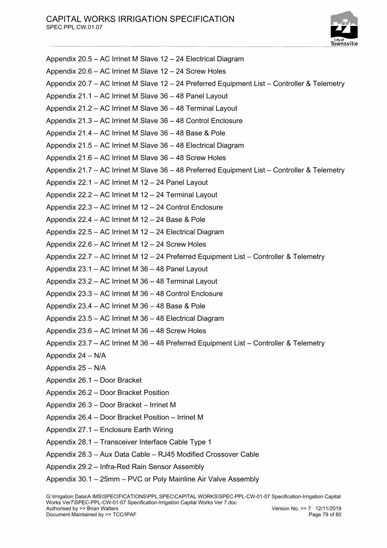
CAPITAL WORKS IRRIGATION SPECIFICATION SPEC.PPL.CW.01.07
G:\Irrigation Data\A IMS\SPECIFICATIONS\PPL.SPEC\CAPITAL WORKS\SPEC-PPL-CW-01-07 Specification-Irrigation Capital Works Ver7\SPEC-PPL-CW-01-07 Specification-Irrigation Capital Works Ver 7.doc Authorised by >> Brian Walters Version No. >> 7 12/11/2019 Document Maintained by >> TCC/IPAF Page 79 of 80
Appendix 20.5 – AC Irrinet M Slave 12 – 24 Electrical Diagram
Appendix 20.6 – AC Irrinet M Slave 12 – 24 Screw Holes
Appendix 20.7 – AC Irrinet M Slave 12 – 24 Preferred Equipment List – Controller & Telemetry
Appendix 21.1 – AC Irrinet M Slave 36 – 48 Panel Layout
Appendix 21.2 – AC Irrinet M Slave 36 – 48 Terminal Layout
Appendix 21.3 – AC Irrinet M Slave 36 – 48 Control Enclosure
Appendix 21.4 – AC Irrinet M Slave 36 – 48 Base & Pole
Appendix 21.5 – AC Irrinet M Slave 36 – 48 Electrical Diagram
Appendix 21.6 – AC Irrinet M Slave 36 – 48 Screw Holes
Appendix 21.7 – AC Irrinet M Slave 36 – 48 Preferred Equipment List – Controller & Telemetry
Appendix 22.1 – AC Irrinet M 12 – 24 Panel Layout
Appendix 22.2 – AC Irrinet M 12 – 24 Terminal Layout
Appendix 22.3 – AC Irrinet M 12 – 24 Control Enclosure
Appendix 22.4 – AC Irrinet M 12 – 24 Base & Pole
Appendix 22.5 – AC Irrinet M 12 – 24 Electrical Diagram
Appendix 22.6 – AC Irrinet M 12 – 24 Screw Holes
Appendix 22.7 – AC Irrinet M 12 – 24 Preferred Equipment List – Controller & Telemetry
Appendix 23.1 – AC Irrinet M 36 – 48 Panel Layout
Appendix 23.2 – AC Irrinet M 36 – 48 Terminal Layout
Appendix 23.3 – AC Irrinet M 36 – 48 Control Enclosure
Appendix 23.4 – AC Irrinet M 36 – 48 Base & Pole
Appendix 23.5 – AC Irrinet M 36 – 48 Electrical Diagram
Appendix 23.6 – AC Irrinet M 36 – 48 Screw Holes
Appendix 23.7 – AC Irrinet M 36 – 48 Preferred Equipment List – Controller & Telemetry
Appendix 24 – N/A
Appendix 25 – N/A
Appendix 26.1 – Door Bracket
Appendix 26.2 – Door Bracket Position
Appendix 26.3 – Door Bracket – Irrinet M
Appendix 26.4 – Door Bracket Position – Irrinet M
Appendix 27.1 – Enclosure Earth Wiring
Appendix 28.1 – Transceiver Interface Cable Type 1
Appendix 28.3 – Aux Data Cable – RJ45 Modified Crossover Cable
Appendix 29.2 – Infra-Red Rain Sensor Assembly
Appendix 30.1 – 25mm – PVC or Poly Mainline Air Valve Assembly

CAPITAL WORKS IRRIGATION SPECIFICATION SPEC.PPL.CW.01.07
G:\Irrigation Data\A IMS\SPECIFICATIONS\PPL.SPEC\CAPITAL WORKS\SPEC-PPL-CW-01-07 Specification-Irrigation Capital Works Ver7\SPEC-PPL-CW-01-07 Specification-Irrigation Capital Works Ver 7.doc Authorised by >> Brian Walters Version No. >> 7 12/11/2019 Document Maintained by >> TCC/IPAF Page 80 of 80
Appendix 30.2 – 40mm – PVC or Poly Mainline Cam Lock Coupling Assembly
Appendix 30.3 – 25mm – PVC or Poly Mainline Quick Coupling Valve Assembly
Appendix 30.4 – N/A
Appendix 30.5 – Scour Valve Assembly 80 – 100mm Series 1 PVC Mainline
Appendix 30.6 – Scour Valve Assembly 150 – 200mm Series 2 PVC Mainline
Appendix 30.7 – Scour Valve Assembly 150 – 200mm Series 1 PVC Mainline
Appendix 30.7 – Scour Valve Assembly 100 Series 2 PVC Mainline
Appendix 31.1 – Hydrometer Covers 50mm – 100mm
Appendix 31.2 – Multijet Covers 25mm - 32mm
Appendix 31.3 – Dorot Master Valve Covers 50mm – 100mm
Appendix 31.4 – Honeywell H5000 Water Meter Covers 50mm – 100mm
Appendix 32.1 – Controller Base & Pole Double Enclosure
Appendix 32.2 – N/A
Appendix 33.1 – Valve Nest Cover (sheet 1)
Appendix 33.2 – Valve Nest Cover (sheet 2)
Appendix 33.3 – Valve Nest Cover (sheet 3)
Appendix 33.4 – Valve Nest Cover (sheet 4)
Note: Attached Appendices have been reduced to fit A4 sheets for documentation purposes.
Scale A1 copies are available on request.

AutoCAD SHX Text
REFERENCE:
AutoCAD SHX Text
REVISIONS
AutoCAD SHX Text
F
AutoCAD SHX Text
REV
AutoCAD SHX Text
DATE
AutoCAD SHX Text
1
AutoCAD SHX Text
DESCRIPTION
AutoCAD SHX Text
2
AutoCAD SHX Text
E
AutoCAD SHX Text
D
AutoCAD SHX Text
C
AutoCAD SHX Text
B
AutoCAD SHX Text
A
AutoCAD SHX Text
1
AutoCAD SHX Text
2
AutoCAD SHX Text
LEGEND
AutoCAD SHX Text
3
AutoCAD SHX Text
4
AutoCAD SHX Text
5
AutoCAD SHX Text
Copyright c 2006 Townsville City Council
AutoCAD SHX Text
20
AutoCAD SHX Text
GRAPHIC SCALE - MM
AutoCAD SHX Text
Townsville City Council is prohibited.
AutoCAD SHX Text
Townsville City Council. Any use of this
AutoCAD SHX Text
drawing without written consent by
AutoCAD SHX Text
Written dimensions shall govern.
AutoCAD SHX Text
actual or designed conditions.
AutoCAD SHX Text
intended to accurately depict
AutoCAD SHX Text
for reference only and are not
AutoCAD SHX Text
Drawing scales as indicated are
AutoCAD SHX Text
service and is the sole property of
AutoCAD SHX Text
This drawing is an instrument of
AutoCAD SHX Text
0
AutoCAD SHX Text
SECTOR:
AutoCAD SHX Text
40
AutoCAD SHX Text
SHEET:
AutoCAD SHX Text
6
AutoCAD SHX Text
DATE:
AutoCAD SHX Text
SCALE:
AutoCAD SHX Text
3
AutoCAD SHX Text
4
AutoCAD SHX Text
5
AutoCAD SHX Text
6
AutoCAD SHX Text
IRRIGATION
AutoCAD SHX Text
CONSTRUCTION:
AutoCAD SHX Text
APPROVAL:
AutoCAD SHX Text
DRAWN:
AutoCAD SHX Text
SURVEY:
AutoCAD SHX Text
DESIGNED:
AutoCAD SHX Text
1:1
AutoCAD SHX Text
1
AutoCAD SHX Text
OF
AutoCAD SHX Text
1
AutoCAD SHX Text
29/8/19
AutoCAD SHX Text
7
AutoCAD SHX Text
TITLE:
AutoCAD SHX Text
PROJECT:
AutoCAD SHX Text
8
AutoCAD SHX Text
A1
AutoCAD SHX Text
F
AutoCAD SHX Text
E
AutoCAD SHX Text
D
AutoCAD SHX Text
C
AutoCAD SHX Text
7
AutoCAD SHX Text
8
AutoCAD SHX Text
B
AutoCAD SHX Text
A
AutoCAD SHX Text
CONTROL SYSTEM
AutoCAD SHX Text
NOTE : ALL DIMENSIONS ARE IN MILLIMETRES UNLESS OTHERWISE NOTED.
AutoCAD SHX Text
Appendix 3.1
AutoCAD SHX Text
B. WALTERS
AutoCAD SHX Text
B. WALTERS
AutoCAD SHX Text
B. WALTERS
AutoCAD SHX Text
& SCREW HOLE LAYOUT
AutoCAD SHX Text
PICCOLO XR PLUS PANEL
AutoCAD SHX Text
%%UPICCOLO XR PLUS UNIT
AutoCAD SHX Text
2
AutoCAD SHX Text
6mm CABLETIE HOLES
AutoCAD SHX Text
ST1
AutoCAD SHX Text
ST2
AutoCAD SHX Text
%%UPANEL LAYOUT
AutoCAD SHX Text
%%USCREW HOLE LAYOUT
AutoCAD SHX Text
1
AutoCAD SHX Text
3
AutoCAD SHX Text
4
AutoCAD SHX Text
5
AutoCAD SHX Text
3
AutoCAD SHX Text
A
AutoCAD SHX Text
01/07/09
AutoCAD SHX Text
Amended Terminal/Circuit configuration
AutoCAD SHX Text
BEHIND TERMINALS
AutoCAD SHX Text
ST2
AutoCAD SHX Text
ST1
AutoCAD SHX Text
ST2
AutoCAD SHX Text
ITEM
AutoCAD SHX Text
1
AutoCAD SHX Text
ENCLOSURE B&R NI04032/S WITH
AutoCAD SHX Text
DESCRIPTION
AutoCAD SHX Text
QTY
AutoCAD SHX Text
1
AutoCAD SHX Text
2
AutoCAD SHX Text
DIN RAIL
AutoCAD SHX Text
3
AutoCAD SHX Text
1
AutoCAD SHX Text
18
AutoCAD SHX Text
KEY LOCK No. NI030
AutoCAD SHX Text
TERMINAL BLOCKS W3/W4 COLOUR AS SHOWN
AutoCAD SHX Text
2
AutoCAD SHX Text
ITEM
AutoCAD SHX Text
DESCRIPTION
AutoCAD SHX Text
QTY
AutoCAD SHX Text
2
AutoCAD SHX Text
ST1
AutoCAD SHX Text
ST2
AutoCAD SHX Text
8 - 18 x 12 BUTTON SD C2
AutoCAD SHX Text
CONTROLLER SCREWS - MEDAL THREAD
AutoCAD SHX Text
3
AutoCAD SHX Text
%%UPANEL LAYOUT
AutoCAD SHX Text
%%USCREW HOLE LAYOUT
AutoCAD SHX Text
4
AutoCAD SHX Text
FUSE HOLDERS
AutoCAD SHX Text
5
AutoCAD SHX Text
TERMINAL END STOP
AutoCAD SHX Text
1

(P1 10) W WITH GY STRIPE *INPUT COMMON
(P1 7) W WITH GN STRIPE *INPUT 2
(P1 8) W WITH PURPLE STRIPE *INPUT 3
(P1 9) W WITH BK STRIPE *INPUT 4
(P1 5) GY *SOLENOID COMMON
(P1 1) BU *SOLENOID 1 (master valve)
(P1 2) GN *SOLENOID 2
MULTI-CORE
CABLES
Wired to
Piccolo XR plus
(P1 & P2 -) BK *6V(-)
(P1 & P2 +) RED *6V(+)
SOLAR
PANEL
BATTERY
(P2 GND) Y *GROUND
(P1 6) W WITH BU STRIPE *INPUT 1
(P1 4) PURPLE *SOLENOID 4
(P1 3) BN *SOLENOID 3
KYOCERA MINI MODULE
1 WATT 6V/6V SOLAR PANEL
FUSE
BATTERY
6V 12AH SLA
TO XR UNIT POWER IN
POWER DIAGRAM
TERMINAL LAYOUT
D1
W (I/P COMMON)
BU (W/M PULSE SWITCH)
NC
NC
NC
BK (O/P COMMON M/V-3)
RED (M/V)
(VALVE 1)
(VALVE 2)
(VALVE 3)
Field
wiring
+
_
+
_
FUSE
1N4004 GENERAL
PURPOSE DIODE
1AT
1AT
FUSE
FUSE
KYOCERA MINI MODULE
1 WATT 6V/6V SOLAR PANEL
(P2 15) GY *SOLENOID COMMON
(P2 11) BU *SOLENOID 5
(P2 12) GN *SOLENOID 6
(P2 14) PURPLE *SOLENOID 8
(P2 13) BN *SOLENOID 7
BK (O/P COMMON 4-7)
(VALVE 4)
(VALVE 5)
(VALVE 6)
(VALVE 7)
NOTES:
PICCOLO XR PLUS P1 TO P2 WIRES
(P1 31) ORANGE GOES TO (P2 31) ORANGE
(P1 32) WHITE GOES TO (P2 33) W WITH BN STRIPE
(P1 33) W WITH BN STRIPE GOES TO (P2 32) WHITE
(P1 GND) Y *GROUND
SOLAR
PANEL
+
_
AutoCAD SHX Text
REFERENCE:
AutoCAD SHX Text
REVISIONS
AutoCAD SHX Text
F
AutoCAD SHX Text
REV
AutoCAD SHX Text
DATE
AutoCAD SHX Text
1
AutoCAD SHX Text
DESCRIPTION
AutoCAD SHX Text
2
AutoCAD SHX Text
E
AutoCAD SHX Text
D
AutoCAD SHX Text
C
AutoCAD SHX Text
B
AutoCAD SHX Text
A
AutoCAD SHX Text
1
AutoCAD SHX Text
2
AutoCAD SHX Text
LEGEND
AutoCAD SHX Text
3
AutoCAD SHX Text
4
AutoCAD SHX Text
5
AutoCAD SHX Text
Copyright c 2006 Townsville City Council
AutoCAD SHX Text
Townsville City Council is prohibited.
AutoCAD SHX Text
Townsville City Council. Any use of this
AutoCAD SHX Text
drawing without written consent by
AutoCAD SHX Text
Written dimensions shall govern.
AutoCAD SHX Text
actual or designed conditions.
AutoCAD SHX Text
intended to accurately depict
AutoCAD SHX Text
for reference only and are not
AutoCAD SHX Text
Drawing scales as indicated are
AutoCAD SHX Text
service and is the sole property of
AutoCAD SHX Text
This drawing is an instrument of
AutoCAD SHX Text
SECTOR:
AutoCAD SHX Text
SHEET:
AutoCAD SHX Text
6
AutoCAD SHX Text
DATE:
AutoCAD SHX Text
SCALE:
AutoCAD SHX Text
3
AutoCAD SHX Text
4
AutoCAD SHX Text
5
AutoCAD SHX Text
6
AutoCAD SHX Text
IRRIGATION
AutoCAD SHX Text
CONSTRUCTION:
AutoCAD SHX Text
APPROVAL:
AutoCAD SHX Text
DRAWN:
AutoCAD SHX Text
SURVEY:
AutoCAD SHX Text
DESIGNED:
AutoCAD SHX Text
NTS
AutoCAD SHX Text
1
AutoCAD SHX Text
OF
AutoCAD SHX Text
1
AutoCAD SHX Text
29-8-2019
AutoCAD SHX Text
7
AutoCAD SHX Text
TITLE:
AutoCAD SHX Text
PROJECT:
AutoCAD SHX Text
8
AutoCAD SHX Text
A1
AutoCAD SHX Text
F
AutoCAD SHX Text
E
AutoCAD SHX Text
D
AutoCAD SHX Text
C
AutoCAD SHX Text
7
AutoCAD SHX Text
8
AutoCAD SHX Text
B
AutoCAD SHX Text
A
AutoCAD SHX Text
CONTROL SYSTEM
AutoCAD SHX Text
NOTE :
AutoCAD SHX Text
Appendix 3.2
AutoCAD SHX Text
B. WALTERS
AutoCAD SHX Text
B. WALTERS
AutoCAD SHX Text
B.WALTERS
AutoCAD SHX Text
LAYOUT & POWER DIAGRAM
AutoCAD SHX Text
PICCOLO XR PLUS TERMINAL
AutoCAD SHX Text
-
AutoCAD SHX Text
-/-/-
AutoCAD SHX Text
-
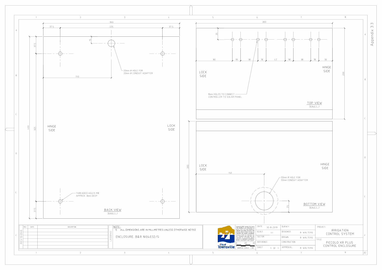
AutoCAD SHX Text
REFERENCE:
AutoCAD SHX Text
REVISIONS
AutoCAD SHX Text
F
AutoCAD SHX Text
REV
AutoCAD SHX Text
DATE
AutoCAD SHX Text
1
AutoCAD SHX Text
DESCRIPTION
AutoCAD SHX Text
2
AutoCAD SHX Text
E
AutoCAD SHX Text
D
AutoCAD SHX Text
C
AutoCAD SHX Text
B
AutoCAD SHX Text
A
AutoCAD SHX Text
1
AutoCAD SHX Text
2
AutoCAD SHX Text
LEGEND
AutoCAD SHX Text
3
AutoCAD SHX Text
4
AutoCAD SHX Text
5
AutoCAD SHX Text
Copyright c 2006 Townsville City Council
AutoCAD SHX Text
20
AutoCAD SHX Text
GRAPHIC SCALE - MM
AutoCAD SHX Text
Townsville City Council is prohibited.
AutoCAD SHX Text
Townsville City Council. Any use of this
AutoCAD SHX Text
drawing without written consent by
AutoCAD SHX Text
Written dimensions shall govern.
AutoCAD SHX Text
actual or designed conditions.
AutoCAD SHX Text
intended to accurately depict
AutoCAD SHX Text
for reference only and are not
AutoCAD SHX Text
Drawing scales as indicated are
AutoCAD SHX Text
service and is the sole property of
AutoCAD SHX Text
This drawing is an instrument of
AutoCAD SHX Text
0
AutoCAD SHX Text
SECTOR:
AutoCAD SHX Text
40
AutoCAD SHX Text
SHEET:
AutoCAD SHX Text
6
AutoCAD SHX Text
DATE:
AutoCAD SHX Text
SCALE:
AutoCAD SHX Text
3
AutoCAD SHX Text
4
AutoCAD SHX Text
5
AutoCAD SHX Text
6
AutoCAD SHX Text
CONSTRUCTION:
AutoCAD SHX Text
APPROVAL:
AutoCAD SHX Text
DRAWN:
AutoCAD SHX Text
SURVEY:
AutoCAD SHX Text
DESIGNED:
AutoCAD SHX Text
1:1
AutoCAD SHX Text
1
AutoCAD SHX Text
OF
AutoCAD SHX Text
1
AutoCAD SHX Text
30-8-2019
AutoCAD SHX Text
7
AutoCAD SHX Text
TITLE:
AutoCAD SHX Text
PROJECT:
AutoCAD SHX Text
8
AutoCAD SHX Text
A1
AutoCAD SHX Text
F
AutoCAD SHX Text
E
AutoCAD SHX Text
D
AutoCAD SHX Text
C
AutoCAD SHX Text
7
AutoCAD SHX Text
8
AutoCAD SHX Text
B
AutoCAD SHX Text
A
AutoCAD SHX Text
%%UBACK VIEW
AutoCAD SHX Text
%%USCALE 1 : 1
AutoCAD SHX Text
NOTE : 1) ALL DIMENSIONS ARE IN MILLIMETRES UNLESS OTHERWISE NOTED.ALL DIMENSIONS ARE IN MILLIMETRES UNLESS OTHERWISE NOTED.
AutoCAD SHX Text
Appendix 3.3
AutoCAD SHX Text
B. WALTERS
AutoCAD SHX Text
%%UBOTTOM VIEW
AutoCAD SHX Text
%%USCALE 1 : 1
AutoCAD SHX Text
20mm HOLE FOR20mm CONDUIT ADAPTER.
AutoCAD SHX Text
THREADED HOLES M8 APPROX. 8mm DEEP.
AutoCAD SHX Text
32mm HOLE FOR32mm CONDUIT ADAPTER
AutoCAD SHX Text
HINGE SIDE
AutoCAD SHX Text
LOCK SIDE
AutoCAD SHX Text
HINGE SIDE
AutoCAD SHX Text
LOCK SIDE
AutoCAD SHX Text
B. WALTERS
AutoCAD SHX Text
B. WALTERS
AutoCAD SHX Text
PICCOLO XR PLUS
AutoCAD SHX Text
CONTROL ENCLOSURE
AutoCAD SHX Text
%%UTOP VIEW
AutoCAD SHX Text
%%USCALE 1 : 1
AutoCAD SHX Text
HINGE SIDE
AutoCAD SHX Text
LOCK SIDE
AutoCAD SHX Text
8mm HOLES TO CONNECT CONTROLLER TO SOLAR PANEL
AutoCAD SHX Text
IRRIGATION
AutoCAD SHX Text
CONTROL SYSTEM
AutoCAD SHX Text
ENCLOSURE: B&R NI04032/S

AutoCAD SHX Text
REFERENCE:
AutoCAD SHX Text
REVISIONS
AutoCAD SHX Text
F
AutoCAD SHX Text
REV
AutoCAD SHX Text
DATE
AutoCAD SHX Text
1
AutoCAD SHX Text
DESCRIPTION
AutoCAD SHX Text
2
AutoCAD SHX Text
E
AutoCAD SHX Text
D
AutoCAD SHX Text
C
AutoCAD SHX Text
B
AutoCAD SHX Text
A
AutoCAD SHX Text
1
AutoCAD SHX Text
2
AutoCAD SHX Text
LEGEND
AutoCAD SHX Text
3
AutoCAD SHX Text
4
AutoCAD SHX Text
5
AutoCAD SHX Text
Copyright c 2006 Townsville City Council
AutoCAD SHX Text
200
AutoCAD SHX Text
GRAPHIC SCALE - MM 1:10
AutoCAD SHX Text
Townsville City Council is prohibited.
AutoCAD SHX Text
Townsville City Council. Any use of this
AutoCAD SHX Text
drawing without written consent by
AutoCAD SHX Text
Written dimensions shall govern.
AutoCAD SHX Text
actual or designed conditions.
AutoCAD SHX Text
intended to accurately depict
AutoCAD SHX Text
for reference only and are not
AutoCAD SHX Text
Drawing scales as indicated are
AutoCAD SHX Text
service and is the sole property of
AutoCAD SHX Text
This drawing is an instrument of
AutoCAD SHX Text
0
AutoCAD SHX Text
SECTOR:
AutoCAD SHX Text
400
AutoCAD SHX Text
SHEET:
AutoCAD SHX Text
6
AutoCAD SHX Text
DATE:
AutoCAD SHX Text
SCALE:
AutoCAD SHX Text
3
AutoCAD SHX Text
4
AutoCAD SHX Text
5
AutoCAD SHX Text
6
AutoCAD SHX Text
PICCOLO XR PLUS
AutoCAD SHX Text
IRRIGATION
AutoCAD SHX Text
CONSTRUCTION:
AutoCAD SHX Text
APPROVAL:
AutoCAD SHX Text
DRAWN:
AutoCAD SHX Text
SURVEY:
AutoCAD SHX Text
DESIGNED:
AutoCAD SHX Text
1:1, 1:2 & 1:10
AutoCAD SHX Text
1
AutoCAD SHX Text
OF
AutoCAD SHX Text
1
AutoCAD SHX Text
5-8-2019
AutoCAD SHX Text
7
AutoCAD SHX Text
TITLE:
AutoCAD SHX Text
PROJECT:
AutoCAD SHX Text
8
AutoCAD SHX Text
A1
AutoCAD SHX Text
F
AutoCAD SHX Text
E
AutoCAD SHX Text
D
AutoCAD SHX Text
C
AutoCAD SHX Text
7
AutoCAD SHX Text
8
AutoCAD SHX Text
B
AutoCAD SHX Text
A
AutoCAD SHX Text
CONTROL SYSTEM
AutoCAD SHX Text
NOTE : 1) ALL DIMENSIONS ARE IN MILLIMETRES UNLESS OTHERWISE NOTED. ALL DIMENSIONS ARE IN MILLIMETRES UNLESS OTHERWISE NOTED. 2) ALL MATERIAL 304 SS EXCEPT WHERE NOTED AS PVCALL MATERIAL 304 SS EXCEPT WHERE NOTED AS PVC
AutoCAD SHX Text
Appendix 3.4
AutoCAD SHX Text
B. WALTERS
AutoCAD SHX Text
ELEVATION SCALE 1:10
AutoCAD SHX Text
END ELEVATION SCALE 1:10
AutoCAD SHX Text
1 1/2 BSP 316 S/STEEL SOCKET (THREADED)
AutoCAD SHX Text
WELD ON REINFORCING ROD
AutoCAD SHX Text
B. WALTERS
AutoCAD SHX Text
B. WALTERS
AutoCAD SHX Text
FRONT PIPE FOR MAINS - 1200mm LONG, 25mm HEAVY DUTY CORRUGATED CONDUIT, 50mm NOMINAL BORE SCHEDULE 10, 304 SS PIPE
AutoCAD SHX Text
POLE - 2000mm LONG 50mm NOMINAL BORE SCHEDULE 10, 304 SS PIPE
AutoCAD SHX Text
REFER DETAIL 1
AutoCAD SHX Text
40mm PVC ENDCAP
AutoCAD SHX Text
DETAIL 1 SCALE 1:2
AutoCAD SHX Text
WELD ON FLAT PLATE 40mm H x 290mm L x 5mm T
AutoCAD SHX Text
POLE - 2000mm LONG 50mm NOMINAL BORE SCHEDULE 10, 304 SS PIPE
AutoCAD SHX Text
TOP OF FRONT PIPE FOR CONDUIT
AutoCAD SHX Text
10mm HOLE
AutoCAD SHX Text
6mm HOLE FOR ANTENNA SCREW(BACK OF POLE)
AutoCAD SHX Text
40mm PVC VALVE SOCKET
AutoCAD SHX Text
40mm PVC PIPE 400mm LONG
AutoCAD SHX Text
25mm HOLE(FRONT OF POLE)
AutoCAD SHX Text
WELD 6mm NUT TO PLATE CENTRAL TO 6mm SCREW HOLE
AutoCAD SHX Text
6mm SCREW HOLE
AutoCAD SHX Text
CD51 -ANTENNA ELEVATION SCALE 1:1
AutoCAD SHX Text
BRACKET SIDE ELEVATION SCALE 1:1
AutoCAD SHX Text
BRACKET PLAN SCALE 1:1
AutoCAD SHX Text
CABLE LENGTH 480mm (NOT TO SCALE)
AutoCAD SHX Text
GROUNDLINE
AutoCAD SHX Text
GROUNDLINE
AutoCAD SHX Text
BASE & ANTENNA
AutoCAD SHX Text
STAINLESS STEEL BRACKET 1mm THICK
AutoCAD SHX Text
WELD ON FLAT PLATE 50mm H x 290mm L x 5mm T

Appendix 3.5
IRRIGATION CONTROL SYSTEM PICCOLO XR PLUS 1-8 PREFERRED EQUIPMENT LIST
CONTROLLER AND TELEMETRY COMPONENTS
CONTROLLER COMPONENTS P.N/DESCRIPTION QUANTITY PICCOLO XR PLUS, 8DO + 4DI 73200-041200 1 BATTERY, 6V, 12 AH 00035-003050 1 MINI MODULE SOLAR PANEL KYOCERA MINI MODULE 2 X 6V 1W 2 ELECTRONIC COMPONENTS REFER APPENDIX 3.2 SOLEX COMPONENTS MISC. TELEMETRY COMPONENTS P.N/DESCRIPTION QUANTITY ANTENNA - STANDARD ANTENNA POLE CD51 CUT TO WAVE LENGTH 1 ANTENNA – EXTENSION ANTENNA POLE CD93 6db WHIP 1 ANTENNA BRACKET - STADARD ANTENNA POLE REFER APPENDIX 3.4
CMF BRACKET 1
ANTENNA BRACKET - EXTENSION ANTENNA POLE REFER APPENDIX 3.6
ANTSIG 653B & CUSTOM BRACKET 1
ANTENNA CABLE .5M RG58 COAX WITH & SMA PLUG FITTED BY RICOM
1

AutoCAD SHX Text
REFERENCE:
AutoCAD SHX Text
REVISIONS
AutoCAD SHX Text
F
AutoCAD SHX Text
REV
AutoCAD SHX Text
DATE
AutoCAD SHX Text
1
AutoCAD SHX Text
DESCRIPTION
AutoCAD SHX Text
2
AutoCAD SHX Text
E
AutoCAD SHX Text
D
AutoCAD SHX Text
C
AutoCAD SHX Text
B
AutoCAD SHX Text
A
AutoCAD SHX Text
1
AutoCAD SHX Text
2
AutoCAD SHX Text
LEGEND
AutoCAD SHX Text
3
AutoCAD SHX Text
4
AutoCAD SHX Text
5
AutoCAD SHX Text
Copyright c 2010 Townsville City Council
AutoCAD SHX Text
200
AutoCAD SHX Text
GRAPHIC SCALE - MM 1:10
AutoCAD SHX Text
Townsville City Council is prohibited.
AutoCAD SHX Text
Townsville City Council. Any use of this
AutoCAD SHX Text
drawing without written consent by
AutoCAD SHX Text
Written dimensions shall govern.
AutoCAD SHX Text
actual or designed conditions.
AutoCAD SHX Text
intended to accurately depict
AutoCAD SHX Text
for reference only and are not
AutoCAD SHX Text
Drawing scales as indicated are
AutoCAD SHX Text
service and is the sole property of
AutoCAD SHX Text
This drawing is an instrument of
AutoCAD SHX Text
0
AutoCAD SHX Text
SECTOR:
AutoCAD SHX Text
400
AutoCAD SHX Text
SHEET:
AutoCAD SHX Text
6
AutoCAD SHX Text
DATE:
AutoCAD SHX Text
SCALE:
AutoCAD SHX Text
3
AutoCAD SHX Text
4
AutoCAD SHX Text
5
AutoCAD SHX Text
6
AutoCAD SHX Text
PICCOLO XR PLUS
AutoCAD SHX Text
IRRIGATION
AutoCAD SHX Text
CONSTRUCTION:
AutoCAD SHX Text
APPROVAL:
AutoCAD SHX Text
DRAWN:
AutoCAD SHX Text
SURVEY:
AutoCAD SHX Text
DESIGNED:
AutoCAD SHX Text
1:2 & 1:10
AutoCAD SHX Text
1
AutoCAD SHX Text
OF
AutoCAD SHX Text
1
AutoCAD SHX Text
13-06-2010
AutoCAD SHX Text
7
AutoCAD SHX Text
TITLE:
AutoCAD SHX Text
PROJECT:
AutoCAD SHX Text
8
AutoCAD SHX Text
A1
AutoCAD SHX Text
F
AutoCAD SHX Text
E
AutoCAD SHX Text
D
AutoCAD SHX Text
C
AutoCAD SHX Text
7
AutoCAD SHX Text
8
AutoCAD SHX Text
B
AutoCAD SHX Text
A
AutoCAD SHX Text
CONTROL SYSTEM
AutoCAD SHX Text
NOTE : 1) ALL DIMENSIONS ARE IN MILLIMETRES UNLESS OTHERWISE NOTED.ALL DIMENSIONS ARE IN MILLIMETRES UNLESS OTHERWISE NOTED.
AutoCAD SHX Text
Appendix 3.6
AutoCAD SHX Text
B. WALTERS
AutoCAD SHX Text
ELEVATION SCALE 1:10
AutoCAD SHX Text
TOP VIEW SCALE 1:2
AutoCAD SHX Text
REFER DETAIL 1
AutoCAD SHX Text
38.1mm TUBE O.D. TUBE 1.6mm WALL 304 SS
AutoCAD SHX Text
TUBE FLARED TO SUIT TOE NIPPLE
AutoCAD SHX Text
40mm NOMINAL BORE TOE NIPPLE
AutoCAD SHX Text
B. WALTERS
AutoCAD SHX Text
R. COLLINS
AutoCAD SHX Text
ANTENNA EXTENSION POLES
AutoCAD SHX Text
ELEVATION SCALE 1:10
AutoCAD SHX Text
DETAIL 1 SCALE 1:2
AutoCAD SHX Text
TOP VIEW SCALE 1:2
AutoCAD SHX Text
DETAIL 2 SCALE 1:2
AutoCAD SHX Text
REFER DETAIL 2
AutoCAD SHX Text
TYPE 1 ANTENNA EXTENSION POLE ASSEMBY
AutoCAD SHX Text
TYPE 2 ANTENNA EXTENSION POLE ASSEMBY
AutoCAD SHX Text
COAX LOOP
AutoCAD SHX Text
20MM FLEXIBLE CONDUIT
AutoCAD SHX Text
FASTEN COAX & CONDUIT TO BRACKET WITH CABLE TIES
AutoCAD SHX Text
MOUNT WEATHER SENSOR AS REQUIRED
AutoCAD SHX Text
COAX LOOP
AutoCAD SHX Text
20MM FLEXIBLE CONDUIT
AutoCAD SHX Text
FASTEN COAX & CONDUIT TO BRACKET WITH CABLE TIES
AutoCAD SHX Text
CD93 6db WHIP ANTENNA
AutoCAD SHX Text
CD93 6db WHIP ANTENNA
AutoCAD SHX Text
ANTSIG U-BOLT & V-BLOCK CLAMP P.N 653B
AutoCAD SHX Text
40MM x 40MM x 3MM ALUMINIUM ANGLE
AutoCAD SHX Text
DRILL BOLT HOLES TO SUIT BRACKET
AutoCAD SHX Text
2x 6mm CABLETIE HOLES
AutoCAD SHX Text
TOP VIEW CONDUIT & ANTENNA NOT SHOWN FOR CLARITY
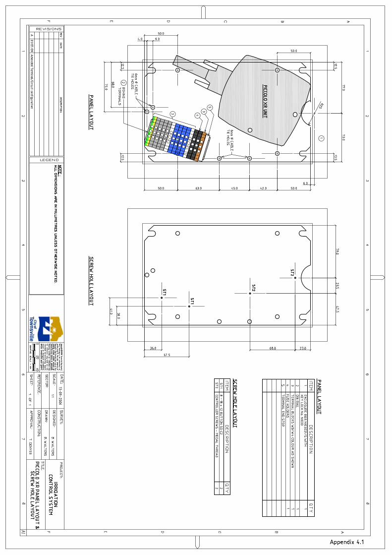
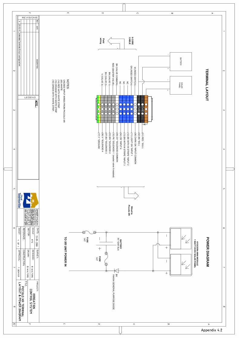


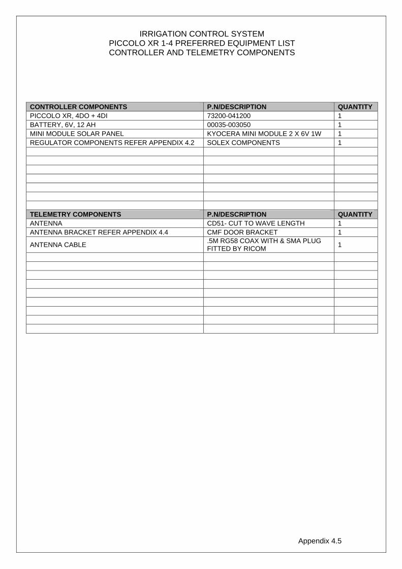
Appendix 4.5
IRRIGATION CONTROL SYSTEM PICCOLO XR 1-4 PREFERRED EQUIPMENT LIST CONTROLLER AND TELEMETRY COMPONENTS
CONTROLLER COMPONENTS P.N/DESCRIPTION QUANTITY PICCOLO XR, 4DO + 4DI 73200-041200 1 BATTERY, 6V, 12 AH 00035-003050 1 MINI MODULE SOLAR PANEL KYOCERA MINI MODULE 2 X 6V 1W 1 REGULATOR COMPONENTS REFER APPENDIX 4.2 SOLEX COMPONENTS 1 TELEMETRY COMPONENTS P.N/DESCRIPTION QUANTITY ANTENNA CD51- CUT TO WAVE LENGTH 1 ANTENNA BRACKET REFER APPENDIX 4.4 CMF DOOR BRACKET 1
ANTENNA CABLE .5M RG58 COAX WITH & SMA PLUG FITTED BY RICOM 1
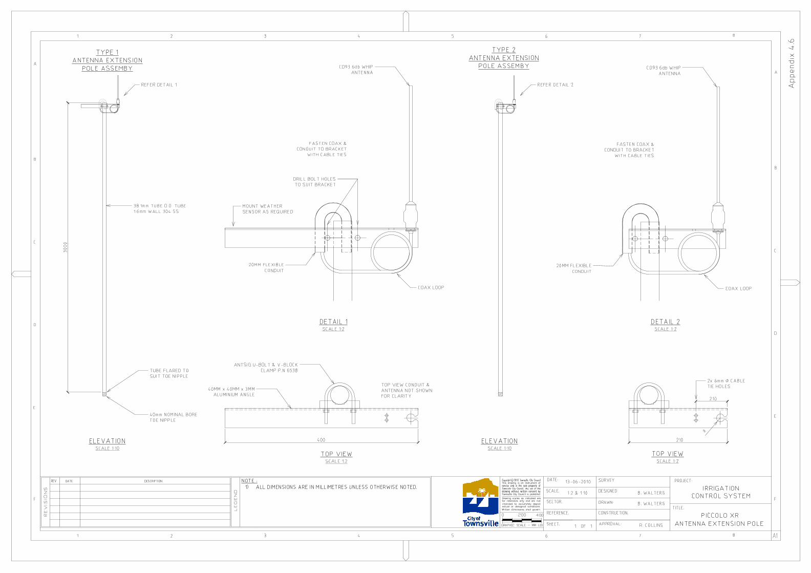
AutoCAD SHX Text
REFERENCE:
AutoCAD SHX Text
REVISIONS
AutoCAD SHX Text
F
AutoCAD SHX Text
REV
AutoCAD SHX Text
DATE
AutoCAD SHX Text
1
AutoCAD SHX Text
DESCRIPTION
AutoCAD SHX Text
2
AutoCAD SHX Text
E
AutoCAD SHX Text
D
AutoCAD SHX Text
C
AutoCAD SHX Text
B
AutoCAD SHX Text
A
AutoCAD SHX Text
1
AutoCAD SHX Text
2
AutoCAD SHX Text
LEGEND
AutoCAD SHX Text
3
AutoCAD SHX Text
4
AutoCAD SHX Text
5
AutoCAD SHX Text
Copyright c 2010 Townsville City Council
AutoCAD SHX Text
200
AutoCAD SHX Text
GRAPHIC SCALE - MM 1:10
AutoCAD SHX Text
Townsville City Council is prohibited.
AutoCAD SHX Text
Townsville City Council. Any use of this
AutoCAD SHX Text
drawing without written consent by
AutoCAD SHX Text
Written dimensions shall govern.
AutoCAD SHX Text
actual or designed conditions.
AutoCAD SHX Text
intended to accurately depict
AutoCAD SHX Text
for reference only and are not
AutoCAD SHX Text
Drawing scales as indicated are
AutoCAD SHX Text
service and is the sole property of
AutoCAD SHX Text
This drawing is an instrument of
AutoCAD SHX Text
0
AutoCAD SHX Text
SECTOR:
AutoCAD SHX Text
400
AutoCAD SHX Text
SHEET:
AutoCAD SHX Text
6
AutoCAD SHX Text
DATE:
AutoCAD SHX Text
SCALE:
AutoCAD SHX Text
3
AutoCAD SHX Text
4
AutoCAD SHX Text
5
AutoCAD SHX Text
6
AutoCAD SHX Text
PICCOLO XR
AutoCAD SHX Text
IRRIGATION
AutoCAD SHX Text
CONSTRUCTION:
AutoCAD SHX Text
APPROVAL:
AutoCAD SHX Text
DRAWN:
AutoCAD SHX Text
SURVEY:
AutoCAD SHX Text
DESIGNED:
AutoCAD SHX Text
1:2 & 1:10
AutoCAD SHX Text
1
AutoCAD SHX Text
OF
AutoCAD SHX Text
1
AutoCAD SHX Text
13-06-2010
AutoCAD SHX Text
7
AutoCAD SHX Text
TITLE:
AutoCAD SHX Text
PROJECT:
AutoCAD SHX Text
8
AutoCAD SHX Text
A1
AutoCAD SHX Text
F
AutoCAD SHX Text
E
AutoCAD SHX Text
D
AutoCAD SHX Text
C
AutoCAD SHX Text
7
AutoCAD SHX Text
8
AutoCAD SHX Text
B
AutoCAD SHX Text
A
AutoCAD SHX Text
CONTROL SYSTEM
AutoCAD SHX Text
NOTE : 1) ALL DIMENSIONS ARE IN MILLIMETRES UNLESS OTHERWISE NOTED.ALL DIMENSIONS ARE IN MILLIMETRES UNLESS OTHERWISE NOTED.
AutoCAD SHX Text
Appendix 4.6
AutoCAD SHX Text
B. WALTERS
AutoCAD SHX Text
ELEVATION SCALE 1:10
AutoCAD SHX Text
TOP VIEW SCALE 1:2
AutoCAD SHX Text
REFER DETAIL 1
AutoCAD SHX Text
38.1mm TUBE O.D. TUBE 1.6mm WALL 304 SS
AutoCAD SHX Text
TUBE FLARED TO SUIT TOE NIPPLE
AutoCAD SHX Text
40mm NOMINAL BORE TOE NIPPLE
AutoCAD SHX Text
B. WALTERS
AutoCAD SHX Text
R. COLLINS
AutoCAD SHX Text
ANTENNA EXTENSION POLE
AutoCAD SHX Text
ELEVATION SCALE 1:10
AutoCAD SHX Text
DETAIL 1 SCALE 1:2
AutoCAD SHX Text
TOP VIEW SCALE 1:2
AutoCAD SHX Text
DETAIL 2 SCALE 1:2
AutoCAD SHX Text
REFER DETAIL 2
AutoCAD SHX Text
TYPE 1 ANTENNA EXTENSION POLE ASSEMBY
AutoCAD SHX Text
TYPE 2 ANTENNA EXTENSION POLE ASSEMBY
AutoCAD SHX Text
COAX LOOP
AutoCAD SHX Text
20MM FLEXIBLE CONDUIT
AutoCAD SHX Text
FASTEN COAX & CONDUIT TO BRACKET WITH CABLE TIES
AutoCAD SHX Text
MOUNT WEATHER SENSOR AS REQUIRED
AutoCAD SHX Text
COAX LOOP
AutoCAD SHX Text
20MM FLEXIBLE CONDUIT
AutoCAD SHX Text
FASTEN COAX & CONDUIT TO BRACKET WITH CABLE TIES
AutoCAD SHX Text
CD93 6db WHIP ANTENNA
AutoCAD SHX Text
CD93 6db WHIP ANTENNA
AutoCAD SHX Text
ANTSIG U-BOLT & V-BLOCK CLAMP P.N 653B
AutoCAD SHX Text
40MM x 40MM x 3MM ALUMINIUM ANGLE
AutoCAD SHX Text
DRILL BOLT HOLES TO SUIT BRACKET
AutoCAD SHX Text
2x 6mm CABLETIE HOLES
AutoCAD SHX Text
TOP VIEW CONDUIT & ANTENNA NOT SHOWN FOR CLARITY
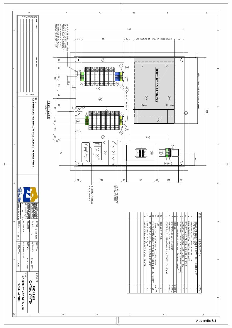
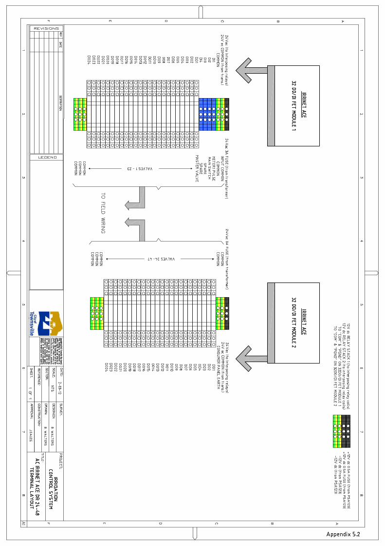
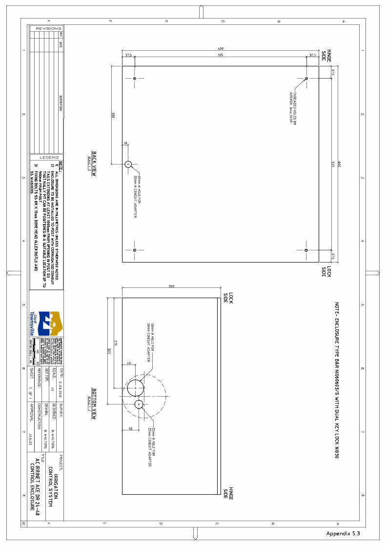

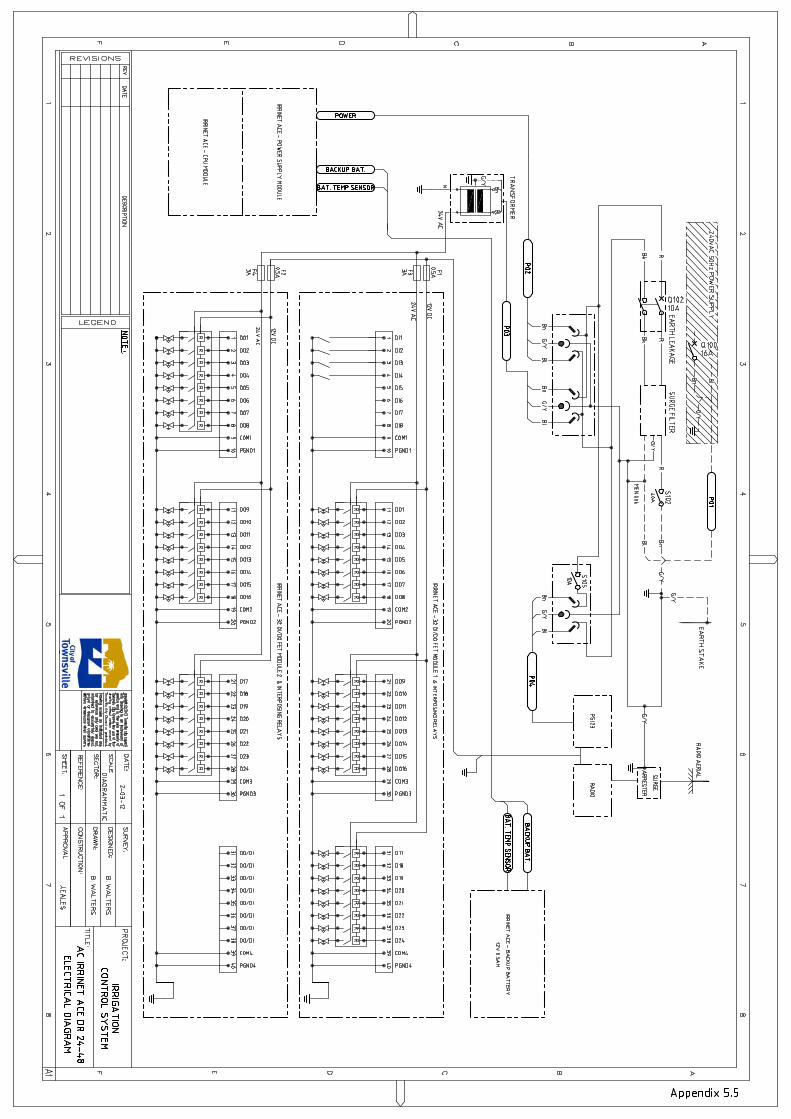
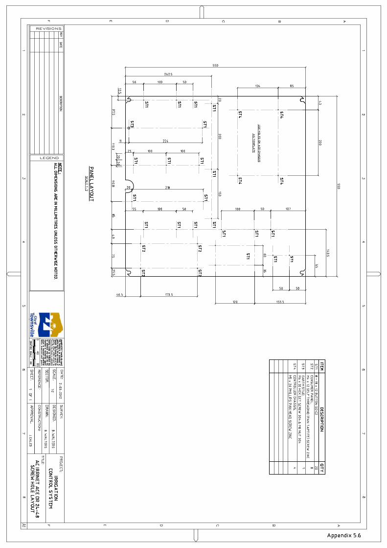
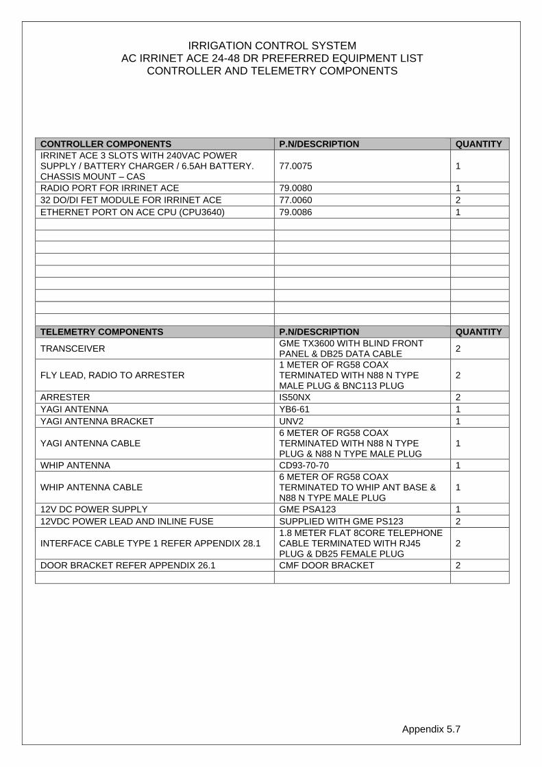
Appendix 5.7
IRRIGATION CONTROL SYSTEM AC IRRINET ACE 24-48 DR PREFERRED EQUIPMENT LIST
CONTROLLER AND TELEMETRY COMPONENTS
CONTROLLER COMPONENTS P.N/DESCRIPTION QUANTITY IRRINET ACE 3 SLOTS WITH 240VAC POWER SUPPLY / BATTERY CHARGER / 6.5AH BATTERY. CHASSIS MOUNT – CAS
77.0075 1
RADIO PORT FOR IRRINET ACE 79.0080 1 32 DO/DI FET MODULE FOR IRRINET ACE 77.0060 2 ETHERNET PORT ON ACE CPU (CPU3640) 79.0086 1 TELEMETRY COMPONENTS P.N/DESCRIPTION QUANTITY
TRANSCEIVER GME TX3600 WITH BLIND FRONT PANEL & DB25 DATA CABLE 2
FLY LEAD, RADIO TO ARRESTER 1 METER OF RG58 COAX TERMINATED WITH N88 N TYPE MALE PLUG & BNC113 PLUG
2
ARRESTER IS50NX 2 YAGI ANTENNA YB6-61 1 YAGI ANTENNA BRACKET UNV2 1
YAGI ANTENNA CABLE 6 METER OF RG58 COAX TERMINATED WITH N88 N TYPE PLUG & N88 N TYPE MALE PLUG
1
WHIP ANTENNA CD93-70-70 1
WHIP ANTENNA CABLE 6 METER OF RG58 COAX TERMINATED TO WHIP ANT BASE & N88 N TYPE MALE PLUG
1
12V DC POWER SUPPLY GME PSA123 1 12VDC POWER LEAD AND INLINE FUSE SUPPLIED WITH GME PS123 2
INTERFACE CABLE TYPE 1 REFER APPENDIX 28.1 1.8 METER FLAT 8CORE TELEPHONE CABLE TERMINATED WITH RJ45 PLUG & DB25 FEMALE PLUG
2
DOOR BRACKET REFER APPENDIX 26.1 CMF DOOR BRACKET 2
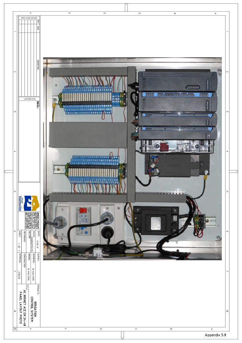
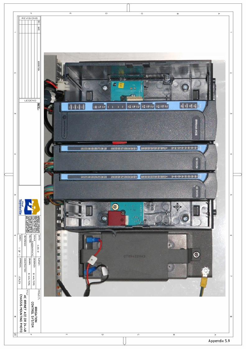

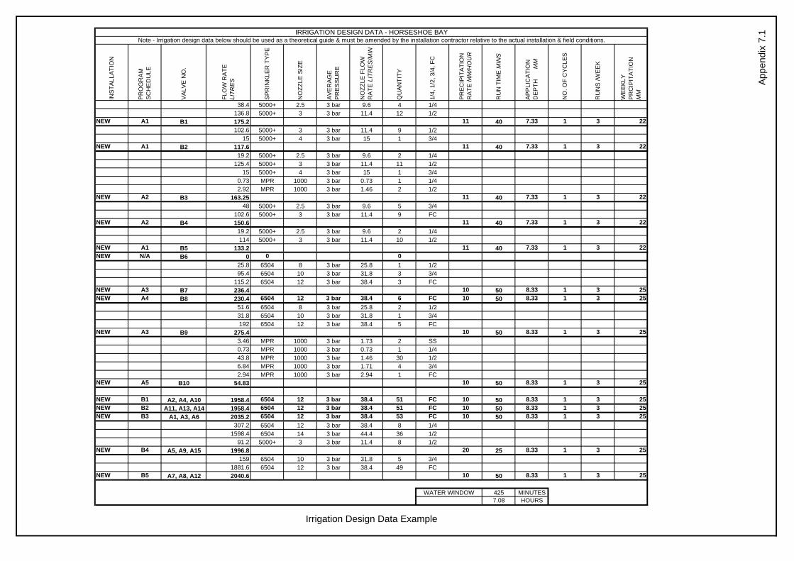
INS
TALL
ATI
ON
PR
OG
RA
M
SC
HE
DU
LE
VA
LVE
NO
.
FLO
W R
ATE
LI
TRE
S
SP
RIN
KLE
R T
YP
E
NO
ZZLE
SIZ
E
AV
ER
AG
E
PR
ES
SU
RE
NO
ZZLE
FLO
W
RA
TE L
ITR
ES
/MIN
QU
AN
TITY
1/4,
1/2
, 3/4
, FC
PR
EC
IPIT
ATI
ON
R
ATE
MM
/HO
UR
RU
N T
IME
MIN
S
AP
PLI
CA
TIO
N
DE
PTH
MM
NO
. OF
CY
CLE
S
RU
NS
/WE
EK
WE
EK
LY
PR
CIP
ITA
TIO
N
MM
38.4 5000+ 2.5 3 bar 9.6 4 1/4136.8 5000+ 3 3 bar 11.4 12 1/2
NEW A1 B1 175.2 11 40 7.33 1 3 22102.6 5000+ 3 3 bar 11.4 9 1/2
15 5000+ 4 3 bar 15 1 3/4NEW A1 B2 117.6 11 40 7.33 1 3 22
19.2 5000+ 2.5 3 bar 9.6 2 1/4125.4 5000+ 3 3 bar 11.4 11 1/2
15 5000+ 4 3 bar 15 1 3/40.73 MPR 1000 3 bar 0.73 1 1/42.92 MPR 1000 3 bar 1.46 2 1/2
NEW A2 B3 163.25 11 40 7.33 1 3 2248 5000+ 2.5 3 bar 9.6 5 3/4
102.6 5000+ 3 3 bar 11.4 9 FCNEW A2 B4 150.6 11 40 7.33 1 3 22
19.2 5000+ 2.5 3 bar 9.6 2 1/4114 5000+ 3 3 bar 11.4 10 1/2
NEW A1 B5 133.2 11 40 7.33 1 3 22NEW N/A B6 0 0 0
25.8 6504 8 3 bar 25.8 1 1/295.4 6504 10 3 bar 31.8 3 3/4
115.2 6504 12 3 bar 38.4 3 FCNEW A3 B7 236.4 10 50 8.33 1 3 25NEW A4 B8 230.4 6504 12 3 bar 38.4 6 FC 10 50 8.33 1 3 25
51.6 6504 8 3 bar 25.8 2 1/231.8 6504 10 3 bar 31.8 1 3/4192 6504 12 3 bar 38.4 5 FC
NEW A3 B9 275.4 10 50 8.33 1 3 253.46 MPR 1000 3 bar 1.73 2 SS0.73 MPR 1000 3 bar 0.73 1 1/443.8 MPR 1000 3 bar 1.46 30 1/26.84 MPR 1000 3 bar 1.71 4 3/42.94 MPR 1000 3 bar 2.94 1 FC
NEW A5 B10 54.83 10 50 8.33 1 3 25
NEW B1 A2, A4, A10 1958.4 6504 12 3 bar 38.4 51 FC 10 50 8.33 1 3 25NEW B2 A11, A13, A14 1958.4 6504 12 3 bar 38.4 51 FC 10 50 8.33 1 3 25NEW B3 A1, A3, A6 2035.2 6504 12 3 bar 38.4 53 FC 10 50 8.33 1 3 25
307.2 6504 12 3 bar 38.4 8 1/41598.4 6504 14 3 bar 44.4 36 1/2
91.2 5000+ 3 3 bar 11.4 8 1/2NEW B4 A5, A9, A15 1996.8 20 25 8.33 1 3 25
159 6504 10 3 bar 31.8 5 3/41881.6 6504 12 3 bar 38.4 49 FC
NEW B5 A7, A8, A12 2040.6 10 50 8.33 1 3 25
425 MINUTES7.08 HOURS
App
endi
x 7.
1IRRIGATION DESIGN DATA - HORSESHOE BAYNote - Irrigation design data below should be used as a theoretical guide & must be amended by the installation contractor relative to the actual installation & field conditions.
Irrigation Design Data Example
WATER WINDOW
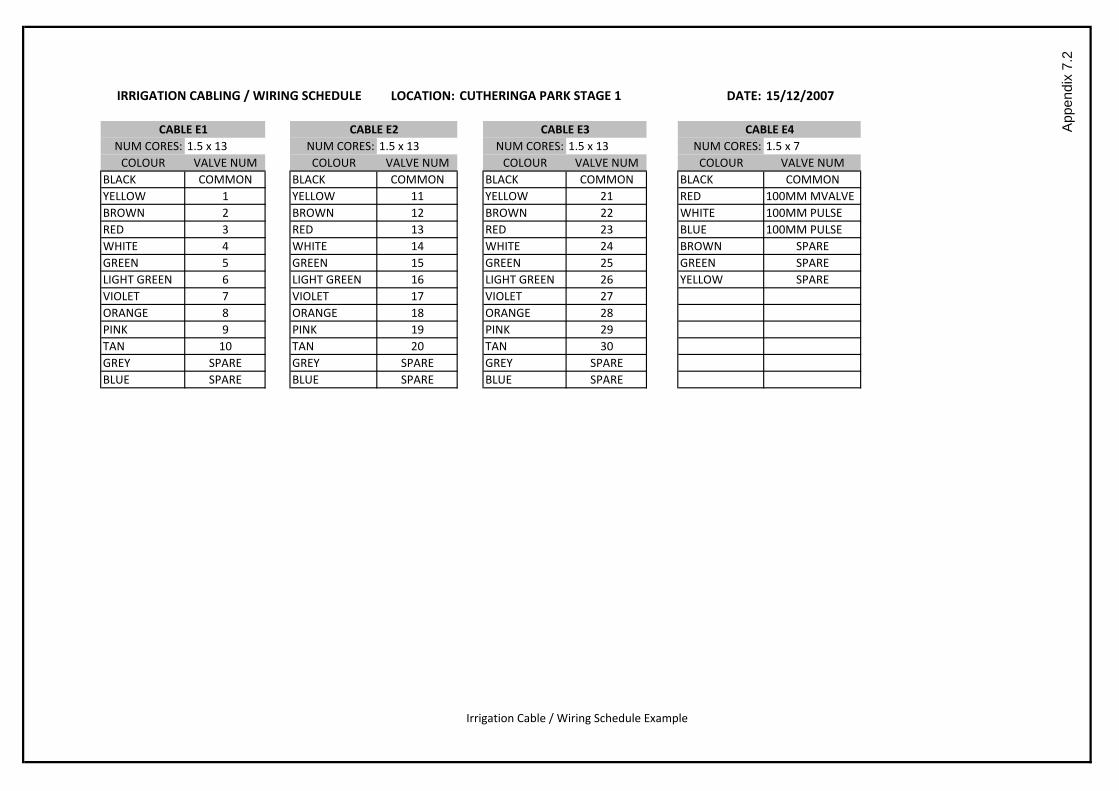
LOCATION: DATE: 15/12/2007
NUM CORES: 1.5 x 13 NUM CORES: 1.5 x 13 NUM CORES: 1.5 x 13 NUM CORES: 1.5 x 7COLOUR VALVE NUM COLOUR VALVE NUM COLOUR VALVE NUM COLOUR VALVE NUM
BLACK COMMON BLACK COMMON BLACK COMMON BLACK COMMONYELLOW 1 YELLOW 11 YELLOW 21 RED 100MM MVALVEBROWN 2 BROWN 12 BROWN 22 WHITE 100MM PULSERED 3 RED 13 RED 23 BLUE 100MM PULSEWHITE 4 WHITE 14 WHITE 24 BROWN SPAREGREEN 5 GREEN 15 GREEN 25 GREEN SPARELIGHT GREEN 6 LIGHT GREEN 16 LIGHT GREEN 26 YELLOW SPAREVIOLET 7 VIOLET 17 VIOLET 27ORANGE 8 ORANGE 18 ORANGE 28PINK 9 PINK 19 PINK 29TAN 10 TAN 20 TAN 30GREY SPARE GREY SPARE GREY SPAREBLUE SPARE BLUE SPARE BLUE SPARE
Irrigation Cable / Wiring Schedule Example
App
endi
x 7.
2
CUTHERINGA PARK STAGE 1IRRIGATION CABLING / WIRING SCHEDULE
CABLE E1 CABLE E2 CABLE E3 CABLE E4

Valve Output (LPM)
Nominal Valve Size (mm)
Controller and Valve Number
Model
Precipitation Rate (mm/hr)
Nominal Pressure in Kpa
Half Circle Nozzle SizeFull Circle Nozzle Size
Quarter Circle Nozzle SizeThree Quarter Nozzle Size
Connection
No Connection
Connection
No Connection
AutoCAD SHX Text
A5
AutoCAD SHX Text
40
AutoCAD SHX Text
245
AutoCAD SHX Text
9
AutoCAD SHX Text
8
AutoCAD SHX Text
7
AutoCAD SHX Text
5
AutoCAD SHX Text
344
AutoCAD SHX Text
PGP
AutoCAD SHX Text
6.1
AutoCAD SHX Text
PLAN LEGEND
AutoCAD SHX Text
VALVE KEY
AutoCAD SHX Text
SPRINKLER KEY
AutoCAD SHX Text
Appendix 8.1
AutoCAD SHX Text
AIR VALVE
AutoCAD SHX Text
FLUSHING VALVE
AutoCAD SHX Text
TYPE C SPRINKLER
AutoCAD SHX Text
TYPE A SPRINKLER
AutoCAD SHX Text
TYPE B SPRINKLER
AutoCAD SHX Text
DRINKING FOUNTAIN
AutoCAD SHX Text
LATERAL INDICATOR
AutoCAD SHX Text
A
AutoCAD SHX Text
LEGEND
AutoCAD SHX Text
D
AutoCAD SHX Text
F
AutoCAD SHX Text
T
AutoCAD SHX Text
TAP
AutoCAD SHX Text
MANUAL VALVE
AutoCAD SHX Text
FILTER
AutoCAD SHX Text
FERTIGATION TANK
AutoCAD SHX Text
FERTIGATION VENTURI
AutoCAD SHX Text
REGULATOR (PRESS.)
AutoCAD SHX Text
STRAINER
AutoCAD SHX Text
P
AutoCAD SHX Text
WATER METER
AutoCAD SHX Text
BACKFLOW
AutoCAD SHX Text
CHECK VALVE
AutoCAD SHX Text
SOLENOID VALVE
AutoCAD SHX Text
W
AutoCAD SHX Text
ELECTRICAL PIT
AutoCAD SHX Text
PN12.5 POLY PIPE(SIZE SHOWN)
AutoCAD SHX Text
63mm PN8 POLY PIPE
AutoCAD SHX Text
75mm PN8 POLY PIPE
AutoCAD SHX Text
50mm PN8 POLY PIPE
AutoCAD SHX Text
40mm PN8 POLY PIPE
AutoCAD SHX Text
POWER CONDUIT & CABLE
AutoCAD SHX Text
PN12 PVC-M RRJ PIPE(SIZE SHOWN)
AutoCAD SHX Text
ENVELOPER PN9 PVC SWJ(SIZE SHOWN)
AutoCAD SHX Text
CONTROL CABLE & CONDUIT
AutoCAD SHX Text
DRIP TURF
AutoCAD SHX Text
DRIP GARDEN
AutoCAD SHX Text
CONTROLLER
AutoCAD SHX Text
DRIP FEED/FLUSH HEADER (25mm LD)
AutoCAD SHX Text
SENSOR
AutoCAD SHX Text
C
AutoCAD SHX Text
1x 100mm
AutoCAD SHX Text
PIT
AutoCAD SHX Text
Figure 1
AutoCAD SHX Text
Figure 2
AutoCAD SHX Text
Figure 3
AutoCAD SHX Text
CAP
AutoCAD SHX Text
CONNECTOR
AutoCAD SHX Text
LINE INTERSECTION EXAMPLE
AutoCAD SHX Text
Figure 4
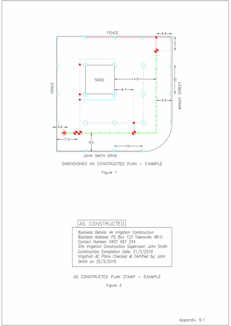
AutoCAD SHX Text
5
AutoCAD SHX Text
5.5
AutoCAD SHX Text
5.5
AutoCAD SHX Text
SHED
AutoCAD SHX Text
FENCE
AutoCAD SHX Text
JOHN SMITH DRIVE
AutoCAD SHX Text
WRIGHT STREET
AutoCAD SHX Text
FENCE
AutoCAD SHX Text
6.5
AutoCAD SHX Text
7.3
AutoCAD SHX Text
14.5
AutoCAD SHX Text
2.6
AutoCAD SHX Text
10
AutoCAD SHX Text
10
AutoCAD SHX Text
6.7
AutoCAD SHX Text
Appendix 9.1
AutoCAD SHX Text
DIMENSIONED AS CONSTRUCTED PLAN - EXAMPLE
AutoCAD SHX Text
Figure 1
AutoCAD SHX Text
Business Details: AA Irrigation Construction AA Irrigation Construction Business Address: PO Box 123 Townsville 4810 PO Box 123 Townsville 4810 Contact Number: 0407 697 244 0407 697 244 Site Irrigation Construction Supervisor: John Smith John Smith Construction Completion Date: 21/3/2019 21/3/2019 Irrigation AC Plans Checked & Certified by: John rrigation AC Plans Checked & Certified by: John John Smith on 25/3/2019
AutoCAD SHX Text
AS CONSTRUCTED
AutoCAD SHX Text
AS CONSTRUCTED PLAN STAMP - EXAMPLE
AutoCAD SHX Text
Figure 2
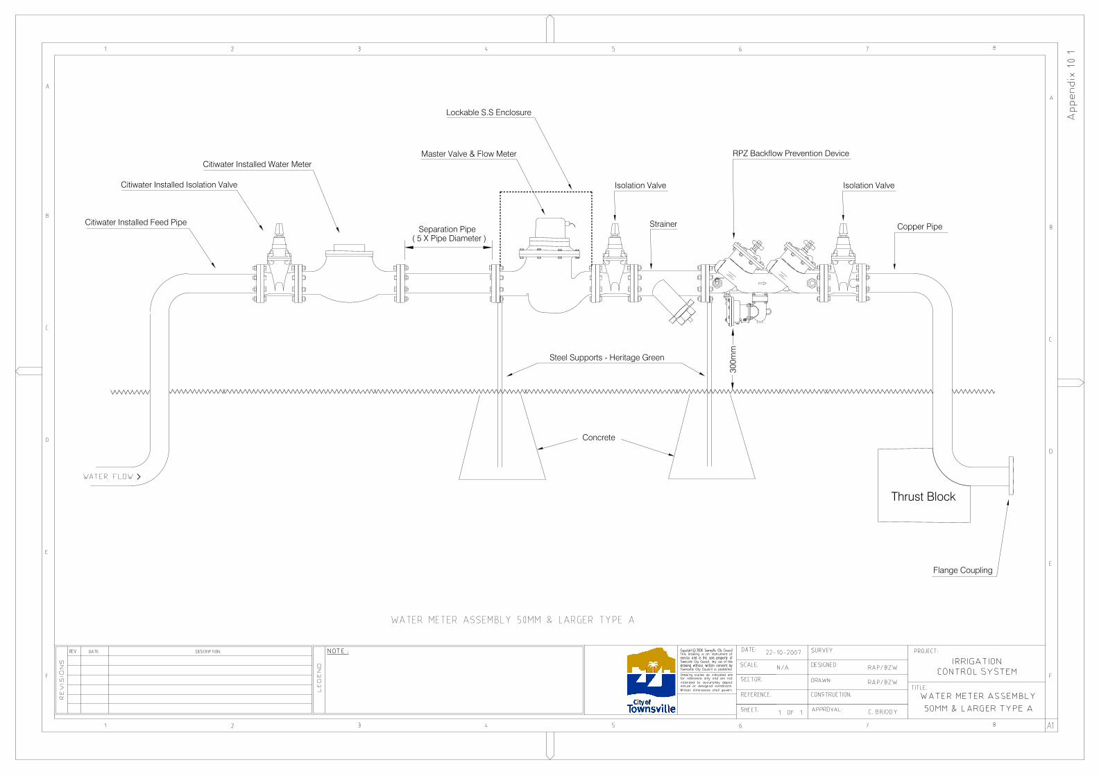
Citiwater Installed Isolation Valve
Citiwater Installed Water MeterMaster Valve & Flow Meter
Isolation Valve
Thrust Block
300m
m
RPZ Backflow Prevention Device
Citiwater Installed Feed Pipe Strainer
( 5 X Pipe Diameter ) Separation Pipe
Steel Supports - Heritage Green
Concrete
Flange Coupling
Copper Pipe
Lockable S.S Enclosure
Isolation Valve
AutoCAD SHX Text
WATER METER ASSEMBLY 50MM & LARGER TYPE A
AutoCAD SHX Text
WATER FLOW
AutoCAD SHX Text
REFERENCE:
AutoCAD SHX Text
REVISIONS
AutoCAD SHX Text
F
AutoCAD SHX Text
REV
AutoCAD SHX Text
DATE
AutoCAD SHX Text
1
AutoCAD SHX Text
DESCRIPTION
AutoCAD SHX Text
2
AutoCAD SHX Text
E
AutoCAD SHX Text
D
AutoCAD SHX Text
C
AutoCAD SHX Text
B
AutoCAD SHX Text
A
AutoCAD SHX Text
1
AutoCAD SHX Text
2
AutoCAD SHX Text
LEGEND
AutoCAD SHX Text
3
AutoCAD SHX Text
4
AutoCAD SHX Text
5
AutoCAD SHX Text
Copyright c 2006 Townsville City Council
AutoCAD SHX Text
Townsville City Council is prohibited.
AutoCAD SHX Text
Townsville City Council. Any use of this
AutoCAD SHX Text
drawing without written consent by
AutoCAD SHX Text
Written dimensions shall govern.
AutoCAD SHX Text
actual or designed conditions.
AutoCAD SHX Text
intended to accurately depict
AutoCAD SHX Text
for reference only and are not
AutoCAD SHX Text
Drawing scales as indicated are
AutoCAD SHX Text
service and is the sole property of
AutoCAD SHX Text
This drawing is an instrument of
AutoCAD SHX Text
SECTOR:
AutoCAD SHX Text
SHEET:
AutoCAD SHX Text
6
AutoCAD SHX Text
DATE:
AutoCAD SHX Text
SCALE:
AutoCAD SHX Text
3
AutoCAD SHX Text
4
AutoCAD SHX Text
5
AutoCAD SHX Text
6
AutoCAD SHX Text
IRRIGATION
AutoCAD SHX Text
CONSTRUCTION:
AutoCAD SHX Text
APPROVAL:
AutoCAD SHX Text
DRAWN:
AutoCAD SHX Text
SURVEY:
AutoCAD SHX Text
DESIGNED:
AutoCAD SHX Text
N/A
AutoCAD SHX Text
1
AutoCAD SHX Text
OF
AutoCAD SHX Text
1
AutoCAD SHX Text
22-10-2007
AutoCAD SHX Text
7
AutoCAD SHX Text
TITLE:
AutoCAD SHX Text
PROJECT:
AutoCAD SHX Text
8
AutoCAD SHX Text
A1
AutoCAD SHX Text
F
AutoCAD SHX Text
E
AutoCAD SHX Text
D
AutoCAD SHX Text
C
AutoCAD SHX Text
7
AutoCAD SHX Text
8
AutoCAD SHX Text
B
AutoCAD SHX Text
A
AutoCAD SHX Text
CONTROL SYSTEM
AutoCAD SHX Text
NOTE :
AutoCAD SHX Text
Appendix 10.1
AutoCAD SHX Text
RAP/BZW
AutoCAD SHX Text
C. BRIODY
AutoCAD SHX Text
WATER METER ASSEMBLY
AutoCAD SHX Text
50MM & LARGER TYPE A
AutoCAD SHX Text
RAP/BZW

300m
m
Concrete
Flange Coupling
Citiwater Installed Water Meter
Citiwater Installed Feed Pipe
Citiwater Installed Meter Enclosure
Steel Supports - Heritage Green
Isolation Valve
Copper Pipe
Master Valve & Flow Meter
Isolation Valve
RPZ Backflow Prevention Device
Strainer Copper Pipe
Lockable S.S Enclosure
Isolation Valve
Thrust Block
AutoCAD SHX Text
WATER METER ASSEMBLY 50MM & LARGER TYPE B
AutoCAD SHX Text
WATER FLOW
AutoCAD SHX Text
REFERENCE:
AutoCAD SHX Text
REVISIONS
AutoCAD SHX Text
F
AutoCAD SHX Text
REV
AutoCAD SHX Text
DATE
AutoCAD SHX Text
1
AutoCAD SHX Text
DESCRIPTION
AutoCAD SHX Text
2
AutoCAD SHX Text
E
AutoCAD SHX Text
D
AutoCAD SHX Text
C
AutoCAD SHX Text
B
AutoCAD SHX Text
A
AutoCAD SHX Text
1
AutoCAD SHX Text
2
AutoCAD SHX Text
LEGEND
AutoCAD SHX Text
3
AutoCAD SHX Text
4
AutoCAD SHX Text
5
AutoCAD SHX Text
Copyright c 2006 Townsville City Council
AutoCAD SHX Text
Townsville City Council is prohibited.
AutoCAD SHX Text
Townsville City Council. Any use of this
AutoCAD SHX Text
drawing without written consent by
AutoCAD SHX Text
Written dimensions shall govern.
AutoCAD SHX Text
actual or designed conditions.
AutoCAD SHX Text
intended to accurately depict
AutoCAD SHX Text
for reference only and are not
AutoCAD SHX Text
Drawing scales as indicated are
AutoCAD SHX Text
service and is the sole property of
AutoCAD SHX Text
This drawing is an instrument of
AutoCAD SHX Text
SECTOR:
AutoCAD SHX Text
SHEET:
AutoCAD SHX Text
6
AutoCAD SHX Text
DATE:
AutoCAD SHX Text
SCALE:
AutoCAD SHX Text
3
AutoCAD SHX Text
4
AutoCAD SHX Text
5
AutoCAD SHX Text
6
AutoCAD SHX Text
IRRIGATION
AutoCAD SHX Text
CONSTRUCTION:
AutoCAD SHX Text
APPROVAL:
AutoCAD SHX Text
DRAWN:
AutoCAD SHX Text
SURVEY:
AutoCAD SHX Text
DESIGNED:
AutoCAD SHX Text
N/A
AutoCAD SHX Text
1
AutoCAD SHX Text
OF
AutoCAD SHX Text
1
AutoCAD SHX Text
22-10-2007
AutoCAD SHX Text
7
AutoCAD SHX Text
TITLE:
AutoCAD SHX Text
PROJECT:
AutoCAD SHX Text
8
AutoCAD SHX Text
A1
AutoCAD SHX Text
F
AutoCAD SHX Text
E
AutoCAD SHX Text
D
AutoCAD SHX Text
C
AutoCAD SHX Text
7
AutoCAD SHX Text
8
AutoCAD SHX Text
B
AutoCAD SHX Text
A
AutoCAD SHX Text
CONTROL SYSTEM
AutoCAD SHX Text
NOTE :
AutoCAD SHX Text
Appendix 10.2
AutoCAD SHX Text
RAP/BZW
AutoCAD SHX Text
C. BRIODY
AutoCAD SHX Text
WATER METER ASSEMBLY
AutoCAD SHX Text
50MM & LARGER TYPE B
AutoCAD SHX Text
RAP/BZW
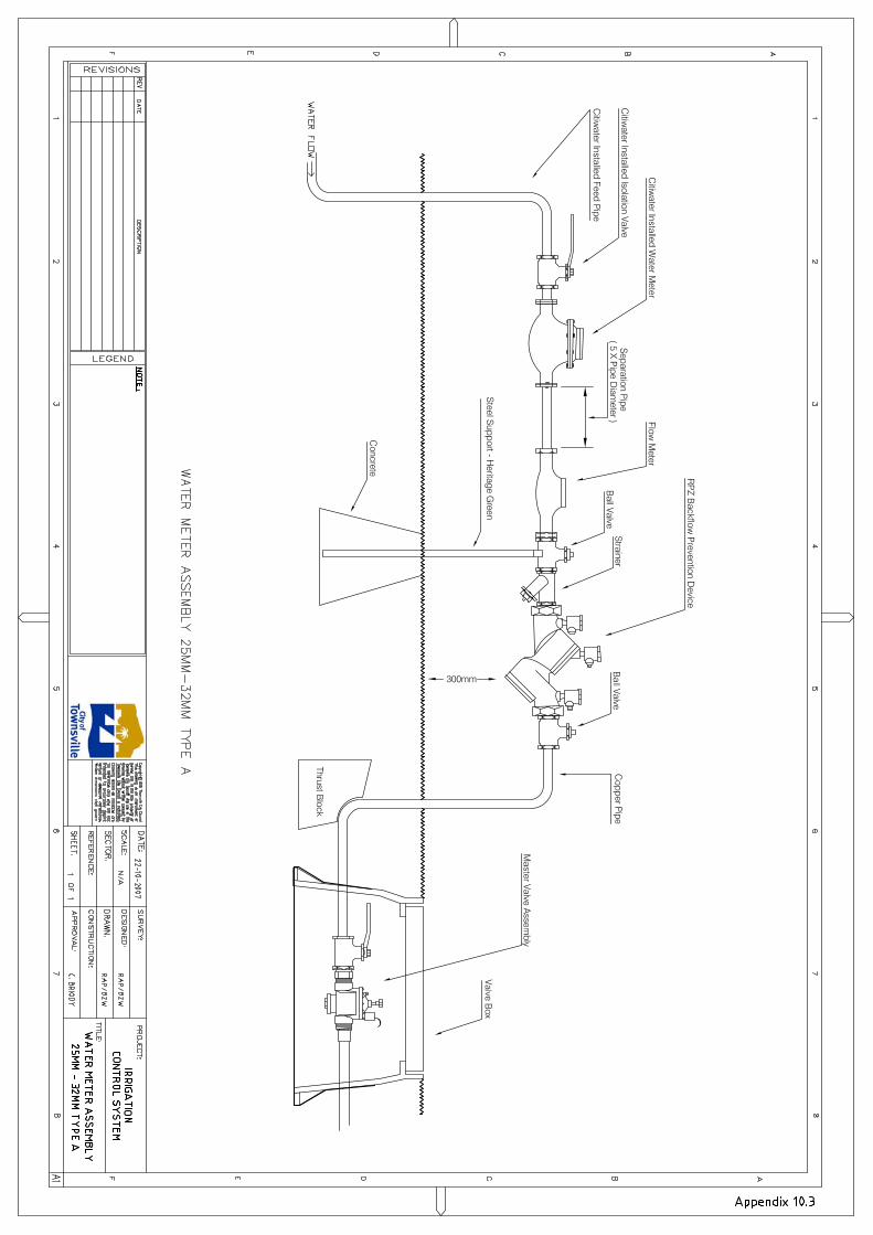
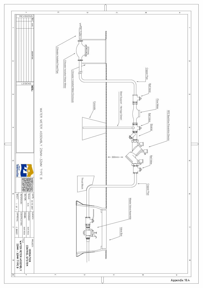
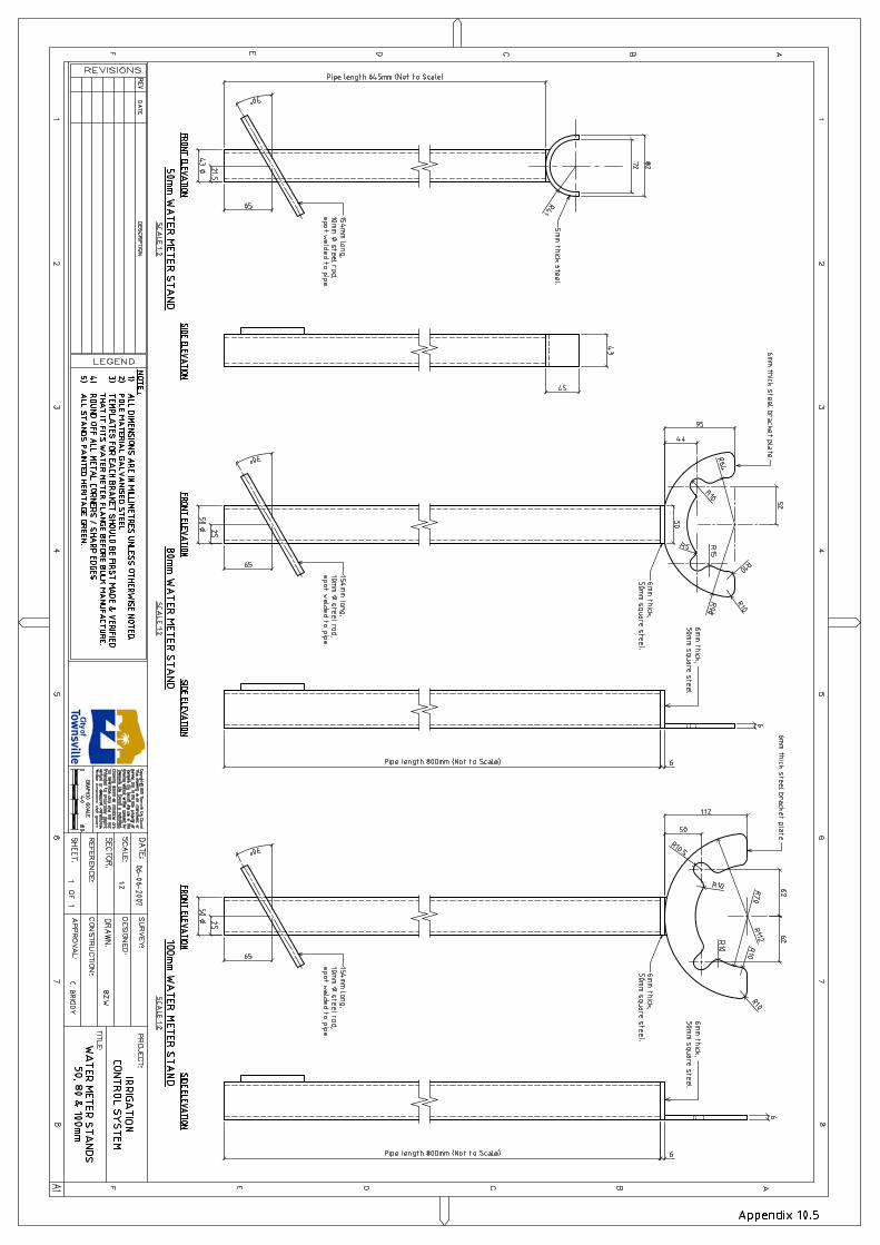

300mm
ThrustBlock
3D 3D
*NOTE
· ALL EQUIPMENT TO BE FLANGE MOUNTED & SIZED TO SUIT 50MM,
80MM, 100MM OR 150MM
· 316 S.S ENCLOSURES TO BE AS PER TCC IRRIG. SPEC'S
APPENDICES
· FIT TCC "A" SERIES LOCK TO ALL S.S ENCLOSURES
A
E
H
F
G
D
J
RECYCLED WATER IRRIG POS & HEAD WORKS
ITEM DESCRIPTION
A DUCTILE OR COPPER PIPE UP LEG ASSEMBLY
B
RSGV OR BALL VALVE (ISOLATION VALVE)
C
HONEYWELL H5000 TOWNSVILLE WATER BILLING WATER
METER C/W DUAL PULSE OUTPUT. 100L PULSE O/P FOR TW, 10L
PULSE O/P FOR IRRIG CONNECTION
D
DOROT 100 SERIES MASTER VALVE ASSEMBLY C/W ELECTRIC
ACTUATOR
E STRAINER FOR BACK FLOW PREVENTION DEVICE
F RP03 OR DC03 BACK FLOW PREVENTION DEVICE
G DUCTILE OR COPPER PIPE UP DOWN ASSEMBLY
H
FLANGE MOUNTED LOCKABLE 316 S.S ENCLOSURE C/W TCC "A"
SERIES PAD LOCK
I
FLANGE MOUNTED LOCKABLE 316 S.S ENCLOSURE C/W TCC "A"
SERIES PAD LOCK
J SUPPORT STAND - AS PER TCC IRRIG. SPEC'S APPENDIX 10.5
I
CB
B
B
J
BZW
BZW
AutoCAD SHX Text
80
AutoCAD SHX Text
FLOW
AutoCAD SHX Text
Not Required
AutoCAD SHX Text
1:5
AutoCAD SHX Text
0
AutoCAD SHX Text
0.1
AutoCAD SHX Text
0.25m
AutoCAD SHX Text
0.2
AutoCAD SHX Text
0.05
AutoCAD SHX Text
0.15
AutoCAD SHX Text
DATE
AutoCAD SHX Text
AP'D
AutoCAD SHX Text
REVISIONS
AutoCAD SHX Text
REV.
AutoCAD SHX Text
INDEX NO.
AutoCAD SHX Text
LEVEL DATUM
AutoCAD SHX Text
Authorised for Issue
AutoCAD SHX Text
COORD.
AutoCAD SHX Text
DES.
AutoCAD SHX Text
DRN.
AutoCAD SHX Text
COORD. DATUM
AutoCAD SHX Text
CHK.
AutoCAD SHX Text
DRAWING SCALES (A1)
AutoCAD SHX Text
SHEET
AutoCAD SHX Text
DRAWING NO.
AutoCAD SHX Text
REV.
AutoCAD SHX Text
REFERENCE DRAWINGS
AutoCAD SHX Text
SURVEY
AutoCAD SHX Text
MANAGER
AutoCAD SHX Text
SENIOR IRRIGATION
AutoCAD SHX Text
DATE
AutoCAD SHX Text
DATE
AutoCAD SHX Text
PLANNER
AutoCAD SHX Text
N.A
AutoCAD SHX Text
RVP
AutoCAD SHX Text
N.A
AutoCAD SHX Text
N.A
AutoCAD SHX Text
N.A
AutoCAD SHX Text
1 OF 1
AutoCAD SHX Text
APPENDIX 10.6
AutoCAD SHX Text
TYPE C
AutoCAD SHX Text
50MM & LARGER
AutoCAD SHX Text
WATER METER ASSEMBLY
AutoCAD SHX Text
IRRIGATION CONTROL SYSTEM
AutoCAD SHX Text
Appendix 10.6
AutoCAD SHX Text
12-11-19
AutoCAD SHX Text
Brian Walters
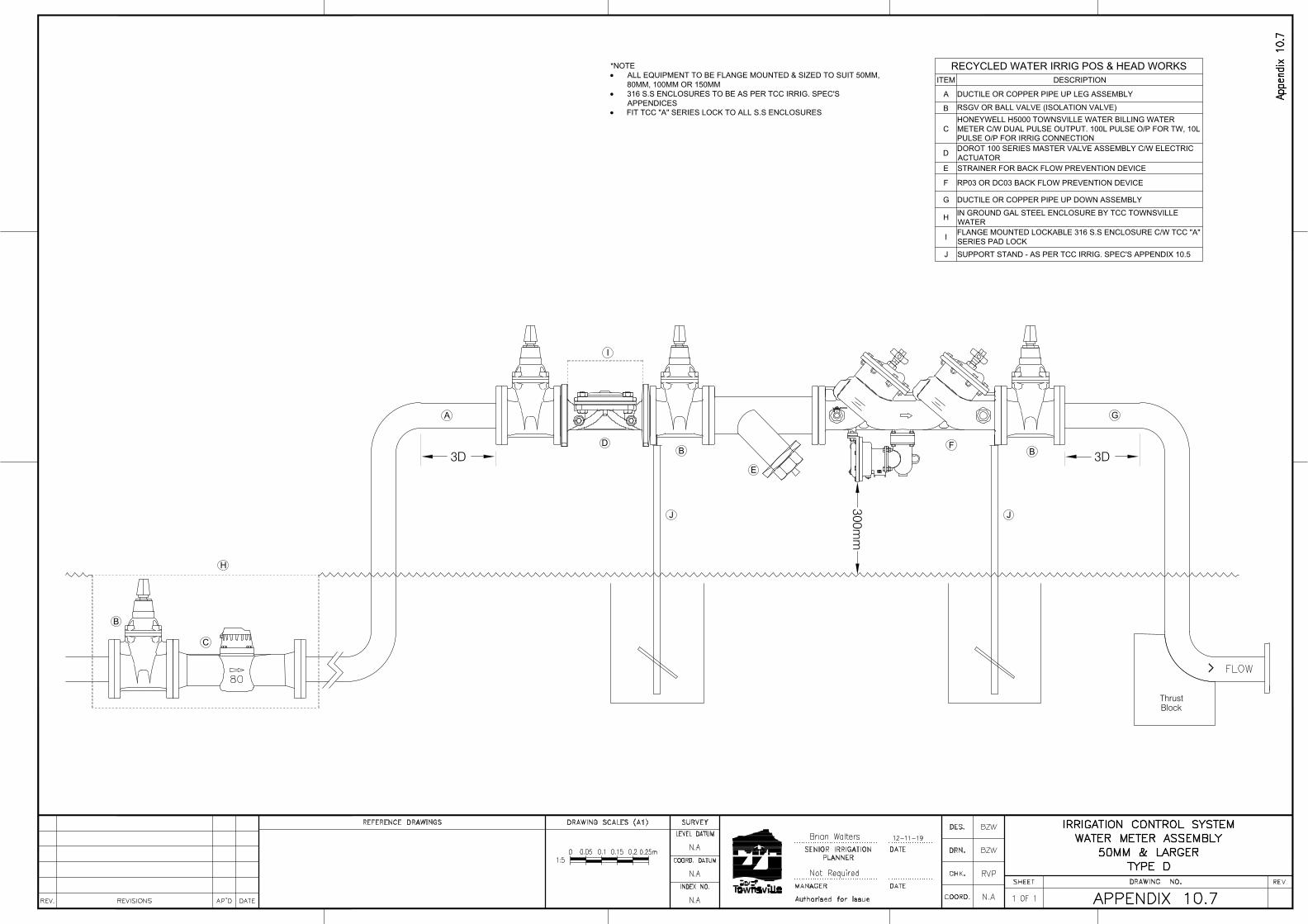
300mm
ThrustBlock
3D 3D
*NOTE
· ALL EQUIPMENT TO BE FLANGE MOUNTED & SIZED TO SUIT 50MM,
80MM, 100MM OR 150MM
· 316 S.S ENCLOSURES TO BE AS PER TCC IRRIG. SPEC'S
APPENDICES
· FIT TCC "A" SERIES LOCK TO ALL S.S ENCLOSURES
A
E
H
F
G
D
J
RECYCLED WATER IRRIG POS & HEAD WORKS
ITEM DESCRIPTION
A DUCTILE OR COPPER PIPE UP LEG ASSEMBLY
B
RSGV OR BALL VALVE (ISOLATION VALVE)
C
HONEYWELL H5000 TOWNSVILLE WATER BILLING WATER
METER C/W DUAL PULSE OUTPUT. 100L PULSE O/P FOR TW, 10L
PULSE O/P FOR IRRIG CONNECTION
D
DOROT 100 SERIES MASTER VALVE ASSEMBLY C/W ELECTRIC
ACTUATOR
E STRAINER FOR BACK FLOW PREVENTION DEVICE
F RP03 OR DC03 BACK FLOW PREVENTION DEVICE
G DUCTILE OR COPPER PIPE UP DOWN ASSEMBLY
H
IN GROUND GAL STEEL ENCLOSURE BY TCC TOWNSVILLE
WATER
I
FLANGE MOUNTED LOCKABLE 316 S.S ENCLOSURE C/W TCC "A"
SERIES PAD LOCK
J SUPPORT STAND - AS PER TCC IRRIG. SPEC'S APPENDIX 10.5
I
C
B
B
B
J
BZW
BZW
AutoCAD SHX Text
80
AutoCAD SHX Text
FLOW
AutoCAD SHX Text
Not Required
AutoCAD SHX Text
1:5
AutoCAD SHX Text
0
AutoCAD SHX Text
0.1
AutoCAD SHX Text
0.25m
AutoCAD SHX Text
0.2
AutoCAD SHX Text
0.05
AutoCAD SHX Text
0.15
AutoCAD SHX Text
DATE
AutoCAD SHX Text
AP'D
AutoCAD SHX Text
REVISIONS
AutoCAD SHX Text
REV.
AutoCAD SHX Text
INDEX NO.
AutoCAD SHX Text
LEVEL DATUM
AutoCAD SHX Text
Authorised for Issue
AutoCAD SHX Text
COORD.
AutoCAD SHX Text
DES.
AutoCAD SHX Text
DRN.
AutoCAD SHX Text
COORD. DATUM
AutoCAD SHX Text
CHK.
AutoCAD SHX Text
DRAWING SCALES (A1)
AutoCAD SHX Text
SHEET
AutoCAD SHX Text
DRAWING NO.
AutoCAD SHX Text
REV.
AutoCAD SHX Text
REFERENCE DRAWINGS
AutoCAD SHX Text
SURVEY
AutoCAD SHX Text
MANAGER
AutoCAD SHX Text
SENIOR IRRIGATION
AutoCAD SHX Text
DATE
AutoCAD SHX Text
DATE
AutoCAD SHX Text
PLANNER
AutoCAD SHX Text
N.A
AutoCAD SHX Text
RVP
AutoCAD SHX Text
N.A
AutoCAD SHX Text
N.A
AutoCAD SHX Text
N.A
AutoCAD SHX Text
1 OF 1
AutoCAD SHX Text
APPENDIX 10.7
AutoCAD SHX Text
TYPE D
AutoCAD SHX Text
50MM & LARGER
AutoCAD SHX Text
WATER METER ASSEMBLY
AutoCAD SHX Text
IRRIGATION CONTROL SYSTEM
AutoCAD SHX Text
Appendix 10.7
AutoCAD SHX Text
12-11-19
AutoCAD SHX Text
Brian Walters
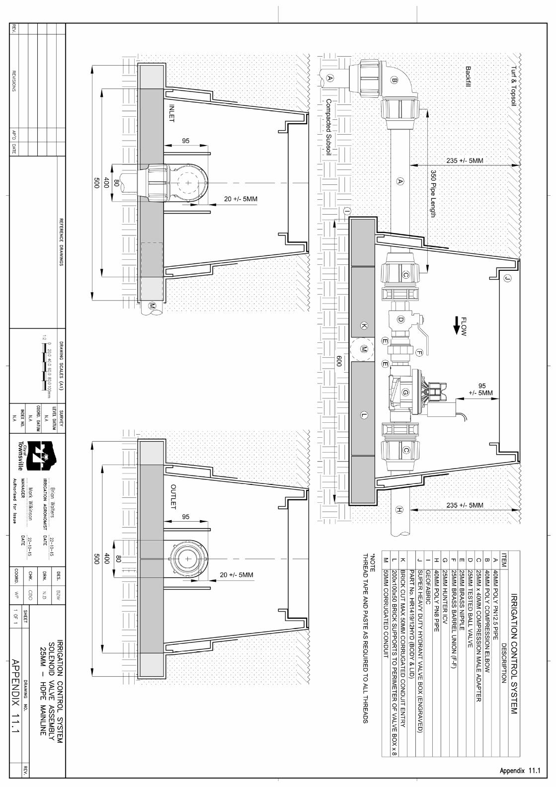
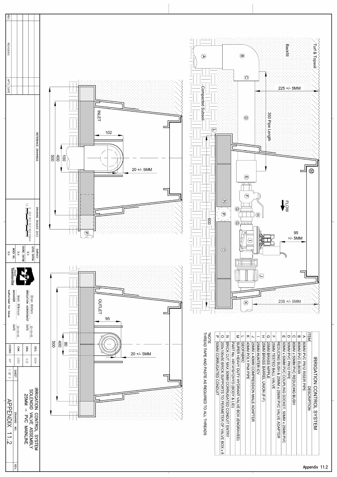
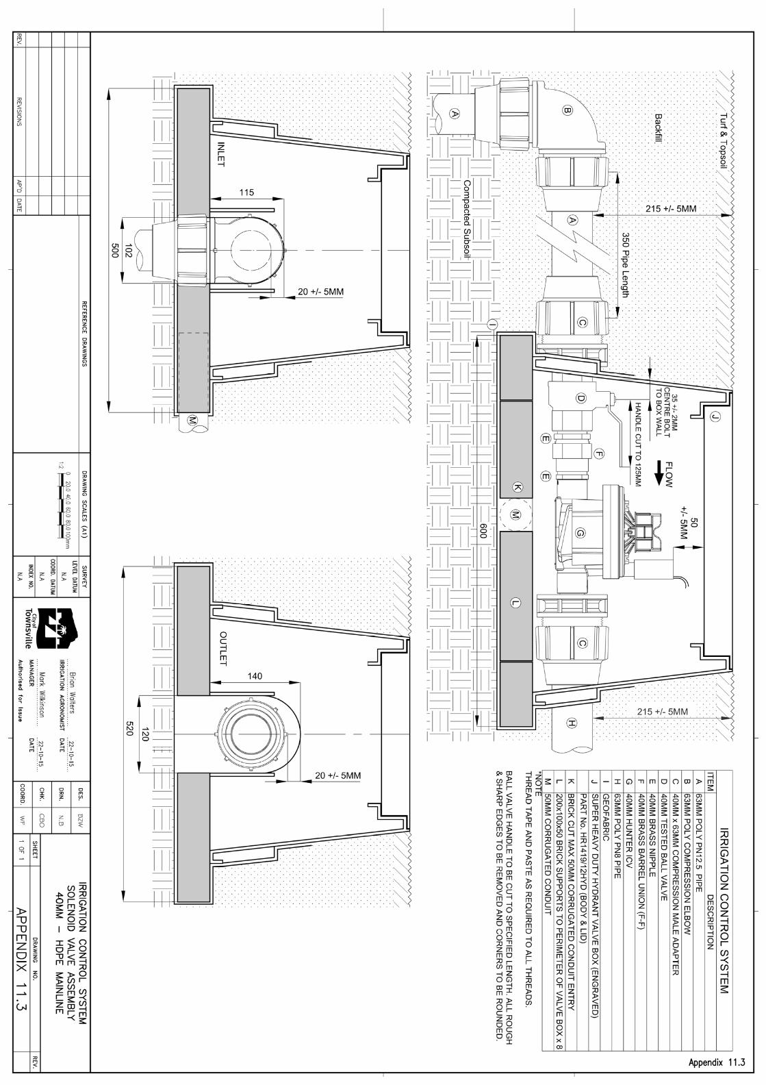


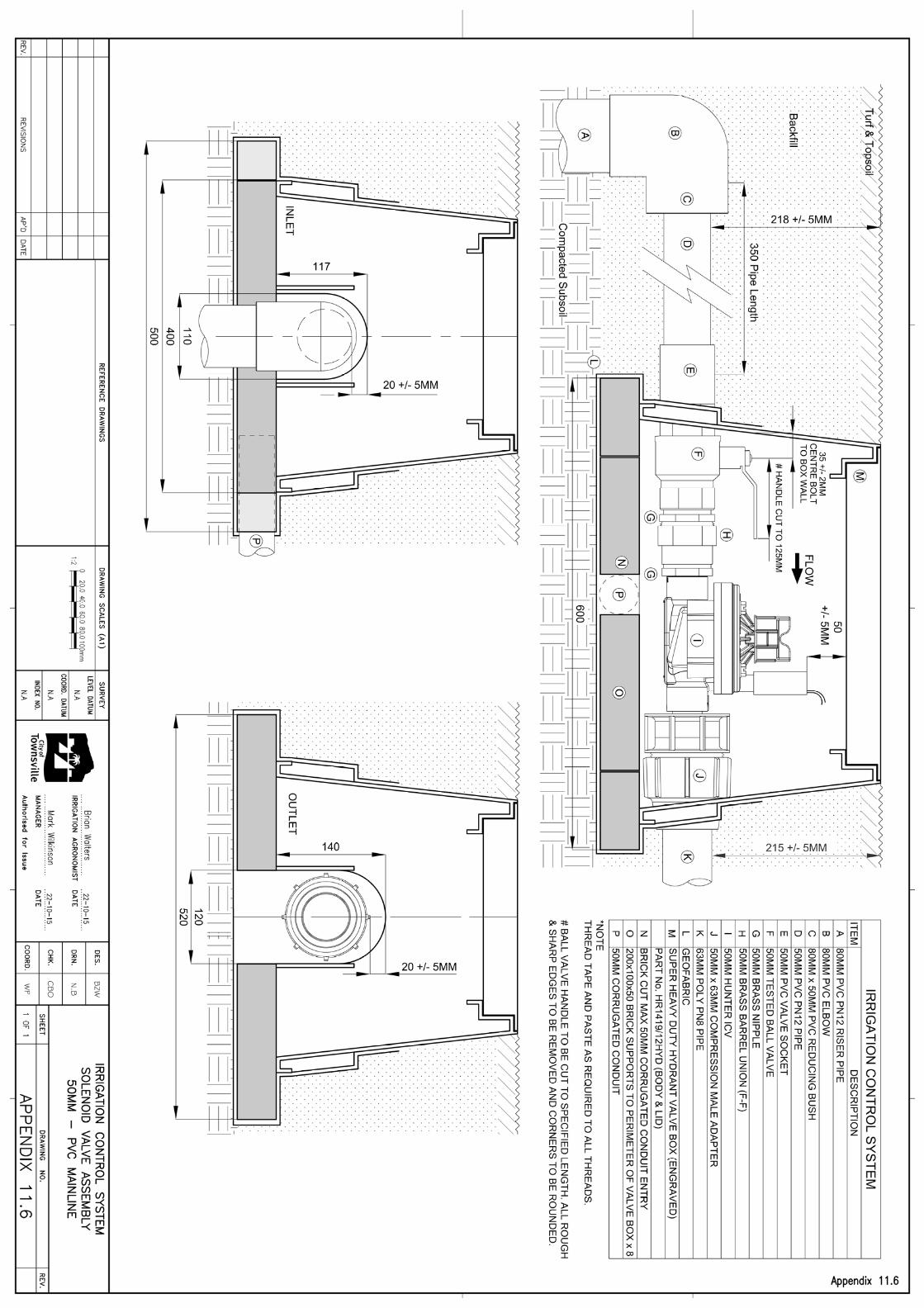
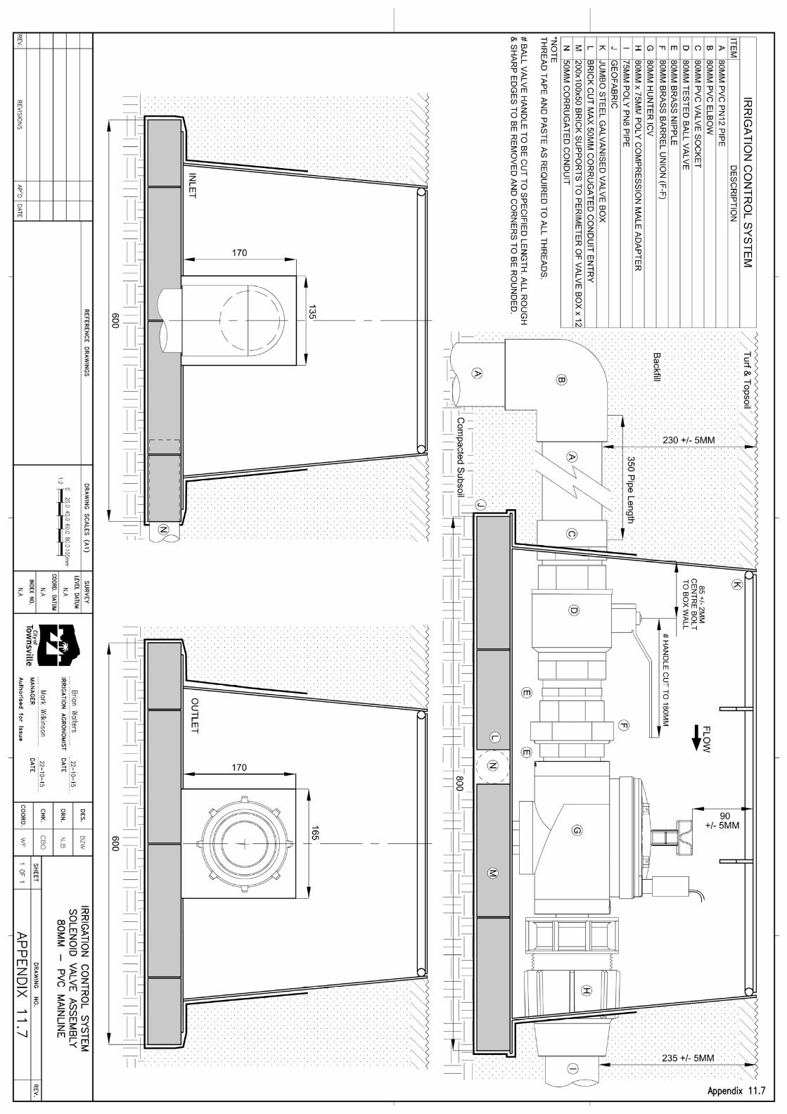
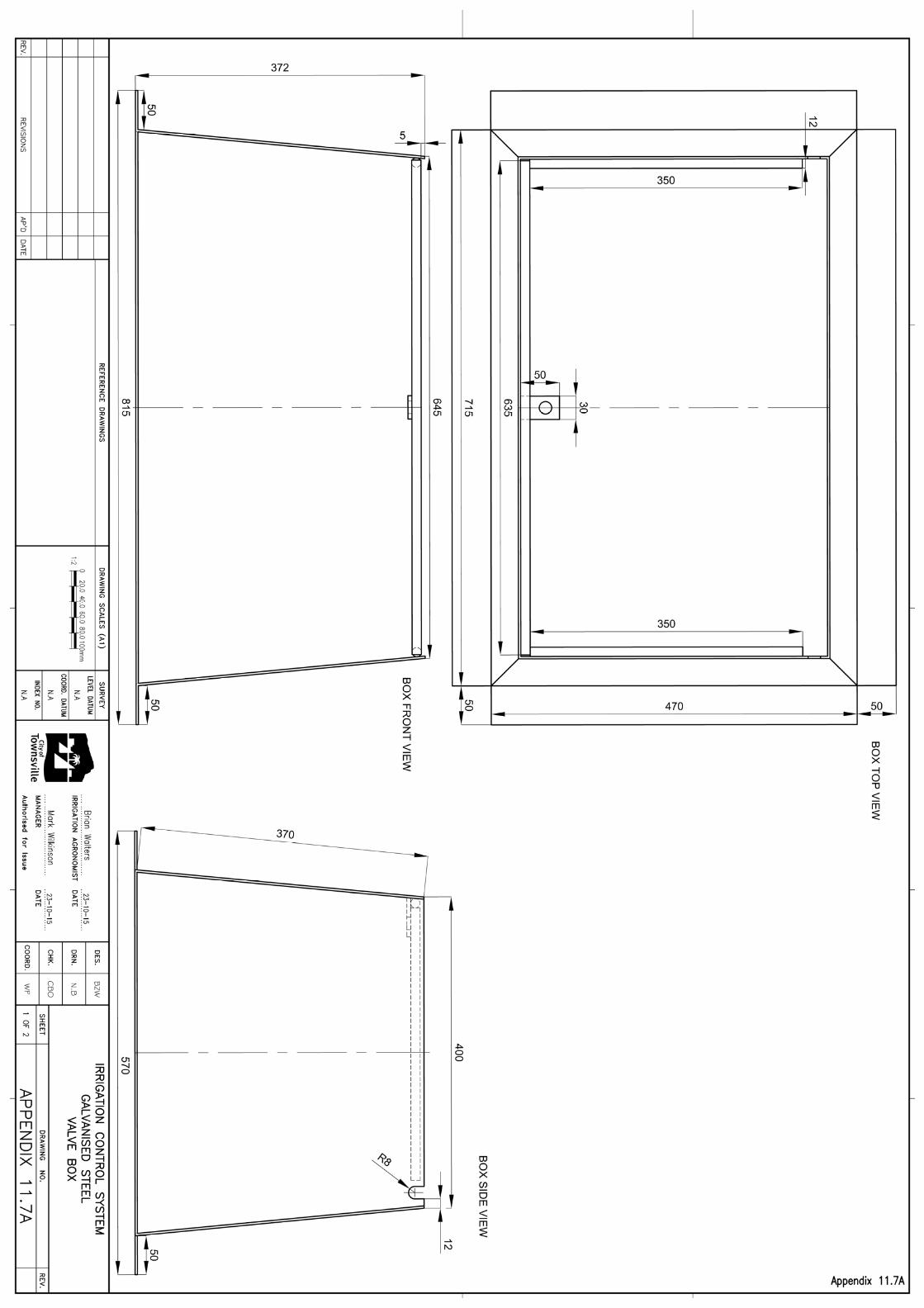
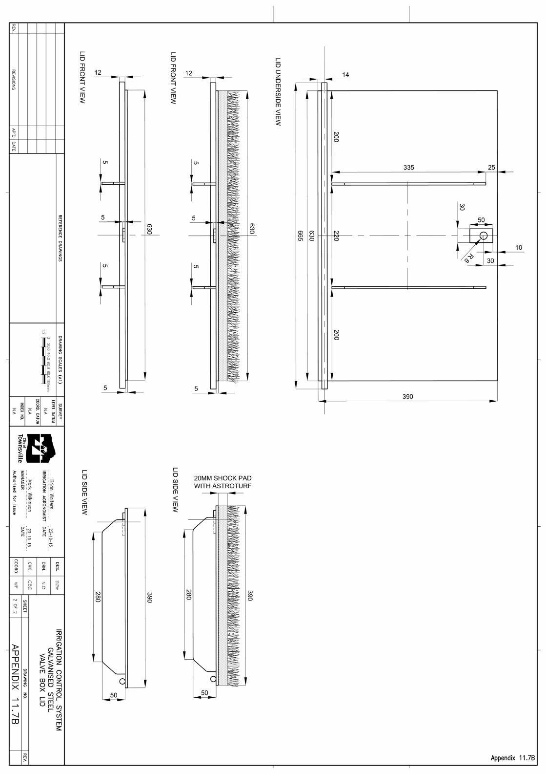
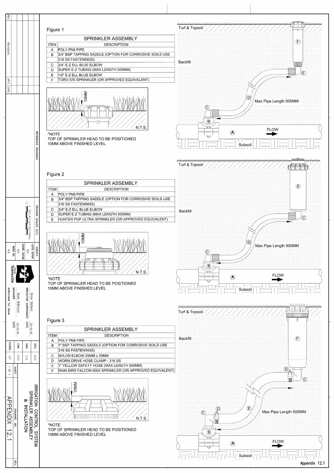
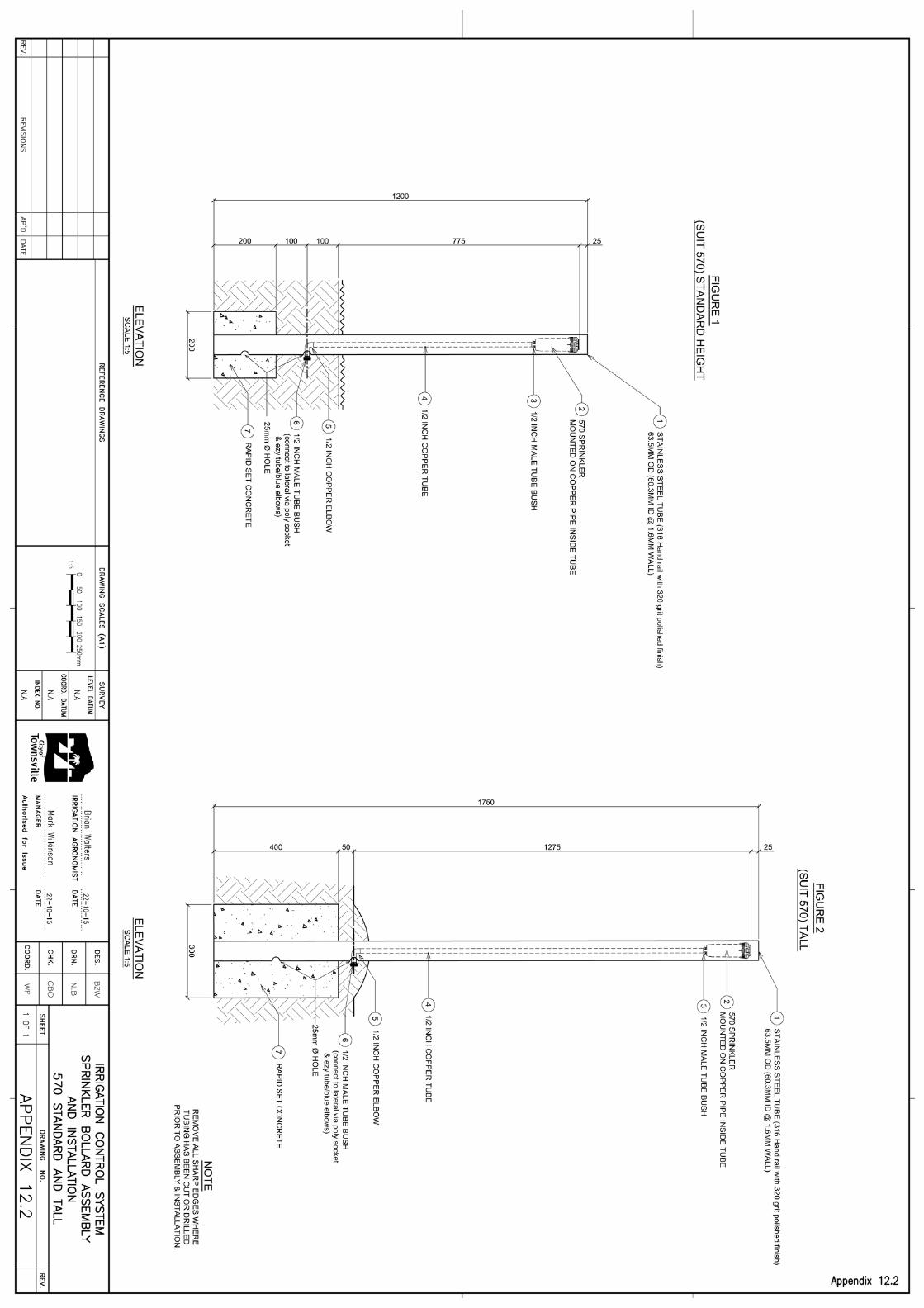

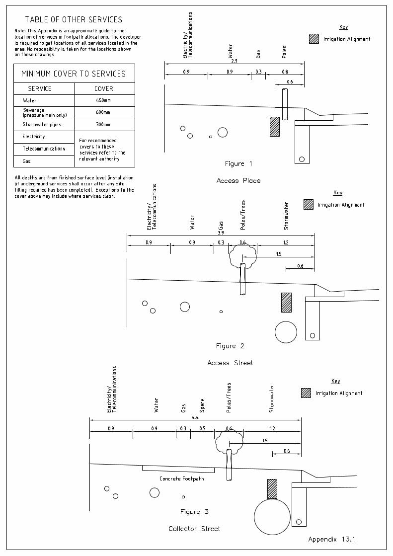
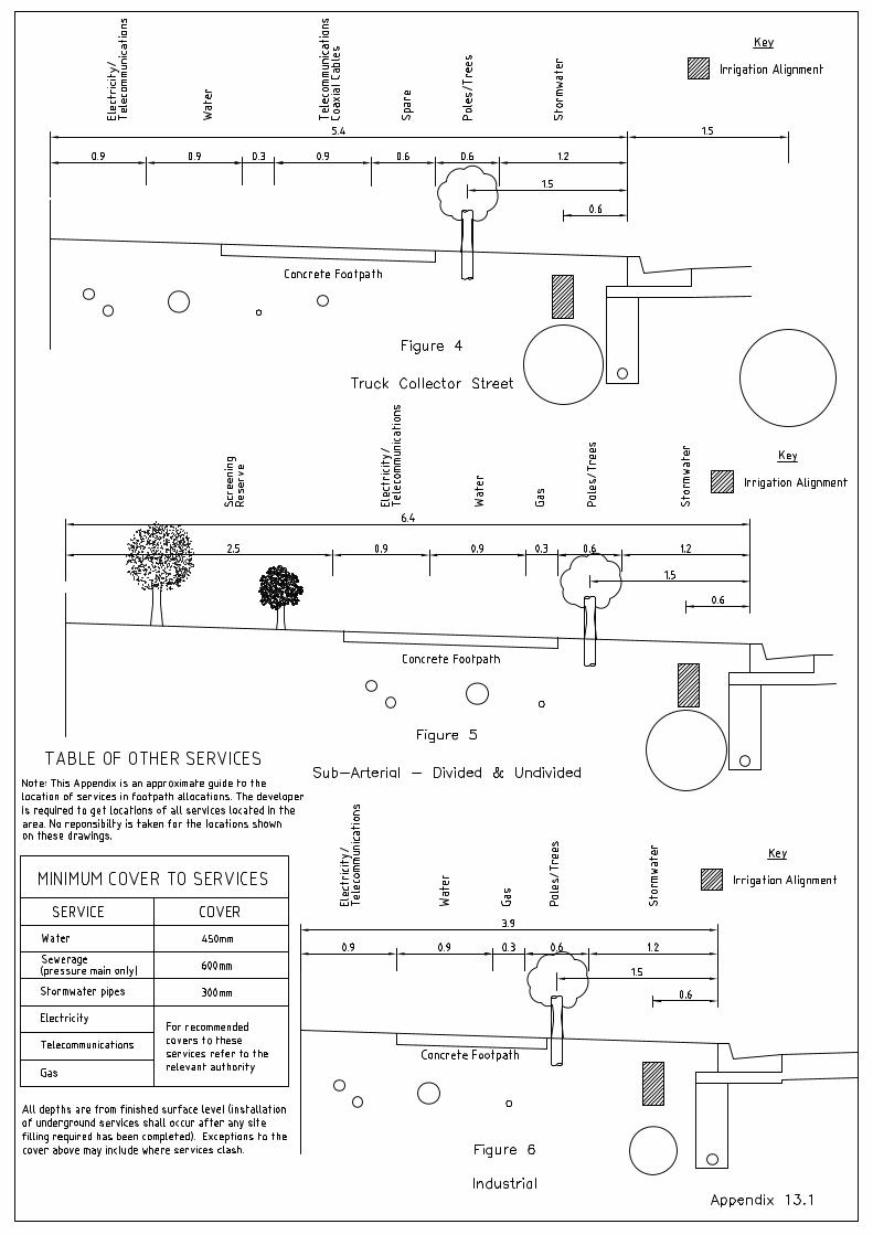
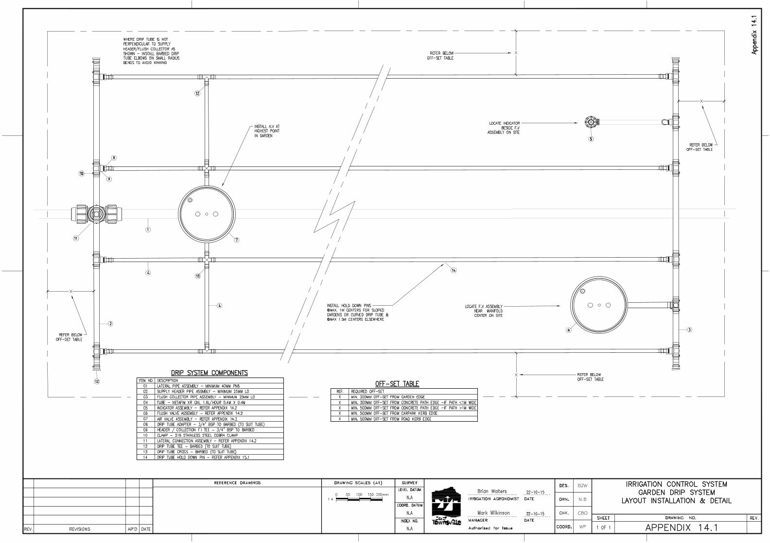
BZW
N.B
CBO
WP
AutoCAD SHX Text
DATE
AutoCAD SHX Text
AP'D
AutoCAD SHX Text
REVISIONS
AutoCAD SHX Text
REV.
AutoCAD SHX Text
INDEX NO.
AutoCAD SHX Text
LEVEL DATUM
AutoCAD SHX Text
Authorised for Issue
AutoCAD SHX Text
COORD.
AutoCAD SHX Text
DES.
AutoCAD SHX Text
DRN.
AutoCAD SHX Text
COORD. DATUM
AutoCAD SHX Text
CHK.
AutoCAD SHX Text
DRAWING SCALES (A1)
AutoCAD SHX Text
SHEET
AutoCAD SHX Text
DRAWING NO.
AutoCAD SHX Text
REV.
AutoCAD SHX Text
REFERENCE DRAWINGS
AutoCAD SHX Text
SURVEY
AutoCAD SHX Text
MANAGER
AutoCAD SHX Text
IRRIGATION AGRONOMIST
AutoCAD SHX Text
DATE
AutoCAD SHX Text
DATE
AutoCAD SHX Text
IRRIGATION CONTROL SYSTEM
AutoCAD SHX Text
GARDEN DRIP SYSTEM
AutoCAD SHX Text
LAYOUT INSTALLATION & DETAIL
AutoCAD SHX Text
APPENDIX 14.1
AutoCAD SHX Text
1 OF 1
AutoCAD SHX Text
N.A
AutoCAD SHX Text
N.A
AutoCAD SHX Text
N.A
AutoCAD SHX Text
22-10-15
AutoCAD SHX Text
22-10-15
AutoCAD SHX Text
Mark Wilkinson
AutoCAD SHX Text
Brian Walters
AutoCAD SHX Text
Appendix 14.1
AutoCAD SHX Text
1:4
AutoCAD SHX Text
0
AutoCAD SHX Text
100
AutoCAD SHX Text
200mm
AutoCAD SHX Text
50
AutoCAD SHX Text
150
AutoCAD SHX Text
1
AutoCAD SHX Text
2
AutoCAD SHX Text
4
AutoCAD SHX Text
3
AutoCAD SHX Text
5
AutoCAD SHX Text
6
AutoCAD SHX Text
7
AutoCAD SHX Text
10
AutoCAD SHX Text
8
AutoCAD SHX Text
9
AutoCAD SHX Text
12
AutoCAD SHX Text
4
AutoCAD SHX Text
11
AutoCAD SHX Text
ITEM NO.
AutoCAD SHX Text
DESCRIPTION
AutoCAD SHX Text
01
AutoCAD SHX Text
LATERAL PIPE ASSEMBLY - MINIMUM 40MM PN8
AutoCAD SHX Text
02
AutoCAD SHX Text
03
AutoCAD SHX Text
04
AutoCAD SHX Text
05
AutoCAD SHX Text
06
AutoCAD SHX Text
SUPPLY HEADER PIPE ASSMBLY - MINIMUM 25MM LD
AutoCAD SHX Text
TUBE - NETAFIM XR CNL 1.6L/HOUR 0.4M X 0.4M
AutoCAD SHX Text
INDICATOR ASSEMBLY - REFER APPENDIX 14.2
AutoCAD SHX Text
FLUSH VALVE ASSEMBLY - REFER APPENDIX 14.2
AutoCAD SHX Text
FLUSH COLLECTOR PIPE ASSEMBLY - MINIMUM 25MM LD
AutoCAD SHX Text
07
AutoCAD SHX Text
AIR VALVE ASSEMBLY - REFER APPENDIX 14.2
AutoCAD SHX Text
08
AutoCAD SHX Text
DRIP TUBE ADAPTER - 3/4" BSP TO BARBED (TO SUIT TUBE)
AutoCAD SHX Text
09
AutoCAD SHX Text
HEADER / COLLECTION F.I TEE - 3/4" BSP TO BARBED
AutoCAD SHX Text
10
AutoCAD SHX Text
CLAMP - 316 STAINLESS STEEL COBRA CLAMP
AutoCAD SHX Text
11
AutoCAD SHX Text
LATERAL CONNECTION ASSEMBLY - REFER APPENDIX 14.2
AutoCAD SHX Text
REF.
AutoCAD SHX Text
REQUIRED OFF-SET
AutoCAD SHX Text
X
AutoCAD SHX Text
MIN. 200MM OFF-SET FROM GARDEN EDGE
AutoCAD SHX Text
MIN. 300MM OFF-SET FROM CONCRETE PATH EDGE -IF PATH <1M WIDE
AutoCAD SHX Text
MIN. 500MM OFF-SET FROM CONCRETE PATH EDGE -IF PATH >1M WIDE
AutoCAD SHX Text
MIN. 500MM OFF-SET FROM CARPARK KERB EDGE
AutoCAD SHX Text
MIN. 500MM OFF-SET FROM ROAD KERB EDGE
AutoCAD SHX Text
X
AutoCAD SHX Text
X
AutoCAD SHX Text
X
AutoCAD SHX Text
X
AutoCAD SHX Text
OFF-SET TABLE
AutoCAD SHX Text
DRIP SYSTEM COMPONENTS
AutoCAD SHX Text
12
AutoCAD SHX Text
13
AutoCAD SHX Text
12
AutoCAD SHX Text
DRIP TUBE TEE - BARBED (TO SUIT TUBE)
AutoCAD SHX Text
13
AutoCAD SHX Text
DRIP TUBE CROSS - BARBED (TO SUIT TUBE)
AutoCAD SHX Text
INSTALL A.V AT HIGHEST POINT IN GARDEN
AutoCAD SHX Text
REFER BELOW OFF-SET TABLE
AutoCAD SHX Text
REFER BELOW OFF-SET TABLE
AutoCAD SHX Text
REFER BELOW OFF-SET TABLE
AutoCAD SHX Text
REFER BELOW OFF-SET TABLE
AutoCAD SHX Text
LOCATE INDICATOR BESIDE F.V ASSEMBLY ON SITE
AutoCAD SHX Text
LOCATE F.V ASSEMBLY NEAR MANIFOLD CENTER ON SITE
AutoCAD SHX Text
14
AutoCAD SHX Text
DRIP TUBE HOLD DOWN PIN - REFER APPENDIX 15.1
AutoCAD SHX Text
INSTALL HOLD DOWN PINS @MAX. 1M CENTERS FOR SLOPED GARDENS OR CURVED DRIP TUBE & @MAX 1.5M CENTERS ELSEWHERE
AutoCAD SHX Text
14
AutoCAD SHX Text
WHERE DRIP TUBE IS NOT PERPENDICULAR TO SUPPLY HEADER/FLUSH COLLECTOR AS SHOWN - INSTALL BARBED DRIP TUBE ELBOWS ON SMALL RADIUS BENDS TO AVOID KINKING
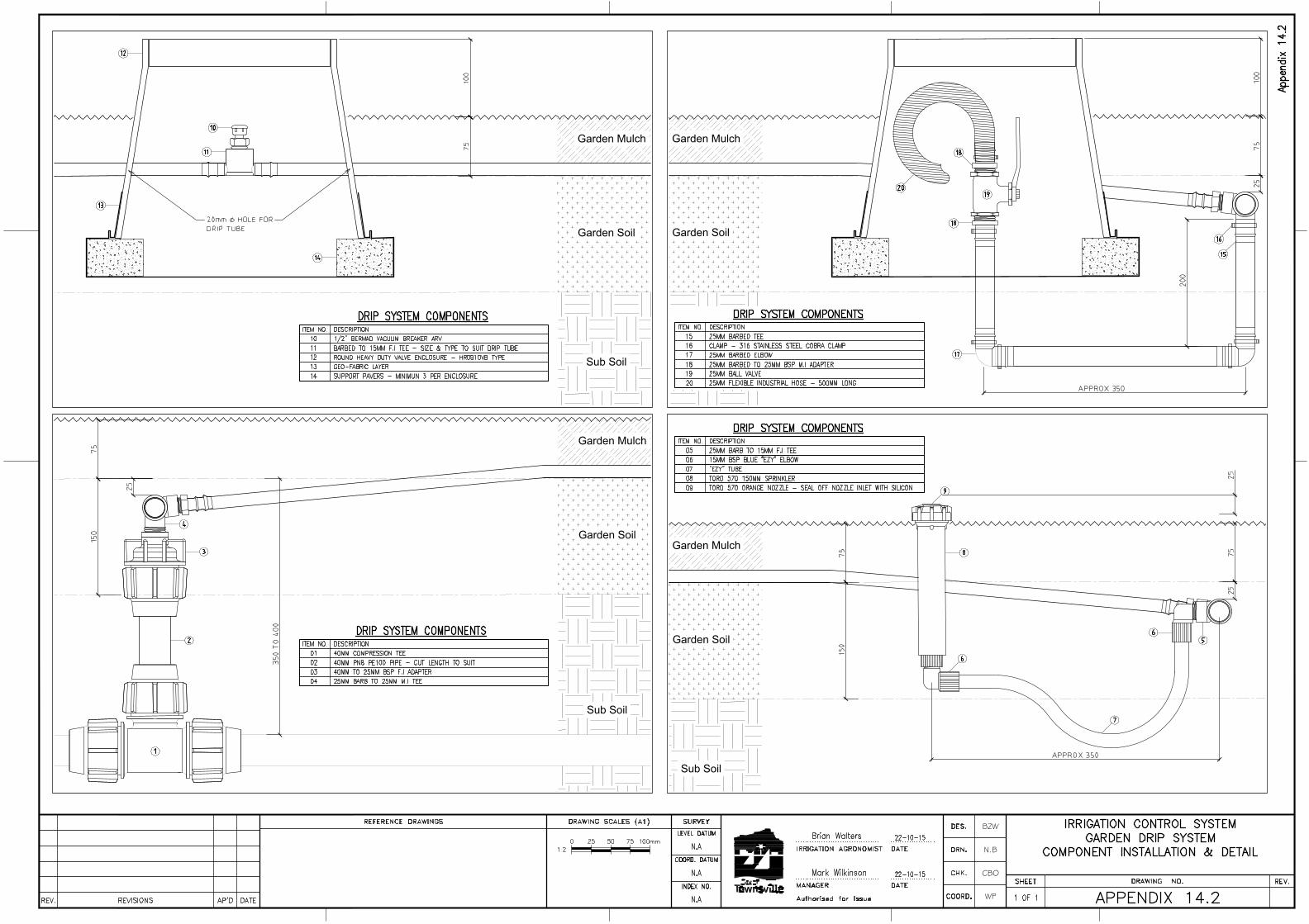
Garden Mulch
Garden Soil
Sub Soil
Garden Mulch
Garden Soil
Sub Soil
Garden Mulch
Garden Soil
Sub Soil
Garden Mulch
Garden Soil
Sub Soil
BZW
N.B
CBO
WP
AutoCAD SHX Text
Female Adaptor
AutoCAD SHX Text
Raccord Femelle
AutoCAD SHX Text
Anschlussverschraubungen IG
AutoCAD SHX Text
Raccordo Femmina
AutoCAD SHX Text
Enlace mixto rosca hembra
AutoCAD SHX Text
40 x 1"
AutoCAD SHX Text
40 x 1"
AutoCAD SHX Text
Female Adaptor
AutoCAD SHX Text
DATE
AutoCAD SHX Text
AP'D
AutoCAD SHX Text
REVISIONS
AutoCAD SHX Text
REV.
AutoCAD SHX Text
INDEX NO.
AutoCAD SHX Text
LEVEL DATUM
AutoCAD SHX Text
Authorised for Issue
AutoCAD SHX Text
COORD.
AutoCAD SHX Text
DES.
AutoCAD SHX Text
DRN.
AutoCAD SHX Text
COORD. DATUM
AutoCAD SHX Text
CHK.
AutoCAD SHX Text
DRAWING SCALES (A1)
AutoCAD SHX Text
SHEET
AutoCAD SHX Text
DRAWING NO.
AutoCAD SHX Text
REV.
AutoCAD SHX Text
REFERENCE DRAWINGS
AutoCAD SHX Text
SURVEY
AutoCAD SHX Text
MANAGER
AutoCAD SHX Text
IRRIGATION AGRONOMIST
AutoCAD SHX Text
DATE
AutoCAD SHX Text
DATE
AutoCAD SHX Text
IRRIGATION CONTROL SYSTEM
AutoCAD SHX Text
GARDEN DRIP SYSTEM
AutoCAD SHX Text
COMPONENT INSTALLATION & DETAIL
AutoCAD SHX Text
APPENDIX 14.2
AutoCAD SHX Text
1 OF 1
AutoCAD SHX Text
N.A
AutoCAD SHX Text
N.A
AutoCAD SHX Text
N.A
AutoCAD SHX Text
22-10-15
AutoCAD SHX Text
22-10-15
AutoCAD SHX Text
Mark Wilkinson
AutoCAD SHX Text
Brian Walters
AutoCAD SHX Text
Appendix 14.2
AutoCAD SHX Text
1:2
AutoCAD SHX Text
0
AutoCAD SHX Text
50
AutoCAD SHX Text
100mm
AutoCAD SHX Text
25
AutoCAD SHX Text
75
AutoCAD SHX Text
ITEM NO.
AutoCAD SHX Text
DESCRIPTION
AutoCAD SHX Text
DRIP SYSTEM COMPONENTS
AutoCAD SHX Text
01
AutoCAD SHX Text
40MM COMPRESSION TEE
AutoCAD SHX Text
02
AutoCAD SHX Text
03
AutoCAD SHX Text
04
AutoCAD SHX Text
40MM TO 25MM BSP F.I ADAPTER
AutoCAD SHX Text
20mm HOLE FORDRIP TUBE
AutoCAD SHX Text
1
AutoCAD SHX Text
2
AutoCAD SHX Text
5
AutoCAD SHX Text
6
AutoCAD SHX Text
6
AutoCAD SHX Text
10
AutoCAD SHX Text
7
AutoCAD SHX Text
8
AutoCAD SHX Text
3
AutoCAD SHX Text
4
AutoCAD SHX Text
11
AutoCAD SHX Text
12
AutoCAD SHX Text
13
AutoCAD SHX Text
14
AutoCAD SHX Text
15
AutoCAD SHX Text
16
AutoCAD SHX Text
17
AutoCAD SHX Text
18
AutoCAD SHX Text
19
AutoCAD SHX Text
18
AutoCAD SHX Text
20
AutoCAD SHX Text
40MM PN8 PE100 PIPE - CUT LENGTH TO SUIT
AutoCAD SHX Text
25MM BARB TO 25MM M.I TEE
AutoCAD SHX Text
9
AutoCAD SHX Text
ITEM NO.
AutoCAD SHX Text
DESCRIPTION
AutoCAD SHX Text
DRIP SYSTEM COMPONENTS
AutoCAD SHX Text
05
AutoCAD SHX Text
06
AutoCAD SHX Text
07
AutoCAD SHX Text
08
AutoCAD SHX Text
09
AutoCAD SHX Text
25MM BARB TO 15MM F.I TEE
AutoCAD SHX Text
15MM BSP BLUE "EZY" ELBOW
AutoCAD SHX Text
"EZY" TUBE
AutoCAD SHX Text
TORO 570 150MM SPRINKLER
AutoCAD SHX Text
TORO 570 ORANGE NOZZLE - SEAL OFF NOZZLE INLET WITH SILICON
AutoCAD SHX Text
ITEM NO.
AutoCAD SHX Text
DESCRIPTION
AutoCAD SHX Text
DRIP SYSTEM COMPONENTS
AutoCAD SHX Text
10
AutoCAD SHX Text
11
AutoCAD SHX Text
1/2" BERMAD VACUUM BREAKER ARV
AutoCAD SHX Text
BARBED TO 15MM F.I TEE - SIZE & TYPE TO SUIT DRIP TUBE
AutoCAD SHX Text
12
AutoCAD SHX Text
ROUND HEAVY DUTY VALVE ENCLOSURE - HR0910VB TYPE
AutoCAD SHX Text
13
AutoCAD SHX Text
GEO-FABRIC LAYER
AutoCAD SHX Text
14
AutoCAD SHX Text
SUPPORT PAVERS - MINIMUN 3 PER ENCLOSURE
AutoCAD SHX Text
ITEM NO.
AutoCAD SHX Text
DESCRIPTION
AutoCAD SHX Text
DRIP SYSTEM COMPONENTS
AutoCAD SHX Text
15
AutoCAD SHX Text
25MM BARBED TEE
AutoCAD SHX Text
16
AutoCAD SHX Text
CLAMP - 316 STAINLESS STEEL COBRA CLAMP
AutoCAD SHX Text
17
AutoCAD SHX Text
25MM BARBED ELBOW
AutoCAD SHX Text
18
AutoCAD SHX Text
25MM BARBED TO 25MM BSP M.I ADAPTER
AutoCAD SHX Text
19
AutoCAD SHX Text
25MM BALL VALVE
AutoCAD SHX Text
20
AutoCAD SHX Text
25MM FLEXIBLE INDUSTRIAL HOSE - 500MM LONG
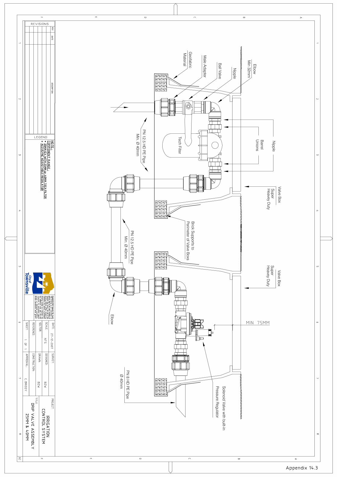


+/- 5MM
50
A
Q
R
B
C
D
E
F
G
E
F
J
K
L L
L
J
N
F
O
P
S
TU
M
H
I
I
I
M
Turf & Topsoil
Backfill
R
50-75MM
V
V
Compacted
Subsoil
K
BZW
N.B
CBO
WP
AutoCAD SHX Text
DATE
AutoCAD SHX Text
AP'D
AutoCAD SHX Text
REVISIONS
AutoCAD SHX Text
REV.
AutoCAD SHX Text
INDEX NO.
AutoCAD SHX Text
LEVEL DATUM
AutoCAD SHX Text
Authorised for Issue
AutoCAD SHX Text
COORD.
AutoCAD SHX Text
DES.
AutoCAD SHX Text
DRN.
AutoCAD SHX Text
COORD. DATUM
AutoCAD SHX Text
CHK.
AutoCAD SHX Text
DRAWING SCALES (A1)
AutoCAD SHX Text
SHEET
AutoCAD SHX Text
DRAWING NO.
AutoCAD SHX Text
REV.
AutoCAD SHX Text
REFERENCE DRAWINGS
AutoCAD SHX Text
SURVEY
AutoCAD SHX Text
MANAGER
AutoCAD SHX Text
IRRIGATION AGRONOMIST
AutoCAD SHX Text
DATE
AutoCAD SHX Text
DATE
AutoCAD SHX Text
IRRIGATION CONTROL SYSTEM
AutoCAD SHX Text
DRIP FILTER & VALVE ASSEMBLY
AutoCAD SHX Text
40MM - HDPE OR PVC MAINLINE
AutoCAD SHX Text
APPENDIX 14.6
AutoCAD SHX Text
1 OF 1
AutoCAD SHX Text
N.A
AutoCAD SHX Text
N.A
AutoCAD SHX Text
N.A
AutoCAD SHX Text
22-10-15
AutoCAD SHX Text
22-10-15
AutoCAD SHX Text
Mark Wilkinson
AutoCAD SHX Text
Brian Walters
AutoCAD SHX Text
Appendix 14.6
AutoCAD SHX Text
1:2
AutoCAD SHX Text
0
AutoCAD SHX Text
40.0
AutoCAD SHX Text
100mm
AutoCAD SHX Text
80.0
AutoCAD SHX Text
20.0
AutoCAD SHX Text
60.0
AutoCAD SHX Text
ITEM NO.
AutoCAD SHX Text
DESCRIPTION
AutoCAD SHX Text
A
AutoCAD SHX Text
63MM(max) POLY PN12.5 PIPE or 80MM(max) PVC PN12 PIPE
AutoCAD SHX Text
B
AutoCAD SHX Text
C
AutoCAD SHX Text
D
AutoCAD SHX Text
E
AutoCAD SHX Text
F
AutoCAD SHX Text
40MM x 63MM COMPRESSION MALE ADAPTER or 40-80MM PVC ADAPTER
AutoCAD SHX Text
40MM POLY NIPPLE
AutoCAD SHX Text
40MM POLY FI ELBOW
AutoCAD SHX Text
40MM BRASS BARREL UNION M-F
AutoCAD SHX Text
40MM TESTED BALL VALVE WITH SHORT HANDLE (LOGI VALVE W649)
AutoCAD SHX Text
G
AutoCAD SHX Text
40MM SUPER ARKAL DISC FILTER, 120 MESH
AutoCAD SHX Text
H
AutoCAD SHX Text
200MM X 150MM PVC PN12 PIPE
AutoCAD SHX Text
I
AutoCAD SHX Text
40MM x 40MM COMPRESSION MALE ADAPTER or 40MM x 50MM(max)
AutoCAD SHX Text
J
AutoCAD SHX Text
40MM POLY PN12.5 PIPE or 50MM(max) POLY PN12.5 PIPE
AutoCAD SHX Text
K
AutoCAD SHX Text
40MM x 40MM COMPRESSION ELBOW or 50MM X 50MM(max)
AutoCAD SHX Text
DRIP SYSTEM COMPONENTS
AutoCAD SHX Text
L
AutoCAD SHX Text
M
AutoCAD SHX Text
GEOFABRIC
AutoCAD SHX Text
SUPER HEAVY DUTY HYDRANT VALVE BOX (ENGRAVED)
AutoCAD SHX Text
PART No. HR1419/12HYD (BODY & LID)
AutoCAD SHX Text
ITEM NO.
AutoCAD SHX Text
DESCRIPTION
AutoCAD SHX Text
N
AutoCAD SHX Text
40MM HUNTER ICV
AutoCAD SHX Text
O
AutoCAD SHX Text
P
AutoCAD SHX Text
Q
AutoCAD SHX Text
R
AutoCAD SHX Text
S
AutoCAD SHX Text
40MM x 50MM POLY REDUCING NIPPLE
AutoCAD SHX Text
BRICK CUT MAX 50MM CORRUGATED CONDUIT ENTRY
AutoCAD SHX Text
200x100x50 BRICK SUPPORTS TO PERIMETER OF VALVE BOX x8
AutoCAD SHX Text
50MM NETAFIM PRV2000 x4 SPRING REGULATOR (FLOW 3.2m3-18m3)
AutoCAD SHX Text
DRIP SYSTEM COMPONENTS
AutoCAD SHX Text
63MM(max) POLY PN8 PIPE (design to specify pipe size required)
AutoCAD SHX Text
REFER PRODUCT LITERATURE FOR SPRING SELECTION
AutoCAD SHX Text
THREAD TAPE AND PASTE AS REQUIRED TO ALL THREADS TO ENSURE
AutoCAD SHX Text
NOTE
AutoCAD SHX Text
SHORT ASSEMBLY LENGTH WITHOUT OVER STRESSING FITTINGS
AutoCAD SHX Text
T
AutoCAD SHX Text
MAX 20MM +/-5MM GAP AROUND FITTING
AutoCAD SHX Text
USE ROUND HOLE SAW & DRILL TO CUT BOX INLET/OUTLET
AutoCAD SHX Text
NOTE
AutoCAD SHX Text
U
AutoCAD SHX Text
V
AutoCAD SHX Text
50MM CORRUGATED CONDUIT
AutoCAD SHX Text
50MM x 63MM(max) COMPRESSION MALE ADAPTER

BZW
N.B
CBO
WP
········
····
AutoCAD SHX Text
DATE
AutoCAD SHX Text
AP'D
AutoCAD SHX Text
REVISIONS
AutoCAD SHX Text
REV.
AutoCAD SHX Text
INDEX NO.
AutoCAD SHX Text
LEVEL DATUM
AutoCAD SHX Text
Authorised for Issue
AutoCAD SHX Text
COORD.
AutoCAD SHX Text
DES.
AutoCAD SHX Text
DRN.
AutoCAD SHX Text
COORD. DATUM
AutoCAD SHX Text
CHK.
AutoCAD SHX Text
DRAWING SCALES (A1)
AutoCAD SHX Text
SHEET
AutoCAD SHX Text
DRAWING NO.
AutoCAD SHX Text
REV.
AutoCAD SHX Text
REFERENCE DRAWINGS
AutoCAD SHX Text
SURVEY
AutoCAD SHX Text
MANAGER
AutoCAD SHX Text
IRRIGATION AGRONOMIST
AutoCAD SHX Text
DATE
AutoCAD SHX Text
DATE
AutoCAD SHX Text
IRRIGATION CONTROL SYSTEM
AutoCAD SHX Text
TURF DRIP SYSTEM
AutoCAD SHX Text
CROSS SECTION INSTALLATION DETAIL
AutoCAD SHX Text
APPENDIX 14.7
AutoCAD SHX Text
1 OF 1
AutoCAD SHX Text
N.A
AutoCAD SHX Text
N.A
AutoCAD SHX Text
N.A
AutoCAD SHX Text
22-10-15
AutoCAD SHX Text
22-10-15
AutoCAD SHX Text
Mark Wilkinson
AutoCAD SHX Text
Brian Walters
AutoCAD SHX Text
Appendix 14.7
AutoCAD SHX Text
NTS
AutoCAD SHX Text
Existing clay soil basexisting clay soil base
AutoCAD SHX Text
Netafim 16mm XR CNL,emitters 1.6l/[email protected]
AutoCAD SHX Text
Excavate
AutoCAD SHX Text
INSTALLATION NOTES Excavate to depth shown Install min 25mm base of compacted loam soil Install drip tube over 25mm base Peg drip tube in place with holding pins Install feeder & collector manifolds with additional 25mm cover Connect all drip tube system & test run Inspect drip system by TCC before proceeding Install of 75mm layer of loam soil over drip tube, ensuring drip tube is not damaged by machinery, wheel burrows or workman Ensure loam layer is at finish is level as shown Apply fertiliser & moisture retention mix as required Install new turf & hand water Temporary irrigation turf through establishment period & until root depth equals drip tube depth
AutoCAD SHX Text
TYPICAL TURF DRIP TUBE INSTALLATION
AutoCAD SHX Text
Existing clay soil basexisting clay soil base
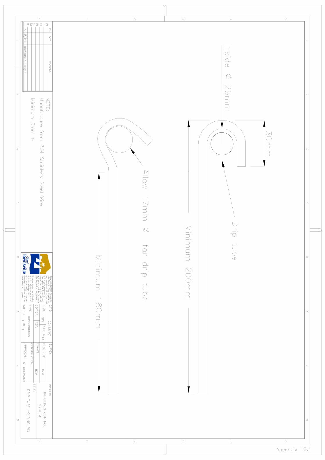

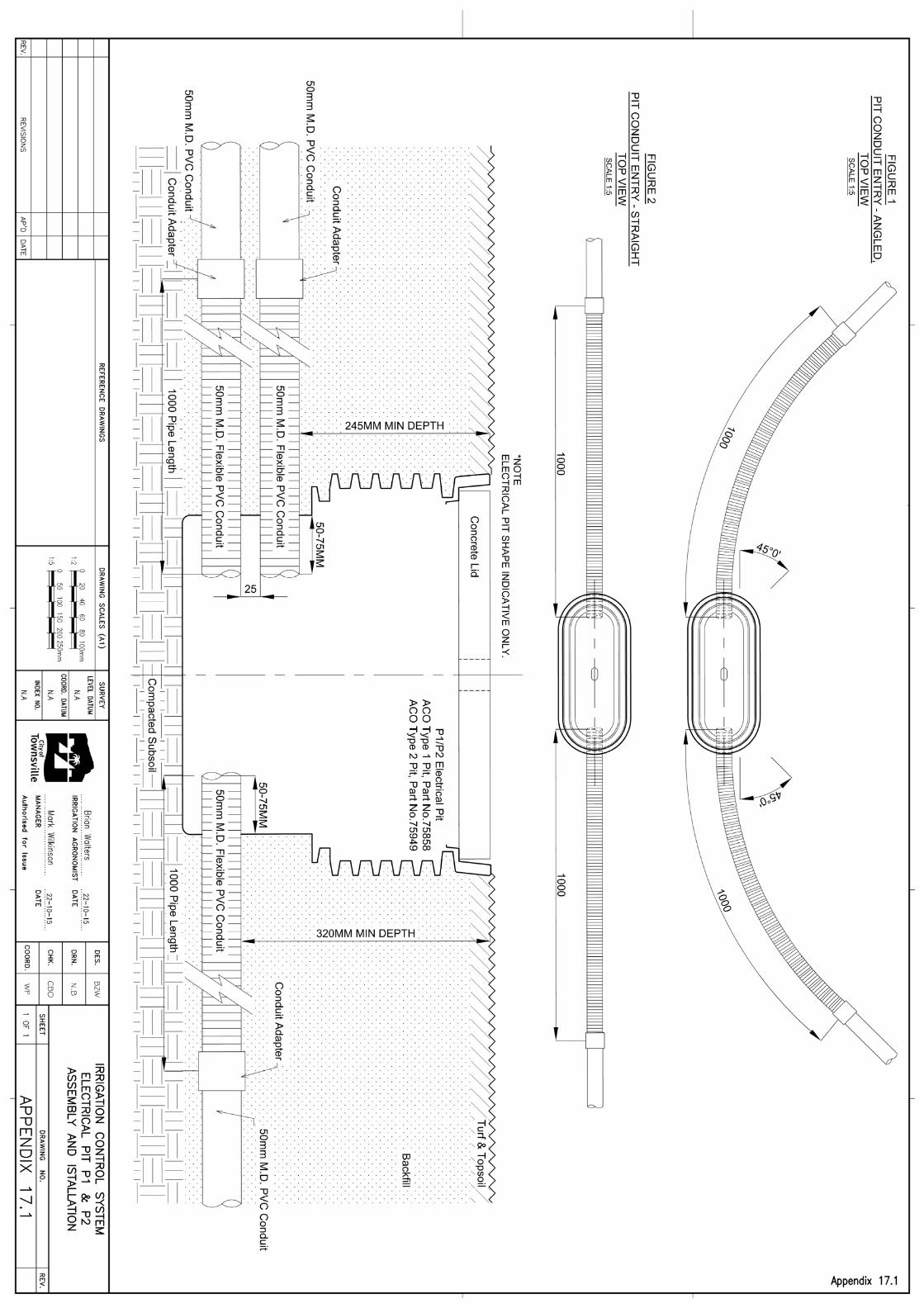

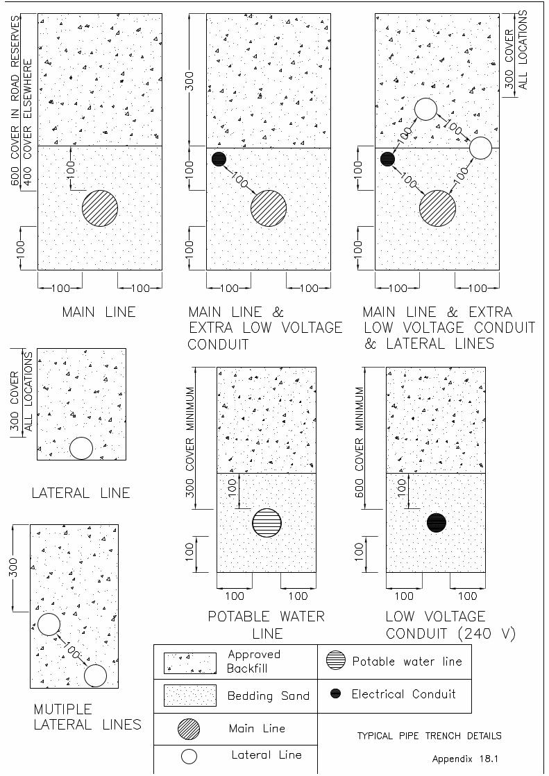
AutoCAD SHX Text
TYPICAL PIPE TRENCH DETAILS
AutoCAD SHX Text
600 COVER IN ROAD RESERVES
AutoCAD SHX Text
100
AutoCAD SHX Text
100
AutoCAD SHX Text
100
AutoCAD SHX Text
100
AutoCAD SHX Text
300
AutoCAD SHX Text
100
AutoCAD SHX Text
100
AutoCAD SHX Text
100
AutoCAD SHX Text
100
AutoCAD SHX Text
100
AutoCAD SHX Text
100
AutoCAD SHX Text
100
AutoCAD SHX Text
100
AutoCAD SHX Text
100
AutoCAD SHX Text
100
AutoCAD SHX Text
100
AutoCAD SHX Text
100
AutoCAD SHX Text
100
AutoCAD SHX Text
100
AutoCAD SHX Text
300 COVER
AutoCAD SHX Text
300
AutoCAD SHX Text
MAIN LINE
AutoCAD SHX Text
MAIN LINE &
AutoCAD SHX Text
LATERAL LINE
AutoCAD SHX Text
Approved
AutoCAD SHX Text
400 COVER ELSEWHERE
AutoCAD SHX Text
EXTRA LOW VOLTAGE
AutoCAD SHX Text
CONDUIT
AutoCAD SHX Text
MAIN LINE & EXTRA
AutoCAD SHX Text
LOW VOLTAGE CONDUIT
AutoCAD SHX Text
& LATERAL LINES
AutoCAD SHX Text
ALL LOCATIONS
AutoCAD SHX Text
300 COVER
AutoCAD SHX Text
ALL LOCATIONS
AutoCAD SHX Text
MUTIPLE
AutoCAD SHX Text
LATERAL LINES
AutoCAD SHX Text
300 COVER MINIMUM
AutoCAD SHX Text
100
AutoCAD SHX Text
100
AutoCAD SHX Text
POTABLE WATER
AutoCAD SHX Text
100
AutoCAD SHX Text
LINE
AutoCAD SHX Text
100
AutoCAD SHX Text
600 COVER MINIMUM
AutoCAD SHX Text
100
AutoCAD SHX Text
100
AutoCAD SHX Text
LOW VOLTAGE
AutoCAD SHX Text
100
AutoCAD SHX Text
CONDUIT (240 V)
AutoCAD SHX Text
100
AutoCAD SHX Text
Backfill
AutoCAD SHX Text
Bedding Sand
AutoCAD SHX Text
Main Line
AutoCAD SHX Text
Lateral Line
AutoCAD SHX Text
Potable water line
AutoCAD SHX Text
Electrical Conduit
AutoCAD SHX Text
Appendix 18.1
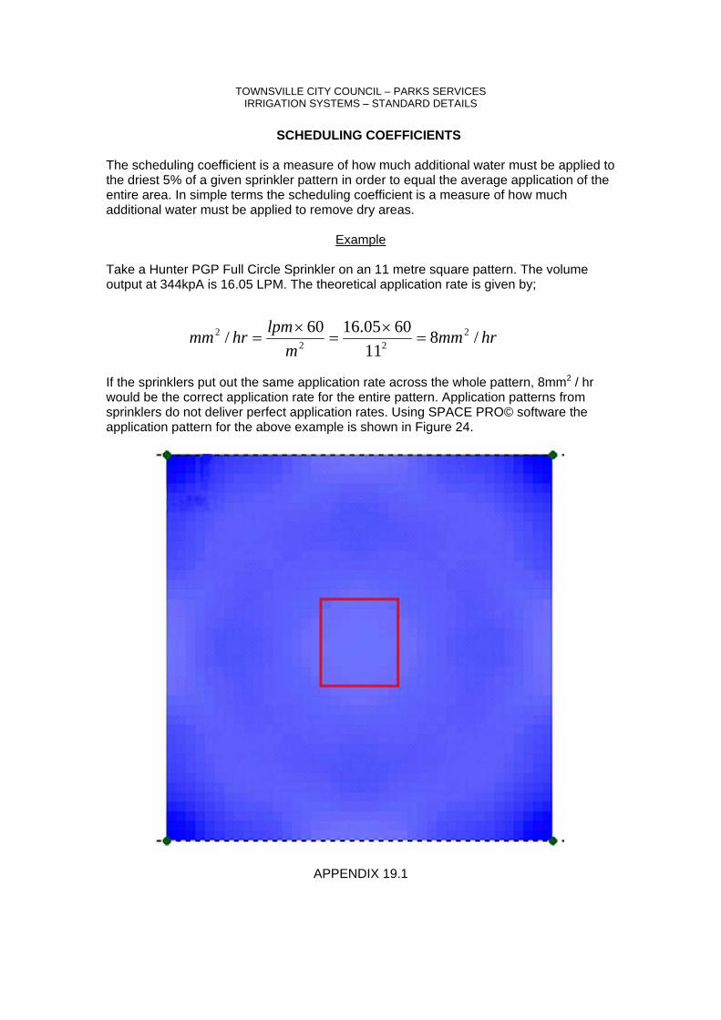
TOWNSVILLE CITY COUNCIL – PARKS SERVICES IRRIGATION SYSTEMS – STANDARD DETAILS
SCHEDULING COEFFICIENTS The scheduling coefficient is a measure of how much additional water must be applied to the driest 5% of a given sprinkler pattern in order to equal the average application of the entire area. In simple terms the scheduling coefficient is a measure of how much additional water must be applied to remove dry areas.
Example Take a Hunter PGP Full Circle Sprinkler on an 11 metre square pattern. The volume output at 344kpA is 16.05 LPM. The theoretical application rate is given by;
If the sprinklers put out the same application rate across the whole pattern, 8mm2 / hr would be the correct application rate for the entire pattern. Application patterns from sprinklers do not deliver perfect application rates. Using SPACE PRO© software the application pattern for the above example is shown in Figure 24.
APPENDIX 19.1
hrmmm
lpmhrmm /811
6005.1660/ 222
2 =×
=×
=
TOWNSVILLE CITY COUNCIL – PARKS SERVICES IRRIGATION SYSTEMS – STANDARD DETAILS
Continued
Figure 24 represents the outputs of the 4 Hunter Sprinklers, 11 metres apart. The sprinklers are represented by the green dots at each corner of the Figure 24. The darker the blue, the more water applied, conversely the lighter the colour the less water applied. The more even the colour, the greater the uniformity of application. The Red Square represents the driest 5% of the pattern. SPACE PRO© calculates the scheduling coefficient automatically. For this example the scheduling coefficient was calculated to be 1.2. The application rate for the driest 5% of the pattern can therefore be calculated by;
The sprinkler run time would need to be increased by an additional 20% in order to apply the application rate of 8mm2 / hr. If the sprinklers are run for 30 minutes per irrigation shift, the increased time is given by;
The more efficient the system, the lower the scheduling coefficient, and hence the lower the run time required to fully irrigation dry areas. No sprinkler system may exceed a scheduling coefficient of 1.3. Contact the Irrigation Planning Officer to obtain test results.
SPACE PRO© is copyright to the Centre for Irrigation Technology.
APPENDIX 19.1
hrmmmmhrmm /7.62.1
8/ 22
2 ==
min362.1min30 =×=time
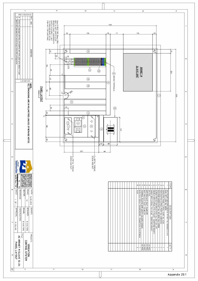

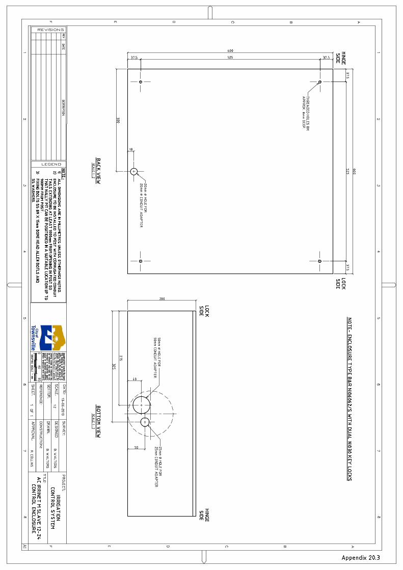
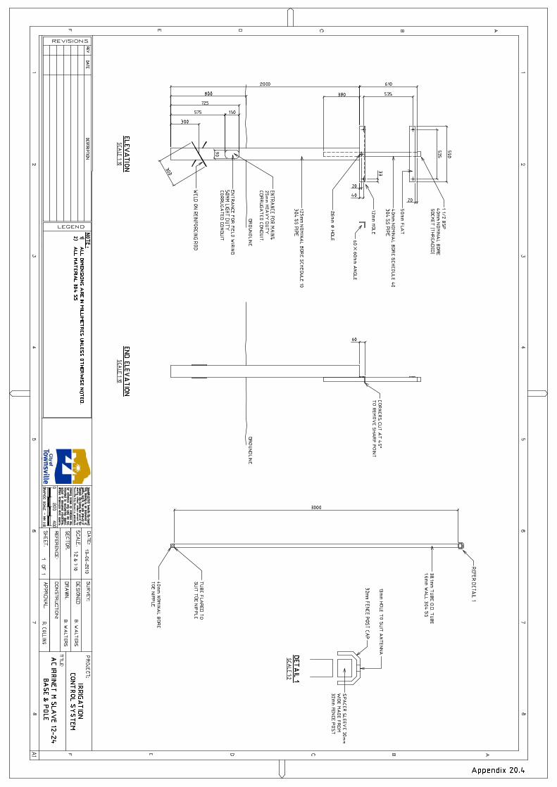
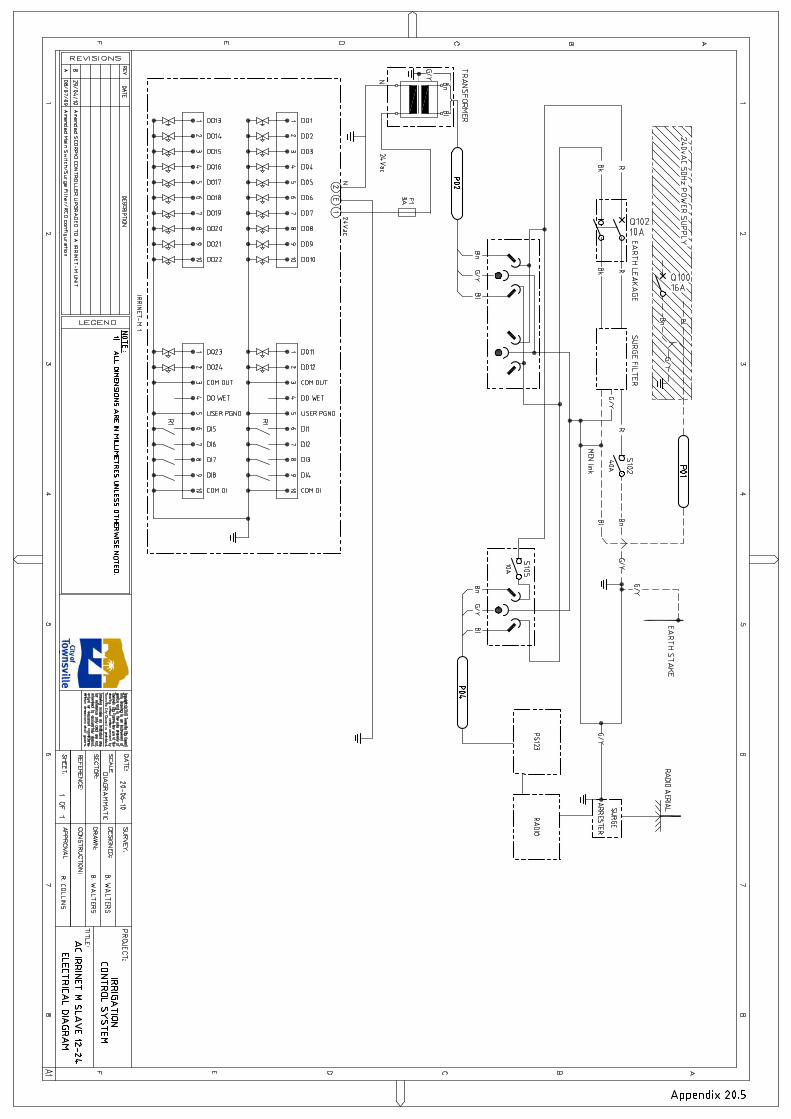

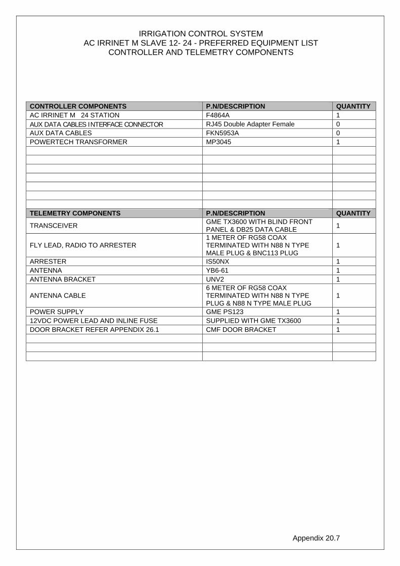
Appendix 20.7
IRRIGATION CONTROL SYSTEM AC IRRINET M SLAVE 12- 24 - PREFERRED EQUIPMENT LIST
CONTROLLER AND TELEMETRY COMPONENTS
CONTROLLER COMPONENTS P.N/DESCRIPTION QUANTITY AC IRRINET M 24 STATION F4864A 1 AUX DATA CABLES INTERFACE CONNECTOR RJ45 Double Adapter Female 0 AUX DATA CABLES FKN5953A 0 POWERTECH TRANSFORMER MP3045 1 TELEMETRY COMPONENTS P.N/DESCRIPTION QUANTITY
TRANSCEIVER GME TX3600 WITH BLIND FRONT PANEL & DB25 DATA CABLE 1
FLY LEAD, RADIO TO ARRESTER 1 METER OF RG58 COAX TERMINATED WITH N88 N TYPE MALE PLUG & BNC113 PLUG
1
ARRESTER IS50NX 1 ANTENNA YB6-61 1 ANTENNA BRACKET UNV2 1
ANTENNA CABLE 6 METER OF RG58 COAX TERMINATED WITH N88 N TYPE PLUG & N88 N TYPE MALE PLUG
1
POWER SUPPLY GME PS123 1 12VDC POWER LEAD AND INLINE FUSE SUPPLIED WITH GME TX3600 1 DOOR BRACKET REFER APPENDIX 26.1 CMF DOOR BRACKET 1
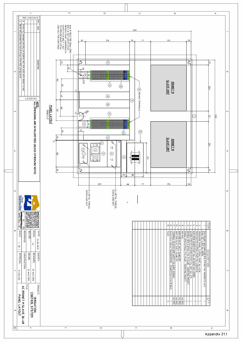
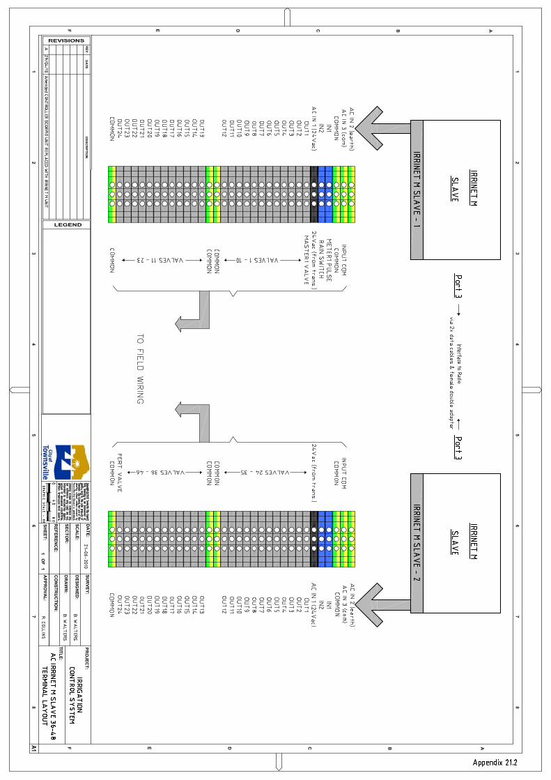


Appendix 21.7
IRRIGATION CONTROL SYSTEM AC IRRINET M SLAVE 36-48 - PREFERRED EQUIPMENT LIST
CONTROLLER AND TELEMETRY COMPONENTS
CONTROLLER COMPONENTS P.N/DESCRIPTION QUANTITY AC IRRINET M F4864A 2 AUX DATA CABLES INTERFACE CONNECTOR RJ45 Double Adapter Female 1 AUX DATA CABLES FKN5953A 2 POWERTECH TRANSFORMER MP3045 1 TELEMETRY COMPONENTS P.N/DESCRIPTION QUANTITY
TRANSCEIVER GME TX3600 WITH BLIND FRONT PANEL & DB25 DATA CABLE 1
FLY LEAD, RADIO TO ARRESTER 1 METER OF RG58 COAX TERMINATED WITH N88 N TYPE MALE PLUG & BNC113 PLUG
1
ARRESTER IS50NX 1 ANTENNA YB6-61 1 ANTENNA BRACKET UNV2 1
ANTENNA CABLE 6 METER OF RG58 COAX TERMINATED WITH N88 N TYPE PLUG & N88 N TYPE MALE PLUG
1
POWER SUPPLY GME PS123 1 12VDC POWER LEAD AND INLINE FUSE SUPPLIED WITH GME TX3600 1 DOOR BRACKET REFER APPENDIX 26.1 CMF DOOR BRACKET 1

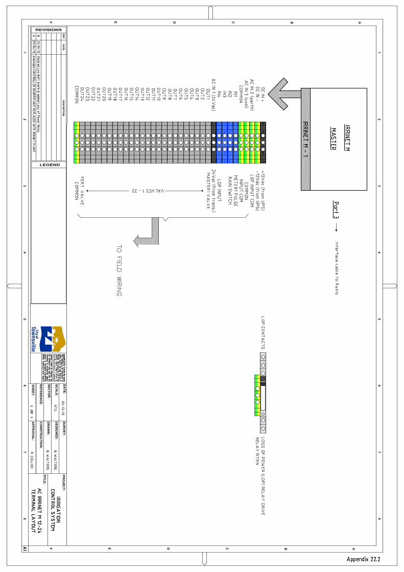


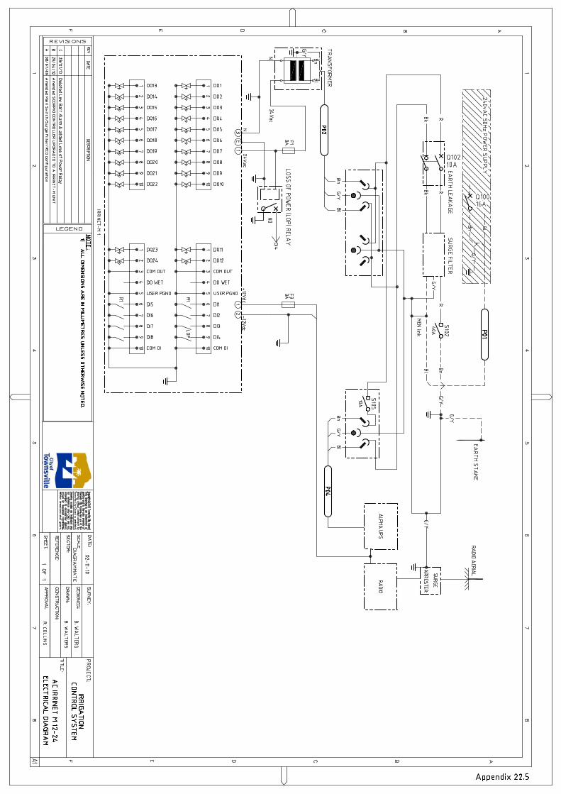
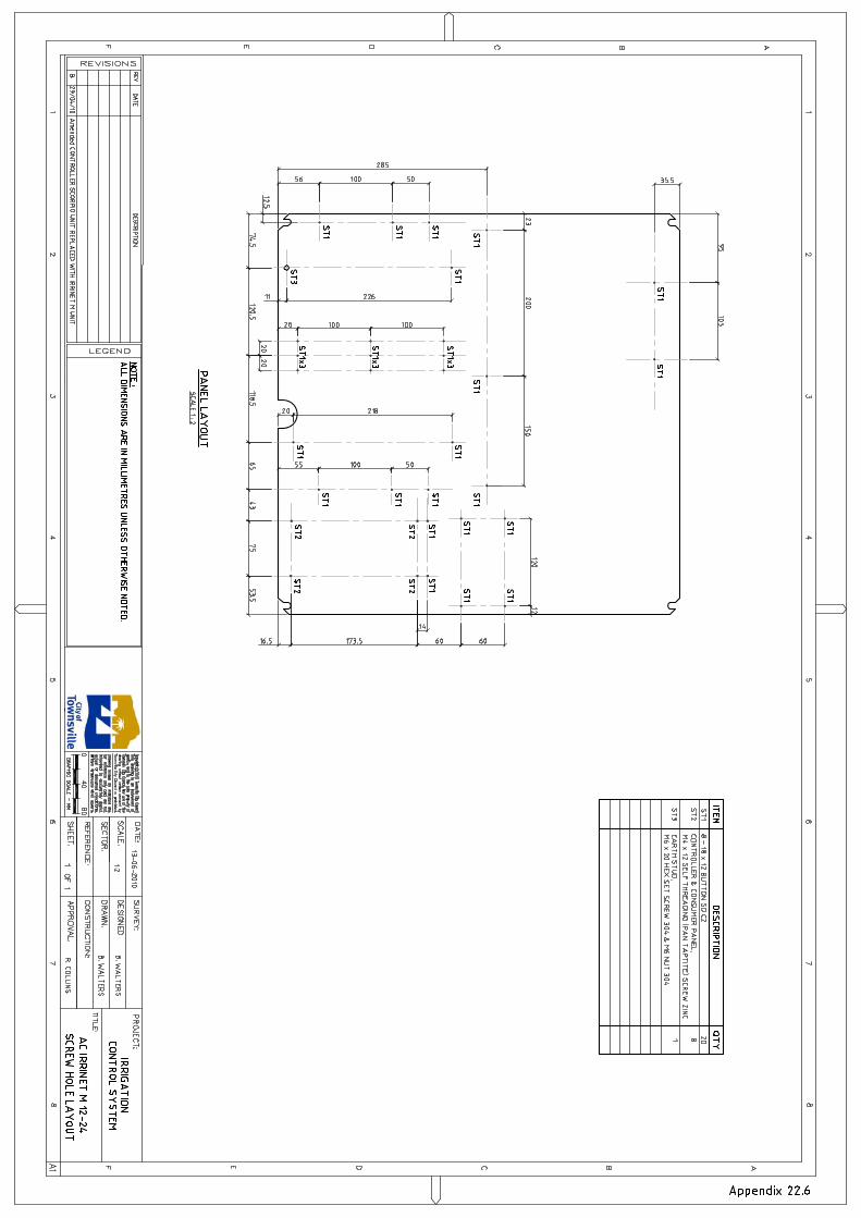

Appendix 22.7
IRRIGATION CONTROL SYSTEM AC IRRINET M 12-24 - PREFERRED EQUIPMENT LIST
CONTROLLER AND TELEMETRY COMPONENTS
CONTROLLER COMPONENTS P.N/DESCRIPTION QUANTITY AC IRRINET M 24 STATION F4864A 2 AUX PORT1 - PORT1 DATA CABLE APPENDIX 28.3 RJ45 MODIFIED CROSSOVER CABLE 0 POWERTECH TRANSFORMER MP3045 1
UNINTERUPTED POWER SUPPLY ALPHA ENERGY AEON DC 1224X WITH TEMPERATURE COMPENSATED BATTERY CHARGING & GEL ELECTROLYTE SLA BATTERY
1
TELEMETRY COMPONENTS P.N/DESCRIPTION QUANTITY
TRANSCEIVER GME TX3600 WITH BLIND FRONT PANEL & DB25 DATA CABLE 1
FLY LEAD, RADIO TO ARRESTER 1 METER OF RG58 COAX TERMINATED WITH N88 N TYPE MALE PLUG & BNC113 PLUG
1
ARRESTER IS50NX 1 ANTENNA YB6-61 1 ANTENNA BRACKET UNV2 1
ANTENNA CABLE 6 METER OF RG58 COAX TERMINATED WITH N88 N TYPE PLUG & N88 N TYPE MALE PLUG
1
POWER SUPPLY USE ABOVE UPS 0 12VDC POWER LEAD AND INLINE FUSE SUPPLIED WITH GME TX3600 1 DOOR BRACKET REFER APPENDIX 26.3 CMF DOOR BRACKET 1

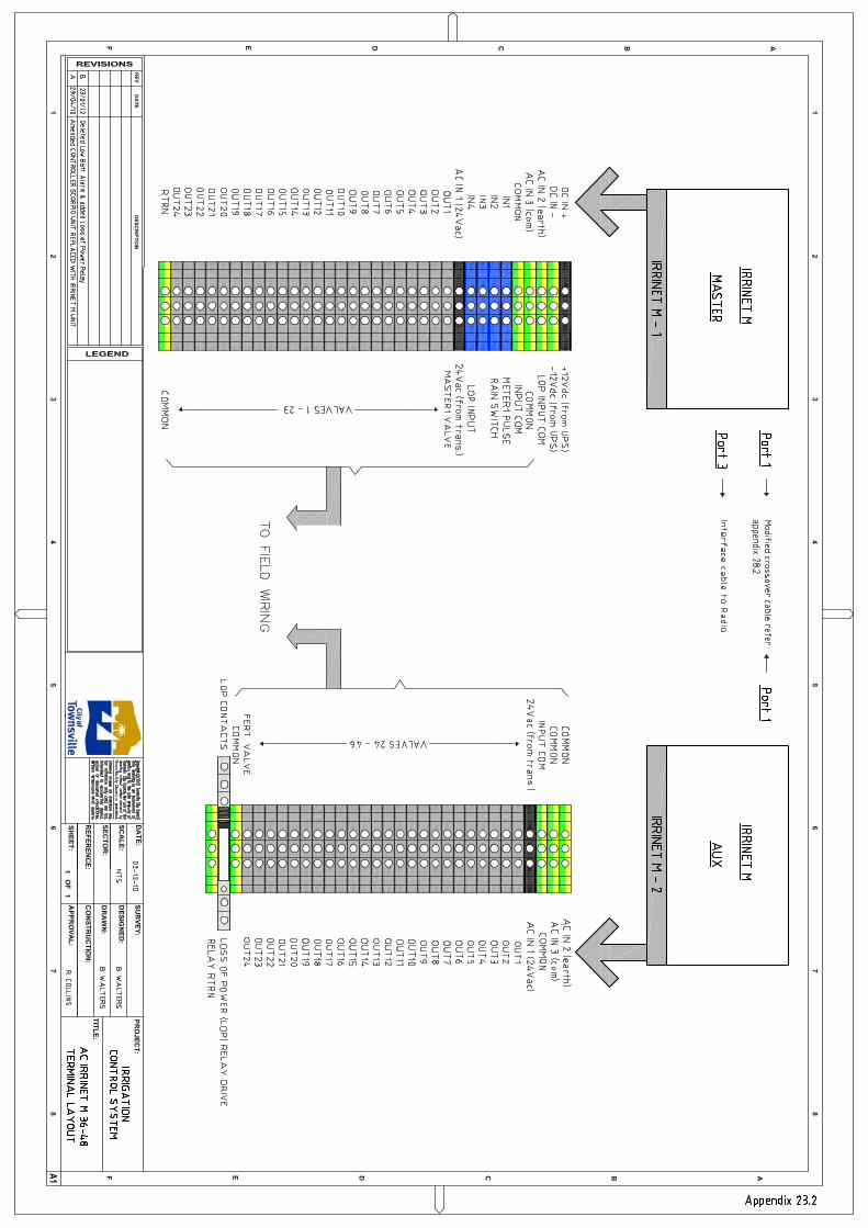


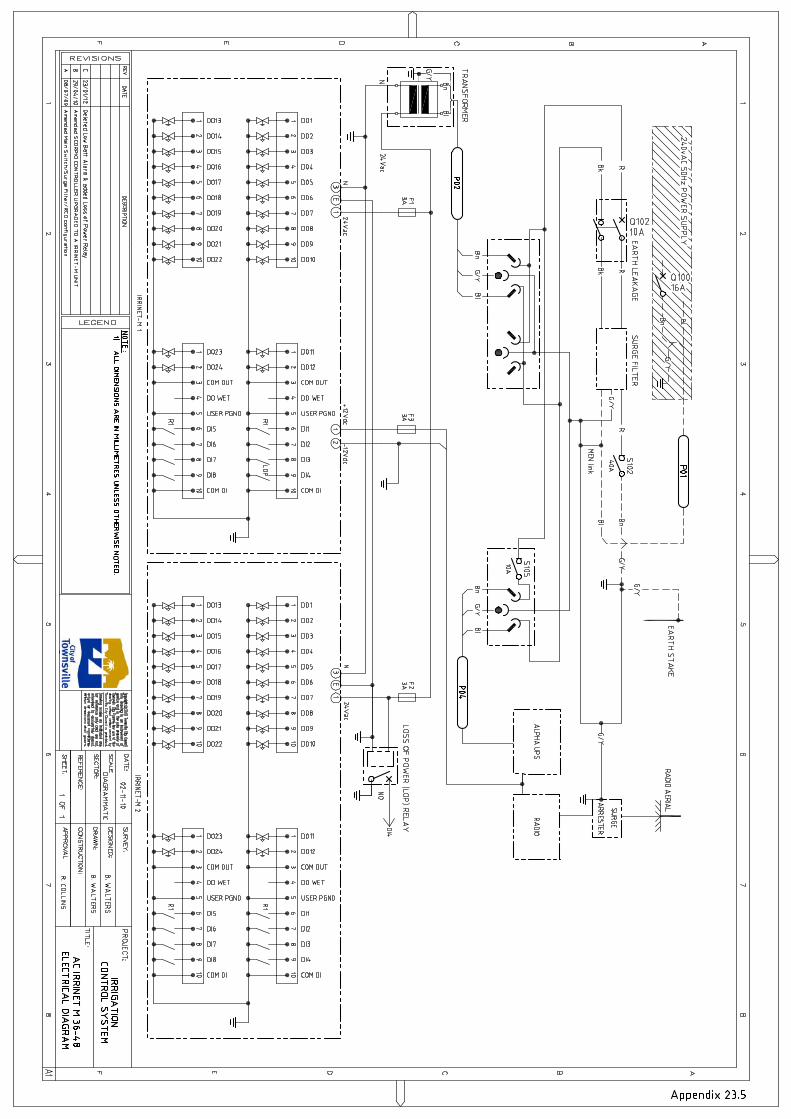
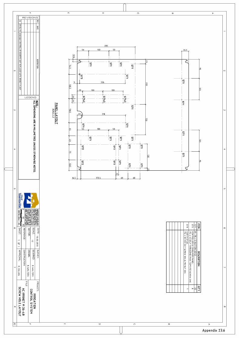
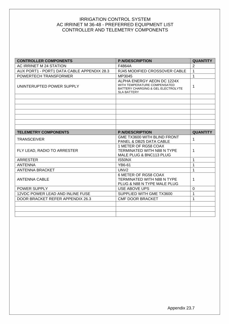
Appendix 23.7
IRRIGATION CONTROL SYSTEM AC IRRINET M 36-48 - PREFERRED EQUIPMENT LIST
CONTROLLER AND TELEMETRY COMPONENTS
CONTROLLER COMPONENTS P.N/DESCRIPTION QUANTITY AC IRRINET M 24 STATION F4864A 2 AUX PORT1 - PORT1 DATA CABLE APPENDIX 28.3 RJ45 MODIFIED CROSSOVER CABLE 1 POWERTECH TRANSFORMER MP3045 1
UNINTERUPTED POWER SUPPLY ALPHA ENERGY AEON DC 1224X WITH TEMPERATURE COMPENSATED BATTERY CHARGING & GEL ELECTROLYTE SLA BATTERY
1
TELEMETRY COMPONENTS P.N/DESCRIPTION QUANTITY
TRANSCEIVER GME TX3600 WITH BLIND FRONT PANEL & DB25 DATA CABLE 1
FLY LEAD, RADIO TO ARRESTER 1 METER OF RG58 COAX TERMINATED WITH N88 N TYPE MALE PLUG & BNC113 PLUG
1
ARRESTER IS50NX 1 ANTENNA YB6-61 1 ANTENNA BRACKET UNV2 1
ANTENNA CABLE 6 METER OF RG58 COAX TERMINATED WITH N88 N TYPE PLUG & N88 N TYPE MALE PLUG
1
POWER SUPPLY USE ABOVE UPS 0 12VDC POWER LEAD AND INLINE FUSE SUPPLIED WITH GME TX3600 1 DOOR BRACKET REFER APPENDIX 26.3 CMF DOOR BRACKET 1

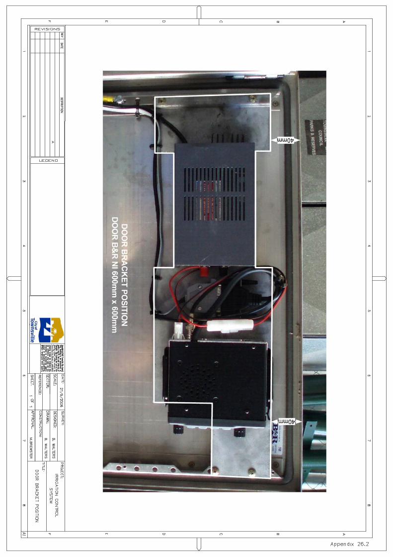
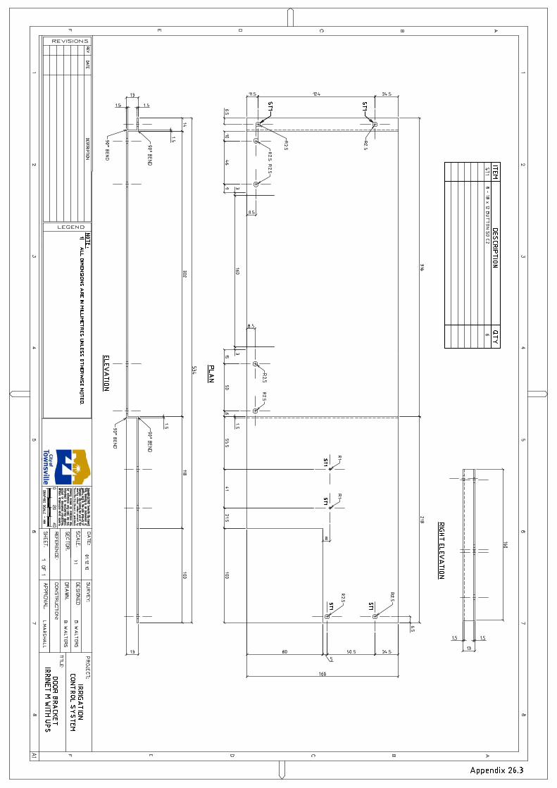
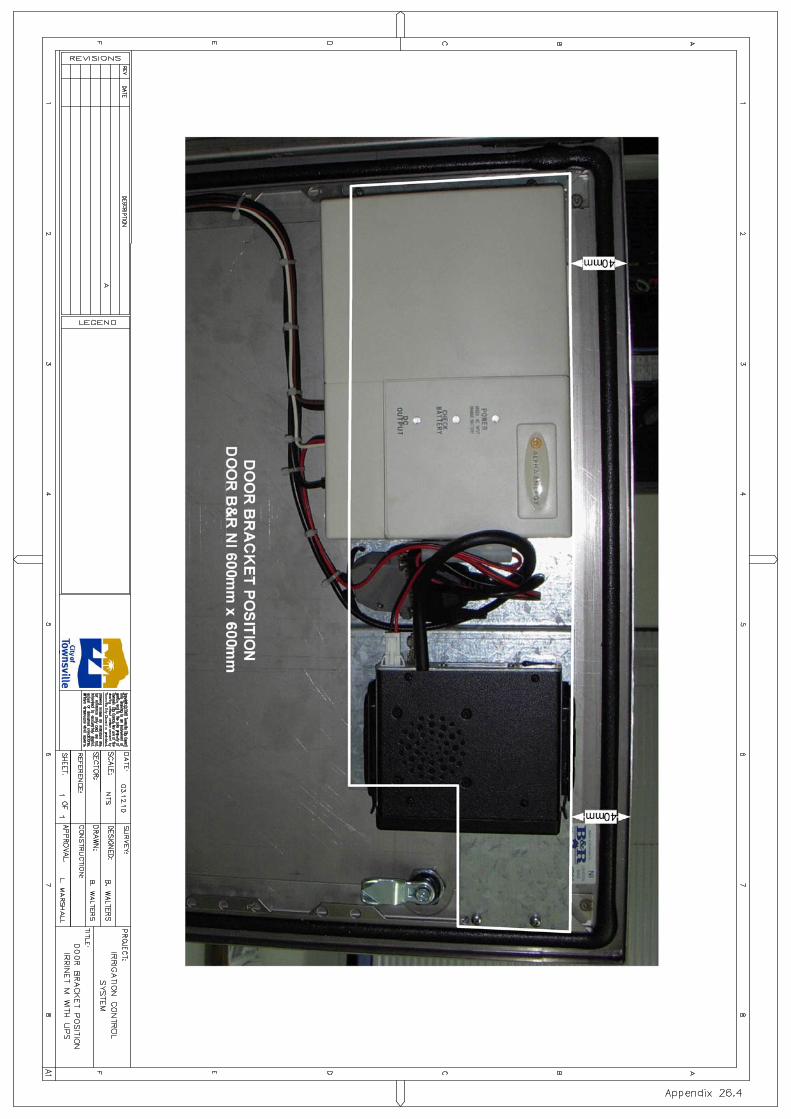
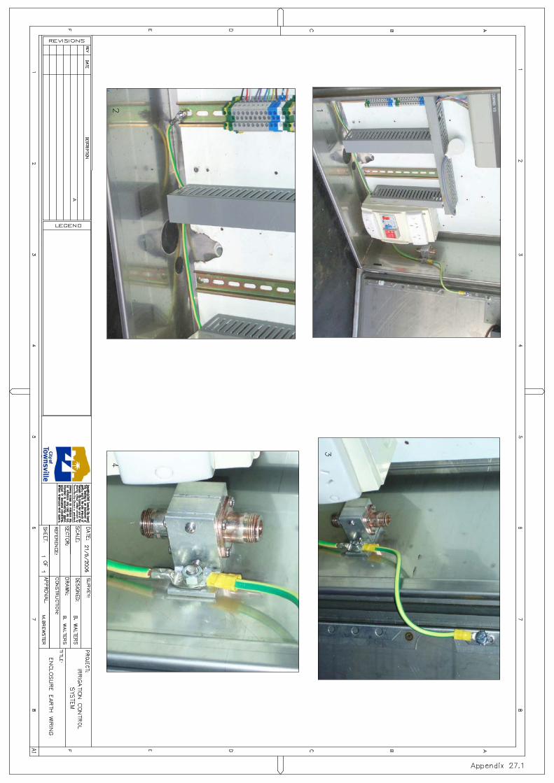


BZW
BZW
CBO
AutoCAD SHX Text
DATE
AutoCAD SHX Text
AP'D
AutoCAD SHX Text
REVISIONS
AutoCAD SHX Text
REV.
AutoCAD SHX Text
INDEX NO.
AutoCAD SHX Text
LEVEL DATUM
AutoCAD SHX Text
Authorised for Issue
AutoCAD SHX Text
COORD.
AutoCAD SHX Text
DES.
AutoCAD SHX Text
DRN.
AutoCAD SHX Text
COORD. DATUM
AutoCAD SHX Text
CHK.
AutoCAD SHX Text
DRAWING SCALES (A1)
AutoCAD SHX Text
SHEET
AutoCAD SHX Text
DRAWING NO.
AutoCAD SHX Text
REV.
AutoCAD SHX Text
REFERENCE DRAWINGS
AutoCAD SHX Text
SURVEY
AutoCAD SHX Text
MANAGER
AutoCAD SHX Text
IRRIGATION AGRONOMIST
AutoCAD SHX Text
DATE
AutoCAD SHX Text
DATE
AutoCAD SHX Text
IRRIGATION CONTROL SYSTEM
AutoCAD SHX Text
I.R RAIN SENSOR ASSEMBLY
AutoCAD SHX Text
EXTENSION POLE MOUNTED
AutoCAD SHX Text
APPENDIX 29.2
AutoCAD SHX Text
1 OF 1
AutoCAD SHX Text
N.A
AutoCAD SHX Text
N.A
AutoCAD SHX Text
N.A
AutoCAD SHX Text
8-6-18
AutoCAD SHX Text
8-6-18
AutoCAD SHX Text
Mark Wilkinson
AutoCAD SHX Text
Brian Walters
AutoCAD SHX Text
Appendix 29.2
AutoCAD SHX Text
1:2
AutoCAD SHX Text
0
AutoCAD SHX Text
40.0
AutoCAD SHX Text
100mm
AutoCAD SHX Text
80.0
AutoCAD SHX Text
20.0
AutoCAD SHX Text
60.0
AutoCAD SHX Text
4mm x 25mm 316 screw & lock nut
AutoCAD SHX Text
2x 75mm cableloops fastened with cable ties
AutoCAD SHX Text
4Omm U-Bolt 304 stainless steel
AutoCAD SHX Text
40mm x 3mm flat aluminium 150mm x 150mm 90° bracket
AutoCAD SHX Text
Extension pole
AutoCAD SHX Text
RAIN SENSOR MOUNTING DETAIL Scale 1:2
AutoCAD SHX Text
EXTENSION POLE Scale 1:10
AutoCAD SHX Text
40mm nominal bore toe nipple to suit controller pole base
AutoCAD SHX Text
Tube flare to suit toe nipple
AutoCAD SHX Text
38.1mm tube O.D 1.6mm wall 304 SS
AutoCAD SHX Text
Refer rain sensor mounting detail
AutoCAD SHX Text
RAIN SENSOR PCB NTS
AutoCAD SHX Text
1:10
AutoCAD SHX Text
0
AutoCAD SHX Text
0.2
AutoCAD SHX Text
0.5m
AutoCAD SHX Text
0.1
AutoCAD SHX Text
0.3
AutoCAD SHX Text
0.4
AutoCAD SHX Text
ITEM
AutoCAD SHX Text
DESCRIPTION
AutoCAD SHX Text
S1
AutoCAD SHX Text
DIP SWITCH 1
AutoCAD SHX Text
DIP SWITCH CONFIGURATION Tropical + Rain Front Off
AutoCAD SHX Text
DIP SWITCH 2
AutoCAD SHX Text
DIP SWITCH 3
AutoCAD SHX Text
DIP SWITCH 4
AutoCAD SHX Text
DIP SWITCH 5
AutoCAD SHX Text
DIP SWITCH 6
AutoCAD SHX Text
DIP SWITCH 7
AutoCAD SHX Text
DIP SWITCH 8
AutoCAD SHX Text
S1
AutoCAD SHX Text
S1
AutoCAD SHX Text
S1
AutoCAD SHX Text
S1
AutoCAD SHX Text
S1
AutoCAD SHX Text
S1
AutoCAD SHX Text
S1
AutoCAD SHX Text
ON
AutoCAD SHX Text
ON
AutoCAD SHX Text
ON
AutoCAD SHX Text
ON
AutoCAD SHX Text
ON
AutoCAD SHX Text
OFF
AutoCAD SHX Text
OFF
AutoCAD SHX Text
OFF
AutoCAD SHX Text
SWITCH SETTING
AutoCAD SHX Text
J1 Termination block
AutoCAD SHX Text
S1 DIP switch block
AutoCAD SHX Text
I.R Rain Sensor (Aquamonix or approved similar)
AutoCAD SHX Text
YELLOW WIRE
AutoCAD SHX Text
RELAY COM
AutoCAD SHX Text
GREEN WIRE
AutoCAD SHX Text
POWER P1
AutoCAD SHX Text
RED 12V DC+
AutoCAD SHX Text
BLACK 12V DC-
AutoCAD SHX Text
NO CONNECTION
AutoCAD SHX Text
RELAY N.C
AutoCAD SHX Text
RELAY N.O
AutoCAD SHX Text
POWER P2
AutoCAD SHX Text
J1
AutoCAD SHX Text
J1
AutoCAD SHX Text
J1
AutoCAD SHX Text
J1
AutoCAD SHX Text
J1
AutoCAD SHX Text
WIRE COLOUR
AutoCAD SHX Text
ITEM
AutoCAD SHX Text
DESCRIPTION
AutoCAD SHX Text
TERMINATION CONFIGURATION Normally Closed Circuit
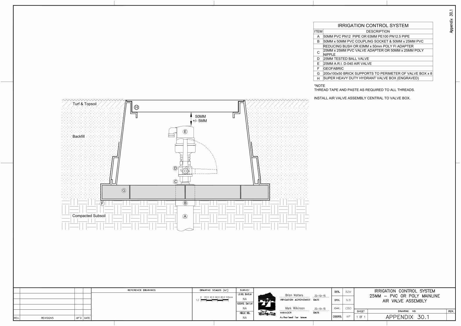
A
E
IRRIGATION CONTROL SYSTEM
ITEM DESCRIPTION
A 50MM PVC PN12 PIPE OR 63MM PE100 PN12.5 PIPE
B 50MM x 50MM PVC COUPLING SOCKET & 50MM x 25MM PVC
REDUCING BUSH OR 63MM x 50mm POLY FI ADAPTER
C
25MM x 25MM PVC VALVE ADAPTER OR 50MM x 25MM POLY
NIPPLE
D 25MM TESTED BALL VALVE
E 25MM A.R.I. D-040 AIR VALVE
F GEOFABRIC
G 200x100x50 BRICK SUPPORTS TO PERIMETER OF VALVE BOX x 8
H
SUPER HEAVY DUTY HYDRANT VALVE BOX (ENGRAVED)
H
F
+/- 5MM
50MM
Turf & Topsoil
Backfill
Compacted Subsoil
G
C
B
D
*NOTE
THREAD TAPE AND PASTE AS REQUIRED TO ALL THREADS.
INSTALL AIR VALVE ASSEMBLY CENTRAL TO VALVE BOX.
BZW
N.B
CBO
WP
AutoCAD SHX Text
DATE
AutoCAD SHX Text
AP'D
AutoCAD SHX Text
REVISIONS
AutoCAD SHX Text
REV.
AutoCAD SHX Text
INDEX NO.
AutoCAD SHX Text
LEVEL DATUM
AutoCAD SHX Text
Authorised for Issue
AutoCAD SHX Text
COORD.
AutoCAD SHX Text
DES.
AutoCAD SHX Text
DRN.
AutoCAD SHX Text
COORD. DATUM
AutoCAD SHX Text
CHK.
AutoCAD SHX Text
DRAWING SCALES (A1)
AutoCAD SHX Text
SHEET
AutoCAD SHX Text
DRAWING NO.
AutoCAD SHX Text
REV.
AutoCAD SHX Text
REFERENCE DRAWINGS
AutoCAD SHX Text
SURVEY
AutoCAD SHX Text
MANAGER
AutoCAD SHX Text
IRRIGATION AGRONOMIST
AutoCAD SHX Text
DATE
AutoCAD SHX Text
DATE
AutoCAD SHX Text
IRRIGATION CONTROL SYSTEM
AutoCAD SHX Text
25MM - PVC OR POLY MAINLINE
AutoCAD SHX Text
AIR VALVE ASSEMBLY
AutoCAD SHX Text
APPENDIX 30.1
AutoCAD SHX Text
1 OF 1
AutoCAD SHX Text
N.A
AutoCAD SHX Text
N.A
AutoCAD SHX Text
N.A
AutoCAD SHX Text
22-10-15
AutoCAD SHX Text
22-10-15
AutoCAD SHX Text
Mark Wilkinson
AutoCAD SHX Text
Brian Walters
AutoCAD SHX Text
Appendix 30.1
AutoCAD SHX Text
1:2
AutoCAD SHX Text
0
AutoCAD SHX Text
40.0
AutoCAD SHX Text
100mm
AutoCAD SHX Text
80.0
AutoCAD SHX Text
20.0
AutoCAD SHX Text
60.0
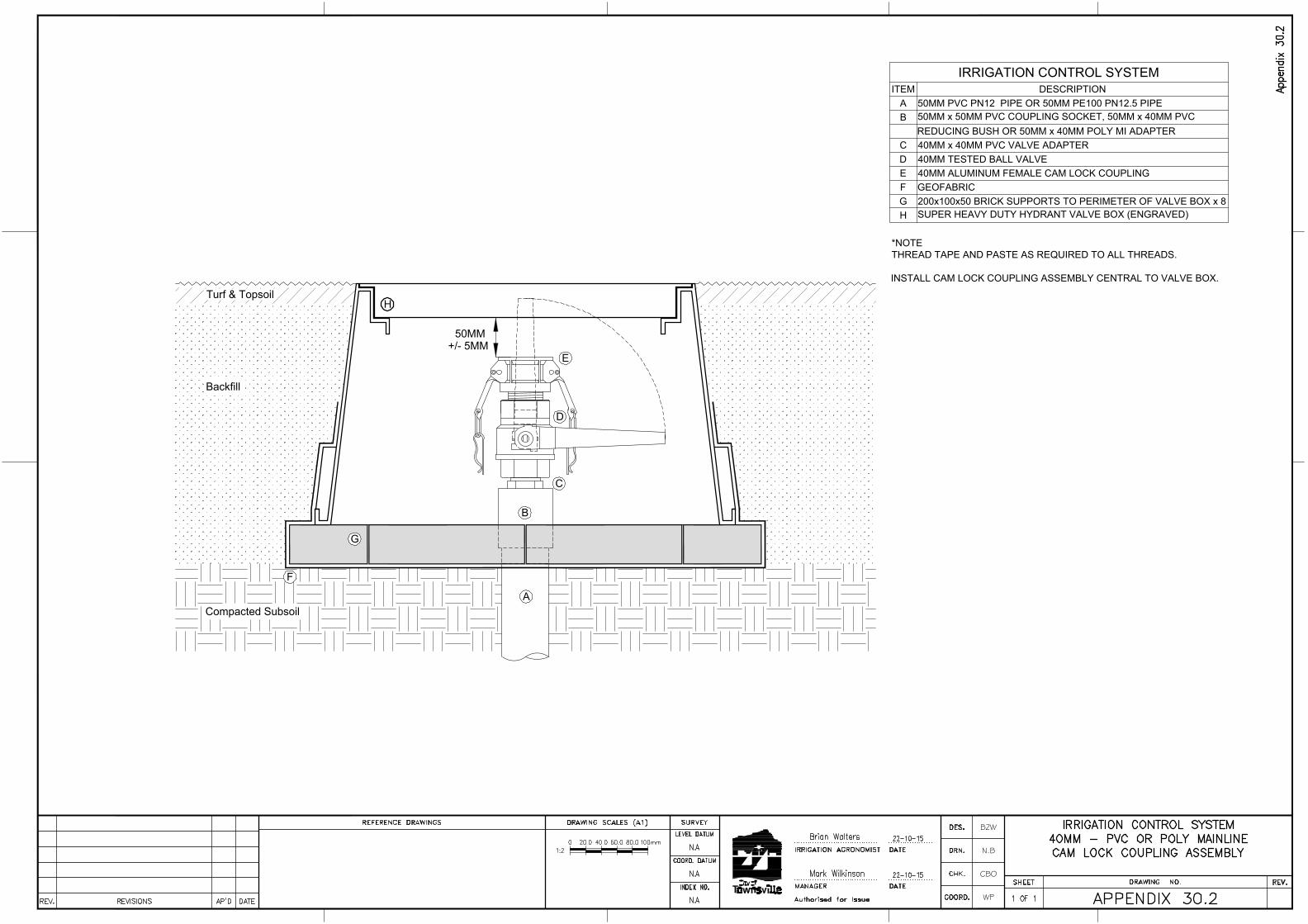
A
E
IRRIGATION CONTROL SYSTEM
ITEM DESCRIPTION
A 50MM PVC PN12 PIPE OR 50MM PE100 PN12.5 PIPE
B50MM x 50MM PVC COUPLING SOCKET, 50MM x 40MM PVC
REDUCING BUSH OR 50MM x 40MM POLY MI ADAPTER
C 40MM x 40MM PVC VALVE ADAPTER
D 40MM TESTED BALL VALVE
E 40MM ALUMINUM FEMALE CAM LOCK COUPLING
F GEOFABRIC
G 200x100x50 BRICK SUPPORTS TO PERIMETER OF VALVE BOX x 8
H
SUPER HEAVY DUTY HYDRANT VALVE BOX (ENGRAVED)
H
F
+/- 5MM
50MM
Turf & Topsoil
Backfill
Compacted Subsoil
G
C
B
D
*NOTE
THREAD TAPE AND PASTE AS REQUIRED TO ALL THREADS.
INSTALL CAM LOCK COUPLING ASSEMBLY CENTRAL TO VALVE BOX.
BZW
N.B
CBO
WP
AutoCAD SHX Text
DATE
AutoCAD SHX Text
AP'D
AutoCAD SHX Text
REVISIONS
AutoCAD SHX Text
REV.
AutoCAD SHX Text
INDEX NO.
AutoCAD SHX Text
LEVEL DATUM
AutoCAD SHX Text
Authorised for Issue
AutoCAD SHX Text
COORD.
AutoCAD SHX Text
DES.
AutoCAD SHX Text
DRN.
AutoCAD SHX Text
COORD. DATUM
AutoCAD SHX Text
CHK.
AutoCAD SHX Text
DRAWING SCALES (A1)
AutoCAD SHX Text
SHEET
AutoCAD SHX Text
DRAWING NO.
AutoCAD SHX Text
REV.
AutoCAD SHX Text
REFERENCE DRAWINGS
AutoCAD SHX Text
SURVEY
AutoCAD SHX Text
MANAGER
AutoCAD SHX Text
IRRIGATION AGRONOMIST
AutoCAD SHX Text
DATE
AutoCAD SHX Text
DATE
AutoCAD SHX Text
IRRIGATION CONTROL SYSTEM
AutoCAD SHX Text
40MM - PVC OR POLY MAINLINE
AutoCAD SHX Text
CAM LOCK COUPLING ASSEMBLY
AutoCAD SHX Text
APPENDIX 30.2
AutoCAD SHX Text
1 OF 1
AutoCAD SHX Text
N.A
AutoCAD SHX Text
N.A
AutoCAD SHX Text
N.A
AutoCAD SHX Text
22-10-15
AutoCAD SHX Text
22-10-15
AutoCAD SHX Text
Mark Wilkinson
AutoCAD SHX Text
Brian Walters
AutoCAD SHX Text
Appendix 30.2
AutoCAD SHX Text
1:2
AutoCAD SHX Text
0
AutoCAD SHX Text
40.0
AutoCAD SHX Text
100mm
AutoCAD SHX Text
80.0
AutoCAD SHX Text
20.0
AutoCAD SHX Text
60.0

A
E
IRRIGATION CONTROL SYSTEM
ITEM DESCRIPTION
A 50MM PVC PN12 PIPE OR 40MM PE100 PN12.5 PIPE
B 50MM x 50MM PVC COUPLING SOCKET & 50MM x 25MM PVC
REDUCING BUSH OR 40MM X 25MM POLY MI ADAPTER
C 25MM x 25MM PVC VALVE ADAPTER
D 25MM TESTED BALL VALVE
E 25MM QUICK COUPLING VALVE
F GEOFABRIC
G 200x100x50 BRICK SUPPORTS TO PERIMETER OF VALVE BOX x 8
H
SUPER HEAVY DUTY HYDRANT VALVE BOX (ENGRAVED)
H
F
+/- 5MM
50MM
Turf & Topsoil
Backfill
Compacted Subsoil
G
C
B
D
*NOTE
THREAD TAPE AND PASTE AS REQUIRED TO ALL THREADS.
INSTALL QCV ASSEMBLY CENTRAL TO VALVE BOX.
BZW
N.B
CBO
WP
AutoCAD SHX Text
DATE
AutoCAD SHX Text
AP'D
AutoCAD SHX Text
REVISIONS
AutoCAD SHX Text
REV.
AutoCAD SHX Text
INDEX NO.
AutoCAD SHX Text
LEVEL DATUM
AutoCAD SHX Text
Authorised for Issue
AutoCAD SHX Text
COORD.
AutoCAD SHX Text
DES.
AutoCAD SHX Text
DRN.
AutoCAD SHX Text
COORD. DATUM
AutoCAD SHX Text
CHK.
AutoCAD SHX Text
DRAWING SCALES (A1)
AutoCAD SHX Text
SHEET
AutoCAD SHX Text
DRAWING NO.
AutoCAD SHX Text
REV.
AutoCAD SHX Text
REFERENCE DRAWINGS
AutoCAD SHX Text
SURVEY
AutoCAD SHX Text
MANAGER
AutoCAD SHX Text
IRRIGATION AGRONOMIST
AutoCAD SHX Text
DATE
AutoCAD SHX Text
DATE
AutoCAD SHX Text
IRRIGATION CONTROL SYSTEM
AutoCAD SHX Text
25MM - PVC OR POLY MAINLINE
AutoCAD SHX Text
QUICK COUPLING VALVE ASSEMBLY
AutoCAD SHX Text
APPENDIX 30.3
AutoCAD SHX Text
1 OF 1
AutoCAD SHX Text
N.A
AutoCAD SHX Text
N.A
AutoCAD SHX Text
N.A
AutoCAD SHX Text
23-10-15
AutoCAD SHX Text
23-10-15
AutoCAD SHX Text
Mark Wilkinson
AutoCAD SHX Text
Brian Walters
AutoCAD SHX Text
Appendix 30.3
AutoCAD SHX Text
1:2
AutoCAD SHX Text
0
AutoCAD SHX Text
40.0
AutoCAD SHX Text
100mm
AutoCAD SHX Text
80.0
AutoCAD SHX Text
20.0
AutoCAD SHX Text
60.0
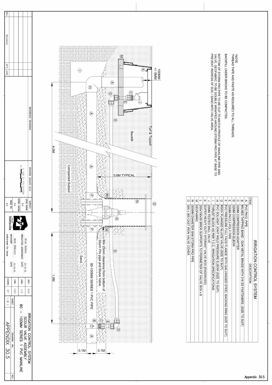
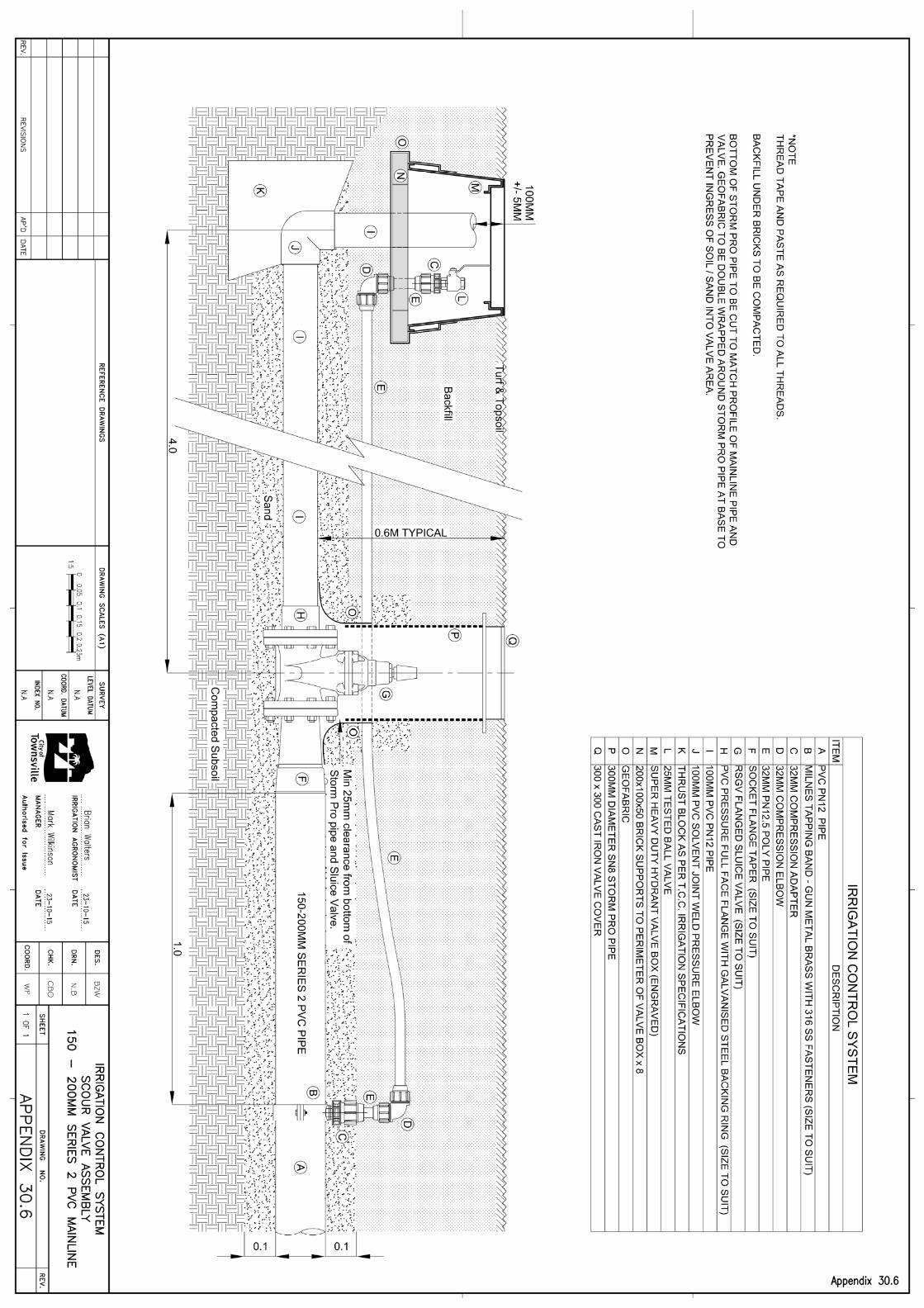
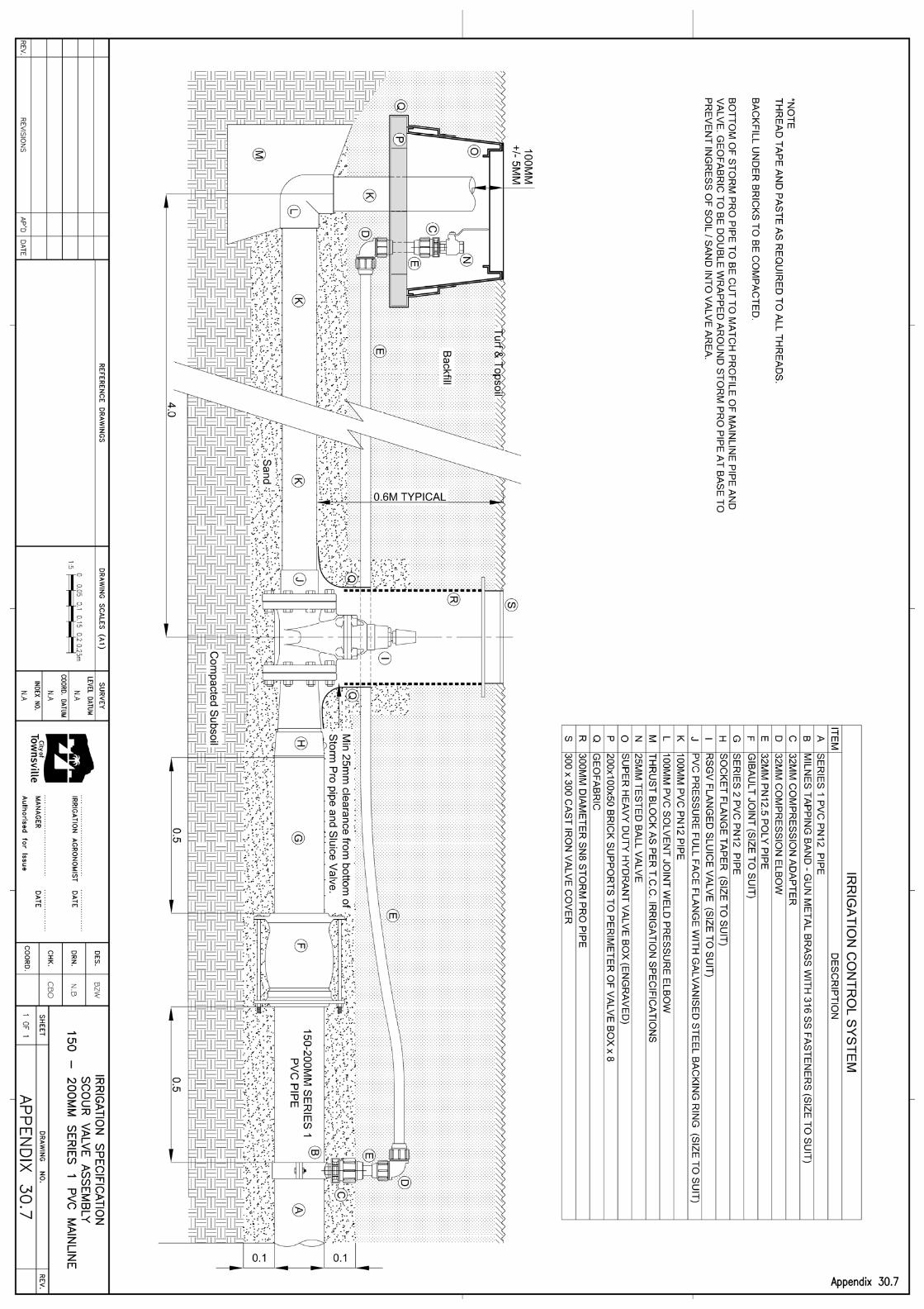
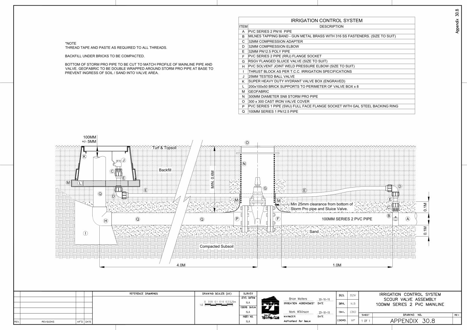
M
+/- 5MM
100MM
Turf & Topsoil
Backfill
Compacted Subsoil
L
B
A
C
D
D
EE
C
F
G
M
N
M
P
Q
O
H
J
K
I
4.0M
MIN
. 0
.6
M
0.1
M
1.0M
Sand
*NOTE
THREAD TAPE AND PASTE AS REQUIRED TO ALL THREADS.
BACKFILL UNDER BRICKS TO BE COMPACTED.
BOTTOM OF STORM PRO PIPE TO BE CUT TO MATCH PROFILE OF MAINLINE PIPE AND
VALVE. GEOFABRIC TO BE DOUBLE WRAPPED AROUND STORM PRO PIPE AT BASE TO
PREVENT INGRESS OF SOIL / SAND INTO VALVE AREA.
E
IRRIGATION CONTROL SYSTEM
ITEM DESCRIPTION
A PVC SERIES 2 PN16 PIPE
B
MILNES TAPPING BAND - GUN METAL BRASS WITH 316 SS FASTENERS. (SIZE TO SUIT)
C 32MM COMPRESSION ADAPTER
D 32MM COMPRESSION ELBOW
E 32MM PN12.5 POLY PIPE
F
PVC SERIES 2 PIPE (RRJ) FLANGE SOCKET
G
RSGV FLANGED SLUICE VALVE (SIZE TO SUIT)
H
PVC SOLVENT JOINT WELD PRESSURE ELBOW (SIZE TO SUIT)
I THRUST BLOCK AS PER T.C.C. IRRIGATION SPECIFICATIONS
J 25MM TESTED BALL VALVE
K
SUPER HEAVY DUTY HYDRANT VALVE BOX (ENGRAVED)
L 200x100x50 BRICK SUPPORTS TO PERIMETER OF VALVE BOX x 8
M GEOFABRIC
N 300MM DIAMETER SN8 STORM PRO PIPE
O 300 x 300 CAST IRON VALVE COVER
P
PVC SERIES 1 PIPE (SWJ) FULL FACE FLANGE SOCKET WITH GAL STEEL BACKING RING
Q 100MM SERIES 1 PN12.5 PIPE
0.1
M
100MM SERIES 2 PVC PIPE
Min 25mm clearance from bottom of
Storm Pro pipe and Sluice Valve.
E
BZW
N.B
CBO
WP
AutoCAD SHX Text
DATE
AutoCAD SHX Text
AP'D
AutoCAD SHX Text
REVISIONS
AutoCAD SHX Text
REV.
AutoCAD SHX Text
INDEX NO.
AutoCAD SHX Text
LEVEL DATUM
AutoCAD SHX Text
Authorised for Issue
AutoCAD SHX Text
COORD.
AutoCAD SHX Text
DES.
AutoCAD SHX Text
DRN.
AutoCAD SHX Text
COORD. DATUM
AutoCAD SHX Text
CHK.
AutoCAD SHX Text
DRAWING SCALES (A1)
AutoCAD SHX Text
SHEET
AutoCAD SHX Text
DRAWING NO.
AutoCAD SHX Text
REV.
AutoCAD SHX Text
REFERENCE DRAWINGS
AutoCAD SHX Text
SURVEY
AutoCAD SHX Text
MANAGER
AutoCAD SHX Text
IRRIGATION AGRONOMIST
AutoCAD SHX Text
DATE
AutoCAD SHX Text
DATE
AutoCAD SHX Text
IRRIGATION CONTROL SYSTEM
AutoCAD SHX Text
SCOUR VALVE ASSEMBLY
AutoCAD SHX Text
100MM SERIES 2 PVC MAINLINE
AutoCAD SHX Text
APPENDIX 30.8
AutoCAD SHX Text
1 OF 1
AutoCAD SHX Text
N.A
AutoCAD SHX Text
N.A
AutoCAD SHX Text
N.A
AutoCAD SHX Text
23-10-15
AutoCAD SHX Text
23-10-15
AutoCAD SHX Text
Mark Wilkinson
AutoCAD SHX Text
Brian Walters
AutoCAD SHX Text
Appendix 30.8
AutoCAD SHX Text
1:5
AutoCAD SHX Text
0
AutoCAD SHX Text
0.1
AutoCAD SHX Text
0.25m
AutoCAD SHX Text
0.2
AutoCAD SHX Text
0.05
AutoCAD SHX Text
0.15
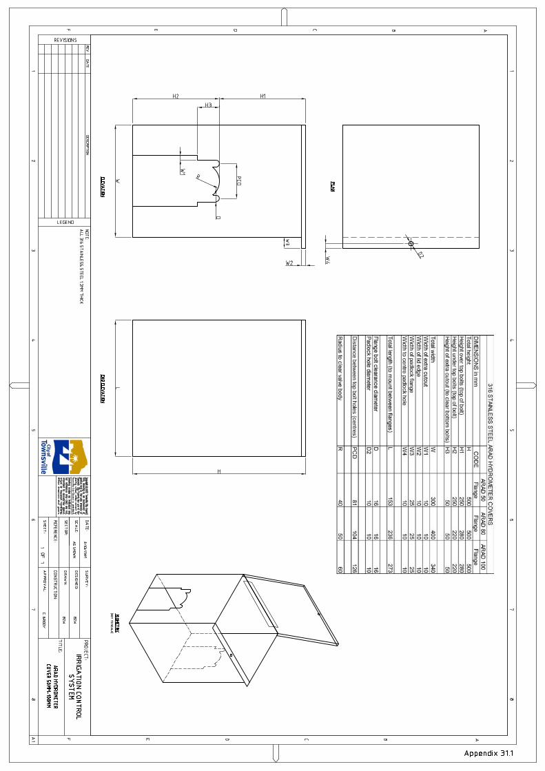
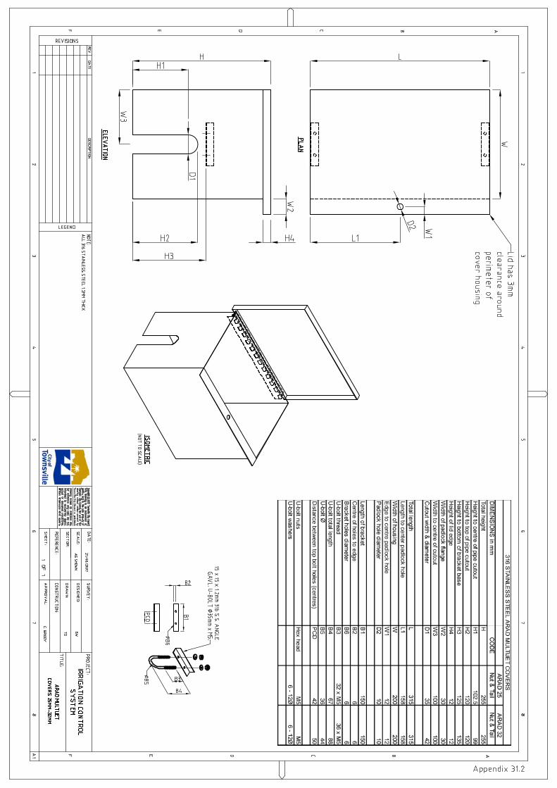

AutoCAD SHX Text
W3
AutoCAD SHX Text
%%UPLAN
AutoCAD SHX Text
%%UELEVATION
AutoCAD SHX Text
%%UEND ELEVATION
AutoCAD SHX Text
%%UISOMETRIC
AutoCAD SHX Text
(NOT TO SCALE)
AutoCAD SHX Text
IRRIGATION CONTROL
AutoCAD SHX Text
AS SHOWN
AutoCAD SHX Text
1
AutoCAD SHX Text
1
AutoCAD SHX Text
2/03/2007
AutoCAD SHX Text
SYSTEM
AutoCAD SHX Text
BZW
AutoCAD SHX Text
C. BRIODY
AutoCAD SHX Text
BZW
AutoCAD SHX Text
DOROT 100 SERIES MASTER VALVE
AutoCAD SHX Text
COVER 50MM-100MM
AutoCAD SHX Text
2007
AutoCAD SHX Text
REFERENCE:
AutoCAD SHX Text
REVISIONS
AutoCAD SHX Text
F
AutoCAD SHX Text
REV
AutoCAD SHX Text
DATE
AutoCAD SHX Text
1
AutoCAD SHX Text
DESCRIPTION
AutoCAD SHX Text
2
AutoCAD SHX Text
E
AutoCAD SHX Text
D
AutoCAD SHX Text
C
AutoCAD SHX Text
B
AutoCAD SHX Text
A
AutoCAD SHX Text
1
AutoCAD SHX Text
2
AutoCAD SHX Text
LEGEND
AutoCAD SHX Text
3
AutoCAD SHX Text
4
AutoCAD SHX Text
5
AutoCAD SHX Text
Copyright c Townsville City Council
AutoCAD SHX Text
Townsville City Council is prohibited.
AutoCAD SHX Text
Townsville City Council. Any use of this
AutoCAD SHX Text
drawing without written consent by
AutoCAD SHX Text
Written dimensions shall govern.
AutoCAD SHX Text
actual or designed conditions.
AutoCAD SHX Text
intended to accurately depict
AutoCAD SHX Text
for reference only and are not
AutoCAD SHX Text
Drawing scales as indicated are
AutoCAD SHX Text
service and is the sole property of
AutoCAD SHX Text
This drawing is an instrument of
AutoCAD SHX Text
SECTOR:
AutoCAD SHX Text
SHEET:
AutoCAD SHX Text
6
AutoCAD SHX Text
DATE:
AutoCAD SHX Text
SCALE:
AutoCAD SHX Text
3
AutoCAD SHX Text
4
AutoCAD SHX Text
5
AutoCAD SHX Text
6
AutoCAD SHX Text
CONSTRUCTION:
AutoCAD SHX Text
APPROVAL:
AutoCAD SHX Text
DRAWN:
AutoCAD SHX Text
SURVEY:
AutoCAD SHX Text
DESIGNED:
AutoCAD SHX Text
OF
AutoCAD SHX Text
7
AutoCAD SHX Text
TITLE:
AutoCAD SHX Text
PROJECT:
AutoCAD SHX Text
8
AutoCAD SHX Text
A1
AutoCAD SHX Text
F
AutoCAD SHX Text
E
AutoCAD SHX Text
D
AutoCAD SHX Text
C
AutoCAD SHX Text
7
AutoCAD SHX Text
8
AutoCAD SHX Text
B
AutoCAD SHX Text
A
AutoCAD SHX Text
Appendix 31.3
AutoCAD SHX Text
NOTE: ALL 316 STAINLESS STEEL 1.2MM THICK
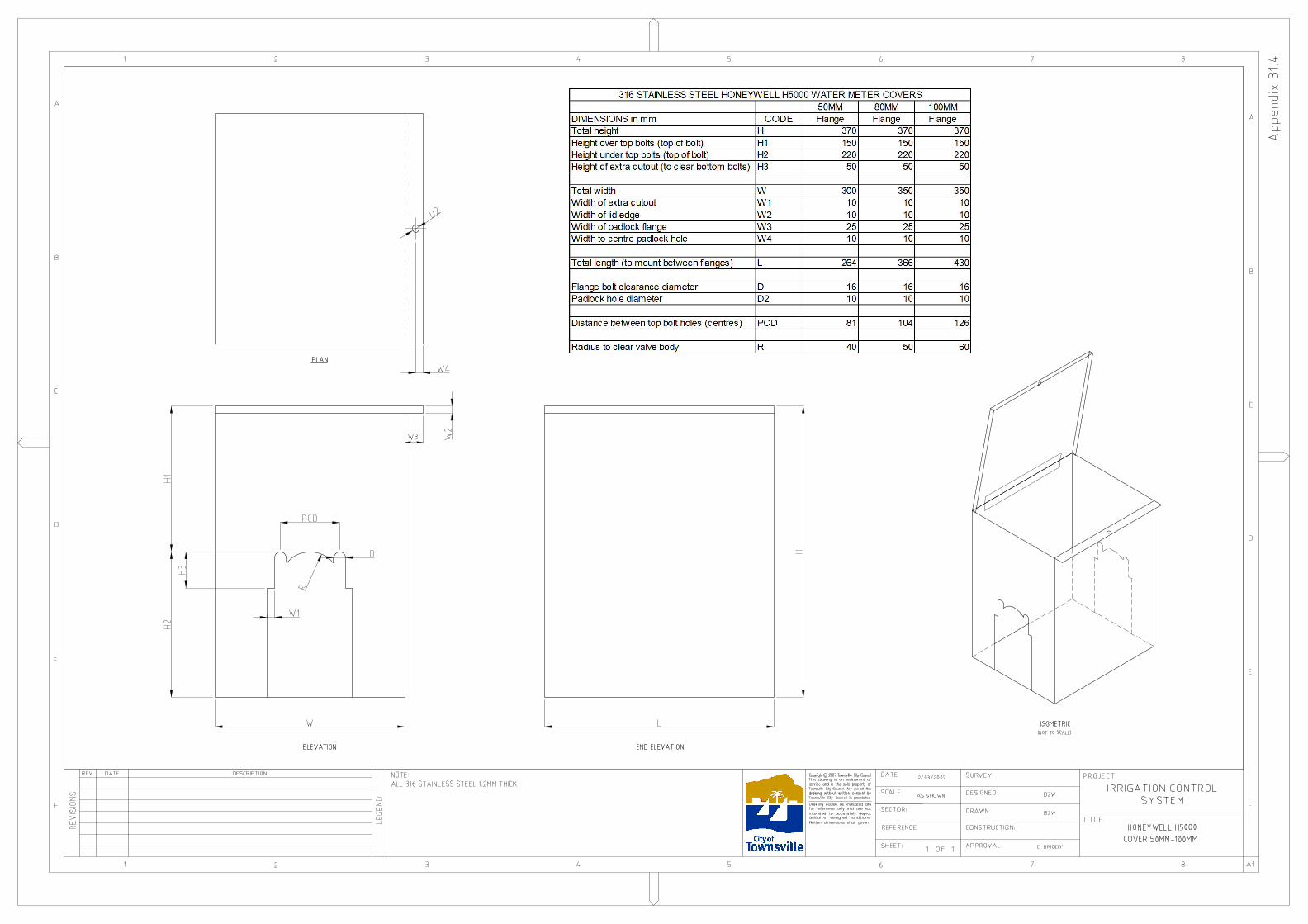
AutoCAD SHX Text
W3
AutoCAD SHX Text
%%UPLAN
AutoCAD SHX Text
%%UELEVATION
AutoCAD SHX Text
%%UEND ELEVATION
AutoCAD SHX Text
%%UISOMETRIC
AutoCAD SHX Text
(NOT TO SCALE)
AutoCAD SHX Text
IRRIGATION CONTROL
AutoCAD SHX Text
AS SHOWN
AutoCAD SHX Text
1
AutoCAD SHX Text
1
AutoCAD SHX Text
2/03/2007
AutoCAD SHX Text
SYSTEM
AutoCAD SHX Text
BZW
AutoCAD SHX Text
C. BRIODY
AutoCAD SHX Text
BZW
AutoCAD SHX Text
HONEYWELL H5000
AutoCAD SHX Text
COVER 50MM-100MM
AutoCAD SHX Text
2007
AutoCAD SHX Text
REFERENCE:
AutoCAD SHX Text
REVISIONS
AutoCAD SHX Text
F
AutoCAD SHX Text
REV
AutoCAD SHX Text
DATE
AutoCAD SHX Text
1
AutoCAD SHX Text
DESCRIPTION
AutoCAD SHX Text
2
AutoCAD SHX Text
E
AutoCAD SHX Text
D
AutoCAD SHX Text
C
AutoCAD SHX Text
B
AutoCAD SHX Text
A
AutoCAD SHX Text
1
AutoCAD SHX Text
2
AutoCAD SHX Text
LEGEND
AutoCAD SHX Text
3
AutoCAD SHX Text
4
AutoCAD SHX Text
5
AutoCAD SHX Text
Copyright c Townsville City Council
AutoCAD SHX Text
Townsville City Council is prohibited.
AutoCAD SHX Text
Townsville City Council. Any use of this
AutoCAD SHX Text
drawing without written consent by
AutoCAD SHX Text
Written dimensions shall govern.
AutoCAD SHX Text
actual or designed conditions.
AutoCAD SHX Text
intended to accurately depict
AutoCAD SHX Text
for reference only and are not
AutoCAD SHX Text
Drawing scales as indicated are
AutoCAD SHX Text
service and is the sole property of
AutoCAD SHX Text
This drawing is an instrument of
AutoCAD SHX Text
SECTOR:
AutoCAD SHX Text
SHEET:
AutoCAD SHX Text
6
AutoCAD SHX Text
DATE:
AutoCAD SHX Text
SCALE:
AutoCAD SHX Text
3
AutoCAD SHX Text
4
AutoCAD SHX Text
5
AutoCAD SHX Text
6
AutoCAD SHX Text
CONSTRUCTION:
AutoCAD SHX Text
APPROVAL:
AutoCAD SHX Text
DRAWN:
AutoCAD SHX Text
SURVEY:
AutoCAD SHX Text
DESIGNED:
AutoCAD SHX Text
OF
AutoCAD SHX Text
7
AutoCAD SHX Text
TITLE:
AutoCAD SHX Text
PROJECT:
AutoCAD SHX Text
8
AutoCAD SHX Text
A1
AutoCAD SHX Text
F
AutoCAD SHX Text
E
AutoCAD SHX Text
D
AutoCAD SHX Text
C
AutoCAD SHX Text
7
AutoCAD SHX Text
8
AutoCAD SHX Text
B
AutoCAD SHX Text
A
AutoCAD SHX Text
Appendix 31.4
AutoCAD SHX Text
NOTE: ALL 316 STAINLESS STEEL 1.2MM THICK

AutoCAD SHX Text
REFERENCE:
AutoCAD SHX Text
REVISIONS
AutoCAD SHX Text
F
AutoCAD SHX Text
REV
AutoCAD SHX Text
DATE
AutoCAD SHX Text
1
AutoCAD SHX Text
DESCRIPTION
AutoCAD SHX Text
2
AutoCAD SHX Text
E
AutoCAD SHX Text
D
AutoCAD SHX Text
C
AutoCAD SHX Text
B
AutoCAD SHX Text
A
AutoCAD SHX Text
1
AutoCAD SHX Text
2
AutoCAD SHX Text
LEGEND
AutoCAD SHX Text
3
AutoCAD SHX Text
4
AutoCAD SHX Text
5
AutoCAD SHX Text
Copyright c 2010 Townsville City Council
AutoCAD SHX Text
200
AutoCAD SHX Text
GRAPHIC SCALE - MM 1:10
AutoCAD SHX Text
Townsville City Council is prohibited.
AutoCAD SHX Text
Townsville City Council. Any use of this
AutoCAD SHX Text
drawing without written consent by
AutoCAD SHX Text
Written dimensions shall govern.
AutoCAD SHX Text
actual or designed conditions.
AutoCAD SHX Text
intended to accurately depict
AutoCAD SHX Text
for reference only and are not
AutoCAD SHX Text
Drawing scales as indicated are
AutoCAD SHX Text
service and is the sole property of
AutoCAD SHX Text
This drawing is an instrument of
AutoCAD SHX Text
0
AutoCAD SHX Text
SECTOR:
AutoCAD SHX Text
400
AutoCAD SHX Text
SHEET:
AutoCAD SHX Text
6
AutoCAD SHX Text
DATE:
AutoCAD SHX Text
SCALE:
AutoCAD SHX Text
3
AutoCAD SHX Text
4
AutoCAD SHX Text
5
AutoCAD SHX Text
6
AutoCAD SHX Text
CONTROLLER BASE & POLE
AutoCAD SHX Text
IRRIGATION
AutoCAD SHX Text
CONSTRUCTION:
AutoCAD SHX Text
APPROVAL:
AutoCAD SHX Text
DRAWN:
AutoCAD SHX Text
SURVEY:
AutoCAD SHX Text
DESIGNED:
AutoCAD SHX Text
1:2 & 1:10
AutoCAD SHX Text
1
AutoCAD SHX Text
OF
AutoCAD SHX Text
1
AutoCAD SHX Text
13-06-2010
AutoCAD SHX Text
7
AutoCAD SHX Text
TITLE:
AutoCAD SHX Text
PROJECT:
AutoCAD SHX Text
8
AutoCAD SHX Text
A1
AutoCAD SHX Text
F
AutoCAD SHX Text
E
AutoCAD SHX Text
D
AutoCAD SHX Text
C
AutoCAD SHX Text
7
AutoCAD SHX Text
8
AutoCAD SHX Text
B
AutoCAD SHX Text
A
AutoCAD SHX Text
CONTROL SYSTEM
AutoCAD SHX Text
NOTE : 1) ALL DIMENSIONS ARE IN MILLIMETRES UNLESS OTHERWISE NOTED. ALL DIMENSIONS ARE IN MILLIMETRES UNLESS OTHERWISE NOTED. 2) ALL MATERIAL 304 SSALL MATERIAL 304 SS
AutoCAD SHX Text
Appendix 32.1
AutoCAD SHX Text
B. WALTERS
AutoCAD SHX Text
ELEVATION SCALE 1:10
AutoCAD SHX Text
END ELEVATION SCALE 1:10
AutoCAD SHX Text
GROUNDLINE
AutoCAD SHX Text
GROUNDLINE
AutoCAD SHX Text
1 1/2 BSP 40mm NOMINAL BORE SOCKET (THREADED)
AutoCAD SHX Text
50mm SS FLAT (Both sides)
AutoCAD SHX Text
12mm HOLE
AutoCAD SHX Text
26mm HOLE
AutoCAD SHX Text
ENTRANCE FOR MAINS 25mm HEAVY DUTY CORRUGATED CONDUIT.
AutoCAD SHX Text
ENTRANCE FOR FIELD WIRING 50MM LIGHT DUTY CORRUGATED CONDUIT
AutoCAD SHX Text
WELD ON REINFORCING ROD
AutoCAD SHX Text
60 X 60mm SS EA
AutoCAD SHX Text
CORNERS CUT AT 45°TO REMOVE SHARP POINT
AutoCAD SHX Text
REFER DETAIL 1
AutoCAD SHX Text
DETAIL 1 SCALE 1:2
AutoCAD SHX Text
13mm HOLE TO SUIT ANTENNA
AutoCAD SHX Text
38.1mm TUBE O.D. TUBE 1.6mm WALL 304 SS
AutoCAD SHX Text
32mm FENCE POST CAP
AutoCAD SHX Text
SPACER SLEEVE 20mm WIDE MADE FROM 32mm FENCE POST
AutoCAD SHX Text
TUBE FLARED TO SUIT TOE NIPPLE
AutoCAD SHX Text
40mm NOMINAL BORE TOE NIPPLE
AutoCAD SHX Text
40mm NOMINAL BORE SCHEDULE 40 304 SS PIPE
AutoCAD SHX Text
B. WALTERS
AutoCAD SHX Text
R. COLLINS
AutoCAD SHX Text
2 x 125mm NOMINAL BORE SCHEDULE 10 304 SS PIPE
AutoCAD SHX Text
DOUBLE ENCLOSURE
AutoCAD SHX Text
50mm SS Flat Bar
AutoCAD SHX Text
40mm NOMINAL BORE SCHEDULE 40 304 SS PIPE - 100mm long