
THIS SPEC IS OBSOLETE
14
THIS SPEC IS OBSOLETE Spec No: 001-58128 Spec Title: BLOOD PRESSURE MONITOR WITH PSOC(R) - AN58128 Sunset Owner: Shruti Hanumanthaiah (SSHH) Replaced By: None
-
Upload
khangminh22 -
Category
Documents
-
view
1 -
download
0
Transcript of THIS SPEC IS OBSOLETE
THIS SPEC IS OBSOLETE
Spec No: 001-58128 Spec Title: BLOOD PRESSURE MONITOR WITH
PSOC(R) - AN58128 Sunset Owner: Shruti Hanumanthaiah (SSHH) Replaced By: None
www.cypress.com Document No. 001-58128 Rev. *C 1
AN58128
Blood Pressure Monitor with PSoC®
Author: Sanjeev Kumar K. Associated Project: Yes
Associated Part Family: CY8C27xxx, CY8C28xxx, CY8C29xxx Software Version: PSoC
® Designer™ 5.3
Related Application Notes: For a complete list of the application notes, click here.
If you have a question, or need help with this application note, contact the author at [email protected].
Blood pressure is one of the vital signs in the human body. It is measured using both invasive and non invasive
techniques. This application note demonstrates how to build a non invasive blood pressure monitor using the PSoC® 1.
This design does not use any external active components to buffer, amplify, and filter the signal.
Contents
Introduction ....................................................................... 1 Operation Principle ............................................................ 2 Block Diagram ................................................................... 2
Pressure Sensor ........................................................... 3 Amplifier ....................................................................... 3 Filter ............................................................................. 4 Multiplexer and ADC .................................................... 5 Pneumatics ................................................................... 5 Display.......................................................................... 5
Working ............................................................................. 8 Project Description ............................................................ 8 Calibration ......................................................................... 8 Summary ......................................................................... 10 Related Application Notes ............................................... 10 Appendix A ...................................................................... 11
Segment LCD Glass Drive and Capacitive Sensing ... 11 Worldwide Sales and Design Support ............................. 13
Introduction
The non invasive method of monitoring blood pressure is widely used. It measures arterial systolic and diastolic pressures of the human body. This device can also measure heart rate. Table 1 describes various non invasive methods used in blood pressure monitors. This application note demonstrates how to use the PSoC to build an oscillometric blood pressure monitor.
Table 1. Non Invasive Methods to Monitor Blood Pressure
Method Non-invasive Principle
Palpatory (Riva-Rocci)
Palpable pulse when cuff pressure equals systolic pressure (SP)
Auscultatory Based on sound waves generated from artery
Ultrasonic Based on frequency difference between transmitted and reflected ultrasound wave when passed through arteries
Tonometry
When the blood vessel is partly collapsed, the surrounding pressure equals the artery pressure. Measured using an array of pressure sensors and the cuff is around the wrist
Oscillometric
(Popular and widely used)
The intra-arterial pulsation is transmitted via cuff to transducer (example, piezo-electric). SP and DP are estimated from the amplitudes of the oscillation by using an empirical algorithm. Oscillometric method is used in almost all portable blood pressure monitors

Blood Pressure Monitor with PSoC®
www.cypress.com Document No. 001-58128 Rev. *C 2
Operation Principle
The blood pressure monitor operates on the following principles.
The cuff is worn around the upper arm and it is inflated beyond the typical systolic pressure.
It is then deflated. The pressure starts decreasing, resulting in blood flow through the artery; this makes the artery to pulsate.
The pressure measured on the device during onset of pulsations defines the systolic blood pressure.
Then the cuff pressure is reduced further. The oscillations become increasingly significant, until they reach maximum amplitude.
The pressure at the maximum amplitude of these oscillations defines the average blood pressure.
The oscillations start decreasing as the cuff pressure reduces. The pressure at this point defines the minimal blood pressure or diastolic blood pressure.
This method of measuring blood pressure is the oscillometric method. It is often used in automatic blood pressure monitor devices because of its excellent reliability. Figure 1 shows the variation of the artery oscillations as the cuff pressure is reduced; it also shows the systolic and diastolic points.
Estimation of systolic and diastolic pressure is done using various empirical algorithms. This application note demonstrates PSoC hardware’s capability to perform blood pressure monitoring by extracting the oscillometric waveform and doesn’t describe the algorithm used to extract blood pressure from the oscillometric waveform. This is primarily because all reliable algorithms are complex and deserve a separate discussion and empirical algorithms don’t give a reliable value across a good number of people.
Figure 1. Oscillometric Pulses Vs Cuff Pressure
Block Diagram
Figure 2 shows the block diagram of the blood pressure monitor using PSoC. The device uses oscillometric method to determine systolic and diastolic pressures. This system includes the following blocks:
Pressure sensor
Amplifier
Filter
Multiplexer and ADC
Pneumatics
Display

Blood Pressure Monitor with PSoC®
www.cypress.com Document No. 001-58128 Rev. *C 3
Figure 2. Block Diagram
Implementation of these blocks in PSoC is described in the following sections.
Pressure Sensor
The pressure sensor for blood pressure monitoring system should have the following characteristics:
Measure pressures from 0 mmHG (0 Kpa) to 300 mmHg (40 Kpa).
Gauge type, because blood pressure in relation to atmospheric pressure
MPX2053 (piezoresistive pressure sensor from free scale) is used in this example. It gives differential output with maximum measurable pressure range of 50 Kpa. It has a transfer characteristic of (20 mV/50 Kpa) 0.4 mv for every 1 Kpa change in pressure or 53 µV per mmHG with Vs=5 V as illustrated in Figure 3.
Figure 3.Transfer Characteristics of Sensor
Amplifier
The sensor output is in the order of a few micro volts. Three opamp topology instrumentation amplifiers are used to amplify the pressure signal. It provides a gain of 93.
Gain = Diff Gain * Conversion Gain = 48 * 1.98 = 93
Blood Pressure Monitor with PSoC®
www.cypress.com Document No. 001-58128 Rev. *C 4
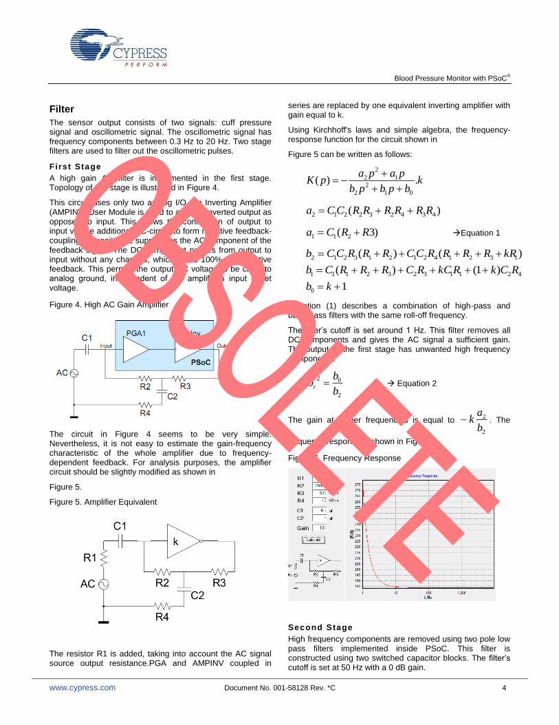
Filter
The sensor output consists of two signals: cuff pressure signal and oscillometric signal. The oscillometric signal has frequency components between 0.3 Hz to 20 Hz. Two stage filters are used to filter out the oscillometric pulses.
First Stage
A high gain AC filter is implemented in the first stage. Topology of this stage is illustrated in Figure 4.
This circuit uses only two analog I/O. An Inverting Amplifier (AMPINV) User Module is used to achieve inverted output as opposed to input. This allows the connection of output to input via the additional RC-circuit to form negative feedback-coupling. Capacitor C2 suppresses the AC component of the feedback signal. The DC component passes from output to input without any changes, which forms 100% DC negative feedback. This permits the output DC voltage to be close to analog ground, independent of the amplifier’s input offset voltage.
Figure 4. High AC Gain Amplifier
The circuit in Figure 4 seems to be very simple. Nevertheless, it is not easy to estimate the gain-frequency characteristic of the whole amplifier due to frequency-dependent feedback. For analysis purposes, the amplifier circuit should be slightly modified as shown in
Figure 5.
Figure 5. Amplifier Equivalent
The resistor R1 is added, taking into account the AC signal source output resistance.PGA and AMPINV coupled in
series are replaced by one equivalent inverting amplifier with gain equal to k.
Using Kirchhoff's laws and simple algebra, the frequency-response function for the circuit shown in
Figure 5 can be written as follows:
kbpbpb
papapK .)(
01
2
2
1
2
2
)( 434232212 RRRRRRCCa
)3( 211 RRCa Equation 1
)()( 1321421213212 kRRRRRCCRRRCCb
42113232111 )1()( RCkRkCRCRRRCb
10 kb
Equation (1) describes a combination of high-pass and band-pass filters with the same roll-off frequency.
The filter’s cutoff is set around 1 Hz. This filter removes all DC components and gives the AC signal a sufficient gain. The output of the first stage has unwanted high frequency components.
2
02
b
br Equation 2
The gain at higher frequencies is equal to
2
2
b
ak . The
frequency response is shown in Figure 6.
Figure 6. Frequency Response
Second Stage
High frequency components are removed using two pole low pass filters implemented inside PSoC. This filter is constructed using two switched capacitor blocks. The filter’s cutoff is set at 50 Hz with a 0 dB gain.

Blood Pressure Monitor with PSoC®
www.cypress.com Document No. 001-58128 Rev. *C 5
Multiplexer and ADC
DC Pressure signal and the oscillometric are multiplexed to ADC inside the PSoC. The MUX selects one of these signals to a 13-bit incremental ADC, which runs at a sampling rate of 30 samples/second. Correlated double sampling, described in the Cypress application note AN2226 is implemented to avoid offset errors. A low-pass IIR filter is implemented in software. This averages and effectively reduces the noise from the input signal. For details on modifying the filter constant and other IIR techniques, see application note AN2099 Single-Pole IIR Filters. To Infinity and Beyond!
Pneumatics
Pneumatics forms the main part of any blood pressure monitoring system. Pneumatics of a typical monitor has the following:
Cuff
Air chamber
Rolling pump
Solenoid valve
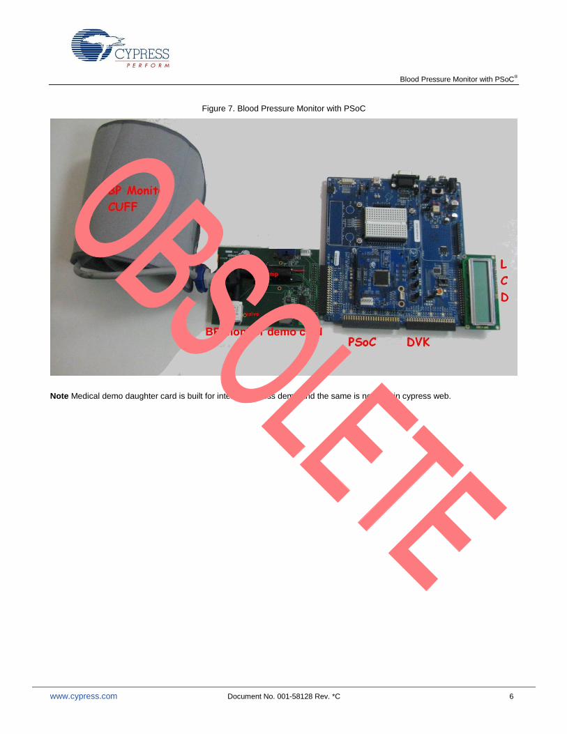
The cuff is worn around the upper arm; it detects the change in pressure due to pulsation of artery. Cuff is connected to pressure sensor through air chamber, which in turn connects to the solenoid valve and rolling pump. Rolling pump inflates the cuff. Solenoid valve deflates the cuff at a defined rate. Usually the deflation rate is lowered if more samples of oscillometric pulses are needed and vice versa. Figure 7 shows the pneumatics setup used to build a typical blood pressure monitor.
Display
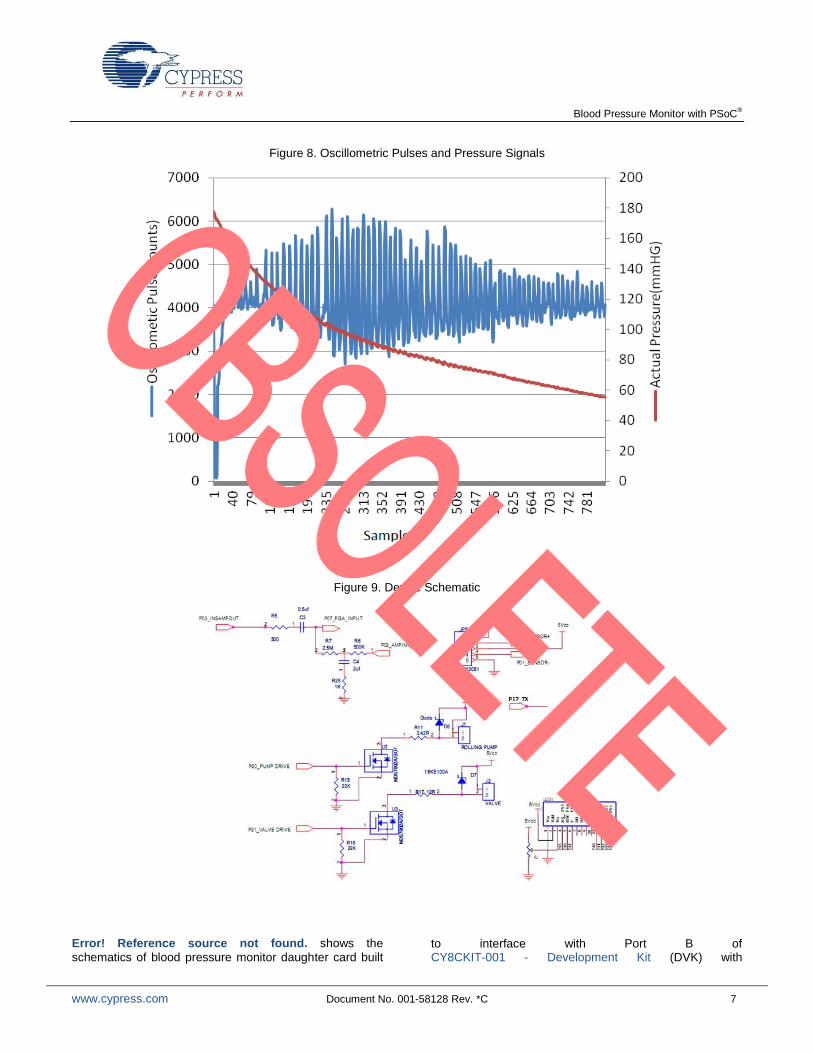
Using serial UART communication, the oscillometric pulses are recorded with reference to pressure in cuff. The UART transmitter runs at a baud rate of 19200. Oscillometric pulses and pressure in cuff are recorded during deflation. Figure 8 shows the Oscillometric Pulses and Pressure Signal.
Blood Pressure Monitor with PSoC®
www.cypress.com Document No. 001-58128 Rev. *C 6
Figure 7. Blood Pressure Monitor with PSoC
Note Medical demo daughter card is built for internal cypress demo and the same is not sold in cypress web.
Blood Pressure Monitor with PSoC®
www.cypress.com Document No. 001-58128 Rev. *C 7
Figure 8. Oscillometric Pulses and Pressure Signals
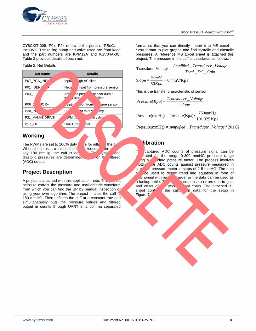
Figure 9. Device Schematic
Error! Reference source not found. shows the
schematics of blood pressure monitor daughter card built to interface with Port B of CY8CKIT-001 - Development Kit (DVK) with
Blood Pressure Monitor with PSoC®
www.cypress.com Document No. 001-58128 Rev. *C 8
CY8CKIT-008. P0x, P2x refers to the ports of PSoC1 in the DVK. The rolling pump and valve used are from koge and the part numbers are KPM12A and KSV04A-3C. Table 2 provides details of each net.
Table 2. Net Details
Net name Details
P07_PGA_INPUT Input of high AC filter
P01_ SENSOR- Negative input from pressure sensor
P03_I Amplified pressure sensor output which acts as input to filter
P06_SENSOR+ Positive input from pressure sensor
P20_PUMP DRIVE PWM output to drive pump
P21_VALVE DRIVE PWM output to drive valve
P17_TX UART transmitter
Working
The PWMs are set to 100% duty cycle for inflating the cuff. When the pressure inside the cuff exceeds a threshold, say 180 mmHg, the cuff is deflated. The systolic and diastolic pressures are determined based on the filtered (ADC) output.
Project Description
A project is attached with this application note. This project helps to extract the pressure and oscillometric waveform from which you can find the BP by manual inspection or using your own algorithm. The project inflates the cuff to 180 mmHG. Then deflates the cuff at a constant rate and simultaneously puts the pressure values and filtered output in counts through UART in a comma separated
format so that you can directly import it to MS excel in *.csv format to plot graphs and find systolic and diastolic pressures. A reference MS Excel sheet is attached this project. The pressure in the cuff is calculated as follows.
GainDCTotal
VoltageTransducerAmplified
__
__ = Voltage Transducer
mV/Kpa 0.450
20= Slope
Kpa
mV
This is the transfer characteristic of sensor.
slope
VoltageTransducerKpaessure
_)(Pr
Kpa 101.325
760mmHg pa)Pressure(K =mHg)Pressure(m
62.201*__ =mHg)Pressure(m VoltageTransducerAmplified
Calibration
The captured ADC counts of pressure signal can be calibrated for the range 0-300 mmHG pressure range using a standard pressure meter. The process involves plotting the ADC counts against pressure measured in standard pressure meter in steps of 2-5 mmHG. The data can be used to derive trend line equation in form of polynomial with required order or the data can be used as a lookup table. This is will compensate errors due to gain and offset of the whole signal chain. The attached XL sheet contains the calibration data for the setup in Figure 7.

Blood Pressure Monitor with PSoC®
www.cypress.com Document No. 001-58128 Rev. *C 9
Figure 10. PSoC Internal Routing and Placement
Blood Pressure Monitor with PSoC®
www.cypress.com Document No. 001-58128 Rev. *C 10
Summary
The blood pressure monitor described in this application note is constructed using PSoC 1 with no active external components. Devices used for medical diagnostic applications must undergo a rigorous documentation and qualification program to meet applicable interruption medical safety efficacy standards.
Related Application Notes
AN2226 - PSoC® 1 - Using Correlated Double Sampling to
Reduce Offset, Drift, and Low Frequency Noise
AN2099 - PSoC® 1, PSoC 3, and PSoC 5LP - Single-Pole
Infinite Impulse Response (IIR) Filters
About the Author
Name: Sanjeev Kumar K.
Title: Applications Engineer
Background: Sanjeev has a Bachelor’s degree in Electronics and Communication from the College of Engineering, Guindy, and Chennai. He currently works on PSoC based applications at Cypress.
Contact: [email protected]

Blood Pressure Monitor with PSoC®
www.cypress.com Document No. 001-58128 Rev. *C 11
Appendix A
Segment LCD Glass Drive and Capacitive Sensing
Portable blood pressure monitors have custom LCD glasses and a few buttons for user input. Apart from monitoring blood pressure, some parts in the PSoC family can drive LCD glasses directly without any driver and also do capacitive touch sensing. Using these parts enable a greater reduction in total bill of materials. For details about LCD drive and capacitive touch sensing refer application note AN56384.
Blood Pressure Monitor with PSoC®
www.cypress.com Document No. 001-58128 Rev. *C 12
Document History
Document Title: Blood Pressure Monitor with PSoC® - AN58128
Document Number: 001-58128
Revision ECN Orig. of Change
Submission Date
Description of Change
** 2824451 KUK 1/18/10 New application note
*A 3126383 KUK 01/03/2011 Comment added to Figure 5.
Project updated to Latest PSoC designer 5.1 and author profile updated.
*B 3940502 KUK 03/27/2013 Updated Software Version as “PSoC® Designer™ 5.3”.
Updated Operation Principle.
Updated Block Diagram (Updated Filter, removed “Safety Timer” and “Pneumatics”).
Added Working.
Renamed “Software” as Project Description and updated the same section.
Added Calibration.
Updated Summary.
Updated Related Application Notes (Removed references of AN2320 as it is an obsolete document).
Updated in new template.
Algorithm to determine systolic and diastolic pressures have been removed.
*C 4744464 SSHH 04/27/2015 This document is obsolete.
Blood Pressure Monitor with PSoC®
www.cypress.com Document No. 001-58128 Rev. *C 13
Worldwide Sales and Design Support
Cypress maintains a worldwide network of offices, solution centers, manufacturer’s representatives, and distributors. To find the office closest to you, visit us at Cypress Locations.
Products
Automotive cypress.com/go/automotive
Clocks & Buffers cypress.com/go/clocks
Interface cypress.com/go/interface
Lighting & Power Control cypress.com/go/powerpsoc cypress.com/go/plc
Memory cypress.com/go/memory
PSoC cypress.com/go/psoc
Touch Sensing cypress.com/go/touch
USB Controllers cypress.com/go/usb
Wireless/RF cypress.com/go/wireless
PSoC® Solutions
psoc.cypress.com/solutions
PSoC 1 | PSoC 3 | PSoC 5LP
Cypress Developer Community
Community | Forums | Blogs | Video | Training
Technical Support
cypress.com/go/support
PSoC is a registered trademark of Cypress Semiconductor Corp. All other trademarks or registered trademarks referenced herein are the property of their respective owners.
Cypress Semiconductor 198 Champion Court San Jose, CA 95134-1709
Phone : 408-943-2600 Fax : 408-943-4730 Website : www.cypress.com
© Cypress Semiconductor Corporation, 2010-2015. The information contained herein is subject to change without notice. Cypress Semiconductor Corporation assumes no responsibility for the use of any circuitry other than circuitry embodied in a Cypress product. Nor does it convey or imply any license under patent or other rights. Cypress products are not warranted nor intended to be used for medical, life support, life saving, critical control or safety applications, unless pursuant to an express written agreement with Cypress. Furthermore, Cypress does not authorize its products for use as critical components in life-support systems where a malfunction or failure may reasonably be expected to result in significant injury to the user. The inclusion of Cypress products in life-support systems application implies that the manufacturer assumes all risk of such use and in doing so indemnifies Cypress against all charges. This Source Code (software and/or firmware) is owned by Cypress Semiconductor Corporation (Cypress) and is protected by and subject to worldwide patent protection (United States and foreign), United States copyright laws and international treaty provisions. Cypress hereby grants to licensee a personal, non-exclusive, non-transferable license to copy, use, modify, create derivative works of, and compile the Cypress Source Code and derivative works for the sole purpose of creating custom software and or firmware in support of licensee product to be used only in conjunction with a Cypress integrated circuit as specified in the applicable agreement. Any reproduction, modification, translation, compilation, or representation of this Source Code except as specified above is prohibited without the express written permission of Cypress. Disclaimer: CYPRESS MAKES NO WARRANTY OF ANY KIND, EXPRESS OR IMPLIED, WITH REGARD TO THIS MATERIAL, INCLUDING, BUT NOT LIMITED TO, THE IMPLIED WARRANTIES OF MERCHANTABILITY AND FITNESS FOR A PARTICULAR PURPOSE. Cypress reserves the right to make changes without further notice to the materials described herein. Cypress does not assume any liability arising out of the application or use of any product or circuit described herein. Cypress does not authorize its products for use as critical components in life-support systems where a malfunction or failure may reasonably be expected to result in significant injury to the user. The inclusion of Cypress’ product in a life-support systems application implies that the manufacturer assumes all risk of such use and in doing so indemnifies Cypress against all charges. Use may be limited by and subject to the applicable Cypress software license agreement.