Models 575B & 578B Source Locking CW Microwave ...
78
Models 575B & 578B Source Locking CW Microwave Frequency Counters Operation Manual 575B CCN 1419/1822 578B CCN 1518/2021 Manual Assy Part Number 5585047-07 Manual Text Part Number 5580056 -07 Printed in USA
-
Upload
khangminh22 -
Category
Documents
-
view
1 -
download
0
Transcript of Models 575B & 578B Source Locking CW Microwave ...

Models 575B & 578BSource Locking CW Microwave
Frequency Counters
Operation Manual
575B CCN 1419/1822 578B CCN 1518/2021
Manual Assy Part Number 5585047-07Manual Text Part Number 5580056 -07
Printed in USA

iii
Warranty Phase Matrix, Inc. warrants this product to be free from defects in material and workmanship for one year from the date of delivery. Damage due to accident, abuse, or improper signal level is not covered by the warranty. Removal, defacement, or alteration of any serial or inspection label, marking or seal may void the warranty. Phase Matrix, Inc. will repair or replace, at its option, any components of this product which prove to be defective during the warranty period, provided the entire unit is returned COLLECT to Phase Matrix, Inc. or an authorized repair facility. Please visit our web site at: www.phasematrix.com for up-to-date return information. In warranty units will be returned freight prepaid; out of warranty units will be returned freight COLLECT. No other warranty other than above is expressed or implied. Certification Phase Matrix, Inc. certifies this instrument to be in conformance with the specifications noted herein at time of shipment from the factory. Phase Matrix, Inc. further certifies that its calibration measurements are traceable to the National Institute of Standards and Technology (NIST). Manual Change Information As Phase Matrix, Inc. continually improves and updates its products, changes to the material covered by the manual will occur. When a part or assembly in a Phase Matrix, Inc. instrument is change to the extent that it is no longer interchangeable with the earlier part, the configuration control number (CCN) of the instrument, shown on the title page of the manual, will change, and a new edition of the manual will be published. To maintain the technical accuracy of the manual, it may be necessary to provide new or additional information with the manual. In these cases, the manual is shipped with a Manual update. Please be sure to incorporate the information as instructed in the Manual update.
575B/578B

iv
SAFETY The Phase Matrix, Inc. Models 575B & 578B are designed and tested according to international safety requirements, but as with all electronic equipment, certain precautions must be observed. This manual contains information, cautions, and warnings that must be followed to prevent the possibility of personal injury and/or damage to the instrument.
SAFETY AND HAZARD SYMBOLS WARNING A WARNING denotes a hazard to personnel. It calls attention to a procedure or practice, which, if not correctly performed or adhered to, could result in personal injury.
CAUTION A CAUTION denotes a hazard to the equipment. It calls attention to an operating procedure or practice, which, if not correctly performed
or adhered to, could result in damage to or destruction of part or all of the product. This is a general warning that appears whenever care is necessary to prevent damage to the equipment. Dangerous Voltage Toxic Substance Static-Sensitive Component Fire Hazard
575B/578B

v
OVERALL SAFETY CONSIDERATIONS WARNING Before this instrument is switched on, it’s protective earth terminals must be connected to the AC power cord’s protective conductor. The main plug must only be inserted in a socket/outlet that has a protective earth contact. The protective action must not be negated by using an extension cord (power cable) or adapter that does not have a protective earth (grounding) conductor.
WARNING Use only fuses of the type specified with the required current and voltage ratings. Never use repaired fuses or short-circuited fuse holders, as doing so causes shock and/or fire hazard.
WARNING
Whenever it is likely that electrical protection is impaired, the instrument must be made inoperative and be secured against any unintended operation.
WARNING
All protective earth terminals, extension cords, autotransformers, and other devices connected to this instrument must be connected to a socket/outlet that has a protective earth contact. Any interruption of the protection causes a potential shock hazard that can result in personal injury.
WARNING
The power supply is energized whenever AC power is connected to this instrument. Disconnect the AC power cord before removing the covers to prevent electrical shock. Internal adjustments or servicing that must be done with the AC power cord connected must be performed only by qualified personnel.
575B/578B
vi
WARNING Since the power supply filter capacitors may remain charged after the AC power cord is disconnected from the equipment, disconnecting the power cord does not ensure that there is no electrical shock hazard.
WARNING Some of the components used in this instrument contain resins and other chemicals that give off toxic fumes if burned. Be sure to dispose of these items properly.
WARNING
Beryllia (beryllium oxide) is used in the construction of the YTF assembly. This material, if handled incorrectly, can pose a health hazard. NEVER disassemble the microwave counter assembly.
CAUTION
Static sensitive components are used in the YTF Assembly. These components can be damaged if handled incorrectly.
CAUTION
Before connecting power to the instrument, ensure that the correct fuse is installed and the voltage-selection switch on the instrument’s rear panel is set properly. Refer to INSTALLATION Section 2, Installation.
CAUTION
Excessive signal levels can damage this instrument. To prevent damage, do not exceed the specified damage level. Refer to the instrument specifications in Section 1 of this manual.
575B/578B

TABLE OF CONTENTS
Warranty .Certification .Manual Change InformationCustomer Suggestion FormSafety .
SECTION 1GENERAL INFORMATION
Description . . . . . . . .Specifications . . . . . . .Options And AccessoriesDeclaration of Conformity. .
SECTION 2INSTALLATION
Unpacking and Initial Inspection . .Storage .Operating ConditionsVentilation . . . . . . . . . .
Installation . . . . . .Preparation For Use .
Voltage SelectionFuse Replacement
Incoming Operational CheckoutService Information .....
Periodic MaintenanceCounter IdentificationFactory Service . . . .Shipping Instructions
SECTION 3OPERATION
Introduction .Front Panel Controls, Connectors, And Indicators
Status Display . . . . .Signal Input .
Rear Panel Controls And ConnectorsInstrument Default Settings . . . . . . .
vii
TABLE OF CONTENTS
. iii
· .. iii· .. iii· .. iii
. iv
1--11--21--81--9
2--12--12--12--12--22--22--22--22--32--42--42--42--42--4
3--13--13--23--33--43--4
575B/578B...............................................................................................................................................................................................................................................................................................................................................
TABLE OF CONTENTS (Continued)
SECTION 3OPERATION (Continued)
Keyboard .Reset/Local . . . . . .Units (MHz/GHz) ..Clear Data/Clear Display ..
Counter Control Functions . . . . .Band Selection .Resolution/Gate Time Selection0.1 Hz Resolution . . . . . .Frequency Limits . . . . . . . . .To Input Frequency Limits . . .To Display Stored Limits . .To Clear Frequency Limits . . .
Data Manipulation Functions ..Frequency Offset . . . . . . .To Input Frequency Offsets .To Display Stored Offset . .To Clear Frequency Offsets .Multiply Function . .To Enter Multiplier .....To Display Multiplier . . . . . . . . . . . .To Clear Multiplier .
mX±B .Source Locking Functions . . . . . . . .
Phase Lock Frequency . . . . . . . .To Enter Phase Lock Frequency . .To Display Phase Lock Frequency . . . . . . . . .To Clear Phase Lock Frequency . . . . . . . . . . . . . . . . . . . . . .Phase Lock .Bandwidth .To Display Stored Bandwidth .Store .Recall .To Display a Stored Phase Lock Frequency . . . . . . . . . . . . . . . .To Phase Lock to a Stored Phase Lock Frequency . . . . . .To Clear a Stored Phase Lock Frequency .
DAC .
viii
3,53,53,53,53,63,63,63,73,83,83,83,93,93,93,9
3,103,103,103,103,113,11
3,113,113,113,123,123,123,133,133,143,143,143,153,153,153,15

TABLE OF CONTENTS (Continued)
SECTION 3OPERATION (Continued)
Description . . . . . .Keyboard Operation
Power Meter . . . . . . .Description . . . . . .Keyboard Operation .
Test Selections . . . .Power...on Tests ....Test Functions . . . .Test 01 -... 200 MHz Self...Test.Test 02 -... Light Display Segments TestTest 03 -... Scan Display Segments TestTest 04 -... Scan Display Digits Test .Test 05 - Keyboard Test .Test 06 - Converter Ramp Test .Test 07 -... Sweep veo Test .Test 08 -... Power Meter Offset Test .Test 09 -... Power Meter Gain Test . .Test 10 - ... Memory Read/Alter RoutineTest 90 -... Display and/or Alter GPIB AddressTest 91 - ... YIG DAC Automatic CalibrationTo Exit Tests .
Mutually Exclusive Functions . . . . . . . .Signal Measurements with the 575B/578B .
Automatic Frequency Measurements . .Multiple Signal Measurements ...
Source Locking . . . . . . . . . . . . . .Options .
Millimeter wave Measurements .Operation .....
Error Messages . . .Operator Errors. .Counter Errors . .
ix
TABLE OF CONTENTS
3... 15...... 3... 16
3... 163... 163... 163... 17
· .... 3... 17
· ..... 3... 17
· ..... 3... 17
· ..... 3... 18
· ..... 3... 18...... 3... 18
· .... 3... 18
· ..... 3... 193... 193... 193... 193...20
..... 3...203...203... 203...21
· .... 3... 213...213...213...223...23
· .... 3...233...243...243...243... 24
575B/578B...................................................................................................................................................................................................................................................................................................................................................
TABLE OF CONTENTS (Continued)
SECTION 4PROGRAMMING
GPIB Functions Implemented . .Remote/Local Function .Device Clear Function ..Device Trigger Function.
GPIB Address Selection .
Talk Only Modes .GPIB Instruction Format .Formal Definition Of InstructionsProgram Code Set
Display ..Band .....Resolution ..Measurement FunctionsData Manipulation Functions . .Power Meter . . . . . . . . .Frequency Limits . . . . . . .Source Locking Functions ..Self,Test Function
Data Format . . .Data Output . . .Service RequestDAC Option ...
Description Of Available Commands . .Display ..Band .Resolution .Measurement Functions . . .
Data Manipulation Functions ..Power Meter . . . . .Frequency Limits . . . . . . .Self,Test Functions .....Source Locking Functions . .Data FormatData Output . . .DAC Option .Service Request .
x
4,14,14,24,24,24,24,34,44,44,44,44,44,54,54,54,54,54,64,64,64,64,64,64,64,64,74,74,74,74,84,84,84,94,94,94,9
TABLE OF CONTENTS
TABLE OF CONTENTS (Continued)
SECTION 4PROGRAMMING (Continued)
Service Request Mask . . . . . . . . . . . . . . . . . .Data Output Format . . . . . . . . . . . . . . . . . . . . .Program Examples . . . . . . . . . . . . . . . . . . . . . .Reading a Measurement . . . . . . . . . . . . . . . . . . .Input Speed. . . . . . . . . . . . . . . . . . . . . . . . . .
4,104,114,124,134,13
SECTION 5OPERATIONAL VERIFICATION TESTS
Introduction . 5,1Equipment Requirements . . . . . . . . . 5,1Source Locking Setup . . . . . . . . . . . . . . . . . . . . .. . . . . . 5,2Operational Verification Test Procedures . . . . . 5,3
Band 1 Range And Sensitivity Test (10 Hz To 10 MHz) . . . . . . 5,3Band 1 Range And Sensitivity Test (20 MHz To 100 MHz) 5,4Band 2 Range And Sensitivity Test .. . . . . . . . . . 5,5Band 3 Range And Sensitivity Test 5,6Band 3 Amplitude Discrimination Test 5,7Band 4 Subband 1 Range And Sensitivity Test (578B Option 06 Only) . . . . 5,8
Operational Test Record 5,9
xi

575B/578B...........................................................................................................................................................................................................................................................................................................................................................
LIST OF ILLUSTRATIONS
Figure
2,1 . Rear Panel Fuse and Voltage Select Locations
3,1 Front Panel (Model 578B)3,2 Status Display3,3 Signal Input Connectors (Model 578B)3,4 Rear Panel3,5 Keyboard3,6 Frequency Limits3,7 Source Locking Setup3,8 Equipment Setup for Band 4 Operation (Option 06)
5,1 Source Locking Setup5,2 Band 1 Range and Sensitivity Test Setup (10 Hz to 10 MHz)5,3 Band 1 Range and Sensitivity Test Setup (20 MHz to 100 MHz)5,4 Band 2 Range and Sensitivity Test Setup5,5 Band 3 Range and Sensitivity Test Setup5,6 Band 3 Amplitude Discrimination Test Setup5,7 Band 4 Range and Sensitivity Test Setup (Model 578B, Option 06)
xii
Page
2,3
3,13,23,33,33,53,213,223,23
5,35,45,55,65,65,75,8
l/GENERAL INFORMATION
GENERAL INFORMATION
DESCRIPTION
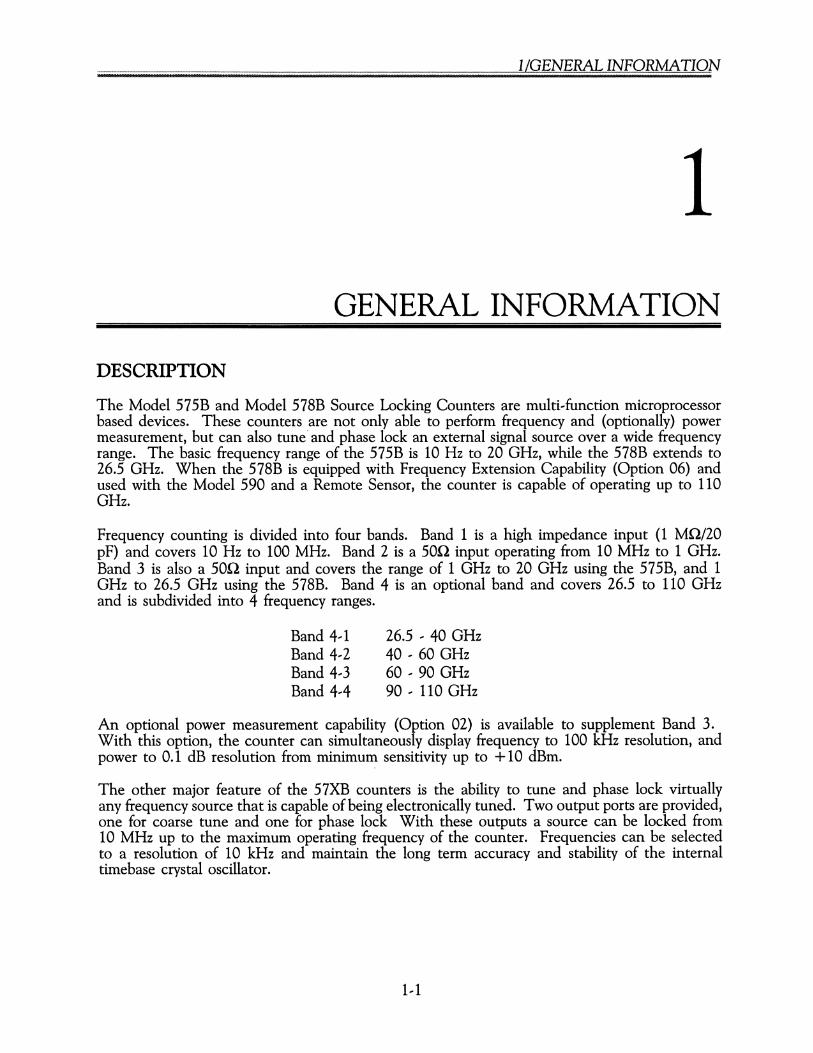
The Model 575B and Model 578B Source Locking Counters are multi...function microprocessorbased devices. These counters are not only able to perform frequency and (optionally) powermeasurement, but can also tune' and phase lock an external signal source over a wide frequencyrange. The basic frequency range of the 575B is 10 Hz to 20 GHz, while the 578B extends to26.5 GHz. When the 578B is equipped with Frequency Extension Capability (Option 06) andused with the Model 590 and a Remote Sensor, the counter is capable of operating up to 110GHz.
Frequency counting is divided into four bands. Band 1 is a high impedance input (1 MQ/20pF) and covers 10 Hz to 100 MHz. Band 2 is a 50Q input operating from 10 MHz to 1 GHz.Band 3 is also a 50Q input and covers the range of 1 GHz to 20 GHz using the 575B, and 1GHz to 26.5 GHz using the 578B. Band 4 is an optional band and covers 26.5 to 110 GHzand is subdivided into 4 frequency ranges.
Band 4 1Band 4 2Band 4 3Band 4 4
26.5 ... 40 GHz40 60 GHz60 90 GHz90 110 GHz
An optional power measurement capability (Option 02) is available to supplement Band 3.With this option, the counter can simultaneously display frequency to 100 kHz resolution, andpower to 0.1 dB resolution from minimum sensitivity up to +10 dBm.
The other major feature of the 57XB counters is the ability to tune and phase lock virtuallyany frequency source that is capable of being electronically tuned. Two output ports are provided,one for coarse tune and one for phase lock With these outputs a source can be locked from10 MHz up to the maximum operating frequency of the counter. Frequencies can be selectedto a resolution of 10 kHz and maintain the long term accuracy and stability of the internaltimebase crystal oscillator.
1... 1

........~.Z~.?/~.Z§~ .
SPECIFICAnONS
General
Resolution
Gate TimeDisplayAccuracyTestSample Rate
ResetOffsets
Operation Temp.PowerWeight, NetWeight, ShippingSize (H x W x D)Accessories Furnished
Frequency RangeSensitivityImpedanceConnectorMax. Input LevelDamage Level
Frequency RangeSensitivityDynamic RangeImpedanceConnectorMax. Input Level
Front panel keyboard input select 0.1 Hz to 1 GHz(0.1 Hz resolution in Band 1 only; no frequency offsetor multiplier in 0.1 Hz resolution).1 ms for 1 kHz resolution; 1 s for 1 Hz resolution12 digit LED, sectionalized±1 count ±time base errorFront panel selected diagnosticsControls time between measurements variable from100 ms type to 10 s. Switchable Hold position freezesdisplay indefinitely.Resets display to zero and initiates new readingKeyboard control of frequency offsets (standard) andpower offsets (standard with power measurement Option02). Displayed frequency (power) is offset by enteringvalue to 1 Hz resolution (0.1 dB power).o to 50°C100/120/220/240 VAC ±10% (selectable) 50 to 60 Hz26 Ib (11.8 kg)32 Ib (14.5 kg)3.5" x 16.75" x 14" (89 mm x 425 mm x 356 mm)Power Cord and Operation Manual
Band 1
10 Hz to 100 MHz25 mV rms1 MQ/20 pFBNC (female)1 V rms150 V rms (above 1 kHz, damage level will decrease at6 dB/octave down to 3.0 V rms)
Band 2
10 MHz to 1 GHz--20 dBm30 dB50 Q nominalBNC (female)+10 dBm
1--2
Damage LevelAcquisition Time
Frequency RangeSensitivity
Dynamic Range
ImpedanceConnector
Max. Input LevelDamage LevelAcquisition TimeAmplitude Discrimination
FM ModulationVSWRFrequency Limits
FrequencyAging RateShort TermTemperatureLine VariationWarm,up TimeOutput FrequencyExt. TimebasePhase Noise
l/GENERAL INFORMATION
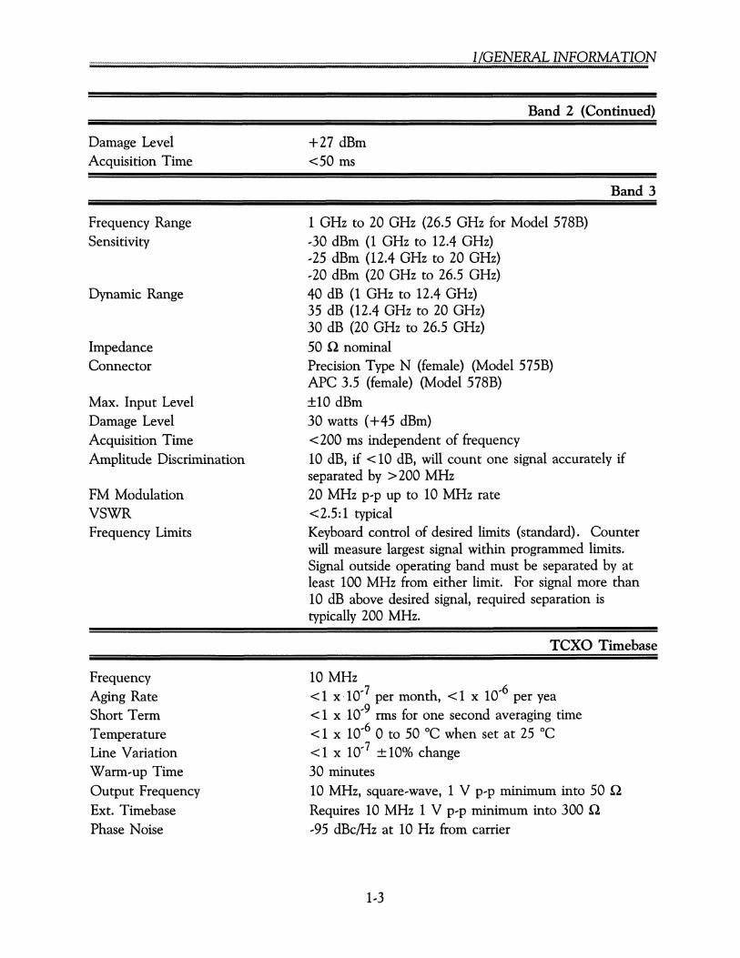
Band 2 (Continued)
+27 dBm<50 ms
Band 3
1 GHz to 20 GHz (26.5 GHz for Model 578B),30 dBm (1 GHz to 12.4 GHz),25 dBm (12.4 GHz to 20 GHz),20 dBm (20 GHz to 26.5 GHz)40 dB (1 GHz to 12.4 GHz)35 dB (12.4 GHz to 20 GHz)30 dB (20 GHz to 26.5 GHz)50 Q nominalPrecision Type N (female) (Model 575B)APC 3.5 (female) (Model 578B)±10 dBm30 watts (+45 dBm)< 200 ms independent of frequency10 dB, if < 10 dB, will count one signal accurately ifseparated by > 200 MHz20 MHz p'p up to 10 MHz rate<2.5:1 typicalKeyboard control of desired limits (standard). Counterwill measure largest signal within programmed limits.Signal outside operating band must be separated by atleast 100 MHz from either limit. For signal more than10 dB above desired signal, required separation istypically 200 MHz.
TCXO Timebase
10 MHz< 1 x 10⁻⁷ per month, < 1 x 10⁻⁶ per yea< 1 x 10--9 nus for one second averaging time< 1 x 10--6 0 to 50°C when set at 25 °C<1 x 10--7 ±10% change30 minutes10 MHz, square-wave, 1 V p'p minimum into 50 Q
Requires 10 MHz 1 V p'p minimum into 300 Q
,95 dBc/Hz at 10 Hz from carrier
1,3

........?Z??./~.Z§!?. .
Source Lock
Frequency RangeResolution
AccuracyLong Term StabilityMin. Phase Lock Signal LevelPolarityBandwidth
10 MHz (to maximum capability of counter)10 kHz for phase lock frequency ~50 MHz2.5 kHz for phase lock frequency <50 MHzEqual to counter's timebaseEqual to counter's timebaseEqual to counter's sensitivityAutomatically selectedUser selectable (10 kHz, 2 kHz, or 500 Hz) orautomatically selects widest bandwidth capable of locking
Lock Time (Typ)Coarse Tune
Phase LockRecalling Stored Data
50 ms +1 counter acquisition time for source bandwidthgreater than 100 Hz. Limited by source tuning speedbelow 100 Hz.20 ms1 counter acquisition +100 ms limited by source tuningspeed
Output Drive (Max)Coarse Tune OutputPhase Lock Output
Voltage Driven
+ 10 V into 5KQ min.
± 10 V into 5KQ min. for source gain constant<64 MHzN±.6 V into 5KQ min. for source gain constant~64 MHzN
100 kHz10kHz1 kHz
MODULATION FREQUENCY (SINEWAVE)
100Hz
8)
..........~ .........
" "" "-.-.r-..... ........ -,
~~~"" 7.. •
~ "',o~~ ,~~, ,~ I' ~I)~
~~ ~ ~.
-"'~..f ~
" ~ ~~ -.~,~ ~. r-,'-.~ ~~~
"'~~~.I ,~"~~ ,~
""~
,'~ "'-,~ ,~
~~~
-l- I- ......... ~~ '-.................. ~~ ~~o10Hz
20
30
40
50
60
10
NOISEREDUCTION
(d
70
1,4

l/GENERAL INFORMATION
Source Lock (Continued)
Current Driven ±75 MA into 10 Q max. for source gain constant<3.2 MHz/MA±4.5 MA into 10 Q max. for source gain constant~.2 MHz/MA
Entire range of selected counter band limited bymaximum output driveSource gain constant X maximum output driveRear panel BNC (female)
Phase LockOutput ConnectorPhase Locked Spectrum
Noise Floor vs Input Frequency The noise floor extends from the carrier to approximatelythe loop bandwidth. Beyond this, the noise floor decreases12 dBlbandwidth octave. The noise floor is the greater of:
Capture RangeCoarse Tune
1. NOISE FLOOR = --70 dBclHz2. NOISE FLOOR = [(20 log F) --6] dBclHz(where F = input frequency in GHz)
10 kHz1 kHz100 Hz10 Hz
~ IIIII
,10~Jf;~ I I I10 I .nearuI kJf~ AI. . I ''hit
• I o'se ~ •ekit I ('mt '."~L-J _ ~(i I --t- r<k . ,near(. I , ...........~
'Jt~ ~ .' ''hit ~~~ ........
~I I o/seL: : I '" ::::: ~, ~I I l'hlt I '" ~ ~ ~ ... ....SOOJf~. I I ~ ~~ ... ~~~~ ........ ...... .... ~ ........
- 500It Llneqr L' I --,~~~ ... i 'r--.. ......~
~ tvOis .''hit ~....~
-..~......~
e (''hit '"-"f'!II
llIl~ ~ ...... .... '" .....~
~ ~
--~ :::::illll ........ ...... ........ ..... ............~- ~....... ....~ ....,~~ ~
~~~..... -.. ...... ..... .... ... ......
........ ..... -....... ...~-. .......... ~~
.........~ ....~.....
~ ..."''':::::: ~ ..~
...... ...... ..........~~ "' ..-.. ........ ...... "~~ -- ..
==~ ~ ........ ...... ......~ ...... ....,~~ ~
~ ... ~-..- .... !II~ ...
-ilIl - "'llIll"~ -....
~ ....~,--~ illIIlIl8~o
1 Hz
10K
10M
100K
1M
MODULATIONAMPLITUDE
(Hz)
SINUSOIDAL MODULATION FREQUENCY (Hz)
1--5
........~.z~.~.(~.z§~ .
Source Lock (Continued)
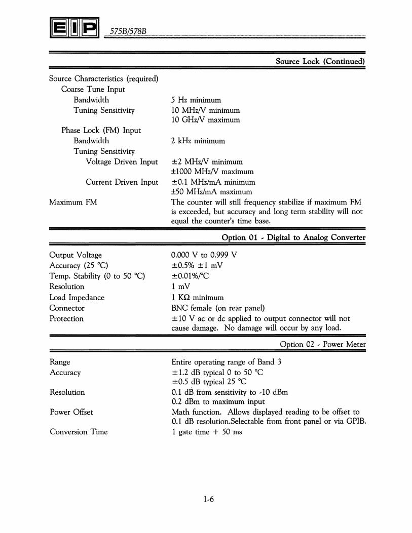
Source Characteristics (required)Coarse Tune Input
BandwidthTuning Sensitivity
Phase Lock (FM) InputBandwidthTuning Sensitivity
Voltage Driven Input
Current Driven Input
Maximum FM
Output VoltageAccuracy (25°C)Temp. Stability (0 to 50°C)ResolutionLoad ImpedanceConnectorProtection
RangeAccuracy
Resolution
Power Offset
Conversion Time
5 Hz minimum10 MHzN minimum10 GHzN maximum
2 kHz minimum
± 2 MHzN minimum±1000 MHzN maximum±0.1 MHz/rnA minimum±50 MHz/rnA maximumThe counter will still frequency stabilize if maximum FMis exceeded, but accuracy and long term stability will notequal the counter's time base.
Option 01 -- Digital to Analog Converter
0.000 V to 0.999 V±0.5% ±1 mV±O.Ol%fC1 mV1 KQ minimumBNC female (on rear panel)± 10 V ac or de applied to output connector will notcause damage. No damage will occur by any load.
Option 02 ' Power Meter
Entire operating range of Band 3± 1.2 dB typical 0 to 50°C±0.5 dB typical 25°C0.1 dB from sensitivity to ,10 dBm0.2 dBm to maximum inputMath function. Allows displayed reading to be offset to0.1 dB resolution.Selectable from front panel or via GPIB.1 gate time + 50 ms
1,6
l/GENERAL INFORMATION
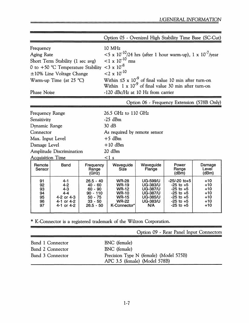
Option 05 ' Ovenized High Stability Time Base (SC,Cut)
FrequencyAging RateShort Term Stability (1 sec avg)o to + 50 °C Temperature Stability± 10% Line Voltage ChangeWarm,up Time (at 25°C)
Phase Noise
10 MHz<5 x 10.. 10/24 hrs (after 1 hour warm-up), 1 x 10..7/year< 1 x 10.. 10 rms<3 x 10..8
<2 x 10..10
Within ::;;5 x 10..9 of final value 10 min after turn-onWithin 1 x 10..9 of final value 30 min after turn-on,120 dBclHz at 10 Hz from carrier
Option 06 ' Frequency Extension (578B Only)
26.5 GHz to 110 GHz,25 dBm30 dBAs required by remote sensor+5 dBm+10 dBm20 dBm<1couismon nne s
Remote Band Frequency Waveguide Waveguide Power DamageSensor Range Size Flange Range Level
(GHz) (dBm) (dBm)
91 4-1 26.5 - 40 WR-28 UG-599/U -25/-20 to+5 +1092 4-2 40 - 60 WR-19 UG-383/U -25 to +5 +1093 4-3 60 - 90 WR-12 UG-387/U -25 to +5 +1094 4-4 90 - 110 WR-10 UG-387/U -25 to +5 +1095 4-2 or 4-3 50 - 75 WR-15 UG-385/U -25 to +5 +1096 4-1 or 4-2 33 - 50 WR-22 UG-383/U -25 to +5 +1097 4-1 or 4-2 26.5 - 50 K-Connector* N/A -25 to +5 +10
Frequency RangeSensitivityDynamic RangeConnectorMax. Input LevelDamage LevelAmplitude DiscriminationA T"
* K,Connector is a registered trademark of the Wiltron Corporation.
Option 09 ' Rear Panel Input Connectors
Band 1 ConnectorBand 2 ConnectorBand 3 Connector
BNC (female)BNC (female)Precision Type N (female) (Model 575B)APC 3.5 (female) (Model 578B)
........~.z~.~.(?z§~ .
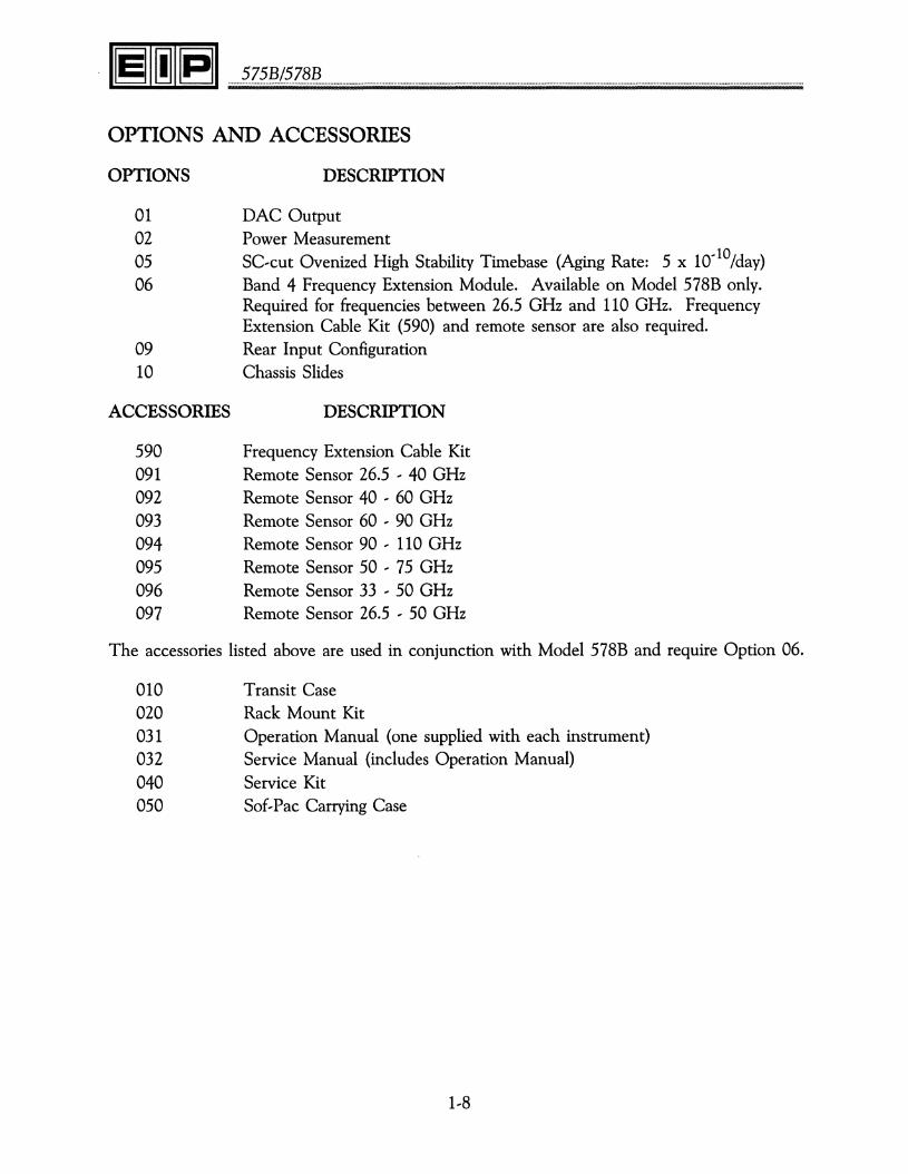
OPTIONS AND ACCESSORIES
OPTIONS DESCRIPTION
01 DAC Output02 Power Measurement05 SC-cut Ovenized High Stability Timebase (Aging Rate: 5 x 10,10/dav)06 Band 4 Frequency Extension Module. Available on Model 578B only.
Required for frequencies between 26.5 GHz and 110 GHz. FrequencyExtension Cable Kit (590) and remote sensor are also required.
09 Rear Input Configuration10 Chassis Slides
ACCESSORIES DESCRIPTION
590 Frequency Extension Cable Kit091 Remote Sensor 26.5 ' 40 GHz092 Remote Sensor 40 ' 60 GHz093 Remote Sensor 60 ' 90 GHz094 Remote Sensor 90 ' 110 GHz095 Remote Sensor 50 ' 75 GHz096 Remote Sensor 33 ' 50 GHz097 Remote Sensor 26.5 ' 50 GHz
The accessories listed above are used in conjunction with Model 578B and require Option 06.
010 Transit Case020 Rack Mount Kit031 Operation Manual (one supplied with each instrument)032 Service Manual (includes Operation Manual)040 Service Kit050 Sof-Pac Carrying Case
1,8
575B/578B
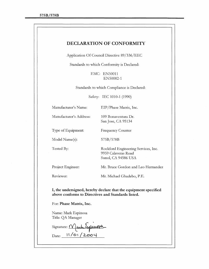
DECLARATION OF CONFORMITY
Application Of Council Directive 89/336/EEC
Standards to which Conformity is Declared:
EMC: EN50011EN50082-1
Standards to which Compliance is Declared:
Safety: IEC 1010-1 (1990)
Manufacturer's Name:
Manufacturer's Address:
Type of Equipment:
Model Name(s):
Tested By:
Project Engineer:
Reviewer:
EIP/Phase Matrix, Inc.
109 Bonaventura Dr.San Jose, CA 95134
Frequency Counter
575B/578B
Rockford Engineering Services, Inc.9959 Calaveras RoadSunol, CA 94586 USA
Mr. Bruce Gordon and Leo Hernandez
Mr. Michael Gbadebo, P .E.
I, the undersigned, hereby declare that the equipment specifiedabove conforms to Directives and Standards listed.
For: Phase Matrix, Inc.
Name: Mark EspinosaTitle: QA Manager
Signature: litw.L-.~Date: I \ / 0 \ (2..00 t-f_

........?z.?.~.(~.z§!?. .
This Page Intentionally Left Blank.
1--10

2/INSTALLATION
INSTALLATION
UNPACKING AND INITIAL INSPECTION
If the shipping container or cushioning material is damaged, it should be kept until the contentsof the shipment have been checked for completeness and the instrument has been checkedmechanically and electrically If the contents are incomplete, if there is mechanical damage ordefect, or if the instrument does not pass the electrical performance tests, notify EIP in care ofthe address shown on the title page. If the shipping container is damaged, or the cushioningmaterial shows signs of stress, notify the carrier as well as EIP. Keep the shipping materials forcarrier's inspection. EIP will arrange for repair or replacement of the instrument without waitingfor claim settlement.
STORAGE
Store the instrument in an environment that is protected from moisture, dust, and othercontaminants. Do not expose the instrument to temperatures below ...55 "C or above 75°C,nor to altitudes above 40,000 ft. (12,000 m).
OPERATING CONDITIONS
This instrument is designed to be operated at temperature not exceeding 0 to 50°C at relativehumidity not to exceed 95% (75% over 25 °C; 45% over 40°C). This instrument will performto specifications at altitudes not exceeding 10,000 ft. (3050 m) and will tolerate vibration notexceeding 2 g. It is fungus resistant. The chassis is not designed to provide protection frommechanical shock or falling water particles and is intended for normal bench use in anenvironmentally clean area. .
VENTILATION
Air circulates through the vents in the rear panel of the counter. These vents must not beobstructed or the temperature inside the counter may increase enough to reduce counter stabilityand shorten component life.
2... 1

........?Z?~./~.Z§.!? .
INSTALLATION
There are no special installation instructions for the EIP 575B or 578B frequency counter. Theseunits are self-contained bench or rack mounted instruments that only require connection to astandard, single...phase power line for operation.
PREPARATION FOR USE
VOLTAGE SELECTION
CAUTION
Disconnect ac power cord before changing voltage selection switch.
The voltage select switch should be set to the proper line voltage. (See Figure 2... 1.) To changethe line voltage, proceed as follows:
1. Disconnect the counter from the power line.
2. Using a screwdriver, turn the slotted voltage indicator to the desired position.
FUSE REPLACEMENT
WARNING
Disconnect ac power cord before replacing fuse.
The fuse for the counter is located on the rear panel above the line voltage socket. The typeof fuse used in your counter depends upon the primary power, as follows:
Line Voltage
100/120 Vac
200/220 Vac
Fuse Type
1.5 A Slow-blow MOL
0.8 A Slow-blow FST
To release the fuse, use a screwdriver to rotate the slotted cap counterclockwise. To reinstallthe fuse, press the fuse and slotted cap assembly into the fuse cavity and turn cap clockwiseuntil it locks into place.
CAUTION
To avoid damage to the counter, always be sure that the fuse usedis the type and value specified, and that the voltage select switchis set to correspond to the ac power input voltage. (See Figure2-1.)
2/INSTALLATION
100/120VAC- 1.5A SB
220/240 VAC- .BOA SB
®
D~~--e
V.A.C.50/60 Hz
®
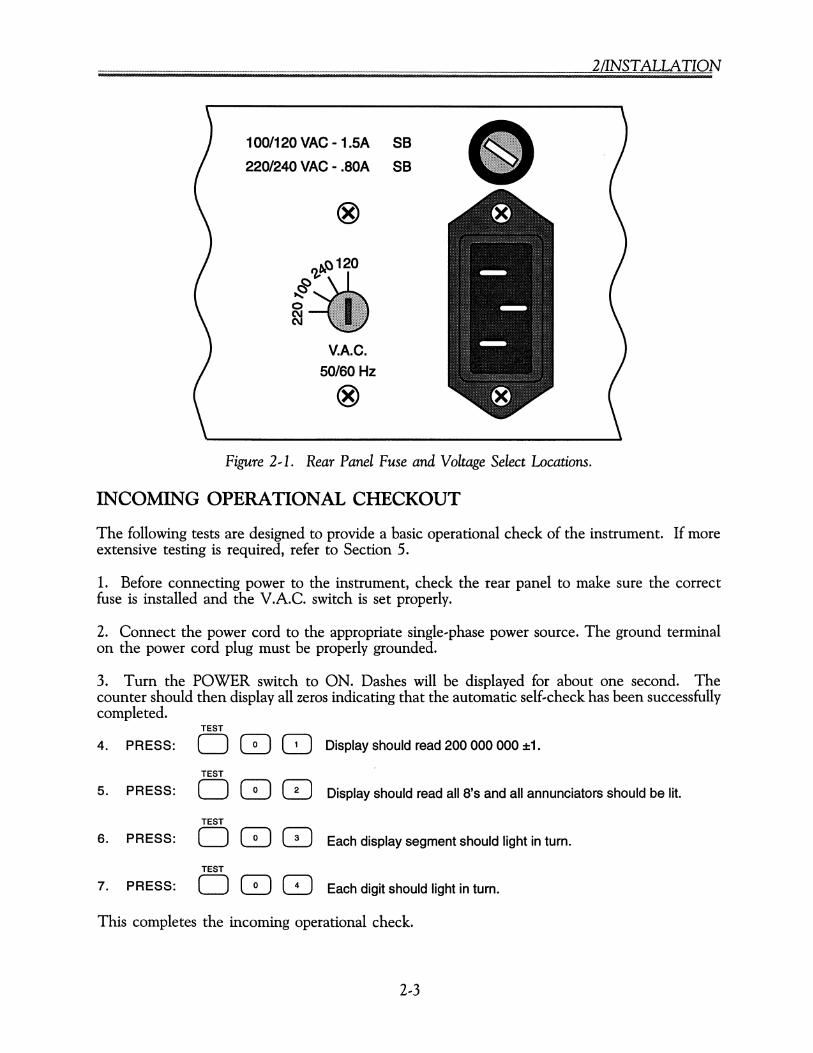
Figure 2~1. Rear Panel Fuse and Voltage Select Locations.
INCOMING OPERATIONAL CHECKOUT
The following tests are designed to provide a basic operational check of the instrument. If moreextensive testing is required, refer to Section 5.
1. Before connecting power to the instrument, check the rear panel to make sure the correctfuse is installed and the V.A.C. switch is set properly.
2. Connect the power cord to the appropriate single-phase power source. The ground terminalon the power cord plug must be properly grounded.
3. Turn the POWER switch to ON. Dashes will be displayed for about one second. Thecounter should then display all zeros indicating that the automatic self-check has been successfullycompleted.
TEST
4. PRESS: 0 8 8 Display should read 200 000 000 ±1.
TEST
5. PRESS: 0 8 0 Display should read all 8's and all annunciators should be lit.
TEST
6. PRESS: 0 8 0 Each display segment should light in turn.
TEST
7. PRESS: 0 8 GJ Each digit should light in turn.
This completes the incoming operational check.
........?z?..~.(~.Z?~ .
SERVICE INFORMATION
PERIODIC MAINTENANCE
No periodic preventive maintenance is required. To maintain accuracy, it is recommended thatthe counter be recalibrated every 12 months. For further information, refer to the service manual.
CAUTION
Do not attempt repair or disassembly of the Microwave Converter,Millimeter Wave Converter, or Time Base Oscillator assemblies. Suchaction will void the warranty of the counter. Contact EIP or yoursales representative if these units require servicing.
COUNTER IDENTIFICATION
This counter is identified by three sets of numbers the model number (575B or 578B), serialnumber, and a configuration control number (CCN). They are located on a label affixed to theframe at the rear of the counter. These numbers must be included in any correspondence regardingyour counter.
FACTORY SERVICE
If the counter is being returned to EIP for service or repair. be sure to include the followinginformation with the shipment.
• Name and address of owner.
• Model number, serial number, and configuration control number of the Counter (listed onthe reat panel of the counter).
• A complete description of the problem. (E.g., under what conditions did the problem occur?What was the signal level? What equipment was attached or connected to the counter? Didthat equipment experience failure symptoms?)
• Name and telephone number of someone familiar with the problem who may be contactedby EIP for any further information if necessary.
• Shipping address to which the counter is to be returned. Include any special shipping instructions.
Pack the counter for shipping as detailed below.
SHIPPING INSTRUCTIONS
Wrap the counter in heavy plastic or kraft paper, and repack in original container if available.If the original container cannot be used, use a heavy (275 pound test) double-walled cartonwith approximately four inches of packing material between the counter and the inner carton.Seal carton with strong filament tape or strapping. Mark the carton to indicate that it containsa fragile electronic instrument. Ship to EIP Microwave, Inc. at the address shown an the frontcover.
2,4
3/0PERATION
OPERATION
INTRODUCTION
This section lists the counter controls, connectors, and indicators, explains how each counterfunction operates, and provides some general measurement considerations.
;" ""'" -, " ",' -, "'" -, -, '" -, EXT REF FRO LMT BND 1
>' -, ~ dBm DAC LOW HI 2 3
~ ~ LCK BW OFFSET 41 42
~~GHi. ~J4ff§g§#ff"MfJ,:!Af4A4#¥~J4Z444#a ~~~, Nt ~: RMT MLT FRO PWR 43 44
DIiJDljJI MODEL5788 SOURCELOCKING MICROWAVE COUNTER
SAMPLERATE
OFF.RON 0HOLD
• GATE
• SEARCH [!!]POWERMETER
onIoff offset dB•••
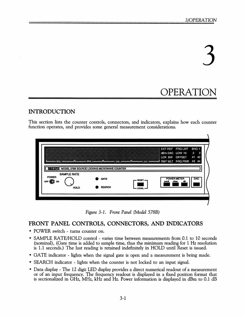
Figure 3,1. Front Panel (Model 578B)
FRONT PANEL CONTROLS, CONNECTORS, AND INDICATORS• POWER switch ' turns counter on.
• SAMPLE RATE/HOLD control -- varies time between measurements from 0.1 to 10 seconds(nominal), (Gate time is added to sample time, thus the minimum reading for 1 Hz resolutionis 1.1 seconds.) The last reading is retained indefinitely in HOLD until Reset is issued.
• GATE indicator ' lights when the signal gate is open and a measurement is being made.
• SEARCH indicator ' lights when the counter is not locked to an input signal.
• Data display -- The 12 digit LED display provides a direct numerical readout of a measurementor of an input frequency. The frequency readout is displayed in a fixed position format thatis sectionalized in GHz, MHz, kHz and Hz. Power information is displayed in dBm to 0.1 dB
3--1

........~.z~.?(?.z§~ .
resolution, on the three right..most digits. When both power and frequency are displayed,frequency resolution is limited to 100 kHz.
• Status display .. a series of annunciators provided to indicate current operating status of thecounter.
• Keyboard .. both data entry and function selection are controlled through the keyboard (seeKeyboard Section on page 3..5).
Figure 3..2. Status Display.
STATUS DISPLAY
• EXT REF .. lights to indicate the counter is set to an external time base reference.
CAUTION
When EXT REF lights it does NOT indicate that correct signal levelhas been applied.
• dBm .. lights to indicate that the Power Meter (Option 02) is active.
• LCK .. lights when the counter has phase locked an external source.
• RMT .. lights to indicate that front panel controls are disabled, and that the counter is beingcontrolled through the GPIB interface.
• DAC .. lights to indicate that that the Digital..to..Analog Converter (Option 01) is active.
• BW .. lights to indicate a phase lock loop bandwidth has been selected.
• MLT .. lights to indicate the multiplier function is active.
• FRQ LMT LOW ... lights when Band 3 frequency limit low is active.
• FRQ LMT HI .. lights when Band 3 frequency limit high is active.
• OFFSET FRQ ... lights when frequency offset is active.
• OFFSET PWR .. lights when power offset is active.
• BND 1, 2, 3, 41, 42, 43, or 44 .. lights to indicate which operating range has been selected.When any Band 4 annunciator is lit it indicates that the Extended Frequency Capability,Option 06, has been selected (578B only).
3..2

3LOPERATION
\I
BAND4
REMOTESENSOR
oW
,
BAND110 Hz-100 MHz
G1 MEGI20pF
BAND210MHz-1 GHz
GSO OHM
BAND31 GHz-26.SGHz
@-t-TOBAND3-e50 OHM
Figure 3--3. Signal Input Connectors (Model S78B).
SIGNAL INPUT
• BAND 1 input connector (BNC female) -- has a nominal input impedance of 1 MQ, shuntedby 20 pF. It is used for measurements in the range of 10 Hz to 100 MHz.
• BAND 2 input connector (BNC female) -- has a nominal input impedance of 50 Q. It is usedfor measurements in the range of 10 MHz to 1 GHz.
• BAND 3 input connector (precision type N female for the Model 575B, APC--3.5 female forModel 578B) -- has a nominal input impedance of 50 Q. It is used for measurements in therange of 1 GHz to 20 GHz (26.5 for Model 578B).
• BAND 4 (Option 06, Model 578B only) -- is a Selectro quick connect connector with anominal input impedance of 50 Q. It is used for measurements in the range of 26.5 GHz to110 GHz. This input is used in conjunction with the Model 590 Frequency Extension CableKit and a remote sensor.
J6
®
VAC.5Qf80Hz
8
F11OM20 VK; -1.5A
22Ql24O VK; - .BOA
o LOCKOUT
J7
®COARSE
TUNEOUT
IIIIIIIIIIIIIIIIIIII! ~J4•• G.P.I.B.
A J111 OUT J2TORMT~ _ INT e
BAND 3 SENSOR-.., • <I> (!)
_
J114 IEEESTD.488-1978BAND 4 B BAND 1 EXT J J3 (8H1,AH1,T&,LA,8R1, RL1,001, DT1)
J113 10MHz
~~TO~D3T J::t IIiii 11111--------__-----a
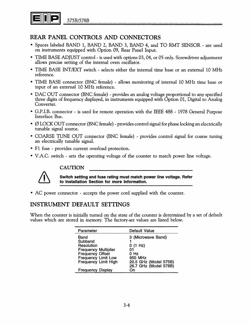
Figure 3--4. Rear Panel.
3--3
........~.z~.~.(~.z§!? .
REAR PANEL CONTROLS AND CONNECTORS• Spaces labeled BAND 1, BAND 2, BAND 3, BAND 4, and TO RMT SENSOR, are used
on instruments equipped with Option 09, Rear Panel Input.
• TIME BASE ADJUST control, is used with options 03,04, or 05 only. Screwdriver adjustmentallows precise setting of the internal oven oscillator.
• TIME BASE INT/EXT switch, selects either the internal time base or an external 10 MHzreference.
• TIME BASE connector (BNC female) , allows monitoring of internal 10 MHz time base orinput of an external 10 MHz reference.
• DAC OUT connector (BNC female) , provides an analog voltage proportional to any specifiedthree digits of frequency displayed, in instruments equipped with Option 01, Digital to AnalogConverter.
• G.P.I.B. connector, is used for remote operation with the IEEE 488 ' 1978 General PurposeInterface Bus.
• 0 LOCK OUT connector (BNC female) , provides control signal for phase locking an electricallytunable signal source.
• COARSE TUNE OUT connector (BNC female) , provides control signal for coarse tuningan electrically tunable signal.
• F1 fuse ' provides current overload protection.
• V.A.C. switch, sets the operating voltage of the counter to match power line voltage.
CAUTION
Switch setting and fuse rating must match power line voltage. Referto Installation Section for more information.
• AC power connector, accepts the power cord supplied with the counter.
INSTRUMENT DEFAULT SETTINGS
When the counter is initially turned on the state of the counter is determined by a set of defaultvalues which are stored in memory. The factory-set values are listed below.
Parameter
BandSubbandResolutionFrequency MultiplierFrequency OffsetFrequency Limit LowFrequency Limit High
Frequency Display
Default Value
3 (Microwave Band)1o (1 Hz)01o Hz950 MHz20.5 GHz (Model 575B)26.7 GHz (Model 578B)On
3,4
[ iii]LOCAL
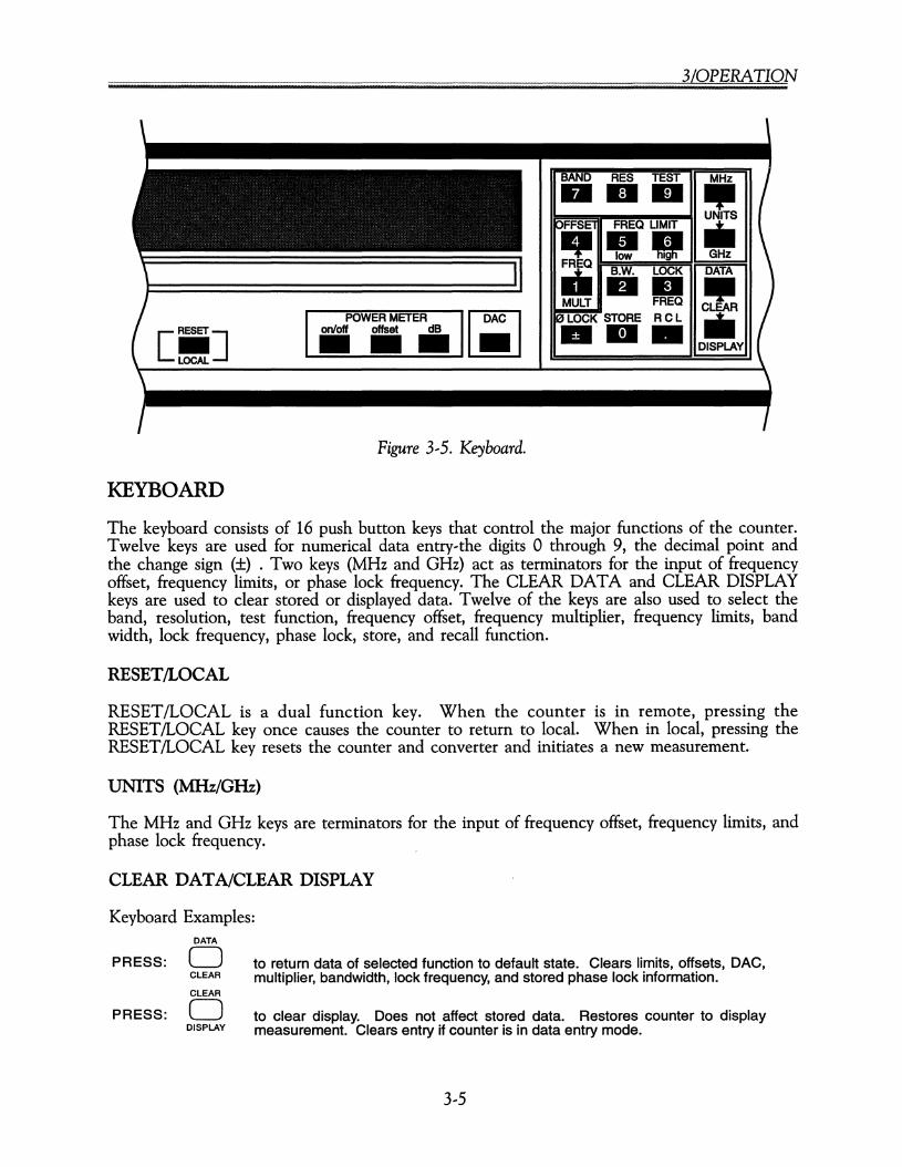
KEYBOARD
POWER METER I.DAC Ion/off offset dB•••Figure 3,5. Keyboard.
3/0PERATION
BAND RES TEST MHz••• 11IIIUNITS
OFFSEl FREQ LIMIT ..IIJI -"low 19 GHzFREQ
B.W. LOCK DATAiii •• 11IIMULT FREQ CLEARe LOCK STORE R C L ..••• DISPLAY
The keyboard consists of 16 push button keys that control the major functions of the counter.Twelve keys are used for numerical data entry-the digits 0 through 9, the decimal point andthe change sign (±) . Two keys (MHz and GHz) act as terminators for the input of frequencyoffset, frequency limits, or phase lock frequency. The CLEAR DATA and CLEAR DISPLAYkeys are used to clear stored or displayed data. Twelve of the keys are also used to select theband, resolution, test function, frequency offset, frequency multiplier, frequency limits, bandwidth, lock frequency, phase lock, store, and recall function.
RESET/LOCAL
RESET/LOCAL is a dual function key. When the counter is in remote, pressing theRESET/LOCAL key once causes the counter to return to local. When in local, pressing theRESET/LOCAL key resets the counter and converter and initiates a new measurement.
UNITS (MHz/GHz)
The MHz and GHz keys are terminators for the input of frequency offset, frequency limits, andphase lock frequency.
CLEAR DATA/CLEAR DISPLAY
Keyboard Examples:DATA
PRESS: 0CLEAR
CLEAR
PRESS: 0DISPLAY
to return data of selected function to default state. Clears limits, offsets, DAC,multiplier, bandwidth, lock frequency, and stored phase lock information.
to clear display. Does not affect stored data. Restores counter to displaymeasurement. Clears entry if counter is in data entry mode.
3,5
........~.z~.~.(~.z§.~ .
COUNTER CONTROL FUNCTIONS
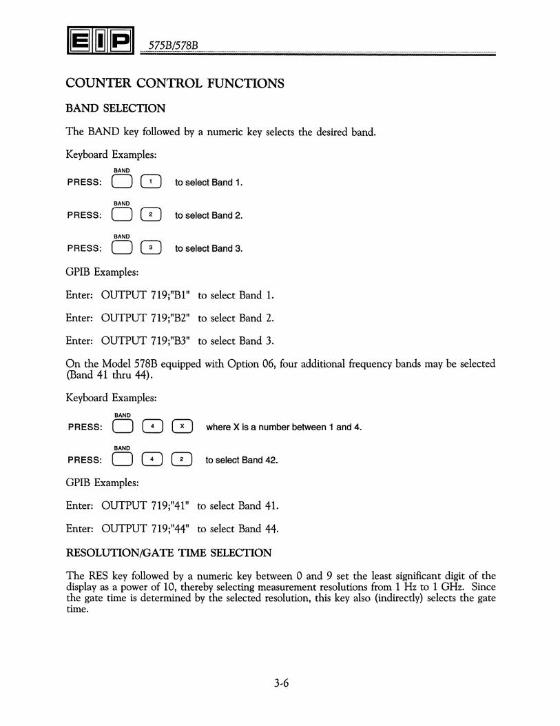
BAND SELECTION
The BAND key followed by a numeric key selects the desired band.
Keyboard Examples:BAND
PRESS: 0 0 to select Band 1.
BAND
PRESS: 0 0 to select Band 2.
BAND
PRESS: 0 0 to select Band 3.
GPIB Examples:
Enter: OUTPUT 719;"B1" to select Band 1.
Enter: OUTPUT 719;"B2" to select Band 2.
Enter: OUTPUT 719;"B3" to select Band 3.
On the Model 578B equipped with Option 06, four additional frequency bands may be selected(Band 41 thru 44).
Keyboard Examples:
BAND
PRESS: 0 8 0 where X is a number between 1 and 4.
BAND
PRESS: 0 8 0 to select Band 42.
GPIB Examples:
Enter: OUTPUT 719;"41" to select Band 41.
Enter: OUTPUT 719;"44" to select Band 44.
RESOLUTION/GATE TIME SELECTION
The RES key followed by a numeric key between 0 and 9 set the least significant digit of thedisplay as a power of 10, thereby selecting measurement resolutions from 1 Hz to 1 GHz. Sincethe gate time is determined by the selected resolution, this key also (indirectly) selects the gatetime.
3--6

3/0PERATION
Keyboard Examples:
RES
PRESS: 00RES
PRESS: 08RES
PRESS: 00RES
PRESS: OGJRES
PRESS: 08RES
PRESS: OGJ
to select a 1 Hz resolution (1 second gate time).
to select a 10 Hz resolution (.1 second gate time).
to select a 100 Hz resolution (.01 second gate time).
to select a 1 kHz resolution (1 ms gate time).
to select a 10 kHz resolution (1 ms gate time).
to select a 1 GHz resolution (1 ms gate time).
GPIB Examples:
Enter: OUTPUT 719;"RO" to select a 1 Hz resolution.
Enter: OUTPUT 719;"R1" to select a 10 Hz resolution.
Enter: OUTPUT 719;"R6" to select a 10 MHz resolution.
Enter: OUTPUT 719;"R9" to select a 1 GHz resolution.
0.1 Hz Resolution
In Band 1 only, the counter also provides a 0.1 Hz resolution. When 0.1 Hz is selected inBand 1, the significance of the digits on the front panel display is shifted left 3 digits. Forexample, a 9 MHz signal input is displayed as 9 GHz. One digit is displayed to the right of thedecimal, and the two right-most digits are blanked out. The display digit to the right of thedecimal will be zero until the measurement is updated at the end of the 10 second gate interval.
Keyboard Examples:
BAND
PRESS: 0 8 to select Band 1.
RES
PRESS: 0 0 8 toselectaO.1 Hz resolution.
GPIB Examples:
Enter: OUTPUT 719;"B1" to select Band 1.
Enter: OUTPUT 719;"R.1" to select a 0.1 Hz resolution.
3,7
........~.Z~.~./~.Z§~ .
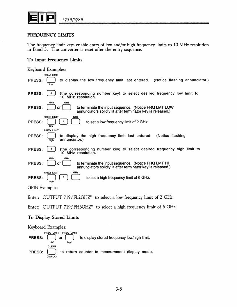
FREQUENCY LIMITS
The frequency limit keys enable entry of low and/or high frequency limits to 10 MHz resolutionin Band 3. The converter is reset after the entry sequence.
To Input Frequency Limits
(the corresponding number key) to select desired frequency low limit to10 MHz resolution.
to display the low frequency limit last entered. (Notice flashing annunciator.)PRESS:
PRESS:
Keyboard Examples:FREQ LIMIT
olow
oMHz GHz
PRESS: DorD to terminate the input sequence. (Notice FRO LMT LOWannunciators solidly lit after terminator key is released.)
FREQ LIMIT GHz
PRESS: 0 0 0 to set a low frequency limit of 2 GHz.low
FREQ LIMIT
PRESS: 0 to display the high frequency limit last entered. (Notice flashinghigh annunciator.)
PRESS: 0 (the corresponding number key) to select desired frequency high limit to10 MHz resolution.
MHz GHz
PRESS: DorD to terminate the input sequence. (Notice FRO LMT HIannunciators solidly lit after terminator key is released.)
FREQ LIMIT GHz
PRESS: 0 0 0 to set a high frequency limit of 6 GHz.high
GPIB Examples:
Enter: OUTPUT 719;"FL2GHZ" to select a low frequency limit of 2 GHz.
Enter: OUTPUT 719;"FH6GHZ" to select a high frequency limit of 6 GHz.
To Display Stored Limits
Keyboard Examples:FREQ LIMIT FREQ LIMIT
PRESS: 0 or 0 to display stored frequency low/high limit.low high
CLEAR
PRESS: 0 to return counter to measurement display mode.DISPLAY
3,8

3/0PERATION
To Clear Frequency Limits
Keyboard Example:
FREQ LIMIT
PRESS: 0low
CLEAR
oDATA
or
FREQ LIMIT
ohigh
CLEARoDATA
NOTE
High and low limits should be separated by at least 100MHz.
GPIB Examples:
Enter: OUTPUT 719;"FLP" to reset low frequency limit to factory default.
Enter: OUTPUT 719;"FHP" to reset high frequency limit to factory default.
DATA MANIPULATION FUNCTIONS
FREQUENCY OFFSET
Frequency offset function enables the entry of a positive or negative frequency offset to 1 Hzresolution. The offset will be incorporated into the frequency measurement after the next gate.
(the corresponding number key) to select desired offset frequency to 1 Hzresolution.
to display frequency offset last entered. (Notice flashing annunciator.)
PRESS:
PRESS:
To Input Frequency Offsets
Keyboard Examples:FREQ
oOFFSET
8MHz GHz
PRESS: DorD to terminate the input sequence. (Notice FRO OFFSET annunciators solidlylit after terminator key is released.)
FREQ GHz
PRESS: 0 0 0 to set a frequency offset of2 GHz.OFFSET
GPIB Examples:
Enter: OUTPUT 719;"F02GHZ" to select 2 GHz frequency offset.
Enter: OUTPUT 719;"FOP" to clear frequency offset.
3,9
........~.z~.~.(~.z§~ .
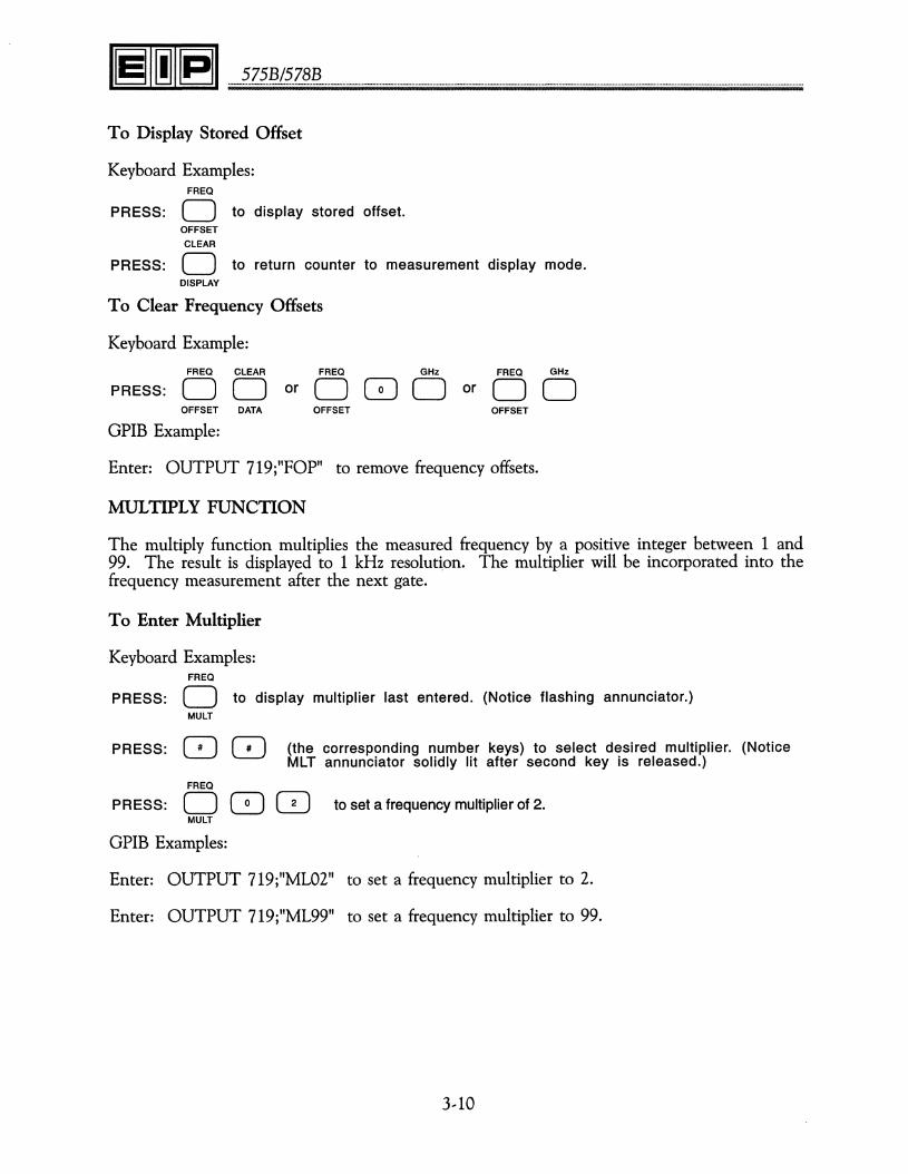
To Display Stored Offset
Keyboard Examples:FREQ
PRESS: 0 to display stored offset.OFFSETCLEAR
PRESS: 0 to return counter to measurement display mode.DISPLAY
To Clear Frequency Offsets
Keyboard Example:
FREQ CLEAR
PRESS: ODorOFFSET DATA
GPIB Example:
FREQ GHz
000 orOFFSET
FREQ GHz
DOOFFSET
Enter: OUTPUT 719;"FOP" to remove frequency offsets.
MULTIPLY FUNCTION
The multiply function multiplies the measured frequency by a positive integer between 1 and99. The result is displayed to 1 kHz resolution. The multiplier will be incorporated into thefrequency measurement after the next gate.
To Enter Multiplier
Keyboard Examples:FREQ
PRESS: 0 to display multiplier last entered. (Notice flashing annunciator.)MULT
PRESS: 8 0 {the corresponding number keys} to select desired multiplier. (NoticeMLT annunciator solidly lit after second key is released.)
FREQ
PRESS: 0 8 8 to set a frequency multiplier of 2.MULT
GPIB Examples:
Enter: OUTPUT 719;"ML02" to set a frequency multiplier to 2.
Enter: OUTPUT 719;"ML99" to set a frequency multiplier to 99.
3--10
3/0PERATION
To Display Multiplier
Keyboard Examples:FREQ
PRESS: 0 to display stored frequency multiplier.MULT
CLEAR
PRESS: 0 to return counter to measurement display mode.DISPLAY
To Clear Multiplier
Keyboard Example:FREQ CLEAR
PRESS: DOorFREQ
DGJGJMULT DATA MULT
GPIB Example:
Enter: OUTPUT 719;"MLP" to clear the multiplier function.
mX±B
By using the frequency offset and multiply functions the counter can automatically performmX±B calculations.
The equation for the function performed is:
Displayed Reading = mX±B where m= Multiplier (00 to 99) entered from the keyboard.x= Input frequency.
±B= Frequency offset entered from the keyboard.
To do mX±B calculation for m = 2, b = 70 MHz
Keyboard Example:
FREQ
PRESS: 0 GJ GJ andMULT
FREQ MHz
DGJGJDOFFSET
SOURCE LOCKING FUNCTIONS
PHASE LOCK FREQUENCY
Enables entry of a phase lock frequency to: a) 10 kHz resolution if the phase lock frequencyis above or equal to 50 MHz, or b) 2.5 kHz resolution if the phase lock frequency is below 50MHz. The counter will attempt to phase lock after the entry sequence is terminated. Thephase lock operation will terminate if the RESET/LOCAL key is pressed while the counter isattempting to phase lock.
3--11
........~.z~.~.(?Z?~ .
NOTE
If the tuning voltage required to set a source at a particularfrequency changes in excess of the capture range of thephase lock circuitry, the counter will not be able to re-Iockthe source uslru; stored lock frequencies.
To Enter Phase Lock Frequency
Keyboard Examples:LOCK
PRESS: 0 to display phase lock frequency last entered. (Notice flashing annunciator.)FREQ
PRESS: 8 (the corresponding number key) to select desired phase lock frequency.
MHz GHz
PRESS: OorO to terminate input sequence. Notice LCK annunciator continues to flashwhile counter is attempting to phase lock. LCK annunciator lights solidlywhen phase lock is successful. If phase lock is unsuccessful, the LCKannunciator continues to flash until lock is achieved or until the sequenceis manually terminated.
LOCK GHz
PRESS: 0 8 GJ 0FREQ
GPIB Example:
to select a 10 GHz phase lock frequency.
Enter: OUTPUT 719;"PL2GHZ" to select 2 GHz phase lock frequency.
To Display Phase Lock Frequency
Keyboard Examples:LOCK
PRESS: 0 to display phase lock frequency to a 1 Hz resolution.FREQ
CLEAR
PRESS: 0 to return counter to measurement display mode.DISPLAY
To Clear Phase Lock Frequency
Keyboard Example:LOCK CLEAR
PRESS: ODorFREQ DATA
LOCK GHz
000 orFREQ
3--12
LOCK GHz
DOFREQ
3/0PERATION
NOTE
When the counter is attempting to phase lock, the informationdisplayed on the front panel is the frequency the counter isattempting to phase lock to. During the phase lock process,if the RESET/LOCAL key is pressed, the counter will abortthe process and return to regular measurement mode. Afterphase lock frequency is cleared, the coarse tune output willreturn to +5 V and the phase lock output will return to 0 V.
GPIB Example:
Enter: OUTPUT 719j"PLP" to remove phase lock frequency.
PHASE LOCK
The 0 LOCK key is used in conjunction with the RCL key function to enable the user to phaselock a stored frequency expeditiously. (See description of RECALL function.) The front paneldisplays the frequency the counter is trying to phase lock, and the LCK annunciator flashes.When the phase lock process is successful, the annunciator will be solidly lit; if unsuccessful,the annunciator will continue to flash until the function is manually terminated.
BANDWIDTH
The B.W. key followed by a numeric key selects the phase lock loop bandwidth as follows:
Keyboard Examples:
B.W.
PRESS: 0 8 to select a 500 Hz loop bandwidth.
B.W.
PRESS: 0 8 to select a 2 kHz loop bandwidth.
B.W.
PRESS: 0 0 to select a 10 kHz loop bandwidth.
B.W.
PRESS: 0 8 to automatically select loop bandwidth.
Bandwidth 0 enables the counter to automatically select the phase lock loop bandwidth. WhenBWO is selected, the counter, during the phase lock process, will try to close the phase lockloop in the 10 kHz, 2 kHz and 500 Hz bandwidth sequentially. It will select the first bandwidthin which it can hold phase lock.
GPIB Examples:
Enter: OUTPUT 719j"BWl" to select a 500 Hz loop bandwidth.
Enter: OUTPUT 719j"BW3" to select a 10 kHz loop bandwidth.
3,13
........~.Z.~.Jj}./~.Z§~ .
To Display Stored Bandwidth
Keyboard Examples:
PRESS:
PRESS:
STORE
B.W.
oCLEAR
oDISPLAY
to display last selected bandwidth number followed by the bandwidth in Hz.(Notice flashing annunciator.)
to clear the display without changing stored setting.
The STORE key stores the current phase lock frequency in a selected register. This functioncan be activated only after the counter has been phase locked. An error will occur if thefunction is activated when the counter is not phase locked. The STORE function reduces thetime required to phase lock when the stored phase lock frequency is recalled. There are a totalof nine storage registers.
Keyboard Examples:
PRESS:
PRESS:
STORE
o8
to display current phase lock frequency to 100 Hz resolution. (Noticeflashing annunciator.)
(an integer between 1 and 9, inclusive) to display the storage register inwhich the phase lock information is to be stored.
STORE
PRESS: 0 [2] to store the current phase lock frequency in register 1.
GPIB Example:
Enter: OUTPUT 719;"ST2" to store current phase lock frequency in register 2.
RECALL
The ReL key enables the counter to perform one of the following functions:
1. To display one of the stored phase lock frequencies;
2. To phase lock to one of the stored phase lock frequencies; or
3. To clear a stored phase lock frequency.
3,14

3.LOPERATION
To Display a Stored Phase Lock Frequency
Keyboard Examples:
PRESS:
PRESS:
PRESS:
RCL
o8CLEAR
o
to display the word reI. (Notice flashing annunciator)
(the corresponding number key) to display the storage register to berecalled. (Note that the stored phase lock frequency is displayed to aresolution of 100 Hz and is followed by the storage register number.)
to return counter to measurement display mode.DISPLAY
To Phase Lock to a Stored Phase Lock Frequency
Keyboard Examples:RCL
PRESS: 0PRESS: 8
e LOCK
PRESS: 0
to display the word rei. (Notice flashing annunciator)
(the corresponding number key) to display the storage register to berecalled. (Note that the stored phase lock frequency is displayed to aresolution of 100 Hz and is followed by the storage register number.)
to phase lock to the recalled frequency. (Note: if the recalled frequency isoutside the frequency range of the current band, the phase lock frequencyregister will not be altered.)
GPIB Example:
Enter: OUTPUT 719;"RC2L" to phase lock to the frequency stored in register 2.
To Clear a Stored Phase Lock Frequency
(the corresponding number key) to display stored phase lock frequency to100 Hz resolution followed by the storage register number.
to display the word rei. (Notice flashing annunciator)
PRESS:
PRESS:
Keyboard Examples:RCL
o8
PRESS:
DATA
oCLEAR
to clear the stored phase lock frequency.
DAC
DESCRIPTION
The DAC key provides control of the optional (Option 01) digital-to-analog converter. Thiskey is used to select three consecutive display digits. The selected digits are converted to ananalog voltage between 0 and .999 volts and applied to the rear panel connector. The outputvoltage corresponds to the numeric display, substituting zeros for any non-numeric charactersthat appear. The output will be updated after every display update.
3--15

........?z.?~.(?.z§.!?. .
KEYBOARD OPERATION
To enable the DAC (Digital-to-Analog Converter), press the DAC key followed by two digits(01--12). The number keyed in will select the most significant digit.
Keyboard Examples:DAC
PRESS: 0 8 Q to select the 1 kHz, 100 Hz, and 10 Hz digits.
DAC
PRESS: 0 8 0 to select the 1 MHz, 100 kHz, and 10 kHz digits.
DAC
PRESS: 0 8 G to turn the DAC off.
GPIB Examples:
Enter: OUTPUT 719;"DC04" to turn on the DAC and select the 1 kHz, 100 Hz, and 10 Hzdigits.
Enter: OUTPUT 719;"DC07" to turn on the DAC and select the 1 MHz, 100 kHz, and 10kHz digits.
Enter: OUTPUT 719;"DC12" to turn on the DAC and select the 100 GHz, 10 GHz, and 1GHz digits.
Enter: OUTPUT 719;"DCP" to turn off the DAC.
POWER METER
DESCRIPTION
The POWER METER keys provide control of the optional (Option 02) power meter. Thepower meter option measures the power of signals applied to Band 3. The power is displayed(to 0.1 dB resolution) simultaneously with frequency (to 100 kHz max. resolution). For AMand FM averaging purposes, gate time is controllable in the power meter mode through theresolution function. Power gate time mirrors frequency gate time. For example, in resolutiono the frequency gate time is 1 second, and the power gate time is 1 second. In resolution 1the frequency gate time is 100 ms, and the power gate time is 100 ms. Option 02 allows poweroffsetsfrom --99.9 dB to 99.9 dB, with a 0.1 dB resolution and willnot degrade the basic performanceof the counter.
KEYBOARD OPERATION
Three keys control the power measurement function.

3/0PERATION
Keyboard Examples:on/off
PRESS: 0 to activate/deactivate power meter.
offset
PRESS: 0 to activate the power offset function.
dB
PRESS: 0 to terminate power offset function.
GPIB Examples:
Enter: OUTPUT 719;"PA" to tum on the power meter.
Enter: OUTPUT 719;"PP" to turn off the power meter.
Enter: OUTPUT 719;"POI0DB" to set a power offset of 10 dB.
Enter: OUTPUT 719;"POODB" to clear a power offset.
Enter: OUTPUT 719;"OP" to disable offsets.
Enter: OUTPUT 719;"OA" to enable offsets.
TEST SELECTIONS
This counter incorporates an automatic power-on self-test along with a variety of performance,calibration and troubleshooting tests accessible from the front panel.
POWER,ON TESTS
The power,on tests are automatically performed by the counter and verify proper operation ofmost functional areas of the counter. As part of the power-on test, the counter checks its RAMand PROM memory. During these tests, dashes are displayed on the front panel. If all testspass, the counter will begin normal operation about one second after turn-on. If the RAM testfails, all 12 sections of the display will read "E", which indicates that either the RAM or RAMdecoding circuit is faulty. If the PROM test fails, the error message will be displayed indicatingthat either the PROM or the PROM decoding circuitry is faulty.
TEST FUNCTIONS
In addition to the power-on tests, the counter features a variety of other performance, calibration,and configuration tests accessible via the TEST key on the front panel. The following is a listof these tests:
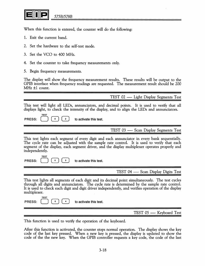
TEST 01 -, 200 MHz Self,Test
This function is used to verify that the Count Chain, Gate Generator, and the VCO are operational.TEST
PRESS: 0 8 8 to activate this test.
3,17
........?z?~.(~.Z?~ .
When this function is entered, the counter will do the following:
1. Exit the current band.
2. Set the hardware to the self... test mode.
3. Set the veo to 400 MHz.
4. Set the counter to take frequency measurements only.
5. Begin frequency measurements.
The display will show the frequency measurement results. These results will be output to theGPIB interface when frequency readings are requested. The measurement result should be 200MHz ±1 count.
TEST 02 --- Light Display Segments Test
This test will light all LEDs, annunciators, and decimal points. It is used to verify that alldisplays light, to check the intensity of the display, and to align the LEDs and annunciators.
TEST
PRESS: 0 8 0 to activate this test.
TEST 03 --- Scan Display Segments Test
This test lights each segment of every digit and each annunciator in every bank sequentially.The cycle rate can be adjusted with the sample rate control. It is used to verify that eachsegment of the display, each segment driver, and the display multiplexer operates properly andindependently.
TEST
PRESS: 0 8 (2] to activate this test.
TEST 04 --- Scan Display Digits Test
This test lights all segments of each digit and its decimal point simultaneously. The test cyclesthrough all digits and annunciators. The cycle rate is determined by the sample rate control.It is used to check each digit and digit driver independently, and verifies operation of the displaymultiplexer.
TEST
PRESS: 0 8 Q to activate this test.
TEST 05 --- Keyboard Test
This function is used to verify the operation of the keyboard.
After this function is activated, the counter stops normal operation. The display shows the keycode of the last key pressed. When a new key is pressed, the display is updated to show thecode of the the new key. When the GPIB controller requests a key code, the code of the last
3--18

3/0PERATION
key pressed is output. (If the controller requests a key code, the counter will output to theGPIB interface the code of the last key pressed even if Special Function 05 is not activated.)If the counter is in LOCAL, this function must be terminated by the CLEAR DISPLAY key.If it is in remote, this function can be terminated by any device ...dependent command.
TEST
PRESS: 0 8 8 to activate this test.
TEST 06 - ... Converter Ramp Test
This test continuously ramps the Band 3 Converter DAC through its range. It is used to testthe YIG DAC, YIG drivers, YIG, and Band 3 RF level circuits.
TEST
PRESS: 0 8 8 to activate this test.
TEST 07 - ... Sweep VCO Test
This test cycles the VCO from 400 to 500 MHz in increments of 50 kHz. The cycle rate canbe adjusted using the sample rate control. It is used to test the VCO and phase lock circuitry.
TEST
PRESS: 0 8 0 to activate this test.
TEST 08 -... Power Meter Offset Test
This test sets the power meter zero DAC. The setting is entered as a four digit hexadecimalnumber. The first two digits are used to program the coarse offset DAC, and the last two digitsprogram the fine offset DAC. Test 08 enables the power meter zero DAC to be tested, andprovides a DC level signal to aid in troubleshooting power meter circuitry.
TEST
PRESS: 0 8 8 to activate this test.
TEST 09 -... Power Meter Gain Test
This test sets the power meter sensing circuit to a selected number. The number is entered asa five...digit hexadecimal number in the following format:
1st digit2nd digit3rd digit4th digit5th digit bit 05th digit bit 1
AI07UI0 bits 4 7AI07UI0 bits 0 3 .AI07U12 bits 4 7 (Power Meter Option only)AI07U12 bits 0 3 (Power Meter Option only)Sets Amp marked "15 dB Gain" to high gain.Sets Amp marked "30 dB Gain" to high gain.
Digit 5 is a 2...bit number, so any number entered for digit 5 will be justified to a number from0...3. Test 09 tests the RF level and power meter circuits.
TEST
PRESS: 0 8 8 to activate this test.
3... 19
........~.Z~.~f~.Z§~ .
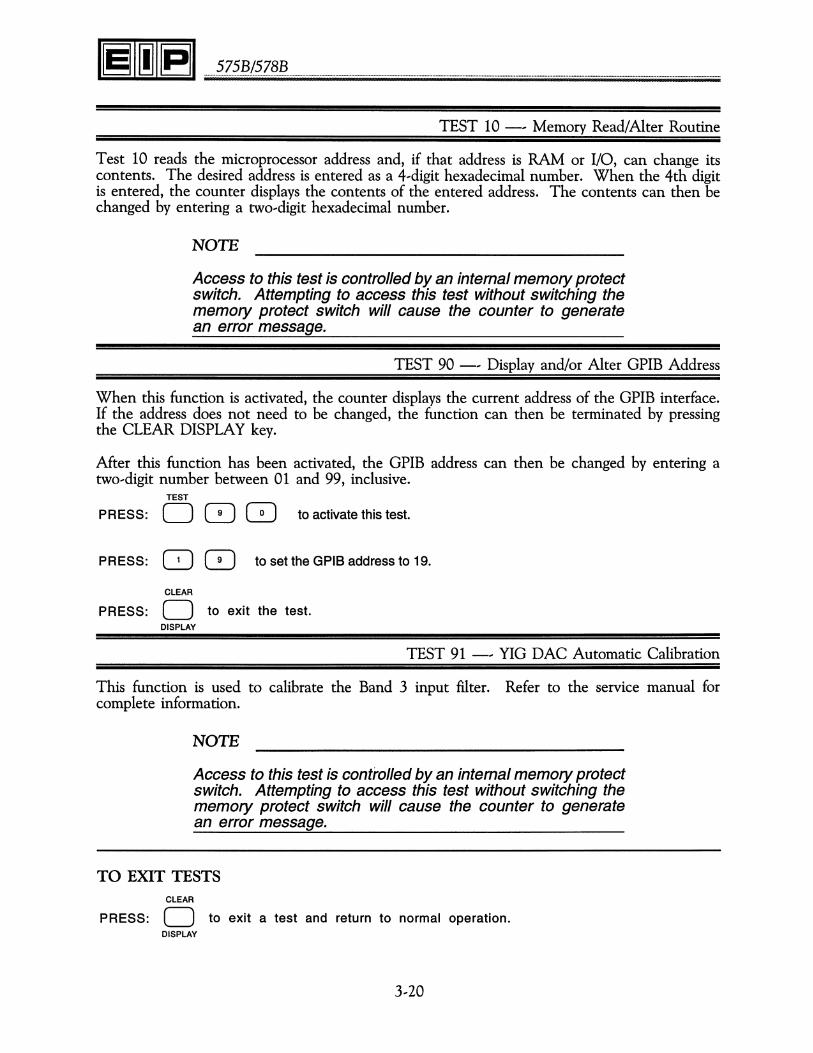
TEST 10 -, Memory Read/Alter Routine
Test 10 reads the microprocessor address and, if that address is RAM or I/O, can change itscontents. The desired address is entered as a 4,digit hexadecimal number. When the 4th digitis entered, the counter displays the contents of the entered address. The contents can then bechanged by entering a two-digit hexadecimal number.
NOTE
Access to this test is controlled by an internal memory protectswitch. Attempting to access this test without switching thememory protect switch will cause the counter to generatean error message.
TEST 90 -, Display and/or Alter GPIB Address
When this function is activated, the counter displays the current address of the GPIB interface.If the address does not need to be changed, the function can then be terminated by pressingthe CLEAR DISPLAY key.
After this function has been activated, the GPIB address can then be changed by entering atwo-digit number between 01 and 99, inclusive.
TEST
PRESS: 0 0 8 to activate this test.
PRESS: 8 8 to set the GPIB address to 19.
CLEAR
PRESS: 0 to exit the test.DISPLAY
TEST 91 -, YIG DAC Automatic Calibration
This function is used to calibrate the Band 3 input filter. Refer to the service manual forcomplete information.
NOTE
Access to this test is controlled by an internal memory protectswitch. Attempting to access this test without switching thememory protect switch will cause the counter to generatean error message.
TO EXIT TESTSCLEAR
PRESS: 0 to exit a test and return to normal operation.DISPLAY
3,20

3/0PERATION
MUTUALLY EXCLUSIVE FUNCTIONS
1. When self-test (Test 01) is active, all other counter functions are inactive with the exceptionof the resolution function. If any key is pushed when the counter is in self-test, the test isexited.
2. The power meter function is terminated whenever BAND 1, 2 or 4 is selected.
3. The source lock function is terminated when the reset function is activated.
4. The counter is not able to phase lock a source and take power readings at the same time.For the source lock and power meter functions, the most recently activated function will overridethe other function. For example, if the power meter function is on, and then the source lockfunction is activated, the power meter function is then turned off.
SIGNAL MEASUREMENTS WITH THE 575B/578B
AUTOMATIC FREQUENCY MEASUREMENTS
To measure the frequency of a CW signal, apply the signal to input connector that correspondsto the frequency being measured and select the appropriate band. The counter will then proceedto automatically find the signal, measure it and display the measured frequency.
MULTIPLE SIGNAL MEASUREMENTS
In actual microwave environments there are often multiple signals present. In a multi-signalenvironment the counter will automatically find and measure the largest signal, as specified byamplitude discrimination.
In Band 3, the counter can also measure signals other than the largest signal present. This isaccomplished by setting frequency limits around the desired signal. Figure 3--6 shows an exampleof the frequency limits feature.
INPUTPOWER(dBm)
6 6.3 6.6
~DISPLAYED
FREQUENCY
Figure 3--6. Frequency Limits.
3--21
........2.Z.2.~!~.Z§~ .
If the signals shown in Figure 3,6 are applied to Band 3 of the counter, it will automaticallyfind the signal at 6 GHz since it is the largest signal. If it is desired to measure the signal at6.3 GHz, set the low frequency limit at 6.2 GHz and the high frequency limit to 6.4 GHz. Thiswill prevent the counter from seeing either the signal at 6 GHz or the signal at 6.6 GHz.
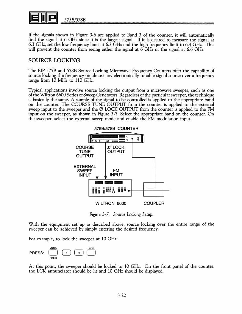
SOURCE LOCKING
The EIP 575B and 578B Source Locking Microwave Frequency Counters offer the capability ofsource locking the frequency on almost any electronically tunable signal source over a frequencyrange from 10 MHz to 110 GHz.
Typical applications involve source locking the output from a microwave sweeper, such as oneof the Wiltron 6600 Series of Sweep Generators. Regardlessof the particular sweeper, the techniqueis basically the same. A sample of the signal to be controlled is applied to the appropriate bandon the counter. The COURSE TUNE OUTPUT from the counter is applied to the externalsweep input to the sweeper and the 0 LOCK OUTPUT from the counter is applied to the FMinput on the sweeper, as shown in Figure 3,7. Select the appropriate band on the counter. Onthe sweeper, select the external sweep mode and enable the FM modulation input.
5758/5788 COUNTER
---- ----oo • g
COURSETUNE
OUTPUT
JO LOCKOUTPUT
-CI CI CI CI CICICI CI CI CI CICI CI CICICI CI CI CI CIggg ggggo g g CI .......:---+----t--
EXTERNALSWEEP FMINPUT ~, ~, INPUT---
WILTRON 6600 COUPLER
Figure 3,7. Source Locking Setup.
With the equipment set up as described above, source locking over the entire range of thesweeper can be achieved by simply entering the desired frequency.
For example, to lock the sweeper at 10 GHz:
LOCK GHz
PRESS: 0 GJ GJ 0FREQ
At this point, the sweeper should be locked to 10 GHz. On the front panel of the counter,the LCK annunciator should be lit and 10 GHz should be displayed.

3/0PERATION
For further information on using the source locking capability with most of the common microwavesweepers, please contact EIP directly or your local sales representative.
OPTIONS
MILLIMETER--WAVE MEASUREMENTS
The 578B offers an extended frequency option (Option 06) that allows operation between 26.5GHz and 110 GHz. This band is designated as Band 4 on the counter and is divided into foursubbands as shown below.
Band
41424344
Frequency Range
26.5 - 40 GHz40 - 50 GHz60 - 90 GHz90 - 110 GHz
To perform measurements in this range, the Model 590 Frequency Extension Cable Kit and oneor more of the remote sensors are required.
5758/5788 COUNTER
MILLIMETER-WAVEINPUT
Figure 3--8. Equipment Setup for Band 4 Operation (Option 06)
CAUTION
Before connecting the remote sensor to the frequency source, verifythat the power level is within the limits specified for the sensor.
Static discharge or ground loops can damage or destroy the diodein a remote sensor. ALWAYS connect the LO cable to the counterfirst, then touch the shield to the body of the sensor before connecting.
Be sure that the counter and waveguide port to which the sensorconnects have a common ground. If in doubt, connect with a groundstrap before connecting the remote sensor.
3--23
.........?Z.??/~.Z§~ .
Operation
To operate the counter in one of the Band 4 frequency ranges, connect the short cable (suppliedwith the Frequency Extension Cable Kit) from the lower Band 4 output jack on the front panelto the Band 3 input. Connect the long cable from the upper Band 4 jack to the remote sensor.Select the desired band. Connect the remote sensor to the frequency source. The counter willautomatically measure and display the frequency of the source.
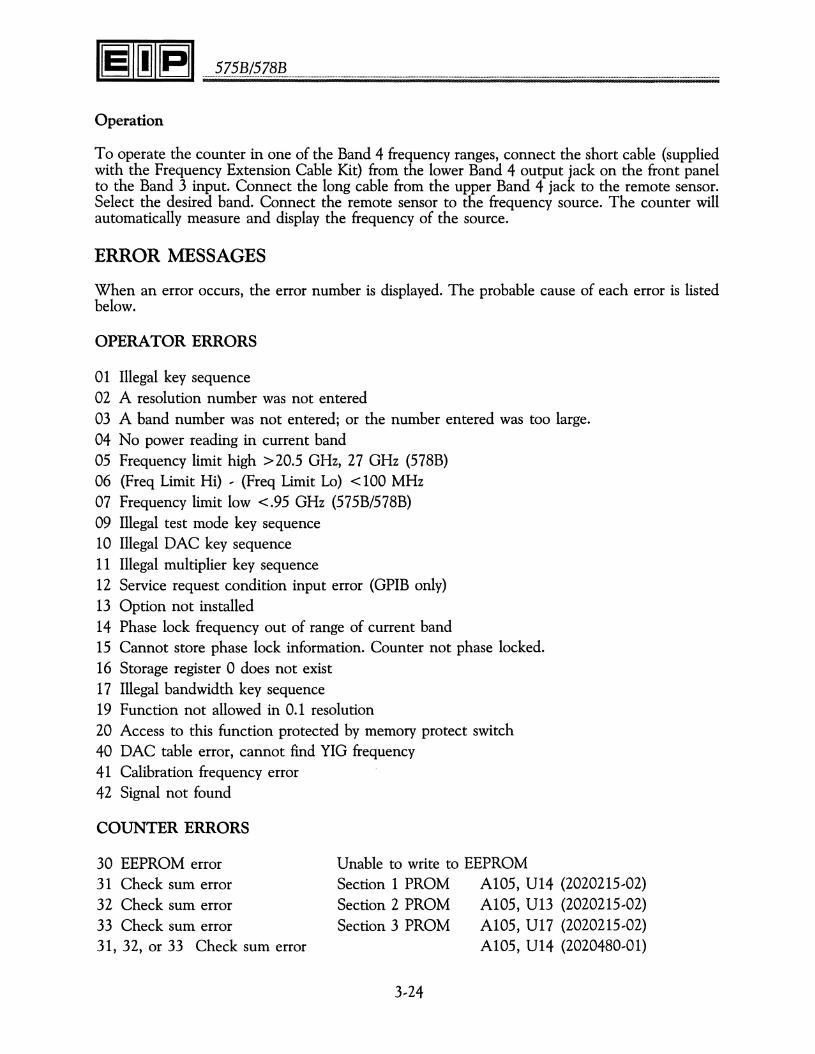
ERROR MESSAGES
When an error occurs, the error number is displayed. The probable cause of each error is listedbelow.
OPERATOR ERRORS
01 Illegal key sequence02 A resolution number was not entered03 A band number was not entered; or the number entered was too large.04 No power reading in current band05 Frequency limit high >20.5 GHz, 27 GHz (578B)06 (Freq Limit Hi) , (Freq Limit Lo) < 100 MHz07 Frequency limit low <.95 GHz (575B/578B)09 Illegal test mode key sequence10 Illegal DAC key sequence11 Illegal multiplier key sequence12 Service request condition input error (GPIB only)13 Option not installed14 Phase lock frequency out of range of current band15 Cannot store phase lock information. Counter not phase locked.16 Storage register 0 does not exist17 Illegal bandwidth key sequence19 Function not allowed in 0.1 resolution20 Access to this function protected by memory protect switch40 DAC table error, cannot find YIG frequency41 Calibration frequency error42 Signal not found
COUNTER ERRORS
30 EEPROM error31 Check sum error32 Check sum error33 Check sum error31, 32, or 33 Check sum error
Unable to write to EEPROMSection 1 PROM A105, U14 (2020215,02)Section 2 PROM A105, U13 (2020215,02)Section 3 PROM A105, U17 (2020215,02)
A105, U14 (2020480,01)
3,24

4/PROGRAMMING
PROGRAMMING
The GPIB interface of the 575B/578B counters is fully compatible with the IEEE 488,1978standard. With the GPIB interface, the counter can respond to remote control instructions andcan output measurement results via the IEEE 488,1978 Bus interface. At the simplest level, thecounter can output data to other devices such as the HP 5150A Thermal Printer. In moresophisticated systems, an instrument controller can remotely program the counter, triggermeasurements, and read results.
GPIB FUNCTIONS IMPLEMENTED
The GPIB interface function subsets implemented are as follows:
Interface Function Subset Description
Source Handshake SH1 complete capabilityAcceptor Handshake AH1 complete capabilityTalker T5 basic talker, serial poll, Talk only
mode, unaddress if MLAListener L3 basic listener, Listen Only mode,
unaddress if MTAService Request SR1 complete capabilityRemote Local RL1 complete capabilityDevice Clear DC1 complete capabilityDevice Trigger DT1 complete capability
REMOTE/LOCAL FUNCTION
When the counter changes from LOCAL to REMOTE or vice-versa, all the stored informationis retained. The counter will operate in the same state as it was before the change. The onlyexception is when the counter is in the TEST mode, the TEST function is automatically terminated.When the counter is in REMOTE and LOCAL LOCKOUT is not active, the RESET key onthe front panel keyboard acts as the return to local key.
4,1

.........?z.??.(?.Z?~ .
DE~CECLEARFUNCTION
When the GPIB command DEVICE CLEAR or SELECTED DEVICE CLEAR is received, thecounter will revert to its power on state as listed below:
Display ActiveBand 3 SelectedResolution 0Fast PassiveOffset Active (Offset set to O)Power Meter PassiveFrequency Limit High set to defaultFrequency Limit Low set to defaultCoarse Tune ActiveTest Passive (Clear Test Functions)Exponent Zero (Output Format)Service Request Passive
DEVICE TRIGGER FUNCTION
When the GPIB bus command DEVICE TRIGGER is received, the counter will initiate a newfrequency reading cycle. The converter will not be reset. If the counter does not have aconverter lock, the DEVICE TRIGGER will not be performed until a converter locked conditionexists.
GPIB ADDRESS SELECTION
This counter employs a software selectable GPIB address which is stored in non...volatile memory.To verify the GPIB address, select Test 90: the counter will display the current GPIB address.Press the Clear Display key to exit Test 90 without changing the GPIB address.
To change the GPIB address, select Test 90 followed by the desired GPIB address see Figure4... 1 for a list of allowable GPIB address codes}.
For example:TEST CLEAR
PRESS: 0 0 0 0 8 0 to select GPIB address 20.DISPLAY
Since the GPIB address is stored in non...volatile memory, the counter will always default to thelast GPIB address selected.
The GPIB address selection is also used to put the counter in the Talk Only or Listen Onlymode. To put the counter in the Listen Only mode simply set the address to 41 or higher,
TALK ONLY MODES
The TALK ONLY modes enable the counter to output data to other devices on the bus, suchas a printer, without the need of an instrument controller, To use the counter in a TALK ONLYmode, enter the GPIB address corresponding to the desired mode of operation.
4...2
4/PROGRAMMING
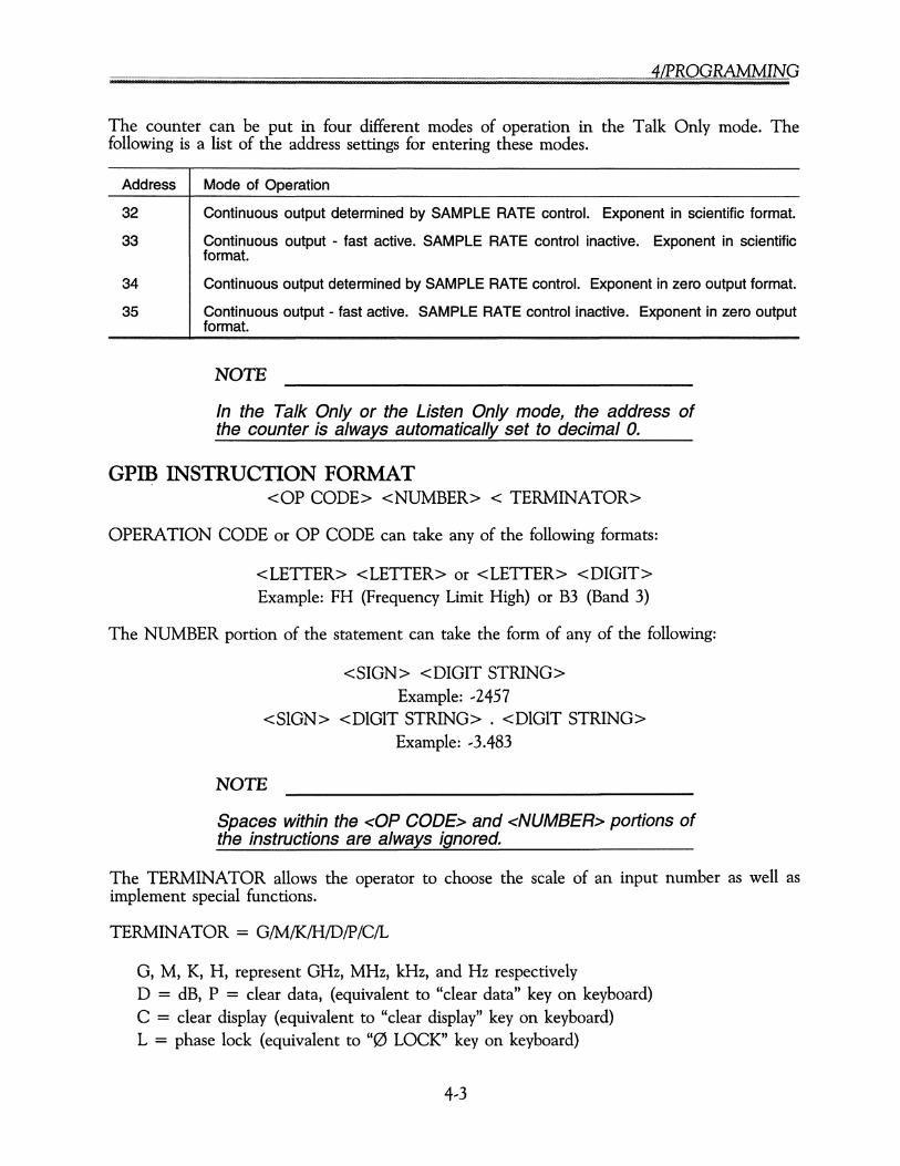
The counter can be put in four different modes of operation in the Talk Only mode. Thefollowing is a list of the address settings for entering these modes.
Address Mode of Operation
32 Continuous output determined by SAMPLE RATE control. Exponent in scientific format.
33 Continuous output - fast active. SAMPLE RATE control inactive. Exponent in scientificformat.
34 Continuous output determined by SAMPLE RATE control. Exponent in zero output format.
35 Continuous output - fast active. SAMPLE RATE control inactive. Exponent in zero outputformat.
NOTE
In the Talk Only or the Listen Only mode, the address ofthe counter is always automatically set to decimal o.
GPIB INSTRUCTION FORMAT<OP CODE> <NUMBER> < TERMINATOR>
OPERATION CODE or OP CODE can take any of the following formats:
<LETTER> <LETTER> or <LETTER> <DIGIT>Example: FH (Frequency Limit High) or B3 (Band 3)
The NUMBER portion of the statement can take the form of any of the following:
<SIGN> <DIGIT STRING>Example: --2457
<SIGN> <DIGIT STRING> . <DIGIT STRING>Example: --3.483
NOTE
Spaces within the <OP CODE> and <NUMBER> portions ofthe instructions are always ignored.
The TERMINATOR allows the operator to choose the scale of an input number as well asimplement special functions.
TERMINATOR = G/M/K/H/D/P/C/L
0, M, K, H, represent GHz, MHz, kHz, and Hz respectivelyD = dB, P = clear data, (equivalent to "clear data" key on keyboard)C = clear display (equivalent to "clear display" key on keyboard)L = phase lock (equivalent to "0 LOCK" key on keyboard)
4--3
........~.Z~.~.I?.Z§~ .
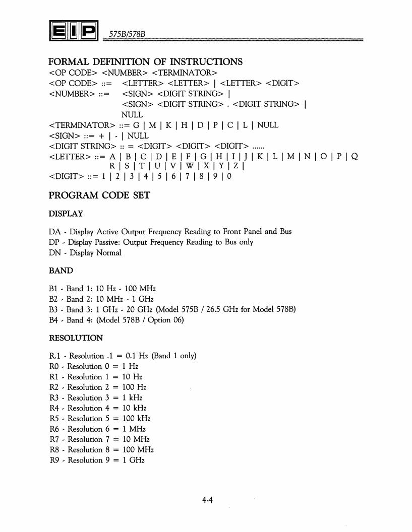
FORMAL DEFINITION OF INSTRUCTIONS<OP CODE> <NUMBER> <TERMINATOR><OP CODE> ::= <LETTER> <LETTER> I <LETTER> <DIGIT><NUMBER> ::= <SIGN> <DIGIT STRING> I
<SIGN> <DIGIT STRING> . <DIGIT STRING>NULL
<TERMINATOR> ::= G I M I K I HID I PIC I L I NULL<SIGN> ::= + I ' I NULL<DIGIT STRING> :: = <DIGIT> <DIGIT> <DIGIT> .<LETTER> ::= A I B I C I DIE I FIG I H I I I J I K I LIM I N I 0 I P I Q
RISITIUIVIWIXIYIZI<DIGIT> ::= 1 I 2 I 3 I 4 I 5 I 6 I 7 I 8 I 9 I 0
PROGRAM CODE SET
DISPLAY
DA ' Display Active Output Frequency Reading to Front Panel and BusDP , Display Passive: Output Frequency Reading to Bus onlyDN ' Display Normal
BAND
B1 ' Band 1: 10 Hz ' 100 MHzB2 ' Band 2: 10 MHz ' 1 GHzB3 ' Band 3: 1 GHz ' 20 GHz (Model 575B / 26.5 GHz for Model 578B)B4 ' Band 4: (Model 578B / Option 06)
RESOLUTION
R.1 ' Resolution .1 = 0.1 Hz (Band 1 only)RO ' Resolution 0 = 1 HzR1 ' Resolution 1 = 10 HzR2 ' Resolution 2 = 100 HzR3 ' Resolution 3 = 1 kHzR4 ' Resolution 4 = 10 kHzR5 ' Resolution 5 = 100 kHzR6 ' Resolution 6 = 1 MHzR7 ' Resolution 7 = 10 MHzR8 ' Resolution 8 = 100 MHzR9 ' Resolution 9 = 1 GHz
4,4

4/PROGRAMMING
MEASUREMENT FUNCTIONS
FA -- Fast Active (Ignore sample rate control)FP -- Fast Passive (Terminates FA)RS -- Reset Basic Counter and Converter. Take a new reading after reset.HA -- Hold ActiveHP -- Hold Passive
DATA MANIPULATION FUNCTIONS
FO -- Frequency Offset. Take a new reading after data entry if counter not in hold.PO -- Power Offset. Take a new reading after data entry if counter not in hold.OA* -- Offset Active:
-- Add Frequency Offset to Frequency Reading-- Add Power Offset to Power Reading if Power Meter Function is active
OP -- Offset Passive (Terminates OA)ML -- Multiplier. Multiplies frequency readings by an integer number.
* In Start-up condition, although OA is Active, Frequency and Power Offsets are programmedto zero.
POWER METER
PA -- Power Meter Option Active. Initiate a new gate.PP -- Power Meter Option Passive (Terminates PA)
FREQUENCY LIMITS
FH -- Frequency Limit High. Basic counter and converter will be reset after data entry.FL -- Frequency Limit Low. Basic counter and converter will be reset after data entry.
SOURCE LOCKING FUNCTIONS
PF -- Phase lock frequency. Counter attempts to phase lock after data entry.PL -- Initiates phase lock sequence. Equivalent to PHASE LOCK key on keyboard,BW -- Bandwidth. Selects phase lock loop 'bandwidth.ST -- Store. Equivalent to STORE key on keyboard.RC -- RECALL. Equivalent to RECALL key on keyboard.CA -- Coarse tune active Source lock process operates normally.CP -- Coarse tune passive. Source lock process bypasses coarse tune process for faster sourcelock time.
4--5
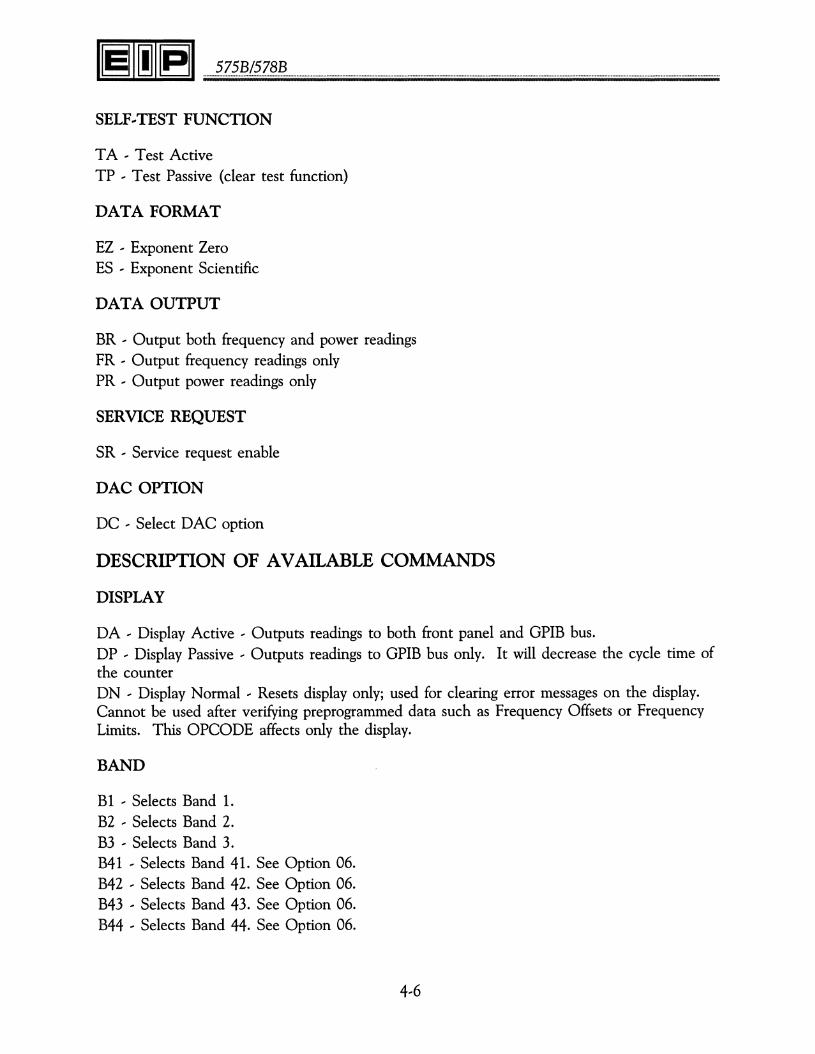
........~.Z~.§./~.Z§.~ .
SELF.-TEST FUNCTION
TA ' Test ActiveTP , Test Passive (clear test function)
DATA FORMAT
EZ ' Exponent ZeroES ' Exponent Scientific
DATA OUTPUT
BR ' Output both frequency and power readingsFR ' Output frequency readings onlyPR ' Output power readings only
SERVICE REQUEST
SR ' Service request enable
DAC OPTION
DC ' Select DAC option
DESCRIPTION OF AVAILABLE COMMANDS
DISPLAY
DA ' Display Active ' Outputs readings to both front panel and GPIB bus.DP , Display Passive, Outputs readings to GPIB bus only. It will decrease the cycle time ofthe counterDN ' Display Normal, Resets display only; used for clearing error messages on the display.Cannot be used after verifying preprogrammed data such as Frequency Offsets or FrequencyLimits. This OPCODE affects only the display.
BAND
B1 ' Selects Band 1.B2 ' Selects Band 2.B3 ' Selects Band 3.B41 ' Selects Band 41. See Option 06.B42 ' Selects Band 42. See Option 06.B43 ' Selects Band 43. See Option 06.B44 ' Selects Band 44. See Option 06.
4,6
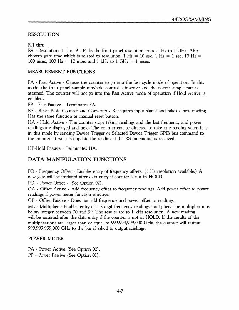
4/PROGRAMMING
RESOLUTION
R.1 thruR9 ' Resolution .1 thru 9 ' Picks the front panel resolution from .1 Hz to 1 GHz. Alsochooses gate time which is related to resolution .1 Hz = 10 sec, 1 Hz = 1 sec, 10 Hz =100 msec, 100 Hz = 10 msec and 1 kHz to 1 GHz = 1 msec.
MEASUREMENT FUNCTIONS
FA ' Fast Active ' Causes the counter to go into the fast cycle mode of operation. In thismode, the front panel sample rate/hold control is inactive and the fastest sample rate isattained. The counter will not go into the Fast Active mode of operation if Hold Active isenabled.FP , Fast Passive, Terminates FA.RS ' Reset Basic Counter and Converter ' Reacquires input signal and takes a new reading.Has the same function as manual reset button.HA ' Hold Active ' The counter stops taking readings and the last frequency and powerreadings are displayed and held. The counter can be directed to take one reading when it isin this mode by sending Device Trigger or Selected Device Trigger GPIB bus command tothe counter. It will also update the reading if the RS mnemonic is received.
HP,Hold Passive, Terminates HA.
DATA MANIPULATION FUNCTIONS
FO ' Frequency Offset, Enables entry of frequency offsets. (1 Hz resolution available.) Anew gate will be initiated after data entry if counter is not in HOLD.PO ' Power Offset ' (See Option 02).OA ' Offset Active ' Add frequency offset to frequency readings. Add power offset to powerreadings if power meter function is active.OP , Offset Passive ' Does not add frequency and power offset to readings.ML ' Multiplier, Enables entry of a 2,digit frequency readings multiplier. The multiplier mustbe an integer between 00 and 99. The results are to 1 kHz resolution. A new readingwill be initiated after the data entry if the counter is not in HOLD. If the results of themultiplications are larger than or equal to 999.999,999,000 GHz, the counter will output999.999,999,000 GHz to the bus if asked to output readings.
POWER METER
PA ' Power Active (See Option 02).PP , Power Passive (See Option 02).
4,7
........?Z?..~f~.Z§~ .
FREQUENCY LIMITS
FH -- Frequency Limit High -- Enables entry of frequency limit high (10 MHz resolutionavailable). The basic counter and converter will be reset after the data entry.FL -- Frequency Limit Low -- Enables entry of frequency limit low (10 MHz resolutionavailable). The basic counter and converter will be reset after the data entry.
SELF.-TEST FUNCTIONS
TA -- Test Active -- Enables the counter to perform the selected test function by enteringTA followed by two digits. When Test 05, 08, 09, or 10 is active and the counter is beingasked to output data, the data that is displayed on the front panel is the data being output.The output data format is as follows:
XXXXXXXXXXXXCRLFX = alpha-numericCR = carriage returnLF = line feed
For detailed descriptions of tests 01 through 09 and test 11, see the section on KeyboardControlled Circuit Tests.TP -- Test Passive -- Terminates test function.
SOURCE LOCKING FUNCTIONS
PF -- Phase lock frequency. Enables entry of phase lock frequency to 10 kHz resolution ifphase lock frequency is above or equal to 50 MHz, and 2.5 kHz resolution if it is below 50MHz. The counter will attempt to phase lock after data entry.PL -- Initiates phase lock sequence. The counter will attempt to phase lock to the frequencyspecified in the phase lock frequency register.BW -- Bandwidth. Enables the selection of the phase lock loop bandwidth. To select thedesired bandwidth, input BW followed by one decimal digit. The digit has to be between 0and 3 inclusively.
BWO = automatic loop bandwidth selection.BWI = 500 Hz loop bandwidth.BW2 = 2 kHz loop bandwidth.BW3 = 10 kHz loop bandwidth.
In BWO, the counter will try to close the 'phase lock loop in 10 kHz, 2 kHz and 500 Hzloop bandwidths, sequentially. It will select the first bandwidth in which it is able to closethe phase lock loop.ST -- Store. Enables the storage of the current phase lock frequency along with otherimportant information related to phase locking that frequency. To store the current phaselock frequency, input ST followed by one decimal digit between 1 and 9 inclusively. Thefunction can be activated only after the counter has been phase locked.RC -- Recall. Enables the recall of the information in one of the storage registers. InputtingRC, followed by one decimal digit between 1 and 9 inclusively, and terminating the string bythe terminator L, enables the counter to attempt to phase lock to the frequency stored in

4/PROGRAMMING
one of the storage registers. Terminating the string by the terminator P will clear thatstorage register.CA ... Coarse tune active. Source lock process operates normally. The counter first goesthrough the coarse tune process to move the signal source's output to within 5 MHz of thedesired frequency. Then the phase lock process takes over to attempt to close the phase lockloop. In this mode, the counter will perform properly even if the coarse tune output of thecounter is not connected to the signal source.CP ... Coarse tune passive. Source lock process bypasses the coarse tune process for fastersource lock time. This mode can be used if the source's output is close to the desiredfrequency.
DATA FORMAT
EZ Exponent Zero ... output format.ES Exponent Scientific ... output format.
DATA OUTPUT
BR Output both frequency and power readings. (See section on output data format.)FR Output frequency readings only. (See section on output data format.)PR Output power readings only. (See section on output data format.)
DAC OPTION
DC ... Enables the DAC option. Enter DC followed by two decimal digits which correspondto the location of the most significant digit in the three digits desired. To turn the DACoption off, input DCOO or DCP.
DCOO turns DAC option offDC02 selects 1 Hz digitthruDC12 ... selects 100, 10, and 1 GHz digits.
SERVICE REQUEST
SR ... Service Request Enable ... Enables the counter to send Service Request to the bus whena certain event has taken place in the counter. To enable the function, input SR followedby two decimal digits. The two digits are the decimal equivalent of the content of the eightbit status register. More than one bit of the status register can be set.
To disable the Service Request function, input SROO.
NOTE
Even when the Service Request function is disabled, theService Request status byte will still be continuously alteredto reflect the internal states of the counter.
4...9

........~.Z~.§../~.Z§~ .
Decimal equivalent:
input buffer empty
32 16 8 4 2 1
measurement available
not phase locked--_..I
phase locked-----...
SERVICE REQUEST MASK
counter searching
frequency reading registeroverflow (multiplier toolarge)
The counter can be instructed to send an interrupt, by setting the SRQ line on the GPIB, whenany ORed combination of the bits in the status byte are set. This is done by sending the countera service request mask.
For example, to instruct the counter to generate an SRQ on measurement available OR inputbuffer empty, send the following service request mask:
OUTPUT 719;"SR33"
This would tell the counter to generate an SRQ whenever bit-O or bit,5 of the status byte areset. Since bit-O corresponds to measurement available and bit,5 corresponds to input bufferempty, the counter would generate an SRQ whenever either the input buffer was empty or ameasurement was available.
The following items should be included in any program using the SRQ feature:
1. Tell the counter when to generate an SRQ. That is, tell the counter which events shouldgenerate an SRQ. This is done using the SRQMASK command.
2, Tell the controller to monitor the SRQ line on the GPIB. The SRQ is a maskable interruptand the controller needs to know if it should respond to the interrupt.
3. Tell the controller what to do when it receives an SRQ interrupt.
4. Serial Poll the counter after an SRQ is generated to clear the interrupt. When the countergenerates an SRQ, it sets bit-o in the status byte. Serial polling the instrument clears the SRQbit and allows the instrument to generate a new SRQ upon the next occurrence of the conditionsspecified in the SRQ Mask.
5. It may also be necessary to clear the SRQ register in the controller. Consult your manualon the controller for more information on clearing the SRQ register in the controller.
4,10
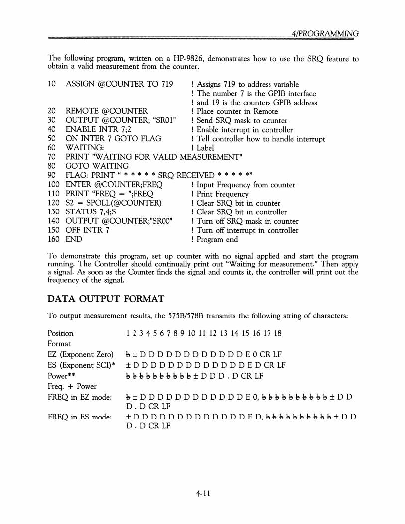
4LPROGRAMMING
The following program, written on a HP--9826, demonstrates how to use the SRQ feature toobtain a valid measurement from the counter.
10 ASSIGN @COUNTER TO 719 ! Assigns 719 to address variable! The number 7 is the GPIB interface! and 19 is the counters GPIB address
20 REMOTE @COUNTER ! Place counter in Remote30 OUTPUT @COUNTER; "SR01" ! Send SRQ mask to counter40 ENABLE INTR 7;2 ! Enable interrupt in controller50 ON INTER 7 GOTO FLAG ! Tell controller how to handle interrupt60 WAITING: ! Label70 PRINT"WAITING FOR VALID MEASUREMENT"80 GOTO WAITING90 FLAG: PRINT " * * * * * SRQ RECEIVED * * * * *"100 ENTER @COUNTER;FREQ ! Input Frequency from counter110 PRINT "FREQ = ";FREQ ! Print Frequency120 S2 = SPOLL(@COUNTER) ! Clear SRQ bit in counter130 STATUS 7,4;S ! Clear SRQ bit in controller140 OUTPUT @COUNTER;"SROO" ! Turn off SRQ mask in counter150 OFF INTR 7 ! Turn off interrupt in controller160 END ! Program end
To demonstrate this program, set up counter with no signal applied and start the programrunning. The Controller should continually print out "Waiting for measurement." Then applya signal. As soon as the Counter finds the signal and counts it, the controller will print out thefrequency of the signal.
DATA OUTPUT FORMAT
To output measurement results, the 575B/578B transmits the following string of characters:
PositionFormatEZ (Exponent Zero)ES (Exponent SCI)*Power**Freq. + PowerFREQ in EZ mode:
FREQ in ES mode:
1 2 3 4 5 6 7 8 9 10 11 12 13 14 15 16 17 18
b ± D D D D D D D D D D D D E 0 CR LF±DDDDDDDDDDDDDEDffiUb b b b b b b b b b ± D D D . D CR LF
b ± D D D D D D D D D D D D E 0, b b b b b b b b b b ± D DD. D CR LF± D D D D D D D D D D D D D E D, b b b b b b b b b b ± D DD. D CR LF
4--11

........?Z?..~f~.Z§~ .
When the counter is in Test 05, 08, 09, or 10, the output will reflect the data on the display.The format is as follows:
XXXXXXXXXXXXCRLF.h = BlankD = DigitX = Alpha-numeric CharacterCR = Carriage ReturnLF = Line Feed
* In Exponent scientific one digit represents the position of the decimal point. Exponentdigit can be either 0, 3, 6, 9.** For power data, the output resolution is fixed at 0.1 dB.
Under different output modes, the following counter outputs can be expected by a listener.
OutputMode
CounterOperatingMode Output
SR
FR
PR
SR, FR, orPR
PAPPTAO1
PAPPTAO1
PAPPTAO1
TAOS, 08, 09, or 10
FREQ = PWRFREQFREQ
FREQFREQFREQ
PWR-999.9-999.9
Data on front paneldisplay
PROGRAM EXAMPLES
The following measurement conditions are set by addressing the counter to listen and thensending the following character string:
-83 . R2 F079.36M FH12.3G FL4.26G FA DP-
T J-- --
z
ET79.36 MHz
HIGH 12.3 GHz
LOW4.26GHz
BAND3--
RESOLUTION100 H
FREQUENCYOFFS
FREQUENCYLIMIT
FREQUENCYLIMIT
FASTACTIVE
DISPLAYPASSIVE
4/PROGRAMMING
READING A MEASUREMENT
To read a measurement from the counter to a controller, the counter must first be addressedto talk and the controller to listen. The EIP counters use two different modes. The HOLDACTIVE or HA mode takes one reading and then waits for a RESET command or a devicetrigger GPIB Command. In this condition the counter is sent a RESET or device trigger and(when addressed to talk) a new reading is output to the bus. The counter will hold that particularreading on the display until another RESET command or device trigger command is received.The second mode is HP or HOLD PASSIVE. In this mode, data is read out in a normal busfashion. The display is automatically updated according to the sample rate chosen. In this condition,successive readings can be output without generating a RESET or device trigger command eachtime.
INPUT SPEED
It takes a specific amount of time for the counter to process the input data (error checking,formatting, changing the mode of operation, etc.). To prevent the data rate of the bus fromslowing down while the counter is processing input data, the data is accepted as soon as it isavailable on the bus and is temporarily stored in memory. The size of the storage memory is100 characters.
The users of the GPIB interface need to be aware of the difference between accepting data andcomplying with it. If the counter is asked to output a reading before it has finished processingthe input data, the output will be in error if the operator makes the assumption that the counteris in the mode that was just programmed. To prevent this, sufficient programmed delays mustbe provided, or use must be made of the counter's Service Request status byte. See ServiceRequest (SR) command description.
4--13

[§ 00 B ?z??!?.z§.~ __ __ _._ __..__ _.__ ___ _. .
This Page Intentionally Left Blank
5/0PERATIONAL VERIFICATION TESTS
SECTION 5OPERATIONAL VERIFICATION TESTS
INTRODUCTION
This section contains test procedures that are used for verifying proper operation of the counter.Although these tests are not comprehensive, they do insure, to a high degree of confidence,that the instrument is operating properly. The tests can be useful for incoming inspection andshould be performed after any servicing to insure proper operation of the counter. All tests canbe performed without removing the instrument covers. A test report form that can be used toprovide a test record is included at the end of this section. If the test application is especiallycritical in nature, more extensive testing of the counter may be required. See the performanceverification test section in the service manual.
Because of the high cost and specialized nature of frequency sources above 40 GHz, testingabove this frequency is not covered. Also, for the purpose of operational verification tests, simulatedpulsed signals are used in Bands 1 and 3.
EQUIPMENT REQUIREMENTS
Equipment required for the operational verification tests on the EIP 575B or 578B counter islisted in Table 5,1. The critical parameters are the minimum use specifications required for theperformance of the procedures, and are included to assist in the selection of alternative equipment.Satisfactory performance of alternative items should be verified prior to use. All applicableequipment must bear evidence of current calibration. For some of the following tests, an EIP578B counter is used to source lock the microwave sweeper, thus providing a stable source fortesting. This combination may be replaced by a frequency synthesizer.
5,1

........~.z~.?(~.z§~ .
Table 5--1. Equipment Requirements.
Critical RecommendedDescription Parameters Manufacturer Model
Synthesized Function 10 Hz to 10 MHz Wavetek 23Generator
Sweep Generator 10 MHz to 26.5 GHz (40 GHz Wiltron 6668Afor Option 06)
Sweep Generator 3 GHz to 18 GHz Wiltron 6635A
Source Locking Counter 10 MHz to 26.5 GHz EIP 578B
Spectrum Analyzer 3 GHz to 18 GHz Hewlett Packard 8566A
Power Meter 10 MHz to 60 GHz Hewlett Packard 437B
Power Sensor 10 MHz to 18 GHz Hewlett Packard 8481A(-20 to +10 dBm)
Power Sensor 100 MHz to 26.5 GHz Hewlett Packard 8485A(-25 to +20 dBm)
Power Sensor 26.5 GHz to 40 GHz Hewlett Packard R8486A(-25 to +20 dBm)
Oscilloscope DC to 100 MHz Tektronix 475
Power Splitter 10 MHz to 26.5 GHz Hewlett Packard 11667B
Directional Coupler 950 MHz to 18 GHz Narda 4222-16
Directional Coupler 18 GHz to 26.5 GHz Narda 4017B-10
Remote Sensor 26.5 GHz to 40 GHz EIP 091
50 n Termination Pamona 4119-50
SOURCE LOCKING SETUP
In some of the following tests, the EIP 578B counter is used to source lock the sweep generatorto provide a stable frequency source for testing the 575B/578B counters.
The source locking setup, described below, is not limited to locking the Wiltron sweeper. It canbe used to source lock almost any electronically tunable signal source over a frequency rangeof 10 MHz to 110 GHz. For more information on source locking the Wiltron 6600 series ofsweep generators, request Application Bulletin 10 from our sales representative in your area ordirectly from EIP.
Regardless of the particular sweeper, the procedure for source locking is basically the same. Asample of the output from the sweeper is applied to the appropriate band on the EIP 578Bcounter. For the setup shown in Figure 5--1, a power splitter provides the sample. The COARSETUNE OUT connector from the 578B counter is connected to the external sweep input on thesweeper. The 0 LOCK OUT connector on the 578B counter is connected to the FM inputon the sweeper. The FM modulation on the sweeper is enabled and the sweeper is set to theexternal sweep mode.
5--2

5/0PERATIONAL VERIFICATION TESTS
5758/5788 COUNTER
COURSETUNE
OUTPUT
EXTERNALSWEEPINPUT
Rf LOCKOUTPUT
FMINPUT---CI CI CI CI CICICI CI CI CI CI
CI CI CICICI CI CI CI CIggg ggggo g g CI ....---+-<:OUTPUT
WILTRON 6600 HP116678POWER SPLITIER
Figure 5,1. Source Locking Setup.
With the equipment set up as described above, source locking over the entire range of thesweeper can be achieved by entering the desired frequency.
For example, to lock the sweeper at 10 GHz:
LOCK GHz
PRESS: 0 GJ GJ 0FREQ
At this point, the sweeper should be locked to 10 GHz, the LCK annunciator on the countershould be lit, and 10 GHz should be the displayed frequency. In the following tests, the outputfrequency from the sweeper is controlled directly by the EIP 578B counter, while the power iscontrolled at the sweeper.
OPERATIONAL VERIFICATION TEST PROCEDURES
BAND 1 RANGE AND SENSITIVITY TEST (10 Hz to 10 MHz)
Description
This test verifies counter operation from 10 Hz to 10 MHz at 25 mVrms (70.7 mV p'p into 50Q). The oscilloscope is used to set signal levels.
Equipment
Synthesized function generator (Wavetek 23)Oscilloscope (Tektronix 475)
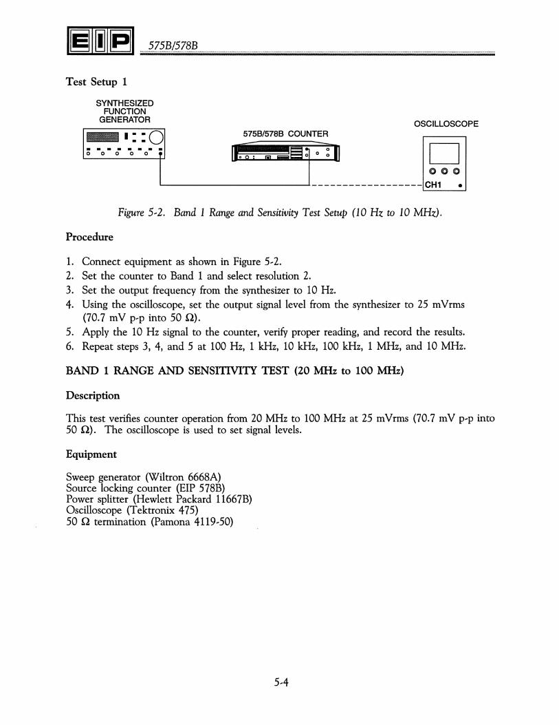
· ~.Z~.~.I?Z§!? .
Test Setup 1
OSCILLOSCOPE5758/5788 COUNTER
D000
~--------------------~------------------CH1 •
SYNTHESIZEDFUNCTION
GENERATOR
-1::0. . . . . . . .00000
Figure 5,2. Band 1 Range and Sensitivity Test Setup (10 Hz to 10 MHz).
Procedure
1. Connect equipment as shown in Figure 5,2.2. Set the counter to Band 1 and select resolution 2.3. Set the output frequency from the synthesizer to 10 Hz.4. Using the oscilloscope, set the output signal level from the synthesizer to 25 mVrms
(70.7 mV p'p into 50 Q).5. Apply the 10 Hz signal to the counter, verify proper reading, and record the results.6. Repeat steps 3, 4, and 5 at 100 Hz, 1 kHz, 10 kHz, 100 kHz, 1 MHz, and 10 MHz.
BAND 1 RANGE AND SENSITIVITY TEST (20 MHz to 100 MHz)
Description
This test verifies counter operation from 20 MHz to 100 MHz at 25 mVrms (70.7 mV p'p into50 Q). The oscilloscope is used to set signal levels.
Equipment
Sweep generator (Wiltron 6668A)Source locking counter (EIP 578B)Power splitter (Hewlett Packard 11667B)Oscilloscope (Tektronix 475)50 Q termination (Pamona 4119,50)
5,4
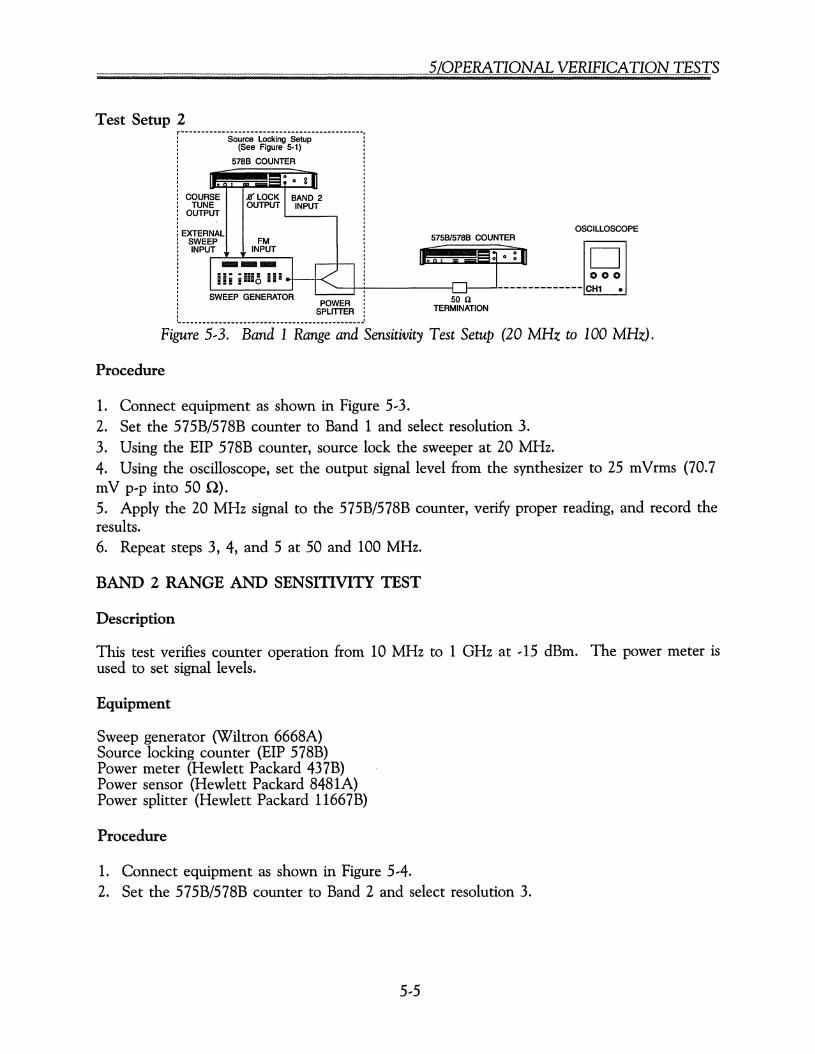
5/0PERATIONAL VERIFICATION TESTS
Test Setup 2r - - -- - -- -- -- - - - -- - - - ------- ---- - - - ---- - - - -- --
Source Locking Setup(See Figure 5-1)
5788 COUNTER
COURSE J({ LOCKTUNE OUTPUT
OUTPUT
EXTERNALSWEEP FMINPUT INPUT.._..
Iii i !II!, II! _. I ~
POWERSPLITTER
5758/5788 COUNTER
50 nTERMINATION
OSCILLOSCOPE
Figure 5,3. Band 1 Range and Sensitivity Test Setup (20 MHz to 100 MHz).
Procedure
1. Connect equipment as shown in Figure 5,3.2. Set the 575B/578B counter to Band 1 and select resolution 3.3. Using the EIP 578B counter, source lock the sweeper at 20 MHz.4. Using the oscilloscope, set the output signal level from the synthesizer to 25 mVrms (70.7mV p'p into 50 Q).5. Apply the 20 MHz signal to the 575B/578B counter, verify proper reading, and record theresults.6. Repeat steps 3, 4, and 5 at 50 and 100 MHz.
BAND 2 RANGE AND SENSITIVITY TEST
Description
This test verifies counter operation from 10 MHz to 1 GHz at ,15 dBm. The power meter isused to set signal levels.
Equipment
Sweep generator (Wiltron 6668A)Source locking counter (EIP 578B)Power meter (Hewlett Packard 437B)Power sensor (Hewlett Packard 8481A)Power splitter (Hewlett Packard 11667B)
Procedure
1. Connect equipment as shown in Figure 5,4.2. Set the 575B/578B counter to Band 2 and select resolution 3.
5,5
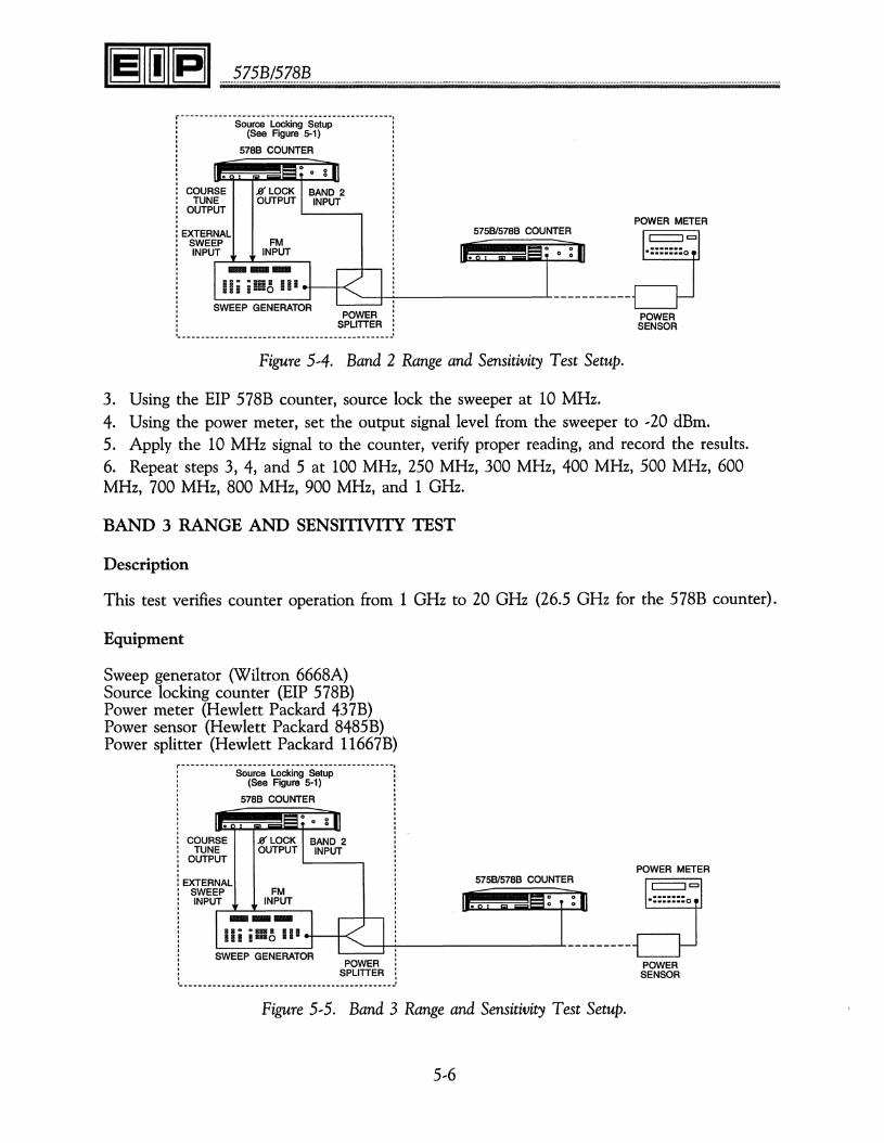
........~.Z~.~.I?Z§~ .
r - - -- - - - --- - - -- - - - --- - - --- - - --- -- --- - - --- - ---Source Locking Setup
(See Figure 5-1)
5788 COUNTER
COURSETUNE
OUTPUT
EXTERNALSWEEPINPUT
J?f LOCKOUTPUT
5758/5788 COUNTER
oo 0
'---+--- -L. _
POWERSPLITTER
POWER METER
POWERSENSOR
Figure 5,4. Band 2 Range and Sensitivity Test Setup.
3. Using the EIP 578B counter, source lock the sweeper at 10 MHz.4. Using the power meter, set the output signal level from the sweeper to ,20 dBm.5. Apply the 10 MHz signal to the counter, verify proper reading, and record the results.6. Repeat steps 3,4, and 5 at 100 MHz, 250 MHz, 300 MHz, 400 MHz, 500 MHz, 600MHz, 700 MHz, 800 MHz, 900 MHz, and 1 GHz.
BAND 3 RANGE AND SENSITIVITY TEST
Description
This test verifies counter operation from 1 GHz to 20 GHz (26.5 GHz for the 578B counter).
Equipment
Sweep generator (Wiltron 6668A)Source locking counter (EIP 578B)Power meter (Hewlett Packard 437B)Power sensor (Hewlett Packard 8485B)Power splitter (Hewlett Packard 11667B)
j- - --- - -- - ---- --- -- - - -- - --- --- - --- ---- -- - -- --
Source Locking Setup(See Figure 5-1)
5788 COUNTER
COURSETUNE
OUTPUT
EXTERNALSWEEPINPUT
J?f LOCKOUTPUT
5758/5788 COUNTERFM
INPUT
~-+-----------_-I-_--------
POWERSPLITTER
Figure 5,5. Band 3 Range and Sensitivity Test Setup.
5,6
POWER METER
POWERSENSOR
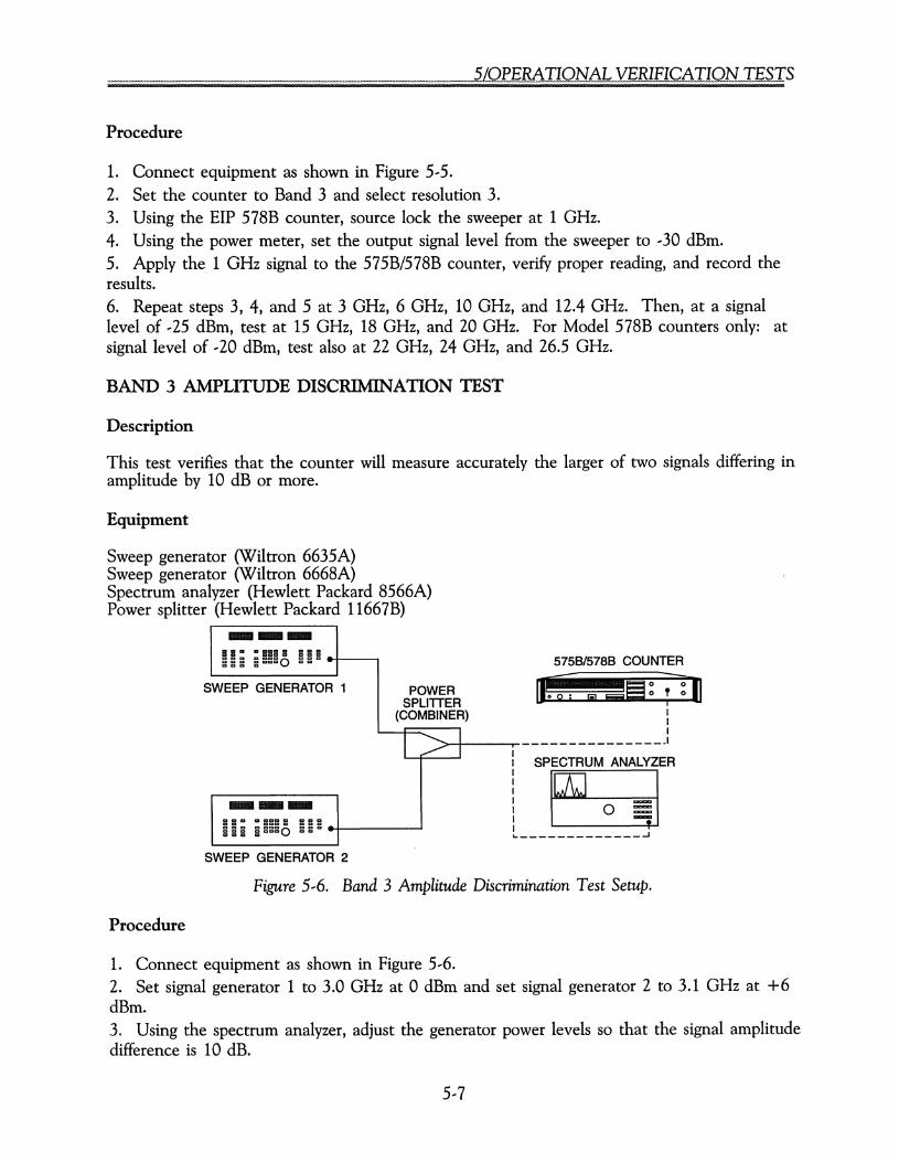
5/0PERATIONAL VERIFICATION TESTS
Procedure
1. Connect equipment as shown in Figure 5,5.2. Set the counter to Band 3 and select resolution 3.3. Using the EIP 578B counter, source lock the sweeper at 1 GHz.4. Using the power meter, set the output signal level from the sweeper to ,30 dBm.5. Apply the 1 GHz signal to the 575B/578B counter, verify proper reading, and record theresults.6. Repeat steps 3, 4, and 5 at 3 GHz, 6 GHz, 10 GHz, and 12.4 GHz. Then, at a signallevel of ,25 dBm, test at 15 GHz, 18 GHz, and 20 GHz. For Model 578B counters only: atsignal level of ,20 dBm, test also at 22 GHz, 24 GHz, and 26.5 GHz.
BAND 3 AMPLITUDE DISCRIMINATION TEST
Description
This test verifies that the counter will measure accurately the larger of two signals differing inamplitude by 10 dB or more.
Equipment
Sweep generator (Wiltron 6635A)Sweep generator (Wiltron 6668A)Spectrum analyzer (Hewlett Packard 8566A)Power splitter (Hewlett Packard 11667B)
o §§
5758/5788 COUNTER
• [;] 58 ~ ?TIlII1
- - - - - - - - - - - _.1
SPECTRUM ANALYZER
_____________ ...J
---aaa a aaa a a a aa a ggggo g g g -a a aaaa a a --
WEEP GENERATOR 1 POWERSPLITTER
(COM8INER)
II ~ I IIIII--- II
aaa a aaa a aaa Ia a aaa a gg g - Iaaa ggggoaaaaaa &..
S
SWEEP GENERATOR 2
Figure 5,6. Band 3 Amplitude Discrimination Test Setup.
Procedure
1. Connect equipment as shown in Figure 5,6.2. Set signal generator 1 to 3.0 GHz at 0 dBm and set signal generator 2 to 3.1 GHz at +6dBm.3, Using the spectrum analyzer, adjust the generator power levels so that the signal amplitudedifference is 10 dB.
5,7

........?Z?.~./~.Z?!?. .
4. Verify that the counter correctly measures the frequency of the higher power signal source.5. Repeat steps 2, 3, and 4 at 6 and 6.1 GHz, at 12 and 12.1 GHz, and at 17.9 and 18 GHz.
BAND 4, SUBBAND 1 RANGE AND SENSITIVITY TEST (578B Option 06 Only)
Description
This test verifies counter operation from 26.5 GHz to 40 GHz at ,25 dBm.
Equipment
Sweep generator (Wiltron 6668A)Power meter (Hewlett Packard 437B)Power sensor (Hewlett Packard R8486A)Remote sensor (EIP 091)Cable kit (EIP 590)
5758/5788 COUNTERSWEEP GENERATOR--- o •0 .......
POWER METER
. .• ··.0IL _I
: REMOTEI SENSORI
L ~__---I------------------=
POWERSENSOR
Figure 5,7. Band 4 Range and Sensitivity Test Setup (Model 578B, Option 06).
Procedure
1. Connect equipment as shown in Figure 5, 7.2. Set the counter to Band 4 and select resolution 3.3. Set the output frequency from the sweeper to 26.5 GHz.4. Using the power meter, set the output signal level from the sweeper to ,25 dBm.5. Apply the 26.5 GHz signal to the remote sensor, verify proper reading, and record theresults.6. Repeat steps 3, 4, and 5 at 30, 35, and 40 GHz.
5,8
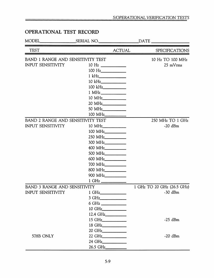
5/0PERATIONAL VERIFICATION TESTS
OPERATIONAL TEST RECORD
MoDEL ~SEroALNO. DATE __
TEST ACTUAL SPECIFICATIONS
BAND 1 RANGE AND SENSITIVITY TESTINPUT SENSITIVITY 10 Hz _
100 Hz _1kHz _
10 kHz. _100 kl-lz _1 MHz _10MHz, _
20MHz _50MHz _100MHz _
BAND 2 RANGE AND SENSITIVITY TESTINPUT SENSITIVITY 10 MHz _
100MHz _250 MHz _300 MHz, _400MHz _500 MHz, _600 MHz, _700 MHz, _800 MHz, _900MHz _1 GHz _
BAND 3 RANGE AND SENSITIVITYINPUT SENSITIVITY 1 GHz __
3GHz _6GHz _10GHz, _12.4 GHz _15GHz _18GHz _20GHz _
578B ONLY 22 GHz, _24GHz, _
26.5 GHz
5,9
10 Hz TO 100 MHz25 mVrms
250 MHz TO 1 GHz,20 dBm
1 GHz TO 20 GHz (26.5 GHz),30 dBm
,25 dBm
,20 dBm

[§ 00 B ?Z??L?.Z§l:.L _ . __ _ _.._ __ _ __.._._ .
OPERATIONAL TEST RECORD (Continued)
TEST ACTUAL SPECIFICATIONS
BAND 3 AMPLITUDE DISCRIMINATION TESTCONDITIONS: Fl > F2 BY 15 dB OR MORE
Fl F23 GHz 3.1 GHz 10 dB6.1 GHz 6 GHz _12 GHz 12.1 GHz _18 GHz 17.9 GHz _
BAND 4--1 RANGE AND SENSITIVITY TEST 26.5 GHz TO 40 GHz(578B, OPTION 06)INPUT SENSITIVITY 26.5 GHz --25 dBm (typical)
30GHz _35GHz, _
40 GHz
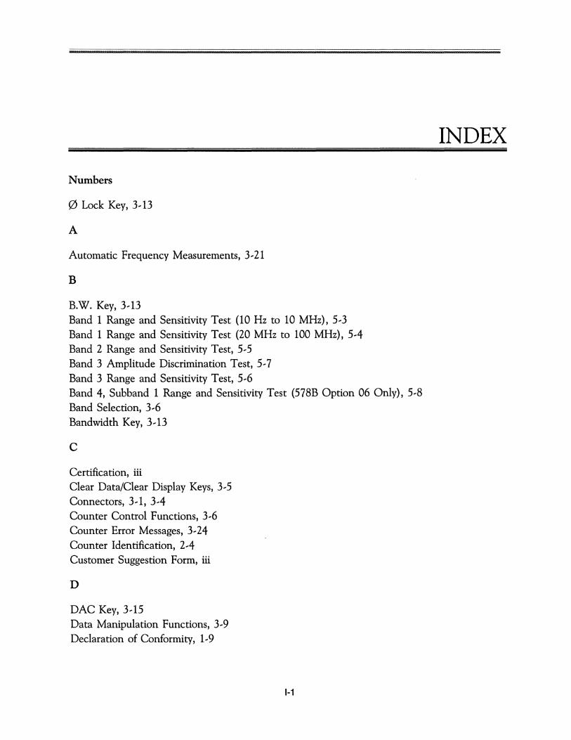
Numbers
o Lock Key, 3.. 13
A
Automatic Frequency Measurements, 3..21
B
B.W. Key, 3.. 13Band 1 Range and Sensitivity Test (10 Hz to 10 MHz), 5..3Band 1 Range and Sensitivity Test (20 MHz to 100 MHz), 5..4Band 2 Range and Sensitivity Test, 5..5Band 3 Amplitude Discrimination Test, 5..7Band 3 Range and Sensitivity Test, 5..6Band 4, Subband 1 Range and Sensitivity Test (578B Option 06 Only), 5..8Band Selection, 3..6Bandwidth Key, 3..13
c
Certification, iiiClear Data/Clear Display Keys, 3..5Connectors, 3.. 1, 3..4Counter Control Functions, 3..6Counter Error Messages, 3..24Counter Identification, 2..4Customer Suggestion Form, iii
D
DAC Key, 3.. 15Data Manipulation Functions, 3..9Declaration of Conformity, 1..9
1-1
INDEX
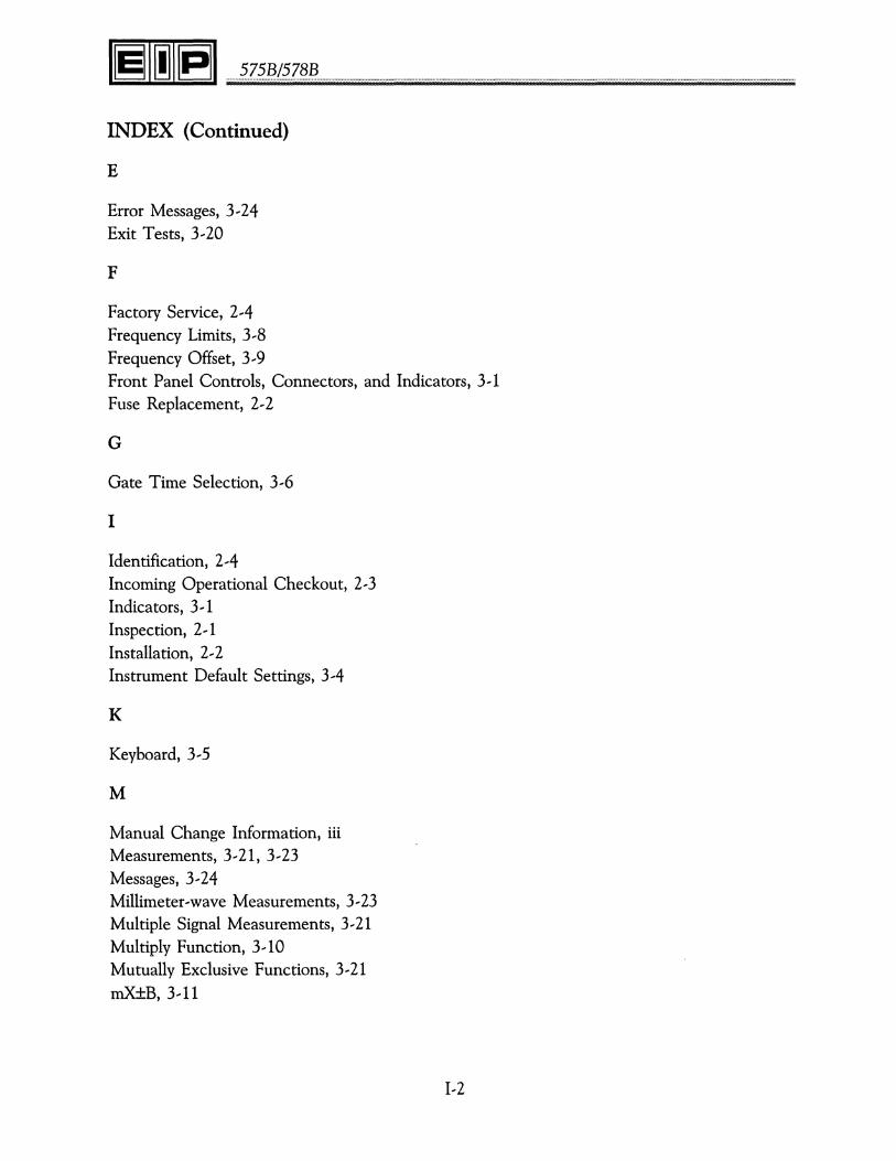
........~.Z~.~./~.Z§!? .
INDEX (Continued)
E
Error Messages, 3...24Exit Tests, 3...20
F
Factory Service, 2...4Frequency Limits, 3 8Frequency Offset, 3 9Front Panel Controls, Connectors, and Indicators, 3... 1Fuse Replacement, 2...2
G
Gate Time Selection, 3...6
I
Identification, 2...4Incoming Operational Checkout, 2...3Indicators, 3 1Inspection, 2 1Installation, 2...2Instrument Default Settings, 3...4
K
Keyboard, 3...5
M
Manual Change Information, iiiMeasurements, 3... 21, 3...23Messages, 3...24Millimeter ...wave Measurements, 3...23Multiple Signal Measurements, 3...21Multiply Function, 3... 10Mutually Exclusive Functions, 3...21mX±B, 3... 11
1...2
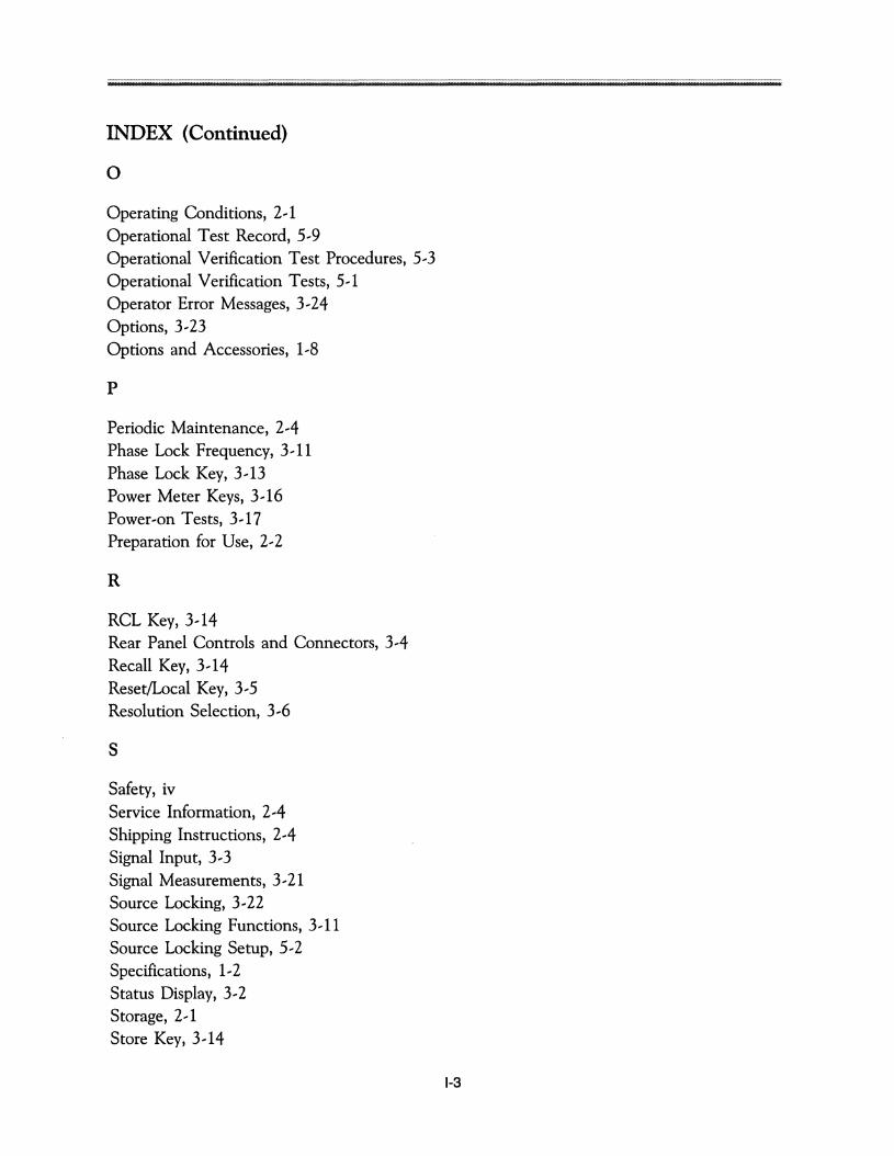
INDEX (Continued)
o
Operating Conditions, 2,1Operational Test Record, 5,9Operational Verification Test Procedures, 5,3Operational Verification Tests, 5,1Operator Error Messages, 3,24Options, 3,23Options and Accessories, 1,8
p
Periodic Maintenance, 2,4Phase Lock Frequency, 3,11Phase Lock Key, 3,13Power Meter Keys, 3,16Power,on Tests, 3,17Preparation for Use, 2,2
R
RCL Key, 3,14Rear Panel Controls and Connectors, 3,4Recall Key, 3,14Reset/Local Key, 3,5Resolution Selection, 3,6
s
Safety, ivService Information, 2,4Shipping Instructions, 2,4Signal Input, 3,3Signal Measurements, 3,21Source Locking, 3,22Source Locking Functions, 3,11Source Locking Setup, 5,2Specifications, 1,2Status Display, 3,2Storage, 2,1Store Key, 3,14
1-3
........?z??.(?.z§~ .
INDEX (Continued)
T
Test Functions, 3 17Test Selections, 3 17
u
Units (MHz/GHz) Keys, 3...5Unpacking and Initial Inspection, 2... 1
v
Ventilation, 2... 1Voltage Selection, 2...2
wWarranty, iii