microwave resonators - UniPV
69
MICROWAVES Università di Pavia, Facoltà di Ingegneria [email protected] http://microwave.unipv.it/perregrini/ Prof. Luca Perregrini Master Degree (LM) in Electronic Engineering MICROWAVE RESONATORS
-
Upload
khangminh22 -
Category
Documents
-
view
0 -
download
0
Transcript of microwave resonators - UniPV

Microwaves, a.a. 2019/20 Prof. Luca Perregrini Microwave resonators, pag. 1
MICROWAVES
Università di Pavia, Facoltà di [email protected]
http://microwave.unipv.it/perregrini/
Prof. Luca Perregrini
Master Degree (LM) in Electronic Engineering
MICROWAVE RESONATORS

Microwaves, a.a. 2019/20 Prof. Luca Perregrini Microwave resonators, pag. 2
SUMMARY
Chapter 6

Microwaves, a.a. 2019/20 Prof. Luca Perregrini Microwave resonators, pag. 3
SUMMARY
• Series and Parallel Resonant Circuits
• Loaded and Unloaded quality factor Q
• Transmission Line Resonators
• Rectangular Waveguide Cavity Resonators
• Circular Waveguide Cavity Resonators
• Dielectric Resonators
• Excitation of Resonators
• Cavity Perturbations

Microwaves, a.a. 2019/20 Prof. Luca Perregrini Microwave resonators, pag. 4
Microwave resonators are used in a variety of applications, including filters,oscillators, frequency meters, and tuned amplifiers.
The operation of microwave resonators is very similar to that of lumped-element resonators of circuit theory, therefore the basic characteristics ofseries and parallel RLC resonant circuits will be revised.
Different implementations of resonators at microwave frequencies will bediscussed, using distributed elements such as transmission lines,rectangular and circular waveguides, and dielectric cavities.
Finally, the excitation of resonators using apertures and current sheets willbe addressed.
MOTIVATION
Microwaves, a.a. 2019/20 Prof. Luca Perregrini Microwave resonators, pag. 5
SERIES RESONANT CIRCUIT
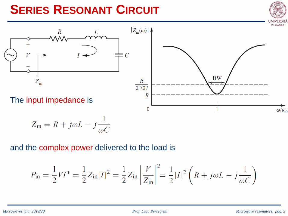
The input impedance is
and the complex power delivered to the load is
Microwaves, a.a. 2019/20 Prof. Luca Perregrini Microwave resonators, pag. 6
SERIES RESONANT CIRCUIT
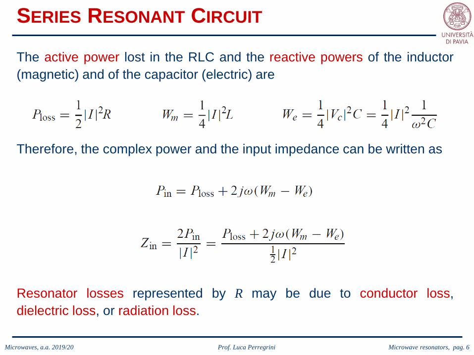
Resonator losses represented by R may be due to conductor loss,dielectric loss, or radiation loss.
The active power lost in the RLC and the reactive powers of the inductor(magnetic) and of the capacitor (electric) are
Therefore, the complex power and the input impedance can be written as

Microwaves, a.a. 2019/20 Prof. Luca Perregrini Microwave resonators, pag. 7
SERIES RESONANT CIRCUIT
(purely real)
Resonance occurs when the average stored magnetic and electricenergies are equal (𝑊𝑊𝑚𝑚 = 𝑊𝑊𝑒𝑒), and the input impedance at resonancebecome
From 𝑊𝑊𝑚𝑚 = 𝑊𝑊𝑒𝑒, the resonant angular frequency 𝜔𝜔0 = 2𝜋𝜋𝑓𝑓0 results

Microwaves, a.a. 2019/20 Prof. Luca Perregrini Microwave resonators, pag. 8
SERIES RESONANT CIRCUIT
Another important parameter of a resonant circuit is the quality factor Q,defined as
The quality factor is a measure of the loss of a resonant circuit (lower lossimplies higher Q).If there is no interaction with an external network, this is called theunloaded Q.
For the series resonant circuit the unloaded Q can be evaluated as

Microwaves, a.a. 2019/20 Prof. Luca Perregrini Microwave resonators, pag. 9
SERIES RESONANT CIRCUIT
Since 𝜔𝜔02 = 1/𝐿𝐿𝐿𝐿, the input impedance can be written as
and
Near the resonant frequency, i.e. for 𝜔𝜔 = 𝜔𝜔0 + Δ𝜔𝜔 with Δ𝜔𝜔 ≪ 𝜔𝜔0, we have

Microwaves, a.a. 2019/20 Prof. Luca Perregrini Microwave resonators, pag. 10
SERIES RESONANT CIRCUIT
The last formula for 𝑍𝑍in can also be used to infer how to model a lossyhigh-Q resonator by perturbation of his lossless counterpart.
The input impedance of a lossless series LC circuit is
𝑍𝑍in = 𝑗𝑗𝑗𝐿𝐿Δ𝜔𝜔 = 𝑗𝑗𝑗𝐿𝐿(𝜔𝜔 − 𝜔𝜔0)
By substituting
𝜔𝜔0 1 +𝑗𝑗
2𝑄𝑄0→ 𝜔𝜔0
and remembering 𝑄𝑄0 = 𝜔𝜔0𝐿𝐿/𝑅𝑅 it results
𝑍𝑍in = 𝑗𝑗𝑗𝐿𝐿Δ𝜔𝜔 = 𝑗𝑗𝑗𝐿𝐿 𝜔𝜔 − 𝜔𝜔0 1 +𝑗𝑗
2𝑄𝑄0=𝜔𝜔0𝐿𝐿𝑄𝑄0
+ 𝑗𝑗𝑗𝐿𝐿(𝜔𝜔 − 𝜔𝜔0) = 𝑅𝑅 + 𝑗𝑗𝑗𝐿𝐿(𝜔𝜔 − 𝜔𝜔0)
This procedure is general and applies to all the low-losses resonators.
Microwaves, a.a. 2019/20 Prof. Luca Perregrini Microwave resonators, pag. 11
SERIES RESONANT CIRCUIT
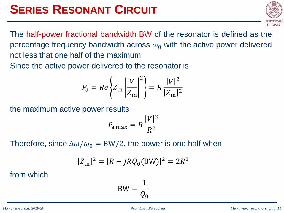
The half-power fractional bandwidth BW of the resonator is defined as thepercentage frequency bandwidth across 𝜔𝜔0 with the active power deliverednot less that one half of the maximumSince the active power delivered to the resonator is
𝑃𝑃a = 𝑅𝑅𝑅𝑅 𝑍𝑍in𝑉𝑉𝑍𝑍in
2
= 𝑅𝑅𝑉𝑉 2
𝑍𝑍in 2
the maximum active power results
𝑃𝑃a,max = 𝑅𝑅𝑉𝑉 2
𝑅𝑅2
Therefore, since Δ𝜔𝜔/𝜔𝜔0 = BW/2, the power is one half when
𝑍𝑍in 2 = 𝑅𝑅 + 𝑗𝑗𝑅𝑅𝑄𝑄0(BW) 2 = 2𝑅𝑅2
from which
BW =1𝑄𝑄0

Microwaves, a.a. 2019/20 Prof. Luca Perregrini Microwave resonators, pag. 12
PARALLEL RESONANT CIRCUIT
In the case of a parallel RLC circuitthe results are similar.
In particular, the quality factor is
and the input impedance closeto the resonance results
Also in this case the half-powerfractional bandwidth BW is
BW =1𝑄𝑄0
See the Pozar’s book for moredetails and for the derivation.
Microwaves, a.a. 2019/20 Prof. Luca Perregrini Microwave resonators, pag. 13
LOADED AND UNLOADED Q
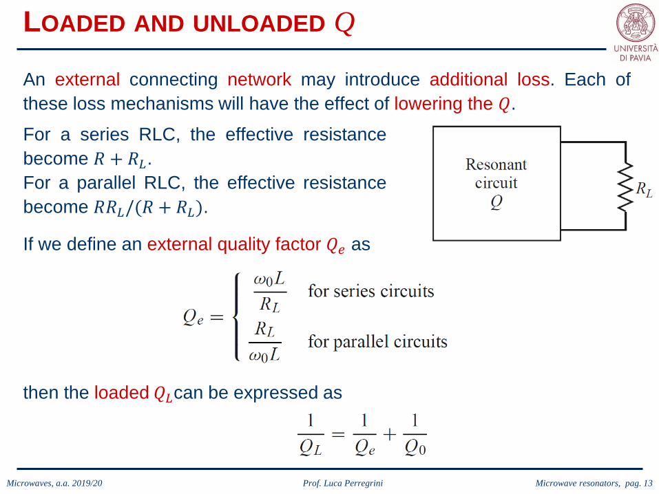
An external connecting network may introduce additional loss. Each ofthese loss mechanisms will have the effect of lowering the 𝑄𝑄.For a series RLC, the effective resistancebecome 𝑅𝑅 + 𝑅𝑅𝐿𝐿.For a parallel RLC, the effective resistancebecome 𝑅𝑅𝑅𝑅𝐿𝐿/(𝑅𝑅 + 𝑅𝑅𝐿𝐿).
If we define an external quality factor 𝑄𝑄𝑒𝑒 as
then the loaded 𝑄𝑄𝐿𝐿can be expressed as

Microwaves, a.a. 2019/20 Prof. Luca Perregrini Microwave resonators, pag. 14
LOADED AND UNLOADED Q
In summary

Microwaves, a.a. 2019/20 Prof. Luca Perregrini Microwave resonators, pag. 15
TRANSMISSION LINE RESONATORS
Open/short transmission lines of special length (half wavelength or quarterwavelength) can be used as resonators when lumped element circuits areunfeasible due to the high frequency.To study the quality factor, lossy transmission lines will be considered.

Microwaves, a.a. 2019/20 Prof. Luca Perregrini Microwave resonators, pag. 16
TRANSMISSION LINE RESONATORS
Short-circuited 𝝀𝝀/𝟐𝟐 lineAt the resonant frequency 𝜔𝜔 = 𝜔𝜔0, thelength of the line is ℓ = 𝜆𝜆/2.The input impedance is
If we are interested in a small frequencyband across 𝜔𝜔0, we can set 𝜔𝜔 = 𝜔𝜔0 + Δ𝜔𝜔(Δ𝜔𝜔 ≪ 𝜔𝜔0).Moreover, if the mode propagating is TEM (ℓ = 𝜆𝜆
2= 𝜋𝜋𝑣𝑣𝑝𝑝
𝜔𝜔0) and αℓ ≪ 1, we have
tanhαℓ ≈ αℓtan𝛽𝛽ℓ = tan𝜔𝜔0 + Δ𝜔𝜔
𝑣𝑣𝑝𝑝ℓ = tan 𝜋𝜋 +
Δ𝜔𝜔𝜔𝜔0
𝜋𝜋 ≈Δ𝜔𝜔𝜔𝜔0
𝜋𝜋
Microwaves, a.a. 2019/20 Prof. Luca Perregrini Microwave resonators, pag. 17
TRANSMISSION LINE RESONATORS
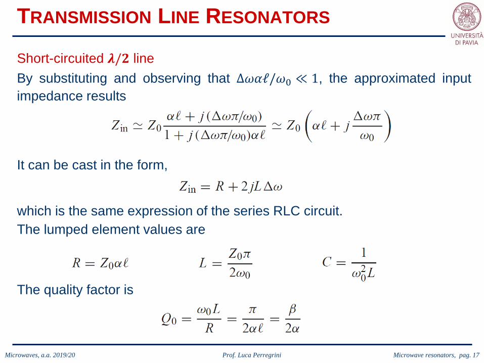
Short-circuited 𝝀𝝀/𝟐𝟐 lineBy substituting and observing that Δ𝜔𝜔𝜔𝜔ℓ/𝜔𝜔0 ≪ 1, the approximated inputimpedance results
It can be cast in the form,
which is the same expression of the series RLC circuit.The lumped element values are
The quality factor is

Microwaves, a.a. 2019/20 Prof. Luca Perregrini Microwave resonators, pag. 18
TRANSMISSION LINE RESONATORS
Short-circuited 𝝀𝝀/𝟒𝟒 lineAt the resonant frequency 𝜔𝜔 = 𝜔𝜔0, thelength of the line is ℓ = 𝜆𝜆/4.The input impedance is
We are interested in a small frequencyband across 𝜔𝜔0: 𝜔𝜔 = 𝜔𝜔0 + Δ𝜔𝜔 (Δ𝜔𝜔 ≪ 𝜔𝜔0).Moreover, if the mode propagating is TEM (ℓ = 𝜆𝜆
4= 𝜋𝜋𝑣𝑣𝑝𝑝
2𝜔𝜔0) and αℓ ≪ 1, we have
tanhαℓ ≈ αℓcot𝛽𝛽ℓ = cot𝜋𝜋2
+𝜋𝜋Δ𝜔𝜔2𝜔𝜔0
= −tan𝜋𝜋Δ𝜔𝜔2𝜔𝜔0
≈ −𝜋𝜋Δ𝜔𝜔2𝜔𝜔0

Microwaves, a.a. 2019/20 Prof. Luca Perregrini Microwave resonators, pag. 19
TRANSMISSION LINE RESONATORS
Short-circuited 𝝀𝝀/𝟒𝟒 lineBy substituting and observing that Δ𝜔𝜔𝜔𝜔ℓ/(2𝜔𝜔0) ≪ 1, the approximated inputimpedance results
It can be cast in the form,
which is the same expression of the parallel RLC circuit.The lumped element values are
The quality factor is

Microwaves, a.a. 2019/20 Prof. Luca Perregrini Microwave resonators, pag. 20
TRANSMISSION LINE RESONATORS
Open-circuited 𝝀𝝀/𝟐𝟐 lineAt the resonant frequency 𝜔𝜔 = 𝜔𝜔0, thelength of the line is ℓ = 𝜆𝜆/2.The input impedance is
We are interested in a small frequencyband across 𝜔𝜔0: 𝜔𝜔 = 𝜔𝜔0 + Δ𝜔𝜔 (Δ𝜔𝜔 ≪ 𝜔𝜔0).
Moreover, if the mode propagating is TEM (ℓ = 𝜆𝜆2
= 𝜋𝜋𝑣𝑣𝑝𝑝𝜔𝜔0
) and αℓ ≪ 1, we have
tanhαℓ ≈ αℓtan𝛽𝛽ℓ = tan 𝜋𝜋 +Δ𝜔𝜔𝜔𝜔0
𝜋𝜋 ≈Δ𝜔𝜔𝜔𝜔0
𝜋𝜋

Microwaves, a.a. 2019/20 Prof. Luca Perregrini Microwave resonators, pag. 21
TRANSMISSION LINE RESONATORS
Open-circuited 𝝀𝝀/𝟐𝟐 lineBy substituting and observing that Δ𝜔𝜔𝜔𝜔ℓ/𝜔𝜔0 ≪ 1, the approximated inputimpedance results
It can be cast in the form,
which is the same expression of the parallel RLC circuit.The lumped element values are
The quality factor is

Microwaves, a.a. 2019/20 Prof. Luca Perregrini Microwave resonators, pag. 22
TRANSMISSION LINE RESONATORS
Let’s consider a resonator comprising many sections of transmission lineswith different characteristic impedances 𝑍𝑍1 , 𝑍𝑍2 , …, 𝑍𝑍𝑁𝑁 , loaded at theextremes with arbitrary reactive impedances 𝑗𝑗𝑗𝑗𝑎𝑎 and 𝑗𝑗𝑗𝑗𝑏𝑏:
𝑍𝑍1𝑗𝑗𝑗𝑗𝑎𝑎 𝑗𝑗𝑗𝑗𝑏𝑏
𝑍𝑍𝑅𝑅𝑍𝑍𝐿𝐿
The characteristic equation to determine the resonant frequencies can beobtained by cutting the structure in any section and imposing the condition
𝑍𝑍2 𝑍𝑍𝑁𝑁
𝑍𝑍𝐿𝐿 = 𝑍𝑍𝑅𝑅∗

Microwaves, a.a. 2019/20 Prof. Luca Perregrini Microwave resonators, pag. 23
RECTANGULAR WAVEGUIDE CAVITY RESONATORS
Waveguide cavities can be made without dielectrics, and therefore theyare preferred when high-Q is required.
A cavity based on a rectangularwaveguide is usually obtained by shortcircuiting the waveguide at both ends.
An infinite number of modes resonatein the cavity, and they can be derivedfrom propagating TE and TM modes inthe waveguide.
The resonant frequencies and fieldexpressions will be derived under thehypothesis of a lossless resonator.
The Q factor will be derived by using aperturbation technique.

Microwaves, a.a. 2019/20 Prof. Luca Perregrini Microwave resonators, pag. 24
RECTANGULAR WAVEGUIDE CAVITY RESONATORS
It is sufficient to impose the perfect electric wall condition at 𝑧𝑧 = 0,𝑑𝑑 to thefield of the TE or TM propagating modes
to determine the resonant frequency and theresonant modal field.
and, therefore
Enforcing �𝐸𝐸𝑡𝑡 𝑥𝑥,𝑦𝑦, 0 = �𝐸𝐸𝑡𝑡 𝑥𝑥,𝑦𝑦,𝑑𝑑 = 0 leads to
where

Microwaves, a.a. 2019/20 Prof. Luca Perregrini Microwave resonators, pag. 25
RECTANGULAR WAVEGUIDE CAVITY RESONATORS
The resonance wavenumber is therefore
and the resonance frequency results
If 𝑏𝑏 < 𝑎𝑎 < 𝑑𝑑 the dominant resonant mode (lowest resonant frequency) willbe the TE101 mode, corresponding to the TE10 dominant waveguide modein a shorted guide of length 𝜆𝜆𝑔𝑔/2. The dominant TM resonant mode is theTM110 mode.

Microwaves, a.a. 2019/20 Prof. Luca Perregrini Microwave resonators, pag. 26
RECTANGULAR WAVEGUIDE CAVITY RESONATORS
Unloaded Q of the TE10ℓ mode
Taking into account the expression of the field of the propagating TE10mode, and using the conditions deriving from the enforcement of theresonance, the resonant field results
To evaluate the Q, we need to determine the electric and magnetic storedenergies, as well as the dissipated power.

Microwaves, a.a. 2019/20 Prof. Luca Perregrini Microwave resonators, pag. 27
RECTANGULAR WAVEGUIDE CAVITY RESONATORS
Unloaded Q of the TE10ℓ mode
The stored energies are derived with some simple calculations:
and, therefore,
Since and , we have

Microwaves, a.a. 2019/20 Prof. Luca Perregrini Microwave resonators, pag. 28
RECTANGULAR WAVEGUIDE CAVITY RESONATORS
Unloaded Q of the TE10ℓ mode
The power dissipated in the metallic boundary (assuming a goodconductor) is obtained using the perturbation technique, i.e., using the fieldcalculated in the lossless case and the formulas for the skin effect:
where is the surface resistance.

Microwaves, a.a. 2019/20 Prof. Luca Perregrini Microwave resonators, pag. 29
RECTANGULAR WAVEGUIDE CAVITY RESONATORS
Unloaded Q of the TE10ℓ mode
The resulting unloaded Q-factor due to only conductor losses (𝑄𝑄𝑐𝑐) is

Microwaves, a.a. 2019/20 Prof. Luca Perregrini Microwave resonators, pag. 30
RECTANGULAR WAVEGUIDE CAVITY RESONATORS
Unloaded Q of the TE10ℓ mode
The power dissipated in the dielectric (if any) with a dielectric constant𝜖𝜖 = 𝜖𝜖𝑟𝑟𝜖𝜖0(1 − 𝑗𝑗 tan𝛿𝛿) is
Therefore, the unloaded Q-factor due to only dielectric losses (𝑄𝑄𝑑𝑑) is
It is interesting to notice that 𝑄𝑄𝑑𝑑 does not depend on the shape of thecavity, but only on the intrinsic losses of the dielectric.Therefore this formula 𝑄𝑄𝑑𝑑 is very general and applies to all the cavities fullyfilled with a dielectric, independently on their shape.

Microwaves, a.a. 2019/20 Prof. Luca Perregrini Microwave resonators, pag. 31
RECTANGULAR WAVEGUIDE CAVITY RESONATORS
Unloaded Q of the TE10ℓ mode
Considering together the conductor and dielectric dissipated power (i.e.,𝑃𝑃𝑑𝑑𝑑𝑑𝑑𝑑𝑑𝑑 = 𝑃𝑃𝑐𝑐 + 𝑃𝑃𝑑𝑑), it can easily be demonstrated that the overall unloaded Q-factor (𝑄𝑄0) is a combination of the quality factors:
In general, the dielectric losses are dominating, and 𝑄𝑄𝑑𝑑 < 𝑄𝑄𝑐𝑐.This is the reason to avoid dielectrics in waveguide resonators.

Microwaves, a.a. 2019/20 Prof. Luca Perregrini Microwave resonators, pag. 32
CIRCULAR WAVEGUIDE CAVITY RESONATORS
A cavity based on a circular waveguide can be obtained by short circuitingthe waveguide at both ends.
The dominant cylindrical cavity mode isthe TE111, derived from the TE11 of thewaveguide.
An example of application is thefrequency meter in the photo: thecylindrical cavity is in between the twowaveguides, and its resonance frequencyis tuned until there is a transmission fromthe input to the output waveguide. Due tothe high frequency selectivity (high-Q),this allows to determine the frequencywith an high accuracy.

Microwaves, a.a. 2019/20 Prof. Luca Perregrini Microwave resonators, pag. 33
CIRCULAR WAVEGUIDE CAVITY RESONATORS
The field of the TE or TM propagating modes is
Imposing the perfect electric wallcondition at 𝑧𝑧 = 0,𝑑𝑑 the resonantfrequency and the resonantmodal field can be obtained
The resonant frequencies are
TE modes
TM modes

Microwaves, a.a. 2019/20 Prof. Luca Perregrini Microwave resonators, pag. 34
CIRCULAR WAVEGUIDE CAVITY RESONATORS
Plotting the resonantfrequencies as a functionof the dimension, thisdesign chart can beobtained.
Microwaves, a.a. 2019/20 Prof. Luca Perregrini Microwave resonators, pag. 35
CIRCULAR WAVEGUIDE CAVITY RESONATORS
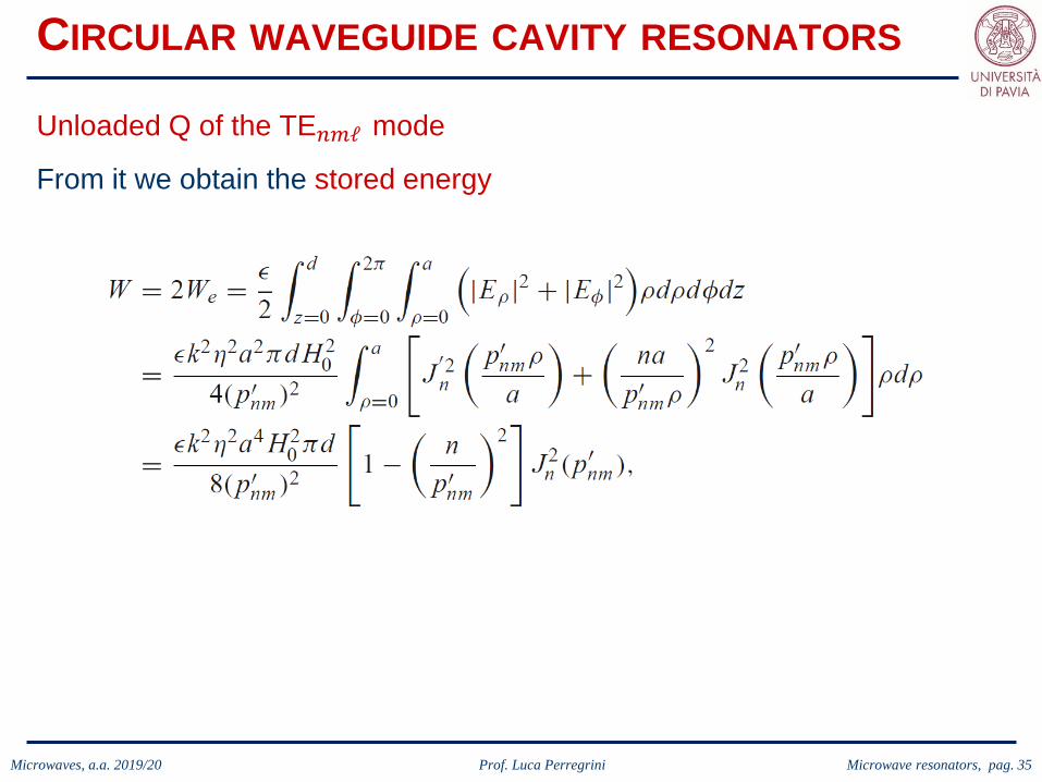
Unloaded Q of the TE𝑛𝑛𝑚𝑚ℓ mode
From it we obtain the stored energy

Microwaves, a.a. 2019/20 Prof. Luca Perregrini Microwave resonators, pag. 36
CIRCULAR WAVEGUIDE CAVITY RESONATORS
Unloaded Q of the TE𝑛𝑛𝑚𝑚ℓ mode
and the dissipated power

Microwaves, a.a. 2019/20 Prof. Luca Perregrini Microwave resonators, pag. 37
The resulting unloaded Q-factor due to only conductor losses (𝑄𝑄𝑐𝑐) is
CIRCULAR WAVEGUIDE CAVITY RESONATORS
Unloaded Q of the TE𝑛𝑛𝑚𝑚ℓ mode
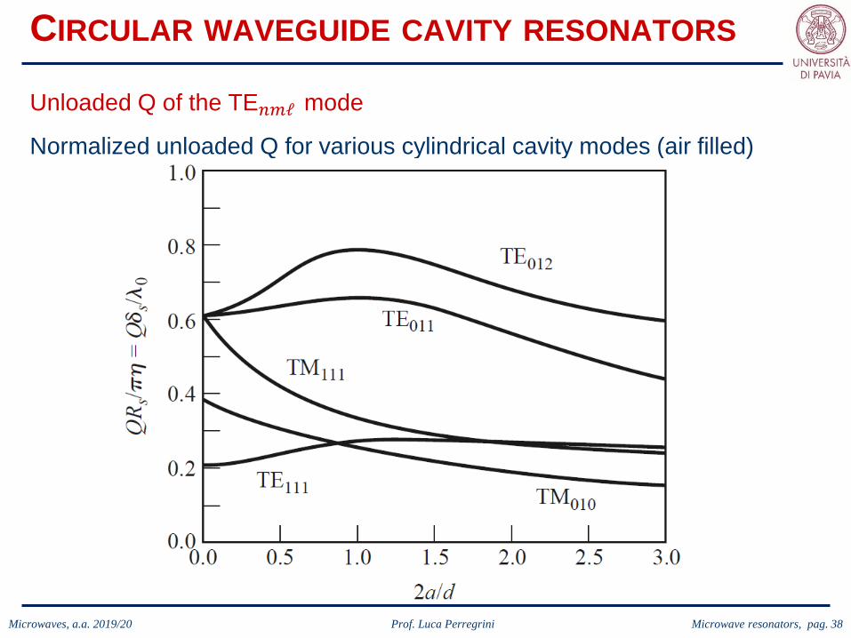
Microwaves, a.a. 2019/20 Prof. Luca Perregrini Microwave resonators, pag. 38
Normalized unloaded Q for various cylindrical cavity modes (air filled)
CIRCULAR WAVEGUIDE CAVITY RESONATORS
Unloaded Q of the TE𝑛𝑛𝑚𝑚ℓ mode

Microwaves, a.a. 2019/20 Prof. Luca Perregrini Microwave resonators, pag. 39
CIRCULAR WAVEGUIDE CAVITY RESONATORS
The power dissipated in the dielectric 𝜖𝜖 = 𝜖𝜖𝑟𝑟𝜖𝜖0(1 − 𝑗𝑗 tan𝛿𝛿) is
Therefore, the unloaded Q-factor due to only dielectric losses (𝑄𝑄𝑑𝑑) is
As expected, 𝑄𝑄𝑑𝑑 does not depend on the shape of the cavity, ad is thesame as in the rectangular case.
Unloaded Q of the TE𝑛𝑛𝑚𝑚ℓ mode

Microwaves, a.a. 2019/20 Prof. Luca Perregrini Microwave resonators, pag. 40
DIELECTRIC RESONATORS
A small disc or cube (or other shape) of (not metalized) dielectric materialcan be used as a microwave resonator.
Low loss and a high dielectric constant (𝜖𝜖𝑟𝑟 = 10 ÷ 100) materials (e.g.,BaO9Ti4, TiO2), the field is confined within the dielectric (some fieldleakage leads to a small radiation loss lowering Q).
Smaller in size, cost, and weight than metallic cavity, easy to incorporate inmicrowave integrated circuits and to couple to planar transmission lines.
No conductor losses, but dielectric loss usually increases with dielectricconstant. Q of up to several thousand can sometimes be achieved.
The resonant frequency can be mechanically tuned using an adjustablemetal plate above the resonator.
Because of these desirable features, dielectric resonators have becomekey components for integrated microwave filters and oscillators.

Microwaves, a.a. 2019/20 Prof. Luca Perregrini Microwave resonators, pag. 41
DIELECTRIC RESONATORS
Due to the high-dielectric permittivity,the boundary condition on the surfaceof the dielectric can be approximated asa perfect magnetic wall (dual of theelectric wall).
Resonant frequencies of TE01𝛿𝛿 mode
In fact, as a first order approximation ofthe reflection on the boundary is
Γ =𝜖𝜖𝑟𝑟 − 1𝜖𝜖𝑟𝑟 + 1
→ 1
Which is the opposite of the electric wall (Γ → −1)
Considering a cylindrical waveguide made of not metalized dielectric, thesolution of the Helmoltz equation is dual with respect ot the metalizedcounterpart (TE→TM, TM→TE, �𝐸𝐸 → �𝐻𝐻, �𝐻𝐻 → �𝐸𝐸).
𝜖𝜖𝑟𝑟 → ∞when

Microwaves, a.a. 2019/20 Prof. Luca Perregrini Microwave resonators, pag. 42
DIELECTRIC RESONATORS
The electric and magnetic field of the TE01mode of a cylindrical waveguide is
Resonant frequencies of TE01𝛿𝛿 mode
The propagation constant in the dielectric is
and the characteristic impedance is
while in air the mode is attenuated with

Microwaves, a.a. 2019/20 Prof. Luca Perregrini Microwave resonators, pag. 43
DIELECTRIC RESONATORS
In the dielectric ( 𝑧𝑧 < 𝐿𝐿/2)
Resonant frequencies of TE01𝛿𝛿 mode
Matching the fields at the interfaces we have
In air ( 𝑧𝑧 < 𝐿𝐿/2)
which leads to

Microwaves, a.a. 2019/20 Prof. Luca Perregrini Microwave resonators, pag. 44
DIELECTRIC RESONATORS
This solution is approximate (ignoresfringing fields at the sides), with error onthe order of 10% (not accurate enoughfor practical purposes). It illustrates thebasic behavior of dielectric resonators,and more accurate solutions areavailable in the literature.
Resonant frequencies of TE01𝛿𝛿 mode
The unloaded Q of the resonator can be calculated by determining the storedenergy (inside and outside the dielectric cylinder), and the power dissipatedin the dielectric and possibly lost to radiation.If the radiation is small, the unloaded Q can be approximated as
𝑄𝑄0 ≈1
tan𝛿𝛿
as in the case of the metallic cavity resonators.

Microwaves, a.a. 2019/20 Prof. Luca Perregrini Microwave resonators, pag. 45
DIELECTRIC RESONATORS
Microwaves, a.a. 2019/20 Prof. Luca Perregrini Microwave resonators, pag. 46
EXCITATION OF RESONATORS
Resonators are not useful unless they are coupled to external circuitry.
The way in which resonators can be coupled to transmission lines andwaveguides depends on the type of resonator under consideration.
Some common coupling techniques (i.e., gap coupling and aperturecoupling) will be discussed.
The coupling coefficient for a resonator connected to a feed line will bedefined and discussed.
The determination of the Q of a resonator from two-port measurement willbe addressed.

Microwaves, a.a. 2019/20 Prof. Luca Perregrini Microwave resonators, pag. 47
EXCITATION OF RESONATORS
Example of couplings:
Microstrip resonator gap coupled to a microstrip feedline.
Circular cavity resonator aperture coupled to a rectangular waveguide.
Rectangular cavity resonator fed by a coaxial probe.
Dielectric resonator coupled to a microstrip line

Microwaves, a.a. 2019/20 Prof. Luca Perregrini Microwave resonators, pag. 48
EXCITATION OF RESONATORS
The level of coupling depends on the application.
If the high-Q of a waveguide cavity resonator is to be preserved (e.g., in afrequency meter), is usually loosely coupled to its feed guide.
On the contrary, resonators used in oscillators or in tuned amplifiers, maybe tightly coupled in order to achieve maximum power transfer.
A measure of the level of coupling between a resonator and a feed is givenby the coupling coefficient.
To obtain maximum power transfer between a resonator and a feed line,the resonator should be matched to the line at the resonant frequency; theresonator is then said to be critically coupled to the feed.

Microwaves, a.a. 2019/20 Prof. Luca Perregrini Microwave resonators, pag. 49
COUPLING COEFFICIENT
To define the coupling coefficient, let’s consider a series resonant circuitconnected to a transmission line.
The input impedance near resonance of the series RLC is
where

Microwaves, a.a. 2019/20 Prof. Luca Perregrini Microwave resonators, pag. 50
COUPLING COEFFICIENT
At resonance (𝜔𝜔 = 𝜔𝜔0 , Δ𝜔𝜔 = 0) theinput impedance is 𝑍𝑍in = 𝑅𝑅, therefore
Moreover, assuming an infinite transmission line (or, equivalently, amatched generator), the external resistance seen from the resonator is𝑅𝑅external = 𝑍𝑍0, and the external Q-factor become
Therefore, the external and unloaded Q are identical at the critical coupling.In this case, the loaded Q is one half of the unloaded Q.

Microwaves, a.a. 2019/20 Prof. Luca Perregrini Microwave resonators, pag. 51
COUPLING COEFFICIENT
We can define the coupling coefficient
which can be applied to both series(𝑔𝑔 = 𝑍𝑍0/𝑅𝑅) and parallel (𝑔𝑔 = 𝑅𝑅/𝑍𝑍0)resonant circuits connected to atransmission line of characteristicimpedance 𝑍𝑍0.
Three cases can be distinguished:𝑔𝑔 < 1: resonator undercoupled to the feedline𝑔𝑔 = 1: resonator critically coupled to the feedline𝑔𝑔 > 1: resonator overcoupled to the feedline
The Smith chart sketch of the impedance loci for the series resonant circuitexemplifies the three cases.
Microwaves, a.a. 2019/20 Prof. Luca Perregrini Microwave resonators, pag. 52
GAP-COUPLED MICROSTRIP OPEN RESONATOR
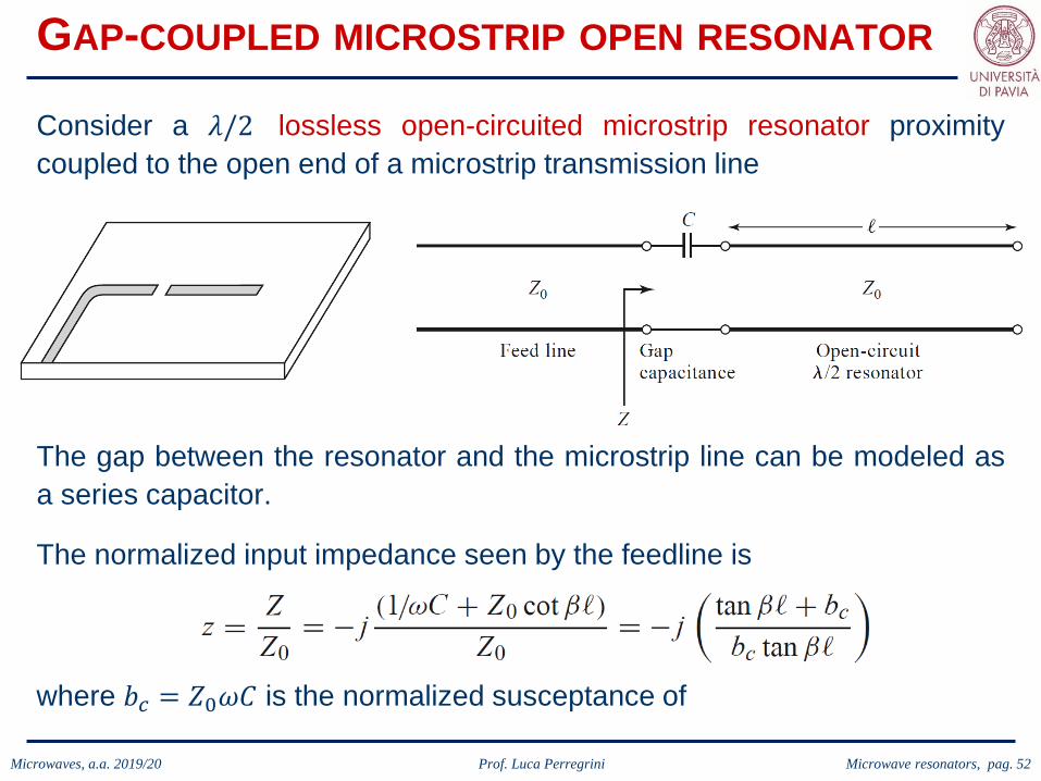
Consider a 𝜆𝜆/2 lossless open-circuited microstrip resonator proximitycoupled to the open end of a microstrip transmission line
The gap between the resonator and the microstrip line can be modeled asa series capacitor.
The normalized input impedance seen by the feedline is
where 𝑏𝑏𝑐𝑐 = 𝑍𝑍0𝜔𝜔𝐿𝐿 is the normalized susceptance of
Microwaves, a.a. 2019/20 Prof. Luca Perregrini Microwave resonators, pag. 53
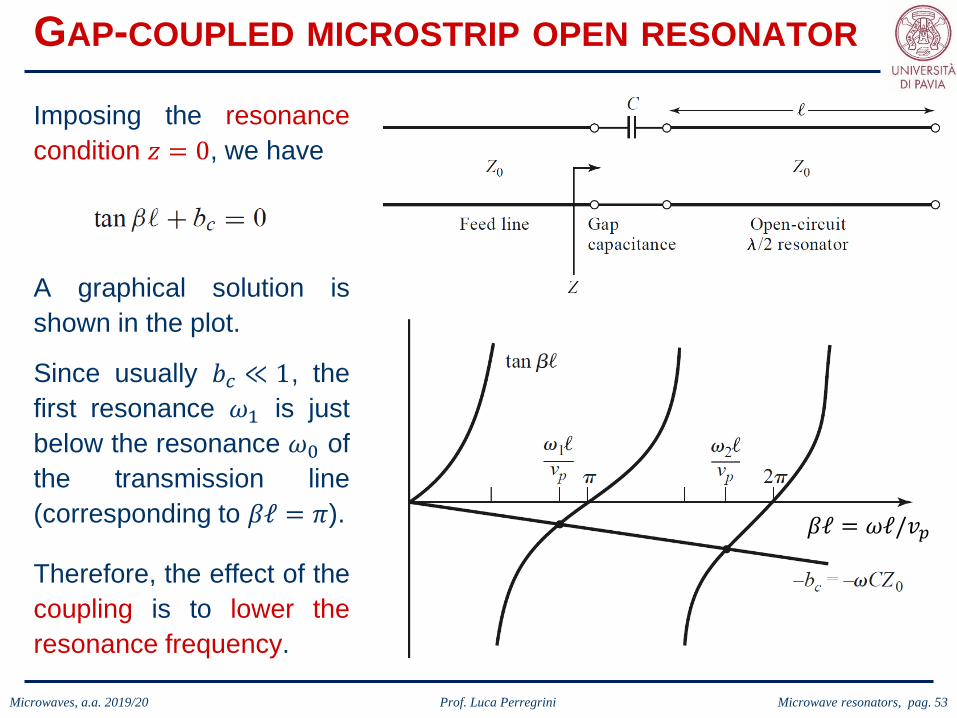
GAP-COUPLED MICROSTRIP OPEN RESONATOR
Imposing the resonancecondition 𝑧𝑧 = 0, we have
A graphical solution isshown in the plot.
Since usually 𝑏𝑏𝑐𝑐 ≪ 1, thefirst resonance 𝜔𝜔1 is justbelow the resonance 𝜔𝜔0 ofthe transmission line(corresponding to 𝛽𝛽ℓ = 𝜋𝜋).
Therefore, the effect of thecoupling is to lower theresonance frequency.
𝛽𝛽ℓ = 𝜔𝜔ℓ/𝑣𝑣𝑝𝑝

Microwaves, a.a. 2019/20 Prof. Luca Perregrini Microwave resonators, pag. 54
GAP-COUPLED MICROSTRIP OPEN RESONATOR
The goal is to represent the resonator around the first resonance 𝜔𝜔1 as aRLC equivalent circuit.Expanding 𝑧𝑧 in a Taylor series around 𝜔𝜔1 we have
0
If the transmission line support a TEM mode, then
where
𝑏𝑏𝑐𝑐 ≪ 1
and, finally
𝑑𝑑(𝛽𝛽ℓ)𝑑𝑑𝜔𝜔
=𝑑𝑑(𝜔𝜔ℓ/𝑣𝑣𝑝𝑝)
𝑑𝑑𝜔𝜔=
ℓ𝑣𝑣𝑝𝑝
Microwaves, a.a. 2019/20 Prof. Luca Perregrini Microwave resonators, pag. 55
GAP-COUPLED MICROSTRIP OPEN RESONATOR
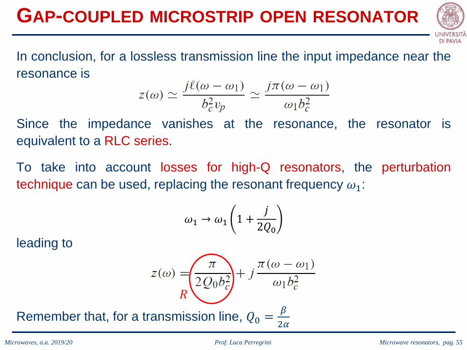
In conclusion, for a lossless transmission line the input impedance near theresonance is
To take into account losses for high-Q resonators, the perturbationtechnique can be used, replacing the resonant frequency 𝜔𝜔1:
𝜔𝜔1 → 𝜔𝜔1 1 +𝑗𝑗
2𝑄𝑄0leading to
𝑅𝑅
Remember that, for a transmission line, 𝑄𝑄0 = 𝛽𝛽2𝛼𝛼
Since the impedance vanishes at the resonance, the resonator isequivalent to a RLC series.
Microwaves, a.a. 2019/20 Prof. Luca Perregrini Microwave resonators, pag. 56
GAP-COUPLED MICROSTRIP OPEN RESONATOR
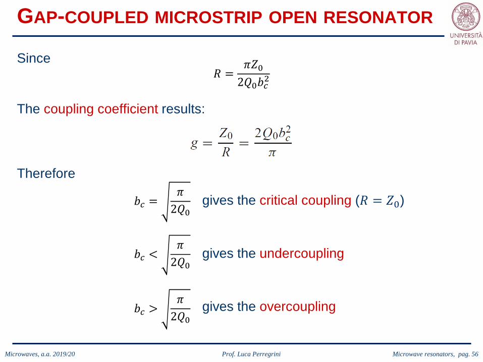
Since
The coupling coefficient results:
𝑅𝑅 =𝜋𝜋𝑍𝑍0
2𝑄𝑄0𝑏𝑏𝑐𝑐2
𝑏𝑏𝑐𝑐 =𝜋𝜋
2𝑄𝑄0gives the critical coupling (𝑅𝑅 = 𝑍𝑍0)
gives the undercoupling
gives the overcoupling
𝑏𝑏𝑐𝑐 <𝜋𝜋
2𝑄𝑄0
𝑏𝑏𝑐𝑐 >𝜋𝜋
2𝑄𝑄0
Therefore

Microwaves, a.a. 2019/20 Prof. Luca Perregrini Microwave resonators, pag. 57
APERTURE-COUPLED RECTANGULAR CAVITY
Consider a 𝜆𝜆𝑔𝑔/2 rectangular waveguide short circuited at the two ends, andcoupled with another waveguide (maybe identical) through a small apertureat one end.
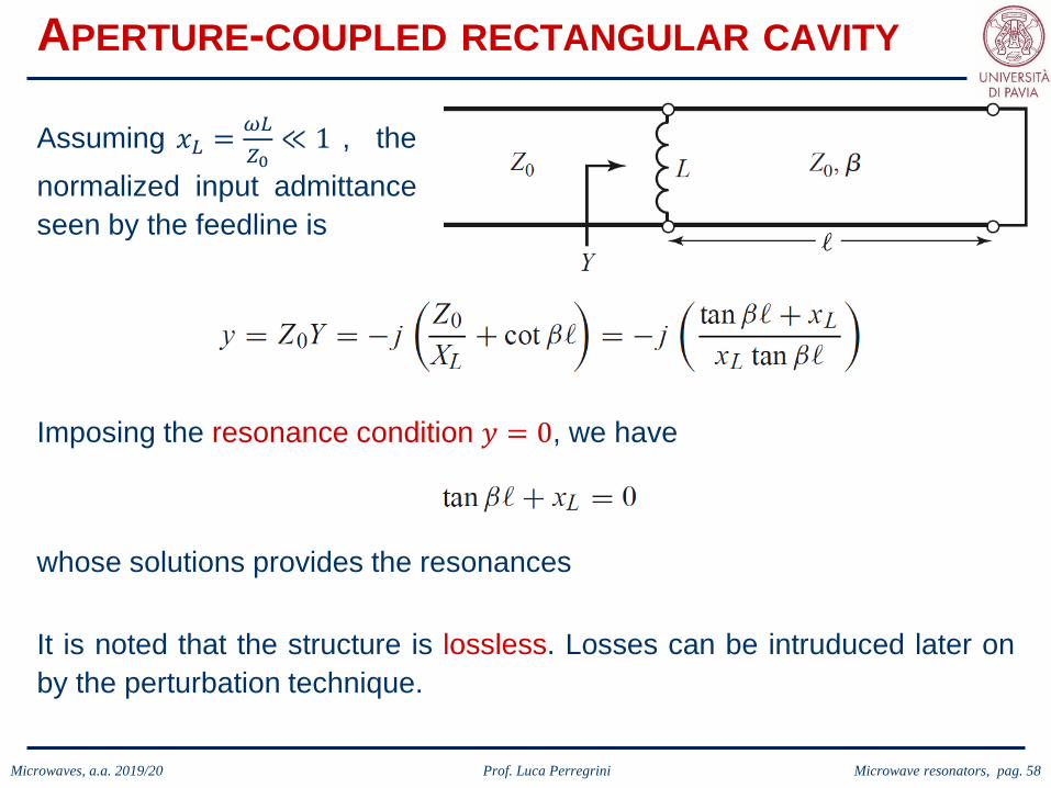
The small aperture acts as a shunt inductance, and the structure can bemodeled by the following equivalent circuit
Microwaves, a.a. 2019/20 Prof. Luca Perregrini Microwave resonators, pag. 58
APERTURE-COUPLED RECTANGULAR CAVITY
Assuming 𝑥𝑥𝐿𝐿 = 𝜔𝜔𝐿𝐿𝑍𝑍0≪ 1 , the
normalized input admittanceseen by the feedline is
Imposing the resonance condition 𝑦𝑦 = 0, we have
whose solutions provides the resonances
It is noted that the structure is lossless. Losses can be intruduced later onby the perturbation technique.

Microwaves, a.a. 2019/20 Prof. Luca Perregrini Microwave resonators, pag. 59
APERTURE-COUPLED RECTANGULAR CAVITY
The goal is again to represent the resonator around the first resonance 𝜔𝜔1as a resonant RLC circuit.Expanding 𝑦𝑦 in a Taylor series around 𝜔𝜔1 we have
0
For the TE or TM mode of a waveguide it results
where
𝑏𝑏𝑐𝑐 ≪ 1
and, finally

Microwaves, a.a. 2019/20 Prof. Luca Perregrini Microwave resonators, pag. 60
APERTURE-COUPLED RECTANGULAR CAVITY
In conclusion, for a lossless resonator the input admittance near theresonance is
To take into account losses for high-Q resonators, the perturbationtechnique can be used, replacing the resonant frequency 𝜔𝜔1:
𝜔𝜔1 → 𝜔𝜔1 1 +𝑗𝑗
2𝑄𝑄0leading to
1/𝑅𝑅
Since the admittance vanishes at the resonance, the resonator isequivalent to a RLC parallel.

Microwaves, a.a. 2019/20 Prof. Luca Perregrini Microwave resonators, pag. 61
APERTURE-COUPLED RECTANGULAR CAVITY
The critical coupling (maximum power transfer) is achieved when (𝑅𝑅 = 𝑍𝑍0),which corresponds to
For a TE mode 𝑍𝑍0 = 𝑘𝑘0𝜂𝜂0/𝛽𝛽, and the coupling coefficient results:

Microwaves, a.a. 2019/20 Prof. Luca Perregrini Microwave resonators, pag. 62
UNLOADED Q FROM TWO-PORT MEASUREMENTS
Direct measurement of the unloaded Q of a resonator is generally notpossible because of the loading effect of the measurement system.
However, it is possible to determine unloaded Q from measurements of thefrequency response of the loaded resonator when it is connected to atransmission line.
Both one-port (reflection) and two-port (transmission) measurementtechniques are possible.

Microwaves, a.a. 2019/20 Prof. Luca Perregrini Microwave resonators, pag. 63
UNLOADED Q FROM TWO-PORT MEASUREMENTS
Let us consider the (equivalent) RLC series circuit embedded in a two-portmeasurement.
The unloaded Q is related to the loaded Q and to the coupling factor:
We need from measurements the loaded Q and the coupling factor.

Microwaves, a.a. 2019/20 Prof. Luca Perregrini Microwave resonators, pag. 64
UNLOADED Q FROM TWO-PORT MEASUREMENTS
For the RLC series theunloaded Q is
𝑄𝑄0 =𝜔𝜔0𝐿𝐿𝑅𝑅
𝑄𝑄𝑒𝑒 =𝜔𝜔0𝐿𝐿2𝑍𝑍0
Moreover, the external Q is twice the one of the single line connection:
Since for the RLC at the resonance we have 𝑍𝑍 = 𝑅𝑅 , it can be easilydemonstrated that
𝑔𝑔 =𝑄𝑄0𝑄𝑄𝑒𝑒
=2𝑍𝑍0𝑅𝑅
Where 𝑆𝑆21 is the measured transmission parameter, which is purely real atthe resonance, and provides the coupling factor.

Microwaves, a.a. 2019/20 Prof. Luca Perregrini Microwave resonators, pag. 65
UNLOADED Q FROM TWO-PORT MEASUREMENTS
The determination of the loaded Q is done from the transmissionmeasurement around the resonance:
3 dBBW
BW
3 dB
3 dB
𝑄𝑄𝐿𝐿 =𝑓𝑓0
BW

Microwaves, a.a. 2019/20 Prof. Luca Perregrini Microwave resonators, pag. 66
UNLOADED Q FROM TWO-PORT MEASUREMENTS
The same reasoning can be repeated for an RLC parallel resonator. Theonly difference is that
𝑔𝑔 =1 − 𝑆𝑆21(𝜔𝜔0)𝑆𝑆21(𝜔𝜔0)
Nothing changes for the determination of the loaded Q.

Microwaves, a.a. 2019/20 Prof. Luca Perregrini Microwave resonators, pag. 67
CAVITY PERTURBATIONS
Cavity resonators are often modified by making small changes in theirshape, or by introducing small pieces of dielectric or metallic materials.
For example, the resonant frequency of a cavity resonator can be easilytuned with a small screw (dielectric or metallic) that enters the cavityvolume, or by changing the size of the cavity with a movable wall.
Another application involves the determination of dielectric constant ofmaterials by measuring the shift in resonant frequency when a smalldielectric sample is introduced into the cavity.
In some cases, the effect of such perturbations on the cavity performancecan be calculated exactly, but often approximations must be made. Oneuseful technique for doing this is the perturbational method, which assumesthat the actual fields of a cavity with a small shape or material perturbationare not greatly different from those of the unperturbed cavity.

Microwaves, a.a. 2019/20 Prof. Luca Perregrini Microwave resonators, pag. 68
CAVITY PERTURBATIONS
In the case of materialperturbation, startingfrom the Maxwell’sequations it can bedemonstrated that theshift of the resonantfrequency is given by Original cavity Perturbed cavity
If we assume �𝐸𝐸 ≈ �𝐸𝐸 0 and �𝐻𝐻 ≈ �𝐻𝐻 0, and approximate 𝜔𝜔 with 𝜔𝜔0 in thedenominator, we obtain
(exact expression)
(approximate expression)

Microwaves, a.a. 2019/20 Prof. Luca Perregrini Microwave resonators, pag. 69
CAVITY PERTURBATIONS
In the case of shapeperturbation, startingfrom the Maxwell’sequations it can bedemonstrated that theshift of the resonantfrequency is given by Original cavity Perturbed cavity
If we assume �𝐸𝐸 ≈ �𝐸𝐸 0 and �𝐻𝐻 ≈ �𝐻𝐻 0, we obtain
(exact expression)
(approximate expression)
Δ𝑉𝑉Δ𝑆𝑆
The frequency shift is related tothe change in the stored energy.