Integration of Cost and Work Breakdown Structures in ... - MDPI
2250 IEEE TRANSACTIONS ON PLASMA SCIENCE, VOL. 32, NO. 6, DECEMBER 2004
Microwave Breakdown in SlotsUlf Jordan, Dan Anderson, Mats Bäckström, Member, IEEE, Arkady V. Kim, Mietek Lisak, and Olof Lundén
Abstract—The properties of microwave-induced breakdown ofair in narrow metallic slots are investigated, both theoretically andexperimentally, with emphasis on factors important for protectionagainst transmission of incident high-power microwave radiation.The key factors investigated are breakdown power threshold,breakdown time, peak-leakage power, and total transmittedenergy, as functions of incident pulse shape and power density.The theoretical investigation includes estimates of the electricfield intensification in narrow slots and basic breakdown plasmamodeling. New results important for application to the high-powermicrowave field, such as the influence of pulse shape on breakdowntime and peak-leakage power, are presented. The experimentalinvestigation comprises a set of slot breakdown experiments atatmospheric pressure, which are analyzed to extract key param-eters, such as transmission cross section, breakdown time, peakleakage power, and transmitted energy. The experimental datais compared and shown to be in good agreement with resultsobtained in the theoretical investigation.
Index Terms—Breakdown plasmas, high-power microwave(HPM) protection, microwave breakdown, slots.
I. INTRODUCTION
THE DEVELOPMENT of high-power microwave (HPM)technology has been a rapidly growing field of applied
physics in recent decades. HPM generators capable of deliveringoutput powers of the order of tens of GW in the GHz range offrequencies have become available and have found a number ofapplications, most of them peaceful, but also some for militaryuse as electromagnetic weapons aimed at causing destructiveinterference with, or even destroying, electronic equipment. Inorder to understand the robustness of electronic systems to in-cident high-power microwaves, it is important to investigate theundesired coupling of microwave power into systems throughcracks, slots, and other apertures created either intentionally bymechanical or electrical design, or unintentionally by imperfec-tions.
Linear transmission through a slot or an aperture becomeslarge at resonance. Thus, from a protection point of view, the res-onant case is potentially the most dangerous situation. However,this situation also implies that the microwave electric field ofan HPM pulse, for example, becomes enhanced when it passesthrough the slot, which may lead to self-induced microwavebreakdown of the air in the slot. The concomitant dischargesustained by the microwave field tends to put an inherent limiton the maximum power that can be transmitted through a slot.
Manuscript received July 1, 2004; revised September 13, 2004.U. Jordan, D. Anderson, and M. Lisak are with the Department of Electro-
magnetics, Chalmers University of Technology, SE-412 96 Göteborg, Sweden.M. Bäckström and O. Lundén are with the Swedish Defence Research
Agency, SE-581 11 Linköping, Sweden.A. V. Kim is with the Institute of Applied Physics, 603950 Nizhny Novgorod,
Russia.Digital Object Identifier 10.1109/TPS.2004.838594
This may be a problem if the purpose of the slot is to transmitmicrowave radiation, e.g., in a slot antenna, but may also bean advantage since it can provide integrated self-induced pro-tection against strong external incident radiation. This powerlimiting effect is used for constructive purposes; for example,in the Transmit-Receive (TR) switches used for protection inhigh-power microwave radar systems (see [1]). In this case, theswitch is designed as a separate piece of waveguide inserted intothe transmission system, and special care has been taken to de-sign a device in which facilitates breakdown and rapidly switchto discharge mode, and only allow small and harmless leakagepower densities. In fact, one of the most crucial features of theTR switch is the geometrical arrangement intended to create lo-calized, strongly enhanced microwave fields, which facilitatebreakdown. In the case of slots and other apertures, a similarfield enhancement may also take place and provide rapid cutoffand small leakage of the incident microwave power. Studies ofthis “self-protecting” mechanism of electronic systems is an im-portant task in order to assess the vulnerability of electronicequipment to incident high-power microwaves. However, veryfew results concerning this latter problem is available in liter-ature. An exception is the work presented in [2], which con-tains the results of extensive numerical simulations. Althoughthis investigation provides important information on the break-down threshold and subsequent leakage power of microwavesincident on a narrow slot in a wave guide, the purely numericalcharacter of the investigation makes it difficult to get a clear pic-ture of the physics involved in the process, and to extrapolate theresults to parameters other than those used in the simulations.
This paper summarizes the results of a comprehensive studyinvolving both theoretical and experimental work of microwavetransmission through narrow slots [3]. The main results of thiswork are the determination of crucial parameters, like powerthresholds for breakdown of HPM pulses incident on rectan-gular narrow slots, pre-breakdown and post-breakdown energytransmission, as well as time-to-breakdown. The analysis givesa good picture of the properties of HPM transmission throughnarrow slots and the concomitant inherent limitation of thetransmission due to self-induced breakdown. The theoreticalpredictions are shown to be in good agreement with the experi-mental results.
II. LINEAR TRANSMISSION AND MICROWAVE ELECTRIC FIELD
STRUCTURE
We start by reviewing some fundamental results concerningthe linear transmission of radiation through narrow slots. Inorder to be explicit in the subsequent analysis, we will restrictour consideration to the case of a long and narrow rectangularslot in a perfectly conducting plane, and assume that the waveis incident perpendicularly on the slot, and that it is polarized
0093-3813/04$20.00 © 2004 IEEE
JORDAN et al.: MICROWAVE BREAKDOWN IN SLOTS 2251
with its E-vector perpendicular to the long side of the slot. Theimportance of this problem is that it is the most dangerous casefrom the point of view of undesirable high transmission, andstill allows approximate analytical solutions for the field struc-ture in the slot, as well as for the linear transmission character-istics through the slot. Although this transmission problem is aclassical one (cf. [4] and [5]), it continues to attract interest, inparticular, the possibility of strong resonant transmission of mi-crowaves through very narrow slots (see [6] and [7]).
The transmission property of a narrow slot is most succinctlyexpressed by its transmission cross section. For the present sit-uation, it can be shown (cf. [5] and [8]) that resonant trans-mission occurs when the width of the slot is approximately anodd number of half-wavelengths. The transmission cross sec-tion does not then depend on the slot height, and for the thresonance harmonic, it is given by
(1)
where the function is defined by
(2)
and is the slot width. In particular, the maximum transmissioncross section for electromagnetic waves incident on a narrowslot occurs for the lowest order resonance (i.e., forwhere is the microwave wavelength) and is given by
(3)
Thus, the maximum transmission cross section of a narrow slotis approximately equal to the area of a square with sides equalto the slot width. Nonresonant transmission is small and can beneglected from the protective point of view unless the incidentpower densities are extremely high.
As is easily seen from the estimates for the transmission crosssection given by (1) and (3), the electric field in the vicinity ofnarrow slots may become strongly enhanced. For further anal-ysis of microwave discharge effects, it is necessary to have ac-cess to useful estimates of these fields. This is again a classicproblem where antenna theory (cf. [9] and [10]) can be used toestimate the electric field in a narrow slot. It is found that theratio of the electric field strength in the slot to that of theincident electric field is approximately given by
(4)
where denotes the height of the slot.
III. BASIC BREAKDOWN THEORY
The high electric fields that may occur in a narrow slot maycause electric breakdown. Microwave breakdown in gases is due
to the ionizing action of free electrons being heated to high en-ergies by the microwave electric field. The density of free elec-trons in a gas evolves according to the continuity equa-tion (cf. [11])
(5)
where is the diffusion coefficient, is the ionization fre-quency, and is the attachment frequency of free electrons onneutral molecules. This partial differential equation is often re-duced to a simpler ordinary differential equation by simplifyingthe diffusion term as follows:
(6)
where denotes an effective diffusion length, and is theconcomitant loss frequency due to diffusion.
This simplification makes it possible to rewrite (5) as the sim-pler ordinary differential equation
(7)
where , which implies the breakdownthreshold condition
(8)
The breakdown condition expressed by (8) is applicable for con-tinuous wave (CW) conditions. However, for the important caseof pulsed microwave power, the condition has to be modifiedto allow for the fact that the electron density must have time togrow to a value sufficiently high enough to affect the microwavepropagation. This can approximately be taken to occur when theelectron density becomes equal to the critical value, , wherethe corresponding plasma angular frequency, , equals the mi-crowave angular frequency, . Accounting for the fact that theionization frequency may depend on time, due to a time vari-ation of the microwave electric field strength, the breakdowncondition can be written
(9)
where denotes the pulse length. In the ratiodepends on the microwave frequency and is rather poorlyknown, but since the ratio only appears inside a logarithm, oneusually takes .
For air, which is of primary importance in the present investi-gation, we will use the following approximations for the charac-teristic frequencies and the diffusion constant appearing in (5),valid at room temperature (cf. [12]):
(10)
2252 IEEE TRANSACTIONS ON PLASMA SCIENCE, VOL. 32, NO. 6, DECEMBER 2004
where the pressure, , is measured in torr and , the effectiveelectric field for energy transfer, accounts for the effect of thecollisions on the electron motion by being defined as
where is the root mean square (rms) value (V/cm) andis the collision frequency between electrons and
neutrals. The coefficient is a characteristic of the gas and forair .
The use of pressure in (10) is conventional in western liter-ature, although the physically relevant parameter is the neutralnumber density. Consequently, for moderate temperature devi-ations from the nominal, such that the chemical composition isnot altered, one must use the reduced pressure instead of(cf. [13]).
The different scalings of the attachment and diffusion fre-quencies with pressure ( , whereas, )imply that diffusion tends to dominate the electron losses atlow pressures and attachment at high pressures. Our subsequentanalysis will be concentrated to close to atmospheric pressures( torr), which implies that diffusion losses tend to besmall, except for very narrow slots.
Although the actual value of the background electron den-sity, , from which the electron avalanche starts, is not im-portant in the determination of the breakdown thresholds forCW operation or for long microwave pulses, it becomes veryimportant for HPM pulses with short-pulse lengths. The natu-rally occurring mechanisms for generation of background elec-tron density is primarily cosmic radiation and/or photodetach-ment of electrons from O -molecules. However, these sourcesare not homogeneous, neither in space, nor in time. In an anal-ysis of the peak transmitted power of short HPM pulses, thestochastic nature of the background electron density variationbecomes crucially important and must be taken into account. Infact, it may happen that no free electrons are available to startthe breakdown avalanche in the breakdown-prone volume at thebeginning of the microwave pulse, and only at a later time, dothe first triggering electrons appear. This “waiting time” impliesthat a first part of the microwave pulse has already been trans-mitted linearly through the slot before the breakdown processcan start. In particular, it implies that there may be a signifi-cant pulse-to-pulse variation in the transmission with occasionalpulses having strong spikes of transmitted pulse power/energywhen the breakdown-limitation of the transmission has been de-layed. This waiting time phenomenon is potentially dangerous,since even a single transmitted high-power peak may seriouslydamage the electronics behind the slot. There are several ways ofavoiding the stochastic variation of the peak transmitted powerby making sure that there is always a nonzero electron den-sity in the breakdown-prone volume. In the TR switches, thisis achieved by either a radioactive material close to the break-down volume, spraying the gas with ionizing radiation, or by asmall keep-alive dc current through the volume. The keep-alivecurrent should be small enough not to affect the linear transmis-sion, but large enough to provide the seed electrons necessary to
instantaneously start the breakdown avalanche once the break-down threshold is exceeded.
IV. IMPORTANT BREAKDOWN CHARACTERISTICS
The threshold condition given by (8) can be written as a bal-ance between the ionization and loss rates according to
. Also including the effect due to the finite length of themicrowave pulse, [cf. (9), assuming a rectangular pulse form]and using the approximations given in (10), the correspondingbreakdown field, (V/cm), becomes
(11)
An important parameter to assess in HPM breakdown situa-tions is the time-to-breakdown, denoted as , and defined asthe time it takes the electron density in the breakdown plasmato reach the critical density , i.e.,
(12)
where the microwave field is assumed to be turned on at .Clearly, this quantity will depend on the time variation of therising flank of the microwave power, but assuming a rectangularpulse, the time-to-breakdown can be expressed simply as
(13)
which, in the limit of strongly overcritical microwave power,reduces to
(14)
At atmospheric pressures, this implies short breakdown timesand efficient blocking of incident HPM pulses, provided thewaiting time phenomenon has been eliminated.
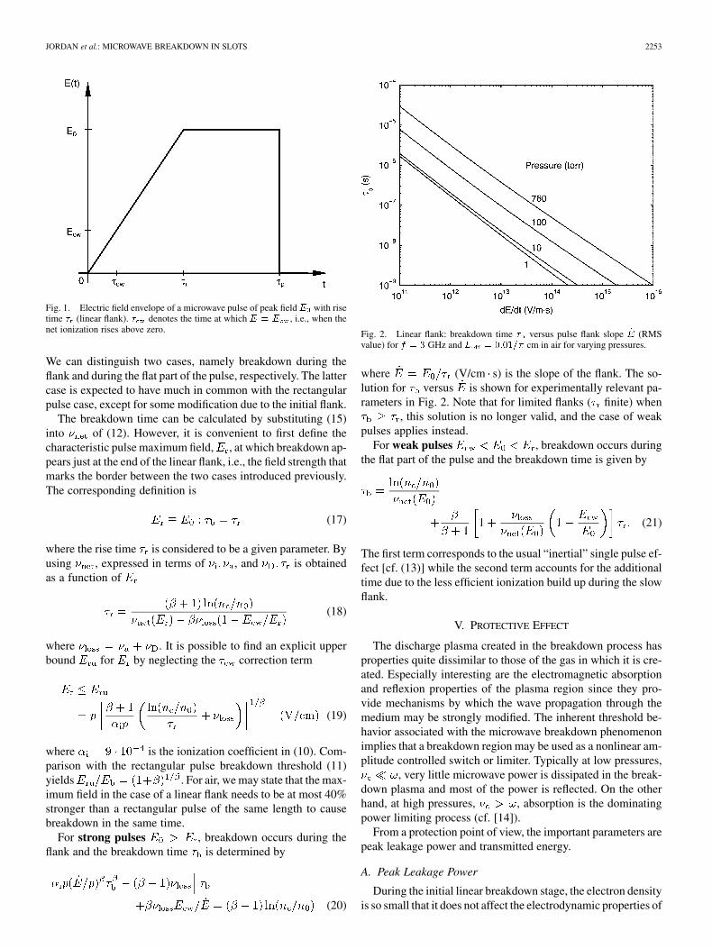
For nonrectangular pulses, the full (12) must be used whendetermining the breakdown time. Qualitatively, a nonrect-angular envelope of the pulses is expected to lead to longerbreakdown times, or equivalently, to higher pulsed breakdownthresholds as compared to the rectangular pulse form. In theseries of experiments to be described later, the pulse formtypically involved a linearly rising flank before the amplitudesaturated at an approximately constant value. In fact, most ofthe breakdown events occurred on the rising flank, and it is thenappropriate to consider pulses of the form
(15)
where the envelope field strength increases from 0 to duringthe rise time (cf. Fig. 1). The envelope equals the CW break-down field strength at time , given by
(16)
JORDAN et al.: MICROWAVE BREAKDOWN IN SLOTS 2253
Fig. 1. Electric field envelope of a microwave pulse of peak field E with risetime � (linear flank). � denotes the time at which E = E , i.e., when thenet ionization rises above zero.
We can distinguish two cases, namely breakdown during theflank and during the flat part of the pulse, respectively. The lattercase is expected to have much in common with the rectangularpulse case, except for some modification due to the initial flank.
The breakdown time can be calculated by substituting (15)into of (12). However, it is convenient to first define thecharacteristic pulse maximum field, , at which breakdown ap-pears just at the end of the linear flank, i.e., the field strength thatmarks the border between the two cases introduced previously.The corresponding definition is
(17)
where the rise time is considered to be a given parameter. Byusing , expressed in terms of , and is obtainedas a function of
(18)
where . It is possible to find an explicit upperbound for by neglecting the correction term
(19)
where is the ionization coefficient in (10). Com-parison with the rectangular pulse breakdown threshold (11)yields . For air, we may state that the max-imum field in the case of a linear flank needs to be at most 40%stronger than a rectangular pulse of the same length to causebreakdown in the same time.
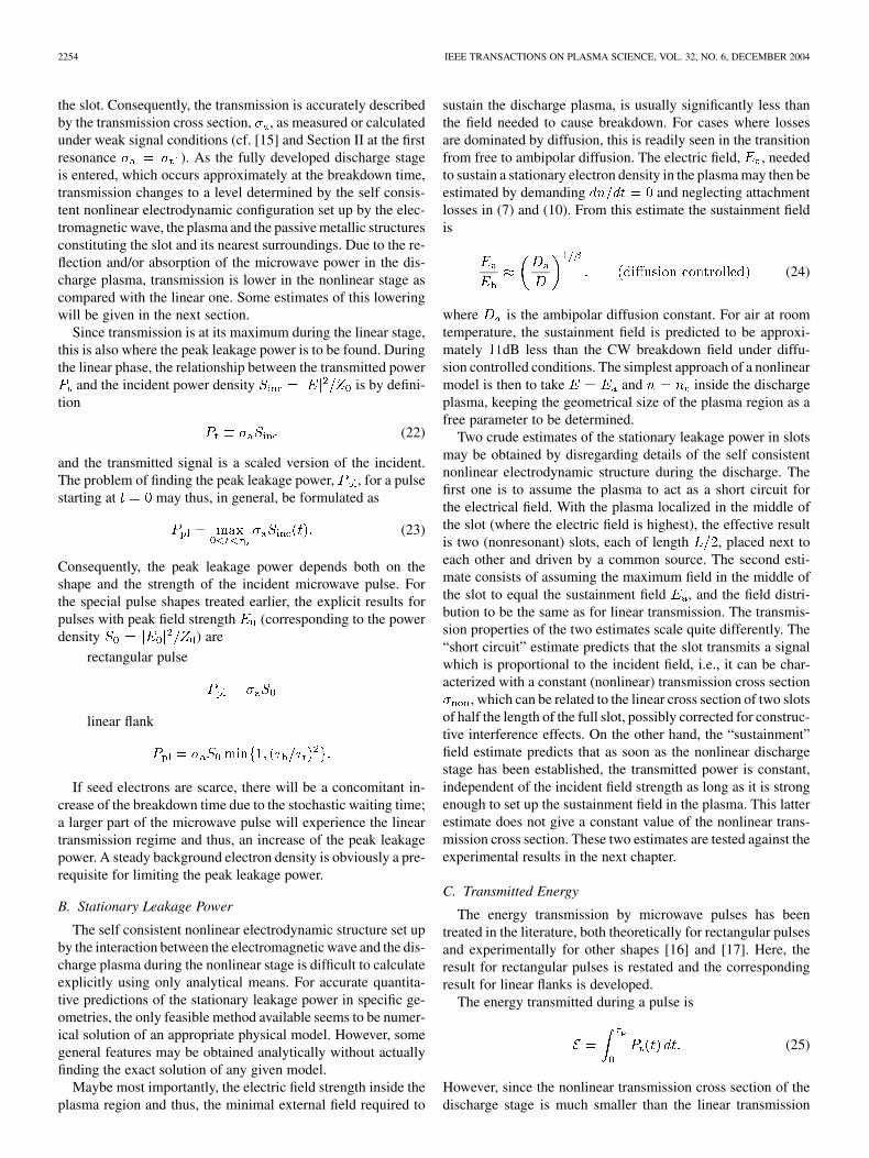
For strong pulses , breakdown occurs during theflank and the breakdown time is determined by
(20)
Fig. 2. Linear flank: breakdown time � versus pulse flank slope _E (RMSvalue) for f = 3 GHz and L = 0:01=� cm in air for varying pressures.
where (V/cm s) is the slope of the flank. The so-lution for versus is shown for experimentally relevant pa-rameters in Fig. 2. Note that for limited flanks ( finite) when
, this solution is no longer valid, and the case of weakpulses applies instead.
For weak pulses , breakdown occurs duringthe flat part of the pulse and the breakdown time is given by
(21)
The first term corresponds to the usual “inertial” single pulse ef-fect [cf. (13)] while the second term accounts for the additionaltime due to the less efficient ionization build up during the slowflank.
V. PROTECTIVE EFFECT
The discharge plasma created in the breakdown process hasproperties quite dissimilar to those of the gas in which it is cre-ated. Especially interesting are the electromagnetic absorptionand reflexion properties of the plasma region since they pro-vide mechanisms by which the wave propagation through themedium may be strongly modified. The inherent threshold be-havior associated with the microwave breakdown phenomenonimplies that a breakdown region may be used as a nonlinear am-plitude controlled switch or limiter. Typically at low pressures,
, very little microwave power is dissipated in the break-down plasma and most of the power is reflected. On the otherhand, at high pressures, , absorption is the dominatingpower limiting process (cf. [14]).
From a protection point of view, the important parameters arepeak leakage power and transmitted energy.
A. Peak Leakage Power
During the initial linear breakdown stage, the electron densityis so small that it does not affect the electrodynamic properties of
2254 IEEE TRANSACTIONS ON PLASMA SCIENCE, VOL. 32, NO. 6, DECEMBER 2004
the slot. Consequently, the transmission is accurately describedby the transmission cross section, , as measured or calculatedunder weak signal conditions (cf. [15] and Section II at the firstresonance ). As the fully developed discharge stageis entered, which occurs approximately at the breakdown time,transmission changes to a level determined by the self consis-tent nonlinear electrodynamic configuration set up by the elec-tromagnetic wave, the plasma and the passive metallic structuresconstituting the slot and its nearest surroundings. Due to the re-flection and/or absorption of the microwave power in the dis-charge plasma, transmission is lower in the nonlinear stage ascompared with the linear one. Some estimates of this loweringwill be given in the next section.
Since transmission is at its maximum during the linear stage,this is also where the peak leakage power is to be found. Duringthe linear phase, the relationship between the transmitted power
and the incident power density is by defini-tion
(22)
and the transmitted signal is a scaled version of the incident.The problem of finding the peak leakage power, , for a pulsestarting at may thus, in general, be formulated as
(23)
Consequently, the peak leakage power depends both on theshape and the strength of the incident microwave pulse. Forthe special pulse shapes treated earlier, the explicit results forpulses with peak field strength (corresponding to the powerdensity ) are
rectangular pulse
linear flank
If seed electrons are scarce, there will be a concomitant in-crease of the breakdown time due to the stochastic waiting time;a larger part of the microwave pulse will experience the lineartransmission regime and thus, an increase of the peak leakagepower. A steady background electron density is obviously a pre-requisite for limiting the peak leakage power.
B. Stationary Leakage Power
The self consistent nonlinear electrodynamic structure set upby the interaction between the electromagnetic wave and the dis-charge plasma during the nonlinear stage is difficult to calculateexplicitly using only analytical means. For accurate quantita-tive predictions of the stationary leakage power in specific ge-ometries, the only feasible method available seems to be numer-ical solution of an appropriate physical model. However, somegeneral features may be obtained analytically without actuallyfinding the exact solution of any given model.
Maybe most importantly, the electric field strength inside theplasma region and thus, the minimal external field required to
sustain the discharge plasma, is usually significantly less thanthe field needed to cause breakdown. For cases where lossesare dominated by diffusion, this is readily seen in the transitionfrom free to ambipolar diffusion. The electric field, , neededto sustain a stationary electron density in the plasma may then beestimated by demanding and neglecting attachmentlosses in (7) and (10). From this estimate the sustainment fieldis
(24)
where is the ambipolar diffusion constant. For air at roomtemperature, the sustainment field is predicted to be approxi-mately dB less than the CW breakdown field under diffu-sion controlled conditions. The simplest approach of a nonlinearmodel is then to take and inside the dischargeplasma, keeping the geometrical size of the plasma region as afree parameter to be determined.
Two crude estimates of the stationary leakage power in slotsmay be obtained by disregarding details of the self consistentnonlinear electrodynamic structure during the discharge. Thefirst one is to assume the plasma to act as a short circuit forthe electrical field. With the plasma localized in the middle ofthe slot (where the electric field is highest), the effective resultis two (nonresonant) slots, each of length , placed next toeach other and driven by a common source. The second esti-mate consists of assuming the maximum field in the middle ofthe slot to equal the sustainment field , and the field distri-bution to be the same as for linear transmission. The transmis-sion properties of the two estimates scale quite differently. The“short circuit” estimate predicts that the slot transmits a signalwhich is proportional to the incident field, i.e., it can be char-acterized with a constant (nonlinear) transmission cross section
, which can be related to the linear cross section of two slotsof half the length of the full slot, possibly corrected for construc-tive interference effects. On the other hand, the “sustainment”field estimate predicts that as soon as the nonlinear dischargestage has been established, the transmitted power is constant,independent of the incident field strength as long as it is strongenough to set up the sustainment field in the plasma. This latterestimate does not give a constant value of the nonlinear trans-mission cross section. These two estimates are tested against theexperimental results in the next chapter.
C. Transmitted Energy
The energy transmission by microwave pulses has beentreated in the literature, both theoretically for rectangular pulsesand experimentally for other shapes [16] and [17]. Here, theresult for rectangular pulses is restated and the correspondingresult for linear flanks is developed.
The energy transmitted during a pulse is
(25)
However, since the nonlinear transmission cross section of thedischarge stage is much smaller than the linear transmission
JORDAN et al.: MICROWAVE BREAKDOWN IN SLOTS 2255
cross section of the breakdown stage, (25) can be approximatedas
(26)
The energy transmitted by a rectangular pulse is then simply
(27)
For pulses with an amplitude less than the pulsed breakdownthreshold, the energy scales as , while for strongerpulses the transmitted energy decreases with increasing electricfield strength, due to the rapid decrease of with increasing
. The decrease of is strong enough to limit thetransmitted energy for all gases with an ionization exponent
, which especially is fulfilled for air, up to at least(V/cm torr). For pulses with much larger
than the pulsed breakdown threshold, ionization dominates thenet ionization, , and the transmitted energy scalesas . Consequently, maximum energy transmissionoccurs when .
For a pulse with linear rising flank, the transmitted energyis
(28)
where is determined by (20) and (21), respectively. En-ergy transmission is slightly less efficient as compared with thatof a rectangular pulse of the same pulse duration due to the“shallow” leading part of the pulse. As for rectangular pulses,energy transmission increases as for increasing in-cident field strength until , after which it startsdecreasing due to pulse tail erosion. Consequently, maximumenergy transfer again corresponds to , and thedecrease in energy due to decreasing breakdown time occursfor gases with ionization exponent . For strong pulses,
, breakdown occurs on the leading linear flank, andthe transmitted energy scales as .
For pulses experiencing strong pulse tail erosion ,the contribution to the transmitted energy from the stationaryleakage power may be significant and a better approximationfor is given by
(29)
where denotes the change in transmission cross section (indB) between the linear breakdown stage and the nonlinear dis-charge stage.
The energy damping by microwave-induced breakdown inthe slot can be characterized by the dimensionless quantity
(30)
Using the approximation (29), the energy damping of a rectan-gular pulse is
(31)
and for a pulse with linear rising flank
(32)
Since the decrease in transmitted energy with increasing pulsestrength is due to the decrease in breakdown time, this scalingonly holds if there are enough seed electrons to avoid a sto-chastic waiting time component in the breakdown time. If seedelectrons are scarce or nonexistent, the decrease may be signif-icantly less, and the scaling may hold instead, com-pletely reversing the results above. Consequently, if energy lim-iting is an important desirable feature in a structure, the exis-tence of the background electron density must be verified and/orascertained by suitable design.
VI. EXPERIMENTAL RESULTS AND COMPARISON WITH THEORY
A. Experimental Setup
The experimental setup consisted of a 700 kW S-band mag-netron ( GHz, s, ns) as microwavesource coupled to a horn antenna by means of waveguides. In thewaveguide path, a directional coupler and a waveguide switchare included for waveform sampling during experimental runsand for calibration, respectively. The target consisted of a thinslot ( mm) cut out of a metal plate and placed in thewall of an otherwise closed box with a volume of approximately1 m . The receiving antenna was placed inside the box.
The target assembly box was placed on a rail system, allowingthe distance between the transmitting antenna and the target slotto be varied between 0 and 4.2 m. Since the power from thesource was kept constant, the distance variation was translatedinto a variation in incident electric field strength at the posi-tion of the slot through the calibration curves established for thesetup. The achievable field strength variation was between 5.6and 100 kV/m. In some of the experiments, radioactive primingwas accomplished by mounting an Am-241 sample close to theslot.
B. Breakdown Thresholds and Breakdown Times
During the measurements, the most common outcome wasbreakdown during the rising flank of the pulse or no breakdownat all. In only a few cases was breakdown recorded during the“interior” of the pulse.
For comparison, the breakdown time as predicted by (20) and(21), using the appropriate field enhancement and effective dif-fusion length, is plotted together with the experimental points.A typical result is shown in Fig. 3. The following features ofFig. 3 should be emphasized.
2256 IEEE TRANSACTIONS ON PLASMA SCIENCE, VOL. 32, NO. 6, DECEMBER 2004
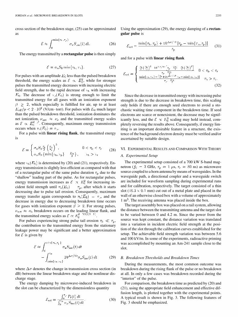
Fig. 3. Breakdown time � versus time derivative of incident electric fielddE=dt. Stars denote experimental data. Curve shows the theoretical modelwith field enhancement and effective diffusion length appropriate for the slotdimensions, calculated for pulse rise time � = 85 ns, and limited by the pulselength � = 1 �s. For breakdown on the rising flank (solid line) and during thepulse interior (dashed line), (20) and (21) have been solved, respectively.
• The points corresponding to breakdown during the risingflank follow the theoretical curve given by (20). Most ofthe points fall slightly above the curve.
• At about V/(m s), the points leave thecurve. This corresponds to , i.e., the transition frombreakdown during the rising flank to breakdown during theinterior of the pulse.
• There is an accumulation of points at s, corre-sponding to the pulses that did not cause breakdown at all.
• A few points fall between the two main regions of points,corresponding to breakdown in the interior of the pulse.
The agreement between the theoretical model and the experi-mental data is not so good for pulses with breakdown duringthe interior of the pulse or no breakdown at all. The reason forthis is the overestimate of the net ionization in the model, stem-ming from the flat interior of the model pulses, as compared tothe tapered off shape of the experimental pulses. This leads toan underestimate of the breakdown times in the model.
The theoretical curve is indeed expected to lie under the mea-sured points since it represents the shortest breakdown time at-tainable with a given pulse, assuming the existence of a finitebackground density of electrons from which to start the break-down avalanche.
C. Transmission Cross Sections
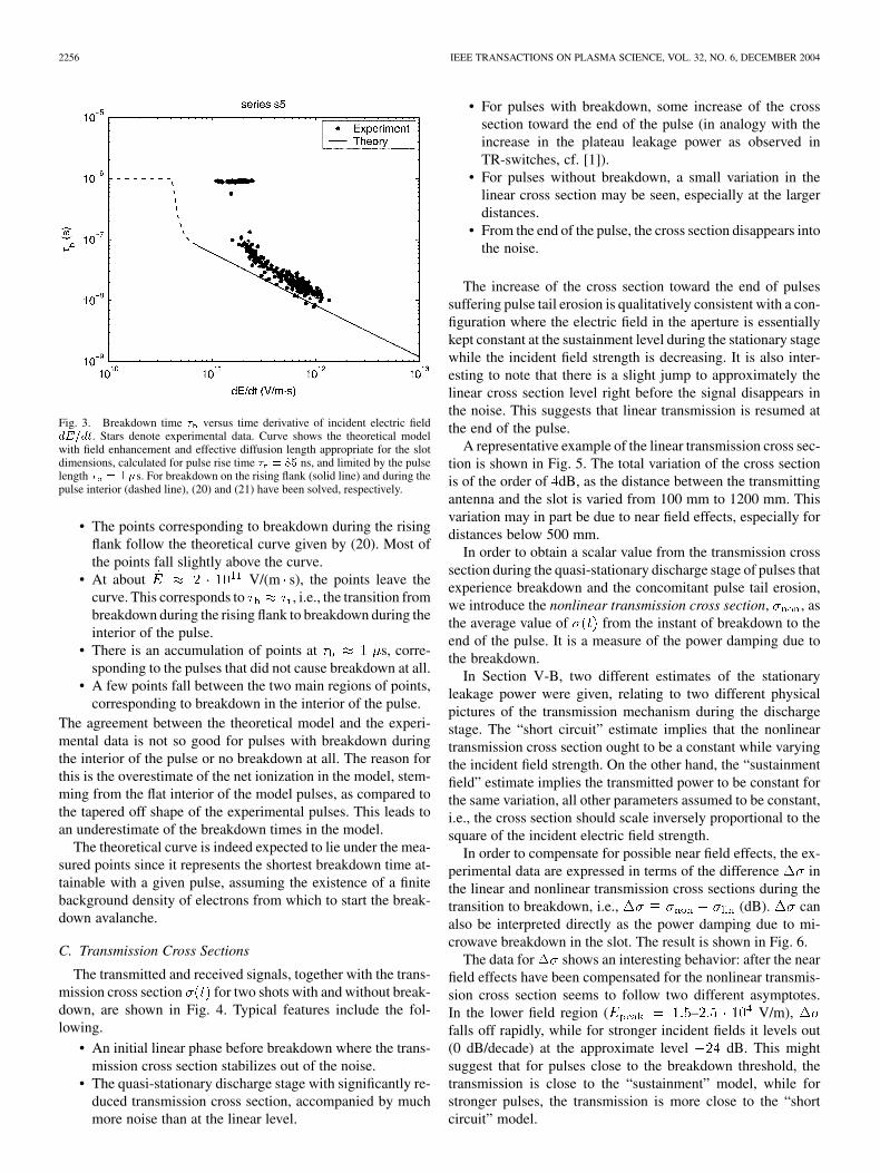
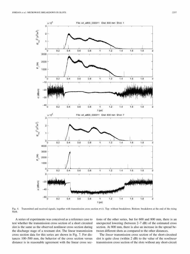
The transmitted and received signals, together with the trans-mission cross section for two shots with and without break-down, are shown in Fig. 4. Typical features include the fol-lowing.
• An initial linear phase before breakdown where the trans-mission cross section stabilizes out of the noise.
• The quasi-stationary discharge stage with significantly re-duced transmission cross section, accompanied by muchmore noise than at the linear level.
• For pulses with breakdown, some increase of the crosssection toward the end of the pulse (in analogy with theincrease in the plateau leakage power as observed inTR-switches, cf. [1]).
• For pulses without breakdown, a small variation in thelinear cross section may be seen, especially at the largerdistances.
• From the end of the pulse, the cross section disappears intothe noise.
The increase of the cross section toward the end of pulsessuffering pulse tail erosion is qualitatively consistent with a con-figuration where the electric field in the aperture is essentiallykept constant at the sustainment level during the stationary stagewhile the incident field strength is decreasing. It is also inter-esting to note that there is a slight jump to approximately thelinear cross section level right before the signal disappears inthe noise. This suggests that linear transmission is resumed atthe end of the pulse.
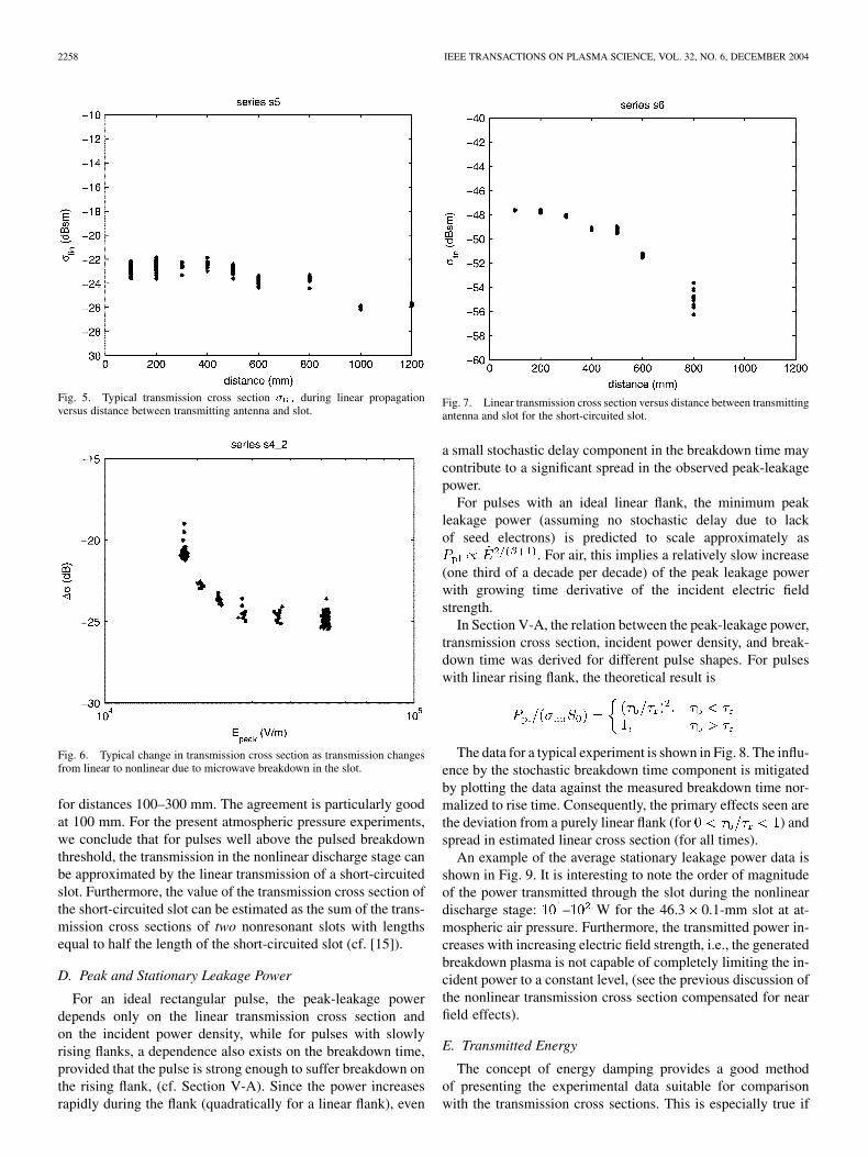
A representative example of the linear transmission cross sec-tion is shown in Fig. 5. The total variation of the cross sectionis of the order of dB, as the distance between the transmittingantenna and the slot is varied from 100 mm to 1200 mm. Thisvariation may in part be due to near field effects, especially fordistances below 500 mm.
In order to obtain a scalar value from the transmission crosssection during the quasi-stationary discharge stage of pulses thatexperience breakdown and the concomitant pulse tail erosion,we introduce the nonlinear transmission cross section, , asthe average value of from the instant of breakdown to theend of the pulse. It is a measure of the power damping due tothe breakdown.
In Section V-B, two different estimates of the stationaryleakage power were given, relating to two different physicalpictures of the transmission mechanism during the dischargestage. The “short circuit” estimate implies that the nonlineartransmission cross section ought to be a constant while varyingthe incident field strength. On the other hand, the “sustainmentfield” estimate implies the transmitted power to be constant forthe same variation, all other parameters assumed to be constant,i.e., the cross section should scale inversely proportional to thesquare of the incident electric field strength.
In order to compensate for possible near field effects, the ex-perimental data are expressed in terms of the difference inthe linear and nonlinear transmission cross sections during thetransition to breakdown, i.e., (dB). canalso be interpreted directly as the power damping due to mi-crowave breakdown in the slot. The result is shown in Fig. 6.
The data for shows an interesting behavior: after the nearfield effects have been compensated for the nonlinear transmis-sion cross section seems to follow two different asymptotes.In the lower field region ( – V/m),falls off rapidly, while for stronger incident fields it levels out(0 dB/decade) at the approximate level dB. This mightsuggest that for pulses close to the breakdown threshold, thetransmission is close to the “sustainment” model, while forstronger pulses, the transmission is more close to the “shortcircuit” model.
JORDAN et al.: MICROWAVE BREAKDOWN IN SLOTS 2257
Fig. 4. Transmitted and received signals, together with transmission cross section �(t). Top: without breakdown. Bottom: breakdown at the end of the risingflank.
A series of experiments was conceived as a reference case totest whether the transmission cross section of a short circuitedslot is the same as the observed nonlinear cross section duringthe discharge stage of a resonant slot. The linear transmissioncross section data for this series are shown in Fig. 7. For dis-tances 100–500 mm, the behavior of the cross section versusdistance is in reasonable agreement with the linear cross sec-
tions of the other series, but for 600 and 800 mm, there is anunexpected lowering (between 2–7 dB) of the estimated crosssection. At 800 mm, there is also an increase in the spread be-tween different shots as compared to the other distances.
The linear transmission cross section of the short-circuitedslot is quite close (within 2 dB) to the value of the nonlineartransmission cross section of the slots without any short-circuit
2258 IEEE TRANSACTIONS ON PLASMA SCIENCE, VOL. 32, NO. 6, DECEMBER 2004
Fig. 5. Typical transmission cross section � during linear propagationversus distance between transmitting antenna and slot.
Fig. 6. Typical change in transmission cross section as transmission changesfrom linear to nonlinear due to microwave breakdown in the slot.
for distances 100–300 mm. The agreement is particularly goodat 100 mm. For the present atmospheric pressure experiments,we conclude that for pulses well above the pulsed breakdownthreshold, the transmission in the nonlinear discharge stage canbe approximated by the linear transmission of a short-circuitedslot. Furthermore, the value of the transmission cross section ofthe short-circuited slot can be estimated as the sum of the trans-mission cross sections of two nonresonant slots with lengthsequal to half the length of the short-circuited slot (cf. [15]).
D. Peak and Stationary Leakage Power
For an ideal rectangular pulse, the peak-leakage powerdepends only on the linear transmission cross section andon the incident power density, while for pulses with slowlyrising flanks, a dependence also exists on the breakdown time,provided that the pulse is strong enough to suffer breakdown onthe rising flank, (cf. Section V-A). Since the power increasesrapidly during the flank (quadratically for a linear flank), even
Fig. 7. Linear transmission cross section versus distance between transmittingantenna and slot for the short-circuited slot.
a small stochastic delay component in the breakdown time maycontribute to a significant spread in the observed peak-leakagepower.
For pulses with an ideal linear flank, the minimum peakleakage power (assuming no stochastic delay due to lackof seed electrons) is predicted to scale approximately as
. For air, this implies a relatively slow increase(one third of a decade per decade) of the peak leakage powerwith growing time derivative of the incident electric fieldstrength.
In Section V-A, the relation between the peak-leakage power,transmission cross section, incident power density, and break-down time was derived for different pulse shapes. For pulseswith linear rising flank, the theoretical result is
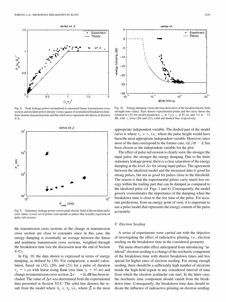
The data for a typical experiment is shown in Fig. 8. The influ-ence by the stochastic breakdown time component is mitigatedby plotting the data against the measured breakdown time nor-malized to rise time. Consequently, the primary effects seen arethe deviation from a purely linear flank (for ) andspread in estimated linear cross section (for all times).
An example of the average stationary leakage power data isshown in Fig. 9. It is interesting to note the order of magnitudeof the power transmitted through the slot during the nonlineardischarge stage: – W for the 46.3 0.1-mm slot at at-mospheric air pressure. Furthermore, the transmitted power in-creases with increasing electric field strength, i.e., the generatedbreakdown plasma is not capable of completely limiting the in-cident power to a constant level, (see the previous discussion ofthe nonlinear transmission cross section compensated for nearfield effects).
E. Transmitted Energy
The concept of energy damping provides a good methodof presenting the experimental data suitable for comparisonwith the transmission cross sections. This is especially true if
JORDAN et al.: MICROWAVE BREAKDOWN IN SLOTS 2259
Fig. 8. Peak leakage power normalized to measured linear transmission crosssection and incident power density versus square of normalized breakdown time.Stars denote measured points and the solid curve represents the theory in SectionV-A.
Fig. 9. Stationary leakage power versus peak electric field of the incident pulse(rms value). Lower set of points corresponds to pulses that actually experiencedpulse tail erosion.
the transmission cross sections or the change in transmissioncross section are close to constants since in this case, theenergy damping is essentially an average between the linearand nonlinear transmission cross sections, weighted throughthe breakdown time (see the discussion near the end of SectionV-C).
In Fig. 10, the data shown is expressed in terms of energydamping, as defined by (30). For comparison, a model calcu-lation, based on (32), (20), and (21) for a pulse of duration
s with linear rising flank (rise time ns) andchange in transmission cross section dB has been in-cluded. The value of was determined from the experimentaldata presented in Section VI-C. The solid line denotes the re-sult from the model where , i.e., where is the most
Fig. 10. Energy damping versus the time derivative of the incident electric fieldstrength (rms value). Stars denote experimental points and the curve shows thesolution to (32) for model parameters � = 1 �s, � = 85 ns, and �� = �24
dB, with � from (20) and (21), solid and dashed line, respectively.
appropriate independent variable. The dashed part of the modelcurve is where , i.e., where the pulse height would havebeen the most appropriate independent variable. However, sincemost of the data correspond to the former case, hasbeen chosen as the independent variable for the plot.
The effect of pulse tail erosion is clearly seen; the stronger theinput pulse, the stronger the energy damping. Due to the finitestationary leakage power, there is a clear saturation of the energydamping at the level for strong input pulses. The agreementbetween the idealized model and the measured data is good forstrong pulses, but not as good for pulses close to the threshold.The reason is that the experimental pulses carry much less en-ergy within the trailing part that can be damped as compared tothe idealized pulse (cf. Figs. 1 and 4). Consequently, the modelgrossly overestimates the importance of the damping when thebreakdown time is close to the rise time of the pulse. For accu-rate predictions, from an energy point of view, it is important touse a pulse model that represents the energy content of the pulseaccurately.
F. Electron Seeding
A series of experiments were carried out with the objectiveof investigating the effect of radioactive priming, i.e., electronseeding on the breakdown time in the considered geometry.
The main observable effect anticipated from introducing “ar-tificial” electron seeding is a change of the stochastic componentof the breakdown time with shorter breakdown times and lessspread for higher rates of electron seeding. For strong enoughseeding, there should be a sufficiently high number of electronsinside the high-field region in any considered interval of timefrom which the electron avalanche can start. In the latter case,the stochastic time component should vanish from the break-down time. Consequently, the breakdown time data should in-dicate the influence of radioactive priming on electron seeding.
2260 IEEE TRANSACTIONS ON PLASMA SCIENCE, VOL. 32, NO. 6, DECEMBER 2004
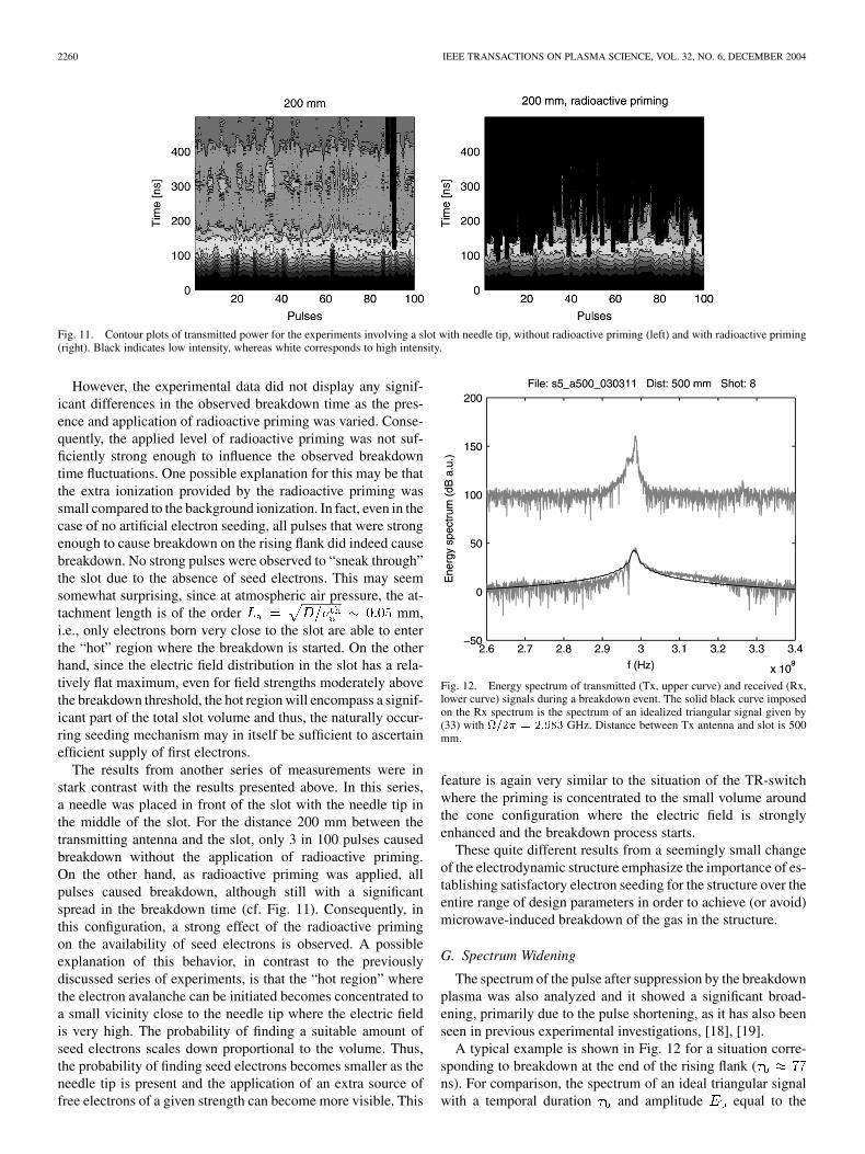
Fig. 11. Contour plots of transmitted power for the experiments involving a slot with needle tip, without radioactive priming (left) and with radioactive priming(right). Black indicates low intensity, whereas white corresponds to high intensity.
However, the experimental data did not display any signif-icant differences in the observed breakdown time as the pres-ence and application of radioactive priming was varied. Conse-quently, the applied level of radioactive priming was not suf-ficiently strong enough to influence the observed breakdowntime fluctuations. One possible explanation for this may be thatthe extra ionization provided by the radioactive priming wassmall compared to the background ionization. In fact, even in thecase of no artificial electron seeding, all pulses that were strongenough to cause breakdown on the rising flank did indeed causebreakdown. No strong pulses were observed to “sneak through”the slot due to the absence of seed electrons. This may seemsomewhat surprising, since at atmospheric air pressure, the at-tachment length is of the order mm,i.e., only electrons born very close to the slot are able to enterthe “hot” region where the breakdown is started. On the otherhand, since the electric field distribution in the slot has a rela-tively flat maximum, even for field strengths moderately abovethe breakdown threshold, the hot region will encompass a signif-icant part of the total slot volume and thus, the naturally occur-ring seeding mechanism may in itself be sufficient to ascertainefficient supply of first electrons.
The results from another series of measurements were instark contrast with the results presented above. In this series,a needle was placed in front of the slot with the needle tip inthe middle of the slot. For the distance 200 mm between thetransmitting antenna and the slot, only 3 in 100 pulses causedbreakdown without the application of radioactive priming.On the other hand, as radioactive priming was applied, allpulses caused breakdown, although still with a significantspread in the breakdown time (cf. Fig. 11). Consequently, inthis configuration, a strong effect of the radioactive primingon the availability of seed electrons is observed. A possibleexplanation of this behavior, in contrast to the previouslydiscussed series of experiments, is that the “hot region” wherethe electron avalanche can be initiated becomes concentrated toa small vicinity close to the needle tip where the electric fieldis very high. The probability of finding a suitable amount ofseed electrons scales down proportional to the volume. Thus,the probability of finding seed electrons becomes smaller as theneedle tip is present and the application of an extra source offree electrons of a given strength can become more visible. This
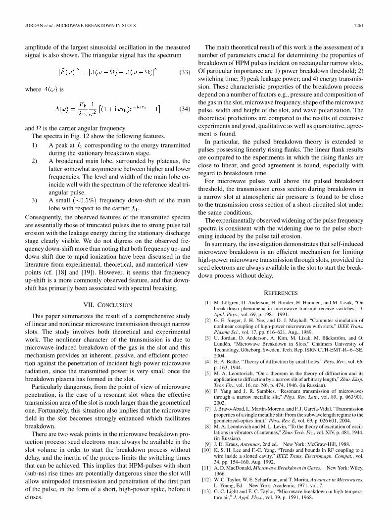
Fig. 12. Energy spectrum of transmitted (Tx, upper curve) and received (Rx,lower curve) signals during a breakdown event. The solid black curve imposedon the Rx spectrum is the spectrum of an idealized triangular signal given by(33) with =2� = 2:983 GHz. Distance between Tx antenna and slot is 500mm.
feature is again very similar to the situation of the TR-switchwhere the priming is concentrated to the small volume aroundthe cone configuration where the electric field is stronglyenhanced and the breakdown process starts.
These quite different results from a seemingly small changeof the electrodynamic structure emphasize the importance of es-tablishing satisfactory electron seeding for the structure over theentire range of design parameters in order to achieve (or avoid)microwave-induced breakdown of the gas in the structure.
G. Spectrum Widening
The spectrum of the pulse after suppression by the breakdownplasma was also analyzed and it showed a significant broad-ening, primarily due to the pulse shortening, as it has also beenseen in previous experimental investigations, [18], [19].
A typical example is shown in Fig. 12 for a situation corre-sponding to breakdown at the end of the rising flank (ns). For comparison, the spectrum of an ideal triangular signalwith a temporal duration and amplitude equal to the
JORDAN et al.: MICROWAVE BREAKDOWN IN SLOTS 2261
amplitude of the largest sinusoidal oscillation in the measuredsignal is also shown. The triangular signal has the spectrum
(33)
where is
(34)
and is the carrier angular frequency.The spectra in Fig. 12 show the following features.
1) A peak at corresponding to the energy transmittedduring the stationary breakdown stage.
2) A broadened main lobe, surrounded by plateaus, thelatter somewhat asymmetric between higher and lowerfrequencies. The level and width of the main lobe co-incide well with the spectrum of the reference ideal tri-angular pulse.
3) A small % frequency down-shift of the mainlobe with respect to the carrier .
Consequently, the observed features of the transmitted spectraare essentially those of truncated pulses due to strong pulse tailerosion with the leakage energy during the stationary dischargestage clearly visible. We do not digress on the observed fre-quency down-shift more than noting that both frequency up- anddown-shift due to rapid ionization have been discussed in theliterature from experimental, theoretical, and numerical view-points (cf. [18] and [19]). However, it seems that frequencyup-shift is a more commonly observed feature, and that down-shift has primarily been associated with spectral breaking.
VII. CONCLUSION
This paper summarizes the result of a comprehensive studyof linear and nonlinear microwave transmission through narrowslots. The study involves both theoretical and experimentalwork. The nonlinear character of the transmission is due tomicrowave-induced breakdown of the gas in the slot and thismechanism provides an inherent, passive, and efficient protec-tion against the penetration of incident high-power microwaveradiation, since the transmitted power is very small once thebreakdown plasma has formed in the slot.
Particularly dangerous, from the point of view of microwavepenetration, is the case of a resonant slot when the effectivetransmission area of the slot is much larger than the geometricalone. Fortunately, this situation also implies that the microwavefield in the slot becomes strongly enhanced which facilitatesbreakdown.
There are two weak points in the microwave breakdown pro-tection process: seed electrons must always be available in theslot volume in order to start the breakdown process withoutdelay, and the inertia of the process limits the switching timesthat can be achieved. This implies that HPM-pulses with short(sub-ns) rise times are potentially dangerous since the slot willallow unimpeded transmission and penetration of the first partof the pulse, in the form of a short, high-power spike, before itcloses.
The main theoretical result of this work is the assessment of anumber of parameters crucial for determining the properties ofbreakdown of HPM pulses incident on rectangular narrow slots.Of particular importance are 1) power breakdown threshold; 2)switching time; 3) peak leakage power; and 4) energy transmis-sion. These characteristic properties of the breakdown processdepend on a number of factors e.g., pressure and composition ofthe gas in the slot, microwave frequency, shape of the microwavepulse, width and height of the slot, and wave polarization. Thetheoretical predictions are compared to the results of extensiveexperiments and good, qualitative as well as quantitative, agree-ment is found.
In particular, the pulsed breakdown theory is extended topulses possessing linearly rising flanks. The linear flank resultsare compared to the experiments in which the rising flanks areclose to linear, and good agreement is found, especially withregard to breakdown time.
For microwave pulses well above the pulsed breakdownthreshold, the transmission cross section during breakdown ina narrow slot at atmospheric air pressure is found to be closeto the transmission cross section of a short-circuited slot underthe same conditions.
The experimentally observed widening of the pulse frequencyspectra is consistent with the widening due to the pulse short-ening induced by the pulse tail erosion.
In summary, the investigation demonstrates that self-inducedmicrowave breakdown is an efficient mechanism for limitinghigh-power microwave transmission through slots, provided theseed electrons are always available in the slot to start the break-down process without delay.
REFERENCES
[1] M. Löfgren, D. Anderson, H. Bonder, H. Hamnen, and M. Lisak, “Onbreak-down phenomena in microwave transmit receive switches,” J.Appl. Phys., vol. 69, p. 1981, 1991.
[2] G. E. Sieger, J. H. Yee, and D. J. Mayhall, “Computer simulation ofnonlinear coupling of high-power microwaves with slots,” IEEE Trans.Plasma Sci., vol. 17, pp. 616–621, Aug., 1989.
[3] U. Jordan, D. Anderson, A. Kim, M. Lisak, M. Bäckström, and O.Lundén, “Microwave Breakdown in Slots,” Chalmers University ofTechnology, Göteborg, Sweden, Tech. Rep. ISRN CTH-EMT-R--6--SE,2004.
[4] H. A. Bethe, “Theory of diffraction by small holes,” Phys. Rev., vol. 66,p. 163, 1944.
[5] M. A. Leontovich, “On a theorem in the theory of diffraction and itsapplication to diffraction by a narrow slit of arbitrary length,” Zhur. Eksp.Teor. Fiz., vol. 16, no. N6, p. 474, 1946. (in Russian).
[6] F. Yang and J. R. Sambles, “Resonant transmission of microwavesthrough a narrow metallic slit,” Phys. Rev. Lett., vol. 89, p. 063 901,2002.
[7] J. Bravo-Abad, L. Martín-Moreno, and F. J. García-Vidal, “Transmissionproperties of a single metallic slit: From the subwavelength regime to thegeometrical-optics limit,” Phys. Rev. E, vol. 69, p. 026 601, 2004.
[8] M. A. Leontovich and M. L. Levin, “To the theory of excitation of oscil-lations in vibrators of antennas,” Zhur. Tech. Fiz., vol. XIV, p. 481, 1944.(in Russian).
[9] J. D. Kraus, Antennas, 2nd ed. New York: McGraw-Hill, 1988.[10] K. S. H. Lee and F.-C. Yang, “Trends and bounds in RF coupling to a
wire inside a slotted cavity,” IEEE Trans. Electromagn. Compat., vol.34, pp. 154–160, Aug. 1992.
[11] A. D. MacDonald, Microwave Breakdown in Gases. New York: Wiley,1966.
[12] W. C. Taylor, W. E. Scharfman, and T. Morita, Advances in Microwaves,L. Young, Ed. New York: Academic, 1971, vol. 7.
[13] G. C. Light and E. C. Taylor, “Microwave breakdown in high-tempera-ture air,” J. Appl. Phys., vol. 39, p. 1591, 1968.
2262 IEEE TRANSACTIONS ON PLASMA SCIENCE, VOL. 32, NO. 6, DECEMBER 2004
[14] W. Woo and J. S. Groot, “Microwave absorption and plasma heating dueto microwave breakdown in the atmosphere,” Phys. Fluids, vol. B3, p.3528, 1991.
[15] T. Martin, M. Bäckström, and J. Lorén, “Transmission cross section ofapertures determined by measurements and FDTD simulations,” in 12thInt. Zurich Symp. Tech. Exhibition Electromagn. Compatibility, Zurich,Switzerland, Feb. 18–20, 1997.
[16] J. T. Mayhan, R. L. Fante, R. O’Keefe, R. Elkin, J. Klugerman, and J.Yos, “Comparison of various microwave breakdown prediction models,”J. Appl. Phys., vol. 42, p. 5362, 1971.
[17] M. Löfgren, D. Anderson, M. Lisak, and L. Lundgren, “Breakdown-induced distortion of high-power microwave pulses in air,” Phys. Fluids,vol. B3, p. 3528, 1991.
[18] S. P. Kuo, A. Ren, and G. Schmidt, “Frequency downshift in rapidlyionizing media,” Phys. Rev. E, vol. 49, p. 3310, 1994.
[19] D. Anderson, A. Kim, M. Lisak, and K. Madsen, “Self-induced ero-sion and spectral breaking of high-power microwave pulses,” J. PlasmaPhys., vol. 63, p. 329, 2000.
Ulf Jordan was born in Storfors, Sweden, in 1974.He received the M.Sc. degree in electrical andelectronic engineering from Chalmers University ofTechnology, Göteborg, Sweden, in 1999, where heis currently working towards the Ph.D. degree.
His main research interests include plasma physicsand microwave breakdown.
Dan Anderson was born in Göteborg, Sweden, in1943. He received the M.S. degree in electrical en-gineering from Chalmers University of Technology,Göteborg, Sweden, in 1969, the B.S. degree in math-ematics and astronomy from the University of Göte-borg, Göteborg, Sweden, in 1971, and the Ph.D. de-gree in electron physics from Chalmers University ofTechnology, Göteborg, Sweden, in 1973.
Since 1973, he has been engaged in research andeducation at Chalmers University, where he is cur-rently a Professor of electromagnetics. His research
and teaching interests covers a broad range of basic aspects and applications ofelectromagnetic theory, e.g., plasma physics with application to fusion energyproduction, nonlinear optics with applications to high speed fiber optical com-munication, microwave discharges with applications to microwave breakdownphenomena, and accelerator physics. He is also engaged in the applied researchof collaborations between Chalmers University and different Swedish high tech-nology industries, and has worked for many years as a part-time consultant forresearch and development work in industry.
Mats Bäckström (M’91) was born in Stockholm,Sweden, on July 27, 1953. He received the M.Sc. de-gree in engineering physics and the Ph.D. degree inphysics from Uppsala University, Uppsala, Sweden,in 1978 and 1985, respectively.
He currently holds the position as Director of Re-search in electromagnetic effects at the Swedish De-fence Research Agency (FOI), Stockholm, Sweden.He is the Project Leader for the FOI projects on HPM(high-power microwaves) protection and system ef-fects. Before he joined FOI, he was head of the elec-
tromagnetic effects group at Saab Military Aircraft, Linköping, Sweden.Dr. Bäckström is Chairman of the Swedish URSI Commission E, Electromag-
netic Noise and Interference. He is Co-Chairman of the URSI working group onIntentional EMI. He has been recognized as an EMP Fellow by the US SummaFoundation. He has been the secretary of the Swedish Chapter of the IEEE EMCSociety.
Arkady V. Kim was born in 1951. He graduated from the Nizhny NovgorodState University, Nizhny Novgorod, Russia, in 1974 and received the Ph.D. de-gree in plasma physics from the Institute of Applied Physics of the RussianAcademy of Sciences (IAP RAS), Nizhny Novgorod, Russia, in 1983.
He began to work at the Radio-Physical Research Institute, Nizhny Novgorod,Russia, in 1974 and he is now a Senior Scientist at the IAP RAS. His researchinterests include nonlinear phenomena with microwave and laser radiation, ul-trafast processes with supershort laser pulses, and superintense laser-plasma in-teractions.
Mietek Lisak was born 1947, in Szczecin, Poland.He studied at the University of Technology, Stettin,Poland, during 1965–1969. He continued his studiesat Chalmers University of Technology, Göteborg,Sweden, during 1970–1972. He received the M.S.degree in electrical engineering and the Ph.D. degreefrom the Institute for Electron Physics, Chalmers,Sweden, in 1972 and 1976, respectively.
Since 1977, he has been with Institute for Elec-tron Physics, Chalmers, Sweden, where he has beenengaged in research and education and where he is
a Professor of electromagnetic field theory and plasma physics. He has beena project leader of national and international projects, and has worked as apart-time research consultant for industry. His research activities cover a broadrange of plasma physics with application to fusion energy production, nonlinearoptics with applications to high-speed fiber optical communication, microwavedischarge physics with applications to microwave phenomena, and acceleratorphysics. He is an author and coauthor of more than 250 papers in internationalscientific journals, and has made more than 100 contributions to scientific con-ferences and symposia, including many invited presentations. He is an authorand coauthor of eight lecture compendia and several popular review reports onthermonuclear fusion and nonlinear optics. He has been supervisor together withProf. Dan Anderson of 35 diploma works for the M.Sc. degree, 18 licentiatetheses, and 15 Ph.D. dissertations.
Dr. Lisak has been the Head of the Swedish Fusion Research Program since1999.
Olof Lundén, photograph and biography not available at the time of publica-tion.
Copyright © 2022 FDOKUMEN