Fire Damage or Equipment Breakdown?
12
ISFI 2010 International Symposium on Fire Investigation Science and Technology 119 FIRE DAMAGE, OR EQUIPMENT BREAKDOWN? Vytenis Babrauskas, Ph.D. Fire Science and Technology Inc., Issaquah WA, USA ABSTRACT Policies for major facilities normally includes both property and boiler & machinery (equipment breakdown) insurance. If two different insurance carriers carry these policies, then a major loss at such a facility may require that the losses be categorized as being property or B&M losses. Guidance for this has not previously been available in the scientific literature. Since B&M coverage is a highly specialized form of coverage, salient features of this type of policy are presented. The paper then discusses the forensic ex- amination of evidence and provides criteria for distinguishing fire damage from damage due to equipment breakdown. Some fundamentals of combustion needed to understand fire damage are also presented. Keywords: boiler and machinery insurance; electrical faults and failures; equipment breakdown insurance; fire damages; fire insurance; fire investigation. INTRODUCTION The purpose of this paper is to consider how scientific principles can be invoked to estab- lish, for the purpose of insurance claims, whether a particular piece of equipment was damaged due to fire, or whether it was equipment breakdown. The problem arises most commonly for ma- jor facilities where the equipment is primarily electrical in nature. Thus, this paper will focus on electrical equipment, although certain principles will also apply to mechanical equipment. The paper is intended not only for fire investigators, but also for forensic scientists or engineers, in- surance adjusters, and attorneys, since all of these professions may have a role in an insurance claims settlement. Consequently, some basics of fire are reviewed to make the concepts under- standable to individuals without a science background. In the investigation of a fire, the origin is to be determined first. If this is successfully done, then the cause should be determined—this involves identifying an ignition source, a fuel, and the cir- cumstances that caused the fuel to be ignited. If the cause has been successfully determined, then the responsibility may be assigned if incendiarism, a defective product, or other circumstances warrant it. When these actions have been completed, the investigation task is finished, unless there are other issues, such the ones that are the focus of the present paper. Recognized treatises describing how to conduct a fire investigation have been published by NFPA 1 and DeHaan 2 . B&M INSURANCE POLICIES In cases of industrial electrical or mechanical equipment, a further issue may arise which can require fire investigation or fire science expertise. It may be incontestable that there was a loss, and it may also be uncontested where the incident originated and how it came to occur. What may, however, be in dispute is the portion of damages that each insurance carrier pays. Businesses often have separate insurance policies for property and for ‘boiler and machinery’ coverage, and different carriers may be carrying these two policies. As the term might suggest, boiler and machinery (B&M) coverage is a type of ‘named peril’ insurance against breakdown of electrical or mechanical equipment. Standard insurance forms published by ISO (Insurance Serv- ices Office; no relation to the International Organization for Standardization which is also re- ferred to as ISO) define B&M policies as covering ‘accidents’ pertaining to certain ‘objects.’ The standard ‘objects’ that are defined are pressure and refrigeration objects; mechanical objects; electrical objects; and turbine objects; along with two meta-objects: ‘comprehensive coverage
-
Upload
independent -
Category
Documents
-
view
5 -
download
0
Transcript of Fire Damage or Equipment Breakdown?
ISFI 2010
International Symposium on Fire Investigation Science and Technology
119
FIRE DAMAGE, OR EQUIPMENT BREAKDOWN?
Vytenis Babrauskas, Ph.D. Fire Science and Technology Inc., Issaquah WA, USA
ABSTRACT Policies for major facilities normally includes both property and boiler & machinery (equipment
breakdown) insurance. If two different insurance carriers carry these policies, then a major loss at such a facility may require that the losses be categorized as being property or B&M losses. Guidance for this has not previously been available in the scientific literature. Since B&M coverage is a highly specialized form of coverage, salient features of this type of policy are presented. The paper then discusses the forensic ex-amination of evidence and provides criteria for distinguishing fire damage from damage due to equipment breakdown. Some fundamentals of combustion needed to understand fire damage are also presented.
Keywords: boiler and machinery insurance; electrical faults and failures; equipment breakdown insurance; fire damages; fire insurance; fire investigation.
INTRODUCTION The purpose of this paper is to consider how scientific principles can be invoked to estab-
lish, for the purpose of insurance claims, whether a particular piece of equipment was damaged due to fire, or whether it was equipment breakdown. The problem arises most commonly for ma-jor facilities where the equipment is primarily electrical in nature. Thus, this paper will focus on electrical equipment, although certain principles will also apply to mechanical equipment. The paper is intended not only for fire investigators, but also for forensic scientists or engineers, in-surance adjusters, and attorneys, since all of these professions may have a role in an insurance claims settlement. Consequently, some basics of fire are reviewed to make the concepts under-standable to individuals without a science background. In the investigation of a fire, the origin is to be determined first. If this is successfully done, then the cause should be determined—this involves identifying an ignition source, a fuel, and the cir-cumstances that caused the fuel to be ignited. If the cause has been successfully determined, then the responsibility may be assigned if incendiarism, a defective product, or other circumstances warrant it. When these actions have been completed, the investigation task is finished, unless there are other issues, such the ones that are the focus of the present paper. Recognized treatises describing how to conduct a fire investigation have been published by NFPA1 and DeHaan2.
B&M INSURANCE POLICIES In cases of industrial electrical or mechanical equipment, a further issue may arise which
can require fire investigation or fire science expertise. It may be incontestable that there was a loss, and it may also be uncontested where the incident originated and how it came to occur. What may, however, be in dispute is the portion of damages that each insurance carrier pays. Businesses often have separate insurance policies for property and for ‘boiler and machinery’ coverage, and different carriers may be carrying these two policies. As the term might suggest, boiler and machinery (B&M) coverage is a type of ‘named peril’ insurance against breakdown of electrical or mechanical equipment. Standard insurance forms published by ISO (Insurance Serv-ices Office; no relation to the International Organization for Standardization which is also re-ferred to as ISO) define B&M policies as covering ‘accidents’ pertaining to certain ‘objects.’ The standard ‘objects’ that are defined are pressure and refrigeration objects; mechanical objects; electrical objects; and turbine objects; along with two meta-objects: ‘comprehensive coverage
120
(excluding production machines),’ and ‘comprehensive coverage (including production ma-chines).’ An ‘accident’ is defined as “A sudden and accidental breakdown of an object or a part of the object. At the time the breakdown occurs, it must manifest itself by physical damage to the object that requires repair or replacement.” Unlike other types of policies, B&M insurance pro-vides that, when an unsafe condition is found, the insurer has the right to immediately suspend the insurance on that object (by giving written notice of the suspension to the insured) until the haz-ard is corrected, after which the suspension can be lifted3. B&M coverage was first offered in 18663 but, because the term ‘boiler and machinery’ appears antiquated, during the course of 2000 – 2006, ISO re-designated such coverage in their standard forms4 as ‘equipment breakdown’ cov-erage, which is more directly connotative.
Named perils The limited nature of the named-perils coverage is made clear by the definition that:
“Breakdown” means the following direct physical loss, that causes damage to a particular com-ponent(s) of “Covered Equipment” and necessitates its repair or replacement:
(1) Failure of pressure or vacuum equipment; (2) Mechanical failure including rupture or bursting caused by centrifugal force; or (3) Electrical failure including arcing
although there are a number of exclusions to these categories, which will not be listed here.
Exclusions It is important to understand that B&M insurance normally excludes fire, fire suppression,
and lightning, and typically pays to repair the damaged component to pre-incident (not new) con-dition. In the latest ISO standard policy form5, used by many U.S. insurance carriers, there are many exclusions, but the following are of interest here:
• Fire or combustion explosion including those that: a. Result in a “Breakdown”; b. Occur at the same time as a “Breakdown”; or c. Ensue from a “Breakdown”.
• An explosion, unless it involves the following equipment a. Steam boiler; b. Electric steam generator; c. Steam piping; d. Steam turbine; e. Steam engine; f. Gas turbine; or g. Moving or rotating machinery when such explosion is caused by centrifugal force or mechanical breakdown.
• Water or other means used to extinguish a fire, even when the attempt is unsuccessful. Thus, in an major loss where both B&M and property (fire) insurance coverages exist, but have been provided by two different carriers, it becomes important to determine what exactly damaged the equipment. In any one incident, there may be both fire and B&M losses, and professional ex-pertise may be needed in order to assess precisely which of the assured’s expenses were due to fire, and which due to equipment breakdown.
SOME IMPORTANT DEFINITIONS The ISO policy form does not contradict established science, but it is not in itself a trea-
tise on fire safety science, materials science, or fire investigation. Thus, established science prin-ciples have to be used to establish what was the physical event that damaged a particular item—fire or equipment breakdown.

ISFI 2010
International Symposium on Fire Investigation Science and Technology
121
To start, it is essential that definitions be properly understood. Fire is defined6 as “uncontrolled combustion”. Controlled combustion takes place in an appliance such as a furnace, burner, etc.; by contrast, uncontrolled combustion does not take place in an appliance made for this purpose. Most instances of fire are accidental, natural (e.g., due to a lightning strike), or incendiary (of or pertaining to the criminal setting on fire of property). But some instances of uncontrolled com-bustion are purposive, yet not classed as incendiary. Here examples would include burn piles and farmers burning fields. Combustion is defined6 as “A self-sustained, high-temperature oxidation reaction.” Oxidation is a chemistry term which has had a history of change. Originally, it simply meant reaction of a substance with oxygen. But eventually the concept became expanded, so that current-day chemistry defines6 it as “A chemical reaction in which a compound or a radical loses electrons.” The opposite reaction, in which electrons are gained, is called ‘reduction.’ But for one compound to gain an electron, another must lose one, so both proceed simultaneously and the overall process is referred to as ‘redox reactions.’ To have a fire, of course, requires that the fire triangle be met, that is, that there be an oxidizer, a fuel, and a source of heat. In almost any accident, air will serve as the oxidizer, so its presence is generally expected. Fuels can be anything that can be oxidized by the existing oxidizer, and there can be both exotic oxidizers and exotic fuels. But for accidents involving electrical facilities, the primary fuel that can be expected to play a role is electrical insulation. Electrical insulators can be gases, liquids, or solids. Gases will generally not be fuels; these may include air, nitrogen, or SF6. The main liquid of interest is transformer fluid, and these are fuels, although some are better fuels than others. The primary solid insulators of interest are plastics. A fire will not exist, if any of the three legs of the fire triangle are removed. Consequently, a fire can be extinguished by: (a) burning the fuel out, or (b) putting foam on it (keeps oxygen out), or (c) pouring water on it (removes heat). Heat is needed initially to ignite the fire, and the source of heat can be anything which brings the fuel to its ignition temperature. After the fire is ignited, ‘chain reactions’ take place which allow the combustion process to continue. Because chain reac-tions are needed for fire to continue, some specific chemicals can be applied which interfere with the chain reaction process and, thus, these substances can extinguish the fire. Due to this fact, in modern usage the fire triangle concept is sometimes expanded to a ‘fire tetrahedron,’ where a fourth leg comprising ‘propagating chain reactions’ is specified to be necessary. In considering fuels, it is important to realize that most solids do not burn as a solid material. The only way that burning of them can take place is that the solid material (e.g., plastic wire insula-tion) will vaporize first, then it is these vapors which actually burn. Pyrolysis is the technical term for the process whereby these vapors are produced from the solid material. The term ‘pyrolysis’ is important to understand since its definition is slightly different in chemistry, versus fire safety science. In chemistry, pyrolysis is defined as the degradation of a material due to heat, in the ab-sence of oxygen. In fire safety science, however, pyrolysis is defined6 as “The chemical degrada-tion of a substance by the action of heat.” Thus, the crucial distinction is that, in fire safety sci-ence, pyrolysis may take place in presence of oxygen (and usually does). When chemists need to invoke this concept, they refer to ‘oxidative pyrolysis.’
TEMPERATURES IN FIRES AND IN ELECTRICAL ARCS As a context for understanding the role of temperatures, it is important to consider the
range of ignition temperatures for combustible materials (‘fuels’) that will be encountered. The actual temperature will depend on the specific material and even on the measurement technique used. But it is useful to consider that there are few substances which ignite below 200ºC (392ºF) and likewise few that require more than 600ºC (1112ºF) to ignite. In fact, the bulk of combustible materials show autoignition (AIT) temperatures in the 250 – 500ºC (482 – 932ºF) range. For wire
122
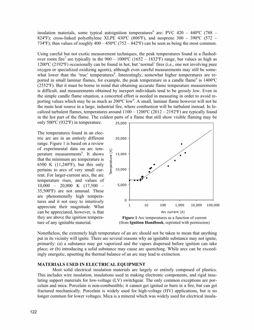
insulation materials, some typical autoignition temperatures6 are: PVC 420 – 440ºC (788 – 824ºF); cross-linked polyethylene XLPE 430ºC (806ºF), and neoprene 300 – 390ºC (572 – 734ºF); thus values of roughly 400 – 450ºC (752 – 842ºF) can be seen as being the most common. Using careful but not exotic measurement techniques, the peak temperatures found in a flashed-over room fire7 are typically in the 900 – 1000ºC (1652 – 1832ºF) range, but values as high as 1200ºC (2192ºF) occasionally can be found in hot, but ‘normal’ fires (i.e., one not involving pure oxygen or specialized oxidizing agents), although even careful measurements may still be some-what lower than the ‘true’ temperatures8. Interestingly, somewhat higher temperatures are re-ported in small laminar flames, for example, the peak temperature in a candle flame6 is 1400ºC (2552ºF). But it must be borne in mind that obtaining accurate flame temperature measurements is difficult, and measurements obtained by inexpert individuals tend to be grossly low. Even in the simple candle flame situation, a concerted effort is needed in measuring in order to avoid re-porting values which may be as much as 200ºC low9. A small, laminar flame however will not be the main heat source in a large, industrial fire, where combustion will be turbulent instead. In lo-calized turbulent flames, temperatures around 1100 – 1200ºC (2012 – 2192ºF) are typically found in the hot part of the flame. The coldest parts of a flame that still show visible flaming may be only 500ºC (932ºF) in temperature. The temperatures found in an elec-tric arc are in an entirely different range. Figure 1 is based on a review of experimental data on arc tem-perature measurements6. It shows that the minimum arc temperature is 6500 K (11,240ºF), but this only pertains to arcs of very small cur-rent. For larger-current arcs, the arc temperature rises, and values of 10,000 – 20,000 K (17,500 – 35,500ºF) are not unusual. These are phenomenally high tempera-tures and it not easy to intuitively appreciate their magnitude. What can be appreciated, however, is that they are above the ignition tempera-ture of any ignitable material. Nonetheless, the extremely high temperature of an arc should not be taken to mean that anything put in its vicinity will ignite. There are several reasons why an ignitable substance may not ignite, primarily: (a) a substance may get vaporized and the vapors dispersed before ignition can take place; or (b) introducing a solid substance may cause arc quenching. While arcs can be exceed-ingly energetic, upsetting the thermal balance of an arc may lead to extinction.
MATERIALS USED IN ELECTRICAL EQUIPMENT Most solid electrical insulation materials are largely or entirely composed of plastics.
This includes wire insulation, insulations used in making electronic components, and rigid insu-lating support materials for low-voltage (LV) switchgear. The only common exceptions are por-celain and mica. Porcelain is non-combustible; it cannot get ignited or burn in a fire, but can get fractured mechanically. Porcelain is widely used for high-voltage (HV) applications, but is no longer common for lower voltages. Mica is a mineral which was widely used for electrical insula-
Figure 1 Arc temperatures as a function of current
(from Ignition Handbook, reprinted with permission)
ISFI 2010
International Symposium on Fire Investigation Science and Technology
123
tion purposes, but is now used only sporadically. Mica also does not ignite or melt in a fire. All plastics can ignite and burn, under the right circumstances. Plastics are grouped into two catego-ries: thermoplastics and thermosets. Thermoplastics can melt and, in some cases, molten flaming drops can fall. However, molten material is viscous and not water-like. Thermosets do not melt or flow, but char and burn in place. Electrical wiring conductors are mostly made from copper (for smaller-gauge wiring) or from aluminum (commonly used in high-current applications). Steel is a much poorer conductor of electricity, but is predominantly used for making cabinets, housings, enclosures, and similar items which need structural strength; it is also found as the central core of some conductors used for overhead lines. Pure copper melts at 1085ºC (1985ºF), and copper used in wiring is essentially pure copper. Pure aluminum melts at 660ºC (1220ºF) while aluminum alloy 1350, widely used for electrical con-ductors melts at 648ºC (1198ºF), but many other aluminum alloys used in the electrical industry have lower melting points, often around 600ºC (1112ºF). The melting point of steel will depend on the type of steel, but can be assumed to be roughly 1500ºC (2700ºF). Solders of course are intended to melt at a low temperature. Traditional solder was tin/lead and, if in a 60/40 propor-tion, melts at around 183 – 190ºC (326 – 374ºF). Due to environmental concerns, lead-free com-positions are increasingly used. These are commonly tin/silver/copper alloys and melt at around 220ºC (428ºF). But a very wide array of specialized solders is available, including ones that melt at higher temperatures. Another low-melting-point material often found in electrical equipment is ‘pot metal.’ This is a non-specific term, but generally refers to alloys with a dominant component of zinc and a melting point in the 350 – 400ºC (662 – 752ºF) range. Brass (copper/zinc alloy) is often used in small electrical parts, with a 70/30 grade having a melting point around 955ºC (1751ºF).
DAMAGES DUE TO FIRE
Heat All organic materials (e.g., plastics, insulating liquids, etc.) that are in the vicinity of
flames can be expected to be fully or partly burned up. Anywhere in the vicinity of flames, alu-minum components are likely to be found melted out, since the melting point of aluminum is so low. Solder or pot metal will not need flame temperatures to melt out, since overheating alone can suffice for this. Steel will not melt in normal fires. However, even stainless steel will be economi-cally destroyed in fire, due to metallurgical changes induced by high temperatures. A material that is of great interest in electrical fires is copper. The melting point of copper is within the range of fire temperatures, so a person might surmise that copper will generally be melted. This turns out not to be the case. What is crucial to keep in mind is that, for a material to melt, the tempera-ture of the metal must reach or exceed the melting point value, not the temperature of the sur-rounding gases or flames. But copper has high thermal conductivity and a high density, thus, it will take a while for a copper item placed in flames to heat up to a temperature even close to the flame temperature, and the process will take longer, the thicker the piece of copper. Thus, in ac-tual fact, fire-melted copper is only occasionally found in fires. Fine-gauge stranded copper con-ductors often ‘disappear’ in a fire, but this is due to rapid corrosion than due to actual melting. When such copper strands get corroded, they typically crumble into a powder which appears dust-like in nature.
Smoke, soot and corrosion damage Organic materials, such as plastics, burn in a fire, but they do not burn up simply to CO2
and H2O. Apart from these main combustion products, a number of other combustion products can be found, the primary one of interest here being soot. Thus, soot residues will typically be
124
found coating surfaces nearby where a fire took place. At the hottest parts where flaming took place, there will generally be less soot, since combustion is more complete there, and there may be a clean burn10. When the temperature is sufficiently high, soot that is formed on surfaces can burn up, with the consequence that the surface will not present a sooty appearance after the fire. The temperature beyond which clean burn may be expected has been found to be approximately 700ºC in the course large-scale fire testing11. For the present purposes, it is important to distin-guish smoke and soot. ‘Smoke’ is defined by ASTM12 as: “The airborne solid and liquid particu-lates and gases evolved when a material undergoes pyrolysis or combustion.” This is an exceed-ingly broad definition, and many scientists do not consider that lumping gaseous products into ‘smoke’ is an ideal definition. Nonetheless, it is clear that creating ‘smoke’ is not a uniquely lim-ited to fires, since pyrolysis does not need to be accompanied by fire, even though it sometimes is. ‘Soot’ is not defined by ASTM but it is defined by the International Organization for Stan-dardization13 as: “Particulate matter produced and deposited during or after combustion.” This makes it clear that soot is only a product of combustion and is not created by other mechanisms. Thus, all soot is smoke, but not all smoke is soot. For the present purposes, it becomes important to consider the chemical nature of soot, versus the type of smoke that can be produced in incidents that do not involve fire. If a plastic is overheated, the chemical structure of the polymer begins to break down. This primarily manifests itself as small particles breaking off the material and becoming airborne. Visibly, such particles initially impart a hazy look to the air into which they are lofted. With greater accumulation, one then per-ceives a white or light grey smoke. When such pyrolysis products land on surfaces, they typically form a sticky coating which is yellow, orange, or brown in color. The particles are sticky since the majority of them are high molecular weight liquids, which tend to feel sticky or gel-like. If the material ignites and burns, then something else happens. Most of these pyrolysis aerosol products are consumed in the flames and do not emerge and become visible. But the process of combustion itself is never ideal, and both soot and minor species of gaseous components are pro-duced. The soot particles start out as small clusters of carbon atoms, but soon grow until they be-come particles of distinctly visible size. Thus, soot particles consist simply of atoms of carbon, assembled into a large cluster. Soot particles are solids and not liquids, and feel similar to pow-dered graphite. By contrast, pyrolysis aerosols are mainly chunks of the original polymer, thus they will contain not only carbon, but also hydrogen and possibly other atoms which might be present in the polymer. Soot particles are black in color. Thus, if what is taking place is a fire and not simply overheating of the material, the smoke that is seen will be black, or dark grey if the soot concentration is low. If chemical analysis were to be done (which is rarely needed), it would be shown that soot particles are nearly wholly carbon, while pyrolysis aerosols have a sizable fraction of other elements. Concerning burning of plastics, in the fire safety science profession, it is accepted that a fire in-volving a plastic material necessarily goes through four stages14,15,16: (1) heating, (2) decomposi-tion (pyrolysis) of the plastic, (3) ignition, and (4) combustion. Thus, it is essential to note that decomposition of the plastic is an essential, integral part of a plastics fire. Note however, that if a plastic goes through stages 1 and 2, but does not proceed to stage 3 and 4, then there is no fire. An event of this type will happen if a moderate electrical overload is sustained which is enough to damage insulation, but not enough to ignite it. Such losses are of course properly categorized as equipment breakdown and not as fire. As explained above, the pyrolysis residues of a plastic are generally recognized as a yel-low/orange/brown colored sticky residue. Such pyrolysate material can be generated by anything that overheats the plastic. If this is an electrical event which does not lead to fire, then overheat

ISFI 2010
International Symposium on Fire Investigation Science and Technology
125
conditions will liberate these pyrolysate aerosols, but they will not ignite and burn. Consequently, they will stay and a portion of them will eventually get deposited onto nearby surfaces. If, on the other hand, an active fire occurs, the pyrolysates will be lofted into the flames and will be burned, producing soot, CO2, H2O, and some additional gaseous products as the outcome of the combus-tion. But there is also a third possibility: a fire occurs, but it is inefficient. This can be due to a shortage of oxygen, characteristics of the fuel which make it not prone to spread flame, or any of various ways by which heat can be extracted from the fire, e.g., presence of refrigerant tubing. In the case of such an inefficient fire, the normal products of combustion will be produced, but there be a substantive fraction of the pyrolysates which is unable to get burned. Thus, presence of such a sticky residue is not a unique identifier of what happened. In some cases, however, it can be possible to use other evidence to arrive at a conclusion. For example, if the environment was well-ventilated and there were no factors that could lead to anomalous extraction of heat, an inef-ficient fire is not a logical conclusion, and it is more appropriate to conclude that an electrical malfunction was the cause of this pyrolysis. The decomposition process of a plastic progressively releases vapors and aerosols into the air. Plastics vary in the way that the residual solid plastic looks like, but for many plastics, a black, charry residue is the outcome if burning has progressed for a sufficiently long time. To create this black, charry residue in place of the original plastic requires prolonged exposure to high tempera-tures. In theory, such residues could be produced solely by electrical heating. But if the material is an environment where oxygen is present and it is exposed to these high temperatures, then igni-tion will normally occur. Thus, it is uncommon that black, charry residues will be recovered from an incident scene and the creation of these residues will not have involved combustion. The ex-ceptions are environments where oxygen was absent, or events where the overheating event was severe, yet very brief, so that there was not sufficient time to achieve ignition. PVC is a specialized plastic commonly used for electrical insulation purposes. It has the charac-teristic that early on in its pyrolysis it tends to produce hydrogen chloride (HCl, hydrochloric acid) and only later does it produce carbon-containing chemical species. HCl is neither a fuel nor an oxidant, but it does affect combustion reactions due to its interference with the chain propaga-tion process. Even if there is no PVC, in a fire there are often other constituents that leave an acidic residue. Acidic residues can be destructive to electronics, although professional cleaning can restore certain items under some conditions.
Firefighting damage Additional damages can be expected in a fire due to firefighting. These may include: (a)
water-logging; (b) mechanical force damage, e.g., from the force of a hose stream; (c) enhanced corrosion, due to depositing of water; (d) if firefighting foams are used, these can corrode some substances; and finally, (e) firefighters may need to manually destroy some objects, such as bat-tering doors down.
DAMAGES DUE TO EQUIPMENT BREAKDOWN In general, non-fire-related damage in electrical equipment is primarily due to: • Mechanical breakage • Arcing, or • Overload.
Note that ‘short-circuits’ are not a damage category separate from the above. Short-circuits are of two types: bolted shorts, and arcing shorts. In a bolted short, by definition, there is no arcing. But overload currents will be present and can readily lead to damage. An arcing short will produce arcing damage, much like any other arcing fault. Apart from the list above, an important fire cause is poor or overheating connections17. By itself, poor connections will rarely lead to an in-
126
surance claim, since the actual damage will necessarily be confined to a very small locale. How-ever, an overheating connection can lead to a fire or a major electrical disturbance, and either of such losses could be claimable.
Arcing Normally, air is an insulator, but under certain circumstances, the insulating properties of air
can ‘break down.’ The three common ways of doing this are: 1. With a fixed spacing between two conductors (‘electrodes’), raise the voltage suffi-
ciently. 2. Bring two conductors together, then separate them (called a ‘break arc’). 3. Put a flame (or some other conductive material) into the air space between two conduc-
tors. Under normal conditions, it requires tremendous voltages to cause the breakdown of air. For ex-ample, a voltage of 1000 Vpeak will cause a breakdown if the gap between the conductors is 0.1 mm or smaller. This, of course, is a very small distance. For a breakdown to occur across 75 mm (3 inches) requires 200,000 volts. The voltage-distance relationship required for breakdown is called Paschen’s Law and its values are extensively tabulated6. But, under some circumstances, it becomes easy for breakdown to occur over gaps of even large distances yet without needing high voltages. The primary way is to introduce hot, ionized gases from a pre-existing arc. For some reason, a breakdown may occur in a busbar between two phases, or between one phase and ground. This will generate hot, ionized gases. If such gases then travel to a point where they are interspersed between two other phases, breakdown may also occur there, creating an ‘escalating fault.’ Breakdown may also be caused by flames, since flames create hot, ionized gases. If those gases flow in an air space which is required to be an insulator, the breakdown strength of the air can drop to a negligible value.
Overload Any flow of electric current in a conductor causes the heating of the conductor according
to Ohm’s Law. Cables should normally be sized and designed so that this heating is acceptable for whatever material serves as the insulator. For a plastic-insulated conductor, a modest overload will cause some degradation of the plastic, but no arcing or fire. Severe overload will result in the ignition of the plastic, causing a fire. Experimental studies have shown6 that, for short-term con-ditions, a current of 300% to 700% of the rated current-carrying capacity (‘ampacity’) has to be flowing for ignition to occur due an overload. This pertains to wiring in the open air. Cables di-rectly buried in the earth will not ignite, due to an absence of oxygen. But a severe overload of a buried cable may progress to arcing if, for example, the insulation melts and the conductors make contact.
DAMAGE CHARACTERISTICS
Heat damages Documenting ‘heat damage’ does not establish what the causative mechanism was. Fire,
arcing, and overloads all produce, among other things, heat damage. Thus, more consideration needs to be given to studying the details of the actual damage, as explained below.
Arcing damages The main arcing damages are holes in steel equipment and arc-melted copper items.
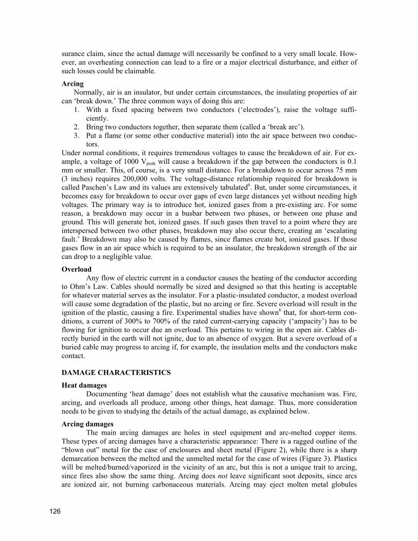
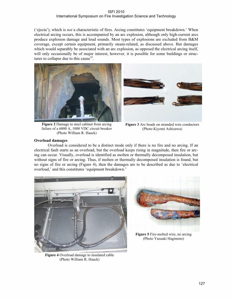
These types of arcing damages have a characteristic appearance: There is a ragged outline of the “blown out” metal for the case of enclosures and sheet metal (Figure 2), while there is a sharp demarcation between the melted and the unmelted metal for the case of wires (Figure 3). Plastics will be melted/burned/vaporized in the vicinity of an arc, but this is not a unique trait to arcing, since fires also show the same thing. Arcing does not leave significant soot deposits, since arcs are ionized air, not burning carbonaceous materials. Arcing may eject molten metal globules
ISFI 2010
International Symposium on Fire Investigation Science and Technology
127
(‘ejecta’), which is not a characteristic of fires. Arcing constitutes ‘equipment breakdown.’ When electrical arcing occurs, this is accompanied by an arc explosion, although only high-current arcs produce explosion damage and loud sounds. Most types of explosions are excluded from B&M coverage, except certain equipment, primarily steam-related, as discussed above. But damages which would separably be associated with an arc explosion, as opposed the electrical arcing itself, will only occasionally be of major interest, however, it is possible for some buildings or struc-tures to collapse due to this cause18.
Figure 2 Damage to steel cabinet from arcing failure of a 6000 A, 1000 VDC circuit breaker
(Photo William R. Haack)
Figure 3 Arc beads on stranded wire conductors
(Photo Kiyomi Ashizawa)
Overload damages Overload is considered to be a distinct mode only if there is no fire and no arcing. If an
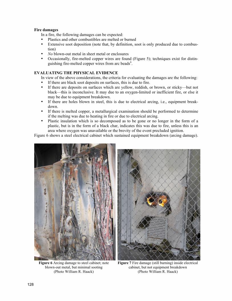
electrical fault starts as an overload, but the overload keeps rising in magnitude, then fire or arc-ing can occur. Visually, overload is identified as molten or thermally decomposed insulation, but without signs of fire or arcing. Thus, if molten or thermally decomposed insulation is found, but no signs of fire or arcing (Figure 4), then the damages are to be described as due to ‘electrical overload,’ and this constitutes ‘equipment breakdown.’
Figure 4 Overload damage to insulated cable
(Photo William R. Haack)
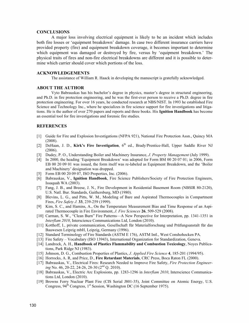
Figure 5 Fire-melted wire, no arcing
(Photo Yasuaki Hagimoto)
128
Fire damages In a fire, the following damages can be expected: • Plastics and other combustibles are melted or burned • Extensive soot deposition (note that, by definition, soot is only produced due to combus-
tion) • No blown-out metal in sheet metal or enclosures • Occasionally, fire-melted copper wires are found (Figure 5); techniques exist for distin-
guishing fire-melted copper wires from arc beads6.
EVALUATING THE PHYSICAL EVIDENCE In view of the above considerations, the criteria for evaluating the damages are the following: • If there are black soot deposits on surfaces, this is due to fire. • If there are deposits on surfaces which are yellow, reddish, or brown, or sticky—but not
black—this is inconclusive. It may due to an oxygen-limited or inefficient fire, or else it may be due to equipment breakdown.
• If there are holes blown in steel, this is due to electrical arcing, i.e., equipment break-down.
• If there is melted copper, a metallurgical examination should be performed to determine if the melting was due to heating in fire or due to electrical arcing.
• Plastic insulation which is so decomposed as to be gone or no longer in the form of a plastic, but is in the form of a black char, indicates this was due to fire, unless this is an area where oxygen was unavailable or the brevity of the event precluded ignition.
Figure 6 shows a steel electrical cabinet which sustained equipment breakdown (arcing damage).
Figure 6 Arcing damage to steel cabinet; note
blown-out metal, but minimal sooting (Photo William R. Haack)
Figure 7 Fire damage (still burning) inside electrical
cabinet, but not equipment breakdown (Photo William R. Haack)

ISFI 2010
International Symposium on Fire Investigation Science and Technology
129
A large blown-out hole can be seen, but there is minimal sooting and essentially none inside the enclosure. By contrast, Figure 7 shows fire actively burning inside an electrical enclosure, but not equipment breakdown. Some additional points need to be kept in mind with assignment of damages into categories.
(1) Electrical equipment will occasionally, but very rarely, be subjected to fire where the fire originated due to wholly non-electrical causes. Perhaps the most famous example is the Browns Ferry Nuclear Power Plant fire of 22 March 1975. This fire originated due to a worker using a lit candle to detect small air flows and led to a crucial cable installation catching fire and the plant suffering serious damages19. In most cases, however, fires in electrical installations occur due to electrical faults or failures. But the electrical fault leading to an initial fire may, by itself, have caused only trivial damage. In such cases, the loss may be wholly assignable to effects of fire, if the replacement costs for the initially damaged electrical equipment are insignificant.
(2) In some cases, the same equipment may sustain both equipment breakdown (e.g., electri-cal arcing) and fire damage, with both types of damages being serious (Figure 8). Thus, not all damaged equipment can be uniquely categorized as being either equipment break-down or fire damage.
DISCUSSION It has occasionally been argued that a loss
already becomes a B&M/equipment breakdown loss as soon as insulation materials start to de-grade, since their functionality is destroyed at that point. This point of view does not correctly recog-nize the nature of the combustion of plastics. As explained above, decomposition of plastics is an integral step in the combustion of plastics and cannot be excluded from the fire process. Such a point of view would also be illogical since it would make ineffective the explicit exclusion of fire coverage in B&M policies, since every fire involving a plastic material would automatically be a B&M loss. No Court has accepted such a rea-soning. It has also sometimes been argued that, if the elec-trical power supply is disconnected and burning stops at that point, that this demonstrates that the event was equipment breakdown and not fire. This is based on the incorrect assumption that all fires must be self-supporting and not require a contin-ued external energy source in order to keep on burning. In actual fact, there are various combusti-ble materials which may burn only if augmented by an external source of heat6. The source of heat does not need to be electrical and could be, for example, a kerosene heater.
Figure 8 Equipment cabinet showing serious
damage both due to arcing (blown holes in metal) and fire (soot deposits). Photo William R. Haack
130
CONCLUSIONS A major loss involving electrical equipment is likely to be an incident which includes
both fire losses or ‘equipment breakdown’ damage. In case two different insurance carriers have provided property (fire) and equipment breakdown coverage, it becomes important to determine which equipment was damaged or destroyed by fire, versus by ‘equipment breakdown.’ The physical traits of fires and non-fire electrical breakdowns are different and it is possible to deter-mine which carrier should cover which portions of the loss.
ACKNOWLEDGEMENTS The assistance of William R. Haack in developing the manuscript is gratefully acknowledged.
ABOUT THE AUTHOR Vyto Babrauskas has his bachelor’s degree in physics, master’s degree in structural engineering, and Ph.D. in fire protection engineering, and he was the first-ever person to receive a Ph.D. degree in fire protection engineering. For over 16 years, he conducted research at NBS/NIST. In 1993 he established Fire Science and Technology Inc., where he specializes in fire science support for fire investigations and litiga-tions. He is the author of over 270 papers and reports and three books. His Ignition Handbook has become an essential tool for fire investigations and forensic fire studies.
REFERENCES [1] Guide for Fire and Explosion Investigations (NFPA 921), National Fire Protection Assn., Quincy MA
(2008). [2] DeHaan, J. D., Kirk’s Fire Investigation, 6th ed., Brady/Prentice-Hall, Upper Saddle River NJ
(2006). [3] Dudey, P. O., Understanding Boiler and Machinery Insurance, J. Property Management (July 1999). [4] In 2000, the heading ‘Equipment Breakdown’ was adopted for Form BM 00 20 07 01; in 2006, Form
EB 00 20 09 01 was issued, the form itself was re-labeled as Equipment Breakdown, and the ‘Boiler and Machinery’ designation was dropped.
[5] Form EB 00 20 09 07, ISO Properties, Inc. (2006). [6] Babrauskas, V., Ignition Handbook, Fire Science Publishers/Society of Fire Protection Engineers,
Issaquah WA (2003). [7] Fang, J. B., and Breese, J. N., Fire Development in Residential Basement Room (NBSIR 80-2120),
U.S. Natl. Bur. Standards, Gaithersburg, MD (1980). [8] Blevins, L. G., and Pitts, W. M., Modeling of Bare and Aspirated Thermocouples in Compartment
Fires, Fire Safety J. 33, 239-259 (1999). [9] Kim, S. C., and Hamins, A., On the Temperature Measurement Bias and Time Response of an Aspi-
rated Thermocouple in Fire Environment, J. Fire Sciences 26, 509-529 (2008). [10] Carman, S. W., “Clean Burn” Fire Patterns—A New Perspective for Interpretation, pp. 1341-1351 in
Interflam 2010, Interscience Communications Ltd, London (2010). [11] Kotthoff, I., private communication, Gesellschaft für Materialforschung und Prüfungsanstalt für das
Bauwesen Leipzig mbH, Leipzig, Germany (1996). [12] Standard Terminology of Fire Standards (ASTM E 176), ASTM Intl., West Conshohocken PA. [13] Fire Safety – Vocabulary (ISO 13943), International Organization for Standardization, Geneva. [14] Landrock, A. H., Handbook of Plastics Flammability and Combustion Toxicology, Noyes Publica-
tions, Park Ridge NJ (1983). [15] Johnson, D. G., Combustion Properties of Plastics, J. Applied Fire Science 4, 185-201 (1994/95). [16] Horrocks, A. R, and Price, D., Fire Retardant Materials, CRC Press, Boca Raton FL (2000). [17] Babrauskas, V., Electrical Fires: Research Needed to Improve Fire Safety, Fire Protection Engineer-
ing No. 46, 20-22, 24-26, 28-30 (2nd Q. 2010). [18] Babrauskas, V., Electric Arc Explosions, pp. 1283-1296 in Interflam 2010, Interscience Communica-
tions Ltd, London (2010). [19] Browns Ferry Nuclear Plant Fire (CIS Serial J801-35), Joint Committee on Atomic Energy, U.S.
Congress, 94th Congress, 1st Session, Washington DC (16 September 1975).