July 2017 - Microwave Journal
128
July 2017 Vol. 60 • No. 7 Founded in 1958 .com
-
Upload
khangminh22 -
Category
Documents
-
view
1 -
download
0
Transcript of July 2017 - Microwave Journal

July 2017
Microw
ave Jou
rnal ®
So
ftware an
d D
esign
V
ol. 60 • N
o. 7
July 2017Vol. 60 • No. 7
Founded in 1958
.com

MWJ/BOONTON/REAL/0717
Real-Time Power Sensors for Real-Time Measurement Challenges
RTP4000 Real-Time True Average Power Sensors• 6kHzto6GHz• WideDynamicRange• Pulse,Average,CWandModulatedModes
RTP5000Real-Time Peak Power Sensors • 6GHz,18GHzand40GHzpowersensors• 195MHzvideobandwidth• 3nsrisetime
RTPP FeaturingReal-Time Power Processing™technology,thesesensorsdeliver100,000measurementspersecond,nogapsinsignalacquisitionandzeromeasurementlatency.
Formoreinformationvisitusatwww.boonton.com orcall+1973-386-9696.
RTPP_MWJ.indd 1 5/12/17 4:57 PM

MWJ/MECA/5G/0517

MWJ/MC448REVT/0416
448 rev T
Mini-Circuits®
www.minicircuits.com P.O. Box 350166, Brooklyn, NY 11235-0003 (718) 934-4500 [email protected]
The industry’s largest selection includes THOUSANDSof models from 2 kHz to 40 GHz, with up to 300 W power
handling, in coaxial,flat-pack, surface mount and rack mount housings for 50 and 75 Ω systems.
From 2-way through 48-way designs, with 0°, 90°, or 180° phase configurations, Mini-Circuits’ power splitter/combiners offer a vast
selection of features and capabilities to meet your needs from high powerand low insertion loss to ultra-tiny LTCC units and much more.
Need to find the right models fast? Visit minicircuits.com and use Yoni2®! It’s our patented search engine that searches actual test data for the models
that meet your specific requirements! You’ll find test data, S-parameters,PCB layouts, pricing, real-time availability, and everything
you need to make a smart decision fast!
All Mini-Circuits’ catalog models are available off the shelf for immediateshipment, so check out our website today for delivery as soon as tomorrow!
EP2C+ 1.8 to 12.5 GHz
POWERSPLITTERS
COMBINERS as low as 89¢
from2 kHz to 40 GHz ea. (qty. 1000)
o SC O M P L I A N T
RoHS Compliant Product availability is listed on our website.
THE WIDEST BANDWIDTH IN THE INDUSTRYIN A SINGLE MODEL!
EP2K1+ 2 to 26.5 GHz EP2W1+ 0.5 to 9.5 GHz EP2C+ 1.8 to 12.5 GHz
NEW!
NEW!
448-RevT.indd 1 2/1/17 9:55 AM

448 rev T
Mini-Circuits®
www.minicircuits.com P.O. Box 350166, Brooklyn, NY 11235-0003 (718) 934-4500 [email protected]
The industry’s largest selection includes THOUSANDSof models from 2 kHz to 40 GHz, with up to 300 W power
handling, in coaxial,flat-pack, surface mount and rack mount housings for 50 and 75 Ω systems.
From 2-way through 48-way designs, with 0°, 90°, or 180° phase configurations, Mini-Circuits’ power splitter/combiners offer a vast
selection of features and capabilities to meet your needs from high powerand low insertion loss to ultra-tiny LTCC units and much more.
Need to find the right models fast? Visit minicircuits.com and use Yoni2®! It’s our patented search engine that searches actual test data for the models
that meet your specific requirements! You’ll find test data, S-parameters,PCB layouts, pricing, real-time availability, and everything
you need to make a smart decision fast!
All Mini-Circuits’ catalog models are available off the shelf for immediateshipment, so check out our website today for delivery as soon as tomorrow!
EP2C+ 1.8 to 12.5 GHz
POWERSPLITTERS
COMBINERS as low as 89¢
from2 kHz to 40 GHz ea. (qty. 1000)
o SC O M P L I A N T
RoHS Compliant Product availability is listed on our website.
The industry’s largest selection includesThe industry’s largest selection includesT THOUSANDSof models from 2 kHz to 40 GHz, with up to 300 W power
handling, in coaxial,flat-pack, surface mount and rack mount housings for 50 and 75Ω systems.
From 2-way through 48-way designs, with 0°, 90°, or 180° phase configurations, Mini-Circuits’ power splitter/combiners offer a vast phase configurations, Mini-Circuits’ power splitter/combiners offer a vast
selection of features and capabilities to meet your needs from high powerselection of features and capabilities to meet your needs from high power
THE WIDEST BANDWIDTH IN THE INDUSTRYIN A SINGLE MODEL!
EP2K1+ 2 to 26.5 GHz EP2W1+ 0.5 to 9.5 GHz EP2C+ 1.8 to 12.5 GHz
NEW!
NEW!
448-RevT.indd 1 2/1/17 9:55 AM

MWJ/RFLAMDA/BROADBAND/0617
MWJ/SUPP/K&L/0617

MWJ/AMPLICAL/LET/0717

MWJ/API/DEFENSE/0617
Inmet & WeinschelInmet & WeinschelInmet & WeinschelRF & Microwave Coaxial Component SolutionsRF & Microwave Coaxial Component SolutionsRF & Microwave Coaxial Component Solutions
D E F E N S E • C O M M E R C I A L • I N D U S T R I A L • S PA C ED E F E N S E • C O M M E R C I A L • I N D U S T R I A L • S PA C ED E F E N S E • C O M M E R C I A L • I N D U S T R I A L • S PA C E
Attenuators and Terminations DC to 50 GHz, power handling up to 1000W Available with various connector options and Low PIM.
Bias Tees, DC Blocks and Power Dividers Up to 50 GHz Including broadband and high current bias tees, high voltage and broadband dc blocks and resistive or Wilkinson power dividers.
Gain Equalizers and Phase Shifters DC to 40 GHz Fixed and adjustable gain equalizers and manually adjustable phase shifters.
Adapters, Connectors and Accessories DC to 65 GHz Adapters with various connector configurations, Planar Crown® and Planar Blindmate® connector systems, dust caps, opens, shorts, open/short/loads and impedance matching pads.
API Technologies designs and manufactures high performance systems, subsystems, modules, and components for technically demanding RF, microwave, millimeter wave, electromagnetic, power, and security applications. API products are used by global defense, industrial, and commercial
customers in the areas of commercial aerospace, wireless communications, medical, oil and gas, electronic warfare, C4ISR, missile defense, harsh environments, satellites, and space.
API Technologies is proud to offer Inmet and Weinschel brand components.
w w w.inmet.apitech.com | w w w.weinschel.apitech.com
Adapters with various connector configurations, Planar Crown® and Planar Blindmate®
Coax WJ Ad (2).indd 1 5/9/2017 11:45:08 AM

July 2017Vol. 60 • No. 7Software & Designmwjournal.com
Cover Feature20 5 Leading EDA Tools for EMC/EMI
Design Challenges
20 Altair/FEKO
24 ANSYS
28 Computer Simulation Technology (CST)
30 Keysight Technologies
34 NI AWR
6 0 Y E A R S O F P U B L I S H I N G E X C E L L E N C E
Technical Features62 Predicting EVM in the RFIC
Design FlowHaim Spiegel, Keysight Technologies; Solon J. Spiegel, RIO SYSTEMS
72 A Modi ed Three-Level Doherty Ampli er for Next-Generation Communication Systems Mike Roberts, Slipstream Engineering Design Ltd.
CONTENTS
20
62
72
10 MICROWAVE JOURNAL JULY 2017
Cover image courtesy of CST
17 Mark Your Calendar18 Coming Events41 Defense News45 International Report49 Commercial Market
52 Around the Circuit102 Catalog Update106 New Products116 Erratum118 Book End
120 Advertising Index120 Sales Reps122 Fabs and Labs
Departments
122

MWJ/AWR/SIMPLY/0717

Product Features86 Two-Stage, 48 V, LDMOS Driver IC for Cellular
NXP Semiconductors
90 Vector Network Analysis for the ManyPico Technology
94 Virtuoso ADE Refresh Provides New Tools for Complex RF Designs
Cadence Design Systems Inc.
Tech Brief100 5 MHz to 40 GHz Signal Source Analyzer
Berkeley Nucleonics Corp.
CONTENTS
Microwave Journal (USPS 396-250) (ISSN 0192-6225) is published monthly by Horizon House Publications Inc., 685 Canton St., Norwood, MA 02062. Periodicals postage paid at Norwood, MA 02062 and additional mailing of ces.
Photocopy Rights: Permission to photocopy for internal or personal use, or the internal or personal use of speci c clients, is granted by Microwave Journal for users through Copyright Clearance Center provided that the base fee of $5.00 per copy of the article, plus $1.00 per page, is paid directly to the Copyright Clearance Center, 222 Rosewood Drive, Danvers, MA 01923 USA (978) 750-8400. For government and/or educational classroom use, the Copyright Clearance Center should be contacted. The rate for this use is 0.03 cents per page. Please specify ISSN 0192-6225 Microwave Journal International. Micro-wave Journal can also be purchased on 35 mm lm from University Micro lms, Periodic Entry Department, 300 N. Zeeb Rd., Ann Arbor, MI 48106 (313) 761-4700. Reprints: For requests of 100 or more reprints, contact Barbara Walsh at (781) 769-9750.
POSTMASTER: Send address corrections to Microwave Journal, PO Box 1143, Skokie, IL 60076 or e-mail [email protected]. Subscription information: (847) 291-5216. This journal is issued without charge upon written request to quali ed persons working in the RF & microwave industry. Other subscriptions are: domestic, $120.00 per year, two-year subscriptions, $185.00; foreign, $200.00 per year, two-year subscriptions, $370.00; back issues (if available) and single copies, $10.00 domestic and $20.00 foreign. Claims for missing issues must be led within 90 days of date of issue for complimentary replacement.
©2017 by Horizon House Publications Inc.Posted under Canadian international publications mail agreement #PM40612608
86 90
mwjournal.com STAFF
94
www.mwjournal.com
Printed in the USA
Publisher: Carl Sheffres Editor: Patrick Hindle
Technical Editor: Gary LerudeManaging Editor: Jennifer DiMarco
Associate Technical Editor: Cliff DrubinCopy Editor: Ashleigh West
Multimedia Staff Editor: Barbara Walsh Contributing Editor: Janine Love
Consulting Editor: Harlan Howe, Jr.Consulting Editor: Frank Bashore
Consulting Editor: David VyeConsulting Editor: Raymond Pengelly
Electronic Marketing Manager:Chris Stanfa
Digital Content Production Specialist:Lauren Tully
Audience Development Manager: Carol Spach
Traffi c Manager: Edward KiesslingDirector of Production & Distribution:
Robert BassArt Director: Janice Levenson
Graphic Designer: Sachiko Stiglitz
EUROPE
International Editor: Richard MumfordOffi ce Manager: Nina Plesu
CORPORATE STAFF
CEO: William M. BazzyPresident: Ivar Bazzy
Vice President: Jared Bazzy
EDITORIAL REVIEW BOARD Dr. I.J. Bahl
F.M. BashoreDr. C.R. BoydM. GoldfarbJ.L. HeatonDr. G. HeiterH. Howe, Jr.
Dr. T. ItohDr. J. LaskerDr. S. Maas
Dr. G.L. MatthaeiDr. D.N. McQuiddy
Dr. J.M. OsepchukR. Pengelly
Dr. Ajay K. PoddarDr. J. RautioDr. U. Rohde
Dr. P. StaeckerF. Sullivan
D. SwansonDr. R.J. Trew
G.D. VendelinD. Vye
Prof. K. Wu
EXECUTIVE EDITORIAL OFFICE685 Canton Street, Norwood, MA 02062
Tel: (781) 769-9750FAX: (781) 769-5037
e-mail: [email protected] EDITORIAL OFFICE
16 Sussex Street, London SW1V 4RW, EnglandTel: Editorial: +44 207 596 8730 Sales: +44 207 596 8740
FAX: +44 207 596 8749
SUBSCRIPTION SERVICESSend subscription inquiries and address changes to:
Tel: (847) 291-5216e-mail: [email protected]
12 MICROWAVE JOURNAL JULY 2017
August 2017High Frequency Components and PCBs+EDI CON USA
Millimeter Wave Technology Overview and Future Directions Microwave Material Measurements Without Cables Clocking the RF ADC: Use Phase Noise Instead of Jitter Wireless Radio Technology: The Next FrontierN
EXT
MO
NT
H

MWJ/ANRITSU/EXTREME/0717 REV 6-13
INTRODUCING THE WORLD’S FIRST ULTRAPORTABLE FAMILY OF mmWAVE SPECTRUM ANALYZERS TO 110 GHZ.
Now taking it to the extreme just got easier. The footprint for up to 110 GHzmeasurements is now a whole lot smaller, and so is the price tag. Anritsuintroduces a new family of 9 kHz to 110 GHz direct-connect solutions whichoffer superior dynamic range in the mmWave bands and in a form factor that fi ts in your pocket! Nothing on the market comes close.
Copyright 20171-800-ANRITSU
WWW.ANRITSU.COM/TEST-MEASUREMENT
MMWAVE Test and measurement for
Automotive Radar, Satellite, 5G, WiGig and more
ULTRAPOR TABLE Benchtop power from a
smartphone-sized instrument that fi ts in your pocket
PERFORMANCEBest-in-class dynamic range, sweep speed, and amplitude
accuracy
ExtremeAd_MJ6_12.indd 1 6/13/17 11:52 AM

Online
Web Survey
Which EMC/EMI software do you use in your design process?Look for our multiple choice survey online at mwjournal.com
White Papers
@ mwjournal.comVisit us
May SurveyWhat current industry
developments most interest you?
IoT (36%)
Millimeter wave components (27%)
GaN components and applications (0%)
5G (27%)
RF energy (9%)
Self-driving vehicles (0%)
Catch Frequency Matters, the industry update from Microwave Journal, www.microwavejournal.com/FrequencyMatters
Nathan Kundtz, founder, CEO and president of Kymeta Corporation, makes the case for satellites’ role in serving the global demand for connectivity and discusses how Kymeta’s unique metamaterials beamforming technology enables lightweight, slim and cost-effective antenna systems for satellite terminals.
Follow us:@ MWJ editor @MWJpromoEditors: @Pathindle @MWJGary
Like us atfacebook.com/microwavejournal
Follow us @microwavejournal
Stay Connected
14 MICROWAVE JOURNAL JULY 2017
Technology and Market Outlook for Next Generation MilSatComs
Sponsored by: Rohde & Schwarz and Wolfspeed 7/25
LEARNINGCENTER
Get More From Your Test Assets
New Class of Ultra Precise Quartz Oscillators Combining Lowest Noise and Minimal Allan Deviation
mmWave: The Ba le of the Bands

The Smart Choicefor Small Spaces
Coilcraft is the brand engineers trust most when specifying tiny inductors for wearable technology
WWW.COILCRAFT.COM
®
Boost the performance and battery life of your wearable products with these tiny RF and power inductors from Coilcraft:• Wirewound chip inductors as small as
0201 size for wireless communications• Shielded power inductors as thin as
0.71 mm for power management• Coupled inductors as small as 2.2 x
1.45 mm for LED display drivers
You can get started by using our suite of web tools to quickly locate the perfect inductors for your design. Compare and analyze multiple parts based on your true operating conditions, and then order free evaluation samples with just a click.
Learn why we’re the biggest name in ultra-miniature inductors. Visit us at www.coilcraft.com.
MWJ/COILCRAFT/SMALL/0316

MWJ/MC/565REVOR/0717565Rev-Orig
Mini-Circuits®
www.minicircuits.com P.O. Box 350166, Brooklyn, NY 11235-0003 (718) 934-4500 [email protected]
$1135from ea. (qty.100)
Value Priced
Need to sample high-power signals without sacrificing space? Mini-Circuits’ growing selection of bi-directional and dual-directional stripline couplers spans bandwidths from VHF/UHF up to C-Band, all with low insertion loss and power handling of 150W or greater. They’re perfect for transmission signal monitoring, antenna reflection monitoring, power amplifiers, military communications and more! Now you have an alternative to existing options on the market, off-the-shelf for value prices. Place your order at minicircuits.com today for delivery as soon as tomorrow!
• Bi-Directional and Dual-Directional Models• Bandwidths as Wide as >1 Decade• Low Insertion Loss• Good Return Loss• Excellent Directivity• Rated for Temperatures up to +105°C
up to 300W from 20-6000 MHz!
Tiny Size and High Power
COUPLERS
565RevOrig_miniHiPowerCouplersAd.indd 1 6/14/17 3:45 PM

AUGUST
2Call for Papers
Deadline
IEDM encourages submissions in all areas, with special emphasis on:• Sensors and MEMS devices
for biological/medical applications
• Technologies for 5 nm and beyond
• Neuromorphic computing/machine learning
• Advanced memory technologies
• Steep subthreshold devices• Spin for memory and logic• More than Moore device
concepts• Package-device level
interactions• Optoelectronics, photonics,
displays and imaging systemswww.ieee-iedm.org
2Microstrip Cross-Coupled Filter DesignSponsored by:
3Sponsored by:
8/30-9/1
RFIT 2017Seoul, South KoreaRFIT provides a forum for
the integrated circuit and RF technology communities to meet and present the latest developments in integrated circuit design, technology
and system integration, with emphasis on wireless
communication systems and emerging applications.www.r t2017.org
EMC + SIPI 2017 is the leading international event where you can share your insights, exchange ideas, ask questions and learn from other EMC & SIPI experts. Experience ve days of technical workshops and tutorials, special sessions, technical papers, panel discussions and 200+ booth Exhibit Hall.www.emc2017.emcss.org
7-11 IEEE EMC+SIPINational Harbor, Md.
MARK YOUR CALENDAR
FOR DETAILS, VISIT MWJOURNAL.COM/EVENTS
MICROWAVE JOURNAL JULY 2017 17
The Congress will provide a unique topical forum to share the latest results of the metamaterials research in Europe and worldwide, and bring together the engineering, physics, applied mathematics and material science communities working on arti cial materials and their applications from microwaves to optical frequencies.www.congress2017.metamorphose-vi.org
8/28-9/2Metamaterials 2017
Marseille, France
29Sponsored by: Sponsored by:
IEDM 2017San Francisco, Calif.
Sign
al Int
egrity
2017Electronic Design InnovationConference & ExhibitionWhere high frequency meets high speed.
September 11-13Hynes Convention Center
COMING SOON... REGISTER TODAY! www.ediconusa.com

18 MICROWAVE JOURNAL JULY 2017
A U G U S TIEEE EMC + SIPIAugust 7–11, 2017 • National Harbor, Md.www.emc2017.emcss.org
Metamaterials 2017August 28–Sept. 2, 2017 • Marseille, Francewww.congress2017.metamorphose-vi.org
RFIT 2017August 30–Sept. 1, 2017 • Seoul, South Koreawww.rfi t2017.org
S E P T E M B E REDI CON USA 2017September 11–13, 2017 • Boston, Mass.www.ediconusa.com
IEEE AUTOTESTCONSeptember 11–14, 2017 • Schaumburg, Ill.www.autotestcon.com
MWC Americas 2017September 12–14, 2017 • San Francisco, Calif.www.mwcamericas.com
O C T O B E RSatellite Innovation SymposiumOctober 2–3, 2017 • Silicon Valley, Calif.www.satelliteinnovation.com
EuMW 2017October 8–13, 2017 • Nuremberg, Germanywww.eumweek.com
AMTA 2017October 15–20, 2017 • Atlanta, Ga.www.amta2017.org
IEEE CSICS 2017October 22–25, 2017 • Miami, Fla.www.csics.org
CALL FOR PAPERSIEEE IMaRC
July 16, 2017
IEEE CSICS 2017July 20, 2017
EMV 2018July 24, 2017
RWW 2018July 25, 2017
IEDM 2017August 2, 2017
90th ARFTG Conference September 29, 2017
mwjournal.com
MILCOM 2017October 23–25, 2017 • Baltimore, Md.www.milcom.org
ITC/USA ConferenceOctober 23–26, 2017 • Las Vegas, Nev.www.telemetry.org
IME/China 2017October 25–27, 2017 • Shanghai, Chinawww.imwexpo.com
Space Tech Expo Europe 2017October 24–26, 2017 • Bremen, Germanywww.spacetechexpo.eu
N O V E M B E RGlobal MilSatCom 2017November 7–9, 2017 • London, U.K.www.globalmilsatcom.com
IEEE COMCAS 2017November 13–15, 2017 • Tel Aviv, Israelwww.comcas.org
IEEE APMC 2017November 13–16, 2017 • Kuala Lumpur, Malaysiawww.apmc2017.org
90th ARFTG Conference November 28–Dec. 1, 2017 • Boulder, Colo.www.arftg.org/index.php
D E C E M B E RIEDM 2017December 4–6, 2017 • San Francisco, Calif.www.ieee-iedm.org
ESC Silicon ValleyDecember 6–7, 2017 • San Jose, Calif.www.escsiliconvalley.com/conference
IEEE IMaRCDecember 11–13, 2017 • Ahmedabad, Indiawww.imarc-ieee.org
J A N U A R Y 2 0 1 8Radio and Wireless WeekJanuary 14–17, 2018 • Anaheim, Calif.www.radiowirelessweek.org
DesignConJanuary 30–Feb.1, 2018 • Santa Clara, Calif.www.designcon.com
F E B R U A R Y 2 0 1 8EMV 2018February 20–22, 2018 • Duesseldorf, Germanywww.mesago.de/en/EMV/For_visitors/Welcome/index.htm
Mobile World Congress 2018February 26–March 1, 2018 • Barcelona, Spainwww.mobileworldcongress.com
• Case Sizes: 0505, 1111• Q > 10,000• Low ESR/ESL• TC = NPO / P90• Modeling Data Available
• Case Sizes: EIA• Low ESR/ESL• TC = NPO• Modeling Data Available
0201 0402 0603 0805
Available in Non-Magnetic Terminations
• Unmatched customer service• Modeling Available• Design kits in stock• Inventory programs
Call us today631-425-0938
In Stock
01005 0201 0402 0603 0805
NEWNEW
• Available in both Tin & Gold• Low Insertion Loss• 16kHz – 67 GHz• 10nF – 100nF• Modeling Data Available
MWJ Ad 2017:Layout 1 6/9/2017
ComingEvents

MWJ/RICHARDSON/SETTING/0717
ATTRIBUTE VALUEDescription MPAC – BeamformingMin Freq (MHz) 8000Max Freq (MHz) 12000DPS Bits 6DPS Range/Step (deg) 340/5DSA Bits 6DSA Range/Step (dB) 30/0.5Insertion Loss (dB) 10Input IP3 (dBm) 17Package Bare wirebond die
Setting the industry standard for signal quality at high frequency
Developed specifically for data communications
and radar sensing, the PE19061 enables the
optimization of RMS phase error over the
industry’s widest frequency range. It covers 6 – 14 GHz
with narrow sub-band optimized performance. This
device was developed specifically for complexities of all
advanced data communication and radar systems.
Unlike conventional CMOS devices, the PE19601 is
immune to latch-up resulting in precise and fine control
at higher power handling. Check out the Peregrine
Semiconductor PE19601 and you will find high reliability,
flexibility, accurate beam formation and high signal
integrity in multi-element arrays.
0
1
2
3
4
5
6
7
8
9
10
4 6 8 10 12 14 16
RM
S Ph
ase
Erro
r (D
eg)
Freq (GHz)
Raw 6-bit performance Center Frequency LUT All Frequency LUT
5 15
PE19601 Product Highlights• High power handling:17dBm
• Input IP3:> 40dBm
• Serial interface to control RX/TX switching
• Customizable with 10bit phase mode
• Interact with custom look-up tables (LUT) via a graphical user interface (GUI)
Your Global Source for RF, Wireless, Energy & Power Technologieswww.richardsonrfpd.com | 800.737.6937 | 630.262.6800
LEARN MORE ABOUT PEREGRINE’S PE19601 MPAC
www.richardsonrfpd.com/PE19601

5 Leading EDA Tools for EMC/EMI Design ChallengesEditor’s Note: Microwave Journal asked some of the leading electromagnetic compatibility (EMC)/electromag-netic interference (EMI) electronic design automation (EDA) software suppliers to provide a description of their features for EMC/EMI applications and unique solving capabilities for these markets.
Altair/FEKOStellenbosch, South Africa
FEKO assists original equipment manufacturers (OEM) and their sup-pliers across many industries to solve EMC problems related to design, analysis and validation. By using soft-ware applications such as FEKO, the number of prototypes and tests are reduced, which changes the devel-opment process from measurement-driven to simulation-driven. Key ap-plications where FEKO is being used on EMC/EMI include emissions, immunity, lightning effects, high in-tensity radiated fields (HIRF), elec-tromagnetic pulses (EMP), shielding, radiation hazard and antenna cou-pling, among others.
EMC SIMULATIONAntenna coupling in platforms is
one of the sweet spots of FEKO (see Figure 1). This aircraft geometry is part of the Computational Electro-magnetics for EMC (CEMEMC) work-shop and corresponds to a morphed
20 MICROWAVE JOURNAL JULY 2017
version of EV55 (Intellectual Prop-erty of EVEKTOR, spol. s r.o. and the HIRF SE Consortium, HIRF-SE FP7 EU project). Depending on the problem and its electrical size and complexity, users just need to select one of the solvers in FEKO. One way to easily calculate antenna coupling in FEKO is through S-parameters, where users can see the effect of changing antenna loads without re-running the solver, easily visualize re-sults for a large number of ports and plot a co-site interference matrix to visually identify and analyze critical couplings. In addi-tion to this, model decomposition in FEKO works with equivalent antenna and EMC sources to reduce compu-tational require-ments.
EMI DESIGN CHALLENGES
There are mul-tiple key use cases related to EMI be-ing solved with FEKO. For ex-ample, coupling of radiated fields
Cover FeatureInvIted PaPer
WIth ContrIbutIons From:Altair/FEKO
ANSYSComputer Simulation Technology (CST)
Keysight TechnologiesNI AWR
s Fig. 1 Aircraft and magnetic field strength at 1 GHz computed by FEKO.
from cable harnesses to windscreen antennas (and to other types of an-tennas) in a vehicle, also related to CISPR-25 EMC standard (CISPR is the International Special Commit-tee on Radio Interference or Co-mité International Spécial des Per-turbations Radioélectriques) that sets industry test standards. There can be noisy signals propagating through different cables in the car and the radiation from such cables is coupled into different antennas, adding noise, thus reducing the performance of systems like ana-

MWJ/CST/CONNECTION/0517
CST, a Dassault Systèmes company | www.cst.com | [email protected]
Components don’t exist in electromagnetic isolation. They influence their neighbors’ performance. They are affected by the enclo-sure or structure around them. They are susceptible to outside influences. With System Assembly and Modeling, CST STUDIO SUITE helps optimize component and system perfor-mance.
Involved in antenna development? You can read about how CST technology is used to simulate antenna performance atwww.cst.com/antenna.
If you’re more interested in filters, couplers, planar and multilayer structures, we’ve a wide variety of worked application examples live on our website atwww.cst.com/apps.
Get the big picture of what’s really going on. Ensure your product and components perform in the toughest of environments.
Choose CST STUDIO SUITE – Complete Technology for 3D EM.
Make the ConnectionFind the simple way through complex EM
systems with CST STUDIO SUITE
joins

CoverFeature
points are simulated at 10 m, and for each point the vertical and horizontal polarizations are calculated.
UNIQUE FEATURESFEKO is easy to use and has a comprehensive, accu-
rate, reliable and fully parallelized set of solvers with true hybridization, including Method of Moments (MoM),
log or digital radio. To address this, FEKO includes a complete integrated cable modeling tool that permits the analysis of the radiation (and irradiation) of cables. This tool, together with a windscreen antenna method specifically designed to model real windscreen anten-nas, permits one to analyze and find solutions related to these cases (see Figure 2). In Figure 2b, fields at two
s Fig. 2 Car model with windscreen antenna, cable harness and equivalent source for the engine control unit (ECU) (a) and simulated electric near fields including measurement setup (b).
60
50
40
30
20
10
0
–10
–20
Frequency (MHz)
10 m Vehicle Broadband Limits
Left Side, Vertical PolarizationLeft Side, Horizontal PolarizationRight Side, Vertical PolarizationRight Side, Horizontal Polarization
WindscreenAntenna
NearFields of ECU
EquivalentSource
CableHarness
E-F
ield
(dB
uV
/m)
(a) (b)
100 200 300 400 500 1000
MWJ/LINEAR/ULTRA/0717
Linear Technology ASM STANDARD PAGE TRIM SIZES : 8 x 10.5” Minimum 8.5 x 11.25” / 216mm x 286mm Maximum
Agency contact: Jon MiwaPhone: 926-642-3053Email: [email protected]
Find your local sales office: www.linear.com/contact
OUTDIV
VCOVCO
FRAC-N DIV MOD
REFDIV
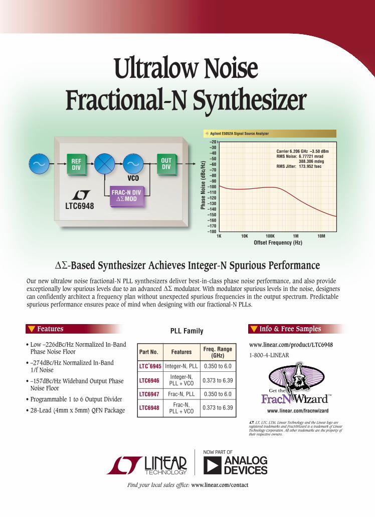
–20–30–40–50–60–70–80–90
–100–110–120–130–140–150–160–170–180
Carrier 6.206 GHz –3.50 dBmRMS Noise: 6.77721 mrad 388.306 mdegRMS Jitter: 173.952 fsec
Agilent E5052A Signal Source Analyzer
1K 10K 100K 1M 10M
Offset Frequency (Hz)
Phas
e No
ise
(dBc
/Hz)
Features
•Low–226dBc/HzNormalizedIn-Band PhaseNoiseFloor
•–274dBc/HzNormalizedIn-Band 1/fNoise
•–157dBc/HzWidebandOutputPhase NoiseFloor
•Programmable1to6OutputDivider
•28-Lead(4mmx5mm)QFNPackage
Info & Free Samples
, LT, LTC, LTM, Linear Technology and the Linear logo areregistered trademarks and FracNWizard is a trademark of Linear Technology Corporation. All other trademarks are the property of their respective owners.
www.linear.com/product/LTC6948
1-800-4-LINEAR
www.linear.com/fracnwizard
-Based Synthesizer Achieves Integer-N Spurious PerformanceOurnewultralownoisefractional-NPLLsynthesizersdeliverbest-in-classphasenoiseperformance,andalsoprovideexceptionallylowspuriouslevelsduetoanadvancedmodulator.Withmodulatorspuriouslevelsinthenoise,designerscanconfidentlyarchitectafrequencyplanwithoutunexpectedspuriousfrequenciesintheoutputspectrum.Predictablespuriousperformanceensurespeaceofmindwhendesigningwithourfractional-NPLLs.
LTC®
6945
LTC6946
LTC6947
LTC6948
Part No. Features
Integer-N, PLL
Integer-N,PLL + VCO
Frac-N, PLL
Frac-N,PLL + VCO
Freq. Range(GHz)
0.350 to 6.0
0.373 to 6.39
0.350 to 6.0
0.373 to 6.39
PLL Family
Get the
Ultralow NoiseFractional-N Synthesizer

24 MICROWAVE JOURNAL JULY 2017
CoverFeature
For more information on these products go to: www.nordengroup.com call 530.642.9123 x1#
or email: [email protected]
Wide Band & Narrow Band Integrated Assemblies Include Limiters, Switches and Detection Circuits 26 - 40GHz Norden Part Number NP2640G30N-P28S is Recommended in 5G Test Set Application Notes
26 - 40GHz Norden Part Number NP2640G30N-P28S
Frequency Converters
Frequency Multipliers Frequency Outputs up to 110 GHz Multiplication Factors 2x, 3x, 4x,
12x and Higher High and Adjustable Output Power Custom Designs can Include Low Phase Noise and Bypass Switching
Norden is the leader in providing test components for the 5G millimeter-wave spectrum around the frequencies of 28, 38, 60 and 73 GHz and the automotive radar 76-81 GHz Band. Norden Frequency Converters are used to extend the frequency rangeinclude frequency multiplication, filtering, and power amplification.
Frequency Bands 500 MHz to 110 GHz Down and Up Converters Transceivers Low Noise Converters
Look To NordenFor Your 5G And Automotive
Radar Test Components
bles are not continuous. FEKO, as part of Altair HyperWorks Computer Aided Engineering (CAE) platform, brings a set of additional and differ-ential capabilities that can be lever-aged at no extra cost due to Altair’s unique licensing system. Very com-plex Computer Aided Design (CAD) models can be cleaned-up and meshed in less time (including au-tomation) thanks to HyperMesh, a leading nite element analysis pre-processor. With HyperStudy, FEKO users can perform design of experi-ments to further optimize designs, including other physics analysis, and with activate electrical circuits, like DC/DC converters, can be analyzed and designed.
ANSYSCanonsburg, Pa.
The problem of RF interference between co-located platform in-tegrated radios can be dif cult to manage. With continued integration into the IoT infrastructure, modern commercial electronic devices are becoming ever more complex and feature rich with increasing wireless capability. This dense wireless capa-bility has resulted in an exponential growth of the radio frequency inter-ference (RFI) problem throughout the electronics industry. Examples of radio environments are a single structure such as an airplane, satel-lite, wireless electronic device or multiple radios in a more dispersed environment, such as many wire-less devices within an of ce setting or at outdoor cell communications sites. These multiple, multi-band RF systems need to coexist peace-fully and “play well” together and not degrade the performance of the other systems in the environment. And the problem of interference is not limited to explicit radio channels. Electronic devices are composed of both RF and digital signals and com-ponents which can share a common ground plane or reference. The digi-tal signals alone, although typically operating at clock frequencies be-
problems, among others. Depend-ing on the electrical size and com-plexity of the problem, one solver or another just needs to be used. FEKO’s integrated cable model-ling tool addresses EMC problems involving complex cables. Two spe-cial methods in FEKO for cables are Multi-Conductor Transmission Line (MTL) and the combined MoM/MTL, which is used for real problems where ground planes below the ca-
Multilevel Fast Multipole Method (MLFMM), Finite Element Method (FEM), Finite Difference Time Do-main (FDTD), Physical Optics/Large Element-Physical Optics (PO/LE-PO), Ray-Launching Geometrical Optics (RL-GO) and Uniform Theory of Diffraction (UTD). These solvers are widely used to solve antenna design and placement, EMC, radar cross-section (RCS), bio-electro-magnetics, radomes and RF devices

MWJ/B&Z/PROGRAM/0513
Noise Figure In Select Frequency Bands
Frequency (GHz)
No
ise
Fig
ure
(dB
)
5.00
4.50
4.00
3.50
3.00
2.50
2.00
1.50
1.00
0.50
0.000 2 4 6 8 10 12 14 16 18 20 22 24 26 28 30 32 34 36 38 40 42 44 46 48 50
4.5dB
4.0dB
2.8dB 2.8dB
2.5dB
1.2dB
0.9dB0.7dB
0.35dB
0.7dB0.5dB
1.2dB
1.8dB
1.3dB1.5dB
TECHNOLOGIESInnovating to Excel
Has Amplifier Performance or Delivery Stalled Your Program?
www.bnztech.com
Frequency Bands
Visit us in Booth 423 at the IMS 2013. B&Z is the preferred source for high perfomance amplifiers.
BNZ30896AmpAdMWJ.indd 1 4/16/13 12:30 PM

26 MICROWAVE JOURNAL JULY 2017
CoverFeature
provides a dynamically linked re-sult view to aid in the identification of the root-cause of interference via graphical signal trace-back and diagnostic summaries. These sum-maries show the origin and paths of transmit-to-receiver interfering sig-nals (see Figure 4).
With the cause of interference uncovered, EMIT enables rapid evaluation of various RFI mitigation measures to arrive at an optimum solution. Including accurate physi-cal effects associated with elec-tromagnetic coupling will improve the fidelity and reliability of the RF system simulation. An HFSS/EMIT datalink allows the model for RFI analysis to be created in EMIT di-rectly from the physical 3D model of the installed antennas in HFSS, providing a seamless end-to-end workflow for a complete RFI solu-tion of systems and environments ranging from large platform co-site interference to receiver de-sense in compact electronic devices.
ANSYS EMIT in the ANSYS RF Option provides a software frame-work for managing system per-formance data including a library of RF systems, a computational engine for simulating RFI effects in complex multi-system environ-ments, a dynamic analysis tool for
low the radio frequencies, can con-tain harmonics that interfere with the radio channels through their com-mon reference geometry. This latter, RF-digital interference is commonly referred to as de-sense, and is one of the more difficult design challenges in wireless electronic devices since it requires a complete system under-standing to predict and/or detect (see Figure 3).
ANSYS EMIT FOR EMI ANALYSIS
ANSYS EMIT is an industry lead-ing software for the simulation of RFI in complex environments. EMIT works together with ANSYS HFSS and HFSS SBR+, formerly Delcross Savant, to combine RF system in-terference analysis with best-in-class electromagnetic simulation for modeling installed antenna-to-an-tenna and radio-to-radio coupling. This solution reliably predicts the effects of RFI in multi-antenna envi-ronments with multiple transmitters and receivers. EMIT’s analysis en-gine computes important RF inter-actions, including nonlinear system component effects. Diagnosing RFI in complex environments is noto-riously difficult and expensive to perform in a testing environment. To address this challenge, EMIT
s Fig. 3 Examples of multi-radio and radio-digital systems that can be analyzed with ANSYS EMIT.
Comm_1
Comm_2
UHF-Bottom
VHF_1
Bluetooth
Control_Rx
GPS
Wi-FiCo
mm
_1
Com
m_2
UH
F-Bo
ttom
VH
F_1
Blue
toot
h
W
i-Fi
M
ulti-
Tx
Rx
Tx

MWJ/ADI/RETHINK/0717
RETHINK THE SIGNAL CHAIN. BREAK THROUGH THE BARRIERS.
WE DELIVER THE INDUSTRY’S LARGEST PORTFOLIO
OF SEMICONDUCTORS, SUBSYSTEMS, AND
HARDWARE- & SOFTWARE-BASED SECURITY.
Analog Devices provides solutions from antenna to bits to enable today’s
mission-critical platforms. We offer the industry’s deepest portfolio of
high-performance electronic signal-chain solutions, decades of system-
level knowledge and expertise, custom modules and subsystems,
and the capability to secure silicon all the way to data output.
THE INDUSTRY’S MOST ROBUST PORTFOLIO NOW OFFERS EVEN MORE analog.com/ADEF#ADIahead

28 MICROWAVE JOURNAL JULY 2017
CoverFeature
rity and power integrity (SI/PI) and identify violations of EMC design rules, while the general purpose 3D solvers can simulate radiated and conducted emissions/susceptibility in detail. Fields and currents on the 3D structure, including the attached circuits, can be visualized to help engineers identify coupling paths.
EMI CHALLENGESImmunity to emissions and envi-
ronmental electromagnetic effects (E3) such as lightning is an important application (see Figure 5). The Trans-mission Line Matrix (TLM) Solver is especially well suited to these appli-cations, and can simulate very large structures effectively. It supports oc-tree meshing and compact models of seams, vents, composite materials and other relevant features, which can further accelerate simulations while maintaining accuracy, and also offers bi-directional coupling to CST CABLE STUDIO for simulating how fields couple into and propagate through cables and cable harnesses.
Another major application of CST EMC STUDIO is antenna coupling.
rapid automatic identification of the root-cause of RFI problems and allows engineers to quickly evalu-ate different “what-if” analyses to resolve EMI issues.
Computer Simulation Technology (CST)
Darmstadt, Germany
EMC CHALLENGESCST EMC STUDIO is an EM simu-
lation tool used by industry leaders to analyze and optimize products for performance and compliance with EMC norms. The CST “Complete Technology” approach means that CST EMC STUDIO includes a range of solvers for many different scenar-ios, from general purpose time and frequency domain solvers to spe-cialized solvers for cables and print-ed electronics. These solvers are all included in one interface, allowing for a uniquely inte-grated workflow.
Both CAD data and printed circuit board (PCB) layouts from EDA tools can be imported into CST EMC STUDIO. Specialized PCB simulation tools can quickly calcu-late signal integ-
s Fig. 4 Interaction diagram and scenario matrix from EMIT, used to reconstruct interference paths and identify root causes for EMI.
GPS
Triband Cellular
Wi-Fi
Wi-Fi Tx
System Clock 800 MHz
Clock Oscillator USB_Memory_3a
Triband Cellular Tx
U-Blox LISA
LSR TiWi Wi-Fi_Port
Cellular Amplier Cell_Port
GSM 850 Tx825.2 MHz
OFDM Tx- 54…2422 MHz
GPS L1-L2
L11575.42 MHz
GPS_Port GPS
Tx
Rx Trib
and
Cellu
lar
W
i-Fi
Sy
stem
Clo
ck2
to 1
s Fig. 5 Surface currents on an aircraft during a lightning strike.

MWJ/NI/SMARTER/0717
©2017 National Instruments. All rights reserved. LabVIEW, National Instruments, NI, ni.com, and NI TestStand are trademarks of National Instruments. Other product and company names listed are trademarks or trade names of their respective companies. 29911
SMART DEVICES REQUIRE
SMARTERAUTOMATED TEST SYSTEMS
The old approach to automated test isn’t scaling, but you already
knew that. Look at your balance sheet. To test smart devices,
you need a smarter test system built on a platform of NI PXI,
LabVIEW, and TestStand. More than 35,000 companies deploy NI
technology to lower their cost of test. What are you waiting for?
Prepare for the future at ni.com/smarter-test.
29911_AT_Ad_MWJ_198x273.indd 1 6/16/17 11:02 AM

CoverFeatureThis is a very effective way to identi-fy EMI problems and test mitigation approaches on a virtual prototype.
Keysight TechnologiesSanta Rosa, Calif.
EMI and EMC are not new issues for system engineers. However, with increasing data rates in computers, networks, storage and mobile de-vices, design engineers are more challenged to deal with not only the traditional emission issues, but also coupling issues with nearby circuit and system components. Overcom-ing these challenges using appro-priate design tools is essential to successful system design.
RF DE-SENSE OR RFI ISSUESOne of the issues designers face
when it comes to EMC and EMI is interference between subsystems and antennas. It is an especially severe problem in mobile devices, where designs are squeezed into very small areas. The interference can cause degradation in receiver sensitivity, also known as “RF de-sense” or “RFI” issues. For example,
high-speed applica-tion processors, memories, camera modules, DC-DC power converters and high-speed interconnects, like USB 3.1 Type C, may cause “self-jamming” issues with RF circuits that include multi-band antennas (see Fig-ure 7).
INTEGRATED CIRCUIT AND EM SIMULATION IS NECESSARY
Diagnosing RF de-sense and self-jamming issues presents a real chal-lenge for today’s designers. They
In a typical antenna-to-antenna sce-nario, the antennas may be installed on extremely large platforms such as aircraft, ships or buildings, but the coupling itself can depend on fine details such as the exact design of the antenna or the seams, vents and cables in the platform. CST EMC STUDIO supports a hybrid ap-proach where the antennas can be simulated in detail with a suitable solver such as the Time Domain Solver, and then used as field source for a coupling simulation with a dif-ferent solver such as the Integral Equation Solver, TLM Solver or As-ymptotic Solver. Combining solvers in this way gives engineers the best of both and can significantly speed up simulation times.
As well as calculating the cou-pling between subsystems, such as antennas on a platform or chan-nels on a PCB, a co-site interference analysis also involves taking into account the frequency spectra of each subsystem. The Interference Task, new in CST EMC STUDIO 2017, offers a straightforward ap-proach for investigating potential EMI issues using coupling data from simulations combined with informa-tion about each Rx/Tx system (see Figure 6). Using this, the Interfer-ence Task produces a violation ma-trix highlighting combinations that could potentially lead to EMI issues.
s Fig. 6 The Interference Task shows which combinations of RF systems can lead to co-site interference.
30 MICROWAVE JOURNAL JULY 2017

MWJ/BERKELEY/MULTI/0717
Berkeley Nucleonics Corp., 2955 Kerner Blvd. San Rafael CA 94901 Email [email protected], Call 800-234-7858 or LIVE-Chat @ www.berkeleynucleonics.com
Multi Channel Phase Coherent RF/Microwave Signal Generators and Synthesizers.
Best in class performance, size, cost, and reliability
•Extremely low phase noise performance•Frequency range from 10Mhz to 20GHz•Very fast switching speed to 10us•Multi-Channel phase coherent system from 2 to 8 Independent outputs•Very small form factor at 1U 19" rackmount•Rich library of API's•OEM options for direct integration
Multi Channel Phase Coherent RF/Microwave Signal Generators and Synthesizers.
Best in class performance, size, cost, and reliability
Rackmount
Bench-Top
OEM

32 MICROWAVE JOURNAL JULY 2017
CoverFeature
ers use different frequency bands. Designers can also employ the use of bandpass or band-rejection fil-ters, which may reduce unwanted energy coupling. Careful design of the whole device is required, includ-ing co-design of the on-board an-tennas with the ground plane.
Since antenna-to-antenna cou-pling is mostly a near field problem, it can be accurately handled with tra-ditional EM simulation technologies such FEM, MoM or FDTD engines. The coupling problem may be miti-gated by adjusting the position of the antennas and/or tweaking the anten-na performance, such as gain versus frequency or radiation patterns.
With Keysight design tools, de-signers can simulate the radiated
must model EM field interactions within devices using EM solvers and be able to handle digital waveforms from circuit- and system-level de-sign tools. For these tasks, a design environment that integrates both circuits and EM is a must. Keysight’s Advanced Design System (ADS) and EMPro provide a uniquely in-tegrated software design platform that offers a solution.
ANTENNA-TO-ANTENNA COUPLING ISSUES
With many antennas crammed into a very small piece of real estate, the coupling between antennas can become quite problematic (see Fig-ure 8). This type of coupling may or may not be as significant if design-
s Fig. 7 Example of a mobile device layout (a) and self-jamming vs. locations of the digital interface on the PCB (b).
Pos 1
Pos 1
Pos 2
Pos 2
Pos 3
Pos 3
50
2.0
1.5
1.0
0.5
0
–0.5
2.0
1.5
1.0
0.5
0
–0.5
2.0
1.5
1.0
0.5
0
–0.5
55 60 65 70Time, nsec
WLAN Antenna
Bluetooth
DDR
CPU
Phone PCB
(a) (b)
s Fig. 8 Cellular, WLAN and Bluetooth antenna coupling in a mobile phone.
0
–10
–20
–30
–40
–50
–60
–70109876543210
Cou
plin
g (d
Ba)
Frequency (GHz)
WLAN
BT
Antenna
10+ dB

Fast-approaching our 50th anniversary — and this year celebrating our 1 billionth Xinger®-brand coupler sold! — today’s Anaren continues to drive innovative, best-in-class RF technology for the world’s most demanding space, defense, wireless, and consumer electronics customers. > Our Space & Defense Group offers a fast-growing range of passive and active solutions,
including multichip modules, IMAs, and custom solutions for today’s digital radars. Exciting, new PCB and ceramic substrates and multilayer packaging techniques. And a growing line-up of space-grade components and high-temperature modules.
> Our Wireless Group continues to reinvent the passive components category. From new, Femto-sized and mil-grade Xinger®-brand SMTs. To subminiature baluns and couplers for consumer products. To our growing family of Anaren Integrated Radio (AIR) modules and other solutions for the wireless IoT.
To learn more about how today’s Anaren can make you more competitive tomorrow — visit www.anaren.com or email us at [email protected] today! 800-411-6596 > www.anaren.com
Isn’t it time to put Anaren innovations like these to work for you ?
Anaren Precision Etched Ceramics (APECS) — offering thin-film tolerances & performance, at a thick-film price
Space-qualified couplers & power dividers — high-rel, lightweight & low-power for today’s satellite applications
Space/Mil-grade Xinger® couplers —proven in Mars missions & ready for tough terrestrial settings, too
RF solutions for next-gen AESAs — including manifolds, T/R modules & beam-formers for air, sea, and land platforms
Insist on genuine, p
roven
er-bra
nd components!
1 billion
components sold!
proven in Mars missions & ready for tough terrestrial settings, too
MWJ/ANNAREN/INNOVATIONS/0914

34 MICROWAVE JOURNAL JULY 2017
CoverFeature
ULTRA Hi RF - Compliant Connector
©2015 R&D Interconnect Solutions. All rights reserved. R&D Interconnect Solutions, Invisipin, and RDIS.com are trademarks of R&D Interconnect Solutions.
www.RD IS . com/MJ M J@RD IS . com 610 -443 -2299
Specif ications• > 50 GHz Bandwidth @1 dB
• 20 mΩ C-Res (typical)
• Up to 4 Amps
*Available in tape and reel (machine placeable) or fully integrated into custom products.
(Coaxial Configuration)
INFINITELY CONFIGURABLE • INDIVIDUALLY SOLDERABLE • HI COMPLIANCE RANGE
• 0.23mm to 0.64mm diameter pins
• Pitches from 0.4mm to >1mm
Configurations
®
to handle a range of design issues, making them ideal for helping sys-tem engineers overcome the EMC and EMI design challenges they face today and in the future.
NI AWREl Segundo, Calif.
Addressing EMC/EMI perfor-mance is an integral part of product development, especially when elec-tronics are densely packed, causing high-frequency signals and fast tran-sients to give rise to either radiated or conducted (transmission) emis-sions with the potential to adversely affect each other. NI AWR Design Environment, an open design plat-form for high-frequency circuit and system product development, ad-dresses these concerns with inte-grated design tools that incorporate planar and arbitrary 3D EM analysis directly within circuit- and system-level design and simulation. The analysis capabilities offered through integrated circuit, system and EM co-simulation are illustrated with the following two examples in which the capabilities in NI AWR software were leveraged to overcome sever-al EMC/EMI design challenges.
MITSUBISHI EXAMPLEDesigners at the Mitsubishi Elec-
tric Corporation used NI AWR De-sign Environment to tackle their EMC/EMI design challenges and improve the sound quality of the company’s DIATONE car audio sys-tem. The design team used Micro-wave Of ce circuit design software and AXIEM planar EM analysis soft-ware to perform a rigorous EMC noise analysis of the navigation sys-tem’s circuit board design, including identi cation of the noise source through analysis of the transmission path and the radiation noise.
The designers considered the overall system, which included an emission source (emitter) and sus-ceptible receptors within a given environment. EMI comes from EM waves that are generated by the in-
access to many different waveforms, whether standard waveforms, user-de ned or measured waveforms.
INTEGRATION IS KEYAs data rates continue to increase,
system designers will likely face even greater EMI and EMC design chal-lenges. Using the right design tools that offer integrated circuit and EM simulation are essential. Keysight’s design tools not only offer that lev-el of integration, but are designed
emissions of electronic circuits and components, determine whether these emissions are within levels speci ed by common standards, such as FCC Part 15, CISPR 22 and MIL-STD-461F, and whether they are compliant—all before hardware has been developed.
In addition to verifying EMI com-pliances, it is critical to have the correct noise waveform injected for an accurate calculation of emission level. Keysight tools offer designers

MWJ/CPI/WHO/0717

36 MICROWAVE JOURNAL JULY 2017
CoverFeature
Powerful Satellite Payload & RF Link Emulator
Multipath, 12 paths @ 600MHz BW
Real time control for Arial Vehicle (UAV) testingLink emulation, Delay, Doppler, AWGN
dBmCorp, Inc32A Spruce Street Oakland, NJ 07436Tel (201) 677-0008 Fax (201) 677-9444
Payload, IMUX/OMUX, Compression, Phase noise etc
Just relea
sed,
600 MHz
bandwidth
RF Test Equipment for Wireless Communications
www.dbmcorp.comemail: [email protected]
model of the noise source as veri-fied through measurements in a test system. This model was then used in conjunction with EM simulations of possible board geometries to inves-tigate how to mitigate EM problems (see Figure 10). The improvement in anti-noise measures combined with a significant reduction in the number of trials resulted in a dramatic re-duction in overall trial cost while still maintaining sound quality.
The tight coupling of Microwave Office and AXIEM accelerated the design process tremendously. EMC noise analysis of the transmission noise components revealed a return path that resulted in a degradation of the audio system sound quality. Hot spots were quickly identified with AXIEM’s current view; chang-es to components could then be quickly implemented in Microwave Office, which in turn coupled back into AXIEM results, as shown in Fig-ure 11. Through EMC noise analy-sis, the trial cost was reduced by at least 60 percent, the parts cost was reduced by at least 30 percent, the labor cost was reduced by at least 60 percent and the utility cost was reduced by at least 50 percent.
RF MICROTECH EXAMPLEAnother EMI/EMC design chal-
lenge was successfully addressed by RF Microtech using NI AWR De-sign Environment in the design of a very large and complex ultra-wide-band (UWB) filter for use in prevent-ing mobile service bands from inter-fering with a critical security control base station at Expo Milano 2015. This type of problem differs from the first example, in that the design-ers were asked to develop a high-performance filter from interfering signals with known characteristics. The challenge was to develop this filter in less than a month.
RF Microtech was challenged to provide a validated full-wave EM simulation of a two-port UWB filter that could reject all five mobile ser-vice bands with greater than 35 dB. The validated EM simulation had to be delivered within two weeks and the complete deployable device by the time the expo opened. The de-sign team used Microwave Office to develop a circuit model of five inde-
tegrated circuit. Modeling the high-frequency noise comprised three basic components: noise source, transmission path and radiation end, as shown in Figure 9.
In this model, the audio board was designed using a two-board con-figuration of a power supply board and a main board containing a mi-crocontroller, digital signal processor and digital-to-analog converter. The designers developed an accurate s Fig. 9 EMC radiation noise analysis
model.
ReceivingEnd (Load)
Noise Source(Signal Source)

MWJ/PASTERNACK/WAVEGUIDE/1016
All Available for Same-Day Shipping
Largest In-Stock Selection of
WaveguideComponents
866.727.8376visit pasternack.com today!
Pasternack’s RF Engineering team has assembled the largest selection of in-stock and ready to ship waveguide components covering RF, microwave and millimeter-wave bands up to 110 GHz. With 20 different waveguide categories and over 500 designs including adapters, power amplifi ers, detectors, bandpass fi lters, PIN diode switches, attenuators, horn antennas and more, Pasternack has the waveguide components you are looking for. Whether it’s waveguide products or any of the other 40,000 in-stock components we carry, our Application Engineers stand ready to deliver solutions for all your RF project needs.
RF SolutionsFrom RF Engineers

38 MICROWAVE JOURNAL JULY 2017
CoverFeaturependent notched-band filters (NBF) cascaded along a transmission line (see Figure 12).
Each indepen-dent filter was de-signed as a fourth or fifth order NBF, composed of sever-al cascaded stages of N shunt resona-tors. The individual filter specifications called for resona-tors with high un-loaded Qs (>1000) and no spurious modes under 6 GHz. After identi-fying the optimum filter geometries, the transmission line and filter sec-tions were verified in ANSYS HFSS full-wave EM anal-ysis tool.
These two use cases have illus-trated how EMC/EMI performance issues were over-come with the use of NI AWR Design Environment inte-grated circuit and EM design tools that enabled both design teams to dramatically cut design cycles and costs and deliver high quality solu-tions on time.n
s Fig. 10 EMC radiation noise analysis model (a) and elimination of resonances after anti-noise measures were implemented in the design (b).
Measured Value
(a)
(b)
s Fig. 11 Integration of circuit analysis with EM modeling speeds problem identification and resolution.
Value measured bythe LCR meterL value of powercable of around 20 cm
CableNoiseSource
LISN
s Fig. 12 Circuit model of notched-band filter.
In
Out
L45
L54
L35
L13
NB1
NB3
NB5
NB4NB2

MWJ/MC/550REVD/0717
550 Rev D
Mini-Circuits®
www.minicircuits.com P.O. Box 350166, Brooklyn, NY 11235-0003 (718) 934-4500 [email protected]
Filter
Eliminates standing waves out-of-band
Reflectionless
Conventional
XBFXBF
XHF
Reflectionless
XHF
XLF
Now Mini-Circuits’ revolutionary X-series reflectionless filters give you even more options to improve your system performance. Choose from over 50 unique models with passbands from DC to 30 GHz. Unlike conventional filters, reflectionless filters are matched to 50Ω in the passband, stopband and transition, eliminating intermods, ripples and other problems caused by reflections in the signal chain. They’re perfect for pairing with non-linear devices such as mixers and multipliers, significantly reducing unwanted signals generated and increasing system dynamic range.2 Jump on the bandwagon, and place your order today for delivery as soon as tomorrow. Need a custom design? Call us and talk to our engineers about a reflectionless filter to improve performance in your system!
• High pass, low pass, and band pass models
• Patented design eliminates in-band spurs• Absorbs stopband signal power rather than reflecting it
• Good impedance match in passband, stopband and transition
• Intrinsically Cascadable3
• Passbands from DC to 30 GHz4
Now over 50 Modelsto Improve Your System Performance!
1 Small quantity samples available, $9.95 ea. (qty. 20)
2 See application note AN-75-007 on our website 3
See application note AN-75-008 on our website 4 Defined to 3 dB cutoff point
Protected by U.S. Patent No. 8,392,495 andChinese Patent No. ZL201080014266.l.Patent applications 14/724976 (U.S.) andPCT /USlS/33118 (PCT) pending.
$695 ea. (qty.1000)1
from
XHF2
DC to 30 GHz!REFLECTIONLESS FILTERS
BareBareBareBareDie FormDie FormDie FormDie Form
2x2mm2x2mm3x3mm
550 rev D_ReflectionlessFilter.indd 1 6/6/17 10:53 AM

Ciao Wireless, Inc. 4 0 0 0 V i a P e s c a d o r, C a m a r i l l o , C A 9 3 0 1 2
Tel (805) 389-3224 Fax (805) 389-3629 [email protected]
OCTAVE BAND LOW NOISE AMPLIFIERS Model No. Freq (GHz) Gain (dB) MIN Noise Figure (dB) Power -out @ P1-dB 3rd Order ICP VSWR CA01-2110 0.5-1.0 28 1.0 MAX, 0.7 TYP +10 MIN +20 dBm 2.0:1 CA12-2110 1.0-2.0 30 1.0 MAX, 0.7 TYP +10 MIN +20 dBm 2.0:1 CA24-2111 2.0-4.0 29 1.1 MAX, 0.95 TYP +10 MIN +20 dBm 2.0:1 CA48-2111 4.0-8.0 29 1.3 MAX, 1.0 TYP +10 MIN +20 dBm 2.0:1 CA812-3111 8.0-12.0 27 1.6 MAX, 1.4 TYP +10 MIN +20 dBm 2.0:1 CA1218-4111 12.0-18.0 25 1.9 MAX, 1.7 TYP +10 MIN +20 dBm 2.0:1CA1826-2110 18.0-26.5 32 3.0 MAX, 2.5 TYP +10 MIN +20 dBm 2.0:1 NARROW BAND LOW NOISE AND MEDIUM POWER AMPLIFIERSCA01-2111 0.4 - 0.5 28 0.6 MAX, 0.4 TYP +10 MIN +20 dBm 2.0:1 CA01-2113 0.8 - 1.0 28 0.6 MAX, 0.4 TYP +10 MIN +20 dBm 2.0:1 CA12-3117 1.2 - 1.6 25 0.6 MAX, 0.4 TYP +10 MIN +20 dBm 2.0:1 CA23-3111 2.2 - 2.4 30 0.6 MAX, 0.45 TYP +10 MIN +20 dBm 2.0:1 CA23-3116 2.7 - 2.9 29 0.7 MAX, 0.5 TYP +10 MIN +20 dBm 2.0:1 CA34-2110 3.7 - 4.2 28 1.0 MAX, 0.5 TYP +10 MIN +20 dBm 2.0:1 CA56-3110 5.4 - 5.9 40 1.0 MAX, 0.5 TYP +10 MIN +20 dBm 2.0:1 CA78-4110 7.25 - 7.75 32 1.2 MAX, 1.0 TYP +10 MIN +20 dBm 2.0:1 CA910-3110 9.0 - 10.6 25 1.4 MAX, 1.2 TYP +10 MIN +20 dBm 2.0:1 CA1315-3110 13.75 - 15.4 25 1.6 MAX, 1.4 TYP +10 MIN +20 dBm 2.0:1 CA12-3114 1.35 - 1.85 30 4.0 MAX, 3.0 TYP +33 MIN +41 dBm 2.0:1CA34-6116 3.1 - 3.5 40 4.5 MAX, 3.5 TYP +35 MIN +43 dBm 2.0:1 CA56-5114 5.9 - 6.4 30 5.0 MAX, 4.0 TYP +30 MIN +40 dBm 2.0:1 CA812-6115 8.0 - 12.0 30 4.5 MAX, 3.5 TYP +30 MIN +40 dBm 2.0:1 CA812-6116 8.0 - 12.0 30 5.0 MAX, 4.0 TYP +33 MIN +41 dBm 2.0:1 CA1213-7110 12.2 - 13.25 28 6.0 MAX, 5.5 TYP +33 MIN +42 dBm 2.0:1 CA1415-7110 14.0 - 15.0 30 5.0 MAX, 4.0 TYP +30 MIN +40 dBm 2.0:1 CA1722-4110 17.0 - 22.0 25 3.5 MAX, 2.8 TYP +21 MIN +31 dBm 2.0:1 ULTRA-BROADBAND & MULTI-OCTAVE BAND AMPLIFIERSModel No. Freq (GHz) Gain (dB) MIN Noise Figure (dB) Power -out @ P1-dB 3rd Order ICP VSWRCA0102-3111 0.1-2.0 28 1.6 Max, 1.2 TYP +10 MIN +20 dBm 2.0:1 CA0106-3111 0.1-6.0 28 1.9 Max, 1.5 TYP +10 MIN +20 dBm 2.0:1 CA0108-3110 0.1-8.0 26 2.2 Max, 1.8 TYP +10 MIN +20 dBm 2.0:1 CA0108-4112 0.1-8.0 32 3.0 MAX, 1.8 TYP +22 MIN +32 dBm 2.0:1 CA02-3112 0.5-2.0 36 4.5 MAX, 2.5 TYP +30 MIN +40 dBm 2.0:1 CA26-3110 2.0-6.0 26 2.0 MAX, 1.5 TYP +10 MIN +20 dBm 2.0:1 CA26-4114 2.0-6.0 22 5.0 MAX, 3.5 TYP +30 MIN +40 dBm 2.0:1 CA618-4112 6.0-18.0 25 5.0 MAX, 3.5 TYP +23 MIN +33 dBm 2.0:1 CA618-6114 6.0-18.0 35 5.0 MAX, 3.5 TYP +30 MIN +40 dBm 2.0:1 CA218-4116 2.0-18.0 30 3.5 MAX, 2.8 TYP +10 MIN +20 dBm 2.0:1 CA218-4110 2.0-18.0 30 5.0 MAX, 3.5 TYP +20 MIN +30 dBm 2.0:1 CA218-4112 2.0-18.0 29 5.0 MAX, 3.5 TYP +24 MIN +34 dBm 2.0:1LIMITING AMPLIFIERSModel No. Freq (GHz) Input Dynamic Range Output Power Range Psat Power Flatness dB VSWRCLA24-4001 2.0 - 4.0 -28 to +10 dBm +7 to +11 dBm +/- 1.5 MAX 2.0:1 CLA26-8001 2.0 - 6.0 -50 to +20 dBm +14 to +18 dBm +/- 1.5 MAX 2.0:1 CLA712-5001 7.0 - 12.4 -21 to +10 dBm +14 to +19 dBm +/- 1.5 MAX 2.0:1 CLA618-1201 6.0 - 18.0 -50 to +20 dBm +14 to +19 dBm +/- 1.5 MAX 2.0:1AMPLIFIERS WITH INTEGRATED GAIN ATTENUATIONModel No. Freq (GHz) Gain (dB) MIN Noise Figure (dB) Power -out @ P1-dB Gain Attenuation Range VSWRCA001-2511A 0.025-0.150 21 5.0 MAX, 3.5 TYP +12 MIN 30 dB MIN 2.0:1CA05-3110A 0.5-5.5 23 2.5 MAX, 1.5 TYP +18 MIN 20 dB MIN 2.0:1CA56-3110A 5.85-6.425 28 2.5 MAX, 1.5 TYP +16 MIN 22 dB MIN 1.8:1CA612-4110A 6.0-12.0 24 2.5 MAX, 1.5 TYP +12 MIN 15 dB MIN 1.9:1CA1315-4110A 13.75-15.4 25 2.2 MAX, 1.6 TYP +16 MIN 20 dB MIN 1.8:1CA1518-4110A 15.0-18.0 30 3.0 MAX, 2.0 TYP +18 MIN 20 dB MIN 1.85:1LOW FREQUENCY AMPLIFIERSModel No. Freq (GHz) Gain (dB) MIN Noise Figure dB Power -out @ P1-dB 3rd Order ICP VSWRCA001-2110 0.01-0.10 18 4.0 MAX, 2.2 TYP +10 MIN +20 dBm 2.0:1CA001-2211 0.04-0.15 24 3.5 MAX, 2.2 TYP +13 MIN +23 dBm 2.0:1CA001-2215 0.04-0.15 23 4.0 MAX, 2.2 TYP +23 MIN +33 dBm 2.0:1CA001-3113 0.01-1.0 28 4.0 MAX, 2.8 TYP +17 MIN +27 dBm 2.0:1CA002-3114 0.01-2.0 27 4.0 MAX, 2.8 TYP +20 MIN +30 dBm 2.0:1CA003-3116 0.01-3.0 18 4.0 MAX, 2.8 TYP +25 MIN +35 dBm 2.0:1CA004-3112 0.01-4.0 32 4.0 MAX, 2.8 TYP +15 MIN +25 dBm 2.0:1
CIAO Wireless can easily modify any of its standard models to meet your "exact" requirements at the Catalog Pricing.
Visit our web site at www.ciaowireless.com for our complete product offering.
MWJ/CIAO/RFAMPLIFIERS/0207

Challenging MissionSyring said that though this was a developmental
test, the scenario is the same as one they would expect to occur during an actual operational engagement. BMD is an incredible challenge, the admiral explained. The defending missile must intercept a missile that can travel thousands of miles per hour, in this case, outside the Earth’s atmosphere. “Yesterday’s test did demon-strate that the system continues to improve and mature, and it is ready to defend the homeland today.”
The next test, to take place in the fall or later in the 2018 calendar year, will involve one target and two in-terceptors/kill vehicles, the next step in ever-increasing operational realism. The program plan for testing adver-sary ICBM salvos is scheduled for the 2023 time frame.
DARPA Technology to Improve UAS Adaptability and Mission Efficiency
Today, unmanned aerial systems (UAS) typi-cally require multiple payloads with dedi-cated components, including antennas, RF
circuitry and processors, to conduct communications, radar and electronic warfare (EW) missions. These sin-gle-function payloads cannot be installed on a compact UAS at the same time because of the size, weight and power (SWaP) constraints of these platforms, limiting what they can do without swapping payloads on the ground—a process that seriously hinders mission effi-ciency.
Under two recently awarded contracts from DARPA worth a combined $5.4 million, BAE Systems is devel-oping technology that will enable compact UAS to con-duct multiple mission tasks with single, multifunction payloads that can adapt to changing battlefield situa-tions and mission needs in real-time.
DARPA’s program, called CONverged Collaborative Elements for RF Task Operations or CONCERTO, fo-cuses on supporting communications, radar and EW systems with a flexible RF architecture that uses shared common hardware, enabling multifunction systems that meet the low-SWaP requirements of compact UAS. The converged systems will be able to efficiently switch between intelligence, surveillance and recon-naissance; command and control; networking and combat operations support missions without physical payload changes.
Protection Against Drones
Drones pose a serious security risk at major public events and also to high-risk infrastruc-tures and facilities such as airports, industrial
MICROWAVE JOURNAL JULY 2017 41
DefenseNewsCliff Drubin, Associate Technical Editor
Visit mwjournal.com for more defense news.For MoreInformation
Missile Defense Agency: BMD System “Ready to Defend the Homeland Today”
The recent successful test of part of the na-tion’s ballistic missile defense (BMD) system shows that the U.S. can defend itself against
the threat of ballistic missile launches from North Ko-rea or Iran, according to the director of the Missile De-fense Agency (MDA). Navy Vice Adm. James D. Syring, speaking to members of the press from Schriever Air Force Base, Colo., said the test replicated an operation-al scenario that concerns the military and represents a critical program milestone. “I was confident before the test that we had the capability to defeat any threat that [North Korea or Iran] would throw at us,” Syring told re-porters, “and I’m even more confident, after seeing the intercept test, that we continue to be on that course.”Ground-Based Midcourse Defense
The BMD System can target an incoming ballistic mis-sile at three points in its trajectory. These are the boost phase, from launch through ascent, one to five minutes; the midcourse phase, when the missile booster burns out and the missile coasts in space toward its target, up to 20 minutes; and the terminal phase, a brief period when the missile reenters the atmosphere, according to the MDA website. This most recent test involved the midcourse phase and was the system’s first live-fire event, matching a ground-based interceptor carrying an exo-atmospheric kill vehicle (EKV) against an intercontinental ballistic mis-sile (ICBM)-class threat designed to replicate something
from North Korea or Iran, Sy-ring said.
During the test, the tar-get ICBM launched from the Reagan Test Site on Kwajalein Atoll in the Mar-shall Islands. Sensors fed target acquisition and track-ing data to the command, control, battle management and communication system.
The Sea-Based X-Band radar positioned in the Pacific Ocean also acquired and tracked the target.
The ground-based missile defense (GMD) system received the target tracking data and developed a fire-control solution to intercept the target. Then a ground-based interceptor—a multistage solid-fuel booster—launched from Vandenberg Air Force Base in Calif., carried the EKV toward the target ICBM’s location in space. The interceptor released the kill vehicle, which used guidance data transmitted from ground and on-board sensors to collide with and destroy the target warhead. The interceptor tested is the same configura-tion that will complete the fielding of 44 total intercep-tors by the end of 2017, the admiral said.
Intercerpter Launch (DoD photo by Senior Airman Robert J. Volio)

DefenseNews
test sites, large plants, mili-tary sites and correctional facilities, especially in light of the fact that sales are booming and anyone can use them.
With this in mind, ESG Elektroniksystem und Logis-tik-GmbH, Diehl Defence and Rohde & Schwarz signed a cooperative agreement in
the area of drone defense. Building on experience gained through their successful cooperation during both the 2015 G7 Summit in Elmau and the U.S. presidential trip to Ha-nover in 2016, the companies seek to coordinate their efforts even more closely and provide fully customized, bundled solutions based on their proven expertise in the fields of radar, radiomonitoring, electromagnetic counter-measures, command and control information systems and position mapping.
The GUARDION drone defense system combines the scalable solutions customized to very specific custom-er requirements to reliably detect and defend against threats posed by the unauthorized use of drones. GUAR-DION focuses on integrating electronic detection, verifi-cation and countermeasures and connecting them to a position mapping and command and control tool. The
HPEMcounterUAS effectors from Diehl Defence, R&S ARDRONIS from Rohde & Schwarz and the TARANIS command and control and position mapping system de-veloped by ESG have proven their capabilities in opera-tional use.
“Such deployment scenarios as well as experience gained elsewhere have confirmed our opinion that mul-tiple intermeshed measures must be employed to ensure reliable protection against drones,” stated Christoph We-ber, head of Defence & Public Security at ESG, on behalf of the cooperation partners.
Dietmar Vahldiek, executive vice president Monitor-ing and Network Testing at Rohde & Schwarz, adds: “For many customers, it is important to receive early warning of potential threats. Detecting radio signals from remote control units therefore plays a key role. Security forces can respond even before the drone is in the air.”
The trend toward increasingly intelligent drones also requires an effector that civil forces can use against autonomously flown systems, i.e. systems that are not dependent on radio signals or GPS for navigation. A significant countermeasure component in GUARDION is therefore the HPEMcounterUAS from Diehl. “Today, reliable protection against small airborne vehicles must function against both radio-controlled and autono-mously flown objects,” added Helmut Rauch, manag-ing director at Diehl Defence.
42 MICROWAVE JOURNAL JULY 2017
MICROWAVE COMPONENTS & SYSTEMS
Thin-film technology in very small,
yet rugged, packages.
Networking, where Microwave & Computer technology meet.(Contact factory for details)
AMPLIFIERS: MILITARY ELECTRONICS: COMPONENTS: Frequency range of 0.1 to 40 GHz Freq range: 0.1 to 40 GHz Mixers 2.0 to 40 GHz
LNA or Power for radar applications Double/Triple Balanced
We also offer custom amplifiers Pulse Modulators IR Mixers
including, but not limited to, Heatsink Threshold Detectors IQ Modulators
and Universal AC Input Detector Log Amplifiers Limiters 0.1 to 40 GHz
remote sensing incl. Ethernet and LAN Detectors 0.01 to 40 GHz
UP/DOWN CONVERTERS:Freq range 3 to 40 GHz
A complete remote converter system 333 Moffett Park Driveusing a computer network control Sunnyvale, CA 94089 www.advmic.com including Ethernet and LAN Ph: 408-739-4214 [email protected]
ONE STOP SHOP
CUSTOM products using AMI
building blocks
R&S ARDRONIS©
Rohde & Schwarz

MWJ/REACTEL/WORLD/0114

MWJ/EUMW/FORUM/0717
A focused Forum addressing the application of RF and microwave technologyto The Internet of Space.
The 2017 Defence, Security and Space ForumAt European Microwave Week
Wednesday, 11 October – Nürnberg Convention Center – Room St. Petersburg
Vast areas of the globe are without sufficient Internet connectivity. Commercial and societal progress as well as safety and security are linked to access to the information superhighway, while military missions require reliable and secure data
communication pathways. This one-day Forum highlights The Internet of Space – Technologies and Applications, a new class of satellite communication services being developed to address these needs.
Programme:08:30 – 10:10 EuRAD Opening Session
10:50 – 12:30 The Internet of Space – Technologies and ApplicationsTwo keynote speakers from the industry will present their view on key applications and the related technologies needed for the realisation of the Internet of Space. The presentations will cover commercial as well as military applications.• The World’s Largest Satellite Constellation ‘OneWeb’ – Redefining Satellite Communications
Wolfgang Duerr, Airbus DS Inc. • The Connections are Key: The Implications of the Internet of Things on Military Technology – Joe Mariani, Deloitte
12:40 - 13:40 Strategy Analytics Lunch & Learn SessionThis session adds a further dimension to the topics by offering a market analytics perspective, illustrating the status, development and potential of the market for the Internet of Space.
14:20 – 16:00 Microwave Journal Industry Panel SessionThis session offers an industrial perspective on the key issues to be addressed in the defence, security and space sector. In accordance with this year’s Defence, Security and Space theme the panel will investigate the opportunities for applications of the Internet of Space as well as address the technological challenges. The presentations are:• The Internet of Space – Technologies and Applications – Mark Lombardi, Keysight Technologies• Internet of Space, Past, Present, & Future – Timothy Boles, MACOM• Leveraging Technology to Develop Solutions for IoT to the IoS – Roger Hall, Qorvo• New Approaches in End-To-End Payload Testing – Yassen Mikhailov, Rohde & Schwarz
16:10 - 17:50 Defence, Security & Space Executive ForumHigh level speakers from leading Defence and Space companies present their views and experiences on the upcoming technologies and applications in the civil and military domains. They will be complemented by speakers from a government agency, consulting company and a start-up, who will offer their views on research needs, trends and New Space opportunities and challenges. Speakers at the Forum will include:• Erich Auer, TeSat SpaceCom• Wolfgang Duerr, Airbus DS Inc.• Matthias Spott, eightyLEO• Joe Mariani, Deloitte• Siegfried Voigt, DLR
17:50 - 18:30 Cocktail ReceptionThe opportunity to network and discuss the issues raised throughout the Forum in an informal setting.
Registration and Programme UpdatesRegistration fees are €20 for those who registered for a conference and €60 for those not registered for a conference
As information is formalized, the Conference Special Events section of the EuMW website will be updated on a regular basis.
Register online at www.eumweek.com
Sponsors:

Infineon Launches Productive4.0 Research Project
Productive4.0, the largest European research initiative to date in the field of Industry 4.0, has been launched by Infineon Technolo-
gies. Working with more than 100 partners from 19 European countries, Infineon Technologies will coordi-nate work on digitizing and networking industry.
“Real-time connected value chains will dramatically increase agility in development and production. They will thus help shorten time to market,” said Dr. Rein-hard Ploss, CEO of Infineon Technologies. “Microelec-tronics is a key enabler for further digitization of the manufacturing industry and for an optimized and inte-grated supply chain management. With its high level of automation, our industry can serve as a blueprint showing how to secure important parts of the value chain and qualified jobs in Europe. We now want to share our know-how with other industrial sectors.”
Europe and, in partic-ular, Germany have spe-cial strengths in the field of microelectronics in au-tomotive, energy, safety and industrial electron-
ics. Productive4.0 is part of the Electronic Components and Systems for European Leadership (ECSEL), the Eu-ropean funding program for microelectronics. Its aim is to strengthen expertise in microelectronics with a view to broad digitization. Thirty partners from Ger-many and a further 79 participants will work together for three years on the €106 million project. The EU and the participating Member States are funding the proj-ect as part of ECSEL with around €51 million. The Free State of Saxony and the German Federal Ministry of Education and Research (BMBF) will jointly contribute €9.6 million to the project.
The aim is to create a user platform across value chains and industries that especially promotes the dig-ital networking of manufacturing companies, produc-tion machines and products. The participating partners will examine methods, concepts and technologies for service-oriented architecture as well as for compo-nents and infrastructure in the Internet of Things. The Productive4.0 project will run until 30 April 2020.
Dr. Max Lemke, representing the European Com-mission, summed up the project from a European viewpoint: “Productive4.0 is one of the first Lighthouse projects funded under the ECSEL Joint Undertaking. The platform approach and the collaboration across value chains and sectors, which is strongly promoted in the Digitising European Industry strategy of the Eu-ropean Commission, promises sustainable impact on the collaboration between and across companies in production and beyond.”
u-blox, Commsignia and NXP Collaborate to Drive V2X
U-blox, Commsignia Inc. and NXP Semicon-ductors are collaborating to address the rapidly growing demand for reliable Vehi-
cle-to-Vehicle (V2V) and Vehicle-to-Infrastructure (V2I) technology.
The adoption of V2X technology in North America and European markets equips new vehicles with the abil-ity to securely and anonymously share information with other similarly equipped vehicles, infrastructure and even pedestrians within a radius of up to 1 km. V2X informa-tion will augment the awareness of drivers to improve safety, reduce congestion and emissions, thereby deliv-ering real savings and benefits to all road users today and in the future for self-driving autonomous vehicles.
This collaboration builds on the strengths of all three companies to deliver substantial time-to-market advantages and benefits to automotive customers, with future-proof solutions that optimise investments and mitigate risks. Automotive manufacturers are look-ing for ways to bring V2X to market now, ramping up to 100 percent implementation in new cars within the next five years. This collaboration between three of the market leaders will accelerate the adoption of V2X technology thanks to the availability of fully integrated hardware and software solutions in a fully-fledged and secure (US DOT SCMS compliant) V2X system.
V2X is the only ADAS technology that operates in real-time, lowest latency and sees around corners, fa-cilitating self-driving autonomous vehicles. V2X, IEEE 802.11p based, is complementary to 5G versions of V2X and both technologies are expected to co-exist for the foreseeable future.
ITU Council Assesses Results and Shapes Future Course
The International Telecommunication Union’s (ITU) governing Council met in Geneva in May 2017 to review progress and to chart
future developments. Chaired by Eva Spina, director general for Planning and Management of Spectrum, at Italy’s Ministry of Economic Development, the Coun-cil was attended by over 380 delegates, representing a total of 84 Member States (48 Member States of Council and 36 Observer Member States), including several ministers, vice-ministers and ambassadors.
In his State of the Union Address, ITU Secretary-General Houlin Zhao noted the advances that have been made over the past year, saying, “We’ve seen tremendous progress in the area of information and communication technologies in recent years. More
Visit mwjournal.com for more international news.
InternationalReportRichard Mumford, International Editor
For MoreInformation
MICROWAVE JOURNAL JULY 2017 45
“...our industry can serve as a blueprint...”

InternationalReport
people are connected. Technologies such as broadband and 4G ser-vices have been de-ployed. E-commerce, e-health, e-money and
many more electronic services have reached more and more people around the world. I am pleased to see that the role of ICTs in helping to achieve the Sustain-able Development Goals is gaining wide recognition.”
In her opening remarks, Spina commented, “We are on the eve of the 2018 Plenipotentiary Confer-ence, in an important moment of transition, in which to make an assessment on the results achieved and to shape activities for the coming years. The great spirit of collaboration among ITU members is the tool that will allow us to meet all of our goals.”
Council members engaged in rich debates through-out the meeting and came together to agree on sev-eral important decisions that serve to strengthen the ITU. These include the approval of the draft ITU bud-get for 2018-2019, approval of the four-year rolling operational plans for its Radiocommunication, Stan-dardization and Development sectors, as well as that of the General Secretariat for 2018-2021. A Council working group on the elaboration of the ITU’s strate-gic and financial plans for 2020-2023 was also estab-lished.
Scientific Cooperation Between Europe and Japan
The Joint Research Centre (JRC), the Euro-pean Commission’s science and knowledge service and the Japanese National Institute
of Advanced Industrial Science and Technology (AIST) signed a Research Framework Agreement (RFA) to boost coopera-tion and scientific excel-lence. The agreement opens new avenues for scientific exchange and synergies in the fields of nano-technology and chemicals, metrology and measure-ment and energy, among others.
The Japanese partner AIST is one of the largest public research organisations in Japan. It focuses on the creation and application of technologies for indus-try and society, and intends to bridge the gap between technological seeds and commercialisation.
The agreement will formalise the cooperation be-tween DG JRC and AIST, which has been in place for several years, concerning mainly the inter-laboratory testing of nanomaterials by in vitro tests, the harmoni-sation and standardisation of measurements and the development of new measurement standards.
46 MICROWAVE JOURNAL JULY 2017
“...boost cooperation and scientific excellence.”
“...an important moment of transition...”

MWJ/MC/556REVOR/0217
Mini-Circuits®
www.minicircuits.com P.O. Box 350166, Brooklyn, NY 11235-0003 (718) 934-4500 [email protected]
556 Rev Orig.
VCOs & SYNTHESIZERSTHE INDUSTRY’S SOLID SOURCE
Looking for replacement solutions for competitor VCOs & Synthesizers? Whether you need a second source for end-of-life parts or you’re working on a new design, Mini-Circuits is here to support you with thousands of models in stock and decades of design experience. Our VCOs and synthesizers don’t just give you industry-leading performance, world-class quality, and fast, easy engineer-to-engineer application support whenever you need it. They also give you the peace of mind that comes with our promise of reliable product supply through the lifetime of your system.
Our engineers will work with you to find a solution from our extensive library of existing designs or develop a custom design to meet your exact requirements. Visit minicircuits.com to explore our catalog, or send your requirements to [email protected] today!
LIFETIME PRODUCT SUPPORT!State-of-the-Art Design Capability. Thousands of Models In Stock.
VCOs from 3 to 7000 MHz Synthesizers from 56 to 7800 MHz Wide Variety of Coaxial and Surface
Mount Packages Over 5300 Catalog Models and
Engineering Designs Over 175,000 Units in Stock! Custom Designs
in 3 to 4 Weeks
-0003 (718) 934-4500 [email protected]
Over 175,000 Units in Stock!Custom Designsin 3 to 4 Weeks
LIFETIME PRODUCT SUPPORT!
556_RevOrig_VCO&SynAd.indd 1 11/16/16 12:23 PM

MWJ/MC/549REVB/1016549 Rev B
Our new EP-series ultra-wideband MMIC splitter/combiners are perfect for wide-band systems like defense, instrumentation, and all cellular bands through LTE and WiFi. These models deliver consistent performance across the whole range, so you can reduce component counts on your bill of materials by using one part instead of many! They utilize GaAs IPD technology to achieve industry-leading performance, high power handling capability and efficient heat dissipation in a tiny device size, giving you a new level of capability and the flexibility to use them almost anywhere on your PCB! They’re available off the shelf, so place your order on minicircuits.com today, and have them in hand as soon as tomorrow!
Mini-Circuits®
www.minicircuits.com P.O. Box 350166, Brooklyn, NY 11235-0003 (718) 934-4500 [email protected]
MMIC SPLITTER/COMBINERSUltra-Ultra -Wideband
EP2K1+2 to 26.5 GHz
EP2C+1.8 to 12.5 GHz
EP2W1+0.5 to 9.5 GHz
EP2K1+2 to 26.5 GHz
THE WIDEST BANDWIDTH IN THE INDUSTRY IN A SINGLE MODEL!
$556Models from ea. (qty.1000)2 to 26.5 GHzSingle Unit Coverage as Wide as
• Series coverage from 0.5 to 26.5 GHz• Power handling up to 2.5W• Insertion loss, 1.1 dB typ.• Isolation, 20 dB typ.• Low phase and amplitude unbalance• DC passing up to 1.2A EP2K-Series, 4x4x1mm EP2W-Series, 5x5x1mm
549 RevB.indd 1 9/12/16 2:47 PM

MICROWAVE JOURNAL JULY 2017 49
menters and product designers must make numerous decisions on the required bandwidth, coverage area, capacity, reliability, battery life, cost, security features, topology and frequency of messages, scalability, among other criteria. Only then will many of these technologies be able to carve out success stories despite the strong competitive landscape.”
Tech Vendor Marketing of Blockchain, 5G, Indoor Location and Autonomous Vehicle Solutions Not Resonating with US Enterprises
Despite a huge push by technology vendors in 2016 and early 2017, several technologi-cal solutions that have been positioned as
fundamental to the evolution of the enterprise land-scape are not being widely noticed by the business community—most notably, blockchain, 5G, indoor lo-cation and autonomous vehicles. In its Q1 2017 survey of 455 U.S.-based companies in nine vertical markets (retail, healthcare, transportation, logistics, automotive, manufacturing, utilities, consumer packaged goods and government), ABI Research found that:• 93 percent of organizations had no awareness of
blockchain.• 62 percent of companies had no familiarity with 5G,
and only 37 percent were just beginning to embark on early investigation processes.
• Only 7 percent of companies were planning or had autonomous vehicle solutions in play.
• Despite indoor location being a key component of many IoT solutions in vertical markets, such as retail, only 22 percent of organizations surveyed were as-sessing or planning indoor location solutions.“The survey clearly shows that we are currently in
the phase of adding connectivity to physical first prod-ucts,” says Stuart Carlaw, chief research officer at ABI Research. “The top three most significant technology segments identified by respondents all centered on connecting physical first products to digital domains.
These were wired (Eth-ernet, PoE), short-range wireless (Bluetooth, Wi-Fi) and cellular technolo-gies (4G/4.5G, LTE-M, NB-IoT, LPWA).”
Carlaw goes on to state that the “air gap” between technological evangelism and end user focus is something that the tech vendor commu-nity will need to address
Cellular, LPWAN Challenge Short-Range Wireless Solutions in IoT Markets
Short-range wireless technologies, like Blue-tooth, Wi-Fi and 802.15.4, increasingly tar-get nascent IoT markets beyond the con-
sumer space. These technologies will face a greater competitive risk from emerging M2M cellular and LP-WAN technologies, particularly in specific IoT market segments. The new competition will target transpor-tation and logistics, utilities and energy management, smart cities and smart buildings, industrial automation and smart agriculture markets, among others.
“LPWAN technologies including RPMA, SIGFOX, LoRa, LTE Cat-M1, NB-IoT and EC-GSM-IoT comprise a very competitive and rapidly evolving IoT connectiv-ity landscape,” says Andrew Zignani, senior analyst at ABI Research. “These technologies are specifically de-signed for IoT and are arguably much better matches for outdoor, larger-scale IoT applications due to their abilities to target greater coverage areas, their ease of deployment and their greater scalability. In contrast, short-range wireless connectivity solutions, such as Bluetooth, Wi-Fi and ZigBee, are created for computing
and consumer applica-tions but are increasingly extended to address IoT verticals, as well.”
IoT is forecast to repre-sent 15 percent of Wi-Fi, 27 percent of Bluetooth and over 60 percent of 802.15.4 device ship-ments by 2022, as these
technologies continue to evolve and target emerging opportunities. LPWAN and legacy M2M cellular tech-nologies are set to ship nearly 575 million chipsets by 2022, growing faster than any short-range connectivity solution across IoT verticals.
Cellular and LPWAN technologies, often perceived as more reliable than short-range connectivity solu-tions, require less intermediary gateways, can support greater distances between end nodes and scale from the very smallest to the largest number of end devices, while providing a battery life that exceeds 10 years. Therefore, to maintain their status in the competitive market, short-range wireless chipset suppliers will need to take advantage of mesh networking functionality, lower chipset costs, wider availability, greater brand awareness, established and proven technologies, secu-rity features, IPv6 support, no service costs and other unique advantages that include higher data rates and strong presence in human-machine interface devices like smartphones.
“IoT markets are diverse, and there is no one size fits all technology solution,” concludes Zignani. “Imple-
Visit mwjournal.com for more commercial market news.
CommercialMarketCliff Drubin, Associate Technical Editor
For MoreInformation
“IoT markets are diverse, and there is no one size fits all technology solution…”
Technology-based solutions fundamental to the evolution of the enterprise landscape are not widely noticed by the business community.

50 MICROWAVE JOURNAL JULY 2017
CommercialMarket
through signi cant education and awareness activities. “All initiatives must factor in company size and vertical market as key demographic indicators,” concludes Carlaw.
Gigabit LTE Expected to Grow to 30 Percent of LTE Subscriptions by 2026
LTE is forecast to grow from approximately 30 percent of global mobile subscriptions in 2017 to 50 percent in 2024. The most ad-
vanced LTE service, Gigabit LTE, is expected to near two million subscriptions globally in 2017, which is less than 5 percent of LTE Advanced Pro subscriptions in 2017. Gigabit LTE devices, launched in 2017, will far exceed the subscription numbers, as few cell sites are expected to reach Gigabit LTE speeds in 2017. Giga-bit LTE is a pivotal piece of an advanced 4G mobile network that can support an operator’s mobile service goals over the next six to eight years and beyond.
“Gigabit LTE is a speci c con guration of the LTE Advanced Pro standard and is expected to account for 70 percent of LTE Advanced Pro subscriptions by 2026,” says Prayerna Raina, senior analyst at ABI Re-search. “It is a critical network milestone for operators in an increasingly competitive environment in the evo-
lution to 5G. It is essential for operators to support the ever-rising bandwidth needs of consumers, while also upgrading the network to support 5G in the future.”
As Gigabit LTE offers higher bandwidth to consum-ers and very ef cient use of spectrum for operators, ABI Research expects more operators to launch Gigabit LTE globally over the next year and a half. Sprint launched the rst Gigabit LTE service for mobile devices in New Orleans in March 2017. Telstra launched a Gigabit LTE mobile hotspot service in Sydney, Australia in February 2017 and is expected to support Gigabit LTE mobile devices as they become available. Monaco Telecom launched a mobile Gigabit LTE service in April 2017. Additional launches are expected to take place this year from all key operators in the U.S., as well as by some operators in Asia, Europe and Canada.
“Today, operators globally are in various stages of upgrading their LTE networks,” concludes Raina. “Over the next four to six years, we expect mobile networks to evolve considerably with the proliferation of LTE Advanced, LTE Advanced Pro and Gigabit LTE on one hand and the launch of 5G on the other. The vendor ecosystem is essential to this network evolution with device availability being critical for the service launch. It is, therefore, imperative for vendors to align their com-petitive strategies with operators’ network transition timelines as well as alliances in the ecosystem.”
SEDI GaN: The Power Leader for Bringing Radar to Life
USA [email protected] [email protected] [email protected] www.sei-device.com or www.sedi.co.jpExport of products in this list may be restricted under applicable US or Japanese law. Please inquire us through the e-mail addresses or websites above.
Part Number Configuration Frequency Range(GHz)
Min. Output Power (W)
Min. Power Gain (dB)
SGN1214-220H-R Partially matched 1.2 - 1.4 220 17.4
SGN21-120H-R Partially matched 1.7 - 2.5 125 14.5
SGN31-080H-R* Partially matched 2.7 - 3.5 80 13.0
SGN2729-250H-R 50Ω matched 2.7 - 2.9 250 13.0
SGN2729-450H-R* 50Ω matched 2.7 - 2.9 450 13.0
SGN2729-600H-R 50Ω matched 2.7 - 2.9 600 12.8
SGN2731-500H-R 50Ω matched 2.7 - 3.1 480 11.8
SGN3135-100H-R* Partially matched 3.1 - 3.5 100 12.5
SGN3035-150H-R 50Ω matched 3.0 - 3.5 150 12.8
SGN3135-500H-R* 50Ω matched 3.1 - 3.5 500 11.0
SGM6901VU* 50Ω matched 8.5 - 10.1 24 23.3
SGC8598-50A-R 50Ω matched 8.5 - 9.8 50 11.0
SGC8598-100A-R 50Ω matched 8.5 - 9.8 100 10.0
SGC8598-200A-R 50Ω matched 8.5 - 9.8 200 10.0
SGFCF2002S-D Partially matched Up to 3.5GHz 17@3GHz 27.4@3GHz
SGN350H-R Unmatched Up to 1.4GHz 350@900MHz 16.4@900MHz
*Under development
High Power: X-band 200W, S-band 600W
Easy to Use: Fully/Partially Matched to 50Ω
Proven Quality and Reliability from the Market Leader

MWJ/TELEDYNE/WIDEBAND/0717
52 MICROWAVE JOURNAL JULY 2017
MERGERS & ACQUISITIONSRFMW Ltd., a specialized distributor providing custom-ers and suppliers with focused distribution of RF and microwave products as well as component-engineering support, announced the acquisition of Microwave Mar-keting Ltd. (MML). MML is also a specialized RF and microwave product supplier with operations based in Lincoln, U. K., an area central to RF and microwave de-sign activity. The agreement increases RFMW’s global footprint and enhances their corporate standing as an RF focused, technically proficient distribution organiza-tion.
L3 Technologies announced that it has acquired Open Water Power Inc. The acquisition was completed on May 19, 2017, and the terms were not disclosed. The business will be renamed L3 Open Water Power and will be integrated into L3’s Sensor Systems business segment. Based in Somerville, Mass., Open Water Pow-er is developing safe and high-energy-density undersea power generation technologies for use by unmanned underwater vehicles (UUV) and other maritime plat-forms. Its breakthrough technology enables safe power generation solutions for UUVs and results in significant safety and endurance improvements over current tech-nologies. Additionally, the company’s capabilities com-plement and are applicable to L3’s existing portfolio of maritime platform, sensor and payload offerings.
Nokia and China Huaxin Post & Telecommunica-tion Economy Development Center signed definitive agreements for the proposed integration of Alcatel-Lucent Shanghai Bell Co. Ltd. and Nokia’s China busi-ness. The new joint venture, which will be branded as Nokia Shanghai Bell (NSB), reflects Nokia’s acquisition of Alcatel-Lucent in November 2016. Nokia will own 50 percent plus one share of NSB, with China Huaxin owning the remainder. The new JV will have one board of directors and one management team. The closing of the JV is targeted for July 2017, following various customary administrative, legal, regulatory and other conditions.
OSI Systems Inc. announced that it has signed a de-finitive agreement to acquire the global explosive trace detection (ETD) business from Smiths Group plc for $75.5 million in cash, subject to certain adjustments as of the closing date. The ETD business, headquartered in Andover, Mass., is a leader in trace detection with a current worldwide installed base of approximately 11,000 units. This business was acquired by Smiths in April 2017 as part of its acquisition of Morpho Detec-tion. The closing of the transaction is subject to antitrust approval and other customary closing conditions.
COLLABORATIONSRemcom announces a partnership with P3 group to provide a fully comprehensive solution for test and mea-surement combined with EM modeling and simulation. The partnership further extends the successful collabo-ration in air cabin communications modeling that com-menced between Remcom and P3 aero systems in late 2016. The partnership gives P3’s customers access to Remcom’s electromagnetic simulation and propagation prediction software to augment test and measurement efforts. In addition, Remcom will now offer its customers consulting services that leverage P3’s management and engineering expertise. These complementary offerings provide a convenient option for design projects that re-quire test and measurement validation and communi-cation channel predictions.
u-blox, Commsignia and NXP Semiconductors have announced a strategic collaboration, in order to ad-dress the rapidly growing demand for reliable vehi-cle-to-vehicle (V2V) and vehicle-to-infrastructure (V2I) technology. The adoption of V2X technology in North American and European markets equips new vehicles with the ability to securely and anonymously share in-formation with other similarly equipped vehicles, infra-structure and even pedestrians within a radius of up to 1 km. IEEE 802.11p V2X technology is the only prov-en and production-ready technology that can reliably see around corners. V2X information will augment the awareness of drivers to improve safety, reduce conges-tion and emissions, thereby delivering real savings and benefits to all road users today and in the future for self-driving autonomous vehicles.
BAE Systems has signed a teaming agreement with Qi-netiQ to incorporate the latest technology for electric drive mobility systems on combat vehicles. This agree-ment combines BAE Systems’ capabilities as a vehicle designer, developer, manufacturer and systems integra-tor with the electric drive expertise offered by QinetiQ, a leading U.K. science and engineering company oper-ating primarily in the defense, security and aerospace markets. The technology offers improved fuel efficien-cy, reliability and mobility performance, as well as re-duced life-cycle costs and unmatched electrical power available to the platform. This combination allows for advanced weaponry, communications, radar and field power generation on vehicles.
ACHIEVEMENTSAnritsu Co. announces that its LTE-Advanced RF Con-formance Test System ME7873LA has earned the first GCF certification for the LTE Category M1 (Cat M1) RF Conformance Test, as part of IoT communications technology. With the GCF certification achievement at the recent CAG#50 meeting in London, the ME7873LA has approval for more than 70 test cases across sev-en bands, including frequency bands in Japan, North America and Europe. Anritsu has the highest number
For up-to-date news briefs, visit mwjournal.comFor MoreInformation
Around the CircuitBarbara Walsh, Multimedia Staff Editor

MWJ/Synergy/Ultra-Low/0617

54 MICROWAVE JOURNAL JULY 2017
Capacitors, Resistors,and Thin Film Products
A Solar Powered Small BusinessEstablished 1976
ISO 9001:2008, RoHS and REACH Compliant439 Commerce Lane, West Berlin, NJ 080911515 Elmwood Avenue, Cranston, RI 02910
856 335 2277www.compexcorp.com • [email protected]
Single Layer Ceramic Capacitors• Custom Diced To
Your Value And Size• Broadest Variety
Available
Thin Film Resistors• Alumina,
Aluminum Nitride, Quartz, Silicon And Beryllium Oxide
• Tolerances Down To 0.01%
Thin Film Substrates and Submounts• Lithography And
Mask-less Options• Thickness Accuracy
To 5 Microns• Integrated Resistors
Mounting Shorts• Instant Conductive
Bonding Pads• Height Matching
Reduces Lead Length And Inductance
• Top Side And Edge-Wrap Terminations
MicrowaveJournal_Compex_HalfPage.indd 1 6/6/17 9:52 AM
of validated tests, as well as the largest number of band combinations supported for Cat M1, positioning An-ritsu as the world leader in GCF-validated test cases.
Custom MMIC announced their recognition by Raythe-on Co. with an award received in May during the Ray-theon Integrated Defense Systems 2017 Supplier Ex-cellence Conference. Raytheon IDS business instituted the Supplier Excellence Award to recognize suppliers who have provided outstanding service and partner-ship in exceeding customer requirements. Award can-didates are judged on certain criteria, including overall quality and on-time delivery. Custom MMIC was one of 84 companies recognized by Raytheon’s Integrated De-fense Systems business for 4-Star Honors.
Kyocera International Inc. announced that it has re-ceived Class Y certification for its semiconductor assem-bly operations in San Diego. Class Y certifies ceramic non-hermetic semiconductor packages for use in space applications. The certification reinforces Kyocera’s posi-tion as the premier, one-stop supplier of high perfor-mance ceramic packaging products and full turnkey, flip-chip assembly services for wide-ranging semicon-ductor device applications in commercial space satel-lites, space vehicles and orbiting systems.
CONTRACTSOrbital ATK, a global leader in aerospace and defense technologies, announced that it has received orders totaling $76 million for .50 caliber ammunition from the U.S. Army. The orders were placed under Orbital ATK’s supply contract to produce small-caliber ammu-nition for the U.S. government at the Lake City Army Ammunition Plant in Independence, Mo. Orbital ATK is the largest manufacturer of small-caliber ammunition for the U.S. Department of Defense. Since 2000, Orbital ATK has produced more than 17 billion rounds of small-caliber ammunition at Lake City to support U.S. and al-lied warfighters around the globe.
The U.S. Navy has awarded Booz Allen Hamilton a five-year single award, $72 million contract to assist the Program Executive Office Command, Control, Commu-nications, Computer and Intelligence (PEO C4I) in its mission to provide naval warfighters with access to the latest information technology. Specifically, Booz Allen will continue to provide the Navy Command and Con-trol Program Office Systems (PMW 150) with a broad range of acquisition expertise, as well as, program man-agement providing support to all four three of PMW 150’s Command and Control (C2) divisions.
The U.S. Navy has selected Raytheon Co. to provide the new Variable Depth Sonar (VDS) for the Littoral Combat Ship (LSC) class. The $27.9 million contract fol-lowed a study and product assessment phase during which Raytheon proved the solution’s features and ca-pabilities met all of the Navy’s design and performance requirements. A mission-critical anti-submarine warfare
Around the Circuit
54 MICROWAVE JOURNAL JULY 2017

MWJ/SKYWORKS/AEROSPACE/0717REV 6-20
[email protected] | USA: 781-376-3000 | Asia: 886-2-2735 0399 | Europe: 33 (0)1 43548540 | NASDAQ: SWKS |
Skyworks Solutions, through its wholly-owned subsidiaries Trans-Tech and Isolink, o ers a complete portfolio of high reliability, hermetic ceramic RFIC and optocoupler products.
www.skyworksinc.com/optocouplers www.skyworksinc.com/technicalceramics
For more information about our hermetic ceramic RFIC and optocoupler solutions, please
contact us at [email protected].
For more information about our advanced material and technical ceramic solutions, please
contact us at [email protected].
High-reliability RF/Analog Semiconductors and OptocouplersAerospace and Defense Solutions
Optocouplers Diodes (Limiter and PIN)
Hermetic Switches
Circulators and Isolators
Amplifi ers

56 MICROWAVE JOURNAL JULY 2017
[email protected] www.metproco.com
978-649-1289
Seals of Approval Guaranteed Highest Possible
Hermeticity with Kovar®
Kovar Feedthrus • Housings • Shrouds • Connectors
NQA Registered ISO 9001:2008 & AS9100C
401 Professional Drive, Gaithersburg, MD, 20879 Ph.: 301-353-8400 Web: www.amcomusa.com Email: [email protected]
GaN / GaAs Power FETs GaN / GaAs MMIC Amplifiers SSPA Modules Frequencies: DC – 17 GHz Broadband Applications Radar, Base Station & VSAT
Power up to 100 W Custom design services Expert technical support 30 years of experience ISO 9001:2008 Certified Founded 1996
asset, the VDS will be deployed from LCS to locate and track enemy submarines. This ship-deployed sonar system design, identical for both LCS variants, features reduced weight to minimize ship impact, increased maneuverability and it provides the opportunity for in-creased war ghting payloads.
Anti-submarine warfare experts at Lockheed Martin Corp. will provide system upgrades to the U.S. Navy’sAN/SQQ-89A(V)15 shipboard undersea warfare sys-tems for surface warships under terms of a $33.7 million contract modi cation announced. Of cials of the Naval Sea Systems Command in Washington D.C. are asking the Lockheed Martin Rotary and Mission Systems seg-ment in Manassas, Va. to develop, integrate and pro-duce future advanced capability build and technical insertion baselines of the AN/SQQ-89A(V)15 undersea warfare combat systems. The AN/SQQ-89A(V)15 is de-signed to search for, detect, classify, localize and track underwater contacts, and to attack or avoid enemy sub-marines, oating, tethered or bottom-attacked mines, and torpedoes.
Comtech Telecommunications Corp. announced that its Maryland-based subsidiary, TeleCommunication Systems Inc., through its Command & Control Technol-ogies group, which is part of Comtech’s Government Solutions segment, has been named as an awardee under the General Service Administration (GSA) Com-plex Commercial SATCOM Solutions (CS3) IDIQ Con-tract. This is a 10-year contract which enables U.S. fed-eral agencies to purchase end-to-end, turnkey solutions which incorporate commercial satellite communication services through the GSA. The multiple-awardee, In-de nite Delivery-Inde nite Quantity (IDIQ) contract has an estimated value of $2.5 billion over its 10-year term.
Roberts Communications Network LLC, a Las Vegas-based provider of satellite and terrestrial communica-tions services to numerous industries, has selected the ASC Signal Division of Communications & Power In-dustries LL to provide seven satellite antenna systems for its new teleport in Las Vegas. Roberts has provided communications services to the pari-mutuel industry for more than 30 years, pioneering the creation of simul-casting for the horse racing industry and helping fuel its subsequent rapid growth. Roberts has been diversify-ing into other industries that rely on satellite and terres-trial communications, and the new teleport will support the company’s continued growth.
Elbit Systems has received contract to provide the Israeli Ministry of Defense (IMOD) with dozens of satcom-on-the-move (SOTM) systems. Elbit Systems will provided these systems to IMOD over a two-year period. SOTM systems are simply a system of satellite antennas established over vehicles to enable communi-cation with a satellite and maintain that communication while the vehicle is moving. Modern military operations often employ commercial satellites to ful ll theater
Around the Circuit

MWJ/RFLAMDA/SWITCHES/0516

58 MICROWAVE JOURNAL JULY 2017
capacity requirements. However, as modern warfare is highly asymmetric and mobile, military units desire a SOTM system. Elbit will be providing IMOD with its popular SOTM family of ELSAT 2100.
Harris Corp. has been awarded contracts to provide Boeing with sonobuoy launching technology for the U.S. Navy’s P-8A anti-submarine aircraft. The contracts were awarded during the third quarter of Harris’ fiscal 2017. Harris will provide single-shot and rotary launch-ers capable of rapidly deploying up to 10 sonobuoys. The lightweight, pneumatic launchers will enable 49 P-8As for U.S., Australian and U.K. aircraft to safely and effectively deploy sonobuoys, which are essential to conducting underwater acoustic surveillance.
PEOPLEMobile filter start-up Resonant Inc. has recruited Andrew Kay to fill the new position of vice president of en-gineering operations. Kay has more than 15 years management experi-ence in RF filter engineering and packaging. He joins Resonant from Skyworks Solutions, where he worked s Andrew Kayin various engineering roles since
2002. Most recently, he was the director of component engineering. Prior to Skyworks, he was a senior engineer at Conexant Systems and Intel. Kay holds a bachelor’s in electrical engineering from Brigham Young University.
Atlantic Microwave Ltd. has appoint-ed John Dunstan as its new U.K. sales manager. His focus is to sell RF and microwave components, intercon-nects and equipment to a wide range of industries including satellite, aero-space, telecommunications, defence and scientific research. As Atlantic Mi-crowave brings new and in- s John Dunstannovative products to market and de-
velops its satcom RF test equipment business, the com-pany needs a U.K. sales team focused on building strong customer relationships and delivering the very highest levels of customer service. Dunstan has held a range of sales and account management roles at lead-ing U.K. companies and brings 40 years of industry ex-perience.
REP APPOINTMENTSRFMW Ltd. and APA Wireless Technologies of Oakland Park, Fla., have announced a distribution agreement ef-fective May 15, 2017. APA Wireless Technologies is a custom designer and manufacturer of high performance voltage controlled oscillators, coaxial resonator oscilla-tors, PLL synthesizers and YIG replacement oscillators for commercial and military communication systems. RFMW is a specialized distributor providing custom-ers and suppliers with focused distribution of RF and
Get More From Your Test Assets
New Class of Ultra Precise Quartz Oscillators Combining Lowest Noise and Minimal
Allan Deviation
mmWave: The Battle of the Bands
Around the Circuit

MWJ/SMITHS/INTERCONNECT/0717
Our individual brands are coming together to connect as one -
Smiths Interconnect
> Industry Leading RF/Microwave Subsystems and Components
> MMW Products and Solutions from 18-325 GHz
> High Performance Connectors and Cable Assemblies
> Technical Expertise, Support and Service
For more information visit > smithsinterconnect.com
SI_AD-MWJ_FP.indd 1 6/4/17 5:15 PM

Around the Circuit
60 MICROWAVE JOURNAL JULY 2017
kits and accessories. The SAM-SUNG ARTIK Smart IoT platform is designed to help developers capitalize on easy-to-use, open and enterprise-grade APIs, software de-velopment kits (SDK) and tools to quickly bring wearable, smart and IoT solutions to market. The plat-form enables easy development and deployment of secure, interop-erable IoT products and services.
microwave components, as well as specialized component-engineer-ing support. Under the agreement, RFMW is franchised worldwide for the complete product offering of APA Wireless Technologies.
Mouser Electronics has signed a global agreement with Samsung to distribute the SAMSUNG ARTIK family of modules, development
Freq. Range
Isolation(dB) min.
Insertion Loss (dB) max.
Current(mA) max.
VSWRmax.
ModelNumber
50-800 MHz 25 0.6 6000 1.20:1 BT-10-E 10-1000 MHz 25 0.5 1000 1.20:1 BT-20 800-1000 MHz 30 0.5 5000 1.50:1 BT-211700-2000 MHz 30 0.5 5000 1.50:1 BT-22 500-2500 MHz 25 1.0 200 1.20:1 BT-02 10-3000 MHz 25 1.8 3000 1.50:1 BT-06-411500-3000 MHz 25 1.0 500 1.20:1 BT-05500-3000 MHz 30 1.8 2000 1.50:1 BT-23 10-4200 MHz 25 1.2 200 1.20:1 BT-031000-5000 MHz 35 1.0 1000 1.50:1 BT-04 100-6000 MHz 30 1.5 500 1.50:1 BT-07 0.5-10 GHz 30 1.0 200 1.50:1 BT-26
100 KHz - 12.4 GHz 40 1.5 700 1.60:1 BT-52-400D100 KHz - 18.0 GHz 40 2.0 700 1.60:1 BT-53-400D
0.3-18.0 GHz 25 1.5 500 1.60:1 BT-29 30 KHz - 27.0 GHz 40 2.2 500 1.80:1 BT-51 30 KHz - 40.0 GHz 40 3.0 500 1.80:1 BT-50 30 KHz - 70.0 GHz 30 3.5 500 2:00:1 BT-54-401 30 KHz - 85.0 GHz 30 4.0 500 2:00:1 BT-55-401
See website for complete specifi cations and our complete line of bias tees.
Pulsar_Bias_Tees_Vert_003.indd 1 11/18/15 2:42 PM
The tiny, low-power, lightweight AR-TIK 0 family is optimized for single-function IoT devices, such as door locks, lights and sensors.
PLACESIQMS, a manufacturing ERP soft-ware and manufacturing execution system authority, held a ribbon-cut-ting ceremony to mark the opening of the company’s new IoT and auto-mation product development office in Pleasanton, Calif. The 30-person facility provides an agile environ-ment for developing smart manu-facturing systems that apply IoT and other enabling technologies to lean and Industry 4.0 manufac-turing principles. The move comes as IQMS continues to expand the scope of its enterprise resource planning (ERP) system in providing manufacturers with the technology to establish world-class operations that optimize automation, quality assurance and supply chain excel-lence.
EDI CON USA 2017 ANNOUNCES EUROPEAN RADAR SUMMIT
Leading RADAR speakers bring ex-pertise to event that covers RF/micro-wave and high-speed digital topics.
The Electronic Design Innovation Conference and Exhibition (EDI CON) USA, the first industry event to bring together RF/microwave and high-speed digital design engineers and system integrators, announced the addition of the European Radar Sum-mit to its conference program at the Hynes Convention Center, Septem-ber 11-13 in Boston.
EDI CON USA 2017 is building on its inaugural 2016 conference with multi-ple parallel tracks covering RF/micro-wave, high-speed digital and EMC/EMI topics. The conference features extended tutorials and short courses on Monday, September 11 followed by technical sessions, invited talks, workshops, panels and exhibition on Tuesday and Wednesday. Technical sessions focus on actionable, edu-cational information for working en-gineers, rather than product pitches and commercial presentations.

MWJ/MC/523REVL/1216523 RevL
Mini-Circuits®
www.minicircuits.com P.O. Box 350166, Brooklyn, NY 11235-0003 (718) 934-4500 [email protected]
$395from
Now!4-Channels
in 1 Compact
Device
Programmable
ATTENUATORS
Power Handlingup to 2W
Ultra-Wideband 10 MHz to 13 GHz
Visit minicircuits.com for detailed model specs, application notes, and more!Place your order today and have them on your test bench as soon as tomorrow!
www.minicircuits.com/products/programmable_attenuators.shtml
Features• Models with attenuation range up to 30, 60, 63, 90, 95, 110 or 120 dB• Choose from USB, Ethernet, RS232 and SPI control options• Use our software or yours! User-friendly GUI and DLLs included• Sweep or hop attenuation levels • Save and recall customized attenuation patterns• Pocket-sized package, as small as 3.0 x 2.0 x 0.6”
• Now 16 unique models in stock, ready to ship!
†
Perfect for…• Fading simulators• Handover system evaluation• Automated test equipment• And MORE!
Specs may vary by model. See data sheets for specific model information. † No drivers required. DLL objects for 32/64 bit Windows® environments using ActiveX® and .NET® frameworks. *
0 to 120 dB 0.25 dB Step 1 MHz to 13 GHz*
523 Rev_L.indd 1 11/10/16 4:03 PM

Predicting EVM in the RFIC Design FlowHaim SpiegelKeysight Technologies, Santa Rosa, Calif.
Solon J. SpiegelRIO SYSTEMS, Giv’at Shmuel, Israel
High data rate wireless communica-tion systems require high spectral efficiency, power efficiency and low levels of signal distortion. At
issue is that low levels of signal distortion are obtained with substantial signal back-off from the saturation region. As the amount of signal back-off increases, the nonlinear dis-tortion decreases at the expense of power efficiency. Error vector magnitude (EVM) is a common figure of merit used to evaluate the quality of a transmitted signal as it relates to the overall signal-to-noise plus interference ratio (SNIR).1 Quantifying EVM during the RFIC design flow is becoming increasingly important, particularly in high-order modula-tion transmission systems.2 That is because integration of EVM analysis during the RFIC design and optimization phases is essential to producing a system with optimum EVM performance over a wide range of output power.
PROBLEM PREDICTING EVMThe traditional RFIC design flow uses con-
tinuous wave (CW) stimulus to evaluate signal integrity, nonlinear terms such as third-order intermodulation products and nonlinear compression points of the subsystem. While CW stimulus provides fast insight into the
system’s performance, it offers a limited understanding of the impact of nonlinear distortion on modulation accuracy. The use of modulating signals in the RFIC design flow offers an alternative. However, this ap-proach is not widely used due to the long simulation times
when a transistor-level design with strong nonlinear characteristics is subject to higher-order modulation. The complexity of the simulation environment also presents a chal-lenge. EVM evaluation is normally performed only after the completion of the design, rath-er than during the RFIC design flow. By not properly taking EVM analysis into account during the design phase—optimizing circuits to a minimum EVM over a wide range of in-put power levels and multiple circuit condi-tions—sub-optimum IC performance in terms of EVM can result.
The traditional expression for the third-order intercept point of a cascaded series of components results in poor prediction of the EVM across a wide range of input power levels:
I II
G(1)P3 P3,1
1 P3,2
1
1 1
= +⎛⎝⎜
⎞⎠⎟
+⎡
⎣⎢⎢
⎤
⎦⎥⎥
−− −
where G1 is the gain of the first stage and the IP3,i represents the third-order intercept point of the ith-stage.
Consider the simplified block diagram in Figure 1 of a transmitter/receiver (T/R) front-end in a phased array. The nonlinear ele-ments are the power amplifier (PA) and core IC. The latter is responsible for the phase and amplitude control to obtain specific beam-forming characteristics. Rather than the third-order intercept points, the nonlinear behavior of the core IC and PA are described by the AM-AM and AM-PM functions. These func-tions provide a more accurate description of the nonlinear characteristics of the system. By defining the simple subsystem of Figure 1 in terms of AM-AM and AM-PM distortion, and
62 MICROWAVE JOURNAL JULY 2017
TechnicalFeature
s Fig. 1 Simplified block diagram of a T/R front-end in a phased array.
AM-AMAM-PM
Input/Output
Antenna
PA
Core IC T/RSwitch
LNA

MWJ/OML/MAKING/0117
Making the Connectionin
Handheld Solutions*Available in
WR-10, WR-12, WR-15&
Ext. WR -12 (56-94 GHz)
*For measurements in:5G, WiGig,
Auto Radar &E-Band Backhaul
*No external I.Osource or
DC Power required
*Available in WR-10, WR-12, WR-15
&Ext. WR -12 (56-94 GHz)
*For measurements in:
E-Band Backhaul
DC Power required
Introducing the first portable solutionfor millimeter wave
spectrum analysis measurement.
Innovation in Millimeter Wave Solutionswww.omlinc.com
(408) 779-2698

64 MICROWAVE JOURNAL JULY 2017
TechnicalFeature
DA Series Attenuators• Broadband Coverage: DC - 13 GHz • 30, 60 and 90 dB units with 0.5 dB steps • USB-2.0 interface for power and control • Software driver/application included.• Custom software solutions available•• High accuracy: ± 0.5dB typical• Fast switching speed: <100ns• Rugged Construction• Applications: Base Station, Broadband Telecommunications, Microwave & VSAT Radios and Military
Not anymore. When you need programmable attenuation for your ATE, our digital attenuatorsoffer easy integration at a pricethat won’t impact your budget.
Square Peg,Round Hole?
in Figure 3, offers even less informa-tion about the EVM at different input power levels. A common practice is to roughly estimate the amount of power back-off from the 1 dB com-pression point to define the maxi-mum linear output power. For ex-ample, one could use the curves of Figure 3 and choose 13 dB back-off, which defines an approximate linear input power of ‐22 dBm for 256-
and their relationship to EVM, refer to Figure 1. The bidirectional T/R front-end comprises a vector modu-lated phase shifter, a low noise ampli-fier, a PA and a bidirectional transfer switch. Amplitude control is obtained by varying the gain at the different amplification units of the core IC. A common approach to implementing variable gain amplification at RF fre-quencies is to change the bias and, therefore, the quiescent current of the device. By varying the quiescent cur-rent, the device’s transconductance changes and so, too, does the volt-age gain. In addition to the amplitude control, the nonlinear characteristics of the core IC also vary with the qui-escent current. Figure 2 shows the simulated AM-AM and AM-PM dis-tortions of the 180 nm CMOS core IC versus input power and bias. Inspec-tion of these curves does not provide clear insight into the optimum operat-ing point for EVM over a wide range of input power levels and modulation formats.
The traditional output versus in-put power characterization, shown
considering that the quiescent points of the core IC and PA stages vary ac-cording to the output power level, RF subsystem design for optimum EVM becomes very challenging, in part because multiple combinations of power levels and quiescent cur-rents between the core IC and PA may lead to similar saturation power levels, yet very different EVM perfor-mance.
Many modern wireless commu-nication systems employ orthogo-nal frequency-division multiplexing (OFDM) with 64-QAM or higher modulation and bandwidths of 40 MHz or greater. EVM of 1.8 percent and below is normally required, and this demands careful system opti-mization. Translating stringent EVM requirements into an actual RFIC design flow is of paramount impor-tance to deliver a system with high-power efficiency and excellent EVM performance.
DISTORTION AND EVMTo better understand the AM-AM
and AM-PM nonlinear characteristics
s Fig. 2 Simulated AM-AM (a) and AM-PM (b) distortion of the core IC.
420
–2–4–6–8
–10–12
8
6
4
2
0
–2
–4
0–10–20–30–40
Bias Voltage = 0.54 VBias Voltage = 0.56 VBias Voltage = 0.57 VBias Voltage = 0.58 VBias Voltage = 0.59 V
Bias Voltage = 0.54 VBias Voltage = 0.56 VBias Voltage = 0.57 VBias Voltage = 0.58 VBias Voltage = 0.59 V
Input Power (dBm)
0–10–20–30–40Input Power (dBm)
AM
-AM
(dB
)A
M-P
M (°
)
(a)
(b)
s Fig. 3 Output vs. input power of the core IC.
15
10
5
0
–5
–10
–15
–200–5–10–15–20–25–30
Input Power (dBm)
Bias Voltage = 0.54 VBias Voltage = 0.56 VBias Voltage = 0.57 VBias Voltage = 0.58 VBias Voltage = 0.59 V
P out
(dB
m)

MWJ/AR/AMPLIFIERS/0717
ISO 9001:2008Certified
We don’t just build great products. We build great products that last.
ISO 9001:2008Certified
rf/microwave instrumentation Other ar divisions: modular rf • sunar rf motion • receiver systems • ar europe
USA 215-723-8181. For an applications engineer, call 800-933-8181. In Europe, call ar United Kingdom +44 1908 282766 • ar France +33147917530 • ar Deutschland +49 6101 80270 0 • ar Benelux +31 172 423000
www.arworld.usDownload the AR RF/Microwave Mobile App: www.arworld.us/arApp
Copyright © 2017 AR. The orange stripe on AR products is
Reg. U.S. Pat. & TM. Off.
Our RF & Microwave AmplifiersGive You An Unfair Advantage
Hybrid Power Solid State Modules & Benchtop Amplifiers
Dual Band Amplifiers
700 MHz to 6 GHz Single Band UnitsNow you can have Class A designs when linearity is the driving force, as in EMC and wireless applications OR Class AB designs when increased power and efficiency is paramount for EW applications. Standard 6 GHz modular designs provide up to 50 watts P out while benchtops are capable of delivering up to 500 watts CW.
AR now offers the widest Class A solid state frequency range coverage in a single amplifier housing. Our widest bandwidth designs cover 0.7 to 10.6 GHz in a dual band configuration. These amplifiers come in a band split configuration from 0.7 to 4.2
GHz and 4 to 10.6 GHz. Output powers provide up to 80 watts for the lower band split while the higher band provides up to 40 watts.
Solid State Pulsed Amplifiers0.8 to 4 GHz Pulse, Up to 150,000 Watts For automotive and military EMC radiated immunity susceptibility testing, as well as radar and communication applications, there is now a very attractive alternative to Traveling Wave Tube Amplifiers (TWTA’s). Octave and sub-octave bands. AR’s new offerings include various frequency ranges and output power levels to meet several standards, or designs can be tailored to suit your specific application.
Solid State 6 To 18 GHz AmplifiersSingle Band Class A Amplifiers Up to 40 Watts CWAR’s solid-state amplifiers covering the 6 – 18 GHz frequency range. Excellent gain flatness and ∞ to 1 output protection. Output powers of 20 & 40 watts available. Ideal for EW & radiated susceptibility testing.
“T” and “TP” Traveling Wave Tube AmplifiersAR’s microwave amplifiers give you more power and cover higher frequencies (“T” Series – TWTA’s: 1- 50 GHz; CW 40 to 2000 watts & “TP” Series – Pulsed TWTA’s: 1- 18 GHz; 1000 to 10,000 watts). These amplifiers are tailor made for various radiated immunity test applications according to MIL-STD-461, DO-160, and ISO.
Come See Us at EMC+SIPI Gaylord National Resort & Convention Center, Washington, DC
August 7-11, 2017, Booth 401
www.arworld.us/advantage
MicrowaveJournal_UnfairAdvantageOmnibus.indd 1 6/15/17 10:00 AM

66 MICROWAVE JOURNAL JULY 2017
TechnicalFeature
analysis in the RFIC design ow for higher-order modulations, i.e., 64-QAM and higher, where EVM levels below ‐30 dB are required. Figure 5 illustrates two RFIC design ows that can be used for EVM analysis. Figure 5a shows the traditional EVM simulation ow. Here, the veri ca-tion methodology for RFIC design, which includes process-voltage and temperature (PVT) variation analy-sis at the circuit level, layout veri -cation, functional veri cation and EVM veri cation at the system level, is carried out at the end of the de-sign. Performing EVM analysis only in the veri cation stage, without taking it into account during the design phase, leads to suboptimal design and slows the overall design process. The latter occurs when the circuit must be redesigned because the device’s quiescent point has to change to meet EVM performance, which occurs particularly in cases where stringent EVM speci cations are demanded.
Introducing EVM simulations dur-ing the RFIC design ow creates a few dif culties. That is because EVM simulations are slow compared to simulations based on CW stimulus, and the design environment is dif-ferent than the normal RFIC design environment. A complete transistor-level circuit description for EVM analysis is very time consuming and, ultimately, too complex for EVM
creases rapidly (see Figure 3). Figure 4 shows how the operating condi-tion affects EVM. At very high input power level, where the core IC oper-ates in compression, the bias point has little impact on EVM. As the in-put power decreases, lower EVM is obtained with a bias voltage of 0.57 V. For input power levels below ‐32 dBm, the high bias voltages (0.58 and 0.59 V) provide lower EVM. One conclusion is that determining EVM is almost impossible by merely inspecting the nonlinear characteris-tics of the IC derived from CW exci-tation. A thorough EVM analysis, as an integral part of the RFIC design ow, is required to optimize circuit conditions for minimum EVM. Also, subsystem implementations of the T/R front-end in Figure 1 and spa-tial lters with adjustable weighing functions demand that integrated EVM simulations be part of the RF system design ow.
EVM IN THE DESIGN FLOWThe previous section described
the importance of integrating EVM
QAM OFDM. Approximately 12 dB gain control is obtained by varying the bias point from 0.54 to 0.59 V.
The simulated EVM of the core IC with 256-QAM and a 40 MHz band-width is shown in Figure 4, using the same bias conditions shown in Figures 2 and 3. As the bias voltage approaches the 0.54 V threshold voltage, EVM versus input power degrades and the voltage gain de-
Fig. 4 Simulated EVM of the core IC vs. bias.
–20–25–30–35–40–45–50–55–60
–5–10–15–20–25–30–35–40Input Power (dBm)
Bias Voltage = 0.54 VBias Voltage = 0.56 VBias Voltage = 0.57 VBias Voltage = 0.58 VBias Voltage = 0.59 V
EV
M (d
B)
Fig. 5 Traditional design ow (a) and modi ed ow that integrates EVM analysis (b).
IC Design/Measurements
IC Design/Measurements
EVM Simulation Test Bench
EVM Simulation Test Bench
Nonlinear Characterization
(a)
(b)
NonlinearCharacterization .s2d File Extraction

MWJ/ROGERS/DRIVING/0717
Learn more @ www.rogerscorp.com/RO4830
Newly launched RO4830 laminates are an ideal product for 76-81 GHz radar sensors. Its low dielectric constant matches the most common Dk for radar sensors at this frequency. Combined with its very low insertion loss and easy fabrication of RO4000® products, RO4830 laminates are the most cost-e ective choice for designers of 76-81 GHz radar sensors.
RO4830 laminates build upon a Rogers’ legacy of excellence in quality and reliability, well known by users of other Rogers’ RF/microwave circuit materials, such as RO3003™ and RO4835™ laminates.
Rogers provides leading-edge electrical testing and fabrication support for automotive radar sensor applications at millimeter wave frequencies.
Make Driving Safer with Rogers RO4830™ LaminatesBreakthrough Material for 76-81 GHz Radar Sensors
www.rogerscorp.com • USA - AZ, tel. +1 480 961 1382 • EUROPE - BELGIUM, tel. +32 9 235 3611
AEB City, AEB Vulnerable Road Users
Properties are at 77 GHz. Measured usingmicrostrip di erential phase length test
method, with 5 mil thick substrate.
Dk Value: 3.2Insertion Loss: 2.2 dB/in.
Innovative Materials for Autonomous Emergency Braking (AEB)Newly launched RO4830 laminates are an ideal product for 76-81 GHz radar sensors. Its low dielectric constant matches the most common Dk for radar sensors at this frequency. Combined with its very low insertion loss and easy fabrication of RO4000® products, RO4830 laminates are the most cost-e ective choice for designers of 76-81
RO4830 laminates build upon a Rogers’ legacy of excellence in quality and reliability, well
(AEB)
IOTBD_79GHz_MWJ.indd 1 6/15/17 1:47 PM
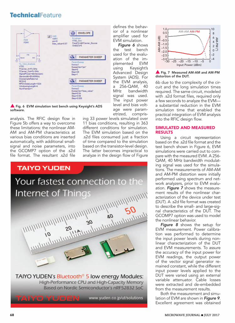
68 MICROWAVE JOURNAL JULY 2017
TechnicalFeature
6b due to the complexity of the cir-cuit and the long simulation times required. The same circuit, modeled with .s2d format files, required only a few seconds to analyze the EVM—a substantial reduction in the EVM simulation time that enabled the practical integration of EVM analysis into the RFIC design flow.
SIMULATED AND MEASURED RESULTS
Using a circuit representation based on the .s2d file format and the test bench shown in Figure 6, EVM simulations were carried out to com-pare with the measured EVM. A 256-QAM, 40 MHz bandwidth modulat-ing signal was used for the simula-tions. The measurements of AM-AM and AM-PM distortion were initially performed using spectrum and net-work analyzers, prior to EVM evalu-ation. Figure 7 shows the measure-ment results of the nonlinear char-acterization of the device under test (DUT). A .s2d file format was created to describe the small- and large-sig-nal characteristics of the DUT. The GCOMP7 option was used to model the nonlinear behavior.
Figure 8 shows the setup for EVM measurement. Power calibra-tion was performed to determine the input power levels during non-linear characterization of the DUT and EVM measurements. To assure the accuracy of the input power for EVM readings, the output power of the vector signal generator re-mained constant, while the different input power levels applied to the DUT were varied using an external variable attenuator. Cable losses were extracted and de-embedded from the measurement results.
Both the measurement and simu-lation of EVM are shown in Figure 9. Excellent agreement was obtained
defines the behav-ior of a nonlinear amplifier used for EVM simulation.
Figure 6 shows the test bench used for the evalu-ation of the im-plemented EVM using Keysight’s Advanced Design System (ADS). For the EVM analysis, a 256-QAM, 40 MHz bandwidth signal was used. The input power level and bias volt-age were param-etrized, compris-
ing 33 power levels simulated over 11 bias conditions, resulting in 363 different conditions for simulation. The EVM simulation based on the .s2d files consumed just a fraction of time compared to the simulation based on the transistor-level design. The latter becomes impractical to analyze in the design flow of Figure
analysis. The RFIC design flow in Figure 5b offers a way to overcome these limitations: the nonlinear AM-AM and AM-PM characteristics at various bias conditions are inserted automatically, with additional small-signal and noise parameters, into the GCOMP7 option of the .s2d file format. The resultant .s2d file
s Fig. 6 EVM simulation test bench using Keysight’s ADS software.
s Fig. 7 Measured AM-AM and AM-PM distortion of the DUT.
1.00.5
0–0.5–1.0–1.5–2.0–2.5–3.0
1086420
–2–4
0–5–10–15–20–25–30Input Power (dBm)
AM-AM AM-PM
AM
-AM
(dB
) AM
-PM (°)

MWJ/RCL/SOURCE/0717
RCL Microwave, Inc.Your Only Source
For Broadband Dielectric Characterization
Extensive experience that gets results!
Leading the industry in broadband dielectric characterization with thin film capability to 20 microns
MICROWAVE
Contact us for a free quote today!
877-387-6125
RCLMicrowave.com
DC 110GHz
Others RCL
RCL20 Microns
Others100 Microns
0.00 +00 3.00+10
.0050
.0040
.0030
.0020
.0010
.0000
Extensive experience that gets results!
Our test methods produce 10,000 data points. Other test methods only produce 1 data point.
10,000 VS 110,000 VS 110,000 VS 1
0.00 +00 3.00+10
6
5
4
3
2
1
Dielectric VS ConstantDissipation Factor VS Frequency

70 MICROWAVE JOURNAL JULY 2017
TechnicalFeature
sults show the importance of evalu-ating EVM, particularly at moderate power levels, where the results are highly dependent on the amplitude and phase distortion characteristics of the nonlinear circuit.
CONCLUSIONThe importance of integrating
EVM analysis into the RFIC design flow, particularly for systems with EVM specifications below ‐30 dB, cannot be overstated. Without in-cluding EVM in the design flow, the complete RF subsystem can have suboptimal EVM under dif-ferent input power and bias condi-tions. Small changes in the bias of an output stage can result in very different EVM over a wide range of input power. Fortunately, a substan-tial reduction in the simulation time for EVM evaluation can be obtained through AM-AM and AM-PM char-acterization and by incorporating this into the .s2d file format. Using this methodology for integrating EVM evaluation into the design flow, engineers can simulate EVM that is in excellent agreement with measured EVM—and in a fraction of the time.n
ACKNOWLEDGMENTThe authors would like to thank
K. Manin, I. Levie, P. Steinberg and E. Turgerman for fruitful discussions and measurement support.
References1. R. Hassung et al., “Effective Evaluation
of Link Quality Using Error Vector Magni-tude Techniques,” Wireless Communica-tion Conference, pp. 89–94, 1997.
2. P. Naraine, “Predicting the EVM Perfor-mance of WLAN Power Amplifiers with OFDM Signals,” Microwave Journal, May 2004.
between simula-tion and measure-ment at moderate and high input power. At power levels below −25 dBm, the sensitiv-ity of the measure-ment equipment limits the ability to measure EVM be-low −45 dB. The re-
s Fig. 8 EVM measured using the Keysight E4438C vector signal generator and N9020A signal analyzer.
s Fig. 9 Simulated vs. measured EVM.
–20
–25
–30
–35
–40
–45
–50
–550–5–10–15–20–25–30
SimulatedMeasured
Input Power (dBm)
EV
M (d
B)

MWJ/CUSTONMMIC/NEXT/0517
Over 100 high performance standard products—and growing.
For more than a decade, we’ve been focused on providing military and
aerospace designers proven GaAs and GaN solutions to their biggest
signal chain challenges.
Visit our website and learn about our commitment to quickly getting you
wherever you’re headed next.
CustomMMIC.com
Where can we take you next

A Modified Three-Level Doherty Amplifier for Next-Generation Communication SystemsMike RobertsSlipstream Engineering Design Ltd., Shipley, U.K.
A modified three-level Doherty amplifier produces good efficiency over 10 dB of operation using devices of equal periphery. Test results are presented that demonstrate a drain efficiency of greater than 40 percent at 10 dB back-off.
M odern communication systems routinely use complex modu-lation techniques that result in peak-to-average ratio (PAR)
signals of 9 dB and higher. To achieve suf-ficient linearity, these high PAR levels require a power amplifier (PA) to operate far below the power levels that would yield optimum power-added efficiency. To understand this effect, consider one of the simplest forms of an RF amplifier, the class AB type shown in Figure 1.
Such an amplifier is relatively straightfor-ward to design and manufacture and can easily provide peak drain efficiencies of around 65 percent when operating in the 2 GHz region. One drawback with this type of simple amplifier is that when the RF output signal level is reduced, the output voltage swing decreases and efficiency drops with the square root of the output power. This means that at a quarter of the output power (-6 dB), efficiency is about half of what it is at peak output power, or 32 percent in this example. Clearly, operating at 6 dB back-off
and higher with a class AB am-plifier results in a significant re-duction in efficiency, because the signal is, on average, sit-ting at a highly inefficient op-erating point.
The use of a Doherty ampli-fier is a well known technique for improving efficiency of a PA in backed-off operation. The standard two-way Doherty am-plifier with a peak in efficiency at 6 dB back-off and full pow-
er is commonly used and well understood. With the use of increasingly complex signals comes the challenge to move the peak in effi-ciency to higher levels of back-off while main-taining efficiency up to full power output. This can be achieved with asymmetrical Doherty amplifiers or by utilizing N-way Doherty tech-niques. This is why the use of Doherty ampli-fiers in modern code division multiple access (W-CDMA) and long-term evolution (LTE) sys-tems has seen a strong resurgence.
The two-way Doherty amplifier provides an improvement over class AB operation, but with higher levels of PAR being used it is necessary to improve efficiency at back-off levels of 10 dB and higher. The three-level or three-way Doherty amplifier produces peaks in efficiency at 9.5, 4.4 and 0 dB, which is a good fit for LTE transmitters. However, as will be seen later, the conventional approach requires that the two auxiliary amplifiers be twice the periphery of the main amplifier.
This article describes the operation of a modified three-level Doherty amplifier1 that produces good efficiency over the top 10 dB of operation using devices of equal periphery. Its operation is explained based on an Ampleon (formerly NXP) design that uses three laterally diffused metal oxide semiconductor (LDMOS) transistors of equal size. Design challenges faced with this type of amplifier are presented and compared against the conventional three-way Doherty architecture. Test results are presented that demonstrate a drain efficiency of greater than 40 percent at 10 dB back-off.
The entire RF design, including layout, is implemented in the NI AWR Design Environ-
72 MICROWAVE JOURNAL JULY 2017
TechnicalFeature
s Fig. 1 Simple class AB amplifier load line.
IDS
VDS

MWJ/NARDA/SPEED/0717
18 GHz THAT MOVES AT THE SPEED OF LIGHT.
18 GHz HIGH-RELIABILITY IF AND RF FIBER-OPTIC LINKSL3 Narda-MITEQ’s hermetically sealed fiber-optic links are ideal for transmitting both IF and RF signals optically, making them the perfect choice for a variety of applications, like antenna remoting and EMC/EMI. Models are available with instantaneous bandwidths of up to 18 GHz and oer a spurious-free dynamic range of 101 dB/Hz. These dynamic transmitters and receivers use standard wavelengths of 1550 nm and 1310 nm, performing in a wide temperature range of -40 °C to +85 °C with a typical low signal loss of 0.4 dB/km. So when your project demands the transmission of reliable IF and RF data optically, count on L3 Narda-MITEQ — your best resource for innovative fiber-optic solutions. Call us at (631) 231-1700. nardamiteq.com/hrta
Enclosures are available for multipletransmitter or receiver combinations.
AEROSPACE SYSTEMSELECTRONIC SYSTEMS
COMMUNICATION SYSTEMSSENSOR SYSTEMS
L3T.COM
Narda-MITEQ

74 MICROWAVE JOURNAL JULY 2017
TechnicalFeature
As input drive level is increased from the 6 dB back-off point, the cur-rent contribution into the load from the auxiliary ampli er increases. This increased current injected by the auxiliary ampli er means that the impedance looking into the load increases. The 50 Ω impedance in-verter between the load and the main ampli er ensures that the main ampli er sees a reduced load as the current contribution from the aux-iliary ampli er increases. So, in this regime, as output power increases, there are two processes taking place. The rst is that, due to load modula-tion from the auxiliary ampli er, the main ampli er is effectively increas-ing in size; that is, its capability to produce power is increasing during the time it is running at maximum voltage swing and hence maximum ef ciency. The other process taking place is that both the main and auxil-iary ampli ers contribute to the total output power.
As the drive level increases fur-ther, these processes continue to increase until the auxiliary ampli er is at maximum output power (if the devices are equal in size) and the cur-rents into the load from the main and
power is achieved, and both the main and auxiliary ampli ers con-tribute equally to deliver full power.
The two-way circuit is con gured with the main ampli er biased in class AB and the auxiliary ampli- er biased in class C. This biasing scheme means that at low input drive levels, the main ampli er con-ducts and the auxiliary ampli er is off. As input levels are increased, the main ampli er drive level also increases. When the output power is a quarter (‐6 dB) of the ampli er maximum, the auxiliary ampli er starts to conduct current. At low sig-nal levels, when the auxiliary ampli- er is not active, the main ampli er (assuming RL = 25 Ω) “sees” 100 Ω. This means that it reaches full volt-age swing at half power. Full voltage swing means that the main ampli er provides maximum ef ciency at half its output power. At this point, the ampli er, as a whole, is delivering a quarter (‐6 dB) of its peak power capability with maximum ef ciency. This is the rst point on the theoreti-cal ef ciency curve in Figure 3.
ment. Within this software environ-ment, Microwave Of ce circuit de-sign software and APLAC harmonic balance are used to simulate, in detail, the large-signal effects of the Doherty ampli er’s operation. The software’s load-pull analysis is used to determine the impact of load im-pedance on ampli er performance.
TWO-WAY DOHERTY DESIGNAlthough well documented in
the literature, it is worth taking a moment to revisit the simple case of the two-way Doherty ampli- er to fully understand the three-level con guration. The standard two-way Doherty ampli er works by splitting the ampli er into two equally-sized ampli ers that are half the size of a single-ended class AB ampli er with the same peak power capability (see Figure 2). The basic principle is that when the output signal level is low, only the main ampli er is active. With increasing output levels, the aux-iliary ampli er is progressively in-troduced up to the point where full
Fig. 2 Single-ended class AB ampli er (a) and two-way Doherty ampli er (b).
InputMatch
Input
InputInput
Splitter
RL
RL
2RL90°Main
Aux
X°
90° X°
(a)
(b)
OutputMatch
Fig. 3 Theoretical ef ciency of a two-way Doherty ampli er.
18 15 12 9 6 3 0
Ef
cien
cy (%
)
Output Power Back-Off (dB)
Sales contactsInside Sales : Christy Strahan Anderson
Domestic/International Sales : Bill LiebmanTechnical Sales : Effi Bainvoll
Exodus Advanced Communications, Corp.3674 E. Sunset Road, Suite 100Las Vegas, Nevada 89120 USA
Tel : 1-702-534-6564Fax : 1-702-441-7016
Email : [email protected]
Best in Class RF Amplifier SSPA’s
www.exoduscomm.com
High Power SSPA: Chip & Wire Assemblies, Modules & Systems: Broadband, CW, Pulse & Linear Applications
: 1MHz to 47GHz, 3KW CW, 10KW PulseBlock Up Converters
Medium Power AmplifiersLow Noise Amplifiers
Journal design 1.indd 1 2017-06-13 오전 9:51:00

MWJ/PMI/DIPLEXERS/0717
Amplifiers – Solid StateAttenuators – Variable/ ProgrammableCouplers (Quadrature, 180° & Directional)Detectors – RF/MicrowaveDLVAs, ERDLVAs & SDLVAsDTOs, VCOs, PLO, DROs, & Frequency SynthesizersFilters & Switched Filter BanksForm, Fit, Functional Products & ServicesFrequency Discriminators & IFMsIntegrated MIC/MMIC Assemblies (IMAs)IQ Vector ModulatorsLimiters – RF/MicrowaveLog AmplifiersMillimeter Wave Components (Up to 50 GHz)Miscellaneous ProductsMultifunction Integrated Assemblies (MIAs)Phase Shifters & Bi-Phase ModulatorsPower Dividers/Combiners (Passive & Active)Pulse Modulators (SPST)Rack & Chassis Mount ProductsReceiver Front Ends & TransceiversSDLVAs, ERDLVAs & DLVAsSingle Side Band ModulatorsSMT & QFN ProductsSwitch Matrices Switched Filter BanksSwitches – Solid StateSystems - Radar Sense & AvoidSystems – Fly Eye RadarsThreshold DetectorsUSB Products
West Coast Operation:4921 Robert J. Mathews Pkwy, Suite 1
El Dorado Hills, CA 95762 USATel: 916-542-1401, Fax: 916-265-2597
East Coast Operation:7311-F Grove Road
Frederick, MD 21704 USATel: 301-662-5019, Fax: 301-662-1731
[email protected] • www.pmi-rf.comISO9001-2008 REGISTERED
Planar Monolithics Industries, Inc.Diplexers / Multiplexers - Filters
PMI offers the highest quality filters, diplexers, multiplexers, switch filter banks, and filter assemblies for industrial and military applications in the DC to 40 GHz frequency range. PMI’s specializes in form, fit, and function replacement parts to customers’ electrical, mechanical, and environmental specifications. More available at http://www.pmi-rf.com/Products/filters/features.htmModel: 11DP-11R5/16R5-CD-SFF-1 (Diplexer)http://www.pmi-rf.com/Products/filters/11DP-11R5-16R5-CD-SFF-1.htm
Model: DPX-18G26R5G40G (Diplexer) http://www.pmi-rf.com/Products/filters/DPX-18G26R5G40G.htm
Model: DP-5700M-6500M-CD-SFF (Diplexer) http://www.pmi-rf.com/Products/filters/DP-5700M-6500M-CD-SFF.htm
Model: PTP-1G18G-2G8G-55-S4F (Triplexer) http://www.pmi-rf.com/Products/filters/PTP-1G18G-2G8G-55-S4F.htm
Center Frequencies, Fo Low Band: 11.5 GHz High Band: 16.5 GHz
Passband Frequencies Low Band: 10.75 to 12.25 GHz High Band: 15.75 to 17.25 GHz
Passband Insertion Loss 3 dB Max. - Measured 1.67 dB
Passband VSWR 1.5:1 Max. - Measured 1.4:1
Rejections Low Band: -50 dBc @ 10.25 GHz - Measured -64 dBc-75 dBc @ 13.75 GHz - Measured -85 dBcHigh Band: -50 dBc @ 17.75 GHz - Measured -64 dBc-75 dBc @ 14.25 GHz - Measured -85 dBc
Package Size: 3.0” X 1.8” X 0.5”Connectors: SMA (F)
Low Passband 5.7 to 6.5 GHz Min.
High Passband 13.75 to 14.50 GHz Min.
Passband Insertion Loss < 1 dB @ Low Passband - Measured 0.57 dB < 2 dB @ High Passband - Measured 1.32 dB
VSWR 2.0:1 @ Passbands - Measured 1.37 dB
CH to CH Isolation > 70 dB - Measured 83.19 dB
Power Handling 20 W
Insertion Loss J1 to J2: 1.3 dB Max. @ 1.0 to 1.9 GHz J1 to J3: 1.3 dB Max. @ 2.1 to 7.6 GHz J1 to J4: 1.3 dB Max. @ 8.4 to 18.0 GHz
Out-Of-Band Rejection J1 to J2: 55 dB Min. @ DC to 0.75 GHz 55 dB Min. @ 2.3 to 18.0 GHz J1 to J3: 55 dB Min. @ DC to 1.7 GHz 55 dB Min. @ 9.2 to 18.0 GHz J1 to J4: 55 dB Min. @ DC to 6.8 GHz 55 dB Min. @ 20.5 to 26.0 GHz
Crossover J2/J3: 5.5 dB Max. @ 1.98 to 2.02 GHz J3/J4: 5.5 dB Max. @ 7.92 to 8.08 GHz
VSWR 2.0:1 Max.
Input Power +20 dBm CW
Package Size: 2.5” x 1.0” x 0.6”Connectors: SMA (F)
Package Size: 0.8”x 0.6” x 0.38” Connectors: 2.92mm (F)
Package Size: 3.5” x 1.4” x 0.5”Connectors: SMA (F) removable
Insertion Loss (Passband) 2 dB Max. - Measured 1.3 dB
VSWR (Passband) 2.5:1 Max. - Measured 2.4:1
Diplexer K Band 1dB Passband 18.0 GHz, Min., 25.0 GHz Max.
Diplexer Ka Band 1dB Passband 28.0 GHz Min., 40.0 GHz Max.
Crossover Band 25.0 GHz Min., 28 GHz Max
Crossover Excess Attenuation 5 dB Typ. - Measured 4.8 dB
Stopband Attenuation 60 dB - Measured 64 dB
K Band (Stopband) 32.0 GHz - 46.0 GHz
Ka Band (Stopband) DC - 22.0 GHz

76 MICROWAVE JOURNAL JULY 2017
TechnicalFeature
Toll Free: 1-800-839-3658 Office: 724-349-1412
Matrix Switch Your RF Signals
Blocking Fan-Out & Fan-In
Mesh
MakeYourSwitch To
. . . . .
. . . .
I/O
I/O .
Fully Non-Blocking
CONVENTIONAL THREE-LEVEL DOHERTY DESIGN
As shown in Figure 6, the con-ventional three-level Doherty am-plifier is a direct extension of the two-way design. By adjusting the relative device periphery between the main and auxiliary amplifiers, it is possible to achieve a variety of different positions for the efficiency peaks. The designer can use the equations defined by Edmund, et al.3 to locate the efficiency peaks as required. This article is concerned with signals around 10 dB of PAR. The relative levels of device periph-ery to achieve an efficiency peak at ‐9.5, ‐4.4 and 0 dB for the conven-tional three-level Doherty is 1:2:2, where the first digit is the main am-plifier followed by Aux 1 and Aux 2.
For this configuration, Z01 is re-quired to be 70.7 Ω, Z02 = 33.3 Ω and RL = 20 Ω. At the first efficien-cy peak, the main amplifier sees an impedance of 90 Ω. In order to match the output to 50 Ω, an im-pedance inverter with a value of √(20*50)=31.6 Ω is required. In es-sence, the conventional three-level Doherty amplifier behaves as a two-way Doherty amplifier up to the second peak (‐4.4 dB) in efficiency; then, from the second peak to full power, the main and auxiliary 1 am-plifiers behave like a main amplifier that is load modulated by the cur-rent contribution from auxiliary 2.
There are two main drawbacks to the conventional three-level
excellent description of the princi-ples involved. The key elements are summarized here for clarity.
Figure 4 represents the simplest possible case where two current sources are feeding into a common load. When I2 = 0, the impedance Z1 is simply equal to RL. If a current is injected into the load from I2 then the impedance Z1 is modified to:
Z1 = 1+ I2I1
⎛⎝⎜
⎞⎠⎟RL (1)
If I1 and I2 are equal, then Z1 = Z2 = 2RL. With the addition of an imped-ance inverter as shown in Figure 5, this circuit becomes the two-way Doherty. The addition of the inverter
causes the imped-ance seen at the main amplifier, Zm, to decrease when the current from the auxiliary ampli-fier is injected into the common load. When the auxiliary amplifier is off Zm = Zo
2 /RL.
auxiliary amplifiers are equal. At this point the main and auxiliary amplifi-ers both see 50 Ω. The key concept in the operation of the Doherty am-plifier is load modulation. The expla-nation given by Cripps2 provides an
s Fig. 4 Standard two-way Doherty load modulation with the inverter removed.
Z1 Z2
I2I1 IL
RL
s Fig. 5 Two-way Doherty amplifier.
AuxAmplier
MainAmplier
ZmZm
Z0
RL
Im
Za
IaIL
s Fig. 6 Conventional three-level Doherty amplifier.
Main
Aux 1
Aux 2
1
2
2
Inp
ut
Z01
Z02
RL
90°
180°

MWJ/ATC/BROADBAND/0617ATC Technical Productions Issue: June 2017 Ad: 550 Series BB Ad Trim Size: 7 13/16” x 10 3/4”Media: Microwave Journal
ATC Series
EIA Size
CapacitanceFrequency
RangeInsertion
LossVoltage Rating
520 L 0402 10 nF 160 KHz to 16 GHz 1 dB max. 16 WVDC
530 L 0402 100 nF 16 KHz to 18 GHz 1 dB max. 16 WVDC
530 Z 0201 100 nF 16 KHz to 20 GHz 0.4 dB typ. 10 WVDC
Reliable and Repeatable Broadband Performance
THE ENGINEERS’ CHOICE® www.atceramics.com
ATC’s 520 and 530 Series family of Broadband Capacitors exhibit low insertion
loss over multiple octaves of frequency spectrum, flat frequency response and
excellent return loss. They are ideal for broadband DC blocking, coupling,
bypassing, and feedback applications in optical communications systems and
equipment using high-speed digital logic.
Attributes
• 0201 and 0402 EIA Case Sizes
• 16 KHz to 20 GHz
• Low Insertion Loss
• Voltage Ratings to 16 WVDC
• Unit-to-Unit Performance Repeatablity
• RoHS Compliant Terminations
• Solderable SMT Terminations

78 MICROWAVE JOURNAL JULY 2017
TechnicalFeature
cluding the use of a single “unit cell” RF design. The basic amplifier unit cell for the main and auxiliaries can be of the same (or very similar) design, which reduces develop-ment time. Also, having three of the same part rather than two different parts on the bill of materials results in economies of scale, which is im-portant for what are likely to be the most expensive components in the amplifier. The configuration also provides proper load modulation of the main amplifier, whose load impedance is steadily reduced with increasing drive level. A schematic of the modified three-level Doherty is shown in Figure 7.
The best way to understand the operation is to start at low signal levels, progressively increasing the input drive and discussing the op-eration at each efficiency peak (see Figure 8). Each unit cell in this ex-ample delivers maximum output power when driving a 50 Ω load. The unit cell also contains phase offset lines to ensure that the elec-trical length of an auxiliary (and main) stage is 180 degrees from the active device at the point where the amplifier is connected into the Doherty combiner circuit. This en-sures that when the auxiliary ampli-fier is switched off, an open circuit is presented to the Doherty combiner and minimum power is dissipated in the auxiliary output matching cir-cuits. The main amplifier is biased in a class AB mode, auxiliary 1 is bi-ased at about 0.7 V, and auxiliary 2 is biased at about 0 V when using enhancement mode LDMOS tran-sistors. These values provide the re-quired progressive switching of the auxiliary amplifiers. Note that the load is 16.7 Ω in this example and
MODIFIED THREE-LEVEL DOHERTY WITH EQUAL DEVICES
The modified three-level Doherty design1 achieves similar performance to a conventional three-level Doherty amplifier with-out having to accommodate out-put transistors of different sizes. Using transistors of equal size for the main and auxiliary stages has a number of practical benefits, in-
Doherty amplifier. The first is that different device sizes are required to provide efficiency peaks in the 10 dB back-off region, which leads to added complexity. The second is that the load modulation of the main amplifier stops between the second and final efficiency peaks. This means that the main ampli-fier is driven into extreme satura-tion over the last 6 dB of output power.1
s Fig. 7 Modified three-level Doherty amplifier.
Main
Aux 1
Aux 2
1
1
1
Input
150 Ω @ – 9 dB100 Ω @ – 6 dB 50 Ω @ 0 dB
∞ @ – 9 dB200 Ω @ – 6 dB 50 Ω @ 0 dB
∞ @ – 9 dB ∞ @ – 6 dB 50 Ω @ 0 dB
Z01 = 50 Ω
RL= 16.6 Ω
Z02 = 50 Ω Z03 = 25 Ω
Node B
Node A
90°
90°
s Fig. 8 Theoretical efficiency of a three-way Doherty amplifier.
90
70
50
30
10
18 15 12
A B C
9 6 3 0
Ef
cien
cy (%
)
Output Power Back-Off (dB)

MWJ/WIN/BECAUSE/0717
Compound Semiconductor Solutions from RF to Lightwave™
winfoundry.com/contactus [email protected]
North America 1-908-752-5437 Europe 353 87 175 7307
WIN. Because not everyone can do this.A wider selection of technologies Scalable manufacturing for any applicationWIN Semiconductors delivers technology solutions that cover applications from DC to 100GHz and beyond. As the innovation leader in compound semiconductors, WIN serves a wide range of rapidly growing markets with unmatched manufacturing scale and unique capabilities to help design engineers solve problems - fast.
Leadership in compound semiconductor manufacturing
Three production locations
Over 1,000,000 ft2 manufacturing space
Flexible wafer production for consumer and specialty markets
Wide array of value-added services
Technology platforms
GaAs HBT for mobile PA and 802.11ac
Highly integrated pHEMT
GaN
Optical devices
With an expansive technology portfolio, rapid turn times, and
unrivaled manufacturing scale, WIN enables market leading
products with a seamless move to high volume production.
How can WIN help you today?Contact WIN today, and see how we can help you reduce size, improve performance and reach the next level of innovation.
With technology, manufacturing scale and support services unmatched in the industry, you’ll see why partnering with us is a win-win.

80 MICROWAVE JOURNAL JULY 2017
TechnicalFeature
Waveguide
USB Controlled
Electromechanical
Surface Mount
PIN Diode
Broadest Selection of In-Stock RF Switches
• Coaxial, Waveguide and Surface Mount options available
• SPST thru SP12T and Transfer con gurations
• Frequencies from 10 MHz to 110 GHz
• All in-stock and ship same-day
RF COMPONENTS ON DEMAND.
RF COMPONENTS ON DEMAND.
RF COMPONENTS ON DEMAND.
RF COMPONENTS ON DEMAND.
RF COMPONENTS ON DEMAND.
RF COMPONENTS ON DEMAND.
main path causes the impedance seen by the main ampli er to fall. This reduction in output imped-ance enables the main ampli er to deliver more power into the com-mon load while remaining in volt-age saturation.
As drive level increases, this pro-cess continues until the current in the load due to the auxiliary ampli- er is half the current in the load due to the main ampli er, and the following condition is reached:
=II
0.5 (2 )A1
M
This condition is point B in Figure 8 and is the second ef ciency peak. Applying Equation 1, the imped-
transformed up to 50 Ω with a 28.8 Ω quarter-wave inverter.
At low signal levels, in the re-gime before point A in Figure 8 is reached, only the main ampli er is active. The impedance presented to the main ampli er unit cell at this point is 150 Ω. At point A (9 dB back-off) the conditions shown in Table 1 apply. As the input drive level increases, it moves to the re-gion between points A and B (6 dB back-off) in Figure 8. At point A, auxiliary 1 switches on and starts to deliver current into the common output load RL. This increase in cur-rent into the common load causes the impedance seen from the main ampli er at node A to increase. The action of the inverter Z01 in the
TABLE 1MODIFIED THREE-LEVEL DOHERTY AT 9 dB BACK-OFF
Stage Impedance Presentedto Unit Cell
Power Deliveredto Output Load
Main 150 Ω 33% of PMaxMain
Aux 1 Open 0
Aux 2 Open 0
Total Power in Load 11% of PTotal
Power Delivered/Total Power Capability
(Back-Off Level in dB)
10log(0.33/3) = −9.6 dB
TABLE 2MODIFIED THREE-LEVEL DOHERTY AT 6 dB BACK-OFF
Stage Impedance Presentedto Unit Cell
Power Deliveredto Output Load
Main 100 Ω 50% of PMaxMain
Aux 1 200 Ω 25% of PMaxAUX1
Aux 2 Open 0
Total Power in Load (Max = 3)
25% of PTotal
Power Delivered/Total Power Capability
(Back-Off Level in dB)
10log(0.75/3) = −6.0 dB
TABLE 3MODIFIED THREE-LEVEL DOHERTY AT 0 dB BACK-OFF
Stage Impedance Presentedto Unit Cell
Power Deliveredto Output Load
Main 50 Ω 100% of PMaxMain
Aux 1 50 Ω 100% of PMaxAUX1
Aux 2 50 Ω 100% of PMaxAUX2
Total Power in Load (Max = 3)
100% of PTotal
Power Delivered/Total Power Capability
(Back-Off Level in dB)
10log(1) = 0 dB

MWJ/FAIRVIEW/RIGHT/1016
The Right RF Parts.Right Away.
We’re RF On Demand, with over one million RF and microwave components in stock and ready to ship. You can count on us to stock the RF parts you need and reliably ship them when you need them. Add Fairview Microwave to your team and consider it done.
fairviewmicrowave.com1.800.715.4396 RF COMPONENTS ON DEMAND.
RF COMPONENTS ON DEMAND.
RF COMPONENTS ON DEMAND.

82 MICROWAVE JOURNAL JULY 2017
TechnicalFeature
ni-microwavecomponents.com/quicksyn
SIGNAL SOURCESQUICKSYN SYNTHESIZERS
Design smaller and more efficiently
with National Instruments QuickSyn
synthesizers. The revolutionary phase-
refining technology used in QuickSyn
synthesizers enables blazing fast
switching speeds, very low spurious
and phase noise performance, wide
frequency range, and small footprint.
FASTER, QUIETER, SMALLER
QuickSyn Lite Synthesizer
© 2016 National Instruments. All rights reserved.
cy, hence the peak in efficiency. The amplifier parameters at this second efficiency peak are given in Table 2.
Bias of the auxiliary 2 amplifier is set such that it starts to turn on and deliver current into the output load when Equation 2 is satisfied. The in-crease in current further reduces the main impedance and allows it to de-liver more power. The increased cur-rent into the load also reduces the load impedance seen by the auxilia-ry 1 amplifier, so this device delivers more power and further increases load current. This increase in cur-rent continues until the contribution from each amplifier is equal and the following is satisfied:
= =I I I (5)M A1 A2
The two auxiliary amplifiers deliver a total normalized current of 2 into the load and the main amplifier delivers 1. This is point C in Figure 8. At this point, the impedance from the main branch looking into node A is now
ZM_NodeA = RL 1+ IA1+ IA2
IM
⎛⎝⎜
⎞⎠⎟=
3RL = 50 Ω (6)
The main amplifier sees 50 Ω and delivers full power. The impedance seen from the auxiliary branch look-ing into node A is given by:
ZA_NodeA = RL 1+ IMIA1+ IA2
⎛⎝⎜
⎞⎠⎟=
32RL = 25Ω (7)
Since Z03 is a 25 Ω inverter, the im-pedance looking into node B is also 25 Ω. This is the correct impedance for two 50 Ω loads in parallel. The parameters for the amplifier at this third and final efficiency peak (0 dB back-off) are given in Table 3.
In addition to the design of the output network, there are a number of practical design considerations for this type of amplifier that should be considered. The first is that the gain of the three-level amplifier is inher-ently quite low because of the three-way input split. This results in the small-signal gain being a minimum of 4.7 dB lower than that obtained from a single-ended device. This is less of an issue at lower cellular bands but can become a problem at higher frequencies, where gain is at a premium. The quarter-wave trans-formers used extensively throughout
ZA_NodeA = RL 1+ IMIA1
⎛⎝⎜
⎞⎠⎟=
3RL = 50 Ω (4)
The impedance at node B look-ing from the auxiliary 2 amplifier is therefore 12.5 Ω (due to Z03), and the impedance seen by the auxiliary 1 unit cell amplifier is 200 Ω. Since the main and auxiliary 1 amplifiers are both running at voltage saturation, they both deliver maximum efficien-
ance seen from the main amplifier looking into node A is given by:
ZM_NodeA = RL 1+ IA1IM
⎛⎝⎜
⎞⎠⎟=
32RL = 25Ω (3)
So, the impedance seen by the main device looking into the 50 Ω inverter Z01 is 100 Ω. Also, the impedance seen from the auxiliary branch look-ing into node A is given by:

MWJ/H&S/ENVIROFLEX/0717
HUBER+SUHNER AG 9100 Herisau/SwitzerlandHUBER+SUHNER INC. Charlotte NC 28273/USA
Enviroflex BasicThe environmental friendly alternative With the introduction of Enviroflex basic, HUBER+SUHNER expand their portfolio of halogen free RF cables. The environmental friendly alternative extends the selection with cost-effective RF cables for less demanding applications. Thanks to the mechanical compatibility with RG cables the Enviroflex products can easily be designed-in using existing connectors.
› hubersuhner.com/enviroflex-basic
MWJ_June_Enviroflex_198x273mm.indd 2 14.06.2017 08:08:23

84 MICROWAVE JOURNAL JULY 2017
TechnicalFeature
put compression (see Figure 10). As can be seen, the design objective of 40 percent drain efficiency at 10 dB back-off is achieved over the band of interest. The small-signal gain of this amplifier is about 16 dB, with a power gain at full power of 14 dB.
CONCLUSIONThis article presented an over-
view and explanation of the oper-ating principles for a modified Am-pleon three-level Doherty amplifier3
that produces good efficiency over the top 10 dB of operation using devices of equal periphery. Design challenges faced with this type of amplifier were discussed and com-pared with those of a conventional three-way Doherty architecture. Ex-perimental results demonstrate a drain efficiency of greater than 40 percent at 10 dB back-off.n
References1. R. Gajadharsing, W. C. E Neo, M. Pelk,
L. C. N. De Vreede and J. Zhao, “3-Way Doherty Amplifier With Minimum Output Network,” U.S. Patent US20100315162, issued December 16, 2010.
2. S. Cripps, “RF Power Amplifiers for Wire-less Communications,” Artech House, Norwood, Mass., April 1999.
3. W. C. Edmund Neo, J. Qureshi, M. J. Pelk, J. R. Gajadharsing and L. C. N. de Vreede, “A Mixed Signal Approach Towards Linear and Efficient N-Way Doherty Amplifiers,” IEEE Transactions on Microwave Theory and Techniques, Vol. 55, No. 5, May 2007.
9. The three-way input split (‐4.7 dB) is achieved by using a 5 dB direc-tional coupler cascaded with a 3 dB hybrid coupler. The transistors used are twin LDMOS devices running at 28 V bias (normally used for push/pull or balanced applications) with one of the transistors unused in the upper device. Results are presented as back-off levels from the full out-put power of 150 W, which in this case is defined as about 2 dB out-
this design limit the bandwidth to about four to five percent maximum, so this approach is only applicable for narrowband applications.
EXPERIMENTAL RESULTSTo demonstrate the concept, a
2.14 GHz version of the Ampleon three-level amplifier was designed and manufactured by Slipstream Engineering Design. A photograph of the amplifier is shown in Figure s Fig. 9 Slipstream Engineering’s 2.14
GHz three-way Doherty amplifier.
s Fig. 10 CW drain efficiency vs. back-off vs. frequency. Full power is 150 W.
70
60
50
40
30
2002468101214
Dra
in E
fci
ency
(%)
Power Back-Off (dB)
2110 MHz 2140 MHz 2170 MHz

MWJ/MC/478REVR/0217
http://www.modelithics.com/mvp/Mini-Circuits.asp
FREE X-Parameters-Based Non-Linear Simulation Models for ADS
478 rev R
RoHS compliant
PHA-1+
0.05-6 GHz $199
ea. (qty. 20)
Gain 13.5 dBPout 22 dBm
Gain 14.0 dB
AVA-183A+
5-18 GHz $7 95
ea. (qty. 20)
Pout 19 dBm
MMIC AMPLIFIERS50 MHz to 26.5 GHz
Mini-Circuits®
www.minicircuits.com P.O. Box 350166, Brooklyn, NY 11235-0003 (718) 934-4500 [email protected]
AVM-273HPK+13-26.5 GHz
$3690ea. (qty. 10)
Gain 13.0 dBPout 27 dBm
Mini-Circuits’ AVM-273HPK+ wideband microwave MMIC amplifier supports applications from 13 to 26.5 GHz with up to 0.5W output power, 13 dB gain, ±1 dB gain flatness and 58 dB reverse isolation. The amplifier comes supplied with a voltage sequencing and DC control module providing reverse voltage protection in one tiny package to simplify your circuit design. This model is an ideal buffer amplifier for P2P radios, military EW and radar, DBS, VSAT and more!
The AVA-183A+ delivers 14 dB gain with excellent gain flatness (±1.0 dB) from 5 to 18 GHz, 38 dB isolation, and 19 dBm power handling. It is unconditionally stable and an ideal LO driver amplifier. Internal DC blocks, bias tee, and microwave coupling capacitor simplify external circuits, minimizing your design time.
The PHA-1+ uses E-PHEMT technology to offer ultra-high dynamic range, low noise, and excellent IP3 performance, making it ideal for LTE, and TD-SCDMA. Good input and output return loss across almost 7 octaves extend its use to CATV, wireless LANs, and base station infrastructure.
Visit minicircuits.com for full specs, performance curves, and free data! These models are in stock and ready to ship today!
We’ve got you covered! 3 MMIC amplifiers support the whole gamut of applications from 50 MHz all the way up to 26.5 GHz!
http://www.modelithics.com/mvp/Mini-Circuits.asp
FREE X-Parameters-Based Non-Linear Simulation Models for ADS
478 rev R avaPHA.indd 1 9/9/16 2:51 PM
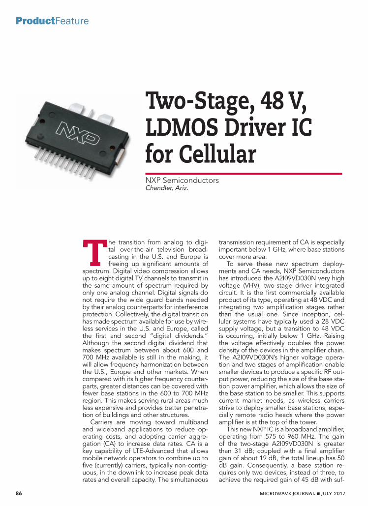
Two-Stage, 48 V, LDMOS Driver IC for Cellular NXP SemiconductorsChandler, Ariz.
The transition from analog to digi-tal over-the-air television broad-casting in the U.S. and Europe is freeing up significant amounts of
spectrum. Digital video compression allows up to eight digital TV channels to transmit in the same amount of spectrum required by only one analog channel. Digital signals do not require the wide guard bands needed by their analog counterparts for interference protection. Collectively, the digital transition has made spectrum available for use by wire-less services in the U.S. and Europe, called the first and second “digital dividends.” Although the second digital dividend that makes spectrum between about 600 and 700 MHz available is still in the making, it will allow frequency harmonization between the U.S., Europe and other markets. When compared with its higher frequency counter-parts, greater distances can be covered with fewer base stations in the 600 to 700 MHz region. This makes serving rural areas much less expensive and provides better penetra-tion of buildings and other structures.
Carriers are moving toward multiband and wideband applications to reduce op-erating costs, and adopting carrier aggre-gation (CA) to increase data rates. CA is a key capability of LTE-Advanced that allows mobile network operators to combine up to five (currently) carriers, typically non-contig-uous, in the downlink to increase peak data rates and overall capacity. The simultaneous
transmission requirement of CA is especially important below 1 GHz, where base stations cover more area.
To serve these new spectrum deploy-ments and CA needs, NXP Semiconductors has introduced the A2I09VD030N very high voltage (VHV), two-stage driver integrated circuit. It is the first commercially available product of its type, operating at 48 VDC and integrating two amplification stages rather than the usual one. Since inception, cel-lular systems have typically used a 28 VDC supply voltage, but a transition to 48 VDC is occurring, initially below 1 GHz. Raising the voltage effectively doubles the power density of the devices in the amplifier chain. The A2I09VD030N’s higher voltage opera-tion and two stages of amplification enable smaller devices to produce a specific RF out-put power, reducing the size of the base sta-tion power amplifier, which allows the size of the base station to be smaller. This supports current market needs, as wireless carriers strive to deploy smaller base stations, espe-cially remote radio heads where the power amplifier is at the top of the tower.
This new NXP IC is a broadband amplifier, operating from 575 to 960 MHz. The gain of the two-stage A2I09VD030N is greater than 31 dB; coupled with a final amplifier gain of about 19 dB, the total lineup has 50 dB gain. Consequently, a base station re-quires only two devices, instead of three, to achieve the required gain of 45 dB with suf-
86 MICROWAVE JOURNAL JULY 2017
ProductFeature

2 GHz Clock Generator
Stanford Research Systems
Phone: (408)744-9040 • Fax: (408)744-9049 • [email protected] • www.thinkSRS.com
• Square wave clocks from DC to 2.05 GHz
• Random jitter <1 ps (rms)
• 80 ps rise and fall times
• 16-digit frequency resolution
• CMOS, LVDS, ECL, PECL, RS-485
• Phase adjustment & time modulation
The CG635 generates clock signals—flawlessly. The clock signals are fast, clean and accurate, and can be set to standard logic levels.
How fast? Frequency to 2.05 GHz with rise and fall times as short as 80 ps.
How clean? Jitter is less than 1 ps and phase noise is better than –90 dBc/Hz (100 Hz offset) at 622.08 MHz.
How accurate? Using the optional rubidium timebase, aging is better than 0.0005 ppm/yr,and temperature stability is better than 0.0001 ppm.
You would expect an instrument this good to be expensive, but it isn’t. You no longer have to buy an rf synthesizer to generate clock signals. The CG635 does the job better—at a fraction of the cost.
Plot shows complementary clocks and PRBS (opt. 01) outputs at 622.08 Mb/s with LVDS levels. Traces have transition times of 80 ps and jitter less than 1 ps (rms).
CG635_ad_cmyk.indd 1 7/2/2015 3:41:59 PM
MWJ/SANFORD/CLOCK/0815

88 MICROWAVE JOURNAL JULY 2017
ProductFeature
MW and MMW amplifiers and integrated assemblies Up to 100 GHz. High degree of customization.
Space / Aerospace / Military / Laboratory
www.erzia.comERZIA, 2001 L Street NW, Suite 500, Washington, DC 20036
[email protected] Tel: +1 202-495-3479 ERZIA HQ, Josefina de la Maza 4, 39012 Santander, [email protected] Tel: +34 942 29 13 42
Doherty configuration as the final stage driver. Operating from 920 to 960 MHz, the A2I09VD030N pro-duces 40 W of peak power with 34 dB of gain and 20 percent efficiency at a 10 dB output back-off. Adjacent channel power ratio (ACPR) is about ‐44 dBc (see Table 1). The device is an excellent driver for several NXP high-power VHV transistors, including the A2V09H525-04N and A2V07H525-04N, which forms an 80 W base station amplifier lineup.
The A2I09VD030N is in produc-tion, and NXP is working on smaller and higher power versions, to offer a more complete portfolio.
The digital dividends are a bo-nus for the cellular industry, enabled by the adoption of digital televi-sion technology. Although the new spectrum in the U.S. is not yet de-ployed, the “reverse” auction has completed, and the FCC has estab-lished a timeline for implementing the new mobile frequencies—which are in the “sweet spot” where signal propagation is well-suited for wire-less communications. The new NXP IC is designed to optimize perfor-mance at these frequencies. By op-erating at 48 V, base station power amplifiers can be created with fewer RF power devices, consuming less power and reducing size.
NXP Semiconductors Chandler, Ariz. www.nxp.com/RF
chitectures: combined with a 3 dB hybrid (see Figure 1), used as two separate drivers or combined in a
ficient margin. The A2I09VD030N is also a dual-path device, so it can be used in different amplifier ar-
s Fig. 1 A dual-path amplifier using the A2I09VD030N IC. The hybrid splitter on the input and combiner on the output can be connected for single-path operation.
Input Side A
48 V Drain Supply
Input Side B
Output Side A
Output Side B
Output CombinerInput Splitter
TABLE 1A2I09VD030N DRIVER IC SPECIFICATIONS
Frequency (MHz) Gain (dB) Power-Added Efficiency (%) ACPR (dBc)
920 34.4 19.9 −45.0
940 34.5 20.0 −44.6
960 34.3 19.8 −44.3
Test Conditions: Single-Carrier W-CDMA, Input PAR = 9.9 dB at 0.01% probability on CCDF. Average Pout = 4 W. VDD = 48 V, IDQ (A+B) = −46 mA, IDQ2 (A+B) = 154 mA

MWJ/ROSENBERGER/AEROSPACE/0417
Aerospace Products
Whether aviation or spaceflight applications – Rosenberger is a qualified and trusted supplier of connectors and cable assemblies to the aerospace industry. Our aerospace products are designed and manufactured in accordance with ESCC, MIL-PRF 39012, or DIN EN 9100.
www.rosenberger.com/aerospace
AEROSPACE
Product range § Cable assemblies § Board-to-Board connections § Board-to-Cable connections § SMD types § PCB connectors
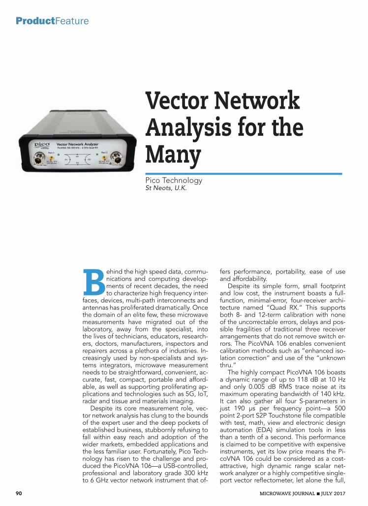
Vector Network Analysis for the ManyPico TechnologySt Neots, U.K.
Behind the high speed data, commu-nications and computing develop-ments of recent decades, the need to characterize high frequency inter-
faces, devices, multi-path interconnects and antennas has proliferated dramatically. Once the domain of an elite few, these microwave measurements have migrated out of the laboratory, away from the specialist, into the lives of technicians, educators, research-ers, doctors, manufacturers, inspectors and repairers across a plethora of industries. In-creasingly used by non-specialists and sys-tems integrators, microwave measurement needs to be straightforward, convenient, ac-curate, fast, compact, portable and afford-able, as well as supporting proliferating ap-plications and technologies such as 5G, IoT, radar and tissue and materials imaging.
Despite its core measurement role, vec-tor network analysis has clung to the bounds of the expert user and the deep pockets of established business, stubbornly refusing to fall within easy reach and adoption of the wider markets, embedded applications and the less familiar user. Fortunately, Pico Tech-nology has risen to the challenge and pro-duced the PicoVNA 106—a USB-controlled, professional and laboratory grade 300 kHz to 6 GHz vector network instrument that of-
fers performance, portability, ease of use and affordability.
Despite its simple form, small footprint and low cost, the instrument boasts a full-function, minimal-error, four-receiver archi-tecture named “Quad RX.” This supports both 8- and 12-term calibration with none of the uncorrectable errors, delays and pos-sible fragilities of traditional three receiver arrangements that do not remove switch er-rors. The PicoVNA 106 enables convenient calibration methods such as “enhanced iso-lation correction” and use of the “unknown thru.”
The highly compact PicoVNA 106 boasts a dynamic range of up to 118 dB at 10 Hz and only 0.005 dB RMS trace noise at its maximum operating bandwidth of 140 kHz. It can also gather all four S-parameters in just 190 µs per frequency point—a 500 point 2-port S2P Touchstone file compatible with test, math, view and electronic design automation (EDA) simulation tools in less than a tenth of a second. This performance is claimed to be competitive with expensive instruments, yet its low price means the Pi-coVNA 106 could be considered as a cost-attractive, high dynamic range scalar net-work analyzer or a highly competitive single-port vector reflectometer, let alone the full,
90 MICROWAVE JOURNAL JULY 2017
ProductFeature

MWJ/REMCOM/RETIRE/0717
Retire Your Soldering Iron …XFdtd’s Circuit Element Optimizer Offers a Brand New Approach
Gone are the days of soldering components in and out of a prototype, trying to achieve the desired performance.
XFdtd’s Circuit Element Optimizer uses a new technology that combines full-wave 3D EM simulation with circuit optimization to solve an age-old RF problem: determining which component values provide the desired match for a given matching network layout.
Download our Discovery Kit to get started www.remcom.com/no-soldering
And there’s only one EM simulation solver that makes it possible: XFdtd®.
3D EM fields are analyzed when selecting the lumped component
values in Full-Wave Matching Circuit Optimization
+1.888.7.REMCOM (US/CAN) | +1.814.861.1299 | www.remcom.com
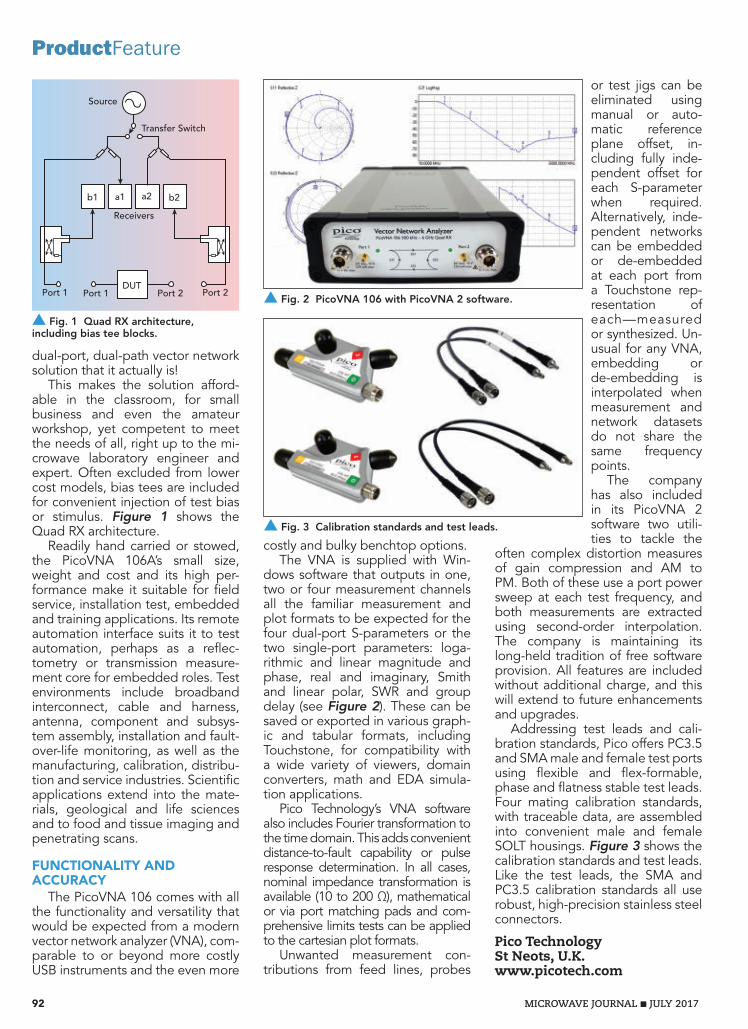
92 MICROWAVE JOURNAL JULY 2017
ProductFeature
or test jigs can be eliminated using manual or auto-matic reference plane offset, in-cluding fully inde-pendent offset for each S-parameter when required. Alternatively, inde-pendent networks can be embedded or de-embedded at each port from a Touchstone rep-resentation of each—measured or synthesized. Un-usual for any VNA, embedding or de-embedding is interpolated when measurement and network datasets do not share the same frequency points.
The company has also included in its PicoVNA 2 software two utili-ties to tackle the
often complex distortion measures of gain compression and AM to PM. Both of these use a port power sweep at each test frequency, and both measurements are extracted using second-order interpolation. The company is maintaining its long-held tradition of free software provision. All features are included without additional charge, and this will extend to future enhancements and upgrades.
Addressing test leads and cali-bration standards, Pico offers PC3.5 and SMA male and female test ports using flexible and flex-formable, phase and flatness stable test leads. Four mating calibration standards, with traceable data, are assembled into convenient male and female SOLT housings. Figure 3 shows the calibration standards and test leads. Like the test leads, the SMA and PC3.5 calibration standards all use robust, high-precision stainless steel connectors.
Pico Technology St Neots, U.K. www.picotech.com
costly and bulky benchtop options.The VNA is supplied with Win-
dows software that outputs in one, two or four measurement channels all the familiar measurement and plot formats to be expected for the four dual-port S-parameters or the two single-port parameters: loga-rithmic and linear magnitude and phase, real and imaginary, Smith and linear polar, SWR and group delay (see Figure 2). These can be saved or exported in various graph-ic and tabular formats, including Touchstone, for compatibility with a wide variety of viewers, domain converters, math and EDA simula-tion applications.
Pico Technology’s VNA software also includes Fourier transformation to the time domain. This adds convenient distance-to-fault capability or pulse response determination. In all cases, nominal impedance transformation is available (10 to 200 Ω), mathematical or via port matching pads and com-prehensive limits tests can be applied to the cartesian plot formats.
Unwanted measurement con-tributions from feed lines, probes
dual-port, dual-path vector network solution that it actually is!
This makes the solution afford-able in the classroom, for small business and even the amateur workshop, yet competent to meet the needs of all, right up to the mi-crowave laboratory engineer and expert. Often excluded from lower cost models, bias tees are included for convenient injection of test bias or stimulus. Figure 1 shows the Quad RX architecture.
Readily hand carried or stowed, the PicoVNA 106A’s small size, weight and cost and its high per-formance make it suitable for field service, installation test, embedded and training applications. Its remote automation interface suits it to test automation, perhaps as a reflec-tometry or transmission measure-ment core for embedded roles. Test environments include broadband interconnect, cable and harness, antenna, component and subsys-tem assembly, installation and fault-over-life monitoring, as well as the manufacturing, calibration, distribu-tion and service industries. Scientific applications extend into the mate-rials, geological and life sciences and to food and tissue imaging and penetrating scans.
FUNCTIONALITY AND ACCURACY
The PicoVNA 106 comes with all the functionality and versatility that would be expected from a modern vector network analyzer (VNA), com-parable to or beyond more costly USB instruments and the even more
s Fig. 1 Quad RX architecture, including bias tee blocks.
Transfer Switch
Source
Receivers
Port 1 Port 1DUT
b1 a1 a2 b2
Port 2Port 2 s Fig. 2 PicoVNA 106 with PicoVNA 2 software.
s Fig. 3 Calibration standards and test leads.

MWJ/SPECTRUM/PUSHON/0717
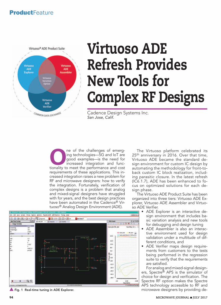
Virtuoso ADE Refresh Provides New Tools for Complex RF DesignsCadence Design Systems Inc.San Jose, Calif.
One of the challenges of emerg-ing technologies—5G and IoT are good examples—is the need for increased integration and func-
tionality to meet the performance and cost requirements of these applications. This in-creased integration raises a new problem for RF and microwave designers: how to verify the integration. Fortunately, verification of complex designs is a problem that analog and mixed-signal designers have struggled with for years, and the best design practices have been automated in the Cadence® Vir-tuoso® Analog Design Environment (ADE).
The Virtuoso platform celebrated its 25th anniversary in 2016. Over that time, Virtuoso ADE became the standard de-sign environment for custom IC design by automating the methodology for front-to-back custom IC block realization, includ-ing parasitic closure. In the latest refresh (IC6.1.7), ADE has been enhanced to fo-cus on optimized solutions for each de-sign phase.
The Virtuoso ADE Product Suite has been organized into three tiers: Virtuoso ADE Ex-plorer, Virtuoso ADE Assembler and Virtuo-so ADE Verifier.
• ADE Explorer is an interactive de-sign environment that includes ba-sic variation analysis and new tools for debugging and design tuning
• ADE Assembler is also an interac-tive environment used for design validation under a multitude of dif-ferent conditions, and
• ADE Verifier maps design require-ments from customers to the tests being performed in the regression suite to verify that the requirements are satisfied.For analog and mixed-signal design-
ers, Spectre® APS is the simulator of choice for design and verification. The Spectre RF option makes the Spectre APS technology accessible to RF and microwave designers by providing de-
94 MICROWAVE JOURNAL JULY 2017
ProductFeature
s Fig. 1 Real-time tuning in ADE Explorer.

MWJ/MC/507REVG/0717
Why do 10,000 customers trust Mini-Circuits test cables? Because they simply don’t fail! Our test cables have been performance qualified to 20,000 flexures* and come backed by our 6-month product guarantee**, so you can be confident you’re getting rugged construction, reliability, and repeatable performance you can depend on. Whether you’re performing production
test, burn-in, over-temperature testing, hi-rel testing – you name it – chances are there’s a Mini-Circuits test cable for your application in stock, ready for immediate shipment. Order some for your test setup at minicircuits.com today, and you’ll quickly find that consistent long-term performance, less retesting and fewer false rejects really add up to bottom-line savings, test after test!
from $68 95
ea. (qty. 1-9)
507 rev G
up to 40 GHz!TEST CABLES
Mini-Circuits®
www.minicircuits.com P.O. Box 350166, Brooklyn, NY 11235-0003 (718) 934-4500 [email protected]
40 GHz(KBL-Series)
Precision 75Ω(CBL-Series)
Precision 50Ω(CBL-Series)
Armored (APC-Series)
Ultra-Flexible(ULC-Series)Flexible(FLC-Series)
Precision VNACables(VNAC-Series)
Reliability You Can Trust…
* All models except VNAC-2R1-K+** Mini-Circuits will repair or replace your test cable at its option if the connector attachment fails within six months of shipment. This guarantee excludes cable or connector interface damage from misuse or abuse.† Various connector options available upon request.
Contact [email protected] to discuss your special requirements.
Model Family Capabilities Freq. (GHz) Connectors† KBL Precision measurement, including phase, through 40 GHz DC-40 2.92mm
CBL- 75+ Precision 75Ω measurement for CATV and DOCSIS® 3.1 DC-18 N, F CBL All-purpose workhorse cables for highly-reliable, precision 50Ω measurement through 18 GHz DC-18 SMA, N
APC Crush resistant armored cable construction for production floors where heavy machinery is used DC-18 N
ULC Ultra-flexible construction, highly popular for lab and production test where tight bends are needed DC-18 SMA FLC Flexible construction and wideband coverage for point to point radios, SatCom Systems through K-Band, and more! DC-26 SMA SLC Super-flexible spaghetti cables with 0.047” diameter and 0.25” bend radius, ideal for enviromental test chambers. DC-18 SMA/SMP VNAC Precision VNA cables for test and measurement equipment through 40 GHz DC-40 2.92mm
NEW!
Spaghetti Cabels(SLC-Series)
NEW!
507rev Gcable.indd 1 5/1/17 3:59 PM

96 MICROWAVE JOURNAL JULY 2017
ProductFeaturesigners fast and high capacity harmon-ic balance analysis. This integration of RF analyses with advanced analog and mixed-signal design tools supports the needs of RF designers who are chal-lenged with high frequency designs using planar CMOS processes.
NEW EXPLORER TOOLSLooking at some of the new features
of Virtuoso ADE in IC6.1.7, in the first example, ADE Explorer is used to de-sign a low noise amplifier (LNA). ADE Explorer has been developed based on extensive interactions with designers to optimize their use model for interactive design. Overlaid on top of this environ-ment are tools for RF designers such as
real-time tuning and specialized measurements. Consid-er the problem of tuning an input matching network to optimize S11 (see Figure 1). Designers can use slider bars to interactively explore the design space and compare the current results with the previous results. In addition to real-time tuning, designers also have access to Explorer’s new interactive debugging capabilities. Suppose that the LNA stops working. A designer can add waveform bubbles to the schematic to monitor key nodes in the circuit, identifying at which node the design “stops wig-gling.” Once the designer identifies where the issue is, the operating point information can be displayed in a table by simply hovering over the devices (see Figure 2).
Another significant new feature in Virtuoso ADE Ex-plorer is support for process corners and statistical vari-ation simulation. Two options are provided for Monte Carlo analysis: choosing the number of iterations or us-ing Monte Carlo analysis with auto-stop (see Figure 3). Virtuoso ADE also provides advanced tools to analyze the relationship between statistical variation and circuit performance. The Virtuoso Variation option provides contribution analysis. Contribution analysis replaces sensitivity analysis and maps the linear and nonlinear input variations to the output variations (see Figure 4). For example, from the Monte Carlo results, the power supply current (Idd) has a second-order dependency on variation, and the dominate source of variation in the power supply current is rshhip, the sheet resistivity of the high resistance polysilicon. Other views of the data can show other dependencies, for example, which blocks are the source of variation. As designs become more complex, the relationship between cause and effect becomes more difficult for designers to readily identify, and contribution analysis provides a useful tool to identify the core trouble area faster. Back to real-time tuning, contribution analysis can be used to define the parameters to be tuned. The final block-level verifica-tion can be run and specification compliance verified (see Figure 5).
ADE ASSEMBLER AND VERIFIERVirtuoso ADE Assembler provides significant new
functionality for design validation, particularly the ability of run plans to run multiple variants of a test bench. For
s Fig. 2 Interactive debugging in ADE Explorer.
s Fig. 3 Monte Carlo analysis example.
s Fig. 4 Contribution analysis example.
s Fig. 5 Corner analysis example.

MICROWAVE JOURNAL JULY 2017 97
example, to characterize the signal-to-noise + distortion ratio (SINAD) of an analog-to-digital converter (ADC) may require measuring dis-tortion across process, voltage and temperature (PVT) corners and the effect of capacitor mismatch using Monte Carlo analysis. Another com-mon application of Virtuoso ADE Assembler is to validate digitally assisted designs. For example, sup-pose the designer is using an inte-grated channel lter for a receiver. The bandpass lter is implement-ed with ve bi-quad sections. The channel lter needs to be controlled to ±1 percent, but the process varia-tion of the on-chip R and C compo-nents is 30 percent. The solution is to tune the R and C values in the design to compensate for process variation. Using calibration, we get all the advantages of an off-chip l-ter with an integrated component. Regular calibration means that the effects of phenomena such as tem-perature drift are eliminated. In the example shown in Figure 6, the last resonator in a bandpass lter is turned into an oscillator, and the frequency of the oscillator is tuned (see Figure 6c). Tuning is achieved by replacing the capacitor in the l-ter with capacitor digital-to-analog converters (DAC). Digital control is used to tune the CAPDAC value to the target frequency and then code all the bi-quad sections to be set to the tuned value. An example of tun-ing the lter is shown in Figure 6d. The lter frequency and lter band-width meet the speci cation after tuning.
Virtuoso ADE Veri er addresses long-standing gaps in the existing design methodologies. ADE Veri- er provides requirements manage-ment, allowing project managers to visualize the completeness of prod-uct validation (see Figure 7). Auto-motive standards such as ISO26262 and equivalent standards for medi-cal and military/aerospace applica-tions require mapping the system-level requirements to product-level requirements, then showing how the requirements will be tested and compliance validated. Going back to the ADC example discussed ear-lier, the system-level requirement may be to achieve a SINAD of 60 dB or better at the Nyquist frequen-
ULTRA-LOW PIM 153dBc or 163dBc CO-LOCATION BAND MITIGATION ULTRA-NARROW BAND (~0.03%BW) ULTRA-WIDE BAND (10GHz BW)
Call for a FREE Engineering Consultation
858.450.0468mcv-microwave.com
CUSTOM PROTOTYPE RF/MICROWAVE FILTERS & ANTENNASQUICK-TURN
PRODUCTSLTE Small Cell TMA/Combiner/Multiplexer DAS SolutionsUltra-Low PIM Duplexers from 450 MHz to 2.7 GHzMiniature Bandpass, Band Reject, Highpass, Lowpass FiltersUltra-high Q Dielectric Resonators and Meta MaterialsNarrow Band and Broad Band Antennas and Filters
LOW PIMLOW PIMLOW PIM
LTE Frequency Band 728 -746 MHz Insertion Loss 0.3~1.2 dB max (25ºC)
0.5~1.5 dB max (Full Temp.) Return Loss 20 dB min Rejection@ Rx Band up to 100 dB min Power Handling, Sea level at ambient temperature, COM port 50 ohm loaded
50W~200W CW max 400W ~1500W Peak max
LTE Frequency Band 698 -716 MHz Insertion Loss 0.3~1.2 dB max (25ºC)
0.5~1.5 dB max (Full Temp.) Return Loss 20 dB min Rejection@ Tx Band up to 95 dB min IMD in RX band, COM port (2 CW tones +43 dBm each)
156 dBc typ., 153 dBc min., 163 dBc available

98 MICROWAVE JOURNAL JULY 2017
ProductFeature
cy. To calculate the SINAD, several simulations may be required: distor-tion across PVT corners, comparator noise across process variation, ca-pacitor mismatch across mismatch and others. Virtuoso ADE Assem-bler provides the first solution for automating the tracking of require-ments and the status of a project.
Release IC6.1.7 of Virtuoso ADE brings new technologies that RF and microwave engineers can use to address the challenge of design-ing and validating 5G and IoT de-signs. The three new tools—ADE Explorer for design, ADE Assembler for validation and ADE Verifier for oversight—enable product devel-opment to be better managed and accelerated.
Cadence Design Systems Inc. San Jose, Calif. www.cadence.com
s Fig. 7 Virtuoso ADE Verifier.
s Fig. 6 Channel filter with calibration (a) and bi-quad section with calibration (b). Tuning the oscillator frequency (c), tuning the frequency filter response (d).
20
0
–20
–40
–60
–80
2.752.502.252.001.751.50
43210
–1
1010
107.55.02.50Frequency (MHz)
Freq
uenc
y (M
Hz)
Time (µs)
OscillatorFrequency
CalibrateCalibration_ValueOscillator Output
After CalibrationBefore Calibration
biquad_12 biquad_12
biquad_345 biquad_345 biquad_345
Osc_w_calibration
17
114
V (d
B)
V (V
)
After: fc = 2.1 MHz, BW = 826 kHzBefore: fc = 3.6 MHz, BW = 1.865 MHz
403020100
0 8 6 4 5 4
(a)
(b)
(c)
(d)

EUROPEAN MICROWAVE WEEK 2017NÜRNBERG CONVENTION CENTER,
NUREMBERG, GERMANY8TH - 13TH OCTOBER 2017
SIX DAYS ONE EXHIBITIONTHREE CONFERENCES
EUROPEAN MICROWAVE WEEK 2017
REGISTRATION INFORMATIONEUROPE’S PREMIER MICROWAVE, RF, WIRELESS AND RADAR EVENT
www.eumweek.comREGISTER ONLINE AT:
Co-sponsored by:Co-sponsored by:
®
Co-sponsored by:
Official Publication:Organised by: Supported by: Supported by:Co-sponsored by:Co-sponsored by:
© NürnbergMesse

Entrance to the Exhibition is FREE and attending couldn’t be easier.
VISITORSRegistering for the Exhibition
• Register as an Exhibition Visitor online at www.eumweek.com
• Receive a confi rmation email with barcode
• Bring your barcode with you to the Exhibition
• Go to the Fast Track Check In Desk and print out your visitor badge
• Alternatively, you can register onsite at the self service terminals during the Exhibition
Please note NO visitor badges will be mailed out prior to the Exhibition.
EUROPEAN MICROWAVE WEEK 2017THE ONLY EUROPEAN EVENT DEDICATED TO THE MICROWAVE AND RF INDUSTRY
The EuMW 2017 team are excited to return to Nuremberg, a uniquely fascinating European city, full of medieval charm. Bringing industry and academia together, European Microwave Week 2017 is a SIX day event, including THREE cutting edge conferences and ONE exciting trade and technology exhibition featuring leading players from across the globe. Concentrating on the needs of engineers, the event showcases the latest trends and developments that are widening the fi eld of applied microwaves. It also offers you the opportunity for face-to-face interaction with those driving the future of microwave technology.
EuMW 2017 will see an estimated 1,700 - 2,000 conference delegates, over 4,000 visitors and in excess of 300 international exhibitors (inc. Asia & US).
REGISTRATION TO THE EXHIBITION IS FREE!Pivotal to the week is the European Microwave Exhibition, which offers YOU the opportunity to see, fi rst hand, the latest technological developments from global leaders in microwave technology.
The exhibition will provide an unrivalled opportunity for visitors to view and ask questions related to the latest products, components and materials from our extensive selection of international exhibitors. It will also feature exhibitor demonstrations, Industrial Workshops and the annual European Microwave Week Microwave Application Seminars (MicroApps).
• International Companies - meet the industry’s biggest names and network on a global scale
• Cutting-edge Technology - exhibitors showcase the latest product innovations, offer hands-on demonstrations and provide the opportunity to talk technical with the experts
• Technical Workshops - get fi rst hand technical advice and guidance from some of the industry’s leading innovators
BE THEREExhibition Dates Opening TimesTuesday 10th October 09:30 - 18:00Wednesday 11th October 09:30 - 17:30Thursday 12th October 09:30 - 16:30
FAST TRACK BADGE RETRIEVAL

Register online and print out your badge in seconds onsite at the Fast Track Check In Desk
CONFERENCE PRICESThere are TWO different rates available for the EuMW conferences:
• ADVANCE DISCOUNTED RATE – for all registrations up to and including 8th September• STANDARD RATE – for all registrations made after 8th September
Please see the Conference Registration Rates table on the back page for complete pricing information.All payments must be in € Euro – cards will be debited in € Euro.
Online registration is open now, up to and during the event until 13th October 2017
DELEGATESRegistering for the Conference
• Register online at www.eumweek.com• Receive an email receipt with barcode• Bring your email, barcode and photo ID with you to the event• Go to the Fast Track Check In Desk and print out your delegate badge• Alternatively, you can register onsite at the self service terminals during the registration opening times below:
- Saturday 7th October (16:00 - 19:00) - Sunday 8th October (07:30 - 17:00) - Monday 9th October (07:30 - 17.00) - Tuesday 10th October (07:30 - 17.00) - Wednesday 11th October (07:30 - 17.00) - Thursday 12th October (07:30 - 17.00) - Friday 13th October (07:30 - 10.00)
Once you have collected your badge, you can collect the conference proceedings on USB stick and delegate bag for the conferences from the specifi ed delegate bag area by scanning your badge.
EUROPEAN MICROWAVE WEEK 2017THE CONFERENCES
Don’t miss Europe’s premier microwave conference event. The 2017 week consists of three conferences and associated workshops:
• European Microwave Integrated Circuits Conference (EuMIC) 9th - 10th October 2017• European Microwave Conference (EuMC) 10th - 12th October 2017• European Radar Conference (EuRAD) 11th - 13th October 2017• Plus Workshops and Short Courses (From 8th October 2017)• In addition, EuMW 2017 will include for the 8th year, the Defence, Security and Space Forum on 11th October 2017
The three conferences specifi cally target ground breaking innovation in microwave research through a call for papers explicitly inviting the submission of presentations on the latest trends in the fi eld, driven by industry roadmaps. The result is three superb conferences created from the very best papers. For a detailed description of the conferences, workshops and short courses please visit www.eumweek.com. The full conference programme can be downloaded from there.
FAST TRACK BADGE RETRIEVAL

CONFERENCE REGISTRATION INFORMATIONEUROPEAN MICROWAVE WEEK 2017, 8th - 13th October, Nuremberg, Germany
Reduced rates are offered if you have society membership to any of the following*: EuMA, GAAS, IET or IEEE.EuMA membership fees: Professional € 25/year, Student € 15/year.If you register for membership through the EuMW registration system, you will automatically be entitled to discounted member rates.Reduced Rates for the conferences are also offered if you are a Student/Senior (Full-time students 30 years or younger and Seniors 65 or older as of 13th October 2017).The fees shown below are invoiced in the name and on behalf of the European Microwave Association. EuMA’s supplies of attendance fees in respect of the European Microwave Week 2017 are exempted from German VAT under Article 4 no. 22a German VAT Act.
Proceedings on USB StickAll papers published for presentation at each conference will be on a USB stick, given out FREE with the delegate bags to those attending conferences. The cost for an additional USB stick is € 50.
International Journal of Microwave and Wireless Technologies (8 issues per year)International Journal combined with EuMA membership: € 67 for Professionals or € 57 for Students.
Partner Programme and Social EventsFull details and contacts for the Partner Programme and other Social Events can be obtained via the EuMW website www.eumweek.com.
STATE RECEPTION – 11TH OCT 2017Tickets for the State Reception are free, but are limited. They are available for delegates on a first-come, first-served basis.
EUROPEAN MICROWAVE WEEK WORKSHOPS & SHORT COURSES
ADVANCE REGISTRATION CONFERENCE FEES (UP TO AND INCLUDING 8TH SEPT.) CONFERENCE FEES ADVANCE DISCOUNTED RATE
Society Member(*any of above) Non Member
1 Conference Standard Student/Sr. Standard Student/Sr.EuMC € 470 € 130 € 660 € 190EuMIC € 360 € 120 € 510 € 170EuRAD € 320 € 110 € 450 € 1602 ConferencesEuMC + EuMIC € 670 € 250 € 940 € 360EuMC + EuRAD € 640 € 240 € 890 € 350EuMIC + EuRAD € 550 € 230 € 770 € 3303 ConferencesEuMC + EuMIC + EuRAD € 810 € 360 € 1140 € 520
STANDARD REGISTRATION CONFERENCE FEES(FROM 9TH SEPT. AND ONSITE)CONFERENCE FEES STANDARD RATE
Society Member(*any of above) Non Member
1 Conference Standard Student/Sr. Standard Student/Sr.EuMC € 660 € 190 € 930 € 270EuMIC € 510 € 170 € 720 € 240EuRAD € 450 € 160 € 630 € 2302 ConferencesEuMC + EuMIC € 940 € 360 € 1320 € 510EuMC + EuRAD € 890 € 350 € 1250 € 500EuMIC + EuRAD € 770 € 330 € 1080 € 4703 ConferencesEuMC + EuMIC + EuRAD € 1140 € 520 € 1600 € 740
WORKSHOP AND SHORT COURSE FEES(ONE STANDARD RATE THROUGHOUT)FEES STANDARD RATE
Society Member(*any of above) Non Member
Standard Student/Sr. Standard Student/Sr.Half day WITH Conferenceregistration € 100 € 80 € 130 € 100
Half day WITHOUTConference registration € 130 € 100 € 170 € 130
Full day WITH Conferenceregistration € 140 € 110 € 180 € 130
Full day WITHOUTConference registration € 180 € 140 € 240 € 170
Register Online at www.eumweek.comONLINE registration is open from 1st June 2017 up to and during the event until 13th October 2017.
ONSITE registration is open from 16:00 on 7th October 2017.ADVANCE DISCOUNTED RATE (up to and including 8th September) STANDARD RATE (from 9th September & Onsite).
SPECIAL FORUMS & SESSIONS
Date Time Title Location No. of Days Fee
Wednesday 11th October 08:30 - 18:30 Defence, Security & Space Forum St. Petersburg 1 € 20 for delegates (those registered for EuMC, EuMIC or EuRAD)
€ 60 for all others (those not registered for a conference)
Monday 9th - Wednesday 11th October 08:30 - 17:50 European Microwave Student School Neu Delhi 3 € 40
Monday 9th - Wednesday 11th October 08:30 - 17:50 European Microwave Doctoral School Singapur 3 € 80
Other Items
SUNDAY 8th October
Half Day SS-01 EuMC
Full Day WS-01 EuMC
Full Day WS-02 EuMC/EuMIC
Full Day WS-03 EuMC
Full Day WS-04 EuMC
Full Day WS-05 EuMC/EuMIC
Full Day WS-06 EuMC/EuMIC
Full Day WS-07 EuMC
Full Day WS-08 EuMC/EuMIC
Full Day WS-09 EuMC/EuMIC
Full Day WS-10 EuMC
Full Day WS-11 EuMC
Half Day WS-12 EuMC
Full Day WS-13 EuMC
Half Day WS-14 EuMC
Half Day WS-15 EuMC
MONDAY 9th October
Full Day WM-01 EuMC
Full Day WM-02 EuMC
Full Day WM-03 EuMC
Half Day WM-04 EuMC
Half Day WM-05 EuMC
Half Day WM-06 EuMC
Half Day WM-07 EuMC
Full Day WM-08 EuMC
TUESDAY 10th October
Full Day WTu-01 EuMC/EuMIC
WEDNESDAY 11th October
Half Day SW-01 EuMC/EuRAD
Half Day WW-01 EuMC
Half Day WW-02 EuMIC/EuRAD
Half Day WW-03 EuMC/EuMIC
THURSDAY 12th October
Half Day WTh-01 EuMC/EuRAD
Full Day WTh-02 EuRAD
Full Day WTh-03 EuMC/EuMIC
FRIDAY 13th October
Full Day SF-01 EuRAD
Half Day SF-02 EuMC/EuRAD
Half Day SF-03 EuRAD
Full Day WF-01 EuRAD
Half Day WF-02 EuMC
Half Day WF-03 EuMC/EuRAD
Half Day WF-04 EuRAD
Full Day WF-05 EuMC
Full Day WF-06 EuMC/EuRAD
Half Day WF-07 EuMC/EuRAD
Half Day WF-08 EuMC/EuRAD

MWJ/EUMW/EXHIBITOR/0617
EUROPEAN MICROWAVE WEEK 2017NÜRNBERG CONVENTION CENTER,
NUREMBERG, GERMANY8TH - 13TH OCTOBER 2017
SIX DAYS ONE EXHIBITIONTHREE CONFERENCES
EUROPE’S PREMIER MICROWAVE, RF, WIRELESS AND RADAR EVENT
OR VISIT: www.eumweek.com
THE EUROPEAN MICROWAVE EXHIBITION (10TH - 12TH OCTOBER 2017)
• 8,000 sqm of gross exhibition space
• 4,000 Attendees
• 1,700 - 2,000 Conference delegates
• In excess of 300 international exhibitors (including Asia-Pacific, the US, and Europe)
INTERESTED IN EXHIBITING?For International Sales: For US Sales:
Alyssa Connell, Event CoordinatorE: [email protected]
Tel: +1 781 619 1930
Richard Vaughan, International Sales ManagerE: [email protected]
Tel: +44 20 7596 8742
Co-sponsored by:Co-sponsored by:
®
Co-sponsored by:
Official Publication:Organised by: Supported by: Supported by:Co-sponsored by:Co-sponsored by:

TechBrief
An external PC reduces the cost of entry, provides measurement exibil-ity and simpli es software upgrades. Computer interfaces include LAN (VXI-11), USBTMC or, optionally, GPIB. A powerful SCPI (standard commands for programmable instruments) com-mand language set is available for controlling the instrument and auto-mating test routines. Combining the 7340’s hardware design with BNC’s API library enables toolsets for many device types and measurements, and the fast analysis time increases test ca-pacity for production applications.
The BNC 7340 signal source an-alyzer re ects BNC’s reputation for technical excellence and customer service.
Berkeley Nucleonics Corp.San Rafael, Calif.www.berkeleynucleonics.com
5 MHz to 40 GHz Signal Source Analyzer
The Berkeley Nucleonics BNC 7340 signal source analyzer performs a wide range of amplitude and
phase measurements, with its core function a phase noise analyzer. Covering 5 MHz to 40 GHz, the 7340 was designed to evaluate sig-nal sources such as crystal oscilla-tors, phase-locked loop synthesizers, clocks, phase-locked or free-running voltage-controlled oscillators (VCO), dielectric resonator oscillators (DRO), SAW and YIG oscillators. It measures
absolute and residual phase noise, pulsed phase noise, amplitude noise and performs time domain transient and spectrum analysis. It can be used as a VCO test bench to mea-sure tuning, pushing, phase noise, current and power.
The analyzer comprises a two-channel cross-correlation system with two internal tunable references sourc-es, with the capability to use external references. The architecture enables the 7340 to perform cross-correlation fast Fourier transform (FFT) analysis of signals. The unit includes an inte-grated frequency counter, power de-tector, two programmable low noise DC supplies (up to 14 V and 600 mA) and three low noise tuning voltages (−5 to +22 V).
The 7340 re ects BNC’s philosophy of using a PC and an intuitive graphical user interface to control the instrument and display the measurement results.
100 MICROWAVE JOURNAL JULY 2017

MWJ/MODELITHICS/ACCELERATE/0717REV 6-20
Vendor Partner
www.Modelithics.com/MVP/AWRDE
FREE 30-day trial of Modelithicsmodels for NI AWR Design Environment
World’s Best RF & Microwave Simulation Models&
ACCELERATE
Requesta FREE
30-Day Trial
The Modelithics® COMPLETE Library™
NI AWR Design Environment®
Microwave Office® circuit design and AXIEM® electromagnetic software
Your High Frequency Designs withThe Modelithics® COMPLETE Library™
of Scalable, Parasitic Simulation Modelsfor Passive and Active Devices andNI AWR Design Environment®
Microwave Office® circuit design and AXIEM® electromagnetic software
DynamicLayout
StatisticalAnalysis
AXIEM EM Co-Sim

Updated Catalog with New Solutions
HUBER+SUHNER offers a wide range of RF connectors for various applications. The products are used in markets like radio base stations, medical, space, defense and other in-dustries. The product portfolio is be-ing constantly refined. Additionally, HUBER+SUHNER supports its cus-tomers worldwide with application engineers, helping the customers in selecting the right product for each specific application.
HUBER+SUHNERhttps://literature.hubersuhner.com/Technologies/Radiofrequency/RFConnectorsEN/
New Corporate Capabilities Catalog
Empower RF Systems is the techno-logical leader in smart power amplifi-er solutions for EW, threat simulation, radar, communications, EMC and product test. Incorporating the latest semiconductor and power combining technologies with a patented archi-tecture, Empower RF builds the most sophisticated and flexible COTS sys-tem amplifiers in the world. In addi-tion to best-in-class SWaP, their next generation amplifiers have sophisticated RF detection to maximize efficiency for a variety of modulation schemes including QAM-xx, OFDM, multi-tone, pulse, AM, FM and more.Empower RF Systems www.empowerrf.com/download/Empower_Catalog_2017.pdf
K&L Microwave Catalog UpdateK&L designs and manufactures a full line of RF and microwave filters, du-plexers and subassemblies, includ-ing ceramic, lumped element, cavity, waveguide and tunable filters. The catalog shows filter responses, loss calculations and standard packages for all products. K&L supplies many of today’s most significant military and homeland security electron-ics programs. Applications include space flight, radar, communications, guidance systems and mo-bile radio base stations, as well as air traffic communication and control. Visit their website to download the complete catalog.K&L Microwavewww.klmicrowave.com
CST STUDIO SUITE 2017® Brochure
The latest brochure for CST STUDIO SUITE 2017® is now available. It pro-vides a comprehensive overview of the company’s solvers, as well as the applications and markets for which CST STUDIO SUITE® 2017 is an indis-pensable tool. With CST’s signature visuals you can see how simulation can be used to improve the design process, allowing you to anticipate issues before prototyping even begins. To learn more, visit their website and download a digital version of the brochure.Computer Simulation Technologywww.cst.com/products/csts2
2017 Catalog Announcement
MiniRF is dedicated to providing quality RF passive components at competitive prices for existing and emerging broadband/CATV and wireless communications systems. MiniRF is a proven leader in supply-ing high performance surface mount passive components. MiniRF com-ponents are found in the products of many of the world’s largest suppliers of communications products with nearly a billion units shipped.MiniRFwww.minirf.com
Test Solutions Product Guide
Rapid growth in the number and variety of wireless applications and connected devices in the market has driven the need for more innovative and highly customized test solutions. Customers are looking for equipment to multiplex application-specific test systems across multiple DUTs, which requires signal routing, distribution and conditioning functions in a va-riety of configurations. This 2017 Test Solutions Product Guide showcases some of the company’s newest, most advanced and most popular test systems developed to date.Mini-Circuitswww.minicircuits.com
102 MICROWAVE JOURNAL JULY 2017
CatalogUpdate

MWJ/EDICON/REVERE/0617 REV 5-11
REGISTER NOWwww.EDICONUSA.com
BosBostonElectronic Design Innovation Conference & Exhibition
Where RF, microwave, EMC/EMI, signal integrity, and power integrity engineers meet for networking, product demonstrations, training and learning.
Featuring:• Exhibition of Industry-Leading Vendors• High-Speed Demonstration Zone• Speed Training in Frequency Matters Theater• In-Depth Short Courses• Hands-On Workshops• Peer-Reviewed Technical Sessions• Panels on Latest Technologies• Keynotes and Plenary Session• Outstanding Paper Awards• Luxury Coach Busing from Boston Area• Family Fun Program
September 11-13, 2017HYNES CONVENTION CENTER • BOSTON, MA
2017
EDICON is coming!EDICON is coming!
Join the High-Frequency, High-Speed Revolution!
Ocial PublicationsOrganized by Ocial PublicationsOrganized by
Organized by Official Publications
@ediconusa #ediconusa

MWJ/EDICONUS/INFOGRAPHIC/0717
Join the Industry Revolution and Register Now www.ediconusa.com
2017Electronic Design Innovation
Conference & Exhibition
2017Electronic Design InnovationConference & ExhibitionWhere high frequency meets high speed.
EDI CON USA BY THE
1,400Attendees Excellent show
layout. Easy to find exhibitors. You had a lot of major com-panies that make it worthwhile coming to the show floor.
“
”15Countries
35US States
and
R E P R E S E N T E D
117Sessions/ Workshops
Great show. Different from other ones because the sessions were not full of marketing information, but real useful information.
“”
The sessions were well planned and well attended.“
”96Industry Expert Speakers
It is wonderful to have so many specialists in one place. You can get your problems solved. This is a great conference.
“”
Rated as Good or Excellent
95%
149 Exhibitors
September 11-13, 2017 Hynes Convention Center
Boston, MA
NUMBERSWe’ve promised you great education, training and networking at the 2017
Electronic Design Innovation Conference (EDI CON) USA. But don’t just take our word for it! Let data from last year’s inaugural event do the talking.

MWJ/EDICON/EXHIBITORS/0717
September 11-13 Hynes Convention Center
Boston, MA
Organized By
2017Electronic Design InnovationConference & ExhibitionWhere high frequency meets high speed.
AEMAmpliTech, Inc.Analog Devices
AnokiwaveAnritsuANSYS
Applied Thin-Film ProductsAR RF/Microwave Instrumentation
ARC TechnologiesB & Z Technologies
Barry Industries, Inc.Berkeley Nucleonics
Cadence Design SystemsCernex & Cernex Wave
Conduct RFCopper Mountain Technologies
CST-Computer Simulation Technology AGdBm Corp, INC
EMSCANExodus Advanced Communications
Focus MicrowavesGEIB Refining Corp
Gowanda ElectronicsGVD Corporation
Holzworth InstrumentationIMI Inc
Innovative Integration
Integra TechnologiesInternational Manufacturing Services, Inc.
IW Microwave Product Division Laser Services Inc
Liberty Test Equipment Lighthouse Technical Sales
MACOM Technology Solutions IncMaury MicrowaveMCV Microwave
Mician IncMicrowave Communications Laboratories,
MCLIMicrowave Development Labortories
MillitechMitsubishi Electric US
MOSISNational Instruments
Ophir RF IncOrban Microwave
PA&EPassive Plus Inc.
Piconics Inc.Planar Monolithics Industries, Inc
PPG Aerospace-Cuming MicrowavePrinceton Technology Corp
Reactel Inc.RCL Microwave Inc
Relcomm TechnologiesRes-net Microwave, Inc.
Response Microwave Inc.RF-Lambda
Rogers Corp.Rohde & Schwarz
SemiGen Inc.SignalCore Inc
Signal Integrity Software Inc,(SiSoft)Smith’s Microwave Subsystems
Sonnet SoftwareSouthwest Microwave, Inc.
T-Tech Inc. TDK- LAMBDA Americas HP Division
TechPlus Microwave, Inc.TECOM IndustriesTeledyne LeCroy
Teledyne Microwave SolutionsTeledyne Relays
Times Microwave SystemsTRAK Microwave
Transline Technology Inc.TTE Filters
UltraSource, IncWeinschel Associates
Wenzel Assoc.WestBond
Exhibition Space is Filling Up Fast. Book Your Booth Today!
Contact your MWJ Sales Representative
EDICONUSA.com
Host Sponsor
Join the Growing List of Exhibitors:
Diamond Sponsor Gold Sponsors

5G IPD RF Filters3D Glass Solutions Inc., a world-class ex-pert on the fabrication of electronic packages and devices using pho-to-definable glass-ce-
ramics, announced the development and pro-duction of the highest efficiency 5G integrated passive devices (IPD) for radio frequency (RF) filters. These RF filters have been designed to operate as bandpass filters for frequencies at 5 and 28 GHz with less than 1 dB of insertion loss. 3DGS’ 5G RF filters are manufactured using APEX® Glass, a material which has sig-nificant benefits over legacy PCB materials.3D Glass Solutions www.3dglasssolutions.com
Wire-Bondable and Edge-Terminated Resistors
For years our custom-ers asked us to bring our short lead times, outstanding customer service and quality fo-cus to the thin film re-sistor industry. As is
the Compex way, we listened. Compex is excit-ed to announce it now offers a full line of wire-bondable and edge-terminated resistors built to its customer’s exact specifications. Avail-able alternatives include single, dual, center-tap, array and custom configurations. Compex would be happy to provide samples to ensure you have the right parts for your needs.Compex Corp. www.compexcorp.com
Multiposition SwitchesDow-Key® Microwave, the world’s largest manufacturer of elec-tromechanical switch-es, provides an exten-sive selection of multi-
position switches for a variety of ATE applica-tions ranging from SP3T to SP14T. Character-istics include a standard design of 1 million life cycles; 2 million for 5 x 5 series and 5 mil-lion for Reliant SP6T. Coil voltages of 12, 24 and 28 V are available and operate from DC to 26.5 GHz. Various control options are of-fered and may also be designed with RoHS compliance.Dow-Key Microwave www.dowkey.com
106 MICROWAVE JOURNAL JULY 2017
COMPONENTS
3 dB Low PIM Attenuators
MECA also offers low PIM 3 dB attenuators in both 50 and 100 W models with a typical PIM spec of 161 dBc.
They feature a variety of connector styles and configuration within series and between series configurations in: 4.1/9.5, 7/16 and type N as well as 4.3/10.0 DIN connectors, while han-dling full rated power to +85°C. All of the ter-minations operate covering 0.698 to 2.7 GHz frequency bands, VSWR = 1.10:1 Typ./1.20:1 Min. Made in the U.S. and 36-month warranty.MECA Electronics Inc. www.e-MECA.com
Transformer
The MRFXF5702 trans-former is designed for applications that re-quire very small, low cost and highly reliable surface mount compo-nents. Applications may be found in broad-band, wireless and
other communications systems. These units are built lead-free and RoHS compliant and feature welded wire construction for increased reliability. S-Parameters are available on re-quest.MiniRF www.minirf.com
Down ConverterNorden Millimeter’s down converter con-verts 26 to 50 GHz down to 4 to 18 GHz to extend the range of lower cost test equip-
ment. Norden can add gain, inter-stage filter-ing and bypass switching stages to the cus-tom assemblies. Norden Millimeter continues as the leader in components used in the 5G market. Norden products can be used to quickly and cost effectively, build mmWave system prototypes which demonstrate the via-bility and feasibility of the technology.Norden Millimeter www.NordenGroup.com
Waveguide Electromechanical Relay Switches
Pasternack has intro-duced 28 new wave-guide electromechani-cal relay switches that offer full waveguide performance covering C, X, Ku, K and Ka fre-quency bands from
5.85 to 40 GHz. They are ideal for applica-tions that include electronic warfare, electron-ic countermeasures, microwave radio, VSAT, SATCOM, radar, research and development, space systems and test instrumentation. Pas-ternack’s new waveguide electromechanical relay switches are configured for single-pole double-throw (SPDT) operation with latching self-cut-off actuators, TTL logic and position indicators with manual override.Pasternack www.pasternack.com
2-Way High-Power Switch
PMI Model No. PDT-8G12G-40-515-SFF is an 8 to 12 GHz, 2-way high-power switch that
has an insertion loss of 2 dB maximum and a VSWR of 1.8:1 maxi-mum. The operating power is +40 dBm CW average, +57 dBm 1 µs, 1 percent duty cy-cle with an isolation of
40 dB minimum. Switching speed 200 ns max-imum - measured 100 ns, power supply re-quirements +5 V at 100 mA and -15 V at 60 mA.Planar Monolithics Industries Inc. www.pmi-rf.com
Electro-Mechanical SwitchRF-Lambda multiport switch improves inser-tion loss repeatability and isolation, which is necessary for higher performance test sys-tems. The repeatability and reliability of this
switch is vital to ATS measurement accuracy and can cut the cost of ownership by reducing calibration cycles and increasing test system up time. The RF-Lambda terminated multiport switch provides the long life and reliability re-quired for automated test and measurement, signal monitoring and routing applications. Highly repeatable switching capability is made possible through RF-Lambda’s rigorous design and tight manufacturing specifications.RF-Lambda www.rflambda.com
N E W P R O D U C T Sfor more new products, visit www.mwjournal.com/buyersguide
featuring storefronts

MWJ/MC/559REVOR/0717
Passbands from 900 to 11400 MHzCAVITY FILTERSNeed to separate signal from scramble? Mini-Circuits’ new ZVBP-series cavity filters are designed to give you razor sharp selectivity and high stopband rejection for bandwidths as narrow as 1% to keep your signal clean. These filters feature rugged construction and robust design with protection from accidental detuning, so you can put them to work with confidence in almost any environment, in the lab or in the field.
FEATURES• Outstanding selectivity• High rejection• Rated for operation from -55 to +100°C• Power handling up to 15W• Rugged construction
They’re available off the shelf for immediate shipment, so place your order today for delivery as soon as tomorrow! Need a custom filter? We’ve got you covered. Just send your requirements to [email protected] for a fast response.
SHARP REJECTION
Mini-Circuits®
www.minicircuits.com P.O. Box 350166, Brooklyn, NY 11235-0003 (718) 934-4500 [email protected] 559 RevOrig
$19995from ea.
559RevOrigCavFilt.indd 1 3/20/17 10:36 AM

108 MICROWAVE JOURNAL JULY 2017
NewProducts
Catch up on the latest industry news with the bi-weekly video update
Frequency Matters from
Microwave Journal
www.mwjournal.com/freqmatters
How EDA Tools Are Addressing EMC/EMI
Challenges During Design
Predicting RFIC Error Vector Magnitude During
Design
Compact, Wideband Bandstop Filter With Extended Upper
Passband
Three-Level Doherty Power Amplifier for Next-Generation
Wireless Infrastructure
CABLES & CONNECTORSSUCOFLEX
HUBER+SUHNER has developed the SUCO-FLEX 526S top perfor-mance cable assembly for various applica-tions in its test labora-tories. When it comes to test and measure-
ment, SUCOFLEX 526S assemblies guarantee the highest level of satisfaction. Thanks to their unique cable and connector design, they deliver best-in-class phase and amplitude sta-bility vs. flexure in combination with excellent return and insertion loss up to 26.5 GHz.HUBER+SUHNER www.hubersuhner.com
110 GHz Cable AssembliesMegaPhase offers its Mega110 products with 1 mm connec-
tors in both semi-rigid and flexible cable as-semblies. Its light-weight 110 GHz cable as-semblies are specifically designed for the de-mands of high-bandwidth applications such as automotive radar, probe stations and mo-bile backhaul. Visit MegaPhase’s website to review its data sheets.MegaPhase www.megaphase.com/rf/110
forms is important. These filters are now avail-able with -3 dB cut off frequencies as high as 30 GHz. A surface mount configuration is available to 4 GHz.RLC Electronics Inc. www.rlcelectronics.com
Wideband Small Size 2-Way Power Divider
The SDL-100 is a RoHS surface mount 2-way power divider operat-ing in the frequency range of 2 to 1000 MHz. This device com-bines wide bandwidth and high performance
in a compact size, 0.300 in × 0.385 in × 0.200 in and operates in the temperature range of -40°C to 85°C. Product features in-clude input power of 1 W (Max.), insertion loss of 1.2 dB (Typ.)/1.5 dB (Max.), an isolation of 23 dB (Typ.)/17 dB (Min.), amplitude unbal-ance of 0.6 dB (Max.) and phase unbalance of 4 degrees (Max.) in the band of 500 to 1000 MHz with better performance in the lower part of the frequency band.Synergy Microwave Corp. www.synergymwave.com
6-Bit Digital Attenuator
RFMW Ltd. announces design and sales sup-port for Qorvo’s TGL2226-SM, a 6-bit, digital attenuator. With frequency coverage from 100 MHz to 15 GHz, the TGL2226-SM
provides 0.5 dB least significant bit size for a range of 31.5 dB. Serving diverse markets such as radar, electronic warfare, satellite and point-to-point communication systems, this digital step attenuator is offered in a 3 mm x 3 mm QFN package for surface mount de-signs. Control voltage is -3 to -5 V.RFMW Ltd. www.rfmw.com
Absorptive Bessel Filters to 30 GHzRLC Electronics’ 4th Or-der Absorptive Bessel Filters provide the ex-cellent group delay re-sponse of Bessel fil-ters, while maintaining
impedance matching far into the stopband. Resistive elements are designed into these fil-ters, resulting in a response that closely mim-ics the classic Bessel in both amplitude and phase. These filters are used in digital sys-tems where truthful reproduction of wave-

MWJ/Synergy/Performance/0817

110 MICROWAVE JOURNAL JULY 2017
NewProducts
TheSignal Integrity Journal
Covering SI, PI, EMC/EMI
It’s nally here...
www.signalintegrityjournal.comwww.signalintegrityjournal.com
A technical resource for working engineers
A unique marketing resource for the industry
MEDIA KIT 2017
signalintegrityjournal.com
From the Publishers of
Microwave Journal
ment boards another key application is high speed digital test boards.Withwave www.with-wave.com
AMPLIFIERSSingle Band Amplifiers Cover 0.7 to 6 GHz Frequency Band
The new 60S1G6 and 500S1G6 are 60 and 500 W CW solid-state amplifiers that have 48 and 57 dB gain, re-spectively. Both deliver 100 per-cent rated output power without foldback over the instanta-neous 0.7 to 6 GHz band and
can survive ∞:1 output VSWR. Applications in-clude radiated susceptibility testing, EW jam-mers and wireless system and device stress screening tests.AR RF/Microwave Instrumentation https://www.arworld.us/html/0.7to6GHz.asp
Wideband Low Phase Noise Amplifier
Custom MMIC, a leading developer of perfor-mance driven monolithic microwave integrat-ed circuits (MMIC), has added a new category to their rapidly expanding standard product
in a second step. Its design has also been made more ergonomic for easier holding and use, thus reducing fatigue.SPINNER www.spinner-group.com
Tin-Dipped Surface Mount and Edge Launch Connectors
SV Microwave now of-fers tin-dipped surface mount and edge launch connectors that make the soldering process fast and easy. These surface mount
and edge launch PCB connectors also provide increased solder joint durability while prevent-ing rust, corrosion and oxidization. Connec-tors’ part numbers are denoted with a “-TD”. Readily available through distribution.SV Microwave www.svmicrowave.com
DC to 50 GHz Vertical Launch Connectors
The new vertical launch connectors are specially designed for solderless vertical PCB launch on test and measurement boards.
They are claimed to have excellent electrical transition performance up to 50 GHz. The con-nectors also reduce installation time by elimi-nating soldering. As well as test and measure-
Ultra-Flexible SMA-M to N-M Test Cables, DC to 18 GHz
Mini-Circuits’ ULC-2FT-SMNM+ ultra-flexible test cable provides low insertion loss (0.3 to 1.5 dB) and excellent return loss (18 to 24 dB) for a wide range of test applications from
DC to 18 GHz. These cables are specially designed for stability of phase and ampli-tude versus flexure in bend radii as tight as 2
in (2.0 in minimum dynamic bend radius, 0.7 in minimum static bend radius), making them ideal for demanding lab environments where frequent bending is common.Mini-Circuits www.minicircuits.com
SPINNER EasyDocks Now Even Better
A new, improved SPIN-NER EasyDock version is now available for you to take advantage of. The older version had to be slid onto the DUT first and then locked in
a second step. The advantage of the new ver-sion is that it does both at the same time: it locks the moment you slide it home, without the need to apply pressure in a different place

MWJ/GENERATOR/RFLAMBDA/0717

112 MICROWAVE JOURNAL JULY 2017
NewProducts
SOURCESExpanded Pre-Amp Comb Generator
Herotek’s new 0.750 in (N3 package) long sur-face mount package for convenient placement on PCB Boards. Excel-
lent for frequency multipliers, frequency syn-thesizers and built-in test source. GCA Series requires only +10 or 0 dBm input for input fre-quency ranges from 250 to 2000 MHz. The company’s GC Series (without preamp) also is offered in its “L” package which is 0.53 in long.Herotekwww.herotek.com
Low G-Sensitivity OCXOMtronPTI announced XO5503 Series low G-sensitivity OCXO with vibration compensa-tion for military and ra-dar application.
XO5503 is designed for application where su-perior performance is required under high vi-bration environment. In military communica-tions and radar applications, reliability comes fi rst. The communication link must stay up; the picture must be clear even when condi-tions are less than ideal.MtronPTIwww.mtronpti.com
SEMICONDUCTORSSchottky Detector Diodes
SemiGen Inc., an ISO and ITAR registered RF/microwave assem-bly, automated PCB manufacturing and RF supply center, has add-ed a series of new Zero Bias Schottky Detector Diodes to its expand-
ing product offerings. SemiGen’s SZB900 se-ries of Zero Bias Schottky Detector Diodes are catered to perform as components of video detectors and power monitors, eliminating the need for external DC biasing. This series of schottky diodes features low junction capaci-tances, high voltage sensitivity, uniform video resistances and high sensitivity, all without ex-ternal bias circuitry.SemiGen Inc.www.semigen.net
offerings. Custom MMIC’s new GaAs MMIC low phase noise amplifi er family offers previously unattained phase noise perfor-
mance. Phase noise is a critical requirement which defi nes the performance level of most radars and communications systems. The fi ve product family achieves phase noise perfor-mance as low as -165 dBc/Hz at 10 kHz offset.Custom MMICwww.custommmic.com
0.01 to 20 GHz RF Power Amplifi er Module
Richardson RFPD Inc. announced the avail-ability and full design support capabilities for a new ultra-wideband power amplifi er mod-ule from Analog Devic-es Inc. The HMC-C582 is a GaAs MMIC
PHEMT power amplifi er in a miniature, her-metic module with replaceable SMA connec-tors that operates between 0.01 GHz and 20 GHz. The device typically provides 24 dB of gain, up to +36 dBm output IP3, and up to +26 dBm of output power at 1 dB gain com-pression.Richardson RFPDwww.richardsonrfpd.com

MWJ/EDICONCHINA/2018/0517
2018
March 20-22, 2018China National Convention Center
EDICONCHINA.com
Host Sponsor:
Diamond Sponsor:
Corporate Sponsor:
Organized by:
BACK TO BEIJING!
Reserve your Booth now for best location!
SAVE THE DATE!

114 MICROWAVE JOURNAL JULY 2017
W-Band Varactor Tuned Gunn Oscillator
For communication, ra-dar and test applica-tions, SAGE Millimeter has released a new W-Band varactor tuned Gunn oscillator. Model SOV-94306310-10-G1 utilizes a high-perfor-
mance GaAs Gunn diode and proprietary cavi-ty design to deliver +13 dBm typical power. The oscillator features a Varactor tuning range of ±3 GHz and delivers low AM/FM noise and harmonic emissions. Compared to its counter-parts, such as multiplier based sources, the Gunn oscillator is a lower cost and cleaner source.SAGE Millimeter www.sagemillimeter.com
SOFTWARECOMPLETE Library Release v17.0
Modelithics Inc. an-nounced the latest re-lease, of the Modelith-ics® COMPLETE Library version 17.0 for use with the Keysight EEsof EDA Advanced Design System (ADS)
simulation software. This release marks an-other big milestone with over 15,000 commer-cial electronic components from over 65 dif-ferent vendors now represented in the COM-PLETE Library of advanced simulation models. The version 17.0 release contains 34 new models, in addition to the already extensive collection of high accuracy, scalable parasitic simulation models.Modelithics Inc. www.modelithics.com
ANTENNAS5G Phased Array Active Antenna
Anokiwave Inc., an in-novative company pro-viding highly integrated IC solutions for mmW markets and active an-tenna based solutions, announced the intro-
duction of the first in a family of phased array antenna innovator’s kits, the AWMF-0129, driven by the Anokiwave AWMF-0108 28GHz 5G Quad Core IC with embedded functions for remote telemetry and low-latency steering™. The AWMF-0129 is a 64-element, single polar-ization 5G phased array antenna designed to cover the 27.5 to 30 GHz frequency band.Anokiwave Inc. www.anokiwave.com
NewProductsMICRO-ADS
Silver Conductive SystemOne Component MB600S
• Coating for EMI/RFI shielding• Temperature resistant up to 700°F
+1.201.343.8983 • www.masterbond.com
with the MWJ APP
GoMobile
Download your MWJ app now at www.mwjournal.com/MWJapp
Dielectric Testers
www.damaskosinc.com
(610)358-0200 fax(610)558-1019
Std Sizes ~100 MHz - 40 GHz
ε, tan δ - Cavity™ sfwrThin Sheets, Substrates, Resins, Foams
Fast Easy No Sample Prep
754 Fortune Crescent, Kingston, ON, K7P 2T3, CanadaTel: 613 384 3939 - Fax: 613 384 5026
e-mail: [email protected]
WAVEGUIDE SWITCHES - COAXIAL SWITCHES - DUAL SWITCHES
WE ARE THE WAVEGUIDE & COAXIAL SWITCH EXPERTS YOUR #1 SOURCE FOR MICROWAVE SWITCHES
QUALITY, SERVICE & QUICK DELIVERIES UNMATCHED IN THE INDUSTRY

MWJ/EUMW/DELEGATE/0617 REV 5-22
EUROPEAN MICROWAVE WEEK 2017NÜRNBERG CONVENTION CENTER,
NUREMBERG, GERMANY8TH - 13TH OCTOBER 2017
SIX DAYS ONE EXHIBITIONTHREE CONFERENCES
EUROPE’S PREMIER MICROWAVE, RF, WIRELESS AND RADAR EVENT
Register online now as a delegate or visitor at: www.eumweek.com
Co-sponsored by:Co-sponsored by:
®
Co-sponsored by:
Official Publication:Organised by: Supported by: Supported by:Co-sponsored by:Co-sponsored by:
The Conferences (8th - 13th October 2017)• European Microwave Integrated Circuits Conference (EuMIC)
9th - 10th October 2017• European Microwave Conference (EuMC) 10th - 12th October 2017• European Radar Conference (EuRAD) 11th - 13th October 2017• Plus Workshops and Short Courses (From 8th October 2017)• In addition, EuMW will include for the 8th year, the Defence, Security and Space
Forum on 11th October 2017
The FREE Exhibition (10th - 12th October 2017) ENTRY TO THE EXHIBITION IS FREE! Register today to gain access to over 300international exhibitors and take the opportunity of face-to-face interaction with
those developing the future of microwave technology. The exhibition also featuresexhibitor demonstrations, industrial workshops and the annual European Microwave
Week Microwave Application Seminars (MicroApps).
DISCOUNTED CONFERENCE RATESDiscounted rates are available up to and including 8th September 2017.
Register NOW and SAVE!Registration is available after this date and up to 13th October
at the standard rate.

116 MICROWAVE JOURNAL JULY 2017
NewProducts
S- & C-Band MIMO Sector Antenna
Southwest Antennas’ new S- and C-Band MIMO sector antenna feature 120 degrees of horizontal beamwidth, allowing for wide area coverage. 45 degree left/right slant polar-ization provides polar-ization and spatial di-versity for connected radios. Designed for 2 × 2 MIMO radio sys-tems, these sector an-
tennas are offered in 2.2 to 2.5 GHz S-Band and frequency options, for ISM / broadcast video and law enforcement use. The antenna features 12 dBi of minimum gain across the entire operating band.Southwest Antennas www.southwestantennas.com
TEST EQUIPMENTVNA Microwave/RF Test Assemblies
W. L. Gore & Associ-ates has expanded the functional frequency range of its “FF series” GORE® VNA Micro-wave/RF test assem-blies, now offering sta-ble, reliable perfor-mance up to 70 GHz. This upgrade address-
es industry requirements for enhanced perfor-mance in the 60-70 GHz range where there is increased need to maintain measurement ac-curacy, especially in Vector Network Analyzers (VNAs), communication testing, and mm-wave to name a few key applications.W. L. Gore & Associates www.gore.com
MICRO-ADS
MPB-5074Date: 2014Set By: JRLColors: 4Size: microFormat: PDF
RF Amplifiers, Isolators and Circulators from 20MHz to 40GHz
Wenteq Microwave Corporation 138 W Pomona Ave, Monrovia, CA 91016
Phone: (626) 305-6666, Fax: (626) 602-3101 Email: [email protected], Website: www.wenteq.com
Super low noise RF amplifiers
Broadband low noise amplifiers
Input PIN diode protected low noise amplifiers
General purpose gain block amplifiers
High power RF amplifiers and broadband power amplifiers
RF isolators and circulators
High power coaxial and waveguide terminations
High power coaxial attenuators
PIN diode power limiters Active up and down
converters
MPB-6099Date: 10-21 2016Set By: JRLColors: 4Size: microFormat: PDF
www.techplusmicrowave.com
916-672-6356
HIGHEST QUALITY FILTERSHIGHEST QUALITY FILTERSHIGHEST QUALITY FILTERS
FOR ANY FOR ANY FOR ANY
APPLICATION OR ENVIRONMENTAPPLICATION OR ENVIRONMENTAPPLICATION OR ENVIRONMENT
COMMERCIAL * MILITARY * COMMERCIAL * MILITARY * COMMERCIAL * MILITARY * SPACE * PUBLIC SAFETYSPACE * PUBLIC SAFETYSPACE * PUBLIC SAFETY
High Performance BroadbandAntennas & Accessories
Commercial Military Law EnforcementHomeland Security Broadcast Video
UAV / Robotics Oil & Gas M2M / IoT
ERRATUMThe article “Network Synthesis and Power Amplifiers: So Much More than Impedance Matching,” written by Gayle Collins and published in the June 2017 issue, should include the following reference to the au-thor’s paper at the 2015 IEEE MTT-S International Microwave Symposium: 20. G. F. Collins, “Network Synthesis
of Power Amplifier Matching Cir-cuits - Standing on the Shoulders of Giants,” 2015 IEEE MTT-S International Microwave Sympo-sium, Phoenix, Ariz., 2015, pp. 1-3.
MPB-2090June 14, 2005Set By: JanetColors: 4CSize: microFormat: live
SPECIAL HERMETIC PRODUCTS, INC.PO BOX 269 – WILTON – NH – 03086(603) 654-2002 – Fax (603) 654-2533
E-mail: [email protected]: www.shp-seals.com
S HP
REVOLUTIONARY HERMETIC SMP CONNECTORS
These SMPs meet the requirements of MIL-STD-348, but utilize unique housing
interface features, which significantly improvesreliability and production assembly yields.
Proprietary techniques are used to independentlycontrol plating thickness on pin and housing.
For use with Aluminum, Kovar and other package material

MWJ/COMCAS/REGISTER/0617
IEEE COMCAS 2017International Conference on Microwaves, Communications, Antennas and Electronic SystemsDavid Intercont inental Hotel 13-15 November 2017 Tel Aviv, I s rae l
REGISTER NOWמהנדסים את העתיד
לשכת המהנדסים האדריכלים והאקדמאים במקצועות הטכנולוגיים
בישראל
ASSOCIATION OF ENGINEERS, ARCHITECTS AND GRADUATES IN TECHNOLOGICAL SCIENCES IN ISRAEL

118 MICROWAVE JOURNAL JULY 2017
US: Call 1-800-225-9977 (in the U.S. or Canada), or 1-781-769-9750, ext. 4030
Fax 1-781-769-6334 E-mail to: [email protected]
UK: Call +44 (0)20 7596 8750 Fax +44 (0)20 7630-0166 E-mail [email protected]
A R T E C H H O U S E 685 Canton Street, Norwood, MA 02062 USA
16 Sussex Street, London SW1V 4RW UKB O S T O N I L O N D O N
For complete descriptions and to order, visit
ArtechHouse.com All orders plus shipping/handling and applicable taxes.
THE MOST ANTICIPATED GNSS BOOK OF THE YEAR.
Understanding GPS/GNSS: Principles and Applications, Third Edition Elliott D. Kaplan and Christopher J. Hegarty
• Provides a current and comprehensive treatment of the Global Navigation Satellite System (GNSS);
• Includes new chapters on the system engineering details of GPS, GLONASS, Galileo, Beidou (BDS), and regional systems, such as the Quasi–Zenith Satellite System (QZSS) and Navigation with Indian Constellation (NavIC);
• Provides both a quick overview of GNSS essentials and an in-depth treatment of advanced topics and explores all the latest advances in technology, applications, and systems. Hardcover • 1008 pp. • 2017 • ISBN: 978-1-63081-058-0 • $179 / £145
BookEnd
W ith the explosive growth of wireless and the attendant complexity of wireless sys-
tems, electromagnetic compatibility (EMC) has metaphorically moved from a seat at the back of the room to sitting at the table with the other development disciplines. Fortunately, the evolving capability of electromagnetic (EM) soft-ware has strengthened EMC engineer-ing so it is not strictly “magic,” yet mas-tering it—if that is possible—requires extensive experience.
Levent Sevgi, who has worked with electromagnetics for almost three de-cades, wrote this book to address the breadth of EMC engineering topics that are not covered by more special-
experience. I’m going to revisit every-thing you learned in your university education and teach you how to look at them with the eye of an EMC engineer. I’m quite sure that at the end of the course you will learn how to diagnose and solve your problem. That would be the success of the course.” That would also be the success of this book.
ized texts: market control, accreditation, calibration, EMC testing and measure-ment and mitigation. The 10 chapters are organized to address 1) basic con-cepts, governing bodies and standards; 2) accreditation; 3) EM modeling; 4) circuit modeling, including grounding; 5) antennas and their calibration; 6) noise and frequency analysis; 7) EMC test and measurement environments; 8) EMC test and measurement devices; 9) EMC tests and measurements; and 10) mitigation of potential EMC prob-lems (i.e., ltering, screening, cabling, grounding and impedance matching). Each chapter concludes with an exten-sive list of references, enabling readers to delve into any of the topics. The book contains practical design tips and more than 20 MATLAB scripts to help readers implement the concepts.
Slightly paraphrasing what Sevgi tells students of his EMC courses, “I’m not going to solve your problems; you’re going to do that! What I’ll do is mostly ll in the gaps of your knowledge and
A Practical Guide to EMC Engineering
Levent Sevgi
To order the book:Published by Artech House
www.artechhouse.comISBN: 978-1-63081-383-3
316 pages$159, Print or eBook

MWJ/ELEARNING/0717
July Short Course Webinars
Past Webinars On Demand
Technical Education Training .............................. 7/25Technology and Market Outlook for Next Generation MilSatComsSponsored by: Rohde & Schwarz and Wolfspeed
Register to attend at mwjournal.com/webinars
MIMO Radars and Their Conventional Equivalents
LEARNINGCENTER Presented by:
Design Considerations and Tradeoffs for Microstrip, Coplanar and Stripline Structures at Millimeter-Wave Frequencies
Sponsored by:
Presented by: Dr. Eli Brookner
microwavejournal.com/events/1636
Sponsored by:
microwavejournal.com/events
Getting to Know 5G: New Radio and the Race to Standardization
Sponsored by:
microwavejournal.com/events
Countering the UAS Challenge
Sponsored by:
microwavejournal.com/events
Demystifying 5G – Numerology and Initial Access Concept for 5G NR
Sponsored by:
microwavejournal.com/events
New Connectors for High-Speed Applications
Sponsored by:
signalintegrityjournal.com/events

Advertiser Page No.
Eastern and Central Time ZonesChuck BoydNortheast Reg. Sales Mgr.(New England, New York, Eastern Canada)685 Canton StreetNorwood, MA 02062Tel: (781) 619-1942FAX: (781) [email protected]
Michael HallmanEastern Reg. Sales Mgr.(NJ, Mid-Atlantic, Southeast, Midwest, TX)4 Valley View CourtMiddletown, MD 21769Tel: (301) 371-8830FAX: (301) [email protected]
Pacific andMountain Time ZonesBrian Landy Western Reg. Sales Mgr. (CA, AZ, OR, WA, ID, NV, UT, NM, CO, WY, MT, ND, SD, NE & Western Canada)144 Segre PlaceSanta Cruz, CA 95060Tel: (831) 426-4143FAX: (831) [email protected]
International SalesRichard VaughanInternational Sales Manager16 Sussex StreetLondon SW1V 4RW, EnglandTel: +44 207 596 8742FAX: +44 207 596 8749 [email protected]
Germany, Austria, and Switzerland(German-speaking)WMS.Werbe- und Media ServiceBrigitte BeranekGerhart-Hauptmann-Street 33, D-72574 Bad UrachGermanyTel: +49 7125 407 31 18FAX: +49 7125 407 31 [email protected]
KoreaYoung-Seoh ChinnJES Media International2nd Floor, ANA Bldg.257-1, Myungil-DongKangdong-GuSeoul, 134-070 KoreaTel: +82 2 481-3411FAX: +82 2 [email protected]
ChinaShenzhen Michael TsuiACT InternationalTel: 86-755-25988571FAX: [email protected]
Shanghai Linda LiACT InternationalTel: [email protected]
BeijingCecily Bian ACT International Tel: +86 135 5262 1310 [email protected]
Hong Kong, Taiwan, SingaporeMark MakACT InternationalTel: [email protected]
JapanKatsuhiro IshiiAce Media Service Inc.12-6, 4-Chome, Nishiiko, Adachi-KuTokyo 121-0824, JapanTel: +81 3 5691 3335FAX: +81 3 5691 [email protected]
Ed Kiessling • Traffic Manager/Inside Sales • 685 Canton Street Norwood, MA 02062 • Tel: (781) 619-1963 FAX: (781) 769-6178 • [email protected]
Sales Representatives
Advanced Microwave, Inc. ..................................... 42Advanced Switch Technology ............................... 114AMCOM Communications, Inc. ............................. 56American Technical Ceramics ................................ 77Amplical Corporation ................................................8Analog Devices ...................................................... 27Anaren Microwave ................................................. 33Anritsu Company ................................................... 13API Technologies.......................................................9AR RF/Microwave Instrumentation ........................ 65Artech House ....................................................... 118B&Z Technologies, LLC ........................................... 25Berkeley Nucleonics Corp. ..................................... 31Boonton Electronics (a Wireless Telecom Group Company) ...........COV 2CentricRF ............................................................... 78Cernex, Inc. ............................................................ 28Chengdu Sampling Master Electronic Technology Corporation Ltd................................ 38China Electronics Technology Instruments Co., LTD. .......................................... 46Ciao Wireless, Inc. .................................................. 40Coilcraft.................................................................. 15Compex Corporation ............................................. 54CPI Beverly Microwave Division ............................ 35CST of America, Inc. ................................................ 21Custom MMIC ....................................................... 71Damaskos Inc. ...................................................... 114dBm Corp. .............................................................. 36EDI CON China 2018 ........................................... 113EDI CON USA 2017 ..............................103, 104, 105ERZIA Technologies S.L. ......................................... 88ES Microwave, LLC ............................................... 114
ET Industries .......................................................... 26EuMW 2017 .................................................. 99, 115EuMW Defence, Security and Space Forum 2017 ............................................. 44Exodus Advanced Communications, Corp. ............ 74Fairview Microwave ......................................... 80, 81G.T. Microwave Inc. ................................................ 84Herotek, Inc. .......................................................... 32Holzworth Instrumentation ................................... 22Huber + Suhner AG ............................................... 83IEEE COMCAS 2017 ............................................. 117K&L Microwave, Inc. ..................................................7L-3 Narda-MITEQ .................................................... 73Linear Technology Corporation .............................. 23Master Bond Inc................................................... 114MCV Microwave ..................................................... 97MECA Electronics, Inc. ...............................................3Metal Processing Co., Inc. ...................................... 56MiCIAN GmbH ....................................................... 70Microwave Journal ....................................... 58, 108, ...........................................................114, 116, 119Mini-Circuits ............................................ 4-5, 16, 39, .......................................................... 47, 48, 61, 85, , ............................................................. 95, 107, 121Modelithics, Inc. .................................................. 101National Instruments....................................... 11, 29NI Microwave Components ................................... 82Norden Millimeter Inc. .......................................... 24OML Inc. ................................................................. 63Passive Plus, Inc. .................................................... 18Pasternack ............................................................. 37Planar Monolithics Industries, Inc. ........................ 75Pulsar Microwave Corporation ............................... 60
Quintech Electronics & Communications Inc. ........ 76R&D Interconnect Solutions................................... 34RCL Microwave, Inc. ............................................... 69Reactel, Incorporated ............................................. 43Remcom ................................................................ 91RF-Lambda ................................................. 6, 57, 111Richardson RFPD .................................................. 19Rogers Corporation................................................ 67Rohde & Schwarz GmbH ...................................COV 3Rosenberger .......................................................... 89Sector Microwave Industries, Inc. ........................ 114Shenzhen GreatFirst Technology Co., Ltd. ............ 100Signal Integrity Journal ....................................... 110Skyworks Solutions, Inc. ........................................ 55Smiths Interconnect .............................................. 59Southwest Antennas ............................................ 116Special Hermetic Products, Inc. ........................... 116Spectrum Elektrotechnik GmbH ............................ 93Stanford Research Systems .................................... 87Sumitomo Electric USA Inc. ................................... 50Synergy Microwave Corporation .................... 53, 109Taiyo Yuden Co., Ltd. .............................................. 68TechPlus Microwave, Inc ...................................... 116Telecom Engine ................................................... 112Teledyne Microwave Solutions .............................. 51VIDA Products Inc. ................................................ 116Waveline Inc. ......................................................... 30Weinschel Associates ............................................. 64Wenteq Microwave Corporation .......................... 116Wenzel Associates, Inc. .......................................... 66Werlatone, Inc...................................................COV 4WIN Semiconductors Corp. .................................... 79
AdvertisingIndexAdvertiser Page No.Advertiser Page No.
120 MICROWAVE JOURNAL JULY 2017

MWJ/MC/553REVA/0717
553 revA
Mini-Circuits®
www.minicircuits.com P.O. Box 350166, Brooklyn, NY 11235-0003 (718) 934-4500 [email protected]
3x3 mm MMIC
Rugged connectorized package0.75 x 0.74 x 0.46"
LOW NOISE AMPLIFIERS0.5 to 8 GHz
IN /OUT Termination Matched!Low noise, high dynamic range, high output power, and flat gain from 0.5 to 8 GHz, all in a single amplifier! Mini-Circuits’ popular ultra-wideband LNAs are now available in both a 3x3mm QFN for your PCB and a rugged connectorized package to facilitate your cable assemblies. Both models are matched over the 0.5 to 8 GHz range*, making them a snap to use for sensitive, high-dynamic-range receivers, instrumentation, defense systems, LTE, WiFi, S-Band and C-Band radar, SatCom and more! They’re available off the shelf for a great value, so visit minicircuits.com and place your order today for delivery as soon as tomorrow!
*See datasheet for suggested application circuit for PMA3-83LN+†Flatness specified over 0.5 to 7 GHz
FEATURES:
• Low Noise Figure, 1.3 dB
• High Gain, 21 dB
• Excellent Gain Flatness, ±0.7 dB†
• High IP3, +35 dBm
• High POUT, +23.2 dBm
PMA3-83LN+
ZX60-83LN+
from$1195
( qty. 20 )
from$15495
( qty. 1-9 )
553_RevA.indd 1 6/14/17 4:16 PM
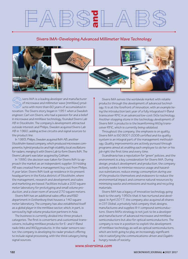
Sivers IMA–Developing Advanced Millimeter Wave Technology
Sivers IMA is a leading developer and manufacturer of microwave and millimeter wave (mmWave) prod-ucts with more than 60 years of accumulated in-
novation. The Sivers story began in 1951 when a Swedish engineer, Carl von Sivers, who had a passion for and a belief in microwave and mmWave technology, founded Sivers Lab AB in Stockholm. The company’s development a racted outside interest and Philips, Sweden acquired Sivers Lab AB in 1960, adding active circuits and signal sources to the product line.
In 1983, Philips, Sweden acquired IMA AB, another Stockholm-based company, which produced microwave com-ponents, hybrid products and high stability local oscillators for radars, merging it with Sivers Lab to form Sivers IMA. The Sivers Lab part was later acquired by Cobham.
In 1990, the decision was taken for Sivers IMA to ap-proach the market as an independent supplier. SI Holding AB was created from a management buy-out from Philips. A year later, Sivers IMA took up residence in its present headquarters in the Kista district of Stockholm, where the management, research and development and sales and marketing are based. Facilities include a 200 square meter laboratory for prototyping and small volume pro-duction, and a clean room of around 270 square meters.
Sivers IMA has an additional sales o ce and R&D department in Gothenburg that houses a 140 square meter laboratory. The company has also established itself as a global player in the mmWave sector, which, in part, is serviced by high volume production partners in Asia.
The business is currently divided into three product categories. The rst is converters and customized trans-ceivers, including mmWave products for E- and V-Band radio links and WiGig products. In the radar sensors sec-tor, the company is developing its radar product o ering to include signal processing, with the third category being signal sources.
Sivers IMA serves the worldwide market with reliable products through the development of advanced technol-ogy. It is at the forefront of innovation, with an example be-ing the introduction last year of a fully integrated V-Band transceiver RFIC in an advanced low-cost SiGe technology. Another stepping stone in the technology development of Sivers IMA´s products is the beamforming WiGig trans-ceiver RFIC, which is currently being validated.
Throughout the company, the emphasis is on quality. Sivers IMA is ISO 9001:2008 certi ed and its quality system is an integral part of the management methodol-ogy. Quality improvements are actively pursued through programs aimed at enabling each employee to do her or his job right the rst time and every time.
Scandinavia has a reputation for “green” policies, and the environment is a key consideration for Sivers IMA. During design, product development and production, the company actively seeks to minimize resource usage and hazard-ous substances, reduce energy consumption during use of the products themselves and endeavors to reduce the environmental impact and conserve natural resources by minimizing waste and emissions and reusing and recycling materials.
Sivers IMA has a legacy of innovative technology going back to the early 1950s that it has nurtured and devel-oped. In April 2017, the company also acquired all shares in CST Global, a privately held company that designs, manufactures and supplies III-V compound semiconduc-tors. Sivers IMA’s strategy is not just to be a developer and manufacturer of advanced microwave and mmWave semiconductors but also for optical semiconductors. The company is now in a position to exploit the development of mmWave technology as well as optical semiconductors, which are both going to play an increasingly signi cant role in satisfying the communications-driven and Gigabit-hungry needs of society.
122 MICROWAVE JOURNAL JULY 2017
and
FABS LABS
www.siversima.com

MWJ/R&S/OUTSTANDING/0717
Outstanding perspectives.With EMC solutions from the market leader.We provide everything you need for development, precompliance and compliance measurements to ensure successful EMC certification. Exceptionally fast EMI test receiversEfficient diagnostic tools for detecting EMIEMC software packages for interactive and fully automatic measurementsWide range of accessories for performing EMI measurementsCompact and modular broadband amplifiersRF shielded chambersComplete EMC test systems
For more information, visit: www.rohde-schwarz.com/ad/emc
15347.022_EMC_Competence_MWJ_Juli17_198x273_e.indd 1 14.06.17 12:26 Uhr

MWJ/WERLATONE/POWER/1216
Up to 1000:1 Bandwidth • Low Insertion Loss • Covering DC-6.5 GHz!Test & Measurement Directional Couplers
17 Jon Barrett RoadPatterson, NY 12563T 845 278 2220F 845 278 [email protected]
Werlatone, Inc.
We Are High Power
Directional CouplersVSWRPowerModel Coupling Insertion SizeType Frequency Flatness
(Inches)
6.7 x 2.27 x 1.69
5.2 x 2.67 x 1.69
6 x 2.2 x 2.2
3.5 x 2.6 x 0.7
6 x 1.5 x 1.1
3 x 3 x 1.09
9.58 x 1.48 x 0.88
3 x 2.2 x 0.7
6.4 x 1.6 x 0.72
4.8 x 0.88 x 0.5
6 x 2 x 0.85
1.8 x 1 x 0.56
6 x 2 x 0.85
2 x 2 x 1.06
2.15 x 2 x 1.36
2.15 x 2 x 1.36
2.15 x 2 x 1.36
2.15 x 2 x 1.36
3 x 3 x 1.59
2 x 2 x 1.06
2.15 x 2 x 1.36
2 x 2 x 1.06
2 x 2 x 1.06
2.15 x 2 x 1.36
1.1 x 0.75 x 0.48
2.15 x 2 x 1.36
2.15 x 2 x 1.36
2.15 x 2 x 1.36
C6021
C5725
C9688
C7734
C8188
C3910
C8373
C7711
C7058
C8060
C7248
C8000
C8214
C10462
C10525
C10537
C10536
C10751
C10006
C10117
C10364
C10762
C10958
C10761
C8644
C10743
C10746
C10748
Loss (dB)
0.45
0.5
0.5
0.35
2.4
0.2
0.8
0.35
0.3
1.1
0.35
0.4
0.35
0.2
0.2
0.2
0.2
0.2
0.2
0.2
0.2
0.2
0.2
0.2
0.4
0.2
0.2
0.2
(dB)
40
40
40
43
20
40
20
40
10
20
6
30
6
40
50
60
50
60
50
40
50
40
40
40
20
40
50
60
(ML)
1.30:1
1.25:1
1.20:1
1.25:1
1.35:1
1.20:1
1.25:1
1.25:1
1.25:1
1.40:1
1.25:1
1.25:1
1.25:1
1.30:1
1.35:1
1.35:1
1.35:1
1.35:1
1.35:1
1.30:1
1.35:1
1.30:1
1.35:1
1.35:1
1.25:1
1.30:1
1.35:1
1.35:1
(W CW)
500
500
800
100
20
200
200
100
200
200
100
100
100
250
700
700
1000
1000
2000
250
500
300
400
600
60
500
500
500
Dual
Dual
Dual
Dual
Uni
Dual
Bi
Dual
Bi
Bi
Bi
Bi
Bi
Dual
Dual
Dual
Dual
Dual
Dual
Dual
Dual
Dual
Dual
Dual
Bi
Dual
Dual
Dual
(MHz)
0.01-1000
0.1-1000
1-1000
30-2500
30-3000
80-1000
100-2500
100-3000
200-2000
200-6000
300-3000
600-6000
700-2500
700-4200
700-4200
700-4200
700-4200
700-4200
700-4200
700-6000
700-6000
1000-6000
1000-6000
1000-6000
1800-6100
2000-6000
2000-6500
2000-6500
(± dB)
0.5
0.5
1.0
1.5
1.0
0.3
1.75
1.0
1.0
2.25
1.0
1.0
1.0
1.0
1.0
1.0
1.0
1.0
1.0
1.0
1.0
0.5
0.5
0.5
1.0
0.5
1.0
1.0
M d l T F