16500 Div 26 Spec (Wired) 04.27.20
32
16500 Div 26 Spec (Wired) 04.27.20 SECTION 26 00 00 N/A Electrical April 27, 2020 N/A [rev. REV0] 1 | P a g e Division 26 Spec (Wired)
-
Upload
khangminh22 -
Category
Documents
-
view
1 -
download
0
Transcript of 16500 Div 26 Spec (Wired) 04.27.20

16500 Div 26 Spec (Wired) 04.27.20 SECTION 26 00 00 N/A Electrical April 27, 2020 N/A [rev. REV0]
1 | P a g e
Division 26
Spec (Wired)

16500 Div 26 Spec (Wired) 04.27.20 SECTION 26 09 43 N/A Network Lighting Controls April 27, 2020 N/A [rev. REV0]
1 | P a g e
SECTION 26 09 43 NETWORK LIGHTING CONTROLS
PART 1 - GENERAL
1.1 Summary
.1 Section includes a networked lighting control system comprised of the following components:
.1 System Software Interfaces
.1 Management Interface
.2 Visualization Interface
.3 Smartphone Programming Interface for Wired Devices
.2 System Backbone and Integration Equipment
.1 System Controller
.2 Digital Time Clock
.3 Wired Networked Devices
.1 Wall Stations
.2 Graphic Wall Stations
.3 Digital Key Switches
.4 Auxiliary Input/Output Devices
.5 Occupancy and Photocell Sensors
.6 Wall Switch Sensors
.7 Embedded Sensors
.8 Power Packs and Secondary Packs
.9 Networked Luminaires
.10 Relay and Dimming Panel
.11 Bluetooth® Low Energy Programming Device
.12 Communication Bridge
.2 The networked lighting control system shall meet all the characteristics and performance requirements specified herein.
.3 The contractor shall provide, install and verify proper operation of all equipment necessary for proper operation of the system as specified herein and as shown on applicable drawings.
1.2 Related Documents
16500 Div 26 Spec (Wired) 04.27.20 SECTION 26 09 43 N/A Network Lighting Controls April 27, 2020 N/A [rev. REV0]
2 | P a g e
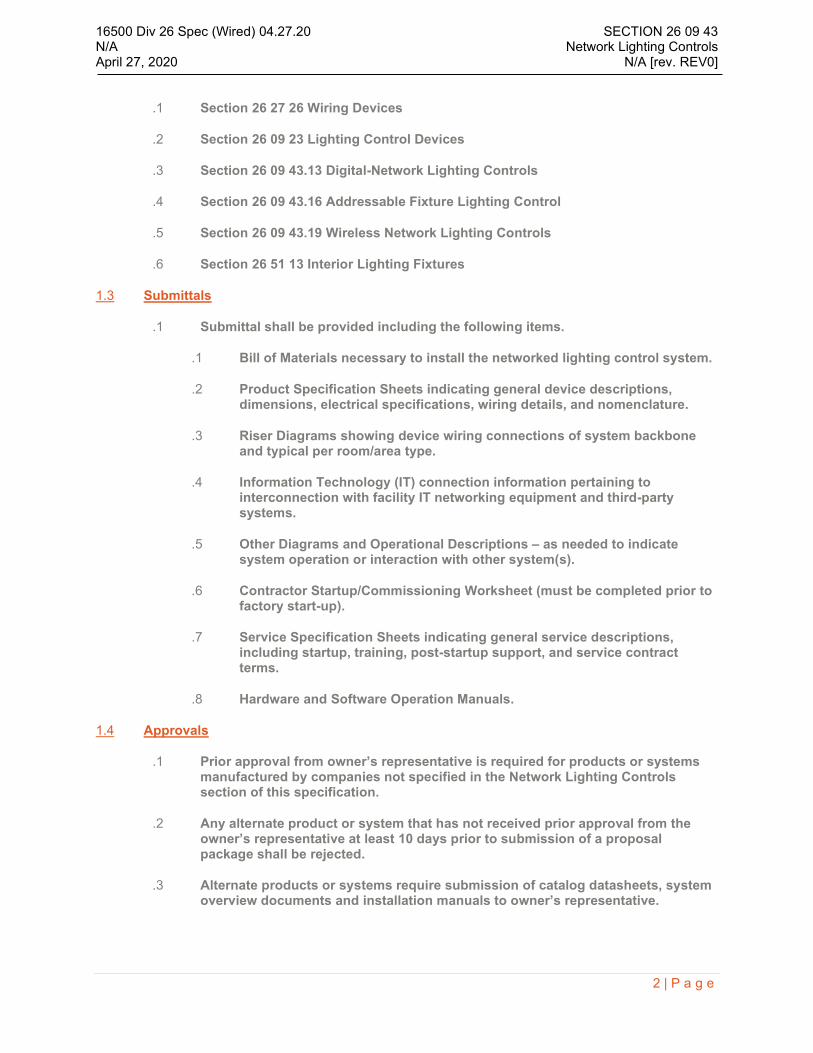
.1 Section 26 27 26 Wiring Devices
.2 Section 26 09 23 Lighting Control Devices
.3 Section 26 09 43.13 Digital-Network Lighting Controls
.4 Section 26 09 43.16 Addressable Fixture Lighting Control
.5 Section 26 09 43.19 Wireless Network Lighting Controls
.6 Section 26 51 13 Interior Lighting Fixtures
1.3 Submittals
.1 Submittal shall be provided including the following items.
.1 Bill of Materials necessary to install the networked lighting control system.
.2 Product Specification Sheets indicating general device descriptions, dimensions, electrical specifications, wiring details, and nomenclature.
.3 Riser Diagrams showing device wiring connections of system backbone and typical per room/area type.
.4 Information Technology (IT) connection information pertaining to interconnection with facility IT networking equipment and third-party systems.
.5 Other Diagrams and Operational Descriptions – as needed to indicate system operation or interaction with other system(s).
.6 Contractor Startup/Commissioning Worksheet (must be completed prior to factory start-up).
.7 Service Specification Sheets indicating general service descriptions, including startup, training, post-startup support, and service contract terms.
.8 Hardware and Software Operation Manuals.
1.4 Approvals
.1 Prior approval from owner’s representative is required for products or systems manufactured by companies not specified in the Network Lighting Controls section of this specification.
.2 Any alternate product or system that has not received prior approval from the owner’s representative at least 10 days prior to submission of a proposal package shall be rejected.
.3 Alternate products or systems require submission of catalog datasheets, system overview documents and installation manuals to owner’s representative.

16500 Div 26 Spec (Wired) 04.27.20 SECTION 26 09 43 N/A Network Lighting Controls April 27, 2020 N/A [rev. REV0]
3 | P a g e
.4 For any alternate system that does not support any form of wireless communication to networked luminaires, networked control devices, networked sensors, or networked input devices, bidders shall provide a total installed cost including itemized labor costs for installing network wiring to luminaires, control devices, sensors, input devices and other required system peripherals.
1.5 Quality Assurance
.1 Product Qualifications
.1 System electrical components shall be listed or recognized by a nationally recognized testing laboratory (e.g., UL, ETL, or CSA) and shall be labeled with required markings as applicable.
.2 System shall be listed as qualified under DesignLights Consortium Networked Lighting Control System Specification V2.0.
.3 System luminaires and controls are certified by manufacturer to have been designed, manufactured and tested for interoperability.
.4 All components shall be subjected to 100% end of line testing prior to shipment to the project site to ensure proper device operation.
.5 All components and the manufacturing facility where product is manufactured must be RoHS compliant.
.2 Installation and Startup Qualifications
.1 System startup shall be performed by qualified personnel approved or certified by the manufacturer.
.3 Service and Support Requirements
.1 Phone Support: Toll free technical support shall be available.
.2 Remote Support: The bidder shall offer a remote support capability.
.3 Onsite Support: The bidder shall offer onsite support that is billable at whole day rates.
.4 Service Contract: The bidder shall offer a Service Contract that packages phone, remote, and onsite support calls for the project. Response times for each type of support call shall be indicated in the terms of the service contract included in the bid package.
1.6 Project Conditions
.1 Only install indoor equipment after the following site conditions are maintained:
.1 Ambient Temperature: 14 to 105 degrees F (-10 to 40 degrees C)
.2 Relative Humidity: less than 90% non-condensing
16500 Div 26 Spec (Wired) 04.27.20 SECTION 26 09 43 N/A Network Lighting Controls April 27, 2020 N/A [rev. REV0]
4 | P a g e
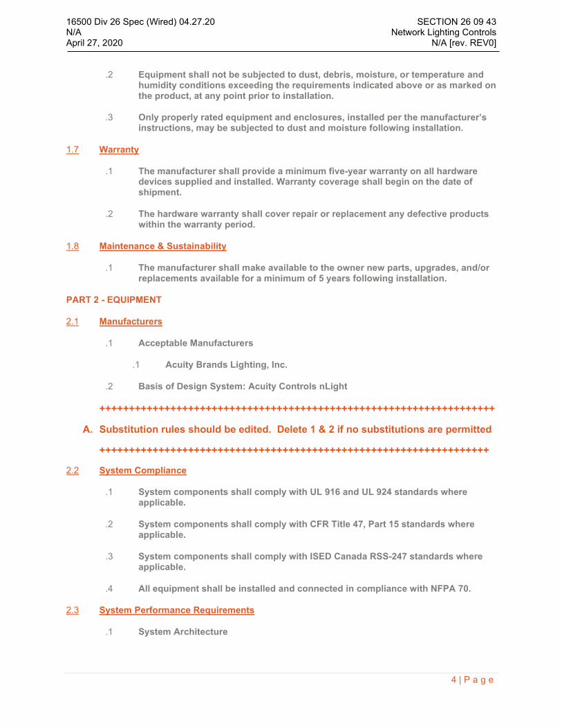
.2 Equipment shall not be subjected to dust, debris, moisture, or temperature and humidity conditions exceeding the requirements indicated above or as marked on the product, at any point prior to installation.
.3 Only properly rated equipment and enclosures, installed per the manufacturer’s instructions, may be subjected to dust and moisture following installation.
1.7 Warranty
.1 The manufacturer shall provide a minimum five-year warranty on all hardware devices supplied and installed. Warranty coverage shall begin on the date of shipment.
.2 The hardware warranty shall cover repair or replacement any defective products within the warranty period.
1.8 Maintenance & Sustainability
.1 The manufacturer shall make available to the owner new parts, upgrades, and/or replacements available for a minimum of 5 years following installation.
PART 2 - EQUIPMENT
2.1 Manufacturers
.1 Acceptable Manufacturers
.1 Acuity Brands Lighting, Inc.
.2 Basis of Design System: Acuity Controls nLight
+++++++++++++++++++++++++++++++++++++++++++++++++++++++++++++++++++
A. Substitution rules should be edited. Delete 1 & 2 if no substitutions are permitted
++++++++++++++++++++++++++++++++++++++++++++++++++++++++++++++++++
2.2 System Compliance
.1 System components shall comply with UL 916 and UL 924 standards where applicable.
.2 System components shall comply with CFR Title 47, Part 15 standards where applicable.
.3 System components shall comply with ISED Canada RSS-247 standards where applicable.
.4 All equipment shall be installed and connected in compliance with NFPA 70.
2.3 System Performance Requirements
.1 System Architecture

16500 Div 26 Spec (Wired) 04.27.20 SECTION 26 09 43 N/A Network Lighting Controls April 27, 2020 N/A [rev. REV0]
5 | P a g e
.1 System shall have an architecture that is based upon three main concepts: (1) networkable intelligent lighting control devices, (2) standalone lighting control zones using distributed intelligence, (3) optional system backbone for remote, time based and global operation.
.2 Intelligent lighting control devices shall have individually addressable network communication capability and consist of one or more basic lighting control components: occupancy sensor, photocell sensor, relay, dimming output, contact closure input, analog 0-10V input, and manual wall station capable of indicating switching, dimming, and/or scene control. Combining one or more of these components into a single device enclosure shall be permissible so as to minimize overall device count of system.
.3 System must be capable of interfacing directly with networked luminaires such that either low voltage network cabling or wireless RF communication is used to interconnect networked luminaires with control components such as sensors, switches and system backbone (see Control Zone Characteristics sections for each type of network connection, wired or wireless).
.4 Networked luminaires and intelligent lighting control devices shall support individual (unique) configuration of device settings and properties, with such configuration residing within the networked luminaires and intelligent control devices.
.5 Lighting control zones consisting of one or more networked luminaires and intelligent lighting control devices and shall be capable of providing automatic control from sensors (occupancy and/or photocell) and manual control from local wall stations without requiring connection to a higher-level system backbone; this capability is referred to as “distributed intelligence.”
.1 Lighting control zones (wired and wireless) of at least 128 devices per zone shall be supported.
.6 Networked luminaires and intelligent lighting control devices shall have distributed intelligence programming stored in non-volatile memory, such that following any loss of power the lighting control zones shall operate according to their defined default settings and sequence of operations.
.7 Lighting control zones shall be capable of being networked with a higher-level system backbone to provide time based control, remote control from inputs and/or systems external to the control zone, and remote configuration and monitoring through a software interface.
.8 The system may include one or more system controllers that provide time-based control. The system controller also provides a means of connecting the lighting control system to a system software interface and building management systems via BACnet/IP or BACnet MS/TP protocol.
.9 All system devices shall support firmware update, either remotely or from within the applications space, for purposes of upgrading functionality at a later date.
16500 Div 26 Spec (Wired) 04.27.20 SECTION 26 09 43 N/A Network Lighting Controls April 27, 2020 N/A [rev. REV0]
6 | P a g e
.2 Wired Networked Control Zone Characteristics
.1 Connections to devices within a wired networked lighting control zone and to backbone components shall be with a single type of low voltage network cable, which shall be compliant with CAT5e specifications or higher. To prevent wiring errors and provide cost savings, the use of mixed types of low voltage network cables shall not be permitted.
.2 Devices in an area shall be connected via a “daisy-chain” topology; requiring all individual networked devices to be connected back to a central component in a “hub-and-spoke” topology shall not be permitted, so as to reduce the total amount of network cable required for each control zone.
.3 System shall provide the option of having pre-terminated plenum rated low voltage network cabling supplied with hardware so as to reduce the opportunity for improper wiring and communication errors during system installation.
.4 Following proper installation and provision of power, all networked devices connected together with low voltage network cable shall automatically form a functional lighting control zone without requiring any type of programming, regardless of the programming mechanism (e.g. software application, handheld remote, pushbutton). The “out of box” default sequence of operation is intended to provide typical sequence of operation so as to minimize the system startup and programming requirements and to also have functional lighting control operation prior to system startup and programming.
.5 Once software is installed, system shall be able to automatically discover all connected devices without requiring any provisioning of system or zone addresses.
.6 All networked devices shall have the ability to detect improper communication wiring and blink its LED in a specific cadence as to alert installation/startup personnel.
.7 Networked control devices intended for control of egress and/or emergency light sources shall not require the use of additional, externally mounted UL924 shunting and/or 0-10V disconnect devices, so as to provide a compliant sequence of operation while reducing the overall installation and wiring costs of the system. The following types of wired networked control devices shall be provided for egress and/or emergency light fixtures:
.1 Low-Voltage power sensing: These devices shall automatically provide 100% light level upon detection of loss of power sensed via the low voltage network cable connection.
.2 UL924 Listed Line-Voltage power sensing: These devices shall be listed as emergency relays under the UL924 standard, and shall automatically close the load control relay and provide 100% light output upon detection of loss of power sensed via line voltage connection to normal power.
16500 Div 26 Spec (Wired) 04.27.20 SECTION 26 09 43 N/A Network Lighting Controls April 27, 2020 N/A [rev. REV0]
7 | P a g e
.8 Networked luminaires and intelligent lighting control devices located in different areas shall be able to transmit and track information within at least 128 system-wide control zones to support required sequences of operation that may span across multiple areas. Occupancy and photocell commands shall be available across a single controller, and switch commands shall be available across single or multiple controllers. These shall also be referred to as global control zones.
.9 Wired networked Wall stations shall provide the follow Scene Control Capabilities:
.1 Preset Scenes that can activate a specific combination of light levels across multiple local and global channels, as required.
.2 Profile Scenes that can modify the sequence of operation for the devices in the area (group) in response to a button press. This capability is defined as supporting “Local Profiles” and is used to dynamically optimize the occupant experience and lighting energy usage. Wall stations shall be able to manually start and stop Local Profiles, or the local profile shall be capable of ending after a specific duration of time between 5 minutes and 12 hours. Parameters that shall be configurable and assigned to a Local Profile shall include, but not be limited to, fixture light level, occupancy time delay, response to occupancy sensors (including enabling/disabling response), response to daylight sensors (including enabling/disabling response), and enabling/disabling of wall stations.
.3 3-way / multi-way control: multiple wall stations shall be capable of controlling the same local and global control zones, so as to support “multi-way” preset scene and profile scene control.
.3 System Integration Capabilities
.1 The system shall interface with third party building management systems (BMS) to support two-way communication using the industry standard BACnet/IP or BACnet MS/TP protocols. The following system integration capabilities shall be available via BACnet/IP and BACnet MS/TP protocols:
.1 The system shall support control of individual devices, including, but not limited to, control of relay and dimming output.
.2 The system shall support reading of individual device status information. The available status will depend on the individual device type and capabilities, which may include but not be limited to, relay state, dimming output, power measurement, occupancy sensor status, and photocell sensor states or readings. All system devices shall be available for polling for devices status.
.3 The system shall support activation of pre-defined system Global Profiles (see Supported Sequence of Operations for further definition of Global Profile capabilities).

16500 Div 26 Spec (Wired) 04.27.20 SECTION 26 09 43 N/A Network Lighting Controls April 27, 2020 N/A [rev. REV0]
8 | P a g e
.2 The system shall support activation of Global Profiles from third party systems by receiving dry contact closure output signals or digital commands via RS-232/RS-485. (See Supported Sequence of Operations for further definition of Profile and Scene Preset capabilities.)
.3 The system shall support activation of demand response levels from Demand Response Automation Servers (DRAS) via the OpenADR 2.0a protocol.
.4 Supported Sequence of Operations
.1 Control Zones
.1 Networked luminaires and intelligent lighting control devices installed in an area (also referred to as a group of devices) shall be capable of transmitting and tracking occupancy sensor, photocell sensor, and manual switch information within at least 48 unique control zones to support different and reconfigurable sequences of operation within the area. These shall also be referred to as local control zones.
.2 Wall station Capabilities
.1 Wall stations shall be provided to support the following capabilities:
.1 On/Off of a local control zone.
.2 Continuous dimming control of light level of a local control zone.
.2 3-way / multi-way control: multiple wall stations shall be capable of controlling the same local control zones, so as to support “multi-way” switching and/or dimming control.
.3 Occupancy Sensing Capabilities
.1 Occupancy sensors shall be configurable to control a local zone.
.2 Multiple occupancy sensors shall be capable of controlling the same local zones. This capability combines occupancy sensing coverage from multiple sensors without consuming multiple control zones.
.3 System shall support the following types of occupancy sensing sequence of operations:
.1 On/Off Occupancy Sensing
.2 Partial-On Occupancy Sensing
.3 Partial-Off Occupancy Sensing
.4 Vacancy Sensing (Manual-On / Automatic-Off)
.4 On/Off, Partial-On, and Partial-Off Occupancy Sensing modes shall function according to the following sequence of operation:

16500 Div 26 Spec (Wired) 04.27.20 SECTION 26 09 43 N/A Network Lighting Controls April 27, 2020 N/A [rev. REV0]
9 | P a g e
.1 Occupancy sensors shall automatically turn lights on to a designated level when occupancy is detected. To support fine tuning of Partial-On sequences the designated occupied light level shall support at least 100 dimming levels.
.2 Occupancy sensors shall automatically turn lights off or to a dimmed state (Partial-Off) when vacancy occurs or if sufficient daylight is detected. To support fine tuning of Partial-Off sequences the designated unoccupied dim level shall support at least 100 dimming levels.
.3 To provide additional energy savings the system shall also be capable of combining Partial-Off and Full-Off operation by dimming the lights to a designated level when vacant and then turning the lights off completely after an additional amount of time.
.4 Photocell readings, if enabled in the Occupancy Sensing control zone, shall be capable of automatically adjusting the light level during occupied or unoccupied conditions as necessary to further reduce energy usage. Additional requirements and details for photocell sensing capabilities are indicated under Photocell Sensing Capabilities.
.5 The use of a wall station shall change the dimming level or turn lights off as selected by the occupant. The lights shall optionally remain in this manually-specified light level until the zone becomes vacant; upon vacancy the normal sequence of operation, as defined above, shall proceed.
.5 Vacancy Sensing mode (also referred to as Manual-On / Automatic-Off) shall function according to the following sequence of operation:
.1 The use of a wall station is required turn lights on. The system shall be capable of programming the zone to turn on to either to a designated light level or the previous user light level. Initially occupying the space without using a wall station shall not result in lights turning on.
.2 Occupancy sensors shall automatically turn lights off or to a dimmed state (Partial-Off) when vacancy occurs or if sufficient daylight is detected. To support fine tuning of Partial-Off sequences the designated unoccupied dim level shall support at least 100 dimming levels.
.3 To provide additional energy savings and an enhanced occupant experience, the system shall also be capable of dimming the lights when vacant and then turning the lights off completely after an additional amount of time.

16500 Div 26 Spec (Wired) 04.27.20 SECTION 26 09 43 N/A Network Lighting Controls April 27, 2020 N/A [rev. REV0]
10 | P a g e
.4 To minimize occupant impact in case the area or zone is still physically occupied following dimming or shutoff of the lights due to detection of vacancy, the system shall support an “automatic grace period” immediately following detection of vacancy, during which time any detected occupancy shall result in the lights reverting to the previous level. After the grace period has expired, the use of a wall station is required to turn lights on.
.5 Photocell readings, if enabled in the Occupancy Sensing control zone, shall be capable of automatically adjusting the light level during occupied or unoccupied conditions as necessary to further reduce energy usage. Additional requirements and details for photocell sensing capabilities are indicated under Photocell Sensing Capabilities.
.6 At any time, the use of a wall station shall change the dimming level or turn lights off as selected by the occupant. The lights shall optionally remain in this manually-specified light level until the zone becomes vacant; upon vacancy the normal sequence of operation, as defined above, shall proceed.
.6 To accommodate diverse types of environments, occupancy time delays before dimming or shutting off lights shall be specifiable for control zones between 15 seconds to 2 hours.
.4 Photocell Sensing Capabilities (Automatic Daylight Sensing)
.1 Photocell sensing devices shall be configurable to control a local zone.
.2 The system shall support the following type of photocell-based control:
.1 Continuous Dimming: The control zone automatically adjusts its dimming output in response to photocell readings, such that a minimum light level consisting of both electric light and daylight sources is maintained at the task. The photocell response shall be configurable to adjust the photocell setpoint and dimming rates.
.5 Schedule Capabilities
.1 System shall support the creation of time schedules for time-of-day override of devices including offsets from dusk and dawn.
.2 System shall support blink warning and timed extension capabilities. At the end of a scheduled period, the system shall be capable of providing a visible “blink warning” 5 minutes prior to the end of the schedule. Wall stations may be programmed to provide timed overrides that turn the lights on for an additional period of time. Timed override duration shall be programmable for each individual device, zone of devices, or customized group of devices, ranging from 5 minutes to 12 hours.

16500 Div 26 Spec (Wired) 04.27.20 SECTION 26 09 43 N/A Network Lighting Controls April 27, 2020 N/A [rev. REV0]
11 | P a g e
.6 Global Profile Capabilities
.1 The system shall be capable of automatically modifying the sequence of operation for selected devices in response to any of the following: a time-of-day schedule, contact closure input state, manually triggered wired wall station input, RS-232/RS-485 command to wired input device, and BACnet input command. This capability is defined as supporting “Global Profiles” and is used to dynamically optimize the occupant experience and lighting energy usage.
.2 Global profiles may be scheduled with the following capabilities:
.1 Global Profiles shall be stored within and executed from the system controller (via internal timeclock) such that a dedicated software host or server is not required to be online to support automatic scheduling and/or operation of Global Profiles.
.2 Global Profile time-of-day schedules shall be capable of being given the following recurrence settings: daily, specific days of week, every “n” number of days, weekly, monthly, and yearly. Lighting control profile schedules shall support definition of start date, end date, end after “n” recurrences, or never ending. Daylight savings time adjustments shall be capable of being performed automatically, if desired.
.3 Global Profile Holiday Schedules should follow recurrent settings for specific US holiday dates regardless if they always occur on a specific date or are determined by the day/week of the month.
.4 Global Profiles shall be capable of being scheduled to run according to timed offsets relative to sunrise or sunset. Sunrise/sunset times shall be automatically derived from location information using an astronomical clock.
.5 Software management interface shall be capable of displaying a graphic calendar view of profile schedules for each control zone.
.3 System Global Profiles shall have the following additional capabilities:
.1 Global Profiles shall be capable of being manually activated directly from the system controller, specially programmed wired input devices, scene capable wired wall stations, and the software management interface.
.2 Global Profiles shall be selectable to apply to a single device, zone of devices, or customized group of devices.
16500 Div 26 Spec (Wired) 04.27.20 SECTION 26 09 43 N/A Network Lighting Controls April 27, 2020 N/A [rev. REV0]
12 | P a g e
.3 Parameters that shall be configurable and assigned to a Global Profile shall include, but not be limited to, fixture light level, occupancy time delay, response to occupancy sensors (including enabling/disabling response), response to daylight sensors (including enabling/disabling response), and enabling/disabling of wall stations.
.4 A backup of Local and Global Profiles shall be stored on the software’s host server such that the Profile backup can be applied to a replacement system controller or wired wall station.
.7 System shall support automated demand response capabilities with automatic reduction of light level to at least three levels of demand response.
2.4 System Software Interfaces
.1 Management Interface
.1 System shall provide a web-based management interface that provides remote system control, live status monitoring, and configuration capabilities of lighting control settings and schedules.
.2 Management interface must be compatible with industry-standard web browser clients, including, but not limited to, Microsoft Internet Explorer®, Apple Safari®, Google Chrome®, Mozilla Firefox®.
.3 Management interface shall require all users to login with a User Name and Password, and shall support creation of at least 100 unique user accounts.
.4 Management interface shall support at least three permission levels for users: read-only, read & change settings, and full administrative system access.
.5 Management interface shall be capable of restricting access for user accounts to specific devices within the system.
.6 All system devices shall be capable of being given user-defined names.
.7 The following device identification information shall be displayed in the Management interface: model number, model description, serial number or network ID, manufacturing date code, custom label(s), and parent network device.
.8 Management interface shall be able to read the live status of a networked luminaire or intelligent control device and shall be capable of displaying luminaire on/off status, dim level, power measurement, device temperature, PIR occupancy sensor status, microphonic occupancy sensor status, remaining occupancy time delay, photocell reading, and active Profiles.

16500 Div 26 Spec (Wired) 04.27.20 SECTION 26 09 43 N/A Network Lighting Controls April 27, 2020 N/A [rev. REV0]
13 | P a g e
.9 Management interface shall be able to read the current active settings of a networked luminaire or intelligent control device and shall be capable of displaying dimming trim levels, occupancy sensor and photocell enable/disable, occupancy sensor time delay and light level settings, occupancy sensor response (normal or vacancy), and photocell setpoints and transition time delays.
.10 Management interface shall be able to change the current active settings and default settings for an individual networked luminaire or intelligent control device.
.11 Management interface shall be capable of applying settings changes for a zone of devices or a group of selected devices using a single “save” action that does not require the user to save settings changes for each individual device.
.12 A printable network inventory report shall be available via the management interface.
.13 A printable report detailing all system profiles shall be available via the management interface.
.14 All sensitive information stored by the software shall be encrypted.
.15 All system software updates must be available for automatic download and installation via the internet.
.2 Visualization and Programming Interfaces
.1 System shall provide an optional web-based visualization interface that displays graphical floorplan.
.2 Graphical floorplan shall offer the following types of system visualization:
.1 Full Device Option - A master graphic of the entire building, by floor, showing each control device installed in the project with zones outlined. This shall include, but not be limited to, the following:
.1 Controls embedded light fixtures
.2 Controls devices not embedded in light fixtures
.3 Daylight Sensors
.4 Occupancy Sensors
.5 Wall Switches and Dimmers
.6 Scene Controllers
.7 Networked Relays
.8 Wired Bridges
.9 System Controllers

16500 Div 26 Spec (Wired) 04.27.20 SECTION 26 09 43 N/A Network Lighting Controls April 27, 2020 N/A [rev. REV0]
14 | P a g e
.10 Wired Relay Panels
.11 Group outlines
.2 Group Only Option - A master graphic of the entire building, by floor, showing only control groups outlined.
.3 Allow for pan and zoom commands so smaller areas can be displayed on a larger scale simply by panning and zooming each floor’s master graphic.
.4 A mouse click on any control device shall display the following information (as applicable):
.1 The device catalog number.
.2 The device name and custom label.
.3 Device diagnostic information.
.4 Information about the device status or current configuration is available with an additional mouse click.
.3 Application interface shall be provided for both Apple iOS® and Android operating systems that allows configuration of lighting control settings.
.4 The application shall support the configuration and control of wired networked control devices via a Bluetooth® Low Energy (BLE) Programming Device.
.1 Application shall support a security pin-code to access the zone of lighting control devices.
.2 The application shall provide indication of signal strength where multiple Bluetooth Low Energy Programming Devices are available for configuration.
.3 The application shall indicate the number of wired networked control devices connected to the local daisy-chain zone.
.4 The application shall provide on/off/dimming control of all control groups.
.5 The application shall provide the ability to identify all individual luminaires and control devices.
.5 Programming capabilities through the application shall include, but not be limited to, the following:
.1 Switch/occupancy/photosensor zone configuration
.2 Manual/automatic on modes
.3 Turn-on dim level
.4 Occupancy sensor time delays
.5 Dual technology occupancy sensors sensitivity
16500 Div 26 Spec (Wired) 04.27.20 SECTION 26 09 43 N/A Network Lighting Controls April 27, 2020 N/A [rev. REV0]
15 | P a g e
.6 Photosensor calibration adjustment and auto-setpoint
.7 Multiple photosensor zone offset
.8 Trim level settings
.9 Preset scene creation and copy for scene capable devices.
.10 Application of custom device labels to the Bluetooth Low Energy Programming Devices and individual connected lighting control devices.
2.5 System Backbone and System Integration Equipment
.1 System Controller
.1 Product Series: nECY
.2 System Controller shall be multi-tasking, real-time digital control processor consisting of modular hardware with plug-in enclosed processors, communication controllers, and power supplies.
.3 System Controller shall have 32-bit microprocessor operating at a minimum of 1 GHz.
.4 System Controller shall have minimum of 512MB memory, with a minimum of 4GB non-volatile flash, to support its own operating system and databases.
.5 System Controller shall perform the following functions:
.1 Time-based control of downstream wired and wireless network devices.
.2 Linking into an Ethernet network.
.3 Integration with Building Management Systems (BMS) and Heating, Ventilation and Air Conditioning (HVAC) equipment.
.4 Connection to various software interfaces, including management interface, historical database and analytics interface, and visualization interface.
.6 System Controller shall have an integral web server to support configuration, diagnostics and hosting of software interfaces.
.7 Device shall have option for a graphical touch screen to support configuration and diagnostics.
.8 Device shall have three RJ-45 networked lighting control ports for connection to any of the following:
.1 The graphical touch screen
.2 Wired communication bridges

16500 Div 26 Spec (Wired) 04.27.20 SECTION 26 09 43 N/A Network Lighting Controls April 27, 2020 N/A [rev. REV0]
16 | P a g e
.3 Direct connection to networked wired luminaires and intelligent lighting control devices (up to 128 total devices per port)
.9 Device shall automatically detect all networked devices connected to it.
.10 Device shall have an internal time clock used for astronomical and standard schedules.
.11 Device shall have 2 switched RJ-45 10/100 BaseT Ethernet ports for local area network (LAN) connection.
.1 Ethernet connection shall support daisy chain wiring to other lighting control system LAN devices.
.2 Ethernet connection shall support IPv4 and shall be capable of using a dedicated static or DHCP assigned IP address.
.12 Device shall have 2 x USB 2.0 Expansion ports for 802.11 Wi-Fi Adapter enabling wireless connectivity including:
.1 Hot Spot
.2 Access Point
.3 Client
.13 Each System Controller shall be capable of managing and operating at least 750 networked devices (wired or wireless).
.1 Multiple System Controllers may be networked together via LAN connection to scale the system up to 20,000 networked devices.
.14 System Controller shall support BACnet/IP and BACnet MS/TP protocols to directly interface with BMS and HVAC equipment without the need for additional protocol translation gateways.
.1 BACnet MS/TP shall support 9600 to 115200 baud rate.
.2 System Controller shall be BACnet Testing Laboratory (BTL listed) using Device Profile BACnet Building Controller (B-BC) with outlined enhanced features.
.15 System controller shall contain a “FIPS 140-2 Level 1 Inside” cryptographic module.
.16 System controller shall support RESTful API control of BACnet objects, user management, date and time, and file management.
.17 System controller shall be available within a NEMA 1 enclosure with Class 1 and Class 2 separation
.1 Enclosure shall support power input power of 120-277VAC, or optional 347
.2 Digital Electronic Time Clock (DTC)

16500 Div 26 Spec (Wired) 04.27.20 SECTION 26 09 43 N/A Network Lighting Controls April 27, 2020 N/A [rev. REV0]
17 | P a g e
.1 DTC shall control and program a linear bus of lighting devices and supply all time functions without connection to a system controller.
.1 Programming of the linear bus of lighting devices shall not require additional hardware, including computers, specialized dongles, or other connection devices.
.2 Programming of the linear bus shall be exclusively done through the touch screen interface.
.2 DTC shall be capable of up to 32 schedules. Each schedule shall consist of one set of On and Off times per day for each day of the week and for each of two holiday lists. The schedules shall apply to any individual relay or group of relays.
.3 DTC shall be run from non-volatile memory so that all system programming is retained indefinitely.
.4 DTC shall be optionally mounted inside of a relay panel. Installation inside of the relay panel shall eliminate the necessity of any additional enclosures for complete installation.
.5 DTC shall have a capacitive 3.5” full color touch screen.
2.6 Wired Networked Devices
.1 Wired Networked Wall Switches, Dimmers, Scene Controllers
.1 Product Series: nPODM, nPODM xS, nPODM xL, nPODMA, nPODMA xS, nPODMA xL.
.2 Devices shall recess into single-gang switch box and fit a standard GFI opening.
.3 Communication and low voltage power shall be delivered to each device via standard low voltage network cabling with RJ-45 connectors.
.4 All switches shall have the ability to detect when it is not receiving valid communication and blink its LED in a pattern to visually indicate a potential wiring issue.
.5 Devices with mechanical push-buttons shall provide tactile and LED user feedback.
.6 Devices with mechanical push-buttons shall be made available with custom button labeling.
.7 Wall switches & dimmers shall support the following device options:
.1 Number of control zones: 1, 2 or 4
.2 Control Types Supported:
.1 On/Off
.2 On/Off/Dimming
16500 Div 26 Spec (Wired) 04.27.20 SECTION 26 09 43 N/A Network Lighting Controls April 27, 2020 N/A [rev. REV0]
18 | P a g e
.3 On/Off/Dimming/Correlated Color Temperature Control for specific luminaire types
.3 Colors: Ivory, White, Light Almond, Gray, Black, Red
.8 Scene controllers shall support the following device options:
.1 Number of scenes: 1, 2 or 4
.2 Control Types Supported:
.1 On/Off
.2 On/Off/Dimming
.3 Preset Level Scene Type
.4 On/Off/Dimming/Preset Level for Correlated Color Temperature
.5 Reprogramming of other devices within daisy-chained zone so as to implement user selected lighting scene. This shall support manual start/stop from the scene controller, or optionally programmed to automatically end after a user selectable duration between 5 minutes and 12 hours.
.6 Selecting a lighting profile to be run by the system’s upstream controller so as to implement a selected lighting profile across multiple zones. This shall support manual start/stop from the scene controller, or optionally programmed to automatically end after a user selectable duration between 5 minutes and 12 hours.
.3 Colors: Ivory, White, Light Almond, Gray, Black, Red
.2 Wired Networked Graphic Wall Stations
.1 Product Series: nPOD TOUCH
.2 Device shall surface mount to single-gang switch box.
.3 Device shall have a 3.5”, capacitive full color touch screen.
.4 Device shall be powered with Class 2 low voltage supplied locally via a directly wired power supply.
.5 Device shall have a micro-USB style connector for local computer connectivity.
.6
.7 Communication shall be over standard low voltage network cabling with RJ-45 connectors.
.8 Device shall enable user supplied screen saver image to be uploaded within one of the following formats: jpg, png, gif, bmp, tif.

16500 Div 26 Spec (Wired) 04.27.20 SECTION 26 09 43 N/A Network Lighting Controls April 27, 2020 N/A [rev. REV0]
19 | P a g e
.9 Device shall enable configuration of all switches, dimmers, control zones, and lighting preset scenes via password protected setup screens.
.10 Graphic wall stations shall support the following device options:
.1 Number of control zones: Up to 16
.2 Number of scenes: Up to 16
.3 Profile type scene duration: User configurable from 5 minutes to 12 hours
.4 Colors: White, Black
.3 Wired Networked Digital Key Switches
.1 Product Series: nPOD KEY, nPOD KEY MNTN
.2 Devices shall recess into single-gang switch box and fit a standard GFI opening.
.3 Communication and low voltage power shall be delivered to each device via standard low voltage network cabling with RJ-45 connectors.
.4 All switches shall have the ability to detect when it is not receiving valid communication and blink its LED in a pattern to visually indicate a potential wiring issue.
.5 Devices shall have LED user feedback to provide indication of on/off status of the programmed lights or scene, as well as indication of device power.
.6 Digital key switches shall support the following device options:
.1 Control Types Supported:
.1 On/Off
.2 On/Off/Dimming
.3 Preset Level Scene Type
.4 Reprogramming of other devices within daisy-chained zone so as to implement user selected lighting scene. This shall support manual start/stop from the scene controller, or optionally programmed to automatically end after a user selectable duration between 5 minutes and 12 hours.
.5 Selecting a lighting profile to be run by the system’s upstream controller so as to implement a selected lighting profile across multiple zones. This shall support manual start/stop from the scene controller, or optionally programmed to automatically end after a user selectable duration between 5 minutes and 12 hours.
.2 Colors: Ivory, White, Light Almond, Stainless Steel
.4 Wired Networked Auxiliary Input / Output (I/O) Devices

16500 Div 26 Spec (Wired) 04.27.20 SECTION 26 09 43 N/A Network Lighting Controls April 27, 2020 N/A [rev. REV0]
20 | P a g e
.1 Product Series: nIO-1S, nIO-RLX, nIO-MLO-5STEPA, nIO-MLO-AB, nIO-NLI, nIO-X, nIO-D, nIO-EZ-PH, nIO-EZD, nIO-EZDL, nIO-EZDA, nIO-EZDX
.2 Devices shall be plenum rated and be inline wired, screw mountable, or have an extended chase nipple for mounting to a ½” knockout.
.3 Communication and low voltage power shall be delivered to each device via standard low voltage network cabling with RJ-45 connectors.
.4 Auxiliary Input/Output Devices shall be specified as an input or output device with the following options:
.1 Contact closure or Pull High input
.1 Input shall be programmable to support maintained or momentary inputs that can activate local or global scenes and profiles, activate lights at a preconfigured level, ramp light level up or down, or toggle lights on/off.
.2 0-10V analog input
.1 Input shall be programmable to function as a daylight sensor.
.3 RS-232/RS-485 digital input
.1 Input supports activation of up to 4 local or global scenes and profiles, and on/off/dimming control of up to 16 local control zones.
.4 0-10V dimming control output, capable of sinking up to 20mA of current
.1 Output shall be programmable to support all standard sequence of operations supported by system.
.5 Digital control output via EldoLED LEDcode communication
.1 Output shall be programmable to support light intensity control, as well as optional correlated color temperature (CCT) control, of the connected luminaire.
.5 Wired Networked Occupancy and Photosensors
.1 Product Series: nCM, nCMB, nRM, nWV, nHW
.2 Occupancy sensors shall sense the presence of human activity within the desired space and fully control the on/off function of the lights.
.3 Sensors shall utilize passive infrared (PIR) technology, which detects occupant motion, to initially turn lights on from an off state, thus preventing false on conditions. Ultrasonic or Microwave based sensing technologies shall not be accepted.
.4 For applications where a second method of sensing is necessary to adequately detect maintained occupancy (such as in rooms with obstructions), a sensor with an additional “dual” technology shall be used.

16500 Div 26 Spec (Wired) 04.27.20 SECTION 26 09 43 N/A Network Lighting Controls April 27, 2020 N/A [rev. REV0]
21 | P a g e
.5 Dual technology sensors shall have one of its two technologies not require motion to detect occupancy. Acceptable dual technology includes PIR/Microphonics (also known as Passive Dual Technology or PDT) which both looks for occupant motion and listens for sounds indicating occupants. Sensors where both technologies detect motion (PIR/Ultrasonic) shall not be acceptable.
.6 All sensing technologies shall be acoustically passive, meaning they do not transmit sounds waves of any frequency (for example in the Ultrasonic range), as these technologies have the potential for interference with other electronic devices within the space (such as electronic white board readers). Acceptable detection technologies include Passive Infrared (PIR), and/or Microphonics technology. Ultrasonic or Microwave based sensing technologies shall not be accepted.
.7 System shall have ceiling, fixture, recessed & corner mounted sensors available, with multiple lens options available customized for specific applications.
.8 Communication and low voltage power shall be delivered to each device via standard low voltage network cabling with RJ-45 connectors.
.9 All sensors shall have the ability to detect when it is not receiving valid communication and blink its LED in a pattern to visually indicate a potential wiring issue.
.10 Sensor programming parameter shall be available and configurable remotely from the software and locally via the device push-button.
.11 Ceiling mount occupancy sensors shall be available with zero or one integrated dry contact switching relays, capable of switching 1 amp at 24 VAC/VDC (resistive only).
.12 Sensors shall be available with one or two occupancy “poles”, each of which provides a programmable time delay.
.13 Sensors shall have optional features for photosensor/daylight override, automatic dimming control, and low temperature/high humidity operation.
.14 Photosensor shall provide for an on/off set-point, and a dead band to prevent the artificial light from cycling. Delay shall be incorporated into the photocell to prevent rapid response to passing clouds.
.15 Photosensor and dimming sensor’s set-point and dead band shall be automatically calibrated through the sensor’s microprocessor by initiating an “Automatic Set-point Programming” procedure. Min and max dim settings as well as set-point may be manually entered.
.16 Dead band setting shall be verified and modified by the sensor automatically every time the lights cycle to accommodate physical changes in the space (i.e., furniture layouts, lamp depreciation, or lamp outages).

16500 Div 26 Spec (Wired) 04.27.20 SECTION 26 09 43 N/A Network Lighting Controls April 27, 2020 N/A [rev. REV0]
22 | P a g e
.17 A dual zone option shall be available for On/Off Photocell, Automatic Dimming Control Photocell, or Combination units. The secondary daylight zone shall be capable of being controlled as an “offset” from the primary zone.
.6 Wired Networked Wall Switch Sensors
.1 Product Series: nWSX LV
.2 Devices shall recess into single-gang switch box and fit a standard GFI opening.
.3 Communication and low voltage power shall be delivered to each device via standard low voltage network cabling with RJ-45 connectors.
.4 All wall switch sensors shall have the ability to detect when it is not receiving valid communication and blink its LED in a pattern to visually indicate a potential wiring issue.
.5 Devices with mechanical push-buttons shall provide tactile user feedback.
.6 Wall switches sensors shall support the following device options:
.1 User Input Control Types Supported: On/Off or On/Off/Dimming
.2 Occupancy Sensing Technology: PIR only or Dual Tech acoustic
.3 Daylight Sensing Option: Inhibit Photosensor
.4 Colors: Ivory, White, Light Almond, Gray, Black, Red
.7 Wired Networked Embedded Sensors
.1 Product Series: nES
.2 Network system shall have embedded sensors consisting of occupancy sensors and/or dimming photocells that can be embedded into luminaire such that only the lens shows on luminaire face.
.3 Occupancy sensor detection pattern shall be suitable for 7.5’ to 20’ mounting heights.
.4 Embedded sensors shall support the following device options:
.1 Occupancy Sensing technology: PIR only or Dual Tech acoustic
.2 Daylight Sensing Option: Occupancy only, Daylight only, or combination Occupancy/Daylight sensor
.8 Wired Networked Power Packs and Secondary Packs
.1 Product Series: nPP16, nPP16-ER, nPP20-PL, nSP16, nSP5-PCD, nSP5-2P-LVR, nSHADE, nAR40, nEPS-60, nPS-80

16500 Div 26 Spec (Wired) 04.27.20 SECTION 26 09 43 N/A Network Lighting Controls April 27, 2020 N/A [rev. REV0]
23 | P a g e
.2 Power Packs shall incorporate one optional Class 1 relay, optional 0-10 VDC dimming output, and contribute low voltage Class 2 power to the rest of the system.
.3 Power Packs shall accept 120 or 277 VAC (or optionally 347 VAC) and carry a plenum rating.
.4 Secondary Packs shall incorporate the relay and 0-10 VDC or line voltage dimming output, but shall not be required to contribute system power.
.5 Power Supplies shall provide system power only, but are not required to switch line voltage circuit.
.6 Auxiliary Relay Packs shall switch low voltage circuits only, capable of switching 1 amp at 40 VAC/VDC (resistive only).
.7 Communication shall be delivered to each device via standard low voltage network cabling with RJ-45 connectors. Secondary packs shall receive low voltage power via standard low voltage network cable.
.8 Power Pack programming parameters shall be available and configurable remotely from the software and locally via the device push-button.
.9 Power Pack shall securely mount through a threaded ½ inch chase nipple or be capable of being secured within a luminaire ballast/driver channel. Plastic clips into junction box shall not be accepted. All Class 1 wiring shall pass through chase nipple into adjacent junction box without any exposure of wire leads. Note: UL Listing under Energy Management or Industrial Control Equipment automatically meets this requirement, whereas Appliance Control Listing does not meet this safety requirement.
.10 When required by local code, Power Pack must install inside standard electrical enclosure and provide UL recognized support to junction box. All Class 1 wiring is to pass through chase nipple into adjacent junction box without any exposure of wire leads.
.11 Power/Secondary Packs shall be available with the following options:
.1 Power Pack capable of full 16-Amp switching of all normal power lighting load types, with optional 0-10V dimming output capable of up to 100mA of sink current.
.2 Secondary Pack with UL924 listing for switching of full 16-Amp Emergency Power circuits, with optional 0-10V dimming output capable of up to 100mA of sink current.
.3 Power and Secondary Packs capable of full 20-Amp switching of general purpose receptacle (plug-load) control.
.4 Secondary Pack capable of full 16-Amp switching of all normal power lighting load types.
.5 Secondary Pack capable of 5-Amps switching and dimming 120 VAC incandescent lighting loads or 120/277 VAC line voltage dimmable fluorescent ballasts (2-wire and 3-wire versions).

16500 Div 26 Spec (Wired) 04.27.20 SECTION 26 09 43 N/A Network Lighting Controls April 27, 2020 N/A [rev. REV0]
24 | P a g e
.6 Secondary Pack capable of 5-Amps switching and dimming of 120/277 VAC magnetic low voltage transformers.
.7 Secondary Pack capable of 4-Amps switching and dimming of 120 VAC electronic low voltage transformers.
.8 Secondary Pack capable of louver/damper motor control for skylights.
.9 Secondary Pack capable of providing a pulse on/pulse off signal for purposes of controlling shade systems via relay inputs.
.10 Secondary Pack capable of switching 1 amp at 40 VAC/VDC (resistive only) with the intent to provide relay signal to auxiliary system (e.g. BMS).
.11 Power Supply capable of providing auxiliary bus power (no switched or dimmed load).
.9 Wired Networked Luminaires
.1 Product Series: Networked Luminaires shall be of the following Acuity Brands LED fixtures, which come factory enabled with embedded networking capability:
.1 Lithonia model families: BLT(R/X) RTL(R/X) VTL(R/X) TL(X) FSL(X) ACL(X) ALL(S) AVL BZL GTL SBS IBL/IBH PTN LDN DOM WL STL
.2 Gotham model families: EVO Incito
.3 Mark model families: Slot 2/4/6 Fin Veil Whisper Nol SPR RUBIK

16500 Div 26 Spec (Wired) 04.27.20 SECTION 26 09 43 N/A Network Lighting Controls April 27, 2020 N/A [rev. REV0]
25 | P a g e
.4 Peerless model families: Vellum Mino Round 2/4 Square Origami Bruno Staple Lightline Lightedge Icetray Cerra Prima Naro Tulip Envision Aero Enzo
.2 Networked luminaire shall have a mechanically integrated control device.
.3 Networked LED luminaire shall have two RJ-45 ports available (via control device directly or incorporated RJ-45 splitter).
.4 Networked LED luminaire shall be able to digitally network directly to other network control devices (sensors, photocells, switches, dimmers).
.5 Networked LED luminaire shall provide low voltage power to other networked control devices (excluding EMG and CCT capable versions).
.6 System shall be able to turn on/off specific LED luminaires without using a relay, if LED driver supports “sleep mode.”
.7 System shall be able to maintain constant lumen output over the specified life of the LED luminaire (also called lumen compensation) by automatically varying the dimming control signal to account for lumen depreciation.
.1 System shall indicate (via a blink warning) when the LED luminaire is no longer able to compensate for lumen depreciation.
.8 System shall be able to provide control of network luminaire intensity, in addition to correlated color temperature of specific LED luminaires.
.9 System shall be able to provide control of network luminaire intensity, in addition to dynamic features, such as grayscale and color accent of specific LED luminaires.
.10 Wired Networked Relay and Dimming Panel
.1 Product Series: ARP
.2 Relay and dimming panel shall be available with 4, 8, 12, 16, 24, 32, 40 or 48 individual relays per panel, with an equal number of individual 0-10V dimming outputs.
16500 Div 26 Spec (Wired) 04.27.20 SECTION 26 09 43 N/A Network Lighting Controls April 27, 2020 N/A [rev. REV0]
26 | P a g e
.3 Optional Field Configurable Relays (FCR) used shall have the following required properties:
.1 Configurable in the field to operate with single-, double-, or triple-pole relay groupings.
.2 Configurable in the field to operate with normally closed or normally open behavior.
.3 Provides visual status of current state and manual override control of each relay.
.4 Listed for the following minimum ratings:
.1 40A @ 120-480VAC Ballast
.2 16A @ 120-277VAC Electronic
.3 20A @ 120-277VAC Tungsten
.4 20A @ 48VDC Resistive
.5 2HP @ 120VAC
.6 3HP @ 240-277VAC
.7 65kA SCCR @ 480VAC
.4 0-10 dimming outputs shall support a minimum of 100mA sink current per output.
.5 Relay and dimming outputs shall be individually programmable to support all standard sequence of operations as defined in this specification.
.6 Panel shall be UL924 listed for control of emergency lighting circuits.
.7 Panel shall power itself from an integrated 120-277 VAC or optional 347VAC supply.
.8 Panel shall provide a configurable low-voltage sensor input with the following properties:
.1 Configurable to support any of the following input types:
.1 Indoor Photocell
.2 Outdoor Photocell
.3 Occupancy Sensor
.4 Contact Closure
.2 Low voltage sensor input shall provide +24VDC power for the sensor so that additional auxiliary power supplies are not required.
.3 Sensor input supports all standard sequence of operations as defined in this specification.

16500 Div 26 Spec (Wired) 04.27.20 SECTION 26 09 43 N/A Network Lighting Controls April 27, 2020 N/A [rev. REV0]
27 | P a g e
.9 Panel shall provide a contact closure input for each group of 8-relays that acts as a panel override to activate the normally configured state of all relays (i.e., normally open or normally closed) in the panel. This input is intended to provide an interface to alarm systems, fire panels, or BMS system to override the panel.
.10 Panel shall supply current limited low voltage power to other networked devices connected via low voltage network cable.
.11 Panel shall be available with NEMA 1 rated enclosure with the following mounting and cover options:
.1 Surface-mounted for all panel sizes
.2 Flush-mounted for up to 16 relay panel sizes
.3 Screw-fastened for up to 16 relay panel sizes
.4 Hinged cover with keyed lock for all panel sizes
.12 Surface-mounted screw cover options for 8 and 16 relay panel sizes shall be plenum rated
.13 Panel shall be rated from 0-50C for 8 and 16 enclosure sizes, and 0-45C for 32 and 48 enclosure sizes.
.11 Wired Networked Bluetooth® Low Energy Programming Device
.1 Product Series: nIO BT
.2 Device shall be plenum rated and be inline wired, screw mountable.
.3 Communication and low voltage power shall be delivered to device via standard low voltage network cabling with RJ-45 connectors.
.4 Bluetooth Low Energy connection shall allow connection from smartphone application for programming device settings within the local daisy-chain zone (see list of available settings in section 2.4-System Software Interfaces, Sub-section E).
.1 Device shall provide visual indication of remote Bluetooth connection via LED integrated into device enclosure such that it is visible from all angles while the zone is being programmed.
.12 Wired Networked Communication Bridge
.1 Product Series: nBRG
.2 Device shall surface mount to a standard 4” x 4” square junction box.
.3 Device shall have 8 RJ-45 ports for connection to lighting control zones (up to 128 devices per port), additional network bridges, and System Controller.
16500 Div 26 Spec (Wired) 04.27.20 SECTION 26 09 43 N/A Network Lighting Controls April 27, 2020 N/A [rev. REV0]
28 | P a g e
.4 Device shall be capable of aggregating communication from multiple lighting control zones for purposes of minimizing backbone wiring requirements back to System Controller.
.5 Device shall be powered with Class 2 low voltage supplied locally via a directly wired power supply, or powered via low voltage network connections from powered lighting control devices (e.g. power packs).
.6 Wired Bridge shall be capable of redistributing power from its local supply and connected lighting control zones with excess power to lighting control zones with insufficient local power. This architecture also enables loss of power to a particular area to be less impactful on network lighting control system.
PART 3 - EXECUTION
3.1 Installation Requirements
.1 Installation Procedures and Verification
.1 The successful bidder shall review all required installation and pre-startup procedures with the manufacturer’s representative through pre-construction meetings.
.2 The successful bidder shall install and connect the networked lighting control system components according to the manufacturer’s installation instructions, wiring diagrams, the project submittals and plans specifications.
.3 The successful bidder shall be responsible for testing of all low voltage network cable included in the bid. Bidder is responsible for verification of the following minimum parameters:
.1 Wire Map (continuity, pin termination, shorts and open connections, etc.)
.2 Length
.3 Insertion Loss
.2 Coordination with Owner’s IT Network Infrastructure
.1 The successful bidder is required to coordinate with the owner’s representative to secure all required network connections to the owner’s IT network infrastructure.
.1 The bidder shall provide to the owner’s representative all network infrastructure requirements of the networked lighting control system.
.2 The bidder shall provide to the manufacturer’s representative all necessary contacts pertaining to the owner’s IT infrastructure, to ensure that the system is properly connected and started up.
.3 Documentation and Deliverables

16500 Div 26 Spec (Wired) 04.27.20 SECTION 26 09 43 N/A Network Lighting Controls April 27, 2020 N/A [rev. REV0]
29 | P a g e
.1 The installing contractor shall be responsible for documenting installed location of all networked devices, including networked luminaires. This includes responsibility to provide as-built plan drawing showing device address barcodes corresponding to locations of installed equipment.
.2 The installing contractor is also responsible for the following additional documentation to the manufacturer’s representative if visualization / graphical floorplan software is provided as part of bid package:
.1 As-Built floor plan drawings showing device address locations required above. All documentation shall remain legible when reproducing\scanning drawing files for electronic submission.
.2 As-Built electrical lighting drawings (reflected ceiling plan) in PDF and CAD format. Architectural floor plans shall be based on as-built conditions.
.1 CAD files shall have layers already turned on/off as desired to be shown in the graphical floorplan background images. The following CAD elements are recommended to be hidden to produce an ideal background graphical image: Titleblock Text- Inclusive of room names and numbers, fixture tags and drawings notes Fixture wiring and homeruns Control devices Hatching or poché of light fixtures or architectural elements
.2 CAD files shall be of AutoCAD 2013 or earlier. Revit file overall floor plan views shall be exported to AutoCAD 2013.
3.2 System Startup
.1 Upon completion of installation by the installer, including completion of all required verification and documentation required by the manufacturer, the system shall be started up and programmed.
.1 For CAT5 wired devices, low voltage network cable testing shall be performed prior to system startup.
.2 System start-up and programming shall include:
.1 Verifying operational communication to all system devices.
.2 Programming the network devices into functional control zones to meet the required sequence of operation.
.3 Programming and verifying all sequence of operations.
.3 Initial start-up and programming is to occur on-site.
3.3 Project Turnover
.1 System Documentation
16500 Div 26 Spec (Wired) 04.27.20 SECTION 26 09 43 N/A Network Lighting Controls April 27, 2020 N/A [rev. REV0]
30 | P a g e
.1 Submit software database file with desired device labels and notes completed. Changes to this file will not be made by the factory.
.2 Installing contractor to grant access to the owner for the programming database, if requested.
.2 Owner Training
.1 Provisions for onsite training for owner and designated attendees to be included in submittal package.
End of Section

16500 Div 26 Spec (Wired) 04.27.20 SECTION 26 09 43 N/A Network Lighting Controls April 27, 2020 N/A [rev. REV0]
1 | P a g e