Training Manual FT 55 - Saturn
68
Training Manual FT 55 All the technical strengths, installation and maintenance: Gepard, Panther .
-
Upload
khangminh22 -
Category
Documents
-
view
0 -
download
0
Transcript of Training Manual FT 55 - Saturn

Training Manual FT 55
All the technical strengths,installation and maintenance:
Gepard, Panther .

- 2 -
T e c h n i c a l N o t e b o o k . . . . . . . . . . . . . . . . . . . . . . . . . . . . . . . . . . . . . . . . . . . . . . . . . . . . . . . . . . . . . .
T e c h n i c a l T r a i n i n g
Presentation of the range
This product range exists in different versions:- Open flue or fan flue boilers- Combi or system boilers The different models:• Gepard (Combi)
Open Flue Fan FlueModels Gepard 23 MOV Gepard 23 MTVHeating output 23,3 kW 23,3 kWDHW output 23,3 kW 23,3 kW
• Panther (Combi)Open Flue Fan Flue
Models Panther 25 KOV Panther 25 KTV Panther 30 KTVHeating output 24,6 kW 24,6 kW 29,6 kWDHW output 24,6 kW 24,6 kW 29,6 kW
• Panther (System)Open Flue Fan Flue
Models Panther 12 KOO Panther 25 KOO Panther 12 KTO Panther 25 KTOHeating output 12,4 kW 24,6 kW 12,6 kW 24,6 kWDHW output - - - -
Gepard / Panther 23 MOV : Gepard / Panther = range name 23 = nominal output MOV : M or K = family of boiler MOV : O or T = Open flue (O) or Fan flue (T) MOV : O or V = System (O) or Combi (V)

- 3 -
T e c h n i c a l N o t e b o o k . . . . . . . . . . . . . . . . . . . . . . . . . . . . . . . . . . . . . . . . . . . . . . . . . . . . . . . . . . . . . .
T e c h n i c a l T r a i n i n g
General presentation of the open flue appliances.
All the models of the range have a common structure.- The hydraulic unit (circulator rating, number of plates in the hot water heat exchanger, expansion tank capacity, etc)- Control panel
The structure of open flue versions:
Draught diverter
Heat exchanger
Chambre de combustion
Hydraulic bloc
Gas valve
Electrical box
Smoke outlet
Over-flow safety device
Burner
Plate heat exchanger
Pump
360450
Ø46
807
230
225
311410
742
179205
Ø125
311410
Ø41
742
184
205
311410
Ø36
742
158
175
(Ø43)
Gepard 23 MOV Panther 25 KOVPanther 12 / 25 KOO
- 4 -
T e c h n i c a l N o t e b o o k . . . . . . . . . . . . . . . . . . . . . . . . . . . . . . . . . . . . . . . . . . . . . . . . . . . . . . . . . . . . . .
T e c h n i c a l T r a i n i n g
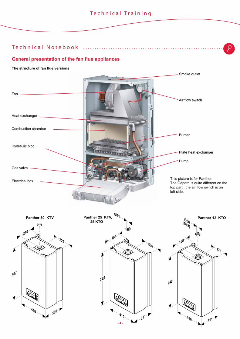
General presentation of the fan flue appliances
The structure of fan flue versions
Fan
Heat exchanger
Combustion chamber
Hydraulic bloc
Gas valve
Electrical box
Smoke outlet
Air flow switch
Burner
Plate heat exchanger
Pump
This picture is for Panther. The Gepard is quite different on the top part : the air flow switch is on left side.
360450
Ø46
807
230
225
311410
742
179205
Ø125
311410
Ø41
742
184
205
311410
Ø36
742
158
175
(Ø43)
Panther 12 KTO
360450
Ø46
807
230
225
311410
742
179205
Ø125
311410
Ø41
742
184
205
311410
Ø36
742
158
175
(Ø43)
360450
Ø46
807
230
225
311410
742
179205
Ø125
311410
Ø41
742
184
205
311410
Ø36
742
158
175
(Ø43)
Panther 30 KTV Panther 25 KTV, 25 KTO

- 5 -
T e c h n i c a l N o t e b o o k . . . . . . . . . . . . . . . . . . . . . . . . . . . . . . . . . . . . . . . . . . . . . . . . . . . . . . . . . . . . . .
T e c h n i c a l T r a i n i n g
Hydraulic description of open flue appliances :
1 Pressure relief valve (3 bar) 2 Gas valve3 Primary filter4 Igniter5 Burner6 Heating flow temperature sensor7 Ignition electrode8 Combustion chamber9 Heat exchanger10 Draught diverter11 Over flow safety device 12 Expansion vessel 13 Flame control electrode14 Heating return temperature sensor15 Pump air vent16 Pump17 Pressure sensor18 By-pass19 3-way valve20 Plate heat exchanger21 Cold water flow detector 22 Cold water filter23 Filling loop assembly24 Drain cock
A Heating flowB Hot water outletC Gas inletD Cold water inlet E Heating returnF Drain pipe
18
10
9
8
6
5
4
2
1
11
14
171615
19
23
24
7
13
12
320
2122
- 6 -
T e c h n i c a l N o t e b o o k . . . . . . . . . . . . . . . . . . . . . . . . . . . . . . . . . . . . . . . . . . . . . . . . . . . . . . . . . . . . . .
T e c h n i c a l T r a i n i n g
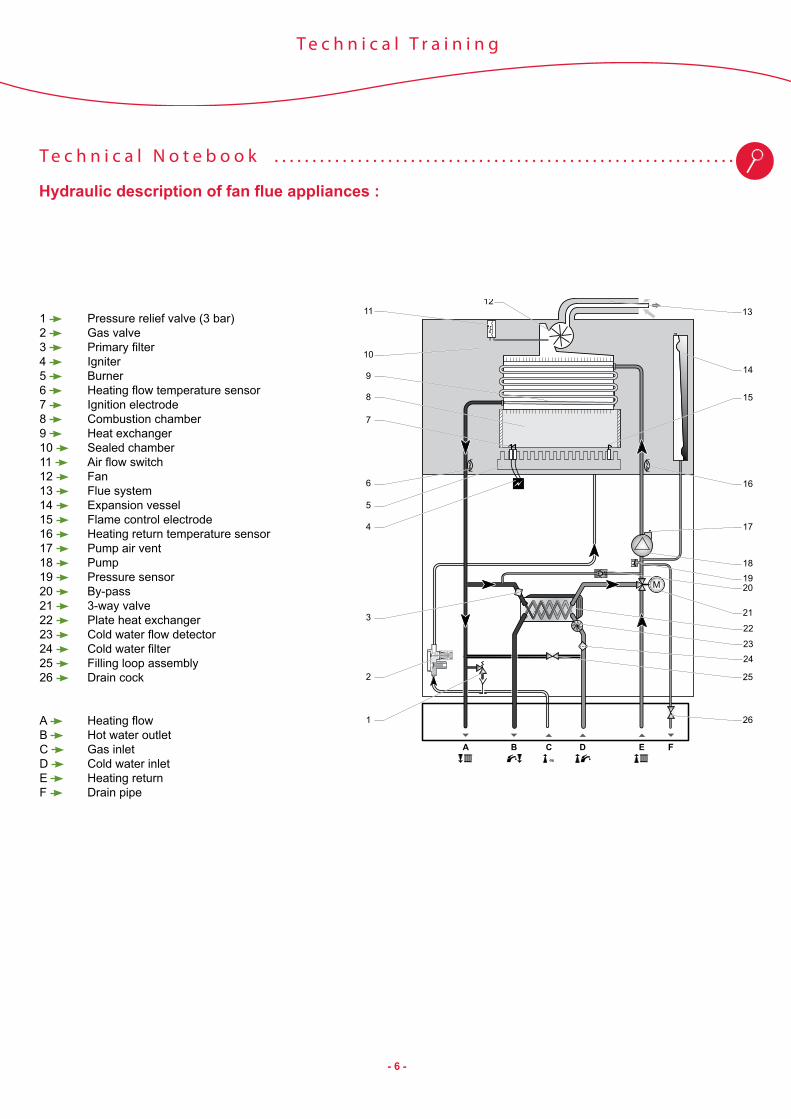
Hydraulic description of fan flue appliances :
1213
10
11
9
8
7
6
5
4
2
3
1
15
14
16
18
17
26
19
21
25
20
22
2324
1 Pressure relief valve (3 bar) 2 Gas valve3 Primary filter4 Igniter5 Burner6 Heating flow temperature sensor7 Ignition electrode8 Combustion chamber9 Heat exchanger10 Sealed chamber11 Air flow switch 12 Fan 13 Flue system14 Expansion vessel 15 Flame control electrode 16 Heating return temperature sensor17 Pump air vent18 Pump19 Pressure sensor20 By-pass21 3-way valve 22 Plate heat exchanger 23 Cold water flow detector 24 Cold water filter25 Filling loop assembly26 Drain cock
A Heating flowB Hot water outletC Gas inletD Cold water inlet E Heating returnF Drain pipe

- 7 -
T e c h n i c a l N o t e b o o k . . . . . . . . . . . . . . . . . . . . . . . . . . . . . . . . . . . . . . . . . . . . . . . . . . . . . . . . . . . . . .
T e c h n i c a l T r a i n i n g
Hydraulic operation of Combi versions
Hydraulic diagram in heating
Hydraulic diagram in hot water

- 8 -
T e c h n i c a l N o t e b o o k . . . . . . . . . . . . . . . . . . . . . . . . . . . . . . . . . . . . . . . . . . . . . . . . . . . . . . . . . . . . . .
T e c h n i c a l T r a i n i n g
Hydraulic description of system (open-flue) appliances :
8
7
5
4
3
2
1
16
18
19
6 12
11
13
15
14
17
9 101 Pressure relief valve (3 bar) 2 Gas valve3 Igniter4 Burner5 Heating flow temperature sensor6 Ignition electrode7 Combustion chamber8 Heat exchanger9 Draught diverter10 Overflow safety device 11 Expansion vessel 12 Flame control electrode13 Heating return temperature sensor14 Pump air vent15 Pump16 Pressure sensor17 By-pass18 3-way valve19 Drain cock
A Heating flowB To cylinder coil or not connectedC Gas inletD From cylinder coil or not connectedE Heating returnF Drain pipe

- 9 -
T e c h n i c a l N o t e b o o k . . . . . . . . . . . . . . . . . . . . . . . . . . . . . . . . . . . . . . . . . . . . . . . . . . . . . . . . . . . . . .
T e c h n i c a l T r a i n i n g
Hydraulic description of system (fan-flue) appliances :
9
1110
8
7
5
4
3
2
1
18
20
21
6
12
14
13
15
17
16
19
1 Pressure relief valve (3 bar) 2 Gas valve3 Igniter4 Burner5 Heating flow temperature sensor6 Ignition electrode7 Combustion chamber8 Heat exchanger9 Sealed chamber10 Air flow switch 11 Fan 12 Flue system13 Expansion vessel 14 Flame control electrode 15 Heating return temperature sensor16 Pump air vent17 Pump18 Pressure sensor19 By-pass20 3-way valve 21 Drain cock
A Heating flowB To cylinder coil or not connectedC Gas inletD From cylinder coil or not connectedE Heating returnF Drain pipe

- 10 -
T e c h n i c a l N o t e b o o k . . . . . . . . . . . . . . . . . . . . . . . . . . . . . . . . . . . . . . . . . . . . . . . . . . . . . . . . . . . . . .
T e c h n i c a l T r a i n i n g
Hydraulic operation of System Boiler
Hydraulic diagram in hot water

- 11 -
T e c h n i c a l N o t e b o o k . . . . . . . . . . . . . . . . . . . . . . . . . . . . . . . . . . . . . . . . . . . . . . . . . . . . . . . . . . . . . .
T e c h n i c a l T r a i n i n g
Technical characteristics
Gepard Panther
Units 23
MOV23 MTV
12
KOO12 KTO
25
KOO25 KOV 25 KTO 25 KTV 30 KTV
Type of appliance
open flue fan flue open
flue fan flue open flue
open flue fan flue fan flue fan flue
All open flue appliances : B11BSAll fan flue appliances : C12, C32, C42, C52, C62, C82, B22
HeatingMinimum calorific rate (Qmin) kW 10,4 10,7 4,2 4,4 9,9 9,9 10,6 10,6 12,2
Maximum calorific rate (Qmax) kW 25,8 25,0 13,8 13,8 26,8 26,8 26,5 26,5 32,5
Min. heating output at 80°C/60°C (Pmin) kW 9,0 8,5 3.4 3,5 8.4 8.4 8.9 8.9 10,4
Max. heating output at 80°C/60°C (Pmax) kW 23,3 23,3 12,4 12.6 24.6 24.6 24,6 24.6 29,6
Factory preset heating output kW 12.6
H.I. efficiency at 80 °C/60 °C, min. power % 86,5 79,4 81,0 79,5 84,8 84,8 84 84,0 85,2
H.I. efficiency at 80 °C/60 °C, max. power % 90,3 93,2 92,6 91,5 91,8 91,8 93,8 92,8 91,1
Minimum heating flow rate l/h 400 400 200 200 400 400 400 400 400
Minimum flow rate with ΔT 20 K l/h 1000 1000 530 530 1050 1270 1050 1050 1270
Min. heating output temperature °C 38 38 38 38 38 38 38 38 38
Max. heating output temperature °C 80 80 80 80 80 80 80 80 80
Expansion tank, useable capacity l 5 5 7 7 7 7 7 7 8
Expansion tank pre-inflation pressure bar 0.75 0.75 0.75 0.75 0.75 0.75 0.75 0.75 0.75Safety valve, maximum operating pressure (PMS) bar 3 3 3 3 3 3 3 3 3
Domestic hot waterMin. DHW output kW 9,0 8,5 - - - 8.4 - 8.9 10,4
Max. DHW output kW 23,3 23,3 - - - 24.6 - 24.6 29,6
Min. calorific rate (Q min) kW 10,4 10,7 - - - 9,9 - 10,6 12,2
Maximum calorific rate (Q max.) kW 25,8 25,0 - - - 26,8 - 26,5 32,5
Min. domestic hot water temperature °C 38 38 - - - 38 - 38 38
Max. domestic hot water temperature °C 60 60 - - - 60 - 60 60
Specific flow rate for ΔT = 30 K l/min 11,1 11,1 - - - 11,3 - 11,3 14
Warmstart function without with without with
Ignition flow rate l/min 1.5 1.5 - - - 1.5 - 1.5 1.5
Cold water flow restrictor (colour) l/min 10 (blue)
10 (blue) - - - 10
(blue) - 10 (blue) 12 (red)
Min. supply pressure bar 0.3 0.3 - - - 0.3 - 0.3 0.3
Recommended supply pressure bar 2 2 - - - 2 - 2 2
Maximum inlet pressure bar 10 10 - - - 10 - 10 10

- 12 -
T e c h n i c a l N o t e b o o k . . . . . . . . . . . . . . . . . . . . . . . . . . . . . . . . . . . . . . . . . . . . . . . . . . . . . . . . . . . . . .
T e c h n i c a l T r a i n i n g
Technical characteristics
Gepard Panther PantherUnits 23 MOV 23 MTV 12 KOO 12 KTO 25 KOO 25 KOV 25 KTO 25 KTV 30 KTV
ElectricalSupply voltage V 230 230 230 230 230 230 230 230 230 Maximum absorbed power W 92,0 127,0 92,0 117,0 92,0 92,0 147,0 147,0 152,0Current A 0,4 0,55 0,4 0,51 0,4 0,4 0,64 0,64 0,66Fuse AElectrical protection IPX4D IPX4D IPX4D IPX4D IPX4D IPX4D IPX4D IPX4D IPX4DElectrical class
Class I = equipment having a device allowing the earthing of accessible metallic parts
Gas category ll2HM3+ ll2HM3+ ll2HM3+ ll2HM3+ ll2HM3+ ll2HM3+ ll2HM3+ ll2HM3+ ll2HM3+
Gas characteristicsNumber of injectors 14 13 17 17
Natural gas G 20 (*) - 20 mb
Restrictor Ø mm 5,65 6,1 4,4 4,65 6,1 6,1 5,8 5,8 6,9
Injector Ø mm 1,20 1,20 1,25 1,25 1,20 1,20 1,20 1,20 1,20
Maximum gas flow rate m3/h 2,73 2,64 1,47 1,46 2,84 2,84 2,84 2,8 3,44
Minimum gas flow rate m3/h 1,1 1,15 0,45 0,45 1,05 1,05 1,05 1,12 1,29
Maximum burner pressure mbar / mm WC
12,0 /122,4
13,0 /132,6
14,5 /147,9
14,5 /147,9
13 /132,6
13,0 /132,6
13,0 /132,6
12,4 /126,4
13,0 /132,6
Minimum burner pressure mbar / mm WC
2,2 / 22,4
2,5 / 25,5
1,65 / 16,8
1,65 / 16,8
2,1 / 21,4
2,1 / 21,4
2,1 / 21,4
1,9 / 19,4
1,7 / 17,3
Natural gas G 30/G31 (*) - 37 mb Only by gas conversion kitRestritor Ø mm 4,8 4,8 - 4,65 5,2 5,2 5,95 5,95 7,3
Injector Ø mm 0,73 0,77 0,73 0,7 0,7 0,7 0,73 0,73 0,73
Maximum gas flow rate m3/h kg/h 1,034 1,016 0,460,91
0,50,9 2.1 2.1 2,05 2,05 2,52
Minimum gas flow rate m3/h kg/h 0,417 0,433 0,180,36
0,20,4 0,8 0,8 0,82 0,82 0,95
Maximum burner pressure mbar 29,6 28,0 36,7 36 31,3 31,3 32,7 32,7 35,5
Minimum burner pressure mbar 5,2 5,2 5,8 6,2 4,6 4,6 5,0 5,0 4,8
(*) ref. 15 °C – 1013 mbar dry gas

- 13 -
T e c h n i c a l N o t e b o o k . . . . . . . . . . . . . . . . . . . . . . . . . . . . . . . . . . . . . . . . . . . . . . . . . . . . . . . . . . . . . .
T e c h n i c a l T r a i n i n g
Control panel Panther / Panther
1 Domestic hot water circuit temperature control2 Display3 Reset button4 Start/stop button5 Heating circuit water temperature control6 Working mode selection
1 Temperature of the domestic hot water circuit2 Fault symbols3 Heating circuit pressure4 Burner on indicator5 Heating circuit temperature
The “ECO» sign appears when the hot water setting is less than 50°C (indipendent if the heat exchanger preheating is active or deactivated).
2
1
3
4
5ECO
3
2
1
4
5
6

- 14 -
T e c h n i c a l N o t e b o o k . . . . . . . . . . . . . . . . . . . . . . . . . . . . . . . . . . . . . . . . . . . . . . . . . . . . . . . . . . . . . .
T e c h n i c a l T r a i n i n g
Control panel Gepard
1 Reset button2 Working mode selection3 Display4 Start/stop button5 Heating and hot water temperature setting
1 Heating symbol2 Holiday symbol3 Domestic hot water symbol4 Display of pressure or temperature5 Measurement units6 Burner on indicator
6
5
4
2
1
3
3
2
1
4
5

- 15 -
T e c h n i c a l N o t e b o o k . . . . . . . . . . . . . . . . . . . . . . . . . . . . . . . . . . . . . . . . . . . . . . . . . . . . . . . . . . . . . .
T e c h n i c a l T r a i n i n g
Safety devices for open flue boilers
Temperature safety (ant-freezing / overheating)
Gas safety valve (EVS)
Smoke overflow
Flame control
3-way valve anti-blockage
Water pressure sensor
Safety Control device Values ActionSafety devices locking the appliance and requiring a RESET in the case of a faultOverheating and temperature limiting
Outgoing/return heating NTC
97 °C => max. temperature Fault displayed F20T° increase more than 10 K/S. Fault displayed F24ΔT (outlet - return) > 35 K Fault displayed F23
Flame control Ignition and ionisation electrode
Up to 2 spark sequences separated by 7 seconds
Fault F28 if no ignitionFault F29 if burner goes out
Gas Gas safety valve 0V when shut down24V then 16V in operation
Display of various faults depending on origin
Smoke overflow ON / OFF thermostat 23 and 25 kW appliances : contact opens at 65°C12 kW appliances : contact opens at 60°C.
Fault displayed F25
Safety devices not requiring a RESET after the fault clearsAntifreeze Outlet NTC 7 °C --> immediate heating Burner lit up to 35°CPump anti-blocking Internal computer Activated for 30s if not activated for
24 hoursActivation without apparent demand
3-way valve anti-blockage
Activated for 30s if not activated for 24 hours
Activation without apparent demand
Heating pressure Pressure sensor Triggered at 0.5 barReset at 0.3 bar
Display below 0.3 bardisplay blinking between 0.3 and 0.5 bar
Heating valve Opens at 3 bar Evacuation of excess pressure (display blinking below 2.5 bar)
Pressure relief valve (3 bar)
Pump anti-block

- 16 -
T e c h n i c a l N o t e b o o k . . . . . . . . . . . . . . . . . . . . . . . . . . . . . . . . . . . . . . . . . . . . . . . . . . . . . . . . . . . . . .
T e c h n i c a l T r a i n i n g
Safety devices for fan flue boilers
Safety Control device Values ActionSafety devices locking the appliance and requiring a RESET in the case of a faultOverheating and temperature limiting
Outgoing/return heating NTC
97 °C => max. temperature Fault displayed F20T° increase more than 10 K/S. Fault displayed F24ΔT (outlet - return) > 35 K Fault displayed F23
Flame control Ignition and ionisation electrode
Up to 3 spark sequences separated by 7 seconds
Fault F28 if no ignitionFault F29 if burner goes out
Gas Gas safety valve 0V when shut down24V then 16V in operation
Display of various faults depending on origin
Air flow Air flow switch 12 kW -> at 25°C : ON 13 Pa, OFF 10 Pa23 kW -> at 25°C : ON 71 Pa, OFF 46 Pa25 kW -> at 25°C : ON 80 Pa, OFF 68 Pa30 kW -> at 25°C : ON 59 Pa, OFF 51 PaOn = contact closedOff = contact opened
Fault displayed F33
Safety devices not requiring a RESET after the fault clearsAntifreeze Outlet NTC 7 °C --> immediate heating Burner lit up to 35°CPump anti-blocking Internal computer Activated for 30s if not activated for 24
hoursActivation without apparent demand
3-way valve anti-blockage
Activated for 30s if not activated for 24 hours
Activation without apparent demand
Heating pressure Pressure sensor Triggered at 0.5 barReset at 0.3 bar
Display below 0.3 bardisplay blinking between 0.3 and 0.5 bar
Heating valve Opens at 3 bar Evacuation of excess pressure (display blinking below 2.5 bar)
Temperature safety (ant-freezing / overheating)
Gas safety valve (EVS)
Air flow switch
Flame control
3-way valve anti-blockage
Water pressure sensor
Pressure relief valve (3 bar)
Pump anti-block

- 17 -
T e c h n i c a l N o t e b o o k . . . . . . . . . . . . . . . . . . . . . . . . . . . . . . . . . . . . . . . . . . . . . . . . . . . . . . . . . . . . . .
T e c h n i c a l T r a i n i n g
Hydraulic unit
Heating pressure valve
Plate heat exchanger* Automatic air vent
2 speed pump
By-pass
3-way valve motor
Screw giving access to the motor shaft for unblocking
Gas valve
Cold water inlet flow sensor*
* not for system versions
Filling cock*

- 18 -
T e c h n i c a l N o t e b o o k . . . . . . . . . . . . . . . . . . . . . . . . . . . . . . . . . . . . . . . . . . . . . . . . . . . . . . . . . . . . . .
T e c h n i c a l T r a i n i n g
Pump bloc / dhw flow detector bloc :
Sub-assembly Components ConnectionsThe pump unit is made up of :
- The automatic bleed valve (1)- The pump turbine section (2)- The 3-way valve (heating / hot water) (3)- The heating by-pass (4)
- The pump suction connector (A)- The pump outlet connector (B)
The flow detector unit is made up of :
- The turbine flow detector (5), fitted with a filter- The pressure sensor (6)
- The plate heat exchanger connections (C) - The by-pass connections to heating (D) - The cold water inlet (E) - The tapping for the filling loop of the heating circuit (F).
The flow detector connects to the pump unit.
To fully understand how this assembly is made up, see the drawings / photos below :
1 B
A
3
2C
F
5
6
4
E
D
The flow detector (5): Its turbine, its filter.
The two assembled units (flow detector / pump):
3-way valve
Bypass
Pressure sensor

- 19 -
T e c h n i c a l N o t e b o o k . . . . . . . . . . . . . . . . . . . . . . . . . . . . . . . . . . . . . . . . . . . . . . . . . . . . . . . . . . . . . .
T e c h n i c a l T r a i n i n g
Combustion unit :
This picture is for Panther.For Gepard, the air flow switch is on the left side of the fan, but the way of working is the same.
For open flue version, the Draught diverter is equipped with a thermostat to protect against smoke over-flow
Air flow switch
Smoke over flow thermostat

- 20 -
T e c h n i c a l N o t e b o o k . . . . . . . . . . . . . . . . . . . . . . . . . . . . . . . . . . . . . . . . . . . . . . . . . . . . . . . . . . . . . .
T e c h n i c a l T r a i n i n g
E-box :
The control panel contains the main board, the display card, the terminals (for electrical accessory connections, electric power supply, etc).
The control panel closed. (Here the display shows the Gepard/Panther)
The control panel fitted with a thermal screen on the vented versions to protect it from the radiation.
24 Volt connection hatch open.The right-hand hatch gives access to the 230 Volt connections.

- 21 -
T e c h n i c a l N o t e b o o k . . . . . . . . . . . . . . . . . . . . . . . . . . . . . . . . . . . . . . . . . . . . . . . . . . . . . . . . . . . . . .
T e c h n i c a l T r a i n i n g
Regulation: general functions
The burner can be lit following two different procedures depending on the prior condition of the unit:
• If the boiler has been switched off:
On lighting after the electricity has been cut off (using the ON/OFF button or by disconnecting the cable), the boiler tests the circulation of water in the circuit.
The procedure is as follows:- first a pre-flush of the pump depending on temperature- burner lights P = 90% of P. max and 3 seconds of stabilisation.- the outgoing temperature must rise by at least 5K.If not:- the burner then goes to max. power for 15 seconds.
As soon as the 5K temperature rise is detected, the burner goes into normal operation.
Otherwise the boiler cuts out indicating a fault (flashing display).
Note: This is the same display as for lack of water pressure.
This function is very useful to avoid overheating when the installation has not been fully bled (particularly at commissioning).
• If the boiler is already switched on:
The principle is the same as case A, except the burner starts at about 60% of maximum power and looks for an increase of 2K instead of 5K.
After the ignition phase, the regulator controls the burner in heating (reduction to Pmin) or hot water (the power is adjusted according to the need).
• Temperature regulation:
After ignition, the burner then goes into reduced power for 1 to 5 minutes:- 1 minute if heating requirements are high- 5 minutes if the heating requirements are lower.
After this period the power is released to be used as required.
The burner turns off at the setting +2K.
Note: it is recommended to use a modulating thermostat rather than a time-proportional one with this type of regulation to avoid interference.
Burner lights P = 90% of P. max
3 seconds
Pump pre-run
DT < 5°C => P = 100% of P. max. for 15 seconds max.
DT ≥ 5°C => OK
DT < 5°C => Flashing display and made safe.
Normal operation
DT ≥ 5°C => OK
Normal operation
P (kW)
P. max
P. min
P. all
P. Ch.
5 min

- 22 -
T e c h n i c a l N o t e b o o k . . . . . . . . . . . . . . . . . . . . . . . . . . . . . . . . . . . . . . . . . . . . . . . . . . . . . . . . . . . . . .
T e c h n i c a l T r a i n i n g
Regulation:
• Domestic hot water control:Regulation of tank heating (only for system boiler):
There are 2 types of regulation allowed for a tank: either regulation by thermostat (ON/OFF contact) or regulation by NTC thermistor.
In either case, the starting of the burner for a tank heating requests is preceded by a 30s pre-flush of the heating pump. This avoids the boiler being locked out in the case of too large a temperature difference between the tank and boiler temperatures.
Tank equipped with a thermostat:- the burner start when the thermostat contact get closed,- the temperature of the primary circuit feeding the tank exchanger is 75°C (burner cut-off at 80°C).- the opening of the thermostat contact stops the burner and triggers a 30s pump post-flush.
Tank equipped with an NTC thermistor:(NTC value: see table in “accessories” chapter)The tank temperature is set directly in the user menu, on the control panel (which is identical to the mixed version control panel).
The thermistor allows continuous control of the tank temperature and consequent regulation of the primary circuit temperature.Tank heating start-up: when the tank temperature drops below the set temperature less 5K, the 3-way valve goes to the hot water position and the heating pump starts up.
Heating stops when the NTC measures the setpoint in the tank. The pump carries out a 30s post-flush (3-way valve still in hot water position) and then stops.
The regulation, in the case of a tank equipped with an NTC, is assisted by self-modification: the sensor measures the temperature 5 minutes after the burner shuts down. If the set point has been exceeded, a correction is applied to the next heating (the burner stops at a lower temperature to prevent a repetition of this temperature excess).
The primary temperature depends on the setting : it is calculated at 15K below the hot water setting. In the case of scale in the tank, the primary temperature is pushed to the maximum.
Regulation during hot water draw (mixed boiler):- demand detection:
The burner is triggered in by a draw of 1.5l/min. It stops at 1.1 l/min. This hysteresis avoids having the burner in an unstable region (repetitive starts/stops).
- temperature regulation:The primary regulation is performed by a calculation of the temperature setting on the primary circuit return. This calculation depends on the draw rate and the hot water temperature setting.Hot water regulation is controlled by the temperature probe on the primary return (NTC5) to limit the influence of the temperature of cold water on the temperature of hot water.
The presence of a solar tank is automatically detected by the solar thermistor being connected to the main circuit board (in position X32).There is no adjustment needed: the card records, at each draw, the time that it takes for the solar hot water to arrive at the boiler cold water inlet. It then applies this time to the following draw with an upper limit of 30 seconds.
For example: at the first draw, the burner starts immediately but the hot water takes 10s to arrive at the boiler.On the next draw, the boiler will wait 10s before starting and record the new time the solar hot water takes.
Thus the burner start-up time delay is constantly corrected for temperature variations in the solar tank.

- 23 -
T e c h n i c a l N o t e b o o k . . . . . . . . . . . . . . . . . . . . . . . . . . . . . . . . . . . . . . . . . . . . . . . . . . . . . . . . . . . . . .
T e c h n i c a l T r a i n i n g
Regulation:
• Warmstart function:
Warmstart function is to maintain temperature in the primary circuit of the boiler to improve the domestic hot water comfort:- Reduction of waiting times in hot tap water- Water conservation
This function only affects Panther KOV and KTV.
Principle of operation :The function is activated when the primary descends to 30K below the hot water setting: the burner lights and switches off at the hot water setting minus 10K.
Warmstart function is enabled or disabled by the installer menu (d66)
ECO picto is displayed when the DHW set-point is under 50°C.

- 24 -
T e c h n i c a l N o t e b o o k . . . . . . . . . . . . . . . . . . . . . . . . . . . . . . . . . . . . . . . . . . . . . . . . . . . . . . . . . . . . . .
T e c h n i c a l T r a i n i n g
Regulation:
• Frost protection:The frost protection function is activated when the temperature falls below 12°C at the start of the heating circuit.The pump then runs for 10 minutes with the 3-way valve in the mixed position (central valve position to feed both the heating circuit and the plate heat exchanger):
- If the temperature of the heating circuit falls below 7°C, the burner lights and remains alight until the temperature at the start of the heating circuit reaches 35°C.
- If the temperature remains between 7 and 15°C, the burner lights after 30 minutes to raise the temperature to 35°C.- If the temperature exceeds 15°C, the pump runs for 30 minutes and then stops.
• Protection against overheating and temperature limiting:The outlet / return thermistors protect the boiler against overheating by checking the maximum outlet temperature (97 °C burner on or 110 °C for three seconds with the burners off).
Complimentary conditions related to the flow rate in the installation:- check on the speed of temperature rise (10K/s max.)- checking the temperature difference outlet – return:
- if ΔT (outlet-return) > 30K => the burner is forced to minimum power for 10 minutes- if ΔT (outlet-return) > 35K => display of fault F23 initially volatile. If the fault repeats 5 times, the boiler shuts down and a “reset” becomes necessary.
(Note: if the burner runs for at least 60 seconds, the counter is reset to zero)
T < 12°C
3-way in mixed position + pump ON for 10 mins
T = 7°C
Burner ON
T = 35°C
Pump 30 minutes post-flush
7°C < T < 15°C
pump for 30 min
then burner on up to 35°C
T > 15°C
Pump 30 minutes
pump OFF, 3-way in initial position

- 25 -
T e c h n i c a l N o t e b o o k . . . . . . . . . . . . . . . . . . . . . . . . . . . . . . . . . . . . . . . . . . . . . . . . . . . . . . . . . . . . . .
T e c h n i c a l T r a i n i n g
VAL
kW
Access to installer and After-Sales menus - Panther:
The display has hidden menus accessible by entering a code.This code is of interest to two groups of professionals:
- The installer who needs to configure the appliance during installation => code 96- The after-sales service who may need to change parts and then reconfigure them for the appliance => code 35
The installer menu gives access to a restricted list of data items whereas the After-Sales menu gives access to all the data items (installation + after-sales).
To access installer or after-sales menu:Press the mode button (1) for about 7 seconds; the display layout will change.- Using the + or - button (2), display code 96 or 35.- Confirm with the mode button (1).The display then shows line 1 of the menu.
To change a value:- Modify the value of the displayed data item using the + or – button (3) on the boiler.- the change is automatically accepted after 3 seconds.
To return to the normal display, press the “mode” button for 3 seconds.
After 15 minutes of inaction, the display returns to normal operating mode.
data value data
Enter code 35 or 96
2
1 3

- 26 -
T e c h n i c a l N o t e b o o k . . . . . . . . . . . . . . . . . . . . . . . . . . . . . . . . . . . . . . . . . . . . . . . . . . . . . . . . . . . . . .
T e c h n i c a l T r a i n i n g
Accessing the Installation and After-Sales menus - Gepard:
The display has hidden menus accessible by entering a code.This code is of interest to two groups of professionals:
- The installer who needs to configure the appliance during installation => code 96- The after-sales service who may need to change parts and then reconfigure them for the appliance => code 35
The installer menu gives access to a restricted list of data items whereas the After-Sales menu gives access to all the data items (installation + after-sales).
To access installer or after-sales menu:Press the mode button (1) for about 7 seconds; the display layout will change.- Using the + or - button (2), display code 96 or 35.- Confirm with the mode button (1).The display then shows line 1 of the menu.
To change a value:- press the “mode” button to toggle between the “d” data and its value (alternative display of the “=” sign and the value).- Modify the value of the displayed data item using the + or – button (3) on the boiler.- the change is automatically accepted after 3 seconds.
To return to the normal display, press the “mode” button for 3 seconds.
After 15 minutes of inaction, the display returns to normal operating mode.
1
2

- 27 -
T e c h n i c a l N o t e b o o k . . . . . . . . . . . . . . . . . . . . . . . . . . . . . . . . . . . . . . . . . . . . . . . . . . . . . . . . . . . . . .
T e c h n i c a l T r a i n i n g
Installation and After-Sales menu details:
Code Parameter Units Description Factory setting
Possible to change?
d.00 Maximum heating power kW12 kW versions adjusted from fatory at 12 kW23, 25 kW versions adjusted from fatory at 15 kW30 kW versions adjusted from fatory at 20 kW
12 15 20
yes
d.01 Pump over-run time - heating min. Select a value between 2 and 60 minutes. 5 yes
d.02 Anti-short cycle time delay after running in heating mode min.
Prevents overly frequent burner start / stop in heating mode (this function does not apply to hot water mode). Select a value between 2 and 60 minutes.
20 yes
d.04 Tank temperature (if fitted with an NTC) (only for SB models) °C Display of the tank water temperature (model SB equipped
with an NTC sensor - NTC1) - read only
d.08 unused
d.09 Heating flow temperature setting (calculated value). °C Display of the Heating flow temperature calculated by the TA
eBus from the outside temperature and the slope chosen. - read only
d.10 Internal pump status. 0 = the pump is stopped1 = the pump is powered (it is running) - read only
The values with a green background are only accessible from the After-Sales menu (access code = 35)
This delay (called “anti short-cycle) prevents an immediate restart in heating mode after the burner has been shut down by the temperature setting or by the TA. It depends on the temperature setting:
- at 80°C, it if fixed (1 minute).- at 20 °C, it is adjustable from 1 to 60 minutes via data item d02 on the installer menu.
Factory setting: 20 minutes.
Some time delays:
d02 data settings
Heating temperature
setting
2 5(default setting)
10 20
80 ° C 1 min 1 1 1
60 ° C 1’30 2’30 4 7’30
40 ° C 1’45 3’30 7 13’30
30 ° C 2 4’15 8’15 16’30
80706050403020100
60
50
40
30
20
10
Time(minutes)
heating set-point (°C)
d02 = 60
d02 = 20
d02 = 2

- 28 -
T e c h n i c a l N o t e b o o k . . . . . . . . . . . . . . . . . . . . . . . . . . . . . . . . . . . . . . . . . . . . . . . . . . . . . . . . . . . . . .
T e c h n i c a l T r a i n i n g
Code Parameter Units Description Factory setting
Possible to change?
d.11 Auxiliary heating pump status(controlled by the option card)
0 = the pump is stopped1 = The pump is requested - read only
d.13 Unused
d.16Heating request by an ON/OFF thermostat (connected to RT terminals of connector X17)
-0 = contact open (no request) 1 = contact closed (heating request in progress)NB : if the contact is shunted, the display is always 1.
- read only
d.17 Regulation type (outlet or return) °C 0 = outlet1 = return - yes
Regulation on the return is useful for low inertia heated floor installations (without buffer tank): this type of regulation avoids burner shut-off when the temperature setting is reached too quickly.When regulation on the return is activated, the burner control is modified: The burner is forced to minimum power for 5 minutes then power regulation is authorised.
d.18 Pump operation -
Operating mode:0 = With burner ; the pump runs when the burner lights.1 = Continuous with RT : the pump runs when the Roomstat is in demand.2 = permanent in winter : the pump run as long as boiler is on winter mode.
1 yes
d.19 Pump speed(Not adjustable on Gepard) -
Operating mode:0 = Burner lit; automatic speed in heating, max. in hot water, min. when the burner is off.1 = Min. speed in heating, max. in hot water2 = Automatic speed in heating, max. in hot water3 = Max. speed in heating and hot water
2 yes
Operation of automatic speed:At each burner start in heating, the pump runs at reduced speed for at least 30 seconds. If the outlet/return temperature difference reaches 20K, the
pump goes to max. speed until the burner shuts down (even if the temperature difference reduces). The same cycle occurs at the next ignition.
d.20 Domestic Hot water max. temperature setting °C
The maximum recommended domestic hot water temperature is 60°C. Select a value between 50°C and 60°C.
60 yes
Note: The domestic Hot water temperature setting is adjustable by the user between 38 and 60°C. Factory setting = 55°C.
d.21Warmstart function : this parameter indicate if the function is enabled and allowed.
- 1 = function enabled and allowed0 = function not disabled or not allowed - read only
d.22 Hot water request by thermostat, NTC or flow detector. - 0: no dhw demand
1: dhw demand ( tap, tank ntc or tank switch) - read only
d.23 Heating demand - 0 = no heating demand1 = heating demand in progress - read only
d.24 air pressure switch (for SE models) ON: closed (position when fan run)OFF: open (stand by position) - read only
d.25Tank reheat request activated either by the interface (in hot water mode) or an e bus thermostat.
-
The product configuration either does or does not allow tank reheating (Exacontrol 2009 with hot water programming):0 = no authorisation for tank reheating1 = authorisation for tank reheating
- read only
The 2 following menus are displayed if an option card (not supplied) is installed on the appliance.
d.27Relay 1 function(This is one of the 2 relays fitted in the option card)
-
Attributing a function to relay 1 of the option card:1 = not applicable to this product2 = additionnal heating pump4 = kitchen hood5 = external gas valve6 = external error message
1 yes
The values with a green background are only accessible from the After-Sales menu (access code = 35)

- 29 -
T e c h n i c a l N o t e b o o k . . . . . . . . . . . . . . . . . . . . . . . . . . . . . . . . . . . . . . . . . . . . . . . . . . . . . . . . . . . . . .
T e c h n i c a l T r a i n i n g
Code Parameter Units Description Factory setting
Possible to change?
d.28Relay 2 function(This is the second relay of the option card)
-
Attributing a function to relay 2 of the option card:1 = not applicable to this product2 = auxiliary heating pump4 = kitchen hood5 = external gas valve6 = external error message
2 yes
d.29 Unused
d.35 Position of 3-way valve (heating / DHW)100 = domestic hot water0 = heating40 = centre position
- read only
d.36 DHW flow rate l/min Flow rate measured by the hot water flow sensor - read only
The following menu is displayed if a solar system is connected to the appliance
d.39 Solar circuit inlet temperature °C Displays the temperature measured by the sensor located on the solar circuit inlet. - read only
d.40 Heating flow temperature °C Displays the heating output temperature. - read only
d.41 Heating return temperature °C Displays the heating return temperature. - read only
Menus d.43, d.45 and d.47 only display if a wired outdoor thermostat is connected to terminal X17 of the main circuit board.
d.43 Heating curve Choice of heating curve depending on the outside temperature (see detail on following page) 1.2 yes
d.44 Ionisation check
Coef. from 0 to 1000
The lower this value (burner lit), the better the detection. However, this value depends on several parameters (gas quality, electrodes...).This value is without units : it’s just an indication.
- read only
d.45 Heating curve base °C (See details, following page). Disappears for TA e-bus 20 yes
d.47 Outdoor temperature °C Displays the temperature measured by the outdoor sensor - read only
d.52 Offset for minimum steppermotor position
Pmin adjustment . To adjust, see «Gas conversion» some pages after. yes
d.53 Offset for maximum steppermotor position
Pmax adjustment . To adjust, see «Gas conversion» some pages after. yes
d.62
Night-time offset(Specific function for Belgium and NL :RT doesn’t stop the burner but change the set-point. Don’t use in other countries)
°C
Lowers the heating start temperature depending on the state of TA 24VE.g.: if d62 is set at 20, Setting= 65 °C if TA 24V onSetting = 65 - 20 °C with TA 24V off0 = function deactivated. Keep to 0 out of BE / NL.
0 yes0 to 30°C
d64 Average burner ignition time S For these 2 values, an average calculated over the last 100 ignitions.
0 read only
d65 Max. burner ignition time S read only
d66 Warmstart 0 = Warmstart activated1 = Warmstart de-activated 1 yes
d.67 Time remaining until the end of the anti-short cycle delay. min. Displays time remaining until the end of the anti-short cycle
delay. - read only
d68 Number of ignitions failed on the first attempt - 0 read only
d69 Number of ignitions failed on the second attempt - 0 read only
The values with a green background are only accessible from the After-Sales menu (access code = 35)

- 30 -
T e c h n i c a l N o t e b o o k . . . . . . . . . . . . . . . . . . . . . . . . . . . . . . . . . . . . . . . . . . . . . . . . . . . . . . . . . . . . . .
T e c h n i c a l T r a i n i n g
Installer Menu: The external sensor operation
Setting is done using 2 parameters:- The sensor slope to be chosen on the curve below (1):
To know which slope to select, you need to know the local minimum temperature which was used for installation calculations. Choose the slope that gives the maximum heating setting at the local minimum temperature.See example below.
1
50
60
70
80
90
30
40
15
20
4.0
0.2
0.6
1.2
3.0
1.5
1.0
2.02.53.5
28
38 25
50
60
70
80
90
30
40
15
20
4.0
0.2
0.6
1.2
3.0
1.5
1.0
2.02.53.5
25
16
2
Heating temperature (°C)
Temperature setting
Outside temperature (°C)
- Heating curve base correction (2):This parameter is used to correct the ambient temperature if the real temperature is different from the expected temperature.The factory setting (20°) corresponds to an estimated ambient temperature. This value can be increased (up to 25°C) or reduced (down to 15°C).E.g.: desired temperature = 20°C, real temperature = 19°C => set to 21°C to offset the curve.
Note: if the outside sensor is associated with a modulating thermostat, the curve base adjusts itself automatically.
1
50
60
70
80
90
30
40
15
20
4.0
0.2
0.6
1.2
3.0
1.5
1.0
2.02.53.5
28
38 25
50
60
70
80
90
30
40
15
20
4.0
0.2
0.6
1.2
3.0
1.5
1.0
2.02.53.5
25
16
2
Example:Either an installation equipped with radiators calculated according to the European standard NF EN 442 (Delta T between air and water = 50 degrees): the maximum heating temperature will then be 73°C (factory setting). Or a minimum local temperature of -6°C.In tracing on the diagram below the vertical from Text -6°C, then the horizontal to 73°C, we arrive at a slope of 2.0.
With an e-bus thermostat (Exacontrol E...) the slope is set on the thermostat. This setting no longer appears in the boiler menu.
With an e-bus thermostat (Exacontrol E...) the curve base adapts itself as needed. This setting no longer appears in the boiler menu.
- 31 -
T e c h n i c a l N o t e b o o k . . . . . . . . . . . . . . . . . . . . . . . . . . . . . . . . . . . . . . . . . . . . . . . . . . . . . . . . . . . . . .
T e c h n i c a l T r a i n i n g
Code Parameter Units Description Factory setting
Possible to change?
d.70 Forcing of 3-way valve (SB version only) -
0 = normal mode1 = do not use (blocking of the 3-way valve in the centre
position)2 = heating mode only
0 yes
d.71 Max. Heating flow temperature setting. °C Select a value between 45 and 80°C. (factory setting 75°C) 75 yes
Note: The heating setting is adjustable via the user interface from 10 to 73°C. Factory setting = 60°C.
d.77 Domestic hot water power (SB version only) kW This item allows limiting of the domestic hot water power
(factory setting = max. setting).P. max. of the model yes
d.80 Heating operating time 100h Blocks
Burner on operating time (100h block)1 = 100 hours(not possible to reset)
0 read only
d.81 Hot water operating time 100h Blocks
Burner on operating time (100h block)1 = 100 hours(not possible to reset)
0 read only
d.82 Number of burner ignitions in heating100 ign.
blocks
1 = 100 ignitions(not possible to reset) 0 read only
d.83 Number of burner ignitions in hot water100 ign.
blocks
1 = 100 ignitions(not possible to reset) 0 read only
d.85 Minimum power of the appliance kWThis parameter is used to increase the minimum output in the case that the boiler is installed with C43p (specific to Be, FR and NL). Keep the factory setting in all other cases.
d.90 Detection of an e-bus room thermostat - 0 = not detected1 = detected - read only
d.93 Product code setting - Product code 2 yes
Details for d93 parameter
Model type nat. gas G20 LPG G30/31Gepard 23 MOV 0 4
23 MTV 1 1Panther 12 KOO 0 7
12 KTO 1 125 KOO 2 825 KOV 3 825 KTO 4 425 KTV 5 530 KTV 6 6
d.94 Reinitialise fault list -This function is used to clear the fault list on the appliance.0 = no1= reset fault list
0 yes
d.95 Program versions °C Gives the version of: 1. Main circuit board 2. Display card (Interface) - read only
d.96 Return to factory settings - This function returns the parameters to the factory settings 1 yes
The values with a green background are only accessible from the After-Sales menu (access code = 35)

- 32 -
T e c h n i c a l N o t e b o o k . . . . . . . . . . . . . . . . . . . . . . . . . . . . . . . . . . . . . . . . . . . . . . . . . . . . . . . . . . . . . .
T e c h n i c a l T r a i n i n g
The Installation and After-Sales menus by theme:
Parameter Code read only
Burner power
Maximum heating power d.00
Offset for minimum steppermotor position d.52
Offset for maximum steppermotor position d.53
Domestic hot water power (AS boiler) d.77
Time delays
Pump post flush time d.01
Anti short-cycle delay d.02
Anti short-cycle delay remaining d.67 x
Temperature
Tank temperature (if fitted with an NTC) d.04 x
Heating flow temperature setting d.09 x
Domestic Hot water max. temperature setting d.20
Solar circuit inlet temperature d.39 x
Heating output temperature d.40 x
Heating return temperature d.41 x
Outside temperature d.47 x
Max. Heating flow temperature setting. d.71
Pumps
Internal pump status d.10 x
Auxiliary pumps status d.11 x
Pump operation d.18
Pump speed d.19
Checking of input requests
Heating request by an ON/OFF thermostat d.16 x
Hot water preheating or tank reheating without NTC or thermostat request. d.21 x
Hot water request by thermostat, NTC or flow detector, without preheating request. d.22 x
Heating demand d.23 x
Tank reheating or preheating activated either by the interface or by an e-bus thermostat d.25 x
Night-time offset d.62
ECS preheating function d.66
eBus room thermostat detection d.90 x
Parameter Code read only
Regulation
Regulation type (outlet or return) d.17
Heating curve d.43
Heating curve base d.45
Fan
air pressure switch (for SE models) d.24 x
Fan speed setting d.33 x
Real fan rotation speed d.34 x
Minimum speed correction d50
Maximum speed correction d51
Accessories
Relay 1 function d.27
Relay 2 function d.28
Statistics
Average burner ignition time d64 x
Max. burner ignition time d65 x
Number of ignitions failed on the first attempt d68 x
Number of ignitions failed on the second attempt d69 x
Heating operating time d.80 x
Hot water operating time d.81 x
Number of burner ignitions in heating d.82 x
Number of burner ignitions in hot water d.83 x
Misc.
Filling loop mode (adjustable only for Panther) d.31
Position of 3-way valve d.35 x
Draw flow rate d.36 x
Ionisation check d.44 x
3-way valve forcing (AS) d.70
Product code setting d.93
Reinitialise fault list d.94
Program versions d.95 x
Return to factory settings d.96

- 33 -
T e c h n i c a l N o t e b o o k . . . . . . . . . . . . . . . . . . . . . . . . . . . . . . . . . . . . . . . . . . . . . . . . . . . . . . . . . . . . . .
T e c h n i c a l T r a i n i n g
Appliance status:
This function can be used at any time to know what operating phase the appliance is in.
To display this menu:
Press the “mode” button for at least 3 seconds. The screen shows the appliance status “S.xx”.
Press the “mode” button for at least 3 seconds to exit this menu.Status Heating modeS.00 No heating demandS.01 Fan pre-runS.02 Pump pre-runS.03 IgnitionS.04 Burner litS.05 Pump/fan post-run S.06 Fan post-runS.07 Pump post-runS.08 After-heating short cycle prevention delay
Status Hot water modeS.10 Hot water demandS.11 Fan pre-sweepS.13 IgnitionS.14 Burner litS.15 Pump/fan post-runS.16 Fan post-runS.17 Pump post-run
Status Hot water reheatS.20 Preheat cycle on versions with tankS.21 Fan pre-runS.23 IgnitionS.24 Burner litS.25 Pump/fan post-runS.26 Fan post-runS.27 Pump post-runS.28 The heater locks out tank reheating after a reheat cycle (for 1 minute)
Status Specific messages
S.30 Default condition, no heating or hot water demand. If an EBUS thermostat is connected to the heater, check that the shunt is present between connectors 3 and 4 of the heater main circuit board.
S.31 “Hot water only” modeS.32 Test cycle: the fan fan speed is outside tolerances when workingS.34 Frost protectionS.39 Heated floor contact open.S.40 Re-heating mode activatedS.41 Water pressure too highS.53 Wait cycle: difference in temperature between heating output and return too high. If ∆T > 30, forced at PminS.54 Wait cycle: lack of water in the system / increase in temperature between heating output and return too high.S.96 Heating return temperature sensor test.S.97 Pressure test S.98 Water outlet and return temperature sensors test.

- 34 -
T e c h n i c a l N o t e b o o k . . . . . . . . . . . . . . . . . . . . . . . . . . . . . . . . . . . . . . . . . . . . . . . . . . . . . . . . . . . . . .
T e c h n i c a l T r a i n i n g
Test modes:
By activating the various test modes, you can access special functions on the appliance.
Press the start/stop button to turn the appliance off.Hold down the mode and start/stop buttons for at least 5 seconds. The screen displays the first test mode “P01”.Press the or buttons of mode to select the desired test mode (P.01, P.02, ....).Press to start the test mode. The test mode number «PX» and «On» flash on the screen.The test mode will stop automatically after 15 minutes.If you want to stop testing , pres Reset button or ON/OFF switch.
Code n° Parameter Description
P.01Force the burner to adjustable power in heating mode
The appliance operates at a power level adjustable from Pmin to 100% using the or buttons after a successful ignition.
P.02 Forces the burner to ignition power.
This function enables ignition of the burner to be controlled.
P.03Force the burner to power adjusted to d00 in heating mode
The appliance operates at adjusted maximum heating power.
P.05 Refill the appliance The 3-way valve is in the central position and the pump and the burner turn off for refilling the appliance.
P.06 Venting the installation
This function is activated for 5 minutes.--> The 3-way valve goes to the heating position.--> The pump operates in cycles of 5 seconds on / 5 seconds off.Ensure that the bleed valve is open.
P.07 Venting the appliance
This function is activated for 5 minutes (4 minutes in DHW, 1 minute in heating).--> The pump operates in cycles of 5 seconds on / 5 seconds off.Ensure that the bleed valve is open.
This function can activate itself automatically during filling: if the pressure measured by the sensor goes from 0 to 0,5 b, the board interprets this as filling and therefore runs the appliance bleeding function itself to avoid burner ignition when the heat exchanger is filled with air.In this case, the pressure indicator on the display flashes.
However if the passage from 0 to 0.5 bar is too fast (less than 15 seconds) the board interprets this as a parasite and does not run the function.

- 35 -
T e c h n i c a l N o t e b o o k . . . . . . . . . . . . . . . . . . . . . . . . . . . . . . . . . . . . . . . . . . . . . . . . . . . . . . . . . . . . . .
T e c h n i c a l T r a i n i n g
Gas conversion :
The gas conversion kits are defined following requirements.
The general gas conversion procedure requires the following operations:- change the gas valve (the modulating valve is different from one type of box to another)- change the gas rail (the diameter of injectors is defined for each gas type).- adjust minimum burner power.To do this, connect a manometer to the gas valve outlet pressure connector.
Force the burner to minimum power using the test mode described on the previous page: choose P01 and set to minimum. Make sure that the heating setting temperature is not reached during adjustment time (taps if necessary open radiator and increase the atmospheric temperature setting).
Go into the service menu using code 35 (described a few pages previously) and go to data item 52: This is the minimum power setting. Then adjust the burner pressure to obtain (pressure tables are supplied with gas changeover kits or in product installer manuals); to increase the pressure, increase the value of data item 52 (which corresponds to increasing the number of pulses to the stepping motor to open it more). Do the opposite to reduce burner pressure.
Confirm the setting by pressing on MODE for 10 seconds.
- then set burner maximum pressure.Force the burner to maximum pressure by changing P01 to 100 %.
Return to the Service menu using the code 35 and go to data item 53: This is the maximum power setting. Then set the burner pressure to be obtained (same procedure as for data item 52).
Confirm the setting by pressing on MODE for 10 seconds.

- 36 -
T e c h n i c a l N o t e b o o k . . . . . . . . . . . . . . . . . . . . . . . . . . . . . . . . . . . . . . . . . . . . . . . . . . . . . . . . . . . . . .
T e c h n i c a l T r a i n i n g
The gas valve :
The gas valve is designed around a stepper motor controlling a variable valve.This mechanism has two gas safety solenoid valves powered with low voltage (24 V DC) : • one on the gas valve inlet (EVS1), • the other on the stepper motor (EVS2) to ensure that the gas flow is completely cut off even if the motor has not hadthe time to close (e.g. after a power cut).The stepper motor (Vm) controls the flow rate by opening or closing the regulating valve.
EVS2
EVS1
Vm
regulating valve
Burner pressure
restrictor into the gas inlet

- 37 -
I n s t a l l a t i o n . . . . . . . . . . . . . . . . . . . . . . . . . . . . . . . . . . . . . . . . . . . . . . . . . . . . . . . . . . . . . . . . . . . . . . . . . .
T e c h n i c a l T r a i n i n g
Heater location :
• side clearance: the panels are removed towards the front but at least 20 mm are required at the side.However, it is not necessary to remove the side panels to maintain the appliance.
Template for Gepard / Panther (12, 23, 25) Template for Panther 30

- 38 -
I n s t a l l a t i o n . . . . . . . . . . . . . . . . . . . . . . . . . . . . . . . . . . . . . . . . . . . . . . . . . . . . . . . . . . . . . . . . . . . . . . . . . .
T e c h n i c a l T r a i n i n g
Reminder of bathroom electrical protection zones
This range of boilers cannot be installed in zones 0, 1 or 2.
Water and gas connections:
1 Heating return 3/4 ‘‘2 Cold water inlet 1/2 ‘‘3 Gas 1/2 ‘‘4 Domestic hot water flow 1/2 ‘‘5 Heating flow 3/4 ‘‘
12
3
0
2,40 m0,60 m
3 m
2,25
m
2,25
m
123
45
110 65 116 65 94
217
27
208
181
205
160
134
26
82 65 116 65 82

- 39 -
I n s t a l l a t i o n . . . . . . . . . . . . . . . . . . . . . . . . . . . . . . . . . . . . . . . . . . . . . . . . . . . . . . . . . . . . . . . . . . . . . . . . . .
T e c h n i c a l T r a i n i n g
Water and gas connections:
System boiler:
1 Tank2 Heating return3 Tank re-heating return4 Gas5 Tank re-heating flow6 Heating flow
Connection without tank:
1 Heating return 3/4’’2 Gas 3/4’’3 Heating flow 3/4’’
GAS
3
4
5
6
1
2
GAS
1
2
3

- 40 -
I n s t a l l a t i o n . . . . . . . . . . . . . . . . . . . . . . . . . . . . . . . . . . . . . . . . . . . . . . . . . . . . . . . . . . . . . . . . . . . . . . . . . .
T e c h n i c a l T r a i n i n g
Type of flue connection Models Flue diameter Flue lenght L(in meters)
C12 12 KTO 60 / 100 mm 0,5 < L < 3 => restrictor Ø36 mm4 < L < 9 => restrictor Ø43 mm
30 KTV 60 / 100 mm 0 < L < 0,3 => restrictor Ø46 mm0,3 < L < 3,5 => no restrictor
25 KTV25 KTO23 MTV
60 / 100 mm
80 / 125 mm
0 < L < 0,5 => restrictor Ø41 mm0,3 < L < 3,5 => no restrictor
0 < L < 1 => restrictor Ø41 mm0,5 < L < 11 => no restrictor
C32 12 KTO 80 / 125 mm 1 < L < 3 => restrictor Ø36 mm4 < L < 12 => restrictor Ø43 mm
30 KTV 60 / 100 mm80 / 125 mm
1 < L < 4 => no restrictor1 < L < 8 => no restrictor
25 KTV25 KTO23 MTV
60 / 100 mm
80 / 125 mm
0 < L < 1,5 => restrictor Ø41 mm1 < L < 4,5 => no restrictor
0 < L < 3 => restrictor Ø41 mm3 < L < 12 => no restrictor
C42 12 KTO 60 / 100 mm 0,5 < L < 3 => restrictor Ø36 mm4 < L < 9 => restrictor Ø43 mm
30 KTV 60 / 100 mm 0 < L < 0,3 => restrictor Ø46 mm0,3 < L < 3,5 => no restrictor
25 KTV25 KTO23 MTV
60 / 100 mm 0 < L < 0,5 => restrictor Ø41 mm0,3 < L < 3,5 => no restrictor
L
1
2
L

- 41 -
I n s t a l l a t i o n . . . . . . . . . . . . . . . . . . . . . . . . . . . . . . . . . . . . . . . . . . . . . . . . . . . . . . . . . . . . . . . . . . . . . . . . . .
T e c h n i c a l T r a i n i n g
Type of flue connection Models Flue diameter Flue lenght L(in meters)
C52
L2L1
1
2
12 KTO 80 + 80 mm 1+1 < L < 3+3 => restrictor Ø36 mm4+4 < L < 9+9 => restrictor Ø43 mm
30 KTV 80 + 80 mm 0,5 + 0,5 < L < 15 + 15 => no restrictor
25 KTV25 KTO23MTV
80 + 80 mm L < 2+2 => restrictor Ø41 mm0,5 + 0,5 < L < 15 + 15 => no restrictor
C82
L2L1
12 KTO 80 + 80 mm 1+1 < L < 3+3 => restrictor Ø36 mm4+4 < L < 9+9 => restrictor Ø43 mm
30 KTV 80 + 80 mm 0,5 + 0,5 < L < 15 + 15 => no restrictor
25 KTV25 KTO23 MTV
80 + 80 mm L < 2+2 => restrictor Ø41 mm0,5 + 0,5 < L < 15 + 15 => no restrictor
B22
L
1
A A
25 KTV25 KTO23 MTV
80 mm L < 2 => no restrictor

- 42 -
I n s t a l l a t i o n . . . . . . . . . . . . . . . . . . . . . . . . . . . . . . . . . . . . . . . . . . . . . . . . . . . . . . . . . . . . . . . . . . . . . . . . . .
T e c h n i c a l T r a i n i n g
Electrical connections :
Two hatches accessible from the electrical box cover can be used to connect various components.
1 Access for 24 V connection2 24V connection terminals 3 230V connection terminals4 Access for 230 V connection
External accessories
1 24V room thermostat connectorAttention: do not connect 230V to this connector. In the case of an e-bus thermostat, leave the shunt in place on this connector.2 E-bus room thermostat or e-bus wireless receiver
connection3 External temperature sensor connection
4 Exchanger tank with thermostat connection (for system boilers).
5 Exchanger tank with temperature sensor connection (for system boilers).
230V
X17
X16TANK
RT 24V T° extBUS
BUS24 V
3
4
5
7
2
1
1
2
3
4
X17 RT 24V T° extBUS
Thermolink B
Thermolink P
Thermolink RC
Thermolink LUX(2011)
Connection to an e-bus roomstat :
In the case of an e-bus thermostat, leave the shunt in place on this connector.
- 43 -
I n s t a l l a t i o n . . . . . . . . . . . . . . . . . . . . . . . . . . . . . . . . . . . . . . . . . . . . . . . . . . . . . . . . . . . . . . . . . . . . . . . . . .
T e c h n i c a l T r a i n i n g
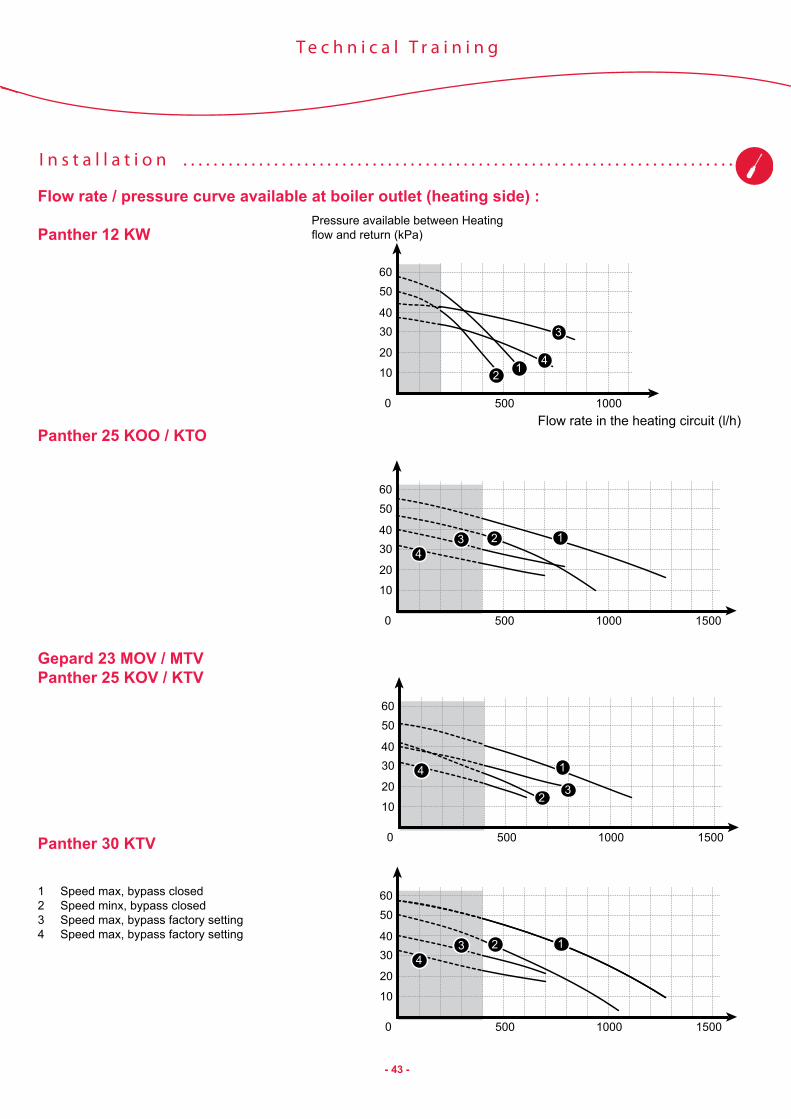
Flow rate / pressure curve available at boiler outlet (heating side) :
Panther 12 KW
Panther 25 KOO / KTO
Gepard 23 MOV / MTVPanther 25 KOV / KTV
Panther 30 KTV
1 Speed max, bypass closed2 Speed minx, bypass closed3 Speed max, bypass factory setting4 Speed max, bypass factory setting
6050
4030
20
10
0 500 1000
3
124
6050
4030
20
10
0 500 1000 1500
1234
6050
4030
20
10
0 500 1000 1500
1
23
4
6050
4030
20
10
0 500 1000 1500
1234
Pressure available between Heating flow and return (kPa)
Flow rate in the heating circuit (l/h)

- 44 -
I n s t a l l a t i o n . . . . . . . . . . . . . . . . . . . . . . . . . . . . . . . . . . . . . . . . . . . . . . . . . . . . . . . . . . . . . . . . . . . . . . . . . .
T e c h n i c a l T r a i n i n g
The flow rate in the installation can be modified with a bypass.
1 Bypass screw
Installation recommendations:
Anti-corrosion and anti-sludge protection:To avoid any corrosion, it is recommended that you add a corrosion inhibitor to the heating circuit water.This inhibitor will prevent any electrical reactions between the different metals in the installation.As a consequence, it also prevents the formation of gasses that may be produced by chemical reactions.
Water treatment is particularly important for plate heaters as the low temperature is favourable to bacterial growth. This can result in sludge that can block all or part of the circuit.
For the dosage of these products, you must know the volume of water in the circuit. It is recommended that you make a note of this volume for future use.
The inhibitors must be compatible with the materials used in the circuit.
Bleeding the heating circuit:The boiler is equipped with an automatic bleed valve in the heating circuit. However, it may be useful to provide one or more additional bleed valves in the installation, particularly at the high points. This will make it possible to bleed the system more quickly.
1
3
2
1 Pump bleed valve plug2 Pump3 Pump shaft screw
1

- 45 -
I n s t a l l a t i o n . . . . . . . . . . . . . . . . . . . . . . . . . . . . . . . . . . . . . . . . . . . . . . . . . . . . . . . . . . . . . . . . . . . . . . . . . .
T e c h n i c a l T r a i n i n g
Check-list for commissioning a heater:
Step Action Check
1 - Before switching on. Check the electrical connections. (general power, connection of accessories, thermostat...)
2 - Before pressurising Check the expansion tank pre-inflation pressure.
The tank may loose pressure, particularly if it has been stored for a long time.
3 - Switch the appliance on, with no demand.
Deactivate heating and hot water using the control panel buttons.Un-stick the pump
Screw giving access to the motor shaft for unblocking
4 - Place the heating circuit under pressure.
Open the taps on the fixing jig. Check that all heating circuit taps are open.Raise the pressure to 2 bar.
Water leaks.Automatic bleeding must be triggered (P07).The appliance will be unavailable for five minutes.
Attention: if pressurisation lasts less than 15 seconds (for example by opening the valves of the connection plate when the installation is already pressurised), the automatic bleeding sequence cannot take place. It is therefore recommended to run this sequence manually using the function P.07 (see § “test mode” in “Technical specification” chapter), before running bleeding of the installation (next stage).5 - Vent the air from the heating circuit. Reset the pressure after bleeding.
Start test function P.06 (see § test mode in “Technical specification” chapter).
Open the heating and installation air bleed valves.
6 - Vent the domestic hot water circuit.
Open the hot water taps to remove the air.
7 - Turn on the gas. Open the gas tap on the fixing jig. Carefully check for leaks with an electronic detector or soapy water.
8 - Boiler configuration at installation.
Adjust the various parameters on the installation menu depending on the installation and the acces-sories. Set the heating flow rate through the bypass if necessary.
Check the value displayed on the After-Sales menu item d44 (ionisation quality). If this value drifts over time, it indicates a deterioration in flame detection.
9 - Run the appliance in heating mode
Check that the water circulates correctly and that the appliance shuts off correctly when reaching the tempe-rature set.Check the exhaust circuit for leaks.Check that the heating flow rate is adequate.
10 - Run the appliance in domestic hot water mode
Check the hot water temperature. Ensure that it meets the user’s requirements.
11 - Explain the appliance to the end-user.
Explain the main operations : ON/OFF, RESET, filling the system, DHW and heating temperature adjustment,Take care that the end-user has his booklet.

- 46 -
M a i n t e n a n c e . . . . . . . . . . . . . . . . . . . . . . . . . . . . . . . . . . . . . . . . . . . . . . . . . . . . . . . . . . . . . . . . . . . . . . . . .
T e c h n i c a l T r a i n i n g
Service visit :
List of recommended annual checks:
Components Check MethodDomestic hot water flow rate sensor
Ignition of the burner for a domestic hot water flow rate of 1.5l/min
In the installer menu, line d36 indicates the domestic hot water flow rate.- Check that the burner properly ignites at the expected flow
rate.- Check that the flow rate measured corresponds to reality.
Gas valve Does the gas flow rate modulate correctly?
Draw off water at max. flow rateReduce the draw rate until the burner goes off.Check that the gas flow rate follows.
NTC Thermistors Measure the resistance of each thermistor (12,500Ω at 20°C, 1,750Ω at 70°C)
Disconnect the thermistors to measure the resistance.
Flame detection (ionisation):
Ionisation quality The ionisation quality can be checked with data item d44 of the After-Sales menu:Less than 300 with the burner lit = good detection
Temperature regulation
Does the burner shut off at the end of regulation?
Check that the burner shuts off when it approaches the setting (test to be performed in hot water mode at low flow rate)
Pressure sensor Does the sensor stop the boiler if the pressure drops below 0.3 bar?
If possible, close the heating circuit isolation valves and drain the boiler until it shuts off.
Expansion tank Does the tank still contain gas?
Check that the water pressure remains stable in operation. If not, check the tank pressure when empty.
Also check:
- Check that there are no water leaks (at connections, safety valves, disconnect... )- Check that there are no gas leaks (at connections, gas valve...) - the sealing of the exhaust ducts- the electrical ground connectionsClean:- the burner- the main heat exchanger- the fan- the heating filter (if necessary, clean the installation)- domestic hot water filter
The seals must be replaced each time they are removed.
- 47 -
M a i n t e n a n c e . . . . . . . . . . . . . . . . . . . . . . . . . . . . . . . . . . . . . . . . . . . . . . . . . . . . . . . . . . . . . . . . . . . . . . . . .
T e c h n i c a l T r a i n i n g
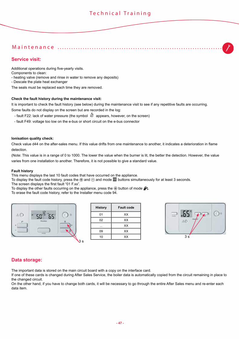
Service visit:
Additional operations during five-yearly visits. Components to clean:- heating valve (remove and rinse in water to remove any deposits)- Descale the plate heat exchangerThe seals must be replaced each time they are removed.
Check the fault history during the maintenance visit:It is important to check the fault history (see below) during the maintenance visit to see if any repetitive faults are occurring.Some faults do not display on the screen but are recorded in the log: - fault F22: lack of water pressure (the symbol appears, however, on the screen)
- fault F49: voltage too low on the e-bus or short circuit on the e-bus connector
Ionisation quality check:Check value d44 on the after-sales menu. If this value drifts from one maintenance to another, it indicates a deterioration in flame detection.(Note: This value is in a range of 0 to 1000. The lower the value when the burner is lit, the better the detection. However, the value varies from one installation to another. Therefore, it is not possible to give a standard value.
Fault historyThis menu displays the last 10 fault codes that have occurred on the appliance.To display the fault code history, press the and and mode buttons simultaneously for at least 3 seconds.The screen displays the first fault “01 F.xx”.To display the other faults occurring on the appliance, press the button of mode .To erase the fault code history, refer to the Installer menu code 94.
Data storage:
The important data is stored on the main circuit board with a copy on the interface card.If one of these cards is changed during After Sales Service, the boiler data is automatically copied from the circuit remaining in place to the changed circuit.On the other hand, if you have to change both cards, it will be necessary to go through the entire After Sales menu and re-enter each data item.
History Fault code
01 XX
02 XX
... XX
09 XX
10 XX3 s
3 s

- 48 -
M a i n t e n a n c e . . . . . . . . . . . . . . . . . . . . . . . . . . . . . . . . . . . . . . . . . . . . . . . . . . . . . . . . . . . . . . . . . . . . . . . . .
T e c h n i c a l T r a i n i n g
Fault diagnosis help:
Description Fault code Cause Solution
Heating temperature sensor fault (NTC2,NTC5)
F00 Flow sensor (NTC2) disconnected• Check the sensor connections.• Check the sensor cables• check the sensor (characteristics
in this chapter at “Measurements”)
F01 Return sensor (NTC5) disconnectedF10 Flow sensor short-circuit (NTC2)F11 Return sensor short-circuit (NTC5)
Storage tank temperature sensor fault (NTC1) F13 Sensor short-circuit : a shunt as been
connected instead of a sensor on X16
Overheating fault (97°C measured by the Heating flow sensor)(NTC2,NTC5)
F20 No water flow
• Check that the pump is working correctly.• Un-stick the pump.• Check that the heating taps are open.• Check the condition of the plate exchanger
if the fault appears in hot water mode.• Check the condition o the heating filter.• Bleed the primary circuit.
No water in the installation (< 0.3 bar) (Cp) F22
Leak in the installationLeak in the Pressure relief valveExpansion tank defective
• Refill and bleed the installation• Check the expansion tank.• Check that there are no leaks.
Maximum difference in temperature between heating output and return reached (35K). (NTC2,NTC5)
F23 Water circulation problem
• Check the connections of the heater output and return sensors.
• Check the pump speed.• See also solution for fault F20.
Water circulation fault (temperature rise greater than 10 K/s). (NTC2,NTC5)
F24 Bad pump operation or low water• See fault 20 or:• Heating taps closed.• Pump disconnected or stuck.
Smoke overflow (only for open flue versions) (K11) F25 The safety device (K11) on the draught
diverter has detected a smoke overflow.
• Check the exhaust (connection, lenght, diameter, no blocking,...)• Check the air intakes on the building• Check the termostatnote : no electric hood allowed on the same room than the boiler.
Gas valve stepper motor current incorrect F26 Stepper motor disconnected or defective • Check the stepper motor connection
• Check the motor
Wrong flame detection. F27 Flame detection in spite of switched off gas valve.
• Check the flame detection electrode• Check the main circuit board.• Check the igniter.
Ignition failure F28 No or insufficient gas.Bad gas valve setting.Gas valve defectiveIgniter defective.Bad earth connection.ignition and flame control electrode defective.
• Check the gas supply circuit (gas tap open).• Check the gas valve.• Check the adjustment of the gas valve.• Check the igniter connection.• Check the electrode condition (corrosion).
Flame failure during burner operation(FL) F29
Air pressure switch failure (Pr) F33 Pressure switch doesn’t switch OFF when fan is OFF. • Check the air pressure switch
Coding resistor fault F42 The coding resistor is not at the expected value • Check the coding resistor (R1) on the wiring
N.B: fault 42 can appear alternately with fault 70 if an erroneous product code has been entered in the installer menu.
EBUS voltage error F49 EBUS line faultShort circuit in EBUS connector • Check the EBUS line voltage

- 49 -
M a i n t e n a n c e . . . . . . . . . . . . . . . . . . . . . . . . . . . . . . . . . . . . . . . . . . . . . . . . . . . . . . . . . . . . . . . . . . . . . . . . .
T e c h n i c a l T r a i n i n g
Fault diagnosis help:
Description Fault code Cause Solution
Main circuit board fault
F61 Gas valve control fault• Check all connections to the main circuit
board• Check the electronic board.• Check the product code.• Reset the appliance.
F62 Gas valve closure faultF63 Main circuit board memory fault
F64 Rapid fluctuation of Heating flow or return sensors.
F65 Main circuit board temperature too highF67 Flame signal fault on the main circuit board
Fluctuation of flame signal (FL) F68 See fault F28 See fault F28
User interface incompatible with main circuit board F70 Bad product code • Check the product code.
• Check the card reference number.Permanent temperature difference between heater flow and return sensors. (NTC2,NTC5)
F72 Discrepancy between Heating flow and return temperatures (permanent difference)
• Check the temperature sensor connections• Replace defective sensors.
Heating circuit pressure sensor fault (Cp)
F73 Pressure sensor short-circuited or disconnected • Check the sensor connections.
• Check the sensorF74 Pressure sensor electrical fault
External accessory faults (not available when this document was printed)
F77 External gas valveCondensate pump • Check the accessory connections
No water in the installation: no temperature increase with burner lit. (NTC2,NTC5)
F83 Circuit not properly bled See fault F22
Permanent temperature difference between heater flow and return sensors(NTC2,NTC5)
F84Flow and return temperature sensors inverted or disconnected.Temperature sensors faulty.
• Check the temperature sensor connections• Replace defective sensors.
Heater flow and return sensors fault(NTC2,NTC5)
F85 Flow and return temperature sensors connected to the same pipe • Check the temperature sensor connections
User interface fault (no display) - Interface card defective
or bad connections.• Check the main circuit board connection.• Replace the interface card
If no fault is displayed on the screen but :- The boiler does not start in heating mode => consult list of status codes in “Technical specification” chapter (this list indicates whether the panel receives a TA heating request, or whether the boiler is in a timer period, for example) => check the temperature readings of the different sensors => check the outdoorl sensor curve- The boiler does not start in hot water mode => consult list of status codes in “Technical specification” chapter => check the temperature readings of the different sensors

- 50 -
M a i n t e n a n c e . . . . . . . . . . . . . . . . . . . . . . . . . . . . . . . . . . . . . . . . . . . . . . . . . . . . . . . . . . . . . . . . . . . . . . . . .
T e c h n i c a l T r a i n i n g
INTERFACE User interface
FUS Fuse
ON / OFF Start/stop button
X2 General sensor connector: Cp Heating pressure sensor V3V 3-way valve Db Hot water flow rate detector
X11 Ext Extracteur X12 230V option card connector X14 Pump (P)
X15 Connector for automatic filling kit
X16 Optional tank connector
X17 Control accessories connector RT Connection for ON/OFF room
thermostat E-bus Connection for modulating room
thermostat (Exacontrol) Text Connector for a wired outside
sensor
X20 General sensor connector: NTC2 Heating output temperature sensor NTC5 Heating return temperature sensor Pr Air flow switch (fan flue boiler) K11 Flue overflow safety device (open
flue boiler) R1 Coding resistance
X21 Ignition and flame control electrode (AL)
X25 Gas valve : EVR : electical feeding for the stepper motor
(=modulating valve) EVS1 : safety valve on the gas inlet EVS2 : safety valve on the gas stepper motor.
X30 Exalink connector
X31 Not used on these models (UK timer)
X32 Solar connector
X40 Card 24V option connector
X51 User interface connector
X90 Not used on these models (factory use)
X101 Earth connector
N.B:Wire colours are only given for information purposes.
This facilitates reading of diagrams but they do not correspond to the colours of wires actually used (wire colours can change on appliances depending on procurement sources).

- 51 -
M a i n t e n a n c e . . . . . . . . . . . . . . . . . . . . . . . . . . . . . . . . . . . . . . . . . . . . . . . . . . . . . . . . . . . . . . . . . . . . . . . . .
T e c h n i c a l T r a i n i n g
Gepard 23 MOV circuit diagram :
110
211
312
413
514
615
716
817
918
105
94
83
72
61
1 23 4
10 9 8 7 6 5 4 3 2 11920 18 17 16 15 14 13 12 11
MNTC
Ebus24 V
X2
X30
X90
X32
X40
X51
X31
X25
X21 X13
230 VACLN
X15
FUS
X14X20
X17
X17
RT
INTERFACE
e-bus T°ext
ON / OFF
K11
EVS1EVS2EVR
NTC5
P
NTC2
1 11 1
110
211
312
413
514
615
716
817
918
Cp V3V Db
10 9 8 7 6 5 4 3 2 11920 18 17 16 15 14 13 12 11
14
25
3634 2 1
X2
X20R1
X12
X101
ALFL
1 23 4
1 2
X21
1 2
105
94
83
72
61
X25
14
25
36
X11

- 52 -
M a i n t e n a n c e . . . . . . . . . . . . . . . . . . . . . . . . . . . . . . . . . . . . . . . . . . . . . . . . . . . . . . . . . . . . . . . . . . . . . . . . .
T e c h n i c a l T r a i n i n g
Gepard 23 MTV circuit diagram:
110
211
312
413
514
615
716
817
918
105
94
83
72
61
1 23 4
10 9 8 7 6 5 4 3 2 11920 18 17 16 15 14 13 12 11
MNTC
Ebus24 V
X2
X30
X90
X32
X40
X51
X31
X25
X21 X13
230 VACLN
X15
FUS
X14X20
X17
X17
RT
INTERFACE
e-bus T°ext
ON / OFF
Pr
EVS1EVS2EVR
NTC5
P
MExt
NTC2
1 2 1 11 1
110
211
312
413
514
615
716
817
918
Cp V3V Db
10 9 8 7 6 5 4 3 2 11920 18 17 16 15 14 13 12 11
14
25
3634 2 1
X2
X20
X12
X101
ALFL
1 23 4
1 2
X21
1 2
105
94
83
72
61
X25
14
25
36
X11

- 53 -
M a i n t e n a n c e . . . . . . . . . . . . . . . . . . . . . . . . . . . . . . . . . . . . . . . . . . . . . . . . . . . . . . . . . . . . . . . . . . . . . . . . .
T e c h n i c a l T r a i n i n g
Panther 25 KOV circuit diagram:
110
211
312
413
514
615
716
817
918
105
94
83
72
61
1 23 4
10 9 8 7 6 5 4 3 2 11920 18 17 16 15 14 13 12 11
MNTC
Ebus24 V
X2
X30
X90
X32
X40
X51
X31
X25
X21 X13
230 VACLN
X15
FUS
X14X20
X17
X17
RT
INTERFACE
e-bus T°ext
ON / OFF
K11
EVS1EVS2EVR
NTC5
P
NTC2
1 11 1
110
211
312
413
514
615
716
817
918
Cp V3V Db
10 9 8 7 6 5 4 3 2 11920 18 17 16 15 14 13 12 11
14
25
3634 2 1
X2
X20R1
X12
X101
ALFL
1 23 4
1 2
X21
1 2
105
94
83
72
61
X25
14
25
36
X11

- 54 -
M a i n t e n a n c e . . . . . . . . . . . . . . . . . . . . . . . . . . . . . . . . . . . . . . . . . . . . . . . . . . . . . . . . . . . . . . . . . . . . . . . . .
T e c h n i c a l T r a i n i n g
Panther 25/30 KTV circuit diagram :
110
211
312
413
514
615
716
817
918
105
94
83
72
61
1 23 4
10 9 8 7 6 5 4 3 2 11920 18 17 16 15 14 13 12 11
MNTC
Ebus24 V
X2
X30
X90
X32
X40
X51
X31
X25
X21 X13
230 VACLN
X15
FUS
X14X20
X17
X17
RT
INTERFACE
e-bus T°ext
ON / OFF
Pr
EVS1EVS2EVR
NTC5
P
NTC2
1 2 1 11 1
110
211
312
413
514
615
716
817
918
Cp V3V Db
10 9 8 7 6 5 4 3 2 11920 18 17 16 15 14 13 12 11
14
25
3634 2 1
X2
X20
X12
X101
ALFL
1 23 4
1 2
X21
1 2
105
94
83
72
61
X25
14
25
36
MExt
X11

- 55 -
M a i n t e n a n c e . . . . . . . . . . . . . . . . . . . . . . . . . . . . . . . . . . . . . . . . . . . . . . . . . . . . . . . . . . . . . . . . . . . . . . . . .
T e c h n i c a l T r a i n i n g
Panther 12 KOO circuit diagram:
110
211
312
413
514
615
716
817
918
105
94
83
72
61
1 23 4
10 9 8 7 6 5 4 3 2 11920 18 17 16 15 14 13 12 11
MNTC
Ebus24 V
X2
X30
X90
X32
X40
X51
X31
X25
X21 X13
230 VACLN
X15
FUS
X14X20
X17
X17
RT
INTERFACE
e-bus T°ext
ON / OFF
K11
EVS1EVS2EVR
NTC5
P
NTC2
1 11 1
110
211
312
413
514
615
716
817
918
Cp V3V
10 9 8 7 6 5 4 3 2 11920 18 17 16 15 14 13 12 11
14
25
3634 2 1
X2
X20R1
X16
ON/OFFNTC1
X12
X101
ALFL
1 23 4
1 2
X21
1 2
105
94
83
72
61
X25
14
25
36
X11
Not used on this model

- 56 -
M a i n t e n a n c e . . . . . . . . . . . . . . . . . . . . . . . . . . . . . . . . . . . . . . . . . . . . . . . . . . . . . . . . . . . . . . . . . . . . . . . . .
T e c h n i c a l T r a i n i n g
Panther 12/25 KTO circuit diagram:
110
211
312
413
514
615
716
817
918
105
94
83
72
61
1 23 4
10 9 8 7 6 5 4 3 2 11920 18 17 16 15 14 13 12 11
X16
ON/OFFNTC1
MNTC
Ebus24 V
X2
X30
X90
X32
X40
X51
X31
X25
X21 X13
230 VACLN
X15
FUS
X14X20
X17
X17
RT
INTERFACE
e-bus T°ext
ON / OFF
Pr
EVS1EVS2EVR
NTC5
P
NTC2
1 2 1 11 1
110
211
312
413
514
615
716
817
918
Cp V3V
10 9 8 7 6 5 4 3 2 11920 18 17 16 15 14 13 12 11
14
25
3634 2 1
X2X20
X12
X101
ALFL
1 23 4
1 2
X21
1 2
105
94
83
72
61
X25
14
25
36
MExt
X11

- 57 -
M a i n t e n a n c e . . . . . . . . . . . . . . . . . . . . . . . . . . . . . . . . . . . . . . . . . . . . . . . . . . . . . . . . . . . . . . . . . . . . . . . . .
T e c h n i c a l T r a i n i n g
Measurements:
Thermistor characteristics (NTC2 and 5)T°C R (Ohms) V (Volts)
0 32600 4,5510 19900 4,3120 12500 3,9530 8000 3,5040 5300 3,1050 3600 2,7060 2500 2,1070 1750 1,7580 1260 1,4090 920 1,01
Air / smoke controlVersion Over flow safety device (K11) (Open flue
versions)Air flow safety device (Pr) (Fan flue versions)
Normal value when the fan is running
Contact closed: R = 0 Ω between 12 and 13 of X20 - The contact is open when the fan stops.
0 VDC between 6 and 7 of X20 when the fan stops.23 VDC between 6 and 7 of X20 fan operating.
In the event of a problem Contact open (faulty): R> 20 Ω between 12 and 13 of X20
0 VDC between 6 and 7 of X20 fan operating.
110
211
312
413
514
615
716
817
918
105
94
83
72
61
1 23 4
10 9 8 7 6 5 4 3 2 11920 18 17 16 15 14 13 12 11
MNTC
Ebus24 V
X2
X30
X90
X32
X40
X51
X31
X25
X21 X13
230 VACLN
X15
FUS
X14X20
X17
X17
RT
INTERFACE
e-bus T°ext
ON / OFF
K11
EVS1EVS2EVR
NTC5
P
NTC2
1 11 1
110
211
312
413
514
615
716
817
918
Cp V3V Db
10 9 8 7 6 5 4 3 2 11920 18 17 16 15 14 13 12 11
14
25
3634 2 1
X2
X20R1
X12
X101
ALFL
1 23 4
1 2
X21
1 2
105
94
83
72
61
X25
14
25
36
X11
110
211
312
413
514
615
716
817
918
105
94
83
72
61
1 23 4
10 9 8 7 6 5 4 3 2 11920 18 17 16 15 14 13 12 11
MNTC
Ebus24 V
X2
X30
X90
X32
X40
X51
X31
X25
X21 X13
230 VACLN
X15
FUS
X20
X17
X17
RT
INTERFACE
e-bus T°ext
ON / OFF
Pr
EVS1EVS2EVR
NTC5
P
NTC2
X14X14
1 2 1 11 1
110
211
312
413
514
615
716
817
918
Cp V3V Db
10 9 8 7 6 5 4 3 2 11920 18 17 16 15 14 13 12 11
14
25
3634 2 1
X2
X20
X12
X101
ALFL
1 23 4
1 2
X21
EVF
1 2
105
94
83
72
61
X25
14
25
36
MExt
Heating pressure sensor: The pressure sensor is fed with 5VDC and it returns a voltage proportional to the circuit pressure.
Pressure (bar) --> 0,3 0,5 0,7 1,0 1,3Pins 11-13 of X2 (Volts) 5 5 5 5 5Pins 11-14 of X2 (Volts) 1,3 1,4 1,5 1,7 1,8
Cp
10 9 8 7 6 5 4 3 2 11920 18 17 16 15 14 13 12 11
34 2 1
X2
NTC3
NTC5 NTC2
10 9 8 7 6 5 4 3 2 11920 18 17 16 15 14 13 12 11
X2
1 2
1 11 1
110
211
312
413
514
615
716
817
918
X20

- 58 -
M a i n t e n a n c e . . . . . . . . . . . . . . . . . . . . . . . . . . . . . . . . . . . . . . . . . . . . . . . . . . . . . . . . . . . . . . . . . . . . . . . . .
T e c h n i c a l T r a i n i n g
Measurements:
Gas valve:
Safety gas valve EVS1 EVS2Resistance 111 Ω 177 ΩNormal voltage 22 to 24 VDC briefly on ignition then 16 VDC
between 6 and 7 of X25.22 to 24 VDC 1 and 2 of X25
If 0V: another fault is blocking the power to the gas valve.Check: - if a fault is displayed on the screen - check in the status list that the appliance is properly taking into account the request (list of statuses in “technical specifications” chapter) - if no fault detected, check the main circuit board
If 24V but the burner doesn’t lit : The servo safety valve is powered. Gas is therefore authorised. Check: - the EVS1 and 2 coil resistance - the gas input - the ignition device
110
211
312
413
514
615
716
817
918
105
94
83
72
61
1 23 4
10 9 8 7 6 5 4 3 2 11920 18 17 16 15 14 13 12 11
MNTC
Ebus24 V
X2
X30
X90
X32
X40
X51
X31
X25
X21 X13
230 VACLN
X15
FUS
X14X20
X17
X17
RT
INTERFACE
e-bus T°ext
ON / OFF
Pr
EVS1EVS2EVR
NTC5
P
NTC2
1 2 1 11 1
110
211
312
413
514
615
716
817
918
Cp V3V Db
10 9 8 7 6 5 4 3 2 11920 18 17 16 15 14 13 12 11
14
25
3634 2 1
X2
X20
X12
X101
ALFL
1 23 4
1 2
X21
1 2
105
94
83
72
61
X25
14
25
36
MExt
X11
EVS2
EVS1
Vm
Fan resistance ; around 70 Ω between the terminals of the fan.

- 59 -
M a i n t e n a n c e . . . . . . . . . . . . . . . . . . . . . . . . . . . . . . . . . . . . . . . . . . . . . . . . . . . . . . . . . . . . . . . . . . . . . . . . .
T e c h n i c a l T r a i n i n g
Disassembly / reassembly
Dismantling the panel
1 front panel2 front panel attachment screws
Remove the two screws (A).Pull the panel downwards to free if from the box.Lift the panel upwards to free it from the lugs at the top.
Heating filter access
1 Hot water heat exchanger mounting lug 2 Hot water heat exchanger attachment screw3 Seal4 Heating filter5 Domestic hot water heat exchangerThe heating filter improves heating circuit bleeding.
Close the heating outlet and return heating valves, then drain the heater.Remove the screws (2) and the mounting lugs (1).Remove the domestic hot water heat exchanger (5).Remove the seal (3).Remove the heating filter (4).Clean and reassemble.
24V
230V
A
AB
C
2
1
B
B
C
AA
A
E
D
1
2
3
4
5
1
2

- 60 -
M a i n t e n a n c e . . . . . . . . . . . . . . . . . . . . . . . . . . . . . . . . . . . . . . . . . . . . . . . . . . . . . . . . . . . . . . . . . . . . . . . . .
T e c h n i c a l T r a i n i n g
Disassembly / reassembly
Heating filter accessThe heating filter is located under the plate heat exchanger.
1. Hot water heat exchanger mounting lug 2. Seal3. Heating filter4. Domestic hot water heat exchangerThe heating filter improves heating circuit bleeding.
Close the heating outlet and return heating valves, then drain the heater.Remove the screws (2) and the mounting lugs (1).Remove the domestic hot water heat exchanger (5).Remove the seal (3).Remove the heating filter (4).Clean and reassemble.
Domestic hot water filter accessThe domestic hot water filter is mounted directly on flow detectors.
To access this filter:Close the cold water inlet valve.Reduce pressure by opening a hot water tap close to the boiler.Remove the flow detector holding clip.Pull the detector forwards to remove it from its housing (it may be tightened because sealed by 2 O’rings)Clean and reassemble.
B
B
C
AA
A
E
D
1
2
3
4
5
1
2

- 61 -
M a i n t e n a n c e . . . . . . . . . . . . . . . . . . . . . . . . . . . . . . . . . . . . . . . . . . . . . . . . . . . . . . . . . . . . . . . . . . . . . . . . .
T e c h n i c a l T r a i n i n g
Dismantling the burner
The burner (gas without the gas manifold) is fixed by 2 screws (by either side of the burner). To access these screws, a long Torx screwdriver is needed.
Torx screwdriver
Dismantling the gas manifold
The gas manifold is located on the back burner.To disassemble:- Unscrew the 2 screws that secure the support of the manifold to the appliance frame- Unscrew the nut of the gas flow

- 62 -
M a i n t e n a n c e . . . . . . . . . . . . . . . . . . . . . . . . . . . . . . . . . . . . . . . . . . . . . . . . . . . . . . . . . . . . . . . . . . . . . . . . .
T e c h n i c a l T r a i n i n g
Dismantling the igniter
The igniter is fixed to a support itself screwed to the frame and accessible from the front.To disassemble, unscrew the side panel and left ajar to spend a screwdriver behind the flow pipe leaving of the heat exchanger.
Dismantling the gas valve
There are 2 ways to disassemble the gas valve depending on the access around the boiler.
If access from the left side panel: If no access from the left side:The gas valve support is screwed to the frame of the device, behind the side panel.
Unscrew the gas valve from its support (access to the screws from underneath the appliance).
- Close the gas- Disconnect electrical connections from gas valve- Unscrew the nut connecting the gas valve- Removing the left side panel- Remove the screws holding the support of gas valve- Remove the whole valve + support
- Close the gas- Disconnect electrical connections from gas valve- Unscrew the nut connecting the gas valve- Removing the left side panel- Remove the screws holding the gas valve to the support- Remove the gas valve

- 63 -
M a i n t e n a n c e . . . . . . . . . . . . . . . . . . . . . . . . . . . . . . . . . . . . . . . . . . . . . . . . . . . . . . . . . . . . . . . . . . . . . . . . .
T e c h n i c a l T r a i n i n g
Dismantling the DHW heat exchanger
The DHW exchanger is pressed against the hydraulic unit with 2 brackets.
P
To remove the plate heat exchanger:- Isolate the boiler installation by closing the isolation valves of the fixing jig- Empty the primary circuit through the drain valve- Open a hot water cock of the installation- Once the boiler drained, unscrew the 2 brackets and remove them.The exchanger can then be removed.During reassembly, check the mounting direction (the exchanger is marked on the edge, forward). While the exchanger is disassemblied, clean the heating filter (see exploded view in next page). Check that the gaskets are in place on the hydraulic unit.

- 64 -
M a i n t e n a n c e . . . . . . . . . . . . . . . . . . . . . . . . . . . . . . . . . . . . . . . . . . . . . . . . . . . . . . . . . . . . . . . . . . . . . . . . .
T e c h n i c a l T r a i n i n g
Exploded view of hydraulic assembly
1 Three-way valve connector2 Three-way valve retaining screws3 Three-way valve4 Flow sensor connector5 Flow sensor6 Safety Discharge Valve retaining clip8 Safety Discharge Valve9 Plate-to-plate heat exchanger
retaining bracket10 Plate-to-plate heat exchanger
retaining screws
11 Heating flow pipe retaining clip12 Heating flow pipe13 Heating return pipe14 Plate-to-plate heat exchanger15 Low water pressure sensor connector16 Low water pressure sensor17 Low water pressure sensor retaining
clip18 Heating return pipe retaining clip19 Expansion vessel pipe20 Automatic air vent
21 Pump housing22 Pump housing retaining clip23 Bypass retaining clip24 Bypass screw25 Pump head earth lead26 Pump head connector27 Pump head retaining screws28 Pump head29 Automatic air vent retaining clip
12 13
11
10 14
9 15
8 16
17 18
7 19
6
20
5 21
29
28
27
26
4
3 22
2 23
241
25

- 65 -
M a i n t e n a n c e . . . . . . . . . . . . . . . . . . . . . . . . . . . . . . . . . . . . . . . . . . . . . . . . . . . . . . . . . . . . . . . . . . . . . . . . .
T e c h n i c a l T r a i n i n g
Dismantling the fan
A single screw keeps the fan in position.To replace take care to the flue gasket.

- 66 -
A c c e s s o r i e s . . . . . . . . . . . . . . . . . . . . . . . . . . . . . . . . . . . . . . . . . . . . . . . . . . . . . . . . . . . . . . . . . . . . . . . . . .
T e c h n i c a l T r a i n i n g
Wired outdoor sensor (ref. 0020012393).
The boiler can accept a wired exterior sensor, to be wired to connector X17 of the main circuit board. In this case, the setting parameters for the sensor are found in the installer menu (d43 and d45).
Outdoor temperature sensor characteristics :
T°C R (Ohms)-25 2167-20 2076-15 1976-10 1862-5 17450 16195 1494
10 138715 124620 1128
Tank thermistor.
A type AS boiler can be associated with a tank. This tank is then controlled, either by a thermostat or a thermistor.The thermistor is supplied as an accessory.
Tank thermistor (NTC1) characteristicsT°C R (Ohms)
0 3260010 1990020 1250030 800040 530050 360060 250070 175080 126090 920

- 67 -
A c c e s s o r i e s . . . . . . . . . . . . . . . . . . . . . . . . . . . . . . . . . . . . . . . . . . . . . . . . . . . . . . . . . . . . . . . . . . . . . . . . . .
T e c h n i c a l T r a i n i n g
Option card (ref. 0020094768).
The option card can manage: - an auxiliary heating pump - a kitchen hood - an external gas valve - signal of failure
2
4
5
6 F.XX
110
211
312
413
514
615
716
817
918
105
94
83
72
61
1 23 4
10 9 8 7 6 5 4 3 2 11920 18 17 16 15 14 13 12 11
X2
X30
X90
X32
X40
X51
X31
X25
X21 X13
X15
FUS
X14X20X18
X16
X17
INTERFACEON / OFF
230 V ac
X40 B
X12 AX12
OPT.

Vaillant Group Slovakia, s.r.o. Pplk. Pljusta 45909 01 Skalica
www.protherm.sk
Phone: +421(0) 346966151Fax: +421(0) 346966111
03/1
0 -
Sta
ndar
d no
n C
onde
ns -
FT
55 V
3 E
N P
ro-