SCOTTS VALLEY LIBRARY UPGRADES
284
SCOTTS VALLEY LIBRARY UPGRADES City of Scotts Valley, CA Scotts Valley’s Public Works Job Number 21-004 Project No. 18517-02 ADDENDUM 01 June 28, 2021 Group 4 Architecture Research + Planning, Inc. 211 Linden Avenue South San Francisco, CA (650) 871-0709
-
Upload
khangminh22 -
Category
Documents
-
view
4 -
download
0
Transcript of SCOTTS VALLEY LIBRARY UPGRADES

SCOTTS VALLEY LIBRARY UPGRADES
City of Scotts Valley, CA
Scotts Valley’s Public Works Job Number 21-004
Project No. 18517-02
ADDENDUM 01
June 28, 2021
Group 4 Architecture Research + Planning, Inc. 211 Linden Avenue
South San Francisco, CA (650) 871-0709

(This page left intentionally blank)

JUNE 28, 2021 TABLE OF CONTENTS
SCOTTS VALLEY LIBRARY GROUP 4 ARCHITECTURE
CITY OF SCOTTS VALLEY G4 Project No. 18517-02
SPECIFICATIONS – ADDENDUM 01
DOCUMENT 000110 TABLE OF CONTENTS
DIVISION 2 – SITE CONSTRUCTION
SECTION 02 4119 SELECTIVE SITE DEMOLITION
DIVISION 3 – CONCRETE
SECTION 03 3000 CONCRETE
DIVISION 5 – METALS
SECTION 05 5000 METAL FABRICATIONS
DIVISION 6 – WOOD AND PLASTICS
SECTION 06 1053 ROUGH CARPENTRY
SECTION 06 4100 ARCHITECTURAL WOODWORK
DIVISION 7 – THERMAL AND MOISTURE PROTECTION
SECTION 07 2100 BUILDING INSULATION
SECTION 07 4620 SIDING AND TRIM
SECTION 07 4646 FIBRE CEMENT PANELS
SECTION 07 9200 JOINT SEALANTS
DIVISION 8 – DOORS AND WINDOWS
SECTION 08 4230 SLIDING AUTOMATIC ENTRANCES
SECTION 08 7100 DOOR HARDWARE[TR1]
SECTION 08 8100 GLASS GLAZING
DIVISION 9 – FINISHES
SECTION 09 2216 NON-STRUCTURAL METAL FRAMING
SECTION 09 2900 GYPSUM BOARD
SECTION 09 3000 TILING
SECTION 09 6813 TILE CARPETING
SECTION 09 7773 WALL LOUVERS
SECTION 09 8436 ACOUSTICAL PANELS
SECTION 09 9100 PAINTING
DIVISION 10 – SPECIALTIES
SECTION 10 1400 SIGNAGE
DIVISION 12 – FURNISHINGS
SECTION 12 9000 SITE FURNISHINGS
SECTION 12 9300 BIKE RACKS

JUNE 28, 2021 TABLE OF CONTENTS
SCOTTS VALLEY LIBRARY GROUP 4 ARCHITECTURE
CITY OF SCOTTS VALLEY G4 Project No. 18517-02
DIVISION 23 - HVAC
SECTION 23 0000 MEP SCOPE NARRATIVE
DIVISION 31 - EXTERIOR CLEARING SECTION 31 1300 SECTIVE TREE AND SHRUB REMOVAL DIVISION 32 – EXTERIOR IMPROVEMENTS
SECTION 32 8400 PLANTING IRRIGATIONSECTION 32 9113 SOIL PREPARATIONSECTION 32 9119 PLANTING AREA FINISH GRADINGSECTION 32 9120 PLANTING SOILSECTION 32 9300 PLANTING MATERIALSSECTION 32 9325 LANDSCAPE MAINTENANCE
END OF TOC – ADDENDUM 01

SCOTTS VALLEY LIBRARY GROUP 4 ARCHITECTURE
CITY OF SCOTTS VALLEY G4 Project No. 18517-02
28 JUNE 2021 ALTERNATES
01 2300 - 1
SECTION 01 2300 ALTERNATES
PART 1 - GENERAL
1.1 RELATED DOCUMENTS
A. Drawings and general provisions of the Contract, including General and Supplementary
Conditions and other Division 1 Specification Sections, apply to this Section.
1.2 SECTION INCLUDES
A. Submission procedures.
B. Documentation of changes to Contract Price and Contract Time.
1.3 RELATED SECTIONS
A. Division 0 Sections
B. Section 01 2500 - Product Substitution Procedures.
C. Section 013300 – Submittal Procedures: Work schedule affected by Alternates.
1.4 DESCRIPTION
A. The items of work indicated below propose modifications to, substitutions for, additions to
and/or deletions from the various parts of the Work specified in other Sections of the
Specifications. The acceptance or rejection of any of the alternates is strictly at the option of
the City subject to City's acceptance of Contractor's stated prices contained in this Proposal.
1.5 REQUIREMENTS
A. Submit Alternates with full description of the proposed Alternate and the effect on adjacent
or related components.
B. Alternates quoted on Bid Forms will be reviewed and accepted or rejected at City's option.
Bid Alternates can be accepted after award of contract until bid expiration date.
C. Coordinate related work and modify surrounding work to integrate the Work of each
Alternate.
D. Where an item is omitted, or scope of Work is decreased, all Work pertaining to the item
whether specifically stated or not, shall be omitted and where an item is added or modified
or where scope of Work is increased, all Work pertaining to that required to render same
ready for use on the Project in accordance with the intention of the Drawings and
Specifications shall be included in an agreed upon price amount.
1.6 SELECTION AND AWARD OF ALTERNATES
A. Indicate variation of Bid Price for Alternates described below and list in Bid Form
Document or any supplement to it, which requests a 'difference' in Bid Price by adding to or
deducting from the base bid price.
B. Bid will be evaluated on base bid price. After determination of preferred bidder,
consideration will be given to Alternates and Bid Price adjustments.
1.7 SCHEDULE OF ALTERNATES
A. Alternates
1. ALTERNATE 1: East Elevation Entry Improvements
2. ALTERNATE 2: East Elevation Façade Improvements

SCOTTS VALLEY LIBRARY GROUP 4 ARCHITECTURE
CITY OF SCOTTS VALLEY G4 Project No. 18517-02
28 JUNE 2021 ALTERNATES
01 2300 - 2
3. ALTERNATE 3: Fireside Room Storefront Glazing
4. ALTERNATE 4: Landscape Improvements
5. ALTERNATE 5: Landscape Maintenance.
PART 2 - PRODUCTS – NOT USED
PART 3 - EXECUTION – NOT USED
END OF SECTION 01 2300

SCOTTS VALLEY LIBRARY GROUP 4 ARCHITECTURE
CITY OF SCOTTS VALLEY G4 Project No. 18517-02
17 MAY 2021 SUBSTITUTION PROCEDURES
01 2500-1
SECTION 01 2500 SUBSTITUTION PROCEDURES
PART 1 – GENERAL
1.1 RELATED DOCUMENTS
A. Drawings and general provisions of the Contract, including General and Supplementary Conditions and other Division 01 Specifications Sections, apply to this Section.
1.2 SUMMARY
A. Section includes administrative and procedural requirements for substitutions.
1.3 RELATED SECTIONS
A. Section 01 6000 - Product Requirements, for submittal procedures and Contract document revisions initiated by Contractor.
1.4 DEFINITIONS
A. Substitutions: Changes in products, materials, equipment, and methods of construction from those required by the Contract Documents and proposed by Contractor. 1. Substitutions for Convenience: Changes proposed by Contractor or City that are not required in
order to meet other Project requirements but may offer advantage to Contractor or City. a. Substitutions for Convenience shall include any comparable ("or equivalent") product,
including proposed changes to named products, proposed changes to listed manufacturers and proposed changes to basis-of-design products, unless a Substitution for Cause regarding the comparable products are proposed in which case the Contractor shall provide information of the cause.
2. Substitutions for Cause: Changes proposed by Contractor that are required due to changed Project conditions, such as unavailability of product, regulatory changes, or unavailability of required warranty terms.
1.5 SUBMITTALS
A. Substitution Requests: Submit complete request by PDF for consideration. Identify product or fabrication or installation method to be replaced. Include Specification Section number and title and Drawing numbers and titles. 1. Substitution Request Form: Attached at end of this section. 2. Documentation: Submit the information indicated below to provide the City Representative with
the minimum information necessary to fairly review and evaluate the proposed substitutions, proposed comparable products and proposed changes to specified products. Show compliance with requirements and the following, as applicable: a. Statement indicating why specified product or fabrication or installation cannot be provided,
if applicable. b. Coordination information which shall be necessary to accommodate proposed substitution,
including a list of changes or modifications needed to other parts of the Work and to construction performed by City and separate Contractors.
c. Detailed side by side comparison of significant qualities of proposed substitution with those of the Work specified. Include annotated copy of applicable specification section. Significant qualities may include attributes such as performance, weight, size, durability, visual effect, sustainable design characteristics, warranties, and specific features and requirements indicated. Indicate deviations, if any, from the Work specified.
d. Product Data, including drawings and descriptions of products and fabrication and installation procedures.

SCOTTS VALLEY LIBRARY GROUP 4 ARCHITECTURE
CITY OF SCOTTS VALLEY G4 Project No. 18517-02
17 MAY 2021 SUBSTITUTION PROCEDURES
01 2500-2
e. Samples and mock-ups, where applicable or requested. f. Certificates and qualification data, where applicable or requested. g. List of similar installations for completed projects with project’s names and addresses and
names and addresses of Architects and City Representative. h. Material test reports from a qualified testing agency indicating and interpreting test results
for compliance with requirements indicated. i. Research reports evidencing compliance with California Building Code in effect for Project,
from ICC-ES or other recognized code organizations acceptable to authorities having jurisdiction.
j. Detailed comparison of Contractor's construction schedule using proposed substitution with products specified for the Work, including effect on the overall Contract Time. If specified product or method of construction cannot be provided within the Contract Time, include letter from manufacturer, on manufacturer's letterhead, stating date of receipt of purchase order, lack of availability, or delays in delivery.
k. Cost information, including a proposal of change, if any, in the Contract Sum. l. Contractor's certification that proposed substitution complies with requirements in the
Contract Documents except as indicated in substitution request, is compatible with related materials, and is appropriate for applications indicated.
m. Contractor's waiver of rights to additional payment or time that may subsequently become necessary because of failure of proposed substitution to produce indicated results.
3. City Representative Action: If necessary, City Representative will request additional information or documentation for evaluation within seven days of receipt of a request for substitution. City Representative will notify Contractor of acceptance or rejection of proposed substitution within fourteen calendar days of receipt of request, or within fourteen calendar days of receipt of additional information or documentation, whichever is later. a. Forms of Acceptance: Change Order or Field Order. b. Use product specified if City Representative does not issue a decision on use of a proposed
substitution within time allocated.
1.6 QUALITY ASSURANCE
A. Compatibility of Substitutions: Investigate and document compatibility of proposed substitution with related products and materials. Engage qualified testing agency to perform compatibility tests recommended by manufacturers.
1.7 PROCEDURES
A. Coordination: Modify or adjust affected Work as necessary to integrate Work of the approved substitutions.
PART 2 – PRODUCTS
2.1 SUBSTITUTIONS
A. Substitutions for Convenience: Per General Conditions, Section C - Control of Work; and the following: 1. Conditions: If the following conditions are not satisfied, City Representative will return requests
as Rejected, noting noncompliance with these requirements: a. Requested substitution offers City a substantial advantage in cost, time, energy
conservation, or other considerations, after deducting additional responsibilities City must assume. City's additional responsibilities may include compensation to others for redesign and evaluation services, increased cost of other construction by City, and similar considerations.
b. Requested substitution does not require extensive revisions to the Contract Documents.

SCOTTS VALLEY LIBRARY GROUP 4 ARCHITECTURE
CITY OF SCOTTS VALLEY G4 Project No. 18517-02
17 MAY 2021 SUBSTITUTION PROCEDURES
01 2500-3
c. Requested substitution is consistent with the Contract Documents and will produce indicated results.
d. Requested substitution provides sustainable design characteristics that specified product provided.
e. Substitution request is fully documented and properly submitted. f. Requested substitution shall not adversely affect Contractor's construction schedule. g. Requested substitution has received necessary approvals of authorities having jurisdiction. h. Requested substitution is compatible with other portions of the Work. i. Requested substitution has been coordinated with other portions of the Work. j. Requested substitution provides specified warranty. k. If requested substitution involves more than one Contractor, requested substitution has been
coordinated with other portions of the Work, is uniform and consistent, is compatible with other products, and is acceptable to all contractors involved.
B. Substitutions for Cause: Submit requests for substitution immediately upon discovery of need for change, but not later than 14 days prior to time required for preparation and review of related submittals. 1. Conditions: City Representative will consider Contractor's request for substitution when the
following conditions are satisfied. If the following conditions are not satisfied, City Representative will return requests without action, except to record noncompliance with these requirements: a. Describe the non-convenience cause that is triggering the request for the change. b. Requested substitution is consistent with the Contract Documents and will produce
indicated results. c. Requested substitution provides sustainable design characteristics that specified product
provided. d. Substitution request is fully documented and properly submitted. e. Requested substitution will not adversely affect Contractor's construction schedule. f. Requested substitution has received necessary approvals of authorities having jurisdiction. g. Requested substitution is compatible with other portions of the Work. h. Requested substitution has been coordinated with other portions of the Work. i. Requested substitution provides specified warranty. j. If requested substitution involves more than one Contractor, requested substitution has been
coordinated with other portions of the Work, is uniform and consistent, is compatible with other products, and is acceptable to all contractors involved.
PART 3 - EXECUTION (NOT USED)
END OF SECTION
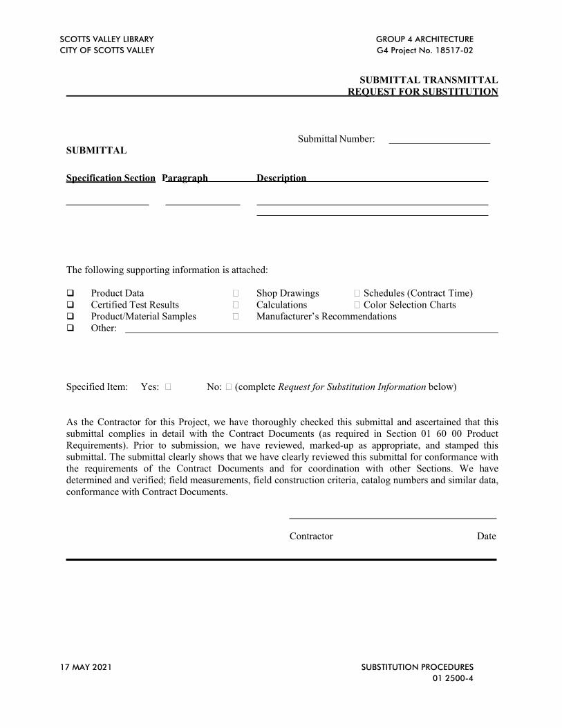
SCOTTS VALLEY LIBRARY GROUP 4 ARCHITECTURE
CITY OF SCOTTS VALLEY G4 Project No. 18517-02
17 MAY 2021 SUBSTITUTION PROCEDURES
01 2500-4
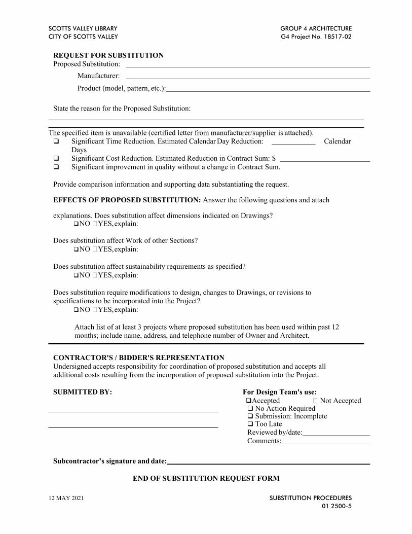
SUBMITTAL TRANSMITTAL
REQUEST FOR SUBSTITUTION
Submittal Number: SUBMITTAL
Specification Section Paragraph Description
The following supporting information is attached: Product Data Shop Drawings Schedules (Contract Time) Certified Test Results Calculations Color Selection Charts Product/Material Samples Manufacturer’s Recommendations Other:
Specified Item: Yes: No: (complete Request for Substitution Information below)
As the Contractor for this Project, we have thoroughly checked this submittal and ascertained that this submittal complies in detail with the Contract Documents (as required in Section 01 60 00 Product Requirements). Prior to submission, we have reviewed, marked-up as appropriate, and stamped this submittal. The submittal clearly shows that we have clearly reviewed this submittal for conformance with the requirements of the Contract Documents and for coordination with other Sections. We have determined and verified; field measurements, field construction criteria, catalog numbers and similar data, conformance with Contract Documents.
Contractor Date
SCOTTS VALLEY LIBRARY GROUP 4 ARCHITECTURE
CITY OF SCOTTS VALLEY G4 Project No. 18517-02
12 MAY 2021 SUBSTITUTION PROCEDURES
01 2500-5
REQUEST FOR SUBSTITUTION Proposed Substitution:
Manufacturer:
Product (model, pattern, etc.):
State the reason for the Proposed Substitution:
The specified item is unavailable (certified letter from manufacturer/supplier is attached). Significant Time Reduction. Estimated Calendar Day Reduction: Calendar
Days Significant Cost Reduction. Estimated Reduction in Contract Sum: $ Significant improvement in quality without a change in Contract Sum.
Provide comparison information and supporting data substantiating the request.
EFFECTS OF PROPOSED SUBSTITUTION: Answer the following questions and attach
explanations. Does substitution affect dimensions indicated on Drawings? NO YES, explain:
Does substitution affect Work of other Sections?
NO YES, explain:
Does substitution affect sustainability requirements as specified?
NO YES, explain:
Does substitution require modifications to design, changes to Drawings, or revisions to specifications to be incorporated into the Project?
NO YES, explain:
Attach list of at least 3 projects where proposed substitution has been used within past 12 months; include name, address, and telephone number of Owner and Architect.
CONTRACTOR'S / BIDDER'S REPRESENTATION
Undersigned accepts responsibility for coordination of proposed substitution and accepts all additional costs resulting from the incorporation of proposed substitution into the Project.
SUBMITTED BY: For Design Team's use:
Accepted Not Accepted No Action Required Submission: Incomplete Too Late Reviewed by/date: Comments:
Subcontractor’s signature and date:
END OF SUBSTITUTION REQUEST FORM

SCOTTS VALLEY LIBRARY GROUP 4 ARCHITECTURE
CITY OF SCOTTS VALLEY G4 Project No. 18517-02
12 MAY 2021 SUBSTITUTION PROCEDURES
01 2500-6
This Page Intentionally Left Blank

SCOTTS VALLEY LIBRARY GROUP 4 ARCHITECTURE
CITY OF SCOTTS VALLEY G4 Project No. 18517-02
12 MAY 2021 SUBMITTAL PROCEDURES
01 3000-1
SECTION 01 3000 SUBMITTAL PROCEDURES
PART 1 – GENERAL
1.1 SECTION INCLUDES
A. Administrative and procedural requirements for submittals required for the Work,
including but not limited to; Shop Drawings, Product Data, Samples, material lists, and
quality control items as required by the Contract Documents.
B. Wherever possible, throughout the Contract Documents, the minimum acceptable quality
of Workmanship and products has been defined by the name and catalog number of a
manufacturer and by reference of recognized industry standards.
C. To ensure that specified products are furnished and installed in accordance with the design
intent, and procedures have been established for submittal of design data and for its review
by City Representative and/or others.
1.2 RELATED SECTIONS
A. Division 00 - General Conditions.
B. Section 01 31 00: Project Management and Coordination.
C. Section 01 40 00: Quality Requirements
D. Section 01 50 00: Temporary Facilities and Controls.
E. Section 01 60 00: Product Requirements
F. Division 02 through Division 33.
PART 2 - PRODUCTS (NOT APPLICABLE)
PART 3 – EXECUTION
3.1 ELECTRONIC DOCUMENT SUBMITTAL SERVICE
A. Submittals, RFIs and meeting minutes are to be in electronic (PDF) format and transmitted
via an Internet-based submittal service that receives, logs and stores documents, provides
electronic stamping and signatures, and notifies addressees via email.
B. Contractor and City Representative are required to use this service.
C. It is Contractor's responsibility to submit documents in PDF format.
D. Paper document transmittals will not be reviewed (except Deferred Approvals and Close-
Out Maintenance & Operations Manuals).
E. All other specified submittal and document transmission procedures apply, except that
electronic document requirements to not apply to samples or color selection charts.
3.2 GENERAL REQUIREMENT AND PROCEDURES
A. Contractor shall package each submittal appropriately for transmittal and handling and will
then send City representative submittal for review per the Project plans and specifications.
Submittals will not be accepted from sources other than from Contractor.
B. Contractor shall clearly identify any deviations from the Contract Documents on each
submittal. Any deviation not so noted, even if stamped reviewed, is not acceptable.
C. After City Representative review, City Representative shall transmit submittals to
Contractor. Contractor shall further distribute to Subcontractor’s and others as required.
SCOTTS VALLEY LIBRARY GROUP 4 ARCHITECTURE
CITY OF SCOTTS VALLEY G4 Project No. 18517-02
12 MAY 2021 SUBMITTAL PROCEDURES
01 3000-2
Work shall not commence, unless otherwise approved by City Representative until
approved submittals are transmitted to Contractor.
D. Contractor’s Review and Approval: Every submittal upon which proper execution of the
Work is dependent shall bear the Contractor’s review and approval stamp, dated and signed
by Contractor certifying that Contractor (a) has reviewed, checked, and approved the
submittal and has coordinated the submittal contents with requirements of Work and
Contract Documents including related Work, (b) Contractor coordinated with all other shop
drawings received to date and this duty of coordination has not been delegated to
Subcontractors, material suppliers, the City Representative, or the Architect on this Project,
(c) determined and verified quantities, field measurements, construction criteria, materials,
equipment, catalog numbers and identifications, and similar data, or will do so, and (d)
states the Work illustrated or described in the submittal is recommended by Contractor and
the Contractor’s warranty will fully apply thereto.
E. Contractor shall coordinate each submittal with fabrication, purchasing, testing, delivery,
other submittals, and related activities requiring sequential activity.
F. Timing of Submittals:
1. In accordance with General Conditions, Contractor shall submit to the City
Representative, those Shop Drawings, Product Data, diagrams, materials lists, Samples
and other submittals required by the Contract Documents.
2. The Contractor shall submit within ten (10) calendar days of the Notice to Proceed, an
itemized listing of required submittals with a scheduled date for each submittal. The
schedule of submittals shall provide adequate time between submittals in order to allow
for proper review without negative impact to the Construction Schedule.
3. Schedule of submittals shall be related to Work progress, and shall be so organized as
to allow sufficient time for transmitting, reviewing, corrections, resubmission, and re-
reviewing.
4. Contractor shall coordinate submittal of related items and City Representative reserves
the right to withhold action on a submittal requiring coordination with other submittals
until all related submittals are received by City Representative.
5. Contractor shall revise, update and submit submittal schedule to Engineer on the first
of each month, or as required by the City.
6. Contractor shall allow in the Construction Schedule, at least fourteen (14) calendar
days for City Representative review following City Representative receipt of submittal.
For mechanical, plumbing, electrical, structural, and other submittals requiring joint
review with Architect’s Consultants, and/or others, Contractor shall allow a minimum
of eighteen (18) calendar days following City Representative receipt of submittal.
Submittals will be reviewed with reasonable promptness, but Engineer reserves the
right of additional time where required based on, but not limited to, submittal size, and
complexity.
7. No adjustments to the Contract Time and/or Milestones shall be authorized because of
a failure to transmit submittals to City Representative sufficiently in advance of the
Work to permit review and processing.
8. In case of product substitution, Shop Drawing preparation shall not commence until
such time City Representative reviews said submittal relative to the General
Conditions.
SCOTTS VALLEY LIBRARY GROUP 4 ARCHITECTURE
CITY OF SCOTTS VALLEY G4 Project No. 18517-02
12 MAY 2021 SUBMITTAL PROCEDURES
01 3000-3
G. Resubmit submittals in a timely manner. Resubmit as specified for initial submittal but
identify as such. Review times for re-submitted items shall be as per the time frames for
initial submittal review.
H. City Representative, or authorized agent, will stamp each submittal with a uniform,
action stamp marking the stamp appropriately to indicate the action taken, as follows:
1. Final Unrestricted Release: When City Representative , or authorized agent, marks a
submittal “Reviewed” the Work covered by the submittal may proceed provided it
complies with requirements of the Contract Documents. Final payment depends on that
compliance.
2. Final-But-Restricted Release: When City Representative , or authorized agent, marks
a submittal “Make Corrections Noted" (Reviewed as Noted) the Work covered by the
submittal may proceed provided it complies with notations or corrections on the
submittal and requirements of the Contract Documents. Final payment depends on that
compliance.
3. Returned for Re-submittal: When City Representative , or authorized agent, marks a
submittal "Revise and Resubmit, Submit Specified Item, Rejected” do not proceed with
Work covered by the submittal, including purchasing, fabrication, delivery, or other
activity. Revise or prepare a new submittal according to the notations; resubmit without
delay. Repeat as necessary to obtain different action mark. In case of multiple
submittals covering same items of Work, Contractor is responsible for any time delays,
schedule disruptions, out of sequence Work, or additional costs due to multiple
submissions of the same submittal item. Do not use, or allow others to use, submittals
marked “Rejected, Revise and Resubmit” at the Project’s site or elsewhere where Work
is in progress.
4. Other Action: Where a submittal is for information or record purposes or special
processing or other activity, the City Representative , or authorized agent, will return
the submittal marked “Action Not Required”.
5. Not Required Submittal: Where a submittal is submitted for review but is not required
to be submitted, the City Representative , or authorized agent, will return the submittal
identified with legend “No Action Taken”.
I. Review and Approval of Submittals by the City Representative : Submittals will be
reviewed but only for conformance with the design concept of the Project and with the
information indicated on the Drawings and stated in the Specifications. Approval of a
separate item as such will not indicate approval of the assembly in which the item functions.
Approval of submittals shall not relieve the Contractor of responsibility for any deviations
from requirements of the Contract Documents or any revisions in resubmittals unless
Contractor has given written notice of such deviation or revision at the time of submission
or resubmission and written approval has been given to the specific deviation or revision,
nor shall approval relieve the Contractor of responsibility for error or omissions in the
submittals or for the accuracy of dimensions and quantities, the adequacy of connections,
and the proper and acceptable fitting, execution, functioning, and completion to the Work.
J. All costs for the preparation, correction, delivery, and return of the submittals shall be
borne by the Contractor.
SCOTTS VALLEY LIBRARY GROUP 4 ARCHITECTURE
CITY OF SCOTTS VALLEY G4 Project No. 18517-02
12 MAY 2021 SUBMITTAL PROCEDURES
01 3000-4
3.3 SHOP DRAWINGS
A. Shop Drawings are original drawings in electronic format (except Deferred Approvals to
be hard copies) prepared by Contractor, Subcontractor, supplier, or distributor illustrating
some portion of Work by showing fabrication, layout, setting, or erection details. Do not
reproduce Contract Documents or copy standard information as the basis of Shop
Drawings. Copies of the Contract Drawing marked to show Shop Drawing information are
not acceptable and will not be reviewed and shall be promptly returned to the Contractor.
B. Produce Deferred Approval Shop Drawings to an accurate scale that is large enough to
indicate all pertinent features and methods. Except for templates, patterns, and similar full-
size drawings, submit Shop Drawings on sheets at least 24 x 36 inches.
C. Shop Drawings shall include, at a minimum, fabrication and installation drawings, setting
diagrams, schedules, patterns, templates, and similar drawings. Include the following
information:
1. Dimensions
2. Identification of products and materials included by sheet and detail number.
3. Compliance with specified standards.
4. Notation of coordination requirements.
5. Notation of dimensions established by field measurement.
D. Provide two (2) spaces, approximately 4 by 5 inches, on the label or beside the title block
on Shop Drawings to record Contractor and City Representative review, and the action
taken. Include the following information on the label for processing and recording action
taken:
1. Project name.
2. Project number.
3. Date.
4. Name and address of City Representative .
5. Name and address of Contractor.
6. Name and address of Subcontractor.
7. Name and address of supplier.
8. Name and address of manufacturer.
9. Name and title of appropriate Specification section.
10. Drawing number and detail references, as appropriate.
3.4 PRODUCT DATA
A. Collect Product Data into a single submittal for each element of Work or system. Product
Data includes printed information, such as manufacturer’s installation instructions, catalog
cuts, standard color charts, roughing-in diagrams and templates, wiring diagrams,
schedules, illustrations, or performance curves.
1. Mark each copy to show or delineate pertinent materials, products, models, applicable
choices, or options. Where Product Data includes information on several products that
are not required, clearly mark copies to indicate the applicable information. Include
the following information:
a. Manufacturer’s printed recommendations.
b. Compliance with trade association standards.
c. Compliance with recognized testing agency standards.
d. Application of testing agency labels and seals.

SCOTTS VALLEY LIBRARY GROUP 4 ARCHITECTURE
CITY OF SCOTTS VALLEY G4 Project No. 18517-02
12 MAY 2021 SUBMITTAL PROCEDURES
01 3000-5
e. Notation of dimensions verified by field measurement.
f. Notation of coordination requirements.
g. Notation of dimensions and required clearances.
h. Indicate performance characteristics and capacities.
i. Indicate wiring diagrams and controls.
2. Do not submit Product Data until compliance with requirements of the Contract
Documents has been confirmed.
3.5 SAMPLES
A. Submit Samples of sufficient size, quantity, cured and finished and physically identical to
the proposed product or material. Samples include partial or full sections or range of
manufactured or fabricated components, cuts or containers of materials, color range sets,
and swatches denoting color, texture, and/or pattern.
1. Mount or display Samples in the manner to facilitate review of qualities indicated.
Include the following:
a. Specification section number and reference.
b. Generic description of the Sample.
c. Sampling source.
d. Product name or name of manufacturer.
e. Compliance with recognized standards.
f. Availability and delivery time.
2. Submit Samples for review of size, kind, color, pattern, and texture. Submit Samples
for a final check of these characteristics with other elements and a comparison of these
characteristics between the final submittal and the actual component as delivered and
installed.
a. Where variations in color, pattern, texture, or other characteristic is inherent in the
material or product represented, submit at least three (3) multiple units that show
the approximate limits of the variations.
b. Refer to other Specification sections for requirements for Samples that illustrate
Workmanship, fabrication techniques, assembly details, connections, operation,
and similar construction characteristics.
c. Refer to other sections for Samples to be returned to Contractor for incorporation
into the Work. Such Samples must be undamaged at time of installation. On the
transmittal indicate special requests regarding disposition of Sample submittals.
d. Samples not incorporated into the Work, or otherwise not designated as City
property, remain the property of Contractor and shall be removed from the Project’s
site prior to Beneficial Occupancy.
3. Color and Pattern: Whenever a choice of color or pattern is available in a specified
product, submit accurate color chips and pattern charts to City Representative for
review and selection by City Representative.
4. Required Copies and Distribution: Same as denoted in Section 3.02.
A. When specified, erect field Samples and mock-ups at the Project site to illustrate products,
materials, or Workmanship and to establish standards by which completed Work shall be
judged.

SCOTTS VALLEY LIBRARY GROUP 4 ARCHITECTURE
CITY OF SCOTTS VALLEY G4 Project No. 18517-02
12 MAY 2021 SUBMITTAL PROCEDURES
01 3000-6
B. Maintain sets of Samples, as returned, at the Project site, for quality comparisons
throughout the course of the Work. Sample sets may be used to obtain final acceptance of
the Work associated with each set.
3.6 QUALITY CONTROL SUBMITTALS
A. Submit quality control submittals, including design data, certifications, manufacturer’s
field reports, and other quality control submittals as required under other sections of the
Contract Documents.
B. When other sections of the Contract Documents require manufacturer’s certification of a
product, material, and/or installation complies with specified requirements, submit a
notarized certification from the manufacturer certifying compliance with specified
requirements.
C. Certification shall be signed by an officer of the manufacturer or other individual
authorized to sign documents on behalf of the represented company.
D. Requirements for submittal of inspection and test reports are specified in other sections of
the Contract Documents.
3.7 CERTIFICATES
A. Submit all certificates in triplicate to City Representative , in accordance with
requirements of each Specification Section.
END OF SECTION
SCOTTS VALLEY LIBRARY GROUP 4 ARCHITECTURE
CITY OF SCOTTS VALLEY G4 Project No. 18517-02
17 MAY 2021 PROJECT MANAGEMENT AND COORDINATION
01 3100-1
SECTION 01 3100 PROJECT MANAGEMENT AND COORDINATION
PART 1 – GENERAL
1.1 RELATED DOCUMENTS
A. Drawings and general provisions of the Contract, including General and Supplementary
Conditions and other Division 01 Specification Sections, apply to this Section.
1.2 SUMMARY
A. Section includes administrative provisions for coordinating construction operations on
Project including, but not limited to, the following:
1. General Project coordination procedures.
2. Coordination drawings.
3. Requests for Interpretation (RFIs).
4. Project meetings.
B. Related Requirements:
1. All the Division 01 sections, but especially the following:
2. Division 01 3000 Submittal Procedures.
3. Division 01 7000 Section "Execution" for procedures for coordinating general
installation and field-Engineering services, including establishment of benchmarks and
control points.
4. Division 01 7800 Section "Closeout Procedures" for coordinating closeout of the
Contract.
1.3 DEFINITIONS
A. RFI: Request For Interpretation (RFI) from Engineer or Contractor, seeking information
from each other during construction.
1.4 INFORMATIONAL SUBMITTALS
A. Subcontract List: Prepare a written summary identifying individuals or firms proposed for
each portion of the Work, including those who are to furnish products or equipment
fabricated to a special design. Include the following information in tabular form:
1. Name, address, and telephone number of entity performing Subcontract or supplying
products.
2. Number and title of related Specification Section(s) covered by Subcontract.
3. Drawing number and detail references, as appropriate, covered by Subcontract.
4. Key Personnel Names: Within 15 calendar days of starting construction operations,
submit a list of key personnel assignments, including superintendent and other personnel
in attendance at Project site. Identify individuals and their duties and responsibilities; list
addresses and telephone numbers, including office, and cellular telephone numbers and
e-mail addresses. Provide names, addresses, and telephone numbers of individuals
assigned as alternates in the absence of individuals assigned to Project.
1.5 GENERAL COORDINATION PROCEDURES
A. Coordination: Coordinate construction operations included in different Sections of the
Specifications to ensure efficient and orderly installation of each part of the Work.
SCOTTS VALLEY LIBRARY GROUP 4 ARCHITECTURE
CITY OF SCOTTS VALLEY G4 Project No. 18517-02
17 MAY 2021 PROJECT MANAGEMENT AND COORDINATION
01 3100-2
Coordinate construction operations, included in different Sections that depend on each other
for proper installation, connection, and operation.
1. Schedule construction operations in sequence required to obtain the best results where
installation of one part of the Work depends on installation of other components, before
or after its own installation.
2. Coordinate installation of different components to ensure maximum performance and
accessibility for required maintenance, service, and repair.
3. Make adequate provisions to accommodate items scheduled for later installation.
B. Prepare memoranda for distribution to each party involved, outlining special procedures
required for coordination. Include such items as required notices, reports, and list of
attendees at meetings.
1. Prepare similar memoranda for City and separate Contractors if coordination of their
Work is required.
C. Administrative Procedures: Coordinate scheduling and timing of required administrative
procedures with other construction activities to avoid conflicts and to ensure orderly
progress of the Work. Such administrative activities include, but are not limited to, the
following:
1. Preparation of Contractor's construction schedule.
2. Preparation of the schedule of values.
3. Installation and removal of temporary facilities and controls.
4. Delivery and processing of submittals.
5. Progress meetings.
6. Pre-installation conferences.
7. Project closeout activities.
8. Startup and adjustment of systems.
D. Conservation: Coordinate construction activities to ensure that operations are carried out
with consideration given to conservation of energy, water, and materials. Coordinate use of
temporary utilities to minimize waste.
1. Salvage materials and equipment involved in performance of, but not actually
incorporated into, the Work. Refer to other Sections for disposition of salvaged materials
that are designated as City's property.
1.6 COORDINATION DRAWINGS
A. Coordination Drawings, General: Prepare coordination drawings in accordance with
requirements in individual Sections, where installation is not completely shown on Shop
Drawings, where limited space availability necessitates coordination, or if coordination is
required to facilitate integration of products and materials fabricated or installed by more
than one entity.
1. Content: Project-specific information, drawn accurately to a scale large enough to
indicate and resolve conflicts. Prepare coordination drawings to comply with accepted
industry drafting standards. Do not base coordination drawings on standard printed data.
Include the following information, as applicable:
a. Applicable Drawings may be used as a basis for preparation of coordination
drawings, provide title blocks, stamps and certifications are removed. Prepare
additional sections, elevations, and details as needed to describe relationship of
various systems and components.

SCOTTS VALLEY LIBRARY GROUP 4 ARCHITECTURE
CITY OF SCOTTS VALLEY G4 Project No. 18517-02
17 MAY 2021 PROJECT MANAGEMENT AND COORDINATION
01 3100-3
1) Provide review stamp, with signature and date, of each trade proposed to Work
within the opening or penetration.
b. Coordinate the addition of trade-specific information to the coordination drawings
by multiple Contractors in a sequence that best provides for coordination of the
information and resolution of conflicts between installed components before
submitting for review.
1) Provide review stamp, with signature and date, of each Contractor and trade
proposed to Work within the opening or penetration.
c. Indicate functional and spatial relationships of components of Engineering,
structural, civil, mechanical, and electrical systems.
1) Grid lines and levels, and references to appropriate Contract drawings.
2) Location and dimensions of openings and penetrations.
d. Indicate dimensions shown on the Drawings. Specifically note dimensions that
appear to be in conflict with submitted equipment and minimum clearance
requirements. Provide alternate sketches to Engineer indicating proposed resolution
of such conflicts. Minor dimension changes and difficult installations will not be
considered changes to the Contract.
e. Indicate space requirements for routine maintenance and for anticipated replacement
of components during the life of the installation.
f. Show location and size of access doors required for access to concealed dampers,
valves, and other controls.
g. Indicate required installation sequences.
B. Coordination Drawing Organization: Organize coordination drawings as follows:
1. Floor Plans and Reflected Ceiling Plans: Show Engineering and structural elements, and
mechanical, plumbing, fire protection, fire alarm, and electrical Work. Show locations of
visible ceiling-mounted devices relative to acoustical ceiling grid. Supplement plan
drawings with section drawings where required to adequately represent the Work.
2. Plenum Space: Indicate sub-framing for support of ceiling and wall systems, mechanical
and electrical equipment, and related Work. Locate components within ceiling plenum
to accommodate layout of light fixtures indicated on Drawings. Indicate areas of conflict
between light fixtures and other components.
3. Mechanical Rooms: Provide coordination drawings for mechanical rooms showing plans
and elevations of mechanical, plumbing, fire protection, fire alarm, and electrical
equipment.
4. Structural Penetrations: Indicate penetrations and openings required for all disciplines.
a. Include all items located within the opening or penetration, and dimensioned
clearance to edge of penetration. Include framing, equipment, suspension systems,
piping, ductwork, cable systems and other construction. Include insulation, supports,
clamps, sealants and accessory items.
5. Slab Edge and Embedded Items: Indicate slab edge locations and sizes and locations of
embedded items for metal fabrications, sleeves, anchor bolts, bearing plates, angles,
door floor closers, slab depressions for floor finishes, curbs and housekeeping pads, and
similar items.
6. Mechanical and Plumbing Work: Show the following:
a. Sizes and bottom elevations of ductwork, piping, and conduit runs, including
insulation, bracing, flanges, and support systems.

SCOTTS VALLEY LIBRARY GROUP 4 ARCHITECTURE
CITY OF SCOTTS VALLEY G4 Project No. 18517-02
17 MAY 2021 PROJECT MANAGEMENT AND COORDINATION
01 3100-4
b. Dimensions of major components, such as dampers, valves, diffusers, access doors,
cleanouts and electrical distribution equipment.
c. Fire-rated enclosures around ductwork.
7. Electrical Work: Show the following:
a. Runs of vertical and horizontal conduit 1-1/4 inches (32 mm) diameter and larger.
b. Light fixture, exit light, emergency battery pack, smoke detector, and other fire
alarm locations.
c. Panel board, switch board, switchgear, transformer, busway, generator, and motor
control center locations.
d. Location of pull boxes and junction boxes, dimensioned from column center lines.
8. Fire Protection System: Show the following:
a. Locations of standpipes, mains piping, branch lines, pipe drops, and sprinkler heads.
9. Review: Engineer will review coordination drawings to confirm that the Work is being
coordinated, but not for the details of the coordination, which are the Contractor's
responsibility. If the Engineer determines that the coordination drawings are not being
prepared in sufficient scope or detail, or are otherwise deficient, the Engineer will so
inform the Contractor, who shall make changes as directed and resubmit.
10. Coordination Drawing Prints: Prepare coordination drawing prints in accordance with
requirements of Division 01 Section "Submittal Procedures."
C. Coordination Digital Data Files: At Contractor's option, prepare coordination digital data
files in accordance with the requirements of Division 01 Section "Submittal Procedures."
1. File Preparation Format: DWG, Version, operating in Microsoft Windows operating
system.
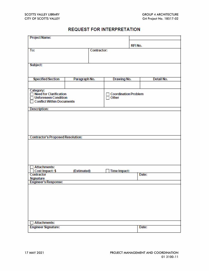
1.7 REQUESTS FOR INTERPRETATION (RFIS)
A. General: Immediately on discovery of the need for additional information or interpretation
of the Contract Documents, Contractor shall prepare and submit an RFI in the form
specified.
1. City Representative will return RFIs submitted to City Representative by other entities
controlled by Contractor with no response.
2. Coordinate and submit RFIs in a prompt manner so as to avoid delays in Contractor's
Work or Work of Subcontractors.
3. Submit one item for each RFI number.
B. Content of the RFI: Include a detailed, legible description of item needing information or
interpretation and the following:
1. Project name.
2. Project number.
3. Date.
4. Name of Contractor.
5. Name of City Representative.
6. RFI number, numbered sequentially.
7. RFI subject.
8. Specification Section number and title and related paragraphs, as appropriate.
9. Drawing number and detail references, as appropriate.
10. Field dimensions and conditions, as appropriate.

SCOTTS VALLEY LIBRARY GROUP 4 ARCHITECTURE
CITY OF SCOTTS VALLEY G4 Project No. 18517-02
17 MAY 2021 PROJECT MANAGEMENT AND COORDINATION
01 3100-5
11. Contractor's suggested resolution. If Contractor's solution(s) impacts the Contract Time
or the Contract Sum, Contractor shall state impact in the RFI.
12. Contractor's signature.
13. Attachments: Include sketches, descriptions, measurements, Product Data, Shop
Drawings, coordination drawings, and other information necessary to fully describe
items needing interpretation.
a. Include dimensions, thicknesses, structural grid references, and details of affected
materials, assemblies, and attachments on attached sketches.
b. Photographs shall not be accepted as a substitute for Engineering sketches.
Photographs may be submitted as supplements to properly prepared sketches and
coordination drawings.
C. RFI Forms: Software-generated form acceptable to City Representative.
1. Attachments shall be electronic files in Adobe Acrobat PDF format.
D. City Representative Action: City Representative will review each RFI, determine action
required, and respond. Allow ten (10) calendar days for City Representative’s response for
each RFI. RFIs received by City Representative after 1:00 p.m. will be considered as
received the following Working day.
1. The types of RFIs listed below will be returned without action. The RFI process is not
the proper mechanism to address such topics. Submit requests under appropriate
procedures outlined in Contract Document.
a. Requests for approval of submittals.
b. Requests for approval of substitutions.
c. Requests for approval of Contractor's means and methods.
d. Requests for coordination information already indicated in the Contract Documents.
e. Requests for adjustments in the Contract Time or the Contract Sum.
f. Requests for interpretation of City Representative’s actions on submittals.
g. Incomplete RFIs or inaccurately prepared RFIs.
2. City Representative’s action may include a request for additional information, in which
case City Representative’s time for response will date from time of receipt of additional
information.
3. City Representative’s action on RFIs that may result in a change to the Contract Time or
the Contract Sum may be eligible for Contractor to submit Change Proposal according
to Contract Documents.
a. If Contractor believes the RFI response warrants change in the Contract Time or the
Contract Sum, notify City Representative in writing within seven calendar days of
receipt of the RFI response.
4. Name and address of City Representative.
5. Date City Representative’s response was received.
E. On receipt of City Representative’s action, update the RFI log and immediately distribute
the RFI response to affected parties. Review response and notify Engineer within eight
calendar days if Contractor disagrees with response.
1. Identification of related Minor Change in the Work, Construction Change Directive, and
Proposal Request, as appropriate.
2. Identification of related Field Order, Work Change Directive, and Proposal Request, as
appropriate.
F. Upon completion of Project, submit three complete archive copies of Project’s Web site
files to City Representative in a digital storage format acceptable to the City Representative.

SCOTTS VALLEY LIBRARY GROUP 4 ARCHITECTURE
CITY OF SCOTTS VALLEY G4 Project No. 18517-02
17 MAY 2021 PROJECT MANAGEMENT AND COORDINATION
01 3100-6
G. Contractor, Subcontractors, and other parties granted access by the Contractor to Project’s
website shall execute a data licensing agreement in the form of an Agreement acceptable to
the City Representative.
1.8 PROJECT MEETINGS
A. General: Contractor will schedule and conduct basic meetings and conferences at Project
site, unless otherwise indicated.
1. Attendees: Entity responsible for conducting meeting shall inform participants and
others involved, and individuals whose presence is required, of date and time of each
meeting.
2. Agenda: Entity responsible for conducting meeting shall prepare and distribute the
meeting agenda.
3. Minutes: Entity responsible for conducting meeting shall record significant discussions
and agreements achieved, and distribute the meeting minutes to everyone concerned,
within seven calendar days of the meeting.
B. Preconstruction Conference: City Representative shall schedule and conduct a
preconstruction conference before starting construction, at a time convenient to City
Representative, but no later than fifteen calendar days after execution of the Agreement.
1. Conduct the conference to review responsibilities and personnel assignments.
2. Attendees: City Representative; Contractor and its superintendent; major
Subcontractors; suppliers; and other concerned parties shall attend the conference.
Participants at the conference shall be familiar with Project and authorized to conclude
matters relating to the Work.
3. Agenda: Discuss items of significance that could affect progress, including the
following:
a. Tentative construction schedules, including overall and rolling schedules
b. Phasing.
c. Critical Work sequencing and long-lead items.
d. Designation of key personnel and their duties.
e. Lines of communications.
f. Procedures for processing field decisions and Change Orders.
g. Procedures for RFIs.
h. Procedures for testing and inspecting.
i. Procedures for processing Applications for Payment.
j. Submittal procedures.
k. Preparation of record documents.
l. Use of the premises.
m. Work restrictions.
n. Working hours.
o. City's occupancy requirements.
p. Responsibility for temporary facilities and controls.
q. Procedures for disruptions and shutdowns.
r. Construction waste management and recycling.
s. Parking availability.
t. Office, Work, and storage areas.
u. Equipment deliveries and priorities.
v. Labor law, including payment and reporting requirements.

SCOTTS VALLEY LIBRARY GROUP 4 ARCHITECTURE
CITY OF SCOTTS VALLEY G4 Project No. 18517-02
17 MAY 2021 PROJECT MANAGEMENT AND COORDINATION
01 3100-7
4. Minutes: Entity responsible for conducting meeting will record and distribute meeting
minutes.
C. Pre-installation Conferences: Contractor shall conduct a pre-installation conference at
Project site before each construction activity that requires coordination with other
contractors.
1. Attendees: Installer and representatives of manufacturers and fabricators involved in or
affected by the installation and its coordination or integration with other materials and
installations that have preceded or will follow, shall attend the meeting.
a. Advise the following of scheduled meeting dates:
1) City Representative
2. Agenda: Review progress of other construction activities and preparations for the
particular activity under consideration, including requirements for the following:
a. Contract Documents.
b. Options.
c. Related RFIs.
d. Related Change Orders.
e. Purchases.
f. Deliveries.
g. Submittals.
h. Possible conflicts.
i. Compatibility problems.
j. Time schedules.
k. Weather limitations.
l. Manufacturer's written recommendations.
m. Warranty requirements.
n. Compatibility of materials.
o. Acceptability of substrates.
p. Temporary facilities and controls.
q. Space and access limitations.
r. Regulations of authorities having jurisdiction.
s. Testing and inspecting requirements.
t. Installation procedures.
u. Coordination with other Work.
v. Required performance results.
w. Protection of adjacent Work.
x. Protection of construction and personnel.
3. Record significant conference discussions, agreements, and disagreements, including
required corrective measures and actions.
4. Reporting: Distribute minutes of the meeting to each party present and to other parties
requiring information.
5. Do not proceed with installation if the conference cannot be successfully concluded.
Initiate whatever actions are necessary to resolve impediments to performance of the
Work and reconvene the conference at earliest feasible date.
D. Project Closeout Conference: The Project closeout conference shall review requirements
and responsibilities related to Project closeout.

SCOTTS VALLEY LIBRARY GROUP 4 ARCHITECTURE
CITY OF SCOTTS VALLEY G4 Project No. 18517-02
17 MAY 2021 PROJECT MANAGEMENT AND COORDINATION
01 3100-8
1. If not conducted as part of a normally scheduled job progress meeting, City
Representative shall schedule and conduct a Project closeout conference, at a time
convenient to City Representative and Contractor, but no later than thirty calendar days
prior to the scheduled date of Project Completion.
2. Attendees: Authorized representatives of City, Contractor and its superintendent; major
Subcontractors; suppliers; and other concerned parties shall attend the meeting.
Participants at the meeting shall be familiar with Project and authorized to conclude
matters relating to the Work.
3. Agenda: Discuss items of significance that could affect or delay Project closeout,
including the following:
a. Preparation of record documents.
b. Procedures required prior to inspection for Project Completion and for final
inspection for acceptance.
c. Submittal of written warranties.
d. Requirements for completing sustainable design documentation.
e. Requirements for preparing operations and maintenance data.
f. Requirements for delivery of material samples, attic stock, and spare parts.
g. Requirements for demonstration and training.
h. Preparation of Contractor's punch list.
i. Procedures for processing Applications for Payment at Project Completion and for
final payment.
j. Submittal procedures.
k. Coordination of separate Contracts.
l. Requirements for completing sustainable design documentation.
m. City's partial occupancy requirements.
n. Installation of City's furniture, fixtures, and equipment.
o. Responsibility for removing temporary facilities and controls.
4. Minutes: Entity conducting meeting shall record and distribute meeting minutes.
E. Progress Meetings: Contractor shall conduct progress meetings at weekly intervals.
1. Coordinate preparation of payment requests with dates of meetings.
2. Attendees: In addition to representatives of City, each Contractor, Subcontractor,
supplier, and other entity concerned with current progress or involved in planning,
coordination, or performance of future activities shall be represented at these meetings.
All participants at the meeting shall be familiar with Project and authorized to conclude
matters relating to the Work.
3. Agenda: Review and correct or approve minutes of previous progress meeting. Review
other items of significance that could affect progress. Include topics for discussion as
appropriate to status of Project.
a. Contractor's Construction Schedule: Review progress since the last meeting.
Determine whether each activity is on time, ahead of schedule, or behind schedule,
in relation to Contractor's construction schedule. Determine how construction behind
schedule shall be expedited; secure commitments from parties involved to do so.
Discuss whether schedule revisions are required to ensure that current and
subsequent activities shall be completed within the Contract Time.
1) Review schedule for next period.
b. Review present and future needs of each entity present, including the following:

SCOTTS VALLEY LIBRARY GROUP 4 ARCHITECTURE
CITY OF SCOTTS VALLEY G4 Project No. 18517-02
17 MAY 2021 PROJECT MANAGEMENT AND COORDINATION
01 3100-9
1) Interface requirements.
2) Sequence of operations.
3) Status of submittals.
4) Deliveries.
5) Off-site fabrication.
6) Access.
7) Site utilization.
8) Temporary facilities and controls.
9) Progress cleaning.
10) Quality and Work standards.
11) Status of correction of deficient items.
12) Field observations.
13) Status of RFIs.
14) Status of proposal requests.
15) Pending changes.
16) Status of Change Orders.
17) Pending claims and disputes.
18) Documentation of information for payment requests.
4. Minutes: Entity responsible for conducting the meeting will record and distribute the
meeting minutes to each party present and to parties requiring information.
a. Schedule Updating: Contractor shall revise construction schedule after each progress
meeting where revisions to the schedule have been made or recognized. Contractor
shall provide revised schedule to reporting entity so that it may be issued
concurrently with the report of each meeting.
F. Coordination Meetings: Project coordination meetings are in addition to specific meetings
held for other purposes, such as progress meetings and pre-installation conferences.
1. Contractor shall conduct Project coordination meetings at weekly intervals or as needed.
2. Attendees: In addition to representatives of City, each Contractor, Subcontractor,
supplier, and other entity concerned with current progress or involved in planning,
coordination, or performance of future activities shall be represented at these meetings.
All participants at the meetings shall be familiar with Project and authorized to conclude
matters relating to the Work.
3. Agenda: Review and correct or approve minutes of the previous coordination meeting.
Review other items of significance that could affect progress. Include topics for
discussion as appropriate to status of Project.
a. Combined Contractor's Construction Schedule: Review progress since the last
coordination meeting. Determine whether each Contract is on time, ahead of
schedule, or behind schedule, in relation to combined Contractor's construction
schedule. Determine how construction behind schedule shall be expedited; secure
commitments from parties involved to do so. Discuss whether schedule revisions are
required to ensure that current and subsequent activities shall be completed within
the Contract Time.
b. Schedule Updating: Revise combined Contractor's construction schedule after each
coordination meeting where revisions to the schedule have been made or recognized.
Issue revised schedule concurrently with report of each meeting.
c. Review present and future needs of each Contractor present, including the following:

SCOTTS VALLEY LIBRARY GROUP 4 ARCHITECTURE
CITY OF SCOTTS VALLEY G4 Project No. 18517-02
17 MAY 2021 PROJECT MANAGEMENT AND COORDINATION
01 3100-10
1) Interface requirements.
2) Sequence of operations.
3) Status of submittals.
4) Deliveries.
5) Off-site fabrication.
6) Access.
7) Site utilization.
8) Temporary facilities and controls.
9) Work hours.
10) Hazards and risks.
11) Progress cleaning.
12) Quality and Work standards.
13) Change Orders.
4. Reporting: Record meeting results and distribute copies to everyone in attendance and to
others affected by decisions or actions resulting from each meeting.
PART 2 - PRODUCTS (NOT USED)
PART 3 - EXECUTION (NOT USED)
END OF SECTION
SCOTTS VALLEY LIBRARY GROUP 4 ARCHITECTURE
CITY OF SCOTTS VALLEY G4 Project No. 18517-02
17 MAY 2021 PROJECT MANAGEMENT AND COORDINATION
01 3100-11

SCOTTS VALLEY LIBRARY GROUP 4 ARCHITECTURE
CITY OF SCOTTS VALLEY G4 Project No. 18517-02
17 MAY 2021 PROJECT MANAGEMENT AND COORDINATION
01 3100-12
This Page Intentionally Left Blank
SCOTTS VALLEY LIBRARY GROUP 4 ARCHITECTURE
CITY OF SCOTTS VALLEY G4 Project No. 18517-02
12 MAY 2021 QUALITY REQUIREMENTS
01 4000-1
SECTION 01 4000 QUALITY REQUIREMENTS
PART 1 GENERAL
1.1 SECTION INCLUDES
A. References and standards.
B. Quality assurance submittals.
C. Mock-ups.
D. Control of installation.
E. Inspection services.
F. Manufacturers' field services.
1.2 RELATED REQUIREMENTS
A. Section 01 60 00 - Product Requirements: Requirements for material and product quality.
1.3 REFERENCE STANDARDS
A. ASTM C1021 - Standard Practice for Laboratories Engaged in Testing of Building
Sealants; 2008 (Reapproved 2014).
B. ASTM C1077 - Standard Practice for Laboratories Testing Concrete and Concrete
Aggregates for Use in Construction and Criteria for Laboratory Evaluation; 2014.
C. ASTM C1093 - Standard Practice for Accreditation of Testing Agencies for Masonry;
2013.
D. ASTM D3740 - Standard Practice for Minimum Requirements for Agencies Engaged in
the Testing and/or Inspection of Soil and Rock as Used in Engineering Design and
Construction; 2012a.
E. ASTM E329 - Standard Specification for Agencies Engaged in Construction Inspection,
Testing, or Special Inspection; 2014a.
F. ASTM E543 - Standard Specification for Agencies Performing Nondestructive Testing;
2013.
G. IAS AC89 - Accreditation Criteria for Testing Laboratories; 2010.
H. Title 24 CCR, Part 1: Continuous inspection, Section 4-333
I. 2016 CBC Chapter 17 - California Building Code Structural Testing and Inspection
1.4 SUBMITTALS
A. Testing Agency Qualifications: As approved by the City.
B. Test Reports: After each test/inspection, promptly submit two copies of report to
Engineer and to Contractor.
1. Include:
a. Date issued.
b. Project title and number.
c. Name of inspector.
d. Date and time of sampling or inspection.
e. Identification of product and specifications section.
f. Location in the Project.
g. Type of test/inspection.

SCOTTS VALLEY LIBRARY GROUP 4 ARCHITECTURE
CITY OF SCOTTS VALLEY G4 Project No. 18517-02
12 MAY 2021 QUALITY REQUIREMENTS
01 4000-2
h. Date of test/inspection.
i. Results of test/inspection.
j. Conformance with Contract Documents.
k. When requested by City Representative , provide interpretation of results.
2. Test report submittals are for City Representative’s knowledge as Contract
administrator for the limited purpose of assessing conformance with information given
and the design concept expressed in the Contract documents, or for City
Representative’s information.
C. Certificates: When specified in individual specification sections, submit certification by
the manufacturer and Contractor or installation/application subcontractor to City
Representative , in quantities specified for Product Data.
1. Indicate material or product conforms to or exceeds specified requirements. Submit
supporting reference data, affidavits, and certifications as appropriate.
2. Certificates may be recent or previous test results on material or product, but must be
acceptable to City Representative .
D. Manufacturer's Instructions: When specified in individual specification sections, submit
printed instructions for delivery, storage, assembly, installation, start-up, adjusting, and
finishing, for the City's information. Indicate special procedures, perimeter conditions
requiring special attention, and special environmental criteria required for application or
installation.
E. Manufacturer's Field Reports: Submit reports for City Representative benefit as Contract
administrator for City.
1. Submit report in duplicate within 30 calendar days of observation to Engineer for
information.
2. Submit for information for the limited purpose of assessing conformance with
information given and the design concept expressed in the Contract documents.
1.5 REFERENCES AND STANDARDS
A. For products and Workmanship specified by reference to a document or documents not
included in the Specifications, also referred to as reference standards, comply with
requirements of the standard, except when more rigid requirements are specified or are
required by applicable codes.
B. Conform to reference standard of date of issue current on date of Contract Documents,
except where a specific date is established by applicable code.
C. Obtain copies of standards where required by product specification sections.
D. Maintain copy at Project site during submittals, planning, and progress of the specific
Work, until Substantial Completion.
E. Should specified reference standards conflict with Contract Documents, request
clarification from City Representative before proceeding.
F. Neither the Contractual relationships, duties, or responsibilities of the parties in Contract
nor those of City Representative shall be altered from the Contract Documents by mention
or inference otherwise in any reference document.
1.6 TESTING AND INSPECTION AGENCIES
A. City will employ and pay for services of an independent testing agency to perform special
inspections required by the California Building Code, Part 2, Volume 2, Chapter 17

SCOTTS VALLEY LIBRARY GROUP 4 ARCHITECTURE
CITY OF SCOTTS VALLEY G4 Project No. 18517-02
12 MAY 2021 QUALITY REQUIREMENTS
01 4000-3
Structural Tests and Special Inspections. All other testing and inspection shall be provided
by Contractor unless otherwise noted.
B. Employment of agency in no way relieves Contractor of obligation to perform Work in
accordance with requirements of Contract Documents.
PART 2 PRODUCTS - NOT USED
PART 3 EXECUTION
3.1 CONTROL OF INSTALLATION
A. Monitor quality control over suppliers, manufacturers, products, services, site conditions,
and Workmanship, to produce Work of specified quality.
B. Comply with manufacturers' instructions, including each step in sequence.
C. Should manufacturers' instructions conflict with Contract Documents, request clarification
from Engineer before proceeding.
D. Comply with specified standards as minimum quality for the Work except where more
stringent tolerances, codes, or specified requirements indicate higher standards or more
precise Workmanship.
E. Have Work performed by persons qualified to produce required and specified quality.
F. Verify that field measurements are as indicated on shop drawings or as instructed by the
manufacturer.
G. Secure products in place with positive anchorage devices designed and sized to withstand
stresses, vibration, physical distortion, and disfigurement.
3.2 MOCK-UPS
A. Tests shall be performed under provisions identified in this section and identified in the
respective product specification sections.
B. Assemble and erect specified items with specified attachment and anchorage devices,
flashings, seals, and finishes.
C. Accepted mock-ups shall be a comparison standard for the remaining Work.
D. Where mock-up has been accepted by City Representative and is specified in product
specification sections to be removed, protect mock-up throughout construction, remove
mock-up and clear area when directed to do so by City Representative .
3.3 TESTING AND INSPECTION
A. Testing Agency Duties:
1. Test samples of mixes submitted by Contractor.
2. Provide qualified personnel at site. Cooperate with City Representative and
Contractor in performance of services.
3. Perform specified sampling and testing of products in accordance with specified
standards.
4. Ascertain compliance of materials and mixes with requirements of Contract
Documents.
5. Promptly notify City Representative and Contractor of observed irregularities or non-
conformance of Work or products.
6. Perform additional tests and inspections required by City Representative .

SCOTTS VALLEY LIBRARY GROUP 4 ARCHITECTURE
CITY OF SCOTTS VALLEY G4 Project No. 18517-02
12 MAY 2021 QUALITY REQUIREMENTS
01 4000-4
7. Attend preconstruction meetings and progress meetings.
8. Submit reports of all tests/inspections specified.
B. Limits on Testing/Inspection Agency Authority:
1. Agency may not release, revoke, alter, or enlarge on requirements of Contract
Documents.
2. Agency may not approve or accept any portion of the Work.
3. Agency may not assume any duties of Contractor.
4. Agency may not stop the Work without authorization from City.
C. Contractor Responsibilities:
1. Deliver to Agency at designated location, adequate samples of materials proposed to
be used that require testing, along with proposed mix designs.
2. Cooperate with laboratory personnel, and provide access to the Work and to
manufacturers' facilities.
3. Provide incidental labor and facilities:
a. To provide access to Work to be tested/inspected.
b. To obtain and handle samples at the site or at source of Products to be
tested/inspected.
c. To facilitate tests/inspections.
d. To provide storage and curing of test samples.
4. Notify City Representative and laboratory 24 hours prior to expected time for
operations requiring testing/inspection services.
5. Employ services of an independent qualified testing laboratory and pay for additional
samples, tests, and inspections required by Contractor beyond specified requirements.
6. Arrange with City's agency and pay for additional samples, tests, and inspections
required by Contractor beyond specified requirements.
D. Re-testing required because of non-conformance to specified requirements shall be
performed by the same agency on instructions by City Representative .
E. Re-testing required because of non-conformance to specified requirements shall be paid
for by Contractor.
3.4 MANUFACTURERS' FIELD SERVICES
A. Where specified in individual specification sections require material or product suppliers
or manufacturers to provide qualified staff personnel to observe site conditions, conditions
of surfaces and installation, quality of Workmanship, start-up of equipment, test, adjust
and balance of equipment as applicable, and to initiate instructions when necessary, include
as part of Work.
B. Report observations and site decisions or instructions given to applicators or installers that
are supplemental or contrary to manufacturers' written instructions.
3.5 DEFECT ASSESSMENT
A. Replace Work or portions of the Work not conforming to specified requirements.

SCOTTS VALLEY LIBRARY GROUP 4 ARCHITECTURE
CITY OF SCOTTS VALLEY G4 Project No. 18517-02
12 MAY 2021 QUALITY REQUIREMENTS
01 4000-5
B. If, in the opinion of City Representative , it is not practical to remove and replace the
Work, City Representative will direct an appropriate remedy or adjust payment.
END OF SECTION

SCOTTS VALLEY LIBRARY GROUP 4 ARCHITECTURE
CITY OF SCOTTS VALLEY G4 Project No. 18517-02
12 MAY 2021 QUALITY REQUIREMENTS
01 4000-6
This Page Intentionally Left Blank

SCOTTS VALLEY LIBRARY GROUP 4 ARCHITECTURE
CITY OF SCOTTS VALLEY G4 Project No. 18517-02
12 MAY 2021 TEMPORARY FACILITIES AND CONTROLS
01 5000-1
SECTION 01 5000 TEMPORARY FACILITIES AND CONTROLS
PART 1 GENERAL
1.1 SECTION INCLUDES
A. Temporary utilities.
B. Temporary telecommunications services.
C. Temporary sanitary facilities.
D. Temporary Controls: Barriers, enclosures, and fencing.
E. Security requirements.
F. Vehicular access and parking.
G. Waste removal facilities and services.
H. Field offices.
1.2 RELATED REQUIREMENTS
A. n/a
1.3 TEMPORARY UTILITIES
A. Provide and pay for all electrical power, lighting, water, heating and cooling, and
ventilation required for construction purposes.
B. Use trigger-operated nozzles for water hoses, to avoid waste of water.
1.4 TELECOMMUNICATIONS SERVICES
A. Provide equipment and connections for Contractor’s office space.
B. Telecommunications services onsite shall include:
1. Internet Connection: High speed data connection adequate to serve Project needs.
2. Ability to run virtual meetings.
1.5 TEMPORARY SANITARY FACILITIES
A. Provide and maintain required facilities and enclosures.
B. Provide at time of Project mobilization.
C. Maintain daily in clean and sanitary condition.
D. At end of construction, return facilities to same or better condition as originally found.
1.6 BARRIERS
A. Provide barriers to prevent unauthorized entry to construction areas, to prevent access to
areas that could be hazardous to Workers or the public and to protect existing facilities and
adjacent properties from damage from construction operations and demolition.
B. Provide barricades and covered walkways required by governing authorities for public
rights-of-way and for public access to existing building.
C. Provide protection for landscape plantings designated to remain. Replace damaged plants.
D. Protect non-owned vehicular traffic, stored materials, site, and structures from damage.
E. Traffic Controls: As needed per local authorities.
SCOTTS VALLEY LIBRARY GROUP 4 ARCHITECTURE
CITY OF SCOTTS VALLEY G4 Project No. 18517-02
12 MAY 2021 TEMPORARY FACILITIES AND CONTROLS
01 5000-2
1.7 FENCING
A. Contractor has the option to provide 6 foot (1.8 m) high fence around the building site;
equip with vehicular and pedestrian gates with locks. Provide access to building for City
and the building tenants.
B. Coordinate fencing with City Representative.
1.8 EXTERIOR ENCLOSURES
A. Provide temporary weather tight closure of exterior openings to accommodate acceptable
Working conditions and protection for Products, to allow for temporary heating and
maintenance of required ambient temperatures identified in individual specification
sections, and to prevent entry of unauthorized persons. Provide access doors with self-
closing hardware and locks.
1.9 SECURITY
A. Provide security and facilities to protect Work and City's operations from unauthorized
entry, vandalism, or theft. Contractor is responsible for security.
1.10 VEHICULAR ACCESS AND PARKING
A. Comply with regulations relating to use of streets and sidewalks, access to emergency
facilities, and access for emergency vehicles.
B. Coordinate access and haul routes with governing authorities and City Representative.
C. Provide and maintain access to fire hydrants, free of obstructions.
D. Provide means of removing mud from vehicle wheels before entering streets.
E. Provide dust-control treatment that is nonpolluting and non-tracking. Reapply treatment as
required to minimize dust.
F. Provide safe vehicular access for public in parking lot.
G. Coordinate parking for subcontractors and vendors with City Representative.
1.11 WASTE REMOVAL
A. See Section 01 7419 - Construction Waste Management and Disposal, for additional
requirements.
B. Provide waste removal facilities and services as required to maintain the site in clean and
orderly condition.
C. Provide containers with lids. Remove trash from site weekly.
D. If materials to be recycled or re-used on the Project must be stored on-site, provide suitable
non-combustible containers; locate containers holding flammable material outside the
structure unless otherwise approved by the authorities having jurisdiction.
1.12 USE OF BUILDING
A. Contractor cannot occupy or otherwise utilize areas not in the project scope without
permission from the City Representative
1.13 FIELD OFFICES
Contractor has the option to provide a field office onsite for their use at no additional cost to
the Owner. Coordinate location with City Representative.

SCOTTS VALLEY LIBRARY GROUP 4 ARCHITECTURE
CITY OF SCOTTS VALLEY G4 Project No. 18517-02
12 MAY 2021 TEMPORARY FACILITIES AND CONTROLS
01 5000-3
1.14 REMOVAL OF UTILITIES, FACILITIES, AND CONTROLS
A. Remove temporary utilities, equipment, facilities, materials, prior to Final Application for
Payment inspection.
B. Clean and repair damage caused by installation or use of temporary Work.
C. Restore existing facilities used during construction to original condition.
D. Restore new permanent facilities used during construction to specified condition.
1.15 POLLUTANT CONTROL
A. Temporary Ventilation: The permanent HVAC system shall only be used during
construction if necessary to condition the building or areas of addition or alteration within
the required temperature range for material and equipment installation. If the HVAC
system is used during construction, use return air filters with a Minimum Efficiency
Reporting Value (MERV) of 8, based on ASHRAE 52.2-1999, or an average efficiency of
30% based on ASHRAQE 52.1-1992. Replace all filters immediately prior to occupancy,
or, if the building is occupied during alteration, at the conclusion of construction. B. Covering of duct openings and protection of mechanical equipment during construction:
At the time of rough installation and during storage on the construction site until final
startup of the heating, cooling and ventilation equipment, all duct and other related air
distribution component openings shall be covered with tape, plastic, sheetmetal or other
methods acceptable to the enforcing agency to reduce the amount of dust, water and debris
which may enter the system.
PART 2 PRODUCTS - NOT USED
PART 3 EXECUTION - NOT USED
END OF SECTION

SCOTTS VALLEY LIBRARY GROUP 4 ARCHITECTURE
CITY OF SCOTTS VALLEY G4 Project No. 18517-02
12 MAY 2021 TEMPORARY FACILITIES AND CONTROLS
01 5000-4
This Page Intentionally Left Blank
SCOTTS VALLEY LIBRARY GROUP 4 ARCHITECTURE CITY OF SCOTTS VALLEY G4 Project No. 18517-02
TEMPORARY TREE AND PLANT PROTECTION 28 JUNE 2021 01 5639-1
SECTION 01 5639 - TEMPORARY TREE AND PLANT PROTECTION
PART 1 - GENERAL
1.1 SUMMARY
A. Section Includes:1. Temporary protection of existing trees.2. Excavation and grading within root zones of existing trees to remain.3. Prohibited construction activities under trees to remain.4. Incidental extra work.5. Dust removal from foliage of existing trees to remain within project site and affected
existing trees adjacent to the project site.6. Pruning of existing trees to remain.7. Debris removal.8. Protective chain-link fence relocation or removal.9. Preventing spread of sudden oak death, pitch canker, noxious weeds.
B. Related Sections:1. Section 31 2200 - Earthwork and Grading.2. Section 32 9113 - Planting Soil Preparation.3. Section 32 9221 - Planting Area Finish Grading.4. Section 32 8400 - Planting Irrigation.5. Section 32 9300 - Planting Materials.6. Division 2 – Existing Conditions.
1.2 REFERENCES
A. Published specifications, standards, tests, or recommended methods of trade, industry, orgovernmental organizations apply to Work of this Section where cited by abbreviations notedbelow (latest editions apply).
B. American National Standards Institute (ANSI):1. ANSI A300 Trees, Shrubs, and Other Woody Plant Maintenance - Standard Practice.2. ANSI Section 133.1 “Tree Trimming and Removal”.
C. University of California, Division of Agriculture and Natural Resources, “Pruning LandscapeTrees”, 1981, publication #2574.
D. American Society for Testing and Materials (ASTM):1. ASTM D1557 - Test Method for Laboratory Compaction Characteristics of Soil Using
Modified Effort.
E. International Society of Arboriculture (ISA):1. Guide for Establishing Values of Trees and Other Plants.
F. National Arborist Association

SCOTTS VALLEY LIBRARY GROUP 4 ARCHITECTURE CITY OF SCOTTS VALLEY G4 Project No. 18517-02
TEMPORARY TREE AND PLANT PROTECTION 01 5639-2 28 JUNE 2021
1.3 DEFINITIONS
A. Acceptance, Acceptable, or Accepted: Acceptance by the Owner’s Representative in writing.
B. Landscape Architect: Landscape Architect employed by the Owner to provide professionallandscape architectural services for the Project.
C. Drip Line: A line straight down from outermost limits of plant canopy branching.
D. Excessive Compaction of Existing Soil: Planting area soil compaction greater than drydensity of existing soil prior to commencement of Work of this Section, as determined byASTM D1557.
E. Injury: Any bruising, scarring, tearing, or breaking of roots, branches, or trunk.
F. Tree-protection Zone: The defined area within which potentially injurious activities areprohibited or restricted to prevent or minimize damage to protected trees during theconstruction period.
G. Undue Stress: A stressed condition of a tree’s health caused by the Contractor’s failure tomeet the requirements of this Section.
H. Critical Root Zone (CRZ): The area of soil around a tree trunk where the roots that providestability and the uptake of minerals and water required for tree survival are located (reference– ANSI A300 BMP.
1.4 SUBMITTALS
A. Schedule for Tree Removal and Protection Fencing Installation:1. Submit schedule indicating timeline for tree removal and protection fencing
installation.2. Sample of proposed wood mulch material. 1 quart.
1.5 QUALITY ASSURANCE
A. Pre-installation Meeting:1. Prior to demolition and other Work, organize and schedule a field meeting with the
Owner’s Representative to review the requirements of this Section, Work to be donewithin tree protection zones, which existing trees are to remain, tree branches that needto be removed, limits of tree protection zones, protection-fence locations, and todocument the condition of existing trees to remain.a. Adjustments to the type and extent of the protection shall be addressed at the
time of the meeting.b. Contractor shall coordinate the meeting.
2. For documentation purposes, photograph condition of areas reviewed, including treesto remain.
3. Keep photographs on file for reference by the Owner’s Representative.

SCOTTS VALLEY LIBRARY GROUP 4 ARCHITECTURE CITY OF SCOTTS VALLEY G4 Project No. 18517-02
TEMPORARY TREE AND PLANT PROTECTION 28 JUNE 2021 01 5639-3
1.6 PROJECT CONDITIONS
A. Existing Conditions:1. Prior to Work commencement visit the Project site and determine conditions under
which work will be performed.2. Do not begin work until meeting with the Owner’s Representative on the Project site
to confirm tree locations and work to be performed. Prior to Work commencementreview and clearly mark in field horizontal locations and depths of existing publicunderground utilities and structures with respective utility companies.
3. Prior to Work commencement review and clearly mark in field horizontal locationsand depths of existing private underground utilities, drains, and structures with theOwner’s Representative.
4. Prior to Work commencement and after reviewing the Owner’s record irrigationdocuments, review with the Owner’s Representative and clearly mark in field locationsof heads, valve boxes and other underground equipment, materials and structures toremain.
B. Protection: Provide adequate protection of existing trees against damage from constructionoperations.1. Tree protection must comprise of a six-foot chain-link fence.2. Locate fence at or beyond tree drip lines (outside edge of tree branching) of items so
protected, or as indicated on tree work drawing.3. Especially protect roots, trunk, and foliage of existing trees.4. Do not permit the following activities to occur within defined Tree Protection Zones:
a. Using trees as support posts, power poles, sign posts, or anchorage for ropes,guy wires and power lines or other similar functions.
b. Poisoning items by disposing of paint, petroleum products, dirty water or otherdeleterious materials on or around trees.
c. Compaction of tree root area by moving trucks, grading, machines, storage ofequipment, gravel, earthfill, supplies, etc.; within the tree drip line (outside edgeof tree branching).
d. Damage to trunk or limbs caused by maneuvering vehicles or stacking materialand equipment too close to them.
1.7 DAMAGES
A. Existing Trees to Remain Which Will Most Likely Survive Injury or Undue Stress:1. If it is determined by the Arborist that injury or undue stress has occurred to a tree or
its root zone that could affect a tree’s health, the Contractor shall pay for costs of labor,materials, fees required by the Arborist to treat the tree in an attempt to bring tree backto the state of health and vigor the tree was in prior to injury or undue stress.
2. If, after two years from date of notice of Substantial Completion, it is determined bythe Arborist that this treatment has not been successful in bringing the tree back to thestate of health and vigor it was in prior to injury or undue stress, remove and replacetree with a tree matching in size and variety using an installer designated by theOwner’s Representative.
3. If an acceptable replacement tree is not available or if for any reason a replacementtree is not desired by the Owner, pay damages to the Owner for the value of the tree asassessed by the tree value formula in the ISA Guide for Establishing Value of Treesand Other Plants.

SCOTTS VALLEY LIBRARY GROUP 4 ARCHITECTURE CITY OF SCOTTS VALLEY G4 Project No. 18517-02
TEMPORARY TREE AND PLANT PROTECTION 01 5639-4 28 JUNE 2021
B. Existing Trees to Remain and Existing Trees to be Transplanted Which Will Most Likely NotSurvive Injury or Undue Stress:1. If a tree that is indicated to remain on the Drawings is removed or destroyed without
written approval from the Owner’s Representative, a tree is injured, or a tree is causedto be in a condition of irreversible undue stress as determined by the Arborist, removeand replace tree with a tree matching in size and variety using an installer designatedby the Owner.
2. If an acceptable replacement tree is not available, or if for any reason a replacementtree is not desired by the Owner, pay damages to the Owner for the value of the tree asassessed by the tree value formula in the ISA Guide for Establishing Value of Treesand Other Plants or in accordance with the table below, whichever is greater.
C. Compensation for Planting Loss: Any tree to remain, damaged or destroyed due to theContractor's negligence or failure to provide adequate protection shall be compensated for inaccordance with the following schedule of values, using "tree-caliper" method (greatest trunkdiameter measured 30-inches above ground):1. For trees or shrubs with diameters up to and including 6 inches, actual cost of
replacement with items similar in species, size and shape, including:a. Actual cost of item boxed out of ground.b. Transportation or delivery of boxed item to the Project site.c. Planting and staking.d. Maintenance in watering, fertilizing, pruning, pest control and other care to
bring replacement to same general conditions as original item.2. For trunks up to:
Size (in inches) $ Amount 7 1,200.00 8 1,700.00 9 2,200.00 10 2,600.00 11 3,100.00 12 3,600.00 13 4,100.00 14 4,600.00 15 5,000.00 16 5,500.00 17 6,000.00 18 and over, add for each caliper inch: 600.00
D. Exceptions: Contractor will not be held responsible for damages due to neglect or abuse byothers, vandalism, and other causes outside the Contractor’s control.
PART 2 - PRODUCTS
2.1 MATERIALS
A. Water: Potable.

SCOTTS VALLEY LIBRARY GROUP 4 ARCHITECTURE CITY OF SCOTTS VALLEY G4 Project No. 18517-02
TEMPORARY TREE AND PLANT PROTECTION 28 JUNE 2021 01 5639-5
B. Wood Chip Mulch: Mulch material shall be as per Section 32 9300 if retained for finallandscape installation. Temporary mulch that is removed after construction shall be 2-inchmaximum, clean, unpainted, untreated wood chip or acceptable equivalent.
C. Fencing:1. 6-foot tall chain link fencing mounted on two-inch diameter galvanized iron posts,
driven into the ground to a depth of at least 2-feet at no more than 10-foot spacing.2. Self-supporting chain link fence panels, 6-foot tall, are acceptable on adjacent paved
areas, and/or as reviewed by the Owner’s Representative.3. Where tree trunks will be located within 5 feet of construction scaffolding, short
sections of plastic snow fence can be utilized for tree protection purposes. Install underthe supervision of the Owner’s Representative.
4. Laminated Tree Protection Zone Notices must be securely attached to TPZ Fences at20-foot intervals.
D. Temporary materials, new or used, that are adequate in capacity for the required usage, mustnot create unsafe conditions, and must not violate requirements of applicable Laws andRegulations, and shall be approved by the Owner’s Representative.
PART 3 - EXECUTION
3.1 EXAMINATION
A. General: Examine site and verify that conditions are suitable to receive Work, and that nodefects or errors are present which would cause defective installation of products or causelatent defects in workmanship and function.
B. Underground Utilities and Structures: Verify that the locations and depths of utilities,structures and other underground items have been clearly marked.
C. Notification of Unsuitable Conditions: Before proceeding with Work, notify the Owner’sDesignated Representative in writing of unsuitable conditions and conflicts.
D. Do not proceed until unsatisfactory conditions have been corrected.
E. Tree Identification: Verify that trees to remain and trees to be removed are adequately labeledin the drawings.1. Existing Trees: The existing trees to be preserved are the trees as shown on the
Drawings to remain. Verify exact location of existing trees in relation to the layout ofnew buildings before work begins.
2. Identification of trees to be removed or to remain that have not been so marked on theDrawings is subject to the approval of the Owner’s Representative.
3. No trees are to be removed without prior approval of the Owner’s Representative.
3.2 PREPARATION
A. Protection of Existing Conditions:1. Use every possible precaution to prevent damage to existing conditions to remain such
as structures, utilities, plant materials and paving on or adjacent to the site of the Work.
SCOTTS VALLEY LIBRARY GROUP 4 ARCHITECTURE CITY OF SCOTTS VALLEY G4 Project No. 18517-02
TEMPORARY TREE AND PLANT PROTECTION 01 5639-6 28 JUNE 2021
2. Provide protective mats, barricades, steel plates, fences or other barriers to protectexisting conditions to remain from damage during construction.
3. Use every possible precaution to prevent excessive compaction of planting area soilwithin or adjacent to the areas of Work.
4. Do not store materials or equipment, permit burning, or operate or park equipmentunder the branches of existing plants to remain.
5. Submit written notification of damaged existing conditions the Owner’sRepresentative immediately.
3.3 TREE PROTECTION WORK
A. Tree Protective Fencing:1. Provide fencing as indicated on the drawings and as called out for in this section.2. Install fencing under the supervision of the Owner’s Representative.3. Install protective fencing and plywood protection adjacent to tree areas and utilities
installation areas prior to commencing work in these locations.4. Relocation of protective fencing as a sequence of construction requires no additional
cost to the Owner. Refer to Section 01 5000 - Temporary Facilities and Controls.5. Tree Protection Zone Fencing must not be moved (or dismantled) during the
construction period, without first obtaining the written approval of the Owner’sRepresentative.
B. Excessive Soil Compaction:1. Prior to beginning work, spread a 6-inch depth of wood-chip mulch over the tree
protection zone areas and within canopy drip-line perimeters where constructionequipment and construction vehicles must operate within them.
2. Replace displaced mulch as soon as it is displaced.3. Maintain mulch layer in tree-protection zones until operation of construction
equipment and vehicles ceases.4. The Owner’s Representative must provide supervision whenever grading and
trenching work encroaches within the Critical Root Zone Areas of trees (as defined bythe canopy drip-line of the trunk.
C. Restrictions: The following activities must be excluded from defined Tree Protection Zones,as defined by the canopy drip-line perimeter or a multiple of the trunk diameter provided bythe Arborist:1. Parking of vehicles or equipment.2. Storage of materials, signs, tools, or refuse.3. Use of trees as support posts, power poles, sign posts or other functions.4. Dumping of toxic materials such as paint, petroleum products, non-potable water, and
other deleterious materials.5. Excessive water or heat from construction equipment or burning of trash under or near
trees.6. Excessive water, exhausts or drying resulting from dewatering or other operations.7. The pruning or alteration of trees without the approval of the Owner’s Representative
D. The Owner’s Representative must be contacted whenever roots exceeding 2 inches are foundduring grading and construction work.
SCOTTS VALLEY LIBRARY GROUP 4 ARCHITECTURE CITY OF SCOTTS VALLEY G4 Project No. 18517-02
TEMPORARY TREE AND PLANT PROTECTION 28 JUNE 2021 01 5639-7
3.4 IRRIGATION MODIFICATION TO MAINTAIN PROTECTED PLANT AREAS
A. Provide long-term temporary irrigation to fully cover areas within Tree Protection Zones andinstruct Owner’s Project Manager on controls for temporary irrigation systems.
B. Refer to the Drawings for modifications to the existing irrigation system which are necessaryto maintain uninterrupted irrigation to areas outside project limits which would otherwise beaffected by construction activities.
C. Irrigation modifications to maintain irrigation within Tree Protection Zones and affectedareas outside the project limits are to be accepted by Owner’s Representative prior to anydemolition or construction activities.
3.5 TREE PRUNING SPECIFICATIONS
A. Branches to Be Removed: The Owner’s Representative must approve all pruning workduring the project.1. Notify the Owner’s Representative when a tree limb is in conflict with the construction.
B. Branch Removal:1. Remove branches prior to commencement of Work and as needed during construction.2. Meet requirements of ANSI A300.
C. Specified pruning work shall meet the following criteria:1. Removal of dead branches .5 inch and over in diameter.2. Remove branches and branch stubs.3. Removal of all broken branches, all loose branches and other debris lodged in trees
with correct cuts that preserve the branch collar area4. Removal of undesirable sucker growth.5. Removal of all live branches which interfere with the tree's structural strength and
healthful development. These include:a. Remove crossing and abraded limbs and branches (the supported limb.)b. Remove structurally weak limbs and branches when pruning is not a practical
optionc. Limbs with twigs and foliage obstructing development of more important
branches.d. Prune to reduce weight in the ends of heavy and overextended limbs and
branches, as directed by the Owner’s Representative.
3.6 ROOT PRUNING
A. Avoid root cutting whenever possible within the Critical Root Zone Areas of trees to bepreserved on site so as to preserve the tree’s ability to absorb water and nutrients through itsroot zone and to ensure tree stability in the soil.
B. Notify The Owner’s Representative if root cutting becomes necessary.
C. Refer to 3.8 Excavation and Grading within Tree Protection Zones below.
D. Avoid tearing or ripping tree roots due to excavation activities.
SCOTTS VALLEY LIBRARY GROUP 4 ARCHITECTURE CITY OF SCOTTS VALLEY G4 Project No. 18517-02
TEMPORARY TREE AND PLANT PROTECTION 01 5639-8 28 JUNE 2021
1. Where root cutting is necessary, no roots are to be cut without prior approval of TheOwner’s Representative.
2. Where root cutting becomes necessary, all roots are to be clean cut with a saw, loppingshears or proper tree pruning device. Under no circumstance are tree roots to be leftsplintered or the ends shredded.
3. Drape 4 layers of burlap over the exposed faces of soil cuts located within the CriticalRoot Zones of trees for a period exceeding 48 hours (under the direction of the Owner’sRepresentative). Water the burlap on a daily basis until the face of the cut is backfilled.
3.7 REMOVING TREES
A. No trees are to be removed without prior approval of the Owner’s Representative.
B. "Removing Trees" shall be interpreted as removing tree to the ground level and reducing thestump a minimum of two (2) feet below grade, using a suitable mechanical stump chipper. Inorder to prevent damage to root systems of remaining adjacent trees, use of a tractor forreduction of stumpage will not be permitted. Trees which are to be removed are indicated onthe drawings. Take care to minimize root loss and damage concerning any adjacent trees thatare to be preserved.
C. Trees to Be Removed: Remove trees injured by construction operations or trees in a conditionof undue stress only as directed by the Owner’s Representative to be incapable of restorationto the state of health and vigor existing before construction commenced.
3.8 EXCAVATION AND GRADING WITHIN TREE PROTECTION ZONES ANDCRITICAL ROOT ZONE AREAS
A. Trenching:1. Excavate upper 3 feet of soil using an air spade or other method approved by the
Owner’s Representative so that roots over 1.5 inches in diameter will not be damaged.2. Do not cut or trench the Critical Root Zones of protected trees without first obtaining
approval in writing from the Owner’s Representative.3. Preserve significant roots wherever possible in excavations.
B. Treatment and Protection of Exposed Roots:1. Have the Arborist monitor trenching work and do work required to cut exposed roots
cleanly.2. Arborist must be on site at time of site disturbance and new construction within the
Critical Root Zone areas of protected trees (as defined by their canopy drip lines ortrunk diameters).
3. Do not allow exposed roots or exposed pruned root ends to dry out before permanentbackfill is placed.
4. Provide temporary soil cover over exposed roots and exposed pruned root ends, or packin wet peat moss or four layers of wet, untreated burlap.
5. Daily wet temporary cover uniformly with water until runoff occurs.6. Support and protect temporary soil cover, peat moss or burlap cover from damage until
exposed roots are permanently backfilled, or until tree is transplanted and permanentlybackfilled.
C. Raising Soil Level:
SCOTTS VALLEY LIBRARY GROUP 4 ARCHITECTURE CITY OF SCOTTS VALLEY G4 Project No. 18517-02
TEMPORARY TREE AND PLANT PROTECTION 28 JUNE 2021 01 5639-9
1. S oil placed on the surface around existing trees can create problems involving gaseousexchange in the root zone, crown rot and soil moisture. Soil aeration is a critical factor.Notify the Owner’s Representative of any grade changes within the Critical Root Zonesof protected trees (as defined by their canopy drip lines or trunk diameters.)
D. Lowering Soil Level:1. Removing soil from under a tree canopy can seriously damage roots and may even
impair the stability of the tree. Notify the Owner’s Representative of any soil workunder a tree.
3.9 DUST CONTROL AND DUST REMOVAL FROM PLANT FOLIAGE
A. Dust Control: Maintain dust control to keep dust occurrence at a bare minimum.
B. Dust Removal: Remove dust from the surfaces of foliage existing plants to remain within theProject area and adjacent to it via spraying with water as often as is required by the Owner’sRepresentative.
3.10 FIELD QUALITY CONTROL
A. Owner’s Representative’s Review and Direction:1. Schedule Owner’s Representative to monitor Work to be done within tree protection
zones.2. Provide Owner’s Representative a minimum seven days advance notice whenever
possible, requesting field visits.3. Keep Owner’s Representative updated with revised schedules for Work to be done
within tree protection zones.
3.11 CLEAN UP
A. Removal of Wood Chip Mulch: All wood chips are to be left in place in tidy piles on the site.Remove mulch after other clean-up work is completed and after construction equipment andvehicles have permanently been removed from the site. Trash and Debris: Remove anddispose of all trash and debris prior to date of Final Completion.
B. Dispose of all fallen debris present around trees subject to work under this section. All woodand debris resulting from the Contractor's operations shall become the property of theContractor and shall be disposed of by the Contractor off Owner’s property.
3.12 PREVENTING SPREAD OF SUDDEN OAK DEATH AND OTHER PLANT DISEASES
A. All tree and plant material removal, transport and disposal will comply with applicable CDFrecommended best management practices for avoiding spread of sudden oak death and othertree diseases, as set forth at:http://www.suddenoakdeath.org/
B. To the greatest extent feasible, avoid working in vegetated and forest areas during wetconditions. Avoid working around trees and vegetation under muddy conditions. Used pavedor rocked work areas and roads to the greatest extent possible.

SCOTTS VALLEY LIBRARY GROUP 4 ARCHITECTURE CITY OF SCOTTS VALLEY G4 Project No. 18517-02
TEMPORARY TREE AND PLANT PROTECTION 01 5639-10 28 JUNE 2021
C. During wet winter and spring months (during periods of high risk/transmission), each pieceof equipment or a vehicle that leaves the site should be inspected by operations personnel forhost plant debris (leaves, twigs, branches).
D. During wet winter and spring months (during periods of high risk/transmission), afterworking in an infested area, remove or wash off accumulations of soil, mud and organic debris from boots, shoes, vehicles and heavy equipment before traveling to un-infested areas. Lysolor a bleach solution can be used to disinfect shoes.
END OF SECTION 01 5639

SCOTTS VALLEY LIBRARY GROUP 4 ARCHITECTURE
CITY OF SCOTTS VALLEY G4 Project No. 18517-02
12 MAY 2021 PRODUCT REQUIREMENTS
01 6000-1
SECTION 01 6000 PRODUCT REQUIREMENTS
PART 1 GENERAL
1.1 SECTION INCLUDES
A. General product requirements.
B. Sustainable design-related product requirements.
C. Transportation, handling, storage and protection.
D. Product option requirements.
E. Substitution limitations and procedures.
F. Procedures for City-supplied products.
G. Maintenance materials, including extra materials, spare parts, tools, and software.
1.2 RELATED REQUIREMENTS
A. n/a
1.3 REFERENCE STANDARDS
A. NFPA 70 - National Electrical Code; National Fire Protection Association; Most Recent
Edition Adopted by Authority Having Jurisdiction, Including All Applicable
Amendments and Supplements.
1.4 SUBMITTALS
A. Proposed Products List: Submit list of major products proposed for use, with name of
manufacturer, trade name, and model number of each product.
1. Submit within 30 calendar days after date of Notice to Proceed.
2. For products specified only by reference standards, list applicable reference
standards.
B. Product Data Submittals: Submit manufacturer's standard published data. Mark each copy
to identify applicable products, models, options, and other data. Supplement manufacturers'
standard data to provide information specific to this Project.
C. Shop Drawing Submittals: Prepared specifically for this Project; indicate utility and
electrical characteristics, utility connection requirements, and location of utility outlets for
service for functional equipment and appliances.
D. Sample Submittals: Illustrate functional and aesthetic characteristics of the product, with
integral parts and attachment devices. Coordinate sample submittals for interfacing Work.
1. For selection from standard finishes, submit samples of the full range of the
manufacturer's standard colors, textures, and patterns.
PART 2 PRODUCTS
2.1 NEW PRODUCTS
A. Provide new products unless specifically required or permitted by the Contract
Documents.
B. DO NOT USE products having any of the following characteristics:
2. Made using or containing CFC's or HCFC's.
3. Contain asbestos or lead-base paint:
SCOTTS VALLEY LIBRARY GROUP 4 ARCHITECTURE
CITY OF SCOTTS VALLEY G4 Project No. 18517-02
12 MAY 2021 PRODUCT REQUIREMENTS
01 6000-2
a. No materials may be used in this Project or in any tools, devices, clothing or
equipment used to affect this construction that contain asbestos or lead-based paint.
All Work or materials found to contain asbestos or lead-base paint, or material
installed with asbestos containing equipment or lead-base paint will be immediately
rejected and this Work shall be removed by a certified EPA hazard material
Contractor under the supervision of a certified hazard material consultant at no
additional cost to City.
b. Contractor and Subcontractors shall certify that no asbestos containing materials
and no lead-base paint were used in this Project. Certification letter must be
addressed to City, including Project and Contractors’ information; to be notarized.
C. Where all other criteria are met, Contractor shall give preference to products that:
1. If used on interior, have lower emissions.
2. If wet-applied, have lower VOC content.
3. Are extracted, harvested, and/or manufactured closer to the location of the Project.
4. Have longer documented life span under normal use.
5. Result in less construction waste.
6. Have a published Green Screen Chemical Hazard Analysis.
2.2 PRODUCT OPTIONS
A. Products Specified by Reference Standards or by Description Only: Use any product
meeting those standards or description.
B. Products Specified by Naming One or More Manufacturers: Use a product of one of the
manufacturers named and meeting specifications, no options or substitutions allowed.
Where Basis of Design product is identified, it shall establish the level of quality for
proposed equal products.
C. Products Specified by Naming One or More Manufacturers with a Provision for
Substitutions: Submit a request for substitution for any manufacturer not named.
D. Equivalent Products: For products specified by name and accompanied by the term
"approved equivalent," "or equal," or "or approved equal," or "or approved," comply with
requirements in "Comparable Products" Article to obtain approval for use of an unnamed
product.
2.3 MAINTENANCE MATERIALS
A. Furnish extra materials, spare parts, tools, and software of types and in quantities specified
in individual specification sections.
B. Deliver to Project site; obtain receipt prior to final payment.
PART 3 EXECUTION
3.1 SUBSTITUTION PROCEDURES
A. See Section 01 2500 Substitution Procedures.
B. Instructions to Bidders specify time restrictions for submitting requests for substitutions
during the bidding period. Comply with requirements specified in that section.
3.2 CITY-SUPPLIED PRODUCTS
A. City's Responsibilities:

SCOTTS VALLEY LIBRARY GROUP 4 ARCHITECTURE
CITY OF SCOTTS VALLEY G4 Project No. 18517-02
12 MAY 2021 PRODUCT REQUIREMENTS
01 6000-3
1. Arrange for and deliver City reviewed shop drawings, product data, and samples, to
Contractor.
2. Arrange and pay for product delivery to site.
3. On delivery, inspect products jointly with Contractor.
4. Submit claims for transportation damage and replace damaged, defective, or deficient
items.
5. Arrange for manufacturers' warranties, inspections, and service.
B. Contractor's Responsibilities:
1. Review City reviewed shop drawings, product data, and samples.
2. Receive and unload products at site; inspect for completeness or damage jointly with
City.
3. Handle, store, install and finish products.
4. Repair or replace items damaged after receipt.
3.3 TRANSPORTATION AND HANDLING
A. Coordinate schedule of product delivery to designated prepared areas in order to minimize
site storage time and potential damage to stored materials.
B. Transport and handle products in accordance with manufacturer's instructions.
C. Transport materials in covered trucks to prevent contamination of product and littering of
surrounding areas.
D. Promptly inspect shipments to ensure that products comply with requirements, quantities
are correct, and products are undamaged.
E. Provide equipment and personnel to handle products by methods to prevent soiling,
disfigurement, or damage.
F. Arrange for the return of packing materials, such as wood pallets, where economically
feasible.
3.4 STORAGE AND PROTECTION
A. Designate receiving/storage areas for incoming products so that they are delivered
according to installation schedule and placed convenient to Work area in order to minimize
waste due to excessive materials handling and misapplication.
B. Store and protect products in accordance with manufacturers' instructions.
C. Store with seals and labels intact and legible.
D. Store sensitive products in weather tight, climate controlled, enclosures in an environment
favorable to product.
E. For exterior storage of fabricated products, place on sloped supports above ground.
F. Cover products subject to deterioration with impervious sheet covering. Provide ventilation
to prevent condensation and degradation of products.
G. Prevent contact with material that may cause corrosion, discoloration, or staining.
H. Provide equipment and personnel to store products by methods to prevent soiling,
disfigurement, or damage.
I. Arrange storage of products to permit access for inspection. Periodically inspect to verify
products are undamaged and are maintained in acceptable condition.
END OF SECTION

SCOTTS VALLEY LIBRARY GROUP 4 ARCHITECTURE
CITY OF SCOTTS VALLEY G4 Project No. 18517-02
12 MAY 2021 PRODUCT REQUIREMENTS
01 6000-4
This Page Intentionally Left Blank

SCOTTS VALLEY LIBRARY GROUP 4 ARCHITECTURE
CITY OF SCOTTS VALLEY G4 Project No. 18517-02
12 MAY 2021 EXECUTION AND CLOSEOUT REQUIREMENTS
01 7000-1
SECTION 01 7000 EXECUTION AND CLOSEOUT REQUIREMENTS
PART 1 GENERAL
1.1 SECTION INCLUDES
A. Examination, preparation, and general installation procedures.
B. Pre-installation meetings.
C. Cutting and patching.
D. Surveying for laying out the Work.
E. Cleaning and protection.
F. Starting of systems and equipment.
G. Closeout procedures, including Contractor's Correction Punch List, except payment
procedures.
H. General requirements for maintenance service.
1.2 RELATED REQUIREMENTS
A. Section 01 4000 - Quality Requirements: Testing and inspection procedures.
B. Section 01 7419 - Construction Waste Management and Disposal: Additional procedures
for trash/waste removal, recycling, salvage, and reuse.
C. Section 01 7800: Project record documents, operation and maintenance data, warranties
and bonds.
D. Section 01 7900 - Demonstration and Training: Demonstration of products and systems to
be commissioned and where indicated in specific specification sections.
1.3 REFERENCE STANDARDS
A. NFPA 241 - Standard for Safeguarding Construction, Alteration, and Demolition
Operations; 2013.
1.4 SUBMITTALS
A. See Section 01 3000 - Administrative Requirements, for submittal procedures.
B. Survey Work:
1. Submit a copy of site drawing signed by the Land Surveyor, showing that the
elevations and locations of the Work are in conformance with Contract Documents.
2. Submit surveys and survey logs for the Project record.
C. Cutting and Patching: Submit written request in advance of cutting or alteration that
affects:
1. Structural integrity of any element of Project.
2. Integrity of weather exposed or moisture resistant element.
3. Efficiency, maintenance, or safety of any operational element.
4. Visual qualities of sight exposed elements.
5. Work of City or separate Contractor.
D. Project Record Documents: Accurately record actual locations of capped and active
utilities.

SCOTTS VALLEY LIBRARY GROUP 4 ARCHITECTURE
CITY OF SCOTTS VALLEY G4 Project No. 18517-02
12 MAY 2021 EXECUTION AND CLOSEOUT REQUIREMENTS
01 7000-2
1.5 QUALIFICATIONS
A. For survey Work, employ a land surveyor registered in the State in which the Project are
located and acceptable to Engineer. Submit evidence of Surveyor's Errors and Omissions
insurance coverage in the form of an Insurance Certificate.
B. For design of temporary shoring and bracing, employ a Professional Engineer experienced
in design of this type of Work and licensed in the State in which the Project is located.
1.6 PROJECT CONDITIONS
A. Use of explosives is not permitted.
B. Grade site to drain. Maintain excavations free of water. Provide, operate, and maintain
pumping equipment.
C. Protect site from puddling or running water. Provide water barriers as required to protect
site from soil erosion.
D. Ventilate enclosed areas to assist cure of materials, to dissipate humidity, and to prevent
accumulation of dust, fumes, vapors, or gases.
E. Dust Control: Execute Work by methods to minimize raising dust from construction
operations. Provide positive means to prevent air-borne dust from dispersing into
atmosphere and over adjacent property.
F. Erosion and Sediment Control: Plan and execute Work by methods to control surface
drainage from cuts and fills, from borrow and waste disposal areas. Prevent erosion and
sedimentation.
G. Pollution Control: Provide methods, means, and facilities to prevent contamination of
soil, water, and atmosphere from discharge of noxious, toxic substances, and pollutants
produced by construction operations. Comply with federal, state, and local regulations.
1.7 COORDINATION
A. Coordinate scheduling, submittals, and Work of the various sections of the Specifications
to ensure efficient and orderly sequence of installation of interdependent construction
elements, with provisions for accommodating items installed later.
B. Notify affected utility companies and comply with their requirements.
C. Verify that utility requirements and characteristics of new operating equipment are
compatible with building utilities. Coordinate Work of various sections having
interdependent responsibilities for installing, connecting to, and placing in service, such
equipment.
D. Coordinate space requirements, supports, and installation of mechanical and electrical
Work that are indicated diagrammatically on Drawings. Follow routing shown for pipes,
ducts, and conduit, as closely as practicable; place runs parallel with lines of building.
Utilize spaces efficiently to maximize accessibility for other installations, for maintenance,
and for repairs.
E. In finished areas except as otherwise indicated, conceal pipes, ducts, and wiring within the
construction. Coordinate locations of fixtures and outlets with finish elements.
F. Coordinate completion and clean-up of Work of separate sections.
G. After City occupancy of premises, coordinate access to site for correction of defective
Work and Work not in accordance with Contract Documents, to minimize disruption of
City's activities.
SCOTTS VALLEY LIBRARY GROUP 4 ARCHITECTURE
CITY OF SCOTTS VALLEY G4 Project No. 18517-02
12 MAY 2021 EXECUTION AND CLOSEOUT REQUIREMENTS
01 7000-3
PART 2 PRODUCTS
2.1 PATCHING MATERIALS
A. New Materials: As specified in product sections; match existing products and Work for
patching and extending Work.
B. Type and Quality of Existing Products: Determine by inspecting and testing products
where necessary, referring to existing Work as a standard.
C. Product Substitution: For any proposed change in materials, submit request for substitution
described in Section 01 6000 - Product Requirements.
PART 3 EXECUTION
3.1 EXAMINATION
A. Verify that existing site conditions and substrate surfaces are acceptable for subsequent
Work. Start of Work means acceptance of existing conditions.
B. Verify that existing substrate is capable of structural support or attachment of new Work
being applied or attached.
C. Examine and verify specific conditions described in individual specification sections.
D. Take field measurements before confirming product orders or beginning fabrication, to
minimize waste due to over-ordering or miss-fabrication.
E. Verify that utility services are available, of the correct characteristics, and in the correct
locations. Furnish information to local utility and City where necessary to adjust, move, or
relocate existing utilities and appurtenances.
F. Prior to Cutting: Examine existing conditions prior to commencing Work, including
elements subject to damage or movement during cutting and patching. After uncovering
existing Work, assess conditions affecting performance of Work. Beginning of cutting or
patching means acceptance of existing conditions.
3.2 PREPARATION
A. Clean substrate surfaces prior to applying next material or substance.
B. Seal cracks or openings of substrate prior to applying next material or substance.
C. Apply manufacturer required or recommended substrate primer, sealer, or conditioner prior
to applying any new material or substance in contact or bond.
3.3 PREINSTALLATION MEETINGS
A. When required in individual specification sections, convene a pre-installation meeting at
the site prior to commencing Work of the section.
B. Require attendance of parties directly affecting, or affected by, Work of the specific
section.
C. Notify City Representative seven calendar days in advance of meeting date.
D. Prepare agenda and preside at meeting:
1. Review conditions of examination, preparation and installation procedures.
2. Review coordination with related Work.

SCOTTS VALLEY LIBRARY GROUP 4 ARCHITECTURE
CITY OF SCOTTS VALLEY G4 Project No. 18517-02
12 MAY 2021 EXECUTION AND CLOSEOUT REQUIREMENTS
01 7000-4
E. Record minutes and distribute copies within four calendar days after meeting to
participants, with two copies to City Representative, participants, and those affected by
decisions made.
3.4 LAYING OUT THE WORK
A. Verify locations of survey control points prior to starting Work.
B. Promptly notify City Representative of any discrepancies discovered.
C. Contractor shall locate and protect survey control and reference points.
D. Control datum for survey is that indicated on Drawings.
E. Protect survey control points prior to starting site Work; preserve permanent reference
points during construction.
F. Promptly report to City Representative the loss or destruction of any reference point or
relocation required because of changes in grades or other reasons.
G. Replace dislocated survey control points based on original survey control. Make no
changes without prior written notice to City Representative .
H. Utilize recognized Engineering survey practices.
I. Establish elevations, lines and levels. Locate and lay out by instrumentation and similar
appropriate means:
1. Site improvements including pavements; stakes for grading, fill and topsoil
placement; utility locations, slopes, and invert elevations.
2. Grid or axis for structures.
3. Building foundation, column locations, ground floor elevations.
J. Periodically verify layouts by same means.
K. Maintain a complete and accurate log of control and survey Work as it progresses.
L. On completion of foundation walls and major site improvements, prepare a certified
survey illustrating dimensions, locations, angles, and elevations of construction and site
work.
3.5 GENERAL INSTALLATION REQUIREMENTS
A. Install products as specified in individual sections, in accordance with manufacturer's
instructions and recommendations, and so as to avoid waste due to necessity for
replacement.
B. Make vertical elements plumb and horizontal elements level, unless otherwise indicated.
C. Install equipment and fittings plumb and level, neatly aligned with adjacent vertical and
horizontal lines, unless otherwise indicated.
D. Make consistent texture on surfaces, with seamless transitions, unless otherwise indicated.
E. Make neat transitions between different surfaces, maintaining texture and appearance.
3.6 CUTTING AND PATCHING
A. Whenever possible, execute the Work by methods that avoid cutting or patching.
B. Perform whatever cutting and patching is necessary to:
1. Complete the Work.
2. Fit products together to integrate with other Work.
3. Provide openings for penetration of mechanical, electrical, and other services.
4. Match Work that has been cut to adjacent Work.
5. Repair areas adjacent to cuts to required condition.
SCOTTS VALLEY LIBRARY GROUP 4 ARCHITECTURE
CITY OF SCOTTS VALLEY G4 Project No. 18517-02
12 MAY 2021 EXECUTION AND CLOSEOUT REQUIREMENTS
01 7000-5
6. Repair new Work damaged by subsequent Work.
7. Remove samples of installed Work for testing when requested.
8. Remove and replace defective and non-conforming Work.
C. Execute Work by methods that avoid damage to other Work and that will provide
appropriate surfaces to receive patching and finishing. In existing work, minimize damage
and restore to original condition.
D. Employ original installer to perform cutting for weather exposed and moisture resistant
elements, and sight exposed surfaces.
E. Cut rigid materials using masonry saw or core drill. Pneumatic tools not allowed without
prior approval.
F. Restore Work with new products in accordance with requirements of Contract Documents.
G. Fit Work air tight to pipes, sleeves, ducts, conduit, and other penetrations through surfaces.
H. Patching:
1. Finish patched surfaces to match finish that existed prior to patching. On continuous
surfaces, refinish to nearest intersection or natural break. For an assembly, refinish
entire unit.
2. Match color, texture, and appearance.
3. Repair patched surfaces that are damaged, lifted, discolored, or showing other
imperfections due to patching Work. If defects are due to condition of substrate, repair
substrate prior to repairing finish.
3.7 PROGRESS CLEANING
A. Maintain areas free of waste materials, debris, and rubbish. Maintain site in a clean and
orderly condition.
B. Remove debris and rubbish from pipe chases, plenums, attics, crawl spaces, and other
closed or remote spaces, prior to enclosing the space.
C. Broom and vacuum clean interior areas prior to start of surface finishing, and continue
cleaning to eliminate dust.
D. Collect and remove waste materials, debris, and trash/rubbish from site periodically and
dispose off-site; do not burn or bury.
3.8 PROTECTION OF INSTALLED WORK
A. Protect installed Work from damage by construction operations.
B. Provide special protection where specified in individual specification sections.
C. Provide temporary and removable protection for installed products. Control activity in
immediate Work area to prevent damage.
D. Provide protective coverings at walls, projections, jambs, sills, and soffits of openings.
E. Protect finished floors, stairs, and other surfaces from traffic, dirt, wear, damage, or
movement of heavy objects, by protecting with durable sheet materials.
F. Prohibit traffic or storage upon waterproofed or roofed surfaces. If traffic or activity is
necessary, obtain recommendations for protection from waterproofing or roofing material
manufacturer.
G. Remove protective coverings when no longer needed; reuse or recycle plastic coverings if
possible.

SCOTTS VALLEY LIBRARY GROUP 4 ARCHITECTURE
CITY OF SCOTTS VALLEY G4 Project No. 18517-02
12 MAY 2021 EXECUTION AND CLOSEOUT REQUIREMENTS
01 7000-6
3.9 SYSTEM STARTUP
A. Coordinate schedule for start-up of various equipment and systems.
B. Verify that each piece of equipment or system has been checked for proper lubrication,
drive rotation, belt tension, control sequence, and for conditions that may cause damage.
C. Verify tests, meter readings, and specified electrical characteristics agree with those
required by the equipment or system manufacturer.
D. Verify that wiring and support components for equipment are complete and tested.
E. Execute start-up under supervision of applicable Contractor personnel and manufacturer's
representative in accordance with manufacturers' instructions.
F. Submit a written report that equipment or system has been properly installed and is
functioning correctly.
3.10 DEMONSTRATION AND INSTRUCTION
A. See Section 01 7900 - Demonstration and Training.
3.11 ADJUSTING
A. Adjust operating products and equipment to ensure smooth and unhindered operation.
B. Testing, adjusting, and balancing HVAC systems: See Section 23 0593 - Testing,
Adjusting, and Balancing for HVAC, and provide TAB report.
3.12 FINAL CLEANING
A. Execute final cleaning prior to Substantial Completion.
B. Use cleaning materials that are nonhazardous.
C. Clean interior and exterior glass, surfaces exposed to view; remove temporary labels,
stains and foreign substances, polish transparent and glossy surfaces, vacuum carpeted
and soft surfaces.
D. Remove all labels that are not permanent. Do not paint or otherwise cover fire test labels
or nameplates on mechanical and electrical equipment.
E. Clean equipment and fixtures to a sanitary condition with cleaning materials appropriate
to the surface and material being cleaned.
F. Clean filters of operating equipment.
G. Clean debris from roofs, gutters, downspouts, scuppers, overflow drains, area drains, and
other drainage systems.
H. Clean site; sweep paved areas, rake clean landscaped surfaces.
I. Remove waste, surplus materials, trash/rubbish, and construction facilities from the site;
dispose of in legal manner; do not burn or bury.
3.13 CLOSEOUT PROCEDURES
A. Make submittals that are required by governing or other authorities.
1. Provide copies to City Representative .
B. Substantial Completion
1. Coordinate Punch List meeting with City Representative prior to notification for
Substantial Completion Review. Contractor and City Representative will review
project and make note of items to be completed and correct (punch list). Contractor
to prepare and distribute the list punch list, the value of items on the list, and reasons
why the Work is not complete.

SCOTTS VALLEY LIBRARY GROUP 4 ARCHITECTURE
CITY OF SCOTTS VALLEY G4 Project No. 18517-02
12 MAY 2021 EXECUTION AND CLOSEOUT REQUIREMENTS
01 7000-7
a. Advise City of pending insurance changeover requirements.
b. Submit specific warranties, workmanship bonds, maintenance service
agreements, final certifications, and similar documents.
c. Submit data cable test reports.
d. Obtain and submit releases permitting City unrestricted use of the Work and
access to services and utilities. Include occupancy permits, operating certificates,
and similar releases.
e. Prepare and submit Project Record Documents, operation and maintenance
manuals, final completion construction photographic documentation, damage or
settlement surveys, property surveys, and similar final record information.
f. Deliver tools, spare parts, extra materials, and similar items to location designated
by City. Label with manufacturer's name and model number where applicable.
g. Make final changeover of permanent locks and deliver keys to City. Advise City's
personnel of changeover in security provisions.
h. Complete startup testing of systems.
i. Submit test/adjust/balance records.
j. Complete commissioning requirements.
k. Submit changeover information related to City's occupancy, use, operation, and
maintenance.
l. Complete final cleaning requirements, including touchup painting.
2. Notify City Representative when Work is considered ready for City Representative
Substantial Completion review.
3. Submit written certification containing Contractor's Correction Punch List, that
Contract Documents have been reviewed, Work has been inspected, and that Work
is complete in accordance with Contract Documents and ready for Engineer's
Substantial Completion review.
C. Conduct Substantial Completion inspection and create Final Correction Punch List
containing City Representative and Contractor's comprehensive list of items identified
to be completed or corrected and submit to Engineer.
D. Correct items of Work listed in Final Correction Punch List and comply with
requirements for access to City-occupied areas.
3.14 FINAL COMPLETION
A. Notify City Representative when Work is considered finally complete and ready for City
Representative’s Substantial Completion final review.
B. Complete items of Work determined by City Representative listed in executed Certificate
of Substantial Completion.
C. Before requesting final review for determining final completion, complete the following:
1. Submit a final Application for Payment.
2. Submit copy of City Representative’s Substantial Completion review list of items to
be completed or corrected (punch list), certified by the Contractor, stating that each
item has been completed or otherwise resolved for acceptance. This review list will
be reviewed and dated by City Representative .
3. Submit notarized and signed evidence of final, continuing insurance coverage
complying with insurance requirements.

SCOTTS VALLEY LIBRARY GROUP 4 ARCHITECTURE
CITY OF SCOTTS VALLEY G4 Project No. 18517-02
12 MAY 2021 EXECUTION AND CLOSEOUT REQUIREMENTS
01 7000-8
4. Submit pest-control final inspection report and signed warranty. Refer to specific
warranty requirements elsewhere in Contract Documents.
5. Instruct City's personnel in operation, adjustment, and maintenance of products,
equipment, and systems.
D. Submit a written request for final review for acceptance. On receipt of request, City
Representative will either proceed with review or notify Contractor of unfulfilled
requirements. City Representative will notify Contractor of construction that must be
completed or corrected.
1. Re-review: Request re-review when the Work identified in previous reviews as
incomplete is completed or corrected.
2. Following completion of all final review items, Contactor shall prepare and submit a
final Certificate for Payment.
3.15 MAINTENANCE
A. Provide service and maintenance of components indicated in specification sections.
B. Maintenance Period: As indicated in specification sections or, if not indicated, not less
than one year from the Date of Substantial Completion or the length of the specified
warranty, whichever is greater.
C. Examine system components at a frequency consistent with reliable operation. Clean,
adjust, and lubricate as required.
D. Include systematic examination, adjustment, and lubrication of components. Repair or
replace parts whenever required. Use parts produced by the manufacturer of the original
component.
E. Maintenance service shall not be assigned or transferred to any agent or Subcontractor
without prior written consent of the City.
END OF SECTION

SCOTTS VALLEY LIBRARY GROUP 4 ARCHITECTURE CITY OF SCOTTS VALLEY G4 Project No. 18517-02
28 JUNE 2021 SELECTIVE STRUCTURE DEMOLITION 02 4119-1
SECTION 02 4119 - SELECTIVE STRUCTURE DEMOLITION
PART 1 - GENERAL
1.1 RELATED DOCUMENTS
A. Drawings and general provisions of the Contract, including General and Supplementary Conditions and Division 1 Specification Sections, apply to this Section.
1.2 SECTION INCLUDES
A. Demolition and removal of selected portions of a building or structure.
B. Demolition and reuse of selected exterior elements.
C. Repair procedures for selective demolition operations.
1.3 SECTIONS RELATED
A. Section 011000 – Summary of Work: For use of the premises and phasing requirements.
B. Section 015000 - Temporary Facilities and Controls: For temporary construction and environmental-protection measures for selective demolition operations.
C. Section 017329 - Cutting and Patching: For cutting and patching procedures for selective demolition operations.
D. Section 017419 – Construction Waste Management and Disposal.
1.4 DEFINITIONS
A. Remove: Detach items from existing construction and legally dispose of them off-site, unless indicated to be removed and salvaged or removed and reinstalled.
B. Remove and Salvage: Detach items from existing construction and deliver them to Owner ready for reuse.
C. Remove and Reinstall: Detach items from existing construction, protect and prepare them for reuse, and reinstall them where indicated.
D. Existing to Remain: Existing items of construction that are not to be removed and that are not otherwise indicated to be removed, removed and salvaged, or removed and reinstalled.
1.5 MATERIALS OWNERSHIP
A. Except for items or materials indicated to be reused, salvaged, reinstalled, or otherwise indicated to remain Owner's property, demolished materials shall become Contractor's property and shall be removed from Project site.
SCOTTS VALLEY LIBRARY GROUP 4 ARCHITECTURE CITY OF SCOTTS VALLEY G4 Project No. 18517-02
SELECTIVE STRUCTURE DEMOLITION 28 JUNE 2021 02 4119-2
B. Historic items, relics, and similar items of interest or value to Owner that may be encountered during selective demolition remain Owner's property. Carefully remove and salvage each item or object in a manner to prevent damage and deliver promptly to Owner. 1. Coordinate with Owner's Construction Manager, who will establish special
procedures for removal and salvage.
1.6 SUBMITTALS
A. Qualification Data: For firms and persons specified in "Quality Assurance" Article below to demonstrate their capabilities and experience. Include lists of completed projects with project names and addresses, names and addresses of architects and owners, and other information specified.
B. Provide detailed information, for review prior to demolition commencement, on methods and sequencing for accomplishing this Work. 1. Information may be in the form of drawings, print mark-overs or field markings,
and walk-throughs with Architect and Owner as required to adequately describe the Work to be done and procedures to be followed.
C. Proposed Dust-Control and Noise-Control Measures: Submit statement or drawing that indicates the measures proposed for use, proposed locations, and proposed time frame for their operation. Identify options if proposed measures are determined to be inadequate.
D. Schedule of Selective Demolition Activities: Indicate the following: 1. Detailed sequence of selective demolition and removal work, with starting and
ending dates for each activity. 2. Interruption of utility services. 3. Coordination for shutoff, capping, and continuation of utility services. 4. Locations of temporary fencing and means of egress, including for other tenants
affected by selective demolition operations.
E. Pre-demolition Photographs: Show existing conditions of adjoining construction and site improvements, including finish surfaces that might be misconstrued as damage caused by selective demolition operations. Submit before Work begins.
1.7 QUALITY ASSURANCE
A. Demolition Firm Qualifications: An experienced firm that has specialized in demolition work similar in material and extent to that indicated for this Project.
B. Professional Engineer Qualifications: Comply with Section 01 4000.
C. Regulatory Requirements: Comply with governing EPA notification regulations before beginning selective demolition. Comply with hauling and disposal regulations of authorities having jurisdiction.
D. Standards: Comply with ANSI A10.6 and NFPA 241.

SCOTTS VALLEY LIBRARY GROUP 4 ARCHITECTURE CITY OF SCOTTS VALLEY G4 Project No. 18517-02
28 JUNE 2021 SELECTIVE STRUCTURE DEMOLITION 02 4119-3
E. Pre-demolition Conference: Conduct conference at Project site. Review methods and procedures related to selective demolition including, but not limited to, the following: 1. Inspect and discuss condition of construction to be selectively demolished. 2. Review structural load limitations of existing structure. 3. Review and finalize selective demolition schedule and verify availability of
materials, demolition personnel, equipment, and facilities needed to make progress and avoid delays.
4. Review requirements of work performed by other trades that rely on substrates exposed by selective demolition operations.
1.8 PROJECT CONDITIONS
A. Owner assumes no responsibility for condition of areas to be selectively demolished. 1. Conditions existing at time of inspection for bidding purpose will be maintained
by Owner as far as practical.
B. The parking lot is shared with other uses. Contractor will be provided part of the parking lot for staging and construction. The Contractor shall be responsible for maintaining security and control over the space designated for their use.
C. Storage or sale of removed items or materials on-site will not be permitted.
D. Utility Service: Maintain existing utilities indicated to remain in service and protect them against damage during selective demolition operations. 1. Maintain fire-protection facilities in service during selective demolition
operations.
E. Exercise special care to protect the building finishes and other items to remain. 1. Damage or disturbance to these items shall be promptly restored, repaired, or
replaced to match existing at no cost to the Owner.
F. If the Contractor has any questions as to the extent of items to remain, he shall notify the Architect and request a clarification before proceeding.
G. Provide bracing and support as required to maintain integrity and security of portion of existing structures to remain.
H. Provide dirt and dust barriers, debris containers, removal routes and disposal to protect areas to remain. Provide cleanup services to maintain cleanliness of these spaces from dirt caused by demolition work.
I. Traffic: 1. Conduct demolition operations and the removal of debris to ensure minimum
interference with streets, walks, and other adjacent occupied or used facilities. 2. Do not close or obstruct streets, walks, or other occupied or used facilities
without permission from authorities having jurisdiction.
J. Where existing unidentified utilities, structures or services are discovered, or other unsatisfactory conditions are uncovered, submit information to the Architect in writing for resolution prior to proceeding.
SCOTTS VALLEY LIBRARY GROUP 4 ARCHITECTURE CITY OF SCOTTS VALLEY G4 Project No. 18517-02
SELECTIVE STRUCTURE DEMOLITION 28 JUNE 2021 02 4119-4
PART 2 - PRODUCTS
2.1 REPAIR MATERIALS
A. Use repair materials identical to existing materials. 1. If identical materials are unavailable or cannot be used for exposed surfaces, use
materials that visually match existing adjacent surfaces to the fullest extent possible.
2. Use materials whose installed performance equals or surpasses that of existing materials.
B. Comply with material and installation requirements specified in individual Specification Sections.
2.2 DEMOLISHED MATERIALS
A. Removed items become the property of the Contractor for disposal.
B. Follow Construction Waste Management Plan.
PART 3 - EXECUTION
3.1 EXAMINATION
A. Examine areas affected by Work of this Section and verify that required protection is in place.
B. Verify that utilities have been disconnected and capped.
C. Survey existing conditions and correlate with requirements indicated to determine extent of selective demolition required.
D. Inventory and record the condition of items to be removed and reinstalled and items to be removed and salvaged.
E. When unanticipated mechanical, electrical, or structural elements that conflict with intended function or design are encountered, investigate and measure the nature and extent of conflict. Promptly submit a written report to Architect.
F. Engage a professional engineer to survey condition of building to determine whether removing any element might result in structural deficiency or unplanned collapse of any portion of structure or adjacent structures during selective demolition operations. 1. Perform surveys as the Work progresses to detect hazards resulting from
selective demolition activities.
G. Where existing conditions conflict with representations of the Contract Documents or existing materials are confirmed asbestos-bearing, notify the Owner's Representative in writing and obtain written clarification or direction prior to proceeding.
H. Do not commence demolition Work until unsatisfactory conditions have been corrected.

SCOTTS VALLEY LIBRARY GROUP 4 ARCHITECTURE CITY OF SCOTTS VALLEY G4 Project No. 18517-02
28 JUNE 2021 SELECTIVE STRUCTURE DEMOLITION 02 4119-5
I. Notify the Owner and Architect if hazardous materials are encountered for directions on how to proceed.
3.2 PREPARATION
A. Provide protection as necessary and in accordance with applicable regulations, and insure that protection is properly in place prior to Work commencement: 1. For workmen, public, Owner's employees, and other contractors. 2. For existing finishes, structures, equipment, utilities, systems, and improvements
to remain. 3. To prevent damage or injury due to dust or dirt; see Section 015000.
B. Lay out cutting work at jobsite and coordinate with related work for which cutting is required. Review proposed layout with Architect prior to performing cutting operations.
C. Verify existing utility services to remain in operation during course of Work, cooperate with Owner in scheduling Work so there will be a minimum of interference. Prearrange utility shutdown or temporary interruption with Owner prior to Work commencement.
D. Notify utility companies having service connections within building such as water, electricity, gas, sewer and other connections.
E. Contact municipal and regulatory agencies affected by and interested in the Work, including but not limited to Public Works, Fire, and Building Inspection. Secure necessary information and permits required, and make detailed arrangements for smooth, safe prosecution of the Work.
F. Site Access and Temporary Controls: Conduct selective demolition and debris-removal operations to ensure minimum interference with roads, streets, walks, walkways, and other adjacent occupied and used facilities. 1. Do not close or obstruct streets, walks, walkways, or other adjacent occupied or
used facilities without permission from Owner and authorities having jurisdiction. Provide alternate routes around closed or obstructed traffic ways if required by governing regulations.
2. Erect temporary protection, such as walks, fences, railings, canopies, and covered passageways, where required by authorities having jurisdiction.
G. Temporary Facilities: Provide temporary barricades and other protection required to prevent injury to people and damage to adjacent buildings and facilities to remain. 1. Provide protection to ensure safe passage of people around selective demolition
area and to and from occupied portions of building. 2. Provide temporary weather protection, during interval between selective
demolition of existing construction on exterior surfaces and new construction, to prevent water leakage and damage to structure and interior areas.
3. Protect walls, ceilings, floors, and other existing finish work that are to remain or that are exposed during selective demolition operations.
4. Cover and protect furniture, furnishings, and equipment that have not been removed.

SCOTTS VALLEY LIBRARY GROUP 4 ARCHITECTURE CITY OF SCOTTS VALLEY G4 Project No. 18517-02
SELECTIVE STRUCTURE DEMOLITION 28 JUNE 2021 02 4119-6
H. Temporary Enclosures: Provide temporary enclosures for protection of existing building and construction, in progress and completed, from exposure, foul weather, other construction operations, and similar activities. Provide temporary weathertight enclosure for building exterior. 1. Where heating or cooling is needed and permanent enclosure is not complete,
provide insulated temporary enclosures. Coordinate enclosure with ventilating and material drying or curing requirements to avoid dangerous conditions and effects.
I. Temporary Partitions: Erect and maintain dustproof partitions and temporary enclosures to limit dust and dirt migration and to separate areas from fumes and noise.
J. Temporary Shoring: Provide and maintain interior and exterior shoring, bracing, or structural support to preserve stability and prevent movement, settlement, or collapse of construction to remain, and to prevent unexpected or uncontrolled movement or collapse of construction being demolished. 1. Strengthen or add new supports when required during progress of selective
demolition.
3.3 UTILITY SERVICES
A. Existing Utilities: Maintain services indicated to remain and protect them against damage during selective demolition operations.
B. Do not interrupt existing utilities serving occupied or operating facilities unless authorized in writing by Owner and authorities having jurisdiction. Provide temporary services during interruptions to existing utilities, as acceptable to Owner and to authorities having jurisdiction. 1. Provide at least 72 hours' notice to Owner if shutdown of service is required
during changeover.
C. Utility Requirements: Locate, identify, disconnect, and seal or cap off indicated utilities serving areas to be selectively demolished. 1. Owner will arrange to shut off indicated utilities when requested by Contractor. 2. Arrange to shut off indicated utilities with utility companies. 3. If utility services are required to be removed, relocated, or abandoned, before
proceeding with selective demolition provide temporary utilities that bypass area of selective demolition and that maintain continuity of service to other parts of building.
4. Cut off pipe or conduit in walls or partitions to be removed. Cap, valve, or plug and seal remaining portion of pipe or conduit after bypassing.
3.4 POLLUTION CONTROLS
A. Dust Control: Use water mist, temporary enclosures, and other suitable methods to limit spread of dust and dirt. Comply with governing environmental-protection regulations. 1. Do not use water when it may damage existing construction or create hazardous
or objectionable conditions, such as ice, flooding, fungal growth and pollution. 2. Wet mop floors to eliminate trackable dirt and wipe down walls and doors of
demolition enclosure. Vacuum carpeted areas.

SCOTTS VALLEY LIBRARY GROUP 4 ARCHITECTURE CITY OF SCOTTS VALLEY G4 Project No. 18517-02
28 JUNE 2021 SELECTIVE STRUCTURE DEMOLITION 02 4119-7
B. Disposal: Remove and transport debris in a manner that will prevent spillage on adjacent surfaces and areas. 1. Remove debris from elevated portions of building by chute, hoist, or other device
that will convey debris to grade level in a controlled descent.
C. Cleaning: Clean adjacent structures and improvements of dust, dirt, and debris caused by selective demolition operations. Return adjacent areas to condition existing before selective demolition operations began.
3.5 SELECTIVE DEMOLITION
A. General: Demolish and remove existing construction only to the extent required by new construction and as indicated.
B. Remove designated interior structures, parts, and finishes at beginning of work to minimize hazardous working conditions and to provide comparatively clean surfaces for installation of new work.
C. Use methods required to complete the Work within limitations of governing regulations and as follows: 1. Proceed with selective demolition systematically, from higher to lower level.
Complete selective demolition operations above each floor or tier before disturbing supporting members on the next lower level.
2. Neatly cut openings and holes plumb, square, and true to dimensions required. Use cutting methods least likely to damage construction to remain or adjoining construction. Use hand tools or small power tools designed for sawing or grinding, not hammering and chopping, to minimize disturbance of adjacent surfaces. Temporarily cover openings to remain.
3. Cut or drill from the exposed or finished side into concealed surfaces to avoid marring existing finished surfaces.
4. Do not use cutting torches until work area is cleared of flammable materials. At concealed spaces, such as duct and pipe interiors, verify condition and contents of hidden space before starting flame-cutting operations. Maintain fire watch and portable fire-suppression devices during flame-cutting operations.
5. Maintain adequate ventilation when using cutting torches. 6. Remove decayed, vermin-infested, or otherwise dangerous or unsuitable
materials and promptly dispose of off-site. 7. Remove structural framing members and lower to ground by method suitable to
avoid free fall and to prevent ground impact or dust generation. 8. Locate selective demolition equipment and remove debris and materials so as not
to impose excessive loads on supporting walls, floors, or framing. 9. Dispose of demolished items and materials promptly. 10. Return elements of construction and surfaces that are to remain to condition
existing before selective demolition operations began.
D. Existing Facilities: Comply with Owner’s requirements for using and protecting walkways, and other building facilities during selective demolition operations.

SCOTTS VALLEY LIBRARY GROUP 4 ARCHITECTURE CITY OF SCOTTS VALLEY G4 Project No. 18517-02
SELECTIVE STRUCTURE DEMOLITION 28 JUNE 2021 02 4119-8
3.6 REMOVALS
A. Where required by the Drawings or specified, and when so directed to be salvaged and reinstalled, remove existing materials and fixtures, equipment, etc. in the most careful manner possible to avoid damage; and, if damaged, restore such items to conditions satisfactory to the Architect.
B. Materials to be removed and not reinstalled shall become the property of the Contractor who shall be responsible for their timely removal from the Project site and their legal disposal. Follow Construction Waste Management Plan.
C. Existing Items to Remain: Protect construction indicated to remain against damage and soiling during selective demolition. When permitted by Architect, items may be removed to a suitable, protected storage location during selective demolition and cleaned and reinstalled in their original locations after selective demolition operations are complete.
D. Concrete Slabs-on-Grade: Saw-cut perimeter of area to be demolished, then break up and remove.
E. Resilient Floor Coverings: Remove floor coverings and adhesive according to recommendations in RFCI-Recommended Work Practices for Removal of Resilient Floor Coverings. 1. Remove residual adhesive and prepare substrate for new floor coverings by one
of the methods recommended by RFCI.
3.7 PATCHING AND REPAIRS
A. General: Promptly repair damage to adjacent construction caused by selective demolition operations.
B. Repairs: Where repairs to existing surfaces are required, patch to produce surfaces suitable for new materials. 1. Completely fill holes and depressions in existing masonry walls that are to
remain with an approved masonry patching material applied according to manufacturer's written recommendations.
C. Finishes: Restore exposed finishes of patched areas and extend restoration into adjoining construction in a manner that eliminates evidence of patching and refinishing.
D. Floors and Walls: Where walls or partitions that are demolished extend one finished area into another, patch and repair floor and wall surfaces in the new space. Provide an even surface of uniform finish color, texture, and appearance. Remove existing floor and wall coverings and replace with new materials, if necessary, to achieve uniform color and appearance. 1. Patch with durable seams that are as invisible as possible. Provide materials and
comply with installation requirements specified in other Sections of these Specifications.
2. Where patching occurs in a painted surface, apply primer and intermediate paint coats over patch and apply final paint coat over entire unbroken surface

SCOTTS VALLEY LIBRARY GROUP 4 ARCHITECTURE CITY OF SCOTTS VALLEY G4 Project No. 18517-02
28 JUNE 2021 SELECTIVE STRUCTURE DEMOLITION 02 4119-9
containing patch. Provide additional coats until patch blends with adjacent surfaces.
3. Where feasible, test and inspect patched areas after completion to demonstrate integrity of installation.
E. Ceilings: Patch, repair, or rehang existing ceilings as necessary to provide an even-plane surface of uniform appearance.
F. Where repair scope is more than incidental, repairs shall comply with current codes.
3.8 CLEANING
A. Construction Waste Management: Manage construction waste in accordance with provisions of Section 017419 Construction Waste Management and Disposal. Submit documentation for Credit MR 2 to satisfy the requirements of that Section.
B. Provide cleaning during demolition as necessary and to the acceptance of the Architect.
C. Leave all portions of demolition area in a level, safe, and sanitary condition acceptable to public authorities and Architect.
3.9 DISPOSAL OF DEMOLISHED MATERIALS
A. General: Promptly dispose of demolished materials. Do not allow demolished materials to accumulate on-site.
B. Burning: Do not burn demolished materials.
C. Disposal: Transport demolished materials off Owner's property and legally dispose of them.
END OF SECTION 02 4119

SCOTTS VALLEY LIBRARY GROUP 4 ARCHITECTURE CITY OF SCOTTS VALLEY G4 Project No. 18517-02
SELECTIVE STRUCTURE DEMOLITION 28 JUNE 2021 02 4119-10
This Page Intentionally Left Blank

SCOTTS VALLEY LIBRARY GROUP 4 ARCHITECTURE CITY OF SCOTTS VALLEY G4 Project No. 18517-02
28 JUNE 2021 CONCRETE 03 3000-1
SECTION 03 3000 - CONCRETE
PART 1 - GENERAL
1.01 SECTION INCLUDES
A. Concrete for slab on grade patch and fill.
1.02 RELATED SECTIONS
A. Section 03 2000 – Concrete Reinforcement.
1.03 REFERENCE STANDARDS A. ACI 211.1 - Standard Practice for Selecting Proportions for Normal, Heavyweight, and
Mass Concrete; American Concrete Institute International; 1991 (Reapproved 2002). B. ACI 301 - Specifications for Structural Concrete for Buildings; American Concrete
Institute International; 2016. C. ACI 302.1R - Guide for Concrete Floor and Slab Construction; American Concrete
Institute International; 2015. D. ACI 304R - Guide for Measuring, Mixing, Transporting, and Placing Concrete; American
Concrete Institute International; 2000. E. ACI 304.2R - Placing Concrete by Pumping Methods; 1996 F. ACI 305R - Hot Weather Concreting; American Concrete Institute International; 2010. G. ACI 308R - Guide to Curing Concrete; American Concrete Institute International; 2011. H. ACI 309 - Standard Practice for Consolidation for Concrete; 2005. I. ACI 318 - Building Code Requirements for Structural Concrete and Commentary;
American Concrete Institute International; 2014. J. ASTM C 31 - Standard Method of Making and Curing Concrete Test Specimens in the
Field. 2016 K. ASTM C 33 - Standard Specification for Concrete Aggregates; 2016. L. ASTM C 94/C 94M - Standard Specification for Ready-Mixed Concrete; 2016. M. ASTM C 143/C 143M - Standard Test Method for Slump of Hydraulic-Cement Concrete;
2016a. N. ASTM C 150 - Standard Specification for Portland Cement; 2016. O. ASTM C 157/C 157M - Standard Test Method for Length Change of Hardened
Hydraulic-Cement, Mortar, and Concrete; 2016. P. ASTM C 171 - Standard Specification for Sheet Materials for Curing Concrete; 2016. Q. ASTM C 173/C 173M - Standard Test Method for Air Content of Freshly Mixed
Concrete by the Volumetric Method; 2016. R. ASTM C 260 - Standard Specification for Air-Entraining Admixtures for Concrete; 2016.
1.04 SUBMITTALS A. See 01 74 19-Construction Waste Management and Disposal, 01 81 13-Sustainable
Design Requirement, and 01 33 00-Submittal Procedures for required submittals. B. Product Data: Submit manufacturer's data on manufactured products, curing material, slab treatments, evaporation reducing compound and joint fillers showing compliance
GROUP 4 ARCHITECTURE SCOTTS VALLEY LIBRARY G4 Project No. 18517-02 CITY OF SCOTTS VALLEY
CONCRETE 28 JUNE 2021 03 3000-2
with specified requirements. C. Samples: Submit as required by City's Testing Agency or Architect.
D. Certified mix design: Submit for each type and strength of concrete, at least 4 weeks prior to placement. 1. Include results of testing or test data used to establish mix proportions in accordance with ACI 318-14. This is to include unit weight, slump, shrinkage, and compression test reports. Mix designs to be prepared, stamped and signed by a Professional Engineer registered in the State of California. E. Certificates of Compliance: 1. Cement. 2. Aggregates. 3. Admixtures. 4. Color Pigments. F. Proposed construction joint locations. G. Manufacturer's Installation Instructions: Indicate installation procedures and interface required with adjacent construction for concrete accessories.
1.05 QUALITY ASSURANCE
A. Perform work of this section in accordance with ACI 301-16 and ACI 318-14. 1. Maintain one copy of each document on site.
B. Manufacturer Qualifications: 1. A firm experienced in manufacturing ready mixed concrete products complying with ASTM C 94 and requirements for production facilities and equipment. 2. Manufacturer to be certified according to the National Ready Mixed Concrete Association certification for ready mixed concrete production facilities.
C. Placement and Finishing sub-contractor to have a minimum of five year’s experience with similar types of projects.
D. Follow recommendations of ACI 305R-10 when concreting during hot weather.
PART 2 – PRODUCTS
2.01 REINFORCEMENT: USE #4, dowel 4” into existing concrete. 2.02 CONCRETE MATERIALS
A. Cement: ASTM C 150, Type I - Normal or Type II - Moderate Portland type. 1. Acquire all cement for entire project from same source.
B. Fine and Coarse Aggregates: ASTM C 33. Cleanliness not to be less than 75 when tested in accordance with California Test 217 for Fine Aggregates or California Test 227 for Coarse Aggregates. 1. Acquire all aggregates for entire project from same source.
C. Fly Ash: ASTM C 618, Class F. D. Calcined Pozzolan: ASTM C 618, Class N. E. Silica Fume: ASTM C 1240, proportioned in accordance with ACI 211.1. F. Slag Cement: ASTM C989, Grade 120. G. Water: Clean and not detrimental to concrete.
2.03 CHEMICAL ADMIXTURES
A. Do not use chemicals that will result in soluble chloride ions in excess of 0.1 percent by weight of cement.
B. Admixtures to be compatible with all other components in the mix. C. Admixtures are to be included in the mix used to establish the mix design.

SCOTTS VALLEY LIBRARY GROUP 4 ARCHITECTURE CITY OF SCOTTS VALLEY G4 Project No. 18517-02
28 JUNE 2021 CONCRETE 03 3000-3
D. Air Entrainment Admixture: ASTM C 260. E. High Range Water Reducing and Retarding Admixture: ASTM C 494/C 494M Type G. F. High Range Water Reducing Admixture: ASTM C 494/C 494M Type F. G. Water Reducing and Accelerating Admixture: ASTM C 494/C 494M Type E. H. Water Reducing and Retarding Admixture: ASTM C 494/C 494M Type D. I. Accelerating Admixture: ASTM C 494/C 494M Type C. J. Retarding Admixture: ASTM C 494/C 494M Type B. K. Water Reducing Admixture: ASTM C 494/C 494M Type A. L. Shrinkage Reducing Admixture: ASTM C 494/C 494M, ASTM C 157.
1. Acceptable Products: a. Eclipse; Grace Construction Products: www.na.graceconstruction.com. b. Substitutions: See Section 01 60 00 - Product Requirements.
2.04 ACCESSORY MATERIALS
A. Underslab Vapor Barrier: See Section 07 26 00 - Below Grade Vapor Retarder. B. Rock Base:
1. Interior slabs-on-grade: Free draining, clean crushed rock or gravel conforming to Caltrans Class 1, Type A permeable material
C. Chemical Hardener: Fluosilicate solution designed for densification of cured concrete slabs.
D. Non-Shrink Grout: ASTM C 1107 Grade B; premixed compound consisting of non-metallic aggregate, cement, water reducing and plasticizing agents. 1. Minimum Compressive Strength at 48 Hours: 2,400 psi (17 MPa). 2. Minimum Compressive Strength at 28 Calendar Days: 7,000 psi (48 MPa). 3. Acceptable Products:
a. Masterflow 713 Plus; Degussa Building Systems: www.chemrex.com. b. Five Star Grout; Five Star Products, Inc.: www.fivestarproducts.com. c. NS Grout; Euclid Chemical Company: www.euclidchemical.com. d. Substitutions: See Section 01600 - Product Requirements.
E. Moisture-Retaining Cover: ASTM C 171; white burlap-polyethylene sheet. F. Liquid Curing Compound: ASTM C 309, Type 1, clear or translucent.
1. For surfaces to be finished or which will be exposed to view, confirm that the curing compound is compatible with and not detrimental to finishes. 2. Color changes to be approved by the Architect.
2.05 CONCRETE MIX DESIGN
A. Proportioning Normal Weight Concrete: Comply with ACI 211.1-02 recommendations. 1. Use admixtures as necessary to produce concrete of a consistency that shall allow thorough compaction of the concrete into corners and around reinforcing without excessive puddling, spading or vibration, and without permitting the materials to segregate or free water to collect on the surface. Produce dense and uniform concrete free from rock pockets, honeycomb and other irregularities. 2. Contractor to review and approve the proposed concrete mix designs for compatibility with placing requirements to insure that the concrete as designed can be placed in accordance with the Drawings and Specifications.
B. Proportioning Structural Lightweight Concrete: Comply with ACI 211.2-98 recommendations.
C. Concrete Strength: Establish required average strength for each type of concrete on the basis of field experience or trial mixtures, as specified in ACI 301-16. Mix design to be prepared by a licensed Professional Engineer. 1. For trial mixtures method, employ independent testing agency acceptable to

GROUP 4 ARCHITECTURE SCOTTS VALLEY LIBRARY G4 Project No. 18517-02 CITY OF SCOTTS VALLEY
CONCRETE 28 JUNE 2021 03 3000-4
Architect for preparing and reporting proposed mix designs. D. Admixtures: Add acceptable admixtures as recommended in ACI 211.1 and at rates
recommended by manufacturer. E. Cements and aggregates to have a proven history of successful use together.
Alternatively submit evidence satisfactory to Architect that aggregate will not react harmfully in presence of alkalis in cement.
F. Normal Weight Concrete: 1. Compressive Strength, when tested in accordance with ASTM C 39/C 39M at 28 calendar days for above grade concrete or 56 calendar days for footing and grade beam concrete: As indicated on drawings. 2. Fly Ash Content: Minimum 25 percent and maximum 35 percent of cementitious materials by weight, except at footings and grade beams where 50 percent minimum is required. 3. Calcined Pozzolan Content: Maximum 20 percent of cementitious materials by weight. 4. Silica Fume Content: Maximum 5 percent of cementitious materials by weight. 5. Water-Cement Ratio: Maximum 45 percent by weight. 6. Dry Unit Weight: Minimum 144 lbs per cubic foot and maximum of 150 lbs per cubic foot. 7. Total Air Content: 6 percent maximum, determined in accordance with ASTM C 173/C 173M. 8. Admixtures: High Range Water Reducer at Contractor’s option. 9. Maximum Slump at point of placement: 4 inches (100 mm).
a. Maximum Slump with Water Reducing Admixture: 8 inches (200 mm). 10. Minimum Slump at point of placement: 1 inch (25 mm) 11. Maximum Aggregate Size: 1 inch (40 mm). 12. Drying Shrinkage:
a. Typical: Maximum 0.050 percent unless otherwise indicated. b. Slabs-on-Grade and Suspended Slabs: Maximum 0.045 percent. c. Shrinkage Reducing Admixture: Provide as required to attain maximum drying shrinkage when adequate shrinkage data for concrete mix design is not available.
G. Patching Mortar: Mix in proportions by volume of one-part cement to two parts water. Substitute white cement for part of cement as necessary to produce color matching surrounding concrete.
2.06 MIXING
A. On Project Site: Mix in drum type batch mixer, complying with ASTM C 685. Mix each batch not less than 1-1/2 minutes and not more than 5 minutes.
B. Transit Mixers: Comply with ASTM C 94/C 94M. 2.07 SOURCE QUALITY CONTROL
A. An independent testing agency will perform source quality control review, as specified in Division 1.
B. Review mix designs and certificates of compliance for materials Contractor proposes to use.
PART 3 – EXECUTION 3.01 EXAMINATION
A. Verify lines, levels, and dimensions before proceeding with work of this section.

SCOTTS VALLEY LIBRARY GROUP 4 ARCHITECTURE CITY OF SCOTTS VALLEY G4 Project No. 18517-02
28 JUNE 2021 CONCRETE 03 3000-5
3.02 PREPARATION A. Verify that forms are clean and free of rust before applying release agent. B. Coordinate placement of embedded items with erection of concrete formwork and
placement of form accessories. C. Roughen surfaces of previously placed and existing concrete to 1/4 inch (7 mm)
amplitude by heavy sand-blasting, waterblasting or bush-hammering. Prior to receiving concrete, clean surfaces of dust and debris using compressed air or water.
D. Clean surfaces of reinforcement and forms previously coated with cementitious materials by wire brushing or other acceptable means.
E. Thoroughly wet all concrete and wood forms before application of concrete. Do not allow free water to remain on the surface.
3.03 PLACING CONCRETE A. Place concrete in accordance with ACI 301-16. B. Place concrete for floor slabs in accordance with ACI 302.1R02. C. Notify Architect not less than 48 hours prior to commencement of placement operations. D. Do not place concrete until testing agency has inspected reinforcing placement. E. Water may be added once to each truckload in the field provided the specified water-cement
ratio is maintained. F. Ensure reinforcement, inserts, embedded parts, and formwork and subgrade will not be
disturbed during concrete placement. G. Maintain records of concrete placement. Record date, location, quantity, air temperature,
and test samples taken. H. Place concrete continuously between predetermined expansion, control, and construction
joints. I. Maximum placement area for placing of concrete to be 10,000 square feet. Contractor to
submit proposed construction joint locations. J. Do not interrupt successive placement; do not permit cold joints to occur. K. Consolidate concrete in accordance with ACI 309-05. L. Saw cut control joints in slab-on-grade within 24 hours after placing. Use 3/16 inch (5
mm) thick blade, cut into 1/4 depth of slab thickness as indicated on drawings. Locate control joints a maximum of 30 times the slab thickness in each direction. Limit the ratio of control joint spacing for each direction to 1.25.
M. Screed floors level, maintaining the following minimum F(F) Floor Flatness and F(L) Floor Levelness values when measured in accordance with ASTM E 1155/ASTM E 1155M. 1. F(F): Specified Overall Value (SOV) of 35; Minimum Localized Value (MLV) of 24. 2. F(L): Specified Overall Value (SOV) of 25; Minimum Localized Value (MLV) of 17.
3.04 CONCRETE FINISHING A. Drypack surface defects, including tie holes, immediately after removing formwork. B. Unexposed Form Finish: Rub down or chip off fins or other raised areas 1/4 inch (6 mm)
or more in height. C. Concrete Beams, Girders, Walls, and Columns: Smooth formed. D. Concealed Concrete Surfaces: Rough Formed E. Concrete Slabs: Finish to requirements of ACI 302.1R02, and as follows, unless
otherwise noted on architectural drawings: 1. Steel trowel surfaces that will receive carpeting, resilient flooring, seamless flooring, thin set quarry tile, thin set ceramic tile, and Fluid Applied Waterproofing. 2. Steel trowel surfaces that will be left exposed.

GROUP 4 ARCHITECTURE SCOTTS VALLEY LIBRARY G4 Project No. 18517-02 CITY OF SCOTTS VALLEY
CONCRETE 28 JUNE 2021 03 3000-6
a. Chemical Hardener: After slab has cured, apply water-diluted hardener in three coats per manufacturer's instructions.
3. Float surfaces that will be left exposed in non-public areas.
END OF SECTION

SCOTTS VALLEY LIBRARY GROUP 4 ARCHITECTURE
CITY OF SCOTTS VALLEY G4 Project No. 18517-02
METAL FABRICATIONS
28 JUNE 2021 05 5000-1
SECTION 05 5000 - METAL FABRICATIONS
PART 1 - GENERAL
1.1 RELATED DOCUMENTS
A. Drawings and general provisions of the Contract, including General and Supplementary
Conditions and Division 1 Specification Sections, apply to this Section.
1.2 SECTION INCLUDES
A. Shop fabricated ferrous metal items shall be galvanized and prime painted where not coated
by fireproofing.
B. Fabricated steel items including the following:
1. Rough hardware.
2. Miscellaneous framing, supports and trim.
3. Shelf and ledger angles.
4. Hanging steel tube support.
1.3 ACTION SUBMITTALS
A. Shop Drawings: Show a large-scale construction of various parts, methods of joining,
thickness of metals, profiles of surfaces, reinforcing, anchorage, and structural supports.
Include information regarding concealed and exposed joints, welds, and fastenings. Where
welded connectors and concrete inserts are required to receive work, show size and
locations required.
B. ICC-ES Reports: Submit ICC-ES reports for expansion bolts, demonstrating acceptability
of expansion bolts to authorities having jurisdiction over the Work.
1.4 DEFINITIONS
A. Steel Sheet Thicknesses: Thickness dimensions, including those referenced in ANSI
A250.8, are minimums as defined in referenced ASTM standards for both uncoated steel
sheet and the uncoated base metal of metallic-coated steel sheets. Metal thicknesses
indicated below correspond to former gage thicknesses:
1. 20 Gage: 0.032-inch- (0.8-mm-).
2. 18 Gage: 0.042-inch- (1.0-mm-).
3. 16 Gage: 0.053-inch- (1.3-mm-).
4. 14 Gage: 0.067-inch- (1.7-mm-).
5. 12 Gage: 0.093-inch- (2.3-mm-).
1.5 QUALITY ASSURANCE
A. Welding:
1. Qualify procedures and personnel according to the following:
2. AWS D1.1, "Structural Welding Code--Steel."
3. AWS D1.3, "Structural Welding Code--Sheet Steel."

SCOTTS VALLEY LIBRARY GROUP 4 ARCHITECTURE
CITY OF SCOTTS VALLEY G4 Project No. 18517-02
METAL FABRICATIONS
05 5000-2 28 JUNE 2021
4. Design Criteria: Work shall be designed to support normally imposed loads and
conform to AISC requirements.
5. Built-up parts shall not exhibit warp.
B.A. Warranty: Provide warranty in accordance with the warranty and/or guarantee requirements
stated elsewhere in Contract Documents.
C.B. Deliver, store, and handle packaged materials in original containers with seals unbroken and
labels intact until time of use.
D.C. Discharge materials carefully and store on clean concrete surface or raised platform in safe,
dry area.
1.6 SCHEDULING, SEQUENCING
A. Ensure timely fabrication of items to be embedded or enclosed by other work.
B. Furnish information and assistance required for locating embedded items and be responsible
for proper locations.
PART 2 - PRODUCTS
2.1 MATERIAL REQUIREMENTS, GENERAL
A. VOC Content: Adhesives, sealants, paints, welding, and coatings applied on-site on the
interior of the building and products used on the interior of the building shall comply with
VOC limits as specified in Section 01 8113 - Sustainable Design Requirements.
1. Use materials that have the lowest possible VOC content in units of g/L when
calculated according to 40 CFR 59, Subpart D (EPA Method 24).
2.2 MATERIALS
A. Steel Materials:
1. Structural Steel Shapes: ASTM A36, conforming to AISC specifications.
2. Architectural and Miscellaneous Steel Items: ASTM A283.
3. Steel Sheets: ASTM A36.
4. Steel Pipe: ASTM A53, Grade A, Schedule 40.
5. Steel Bars: ASTM A36.
6. Steel Tubing: ASTM A500, Grade A.
7. Steel Plate: ASTM A36.
8. Galvanized Steel: ASTM A653/A653M, with minimum G90 (Z275) coating unless
noted otherwise.
B. All interior metal shall be primed painted to a minimum thin-film thickness of 2 mils unless
noted on the Contract Documents as unpainted. Some members or portion thereof may be
required to be left unpainted, such as those that will be in contact and acting compositely
with concrete, or those that will receive spray-applied fire protection materials

SCOTTS VALLEY LIBRARY GROUP 4 ARCHITECTURE
CITY OF SCOTTS VALLEY G4 Project No. 18517-02
METAL FABRICATIONS
28 JUNE 2021 05 5000-3
2.3 ACCESSORIES
A. General: Provide Type 304 stainless steel fasteners for exterior use and zinc-plated
fasteners with coating complying with ASTM B633, Class Fe/Zn 5, where built into
exterior walls. Select fasteners for type, grade and class required.
B. Typical Unfinished Bolts, Nuts, and Washers: Low carbon steel standard fasteners,
externally and internally threaded, ASTM A307 Grade A; malleable washers.
C. Expansion Bolts: FS FF-S-325, Group II, Type 4.
D. Expansion Anchors: Anchor bolt and sleeve assembly with capability to sustain, without
failure, a load equal to six times the load imposed when installed in unit masonry and four
times the load imposed when installed in concrete, as determined by testing according to
ASTM E488, conducted by a qualified independent testing agency.
E. Washers: ANSI B18.22.1; flat round washers.
F. Anchor Bolts: ASTM F1554, Grade 36.
G. Primer: Zinc-chromate type.
H. Zinc for Galvanizing: ASTM B6.
I. Welding Electrodes: E-70XX.
2.4 MISCELLANEOUS FRAMING, SUPPORTS AND TRIM
A. Miscellaneous Framing and Supports: Provide steel framing and supports for hanging
support applications indicated which are not a part of structural steel framework, as required
to complete work.
1. Fabricate units to sizes, shapes, and profiles indicated and required to receive
adjacent other construction retained by framing and supports. Fabricate from
structural steel shapes, plates, and steel bars of welded construction using mitered
joints for field connection. Cut, drill, and tap units to receive hardware, hangers, and
similar items.
B. Miscellaneous Steel Trim: Provide shapes and sizes indicated for profiles shown. Unless
otherwise indicated, fabricate units from structural steel shapes, plates, and steel bars, with
continuously welded joints and smooth exposed edges. Use concealed field splices
wherever possible. Provide cutouts, fittings, and anchorages as required for coordination
for assembly and installation with other work.
2.5 SHELF AND LEDGER ANGLES
A. Fabricate shelf and ledger angles from steel angles of sizes indicated and for attachment to
concrete framing. Provide slotted holes to receive 3/4-inch (19.1 mm) bolts, spaced not
more than 6-inches (152 mm) from ends and not more than 24-inches (0.61 m) oc, unless
otherwise indicated.

SCOTTS VALLEY LIBRARY GROUP 4 ARCHITECTURE
CITY OF SCOTTS VALLEY G4 Project No. 18517-02
METAL FABRICATIONS
05 5000-4 28 JUNE 2021
B. Furnish wedge-type concrete inserts, complete with fasteners, for attachment of shelf angles
to cast-in-place concrete.
2.6 SPECIALTY FABRICATED PRODUCTS
A. Preparation:
1. Coordinate with other work supporting or adjoining miscellaneous metal and verify
requirements for cutting out, fitting, and attaching.
2. Verify sizes, designs, and locations of items; do so at site whenever construction
progress permits.
B. General Requirements:
1. Fabricate items from materials noted and make true to profiles shown. Obtain the
Architect's approval of proposed variations.
2. Miter corners and angles of frames and moldings unless otherwise noted.
3. Perform cutting, shearing, drilling, punching, threading, tapping as required for items
or their adjacent work.
4. Drill or punch holes; do not use cutting torch.
5. Ensure shearing and punching leaves true lines and surfaces.
6. Items to be Galvanized: Fabricate in accordance with recommended practices of
ASTM A385 and A386 unless specifically noted otherwise.
7. Fabricate exterior items for assembly and installation on site without field welding of
joint.
8. Ensure metal thickness and assembly details provide ample strength and stiffness.
9. Size sleeves for approximately 1/4-inch clearance all around.
C. Fastening:
1. Provide fasteners and anchor assemblies required for complete fabrication, field
assembly, and erection.
2. Conceal fastenings wherever practicable.
3. Size internally threaded diameters to accommodate galvanized threaded bolts where
galvanizing is required.
4. Permanent connections in Ferrous Metal Items: Employ welding wherever
practicable; avoid bolts and screws.
D. Welding:
1. Use electric shielded-arc process according to AWS D1.1.
2. Maintain shape and profile of item welded.
3. Prevent heat blisters, run-throughs, and surface distortions.
4. Welds Normally Exposed to View in Finished Work: Make uniform and grind
smooth.
5. Exposed Welds: Remove burrs, flux, welding oxide, air spots and discoloration;
grind smooth, polish, or otherwise finish to match material welded.
E. Bolted and Screwed Connections:
1. Use bolts for field connections only, and then only as noted. Countersink heads;
finish smooth and flush.
2. Provide washers under heads and nuts bearing on wood.
3. Draw nuts tight and prevent loosening of permanent connections by nicking threads.
4. Use beveled washers where bearing is on sloped surfaces.
SCOTTS VALLEY LIBRARY GROUP 4 ARCHITECTURE
CITY OF SCOTTS VALLEY G4 Project No. 18517-02
METAL FABRICATIONS
28 JUNE 2021 05 5000-5
5. Where necessary to use screws for permanent connections in ferrous metal, use flat
head type, countersink, fill screw slots, and finish smooth and flush.
6. Evenly space exposed heads.
2.7 PRIMER FINISHES
A. Preparations of Surfaces:
1. Thoroughly clean ungalvanized ferrous-metal surfaces of mill scale, rust, dirt, grease,
oil, and other foreign matter from ferrous metal prior to galvanizing, hot phosphate
treatment or painting.
a. Use solvent or mechanical cleaning methods that comply with SSPC
recommendations.
2. Where hand-cleaning methods are not adequate, and unless specified otherwise, clean
in accordance with SSPC-SP 1, SSPC-SP 2, or SSPC-SP 7 as required.
3. Completely eliminate burrs, rough spots and pitting from normally exposed ferrous
metal items.
4. AESS Surface Preparation: Blast-clean ungalvanized steel surfaces as recommended
by coating manufacturer and according to SSPC-SP 6 minimum in preparation for
galvanizing.
a. Only exterior steel is to be galvanized.
B. Galvanizing:
1. Galvanize items after fabrication in largest sections practicable unless otherwise
permitted or recommended by ASTM A384 and A385.
2. Where galvanizing is removed by welding or other assembly procedures, touch up
abraded areas with molten zinc or zinc-rich paint.
3. Where ferrous metal item is noted to be galvanized, perform galvanizing in
accordance with following standards as applicable to item, using a minimum of 2.0
ounces per square foot:
a. Hardware Items Including Fasteners: ASTM A153.
b. Items Both under 1/8-inch Thickness and Fabricated from Rolled, Pressed, and
Forged Shapes, Plates, Bars, and Strips: ASTM A123/A123M.
c. Other Fabricated Items: ASTM A123/A123M.
C. Finish Schedule: Unless noted otherwise in Materials or Standard Catalog Products
Articles.
1. Ferrous Metal, Interior Items:
a. Concealed: Clean, chemically etch, and shop-apply one prime-coat.
b. Exposed and AESS: Clean, treat with hot phosphate, chemically etch, and
shop-apply one prime-coat.
2. Ferrous Metal, Exterior Items:
a. Concealed: Clean and hot-dip galvanize in accordance with galvanizing
standards.
b. Exposed and AESS: Clean, then hot-dip galvanize in accordance with
galvanizing standards, chemically etch, and shop- apply one prime-coat.
3. Special Ferrous Metal Items as Noted Below: Clean and hot-dip galvanize in
accordance with galvanizing standards. Do not prime coat.
4. Items Noted as Chrome-Plated: Same as US26D finish.
5. Hardware Including Fasteners (Bolts, Nuts, Washers, Etc.):
a. Finish to match items fastened.
b. Where galvanizing is required, hot-dip galvanize according to ASTM A153.

SCOTTS VALLEY LIBRARY GROUP 4 ARCHITECTURE
CITY OF SCOTTS VALLEY G4 Project No. 18517-02
METAL FABRICATIONS
05 5000-6 28 JUNE 2021
2.8 SOURCE QUALITY CONTROL
A. Test and Inspections: The City Representative will engage a testing laboratory to inspect
welds per 2016 CBC Chapter 17A, AISC 360, and AISC 341.
PART 3 - EXECUTION
3.1 INSPECTION
A. Examine areas to receive work and verify that setting conditions and dimensions are correct
to receive items.
B. Do not start installation until unsatisfactory conditions have been corrected.
3.2 INSTALLATION
A. Install work plumb, true, rigid, and neatly trimmed out.
B. Cutting, Fitting, and Placement: Perform cutting, drilling, and fitting required for installing
metal fabrications. Set metal fabrications accurately in location, alignment, and elevation;
with edges and surfaces level, plumb, true, and free of rack; and measured from established
lines and levels.
C. Fit exposed connections accurately together to form hairline joints. Weld connections that
are not to be left as exposed joints but cannot be shop welded because of shipping size
limitations. Do not weld, cut, or abrade surfaces of exterior units that have been hot-dip
galvanized after fabrication and are for bolted or screwed field connections.
D. Field Welding: Comply with the following requirements:
1. Use materials and methods that minimize distortion and develop strength and
corrosion resistance of base metals.
2. Obtain fusion without undercut or overlap.
3. Remove welding flux immediately.
4. At exposed connections, finish exposed welds and surfaces smooth and blended so no
roughness shows after finishing and contour of welded surface matches that of
adjacent surface.
E. Fastening to In-Place Construction: Provide anchorage devices and fasteners where metal
fabrications are required to be fastened to in-place construction. Provide threaded fasteners
for use with concrete and masonry inserts, toggle bolts, through bolts, lag bolts, wood
screws, and other connectors.
F. Provide temporary bracing or anchors in formwork for items that are to be built into
concrete, masonry, or similar construction.
G. Do not tighten fastener through finish alone without spacer washers.
H. Provide concrete inserts or predrilled expansion bolts in fastening items into concrete.
SCOTTS VALLEY LIBRARY GROUP 4 ARCHITECTURE
CITY OF SCOTTS VALLEY G4 Project No. 18517-02
METAL FABRICATIONS
28 JUNE 2021 05 5000-7
I. Protect dissimilar metals from contact with each other or with other materials causing
corrosion.
J. Fasten work tightly to prevent rattle or vibration except where expansion-contraction
tolerances are required.
K. Use non-shrink grout mixed in accordance with manufacturer's direction for setting frames,
plates, sills, bolts and similar items.
L. Set items shown or required to be installed in sleeves with quick setting anchor cement
unless otherwise noted.
M. Protect metal from damage to surface, profile and shape.
3.3 TRASH ENCLOSURE GATE INSTALLATION
A. Install gates plumb and level, accurately fitted, free from distortion or defects.
B. Allow for erection loads, and for sufficient temporary bracing to maintain true alignment
until completion of erection and installation of permanent attachments.
C. Provide masonry anchorage devices where required for securing tube steel jamb support to
enclosure wall.
D. Set anchorage devices opposite each anchor location, in accordance with details on final
shop drawings and anchorage device manufacturer's instructions. Leave rough holes rough,
not reamed, and free from dust and debris.
E. Field weld components indicated on Drawings.
1. Perform field welding in accordance with AWS D1.1.
F. After erection, prime welds, abrasions, and surfaces not galvanized, except surfaces to be in
contact with concrete.
G. Set tube steel jamb supports secure in place with masonry anchorage devices.
H. Fit doors accurately in jamb supports.
I. Immediately after erection, sand smooth any rusted or damaged areas of prime coat and re-
prime with compatible primer.
J. Check and readjust operating hardware items just prior to final inspection. Leave work in
complete and proper operating condition.
K. Remove and replace gates or jamb supports that are warped, bowed, or otherwise
unacceptable.

SCOTTS VALLEY LIBRARY GROUP 4 ARCHITECTURE
CITY OF SCOTTS VALLEY G4 Project No. 18517-02
METAL FABRICATIONS
05 5000-8 28 JUNE 2021
3.4 INSTALLING METAL BOLLARDS
A. Anchor bollards in place with concrete footings. Center and align bollards in holes 3 inches
(75 mm) above bottom of excavation. Place concrete and vibrate or tamp for consolidation.
Support and brace bollards in position until concrete has cured.
B. Fill bollards solidly with concrete, mounding top surface to shed water.
C. Backfill: The backfill in the annular space around bollards not embedded in poured
footings shall be by the following methods:
1. Clean excess soil from hole. Do not leave loose soil at bottom of hole.
2. Backfill: Concrete with an ultimate strength of 3,000 pounds per square inch (210.92
kgs/sq cm) at 28 days. The hole shall not be less than 4-inches (101.6 mm) larger
than the diagonal dimension of a round, square or rectangular bollard.
3.5 SETTING LOOSE PLATES
A. Clean concrete and masonry bearing surfaces of any bond-reducing materials, and roughen
to improve bond to surfaces. Clean bottom surface of bearing plates.
B. Set loose leveling and bearing plates on wedges, or other adjustable devices. After the
bearing members have been positioned and plumbed, tighten the anchor bolts. Do not
remove wedges or shims, but if protruding, cut off flush with the edge of the bearing plate
before packing with grout. Pack grout solidly between bearing surfaces and plates to ensure
that no voids remain.
3.6 ADJUSTING
A. Touch-Up Painting of Steel Items: Immediately after erection, clean field welds, bolted
connections, abraded areas of shop paint, and paint exposed areas with same material as
used for shop painting to comply with SSPC-PA 1 requirements for touch-up of field
painted surfaces.
1. Apply by brush or spray to provide a minimum dry film thickness of 3.0 mils (0.076
mm).
3.7 CLEANING
A. Construction Waste Management: Manage construction waste in accordance with
provisions of Section 01 7419 Construction Waste Management and Disposal. Submit
documentation for Credit MR 2 to satisfy the requirements of that Section.
B. For galvanized surfaces clean welds, bolted connections and abraded areas and apply
galvanizing repair paint to comply with ASTM A780.
C. Remove protective devices only when items will be safe from other construction operations
or removal is required to permit related work.
D. Clean prime-coated items as required for finish painting.
END OF SECTION 05 5000

SCOTTS VALLEY LIBRARY GROUP 4 ARCHITECTURE
CITY OF SCOTTS VALLEY G4 Project No. 18517-02
28 JUNE 2021 MISCELLANEOUS ROUGH CARPENTRY
06 1053-1
SECTION 06 1053 – MISCELLANEOUS ROUGH CARPENTRY
PART 1 - GENERAL
1.1 RELATED DOCUMENTS
A. Drawings and general provisions of the Contract, including General and Supplementary
Conditions and Division 1 Specification Sections, apply to this Section.
1.2 SECTION INCLUDES
A. Rooftop equipment bases and support curbs.
B. Wood blocking, cants, and nailers.
C. Wood furring and grounds.
D. Wood sleepers.
E. Plywood backing panels.
1.3 RELATED SECTIONS
A. Section 06 2000 –Finish Carpentry.
1.4 ACTION SUBMITTALS
A. Product Data: For each type of process and factory-fabricated product. Indicate component
materials and dimensions and include construction and application details.
1. For products receiving a waterborne treatment, include statement that moisture
content of treated materials was reduced to levels specified before shipment to
Project site.
2. Include copies of warranties from chemical treatment manufacturers for each type of
treatment.
B. Research/Evaluation Reports: For the following, showing compliance with2016 CBC:
1. Power-driven fasteners.
2. Powder-actuated fasteners.
3. Expansion anchors.
4. Metal framing anchors.
1.5 DEFINITIONS
A. Dimension Lumber: Lumber of 2-inches nominal (38 mm actual) or greater but less than 5-
inches nominal (114 mm actual) in least dimension.
B. Lumber grading agencies, and the abbreviations used to reference them, include the
following:
1. NLGA - National Lumber Grades Authority.

GROUP 4 ARCHITECTURE SCOTTS VALLEY LIBRARY
G4 Project No. 18517-02 CITY OF SCOTTS VALLEY
MISCELLANEOUS ROUGH CARPENTRY 28 JUNE 2021
06 1053-2
2. WCLIB: West Coast Lumber Inspection Bureau.
3. WWPA: Western Wood Products Association.
1.6 QUALITY ASSURANCE
A. Manufacturer Qualifications: A qualified manufacturer that is certified for chain of custody
by an FSC-accredited certification body.
B. Forest Certification: Provide components made with all wood products obtained from
forests certified by an FSC-accredited certification body to comply with FSC STD-01-001,
"FSC Principles and Criteria for Forest Stewardship."
1. Dimension lumber framing.
2. Miscellaneous lumber.
C. WARRANTY
Warranty: Provide warranty in accordance with the warranty and/or guarantee requirements
stated elsewhere in Contract Documents.
DELIVERY, STORAGE, AND HANDLING
D. Stack lumber flat with spacers between each bundle to provide air circulation. Provide for
air circulation around stacks and under coverings.
E. Deliver interior wood materials that are to be exposed to view only after building is
enclosed and weatherproof, wet work other than painting is dry, and HVAC system is
operating and maintaining temperature and humidity at occupancy levels.
PART 2 - PRODUCTS
2.1 WOOD PRODUCTS
A. Lumber: DOC PS 20 and applicable rules of grading agencies indicated. If no grading
agency is indicated, provide lumber that complies with the applicable rules of any rules-
writing agency certified by the ALSC Board of Review. Provide lumber graded by an
agency certified by the ALSC Board of Review to inspect and grade lumber under the rules
indicated.
1. Factory mark each piece of lumber with grade stamp of grading agency.
2. For exposed lumber indicated to receive a stained or natural finish, mark grade stamp
on end or back of each piece or omit grade stamp and provide certificates of grade
compliance issued by grading agency.
3. Where nominal sizes are indicated, provide actual sizes required by DOC PS 20 for
moisture content specified. Where actual sizes are indicated, they are minimum
dressed sizes for dry lumber.
4. Provide dressed lumber, S4S, unless otherwise indicated.

SCOTTS VALLEY LIBRARY GROUP 4 ARCHITECTURE
CITY OF SCOTTS VALLEY G4 Project No. 18517-02
28 JUNE 2021 MISCELLANEOUS ROUGH CARPENTRY
06 1053-3
B. Certified Wood: Use wood based products made from wood obtained from forests certified
by an FSC accredited certification body to comply with the Forest Stewardship Councils
“Principles and Criteria.”
2.2 MISCELLANEOUS LUMBER
A. General: Provide miscellaneous lumber indicated and lumber for support or attachment of
other construction, including the following:
1. Blocking.
2. Nailers.
3. Rooftop equipment bases and support curbs.
4. Cants.
5. Furring.
6. Grounds.
B. For items of dimension lumber size, provide Construction or No. 2 grade lumber with 19
percent maximum moisture content of any species.
C. For exposed boards, provide lumber with 19 percent maximum moisture content and any of
the following species and grades:
1. Hem-fir or hem-fir (north), Construction or No. 2 Common grade; NLGA, WCLIB,
or WWPA.
D. For concealed boards, provide lumber with 19 percent maximum moisture content and the
following species and grades:
1. Western woods, Standard or No. 3 Common grade; WCLIB or WWPA.
E. For blocking not used for attachment of other construction Utility, Stud, or No. 3 grade
lumber of any species may be used provided that it is cut and selected to eliminate defects
that will interfere with its attachment and purpose.
F. For blocking and nailers used for attachment of other construction, select and cut lumber to
eliminate knots and other defects that will interfere with attachment of other work.
G. For furring strips for installing plywood or hardboard paneling, select boards with no knots
capable of producing bent-over nails and damage to paneling.
2.3 PLYWOOD BACKING PANELS
A. Telecommunications and Electrical Equipment Backing Panels: AWPA Standard C27 for
Type A use and Standard DB-90 free from defects, fire-retardant treated and bearing the
Underwriters Laboratories label, or stamp, attesting to the FRS rating, in size indicated or, if
not indicated, not less than 8’ by 4’ by 3/4-inch nominal.
1. Provide kiln-dried plywood with maximum moisture content of 15 percent or less.
2. Underwriters Laboratories FRS Rating:
a. Surface-Burning Characteristics: ASTM E84.
1) Flame-Spread Index: 25 or less.
2) Smoke Developed: 25 or less.
3. The fire retardant chemicals used shall be halogen and sulfate free.

GROUP 4 ARCHITECTURE SCOTTS VALLEY LIBRARY
G4 Project No. 18517-02 CITY OF SCOTTS VALLEY
MISCELLANEOUS ROUGH CARPENTRY 28 JUNE 2021
06 1053-4
4. Provide plywood that meets the surface burning characteristics testing requirements
of NFPA 255.
5. Do not paint backing panels unless approved by authorities having jurisdiction.
Mask UL markings so that they remain visible after painting is complete.
2.4 FASTENERS
A. General: Provide fasteners of size and type indicated that comply with requirements
specified in this Article for material and manufacture.
1. Where carpentry is exposed to weather, in ground contact, pressure-preservative
treated, or in area of high relative humidity, provide fasteners with hot-dip zinc
coating complying with ASTM A153/A153M.
B. Nails: ASTM F1667.
C. Power-Driven Fasteners: NES NER-272.
D. Wood Screws: ASME B18.6.1.
E. Screws for Fastening to Cold-Formed Metal Framing: ASTM C954, except with wafer
heads and reamer wings, length as recommended by screw manufacturer for material being
fastened.
F. Lag Bolts: ASME B18.2.1 (ASME B18.2.3.8M).
G. Bolts: Steel bolts complying with ASTM A307, Grade A (ASTM A153/A153M, Property
Class 4.6); with ASTM A563 hex nuts and, where indicated, flat washers.
H. Expansion Anchors: Anchor bolt and sleeve assembly of material indicated below with
capability to sustain, without failure, a load equal to 6 times the load imposed when
installed in unit masonry assemblies and equal to 4 times the load imposed when installed in
concrete as determined by testing per ASTM E488/E488M conducted by a qualified
independent testing and inspecting agency.
2.5 METAL FRAMING ANCHORS
A. Galvanized Steel Sheet: Hot-dip, zinc-coated steel sheet complying with
ASTM A653/A653M, G60 (Z180) coating designation.
1. Use for interior locations where stainless steel is not indicated.
PART 3 - EXECUTION
3.1 INSTALLATION, GENERAL
A. Set carpentry to required levels and lines, with members plumb, true to line, cut, and fitted.
Fit carpentry to other construction; scribe and cope as needed for accurate fit.
Locate furring, nailers, blocking, grounds, and similar supports to comply with
requirements for attaching other construction.

SCOTTS VALLEY LIBRARY GROUP 4 ARCHITECTURE
CITY OF SCOTTS VALLEY G4 Project No. 18517-02
28 JUNE 2021 MISCELLANEOUS ROUGH CARPENTRY
06 1053-5
B. Framing Standard: Comply with AF&PA's (American Forest and Paper Association)
"Details for Conventional Wood Frame Construction," unless otherwise indicated.
C. Metal Framing Anchors: Install metal framing to comply with manufacturer's written
instructions.
D. Do not splice structural members between supports, unless otherwise indicated.
E. Provide blocking and framing as indicated and as required to support facing materials,
fixtures, specialty items, and trim.
1. Provide metal clips for fastening gypsum board or lath at corners and intersections
where framing or blocking does not provide a surface for fastening edges of panels.
Space clips not more than 16-inches (406 mm) oc.
F. Provide fire blocking in furred spaces, stud spaces, and other concealed cavities as indicated
and as follows:
1. Fire block furred spaces of walls, at each floor level, at ceiling, and at not more than
96-inches (2438 mm) oc with solid wood blocking or noncombustible materials
accurately fitted to close furred spaces.
2. Fire block concealed spaces of wood-framed walls and partitions at each floor level,
at ceiling line of top story, and at not more than 96-inches (2438 mm) oc. Where fire
blocking is not inherent in framing system used, provide closely fitted solid wood
blocks of same width as framing members and 2-inch nominal- (38-mm actual-)
thickness.
3. Fire block concealed spaces between floor sleepers with same material as sleepers to
limit concealed spaces to not more than 100 sq. ft. (9.3 sq. m) and to solidly fill space
below partitions.
4. Fire block concealed spaces behind combustible cornices and exterior trim at not
more than 20-feet (6 m) oc.
G. Sort and select lumber so that natural characteristics will not interfere with installation or
with fastening other materials to lumber. Do not use materials with defects that interfere
with function of member or pieces that are too small to use with minimum number of joints
or optimum joint arrangement.
H. Comply with AWPA M4 for applying field treatment to cut surfaces of preservative-treated
lumber.
1. Use inorganic boron for items that are continuously protected from liquid water.
2. Use copper naphthenate for items not continuously protected from liquid water.
I. Securely attach carpentry work to substrate by anchoring and fastening as indicated,
complying with the following:
1. NES NER-272 for power-driven fasteners.
2. Table 2301.9.1, "Fastening Schedule," in CBC.
J. Use common wire nails, unless otherwise indicated. Select fasteners of size that will not
fully penetrate members where opposite side will be exposed to view or will receive finish
materials. Make tight connections between members. Install fasteners without splitting
wood; do not countersink nail heads, unless otherwise indicated.

GROUP 4 ARCHITECTURE SCOTTS VALLEY LIBRARY
G4 Project No. 18517-02 CITY OF SCOTTS VALLEY
MISCELLANEOUS ROUGH CARPENTRY 28 JUNE 2021
06 1053-6
3.2 WOOD GROUND, SLEEPER, BLOCKING, AND NAILER INSTALLATION
A. Install where indicated and where required for screeding or attaching other work. Form to
shapes indicated and cut as required for true line and level of attached work. Coordinate
locations with other work involved.
B. Attach items to substrates to support applied loading. Recess bolts and nuts flush with
surfaces, unless otherwise indicated.
C. Provide permanent grounds of dressed, pressure-preservative-treated, key-beveled lumber
not less than 1-1/2-inches (38 mm) wide and of thickness required to bring face of ground
to exact thickness of finish material. Remove temporary grounds when no longer required.
3.3 WOOD FURRING INSTALLATION
A. Install level and plumb with closure strips at edges and openings. Shim with wood as
required for tolerance of finish work.
B. Furring to Receive Plywood or Hardboard Paneling: Install 1-by-3-inch nominal- (19-by-
63-mm actual-) size furring horizontally at 24-inches (610 mm) 600 mm oc.
C. Furring to Receive Gypsum Board: Install 1-by-2-inch nominal- (19-by-38-mm actual-)
size furring vertically at 16-inches (406 mm) 400 mm oc.
3.4 PLYWOOD BACKBOARD INSTALLATION
A. Keep plywood dry at all times during transit, storage (on site) and installation. If plywood
does become wet, either replace plywood or dry plywood to maximum 15 percent moisture
content prior to installation.
B. Install plywood onto the walls using fasteners appropriate for the wall type (e.g., concrete
anchors for a concrete wall).
C. Install plywood such that the fire rated symbol/marking is clearly visible.
D. Install plywood onto the walls as shown on Drawings. If not noted, then install plywood
from 6 inches to 102 inches, AFF.
E. Install electrical and telecommunication outlets flush to the plywood backboard.
F. Paint plywood with a bright (white) low-gloss paint where permitted by authorities having
jurisdiction. Mask the plywood’s fire rated symbol such that the symbol is still visible after
painting.
3.5 CLEANING
A. Construction Waste Management: Manage construction waste in accordance with
provisions of Section 01 7419 Construction Waste Management and Disposal.
END OF SECTION 06 1053

SCOTTS VALLEY LIBRARY GROUP 4 ARCHITECTURE
CITY OF SCOTTS VALLEY G4 Project No. 18517-02
ARCHITECTURAL WOODWORK
28 JUNE 2021 06 4100-1
SECTION 06 4100 – ARCHITECTURAL WOODWORK
PART 1 - GENERAL
1.1 RELATED DOCUMENTS
A. Drawings and general provisions of the Contract, including General and Supplementary
Conditions and Division 1 Specification Sections, apply to this Section.
1.2 SECTION INCLUDES
A. Plastic laminate countertops.
B. Plastic laminate cabinets.
1.3 RELATED SECTIONS
A. Section 06 2000 – Finish Carpentry: Finished wood carpentry trims.
1.4 DEFINITIONS
A. Exposed surfaces include all surfaces visible when:
1. Drawers and opaque doors (if any) are closed.
2. Areas behind clear glass doors.
3. Bottoms of cabinets 42-inches or more above finished floor.
4. Top of cabinets below 78-inches above finished floor.
B. Semi-exposed surfaces include the following:
1. Open opaque doors or extended drawers.
2. Bottoms of cabinets that are more than 30-inches and less than 42-inches above
finished floor.
C. Concealed surfaces include the following:
1. Surfaces not visible after installation.
2. Bottoms of cabinets less than 30-inches above finished floor.
3. Tops of cabinets over 78-inches above finish floor and not visible from an upper
level.
4. Stretchers, blocking, and components concealed by drawers.
1.5 COORDINATION
A. Coordinate sizes and locations of framing, blocking, furring, reinforcements, and other
related units of Work specified in other Sections to ensure that interior architectural
woodwork can be supported and installed as indicated.
1.6 ACTION SUBMITTALS
A. Product Data: For each type of product indicated, including cabinet hardware and
accessories and finishing materials and processes.

SCOTTS VALLEY LIBRARY GROUP 4 ARCHITECTURE
CITY OF SCOTTS VALLEY G4 Project No. 18517-02
ARCHITECTURAL WOODWORK
06 4100-2 28 JUNE 2021
B. Shop Drawings: Submit shop drawings for each item of architectural woodwork. Indicate
dimensions, details of construction, finishes, and hardware.
1. Show details full size.
2. Show locations and sizes of furring, blocking, and hanging strips, including
concealed blocking and reinforcement specified in other Sections.
C. Samples for Verification:
1. Veneer-faced panel products with or for transparent finish, 12 by 24 inches (300
by 600 mm), for each species and cut. Include at least one face-veneer seam and
edge condition, finished as specified.
2. Thermoset decorative-panels, 8 by 10 inches (200 by 250 mm), for each type,
color, pattern, and surface finish, with edge banding on 1 edge.
1.7 INFORMATIONAL SUBMITTALS
A. Woodwork Quality Standard Compliance Certificates: WI-certified compliance certificates.
1.8 QUALITY CONTROL
A. Source Limitations: Engage a qualified woodworking firm to assume undivided
responsibility for production of interior architectural woodwork with sequence-matched
wood veneers.
B. NAAWS Quality Standard: Comply with the specified grade(s) of interior architectural
woodwork indicated for construction, finishes, and installation, specified section(s), and
applicable requirements of the current edition of the "North American Architectural
Woodwork Standards – 3.0, United States Version".
1. Provide WI-certified compliance labels and certificates indicating that
woodwork, including installation, complies with requirements of grades specified.
2. Provide Seismic certificates indicating that casework is installed with all required
wall blocking and that fastener size, frequency and locations requirements have
been met.
C. WARRANTY
C. Warranty: Provide warranty in accordance with the warranty and/or guarantee
requirements stated elsewhere in Contract Documents.
1.9 DELIVERY, STORAGE, AND HANDLING
Do not deliver woodwork until painting and similar operations that could damage
woodwork have been completed in installation areas. If woodwork must be stored in other
than installation areas, store only in areas where environmental conditions comply with
requirements specified in "Site Conditions" Article.
1.10 SITE CONDITIONS
A. Environmental Limitations: Do not deliver or install woodwork until building is enclosed,
wet work is complete, and HVAC system is operating and maintaining temperature and
relative humidity at occupancy levels during the remainder of the construction period.
SCOTTS VALLEY LIBRARY GROUP 4 ARCHITECTURE
CITY OF SCOTTS VALLEY G4 Project No. 18517-02
ARCHITECTURAL WOODWORK
28 JUNE 2021 06 4100-3
B. Field Measurements: Where woodwork is indicated to fit to other construction, verify
dimensions of other construction by field measurements before fabrication, and indicate
measurements on Shop Drawings. Coordinate fabrication schedule with construction
progress to avoid delaying the Work.
1. Locate concealed framing, blocking, and reinforcements that support woodwork
by field measurements before being enclosed, and indicate measurements on Shop
Drawings.
C. Field Measurements: All casework dimensions shall be field verified prior to fabrication.
PART 2 - PRODUCTS
A. General: Provide materials that comply with requirements of NAAWS's quality standard
for each type of woodwork and quality grade specified, unless otherwise indicated.
B. Hardwood and Softwood Lumber: Custom graded in accordance with NAAWS; average
moisture content of 8 percent.
1. Species: Any closed-grain hardwood. For use at concealed areas only.
C. Hardwood Plywood: ANSI/HPVA HP-1; veneer core material; type of glue recommended
for application.
1. Formaldehyde Emission Levels: No urea formaldehyde.
2. Face Grade: Grade A.
3. Thickness: 3/4-inch.
4. Core: 5-ply.
5. Cut: Sliced-vertical grain.
6. Back Grade: Minimum Grade 2.
D. MDF: ANSI A208.2, Grade 130, made with binder containing no urea-formaldehyde resin.
1. Acceptable Products: Roseburg’s "Medite II" and Weyerhaeuser's "Premier Plus"
or approved equal.
E. Cabinet Interiors, Shelves, and Counter Substrate: MDF interior grade wood-based
composite panels as specified, manufactured from softwood fibers with minimum 90%
pre-consumer recycled wood combined with formaldehyde-free synthetic resin, with
clear sealer.
F. Wood Particleboard: Not permitted.
G. Thermoset Decorative Panels (Melamine): Particleboard or medium-density fiberboard
finished with thermally fused, melamine-impregnated decorative paper complying with
LMA SAT-1.
1. Provide PVC or polyester edge banding complying with LMA EDG-1 on
components with exposed or semiexposed edges.
2. Color: White, unless indicated otherwise on Drawings.
H. Adhesive: FS MMM-A-130 contact adhesive; type recommended by laminate
manufacturer to suit application.
SCOTTS VALLEY LIBRARY GROUP 4 ARCHITECTURE
CITY OF SCOTTS VALLEY G4 Project No. 18517-02
ARCHITECTURAL WOODWORK
06 4100-4 28 JUNE 2021
1. VOC Limits for Installation Adhesives and Glues: Use installation adhesives that
comply with the following limits for VOC content when calculated according to
40 CFR 59, Subpart D (EPA Method 24):
a. Wood Glues: 30 g/L.
b. Contact Adhesive: 250 g/L.
I. Cable tray; 3” wire mesh for the full width of counter/cabinet.
J. Grommets, black plastic with slotted cap; Mockett or equal.
K. Bolts, Nuts, Washers, Lags, Pins, Fasteners, and Screws: Of size and type to suit
application.
2.2 CUSTOM CASEWORK FABRICATION, GENERAL
A. Interior Woodwork Grade: Unless otherwise indicated, provide Custom-grade interior
woodwork complying with referenced quality standard.
B. Wood Moisture Content: Comply with requirements of referenced quality standard for
wood moisture content in relation to ambient relative humidity during fabrication and in
installation areas.
C. Sand fire-retardant-treated wood lightly to remove raised grain on exposed surfaces before
fabrication.
D. Fabricate woodwork to dimensions, profiles, and details indicated.
E. Complete fabrication, including assembly, finishing, and hardware application, to maximum
extent possible before shipment to Project site. Disassemble components only as
necessary for shipment and installation. Where necessary for fitting at site, provide
ample allowance for scribing, trimming, and fitting.
F. Shop-cut openings to maximum extent possible to receive hardware, appliances, plumbing
fixtures, electrical work, and similar items. Locate openings accurately and use
templates or roughing-in diagrams to produce accurately sized and shaped openings.
Sand edges of cutouts to remove splinters and burrs.
1. Seal edges of openings in countertops with a coat of varnish.
2.3 WOOD CABINET CONSTRUCTION
A. NAAWS Requirements:
1. Quality Standard: Comply with NAAWS Section 10.
2. Grade: Custom.
3. Material: Plastic laminated MDF.
4. Construction Style: Type A Frameless.
5. Construction Type: Type II single-length sections to fit across openings.
6. Door and Drawer Front Style: Flush overlay.
B. Semi exposed Surfaces: Provide surface materials indicated below:
1. Surfaces Other Than Drawer Bodies: Thermoset decorative panels.
2. Drawer Sides and Backs: Hardwood.

SCOTTS VALLEY LIBRARY GROUP 4 ARCHITECTURE
CITY OF SCOTTS VALLEY G4 Project No. 18517-02
ARCHITECTURAL WOODWORK
28 JUNE 2021 06 4100-5
3. Drawer Bottoms: Hardwood.
C. Countertop Support: 3/4-inch plywood.
D. Color and Finish: Plastic laminate to be selected from manufacturer’s full range.
E. Edge Material: Same as cladding on faces.
F. Door interior: Same as cladding on faces.
G. Interiors: White melamine shelving and cabinet.
H. Cabinet Hardware: ANSI/BHMA A156.9, see schedule at end of this Section.
1. Grade: Custom.
2. NAAWS Finish System 3: Score 124-T, lacquer post-catalyzed.
3. Staining: Match approved sample for color.
4. Sheen: Satin, 31-45 gloss units measured on 60-degree gloss meter per
ASTM D523.
PART 3 - EXECUTION
3.1 PREPARATION
A. Before installation, condition woodwork to average prevailing humidity conditions in
installation areas.
B. Verify the adequacy and proper location of any required backing or support framing.
C. Verify that electrical and other building items affecting surfacing components are in place,
complete and to receive the work of this Section.
D. Before installing architectural woodwork, examine shop-fabricated work for completion
and complete work as required, including removal of packing material and backpriming.
3.2 INSTALLATION, GENERAL
A. Grade: Install woodwork to comply with requirements for the same grade specified in
Part 2 for fabrication of type of woodwork involved.
B. Assemble woodwork and complete fabrication at Project site to comply with requirements
for fabrication in Part 2, to extent that it was not completed in the shop.
C. Install woodwork level, plumb, true, and straight. Shim as required with concealed shims.
Install level and plumb (including tops) to a tolerance of 1/8 inch in 96 inches (3 mm in
2400 mm).
D. Scribe and cut woodwork to fit adjoining work, refinish cut surfaces, and repair damaged
finish at cuts.

SCOTTS VALLEY LIBRARY GROUP 4 ARCHITECTURE
CITY OF SCOTTS VALLEY G4 Project No. 18517-02
ARCHITECTURAL WOODWORK
06 4100-6 28 JUNE 2021
E. Anchor woodwork to anchors or blocking built in or directly attached to substrates. Secure
with countersunk, concealed fasteners and blind nailing as required for complete
installation. Use fine finishing nails or finishing screws for exposed fastening,
countersunk and filled flush with woodwork and matching final finish if transparent
finish is indicated.
3.3 CABINET INSTALLATION
A. Install woodwork to comply with NAAWS Section 10 for same grade specified in Part 2 of
this Section for type of woodwork involved.
B. Install without distortion so doors and drawers fit openings properly and are accurately
aligned. Adjust hardware to center doors and drawers in openings and to provide
unencumbered operation. Complete installation of hardware and accessory items as
indicated.
1. Install cabinets with no more than 1/8 inch in 96-inch (3 mm in 2400-mm) sag,
bow, or other variation from a straight line.
2. Maintain veneer sequence matching of cabinets with transparent finish.
3. Fasten wall cabinets through back, near top and bottom, at ends and not more than
16 inches (400 mm) OC with No. 10 wafer-head sheet metal screws through metal
backing or metal framing behind wall finish.
C. Plastic Laminate Countertops: Anchor securely to base units.
1. Align adjacent countertops and form seams handtight to minimize joints using
adhesive in color to match countertop. Carefully dress joints smooth, remove
surface scratches, and clean entire surface.
D. Use concealed joint fasteners to align and secure adjoining cabinet units.
E. Carefully scribe casework abutting other components, with maximum gaps of 1/32 inch.
Do not use additional overlay trim for this purpose.
F. Secure cabinet bases to floor using appropriate anchorages. Permanently fix countertops to
wall using appropriate angles.
G. Touch up finishing work specified in this Section after installation of woodwork. Fill nail
holes with matching filler where exposed.
H. Clean casework, counters, shelves, hardware, fittings and fixtures.
I. Upon completion of installation, clean all installed items. Remove pencil and ink marks
from surfaces. Leave area of work broom clean.
J. Protect countertops after installation; do not allow other trades to use countertops as
footstools or ladders to perform their work. Cover completed cabinetwork with 4-mil
polyethylene film protective enclosure, applied in a manner to permit easy removal.

SCOTTS VALLEY LIBRARY GROUP 4 ARCHITECTURE
CITY OF SCOTTS VALLEY G4 Project No. 18517-02
ARCHITECTURAL WOODWORK
28 JUNE 2021 06 4100-7
3.4 ADJUSTING
A. Repair damaged and defective woodwork, where possible, to eliminate functional and
visual defects; where not possible to repair, replace woodwork. Adjust joinery for
uniform appearance.
3.5 CLEANING
A. Clean, lubricate, and adjust hardware.
B. Clean woodwork on exposed and semi-exposed surfaces. Touch up shop-applied finishes to
restore damaged or soiled areas.
C. Construction Waste Management: Manage construction waste in accordance with
provisions of Section 01 7419 Construction Waste Management and Disposal. Submit
documentation for Credit MR 2 to satisfy the requirements of that Section.
3.6 CABINET HARDWARE SCHEDULE
A. General: Provide cabinet hardware and accessory materials associated with architectural
cabinets, except for items specified in Section 08 7100. Where manufacturer's name or
product number is not indicated provide best quality commercially available cabinet
hardware.
B. Cabinet Shelf Pilaster Standards and Rests: BHMA A156.9, all components steel, B04071;
with shelf rests, B04081:
1. Acceptable Products, Heavy-Duty Pilaster Standards:
a. KV 255 Series.
b. Sugatsune SPE-1820.
c. Approved equal.
2. Acceptable Products, Shelf Rests:
a. KV 237.
b. Sugatsune SPF-20
c. Approved equal.
C. Seismic Shelf Clips: BHMA A156.9, B04013:
1. Hafele; 282.24.721.
D. Heavy Weight Drawer Slides: BHMA A156.9, B05091:
1. Acceptable Products:
a. KV 8805.
b. Accuride 3640A.
c. Approved equal.
2. Heavy Duty (Grade 1HD-100 and Grade 1HD-200): Side mounted; full-over-
travel-extension type; zinc-plated steel ball-bearing slides.
3. Full extension slides with 1-inch over-travel, side-mount,
a. General Purpose Drawers: 200 lb capacity.
4. Size slides in accordance with manufacturer’s recommendations for drawer width.
E. Drawer and Door Pulls:
1. Back-Mounted Pulls: BHMA A156.9, B02011.
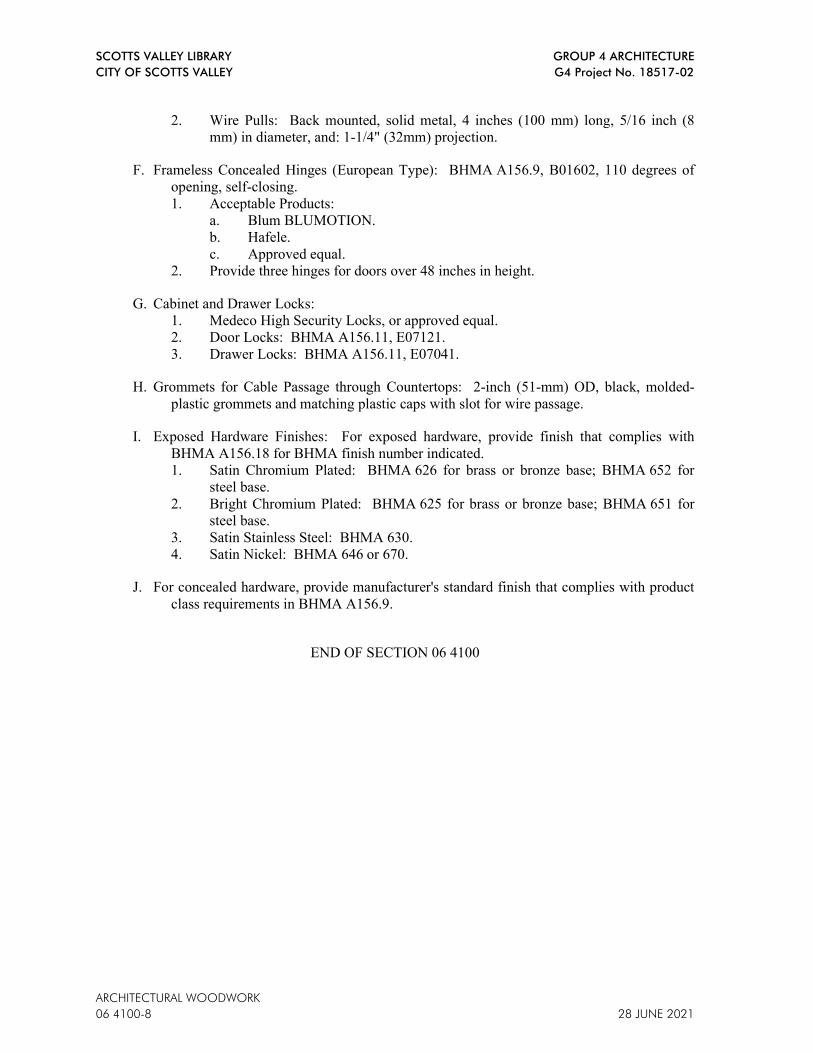
SCOTTS VALLEY LIBRARY GROUP 4 ARCHITECTURE
CITY OF SCOTTS VALLEY G4 Project No. 18517-02
ARCHITECTURAL WOODWORK
06 4100-8 28 JUNE 2021
2. Wire Pulls: Back mounted, solid metal, 4 inches (100 mm) long, 5/16 inch (8
mm) in diameter, and: 1-1/4" (32mm) projection.
F. Frameless Concealed Hinges (European Type): BHMA A156.9, B01602, 110 degrees of
opening, self-closing.
1. Acceptable Products:
a. Blum BLUMOTION.
b. Hafele.
c. Approved equal.
2. Provide three hinges for doors over 48 inches in height.
G. Cabinet and Drawer Locks:
1. Medeco High Security Locks, or approved equal.
2. Door Locks: BHMA A156.11, E07121.
3. Drawer Locks: BHMA A156.11, E07041.
H. Grommets for Cable Passage through Countertops: 2-inch (51-mm) OD, black, molded-
plastic grommets and matching plastic caps with slot for wire passage.
I. Exposed Hardware Finishes: For exposed hardware, provide finish that complies with
BHMA A156.18 for BHMA finish number indicated.
1. Satin Chromium Plated: BHMA 626 for brass or bronze base; BHMA 652 for
steel base.
2. Bright Chromium Plated: BHMA 625 for brass or bronze base; BHMA 651 for
steel base.
3. Satin Stainless Steel: BHMA 630.
4. Satin Nickel: BHMA 646 or 670.
J. For concealed hardware, provide manufacturer's standard finish that complies with product
class requirements in BHMA A156.9.
END OF SECTION 06 4100
SCOTTS VALLEY LIBRARY GROUP 4 ARCHITECTURE
CITY OF SCOTTS VALLEY G4 Project No. 18517-02
BUILDING INSULATION
28 JUNE 2021 07 2100-1
SECTION 07 2100 - BUILDING INSULATION
PART 1 - GENERAL
1.1 RELATED DOCUMENTS
A. Drawings and general provisions of the Contract, including General and Supplementary
Conditions and Division 1 Specification Sections, apply to this Section.
1.2 SECTION INCLUDES
A. Applications:
1. Thermal insulation for exterior walls; faced batt type.
2. Thermal insulation for use where indicated; rigid board type.
3. Sound attenuation insulation for interior partitions where indicated; unfaced batt type.
4. Continuous rigid insulation at building exterior.
1.3 ACTION SUBMITTALS
A. Product Data: For each type of insulation product specified.
1.4 INFORMATIONAL SUBMITTALS
A. Product Test Reports: Based on evaluation of comprehensive tests performed by a qualified
testing agency for insulation products.
1.5 QUALITY ASSURANCE
A. Fire Performance Characteristics: Provide insulation materials identical to those whose
indicated fire performance characteristics have been determined per the ASTM test method
indicated below, by UL or other testing and inspecting organizations acceptable to
authorities having jurisdiction. Identify products with appropriate markings of applicable
testing and inspecting organization.
1. Surface Burning Characteristic: ASTM E84.
2. Fire Resistance Ratings: ASTM E119.
3. Combustion Characteristics: ASTM E136.
B. Single-Source Responsibility for Insulation Products: Obtain each type of building
insulation from a single source with resources to provide products of consistent quality in
appearance and physical properties without delaying progress of the Work.
C. Warranty: Provide warranty in accordance with the warranty and/or guarantee requirements
stated elsewhere in Contract Documents.
1.6 DELIVERY, STORAGE, AND HANDLING
A. Protect insulation materials from physical damage and from deterioration by moisture,
soiling, and other sources. Store inside and in a dry location. Comply with manufacturer's
recommendations for handling, storage, and protection during installation.
SCOTTS VALLEY LIBRARY GROUP 4 ARCHITECTURE
CITY OF SCOTTS VALLEY G4 Project No. 18517-02
BUILDING INSULATION
07 2100-2 28 JUNE 2021
PART 2 - PRODUCTS
2.1 MATERIAL REQUIREMENTS, GENERAL
A. Insulation Materials: Provide only insulation materials that are GREENGUARD Certified.
2.2 GLASS FIBER INSULATING MATERIALS
A. Batt Insulation:
1. Type(s): See Drawings for locations.
a. Faced Glass-Fiber Batt: Type III, Class A; Category 1, faced with foil-scrim-
kraft, foil-scrim, or foil-scrim-polyethylene vapor-retarder membrane on 1
face.
b. Unfaced Glass-Fiber Blanket: Type I.
2. Batt Width: Maximum width as required for application.
3. Flame Spread Rating: Less than 25, as tested in accordance with ASTM E84.
4. Sustainability Requirements: Provide glass-fiber blanket insulation as follows:
a. Free of Formaldehyde: Insulation manufactured with 100 percent acrylic
binders and no formaldehyde.
b. Low Emitting: Insulation tested according to ASTM D5116 and shown to
emit less than 0.05-ppm formaldehyde.
5. Required R-Values and Locations, Cotton Insulation:
a. Insulation at Exterior Stud Walls: R-19, 5-1/2-inches thick.
b. Insulation at Soffits: R-19, 5-1/2-inches thick.
B. Insulation for Sound Attenuation: ASTM C665; Type I preformed glass fiber batts
conforming to the following:
1. Batt Width: Maximum width as required for application.
2. Thickness: 3-5/8-inches.
3. Facing: Unfaced.
4. Flame Spread Rating: Less than 25, as tested in accordance with ASTM E84.
5. Smoke Developed: Less than 50, as tested in accordance with ASTM E84.
6. Overall Sound Transmission: STC 50.
7. Minimum density of 6 lb/cu ft (96 kg/cu m), thermal resistivity of 4.5 deg F x h x sq
ft/Btu x in. at 75 deg F (31.2 K x m/W at 24 deg C).
C. Preformed Units: Sizes to fit applications indicated, selected from manufacturer's standard
thicknesses, widths, and lengths.
2.3 RIGID INSULATION
A. Polyisocyanurate Foam Insulation: ASTM C1289, Type I, Class 1 or Class 2; CFC- and
HCFC-free.
1. Facing: Foil facers on both major surfaces.
2. Fire Rating: Class A.
3. Flame Spread Rating: 25 or less.
4. Thermal Resistance: R-value: 27.4 minimum.
5. Board Width: Maximum width as required for application.
6. Thickness: As indicated on Drawings.
7. Edge: Square.
8. Product: Rmax TSX-8500 or Hunter XCI Class A.

SCOTTS VALLEY LIBRARY GROUP 4 ARCHITECTURE
CITY OF SCOTTS VALLEY G4 Project No. 18517-02
BUILDING INSULATION
28 JUNE 2021 07 2100-3
D. Rigid Insulation Furring System: Knight Wall Systems, ThermaZee thermal Z-girts
between exterior cladding and framing to be installed against exterior sheathing that has
been waterproofed as specified in Section 07 2719.
0. Depth of ThermaZee: As indicated on Drawings.
0. On Center Spacing: As indicated on Drawings.
0. Fire-Test-Response Characteristics: Provide composite framing support system with
fire-test results indicated as determined by test standard indicated and applied by UL
or other testing and inspection agency acceptable to authorities having jurisdiction.
. Surface Burning Characteristics: In compliance with ASTM E84, for foam
insulation, fiber reinforced polymer (FRP) and interior surfaces as follows:
. Flame Spread Index (FSI): 25 or less.
. Smoke Developed Index (SDI): 450 or less.
B. Rigid Insulation Furring System: Knight Wall Systems, ThermaZee thermal Z-girts
between exterior cladding and framing to be installed against exterior sheathing that has
been waterproofed as specified in Section 07 2719.
1. Depth of ThermaZee: As indicated on Drawings.
2. On Center Spacing: As indicated on Drawings.
3. Fire-Test-Response Characteristics: Provide composite framing support system with
fire-test results indicated as determined by test standard indicated and applied by UL
or other testing and inspection agency acceptable to authorities having jurisdiction.
a. Surface Burning Characteristics: In compliance with ASTM E84, for foam
insulation, fiber reinforced polymer (FRP) and interior surfaces as follows:
b. Flame Spread Index (FSI): 25 or less.
c. Smoke Developed Index (SDI): 450 or less.
2.32.4 AUXILIARY INSULATING MATERIALS
A. Adhesive for Bonding Insulation: Product with demonstrated capability to bond insulation
or mechanical anchors securely to substrates indicated without damaging or corroding
insulation, anchors, or substrates.
B. Adhesively Attached Pin Anchors: Perforated plate, 2-inches square, welded to projecting
pin, with self-locking washer, complying with the following requirements:
1. Plate: Zinc-plated steel, 0.106-inch thick.
2. Pin: Copper-coated low carbon steel, fully annealed, 0.106-inches in diameter,
length to suit depth of insulation indicated and, with washer in place, to hold
insulation tightly to substrate behind insulation.
3. Self-Locking Washer: Mild steel, 0.016-inch thick, size as required to hold
insulation securely.
C. Staples: Steel wire; type and size to suit application.
D. Tape: Mesh reinforced, self-adhering type, 2-inch wide.

SCOTTS VALLEY LIBRARY GROUP 4 ARCHITECTURE
CITY OF SCOTTS VALLEY G4 Project No. 18517-02
BUILDING INSULATION
07 2100-4 28 JUNE 2021
PART 3 - EXECUTION
3.1 EXAMINATION
A. Examine substrates and conditions with Installer present, for compliance with requirements
of the Sections in which substrates and related work are specified and to determine if other
conditions affecting performance of insulation are satisfactory.
B. Verify that substrate, adjacent materials, and insulation are dry and ready to receive
insulation.
C. Verify mechanical and electrical services within walls have been installed and tested.
D. Do not proceed with installation of insulation until unsatisfactory conditions have been
corrected.
3.2 INSTALLATION
A. Comply with insulation manufacturer's instructions applicable to products and application
indicated. If printed instructions are not available or do not apply to project conditions,
consult manufacturer's technical representative for specific recommendations before
proceeding with installation of insulation.
B. Extend insulation full thickness as indicated to envelop entire area to be insulated. Cut and
fit tightly around obstructions, and fill voids with insulation. Remove projections that
interfere with placement.
C. Apply a single layer of insulation of required thickness, unless otherwise shown or required
to make up total thickness. Trim insulation neatly to fit spaces.
D. Install in exterior walls, roof, and soffit spaces where indicated, without gaps or voids.
E. Install for sound attenuation in interior walls, above toilet room ceilings, and over
suspended ceilings where indicated, without gaps or voids.
3.3 INSTALLATION, BATT INSULATION
A. Apply insulation units to substrates by method indicated, complying with manufacturer's
written instructions. If no specific method is indicated, bond units to substrate with
adhesive or use mechanical anchorage to provide permanent placement and support of units.
B. Install mineral-fiber insulation in cavities formed by framing members according to the
following requirements:
1. Use insulation widths and lengths that fill the cavities formed by framing members.
If more than one length is required to fill cavity, provide lengths that will produce a
snug fit between ends.
2. Place insulation in cavities formed by framing members to produce a friction fit
between edges of insulation and adjoining framing members.
3. Maintain 3-inch (76-mm) clearance of insulation around recessed lighting fixtures.
4. Install eave ventilation troughs between roof framing members in insulated attic
spaces at vented eaves.
SCOTTS VALLEY LIBRARY GROUP 4 ARCHITECTURE
CITY OF SCOTTS VALLEY G4 Project No. 18517-02
BUILDING INSULATION
28 JUNE 2021 07 2100-5
5. For metal-framed wall cavities where cavity heights exceed 96 inches (2438 mm),
support unfaced blankets mechanically and support faced blankets by taping
stapling paper flanges to flanges of metal studs.
C. Stuff glass fiber loose fill insulation into miscellaneous voids and cavity spaces where
shown. Compact to approximately 40 percent of normal maximum volume (to a density of
approximately 2.5 pcf).
D. Retain batt insulation in place with spindle fasteners at exterior concrete walls. Place
insulation fasteners at spacing recommended by manufacturer.
E. Tape seal butt ends, lapped flanges, and tears or cuts in insulation membrane.
3.4 INSTALLATION, THERMAZEE
A. Verify that the steel farming is flat, with no steps or voids greater than 1/4” in any area.
Fastening ThermaZee to steel framing is performed with low-profile 1/4” #14 fasteners,
maximum 16” on center, of sufficient diameter and loading capacity for the application,
utilizing the pre-drilled holes in the metal retention plates.
B. Begin ThermaZee installation at a transition or termination point following manufacturer’s
written instructions. It is essential that the starting vertical column/horizontal row of
ThermaZee be properly secured to the substrate, and is level/plumb and true.
1. Do not use impact fasteners or impact power tools to install ThermaZees. Shims may
be used to achieve the maximum ±1/16” deflection.
2. Use Fastener Setting Guide on ThermaZee to install fasteners to the cladding face.
C. Horizontal Applications must be level and properly spaced to ensure mineral wool
insulation retention. Additionally, horizontal applications require a 3/16” gap without
sealant (as opposed to a standard 1/16” gap with sealant) at ThermaZee connections, to
allow for water drainage, while maintaining the minimum 3” overlap of the metal inserts of
the Fastener Retention System.
D. Vertical Applications must be plumb and properly spaced to help ensure mineral wool
insulation retention.
E. Connecting ThermaZee sections: Connect lengths of ThermaZee together following
manufacturer’s written instructions.
1. Carefully slide the extended galvanized metal substrate insert and cladding insert of
the already installed ThermaZee into the corresponding channels of the new,
receiving ThermaZee. In vertical applications, leave a 1/16” gap and minimum of 3”
overlap of the inserts; in horizontal applications, leave a 3/16” gap and minimum of
3” overlap of the inserts.
2. Fasten the ThermaZee through the overlapped galvanized metal inserts into the
substrate with approved fasteners.
3.5 INSTALLATION, BOARD INSULATION
A. Cut bottom, starting insulation panel to size and shim to level. Allow for 1/2-inch gap
between the panel and base (if applicable) for approved expandable sealant.
SCOTTS VALLEY LIBRARY GROUP 4 ARCHITECTURE
CITY OF SCOTTS VALLEY G4 Project No. 18517-02
BUILDING INSULATION
07 2100-6 28 JUNE 2021
B. Ensure the first ThermaZee is level and plumb.
C. After cleaning debris and moisture from top channel of ThermaZee, place insulation panel
into channel, aligning the air rib into the groove properly. Insert the ThermaZee spline into
the end vertical channel of the insulation panel with a rubber mallet, gently tamping to
ensure a snug fit with the corner sealant beads.
D. Using a spare cutoff of ThermaZee as a buffer, gently tamp down onto the insulation panel
with a rubber mallet. Ensure a firm bond and no damage is done to the panel edge.
E. When installing the next adjacent panel, DO NOT SLIDE THE PANEL INTO PLACE. Use
the spare cutoff of ThermaZee to gently tamp it into place along the length of the top. Use
the provided notched tamping block to gently tamp the two panels together to create a firm
bond with the spline between them. Continue installing panels in this way, bottom to top,
ensuring vertical joints are staggered from row to row and adjacent panel joints are fitted
tight.
F. Once one row has been completed, install the next ThermaZee by using the provided
notched tamping block and rubber mallet, ensuring a firm bond between the bottom channel
of the girt and top edge of the insulation panel.
3.6 CLEANING
A. Construction Waste Management: Manage construction waste in accordance with
provisions of Section 01 7419 Construction Waste Management and Disposal.
3.7 PROTECTION
A. Protect installed insulation from damage due to harmful weather exposures, physical abuse,
and other causes.
B. Provide temporary coverings or enclosures where insulation will be subject to abuse and
cannot be concealed and protected by permanent construction immediately after installation.
END OF SECTION 07 2100

SCOTTS VALLEY LIBRARY GROUP 4 ARCHITECTURE CITY OF SCOTTS VALLEY G4 Project No. 18517-02
28 JUNE 2021 SIDING AND TRIM 07 4620-1
SECTION 07 4620 – SIDING AND TRIM
PART 1 GENERAL
1.1 SECTION INCLUDES
A. Factory-finished fiber cement lap siding, panels, trim, moulding and accessories.
1.2 RELATED SECTIONS
A. Section 09 2216 - Light Gage Metal Framing: Wall framing and bracing.
B. Section 07210 - Insulation: Exterior wall insulation.
1.3 REFERENCES
A. AS D3359 - Standard Test Method for Measuring Adhesion by Tape Test, Tool and Tape.
B. AS E136 - Standard Test Method for Behavior of Materials in a Vertical Tube Furnace at 750 degrees C.
1.4 SUBMITTALS
A. Submit under provisions of Section 01 300.
B. Product Data: Manufacturer's data sheets on each product to be used, including: 1. Preparation instructions and recommendations. 2. Storage and handling requirements and recommendations. 3. Installation methods.
C. Shop Drawings: Provide detailed drawings of atypical non-standard applications of cementitious siding materials which are outside the scope of the standard details and specifications provided by the manufacturer.
D. Verification Samples: For each finish product specified, two samples, minimum size 4 by 6 inches (100 by 150 mm), representing actual product, color, and patterns.
1.5 QUALITY ASSURANCE
A. Installer Qualifications: Minimum of 2 years experience with installation of similar products.
B. Mock-Up: Provide a mock-up for evaluation of surface preparation techniques and application workmanship. 1. Finish areas designated by Architect. 2. Do not proceed with remaining work until workmanship, color, and sheen are
approved by Architect. 3. Remodel mock-up area as required to produce acceptable work.
1.6 DELIVERY, STORAGE, AND HANDLING

GROUP 4 ARCHITECTURE SCOTTS VALLEY LIBRARY G4 Project No. 18517-02 CITY OF SCOTTS VALLEY
SIDING AND TRIM 28 JUNE 2021 07 4620-2
A. Store products in manufacturer's unopened packaging until ready for installation.
B. Store siding on edge or lay flat on a smooth level surface. Protect edges and corners from chipping. Store sheets under cover and keep dry prior to installing.
C. Store and dispose of solvent-based materials, and materials used with solvent-based materials, in accordance with requirements of local authorities having jurisdiction.
1.7 PROJECT CONDITIONS
A. Maintain environmental conditions (temperature, humidity, and ventilation) within limits recommended by manufacturer for optimum results. Do not install products under environmental conditions outside manufacturer's absolute limits.
1.8 WARRANTY
A. Product Warranty: Limited, non-pro-rated product warranty. 1. Vertical siding for 30 years.
B. Finish Warranty: Limited product warranty against manufacturing finish defects. 1. When used for its intended purpose, properly installed and maintained
according to manufacturer’s published installation instructions, colors and finish for a period of 15 years from the date of substantial completion: will not peel; will not crack; and will not chip. Finish warranty includes the coverage for labor and material.
C. Workmanship Warranty: Application limited warranty for 2 years.
PART 2 PRODUCTS
2.1 MANUFACTURERS
A. Basis of Design: James Hardie Building Products, Inc., which is located at: 26300 La Alameda Suite 400 ; Mission Viejo, CA 92691; Toll Free Tel: 866-274-3464; Tel: 949-367-4980; Fax: 949-367-4981; Email: request info ([email protected]); Web: www.jameshardiepros.com.
B. Acceptable Manufacturers: 1. Allura USA. 2. American Fiber Cement Corporation.
C. Substitutions: Requests for approval of equal substitutions will be considered in accordance with provisions of Section 01 6000.
2.2 SIDING AND TRIM
A. Vertical siding, Smooth panels and siding requirement for materials: 1. Fiber-cement siding - complies with ASTM C 1186 Type A Grade II. 2. Fiber-cement siding - complies with ASTM E 136 as a noncombustible
material. 3. Fiber-cement siding - complies with ASTM E 84 Flame Spread Index = 0,
Smoke Developed Index = 5. 4. CAL-FIRE, Fire Engineering Division Building Materials Listing - Wildland

SCOTTS VALLEY LIBRARY GROUP 4 ARCHITECTURE CITY OF SCOTTS VALLEY G4 Project No. 18517-02
28 JUNE 2021 SIDING AND TRIM 07 4620-3
Urban Interface (WUI) Listed Product. 5. Fiber-cement siding - complies with ASTM C 1186 Type A Grade II. 6. Fiber-cement siding - complies with ASTM E 136 as a noncombustible
material. 7. Fiber-cement Siding - complies with ASTM E 84 Flame Spread Index = 0,
Smoke Developed Index = 5. 8. ICC-ES evaluation report ESR-2290 9. CAL-FIRE, Fire Engineering Division Building Materials Listing - Wildland
Urban Interface (WUI) Listed Product.
2.3 FASTENERS
A. Metal Framing: 1. Metal Framing: 1-1/4 inches (32 mm) No. 8-18 by 0.375 inch (9.5 mm) head
self-drilling, corrosion resistant S-12 ribbed buglehead screws. 2. Metal Framing: 1-5/8 inches (41 mm) No. 8-18 by 0.323 inch (8.2 mm) head
self-drilling, corrosion resistant S-12 ribbed buglehead screws. 3. Metal Framing: 1 inch (25 mm) No. 8-18 by 0.323 inch (8.2 mm) head self-
drilling, corrosion resistant ribbed buglehead screws. 4. Metal Framing: 1 inch (25 mm) No. 8-18 by 0.311 inch (7.9 mm) head self-
drilling, corrosion resistant S-12 ribbed buglehead screws. 5. Metal Framing: 1.5 inch (38mm) [AGS-100] .100 inches by 25 inches (2540
mm by 635 mm) ET&F Pin or equivalent pneumatic fastener.
B. FlNlSHES 1. Product: Factory finished color and finish by manufacturer. 2. Definition: Factory applied finish; defined as a finish applied in the same
facility and company that manufactures the siding substrate. 3. Process:
a. Factory applied finish by fiber cement manufacturer in a controlled environment within the fiber cement manufacturer's own facility utilizing a multi-coat, heat cured finish within one manufacturing process.
b. Each finish color must have documented color match to delta E of 0.5 or better between product lines, manufacturing lots or production runs as measured by photospectrometer and verified by third party.
4. Protection: Factory applied finish protection such as plastic laminate that is removed once siding is installed
5. Accessories: Complete finishing system includes pre-packaged touch-up kit provided by fiber cement manufacturer. Provide quantities as recommended by manufacturer.
B. Factory Finish Color for Siding Colors: To be selected from manufacturer’s full range of colors.
PART 3 EXECATION
3.1 EXAMINATION
A. Do not begin installation until substrates have been properly prepared.

GROUP 4 ARCHITECTURE SCOTTS VALLEY LIBRARY G4 Project No. 18517-02 CITY OF SCOTTS VALLEY
SIDING AND TRIM 28 JUNE 2021 07 4620-4
B. If framing preparation is the responsibility of another installer, notify Architect of unsatisfactory preparation before proceeding.
C. Refer to section 09 2216 – Non-Structural Metal Framing. 1. Install water-resistive barriers and claddings to dry surfaces. 2. Repair any punctures or tears in the water-resistive barrier prior to the
installation of the siding. 3. Protect siding from other trades.
3.2 PREPARATION
A. Clean surfaces thoroughly prior to installation.
B. Prepare surfaces using the methods recommended by the manufacturer for achieving the best result for the substrate under the project conditions.
C. Install a water-resistive barrier is required in accordance with local building code requirements.
D. The water-resistive barrier must be appropriately installed with penetration and junction flashing in accordance with local building code requirements.
E. Install Engineered for insulation wrap weather barrier in accordance with local building code requirements.
F. Use wrap seam tape and joint and laps.
G. Install and flashing.
3.3 INSTALLATION - VERTICAL SIDING
A. Install materials in strict accordance with manufacturer's installation instructions.
B. Block framing between studs where HardiePanel siding horizontal joints occur.
C. Install metal Z flashing and provide a 1/4 inch (6 mm) gap at horizontal panel joints.
D. Place fasteners no closer than 3/8 inch (9.5 mm) from panel edges and 2 inches (51 mm) from panel corners.
E. Allow minimum vertical clearance between the edge of siding and any other material in strict accordance with the manufacturer's installation instructions.
F. Maintain clearance between siding and adjacent finished grade.
G. Specific framing and fastener requirements refer to Tables 2 and 3 in National Evaluation Service Report No. NER-405.
H. Factory Finish Touch Up: Apply touch up paint to cut edges in accordance with manufacturer's printed instructions. 1. Touch-up nicks, scrapes, and nail heads in pre-finished siding using the
manufacturer's touch-up kit pen. 2. Touch-up of nails shall be performed after application, but before plastic
protection wrap is removed to prevent spotting of touch-up finish.

SCOTTS VALLEY LIBRARY GROUP 4 ARCHITECTURE CITY OF SCOTTS VALLEY G4 Project No. 18517-02
28 JUNE 2021 SIDING AND TRIM 07 4620-5
3. Use touch-up paint sparingly. If large areas require touch-up, replace the damaged area with new pre-finished siding. Match touch up color to siding color through use of manufacturer's branded touch-up kits.
3.4 PROTECTION
A. Protect installed products until completion of project.
B. Touch-up, repair or replace damaged products before Substantial Completion.
END OF SECTION 07 4620

GROUP 4 ARCHITECTURE SCOTTS VALLEY LIBRARY G4 Project No. 18517-02 CITY OF SCOTTS VALLEY
SIDING AND TRIM 28 JUNE 2021 07 4620-6
This Page Intentionally Left Blank

SCOTTS VALLEY LIBRARY GROUP 4 ARCHITECTURE CITY OF SCOTTS VALLEY G4 Project No. 18517-02
FIBRE CEMENT WALL PANELS 28 JUNE 2021
07 4646-1
SECTION 07 4646 - FIBRE CEMENT WALL PANELS
PART 1 - GENERAL
1.1 GENERAL PROVISIONS
A. Attention is directed to the CONTRACT AND GENERAL CONDITIONS and all Sections within
DIVISION 01 - GENERAL REQUIREMENTS which are hereby made a part of this Section of the
Specifications.
1.2 DESCRIPTION OF WORK
A. Work Included: The Work of this Section includes Fibre cement panels of the following types:
1. Through color high density fibre cement panels.
2. Fixed with concealed clip system.
1.3 RELATED WORK SPECIFIED ELSEWHERE
A. Carefully examine Contract Documents for requirements that affect work of this section.
B. Other specifications sections that directly relate to work of this section include, but are not limited
to, the following:
1. Section 05 4000 - Cold-Formed Metal Framing.
2. Section 07 2100 – Thermal Insulation; exterior insulation, if required for NFPA 285
compliance, is not included in the scope of Section 07450.
4. Section 07 2729 - Air Barriers Coatings: Exterior wall air and moisture barrier.
1.4 REFERENCES
A. ASTM International (ASTM):
1. ASTM C 1185 - 08 Standard Test Methods for Sampling and Testing Non-Asbestos Fibre-
Cement Flat Sheet, Roofing and Siding Shingles, and Clapboards.
2. ASTM C 1186 - 08 Standard Specification for Flat Fibre-Cement Sheets.
3. ASTM E 84 - Surface Burning Characteristics of Building Materials.
4. ASTM E 136 - Standard Test Method for Behavior of Materials in a Vertical Tube Furnace at
750 degree C.
B. CEN - European Committee For Standardization: EN12467 - Fibre Cement Flat Sheets - Product
Specification and Test Methods.
1.5 SUBMITTALS
A. Products Submittals shall be per Section 01 3000 – Submittal Procedures.
B. Product Data: Manufacturer's data sheets on each product to be used, including, but not limited to:
1. Preparation instructions and recommendations for panel system.

GROUP 4 ARCHITECTURE SCOTTS VALLEY LIBRARY
G4 Project No. 18517-02 CITY OF SCOTTS VALLEY
28 JUNE 2021 FIBRE CEMENT WALL PANELS
07 4646-2
2. Storage and handling requirements and recommendations.
3. Installation methods for the supporting framework and the panels.
C. Shop Drawings: Provide detailed drawings of non-standard applications of fibre cement materials
which are outside the scope of the standard details and specifications provided by the manufacturer.
D. Code Compliance: Documents showing product compliance with local building code shall be
submitted prior to the bid. These documents shall include, but not be limited to, appropriate
Evaluation Reports and/or test reports supporting the use of the product.
E. Engineering Calculations: Submit engineering calculations as required by the local building code,
showing that the installed panels and attachment system meets the wind load requirements for the
project.
F. Selection Samples: For each finish product specified, two complete sets of 5 ¼” x 2 1/2”
(160x65mm) color chips representing manufacturer's full range of colors and patterns available in
the US shall be provided upon request.
G. Verification Samples: For each finish product specified, two samples, minimum size 12 inches (305
mm) square, representing actual product, color, and patterns.
H. Operation and Maintenance Data: Submit operation, maintenance, and cleaning information for
products covered under this section.
1.6 QUALITY ASSURANCE
A. Installer Qualifications: All products listed in this section are to be installed by a single installer
trained and approved by the manufacture or representative.
B. Color Evaluation: No change, 2000 hours of accelerated weathering with color evaluation, CCHD
Performance Test Report.
C. Mock-Up: Provide a full size mock-up minimum 8’-0” by 4’-0” for evaluation of surface
preparation techniques and application workmanship. Mock-up shall include a top and bottom
condition and window jamb.
1. Finish areas designated by Architect.
2. Do not proceed with remaining work until workmanship, color, and sheen are approved by
Architect.
1.7 DELIVERY, STORAGE, AND HANDLING
A. Moving panels that are stacked on pallets should be done with a forklift or a crane. Ensure the
panels are secured to the pallet in a way that will not cause damage. Stacks should be transported
under a waterproof cover.
B. All panel materials must be stored flat on pallets, inside and undercover in dry conditions, protected
from weather and other trades. Stack the pallets in a way so that the panels are ventilated.
C. Always lift panels off of each other, never slide them over one another, since scratching may occur.

SCOTTS VALLEY LIBRARY GROUP 4 ARCHITECTURE CITY OF SCOTTS VALLEY G4 Project No. 18517-02
FIBRE CEMENT WALL PANELS 28 JUNE 2021
07 4646-3
1.8 PROJECT CONDITIONS
A. Maintain environmental conditions (temperature, humidity, and ventilation) within limits
recommended by manufacturer for optimum results. Do not install products under environmental
conditions outside manufacturer's absolute limits or which could involve life safety situations.
B. Field Measurements: Verify actual measurements/openings by field measurements performed by
the installer prior to release for fabrication. The General Contractor or Installer shall be responsible
for existing site dimensions. Recorded measurements shall be indicated on shop drawings based on
field measurements provided by the installer. Coordinate field measurements and fabrication
schedule with construction progress to avoid construction delays.
1.9 WARRANTY
A. Warranty: At project closeout, provide manufacturer's limited fifteen (15) year warranty covering
defects in materials. Warranty is only available when material is installed by an installation
contractor trained and approved by the manufacturer's representative.
PART 2 - PRODUCTS
2.1 MANUFACTURER
A. As a basis of Design, Fibre Cement Panels shall be manufacturerd by:
EQUITONE Inc
1731 Fred Lawson Drive, Maryville, TN 37801
Tel: +1 865-268-2705. E-mail: [email protected]
Web: http://www.equitone.com
B. Substitutions: Per 01 2500.
C. Requests for substitutions will be considered in accordance with provisions of Section 01 6000 -
Product Requirements.
2.2 WALL PANELS
A. Through Color High Density Fibre Cement Panels:
1. Basis of Design: EQUITONE - pictura Fibre Cement Panel
a. Application: Exterior.
b. Thickness: ½ inch (12mm).
c. Finish: EQUITONE - pictura is a colored facade panel. The surface is smooth, matt, with
double layer acrylic coating and a UV hardened PU top-coat (front side) to produce a dirt
resistant finish. This finish makes a hard surface, scratch resistant and “anti graffiti”
protection for most kinds of vandalism. The rear receives a transparent back-sealing coating.
e. Physical Characteristics: ASTM C1185, ASTM C1186,
EN 12467 'Fibre-cement flat sheets'.
1) Density Dry: Minimum 1.65 kg/m³ (103 lb/ft³)
2) Bending strength @ ambient, perpendicular: 26.0 N/mm² (3,771 lbf/in²)
3) Bending strength @ ambient, parallel: 17N/mm2. (2,465 lbf/in²)
4) Modulus of elasticity @ ambient, perpend: > 15,000N/mm2. (> 2,175,570 lbf/in²)
GROUP 4 ARCHITECTURE SCOTTS VALLEY LIBRARY
G4 Project No. 18517-02 CITY OF SCOTTS VALLEY
28 JUNE 2021 FIBRE CEMENT WALL PANELS
07 4646-4
5) Hygric movement 0-100%, mean: 1.60 mm/m.
6) Porosity 0-100%: < 20 %.
7) Durability classification (EN 12467): Category A.
8) Strength classification (EN 12467): Class 4.
9) Fire reaction (EN 13501-1): A2-s1-d0;
ASTM E84-Zero Flame Spread and smoke development of < 5;
ASTM E-136 - passed.
10) Impermeability test: Ok.
11) Warm water test: Ok.
12) Soak dry test: Ok.
13) Freeze thaw test: Ok.
14) Thermal conductivity: 0.6 W/mK.
2, Acceptable Product: SVK Decoboard Classic, custom blue color.
2.3 MISCELLANEOUS CLADDING MATERIALS
A. Perforated Insect/Vermin Screen: Manufacturer's standard.
B. Building Wrap: Approved Building Wrap complying with local codes for product and installation
requirements.
C. Aluminum Joint Closures and Decorative Corner Profiles: Manufacturer's standard products as
detailed. Maximum thickness of non structural finishing profile to be 0.8 mm or 21 gauge.
D. Panel Fastening Options: concealed clips.
PART 3 - EXECUTION
3.1 EXAMINATION
A. Do not begin installation until substrates have been properly prepared.
B. If substrate preparation is the responsibility of another installer, notify Architect of unsatisfactory
preparation before proceeding.
3.2 PREPARATION
A. Clean panel surfaces thoroughly prior to installation. Remove any cutting or drilling dust from the
surface of the panel using a micro-soft cloth.
B. Prepare surfaces using the methods recommended by Equitone for achieving the best result for the
substrate under the project conditions.
3.3 INSTALLATION
A. Install in accordance with manufacturer's instructions and approved submittals.
B. For exterior applications, comply with local codes and structural engineer's fastening calculations
along with manufacturer's recommendations for fastener spacing.
3.4 EXTERIOR CLADDING FOR RAINSCREEN APPLICATIONS
A. Detailing Requirements:

SCOTTS VALLEY LIBRARY GROUP 4 ARCHITECTURE CITY OF SCOTTS VALLEY G4 Project No. 18517-02
FIBRE CEMENT WALL PANELS 28 JUNE 2021
07 4646-5
1. Air space inlets and outlets are required at top and bottom of building or wall termination and
shall be equivalent to a continuous 1/2 inch to 3/4 inch (12 mm to 18 mm) to facilitate airflow
behind the panels. Do not block vertical airflow at windows, doors, eaves, or at the base of the
building. Airflow shall be continuous from bottom to top so there is air movement behind
each panel. The minimum cavity width should be at least 25/32” (20mm) for facades up to 33’
(10m) high. For facades between 66’-165’ (20-50 m) the cavity width needs to increase to 1
3/16” (30mm). Air flow behind the fiber cement panels is critical to the performance of the
rain screen constructions.
2. Fasteners in profile shall accommodate thermal expansion/contraction of metal and not
interfere with panel application.
3. Install panels starting from top of building and work down the facade.
4. For straight walls, start panel installation in center and work outward.
5. For walls with inside corners, start installation at corner and work across wall.
6. Pattern: Straight pattern with vertical panels. Panel size as indicated.
7. Pattern: Straight pattern with horizontal panels. Panel size as indicated.
8. Pattern: Semi pattern with horizontal panels. Panel size as indicated.
B. Rain Screen Installation: Comply with manufacturer's installation requirements.
3.5 PROTECTION
A. Protect installed products until completion of project.
B. Touch-up, repair or replace damaged products before Substantial Completion.
END OF SECTION

GROUP 4 ARCHITECTURE SCOTTS VALLEY LIBRARY
G4 Project No. 18517-02 CITY OF SCOTTS VALLEY
28 JUNE 2021 FIBRE CEMENT WALL PANELS
07 4646-6
This Page Intentionally Left Blank

SCOTTS VALLEY LIBRARY GROUP 4 ARCHITECTURE CITY OF SCOTTS VALLEY G4 Project No. 18517-02
JOINT SEALANTS 28 JUNE 2021 07 9200-1
SECTION 07 9200 - JOINT SEALANTS
PART 1 - GENERAL
1.1 RELATED DOCUMENTS
A. Drawings and general provisions of the Contract, including General and Supplementary Conditions and Division 1 Specification Sections, apply to this Section.
1.2 SECTION INCLUDES
A. Exterior Joints in Vertical Surfaces and Horizontal Non-traffic Surfaces: 1. At flashing and sheet metal. 2. Construction joints in cast-in-place concrete. 3. Perimeter joints around frames of storefronts, doors, windows, and louvers.
B. Interior Joints in Vertical Surfaces and Horizontal Non-traffic Surfaces: 1. Control and expansion joints on exposed interior surfaces of exterior walls. 2. Perimeter joints of exterior openings. 3. Tile control and expansion joints. 4. Vertical joints on exposed surfaces of concrete walls and partitions. 5. Interior rated and non-rated sealants. 6. Perimeter joints between interior wall surfaces and frames of interior doors,
windows, and elevator entrances. 7. Perimeter joints between plumbing fixtures and adjoining walls, floors, and counters. 8. Control and expansion joints in ceiling and overhead surfaces. 9. Acoustical joints in wall and ceiling surfaces.
C. Interior Joints in Horizontal Traffic Surfaces: 1. Isolation joints in cast-in-place concrete slabs.
D. Joint sealant primers and accessories.
1.3 RELATED SECTIONS
A. Section 07 6000 - Flashing and Sheet Metal.
B. Section 08 8100 - Glazing: Sealants used in glazing.
C. Section 09 2900 - Gypsum Board: Sealing concealed perimeter joints of gypsum board partitions to reduce sound transmission.
SCOTTS VALLEY LIBRARY GROUP 4 ARCHITECTURE CITY OF SCOTTS VALLEY G4 Project No. 18517-02
JOINT SEALANTS 07 9200-2 28 JUNE 2021
1.2 ACTION SUBMITTALS
A. Product Data: Manufacturer's technical data for each product required, including instructions for joint preparation and sealant application. Include certification by joint sealant manufacturer that sealants, primers, and cleaners comply with local regulations controlling the use of volatile organic compounds (VOC). Include tested physical and performance properties. Include data sheets for substrate cleaners and substrate primers recommended by sealant manufacturer for specific substrate surface conditions.
B. Samples for Verification: For each type and color of joint sealant required, provide Samples with joint sealants in 1/2-inch- (13-mm-) wide joints formed between two 6-inch- (150-mm-) long strips of material matching the appearance of exposed surfaces adjacent to joint sealants. 1. Submit 2 copies of manufacturer’s standard color chart with physical samples of each
color. Submit information on availability of custom colored sealants.
C. Joint Sealant Schedule: Include the following information: 1. Joint sealant application and typical joint locations to receive sealants. 2. Joint sealant manufacturer and product name. 3. Joint sealant formulation and color.
1.3 INFORMATIONAL SUBMITTALS
A. Certification by joint sealant manufacturer that sealants plus the primers and cleaners required for sealant installation comply with local regulations controlling use of volatile organic compounds (VOCs).
B. Submit manufacturer’s letter of certification that products comply with specified requirements and are suitable for the uses intended.
C. Product Test Reports: 1. Certified test results of elastomeric sealants showing compliance with specified
requirements. Include results of aged performances including hardness, stain-resistance, adhesion and cohesion under cyclic movement, low temperature flexibility, modulus of elasticity at 100-percent strain, effects of heat and aging, and effects of accelerated weathering.
2. Preconstruction field test results indicating which products and joint preparation methods demonstrated acceptable adhesion to joint substrates.
D. Qualification Data: For Installer.
1.4 CLOSEOUT SUBMITTALS
A. Warranties: Special warranties specified in this Section.
1.5 QUALITY ASSURANCE
A. Installer Qualifications: Manufacturer's authorized Installer who is approved or licensed for installation of elastomeric sealants required for this Project.
SCOTTS VALLEY LIBRARY GROUP 4 ARCHITECTURE CITY OF SCOTTS VALLEY G4 Project No. 18517-02
JOINT SEALANTS 28 JUNE 2021 07 9200-3
B. Source Limitations: Obtain each type of joint sealant through one source from a single manufacturer.
C. Product Testing: Obtain test results for "Product Test Reports" Paragraph in "Submittals" Article from a qualified testing agency based on testing current sealant formulations within a 36-month period preceding the Work. 1. Testing Agency Qualifications: An independent testing agency qualified according
to ASTM C1021 to conduct the testing indicated, as documented according to ASTM E548.
2. Test elastomeric joint sealants for compliance with requirements specified by reference to ASTM C920, and where applicable, to other standard test methods.
D. Sealant manufacturer shall confirm in writing that all materials contacting the sealants, including joint backings, gaskets, spacers, and joint substrates, are compatible with the sealant to be installed. Schedule sufficient time to test these materials for compatibility with the sealant, as necessary. Compatibility tests shall be performed to the sealant manufacturer’s standards. 1. Determine if priming and/or other preparation techniques are required. 2. Determine compatibility of exterior joint sealant with stone material to be used.
Verify that joint sealant oils do not migrate onto stone face causing visual banding while wet or dry. Manufacturer shall perform staining tests of sealant systems in accordance with ASTM C510 and ASTM D2203 methods for each joint substrate condition in the work.
3. Testing for adhesion is not required if sealant manufacturer has performed previous testing of proposed sealants for adhesion to and compatibility with required joints substrates.
E. Sealant manufacturer shall confirm in writing the appropriate joint preparation and priming techniques required to obtain rapid, acceptable adhesion of the joint sealants to the joint substrates.
F. Preconstruction Field Testing: Prior to installation of joint sealants, field-test adhesion to all joint substrates and surface types. Field adhesion testing shall be completed and results shall be reviewed and approved by sealant manufacturer and installer before commencing sealant installation. 1. Install joint sealants in 5-foot joint lengths. Allow to cure before testing. Test
adhesion by pulling sealant out of joint according to “Method A, Field-Applied Sealant Joint Hand Pull Tab”, in Appendix X1 in ASTM C1193. For joints with dissimilar substrates, verify adhesion to each substrate separately; extend cut along one side, verifying adhesion to opposite side. Repeat procedure for opposite side.
2. Perform field tests for each type of elastomeric sealant and joint substrate. 3. Arrange for tests to take place with joint sealant manufacturer's technical
representative present. 4. Report whether or not sealant in joint connected to pulled-out portion failed to adhere
to joint substrates or tore cohesively. Include data on pull distance used to test each type of product and joint substrate.
5. Sealants not evidencing adhesive failure from testing, in absence of other indications of noncompliance with requirements, will be considered satisfactory. Do not use sealants that fail to adhere to joint substrate during testing.

SCOTTS VALLEY LIBRARY GROUP 4 ARCHITECTURE CITY OF SCOTTS VALLEY G4 Project No. 18517-02
JOINT SEALANTS 07 9200-4 28 JUNE 2021
G. Pre-Installation Meeting: Review joint application procedures, compatibility tests, adhesion tests, and warranty requirements in a meeting involving installer, manufacturer or manufacturer’s representative, City, Architect, and contractor.
1.6 DELIVERY, STORAGE, AND HANDLING
A. Deliver materials to Project site in original unopened containers or bundles with labels indicating manufacturer, product name and designation, color, expiration period for use, pot life, curing time, and mixing instructions for multi-component materials intact and legible.
B. Store and handle materials in compliance with manufacturer's recommendations to prevent their deterioration or damage due to moisture, high or low temperatures, contaminants, or other causes.
1.7 PROJECT CONDITIONS
A. Do not proceed with installation of joint sealants under the following conditions: 1. When ambient and substrate temperature conditions are outside the limits permitted
by joint sealant manufacturer. 2. Below 40 deg F (4.4 deg C). 3. When joint substrates are wet or retaining moisture.
B. Joint Width Conditions: Do not proceed with installation of joint sealants where joint widths are less than allowed by joint sealant manufacturer for application indicated.
C. Joint Substrate Conditions: Do not proceed with installation of joint sealants until contaminants capable of interfering with their adhesion are removed from joint substrates.
1.8 WARRANTY 1. Warranty: Provide manufacturer's written warranty in which manufacturer agrees to
repair or replace sealants and accessories that fail in materials or workmanship within specified warranty period. Manufacturer may not disclaim any implied warranty such as merchantability or fitness for a particular purpose. Both the expressed and implied terms of the warranty may be read together for the benefit of the City.
2. Warranty Period: Two years from date of substantial completion.
B. Exterior Sealants: Furnish a written warranty against leaks or other defects of materials and workmanship. Defects include but are not limited to changes in the structural, physical or chemical properties of the sealant materials that impair function or require abnormal maintenance, changes in surface finish, color or texture, failure in adhesion, weather resistance or durability, failure to prevent entry of water, or failure to comply with specified requirements. 1. Warranty Period: Ten years from date of substantial completion. 2. Repair or replace defective materials and workmanship during warranty period
without expense to City, including removal and replacement of other items as required.
C. Failure of the materials and workmanship include leakage, hardening, cracking, crumbling, melting, shrinkage or running of the sealant or caulking, or the staining of adjacent materials.
SCOTTS VALLEY LIBRARY GROUP 4 ARCHITECTURE CITY OF SCOTTS VALLEY G4 Project No. 18517-02
JOINT SEALANTS 28 JUNE 2021 07 9200-5
PART 2 - PRODUCTS
2.1 MATERIAL REQUIREMENTS, GENERAL
A. VOC Content of Interior Sealants: Provide sealants and sealant primers for use inside the weatherproofing system that comply with the following limits for VOC content when calculated according to 40 CFR 59, Part 59, Subpart D (EPA Method 24): 1. Architectural Sealants: 250 g/L. 2. Sealant Primers for Nonporous Substrates: 250 g/L. 3. Sealant Primers for Porous Substrates: 775 g/L.
2.2 PERFORMANCE REQUIREMENTS
A. Provide elastomeric joint sealants that establish and maintain watertight and airtight continuous joint seals without staining or deteriorating joint substrates.
B. Provide joint sealants for interior applications that establish and maintain airtight and water-resistant continuous joint seals without staining or deteriorating joint substrates.
2.3 MANUFACTURERS
A. Available Products: Subject to compliance with requirements, products that may be incorporated into the Work include, but are not limited to, products listed in other Part 2 articles.
2.4 MATERIALS
A. Compatibility: Provide joint sealants, backings, and other related materials that are compatible with one another and with joint substrates under conditions of service and application, as demonstrated by sealant manufacturer, based on testing and field experience.
B. Colors of Exposed Joint Sealants: As selected by Architect from manufacturer's full range.
C. Provide selections made by Architect from manufacturer's full range of standard colors for products of type indicated.
2.5 EXTERIOR JOINT SEALANTS
A. Exterior Silicone Weatherproofing and Control Joint Sealant: ASTM C920, also ASTM C1193 and tested under ASTM C719; Type S, Grade NS, Class 100/50, Use NT, M, G, A, and O; single component, low-modulus, non-sag sealant, use at exterior joints in vertical surfaces and non-traffic horizontal surfaces such as but not limited to: 1. Control and expansion joints in cast-in-place concrete. 2. Joints between architectural precast concrete units. 3. Joints in exterior plaster wall systems. 4. Control and expansion joints in unit masonry. 5. Butt joints between metal panels. 6. Joints between different materials listed above. 7. Perimeter joints between materials listed above and frames of doors, windows,
storefronts, louvers, and similar openings.

SCOTTS VALLEY LIBRARY GROUP 4 ARCHITECTURE CITY OF SCOTTS VALLEY G4 Project No. 18517-02
JOINT SEALANTS 07 9200-6 28 JUNE 2021
8. Control and expansion joints in ceilings and overhead surfaces. 9. Other exterior joints in vertical surfaces and non-traffic horizontal surfaces for which
no other sealant is specified. 10. Products: Dow Corning Corporation; Dow Corning 790, Pecora Corporation; 890,
Tremco; Spectrem 1, or approved equal.
B. Exterior Polyurethane Weatherproofing and Control Joint Sealant: ASTM C920, Type S, Grade NS, Class 25, Use NT, M, G, A, and O; single component, chemical curing, non-staining, non-bleeding, non-sagging type; color as selected; use in exterior vertical surfaces such as, but not limited to: 1. Expansion and control joints of precast panels and tilt-up concrete panels. 2. Window and door perimeters, reglets, and flashings. 3. Joints between architectural precast concrete units. 4. Control and expansion joints in unit masonry. 5. Butt joints between metal panels. 6. Joints between different materials listed above. 7. Perimeter joints between materials listed above and frames of doors, windows,
storefronts, louvers, and similar openings. 8. Control and expansion joints in ceilings and overhead surfaces. 9. Products: Pecora Corporation; Dynatrol I, Sika Corporation, Inc.; Sikaflex 1a, BASF
(Sonneborne); NP 1, Tremco; Dymonic FC, or approved equal.
C. Flashings Polyurethane Sealant: ASTM C920, polyurethane-based sealant; Type S, Grade NS, Class 100/50, and Use T, NT, G, and M; single component elastomeric. 1. Products: Sika Corporation, Inc.; SikaFlex-15LM, Tremco, Inc.; Vulkem 921, or
approved equal.
D. Exterior Plaster Joint Sealant: ASTM C920, also ASTM C1193 and tested under ASTM C719; Type S, Grade NS, Class 100/50, Use NT, M, G, A, and O; single component, low-modulus, non-sag sealant, 1. Acceptable Sealants:
a. Tremco; Spectrem 3 or Spectrem 4, or approved equal.
E. Concrete Walkway Joint Sealant: ASTM C920, Type M and A, Grade P, Class 25, Use T, M, and O; multi-component, pourable urethane sealant. 1. Products: Pecora Corporation; Urexpan NR-200, Sika, Inc. SikaFlex 2c SL, Tremco
Incorporated, THC 900/901, or approved equal.
2.6 INTERIOR JOINT SEALANTS
A. Interior Weatherproofing and Control Joint Sealant: ASTM C920, Type S, Grade NS, Class 25, Use NT, M, G, A, and O; single component, chemical curing, non-staining, non-bleeding, non-sagging type; color as selected; use in interior surfaces such as, but not limited to: 1. Control and expansion joints on exposed interior surfaces of exterior walls. 2. Perimeter joints on exposed interior surfaces of exterior openings. 3. Joints on precast beams and planks. 4. Perimeter joints between interior wall surfaces and frames of interior doors,
windows, storefronts, louvers, elevator entrances and similar openings.
SCOTTS VALLEY LIBRARY GROUP 4 ARCHITECTURE CITY OF SCOTTS VALLEY G4 Project No. 18517-02
JOINT SEALANTS 28 JUNE 2021 07 9200-7
5. Other interior joints in vertical surfaces and non-traffic horizontal surfaces subject to movement for which no other sealant is specified.
6. Products: Pecora Corporation; Dynatrol I-XL, Sika Corporation, Inc.; Sikaflex 1a, BASF (Sonneborne); NP 1, Tremco; Dymonic FC, or approved equal.
B. Interior Latex Joint Sealant: Provide product complying with ASTM C834, Type S, Use O, Grade NS; use at interior joints in vertical surfaces and non-traffic horizontal surfaces such as, but not limited to: 1. Perimeters of interior door and window frames. 2. Interior wall surfaces scheduled to receive latex paints. 3. Perimeters of plumbing fixtures. 4. Control and expansion joints on exposed interior surfaces of exterior walls. 5. Perimeter joints on exposed interior surfaces of exterior openings. 6. Joints on precast beams and planks. 7. Perimeter joints between interior wall surfaces and frames of interior doors,
windows, storefronts, louvers, elevator entrances and similar openings. 8. Trim or finish joints subject to movement. 9. Products: Pecora Corporation; AC-20, BASF (Sonneborn); Sonolac, Tremco;
Tremflex 834, or approved equal.
C. Mildew Resistant Silicone Sealant: ASTM C920, Type S, Grade NS, Class 25; Use NT, G, fcA, and O; use on non-porous interior surfaces under high humidity and temperature extremes. For use in bathrooms, spas, and similar applications where joints need protection against fungi and bacteria. 1. Products: Dow Corning Corporation; Dow Corning 786, Pecora, Inc. 898, Tremco,
Inc Tremsil 200, or approved equal.
D. Acoustical Sealant for Exposed and Concealed Joints: Non-sag, paintable, nonstaining, latex sealant, with a VOC content of 250 g/L or less when calculated according to 40 CFR 59, Subpart D (EPA Method 24), complying with ASTM C834 that effectively reduces airborne sound transmission through perimeter joints and openings in building construction as demonstrated by testing representative assemblies according to ASTM E90; use for drywall or plaster wall systems, bedding electrical boxes and other wall outlets. 1. Products: Pecora Corporation; AIS 919 Acoustical and Insulation Latex Sealant,
United States Gypsum Co.; SHEETROCK Acoustical Sealant, Tremco, Inc.; Tremflex 834 or Tremco Acoustical Sealant, or approved equal.
2.7 JOINT SEALANT BACKING
A. General: Provide sealant backings and accessory materials, including primers, of material and type that are non-staining; are compatible with joint substrates, sealants, and other joint fillers; and are approved for applications indicated by sealant manufacturer based on field experience and laboratory testing.
B. Foam Joint Fillers: Non-gassing, preformed, compressible, resilient, non-staining, non-waxing, non-extruding strips of flexible plastic foam of one of materials indicated below, as recommended by manufacturer for compatibility with their sealant; of size, shape, and density to control sealant depth, prevent three-sided adhesion, provide a surface against which to tool, and otherwise contribute to producing optimum sealant performance:

SCOTTS VALLEY LIBRARY GROUP 4 ARCHITECTURE CITY OF SCOTTS VALLEY G4 Project No. 18517-02
JOINT SEALANTS 07 9200-8 28 JUNE 2021
1. Cylindrical Sealant Backings: ASTM C1330, Type C (closed-cell material with a surface skin) or Type B (bicellular material with a surface skin), and of size and density to control sealant depth and otherwise contribute to producing optimum sealant performance and as recommended by sealant manufacturer.
2. Elastomeric Tubing Sealant Backings: Flexible cellular rubber tubing complying with ASTM D1056, nonabsorbent to water and gas, and capable of remaining resilient at temperatures down to minus 26 deg F (minus 32 deg C). Provide products with low compression set and of size and shape to provide a secondary seal, to control sealant depth, and to otherwise contribute to optimum sealant performance.
2.8 MISCELLANEOUS MATERIALS
A. Primer: Material recommended by joint sealant manufacturer where required for adhesion of sealant to joint substrates indicated, as determined from pre-construction joint sealant-substrate tests and field tests. Certify that primer will not permanently stain adjacent joint surfaces.
B. Cleaners for Nonporous Surfaces: Chemical cleaners acceptable to manufacturers of sealants and sealant backing materials, free of oily residues or other substances capable of staining or harming in any way joint substrates and adjacent nonporous surfaces, and formulated to promote optimum adhesion of sealants with joint substrates.
C. Masking Tape: Non-staining, nonabsorbent material compatible with joint sealants and surfaces adjacent to joints, to mask off adjacent joint surfaces where sealant is not permanently intended to be applied.
D. Bondbreaker Tape: Polyethylene pressure sensitive adhesive tape, to be used in areas where backer rod cannot fit and where three-sided adhesion is to be avoided.
PART 3 - EXECUTION
3.1 EXAMINATION
A. Examine joints indicated to receive joint sealants, with Installer present, for compliance with requirements for joint configuration, installation tolerances, and other conditions affecting joint sealant performance.
B. Verify that joint sizes and surfaces are free of defects and acceptable for installation of joint sealants.
C. Verify joint dimensions and shapes to ensure they are within the sealant manufacturer’s guidelines. Resolve any variances prior to installation. Do not proceed with sealant installation until the unsatisfactory conditions have been corrected.
3.2 PREPARATION
A. Thoroughly clean the areas that the sealant will contact using a de-greasing solvent not harmful to the environment using the two-rag wipe technique. IPA (isopropyl alcohol) is not a degreasing solvent. The sealant should have a minimum contact area of 1/4”.

SCOTTS VALLEY LIBRARY GROUP 4 ARCHITECTURE CITY OF SCOTTS VALLEY G4 Project No. 18517-02
JOINT SEALANTS 28 JUNE 2021 07 9200-9
B. Surface Cleaning of Joints: Clean out joints immediately before installing joint sealants to comply with joint-sealant manufacturer's written instructions and the following requirements: 1. Remove all foreign material from joint substrates that could interfere with adhesion
of joint sealant, including dust, paints (except for permanent, protective coatings tested and approved for sealant adhesion and compatibility by sealant manufacturer), old joint sealants, oil, grease, waterproofing, water repellents, water, surface dirt, and frost.
2. Clean, porous joint substrate surfaces by brushing, grinding, blast cleaning, mechanical abrading, or a combination of these methods to produce a clean, sound substrate capable of developing optimum bond with joint sealants. Remove loose particles remaining after cleaning operations above by vacuuming or blowing out joints with oil-free compressed air. Porous joint substrates include the following: a. Concrete. b. Masonry.
3. Remove laitance and form-release agents from concrete. 4. Clean nonporous surfaces with chemical cleaners or other means that do not stain,
harm substrates, or leave residues capable of interfering with adhesion of joint sealants. Nonporous joint substrates include the following: a. Metal. b. Glass. c. Porcelain enamel. d. Glazed ceramic tile.
C. Masking Tape: Use masking tape where required to prevent contact of sealant with adjoining surfaces that otherwise would be permanently stained or damaged by such contact or by cleaning methods required to remove sealant smears. Remove tape immediately after tooling without disturbing joint seal.
3.3 JOINT PRIMING
A. Prime joint substrates where indicated or where recommended by joint sealant manufacturer based on pre-construction joint sealant-substrate tests or prior experience. Apply primer to comply with joint sealant manufacturer's recommendations.
B. Confine primers to areas of joint sealant bond; do not allow spillage or migration onto adjoining surfaces.
C. Allow primer to dry. Do not prime areas that cannot be sealed the same day.
3.4 INSTALLATION OF SEALANT BACKINGS
A. Install joint fillers of type indicated to provide support of sealants during application and at position required to produce the cross-sectional shapes and depths of installed sealants relative to joint widths that allow optimum sealant movement capability. 1. Do not leave gaps between ends of joint fillers. 2. Do not stretch, twist, puncture, or tear joint fillers. 3. Remove absorbent joint fillers that have become wet prior to sealant application and
replace with dry material.

SCOTTS VALLEY LIBRARY GROUP 4 ARCHITECTURE CITY OF SCOTTS VALLEY G4 Project No. 18517-02
JOINT SEALANTS 07 9200-10 28 JUNE 2021
3.5 INSTALLATION OF JOINT SEALANTS
A. General: Comply with joint sealant manufacturer's printed installation instructions applicable to products and applications indicated, except where more stringent requirements apply.
B. Sealant Installation Standard: Comply with recommendations of ASTM C1193 for use of joint sealants as applicable to materials, applications, and conditions indicated.
C. Perform acoustical sealant application work in accordance with ASTM C919.
D. Installation of Sealants: Install sealants by proven techniques that result in sealants directly contacting and fully wetting joint substrates, completely filling recesses provided for each joint configuration, and providing uniform, cross-sectional shapes and depths relative to joint widths that allow optimum sealant movement capability. Install sealants at the same time sealant backings are installed.
E. Install joint backing to maintain the following joint ratios, but in no case less than 1/4 inch (6 mm): 1. Joints up to 1/2 inch wide: 1:1 width to depth ratio. 2. Joints Greater than 1/2 inch wide: 2:1 width to depth ratio; maximum 1/2 inch joint
depth. 3. Sub-caulk joints that are deep, or joints without suitable backstop, to proper depth. 4. Protect side walls of joint (to depth of caulking) with bond breaker tape. 5. Install with adhesive on 2 faces in contact with sides of joints.
F. Tooling of Non-sag Sealants: Immediately after sealant application and prior to time skinning or curing begins, tool sealants to form smooth, uniform beads of configuration indicated, to eliminate air pockets, and to ensure contact and adhesion of sealant with sides of joint. Remove excess sealants from surfaces adjacent to joint. 1. Remove excess sealant from surfaces adjacent to joints. 2. Use tooling agents that are approved in writing by sealant manufacturer and that do
not discolor sealants or adjacent surfaces. 3. Provide concave joint configuration per Figure 5A in ASTM C1193, unless otherwise
indicated. 4. Provide flush joint configuration where indicated per Figure 5B in ASTM C1193.
3.6 FIELD QUALITY CONTROL
A. Field-Adhesion Testing: Field test joint-sealant adhesion to joint substrates as follows: 1. Extent of Testing: Test completed elastomeric sealant joints as follows:
a. Perform 10 tests for the first 1000 feet (300 m) of joint length for each type of elastomeric sealant and joint substrate.
2. Test Method: Test joint sealants as appropriate for type of joint-sealant application indicated. a. For joints with dissimilar substrates, verify adhesion to each substrate
separately; do this by extending cut along one side, verifying adhesion to opposite side. Repeat procedure for opposite side.
3. Inspect joints for complete fill, for absence of voids, and for joint configuration complying with specified requirements. Record results in a field-adhesion-test log.
SCOTTS VALLEY LIBRARY GROUP 4 ARCHITECTURE CITY OF SCOTTS VALLEY G4 Project No. 18517-02
JOINT SEALANTS 28 JUNE 2021 07 9200-11
4. Inspect tested joints and report on the following: a. Whether sealants in joints connected to pulled-out portion failed to adhere to
joint substrates or tore cohesively. Include data on pull distance used to test each type of product and joint substrate. Compare these results to determine if adhesion passes sealant manufacturer's field-adhesion hand-pull test criteria.
b. Whether sealants filled joint cavities and are free of voids. c. Whether sealant dimensions and configurations comply with specified
requirements. 5. Record test results in a field-adhesion-test log. Include dates when sealants were
installed, names of persons who installed sealants, test dates, test locations, whether joints were primed, adhesion results and percent elongations, sealant fill, sealant configuration, and sealant dimensions.
6. Repair sealants pulled from test area by applying sealants following same procedures used originally to seal joints. Ensure that original sealant surfaces are clean.
B. Evaluation of Field Test Results: Sealants not evidencing adhesive failure from testing or noncompliance with other indicated requirements will be considered satisfactory. Remove sealants that fail to adhere to joint substrates during testing or to comply with other requirements. Retest failed applications until test results prove sealants comply with indicated requirements.
3.7 CLEANING
A. Clean off excess sealants and sealant smears adjacent to joints as the Work progresses by methods and with cleaning materials approved in writing by manufacturers of joint sealants and of products in which joints occur.
B. Construction Waste Management: Manage construction waste in accordance with provisions of Section 01 7419 Construction Waste Management and Disposal
C. Leave finished work in a neat, clean condition with no evidence of spillovers onto adjacent surfaces.
3.8 PROTECTION
A. Protect joint sealants during and after curing period from contact with contaminating substances or from damage resulting from construction operations or other causes so that they are without deterioration or damage at time of Project Acceptance.
B. If, despite such protection, damage or deterioration occurs, cut out and remove damaged or deteriorated joint sealants immediately so that and installations with repaired areas are indistinguishable from original work.
END OF SECTION 07 9200

SCOTTS VALLEY LIBRARY GROUP 4 ARCHITECTURE CITY OF SCOTTS VALLEY G4 Project No. 18517-02
JOINT SEALANTS 07 9200-12 28 JUNE 2021
This Page Intentionally Left Blank
SCOTTS VALLEY LIBRARY GROUP 4 ARCHITECTURE
CITY OF SCOTTS VALLEY G4 Project No. 18517-02
SLIDING AUTOMATIC ENTRANCE DOORS
28 JUNE 2021 08 4230-1
SECTION 08 4230 – SLIDING AUTOMATIC ENTRANCE DOORS
PART 1 - GENERAL
1.1 RELATED DOCUMENTS
A. Drawings and general provisions of the Contract, including General and Supplementary
Conditions and Division 1 Specification Sections, apply to this Section.
1.2 SECTION INCLUDES
A. Exterior single-sliding, automatic entrance door assemblies.
1.3 RELATED SECTIONS
A. Section 08 7100 - Door Hardware: Hardware to the extent not specified in this Section.
B. Section 08 8100 – Glazing: Materials and installation requirements of glazing for automatic
entrance doors.
C. For electrical connections including conduit and wiring for automatic entrance door
operators, connect to existing power.
1.4 DEFINITIONS
A. Activation Device: Device that, when actuated, sends an electrical signal to the door
operator to open the door.
B. Safety Device: Device that prevents a door from opening or closing.
1.5 COORDINATION
A. Coordinate size and location of recesses in concrete floors for recessed sliding tracks and
recessed control mats that control automatic entrance doors. Concrete, reinforcement, and
formwork requirements are specified in Division 3.
B. Templates: Obtain and distribute, to the parties involved, templates for doors, frames, and
other work specified to be factory prepared for installing automatic entrance doors. Check
Shop Drawings of other work to confirm that adequate provisions are made for locating and
installing automatic entrance doors to comply with indicated requirements.
C. Electrical System Roughing-in: Coordinate layout and installation of automatic entrance
door assemblies with connections to power supplies and security access control system.
1.6 ACTION SUBMITTALS
A. Product Data: Include construction details, material descriptions, dimensions of individual
components and profiles, and finishes for automatic entrance doors.

SCOTTS VALLEY LIBRARY GROUP 4 ARCHITECTURE
CITY OF SCOTTS VALLEY G4 Project No. 18517-02
SLIDING AUTOMATIC ENTRANCE DOORS
08 4230-2 28 JUNE 2021
B. Shop Drawings: Include plans, elevations, sections, details, hardware mounting heights,
and attachments to other work.
1. For installed products indicated to comply with design loads, include structural
analysis data signed and sealed by the qualified professional engineer responsible for
their preparation.
2. Wiring Diagrams: Power, signal, and control wiring.
C. Samples for Initial Selection: For units with factory-applied color finishes.
1.7 INFORMATIONAL SUBMITTALS
A. Product Certificates: For each type of emergency-exit automatic entrance door, signed by
product manufacturer.
B. Qualification Data: For Installer, manufacturer, certified inspector, and professional
engineer.
C. Product Test Reports: Based on evaluation of comprehensive tests performed by a qualified
testing agency, for automatic entrance door assemblies.
1.8 CLOSEOUT SUBMITTALS
A. Maintenance Data: For door operators and control systems to include in maintenance
manuals.
B. Demonstration and training video.
C. Warranty: Provide warranty in accordance with the warranty and/or guarantee requirements
stated elsewhere in Contract Documents.
1.9 MAINTENANCE MATERIAL SUBMITTALS
A. Initial Maintenance Service: Beginning at Project Acceptance, provide 12 months' full
maintenance by skilled employees of automatic entrance door assembly Installer. Include
quarterly preventive maintenance, repair or replacement of worn or defective components,
lubrication, cleaning, and adjusting as required for proper automatic entrance door assembly
operation at rated speed and capacity. Provide parts and supplies same as those used in the
manufacture and installation of original equipment.
1. Engage a certified inspector to perform safety inspection after each adjustment or
repair, and at end of maintenance period. Submit completed inspection form to City
Representative.
2. Perform maintenance, including emergency callback service, during normal working
hours.
1.10 QUALITY ASSURANCE
A. Installer Qualifications: Manufacturer's authorized representative who is trained and
approved for installation and maintenance of units required for this Project and who
employs a certified inspector.
B. Manufacturer Qualifications: A qualified manufacturer with company certificate issued by
AAADM.

SCOTTS VALLEY LIBRARY GROUP 4 ARCHITECTURE
CITY OF SCOTTS VALLEY G4 Project No. 18517-02
SLIDING AUTOMATIC ENTRANCE DOORS
28 JUNE 2021 08 4230-3
C. Certified Inspector: Certified by AAADM.
D. Engineering Responsibility: Prepare data for sliding automatic entrance doors, including
Shop Drawings, based on testing and engineering analysis of manufacturer's standard units
in assemblies similar to those indicated for this Project.
E. Source Limitations: Obtain automatic entrance door assemblies through one source from a
single manufacturer.
F. Product Options: Drawings indicate sizes, profiles, and dimensional requirements of
automatic entrance door assemblies and are based on the specific system indicated. Refer to
Division 1 Section "Product Requirements."
1. Do not modify intended aesthetic effects, as judged solely by Architect, except with
Architect's approval. If modifications are proposed, submit comprehensive
explanatory data to Architect for review.
G. Welding: Qualify procedures and personnel according to AWS D1.2, "Structural Welding
Code-Aluminum."
H. Power-Operated Door Standard: BHMA A156.10.
I. Electrical Components, Devices, and Accessories: Listed and labeled as defined in
NFPA 70, Article 100, by a testing agency acceptable to authorities having jurisdiction, and
marked for intended use.
J. Emergency-Exit Door Requirements: Comply with requirements of authorities having
jurisdiction for automatic entrance doors serving as a required means of egress.
K. Preinstallation Conference: Conduct conference at Project site to comply with requirements
in Division 1 Section "Project Management and Coordination." Review methods and
procedures related to automatic entrance doors including, but not limited to, the following:
1. Review structural load limitations.
2. Review and finalize construction schedule and verify availability of materials,
Installer's personnel, equipment, and facilities needed to make progress and avoid
delays.
3. Review required testing, inspecting, and certifying procedures.
4. Review scheduling to ensure minimal disruption of tenant merchant business.
1.11 SITE CONDITIONS
A. Field Measurements: Verify openings to receive automatic entrance door assemblies by
field measurements before fabrication and indicate measurements on Shop Drawings.
1.12 WARRANTY
1. Provide warranty in accordance with the warranty and/or guarantee requirements
stated elsewhere in Contract Documents.
2. Failures include, but are not limited to, the following:
a. Structural failures including, but not limited to, excessive deflection.
b. Faulty operation of operators, controls, and hardware.
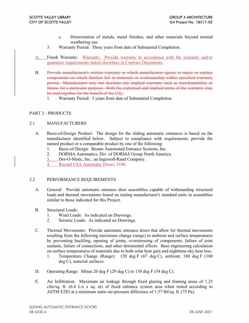
SCOTTS VALLEY LIBRARY GROUP 4 ARCHITECTURE
CITY OF SCOTTS VALLEY G4 Project No. 18517-02
SLIDING AUTOMATIC ENTRANCE DOORS
08 4230-4 28 JUNE 2021
c. Deterioration of metals, metal finishes, and other materials beyond normal
weathering use.
3. Warranty Period: Three years from date of Substantial Completion.
A. Finish Warranty: Warranty: Provide warranty in accordance with the warranty and/or
guarantee requirements stated elsewhere in Contract Documents.
B. Provide manufacturer's written warranty in which manufacturer agrees to repair or replace
components on which finishes fail in materials or workmanship within specified warranty
period. Manufacturer may not disclaim any implied warranty such as merchantability or
fitness for a particular purpose. Both the expressed and implied terms of the warranty may
be read together for the benefit of the City.
1. Warranty Period: 5 years from date of Substantial Completion.
PART 2 - PRODUCTS
2.1 MANUFACTURERS
A. Basis-of-Design Product: The design for the sliding automatic entrances is based on the
manufacturer identified below. Subject to compliance with requirements, provide the
named product or a comparable product by one of the following:
1. Basis-of-Design: Besam Automated Entrance Systems, Inc.
2. DORMA Automatics; Div. of DORMA Group North America.
3. Dor-O-Matic, Inc.; an Ingersoll-Rand Company.
4. Record USA Automatic Doors; 5100.
2.2 PERFORMANCE REQUIREMENTS
A. General: Provide automatic entrance door assemblies capable of withstanding structural
loads and thermal movements based on testing manufacturer's standard units in assemblies
similar to those indicated for this Project.
B. Structural Loads:
1. Wind Loads: As indicated on Drawings.
2. Seismic Loads: As indicated on Drawings.
C. Thermal Movements: Provide automatic entrance doors that allow for thermal movements
resulting from the following maximum change (range) in ambient and surface temperatures
by preventing buckling, opening of joints, overstressing of components, failure of joint
sealants, failure of connections, and other detrimental effects. Base engineering calculation
on surface temperatures of materials due to both solar heat gain and nighttime-sky heat loss.
1. Temperature Change (Range): 120 deg F (67 deg C), ambient; 180 deg F (100
deg C), material surfaces.
D. Operating Range: Minus 20 deg F (29 deg C) to 130 deg F (54 deg C).
E. Air Infiltration: Maximum air leakage through fixed glazing and framing areas of 1.25
cfm/sq. ft. (6.4 L/s x sq. m) of fixed entrance system area when tested according to
ASTM E283 at a minimum static-air-pressure difference of 1.57 lbf/sq. ft. (75 Pa).

SCOTTS VALLEY LIBRARY GROUP 4 ARCHITECTURE
CITY OF SCOTTS VALLEY G4 Project No. 18517-02
SLIDING AUTOMATIC ENTRANCE DOORS
28 JUNE 2021 08 4230-5
F. Opening-Force Requirements:
1. Egress Doors: Not more than 50 lbf (222 N) required to manually set door in motion
if power fails, and not more than 15 lbf (66.7 N) required to open door to minimum
required width.
2. Accessible Interior Doors: Not more than 5 lbf (22.2 N).
G. Closing-Force Requirements: Not more than 15 lbf (66.7 N) required to prevent door from
closing.
2.3 MATERIALS
A. Aluminum: Alloy and temper recommended by manufacturer for type of use and finish
indicated.
1. Extruded Bars, Rods, Profiles, and Tubes: ASTM B221.
2. Sheet and Plate: ASTM B209.
3. Welding Rods and Bare Electrodes: AWS A5.10/A5.10M.
B. Sealants and Joint Fillers: Refer to Section 07 9200.
C. Nonmetallic, Shrinkage-Resistant Grout: Premixed, nonmetallic, noncorrosive, nonstaining
grout; complying with ASTM C1107/C1107M; of consistency suitable for application.
D. Bituminous Paint: Cold-applied, asphalt-mastic paint complying with SSPC-Paint 12
requirements, except containing no asbestos; formulated for 30-mil (0.76-mm) thickness per
coat.
2.4 AUTOMATIC ENTRANCE DOOR ASSEMBLIES
A. General: Provide manufacturer's standard automatic entrance door assemblies including
doors, sidelites, framing, headers, carrier assemblies, roller tracks, door operators, activation
and safety devices, and accessories required for a complete installation.
B. Sliding Automatic Entrance Door:
1. Configuration: Single-sliding door, with one sliding leaf and sidelite.
a. Traffic Pattern: Two way.
b. Emergency Breakaway Capability: Sliding leaf only Sliding leaf and sidelite
as indicated on Drawings.
c. Mounting: Between jambs Surface.
2. Activation Device: Motion detector mounted on each side of door header to detect
pedestrians in activating zone and to open door.
3. Safety Devices: Two photoelectric beams mounted in sidelite jambs to detect
pedestrians in presence zone and to prevent door from closing.
4. Finish: Finish framing, door(s), sidelite(s), and header with Class I, clear anodic
finish high-performance organic finish (3-coat fluoropolymer) finish matching
adjacent curtain wall finish matching adjacent storefront.
a. Color: Match storefront (Clear Anodized).
2.5 COMPONENTS
A. Framing and Transom Members: Manufacturer's standard extruded aluminum, minimum
0.125 inch (3.2 mm) thick and reinforced as required to support imposed loads.

SCOTTS VALLEY LIBRARY GROUP 4 ARCHITECTURE
CITY OF SCOTTS VALLEY G4 Project No. 18517-02
SLIDING AUTOMATIC ENTRANCE DOORS
08 4230-6 28 JUNE 2021
1. Nominal Size: As indicated on Drawings.
2. Extruded Glazing Stops and Applied Trim: Minimum 0.062-inch (1.6-mm) wall
thickness.
B. Stile and Rail Doors: Manufacturer's standard 1-3/4-inch- (45-mm-) thick, glazed doors
with minimum 0.125-inch- (3.2-mm-) thick, extruded-aluminum tubular stile and rail
members. Mechanically fasten corners with reinforcing brackets that are welded, or
incorporate concealed tie-rods that span full length of top and bottom rails.
1. Glazing Stops and Gaskets: Square, snap-on, extruded-aluminum stops and
manufacturer's standard preformed gaskets.
2. Stile Design: Medium stile, 3-1/2-inch (90-mm) nominal width.
3. Rail Design: 10-inch (254-mm) nominal height.
C. Sidelites: Manufacturer's standard 1-3/4-inch- (45-mm-) deep sidelites with minimum
0.125-inch- (3.2-mm-) thick, extruded-aluminum tubular stile and rail members matching
door design.
1. Glazing Stops and Gaskets: Same materials and design as for stile and rail door.
D. Glazing: As specified in Section 08 8100.
E. Headers: Fabricated from minimum 0.125-inch- (3.2-mm-) thick extruded aluminum and
extending full width of automatic entrance door units to conceal door operators, carrier
assemblies, and roller tracks. Provide hinged or removable access panels for service and
adjustment of door operators and controls. Secure panels to prevent unauthorized access.
1. Mounting: Concealed, with one side of header flush with framing.
2. Capacity: Capable of supporting doors up to 175 lb (79 kg) per leaf over spans up to
14 feet (4.3 m) without intermediate supports.
a. Provide sag rods for spans exceeding 14 feet (4.3 m).
F. Carrier Assemblies and Overhead Roller Tracks: Manufacturer's standard carrier assembly
that allows vertical adjustment; consisting of nylon- or delrin-covered ball-bearing-center
steel wheels operating on a continuous roller track, or ball-bearing-center steel wheels
operating on a nylon- or delrin-covered continuous roller track. Support doors from carrier
assembly by cantilever and pivot assembly.
1. Rollers: Minimum two ball-bearing roller wheels and two antirise rollers for each
active leaf.
G. Threshold: Manufacturer's standard threshold members and bottom-guide track system,
with stainless-steel ball-bearing-center roller wheels.
1. Configuration: No threshold across door opening, recessed, pin-guide track system at
sidelites.
H. Brackets and Reinforcements: Manufacturer's standard high-strength aluminum with
nonstaining, nonferrous shims for aligning system components.
I. Fasteners and Accessories: Manufacturer's standard corrosion-resistant, nonstaining,
nonbleeding fasteners and accessories compatible with adjacent materials.
J. Caution Sign: BHMA A156.10; 6 inches (150 mm) in diameter, with minimum 1/2-inch-
(13-mm-) high, black lettering on a yellow background with the words "CAUTION
AUTOMATIC DOOR."

SCOTTS VALLEY LIBRARY GROUP 4 ARCHITECTURE
CITY OF SCOTTS VALLEY G4 Project No. 18517-02
SLIDING AUTOMATIC ENTRANCE DOORS
28 JUNE 2021 08 4230-7
K. Emergency Breakaway Sign: BHMA A156.10; red background with 1-inch- (25-mm-)
high contrasting letters with the words "IN EMERGENCY PUSH TO OPEN."
2.6 DOOR OPERATORS
A. General: Provide door operators of size recommended by manufacturer for door size,
weight, and movement; for condition of exposure; and for long-term, maintenance-free
operation under normal traffic load for type of occupancy indicated.
1. Door Operator Performance: Provide door operators that will open and close doors
and maintain them in fully closed position when subjected to Project's design wind
pressures.
B. Electromechanical Operators: Self-contained overhead unit powered by fractional-
horsepower, permanent-magnet dc motor; with closing speed controlled mechanically by
gear train and dynamically by braking action of electric motor; with solid-state
microprocessor controller; UL 325; and with manual operation including spring closing
with power off.
1. Operation: Power opening and power closing.
2. Features:
a. Adjustable opening and closing speeds.
b. Adjustable backcheck and latching.
c. Adjustable hold-open time between 0 and 30 seconds.
d. Obstruction recycle.
e. On-off/hold-open switch to control electric power to operator.
f. Energy conservation switch that reduces door-opening width.
g. Software: Incorporates self-diagnosing system
3. Mounting: Concealed.
2.7 ACTIVATION AND SAFETY DEVICES
A. Combination Motion/Presence Detectors: Self-contained units; consisting of both motion
and presence detectors in a single metal or plastic housing; adjustable to provide detection
field sizes and functions required by BHMA A156.10.
1. Motion Detector: K-band-frequency, microwave-scanner units; with relay hold time
of not less than 2 to 10 seconds.
a. Provide capability for switching between bi-directional and uni-directional
detection.
b. Bi-directional, doors in sequence, adjust for the second door to open for
smooth operation in both directions. First door to close in a timely manner to
limit exterior air exchange.
2. Presence Detector: Infrared-scanner units; with relay hold time of not less than 2 to
10 seconds. Detectors shall remain active at all times.
B. Photoelectric Beams: Pulsed infrared, sender-receiver assembly for recessed mounting.
Beams shall not be active when doors are fully closed.
C. Electrical Interlocks: Unless units are equipped with self-protecting devices or circuits,
provide electrical interlocks to prevent activation of operator when door is locked, latched,
or bolted.

SCOTTS VALLEY LIBRARY GROUP 4 ARCHITECTURE
CITY OF SCOTTS VALLEY G4 Project No. 18517-02
SLIDING AUTOMATIC ENTRANCE DOORS
08 4230-8 28 JUNE 2021
D. Opening-Width Control Switch: Two-position switch that in the normal position allows
sliding doors to travel to full opening width and in the alternate position reduces opening to
a selected partial opening width.
2.8 HARDWARE
A. General: Provide units in sizes and types recommended by automatic entrance door and
hardware manufacturers for entrances and uses indicated. Finish exposed parts to match
door finish.
B. Emergency Breakaway Hardware: Provide release hardware that allows panel to swing out
in direction of egress to full 90 degrees from any position in sliding mode. Maximum force
to open panel shall be 50 lbf (222 N) according to BHMA A156.10. Interrupt powered
operation of panel operator while in breakaway mode.
C. Deadlocks: Manufacturer's standard deadbolt operated by exterior cylinder and interior
thumb turn; with minimum 1-inch- (25-mm-) long throw bolt; BHMA A156.5, Grade 1.
1. Cylinders: BHMA A156.5, Grade 1, six-pin mortise type.
a. Keying: Integrate into building master key system.
2. Deadbolts: Laminated-steel hook, mortise type, BHMA A156.5, Grade 1.
D. Automatic Locking: Electrically controlled device mounted in header that automatically
locks door against sliding when in closed position. Provide fail secure operation if power
fails.
1. Include concealed, vertical-rod exit devices, UL 305, with latching into threshold and
overhead carrier assembly and released by full-width panic bar push paddle; and that
prevent emergency breakout doors from swinging and permit emergency egress.
E. Sliding Weather Stripping: Manufacturer's standard replaceable components complying
with AAMA 701; made of wool, polypropylene, or nylon woven pile with nylon-fabric or
aluminum-strip backing.
F. Weather Sweeps: Manufacturer's standard nylon brush sweep mounted to underside of door
bottom.
2.9 FABRICATION
A. General: Factory fabricate automatic entrance door assembly components to designs, sizes,
and thicknesses indicated and to comply with indicated standards.
1. Form aluminum shapes before finishing.
2. Weld in concealed locations to greatest extent possible to minimize distortion or
discoloration of finish. Remove weld spatter and welding oxides from exposed
surfaces by descaling or grinding.
3. Use concealed fasteners to greatest extent possible. Where exposed fasteners are
required, use countersunk Phillips flat-head machine screws, finished to match
framing.
a. Where fasteners are subject to loosening or turning out from thermal and
structural movements, wind loads, or vibration, use self-locking devices.
b. Reinforce members as required to receive fastener threads.

SCOTTS VALLEY LIBRARY GROUP 4 ARCHITECTURE
CITY OF SCOTTS VALLEY G4 Project No. 18517-02
SLIDING AUTOMATIC ENTRANCE DOORS
28 JUNE 2021 08 4230-9
4. Where aluminum will contact dissimilar metals, protect against galvanic action by
painting contact surfaces with primer or by applying sealant or tape recommended by
manufacturer for this purpose.
B. Framing: Provide automatic entrance doors as prefabricated assemblies. Complete
fabrication, assembly, finishing, hardware application, and other work before shipment to
Project site.
1. Fabricate tubular and channel frame assemblies with manufacturer's standard welded
or mechanical joints. Provide sub-frames and reinforcement as required for a
complete system to support required loads.
2. Perform fabrication operations in manner that prevents damage to exposed finish
surfaces.
3. Form profiles that are sharp, straight, and free of defects or deformations.
4. Prepare components to receive concealed fasteners and anchor and connection
devices.
5. Fabricate components with accurately fitted joints with ends coped or mitered to
produce hairline joints free of burrs and distortion.
6. Fabricate exterior components to drain water passing joints and condensation and
moisture occurring or migrating within the system to the exterior.
7. Provide anchorage and alignment brackets for concealed support of assembly from
the building structure.
8. Allow for thermal expansion of exterior units.
C. Doors: Factory fabricated and assembled in profiles indicated. Reinforce as required to
support imposed loads and for installing hardware.
D. Door Operators: Factory fabricated and installed in headers, including adjusting and
testing.
E. Glazing: Fabricate framing with minimum glazing edge clearances for thickness and type
of glazing indicated, according to GANA's "Glazing Manual."
F. Hardware: Factory install hardware to the greatest extent possible; remove only as required
for final finishing operation and for delivery to and installation at Project site. Cut, drill,
and tap for factory-installed hardware before applying finishes.
1. Provide sliding weather stripping, mortised into door, at perimeter of sliding
doors and breakaway sidelites.
G. Activation and Safety Devices: Factory install devices in doors and headers.
1. Install photoelectric beams in vertical jambs of sidelites, with dimension above
finished floor as follows:
a. Top Beam: 48 inches (1219 mm).
b. Bottom Beam: 24 inches (610 mm).
2.10 ALUMINUM FINISHES
A. General: Comply with NAAMM's "Metal Finishes Manual for Architectural and Metal
Products" for recommendations for applying and designating finishes.
B. Finish designations prefixed by AA comply with the system established by the Aluminum
Association for designating aluminum finishes.
SCOTTS VALLEY LIBRARY GROUP 4 ARCHITECTURE
CITY OF SCOTTS VALLEY G4 Project No. 18517-02
SLIDING AUTOMATIC ENTRANCE DOORS
08 4230-10 28 JUNE 2021
1. Color: Match existing storefront system.
C. High-Performance Organic Finish: 3-coat fluoropolymer finish complying with
AAMA 2605 and containing not less than 70 percent PVDF resin by weight in both color
coat and clear topcoat. Prepare, pretreat, and apply coating to exposed metal surfaces to
comply with coating and resin manufacturers' written instructions.
1. Color and Gloss: Match adjacent storefront.
PART 3 - EXECUTION
3.1 EXAMINATION
A. Examine conditions, with Installer present, for compliance with requirements for
installation tolerances, header support, and other conditions affecting performance of
automatic entrance doors.
1. Proceed with installation only after unsatisfactory conditions have been corrected.
3.2 INSTALLATION
A. General: Do not install damaged components. Fit frame joints to produce hairline joints
free of burrs and distortion. Rigidly secure non-movement joints. Seal joints watertight.
1. Where aluminum will contact dissimilar metals, protect against galvanic action by
painting contact surfaces with primer or by applying sealant or tape recommended by
manufacturer for this purpose.
2. Where aluminum will contact concrete or masonry, protect against corrosion by
painting contact surfaces with bituminous paint.
B. Entrances: Install automatic entrance doors plumb and true in alignment with established
lines and grades without warp or rack of framing members and doors. Anchor securely in
place.
1. Install surface-mounted hardware using concealed fasteners to greatest extent
possible.
2. Set headers, carrier assemblies, tracks, operating brackets, and guides level and true
to location with anchorage for permanent support.
3. Install components to drain water passing joints, condensation occurring within
framing members, and moisture migrating within the system to exterior.
C. Door Operators: Connect door operators to electrical power distribution system as specified
in Division 26 Sections.
D. Activation and Safety Devices: Adjust devices to provide detection field and functions
indicated.
E. Glazing: Install glazing as specified in Section 08 8100.
F. Sealants: Comply with requirements specified in Section 07 9200 to provide weathertight
installation.
1. Set framing members, thresholds, bottom-guide track system, and flashings in full
sealant bed.
2. Seal perimeter of framing members with sealant.

SCOTTS VALLEY LIBRARY GROUP 4 ARCHITECTURE
CITY OF SCOTTS VALLEY G4 Project No. 18517-02
SLIDING AUTOMATIC ENTRANCE DOORS
28 JUNE 2021 08 4230-11
G. Signage: Provide caution signs on each automatic entrance door, visible from both sides of
door. Mount caution signs with centerline 58 inches (1475 mm) above finished floor.
1. Emergency Breakaway Panels: Provide emergency breakaway sign visible to egress
side of each automatic entrance door and sidelite that has emergency breakaway
capability. Mount signs adjacent to lock stile with centerline between 36 and 60
inches (900 and 1525 mm) above finished floor.
3.3 FIELD QUALITY CONTROL
A. Inspector: City will engage a certified inspector to test and inspect automatic entrance
doors and prepare test and inspection reports.
B. Testing Services: Certified inspector shall test and inspect each automatic entrance door to
determine compliance of installed systems with applicable BHMA standards.
1. Inspection Report: Certified inspector shall submit report in writing to Architect and
Contractor within 24 hours after inspection.
C. Repair or remove work where test results and inspections indicate that it does not comply
with specified requirements.
D. Additional testing and inspecting, at Contractor's expense, will be performed to determine
compliance of replaced or additional work with specified requirements.
3.4 ADJUSTING
A. Adjust door operators, controls, and hardware for smooth and safe operation, for
weathertight closure, and complying with requirements in BHMA A156.10.
B. Lubricate operating hardware and other moving parts.
C. Readjust door operators and controls after repeated operation of completed installation
equivalent to 3 days' use by normal traffic (100 to 300 cycles). Lubricate hardware,
operating equipment, and other moving parts.
D. Occupancy Adjustment: When requested within 12 months of date of Project Acceptance,
provide on-site assistance in adjusting system to suit actual occupied conditions. Provide
up to two visits to Project outside normal occupancy hours for this purpose.
3.5 CLEANING
A. Clean glass and aluminum surfaces promptly after installation. Remove excess glazing and
sealant compounds, dirt, and other substances. Repair damaged finish to match original
finish.
1. Comply with requirements in Section 08 8100 for cleaning and maintaining glass.
B. Construction Waste Management and Disposal: Manage construction waste in accordance
with provisions of Section 01 7419 Construction Waste Management and Disposal.

SCOTTS VALLEY LIBRARY GROUP 4 ARCHITECTURE
CITY OF SCOTTS VALLEY G4 Project No. 18517-02
SLIDING AUTOMATIC ENTRANCE DOORS
08 4230-12 28 JUNE 2021
3.6 DEMONSTRATION
A. The sub-contractor shall provide trained personnel to demonstrate and train City’s
maintenance personnel to adjust, operate, and maintain automatic entrance doors and door
operators. The Contractor shall video record the session and provide the video to the City.
END OF SECTION 08 4230

SCOTTS VALLEY LIBRARY GROUP 4 ARCHITECTURE
CITY OF SCOTTS VALLEY G4 Project No. 18517-02
28 JUNE 2021 DOOR HARDWARE
08 71 00 - 1
SECTION 08 7100 – DOOR HARDWARE
PART 1 GENERAL
1.01 SUMMARY
A. Section Includes:
1. Hardware for non-rated doors.
2. Hardware for fire-rated doors.
3. Weatherstripping, seals and door gaskets.
4. Weathertight thresholds.
B. Related Sections
1. Section 08 12 13 - Hollow Metal Frames.
2. Section 08 13 13 - Hollow Metal Doors.
3. Section 08 14 00 - Flush Wood Doors.
1.02 REFERENCE STANDARDS
A. American National Standards Institute:
1. ANSI A156.18 - Materials and Finishes.
B. CBC - California Building Code.
C. California Department of General Services - Division of the State Architect -Access Polices:
1. Policy 99-08 - Door Stops and other Floor-Mounted Obstructions.
D. Intertek Testing Services (Warnock Hersey Listed):
1. WH - Certification Listings.
E. National Fire Protection Association:
1. NFPA 80 - Fire Doors and Windows.
2. NFPA 101 - Code for Safety to Life from Fire in Buildings and Structures.
3. NFPA 252 - Standard Methods of Fire Tests of Door Assemblies.
F. Underwriters Laboratories Inc.:
1. UL - Building Materials Directory.
1.03 PERFORMANCE REQUIREMENTS
A. Design Requirements:
1. Intent is provision of all required items of door hardware.
2. All doors which open into stairways, mechanical rooms, or other spaces where caution is
required shall have levers with tactile markings to alert a visually impaired person of such
conditions.
3. As an extension to an existing system, no substitutions for locksets will be approved unless
specifically invited.
4. Hardware shall be made to template.

SCOTTS VALLEY LIBRARY GROUP 4 ARCHITECTURE
CITY OF SCOTTS VALLEY G4 Project No. 18517-02
28 JUNE 2021 DOOR HARDWARE
08 71 00 - 2
B. Fire-Rated Openings:
1. Provide door hardware with UL or WH listing for type of application involved.]
2. Hardware: Tested in accordance with NFPA 252.
3. Any specified hardware for such openings not in compliance therewith shall be referred to
City’s Representative.
4. Hardware for Smoke and Draft Control Doors (Indicated as "S" on Drawings): Provide
hardware that enables door assembly to comply with air leakage requirements of the
applicable code.
C. All hardware shall meet requirements of CBC Sections 1010 and 11B-404.
D. Closers shall have following maximum pressure for opening doors.
1. Interior Door: 5 pounds pressure.
2. Exterior Doors: 5 pounds pressure.
3. Fire Doors: 5 pounds pressure maximum or maximum effort to operate door may be
increased to maximum allowable by appropriate administration authority, not to exceed
15 pounds per CBC Section 11B-404.2.9
E. Exit Devices:
1. Exit devices shall comply with CBC Section 1010.1.10
2. Unlatching force shall not exceed 15 pounds applied in direction of travel.
F. Thresholds shall comply with CBC Section 11B-404.2.5.
G. Electronic Hardware:
1. Electronic hardware products contained within the section represent part of a complete
engineered system. If alternate electronic products are submitted, it is Contractor’s
responsibility to provide a complete and working system at no additional cost to City.
This requirement includes re-engineering of electrical diagrams and system layout, as
well as power supplies, power transfers and electrical components.
2. Hardware requiring electrical connection is to listed and classified by testing firm
acceptable to authority having jurisdiction as suitable for purpose specified and indicated.
1.04 ADMINISTRATIVE REQUIREMENTS
A. Coordination:
1. Coordinate hardware with doors, frames, and related work to ensure proper size,
thickness, hand, function, and finish of hardware.
2. Coordinate door hardware work with other directly affected sections involving
manufacturer or fabrication of internal reinforcement for door hardware and recessed items.
3. Provide necessary copies of templates or actual hardware as required ensuring proper
preparation of doors and frames.
4. Provide necessary copies of schedules and templates to necessary trade supplying materials
to be prepped for door hardware in ample time to avoid fabrication and construction delays.
5. Coordinate mounting heights with door and frame manufacturers.
6. Coordinate reinforcing units provided by door and frame manufacturers with by hardware
supplier and hardware manufacturer.
7. Coordinate City’s keying requirements during course of work.
8. Coordinate requirements for electrical devices and connections for hardware.
SCOTTS VALLEY LIBRARY GROUP 4 ARCHITECTURE
CITY OF SCOTTS VALLEY G4 Project No. 18517-02
28 JUNE 2021 DOOR HARDWARE
08 71 00 - 3
9. Coordinate with other trades to ensure that line voltage and low voltage wiring is
coordinated to provide complete and working system.
B. Preinstallation Meeting:
1. Prior to installation of electronic hardware arrange a preinstallation meeting between
Contractor, suppliers, and installers and related trades to review materials, procedures and
coordinating related work.
C. Sequencing:
1. Sequence installations to ensure utility connections are achieved in an orderly and
expeditious manner.
1.05 SUBMITTALS
A. See Section 01 33 00 - Submittal Procedures, for submittal procedures.
B. Product Data: For each door hardware item, furnish manufacturer’s product information
including parts list.
C. Samples: Prior to preparation of hardware schedule:
1. Submit two samples of hinge, latchset, lockset, closer, and smoke seal illustrating style,
color, and finish.
2. Samples will be returned to supplier.
D. Door Hardware Schedule:
1. Submit schedule at earliest possible date, particularly where acceptance of hardware
schedule must precede fabrication of other work (e.g., hollow metal frames) which is
critical in the project construction schedule.
2. Reference each door using Door Number and hardware group used in the Contract
Documents.
3. Door hardware schedule to included detailed list of each hardware item, quantity,
manufacture, and model number, function, size as applicable, hardware finish, and
fastenings.
4. Door hardware schedule to include door handing and degree of opening, door and frame
sizes and materials, and other pertinent information.
5. Door hardware schedule to include explanation of all abbreviations, symbols, codes,
similar contained in schedule.
6. Door hardware schedule to include electrical characteristics and connection requirements.
7. Mounting locations for hardware.
8. Include with schedule product data, samples, shop drawings of other work affected by
finish hardware, and other information essential to the coordinated review of hardware
schedule.
9. Note in cover letter variations from specified hardware and hardware groups stating
changes and reasons for changes. City’s Representative will review only those items which
are referenced in cover letter.
E. Templates: Furnish hardware templates to each fabricator of doors, frames, and other work to
be factory-prepared for the installation of hardware. Upon request, check shop drawings of
such other work to confirm that adequate provisions are made for proper location and
installation of hardware.
SCOTTS VALLEY LIBRARY GROUP 4 ARCHITECTURE
CITY OF SCOTTS VALLEY G4 Project No. 18517-02
28 JUNE 2021 DOOR HARDWARE
08 71 00 - 4
F. Manufacturer's Installation Instructions: Indicate special procedures, perimeter conditions
requiring special attention.
G. Project Record Documents: Record actual locations of concealed equipment, services, and
conduit.
H. Maintenance Data: Include data on operating hardware, lubrication requirements, and
inspection procedures related to preventative maintenance.
I. Keys: Deliver with identifying tags to City’s Lock Shop by security shipment direct from
hardware manufacturer.
J. Operation and Maintenance Manual: Submit manual in accordance with the requirements
specified in Section 01 78 00 Closeout Submittals. Manual to include the following
1. Final hardware schedule, catalog cuts, and keying schedule.
2. Hardware installation, adjustment, and lubrication instructions.
3. Hardware inspection procedures related to preventative maintenance.
4. Wiring diagrams, elevation drawings, and operational descriptions for all electronic
openings.
1.06 MAINTENANCE PRODUCTS
A. Provide special wrenches and tools applicable to each different or special hardware
component.
B. Provide maintenance tools and accessories supplied by hardware component manufacturer.
C. Deliver materials to City’s designated storage place, unload, and position in place per City’s
instructions.
D. Provide City with a signed receipt indicating materials and quantities upon delivery
1.07 QUALITY ASSURANCE
A. Manufacturer Qualifications: Company specializing in manufacturing the products specified
in this section with minimum three years of documented experience.
B. Hardware Supplier Qualifications: Company specializing in supplying commercial door
hardware with 3 years of documented experience.
C. Hardware Supplier Personnel: Employ an Architectural Hardware Consultant (AHC) to assist
in the work of this section.
1.08 DELIVERY, STORAGE, AND PROTECTION
A. Tag each item or package separately, with identification related to final hardware schedule,
and include basic installation instructions with each item or package.
B. Package hardware sets in containers clearly marked with appropriate hardware set number to
match set numbers of reviewed hardware schedule. Two or more identical sets may be packed

SCOTTS VALLEY LIBRARY GROUP 4 ARCHITECTURE
CITY OF SCOTTS VALLEY G4 Project No. 18517-02
28 JUNE 2021 DOOR HARDWARE
08 71 00 - 5
in same container.
C. Provide secure lock-up for hardware delivered to the project, but not yet installed. Control
handling and installation of hardware items which are not immediately replaceable, so that
completion of the work will not be delayed by hardware losses, both before and after
installation.
1. Comply with requirements in Section 01 60 00 - Product Requirements.
1.09 WARRANTY
A. See Section 01 78 00 - Closeout Submittals, for additional warranty requirements.
B. Warranty: Provide warranty in accordance with the warranty and/or guarantee
requirements stated elsewhere in Contract Documents.Warranty: Provide warranty in
accordance with the warranty and/or guarantee requirements stated elsewhere in
Contract Documents.
B.
C. Submit manufacturer's warranty and ensure that forms have been completed in City's name
and registered with manufacturer.
PART 2 PRODUCTS
2.01 GENERAL REQUIREMENTS
A. Manufacturers' catalog numbers are used herein to establish type, series, operation, and quality
desired; substitutions of equal products will be permitted only where invited.
B. Furnish each type of door hardware with accessories as required for applications indicated and
for complete, finished, operational doors.
C. Fastenings: Furnish fastenings of sufficient quantity, suitable size and type for heavy use and
long life and as recommended by hardware manufacturer and as required to secure hardware.
Following guidelines should be adhered to for fasteners and anchors:
1. Finish: Exposed portions of fasteners and anchors shall match hardware item being
fastened.
2. Provide sex bolts, toggle bolts, or other anchors as recommended by hardware
manufacturer according to material to which hardware is applied. Provide sex bolts for
door closers attached to wood doors.
3. Exposed Screw Heads: Phillips head type, unless otherwise indicated.
4. Use machine screws for hardware applied to metal.
5. Install hardware fastened to concrete or masonry with machine screws and “Star” type
double expansion shields, or for screw sizes less than 1/4 inch, fasten with wood screws
and Phillips “Red Head” Plastic Anchors, Fastway Extruded Vinyl Anchors, or “Star”
Plastic Anchors , or equal. Do not use lead shields or tampins.
2.02 DOOR HARDWARE ITEMS
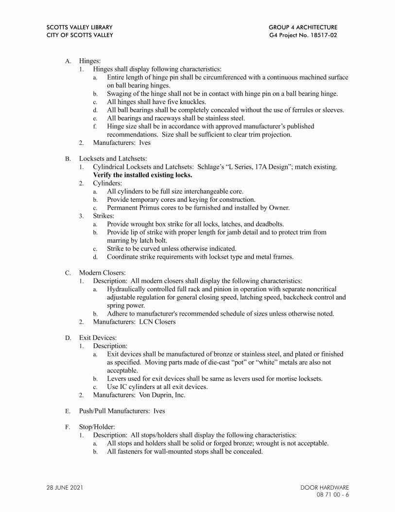
SCOTTS VALLEY LIBRARY GROUP 4 ARCHITECTURE
CITY OF SCOTTS VALLEY G4 Project No. 18517-02
28 JUNE 2021 DOOR HARDWARE
08 71 00 - 6
A. Hinges:
1. Hinges shall display following characteristics:
a. Entire length of hinge pin shall be circumferenced with a continuous machined surface
on ball bearing hinges.
b. Swaging of the hinge shall not be in contact with hinge pin on a ball bearing hinge.
c. All hinges shall have five knuckles.
d. All ball bearings shall be completely concealed without the use of ferrules or sleeves.
e. All bearings and raceways shall be stainless steel.
f. Hinge size shall be in accordance with approved manufacturer’s published
recommendations. Size shall be sufficient to clear trim projection.
2. Manufacturers: Ives
B. Locksets and Latchsets:
1. Cylindrical Locksets and Latchsets: Schlage’s “L Series, 17A Design”; match existing.
Verify the installed existing locks.
2. Cylinders:
a. All cylinders to be full size interchangeable core.
b. Provide temporary cores and keying for construction.
c. Permanent Primus cores to be furnished and installed by Owner.
3. Strikes:
a. Provide wrought box strike for all locks, latches, and deadbolts.
b. Provide lip of strike with proper length for jamb detail and to protect trim from
marring by latch bolt.
c. Strike to be curved unless otherwise indicated.
d. Coordinate strike requirements with lockset type and metal frames.
C. Modern Closers:
1. Description: All modern closers shall display the following characteristics:
a. Hydraulically controlled full rack and pinion in operation with separate noncritical
adjustable regulation for general closing speed, latching speed, backcheck control and
spring power.
b. Adhere to manufacturer's recommended schedule of sizes unless otherwise noted.
2. Manufacturers: LCN Closers
D. Exit Devices:
1. Description:
a. Exit devices shall be manufactured of bronze or stainless steel, and plated or finished
as specified. Moving parts made of die-cast “pot” or “white” metals are also not
acceptable.
b. Levers used for exit devices shall be same as levers used for mortise locksets.
c. Use IC cylinders at all exit devices.
2. Manufacturers: Von Duprin, Inc.
E. Push/Pull Manufacturers: Ives
F. Stop/Holder:
1. Description: All stops/holders shall display the following characteristics:
a. All stops and holders shall be solid or forged bronze; wrought is not acceptable.
b. All fasteners for wall-mounted stops shall be concealed.
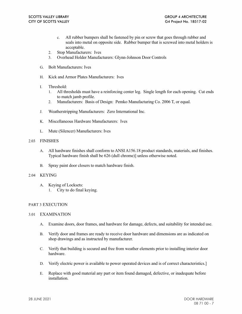
SCOTTS VALLEY LIBRARY GROUP 4 ARCHITECTURE
CITY OF SCOTTS VALLEY G4 Project No. 18517-02
28 JUNE 2021 DOOR HARDWARE
08 71 00 - 7
c. All rubber bumpers shall be fastened by pin or screw that goes through rubber and
seals into metal on opposite side. Rubber bumper that is screwed into metal holders is
acceptable.
2. Stop Manufacturers: Ives
3. Overhead Holder Manufacturers: Glynn-Johnson Door Controls
G. Bolt Manufacturers: Ives
H. Kick and Armor Plates Manufacturers: Ives
I. Threshold:
1. All thresholds must have a reinforcing center leg. Single length for each opening. Cut ends
to match jamb profile.
2. Manufacturers: Basis of Design: Pemko Manufacturing Co. 2006 T, or equal.
J. Weatherstripping Manufacturers: Zero International Inc.
K. Miscellaneous Hardware Manufacturers: Ives
L. Mute (Silencer) Manufacturers: Ives
2.03 FINISHES
A. All hardware finishes shall conform to ANSI A156.18 product standards, materials, and finishes.
Typical hardware finish shall be 626 (dull chrome)] unless otherwise noted.
B. Spray paint door closers to match hardware finish.
2.04 KEYING
A. Keying of Locksets:
1. City to do final keying.
PART 3 EXECUTION
3.01 EXAMINATION
A. Examine doors, door frames, and hardware for damage, defects, and suitability for intended use.
B. Verify door and frames are ready to receive door hardware and dimensions are as indicated on
shop drawings and as instructed by manufacturer.
C. Verify that building is secured and free from weather elements prior to installing interior door
hardware.
D. Verify electric power is available to power operated devices and is of correct characteristics.]
E. Replace with good material any part or item found damaged, defective, or inadequate before
installation.

SCOTTS VALLEY LIBRARY GROUP 4 ARCHITECTURE
CITY OF SCOTTS VALLEY G4 Project No. 18517-02
28 JUNE 2021 DOOR HARDWARE
08 71 00 - 8
3.02 STANDARDS FOR INSTALLATION
A. Install door hardware in accordance with manufacturer's templates and instructions.
B. Install hardware for fire-rated openings in accordance with CBC Section 715 and requirements
for door manufacturer’s fire rating listing.
C. Install door hardware at heights indicated on the Drawings unless otherwise indicated.
1. Mounting height of latching hardware shall be 30 to 44 inches above finished floor surface
per CBC Section 11B-404.2.7
2. Mount exit devices 36 to 44 inches above finished floor surface.
D. Wherever cutting and fitting is required to install hardware onto or into surfaces which are
later to be painted or finished in another way, coordinate removal, storage, and reinstallation,
or application of surface protections with finishing work specified in the Division 09 Sections.
E. Floor stops shall not be located in path of travel and 4 inches maximum from walls (Policy 99-
08).
F. Screws shall be screwed, not driven into place.
G. Do not install surface-mounted hardware until finishes have been completed on substrates
involved.
H. Fitting: Accurately and properly fit door hardware. Securely fasten fixed parts for smooth,
trouble-free, nonbinding operation; fit faces of mortised parts snug and flush; operating parts
shall move freely and smoothly without binding, sticking or excessive clearance.
I. Ensure door hardware displays no evidence of finish paint after final building clean up with
exception of prime-coated door hardware installed for finish painting. Contractor may achieve
this by sequencing installation, removing after fitting and reinstalling after painting is completed,
providing protection, cleaning to original hardware finish or other approved means.
J. Latch and Bolt: Install latch and bolt to automatically engage in keeper, whether activated by
closer or by manual push; in no case shall additional manual pressure be required to engage latch
or bolt in keeper.
K. Closers:
1. Adjust closer delay and operating speeds to comply with requirements of CBC Section
Maximum effort to operate closers shall not exceed 5 lbs., such pull or push effort being
applied at right angles to hinged doors. Compensating devices or automatic door
operators may be utilized to meet the above standards. When fire doors are required, the
maximum effort to operate the closer may be increased but shall not exceed 15 lbs. when
specifically approved by fire marshal. All closers shall be adjusted to operate with the
minimum amount of opening force and still close and latch the door. These forces do not
apply to the force required to retract latch bolts or disengage other devices that hold the
door in a closed position. Per 11B-404.2.8.1, door shall take at least 5 seconds to move
from an open position of 90 degrees to a position of 12 degrees from the latch jamb.
1. Do not mount closers on corridor or vestibule side of door, except at exterior doors.

SCOTTS VALLEY LIBRARY GROUP 4 ARCHITECTURE
CITY OF SCOTTS VALLEY G4 Project No. 18517-02
28 JUNE 2021 DOOR HARDWARE
08 71 00 - 9
2. Mount closers for 180 degrees swing wherever possible. Supply drop plates at narrow top
rail doors.
3. Carefully adjust closers to operate noiselessly and evenly.
4. Have manufacturer's representative regulate closers prior to City’s acceptance of building.
L. Exit Devices: Contractor shall have authorized factory service technician inspect all exit devices
after completion of installation to ensure proper adjustment and operation.
M. Kick Plates/Armor Plates: Install on push side of doors unless otherwise noted.
N. As required during progress of work, remove and reset doors and hardware for installation of
work of other trades.
O. After work has been otherwise completed, examine hardware in place for complete and proper
installation.
3.03 FIELD QUALITY CONTROL
A. Field inspection and testing will be performed under provisions of Section 01 45 19 -
Inspection of Work.
B. Provide an Architectural Hardware Consultant to inspect installation and certify that hardware
and installation has been furnished and installed in accordance with manufacturer's
instructions and as specified.
3.04 ADJUSTING
A. Adjust and check each operating item of hardware and each door, to ensure proper operation
of function of every unit.
B. Lubricate bearing surfaces of moving parts and adjust latching and holding devices for proper
function; adjust door control devices for speed and power; test keys for proper conformance with
keying system.
C. Replace units which cannot be adjusted to operate freely and smoothly as intended for the
application made.
D. Final Adjustment: Wherever hardware installation is made more than one month prior to
acceptance or occupancy of a space or area, return to the work during the week prior to
acceptance or occupancy, and make final check and adjustment of all hardware items as
necessary. Restore proper function and finish of hardware and doors. Adjust door control
devices to compensate for final operation of heating and ventilating equipment.
3.05 CLEANING
A. Completely remove protective materials and devices and thoroughly clean exposed surfaces of
hardware; check for surface damage prior to final cleaning for City’s acceptance of Project.
3.06 PROTECTION OF INSTALLED WORK

SCOTTS VALLEY LIBRARY GROUP 4 ARCHITECTURE
CITY OF SCOTTS VALLEY G4 Project No. 18517-02
28 JUNE 2021 DOOR HARDWARE
08 71 00 - 10
A. Protect installed Work under provisions of Section 01 76 00 - Protecting Installed Work.
B. Protect door hardware from damage or marring of finish during construction; use strippable
coatings, removable tapes or other approved means.
C. Do not permit adjacent work to damage hardware or finish.
3.07 DEFECTIVE WORK
A. Replace, rework or otherwise make good any hardware found defective as follows:
1. Unauthorized substitutes.
2. Hardware broken, damaged, disfigured, or defaced
3. Hardware delivered with missing, broken, damaged or defaced parts.
4. Hardware of incorrect hand or function.
5. Incomplete, misaligned, or incorrectly located hardware.
3.08 HARDWARE SCHEDULE
GROUP NO. 1
3 EA HINGE 5BB1HW 5 X 4.5 652 IVE
1 EA CLASSROOM LOCK L9070T 17A 626 SCH
1 EA PRIMUS CORE 20-740 - PROVIDED BY
OWNER
626 SCH
1 EA SURFACE CLOSER 4040XP 689 LCN
1 EA KICK PLATE 8400 10" X 2" LDW B-CS 630 IVE
1 EA WALL STOP WS401/402CCV 626 IVE
1 EA GASKETING 188SBK PSA BK ZER
1 EA DOOR BOTTOM 360LS AA ZER
GROUP NO. 2
1 EA THRESHOLD 2006 T ALUM PEM
AUTOMATIC DOORS – BY MANUFACTURER
END OF SECTION 08 7100

SCOTTS VALLEY LIBRARY GROUP 4 ARCHITECTURE
CITY OF SCOTTS VALLEY G4 Project No. 18517-02
GLASS GLAZING
28 JUNE 2021 08 8100-1
SECTION 08 8100 – GLASS GLAZING
PART 1 - GENERAL
1.1 RELATED DOCUMENTS
A. Drawings and general provisions of the Contract, including General and Supplementary
Conditions and Division 1 Specification Sections, apply to this Section.
1.2 SECTION INCLUDES
A. Glass in the following locations:
1. Aluminum storefront.
2. Interior aluminum-framed doors and windows.
3. Automatic Sliding Doors
B. Glass of the following types:
1. Insulated.
2. Tempered.
1.3 RELATED SECTIONS
A. Section 08 1116 – Aluminum Door and Window Frames.
1.4 DEFINITIONS
A. Deterioration of Insulating Glass: Failure of the hermetic seal under normal use that is
attributed to the manufacturing process and not to causes other than glass breakage and
practices for maintaining and cleaning insulating glass contrary to manufacturer's written
instructions. Evidence of failure is the obstruction of vision by dust, moisture, or film on
interior surfaces of glass.
B. Deterioration of Laminated Glass: Development of manufacturing defects including edge
separation or delamination which materially obstructs vision through glass.
C. Interspace: Space between lites of an insulating-glass unit that contains dehydrated air or a
specified gas.
D. Manufacturer: A firm that produces primary glass or fabricated glass as defined in
referenced glazing publications.
1.5 ACTION SUBMITTALS
A. Product Data: For each glass product and glazing material indicated.
B. Shop Drawings: Show location of exterior glass units required to be heat strengthened based
on glass stress analysis calculations.
C. Samples for Verification:

SCOTTS VALLEY LIBRARY GROUP 4 ARCHITECTURE
CITY OF SCOTTS VALLEY G4 Project No. 18517-02
GLASS GLAZING
08 8100-2 28 JUNE 2021
1. Glass: 12-inch-square samples of each type of glass indicated except for clear
monolithic glass products,
2. Sealant: 12-inch-long samples of each color required (except black) for each type of
sealant or gasket exposed to view. Install sealant or gasket sample between two
strips of material representative in color of the adjoining framing system.
1.6 INFORMATIONAL SUBMITTALS
A. Calculations: Furnish calculations showing glass stresses based on glass lites and shading
patterns. Calculations shall be prepared by the glass manufacturer and shall be signed by a
registered professional engineer licensed in the State of California.
B. Product Certificates: Signed by glazing materials manufacturers certifying that their
products comply with specified requirements.
1. Separate certifications are not required for glazing materials bearing manufacturer's
permanent labels designating type and thickness of glass, provided labels represent a
quality control program of a recognized certification agency or independent testing
agency acceptable to authorities having jurisdiction.
C. Glazing Schedule: Indicate glass types and thicknesses for each size opening and location.
Use same designation indicated on the Drawings.
1.7 CLOSEOUT SUBMITTALS
A. Maintenance Data: For glass and other glazing materials to include in Operating and
Maintenance Manual specified in Division 1.
B. Warranty: Provide warranty in accordance with this specification section, in addition to the
warranty and/or guarantee requirements stated elsewhere in Contract Documents including,
but not limited to, Part III: Contract Documents Contract, Part IV: General Conditions, and
Division 1 of technical specifications.
1.8 QUALITY ASSURANCE
A. Glazier Qualifications: Engage an experienced glazier who has completed glazing similar in
material, design, and extent to that required for this Project, with a record of successful in-
service performance.
B. Glazing Publications: Comply with published recommendations of glass product
manufacturers and organizations below, except where more stringent requirements are
indicated. Refer to these publications for glazing terms not otherwise defined in this
Section or in referenced standards.
1. FGMA Publications: "FGMA Glazing Manual."
2. LSGA Publications: "LSGA Design Guide."
3. Safety Glass: Products complying with ANSI Z97.1 and testing requirements of 16
CFR Part 1201 for Category II materials.
C. Single-Source Responsibility for Glass: Obtain glass from one source for each product
indicated below:
1. Primary glass of each (ASTM C1036) type and class indicated.
2. Heat-treated glass of each (ASTM C1048) condition indicated.

SCOTTS VALLEY LIBRARY GROUP 4 ARCHITECTURE
CITY OF SCOTTS VALLEY G4 Project No. 18517-02
GLASS GLAZING
28 JUNE 2021 08 8100-3
3. No visible strain pattern to the naked eye under various lighting conditions as judged
solely by the Architect.
D. Fabricator Qualifications: Shop that employs skilled, manufacturer-certified workers who
custom fabricate glass similar to that required for this Project and whose products have a
record of successful in-service performance.
E. Safety Glass: Category II materials complying with testing requirements in 16 CFR 1201
and ANSI Z97.1. Subject to compliance with requirements, permanently mark safety glass
with certification label of Safety Glazing Certification Council or another certification
agency acceptable to authorities having jurisdiction
1. Label shall indicate manufacturer’s name, type of glass, thickness, and safety glazing
standard with which glass complies.
F. Insulating Glass Certification Program: Provide insulating glass units permanently marked
with appropriate Insulating Glass Certification Council (IGCC) certification label.
1.9 DELIVERY, STORAGE, AND HANDLING
A. Protect glazing materials to comply with manufacturer's directions and as needed to prevent
damage to glass and glazing materials from condensation, temperature changes, direct
exposure to sun, or other causes.
1.10 PROJECT CONDITIONS
A. Environmental Conditions: Do not proceed with glazing when ambient and substrate
temperature conditions are outside the limits permitted by glazing materials manufacturer or
when glazing channel substrates are wet from rain, frost, condensation, or other causes.
B. Install liquid sealants only when ambient and substrate temperatures are above 40 deg F
(4.4 deg C).
1.11 WARRANTY
A. Warranty: Warranty: Provide warranty in accordance with the warranty and/or guarantee
requirements stated elsewhere in Contract Documents.
B. Laminated Glass: Furnish written warranty signed by glass manufacturer, agreeing to
furnish replacements for those laminated glass units which develop manufacturing defects
as defined, warranty period: 5-years from date of substantial completion.
C. Insulating Glass: Furnish written warranty signed by glass manufacturer, agreeing to furnish
replacements for those insulating glass units developing manufacturing defects as defined.
Warranty Period: 10-years from date of substantial completion.
D. Mirror Glass: Furnish written warranty agreeing to furnish replacement mirrors for those
units developing silver spoilage. Warranty Period: 15-years from date of substantial
completion.
E. These warranties shall be in addition to and not a limitation of other rights the City may
have against the Contractor under the Contract Documents.

SCOTTS VALLEY LIBRARY GROUP 4 ARCHITECTURE
CITY OF SCOTTS VALLEY G4 Project No. 18517-02
GLASS GLAZING
08 8100-4 28 JUNE 2021
PART 2 - PRODUCTS
2.1 ENVIRONMENTAL MATERIAL REQUIREMENTS, GENERAL
A. VOC Content: Welding and coatings applied on-site on the interior of the building and
products used on the interior of the building shall comply with VOC limits as specified in
Section 01 8113 - Sustainable Design Requirements.
1. Use materials that have the lowest possible VOC content in units of g/L when
calculated according to 40 CFR 59, Subpart D (EPA Method 24).
2.2 PERFORMANCE REQUIREMENTS
A. Energy Performance Requirements: Certify and label energy performance according to
NFRC as follows:
1. Thermal Transmittance (U-factor):
2. Fixed Glazing and Framing: Shall have U-factor of not more than 0.38 Btu/sq. ft. x h
x deg F as determined according to NFRC 100.
B. Provide glazing systems capable of withstanding normal thermal movement and wind and
impact loads (where applicable) without failure, including loss or glass breakage
attributable to the following: defective manufacture, fabrication, and installation; failure of
sealants or gaskets to remain watertight and airtight; deterioration of glazing materials; or
other defects in construction.
1. Normal thermal movement is defined as that resulting from an ambient temperature
range of 120-deg. F. and from a consequent temperature range within glass and glass
framing members of 180-deg. F.
C. Thermal and Optical Performance Properties: Provide glass with performance properties
specified based on manufacturer's published test data, as determined according to
procedures indicated below:
1. For monolithic-glass lites, properties are based on units with lites 6.0 mm thick.
2. For insulating-glass units, properties are based on units of thickness indicated for
overall unit and for each lite.
3. For laminated-glass lites, properties are based on products of construction indicated.
4. Tempered Glass Coatings: Apply Low-E, frit, and other specified coatings to glass
only after tempering to minimize quench pattern visibility.
D. Provide mirrored glass that will not fail under normal usage. Failure includes glass
breakage and deterioration attributable to defective manufacture, fabrication, and
installation.
2.3 PRIMARY FLOAT GLASS PRODUCTS
A. Uncoated Clear Float Glass: ASTM C1036, Condition A (uncoated surfaces), Type I
(transparent glass, flat), Quality q3 (glazing select), class and kind as indicated in schedule
at the end of Part 3.
B. Heat-Treated Float Glass: ASTM C1048, Type I (transparent glass, flat), Quality q3
(glazing select), class and kind as required.
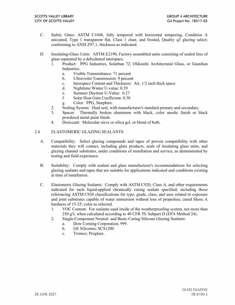
SCOTTS VALLEY LIBRARY GROUP 4 ARCHITECTURE
CITY OF SCOTTS VALLEY G4 Project No. 18517-02
GLASS GLAZING
28 JUNE 2021 08 8100-5
C. Safety Glass: ASTM C1048, fully tempered with horizontal tempering, Condition A
uncoated, Type 1 transparent flat, Class 1 clear, and frosted, Quality q3 glazing select;
conforming to ANSI Z97.1; thickness as indicated.
D. Insulating-Glass Units: ASTM E2190, Factory-assembled units consisting of sealed lites of
glass separated by a dehydrated interspace.
1. Product: PPG Industries, Solarban 72; Oldcastle Architectural Glass, or Guardian
Industries.
a. Visible Transmittance: 71 percent
b. Ultraviolet Transmission: 9 percent
c. Interspace Content and Thickness: Air, 1/2 inch thick space
d. Nighttime Winter U-value: 0.29
e. Summer Daytime U-Value: 0.27
f. Solar Heat Gain Coefficient: 0.30
g. Color: PPG, Starphire.
2. Sealing System: Dual seal, with manufacturer's standard primary and secondary.
3. Spacer: Thermally broken aluminum with black, color anodic finish or black
powdered metal paint finish.
4. Desiccant: Molecular sieve or silica gel, or blend of both.
2.4 ELASTOMERIC GLAZING SEALANTS
A. Compatibility: Select glazing compounds and tapes of proven compatibility with other
materials they will contact, including glass products, seals of insulating glass units, and
glazing channel substrates, under conditions of installation and service, as demonstrated by
testing and field experience.
B. Suitability: Comply with sealant and glass manufacturer's recommendations for selecting
glazing sealants and tapes that are suitable for applications indicated and conditions existing
at time of installation.
C. Elastomeric Glazing Sealants: Comply with ASTM C920, Class A, and other requirements
indicated for each liquid-applied chemically curing sealant specified, including those
referencing ASTM C920 classifications for type, grade, class, and uses related to exposure
and joint substrates capable of water immersion without loss of properties; cured Shore A
hardness of 15-25; color as selected.
1. VOC Content: For sealants used inside of the weatherproofing system, not more than
250 g/L when calculated according to 40 CFR 59, Subpart D (EPA Method 24).
2. Single-Component Neutral- and Basic-Curing Silicone Glazing Sealants:
a. Dow Corning Corporation; 999.
b. GE Silicones; SCS1200.
c. Tremco; Proglaze.

SCOTTS VALLEY LIBRARY GROUP 4 ARCHITECTURE
CITY OF SCOTTS VALLEY G4 Project No. 18517-02
GLASS GLAZING
08 8100-6 28 JUNE 2021
2.5 GLAZING TAPES
A. Back-Bedding Mastic Glazing Tape: Preformed, butyl-based elastomeric tape with a solids
content of 100 percent, non-staining and non-migrating in contact with nonporous surfaces,
with or without spacer rod as recommended in writing by tape and glass manufacturers for
application indicated, packaged on rolls with a release paper backing, and complying with
ASTM C1281 and AAMA 800 for products indicated below:
1. AAMA 806.3 tape, for glazing applications in which tape is subject to continuous
pressure.
2. AAMA 807.3 tape, for glazing applications in which tape is not subject to continuous
pressure.
2.6 GLAZING GASKETS
A. Dense Elastomeric Compression Seal Gaskets: Molded or extruded neoprene, EPDM, or
silicone gaskets of profile and hardness required to maintain watertight seal; complying
with ASTM C864, D.S. Brown Co., Maloney, Tremco or approved equal.
B. Soft Compression Gaskets: Extruded or molded closed cell, integral-skinned neoprene,
EPDM, or silicone of profile and hardness required to maintain watertight seal; complying
with ASTM C509, Type II, black; D.S. Brown Co., Maloney, Tremco or approved equal.
2.7 MISCELLANEOUS GLAZING MATERIALS
A. General: Provide products of material, size, and shape complying with referenced glazing
standard, requirements of manufacturers of glass and other glazing materials involved for
glazing application indicated, and with a proven record of compatibility with surfaces
contacted in installation.
B. Cleaners, Primers and Sealers: Type recommended by sealant or gasket manufacturer.
C. Glazing Stops: Screw applied or snap on type (beads) coordinated with glass section
indicated, finished to complement exterior window finish.
D. Spacers: Elastomeric blocks or continuous extrusions with a Shore ‘A’ durometer hardness
required by glass manufacturer to maintain glass lites in place for installation indicated.
Any visible sides shall be black.
2.8 FABRICATION OF GLASS AND OTHER GLAZING PRODUCTS
A. Pre-Glazed Units: Fabricate glass and other glazing products in sizes required to pre-glaze
units at the factory, with edge and face clearances, edge and surface conditions, and bite
complying with recommendations of product manufacturer and referenced glazing standard
as required to comply with system performance requirements.
B. Field-Glazed Units: Fabricate glass and other glazing products in sizes required to glaze
openings indicated for Project, with edge and face clearances, edge and surface conditions,
and bite complying with recommendations of product manufacturer and referenced glazing
standard as required to comply with system performance requirements.
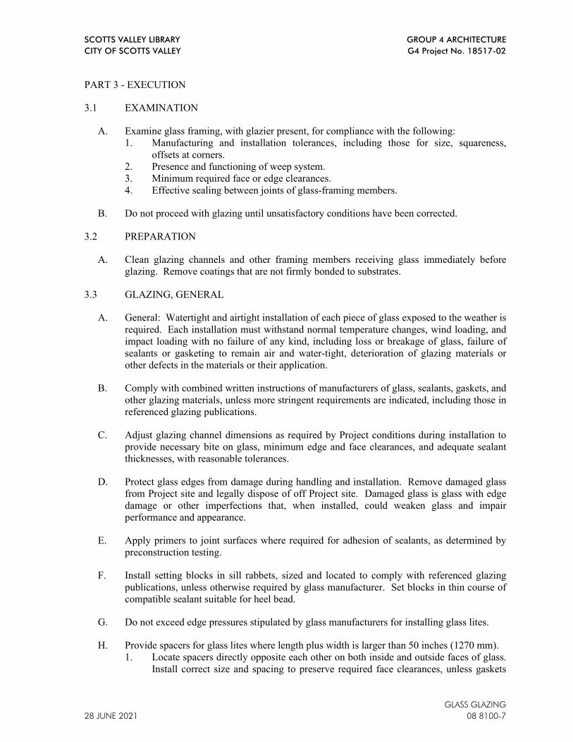
SCOTTS VALLEY LIBRARY GROUP 4 ARCHITECTURE
CITY OF SCOTTS VALLEY G4 Project No. 18517-02
GLASS GLAZING
28 JUNE 2021 08 8100-7
PART 3 - EXECUTION
3.1 EXAMINATION
A. Examine glass framing, with glazier present, for compliance with the following:
1. Manufacturing and installation tolerances, including those for size, squareness,
offsets at corners.
2. Presence and functioning of weep system.
3. Minimum required face or edge clearances.
4. Effective sealing between joints of glass-framing members.
B. Do not proceed with glazing until unsatisfactory conditions have been corrected.
3.2 PREPARATION
A. Clean glazing channels and other framing members receiving glass immediately before
glazing. Remove coatings that are not firmly bonded to substrates.
3.3 GLAZING, GENERAL
A. General: Watertight and airtight installation of each piece of glass exposed to the weather is
required. Each installation must withstand normal temperature changes, wind loading, and
impact loading with no failure of any kind, including loss or breakage of glass, failure of
sealants or gasketing to remain air and water-tight, deterioration of glazing materials or
other defects in the materials or their application.
B. Comply with combined written instructions of manufacturers of glass, sealants, gaskets, and
other glazing materials, unless more stringent requirements are indicated, including those in
referenced glazing publications.
C. Adjust glazing channel dimensions as required by Project conditions during installation to
provide necessary bite on glass, minimum edge and face clearances, and adequate sealant
thicknesses, with reasonable tolerances.
D. Protect glass edges from damage during handling and installation. Remove damaged glass
from Project site and legally dispose of off Project site. Damaged glass is glass with edge
damage or other imperfections that, when installed, could weaken glass and impair
performance and appearance.
E. Apply primers to joint surfaces where required for adhesion of sealants, as determined by
preconstruction testing.
F. Install setting blocks in sill rabbets, sized and located to comply with referenced glazing
publications, unless otherwise required by glass manufacturer. Set blocks in thin course of
compatible sealant suitable for heel bead.
G. Do not exceed edge pressures stipulated by glass manufacturers for installing glass lites.
H. Provide spacers for glass lites where length plus width is larger than 50 inches (1270 mm).
1. Locate spacers directly opposite each other on both inside and outside faces of glass.
Install correct size and spacing to preserve required face clearances, unless gaskets

SCOTTS VALLEY LIBRARY GROUP 4 ARCHITECTURE
CITY OF SCOTTS VALLEY G4 Project No. 18517-02
GLASS GLAZING
08 8100-8 28 JUNE 2021
and glazing tapes are used that have demonstrated ability to maintain required face
clearances and to comply with system performance requirements.
2. Provide 1/8-inch (3-mm) minimum bite of spacers on glass and use thickness equal to
sealant width. With glazing tape, use thickness slightly less than final compressed
thickness of tape.
I. Provide edge blocking where indicated or needed to prevent glass lites from moving
sideways in glazing channel, as recommended in writing by glass manufacturer and
according to requirements in referenced glazing publications.
J. Set glass lites in each series with uniform pattern, draw, bow, and similar characteristics.
K. Set glass lites with proper orientation so that coatings face exterior or interior as specified.
L. Comply with manufacturer's specifications and recommendations for installation of glazing
in window units.
3.4 GASKET GLAZING (DRY)
A. Fabricate compression gaskets in lengths recommended by gasket manufacturer to fit
openings exactly, with stretch allowance during installation.
B. Insert soft compression gasket between glass and frame or fixed stop so it is securely in
place with joints miter cut and bonded together at corners.
C. Center glass lites in openings on setting blocks and press firmly against soft compression
gasket by inserting dense compression gaskets formed and installed to lock in place against
faces of removable stops. Start gasket applications at corners and work toward centers of
openings. Compress gaskets to produce a weathertight seal without developing bending
stresses in glass. Seal gasket joints with sealant recommended by gasket manufacturer.
D. Install gaskets so they protrude past face of glazing stops.
3.5 CLEANING AND PROTECTION
A. Construction Waste Management: Manage construction waste in accordance with
provisions of Section 01 7419 Construction Waste Management and Disposal.
B. Examine glass surfaces adjacent to or below exterior concrete at frequent intervals during
construction, but not less than once a month, for build-up of dirt, scum, alkali deposits, or
stains, and remove as recommended by glass manufacturer.
C. Remove and replace glass that is broken, chipped, cracked, abraded, or damaged in any
way, during construction period, including natural causes, accidents and vandalism.
D. Wash glass on both faces in each area of Project not more than 4 days prior to date
scheduled for inspections that establish date of Project Acceptance. Wash glass using non-
abrasive soft cloths as recommended by glass manufacturer.
E. Protect exterior glass from breakage immediately after installation by attaching crossed
streamers to framing held away from glass. Do not apply markers to glass surface.
Remove nonpermanent labels, and clean surfaces.

SCOTTS VALLEY LIBRARY GROUP 4 ARCHITECTURE
CITY OF SCOTTS VALLEY G4 Project No. 18517-02
GLASS GLAZING
28 JUNE 2021 08 8100-9
F. Protect glass from contact with contaminating substances resulting from construction
operations including weld splatter. If, despite such protection, contaminating substances do
come into contact with glass, remove them immediately as recommended by glass
manufacturer.
3.6 GLAZING SCHEDULE – SEE DRAWINGS
END OF SECTION 08 8100

SCOTTS VALLEY LIBRARY GROUP 4 ARCHITECTURE
CITY OF SCOTTS VALLEY G4 Project No. 18517-02
GLASS GLAZING
08 8100-10 28 JUNE 2021
This Page Intentionally Left Blank

SCOTTS VALLEY LIBRARY GROUP 4 ARCHITECTURE CITY OF SCOTTS VALLEY G4 Project No. 18517-02
NON-STRUCTURAL METAL FRAMING 28 JUNE 2021 09 2216 - 1
SECTION 09 2216 - NON-STRUCTURAL METAL FRAMING
PART 1 - GENERAL
1.1 RELATED DOCUMENTS
A. Drawings and general provisions of the Contract, including General and Supplementary Conditions and Division 1 Specification Sections, apply to this Section.
1.2 SECTION INCLUDES
A. Non-load-bearing steel framing members for the following applications: 1. Interior framing systems (e.g., supports for partition walls, framed soffits, furring,
etc.). 2. Interior suspension systems (e.g., supports for ceilings, suspended soffits, etc.). 3. Resilient channel installation for acoustical construction. 4. Flat strap and backing plate for support of wall mounted equipment and fixtures.
1.3 RELATED SECTIONS
A. Section 09 2900 – Gypsum Board: Application of gypsum board over non-load bearing steel framing.
1.4 ACTION SUBMITTALS
A. Product Data: For each type of product indicated. Include the following: 1. Brand. 2. Stud sizes. 3. Stud gauge.
B. Shop Drawings: Show provision for fixture and equipment anchorage to stud systems different from typical systems or details indicated.
1.5 QUALITY ASSURANCE
A. Fire-Resistance-Rated Assemblies: Provide materials and construction identical to those tested in assembly indicated according to ASTM E119 by an independent testing and inspecting agency acceptable to authorities having jurisdiction.
B. Fire-Test-Response Characteristics: Provide components that comply with rating requirements specified for fire-rated assemblies under UL 2079 for non-load bearing wall systems. 1. Deflection Clips and Firestop Track: Connections and/or top runner provided in fire-
resistance-rated assemblies shall be certified by UL 2079 for cyclic movement requirements.
C. STC-Rated Assemblies: For STC-rated assemblies, provide materials and construction identical to those tested in assembly indicated according to ASTM E90 and classified according to ASTM E413 by an independent testing agency.
SCOTTS VALLEY LIBRARY GROUP 4 ARCHITECTURE CITY OF SCOTTS VALLEY G4 Project No. 18517-02
NON-STRUCTURAL METAL FRAMING 09 2216 - 2 28 JUNE 2021
D. Structural supports and blocking for light fixtures and miscellaneous wall- or ceiling-mounted items shall be designed and engineered by Contractor.
E. Performance Requirements: 1. Loads: Comply with 2016 CBC requirements for seismic bracing design of metal
framing systems for gypsum board wall assemblies. 2. Deflection:
a. Partitions to Receive Gypsum Board: L/240. b. Partitions to Receive Tile Backer Board: L/360. c. Framed Ceilings: L/360. L/240 maximum, typical.
3. Seismic Requirements: Comply with code requirements for seismic bracing.
PART 2 - PRODUCTS
2.1 MANUFACTURERS
A. Steel Framing and Furring Manufacturers: Gold Bond Building Products Div., National Gypsum Co., United States Gypsum Co., or approved equal.
B. Steel Slip-Type Head Joints: Brady Construction Innovations, Inc., Sliptrack Systems, ClarkDietrich Building Systems, SLP-TRK Slotted Track, or approved equal.
C. Grid Suspension Assemblies: Chicago Metallic Corp., USG Interiors, Inc., or approved equal.
D. Steel Headers: ClarkDietrich Building Systems, ProX Header, or approved equal.
2.2 STEEL FRAMING FOR FRAMED ASSEMBLIES
A. Framing Members, General: Comply with ASTM C754 for conditions indicated. 1. Steel Studs and Runners: Comply with ASTM C645 requirements for metal and
profiles shown on Drawings, unless otherwise indicated. 2. Protective Coating: ASTM A653/A653M, G60 (Z180) minimum, hot-dip galvanized
zinc coating, unless otherwise indicated. 3. Minimum Base-Metal Thickness: 0.0312 inch (0.79 mm).
a. If stud thickness is not indicated, provide thickness as required for specified deflection criteria, based on stud depth and spacing indicated and partition height required.
b. If stud spacing is not indicated, space studs at 16-inches oc. 4. Flange Edges of Studs: Bent back 90 deg and doubled over to form 3/16-inch-wide
minimum lip (return) and complying with the requirements indicated on Drawings for depth indicated.
B. Slip-Type Head Joints: Where indicated, provide one of the following: 1. Slotted Slip Track: ASTM C645 top runner with 2-1/2-inch- (63.5-mm-) deep
flanges in thickness not less than indicated for studs; with 1-1/2-inch x 1/4-inch vertical slots.
2. Single Long-Leg Runner System: ASTM C645 top runner with 2-inch- (50.8-mm-) deep flanges in thickness not less than indicated for studs, installed with studs friction
SCOTTS VALLEY LIBRARY GROUP 4 ARCHITECTURE CITY OF SCOTTS VALLEY G4 Project No. 18517-02
NON-STRUCTURAL METAL FRAMING 28 JUNE 2021 09 2216 - 3
fit into top runner and with continuous bridging located within 12 inches (305 mm) of the top of studs to provide lateral bracing.
3. Deflection Track: Steel sheet top runner manufactured to prevent cracking of finishes applied to interior partition framing resulting from deflection of structure above; in thickness not less than indicated for studs and in width to accommodate depth of studs.
C. Interior and Exterior Headers: ASTM A653/A653M and ASTM C645, where indicated. 1. Product: ClarkDietrich, ProSTUD Drywall Framing System, ProSTUD 25, or
approved equal. a. Strength: 25 Gauge: Grade 50 with a minimum yield point of 50,000 psi (345
MPa). b. Minimum Thickness: 0.0150 inches (0.3810 mm). c. Design Thickness: 0.0158 inches (0.4013 mm).
2. Product: ClarkDietrich, ProSTUD Drywall Framing System, ProSTUD 20, or approved equal: a. Strength: 20 Gauge: Grade 65 with a minimum yield point of 65,000 psi (448
MPa). b. Minimum Thickness: 0.019 inches (0.4826 mm). c. Design Thickness: 0.0200 inches (0.5080 mm).
3. Width: As required for opening width indicated on Drawings. 4. Finish: Galvanized, Class G90 in accordance with ASTM A1003 with coating weight
in accordance with ASTM C645. 5. Internal Clip: ProX Clip Series, or approved equal:
a. Thickness: 16 gauge (54 mils). b. Width: As indicated on Drawings.
6. Fasteners: Sheet metal screws in accordance with ASTM C954 or SAE J78: a. Interior: No. 8 screws. b. Exterior: No. 10 screws.
D. Flat Strap and Backing Plate: Steel sheet for blocking and bracing in length and width indicated and where required by City for City-installed items. Where backing is not indicated on Drawings comply with the following: 1. Minimum Base-Metal Thickness: 0.0312 inch (0.79 mm). 2. Install continuous plate across minimum 3 studs, attaching to each stud. 3. Notch channel at studs. 4. For Loads Under 50 lbs/ft:
a. Plate Size: 6" x 1-1/4", 16 gage track channel. b. Attachment: No. 8 flat head screws, three at each stud.
5. For Loads 51 lbs/ft to 100 lbs/ft: a. Plate Size: 6" x 1-1/4", 16 gage track channel. b. Attachment: Welding.
6. For Loads 101 lbs/ft to 250 lbs/ft: a. Plate Size: 6-inch wide 14 gage plate with 4" x 1-1/4" 16 gage track channel
stiffeners welded to back.
E. Cold-Rolled Channel Bridging: 0.0538-inch (1.37-mm) bare-steel thickness, with minimum 1/2-inch- (12.7-mm-) wide flanges. 1. Depth: 1-1/2 inches (38.1 mm) minimum, unless noted otherwise on Drawings. 2. Clip Angle: Not less than 1-1/2 by 1-1/2 inches (38.1 by 38.1 mm), 0.068-inch-
(1.73-mm-) thick, galvanized steel.

SCOTTS VALLEY LIBRARY GROUP 4 ARCHITECTURE CITY OF SCOTTS VALLEY G4 Project No. 18517-02
NON-STRUCTURAL METAL FRAMING 09 2216 - 4 28 JUNE 2021
F. Hat-Shaped, Rigid Furring Channels: ASTM C645. 1. Minimum Base Metal Thickness: 0.0312 inch (0.79 mm). 2. Depth: 7/8 inch (22.2 mm).
G. Resilient Furring Channels and Clips: 1/2-inch- (12.7-mm-) deep, steel sheet members designed to reduce sound transmission. 1. Manufacturer: Unimast, RC-2 Pro, Cemco RC-2 or Dale/Incor RFC-2, or approved
equal. 2. Configuration: Hat shaped. 3. Isolation Clips: Kinetics IsoMax, or approved equal.
2.3 SUSPENSION SYSTEM COMPONENTS
A. Tie Wire: ASTM A641/A641M, Class 1 zinc coating, soft temper, 0.0625-inch-(1.59-mm-) diameter wire, or double strand of 0.0475-inch- (1.21-mm-) diameter wire.
B. Hanger Attachments to Concrete: 1. Anchors: Fabricated from corrosion-resistant materials with holes or loops for
attaching wire hangers and capable of sustaining, without failure, a load equal to 5 times that imposed by construction as determined by testing according to ASTM E488 by an independent testing agency. a. Type: Postinstalled, expansion anchor.
2. Powder-Actuated Fasteners: Suitable for application indicated, fabricated from corrosion-resistant materials with clips or other devices for attaching hangers of type indicated, and capable of sustaining, without failure, a load equal to 10 times that imposed by construction as determined by testing according to ASTM E1190 by an independent testing agency.
C. Wire Hangers: ASTM A641/A641M, Class 1 zinc coating, soft temper, 0.162-inch (4.12-mm) diameter.
D. Carrying Channels: Cold-rolled, commercial-steel sheet with a base-metal thickness of 0.0538 inch (1.37 mm) and minimum 1/2-inch- (12.7-mm-) wide flanges. 1. Depth: 2 inches (51 mm).
E. Furring Channels (Furring Members): As specified herein.
F. Grid Suspension System for Gypsum Board Ceilings: ASTM C645, direct-hung system composed of main beams and cross-furring members that interlock. 1. Products: Subject to compliance with requirements, products that may be
incorporated into the Work include Armstrong World Industries, Inc.; Drywall Grid Systems, Chicago Metallic Corporation; 640 Drywall Ceiling Suspension, USG Corporation; Drywall Suspension System, or approved equal.
2.4 AUXILIARY MATERIALS
A. General: Provide auxiliary materials that comply with referenced installation standards. 1. Fasteners for Metal Framing: Of type, material, size, corrosion resistance, holding
power, and other properties required to fasten steel members to substrates.

SCOTTS VALLEY LIBRARY GROUP 4 ARCHITECTURE CITY OF SCOTTS VALLEY G4 Project No. 18517-02
NON-STRUCTURAL METAL FRAMING 28 JUNE 2021 09 2216 - 5
B. Shot Pins: 0.140-inch diameter low velocity powder-actuated drive pins equivalent to Ramset/Red Head No. 1508, or approved equal, with 7/8-inch minimum penetration into concrete.
C. Isolation Strip at Exterior Walls: Provide the following: 1. Foam Gasket: Adhesive-backed, closed-cell vinyl foam strips that allow fastener
penetration without foam displacement, 1/8 inch (3.2 mm) thick, in width to suit steel stud size.
D. Acoustical Gasket at Window System/Framing Interface: ASTM D1065, Type 1, Class A; flexible cellular neoprene gasket.
E. Acoustical Flute Closure: Flexible cellular neoprene closure shaped to fit underside of deck flutes at steel deck/head of framing interface.
PART 3 - EXECUTION
3.1 EXAMINATION
A. Examine areas and substrates, with Installer present, and including welded hollow-metal frames, cast-in anchors, and structural framing, for compliance with requirements, installation tolerances, and other conditions affecting performance. 1. Proceed with installation only after unsatisfactory conditions have been corrected.
3.2 INSTALLATION, GENERAL
A. Installation Standard: ASTM C754. 1. Portland Cement Plaster Assemblies: Also comply with requirements in
ASTM C1063 that apply to framing installation. 2. Gypsum Board Assemblies: Also comply with requirements in ASTM C840 that
apply to framing installation.
B. Cutting: 1. General: Cut framing components squarely or on angle as required to fit tightly with
proper bearing against abutting members. 2. Cutting Studs: If stud web is cut more than 50-percent, or stud flanges are cut,
restore stud to original strength by wire-tying, or welding on steel reinforcement.
C. Install supplementary framing, and blocking to support fixtures, equipment services, heavy trim, grab bars, toilet accessories, furnishings, or similar construction. 1. Comply with details indicated and with recommendations of gypsum board
manufacturer or, if none available, with "Gypsum Construction Handbook" published by United States Gypsum Co.
D. Backing Plates: 1. Install as indicated and specified for support of wall-hung cabinets, toilet partitions
and accessories, and other items to be mounted on vertical surfaces. 2. Welding shall comply with AWS D1.3. 3. Paint welds with a rust-inhibitive paint.

SCOTTS VALLEY LIBRARY GROUP 4 ARCHITECTURE CITY OF SCOTTS VALLEY G4 Project No. 18517-02
NON-STRUCTURAL METAL FRAMING 09 2216 - 6 28 JUNE 2021
E. Install bracing at terminations in assemblies.
F. Do not bridge building control and expansion joints with non-load-bearing steel framing members. Frame both sides of joints independently.
G. Isolate steel framing from building structure at locations indicated to prevent transfer of loading imposed by structural movement. Comply with details shown on Drawings. Provide slip- or cushioned-type joints as detailed to attain lateral support and avoid axial loading.
H. Partitions must securely abut to building mullions and walls. Do not use mechanical fasteners to connect framing to mullions; provide closed cell neoprene gasket between mullion and end stud.
3.3 INSTALLING SUSPENSION SYSTEMS
A. Install suspension system components in sizes and spacings indicated on Drawings, but not less than those required by referenced installation standards for assembly types and other assembly components indicated.
B. Isolate suspension systems from building structure where they abut or are penetrated by building structure to prevent transfer of loading imposed by structural movement.
C. Suspend hangers from building structure as follows: 1. Install hangers plumb and free from contact with insulation or other objects within
ceiling plenum that are not part of supporting structural or suspension system. a. Splay hangers only where required to miss obstructions and offset resulting
horizontal forces by bracing, counter-splaying, or other equally effective means.
2. Where width of ducts and other construction within ceiling plenum produces hanger spacings that interfere with locations of hangers required to support standard suspension system members, install supplemental suspension members and hangers in the form of trapezes or equivalent devices. a. Size supplemental suspension members and hangers to support ceiling loads
within performance limits established by referenced installation standards. 3. Wire Hangers: Secure by looping and wire tying, either directly to structures or to
inserts, eye screws, or other devices and fasteners that are secure and appropriate for substrate, and in a manner that will not cause hangers to deteriorate or otherwise fail.
4. Do not connect or suspend steel framing from ducts, pipes, or conduit.
D. Fire-Resistance-Rated Assemblies: Wire tie furring channels to supports.
E. Seismic Bracing: Sway-brace suspension systems with hangers used for support.
F. Headers: Install in accordance with ASTM C1007.
G. Grid Suspension Systems for Use with Gypsum Board: Attach perimeter wall track or angle where grid suspension systems meet vertical surfaces. Mechanically join main beam and cross-furring members to each other and butt-cut to fit into wall track.

SCOTTS VALLEY LIBRARY GROUP 4 ARCHITECTURE CITY OF SCOTTS VALLEY G4 Project No. 18517-02
NON-STRUCTURAL METAL FRAMING 28 JUNE 2021 09 2216 - 7
H. Installation Tolerances: Install suspension systems that are level to within 1/8 inch in 12 feet (3 mm in 3.6 m) measured lengthwise on each member that will receive finishes and transversely between parallel members that will receive finishes.
3.4 INSTALLING FRAMED ASSEMBLIES
A. Where studs are installed directly against dissimilar materials at exterior walls, install isolation strip between studs and exterior wall.
B. Install steel studs and furring in sizes and at spacings indicated but not less than that required by the referenced steel framing installation standard to comply with maximum deflection and minimum loading requirements specified: 1. Space studs as indicated on Drawings. 2. Install studs so flanges within framing system point in same direction and so that
leading edges or ends of each gypsum board can be attached to open (unsupported) edges of stud flanges first.
C. Install tracks (runners) at floors and overhead supports. Extend framing full height to structural supports or substrates above suspended ceilings, except where partitions are indicated to terminate at suspended ceilings. Continue framing around ducts penetrating partitions above ceiling. 1. Deflection Head Joints: Where framing extends to overhead structural supports,
install to produce joints at tops of framing systems that prevent axial loading of finished assemblies.
2. Door Openings: Frame door openings to comply with details indicated and with applicable published recommendations of gypsum board manufacturer. Screw vertical studs at jambs to jamb anchor clips on door frames; install runner track section (for cripple studs) at head and secure to jamb studs. a. Install two studs at each jamb, unless otherwise indicated. b. Extend jamb studs through suspended ceilings and attach to underside of
overhead structure, where indicated on Drawings. 3. Other Framed Openings: Frame openings other than door openings the same as
required for door openings, unless otherwise indicated. Install framing below sills of openings to match framing required above door heads.
4. Fire-Resistance-Rated Partitions: Install framing to comply with fire-resistance-rated assembly indicated and support closures and to make partitions continuous from floor to underside of solid structure.
D. Stud Wall Lateral Bracing: Comply with requirements of the 2016 CBC. Laterally brace walls extending above ceiling height by means of braces installed at not more than 45 degrees from horizontal as follows: 1. 3-5/8 in x 25-gauge studs at 8 feet oc on each side of wall (in tension only). 2. 12 gauge wire at 6 feet oc on each side of wall (in tension only). 3. 3-5/8-inch x 1-1/4 inch x 16 gauge studs at 8 feet oc acting in either tension or
compression. They may be on one side of wall only. a. Maximum length is 7 feet when in compression. b. For lengths from 7 to 10 feet (when in compression) form box studs built from
two studs welded toe to toe for lengths from 10’ to 16’ (when in compression). c. Form “T” sections of 4” x 1-5/8” x 18-gauge studs welded together.
4. Attach stud braces at middle third of beams, purlins or joists.

SCOTTS VALLEY LIBRARY GROUP 4 ARCHITECTURE CITY OF SCOTTS VALLEY G4 Project No. 18517-02
NON-STRUCTURAL METAL FRAMING 09 2216 - 8 28 JUNE 2021
E. Provide horizontal 3/4 inch channel track and web stiffeners continuous at all walls over 17 feet high.
F. Install noncombustible void closures in metal decking flutes where walls abut decking.
G. Installation Tolerance: Install each framing member so fastening surfaces vary not more than 1/8 inch (3 mm) in 10 feet in any direction from the plane formed by faces of adjacent framing.
3.5 CLEANING
A. Construction Waste Management: Manage construction waste in accordance with provisions of Section 01 7419 Construction Waste Management and Disposal.
END OF SECTION 09 2216

SCOTTS VALLEY LIBRARY GROUP 4 ARCHITECTURE CITY OF SCOTTS VALLEY G4 Project No. 18517-02
GYPSUM BOARD 28 JUNE 2021 09 2900-1
SECTION 09 2900 - GYPSUM BOARD
PART 1 - GENERAL
1.1 RELATED DOCUMENTS
A. Drawings and general provisions of the Contract, including General and Supplementary Conditions and Division 1 Specification Sections, apply to this Section.
1.2 SECTION INCLUDES
A. Gypsum wallboard, non-rated.
B. Gypsum board trims and accessories.
1.3 RELATED SECTIONS
A. Section 07 9200 - Joint Sealants: Acoustical sealant.
B. Section 09 2216 – Non-Structural Metal Framing.
1.4 DEFINITIONS
A. Gypsum Board Construction Terminology: Refer to ASTM C11 and GA-505 for definitions of terms related to gypsum board assemblies not defined in this Section or in other referenced standards.
1.5 ACTION SUBMITTALS
A. Product Data: For each type of product specified.
B. Layout drawings for control joint locations as necessary to show control joint locations.
1.6 INFORMATIONAL SUBMITTALS
A. Product Certificates: Signed by manufacturers of gypsum board certifying that their products comply with specified requirements.
1.7 DELIVERY, STORAGE, AND HANDLING
A. Deliver materials in original packages, containers, or bundles bearing brand name and identification of manufacturer or supplier.
B. Store materials inside under cover and keep them dry and protected against damage from weather, direct sunlight, surface contamination, corrosion, construction traffic, and other causes. Neatly stack gypsum panels flat to prevent sagging.
C. Handle gypsum board to prevent damage to edges, ends, and surfaces. Do not bend or otherwise damage metal corner beads and trim.
SCOTTS VALLEY LIBRARY GROUP 4 ARCHITECTURE CITY OF SCOTTS VALLEY G4 Project No. 18517-02
GYPSUM BOARD 09 2900-2 28 JUNE 2021
1.8 PROJECT CONDITIONS
A. Environmental Conditions, General: Establish and maintain environmental conditions for applying and finishing gypsum board to comply with ASTM C840 and with gypsum board manufacturer's recommendations.
B. Room Temperatures: For non-adhesive attachment of gypsum board to framing, maintain not less than 40 deg F (4 deg C). For adhesive attachment and finishing of gypsum board, maintain not less than 50 deg F (10 deg C) for 48 hours prior to application and continuously after until dry. Do not exceed 95 deg F (35 deg C) when using temporary heat sources.
C. Ventilation: Ventilate building spaces, as required, for drying joint treatment materials. Avoid drafts during hot dry weather to prevent finishing materials from drying too rapidly.
PART 2 - PRODUCTS
2.1 MATERIAL REQUIREMENTS, GENERAL
A. VOC Content: Adhesives and sealants applied on-site on the interior of the building and products used on the interior of the building shall comply with VOC limits as specified in Section 01 8113 - Sustainable Design Requirements. 1. Use materials that have the lowest possible VOC content in units of g/L when
calculated according to 40 CFR 59, Subpart D (EPA Method 24).
2.2 GYPSUM BOARD PRODUCTS
A. Acceptable Manufacturers: G-P Gypsum, National Gypsum Company, PABCO Gypsum, USG Corporation, or approved equal.
B. General: Provide gypsum board of types indicated in maximum lengths available to minimize end-to-end butt joints.
C. Interior Gypsum Wallboard: ASTM C1396 except where noted otherwise: 1. Gypsum Ceiling Board: ASTM C1395/C1396; High-strength, sag-resistant type for
ceiling surfaces. 2. Long Edges: Tapered. 3. Thickness: 5/8-inch throughout unless indicated otherwise on Drawings.
D. Exterior Gypsum Sheathing: ASTM C1177/C1177M, Georgia-Pacific, Dens-Glass Gold Exterior Sheathing, 5/8-inch- (15.8-mm-) thick water-resistant treated gypsum core board with inorganic glass mats both sides and long edges, gold color alkali resistant surface coating, for exterior applications.
2.3 TRIM ACCESSORIES
A. Accessories for Interior Installation: Corner beads, edge trim, and control joints complying with ASTM C1047. 1. Material: Formed metal or metal combined with paper, with metal sheet steel zinc-
coated by hot-dip or electrolytic processes, or with aluminum or rolled zinc.

SCOTTS VALLEY LIBRARY GROUP 4 ARCHITECTURE CITY OF SCOTTS VALLEY G4 Project No. 18517-02
GYPSUM BOARD 28 JUNE 2021 09 2900-3
B. Square Corner Bead Reinforcement: One of the following: 1. Dur-A-Bead as manufactured by USG or approved equal. 2. Wallboard corner bead with 1 1/4-inch flanges as manufactured Gold Bond Building
Products Div., National Gypsum Co. or approved equal.
C. Metal Casing Bead: One of the following: 1. No. 200A Metal Trim manufactured by USG or approved equal. 2. No. 100 wall board casing manufactured by Gold Bond National Gypsum Company,
or approved equal.
D. Control Joints: One of the following: 1. No. 093; as manufactured by USG or approved equal. 2. E-Z expansion joint 0.093 zinc control joint, manufactured by Gold Bond National
Gypsum Company, or approved equal.
2.4 JOINT TREATMENT MATERIALS
A. General: Provide joint treatment materials complying with ASTM C475 and the recommendations of both the manufacturers of sheet products and of joint treatment materials for each application indicated.
B. Joint Tape for Gypsum Board: ASTM C475 and as follows: 1. Interior Gypsum Board: Paper reinforcing tape, one grade for bedding tapes and
filling depressions, and one for topping and sanding, unless otherwise indicated. 2. Glass-Mat Gypsum Sheathing Board: 10-by-10 glass mesh.
C. Setting-Type Joint Compounds for Gypsum Board: 1. Factory-packaged, job-mixed, chemical-hardening powder products formulated for
uses indicated. 2. Where setting-type joint compounds are indicated as a taping compound only or for
taping and filling only, use formulation that is compatible with other joint compounds applied over it.
D. For filling joints and treating fasteners of water-resistant gypsum backing board behind base for ceramic tile, use formulation recommended by the gypsum board manufacturer for this purpose.
E. For topping compound, use sandable formulation.
F. Drying-Type Joint Compounds for Interior Gypsum Board: Factory-packaged vinyl-based products complying with the following requirements for formulation and intended use. 1. Ready-Mixed Formulation: Factory-mixed product. 2. All-purpose compound formulated for both taping and topping compounds.
2.5 AUXILIARY MATERIALS
A. Fastening Adhesive for Metal: Special adhesive recommended for laminating gypsum panels to steel framing. 1. VOC Limits for Installation Adhesives and Glues: Use installation adhesives that
comply with the following limits for VOC content when calculated according to 40 CFR 59, Subpart D (EPA Method 24):

SCOTTS VALLEY LIBRARY GROUP 4 ARCHITECTURE CITY OF SCOTTS VALLEY G4 Project No. 18517-02
GYPSUM BOARD 09 2900-4 28 JUNE 2021
a. Multipurpose Construction Adhesives: 70 g/L.
B. Steel Drill Screws: ASTM C1002, unless otherwise indicated. 1. Use screws complying with ASTM C954 for fastening panels to steel members from
0.033 to 0.112 inch (0.84 to 2.84 mm) thick. a. Gold Bond, Type-S, 1-inch drywall screws U.S. Gypsum Type-S, panhead, 1-
inch, or approved equal. 2. For fastening cementitious backer units, use screws of type and size recommended by
panel manufacturer.
C. Other Fasteners: As required and recommended by gypsum wallboard manufacturer and in accordance with the specified Standards. Space fasteners in accordance with 2016 CBC Table 47 G and 47 H.
D. Acoustical Accessories: 1. Acoustic Insulation: See Section 07 2100. 2. Acoustical Sealant: See Section 07 9200. 3. Rated Acoustical Sealant: See Section 07 9200.
PART 3 - EXECUTION
3.1 EXAMINATION
A. Examine substrates to which gypsum board assemblies attach or abut, installed hollow metal frames, cast-in-anchors, and structural framing with Installer present for compliance with requirements for installation tolerances and other conditions affecting performance of assemblies specified in this Section. Do not proceed with installation until unsatisfactory conditions have been corrected.
3.2 APPLYING AND FINISHING GYPSUM BOARD, GENERAL
A. Gypsum Board Application and Finishing Standards: Install and finish gypsum panels to comply with ASTM C840 and GA-216.
B. When cutting gypsum drywall is required, work from the face side. When cutting by scoring, cut through the face paper and then snap the panel back away from the cut face. Then break the back paper by snapping the gypsum board in the reverse direction or by cutting the back paper. 1. Smooth all cut ends and edges of panels where necessary to obtain a smooth joint.
C. Install wall/partition board panels to minimize the number of abutting end joints or avoid them entirely. Stagger abutting end joints not less than one framing member in alternate courses of board. At high walls, install panels horizontally with end abutting joints over studs and staggered.
D. Install control joints at locations indicated on Drawings, or if not indicated, install according to ASTM C840 in specific locations as directed by Architect.
SCOTTS VALLEY LIBRARY GROUP 4 ARCHITECTURE CITY OF SCOTTS VALLEY G4 Project No. 18517-02
GYPSUM BOARD 28 JUNE 2021 09 2900-5
E. Install gypsum panels with face side out. Do not install imperfect, damaged, or damp panels. Butt panels together for a light contact at edges and ends with not more than 1/16 inch of open space between panels. Do not force into place.
F. Locate both edge or end joints over supports. Position adjoining panels so that tapered edges abut tapered edges, and field-cut edges abut field-cut edges and ends. Do not place tapered edges against cut edges or ends. Stagger vertical joints over different studs on opposite sides of partitions. Avoid joints at corners of framed openings where possible.
G. Attach gypsum panels to studs so that the leading edge or end of each panel is attached to nailing members except where joints are at right angles to framing members.
H. For cut-outs in panels for pipes, fixtures, or other small openings, make holes and cut-outs by sawing or by such other method that will not fracture the core or tear the covering and with such accuracy that plates, escutcheons, trim, or similar, will cover all edges. 1. Attach gypsum panels to framing provided at openings and cutouts. 2. Use of “score and knock out” method will not be permitted.
I. Where partitions intersect open roof trusses and other structural members projecting below underside of roof structure, cut gypsum panels to fit profile formed by coffers, joists, and other structural members; allow 1/4-to-1/2-inch-wide joints to install sealant.
J. Apply wall board first to ceilings and then to walls, using maximum practical lengths to minimize end joints.
K. Isolate perimeter of non-load-bearing gypsum board partitions at structural abutments, except floors, as detailed. Provide 1/4-inch-to-1/2-inch-wide spaces at these locations and trim edges with U-bead edge trim where edges of gypsum panels are exposed. Seal joints between edges and abutting structural surfaces with acoustical sealant.
L. Space fasteners in gypsum panels according to referenced gypsum board application and finishing standard and manufacturer's recommendations.
M. Where gypsum wallboard is applied to metal ceiling framing or furring, attach with 1 inch Type S screws at 16 inches oc in field and with 1-1/4 inch Type S screw at 12 inches oc at edges.
N. Treat cut edges and holes in moisture resistant gypsum board with sealant.
O. Place control joints to be consistent with lines of building spaces. 1. Provide where system abuts structural elements. 2. Provide at dissimilar materials. 3. Provide where lengths in partitions exceed 30'-0".
P. For partitions, apply full height sheets with long dimension parallel to framing members with abutting edges over supports. Where ceiling heights exceed 10'-0" and where required, apply sheets with long dimension perpendicular to framing members. For ceilings, apply sheets with long dimension either perpendicular or parallel to framing members to result in fewest joints.

SCOTTS VALLEY LIBRARY GROUP 4 ARCHITECTURE CITY OF SCOTTS VALLEY G4 Project No. 18517-02
GYPSUM BOARD 09 2900-6 28 JUNE 2021
3.3 INSTALLATION OF FASTENERS
A. Start screws at the center of the gypsum board sheet.
B. Do not locate fasteners less than 3/8-inch from edges or ends of sheets. Do not locate fasteners less than one-inch from edges or ends in horizontal applications.
C. Non-Fire-Rated Partitions: Install fasteners in accordance with GA-216 and ASTM C840.
D. Non-Fire-Rated Ceilings: Install fasteners spaced not more than 12-inches on center.
E. Install screws using powered screw guns with adjustable screw-depth control head. Drive shank perpendicular to gypsum board surface. Do not hammer screws.
F. Set fastener heads slightly below surface of gypsum board, but do not break or strip paper face around fastener.
G. Stagger fasteners opposite each other on adjacent ends and edges.
H. Omit fasteners at edges where metal edge trim will be installed.
3.4 INSTALLING TRIM ACCESSORIES
A. General: For trim accessories with back flanges, fasten to framing with the same fasteners used to fasten gypsum board. Otherwise, fasten trim accessories according to accessory manufacturer's directions for type, length, and spacing of fasteners.
B. Install corner beads at external corners.
C. Install edge trim where edge of gypsum panels would otherwise be exposed or semi-exposed. Provide edge trim type with face flange formed to receive joint compound except where other types are indicated.
D. Control Joints: 1. Ceilings: Maximum area for ceilings with perimeter relief shall be 2,500-sq. ft.;
maximum area for ceilings without perimeter relief shall be 900-sq. ft. Do not exceed 50-feet between control joints in ceilings with perimeter relief; 30-feet between control joints in ceilings without perimeter relief.
2. Walls and Partitions: Maximum spacing between control joints shall not exceed 30-feet.
3. Control joint locations shall occur only where indicated on reviewed layout drawings.
E. Install L-bead where edge trims can only be installed after gypsum panels are installed.
3.5 FINISHING GYPSUM BOARD ASSEMBLIES
A. General: Apply joint treatment at gypsum board joints (both directions); flanges of corner bead, edge trim, and control joints; penetrations; fastener heads, surface defects, and elsewhere as required to prepare gypsum board surfaces for decoration and levels of gypsum board finish indicated.

SCOTTS VALLEY LIBRARY GROUP 4 ARCHITECTURE CITY OF SCOTTS VALLEY G4 Project No. 18517-02
GYPSUM BOARD 28 JUNE 2021 09 2900-7
B. Carefully inspect the Drawings and verify the desired location of metal trim. Install all metal trim in strict accordance with the approved submittal of the manufacturer’s recommendations, paying particular attention to make all trim installations plumb, level and true to line with firm attachment to supporting members.
C. Prefill open joints, rounded or beveled edges, and damaged areas using setting-type joint compound.
D. Apply joint tape over gypsum board joints and to trim accessories with concealed face flanges as recommended by trim accessory manufacturer and as required to prevent cracks from developing in joint compound at flange edges. 1. Taping is not required under wainscot surfaces, except at moisture-resistant type
walls.
E. Fold reinforcing tape along its centerline and apply to all interior angles, following the same procedure for all joints.
F. Lightly sand and dry compound with fine sandpaper between coats to remove all irregularities.
G. Apply a second coat of compound to all joints, feathering approximately 3 inches beyond edges of the tape. Also apply a second coat to all nail recesses, leaving flush with the adjacent surface. When compound is dry, sand again.
H. Apply final coat, feathering out approximately 2 inches beyond the second coat. Third coat nail recesses and metal trims. After drying, lightly sandpaper surfaces, using caution not to excessively damage the face paper of the gypsum drywall.
I. Examine surfaces to ensure against defects. Touch up as required for uniformity.
J. Gypsum Board Finish Levels: Finish panels to levels indicated below, according to ASTM C840: 1. Level 2: Gypsum board substrate at tile, except remove tool marks and ridges. 2. Level 3: Gypsum board used as base for acoustical ceiling tile. 3. Level 4: Use throughout except where noted otherwise. 4. Level 5: Use where noted.
K. Interior Gypsum Board Finishing: 1. Corners: Square. 2. Taping (Level 1):
a. Use taping or all-purpose compound. b. Butter taping compound into inside corners and joints. c. Center tape over joints and press down into fresh compound. d. Remove excess compound. Tape joints of gypsum board above suspended
ceilings. 3. First Coat (Level 2):
a. Use taping or all-purpose drying-type compound or setting-type joint compound.

SCOTTS VALLEY LIBRARY GROUP 4 ARCHITECTURE CITY OF SCOTTS VALLEY G4 Project No. 18517-02
GYPSUM BOARD 09 2900-8 28 JUNE 2021
b. Immediately after bedding tape, apply skim coat of compound over body of tape and allow to dry completely in accordance with manufacturer’s instructions.
c. Apply first coat of compound over flanges of trim and accessories, and over exposed fastener heads and finish level with board surface.
4. Second Coat (Level 3): a. Use all purpose or topping drying type joint compound. b. After first coat treatments is dried, apply second coat of compound over tape
and trim, feathering compound 2-inches beyond edge of first coat. 5. Third Coat (Level 4):
a. Use all purpose or topping drying type joint compound. b. After second coat has dried, sand surface lightly and apply thin finish coat to
joints, fasteners and trim, feathering compound 2-inches beyond edge of second coat.
c. Allow third coat to dry. Apply additional compound, and touch-up and sand, to provide surface free of visual defects, tool marks, and ridges, ready for application of finish.
6. Skim Coat (Level 5): a. Apply skim coat of all-purpose drying-type compound over exposed surfaces
of gypsum board. b. After skim coat has dried, touch-up and sand to provide surface free of visual
defects, tool marks, and ridges, and ready for application of finish.
3.6 CLEANING AND PROTECTION
A. Construction Waste Management: Manage construction waste in accordance with provisions of Section 01 7419 Construction Waste Management and Disposal.
B. Take all means necessary to prevent spilling and splashing compound. Promptly remove any residual joint compound from adjacent surfaces.
C. Do not allow the accumulation of scrap and debris resulting from the gypsum drywall installation and finishing operations.
D. Provide final protection and maintain conditions, in a manner suitable to Installer that ensures gypsum board assemblies remain without damage or deterioration at time of Project Acceptance.
END OF SECTION 09 2900

SCOTTS VALLEY LIBRARY GROUP 4 ARCHITECTURE CITY OF SCOTTS VALLEY G4 Project No. 18517-02
TILING 28 JUNE 2021 09 3000-1
SECTION 09 3000 – TILING
PART 1 - GENERAL
1.1 RELATED DOCUMENTS
A. Drawings and general provisions of the Contract, including General and Supplementary Conditions and Division 1 Specification Sections, apply to this Section.
1.2 SECTION INCLUDES
A. Porcelain tile wall tile to patch existing wall.
B. Epoxy grout at Restrooms to patch existing wall.
1.3 RELATED SECTIONS
A. Section 01 3543 – Special Environmental Requirements.
B. Section 07 9205 – Interior Joint Sealers: Sealing of expansion, contraction, control, and isolation joints in tile surfaces.
C. Section 09 2900 - Gypsum Board: Gypsum backing board and cementitious backing board installed as part of gypsum wallboard systems for use under tile installations.
1.4 ACTION SUBMITTALS
A. Product Data: For each type of product specified.
B. Samples for Verification: 1. Full-size units of each type and composition of tile and for each color and finish
required. 2. Grout of each type and for each color required. 3. Metal edge transition strip. 4. Threshold material.
C. CALGreen Submittals: Provide product data for the following: 1. Product Data for CALGreen 5.504.4.1 – Finish Material Pollutant Control;
Adhesives, Sealants, and Caulks: For adhesives, sealants, and caulks, including printed statement of VOC content.
1.5 MAINTENANCE MATERIAL SUBMITTALS
A. Deliver extra materials to Owner. Furnish extra materials that match products installed as described below, packaged with protective covering for storage and identified with labels clearly describing contents. 1. Tile and Trim Units: Furnish quantity of full-size units equal to 3 percent of amount
installed for each type, composition, color, pattern, and size indicated.

GROUP 4 ARCHITECTURE SCOTTS VALLEY LIBRARY G4 Project No. 18517-02 CITY OF SCOTTS VALLEY
28 JUNE 2021 TILING 09 3000-2
1.6 QUALITY ASSURANCE
A. Installer's Qualifications: A minimum of 3-years’ experience installing ceramic tile of the types specified, and a minimum of 5 installations of a magnitude similar to or larger than the work of this Section.
B. Single-Source Responsibility for Tile: Obtain each color, grade, finish, type, and variety of tile from a single source with resources to provide products of consistent quality in appearance without delaying progress of the work.
C. Single-Source Responsibility for Setting and Grouting Materials: Obtain ingredients of a uniform quality from one manufacturer for each cementitious and admixture component and from one source or producer for each aggregate.
D. Floor tile shall have a minimum dry coefficient of friction (DCOF) of 0.42 determined in accordance with ANSI A137.1 DCOF AcuTest.
1.7 DELIVERY, STORAGE, AND HANDLING
A. Deliver and store packaged materials in original containers with seals unbroken and labels intact until time of use. Comply with requirement of ANSI A137.1 for labeling sealed tile packages.
B. Prevent damage or contamination to materials by water, freezing, foreign matter, and other causes.
1.8 SITE CONDITIONS
A. Maintain environmental conditions and protect work during and after installation to comply with referenced standards and manufacturer's printed recommendations.
B. Vent temporary heaters to exterior to prevent damage to tile work from carbon dioxide buildup.
C. Maintain temperatures at 50 deg F (10 deg C) or more in tiled areas during installation and for 7 days after completion, unless higher temperatures are required by referenced installation standard or manufacturer's instructions.
PART 2 - PRODUCTS
2.1 TILE PRODUCTS
A. ANSI Standard for Ceramic Tile: Comply with ANSI A137.1 "American National Standard Specifications for Ceramic Tile" for types, compositions, and grades of tile indicated.
B. Glazed Ceramic Wall Tile (match existing): Provide flat tile complying with the following requirements: 1. Manufacturers: Dal-Tile Natural Hues Ecobody. 2. Tile Dimensions: As indicated on Drawings. 3. Nominal Thickness: 6mm.

SCOTTS VALLEY LIBRARY GROUP 4 ARCHITECTURE CITY OF SCOTTS VALLEY G4 Project No. 18517-02
TILING 28 JUNE 2021 09 3000-3
4. Face: As selected by Architect. 5. Finish and Color: match existing.
2.2 SETTING MATERIALS
A. Medium-Bed, Latex-Portland Cement Mortar: Comply with requirements in ANSI A118.04 and ANSI A118.15. Provide Type S mortar that is approved by manufacturer for application thickness of minimum 1/2-inch to maximum of 1-1/4-inches. 1. Provide prepackaged, dry-mortar mix containing dry, redispersible, vinyl acetate or
acrylic additive to which only water must be added at Project site.
B. Water-Cleanable, Tile-Setting Epoxy: ANSI A118.3. 1. Provide product capable of withstanding continuous and intermittent exposure to
temperatures of up to 140 and 212 deg F (60 and 100 deg C), respectively, and certified by manufacturer for intended use.
2. For wall applications, provide mortar that complies with requirements for nonsagging mortar in addition to the other requirements in ANSI A118.4.
3. Color: To be selected by Architect from manufacturer’s full range.
C. Water: Clean, potable.
2.3 GROUTING MATERIALS
A. Latex-Portland Cement Grout: ANSI A118.6, Portland cement, latex additive, and water; latex- Portland cement type; un-sanded. 1. Latex additive (water emulsion) serving as replacement for part or all of gaging
water, added at job site with dry grout mixture, with type of latex and dry grout mix as follows:
2. Latex Type: Manufacturer’s standard. 3. Color: As indicated on Drawings.
B. Color Admixture: Cementitious type, color as specified from manufacturer’s full color range including premium colors.
C. Application: Use commercial Portland cement grout combined with latex additive for grouting joints in floor tile unless otherwise indicated.
2.4 MISCELLANEOUS MATERIALS
A. Protective Grout Sealer: Manufacturer's heavy-duty product for sealing grout joints and that does not change color or appearance of grout as manufactured by Custom Building Products, Bostik, Hydrament, Laticrete, or Mapei.
2.5 MIXING MORTARS AND GROUT
A. Mix mortars and grouts to comply with requirements of referenced standards and manufacturers including those for accurate proportioning of materials, water, or additive content; type of mixing equipment, selection of mixer speeds, mixing containers, mixing time, and other procedures needed to produce mortars and grouts of uniform quality with optimum performance characteristics for application indicated.

GROUP 4 ARCHITECTURE SCOTTS VALLEY LIBRARY G4 Project No. 18517-02 CITY OF SCOTTS VALLEY
28 JUNE 2021 TILING 09 3000-4
PART 3 - EXECUTION
3.1 EXAMINATION
A. Examine substrates and areas where tile will be installed, with Installer present, for compliance with requirements for installation tolerances and other conditions affecting performance of installed tile.
B. Level and smooth subfloor, incorporating slopes as required on Drawings. Sand or grind protrusions, bumps, and ridges. Patch and repair cracks and rough areas. Fill depressions.
C. Verify that substrates for setting tile are firm, dry, clean, and free from oil or waxy films and curing compounds.
D. Do not start work until grounds, anchors, recessed frames, plugs, hangers, bucks, electrical and mechanical work in or behind tile have been installed. Do not proceed until adjoining work is protected.
E. Do not proceed with installation until unsatisfactory conditions have been corrected.
3.2 PREPARATION
A. Blending: For tile exhibiting color variations within the ranges selected during sample submittals, verify that tile has been blended in factory and packaged accordingly so that tile units taken from one package show the same range in colors as those taken from other packages and match approved samples. If not factory blended, either return to manufacturer or blend tiles at Project site before installing.
3.3 INSTALLATION, GENERAL
A. TCNA Installation Guidelines: TCNA "Handbook for Ceramic Tile Installation"; comply with TCNA installation methods indicated.
B. Extend tile work into recesses and under or behind equipment and fixtures to form a complete covering without interruptions except as otherwise shown. Terminate work neatly at obstructions, edges, and corners without disrupting pattern or joint alignments.
C. Accurately form intersections and returns. Perform cutting and drilling of tile without marring visible surfaces. Carefully grind cut edges of tile abutting trim, finish, or built-in items for straight aligned joints. Fit tile closely to electrical outlets, piping, fixtures, and other penetrations so that plates, collars, or covers overlap tile.
D. Jointing Pattern: Unless otherwise shown, lay tile in grid pattern. Align joints when adjoining tiles on floor, base, walls, and trim are same size. Lay out tile work and center tile fields in both directions in each space or on each wall area. Adjust to minimize tile cutting. Provide uniform joint widths unless otherwise shown.
E. For tile mounted in sheets, make joints between tile sheets same width as joints within tile sheets so that extent of each sheet is not apparent in finished work.
F. Lay out tile wainscots to next full tile beyond dimensions indicated.

SCOTTS VALLEY LIBRARY GROUP 4 ARCHITECTURE CITY OF SCOTTS VALLEY G4 Project No. 18517-02
TILING 28 JUNE 2021 09 3000-5
G. Expansion Joints: Locate expansion joints and other sealant-filled joints, including control, contraction, and isolation joints, where indicated during installation of setting materials, mortar beds, and tile. Do not saw cut joints after installation of tiles.
H. Locate joints in tile surfaces directly above joints in concrete substrates.
3.4 CLEANING
A. Cleaning: Upon completion of placement and grouting, clean all ceramic tile surfaces so they are free of foreign matter.
B. Remove latex-Portland cement grout residue from tile as soon as possible.
C. Finished Tile Work: Leave finished installation clean and free of cracked, chipped, broken, unbonded, and otherwise defective tile work.
D. Before final inspection, remove protective coverings and rinse neutral cleaner from tile surfaces.
E. Construction Waste Management: Manage construction waste in accordance with provisions of Section 01 7419 Construction Waste Management and Disposal. Submit documentation for Credit MRp2/MRc5 to satisfy the requirements of that Section.
3.5 PROTECTION
A. Unglazed tile may be cleaned with acid solutions only when permitted by tile and grout manufacturer's printed instructions, but no sooner than 14 days after installation. Protect metal surfaces, cast iron, and vitreous plumbing fixtures from effects of acid cleaning. Flush surface with clean water before and after cleaning.
B. Provide final protection and maintain conditions in a manner acceptable to manufacturer and installer that ensure that tile is without damage or deterioration at time of Substantial Completion.
C. When recommended by tile manufacturer, apply a protective coat of neutral protective cleaner to completed tile walls and floors. Protect installed tile work with kraft paper or other heavy covering during construction period to prevent staining, damage, and wear.
D. Prohibit foot and wheel traffic from tiled floors for at least 7 days after grouting is completed.
3.6 INSTALLATION SCHEDULE
A. General: Install tile according to most current edition of the TCNA Handbook using method numbers as indicated below.
B. Wall Tile over Metal Studs and Gypsum Wallboard: TCNA Handbook, No. W243. 1. Sealant Materials: As specified in Section 07 9205.
END OF SECTION 09 3000

GROUP 4 ARCHITECTURE SCOTTS VALLEY LIBRARY G4 Project No. 18517-02 CITY OF SCOTTS VALLEY
28 JUNE 2021 TILING 09 3000-6
The Page Intentionally Left Blank

SCOTTS VALLEY LIBRARY GROUP 4 ARCHITECTURE
CITY OF SCOTTS VALLEY G4 Project No. 18517-02
TILE CARPETING
28 JUNE 2021 09 6813-1
SECTION 09 6813 - TILE CARPETING
PART 1 - GENERAL
1.1 RELATED DOCUMENTS
A. Drawings and general provisions of the Contract, including General and Supplementary
Conditions and Division 1 Specification Sections, apply to this Section.
1.2 SECTION INCLUDES
A. Modular, non-indexed carpet tile.
1.3 RELATED SECTIONS
A. Section 09 6123 – Concrete Vapor Emission Treatment.
1.4 ACTION SUBMITTALS
A. Product Data: For each type of product indicated. Include manufacturer's written data on
physical characteristics, durability, and fade resistance. Include installation
recommendations for each type of substrate.
B. Samples: For each of the following products and for each color and texture required. Label
each Sample with manufacturer's name, material description, color, pattern, and designation
indicated on Drawings and in schedules.
1. Carpet Tile: Full-size Sample.
2. Exposed Edge, Transition, and other Accessory Stripping: 12-inch- (300-mm-) long
Samples.
C. Plan drawings: For each room/space layout the carpet tile module size, pattern, and
orientation.
1.5 INFORMATIONAL SUBMITTALS
A. Product Schedule: For carpet tile. Use same designations indicated on Drawings.
B. Qualification Data: For Installer.
C. Product Test Reports: Based on evaluation of comprehensive tests performed by a qualified
testing agency.
1.6 CLOSEOUT SUBMITTALS
A. Maintenance Data: For carpet tiles to include in maintenance manuals. Include the
following:
1. Methods for maintaining carpet tile, including cleaning and stain-removal products
and procedures and manufacturer's recommended maintenance schedule.
2. Precautions for cleaning materials and methods that could be detrimental to carpet
tile.

SCOTTS VALLEY LIBRARY GROUP 4 ARCHITECTURE
CITY OF SCOTTS VALLEY G4 Project No. 18517-02
TILE CARPETING
09 6813-2 28 JUNE 2021
B. Warranty: Provide warranty in accordance with the warranty and/or guarantee
requirements stated elsewhere in Contract Documents.
C. Furnish extra materials described below, before installation begins, that match products
installed and that are packaged with protective covering for storage and identified with
labels describing contents.
1. Carpet Tile: Full-size units equal to 5 percent of amount installed for each type
indicated, but not less than 10 sq. yd. (8.3 sq. m).
1.7 QUALITY ASSURANCE
A. Installer Qualifications: An experienced installer who is approved by carpet tile
manufacturer and certified by the Floor Covering Installation Board or who can
demonstrate compliance with its certification program requirements with a minimum of 5
years continuous experience in the installation of the types of carpet tile specified.
B. Carpet Surface Burning Characteristics: Provide carpet identical to that tested for the
following fire performance characteristics, per test method indicated below. Identify carpet
with appropriate markings of applicable testing and inspecting organization.
1. Test Method: ASTM E84.
2. Flame Spread: 75 or less.
3. Fire Hazard Classification: Class I floor finish.
4. Minimum critical flux limit of 0.45-watts/square centimeter when tested in
accordance with NFPA 253.
C. Static electricity generation of installed carpet shall not exceed 3.5 KV at 70-deg. F and 20-
percent R.H. for life of carpet tile.
D. Carpet Tile Low-VOC Emissions: Provide carpet and cushion materials that have been
tested and certified to indicate carpet, carpet backings, cushions, and adhesives emit no or
low VOCs (volatile organic compounds). Provide products carrying the following
certifications:
1. CRI Green Label.
E. Mockups: Before installing carpet tile, build mockups to verify selections made under
sample submittals and to demonstrate aesthetic effects and set quality standards for
materials and execution.
1. Approved mockups may become part of the completed Work if undamaged at time of
Project Acceptance.
1.8 DELIVERY, STORAGE, AND HANDLING
A. Comply with CRI 104, Section 5, "Storage and Handling."
B. Deliver and store packaged materials in original containers labels intact until time for use,
with seals unbroken and store rolls in a flat position. Protect from damage, dirt, stains and
moisture.
C. Do not store carpet tile near products that can off gas harmful substances.

SCOTTS VALLEY LIBRARY GROUP 4 ARCHITECTURE
CITY OF SCOTTS VALLEY G4 Project No. 18517-02
TILE CARPETING
28 JUNE 2021 09 6813-3
1.9 PROJECT CONDITIONS
A. Comply with CRI 104, Section 7.2, "Site Conditions; Temperature and Humidity" and
Section 7.12, "Ventilation."
B. Environmental Limitations:
1. Do not install carpet tiles until wet work in spaces is complete and dry, and ambient
temperature and humidity conditions are maintained at the levels indicated for Project
when occupied for its intended use.
2. Use adhesives in strict compliance with manufacturer's recommendations and
ventilate area with maximum outside air for a minimum of 48-hours after installation.
C. Do not install carpet tiles over concrete slabs until slabs have cured and are sufficiently dry
to bond with adhesive and concrete slabs have pH range recommended by carpet tile
manufacturer.
1. Test substrates to ensure that no dusting will occur through installed carpet tile.
Apply sealer on porous concrete surfaces where required to prevent dusting.
1.10 WARRANTY
1. Warranty: Provide warranty in accordance with the warranty and/or guarantee
requirements stated elsewhere in Contract Documents.
2. Failures include, but are not limited to, more than 10 percent loss of face fiber, edge
raveling, snags, runs, loss of tuft bind strength, dimensional stability, excess static
discharge, and delamination.
3. Warranty Period: 20 years from date of substantial completion.
PART 2 - PRODUCTS
2.1 CARPET TILE
A. Products: Subject to compliance with requirements, products that may be incorporated into
the Work include, but are not limited to, one of the following:
1. Basis of Design: Interface Flooring Systems.
a. Multiple colors and patterns, see drawings for locations.
2. Acceptable Manufacturers: Shaw Floors, Bentley Prince Street, and Lees Carpets.
B. Carpet shall be certified by the California Gold Sustainable Carpet Standard at the gold or
platinum level. Carpet tile systems shall not exceed the target emissions factors of the
Carpet and Rug Institute’s following programs:
1. Carpet: Green Label Plus Program and Testing Procedures.
2. Carpet Adhesive: Green Label Program and Testing Procedure.
3. Handicapped Requirement - 4500 (min) = (yarn weight) (36) divided by pile height.
2.2 INSTALLATION ACCESSORIES
A. Trowelable Leveling and Patching Compounds: Latex-modified, hydraulic-cement-based
formulation provided or recommended by carpet tile manufacturer.
B. Adhesives: Water-resistant, mildew-resistant, nonstaining, pressure-sensitive type to suit
products and subfloor conditions indicated, that complies with flammability requirements

SCOTTS VALLEY LIBRARY GROUP 4 ARCHITECTURE
CITY OF SCOTTS VALLEY G4 Project No. 18517-02
TILE CARPETING
09 6813-4 28 JUNE 2021
for installed carpet tile and is recommended by carpet tile manufacturer for releasable
installation.
1. VOC Limits: Provide adhesives that comply with the following limits for VOC
content when tested according to ASTM D 5116:
a. Total VOCs: 10.00 mg/sq. m x h.
b. Formaldehyde: 0.05 mg/sq. m x h.
c. 2-Ethyl-1-Hexanol: 3.00 mg/sq. m x h.
PART 3 - EXECUTION
3.1 EXAMINATION
A. Examine substrates, areas, and conditions, with Installer present, for compliance with
requirements for maximum moisture content, alkalinity range, installation tolerances, and
other conditions affecting carpet tile performance. Examine carpet tile for type, color,
pattern, and potential defects.
B. Concrete Subfloors: Verify that concrete slabs comply with ASTM F710 and the following:
1. Slab substrates are dry and free of curing compounds, sealers, hardeners, and other
materials that may interfere with adhesive bond. Determine adhesion and dryness
characteristics by performing bond and moisture tests recommended by carpet tile
manufacturer.
2. Subfloor finishes comply with requirements specified in Division 3 Section "Cast-in-
Place Concrete" for slabs receiving carpet tile.
3. Subfloors are free of cracks, ridges, depressions, scale, and foreign deposits.
4. Adhesion Testing: Perform tests recommended by manufacturer. Proceed with
installation only after substrates pass testing.
5. Moisture and Alkalinity Testing:
a. Perform at a rate of three tests for the first 1,000 square feet and one additional
test for each 1,000 square feet thereafter.
b. Anhydrous Calcium Chloride Test: ASTM F1869; proceed with installation
only after substrates have maximum moisture-vapor-emission rate of 3 lb of
water/1000 sq. ft. (1.36 kg of water/92.9 sq. m) in 24 hours.
c. Internal Relative Humidity Test: ASTM F2170; proceed with installation only
after substrates have a maximum relative humidity level of 75%RH or less.
d. Digital Alkalinity-pH Test: ASTM F710; proceed with installation only after
substrates have a result of 9.0pH or less.
e. Perform tests recommended by manufacturer. Proceed with installation only
after substrates pass testing.
C. Proceed with installation only after unsatisfactory conditions have been corrected.
3.2 PREPARATION
A. General: Comply with CRI 104, Section 6.2, "Site Conditions; Floor Preparation," and with
carpet tile manufacturer's written installation instructions for preparing substrates indicated
to receive carpet tile installation.
B. Use trowelable leveling and patching compounds, according to manufacturer's written
instructions, to fill cracks, holes, depressions, and protrusions in substrates. Fill or level
SCOTTS VALLEY LIBRARY GROUP 4 ARCHITECTURE
CITY OF SCOTTS VALLEY G4 Project No. 18517-02
TILE CARPETING
28 JUNE 2021 09 6813-5
cracks, holes and depressions 1/8 inch (3 mm) wide or wider and protrusions more than
1/32 inch (0.8 mm), unless more stringent requirements are required by manufacturer's
written instructions.
C. Remove coatings, including curing compounds, and other substances that are incompatible
with adhesives and that contain soap, wax, oil, or silicone, without using solvents. Use
mechanical methods recommended in writing by carpet tile manufacturer.
D. Broom and vacuum clean substrates to be covered immediately before installing carpet tile.
3.3 INSTALLATION
A. General: Comply with CRI 104, Section 14, "Carpet Modules," and with carpet tile
manufacturer's written installation instructions.
B. Installation Method: As recommended in writing by carpet tile manufacturer.
C. Maintain dye lot integrity. Do not mix dye lots in same area.
D. Cut and fit carpet tile to butt tightly to vertical surfaces, permanent fixtures, and built-in
furniture including cabinets, pipes, outlets, edgings, thresholds, and nosings. Bind or seal
cut edges as recommended by carpet tile manufacturer.
E. Extend carpet tile into toe spaces, door reveals, closets, open-bottomed obstructions,
removable flanges, alcoves, and similar openings.
F. Maintain reference markers, holes, and openings that are in place or marked for future
cutting by repeating on finish flooring as marked on subfloor. Use nonpermanent,
nonstaining marking device.
G. Install pattern parallel to walls and borders.
3.4 CLEANING AND PROTECTION
A. Construction Waste Management: Manage construction waste in accordance with
provisions of Section 01 7419 Construction Waste Management and Disposal.
B. Perform the following operations immediately after installing carpet tile:
1. Remove excess adhesive, seam sealer, and other surface blemishes using cleaner
recommended by carpet tile manufacturer.
2. Remove yarns that protrude from carpet tile surface.
3. Vacuum carpet tile using commercial machine with face-beater element.
C. Protect installed carpet tile to comply with CRI 104, Section 16, "Protection of Indoor
Installations."
D. Protect carpet tile against damage from construction operations and placement of equipment
and fixtures during the remainder of construction period. Use protection methods indicated
or recommended in writing by carpet tile manufacturer.
END OF SECTION 09 6813

WilliamL
Snapshot

SCOTTS VALLEY LIBRARY GROUP 4 ARCHITECTURE CITY OF SCOTTS VALLEY G4 Project No. 18517-02
METAL LOUVER WALL SYSTEMS 28 JUNE 2021 09 7773-1
PART 1 - GENERAL
1.1 SUMMARY
A. Section Includes:
1. Metal louver wall systems.
B. Related Requirements, but not limited to:
1. Section 07 4243 – Composite Wall Panels.
2. Section 07 6000 – Flashing and Sheetmetal.
3. Section 09 2216 – Non-Structural Metal Framing.
1.2 COORDINATION
A. Coordinate layout and installation of metal louver wall system with adjacent construction.
1.3 PREINSTALLATION MEETINGS
A. Preinstallation Conference: Conduct conference at project site.
1.4 ACTION SUBMITTALS
A. Product Data: For each type of metal louver and accessory included within wall system.
B. Shop Drawings: For metal louver wall system and accessories. Include plans, elevations, sections, and attachment details. Show louver profiles, angles, and spacing.
C. Samples: For each exposed product and for each type, color, and finish specified, 12 inches (305 mm) long in size.
D. Samples for Initial Selection: For metal louver wall units and accessories with factory-applied colors and finishes.
E. Samples for Verification: For the following products:
1. Metal Louver Wall Units: 12 inches (305 mm) long by full-width Samples of each type, color, and finish and a 12-inch- (305-mm-) long spliced section.
2. End Caps: Full-size units for each matching metal louver wall unit.
F. Delegated Design Submittals: For design of seismic restraints and attachment devices indicated to comply with performance requirements and design criteria, including analysis data signed and sealed by the qualified professional engineer responsible for their preparation.

GROUP 4 ARCHITECTURE SCOTTS VALLEY LIBRARY G4 Project No. 18517-02 CITY OF SCOTTS VALLEY
28 JUNE 2021 METAL LOUVER WALL SYSTEMS 09 7773-2
1.5 INFORMATIONAL SUBMITTALS
A. Qualification Statements: For Installer and delegated design engineer.
1.6 CLOSEOUT SUBMITTALS
A. Maintenance Data: For finishes.
1.7 MAINTENANCE MATERIAL SUBMITTALS
A. Extra Stock Material: Furnish extra materials, from the same production run, to Owner that match products installed and that are packaged with protective covering for storage and identified with labels describing contents.
1. Metal Louver Wall System Components: Quantity of each metal wall louver unit and accessory equal to 2 full length pieces.
1.8 QUALITY ASSURANCE
A. Qualifications:
1. Installers: Authorized representative who is trained and approved by manufacturer. 2. Delegated Design Engineer: A professional engineer who is legally qualified to practice
in jurisdiction where Project is located and who is experienced in providing engineering services of the kind indicated.
1.9 MOCKUPS
A. Build mockups to verify selections made under Sample submittals, to demonstrate aesthetic effects, and to set quality standards for materials and execution.
1. Build mockup of each type of metal louver wall system as indicated on Drawings. 2. Approval of mockups does not constitute approval of deviations from the Contract
Documents contained in mockups unless Owner specifically approves such deviations by Change Order.
3. Subject to compliance with requirements, approved mockups may become part of the completed Work if undisturbed at time of Substantial Completion.
1.10 DELIVERY, STORAGE, AND HANDLING
A. Deliver metal louver wall system components and accessories to Project site in original, unopened packages and store them in a fully enclosed, conditioned space where they are protected against damage from moisture, humidity, temperature extremes, direct sunlight, surface contamination, and other causes.
B. Handle components and accessories in a manner that prevents damage.

SCOTTS VALLEY LIBRARY GROUP 4 ARCHITECTURE CITY OF SCOTTS VALLEY G4 Project No. 18517-02
METAL LOUVER WALL SYSTEMS 28 JUNE 2021 09 7773-3
1.11 FIELD CONDITIONS
A. Environmental Limitations: Do not install metal louver wall systems until spaces are enclosed and weathertight, wet-work in spaces is complete and dry, and HVAC system is operating and maintaining temperature and relative humidity at levels planned for building occupants during the remainder of the construction period.
PART 2 - PRODUCTS
2.1 MANUFACTURERS
A. Basis-of-Design Product: Subject to compliance with requirements, provide B+N Industries, Inc.; Fortina Wall Louver System, models as specified below or comparable product by one of the following:
1. Ceilings Plus. 2. Geolam, Inc.
2.2 SOURCE LIMITATIONS
A. Obtain components and materials specified in this Section from single manufacturer.
2.3 PERFORMANCE REQUIREMENTS
A. Delegated Design: Engage a qualified professional engineer, as defined in Section 014000 "Quality Requirements" to design seismic restraints and attachment devices.
B. Structural Performance: Metal louver wall systems to withstand the effects of gravity loads and the following loads and stresses within limits and under conditions indicated without permanent deformation of louver components, noise or metal fatigue caused by louver-blade rattle or flutter, or permanent damage to fasteners and anchors.
C. Surface-Burning Characteristics: For metal louver wall systems, including backings, determined by testing in accordance with ASTM E84 by a qualified testing agency. Identify products with appropriate markings of applicable testing agency.
1. Flame-Spread Index: 25 or less. 2. Smoke-Developed Index: 250 or less.
D. Wind Pressures: Winds to be considered to act normal to the face of the building.
1. Wind Loads: Determine loads based on a uniform pressure of 20 lbf/sq. ft. (957 Pa) acting inward or outward.
2. Wind Loads: Determine loads based on pressures indicated below:
a. Corner Zone: Within 20’ of building corners, uniform pressure of 30 lbf/sq. ft. (1436 Pa), acting inward, and 30 lbf/sq. ft. (1436 Pa), acting outward.

GROUP 4 ARCHITECTURE SCOTTS VALLEY LIBRARY G4 Project No. 18517-02 CITY OF SCOTTS VALLEY
28 JUNE 2021 METAL LOUVER WALL SYSTEMS 09 7773-4
E. Windborne-Debris-Impact Resistance: Metal wall louver systems located within 30 ft. (9.1 m) of grade to pass basic protection, when tested in accordance with AMCA 540.
F. Seismic Performance: As indicated on Drawings.
G. Seismic Performance: Metal wall louver systems, including attachments to other construction, to withstand the effects of earthquake motions determined in accordance with ASCE/SEI 7.
1. Design earthquake spectral response acceleration, short period (Sds) for Project is 0.4 2. Component Importance Factor: 1.0.
H. Thermal Movements: Allow for thermal movements from ambient and surface temperature changes.
1. Temperature Change: 120 deg F (67 deg C), ambient; 180 deg F (100 deg C), material surfaces
2.4 METAL LOUVER WALL SYSTEMS
A. Rectangular Metal Louver Wall System, see A3.4-2-ALT:
1. Basis-of-Design Product: Subject to compliance with requirements, provide B+N Industries, Inc.; Fortina Profile 50 THS Louvers or comparable product.
2. Louver Depth: 5 inches (125 mm).
B. Aluminum Extrusions: ASTM B221 alloy and temper recommended by producer and finisher for type of use and finish indicated.
C. Laminated-Film Finish: Provide manufacturer's standard PVC-free film permanently bonded to metal louver wall units with adhesive.
1. Color and Pattern: As selected by Architect from manufacturer's full range.
2.5 ACCESSORIES
A. End Caps: Manufacturer's standard material fabricated to fit and conceal exposed open ends of metal louver wall units. Finished to match louver.
B. Decorative Back Rails: Manufacturer's standard aluminum extrusions sized to close open ends of metal louver wall units. Finished to match louver.
C. L-Stringers: Manufacturer's standard aluminum extrusions.
D. Connectors: Manufacturer's standard aluminum extrusion louver-to-stringer clips. Sized to fit louvers; with setscrew fasteners.
E. Brackets: Manufacturer's standard galvanized-steel brackets.
F. Fasteners: Manufacturer's standard. Use types and sizes to suit unit installation conditions.

SCOTTS VALLEY LIBRARY GROUP 4 ARCHITECTURE CITY OF SCOTTS VALLEY G4 Project No. 18517-02
METAL LOUVER WALL SYSTEMS 28 JUNE 2021 09 7773-5
1. Use tamper-resistant screws for exposed fasteners unless otherwise indicated. 2. For fastening aluminum, use aluminum fasteners or 300 series stainless steel fasteners. 3. For fastening galvanized steel, use hot-dip-galvanized-steel fasteners or 300 series
stainless steel fasteners. 4. For exposed fasteners within color-finished metal louver wall assemblies, use fasteners
with heads that match color of louvers.
G. Exterior Bracing: Cold-rolled steel channels and angles, hot-dip galvanized to comply with ASTM A653/A653M, G60 coating designation; size and profile as required to withstand wind load.
2.6 FABRICATION
A. Factory assemble metal louver wall systems to minimize field splicing and assembly. Disassemble units as necessary for shipping and handling limitations. Clearly mark units for reassembly and coordinated installation. Where length of metal louver wall units exceed fabrication and handling limitations, fabricate units to permit field-bolted assembly with close-fitting joints, reinforced with splice plate clips.
B. Include supports, anchorages, and accessories required for complete assembly.
PART 3 - EXECUTION
3.1 EXAMINATION
A. Examine substrates and openings, with Installer present, for compliance with requirements for installation tolerances and other conditions affecting performance of the Work.
B. Proceed with installation only after unsatisfactory conditions have been corrected.
3.2 PREPARATION
A. Coordinate setting drawings, diagrams, templates, instructions, and directions for installation and anchoring of metal louver wall system that are to be embedded in concrete or masonry construction. Coordinate delivery of such items to Project site.
3.3 INSTALLATION
A. Install metal louver wall system in accordance with approved Shop drawings and manufacturer's written instructions.
B. Locate and place louvers level, plumb, and at indicated alignment with adjacent work.
C. Use concealed anchorages where possible.
D. Form closely fitted joints with exposed connections accurately located and secured.

GROUP 4 ARCHITECTURE SCOTTS VALLEY LIBRARY G4 Project No. 18517-02 CITY OF SCOTTS VALLEY
28 JUNE 2021 METAL LOUVER WALL SYSTEMS 09 7773-6
E. Protect unpainted galvanized- and nonferrous-metal surfaces that are in contact with concrete, masonry, or dissimilar metals from corrosion and galvanic action by separating surfaces with gaskets or nonmetallic flashing.
F. Install end caps, edge moldings, and trim at perimeter of metal louver wall system and where necessary to conceal edges and ends of louvers.
1. Screw attach moldings to substrate at intervals of not more than 16 inches (406 mm) o.c. and not more than 3 inches (76 mm) from ends, leveling to a tolerance of 1/8 inch in 12 ft. (3 mm in 3.7 m). Miter corners accurately and connect securely.
2. Do not use exposed fasteners, including pop rivets, on moldings and trim.
G. Install mounting system brackets and carriers so they are aligned and securely interlocked with one another.
1. Remove and replace dented, bent, or kinked members. 2. Install stabilizer channels, tees, and bars at regular intervals to stabilize brackets and
carriers; spaced as standard with manufacturer for use indicated.
H. Cut metal louver wall units for accurate fit at borders and at interruptions and penetrations by other work. Stiffen edges of cut units as required to eliminate evidence of buckling or variations in flatness.
I. Install metal louver wall units in coordination with mounting system.
1. Align joints in adjacent courses to form uniform, straight joints parallel to room axis in both directions unless otherwise indicated on Drawings.
2. Fit adjoining units to form flush, tight joints. Scribe and cut units for accurate fit at borders and around construction penetrating ceiling.
a. Install metal louver wall units with butt joints aligned, every other louver length staggered a minimum of 12 inches (305 mm) using internal connectors and splices.
3. Install metal louver wall units in directions indicated.
J. Install concealed gaskets, flashings, and joint fillers as metal louver wall system installation progresses, where weathertight joints are required. Comply with Section 07 9200 "Joint Sealants" for sealants applied during installation.
3.4 CLEANING
A. Comply with manufacturer's written instructions for cleaning; touchup of minor finish damage.
B. Remove and replace components that cannot be successfully cleaned and repaired to permanently eliminate evidence of damage, including dented and bent units.
END OF SECTION

SCOTTS VALLEY LIBRARY GROUP 4 ARCHITECTURE CITY OF SCOTTS VALLEY G4 Project No. 18517-02
28 JUNE 2021 ACOUSTICAL PANELS 09 8436-1
SECTION 09 8436 – ACOUSTICAL PANELS
PART 1 - GENERAL
1.1 RELATED DOCUMENTS
A. Drawings and general provisions of the Contract, including General and Supplementary Conditions and Division 1 Specification Sections, apply to this Section.
1.2 SECTION INCLUDES
A. Acoustical panels/system.
1.3 RELATED SECTIONS
1.4 ACTION SUBMITTALS
A. Product Data: For each type of product indicated.
B. Shop Drawings: Show fabrication and installation details for acoustical panels, including plans, elevations, sections, details, and attachments to other Work. 1. Show orientation of fabric application, pattern matching, and seams.
C. Coordination Drawings: Show intersections with lighting fixtures, air outlets and inlets, speakers, sprinklers, access panels, and other adjacent work.
D. Samples for Verification: Units of each type of acoustical panel indicated; in sets for each color, texture, and pattern specified for facing materials, showing the full range of variations expected in these characteristics. Include samples of installation devices and accessories. 1. 12" by 12" samples. 2. Panels: Original production in finish specified for final use. 3. Panel Edge: 12-inch- (300-mm-) long Sample showing edge profile, corner, and
finish. 4. Core Material: 12-inch- (300-mm-) square Sample showing corner. 5. Mounting Device: Full-size Sample. 6. Sample Panels: No larger than 36 by 36 inches (914 by 914 mm). Show joints and
mounting methods.
1.5 INFORMATIONAL SUBMITTALS
A. Product Certificates: Signed by manufacturers of acoustical panels certifying that products furnished comply with requirements.
B. Qualification Data: For firms and persons specified in "Quality Assurance" Article to demonstrate their capabilities and experience. Include lists of completed projects with project names and addresses, names and addresses of architects and owners, and other information specified.

SCOTTS VALLEY LIBRARY GROUP 4 ARCHITECTURE CITY OF SCOTTS VALLEY G4 Project No. 18517-02
ACOUSTICAL PANELS 28 JUNE 2021 09 8436 - 2
C. Product Test Reports: From a qualified testing agency indicating acoustical panels/spray system comply with requirements, based on comprehensive testing of current products.
1.6 CLOSEOUT SUBMITTALS
A. Maintenance Data: For acoustical panels and facings to include in maintenance manuals specified in Division 1.
1.7 MAINTENANCE MATERIAL SUBMITTALS
A. Furnish extra materials described below, before installation begins, that match products installed and that are packaged with protective covering for storage and identified with labels describing contents. 1. Acoustical Panels: Full-size units equal to 2 percent of amount installed.
1.8 QUALITY ASSURANCE
A. Manufacturer Qualifications: A firm experienced in manufacturing acoustical panels similar to those indicated for this Project and with a record of successful in-service performance.
B. Source Limitations for Acoustical Panels: Obtain acoustical panels from one source with resources to provide products of consistent quality in appearance and physical properties.
C. Fire-Test-Response Characteristics: Provide acoustical panels with the following surface-burning characteristics as determined by testing identical products per ASTM E84 by UL or another testing and inspecting agency acceptable to authorities having jurisdiction. Identify acoustical panels with appropriate markings of applicable testing and inspecting agency. 1. Flame Spread: 25 or less. 2. Smoke Developed: 450 or less.
1.9 DELIVERY, STORAGE, AND HANDLING
A. Protect acoustical panels/system from excessive moisture when shipping, storing, and handling. Deliver in unopened bundles and store in a dry place with adequate air circulation. Do not deliver material to building until wet-work, such as concrete and plaster, has been completed and cured to a condition of equilibrium. Protect panel edges from crushing and impact.
1.10 SITE CONDITIONS
A. Environmental Limitations: Do not install acoustical panels until construction in spaces is complete and ambient temperature and humidity conditions are maintained at the levels indicated for Project when occupied for its intended use. 1. Do not install acoustical panels until building is closed in and HVAC system is
operational. 2. Locate materials onsite at least 24 hours before beginning installation to allow
materials to reach temperature and moisture content equilibrium. 3. Maintain the following conditions in areas where acoustical materials are to be
installed 24 hours before, during and after installation:

SCOTTS VALLEY LIBRARY GROUP 4 ARCHITECTURE CITY OF SCOTTS VALLEY G4 Project No. 18517-02
28 JUNE 2021 ACOUSTICAL PANELS 09 8436-3
a. Relative Humidity: 65 - 75%. b. Uniform Temperature: 55 - 70 degrees F (13 - 21 degrees C).
B. Air-Quality Limitations: Protect acoustical panels from exposure to airborne odors, such as tobacco smoke, and install panels under conditions free from odor contamination of ambient air.
C. Field Measurements: Verify surface dimensions by field measurements before fabrication and indicate measurements on Shop Drawings. Coordinate fabrication schedule with construction progress to avoid delaying the Work. 1. Established Dimensions: Where field measurements cannot be made without
delaying the Work, establish surface dimensions and proceed with fabricating acoustical panels without field measurements. Coordinate construction to ensure that actual surface dimensions correspond to established dimensions.
PART 2 - PRODUCTS
2.1 MANUFACTURERS
A. Acceptable Products: Subject to compliance with requirements, products that may be incorporated into the Work include, but are not limited to manufacturer named below, Basis of Design: 1. Armstrong World Industries, Inc.
a. Product: Tectum Panels (to match existing acoustical wall panels). b. Finish: Painted, see drawings
2. Armstrong World Industries, Inc. a. Product: Tectum Fabric Walls or equal. b. Finish: Fabric, see drawings
2.2 ACOUSTICAL FABRIC PANELS
A. Construction: Noncombustible and dimensionally stable wood fibers bonded with inorganic hydraulic cement. 1. Panel Thickness: 1-1/2 inch. 2. Edges: Square. 3. Corners: Square. 4. Finish: Fabric-wrapped, abuse-resistant: Maharam, Nico.
a. Color: As selected from manufacturer's full range of available colors. 5. Flame Spread: ASTM E 1264, Class A. 6. Sound-Absorption Performance: Provide acoustical panels with minimum noise
reduction coefficients indicated, as determined by testing per ASTM C423 for mounting type specified.
Thickness Mounting Frequency/Absorption NRC
125 250 500 1000 2000 4000 1” 0.15 0.45 0.85 1.00 1.00 0.95 0.85
SCOTTS VALLEY LIBRARY GROUP 4 ARCHITECTURE CITY OF SCOTTS VALLEY G4 Project No. 18517-02
ACOUSTICAL PANELS 28 JUNE 2021 09 8436 - 4
B. Fabricate panels/spray area to sizes and configurations indicated; attach facing materials to cores to produce installed panels with visible surfaces fully covered and free from waves in weave, wrinkles, sags, blisters, seams, adhesive, or other foreign matter. 1. Fabricate back-mounted panels in factory to exact sizes required to fit surfaces, based
on field measurements of completed substrates indicated to receive acoustical panels. 2. Where square corners are indicated, tailor corners. 3. Where directional or repeating patterns, or directional weave, are indicated, in same
direction. 4. Where facings with seams are indicated, fabricate invisible seams and comply with
Shop Drawings for location.
C. Dimensional Tolerances of Finished Units: Plus or minus 1/16 inch (1.6 mm) for the following: 1. Thickness. 2. Edge straightness. 3. Overall length and width. 4. Squareness from corner to corner.
2.3 ACCESSORIES
A. Mounting Devices: Concealed on back of unit, recommended by manufacturer to support weight of unit: Velcro.
PART 3 - EXECUTION
3.1 EXAMINATION
A. Examine substrates and blocking, with Installer present, for compliance with requirements for installation tolerances and other conditions affecting acoustical panel performance. Proceed with installation only after unsatisfactory conditions have been corrected.
3.2 INSTALLATION
A. Install acoustical panels in locations indicated with vertical surfaces and edges plumb, top edges level and in alignment with other panels, and scribed to fit adjoining work accurately at borders and at penetrations. Comply with panel manufacturer's written instructions for installation of panels using type of mounting accessories indicated or, if not indicated, as recommended by manufacturer.
B. Securely affix panels directly to back structure.
C. Construction Tolerances: As follows: 1. Variation from Plumb and Level: Plus or minus 1/16 inch (1.6 mm). 2. Variation of Joints from Hairline: Not more than 1/16 inch (1.6 mm).
3.3 ADJUSTING
A. Touch up any minor finish damage.

SCOTTS VALLEY LIBRARY GROUP 4 ARCHITECTURE CITY OF SCOTTS VALLEY G4 Project No. 18517-02
28 JUNE 2021 ACOUSTICAL PANELS 09 8436-5
B. Clip loose threads; remove pills and extraneous materials.
3.4 CLEANING
A. Clean exposed surfaces of acoustical panel, trim, moldings and suspension members to comply with manufacturer's instructions for cleaning.
B. Remove and replace work which cannot be successfully cleaned and repaired to permanently eliminate evidence of damage.
C. Clean panels with facing, on completion of installation, to remove dust and other foreign materials according to manufacturer's written instructions.
D. Remove surplus materials, rubbish, and debris resulting from acoustical panel installation, on completion of the Work, and leave areas of installation in a neat and clean condition.
E. Construction Waste Management: Manage construction waste in accordance with provisions of Section 01 7419 Construction Waste Management and Disposal.
3.5 PROTECTION
A. Provide final protection and maintain conditions, including temperature and humidity limitations and dust control, in a manner acceptable to manufacturer and Installer that ensure acoustical panels are without damage or deterioration at time of Substantial Completion.
B. Replace panels that cannot be cleaned and repaired, in a manner approved by Architect, before time of Substantial Completion.
END OF SECTION 09 8436

SCOTTS VALLEY LIBRARY GROUP 4 ARCHITECTURE CITY OF SCOTTS VALLEY G4 Project No. 18517-02
ACOUSTICAL PANELS 28 JUNE 2021 09 8436 - 6
This Page Intentionally Left Blank

SCOTTS VALLEY LIBRARY GROUP 4 ARCHITECTURE CITY OF SCOTTS VALLEY G4 Project No. 18517-02
SIGNAGE 28 JUNE 2021 10 1400-1
SECTION 10 1400 - SIGNAGE
PART 1 - GENERAL
1.1 RELATED DOCUMENTS
A. Drawings and general provisions of the Contract, including General and Supplementary Conditions and Division 1 Specification Sections, apply to this Section.
1.2 SECTION INCLUDES
A. Exterior signage provided by City, installed by Contractor. 1. See G-Series Drawings for types and locations.
B. Interior signage for the following: 1. See G-Series Drawings for types and locations.
1.3 RELATED SECTIONS
A. Division 26 for LED lighting in signage.
1.4 ACTION SUBMITTALS
A. Product Data: Include construction details, material descriptions, dimensions of individual components and profiles, and finishes for each type of sign.
B. Shop Drawings: Include plans, elevations, and large-scale sections of typical members and other components. Show mounting methods, grounds, mounting heights, layout, spacing, reinforcement, accessories, and installation details. 1. Provide message list for each sign, including large-scale details of wording, lettering,
artwork, and Braille layout. 2. Furnish message list for each sign required, including large scale details of wording
and layout of lettering. 3. For signs supported by or anchored to permanent construction, furnish setting
drawings, templates, and directions for installation of anchor bolts and other anchors. 4. Furnish full-size spacing templates for individually mounted dimensional letters and
numbers.
C. Samples for Verification: For each type of sign, include the following Samples to verify color selected. Resubmit samples until color, texture, sheen, and other specified criteria have been approved. 1. Panel Signs: Full-size samples of each type of sign required. 2. Dimensional Characters: Full-size Samples of each type of dimensional character
(letter and number) required. Show character style, material, finish, and method of attachment.
3. Acrylic: Show representative color, thickness and surface finish. 4. Casting: Show representative texture, character style, spacing, finish, and method of
attachment. 5. Approved samples will be returned for installation into Project.

SCOTTS VALLEY LIBRARY GROUP 4 ARCHITECTURE CITY OF SCOTTS VALLEY G4 Project No. 18517-02
SIGNAGE 10 1400-2 28 JUNE 2021
D. Sign Location: As shown on the exterior elevation and details.
E. Operation and Maintenance Data: Provide proper cleaning instructions required for continued maintenance of signs.
1.5 REGULATORY REQUIREMENTS
A. 2019 CBC and ADA Requirements:
B. Provide signage at public toilet rooms.
1.6 QUALITY ASSURANCE
A. Regulatory Requirements: Comply with 2016 CBC Chapter 11 and applicable provisions in ADA-ABA Accessibility Guidelines.
B. Pre-Installation Conferences: Sign locations shown on the location plans are for general information only. Prior to installation and as required, arrange meetings with the Architect at the site for final location for all sign items.
1.7 WARRANTY 1. Warranty: Provide warranty in accordance with the warranty and/or guarantee
requirements stated elsewhere in Contract Documents. 2. Materials and Workmanship: Five years.
PART 2 - PRODUCTS
2.1 MATERIALS
A. Exterior Signage: Complying with ADA, 18 gage galvanized steel painted. Cast acrylic sheet, translucent non-glare, 0.125-inch thick, letterforms, LED lights in letters, color as indicated on Drawings. 1. Provide electrical feed for LED lit letters. 2. Provide exterior conduit.
B. Water Jet Cutting: Use CNC Water Jet Cutting process and as follows: 1. Use high speed jet of pressurized water with garnet abrasives, of pressure required to
achieve clean, accurate, precise cuts of patterns indicated in aluminum of thickness indicated.
2. Maintain flatness of material. Warping due to cutting will be cause for rejection of the panel.
3. Remove any burrs that may remain after cutting is complete, grinding or sanding if necessary, to produce a smooth, finished panel.
2.2 ACCESSORIES
A. Mounting Methods: Use concealed fasteners or silicone adhesive fabricated from materials that are not corrosive to sign material and mounting surface. 1. Components:

SCOTTS VALLEY LIBRARY GROUP 4 ARCHITECTURE CITY OF SCOTTS VALLEY G4 Project No. 18517-02
SIGNAGE 28 JUNE 2021 10 1400-3
a. Aluminum Rods: ASTM B221, Alloy 6063-T5/T52, diameter as indicated on Drawings.
b. Aluminum Brackets: As indicated on Drawings. c. Aircraft Cable: Stainless steel, Type 316, 7x7 wire, diameter sized for weight
of sign.
B. Anchors and Inserts: Provide nonferrous-metal or hot-dip galvanized anchors and inserts for exterior installations and elsewhere as required for corrosion resistance. Use toothed steel or lead expansion-bolt devices for drilled-in-place anchors. Furnish inserts, as required, to be set into concrete or masonry work.
2.3 FINISHES
A. Acrylic Sheet: Copy, background, and frame colors that are UV and water resistant for five years.
B. Aluminum: Class I, clear anodized; Class I, color anodized; or baked enamel, as selected.
C. Steel: Painted.
PART 3 - EXECUTION
3.1 INSTALLATION, EXTERIOR SIGNAGE
A. Excavation: Excavate for sign foundation to elevations and dimensions indicated. Reconstruct subgrade that is not firm, undisturbed, or compacted soil, or that is damaged by freezing temperatures, frost, rain, accumulated water, or construction activities by excavating a further 12 inches (300 mm), backfilling with satisfactory soil, and compacting to original subgrade elevation.
B. Locate signs and accessories where indicated, using mounting methods of types described and complying with manufacturer's written instructions.
C. Installing on Roof: 1. Vertical Tolerance: Set posts plumb within a tolerance of 1/16 inch in 3 feet (2 mm in
1 m). 2. Attach to solid substrate:
a. Stainless steel lag bolts. b. Shim with hard plastic shims. c. Coordinate with existing roofing, seal watertight per roofing manufacturer
requirements. 3. Install letters forms level, plumb, and at heights indicated, with sign surfaces free of
distortion and other defects in appearance.
D. Dimensional Characters: Mount characters using standard fastening methods recommended in writing by manufacturer for character form, type of mounting, wall construction, and condition of exposure indicated. Provide heavy paper template to establish character spacing and to locate holes for fasteners. 1. Flush Mounting: Mount characters with backs in contact with wall surface. 2. Projected Mounting: Mount characters at projection distance from surface indicated.

SCOTTS VALLEY LIBRARY GROUP 4 ARCHITECTURE CITY OF SCOTTS VALLEY G4 Project No. 18517-02
SIGNAGE 10 1400-4 28 JUNE 2021
E. Bracket-Mounted Signs: Manufacturer's standard mounting.
F. Dimensional Characters: 1. Vinyl Characters: Applied to glass doors. 2. Metal Characters: Projected mounting. Bracket with concealed non-corroding studs
for substrates encountered.
3.2 INSTALLATION, INTERIOR SIGNAGE
A. Install signs level, plumb, and at heights indicated, with sign surfaces free from distortion and other defects in appearance.
B. Interior Wall Signs: Install signs on walls adjacent to latch side of door where applicable. Where not indicated or possible, such as double doors, install signs on nearest adjacent walls. Locate to allow approach within 3 inches (75 mm) of sign without encountering protruding objects or standing within swing of door.
C. Install sign items, including all components, in accordance with reviewed Graphic Schedule at locations shown.
D. Install with reviewed manufacturer’s adhesive or mechanical fasteners after application of finish painting at heights noted.
3.3 CLEANING
A. Construction Waste Management: Manage construction waste in accordance with provisions of Section 01 7419 Construction Waste Management and Disposal.
END OF SECTION 10 1400

SCOTTS VALLEY LIBRARY GROUP 4 ARCHITECTURE CITY OF SCOTTS VALLEY G4 Project No. 18517-02
28 JUNE 2021 SITE FURNISHINGS 12 9000-1
SECTION 12 9000 – SITE FURNISHINGS
PART 1 - GENERAL
A. SECTIONS INCLUES
The scope includes prefabricated bike racks, benches, and bollards as shown on the drawings and general provisions of the Contract, including General and Supplementary Conditions and Division 1 Specification Sections, apply to this Section.
1.2 RELATED SECTIONS
A. Section 01 3543 – Special Environmental Requirements.
B. Section 09 9000 – Painting
1.3 REFERENCE STANDARDS
A. ASTM International (ASTM): 1. ASTM A36 Standard Specification for Carbon Structural Steel. 2. ASTM A53 Standard Specification for Pipe, Steel, Black and Hot-Dipped, Zinc-
Coated, Welded and Seamless. 3. ASTM A500 Standard Specification for Cold-Formed Welded and Seamless Carbon
Steel Structural Tubing in Rounds and Shapes. 4. ASTM A513 Standard Specification for Electric-Resistance-Welded Carbon and
Alloy Steel Mechanical Tubing. 5. ASTM A786 Standard Specification for Hot-Rolled Carbon, Low-Alloy, High-
Strength Low-Alloy, and Alloy Steel Floor Plates. 6. ASTM A1008 Standard Specification for Steel, Sheet, Cold-Rolled, Carbon,
Structural, High-Strength Low-Alloy, High-Strength Low-Alloy with Improved Formability, Solution Hardened, and Bake Hardenable.
7. ASTM A1011 Standard Specification for Steel, Sheet and Strip, Hot-Rolled, Carbon, Structural, High-Strength Low-Alloy, High-Strength Low-Alloy with Improved Formability, and Ultra-High Strength.
B. American Welding Society (AWS): 1. AWS D1.1 Structural Welding Code - Steel. 2. AWS D1.3 Structural Welding Code - Sheet Steel.
C. American National Standards Institute (ANSI): 1. ANSI A117.1 Accessible and Usable Buildings and Facilities Standards.
D. The Society for Protective Coatings (SSPC): 1. SSPC-SP3 Power Tool Cleaning.
1.4 ADMINISTRATIVE REQUIREMENTS
A. Coordination: Coordinate work of this Section with work of other trades for proper time and sequence to avoid construction delays. Comply with Section 01 3100 - Project Management and Coordination.

SCOTTS VALLEY LIBRARY GROUP 4 ARCHITECTURE CITY OF SCOTTS VALLEY G4 Project No. 18517-02
SITE FURNISHINGS 28 JUNE 2021 12 9000-2
B. Sequencing: Sequence work of this section in accordance with Section 01 1216 - Work Sequence and manufacturer’s written recommendations for sequencing construction operations.
C. Scheduling: Schedule work of this Section in accordance with Section 01 3213 - Scheduling of Work.
1.5 ACTION SUBMITTALS
A. General: Submit listed submittals in accordance with Contract Conditions and Section 01 3300 - Submittal Procedure.
B. Product Data: Submit specified products as follows: 1. Manufacturer’s product data. 2. Manufacturer’s installation instructions.
C. Shop Drawings: Indicate information on shop drawings as follows: 1. Stair plans, elevations, details, methods of installation and anchoring. 2. Show members, sizes and thickness, anchorage locations and accessory items. 3. Furnish setting diagrams for anchorage installation as required. 4. Include calculations stamped by a structural engineer registered in the
jurisdiction in which the project is located.
D. Samples: Submit as follows: 1. Two samples, minimum size 6 inches (152 mm) square, representing actual
product, finish and patterns for each finished tread product specified.
1.6 INFORMATION SUBMITTALS
A. General: Submit listed submittals in accordance with Contract Conditions and Section 01 3300 - Submittal Procedures.
B. Manufacturer’s Instructions: Submit manufacturer’s storage and installation instructions.
C. Source Quality Control: Submit documentation verifying that components and materials specified in this Section are from single manufacturer.
D. Qualification Statements: 1. Submit certificate verification that manufacturer is American Institute of Steel
Construction (AISC) Certified for Standard Steel Building Structures. 2. Submit letter of verification for Installer’s Qualifications.
1.7 QUALITY ASSURANCE
A. Qualifications: 1. Manufacturer:
a. American Institute of Steel Construction (AISC) Certified firm having 10 years of experience manufacturing components similar to or exceeding requirements specified in scope of project.
b. Having sufficient capacity to produce and deliver required materials without causing delay in work.

SCOTTS VALLEY LIBRARY GROUP 4 ARCHITECTURE CITY OF SCOTTS VALLEY G4 Project No. 18517-02
28 JUNE 2021 SITE FURNISHINGS 12 9000-3
B. Installer: Acceptable to manufacturer.
1.8 DELIVERY, STORAGE & HANDLING
A. Delivery and Acceptance Requirements: 1. Deliver material in accordance with Section 01 6100 - Common Product
Requirements and in accordance with manufacturer’s written instructions. 2. Deliver materials in manufacturer’s original packaging with identification
labels intact and in sizes to suit project. a. Storage and Handling Requirements:
Store materials protected from exposure to harmful weather conditions and at temperature conditions recommended by manufacturer.
b. Packaging Waste Management: See Section 01 7890 for management of packaging waste.
PART 2 PRODUCTS
2.1 BIKE RACKS A. Manufacturer: Basis of Design: Landscape Forms, Website: landscapeforms.com
1. Models: Emerson
B. Acceptable Manufacturer: Subject to review by architect.
C. Substitution procedures per Section 01 2500 - Substitution Procedures.
D. Single Source Responsibility: Provide components and materials specified in this section from a single American Institute of Steel Construction (AISC) Certified manufacturer.
E. Materials:
1. Steel Shapes and Plates: To ASTM A36. 2. Steel Pipe: To ASTM A53 Type E or S, Grade B. 3. Steel Tubing:
a. Structural Use: To ASTM A500, Grade B or C. b. Non-Structural Use: To ASTM A513, hot rolled or coiled rolled (mill option).
4. Steel Sheet: a. Structural Use: To ASTM A1011 (hot rolled). b. Non-Structural Use: To ASTM A786, ASTM A1008.
5. Fasteners: As recommended by manufacturer. C. Fabrication:
1. Use same material and finish as parts being joined. Use stainless steel between dissimilar metals and non-corrosive fasteners at exterior connections or joints.
2. Provide fasteners of sufficient strength to support connected members and loads, and to develop full strength of parts fastened or connected.
3. Construct stairs and rails with all components necessary for support and anchorage, and for a complete installation.

SCOTTS VALLEY LIBRARY GROUP 4 ARCHITECTURE CITY OF SCOTTS VALLEY G4 Project No. 18517-02
SITE FURNISHINGS 28 JUNE 2021 12 9000-4
D. Finishes 1. Maintain factory finish.
2.2 BENCHES A. Manufacturer: Basis of Design: Landscape Forms, Website: landscapeforms.com
1. Models: Strata backless with skate stops.
2.3 BOLLARDS A. Manufacturer: Basis of Design: Landscape Forms, Website: landscapeforms.com
1. Models: Annapolis hardwired lighting, finish to match existing.
PART 3 EXECUTION 3.01 EXAMINATION
A. Verification of Conditions: Verify that conditions of substrates previously installed under other sections or contracts are acceptable for product installation in accordance with manufacturer’s instructions prior to metal stair and railing installation.
3.02 PREPARATION A. Ensure structure or substrate is adequate to support bike rack. B. Site Prep.
3.03 INSTALLATION
A. Coordinate bike rack work with work of other trades for proper time and sequence to avoid construction delays.
B. Install bike rack in accordance with manufacturer’s instructions. Install square, plumb, straight and true to line and level, with neatly fitted joints and intersections. 1. Do not cut or alter structural components without written authorization.
C. Adjust components and systems for correct function and operation in accordance with manufacturer’s written instructions.
3.04 CLEANING A. Perform cleanup in accordance with - Cleaning and Waste Management. B. Upon completion, remove surplus materials, rubbish, tools and equipment in accordance
with Final Cleaning. C. Waste Management:
1. Coordinate recycling of waste materials with Construction Waste Management and Disposal.
2. Collect recyclable waste and dispose of or recycle field generated construction waste created during demolition, construction or final cleaning.
END OF SECTION 12 9300
SCOTTS VALLEY LIBRARY GROUP 4 ARCHITECTURE CITY OF SCOTTS VALLEY G4 Project No. 18517-02
28 JUNE 2021 BIKE RACKS 12 9300-1
SECTION 12 9300 – BIKE RACKS
PART 1 - GENERAL
A. SECTIONS INCLUES
The scope includes prefabricated bike racks as shown on the drawings and general provisions of the Contract, including General and Supplementary Conditions and Division 1 Specification Sections, apply to this Section.
1.2 RELATED SECTIONS
A. Section 01 3543 – Special Environmental Requirements.
B. Section 09 9000 – Painting
1.3 REFERENCE STANDARDS
A. ASTM International (ASTM): 1. ASTM A36 Standard Specification for Carbon Structural Steel. 2. ASTM A53 Standard Specification for Pipe, Steel, Black and Hot-Dipped, Zinc-
Coated, Welded and Seamless. 3. ASTM A500 Standard Specification for Cold-Formed Welded and Seamless Carbon
Steel Structural Tubing in Rounds and Shapes. 4. ASTM A513 Standard Specification for Electric-Resistance-Welded Carbon and
Alloy Steel Mechanical Tubing. 5. ASTM A786 Standard Specification for Hot-Rolled Carbon, Low-Alloy, High-
Strength Low-Alloy, and Alloy Steel Floor Plates. 6. ASTM A1008 Standard Specification for Steel, Sheet, Cold-Rolled, Carbon,
Structural, High-Strength Low-Alloy, High-Strength Low-Alloy with Improved Formability, Solution Hardened, and Bake Hardenable.
7. ASTM A1011 Standard Specification for Steel, Sheet and Strip, Hot-Rolled, Carbon, Structural, High-Strength Low-Alloy, High-Strength Low-Alloy with Improved Formability, and Ultra-High Strength.
B. American Welding Society (AWS): 1. AWS D1.1 Structural Welding Code - Steel. 2. AWS D1.3 Structural Welding Code - Sheet Steel.
C. American National Standards Institute (ANSI): 1. ANSI A117.1 Accessible and Usable Buildings and Facilities Standards.
D. The Society for Protective Coatings (SSPC): 1. SSPC-SP3 Power Tool Cleaning.
1.4 ADMINISTRATIVE REQUIREMENTS
A. Coordination: Coordinate work of this Section with work of other trades for proper time and sequence to avoid construction delays. Comply with Section 01 3100 - Project Management and Coordination.

SCOTTS VALLEY LIBRARY GROUP 4 ARCHITECTURE CITY OF SCOTTS VALLEY G4 Project No. 18517-02
BIKE RACKS 28 JUNE 2021 12 9300-2
B. Sequencing: Sequence work of this section in accordance with Section 01 1216 - Work Sequence and manufacturer’s written recommendations for sequencing construction operations.
C. Scheduling: Schedule work of this Section in accordance with Section 01 3213 - Scheduling of Work.
1.5 ACTION SUBMITTALS
A. General: Submit listed submittals in accordance with Contract Conditions and Section 01 3300 - Submittal Procedure.
B. Product Data: Submit specified products as follows: 1. Manufacturer’s product data. 2. Manufacturer’s installation instructions.
C. Shop Drawings: Indicate information on shop drawings as follows: 1. Stair plans, elevations, details, methods of installation and anchoring. 2. Show members, sizes and thickness, anchorage locations and accessory items. 3. Furnish setting diagrams for anchorage installation as required. 4. Include calculations stamped by a structural engineer registered in the
jurisdiction in which the project is located.
D. Samples: Submit as follows: 1. Two samples, minimum size 6 inches (152 mm) square, representing actual
product, finish and patterns for each finished tread product specified.
1.6 INFORMATION SUBMITTALS
A. General: Submit listed submittals in accordance with Contract Conditions and Section 01 3300 - Submittal Procedures.
B. Manufacturer’s Instructions: Submit manufacturer’s storage and installation instructions.
C. Source Quality Control: Submit documentation verifying that components and materials specified in this Section are from single manufacturer.
D. Qualification Statements: 1. Submit certificate verification that manufacturer is American Institute of Steel
Construction (AISC) Certified for Standard Steel Building Structures. 2. Submit letter of verification for Installer’s Qualifications.
1.7 QUALITY ASSURANCE
A. Qualifications: 1. Manufacturer:
a. American Institute of Steel Construction (AISC) Certified firm having 10 years of experience manufacturing components similar to or exceeding requirements specified in scope of project.
b. Having sufficient capacity to produce and deliver required materials without causing delay in work.

SCOTTS VALLEY LIBRARY GROUP 4 ARCHITECTURE CITY OF SCOTTS VALLEY G4 Project No. 18517-02
28 JUNE 2021 BIKE RACKS 12 9300-3
B. Installer: Acceptable to manufacturer.
1.8 DELIVERY, STORAGE & HANDLING
A. Delivery and Acceptance Requirements: 1. Deliver material in accordance with Section 01 6100 - Common Product
Requirements and in accordance with manufacturer’s written instructions. 2. Deliver materials in manufacturer’s original packaging with identification
labels intact and in sizes to suit project. a. Storage and Handling Requirements:
Store materials protected from exposure to harmful weather conditions and at temperature conditions recommended by manufacturer.
b. Packaging Waste Management: See Section 01 7890 for management of packaging waste.
PART 2 PRODUCTS
2.1 BIKE RACKS A. Manufacturer: Basis of Design: DERO BIKE RACK CO., 5522 Lakeland Avenue N.,
Minneapolis, MN 55429, 1-888-337-6729. Fax: 612-331-2731 Website: www.dero.com
B. Models:
1. Ultra Space Saver Squared 2. Hoop Heavy Duty
C. Acceptable Manufacturer: Subject to review by architect.
D. Substitution procedures per Section 01 2500 - Substitution Procedures.
E. Single Source Responsibility: Provide components and materials specified in this section from a single American Institute of Steel Construction (AISC) Certified manufacturer.
F. Materials:
1. Steel Shapes and Plates: To ASTM A36. 2. Steel Pipe: To ASTM A53 Type E or S, Grade B. 3. Steel Tubing:
a. Structural Use: To ASTM A500, Grade B or C. b. Non-Structural Use: To ASTM A513, hot rolled or coiled rolled (mill option).
4. Steel Sheet: a. Structural Use: To ASTM A1011 (hot rolled). b. Non-Structural Use: To ASTM A786, ASTM A1008.
5. Fasteners: As recommended by manufacturer. C. Fabrication:
1. Use same material and finish as parts being joined. Use stainless steel between dissimilar metals and non-corrosive fasteners at exterior connections or joints.

SCOTTS VALLEY LIBRARY GROUP 4 ARCHITECTURE CITY OF SCOTTS VALLEY G4 Project No. 18517-02
BIKE RACKS 28 JUNE 2021 12 9300-4
2. Provide fasteners of sufficient strength to support connected members and loads, and to develop full strength of parts fastened or connected.
3. Construct stairs and rails with all components necessary for support and anchorage, and for a complete installation.
D. Finishes 1. Maintain factory finish.
PART 3 EXECUTION 3.01 EXAMINATION
A. Verification of Conditions: Verify that conditions of substrates previously installed under other sections or contracts are acceptable for product installation in accordance with manufacturer’s instructions prior to metal stair and railing installation.
3.02 PREPARATION A. Ensure structure or substrate is adequate to support bike rack. B. Site Prep.
3.03 INSTALLATION
A. Coordinate bike rack work with work of other trades for proper time and sequence to avoid construction delays.
B. Install bike rack in accordance with manufacturer’s instructions. Install square, plumb, straight and true to line and level, with neatly fitted joints and intersections. 1. Do not cut or alter structural components without written authorization.
C. Adjust components and systems for correct function and operation in accordance with manufacturer’s written instructions.
3.04 CLEANING A. Perform cleanup in accordance with - Cleaning and Waste Management. B. Upon completion, remove surplus materials, rubbish, tools and equipment in accordance
with Final Cleaning. C. Waste Management:
1. Coordinate recycling of waste materials with Construction Waste Management and Disposal.
2. Collect recyclable waste and dispose of or recycle field generated construction waste created during demolition, construction or final cleaning.
END OF SECTION 12 9300

SCOTTS VALLEY LIBRARY GROUP 4 ARCHITECTURE
CITY OF SCOTTS VALLEY G4 Project No. 18517-02
28 JUNE 2021 SELECTIVE STRUCTURE DEMOLITION
23 0000-1
SECTION 23 0000 - MEP SCOPE NARRATIVE
PART 1 - MECHANICAL SCOPE OF WORK
1.1 GENERAL DESCRIPTION
A. As per architectural drawings the Adult Flex Space 111 is currently open to the Library. It’s the intend to close off this space by putting a wall around this room. Below is the summary for the MEP scope of work associated with new wall for the Adult Flex Space.
1.2 DESCRIPTION OF EXISTING MECHANICAL SYSTEM
A. Currently ventilation to the space is provided by supply ductwork distribution coming from AC-3 unit and air is pulled back by return air ducts coming from both AC-3 and AC-1.
B. All ductwork in the space is round spiral duct.
C. There are currently 2 thermostats located in the space, one for AC-1 and the other is for AC-3. Existing as build drawings don’t show thermostat labeling but it’s safe to assume that thermostats are for AC-1 and AC-3.
D. Based on existing drawings it’s not clear which thermostat serves which unit. This needs to be field verified.
1.3 DESCRIPTION OF RECONFIGURING OF MECHANICAL SYSTEM
A. Existing supply ductwork along with air devices will remain as is.
B. Field verification needs to take place for existing thermostats.
C. Existing thermostat associated with AC-1 needs to be relocated to new location.
D. Existing thermostat associated with AC-3 can either remain in the space or to be relocated to the open space. This needs to be verified with owner.
E. Existing return grille along with 18” round return air duct associated with AC-1 needs to be relocated to new location. One possible location is on the new wall for this room facing Adult Fiction 110. Another possible location is along the wall in Storage Room 125. The sketch below reflects the first option.
F. New 16” round ducted return coming from AC-3 needs to be extended to this room. Volume damper needs to be provided in new and existing return air ducts. Existing return air grille needs to be balanced at 760 cfm.
G. New return air grille needs to be provided in the room equal to Titus model 350RL size 18”x18” or equal.

SCOTTS VALLEY LIBRARY GROUP 4 ARCHITECTURE
CITY OF SCOTTS VALLEY G4 Project No. 18517-02
MECHANICAL SCOPE OF WORK DESCRIPTION 28 JUNE 2021
23 0000-2
H. DESCRIPTION OF RECONFIGURING OF ELECTRICAL SYSTEM
I. It’s our understanding that there are already existing electrical outlets in the room and no electrical work is required.
J. No electrical work associated with reconfiguring electrical system is required.
K. Low voltage work associated with thermostat relocation is required.
PART 2 - ASSUMPTIONS
2.1 MECHANICAL
A. No new electrical outlets are needed in enclosed room
B. No plumbing work is needed in enclosed room
C. Existing as-build drawings are accurate.
D. Existing airflows are as specified on the drawings.

SCOTTS VALLEY LIBRARY GROUP 4 ARCHITECTURE
CITY OF SCOTTS VALLEY G4 Project No. 18517-02
28 JUNE 2021 SELECTIVE STRUCTURE DEMOLITION
23 0000-3
PART 3-SKETCH
3.1 Sketch
Below is the sketch.
END OF WORK DISCRIPTION

WilliamL
Snapshot
SCOTTS VALLEY LIBRARY GROUP 4 ARCHITECTURE CITY OF SCOTTS VALLEY G4 Project No. 18517-02
SELECTIVE TREE AND SHRUB REMOVAL 28 JUNE 2021 31 1300-1
SECTION 31 1300 - SELECTIVE TREE AND SHRUB REMOVAL
PART 1 - GENERAL
1.1 DESCRIPTION
A. Work Included: Perform selective clearing of trees and shrubs and stripping of all weeds within in project area complete as shown, and as specified.
B. Related Work: 1. Temporary Tree and Plant Protection - Section 01 5639 2. Existing Plants to Remain - Section 31 1200 3. Finish Grading - Section 31 2219 4. Soil Preparation - Section 32 9113
1.2 JOB CONDITIONS
A. For Existing Plant Material to remain, see Temporary Tree and Plant Protection - Section 01 5639.
B. Work Schedule: Proceed and coordinate with the work as the site becomes available, consistent with seasonal limitations for clearing.
1.3 SELECTION AND TAGGING OF TREES AND SHRUBS:
A. Landscape Architect will select and tag at the site, those trees and shrubs to be removed.
PART 2 - PRODUCTS
2.1 MATERIALS FOR CLEARING AND STRIPPING: Contractor's option.
PART 3 - EXECUTION
3.1 TREES AND SHRUBS TO BE CLEARED
A. Clearing: Remove and dispose of trees, snags, stumps, shrubs, brush, limbs, and other vegetative growth. Remove all evidence of their presence from the surface including sticks and branches greater than 1-inch in diameter or thickness. Remove and dispose of trash piles and rubbish. Protect trees, shrubs, and other vegetative growth which are not designated for removal.
B. Grubbing: After clearing, remove and dispose of wood or root matter including stumps, trunks, roots, or root systems greater than 1-inch in diameter or thickness to a depth of 24-inches below the ground surface.
C. General: Clear all trees, shrubs, and weeds in conflict with new planting and as indicated on drawings.

SCOTTS VALLEY LIBRARY GROUP 4 ARCHITECTURE CITY OF SCOTTS VALLEY G4 Project No. 18517-02
SELECTIVE TREE AND SHRUB REMOVAL 31 1300-2 28 JUNE 2021
D. Special Conditions: Clear trees at edges of building and all paving areas only at direction of Landscape Architect.
E. Stump Removal: Grind or remove all tree stumps to a minimum depth of two (2) ft. below proposed finish grade.
F. Disposal: Dispose of all cleared trees and shrubs off the site unless otherwise directed by Landscape Architect.
3.3 CLEAN-UP
A. Keep all areas of work clean, neat and orderly at all times.
B. Clean up and remove all debris from the entire work area prior to Final Acceptance.
END OF SECTION 31 1300

SCOTTS VALLEY LIBRARY GROUP 4 ARCHITECTURE CITY OF SCOTTS VALLEY G4 Project No. 18517-02
PLANTING IRRIGATION 28 JUNE 2021 32 8400-1
SECTION 32 8400 – PLANTING IRRIGATION
PART 1 - GENERAL
1.1 SUMMARY
A. Section includes but is not limited to: 1. Trenching, stockpiling excavation materials; refilling and compaction of trenches. 2. Sleeving 3. Piping 4. Valves 5. Fittings 6. Irrigation heads 7. High voltage wiring and connections at new controller. 8. Low voltage control wiring and connections at new controller.
B. Existing equipment: 1. Point of water connection 2. Irrigation main line 3. Controller (to be replaced)
1.2 REFERENCES Cited Standards - current edition:
A. ASTM: American Society for Testing Materials: A-120 Standard specifications for pipe, steel, black and hot-dipped zinc coated
(galvanized) welded and seamless, for ordinary uses. D-883 Standard definitions of terms relating to plastics. D-1600 Standard abbreviations of terms relating to plastics. D-1784 Standard specifications for rigid polyvinyl chloride (PVC) compounds and
chlorinated polyvinyl chloride (CPVC) compounds. D-1785 Standard specifications for polyvinyl chloride (PVC) plastic pipe, Schedules 40,
80, and 120. D-2241 Standard specifications for polyvinyl chloride (PVC) plastic pipe (SDR-PR). D-2464 Standard specifications for threaded polyvinyl chloride (PVC) Schedule 80. D-2466 Standard specifications for polyvinyl chloride (PVC) plastic pipe fittings, Schedule
40. D-2467 Standard specifications for socket-type polyvinyl chloride (PVC) plastic pipe
fittings, Schedule 40. D-2564 Standard specifications for solvents for polyvinyl chloride (PVC) plastic pipe and
fittings. D-2672 Standard specifications for bell-end polyvinyl chloride (PVC) pipe. D-2774 Standard recommended practice for underground installation of thermoplastic
pressure pipe. D-2855 Standard practice for making solvent cemented joints with polyvinylchloride
(PVC) pipe and fittings. D-3036 Standard specifications for socket-type polyvinyl chloride (PVC) plastic line
couplings.

SCOTTS VALLEY LIBRARY GROUP 4 ARCHITECTURE CITY OF SCOTTS VALLEY G4 Project No. 18517-02
PLANTING IRRIGATION 32 8400-2 28 JUNE 2021
D-3139 Standard specifications for joints for plastic pressure pipes using flexible elastomeric seals.
1.3 RELATED WORK SPECIFIED UNDER OTHER SECTIONS
A. Earthwork - Section 31 0000
B. Temporary Tree and Plant Protection - Section 01 5639
C. Finish Grading - Section 31 2219
D. Planting - Section 32 9300
E. Landscape Maintenance - Section 32 9325
1.4 REGULATORY REQUIREMENTS
A. Work and materials shall be in full accordance with the latest rules and regulations of the National Electric Code; the California Plumbing Code as adopted by the International Association of Plumbing and Mechanical Officials, current edition.
1.5 SUPERVISION
A. Supervise the work constantly through an authorized representative and keep the same supervisor on the job from commencement to completion.
B. Provide a supervisor who is fully knowledgeable about the Project, at the site during installation to interface with the City.
1.6 INSTRUCTION
A. After the system has been approved by City, instruct the City personnel about the complete operation and maintenance of the irrigation system. Provide a minimum of two (2) hours of instruction.
1.7 MATERIAL SUBMITTALS
A. Product Data: Provide manufacturer’s current printed specifications and catalog cuts of the following: 1. Strainer 2. Pressure reducing valve 3. Pipe, sleeving, and fittings 4. Gate and/or ball valve 5. Irrigation head(s) 6. Master and remote control valve 7. Flow sensor 8. Emitter control valve 9. Quick coupling valve 10. Valve boxes 11. Low voltage wire 12. Wire splice assembly

SCOTTS VALLEY LIBRARY GROUP 4 ARCHITECTURE CITY OF SCOTTS VALLEY G4 Project No. 18517-02
PLANTING IRRIGATION 28 JUNE 2021 32 8400-3
13. Valve identification tags 14. Solvent cement 15. Primer 16. Thread sealant
1.8 CONTROLLER CHARTS
A. Obtain City approval of the Record Drawings before charts are prepared.
B. Provide two charts for each controller installed, showing the area covered by the controller. The charts are to be as follows: 1. Size: 8 1/2 x 11-inches. 2. Easily readable reduced drawing of the installed system. 3. Blackline print with a light color-highlighting marker used to show area of coverage
for each station. Use a different highlighter color for each station. 4. Hermetically seal chart between two pieces of plastic, each piece being minimum 20
mils. thick.
C. Complete the chart and obtain approval from City prior to final inspection of the irrigation system.
1.9 OPERATIONAL AND MAINTENANCE MANUALS
A. Provide three (3) manuals which are professionally bound or o-ring binder enclosed and include copies of the Contractor's name and address, detail drawings of installed equipment which vary from the construction documents, warranty information, names, address and phone numbers of manufacturer’s, names, address and phone numbers of local supplier who provided the equipment, and complete operating and maintenance instructions for all components, include exploded views of each device where available.
1.10 CLOSE OUT SUBMITTALS
A. Maintain one complete set of blue line prints of irrigation Drawings in the field office.
B. Record accurately on one set of blue line prints of the irrigation Drawings, variances of the work from the original Drawings, including changes in both pressure and non-pressure piping.
C. Upon completion of each increment of work, transfer information and dimensions to the prints. Record the changes and dimensions in a legible and professional manner. When the Drawings are approved, transfer information to a set of reproducible Drawings supplied by the Architect or City.
D. Dimension from two permanent points of reference (building corners, monuments, sidewalks, curbs, pavement, lightposts, or fire hydrants) the locations of the following noted items. Show locations on Record Drawings and record daily as the Project is being installed. Dimensions noted on Drawings shall be 1/4-inch in size.
E. Show locations and depths of the following items: 1. Point of connection

SCOTTS VALLEY LIBRARY GROUP 4 ARCHITECTURE CITY OF SCOTTS VALLEY G4 Project No. 18517-02
PLANTING IRRIGATION 32 8400-4 28 JUNE 2021
2. Routing of pressure main line piping (dimension maximum 100-feet along routing) 3. Gate valves 4. Master valve and flow sensor 5. Remote control valves 6. Quick coupling valves (new and existing) 7. Routing of low voltage wire (dimension maximum 100-feet along routing) 8. Controller
F. Other related equipment as directed by the City.
G. Complete the following checklist at the end of the Project, using the format shown: 1. Plumbing permits (if none are required, so note) 2. Material approvals (approved by and date) 3. Pressure main line pipe tests (by whom and date) 4. Record Drawings completed (received by and date) 5. Controller charts completed (received by and date) 6. Materials furnished (received by and date) 7. Operation and maintenance manuals furnished (received by and date) 8. System equipment operation instructions (received by and date; total hours of
instruction given) 9. Manufacturer warranties, if required (received by and date) 10. Written Guarantee (received by and date)
H. Signed and dated checklist must be forwarded to City before final acceptance of the Project.
I. Supply new equipment for defective equipment supplied for this Project during the stated warranty period, at no additional expense to the City .
J. Include a 1-year replacement guarantee on the equipment. Return to manufacturer equipment determined to be defective for a full replacement for a 1-year period, beginning when the City accepts the irrigation system.
K. Provide written documentation that the subcontractor or supplier furnishing products herein has been installing products specified herein are in the landscape and irrigation industry, operating under its current business name for a minimum of five (5) years.
L. Upon completion of the installation of the recycled water landscape irrigation system, the district will need to complete a cross-connection inspection to ensure that no potable water and recycled water lines are connected to each other. Contact Brody Knutson at (831) 600-1905 or [email protected] if there are questions and to schedule the cross-connection inspection.
PART 2 - MATERIALS
2.1 MAIN LINE PIPE
A. Manufacturer: PW Pipe, J-M pipe, or equal.
B. Pipe: 1120-schedule 40 PVC pipe with solvent welded joints.

SCOTTS VALLEY LIBRARY GROUP 4 ARCHITECTURE CITY OF SCOTTS VALLEY G4 Project No. 18517-02
PLANTING IRRIGATION 28 JUNE 2021 32 8400-5
C. Pipe joints: schedule 40 PVC fittings.
2.2 LATERAL LINE PIPE
A. Manufacturer: PW Pipe, J-M pipe, or equal.
B. Pipe: 1120-schedule 40 PVC pipe with solvent welded joints.
C. Pipe joints: schedule 40 PVC fittings.
2.3 FITTINGS FOR PVC PIPE
A. Manufacturer: Lasco, Dura, or equal.
B. Material: Polyvinylchloride (PVC) plastic in conformance with ASTM D-1784 (cell classification 12454-B).
C. Schedule: 40 or 80, refer to the Drawings for application.
2.4 SLEEVING
A. PVC class 200 or Schedule 40 pipe whichever has the thickest wall.
2.5 BALL VALVE
A. Manufacturer: Apollo as specified in the irrigation legend or approved equal.
B. Components: Class 125 bronze, full port, female, I.P.S. threaded connections.
C. Standard direction of opening (counterclockwise to open).
2.6 CONTROLLER
A. Manufacturer: Hunter and accessories as specified in the irrigation legend.
2.7 REMOTE CONTROL VALVE
A. Manufacturer: Hunter as specified in the irrigation legend or approved equal.
B. Solenoid control valve consisting of a main valve and a solenoid control pilot.
C. Components: 1. Plastic body 2. Manual on-off bleed screw
D. Emitter zones: 1. Filter and regulator integral with valve assembly
E. Provide recycled water tag to valve as detailed.

SCOTTS VALLEY LIBRARY GROUP 4 ARCHITECTURE CITY OF SCOTTS VALLEY G4 Project No. 18517-02
PLANTING IRRIGATION 32 8400-6 28 JUNE 2021
2.8 QUICK COUPLING VALVE AND KEY
A. Manufacturer: Rain Bird
B. QCV: 33DNP
C. Key and hose swivel: Rain Bird matching key
D. Components: 1. Bronze construction with female I.P.T. threaded connections. 2. Valve body: Two-piece construction 3. Cover: Bronze with thermoplastic rubber cover marked "Do Not Drink" in English
and Spanish language. 4. Quick coupling valve key to be of the same manufacturer as the QCV.
E. Provide recycled water tag to valve as detailed.
2.9 VALVE BOXES
A. Manufacturer: NDS, Rain Bird, Carson, Applied Engineering Products, or equal.
B. Material: Structural foam with polyester resins and ultraviolet inhibitors.
C. Remote Control Valve, Ball Valve, and Flow Sensor Boxes: 11-3/4 -inch by 17-inch by 12-inch deep. Color: Green. Lid: Bolt lockable “T” cover type, marked "IRRIGATION".
D. Quick Coupling Valve Boxes: 10-inch diameter dia. by 10-1/4-inch deep. Color: Green. Lid: Bolt lockable “T” cover type, marked "IRRIGATION" for irrigation valves or "WATER" for potable water valves.
E. Low Voltage Pull/Splice Boxes: 10-inch diameter by 10-1/4-inch deep. Color: Green. Lid: Bolt lockable T cover type, marked "IRRIGATION".
F. Valve boxes shall be purple and indicate recycled water use clearly on the top of the valve lid.
2.10 MULTI-OUTLET EMITTER
A. Manufacturer: Rain Bird XBD 81.
2.11 SPRAY OR MULTI-STREAM ROTOR SPRINKLER
A. Manufacturer: Hunter as specified in the irrigation legend or approved equal.
2.12 LOW VOLTAGE WIRE FOR SOLENOID CONTROLLED VALVES
A. Manufacturer: Paige Electric, Regency, or equal.
B. Single conductor attributes: 1. Soft-annealed, uncoated copper.

SCOTTS VALLEY LIBRARY GROUP 4 ARCHITECTURE CITY OF SCOTTS VALLEY G4 Project No. 18517-02
PLANTING IRRIGATION 28 JUNE 2021 32 8400-7
2. Single conductor, with PVC insulating jacket, 600 volt rated UL listed Type UF for direct burial in soil.
3. Common ground wire to have a white insulating jacket with a colored strip along the jacket which matches the controller's control wire color.
4. Control wire to have an insulating jacket color other than white and each set of control wires at a satellite to have an insulating jacket color different from adjacent satellite control wires.
5. Spare wire to have an insulating jacket color other than white or the color of the control wires.
6. Control wires and spare wires: #14-1 AWG 7. Common wires: #14-1 AWG.
C. Two-Wire 1. The two-wire output module shall be manufactured by Hunter, the same manufacturer
as the controller and shall carry all the same necessary approvals and compliance as the host controller.
2. Output Module Characteristics: a. The output of the output modules, including the two-wire output module, shall
not exceed 29VAC (nominal 24VAC~) at 50 or 60 Hz, suitable for direct-burial wiring in landscape irrigation applications.
b. The two-wire output module shall include two separate, clearly labeled, heavy-duty two-wire path screw terminals for wiring in different directions.
c. The two-wire output module shall also permit operation of a Pump/Master Valve output via decoder in the two-wire path, if desired.
d. The two-wire output module shall include a programming port and button for programming station addresses into the field decoders. The two-wire output module shall also include an LED light for programming and diagnostic purposes.
e. The two-wire output module shall operate dedicated, programmable field decoders, manufactured by the same manufacturer as the controller and the two-wire output module, and specifically designed to operate as a complete system.
f. The two-wire output module must be capable of operating two field decoders, plus a decoder-operated Pump/Master Valve output, simultaneously.
D. Field Decoders 1. Decoder Characteristics:
a. The field decoders shall be completely waterproof, rated at a minimum of IP68 for total immersion.
b. Each field decoder shall be programmable with the desired station address and shall not require separate serial numbers of any kind.
c. Each field decoder must include a waterproof status LED light to confirm programming and operations, and serve as a field diagnostic aid.
2. The programmable field decoders shall receive their station addresses from a programming port built into the two-wire output module. The installer shall select the station number to program into the field decoder, prior to installation in the field at valve locations.
3. The field decoder output to the solenoid shall be 24VAC~, 50/60 Hz, and the output of an active station shall be measurable on a standard voltmeter.
SCOTTS VALLEY LIBRARY GROUP 4 ARCHITECTURE CITY OF SCOTTS VALLEY G4 Project No. 18517-02
PLANTING IRRIGATION 32 8400-8 28 JUNE 2021
4. The wiring distance from the decoder to the solenoid shall be limited only by the total distance from the controller to the solenoid and the wire diameter, as indicated in the manufacturer’s wiring table.
E. Field Wiring 1. The field decoders shall have color-coded wires to facilitate proper connection to the
two-wire path and to the valve solenoid. There shall be no polarity on the two-wire path, which means it does not matter which path wire is connected to which incoming lead, and there shall be no polarity on the output wires to the 24VAC solenoid.
2. All field decoder connections shall be made with gel-filled or similar waterproof splice connectors designed for standard in-ground landscape irrigation purposes.
3. Wiring between the two-wire output module and the field decoders shall consist of direct-burial-rated standard irrigation wiring of an appropriate diameter for the maximum distances per the manufacturer’s specifications. a. Generally, American 14 AWG or international 2.5 mm2 are the preferred
minimum sizes in professional installations, for tensile strength and longevity. b. Shorter runs may be achieved with smaller wires as indicated by the
manufacturer’s recommendations. 4. It is permissible, but not required, to run field wiring in plastic or metal conduit for
resistance to pests.
F. Earth Grounding 1. The host controller shall be thoroughly earth grounded in accordance with the
manufacturer’s specifications, ideally to a resistance of 10 ohms or less. 2. The two-wire path does not require earth grounding or surge suppressors of any kind
for typical installations. 3. Compatible in-line surge arresting modules from the controller manufacturer may be
added and grounded if specified. a. Compatible surge arresting modules shall be connected to 8' (2.5 m) copper-clad
rods, or 100 mm x 1 m copper ground plates, and installed at least 8' (2.5 m) away from and at right angles to the two-wire path.
b. Surge-arresting modules shall be connected to the two-wire path either in-line or at the far end of the two-wire path from the controller as specified.
G. Model 1. All components of the system shall have a five-year manufacturer’s warranty. 2. The host irrigation controller shall be Hunter Industries Model: HCC-800-M. 3. The two-wire output module shall be Hunter Industries Model EZ-DM. 4. The field decoders shall be Hunter Industries Model EZ-1. 5. Compatible surge arrestors shall be Hunter Industries Model DUAL-S.
2.13 WIRE SPLICE ASSEMBLY
A. Manufacturer: 3M Co. 3M-DBY splice kit, Paige Electric DBM-L, or equal.
B. Attributes: 1. Direct bury splice kit with a Y electrical spring connector. 2. Voltage rating: 30 volts maximum.
SCOTTS VALLEY LIBRARY GROUP 4 ARCHITECTURE CITY OF SCOTTS VALLEY G4 Project No. 18517-02
PLANTING IRRIGATION 28 JUNE 2021 32 8400-9
2.14 VALVE IDENTIFICATION TAGS
A. Manufacturer: T. Christy Enterprises ID-STD-Y1-alpha-numeric sequence, or equal (no known equal).
B. Material: yellow colored polyurethane behrdesopan (flexible plastic).
C. Black alpha-numeric lettering on one side.
2.15 RECYCLED WATER MARKING (VALVES)
A. Manufacturer: T. Christy Enterprises part no. 3150 (no known equal).
B. Material: Polyurethane behrdesopan. 1. 3 inch by 4 inch in size and hot stamped with 1-1/8 inch black letters on a yellow
background, which states in English and Spanish "WARNING - RECYCLED WATER - DO NOT DRINK".
2. Manufacturer provided punched hole.
2.16 RECYCLED WATER MARKING (CONTROLLER):
A. Manufacturer: T. Christy Enterprises part no. 4100 (no known equal).
B. Material: Decal manufactured from a 3.5 mil flexible vinyl base.
C. Attributes: 1. 4-3/8 inch by 3-1/2 inch in size and have a permanent acrylic adhesive backing, on a #90
stay-flat liner. 2. Purple (PMS 522C) background, printed with a UV cured vinyl ink. 3. Legend printing: Black with a UV cured vinyl ink. 4. Decal is clear flood over-printed for superior weathering and UV protection. 5. Decal release paper shall be slit for ease of application. 6. Decal states in English and Spanish:
"ATTENTION - CONTROLLER UNIT FOR RECYCLED WATER"
2.17 MISCELLANEOUS INSTALLATION MATERIALS
A. Solvent cement, cleaner, and primer: IPS Weld-On, Oatey, or equal.
B. Pipe joint compound: Rectorseal T Plus 2, Permatex, or equal. A non-hardening, non-toxic material designed specifically for use on metallic and plastic (PVC) threaded connections in water carrying pipe.
2.18 MAINTENANCE
A. Extra materials: Provide the following: 1. Five (5) emitter or irrigation heads of each size and type. 2. One (1) valve key for operating manual gate valves. 3. Four (4) wrenches for adjusting, removing, and installing each type of head. 4. Two (2) quick coupler keys and hose swivels.

SCOTTS VALLEY LIBRARY GROUP 4 ARCHITECTURE CITY OF SCOTTS VALLEY G4 Project No. 18517-02
PLANTING IRRIGATION 32 8400-10 28 JUNE 2021
PART 3 - INSTALLATION
3.1 CONSTRUCTION OF SYSTEM
A. Construct the irrigation system to the sizes, grades, and locations shown on the Drawings. Pipe routing shown on the Drawings is diagrammatic. Establish the locations of irrigation heads, etc. at the time of construction. Spacing of the irrigation heads is shown on the Drawings and the maximum spacing (head to head) is indicated in the irrigation legend on the Drawings. Exceed spacing only with the approval of the City.
3.2 FIELD QUALITY CONTROL
A. Progress observations: In addition to the observations specified below, the City will make periodic progress observations.
B. Notify the City in advance of the following observation meetings: 1. Field layout: 7-day notice. 2. Pressure supply line installation and testing: 48-hour notice. 3. Coverage test: 48-hour notice 4. Maintenance period observations: 7-day notice. 5. Final observation: 7-day notice.
C. The City will not allow review if a site visit is scheduled without specified Record Drawings, without completing previously noted corrections, or without preparing the system for review.
3.3 COORDINATION
A. Inspect, become familiar with, and protect existing utilities.
B. Coordinate placement of items to be embedded into concrete Work.
C. Verify static pressure at point of connection before starting construction and notify the City if it is less than or greater than the static PSI stated on the Drawings. Verify static pressure before start of work.
3.4 HANDLING AND STORAGE
A. Protect Work and materials from damage during construction and storage.
B. Handle plastic pipe carefully; especially protect it from prolonged exposure to sunlight.
3.5 LAYOUT
A. Before installation, stake layout of pressure main line pipes, valves, and emitters for approval by the City. Coordinate with existing layout of utilities, monuments, and trees. Adjust as directed by the City representative.
B. Drawings are diagrammatic. Provide necessary fittings and offsets to adapt to existing conditions and prevent conflicts with other Work and existing improvements. Keep 90-degree elbow fittings to a minimum in pressure main line pipe. Use 45-degree fittings to keep water flow in a minimum turbulence condition.
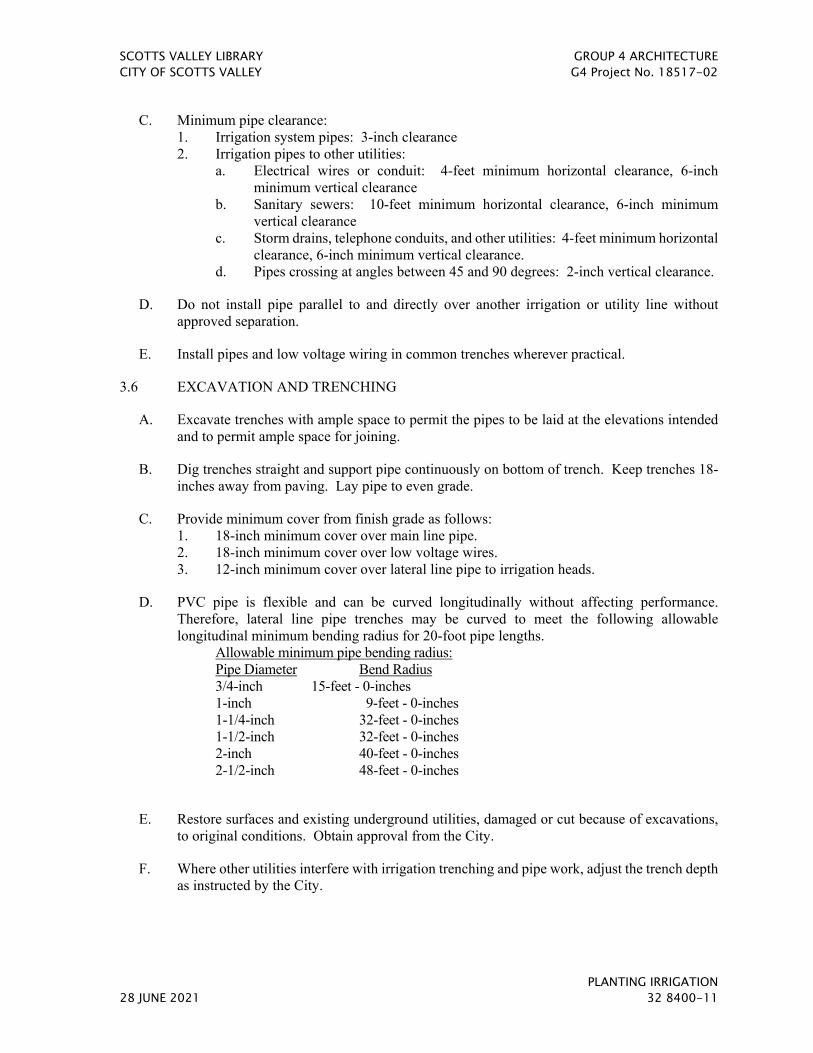
SCOTTS VALLEY LIBRARY GROUP 4 ARCHITECTURE CITY OF SCOTTS VALLEY G4 Project No. 18517-02
PLANTING IRRIGATION 28 JUNE 2021 32 8400-11
C. Minimum pipe clearance: 1. Irrigation system pipes: 3-inch clearance 2. Irrigation pipes to other utilities:
a. Electrical wires or conduit: 4-feet minimum horizontal clearance, 6-inch minimum vertical clearance
b. Sanitary sewers: 10-feet minimum horizontal clearance, 6-inch minimum vertical clearance
c. Storm drains, telephone conduits, and other utilities: 4-feet minimum horizontal clearance, 6-inch minimum vertical clearance.
d. Pipes crossing at angles between 45 and 90 degrees: 2-inch vertical clearance.
D. Do not install pipe parallel to and directly over another irrigation or utility line without approved separation.
E. Install pipes and low voltage wiring in common trenches wherever practical.
3.6 EXCAVATION AND TRENCHING
A. Excavate trenches with ample space to permit the pipes to be laid at the elevations intended and to permit ample space for joining.
B. Dig trenches straight and support pipe continuously on bottom of trench. Keep trenches 18-inches away from paving. Lay pipe to even grade.
C. Provide minimum cover from finish grade as follows: 1. 18-inch minimum cover over main line pipe. 2. 18-inch minimum cover over low voltage wires. 3. 12-inch minimum cover over lateral line pipe to irrigation heads.
D. PVC pipe is flexible and can be curved longitudinally without affecting performance. Therefore, lateral line pipe trenches may be curved to meet the following allowable longitudinal minimum bending radius for 20-foot pipe lengths.
Allowable minimum pipe bending radius: Pipe Diameter Bend Radius 3/4-inch 15-feet - 0-inches 1-inch 9-feet - 0-inches 1-1/4-inch 32-feet - 0-inches 1-1/2-inch 32-feet - 0-inches 2-inch 40-feet - 0-inches 2-1/2-inch 48-feet - 0-inches
E. Restore surfaces and existing underground utilities, damaged or cut because of excavations, to original conditions. Obtain approval from the City.
F. Where other utilities interfere with irrigation trenching and pipe work, adjust the trench depth as instructed by the City.

SCOTTS VALLEY LIBRARY GROUP 4 ARCHITECTURE CITY OF SCOTTS VALLEY G4 Project No. 18517-02
PLANTING IRRIGATION 32 8400-12 28 JUNE 2021
3.7 SLEEVES
A. Install at 12-inch minimum below bottom of pavement base, and at least as deep as required depth of pipe.
B. Extend sleeve 12-inch minimum beyond inside face of curb or edge of pavement.
C. Backfill and compact according to this specification under “Backfilling”.
D. Sleeve internal diameter is to be minimum twice the outside diameter for all pipes contained within sleeve and extend minimum 24-inches beyond edge of pavement. In-line fittings are not permitted in sleeves less than 20-feet long.
E. Provide wooden caps at ends of sleeves until pipe is installed.
F. Install extra 2-inch sleeve parallel to each sleeve and cap each end. Show locations on Record Drawings.
G. Install sleeves level and in a straight line.
H. Backfill with 4-inches of clean sand around circumference of sleeve, and compact by tamping.
3.8 PIPE ASSEMBLY
A. Install piping under existing concrete by jacking or boring. Where cutting or breaking of existing paved asphalt surface is necessary, remove the pavement, install the pipe or conduit, backfill and compact to original specifications. Restore paving as specified in Pavement Plans, as directed by Architect, and as approved by the City.
B. Install pipe in a dry trench and provide for expansion and contraction as described by the manufacturer of the pipe.
C. Cut plastic pipe with a pipe cutter or hack saw with the assistance of a squared-in sawing vice, or in a manner to ensure a square cut. Remove burrs at cut ends prior to installation to obtain a smooth unobstructed flow.
D. Use PVC pipe cleaner and primer on solvent weld PVC pipe before PVC solvent cement is applied.
E. Install piping in trench with manufacturer's markings (manufacturer, pipe size, Schedule or Class, pressure rating, etc.) facing up and readable to City during installation.
F. Pipe Jointing: Jointing shall be in conformance with the pipe manufacturer's installation instructions.
G. Joint Deflection for solvent welded pipe: Special care shall be taken to not have joint deflection while solvent welding pipe into socket fittings.

SCOTTS VALLEY LIBRARY GROUP 4 ARCHITECTURE CITY OF SCOTTS VALLEY G4 Project No. 18517-02
PLANTING IRRIGATION 28 JUNE 2021 32 8400-13
H. Paint below grade galvanized iron pipe and fittings with two coats of a corrosion preventative coating which is a composition of a coal tar base pitch, fast evaporating solvents and selected fillers.
I. Solvent Weld Joints: 1. Instruct each pipe installer in the proper assembly of solvent joints from a
representative of either the pipe, cement or fitting manufacturer before starting a job, unless the installer has been previously instructed in the recommended solvent cement procedures.
2. Prepare joint by first making sure the pipe end is square, then deburring the pipe end and cleaning pipe and fitting of dirt, dust and moisture with PVC pipe cleaner.
3. Dry-insert pipe into fitting to check for proper insertion depth. Pipe should enter fitting 1/3 to 2/3 depth of socket.
4. Coat the inside socket surface of the fitting and the external surface of the male end of the pipe with primer. Apply cement liberally to the male end of the pipe and apply cement lightly to the inside of the socket. Apply a second coat of cement to the pipe end.
5. Insert pipe immediately into fitting and turn 1/4 turn to distribute cement and remove air bubbles. The pipe must seat to the bottom of the socket and fitting. Check alignment of the fitting. Align pipe and fitting properly without strain to either.
6. Hold joint still for approximately thirty (30) seconds and wipe the excess cement from the pipe and fitting.
7. Cure joint a minimum of thirty (30) minutes before handling and at least six (6) hours before allowing water in the pipe.
J. Threaded Joint: 1. Field threading of plastic pipe or fittings is not permitted. Factory-made threads are the
permitted method. 2. Use factory-made metallic nipples whenever possible. Field-cut threads in metallic
pipe will be permitted where necessary. Cut threads accurately on axis with sharp dies. 3. Install threaded joints with pipe joint compound. Apply compound to male threads
and first two female threads. 4. Where assembling metallic pipe to metallic fitting or valve, expose no more than three
(3) full threads when joint is finished. 5. Where assembling threaded plastic fittings, take up joint no more than one full turn
beyond hand tight. 6. Where assembling soft metal (brass or copper) or plastic pipe, use strap type friction
wrench; do not use metal-jawed wrench.
K. Cap open pipe ends as pipe is assembled to prevent entrance of dirt or obstruction. Remove caps only when necessary to continue assembly.
L. Where pipes or control wires pass through sleeves, provide removable non-decaying plug material at ends of sleeve to prevent entrance of soil.
3.9 CONTROLLER
A. Remove existing controller. Salvage all existing control wire and power-off the existing 120 vac power source. Reroute existing control wire to new controller location as noted on the plans.

SCOTTS VALLEY LIBRARY GROUP 4 ARCHITECTURE CITY OF SCOTTS VALLEY G4 Project No. 18517-02
PLANTING IRRIGATION 32 8400-14 28 JUNE 2021
B. Install specified controller in new location as shown on Drawings. The exact location will be determined on the site by the City Engineer.
C. Provide conduit and wire and connect to 120 volt switch and GFCI protected duplex receptacle accessible to controller for ease of maintenance. 120 vac power provided under electrical contract work.
D. Controller is vendor mounted to a mounting plate. Mount assembly to a concrete wall as detailed on Drawings.
E. Connect existing and new control wires to controller in sequential arrangement according to original and new assigned identification number of valve.
F. Label each control wire at controller with a permanent non-fading label indicating station number of valve controlled. Permanently attach label to control wire.
E. Complete communication installation, connection, and activation to the controller. Demonstrate to the City Engineer that the controller communicates with the central computer.
F. Grounding: 1. Critical to the installation of the controller is the connection to a grounding rod - install
per the manufacturer's specifications. Do not connect to the electrical service ground, use a separate copper-clad grounding rod. Failure to ensure correct grounding may result in damage to the electronics and void the warranty.
2. Measure the resistance to ground of the grounding circuit. Resistance must be less than 50 ohms.
3. Connect the grounding rod to the controller with a #10 AWG bare copper wire.
3.10 REMOTE CONTROL VALVE
A. Provide excavation and backfill, furnishing, installing and testing of risers, fittings, and valve, and other Work in accordance with the Drawings and Specifications.
B. Install where shown on Drawings, group together where practical and in landscape areas. Limit three remote control valves per manifold and one remote control valve per box - No exceptions.
C. Thoroughly flush main line pipe before installing valves.
D. Label each valve with an identification tag, indicating identification number of valve (controller and station number). Permanently attach label to solenoid control wire.
E. Provide each remote control valve with its own threaded riser and connection to main line pipe. Do not manifold valves to a single riser from main line.
3.11 LOW VOLTAGE WIRING
A. Install wiring along the side of main line piping wherever practical.
B. Tie wires in bundles with pipe wrapping tape at 10-foot intervals and allow slack for contraction between strappings.
SCOTTS VALLEY LIBRARY GROUP 4 ARCHITECTURE CITY OF SCOTTS VALLEY G4 Project No. 18517-02
PLANTING IRRIGATION 28 JUNE 2021 32 8400-15
C. Loop a minimum of 3-feet of extra wire in a 1-inch diameter coil at each splice.
D. Make connections to wiring by twisting bare wires, securing with wire connectors and sealing with weatherproof wire splice assembly as shown on Drawings.
E. Splicing of valve control wire other than at valve or satellite controller is permitted only on runs exceeding 2500-feet. For this condition, locate splices within a separate 10-inch diameter valve box.
F. Where low voltage wires pass under pedestrian paving, install wire through Schedule 40 electrical conduit.
G. Install the wire in a logical manner, avoiding existing shrubs, trees, light posts, monuments, and signs.
3.12 BALL VALVE
A. Provide excavation and backfill, the furnishing and installing of fittings and valve, and other work in accordance with the Drawings and Specifications.
B. Set the valve box flush with finish grade unless otherwise designated on the Drawings.
C. Thoroughly flush pipe before installing valve.
D. Locate and install as shown on the Drawings and details.
E. Unless otherwise noted on the Drawings, place the valve in the open position when system is finished.
3.13 QUICK COUPLING VALVE
A. Provide excavation and backfill, the furnishing, installing, testing of risers, fittings, and valve, and other work in accordance with the Drawings and Specifications.
B. Set the valve perpendicular to the finish grade unless otherwise designated on the Drawings.
C. Thoroughly flush lines before installing valve.
D. Locate and install as shown on the Drawings and details.
3.14 VALVE BOX INSTALLATION
A. Do not saw cut the plastic valve boxes for any reason. Any sawcut box will require removal from site and replacement with a new replacement box.
B. Install bricks, gravel, and wire mesh as the Drawing details indicate.
C. Rectangular Valve Boxes: 1. Locate valve boxes at 12-inches from and perpendicular to walk edges, buildings, and
walls. Provide 12-inches between valve boxes where valves are grouped together. 2. Install four common bricks (one at each corner of box) under base of box for support.

SCOTTS VALLEY LIBRARY GROUP 4 ARCHITECTURE CITY OF SCOTTS VALLEY G4 Project No. 18517-02
PLANTING IRRIGATION 32 8400-16 28 JUNE 2021
3. Install 3/8-inch diameter pea gravel inside box for drainage. 4. No soil or collection of water permitted inside box. Install 10 mil. polyethylene tape
to box side cutouts and pipe where pipe exits box (where applicable). 5. Indicate box locations on Record Drawings. 6. Lock box lid at end of project.
D. Round Valve or Splice Boxes: 1. Locate valve boxes at 12-inches from walk edges, buildings, and walls. Provide 12-
inches between valve boxes where valves are grouped together. 2. Install two common bricks (one on each side) under base of box for support. 3. Install 3/8-inch diameter pea gravel inside box for drainage. 4. No soil or collection of water permitted inside box. Install 10 mil. polyethylene tape
to box side cutouts and pipe where pipe exits box (where applicable). 5. Indicate box locations on Record Drawings. 6. Indicate splice box locations on Record Drawings and note which field satellite the
wires originate from and the quantity of wires available. 7. Lock box lid with threaded bolt at end of project, hand tight.
3.15 EMITTERS OR EMITTER TUBING
A. Provide excavation and backfill, furnishing, installing and testing of risers, fittings, emitter heads, tubing, and other Work in accordance with the Drawings and Specifications.
B. Thoroughly flush PVC lateral line piping before installing heads or tubing.
C. Do not use pipe joint compound on inlet threads.
D. Locate and install heads or tubing as shown on the Drawings and details.
3.16 BACKFILLING
A. Do not allow the Work of this Contract to be covered or enclosed until it has been inspected, tested and approved in writing by the City. Should Work be enclosed or covered before inspection and test, uncover the Work at no additional expense to the City.
B. Backfill material: Earth excavated from the trenches, free from rocks, concrete chunks, and other foreign or coarse materials. Select backfill that is to be placed next to plastic pipe to avoid any sharp objects that may damage the pipe.
C. Backfill PVC plastic pipe under asphalt paving with 6 inches of clean sand on all sides of pipe unless it is contained within a sleeve.
D. Place backfill materials in 6-inch layers and compact by jetting or tamping to a minimum compaction density equal to original soil density.
E. Grade areas to finish grade and remove excess soil, rocks or debris remaining after backfilling is completed.

SCOTTS VALLEY LIBRARY GROUP 4 ARCHITECTURE CITY OF SCOTTS VALLEY G4 Project No. 18517-02
PLANTING IRRIGATION 28 JUNE 2021 32 8400-17
F. If settlement occurs along trenches, and adjustment of pipes, valves and sprinkler heads, soil, or paving is necessary to bring these items to the proper level or the permanent grade, provide adjustments at no additional expense to the City.
3.17 FLUSHING
A. Prior to leakage testing, thoroughly flush with water to remove debris introduced into the piping during the construction operations. Open valve outlets and continue flushing operations until clear water flows.
3.18 TESTS
A. General. Test pipelines for leakage in accordance with the requirements specified for each type of pipe. Provide materials and labor required for the leakage test including pumps, gauges, temporary plugs, and thrust blocks. Use laboratory calibrated test gauges recalibrated by a certified laboratory at the Contractor’s expense prior to the leakage test if requested by the City. Block off during the testing, valves and appurtenances that might be damaged by the test pressure and provide suitable thrust restraints. If the test of any section of pipe results in leakage greater than the specified allowable amount, repair the defective work and retest that section until the leakage is within the allowable amount. Water for testing will be furnished by the City from available sources at the site. Pay for the cost of water and perform testing at no additional expense to the City.
B. Notify the City at least three (3) days in advance of testing.
C. Center load piping with small amount of backfill to prevent arching or slipping under pressure. Do not cover fittings.
D. PVC pipe (solvent weld joints) - Apply the following tests after solvent weld plastic pipe joints have cured at least 24 hours: 1. Test main line piping upstream of remote control valves with water at 120 PSI pressure
for 6 hours. Visually inspect for leaks. Pressure is to remain constant during test. Retest after correcting defects.
2. Test lateral line piping downstream of remote control valves with water at line pressure and visually inspect for leaks. Retest after correcting defects.
3. Remake any faulty joints with new materials. Use of cement or caulking to seal leaks is absolutely prohibited.
3.19 PROTECTION OF PROPERTY
A. The existing services and irrigation equipment as indicated on the Drawings shall remain operational are shown diagrammatically. Field verify the sizes, location, and proper operation of existing equipment to remain operational within and beyond the Contract Area. This includes, but is not limited to the following: 1. Existing irrigation at interface areas between the Contract Area and adjacent irrigation
areas that are to remain operational. 2. Utilities servicing buildings within and beyond the Contract Area. 3. Potable (domestic) water services to buildings within and beyond the Contract Area.

SCOTTS VALLEY LIBRARY GROUP 4 ARCHITECTURE CITY OF SCOTTS VALLEY G4 Project No. 18517-02
PLANTING IRRIGATION 32 8400-18 28 JUNE 2021
B. Notify the City prior to field verification of existing utilities and irrigation. Provide a report, in writing to the City for review and possible revision, any deviation of existing services and irrigation equipment as shown on the Drawings.
C. Contact Underground Service Alert (U.S.A.) at (800) 642-2444 for location and marking of existing utilities prior to construction.
3.20 GUARANTEE
A. Fill and repair depressions due to the settlement of irrigation trenches for one year following completion and acceptance of the job.
B. Guarantee materials, equipment and workmanship furnished to be free of defects and agree to replace at no additional expense to the City, upon demand within one year after installation is accepted, defective components or installations that may be found.
3.21 CLEAN-UP
A. When Work of this section has been completed and at such other times as may be directed by the City, remove all trash, debris, surplus materials and equipment from site.
END OF SECTION 32 8400

SCOTTS VALLEY LIBRARY GROUP 4 ARCHITECTURE CITY OF SCOTTS VALLEY G4 Project No. 18517-02
SOIL PREPARATION 28 JUNE 2021 32 9113-1
SECTION 32 9113 - SOIL PREPARATION
PART 1 - GENERAL
1.1 SUMMARY
A. Section Includes: 1. Container planting soil mix. 2. Imported topsoil. 3. Amendment for existing soil to be amended in-place. 4. Soil sampling and testing prior to planting.
B. Related Requirements: 1. Section 01 5639 – Temporary Tree and Plant Protection 2. Section 31 1300 - Selective Tree and Shrub Removal 3. Section 32 8400 - Landscape Irrigation 4. Section 32 9119 - Planting Area Finish Grading 5. Section 32 9120 - Planting Soil 6. Section 32 9300 - Planting Materials
1.2 REFERENCES
A. General: The following published specifications, standards, tests, or recommended methods of trade, industry, or governmental organizations apply to Work of this Section where cited by abbreviations noted below. The latest edition applies, unless otherwise noted.
B. ASTM International (ASTM): 1. ASTM D1557 - Test Method for Laboratory Compaction Characteristics of Soil Using
Modified Effort.
C. United States Department of Agriculture (USDA): 1. Soil Texture Triangle Classification. 2. USDA Handbook No. 60.
1.3 DEFINITIONS
A. Aesthetic Acceptance of Grades: Acceptance by the Owner’s Representative in writing of the aesthetic correctness of the contours as observed without a survey instrument. Aesthetic acceptance does not address whether an area drains properly, whether the areas are at the correct elevation, or whether it has been compacted properly.
B. Drip Line: Line straight down from outermost limit of tree canopy branching.
C. Excessive Compaction: Planting area soil compaction greater than 75 percent of maximum dry density as determined by ASTM D1557.
D. Finished Grades: The soil surface grade elevations and contours indicated on the Drawings.
E. Tree Protection Zone: The ground area within tree protection fencing.

SCOTTS VALLEY LIBRARY GROUP 4 ARCHITECTURE CITY OF SCOTTS VALLEY G4 Project No. 18517-02
SOIL PREPARATION 32 9113-2 28 JUNE 2021
F. Horticultural Consultant: Project arborist.
1.4 ADMINISTRATIVE REQUIREMENTS
A. Submittal Procedures: Action and Informational Submittals shall be submitted in accordance with Section 01 3000 - Submittal Procedures.
1.5 ACTION SUBMITTALS
A. Product Data: 1. Chemical additives. 2. Fertilizers. 3. Organic amendment.
1.6 INFORMATIONAL SUBMITTALS
A. Test Reports: 1. Import Topsoil: Laboratory soil test reports indicating specified characteristics of
surface soils, with test date no more than 2 weeks old. 2. Replanted Areas: Laboratory soil test reports indicating specified characteristics of
surface soils, with test date no more than 2 weeks old. 3. Laboratory test report of organic amendment indicating specified characteristics of
organic amendment, with test date no more than 2 weeks old.
B. Purchase Documentation: 1. Organic Amendment purchase and delivery notices. 2. Fertilizer purchase and delivery invoices. 3. Chemical amendment purchase and delivery invoices.
1.7 QUALITY ASSURANCE
A. Requirements of Regulatory Agencies: 1. Meet requirements of applicable laws, codes, and regulations required by authorities
having jurisdiction over Work. 2. Provide for inspections and permits required by federal, state and local authorities in
furnishing, transporting, and installing materials.
B. Settlement Mock-Up: See Section 32 9120 - Planting Soil.
C. Soil Testing Laboratory: Soils testing shall be performed by Waypoint Analytical California, Inc. (Formerly Soil & Plant Laboratory, Inc.), 4741 East Hunter Ave., Suite A, Anaheim, CA 92807, (714) 282-8777, Email: [email protected], Perry Laboratory, 424 Airport Boulevard, Watsonville, CA 95076, (831) 722-7606, http://perrylaboratory.com/contact.shtml; or equivalent laboratory approved by the Owner’s Representative. Contractor shall arrange to collect, transport and pay for all soil testing.
1.8 FIELD CONDITIONS
A. Environmental Requirements:

SCOTTS VALLEY LIBRARY GROUP 4 ARCHITECTURE CITY OF SCOTTS VALLEY G4 Project No. 18517-02
SOIL PREPARATION 28 JUNE 2021 32 9113-3
1. Do not work soil when moisture content is so great that excessive compaction will occur, or when it is so dry that dust will form in the air, or that clods will not break readily.
2. Apply water, if necessary, to bring soil to an optimum moisture content for tilling. 3. Do not work soil when muddy or frozen. 4. Do not apply chemicals if wind conditions will cause hazardous drift to people or
property.
B. Existing Conditions: 1. Prior to Work commencement review and clearly mark in field horizontal and vertical
locations of existing public underground utilities and structures with respective utility companies.
2. Prior to Work commencement review and clearly mark in field horizontal and vertical locations of existing private underground utilities and structures with the Owner’s Representative.
PART 2 - PRODUCTS
2.1 DESIGN AND PERFORMANCE CRITERIA
A. Soil Mixes, Backfill Mixes, and Amended Planting Area Surface Soil: Uncompacted on-site soil with amendments incorporated uniformly to provide a well-draining, fertile medium for vigorous plant root growth.
B. Planting Soil: 1. Free-draining. 2. Meets requirements for Planting Soil mix.
C. Sustainable Design: 1. Local/Regional Materials: Give preference to manufacturer’s whose facilities are
within a 500 mile radius of the project site. Also give preference to materials that are harvested, extracted, mined, quarried, etc. within a 500 mile radius of the project site.
2.2 MATERIALS
A. Imported Topsoil for Planting Areas: 1. General: Imported planting soil shall be friable and have sufficient structure in order
to give good tilth and aeration to the soil. When amended, fertilized, and conditioned, the soil must be friable, be well drained, and be supportive of vigorous plant growth and contain low concentrations of inhibitory constituents. The soil must have sufficient moisture retention and nutrient retention to avoid excessive frequency of irrigation and frequency of fertilizer application. The soil must be clean and free of excessive gravel, rock, and physical impurities.
2. Deleterious Materials: Free of roots, clods, stones larger than 1 inch in the greatest dimension, pockets of coarse sand, noxious weeds, sticks, lumber, brush, and other debris.
3. Disease-causing Organisms: Free of infestation of nematodes or other undesirable disease-causing organisms such as insects and plant pathogens.

SCOTTS VALLEY LIBRARY GROUP 4 ARCHITECTURE CITY OF SCOTTS VALLEY G4 Project No. 18517-02
SOIL PREPARATION 32 9113-4 28 JUNE 2021
4. Gradation: Sandy loam as classified by the USDA Soil Texture Triangle classification method. Gravel over 1/4-inch diameter shall be less than 20 percent by weight.
5. Permeability Rate: Hydraulic conductivity rate shall be not less than 3 inches per hour, nor more than 10 inches per hour when tested in accordance with the USDA Handbook, No. 60, Method 34B or other accepted methods.
6. Acceptable Fertility Range Prior to Amendment: Ammonium Bicarbonate / DTPA Extraction Parts per million (mg/kg dry-weight basis)
Phosphorus: 2.0 – 40.0 Potassium: 40.0 – 220.0 Iron: 2.0 – 35.0 Manganese: 0.3 – 6.0 Zinc: 0.6 – 8.0 Copper: 0.1 – 5.0 Boron: 0.2 – 1.0 Magnesium: 50.0 – 150.0 Sodium: 0 – 100.0 Sulfur: 25.0 – 500.0 Molybdenum: 0.1 – 2.0
7. Final Acceptable Fertility Range After Amendment:
Ammonium Bicarbonate / DTPA Extraction Parts per million (mg/kg dry-weight basis)
Phosphorus: 10.0 – 40.0 Potassium: 100.0 – 220.0 Iron: 24.0 – 35.0 Manganese: 0.6 – 6.0 Zinc: 1.0 – 8.0 Copper: 0.3 – 5.0 Boron: 0.2 – 1.0 Magnesium: 50.0 – 150.0 Sodium: 0 – 100.0 Sulfur: 25.0 – 500.0 Molybdenum: 0.1 –2.0
8. Acidity: 5.5 – 6.5 soil pH range measured in the saturation extract (Method 21a, USDA
Handbook No. 60). 9. Salinity: 0.5 – 2.5 dS/m salinity range measured in the saturation extract (Method 3a,
USDA Handbook No. 60). 10. Chloride: 150 mg/liter (parts per million) maximum concentration of soluble chloride
in the saturation extract (Method 3a, USDA Handbook No. 60). 11. Boron: 1-mg/liter (parts per million) maximum concentration of soluble boron in the
saturation extract (Method 3a, USDA Handbook No. 60). 12. Sodium Adsorption Ratio (SAR): Maximum of 3.0 measured per Method 20b, USDA
Handbook No. 60.
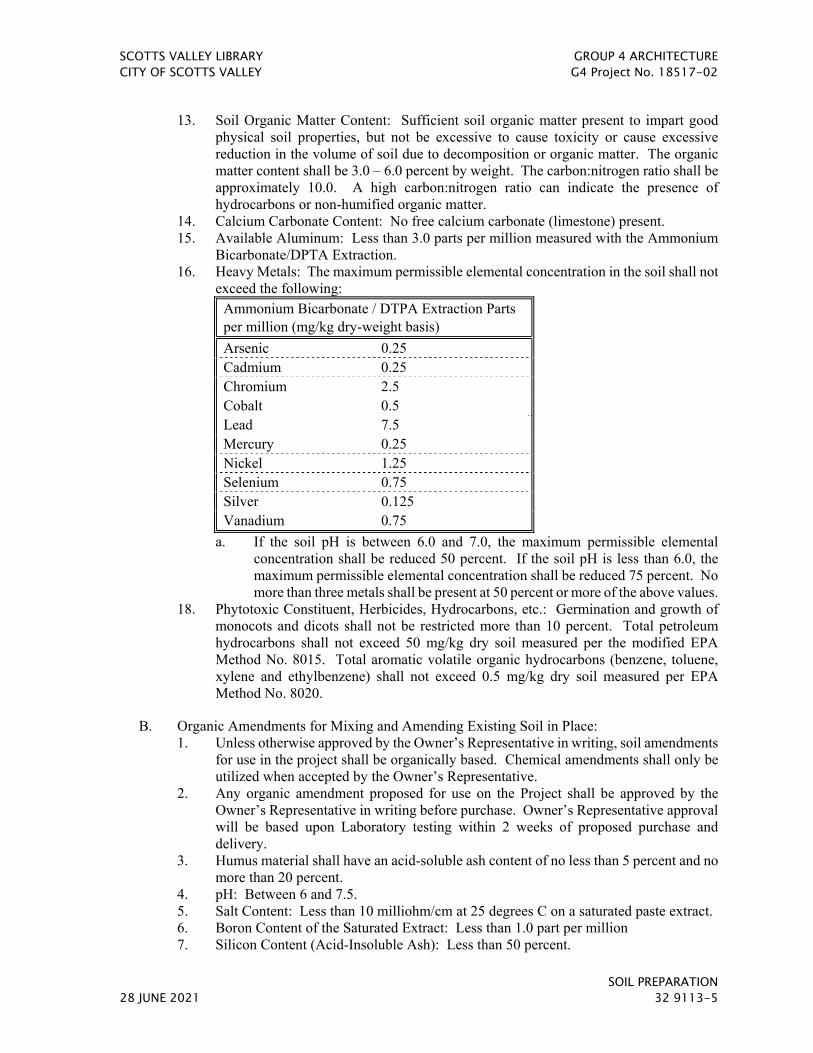
SCOTTS VALLEY LIBRARY GROUP 4 ARCHITECTURE CITY OF SCOTTS VALLEY G4 Project No. 18517-02
SOIL PREPARATION 28 JUNE 2021 32 9113-5
13. Soil Organic Matter Content: Sufficient soil organic matter present to impart good physical soil properties, but not be excessive to cause toxicity or cause excessive reduction in the volume of soil due to decomposition or organic matter. The organic matter content shall be 3.0 – 6.0 percent by weight. The carbon:nitrogen ratio shall be approximately 10.0. A high carbon:nitrogen ratio can indicate the presence of hydrocarbons or non-humified organic matter.
14. Calcium Carbonate Content: No free calcium carbonate (limestone) present. 15. Available Aluminum: Less than 3.0 parts per million measured with the Ammonium
Bicarbonate/DPTA Extraction. 16. Heavy Metals: The maximum permissible elemental concentration in the soil shall not
exceed the following: Ammonium Bicarbonate / DTPA Extraction Parts per million (mg/kg dry-weight basis)
Arsenic 0.25 Cadmium 0.25 Chromium 2.5 Cobalt 0.5 Lead 7.5 Mercury 0.25 Nickel 1.25 Selenium 0.75 Silver 0.125 Vanadium 0.75
a. If the soil pH is between 6.0 and 7.0, the maximum permissible elemental concentration shall be reduced 50 percent. If the soil pH is less than 6.0, the maximum permissible elemental concentration shall be reduced 75 percent. No more than three metals shall be present at 50 percent or more of the above values.
18. Phytotoxic Constituent, Herbicides, Hydrocarbons, etc.: Germination and growth of monocots and dicots shall not be restricted more than 10 percent. Total petroleum hydrocarbons shall not exceed 50 mg/kg dry soil measured per the modified EPA Method No. 8015. Total aromatic volatile organic hydrocarbons (benzene, toluene, xylene and ethylbenzene) shall not exceed 0.5 mg/kg dry soil measured per EPA Method No. 8020.
B. Organic Amendments for Mixing and Amending Existing Soil in Place: 1. Unless otherwise approved by the Owner’s Representative in writing, soil amendments
for use in the project shall be organically based. Chemical amendments shall only be utilized when accepted by the Owner’s Representative.
2. Any organic amendment proposed for use on the Project shall be approved by the Owner’s Representative in writing before purchase. Owner’s Representative approval will be based upon Laboratory testing within 2 weeks of proposed purchase and delivery.
3. Humus material shall have an acid-soluble ash content of no less than 5 percent and no more than 20 percent.
4. pH: Between 6 and 7.5. 5. Salt Content: Less than 10 milliohm/cm at 25 degrees C on a saturated paste extract. 6. Boron Content of the Saturated Extract: Less than 1.0 part per million 7. Silicon Content (Acid-Insoluble Ash): Less than 50 percent.

SCOTTS VALLEY LIBRARY GROUP 4 ARCHITECTURE CITY OF SCOTTS VALLEY G4 Project No. 18517-02
SOIL PREPARATION 32 9113-6 28 JUNE 2021
8. Calcium Carbonate: Shall not be present if the amendment is to be applied on alkaline soils.
9. Types of acceptable products are composts, manures, mushroom composts, straw, alfalfa, peat mosses, etc., low in salts, low in heavy metals, free from weed seeds, free of pathogens and other deleterious materials.
10. Composted wood products are conditionally acceptable (stable humus must be present).
11. Wood-based products which are based on redwood or cedar are not acceptable. 12. Sludge-based materials are not acceptable. 13. Carbon-Nitrogen Ratio: Less than 5:1. 14. Compost: Aerobic without malodorous presence of decomposition products. 15. Maximum particle size
a. For Mixing with Soil: 0.5-inch and 80 percent or more shall pass a No. 4 screen. b. For Applying via Hydroseeding Machine: 0.25-inch.
16. Maximum total permissible pollutant concentrations in organic amendment in parts per million on a dry-weight basis:
Arsenic: 20 Cadmium: 15 Chromium: 300 Cobalt: 50 Copper: 150 Lead: 200 Mercury: 10 Molybdenum: 20 Nickel: 100 Selenium: 50 Silver: 10 Vanadium: 400 Zinc: 250
Higher amounts of salinity or boron may be present if the soils are to be pre-leached to reduce the excess or if the plant species will tolerate the salinity and/or boron.
17. From 45- to 65-percent moisture measured via wet-weight basis. 18. Free of stones and debris. 19. Tests 5 to 8 on Solvita Test.
C. Fertilizers: The following, or equal. 1. Southern Organics & Supply, 866 240-8501; www.southernorganicsand supply.com. 2. Vermi Technology Unlimited, 352 591-1111; www.vermitechnology.com. 3. Kelly’s Green Team, 660 627-5500; www.kellysgreenteam.com.
D. Potential Chemical Amendments Required by Accepted Amendment Program and Backfill Mix: 1. Chemical Amendments will only be used if accepted by the Owner’s Representative
in writing. 2. Ground Limestone: Agricultural limestone containing not less than 85 percent of total
carbonate, ground to such fineness that 50 percent will pass No. l sieve and 90 percent will pass No. 20 sieve.

SCOTTS VALLEY LIBRARY GROUP 4 ARCHITECTURE CITY OF SCOTTS VALLEY G4 Project No. 18517-02
SOIL PREPARATION 28 JUNE 2021 32 9113-7
3. Dolomite Lime: Agricultural grade mineral soil conditioner containing 35 percent minimum magnesium carbonate and 49 percent minimum calcium carbonate, 100 percent passing No. 65 sieve.
4. Gypsum: Agricultural grade product containing 80 percent minimum calcium sulfate. 5. Iron Sulfate (Ferric or Ferrous): Supplied by a commercial fertilizer supplier,
containing 20 to 30 percent iron and 35 percent to 40 percent sulfur. 6. Sulfate of Potash: Agricultural grade containing 50 to 53 percent of water-soluble
potash. 7. Single Superphosphate: Commercial product containing 20 to 25 percent available
phosphoric acid. 8. Ammonium Sulfate: Commercial product containing approximately 21 percent
ammonia. 9. Ammonium Nitrate: Commercial product containing approximately 34 percent
ammonia. 10. Calcium Nitrate: Agricultural grade containing 15-1/2 percent nitrogen. 11. Urea Formaldehyde: Granular commercial product containing 38 percent nitrogen. 12. IBDU (Iso Butyldiene Diurea): Commercial product containing 31 percent nitrogen. 13. Soil Sulfur: Agricultural grade sulfur containing a minimum of 96 percent sulfur. 14. Silicic Acid Calcium: Commercial grade.
2.3 SOURCE QUALITY CONTROL
A. Soil Analysis to Verify Chemical and Physical Characteristics of Topsoil Proposed for Importation: 1. Take representative samples from at least 3 locations at topsoil source. 2. Send samples to an independent soil testing laboratory and employ the laboratory to
test the soil samples for the following: 3. pH measurement in the saturation extract per USDA Handbook No. 60, Method 21. 4. Electrical conductivity of the saturation extract per USDA Handbook No. 60, Method
2. 5. Sodium absorption ratio of the saturation extract per USDA Handbook No. 60, Method
20b. 6. Determination of boron, calcium, copper, iron, magnesium, manganese, molybdenum,
phosphorous, potassium, sodium, sulfur, and zinc, via the following test methods: Mehlich Number 3, Bray P1, Bray P2, Olsen P, DTPA, ammonium acetate, ammonium bicarbonate DTPA, and hot water extract from boron.
7. Analysis of saturation extract for calcium, magnesium, sodium, boron, chloride, phosphorous, nitrate, and sulfate.
8. Measurement of following trace metals by the DTPA extract: aluminum, arsenic, cadmium, chromium, cobalt, lead, lithium, nickel, selenium, silver, strontium, tin, and vanadium.
9. Presence of calcium carbonate and magnesium carbonate. 10. Estimate of soil texture per commonly used methods. 11. Estimate of organic matter content per commonly used methods. 12. Exchangeable Ammonium cation. 13. Base Saturation. 14. Cation Exchange Capacity. 15. Carbonates Determination. 16. Soil Bulk Density. 17. Water Infiltration Rate per USDA Handbook No. 60, Method 34b.

SCOTTS VALLEY LIBRARY GROUP 4 ARCHITECTURE CITY OF SCOTTS VALLEY G4 Project No. 18517-02
SOIL PREPARATION 32 9113-8 28 JUNE 2021
18. At least 30 days prior to transport of topsoil to project site, submit laboratory’s written soil analysis report including soil analysis data and amendment recommendations to the Architect/Engineer for verification of the required topsoil chemical and physical characteristics.
B. Soil Tests for Parasitic Nematodes for Imported Planting Media: 1. Test soils which have been used for agricultural purposes within the prior 12 months
for parasitic nematodes. 2. Soil will be acceptable if the parasitic nematode population is less than 200 per 50
cubic centimeters of soil. 3. Do not artificially dry soil prior to testing. 4. Submit written test report to the Owner’s Representative.
C. Organic Amendment: Employ independent soil testing laboratory to test organic amendment for specified properties and submit test results. 1. Sphagnum peat moss is not acceptable.
D. Imported Soils and Amendments: 1. If imported soils are required, source soils shall have a comparable origin to on-site
locations. 2. Imported soils shall not be sourced from Natural Resource web soil survey as prime
farmland, unique farmland or farmland of statewide or local importance; or form greenfield sites.
E. Lime treated soils: Sample and submit soil sample taken from planting areas adjacent to any lime treatment. Request soil test and report agricultural suitability and amendments. Amend per recommendations.
2.4 SOIL MIX
A. Preliminary Planting Area Soil Mix to Establish Bid (actual quantities contingent on amendment program determined by the Owner’s Representative based on soil test report) as follows: 1. Content:
a. 8 cubic feet of organic amendment per cubic yard of dry soil. b. 2 pounds Iron Sulfate per cubic yard of dry soil. c. 1-pound granular Micromax per cubic yard of dry soil. d. 1/2-pound Triple Superphosphate 0-45-0 per cubic yard of dry soil. e. 1-pound of Nitroform 38-0-0 per cubic yard dry soil. f. 1-pound of Potassium Sulfate 0-0-50 per cubic yard dry soil.
B. Mixing: 1. Blend amendment materials uniformly with dry existing soil from stock pile and plant
pits or dry imported Planting Soil in bulk by turning over materials with an end loader. 2. Blend materials in a clean area which will not contaminate mix. 3. Do not mix in planting areas.
C. Final Planting Soil Mix for Installation: Planting soil mixes determined by the Owner’s Representative upon review of the soil test report.

SCOTTS VALLEY LIBRARY GROUP 4 ARCHITECTURE CITY OF SCOTTS VALLEY G4 Project No. 18517-02
SOIL PREPARATION 28 JUNE 2021 32 9113-9
D. Container Planter Soil Mix: Import topsoil amended upon review of soil test report.
E. Plant Soil Depths: As indicated on the Drawings.
2.5 SOURCE QUALITY CONTROL
A. Organic Amendment: Employ independent soil testing laboratory to test organic amendment for specified properties and submit test results. 1. Sphagnum peat moss is not acceptable.
B. Imported Soils and Amendments: 1. If imported soils are required, source soils shall have a comparable origin to on-site
locations. 2. Imported soils shall not be sourced from Natural Resource web soil survey as prime
farmland, unique farmland or farmland of statewide or local importance; or from greenfield sites.
PART 3 - EXECUTION
3.1 EXAMINATION
A. General: Examine site and verify that conditions are suitable to receive Work and that no defects or errors are present which would cause defective installation of products or cause latent defects in workmanship and function.
B. Subgrade: Verify that the subgrade is at the correct elevation and slope.
C. Underground Utilities and Structures: Verify that the locations of utilities, structures and other underground items have been clearly marked.
D. Notification of Unsuitable Conditions: Before proceeding with Work, notify the Owner’s Representative in writing of unsuitable conditions and conflicts.
E. Soil Tests to Determine Final Planting Soil Mix, Planting Area Soil Surface Amendment Programs, and Maintenance Period Fertilization Programs: 1. Take three 1-pound composite representative soil samples from locations determined
by the Owner’s Representative in the field. 2. Send samples to an independent soil testing laboratory and employ the laboratory to
test the soil samples for the following: a. pH measurement in the saturation extract per USDA Handbook No. 60, Method
21. b. Electrical conductivity of the saturation extract per USDA Handbook No. 60,
Method 2. c. Sodium absorption ratio of the saturation extract per USDA Handbook No. 60,
Method 20b. d. Determination of boron, calcium, copper, iron, magnesium, manganese,
molybdenum, phosphorous, potassium, sodium, sulfur, and zinc, via the following test methods: Mehlich Number 3, Bray P1, Bray P2, Olsen P, DTPA,

SCOTTS VALLEY LIBRARY GROUP 4 ARCHITECTURE CITY OF SCOTTS VALLEY G4 Project No. 18517-02
SOIL PREPARATION 32 9113-10 28 JUNE 2021
ammonium acetate, ammonium bicarbonate DTPA, and hot water extract from boron.
e. Analysis of saturation extract for calcium, magnesium, sodium, boron, chloride, phosphorous, nitrate, and sulfate.
f. Measurement of following trace metals by the DTPA extract: aluminum, arsenic, cadmium, chromium, cobalt, lead, lithium, nickel, selenium, silver, strontium, tin, and vanadium.
g. Presence of calcium carbonate and magnesium carbonate. h. Estimate of soil texture per commonly used methods. i. Estimate of organic matter content per commonly used methods. j. Exchangeable Ammonium Cation. k. Base Saturation. l. Cation Exchange Capacity. m. Carbonates Determination. n. Soil Bulk Density. o. Water Infiltration Rate per USDA Handbook No. 60, Method 34b.
3. At least 30 days prior to commencement of soil preparation Work, submit to the Owner’s Representative the laboratory’s written soil test report including the laboratory’s soil test data; the laboratory’s interpretation of nutritional deficiencies, excesses, and potential toxicities; the laboratory’s amendment recommendations; and the laboratory’s maintenance recommendations.
4. The Owner’s Representative will determine the final amendment and maintenance period fertilization programs based on the soil test report which may differ from the soil test report amendment recommendations.
F. Soil Tests for Parasitic Nematodes: 1. Test soils which have been used for agricultural purposes within the prior 12 months
for parasitic nematodes. 2. Soil will be acceptable if the parasitic nematode population is less than 200 per 50
cubic centimeters of soil. 3. Do not artificially dry soil prior to testing. 4. Submit written test report to the Owner’s Representative.
G. Soil Tests for Herbicide Contamination: 1. Perform a radish/rye grass growth trial on soils suspected of herbicide contamination. 2. Submit written test report to the Owner’s Representative.
3.2 PREPARATION
A. Refer to Section 32 9120 - Planting Soil.
3.3 RIPPING AND TILLING
A. Refer to Section 32 9120 - Planting Soil.
3.4 FIELD QUALITY CONTROL
A. Soil Amendment Verification:
SCOTTS VALLEY LIBRARY GROUP 4 ARCHITECTURE CITY OF SCOTTS VALLEY G4 Project No. 18517-02
SOIL PREPARATION 28 JUNE 2021 32 9113-11
1. Schedule the Owner’s Representative to take up to 5 random composite samples of amended soil surface areas and soil mixes for laboratory testing to verify amendment composition.
2. Submit composite samples collected by the Owner’s Representative to the same soil testing laboratory used to test the soil as specified herein.
3. Employ the laboratory to test soil samples and submit test results to the Owner’s Representative.
4. Perform corrective work as recommended by the laboratory soil test reports if directed to do so by the Owner’s Representative.
5. When a laboratory soil test indicates that the soil or soil mixes meet the requirements of the Specifications the Contractor will receive written notification of acceptance from the Owner’s Representative.
6. Installation of ground cover plants and seed may commence upon Contractor’s receipt of the written notification of acceptance.
3.5 CLEANING
A. Construction Waste Management: 1. Dispose of construction waste off the property at the contractor’s expense. Contractor
to maintain the site in an orderly fashion and leave the site in a clean and tidy condition at the end of each workday.
END OF SECTION 32 9113

WilliamL
Snapshot

SCOTTS VALLEY LIBRARY GROUP 4 ARCHITECTURE CITY OF SCOTTS VALLEY G4 Project No. 18517-02
PLANT AREA FINISH GRADING 28 JUNE 2021 32 9119-1
SECTION 32 9119 - PLANTING AREA FINISH GRADING
PART 1 - GENERAL
1.1 SUMMARY
A. Section Includes: 1. Finish grading of imported planting soils and existing soil at planting areas to remain
prior to plant installation. 2. Touch-up finish grading of planting areas after plants are installed. 3. Repair to Existing Plants to Remain damaged by Construction Activities.
B. Related Sections: 1. Section 32 8400 - Landscape Irrigation 2. Section 32 9113 - Soil Preparation 3. Section 32 9120 - Planting Soil 4. Section 32 9300 - Planting Materials
1.2 REFERENCES
A. General: The following published specifications, standards, tests, or recommended methods of trade, industry, or governmental organizations apply to Work of this Section where cited by abbreviations noted below. The latest edition applies, unless otherwise noted.
B. ASTM International (ASTM): 1. ASTM D1557 - Test Method for Laboratory Compaction Characteristics of Soil Using
Modified Effort.
1.3 DEFINITIONS
A. Aesthetic Acceptance of Finish Grades: Acceptance by the Owner’s Representative in writing of the aesthetic correctness of the contours and surface smoothness. Aesthetic acceptance does not address whether an area drains properly, whether the areas are at the correct elevations, or whether it has been compacted properly.
B. Excessive Compaction: Planting area soil or soil mix compaction greater than 80 percent maximum dry density as determined by ASTM D1557.
C. Existing Planting Areas to Remain: Site Areas, identified on the drawings within the limits of work where construction activities are to be minimized to preserve existing plants and irrigation- unless otherwise accepted by the Owner’s Representative in writing.
D. Finished Grades: The required final soil surface grade elevations indicated on the Drawings.
E. Soil Subgrade: The soil surface on which soil mixes, aggregate base, and drain rock are placed.
F. Tree Protection Zone: The ground area within the tree protection fencing.

SCOTTS VALLEY LIBRARY GROUP 4 ARCHITECTURE CITY OF SCOTTS VALLEY G4 Project No. 18517-02
PLANTING AREA FINISH GRADING 32 9119-2 28 JUNE 2021
1.4 SEQUENCING
A. Planting Work: Except for touch-up finish grading, perform finish grading work prior to staking of plant locations and excavation of plant pits.
1.5 FIELD CONDITIONS
A. Environmental Requirements: 1. Do not work soil when moisture content is so great that excessive compaction will
occur, nor when it is so dry that dust will form in the air or that clods will not break readily.
2. Apply water, if necessary, to bring soil to an optimum moisture content for grading. 3. Do not work soil when muddy or frozen.
B. Existing Conditions: 1. Prior to Work commencement review and clearly mark in field horizontal and vertical
locations of existing public underground utilities and structures with respective utility companies.
2. Prior to Work commencement review and clearly mark in field horizontal and vertical locations of existing private underground utilities and structures with the Owner’s Representative.
PART 2 - PRODUCTS (NOT USED)
PART 3 - EXECUTION
3.1 EXAMINATION
A. General: Examine site and verify that conditions are suitable for finish grading Work, and that no defects or errors are present which would interfere with or cause incorrect finish grading Work to occur.
B. Excessive Compaction: Verify that the planting soil is compacted no more than 80 percent relative density as determined by ASTM D1557.
C. Soil Preparation: Verify that subsoil ripping and soil preparation Work is complete.
3.2 PREPARATION
A. Protection of Existing Conditions: 1. Use every possible precaution to prevent damage to existing conditions to remain such
as structures, utilities, irrigation systems, plant materials and paving on or adjacent to the site of the Work.
2. Provide barricades, fences or other barriers to protect existing conditions to remain from damage during construction.
3. Use every possible precaution to prevent excessive compaction of planting area soil within or adjacent to the areas of Work.
SCOTTS VALLEY LIBRARY GROUP 4 ARCHITECTURE CITY OF SCOTTS VALLEY G4 Project No. 18517-02
PLANT AREA FINISH GRADING 28 JUNE 2021 32 9119-3
4. Do not store materials or equipment, permit burning, or operate or park equipment under the branches of existing plants to remain.
5. Submit written notification of conditions damaged during construction to the Owner’s Representative immediately.
3.3 FIELD ENGINEERING
A. General: 1. Establish lines and levels; locate and lay out by instrumentation and similar appropriate
means for planting area finish grades. 2. Provide as many grade stakes and string lines as required to achieve smooth finish
grades acceptable to the Owner’s Representative with positive surface drainage.
B. Swale Flow Lines, Bottom of Slopes, Top of Slopes and Grade Breaks: Install grade stakes at maximum 10 feet oc.
C. High Points and Low Points: Provide grade stakes at high points and low points.
3.4 FINISH GRADING
A. General: 1. Grade soil surface with smooth uniform slope between points where elevations are
given. 2. Slope finish grades to drain surface water away from buildings, walks, paving, and
other structures unless indicated otherwise. 3. Slope finish grades to drain surface water to catch basins, area drains or trench drains
as indicated on the Drawings. 4. Grade soil surface smooth to be free of high and low areas which will inhibit surface
drainage. 5. Grade the edges of planting area soil surfaces along paving, headers, curbs, and
aggregate mulch bands to an elevation 1-inch below the top of paving and mow bands, unless indicated otherwise.
6. Grade soil surface using rakes, screed boards, string lines, laser levels, and other means to achieve smooth surfaces acceptable to the Owner’s Representative.
7. Fabricate screed boards to profile of swales along sidewalks and pull screeds along sidewalks to accurately form swales.
B. Equipment: 1. Use equipment of appropriate size, weight, and type to achieve the indicated soil
profiles and smooth soil surfaces free of high areas, depressions, and equipment tracks. 2. Use equipment of appropriate weight and track type to prevent excessive compaction.
C. Depressions and Loose Material: Fill and compact any depressions, and remove loose material to finish surface true to line and grade, presenting a smooth, compacted, and unyielding surface.
D. Touch-up: After plants are installed, finish grade disturbed areas smooth to bring surface of soil back to accepted finish grades.
SCOTTS VALLEY LIBRARY GROUP 4 ARCHITECTURE CITY OF SCOTTS VALLEY G4 Project No. 18517-02
PLANTING AREA FINISH GRADING 32 9119-4 28 JUNE 2021
3.5 TOLERANCES
A. Ground Cover and Shrub Areas: 1. Grade soil surface to within 0.05-foot of grades indicated on the Drawings, except
bring perimeter surface grades along paving, curbs, walls, and other structures to within 0.02foot of grades indicated on the Drawings.
2. Transition soil surface grades along paving, curbs, walls, and other structures to areas of less strict tolerance over 5-foot distance.
B. Make proper allowances for settlement, spoils from plant pits, and addition of soil amendment.
3.6 ADJUSTING
A. Finished Grade: 1. Provide allowance for 5 eight-hour days of adjustment grading work with a work crew
of six using rakes and shovels to smooth and shape the planting area surfaces. 2. After the planting areas have been graded to the profiles and elevations indicated on
the Drawings and have been graded to within the specified tolerances, perform adjustment grading as directed by the Owner’s Representative in the field.
3. Provide a minimum 3-days advance written notification to Owner’s Representative indicating days adjustment grading is scheduled.
4. Do not use adjustment grading to bring soil surface to within the specified tolerances.
3.7 FIELD QUALITY CONTROL
A. Aesthetic Acceptance of Finish Grades: 1. Upon completion of finish grading Work and prior to excavation of plant pits and
seeding, schedule a review with the Owner’s Representative to obtain aesthetic acceptance.
2. Provide 3-days advance written notification of time scheduled for review and aesthetic acceptance.
3. Do not commence seeding or other planting Work until receiving aesthetic acceptance.
B. Tests for Excessive Compaction: 1. Where excessive compaction is suspected by Owner’s Representative, have
Geotechnical Engineer perform nuclear density field tests. 2. Correct excessively compacted soil areas to the depth of the excessive compaction by
means and methods acceptable to the Owner’s Representative prior to installing plant material.
3. Refer to Section 32 9120 – Planting Soil.
END OF SECTION 32 9119

SCOTTS VALLEY LIBRARY GROUP 4 ARCHITECTURE CITY OF SCOTTS VALLEY G4 Project No. 18517-02
PLANTING SOIL 28 JUNE 2021 32 9120-1
SECTION 32 9120 - PLANTING SOIL
PART 1 - GENERAL
1.1 SUMMARY
A. Section Includes: 1. Ripping subgrade soil. 2. Placement of On-Site Planting Soils from imported topsoil. 3. Existing Soils to be protected, cleaned, and amended in-place. 4. Decompaction and cleaning of soils impacted by construction.
B. Related Sections: 1. Section 01 5639 -Temporary Tree and Plant Protection 2. Section 31 1300 - Selective Tree and Shrub Removal 3. Section 32 8400 - Planting Irrigation 4. Section 32 9113 - Soil Preparation 5. Section 32 9119 - Planting Area Finish Grading 6. Section 32 9300 - Planting Materials
1.2 REFERENCES
A. General: The following published specifications, standards, tests, or recommended methods of trade, industry, or governmental organizations apply to Work of this Section where cited by abbreviations noted below. The latest edition applies, unless otherwise noted.
B. ASTM International (ASTM): 1. ASTM D1557 - Test method for Laboratory Compaction Characteristic of Soil Using
Modified Effort.
C. Environmental Protection Agency (EPA): 1. EPA Method 015. 2. EPA Method 8020.
D. United States Department of Agriculture (USDA): 1. USDA Texture Triangle Classification. 2. USDA Handbook No. 60.
E. Seal of Testing Assurance (STA): 1. Test Methods for Evaluating Compost and Compost Manufacturers.
1.3 DEFINITIONS
A. Aesthetic Acceptance of Grades: Acceptance by the Owner’s Representative in writing of the aesthetic correctness of the contours as observed without a survey instrument. Aesthetic acceptance does not address whether an area drains properly, whether the areas are at the correct elevation, or whether it has been compacted properly.
B. Horticultural Consultant: Project Arborist.

SCOTTS VALLEY LIBRARY GROUP 4 ARCHITECTURE CITY OF SCOTTS VALLEY G4 Project No. 18517-02
PLANTING SOIL 32 9120-2 28 JUNE 2021
C. Owner’s Representative for Landscape: Landscape Architect employed by the Owner to provide professional services for the Project.
D. Excessive Compaction: Topsoil and other planting area soil compaction greater than 80 percent of maximum dry density as determined by ASTM D 1557.
E. Existing Planting Areas to Remain: Site Areas, identified on the drawings, within the limits of work, where construction activities are to be minimized to preserve existing Planting and Irrigation, unless otherwise authorized by the Owner’s Representative.
F. Existing Soil: Area of undisturbed native soil where no rough grading is to be done. No topsoil is to be placed. Only surface cultivation and soil amending are included in this Section, as detailed.
G. Finished Grades: The soil surface grade elevations and contours indicated on the Drawings.
H. Drip Line: Line straight down from outermost limit of tree canopy branching.
I. Tree Protection Zone: The ground area within tree protection fencing.
J. Compaction: The density of soil measured as oven dry weight divided by volume.
K. Ped: Clump or clod of soil held together by a combination of clay, organic matter, and fungal hyphae, retaining the original structure of the harvested soil.
L. On-Site Planting Soil: Soils harvested from the site, stored and re-installed at locations and depths indicated on the Drawings to meet proposed finish grades.
M. Re-Graded Site Areas: Indicated on the Drawings, site areas subject to Earth Moving cut or fill to meet proposed finish grades.
N. Subgrade Soil Surface: The soil surface on which topsoil is placed.
O. Clearing: Remove and dispose of trees, snags, stumps, shrubs, brush, limbs, and other vegetative growth. Remove all evidence of their presence from the surface including sticks and branches greater than 1-inch in diameter or thickness. Remove and dispose of trash piles and rubbish. Protect trees, shrubs, and other vegetative growth which are not designated for removal.
P. Grubbing: After clearing, remove and dispose of wood or root matter including stumps, trunks, roots, or root systems greater than 1-inch in diameter or thickness to a depth of 12-inches below the ground surface.
Q. Stripping: Remove and dispose of all organic sod, topsoil, grass and grass roots, and other objectionable material remaining after clearing and grubbing from the areas designated to be stripped.
1.4 ADMINISTRATIVE REQUIREMENTS
A. Submittal Procedures: Action and Informational Submittals shall be submitted in accordance with Section 01 3000 - Submittal Procedures.
SCOTTS VALLEY LIBRARY GROUP 4 ARCHITECTURE CITY OF SCOTTS VALLEY G4 Project No. 18517-02
PLANTING SOIL 28 JUNE 2021 32 9120-3
B. Soils Pre-Installation Meeting: Prior to the preparation of the soil mock-ups, schedule and conduct a meeting with the Owner’s Representative and Geotechnical Engineer to review the purpose of the soil mixes; the purpose of the mock-up; aspects of the soil installation; and required times for field visits by the Owner’s Representative and Geotechnical Engineer.
C. Sequencing: 1. Placement of On-Site Planting Soils from stockpiles. 2. Do not place planting soil in areas subject to construction vehicle and equipment traffic
until all such traffic ceases for the remainder of the project in order to avoid excessive compaction. Any exceptions must be accepted by the Owner’s Representative, in writing.
1.5 INFORMATIONAL SUBMITTALS
A. Test Reports: Current laboratory soil test report for proposed imported planting soil indicating specified chemical and physical characteristics with a test date no more than 2 weeks old. Contractor shall pay for all soil transportation and testing costs to obtain an acceptable soil for use as topsoil.
1.6 QUALITY CONTROL
A. Soil Testing Laboratory: Soils testing shall be performed by Waypoint Analytical California, Inc. (Formerly Soil & Plant Laboratory, Inc.), 4741 East Hunter Ave., Suite A, Anaheim, CA 92807, (714) 282-8777; or Perry Laboratory, 424 Airport Boulevard, Watsonville, CA 95076, (831) 722-7606, http://perrylaboratory.com/contact.shtml; or equivalent laboratory approved by the Owner’s Representative. Contractor shall arrange to collect, transport and pay for all soil testing.
B. Requirements of Regulatory Agencies 1. Meet requirements of applicable laws, codes and regulations by authorities having
jurisdiction over the work. 2. Provide for inspections and permits required by Federal, State, and Local authorities
having jurisdiction over the work.
C. Verification of Tree Planting Area Drainage: 1. Verify that all tree plant areas percolate completely within a 24-hour period.
a. After ripping of the tree planting area, fill with water to minimum of 2/3 of the depth of the tree pit prior to ripping bottom of tree pit.
b. If water percolates completely within 24 hours, planting may proceed. c. If water does not percolate completely, notify Owner’s Representative.
1.7 FIELD CONDITIONS
A. Environmental Requirements: 1. Do not work soil when moisture content is so great that excessive compaction will
occur, nor when it is so dry that dust will form in the air or that clods will not break readily.
2. Apply water, if necessary, to bring to an optimum moisture content for tilling on site planting soils and imported planting media.
3. Do not work soil when muddy or frozen.

SCOTTS VALLEY LIBRARY GROUP 4 ARCHITECTURE CITY OF SCOTTS VALLEY G4 Project No. 18517-02
PLANTING SOIL 32 9120-4 28 JUNE 2021
4. Do not apply chemicals if wind conditions will cause hazardous drift to people or property.
B. Existing Conditions: 1. Prior to Work commencement, review and clearly mark in field horizontal and vertical
locations of existing public underground utilities and structures with appropriate utility companies.
2. Prior to Work commencement, review and clearly mark in field horizontal and vertical locations of existing private underground utilities and structures with the Owner’s Representative.
3. Prior to work commencement confirm planting areas have been over excavated of existing soils to be the depths intended on Planting Soils Plans. Refer to paving details for maintaining structural integrity of pavement edge against planted areas.
C. Protection: 1. Protect soil and soil stockpiles, from wind, rain and washing that can erode soil or
separate fines and coarse material, and contamination by chemicals, dust and debris that may be detrimental to plants or soil drainage. Confine delivered materials to neat piles in areas coordinated with the Owner’s Representative. Cover stockpiles with plastic sheeting or fabric at the end of each Workday.
1.8 SEQUENCING
A. Placement of On-Site Planting Soils: Do not place planting soil in areas subject to construction vehicle and equipment traffic until all such traffic ceases for the remainder of the project in order to avoid excessive compaction.
PART 2 - PRODUCTS
2.1 SUSTAINABLE DESIGN CRITERIA
A. Local/Regional Materials: Give preference to manufacturer’s whose facilities are within a 500 mile radius of the project site. Also give preference to materials that are harvested, extracted, mined, quarried, etc. within a 500 mile radius of the project site.
2.2 MATERIALS
A. Imported Planting Soil for Planting Areas: 1. Refer to Section 32 9113 - Soil Preparation.
B. Soil Amendment: 1. Refer to Section 32 9113 - Soil Preparation.
2.3 SOURCE QUALITY CONTROL
A. Soil Analysis and Testing. 1. Refer to Section 32 9113 – Soil Preparation.

SCOTTS VALLEY LIBRARY GROUP 4 ARCHITECTURE CITY OF SCOTTS VALLEY G4 Project No. 18517-02
PLANTING SOIL 28 JUNE 2021 32 9120-5
PART 3 - EXECUTION
3.1 EXAMINATION
A. General: Examine site and verify that conditions are suitable to receive Work and that no defects or errors are present which would cause defective installation of products or cause latent defects in workmanship and function.
B. Verification of Subgrade: Verify that subgrade soil surface has been graded to correct elevations and slope and that subdrainage is installed properly. Subgrade conditions must be accepted by the Owner’s Representative in writing before any placement of On-Site Planting Soil on subgrade.
C. Underground Utilities and Structures: Verify that the locations of utilities, structures, and other underground items have been clearly marked.
D. Notification: Before proceeding with Work, notify the Owner’s Representative in writing of unsuitable conditions and conflicts.
3.2 PREPARATION
A. Protection of Existing Conditions: 1. Use every possible precaution to prevent damage to existing conditions to remain such
as structures, utilities, irrigation systems, plant materials and paving on or adjacent to the site of the Work.
2. Use every possible precaution to prevent excessive compaction of planting area soil within or adjacent to the areas of Work.
3. Provide barricades, fences or other barriers to protect existing conditions to remain from damage and excessive compaction during construction.
4. Do not store materials or equipment, permit burning, or operate or park equipment under the branches of existing plants to remain.
5. Submit written notification of conditions damaged during construction to the Owner’s Representative immediately.
B. Perform the following ripping and tilling operations with existing soil at planting areas where it has been determined that imported planting soils are not required.
C. Ripping Subgrade Soil for Areas to Receive Planting Soil: 1. Prior to placing topsoil, rip areas to receive topsoil on the same day topsoil is placed. 2. Rip subgrade twice to a depth of 24 inches unless indicated otherwise. 3. Space ripping tines at 24 inches oc. 4. Make second ripping pass in a direction 90 degrees to the direction of the first ripping
pass. 5. Do not rip closer than 2 feet horizontally and vertically to installed and existing utility
lines and structures. 6. Protect ripped surfaces from vehicular equipment traffic. 7. Where compacted soil pedestals will be installed to place tree boxes or rootballs,
recompact ripped soils to 90 percent of maximum dry density as determined by ASTM D 1557 under areas.

SCOTTS VALLEY LIBRARY GROUP 4 ARCHITECTURE CITY OF SCOTTS VALLEY G4 Project No. 18517-02
PLANTING SOIL 32 9120-6 28 JUNE 2021
8. Verify soil percolation of ripped subgrade in tree planting areas. Refer to Paragraph 1.7.F.
D. Excessively Compacted Areas: 1. Where installed Planting Soils from stockpiles have been compacted to more than 80-
percent maximum dry density per ASTM 01557, remove and dispose compacted soils, and replace with new Planting Soils at no additional cost to Owner.
2. Where installed Existing Soil Amended in Place Planting Soil has become compacted more than 80-percent maximum dry density per ASTM D1557 rip soil to 4 inches below the depth of the excessive compaction. Do not rip soils within the limits of the tree protection fencing – notify Owner’s Representative for direction in these areas.
3. Space ripping tines at 18 inches on center.
E. Tilling of Subgrade Surface in Areas to Receive Planting Soil: 1. After ripping, uniformly till soil surface to a 6 to 8-inch depth using a rototiller or other
accepted tilling implement.
F. Tilling of Existing Soil Surface in Areas to Receive Amendment in Place. 1. Refer to Paragraph 3.6.
G. Cleaning Subgrade Surface: 1. After ripping and prior to placing planting soil or amendments, inspect soil surface and
clear surface of stones larger than 1 inch, debris, roots, branches, sticks, oils, chemicals, plaster, concrete, contaminated soil and other deleterious materials.
3.3 CLEANING STRIPPED AND STOCKPILED EXISTING PLANTING SOIL
A. Cleaning Topsoil: Remove stones, tree and shrub roots, clods, sticks, pockets of coarse sand, noxious weeds, brush, deleterious materials larger than 1 inch diameter and other litter from topsoil prior to placement and during placement.
3.4 IMPORTED PLANTING SOIL INSTALLATION
A. Location and Depths: As indicated on the Drawings.
B. Imported Planting Soil Placement: 1. Place imported planting soil on the same day as it is delivered to site. 2. Place imported planting soil on the same day that subgrade soil ripping occurs and
prior to vehicle or equipment traffic running over the ripped surface. 3. Place imported planting soil with equipment of appropriate size for area and in a
manner that avoids excessive compaction of the imported planting soil. 4. Avoid repeatedly driving equipment in same tracks so that imported planting soil does
not become excessively compacted. 5. Coordinate with other trades for the installation of plumbing, electrical, and irrigation
services in conjunction with soil placement operations.
C. Allowances: Place imported planting soil to elevations that allow for settlement, addition of soil amendment, and finish grading tolerances.
SCOTTS VALLEY LIBRARY GROUP 4 ARCHITECTURE CITY OF SCOTTS VALLEY G4 Project No. 18517-02
PLANTING SOIL 28 JUNE 2021 32 9120-7
3.5 EXISTING SOILS TO BE PROTECTED AND AMENDED IN-PLACE
A. Location and Depths: As indicated on the Drawings.
B. Cleaning Existing Soil Surface: 1. Prior to placing amendments, inspect soil surface and clear surface of stones larger
than 1 inch, debris, roots, branches, sticks, oils, chemicals, plaster, concrete, contaminated soil and other deleterious materials.
C. Amendment Incorporation: 1. Spread dry amendments evenly over surface of dry soil with a drop spreader. 2. Organic amendment and soil must be dry. 3. Incorporate amendments uniformly within top 6 to 8 inches of soil within a few hours
after amendment application, except at areas within drip lines of existing trees to remain.
4. At areas within drip lines of existing trees to remain, incorporate amendments uniformly to 1- to 2-inch depth within a few hours after application.
5. Mechanically incorporate the amendments into the soil via a method that will not excessively compact the soil below incorporated amendments.
6. Allow soil to dry until stringiness disappears. 7. Prior to planting, re-till soil to a 6-inch depth at areas outside of drip lines of existing
trees to remain and re-till soil to a 1 to 2-inch depth at areas within drip lines of existing trees to remain.
8. Avoid repeatedly driving equipment in same tracks so that imported planting soil does not become excessively compacted.
9. Coordinate with other trades for the installation of plumbing, electrical, and irrigation services in conjunction with soil placement operations.
3.6 PLANTING SOIL TESTING IN PLACE
A. Planting soil Testing: 1. Notify Owner’s Representative when topsoil placement has been compacted. 2. Owner’s Representative shall take samples of topsoil and send to testing laboratory to
confirm topsoil delivered to the site is consistent with approved topsoil tested prior to delivery and installation.
3. Installed topsoil material which does not meet the project’s specifications shall be removed and replaced at no cost to the Owner, including repair to irrigation and plantings installed after topsoil is placed.
3.7 TOLERANCES
A. Planting Soil Finished Grade: See Section 32 9119 - Planting Area Finish Grading.
3.8 PROTECTION OF INSTALLED PLANTING SOIL
A. Surface Drainage: Keep planting soil surface sloped so that surface drains.
B. Compaction and Contamination:

SCOTTS VALLEY LIBRARY GROUP 4 ARCHITECTURE CITY OF SCOTTS VALLEY G4 Project No. 18517-02
PLANTING SOIL 32 9120-8 28 JUNE 2021
1. In handling materials and operating tools and equipment, protect the topsoil from excessive compaction by laying down planks, plywood, or other accepted protective devices.
2. Do not store or stockpile materials on the topsoil. 3. Do not allow vehicles to park or drive on topsoil, except equipment which is preparing
and finish grading the soil. 4. If ruts are formed, blade rutted topsoil smooth. 5. Loosen excessively compacted soil to the full depth of the excessive compaction;
rototill and grade surface smooth.
3.9 SOIL CLEANING AND DECOMPACTION WHERE IMPACTED BY CONSTRUCTION
A. Remove construction surfacing and debris. 1. Inspect soil surface and clear surface of stones larger than 1 inch, debris, roots,
branches, sticks, oils, chemicals, plaster, concrete, contaminated soil and other deleterious materials.
2. Location: As indicated on the Drawings.
B. Test soil for contaminants. Remove and dispose of any soils contaminated by construction.
C. Perform the following ripping and tilling operations with existing soil that have been compacted or otherwise damaged by construction. 1. Location: As indicated on the Drawings or as directed by Owner’s Representative. 2. Depth: As necessary to decompact full depth of soil compacted by construction. 3. Do not decompact at trees with the tree protection zone. 4. Do not disturb tree roots.
D. Ripping Existing Soil: 1. Rip soil twice to a depth of 24 inches. 2. Space ripping tines at 18 inches on center. 3. Make second ripping pass in a direction 90 degrees to the direction of the first pass. 4. Do not rip closer than 2 feet horizontally and 2 feet vertically to installed and existing
utility lines and utility structures. 5. Do not rip within 10 feet of existing tree drip lines.
E. Tilling: After ripping, uniformly till soil surface to a 6- to 8-inch depth using a rototiller or other accepted tilling implement.
F. Cleaning Soil Surface: After tilling soil surface, clear soil surface of surface stones larger than 1 inch, debris, roots, branches, sticks, contaminated soil, and other extraneous materials.
3.10 CLEANING
A. Construction Waste Management: 1. Dispose of construction waste off the property at the contractor’s expense. Contractor
to maintain the site in an orderly fashion and leave the site in a clean and tidy condition at the end of each workday.

SCOTTS VALLEY LIBRARY GROUP 4 ARCHITECTURE CITY OF SCOTTS VALLEY G4 Project No. 18517-02
PLANTING SOIL 28 JUNE 2021 32 9120-9
3.11 REPAIR
A. Excessively Compacted Topsoil: 1. Mechanically loosen excessively compacted topsoil to its full depth via a method
acceptable to the Owner’s Representative and re-grade surface smooth. 2. Keep topsoil from being excessively compacted until date of Final Completion.
B. Erosion Repair: 1. Repair erosion that occurs between topsoil installation and plant or seed installation. 2. Fill eroded areas with topsoil and finish grade.
END OF SECTION 32 9120

WilliamL
Snapshot

SCOTTS VALLEY LIBRARY GROUP 4 ARCHITECTURE CITY OF SCOTTS VALLEY G4 Project No. 18517-02
PLANTING MATERIALS 28 JUNE 2021 32 9300-1
SECTION 32 9300 - PLANTING MATERIALS
PART 1 - GENERAL
1.1 SUMMARY
A. Section Includes: 1. Trees 2. Shrubs 3. Ground covers 4. Wood chip mulch 5. Tree stakes and ties 6. Cobbles 7. Stepping pads 8. Weed cloth and staples 9. Container watering system 10. Related materials
B. Related Sections: 1. Section 01 5639 - Temporary Tree and Plant Protection 2. Section 32 8400 - Planting Irrigation 3. Section 32 9113 - Soil Preparation 4. Section 32 9119 - Planting Area Finish Grading 5. Section 32 9120 - Planting Soil 6. Section 32 9325 - Landscape Maintenance
1.2 REFERENCES
A. General: The following published specifications, standards, tests, or recommended methods of trade, industry, or governmental organizations apply to Work of this Section where cited by abbreviations noted below. The latest edition applies, unless otherwise noted.
B. American National Standards Institute (ANSI): 1. Z60.1 — American Standard for Nursery Stock.
C. ASTM International (ASTM): 1. ASTM D412 – Test Methods for Vulcanized Rubber and Thermoplastic Elastomers –
Tension.
D. International Code of Botanical Nomenclature (ICBN).
E. International Code of Nomenclature of Cultivated Plants (ICNCP).
F. National Arborist Association. Pruning Standards for Shade Trees (NAAPS), 1988.
G. "An Annotated Checklist of Woody Ornamental Plants of California, Oregon and Washington, (Number 4091)", McClintock and Leiser, Division of Agricultural Sciences, University of California, 1979.
SCOTTS VALLEY LIBRARY GROUP 4 ARCHITECTURE CITY OF SCOTTS VALLEY G4 Project No. 18517-02
PLANTING MATERIALS 32 9300-2 28 JUNE 2021
H. "American Standard for Nursery Stock", 1986 Edition, American Association of Nurserymen, Inc.
I. "Hortus III", 1976 Edition, Bailey Hortorium, Cornell University.
J. “The Jepson Manual: Higher Plants of California,” 1993 Edition, The Regents of the University of California.
1.3 DEFINITIONS
A. Aesthetic Acceptance of Finish Grades: Acceptance by the Owner’s Representative in writing of the aesthetic correctness of the contours and surface smoothness. Aesthetic acceptance does not address whether an area drains properly, whether the areas are at the correct elevations, or whether it has been compacted properly.
B. Caliper: Trunk diameter measured at a point 6 inches above natural ground surface for trees up to 4 inches in caliper, and measured at a point 12 inches above natural ground surface for trees over 4 inches in caliper.
C. Excessive Compaction: Planting area soil compaction greater than 75 percent of maximum dry density as determined by ASTM D1557.
D. Horticultural Consultant: Project Arborist.
E. Plant Height: Measurement of main body height, not measurement to top branch tip.
F. Plant Spread: Measurement of main body diameter, not measurement from branch tip to tip.
1.4 ADMINISTRATIVE REQUIREMENTS
A. Submittal Procedures: 1. Action and Informational Submittals shall be submitted in accordance with Section 01
3000 - Submittal Procedures. 2. Closeout Submittals shall be submitted in accordance with Section 01 7700 - Closeout
Procedures and Section 01 7830 – Guarantees, Bonds, Service and Maintenance Contracts.
B. Sequencing: 1. Plant Installation: Excavate plant pits and install plants after finish grading has
received aesthetic acceptance.
C. Substitutions: 1. Plant Material: Accepted substitute plants shall be true to species and variety and shall
meet requirements of this Section except that plants larger than specified may be used, if accepted by the Owner’s Representative, and at no additional cost to the Owner.
2. Refer to Section 01 2500 – Substitution Procedures for additional requirements.
1.5 CERTIFICATE OF COMPLETION
A. Contractor to provide items required by the Department of Water Resources, Title 23, Chapter 2.7. Model Water Efficient Landscape Ordinance.

SCOTTS VALLEY LIBRARY GROUP 4 ARCHITECTURE CITY OF SCOTTS VALLEY G4 Project No. 18517-02
PLANTING MATERIALS 28 JUNE 2021 32 9300-3
B. Items to be included, but not limited to: 1. Irrigation audit report performed by third party certified landscape irrigation auditor
arranged and paid for by the Contractor. Landscape audits shall not be conducted by the person who designed the landscape or installed the landscape.
2. Controller parameter/settings. 3. Soil sampling analysis results. 4. List of soil amendments installed including rates of application.
1.6 INFORMATIONAL SUBMITTALS
A. Plant Material Location Data: 1. Refer to 2.4 Source Quality Control. 2. Provide identity of source nursery or other place of growth for all quantities and sizes
of each plant material type. 3. Address, phone number, and contact person for each nursery or other place of growth. 4. Certificates of Inspection: As required by law for transportation of each shipment of
plants along with invoice and including Sudden Oak Death (SOD).
1.7 ACTION SUBMITTALS:
A. Product Data: Manufacturer's current catalog cuts and specifications of the following: 1. Mulch and fertilizer. 2. Tree stakes and ties. 3. Cobbles. 4. Weed cloth. 5. Stepping pads. 6. Container watering system
B. Samples: 1. Mulch: One (1) pint, each type. 2. Cobbles: Four representative of typical size and color. 3. Weed cloth: 12”x12” 4. Stepping pad: One representative of typical size and color.
C. Photos: Plant Material
D. Results from plant pit drainage tests.
E. Certificate of Completion.
1.8 CLOSEOUT SUBMITTALS
A. Warranty as specified.
1.9 QUALITY ASSURANCE
A. Regulatory Requirements: 1. Meet requirements of applicable laws, codes, and regulations required by authorities
having jurisdiction over Work.

SCOTTS VALLEY LIBRARY GROUP 4 ARCHITECTURE CITY OF SCOTTS VALLEY G4 Project No. 18517-02
PLANTING MATERIALS 32 9300-4 28 JUNE 2021
2. Provide for inspections and permits required by federal, state and local authorities in furnishing, transporting, and installing materials.
B. Tree Staking Mock-Up: 1. Prepare mock-up of wooden tree staking system and ties. 2. Construct mock-up using specified materials. 3. Accepted mock-up shall be Project standard by which Work will be judged.
C. Mortared and Loose Cobble Mock-Up: 1. Prepare mock-up of 18”x4’ mortared cobble and 2’x4’ loose cobble. 2. Construct mock-up using specified materials. 3. Accepted mock-up shall be Project standard by which Work will be judged.
1.10 DELIVERY, STORAGE AND HANDLING
A. Delivery: Do not deliver disease-infected plant materials to the site.
B. Handling Plants: 1. Do not lift or handle container plants by tops, stems or trunks. 2. Do not bind or handle plants with wire or rope. 3. Pad trunk and branches where hoisting cables or straps contact.
C. Labeling: Furnish standard products in manufacturer's standard containers bearing original labels legibly showing quantity, analysis, genus/species and name of manufacturer/grower.
D. Handling: Do not lift or handle plants by tops, stems or trunks at any time. Do not bind or handle plants with wire or rope at any time (except wrapped rootball of field dug material).
E. Digging Plants: Dig ball and burlap plants with firm, natural balls of earth of diameter meeting or exceeding requirements of ANSI Z60.1 and of sufficient depth as required to include the fibrous and feeding roots. Wrap and tie as required to prevent all cracking or loss of soil from rootball.
F. Pruning: Do not prune plant materials prior to installation and acceptance. Request review by Owner’s Representative prior to pruning.
G. Plant Storage Prior to Installation: 1. Protect plant root balls from sun and drying winds. 2. Keep root balls moist. 3. Keep sun-sensitive plants shaded. 4. Anchor plants to prevent damage from strong winds.
1.11 FIELD CONDITIONS
A. Environmental Requirements: 1. Protect plant material being stored on site from sun and drying winds. 2. Do not lay plant materials on their side where trunk is exposed to sunscald. 3. Keep plants upright.
B. Existing Conditions:

SCOTTS VALLEY LIBRARY GROUP 4 ARCHITECTURE CITY OF SCOTTS VALLEY G4 Project No. 18517-02
PLANTING MATERIALS 28 JUNE 2021 32 9300-5
1. Prior to Work commencement, review and clearly mark in field horizontal and vertical locations of public existing underground utilities and structures with respective utility companies.
2. Prior to Work commencement, review and clearly mark in field horizontal and vertical locations of private underground utilities and structures with the Owner’s Designated Representative.
1.12 WARRANTY
A. Contractor: Warrant that plant material shall be in a healthy and flourishing condition one (1) year from date of Final Completion. Refer to Section 017830 – Guarantees, Bonds, Service and Maintenance Contracts for submittals form. 1. Delays: Delays in completion of planting operations which extend the planting into an
additional planting season shall extend the Warranty Period correspondingly. 2. Condition of Plants: Plants shall be free of dead or dying branches and branch tips,
with foliage of a normal density, size and color. 3. Incorrect Materials:
a. During Warranty Period, replace at no additional cost to the Owner, plants revealed as being untrue to name.
b. Provide replacements of a size and quality to match the planted materials at the time the mistake is discovered.
4. Replacements: a. As soon as weather and seasonal conditions permit, replace at no additional cost
to the Owner, dead plants and plants not in a vigorous, thriving condition, as determined by the Owner’s Representative during and at the end of Warranty Period.
b. Closely match replacements to adjacent specimens of the same species. Apply requirements of this Specification to replacements.
c. Apply requirements of this Section to replacements.
1.13 MAINTENANCE PERIOD AND FINAL COMPLETION:
A. See Section 32 9325 - Landscape Maintenance.
PART 2 - PRODUCTS
2.1 SUSTAINABLE DESIGN CRITERIA
A. Integrated Pest Management (IPM): Prioritize IPM techniques to control plant pests and diseases.
B. Local/Regional Materials: Give preference to manufacturer’s whose facilities are within a 500 mile radius of the project site. Also give preference to materials that are harvested, extracted, mined, quarried, etc. within a 500 mile radius of the project site.
2.2 MATERIALS
A. Requirements for Trees, Shrub, Vine, and Ground Cover:

SCOTTS VALLEY LIBRARY GROUP 4 ARCHITECTURE CITY OF SCOTTS VALLEY G4 Project No. 18517-02
PLANTING MATERIALS 32 9300-6 28 JUNE 2021
1. Growing Practices: Nursery grown in accordance with best horticultural industry practices.
2. Nursery Stock: Plants will be in accordance with the California State Regulations for Nursery Inspection of Rules and Grading, and will conform with American Association of Nurseryman Standards, ANSI Z60, in all ways.
3. Nomenclature: Plant nomenclature shall meet requirements of ICBN and ICNCP. 4. Climatic Growing Conditions: Grown under climatic conditions similar to those of
this Project for at least two years unless otherwise accepted by the Owner’s Representative.
5. Container Growth Limitations: Container stock excluding annuals shall have been grown in the containers in which delivered for at least six months, but not over two years.
6. Root Ball Size: Meet or exceed requirements of ANSI Z60.1. 7. Branching: Structurally strong, able to stand upright without stakes or guys on a
windless day; exceptionally heavy, symmetrical, tightly knit, so trained or favored in development and appearance as to be superior in form, number of branches, compactness and symmetry.
8. Vigor: Sound, healthy and vigorous, well branched and densely foliated when in leaf. 9. Disease and Pests: Free of disease, insect pests, eggs, or larvae. 10. Root System: Healthy well-developed root systems, free of kinked, circling, girdling
and center roots, root-bound condition and cracked or broken root balls. 11. Plant Size: Measure plants when branches are in their normal upright position. 12. Pruning: Do not prune, thin or shape plants before delivery without acceptance by the
Owner’s Representative. 13. Unacceptable Conditions: Multiple leaders, unless specified, damaged or crooked
leaders, bark abrasions, sunscald, disfiguring knots, or fresh cuts of limbs over 3/4-inch diameter which have not completely callused.
B. Fertilizer: PHC 27-9-9 with Mycor A & B Packets, Plant Health Care, Inc., 800-421-9051; or equal.
C. Water: Clean, fresh, potable and free of toxic elements.
D. Wood Mulch: 1. Type: 3-inch-thick layer of aged, composted redwood bark, free of seed, sticks, dirt,
dust and other debris, as accepted by Landscape Architect. 2. Size: 1-inch to 1-1/2-inch diameter.
E. Wood Pole Tree Stakes: 1. Type: Round tree stakes, fir, 2-inch diameter x 10-foot length, with a tapered driving
point and chamfered top, green color, treated with a copper-based preservative, or approved equal.
2. Source: D-Stake Mill, 1726 Southwest Highway 18, McMinnville, OR 97128, (800) 528-5525.
3. Ties: Wonder Tree Ties, by Wonder Tree Tie, Inc. (714) 666-3121, or approved equal.
F. Cobbles: 3-6-inch rounded river cobble, Available from Central Home Supply, 808 River Street, Santa Cruz, or approved equal. No broken stone or cobble pieces.

SCOTTS VALLEY LIBRARY GROUP 4 ARCHITECTURE CITY OF SCOTTS VALLEY G4 Project No. 18517-02
PLANTING MATERIALS 28 JUNE 2021 32 9300-7
G. Weed cloth: One layer of non-woven polypropylene weed cloth under one layer of woven weed cloth, secured with 6-inch-long galvanized staples at 24” on center. Overlap joints. Products: GCi 295 Series Architect's Choice Polyspun Landscape Fabric and GCi 500 Series Landscaper's Choice Woven Landscape Fabric, Available from: Ewing Irrigation and Landscape Supply, 5550 Soquel Ave Santa Cruz, CA, 95062-1857, 831-464-6777, or approved equal.
H. Stepping pads: Manufacturer: Stepstone 17025 South Main Street, Gardena, CA 90248; P hone: 800-572-9029; Material: Concrete, Model: Large-scale CalArc; Color: TBD, Finish: TBD, or approved equal.
I. Container watering system: Manufacturer: Tournesol Siteworks, 2930 Faber St, Union City, CA 94587, 800-542-2282; Model: CWC Container Irrigation Insert; Model #: CWC-R 1100/CWM-R1114-MS, or approved equal.
2.3 MIXES
A. Plant Pit Backfill: Refer to Sections 32 9113 - Soil Preparation and 32 9120 - Planting Soil.
2.4 SOURCE QUALITY CONTROL
A. Advanced Tree Procurement: 1. Within 60 days of the award of contract, notify Owner’s Representative in writing of
the availability or lack thereof of the specified plant material and sources. 2. Procure plants and arrange for contract growing as required to ensure that plant
material is available in the quantities and sizes specified, and of the quality specified, at time of installation.
3. Verify plant branching requirements with Owner’s Representative prior to contract growing.
4. Owner’s Representative will review advanced procured plants prior to initial purchase and at end of the first growing season.
5. Prior to delivery of advanced procured plant material to site, coordinate and schedule a final review of the plant material at the place of growth.
6. Review and acceptance of the advance-procured plant material at the place of growth does not cancel the right of the Owner’s Representative to reject plant material at the site, if damage or unacceptable conditions are found that were not detected at the place of growth.
B. Plant Material Review and Tagging: 1. At the Owner’s Representative’s discretion, trees may or may not be reviewed,
photographed, and tagged by the Owner’s Representative at the nursery or other place of growth.
2. At the Owner’s Representative’s discretion, shrubs may or may not be reviewed, photographed, and tagged by the Owner’s Representative at the nursery or other place of growth.
3. Tagging of plant material at the nursery or place of growth does not affect the right of the Owner’s Representative to reject plant material at the site, if damage or unacceptable conditions are found that were not detected at the nursery, place of growth, or in the submitted photographs.

SCOTTS VALLEY LIBRARY GROUP 4 ARCHITECTURE CITY OF SCOTTS VALLEY G4 Project No. 18517-02
PLANTING MATERIALS 32 9300-8 28 JUNE 2021
PART 3 - EXECUTION
3.1 EXAMINATION
A. General: Examine site and verify that conditions are suitable to receive Work and that no defects or errors are present which would cause defective installation of products or cause latent defects in workmanship and function.
B. Finish Grading and Soil Preparation: Verify that finish grading Work and soil preparation Work is complete.
C. Verification Surface Drainage: Verify positive surface drainage of planted areas.
D. Notification: Before proceeding with Work, notify the Owner’s Designated Representative in writing of unsuitable conditions.
3.2 PREPARATION
A. Protection of Existing Conditions: 1. Use every possible precaution to prevent damage to existing conditions to remain such
as structures, utilities, plant materials and walks on or adjacent to the site of the Work. 2. Use every possible precaution to prevent excessive compaction of planting area soil
within or adjacent to the areas of Work. 3. Provide barricades, fences or other barriers to protect existing conditions to remain
from damage during construction. 4. Do not store materials or equipment, permit burning, or operate or park equipment
under the branches of existing plants to remain. 5. Submit written notification of damaged plants and structures to the Owner’s
Designated Representative immediately.
3.3 SUBSURFACE OBSTRUCTIONS
A. Plant Pit Excavation: 1. If rock, underground utilities, structures, tree roots or other obstructions are
encountered in the excavation of plant pits, alternate locations may be accepted by the Owner’s Representative.
2. Submit written notification of encountered obstructions to the Owner’s Representative immediately.
B. Irrigation Piping: Reroute around the plant root ball.
3.4 DRAINAGE TEST OF PLANT PITS
A. Testing: Immediately after completion of excavation, test drainage of plant pits by filling with water twice in succession. Give written notification of conditions permitting the retention of water in plant pits for more than twenty-four (24) hours.
B. Correction: Submit for acceptance a written proposal and cost estimate for the correction of poor drainage conditions before proceeding with planting.

SCOTTS VALLEY LIBRARY GROUP 4 ARCHITECTURE CITY OF SCOTTS VALLEY G4 Project No. 18517-02
PLANTING MATERIALS 28 JUNE 2021 32 9300-9
C. Percolation Test Pit: 1. Location: At five (5) tree planting locations and reviewed with Owner’s
Representative. 2. Restrictions: Do not perform test on a rainy or freezing day. Repeat all tests interrupted
by rain or cold. 3. Procedure:
a. Dig test pit of a size specified for the tree pits, a minimum of 4 feet deep. Legibly calibrate a stake at 1-inch intervals and drive it firmly into the undisturbed soil at the bottom of the pit.
b. Fill test pit with water to within 1 foot of the finish grade. Immediately record water level on the stake.
c. After 3 hours, record water level again. Repeat recording of water level once each hour for the succeeding five hours.
4. Documentation: Submit written documentation of all test pit results, dated and signed by the tester.
3.5 PLANT LAYOUT
A. Trees: 1. Stake location of trees where indicated on Drawings. 2. Scale tree locations where no dimensions are given. 3. Drive a 3-foot long wood lath stake at each tree location and mark each tree type with
different color survey tape and write tree type and size on each stake with a permanent ink marker.
4. Contact the Owner’s Representative to review all locations in field prior to excavating plant pits and installing irrigation.
5. Do not excavate plant pits or install irrigation until the Owner’s Representative has accepted plant locations.
B. Shrubs and Groundcover: 1. Locations of plants will be checked in the field and will be adjusted to exact position
before planting begins. 2. Right is reserved to refuse review at this time if, in the Landscape Architect's opinion,
an insufficient quantity of plants is available. 3. Contact the Owner’s Representative to review all locations in field prior to excavating
plant pits and installing irrigation. 4. Do not excavate plant pits or install irrigation until the Owner’s Representative has
accepted plant locations.
3.6 EXCAVATION OF TREE AND SHRUB PLANT PITS
A. Equipment: 1. Excavate pits with a back-hoe or hand digging. 2. Do not use an auger.
B. Dimensions: 1. Where not indicated on the Drawings, excavate plant pits to a depth equal to the root
ball height minus the amount needed to allow for settlement and to install the root balls at the specified elevation relative to adjacent finished grade.

SCOTTS VALLEY LIBRARY GROUP 4 ARCHITECTURE CITY OF SCOTTS VALLEY G4 Project No. 18517-02
PLANTING MATERIALS 32 9300-10 28 JUNE 2021
2. Install top of plant root balls 1 inch above adjacent finished grade, or higher if required to allow settlement, except where indicated otherwise.
3. Excavate pits to a diameter which is 3 times the root ball diameter, except where indicated otherwise on the Drawings.
4. Center plant pits on plant locations where possible. 5. Where plant pits cannot be excavated to specified dimensions nor centered on plants
due to obstructions such as paving, walls, curbs, or other structures excavate pits in directions without obstructions until pit volume equals the specified plant pit volume, except where indicated otherwise.
6. Do not undercut adjacent obstructions unless accepted by the Owner’s Representative. 7. Excavate plant pit sides along adjacent elements such as paving, walls, curbs, and other
structures at a 45 degree angle sloping away from the bottom surfaces of the adjacent elements, except where indicated otherwise.
3.7 PLANTING AND BACKFILL OPERATIONS
A. Protection of Plants Prior to Installation: 1. Protect plant root balls from sun or drying winds. 2. Keep root balls of plants that cannot be planted immediately upon delivery in the shade,
well-protected and well-watered. 3. Do not lay plants on side and expose trunks to sunscald. 4. Keep plants upright. 5. Avoid damage to containers and rootballs. If rootball is cracked or broken during
handling and de-potting, plant will be rejected. Do not remove plant from container prior to completion of plant pit preparation.
B. Removal of Containers: 1. Metal Containers: Cut can on two sides with accepted cutting tool. Do not use spade. 2. Plastic Containers: Tip container to horizontal orientation and shake carefully to
remove shrub. Support rootball during installation to prevent cracking or shedding of soil.
3. Boxed Trees: Lift from bottom with forklift or from sides with 2-inch x 4-inch rails nailed to each side of box. Do not remove box prior to settling tree in plant pit. Remove sides of box after acceptance by Landscape Architect and prior to backfilling. Bottom of box may be left in place.
4. Balled and Burlapped Plants: Lift and carry by bottom of ball only. Do not remove wrapping until plant is set in plant pit. Cut all wire and peel wire and burlap away from upper 1/3 of rootball prior to backfilling.
C. Root Ball Scarification: 1. After removing plant from container, scarify side of root ball to prevent root-bound
condition. 2. Loosen root ball soil surface to depth of 1/8-inch to 1/4-inch without damaging roots
or breaking root ball.
D. Cutting Circling Roots: 1. If circling roots are encountered at root ball sides, notify the Landscape Architect for
field review. 2. Upon the Owner’s Representative acceptance, cut roots on 4 sides of root ball 90
degrees apart at no additional cost to the Owner.
SCOTTS VALLEY LIBRARY GROUP 4 ARCHITECTURE CITY OF SCOTTS VALLEY G4 Project No. 18517-02
PLANTING MATERIALS 28 JUNE 2021 32 9300-11
3. Use a 4-inch wide sharp straight blade. 4. Cut roots by pushing spade or knife down sides of root ball 90 degrees to root ball
surface and 2 inches into root ball. 5. Keep spade or knife sharp to cut roots cleanly.
E. Plant Placement: 1. Handling plant carefully, set plant root ball on pit bottom centered on accepted
horizontal location. 2. Install plant root ball vertically so that top of shrub root ball is 1 inch above adjacent
finished grade and tree root ball is 2-inches above adjacent finished grade after settlement except where indicated otherwise.
F. Removal of Root Ball Wrapping Materials: Remove and dispose of burlap, nylon cord, wire baskets, twine and other materials prior to backfilling.
G. Backfill Mix Placement: 1. Place mix carefully as not to damage the plant root ball, trunk, branches, or foliage. 2. Fill pit until top of backfill mix is even with top of root ball.
H. Backfill Mix Settlement: 1. After backfill mix has been placed, pre-settle mix by watering evenly. 2. Fill settled backfill mix areas with additional backfill mix as required to bring it even
with top of root ball, and drench added backfill mix with water. 3. Continue filling settled areas and drenching with water until settlement stops.
I. Settled Plant Adjustment: Raise plant root balls which settle so that top of root balls are at the specified elevation relative to adjacent finished grade.
J. Fertilizer: Fertilize all trees with PHC 27-9-9 and Mycor A & B Packets by soil drenching 1.6 pounds of nitrogen per 1,000 square feet of root area or out to drip line of trees. Do not inject fertilizer into rootball.
3.8 WOOD POLE TREE STAKING SYSTEM
A. Locations, Stake Size, and Stake Quantity: Refer to Schedule at end of this Section.
B. Orientation: 1. Locate stakes in a line with trunk of tree, as close to the main trunk as possible without
penetrating root ball. 2. Locate line of stakes and trunk perpendicular to the prevailing wind direction, which
may vary within the Project site.
C. Stake Depth: 1. Drive 8-foot long stakes into soil to minimum 24 inches below the root-ball bottom. 2. Drive 10-foot long stakes into soil to minimum 24 inches below the root-ball bottom. 3. Pre-drill pilot holes 1/2 diameter of stake if required to drive stakes in hard soil
conditions.
D. Tying Trees to Stakes Trees: 1. Refer to detail on Drawings.

SCOTTS VALLEY LIBRARY GROUP 4 ARCHITECTURE CITY OF SCOTTS VALLEY G4 Project No. 18517-02
PLANTING MATERIALS 32 9300-12 28 JUNE 2021
2. Tie ends of ties with double-back locking configuration as recommended by the tie manufacturer.
3.9 WOOD MULCH INSTALLATION
A. Depth: 1. Install a 3-inch depth mulch layer over plant watering basins and shrub areas except
where indicated otherwise. 2. Install 3-inch depth mulch over ground cover areas, unless indicated otherwise.
B. Rake mulch surface smooth.
C. Slope mulch away from woody plant stems so that mulch does not touch stems.
3.13 CLEANING
A. Construction Waste Management: Manage construction waste in accordance with provisions of Section 01 7419 - Construction Waste Management and Disposal. Dispose of construction waste off the property at the contractor’s expense. Contractor to maintain the site in an orderly fashion and leave the site in a clean and tidy condition at the end of each workday.
3.14 SCHEDULES
A. Wood Pole Tree Stake System Schedule:
Tree Size Stake Size Stake Quantity Per Tree
Over 2-1/2-inch caliper up to 4-inch caliper:
10 feet long × 3 inches diameter
2
END OF SECTION 32 9300

SCOTTS VALLEY LIBRARY GROUP 4 ARCHITECTURE CITY OF SCOTTS VALLEY G4 Project No. 18517-02
LANDSCAPE MAINTENANCE 28 JUNE 2021 32 9325-1
SECTION 32 9325 - LANDSCAPE MAINTENANCE
PART 1 - GENERAL
1.1 SUMMARY
A. Work Included: Provide continuous Landscape Maintenance, complete as specified during progress of the work, after installation, and for a period of ninety days (90 days) after Preliminary Acceptance. Includes trees, shrubs, groundcover areas, removing weeds, and other landscaping locations in the project scope of work and extended for a period of 5 years as part of Add Alternate #5.
B. Related Work: 1. Section 01 5639 - Temporary Tree and Plant Protection 2. Section 32 8400 - Planting Irrigation 3. Section 32 9113 - Soil Preparation 4. Section 32 9120 - Planting Soil 5. Section 32 9300 - Planting Materials
1.2 REFERENCES
A. University of California Cooperative Extension Publications: 1. "Fertilizing Woody Plants", Leaflet #2958, Sept. 1979, or latest edition. 2. "Pruning Landscape Trees", Leaflet #2574, Jan. 1979, or latest edition. 3. "Staking Landscape Trees", Publication #AXT-311.
B. "Arboriculture: Care of Trees, Shrubs and Vines in the Landscape" by Richard W. Harris, Prentice-Hall, Inc. 1983.
1.3 SUBMITTALS
A. Submit in accordance with Division 1, Section “Submittals.
B. Quality Control Submittals: 1. Schedule of maintenance operations and monthly status report including list of
equipment, materials proposed for the job and watering schedule. 2. Monthly record of all integrated pest management techniques used for the project. 3. Documentation of existing planting and irrigation system.
C. Project Close-out Submittal: Three (3) sets in 3-ring binders, a landscape maintenance manual containing an indexed collection of all schedules, records and permits listed above, as well as a documentation of accepted condition of planting and irrigation at Final Acceptance.
1.4 QUALITY ASSURANCE
A. Qualifications: 1. Experience: The landscape contractor or maintenance subcontractor shall have a full-
time employee assigned to the job as foreman for the duration of the contract. He/she
SCOTTS VALLEY LIBRARY GROUP 4 ARCHITECTURE CITY OF SCOTTS VALLEY G4 Project No. 18517-02
LANDSCAPE MAINTENANCE 32 9325-2 28 JUNE 2021
shall have a minimum of four (4) years experience in landscape maintenance supervision, with experience or training in turf management, entomology, pest control, soils, fertilizers and plant identification.
2. Labor Force: The landscape maintenance labor force shall be thoroughly familiar with, and trained in, the work to be accomplished and shall perform the task in a competent, efficient manner acceptable to the Owner’s Representative.
B. Requirements: 1. Refer to Division I.
1.5 PROJECT/SITE CONDITIONS
A. Site Visit: At beginning of maintenance period, visit and walk the site with the Owner’s Representative to clarify scope of work and understand existing project/site conditions.
B. Documentation of Conditions: Document general condition of existing trees, shrubs, vines, groundcovers and lawn recording all plant materials which are healthy, thriving, damaged, dead or dying.
C. Irrigation System: Document general condition of existing irrigation system, making sure that faulty electrical controllers, broken or inoperable sprinkler heads or emitters are reported.
1.6 SEQUENCING AND SCHEDULING
A. Perform all maintenance during hours mutually agreed upon between Owner’s Representative and Contractor.
B. Work force shall be present at the project site at least once a week and as often as necessary to perform specified maintenance in accordance with the approved maintenance schedule.
1.7 WARRANTY
A. Specific Requirements: Refer to the following sections: 1. Section 32 9300 - Planting Materials 2. Section 32 8400 - Planting Irrigation
PART 2 - PRODUCTS
2.1 MATERIALS
A. General: All materials and equipment shall be provided by the Contractor, except as specified below.
B. Water: Clean, potable and fresh, as available from Owner’s Representative.
C. Fertilizers: 1. Tightly-compressed, slow-release and long-lasting complete fertilizer tablets bearing
manufacturer's label of guaranteed analysis of chemicals present.

SCOTTS VALLEY LIBRARY GROUP 4 ARCHITECTURE CITY OF SCOTTS VALLEY G4 Project No. 18517-02
LANDSCAPE MAINTENANCE 28 JUNE 2021 32 9325-3
2. Balanced, once-a-season application, controlled-release fertilizers with a blend of coated prills which supply controlled-release nitrogen, phosphorus and potassium, and uncoated, rapidly soluble prills containing nitrogen and phosphorus.
D. Herbicides, Insecticides, and Fungicides: 1. Any pre-emergent or post-emergent herbicide used for weed control must be approved
for use by the Owner’s Representative. Integrated Pest Management Techniques should be prioritized.
E. Replacement Tree Stakes, Ties and Wires: Match originally accepted existing materials on the site.
2.2 EQUIPMENT
A. General: Use only the proper tool for each job. Maintain all tools in sharp, properly-functioning condition. Clean and sterilize pruning tools prior to usage.
B. Insect/Disease Prevention: Take all acceptable measures to prevent introduction of insect or disease-laden materials onto the site. See Section 32 9300 - Planting.
PART 3 - EXECUTION
3.1 ESTABLISHING THE MAINTENANCE PERIOD
A. Preliminary Review: As soon as planting is substantially completed per documents, hold a preliminary review to determine the condition of the work.
B. Date of Review: Notify Owner’s Representative at least five (5) workings days prior to anticipated date of review.
C. Beginning of the Maintenance Period: The date on which the Owner’s Representative issues a letter of Preliminary Acceptance of the completeness of landscape and irrigation installation to the Contractor.
3.2 PREPARATION
A. Protection: 1. Protect all new planting areas from damage of all kinds from beginning of work until
sufficiently established or until Final Acceptance. 2. Provide temporary protection fences, barriers and signs as required for protection.
B. Replacements: 1. Immediately treat or replace all plants which become damaged or injured as a result of
Contractor's operations or negligence, as directed by the Owner’s Representative, at no cost to the Owner.
2. Replacement plants shall match size, condition and variety of plants replaced.
3.3 PLANTING
A. Watering Basins:

SCOTTS VALLEY LIBRARY GROUP 4 ARCHITECTURE CITY OF SCOTTS VALLEY G4 Project No. 18517-02
LANDSCAPE MAINTENANCE 32 9325-4 28 JUNE 2021
1. Maintain all watering basins around plants so that enough water can be applied to establish moisture through major root zones.
2. For supplemental hand watering of watering basins, use a water wand to break the water force. Do not permit use of "jet" type watering equipment. Do not permit crown roots to become exposed to air through dislodging of soil and mulch.
3. Maintain originally called for depth of mulch to reduce evaporation and frequency of watering.
4. In rainy season, open basins to allow surface drainage away from the root crown where excess water may accumulate. Restore watering basins at end of rainy season.
B. Resetting: Reset plants to proper grades and upright position.
C. Weed Control: 1. All areas between plants, including watering basins, shall be weed free at all times. 2. Use Integrated Pest Management Techniques to control weed growth. 3. Avoid frequent soil cultivation that destroys shallow roots.
D. Pruning: 1. Prune trees to select and develop permanent scaffold branches that are smaller in
diameter than the trunk or branch to which they are attached, and which have vertical spacing of 18 inches to 48 inches and radial orientation so as not to overlay one another.
2. Prune trees to eliminate diseased or damaged growth, and narrow V-shaped branch forks that lack strength. Reduce toppling and wind damage by thinning out crowns.
3. Prune trees to maintain growth within space limitations, maintaining a natural appearance and balancing crown with roots.
4. No stripping of lower branches ("raising up") of young trees will be permitted. 5. Retain lower branches in a "tipped back" or pinched condition to promote caliper trunk
growth (tapered trunk). Do not cut back to fewer than six buds or leaves on such branches. Only cut lower branches flush with the trunk after the tree is able to stand erect without staking or other support.
6. Thin out and shape evergreen trees when necessary to prevent wind and storm damage. Do primary pruning of deciduous trees during the dormant season. Do not permit any pruning of trees prone to excessive "bleeding" during growth season.
7. Prune damaged trees or those that constitute health or safety hazards at any time of year as required.
8. Make all cuts clean and close to the trunk, without cutting into the branch collar. "Stubbing" will not be permitted. Cut smaller branches flush with trunk or lateral branch. Make larger cuts (1 inch in diameter or larger) parallel to shoulder rings, with the top edge of the cut at the trunk or lateral branch.
9. Branches too heavy to handle shall be precut in three stages to prevent splitting or peeling of bark. Make the first two cuts 18 inches or more from the trunk to remove the branch. Make the third cut at the trunk to remove the resulting stub.
10. Do not prune or clip shrubs into balled or boxed forms unless specifically called for by design.
11. Take extreme care to avoid transmitting disease from one infected plant to another. Properly sterilize pruning tools before going from one infected plant to all other plants.
E. Staking and Guying of Trees: 1. Inspect stakes and guys at least once a month to check for rubbing that causes bark
wounds.

SCOTTS VALLEY LIBRARY GROUP 4 ARCHITECTURE CITY OF SCOTTS VALLEY G4 Project No. 18517-02
LANDSCAPE MAINTENANCE 28 JUNE 2021 32 9325-5
2. Conform to the recommended procedures of staking and guying as outlined in the University of California Publication AXT-311, "Staking Landscape Trees."
F. Maintenance of Existing Plantings to Remain: 1. General: Conform to all applicable paragraphs regarding pruning, watering, spraying
and fertilizing of new plant materials as specified in this section. 2. Symptoms: Be alert to symptoms of construction damage to existing plantings as
evidenced by wilting, unseasonal or early flowering or loss of leaves, and insect or disease infestation due to declining vigor.
3. Notification: Submit in writing of evidences of declining vigor immediately upon discerning the problem. Take appropriate interim measures to mitigate the severity of the problem as specified in this section.
4. Proposal: Submit written proposal and cost estimate for the correction of all conditions before proceeding with permanent correction work.
3.4 GROUNDCOVERS
A. Watering: 1. Check for moisture penetration throughout the root zone at least twice a month. 2. Water as frequently as necessary to maintain healthy growth of groundcovers.
B. Weed Control: 1. Control weeds, preferably with hand weeding or other approved integrated pest
management techniques. 2. Minimize hoeing of weeds in order to avoid plant damage.
C. Fertilization: 1. Recently installed plant materials: Verify with Owner’s Representative actual
completion date of planting installation and rate of prior application of fertilizers. 2. New plant materials: Place one (1) 5-gram tablets (20-10-5; N-P-K) beside the root
ball about an inch from root tips. 3. Established Plant Materials: Do not use complete fertilizers unless soil test shows
specific nutrient deficiencies.
D. Mowing and Edging: 1. Edge groundcovers to keep in bounds. Trim top growth as necessary to achieve an
overall even appearance. 2. Groundcovers which lend themselves to mowing shall be mowed to specified height
above finished grade in order to renew growth, improve density and attractiveness.
E. Replace dead and missing plants. Damages due to Contractor's negligence shall be paid for without charge to Owner’s Representative.
3.5 PERENNIALS
A. Weed Control: All planters with annuals and perennials shall be weed-free at all times.
B. Pruning: 1. Limit pruning to removal of damaged or dead twigs and foliage. 2. Remove spent flowers on a weekly basis.
SCOTTS VALLEY LIBRARY GROUP 4 ARCHITECTURE CITY OF SCOTTS VALLEY G4 Project No. 18517-02
LANDSCAPE MAINTENANCE 32 9325-6 28 JUNE 2021
C. Replacements of Annuals: 1. Replace annuals when materials exhibit a "spent" condition. 2. Thoroughly cultivate soil after removal of "spent" or "dead" plants prior to planting
new materials.
D. Fertilization: Incorporate slow release fertilizers per manufacturer's current specifications, and rake smooth.
3.6 INSECTS, PESTS, AND DISEASE CONTROL
A. Inspection: Inspect all plant materials for signs of stress, damage and potential trouble from the following: 1. Presence of insects, moles, gophers, ground squirrels, snails and slugs in planting areas. 2. Discolored or blotching leaves or needles. 3. Unusually light green or yellowish green color inconsistent with normal green color of
leaves.
B. Use Integrated Pest Management Techniques to control pests and diseases.
C. Personnel: Only licensed, qualified, trained personnel shall perform spraying for insect, pest and disease control and only after receiving approval from Owner’s Representative.
D. Application: Spray with extreme care to avoid all hazards to any person or pet in the area or adjacent areas.
3.7 IRRIGATION SYSTEM
A. General: 1. Repair without additional charge to Owner’s Representative all damages to system
caused by Contractor's operations. Perform all repairs within one (1) watering period. 2. Report promptly to Owner’s Representative all accidental damage not resulting from
Contractor's negligence or operations. 3. Do not run the irrigation system during rainy days. Set and program automatic
controllers for seasonal water requirements. 4. Twice a month, use a probe or other acceptable tool to check the rootball moisture of
representative plants as well as the surrounding soil.
B. Cleaning and Monitoring the System: 1. Continually monitor the irrigation systems to verify that they are functioning properly
as designed. Make program adjustments required by changing field conditions. 2. Clean pump filter and strainer at least once a year and as often as necessary to keep the
irrigation systems free of sand and other debris. 3. Prevent spraying on windows and building walls by balancing the throttle control on
the remote-control valves and the adjustment screws on the sprinkler heads. Do not allow water to atomize and drift.
3.8 TERMINATION OF THE MAINTENANCE PERIOD
A. Final Acceptance Procedure:
SCOTTS VALLEY LIBRARY GROUP 4 ARCHITECTURE CITY OF SCOTTS VALLEY G4 Project No. 18517-02
LANDSCAPE MAINTENANCE 28 JUNE 2021 32 9325-7
1. Work will be accepted by the Owner’s Representative upon satisfactory completion of all work, including maintenance period, but exclusive of replacement of materials under the Warranty Period.
2. Submit a written request to Owner’s Representative for review for Final Acceptance at least five (5) working days prior to anticipated Final Review date, which is at the end of the Maintenance Period.
B. Corrective Work: 1. Work requiring corrective action or replacement shall be performed within ten (10)
calendar days after the Final Review. 2. Perform corrective work and materials replacement in accordance with the Drawings
and Specifications, and shall be made by the Contractor at no cost to the Owner’s Representative.
3. After corrective work is completed, the Contractor shall again request a Final Review for Final Acceptance as outlined above.
4. Continue maintenance of all landscaped areas until such time as all corrective measures have been completed and accepted.
C. Conditions for Acceptance of Work at End of Maintenance Period: 1. Each plant shall be alive and thriving, showing signs of growth and no signs of stress,
disease, or any other weaknesses. 2. Replace all plants not meeting these conditions. An additional Warranty Period equal
in length to the original shall be commenced for all such plants and planted areas.
D. Final Acceptance Date: The date on which the Owner’s Representative issues a Letter of Final Acceptance. Upon Final Acceptance, the Owner’s Representative will assume responsibility for maintenance of the work.
3.9 CLEANING
A. Dispose of all pruned materials, vacuum all lawn clippings and leaves, sweep all walkways and rake smooth all mulched areas.
B. Remove from the site all containers and evidence of maintenance activities.
3.10 CLOSE OUT
A. Landscape Maintenance Record: Submit binder to Owner’s Representative with all documentation and records required and utilized during the maintenance period.
B. Keys and Identification: Return all keys and identification materials supplied by Owner’s Representative for the purpose of site access.
END OF SECTION 32 9325

WilliamL
Snapshot