17-IAGT-101 SGT-750 FUEL FLEXIBILITY, ENGINE AND RIG ...
16
SYMPOSIUM OF THE INDUSTRIAL APPLICATION OF GAS TURBINES COMMITTEE BANFF, ALBERTA, CANADA OCTOBER 2017 The IAGT Committee is sponsored by the Canadian Gas Association and supported by the National Research Council Canada. The IAGT Committee is not responsible for statements or opinions advanced in the technical papers or at the Symposium or meeting discussions. Abstract This paper will discuss fuel gas flexibility and its importance for operation in the oil and gas industry. Environmental awareness and related regulations prohibit or limits venting or flaring certain gases. Maintaining mandated low emission levels over fuel property changes requires increased flexibility of the turbine combustion systems. The paper will also describe the fuel flexibility tests performed for SGT-750 gas turbine and how variations in Wobbe Index are handled by the control system. The SGT-750 gas turbine has a control algorithm using the standard gas turbine parameters and doesn’t need the use of external Wobbe Index metering system. The SGT-750 is a high performance twin shaft gas turbine rated at 41 MW with 41,6% simple cycle efficiency and is designed for both mechanical drive and power generation applications. The gas turbine has a DLE combustion system designed to cope with variations in fuel composition while keeping very low NOx emissions. In the paper different tests will be discussed. In a single burner high pressure test rig a full fuel flexibility test has been conducted. The tests were done for both inert and reactive gas blends. High concentrations of inert gases, nitrogen and carbon dioxide, were tested at simulated extreme cold conditions (down to -60°C) at full and part loads. Reactive gases such as ethane, propane, butane, hydrogen and also syngas blends were successfully tested. At the Siemens gas turbine test facility in Finspong several engine tests for the whole load range with up to 50% nitrogen and 40% carbon dioxide were performed. During these tests the limit for the inert fractions was the delivery system and not the combustion system. These tests will be described in the paper together with the control philosophy. 17-IAGT-101 SGT-750 FUEL FLEXIBILITY, ENGINE AND RIG TESTS Anders Hellberg ([email protected]) Siemens Industrial Turbomachinery AB SE-612 83 Finspong Sweden Keywords: Gas turbine, fuel flexibility, testing, SGT-750, low emissions
-
Upload
khangminh22 -
Category
Documents
-
view
0 -
download
0
Transcript of 17-IAGT-101 SGT-750 FUEL FLEXIBILITY, ENGINE AND RIG ...
SYMPOSIUM OF THE INDUSTRIAL APPLICATION OF GAS TURBINES COMMITTEEBANFF, ALBERTA, CANADA
OCTOBER 2017
The IAGT Committee is sponsored by the Canadian Gas Association and supported by the NationalResearch Council Canada. The IAGT Committee is not responsible for statements or opinions
advanced in the technical papers or at the Symposium or meeting discussions.
AbstractThis paper will discuss fuel gas flexibility and its importance for operation in the oiland gas industry. Environmental awareness and related regulations prohibit or limitsventing or flaring certain gases. Maintaining mandated low emission levels over fuelproperty changes requires increased flexibility of the turbine combustion systems.
The paper will also describe the fuel flexibility tests performed for SGT-750 gasturbine and how variations in Wobbe Index are handled by the control system. TheSGT-750 gas turbine has a control algorithm using the standard gas turbineparameters and doesn’t need the use of external Wobbe Index metering system.
The SGT-750 is a high performance twin shaft gas turbine rated at 41 MW with41,6% simple cycle efficiency and is designed for both mechanical drive and powergeneration applications. The gas turbine has a DLE combustion system designed tocope with variations in fuel composition while keeping very low NOx emissions.
In the paper different tests will be discussed. In a single burner high pressure test riga full fuel flexibility test has been conducted. The tests were done for both inert andreactive gas blends. High concentrations of inert gases, nitrogen and carbon dioxide,were tested at simulated extreme cold conditions (down to -60°C) at full and partloads. Reactive gases such as ethane, propane, butane, hydrogen and also syngasblends were successfully tested.
At the Siemens gas turbine test facility in Finspong several engine tests for the wholeload range with up to 50% nitrogen and 40% carbon dioxide were performed.
During these tests the limit for the inert fractions was the delivery system and not thecombustion system. These tests will be described in the paper together with thecontrol philosophy.
17-IAGT-101
SGT-750 FUEL FLEXIBILITY, ENGINE AND RIG TESTSAnders Hellberg ([email protected])
Siemens Industrial Turbomachinery ABSE-612 83 Finspong
Sweden
Keywords: Gas turbine, fuel flexibility, testing, SGT-750, low emissions
2
1 INTRODUCTION
1.1 General design
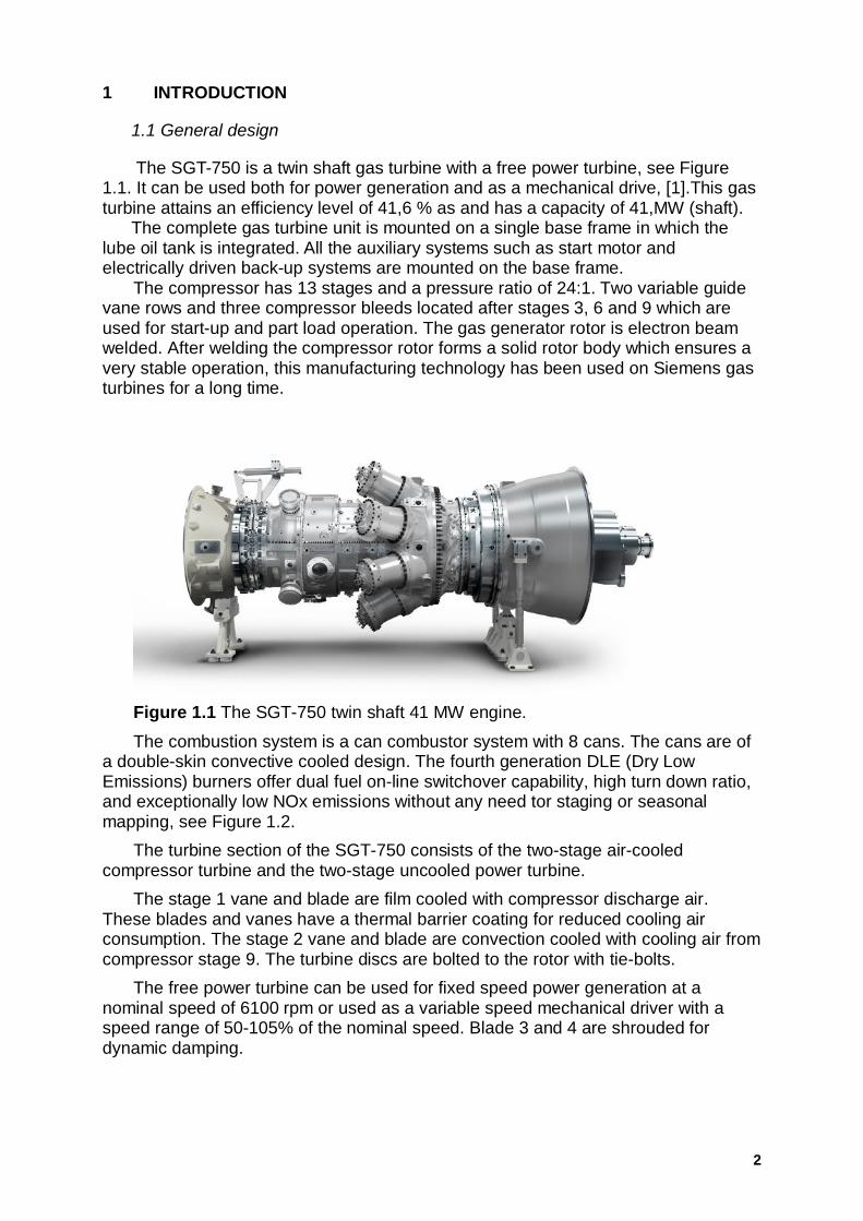
The SGT-750 is a twin shaft gas turbine with a free power turbine, see Figure1.1. It can be used both for power generation and as a mechanical drive, [1].This gasturbine attains an efficiency level of 41,6 % as and has a capacity of 41,MW (shaft).
The complete gas turbine unit is mounted on a single base frame in which thelube oil tank is integrated. All the auxiliary systems such as start motor andelectrically driven back-up systems are mounted on the base frame.
The compressor has 13 stages and a pressure ratio of 24:1. Two variable guidevane rows and three compressor bleeds located after stages 3, 6 and 9 which areused for start-up and part load operation. The gas generator rotor is electron beamwelded. After welding the compressor rotor forms a solid rotor body which ensures avery stable operation, this manufacturing technology has been used on Siemens gasturbines for a long time.
Figure 1.1 The SGT-750 twin shaft 41 MW engine.
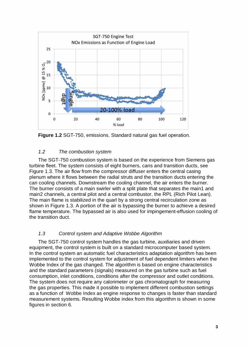
The combustion system is a can combustor system with 8 cans. The cans are ofa double-skin convective cooled design. The fourth generation DLE (Dry LowEmissions) burners offer dual fuel on-line switchover capability, high turn down ratio,and exceptionally low NOx emissions without any need tor staging or seasonalmapping, see Figure 1.2.
The turbine section of the SGT-750 consists of the two-stage air-cooledcompressor turbine and the two-stage uncooled power turbine.
The stage 1 vane and blade are film cooled with compressor discharge air.These blades and vanes have a thermal barrier coating for reduced cooling airconsumption. The stage 2 vane and blade are convection cooled with cooling air fromcompressor stage 9. The turbine discs are bolted to the rotor with tie-bolts.
The free power turbine can be used for fixed speed power generation at anominal speed of 6100 rpm or used as a variable speed mechanical driver with aspeed range of 50-105% of the nominal speed. Blade 3 and 4 are shrouded fordynamic damping.
3
Figure 1.2 SGT-750, emissions. Standard natural gas fuel operation.
1.2 The combustion systemThe SGT-750 combustion system is based on the experience from Siemens gas
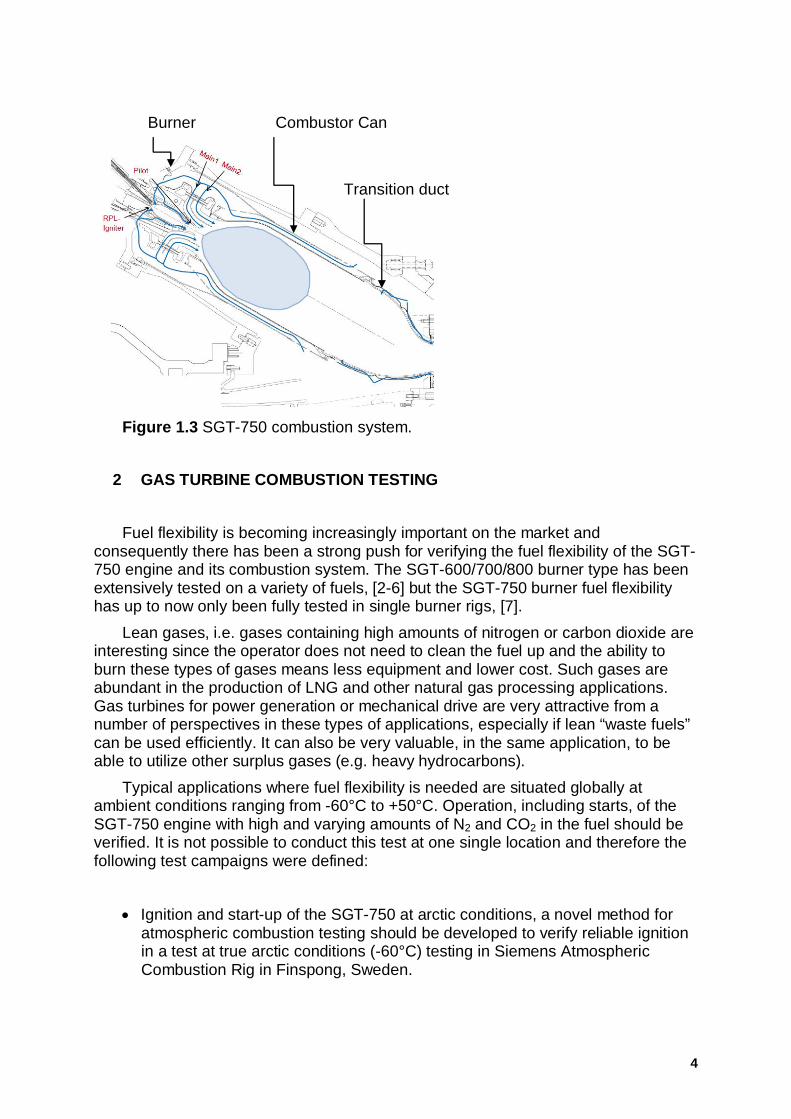
turbine fleet. The system consists of eight burners, cans and transition ducts, seeFigure 1.3. The air flow from the compressor diffuser enters the central casingplenum where it flows between the radial struts and the transition ducts entering thecan cooling channels. Downstream the cooling channel, the air enters the burner.The burner consists of a main swirler with a split plate that separates the main1 andmain2 channels, a central pilot and a central combustor, the RPL (Rich Pilot Lean).The main flame is stabilized in the quarl by a strong central recirculation zone asshown in Figure 1.3. A portion of the air is bypassing the burner to achieve a desiredflame temperature. The bypassed air is also used for impingement-effusion cooling ofthe transition duct.
1.3 Control system and Adaptive Wobbe Algorithm
The SGT-750 control system handles the gas turbine, auxiliaries and drivenequipment, the control system is built on a standard microcomputer based system.In the control system an automatic fuel characteristics adaptation algorithm has beenimplemented to the control system for adjustment of fuel dependent limiters when theWobbe Index of the gas changed. The algorithm is based on engine characteristicsand the standard parameters (signals) measured on the gas turbine such as fuelconsumption, inlet conditions, conditions after the compressor and outlet conditions.The system does not require any calorimeter or gas chromatograph for measuringthe gas properties. This made it possible to implement different combustion settingsas a function of Wobbe Index as engine response to changes is faster than standardmeasurement systems. Resulting Wobbe index from this algorithm is shown in somefigures in section 6.
4
Figure 1.3 SGT-750 combustion system.
2 GAS TURBINE COMBUSTION TESTING
Fuel flexibility is becoming increasingly important on the market andconsequently there has been a strong push for verifying the fuel flexibility of the SGT-750 engine and its combustion system. The SGT-600/700/800 burner type has beenextensively tested on a variety of fuels, [2-6] but the SGT-750 burner fuel flexibilityhas up to now only been fully tested in single burner rigs, [7].
Lean gases, i.e. gases containing high amounts of nitrogen or carbon dioxide areinteresting since the operator does not need to clean the fuel up and the ability toburn these types of gases means less equipment and lower cost. Such gases areabundant in the production of LNG and other natural gas processing applications.Gas turbines for power generation or mechanical drive are very attractive from anumber of perspectives in these types of applications, especially if lean “waste fuels”can be used efficiently. It can also be very valuable, in the same application, to beable to utilize other surplus gases (e.g. heavy hydrocarbons).
Typical applications where fuel flexibility is needed are situated globally atambient conditions ranging from -60°C to +50°C. Operation, including starts, of theSGT-750 engine with high and varying amounts of N2 and CO2 in the fuel should beverified. It is not possible to conduct this test at one single location and therefore thefollowing test campaigns were defined:
· Ignition and start-up of the SGT-750 at arctic conditions, a novel method foratmospheric combustion testing should be developed to verify reliable ignitionin a test at true arctic conditions (-60°C) testing in Siemens AtmosphericCombustion Rig in Finspong, Sweden.
Burner Combustor Can
Transition duct

5
· Verified operation of the complete combustion system in a high pressurecombustion test rig at authentic arctic compressor discharge temperature andpressure. Natural gas fuel with different concentrations of N2 and CO2. Testingwas done at DLR, Cologne, Germany.
· Heavier hydrocarbons, hydrogen and syngas blended with natural gas werealso explored, as DLR could offer tests on these gases within the allocatedtest period.
· Engine operation, including starts, of the SGT-750 engine with high andvarying amounts of N2 and CO2 in the fuel was verified at near ISO condition.Testing was done at Siemens test facility in Finspong, Sweden.
3 IGNITION TESTS IN ATMOSPHERIC RIG AT ARCTIC CONDITIONS
During start-up of a gas turbine the compressor runs at low speed and lowpressure is built up. Ignition tests can therefore be done at atmospheric conditions.Consequently, ignition testing is commonly done in designated atmosphericcombustion test rigs. Siemens Industrial Turbomachinery have a flexible atmosphericcombustion test rig available in Finspong, Sweden and this was used for an ignitiontest series at extremely cold ambient conditions.
A full scale SGT-750 standard combustion system including one burner can andtransition duct was used. In order to provide the combustion air to the test rig with therequired O2/N2 content and temperature, a special air supply unit incorporating liquidair storage, steam driven liquid air evaporator and a flow- and temperature- controlstation was assembled. This was prepared by the gas supply company, where thereis unique experience on the use of liquid air.
The test was performed for a variety of air flow rates in the temperature rangefrom -60 to -30°C. The start settings of fuel flow rates to the igniter and main burnerwas varied to find the optimal ignition conditions. Tests were done with natural gaswith different blends of nitrogen and carbon dioxide. The SGT-750 combustionsystem could successfully be ignited at conditions identical to engine identical startup conditions, at an air temperature down to -60°C. Pure natural gas and natural gasdiluted with up to 55 vol% N2 and 30 vol% CO2 respectively were ignited successfullyin the test setup, giving confidence in the true arctic capabilities.
4 LEAN GAS FUELS TEST AT ARCTIC CONDITIONS IN SINGLE BURNERHIGH PRESSURE RIG
It is not possible to perform a full engine test at arctic conditions (-60°C) sincethere is yet no SGT-750 installed at such location. Therefore the fuel flexibility testcampaign with inert components in natural gas was performed in the single burnerhigh pressure test facility at DLR (German Aerospace Center) in Cologne, Germany.
The tests in HPCR in DLR allowed validation of the standard SGT-750combustion system for the complete engine load range at cold climate. CO2 and N2mixtures with natural gas was used. The engine test experience on gas fuel mixturescontaining large fractions of inert gases indicated that the most challenging operatingconditions are low firing temperatures and low combustor inlet air temperatures. TheHPCR testing therefore focused on low engine load conditions at extremely coldconditions in order to validate the SGT-750 robustness to flame extinction andcombustion dynamics.

6
The test campaign planning was influenced by a specific project demand whichrequired combustion system operation with mixture of natural gas with 20vol% of CO2at equivalent cold ambient conditions (-60°C). The results with 20vol% of CO2 innatural gas are summarized in Figure 4.1 were the NOx emissions, the combustiondynamics and the combustor inlet air temperature are shown.
Figure 4.1 Test results on HPCR with gas fuel mixtures containing 20vol% CO2.
At the lowest engine load the combustor inlet air temperature is around 200°C,this is the most critical point for starting on lean fuels. The combustion systemshowed capabilities for low NOx emissions combined with low combustion dynamics.The test points at higher load showed that it was possible to reach NOx emissionsbelow 10 ppmv at 15% O2 with low combustion dynamics.
.
Table 4.1 Test results in HPCR at low load cold climate conditions using highconcentrations of N2 and CO2 in gas fuel.
5% load 25% load 5% load 25% load
CO2 (vol%) 37 40 0 0N2 (vol%) 0 0 42 53NOx (ppm at 15% O2) 8.4 5.3 10.9 3.7
In order to test the operability limits for the SGT-750 combustion system with inertgas mixtures, higher levels of CO2 and N2 were tested at equivalent operatingconditions corresponding to 5% and 25% of engine load at -60°C ambienttemperature. The results in Table 4.1 show that 42vol% N2 and 37vol% CO2 wasused at the most difficult operating points (5% load; -60°C ambient temperature)maintaining low NOx emissions.

7
The single burner test campaign in DLR confirmed the high capability of the SGT-750burner to operate reliably with high concentrations of inert gases in natural gas evenat conditions equivalent to -60°C ambient temperature
5 SINGLE BURNER HIGH PRESSURE RIG TESTS WITH HEAVY HYDROCARBONS AND HYDROGEN
After the lean gas test at DLR a second test of the fuel flexibility of the SGT-750burner with highly reactive fuels was performed. This campaign was used tounderstand the SGT-750 burner capability to burn mixtures of ethane, propane,butane, hydrogen and a mixture of hydrogen combined with carbon monoxide.
For the inert gas mixtures with natural gas as discussed in Chapter 3, coldclimate was used as reference testing condition, but for highly reactive fuels the mostdifficult phenomena occur at higher preheat and firing temperatures which inducehigher risks for flashback and increased NOx emissions. For highly reactive fuels thetests were performed at conditions corresponding to the engine full load at ISO-rangetemperatures (15°C).
The test results obtained by using ethane, propane and butane mixtures aresummarized in Table 5.1. The limiting factor for the concentration levels tested forethane, propane and butane was not defined by combustion issues but was relatedto the maximum mass flow that was achievable by the DLR test facility at the time oftesting.
Table 5.1 Test results in HPCR at full load conditions using gas fuel mixtures withethane, propane and butane.
High C2 test High C3 test High C4 test
C2 (vol%) 35.6 5.0 5.9C3 (vol%) 0.0 26.4 0.0C4 (vol%) 0.0 0.0 13.4NOx (ppm at 15% O2) 8.2 8.9 9.4
It is expected that the SGT-750 burner is capable to achieve stable combustionand low NOx emissions even at higher concentrations than is shown here.
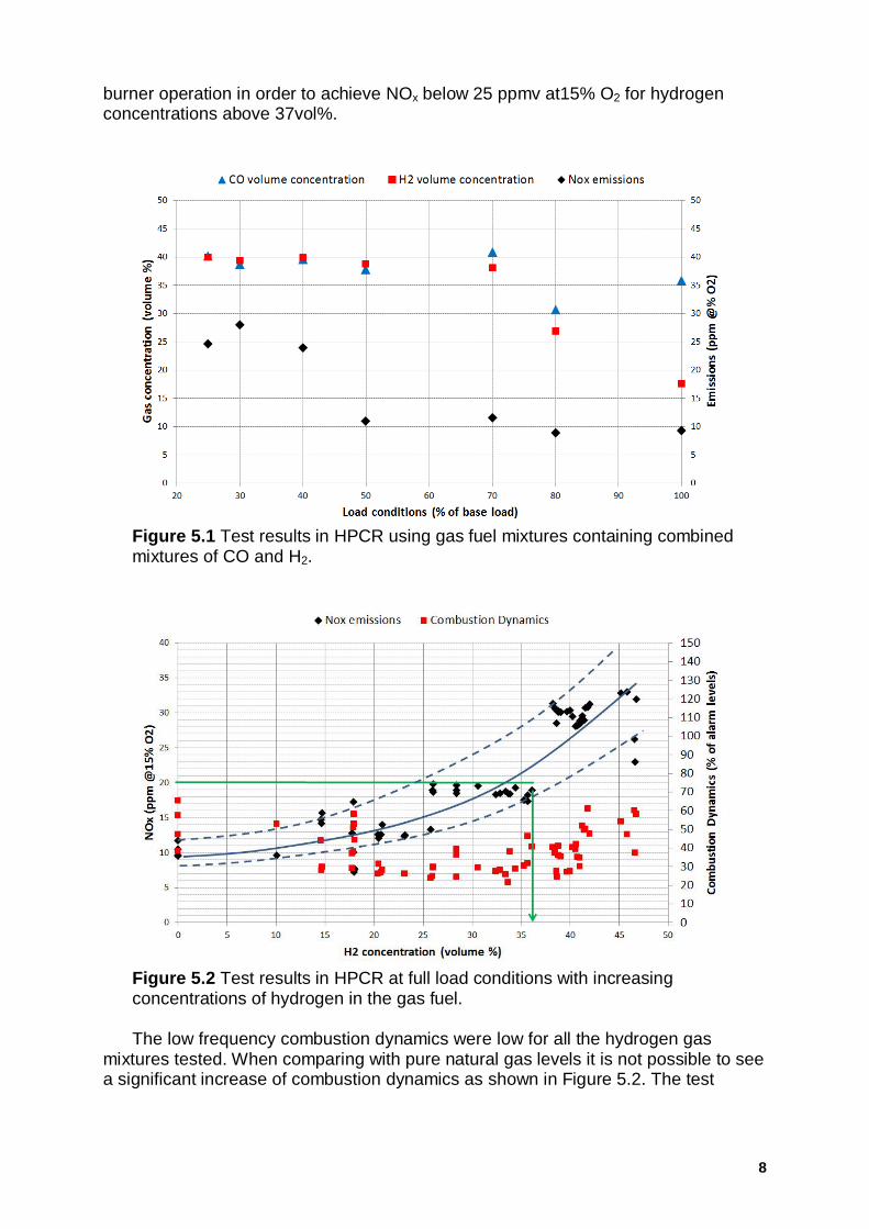
The combustion system was also tested on gas mixtures of CO and H2, whichcombines the low auto-ignition energy of carbon monoxide with the high flame speedof hydrogen (see Figure 5.1). These types of mixtures are usually referred to assyngas fuels. The SGT-750 combustion system was tested at several load conditionsand the burner was tuned at NOx emissions below 15ppmv at 15% O2 for loadsabove 50% of base load and single digit NOx for loads above 80%. The concentrationof hydrogen was reduced while increasing engine load in order to maintain NOxemissions around 10 ppmv.
Figure 5.2 shows the test results for the SGT-750 operation at engine full loadconditions with mixtures of natural gas and hydrogen. The SGT-750 burner operationcould be tuned to achieve around 10-12 ppmv NOx at15% O2 while having up to25vol% of hydrogen in natural gas fuel. The NOx emissions could be tuned below 20ppmv at15% O2 for hydrogen concentrations up to 35vol%. The NOx emissions wereincreasing with higher hydrogen concentrations. This was caused by the need toincrease the pilot fuel ratio, but the tests showed that it was still possible to tune the
8
burner operation in order to achieve NOx below 25 ppmv at15% O2 for hydrogenconcentrations above 37vol%.
Figure 5.1 Test results in HPCR using gas fuel mixtures containing combinedmixtures of CO and H2.
Figure 5.2 Test results in HPCR at full load conditions with increasingconcentrations of hydrogen in the gas fuel.
The low frequency combustion dynamics were low for all the hydrogen gasmixtures tested. When comparing with pure natural gas levels it is not possible to seea significant increase of combustion dynamics as shown in Figure 5.2. The test
9
results shown in figure 5.2 also contain test points taken just after the hydrogenconcentration was increased and those show higher NOx emissions. At hydrogenconcentrations corresponding to 18vol% and 47vol% the fuel splits were altered toexplore the NOx and combustion dynamics response showing the low NOx capabilityalso at high hydrogen concentrations.
6 GAS TURBINE TEST WITH LEAN GAS FUELS
6.1 Operation with high content of CO2 and N2
The SGT-750 gas turbine was tested with high inert (N2, CO2) fuels during a threeweek test campaign at Siemens gas turbine test facility in Finspong, Sweden. Theaim was both to investigate the behaviour during steady state operation, but also tosee the responses to variations in fuel composition and to transients in engineoperation. Ignition and start tests were also performed during the campaign (seesection 6.2).
The test engine was of standard design, but with some extra instrumentation, e.g.thermocouples in the combustor. No modification was done to the combustionsystem hardware for the test. The gas supply pressure upstream the fuel controlvalves was kept at a similar level during the N2 test as for natural gas operationresulting in a more opened position of the fuel valves. However, due to limitations inthe CO2 vaporizer the gas supply pressure had to be reduced during the CO2 tests toreach high contents of CO2.
The principle of the test setup was similar to what was used in previous tests [4]for the SGT-700 and SGT-800 gas turbines. Inert gas was fed to the existing naturalgas supply system for the engine. The injection of inert gas was done upstream ofnormal filtration equipment and a 3 m3 buffer tank. The supply of nitrogen and carbondioxide was accomplished by vaporizing liquid inert from truck tanks. Thevaporization was accomplished with the use of a steam boiler and a heat exchanger.The test equipment was sized to deliver up to around 40vol% of CO2 and 50vol% ofN2 to the engine.
The injection of inert gas was controlled with a manual valve and the desired flowwas communicated from engine operators to operators of the gas supply. Thisresulted in relatively rough changes in fuel composition and pressure, but this couldbe handled well by the engine and its control system.
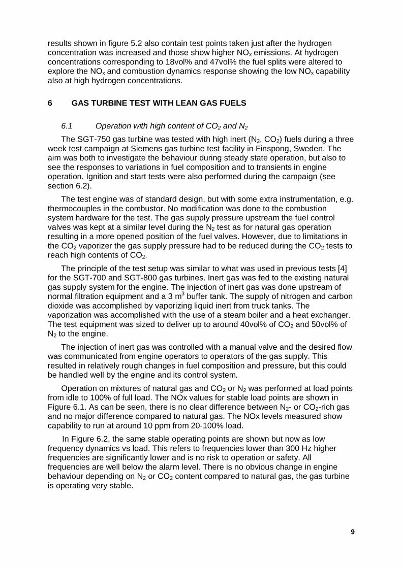
Operation on mixtures of natural gas and CO2 or N2 was performed at load pointsfrom idle to 100% of full load. The NOx values for stable load points are shown inFigure 6.1. As can be seen, there is no clear difference between N2- or CO2-rich gasand no major difference compared to natural gas. The NOx levels measured showcapability to run at around 10 ppm from 20-100% load.
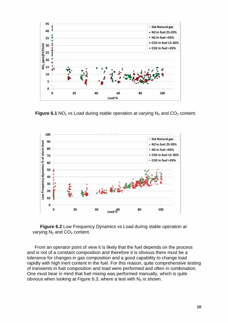
In Figure 6.2, the same stable operating points are shown but now as lowfrequency dynamics vs load. This refers to frequencies lower than 300 Hz higherfrequencies are significantly lower and is no risk to operation or safety. Allfrequencies are well below the alarm level. There is no obvious change in enginebehaviour depending on N2 or CO2 content compared to natural gas, the gas turbineis operating very stable.
10
Figure 6.1 NOx vs Load during stable operation at varying N2 and CO2 content.
Figure 6.2 Low Frequency Dynamics vs Load during stable operation atvarying N2 and CO2 content.
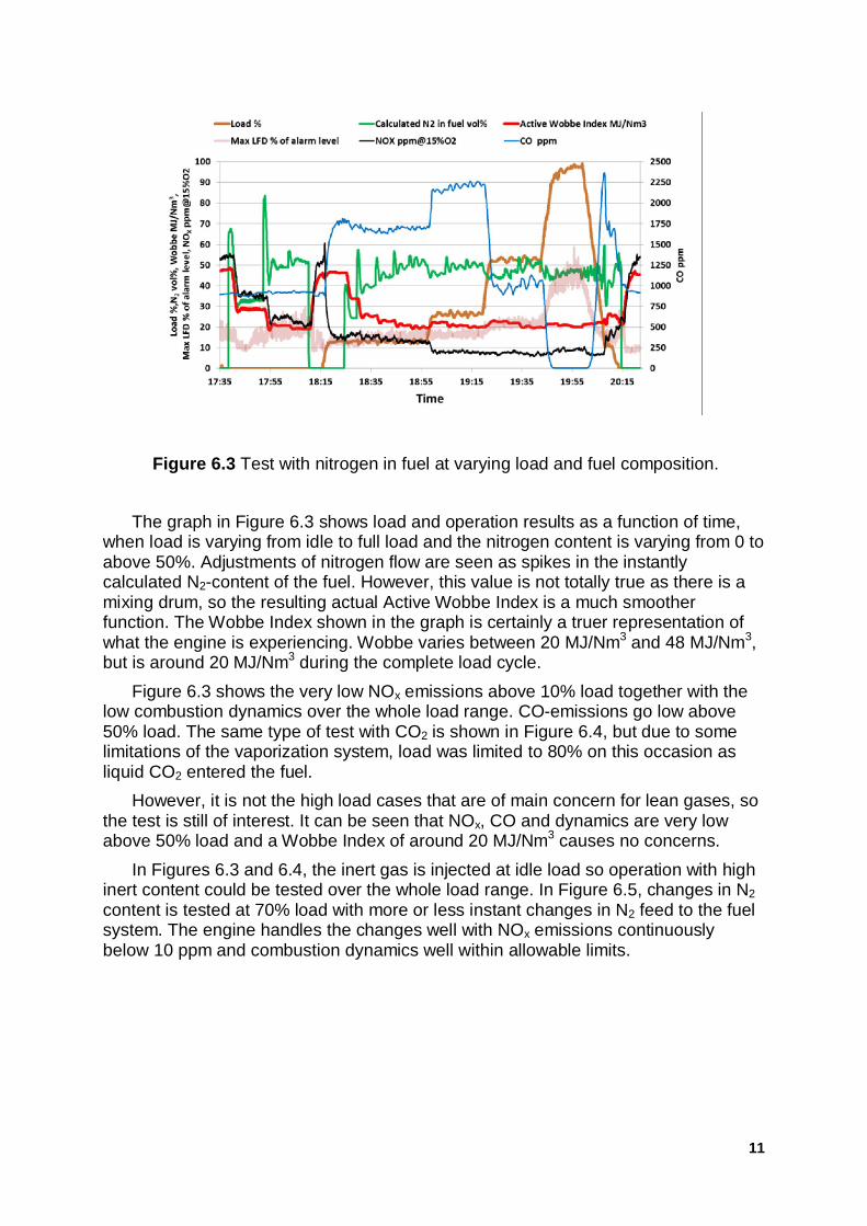
From an operator point of view it is likely that the fuel depends on the processand is not of a constant composition and therefore it is obvious there must be atolerance for changes in gas composition and a good capability to change loadrapidly with high inert content in the fuel. For this reason, quite comprehensive testingof transients in fuel composition and load were performed and often in combination.One must bear in mind that fuel mixing was performed manually, which is quiteobvious when looking at Figure 6.3, where a test with N2 is shown.
11
Figure 6.3 Test with nitrogen in fuel at varying load and fuel composition.
The graph in Figure 6.3 shows load and operation results as a function of time,when load is varying from idle to full load and the nitrogen content is varying from 0 toabove 50%. Adjustments of nitrogen flow are seen as spikes in the instantlycalculated N2-content of the fuel. However, this value is not totally true as there is amixing drum, so the resulting actual Active Wobbe Index is a much smootherfunction. The Wobbe Index shown in the graph is certainly a truer representation ofwhat the engine is experiencing. Wobbe varies between 20 MJ/Nm3 and 48 MJ/Nm3,but is around 20 MJ/Nm3 during the complete load cycle.
Figure 6.3 shows the very low NOx emissions above 10% load together with thelow combustion dynamics over the whole load range. CO-emissions go low above50% load. The same type of test with CO2 is shown in Figure 6.4, but due to somelimitations of the vaporization system, load was limited to 80% on this occasion asliquid CO2 entered the fuel.
However, it is not the high load cases that are of main concern for lean gases, sothe test is still of interest. It can be seen that NOx, CO and dynamics are very lowabove 50% load and a Wobbe Index of around 20 MJ/Nm3 causes no concerns.
In Figures 6.3 and 6.4, the inert gas is injected at idle load so operation with highinert content could be tested over the whole load range. In Figure 6.5, changes in N2content is tested at 70% load with more or less instant changes in N2 feed to the fuelsystem. The engine handles the changes well with NOx emissions continuouslybelow 10 ppm and combustion dynamics well within allowable limits.

12
Figure 6.4 Test with carbon dioxide in fuel at varying load and fuel composition.
From a test like this a Wobbe Index change rate can be calculated, as indicatedin the figure, giving change rates at 5-10%/s depending on the basis used. This is farabove acceptable limits for a fuel flexible combustion system. The same type of testswere performed with CO2 with similar results.
Figure 6.5 Test with nitrogen transient at constant load.
13
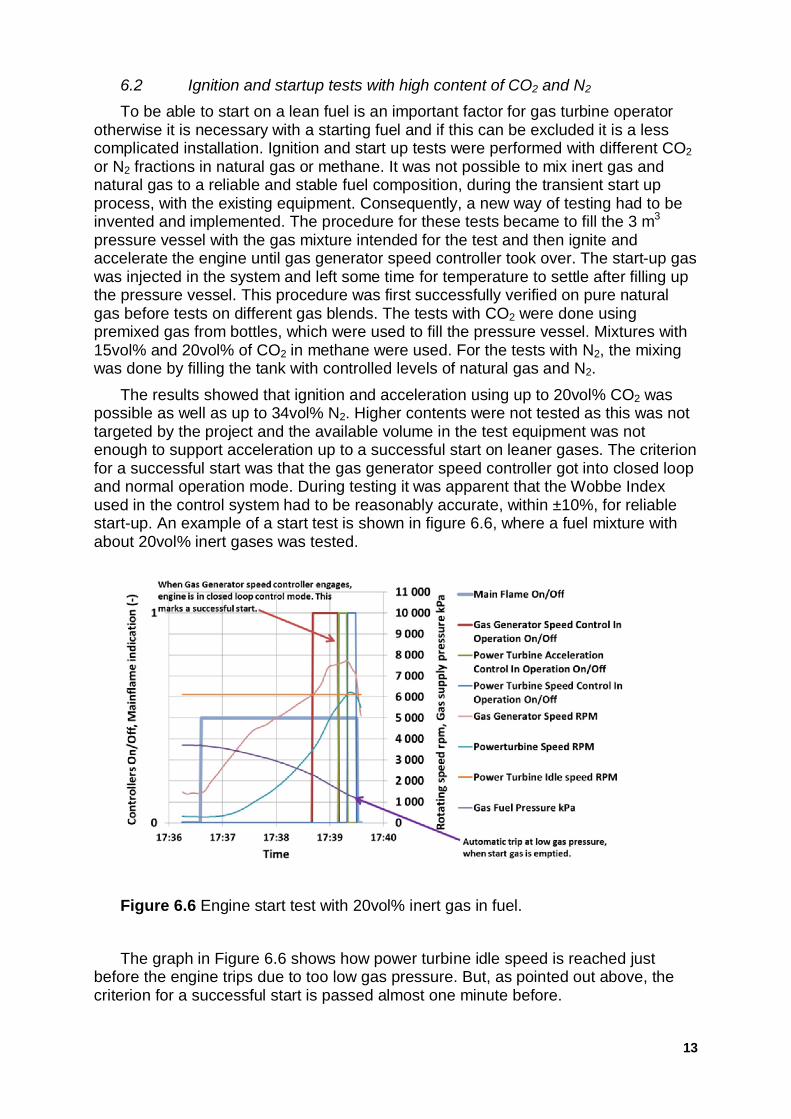
6.2 Ignition and startup tests with high content of CO2 and N2
To be able to start on a lean fuel is an important factor for gas turbine operatorotherwise it is necessary with a starting fuel and if this can be excluded it is a lesscomplicated installation. Ignition and start up tests were performed with different CO2or N2 fractions in natural gas or methane. It was not possible to mix inert gas andnatural gas to a reliable and stable fuel composition, during the transient start upprocess, with the existing equipment. Consequently, a new way of testing had to beinvented and implemented. The procedure for these tests became to fill the 3 m3
pressure vessel with the gas mixture intended for the test and then ignite andaccelerate the engine until gas generator speed controller took over. The start-up gaswas injected in the system and left some time for temperature to settle after filling upthe pressure vessel. This procedure was first successfully verified on pure naturalgas before tests on different gas blends. The tests with CO2 were done usingpremixed gas from bottles, which were used to fill the pressure vessel. Mixtures with15vol% and 20vol% of CO2 in methane were used. For the tests with N2, the mixingwas done by filling the tank with controlled levels of natural gas and N2.
The results showed that ignition and acceleration using up to 20vol% CO2 waspossible as well as up to 34vol% N2. Higher contents were not tested as this was nottargeted by the project and the available volume in the test equipment was notenough to support acceleration up to a successful start on leaner gases. The criterionfor a successful start was that the gas generator speed controller got into closed loopand normal operation mode. During testing it was apparent that the Wobbe Indexused in the control system had to be reasonably accurate, within ±10%, for reliablestart-up. An example of a start test is shown in figure 6.6, where a fuel mixture withabout 20vol% inert gases was tested.
Figure 6.6 Engine start test with 20vol% inert gas in fuel.
The graph in Figure 6.6 shows how power turbine idle speed is reached justbefore the engine trips due to too low gas pressure. But, as pointed out above, thecriterion for a successful start is passed almost one minute before.
14
7 CONCLUSIONS
The SGT-750 has proven to have a very high tolerance to various types ofgaseous fuels during the different tests. All tests have been done with a standardSGT-750 DLE gas turbine with a standard control, combustion and fuel system.
Engine operation, including ignition and starts, of the SGT-750 with high andvarying amounts of nitrogen and carbon dioxide in the fuel was successfully proven.The engine operated on fuel containing 50vol% of N2 or 40vol% of CO2. Furthermore,start capability was proven on up to 34vol% of N2 or 20vol% of CO2. Also, fastfluctuations in fuel composition and pressure were validated with satisfactory results.Emissions on the tested fuel blends were at levels comparable to natural gasoperation. The control algorithm which takes care of fuel composition changes, i.e.changes in Wobbe Index was proven to be fast and reliable and has allowed rapidchanges in fuel composition. After the tests the gas turbine was inspected and nowear or damages were detected.
The complete combustion operation envelope at arctic conditions for the SGT-750 burner was verified in a high pressure test rig. The fuel compositions exploredduring engine testing proved to be achievable also at equivalent ambienttemperatures down to -60°C.
The ignition capability and reliability at arctic conditions were tested atatmospheric conditions with a single burner setup. It was verified that ignition isreliable using up to 55vol% of N2 and 30vol% of CO2 at air temperatures down to -60°C.
The single burner high pressure test campaign was also used to validate the fuelflexibility capabilities for highly reactive fuels. The standard SGT-750 burner showedto be capable of operating on high fractions of ethane, propane, butane andhydrogen while maintaining low NOx emissions. The maximum levels tested forethane, propane and butane concentrations were limited by the test facility. Forcases with hydrogen mixtures it was possible to test without flow limitations and itwas shown that low NOx emissions were achievable for H2 concentrations up to47vol%.
As stability and emissions were recorded at acceptable levels both for inert andreactive gas it implies that the fuel/air mixing is acceptable with unchanged gas fuelnozzle sizes. The results achieved for both inerts and highly reactive fuels representa validation of the standard SGT-750 gas fuel acceptance limits. The test resultsrepresent a valuable start reference for further development of the fuel flexibility forthe combustion system.
15
NOMENCLATURE
C2H6 EthaneC3H8 PropaneC4H10 ButaneCO Carbon monoxideCO2 Carbon dioxideDLE Dry Low EmissionsDLR Deutsches Zentrum für Luft- und RaumfahrtH2 HydrogenHPCR High Pressure Combustion RigISO International Organization for StandardizationLFD Low Frequency DynamicsN2 NitrogenNG Natural GasNOx Nitrogen oxidesRPL Rich Pilot Lean combustorWI Wobbe Index
16
REFERENCES
[1] M. Nilsson, A. Hellberg; Operational experience of 37 MW Siemens SGT-750 Symposium Of The Industrial Application Of Gas Turbines Committee Banff,
Alberta, Canada, October 2013
[2] A. Larsson, M. Andersson, A. Manrique Carrera, M. Blomstedt, Extended fuelflexibility capabilities of the SGT-700 DLE combustion system, Power-Gen Asia,September 1-3, 2015, Bangkok, Thailand
[3] A. Bonaldo, M. Andersson, A. Larsson; GT2014-26023, Engine testing usinghighly reactive fuels on Siemens Industrial Gas Turbines, ASME Turbo Expo2014, Dusseldorf, June 2014.
[4] J. Larfeldt, A. Larsson, M. Andersson, SGT-700 and SGT-800 fuel flexibilitytesting activities, The Future of Gas Turbine Technology, 6th InternationalConference, 17-18 October 2012, Brussels, Belgium.
[5] M. Andersson, A. Larsson, A. Lindholm, J. Larfeldt; GT2012-69027, Extendedfuel flexibility testing of Siemens Industrial Gas Turbines: a novel approach,ASME Turbo Expo 2012, Copenhagen, June 2012.
[6] M. Andersson, A. Larsson, A. Manrique Carrera; GT2011-46099, Pentane richfuels for standard Siemens gas turbines, ASME Turbo Expo 2011, Vancouver,June 2011.
[7] M. Andersson, A. H. Näsvall, A. Manricue Carrera; GT2011-46387, Experimentalinvestigation of the 4th generation DLE burner concept: emission and fuelflexibility performance at atmospheric conditions, ASME Turbo Expo