Drilling Rig Hoisting Platform Security Monitoring System ...
15
machines Article Drilling Rig Hoisting Platform Security Monitoring System Design and Application Junjiang He 1, * and Min Luo 2 1 School of Mechatronic Engineering, Southwest Petroleum University, Chengdu 610500, China 2 School of Electrical Engineering, Southwest Petroleum University, Chengdu 610500, China; [email protected] * Correspondence: [email protected]; Tel.: +86-151-9813-0461 Received: 1 June 2017; Accepted: 3 August 2017; Published: 22 August 2017 Abstract: Drilling rig hoisting platform security monitoring system has played a very important role in oil exploration. And drilling parameters and working condition of workers are particularly important, because these parameters indicate that whether the drilling work is safe and effective directly. A security monitoring system is established to provide the real-time parameters for drilling safety is the purpose of this study. The monitoring system includes a top drive, a traveling block hook, an oil derrick and a driller room, and the controller of the system is programmable logic controller PLC. The procedure of the system is written by the RSLogix5000 software, the PC configuration is used force control monitor configuration software. According to the system, top drive, driller room and environment wind speed parameters in real-time are collected and displayed in the configuration of upper computer, the collected parameters can be used to determine the working conditions of the top drive and to send timely warnings for inspection maintenance to avoid drilling safety accidents. Work fatigue remind of driller and regularly remind of derrick check can be as much as possible to reduce safety accidents. And automatic operation of traveling block hook reached the default point faster and more smoothly than manual operation given the other uncontrollable factors in manual operation. The application of the system is successfully working in the drilling work site. Keywords: drilling rig hoisting platform; monitoring system; programmable logic controller; force control monitor configuration; real-time parameters; drilling safety 1. Introduction A drilling rig hoisting platform is an indispensable piece of equipment in oil exploration. The entire platform mainly includes a top drive, a traveling block hook, an oil derrick, and a driller room [1], as shown in Figure 1. The top drive rotates the drilling tool and circulates the mud, shackle, and pick up pipe [2]. The oil derrick lays the crown block, suspends the traveling block hook and top drive, and stores the drill pipe [3]. The driller room, which has various electrical, mechanical, and communication technologies as an organic whole, provides a comfortable working environment for the driller [4]. The rig hoisting platform is a cornerstone in a drilling operation. It is particularly important to ensure safety because the complexity of the actual working condition and working environment is prone to accidents. Addressing the potential safety hazard in the process of drilling and properly documenting casualties and economic losses caused by accidents are urgently needed. So establishing the rig hoisting platform’s security monitoring system is necessary. Machines 2017, 5, 19; doi:10.3390/machines5030019 www.mdpi.com/journal/machines
-
Upload
khangminh22 -
Category
Documents
-
view
3 -
download
0
Transcript of Drilling Rig Hoisting Platform Security Monitoring System ...

machines
Article
Drilling Rig Hoisting Platform Security MonitoringSystem Design and Application
Junjiang He 1,* and Min Luo 2
1 School of Mechatronic Engineering, Southwest Petroleum University, Chengdu 610500, China2 School of Electrical Engineering, Southwest Petroleum University, Chengdu 610500, China;
[email protected]* Correspondence: [email protected]; Tel.: +86-151-9813-0461
Received: 1 June 2017; Accepted: 3 August 2017; Published: 22 August 2017
Abstract: Drilling rig hoisting platform security monitoring system has played a very importantrole in oil exploration. And drilling parameters and working condition of workers are particularlyimportant, because these parameters indicate that whether the drilling work is safe and effectivedirectly. A security monitoring system is established to provide the real-time parameters for drillingsafety is the purpose of this study. The monitoring system includes a top drive, a traveling block hook,an oil derrick and a driller room, and the controller of the system is programmable logic controllerPLC. The procedure of the system is written by the RSLogix5000 software, the PC configuration isused force control monitor configuration software. According to the system, top drive, driller roomand environment wind speed parameters in real-time are collected and displayed in the configurationof upper computer, the collected parameters can be used to determine the working conditions of thetop drive and to send timely warnings for inspection maintenance to avoid drilling safety accidents.Work fatigue remind of driller and regularly remind of derrick check can be as much as possible toreduce safety accidents. And automatic operation of traveling block hook reached the default pointfaster and more smoothly than manual operation given the other uncontrollable factors in manualoperation. The application of the system is successfully working in the drilling work site.
Keywords: drilling rig hoisting platform; monitoring system; programmable logic controller;force control monitor configuration; real-time parameters; drilling safety
1. Introduction
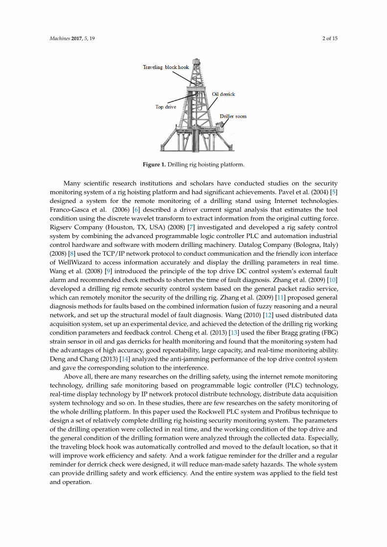
A drilling rig hoisting platform is an indispensable piece of equipment in oil exploration.The entire platform mainly includes a top drive, a traveling block hook, an oil derrick, and a drillerroom [1], as shown in Figure 1. The top drive rotates the drilling tool and circulates the mud, shackle,and pick up pipe [2]. The oil derrick lays the crown block, suspends the traveling block hook andtop drive, and stores the drill pipe [3]. The driller room, which has various electrical, mechanical,and communication technologies as an organic whole, provides a comfortable working environmentfor the driller [4]. The rig hoisting platform is a cornerstone in a drilling operation. It is particularlyimportant to ensure safety because the complexity of the actual working condition and workingenvironment is prone to accidents. Addressing the potential safety hazard in the process of drillingand properly documenting casualties and economic losses caused by accidents are urgently needed.So establishing the rig hoisting platform’s security monitoring system is necessary.
Machines 2017, 5, 19; doi:10.3390/machines5030019 www.mdpi.com/journal/machines
Machines 2017, 5, 19 2 of 15Machines 2017, 5, 19 2 of 15
Figure 1. Drilling rig hoisting platform.
Many scientific research institutions and scholars have conducted studies on the security monitoring system of a rig hoisting platform and had significant achievements. Pavel et al. (2004) [5] designed a system for the remote monitoring of a drilling stand using Internet technologies. Franco-Gasca et al. (2006) [6] described a driver current signal analysis that estimates the tool condition using the discrete wavelet transform to extract information from the original cutting force. Rigserv Company (Houston, TX, USA) (2008) [7] investigated and developed a rig safety control system by combining the advanced programmable logic controller PLC and automation industrial control hardware and software with modern drilling machinery. Datalog Company (Bologna, Italy) (2008) [8] used the TCP/IP network protocol to conduct communication and the friendly icon interface of WellWizard to access information accurately and display the drilling parameters in real time. Wang et al. (2008) [9] introduced the principle of the top drive DC control system’s external fault alarm and recommended check methods to shorten the time of fault diagnosis. Zhang et al. (2009) [10] developed a drilling rig remote security control system based on the general packet radio service, which can remotely monitor the security of the drilling rig. Zhang et al. (2009) [11] proposed general diagnosis methods for faults based on the combined information fusion of fuzzy reasoning and a neural network, and set up the structural model of fault diagnosis. Wang (2010) [12] used distributed data acquisition system, set up an experimental device, and achieved the detection of the drilling rig working condition parameters and feedback control. Cheng et al. (2013) [13] used the fiber Bragg grating (FBG) strain sensor in oil and gas derricks for health monitoring and found that the monitoring system had the advantages of high accuracy, good repeatability, large capacity, and real-time monitoring ability. Deng and Chang (2013) [14] analyzed the anti-jamming performance of the top drive control system and gave the corresponding solution to the interference.
Above all, there are many researches on the drilling safety, using the internet remote monitoring technology, drilling safe monitoring based on programmable logic controller (PLC) technology, real-time display technology by IP network protocol distribute technology, distribute data acquisition system technology and so on. In these studies, there are few researches on the safety monitoring of the whole drilling platform. In this paper used the Rockwell PLC system and Profibus technique to design a set of relatively complete drilling rig hoisting security monitoring system. The parameters of the drilling operation were collected in real time, and the working condition of the top drive and the general condition of the drilling formation were analyzed through the collected data. Especially, the traveling block hook was automatically controlled and moved to the default location, so that it will improve work efficiency and safety. And a work fatigue reminder for the driller and a regular reminder for derrick check were designed, it will reduce man-made safety hazards. The whole system can provide drilling safety and work efficiency.And the entire system was applied to the field test and operation.
Figure 1. Drilling rig hoisting platform.
Many scientific research institutions and scholars have conducted studies on the securitymonitoring system of a rig hoisting platform and had significant achievements. Pavel et al. (2004) [5]designed a system for the remote monitoring of a drilling stand using Internet technologies.Franco-Gasca et al. (2006) [6] described a driver current signal analysis that estimates the toolcondition using the discrete wavelet transform to extract information from the original cutting force.Rigserv Company (Houston, TX, USA) (2008) [7] investigated and developed a rig safety controlsystem by combining the advanced programmable logic controller PLC and automation industrialcontrol hardware and software with modern drilling machinery. Datalog Company (Bologna, Italy)(2008) [8] used the TCP/IP network protocol to conduct communication and the friendly icon interfaceof WellWizard to access information accurately and display the drilling parameters in real time.Wang et al. (2008) [9] introduced the principle of the top drive DC control system’s external faultalarm and recommended check methods to shorten the time of fault diagnosis. Zhang et al. (2009) [10]developed a drilling rig remote security control system based on the general packet radio service,which can remotely monitor the security of the drilling rig. Zhang et al. (2009) [11] proposed generaldiagnosis methods for faults based on the combined information fusion of fuzzy reasoning and a neuralnetwork, and set up the structural model of fault diagnosis. Wang (2010) [12] used distributed dataacquisition system, set up an experimental device, and achieved the detection of the drilling rig workingcondition parameters and feedback control. Cheng et al. (2013) [13] used the fiber Bragg grating (FBG)strain sensor in oil and gas derricks for health monitoring and found that the monitoring system hadthe advantages of high accuracy, good repeatability, large capacity, and real-time monitoring ability.Deng and Chang (2013) [14] analyzed the anti-jamming performance of the top drive control systemand gave the corresponding solution to the interference.
Above all, there are many researches on the drilling safety, using the internet remote monitoringtechnology, drilling safe monitoring based on programmable logic controller (PLC) technology,real-time display technology by IP network protocol distribute technology, distribute data acquisitionsystem technology and so on. In these studies, there are few researches on the safety monitoring ofthe whole drilling platform. In this paper used the Rockwell PLC system and Profibus technique todesign a set of relatively complete drilling rig hoisting security monitoring system. The parametersof the drilling operation were collected in real time, and the working condition of the top drive andthe general condition of the drilling formation were analyzed through the collected data. Especially,the traveling block hook was automatically controlled and moved to the default location, so that itwill improve work efficiency and safety. And a work fatigue reminder for the driller and a regularreminder for derrick check were designed, it will reduce man-made safety hazards. The whole systemcan provide drilling safety and work efficiency. And the entire system was applied to the field testand operation.

Machines 2017, 5, 19 3 of 15
2. Composition of the Drilling Rig Hoisting Security Monitoring System
The rig hoisting platform monitoring system comprises three parts: the upper machine,the controller programmable logic controller PLC, and the device layer. The network diagram ofthe entire system is shown in Figure 2.
As shown in Figure 2, the control layer is the middle layer of the system. It is the hinge of the systemin which all types of data are transmitted. The controller property is important. The programmablelogic controller PLC has so many advantages that other fields aside from the petrochemical industryfield use it. The main advantages of the programmable logic controller PLC [15] are as follows:
(1) High reliability and strong anti-jamming capability;(2) Complete supporting facilities, fully functional, and high applicability;(3) Rich I/O interface module;(4) Small volume, light weight, low energy consumption;(5) Strong commonality, variable control program, and easy to use.
Aside from the control layer, the information layer and device layer have their own functions.The information layer displays data to users, thus enabling users to be intuitive, understand the scene,and send the command control field device through this layer. The device layer is analogous to humanskin tissue, and it can turn the scene situation into the corresponding voltage or current signal.
The working process of the entire system is the device layer, which turns the scene situation intothe corresponding voltage or current signal. Then, the control layer collects the voltage or currentsignal using fieldbus technology. As the last step, the information layer analyzes data using specialprocessing software and displays the working condition of the scene on the screen, in this paper usedRSLogix5000 to analyze data and force control monitor configuration to display the working condition.The information layer can transmit the control signal to the device layer according to the control layer.Therefore, the system realizes the functions of monitoring and control.
Machines 2017, 5, 19 3 of 15
2. Composition of the Drilling Rig Hoisting Security Monitoring System
The rig hoisting platform monitoring system comprises three parts: the upper machine, the controller programmable logic controller PLC, and the device layer. The network diagram of the entire system is shown in Figure 2.
As shown in Figure 2, the control layer is the middle layer of the system. It is the hinge of the system in which all types of data are transmitted. The controller property is important. The programmable logic controller PLC has so many advantages that other fields aside from the petrochemical industry field use it. The main advantages of the programmable logic controller PLC [15] are as follows:
(1) High reliability and strong anti-jamming capability; (2) Complete supporting facilities, fully functional, and high applicability; (3) Rich I/O interface module; (4) Small volume, light weight, low energy consumption; (5) Strong commonality, variable control program, and easy to use.
Aside from the control layer, the information layer and device layer have their own functions. The information layer displays data to users, thus enabling users to be intuitive, understand the scene, and send the command control field device through this layer. The device layer is analogous to human skin tissue, and it can turn the scene situation into the corresponding voltage or current signal.
The working process of the entire system is the device layer, which turns the scene situation into the corresponding voltage or current signal. Then, the control layer collects the voltage or current signal using fieldbus technology. As the last step, the information layer analyzes data using special processing software and displays the working condition of the scene on the screen, in this paper used RSLogix5000 to analyze data and force control monitor configuration to display the working condition. The information layer can transmit the control signal to the device layer according to the control layer. Therefore, the system realizes the functions of monitoring and control.
Figure 2. Netwok diagram of whole system.
3. Design Scheme of the Drilling Rig Hoisting Security Monitoring System
To guarantee the safety of drilling operations, monitoring and mastering the drilling working conditions are necessary.
3.1. Top Drive Monitoring Scheme Design
Information layer (EtherNet/IP)
Control layer (ControlNet)
Device layer (DeviceNet)
Top drive
Traveling block hook
Oil derrick
Driller room
Computer
PLC
Sensor
Figure 2. Netwok diagram of whole system.
3. Design Scheme of the Drilling Rig Hoisting Security Monitoring System
To guarantee the safety of drilling operations, monitoring and mastering the drilling workingconditions are necessary.
Machines 2017, 5, 19 4 of 15
3.1. Top Drive Monitoring Scheme Design
With the development of drilling technology, the top drive drilling system gradually replacedthe rotary drilling rig [16]. In the process of drilling, the top drive drilling systems provides thedrilling motive, circulates drilling fluids, and reduces the number of connecting single pipes. It playsan important role in the entire process of drilling. Real-time mastery of the working conditions of thetop drive drilling system is necessary. The top drive drilling system mainly consists of a top-drillingmotor assemble, motor bracket/guide block assemble, make-up or break-out device of the drill pipeassemble, and other auxiliary systems.
The top-drilling motor assemble provides the drilling motive [16] and enables the motor speedand the motor temperature to indicate if the motor is running normally. As wind pressure of thecooling fan also affects the motor temperature, it needs to be monitored. The reduction gearbox,which is responsible for the temperature and oil pressure, is indispensable as it determines the workingcondition. In the drilling process, if sticking or other accidents that require the motor to be stoppedoccur, the pressure of the brake cylinder should be controlled. Changing the pressure of the brakecylinder can realize the automatic start–stop motor control of this control system.
The make-up or break-out device of the drill pipe assemble provides service for the trip [16].It possesses the greatest advantages of the top drive drilling equipment, and it can save drilling timeand reduce the labor intensity of workers. Therefore, monitoring this part is important for the drillingoperation. Controlling the turret head motor can master the location of the turret head in real time.Controlling the cylinder oil pressure of the inclined structure can determine the location of the inclinedstructure. More importantly, pressure in the well should be monitored and alarm should be given ina timely manner.
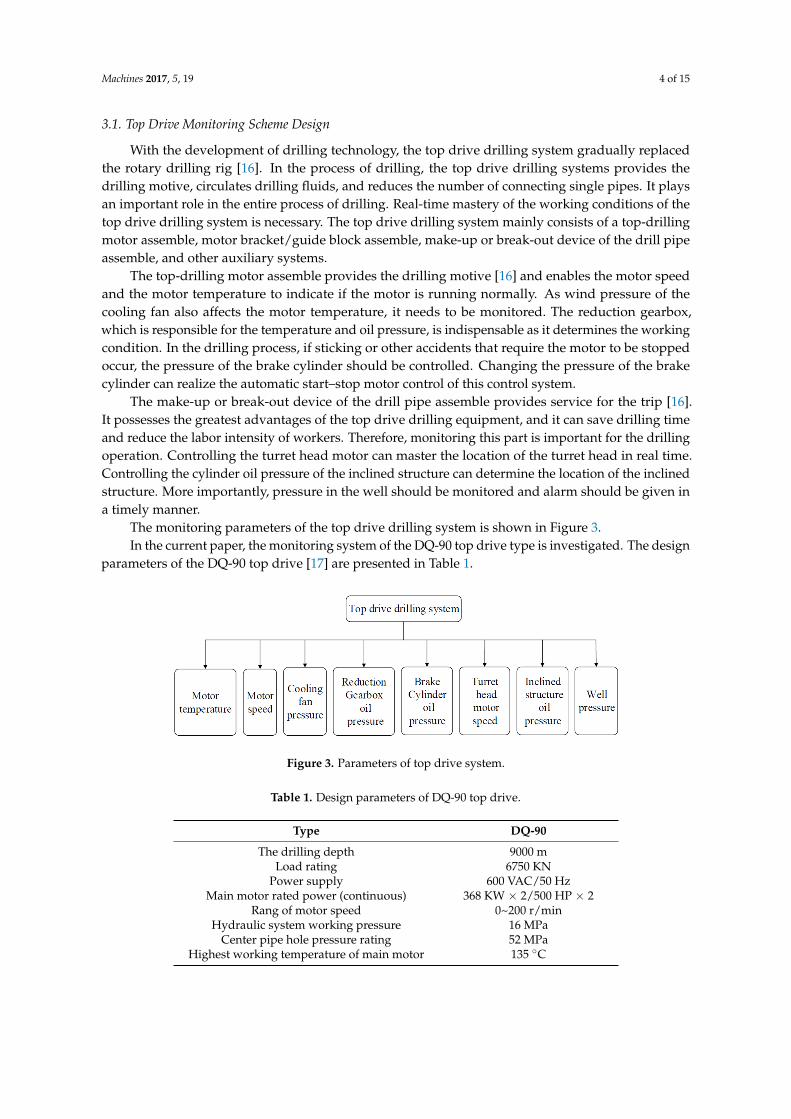
The monitoring parameters of the top drive drilling system is shown in Figure 3.In the current paper, the monitoring system of the DQ-90 top drive type is investigated. The design
parameters of the DQ-90 top drive [17] are presented in Table 1.
Machines 2017, 5, 19 4 of 15
With the development of drilling technology, the top drive drilling system gradually replaced the rotary drilling rig [16]. In the process of drilling, the top drive drilling systems provides the drilling motive, circulates drilling fluids, and reduces the number of connecting single pipes. It plays an important role in the entire process of drilling. Real-time mastery of the working conditions of the top drive drilling system is necessary. The top drive drilling system mainly consists of a top-drilling motor assemble, motor bracket/guide block assemble, make-up or break-out device of the drill pipe assemble, and other auxiliary systems.
The top-drilling motor assemble provides the drilling motive [16] and enables the motor speed and the motor temperature to indicate if the motor is running normally. As wind pressure of the cooling fan also affects the motor temperature, it needs to be monitored. The reduction gearbox, which is responsible for the temperature and oil pressure, is indispensable as it determines the working condition. In the drilling process, if sticking or other accidents that require the motor to be stopped occur, the pressure of the brake cylinder should be controlled. Changing the pressure of the brake cylinder can realize the automatic start–stop motor control of this control system.
The make-up or break-out device of the drill pipe assemble provides service for the trip [16]. It possesses the greatest advantages of the top drive drilling equipment, and it can save drilling time and reduce the labor intensity of workers. Therefore, monitoring this part is important for the drilling operation. Controlling the turret head motor can master the location of the turret head in real time. Controlling the cylinder oil pressure of the inclined structure can determine the location of the inclined structure. More importantly, pressure in the well should be monitored and alarm should be given in a timely manner.
The monitoring parameters of the top drive drilling system is shown in Figure 3. In the current paper, the monitoring system of the DQ-90 top drive type is investigated. The
design parameters of the DQ-90 top drive [17] are presented in Table 1.
Figure 3. Parameters of top drive system.
Table 1. Design parameters of DQ-90 top drive.
Type DQ-90The drilling depth 9000 m
Load rating 6750 KN Power supply 600 VAC/50 Hz
Main motor rated power (continuous) 368 KW × 2/500 HP × 2 Rang of motor speed 0~200 r/min
Hydraulic system working pressure 16 MPa Center pipe hole pressure rating 52 MPa
Highest working temperature of main motor 135 °C
3.2. Traveling Block Hook Monitoring Scheme Design
The traveling block can relieve winch work load in the process of drilling or well repairing, and it is indispensable in connecting a single root, drilling, and tripping [1].
In connecting a single pipe in the process of normal drilling, the borehole continuously excavated and the pipe column should always be connected. The driller adjusts the traveling block
Figure 3. Parameters of top drive system.
Table 1. Design parameters of DQ-90 top drive.
Type DQ-90
The drilling depth 9000 mLoad rating 6750 KN
Power supply 600 VAC/50 HzMain motor rated power (continuous) 368 KW × 2/500 HP × 2
Rang of motor speed 0~200 r/minHydraulic system working pressure 16 MPa
Center pipe hole pressure rating 52 MPaHighest working temperature of main motor 135 ◦C
Machines 2017, 5, 19 5 of 15
3.2. Traveling Block Hook Monitoring Scheme Design
The traveling block can relieve winch work load in the process of drilling or well repairing, and itis indispensable in connecting a single root, drilling, and tripping [1].
In connecting a single pipe in the process of normal drilling, the borehole continuously excavatedand the pipe column should always be connected. The driller adjusts the traveling block hook heightto fit the operation to connect the single pipe. As the driller’s perspective is limited, monitoring andcontrolling the height of the traveling block hook is necessary. Aside from increasing the crown blockprotector, a special hook stay location is added to the automatic push-button control. A transmitteris installed on the default location of derrick, photosensitive sensor installed on the traveling block,the photosensitive sensor signal that reaches the default location is tested, and the system will judgeis to stop or continue movement. When the button is pressed, the hook automatically moves to thedefault height. This mechanism is used during special emergency situations instead of manual control.This control method can also be applied to the operation.
Different drilling pressures are needed in a drilling operation. The height of the travelingblock hook is adjusted to meet the process of the downhole operation. Grasping the work situationunderground is difficult because of the limits of technology. An emergency device is added to sendout an alarm when sticking or other emergencies occur in the drilling process to immediately stop theentire system.
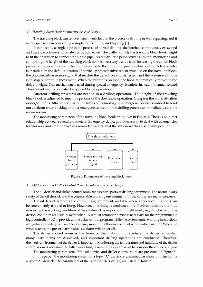
The monitoring parameters of the traveling block hook are shown in Figure 4. There is no directrelationship between several parameters. Emergency device provides a way to deal with emergenciesfor workers, and alarm device is a reminder for staff that the system reaches a safe limit position.
Machines 2017, 5, 19 5 of 15
hook height to fit the operation to connect the single pipe. As the driller’s perspective is limited, monitoring and controlling the height of the traveling block hook is necessary. Aside from increasing the crown block protector, a special hook stay location is added to the automatic push-button control. A transmitter is installed on the default location of derrick, photosensitive sensor installed on the traveling block, the photosensitive sensor signal that reaches the default location is tested, and the system will judge is to stop or continue movement. When the button is pressed, the hook automatically moves to the default height. This mechanism is used during special emergency situations instead of manual control. This control method can also be applied to the operation.
Different drilling pressures are needed in a drilling operation. The height of the traveling block hook is adjusted to meet the process of the downhole operation. Grasping the work situation underground is difficult because of the limits of technology. An emergency device is added to send out an alarm when sticking or other emergencies occur in the drilling process to immediately stop the entire system.
The monitoring parameters of the traveling block hook are shown in Figure 4. There is no direct relationship between several parameters. Emergency device provides a way to deal with emergencies for workers, and alarm device is a reminder for staff that the system reaches a safe limit position.
Figure 4. Parameters of traveling block hook.
3.3. Oil Derrick and Driller Control Room Monitoring Scheme Design
The oil derrick and driller control room are essential parts of drilling equipment. The normal work safety of the oil derrick and the comfortable working environment for the driller are major concerns.
The oil derrick supports the entire lifting equipment, and it is where various drilling tools can be conveniently tripped or hung. However, oil drilling is conducted in difficult conditions, and thus mastering the working condition of the oil derrick is important. In field work, regular checks on the derrick condition are usually overlooked. A regular reminder device is necessary for the programmable logic controller PLC to provide a time delay control program while the system emits warning instructions at regular intervals. Just like other systems, monitoring the environment wind is also essential. When the wind reaches the preset alarm value, an alarm will be set off.
The driller control room is the brain of the platform. It is where the driller is located, many instruments are displayed, and important drilling operations are conducted. Therefore, the work environment of the driller is important. Monitoring the temperature and humidity of the driller control room is necessary. A driller work fatigue reminding system is set to consider the driller’s fatigue.
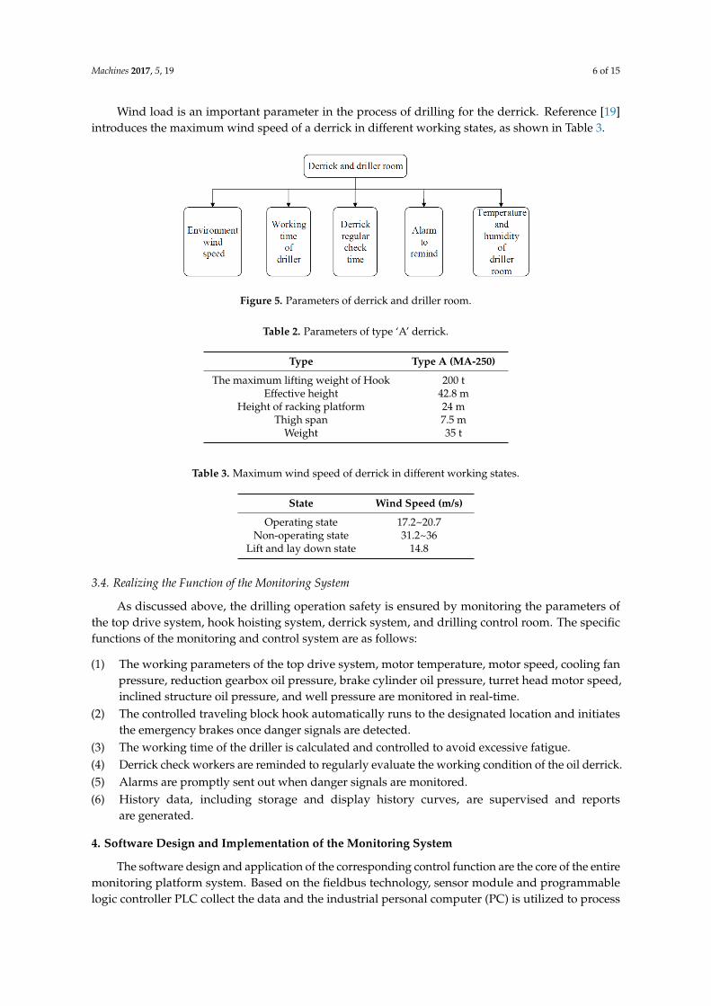
The monitoring parameters of the oil derrick and driller control room are presented in Figure 5. In this paper, the monitoring system of a type “A” derrick is examined, as shown in Figure 1 is
a type “A” derrick. The parameters of the type “A” derrick [18] are listed in Table 2. Wind load is an important parameter in the process of drilling for the derrick. Reference [19]
introduces the maximum wind speed of a derrick in different working states, as shown in Table 3.
Figure 4. Parameters of traveling block hook.
3.3. Oil Derrick and Driller Control Room Monitoring Scheme Design
The oil derrick and driller control room are essential parts of drilling equipment. The normal worksafety of the oil derrick and the comfortable working environment for the driller are major concerns.
The oil derrick supports the entire lifting equipment, and it is where various drilling tools canbe conveniently tripped or hung. However, oil drilling is conducted in difficult conditions, and thusmastering the working condition of the oil derrick is important. In field work, regular checks on thederrick condition are usually overlooked. A regular reminder device is necessary for the programmablelogic controller PLC to provide a time delay control program while the system emits warning instructionsat regular intervals. Just like other systems, monitoring the environment wind is also essential. When thewind reaches the preset alarm value, an alarm will be set off.
The driller control room is the brain of the platform. It is where the driller is located,many instruments are displayed, and important drilling operations are conducted. Therefore,the work environment of the driller is important. Monitoring the temperature and humidity of the drillercontrol room is necessary. A driller work fatigue reminding system is set to consider the driller’s fatigue.
The monitoring parameters of the oil derrick and driller control room are presented in Figure 5.In this paper, the monitoring system of a type “A” derrick is examined, as shown in Figure 1 is
a type “A” derrick. The parameters of the type “A” derrick [18] are listed in Table 2.
Machines 2017, 5, 19 6 of 15
Wind load is an important parameter in the process of drilling for the derrick. Reference [19]introduces the maximum wind speed of a derrick in different working states, as shown in Table 3.Machines 2017, 5, 19 6 of 15
Figure 5. Parameters of derrick and driller room.
Table 2. Parameters of type ‘A’ derrick.
Type Type A (MA-250) The maximum lifting weight of Hook 200 t
Effective height 42.8 m Height of racking platform 24 m
Thigh span 7.5 m Weight 35 t
Table 3. Maximum wind speed of derrick in different working states.
State Wind Speed (m/s)Operating state 17.2~20.7
Non-operating state 31.2~36 Lift and lay down state 14.8
3.4. Realizing the Function of the Monitoring System
As discussed above, the drilling operation safety is ensured by monitoring the parameters of the top drive system, hook hoisting system, derrick system, and drilling control room. The specific functions of the monitoring and control system are as follows:
(1) The working parameters of the top drive system, motor temperature, motor speed, cooling fan pressure, reduction gearbox oil pressure, brake cylinder oil pressure, turret head motor speed, inclined structure oil pressure, and well pressure are monitored in real-time.
(2) The controlled traveling block hook automatically runs to the designated location and initiates the emergency brakes once danger signals are detected.
(3) The working time of the driller is calculated and controlled to avoid excessive fatigue. (4) Derrick check workers are reminded to regularly evaluate the working condition of the oil
derrick. (5) Alarms are promptly sent out when danger signals are monitored. (6) History data, including storage and display history curves, are supervised and reports are
generated.
4. Software Design and Implementation of the Monitoring System
The software design and application of the corresponding control function are the core of the entire monitoring platform system. Based on the fieldbus technology, sensor module and programmable logic controller PLC collect the data and the industrial personal computer (PC) is utilized to process data. Through the detection signal and determined abnormal signal, the control actuator sends out the alarm and runs the start–stop motor and other control operations.
The force control configuration software, RS5000 programming software, and RSLinx communication software are used to create the entire monitoring system. Force control
Figure 5. Parameters of derrick and driller room.
Table 2. Parameters of type ‘A’ derrick.
Type Type A (MA-250)
The maximum lifting weight of Hook 200 tEffective height 42.8 m
Height of racking platform 24 mThigh span 7.5 m
Weight 35 t
Table 3. Maximum wind speed of derrick in different working states.
State Wind Speed (m/s)
Operating state 17.2~20.7Non-operating state 31.2~36
Lift and lay down state 14.8
3.4. Realizing the Function of the Monitoring System
As discussed above, the drilling operation safety is ensured by monitoring the parameters ofthe top drive system, hook hoisting system, derrick system, and drilling control room. The specificfunctions of the monitoring and control system are as follows:
(1) The working parameters of the top drive system, motor temperature, motor speed, cooling fanpressure, reduction gearbox oil pressure, brake cylinder oil pressure, turret head motor speed,inclined structure oil pressure, and well pressure are monitored in real-time.
(2) The controlled traveling block hook automatically runs to the designated location and initiatesthe emergency brakes once danger signals are detected.
(3) The working time of the driller is calculated and controlled to avoid excessive fatigue.(4) Derrick check workers are reminded to regularly evaluate the working condition of the oil derrick.(5) Alarms are promptly sent out when danger signals are monitored.(6) History data, including storage and display history curves, are supervised and reports
are generated.
4. Software Design and Implementation of the Monitoring System
The software design and application of the corresponding control function are the core of the entiremonitoring platform system. Based on the fieldbus technology, sensor module and programmablelogic controller PLC collect the data and the industrial personal computer (PC) is utilized to process

Machines 2017, 5, 19 7 of 15
data. Through the detection signal and determined abnormal signal, the control actuator sends out thealarm and runs the start–stop motor and other control operations.
The force control configuration software, RS5000 programming software, and RSLinxcommunication software are used to create the entire monitoring system. Force control configurationsoftware is a professional monitoring configuration software by Beijing 3d force control technology co.LTD, the software can be widely used in oil and gas, chemical, coal, electricity, environmental protection,energy management, intelligent buildings, and other fields. RS5000 programming software is a PLCladder programming software for Rockwell Automation company in America. RSLinx communicationsoftware is the software that controls the communication between the controller and the computer, and isalso the product of Rockwell Automation company.
4.1. Exploitation and Design of the Force Control Configuration Software
The force control configuration software includes the man–machine interface VIEW, projectmanager, I/O driver, real-time database DB, control strategy of the generator, and other Web servicecomponents, among others [20]. The I/O driver and real-time database DB can implement the variableconfiguration and the link of the OPC database or force control configuration. The software collectsfield data and controls the system process. It uses the flexible “configuration way” rather than theprogramming method to integrate the system. The preset software modules are set to obtain a simpleconfiguration to complete the functions and monitor the control layer. Engineers consider it convenientto use and that it greatly improve the efficiency of the integrated system.
The monitoring configuration screen is designed on the basis of the hardware structure of thesystem and exploitation. The login system and operating system require a dedicated administrator,and thus the system needs login rights management. Each part of the configuration screen isbuilt subsequently.
4.1.1. Top Drive Drilling System
This part includes many monitoring parameters, and an actual engineering application is neededto configure the screen concisely, intuitively, and conveniently. The monitoring configuration screenis shown in Figure 6. Because most of the top drive system is the hydraulic control, oil pressure isvery important for top drive. As shown in Figure 5, the oil pressure of different hydraulic cylinderis monitored. At the same time, the driving motor speed and the motor temperature are monitored,so the working condition of the top drive can be well understood in all aspects.
Machines 2017, 5, 19 7 of 15
configuration software is a professional monitoring configuration software by Beijing 3d force control technology co. LTD, the software can be widely used in oil and gas, chemical, coal, electricity, environmental protection, energy management, intelligent buildings, and other fields. RS5000 programming software is a PLC ladder programming software for Rockwell Automation company in America. RSLinx communication software is the software that controls the communication between the controller and the computer, and is also the product of Rockwell Automation company.
4.1. Exploitation and Design of the Force Control Configuration Software
The force control configuration software includes the man–machine interface VIEW, project manager, I/O driver, real-time database DB, control strategy of the generator, and other Web service components, among others [20]. The I/O driver and real-time database DB can implement the variable configuration and the link of the OPC database or force control configuration. The software collects field data and controls the system process. It uses the flexible “configuration way” rather than the programming method to integrate the system. The preset software modules are set to obtain a simple configuration to complete the functions and monitor the control layer. Engineers consider it convenient to use and that it greatly improve the efficiency of the integrated system.
The monitoring configuration screen is designed on the basis of the hardware structure of the system and exploitation. The login system and operating system require a dedicated administrator, and thus the system needs login rights management. Each part of the configuration screen is built subsequently.
4.1.1. Top Drive Drilling System
This part includes many monitoring parameters, and an actual engineering application is needed to configure the screen concisely, intuitively, and conveniently. The monitoring configuration screen is shown in Figure 6. Because most of the top drive system is the hydraulic control, oil pressure is very important for top drive. As shown in Figure 5, the oil pressure of different hydraulic cylinder is monitored. At the same time, the driving motor speed and the motor temperature are monitored, so the working condition of the top drive can be well understood in all aspects.
Figure 6. Monitoring configuration screen of top drive. Figure 6. Monitoring configuration screen of top drive.

Machines 2017, 5, 19 8 of 15
Figure 6 presents all the top drive monitoring parameters. The top drive is divided into severalimportant components. Each component of the monitoring parameters is detailed in the annotation.The driller can be intuitive and detect the working situation of each part.
4.1.2. Oil Derrick and Driller Control Room
The monitoring configuration screen in Figure 7 considers the drilling workers’ workingenvironment and reduces the intensity of their work.
The screen shows the convenient parameters that the driller needs to control the hook heightcontrol button. The reminder lamp is set up in an eye-catching location.
Machines 2017, 5, 19 8 of 15
Figure 6 presents all the top drive monitoring parameters. The top drive is divided into several important components. Each component of the monitoring parameters is detailed in the annotation. The driller can be intuitive and detect the working situation of each part.
4.1.2. Oil Derrick and Driller Control Room
The monitoring configuration screen in Figure 7 considers the drilling workers’ working environment and reduces the intensity of their work.
The screen shows the convenient parameters that the driller needs to control the hook height control button. The reminder lamp is set up in an eye-catching location.
Figure 7. Monitoring configuration screen of derrick and driller room.
4.2. Design and Program of the Procedure
RSLogix5000 was applied to the program. The software provides an integrated programming environment for the programmable logic controller and considers users’ actual needs. Users can input and edit the programmable logic controller PLC program, comment and inspect the program, and manage files, among others.
4.2.1. I/O Configuration to Local Module
Before programming, the I/O configuration is added to local module as an important step. The programmable logic controller PLC has local input and output modules, which are analog input and analog output as well as digital input and digital output, respectively. Choosing the right connection module is important. The configuration module used in this monitoring system is presented in Figure 8. In Figure 8, six controller modules are used, which are input and output modules of analog signals and digital signals.
Figure 8. I/O configuration.
Figure 7. Monitoring configuration screen of derrick and driller room.
4.2. Design and Program of the Procedure
RSLogix5000 was applied to the program. The software provides an integrated programmingenvironment for the programmable logic controller and considers users’ actual needs. Users caninput and edit the programmable logic controller PLC program, comment and inspect the program,and manage files, among others.
4.2.1. I/O Configuration to Local Module
Before programming, the I/O configuration is added to local module as an important step.The programmable logic controller PLC has local input and output modules, which are analog inputand analog output as well as digital input and digital output, respectively. Choosing the rightconnection module is important. The configuration module used in this monitoring system is presentedin Figure 8. In Figure 8, six controller modules are used, which are input and output modules of analogsignals and digital signals.
Machines 2017, 5, 19 8 of 15
Figure 6 presents all the top drive monitoring parameters. The top drive is divided into several important components. Each component of the monitoring parameters is detailed in the annotation. The driller can be intuitive and detect the working situation of each part.
4.1.2. Oil Derrick and Driller Control Room
The monitoring configuration screen in Figure 7 considers the drilling workers’ working environment and reduces the intensity of their work.
The screen shows the convenient parameters that the driller needs to control the hook height control button. The reminder lamp is set up in an eye-catching location.
Figure 7. Monitoring configuration screen of derrick and driller room.
4.2. Design and Program of the Procedure
RSLogix5000 was applied to the program. The software provides an integrated programming environment for the programmable logic controller and considers users’ actual needs. Users can input and edit the programmable logic controller PLC program, comment and inspect the program, and manage files, among others.
4.2.1. I/O Configuration to Local Module
Before programming, the I/O configuration is added to local module as an important step. The programmable logic controller PLC has local input and output modules, which are analog input and analog output as well as digital input and digital output, respectively. Choosing the right connection module is important. The configuration module used in this monitoring system is presented in Figure 8. In Figure 8, six controller modules are used, which are input and output modules of analog signals and digital signals.
Figure 8. I/O configuration.
Figure 8. I/O configuration.

Machines 2017, 5, 19 9 of 15
Based on the hardware input and output types, the programmable logic controller PLC moduleobtains the connection slot number and the convert relational, as shown in Table 4.
Table 4. PLC module connection slot number and the convert relational.
Hardware PLC Connection Slot Number Transformation Relation
Motor temperature 6 slot 5 mouth 0~150 ◦C corresponding 0~5 VMotor speed 6 slot 1 mouth 0~300 r/min corresponding 0~5 VWind speed 6 slot 3 mouth 0~200 Km/h corresponding 0~5 V
Brake cylinder oil pressure 6 slot 6 mouth 0~20 MPa corresponding 0~5 VDrilling fluid return pressure 3 slot 7 mouth 0~5 MPa corresponding 0~5 VBalance cylinder oil pressure 3 slot 6 mouth 0~20 MPa corresponding 0~5 VCooling fan wind pressure 6 slot 7 mouth 0~20 MPa corresponding 0~5 VTilting cylinder oil pressure 3 slot 0 mouth 0~20 MPa corresponding 0~5 VDriller room temperature 3 slot 4 mouth 0~50 ◦C corresponding 0~5 V
Driller room humidity 3 slot 5 mouth 0~100% corresponding 0~5 VHook height remind 3 slot 3 mouth Corresponding input voltage 4~5 V
Buzzer warning 7 slot 3 mouth Corresponding input voltage 1~2 V
4.2.2. Program Design of the Top Drive System
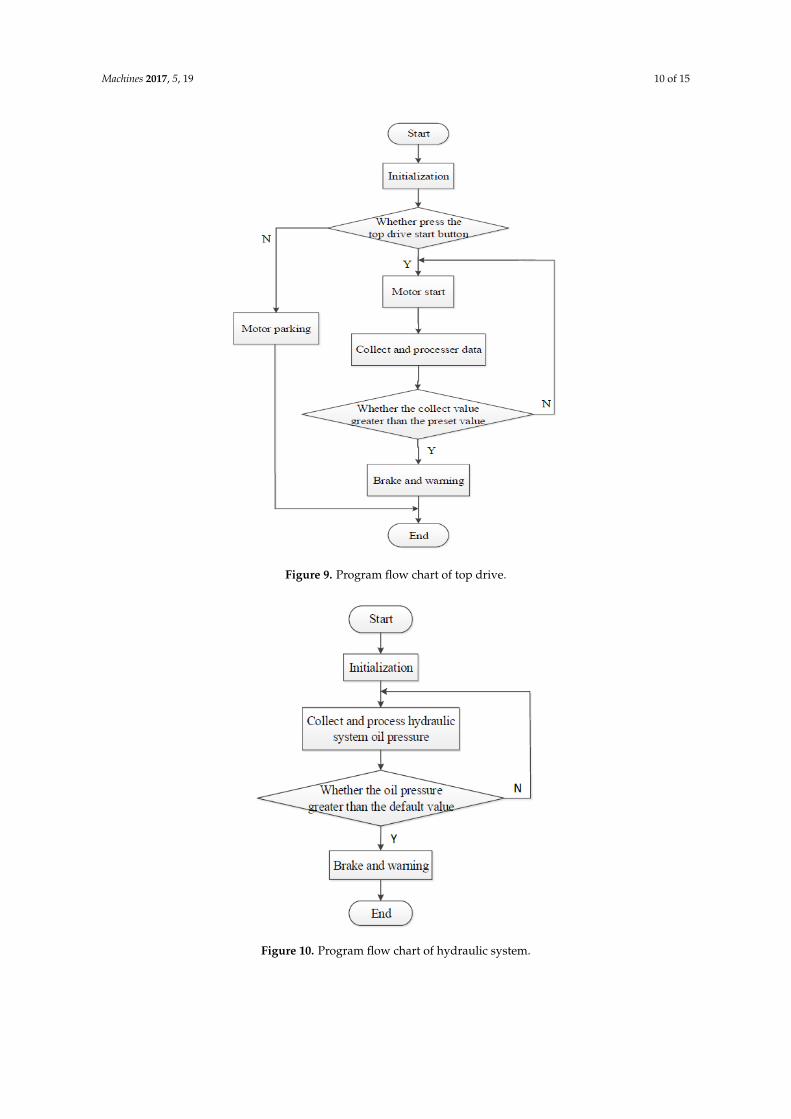
The designing of the top drive system program goes as follows: The programmable logic controllerPLC is powered on, and the module is initialized. Whether or not to push the drive start button isdetermined. When the top drive is launched, the motor temperature, motor speed, and wind pressureof cooling fan are collected and processed in real time to determine if the temperature is over 135 ◦Cand the wind pressure id less than 1 MPa. If the values are greater than the preset temperature andwind pressure, the motor will send out an alarm and brake. The program flow chart is illustrated inFigure 9.
The other acquisition modules are the real-time monitoring of the reduction of gearbox oil pressure,brake cylinder oil pressure, and inclined structure oil pressure. According to top drive hydraulicdesign manual, rated pressure of hydraulic system is 16 MPa. If this oil pressure exceeds more thanthe system rating pressure 16 MPa, the system will send out an alarm and set off the emergency brake.The program flow chart is presented in Figure 10.
4.2.3. Program Design of the Derrick and Driller Room System
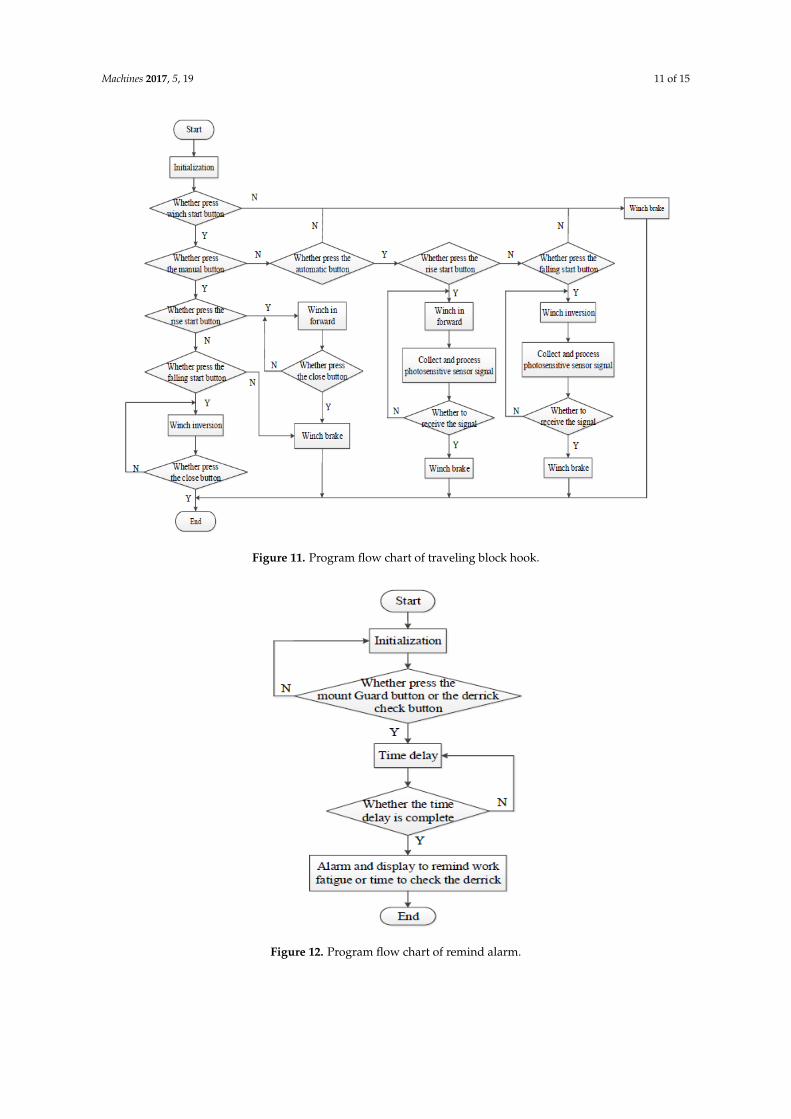
The traveling block hook is present in the derrick, and it controls the traveling block hook in thecontrol winch. In this system, photosensitive sensors are used to determine if the hook arrives at thespecified location. The module is initialized, determine if the winch start button should be pressed,determine if the automatic button or the manual button should be pressed, and find out if the hook isrising or falling. The hook stops at the specified working location when the automatic button is pressedand when the hook arrives at the specified location and detects the photosensitive sensor signal. If themanual button is pressed, the driller will manually operate the height of the hook. The program flowchart is shown in Figure 11.
The regular inspection of the oil derrick and driller fatigue work reminders should be used inthe time delay procedure. A driller mount guard button and an oil derrick check button are present.When the driller mount guard presses the mount guard button, the system starts to monitor the timeto set off the alarm once the prescribed working hours are exceeded. Regular checks on the oil derrickare the same as those on the driller mount guard. The program flow chart is shown in Figure 12.
Machines 2017, 5, 19 10 of 15
Machines 2017, 5, 19 10 of 15
Figure 9. Program flow chart of top drive.
Figure 10. Program flow chart of hydraulic system.
Figure 9. Program flow chart of top drive.
Machines 2017, 5, 19 10 of 15
Figure 9. Program flow chart of top drive.
Figure 10. Program flow chart of hydraulic system. Figure 10. Program flow chart of hydraulic system.
Machines 2017, 5, 19 11 of 15Machines 2017, 5, 19 11 of 15
Figure 11. Program flow chart of traveling block hook.
Figure 12. Program flow chart of remind alarm.
Figure 11. Program flow chart of traveling block hook.
Machines 2017, 5, 19 11 of 15
Figure 11. Program flow chart of traveling block hook.
Figure 12. Program flow chart of remind alarm.
Figure 12. Program flow chart of remind alarm.

Machines 2017, 5, 19 12 of 15
5. Application
The system was successfully conducted in the laboratory test and operation. The test resultwas perfect, and real-time acquisition and control of various parameters were successful. After thelaboratory test, the monitoring system was also successfully applied to the corresponding function atthe drilling scene.
5.1. Application of the Top Drive Monitoring System
The top drive monitoring system is successfully applied in well site of Sichuan, China. The systemoperation process is as follows: the corresponding sensor and the Programmable Logic ControllerPLC were installed, the signal cable was connected, and the system was started. The PLC wiringdiagram and the configuration of the monitor screen are presented in Figures 13 and 14, respectively.In Figure 13, a CPU and six controller modules are used.
Figure 14 shows the top drive real-time monitoring parameters. The analyzed parameters reportforms and receive the drilling condition for a period of time. For example, the analyzed motor speedand temperature can explain the performance of the main motor, the different performances of drillingfluid, whether the motor power supply is stable or not, and the formation conditions.
Most importantly, these data can be used to determine the working conditions of the top driveand to send timely warnings for inspection maintenance to avoid drilling safety accidents.
Machines 2017, 5, 19 12 of 15
5. Application
The system was successfully conducted in the laboratory test and operation. The test result was perfect, and real-time acquisition and control of various parameters were successful. After the laboratory test, the monitoring system was also successfully applied to the corresponding function at the drilling scene.
5.1. Application of the Top Drive Monitoring System
The top drive monitoring system is successfully applied in well site of Sichuan, China. The system operation process is as follows: the corresponding sensor and the Programmable Logic Controller PLC were installed, the signal cable was connected, and the system was started. The PLC wiring diagram and the configuration of the monitor screen are presented in Figures 13 and 14, respectively. In Figure 13, a CPU and six controller modules are used.
Figure 14 shows the top drive real-time monitoring parameters. The analyzed parameters report forms and receive the drilling condition for a period of time. For example, the analyzed motor speed and temperature can explain the performance of the main motor, the different performances of drilling fluid, whether the motor power supply is stable or not, and the formation conditions.
Most importantly, these data can be used to determine the working conditions of the top drive and to send timely warnings for inspection maintenance to avoid drilling safety accidents.
Figure 13. PLC wiring diagram.
Figure 14. Configuration monitor screen of top drive.
Figure 13. PLC wiring diagram.
Machines 2017, 5, 19 12 of 15
5. Application
The system was successfully conducted in the laboratory test and operation. The test result was perfect, and real-time acquisition and control of various parameters were successful. After the laboratory test, the monitoring system was also successfully applied to the corresponding function at the drilling scene.
5.1. Application of the Top Drive Monitoring System
The top drive monitoring system is successfully applied in well site of Sichuan, China. The system operation process is as follows: the corresponding sensor and the Programmable Logic Controller PLC were installed, the signal cable was connected, and the system was started. The PLC wiring diagram and the configuration of the monitor screen are presented in Figures 13 and 14, respectively. In Figure 13, a CPU and six controller modules are used.
Figure 14 shows the top drive real-time monitoring parameters. The analyzed parameters report forms and receive the drilling condition for a period of time. For example, the analyzed motor speed and temperature can explain the performance of the main motor, the different performances of drilling fluid, whether the motor power supply is stable or not, and the formation conditions.
Most importantly, these data can be used to determine the working conditions of the top drive and to send timely warnings for inspection maintenance to avoid drilling safety accidents.
Figure 13. PLC wiring diagram.
Figure 14. Configuration monitor screen of top drive. Figure 14. Configuration monitor screen of top drive.
Machines 2017, 5, 19 13 of 15
5.2. Application of the Traveling Block Hook Monitoring System
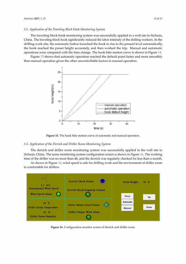
The traveling block hook monitoring system was successfully applied in a well site in Sichuan,China. The traveling block hook significantly reduced the labor intensity of the drilling workers. In thedrilling work site, the automatic button launched the hook to rise to the present level automatically,the hook reached the preset height accurately, and then worked the trip. Manual and automaticoperations were compared with the time change. The hook hike motion curve is shown in Figure 14.
Figure 15 shows that automatic operation reached the default point faster and more smoothlythan manual operation given the other uncontrollable factors in manual operation.
Machines 2017, 5, 19 13 of 15
5.2. Application of the Traveling Block Hook Monitoring System
The traveling block hook monitoring system was successfully applied in a well site in Sichuan, China. The traveling block hook significantly reduced the labor intensity of the drilling workers. In the drilling work site, the automatic button launched the hook to rise to the present level automatically, the hook reached the preset height accurately, and then worked the trip. Manual and automatic operations were compared with the time change. The hook hike motion curve is shown in Figure 14.
Figure 15 shows that automatic operation reached the default point faster and more smoothly than manual operation given the other uncontrollable factors in manual operation.
Figure 15. The hook hike motion curve of automatic and manual operation.
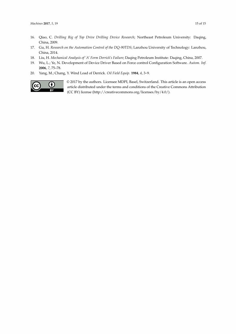
5.3. Application of the Derrick and Driller Room Monitoring System
The derrick and driller room monitoring system was successfully applied in the well site in Sichuan, China. The scene monitoring system configuration screen is shown in Figure 16. The working time of the driller was no more than 4h, and the derrick was regularly checked for less than a month.
As shown in Figure 16, wind speed is safe for drilling work and the environment of driller room is comfortable for drillers.
Figure 16. Configuration monitor screen of derrick and driller room.
Figure 15. The hook hike motion curve of automatic and manual operation.
5.3. Application of the Derrick and Driller Room Monitoring System
The derrick and driller room monitoring system was successfully applied in the well site inSichuan, China. The scene monitoring system configuration screen is shown in Figure 16. The workingtime of the driller was no more than 4h, and the derrick was regularly checked for less than a month.
As shown in Figure 16, wind speed is safe for drilling work and the environment of driller roomis comfortable for drillers.
Machines 2017, 5, 19 13 of 15
5.2. Application of the Traveling Block Hook Monitoring System
The traveling block hook monitoring system was successfully applied in a well site in Sichuan, China. The traveling block hook significantly reduced the labor intensity of the drilling workers. In the drilling work site, the automatic button launched the hook to rise to the present level automatically, the hook reached the preset height accurately, and then worked the trip. Manual and automatic operations were compared with the time change. The hook hike motion curve is shown in Figure 14.
Figure 15 shows that automatic operation reached the default point faster and more smoothly than manual operation given the other uncontrollable factors in manual operation.
Figure 15. The hook hike motion curve of automatic and manual operation.
5.3. Application of the Derrick and Driller Room Monitoring System
The derrick and driller room monitoring system was successfully applied in the well site in Sichuan, China. The scene monitoring system configuration screen is shown in Figure 16. The working time of the driller was no more than 4h, and the derrick was regularly checked for less than a month.
As shown in Figure 16, wind speed is safe for drilling work and the environment of driller room is comfortable for drillers.
Figure 16. Configuration monitor screen of derrick and driller room.
Figure 16. Configuration monitor screen of derrick and driller room.

Machines 2017, 5, 19 14 of 15
6. Conclusions
(1) The drilling rig hoisting security monitoring system is established to collect and control theparameters of top drive, traveling block hook, oil derrick and driller room, and successfullyapplicate in well drilling work site.
(2) Independently developed a software system based on force control, RSLogic5000 software.Parameters of each part are displayed in real-time, and implemented the alarm function,generated reports, plotted related parameters.
(3) The collected parameters are used to determine the working conditions of the top drive and tosend timely warnings for inspection maintenance to avoid drilling safety accidents.
(4) Automatic control traveling block hook move to the default location is more efficient and securitythan manual control. For each time, automatic control traveling block hook can save 5~10 s.
(5) Work fatigue remind of driller and derrick check regularly remind can be as much as possible toreduce safety accidents. The system will send a work fatigue warning signal every four hours ofcontinuous work for driller, and send a derrick check signal every one month.
Author Contributions: Junjiang He designed the monitoring system, wrote system program and wrote the paper;Liangjie Mao responsible for equipment commissioning and site personnel allocation; Min Luo collected data andanalyzed the data.
Conflicts of Interest: The authors declare no conflict of interest.
References
1. Xu, J.; Shan, Y. Oil Drilling Machinery; Petroleum Industry Press: Beijing, China, 2015.2. Liang, Z.; Zhang, L.W.; Jiang, F.G.; Li, S. Present State and Proposal of Casing Drive Tool. Oil Field Equip.
2013, 42, 1–5.3. Shao, G.; Dong, X.; Pu, Z.; An, X. Design of Hydraulic Top Drive Rig Derrick. J. Anhui Univ. Sci. Technol.
(Nat. Sci.) 2012, 32, 86–87.4. Fan, C.; Kong, M.; Han, J.; Zhang, W.; Wang, C.; Li, Y. Tarim Drilling Branch of Bohai Petroleum Engineering
Company. System Design and Analysis of HVAC System Design and Analysis of Driller Room in Oil Rig.Electr. Explos. Prot. 2014, 1, 7–11.
5. Pavel, H.; Baluch, D.; Lesso, I. Drilling stand monitoring using internet. Acta Montan. Slovaca 2004, 9,189–191.
6. Franco-Gasca, L.A.; Herrera-Ruiz, G.; Peniche-Vera, R.; Peniche-Vera, R.d.R.; Leal-Tafolla, W. Sensor less toolfailure monitoring system for drilling machines. Int. J. Mach. Tools Manuf. 2006, 46, 381–386. [CrossRef]
7. Drill View 21 Controls. 2008. Available online: http://www.rigserv.com/frames.html (accessed on2 August 2017).
8. Make Decisions-Quickly and Effective. 2008. Available online: http://www.wellwizard.com/wwedr.htm(accessed on 2 August 2017).
9. Wang, Y.; Wang, L.; Tan, G. CANRIG Top Drive External Fault Alarm Analysis. Drill. Prod. Technol. 2008, 31,99–101.
10. Zhang, N.; Li, X.; Hu, C. Remote Security Monitoring System of Drilling Rig Based on GPRS. Pet. Instrum.2009, 3, 66–68.
11. Zhang, N.; Guo, J.; Xu, J.; Hu, C. Research on Rig Safety Monitoring System Based on Fuzzy Neural Network.China Pet. Mach. 2009, 37, 53–55.
12. Wang, M. Experimental Rig Lifting Device Monitoring System Design; Southwest Petroleum University:Chengdu, China, 2010.
13. Cheng, Y.; Lu, X.; Gong, Y.; Wu, Y.; Rao, Y. Derrick safety monitoring system based on fiber Bragg gratingstrain sensors. Photonic Sens. 2013, 3, 237–240. [CrossRef]
14. Deng, L.; Chang, Z. Top Drive Control System Anti-jamming Performance Analysis. Pract. Electron. 2013, 17,32.
15. Wang, Y. Brief Talk the Characteristics and Development Direction of the PLC Control Technology. J. LanzhouHigh Polytech. Coll. 2011, 18, 40–44.
Machines 2017, 5, 19 15 of 15
16. Qiao, C. Drilling Rig of Top Drive Drilling Device Research; Northeast Petroleum University: Daqing,China, 2009.
17. Gu, H. Research on the Automation Control of the DQ-90TDS; Lanzhou University of Technology: Lanzhou,China, 2014.
18. Liu, H. Mechanical Analysis of ‘A’ Form Derrick’s Failure; Daqing Petroleum Institute: Daqing, China, 2007.19. Wu, L.; Ye, N. Development of Device Driver Based on Force control Configuration Software. Autom. Inf.
2006, 7, 75–78.20. Yang, M.; Chang, Y. Wind Load of Derrick. Oil Field Equip. 1984, 4, 3–9.
© 2017 by the authors. Licensee MDPI, Basel, Switzerland. This article is an open accessarticle distributed under the terms and conditions of the Creative Commons Attribution(CC BY) license (http://creativecommons.org/licenses/by/4.0/).