Master Thesis Drilling rig design for a unique oil field application
122
Montanuniversität Leoben Master Thesis Drilling rig design for a unique oil field application – field redevelopment in Ruehlermoor “peat mining field” Simon Stolte 1335169 Supervisor: Univ.-Prof. Dipl.-Ing. Dr. mont. Gerhard Thonhauser: Montanuniversität Leoben Christian Bruenink, Detlef Klaus: GDF Suez E&P Deutschland GmbH
-
Upload
khangminh22 -
Category
Documents
-
view
1 -
download
0
Transcript of Master Thesis Drilling rig design for a unique oil field application

Montanuniversität Leoben
Master Thesis
Drilling rig design for a unique oil field application –
field redevelopment in Ruehlermoor “peat mining
field”
Simon Stolte
1335169
Supervisor:
Univ.-Prof. Dipl.-Ing. Dr. mont. Gerhard Thonhauser: Montanuniversität Leoben
Christian Bruenink, Detlef Klaus: GDF Suez E&P Deutschland GmbH

Simon Stolte 1335169
I
EIDESTATTLICHE ERKLÄRUNG
Ich erkläre an Eides statt, dass ich diese Arbeit selbstständig verfasst, andere als
die angegebenen Quellen und Hilfsmittel nicht benutzt und mich auch sonst keiner
unerlaubten Hilfsmittel bedient habe.
AFFIDAVIT
I hereby declare that the content of this work is my own composition and has not been
submitted previously for any higher degree. All extracts have been distinguished using
quoted references and all information sources have been acknowledged.
______________________ _________________________
Datum Simon Stolte

Simon Stolte 1335169
II
Table of Contents
Declaration..………………………………..……………….….I
Abbreviations…..…………………………………………….IV List of Tables………...……………………………………..…V
List of Figures………..………………………….…………...VI 1. Abstract / Kurzfassung ............................................... 1
1.1 Abstract ................................................................................... 1
1.2 Kurzfassung ............................................................................ 2
2. Introduction.................................................................. 4
3. The peat mining field Ruehlermoor............................ 8
3.1 History...................................................................................... 8
3.2 Old wells (0-99, 100er, 200er, 300er) ................................... 9
3.3 Thermal wells (500er and 600er) ........................................ 10
3.4 Wells drilled since the 2000s (400er, 800er)..................... 10
3.5 Geology ................................................................................. 13
3.6 The Redevelopment project ............................................... 16
3.6.1. General description ........................................................... 16
3.6.2. The future wells schemes ................................................. 17
3.7 Infield infrastructure ............................................................ 19
3.7.1. Dyke structure ................................................................... 19
3.7.2. The Train and the rail condition ........................................ 21
3.7.3. The Carrier ......................................................................... 24
3.7.4. Road Transport with Tractor, Crawler crane & Unimog ... 27
3.8 Logistics / Infrastructure utilization .................................. 30
4. Drilling Rig Franks Cabot 300/11 .............................. 33
4.1 Rig Specifications ................................................................ 33
4.2 Drilling site ............................................................................ 35
5. Economically view to work with a contractor ......... 39
6. The tendering process .............................................. 42
7. The most preferred specifications of a new rig ...... 45
8. Concepts of the contractors ..................................... 49
8.1 Company A 1......................................................................... 49
8.2 Company A 2......................................................................... 53
8.3 Company B............................................................................ 55
8.4 Company C............................................................................ 58
8.5 Company D............................................................................ 60
Simon Stolte 1335169
III
8.6 Rig specifications of the contractors................................ 63
9. Efficiency Analysis .................................................... 65
9.1 Definition and Reasons ....................................................... 67
9.2 Description of the Concept................................................. 68
9.3 Analysis of the weighted criteria ....................................... 70
10. Evaluation of the efficiency analysis ....................... 73
10.1 The rig move scenario ......................................................... 73
10.2 Pre – disqualification ........................................................... 75
10.3 Efficiency analyses result ................................................... 76
10.4 Efficiency and HSE considerations ................................... 78
11. Conclusions ............................................................... 81
12. Outlook ....................................................................... 83
References ...................................................................... 84
13. Appendix .................................................................... 85
13.1 Preliminary Equipment List ................................................ 85
13.2 Rig Franks 300 Specification.............................................. 96
13.3 Evaluation Matrixes ............................................................. 98
13.3.1. Rig Concept 45 % .............................................................. 98
13.3.2. Rig Move 20 % ................................................................. 104
13.3.3. Distance to operator 10 % ............................................... 104
13.3.4. Qualification of personal 10 % ........................................ 105
13.3.5. Local experience 5 %....................................................... 105
13.3.6. Energy 5 % ....................................................................... 106
13.3.7. Rig availability 5 % .......................................................... 106
13.4 Time Analysis of well RLMR 801 and H 25 ..................... 107
13.4.1. RLMR H 25 ....................................................................... 107
13.4.2. RLMR 801 ......................................................................... 108
13.5 Contractor comparison ..................................................... 109

Simon Stolte 1335169
IV
Abbreviations
300 Cabot Franks 300/11 drilling rig
EMPG ExxonMobil production Germany
FEED Front End Engineering & Design
FID Final investment decision
HP/HT High pressure / High temperature
HPU Hydraulic power unit
HSE Health & Safety Execution
HTV Horizontal to vertical
MD Measured depth
PULD Pick up/lay down machine
RLMR Ruehlermoor; Abbreviation of the wells in the field Ruehlermoor
TDS Top drive system
TVD Total vertical depth
Unimog Mercedes-Benz Unimog
VFD Variable frequency drive

Simon Stolte 1335169
V
List of Tables
Table 3.1: Different carrier in Ruehlermoor
Table 5.1: Cost calculation Rig Cabot Franks 300/11
Table 5.2: Cost estimation Rig Cabot Franks 300/11
Table 5.3: Rig costs of a contractor
Table 8.1: Contractor comparison
Table 9.1: Criteria weighting procedure
Table 9.2: Mast criteria weighting
Table 9.3: Contractor rating
Table 9.4: Results rig concept
Table 10.1: Rig move durations
Table 10.2: Rig move requirements
Table 10.3: Efficiency analyses result
Table 10.4: HSE considerations of the contractors
Table 11.1: Final efficiency analyses result

Simon Stolte 1335169
VI
List of Figures
Figure 2.1: Comparison of the use of primary sources of energy and of the ratio of
domestic supply to imports for Germany in 2003 and 2013, and relative shares in 2013
(based on AGEB 2014, LBEG 2014) [3]
Figure 2.2: Distribution of the German oil production separated in the states of
Germany [4]
Figure 2.3: Oil field in northern Germany [3]
Figure 3.1: Rig 42, Ruehlertwist 1950 [5]
Figure 3.2: Time Analysis of Well RLMR 801
Figure 3.3: Time Analysis of Well RLMR H 25
Figure 3.4: Geology structure Ruehlermoor
Figure 3.5: Geology Profile Ruehlermoor
Figure 3.6: Well construction process gates
Figure 3.7: Typical dyke structure
Figure 3.8: Underground of dyke 4
Figure 3.9: CHL 40 locomotive and a shunting engine
Figure 3.10: Typical Train in the Ruehlermoor oil field [6]
Figure 3.11: Performance chart CHL 40 G locomotive
Figure 3.12: Rail way system in Ruehlermoor
Figure 3.13: Multicarrier
Figure 3.14: Pipe transportation carrier
Figure 3.15: Heavy load carrier 1
Figure 3.16: Heavy load carrier 2
Figure 3.17: Roads in the Ruehlermoor Oilfield
Figure 3.18: Load capacity of the Mercedes-Benz Unimog
Figure 3.19: 60 t crawler crane
Figure 3.20: Load capacity 60 t crawler crane
Figure 3.21: Chronological construction procedure
Figure 3.22: Rig move scenario
Figure 4.1: Franks Cabot 300/11 Pic.1
Figure 4.2: Franks Cabot 300/11 Pic.2
Figure 4.3: Figure 4.3: Drilling area RLMR 801
Figure 4.4: Conventional rail organization
Figure 4.5: Unconventional rail organization
Figure 6.1: Schedule of the tendering process
Figure 7.1: Pulling force in a curve depending of the distance between locomotive and
load
Figure 8.1: Rig A1

Simon Stolte 1335169
VII
Figure 8.2: Rail car system
Figure 8.3: Rig A2
Figure 8.4: Rig B
Figure 8.5: Rig C
Figure 8.6: Rig D
Figure 9.2: Evaluation structure with weighting

Abstract Simon Stolte 1335169
Page 1 of 114
1. Abstract / Kurzfassung
1.1 Abstract
A major part of the German oil and gas consumption is covered by imports, thus it is
important that Germany strengthen the domestic production. The oil field
"Ruehlermoor" with more than 500 existing wells is Germany's largest onshore oil field
and is operated by a joint venture of GDF Suez and ExxonMobil. It was discovered in
1941, is located in a peat mining area at the German-Dutch border and covers 24
square kilometers. Its infrastructure is unique in the world. Due to the unstable
underground in the field most transports are done with a narrow-gauge railway (track
width 900 mm). The peat mining industry and the oil production operate
simultaneously. Parallel arranged dykes, which are several meters high and up to 40 m
wide serve as area for the sucker rod pumps, the infrastructure and for drilling and
workover operations.
The oil field is in production for 60 years and has an exploitation of 27 % (2015). Since
the 80s, the reservoir is stimulated with hot steam injections. Meanwhile, the pipelines
of the field and the steam generation plant have to be replaced. The redevelopment of
the field needs over 100 new wells in 500 - 700 m depth in the next 5 years, the
construction of a cogeneration plant and the consequent increase in steam injection
and oil production has to ensure the economic viability of the field.
The last wells in the Ruehlermoor oil field were drilled with a company's own carrier rig
built in 1982, which could compensate the small space conditions by its compact
design, but is not capable to drill such a drilling campaign.
The future drilling rig needs a hook load of 150 tons except load to pull casings
according to the thermal effects in tension. It must be able to transport by rail and the
individual parts must not exceed 60 tons. There is no ability to skid in Ruehlermoor,
because the surface locations of the new wells are located in between of the existing
wells. The small size of the well site and the narrow dykes on which only a road and
one rail are available as infrastructure, transport and the rig up/rig down procedure is a
major challenge. The rig must be able to drill a minimum of wells, before the
cogeneration plant goes into production in 2020, in order to ensure efficient operation
of the project. The acquisition of a new rig is therefore essential. Through a Europe-
wide tendering process 11 drilling contractors were invited to propose their rig concepts
and 4 of them submitted tender documents.
This thesis accompanied the tendering process, deals with the peculiarities of the oil
field Ruehlermoor and shows why the construction of a new rig is needed to meet the
circumstances of the field and why the transport of the rig has a decisive impact on the

Kurzfassung Simon Stolte 1335169
Page 2 of 114
success of the project. Furthermore, the thesis describes the concepts of the
contractors and evaluates them technically. For this, matrices have been developed
with differently weighted evaluation criteria in accordance to the circumstances, which
are needed to do an efficiency analysis. A recommendation for the best concept is then
developed using the analysis.
1.2 Kurzfassung
Ein Großteil des deutschen Erdöl- und Erdgasverbrauchs wird durch Importe gedeckt
und darum ist es wichtig, dass Deutschland die inländische Produktion stärkt. Das
Erdölfeld „Rühlermoor“ mit über 500 bestehenden Bohrungen ist Deutschlands größtes
Erdölfeld auf dem Festland und wird von einem Joint Venture aus GDF Suez und
ExxonMobil betrieben. Entdeckt wurde es 1941. Es liegt in einem Torfabbaugebiet an
der deutsch-holländische Grenze, erstreckt sich über 24 km² und ist in seiner
Infrastruktur einzigartig auf der Welt. Aufgrund des instabilen Untergrundes werden die
meisten Transporte im Feld mit einer Schmalspurbahn (Spurbreite 900 mm) erledigt.
Die Torfabbauindustrie und die Ölproduktion arbeiten simultan. Parallel angeordnete
Deiche, die mehrere Meter hoch und bis zu 40 m breit sind dienen dabei als Bereich für
die Gestängetiefpumpen, die Infrastruktur und als Handlungsfläche für Bohr- und
Workovermaßnahmen.
Das Erdölfeld ist seit 60 Jahren in Produktion und weist eine Ausbeutung von 27 % auf
(2015). Seit den 80er Jahren wird das Reservoir mit Heißdampfinjektionen stimuliert.
Mittlerweile müssen jedoch die Pipelines des Feldes und die Dampferzeugungsanlage
ersetzt werden. Die Neuentwicklung des Feldes mit über 100 Neubohrungen in 500 –
700 m Tiefe in den kommenden 5 Jahren, dem Neubau einer Kraft-Wärmekopplungs-
Anlage und dem daraus resultierendem Anstieg an Dampfinjektion und Erdölproduktion
soll die Wirtschaftlichkeit des Feldes weiterhin garantieren.
Die letzten Bohrungen im Rühlermoor Erdölfeld wurden mit einer konzerneigenen
Carrieranlage aus dem Baujahr 1982 gebohrt, die die geringen Platzbedingungen
durch ihre kompakte Bauweise kompensieren konnte, aber nicht in der Lage ist solch
eine Bohrkampagne zu bohren.
Die Anschaffung einer neuen Anlage ist daher unverzichtbar. Die zukünftige
Bohranlage benötigt eine Hakenausnahmelast von 150 Tonnen, um Casinge
entsprechend der thermischen Einwirkungen in Spannung zu ziehen. Sie muss auf der
Schiene transportierbar sein und die Einzelteile dürfen 60 Tonnen nicht überschreiten.
Die Möglichkeit zu Skidden besteht in Rühlermoor durch existierende Bohrungen
zwischen den Neubohrungen nicht. Durch die geringe Größe des Bohrplatzes und den

Kurzfassung Simon Stolte 1335169
Page 3 of 114
schmalen Deichen, auf dem lediglich eine Straße und ein Gleis als Infrastruktur
vorhanden sind, sind der Transport und der Umbau der Bohranlage eine große
Herausforderung. Die Anlage muss in der Lage sein ein Minimum an Bohrungen fertig
zu stellen, bevor die Kraft-Wärmekopplungs-Anlage 2020 in Produktion geht, um eine
wirtschaftliche Nutzung des Projektes zu gewährleisten. Durch ein europaweites
Ausschreibungsverfahren wurden 11
Bohrfirmen aufgefordert ihre Bohranlagenkonzepte zu präsentieren bei der 4 von
ihnen ein Angebot abgaben.
Diese Arbeit begleitet den Ausschreibungsprozess, befasst sich mit den
Besonderheiten des Erdölfeldes Rühlermoor und zeigt auf, warum der Neubau einer
Anlage nötig ist, um den Gegebenheiten des Feldes gerecht zu werden und warum der
Transport der Anlage einen entscheidenden Anteil an dem Erfolg des geplanten
Projektes hat. Des Weiteren werden die Konzepte der Firmen beschrieben und
technisch bewertet. Hierfür wurden Matrizen mit unterschiedlich gewichteten
Bewertungskriterien dem Umständen entsprechend entwickelt, die einer Bewertung mit
Hilfe einer Nutzwertanalyse dienen. Anhand der Analyse wird dann eine Empfehlung
für das beste Konzept erarbeitet.

Introduction Simon Stolte 1335169
Page 4 of 114
2. Introduction
Germany is not capable of compensating the demand of oil with its own production. [1]
Although the consumption has been slightly decreasing over the past 15 years, [2] the
development of the inland oil exploration and production has to be enhanced. The oil
production has been stagnating over the last 20 years due to various reasons. The
existing oil fields resources are more and more exhausted. The exploration of new
fields is a challenge in Germany. The urban landscape makes it difficult to find spots for
exploration wells or large-scale underground investigations. In addition to that, topics
like hydraulic fracturing resulted in the resistance of the population to respective drilling
of new wells. Additionally to that the effort to authorize new drilling activities gets more
extensive. Different state authorities want the proof of a safe working environment for
people, flora, fauna and habitat. Therefore, the production of oil has to be enhanced in
existing fields and production wells. There are diverse possibilities to achieve a higher
efficiency while increasing safety for all stakeholders. Workover of existing wells, new
wells in existing fields, re-entry wells or the stimulation of the reservoir with heat or
chemicals are only a few possibilities.
The oil production in Lower Saxony Basin is the second highest in Germany. However,
the overall production of oil covers only 2-3 % of the total consumption (Figure 2.1 and
2.2).
Figure 2.1: Comparison of the use of primary sources of energy and of the ratio of domestic
supply to imports for Germany in 2003 and 2013, and relative shares in 2013 (based on
AGEB 2014, LBEG 2014) [3]

Introduction Simon Stolte 1335169
Page 5 of 114
Figure 2.2: Distribution of the German oil production separated in the states of Germany [4]
One of the existing oil fields in Lower Saxony in the Emsland region is the “peat mining
field” or “Ruehlermoor oilfield” located at the north western part at the border to the
Netherlands (Figure 2.3 (red arrows)).
Figure 2.3: Oil fields in northern Germany [3]
It covers a 24 km² area and is separated into two different production areas - the
western part Ruehler Twist and the eastern part Ruehlermoor. It contains a 7.08 km²
nature reservoir. The Ruehlermoor oilfield was discovered in 1941 and developed from
the middle of 1949 to be the biggest oil field of GDF Suez. A joint venture of
ExxonMobil Production Germany (EMPG) and GDF Suez E&P Deutschland GmbH
operate the field together with 50 % share each. GDF Suez is the drilling operator and

Introduction Simon Stolte 1335169
Page 6 of 114
EMPG is working as the production and field operator. The field contains 128 million
tons of oil in place in the “Bentheimer sandstone”. The immense challenge in producing
the oil is the infrastructure in combination with the nature reservoir and the
simultaneously ongoing peat mining operation. Under an 8 – 13 m thick peat layer, the
sucker rod pumps are producing oil out of 500 – 700 m deep 2 - dimensional J-shape
wells. The pumps are placed on small dykes, which are roughly 40 m wide. They can
be reached with a small train or with a car. The rail way system within the field has a
900 mm gauge, is over 100 kilometres long and is necessary for an improved load
distribution.
In the past 65 years the field with over 500 wells went through different stages of
production. In the first years the oil production was operating due to the natural flow.
Until 1964, 372 wells have been drilled and produced by conventional oil recovery.
Since 1956 water injection wells have been drilled additionally to pressurize the
reservoir in order to cover the decline in production and to hold the reservoir pressure.
In the 70s additional 80 wells were drilled because of the increasing oil price. Since the
beginning of the 80s the first steam injection wells started to support the production of
high viscous oil (ca. 120 cP (Water: 1 cP)). With temperatures of the steam up to 320
°C and production temperatures up to 100 °C the viscosity was able to be reduced and
the production proceeded. Due to persisting decline in the 90s older wells with
malfunctions were plugged and re-drilled with side-tracks. In the 2000s an additional
drilling campaign was initiated to stop the decline of oil production. Currently there are
159 production wells, 8 steam injection wells and 28 water injection wells in operation
(August 2013).
2013 GDF Suez E&P Deutschland GmbH and ExxonMobil Germany GmbH started to
discuss about a complete redevelopment of the field to ensure a prolongation of
production for additional 30 years. Even though the undertaking was understood as a
challenge, the motivation of this project was the prediction of a high amount of oil still
being producible. The redevelopment project was started.
Regarding the problems of the oil production in Germany and the infield situation the
project is confronted with big challenges. The project plan includes the construction of
a cogeneration plant, which will be set in production in 2020. Additionally the drilling
over 100 new production, water and steam injection wells is planned. The water
injection wells with a length of up to 1500 m MD each will be drilled on 2 sides outside
the peat mining area to dispose the produced water. Nowadays the water cut is > 90%
all over the field and in the future it will most likely not decrease. The field produces
over 500 t oil every day. The cogeneration plant uses the produced water to generate
steam and electricity. This is required, because it is not possible to inject the complete
produced water back into the formation due to the capacity limits. Additionally the
generated electricity can be used in the operation and the surplus can be sold.

Introduction Simon Stolte 1335169
Page 7 of 114
The steam injector wells will be placed within the field to heat up the reservoir and
reduce the viscosity of the oil. The well head temperature has to be raised to 200 °C.
Therefore, new production infrastructure like pipelines and wellheads must be installed,
because the present equipment does not handle these high temperatures. Also the
completion design will be changed to withstand extreme conditions with the occurrence
of high temperatures, CO2 and H2S. Up to 150 °C H2S is high corrosive. Above this
temperature CO2 gets highly corrosive. Thus, during the life time of the producer with a
rising of the temperature of the produced fluid, it will mostly be a corrosive medium in
place.
Water production wells will be drilled at the border of the field, which will reduce the
pressure in the production zone and build a low pressure barrier against the water
injection wells outside of the field. Observations have shown, that with pressures
around 30 – 40 bars the oil transport in the pores is better than with the current
pressure, which is around 60 bars. If the pressure is too high during the injection of the
steam, the possibility occurs that the steam changes into the fluid phase and blocks the
flowing channels of the reservoir rock which will result in a decrease the oil
propagation. Also the water cut can raise and a steam break through is possible.
Therefore, the water production wells will be placed around the field. The overall
investment for the consortium will be around 1.2 billion Euros.

The peat mining field Ruehlermoor Simon Stolte 1335169
Page 8 of 114
3. The peat mining field Ruehlermoor
This chapter informs about the history of the Ruehlermoor oilfield from the beginning
until today. Well schemes will be shown to get an idea of how wells were drilled and
cased in the past. Afterwards the geology of the field is presented. The process and
stage of the redevelopment is discussed and later on the infield infrastructure with train,
carrier, road transport and logistics is explained.
3.1 History
On the 24.08.1949 the Ruehlermoor 1 (RLMR1) well found oil in the Bentheimer
sandstone at 670 m vertical depth. It was the 4th oil finding in the Emsland within 7
years. (1942 in Lingen-Dalum, 1943 in Emlichheim, and 1943 in Georgsdorf) After the
second successful oil finding in Ruehlermoor in 1949 the consortium of Deutsche
Schachtbau und Tiefbohrgesellschaft mbH – today GDF Suez – and Gewerkschaft
Elwerath – today ExxonMobil developed the field Ruehlermoor in 1950 with additional
13 wells. The wells got serial numbers which can be sorted in a timeline including an
abbreviation RLMR for “Ruehlermoor”. The wells with numbers from 1-399 were drilled
until the beginning of the 60s. Wells with numbers from 500-799 were drilled afterwards
until the beginning of the 90s and have a comparable casing design to the wells of the
redevelopment project. Later drilled wells got numbers between 400 and 499 or 800-
899. Also then all equipment was transported on rails because of the unconsolidated
underground. The production of 880 t per year in 1949 raised up to 30,000 t per year in
1950.
Due to drilling of additional 17 wells in 1951 the production increased up to 96,000 t oil
per year. Consequently, in 1966, the development of the field with building pipelines
and drilling of new wells resulted in over 1,000,000 t per year of oil production out of
274 wells. At that time 366 wells were already drilled, including 15 wells that were only
used for water injection and 77 were abandoned wells. The water cut rose during the
following years but a constant production was perceived. The attempt to increase the
oil production by installing lager pumps failed and in the beginning of the 70s the oil
production decreased for the first time. This trend would be stopped with drilling of 80
new wells from 1976 to 1980. Additionally to that in 1980 the steam injection started
which caused the occurrence of H2S but somewhere tripled the oil production in the
invaded zone.

The peat mining field Ruehlermoor Simon Stolte 1335169
Page 9 of 114
Figure 3.1: Rig 42, Ruehler Twist 1950 [5]
3.2 Old wells (0-99, 100er, 200er, 300er)
As mentioned before the field was developed in the 50s. The
RLMR 1 was drilled from the 15.6.1949 until the 18.8.1949 with
the following casing design:
- 13 3/8” up to 263 m,
- 9 5/8” up to 574 m and a
- 6 5/8” pre drilled Liner from 566 – 671 m.
For the following wells in the 50s and 60s it is a nontypical
design. Later on almost every well was completed with a 9 5/8”
or 10 ¾” up to around 130 m, a 6 5/8” up to around 620 – 830 m
and a 5, 4 ¾” or 4 ½” Liner up to the end depth which is a more
economic casing scheme. The liners were slotted, perforated or
pre-drilled and in some wells additional 2 7/8” sand screens were
installed to prevent sand production.
The peat mining field Ruehlermoor Simon Stolte 1335169
Page 10 of 114
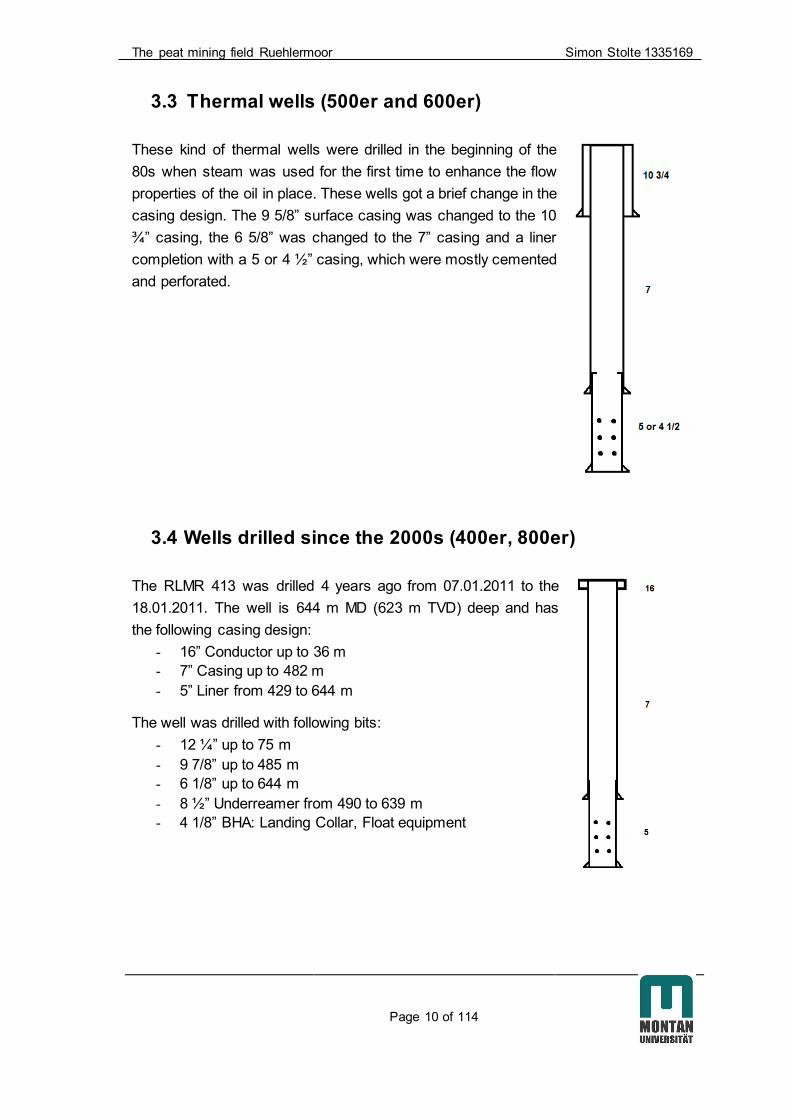
3.3 Thermal wells (500er and 600er)
These kind of thermal wells were drilled in the beginning of the
80s when steam was used for the first time to enhance the flow
properties of the oil in place. These wells got a brief change in the
casing design. The 9 5/8” surface casing was changed to the 10
¾” casing, the 6 5/8” was changed to the 7” casing and a liner
completion with a 5 or 4 ½” casing, which were mostly cemented
and perforated.
3.4 Wells drilled since the 2000s (400er, 800er)
The RLMR 413 was drilled 4 years ago from 07.01.2011 to the
18.01.2011. The well is 644 m MD (623 m TVD) deep and has
the following casing design:
- 16” Conductor up to 36 m
- 7” Casing up to 482 m
- 5” Liner from 429 to 644 m
The well was drilled with following bits:
- 12 ¼” up to 75 m
- 9 7/8” up to 485 m
- 6 1/8” up to 644 m
- 8 ½” Underreamer from 490 to 639 m
- 4 1/8” BHA: Landing Collar, Float equipment

The peat mining field Ruehlermoor Simon Stolte 1335169
Page 11 of 114
This so called “slim well design” is typical for the field Ruehlermoor since the beginning
of the 2000s. During the drop of the oil price in the 90s this casing design was chosen
to reduce the costs. It is designed for production temperatures of 100 C°. For the
Redevelopment project this design is not feasible. Due to higher production fluid
temperature changes this casing design includes a higher risk of a failing well integrity.
GDF Suez and EMPG decided that the risk is too high to use this casing design for
injection of high temperature steam. It is not possible to pull the whole 7” casing in
tension to withstand the high forces occurring during high temperature changes,
because of 2 different cement types. The lower section is covered with tail cement
which hardens faster than the lead cement in the upper section. This tail cement
section is relatively short compared to the lead cement section and works as an
anchor. Thus, the casing could be pulled in tension. The result is that only the part of
the casing covered with lead cement can be pulled in tension. Additionally it is not
possible to assure a safe well integrity with the 7” casing as the only barrier. Also as a
producer this design has some uncertainties. If gas with H2S and/or CO2 enters the
tubing annulus the 7” casing is the only barrier to the formation. If the casing corrodes it
may result in major negative effects to the environment.
The RLMR 801 is a well which was cored additionally to get detailed
underground information. It is located on dyke 6 and was drilled from
07.05.2014 – 28.05.2014. It is 636 m MD and 617 m TVD deep with
the following casing design:
- 16” conductor casing up to 36 m,
- 9 5/8” casing up to 475 m
- 7” Liner set in 2 steps from 0 to 636 m
(first 428 m – 636 m, second 0 – 428 m)
A 7” tie-back from 0 - 428 m was chosen, that the work over team can
use their stocked 7” tools. The second fact for the extraordinariness of
the casing design is that the geological department needed a 4” core.
This is only possible to achieve with an 8 ½” coring tool which fits a 9
5/8” casing. It is the last producer well drilled in the field until today.

The peat mining field Ruehlermoor Simon Stolte 1335169
Page 12 of 114
The RLMR H 25 is a steam injector well located on dyke 7 and was
drilled from 02.06.2014 – 17.06.2014. It has a depth of 614 m MD and
599 m TVD. Its casing design is the following:
- 16” conductor casing up to 36 m
- 9 5/8” Casing up to 288.5 m
- 7” casing from 0 to 534 m
- 5” Liner from 476 to 603.5 m
This casing design is a good reference for the wells of the
redevelopment project, which is discussed in more detail in chapter
3.6.2 “The future wells schemes”.
Figure 3.2 and 3.3 show a time analysis of the drilling process of
RLMR 801 and RLMR H 25 distinguished in the different working
procedures. It is developed with information out of daily reports. For
the redevelopment project no coring is planned, but all other
processes shown in the figure can be a reference to analyze the
effectiveness of the new rig.
In the appendix the detailed time analyses can be found. (Appendix 13.4)
Figure 3.2: Time Analysis of well RLMR 801
236,5
128,25
70,75
25,5 38,5
16,5
Total Duration [hrs]
Drilling
Coring
Run & Cement Casing
Logging
Work on BOP/WH
Other

The peat mining field Ruehlermoor Simon Stolte 1335169
Page 13 of 114
Figure 3.3: Time Analysis of well RLMR H 25
3.5 Geology
The Ruehle structure is characterized by an EW-trending elongated anticline.
Geologically the reservoir contains the structure of the Bentheim Sandstone (“Oil
sand”; Lower Valanginian, Lower Cretaceous) with a thickness between 10 to 80 m.
The top of the structure (Upper Layer of the Bentheim Sandstone) ranges from -510 m
TVDSS to more than -1000 m TVDSS. The initial OWC is approx. at -870 m TVDSS.
Faulting within the Ruehlermoor structure, due to extensional tectonics, is dominated
by normal faults with vertical throws ranging from less than 5 m to 40 m. Several faults
exist in the reservoir with different orientation, though trends from 90° to 180° prevail.
The convex layered reservoir provides a very good trap situation (Figure 3.4)
219 79,75
22,75 54,5 8
Total Duration [hrs]
Drilling
Run & Cement Casing
Logging
Work on BOP/WH
Other

The peat mining field Ruehlermoor Simon Stolte 1335169
Page 14 of 114
Figure 3.4: Geology structure Ruehlermoor
The oil bearing sandstone is subdivided into two different layers - the upper layer with
thicknesses of 10 to 20 m and the lower layer with thicknesses of 8 to 26 m. In between
them is a small shaly intercalation of 1 to 4 m. (Figure 3.5) This makes it possible to
produce independently from both layers. The temperature gradient in this area of the
Lower Saxony basin is 3.1 °C per 100 m. The actual average temperature in the
reservoir is 35 °C and the oil has a viscosity of 120 cp. One major problem producing
reservoir fluids in Ruehlermoor is H2S with partly up to 10 Vol-percent for a short period
during a steam break through. A breakthrough of steam occurs, if the pressure of the
injected steam is that high, that the propagation of the steam through the pores is
faster than the propagation of the oil. The steam “overtakes” the oil inside the flowing
channels of the sandstone and comes out of the producer well. The average amount of
H2S production is 1 Vol-percent due to steam reactions in the reservoir. The high
temperature dissolves the corrosive H2S out of the oil. This is called steam distillation.
The highest H2S production occurs, when the gas breaks through with up to 220° C.
The steam in the gas phase provides a good reservoir temperature increase. If steam
becomes liquid because of the given pressure temperature conditions the propagation
velocity of the oil decreases. To avoid this from happening, the pressure conditions in
the reservoir and in the steam injection well has to be monitored and controlled at all
time.

The peat mining field Ruehlermoor Simon Stolte 1335169
Page 15 of 114
Figure 3.5: Geology profile Ruehlermoor

The peat mining field Ruehlermoor Simon Stolte 1335169
Page 16 of 114
3.6 The Redevelopment project
This chapter describes the development process of the redevelopment project and the
current position in the project plan. Different well schemes are shown and described to
give an overview of how the future wells will most likely look like.
3.6.1. General description
The redevelopment project goes through different stages of development. (Figure 3.6)
Now the project resides between Gate 3 and 4 in the Front End Engineering & Design
(FEED) phase (red borderlines in Figure 3.6). Gate 4 will be in September 2016.
Generally the rig selection is finished before Gate 3 starts (blue border lines in Figure
3.6). It was decided that the rig selection should be performed in the FEED phase,
because of insufficient information about the future wells.
Figure 3.6: Well construction process gates

The peat mining field Ruehlermoor Simon Stolte 1335169
Page 17 of 114
In 2010 EMPG came to the conclusion that the production pipelines of the field have to
get renewed, because of their age and the raising possibility of failures. The existing
pipelines are old and partly hardly corroded. The plan to redevelop the field has been
started, because the pipelines and the existing steam production plant have to be
renewed and on top of that the daily production stagnated. The actual steam
production plant uses fresh water which has to be produced with additional water wells.
The break-even point of the project is slightly over 60 $/bbl. The current oil price of
47.80 $/bbl [10] makes a decision difficult for such a long term project. It can only be
granted if the expectation is that the oil price rises again until 2019, while the price is
crucial for the project.
A new cogeneration plant is planned to be built until 2020, which could decrease the
energy consumption of the steam production. 2020 is a crucial year, because
government subsidies are secured until this year for cogeneration plants and this state
support is crucial for an economic project. Also it would be able to use reservoir water,
after upstream water processing instead of fresh water. Additionally these investments
could be justified with the target to produce more oil with less energy consumption
afterwards.
According to the current status the drilling phase of the project will start in January
2017 with building drilling sites, rails and streets to the new surface drilling sites.
It is not finalized, if the streets and rail way system will be renewed before the drilling
phase starts and the full funding is triggered by the management with additional
money, or if the renewal starts after the full funding. The renewal of the infrastructure
takes approximately 3 – 5 month. Also during the project the maintenance of the
infrastructure will be done continuously.
Before the cogeneration plant goes into production in 2020 at least 5 steam injection
wells have to be drilled and connected to the plant with pipelines, so that the plant can
work economically with minimum 40 % capacity. The plant is the biggest investment of
the project.
3.6.2. The future wells schemes
At the status of October 2015 112 wells are planned for the redevelopment project: 80
producers, 18 steam injectors and 14 water injection wells. They will be drilled in 3
different phases. The wells of the first phase are responsible for enhancing the
production and provide injection wells for steam. One by-product of the oil production in
Ruehlermoor is gas. It will be used to supply the cogeneration plant as additional
combustible to purchased gas. This reduces the overall working costs. In the second
phase additional wells will be drilled to raise the production. After the second phase
there is a drilling break to observe the reservoir behaviour and the eventually following

The peat mining field Ruehlermoor Simon Stolte 1335169
Page 18 of 114
drilling spots are fixed according the observations. If the pressure conditions, the
production and injection behave like expected or the new spots are defined, the third
drilling phase will start. The reservoir department has fixed the exact targets and
starting points of the future wells. The detailed completion and casing design is still in
discussion but the basics are finalized. The harsh environment with CO2, H2S and high
temperature changes need a detailed casing planning with partly high steel grades.
Following casing designs are planned and checked externally with a simulation
process. Therefore, Halliburton provides different kinds of Landmark software. For high
temperature/high pressure wells the software WELLCATTM has to be used, because
“WELLCAT casing design software lets engineers model complex HP/HT
conditions and design the most appropriate casing and tubular design, while
obtaining both the right well integrity and the best cost configuration”. [11]
The alternatively used landmark software StressCheckTM
“…features graphical design tools and algorithms that automatically generate
minimum-cost solutions that minimize the cost of well tubularsis not able to
consider the high temperature changes”. [12]
Therefore, it is not suitable for the future casing design simulation, because of high
temperatures conditions. The redevelopment project is planned with the following
casing designs:
Producer:
- 16 “ Conductor up to 35 m
- 9 5/8” Casing up to 300 m (basis of tertiary)
- 7” Production casing tensioned up to roughly 600 m (basis of the flaser
sandstone)
- 6 1/8” open hole with 5 ½” pre drilled liner and swell packer between the 2
reservoir layers
Steam injector
- 16” Conductor up to 35 m
- 9 5/8” and 7 “ casing like the producer and with the 7” pulled in tension
- 5“ liner with 50 m overlap in the 7” casing (cemented & perforated)
Water injector
- 16” Conductor up to 35 m
- 9 5/8” casing up to 300 m (basis of tertiary)
- 7” casing up to 1100 m (basis flaser sandstone)
- 5” casing up to 1500 m
All wells will be drilled in a 2-D J shape. The water injection wells will be drilled close to
horizontal. The producer well will only have an inclination up to 40°.

The peat mining field Ruehlermoor Simon Stolte 1335169
Page 19 of 114
3.7 Infield infrastructure
3.7.1. Dyke structure
The underground where the wells are located is in a very nontypical condition
regarding to a drilling location. Local people call the underground pudding, because of
its unconsolidated behaviour facing heavy loads. Figure 3.7 shows a typical dyke of the
Ruehlermoor oil field:
1. Sucker rod pump of an existing well
2. Well head
3. Rail to the wellhead parallel to the main rail (Figure 3.7 and 3.8)
4. Main rail
5. Road with gravel or cement/bitumen
6. Renatured peat pit (in this case filled with water)
7. Up to 4 m of different peat & sand layers
8. Empty peat mining area before renaturing
9. Trees as a windbreak and the border and a stabilisation of the dyke
10. Drill cellar
11. Concrete foundation
Figure 3.7 Typical dyke structure
Figure 3.8 shows the structure of the underground of the 12 dykes in the southern part
of the Ruehlermoor oil field. They are between 27 and approx. 40 m wide. The
structure is not very static against heavy loads with several tons, because of the narrow
ground water level at around 1.40 – 2.15 m and additionally because of 2 - 4 different

The peat mining field Ruehlermoor Simon Stolte 1335169
Page 20 of 114
layers of sand, peat and humus. Therefore, transports with heavy loads are only
allowed to drive in the field with a guide, with very slow velocity and as far as possible
away from the slope. Dynamic loads like running pumps have a similar effect to the
underground. They can subdivide over time. Figure 3.8 shows an underground study of
dyke 4 directly at well RLMR 346. It is shown, that a 2.7 – 2.8 m thick reduction
sensitive peaty layer directly under the topsoil covers a thin sandy and humus layer
and a 1.8 – 1.9 m sand layer. This combination is responsible for the untypical elastic
behavior of the underground called pudding. Several studies about the underground
were made and the field personal knows of the behavior of the ground, but also after
decades nobody knows exactly how heavy load transports will behave. Sometimes the
ground shrinks under pressure and expands afterwards. This behavior may have
caused an accident with a heavy load carrier and a transported crane, where the crane
slips of the carrier while standing on rail overnight. The field personal found the crane
next to the carrier but on the rail and on the underground nothing could be found. The
rail was balanced and the determination after the accident found nothing extraordinary.
The thickness of the underground layers can change everywhere on each dyke with no
predictable behavior.
Figure 3.8 Underground of dyke 4

The peat mining field Ruehlermoor Simon Stolte 1335169
Page 21 of 114
3.7.2. The Train and the rail condition
Figure 3.9: CHL 40 locomotive and a shunting Figure 3.10: Typical Train in the Ruehlermoor
engine oil field [6]
The rail way system in Ruehlermoor is over 100 km long (Figure 3.12) and all wells and
drilling locations are accessible with it. The rail infrastructure connects the northern part
and the southern part with 2 crossing points of the public road L-47. Also the tool
house, the storage area with the mud mixing plant and the head office area in the north
east of the field are reachable by rail.
Figure 3.12: Rail way system in Ruehlermoor
GDF Suez operates 11 diesel-hydraulic driven locomotives for the field which are built
by the manufacturer “Schöma”. They are separated in 2 different types with different
pulling force capacity. The bigger CHL 40 G and the smaller CHL 30 G shunting

The peat mining field Ruehlermoor Simon Stolte 1335169
Page 22 of 114
engine. They are partly over 30 years old, but still working daily in the field. 2 CHL 40 G
were bought in the 90s and 1 was bought in 2013. With 7 t working weight, an axle load
of 3.5 t and 63 horse power a maximum speed of 15.3 km/h is reachable. It has a
maximum tractive effort of 23.3 kN. With this power - depending of the driving speed - a
load up to approximately 238 tons can be pulled horizontally (Figure 3.11).
The driver has the possibility to use the air conditioning and the auxiliary heating. To
increase the safety of the people some devices are available. The locomotive can be
operated with a remote control to enable one driver operating the train as well as the
manual switches safely. Furthermore, the locomotives are connected with a radio set
for an easy communication between the crew. If the public street L-47 has to be
crossed by a train, the driver has to stop in front of the street, change the traffic lights to
red with a key and cross it afterwards.
Figure 3.11: Performance chart CHL 40 G

The peat mining field Ruehlermoor Simon Stolte 1335169
Page 23 of 114
During the redevelopment project GDF Suez will be responsible for all train transport
where the load will be restricted to 150 tons total train weight, because of the already
mentioned underground conditions. This is also the reason why most of the transport
has to be done by rail. The streets and the dykes may do not withstand the huge
quantity of transports during the project.
Within the field 2 different rail types for 2 different loads are installed. The S-20 or S-27
rail for loads up to 5 tons per axle (less steel diameter and a brief different structure)
and the S-30 rail for heavier transports up to 15 tons per axle (max. 60 tons) and a
minimum curve radius of 31.8 m. This radius will be able to change for the
redevelopment project, because the value of 31.8 m was developed for the current
tasks in the field.
All used rails have to be changed to the S-30, because the expected loads during the
rig move will be more than 5 tons per axle, and thus are too much for the S-20 or S-27
rail. A few hundred meters long test rail will be built before the project starts to analyze
the behaviour of the underground facing a load of 15 tons per axle and 60 tons total
weight. This weight has been declared in the tender documents.
Until now the future moving procedure and the logistic concept is under development.
Different possibilities and opportunities for the project are feasible. Maybe a joint
venture with the peat mining company, who also uses the rail could support the rig
move or provides personal to develop a suitable logistic concept. Also purchasing of
new locomotives with different parameters is possible, because the locomotives
working in the field are ideal for the current tasks and not for the future ones. This
redevelopment forces the organisation team to think “out of the box”, to find new ways
to work in the field Ruehlermoor and solve problems which have never been there
before.

The peat mining field Ruehlermoor Simon Stolte 1335169
Page 24 of 114
3.7.3. The Carrier
For the infield transport different kind of carriers are used for the different purposes. 4
of them, which are currently used for the requirements of GDF Suez and EMPG are a
good reference for the future redevelopment project and are shown in the following
table and in Figure 3.13 – 3.16.
Table 3.1: Different carrier in Ruelermoor
Type
Dimensions of
loading area
[L x B x H in m]
Possible loading capacity [t]
1. Multi carrier 8.3 x 2.4 x 0.5 25
2. Pipe carrier For different pipe
length changeable
2 7/8” up to 100 pipes
3 ½” up to 70 pipes
3. Heavy load carrier 1 8.6 x 2.8 x 0.9 40
4. Heavy load carrier 2 9.0 x 1.20 x 0.55 40
The multicarrier (Figure 3.13) provides different load scenarios. The carrier was
constructed to take loads up to 25 tons on two double axles in two 10 feet container or
one 20 feet container. The containers are fixed at the carrier with a special locking
device. Other loads like BOP, stairs, a closing unit, pumps etc. are also transportable.
The relatively low height results in an easy loading and safety benefits. If the carrier is
equipped with an office or crew container an entrance area is still available. Therefore,
6 foldable stairs and stackable handrails are constructed at different points on the
carrier for additional safety if the crew wanted to enter the container. The carriers are
manufactured by a company called “Busch”. The construction of the multicarrier carrier
takes around 6 month.
For the future project the load scenarios or the carrier and/or the design can change
because of different requirements. The advantages of this existing carrier are that the
technical drawings exist, and thus can be easily and fast be rebuilt. They are tested
and they are a good option for a safe container transport. The risk to take this design
is, that they might not be suitable for the future loads and a new design has to be
developed which consumes time and money. The new design results in an eventual
new concept that has not been audited and contains some uncertainties.

The peat mining field Ruehlermoor Simon Stolte 1335169
Page 25 of 114
Figure 3.13: Multicarrier
The drill pipe and casing transport is done with the pipe transportation carrier shown in
Figure 3.14. In principle it is a combination of two u-shape steel frameworks which are
fixed on rail cars and connected with each other with a steel pipe. Inside of the “U” the
pipes or casings are placed in several layers and transported to the site.
Figure 3.14: Pipe transportation carrier
Figure 3.15: Heavy load carrier 1

The peat mining field Ruehlermoor Simon Stolte 1335169
Page 26 of 114
Two heavy load carriers (Figure 3.15 and 3.16) are able to move loads up to 40 t on
two double axles with a maximum total weight of 60 t. The distance between the two
double axles is 13.5/13.8 m. Heavy load carrier 1 (Figure 3.15) was used to transport
heavy machinery such as a cementing unit. This carrier can be used for the future rig
move. With a transportation area height of ca. 1 m it can be loaded with a crane or a
fork lift. The resulting centre of gravity of transported loads compared to the multicarrier
is higher and poses higher risks for accidents or uncertain situations.
60 ton wheel cranes are too heavy to drive inside the field. Therefore, the heavy load
carrier 2 (Figure 3.16) has been constructed. With its small transport area of 1.20 m
width and a low height of 0.55 m this device can be used for vehicle transport. For
preparation of the transport one rail chassis gets dismantled and the vehicle can drive
over the loading area. Afterwards the rail chassis gets installed again. To move the
vehicle, the loading area is elevated hydraulically and fixed to the framework or the
substructure of the vehicle. This carrier is a special device and can only be used for
narrow loads or vehicles. Additionally for each vehicle an individual framework has to
be built to connect it with the loading area.
Figure 3.16: Heavy load carrier 2
Some other and older carriers are part of the carrier pool of GDF Suez. However these
are not suitable for the project because of not enough loading capacity or they are
otherwise involved in the daily workover procedures.
All mentioned carriers are planned and constructed for the current circumstances and
requirements of the oil field. During the future redevelopment project, additionally to the
changing requirements other carriers and concepts are possible. The future contractor
has to instruct a manufacturer of rail carrier and work with him together closely. The
recommendations of the future rig may change extremely to the recommendations
today.

The peat mining field Ruehlermoor Simon Stolte 1335169
Page 27 of 114
For new planned and constructed rail carrier only a few restrictions are available:
- Max. transported part width: 4 m
- Max. rail trolley distance: 13.5 m
- Max. total weight of carrier and load: 60 tons
- Max. part length: around 20 m
- Rail width: 900 mm
Furthermore, the safety of the transport is very important. A low centre of gravity and
an equally distributed weight helps to transport parts easily and safely. The crew has to
be instructed before every move. The training of the personal and the communication
via radio during the move is extremely important.
3.7.4. Road Transport with Tractor, Crawler crane & Unimog
The unconsolidated underground makes it difficult to be driven on it with heavy loads.
For preparing a street on the dyke it has to be covered with gravel and asphalt or
bitumen. Because of the high investigation and costs for street preparation, most of the
roads in the field are covered only with gravel. Figure 3.17 shows the road net of the
Ruelermoor oil field.
Figure 3.17: Roads in the Ruehlermoor Oilfield
The different colours indicate the various load capacities allowed and the
recommended frequencies of utilization. The green line indicates a heavy load road.
Once a day you are allowed to drive on it with a maximum load of 40 tons total

The peat mining field Ruehlermoor Simon Stolte 1335169
Page 28 of 114
transportation weight. These utilization recommendations are not always possible to
consider and result in street and/or dyke damage. This street is manufactured with two
asphalt layers and a bitumen layer in between. The yellow road is the public road L 47.
All other roads are prepared with gravel with a maximum axle load capacity of 1 ton.
Transports heavier than 7.5 ton per axle are only allowed to drive on the green marked
streets, with walking velocity and only with an additional GDF Suez guiding car. This
procedure was developed during the lifetime of the field of infield personal.
The streets are 3 to 4 m wide. This is so narrow that it is difficult to pass with two
vehicles simultaneously. Usually one of the vehicles has to wait or drive backwords to
an area like a cemented well location to let the other vehicle pass through first.
Different kinds of vehicles are driving through the field: cars, transporters, tractors, the
crawler crane or the Mercedes-Benz Unimog or simplified Unimog. Each of them drives
within the field with different frequencies and for various reasons. During the
redevelopment project the amount of vehicles within the field will increase extremely,
because of simultaneously working people.
Cars are mostly used for inspection drives by GDF Suez or EMPG. If something has to
be maintained at well site of a producing or abandonment well, the crews of EMPG
uses small transporters loaded with equipment. If a bigger problem at a well occurs
GDF Suez will work over the well with several available rail mounted workover rigs.
For hoisting of lighter loads at the well site area like BOP´s, Annular Preventer, tongs
etc. a Unimog with a Palfinger crane can be used. This crane has a 400° working area
and a maximum hoisting capacity of 5700 kg [7]. With increasing distance between the
hoisted load and the Unimog the hoisting capacity changes significantly (Figure 3.18).
Figure 3.18: Load capacity of the Mercedes-Benz Unimog

The peat mining field Ruehlermoor Simon Stolte 1335169
Page 29 of 114
The machine has a small load area behind the driver’s cabin, where loads can be
stored or transported with. This diesel driven machine is built to work continuously also
with heavier loads of a few tons. Alternatively a 5 – 8 t “Manitou” forklift can assist the
drilling and workover team with transport by placing the equipment within the drilling
site. Furthermore, during drilling operations this device is used to transport drill pipes
and casings to the pipe rack. Basically every time a forklift must be available during
drilling operations.
In case of heavier loads the existing crawler crane has to be used. For the rig move
during the redevelopment project - depending on which type of concept – one or two
crawler cranes have to be used to hoist and load heavy equipment with a maximum
possible weight of 42.3 t. Also for the hoisting jobs with the crane it has to be
considered that with increasing distance between the hoisted load and the crane the
hoisting capacity changes (Figure 3.20).
The main advantage of the crawler crane is that it is allowed to drive in the field due to
the equal load distribution through the chains. With a maximum speed of 10 km/h the
traveling time of the crane should be considered. At the drilling site the crane can
move with small loads on its hook, but this should be voided due to safety reasons.
Additionally tractors and carriers can support the moving process.
Figure 3.19: 60 t crawler crane Figure: 3.20: Load capacity 60 t crawler crane
Within the field there are some trailers and tractors available. These agricultural
machines are flexibly applicable and in the past loads up to 14 t were transported with
the trailers. Also the hydraulic arm of the tractor can be used for hoisting or with a

The peat mining field Ruehlermoor Simon Stolte 1335169
Page 30 of 114
mounted bucket for charging and waste disposal work. Also a fork can be mounted to
the hydraulic arm to support the drilling crew like the Manitou fork lift.
3.8 Logistics / Infrastructure utilization
The logistic will be a challenge during the redevelopment project due to the fact that
different companies are using the infrastructure at the same time and because of
hundreds of people working in the field simultaneously. While organizing the traffic in
the Ruehlermoor oil field some specifics have to be considered. It is not possible for
vehicles like trucks, tractors or cranes to pass each other on a street. They are too
narrow and next to the streets is peat. The danger of getting stuck or slip down the
dyke is too high. Subsequently circle traffic has to be established which means time
loss for transports. Additionally the frequencies of transports per day are limited on the
dykes to ensure the resistivity of the underground and enhance the lifetime of the
streets. During the project several companies will work in the field simultaneously: The
peat mining company, the pipeline constructors, the drilling site builders, the workover
team for the existing wells and the drilling team. They are using the rail and street net.
Figure 3.21 shows the future chronological construction process and infrastructure
utilization with simultaneously working crafts during the redevelopment project.
Figure 3.21: Chronological construction procedure
Before the redevelopment project will starts, the logistic has to be planned and the
infrastructure has to be capable of supporting the future amount of trucks, cars, trains
and cranes. Therefore, the proposal is to assure this traffic with rail and street
maintenance or with replacing old rails/streets in advance. After the construction of the
first part of the infrastructure all other crafts can use them. For the drilling activities the
drilling pad will be built first, which starts after the pipeline construction team and the
Rail/Street Utilization
Redev. Project
Pipeline building
Drill site Construction
Drilling
Completion
Hook-up
Peat Mining
Transport of Peat
Workover
Workover of wells

The peat mining field Ruehlermoor Simon Stolte 1335169
Page 31 of 114
infrastructure team finishes their work. (Figure 3.21) That does not mean that all drilling
pads have to be prepared before drilling can start. A well operation team of people will
be organized at the office facility next to the field to handle the estimated 300 – 500
people. The team contains people which are directly involved in different crafts in the
daily work during the redevelopment. They organize the operation and the logistics
every day on 7 days a week partly in shifts for 24 hours. The workover will be
organized from another department. Old and new wells need workover with small rail
mounted workover rigs (roughly 60 t hook load capacity) to work efficiently. At older
wells maintenance jobs will be done and at the new ones the completion gets installed.
The peat mining is organized from a different company. At this point of time, it is
discussed, if it is necessary to replace the complete rail net to deal with the tremendous
traffic effort which will occur during the project.
During the redevelopment project the rig move will have a big influence at the success
of the project. Therefore, a rig move scenario was developed to give the contractor the
possibility to plan the rig move in detail. This will also provide the opportunity to involve
the rig move scenario into the technical evaluation.
Figure 3.22 shows the scenario. The distance between well A and B is 300 m with two
existing wells – here called sidetracks - in between with 100 m distance to each other
and one additional sidetrack next to well B. These sidetracks are arround 40 m long
and can be used to park equipment or to pass other locomotives. If driving over a
neigbor dyke is needed, 1000 m has to be taken into account.
Figure 3.2: Rig move scenario
For the calculation of driving times and rig move organisation following data was
provided:
- Distance Well A to Well B (direct): 300 m
- Distance Well A to Well B (indirect over a neighbor dyke): 1000 m
- Length of sidetrack (1): ca. 40 m
- Train speed with load: 4 km/h
- Locomotive speed without load: 15 km/h

The peat mining field Ruehlermoor Simon Stolte 1335169
Page 32 of 114
- Max. single transport load: 60 t
- Max. single transport length: ca. 20 m
- Max. tractive force of the locomotive: 150 (e.g. 5 x
30 t)
- Max. length of the train: depending on the weight of
the single transport weights
- Max. distance between two axles: 13.8 m
- Min. Curve radius of the S-30 rail 31.8 m
- Rail width: 900 mm
With this data the contractors plan their rig move. A detailed analysis of this scenario
can be found in chapter 10.1 “The rig move scenario”

Drilling Rig Franks Cabot 300/11 Simon Stolte 1335169
Page 33 of 114
4. Drilling Rig Franks Cabot 300/11
This chapter discusses the company´s own rig which was first used for workover
operations and later on for drilling operations/activities. Moreover a small overview
about the actual drilling site is shown, which can be used for drilling operations.
4.1 Rig Specifications
The drilling operations performed by the drilling rig Franks Cabot 300/11 later on called
as the “300” started in November 2002 in the Ruehlermoor oilfield. Before, it was
located for workover projects in Hamburg. The 300 is operated and maintained by GDF
Suez personal. This kind of carrier based rigs with a pre-installed self-erecting mast is
able to drive on public roads without special permits. The 300 is a carrier rig and
weights of roughly 38 tons.
For the requirements in the oil field Ruehlermoor remarkable modifications at the 300
have been done over the last 13 years, mainly because the equipment of the 300
workover rig was not capable for drilling activities. Tanks, pumps, the rotary table and
the substructure were renewed or modified. The old water pumps were not powerful
enough and not able to pump mud sufficiently, a proper substructure which includes
the rotary table was brought. During work over a small rotary table was mounted on the
BOP which is not allowed for drilling activities. Furthermore, safety inspections were
done and critical points like weak structural welds, old ropes or similar issues were
repaired or replaced.
The rig is too heavy to drive in the field on wheels. For moving two hydraulically
adjustable rail chassis were installed to the framework of the rig - one behind the first
double axle and the other one at the end. This hydraulic device allows lowering and
increasing of the transportation height. Both rail chassis together weight additional 2
tons. For the first wells the rig was driven on rail in the field. The higher centre of
gravity on the 900 mm rail caused by the rail chassis was a problem regarding safety.
The transport on rail was a shaky procedure. An emergency button allows lowering the
rig on the wheels in a fast manner. After a few transports on rail the crew decided to
drive with one side (wheels pairs) of the rig between the rails and with the other side on
steel plates which were laid on street. It was an elaborate action but because of safety
reason the preferred procedure. Figure 4.1 and 4.2 show the 300 in working position
with an elevated and guyed mast, but with the drill floor in down position. A detailed
equipment list of the 300 can be found in the appendix under the point 13.2.

Drilling Rig Franks Cabot 300/11 Simon Stolte 1335169
Page 34 of 114
Figure 4.1: Franks Cabot 300/11 Pic.1
Figure 4.2: Franks Cabot 300/11 Pic.2

Drilling Rig Franks Cabot 300/11 Simon Stolte 1335169
Page 35 of 114
4.2 Drilling site
The redevelopment project plans with over 110 wells which need to be drilled. All these
wells need drilling sites which are organized the same to simplify the procedure and
ensure a learning curve in rig move and drill site construction time during the project. 3
sites need to be prepared at the same time to fulfil the time plan for drilling 2 wells a
month. The drilling area design is adapted to the local requirements. These
requirements were part of the rig tender that the future rig is fit for purpose in regards to
weight and size limitations in the Ruehlermoor field. If the local conditions do not
ensure a proper drilling area the dyke can be changed in a way of enlargement, but this
is time and money consuming. For the 300 this enlargement of 3 m was a procedure to
have enough space for an emergency exit and for the forklift which needed space to
move and transport parts within the drill site. For preparation of the well site first the
peat will be excavated for 40 – 60 cm with an excavator on chains, which was
transported to site by heavy load rail carrier. The excavated peat will be transported on
rail at a central place and reused in the field, for example to repair damaged dykes. For
the cellar the peat will be excavated until the sand layer underneath the peat in 3.5 to 4
m in depth. (Figure 3.7)
There are 2 zones at the drilling site. Zone 1 is the zone directly bearing the drilling rig
including the cellar. This zone is cemented. The cement was brought by half-filled
cement trucks to observe the load restrictions of the streets. In the past, roughly 4
trucks a day were needed to provide enough cement for the cementing job. The
second zone is the surrounding area where the other equipment will be placed. This
area will be equipped with a geotextile under a layer of sand and wooden plates on top.
This combination of materials ensures a better load distribution in the underground.
For the future project the drilling site will be cemented or, to reduce excavation and
transportation of peat, steel beams will be rammed into the ground to carry the
expected loads under zone 1. This action will help to support the preservation of the
dykes because of less sand transports.
Zone 2 is also for the future drilling operation the space where containers, pumps,
generators, etc. are placed and where the forklift or other vehicles can drive. If the
ground under the wooden plates subsides over time or during high driving frequencies,
it gets refilled with additional sand. Zone 1 will be covered with a layer of sand under
the cement. The sand will be transported via tractor and carrier. Before preparation of
the site a conductor casing will be rammed up to 35 m with a machine transported like
the excavator on rail. To coordinate the significant amount of transports per week, a
coordination and safety meeting will be hosted regularly. The cement trucks and
tractors are allowed to drive very slowly on wheels on the streets. The complete

Drilling Rig Franks Cabot 300/11 Simon Stolte 1335169
Page 36 of 114
construction of a drilling site in Ruehlermoor takes around 6 weeks including hardening
time of the cement.
Figure 4.3 shows the smallest drilling site in the field Ruehlermoor with 90 m length and
30 m width. This site was prepared for the drilling operation with the 300 of the RLMR
801. The arrangement shows, that the space used for future drilling operations is very
limited.
To Figure 4.3:
1: Franks Cabot 300/11
2: Pipe rack
3: 3 x Piston pumps
4: Diesel tank
5: 2 x Fresh water tank
6: Suction tank
7: Shaker tank
8: 2 x Generator
9: Hydraulic power unit (HPU)
10: Closing unit
11: Electricity manifold
12: Tool house
13: 2 x Cutting tank
14: Centrifuge
15: Directional-drilling-service
16: Mud service
17: Geodata container
18: Spare parts container
19: Waste container
20: Office and Sleeper container
21: Washing container
22: Drillers & Team container
23: 2 x Toolpusher containers

Drilling Rig Franks Cabot 300/11 Simon Stolte 1335169
Page 37 of 114
Figure 4.3: Drilling area RLMR 801

Drilling Rig Franks Cabot 300/11 Simon Stolte 1335169
Page 38 of 114
The plan is to have the possibility to place the wells as close to each other as possible
or to an already existing one. Therefore, two conditions have to be fulfilled. First the rail
– the side track - to the well has to be installed in an unconventional manner (Figure
4.5) to reduce the space between 2 wells. Unconventional because until now the 300
and older rigs used in the field had only the possibility to mount the flowline at one side
of the drill floor and because of that the conventional rail organization (Figure 4.4) was
established. On most locations there is no possibility to place the cutting box on the
side of the rig where no rail is placed, because of the slope of the dyke next to the wells
(Figure 3.7). Second the future rig has to have the possibility to install the flow line and
the mud tanks on both sides of the mast to avoid the mentioned problem.
Figure 4.4: Conventional rail organization
Figure 4.5: Unconventional rail organization
Figure 4.5 shows a possibility to arrange future rails to reduce the space between the
wells. The advantage of the organisation of wells with the unconventional rail
organization is that the distance between two wells is smaller and the possibilities for
the reservoir department to place new wells gets bigger, because less space of the
dykes are blocked with rails and drilling sites.

Economically view to work with a contractor Simon Stolte 1335169
Page 39 of 114
5. Economically view to work with a contractor
The 300 is a drilling rig which was built in 1982. For the work in the field Ruehlermoor it
got a range of modifications to fulfil the requirements. Predictable the 300 is not able to
drill continuously 20 wells a year, because of its age and the needed maintenance
resulting of the continuous work. The risk of failure is relatively high. This was
documented during drilling with the 300.
Certainly the pure economy should be considered in this chapter. A real case of the old
rig 300 with GDF personal is compared with a new rig which will be operated by a
contractor. For a drilling campaign like the redevelopment project the 300 needs an
additional upgrade to the upgrade which was done at the beginning of drilling in
Ruehlermoor. Table 5.1 shows the view on the upgrade costs which include following
points:
- A detailed engineering on mast strength
o Lengthening of 4 m to accommodate range 2 doubles (including guying
pattern) or,
o Torque tube to accommodate TDS/power swivel with range 3 singles.
Also potential lengthening requirement
- Detailed engineering on suitability to use a higher substructure
- Enhanced pipe handling and rotary equipment
- Sufficient mud pump and solid control equipment
- Sufficient power pack (generator)
In addition the following is recommended to increase the overall performance of the
drilling operations
- Evaluate maintenance system
- Review drilling program for drilling optimization
o Casing drilling & directional control
o Necessity of logging operations
o Necessity of reaming & check
- Evaluate rig move procedures

Economically view to work with a contractor Simon Stolte 1335169
Page 40 of 114
Table 5.1: Cost calculation Rig Cabot Franks 300/11
Table 5.2 shows the costs of the drilling campaign of the redevelopment project using
the 300 including the upgrade costs. The costs in the table consider the real costs of
the RLMR 414 drilled with the 300 with a 100 €/h additional rate to improve the 300
technically to withstand the requirements of the redevelopment project – the upgrade
costs. An operating rate of 6.720 hours per year is for the condition of the 300 a really
optimistic value. The ability for the 300 to work under this condition cannot be
guaranteed. This was observed in past drilling activities.
Table 5.2: Cost estimation Rig Cabot Franks 300/11
Drilling Rig Franks Cabot 300/11 - Rig Rate
RLMR Re-Development
Rig with standard Equipment 274 €/h
Drilling Personnel 392 €/h
Rig Upgrade 100 €/h
Total Rig Rate without Energy 766 €/h
A framework agreement is a reasonable possibility to find a comparison to the costs
caused by the 300. Table 5.3 shows the costs with all agreed equipment for a 120 t
onshore drilling rig operated by a contractor. The total operation rig rate (100 %
Drilling Rig Cabot Franks 300/11
Calculation of specific rate for Rig Upgrade
Total Upgrade Costs 2.691.000 €
Depreciation, interest, repairs &
maintenance (Ref. Framework rule on
governance, financing and settlement of
funding operations)
20% per Year
Operating Costs 5% per Year
Operating time 6.720 h/a
Rig Upgrade Rate 100 €/h

Economically view to work with a contractor Simon Stolte 1335169
Page 41 of 114
(without energy)) is 44 € cheaper than the work with the 300. Additionally the contractor
provides the personal and the maintenance system. In this case taking cooperation
with a contractor into account is a reasonable procedure to reduce costs during
operation because of the lower rig rate and future costs by less personal and no
needed maintenance system. Then, GDF Suez will be responsible only for the train
and street infrastructure during the redevelopment project.
Table 5.3: Rig cost of a contractor
120 t onshore drilling rig
Rig rates per hour for drilling operation
Rig rate, without energy
(100%) 720 €
Reduced rig rate (90%) 648 €
Repair rate (80%) 576 €
Special rate (70 %) 504 €
Standby rate (50%) 360 €
These considerations lead to appoint a drilling contractor for the redevelopment project.

The tendering process Simon Stolte 1335169
Page 42 of 114
6. The tendering process
The certainty that never before a drilling campaign with over 100 wells in 5 years
including the given load and space restriction was done, leads to a rethinking process
about drilling in Ruehlermoor. The situation with the 300, the infrastructure, the
locomotives and the carrier were developed over decades and are optimal for the
current situation. However, this project includes more drilling activities in less time in
which the entire process has to be rethought.
At the beginning of the redevelopment project the plan was to take the existing
company own carrier rig Franks Cabot 300. Predictable the rig was in its age and
condition not able to drill the campaign without any upgrade or major failures and
maintenance. Moreover the work with a contractor is even cheaper than working with
the upgraded 300.
Purchasing a rig from a manufacturer was the second possibility. Thus, different
manufacturers were informed with a first tendering process and 3 of them responded
with different concepts. These concepts could not cover the requirements of the field.
Additionally if GDF Suez buys a rig they would have to employ a crew for the rig and
create a maintenance system with spare parts storage. This is connected with costs
even when no drilling activity is done.
Therefore, a third option was considered. The assignment of a drilling contractor avoids
additional costs for a drilling crew and provides its own maintenance system.
A second tendering process was initiated were 19 European contractors were
informed, 11 indicated interest and 4 of them responded with 5 different concepts
which are described in chapter 8. The risk to start this kind of tendering process is, that
no concept is able to satisfy the technical team or no contractor respond. Additionally
the work with a contractor is always a challenge because two companies are working
together to reach one target with maybe different expertise and views. This could lead
to discussions between the responsible people of both companies, which maybe delay
the process. Also in case of an incident both contractual partners will try to proof their
innocence which may result in a lawsuit.
The tender documents of GDF Suez implied rough and basic facts about the future
drilling rig. The technical team tried to encourage the contractors to bring in their own
ideas. This might lead to a lot of questions. Thus, all contractors were invited to visit the
oil field in advance, to learn more about the circumstances and the future problems of
the project and clarify the first questions. 8 of them took the opportunity.
For the tendering process an online software tool was used to clarify every question
online and for every involved party visible, that the contractors get the same
information at the same time. This is necessary to stay legally secure.

The tendering process Simon Stolte 1335169
Page 43 of 114
The closing date for the contractors to submit their final tender documents was July 31.
Figure 6.1 shows the current status of the tendering process.
Figure 6.1 Schedule of the tendering process
After a first review of the documents with the legal and the commercial department the
technical team decided to consider all 5 concepts. The commercial parts will be opened
after the technical evaluation is finished. To ensure that no misunderstandings while
reading the tender documents would occur, all contractors were invited to present their
concepts at the headquarters of GDF Suez in Lingen - Germany. All of them followed
the invitation. After the development of an assessment schema, which is described in
chapter 9, the first ranking was done. With this schema the advantages and
disadvantages of each concept were determined.
It was perceived that less information about the rig move was available, and therefore a
final ranking could not be done. Hence, a second document was created by GDF Suez,
where all contractor had to explain their rig move in more detail and clarify other
unclear points like transportation and installation of casing during cementing or
handling of pipes at the drill site.
The contractors got 2 weeks to submit their documents. Afterwards the evaluation was
finished. In a final presentation the results were shown and the decision was made to
open the commercial documents of only 3 contractors. 2 concepts were disqualified by
exceeding the load restrictions which is explained in chapter 10.2 “Pre-disqualification”.
The following steps will be to open the commercial tender documents and to start a
combined ranking process. The tendering process will be finished presumably in
January 2017 with a final decision and one contractor will be awarded and can start
immediately with the detail engineering for 6 month. After that the construction and

The tendering process Simon Stolte 1335169
Page 44 of 114
commissioning of the rig can start, when a pre-investment decision is made, otherwise
the start will be after the FID (Final investment decision).
To get a better understanding what and how the concepts were ranked the next two
chapters will describe the most preferred specifications of a future rig and the concepts
of the contractors.

The most preferred specifications of a new rig Simon Stolte 1335169
Page 45 of 114
7. The most preferred specifications of a new rig
The oil field Ruehlermoor with its unconsolidated underground layers and the small
drilling sites on dykes is unique and a challenge for all operations during the
redevelopment project. Following restrictions are pre-existing in the field:
The maximum individual part length of around 20 m, an individual part width of 4 m and
a maximum total weight of 60 t must not be exceeded. The S 30 rail has a minimum
radius of 31.8 m and allows a maximum rail chassis distance of 13.5 m. The behaviour
of the unconsolidated underground cannot be foreseen, when heavy loads where
transported through the field. Therefore, the experience of the people working in
Ruehlermoor over the past is very important.
This chapter describes a rig, which covers all the recommendation of drilling engineers
and supervisors and also provides the possibility to drill the wells for the redevelopment
project in a fast and safe way. It has to be considered that the rig which is described in
the tender has the possibility to drill deeper wells outside the field. To drill J-shape
wells up to 40° inclination and 600 – 800 m (MD) a 150 t onshore drilling rig is a
suitable option.
The future drilling rig for the field Ruehlermoor has to be small, flexible and easy to
move. Therefore, several additional points have to be considered. To not overcome
load restrictions the rig could only be assembled out of components which are light and
easy to handle. The fact, that every drilling location is reachable over rails, a drilling rig
on rails enables a fast rig move and an easy transportation. Every load transported by
rail stands on small load points, the wheels. The distance between the rails is with 900
mm relatively small. The rails provide a good load distribution, but the experience
showed that heavy loads on rails can fall off, because of underground subsidence over
time. Dynamically repetitive motions during working and transportation of heavy loads
should be avoided as much as possible also because of subsidence of the
underground. This can occur, when pumps and tanks stay on rail during operation.
These movements have to be prevented. It is not easy to find a perfect solution and it
is discussable which solution will work the best for the field.
To give a better overview of the best or most appropriate rig, regarding the currently
known requirements of the field and the project, some parameters which will maybe be
used in the future rig are described in the following.
The derrick
The derrick is presumably the biggest and one of the heaviest loads of the rig during
the move. Therefore, the derrick should have the possibility to be drivable on rail in a
horizontal way. The longer the distance between the wheels the higher the possibility
that the rail car derails when passing a curve. Furthermore, the distance between the

The most preferred specifications of a new rig Simon Stolte 1335169
Page 46 of 114
locomotive and the railcar should be as short as possible, because otherwise the
possibility to derail increases (Figure 7.1). Additionally the load distribution should be
as even as possible. Not only for the mast, for all moved loads. If most of the load is at
the back or at the front or distributed differently to the sides derailing is more likely.
Figure 7.1: Pulling force in a curve depending of the distance between locomotive and load
These facts should be considered. All load movements with carrier, rail chassis and
locomotives should fulfil these restrictions. In addition the derrick should be able to
telescope to avoid remount the drilling line before move.
Drive, motor
In the field no grid with enough power to operate a rig is available. Therefore, an AC
driven rig with power of diesel driven generators will be the best. Modern AC motors
are well adjustable with a variable frequencies drive (VFD). A hydraulically drive is not
preferable in a nature sensitive area and a mechanical drive is not as easy to control as
an AC driven motor with VFD. One power system for the control of the main equipment
is preferred. Equipment with additional driving systems like air winches or hydraulic
driven equipment has to be neglected. BOP, the closing unit or iron roughneck are

The most preferred specifications of a new rig Simon Stolte 1335169
Page 47 of 114
indeed driven by a hydraulic system, however, most of the main components should be
operated by electric motors to be controlled easily and for a better digital control.
Substructure
The substructure has to comply with the mentioned restrictions as well. The BOP has
to be able to be handled with a safe hands-off-system, which can be reached on
minimum 2 sides of the substructure to stay flexible at different drilling locations. Also
an automatically or winch- or drawwork-supported erection of the substructure is
preferred with fewest parts possible.
The mud system
Discussions showed that the best mud system is a system with easily cleanable and
light tanks which are easy to install, flexible to arrange and which have enough space
for the necessary mud. With easy cleaning is meant that in the best case 100 % of the
mud in the tank is usable and nobody has to go inside for cleaning, during the mud
change. This is reachable with round tank ground structures. A flexible arrangement of
the tank system makes it easier to position the tanks on drilling sites with other
circumstances. Therefore, the linkage between the tanks has to be easy and fast. The
continuous movement of the mud in the tanks should be provided with electrical driven
agitators. They need less maintenance and have proven their worth.
Control equipment
When the rig is an AC driven rig with the mentioned hydraulic parts, specialists like
electricians have to be on rig side. The control of the rig has to be as easy as possible
to understand and with less expertise able to operate and able to maintenance. Tough
screens, cameras and sensors must be working in harmony with working software. A
hard drive for storage of all rig data has to be available. An interface for GEO Data
should be available to use the data transmission to the office in Lingen providing the
drilling engineer all necessary real-time drilling data to occupy the drilling operations
from the office. GEO Data is a company who works for GDF Suez and supports with
drilling mud and cutting classification and observation. Furthermore, gas detection
equipment of GEO Data increases the safety during drilling operations.
Pipe handling
The more hands-off the procedure is the safer the drilling operation. Pipe handler or
mechanised catwalks, iron roughnecks and a mechanized derrick man can increase
the safety during operation but can also decrease the productivity because of slower
working procedure. For the field Ruehlermoor a pipe handler should be capable to
handle tools up to 3 t and a length of minimum range 3 (around 14 m). The 8” mud
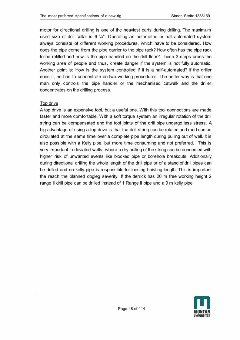
The most preferred specifications of a new rig Simon Stolte 1335169
Page 48 of 114
motor for directional drilling is one of the heaviest parts during drilling. The maximum
used size of drill collar is 6 ¼”. Operating an automated or half-automated system
always consists of different working procedures, which have to be considered. How
does the pipe come from the pipe carrier to the pipe rack? How often has the pipe rack
to be refilled and how is the pipe handled on the drill floor? These 3 steps cross the
working area of people and thus, create danger if the system is not fully automatic.
Another point is: How is the system controlled if it is a half-automated? If the driller
does it, he has to concentrate on two working procedures. The better way is that one
man only controls the pipe handler or the mechanised catwalk and the driller
concentrates on the drilling process.
Top drive
A top drive is an expensive tool, but a useful one. With this tool connections are made
faster and more comfortable. With a soft torque system an irregular rotation of the drill
string can be compensated and the tool joints of the drill pipe undergo less stress. A
big advantage of using a top drive is that the drill string can be rotated and mud can be
circulated at the same time over a complete pipe length during pulling out of well. It is
also possible with a Kelly pipe, but more time consuming and not preferred. This is
very important in deviated wells, where a dry pulling of the string can be connected with
higher risk of unwanted events like blocked pipe or borehole breakouts. Additionally
during directional drilling the whole length of the drill pipe or of a stand of drill pipes can
be drilled and no kelly pipe is responsible for loosing hoisting length. This is important
the reach the planned dogleg severity. If the derrick has 20 m free working height 2
range II drill pipe can be drilled instead of 1 Range II pipe and a 9 m kelly pipe.

Concepts of the contractors Simon Stolte 1335169
Page 49 of 114
8. Concepts of the contractors
In this chapter the different concepts are described regarding following points:
- Technical concept
- Rig up procedure
- Rig move
- Advantages / Disadvantages without specific weight
This gives an overview, how the concepts will work in the field and which problems
maybe occur.
8.1 Company A 1
The company A offered 3 different rig concepts for the field Ruehlermoor. 2 of them
(A1 and A2) were described in detail and the last one is only a lighter version of A1,
which is capable to drill wells in Ruehlermoor but not deeper ones. However, it is 50 %
cheaper than concept A1.
Figure 8.1: Rig A1

Concepts of the contractors Simon Stolte 1335169
Page 50 of 114
Technical Concept
The 1000 horse power rig concept is a conventional rig concept for 2 Range II or 1
Range III drill pipe stored on the surface or on the drill floor. Different scenarios are
possible. It is assembled out of different components. It has a hydraulically raised
cantilever mast on a parallelogram substructure, which is also raised hydraulically. A
pick up/lay down machine (PULD) is responsible for a semi-automated pipe handling.
The rig is equipped with a 1,000 HP drawwork, driven by an AC motor. The motor
includes the operational electrical break and an additional parking break.
Rig Up Procedure
One decisive factor for the project is the concept of the rig up procedure and the rig
move. With a fast procedure, time and money can be saved.
The modular concept of the rig can be disassembled to smaller components which are
easier to move and handle, and thus aligned to the conditions in the field Ruehlermoor.
The rig concept is designed for a fast, safe and simple assemble and also for a short
rig up time, as well as keeping mobilization requirements to a minimum.
The erection of the rig mast and the entire rig floor into its operational position is
achieved by hydraulic rams in one single shot. That process is divided into two simple
procedures, which requires less of rigging equipment. The parallelogram substructure
simply consists of two units which can be moved, for inter field moves, in a complete
transport package. The substructure units are spaced and connected with horizontal
bracing members, which serve both as erection guides for setting out purposes and
structural members for drilling modes. The substructure units are connected with four
drill floor modules at their uppermost sections. These modules are interconnected to
form a rigid structure, including incorporated wind walls, and to accommodate the
driller’s cabin. In the ground floor position the substructure units will be assembled
together with the drill floor modules. Afterwards the substructure front extension beams
are completed with the substructure hydraulic raising cylinders and will be pinned to the
off drawworks side of the substructure. To finalize the footprint of the rig substructure
the drawworks module will be pinned to the substructure rear extension beams. The
mast will be assembled in horizontal position by using a mobile crane. In advance the
drawworks module is installed and gives support to the mast lower sections during
assembly. A dedicated mast stand will be used to support the mast top section and
crown. The racking board will be pinned to the mast in horizontal alignment. Once the
mast is completely assembled it will be raised in vertical position by two hydraulic rams.
The rams are directly connected to the substructure extension beams in front of the
drawworks module. Subsequently the mast will be locked into position with frame legs
pinned to the drill floor modules. The parallelogram substructure will then be raised in
working height by two additional hydraulic rams built-in to the substructure front

Concepts of the contractors Simon Stolte 1335169
Page 51 of 114
extension beams at off drawworks side of the structure. The substructure will be locked
by pinned in lock brace members into final position. All components consisting mast
and substructure are designed to meet all road transportation restrictions without
requiring additional transportation permits. The rig components are further designed to
allow an in-field mobilization on rail cars in larger transportation loads by reducing the
rig up and rig down time between wells.
Rig move
The rig will be transported via rail like a train in presumable 3 days. It is possible to
transport the rig including all needed equipment with 2 locomotives in 20 steps (35
locomotive moves) from one location to the other. Therefore, a significant amount of
rail chassis and carriers are needed. Additionally 2 cranes must work continuously
during the moving action. The cranes have to change 5 times the location to do all
hoisting work. With an hydraulically rail chassis device (Figure 7.2) the mud tanks,
generators, the diesel tank and the VFD can change in very short time from
transportation to working position. The relatively low transportation height of the heavy
loads provides a low center of gravity, which increases the safeness of the rig move.
The hydraulically erectable mast will be transported with its length of roughly 20 m on
two special rail chassis. Smaller or rather lighter equipment like BOP, the manifold,
office and service containers will be transported by carrier.
Figure 8.2: Rail car system
During the rig move 4 side rails to other wells are used as transitional storage area for
parts which are not used immediately after dismantling at the leaving well site. The
combination of mud tanks, generators, diesel tank and VFD will be driven by 2
locomotives in one train to the new location but will be left at the main rail behind the
new well location. For this transport one locomotive pulls the equipment and the other
one pushes. Because of the blocked main rail after the transport of the train the pulling

Concepts of the contractors Simon Stolte 1335169
Page 52 of 114
locomotive has to drive back to the leaving location over a neighbor dyke to continue
the moving process.
Advantages
- Rail chassis system provides a fast and safe moving scenario
- Small pieces are easier to handle and could be moved faster
- Vertical drill pipe storage shortens round trips and the BHA Handling
- Mast will be mounted on surface no heavy and high hoisting works
- Rail chassis provides a low center of gravity during move safety increases
- Train system provides a predictable fast rig move
- Possible changes on the rig can be achieved because the rig is not built yet
- The tanks are rounded at their ground
- The street stays free for emergency exit and small transports
Disadvantages
- 2 Cranes for rig move operation necessary
- A lots of pieces have to be moved
- New rail cars are needed to be planned and built
- Cranes are moving 5 times between the drilling locations during move
- The monkey board still needs a person to work on (bad safety factor)
- Main rail is blocked by equipment

Concepts of the contractors Simon Stolte 1335169
Page 53 of 114
8.2 Company A 2
Figure 8.3: Rig A2
Technical Concept
The rig is a trailer based super-single rig with a full automatic pipe handling system.
The rig concept includes a semitrailer mounted, high mobility, cantilever rotary drilling &
workover rig which is diesel driven and hydraulically operated. The hoisting system is
based on a telescopic mast, operating as a hydraulic hoist. The mast is a welded box
type and composed of two independent sections: the bottom section is fixed to the drill
floor on the trailer and the telescopic section is running up and down. Raising and
lowering of the mast are performed with help of a hydraulic jack and with built-in safety
devices.
The telescopic mast is running up and down by hydraulic jack. A safety belt is installed
to avoid possible operator's fall. An auxiliary hydraulic winch is provided on the side of
bottom mast section to handle materials on the rig floor and to lift materials from the
ground to the rig floor. The crown block is fixed to the mast telescopic section. The
substructure and the drill floor are directly connected to the rig trailer. Due to its specific
design which allows to cantilever the drill floor, this type of rig can be easily set over
large existing cellars and provide ample space under the drilling floor for BOP
installation. The bottom of the drill floor, completed with the lower section of the

Concepts of the contractors Simon Stolte 1335169
Page 54 of 114
substructure, is equipped with rails and rail chassis to facilitate the sliding of BOP to the
well centerline. A hydraulic clamp is installed in the mouse hole and located
underneath the drilling floor. It’s furnished with steel guide to help the pipes to center
the hydraulic clamp. The pipe handler is a fully automatic working system with a
vertical pipe racking system and operates with range 3 pipes. Drill pipes are stored in
boxes in a radial arrangement. A hydraulic driven arm supplies the drill pipes from the
pins to the mouse hole position and back. A crane on the top of the pipe handler
including a slide inside the mast of this crane is responsible for heavier loads like the
BHA or drill collars.
Rig Up Procedure
The trailer based rig which could be moved easily in the field because of the trailer
design. The full automatic pipe handling system consists of many long pipe storage
boxes and a middle mast including a crane arm and a winch. Four independent
hydraulic outriggers stabilize the semitrailer and substructure rising. The outriggers are
provided with a safety mechanical locking system and are controlled by a side control
panel.
When the trailer stands at site the telescopic mast will be erected and also the trailer
will elevated hydraulically. The drawwork is fixed at the trailer. The driller cabin will be
placed at the drill floor and both will be mounted behind the mast. Tank system, the
power unit, the pumps, service containers and other equipment will be moved with
trailers on rail or tractors with the carrier. The power unit is installed in a container on
wheels.
Rig move
The main problem of this system is that the trailer weights 63 tons. The maximum
allowed weight on the rail is 60 tons. With exceeding the 60 tons no transport in the
field is possible. The 3 tons overload have to be reduced if company A is further
interested in this rig concept.
Advantages
- Full automatic pipe handling machine
- No person on a monkey board
- Trailer mounted rig provides a fast rig up procedure
- The street stays free for emergency exit and small transport
- Possible changes on the rig can be achieved because the rig is not built yet
Disadvantages
- 2 cranes are needed for rig move
- The pipe handler has a lot of additional parts which has to be moved

Concepts of the contractors Simon Stolte 1335169
Page 55 of 114
- The transportation weight of 63 tons exceed the load restrictions for the field
Ruehlermoor
- Rig up of the pipe handler needs a lot of space and time
- Main rail is blocked by equipment
8.3 Company B
Figure 8.4: Rig B
Technical concept
The diesel-electric powered (AC) double-stands rig for 2 range II drill pipes is
assembled out of many relatively light modules and a separate 40 ft. power house
container. The internal lined mast is hydraulic erectable and can be telescoped once.
Mast and associated load-carrying elements (crown block, traveling block with hook)
are constructed to handle a hook load of minimum 170 t. The mast base will be used
as a transport carrier for the BOP stack to provide a compact transport unit. The
drawwork stays on the ground. The finger board with a maximum storage capacity for
800 – 1000 m 5“ or 3 ½“ drill pipe, heavy weight drill pipe and also drill collar is capable

Concepts of the contractors Simon Stolte 1335169
Page 56 of 114
of fulfilling the requirements in the field Ruehlermoor. Operations outside the field may
require a higher capacity and a change of the finger board.
The rig is equipped with a traveling block and a hook, which can be operated with a top
drive as well as with a swivel – kelly combination. This raises the flexibility of the rig
during malfunctions of the top drive. The top drive is a Canrig, Model 6027 AC which is
AC driven. With a maximum load of 249 t and the provided power of 450 kW the top
drive is sufficient regarding speed and make-up / break out torque.
The drill floor is designed as a slingshot-substructure. It has a free height of 5.50 m and
a load capacity of 100 t. The rotary table is equipped with a 20 ½” orifice, a split type
master bushing and bowls 1-3. A hook load of 170 t can be handled. The substructure
has also an integrated BOP-rail chassis-system to manage a safe handling of BOP-
equipment.
The air-conditioned driller’s cabin is located on the drill floor at B-side. All control
devices and displays are integrated parts of controls. This ensures a safe operation of
the rig. The position of controls guarantees a clear view at the drill floor. Barely visible
spots are monitored by cameras and viewable on monitors installed in driller’s cabin.
The MH Wirth Single Gear GH 1000 EG-AC-1G draw work is equipped with an AC-
drilling engine with 858 kW and a 4Q-control device. An additional disk brake is
installed for emergency and parking situations. The power house (VFD) controls,
adjusts and distributes the entire electricity provided by generators to all AC and DC
consumers. The necessary energy supply is ensured by 3 generators. Each of them
can provide 1000 kVA. Dependent on power demand and operating status one or two
generators will operate. Backup power supply is ensured by a 150 kVA generator. This
emergency generator can also be used during the rig move for power supply on the
next well site. Pipe handling is done with a PULD. The systems allows the transport of
2 7/8“ to 20“ (outer diameter) pipes with maximum length of 14.6 m from pipe rack to
the rig floor (and back) without manual intervention. The transport of all pipes shall be
done on railway. The pipe racks are designed to enable a direct on- and offloading
from train without additional equipment for loading.
Rig Up Procedure
For the Rig up procedure 2 cranes are used. First the sling shot substructure is placed
on site to mount the wind walls and the driller´s cabin. After that the substructure will be
hydraulically erected, the mast support structure with the BOP inside will be placed
under the position of the mast and the BOP is placed under the drill floor with a hoisting
system. For maintenance or pressure tests, the BOP can be driven out of the
substructure on a minimum of 2 different sides with a BOP rail chassis system. Behind
the drawwork the 40 ft. power house with the VFD will be placed. On top this 40 ft.
container the mast will be placed with both cranes and connected to the drill floor. The

Concepts of the contractors Simon Stolte 1335169
Page 57 of 114
mast has already the fingerboard and the top drive installed. With hydraulic cylinders
the mast will be erected and telescoped afterwards. The internal guying lines will be
fixed. Then the PULD system will be installed. Mud pumps, mud tanks, service and
personal container will be placed and the rig up procedure is finished.
Rig move
Company B tries to achieve a rig move from spud to spud in 3 days with 12 hours per
day working time. For the movement two 60 t crawler cranes provided by a contractor
are responsible for the hoisting works. Company B pays attention that no component
weights more than 30 tons. To remember: The maximum possible movable weight by
S-30 rail is 60 tons and 15 tons per axle. In total 43 parts have to be moved in the plan
of company B. Big parts like the VFD and the tanks stay on rail during the moving time.
The other parts will be transported on rail carrier only for the distance between the two
drilling locations. One crane will load on drilling location 1 and the other one will unload
on the other location after both cranes hoist the mast together on a rail car at the
leaving location. During the move the mast is around 20 m long and a special steel
structure which contains the BOP and supports the mast is pinned to the mast
additionally. Therefore, this combination of parts has to be hoisted with both cranes for
load and safety reasons.
Advantages
- Possible changes on the rig can be achieved because the rig is not built yet
- The main rails stays free (except the cutting box) for different types of
transports and other services like cementing
- The street stays free for emergency exit and small transport
- The pour on of additional area at the dyke to gain more space for the drilling
area like on RLMR 801(compare Figure 4.3 points 15 – 19) is not necessary for
this concept
- Mainly German parts provide a flexible and fast after sale service
- The rotary table and Kelly pipe are together with the swivel a complete drilling
alternative
- The tanks are rounded at the ground with connections and pipes underneath.
This provide close to 100% usage of the drilling mud at a smaller needed area
Disadvantages
- 2 Cranes are necessary during rig move
- New rail cars are needed to planned, built and purchased by GDF Suez
- Canrig top drive out of the USA without a backup on other rigs, when spare
parts are needed fast
- The monkey board still needs a person to work on (bad safety factor)
- Many small pieces have to be moved
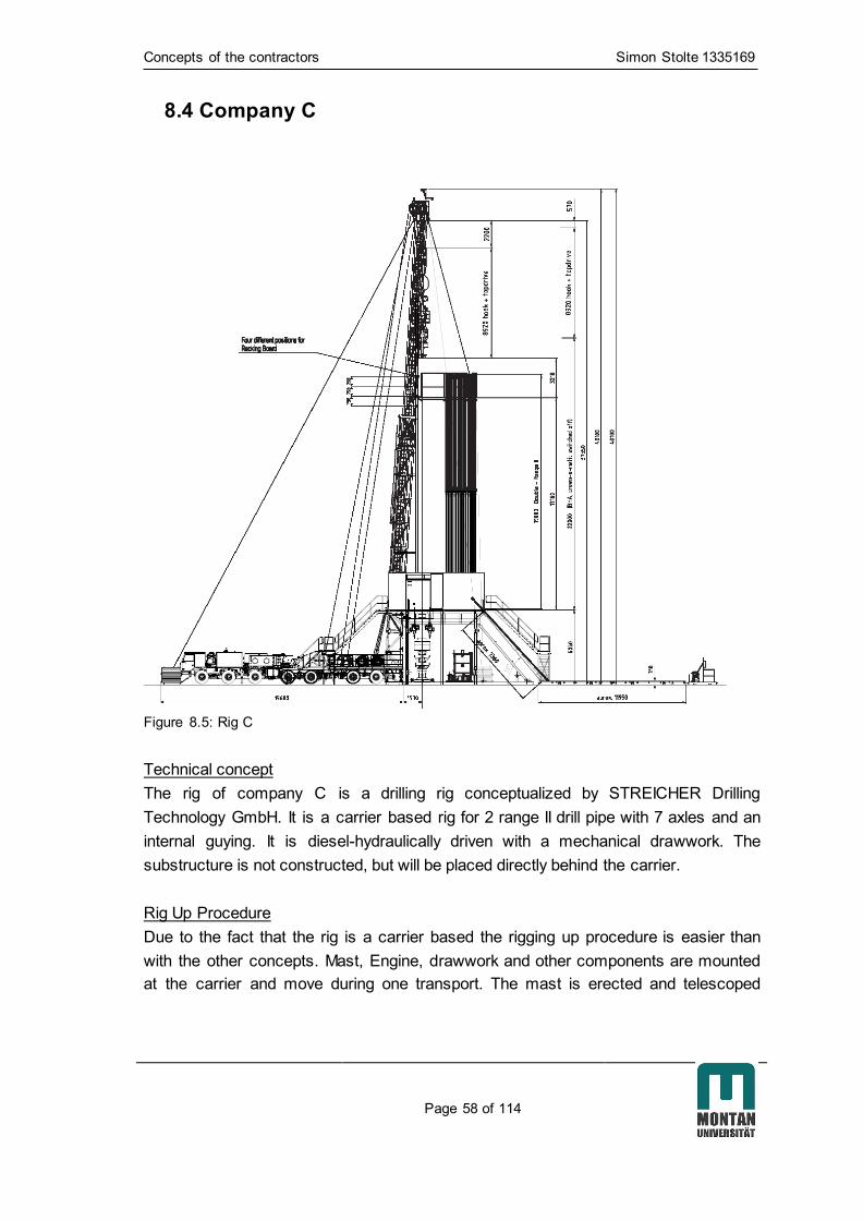
Concepts of the contractors Simon Stolte 1335169
Page 58 of 114
8.4 Company C
Figure 8.5: Rig C
Technical concept
The rig of company C is a drilling rig conceptualized by STREICHER Drilling
Technology GmbH. It is a carrier based rig for 2 range II drill pipe with 7 axles and an
internal guying. It is diesel-hydraulically driven with a mechanical drawwork. The
substructure is not constructed, but will be placed directly behind the carrier.
Rig Up Procedure
Due to the fact that the rig is a carrier based the rigging up procedure is easier than
with the other concepts. Mast, Engine, drawwork and other components are mounted
at the carrier and move during one transport. The mast is erected and telescoped

Concepts of the contractors Simon Stolte 1335169
Page 59 of 114
hydraulically and guyed internally showed in Figure 8.5. The drill floor is placed behind
the rig probably with cranes. The final procedure is not planned yet.
Rig move
The rig move within the field is only possible with a massive preparation of the
transportation way to the location. The driving way has to be prepared in advance with
a solid sand bed and so called DURA-BASE® mats on top. [13] To ensure that no
hillside slide arises the rig has to be driven at least in 4.5 m distance to the slope.
Therefore, some fences and equipment of existing wells has to be removed. Afterwards
everything has to be reconstructed. The rig drives on this prepared way on its own
wheels at 7 axles. It has to be reached that all wheels are loaded simultaneously and
equally to distribute the total load of the rig as much as possible. This is at the
unconsolidated underground a big challenge. All other equipment, which is not installed
at the carrier, will be transported via flatbed trucks which are driving on the DURA-
BASE® mats loaded and on the streets unloaded circular.
Advantages
- Rotary table as drilling alternative to the top drive
- Robust equipment technique
- Easy rig up/rig down procedure
- The street stays free for emergency exit and small transport
Disadvantages
- With 73 t standard weight it is not possible to drive inside the field because of
street load restrictions. Only with a report of a certificated company a movement
in and within the field is possible on so called dura-base mats supported with
additional sand between the rails
- For the transport needed sand, dura-base mats are linked with additional
logistic and preparation work, which might make the company C rig uneconomic
- 2 x 60 t cranes and 2 flatbed trucks are necessary for the rig move
- Man on the monkey board is always a safety risk
- No automatic cat walk or pipe handler
- No automatic driller
- Link tilts: only 1.0 t in 1.5 m distance
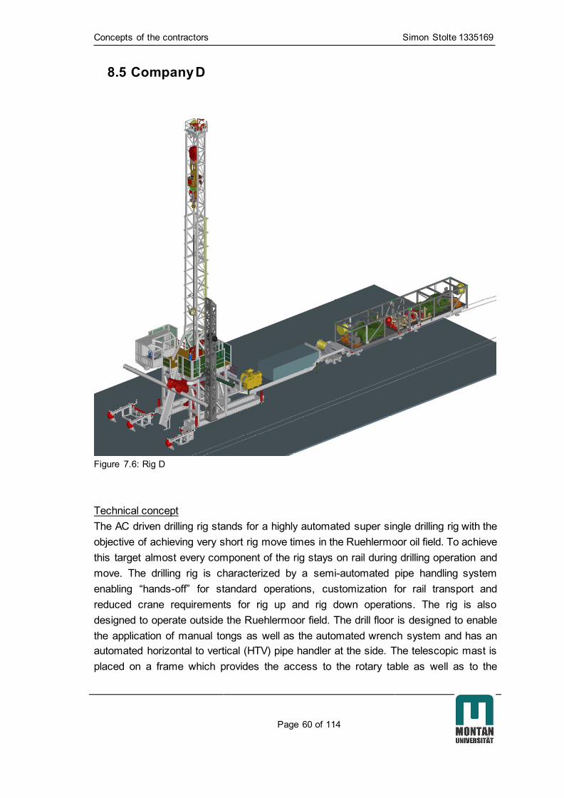
Concepts of the contractors Simon Stolte 1335169
Page 60 of 114
8.5 Company D
Figure 7.6: Rig D
Technical concept
The AC driven drilling rig stands for a highly automated super single drilling rig with the
objective of achieving very short rig move times in the Ruehlermoor oil field. To achieve
this target almost every component of the rig stays on rail during drilling operation and
move. The drilling rig is characterized by a semi-automated pipe handling system
enabling “hands-off” for standard operations, customization for rail transport and
reduced crane requirements for rig up and rig down operations. The rig is also
designed to operate outside the Ruehlermoor field. The drill floor is designed to enable
the application of manual tongs as well as the automated wrench system and has an
automated horizontal to vertical (HTV) pipe handler at the side. The telescopic mast is
placed on a frame which provides the access to the rotary table as well as to the

Concepts of the contractors Simon Stolte 1335169
Page 61 of 114
wrench system. The rig floor can be accessed by two independent stairs. The rig has
an increased free working height under the top drive of 20 m to use casing running
tools and circulation heads in combination with drilling tubular of Range III. Furthermore
the increased free working height permits an increased length of BHA strings and
reduces the amount of connections made on the drill floor. The rig is designed for
levelling of the rig after rig up. The semi-automated pipe handling system consists of
the pipe feeder, the pipe handler and the automated wrench system. The system is
controlled by the driller in the cabin. In addition to the direct visibility of the handling
system through the window of the driller´s cabin, cameras at the drawworks and the
shakers and a third camera displayed in the driller’s cabin provides visual information
on the pipe handling area. A detachable pipe chute system in combination with drill
floor winches and an external mobile winch can be used to transport tubular or other
equipment up to the drill floor. The pipe handling gripper can also be equipped with a
hook (optional) to transport e.g. a basket on the drill floor. The pipe handler can
operate following pipes:
- Tubular/Casing Range 2 3/8” – 20”
- Max. Hoisting Capacity 3.500 kg
- Max. Length of Tubular 14,6 m
Also handling of wire wrapped filters and similar equipment is possible. The telescopic
mast system has a top drive guide rail system that doesn’t need to be adjusted after a
rig move. This reduces the rig move time for the contractor. The BOP handling is
possible without the need of a crane. The BOP will be brought to the drill site before the
main rig arrives will be parked during rig up at the tubular handling area/pipe feeding
location on a rail chassis. After the rig is built up the rail chassis including the BOP will
be placed under the rig and connected to the lifting chains mounted under the drill floor.
The rail chassis will be removed and the pipe feeder placed at its operating position by
the fork lift. The substructure has a special sling shot design which can be rigged up
without the need of cranes.
Rig Up Procedure
The plan is to reduce the crane works as much as possible. At first the substructure will
be transported to the rig site. The two substructure elements are on rail chassis and will
be placed on the end of the rail tracks. The substructure elements are separated from
the rail track by the usage of cylinders. After placing the two substructure elements to
the middle section of the drill floor it will be fixed in between of the substructure
elements via fast connection system with the already placed substructure elements.
The next step is to place the driller’s cabin module and the driller’s cabin on to the
substructure with the forklift. The truck trailer including the mast system and drawworks
Concepts of the contractors Simon Stolte 1335169
Page 62 of 114
is placed on the rig site and connected to the substructure. The telescopic mast will be
lifted in the vertical position via the mast cylinders and the substructure will be elevated
via hydraulic cylinder to the height of approx. 5.9 m. The telescopic mast system will be
brought in operation position via a winch system and the pipe handling segments are
connected with the support of the fork lift. Pipe handler including gripper will be
positioned vertically via the drilling rig winch system. After positioning of the drilling rig
three train transports can be brought to the rig site. These 3 train transports consists of
mud pumps, the powerhouse, 3 generators and the 20 m³ diesel tank, the complete
tank system and at last the re-filled mud tanks and water tanks. The substructure
elements are separated from the rail track by the usage of cylinders. This rig concept
needs only 1 crawler crane during the move and rig up/ rig down procedure for
individual parts.
Rig move
The layout of the rig is based on four main transport packages (containing several units
on rail chassis). The drilling rig consists of a truck trailer that comes with rail chassis
during operation at the Ruehlermoor field. The rail chassis can be replaced by a
chassis for road usage if drilling outside of the Ruehlermoor field is required. The truck
trail has the drawworks, the two air winches, the HPU/Compressor and the reserve
rope drum installed. The top drive and the travelling block are also included into the
mast system during transport. The transport of the substructure will be done via rail
chassis in the Ruehlermoor field. The main substructure transport unit consists of two
modules (left-right) with approx. 1.5 meter width each and will be transported to the rig
site first. The two substructure elements are on rail chassis and will be placed on the
end of the rail tracks. The pipe handler mast and pipe handling gripper are transported
to the rig site. The three main train transports have individual cabling which is not
required to be disconnected during rig move. The electrical connection between power
house and tank system needs to be connected after rig move as well as the mud piping
to the external equipment e.g. mud pumps and tank system. The train transports, in
case applicable, are internally connected (electrical, hydraulic, mud) and do not need to
be disconnected during transport. After positioning of the train units the connection
between the train units (electrical, hydraulic, mud) needs to be placed. The train parts
stay on rail and are jacked up via hydraulic cylinder during operation. In addition all
other equipment need to be transported via rail carrier to the drilling location and
placed via the fork lift.

Concepts of the contractors Simon Stolte 1335169
Page 63 of 114
Advantages
- Only one crane needed
- The street stays free for transports or emergency escape
- Tank system can be placed on both sides of rig
- Good flexibility of the pipe handler (180° work radius, 3.5 t hoisting capacity)
- No guying
- Dismantling of the drill floor over a up to 1.5 high equipment possible
- Predictable relatively fast rig move
- Possible changes on the rig can be achieved because the rig is not built yet
- The tanks are rounded at the ground
- The pour on of additional area at the dyke to gain more space for the drilling
area like on RLMR 801(compare Figure 4.3 points 15 – 19) is not necessary for
this concept
Disadvantages
- The main rail is only reachable from one side
- The casing and the drill pipe has to be stored at the drilling area horizontally
- Only a small supporting rotary table is installed
- Before working with the BHA the well drill string has to be laid down
- Only few but heavy, slow and dangerous transports with train
- Purchasing of rail chassis needed
- Mast transport with 60 tons and roughly 20 m length could be difficult
8.6 Rig specifications of the contractors
After the first tender documents of the contractors were delivered and the presentation
of their concepts were finished a table was developed where all specifications of the rig
concepts could be compared. (Table 8.1) This table compares the specifications also
asked in the tender documents of GDF Suez.

Concepts of the contractors Simon Stolte 1335169
Page 64 of 114
Table 8.1 Contractor comparison
Table 8.1 shows the first criteria of the contractor comparison table. The general specifications of the rig and of the mast can be compared. The
complete table could be found in the appendix under point 13.4.3 “Contractor comparison”.
Company A1 Company A 2 Company B Company C Company D
General
Needed space (m) 25,6 x 81,0 25,6 x 81,0 26,9 x 85,2 30,0 x 90,0 22,0 x 140,0
Guying no intern intern intern no
Excepted rig Move time (days) 2-3 3 3 a 12 hrs. 3 2-3
Drive diesel-electric diesel-electric diesel-electric diesel hydraulic diesel electric
Max. load of individual part (t) 30 63,5 t 30 73 60
Drillers cabin / Doghouse yes yes yes yes yes
A Mast, Drawwork, PULD etc.
A 1 Mast
Stands 2 pipes range 2 Range 3 super single 2 pipes range 2 2 pipes range 2 Range 3 super single
Type
hydraulically erectable hydraulically erectable hydraulically erectable erectable U-shape, hydraulically
erectable
Year new new 2007 In construction new
Free w orking height (m) No information 16 No information 34,0 20,00
Except load
(t)
150 136 170 (6 fold) 207 (10 fold)
150 150
Set back capacity monkey board
- 3 1/2" DP (m) 4000 4600 800 - 1000 No information Super single
- 5" DP (m) 2000 3600 800 - 1000 No information Super single
- 6 1/4" DC (and) (pcs.) 8 stands 8 stands possible No information Super single
- 8 1/4" DC (or) (pcs.) 4 stands 4 stands No information No information Super single

Efficiency Analysis Simon Stolte 1335169
Page 65 of 114
9. Efficiency Analysis
This chapter describes the development process of the efficiency analysis. This
includes the definition, description and the execution of the analyses. Basically the
evaluation is divided in different criteria. (Figure 9.1)
Figure 9.1: Evaluation structure
These separately considered criteria have a different influence on the end result of the
evaluation. The weighting of the matrixes is separated in 7 sub-points on the technical
side which include 70 % of the total evaluation and in 6 sub-points on the commercial
side which include 30 % of the total evaluation. In summery all total values of the
particular criteria (rig concept, rig move etc.) are involved in the final calculation with
different weight. (Figure 9.2) In this thesis only the technical side will be considered.
Evaluation of the rig concept
Technical evaluation
Rig concept
Rig move
Distance to operater
Qualification of personal
Local experience
Rig availability
Energy
12 sub matrixes for the rig concept
Commercial evaluation

Efficiency Analysis Simon Stolte 1335169
Page 66 of 114
Figure 9.2: Evaluation structure with weighting
The rig concept
This point includes the technical rig concept with its different parts or equipment to
achieve a good overview of the future drilling rig. The 12 sub-points of the criteria “Rig
concept” are: Mast, substructure, drawwork, rotary table, top drive, pumps, tank, power
supply, well safety equipment, installation equipment, data collection and storage and
pipe handling. Each sub-point has different evaluation criteria (Appendix 13.3
“Evaluation matrixes”)
The rig move
In this criterion following points are considered:
- Weight and size of parts or equipment
- train and crane utilization
- expected time for the move
These criteria are used to get a first idea, how the contractors will perform an infield rig
move and which requirements are necessary.
Distance to operator
In this point the most important factor is the distance from the contractors head office to
the field Ruehlermoor. With a short distance the operator expects a high flexibility of
100 %
Rig concept 45 %
Rig move 20 %
Distance to operater 10 %
Qualification of personal 10 %
Local experience 5 %
Rig availability 5 %
Energy 5 %
Price 50 %
Long term drilling contract 15 %
Term of payment 10 %
Management commitment 10 %
Warrenty 10 %
Detail engineering contract 5 %
70 % 30 %

Efficiency Analysis Simon Stolte 1335169
Page 67 of 114
the contractor and the opportunity of a fast acting process in terms of repair,
maintenance, personal supply, experts supply (mechanics, electricians etc.) or other
occurring situations.
Qualification of personal
This chapter was not evaluable because of insufficient information about the future
personal working at and for the rig.
Local experience
This point covers the experience of the operator with the contractor past projects. Has
this contractor ever worked with the operator? What was the result? Was the job done
sufficiently, safe and fast and was everybody satisfied?
Energy consumption
With energy consumption all for the rig needed energy in form of diesel, gas and
electricity is meant which is consumed to operate the rig properly. But no rig is built yet
and the energy consumption changes with the downhole conditions, the used tools, the
trajectory of the well etc. To get predictable energy consumption values the detailed
engineering phase has to be used. Currently this criterion will be rated for each
contractor the same.
Rig availability
The fact that no rig is built yet, and the companies insured that they can all build their
rigs within 9 months, leads to the same ranking in this criterion. Only company C could
provide the future drilling rig earlier, because their concept is already in production.
9.1 Definition and Reasons
Generally financial decisions like investments are based on facts. Is the investment
economically, is the company able to enlarge the revenue and/or the profit, how long
does the depreciation take or when will the investment amortize? These are crucial
questions.
The redevelopment project is linked to several investments for the joint venture of GDF
Suez and EMPG. Every investment has to be approved by the management. For GDF
Suez the task is to find the best rig concept out of 5 concepts, which covers the
requirements of the Ruehlermoor oil field most effectively. To reduce the uncertainties
and risks as much as possible an efficiency analyses has been chosen. It can help with
a complex problem by weighting and analyzing of different pre-defined criteria to find

Efficiency Analysis Simon Stolte 1335169
Page 68 of 114
out the best concept in its entirety. The efficiency analysis does not give absolute or
objective benefit about the criteria, however it can help to develop rational results to
facilitate the choice. Per definition the efficiency analysis is an evaluation process,
where different alternatives can be evaluated and compared with several different
outcome measurements. It involves also qualitative factors. [8]
9.2 Description of the Concept
An efficiency analysis is done by several steps:
1. The targets, the criteria and eventual K.O. - criteria have to be defined
2. Weighting of the criteria,
3. Rating of the criteria and calculation
4. Result analysis, maybe finding alternatives by developing a ranking and linkage to
the weighted criteria
In this chapter the targets and K.O. - criteria are defined. The criteria were generated
with the support of drilling engineers and drilling supervisors and are compared
pairwise and weighted afterwards. It is based on a comparison of merely 2 criteria with
each other. Therefore, a matrix is developed (Table 9.1(fictional)). This table correlates
the criteria directly to each other and gives a weighting and the fraction in percentage.
With this measurement a fast and easy distribution of the different criteria is made
possible.
Table 9.1: Criteria weighting procedure
1 A Criteria
Crite
rion 1
Crite
rion 2
Crite
rion 3
Tota
l
%
Criterion 1 1 0 1 16.6
Criterion 2 1
1 2 33.3
Criterion 3 2 1 3 50.0
6 100
Table 9.1 has to be filled out at the right side of the orange diagonal first with the three
weighting grades 2, 1 and 0. The left side of the diagonal results from the values of the
right side. Starting point is criterion 1. If this is more important than criterion 2 it gets a
“2”. If it is less important it receives a “0” and if both criteria are equally important it gets
a 1. With this procedure the table is filled out. The columns on left side of the diagonal
get the opposite/same values of the right side depending on the value. 1 stays 1, 2

Efficiency Analysis Simon Stolte 1335169
Page 69 of 114
becomes 0 and 0 becomes 2. After that the values of each criterion is summed up and
noticed in the column with the name “Total”. With the sum of all total values each
particular percentage or weight can be calculated like in following example:
6
1∗ 100 = 16,6% (1)
An example of a filled in table is given in table 9.2, which is also used for the later on
evaluation of the concepts. In this table the criterion “Mast” is chosen.
Table 9.2: Mast criteria weighting
1 A Criterion Mast Y
ear
Fre
e w
ork
ing h
eig
ht
guyin
g
Max. e
xcept lo
ad
Max. u
sually
load
Setb
ack c
apacity
monkey
board
Derric
k M
an S
yste
m
Ele
vatio
n o
f the M
ast
clim
bin
g d
evic
e
Tota
l
Facto
r
Year
0 0 0 0 0 0 0 1 1 0.014
Free working height 2
2 2 2 2 2 2 2 16 0.222
Guying 2 0
2 2 2 2 2 2 14 0.194
Max. except load 2 0 0
0 2 2 2 2 10 0.139
Max. usually load 2 0 0 2
2 2 2 2 12 0.167
Setback capacity monkey board 2 0 0 0 0
2 2 2 8 0.111
Derrick Man System 2 0 0 0 0 0
0 2 4 0.056
Elevation of the Mast 2 0 0 0 0 0 2
1 5 0.069
Climbing device 1 0 0 0 0 0 0 1
2 0.028
72 1
In total 72 points are distributed into 9 sub-criteria such as year, free working height
etc. These points are necessary to calculate the percentage (the weight) of each
criterion. Example criterion “guying”:
14
72∗ 100 = 19,4% (2)
To combine the weighted criteria with the concept of the contractor the factor and not
the percentage is used, which is in this case 0.194.

Efficiency Analysis Simon Stolte 1335169
Page 70 of 114
To get a weighting of the criteria several drilling engineers and drilling supervisors were
interviewed. This is important to get a reliable result, when a lot of experience is
involved. The weighting is always a mean value of the interviewed persons and stays a
subjective estimate. That weighting was generated especially for the requirements of
Ruehlermoor. The result of this weighting procedure may look completely different for a
drilling rig for another oilfield, because of different circumstances. In this case the sub-
criterion “free working height” is declared as the most important sub-criterion in the
criterion “Mast” with 22.2 %. To use this calculated value it has to be linked to the
ranked future concepts. This is explained in the following chapter.
9.3 Analysis of the weighted criteria
The weighted criteria give only information about the importance of the criterion for the
future rig concept. Only with this the concepts cannot be ranked. The linkage between
the weighted criteria and the concepts of the contractors are made in analysis matrixes.
Within these matrixes the weighted criteria get ranked by experts, drilling engineers
and supervisors, who know how to get a proper ranking accordingly to the
requirements of the field. The concepts are compared and ranked in every criterion
(Table 9.3) and with the help of the preliminary equipment list (Appendix (13.1)). This
leads to a personal view and a subjective ranking. It is not an absolute value and could
change if the properties or circumstances of the project changes or another person get
interviewed.
Table 9.3 is a fictional example for a ranking of the criterion “Mast”. For the real
evaluation of the rig concepts the matrix has 4 different columns with rankings from 1 to
4. If all contractors are equally appraisable they all get a 1. If only two of them are
equally good the ranking will be 1,2,2,4 or 1,1,3,4. Many different options are possible.
One fictional example: 3 companies want to use a totally new mast and the other one
will take a used one, then the first 3 get a 1 and the fourth a 4. Or if they want to use
masts with different age the ranking could be 1,3,2,4 for company A, B, C and D.

Efficiency Analysis Simon Stolte 1335169
Page 71 of 114
Table 9.3: Contractor rating
Contractor
Criteria
Contra
cto
r 1
Contra
cto
r 2
Year 1 2
free working height 2 1
guying 1 2
Max. except load 1 2
Max. usually load 2 1
Setback capacity monkey board 1 2
Derrick Man System 1 2
Elevation of the Mast 1 1
Climbing device 2 1
Total 1.417 1.514
The determined values of each contractor of the various criteria are multiplied with the
factor (weight) of the respective criteria.
Based on this rating and in combination with the weighted criteria the following
calculation is made to get a reference of the best contractor in the criteria mast.
Therefore, table 9.2 and 9.3 are used:
Criterion “Year” with 0.014 (Table 9.2) is multiplied with the rank 1 (Table 9.3), criterion
“free working height” with 0.222 is multiplied with the rank 2, and so on.
Contractor 1:
0.014 ∗ 1+ 0.222 ∗ 2+ 0.194 ∗ 1 + 0.139 ∗ 1 + 0.167 ∗ 2+ 0.111 ∗ 1 (3)
+0.056 ∗ 1+ 0.069 ∗ 1+ 0.028 ∗ 2 = 𝟏.𝟒𝟏𝟕
Contractor 2:
0.014 ∗ 2+ 0.222 ∗ 1+ 0.194 ∗ 2 + 0.139 ∗ 2 + 0.167 ∗ 1+ 0.111 ∗ 2 (4)
+0.056 ∗ 2+ 0.069 ∗ 1+ 0.028 ∗ 1 = 𝟏.𝟓𝟏𝟒
The result shows, that for the criterion “Mast” contractor 1 provides a better concept,
because of a lower value. Now the value of the criterion “Mast” is calculated. This is
done with all different sub-criteria. (Appendix 13.3: Evaluation matrixes). Every matrix
evaluation ends up with a calculated value.

Efficiency Analysis Simon Stolte 1335169
Page 72 of 114
Table 9.4 shows the calculated final values of the 12 sub-matrixes of the criterion “rig
concept”. The sub-matrixes of the matrix “Rig concept” like “Mast”, “Substructure”,
“Drawwork”, etc. are weighted with the same weight of 8.3 % each. Company B
provides the best rig concept with the value 1.08.
Table 9.4: Results rig concept
Contractor
Criteria
Com
pany A
Com
pany B
Com
pany C
Com
pany D
Mast 1.74 1.60 2.07 2.11
Substructure 0.67 1.19 2.11 1.15
Drawwork 0.93 0.93 2.64 0.93
Rotary Table 1.17 1.63 0.63 1.17
Top drive 2.32 0.70 2.31 0.70
Pumps 1.81 0.86 1.81 1.46
Tank System 1.44 1.00 1.74 1.15
Power supply 0.27 0.27 0.44 0.27
Well safety equipment 1.00 1.75 1.00 1.00
Installation equipment 1.00 1.75 1.00 1.00
Data Collection 0.04 0.04 0.04 0.04
Pipe Handler 1.19 1.19 2.14 2.33
Total 1.13 1.08 1.49 1,11
The calculated total value of each contractor (Table 9.4) will be multiplied with 45 % in
the particular end value. (Figure 9.2 and Table 10.3)
Furthermore, this weighting and calculation procedure is done with the other matrixes
“Rig move”, “Distance to operator”, “Local experience”, “Rig availability” and “Energy
consumption” and summed up to a final evaluation matrix shown and explained in
chapter 10.3 “Efficiency analyses result”
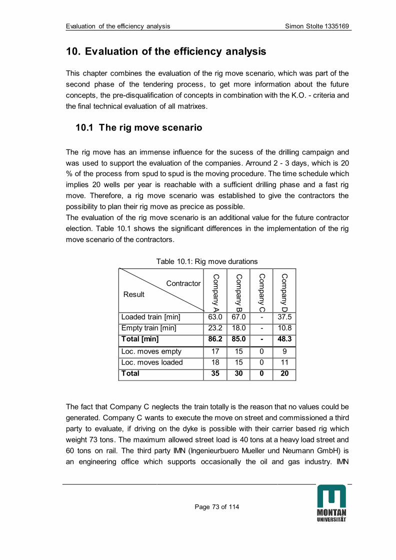
Evaluation of the efficiency analysis Simon Stolte 1335169
Page 73 of 114
10. Evaluation of the efficiency analysis
This chapter combines the evaluation of the rig move scenario, which was part of the
second phase of the tendering process, to get more information about the future
concepts, the pre-disqualification of concepts in combination with the K.O. - criteria and
the final technical evaluation of all matrixes.
10.1 The rig move scenario
The rig move has an immense influence for the sucess of the drilling campaign and
was used to support the evaluation of the companies. Arround 2 - 3 days, which is 20
% of the process from spud to spud is the moving procedure. The time schedule which
implies 20 wells per year is reachable with a sufficient drilling phase and a fast rig
move. Therefore, a rig move scenario was established to give the contractors the
possibility to plan their rig move as precice as possible.
The evaluation of the rig move scenario is an additional value for the future contractor
election. Table 10.1 shows the significant differences in the implementation of the rig
move scenario of the contractors.
Table 10.1: Rig move durations
Contractor
Result
Com
pany A
Com
pany B
Com
pany C
Com
pany D
Loaded train [min] 63.0 67.0 - 37.5
Empty train [min] 23.2 18.0 - 10.8
Total [min] 86.2 85.0 - 48.3
Loc. moves empty 17 15 0 9
Loc. moves loaded 18 15 0 11
Total 35 30 0 20
The fact that Company C neglects the train totally is the reason that no values could be
generated. Company C wants to execute the move on street and commissioned a third
party to evaluate, if driving on the dyke is possible with their carrier based rig which
weight 73 tons. The maximum allowed street load is 40 tons at a heavy load street and
60 tons on rail. The third party IMN (Ingenieurbuero Mueller und Neumann GmbH) is
an engineering office which supports occasionally the oil and gas industry. IMN

Evaluation of the efficiency analysis Simon Stolte 1335169
Page 74 of 114
declared that the weight of the rig does not exceed the capable load of the dyke, if the
driving way is prepared in advance with a solid sand bed and so called DURA-BASE®
mats on top to distribute the occurring loads. These mats are made out of
thermoplastic and can be connected which each other to a solid underground. [13] The
distance to the slope of the dyke has to be minimum 4.5 m otherwise the underground
structure gets damaged. To ensure this distance some of the pre-existing drilling areas
with their surrounding fences, some pipelines and well equipment have to be removed.
The equipment which is not mounted on the carrier based rig will be transported via
flatbed trucks.
The other 3 contractors executed their rig moves scenario with the utilization of the rail
way system. With 48.3 minutes traveling time of empty and loaded locomotive
Company D needs the least time to move their rig from location A to location B in 300
m distance. Table 10.2 lists the estimated resources for the rig move of each
contractor.
Table 10.2: Rig move requirements
Company
Requirements
Com
pany A
Com
pany B
Com
pany C
Com
pany D
Locomotives 2 3 0 2
Cranes 2 2 2 1
Location change of Crane 5 2 0 1
Carrier 7 10 0 5-7
Flatbed truck 0 0 2 0
Rail chassis 16 7 0 28
Needed parking rail 4 2 0 4
Expected time [days] 2-3 3 3 2-3
Max. part weight [t] Ca. 30 30 73 60
Max part length [m] ca. 20 ca. 20 ca. 20 ca. 20
Location changes of
empty & loaded trains 35 30 - 20
Noticeable is the big difference in needed rails chassis and location changes of the
empty and loaded trains between the contractors. Depending on the concept more
carriers or more rail chassis are used for transportation. Company A and company D
are planning the move with a train organization, where big and heavy components like

Evaluation of the efficiency analysis Simon Stolte 1335169
Page 75 of 114
tanks, generators and the powerhouse stay on rail and will be moved with mounted rail
chassis. Company B does the rig move with the utilization of carrier. The loads are
hoisted on carrier at location A and reloaded at location B. Thereby the differences can
be explained. There is another explanation for the different amount of moves of the
train. Company D plans to transport more equipment within one move of a train
including more pieces, which are separated on different parking rails. Company A and
B plan to transport less equipment within one train. This is the reason why company D
can transport the equipment with less moves in less time. The number of moved parts
or the amount of moves is for the evaluation not important, because if a company can
reach a shorter time for moving more parts than another company, the first one should
be preferred.
10.2 Pre – disqualification
Before the efficiency analysis is done and a final decision can be made, the K.O. -
criteria should be considered. These criteria have to be fulfilled completely of each
concept. Otherwise the concept has to be disqualified. One example is the maximum
individual transportation part width of 4 m. If a part is bigger, than it cannot be
transported within the field and the concept will be disqualified.
Concept A2 and concept C cannot fulfil all K.O. - criteria. They exceed the maximum
allowed load on roads or on rail. The third party IMN was not able to eliminate the
possibility that the rail and street system on the dykes withstand the occurring loads
without any damage. These facts and risks result in a too complex measurement and
disqualified the tenderer company C.
Company A2 with their rig concept of a super single drilling rig also does not fulfil the
requirements. The load restrictions in the field will be exceeded with over 60 tons
transportation weight. Furthermore, the full automatic pipe handler with its vertical
round pipe storage system contains a lot of big and especially long parts which are not
easy to transport within the field. Additionally they cannot be handled on the small
drilling sites. These facts are responsible for a pre-disqualification of the rig concept of
concept A2.

Evaluation of the efficiency analysis Simon Stolte 1335169
Page 76 of 114
10.3 Efficiency analyses result
With all generated information and data, delivered from the contractors and the
employees of GDF SUEZ following results are developed with the evaluation matrixes
and sub-matrixes of the efficiency analyses:
Table 10.3: Efficiency analyses result
Contractor
Criteria
Com
pany A
Com
pany B
Com
pany C
Com
pany D
Best c
oncept
per c
riteria
Rig Concept (45 %) 0.509 0.484 0.672 0.499 B
Rig Move (20%) 0.354 0.410 0.585 0.333 D
Distance to operator (10%) 0.036 0.064 0.121 0.093 A
Qualification of personal (10%) 0.000 0.000 0.000 0.000 -
Local Experience (5%) 0.075 0.042 0.100 0.025 D
Energy (5%) 0.033 0.033 0.033 0.033 ABCD
Rig availability (5%) 0.100 0.100 0.050 0.100 C
Total value 1.107 1.133 1.562 1.084 -
Total ranking 2 3 4 1 -
Table 10.3 shows the total ranking of the different concepts based on the total points of
all matrixes. Company D has the most appropriate technical concept with 1.084 points
followed by company A with 1.107, company B with 1.133 and company C with 1.562
points. A main effect of the end result has the rig move. This part of the drilling process
has a major effect on the success of the future drilling campaign.
The total values of table 10.3 are very close together and the ranking can change
immediately, if only one criterion will get a different weighting or the subjective
evaluation get changed. Out of the question company C is not capable to keep up with
the 3 other concepts, because of the pre-disqualification and other points which are
later on discussed in this chapter.
The rig concept
Company B provides the best rig concept, because of a narrow rig construction and the
highest hoisting capacity. Additionally it provides a powerful top drive, a rotary table
which can work as a drilling alternative and sufficient German pumps. With these
pumps a lot of good experience was made in other projects and the manufacturer of
the pumps provides a sufficient after sale service. Furthermore, the tanks are

Evaluation of the efficiency analysis Simon Stolte 1335169
Page 77 of 114
constructed like bathtubs and allow an easy cleaning and therefore a fast possible mud
change with a nearly 100 % usage. These points lead to the best ranking. Company A
and D provide a similar good rig concept. Company A has a low ranking in the criterion
“Mast” because of the low free working height. Additionally they want to use Chinese
pumps which may can produce some problems with the after sale service and the
quality of the pumps itself. Company C is at the last rank because of the old technical
standard of the rig. It does not provide a PULD machine, the diesel-hydraulic drive is
not preferred in a nature reserve, mechanical drawwork with no automatic lowering
device and the widest guying of all concepts are the main points of the last rank of
company C.
The rig move
Company D and A are planning their rig move similarly. Both plan to move as much as
possible on rail and want to leave it there during operation as well. The fact, that
company D moves faster and needs less crane operation leads to the first rank.
Company A convinces with a low center of gravity of the moved heavy parts like
generators, VFD etc. and less equipment during the move insofar as carrier and rail
chassis. On the other hand they have to move their cranes much more than the
competitors and moves parts/equipment the most. Company D loses points because of
the highest amount of needed rail chassis and the fact that they have to move parts up
to 60 tons. More weight means more risk on the unconsolidated underground.
Company A and B have a maximum part weight of approximately 30 tons.
Company B needs the most rail carrier and the most hoisting works. This in
combination with a relatively long locomotive moving time and that they want to use a
third locomotive (Company A and D need 2) ends up in the third place in the rig move
ranking. Company C has the least efficient rig move concept because of conditions
explained in the chapter 10.2 “Pre-disqualification” and 10.1 “The rig move scenario”.
Distance to operator
Company A, B and D are located in Germany and C in the Czech Republic and has the
longest distance to the oilfield Ruehlermoor. This may leads to a worse flexibility in
case of unwanted events like illnesses of employees or the need of a technical support
by experts. Because of that company C is listed at the last rank. Between the other
competitors the distance to the head quarter or to the future supporting/operating
facilities is taken for the ranking. Therefore, company A wins this ranking with the
closest distance in front of B, D. The fact that the drilling company, which wins the
tender, could organize a nearby supporting facility (workshop, office etc.) for the
duration of the drilling campaign is not considered in this evaluation.

Evaluation of the efficiency analysis Simon Stolte 1335169
Page 78 of 114
Qualification of personal
This chapter was not evaluable, because of too less information about the future
personal working at and for the rig. Therefore, it has to be thought about, if the 10 %
weighting may have to change to another criterion to evaluate the total 100 %.
Local experience
In this category the operators experience with company D and B was the best, because
of a lot of past projects. Nowadays the work with company A is also increasing and
should be considered in a few months again. With company C no project was executed
so far.
Energy consumption
No rig is built yet. Therefore, the experience of the future energy consumption is only
predictable. Moreover the energy consumption changes with the downhole conditions,
the used tools, the trajectory of the well etc. To get detailed predictable energy
consumption the detailed engineering phase has to be used. At this time this chapter
will be rated for each contractor the same.
Rig availability
The fact that no rig is built yet, and the companies insured that they all can build their
rigs within 9 months leads to the same ranking in this point. Only company C can
provide earlier the future drilling rig, because their concept is in production and could
start to drill immediately after finishing of construction in the beginning of 2017. The
competitors will then start the construction of their rig concepts.
10.4 Efficiency and HSE considerations
Neither the drilling operation, nor the rig move operation or the drill site organization is
the most important point. All processes are equally important. The results of the
efficiency analyses do not include operational processes like delivering of pipes and
casings to drill site or cementing the casings. A drilling rig which is able to drill the
required 500 – 700 m deep wells in 8 days but needs 6 days for moving is less
interesting for the project than a drilling rig which is able to drill the wells in 10 days and
move in 3 days. Subsequently all procedures have to be regarded. Therefore, the
contractors were asked in the second tendering phase next to the rig move scenario,
how they will perform the transport of pipes and casings and execute the cementing
job. Following differences are striking. Company B and D do not use the additional
elevated pocket at the drilling site (Figure 4.3 green area), which saves time and

Evaluation of the efficiency analysis Simon Stolte 1335169
Page 79 of 114
money for the construction. Company A, C and D will store the casings on storage
areas on the drilling side whereat company B store them in pipe carrier on a neighbour
well site rail. Company D needs an additional storage area for drill pipes, because they
are using a super single drilling rig, which is not able to store the drill pipes vertical in
the monkey board on the drill floor after drilling like the other companies. All companies
will place the cementing unit on rail and will leave it there during the cementing job.
Company B provides the only concept were the main rail stays almost free. Only the
cutting box stays on rail and can easily be removed. This increases the flexibility of rail
transports to the drilling site. All concepts leave the street for thoroughfares free, which
also can be used in case of an emergency for an ambulance.
In addition to that all management and safety qualifications have to be fulfilled from the
contractors. GDF Suez will not contract a company which is not able to provide a safe
working environment. Therefore, a HSE evaluation was made (Table 10.4)
Table 10.4: HSE considerations of the contractors
Company Employees
work related
injuries/illnesses Working days lost
Fatalities or
multiple hospital
admissions 2011 2012 2013 2011 2012 2013
A 224 0** 2** 0** 0** 185** 0** No
B 244 1 1 3 15 8 112 No
C 546 6 8 8 706 629 577 No
D 160* 2 1 0 29 16 0 No
*in 2013
**in 2012; 2013; 2014
Company Total work
related injuries
% of
injured
personal
total work
days lost
days lost
per
employee
Rating Ranking***
A 2 0.89 185 0.83 0.87 1
B 5 2.05 135 0.55 1.55 3
C 22 4.03 1912 3.50 3.85 4
D 3 1.88 45 0.28 1.34 2
*** To get a ranking the % of injured personal gets 2/3 of importance
and the days lost per employee get 1/3 of importance
This table was developed on basis of the contractor qualification questionnaire, which
was part of the tender documents of GDF Suez. In this questionnaire next to other
points, the amount of employees, the work related injuries/illnesses and the related lost
working days for the years 2011 - 2013 were investigated. These numbers were related
to each other to develop a ranking.

Evaluation of the efficiency analysis Simon Stolte 1335169
Page 80 of 114
The fact that a work-related injury / illness happened is rated 2/3 of the total value,
compared to the associated lost workdays, which enter into the calculated final value
with 1/3. Normally the work related injuries/illnesses and the lost working days were
related to the amount on worked hours. But because of missing data the amount of
employees was taken to give an overview or an evidence of how safe the contractor
will work. The second part of table 10.4 shows the calculated results.
One example: Company C has 546 employees. From 2011 to 2013 they had 22 work
related injuries/illnesses. That means that 4.03 % of the company´s own employees
were injured/ill during this period. Furthermore, due to the injuries/illnesses they lost
1912 working days. That means every employee was 3.5 days in this 3 year period not
at work. With the weighting following calculation is made:
4.03 ∗2
3+ 3.50 ∗
1
3= 3.85 (5)
With 3.85 points company C is ranked on the last place. Company A has the best value
with 0.87 followed by D with 1.34 and B with 3.55.
This ranking was only done to support the evaluation of the efficiency analyses and
was not a part of it.

Conclusions Simon Stolte 1335169
Page 81 of 114
11. Conclusions
The oilfield Ruehlermoor is unique worldwide and the biggest onshore oilfield in
Germany. The load and size restrictions make it very difficult to enter the field with a
150 t onshore drilling rig. In addition to that the target to drill 20 wells a year is a
challenge under the given circumstances. The wells drilled with the Franks Cabot 300
gave the technical team the experience that this rig will not be capable to drill the
campaign within the given time and without major problems. The rig was built in 1982,
and would have to be upgraded for roughly 2.7 million Euros and the personal and the
maintenance system must be provided. Additionally, it was shown that an assignment
of a contractor could be even cheaper. Therefore, the decision was made to instruct a
contractor for the drilling campaign. A tendering process was initiated. 19 European
companies were informed and 11 indicated interest. Four different contractors with in
summery 5 concepts intended to fulfil the recommendations to win the tender.
With around 20 % of moving time (2-3 days) the rig move procedure is very important.
Mostly for drilling operations the rig move and the drilling side play a sub role in a
drilling campaign. In this case the circumstances are different. Load and size
restrictions encourage the contractor to develop a new concept to move the rig with all
its equipment on the existing rail system. Additionally the area during move and on the
drilling side is limited, resulting in a need of a good organization and a well-structured
rig move plan. The drilling and moving procedure should be possible within 14 days. A
focus was placed on a rig move scenario. This scenario was developed to understand
the future moving process and for estimation of the consumed time of each rig concept
during move.
In an evaluation process the concepts were rated and analyzed. With an efficiency
analysis rationally comprehensible results were produced, based on personal
assessments. This analysis works with pairwise weighting of criteria and sub-criteria
which are cumulated in matrixes. The matrixes were developed and filled out with the
help of drilling engineers and drilling supervisors.
HSE statistics of the contractors were analyzed to get an overview of their working
terms. Furthermore, efficiency measures were asked for to find out, how the contractor
will implement tasks like running casing after drilling, cementations or change of BHA.
Two concepts were disqualified because of pre-developed K.O. - criteria. In conclusion,
all concepts are suitable to work in the oil field Ruehlermoor, but 2 of them have a
major negative effect to the infrastructure, because of exceeding load restrictions.
Therefore, they cannot be considered for the drilling campaign. 3 concepts were able to
convince the technical team of GDF Suez and will be ranked commercially also. The
pre-disqualified company C was part of the efficiency analyses and the evaluation
process, because the final disqualification decision was made in cooperation of the

Conclusions Simon Stolte 1335169
Page 82 of 114
technical team with the legal and the commercial department after finishing the
technical evaluation. On the technical view all concepts are suitable for the oil field
Ruehlermoor and are capable to do the drilling campaign but two concepts should be
accentuated. Due to the fact of the second place in the technical evaluation and the
first place in the HSE statistics company A gets a more possible contractor for the
redevelopment project and the drilling campaign. Company D with a good rig concept
and a similar HSE statistic is the most preferable concept. These results are based at
this point of time on finishing the efficiency analyses and the evaluation process with
the given data. Company A prefers a double stand rig and company D a super single
rig. A super single rig needs more space for drill pipes and casings on the drilling side
which has to be considered. The double stand rig itself is bigger. After the commercial
evaluation the final result may change the result but this could not be considered in the
technical evaluation.
On the technical side these two companies should be emphasized. Company B loses
the evaluation with their rig move concept. Many parts have to be hoisted on carriers or
moved by tractors. On the future drilling location all these parts have to be hoisted and
placed again. The move was done with the 300 nearly the same, but with less
equipment and less time pressure. Company A and Company D invited an innovative
concept which simplifies the rig move procedure. Company C and the second concept
of company A were pre - disqualified which is explained in chapter 10.2 due to the fact
that they exceed the load restrictions of the dykes. The expertise of a third party (IMN)
showed that the infield move is possible with a load of over 70 tons, but the fact that a
damage of streets, rails and dykes could not be excluded leads to a disqualification of
the concept. Table 11.1 shows the final results after the efficiency analyses.
Table 11.1 Final efficiency analyses result
Contractor
Criteria
Com
pany A
Com
pany B
Com
pany C
Com
pany D
Total value 1.107 1.133 1.562 1.084
Total ranking 2 3 4 1
The final decision will be made after the commercial documents are opened and
evaluated.
Outlook Simon Stolte 1335169
Page 83 of 114
12. Outlook
This thesis does not provide a perfect decision for the most fitting rig concept for the
redevelopment project. It provides a recommendation developed out of given and
raised data because of the subjective interpretation of the criteria weighting and
ranking. The technical team can use this thesis to get an overview of the concepts and
to get the possibility to rate them prospectively based on the provided evaluation and
interpretations under consideration that some points cannot be ranked in this stage of
the tendering process. One example is that because of insufficient information the
criterion “Qualification of personal”, which implies 10 % of the total value, could not be
ranked. The 10 % should maybe put in the criterion “Rig move”, because of the
tremendous impact of the execution of the rig move for the success of the project. This
maybe could lead to a slightly different result, because of similar suitable rig concepts
of company A, B and D. Subsequently the commercial ranking will have an impact on
the final decision.
The efficiency analysis is a procedure and is never really finished. It is an evaluation
process. During the future detail engineering phase many problems and ambiguities
will be solved predictably. This redevelopment project encourages the organisation
team to think “out of the box”, to find new ways to work in the field Ruehlermoor and
solve problems which have never been there before.

References Simon Stolte 1335169
Page 84 of 114
References
[1]http://www.indexmundi.com/energy.aspx?country=de&product=oil&graph=product
pro (May 15, 2015)
[2] http://de.statista.com/statistik/daten/studie/1004/umfrage/entwicklung-des-
oelverbrauchs-in-deutschland/ (May 16, 2015)
[3] http://www.bgr.bund.de/EN/Themen/Energie/energie_node_en.html (May 16,
2015)
[4] https://www.erdoel-erdgas.de/Themen/Erdoel-aus-Deutschland (May 18, 2015)
[5] http://www.wintershall.com/mediathek/detail/media/anlage-42-mit-salzgitter-
klappmast-ruehlertwist-1950.html (May 22, 2015)
[6] http://www.hans-maennel.de/d/feldb/exxon.htm (April 18, 2015)
[7] https://static.palfinger.com/medias/sys_master/root/h30/h84/8807416692766.pdf
(July 20, 2015)
[8] http://welt-der-bwl.de/Nutzwertanalyse (June 10, 2015)
[9]http://www.tuv.com/en/corporate/business_customers/management_system/occu
occupati_safsaf_systems/scc_scp_certification/scc_scp.jsp (June 14, 2015)
[10] http://www.finanzen.net/rohstoffe/oelpreis (August 12, 2015)
[11] https://www.landmark.solutions/WELLCAT (September 24, 2015)
[12] https://www.landmark.solutions/StressCheck-CasingSeat (September 24, 2015)
[13] http://www.newpark.com/capabilities-de/mats-and-integrates-services-de/dura-
base-mats-de/durabase-matten-uberblick (October 5, 2015)

Appendix Simon Stolte 1335169
Page 85 of 114
13. Appendix
13.1 Preliminary Equipment List
A GENERAL
A 1 Mast
Mast height to handle double stands with a static hook load of 150 tons.
The rig location shall be provided with illumination with strength of 300 lux in all working
areas and 200 lux in all storage areas. The mast illumination should be heavy duty,
vapor tight and fluorescent type.
All handrails have to be fitted with 2 rails and a kicking board. Handrails on the drill
floor should be plated in where a risk of falling tools exists. All floor penetrations on the
rig floor to be covered where a risk of falling tools exists.
CONTRACTOR shall ensure that the drilling mast is inspected by a recognized
inspection CONTRACTOR in accordance with the API Specification 4F – Drilling and
Well Servicing Structures and to meet the requirements of the certifying authorities
(see Engineering and Manufacturing Status in the ITT)
Mast complete with:
a) Racking platform with locks on fingers able to accommodate:
• 1500 m 5" drill pipe.
• 1500 m 3 1/2" drill pipe.
• 250 m 2 3/8" drill pipe.
• 4 stands 8" drill collar.
• 8 stands 6 3/4" drill collar.
• 4 stands 8" drill collar.
• 4 stands 8" drill collar.
• 4 stands 4 3/4" drill collar.
b) Air winch system at racking platform level to aid the racking of drill collars (up to 8”).
c) Fast and deadline guide for drilling line.
d) Climbing safety device for derrick man.
e) Three counterbalances system: two for the rotary tongs and one for the pipe
spinning tong.
f) Two drill floor-mounted air-winches, one min. SWL of 3000 kg and one min. SWL of
1500 kg. All winches to be equipped with automatic brakes, overload protection,
automatic spooling device and marked with SWL.
g) Certified derrick man escape device, including safety harness, riding belt,
mechanical slide and test weight.

Appendix Simon Stolte 1335169
Page 86 of 114
h) Camera system at racking board position with colored monitor system in driller’s
cabin.
A 2 Substructure
One set of substructure with flooring having sufficient clear height to permit easy
installation of CONTRACTOR furnished BOP stacks and COMPANY furnisher
wellhead. Complete as follows:
a) Set back capacity of substructure ~100 to simultaneous with ~150 to rotary table
load.
b) Handling gear for easy handling BOP stacks and wellheads. Rail chassis beams and
chain hoist. Two chain hoist with min. 10 tons capacity each. All lifting equipment to be
marked with SWL.
c) Non slip matting covering those areas of the floor where personnel are required to
stand when handling pipe.
A 3 Drawworks
One electric drawworks of at least 500 kW rating.
Complete with:
a) Mechanical park break
b) Crown block safety device.
c) Grooving on main drum for drilling line.
d) Automatic driller
A 4 Crown Block
To be rated for static hook load capacity of min. 150 tons.
A 5 Travelling Block
One travelling block-hook combination, min. 150 tons capacity c/w
a) Spring assembly.
b) Hook locking device.
A 6 Top-Drive
Rated static capacity 150 tons, working pressure min 350 bar. Make up Torque wrench
moment 50.000 Nm. Continuous drilling torque 30.000 Nm. Max. RPM at max.
continuous torque 140. Max RPM 200.
Complete with:
a) Full range of jaws.
b) Upper IBOP valve 350 bar.
c) Saver sub lower connection NC50.
d) Lower IBOP valve 350 bar.
e) Casing circulating packer.
f) Elevator links (running casing) w/ rated capacity min 150 tons. Link tilt capacity of 3
tons at 1.5 m tilt distance.
g) Two spare saver subs.

Appendix Simon Stolte 1335169
Page 87 of 114
A 7 Drilling Line
One drilling line min 1-3/8", 6x19 IPS with IWRC at least 2000 m length.
Drilling line must be spooled on a power driven steel drum.
Complete with:
a) Cover for drum and chain.
b) Support frame for drum with lifting eyes for crane handling.
A 8 Deadline Anchor
One dead line anchor for 1-3/8" wire line completed with load cell.
A 9 Rotary Table
One rotary table with an opening of min. 17-1/2", independently driven. AC driven
preferred.
Complete with:
a) Split type master bushings.
b) Full range of insert bowls for running of 9 5/8”, 7”, 5” casings, 3 1/2” tubing and 12
1/4”, 8 1/2”, 6 1/8 and 4 1/8” bits.
c) Drip pan underneath rotary table.
d) Able to rotate clockwise and anti-clockwise.
e) Mechanical locking device.
A 10 Pipe Racks
One set of pipe racks with adequate capacity for 1.000 m of 9-5/8” 47.0# casing of
max. 3 layers and suitable to accommodate drill pipe, drill collars and tubing complete
with catwalk.
Air winch for end of catwalk c/w wood lined pipe catcher across with of catwalk. All
lifting equipment to be marked with SWL.
Automatic cat walk system or an automatic pickup/laydown device (e.g. pipe handling)
will be preferred.
A 11 Rig Service Air System
The rig air system should have sufficient compressor capacity to operate the rig.
A 12 Power Equipment
The specified power has to be the effective (real) out power. The CONTRACTOR has
to provide an electrical single line diagram with the tender bid documents.
Complete power system consisting of diesel driven generator sets using an SCR or
VFD system.
Sufficient power must be available to control and power simultaneously two mud
pumps and the rotary table (top drive) all at full load and the drawworks at half load.
CONTRACTOR to supply calculations demonstrating that power plant is suitable for
maximum operating conditions and specifying limitations.
Sufficient power must be available to meet the power demand of all motors and lighting
equipment simultaneously.
Appendix Simon Stolte 1335169
Page 88 of 114
Emergency shutdown switches for the complete power system must be provided at the
driller’s position and the power plant.
Provision for power supply for a mud-logging and mud lab unit.
Provision for power supply for all rig site accommodation and offices.
Engines should be equipped with spark arresters on the exhausts. Air intake shut off
valves should operate either from the driller’s console or from the power plant.
Drilling unit should be capable of supplying sufficient power for third party solids
control/ treatment equipment.
Emergency generator for the rig.
Electrical power and compressed air for COMPANY and third party use within the limit
of availability and priorities on the rig.
Generator sets to be equipped with spill protection
B HIGH PRESSURE MUD SYSTEM
All components of the high-pressure mud system must have a working pressure of 350
bars and be designed and constructed in accordance to the given manufacturing
standards. All connections should be welded and not threaded.
B 1Pumps
Triplex pumps, each equipped with an independently driven centrifugal charging pump.
Pump power rating minimum an output of overall 2500 l/min and a minimum overall
output of ~1200 l/min at 350 bars.
Integrated closed loop-cooling system for each pumps.
There has to be an efficient number of spare parts for the mud pump units at the rig
site. This includes but not be limited to spare liners, piston, wear plates, fluid end, fluid
end packing and bolts, piston rods, pony rods, piston clamps, etc.
Complete with:
a) Forged or cast steel fluid ends.
b) Quick-change system for liners and pistons.
c) Cooling/lube oil system for liners.
d) High-pressure pulsation dampener.
e) 3" reset relief valve (adjustable) with discharge to active tank.
f) Suction and discharge strainer.
g) Covers over piston pots.
h) Full range of liners and pistons to operate at the optimum volume/pressure as
required by the drilling program.
B 2 Pump Discharge Lines
One 4"x 350 bar WP mud pump discharge line with 4” 350 bar gate valves. All flexible
hoses to be equipped with whip lines or turnbuckles.

Appendix Simon Stolte 1335169
Page 89 of 114
B 3 Standpipe
One 4" ID 350 bar WP standpipe with gooseneck connected to an H-type standpipe
manifold. All 4” connections must be Fig 1002 Weco unions and all 2” connections
must be Fig 1502 Weco unions.
Standpipe manifold complete with:
a) Pressure gauges and sensors for instrumentation and recorders.
b) Kill-line outlet.
c) Fill-up/bleed-off line outlet.
d) Spare outlet with Weco Fig. 1002 and 1502
e) Drawing of stand pipe manifold to be attached to the tender bid documents.
B 4 Rotary Hoses
Two 3 1/2” ID 350 bar WP rotary hoses complete with whip lines and 4” Weco Fig 1002
unions. One in use and one as spare. Both hoses c/w integral connections (no LP
connections).
One 2" ID 350 bar WP casing wash down hose 15 m long each with 2” Weco 1502
unions. Both hoses c/w integral connections (no LP connections).
B 5 Fill-up System
A balanced fill-up system connected to the low pressure system, fed by a centrifugal
pump and a valve at the rig floor.
C LOW PRESSURE MUD SYSTEM
A flow schema showing the piping configuration of the active mud system, the reserve
mud system, the mixing system and the solids control system has to be provided with
the tender bid documents.
C 1 Mud Tank System
Active mud tank system with a total capacity of 50 m³. Each tank equipped with
sufficient number of mud agitators. Tanks to be sectionalized for in series treatment by
solids removal equipment (shaker tank -settling tank, desander suction comp., desilter
suction comp., degasser suction comp., intermediate tank, suction tank w/ pill tank,
etc.)
One settling tank /shaker. Capacity of settling tank to be specified.
One pill tank of about 5 m³ with mud agitator.
One trip tank with two independent chambers. Each chamber with 1.5 m³ Trip tank
complete with centrifugal pump, an alarm and chart recorder.
One mixing tank of about 10 m³ with an agitator.
Additional three mud reserve silos with each about 30 m³ equipped with digital level
indicator. Including manifold and transfer pump.
Mud tanks to be capable of handling mud with MW of 2.0 kg/l.
Appendix Simon Stolte 1335169
Page 90 of 114
All tanks (incl. reserve tanks) must have the possibility to be connected and
disconnected with the active mud system by flow lines and valves. Transferring of mud
between the tanks must be possible while circulating with the mud pumps through the
well.
A round-tank system (or a similar system) is preferred due to the ability for quick and
safe tank cleaning without the necessity to send a person into the tanks.
C 2 Mud Mixing System
Complete mixing system comprise one hopper and one centrifugal pump. System to be
able to treat mud in the active system together with mixing a pill or reserve mud whilst
not interfering with the mud pump and charging pump operation.
The hopper should be fitted with a big bag safety frame above it. The hopper should be
easily accessible by a forklift.
The hopper should be to mix polymer mud.
One emergency shower must be installed at the mixing area. Eye wash stations have
to be installed on the rig floor, closed to the mixing area and at the shale shakers.
C 3 Shale Shakers
Minimum two independently driven linear motion shale shakers, capable of handling
2500 l/min mud through API mesh 100 screens. A full range of screens must be
available and supplied by the Rig CONTRACTOR.
Acceptable manufacturers/ type include:
a) Swaco Mongoose PRO
b) Derrick Flo-Line Cleaner
c) Brandt King Cobra
C 4 Desander/ Desilter or Mud Cleaner
One Desander/Desilter unit capable of handling 1000 l/min.
C 5 Vacuum Degasser
One independently drove vacuum type degassing unit. Design approved at the
discretion of the COMPANY. The vent line has to be a separate line and not connected
to the vent of the mud gas separator.
C 6 Mud-Gas Separator (Poor-Boy Degasser)
One atmospheric mud gas separator with vent line regarding vertical with 48”. The vent
line must be securely anchored.
The mud gas separator has to be located between the choke manifold and the shale
shakers and has a straight discharge to the vent line.
The mud gas separator inlet line size should be the same size or larger than the choke
manifold discharge line.
C 7 Cellar Pump
One air operated sump pump for evacuating the cellar

Appendix Simon Stolte 1335169
Page 91 of 114
C 8 Mud Saver Bucket
One mud saver bucket for 5" and 3 1/2” drill pipe, return of mud bucket to be routed to
the trip tank.
C 9 Ditch Magnet
Two ditch magnets to fit on the flow line.
C 10 Mud Testing Equipment
One set of mud testing equipment according to API Spec 10, RP-13B.
D BOP EQUIPMENT
All equipment shall be in accordance with API RP 53 & 16C. Drawings giving detailed
data on pressure rating and BOP stack configuration, indicating also choke and kill line
hook up to be submitted with the bid documents. The complete BOP equipment
including choke manifold and accumulator unit requires valid manufacturer equipment
certification. The certification has to be made available to COMPANY at contract
award.
D 1 11” BOP Stack
One 11” x 5000 psi WP annular blowout preventer
One double or two single 11” x 5,000 psi WP ram type preventer (pipe rams placed top
and blind/shear rams placed bottom).
One set of blind rams, one set of 5” pipe rams, one set of 3 1/2” pipe rams, one set of 2
7/8”-5” variable rams, one set 7” casing rams
One spacer spool 11” 5000 psi to install BOP stack to surface level (height has to be
specified).
One drilling spool with 3-1/16” outlets for 11” BOP stack to install choke and kill line.
One double studded adapter flange 11” 5000 psi to 7 1/16” 3000 psi
Flow risers for use with BOP's and for the stovepipe (bell nipple, mud pitcher).
All necessary clamps, bolts, nuts and gaskets for above BOP's and spools including
gasket between wellhead and BOP's.
Spare parts for above.
D 2 7 1/16” BOP Stack (optional)
One 7 1/16” x 3,000 psi WP annular blowout preventer.
One double or two single 7 1/16” x 3,000 psi WP ram type preventer (pipe rams placed
top and blind/shear rams placed bottom).
One set of blind rams, one set of 3 1/2” pipe rams, one set of 2 3/8”-4” variable rams,
one set 5” casing rams
One spacer spool 7 1/16” 3000 psi to install BOP stack to surface level (height has to
be specified).
One drilling spool with 3-1/16” outlets for 7 1/16” BOP stack to install choke and kill
line.

Appendix Simon Stolte 1335169
Page 92 of 114
Flow risers for use with BOP's and for the stovepipe (bell nipple, mud pitcher).
All necessary clamps, bolts, nuts and gaskets for above BOP's and spools including
gasket between wellhead and BOP's.
Spare parts for above.
D 3 Blow-out Preventer Control System
One 5,000 psi WP automatic pump accumulator unit. Clearly specify make, model etc.
of the complete unit and of the following individual components.
Number and capacity of air-driven pumps.
Capacity electrically driven triplex pump.
Capacity fluid reservoir.
Number and total capacity of cylindrical bottles.
Pressure reducing and regulating valves for manifold and for annular BOP.
Low level, low pressure alarm for the hydraulic fluid level.
The unit to be sized such that with the pumps out of service, 1,200 psi (200 psi above
pre charge) remains after completing the following cycle.
Specify and calculate fluid requirements for each individual operation and the complete
cycle. Total accumulator capacity should be two times the fluid requirement to
complete the cycle (close-open-close and open HCR). CONTRACTOR to supply
calculations demonstrating that total accumulator capacity is suitable for the requested
operating conditions.
Two remote control panels. One control panel at driller´s position and one panel close
to the toolpusher office.
The main closing unit should be located in a safe area away from the cellar and derrick
floor.
D 4 Choke Manifold
One 5,000 psi WP choke manifold in accordance with API RP 53 & 16C.
Drawing giving detailed data on pressure ratings and dimensions of the choke manifold
to be submitted with the bid documents.
One remote choke control panel according to API RP 6 & 16 including choke position as
well as rig air, hydraulic, standpipe, casing and choke manifold pressures.
D 5 Choke Line
One 5,000 psi WP choke line in accordance with API RP 53 & 16C. Min. 3 1/8” ID 5000
psi WP coflex hose with flange connections on both ends.
One 3 1/8” 5000 psi WP H2S resistant manually operated gate valve.
One 3-1/8” 5000 psi WP hydraulically operated HCR valve.
D 6 Kill Line
One 5,000 psi WP kill line in accordance with API RP 53 & 16C. 2 1/16” ID 5000 WP
line with flanged connections on both ends.
Two 2-1/16” 5000 psi WP resistant manually operated gate valve.

Appendix Simon Stolte 1335169
Page 93 of 114
One 2-1/16” 5000 psi WP check valve.
D 7 Hydraulic Test Pump
One hydraulic air operated 5,000 psi test-pump complete with chart recorder, gauges,
HP and LP hoses.
D 8 Test Stump (optional)
One test stump/flange for 11” 5000 psi BOP stack complete with 5” tool joint box with
side port on bottom.
D 9 Cup Type Tester
Cup type testers with cups for 9-5/8” 47.0 – 53.5 # and 7" 23.0 – 35.0 #
Standard combination tools to pull wear bushings from CHH for the above mentioned
casing sizes.
E INSTRUMENTS
E 1 Drillers Position
One weight indicator.
Two standpipe pressure gauges, 0 - 350 bar.
One choke manifold pressure gauge, 0 - 350 bar.
One rotary tachometer.
One rotary torque indicator.
One cumulative pump stroke counter for each mud pump.
Two pump stroke indicators; one for each mud pump.
One tong torque indicator.
One pit volume totalizer with floats in all active mud tanks and on reserve tank
complete with loss gain indicator and alarm (audio and visual). One mud flow indicator
with high and low alarm.
E 2 Drillers Doghouse
Recorder for pump pressure, circulation rate (pump strokes), weight on bit/string
weight, rotary RPM, rotary torque and rate of penetration.
One recorder for the mud volume totalizer and flow rate.
One recorder for trip tank.
E 3 Choke Manifold
One standpipe manifold pressure gauge, 0-350 bar.
One choke manifold pressure gauge, 0-350 bar.
One 1" NPT connection for pressure gauges of various ranges.
E 4 Standpipe Manifold
One pressure gauge 0-350 bar, visible from the drillers position.
E 5 Mud Pumps
Each pump equipped with a pressure gauge before the isolation valve.

Appendix Simon Stolte 1335169
Page 94 of 114
F TRANSPORT & LIFTING EQUIPMENT
All necessary transport and lifting equipment to efficiently handle all CONTRACTOR's
and COMPANY furnished materials, equipment, supplies and personnel at the drilling
location.
F 1 Forklift
Capacity min 5 tons c/w certified forklift hook beam extension, pick up hook and with
pipe clamp.
G MISCELLANEOUS EQUIPMENT
G 1 Fire Fighting
Necessary fire-fighting and safety equipment as required for the operations and as
specified by local regulations.
G 2 Fuel Tank(s)
Fuel tank with a minimum capacity of 5 days of operation with individually measuring
system. Fuel tanks to be double skinned (with leak detection) or fuel storage area to be
surrounded by bund walls.
G 3 Water Tank(s)
Water tank(s) with a min. total capacity of 60 m3 with electrically powered water transfer
pump.
G 4 Welding Unit
2 electric welding sets 300 - 400 Amp.
Two oxygen and acetylene cutting torch sets.
G 5 High Pressure Cleaner
Two industrial high pressure jet washing and steam cleaning systems.
G 6 Rig Floor Hand Tools
Complete furnishing of standard rig floor hand tools according good oilfield practice,
such as chain tongs, spanner, pipe wrench, torque wrench, hammer, grease guns, etc.
G 7 Communication System
A communication system between drill floor, tool pusher office, mud tanks, COMPANY
offices, service office, mud logging unit and mud engineer office.
Sufficient amount ex-proof radios for communications on site (e.g. during cementing,
crane lifts)
G 8 Gas Detection / Protections
2 psc. Explosimeter
2 pcs. H2S and CO2 Detectors (DREAGER Multiwarn)
A detection system for combustible gases will be provided by 3rd Party.
G 9 Skinny Pipe (Top Job Cementation)
50 m 1 1/2” pipe with 1 1/2” thread pin x box to be used for top cementing job. Including
adapter T-piece with 2” Weco connection Fig. 1502.
Appendix Simon Stolte 1335169
Page 95 of 114
G 10 Lighting
Sufficient portable Floodlights (height ~7 m) with capacity ~500 W. Each equipped with
sufficient cable to be positioned anywhere on the drilling location
Sufficient amount of hand torches explosion proofed and completed with Batteries.
Sufficient amount of emergency lighting (battery powered) located at drill floor,
doghouse, escape routes
G 11 Safety Signs
Sufficient safety signs on the drilling location s per German standards. Where possible
these signs should be in pictograms.
G 12 Personnel Protective Equipment
CONTRACTOR to provide sufficient personnel protective equipment for all its
personnel plus spare, such as safety helmets, safety boots, safety overalls, ear
protection, safety glasses, rubber gloves, safety impact gloves, rubber aprons, full face
visors, eye shields (for grinding machines etc.), dust masks, safety belts c/w lines, etc.
G 13 Wind Socks
CONTRACTOR to provide two wind socks, located at opposite sides of the drilling
location
G 14 Callipers
Ring gauges for 12 1/4”, 8 1/2”, 6 1/8" and 4 1/8” bits.

Rig Franks 300 Specification Simon Stolte 1335169
Page 96 of 114
13.2 Rig Franks 300 Specification
Tool/Equipment Detail Information
Drilling Equipment
Mast U-Type with 29 m free working height
Load capacity (normal) 6 fold: 656 kN; 4 fold: 448 kN
Load capacity (exception) 6 fold: 956 kN; 4 fold: 784 kN
Drawwork Type : 1068/ 210 Diesel driven with Lebus system and
supporting break
Band Brake Refurbished 2011
Dynamic Brake Hydromatic system
Rotary Table
Manufacturer / Type / Capacity: Ideco / SR 175 / 102 t
Hydraulically driven with soft torque system, orifice: 17
½”, 22.000 Nm power at 350 bars, max. 190 min-1
Swivel Ideco TL 120, 120 t capacity, 350 bar
Kelly & Kelly Drive Bushing 4” 9 m length Kelly
Crown Block Reeving: 4 & 6 possible ( 480 kN & 702 kN regular load
capacity)
Travelling Block Ideco UTB 110 Shorty (100 t capacity)
Deadline Anchor Manufacturer / Type: National / F
Hook Manufacturer / Capacity: Ideco / 100 t
Drill line 1”
Substructure Enfab Industries Inc, Texes (year 2000)
Guying 6 steel wires: 4 anchored in the ground and 2 neck wires
Tuggers and Sheaves Manufacturer / Type: Braden / PD 12
BOP Hoisting equipment Yes (50 kN)
Fingerboard For 5000 m 2 7/8” tubing or 3 ½” drill pipe
Drill Floor 4.5 x 4.6 m, covered with anti-slip material, Set back
hole, 3 m height underneath usable
Mud System
Mud Pumps
Manufacturer / Type: Halliburton / HT 400, mechanical
drive, max. Pressure. 772 bar, max. Vol.-rate: 1650
l/min
Shale Shakers Manufacturer / Type: Swaco / Mongoose, max. capacity:
1.5 m³/min
Centrifugal pumps 2

Rig Franks 300 Specification Simon Stolte 1335169
Page 97 of 114
Mud-mixing System
3 Brine Tanks a 34,5 m³
3 Tanks ( 25, 25 & 50 m³)
2 Mixing Hoppers
Mud-Mixing Agitator Manufacturer / Type: SEW_EURODRIVE /FAF77/
A/112/ Go
Trip Tank System Single Tank: appr. 3 m³
Standpipe Manifold and Rotary
Hoses 3” Chiksan Lines
Well control Equipment
Ram-Type Preventer Manufacturer / Type / Rating / Size: Shaffer / LWP /
3000 psi / 7 1/16”, (9” Schaffer double ram)
Annular Type Preventer Manufacturer / Rating / Size: Hydrill / 5,000 psi,
7 1/16”, 9” Cameron Townsend
Choke Manifold ID: 2 1/16”; Rating: 350 bar
Mud Degasser yes
Remote Choke Control Panel Manufacturer: Cameron
Surface Hydraulic BOP control unit 1 electric-motor-powered, belt driven triplex pump, 7
accumulator bottles (4 x 54 L. & 3 x 60 L.)
Power Plant
General
Manufacturer / Type / Drive: Mercedes / 6 Cylinder
Diesel / Allison automatic gearbox with torque converter,
450 kVA output
HPU Engine Manufacturer / Type: Mercedes / 8 cylinder
Generator 2 x 450/350 kVA
Air Compressor Make / Serial no.: Boge / 136.011.55
Air Receivers 1
Refrigerating and Air-Conditioning Wall-mounted carrier units
Electrical Equipment
Main Switchboard Siemens Switchboard
AC Motors -
Cables and Cable Trays Less protection
Safety Equipment
Fire Extinguisher Several portable extinguisher
Closing unit Valvcon, 290 l Volume, 210 bar, 1 electrical pump,
remote control
Preventer testing unit Pressure Rating: 1050 bar
Spare parts
Stock Control Limit stock on site

Evaluation Matrixes Simon Stolte 1335169
Page 98 of 114
13.3 Evaluation Matrixes
13.3.1. Rig Concept 45 %
1 Mast, Substructure, Drawwork, Accessories
1 A Criteria Mast
Year
free w
ork
ing h
eig
ht
guyin
g
Max. e
xcept lo
ad
Max. u
sually
load
Setb
ack c
apacity
monkey
board
Derric
k M
an S
yste
m
Ele
vatio
n o
f the M
ast
clim
bin
g d
evic
e
Tota
l
Facto
r
Year
0 0 0 0 0 0 0 1 1 0,014
free working height 2
2 2 2 2 2 2 2 16 0,222
guying 2 0
2 2 2 2 2 2 14 0,194
Max. except load 2 0 0
0 2 2 2 2 10 0,139
Max. usually load 2 0 0 2
2 2 2 2 12 0,167
Setback capacity monkey board 2 0 0 0 0
2 2 2 8 0,111
Derrick Man System 2 0 0 0 0 0
0 2 4 0,056
Elevation of the Mast 2 0 0 0 0 0 2
1 5 0,069
Climbing device 1 0 0 0 0 0 0 1
2 0,028
72 1
1 B Substructure
Year
Siz
e o
f work
ing A
rea
Fre
e H
eig
ht u
nder d
rill
floor
BO
P H
andlin
g S
yste
m
Set B
ack c
apacity
Ele
vatio
n o
f Substru
ctu
re
Drip
Pan
Cat w
alk
Tota
l
Facto
r
Year
0 0 0 0 0 1 0 1 0,019
Size of working Area 2
0 0 0 2 2 2 8 0,148
Free Height under drill floor 2 2
2 2 2 2 2 14 0,259
BOP Handling System 2 2 0
0 2 2 1 9 0,167
Set Back capacity 2 2 0 0
2 2 2 10 0,185
Elevation of Substructure 2 0 0 0 0
2 1 5 0,093
Drip Pan 1 0 0 0 0 0
0 1 0,019
Cat walk 2 0 0 1 0 1 2
6 0,111
54 1

Evaluation Matrixes Simon Stolte 1335169
Page 99 of 114
1 C Drawwork
Year
Driv
e
LE
BU
S S
yste
m
Bra
ke T
ype
Supportin
g b
rake
auto
matic
low
erin
g d
evic
e
Rota
tion m
onito
ring
Anti-c
ollis
ion S
yste
m
Tota
l
Facto
r
Year
1 0 0 0 0 0 0 1 0,018
Drive 1
1 2 2 2 2 0 10 0,179
LEBUS System 2 1
2 1 2 1 0 9 0,161
Brake Type 2 0 0
0 1 2 0 5 0,089
Supporting brake 2 0 1 2
2 2 1 10 0,179
automatic lowering device 2 0 0 1 0
1 0 4 0,071
Rotation monitoring 2 0 1 0 0 1
0 4 0,071
Anti-collision System 2 2 2 2 1 2 2
13 0,232
56 1
2 Rotary Equipment
2 A Rotary Table
Year
orific
e
Sta
tic lo
ad c
apacity
Driv
e
Max. ro
tatio
nal s
peed
Num
ber o
f Bow
ls
Tota
l
Facto
r
Year
0 0 1 0 0 1 0,033
Orifice 2
2 2 2 2 10 0,333
Static load capacity 2 0
2 2 2 8 0,267
Drive 1 0 0
1 2 4 0,133
Max. rotational speed 2 0 0 1
1 4 0,133
Number of Bowls 2 0 0 0 1
3 0,1
30 1

Evaluation Matrixes Simon Stolte 1335169
Page 100 of 114
2 B Top Drive
Year
Driv
e
Pow
er
Sta
tic lo
ad c
apacity
Dynam
ic lo
ad c
apacity
Max. p
ossib
le to
rque
Contin
uous to
rque
Soft to
rque s
yste
m
Handlin
g o
f pip
es/F
lexib
ility
Tota
l
Facto
r
Year
1 0 0 0 0 0 0 0 1 0,014
Drive 1
0 0 0 0 0 0 0 1 0,014
Power 2 2
1 1 1 0 0 0 7 0,095
Static load capacity 2 2 1
2 0 0 2 0 9 0,122
Dynamic load capacity 2 2 1 0
0 0 2 0 7 0,095
Max. possible torque 2 2 1 2 2
0 2 0 11 0,149
Continuous torque 2 2 2 2 2 2
2 2 16 0,216
Soft torque system 2 2 2 0 0 0 0
1 7 0,095
Handling of
pipes/Flexibility 2 2 2 2 2 2 1 2
15 0,203
74 1
3 Pumps
3 A Pumps
Num
ber
Pow
er
Driv
e
Max. P
ressure
Max. V
olu
me ra
te
Nois
e p
rote
ctio
n
Feedin
g p
um
p
Puls
atio
n d
am
pener
soft p
um
p s
yste
m
Tota
l
Facto
r
Number
0 0 0 0 0 0 0 0 0 0,000
Power 2
2 0 0 2 2 2 2 12 0,174
Drive 2 0
0 0 1 0 1 2 6 0,087
Max. Pressure 2 2 2
1 2 2 2 2 15 0,217
Max. Volume rate 2 2 2 1
2 2 2 2 15 0,217
Noise protection 2 0 1 0 0
1 0 1 5 0,072
Feeding pump 2 0 2 0 0 1
1 2 8 0,116
Pulsation dampener 2 0 1 0 0 2 1
2 8 0,116
soft pump system 2 0 0 0 0 1 0 0
3 0,043
69 1

Evaluation Matrixes Simon Stolte 1335169
Page 101 of 114
4 Tank System
4 A Tank System Num
ber
Sin
gle
Volu
me
Tota
l Volu
me
Sand tra
p
Agita
tor
Tank
Constru
ctio
n
Space
Shaker S
yste
m
Desilte
r
Tota
l
Facto
r
Number of tanks
0 0 0 0 0 0 0 2 2 0,029
Single Volume 2
0 0 0 0 0 0 2 4 0,059
Active Volume 2 2
2 2 0 2 2 2 14 0,206
Sand trap 2 2 0
2 2 0 0 2 8 0,118
Agitator 2 2 0 0
0 1 1 2 8 0,118
Tank Construction 2 2 2 0 2
0 2 0 10 0,147
Space 2 2 0 2 1 2
1 2 10 0,147
Shaker System 2 2 0 2 1 0 1
2 10 0,147
Desilter 0 0 0 0 0 2 0 0
2 0,029
68 1
5 Power Supply
5 A Power supply
Num
ber o
f engin
es
Driv
e
Pow
er ra
ting
Energ
y c
onsum
ptio
n
Effic
iency
Space
Em
erg
ency e
nerg
y
supply
Com
pre
ssor
Tota
l
Facto
r
Number of engines
1 0 0 0 0 0 0 1 0,018
Drive 1
0 1 0 0 0 0 2 0,036
Power rating 2 2
2 2 1 1 2 12 0,218
Energy consumption 2 1 0
2 0 0 0 5 0,091
Efficiency 2 2 0 0
0 0 1 5 0,091
Space 2 2 1 2 2
1 2 12 0,218
Emergency energy supply 2 2 1 2 2 1
2 12 0,218
Compressor 2 2 0 2 0 0 0
6 0,109
55 1

Evaluation Matrixes Simon Stolte 1335169
Page 102 of 114
6 Well Safety Equipment
6 A Well Safety Equipment
Drillin
g-/S
pacer S
pools
BO
P S
tack
Clo
sin
g u
nit
Trip
pin
g E
quip
ment
Choke M
anifo
ld
Choke-/ K
ill Lin
e
Fla
re
Test E
quip
ment
Tota
l
Facto
r
Drilling-/Spacer Spools
0 0 0 0 0 2 1 3 0,054
BOP Stack 2
2 2 2 2 2 2 14 0,250
Closing unit 2 0
2 2 2 2 2 12 0,214
Tripping Equipment 2 0 0
0 0 2 1 5 0,089
Choke Manifold 2 0 0 2
1 2 2 9 0,161
Choke-/ Kill Line 2 0 0 2 1
2 2 9 0,161
Flare 0 0 0 0 0 0
0 0 0,000
Test Equipment 1 0 0 1 0 0 2
4 0,071
56 1
7 Installation equipment
7 A Installation Equipment Ele
vato
r
Slip
s
Ezy T
orq
ue
Spill w
inch
Torq
ue W
rench
Spin
nin
g W
rench
Flo
or H
and / Iro
n
Roughneck
safe
ty c
lam
ps
Rota
ry T
ong
Tota
l
Facto
r
Elevator
1 0 0 1 1 0 0 0 3 0,042
Automatic Slips 1
0 0 0 1 0 0 0 2 0,028
Ezy Torque 2 2
1 0 0 2 2 2 11 0,153
Spill winch 2 2 1
1 2 2 2 2 14 0,194
Torque Wrench 1 2 2 1
2 2 2 2 14 0,194
Spinning Wrench 1 1 2 0 0
2 2 0 8 0,111
Floor hand/ Iron roughneck 2 2 0 0 0 0
0 0 4 0,056
safety clamps 2 2 0 0 0 0 2
2 8 0,111
Rotary Tong 2 2 0 0 0 2 2 0
8 0,111
72 1

Evaluation Matrixes Simon Stolte 1335169
Page 103 of 114
8 Data collection and storage
8 A Data Collection
Hook L
oad
Trip
Tank V
olu
me
Multi-C
hannel D
ata
colle
cto
r
Tilt M
easure
ment
Mud M
easure
ment, F
low
line In
dic
ato
r
Lith
olo
gy M
easure
ment
Gas m
easure
ment
Geo D
ata
Inte
rface
Tota
l
Facto
r
Hook Load
1 0 1 0 0 1 0 3 0,056
Trip Tank Volume 1
2 1 2 2 1 2 11 0,204
Multi-Channel Data collector 2 0
0 0 0 0 0 2 0,037
Tilt Measurement 1 1 2
2 2 1 2 11 0,204
Mud Measurement, Flow line Indicator 2 0 2 0
2 0 2 8 0,148
Lithology Measurement 2 0 2 0 0
0 2 6 0,111
Gas measurement 1 1 2 1 2 2
2 11 0,204
Geo Data Interface 2 0 0 0 0 0 0
2 0,037
54 1
9 Pipe Handling
9 A Pipe Handling
Year
Degre
e o
f auto
matio
n
Range o
f handable
pip
es
Energ
y c
onsum
ptio
n
Work
ing s
peed
Loadin
g o
f pip
e ra
ck
Driv
e
Tota
l
Facto
r
Year
0 0 0 0 0 0 0 0,000
Degree of automation 2
0 2 0 0 2 6 0,143
Range of handable pipes 2 2
2 2 2 2 12 0,286
Energy consumption 2 0 0
0 0 0 2 0,048
Working speed 2 2 0 2
1 2 9 0,214
Loading of pipe rack 2 2 0 2 1
2 9 0,214
Drive 2 0 0 2 0 0
4 0,095
42 1

Evaluation Matrixes Simon Stolte 1335169
Page 104 of 114
13.3.2. Rig Move 20 %
Criteria Siz
e o
f parts
weig
ht o
f parts
Tra
nsporta
bility
Cra
ne U
tilizatio
n
Tra
in U
tilizatio
n
Num
ber o
f moved p
arts
Expecte
d T
ime
Tota
l
Facto
r
Size of parts 1 0 2 2 2 2 9 0,231
Weight of parts 1
1 2 2 2 0 7 0,179
Transportability 2 1
2 2 2 2 9 0,231
Crane Utilization 0 0 0
1 2 0 3 0,077
Train Utilization 0 0 0 1
2 0 3 0,077
Number of moved parts 0 0 0 0 0
0 0 0,000
Expected Time 0 2 0 2 2 2
8 0,205
39 1,0
13.3.3. Distance to operator 10 %
Criteria
speed o
f actio
n
Need o
f Housin
g
Tim
e d
ependin
g
Costs
Fle
xib
ility
Tota
l
Facto
r
Speed of action
2 2 0 4 0,286
Need of Housing/Hotel 0
1 0 1 0,071
Time depending Costs 1 2
0 3 0,214
Flexibility 2 2 2
6 0,429
14 1

Evaluation Matrixes Simon Stolte 1335169
Page 105 of 114
13.3.4. Qualification of personal 10 %
Criteria
Educatio
n
Experie
nce
Certific
ate
s
Age
Tota
l
Facto
r
Education
0 0 1 1 0,083
Experience 2
1 2 5 0,417
Certificates 2 1
2 5 0,417
Age 1 0 0
1 0,083
12 1
13.3.5. Local experience 5 %
Criteria Y
ears
in th
e fie
ld
GD
F/C
ontra
cto
r
experie
nce
Num
ber o
f experie
nced
pers
onal
Tota
l
Facto
r
Years in the field
2 0 2 0,333
GDF/Contractor
experience 0
1 1 0,167
Number of
experienced personal 2 1
3 0,500
6 1,0

Evaluation Matrixes Simon Stolte 1335169
Page 106 of 114
13.3.6. Energy 5 %
Criteria
Type o
f Energ
y
Am
ount o
f used e
nerg
y
Costs
of th
e e
nerg
y
Tota
l Poin
ts
Facto
r
Type of Energy
2 2 4 0,667
Amount of used
energy 0
2 2 0,333
Costs of the energy 0 0
0 0,000
6 1
13.3.7. Rig availability 5 %
Criteria
Tra
inin
g p
erio
d
Deliv
ery
time
Tota
l Poin
ts
Facto
r
Training period 0 0 0,000
Delivery time 2 2 1,000
2 1,000

Time Analysis of well RLMR 801 and H 25 Simon Stolte 1335169
Page 107 of 114
13.4 Time Analysis of well RLMR 801 and H 25
13.4.1. RLMR H 25
Drilling
Run & Cement Casing
Hrs Hrs Hrs Hrs Hrs Hrs Hrs Hrs Hrs Hrs Hrs Hrs Hrs Hrs Hrs Hrs Hrs Hrs Hrs Hrs Hrs Hrs Hrs Hrs R
ig u
p/R
ig d
ow
n
Lay d
ow
n / P
ick U
p p
ipe
Circula
te a
nd c
onditi
on m
ud
Drilling
PO
OH
/ T
rip O
ut
RIH
/ T
rip in
Ream
and/o
r W
ash
Surv
ey O
ther/
Handle
tools
Cle
anin
g R
ig flo
or
Safe
ty M
eetin
g
Form
atio
n P
ressure
Test
Well
Contr
ol
Loggin
g s
afe
ty m
eetin
g
Loggin
g
Casin
g R
unnin
g E
qp. G
TS
Run in
Casin
g
Run o
ut C
asin
g
Circula
te C
asin
g
Handle
tools
Safe
ty M
eetin
g
Oth
er
Cem
ent C
asin
g
WO
C
Work
with
BO
P / W
H
02.06.2014 0 3,25 0,75 12,5 2 3,5 1 1 0 0 0 0 0 0 0 0 0 0 0 0 0 0 0 0
03.06.2014 0 0,5 1,25 17,25 3,5 1,5 0 0 0 0 0 0 0 0 0 0 0 0 0 0 0 0 0 0
04.06.2014 0 0 0,75 0 3,5 0,75 3,5 0 1 0 0 0 0,25 2,5 0,5 3 0 4,5 1,5 0,25 0 1,75 0,25 0
05.06.2014 0 0 0 0 0 0 0 0 0 0 0 0 0 0 0 0 0 0 0 0 0 0 12 12
06.06.2014 0 2,25 1 14,75 0 3,75 1 1 0 0 0,25 0 0 0 0 0 0 0 0 0 0 0 0 0
07.06.2014 0 0 0,5 21,25 1,25 0 0 0,75 0 0 0 0,25 0 0 0 0 0 0 0 0 0 0 0 0
08.06.2014 0 0,5 2,25 0 4,5 1 1 0 2,25 0,25 0 0,25 0 0 0 0 0 0 0 0 0 0 0 12
09.06.2014 0 1 2,75 0 2,5 1,5 12,75 0 0 0 0 0,5 0 0 0 0 0 0 0 0 0 0 0 3
10.06.2014 0 0 1 0 3,25 0 4,5 0 0 0 0 0,25 0,25 7,75 1,5 5 0 0 0 0,5 0 0 0 0
11.06.2014 0 0 0 0 0 0 0 0 0 0 0 0 0 0 0 1 0 3 0,5 0,25 1 3,25 9 6
12.06.2014 0 2,5 1,5 6,75 0 3 0 2 0 0 0,5 0,25 0 0 0 0 0 0 0 0 0 0 0 7,5
13.06.2014 0 1 0,75 9 7,25 3,25 1,5 0 0,5 0 0 0,25 0 0,5 0 0 0 0 0 0 0 0 0 0
14.06.2014 0 0,5 0 0 0 0 0 0 0 0 0 0 0 11,5 1,5 4,5 0 5,5 0 0,5 0 0 0 0
15.06.2014 0 0,5 0 1,25 3,25 0 0 0 0 0 0 0 0 0 0 5,5 8 4 0 0,25 0 1,25 0 0
16.06.2014 0 0 1,25 15,5 5,75 1,5 0 0 0 0 0 0 0 0 0 0 0 0 0 0 0 0 0 0
17.06.2014 8 0 0 0 2 0 0 0 0 0 0 0 0 0 0 0 0 0 0 0 0 0 0 14
SUMME 8 12 13,75 98,25 38,75 19,75 25,25 4,75 3,75 0,25 0,75 1,75 0,5 22,25 3,5 19 8 17 2 1,75 1 6,25 21,25 54,5

Time Analysis of well RLMR 801 and H 25 Simon Stolte 1335169
Page 108 of 114
13.4.2. RLMR 801
Drilling Coring
Run & Cement Casing
Hrs Hrs Hrs Hrs Hrs Hrs Hrs Hrs Hrs Hrs Hrs Hrs Hrs Hrs Hrs Hrs Hrs Hrs Hrs Hrs Hrs Hrs Hrs Hrs Hrs Hrs Hrs Hrs Hrs Hrs Hrs Hrs Hrs Hrs Hrs
Rig
up/R
ig d
ow
n
Lay d
ow
n /
Pic
k U
p p
ipe
Circula
te a
nd c
onditio
n m
ud
Drilli
ng
PO
OH
/ T
rip O
ut
RIH
/ T
rip in
Ream
and/o
r W
ash
Surv
ey O
ther
Cle
anin
g R
ig f
loor
Rig
Serv
ice
Safe
ty M
eeting
Form
ation P
ressure
Test
Well
Contr
ol
Safe
ty M
eeting
Lay d
ow
n /
Pic
k U
p p
ipe
Circula
te a
nd c
onditio
n m
ud
Trip I
n
Trip O
ut
Ream
and/o
r W
ash
Coring
Well
Contr
ol
/ O
ther
Fis
hin
g
Loggin
g
Casin
g R
unnin
g E
qp.
GT
S
Trip in C
asin
g
Trip o
ut C
asin
g
Circula
te a
nd c
onditio
n m
ud
Circula
te C
asin
g
Handle
tools
Safe
ty M
eeting
Oth
er
Test P
hase
Cem
ent C
asin
g
WO
C
Work
with B
OP
/ W
H
07.05.2014 8 2,5 2,5 6 2,5 2,5 0 0 0 0 0 0 0 0 0 0 0 0 0 0 0 0 0 0 0 0 0 0 0 0 0 0 0 0 0
08.05.2014 0 4,25 0 15 0 1,5 2,5 0,75 0 0 0 0 0 0 0 0 0 0 0 0 0 0 0 0 0 0 0 0 0 0 0 0 0 0 0
09.05.2014 0 0 0 20 0 0 0 4 0 0 0 0 0 0 0 0 0 0 0 0 0 0 0 0 0 0 0 0 0 0 0 0 0 0 0
10.05.2014 0 0 1 5,25 6,5 2,5 6,25 1,5 1 0 0 0 0 0 0 0 0 0 0 0 0 0 0 0 0 0 0 0 0 0 0 0 0 0 0
11.05.2014 0 6,25 1,75 0 0 0 8,75 0 0 0 0 0 0 0 0 0 0 0 0 0 0 0 5,5 1,5 0 0 0 0 0 0,25 0 0 0 0 0
12.05.2014 0 0 0 0 0 0 0 0 0 0 0 0 0 0 0 0 0 0 0 0 0 0 0 0,75 5,75 0 0 5 0 1 4 0,25 2,75 4,5 0
13.05.2014 0 0 0 0 0 0 0 0 0 0 0 0 0 0 0 0 0 0 0 0 0 0 0 0 0 0 0 0 0 0 0 0 0 9 15
14.05.2014 0 3,5 0,5 5,5 0 8,25 0 0 0 5 0,25 0 0 0 0 0 0 0 0 0 0 0 0 0 0 0 0 0 0 0 0 0 0 0 1
15.05.2014 0 0,5 0,75 10,25 4,25 2,75 3,25 0 0,75 0 0 0,75 0,75 0 0 0 0 0 0 0 0 0 0 0 0 0 0 0 0 0 0 0 0 0 0
16.05.2014 0 0 6,25 0 4 0 3,5 0 0 0 0 0 0 0,5 1,5
2,25 1,5 0 4 0,5 0 0 0 0 0 0 0 0 0 0 0 0 0 0
17.05.2014 0 0 0 0 0 0 0 0 0 0 0 0 0 1 3,5 1,5 4 9,75 0,25 3,75 0,25 0 0 0 0 0 0 0 0 0 0 0 0 0 0
18.05.2014 0 0 0 0 0 0 0 0 0 0 0 0 0 0 2,5 2,5 5,5 10 0 3,5 0 0 0 0 0 0 0 0 0 0 0 0 0 0 0
19.05.2014 0 0 0 0 0 0 0 0 0 0 0 0 0 0,25 1,75 1,5 2,5 12,25 0 5 0,75 0 0 0 0 0 0 0 0 0 0 0 0 0 0
20.05.2014 0 0 0 0 0 0 0 0 0 0 0 0 0 0,5 3 2,5 5,5 10,5 0 2 0 0 0 0 0 0 0 0 0 0 0 0 0 0 0
21.05.2014 0 1 0 0 0 0 0 1 0 0 0 0 0 0 2,5 0,5 3,25 12 0 3,25 0,5 0 0 0 0 0 0 0 0 0 0 0 0 0 0
22.05.2014 0 0 2 5,5 1,75 4,5 10,25 0 0 0 0 0 0 0 0 0 0 0 0 0 0 0 0 0 0 0 0 0 0 0 0 0 0 0 0
23.05.2014 0 0 0 0 4 0 0 1 0 0 0 0 0 0 0 0 0 0 0 0 0 3,5 15,5 0 0 0 0 0 0 0 0 0 0 0 0
24.05.2014 0 1 1 0 4 5 1,75 0,75 0 0 0 0 0 0 0 0 0 0 0 0 0 5 4,5 1 0 0 0 0 0 0 0 0 0 0 0
25.05.2014 0 0 0 0 0 0 0 0 0 0 0 0 0 0 0 0 0 0 0 0 0 0 0 0 6,75 4,25 0,5 0 4,5 0 2,75 2,75 2,5 0 0
26.05.2014 0 0 0 0 0 0 0 0 0 0 0 0 0 0 0 0 0 0 0 0 0 0 0 0 3,5 0 0 0 1 0 3
3,5 0 13
27.05.2014 0 2 1,25 10,5 0 4,25 0 0 0 0 0 0 0 0 0 0 0 0 0 0 0 0 0 0 0 0 0 0 0 0 0 0 0 0 6
28.05.2014 0 3 0 0 0 0 0 5,5 0 0 0 0 0 0 0 0 0 0 0 0 0 0 0 0 0 0 0 0 0 0 0 0 0 0 3,5
SUMME 8 24 17 78 27 31,25 36,25 14,5 1,75 5 0,25 0,75 0,75 2,25 14,75 8,5 23 56 0,25 21,5 2 8,5 25,5 3,25 16 4,25 0,5 5 5,5 1,25 9,75 3 8,75 13,5 38,5

Contractor comparison Simon Stolte 1335169
Page 109 of 114
13.5 Contractor comparison
Company A1
Company A 2
Company B
Company C
Company D
General
Needed space (m) 25,6 x 81,0 25,6 x 81,0 26,9 x 85,2 30,0 x 90,0 22,0 x 140,0 Guying no intern intern intern no Excepted rig move time (days) 2-3 3 3 a 12 hrs 3 2-3
Drive diesel-electric diesel-electric diesel-electric diesel hydraulic diesel electric Max. load of individual part (t) 30 63,5 t 30 73 60 Drillers cabin / Doghouse yes yes yes yes yes
A Mast, Drawwork, PULD etc.
A 1 Mast
Stands 2 pipes range 2 Range 3 super single 2 pipes range 2 2 pipes range 2 Range 3 super single
Type
hydraulically erectable No information hydraulically erectable erectable
U-shape, hydraulically erectable
Year new new 2007 In construction new
Free w orking height (m) No information 16 No information 34,0 20,00
Except load
(t)
150 136 170 (6 fold)
207 (10 fold) 150 150
Set back capacity monkey board
- 3 1/2" DP (m) 4000 4600 800 - 1000 No information Super single
- 5" DP (m) 2000 3600 800 - 1000 No information Super single
- 6 1/4" DC (and) (pcs.) 8 stands 8 stands possible No information Super single
- 8 1/4" DC (or) (pcs.) 4 stands 4 stands No information No information Super single
A 2 Substructure
Type slingshot No information slingshot No information slingshot
Height until drill floor (m) 6,2 5,64 5,5 4,8 5,60
DP set back capacity (t) No information No information 100 115 No information
Max. rotary table load (t) ~153 No information 160 No information No information
Max. set back capacity
with rotary table load (t) ~254 No information No information ~265 No information
BOP installation equipment
hydraulic chain hoist
system hydraulic jack up BOP Trolley System rail and dolly system JDN Pneumatic
Monorail Hoist
- hoisting capacity (t) 2 x ~10 No information No information No information 10
Drip Pan yes yes no yes
Substructure elevation process hydraulically hydraulically hydraulically No information No information
A 3 Drawwork Manufacturer No information No information MH Wirth No information Prep
Type TSM 1000 HP DrillMec Single Gear GH 1000 EG-AC- DL-2-0800A-3B

Contractor comparison Simon Stolte 1335169
Page 110 of 114
1G Drive AC AC AC (4Q) mechanically AV (VFD)
Available power (kW) 745 671 858 560 600
Main brake 4Q No information Drive Motors (VFD controlled) No information No information
Supporting brake Disc yes Disc Disc No information
Automatic driller ja/nein yes yes ADS nein yes Anti-collision System ja/nein yes No information zone positioning system No information yes
A 4 PULD / Pipe Handler
Type Hercules DrillMec PULD for transferring pipes, casings a.s.o. from trailer to
rig floor
no Streicher HTV Pipe Handler incl. Pipe
Feeder
Range of Pipes 2 3/8" - 13 3/8"; max lift 9 1/2" DC
2 3/8" - 13 3/8" 2 7/8" - 20" until 14,6 m length
No information 2 3/8" - 20" until
14,6 m
Hoisting capacity (t) No information No information 4 No information 3,5
Pipe rack
No information Pipe rack Directly load/unload from rail
to rack 180 m 8 3/4" No information
A 5 Drilling line A 5.1 Drilling line Diameter (inch) 1 1/8" hydraulic system 1 1/4", 8X19 S/IWRC 1 1/8" 1 1/8" 2000 m A 6 Supporting winch Number (pcs.) 2 1 2 2 2 Drive hydraulically hydraulically No information hydraulically air driven Max. pulling force (t) 1x 4,0; 1x 1,5 2,5 3 je 3 to 3 B Rotary equipment
B 1 Rotary table Manufacturer National No information National Type No information Streicher Type C275 No information C 205 No information No information Orifice (inch) 27 1/2 27 1/2 20 1/2" 27 1/2 27 1/2" Load capacity (t) No information No information 160 No information 150 max. Torque (Nm) No information No information No information 4.400 45.000 drive hydraulically No information hydraulically hydraulically No information B 2 Top drive Manufacturer Tesco DrillMec Canrig Streicher Canrig
Type EMI 400HP HTD250C 6027 AC TD180 6027 AC
Drive AC No information AC hydraulically AC
Power (kW) 298 450 380 450
Max. load capacity (t) 227 226 249 1.765 275

Contractor comparison Simon Stolte 1335169
Page 111 of 114
Max. rpm (rpm) 0 - 200 180 225 240 No information
Max. torque (Nm) 20.300 @140rpm 36.000 81.300 44500 90.800 @ 7 rpm
Continuous torque (daNm) 2.847 No information 4.070 No information 4.070 @ 105 rpm
Soft Torque Rotary System No information No information ja No information No information C Mud pumps
C 1 Pumps Number 2 2 2 2 2 Manufacturer Bomco Bomco MH Wirth IDECO Streicher Type light F-800 light F-800 TPK 1000 AC-RC / 5000 psi IRI T1000 Honghua HHF-800 Drive electrical electrical AC hydraulically AC Available power per pump (kW) 597 597 858 No information 600
Max. pressure
( bar )
345 345 146 at 7 1/4" Liner 345 at 4 1/2" Liner
No information 345
Max. volume rate (l/min)
2350 l/min @137 bar 350 bar @815 l/min
2350 l/min @137 bar 350 bar @815 l/min
2761 at 7 1/4" Liner 1064 at 4 1/2" Liner
Per pump 2650 2.500
SPS (Soft Pump System) No information No information ja 350 bar @1.100 l/min No information Feeding pump No information No information Vision Magnum No information No information
D Mud system D 1 Circulation tank Total volume (m³) 55 55 47,3 No information 50 D 1.1 Shaker tank 2 pcs (3 optional)
Volume
(m³)
15 8 m³ Sand trap 15 m³ shaker
8 m³ Sand trap 18 m³ desander/desilter
No information 20
D 1.2 Trip tank Number 2 2 2 2 2 Volume (m³) je 2,0 je 2,0 1,5 je 2,0 1,5 D 1.3 Suction tank Volume (m³) 2 x ~15 2 x ~15 22 No information 30 D 2 Mixing system D 2.1 Mixing tank Volume (m³) 10 10 22 (= suction tank) No information 10 Pill tank (m³) 5 5 5 No information 5 D 2.2 Hopper Number 1 1 1 No information 1

Contractor comparison Simon Stolte 1335169
Page 112 of 114
D 3 Mud regeneration system D 3.1 Shale shaker
Number
2x Mongoos Pro (1x as mud cleaner)
2x Mongoos Pro (1x as mud cleaner)
Swaco Mongoose pro shaker 2 (3 optional)
3x Mongoos 3 (2 single, 1 double)
Power (kW) No information No information 1,8 No information No information
D 3.2 Desander / Desilter
Number
10" Desander 1300l/min per Cone (3 Cones)
10" Desander 1300l/min per Cone (3 Cones)
3 No information
1 Desander 1Desilter
Number of cyclones 4" Desilter 180 l/min per cone (20 cones)
4" Desilter 180 l/min per cone (20 cones)
3 x 12" 10 x 4"
No information 2 X 10" 20 x 4"
D 3.3 Mud degasser
Number 1 1 No information No information 1 Manufacturer No information No information No information No information Derrick Vacu Flow Type DG-10/12 vacuum type DG-10/12 vacuum type No information Swaco Vacuum Mud flow rate (l/min) No information No information No information No information 3000
D 3.4 Mud gas separator
Number 1 1 1 1 1 Manufacturer Company A Company A No information No information No information Type No information No information Vacuum or Poor-Boy No information 3700 Flow rate (l/min) No information No information No information No information No information D 4 Additional tanks D 4.1 Reserve tanks / Water tanks Number No information No information No information No information 2 Volume (m³) No information No information No information No information 30 D 4.3 Cutting Tank Number No information No information No information No information 1 Volume (m³) No information No information No information No information No information E Energy supply
E 1 Drive Diesel-electrical Diesel-electrical Diesel-electrical No information No information
E 2 Energy consumption
Rated power (kW) No information No information No information No information 1950
E 3 Diesel engines
Number 3 No information 3 2 No information Manufacturer Cummins No information Caterpillar No information No information Type No information No information C 32 No information No information

Contractor comparison Simon Stolte 1335169
Page 113 of 114
power (kW) each 695 No information No information each 720 No information
E 4 Generators
Number 3 No information 3 No information 3 Manufacturer Stamford No information
No information MTU or Caterpillar
Type HCI634G2 No information SR4B, 3 Phase synchro No information No information Power (kVA) 750 No information 1000 kVA / 690 V No information 1000 kVA / 690 V Backup power (kVA) yes No information 150 kVA / 400 V No information no
E 5 Fuel tanks
(double wall)
Number 1 No information 1 2 1 Volume (m³) 20 No information 20 je 20 20
E 6 Compressor
Number No information No information 2 No information No information
Manufacturer
No information No information
Renner screw compressor RS 22
No information No information
Suction volume (m³/min) No information No information 3,46 No information No information Max. working pressure. (bar) No information No information 7,5 No information No information Storage capacity (l) No information No information 1.500 No information No information
F BOHRLOCHSICHERUNGS-AUSRÜSTUNG F 1 Annulus preventer Number 1 1 1 1 1 Manufacturer Shaffer Shaffer Axon No information No information Type No information No information Type 52 No information No information Size (inch) 11" 11" 13 5/8 or 7 1/16 11" 11" Pressure rating (psi) 5000 5000 5000 5000 5000 F 2 Shear / Pipe preventer Number 1 1 1 1 Manufacturer Shaffer Shaffer Axon Type Type 50 Size (inch) 11" 11" 13 5/8 or 7 1/16" 11" 11" Pressure rating (psi) 5000 5000 5000 psi 5000 5000 F 3 Closing unit
Manufacturer
Koomey Koomey NCS
CAD Control Systems. Broussard
No information
Type No information No information No information CAD -Ex-88055007 No information
Total storage volume (l) 1500 1500 900 923 No information
Storage pressure (bar) No information No information 210 No information No information
Annulus preventer pressure control valve
yes yes No information No information
No information

Contractor comparison Simon Stolte 1335169
Page 114 of 114
G VERSCHRAUBEINRICHTUNGEN
G 1 Catheads Type No information No information No information No information Streicher Number No information No information No information 1 1 Max. Line pull force (kN) No information No information No information No information 140 No information No information No information No information No information G 2 Ezy Torque Number Type G 3 Spinning Wrench Manufacturer part of iron roughneck part of iron roughneck ja No information via iron roughneck Type No information No information hydraulically No information No information G 5 Tubing jar Number No information No information No information No information no G 6 Rotary Tongs
Type
HT100, HT55, HT35, HAT
25 HT100, HT55, HT35, HAT 25
BV 65 3 1/2" - 21 1/2" 88140 Nm
No information ja
Type
No information No information BV 100 4" - 21" 135.600 Nm No information No information
G 7 Iron Roughneck
Type
Bauer PT100/800 DrillMec System
Floor hand FH-80 (Wrench & Spinner combination Tool)
McCoy WeTorq 105H Automated Wrench System modified by
Streicher Manufacturer No information No information B+V No information NOV ST 80 Pipe Range 2 3/8" DP - 8" DC 3 1/2" DP - 8 1/2" DC 2 7/8" - 8 1/2" Make up torque (Nm) No information 80.000 88300 No information 81500 Break out Torque (Nm) No information No information 108500 No information 108500