Drilling Technologies - Down-Hole Motor
34
-
Upload
independent -
Category
Documents
-
view
0 -
download
0
Transcript of Drilling Technologies - Down-Hole Motor
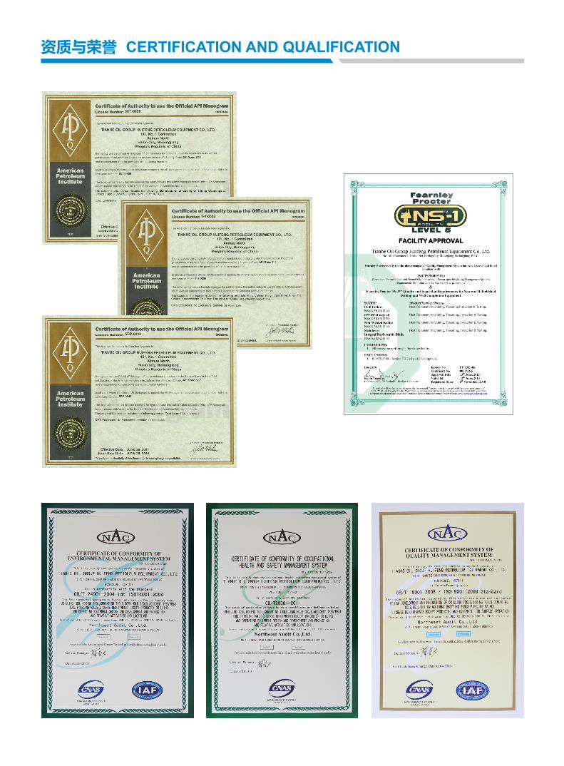
资质与荣誉 CERTIFICATION AND QUALIFICATION

天合石油集团是专业从事石油钻采工具和设备的研发、制造、销售、油田服务于一体的综合服务型和制造型企业。
公司是中国国家级高新技术企业,中国驰名商标企业,是中国石油和石油化工设备工业协会理事单位。公司具有 ISO 国际质量体系、API、NS-1、HSE 健康、安全环境管理体系等认证资质。
公司产品销售网络已覆盖中国石油、中国石化、中海油等集团公司所属全部油田,截至目前公司产品已出口至全球 45 个产油国,其中国际市场出口额已占公司 80% 左右的销售额。
Tianhe Oil Group is a comprehensive enterprise of equipment manufacturing and oilfield service providing. The company is specialized in innovation, manufacture and sales of drill and petroleum extraction tools, equipments and oil field services.
Tianhe Oil Group is the council member of CPEIA (China Petroleum and Equipment Industry Association), rewarded as national level of Hi-Tech enterprise. The company is a Chinese well-known trademark enterprise. It has been certified to ISO, API, NS-1, and HSE management system.
The company has developed a strong domestic sales network covering all oilfields of CNPC, SINOPEC and CNOOC. Currently, our products and equipments have been exported to 45 countries, overseas business has covered 80% of our company sales.
企业简介 COMPANY PROFILE
1
天合石油集团汇丰石油装备股份有限公司
1. 前言 Introduction
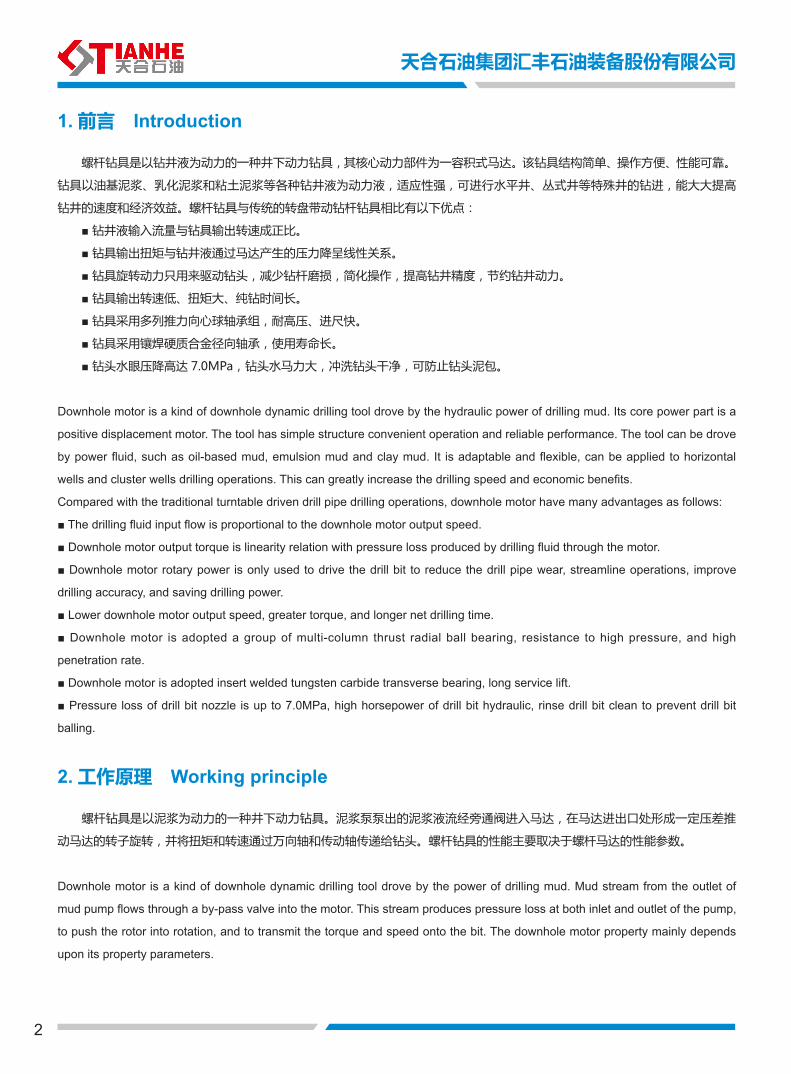
螺杆钻具是以钻井液为动力的一种井下动力钻具,其核心动力部件为一容积式马达。该钻具结构简单、操作方便、性能可靠。
钻具以油基泥浆、乳化泥浆和粘土泥浆等各种钻井液为动力液,适应性强,可进行水平井、丛式井等特殊井的钻进,能大大提高
钻井的速度和经济效益。螺杆钻具与传统的转盘带动钻杆钻具相比有以下优点:
■ 钻井液输入流量与钻具输出转速成正比。
■ 钻具输出扭矩与钻井液通过马达产生的压力降呈线性关系。
■ 钻具旋转动力只用来驱动钻头,减少钻杆磨损,简化操作,提高钻井精度,节约钻井动力。
■ 钻具输出转速低、扭矩大、纯钻时间长。
■ 钻具采用多列推力向心球轴承组,耐高压、进尺快。
■ 钻具采用镶焊硬质合金径向轴承,使用寿命长。
■ 钻头水眼压降高达 7.0MPa,钻头水马力大,冲洗钻头干净,可防止钻头泥包。
Downhole motor is a kind of downhole dynamic drilling tool drove by the hydraulic power of drilling mud. Its core power part is a
positive displacement motor. The tool has simple structure convenient operation and reliable performance. The tool can be drove
by power fluid, such as oil-based mud, emulsion mud and clay mud. It is adaptable and flexible, can be applied to horizontal
wells and cluster wells drilling operations. This can greatly increase the drilling speed and economic benefits.
Compared with the traditional turntable driven drill pipe drilling operations, downhole motor have many advantages as follows:
■ The drilling fluid input flow is proportional to the downhole motor output speed.
■ Downhole motor output torque is linearity relation with pressure loss produced by drilling fluid through the motor.
■ Downhole motor rotary power is only used to drive the drill bit to reduce the drill pipe wear, streamline operations, improve
drilling accuracy, and saving drilling power.
■ Lower downhole motor output speed, greater torque, and longer net drilling time.
■ Downhole motor is adopted a group of multi-column thrust radial ball bearing, resistance to high pressure, and high
penetration rate.
■ Downhole motor is adopted insert welded tungsten carbide transverse bearing, long service lift.
■ Pressure loss of drill bit nozzle is up to 7.0MPa, high horsepower of drill bit hydraulic, rinse drill bit clean to prevent drill bit
balling.
2. 工作原理 Working principle
螺杆钻具是以泥浆为动力的一种井下动力钻具。泥浆泵泵出的泥浆液流经旁通阀进入马达,在马达进出口处形成一定压差推
动马达的转子旋转,并将扭矩和转速通过万向轴和传动轴传递给钻头。螺杆钻具的性能主要取决于螺杆马达的性能参数。
Downhole motor is a kind of downhole dynamic drilling tool drove by the power of drilling mud. Mud stream from the outlet of
mud pump flows through a by-pass valve into the motor. This stream produces pressure loss at both inlet and outlet of the pump,
to push the rotor into rotation, and to transmit the torque and speed onto the bit. The downhole motor property mainly depends
upon its property parameters.
2
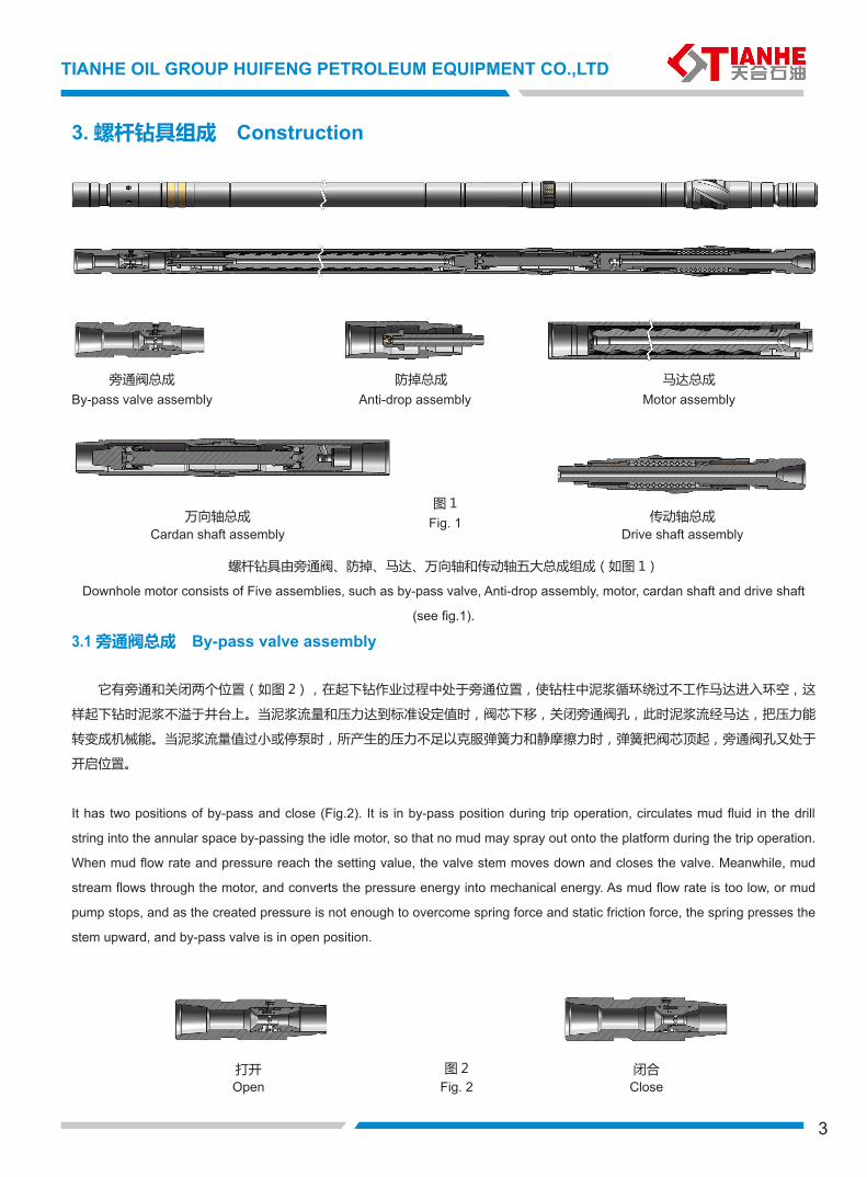
3. 螺杆钻具组成 Construction
螺杆钻具由旁通阀、防掉、马达、万向轴和传动轴五大总成组成(如图 1)
Downhole motor consists of Five assemblies, such as by-pass valve, Anti-drop assembly, motor, cardan shaft and drive shaft
(see fig.1).
3.1 旁通阀总成 By-pass valve assembly
它有旁通和关闭两个位置(如图 2),在起下钻作业过程中处于旁通位置,使钻柱中泥浆循环绕过不工作马达进入环空,这
样起下钻时泥浆不溢于井台上。当泥浆流量和压力达到标准设定值时,阀芯下移,关闭旁通阀孔,此时泥浆流经马达,把压力能
转变成机械能。当泥浆流量值过小或停泵时,所产生的压力不足以克服弹簧力和静摩擦力时,弹簧把阀芯顶起,旁通阀孔又处于
开启位置。
It has two positions of by-pass and close (Fig.2). It is in by-pass position during trip operation, circulates mud fluid in the drill
string into the annular space by-passing the idle motor, so that no mud may spray out onto the platform during the trip operation.
When mud flow rate and pressure reach the setting value, the valve stem moves down and closes the valve. Meanwhile, mud
stream flows through the motor, and converts the pressure energy into mechanical energy. As mud flow rate is too low, or mud
pump stops, and as the created pressure is not enough to overcome spring force and static friction force, the spring presses the
stem upward, and by-pass valve is in open position.
Fig. 1
By-pass valve assembly Anti-drop assembly Motor assembly
Cardan shaft assembly Drive shaft assembly
Fig. 2Open 打开
旁通阀总成 防掉总成 马达总成
传动轴总成万向轴总成图 1
图 2 闭合Close
TIANHE OIL GROUP HUIFENG PETROLEUM EQUIPMENT CO.,LTD
3
3.2 马达总成 Motor assembly 它由定子和转子组成。定子是在钢管内壁上压注橡胶衬套而成。橡胶内孔是具有一定几何参数的螺旋。转子是一根有镀铬硬
层的螺杆。
转子与定子相互啮合,是用两者的导程差而形成的螺旋密封线,同时形成密封腔。随着转子在定子中的转动,密封腔沿着轴
向移动,不断的生成与消失,完成其能量转换,这就是螺杆马达的基本工作原理。
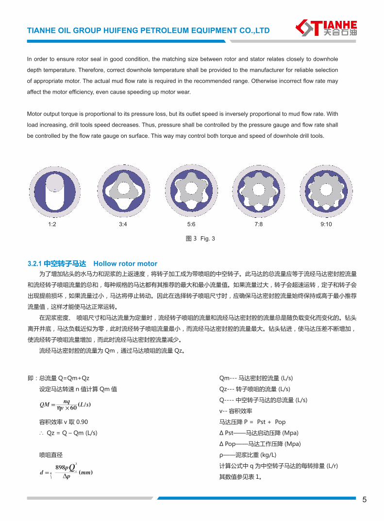
马达转子的螺旋线有单头和多头之分(定子的螺旋线头数比转子多 1)。转子的头数越少,转速越高,扭矩越小; 头数越多,
转速越低,扭矩越大。图 3 是几种典型马达配合的截面轮廊:
马达定子一个导程组成一个密封腔,也称为一级。每级额定工作压降为 0.8Mpa, 最大压降为额定工作压力的 1.3 倍,如四级
马达,额定压降应为 3.2Mpa, 最大压降为 4.2Mpa。压降超过此值马达就会产生泄漏,转速很快下降,严重时会完全停止转动,
甚至造成马达损坏,用户应特别注意。
为了确保马达的密封效果,转子与定子之间的配合尺寸与不同井深的温度有关 , 因此在选择钻具时应尽可能准确地提供给厂
家钻具应用场所的井温情况,以便推荐使用松紧配合状态适合的马达。现场使用的泥浆流量应在推荐的范围之内 , 否则将影响马
达效率,甚至马达磨损加快。
马达的输出扭矩与马达的压降成正比,输出转速与输入泥浆量成正比,随着负载的增加,钻具的转速有所降低,因此在地面
只要根据压力表控制压力,根据流量计控制泵的流量,就可以控制井下钻具的扭矩和转速。
It consists of stator and rotor. Stator is made by squeezing rubber sleeve on the inner wall of steel tube. Rubber sleeve inner
hole forms spiral structure with a certain geometric parameter. Rotor is a screw rod with chrome-plated layer.
Stator and rotor matches with each other, to form spiral line and seal cavity through their lead difference. With rotor running
in the stator, the seal cavity is moving along its axial direction, continuously forms and disappears, to complete its energy
conversion. This is the basic principle of downhole motor.
Spiral seal line on rotor is divided into single end and multi-end (stator with one more end than rotor). The less ends the motor
has the higher speed and the lower torque are. The more ends it has, the lower speed and the higher torque are. Fig.3 shows
the sectional profile of several typical motors.
A lead forms a seal cavity in motor stator. This is called one stage. When the rated working pressure of each stage lows down
to 0.8 Mpa, the maximum pressure loss will be 1.3 times of the rated pressure. For an example, for 4-stage motor, the rated
pressure loss shall be 3.2 Mpa, the maximum pressure loss shall be 4.2 Mpa. As the pressure loss is over such value, motor
may bring about leakage and speed will quickly slow down. More seriously, it may cause operation into complete stop, even
cause the motor to be damaged. This is the caution for the customers.
4
天合石油集团汇丰石油装备股份有限公司
TIANHE OIL GROUP HUIFENG PETROLEUM EQUIPMENT CO.,LTD
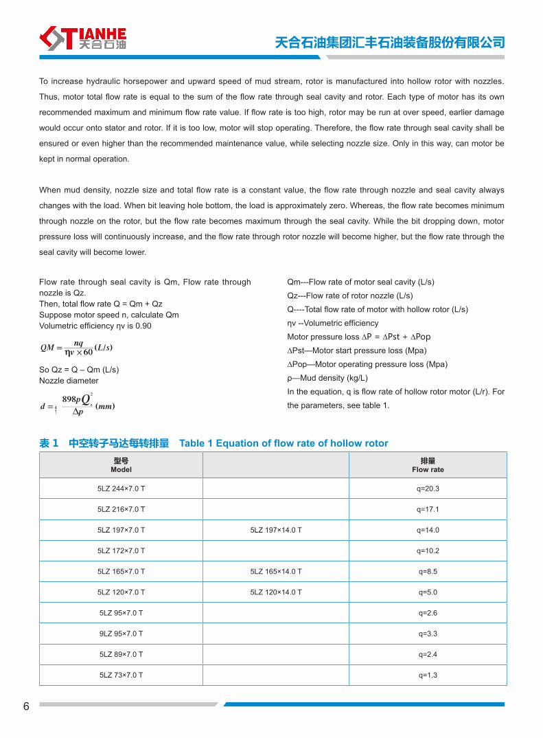
3.2.1 中空转子马达 Hollow rotor motor 为了增加钻头的水马力和泥浆的上返速度,将转子加工成为带喷咀的中空转子。此马达的总流量应等于流经马达密封腔流量
和流经转子喷咀流量的总和,每种规格的马达都有其推荐的最大和最小流量值。如果流量过大,转子会超速运转,定子和转子会
出现提前损坏,如果流量过小,马达将停止转动。因此在选择转子喷咀尺寸时,应确保马达密封腔流量始终保持或高于最小推荐
流量值,这样才能使马达正常运转。
在泥浆密度、 喷咀尺寸和马达流量为定量时,流经转子喷咀的流量和流经马达密封腔的流量总是随负载变化而变化的。钻头
离开井底,马达负载近似为零,此时流经转子喷咀流量最小,而流经马达密封腔的流量最大。钻头钻进,使马达压差不断增加,
使流经转子喷咀流量增加,而此时流经马达密封腔流量减少。
流经马达密封腔的流量为 Qm,通过马达喷咀的流量 Qz。
5
Fig. 3图 3
1:2 3:4 5:6 7:8 9:10
In order to ensure rotor seal in good condition, the matching size between rotor and stator relates closely to downhole
depth temperature. Therefore, correct downhole temperature shall be provided to the manufacturer for reliable selection
of appropriate motor. The actual mud flow rate is required in the recommended range. Otherwise incorrect flow rate may
affect the motor efficiency, even cause speeding up motor wear.
Motor output torque is proportional to its pressure loss, but its outlet speed is inversely proportional to mud flow rate. With
load increasing, drill tools speed decreases. Thus, pressure shall be controlled by the pressure gauge and flow rate shall
be controlled by the flow rate gauge on surface. This way may control both torque and speed of downhole drill tools.
即:总流量 Q=Qm+Qz
设定马达转速 n 值计算 Qm 值
容积效率 v 取 0.90
∴ Qz = Q – Qm (L/s)
喷咀直径
Qm--- 马达密封腔流量 (L/s)
Qz--- 转子喷咀的流量 (L/s)
Q---- 中空转子马达的总流量 (L/s)
v-- 容积效率
马达压降 P = Pst + Pop
∆ Pst——马达启动压降 (Mpa)
∆ Pop——马达工作压降 (Mpa)
ρ——泥浆比重 (kg/L)
计算公式中 q 为中空转子马达的每转排量 (L/r)
其数值参见表 1。
60( / )QM
vnq
L s#h=
p898( )d
pmmz
2
4
QD
=
6
表 1 中空转子马达每转排量 Table 1 Equation of flow rate of hollow rotor型号
Model排量
Flow rate
5LZ 244×7.0 T q=20.3
5LZ 216×7.0 T q=17.1
5LZ 197×7.0 T 5LZ 197×14.0 T q=14.0
5LZ 172×7.0 T q=10.2
5LZ 165×7.0 T 5LZ 165×14.0 T q=8.5
5LZ 120×7.0 T 5LZ 120×14.0 T q=5.0
5LZ 95×7.0 T q=2.6
9LZ 95×7.0 T q=3.3
5LZ 89×7.0 T q=2.4
5LZ 73×7.0 T q=1.3
To increase hydraulic horsepower and upward speed of mud stream, rotor is manufactured into hollow rotor with nozzles.
Thus, motor total flow rate is equal to the sum of the flow rate through seal cavity and rotor. Each type of motor has its own
recommended maximum and minimum flow rate value. If flow rate is too high, rotor may be run at over speed, earlier damage
would occur onto stator and rotor. If it is too low, motor will stop operating. Therefore, the flow rate through seal cavity shall be
ensured or even higher than the recommended maintenance value, while selecting nozzle size. Only in this way, can motor be
kept in normal operation.
When mud density, nozzle size and total flow rate is a constant value, the flow rate through nozzle and seal cavity always
changes with the load. When bit leaving hole bottom, the load is approximately zero. Whereas, the flow rate becomes minimum
through nozzle on the rotor, but the flow rate becomes maximum through the seal cavity. While the bit dropping down, motor
pressure loss will continuously increase, and the flow rate through rotor nozzle will become higher, but the flow rate through the
seal cavity will become lower.
Flow rate through seal cavity is Qm, Flow rate through nozzle is Qz.Then, total flow rate Q = Qm + QzSuppose motor speed n, calculate QmVolumetric efficiency ηv is 0.90
So Qz = Q – Qm (L/s)Nozzle diameter
Qm---Flow rate of motor seal cavity (L/s)
Qz---Flow rate of rotor nozzle (L/s)
Q----Total flow rate of motor with hollow rotor (L/s)
ηv --Volumetric efficiency
Motor pressure loss ∆P = ∆Pst + ∆Pop
∆Pst—Motor start pressure loss (Mpa)
∆Pop—Motor operating pressure loss (Mpa)
ρ—Mud density (kg/L)
In the equation, q is flow rate of hollow rotor motor (L/r). For
the parameters, see table 1.
天合石油集团汇丰石油装备股份有限公司
p898( )d
pmmz
2
4
QD
=
60( / )QM
vnq
L s#h=
7
TIANHE OIL GROUP HUIFENG PETROLEUM EQUIPMENT CO.,LTD
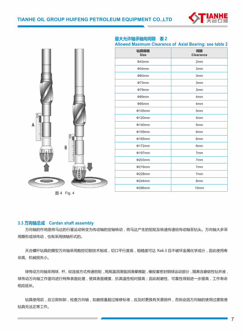
最大允许轴承轴向间隙 表2Allowed Maximum Clearance of Axial Bearing: see table 2
钻具规格Size
间隙Clearance
Ф43mm 2mm
Ф54mm 3mm
Ф60mm 3mm
Ф73mm 3mm
Ф79mm 3mm
Ф89mm 4mm
Ф95mm 4mm
Ф105mm 5mm
Ф120mm 5mm
Ф140mm 5mm
Ф159mm 6mm
Ф165mm 6mm
Ф172mm 6mm
Ф197mm 7mm
Ф203mm 7mm
Ф216mm 7mm
Ф228mm 7mm
Ф244mm 8mm
Ф286mm 10mmFig. 4图 4
3.3 万向轴总成 Cardan shaft assembly 万向轴的作用是将马达的行星运动转变为传动轴的定轴转动,将马达产生的扭矩及转速传递给传动轴至钻头。万向轴大多采
用瓣形或球传动,也有采用挠轴形式的。
天合螺杆钻具的瓣型万向轴采用数控切割技术制成,切口平行度高,粗糙度可达 Ra6.3 且不破坏金属化学成分,因此使用寿
命高、机械损失小。
球传动万向轴采用球、杆、绞连接方式传递扭矩,用高温润滑脂润滑摩擦副,橡胶套密封钢球运动部分,隔离含磨砺性钻井液,
球传动万向轴工作面均进行特殊表面处理,使其表面硬度、抗高温性相对提高;因此耐磨性、可靠性得到进一步提高,工作寿命
相应延长。
钻具使用后,应立即拆卸,检查万向轴,如磨损量超过维修标准,应及时更换有关易损件,否则会因万向轴的使用过度致使
钻具无法正常工作。
8
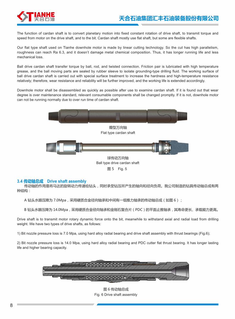
The function of cardan shaft is to convert planetary motion into fixed constant rotation of drive shaft, to transmit torque and speed from motor on the drive shaft, and to the bit. Cardan shaft mostly use flat shaft, but some are flexible shafts.
Our flat type shaft used on Tianhe downhole motor is made by linear cutting technology. So the cut has high parallelism, roughness can reach Ra 6.3, and it doesn’t damage metal chemical composition. Thus, it has longer running life and less mechanical loss.
Ball drive cardan shaft transfer torque by ball, rod, and twisted connection. Friction pair is lubricated with high temperature grease, and the ball moving parts are sealed by rubber sleeve to isolate grounding-type drilling fluid. The working surface of ball drive cardan shaft is carried out with special surface treatment to increase the hardness and high-temperature resistance relatively; therefore, wear resistance and reliability will be further improved, and the working life is extended accordingly.
Downhole motor shall be disassembled as quickly as possible after use to examine cardan shaft. If it is found out that wear degree is over maintenance standard, relevant consumable components shall be changed promptly. If it is not, downhole motor can not be running normally due to over run time of cardan shaft.
Flat type cardan shaft
Ball type drive cardan shaft
Fig. 5图 5
瓣型万向轴
球传动万向轴
图 6 传动轴总成
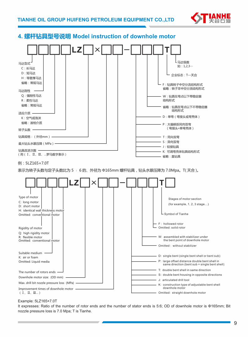
3.4 传动轴总成 Drive shaft assembly 传动轴的作用是将马达的旋转动力传递给钻头,同时承受钻压所产生的轴向和径向负荷。我公司制造的钻具传动轴总成有两种结构:
A 钻头水眼压降为 7.0Mpa,采用硬质合金径向轴承和中间有一组推力轴承的传动轴总成(如图 6);
B 钻头水眼压降为 14.0Mpa,采用硬质合金径向轴承和金刚石复合片(PDC)的平面止推轴承,其寿命更长、承载能力更高。
Drive shaft is to transmit motor rotary dynamic force onto the bit, meanwhile to withstand axial and radial load from drilling weight. We have two types of drive shafts, as follows:
1) Bit nozzle pressure loss is 7.0 Mpa, using hard alloy radial bearing and drive shaft assembly with thrust bearings (Fig.6);
2) Bit nozzle pressure loss is 14.0 Mpa, using hard alloy radial bearing and PDC cutter flat thrust bearing. It has longer lasting life and higher bearing capacity.
Fig. 6 Drive shaft assembly
天合石油集团汇丰石油装备股份有限公司
9
TIANHE OIL GROUP HUIFENG PETROLEUM EQUIPMENT CO.,LTD
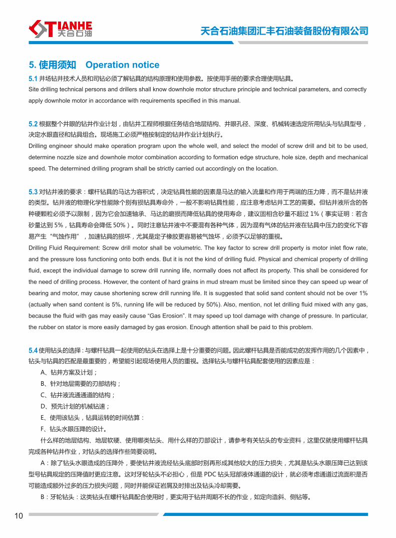
例:5LZ165×7.0T
表示为转子头数与定子头数比为 5 ﹕ 6 的、外径为 Φ165mm 螺杆钻具,钻头水眼压降为 7.0Mpa。T( 天合 )。
4. 螺杆钻具型号说明 Model instruction of downhole motor
Example: 5LZ165×7.0TIt expresses: Ratio of the number of rotor ends and the number of stator ends is 5:6; OD of downhole motor is Φ165mm; Bit nozzle pressure loss is 7.0 Mpa; T is Tianhe.
X
10
5. 使用须知 Operation notice5.1 井场钻井技术人员和司钻必须了解钻具的结构原理和使用参数。按使用手册的要求合理使用钻具。
Site drilling technical persons and drillers shall know downhole motor structure principle and technical parameters, and correctly
apply downhole motor in accordance with requirements specified in this manual.
5.2 根据整个井眼的钻井作业计划,由钻井工程师根据任务结合地层结构、井眼孔径、深度、机械转速选定所用钻头与钻具型号,
决定水眼直径和钻具组合。现场施工必须严格按制定的钻井作业计划执行。
Drilling engineer should make operation program upon the whole well, and select the model of screw drill and bit to be used,
determine nozzle size and downhole motor combination according to formation edge structure, hole size, depth and mechanical
speed. The determined drilling program shall be strictly carried out accordingly on the location.
5.3 对钻井液的要求:螺杆钻具的马达为容积式,决定钻具性能的因素是马达的输入流量和作用于两端的压力降,而不是钻井液
的类型。钻井液的物理化学性能除个别有损钻具寿命外,一般不影响钻具性能,应注意考虑钻井工艺的需要。但钻井液所含的各
种硬颗粒必须予以限制,因为它会加速轴承、马达的磨损而降低钻具的使用寿命,建议固相含砂量不超过 1%(事实证明:若含
砂量达到 5%,钻具寿命会降低 50%)。同时注意钻井液中不要混有各种气体,因为混有气体的钻井液在钻具中压力的变化下容
易产生“气蚀作用”,加速钻具的损坏,尤其是定子橡胶更容易被气蚀坏,必须予以足够的重视。
Drilling Fluid Requirement: Screw drill motor shall be volumetric. The key factor to screw drill property is motor inlet flow rate,
and the pressure loss functioning onto both ends. But it is not the kind of drilling fluid. Physical and chemical property of drilling
fluid, except the individual damage to screw drill running life, normally does not affect its property. This shall be considered for
the need of drilling process. However, the content of hard grains in mud stream must be limited since they can speed up wear of
bearing and motor, may cause shortening screw drill running life. It is suggested that solid sand content should not be over 1%
(actually when sand content is 5%, running life will be reduced by 50%). Also, mention, not let drilling fluid mixed with any gas,
because the fluid with gas may easily cause “Gas Erosion”. It may speed up tool damage with change of pressure. In particular,
the rubber on stator is more easily damaged by gas erosion. Enough attention shall be paid to this problem.
5.4 使用钻头的选择:与螺杆钻具一起使用的钻头在选择上是十分重要的问题。因此螺杆钻具是否能成功的发挥作用的几个因素中,
钻头与钻具的匹配是最重要的,希望能引起现场使用人员的重视。选择钻头与螺杆钻具配套使用的因素应是:
A、钻井方案及计划;
B、针对地层需要的刃部结构;
C、钻井液流通通道的结构;
D、预先计划的机械钻速;
E、使用该钻头,钻具运转的时间估算:
F、钻头水眼压降的设计。
什么样的地层结构、地层软硬、使用哪类钻头、用什么样的刃部设计,请参考有关钻头的专业资料,这里仅就使用螺杆钻具
完成各种钻井作业,对钻头的选择作些简要说明。
A:除了钻头水眼造成的压降外,要使钻井液流经钻头底部时别再形成其他较大的压力损失,尤其是钻头水眼压降已达到该
型号钻具规定的压降值时更应注意。这对牙轮钻头不必担心,但是 PDC 钻头冠部液体通道的设计,就必须考虑通道过流面积是否
可能造成额外过多的压力损失问题,同时并能保证岩屑及时排出及钻头冷却需要。
B:牙轮钻头:这类钻头在螺杆钻具配合使用时,更实用于钻井周期不长的作业,如定向造斜、侧钻等。
天合石油集团汇丰石油装备股份有限公司
11
TIANHE OIL GROUP HUIFENG PETROLEUM EQUIPMENT CO.,LTD
C:PDC 钻头:PDC 钻头不仅适用于定向造斜,更适用于钻井周期较长的作业,如打直井等。在较长周期的钻井作业中,最
重要的因素就是钻头与钻具作为一个整体,不要由于其中的哪一部分出了问题,而造成不必要的起下钻。大家已熟知:复合片钻
头较牙轮钻头寿命长,而且结构是整体的,具有很多优点。
D:提高钻具和钻头的使用寿命,也是一个重要因素。改善传动轴的稳定性,例如加稳定器,对提高钻具寿命发挥钻头性能
是有帮助的。考虑钻头金刚石的几何尺寸、布置方位、钻压负荷与要求井下钻具转速高、钻压小的甚密关系。总之,使用螺杆钻
具不对所匹配的钻头进行认真选择,要想取得满意的效果是困难的,还会造成钻具过早地损失。
Bit Selection: For bit selection, it is important to combine and match the screw drill. It's important for successful screw drill
application. Application factors to match bit with the screw drill are as follows:
(A) Drilling Plan and Program; (B) Formation Edge Structure;
(C) Structure of Mud Flowing Channels;
(D) Determined Mechanical Drilling Speed;
(E) Estimation of Bit and Screw Drill Running Life; (F) Design of Bit Nozzle Pressure Loss
Please, refer to the relevant professional information for proper bit selection. Below is a brief description of bit selection for
performing the drilling operation with screw drill.
A: In order to avoid high pressure loss, when drilling fluid flows through the bit bottom, special attention should be paid, when
pressure loss has reached the certain level for this kind of drilling tool. This does not affect rock bit, but important for the crown
passage design of PDC bit. Problem should be considered as passing fluid area may cause much extra loss, as well as to
ensure prompt discharge of cuttings and bit cooling.
B: Rock Bit: When this kind of bit is used with the screw drill, it is more appropriate to shorten the drilling period, such as
directional deflection and re-entry etc.
C: PDC Bit: It is not only used for directional deflection, but also more appropriate for longer drilling period, such as vertical well
drilling. During longer period of drilling operation, the more important factor is to integrate the bit and the screw drill in order to
avoid unnecessary trip operation due to some problems. It is known that PDC bit can last longer than rock bit, and it is integral
in structure, having more advantages.
D: It is also an important factor to prolong running life of bit and tools. It is helpful to extend screw life and to develop bit property
by improving the stability of drive shaft, e.g. stabilizer. And it should be considered the close relationship between diamond
geometric dimension, allocation, drilling weight load and the required high speed and lower drilling weight of downhole tool. In
general, it is hard to obtain satisfactory effect without strictly matching bit and screw drill; it can also cause damage onto the tool
earlier.
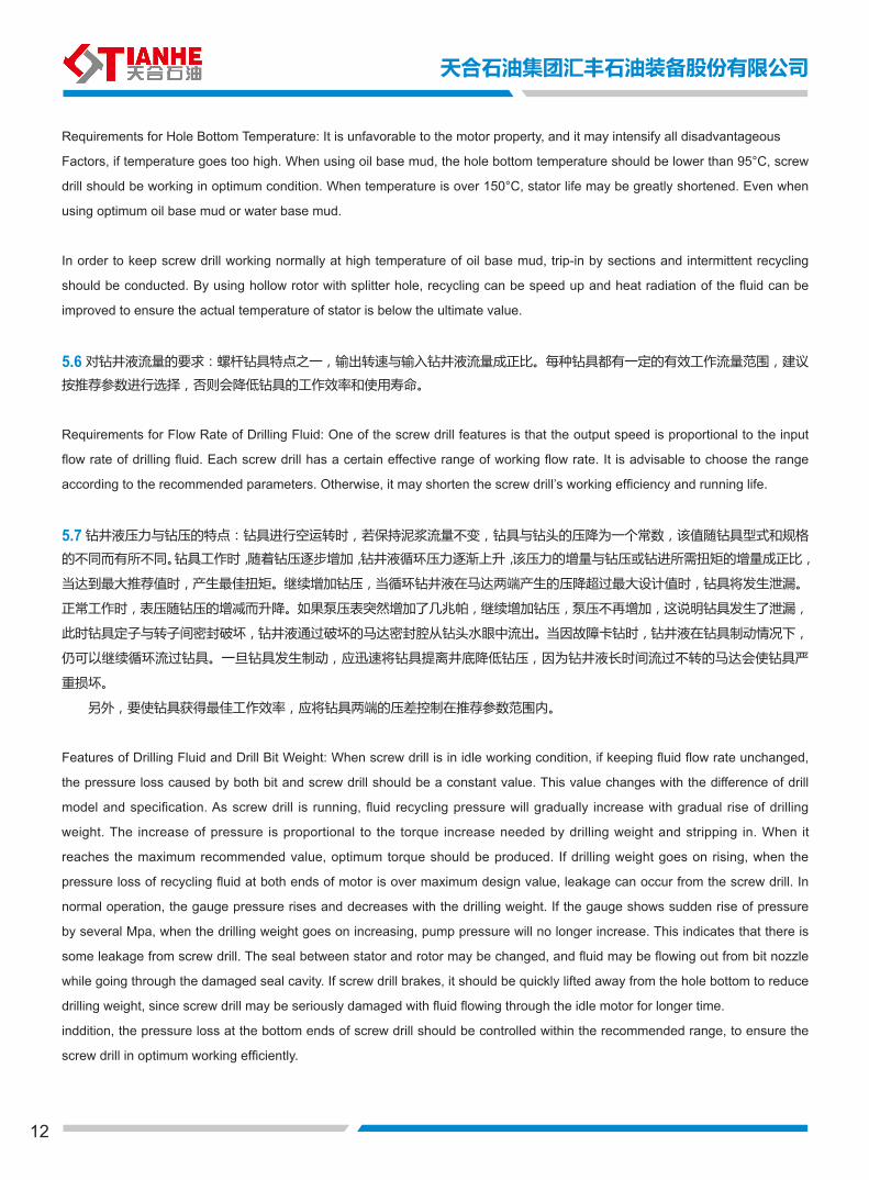
5.5 对井底环境温度的要求:温度过高对钻具马达性能十分不利,会使所有不利因素加剧。使用油基泥浆液,井底温度低于 95 C,
钻具工作状态最佳。当温度超过 150 C 时,即使使用最佳的油基钻井液,甚至使用水基钻井液,钻具定子寿命也会大幅度缩短。
为使钻具在较高的油基钻井液下正常工作,可以采用分段下钻,间歇循环,使用带分流孔的空心转子,以加速循环或改善钻
井液的散热性及其它性能的方法。保证实际定子工作温度低于极限值。
12
Requirements for Hole Bottom Temperature: It is unfavorable to the motor property, and it may intensify all disadvantageous
Factors, if temperature goes too high. When using oil base mud, the hole bottom temperature should be lower than 95°C, screw
drill should be working in optimum condition. When temperature is over 150°C, stator life may be greatly shortened. Even when
using optimum oil base mud or water base mud.
In order to keep screw drill working normally at high temperature of oil base mud, trip-in by sections and intermittent recycling
should be conducted. By using hollow rotor with splitter hole, recycling can be speed up and heat radiation of the fluid can be
improved to ensure the actual temperature of stator is below the ultimate value.
5.6 对钻井液流量的要求:螺杆钻具特点之一,输出转速与输入钻井液流量成正比。每种钻具都有一定的有效工作流量范围,建议
按推荐参数进行选择,否则会降低钻具的工作效率和使用寿命。
Requirements for Flow Rate of Drilling Fluid: One of the screw drill features is that the output speed is proportional to the input
flow rate of drilling fluid. Each screw drill has a certain effective range of working flow rate. It is advisable to choose the range
according to the recommended parameters. Otherwise, it may shorten the screw drill’s working efficiency and running life.
5.7 钻井液压力与钻压的特点:钻具进行空运转时,若保持泥浆流量不变,钻具与钻头的压降为一个常数,该值随钻具型式和规格
的不同而有所不同。钻具工作时,随着钻压逐步增加,钻井液循环压力逐渐上升,该压力的增量与钻压或钻进所需扭矩的增量成正比,
当达到最大推荐值时,产生最佳扭矩。继续增加钻压,当循环钻井液在马达两端产生的压降超过最大设计值时,钻具将发生泄漏。
正常工作时,表压随钻压的增减而升降。如果泵压表突然增加了几兆帕,继续增加钻压,泵压不再增加,这说明钻具发生了泄漏,
此时钻具定子与转子间密封破坏,钻井液通过破坏的马达密封腔从钻头水眼中流出。当因故障卡钻时,钻井液在钻具制动情况下,
仍可以继续循环流过钻具。一旦钻具发生制动,应迅速将钻具提离井底降低钻压,因为钻井液长时间流过不转的马达会使钻具严
重损坏。
另外,要使钻具获得最佳工作效率,应将钻具两端的压差控制在推荐参数范围内。
Features of Drilling Fluid and Drill Bit Weight: When screw drill is in idle working condition, if keeping fluid flow rate unchanged,
the pressure loss caused by both bit and screw drill should be a constant value. This value changes with the difference of drill
model and specification. As screw drill is running, fluid recycling pressure will gradually increase with gradual rise of drilling
weight. The increase of pressure is proportional to the torque increase needed by drilling weight and stripping in. When it
reaches the maximum recommended value, optimum torque should be produced. If drilling weight goes on rising, when the
pressure loss of recycling fluid at both ends of motor is over maximum design value, leakage can occur from the screw drill. In
normal operation, the gauge pressure rises and decreases with the drilling weight. If the gauge shows sudden rise of pressure
by several Mpa, when the drilling weight goes on increasing, pump pressure will no longer increase. This indicates that there is
some leakage from screw drill. The seal between stator and rotor may be changed, and fluid may be flowing out from bit nozzle
while going through the damaged seal cavity. If screw drill brakes, it should be quickly lifted away from the hole bottom to reduce
drilling weight, since screw drill may be seriously damaged with fluid flowing through the idle motor for longer time.
inddition, the pressure loss at the bottom ends of screw drill should be controlled within the recommended range, to ensure the
screw drill in optimum working efficiently.
天合石油集团汇丰石油装备股份有限公司
13
TIANHE OIL GROUP HUIFENG PETROLEUM EQUIPMENT CO.,LTD
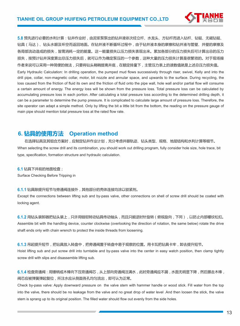
5.8 预先进行必要的水利计算:钻井作业时,由泥浆泵泵出的钻井液依次经立杆、水龙头、方钻杆而进入钻杆、钻铤、无磁钻铤、
钻具(马达)、钻头水眼及环空而返回地面。在钻井液不断循环过程中,由于钻井液本身的摩擦和钻井液与管壁、井壁的摩擦及
各局部流动造成的损失,皆需消耗一定的能量。这一能量损失以压力损失表现出来。累加各部分的压力损失后可计算出总的压力
损失,按预计钻井深度算出总压力损失后,就可以作为确定泵压的一个参数,这种大量的压力损失计算是很繁琐的。对于现场操
作者来说可以采用一种简便的做法,只要将钻头稍稍提离井底,在额定排量下,主管压力表上的读数值就是上述总压力损失值。
Early Hydraulic Calculation: In drilling operation, the pumped mud flows successively through riser, swivel, Kelly and into the drill pipe, collar, non-magnetic collar, motor, bit nozzle and annular space, and upwards to the surface. During recycling, the loss caused from the friction of fluid its own and the friction of fluid onto the pipe wall, hole wall and/or partial flow will consume a certain amount of energy. The energy loss will be shown from the pressure loss. Total pressure loss can be calculated by accumulating pressure loss in each portion. After calculating a total pressure loss according to the determined drilling depth, it can be a parameter to determine the pump pressure. It is complicated to calculate large amount of pressure loss. Therefore, the site operator can adapt a simple method. Only by lifting the bit a little bit from the bottom, the reading on the pressure gauge of main pipe should mention total pressure loss at the rated flow rate.
在选择钻具及其组合方案时,应制定钻井作业计划,充分考虑井眼轨迹、钻头类型、规格、地层结构和水利计算等细节。
When selecting the screw drill and its combination, you should work out drilling program, fully consider hole size, hole trace, bit
type, specification, formation structure and hydraulic calculation.
6.1 钻具下井前的地面检查;
Surface Checking Before Tripping in
6.1.1 钻具除提升短节与旁通阀连接外,其他部分的壳体连接均涂以锁紧剂。
Except the connections between lifting sub and by-pass valve, other connections on shell of screw drill should be coated with
locking agent.
6.1.2 用钻头装卸器把钻头装上,只许用链钳转动钻具传动轴头,而且只能逆时针旋转(俯视旋向,下同),以防止内部螺纹松扣。
Assemble bit with the handling device, counter clockwise (overlooking the direction of rotation, the same below) rotate the drive
shaft ends only with chain wrench to protect the inside threads from loosening.
6.1.3 吊起提升短节,把钻具放入转盘中,把旁通阀置于转盘中易于观察的位置。用卡瓦把钻具卡牢,卸去提升短节。
Hoist lifting sub and put screw drill into turntable and by-pass valve into the center in easy watch position, then clamp tightly
screw drill with slips and disassemble lifting sub.
6.1.4 检查旁通阀:用锤柄或木棒向下压旁通阀芯,从上部向旁通阀注满水,此时旁通阀应不漏,水面无明显下降,然后挪走木棒,
阀芯应被弹簧弹起复位,所注水应从侧面各孔均匀流出,即可认为正常。
Check by-pass valve: Apply downward pressure on the valve stem with hammer handle or wood stick. Fill water from the top
into the valve, there should be no leakage from the valve and no great drop of water level .And then loosen the stick, the valve
stem is sprang up to its original position. The filled water should flow out evenly from the side holes.
6. 钻具的使用方法 Operation method
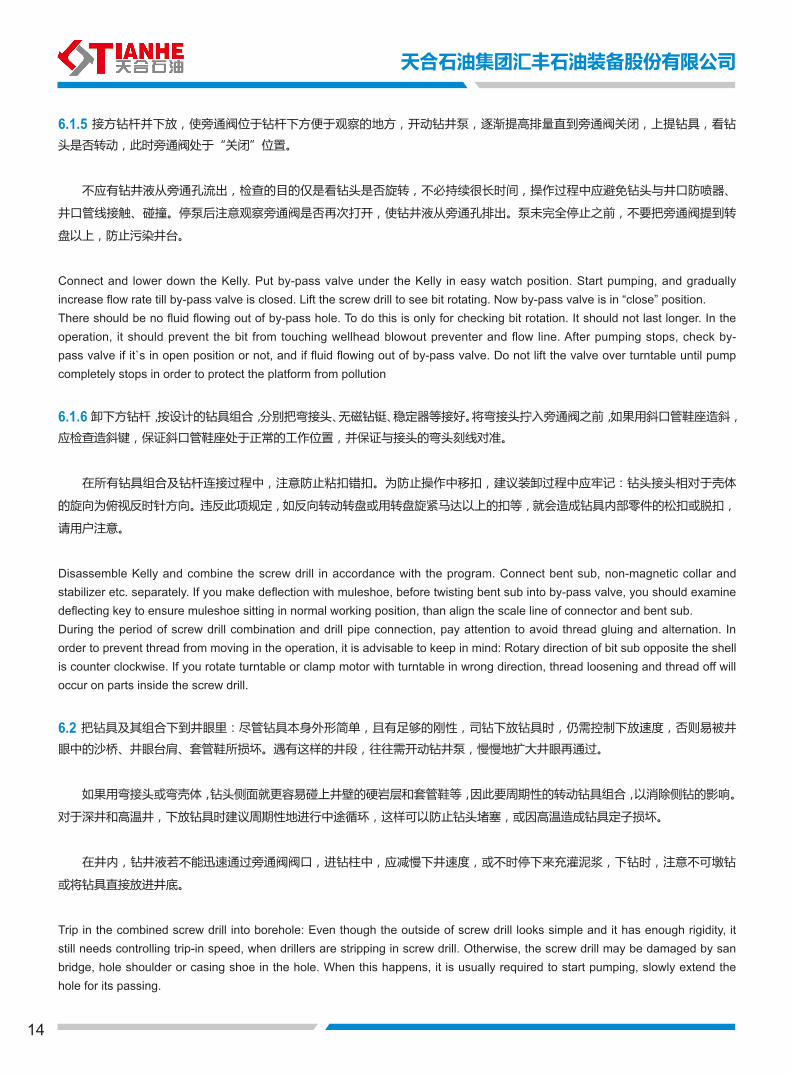
6.1.5 接方钻杆并下放,使旁通阀位于钻杆下方便于观察的地方,开动钻井泵,逐渐提高排量直到旁通阀关闭,上提钻具,看钻
头是否转动,此时旁通阀处于“关闭”位置。
不应有钻井液从旁通孔流出,检查的目的仅是看钻头是否旋转,不必持续很长时间,操作过程中应避免钻头与井口防喷器、
井口管线接触、碰撞。停泵后注意观察旁通阀是否再次打开,使钻井液从旁通孔排出。泵未完全停止之前,不要把旁通阀提到转
盘以上,防止污染井台。
Connect and lower down the Kelly. Put by-pass valve under the Kelly in easy watch position. Start pumping, and gradually increase flow rate till by-pass valve is closed. Lift the screw drill to see bit rotating. Now by-pass valve is in “close” position.There should be no fluid flowing out of by-pass hole. To do this is only for checking bit rotation. It should not last longer. In the operation, it should prevent the bit from touching wellhead blowout preventer and flow line. After pumping stops, check by-pass valve if it`s in open position or not, and if fluid flowing out of by-pass valve. Do not lift the valve over turntable until pump completely stops in order to protect the platform from pollution
6.1.6 卸下方钻杆,按设计的钻具组合,分别把弯接头、无磁钻铤、稳定器等接好。将弯接头拧入旁通阀之前,如果用斜口管鞋座造斜,
应检查造斜键,保证斜口管鞋座处于正常的工作位置,并保证与接头的弯头刻线对准。
在所有钻具组合及钻杆连接过程中,注意防止粘扣错扣。为防止操作中移扣,建议装卸过程中应牢记:钻头接头相对于壳体
的旋向为俯视反时针方向。违反此项规定,如反向转动转盘或用转盘旋紧马达以上的扣等,就会造成钻具内部零件的松扣或脱扣,
请用户注意。
Disassemble Kelly and combine the screw drill in accordance with the program. Connect bent sub, non-magnetic collar and stabilizer etc. separately. If you make deflection with muleshoe, before twisting bent sub into by-pass valve, you should examine deflecting key to ensure muleshoe sitting in normal working position, than align the scale line of connector and bent sub.During the period of screw drill combination and drill pipe connection, pay attention to avoid thread gluing and alternation. In order to prevent thread from moving in the operation, it is advisable to keep in mind: Rotary direction of bit sub opposite the shell is counter clockwise. If you rotate turntable or clamp motor with turntable in wrong direction, thread loosening and thread off will occur on parts inside the screw drill.
6.2 把钻具及其组合下到井眼里:尽管钻具本身外形简单,且有足够的刚性,司钻下放钻具时,仍需控制下放速度,否则易被井
眼中的沙桥、井眼台肩、套管鞋所损坏。遇有这样的井段,往往需开动钻井泵,慢慢地扩大井眼再通过。
如果用弯接头或弯壳体,钻头侧面就更容易碰上井壁的硬岩层和套管鞋等,因此要周期性的转动钻具组合,以消除侧钻的影响。
对于深井和高温井,下放钻具时建议周期性地进行中途循环,这样可以防止钻头堵塞,或因高温造成钻具定子损坏。
在井内,钻井液若不能迅速通过旁通阀阀口,进钻柱中,应减慢下井速度,或不时停下来充灌泥浆,下钻时,注意不可墩钻
或将钻具直接放进井底。
Trip in the combined screw drill into borehole: Even though the outside of screw drill looks simple and it has enough rigidity, it still needs controlling trip-in speed, when drillers are stripping in screw drill. Otherwise, the screw drill may be damaged by san bridge, hole shoulder or casing shoe in the hole. When this happens, it is usually required to start pumping, slowly extend the hole for its passing.
14
天合石油集团汇丰石油装备股份有限公司
15
TIANHE OIL GROUP HUIFENG PETROLEUM EQUIPMENT CO.,LTD
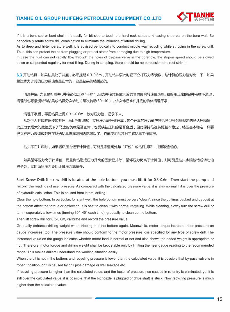
If it is a bent sub or bent shell, it is easily for bit side to touch the hard rock status and casing shoe etc on the bore wall. So periodically rotate screw drill combination to eliminate the influence of lateral drilling.As to deep and hi-temperature well, it is advised periodically to conduct middle way recycling while stripping in the screw drill. Thus, this can protect the bit from plugging or protect stator from damaging due to high temperature.In case the fluid can not rapidly flow through the holes of by-pass valve in the borehole, the strip-in speed should be slowed down or suspended regularly for mud filling. During in stripping, there should be no percussion or direct strip-in.
6.3 开动钻具:如果钻具处于井底,必须提起 0.3-0.6m,开动钻井泵此时记下立杆压力表读数,与计算的压力值对比一下,如果
超过水力计算的压力数值也是正常的,这是钻头侧钻引起的。
清理井底,尤其是打斜井,井底必须足够“干净”,因为井底堆积或沉淀的岩屑影响转速或造斜。最好用正常的钻井液循环清理,
清理时也可慢慢转动钻具或钻具分次转动(每次转动 30~40),依次地把堆在井底的物体清理干净。
清理干净后,再把钻具上提 0.3¬-0.6m,校对压力值,记录下来。
从新下入井底并逐步加井压,马达扭矩增加,立杆压力表压值升高,这个升高的压力值应符合各型号钻具规定的马达压降值,
此压力表增大的数值反映了马达的负载是否正常,也反映钻压加的是否合适,因此保持马达转距基本稳定,钻压基本稳定,只要
把立杆压力表读数限制在所选钻具推浮范围内就可以了。它能使司钻及时了解钻具工作情况。
钻头不在井底时,如果循环压力低于计算值,可能是旁通阀处与“开位”或钻杆损坏,井漏等造成的。
如果循环压力高于计算值,而且侧钻造成压力升高的因素已排除,循环压力仍高于计算值,则可能是钻头水眼被堵或转动轴
被卡死,此时循环压力要比计算压力高得多。
Start Screw Drill: If screw drill is located at the hole bottom, you must lift it for 0.3-0.6m. Then start the pump and
record the readings of riser pressure. As compared with the calculated pressure value, it is also normal if it is over the pressure
of hydraulic calculation. This is caused from lateral drilling.
Clear the hole bottom. In particular, for slant well, the hole bottom must be very “clean”, since the cuttings packed and deposit at
the bottom affect the torque or deflection. It is best to clean it with normal recycling. While cleaning, slowly turn the screw drill or
turn it seperately a few times (turning 30°- 40° each time), gradually to clean up the bottom.
Then lift screw drill for 0.3-0.6m, calibrate and record the pressure value.
Gradually enhance drilling weight when tripping into the bottom again. Meanwhile, motor torque increase, riser pressure on
gauge increases, too. The pressure value should conform to the motor pressure loss specified for any type of screw drill. The
increased value on the gauge indicates whether motor load is normal or not and also shows the added weight is appropriate or
not. Therefore, motor torque and drilling weight shall be kept stable only by limiting the riser gauge reading to the recommended
range. This makes drillers understand the working situation easily.
When the bit is not in the bottom, and recycling pressure is lower than the calculated value, it is possible that by-pass valve is in
“open” position, or it is caused by drill pipe damage or well leakage etc.
If recycling pressure is higher than the calculated value, and the factor of pressure rise caused in re-entry is eliminated, yet it is
still over the calculated value, it is possible that the bit nozzle is plugged or drive shaft is stuck. Now recycling pressure is much
higher than the calculated value.
16
6.4 起钻:钻具起钻过程类似常规操作。起钻时,旁通阀处于开位,允许钻柱中的钻井液泻入环空。但是钻具本身不能排出钻井液,
通常在起钻前在钻柱上部注入一段加重钻井液顺利排出。
Trip Out: Screw drill tripping out is similar to the conventional trip-out. By-pass valve is in open position during stripping out. The
fluid in string is allowed to be drained into annular space. But screw drill can not rapidly discharge the fluid by itself. Usually a
section of heavy fluid is added into the top of string before stripping out, to press the fluid in the pipe smoothly to drain.
6.4.1 在钻具提出到旁通阀位置后,卸下旁通阀口上各部件,先用清水从旁通阀顶部进行冲洗,然后使用木棒或锤柄等将阀芯按下、
松开使其移动无阻。清洗完毕,拧上提升短节,提出钻具。
注:每次起钻后,需要认真检查旁通阀卡簧的变形情况及隔板、筛板的磨损情况,根据变形情况和磨损情况及时调整更换零部件;
还需要检查阀芯滑动的灵活程度。
After screw drill is stripped out to the location of by-pass valve, disassembly the parts on the top of valve holes. Firstly wash it
from the valve top with clean water, and then press down the valve stem with hammer handle or wood stick, loosen it for free
movement. As cleaning is completed, twist lifting sub and trip out the screw drill.
Note: Every time after tripping, there is a need to carefully check the deformation of the by-pass valve snapring and the wear of
baffle plate and screen plate. Replace new parts according to the situation. Also need to check the flexibility of valve assembly
sliding.
6.4.2 装好钻头装卸器,卡牢钻具外壳,反转钻头(俯视反旋)把马达中残存的泥浆从旁通阀排出,卸下钻头。
Install the bit assembly and disassembly device to clamp the shell of screw drill. Turn the bit in counter rotation to drain the
residual mud from by-pass valve, and then disassemble bit.
6.4.3 卸下钻具,从传动轴孔中冲洗钻头,将转动轴水帽及轴承清洗干净,然后平放钻具,正常维护保养待用。若暂停使用或长时
间搁置不用,建议向钻具内注入少量矿物油防锈(注:不允许加入柴油)。
Disassemble screw drill. Wash it from the holes of drive shaft, then clean the cap of drive shaft and bearing. Then place the
screw drill onto a flat place. So as to carry out the usual repair and maintenance. It is advised to inject small quantity of mineral
oil (not allow to add diesel) into screw drill against rusting, if it is not used temporally or if it is stored for longer time.
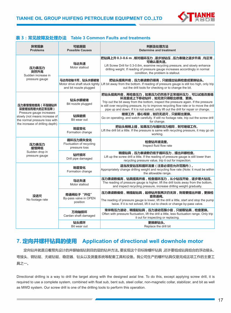
6.5 用钻具井的故障分析:
如前所述,钻井液循环压力变化反映在立杆压力表上,它可以帮助现场人员辩别井底发生的情况和问题,事实证明:正确的判
断可以节省大量起下钻所耗费的时间和成本。综合考虑钻具使用过程中的各种因素,归纳为表 3。供用户参考。
Failure Analysis
As mentioned above, the change of fluid recycling pressure is indicated from the pressure gauge of riser. This may help site
operators identify what is happening in the bottom. In fact, correct identification can save tripping time and cut down the costs.
Complex trouble shooting is shown in Table 3 for customers’ reference.
天合石油集团汇丰石油装备股份有限公司
17
TIANHE OIL GROUP HUIFENG PETROLEUM EQUIPMENT CO.,LTD
异常现象Problems
可能原因Possible Causes
判断及处理方法Determine and treatment
压力表压力突然升高
Sudden increase in pressure gauge
马达失速Motor stallout
把钻具上升 0.3-0.6 m,核对循环压力,逐步加钻压,压力表随之逐步升高,均正常,可确认是失速。
Lift Screw Drill for 0.3-0.6m, examine recycling pressure, and slowly enhance drilling weight. If reading of pressure gauge increases accordingly in normal
condition, the problem is stallout.
马达传动轴卡死,钻头水眼被堵Motor drive shaft stuck tightly
and bit nozzle plugged
把钻头提离井底,压力表读数仍很高,只能提出钻具检查或更换钻头。Lift bit away from the bottom. If reading of pressure gauge is still too high, only trip
out the drill tools for checking or to change the bit.
压力表慢慢地增高(不指随钻井深度增加而增大的正常压降)Pressure gauge increases
slowly (not means increase of the normal pressure loss with the increase of drilling depth)
钻头水眼被堵Bit nozzle plugged
把钻头提离井底,再检查压力,如果压力仍然高于正常循环压力,可以试着改善循环流量或上下移动钻杆,如无效只得取出修理、更换。
Trip out the bit away from the bottom, inspect the pressure again. If the pressure is still over recycling pressure, try to improve recycling flow rate or to move the drill
pipe up and down. If it is not solved, only lift out the drill for repair or change.
钻探磨损Bit wear out
继续工作,细心观察,如仍无进尺,只能取出更换。Go on operating, and watch carefully. If still no footage rate, trip out the screw drill
for change.
地层变化Formation change
把钻头稍稍上提,如果压力与循环压力相同,则可继续工作。Lift the drill bit a little. If the pressure is same with recycling pressure, it may go on
working.
压力表压力缓慢降低
Sudden drop in pressure gauge
循环压力损失变化Fluctuation of recycling
pressure loss
检查钻井液流量。Inspect fluid flow rate
钻杆损坏Drill pipe damaged
稍提钻具,压力表读数仍低于循环压力,提出井眼检查。Lift up the screw drill a little. If the reading of pressure gauge is still lower than
recycling pressure value, trip it out for inspection.
没进尺No footage rate
地层变化Formation change
适当改变钻压和循环流量(注意必须在允许范围内)。Appropriately change drilling weight and recycling flow rate (Note: it must be within
the allowable range.
马达失速Motor stallout
压力表读数偏高,钻具提离井底,检查循环压力,从小钻压开始,逐步增大钻压。The reading of pressure gauge is higher, lift the drill tools away from the bottom,
and inspect recycling pressure, increase drilling weight gradually.
旁通阀处于“开位”By-pass valve in OPEN
position
压力表读数偏低,稍提起钻具,起停钻井泵两次仍无效,则需要提出井眼,更换检查旁通阀。
The reading of pressure gauge is lower, lift the drill a little, start and stop the pump twice. If it is not solved, lift it out to check or change by-pass valve.
万向轴损坏Cardan shaft damaged
常伴有压力波动,稍提起钻具,压力波动范围小些,只能取钻具,检查更换。Often with pressure fluctuation, lift the drill a little, less fluctuation range. Only trip
it out for inspecting or replacing. 钻头损坏
Bit wear out更换新钻头。
Replace the drill bit
表 3:常见故障及处理办法 Table 3 Common Faults and treatments
7. 定向井螺杆钻具的使用 Application of directional well downhole motor 定向钻井就是沿着预先设计的井眼轴线钻到目的层的钻井方法。要实现这个目标除螺杆钻具,还许要组成钻具组合的浮动接头、
弯接头、钢钻铤、无磁钻铤、稳定器、钻头以及测量系统等配套工具和设备。我公司生产的螺杆钻具仅是完成这项工作的主要工
具之一。
Directional drilling is a way to drill the target along with the designed axial line. To do this, except applying screw drill, it is required to use a complete system, combined with float sub, bent sub, steel collar, non-magnetic collar, stabilizer, and bit as well as MWD system. Our screw drill is one of the drilling tools to perform this operation.
18
7.1 我公司生产的螺杆钻具可以满足定向钻井的各项需要。
Our screw drill meets the demands of directional drilling.
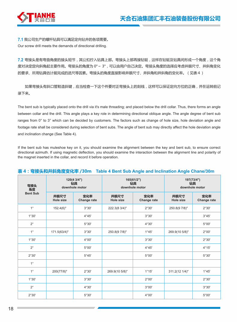
7.2 弯接头是有弯曲角度的接头短节,其公扣拧入钻具上部。弯接头上部再接钻铤,这样在钻铤及钻具间形成一个角度,这个角
度对决定定向斜角起主要作用。弯接头的角度为 0°~ 3°,可以由用户自己决定。弯接头角度的选择应考虑井眼尺寸、井斜角变化
的要求、所用钻具估计能完成的进尺等因素。弯接头的角度直接影响井眼尺寸、井斜角和井斜角的变化率。(见表4)
如果弯接头有斜口管鞋造斜键,应当检查一下这个件要对正弯接头上的刻线,这样可以保证定向方位的正确,并在运转前记
录下来。
The bent sub is typically placed onto the drill via it's male threading; and placed below the drill collar. Thus, there forms an angle
between collar and the drill. This angle plays a key role in determining directional oblique angle. The angle degree of bent sub
ranges from 0° to 3° which can be decided by customers. The factors such as change of hole size, hole deviation angle and
footage rate shall be considered during selection of bent subs. The angle of bent sub may directly affect the hole deviation angle
and inclination change (See Table 4).
If the bent sub has muleshoe key on it, you should examine the alignment between the key and bent sub, to ensure correct directional azimuth. If using magnetic deflection, you should examine the interaction between the alignment line and polarity of the magnet inserted in the collar, and record it before operation.
表 4:弯接头和井斜角度变化率 /30m Table 4 Bent Sub Angle and Inclination Angle Chane/30m
弯接头角度
Bent Sub
120(4 3/4")钻具
downhole motor
165(61/2") 钻具
downhole motor
197(73/4")钻具
downhole motor
井眼尺寸Hole size
变化率Change rate
井眼尺寸Hole size
变化率Change rate
井眼尺寸Hole size
变化率Change rate
1° 152.4(6)" 3°30' 222.3(8 3/4)" 2°30' 250.8(9 7/8)" 2°30'
1°30' 4°45' 3°30' 3°45'
2° 5°30' 4°30' 5°00'
1° 171.5(63/4)" 3°30' 250.8(9 7/8)" 1°45' 269.9(10 5/8)" 2°00'
1°30' 4°00' 3°30' 2°30'
2° 5°00' 4°45' 4°15'
2°30' 5°45' 5°00' 5°30'
1°
1° 200(77/8)" 2°30' 269.9(10 5/8)" 1°15' 311.2(12 1/4)" 1°45'
1°30' 3°30' 2°00' 2°30'
2° 4°30' 3°00' 3°30'
2°30' 5°30' 4°00' 5°00'
天合石油集团汇丰石油装备股份有限公司
19
TIANHE OIL GROUP HUIFENG PETROLEUM EQUIPMENT CO.,LTD
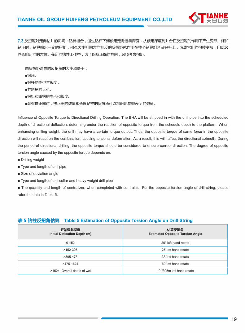
7.3 反扭矩对定向钻井的影响:钻具组合,通过钻杆下到预定定向造斜深度,从预定深度到井台在反扭矩的作用下产生变形。施加
钻压时,钻具输出一定的扭矩,那么大小相同方向相反的反扭矩就作用在整个钻具组合及钻杆上,造成它们的扭转变形,因此必
然影响定向的方位。在定向钻井工作中,为了保持正确的方向,必须考虑扭矩。
由反扭矩造成的反扭角的大小取决于:
■钻压。
■钻杆的类型与长度 。
■井斜角的大小。
■钻铤和重钻的类形和长度。
■装有扶正器时,扶正器的数量和长度钻柱的反扭角可以粗略地参照表 5 的数值。
Influence of Opposite Torque to Directional Drilling Operation: The BHA will be stripped in with the drill pipe into the scheduled
depth of directional deflection, deforming under the reaction of opposite torque from the schedule depth to the platform. When
enhancing drilling weight, the drill may have a certain torque output. Thus, the opposite torque of same force in the opposite
direction will react on the combination, causing torsional deformation. As a result, this will, affect the directional azimuth. During
the period of directional drilling, the opposite torque should be considered to ensure correct direction. The degree of opposite
torsion angle caused by the opposite torque depends on:
■ Drilling weight
■ Type and length of drill pipe
■ Size of deviation angle
■ Type and length of drill collar and heavy weight drill pipe
■ The quantity and length of centralizer, when completed with centralizer For the opposite torsion angle of drill string, please
refer the data in Table-5.
表 5 钻柱反扭角估算 Table 5 Estimation of Opposite Torsion Angle on Drill String
开始造斜深度Initial Deflection Depth (m)
估算反扭角Estimated Opposite Torsion Angle
0-152 20° left hand rotate
>152-305 25°left hand rotate
>305-475 35°left hand rotate
>475-1524 50°left hand rotate
>1524- Overall depth of well 10°/305m left hand rotate
20
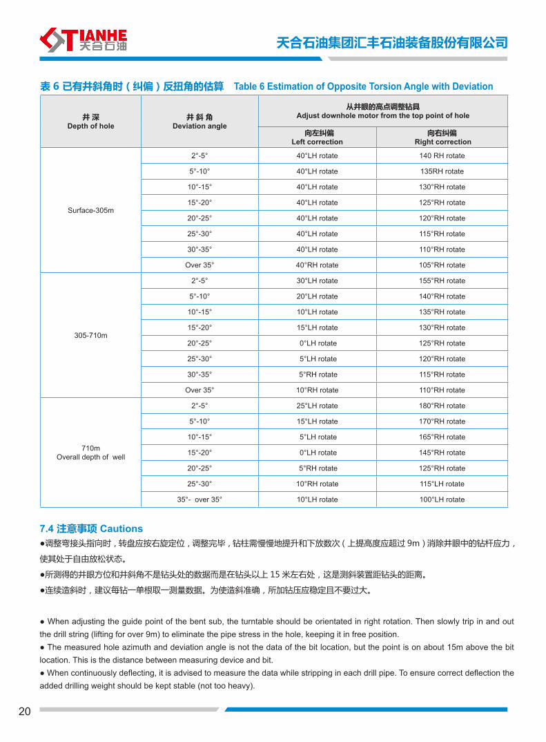
表 6 已有井斜角时(纠偏)反扭角的估算 Table 6 Estimation of Opposite Torsion Angle with Deviation
井 深Depth of hole
井 斜 角Deviation angle
从井眼的高点调整钻具Adjust downhole motor from the top point of hole
向左纠偏Left correction
向右纠偏 Right correction
Surface-305m
2°-5° 40°LH rotate 140 RH rotate
5°-10° 40°LH rotate 135RH rotate
10°-15° 40°LH rotate 130°RH rotate
15°-20° 40°LH rotate 125°RH rotate
20°-25° 40°LH rotate 120°RH rotate
25°-30° 40°LH rotate 115°RH rotate
30°-35° 40°LH rotate 110°RH rotate
Over 35° 40°RH rotate 105°RH rotate
305-710m
2°-5° 30°LH rotate 155°RH rotate
5°-10° 20°LH rotate 140°RH rotate
10°-15° 10°LH rotate 135°RH rotate
15°-20° 15°LH rotate 130°RH rotate
20°-25° 0°LH rotate 125°RH rotate
25°-30° 5°LH rotate 120°RH rotate
30°-35° 5°RH rotate 115°RH rotate
Over 35° 10°RH rotate 110°RH rotate
710mOverall depth of well
2°-5° 25°LH rotate 180°RH rotate
5°-10° 15°LH rotate 170°RH rotate
10°-15° 5°LH rotate 165°RH rotate
15°-20° 0°LH rotate 145°RH rotate
20°-25° 5°RH rotate 125°RH rotate
25°-30° 10°RH rotate 115°LH rotate
35°- over 35° 10°LH rotate 100°LH rotate
7.4 注意事项 Cautions●调整弯接头指向时,转盘应按右旋定位,调整完毕,钻柱需慢慢地提升和下放数次(上提高度应超过 9m)消除井眼中的钻杆应力,
使其处于自由放松状态。
●所测得的井眼方位和井斜角不是钻头处的数据而是在钻头以上 15 米左右处,这是测斜装置距钻头的距离。
●连续造斜时,建议每钻一单根取一测量数据。为使造斜准确,所加钻压应稳定且不要过大。
● When adjusting the guide point of the bent sub, the turntable should be orientated in right rotation. Then slowly trip in and out the drill string (lifting for over 9m) to eliminate the pipe stress in the hole, keeping it in free position.● The measured hole azimuth and deviation angle is not the data of the bit location, but the point is on about 15m above the bit location. This is the distance between measuring device and bit.● When continuously deflecting, it is advised to measure the data while stripping in each drill pipe. To ensure correct deflection the added drilling weight should be kept stable (not too heavy).
天合石油集团汇丰石油装备股份有限公司
21
TIANHE OIL GROUP HUIFENG PETROLEUM EQUIPMENT CO.,LTD
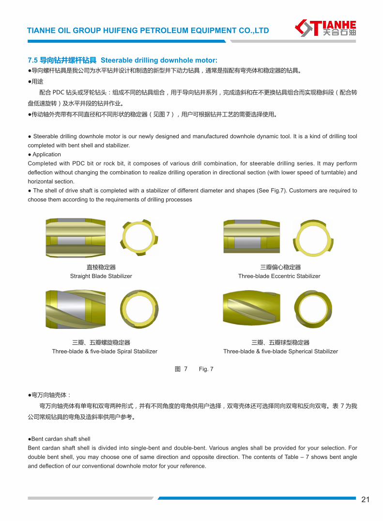
7.5 导向钻井螺杆钻具 Steerable drilling downhole motor:●导向螺杆钻具是我公司为水平钻井设计和制造的新型井下动力钻具,通常是指配有弯壳体和稳定器的钻具。
●用途
配合 PDC 钻头或牙轮钻头:组成不同的钻具组合,用于导向钻井系列,完成造斜和在不更换钻具组合而实现稳斜段(配合转
盘低速旋转)及水平井段的钻井作业。
●传动轴外壳带有不同直径和不同形状的稳定器(见图 7),用户可根据钻井工艺的需要选择使用。
● Steerable drilling downhole motor is our newly designed and manufactured downhole dynamic tool. It is a kind of drilling tool completed with bent shell and stabilizer.● ApplicationCompleted with PDC bit or rock bit, it composes of various drill combination, for steerable drilling series. It may perform deflection without changing the combination to realize drilling operation in directional section (with lower speed of turntable) and horizontal section.● The shell of drive shaft is completed with a stabilizer of different diameter and shapes (See Fig.7). Customers are required to choose them according to the requirements of drilling processes
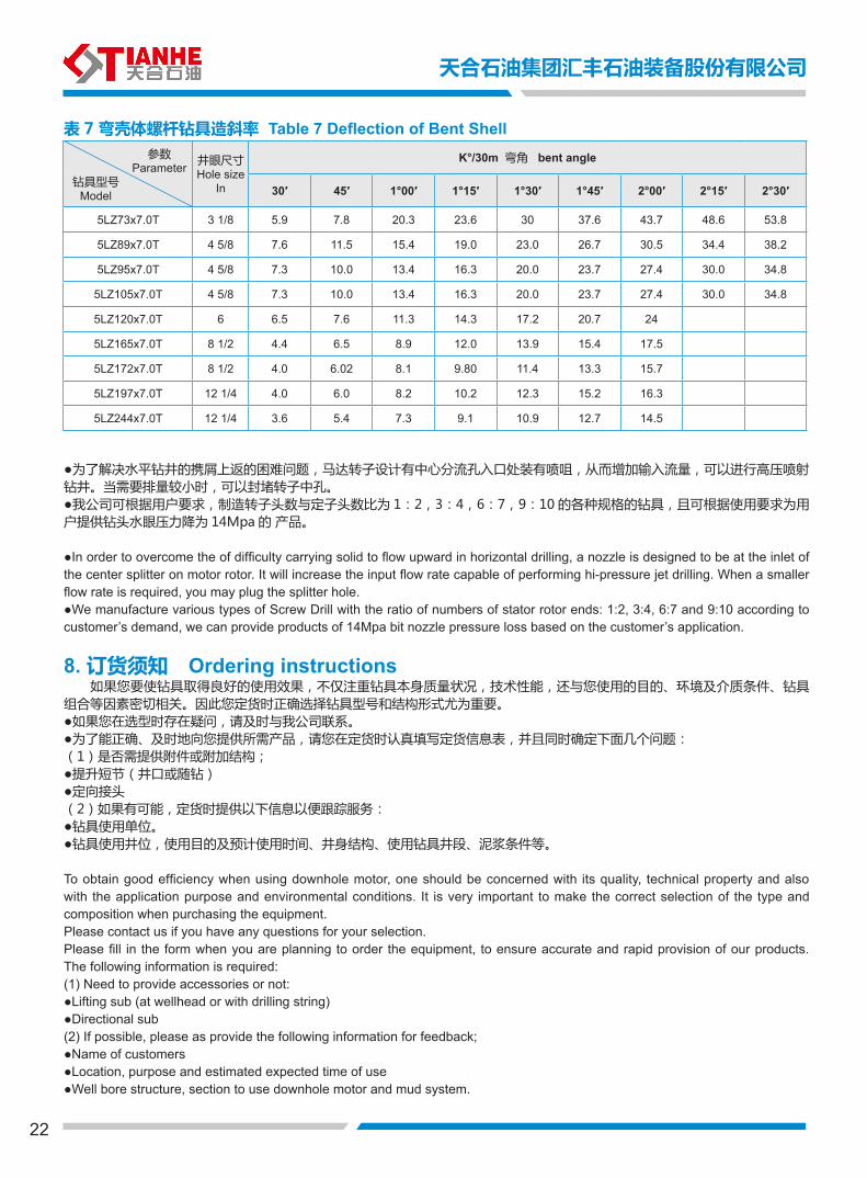
●弯万向轴壳体:
弯万向轴壳体有单弯和双弯两种形式,并有不同角度的弯角供用户选择,双弯壳体还可选择同向双弯和反向双弯。表 7 为我
公司常规钻具的弯角及造斜率供用户参考。
●Bent cardan shaft shellBent cardan shaft shell is divided into single-bent and double-bent. Various angles shall be provided for your selection. For double bent shell, you may choose one of same direction and opposite direction. The contents of Table – 7 shows bent angle and deflection of our conventional downhole motor for your reference.
直棱稳定器
三瓣、五瓣螺旋稳定器
图 7
三瓣偏心稳定器
三瓣、五瓣球型稳定器
Straight Blade Stabilizer Three-blade Eccentric Stabilizer
Three-blade & five-blade Spherical Stabilizer Three-blade & five-blade Spiral Stabilizer
Fig. 7
22
井眼尺寸Hole size
In
K°/30m 弯角 bent angle
30′ 45′ 1°00′ 1°15′ 1°30′ 1°45′ 2°00′ 2°15′ 2°30′
5LZ73x7.0T 3 1/8 5.9 7.8 20.3 23.6 30 37.6 43.7 48.6 53.8
5LZ89x7.0T 4 5/8 7.6 11.5 15.4 19.0 23.0 26.7 30.5 34.4 38.2
5LZ95x7.0T 4 5/8 7.3 10.0 13.4 16.3 20.0 23.7 27.4 30.0 34.8
5LZ105x7.0T 4 5/8 7.3 10.0 13.4 16.3 20.0 23.7 27.4 30.0 34.8
5LZ120x7.0T 6 6.5 7.6 11.3 14.3 17.2 20.7 24
5LZ165x7.0T 8 1/2 4.4 6.5 8.9 12.0 13.9 15.4 17.5
5LZ172x7.0T 8 1/2 4.0 6.02 8.1 9.80 11.4 13.3 15.7
5LZ197x7.0T 12 1/4 4.0 6.0 8.2 10.2 12.3 15.2 16.3
5LZ244x7.0T 12 1/4 3.6 5.4 7.3 9.1 10.9 12.7 14.5
表 7 弯壳体螺杆钻具造斜率 Table 7 Deflection of Bent Shell
钻具型号Model
参数Parameter
●为了解决水平钻井的携屑上返的困难问题,马达转子设计有中心分流孔入口处装有喷咀,从而增加输入流量,可以进行高压喷射钻井。当需要排量较小时,可以封堵转子中孔。●我公司可根据用户要求,制造转子头数与定子头数比为 1:2,3:4,6:7,9:10 的各种规格的钻具,且可根据使用要求为用户提供钻头水眼压力降为 14Mpa 的 产品。
●In order to overcome the of difficulty carrying solid to flow upward in horizontal drilling, a nozzle is designed to be at the inlet of the center splitter on motor rotor. It will increase the input flow rate capable of performing hi-pressure jet drilling. When a smaller flow rate is required, you may plug the splitter hole.●We manufacture various types of Screw Drill with the ratio of numbers of stator rotor ends: 1:2, 3:4, 6:7 and 9:10 according to customer’s demand, we can provide products of 14Mpa bit nozzle pressure loss based on the customer’s application.
8. 订货须知 Ordering instructions 如果您要使钻具取得良好的使用效果,不仅注重钻具本身质量状况,技术性能,还与您使用的目的、环境及介质条件、钻具组合等因素密切相关。因此您定货时正确选择钻具型号和结构形式尤为重要。●如果您在选型时存在疑问,请及时与我公司联系。●为了能正确、及时地向您提供所需产品,请您在定货时认真填写定货信息表,并且同时确定下面几个问题:(1)是否需提供附件或附加结构;●提升短节(井口或随钻)●定向接头(2)如果有可能,定货时提供以下信息以便跟踪服务:●钻具使用单位。●钻具使用井位,使用目的及预计使用时间、井身结构、使用钻具井段、泥浆条件等。
To obtain good efficiency when using downhole motor, one should be concerned with its quality, technical property and also with the application purpose and environmental conditions. It is very important to make the correct selection of the type and composition when purchasing the equipment.Please contact us if you have any questions for your selection.Please fill in the form when you are planning to order the equipment, to ensure accurate and rapid provision of our products. The following information is required:(1) Need to provide accessories or not: ●Lifting sub (at wellhead or with drilling string)●Directional sub(2) If possible, please as provide the following information for feedback;●Name of customers●Location, purpose and estimated expected time of use●Well bore structure, section to use downhole motor and mud system.
天合石油集团汇丰石油装备股份有限公司
23
TIANHE OIL GROUP HUIFENG PETROLEUM EQUIPMENT CO.,LTD
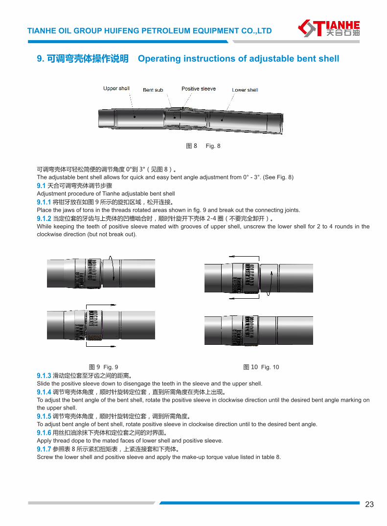
9. 可调弯壳体操作说明 Operating instructions of adjustable bent shell
图 8 Fig. 8
可调弯壳体可轻松简便的调节角度 0°到 3°(见图 8)。The adjustable bent shell allows for quick and easy bent angle adjustment from 0° - 3°. (See Fig. 8)9.1 天合可调弯壳体调节步骤Adjustment procedure of Tianhe adjustable bent shell9.1.1 将钳牙放在如图 9 所示的旋扣区域,松开连接。Place the jaws of tons in the threads rotated areas shown in fig. 9 and break out the connecting joints.9.1.2 当定位套的牙齿与上壳体的凹槽啮合时,顺时针旋开下壳体 2-4 圈(不要完全卸开)。While keeping the teeth of positive sleeve mated with grooves of upper shell, unscrew the lower shell for 2 to 4 rounds in the clockwise direction (but not break out).
图 9 Fig. 9 图 10 Fig. 109.1.3 滑动定位套至牙齿之间的距离。Slide the positive sleeve down to disengage the teeth in the sleeve and the upper shell.9.1.4 调节弯壳体角度,顺时针旋转定位套,直到所需角度在壳体上出现。To adjust the bent angle of the bent shell, rotate the positive sleeve in clockwise direction until the desired bent angle marking on the upper shell. 9.1.5 调节弯壳体角度,顺时针旋转定位套,调到所需角度。To adjust bent angle of bent shell, rotate positive sleeve in clockwise direction until to the desired bent angle. 9.1.6 用丝扣油涂抹下壳体和定位套之间的对界面。Apply thread dope to the mated faces of lower shell and positive sleeve.9.1.7 参照表 8 所示紧扣扭矩表,上紧连接套和下壳体。Screw the lower shell and positive sleeve and apply the make-up torque value listed in table 8.
24
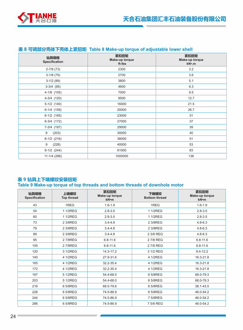
表 8 可调部分壳体下壳体上紧扭矩 Table 8 Make-up torque of adjustable lower shell
钻具规格Specification
上端螺纹Top thread
紧扣扭矩Make-up torque
kN•m
下端螺纹Bottom thread
紧扣扭矩Make-up torque
kN•m43 1REG 1.6-1.9 1REG 1.6-1.9
54 1 1/2REG 2.8-3.5 1 1/2REG 2.8-3.5
60 1 1/2REG 2.8-3.5 1 1/2REG 2.8-3.5
73 2 3/8REG 3.4-4.8 2 3/8REG 4.8-6.3
79 2 3/8REG 3.4-4.8 2 3/8REG 4.8-6.3
89 2 3/8REG 3.4-4.8 2 3/8 REG 4.8-6.3
95 2 7/8REG 6.8-11.6 2 7/8 REG 6.8-11.6
105 2 7/8REG 6.8-11.6 2 7/8 REG 6.8-11.6
120 3 1/2REG 14.3-17.2 3 1/2 REG 9.4-12.2
140 4 1/2REG 27.9-31.6 4 1/2REG 16.3-21.8
165 4 1/2REG 32.2-35.4 4 1/2REG 16.3-21.8
172 4 1/2REG 32.2-35.4 4 1/2REG 16.3-21.8
197 5 1/2REG 54.4-68.0 6 5/8REG 68.0-79.3
203 5 1/2REG 54.4-68.0 6 5/8REG 68.0-79.3
216 6 5/8REG 68.0-79.6 6 5/8REG 38.1-43.5
228 6 5/8REG 74.5-86.9 6 5/8REG 46.0-54.2
244 6 5/8REG 74.5-86.9 7 5/8REG 46.0-54.2
286 6 5/8REG 74.5-86.9 7 5/8 REG 46.0-54.2
钻具规格Specification
紧扣扭矩Make-up torque
ft-lbs
紧扣扭矩Make-up torque
kN•.m2-7/8 (73) 2300 3.2
3-1/8 (79) 2700 3.6
3-1/2 (89) 3800 5.1
3-3/4 (95) 4600 6.3
4-1/8 (105) 7000 9.5
4-3/4 (120) 9500 12.7
5-1/2 (140) 16000 21.5
6-1/4 (159) 20000 26.7
6-1/2 (165) 23000 31
6-3/4 (172) 27000 37
7-3/4 (197) 29000 39
8 (203) 30000 40
8-1/2 (216) 38000 51
9 (228) 40000 53
9-1/2 (244) 61000 83
11-1/4 (286) 1000000 136
表 9 钻具上下端螺纹安装扭矩 Table 9 Make-up torque of top threads and bottom threads of downhole motor
天合石油集团汇丰石油装备股份有限公司
25
TIANHE OIL GROUP HUIFENG PETROLEUM EQUIPMENT CO.,LTD
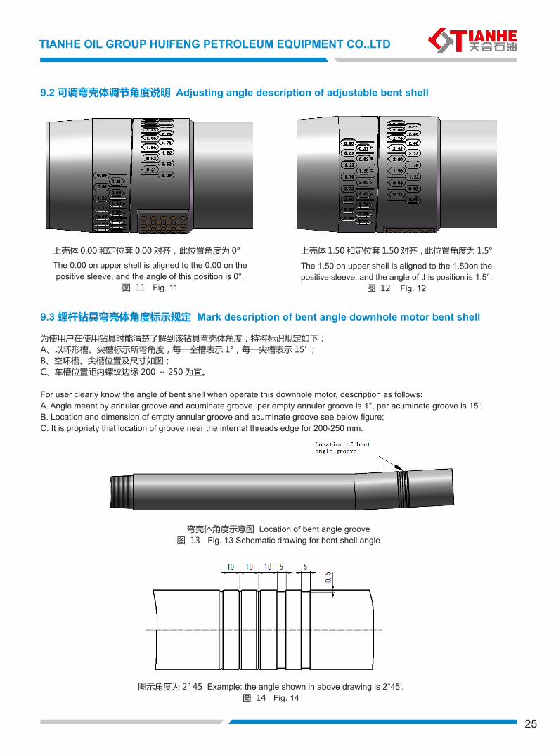
9.2 可调弯壳体调节角度说明 Adjusting angle description of adjustable bent shell
9.3 螺杆钻具弯壳体角度标示规定 Mark description of bent angle downhole motor bent shell
为使用户在使用钻具时能清楚了解到该钻具弯壳体角度,特将标识规定如下:A、以环形槽、尖槽标示所弯角度,每一空槽表示 1°,每一尖槽表示 15' ;B、空环槽、尖槽位置及尺寸如图;C、车槽位置距内螺纹边缘 200 ~ 250 为宜。
For user clearly know the angle of bent shell when operate this downhole motor, description as follows:A. Angle meant by annular groove and acuminate groove, per empty annular groove is 1°, per acuminate groove is 15';B. Location and dimension of empty annular groove and acuminate groove see below figure;C. It is propriety that location of groove near the internal threads edge for 200-250 mm.
弯壳体角度示意图 Location of bent angle groove
图 13 Fig. 13 Schematic drawing for bent shell angle
上壳体 0.00 和定位套 0.00 对齐,此位置角度为 0°
The 0.00 on upper shell is aligned to the 0.00 on the positive sleeve, and the angle of this position is 0°.
图 11 Fig. 11
上壳体 1.50 和定位套 1.50 对齐,此位置角度为 1.5°
The 1.50 on upper shell is aligned to the 1.50on the positive sleeve, and the angle of this position is 1.5°.
图 12 Fig. 12
图示角度为 2° 45 Example: the angle shown in above drawing is 2°45′.图 14 Fig. 14
26
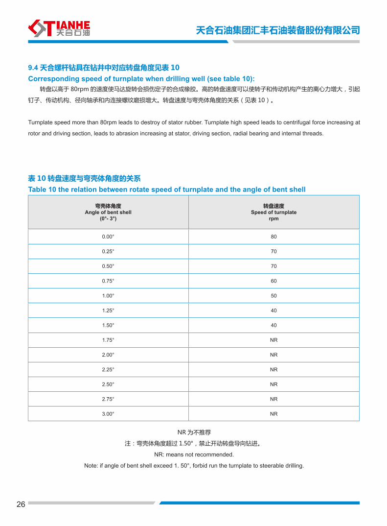
9.4 天合螺杆钻具在钻井中对应转盘角度见表 10 Corresponding speed of turnplate when drilling well (see table 10): 转盘以高于 80rpm 的速度使马达旋转会损伤定子的合成橡胶。高的转盘速度可以使转子和传动机构产生的离心力增大,引起
钉子、传动机构、径向轴承和内连接螺纹磨损增大。转盘速度与弯壳体角度的关系(见表 10)。
Turnplate speed more than 80rpm leads to destroy of stator rubber. Turnplate high speed leads to centrifugal force increasing at
rotor and driving section, leads to abrasion increasing at stator, driving section, radial bearing and internal threads.
表 10 转盘速度与弯壳体角度的关系 Table 10 the relation between rotate speed of turnplate and the angle of bent shell
NR 为不推荐
注:弯壳体角度超过 1.50°,禁止开动转盘导向钻进。
NR: means not recommended.
Note: if angle of bent shell exceed 1. 50°, forbid run the turnplate to steerable drilling.
弯壳体角度Angle of bent shell
(0°- 3°)
转盘速度Speed of turnplate
rpm
0.00° 80
0.25° 70
0.50° 70
0.75° 60
1.00° 50
1.25° 40
1.50° 40
1.75° NR
2.00° NR
2.25° NR
2.50° NR
2.75° NR
3.00° NR
天合石油集团汇丰石油装备股份有限公司
27
TIANHE OIL GROUP HUIFENG PETROLEUM EQUIPMENT CO.,LTD
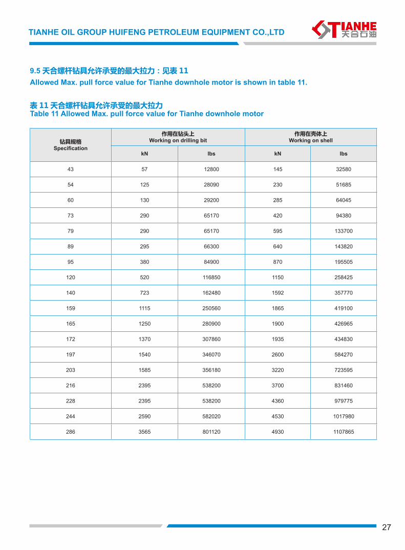
钻具规格Specification
作用在钻头上Working on drilling bit
作用在壳体上Working on shell
kN lbs kN lbs
43 57 12800 145 32580
54 125 28090 230 51685
60 130 29200 285 64045
73 290 65170 420 94380
79 290 65170 595 133700
89 295 66300 640 143820
95 380 84900 870 195505
120 520 116850 1150 258425
140 723 162480 1592 357770
159 1115 250560 1865 419100
165 1250 280900 1900 426965
172 1370 307860 1935 434830
197 1540 346070 2600 584270
203 1585 356180 3220 723595
216 2395 538200 3700 831460
228 2395 538200 4360 979775
244 2590 582020 4530 1017980
286 3565 801120 4930 1107865
9.5 天合螺杆钻具允许承受的最大拉力:见表 11 Allowed Max. pull force value for Tianhe downhole motor is shown in table 11.
表 11 天合螺杆钻具允许承受的最大拉力 Table 11 Allowed Max. pull force value for Tianhe downhole motor
天合石油集团汇丰石油装备股份有限公司
钻具型号Model
外径尺寸OD
钻头尺寸Size of bit
两端连接螺纹Connection 头数
Rotor end
级数stage
排量Flow rate
转速Rotate speed
工作压力降Working pressure loss
输出扭矩Output torque
最大压力降Max. pressure loss
最大扭矩Max. torque
工作钻压Working bit weight
最大钻压Max. bit weight
输出功率Output power
mm in mm in 上端Up
下端Down lpm gpm rpm vpa psl N•m lb-ft vpa psl N•m lb-ft kN lb kN lb kW hp
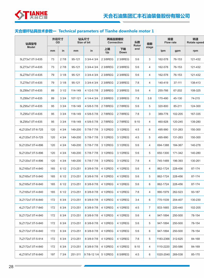
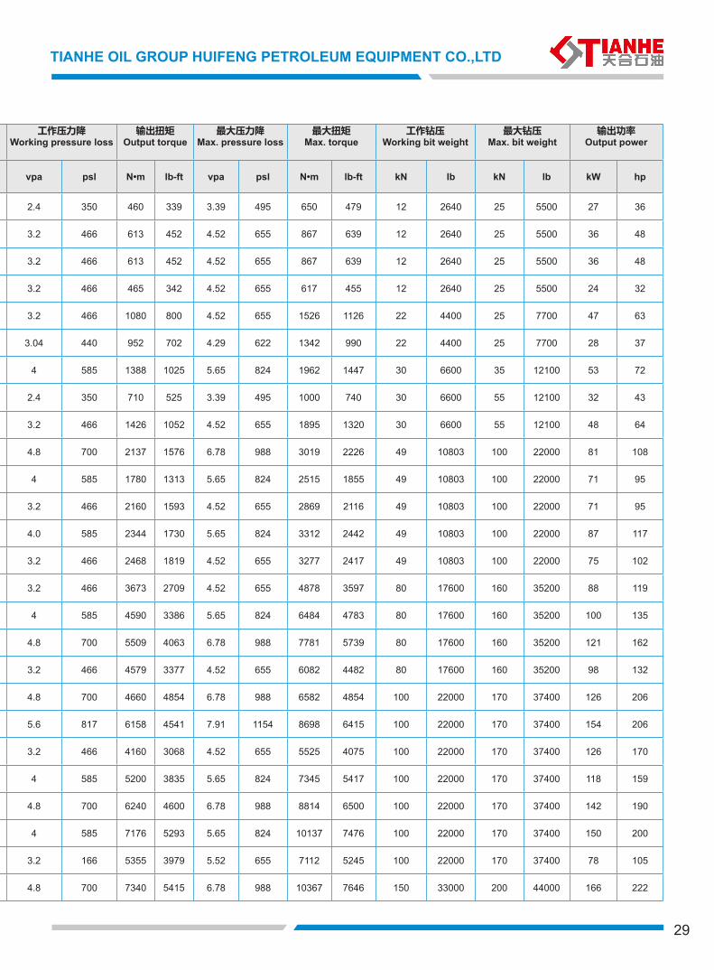
5LZ73x7.0T-3-635 73 2 7/8 95-121 3 3/4-4 3/4 2 3/8REG 2 3/8REG 5:6 3 162-578 76-153 121-432 2.4 350 460 339 3.39 495 650 479 12 2640 25 5500 27 36
5LZ73x7.0T-4-635 73 2 7/8 95-121 3 3/4-4 3/4 2 3/8REG 2 3/8REG 5:6 4 162-578 76-153 121-432 3.2 466 613 452 4.52 655 867 639 12 2640 25 5500 36 48
5LZ79x7.0T-4-635 79 3 1/8 95-121 3 3/4-4 3/4 2 3/8REG 2 3/8REG 5:6 4 162-578 76-153 121-432 3.2 466 613 452 4.52 655 867 639 12 2640 25 5500 36 48
7LZ79x7.0T-4-635 79 3 1/8 95-121 3 3/4-4 3/4 2 3/8REG 2 3/8REG 7:8 4 140-419 37-111 138-413 3.2 466 465 342 4.52 655 617 455 12 2640 25 5500 24 32
5LZ89x7.0T-4-635 89 3 1/2 114-149 4 1/2-5 7/8 2 3/8REG 2 3/8REG 5:6 4 255-766 67-202 108-325 3.2 466 1080 800 4.52 655 1526 1126 22 4400 25 7700 47 63
7LZ89x7.0T-4-635 89 3 3/4 107-121 4 1/4-4 3/4 2 3/8REG 2 3/8REG 7:8 3.8 170-490 45-130 74-215 3.04 440 952 702 4.29 622 1342 990 22 4400 25 7700 28 37
5LZ95x7.0T-4-635 95 3 3/4 118-149 4 5/8-5 7/8 2 7/8REG 2 7/8REG 5:6 5 320-800 85-211 124-300 4 585 1388 1025 5.65 824 1962 1447 30 6600 35 12100 53 72
7LZ95x7.0T-4-635 95 3 3/4 118-149 4 5/8-5 7/8 2 7/8REG 2 7/8REG 7:8 3 389-778 102-205 167-335 2.4 350 710 525 3.39 495 1000 740 30 6600 55 12100 32 43
9LZ95x7.0T-4-635 95 3 3/4 118-149 4 5/8-5 7/8 2 7/8REG 2 7/8REG 9:10 4 460-928 120-245 139-280 3.2 466 1426 1052 4.52 655 1895 1320 30 6600 55 12100 48 64
4LZ120x7.0T-6-725 120 4 3/4 149-200 5 7/8-7 7/8 3 1/2REG 3 1/2REG 4:5 6 495-990 131-263 150-300 4.8 700 2137 1576 6.78 988 3019 2226 49 10803 100 22000 81 108
4LZ120x7.0T-5-725 120 4 3/4 149-200 5 7/8-7 7/8 3 1/2REG 3 1/2REG 4:5 5 495-990 131-263 150-300 4 585 1780 1313 5.65 824 2515 1855 49 10803 100 22000 71 95
5LZ120x7.0T-4-896 120 4 3/4 149-200 5 7/8-7 7/8 3 1/2REG 3 1/2REG 5:6 4 694-1388 184-367 140-278 3.2 466 2160 1593 4.52 655 2869 2116 49 10803 100 22000 71 95
5LZ120x7.0T-5-896 120 4 3/4 149-200 5 7/8-7 7/8 3 1/2REG 3 1/2REG 5:6 5 650-1300 171-342 140-280 4.0 585 2344 1730 5.65 824 3312 2442 49 10803 100 22000 87 117
7LZ120x7.0T-4-896 120 4 3/4 149-200 5 7/8-7 7/8 3 1/2REG 3 1/2REG 7:8 4 745-1489 196-393 130-261 3.2 466 2468 1819 4.52 655 3277 2417 49 10803 100 22000 75 102
5LZ165x7.0T-4-840 165 6 1/2 213-251 8 3/8-9 7/8 4 1/2REG 4 1/2REG 5:6 4 862-1724 228-456 87-174 3.2 466 3673 2709 4.52 655 4878 3597 80 17600 160 35200 88 119
5LZ165x7.0T-5-840 165 6 1/2 213-251 8 3/8-9 7/8 4 1/2REG 4 1/2REG 5:6 5 862-1724 228-456 87-174 4 585 4590 3386 5.65 824 6484 4783 80 17600 160 35200 100 135
5LZ165x7.0T-6-840 165 6 1/2 213-251 8 3/8-9 7/8 4 1/2REG 4 1/2REG 5:6 6 862-1724 228-456 87-174 4.8 700 5509 4063 6.78 988 7781 5739 80 17600 160 35200 121 162
7LZ165x7.0T-4-840 165 6 1/2 213-251 8 3/8-9 7/8 4 1/2REG 4 1/2REG 7:8 4 990-1979 262-523 93-187 3.2 466 4579 3377 4.52 655 6082 4482 80 17600 160 35200 98 132
3LZ172x7.0T-6-840 172 6 3/4 213-251 8 3/8-9 7/8 4 1/2REG 4 1/2REG 3:4 6 770-1539 204-407 130-230 4.8 700 4660 4854 6.78 988 6582 4854 100 22000 170 37400 126 206
4LZ172x7.0T-7-840 172 6 3/4 213-251 8 3/8-9 7/8 4 1/2REG 4 1/2REG 4:5 7 833-1665 220-440 102-205 5.6 817 6158 4541 7.91 1154 8698 6415 100 22000 170 37400 154 206
5LZ172x7.0T-4-840 172 6 3/4 213-251 8 3/8-9 7/8 4 1/2REG 4 1/2REG 5:6 4 947-1894 250-500 78-154 3.2 466 4160 3068 4.52 655 5525 4075 100 22000 170 37400 126 170
5LZ172x7.0T-5-840 172 6 3/4 213-251 8 3/8-9 7/8 4 1/2REG 4 1/2REG 5:6 5 947-1894 250-500 78-154 4 585 5200 3835 5.65 824 7345 5417 100 22000 170 37400 118 159
5LZ172x7.0T-6-840 172 6 3/4 213-251 8 3/8-9 7/8 4 1/2REG 4 1/2REG 5:6 6 947-1894 250-500 78-154 4.8 700 6240 4600 6.78 988 8814 6500 100 22000 170 37400 142 190
7LZ172x7.0T-5-914 172 6 3/4 213-251 8 3/8-9 7/8 4 1/2REG 4 1/2REG 7:8 5 1183-2366 312-625 84-168 4 585 7176 5293 5.65 824 10137 7476 100 22000 170 37400 150 200
9LZ172x7.0T-4-840 172 6 3/4 213-251 8 3/8-9 7/8 4 1/2REG 4 1/2REG 9:10 4 1110-2220 293-586 84-169 3.2 166 5355 3979 5.52 655 7112 5245 100 22000 170 37400 78 105
4LZ197x7.0T-6-840 197 7 3/4 251-311 9 7/8-12 1/4 5 1/2REG 6 5/8REG 4:5 6 1020-2040 269-538 85-170 4.8 700 7340 5415 6.78 988 10367 7646 150 33000 200 44000 166 222
天合螺杆钻具技术参数一 Technical parameters of Tianhe downhole motor 1
28
29
TIANHE OIL GROUP HUIFENG PETROLEUM EQUIPMENT CO.,LTD
钻具型号Model
外径尺寸OD
钻头尺寸Size of bit
两端连接螺纹Connection 头数
Rotor end
级数stage
排量Flow rate
转速Rotate speed
工作压力降Working pressure loss
输出扭矩Output torque
最大压力降Max. pressure loss
最大扭矩Max. torque
工作钻压Working bit weight
最大钻压Max. bit weight
输出功率Output power
mm in mm in 上端Up
下端Down lpm gpm rpm vpa psl N•m lb-ft vpa psl N•m lb-ft kN lb kN lb kW hp
5LZ73x7.0T-3-635 73 2 7/8 95-121 3 3/4-4 3/4 2 3/8REG 2 3/8REG 5:6 3 162-578 76-153 121-432 2.4 350 460 339 3.39 495 650 479 12 2640 25 5500 27 36
5LZ73x7.0T-4-635 73 2 7/8 95-121 3 3/4-4 3/4 2 3/8REG 2 3/8REG 5:6 4 162-578 76-153 121-432 3.2 466 613 452 4.52 655 867 639 12 2640 25 5500 36 48
5LZ79x7.0T-4-635 79 3 1/8 95-121 3 3/4-4 3/4 2 3/8REG 2 3/8REG 5:6 4 162-578 76-153 121-432 3.2 466 613 452 4.52 655 867 639 12 2640 25 5500 36 48
7LZ79x7.0T-4-635 79 3 1/8 95-121 3 3/4-4 3/4 2 3/8REG 2 3/8REG 7:8 4 140-419 37-111 138-413 3.2 466 465 342 4.52 655 617 455 12 2640 25 5500 24 32
5LZ89x7.0T-4-635 89 3 1/2 114-149 4 1/2-5 7/8 2 3/8REG 2 3/8REG 5:6 4 255-766 67-202 108-325 3.2 466 1080 800 4.52 655 1526 1126 22 4400 25 7700 47 63
7LZ89x7.0T-4-635 89 3 3/4 107-121 4 1/4-4 3/4 2 3/8REG 2 3/8REG 7:8 3.8 170-490 45-130 74-215 3.04 440 952 702 4.29 622 1342 990 22 4400 25 7700 28 37
5LZ95x7.0T-4-635 95 3 3/4 118-149 4 5/8-5 7/8 2 7/8REG 2 7/8REG 5:6 5 320-800 85-211 124-300 4 585 1388 1025 5.65 824 1962 1447 30 6600 35 12100 53 72
7LZ95x7.0T-4-635 95 3 3/4 118-149 4 5/8-5 7/8 2 7/8REG 2 7/8REG 7:8 3 389-778 102-205 167-335 2.4 350 710 525 3.39 495 1000 740 30 6600 55 12100 32 43
9LZ95x7.0T-4-635 95 3 3/4 118-149 4 5/8-5 7/8 2 7/8REG 2 7/8REG 9:10 4 460-928 120-245 139-280 3.2 466 1426 1052 4.52 655 1895 1320 30 6600 55 12100 48 64
4LZ120x7.0T-6-725 120 4 3/4 149-200 5 7/8-7 7/8 3 1/2REG 3 1/2REG 4:5 6 495-990 131-263 150-300 4.8 700 2137 1576 6.78 988 3019 2226 49 10803 100 22000 81 108
4LZ120x7.0T-5-725 120 4 3/4 149-200 5 7/8-7 7/8 3 1/2REG 3 1/2REG 4:5 5 495-990 131-263 150-300 4 585 1780 1313 5.65 824 2515 1855 49 10803 100 22000 71 95
5LZ120x7.0T-4-896 120 4 3/4 149-200 5 7/8-7 7/8 3 1/2REG 3 1/2REG 5:6 4 694-1388 184-367 140-278 3.2 466 2160 1593 4.52 655 2869 2116 49 10803 100 22000 71 95
5LZ120x7.0T-5-896 120 4 3/4 149-200 5 7/8-7 7/8 3 1/2REG 3 1/2REG 5:6 5 650-1300 171-342 140-280 4.0 585 2344 1730 5.65 824 3312 2442 49 10803 100 22000 87 117
7LZ120x7.0T-4-896 120 4 3/4 149-200 5 7/8-7 7/8 3 1/2REG 3 1/2REG 7:8 4 745-1489 196-393 130-261 3.2 466 2468 1819 4.52 655 3277 2417 49 10803 100 22000 75 102
5LZ165x7.0T-4-840 165 6 1/2 213-251 8 3/8-9 7/8 4 1/2REG 4 1/2REG 5:6 4 862-1724 228-456 87-174 3.2 466 3673 2709 4.52 655 4878 3597 80 17600 160 35200 88 119
5LZ165x7.0T-5-840 165 6 1/2 213-251 8 3/8-9 7/8 4 1/2REG 4 1/2REG 5:6 5 862-1724 228-456 87-174 4 585 4590 3386 5.65 824 6484 4783 80 17600 160 35200 100 135
5LZ165x7.0T-6-840 165 6 1/2 213-251 8 3/8-9 7/8 4 1/2REG 4 1/2REG 5:6 6 862-1724 228-456 87-174 4.8 700 5509 4063 6.78 988 7781 5739 80 17600 160 35200 121 162
7LZ165x7.0T-4-840 165 6 1/2 213-251 8 3/8-9 7/8 4 1/2REG 4 1/2REG 7:8 4 990-1979 262-523 93-187 3.2 466 4579 3377 4.52 655 6082 4482 80 17600 160 35200 98 132
3LZ172x7.0T-6-840 172 6 3/4 213-251 8 3/8-9 7/8 4 1/2REG 4 1/2REG 3:4 6 770-1539 204-407 130-230 4.8 700 4660 4854 6.78 988 6582 4854 100 22000 170 37400 126 206
4LZ172x7.0T-7-840 172 6 3/4 213-251 8 3/8-9 7/8 4 1/2REG 4 1/2REG 4:5 7 833-1665 220-440 102-205 5.6 817 6158 4541 7.91 1154 8698 6415 100 22000 170 37400 154 206
5LZ172x7.0T-4-840 172 6 3/4 213-251 8 3/8-9 7/8 4 1/2REG 4 1/2REG 5:6 4 947-1894 250-500 78-154 3.2 466 4160 3068 4.52 655 5525 4075 100 22000 170 37400 126 170
5LZ172x7.0T-5-840 172 6 3/4 213-251 8 3/8-9 7/8 4 1/2REG 4 1/2REG 5:6 5 947-1894 250-500 78-154 4 585 5200 3835 5.65 824 7345 5417 100 22000 170 37400 118 159
5LZ172x7.0T-6-840 172 6 3/4 213-251 8 3/8-9 7/8 4 1/2REG 4 1/2REG 5:6 6 947-1894 250-500 78-154 4.8 700 6240 4600 6.78 988 8814 6500 100 22000 170 37400 142 190
7LZ172x7.0T-5-914 172 6 3/4 213-251 8 3/8-9 7/8 4 1/2REG 4 1/2REG 7:8 5 1183-2366 312-625 84-168 4 585 7176 5293 5.65 824 10137 7476 100 22000 170 37400 150 200
9LZ172x7.0T-4-840 172 6 3/4 213-251 8 3/8-9 7/8 4 1/2REG 4 1/2REG 9:10 4 1110-2220 293-586 84-169 3.2 166 5355 3979 5.52 655 7112 5245 100 22000 170 37400 78 105
4LZ197x7.0T-6-840 197 7 3/4 251-311 9 7/8-12 1/4 5 1/2REG 6 5/8REG 4:5 6 1020-2040 269-538 85-170 4.8 700 7340 5415 6.78 988 10367 7646 150 33000 200 44000 166 222
30
天合石油集团汇丰石油装备股份有限公司
钻具型号Model
外径尺寸OD
钻头尺寸Size of bit
两端连接螺纹Connection 头数
Rotor end
级数stage
排量Flow rate
转速Rotate speed
工作压力降Working pressure loss
输出扭矩Output torque
最大压力降Max. pressure loss
最大扭矩Max. torque
工作钻压Working bit weight
最大钻压Max. bit weight
输出功率Output power
mm in mm in 上端Up
下端Down lpm gpm rpm vpa psl N•m lb-ft vpa psl N•m lb-ft kN lb kN lb kW hp
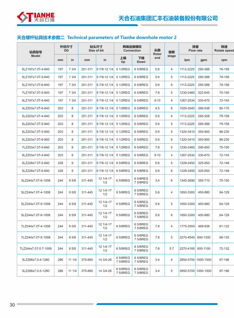
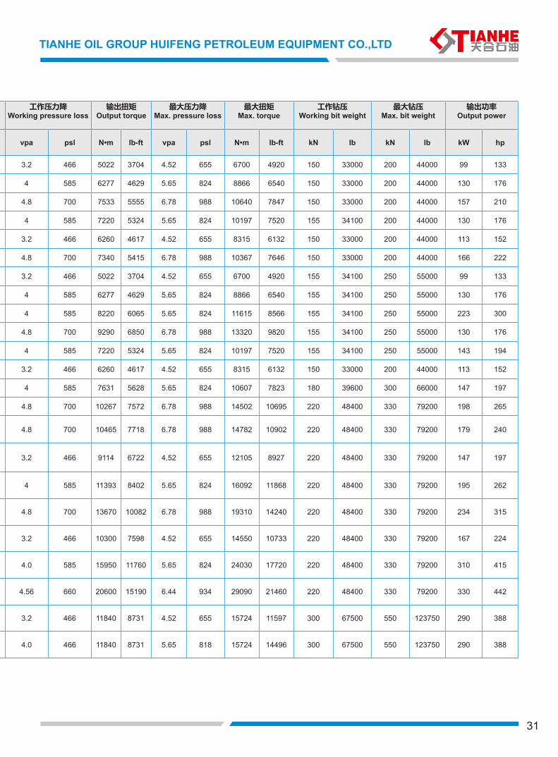
5LZ197x7.0T-4-840 197 7 3/4 251-311 9 7/8-12 1/4 5 1/2REG 6 5/8REG 5:6 4 1113-2225 295-588 79-158 3.2 466 5022 3704 4.52 655 6700 4920 150 33000 200 44000 99 133
5LZ197x7.0T-5-840 197 7 3/4 251-311 9 7/8-12 1/4 5 1/2REG 6 5/8REG 5:6 5 1113-2225 295-588 79-158 4 585 6277 4629 5.65 824 8866 6540 150 33000 200 44000 130 176
5LZ197x7.0T-6-840 197 7 3/4 251-311 9 7/8-12 1/4 5 1/2REG 6 5/8REG 5:6 6 1113-2225 295-588 79-158 4.8 700 7533 5555 6.78 988 10640 7847 150 33000 200 44000 157 210
7LZ197x7.0T-5-840 197 7 3/4 251-311 9 7/8-12 1/4 5 1/2REG 6 5/8REG 7:8 5 1230-2460 322-645 75-150 4 585 7220 5324 5.65 824 10197 7520 155 34100 200 44000 130 176
9LZ197x7.0T-4-840 197 7 3/4 251-311 9 7/8-12 1/4 5 1/2REG 6 5/8REG 9:10 4 1267-2534 335-670 72-145 3.2 466 6260 4617 4.52 655 8315 6132 150 33000 200 44000 113 152
4LZ203x7.0T-6-840 203 8 251-311 9 7/8-12 1/4 5 1/2REG 6 5/8REG 4:5 6 1020-2040 269-538 85-170 4.8 700 7340 5415 6.78 988 10367 7646 150 33000 200 44000 166 222
5LZ203x7.0T-4-840 203 8 251-311 9 7/8-12 1/4 5 1/2REG 6 5/8REG 5:6 4 1113-2225 295-558 79-158 3.2 466 5022 3704 4.52 655 6700 4920 155 34100 250 55000 99 133
5LZ203x7.0T-5-840 203 8 251-311 9 7/8-12 1/4 5 1/2REG 6 5/8REG 5:6 5 1113-2225 295-588 79-158 4 585 6277 4629 5.65 824 8866 6540 155 34100 250 55000 130 176
5LZ203x7.0T-5-900 203 8 251-311 9 7/8-12 1/4 5 1/2REG 6 5/8REG 5:6 5 1320-3410 350-900 86-230 4 585 8220 6065 5.65 824 11615 8566 155 34100 250 55000 223 300
5LZ203x7.0T-6-900 203 8 251-311 9 7/8-12 1/4 5 1/2REG 6 5/8REG 5:6 6 1320-3410 350-900 86-230 4.8 700 9290 6850 6.78 988 13320 9820 155 34100 250 55000 130 176
7LZ203x7.0T-5-840 203 8 251-311 9 7/8-12 1/4 5 1/2REG 6 5/8REG 7:8 5 1230-2460 295-650 75-150 4 585 7220 5324 5.65 824 10197 7520 155 34100 250 55000 143 194
9LZ203x7.0T-4-840 203 8 251-311 9 7/8-12 1/4 5 1/2REG 6 5/8REG 9:10 4 1267-2534 335-670 72-145 3.2 466 6260 4617 4.52 655 8315 6132 150 33000 200 44000 113 152
5LZ228x7.0T-5-840 228 9 251-311 9 7/8-12 1/4 6 5/8REG 6 5/8REG 5:6 5 1228-2455 325-650 72-148 4 585 7631 5628 5.65 824 10607 7823 180 39600 300 66000 147 197
5LZ228x7.0T-6-840 228 9 251-311 9 7/8-12 1/4 6 5/8REG 6 5/8REG 5:6 6 1228-2455 325-650 72-148 4.8 700 10267 7572 6.78 988 14502 10695 220 48400 330 79200 198 265
3LZ244x7.0T-6-1008 244 9 5/8 311-445 12 1/4-17 1/2 6 5/8REG 6 5/8REG
7 5/8REG 3:4 6 1345-2690 355-710 75-150 4.8 700 10465 7718 6.78 988 14782 10902 220 48400 330 79200 179 240
5LZ244x7.0T-4-1008 244 9 5/8 311-445 12 1/4-17 1/2 6 5/8REG 6 5/8REG
7 5/8REG 5:6 4 1650-3300 450-880 64-129 3.2 466 9114 6722 4.52 655 12105 8927 220 48400 330 79200 147 197
5LZ244x7.0T-5-1008 244 9 5/8 311-445 12 1/4-17 1/2 6 5/8REG 6 5/8REG
7 5/8REG 5:6 5 1650-3300 450-880 64-129 4 585 11393 8402 5.65 824 16092 11868 220 48400 330 79200 195 262
5LZ244x7.0T-6-1008 244 9 5/8 311-445 12 1/4-17 1/2 6 5/8REG 6 5/8REG
7 5/8REG 5:6 6 1650-3300 450-880 64-129 4.8 700 13670 10082 6.78 988 19310 14240 220 48400 330 79200 234 315
7LZ244x7.0T-4-1008 244 9 5/8 311-445 12 1/4-17 1/2 6 5/8REG 6 5/8REG
7 5/8REG 7:8 4 1775-3550 469-938 61-122 3.2 466 10300 7598 4.52 655 14550 10733 220 48400 330 79200 167 224
7LZ244x7.0T-5-1008 244 9 5/8 311-445 12 1/4-17 1/2 6 5/8REG 6 5/8REG
7 5/8REG 7:8 5 2270-4540 600-1200 68-135 4.0 585 15950 11760 5.65 824 24030 17720 220 48400 330 79200 310 415
7LZ244x7.0T-5.7-1008 244 9 5/8 311-445 12 1/4-17 1/2 6 5/8REG 6 5/8REG
7 5/8REG 7:8 5.7 2270-4160 600-1100 72-132 4.56 660 20600 15190 6.44 934 29090 21460 220 48400 330 79200 330 442
3LZ286x7.0-4-1280 286 11 1/4 375-660 14 3/4-26 6 5/8REG7 5/8REG
6 5/8REG7 5/8REG 3:4 4 2850-5700 1000-1500 97-196 3.2 466 11840 8731 4.52 655 15724 11597 300 67500 550 123750 290 388
3LZ286x7.0-5-1280 286 11 1/4 375-660 14 3/4-26 6 5/8REG7 5/8REG
6 5/8REG7 5/8REG 3:4 5 2850-5700 1000-1500 97-196 4.0 466 11840 8731 5.65 818 15724 14496 300 67500 550 123750 290 388
天合螺杆钻具技术参数二 Technical parameters of Tianhe downhole motor 2
31
TIANHE OIL GROUP HUIFENG PETROLEUM EQUIPMENT CO.,LTD
钻具型号Model
外径尺寸OD
钻头尺寸Size of bit
两端连接螺纹Connection 头数
Rotor end
级数stage
排量Flow rate
转速Rotate speed
工作压力降Working pressure loss
输出扭矩Output torque
最大压力降Max. pressure loss
最大扭矩Max. torque
工作钻压Working bit weight
最大钻压Max. bit weight
输出功率Output power
mm in mm in 上端Up
下端Down lpm gpm rpm vpa psl N•m lb-ft vpa psl N•m lb-ft kN lb kN lb kW hp
5LZ197x7.0T-4-840 197 7 3/4 251-311 9 7/8-12 1/4 5 1/2REG 6 5/8REG 5:6 4 1113-2225 295-588 79-158 3.2 466 5022 3704 4.52 655 6700 4920 150 33000 200 44000 99 133
5LZ197x7.0T-5-840 197 7 3/4 251-311 9 7/8-12 1/4 5 1/2REG 6 5/8REG 5:6 5 1113-2225 295-588 79-158 4 585 6277 4629 5.65 824 8866 6540 150 33000 200 44000 130 176
5LZ197x7.0T-6-840 197 7 3/4 251-311 9 7/8-12 1/4 5 1/2REG 6 5/8REG 5:6 6 1113-2225 295-588 79-158 4.8 700 7533 5555 6.78 988 10640 7847 150 33000 200 44000 157 210
7LZ197x7.0T-5-840 197 7 3/4 251-311 9 7/8-12 1/4 5 1/2REG 6 5/8REG 7:8 5 1230-2460 322-645 75-150 4 585 7220 5324 5.65 824 10197 7520 155 34100 200 44000 130 176
9LZ197x7.0T-4-840 197 7 3/4 251-311 9 7/8-12 1/4 5 1/2REG 6 5/8REG 9:10 4 1267-2534 335-670 72-145 3.2 466 6260 4617 4.52 655 8315 6132 150 33000 200 44000 113 152
4LZ203x7.0T-6-840 203 8 251-311 9 7/8-12 1/4 5 1/2REG 6 5/8REG 4:5 6 1020-2040 269-538 85-170 4.8 700 7340 5415 6.78 988 10367 7646 150 33000 200 44000 166 222
5LZ203x7.0T-4-840 203 8 251-311 9 7/8-12 1/4 5 1/2REG 6 5/8REG 5:6 4 1113-2225 295-558 79-158 3.2 466 5022 3704 4.52 655 6700 4920 155 34100 250 55000 99 133
5LZ203x7.0T-5-840 203 8 251-311 9 7/8-12 1/4 5 1/2REG 6 5/8REG 5:6 5 1113-2225 295-588 79-158 4 585 6277 4629 5.65 824 8866 6540 155 34100 250 55000 130 176
5LZ203x7.0T-5-900 203 8 251-311 9 7/8-12 1/4 5 1/2REG 6 5/8REG 5:6 5 1320-3410 350-900 86-230 4 585 8220 6065 5.65 824 11615 8566 155 34100 250 55000 223 300
5LZ203x7.0T-6-900 203 8 251-311 9 7/8-12 1/4 5 1/2REG 6 5/8REG 5:6 6 1320-3410 350-900 86-230 4.8 700 9290 6850 6.78 988 13320 9820 155 34100 250 55000 130 176
7LZ203x7.0T-5-840 203 8 251-311 9 7/8-12 1/4 5 1/2REG 6 5/8REG 7:8 5 1230-2460 295-650 75-150 4 585 7220 5324 5.65 824 10197 7520 155 34100 250 55000 143 194
9LZ203x7.0T-4-840 203 8 251-311 9 7/8-12 1/4 5 1/2REG 6 5/8REG 9:10 4 1267-2534 335-670 72-145 3.2 466 6260 4617 4.52 655 8315 6132 150 33000 200 44000 113 152
5LZ228x7.0T-5-840 228 9 251-311 9 7/8-12 1/4 6 5/8REG 6 5/8REG 5:6 5 1228-2455 325-650 72-148 4 585 7631 5628 5.65 824 10607 7823 180 39600 300 66000 147 197
5LZ228x7.0T-6-840 228 9 251-311 9 7/8-12 1/4 6 5/8REG 6 5/8REG 5:6 6 1228-2455 325-650 72-148 4.8 700 10267 7572 6.78 988 14502 10695 220 48400 330 79200 198 265
3LZ244x7.0T-6-1008 244 9 5/8 311-445 12 1/4-17 1/2 6 5/8REG 6 5/8REG
7 5/8REG 3:4 6 1345-2690 355-710 75-150 4.8 700 10465 7718 6.78 988 14782 10902 220 48400 330 79200 179 240
5LZ244x7.0T-4-1008 244 9 5/8 311-445 12 1/4-17 1/2 6 5/8REG 6 5/8REG
7 5/8REG 5:6 4 1650-3300 450-880 64-129 3.2 466 9114 6722 4.52 655 12105 8927 220 48400 330 79200 147 197
5LZ244x7.0T-5-1008 244 9 5/8 311-445 12 1/4-17 1/2 6 5/8REG 6 5/8REG
7 5/8REG 5:6 5 1650-3300 450-880 64-129 4 585 11393 8402 5.65 824 16092 11868 220 48400 330 79200 195 262
5LZ244x7.0T-6-1008 244 9 5/8 311-445 12 1/4-17 1/2 6 5/8REG 6 5/8REG
7 5/8REG 5:6 6 1650-3300 450-880 64-129 4.8 700 13670 10082 6.78 988 19310 14240 220 48400 330 79200 234 315
7LZ244x7.0T-4-1008 244 9 5/8 311-445 12 1/4-17 1/2 6 5/8REG 6 5/8REG
7 5/8REG 7:8 4 1775-3550 469-938 61-122 3.2 466 10300 7598 4.52 655 14550 10733 220 48400 330 79200 167 224
7LZ244x7.0T-5-1008 244 9 5/8 311-445 12 1/4-17 1/2 6 5/8REG 6 5/8REG
7 5/8REG 7:8 5 2270-4540 600-1200 68-135 4.0 585 15950 11760 5.65 824 24030 17720 220 48400 330 79200 310 415
7LZ244x7.0T-5.7-1008 244 9 5/8 311-445 12 1/4-17 1/2 6 5/8REG 6 5/8REG
7 5/8REG 7:8 5.7 2270-4160 600-1100 72-132 4.56 660 20600 15190 6.44 934 29090 21460 220 48400 330 79200 330 442
3LZ286x7.0-4-1280 286 11 1/4 375-660 14 3/4-26 6 5/8REG7 5/8REG
6 5/8REG7 5/8REG 3:4 4 2850-5700 1000-1500 97-196 3.2 466 11840 8731 4.52 655 15724 11597 300 67500 550 123750 290 388
3LZ286x7.0-5-1280 286 11 1/4 375-660 14 3/4-26 6 5/8REG7 5/8REG
6 5/8REG7 5/8REG 3:4 5 2850-5700 1000-1500 97-196 4.0 466 11840 8731 5.65 818 15724 14496 300 67500 550 123750 290 388
32
QUALITY EXAMINATION
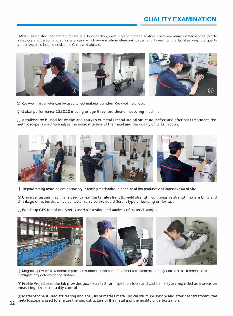
TIANHE has distinct department for the quality inspection, metering and material testing. There are many metalloscopes, profile projectors and carbon and sulfur analyzers which were made in Germany, Japan and Taiwan. all the facilities keep our quality control system’s leading position in China and abroad.
① Rockwell hardometer can be used to test material samples’ Rockwell hardness.
② Global performance 12.30.10 moving bridge three-coordinate measuring machine.
③ Metalloscope is used for testing and analysis of metal's metallurgical structure. Before and after heat treatment, the metalloscope is used to analyze the microstructure of the metal and the quality of carburization.
④ Impact testing machine are necessary in testing mechanical properties of the products and impact value of Akv.
⑤ Universal testing machine is used to test the tensile strength, yield strength, compressive strength, extensibility and shrinkage of materials. Universal tester can also provide different type of bending or flex test.
⑥ Benchtop OES Metal Analyzer is used for testing and analysis of material sample.
⑦ Magnetic powder flaw detector provides surface inspection of material with fluorescent magnetic particle. It detects andhighlights any defects on the surface.
⑧ Profile Projector in the lab provides geometry test for inspection tools and cutters. They are regarded as a precision measuring device in quality control.
⑨ Metalloscope is used for testing and analysis of metal's metallurgical structure. Before and after heat treatment, the metalloscope is used to analyze the microstructure of the metal and the quality of carburization.
① ③
⑥⑤④
⑦ ⑧ ⑨
②