Hoisting Equipment Table of contents INFO - CMCO
140
8 Hoisting Equipment Table of contents Page Ratchet lever hoists 14 - 30 Hand chain hoists 31 - 47 Corrosion protection 48 - 51 Trolleys & Trolley clamps 52 - 59 Electric & Pneumatic chain hoists 60 - 81 Chains & Accessories 82 - 84 Manual winches 85 - 95 Cable puller & Accessories 96 - 101 Electric winches & Accessories 102 - 113 Rack & Pinion jacks 114 - 135 Crane Systems 136 - 145 Power supply 146 - 147 INFO Please note our user instructions at the beginning of each chapter. Yale and Pfaff-silberblau hoisting equipment products are reliable and proven equipment renowned world-wide for applications in industry, trade and services. The comprehensive range includes manual and powered hoisting equipment for a safe lifting and handling of loads ranging from 125 kg to 50000 kg. The products feature a long service life as well as easy and quick maintenance or repair. Yale and Pfaff-silberblau hoisting equipment products comply with national and international regulations such as the EC Machinery Directive 2006/42/EC and corresponding supplements. In order to meet our high quality standard, the devices are subjected to an overload test in the factory and provided with a test certificate and operating instructions with a declaration of conformity or a manufacturer’s declaration.
-
Upload
khangminh22 -
Category
Documents
-
view
1 -
download
0
Transcript of Hoisting Equipment Table of contents INFO - CMCO
8
Hoisting Equipment Table of contents
Page Ratchet lever hoists 14 - 30
Hand chain hoists 31 - 47
Corrosion protection 48 - 51
Trolleys & Trolley clamps 52 - 59
Electric & Pneumatic chain hoists 60 - 81
Chains & Accessories 82 - 84
Manual winches 85 - 95
Cable puller & Accessories 96 - 101
Electric winches & Accessories 102 - 113
Rack & Pinion jacks 114 - 135
Crane Systems 136 - 145
Power supply 146 - 147
INFO
Please note our user instructions at the beginning of each chapter.
Yale and Pfaff-silberblau hoisting equipment products are reliable and proven equipment renowned world-wide for applications in industry, trade and services. The comprehensive range includes manual and powered hoisting equipment for a safe lifting and handling of loads ranging from 125 kg to 50000 kg. The products feature a long service life as well as easy and quick maintenance or repair. Yale and Pfaff-silberblau hoisting equipment products comply with national and international regulations such as the EC Machinery Directive 2006/42/EC and corresponding supplements. In order to meet our high quality standard, the devices are subjected to an overload test in the factory and provided with a test certificate and operating instructions with a declaration of conformity or a manufacturer’s declaration.

9
HOISTING EQUIPMENT
10
Hoisting Equipment User information
INFO
INFO
For information on training please see page 4.
This user information presents a general review regarding the operation of hoisting equipment and does not substitute the existing operating instruc-tions for the specific hoist product.
Lifting operations with hoisting equipment may be carried out by competent users (trained in theory and practice) only. When operated correctly, our hoist products will offer the highest degree of safety in line with long life expectancy and avoid damage to the product and people.
Modification of delivery conditionDesign and construction of the hoist may not be altered, e.g. by installation of outside supplied parts, bending, welding, grinding, removal of safety relevant components like locking devices, locking pins, safety latches etc.
Limitations of operationLoadingOur hoists have been designed for lifting and transporting of loads. Some models (e.g. ratchet lever hoists) may also be used for pulling and lashing purposes, if admitted in the operating instructions. The indicated capacities refer to loading in straight line and must not be exceeded. Lifting media (e.g. lifting chain or rope) must not be slung over edges and must not be used for the attachment of the load.
TemperatureHoists may normally be operated at ambient tempera-tures between -10 °C up to + 50 °C.
These values are approximate and may deviate from the specific givings of the hoist product. The accurate data are given in the current operating instructions. Special models are available on request for higher or lower temperature ranges.
Attention: At temperatures below 0 °C the brake should be checked for freezing. (Check lifting function prior to starting work and refer to “Inspection prior to initial operation”).
Shock loadingThe indicated capacities are based on shock-free loading of the hoist. Light bumps as occurred during lifting and lowering as well as transporting of load are admitted. Heavier shock loadings, e.g. falling of the load, are strictly forbidden.
ChemicalsHoists and attachments may not be operated without hesitation in the area of chemicals or chemical vapours – consult our specialists for advice. Hoists which have been subject to chemicals or vapours must be taken out of service and inspected by us.
Transport of peopleTransport of people with hoisting equipment is generally forbidden! Transport of people may only by carried out with specially authorized products (e.g. Yaletrac, Mtrac).
Operation in danger zonesLifting or transport of loads must be avoided while personnel are in the danger zone. People are not allowed to pass over or under a suspended load.
Electrical hazards Load carrying hoist components (e.g. load chain) must not be subject to electric current and must never be used as a ground connection during welding. Further electrical hazards, e.g. with powered hoists, are indicated in the specific operating instructions!Electric connections may only be performed by authorized persons resp. companies.
11
Hoisting Equipment User information
INFO
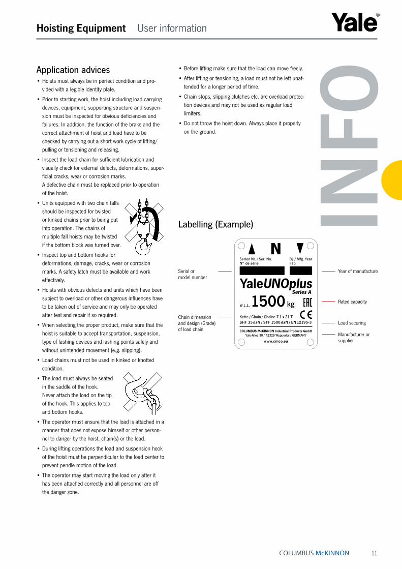
Chain dimension and design (Grade) of load chain
Rated capacity
Manufacturer or supplier
Year of manufactureSerial or model number
Load securing
W.L.L. 1500 kgKette / Chain / Chaîne 7.1 x 21 TSHF 35 daN / STF 1500 daN / EN 12195-3
COLUMBUS McKINNON Industrial Products GmbHYale-Allee 30 / 42329 Wuppertal / GERMANY
www.cmco.eu
Serien Nr. / Ser. No. Bj. / Mfg. YearN° de série Fab.
• Before lifting make sure that the load can move freely.
• After lifting or tensioning, a load must not be left unat-tended for a longer period of time.
• Chain stops, slipping clutches etc. are overload protec-tion devices and may not be used as regular load limiters.
• Do not throw the hoist down. Always place it properly on the ground.
Labelling (Example)
Application advices• Hoists must always be in perfect condition and pro-
vided with a legible identity plate.
• Prior to starting work, the hoist including load carrying devices, equipment, supporting structure and suspen-sion must be inspected for obvious deficiencies and failures. In addition, the function of the brake and the correct attachment of hoist and load have to be checked by carrying out a short work cycle of lifting/pulling or tensioning and releasing.
• Inspect the load chain for sufficient lubrication and visually check for external defects, deformations, super-ficial cracks, wear or corrosion marks. A defective chain must be replaced prior to operation of the hoist.
• Units equipped with two chain falls should be inspected for twisted or kinked chains prior to being put into operation. The chains of multiple fall hoists may be twisted if the bottom block was turned over.
• Inspect top and bottom hooks for deformations, damage, cracks, wear or corrosion marks. A safety latch must be available and work effectively.
• Hoists with obvious defects and units which have been subject to overload or other dangerous influences have to be taken out of service and may only be operated after test and repair if so required.
• When selecting the proper product, make sure that the hoist is suitable to accept transportation, suspension, type of lashing devices and lashing points safely and without unintended movement (e.g. slipping).
• Load chains must not be used in kinked or knotted condition.
• The load must always be seated in the saddle of the hook. Never attach the load on the tip of the hook. This applies to top and bottom hooks.
• The operator must ensure that the load is attached in a manner that does not expose himself or other person-nel to danger by the hoist, chain(s) or the load.
• During lifting operations the load and suspension hook of the hoist must be perpendicular to the load center to prevent pendle motion of the load.
• The operator may start moving the load only after it has been attached correctly and all personnel are off the danger zone.

12
Hoisting Equipment User information
13
Hoisting Equipment User information
INFO
Maintenance and repair• To ensure safe operation, all hoisting equipment must
be subjected to regular inspections according to the maintenance instructions given by the manufacturer.
• Hoists which are due for maintenance (normally once per year, unless adverse working conditions dictate shorter periods) or products with obvious defects may be returned to us for inspection and repair.
• Inspections and tests must be performed by competent persons or specialist workshops that use original spare parts.
Inspections• According to German laws and standards all hoist-
ing equipment must be subjected to a mandatory inspection at least once a year. The inspection must be performed by a competent person.
• On building sites hoists have to be inspected every time before operation.
• Hoist and supporting components have to be cleaned prior to inspection. The cleaning procedure must not cause chemical damages (e.g. no acid-embrittlement). Do not expose the hoist and supporting components to unallowed temperatures by e.g. flame cleaning avoid concealment of cracks and excessive material loss (sand blasting). We shall be pleased to consult you in this respect. Please submit your hoists for inspection in clean condi-tion. This will reduce inspection costs considerably.
Criteria for hoist disposalHoists must no longer be operated if e.g.:
• The identification (identity plate) is missing or illegible.
• Security relevant components like brake, slipping clutch, ratchet pawls etc. do not properly function any longer.
• Housing, control units and suspension of the hoist present obvious deficiencies, i.e. - cuts, grooves, cracks - excessive corrosion - staining due to heat - signs of subsequent welding resp. spatters which cannot be easily removed and leave stains.
• Ropes show breakage of wires resp. bruises (criteria for disposal of ropes are given in classification DIN 15020), damages to the rope sleeve and similar failures.
• The load chain presents twisted or distorted links or shows an elongation of 5 % of one chain link or a reduc-tion in diameter of more than 10 % (average of two measurings (longitudinal and transverse) compared to the nominal diameter).
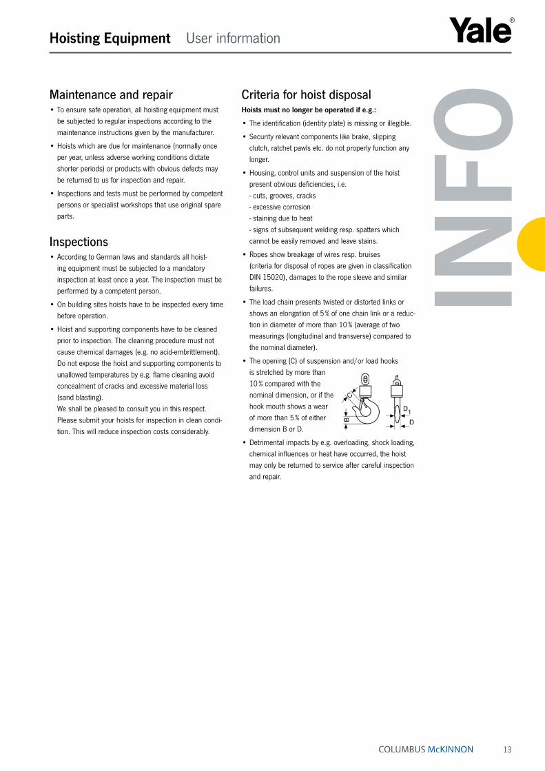
• The opening (C) of suspension and/or load hooks is stretched by more than 10 % compared with the nominal dimension, or if the hook mouth shows a wear of more than 5 % of either dimension B or D.
• Detrimental impacts by e.g. overloading, shock loading, chemical influences or heat have occurred, the hoist may only be returned to service after careful inspection and repair.

14
Hoisting Equipment Ratchet lever hoists
C 85Ratchet lever hoist with roller chainCapacity 750 - 3000 kg
D 85Ratchet lever hoist with link chainCapacity 750 - 10000 kgAlmost unlimited applications in maintenance, mining, construction, steel fabrication, shipbuilding and utility work. Ideal for moving and positioning heavy machines and securing heavy loads, simplifies setting pipes etc. in manholes and trenches.
Features• Enclosed housing with housing cover, handlever and
bottom block made from high tensile white malleable cast iron for overall rugged construction.
• Wet painting colour code RAL 1023.
• The graphite cast iron load sheave for the link chain has precision machined chain pockets for accurate fit and durability of the load chain.
• The roller chain sprocket is made from heat treated chromium-molybdenum steel with precision machined teeth to ensure smooth chain movement.
• Alloyed steel link chain with zinc-plated, in accordance with national and international standards and regula-tions.
Options• Except for the capacity 10 t, all units can be equipped
with an overload protection (slip clutch). This slip clutch is activated at 25 % ± 15 % overload, lifting of the load is no longer possible.
INFO
Since 1936, the Velbert factory has built over 1 million units.
All ratchet lever hoists with a capacity exceeding 750 kg can be used for load attachment according to EN 12195.
Yale hoists and trolleys are not designed for passenger elevation applications and must not be used for this purpose.
We are pleased to send you our new Atex catalogue in PDF format.
15
Option:
Overload protection for C/D 85.
Hoisting Equipment Ratchet lever hoists
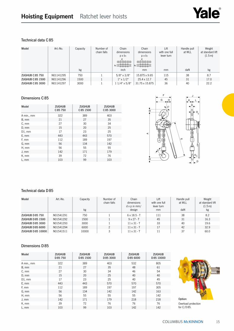
Technical data C 85
Model Art.-No. Capacity
kg
Number ofchain falls
Chaindimensions
p x b₁
inch
Chaindimensions
p x b₁
mm
Liftwith one fulllever turn
mm
Handle pullat WLL
daN
Weightat standard lift
(1.5 m)
kg
ZUGHUB C 85 750 N01141295 750 1 5/8" x 3/8" 15.875 x 9.65 115 38 8.7ZUGHUB C 85 1500 N01141296 1500 1 1" x 1/2" 25.4 x 12.7 45 31 17.0ZUGHUB C 85 3000 N01141297 3000 1 1 1/4" x 5/8" 31.75 x 15.875 36 40 22.2
Dimensions C 85
Model ZUGHUBC 85 750
ZUGHUBC 85 1500
ZUGHUBC 85 3000
A min., mm 322 389 403B, mm 21 27 35C, mm 27 30 34D, mm 15 20 25D1, mm 17 23 25E, mm 443 443 570F, mm 112 189 197G, mm 56 134 142H, mm 56 55 55J, mm 142 171 179K, mm 39 72 76L, mm 103 99 103
Dimensions D 85
Model ZUGHUBD 85 750
ZUGHUBD 85 1500
ZUGHUBD 85 3000
ZUGHUBD 85 6000
ZUGHUBD 85 10000
A min., mm 322 389 403 532 805B, mm 21 27 35 48 61C, mm 27 30 34 46 54D, mm 15 20 25 40 40D1, mm 17 23 25 40 45E, mm 443 443 570 570 570F, mm 112 189 197 197 305G, mm 56 134 142 142 163H, mm 56 55 55 55 142J, mm 142 171 179 218 218K, mm 39 72 76 76 76L, mm 103 99 103 142 142
Technical data D 85
Model Art.-No. Capacity
kg
Number ofchain falls
Chaindimensions
d x p in mm/design
Liftwith one fulllever turn
mm
Handle pullat WLL
daN
Weightat standard lift
(1.5 m)kg
ZUGHUB D 85 750 N01541291 750 1 6 x 18.5 - T 111 38 8.2ZUGHUB D 85 1500 N01541292 1500 1 9 x 27 - T 45 31 16.3ZUGHUB D 85 3000 N01541293 3000 1 11 x 31 - T 33 40 19.6ZUGHUB D 85 6000 N01541294 6000 2 11 x 31 - T 17 42 32.9ZUGHUB D 85 10000 N01541511 10000 3 11 x 31 - T 11 37 60.0
F
G H
C
BB
A
E
C
J
LK
D
D
D1
D1

16
Hoisting Equipment Ratchet lever hoists
Ratchet lever hoistCapacity 750 - 9000 kgRedefining lever-operated hoists, the YaleERGO 360 ® features the revolutionary crank han dle that allows for efficient operation in both lifting and pulling applications. Ergonomically designed for increased safety, the patented YaleERGO 360 ® lets the operator work up to 12 times faster and with as much as 30 % less pull force than with conventional ratchet lever tools.
Features• The lightweight, high-strength aluminium housing with
powder coating and high-quality bearings offer a long service life even with intensive use and rough operating conditions.
• The hand lever with integrated snap crank ensures ideal power transmission and enables a 360° working range. This increases productivity and reduces the risk of injury.
• Display of the operating direction or free chaining in the viewing window of the hand lever.
• The covered load pressure brake remains free of dirt and moisture, which enables precise load positioning.
• Standard free chaining device to quickly attach the load or to pull the chain through the hoist in both directions.
• Chain guide and stripper are made of robust cast iron and zinc plated to protect against corrosion.
• Alloyed steel link chain with zinc-plated resp. yellow chromated finish, in accordance with national and international standards and regulations.
• Rotatable, forged top and load hooks and casted safety latches provide reliable and safe load suspension. The screwed top hook cross bars and bottom blocks are allowed for easy maintenance.
Options• All YaleERGO 360 ® units can be equipped with an over-
load protection device in the form of a slip clutch which is factory preset to approx. 25 % ± 15 % overload.
• Shipyard hooks available for 1500 kg and 3000 kg units.
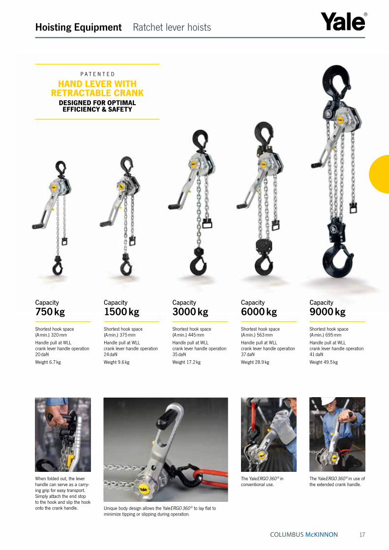
P A T E N T E D
HAND LEVER WITH RETRACTABLE CRANK
DESIGNED FOR OPTIMAL EFFICIENCY & SAFETY
17
Capacity
1500 kgShortest hook space (A min.) 375 mm
Handle pull at WLL crank lever handle operation 24 daN
Weight 9.6 kg
Capacity
3000 kgShortest hook space (A min.) 445 mm
Handle pull at WLL crank lever handle operation 35 daN
Weight 17.2 kg
Capacity
6000 kgShortest hook space (A min.) 563 mm
Handle pull at WLL crank lever handle operation 37 daN
Weight 28.9 kg
Capacity
9000 kgShortest hook space (A min.) 695 mm
Handle pull at WLL crank lever handle operation 41 daN
Weight 49.5 kg
Capacity
750 kgShortest hook space (A min.) 320 mm
Handle pull at WLL crank lever handle operation 20 daN
Weight 6.7 kg
Hoisting Equipment Ratchet lever hoists
Unique body design allows the YaleERGO 360 ® to lay flat to minimize tipping or slipping during operation.
The YaleERGO 360 ® in conventional use.
The YaleERGO 360 ® in use of the extended crank handle.
When folded out, the lever handle can serve as a carry-ing grip for easy transport. Simply attach the end stop to the hook and slip the hook onto the crank handle.

18
SAFE & SECURESELECTOR LEVER LOCKS IN PLACE TO PREVENT ACCIDENTALLY SWITCHING.
Pull down on the selector lever to unlock it, turn it to the desired direction,
and release it into the locking position.
DISTINCTIVE CLICKING SOUND
ENSURES THE HANDLE IS LOCKED INTO POSITION
To return handle to upright position, simply pull the handle outward
and snap into place inside the lever.
Hoisting Equipment Ratchet lever hoists
Simple & smooth free chaining deviceQuick positioning of the unloaded chain - even with one-handed operation.
In this operating mode, the chain can be pulled through the unit by hand in both direc-tions in order to attach it more quickly.
The free chaining device is activated by moving (shifting) the lever to the neutral position ( N ).
The hand lever with integrated crank• 360° rotation increases efficiency, allowing operators
to work up to 12 times faster than with a conventional ratchet lever hoist.
• Requires 30 % less pull force to operate.
• Easy and effective operation from any angle with handle that folds down and locks into position on either side of the lever.
• Design keeps the operator’s body aligned with the load chain, reducing the risk of the twist effect – when a hoist twists around the chain. No need to use a second hand to stabilize the hoist.
• Operator can securely grip the grooved, no-slip handle.
• Crank handle made of durable polyamide with a heavy-duty steel core for rugged use.
Convenient directional indicatorEasy-to-use, highly visible directional indicator window located in the handle clearly shows the operating direction as LIFTING (▲), LOWERING (▼) or NEUTRAL ( N ).

19
Model Art.-No. Capacity
kg
Number of chain falls
Chain dimensions
d x p in mm/design
Lift with one full lever turn
mm
Handle pull at WLL
daN
Handle pull at WLL
with crankdaN
Weight at standard lift
(1.5 m)kg
YaleERGO 360 750 192028204 750 1 5.6 x 17.1 - T 27.2 21 20 6.7YaleERGO 360 1500 192028202 1500 1 7.1 x 21 - T 21.7 31 24 9.6YaleERGO 360 3000 192028553 3000 1 10 x 28 - V 20.1 43 35 17.2YaleERGO 360 6000 192035451 6000 2 10 x 28 - V 10.1 46 37 28.9YaleERGO 360 9000 192039362 9000 3 10 x 28 - V 6.7 50 41 49.5
Dimensions YaleERGO 360 ®
Model YaleERGO 360 750
YaleERGO 360 1500
YaleERGO 360 3000
YaleERGO 360 6000
YaleERGO 360 9000
A min., mm 320 375 445 563 695B, mm 20 26 37 45 68C, mm 27 31 40 47 68D, mm 18 21 28 35 50E, mm 327 327 377 377 377F, mm 300 300 350 350 350G, mm 40 51 57 71 116H, mm 81 96 123 162 199J, mm 121 147 180 233 315K, mm 56 69 86 86 86L, mm 105 110 121 121 121M, mm 161 179 207 207 207N, mm 30 30 30 30 30O, mm 120 120 120 120 120P, mm 257 273 299 299 299
YaleERGO 360 ®, 750 - 3000 kg, single fall
YaleERGO 360 ®, 6000 kg, double fall
Option:
Shipyard hooksfor capacities 1500 and 3000 kg. Based on a special design the shipyard hooks can be fixed to avoid slipping (resp. on steel plates which were braced for welding).
YaleERGO 360 ®, 9000 kg, three fall
Technical data YaleERGO 360 ®
Hoisting Equipment Ratchet lever hoists
20
Hoisting Equipment Ratchet lever hoists
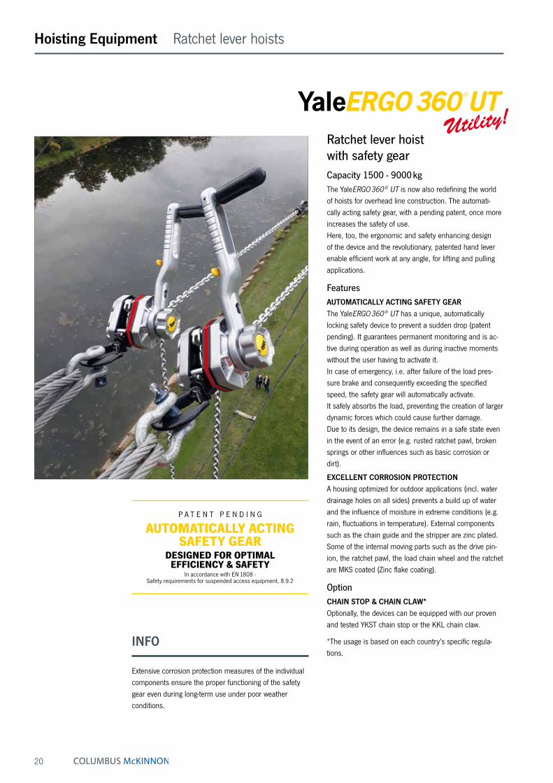
Ratchet lever hoist with safety gearCapacity 1500 - 9000 kgThe YaleERGO 360 ® UT is now also redefining the world of hoists for overhead line construction. The automati-cally acting safety gear, with a pending patent, once more increases the safety of use. Here, too, the ergonomic and safety enhancing design of the device and the revolutionary, patented hand lever enable efficient work at any angle, for lifting and pulling applications.
FeaturesAUTOMATICALLY ACTING SAFETY GEAR The YaleERGO 360 ® UT has a unique, automatically locking safety device to prevent a sudden drop (patent pending). It guarantees permanent monitoring and is ac-tive during operation as well as during inactive moments without the user having to activate it. In case of emergency, i.e. after failure of the load pres-sure brake and consequently exceeding the specified speed, the safety gear will automatically activate. It safely absorbs the load, preventing the creation of larger dynamic forces which could cause further damage. Due to its design, the device remains in a safe state even in the event of an error (e.g. rusted ratchet pawl, broken springs or other influences such as basic corrosion or dirt).
EXCELLENT CORROSION PROTECTION A housing optimized for outdoor applications (incl. water drainage holes on all sides) prevents a build up of water and the influence of moisture in extreme conditions (e.g. rain, fluctuations in temperature). External components such as the chain guide and the stripper are zinc plated. Some of the internal moving parts such as the drive pin-ion, the ratchet pawl, the load chain wheel and the ratchet are MKS coated (Zinc flake coating).
OptionCHAIN STOP & CHAIN CLAW* Optionally, the devices can be equipped with our proven and tested YKST chain stop or the KKL chain claw.
*The usage is based on each country’s specific regula-tions.
P A T E N T P E N D I N G
AUTOMATICALLY ACTING SAFETY GEAR
DESIGNED FOR OPTIMAL EFFICIENCY & SAFETY
In accordance with EN 1808 - Safety requirements for suspended access equipment, 8.9.2
INFO
Extensive corrosion protection measures of the individual components ensure the proper functioning of the safety gear even during long-term use under poor weather conditions.
21
INFO
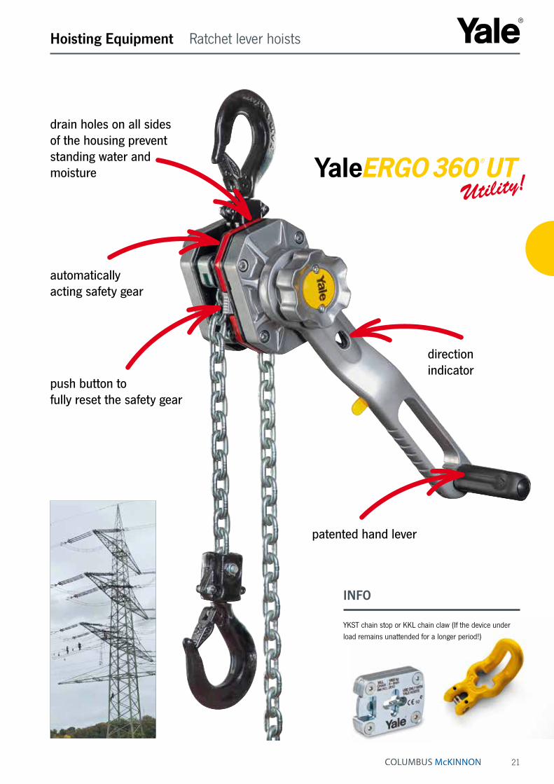
YKST chain stop or KKL chain claw (If the device under load remains unattended for a longer period!)
Hoisting Equipment Ratchet lever hoists
drain holes on all sides of the housing prevent standing water and moisture
direction indicator
push button to fully reset the safety gear
patented hand lever
automatically acting safety gear

22
STRUCTURE & FUNCTIONALITY OF THE AUTOMATIC SAFETY GEAR
Rocker pawl
Lock discSpacer frame
Cam disc
Reset button
FUNCTION NORMAL OPERATION
Speed < 0.5 m/sThe rocker pawl moves continuously along the contours of the cam disc and lock disc.
FUNCTION ABSORPTION
Speed > 0.5 m/sAs soon as the speed exceeds 0.5 m/s, the rocker pawl engages the lock disc and safely absorbs the load.
REQUIREMENTS FOR THE REDUNDANT SAFETY GEAR In accordance with EN 1808 - Safety requirements for suspended access equipment, 8.9.2• shall automatically engage in the event of overspeed
(more than 0.5 m/s)
• the stopping distance must not exceed 500 mm
• shall be capable of being reset
• shall be capable of being tested
• shall permit lifting at any time
INFO
In any cases the load is caught exceeding a speed of 0.5 m/s.
Speeds below 0.5 m/s (corresponds to 2 km/h) are not safety relevant according to EN 1808.
Hoisting Equipment Ratchet lever hoists
Overhead line construction Aerial construction
P A T E N T P E N D I N G
AUTOMATICALLY ACTING SAFETY GEAR
DESIGNED FOR OPTIMAL EFFICIENCY & SAFETY
In accordance with EN 1808 - Safety requirements for suspended access equipment, 8.9.2

23
Technical data YaleERGO 360 ® UT
Dimensions YaleERGO 360 ® UT
Model YaleERGO 360 UT 1500
YaleERGO 360 UT 3000
YaleERGO 360 UT 6000
YaleERGO 360 UT 9000
A min., mm 375 445 563 695B, mm 26 37 45 68C, mm 31 40 47 68D, mm 21 28 35 50E, mm 327 377 377 377F, mm 300 350 350 350G, mm 51 57 71 116H, mm 96 123 162 199J, mm 147 180 233 315K, mm 69 86 86 86L, mm 124 136 136 136M, mm 193 222 222 222N mm 30 30 30 30O, mm 120 120 120 120P, mm 287 314 314 314 YaleERGO 360 ® UT, 1500 - 3000 kg, single fall
YaleERGO 360 ® UT, 9000 kg, three fall
AB
B
F E
G HJ
C
C
M
D
D
K L
N
O
P
YaleERGO 360 ® UT, 6000 kg, double fall
AB
B
F E
G
J
H
C
C
M
D
D
K L
N
O
P
BB
A
G H
C
J
C
F E
MK
D
D
N
L
O
P
Model Art.-No. Capacity
kg
Number of chain falls
Chain dimensions
d x p in mm/design
Lift with one full lever turn
mm
Handle pull at WLL
daN
Handle pull at WLL
with crankdaN
Weight at standard lift
(1.5 m)kg
YaleERGO 360 UT 1500 192069625 1500 1 7.1 x 21 - T 21.7 31 24 9.8YaleERGO 360 UT 3000 192069671 3000 1 10 x 28 - V 20.1 43 35 18.1YaleERGO 360 UT 6000 192071416 6000 2 10 x 28 - V 10.1 46 37 29.8YaleERGO 360 UT 9000 192083321 9000 3 10 x 28 - V 6.7 50 41 50.4
Hoisting Equipment Ratchet lever hoists
Construction of contact lines Cable car construction Positioning of loads
24
Hoisting Equipment Ratchet lever hoists
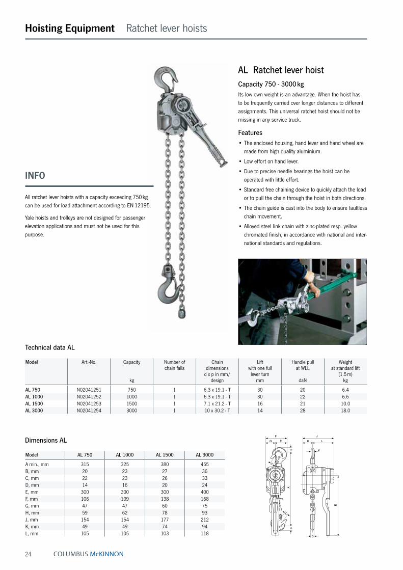
AL Ratchet lever hoistCapacity 750 - 3000 kgIts low own weight is an advantage. When the hoist has to be frequently carried over longer distances to different assignments. This universal ratchet hoist should not be missing in any service truck.
Features• The enclosed housing, hand lever and hand wheel are
made from high quality aluminium.
• Low effort on hand lever.
• Due to precise needle bearings the hoist can be operated with little effort.
• Standard free chaining device to quickly attach the load or to pull the chain through the hoist in both directions.
• The chain guide is cast into the body to ensure faultless chain movement.
• Alloyed steel link chain with zinc-plated resp. yellow chromated finish, in accordance with national and inter-national standards and regulations.
Technical data AL
Model Art.-No. Capacity
kg
Number of chain falls
Chain dimensions
d x p in mm/design
Lift with one full lever turn
mm
Handle pull at WLL
daN
Weight at standard lift
(1.5 m)kg
AL 750 N02041251 750 1 6.3 x 19.1 - T 30 20 6.4AL 1000 N02041252 1000 1 6.3 x 19.1 - T 30 22 6.6AL 1500 N02041253 1500 1 7.1 x 21.2 - T 16 21 10.0AL 3000 N02041254 3000 1 10 x 30.2 - T 14 28 18.0
Model AL 750 AL 1000 AL 1500 AL 3000
A min., mm 315 325 380 455B, mm 20 23 27 36C, mm 22 23 26 33D, mm 14 16 20 24E, mm 300 300 300 400F, mm 106 109 138 168G, mm 47 47 60 75H, mm 59 62 78 93J, mm 154 154 177 212K, mm 49 49 74 94L, mm 105 105 103 118
Dimensions ALF
G H
B
C
A
C
B
JK L
D
E
D
INFO
All ratchet lever hoists with a capacity exceeding 750 kg can be used for load attachment according to EN 12195.
Yale hoists and trolleys are not designed for passenger elevation applications and must not be used for this purpose.

25
Hoisting Equipment Ratchet lever hoists
Technical data PT
Model Art.-No. Capacity
kg
Number of chain falls
Chain dimensions
d x p in mm/design
Lift with one full lever turn
mm
Handle pull at WLL
daN
Weight at standard lift
(1.5 m)kg
PT 800 N02200005 800 1 5.6 x 17.1 - T 24 26 5.5PT 1600 N02200006 1600 1 7.1 x 21.2 - T 23 30 9.6PT 3200 N02200007 3200 1 9 x 27.2 - V 16 38 16.0PT 6300 N02200008 6300 2 9 x 27.2 - V 8 39 31.0
Model PT 800 PT 1600 PT 3200 PT 6300
A min., mm 290 330 430 580B, mm 21 27 36 53C, mm 24 31 35 46D, mm 13 20 24 43E, mm 235 370 370 370F, mm 120 138 177 259G, mm 38 41 53 85H, mm 82 97 124 174J, mm 142 163 185 185K, mm 52 65 83 83L, mm 90 98 102 102
Dimensions PT
INFO
All ratchet lever hoists with a capacity exceeding 750 kg can be used for load attachment according to EN 12195.
Yale hoists and trolleys are not designed for passenger elevation applications and must not be used for this purpose.
Option:
Overload protection device
N
D
D
L K
JF
BB
E
A
C
C
G H
PT Ratchet lever hoistCapacity 800 - 6300 kgRatchet lever hoists PT features improved techniques and ergonomical styling. The advantages of the predecessor range have been maintained and further optimized. A good, versatile, all round ratchet lever hoist for demand-ing conditions.
Features• The proven stamped steel housing provides extremely
low weight without limiting the reliability and sturdiness of the unit.
• The short handlever is fitted with an ergonomic rubber grip.
• Standard free chaining device to quickly attach the load or to pull the chain through the hoist in both directions.
• Alloyed steel link chain with zinc-plated resp. yellow chromated finish, in accordance with national and international standards and regulations.
• Forged suspension and load hooks are made from non-aging, high tensile steel and fitted with robust safety latches.
Option• All models can be equipped with an overload protection
device in the form of a slip clutch which is factory preset to approx. 25 % ± 15 % overload.
26
Hoisting Equipment Ratchet lever hoists
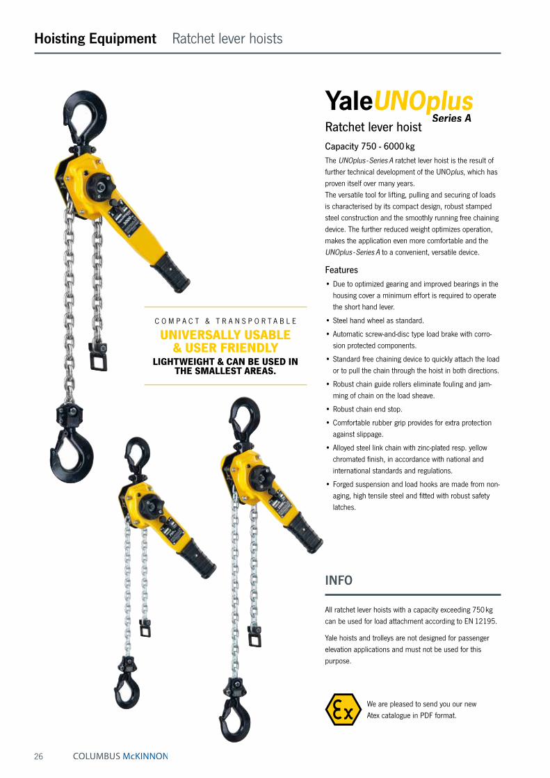
Ratchet lever hoistCapacity 750 - 6000 kgThe UNOplus - Series A ratchet lever hoist is the result of further technical development of the UNOplus, which has proven itself over many years. The versatile tool for lifting, pulling and securing of loads is characterised by its compact design, robust stamped steel construction and the smoothly running free chaining device. The further reduced weight optimizes operation, makes the application even more comfortable and the UNOplus - Series A to a convenient, versatile device.
Features• Due to optimized gearing and improved bearings in the
housing cover a minimum effort is required to operate the short hand lever.
• Steel hand wheel as standard.
• Automatic screw-and-disc type load brake with corro-sion protected components.
• Standard free chaining device to quickly attach the load or to pull the chain through the hoist in both directions.
• Robust chain guide rollers eliminate fouling and jam-ming of chain on the load sheave.
• Robust chain end stop.
• Comfortable rubber grip provides for extra protection against slippage.
• Alloyed steel link chain with zinc-plated resp. yellow chromated finish, in accordance with national and international standards and regulations.
• Forged suspension and load hooks are made from non-aging, high tensile steel and fitted with robust safety latches.
INFO
All ratchet lever hoists with a capacity exceeding 750 kg can be used for load attachment according to EN 12195.
Yale hoists and trolleys are not designed for passenger elevation applications and must not be used for this purpose.
We are pleased to send you our new Atex catalogue in PDF format.
C O M P A C T & T R A N S P O R T A B L E
UNIVERSALLY USABLE & USER FRIENDLY
LIGHTWEIGHT & CAN BE USED IN THE SMALLEST AREAS.
27
Hoisting Equipment Ratchet lever hoists
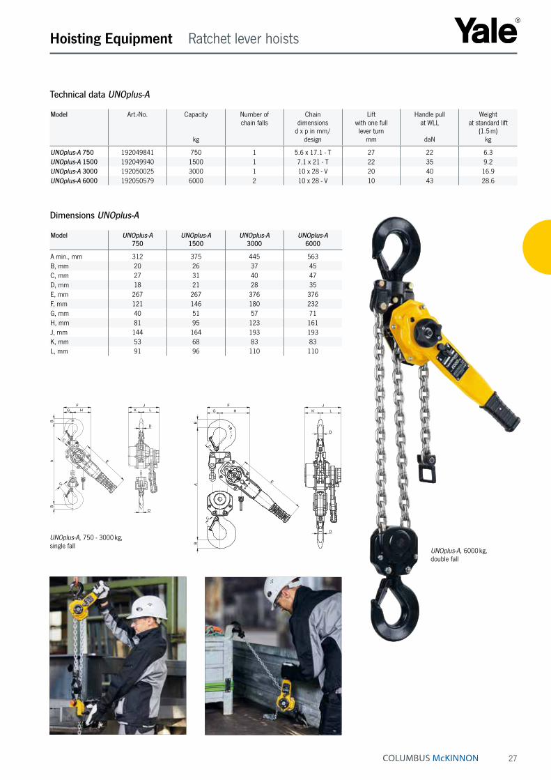
Technical data UNOplus-A
Model Art.-No. Capacity
kg
Number of chain falls
Chain dimensions
d x p in mm/design
Lift with one full lever turn
mm
Handle pull at WLL
daN
Weight at standard lift
(1.5 m)kg
UNOplus-A 750 192049841 750 1 5.6 x 17.1 - T 27 22 6.3UNOplus-A 1500 192049940 1500 1 7.1 x 21 - T 22 35 9.2UNOplus-A 3000 192050025 3000 1 10 x 28 - V 20 40 16.9UNOplus-A 6000 192050579 6000 2 10 x 28 - V 10 43 28.6
Dimensions UNOplus-A
Model UNOplus-A 750
UNOplus-A 1500
UNOplus-A 3000
UNOplus-A 6000
A min., mm 312 375 445 563B, mm 20 26 37 45C, mm 27 31 40 47D, mm 18 21 28 35E, mm 267 267 376 376F, mm 121 146 180 232G, mm 40 51 57 71H, mm 81 95 123 161J, mm 144 164 193 193K, mm 53 68 83 83L, mm 91 96 110 110
UNOplus-A, 6000 kg, double fall
UNOplus-A, 750 - 3000 kg, single fall
BB
A
G
E
C
C
FH
J
D
D
K L L
AB
B
E
GF
H
C
C
J
D
D
K
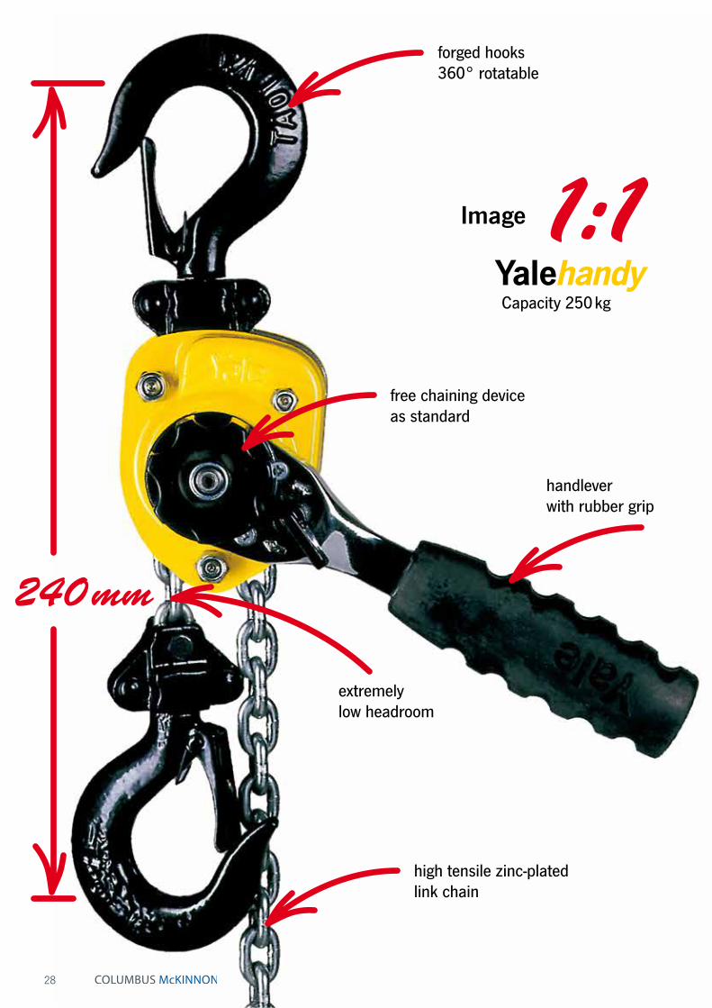
1:1
240 mm
Image
Capacity 250 kg
28
forged hooks 360° rotatable
free chaining device as standard
extremely low headroom
high tensile zinc-plated link chain
handlever with rubber grip

29
Hoisting Equipment Ratchet lever hoists
Technical data Yalehandy
Model Art.-No. Capacity
kg
Number of chain falls
Chain dimensions
d x p in mm/design
Lift with one full lever turn
mm
Handle pull at WLL
daN
Weight at standard lift
(1.5 m)kg
Yalehandy 250 N02300018 250 1 4 x 12 - T 80 25 2.2Yalehandy 500 N02300070 500 1 4 x 12 - V 40 25 2.8
Model Yalehandy 250 Yalehandy 500
A min., mm 240 282B, mm 20 17C, mm 21 24D, mm 14 12E, mm 160 160F, mm 72 104G, mm 33 38H, mm 39 66J, mm 98 116K, mm 21 36L, mm 77 80
Dimensions Yalehandy
INFO
Yale hoists and trolleys are not designed for passenger elevation applications and must not be used for this purpose.
Ratchet lever hoistCapacity 250 - 500 kgThe extreme low own weight and the very compact design make the hoist easy to use even in confined working conditions. Due to the multitude of application possibili-ties e.g. in industry, trade and service this ratchet lever hoist is indispensable.
Features• The enclosed design protects the internal parts from
contamination.
• The short handlever is fitted with an ergonomic rubber grip.
• All parts of the disc type load brake are manufactured from high quality materials and are corrosion protected.
• Standard free chaining device to quickly attach the load or to pull the chain through the hoist in both directions.
• Alloyed steel link chain with zinc-plated resp. yellow chromated finish, in accordance with national and international standards and regulations.
• Forged suspension and load hooks are made from non-aging, high tensile steel and fitted with robust safety latches.
30
Hoisting Equipment Ratchet lever hoists
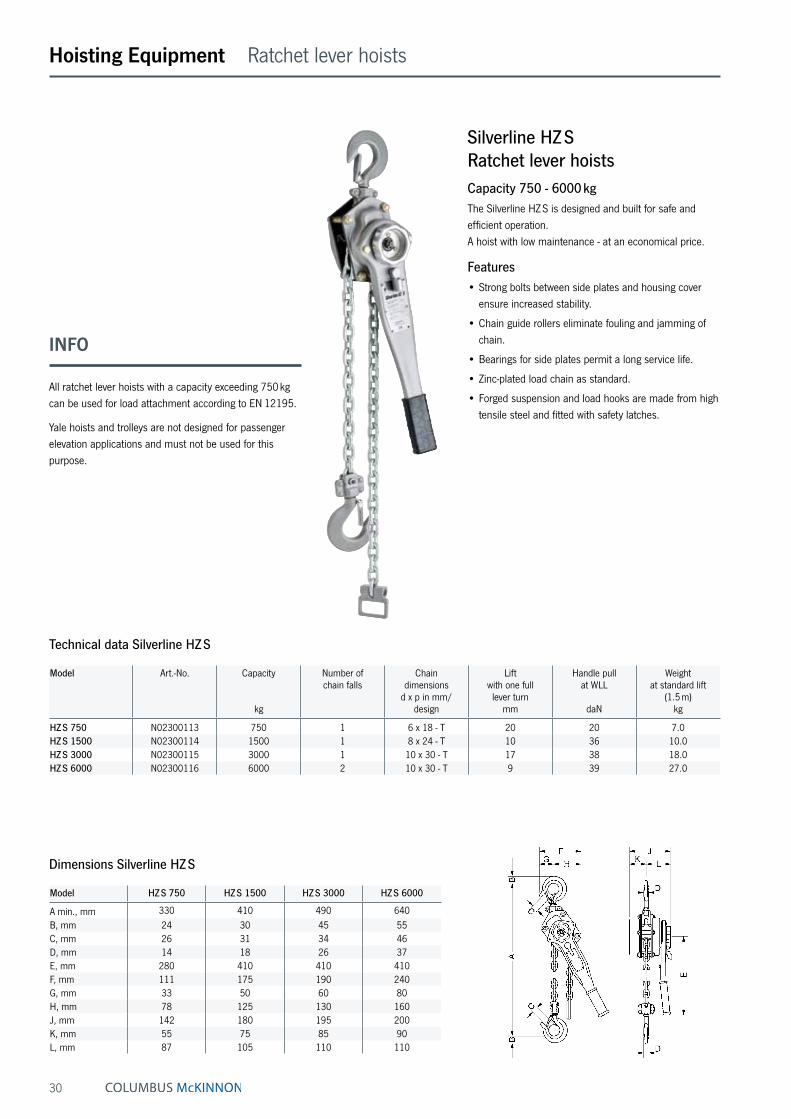
Technical data Silverline HZ S
Model Art.-No. Capacity
kg
Number of chain falls
Chain dimensions
d x p in mm/design
Lift with one full lever turn
mm
Handle pull at WLL
daN
Weight at standard lift
(1.5 m)kg
HZ S 750 N02300113 750 1 6 x 18 - T 20 20 7.0HZ S 1500 N02300114 1500 1 8 x 24 - T 10 36 10.0HZ S 3000 N02300115 3000 1 10 x 30 - T 17 38 18.0HZ S 6000 N02300116 6000 2 10 x 30 - T 9 39 27.0
Model HZ S 750 HZ S 1500 HZ S 3000 HZ S 6000
A min., mm 330 410 490 640B, mm 24 30 45 55C, mm 26 31 34 46D, mm 14 18 26 37E, mm 280 410 410 410F, mm 111 175 190 240G, mm 33 50 60 80H, mm 78 125 130 160J, mm 142 180 195 200K, mm 55 75 85 90L, mm 87 105 110 110
Dimensions Silverline HZ S
Silverline HZ SRatchet lever hoistsCapacity 750 - 6000 kgThe Silverline HZ S is designed and built for safe and efficient operation. A hoist with low maintenance - at an economical price.
Features• Strong bolts between side plates and housing cover
ensure increased stability.
• Chain guide rollers eliminate fouling and jamming of chain.
• Bearings for side plates permit a long service life.
• Zinc-plated load chain as standard.
• Forged suspension and load hooks are made from high tensile steel and fitted with safety latches.
INFO
All ratchet lever hoists with a capacity exceeding 750 kg can be used for load attachment according to EN 12195.
Yale hoists and trolleys are not designed for passenger elevation applications and must not be used for this purpose.
31
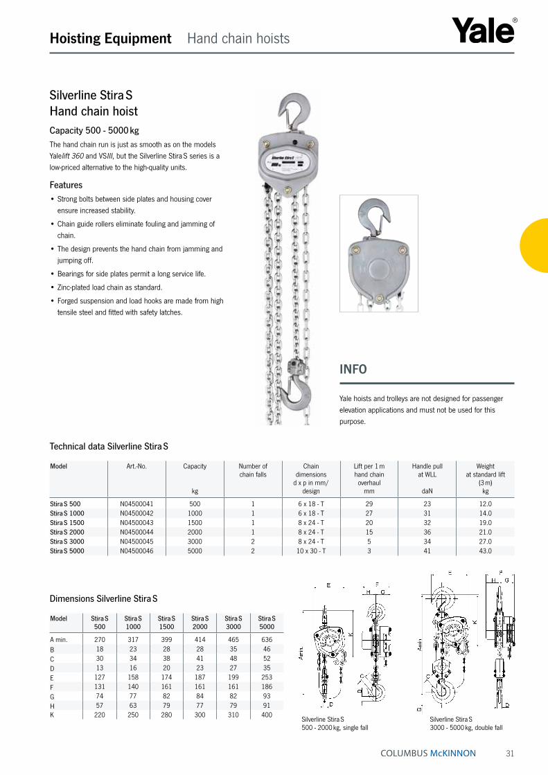
Silverline Stira S 500 - 2000 kg, single fall
Silverline Stira S 3000 - 5000 kg, double fall
Silverline Stira SHand chain hoistCapacity 500 - 5000 kgThe hand chain run is just as smooth as on the models Yalelift 360 and VSIII, but the Silverline Stira S series is a low-priced alternative to the high-quality units.
Features• Strong bolts between side plates and housing cover
ensure increased stability.
• Chain guide rollers eliminate fouling and jamming of chain.
• The design prevents the hand chain from jamming and jumping off.
• Bearings for side plates permit a long service life.
• Zinc-plated load chain as standard.
• Forged suspension and load hooks are made from high tensile steel and fitted with safety latches.
Hoisting Equipment Hand chain hoists
Model Stira S 500
Stira S 1000
Stira S 1500
Stira S 2000
Stira S 3000
Stira S 5000
A min. 270 317 399 414 465 636B 18 23 28 28 35 46C 30 34 38 41 48 52D 13 16 20 23 27 35E 127 158 174 187 199 253F 131 140 161 161 161 186G 74 77 82 84 82 93H 57 63 79 77 79 91K 220 250 280 300 310 400
Dimensions Silverline Stira S
Technical data Silverline Stira S
Model Art.-No. Capacity
kg
Number of chain falls
Chain dimensions
d x p in mm/design
Lift per 1 m hand chain overhaul
mm
Handle pull at WLL
daN
Weight at standard lift
(3 m)kg
Stira S 500 N04500041 500 1 6 x 18 - T 29 23 12.0Stira S 1000 N04500042 1000 1 6 x 18 - T 27 31 14.0Stira S 1500 N04500043 1500 1 8 x 24 - T 20 32 19.0Stira S 2000 N04500044 2000 1 8 x 24 - T 15 36 21.0Stira S 3000 N04500045 3000 2 8 x 24 - T 5 34 27.0Stira S 5000 N04500046 5000 2 10 x 30 - T 3 41 43.0
INFO
Yale hoists and trolleys are not designed for passenger elevation applications and must not be used for this purpose.
32
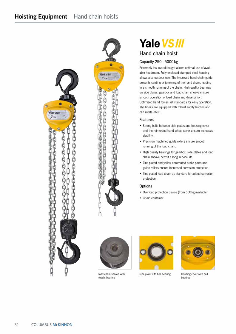
Hand chain hoistCapacity 250 - 5000 kgExtremely low overall height allows optimal use of avail-able headroom. Fully enclosed stamped steel housing allows also outdoor use. The improved hand chain guide prevents canting or jamming of the hand chain, leading to a smooth running of the chain. High quality bearings on side plates, gearbox and load chain sheave ensure smooth operation of load chain and drive pinion. Optimized hand forces set standards for easy operation. The hooks are equipped with robust safety latches and can rotate 360°.
Features• Strong bolts between side plates and housing cover
and the reinforced hand wheel cover ensure increased stability.
• Precision machined guide rollers ensure smooth running of the load chain.
• High quality bearings for gearbox, side plates and load chain sheave permit a long service life.
• Zinc-plated and yellow-chromated brake parts and guide rollers ensure increased corrosion protection.
• Zinc-plated load chain as standard for added corrosion protection.
Options• Overload protection device (from 500 kg available)
• Chain container
Hoisting Equipment Hand chain hoists
Housing cover with ball bearing
Load chain sheave with needle bearing
Side plate with ball bearing

33
Hoisting Equipment Hand chain hoists
Hand chain hoistCapacity 10000 - 50000 kgHaving long years of experience with this solid product, we decided to extend the VSIII series by the load capaci-ties 10 t, 20 t, 30 t and 50 t.
In order to serve all industries (even the paper- or the ship industry), the VSIII lifts the loads very sensitively, as the components and construction parts have been positioned very precisely.
Features• Strong bolts between side plates and housing cover
and the reinforced hand wheel cover ensure increased stability.
• Precision machined guide rollers ensure smooth running of the load chain.
• High quality bearings for gearbox, side plates and load chain sheave permit a long service life.
• Zinc-plated and yellow-chromated brake parts and guide rollers ensure increased corrosion protection.
• Zinc-plated load chain as standard for added corrosion protection.
Options• Overload protection device (from 500 kg available)
• Chain container
INFO
To avoid bruising or injuries, the chain inlet as well as the top hook connection is covered in protective material.
S E R I E S E X T E N S I O N
NOW WITH HIGH SWL!10000 - 50000 kg

34
Hoisting Equipment Hand chain hoists
Technical data VSIII
Model Art.-No. Capacity in kg/
Number of chain falls
Chain dimensions
d x p in mm/design
Lift per 1 m hand chain overhaul
mm
Handle pull at WLL
daN
Weight at standard lift
(3 m)kg
VSIII 0,25/1 N04200123 250/1 4 x 12 - T 50 20 4.9VSIII 0,5/1 N04200124 500/1 5 x 15 - T 26 21 9.0VSIII 1,0/1 N04200125 1000/1 6 x 18 - T 24 24 11.5VSIII 1,5/1 N04200134 1500/1 8 x 24 - T 17 30 17.5VSIII 2,0/1 N04200126 2000/1 8 x 24 - T 19 32 19.0VSIII 2,0/2 N04200127 2000/2 6 x 18 - T 15 29 17.3VSIII 3,0/1 N04200128 3000/1 10 x 30 - T 12 40 31.0VSIII 3,0/2 N04200129 3000/2 8 x 24 - T 10 37 27.0VSIII 5,0/2 N04200130 5000/2 10 x 30 - T 8 41 4.0VSIII 10/4 192039383 10000/4 10 x 30 - T 2.84 37 78.5VSIII 20/8 192039384 20000/8 10 x 30 - T 1.42 44.5 197VSIII 30/12 192039385 30000/12 10 x 30 - T 0.83 46.3 268VSIII 50/18 192039386 50000/18 10 x 30 - T 0.56 53.6 540
Dimensions VSIII
Model VSIII 0,25/1
VSIII 0,5/1
VSIII 1,0/1
VSIII 1,5/1
VSIII 2,0/1
VSIII 2,0/2
VSIII 3,0/1
VSIII 3,0/2
VSIII 5,0/2
VSIII 10/4
VSIII 20/8
VSIII 30/12
VSIII 50/18
A min., mm 290 350 380 450 460 490 570 580 700 860 950 1112 1700B, mm 12 21 27 33 37 37 46 46 56 63 90 90 165C, mm 26 28 32 37 41 41 44 44 50 65 86 85 135D, mm 11 16 19 22 27 27 31 31 37 47 69 67 108E, mm 118 145 158 180 205 170 240 220 250 463 860 704 776F, mm 113 140 155 175 180 155 210 175 190 104 200 410 627G, mm 65 80 87 85 94 87 110 94 95 55 100 225 314H, mm 48 60 68 90 86 68 100 81 95 50 100 186 314K, mm 190 240 270 300 320 285 370 340 410 448 508 528 656
Option: Chain container VSIII, 250 - 3000 kg, single fall VSIII, 2000 - 5000 kg, double fall
INFO
Yale hoists and trolleys are not designed for passenger elevation applications and must not be used for this purpose.

35
Hoisting Equipment Hand chain hoists
INFO
HTG trolleys for hand chain hoists upwards 10000 kg please see pages 54 - 57.
E F
G H
DBA
min
.
K
C
Am
in.
K
B
C
E FG
D
H
VSIII, 10000 kg, four chain falls
F
G H
E
Am
in.
B
K
C
D
VSIII, 20000 kg, eight chain falls
VSIII, 50000 kg, eighteen chain falls
B
C
E
D
Am
in.
K
F
G H
VSIII, 30000 kg, twelve chain falls
S E R I E S E X T E N S I O N
NOW WITH HIGH SWL!10000 - 50000 kg
36
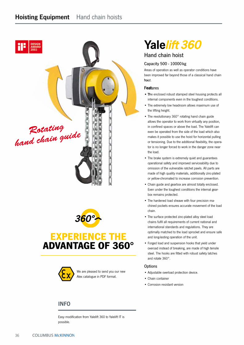
INFO
Easy modification from Yalelift 360 to Yalelift IT ispossible.
Hoisting Equipment Hand chain hoists
Hand chain hoistCapacity 500 - 10000 kgAreas of operation as well as operator conditions have been improved far beyond those of a classical hand chain hoist.
Features• The enclosed robust stamped steel housing protects all
internal components even in the toughest conditions.
• The extremely low headroom allows maximum use of the lifting height.
• The revolutionary 360° rotating hand chain guide allows the operator to work from virtually any position, in confined spaces or above the load. The Yalelift can even be operated from the side of the load which also makes it possible to use the hoist for horizontal pulling or tensioning. Due to the additional flexibility, the opera-tor is no longer forced to work in the danger zone near the load.
• The brake system is extremely quiet and guarantees operational safety and improved serviceability due to omission of the vulnerable ratchet pawls. All parts are made of high quality materials, additionally zinc-plated or yellow-chromated to increase corrosion prevention.
• Chain guide and gearbox are almost totally enclosed. Even under the toughest conditions the internal gear-box remains protected.
• The hardened load sheave with four precision ma-chined pockets ensures accurate movement of the load chain.
• The surface protected zinc-plated alloy steel load chains fulfil all requirements of current national and international standards and regulations. They are optimally matched to the load sprocket and ensure safe and long-lasting operation of the unit.
• Forged load and suspension hooks that yield under overoad instead of breaking, are made of high tensile steel. The hooks are fitted with robust safety latches and rotate 360°.
Options• Adjustable overload protection device.
• Chain container
• Corrosion resistant version
We are pleased to send you our new Atex catalogue in PDF format.
hoist.
Features• The enclosed robust stamped steel housing protects all
internal components even in the toughest conditions.
Rotating
hand chain guide
EXPERIENCE THEADVANTAGE OF 360°

37
Chain guide
Hand chain hoist, 20 tCapacity 20000 kgIn spite of its high capacity, the Yalelift 360 20 t features a compact design.
Features• All components are made of high quality materials,
some components are zinc-plated or yellow-chromated for added corrosion protection. This ensures that also heaviest loads are held reliably.
• The enclosed robust stamped steel body resists in the toughest conditions and allows outside operation.
• The hardened load sheave with five precision machined pockets ensures accurate movement of the load chain.
• The low headroom (hook-to-hook dimension 1065 mm) allows maximum use of the lifting height.
• The Yalelift 360 20 t is equipped with six chain falls only which results in higher speed and lower weight.
Options• Adjustable overload protection device.
• Chain container
• Corrosion resistant version
Hoisting Equipment Hand chain hoists
U P G R A D E
SIMPLE & FLEXIBLEFROM Yalelift 360 TO Yalelift IT
The robust stamped steel housing with four stay bolts is resistant to the toughest working conditions.
38
Hoisting Equipment Hand chain hoists
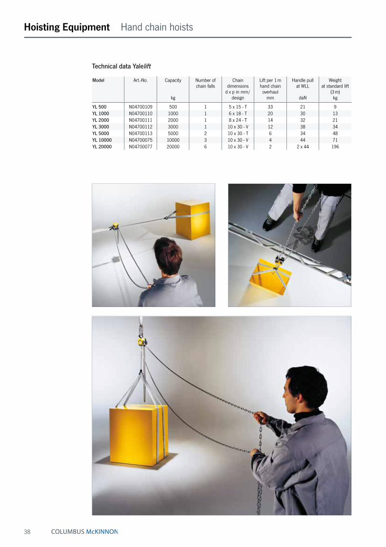
Technical data Yalelift
Model Art.-No. Capacity
kg
Number of chain falls
Chain dimensions
d x p in mm/design
Lift per 1 m hand chain overhaul
mm
Handle pull at WLL
daN
Weight at standard lift
(3 m)kg
YL 500 N04700109 500 1 5 x 15 - T 33 21 9YL 1000 N04700110 1000 1 6 x 18 - T 20 30 13YL 2000 N04700111 2000 1 8 x 24 - T 14 32 21YL 3000 N04700112 3000 1 10 x 30 - V 12 38 34YL 5000 N04700113 5000 2 10 x 30 - T 6 34 48YL 10000 N04700075 10000 3 10 x 30 - V 4 44 71YL 20000 N04700077 20000 6 10 x 30 - V 2 2 x 44 196

39
Hoisting Equipment Hand chain hoists
Model YL 500 YL 1000 YL 2000 YL 3000 YL 5000 YL 10000 YL 20000
A min., mm 300 335 395 520 654 825 1065B, mm 17 22 30 38 45 68 85C, mm 24 29 35 40 47 68 64D, mm 133 156 182 220 220 220 303E, mm 148 175 203 250 250 383 555F, mm 148 167 194 219 219 219 250G, mm 139 164 192 225 242 326 391H, mm 206 242 283 335 352 436 501I, mm 24 24 31 34 21 136 –K, mm 61 70 83 95 95 95 396L, mm 87 97 111 124 124 124 125M, mm 110 125 156 178 285 401 471N, mm 14 19 22 30 37 50 56
Dimensions Yalelift
Yalelift 360, 10000 kg, three falls Yalelift 360, 20000 kg, six falls
Yalelift 360, 500 - 3000 kg, single fall Yalelift 360, 5000 kg, double fall

40
Hoisting Equipment Hand chain hoists
YL IT – Hand chain hoist with integrated push or with integrated geared trolleyCapacity 500 - 20000 kgThe combination of the Yalelift 360 with a low headroom manual trolley provides even more flexibility in the ap-plication.
Features• All units of this series up to a capacity of 3000 kg are
built with a single chain fall, the min. headroom (Dim. A) has been further reduced. Ideal for applications with low ceilings and limited headroom.
• The approved and almost stepless adjustment system of the trolley enables the simple and quick assembly due to adjusting nuts.
• Trolleys up to 5 t capacity are offered for two beam ranges; range A for a flange width of up to 180 mm is standard and covers approx. 80 % of all applications. Conversion to range B for beam width up to 300 mm can be easily accomplished.
• The trolley wheels are designed for a max. beam profile incline of 14 % (DIN 1025 - part 1), excellent rolling fea-tures are guaranteed by pre-lubricated, encapsulated ball bearings.
• Anti-drop and anti-tilt devices as standard.
Options• Adjustable overload protection device.
• Chain container
• Rubber buffers
• Corrosion resistant version
• Beam locking device to secure the unloaded hoist with integrated trolley in a fixed position on the beam (park position e.g. on ships).
Depicted rubber buffers are optionally available!
U P G R A D E
SIMPLE & FLEXIBLEFROM Yalelift 360 TO Yalelift IT
EXPERIENCE THE ADVANTAGE OF 360°
41
Hoisting Equipment Hand chain hoists
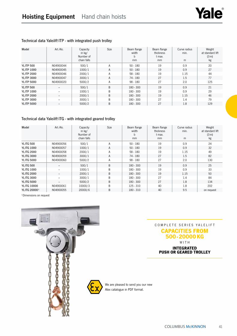
Technical data Yalelift ITP - with integrated push trolley
Model Art.-No. Capacity in kg/
Number of chain falls
Size Beam flange width
bmm
Beam flange thickness
t max.mm
Curve radius min.
m
Weight at standard lift
(3 m)kg
YL ITP 500 N04900044 500/1 A 50 - 180 19 0.9 20YL ITP 1000 N04900045 1000/1 A 50 - 180 19 0.9 27YL ITP 2000 N04900046 2000/1 A 58 - 180 19 1.15 44YL ITP 3000 N04900047 3000/1 A 74 - 180 27 1.5 77YL ITP 5000 N04900020 5000/2 A 98 - 180 27 2.0 125
YL ITP 500 – 500/1 B 180 - 300 19 0.9 21YL ITP 1000 – 1000/1 B 180 - 300 19 0.9 29YL ITP 2000 – 2000/1 B 180 - 300 19 1.15 46YL ITP 3000 – 3000/1 B 180 - 300 27 1.4 79YL ITP 5000 – 5000/2 B 180 - 300 27 1.8 129
Technical data Yalelift ITG - with integrated geared trolley
Model Art.-No. Capacity in kg/
Number of chain falls
Size Beam flange width
bmm
Beam flange thickness
t max.mm
Curve radius min.
m
Weight at standard lift
(3 m)kg
YL ITG 500 N04900056 500/1 A 50 - 180 19 0.9 24YL ITG 1000 N04900057 1000/1 A 50 - 180 19 0.9 32YL ITG 2000 N04900058 2000/1 A 58 - 180 19 1.15 49YL ITG 3000 N04900059 3000/1 A 74 - 180 27 1.5 82YL ITG 5000 N04900060 5000/2 A 98 - 180 27 2.0 130
YL ITG 500 – 500/1 B 180 - 300 19 0.9 25YL ITG 1000 – 1000/1 B 180 - 300 19 0.9 33YL ITG 2000 – 2000/1 B 180 - 300 19 1.15 50YL ITG 3000 – 3000/1 B 180 - 300 27 1.4 84YL ITG 5000 – 5000/2 B 180 - 300 27 1.8 134YL ITG 10000 N04900061 10000/3 B 125 - 310 40 1.8 202YL ITG 20000 ¹ N04900055 20000/6 B 180 - 310 40 9.5 on request
¹ Dimensions on request
We are pleased to send you our new Atex catalogue in PDF format.
C O M P L E T E S E R I E S Y A L E L I F T
CAPACITIES FROM 500 - 20000 KG
W I T H
INTEGRATED PUSH OR GEARED TROLLEY
42
Hoisting Equipment Hand chain hoists
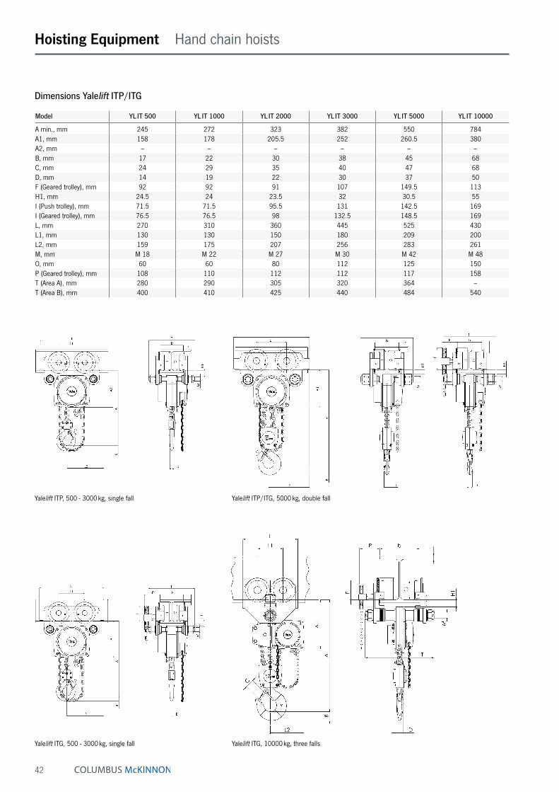
Dimensions Yalelift ITP/ITG
Model YL IT 500 YL IT 1000 YL IT 2000 YL IT 3000 YL IT 5000 YL IT 10000
A min., mm 245 272 323 382 550 784A1, mm 158 178 205.5 252 260.5 380A2, mm – – – – – –B, mm 17 22 30 38 45 68C, mm 24 29 35 40 47 68D, mm 14 19 22 30 37 50F (Geared trolley), mm 92 92 91 107 149.5 113H1, mm 24.5 24 23.5 32 30.5 55I (Push trolley), mm 71.5 71.5 95.5 131 142.5 169I (Geared trolley), mm 76.5 76.5 98 132.5 148.5 169L, mm 270 310 360 445 525 430L1, mm 130 130 150 180 209 200L2, mm 159 175 207 256 283 261M, mm M 18 M 22 M 27 M 30 M 42 M 48O, mm 60 60 80 112 125 150P (Geared trolley), mm 108 110 112 112 117 158T (Area A), mm 280 290 305 320 364 –T (Area B), mm 400 410 425 440 484 540
Yalelift ITG, 500 - 3000 kg, single fall Yalelift ITG, 10000 kg, three falls
Yalelift ITP, 500 - 3000 kg, single fall Yalelift ITP/ITG, 5000 kg, double fall

43
YL LH – Hand chain hoist with integrated push or with integrated geared trolley (low headroom)Capacity 500 - 10000 kgThe hand chain hoist model Yalelift LH with integrated low headroom manual trolley is the consequent further development of the Yalelift IT. Wherever an even smaller headroom is essential, the Yalelift LH is the ideal choice.
Features• The specially developed chain reeving system and
chain guide allow the bottom block to be pulled laterally to the hoist even further up and almost against the beam flange.
• The integrated design of the innovative Yalelift LH uses the same manual trolleys as incorporated in the Yalelift IT series.
• All units of this series up to a capacity of 3000 kg are built with a single chain fall.
• The approved and almost stepless adjustment system of the trolley enables the simple and quick assembly due to adjusting nuts.
• Trolleys up to 5 t capacity are offered for two beam ranges; range A for a flange width of up to 180 mm is standard and covers approx. 80 % of all applications. Conversion to range B for beam width up to 300 mm can be easily accomplished.
• The trolley wheels are designed for a max. beam profile incline of 14 % (DIN 1025 - part 1), excellent rolling fea-tures are guaranteed by pre-lubricated, encapsulated ball bearings.
• The low headroom version of the Yalelift IT is adju stable to fit a wide range of beam profiles (e.g. INP, IPE, IPB).
• Anti-drop and anti-tilt devices as standard.
• Excellent rolling features due to machined steel wheels mounted on pre-lubricated, encapsulated ball bearings.
Options• Adjustable overload protection device.
• Chain container
• Rubber buffers
• Corrosion resistant version
• Beam locking device to secure the unloaded hoist with integrated trolley in a fixed position on the beam (park position e.g. on ships).
Hoisting Equipment Hand chain hoists
Depicted rubber buffers are optionally available!
We are pleased to send you our new Atex catalogue in PDF format.
with
extremely low
headroom
EXPERIENCE THE ADVANTAGE OF 360°
44
Hoisting Equipment Hand chain hoists
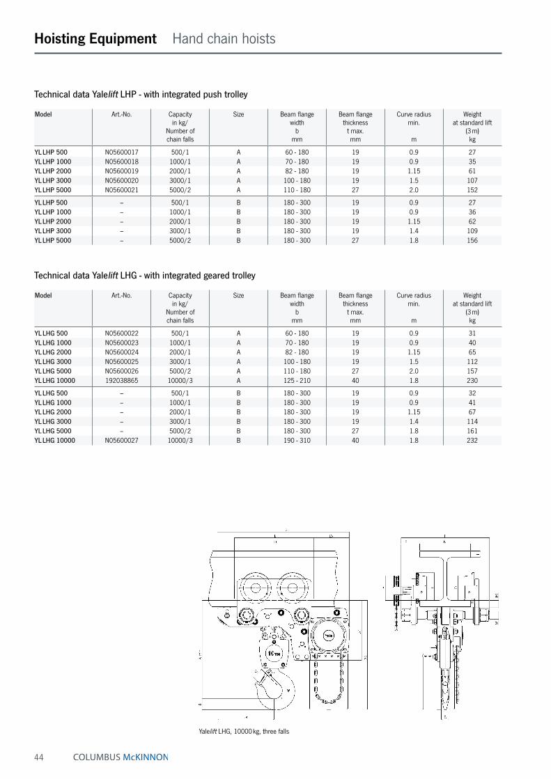
Technical data Yalelift LHP - with integrated push trolley
Model Art.-No. Capacity in kg/
Number of chain falls
Size Beam flange width
bmm
Beam flange thickness
t max.mm
Curve radius min.
m
Weight at standard lift
(3 m)kg
YL LHP 500 N05600017 500/1 A 60 - 180 19 0.9 27YL LHP 1000 N05600018 1000/1 A 70 - 180 19 0.9 35YL LHP 2000 N05600019 2000/1 A 82 - 180 19 1.15 61YL LHP 3000 N05600020 3000/1 A 100 - 180 19 1.5 107YL LHP 5000 N05600021 5000/2 A 110 - 180 27 2.0 152
YL LHP 500 – 500/1 B 180 - 300 19 0.9 27YL LHP 1000 – 1000/1 B 180 - 300 19 0.9 36YL LHP 2000 – 2000/1 B 180 - 300 19 1.15 62YL LHP 3000 – 3000/1 B 180 - 300 19 1.4 109YL LHP 5000 – 5000/2 B 180 - 300 27 1.8 156
Yalelift LHG, 10000 kg, three falls
Technical data Yalelift LHG - with integrated geared trolley
Model Art.-No. Capacity in kg/
Number of chain falls
Size Beam flange width
bmm
Beam flange thickness
t max.mm
Curve radius min.
m
Weight at standard lift
(3 m)kg
YL LHG 500 N05600022 500/1 A 60 - 180 19 0.9 31YL LHG 1000 N05600023 1000/1 A 70 - 180 19 0.9 40YL LHG 2000 N05600024 2000/1 A 82 - 180 19 1.15 65YL LHG 3000 N05600025 3000/1 A 100 - 180 19 1.5 112YL LHG 5000 N05600026 5000/2 A 110 - 180 27 2.0 157YL LHG 10000 192038865 10000/3 A 125 - 210 40 1.8 230
YL LHG 500 – 500/1 B 180 - 300 19 0.9 32YL LHG 1000 – 1000/1 B 180 - 300 19 0.9 41YL LHG 2000 – 2000/1 B 180 - 300 19 1.15 67YL LHG 3000 – 3000/1 B 180 - 300 19 1.4 114YL LHG 5000 – 5000/2 B 180 - 300 27 1.8 161YL LHG 10000 N05600027 10000/3 B 190 - 310 40 1.8 232
45
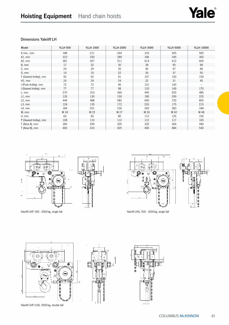
Yalelift LHG, 500 - 3000 kg, single fallYalelift LHP, 500 - 3000 kg, single fall
Hoisting Equipment Hand chain hoists
Yalelift LHP/LHG, 5000 kg, double fall
Dimensions Yalelift LH
Model YLLH 500 YLLH 1000 YLLH 2000 YLLH 3000 YLLH 5000 YLLH 10000
A min., mm 188 211 264 316 425 565A1, mm 223 250 289 346 345 365A2, mm 381 427 511 614 612 665B, mm 17 22 30 38 45 68C, mm 24 29 35 40 47 68D, mm 14 19 22 30 37 50F (Geared trolley), mm 92 92 91 107 150 150H1, mm 24 24 24 32 31 45I (Push trolley), mm 72 72 96 131 143 –I (Geared trolley), mm 77 77 98 133 149 170L, mm 270 310 360 445 525 485L1, mm 130 130 150 180 209 225L2, mm 444 488 582 690 720 805L3, mm 124 135 172 203 175 215L4, mm 184 201 230 265 283 348M, mm M 18 M 22 M 27 M 30 M 42 M 48O, mm 60 60 80 112 125 150P (Geared trolley), mm 108 110 112 112 117 165T (Area A), mm 280 290 305 320 364 440T (Area B), mm 400 410 425 440 484 540
46
Hoisting Equipment Hand chain hoists
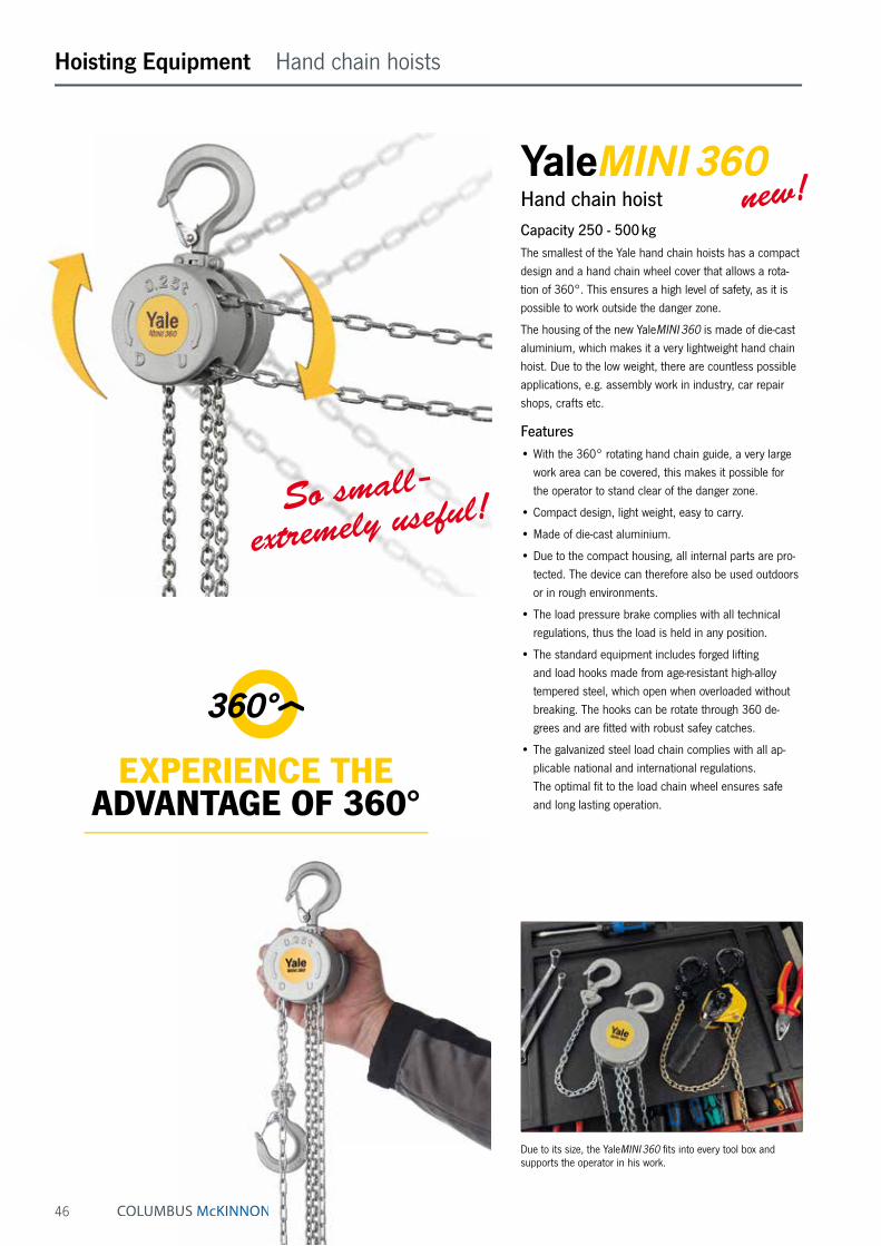
Hand chain hoistCapacity 250 - 500 kgThe smallest of the Yale hand chain hoists has a compact design and a hand chain wheel cover that allows a rota-tion of 360°. This ensures a high level of safety, as it is possible to work outside the danger zone.
The housing of the new YaleMINI 360 is made of die-cast aluminium, which makes it a very lightweight hand chain hoist. Due to the low weight, there are countless possible applications, e.g. assembly work in industry, car repair shops, crafts etc.
Features• With the 360° rotating hand chain guide, a very large
work area can be covered, this makes it possible for the operator to stand clear of the danger zone.
• Compact design, light weight, easy to carry.
• Made of die-cast aluminium.
• Due to the compact housing, all internal parts are pro-tected. The device can therefore also be used outdoors or in rough environments.
• The load pressure brake complies with all technical regulations, thus the load is held in any position.
• The standard equipment includes forged lifting and load hooks made from age-resistant high-alloy tempered steel, which open when overloaded without breaking. The hooks can be rotate through 360 de-grees and are fitted with robust safey catches.
• The galvanized steel load chain complies with all ap-plicable national and international regulations. The optimal fit to the load chain wheel ensures safe and long lasting operation.
Due to its size, the YaleMINI 360 fits into every tool box and supports the operator in his work.
new!
So small -
extremely useful!
EXPERIENCE THEADVANTAGE OF 360°
47
Hoisting Equipment Hand chain hoists
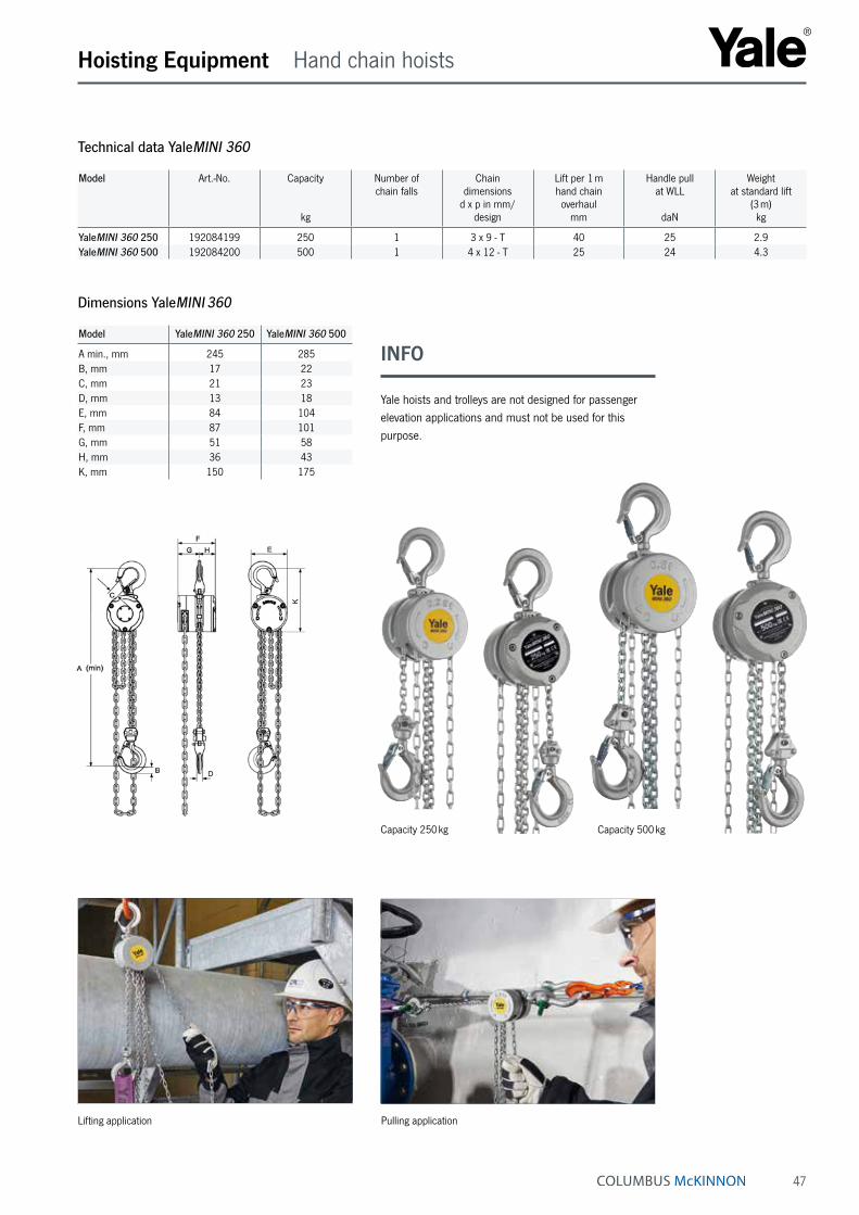
Lifting application
Capacity 250 kg Capacity 500 kg
Technical data YaleMINI 360
Model Art.-No. Capacity
kg
Number of chain falls
Chain dimensions
d x p in mm/design
Lift per 1 m hand chain overhaul
mm
Handle pull at WLL
daN
Weight at standard lift
(3 m)kg
YaleMINI 360 250 192084199 250 1 3 x 9 - T 40 25 2.9YaleMINI 360 500 192084200 500 1 4 x 12 - T 25 24 4.3
Model YaleMINI 360 250 YaleMINI 360 500
A min., mm 245 285B, mm 17 22C, mm 21 23D, mm 13 18E, mm 84 104F, mm 87 101G, mm 51 58H, mm 36 43K, mm 150 175
Dimensions YaleMINI 360
INFO
Yale hoists and trolleys are not designed for passenger elevation applications and must not be used for this purpose.
Pulling application
48
Corrosion protectionWhat does corrosion actually mean?Corrosion is a term from the Latin “corrodere” and means to decompose or eat away and is, from a technical point of view the reaction of a material with its environment. In popular speech, metals are also referred as “rusting”.
How does corrosion occur?Nowadays, metals are exposed to a wide variety of envi-ronmental influences, such as climate and air pollution. This can change their structure. Especially with metals such as iron or steel, oxide formation has a negative effect on the material. Rust develops as a product of corrosion. In untreated or damaged areas, humidity can hit the metal surface and thus attack it. The corresponding area begins to corrode to the point of rusting through completely.
Types of corrosionTechnically speaking, types of corrosion are classified according to material, cause and appearance and also according to where they occur. The standard DIN EN ISO 8044 defines 37 different types of corrosion. One of the best-known types of corrosion is contact cor-rosion, in which an electrochemical reaction between two different metallic materials in conjunction with e.g. humid-ity leads to corrosion of the less noble metal.
Other types of corrosion can be:
• pitting corrosion
• surface corrosion
• vibration corrosion cracking
• gap corrosion, etc.
Areas of applicationCorrosion-protected equipment with galvanised load or hand chains or rust and acid-resistant chains should be used wherever increased demands are made on corrosion resistance are required. Typical applications are in the food industry (e.g. dairies, slaughterhouses, etc.), the chemical industry (e.g. paper industry, colouring), agricul-ture or wastewater treatment plants.
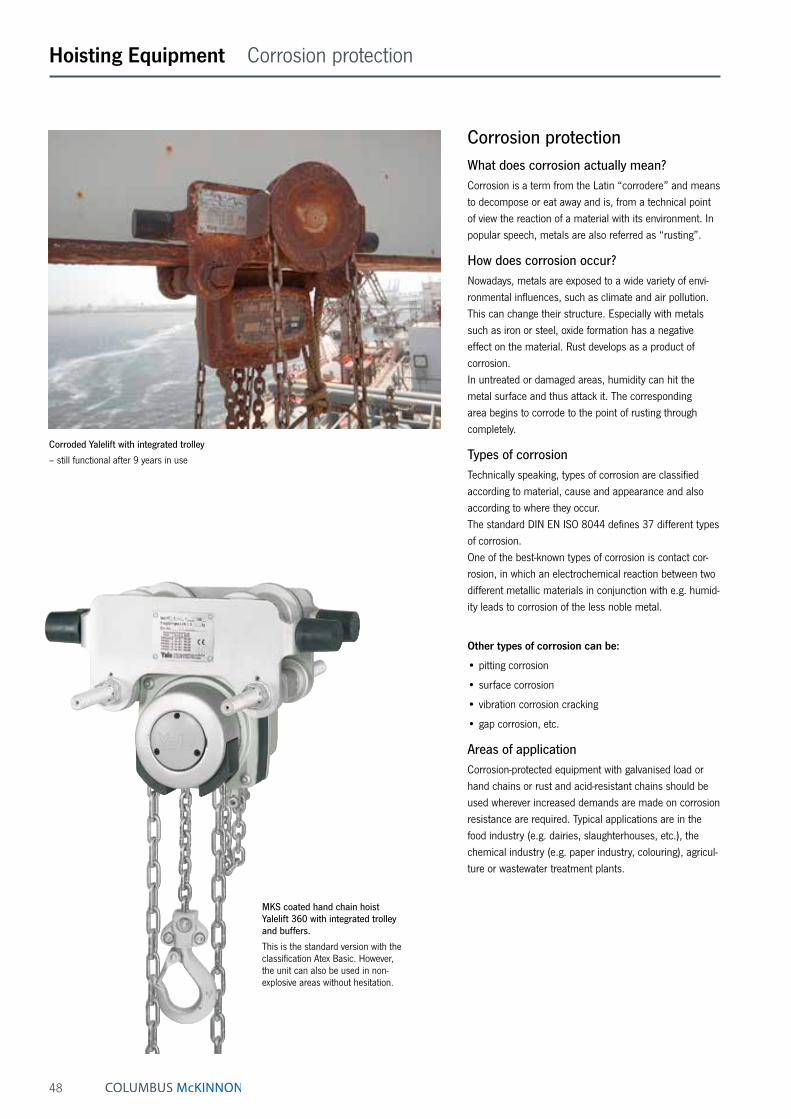
Corroded Yalelift with integrated trolley
– still functional after 9 years in use
Hoisting Equipment Corrosion protection
MKS coated hand chain hoist Yalelift 360 with integrated trolley and buffers.
This is the standard version with the classification Atex Basic. However, the unit can also be used in non-explosive areas without hesitation.

49
INFO
Corrosion causes annually in Germany alone 75 billion € damage!
Hoisting Equipment Corrosion protection
Preventive corrosion protectionTo prevent early corrosion, all our products are coated. This coating varies depending on the model and is carried out in the form of a wet coating, powder or MKS coating.
For specifications on corrosion protection, the DIN EN ISO 12944 series of standards is used in many cases. This series of standards is used for steel structures or structures whose components are made of unalloyed or low-alloyed steel with a thickness of at least 3 mm and which are designed in accordance with a structural safety designed.
We can only base our products on the corrosivity cat-egories contained in this series of standards (see table below). For some models, increased corrosion protection can be achieved by applying additional or thicker coatings. You will find a detailed list on the next page.
Corrosion protection classes in accordance to DIN EN ISO 12944
Atmospheric-Corrosivity categories, Corrosion stress
Corrosivity Corrosion protection period
Protection period in years
Examples of typical environments
C1 very low
very low low-aggressive
inside
short (L) medium (M)
long (H) very long (VH)
up to 7 7 to 15 15 to 25
> 25
Only indoor rooms, insulated buildings 60 % relative humidity
C2 low
low moderate aggressive
outside/inside
short (L) medium (M)
long (H) very long (VH)
up to 7 7 to 15 15 to 25
> 25
Slightly polluted atmosphere, dry climate, e.g. rural areas
C3 medium
moderate low-aggressive
outside
short (L) medium (M)
long (H) very long (VH)
up to 7 7 to 15 15 to 25
> 25
City and industrial atmosphere with moderate SO₂ pollution or moderate climate
C4 high
high moderately aggressive
outside/inside
short (L) medium (M)
long (H) very long (VH)
up to 7 7 to 15 15 to 25
> 25
Industrial and coastal atmosphere with moderate salt pollution
C5 very high
very high aggressive
outside/inside
short (L) medium (M)
long (H) very long (VH)
up to 7 7 to 15 15 to 25
> 25
Industrial atmosphere with high relative humidity and aggressive atmosphere as well as coastal atmosphere with high salt content
CX extremely
very high maritim
outside/inside
short (L) medium (M)
long (H) very long (VH)
up to 7 7 to 15 15 to 25
> 25
Offshore areas with high salt content, industrial areas with extreme humidity and aggressive atmosphere as well as subtropical and tropical atmosphere
50
Hoisting Equipment Corrosion protection
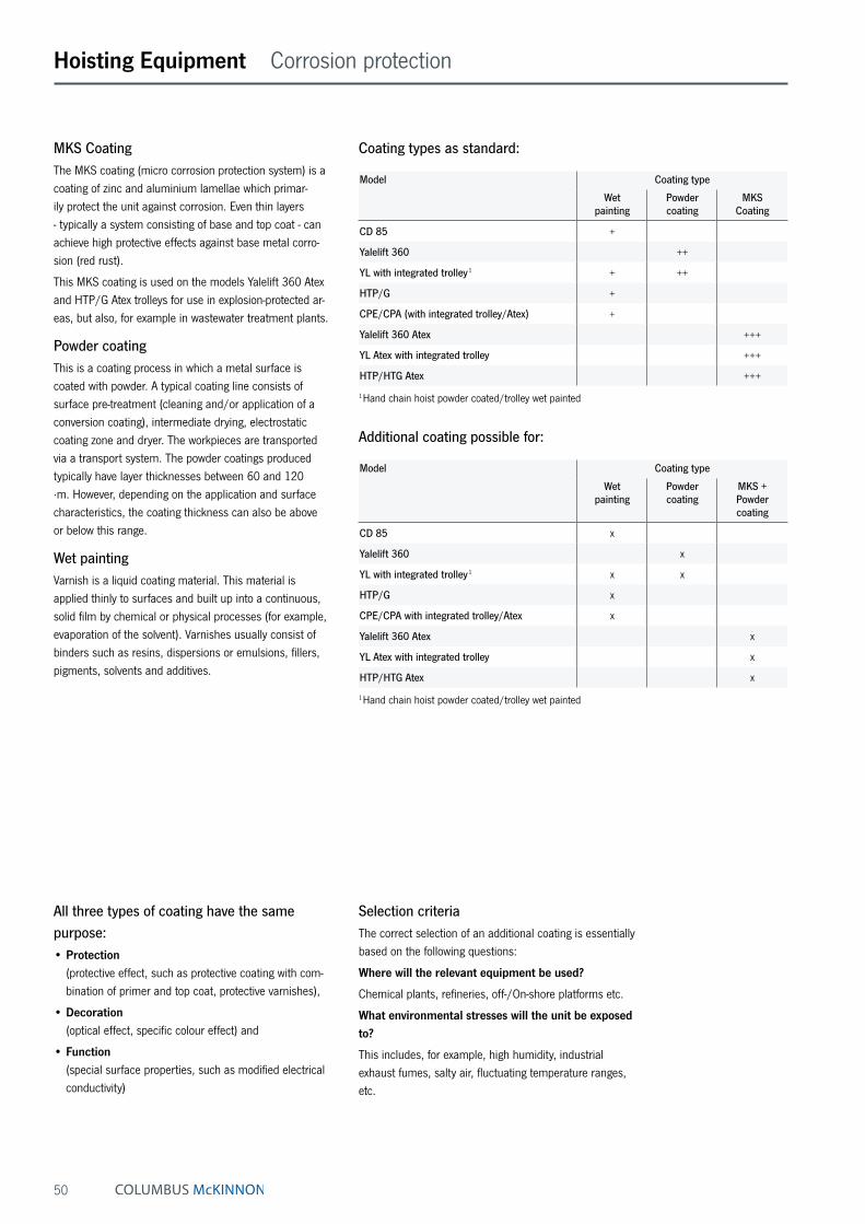
All three types of coating have the same purpose:• Protection
(protective effect, such as protective coating with com-bination of primer and top coat, protective varnishes),
• Decoration (optical effect, specific colour effect) and
• Function (special surface properties, such as modified electrical conductivity)
MKS CoatingThe MKS coating (micro corrosion protection system) is a coating of zinc and aluminium lamellae which primar-ily protect the unit against corrosion. Even thin layers - typically a system consisting of base and top coat - can achieve high protective effects against base metal corro-sion (red rust).
This MKS coating is used on the models Yalelift 360 Atex and HTP/G Atex trolleys for use in explosion-protected ar-eas, but also, for example in wastewater treatment plants.
Powder coatingThis is a coating process in which a metal surface is coated with powder. A typical coating line consists of surface pre-treatment (cleaning and/or application of a conversion coating), intermediate drying, electrostatic coating zone and dryer. The workpieces are transported via a transport system. The powder coatings produced typically have layer thicknesses between 60 and 120 μm. However, depending on the application and surface characteristics, the coating thickness can also be above or below this range.
Wet paintingVarnish is a liquid coating material. This material is applied thinly to surfaces and built up into a continuous, solid film by chemical or physical processes (for example, evaporation of the solvent). Varnishes usually consist of binders such as resins, dispersions or emulsions, fillers, pigments, solvents and additives.
Model Coating type
Wet painting
Powder coating
MKS Coating
CD 85 +
Yalelift 360 ++
YL with integrated trolley 1 + ++
HTP/G +
CPE/CPA (with integrated trolley/Atex) +
Yalelift 360 Atex +++
YL Atex with integrated trolley +++
HTP/HTG Atex +++
1 Hand chain hoist powder coated/trolley wet painted
Coating types as standard:
Model Coating type
Wet painting
Powder coating
MKS + Powder coating
CD 85 x
Yalelift 360 x
YL with integrated trolley 1 x x
HTP/G x
CPE/CPA with integrated trolley/Atex x
Yalelift 360 Atex x
YL Atex with integrated trolley x
HTP/HTG Atex x
1 Hand chain hoist powder coated/trolley wet painted
Additional coating possible for:
Selection criteriaThe correct selection of an additional coating is essentially based on the following questions:
Where will the relevant equipment be used?
Chemical plants, refineries, off-/On-shore platforms etc.
What environmental stresses will the unit be exposed to?
This includes, for example, high humidity, industrial exhaust fumes, salty air, fluctuating temperature ranges, etc.

51
Hoisting Equipment Corrosion protection
80 µm70 µm 200µm160µm120µm
C2C1 C5C4C3
80 µm70 µm
80 µm80 µm80 µm
104 µm
64 µm
30 µm
Layer thickness
Layer thickness structure in general
MKS Basecoat 8 µmMKS Topcoat 8 µm
MKS Basecoat 8 µmMKS Topcoat 8 µm
Degreased and Phosphates
Degreased and Phosphates
Sandblasted Sandblasted SandblastedPrimer
20
60
120
200
INFO
When measuring the coating thickness, slight deviations from the values given here are possible, depending on the measuring point.
A coating protocol can be prepared on request, at an additional charge.
Inspection points of dry film thickness (DFT)
Order No.:
Model:
Serial No.:
Tag No.:
Note:The dimensional unit for all specified measured values is µm!
P = Powder coatingN = Wet paint coatingMP = Measure Point Date:
Sign:
MP 2
P
NMP 4
P
N
MP 5
P
N
MP 6
P
N
MP 1
P
N
MP 3
P
N
Up to C3 we cover all standard coatings (wet painting and powder coating) on our products.This means that the corrosivity categories C1 and C2 are also covered.

52
Hoisting Equipment Beam clamp
YCBeam clampCapacity 1000 - 10000 kgProvides a quick and versatile rigging point for hoisting
equipment, pulley blocks or loads. Flexible application due
to wide adjustment range. The central threaded spindle
allows easy attachment and a safe and secure grip.
The spindle can be secured against loosening.
Technical data YC
Model Art.-No. Capacitykg
Beam flange widthmm
Weightkg
YC 1 NO5406181 1000 75 - 230 3.4YC 2 NO5406182 2000 75 - 230 3.8YC 3 NO5407417 3000 80 - 320 7.6YC 5 NO5407418 5000 90 - 320 11.0YC 10 NO5407419 10000 90 - 320 17.2
Model YC 1 YC 2 YC 3 YC 5 YC 10
A min., mm 115 115 180 180 175A max., mm 150 150 225 225 220A1, mm 78 78 85 95 95A2, mm 246 246 325 325 325B1, mm 186 186 232 242 268B2, mm 350 350 455 445 480b1, mm 75 75 80 90 90b2, mm 230 230 320 320 320C, mm 50 50 70 70 70D, mm 3 4 6 10 14E, mm 215 215 255 255 275F1, mm 34 35 35 35 35F2, mm 17 18 21 21 20G1, mm 82 82 120 116 110G2, mm 44 44 75 75 66H, mm 20 20 22 28 38J1, mm 14 14 30 30 34J2, mm 21 21 34 34 35K1, mm 48 50 60 60 60K2, mm 31 32 40 42 40L, mm 80 86 114 129 146
Dimensions YC
E
Am
in.
K2
G2
J2
B2A2b2
F2
max
.
b1
A1
B1
F1
K1
G1
JA
1
C
H
D
L
INFO
Yale hoists and trolleys are not designed for passenger elevation applications and must not be used for this purpose.
Useable as a horizontal rigging point. Also applicable as lifting clamp..
E
Am
in.
K2
G2
J2
B2A2b2
F2
max
.
b1
A1
B1
F1
K1
G1
JA
1
C
H
D
L
53
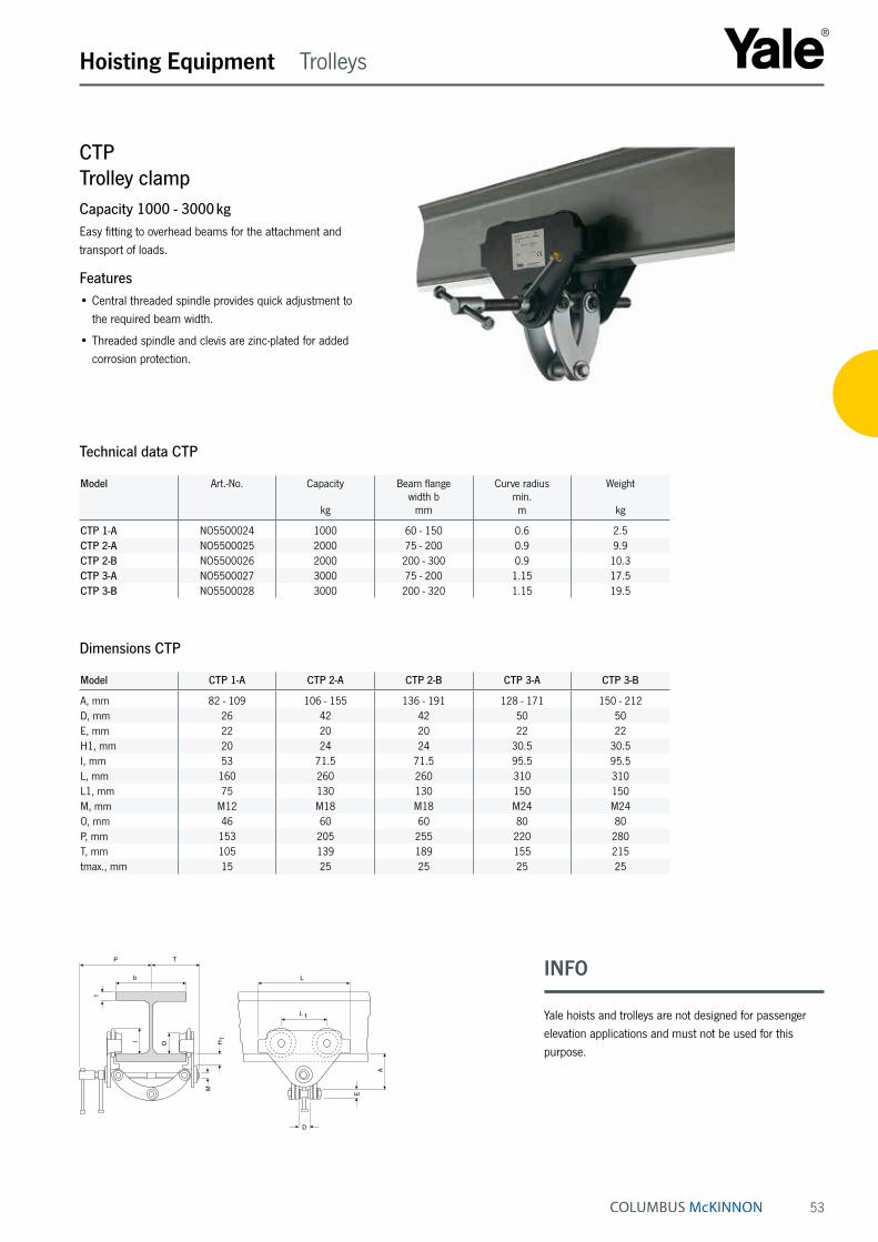
CTPTrolley clampCapacity 1000 - 3000 kgEasy fitting to overhead beams for the attachment and transport of loads.
Features• Central threaded spindle provides quick adjustment to
the required beam width.
• Threaded spindle and clevis are zinc-plated for added corrosion protection.
Hoisting Equipment Trolleys
Technical data CTP
Model Art.-No. Capacity
kg
Beam flange width b
mm
Curve radius min.m
Weight
kg
CTP 1-A NO5500024 1000 60 - 150 0.6 2.5CTP 2-A NO5500025 2000 75 - 200 0.9 9.9CTP 2-B NO5500026 2000 200 - 300 0.9 10.3CTP 3-A NO5500027 3000 75 - 200 1.15 17.5CTP 3-B NO5500028 3000 200 - 320 1.15 19.5
Model CTP 1-A CTP 2-A CTP 2-B CTP 3-A CTP 3-B
A, mm 82 - 109 106 - 155 136 - 191 128 - 171 150 - 212D, mm 26 42 42 50 50E, mm 22 20 20 22 22H1, mm 20 24 24 30.5 30.5I, mm 53 71.5 71.5 95.5 95.5L, mm 160 260 260 310 310L1, mm 75 130 130 150 150M, mm M12 M18 M18 M24 M24O, mm 46 60 60 80 80P, mm 153 205 255 220 280T, mm 105 139 189 155 215tmax., mm 15 25 25 25 25
Dimensions CTP
D
E
A
L
L 1
H1
M
OI
b
P T
t
INFO
Yale hoists and trolleys are not designed for passenger elevation applications and must not be used for this purpose.
54
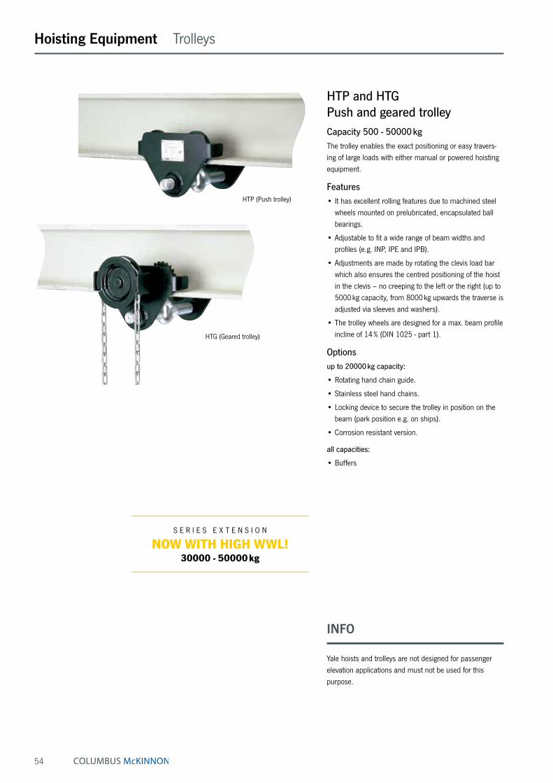
HTP (Push trolley)
HTG (Geared trolley)
Hoisting Equipment Trolleys
INFO
Yale hoists and trolleys are not designed for passenger elevation applications and must not be used for this purpose.
S E R I E S E X T E N S I O N
NOW WITH HIGH WWL!30000 - 50000 kg
HTP and HTGPush and geared trolleyCapacity 500 - 50000 kgThe trolley enables the exact positioning or easy travers-ing of large loads with either manual or powered hoisting equipment.
Features• It has excellent rolling features due to machined steel
wheels mounted on prelubricated, encapsulated ball bearings.
• Adjustable to fit a wide range of beam widths and profiles (e.g. INP, IPE and IPB).
• Adjustments are made by rotating the clevis load bar which also ensures the centred positioning of the hoist in the clevis – no creeping to the left or the right (up to 5000 kg capacity, from 8000 kg upwards the traverse is adjusted via sleeves and washers).
• The trolley wheels are designed for a max. beam profile incline of 14 % (DIN 1025 - part 1).
Optionsup to 20000 kg capacity:
• Rotating hand chain guide.
• Stainless steel hand chains.
• Locking device to secure the trolley in position on the beam (park position e.g. on ships).
• Corrosion resistant version.
all capacities:
• Buffers

55
Hoisting Equipment Trolleys
Technical data HTP
Model Art.-No. Capacity
kg
Size Beam flange width
bmm
Beam flange thickness
t max.mm
Curve radius min.
m
Hand effort at WLL
daN
Weight
kg
Weight with
locking devicekg
HTP 500 N05141273 500 A 50 - 220 25 0.9 – 8.0 14.5HTP 1000 N05141274 1000 A 50 - 220 25 0.9 – 9.0 17.0HTP 2000 N05141275 2000 A 66 - 220 25 1.15 – 16.0 24.0HTP 3000 N05141276 3000 A 74 - 220 25 1.4 – 32.0 41.2HTP 5000 N05141277 5000 A 90 - 220 25 1.8 – 48.0 58.5
HTP 500 N05148305 500 B 160 - 300 40 0.9 – 10.6 17.1HTP 1000 N05148306 1000 B 160 - 300 40 0.9 – 12.0 20.0HTP 2000 N05148307 2000 B 160 - 300 40 1.15 – 19.3 27.3HTP 3000 N05148308 3000 B 160 - 300 40 1.4 – 35.8 45.0HTP 5000 N05148309 5000 B 180 - 300 40 1.8 – 52.2 62.7
Technical data HTG
Model Art.-No. Capacity
kg
Size Beam flange width
bmm
Beam flange thickness
t max.mm
Curve radius min.
m
Hand effort at WLL
daN
Weight ¹
kg
Weight ¹ with
locking devicekg
HTG 500 N05300006 500 A 50 - 220 25 0.9 3 97 16.2HTG 1000 N05300007 1000 A 50 - 220 25 0.9 6 11.2 19.2HTG 2000 N05300008 2000 A 66 - 220 25 1.15 7 18.0 26.0HTG 3000 N05300009 3000 A 74 - 220 25 1.4 7 35.4 44.6HTG 5000 N05300010 5000 A 90 - 220 25 1.8 9 51.8 62.3
HTG 500 N05300011 500 B 160 - 300 40 0.9 3 12.6 19.1HTG 1000 N05300012 1000 B 160 - 300 40 0.9 6 14.1 22.1HTG 2000 N05300013 2000 B 160 - 300 40 1.15 7 21.3 29.3HTG 3000 N05300014 3000 B 160 - 300 40 1.4 7 39.2 48.4HTG 5000 N05300015 5000 B 180 - 300 40 1.8 9 56.0 66.5HTG 8000 N05300016 8000 B 125 - 310 40 1.8 14 104.0 –HTG 10000 N05300017 10000 B 125 - 310 40 1.8 14 104.0 –HTG 15000 N05300018 15000 B 125 - 310 40 5.0 29 230.0 –HTG 20000 N05300019 20000 B 125 - 310 40 5.0 29 230.0 –HTG 30000 192045613 30000 B 175 - 305 34 1.6 24 248.0 –HTG 50000 192045614 50000 B 175 - 305 34 5.1 25 489.0 –
¹ Weight HTG: without hand chain
We are pleased to send you our new Atex catalogue in PDF format.

56
Hoisting Equipment Trolleys
Dimensions HTP
Model HTP 500-A
HTP 1000-A
HTP 2000-A
HTP 3000-A
HTP 5000-A
HTP 500-B
HTP 1000-B
HTP 2000-B
HTP 3000-B
HTP 5000-B
A, mm 77 82.5 98.5 114 132.5 92 97.5 113.5 129 147.5D, mm 16 17 22 26 33 16 17 22 26 33D1, mm 25 30 40 48 60 25 30 40 48 60D2, mm 30 35 47 58 70 30 35 47 58 70F1, mm 57.5 57.5 57.5 57.5 57.5 57.5 57.5 57.5 57.5 57.5H1, mm 30.5 30.5 30.5 30 30 45.5 45.5 45.5 45 49.5I (HTP), mm 71.5 71.5 95.5 131 142.5 71.5 71.5 95.5 131 142.5L, mm 260 260 310 390 450 260 260 310 390 450L1, mm 130 130 150 180 209 130 130 150 180 209O, mm 60 60 80 112 125 60 60 80 112 125P1, mm 168 168 168 168 168 168 168 168 168 168P2, mm 146 150 155 160 167.5 177 177 177 180 187.5L3, mm 346 346 396 476 556 346 346 396 476 556
Dimensions HTG
Model HTG 500-A
HTG 1000-A
HTG 2000-A
HTG 3000-A
HTG 5000-A
HTG 500-B
HTG 1000-B
HTG 2000-B
HTG 3000-B
HTG 5000-B
A, mm 77 82.5 98.5 114 132.5 92 97.5 113.5 129 147.5D, mm 16 17 22 26 33 16 17 22 26 33D1, mm 25 30 40 48 60 25 30 40 48 60D2, mm 30 35 47 58 70 30 35 47 58 70F (HTG), mm 91.5 91.5 90.5 107.5 149.5 91.5 91.5 90.5 107.5 149.5F1, mm 57.5 57.5 57.5 57.5 57.5 57.5 57.5 57.5 57.5 57.5H1, mm 30.5 30.5 30.5 30 30 45.5 45.5 45.5 45 45I (HTG), mm 76.5 76.5 98 132.5 148.5 76.5 76.5 98 132.5 148.5L, mm 260 260 310 390 450 260 260 310 390 450L1, mm 130 130 150 180 209 130 130 150 180 209O, mm 60 60 80 112 125 60 60 80 112 125P (HTG), mm 110 110 110 110 110 110 110 110 110 110P1, mm 168 168 168 168 168 168 168 168 168 168P2, mm 146 150 155 160 167.5 187 187 189.5 191.5 191.5L3, mm 346 346 396 476 556 346 346 396 476 556P3, mm 194 194 194 195 195 194 194 194 195 195
Dimensions HTG
Model HTG 8000-B
HTG 10000-B
HTG 15000-B
HTG 20000-B
HTG30000-B
HTG50000-B
A, mm 276 276 270 270 261 310B, mm 52 52 70 70 65 100D, mm 30 30 35 35 35 60D1, mm 80 80 110 110 90 125D2, mm 114 114 155 155 125 195F (HTG), mm 113 113 113 113 93 93F1, mm 77 77 – – – –H1, mm 45 45 45 45 40 40I (HTG), mm 170 170 170 170 224 224L, mm 430 430 870 870 625 1.260L1, mm 200 200 200 200 296 296L2, mm – – 115 115 164.5 164.5O, mm 150 150 150 150 196 196P (HTG), mm 163 163 163 163 165 165P1, mm 193 193 – – – –T, mm 270 270 270 270 333 343L3, mm 536 536 976 976 – –
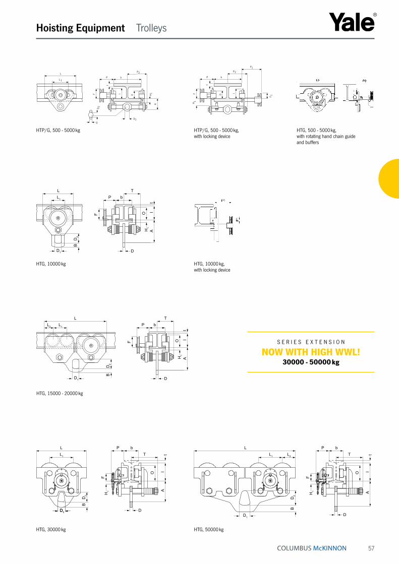
57
P
P
b
D1
2
2
H1
A
t
OIF
D
D
L 1
L
Hoisting Equipment Trolleys
P b
F
P1
H1
t
F 1
P2
O I
LL1
BD
2
D1
P bT
O IA
tH
1
F
D
LL2 L1 P b
T
O IA
tH
1
F
DD1
BD
2
A
TL P bL1
D1D1 D
BD
2 H1
F
O IA
t
A
LL1
D1
BD
2
TP b
D
H1
F
O IA
tL2
HTG, 500 - 5000 kg, with rotating hand chain guide and buffers
HTP/G, 500 - 5000 kg
HTP/G, 500 - 5000 kg, with locking device
HTG, 10000 kg HTG, 10000 kg, with locking device
HTG, 15000 - 20000 kg
HTG, 30000 kg HTG, 50000 kg
S E R I E S E X T E N S I O N
NOW WITH HIGH WWL!30000 - 50000 kg
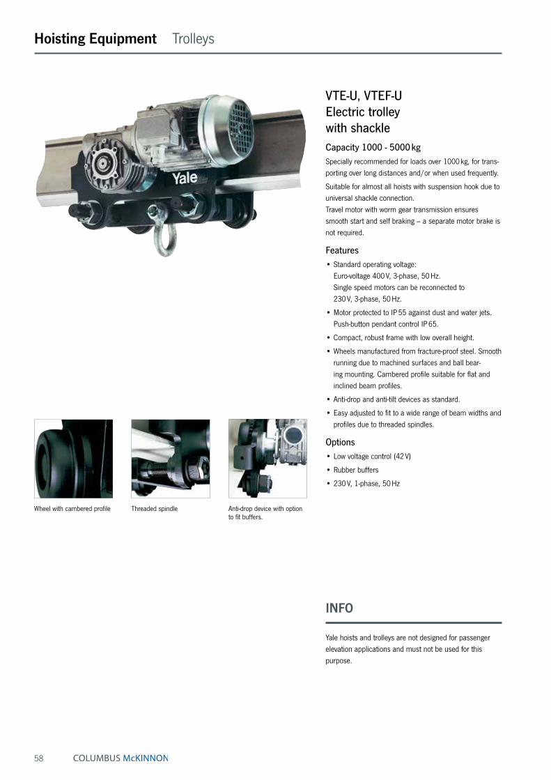
58
VTE-U, VTEF-UElectric trolley with shackleCapacity 1000 - 5000 kgSpecially recommended for loads over 1000 kg, for trans-porting over long distances and/or when used frequently.
Suitable for almost all hoists with suspension hook due to universal shackle connection. Travel motor with worm gear transmission ensures smooth start and self braking – a separate motor brake is not required.
Features• Standard operating voltage:
Euro-voltage 400 V, 3-phase, 50 Hz. Single speed motors can be reconnected to 230 V, 3-phase, 50 Hz.
• Motor protected to IP 55 against dust and water jets. Push-button pendant control IP 65.
• Compact, robust frame with low overall height.
• Wheels manufactured from fracture-proof steel. Smooth running due to machined surfaces and ball bear-ing mounting. Cambered profile suitable for flat and inclined beam profiles.
• Anti-drop and anti-tilt devices as standard.
• Easy adjusted to fit to a wide range of beam widths and profiles due to threaded spindles.
Options• Low voltage control (42 V)
• Rubber buffers
• 230 V, 1-phase, 50 Hz
Hoisting Equipment Trolleys
INFO
Yale hoists and trolleys are not designed for passenger elevation applications and must not be used for this purpose.
Wheel with cambered profile Threaded spindle Anti-drop device with option to fit buffers.
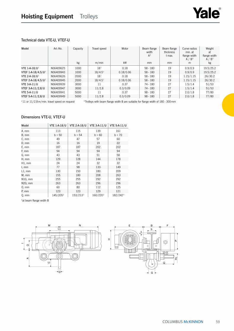
59
Hoisting Equipment Trolleys
Technical data VTE-U, VTEF-U
Model Art.-No. Capacity
kg
Travel speed
m/min
Motor
kW
Beam flange width
A 2
mm
Beam flange thickness
t max.
mm
Curve radius min. at
flange width A / B 2
m
Weight at
flange width A / B 2
kg
VTE 1-A-18/U 1 N06409625 1000 18 1 0.18 58 - 180 19 0.9/0.9 19.5/25.2VTEF 1-A-18/4,5/U 1 N06409943 1000 18/4.5 1 0.18/0.06 58 - 180 19 0.9/0.9 19.5/25.2VTE 2-A-18/U 1 N06409626 2000 18 1 0.18 58 - 180 19 1.15/1.15 26/30.2VTEF 2-A-18/4,5/U 1 N06409945 2000 18/4.5 1 0.18/0.06 58 - 180 19 1.15/1.15 26/30.2VTE 3-A-11/U N06409939 3000 11 0.37 74 - 180 27 1.5/1.4 51/53VTEF 3-A-11/2,8/U N06409947 3000 11/2.8 0.3/0.09 74 - 180 27 1.5/1.4 51/53VTE 5-A-11/U N06409941 5000 11 0.37 98 - 180 27 2.0/1.8 77/80VTEF 5-A-11/2,8/U N06409949 5000 11/2.8 0.3/0.09 98 - 180 27 2.0/1.8 77/80
¹ 11 or 11/2.8 m/min. travel speed on request 2 Trolleys with beam flange width B are suitable for flange width of 180 - 300 mm
Dimensions VTE-U, VTEF-U
Model VTE 1-A-18/U VTE 2-A-18/U VTE 3-A-11/U VTE 5-A-11/U
A, mm 113 115 139 161B, mm b + 50 b + 54 b + 60 b + 70C, mm 49 47 57 60D, mm 16 16 19 22E, mm 187 187 202 202F, mm 94 94 94 94G, mm 43 43 51 58H, mm 129 128 144 178H1, mm 24 24 32 32I, mm 77 98 133 149L1, mm 130 150 180 209M, mm 155 180 208 263N1G, mm 255 255 292 292N2G, mm 263 263 296 296O, mm 60 80 112 125P, mm 123 123 129 121Q, mm 145/205 3 153/213 3 160/220 3 182/242 3
3 at beam flange width B
L1
1
M N
D
I
OA
C
G
P
bFBE
H
t
Q
H
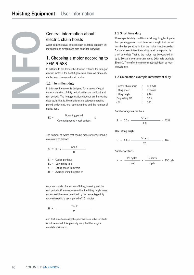
60
Hoisting Equipment User information
INFO
General information about electric chain hoistsApart from the usual criterion such as lifting capacity, lift-ing speed and dimensions also consider following:
1. Choosing a motor according to FEM 9.683In addition to the torque the decisive criterion for rating an electric motor is the heat it generates. Here we differenti-ate between two operational modes:
1.1 Intermittent dutyIn this case the motor is designed for a series of equal cycles consisting of duty periods with constant load and rest periods. The heat generation depends on the relative duty cycle, that is, the relationsship between operating period under load, total operating time and the number of starts/hour.
Operating period ED = % Operating period + rest periods
The number of cycles that can be made under full load is calculated as follows:
ED x V S ≈ 0.3 x H
S = Cycles per hour ED = Duty rating in % V = Lifting speed in m/min H = Average lifting height in m
A cycle consists of a motion of lifting, lowering and the rest periods. One must ensure that the lifting height does not exceed the value permitted by the percentage duty cycle referred to a cycle period of 10 minutes
ED x V H ≤ 20
and that simultaneously the permissible number of starts is not exceeded. It is generally accepted that a cycle consists of 6 starts.
1.2 Short time dutyWhere special duty conditions exist (e.g. long hook path) the operating period must be of such length that the ad-missible temperature limit of the motor is not exceeded. For such cases intermittent duty must be replaced by short time duty. That is, the motor may be operated for up to 10 starts over a certain period (with Yale products 30 min). Thereafter the motor must cool down to room temperature.
1.3 Calculation example intermittant duty Electric chain hoist : CPV 5-8 Lifting speed : 8 m/min Lifting height : 2,8 m Duty rating ED : 50 % c/h : 180
Number of cycles per hour
50 x 8 S = 0.3 x = 42.8 2.8
Max. lifting height
50 x 8 H = 2.8 ≤ = 20 m 20
Number of starts
25 cycles 6 starts N = x = 150 c/h hour cycle
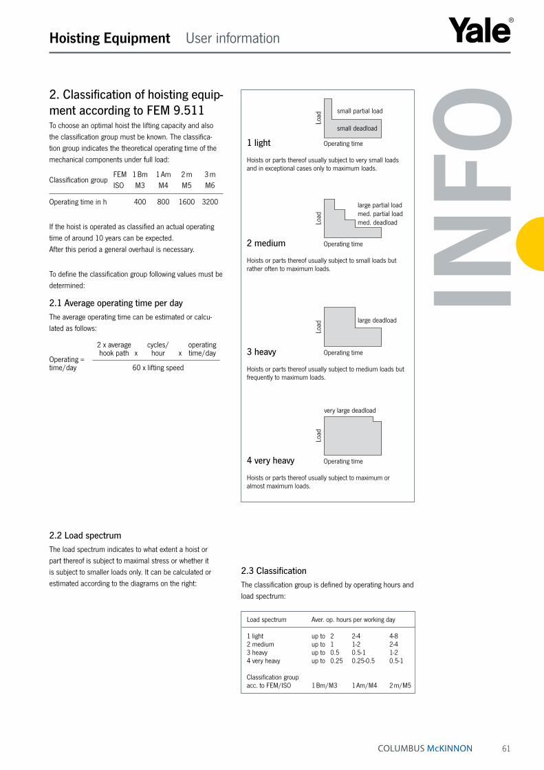
61
Hoisting Equipment User information
INFO
2. Classification of hoisting equip-ment according to FEM 9.511To choose an optimal hoist the lifting capacity and also the classification group must be known. The classifica-tion group indicates the theoretical operating time of the mechanical components under full load:
FEM 1 Bm 1 Am 2 m 3 mClassification group ISO M3 M4 M5 M6
Operating time in h 400 800 1600 3200
If the hoist is operated as classified an actual operating time of around 10 years can be expected. After this period a general overhaul is necessary.
To define the classification group following values must be determined:
2.1 Average operating time per dayThe average operating time can be estimated or calcu-lated as follows: 2 x average cycles/ operating hook path x hour x time/dayOperating = time/day 60 x lifting speed
2.2 Load spectrumThe load spectrum indicates to what extent a hoist or part thereof is subject to maximal stress or whether it is subject to smaller loads only. It can be calculated or estimated according to the diagrams on the right:
1 light
Load
small partial load
small deadload
Operating time Hoists or parts thereof usually subject to very small loads and in exceptional cases only to maximum loads.
2 medium
Load
large partial loadmed. partial loadmed. deadload
Operating time Hoists or parts thereof usually subject to small loads but rather often to maximum loads.
3 heavy
Load
large deadload
Operating time Hoists or parts thereof usually subject to medium loads but frequently to maximum loads.
4 very heavy
Load
very large deadload
Operating time Hoists or parts thereof usually subject to maximum or almost maximum loads.
2.3 ClassificationThe classification group is defined by operating hours and load spectrum:
Load spectrum Aver. op. hours per working day
1 light up to 2 2-4 4-8 2 medium up to 1 1-2 2-4 3 heavy up to 0.5 0.5-1 1-2 4 very heavy up to 0.25 0.25-0.5 0.5-1
Classification group acc. to FEM/ISO 1 Bm/M3 1 Am/M4 2 m/M5
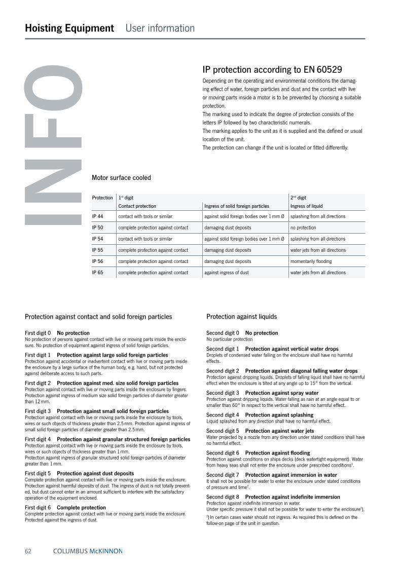
62
Hoisting Equipment User information
INFO
IP protection according to EN 60529Depending on the operating and environmental conditions the damag-ing effect of water, foreign particles and dust and the contact with live or moving parts inside a motor is to be prevented by choosing a suitable protection. The marking used to indicate the degree of protection consists of the letters IP followed by two characteristic numerals. The marking applies to the unit as it is supplied and the defined or usual location of the unit. The protection can change if the unit is located or fitted differently.
Protection against contact and solid foreign particles
First digit 0 No protectionNo protection of persons against contact with live or moving parts inside the enclo-sure. No protection of equipment against ingress of solid foreign particles.
First digit 1 Protection against large solid foreign particlesProtection against accidental or inadvertent contact with live or moving parts inside the enclosure by a large surface of the human body, e.g. hand, but not protected against deliberate access to such parts.
First digit 2 Protection against med. size solid foreign particlesProtection against contact with live or moving parts inside the enclosure by fingers. Protection against ingress of medium size solid foreign particles of diameter greater than 12 mm.
First digit 3 Protection against small solid foreign particlesProtection against contact with live or moving parts inside the enclosure by tools, wires or such objects of thickness greater than 2.5 mm. Protection against ingress of small solid foreign particles of diameter greater than 2.5 mm.
First digit 4 Protection against granular structured foreign particlesProtection against contact with live or moving parts inside the enclosure by tools, wires or such objects of thickness greater than 1 mm. Protection against ingress of granular structured solid foreign particles of diameter greater than 1 mm.
First digit 5 Protection against dust depositsComplete protection against contact with live or moving parts inside the enclosure. Protection against harmful deposits of dust. The ingress of dust is not totally prevent-ed, but dust cannot enter in an amount sufficient to interfere with the satisfactory operation of the equipment enclosed.
First digit 6 Complete protectionComplete protection against contact with live or moving parts inside the enclosure. Protected against the ingress of dust.
Protection against liquids
Second digit 0 No protectionNo particular protection
Second digit 1 Protection against vertical water dropsDroplets of condensed water falling on the enclosure shall have no harmful effects.
Second digit 2 Protection against diagonal falling water dropsProtection against dripping liquids. Droplets of falling liquid shall have no harmful effect when the enclosure is tilted at any angle up to 15° from the vertical.
Second digit 3 Protection against spray waterProtection against dripping liquids. Water falling as rain at an angle equal to or smaller than 60° in respect to the vertical shall have no harmful effect.
Second digit 4 Protection against splashingLiquid splashed from any direction shall have no harmful effect.
Second digit 5 Protection against water jetsWater projected by a nozzle from any direction under stated conditions shall have no harmful effect.
Second digit 6 Protection against floodingProtection against conditions on ships decks (deck watertight equipment). Water from heavy seas shall not enter the enclosure under prescribed conditions2.
Second digit 7 Protection against immersion in waterIt shall not be possible for water to enter the enclosure under stated conditions of pressure and time2.
Second digit 8 Protection against indefinite immersionProtection against indefinite immersion in water. Under specific pressure it shall not be possible for water to enter the enclosure2).2) In certain cases water should not ingress. As required this is defined on the follow-on page of the unit in question.
Motor surface cooled
Protection 1st digit 2nd digit
Contact protection Ingress of solid foreign particles Ingress of liquid
IP 44 contact with tools or similar against solid foreign bodies over 1 mm Ø splashing from all directions
IP 50 complete protection against contact damaging dust deposits no protection
IP 54 contact with tools or similar against solid foreign bodies over 1 mm Ø splashing from all directions
IP 55 complete protection against contact damaging dust deposits water jets from all directions
IP 56 complete protection against contact damaging dust deposits momentarily flooding
IP 65 complete protection against contact against ingress of dust water jets from all directions
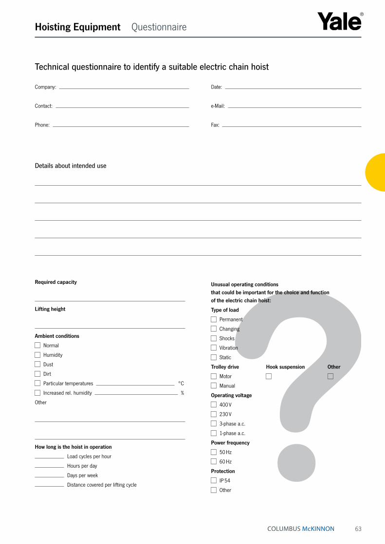
63
Hoisting Equipment Questionnaire
Technical questionnaire to identify a suitable electric chain hoist
Company: Date:
Contact: e-Mail:
Phone: Fax:
Details about intended use
Required capacity
Lifting height
Ambient conditions
Normal
Humidity
Dust
Dirt
Particular temperatures °C
Increased rel. humidity %
Other
How long is the hoist in operation
Load cycles per hour
Hours per day
Days per week
Distance covered per lifting cycle
Unusual operating conditions that could be important for the choice and function of the electric chain hoist:
Type of load
Permanent
Changing
Shocks
Vibration
Static
Trolley drive Hook suspension Other
Motor
Manual
Operating voltage
400 V
230 V
3-phase a.c.
1-phase a.c.
Power frequency
50 Hz
60 Hz
Protection
IP 54
Other

64
Hoisting Equipment Electric chain hoists
INFO
Festooned cable systems please see pages 146 - 147.
Yale hoists and trolleys are not designed for passenger elevation applications and must not be used for this purpose.
Electric chain hoistwith suspension hook or withintegrated trolleyCapacity 125 - 5000 kgThe electric chain hoist CPV combines modern design and technical innovation. A robust construction makes the series a versatile tool for professional applications. The integrated limit switch for the highest and lowest hook position considerably extends the working life span of the slip clutch, motor and gearbox.
Features• Increased operating safety through 42 V control voltage
(low voltage control) and the main contactor.
• The integrated limit switch for the highest and lowest hook position considerably extends the service life of the slip clutch, motor and gearbox.
• Overload protection (slip clutch) in all CPV hoists is outside force flow to meet higher safety requirements.
• Electromagnetic spring pressure brake holds the load safely even in the event of power failure.
• Different suspension types available such as top hook, lug or an integrated trolley. A retro-fit to another type of suspension is possible.
• Any chain length (lifting height) as per customer order.
• Oil bath gearbox (or semifluid grease with CPV/F 2-8 and 5-4 as well as CPV 2-4 and 5-2) with helical gearing for particularly smooth service and enhanced lifetime.
• All-steel chain guide.
• The chain guide of the smallest hoist CPV/F 2-8 and 5-4 as well as CPV 2-4 and 5-2 is a thermoplastic (POM) chain guide that is integral with the housing.
• CPV series are protected up to IP 55.
• 2 year warranty (excluding wear parts) and a lifetime lubricated gearbox.
C O M P L E T E S E R I E S C P V
CAPACITIES125 - 5000 KG
W I T H
SUSPENSION HOOK AS STANDARD,
SUSPENSION LUG AS AN OPTION,
PUSH, GEARED OR ELECTRIC TROLLEY
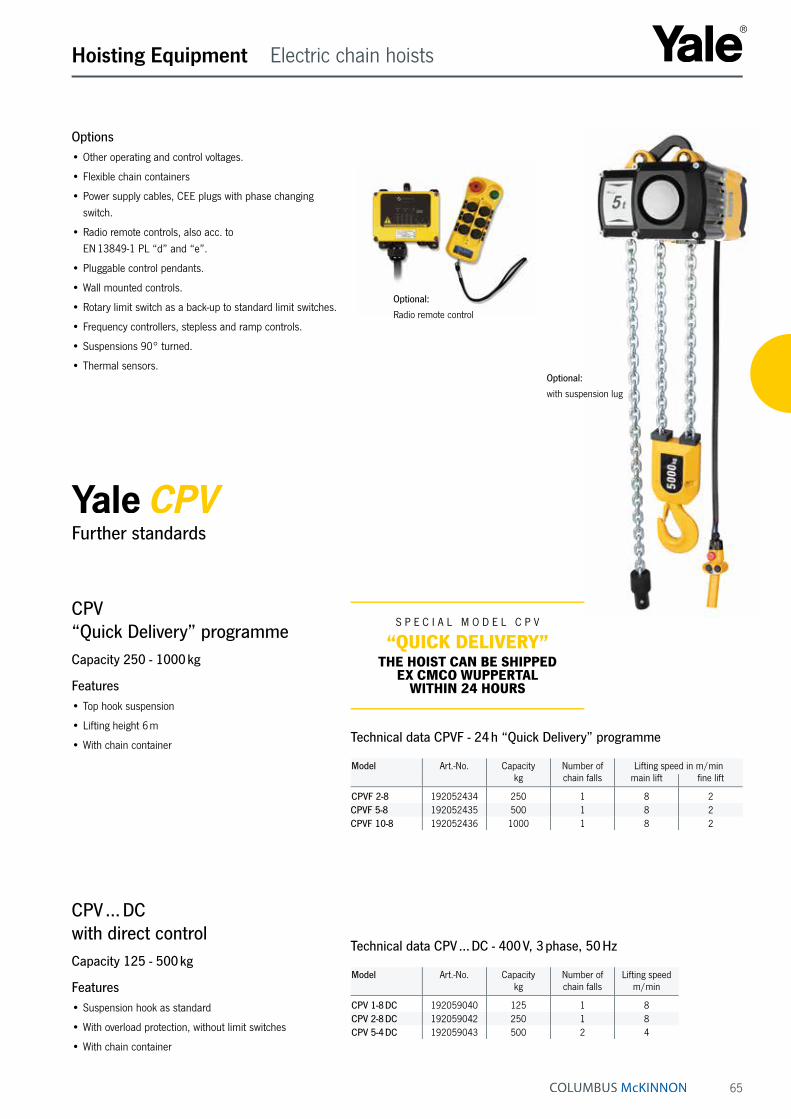
65
Hoisting Equipment Electric chain hoists
Options• Other operating and control voltages.
• Flexible chain containers
• Power supply cables, CEE plugs with phase changing switch.
• Radio remote controls, also acc. to EN 13849-1 PL “d” and “e”.
• Pluggable control pendants.
• Wall mounted controls.
• Rotary limit switch as a back-up to standard limit switches.
• Frequency controllers, stepless and ramp controls.
• Suspensions 90° turned.
• Thermal sensors.
CPV ... DCwith direct controlCapacity 125 - 500 kg
Features• Suspension hook as standard
• With overload protection, without limit switches
• With chain container
Model Art.-No. Capacitykg
Number of chain falls
Lifting speedm/min
CPV 1-8 DC 192059040 125 1 8CPV 2-8 DC 192059042 250 1 8CPV 5-4 DC 192059043 500 2 4
CPV “Quick Delivery” programmeCapacity 250 - 1000 kg
Features• Top hook suspension
• Lifting height 6 m
• With chain container
Technical data CPV ... DC - 400 V, 3 phase, 50 Hz
Technical data CPVF - 24 h “Quick Delivery” programme
S P E C I A L M O D E L C P V
“QUICK DELIVERY”THE HOIST CAN BE SHIPPED
EX CMCO WUPPERTAL WITHIN 24 HOURS
Further standards
Optional:
Radio remote control
Optional:
with suspension lug
Model Art.-No. Capacitykg
Number of chain falls
Lifting speed in m/minmain lift fine lift
CPVF 2-8 192052434 250 1 8 2CPVF 5-8 192052435 500 1 8 2CPVF 10-8 192052436 1000 1 8 2
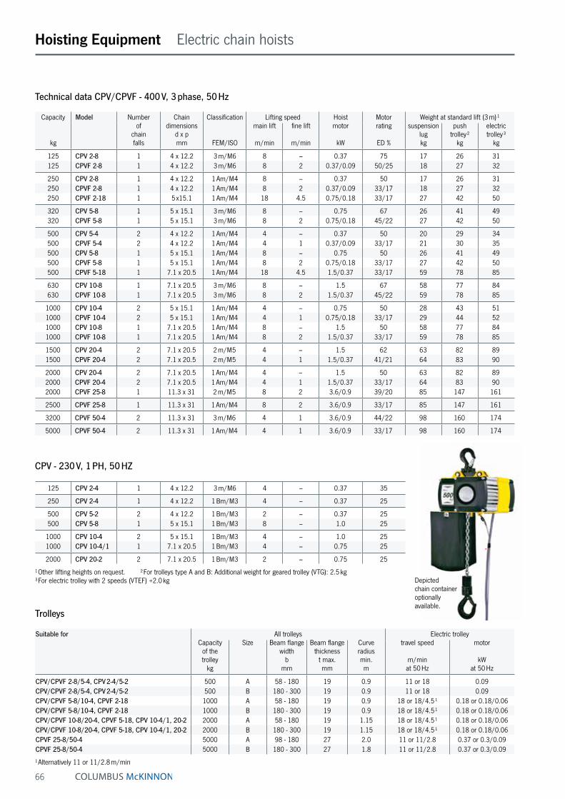
66
Hoisting Equipment Electric chain hoists
Depicted chain container optionally available.
Technical data CPV/CPVF - 400 V, 3 phase, 50 Hz
Trolleys
Suitable for All trolleys Electric trolleyCapacity
of the trolley
kg
Size Beam flange width
bmm
Beam flange thickness
t max.mm
Curve radius min.m
travel speed
m/min at 50 Hz
motor
kW at 50 Hz
CPV/CPVF 2-8/5-4, CPV 2-4/5-2 500 A 58 - 180 19 0.9 11 or 18 0.09CPV/CPVF 2-8/5-4, CPV 2-4/5-2 500 B 180 - 300 19 0.9 11 or 18 0.09CPV/CPVF 5-8/10-4, CPVF 2-18 1000 A 58 - 180 19 0.9 18 or 18/4.5 ¹ 0.18 or 0.18/0.06CPV/CPVF 5-8/10-4, CPVF 2-18 1000 B 180 - 300 19 0.9 18 or 18/4.5 ¹ 0.18 or 0.18/0.06CPV/CPVF 10-8/20-4, CPVF 5-18, CPV 10-4/1, 20-2 2000 A 58 - 180 19 1.15 18 or 18/4.5 ¹ 0.18 or 0.18/0.06CPV/CPVF 10-8/20-4, CPVF 5-18, CPV 10-4/1, 20-2 2000 B 180 - 300 19 1.15 18 or 18/4.5 ¹ 0.18 or 0.18/0.06CPVF 25-8/50-4 5000 A 98 - 180 27 2.0 11 or 11/2.8 0.37 or 0.3/0.09CPVF 25-8/50-4 5000 B 180 - 300 27 1.8 11 or 11/2.8 0.37 or 0.3/0.09
¹ Alternatively 11 or 11/2.8 m/min
Capacity
kg
Model Number of
chain falls
Chain dimensions
d x pmm
Classification
FEM/ISO
Lifting speed Hoist motor
kW
Motor rating
ED %
Weight at standard lift (3 m) ¹main lift
m/min
fine lift
m/min
suspension lugkg
push trolley ²
kg
electric trolley ³
kg
125 CPV 2-8 1 4 x 12.2 3 m/M6 8 – 0.37 75 17 26 31125 CPVF 2-8 1 4 x 12.2 3 m/M6 8 2 0.37/0.09 50/25 18 27 32
250 CPV 2-8 1 4 x 12.2 1 Am/M4 8 – 0.37 50 17 26 31250 CPVF 2-8 1 4 x 12.2 1 Am/M4 8 2 0.37/0.09 33/17 18 27 32250 CPVF 2-18 1 5 x15.1 1 Am/M4 18 4.5 0.75/0.18 33/17 27 42 50
320 CPV 5-8 1 5 x 15.1 3 m/M6 8 – 0.75 67 26 41 49320 CPVF 5-8 1 5 x 15.1 3 m/M6 8 2 0.75/0.18 45/22 27 42 50
500 CPV 5-4 2 4 x 12.2 1 Am/M4 4 – 0.37 50 20 29 34500 CPVF 5-4 2 4 x 12.2 1 Am/M4 4 1 0.37/0.09 33/17 21 30 35500 CPV 5-8 1 5 x 15.1 1 Am/M4 8 – 0.75 50 26 41 49500 CPVF 5-8 1 5 x 15.1 1 Am/M4 8 2 0.75/0.18 33/17 27 42 50500 CPVF 5-18 1 7.1 x 20.5 1 Am/M4 18 4.5 1.5/0.37 33/17 59 78 85
630 CPV 10-8 1 7.1 x 20.5 3 m/M6 8 – 1.5 67 58 77 84630 CPVF 10-8 1 7.1 x 20.5 3 m/M6 8 2 1.5/0.37 45/22 59 78 85
1000 CPV 10-4 2 5 x 15.1 1 Am/M4 4 – 0.75 50 28 43 511000 CPVF 10-4 2 5 x 15.1 1 Am/M4 4 1 0.75/0.18 33/17 29 44 521000 CPV 10-8 1 7.1 x 20.5 1 Am/M4 8 – 1.5 50 58 77 841000 CPVF 10-8 1 7.1 x 20.5 1 Am/M4 8 2 1.5/0.37 33/17 59 78 85
1500 CPV 20-4 2 7.1 x 20.5 2 m/M5 4 – 1.5 62 63 82 891500 CPVF 20-4 2 7.1 x 20.5 2 m/M5 4 1 1.5/0.37 41/21 64 83 90
2000 CPV 20-4 2 7.1 x 20.5 1 Am/M4 4 – 1.5 50 63 82 892000 CPVF 20-4 2 7.1 x 20.5 1 Am/M4 4 1 1.5/0.37 33/17 64 83 902000 CPVF 25-8 1 11.3 x 31 2 m/M5 8 2 3.6/0.9 39/20 85 147 161
2500 CPVF 25-8 1 11.3 x 31 1 Am/M4 8 2 3.6/0.9 33/17 85 147 161
3200 CPVF 50-4 2 11.3 x 31 3 m/M6 4 1 3.6/0.9 44/22 98 160 174
5000 CPVF 50-4 2 11.3 x 31 1 Am/M4 4 1 3.6/0.9 33/17 98 160 174
125 CPV 2-4 1 4 x 12.2 3 m/M6 4 – 0.37 35
250 CPV 2-4 1 4 x 12.2 1 Bm/M3 4 – 0.37 25
500 CPV 5-2 2 4 x 12.2 1 Bm/M3 2 – 0.37 25500 CPV 5-8 1 5 x 15.1 1 Bm/M3 8 – 1.0 25
1000 CPV 10-4 2 5 x 15.1 1 Bm/M3 4 – 1.0 251000 CPV 10-4/1 1 7.1 x 20.5 1 Bm/M3 4 – 0.75 25
2000 CPV 20-2 2 7.1 x 20.5 1 Bm/M3 2 – 0.75 25
¹ Other lifting heights on request. ² For trolleys type A and B: Additional weight for geared trolley (VTG): 2.5 kg ³ For electric trolley with 2 speeds (VTEF) +2.0 kg
CPV - 230 V, 1 PH, 50 HZ

67
Hoisting Equipment Electric chain hoists
FOR CORROSIVE ENVIRONMENT & FOOD INDUSTRY• Stainless steel load chains.
• Stainless steel load hooks for single fall hoists.
• Zinc- or copper- bottom blocks for double fall hoists.
• Zinc plated trolleys and/or 2-component topcoat.
• Food industry approved gearbox lubricants and grease (H1).
• Textile rain coats for hoists and trolleys.
FOR SIMULTANEOUS LIFTINGYale offers solutions for lifting loads with two or more electric chain hoists simultaneously. Depending on the customer’s application, the hoist system must meet vari-ous and sometimes very demanding requirements.
• Radio or cable controls.
• Movement selection: single or group movement.
• On trolleys or as point hoists.
• Coupled trolleys.
Please contact Columbus McKinnon to find a suit-able solution.
FOR STATIONARY LOADS ABOVE PERSONSColumbus McKinnon offers Yale electric chain hoists designed for holding stationary loads above persons in accordance with the EN 14492-2:2019.
We implement these increased safety requirements in our models CPV ... DB, offering load capacities from 125 kg to 1000 kg.
Model Art.-No. Capacity
kg
Number of chain falls
Lifting speed
m/min
CPV 2-8 DB 192054103 125 1 8CPV 5-4 DB 192054104 250 2 4
CPV 5-8 DB 192054105 250 1 8CPV 10-4 DB 192054107 500 2 4CPV 10-8 DB 192054108 500 1 8CPV 20-4 DB 192054109 1000 2 4
Options and features for applications
FOR CRANE BUILDING• Beam locking device for trolleys.
• Rubber buffers for trolleys.
• Trolley travel end buffer stops.
• 90° suspension on trolley.
• Counter for operating hours.
• Trolley travel end limit switches.
• Signal horn or lamp for crane applications.
• Festoon cable systems or other power supply.
• Suspensions for light crane systems.
• Crane operation pendants.
FOR WIND ENERGY• Chain lengths up to 200 m.
• Electric chain hoists with high lifting speed.
• Chain containers for longer chains and with special suspensions.
• Increased corrosion-resistance.
• Special suspensions.
• Load hooks with protective cover.

68
Hoisting Equipment Electric chain hoists
CPV/CPVF with suspension lug, 125 - 2500 kg, single fall
CPV/CPVF with suspension lug, 500 - 5000 kg, double fall
CPV/CPVF suspension hook, 250 - 2500 kg
Dimensions CPV/CPVF
Model CPV/CPVF 2-8 CPV 2-4
CPV/CPVF 5-4 CPV 5-2
CPVF 2-18 CPV/CPVF 5-8
CPV/CPVF 10-4 CPVF 5-18 CPV/CPVF 10-8
CPV 10-4/1
CPV/CPVF 20-4 CPV 20-2
CPVF 25-8 CPVF 50-4
A, mm 327 363 357 430 431 528 514 658A1, mm 163 163 196 196 234 234 288 288A2 (dimension with chain container), mm- Size I (for lift-height, m) 343 (15 m) 343 (7.5 m) 476 (10 m) 476 (5 m) 564 (12 m) 564 (6 m) 580 (13 m) 580 (6 m)- Size II (for lift-height, m) 413 (32 m) 413 (16 m) 526 (22 m) 526 (11 m) 644 (18 m) 644 (9 m) 764 (25 m) 764 (12 m)- Size III (for lift-height, m) 483 (52 m) 483 (26 m) 606 (40 m) 606 (20 m) 734 (25 m) 734 (12 m) 854 (30 m) 854 (15 m)- Size IV (for lift-height, m) – – 798 (64 m) 798 (32 m) 934 (40 m) 934 (20 m) – –B, mm 23 23 22 29 29 37 37 37B1, mm 12 12 15 15 20 20 33 33C, mm 30 30 29 35 35 40 46 46C1, mm 30 30 38 38 45 45 71 71C2, mm 105 105 105 105 154 154 194 194D, mm 16 16 15 21 21 26 35 35D1, mm 12 12 15 15 15 15 25 25E, mm 205 205 277 277 326 326 409 409G, mm 106 126 120 144 140 173 179 179G1 (size I), mm 124 124 142 166 175 208 264 264G1 (size II), mm 124 124 162 186 175 208 264 264G1 (size III), mm 124 124 162 186 175 208 265 265G1 (size IV), mm 124 124 162 186 175 208 – –H, mm 99 79 157 133 186 154 230 230H2, mm 92 72 158 158 186 186 230 180K, mm 215 215 208 208 285 285 335 335M (size I), mm 157 157 162 162 209 209 300 300M (size II), mm 157 157 197 197 209 209 300 300M (size III), mm 157 157 197 197 209 209 301 301M (size IV), mm 157 157 197 197 209 209 – –N ¹, mm 159 159 219 219 274 274 299 299
¹ for 230 V, 1-phase, 50 Hz: approx. +35 mm
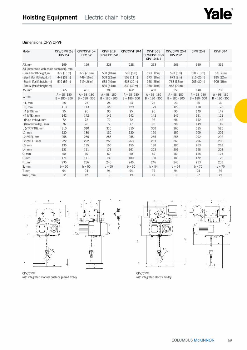
69
Hoisting Equipment Electric chain hoists
CPV/CPVF with integrated manual push or geared trolley
CPV/CPVF with integrated electric trolley
Dimensions CPV/CPVF
Model CPV/CPVF 2-8 CPV 2-4
CPV/CPVF 5-4 CPV 5-2
CPVF 2-18 CPV/CPVF 5-8
CPV/CPVF 10-4 CPVF 5-18 CPV/CPVF 10-8
CPV 10-4/1
CPV/CPVF 20-4 CPV 20-2
CPVF 25-8 CPVF 50-4
A3, mm 199 199 228 228 263 263 339 339A4 (dimension with chain container), mm- Size I (for lift-height, m) 379 (15 m) 379 (7.5 m) 508 (10 m) 508 (5 m) 593 (12 m) 593 (6 m) 631 (13 m) 631 (6 m)- Size II (for lift-height, m) 449 (32 m) 449 (16 m) 558 (22 m) 558 (11 m) 673 (18 m) 673 (9 m) 815 (25 m) 815 (12 m)- Size III (for lift-height, m) 519 (52 m) 519 (26 m) 638 (40 m) 638 (20 m) 768 (25 m) 768 (12 m) 905 (30 m) 905 (15 m)- Size IV (for lift-height, m) – – 830 (64 m) 830 (32 m) 968 (40 m) 968 (20 m) – –A5, mm 365 401 389 462 460 558 648 738
b, mm A = 58 - 180 B = 180 - 300
A = 58 - 180 B = 180 - 300
A = 58 - 180 B = 180 - 300
A = 58 - 180 B = 180 - 300
A = 58 - 180 B = 180 - 300
A = 58 - 180 B = 180 - 300
A = 98 - 180 B = 180 - 300
A = 98 - 180 B = 180 - 300
H1, mm 25 25 24 24 23 23 30 30H3, mm 113 113 129 129 129 129 178 178H4 (VTG), mm 95 95 95 95 95 95 149 149H4 (VTE), mm 142 142 142 142 142 142 121 121I (Push trolley), mm 72 72 72 72 96 96 142 142I (Geared trolley), mm 76 76 77 77 98 98 149 149L (VTP/VTG), mm 310 310 310 310 360 360 525 525L1, mm 130 130 130 130 150 150 209 209L2 (VTE), mm 255 255 255 255 255 255 292 292L2 (VTEF), mm 222 222 263 263 263 263 296 296L3, mm 135 135 155 155 180 180 263 263L4, mm 131 111 173 161 203 203 258 208O, mm 60 60 60 60 80 80 125 125P, mm 171 171 180 180 180 180 172 172P1, mm 236 236 246 246 246 246 233 233S, mm b + 50 b + 50 b + 50 b + 50 b + 54 b + 54 b + 70 b + 70T, mm 94 94 94 94 94 94 94 94tmax., mm 12 12 19 19 19 19 27 27
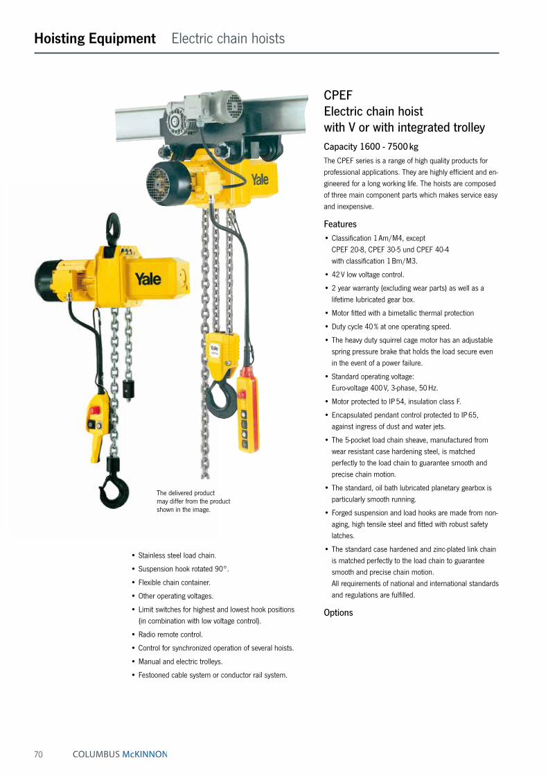
70
CPEFElectric chain hoist with V or with integrated trolleyCapacity 1600 - 7500 kgThe CPEF series is a range of high quality products for professional applications. They are highly efficient and en-gineered for a long working life. The hoists are composed of three main component parts which makes service easy and inexpensive.
Features• Classification 1 Am/M4, except
CPEF 20-8, CPEF 30-5 und CPEF 40-4 with classification 1 Bm/M3.
• 42 V low voltage control.
• 2 year warranty (excluding wear parts) as well as a lifetime lubricated gear box.
• Motor fitted with a bimetallic thermal protection
• Duty cycle 40 % at one operating speed.
• The heavy duty squirrel cage motor has an adjustable spring pressure brake that holds the load secure even in the event of a power failure.
• Standard operating voltage: Euro-voltage 400 V, 3-phase, 50 Hz.
• Motor protected to IP 54, insulation class F.
• Encapsulated pendant control protected to IP 65, against ingress of dust and water jets.
• The 5-pocket load chain sheave, manufactured from wear resistant case hardening steel, is matched perfectly to the load chain to guarantee smooth and precise chain motion.
• The standard, oil bath lubricated planetary gearbox is particularly smooth running.
• Forged suspension and load hooks are made from non-aging, high tensile steel and fitted with robust safety latches.
• The standard case hardened and zinc-plated link chain is matched perfectly to the load chain to guarantee smooth and precise chain motion. All requirements of national and international standards and regulations are fulfilled.
Options
• Stainless steel load chain.
• Suspension hook rotated 90°.
• Flexible chain container.
• Other operating voltages.
• Limit switches for highest and lowest hook positions (in combination with low voltage control).
• Radio remote control.
• Control for synchronized operation of several hoists.
• Manual and electric trolleys.
• Festooned cable system or conductor rail system.
Hoisting Equipment Electric chain hoists
The delivered product may differ from the product shown in the image.

71
CPEF 100-2Electric chain hoist with suspension hook or with integrated trolleyCapacitiy 10000 kgThe model CPEF 100-2 consists of two CPEF 50-2 units. They are connected by a framework. Hook suspension, geared or electric trolleys are available. Integrated limit switches for highest and lowest hook posi-tions are standard. 42 V low voltage control as standard.
Options• Stainless steel load chain.
• Flexible chain container.
• Other operating voltages.
• Motor with stainless steel brake.
• Radio remote control.
• Festooned cable system or conductor rail system.
Hoisting Equipment Electric chain hoists
INFO
The units are certified by the employer‘s liability insur-ance association (Berufsgenossenschaft) and fulfil the requirements of the machinery directive 2006/42/EG.
Festooned cable systems please see pages 146 - 147.The delivered product may differ from the product shown in the image.
5-pocket load chain
sheave machined for smooth, precise chain motion.
Universal connection
to suspension hook, trolley or steel structures.
Double fall bottom block
for capacities between 3200 up to 5000 kg.
Hoist connected directly to trolley
with electric drive. Manual pull and geared trolleys also available.
Option:
Flexible chain container made from wear resistant textile fabric.

72
compact planetary gearbox
zinc-plated Yale load chain
push-button pendant control, IP 65
lowest hook dimension A only 516 mm
up to CPEF 30-5
The delivered product may differ from the product shown in the image.
Hoisting Equipment Electric chain hoists

73
Model Weight at standard lift (3 m) ¹suspension
hookkg
manual geared trolley
kg
electric trolley
kg
CPEF 16-8 93 159 171CPEF 20-8 93 159 171CPEF 25-5 93 159 171CPEF 30-5 93 159 171CPEF 32-4 112 178 189CPEF 40-4 112 178 189CPEF 50-2 112 178 189CPEF 75-1,6 226 326 348CPEF 100-2 287 390 413
¹ Other lifting heights on request.
Technical data trolleys
Capacity
kg
Size Beam flange width
bmm
Beam flange thickness
t max. mm
Curve radius min.
m
Electric trolley travel speed
m/minat 50 Hz
Electric trolley motor
kWat 50 Hz
1600 - 5000 A 98 - 180 27 2.0 11/2.8 0.3/0.091600 - 5000 B 180 - 300 27 1.8 11/2.8 0.3/0.097500 - 10000 B 125 - 310 40 1.8 5/1.25 0.55/0.12
Model Art.-No. CPEF with
hook suspension
Capacity in kg/
Number of chain falls
Chain dimensions
d x pmm
Classification
FEM/ISO
Lifting speed Hoist motor
kW
Motor rating
ED %
main lift
m/min
fine lift
m/min
CPEF 16-8 N06000246 1600/1 11 x 31 1 Am/M4 8 2 2.3/0.58 40/20CPEF 20-8 N06000248 2000/1 11 x 31 1 Bm/M3 8 2 2.8/0.7 25/15CPEF 25-5 N06000250 2500/1 11 x 31 1 Am/M4 5 1.25 2.3/0.58 40/20CPEF 30-5 N06000252 3000/1 11 x 31 1 Bm/M3 5 1.25 2.8/0.7 25/15CPEF 32-4 N06000254 3200/2 11 x 31 1 Am/M4 4 1 2.3/0.58 40/20CPEF 40-4 N06000256 4000/2 11 x 31 1 Bm/M3 4 1 2.8/0.7 25/15CPEF 50-2 N06000258 5000/2 11 x 31 1 Am/M4 2.5 0.6 2.3/0.58 40/20CPEF 75-1,6 N06000278 7500/3 11 x 31 1 Am/M4 1.6 0.4 2.8/0.58 40/20CPEF 100-2 N06041607 10000/4 11 x 31 1 Am/M4 2.5 0.6 2 x 2.3/0.58 40/20
Technical data CPEF - 400 V, 3 phase, 50 Hz
INFO
Festooned cable systems please see pages 146 - 147.
The delivered product may differ from the product shown in the image.
Hoisting Equipment Electric chain hoists
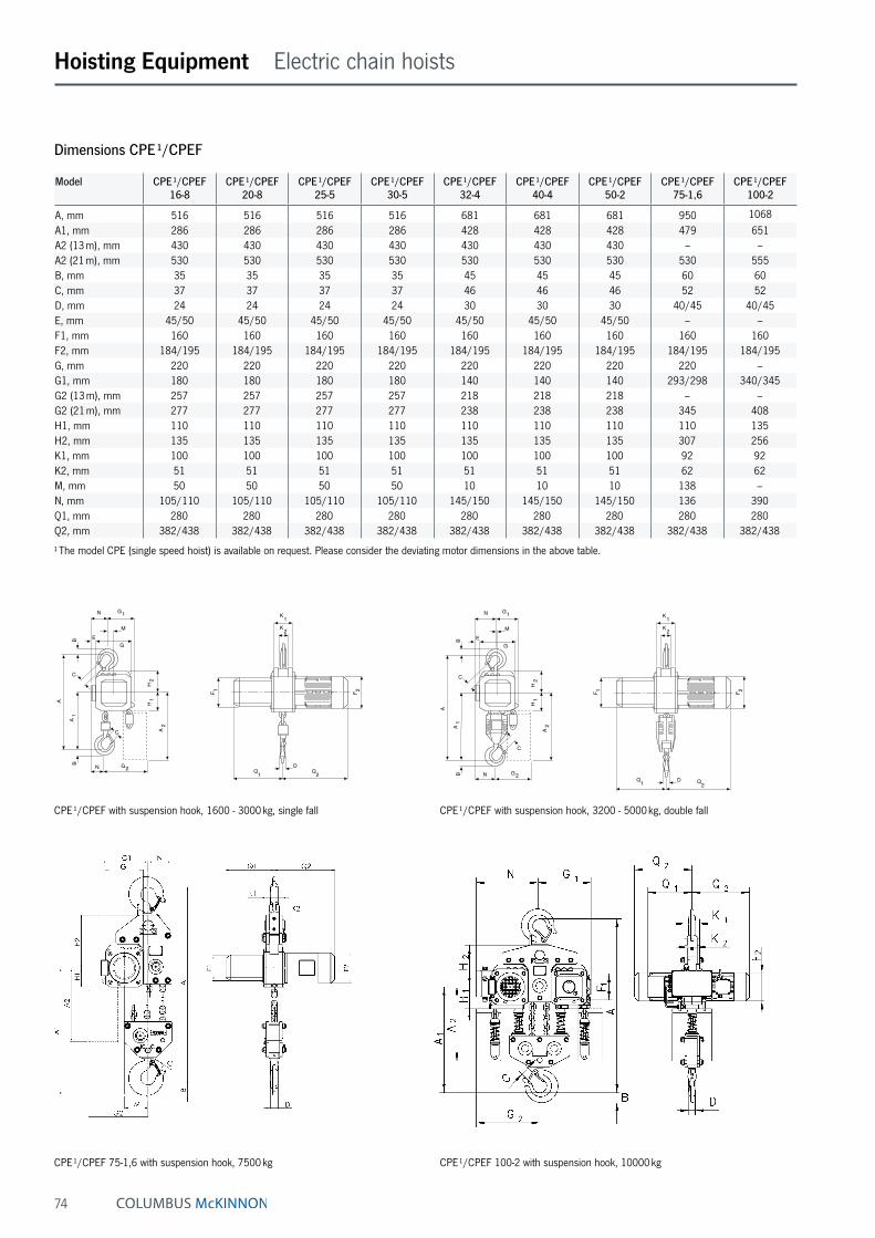
74
Hoisting Equipment Electric chain hoists
Dimensions CPE ¹/CPEF
Model CPE ¹/CPEF 16-8
CPE ¹/CPEF 20-8
CPE ¹/CPEF 25-5
CPE ¹/CPEF 30-5
CPE ¹/CPEF 32-4
CPE ¹/CPEF 40-4
CPE ¹/CPEF 50-2
CPE ¹/CPEF 75-1,6
CPE ¹/CPEF 100-2
A, mm 516 516 516 516 681 681 681 950 1068A1, mm 286 286 286 286 428 428 428 479 651A2 (13 m), mm 430 430 430 430 430 430 430 – –A2 (21 m), mm 530 530 530 530 530 530 530 530 555B, mm 35 35 35 35 45 45 45 60 60C, mm 37 37 37 37 46 46 46 52 52D, mm 24 24 24 24 30 30 30 40/45 40/45E, mm 45/50 45/50 45/50 45/50 45/50 45/50 45/50 – –F1, mm 160 160 160 160 160 160 160 160 160F2, mm 184/195 184/195 184/195 184/195 184/195 184/195 184/195 184/195 184/195G, mm 220 220 220 220 220 220 220 220 –G1, mm 180 180 180 180 140 140 140 293/298 340/345G2 (13 m), mm 257 257 257 257 218 218 218 – –G2 (21 m), mm 277 277 277 277 238 238 238 345 408H1, mm 110 110 110 110 110 110 110 110 135H2, mm 135 135 135 135 135 135 135 307 256K1, mm 100 100 100 100 100 100 100 92 92K2, mm 51 51 51 51 51 51 51 62 62M, mm 50 50 50 50 10 10 10 138 –N, mm 105/110 105/110 105/110 105/110 145/150 145/150 145/150 136 390Q1, mm 280 280 280 280 280 280 280 280 280Q2, mm 382/438 382/438 382/438 382/438 382/438 382/438 382/438 382/438 382/438
¹ The model CPE (single speed hoist) is available on request. Please consider the deviating motor dimensions in the above table.
F 2F 1
K1K2
Q1 Q2D
C
N G2
EM
G
N G1
B
C
A
A1
B
H1
H2
A2
CPE ¹/CPEF 75-1,6 with suspension hook, 7500 kg CPE ¹/CPEF 100-2 with suspension hook, 10000 kg
CPE ¹/CPEF with suspension hook, 1600 - 3000 kg, single fall CPE ¹/CPEF with suspension hook, 3200 - 5000 kg, double fall
F 2F 1
K1K2
Q1 Q2D
C
N G2
EM
G
N G1
B
C
A
A1
B
H1
H2
A2

75
Model CPEF 16-8 CPEF 20-8 CPEF 25-5 CPEF 30-5 CPEF 32-4 CPEF 40-4 CPEF 50-2 CPEF 75-1,6 CPEF 100-2
A3, mm 121 121 121 121 121 121 121 – 110A4, mm 465 465 465 465 615 615 615 855 965A5, mm 298 298 298 298 298 298 298 477 450A6, mm 178 178 178 178 178 178 178 – 170
b, mm A = 98 - 180/ B = 180 - 300
A = 98 - 180/ B = 180 - 300
A = 98 - 180/ B = 180 - 300
A = 98 - 180/ B = 180 - 300
A = 98 - 180/ B = 180 - 300
A = 98 - 180/ B = 180 - 300
A = 98 - 180/ B = 180 - 300 125 - 310 125 - 310
F, mm 150 150 150 150 150 150 150 113 113I, mm 142.5 142.5 142.5 142.5 142.5 142.5 142.5 170 170L1, mm 209 209 209 209 209 209 209 200 200L2, mm 262.5 262.5 262.5 262.5 262.5 262.5 262.5 215 215L3 (VTE), mm 292 292 292 292 292 292 292 – 335L3 (VTEF), mm 296 296 296 296 296 296 296 – 335L4, mm 213 213 213 213 253 253 253 215 390L5, mm 312 312 312 312 272 272 272 215 215L6 (VTE), mm 342 342 342 342 342 342 342 – –L6 (VTEF), mm 346 346 346 346 306 306 306 – –O, mm 125 125 125 125 125 125 125 150 150P (VTE), mm 197 197 197 197 197 197 197 – 273P (VTEF), mm 205 205 205 205 205 205 205 – 280P1, mm 229 229 229 229 229 229 229 – 110S, mm b + 70 b + 70 b + 70 b + 70 b + 70 b + 70 b + 70 b + 98 b + 98T, mm 94 94 94 94 94 94 94 – 94tmax., mm 27 27 27 27 27 27 27 40 40
Dimensions CPEF
Hoisting Equipment Electric chain hoists
L 4
L 1
A5
A4
B
Q
P 1 Sb
t
L 2 L 2
OI
2
T 1
F
L 5
CPE ¹/CPEF with integrated geared or electric trolley, 7500 kg CPE ¹/CPEF with integrated electric trolley, 10000 kg
CPE ¹/CPEF with integrated manual geared trolley CPE ¹/CPEF with integrated electric trolley
L 4
L 1A
5
A4
P Sbt
L 2 L 3
A6
A3
T
OI
L 5
L 6
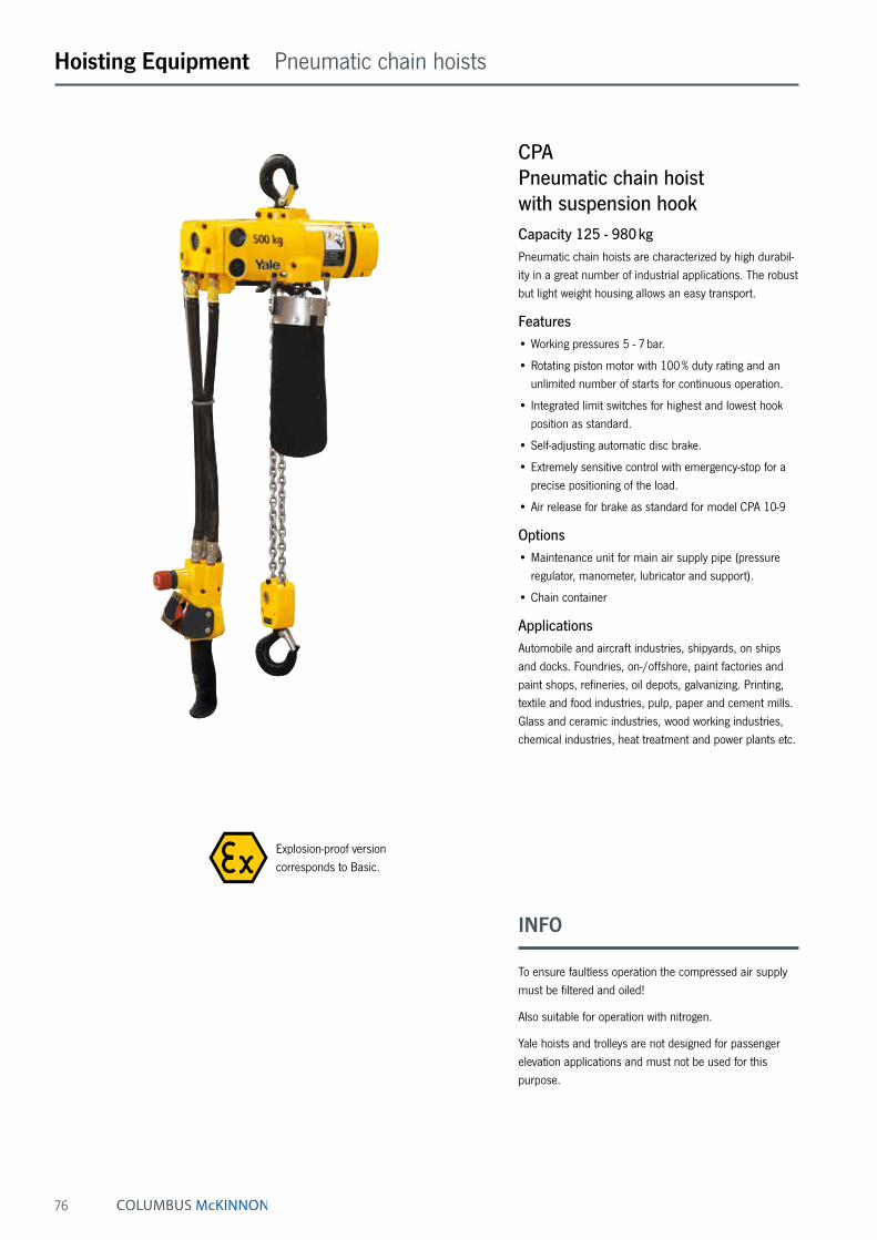
76
Hoisting Equipment Pneumatic chain hoists
CPAPneumatic chain hoist with suspension hookCapacity 125 - 980 kgPneumatic chain hoists are characterized by high durabil-ity in a great number of industrial applications. The robust but light weight housing allows an easy transport.
Features• Working pressures 5 - 7 bar.
• Rotating piston motor with 100 % duty rating and an unlimited number of starts for continuous operation.
• Integrated limit switches for highest and lowest hook position as standard.
• Self-adjusting automatic disc brake.
• Extremely sensitive control with emergency-stop for a precise positioning of the load.
• Air release for brake as standard for model CPA 10-9
Options• Maintenance unit for main air supply pipe (pressure
regulator, manometer, lubricator and support).
• Chain container
ApplicationsAutomobile and aircraft industries, shipyards, on ships and docks. Foundries, on-/offshore, paint factories and paint shops, refineries, oil depots, galvanizing. Printing, textile and food industries, pulp, paper and cement mills. Glass and ceramic industries, wood working industries, chemical industries, heat treatment and power plants etc.
INFO
To ensure faultless operation the compressed air supply must be filtered and oiled!
Also suitable for operation with nitrogen.
Yale hoists and trolleys are not designed for passenger elevation applications and must not be used for this purpose.
Explosion-proof version corresponds to Basic.

77
Model Art.-No. Capacity in kg/
Number of chain falls
Chain dimensions
d x pmm
Classification
FEM/ISO
Lifting speed with
rated load ¹m/min
Lifting speed without load ¹
m/min
Lowering speed with
rated load ¹m/min
Air consump-tion with
rated load ¹m³/min
Hoist motor
kW
Weight at standard lift
(3 m)kg
CPA 1-13 N08501007 125/1 4 x 12.2 1 Am/M4 13.1 17.1 11.3 0.9 0.4 15.4CPA 2-10 N08501008 250/1 4 x 12.2 1 Am/M4 9.8 17.1 13.7 0.9 0.4 15.4CPA 5-5 N08501010 500/2 4 x 12.2 1 Am/M4 4.6 7.9 6.7 0.9 0.4 17.2CPA 10-9 N08501012 980/2 6.3 x 19.5 1 Bm/M3 8.5 16.2 14.9 2.1 1.33 27.7
¹ Values for 6.3 bar flow pressure and 2 m control drop. Speeds will be reduced in case of longer control length.CPA 1-13, CPA 2-10 and CPA 5-5 max. hose length 12 m, air supply 3/8" NPT, air consumption 0.9 m³/min. CPA 10-9 max. hose length 20 m, air supply 1/2" NPT, air consumption 2.1 m³/min.
Technical data CPA
Hoisting Equipment Pneumatic chain hoists
Model CPA 1-13 CPA 2-10 CPA 5-5 CPA 10-9
A, mm 292 292 324 457A1, mm 410 410 410 508B, mm 21 21 14 27C, mm 20 20 24 28D, mm 16 16 14 28F1, mm 90 90 90 130F2, mm 120 120 120 180K, mm 103 103 103 165L, mm 57 57 57 83M, mm 120 120 120 135N, mm 50 50 50 25Q1, mm 142 142 142 162Q2, mm 183 183 183 181
Dimensions CPA
CPA 1-13 / 2-10 / 5-5 CPA 10-9

78
Hoisting Equipment Pneumatic chain hoists
CPA ATEX BasicPneumatic chain hoist with suspension hook or with integrated trolleyCapacity 2000 - 10000 kgWith 100 % duty rating and an unlimited number of starts the model CPA is suitable for heavy duty applications. It is insusceptible to contamination, humidity and aggressive mediums from the outside. The hoists are composed of three main components which makes service easy and inexpensive.
Features• Working pressures 4 - 6 bar.
• Robust rotating piston motor has an adjustable spring pressure brake that holds the load secure even in the event of an air failure.
• The standard, oil bath lubricated planetary gearbox is particularly smooth running and enables a low overall height.
• High starting torque due to switching valves in the motor body.
• Low noise emission due to large dimension silencer.
• Sensitive control by means of 2 resp. 4 button pendant control with emergency-stop.
• The assembly of component parts result in a low over-all height (up to 3000 kg only one chain fall).
• The 5-pocket load chain sheave, manufactured from wear resistant case hardening steel, is matched perfectly to the load chain to guarantee smooth and precise chain motion.
• Forged suspension and load hooks are made from non-aging, high tensile steel and fitted with robust safety latches.
• The standard case hardened and zinc-plated link chain is matched perfectly to the load chain to guarantee smooth and precise chain motion. All requirements of national and international standards and regulations are fulfilled.
Options• Also available in combination with trolleys, both
trolley/hook suspension and with integrated trolley. Also applies to Atex.
• Rope control
• Limit switch
• Chain container
• Maintenance unit, consisting of pressure regulator, pressure gauge, lubricator and holder
• Mobile maintenance unit
• Stainless steel load chain.
INFO
To ensure faultless operation the compressed air supply must be filtered and oiled!
Also suitable for operation with nitrogen.
Where no maintenance unit can be installed permanently, it is recommended to work with a mobile maintenance unit.
Information for load chain see pages 82 - 84 please.
Image shows BASIC design

79
Hoisting Equipment Pneumatic chain hoists
Technical data CPA ATEX Basic
Model Art.-No. Capacity in kg/
Number of chain falls
Chain dimensions
d x pmm
Classification
FEM/ISO
Lifting speed with
rated load ¹m/min
Lifting speed without load ¹
m/min
Lowering speed with
rated load ¹m/min
Hoist motor
kW
CPA ATEX 20-8 N08505001 2000/1 11.3 x 31 1 Bm/M3 7.4 9.9 11.0 2.6CPA ATEX 30-6 N08505002 3000/1 11.3 x 31 1 Bm/M3 6.0 9.9 13.0 3.2CPA ATEX 50-3 N08505004 5000/2 11.3 x 31 1 Am/M4 3.4 5.0 6.0 3.0CPA ATEX 60-3 192069175 6000/2 11.3 x 31 1 Am/M4 3.0 5.0 6.5 3.2CPA ATEX 75-2 N08505005 7500/3 11.3 x 31 1 Am/M4 2.0 3.3 4.3 3.2CPA ATEX 100-3 N08505006 10000/4 11.3 x 31 1 Am/M4 3.4 5.0 6.0 2 x 3.0
¹ Values at 6 bar flow pressure and 2 m control hose. Air consumption at nominal load 4.7 m³/min. For CPA 100-3 = 9.4 m³/min, air connection R1".Quick exhaust valves are installed from 11 m upwards, max. hose length 20 m.
Technical data trolleys
Capacity
kg
Size Beam flange width
b
mm
Beam flange thickness
t max.
mm
Curve radius min.
m
Pneumatic trolley
travel speed
m/min
Pneumatic trolley motor
kW
2000 - 6000 A 98 - 180 27 2.0 18 0.552000 - 6000 B 180 - 300 27 1.8 18 0.557500 - 10000 B 125 - 310 40 1.8 – –
Flow pressure 6 bar, air consumption with rated load 0.75 m³/min, air connection R½".
Application with pneumatic trolley
Model Art.-No. Weight ² suspension
hookkg
Weight ² geared trolley
kg
Weight ² pneumatic
trolleykg
CPA ATEX 20-8 N08505001 121 188 199CPA ATEX 30-6 N08505002 121 188 199CPA ATEX 50-3 N08505004 140 206 218CPA ATEX 60-3 192069175 140 206 218CPA ATEX 75-2 N08505005 on request on request on requestCPA ATEX 100-3 N08505006 on request on request on request
² Weight for standard lift 3 m HOL. Other lifting heights on request.
INFO
Yale hoists and trolleys are not designed for passenger elevation applications and must not be used for this purpose.
We are pleased to send you our new Atex catalogue in PDF format.
INFO
Also available in Medium, High design on request.
Image shows MEDIUM design incl. rope control
Mobile maintenance unit
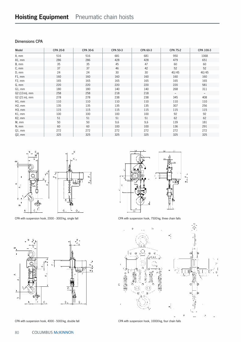
80
Hoisting Equipment Pneumatic chain hoists
Dimensions CPA
Model CPA 20-8 CPA 30-6 CPA 50-3 CPA 60-3 CPA 75-2 CPA 100-3
A, mm 516 516 681 681 950 1068A1, mm 286 286 428 428 479 651B, mm 35 35 45 47 60 60C, mm 37 37 46 42 52 52D, mm 24 24 30 30 40/45 40/45F1, mm 160 160 160 160 160 160F2, mm 165 165 165 165 165 165G, mm 220 220 220 220 220 581G1, mm 180 180 140 140 268 311G2 (13 m), mm 258 258 218 218 – –G2 (21 m), mm 278 278 238 238 345 408H1, mm 110 110 110 110 110 110H2, mm 135 135 135 135 307 256H3, mm 115 115 115 115 115 115K1, mm 100 100 100 100 92 92K2, mm 51 51 51 51 62 62M, mm 50 50 9,6 9,6 139 181N, mm 60 60 100 100 136 291Q1, mm 272 272 272 272 272 272Q2, mm 325 325 325 325 325 325
CPA with suspension hook, 4000 - 5000 kg, double fall CPA with suspension hook, 10000 kg, four chain falls
CPA with suspension hook, 2000 - 3000 kg, single fall CPA with suspension hook, 7500 kg, three chain falls

81
Hoisting Equipment Pneumatic chain hoists
Dimensions CPA
Model CPA 20-8 CPA 30-6 CPA 50-3 CPA 60-3 CPA 75-2 CPA 100-3
A2 (13 m), mm 430 430 430 430 – –A2 (21 m), mm 530 530 530 530 530 530A4, mm 465 465 615 615 855 965A5, mm 298 298 298 298 477 425A6, mm 190 190 190 190 182 182
b, mm A = 98 - 180/ B = 180 - 300
A = 98 - 180/ B = 180 - 300
A = 98 - 180/ B = 180 - 300
A = 98 - 180/ B = 180 - 300 125 - 310 125 - 310
F, mm 150 150 150 150 113 113I, mm 142.5 142.5 142.5 142.5 130 130L1, mm 209 209 209 209 200 200L2, mm 262.5 262.5 262.5 262.5 215 215L3, mm 265 265 265 265 265 265L4, mm 213 213 253 253 291 291L5, mm 312 312 272 272 – –L6, mm 315 315 275 275 – –O, mm 125 125 125 125 150 150P, mm 208 208 208 208 208 208P1, mm 284 284 284 284 284 284S, mm b + 70 b + 70 b + 70 b + 70 b + 98 b + 98t, mm 27 27 27 27 40 40T1 size A 182 182 182 182 – –T1 size B 242 242 242 242 270 270
CPA with integrated manual geared trolley CPA with integrated pneumatic trolley
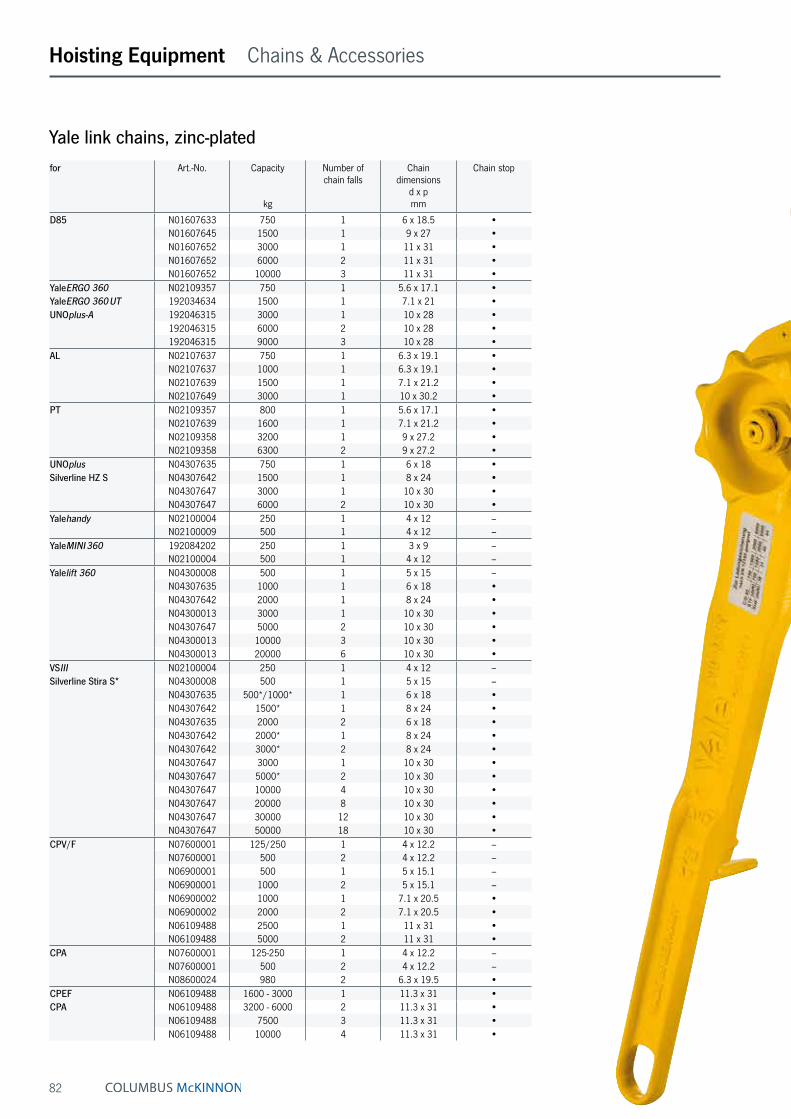
82
Hoisting Equipment Chains & Accessories
for Art.-No. Capacity
kg
Number of chain falls
Chain dimensions
d x pmm
Chain stop
D85 N01607633 750 1 6 x 18.5 •N01607645 1500 1 9 x 27 •N01607652 3000 1 11 x 31 •N01607652 6000 2 11 x 31 •N01607652 10000 3 11 x 31 •
YaleERGO 360 N02109357 750 1 5.6 x 17.1 •YaleERGO 360 UT 192034634 1500 1 7.1 x 21 •UNOplus-A 192046315 3000 1 10 x 28 •
192046315 6000 2 10 x 28 •192046315 9000 3 10 x 28 •
AL N02107637 750 1 6.3 x 19.1 •N02107637 1000 1 6.3 x 19.1 •N02107639 1500 1 7.1 x 21.2 •N02107649 3000 1 10 x 30.2 •
PT N02109357 800 1 5.6 x 17.1 •N02107639 1600 1 7.1 x 21.2 •N02109358 3200 1 9 x 27.2 •N02109358 6300 2 9 x 27.2 •
UNOplus N04307635 750 1 6 x 18 •Silverline HZ S N04307642 1500 1 8 x 24 •
N04307647 3000 1 10 x 30 •N04307647 6000 2 10 x 30 •
Yalehandy N02100004 250 1 4 x 12 –N02100009 500 1 4 x 12 –
YaleMINI 360 192084202 250 1 3 x 9 –N02100004 500 1 4 x 12 –
Yalelift 360 N04300008 500 1 5 x 15 –N04307635 1000 1 6 x 18 •N04307642 2000 1 8 x 24 •N04300013 3000 1 10 x 30 •N04307647 5000 2 10 x 30 •N04300013 10000 3 10 x 30 •N04300013 20000 6 10 x 30 •
VSIII N02100004 250 1 4 x 12 –Silverline Stira S* N04300008 500 1 5 x 15 –
N04307635 500*/1000* 1 6 x 18 •N04307642 1500* 1 8 x 24 •N04307635 2000 2 6 x 18 •N04307642 2000* 1 8 x 24 •N04307642 3000* 2 8 x 24 •N04307647 3000 1 10 x 30 •N04307647 5000* 2 10 x 30 •N04307647 10000 4 10 x 30 •N04307647 20000 8 10 x 30 •N04307647 30000 12 10 x 30 •N04307647 50000 18 10 x 30 •
CPV/F N07600001 125/250 1 4 x 12.2 –N07600001 500 2 4 x 12.2 –N06900001 500 1 5 x 15.1 –N06900001 1000 2 5 x 15.1 –N06900002 1000 1 7.1 x 20.5 •N06900002 2000 2 7.1 x 20.5 •N06109488 2500 1 11 x 31 •N06109488 5000 2 11 x 31 •
CPA N07600001 125-250 1 4 x 12.2 –N07600001 500 2 4 x 12.2 –N08600024 980 2 6.3 x 19.5 •
CPEF N06109488 1600 - 3000 1 11.3 x 31 •CPA N06109488 3200 - 6000 2 11.3 x 31 •
N06109488 7500 3 11.3 x 31 •N06109488 10000 4 11.3 x 31 •
Yale link chains, zinc-plated
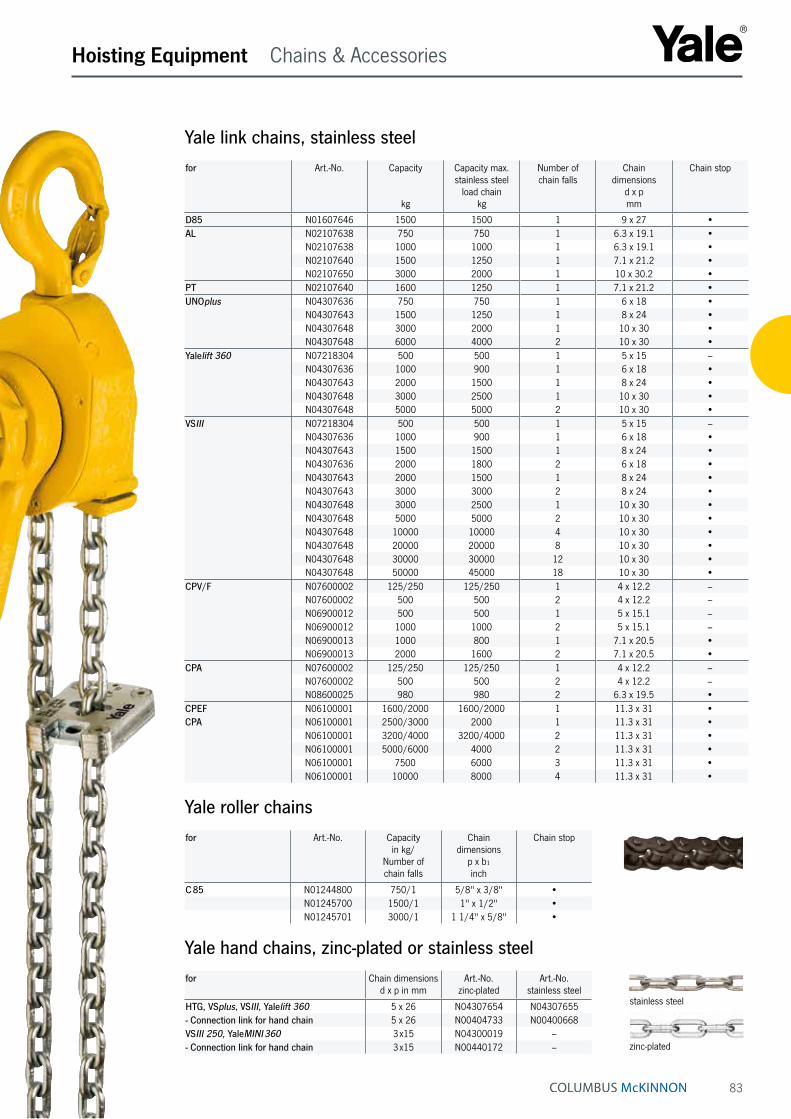
83
zinc-plated
Hoisting Equipment Chains & Accessories
for Art.-No. Capacity in kg/
Number of chain falls
Chain dimensions
p x b₁ inch
Chain stop
C 85 N01244800 750/1 5/8" x 3/8" •N01245700 1500/1 1" x 1/2" •N01245701 3000/1 1 1/4" x 5/8" •
Yale roller chains
Yale link chains, stainless steelfor Art.-No. Capacity
kg
Capacity max.stainless steel
load chainkg
Number of chain falls
Chain dimensions
d x pmm
Chain stop
D85 N01607646 1500 1500 1 9 x 27 •AL N02107638 750 750 1 6.3 x 19.1 •
N02107638 1000 1000 1 6.3 x 19.1 •N02107640 1500 1250 1 7.1 x 21.2 •N02107650 3000 2000 1 10 x 30.2 •
PT N02107640 1600 1250 1 7.1 x 21.2 •UNOplus N04307636 750 750 1 6 x 18 •
N04307643 1500 1250 1 8 x 24 •N04307648 3000 2000 1 10 x 30 •N04307648 6000 4000 2 10 x 30 •
Yalelift 360 N07218304 500 500 1 5 x 15 –N04307636 1000 900 1 6 x 18 •N04307643 2000 1500 1 8 x 24 •N04307648 3000 2500 1 10 x 30 •N04307648 5000 5000 2 10 x 30 •
VSIII N07218304 500 500 1 5 x 15 –N04307636 1000 900 1 6 x 18 •N04307643 1500 1500 1 8 x 24 •N04307636 2000 1800 2 6 x 18 •N04307643 2000 1500 1 8 x 24 •N04307643 3000 3000 2 8 x 24 •N04307648 3000 2500 1 10 x 30 •N04307648 5000 5000 2 10 x 30 •N04307648 10000 10000 4 10 x 30 •N04307648 20000 20000 8 10 x 30 •N04307648 30000 30000 12 10 x 30 •N04307648 50000 45000 18 10 x 30 •
CPV/F N07600002 125/250 125/250 1 4 x 12.2 –N07600002 500 500 2 4 x 12.2 –N06900012 500 500 1 5 x 15.1 –N06900012 1000 1000 2 5 x 15.1 –N06900013 1000 800 1 7.1 x 20.5 •N06900013 2000 1600 2 7.1 x 20.5 •
CPA N07600002 125/250 125/250 1 4 x 12.2 –N07600002 500 500 2 4 x 12.2 –N08600025 980 980 2 6.3 x 19.5 •
CPEF N06100001 1600/2000 1600/2000 1 11.3 x 31 •CPA N06100001 2500/3000 2000 1 11.3 x 31 •
N06100001 3200/4000 3200/4000 2 11.3 x 31 •N06100001 5000/6000 4000 2 11.3 x 31 •N06100001 7500 6000 3 11.3 x 31 •N06100001 10000 8000 4 11.3 x 31 •
Yale hand chains, zinc-plated or stainless steelfor Chain dimensions
d x p in mmArt.-No.
zinc-platedArt.-No.
stainless steel
HTG, VSplus, VSIII, Yalelift 360 5 x 26 N04307654 N04307655- Connection link for hand chain 5 x 26 N00404733 N00400668VSIII 250, YaleMINI 360 3 x15 N04300019 –- Connection link for hand chain 3 x15 N00440172 –
stainless steel
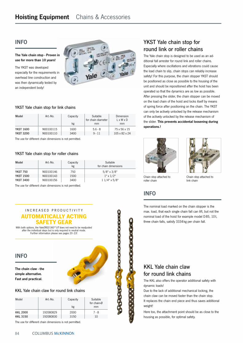
84
Hoisting Equipment Chains & Accessories
Chain stop attached to roller chain
Chain stop attached to link chain
Model Art.-No. Capacity
kg
Suitable for chain diameter
mm
Dimension L x W x D
mm
YKST 1600 N00100115 1600 5.6 - 8 75 x 56 x 15YKST 3200 N00100110 3400 9 - 11 105 x 82 x 24
The use for different chain dimensions is not permitted.
YKST Yale chain stop for link chains
Model Art.-No. Capacitykg
Suitable for chain dimensions
YKST 750 N00100146 750 5/8" x 3/8"YKST 1500 N00100143 1500 1" x 1/2"YKST 3400 N00100156 3400 1 1/4" x 5/8"
The use for different chain dimensions is not permitted.
YKST Yale chain stop for roller chains
INFO
The nominal load marked on the chain stopper is the max. load, that each single chain fall can lift, but not the nominal load of the hoist for example model D 85, 10 t, three chain falls, satisfy 3334 kg per chain fall.
Model Art.-No. Capacity
kg
Suitable for chain-Ø
mm
KKL 2000 192080829 2000 7 - 8KKL 3150 192080830 3150 10
The use for different chain dimensions is not permitted.
KKL Yale chain claw for round link chains
INFO
The Yale chain stop - Proven in use for more than 10 years!
The YKST was developed especially for the requirements in overhead line construction and was then dynamically tested by an independent body!
KKL Yale chain claw for round link chainsThe KKL also offers the operator additional safety with dynamic loads! Due to the lack of additional mechanical locking, the chain claw can be moved faster than the chain stop. It replaces the chain end piece and thus saves additional weight!
Here too, the attachment point should be as close to the housing as possible, for optimal safety.
YKST Yale chain stop for round link or roller chainsThe Yale chain stop is designed to be used as an ad-ditional fall arrester for round link and roller chains. Especially where oscillations and vibrations could cause the load chain to slip, chain stops can reliably increase safety! For this purpose, the chain stopper YKST should be positioned as close as possible to the housing of the unit and should be repositioned after the hoist has been operated so that the dynamics are as low as possible. After pressing the slider, the chain stopper can be moved on the load chain of the hoist and locks itself by means of spring force after positioning on the chain. The YKST can only be actively unlocked by the release mechanism of the actively unlocked by the release mechanism of the slider. This prevents accidental loosening during operations.!
INFO
The chain claw - the simple alternative. Fast and practical.
I N C R E A S E D P R O D U C T I V I T Y
AUTOMATICALLY ACTING SAFETY GEAR
With both options, the YaleERGO 360 ® UT does not need to be readjusted after the individual steps but is only required in neutral mode.
Further information please see pages 20 - 23!

85
SW-WWall-mounted winchCapacity 80 - 750 kgWall-mounted rope winches of the SW-W model range are intended for fixed stationary mounting inside a building. The steel wire rope is guided to the required suspension point of the load by means of deflection sheaves.
Features• Robust aluminium housing for models SW-W 80
and SW-W 125, proven steel plate design for models SW-W 300 - 750.
• Spur gear drive for optimal efficiency and comfortable handling. Direct drive for loads up to 125 kg.
• The low-noise safety spring brake safely holds the load in every position.
• Removable hand crank for models SW-W 80 and SW-W 125, foldable crank for models SW-W 300 - 750.
• Easy and quick mounting onto walls.
Technical data SW-W
Model Art.-No. Capacity 1st layer
kg
Capacity top layer
kg
Drum diameter
mm
Rope diameter ¹
mm
Useable rope length
1st layerm
Useable rope length top layer
m
Lift per crank
rotationmm
Required crank effort
daN
Weight without
ropekg
SW-W 80 N040271017 80 45 51 3 2.4 30 170 12 3SW-W 125 N040271008 125 65 40 4 2 12 138 13 3SW-W 300 30271001 300 220 108 5 2.1 15 68 15 10SW-W 500 30271136 500 350 108 6 2.4 15 35 13 11SW-W 750 30271019 750 550 108 7 2 10 35 20 11
¹ recommended rope: EN 12385 FE-znk 1770 sZ-spa
Model SW-W 80 SW-W 125 SW-W 300 SW-W 500 SW-W 750
A, mm 110 110 250 250 250B, mm 110 110 250 250 250C, mm 130 130 290 290 290D, mm 130 130 290 290 290Ø E, mm 9 9 14.5 14.5 14.5F, mm 15 15 2 2 2H, mm 121 121 85 85 85I, mm 55 55 138 138 138J, mm – – 117 117 117K, mm 250 250 250 250 250L, mm 130 130 130 130 130M, mm 68 68 39 39 39O, mm 60 60 50 50 50P, mm 275 275 192 192 192
Dimensions SW-W
80 - 125 kg
300 - 750 kg
Hoisting Equipment Manual winches

86
Hoisting Equipment Manual winches
SW-W ALPHAWall-mounted winchCapacity 300 - 1000 kgA versatile wall-mounted winch for an easy lifting of loads.
Features• Light weight robust stamped steel housing and com-
pact design.
• Spur gear drive for optimal efficiency and comfortable handling.
• Rope lead-offs to all directions.
• All parts are zinc-plated for increased corrosion protec-tion, drum with additional special coating.
• Integrated crank with load pressure brake for safe hold-ing of the load.
• Easy and quick mounting onto walls.
Technical data SW-W ALPHA
Model Art.-No. Capacity 1st layer
kg
Capacity top layer
kg
Drum length
mm
Rope diameter ¹
mm
Useable rope length
1st layerm
Useable rope length top layer
m
Lift per crank
rotationmm
Required crank effort
daN
Weight without
ropekg
SW-W ALPHA 300 30272006 300 130 50 5 1.3 28 57 13 10SW-W ALPHA 500 30272005 500 230 50 6 1 20 55 17 10SW-W ALPHA 750 30272002 750 270 50 7 1 26 45 17 16SW-W ALPHA 1000 30272001 1000 360 50 7 1 26 45 18 16
¹ recommended rope: EN 12385 FE-znk 1770 sZ-spa
Model SW-W ALPHA 300
SW-W ALPHA 500
SW-W ALPHA 750
SW-W ALPHA 1000
A, mm 234 234 306 306B, mm 262 262 337 337C, mm 274 274 357 357D, mm 203 203 265 265E, mm 107 107 107 107F, mm 194 194 194 194G, mm 183 183 255 255Ø H, mm 63 63 63.5 63.5I, mm 200 250 250 320J, mm 58.6 58.6 92.5 92.5K, mm 109.5 109.5 107 107
Dimensions SW-W ALPHA
Rope feeding
Lifting Lowering
View x
M 1:2.5
Fastening screws to be fastened with M12 bolts quality class 8.8 (not included)
INFO
For a better guiding of the rope to the suspension point we recommend the use of sheaves or sheave blocks, please see page 95.

87
SW-W-SGOWall-mounted winch with worm gear driveCapacity 250 - 5000 kgWall-mounted winch with worm gear drive and load pres-sure brake for efficient lifting of heavy loads.
Features• Housing and rope drums made out of robust steel
plate.
• Worm gear drive with additional load pressure brake for safe holding of the load.
• Roller bearings ensure smooth running of the rope and increased lifetime of the winch.
• Second speed for fast lifting of smaller loads, resulting in lowest possible handle effort and rapid winding of the rope (for capacitites of 2000 kg and above).
• Wide rope drum for a large rope capacity with two rope attachment points.
• Easy and quick mounting.
Hoisting Equipment Manual winches
SW-W-SGO, capacity 1500 kg
Dimensions SW-W-SGO
Model SGO 250 SGO 500 SGO 1000 SGO 1500 SGO 2000 SGO 3000 SGO 5000
A, mm 238 269 302 302 410 436 436B, mm 145 160 195 250 310 380 467C, mm 100 115 141 178 196 251 316D, mm 192 223 254 254 360 386 386G, mm 107 108 109 109 137 137 137H, mm 105 135 162 162 177 203 200Ø J, mm 48 70 102 102 133 162 219Ø K, mm 14 14 17 17 25 25 25Ø L, mm 160 190 240 240 312 375 437M, mm 191 221 266 278 372 480 515N, mm 15 15 15 15 45 47 60O, mm 365 393 440 451 705 813 847P, mm 280 325 350 350 380 380 380R, mm 171 193 263 306 434 536 618S, mm 132 132 132 132 220 220 220
Technical data SW-W-SGO
Model Art.-No. Capacity 1st layer
kg
Capacity top layer
kg
Rope diameter ¹
mm
Useable rope length
1st layerm
Useable rope length top layer
m
Lift per crank
rotationmm
Required crank effort
daN
Weight without
ropekg
SGO 250 40251003 250 92 4 3.6 104 17 6 10SGO 500 40252026 500 224 6 4.3 78 20 10 13SGO 1000 40253006 1000 527 8 5.5 63 13 13 22SGO 1500 40253000 1500 846 10 4.2 41 9 14 24SGO 2000 30254002 2000 1038 12 5.4 75 5/12 ² 11/24 ² 60SGO 3000 30255009 3000 1667 14 5.7 68 5/11 ² 14/31 ² 78SGO 5000 30256013 5000 3276 18 5.2 43 3/13 ² 14/73 ² 117
¹ recommended rope: EN 12385 FE-znk 1770 sZ-spa ² 1st/2nd speed
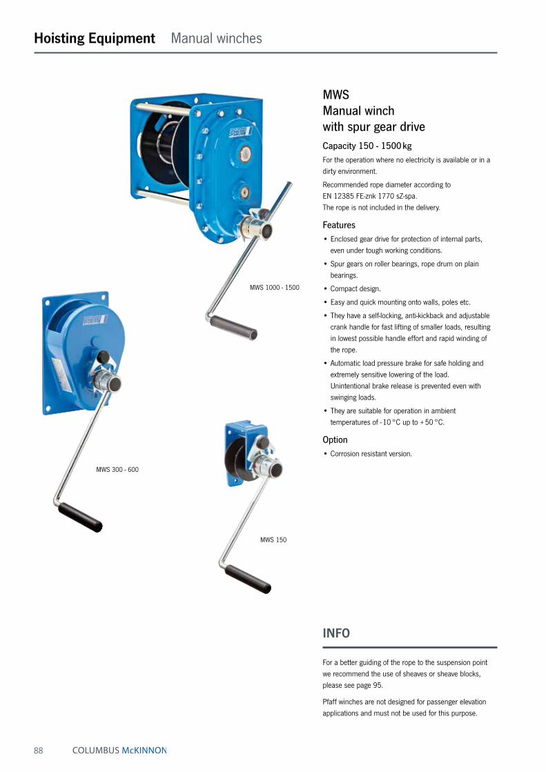
88
Hoisting Equipment Manual winches
MWSManual winch with spur gear driveCapacity 150 - 1500 kgFor the operation where no electricity is available or in a dirty environment.
Recommended rope diameter according to EN 12385 FE-znk 1770 sZ-spa. The rope is not included in the delivery.
Features• Enclosed gear drive for protection of internal parts,
even under tough working conditions.
• Spur gears on roller bearings, rope drum on plain bearings.
• Compact design.
• Easy and quick mounting onto walls, poles etc.
• They have a self-locking, anti-kickback and adjustable crank handle for fast lifting of smaller loads, resulting in lowest possible handle effort and rapid winding of the rope.
• Automatic load pressure brake for safe holding and extremely sensitive lowering of the load. Unintentional brake release is prevented even with swinging loads.
• They are suitable for operation in ambient temperatures of - 10 °C up to + 50 °C.
Option• Corrosion resistant version.
INFO
For a better guiding of the rope to the suspension point we recommend the use of sheaves or sheave blocks, please see page 95.
Pfaff winches are not designed for passenger elevation applications and must not be used for this purpose.
MWS 150
MWS 1000 - 1500
MWS 300 - 600
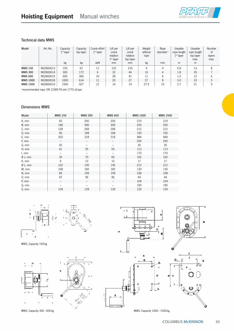
89
Hoisting Equipment Manual winches
Technical data MWS
Model Art.-No. Capacity 1st layer
kg
Capacity top layer
kg
Crank effort 1st layer
daN
Lift per crank
rotation 1st layer
mm
Lift per crank
rotation top layer
mm
Weight without
rope
kg
Rope diameter ¹
mm
Useable rope length
1st layer
m
Useable rope length top layer
max.m
Number of
layers max.
MWS 150 N02800013 150 67 11 122 210 4 4 0.8 13 8MWS 300 N02800014 300 172 6 32 44 10 4 1.8 35 7MWS 600 N02800015 600 366 10 28 41 11 6 1.2 12 6MWS 1000 N02800018 1000 614 11 20 27 27 8 3.0 33 5MWS 1500 N02800019 1500 927 12 14 19 27.5 10 2.7 21 5
¹ recommended rope: EN 12385 FE-znk 1770 sZ-spa
Model MWS 150 MWS 300 MWS 600 MWS 1000 MWS 1500
A, mm 65 200 200 219 219B, mm 168 300 300 250 250C, mm 128 268 268 212 212D, mm 40 168 168 150 150E, mm 303 318 318 484 484F, mm – – – 250 250G, mm 26 – – 30 30H, mm 41 55 55 113 113I, mm – – – 170 170Ø J, mm 35 70 60 102 102K, mm 9 12 12 17 17Ø L, mm 102 145 145 212 212M, mm 168 182 182 130 130N, mm 89 199 199 338 338O, mm 92 96 96 44 44P, mm – – – 104 104Q, mm – – – 190 190S, mm 129 129 129 129 129
Dimensions MWS
MWS, Capacity 150 kg
MWS, Capacity 300 - 600 kg MWS, Capacity 1000 - 1500 kg

90
Hoisting Equipment Manual winches
LB-VA, stainless steel version, capacity 900 kg
LB, zinc-plated version, capacity 1200 kg
LB, zinc-plated version, capacity 350 kg
LBConsole-mounted winchCapacity 150 - 1200 kgOriginally developed as offroad winch the console-mount-ed winch model LB is used today for a variety of lifting and pulling applications.
Features• Light weight robust stamped steel housing.
• Spur gear drive for optimal efficiency and comfortable handling.
• Automatic load pressure brake for save holding of the load in any position. An unintentional brake release is prevented.
• All parts are zinc-plated for increased corrosion protec-tion, drum with additional special coating.
• Easy and quick mounting to consoles, even under lift-ing conditions.
Options• Stainless steel version (mat. 1.4301) for increased
corrosion protection.
INFO
For a better guiding of the rope to the suspension point we recommend the use of sheaves or sheave blocks, please see page 95.
Pfaff winches are not designed for passenger elevation applications and must not be used for this purpose.

91
Hoisting Equipment Manual winches
LB, capacities 650 - 1200 kg
LB, capacities 150 - 350 kg
Technical data LB
Model Art.-No. Capacity 1st layer
kg
Capacity top layer
kg
Rope diameter
mm
Useable rope length
1st layerm
Useable rope length top layer
m
Lift per crank
rotationmm
Required crank effort
daN
Weight without
ropekg
LB 150 VZ 30239016 150 75 4 ¹ 0.8 11 125 17 4.2LB 350 VZ 30239015 350 170 4 ¹ 1.8 20 125 25 4.8LB 650 VZ 41239004 650 290 6 ¹ 1 20 55 22 7.3LB 900 VZ 41239006 900 400 7 ¹ 0.8 14 58 24 10LB 1200 VZ 42239008 1200 430 7 ² 1 26 45 24 12.1LB 250 VA 32239017 250 125 4 ¹ 1.8 19.5 125 20 4.8LB 650 VA 42239012 650 290 6 ¹ 1 20 55 22 7.6LB 900 VA 32239013 900 320 7 ¹ 1 26 45 24 12.1
¹ recommended rope: EN 12385 FE-znk 1770 sZ-spa ² recommended rope: EN 12385 SE-znk 2160 sZ-spa
Dimensions LB
Model LB 150 VZ LB 350 VZ LB 650 VZ LB 900 VZ LB 1200 VZ LB 250 VA LB 650 VA LB 900 VA
A, mm – – 232 232 273 – 232 273B, mm 155 155 192 192 266 155 192 266C, mm 175 175 210 210 240 175 210 240Ø D, mm 36 36 63.5 63.5 63.5 36 63.5 63.5Ø E, mm 100 100 183 183 255 100 183 255F, mm – – 100 100 78 – 100 78G, mm 75 75 58 58 75 75 58 75H, mm – – 100 100 138 – 100 138K, mm 159 189 192 192 192 191.5 190 190L, mm – – 25 25 35 – 25 35M, mm 45 75 38 38 30 75 38 30N, mm – – – – 53 – – 53O, mm 200 320 250 320 320 320 250 250P, mm 260 290 293 293 293 292.5 291 291Q, mm 81 111 95 95 95 111 95 95R, mm 50 80 50 50 50 80 50 50S, mm 48 63 55 55 55 65.5 55 55
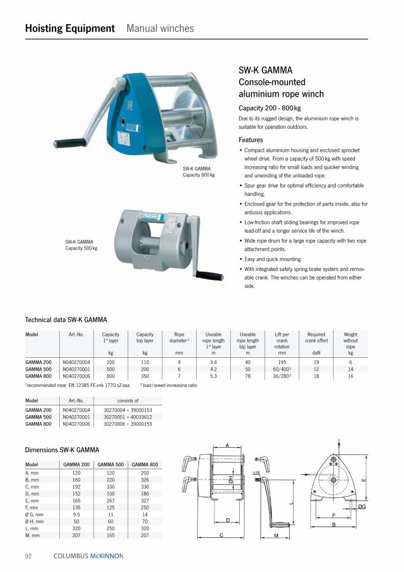
92
Hoisting Equipment Manual winches
SW-K GAMMAConsole-mounted aluminium rope winchCapacity 200 - 800 kgDue to its rugged design, the aluminium rope winch is suitable for operation outdoors.
Features• Compact aluminium housing and enclosed sprocket
wheel drive. From a capacity of 500 kg with speed increasing ratio for small loads and quicker winding and unwinding of the unloaded rope.
• Spur gear drive for optimal efficiency and comfortable handling.
• Enclosed gear for the protection of parts inside, also for arduous applications.
• Low-friction shaft sliding bearings for improved rope lead-off and a longer service life of the winch.
• Wide rope drum for a large rope capacity with two rope attachment points.
• Easy and quick mounting.
• With integrated safety spring brake system and remov-able crank. The winches can be operated from either side.
Technical data SW-K GAMMA
Model Art.-No. Capacity 1st layer
kg
Capacity top layer
kg
Rope diameter ¹
mm
Useable rope length
1st layerm
Useable rope length top layer
m
Lift per crank
rotationmm
Required crank effort
daN
Weight without
ropekg
GAMMA 200 N040270004 200 110 4 3.6 40 195 19 6GAMMA 500 N040270001 500 200 6 4.2 50 60/400 ² 12 14GAMMA 800 N040270006 800 350 7 5.3 78 36/280 ² 18 16
¹ recommended rope: EN 12385 FE-znk 1770 sZ-spa ² load/speed increasing ratio
Model GAMMA 200 GAMMA 500 GAMMA 800
A, mm 120 120 200B, mm 160 220 326C, mm 192 330 336D, mm 152 100 180E, mm 165 267 327F, mm 135 125 250Ø G, mm 9.5 11 14Ø H, mm 50 60 70L, mm 320 250 320M, mm 207 165 207
Dimensions SW-K GAMMA
SW-K GAMMA Capacity 800 kg
SW-K GAMMA Capacity 500 kg
Model Art.-No. consists of
GAMMA 200 N040270004 30270004 + 39000153GAMMA 500 N040270001 30270001 + 40033612GAMMA 800 N040270006 30270006 + 39000153
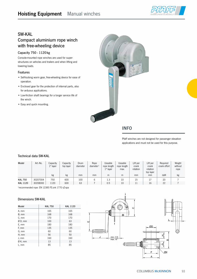
93
SW-KALCompact aluminium rope winch with free-wheeling deviceCapacity 750 - 1120 kgConsole-mounted rope winches are used for super-structures on vehicles and trailers and when lifting and lowering loads.
Features• Self-locking worm gear, free-wheeling device for ease of
operation.
• Enclosed gear for the protection of internal parts, also for arduous applications.
• Low-friction shaft bearings for a longer service life of the winch.
• Easy and quick mounting.
Hoisting Equipment Manual winches
Technical data SW-KAL
Model Art.-No. Capacity 1st layer
kg
Capacity top layer
kg
Drum diameter
mm
Rope diameter ¹
mm
Useable rope length
1st layer
m
Useable rope length
max.
m
Lift per crank
rotation
mm
Lift per crank
rotationtop layer
mm
Required crank effort
daN
Weight without
rope
kg
KAL 750 30207004 750 600 100 6 1.3 10 15 17 20 7KAL 1120 30208000 1120 600 63 7 0.5 10 11 16 22 7
¹ recommended rope: EN 12385 FE-znk 1770 sZ-spa
Model KAL 750 KAL 1120
A, mm 165 165B, mm 168 168C, mm 170 170Ø D, mm 100 63E, mm 180 180F, mm 135 135G, mm 60 60H, mm 56 50J, mm 160 160Ø K, mm 13 13L, mm 85 85
Dimensions SW-KAL
INFO
Pfaff winches are not designed for passenger elevation applications and must not be used for this purpose.

94
Hoisting Equipment Manual winches
SW-K LAMBDAConsole-mounted rope winch DGUV Vorschrift 17 (BGV C1)Capacity 300 kgThe compact rope winch for applications on stages, in studios, theatres, etc.
Features• State-of-the-art design with galvanized side sections for
easy handling.
• Grooved drum for single-layer winding of the steel rope. An 18:1 ratio between drum and rope diameter increases the service life of the rope substantially.
• With spring-loaded rope pressure roller to prevent the unloaded rope from jumping off the drum.
• Gear rated for twice the nominal load.
• Spur gear drive for optimal efficiency and comfortable handling.
• The fitted safety crank with two spring brakes acting independently of each other for safe holding of the load in any position.
• In compliance with DGUV Vorschrift 17 (BGV C1) and DIN 56925. Certified by the German committee for lifting equipment (GS-approval-tested safety).
Options• Drum extension for a larger rope capacity.
• Special grooves (several layers)
Technical data SW-K LAMBDA
Model Art.-No. Capacity
kg
Rope diameter ¹
mm
Useable rope length
1st layerm
Lift per crank
rotationmm
Required crank effort
daN
Weight without
ropekg
SW-K LAMBDA 30272015 300 6 10 50 18 30SW-K LAMBDA 30272017 300 6 15 50 18 36
¹ recommended rope: EN 12385 FE-znk 1960 sZ-spa
Rope pressure drum
Model SW-K LAMBDA SW-K LAMBDA
A, mm 379 469B, mm 310 310C, mm 340 340Ø D, mm 139.4 139.4E, mm 180 270F, mm 280 280G, mm 175 265Ø H, mm 13 13J, mm 250 250K, mm 130 130
Dimensions SW-K LAMBDA
INFO
Pfaff winches are not designed for passenger elevation applications and must not be used for this purpose.

95
Hoisting Equipment Manual winches accessories
Model Art.-No. Classification
FEM/ISO
Pulling force in kg
at deflection 90°
Pulling force in kg
at deflection 180°
Rope diameter
mm
DSRB S 90/4 33447103 2m/M5 700 500 3-4DSRB S 90/6 33447413 1Dm/M1 700 500 5-6DSRB S 145/7 33447106 1 Am/M4 1100 800 7DSRB S 185/8 33447107 2m/M5 2300 1630 8DSRB S 270/12 33447111 2m/M5 2500 1800 9-12
All sheaves are available as an individual component on request.
Technical data DSRB
Model DSRB S 90/4
DSRB S 90/6
DSRB S 145/7
DSRB S 185/8
DSRB S 270/12
B, mm 85 85 125 138 191C, mm 90 90 160 195 290Ø D, mm 90 90 145 185 270Ø D1, mm 20 25 25 30 40Ø Dm, mm 80 78 126 160 246E, mm 62 62 88 106 138H, mm 134 134 224 273 407K, mm 65 65 110 135 202L, mm 120 120 200 245 360Ø M/M1, mm 9/9 9/9 11.5/13 13.5/15 18/20S, mm 4 6 6 8 10
Dimensions DSRB
Rope diameter Breaking load of rope min.
kN
Art.-No.Rope length
5 m
Art.-No.Rope length
10 m
Art.-No.Rope length
15 m
Art.-No.Rope length
20 m
Capacity clevis end
kg
4 mm 10.1 33600405 33600410 33600415 33600420 5005 mm 15.8 33600505 33600510 33600515 33600520 10006 mm 22.8 33600605 33600610 33600615 33600620 10007 mm 31.0 33600705 33600710 33600715 33600720 1000
DSRB SSheave block for rope guidance, equipped with ball bearings
Standard ropes for manual winchesAccording to DIN EN 12385-4(formerly DIN 3060 resp. 3069)
INFO
Additional accessories available on request.
Rope-Ø
FRope
FRope
Ex on request!
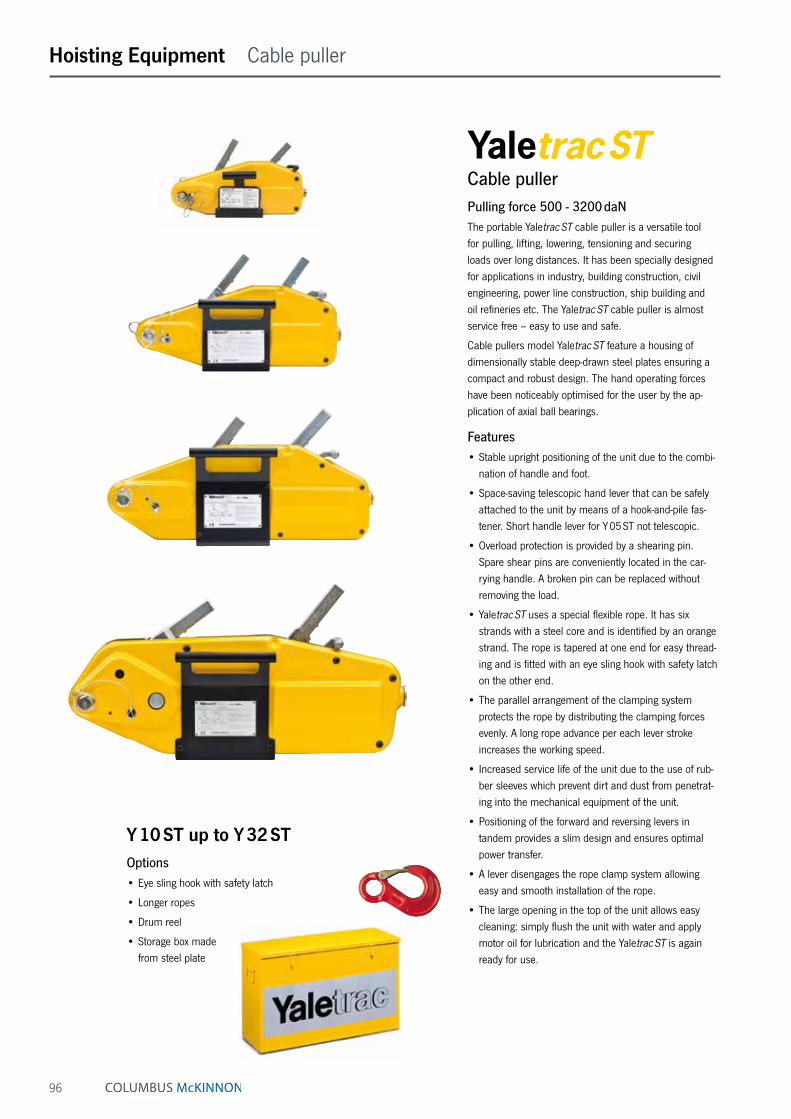
96
Hoisting Equipment Cable puller
Cable pullerPulling force 500 - 3200 daNThe portable Yaletrac ST cable puller is a versatile tool for pulling, lifting, lowering, tensioning and securing loads over long distances. It has been specially designed for applications in industry, building construction, civil engineering, power line construction, ship building and oil refineries etc. The Yaletrac ST cable puller is almost service free – easy to use and safe.
Cable pullers model Yaletrac ST feature a housing of dimensionally stable deep-drawn steel plates ensuring a compact and robust design. The hand operating forces have been noticeably optimised for the user by the ap-plication of axial ball bearings.
Features• Stable upright positioning of the unit due to the combi-
nation of handle and foot.
• Space-saving telescopic hand lever that can be safely attached to the unit by means of a hook-and-pile fas-tener. Short handle lever for Y 05 ST not telescopic.
• Overload protection is provided by a shearing pin. Spare shear pins are conveniently located in the car-rying handle. A broken pin can be replaced without removing the load.
• Yaletrac ST uses a special flexible rope. It has six strands with a steel core and is identified by an orange strand. The rope is tapered at one end for easy thread-ing and is fitted with an eye sling hook with safety latch on the other end.
• The parallel arrangement of the clamping system protects the rope by distributing the clamping forces evenly. A long rope advance per each lever stroke increases the working speed.
• Increased service life of the unit due to the use of rub-ber sleeves which prevent dirt and dust from penetrat-ing into the mechanical equipment of the unit.
• Positioning of the forward and reversing levers in tandem provides a slim design and ensures optimal power transfer.
• A lever disengages the rope clamp system allowing easy and smooth installation of the rope.
• The large opening in the top of the unit allows easy cleaning: simply flush the unit with water and apply motor oil for lubrication and the Yaletrac ST is again ready for use.
Y 10 ST up to Y 32 STOptions• Eye sling hook with safety latch
• Longer ropes
• Drum reel
• Storage box made from steel plate
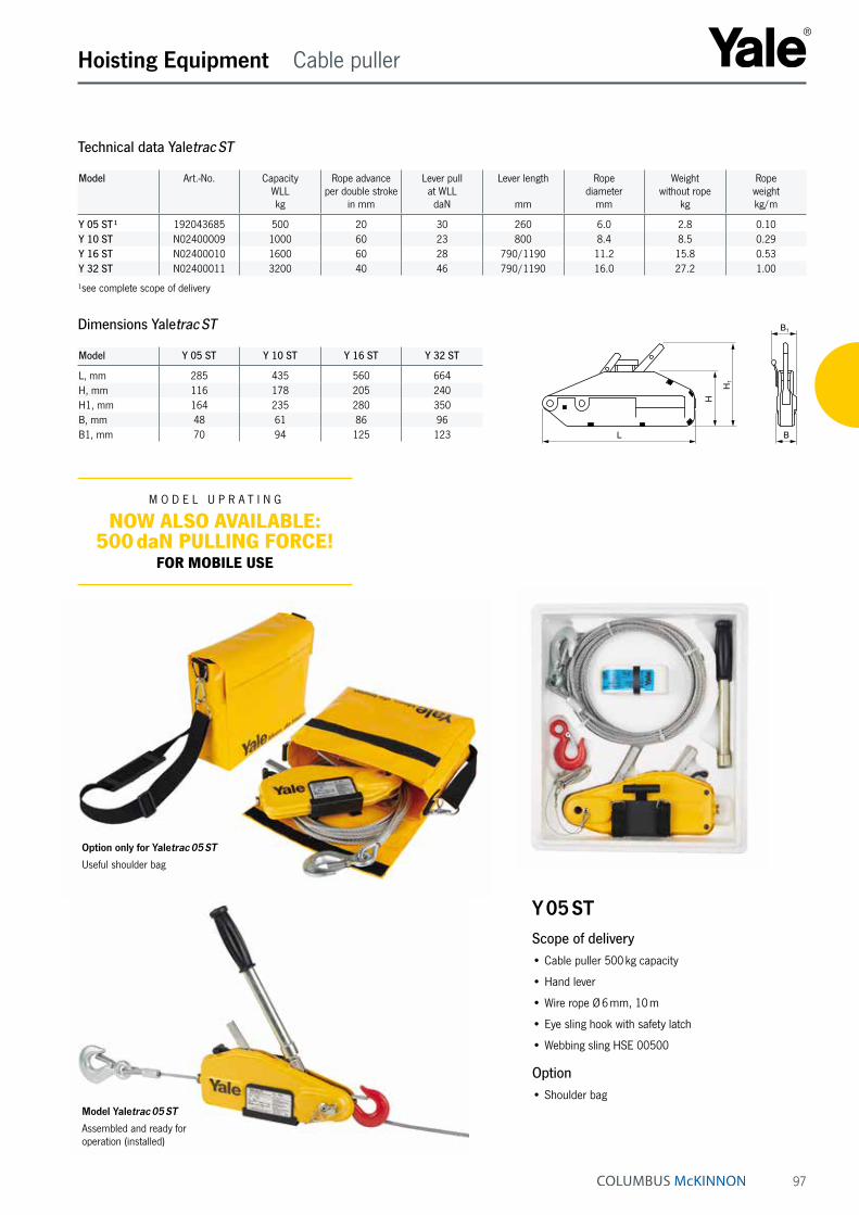
97
Hoisting Equipment Cable puller
Technical data Yaletrac ST
Model Art.-No. Capacity WLLkg
Rope advance per double stroke
in mm
Lever pull at WLL
daN
Lever length
mm
Rope diameter
mm
Weight without rope
kg
Rope weightkg/m
Y 05 ST ¹ 192043685 500 20 30 260 6.0 2.8 0.10Y 10 ST N02400009 1000 60 23 800 8.4 8.5 0.29Y 16 ST N02400010 1600 60 28 790/1190 11.2 15.8 0.53Y 32 ST N02400011 3200 40 46 790/1190 16.0 27.2 1.00
¹see complete scope of delivery
Dimensions Yaletrac ST
Model Y 05 ST Y 10 ST Y 16 ST Y 32 ST
L, mm 285 435 560 664H, mm 116 178 205 240H1, mm 164 235 280 350B, mm 48 61 86 96B1, mm 70 94 125 123 B
B1
H1
H
L
M O D E L U P R A T I N G
NOW ALSO AVAILABLE: 500 daN PULLING FORCE!
FOR MOBILE USE
Model Yaletrac 05 ST
Assembled and ready for operation (installed)
Y 05 STScope of delivery• Cable puller 500 kg capacity
• Hand lever
• Wire rope Ø 6 mm, 10 m
• Eye sling hook with safety latch
• Webbing sling HSE 00500
Option• Shoulder bag
Option only for Yaletrac 05 ST
Useful shoulder bag
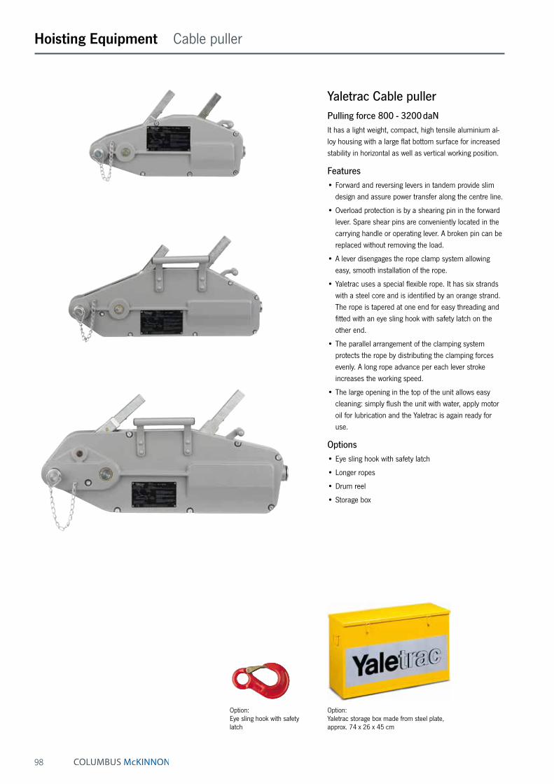
98
Hoisting Equipment Cable puller
Yaletrac Cable pullerPulling force 800 - 3200 daNIt has a light weight, compact, high tensile aluminium al-loy housing with a large flat bottom surface for increased stability in horizontal as well as vertical working position.
Features• Forward and reversing levers in tandem provide slim
design and assure power transfer along the centre line.
• Overload protection is by a shearing pin in the forward lever. Spare shear pins are conveniently located in the carrying handle or operating lever. A broken pin can be replaced without removing the load.
• A lever disengages the rope clamp system allowing easy, smooth installation of the rope.
• Yaletrac uses a special flexible rope. It has six strands with a steel core and is identified by an orange strand. The rope is tapered at one end for easy threading and fitted with an eye sling hook with safety latch on the other end.
• The parallel arrangement of the clamping system protects the rope by distributing the clamping forces evenly. A long rope advance per each lever stroke increases the working speed.
• The large opening in the top of the unit allows easy cleaning: simply flush the unit with water, apply motor oil for lubrication and the Yaletrac is again ready for use.
Options• Eye sling hook with safety latch
• Longer ropes
• Drum reel
• Storage box
Option: Yaletrac storage box made from steel plate, approx. 74 x 26 x 45 cm
Option: Eye sling hook with safety latch
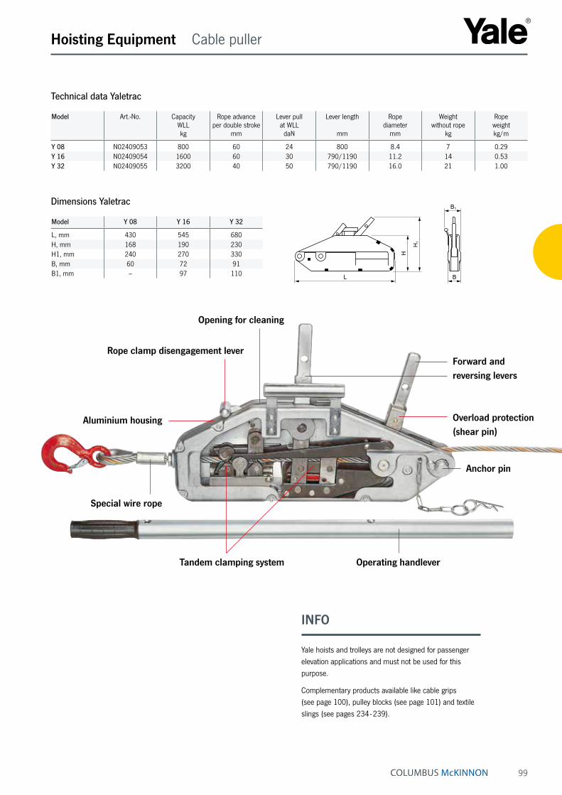
99
Hoisting Equipment Cable puller
Technical data Yaletrac
Model Art.-No. Capacity WLLkg
Rope advance per double stroke
mm
Lever pull at WLL
daN
Lever length
mm
Rope diameter
mm
Weight without rope
kg
Rope weight kg/m
Y 08 N02409053 800 60 24 800 8.4 7 0.29Y 16 N02409054 1600 60 30 790/1190 11.2 14 0.53Y 32 N02409055 3200 40 50 790/1190 16.0 21 1.00
Dimensions Yaletrac
Model Y 08 Y 16 Y 32
L, mm 430 545 680H, mm 168 190 230H1, mm 240 270 330B, mm 60 72 91B1, mm – 97 110
INFO
Yale hoists and trolleys are not designed for passenger elevation applications and must not be used for this purpose.
Complementary products available like cable grips (see page 100), pulley blocks (see page 101) and textile slings (see pages 234 - 239).
B
B1
H1
H
L
Aluminium housing
Opening for cleaning
Rope clamp disengagement lever
Special wire rope
Tandem clamping system Operating handlever
Anchor pin
Overload protection (shear pin)
Forward and reversing levers
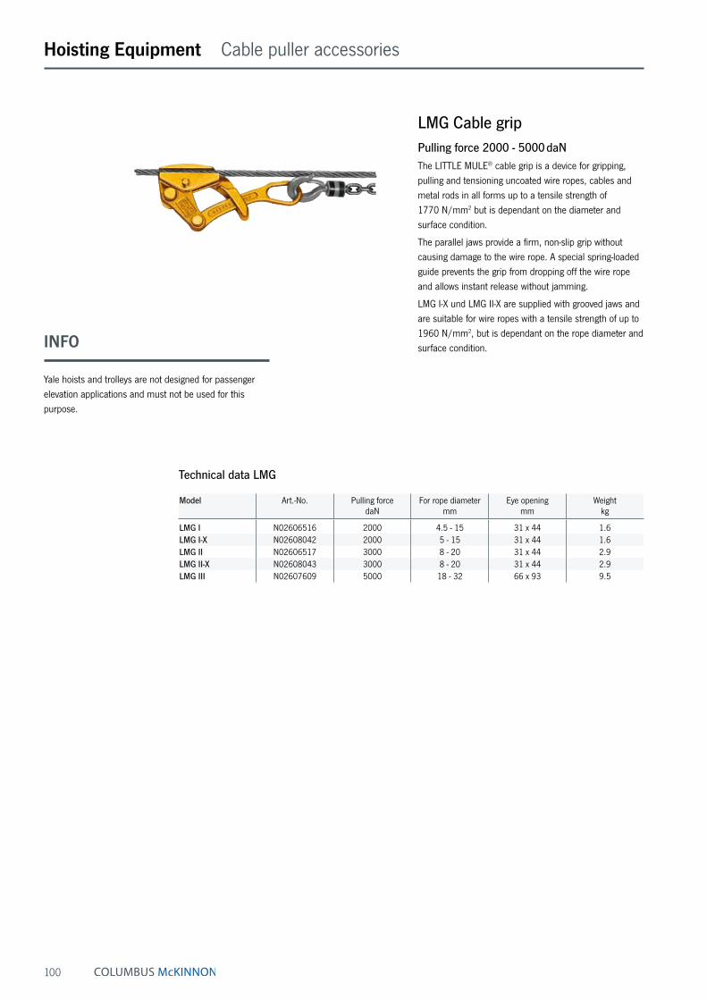
100
Hoisting Equipment Cable puller accessories
INFO
Yale hoists and trolleys are not designed for passenger elevation applications and must not be used for this purpose.
LMG Cable gripPulling force 2000 - 5000 daNThe LITTLE MULE® cable grip is a device for gripping, pulling and tensioning uncoated wire ropes, cables and metal rods in all forms up to a tensile strength of 1770 N/mm2 but is dependant on the diameter and surface condition.
The parallel jaws provide a firm, non-slip grip without causing damage to the wire rope. A special spring-loaded guide prevents the grip from dropping off the wire rope and allows instant release without jamming.
LMG I-X und LMG II-X are supplied with grooved jaws and are suitable for wire ropes with a tensile strength of up to 1960 N/mm2, but is dependant on the rope diameter and surface condition.
Technical data LMG
Model Art.-No. Pulling forcedaN
For rope diametermm
Eye openingmm
Weightkg
LMG I N02606516 2000 4.5 - 15 31 x 44 1.6LMG I-X N02608042 2000 5 - 15 31 x 44 1.6LMG II N02606517 3000 8 - 20 31 x 44 2.9LMG II-X N02608043 3000 8 - 20 31 x 44 2.9LMG III N02607609 5000 18 - 32 66 x 93 9.5
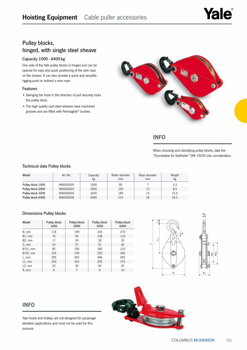
101
Hoisting Equipment Cable puller accessories
Pulley blocks, hinged, with single steel sheaveCapacity 1000 - 6400 kgOne side of the Yale pulley blocks is hinged and can be opened for easy and quick positioning of the wire rope on the sheave. It can also provide a quick and versatile rigging point or redirect a wire rope.
Features• Swinging the hook in the direction of pull securely locks
the pulley block.
• The high quality cast steel sheaves have machined grooves and are fitted with Permaglide® bushes.
Model Art.-No. Capacitykg
Roller diametermm
Rope diametermm
Weightkg
Pulley block 1000 N46000005 1000 85 7 3.3Pulley block 2000 N46000003 2000 150 13 8.9Pulley block 3200 N46000004 3200 180 15 15.5Pulley block 6400 N46000006 6400 210 18 26.5
Technical data Pulley blocks
Model Pulley block 1000
Pulley block 2000
Pulley block 3200
Pulley block 6400
B, mm 118 199 230 270B1, mm 76 92 108 116B2, mm 17 24 28 35C, mm 23 27 31 42Ø D1, mm 85 150 180 210Ø D2, mm 105 190 220 260L, mm 305 425 496 655L1, mm 200 263 295 375L2, mm 23 30 40 47R, mm 4 7 9 10
Dimensions Pulley blocks
B
L
C
R
L1
L2
B 1
B 2øD
2
øD1
INFO
Yale hoists and trolleys are not designed for passenger elevation applications and must not be used for this purpose.
INFO
When choosing and classifying pulley blocks, take the “Grundsätze für Seiltriebe” DIN 15020 into consideration.

102
Hoisting Equipment User information
Steel rope for manual and electric winchesAll electric winches are supplied without load bearing mechanisms as standard. To ensure safe operation an optimum rope design, optimum length and associated fastening elements (hooks, shackles) are selected.
We recommend to choose wire ropes on the basis of design, type of construction and strength to suit the intended use and frequency of use. The features of the different types of rope design are as follows:
Breaking load → Load bearing capacity, strength of the rope
Bending fatigue + flexibility → Service life
External wear → Stability of the outer strands
Torsion characteristics → Lifting of guided or unguided loads
Handling
Our product range includes winches for lifting, pulling and moving of loads. In combination to our winches the follow-ing rope types apply:
Standard design 6 x 19 + FE 1770 N/mm²Manual winch rope with fiber inlay 3 - 12 mm Ø
Galvanized or stainless steel in mat. 1.4401 Nominal strength 1570 N/mm² (low breaking load)
• not non-twisting
• crosslay type of construction
• low-tension
• lifting rope for infrequent actuation
• rugged and widely resistant
Warrington-Seale 6 x 36 WS + SES (FE) 1770 N/mm²Manual and electric winch rope in parallel type of construction 10 - 28 mm Ø
Galvanized, with fiber or steel inlays as options
• highly flexible
• high breaking load
• average number of reversed bending stresses
Non-rotating special rope SE-znk - 1960 N/mm²Standard rope for electric winches, non-rotating spiral strand rope 3 - 13 mm Ø
Galvanized
• balanced characteristics
• lifting rope for unguided single rope suspension ele-ments
• lifting rope for large lifting heights with multiple rope suspension elements
• not to be used with a swivel
• high strength
• high bending fatigue characteristics
Heavy duty winch ropeElectric winch rope with plastic-coated steel core in double-parallel type of construction 6 - 30 mm Ø
Bright and greased, not non-twisting
• special rope for frequent bending stress reversals and long use
• to be used only with matching rope sheaves and drums
• optimized break loads due to higher fill factor
INFO
The use of plastic-coated steel wire ropes with lifting equipment is not permitted.
To meet individual requirements we can provide assis-tance for the selection of length, diameter and type of the rope, as well as a fastening equipment (thimbles, hooks, rope clips, etc.).

103
Hoisting Equipment User information
Rope fasteners/rope connectionsThe safe functioning of the rope drive depends to a large extent on the rope fastenings on the winch and on the load. Rope connections and ropes themselves have to be checked at regular intervals by competent persons. The following rope connections are permissible for use with lifting equipment:
Non-releasable rope connectionsAluminium press-on connection with thimbles
in combination with safety eye hooks or screw shackles provide a simple and safe means of suspending loads.
Splice connections (uncoated) in combination with thimbles, hooks, etc.
In the most unfavourable situation, splice connections can lead to a reduction in the breaking load of the rope line of up to 40 %.
Releasable rope connectionsRope clips
• The end which is not under load must never be fas-tened to the load-bearing line.
• The length of the unloaded rope end should be at least 20 times the diameter of the rope and not less than 150 mm.
• Clips may no longer be used once the rope has worn by more than 10 %.
• Wire rope clamps may not be used for rope con-nections for lifting equipment, with the exception of fastening equipment which is manufactured for none-recuring, special purposes!
Handling of ropes – Unwinding
RIGHT
WRONG
Care of ropes“Running ropes” in particular will only offer optimum ser-vice lives if they are well lubricated. The use of steel ropes without grease will cause them to wear quickly and the load bearing mechanism will have to be replaced early.
INFO
Pressed and splice connections may only be produced by specialist firms or rope manufacturers.
Notes on the installation of winches
The distance between rope drum and sheave must be selected in a way that the maximum deflection angle for the type of rope used is not exceeded:
Standard rope – Deflection angle < 3° (Minimum distance = Drum width x 10)
Special rope - Deflection angle < 1.5° (Minimum distance = Drum width x 20)
• To prevent the wire rope from becoming slack when un-loaded it should always have an additional rope weight when used with lifting equipment
• Guided loads must be monitored with a slack rope cut-out.
• To prevent the rope from becoming damaged, steel wire ropes must never be guided - over edges - over deflection radii which are too small or - over rope sheaves with grooves which are too small.
• High dynamic forces can lead to sudden breaks or crashes of the load. It is therefore imperative that loads are never brought to a dead stop (“on block”) and that loads are never allowed to drop into the rope.

104
Hoisting Equipment Electric winches
Electric winchCapacity 250 - 2000 kgWinches series RPE are designed for performance, efficiency and safety and offer many advantages and op-tions. RPE‘s compact, practical cube design and universal rope lead-offs allow individual applications in almost any position for lifting and pulling loads. The winches are designed to DIN 15020, classification 1 Bm/M3 and the EC machinery directives.
Every winch is factory tested with overload. The units are supplied with a test certificate showing the unit‘s serial-no. and an operating instructions manual which contains a manufacturer‘s declaration.
Features• Compact dimensions due to internal brake motor.
• Standard operating voltages of 400 V/230 V, 3-ph, 50 Hz or 230 V, 1-ph, 50 Hz
• Protected to IP 54
• Insulation class F
• Adjustable slip clutch to protect the winch from over-loading standard for RPE 10-6 and RPE 20-6.
• Spur gear transmission with helical first gear ensures smooth motion. Lubricated by grease and can, there-fore, be used in any position.
• Spring pressure disc brake incorporated in the motor holds the load secure even in the event of a power failure.
• Plain rope drum standard.The rope is secured to the drum in a recess so that the rope can be wound onto the drum in several layers without damage.
• 42 V low voltage control (incl. push-button with emer-gency-stop and 2 m control cable) or without controls.
Rope attachment Spring pressure disc brake Brake motor
INFO
When selecting the length of the rope please bear in mind that a minimum of 2 - 3 windings have to remain on the drum.
The wire rope, if ordered, comes dismounted, and is to be mounted onto the drum by the user.
Please note, the single-phase winches generate a higher noise level than those with three-phase motors.
The image shows the winch RPE up to 1,0 t
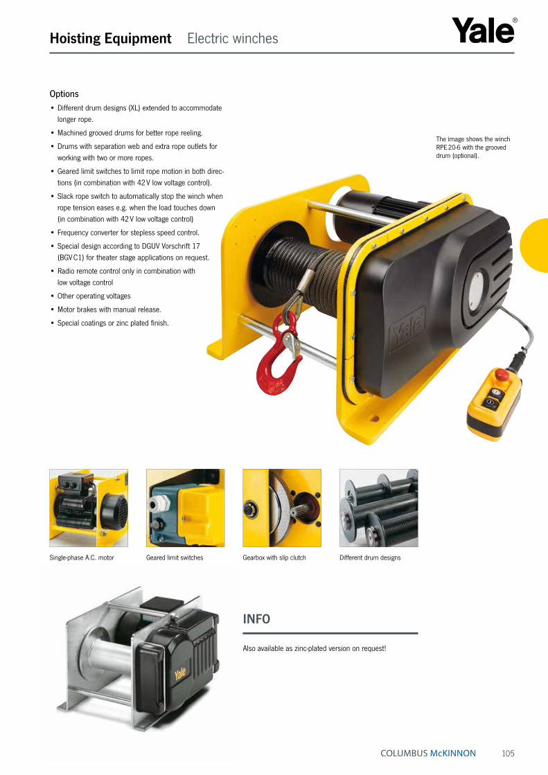
105
INFO
Also available as zinc-plated version on request!
Hoisting Equipment Electric winches
Single-phase A.C. motor Geared limit switches Gearbox with slip clutch Different drum designs
Options• Different drum designs (XL) extended to accommodate
longer rope.
• Machined grooved drums for better rope reeling.
• Drums with separation web and extra rope outlets for working with two or more ropes.
• Geared limit switches to limit rope motion in both direc-tions (in combination with 42 V low voltage control).
• Slack rope switch to automatically stop the winch when rope tension eases e.g. when the load touches down (in combination with 42 V low voltage control)
• Frequency converter for stepless speed control.
• Special design according to DGUV Vorschrift 17 (BGV C1) for theater stage applications on request.
• Radio remote control only in combination with low voltage control
• Other operating voltages
• Motor brakes with manual release.
• Special coatings or zinc plated finish.
The image shows the winch RPE 20-6 with the grooved drum (optional).

106
Hoisting Equipment Electric winches
Model Capacity top layer
kg
Drum size Useable rope length max.m
1st layer 2nd layer 3rd layer 4th layer
RPE 2-13 ¹ 250 1¹ 11.1 24.5 39 54RPE 5-6 ¹ 500 1¹ 7.4 16.9 27 38RPE 10-6 ¹ 1000 1¹ 10.1 23.0 37 –RPE 20-6 2000 1 13.2 30.3 49 –
RPE 2-13 L 250 2 16.8 36.4 57 80RPE 5-6 L 500 2 11.3 25.2 40 57RPE 5-12 L 500 2 11.3 25.2 40 57RPE 10-6 L 1000 2 15.8 35.2 56 –RPE 20-6 L 2000 2 20.6 46.1 74 –
RPE 2-13 XL 250 3 44.3 94.1 148 200RPE 5-6 XL 500 3 30.0 65.5 105 149RPE 5-12 XL 500 3 65.0 65.5 105 149RPE 10-6 XL 1000 3 30.7 67.0 107 –RPE 20-6 XL 2000 3 34.1 74.9 120 –1 available on request only!
Plain drum rope capacity
Technical data RPE
Model Capacity top layer
kg
Drum size Useable rope lengthm
1st layer max.
RPE 2-13 R ¹ 250 1¹ 8.8 43RPE 5-6 R ¹ 500 1¹ 6.2 33RPE 10-6 R ¹ 1000 1¹ 8.2 30RPE 20-6 R 2000 1 12.0 44
RPE 2-13 LR 250 2 13.3 64RPE 5-6 LR 500 2 9.5 49RPE 5-12 LR 500 2 9.5 49RPE 10-6 LR 1000 2 12.9 47RPE 20-6 LR 2000 2 16.8 61
RPE 2-13 XLR 250 3 35.3 165RPE 5-6 XLR 500 3 25.7 128RPE 5-12 XLR 500 3 25.7 128RPE 10-6 XLR 1000 3 25.2 89RPE 20-6 XLR 2000 3 27.9 991 available on request only!
Grooved drum rope capacity (recommended for single layer operation)
INFO
When selecting the length of the rope please bear in mind that a minimum of 2 - 3 windings have to remain on the drum.
Yale hoists and trolleys are not designed for passenger elevation applications and must not be used for this purpose.
Model Capacity
kg
Lifting speed m/min
Rope layersmax.
Rope diameter
mm
Motor
kW
ED Weight without ropekg
1st layer top layer L XL
RPE 2-13 L 250 10.2 13.2 4 4 0.55 40 % 40 48RPE 5-6 L 500 4.6 6.6 4 6 0.55 40 % 41 49RPE 5-12 L 500 8.7 12.6 4 6 1.1 40 % 47 54RPE 10-6 L ¹ 1000 5.1 6.5 3 8 1.1 40 % 89 105RPE 20-6 ¹ 2000 5.2 7.6 3 12 2.2 40 % 213 235
¹ Adjustable slip clutch as standard
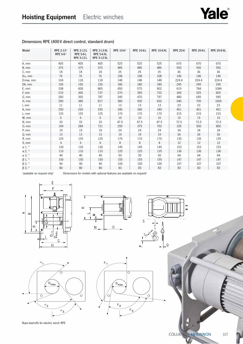
107
Hoisting Equipment Electric winches
α 1
α 2α 3
Dmax.
β 2β 3
β 1
Dmax.
Rope lead-offs for electric winch RPE
Dimensions RPE (400 V direct control, standard drum)
Model RPE 2-13 ¹ RPE 5-6 ¹
RPE 2-13 L RPE 5-6 L
RPE 5-12 L
RPE 2-13 XL RPE 5-6 XL
RPE 5-12 XL
RPE 10-6 ¹ RPE 10-6 L RPE 10-6 XL RPE 20-6 RPE 20-6 L RPE 20-6 XL
A, mm 405 405 405 525 525 525 670 670 670B, mm 375 375 375 485 485 485 550 550 550C, mm 18 18 18 25 25 25 36 36 36DTR, mm 76 76 76 108 108 108 146 146 146D max, mm 104 118 118 148 148 148 224.4 224.4 224.4DA, mm 150 150 150 180 180 180 245 245 245E, mm 338 428 865 450 575 902 619 784 1084F, mm 210 300 737 270 395 722 360 525 825G, mm 260 350 787 345 470 797 480 645 945H, mm 290 380 817 380 505 832 540 705 1005I, mm 11 11 11 13 13 13 23 23 23K, mm 250 250 250 340 340 340 401 401 401L, mm 125 125 125 170 170 170 215 215 215M, mm 6 6 6 10 10 10 15 15 15N, mm 33 33 33 47.5 47.5 47.5 72.5 72.5 72.5O, mm 194 284 721 250 375 702 335 500 800P, mm 19 19 19 24 24 24 34 34 34Q, mm 13 13 13 19 19 19 26 26 26R, mm 125 125 125 170 170 170 135 135 135S, mm 4 6 6 8 8 8 12 12 12α 1, ° 130 130 130 145 145 145 153 153 153α 2, ° 110 110 110 125 125 125 136 136 136α 3, ° 40 40 40 50 50 50 64 64 64β 1, ° 150 150 150 155 155 155 147 147 147β 2, ° 90 90 90 100 100 100 107 107 107β 3, ° 80 80 80 83 83 83 83 83 831 available on request only! Dimensions for models with optional features are available on request!

108
Hoisting Equipment Endless winches
Endless winch
up to 500 kg!Endless winchCapacity 66 - 500 kg(two-fall design up to 1000 kg, optional)The Yale Mtrac ® endless winch combines state-of-the-art industrial design with technical innovation to solve a specific customer need – the need for a safe and simple handling solution for mobile applications. We did just that. Because the rope of the endless winch is not collected during operation, there is no limit to the lifting height and traction length when using this product. And, with a full offering of wire ropes and accessories, this winch can be used in virtually any application requiring a hoist., e.g. on construction sites, in maintenance and assembly, in wind mills and power supply, water and utility sector, overhead line maintenance, etc.
Features• Control pendant (IP 65-type of enclosure) is connected
via a control cable.
• Standard power cable has a length of 1.0 m and is fitted with a CE connector plug (or a Schuko-plug).
• 42 V low-voltage control
• Ergonomic, fitted carrying handle features a comfortable plastic grip.
• Mounting feet fixed on the housing for easy set up.
• Standard operating voltages of 400 V, 3-ph, 50 Hz or 230 V, 1-ph, 50 Hz.
• Galvanized, high-density steel rope is 10 m long (dia. 6.5 mm) and features a safety hook on one end as well as a rounded, plastic-coated tip at the loose end.
• Two spring buffers with adjusting rings can be attached to the wire rope to set the limit switches for both upward and downward movement.
• Drive sheave is made of especially hardened steel designed to ensure long service life.
• The patented (German Patent DE 10 2012 100 099) bi-directional actuator ensures the rope is safely guided and securely held in place.
• Slip clutch is located outside of the load path for added safety.
• Limit switches ensure safe cut-out for the upper and lower hook positions.
• Electromagnetic brake holds the load safely, even in the event of a power failure.
• Winch is classified up to 1 Bm/M3 acc. to FEM/ISO.
• Winch is protected up to IP 55.
Endless winch
up to 500 kg!
STANDARDThis image shows the Yale Mtrac winch with standard equipment.
P A T E N T E D*
BI-DIRECTIONAL ACTUATORFOR BI-DIRECTIONAL
LIFTING
*German Patent DE 10 2012 100 099

109
Hoisting Equipment Endless winches
FEATURESPATENTED* BI-DIRECTIONAL ACTUATORThe Yale Mtrac endless winch features a unique bi-directional actuator that allows the winch to move the rated load on both ends of the rope. A hook can be fitted on the unloaded rope end (as an option) thus eliminating no-load motions. How does it work? Once the load has reached the top position, the unloaded rope end with the other hook is automatically in the bottom position and a new load can be picked up immediately. The lifting frequency is doubled as the two falls can be evenly loaded alternately with the rated load.
*German Patent DE 10 2012 100 099
READY TO USEEach winch leaves our factory as a complete plug and play unit. The control cable with control pendant is connected, as is the power supply cable with the plug. The standard design also features a wire rope complete with fitted safety hook. The carrying handle is included as standard and load-bearing feet are provided on the lower part of the housing.
STATE-OF-THE-ART INDUSTRIAL DESIGNA compact and state-of-the-art design was at the focus of the Yale Mtrac. The housing is made of low-pressure, die-cast aluminum and the high-strength, glass-fiber rein-forced plastic covers ensure low weight and outstanding rigidity. A carrying frame, available as an option, allows for easy, two-person transport and provides additional protection against damage when moving the unit or operating it in rough conditions.
VERSATILE APPLICATIONMtrac winches can be used vertically, at an angle or horizontally for versatility depending on your application. Optionally, the load capaci ty can be doubled with two-fall reeving. Bolting points on the housing allow the customer to attach the winch in a way that best suits their applica-tion.
PROVEN TECHNOLOGYMtrac winches include reliable and proven Yale technolo-gy. The oil-bath lubricated and case-hardened gearbox has a helical gearing for smooth operation and a long service life. IP 55-rated motor enclosure ensures reliable opera-tion of the winch for both indoor and outdoor applications.
BEST-IN-CLASS SAFETYStandard winch models feature 42 V low-voltage control with built-in limit switches designed to stop the hoist when the hook has reached the upper or lower position. The operator can define the limit switch positions by simply relocating the spring buffers on the rope. The winch is also protected against overload by means of a slip clutch that is designed to guarantee a permanent connection between the load and the brake.
SIMPLE MAINTENANCEYale Mtrac winches are easy to service. Units are designed with a modular structure with all critical parts easily ac-cessible. Re-adjusting the slip clutch and inspecting the brake is quick and easy as well. In addition, the handle, or carrying frame, can be quickly and easily assembled and removed.
ERGONOMIC DESIGNStandard units have a comfortable plastic grip that allows for conven ient one-person transport. The optional carrying frame features a grip on each handle, making two-person transport easy. And, because of the rounded housing, operator injury is minimized.
STANDARDThis image shows the Yale Mtrac winch with stand-ard equipment.
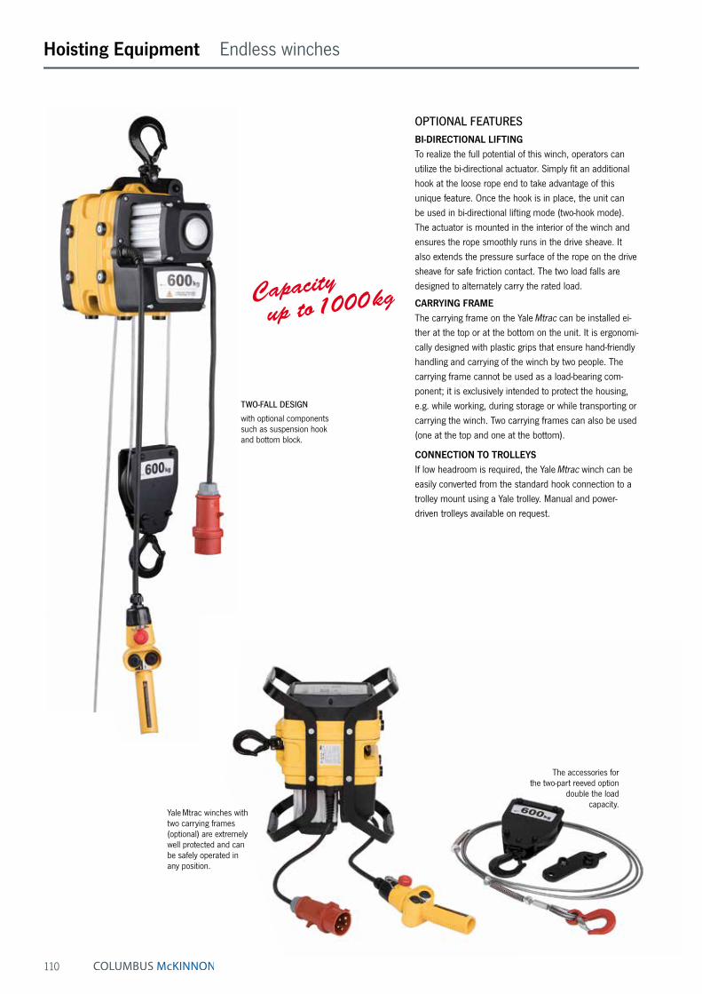
110
Capacity up to 1000 kg
Hoisting Equipment Endless winches
Yale Mtrac winches with two carrying frames (optional) are extremely well protected and can be safely operated inany position.
TWO-FALL DESIGN
with optional components such as suspension hook and bottom block.
OPTIONAL FEATURESBI-DIRECTIONAL LIFTINGTo realize the full potential of this winch, operators can utilize the bi-directional actuator. Simply fit an additional hook at the loose rope end to take advan tage of this unique feature. Once the hook is in place, the unit can be used in bi-directional lifting mode (two-hook mode). The actuator is mounted in the interior of the winch and ensures the rope smoothly runs in the drive sheave. It also extends the pressure surface of the rope on the drive sheave for safe friction contact. The two load falls are designed to alternately carry the rated load.
CARRYING FRAMEThe carrying frame on the Yale Mtrac can be installed ei-ther at the top or at the bottom on the unit. It is ergonomi-cally designed with plastic grips that ensure hand-friendly handling and carrying of the winch by two people. The carrying frame cannot be used as a load-bearing com-ponent; it is exclusively intended to protect the housing, e.g. while working, during storage or while transporting or carrying the winch. Two carrying frames can also be used (one at the top and one at the bottom).
CONNECTION TO TROLLEYSIf low headroom is required, the Yale Mtrac winch can be easily converted from the standard hook connection to a trolley mount using a Yale trolley. Manual and power-driven trolleys available on request.
The accessories forthe two-part reeved option
double the loadcapacity.
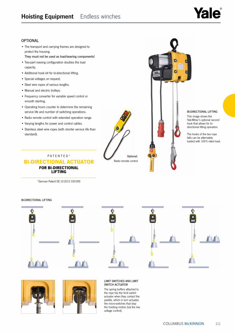
111
Hoisting Equipment Endless winches
Optional:
Radio remote control
BI-DIRECTIONAL LIFTING
BI-DIRECTIONAL LIFTING
This image shows the Yale Mtrac’s optional second hook that allows for bi-directional lifting operation.
The hooks of the two rope falls can be alternately loaded with 100 % rated load.
OPTIONAL• The transport and carrying frames are designed to
protect the housing. They must not be used as load-bearing components!
• Two-part reeving configuration doubles the load capacity.
• Additional hook kit for bi-directional lifting.
• Special voltages on request.
• Steel wire ropes of various lengths.
• Manual and electric trolleys.
• Frequency converter for variable speed control or smooth starting.
• Operating hours counter to determine the remaining service life and number of switching operations.
• Radio remote control with extended operation range.
• Varying lengths for power and control cables.
• Stainless steel wire ropes (with shorter service life than standard).
P A T E N T E D *
BI-DIRECTIONAL ACTUATORFOR BI-DIRECTIONAL
LIFTING
*German Patent DE 10 2012 100 099
LIMIT SWITCHES AND LIMIT SWITCH ACTUATOR
The spring buffers attached to the rope trip the limit switch actuator when they contact the paddle, which in turn actuates the micro-switches that stop the hoisting motion (via the low voltage control).

112
Hoisting Equipment Endless winches
Technical data YaleMtrac
Dimensions
A, mm 385A1, mm 287A2, mm 272A3, mm 221A4, mm 119B, mm 22C, mm 29D, mm 19E, mm 202E1, mm 92F, mm 132F1, mm 93F2, mm 147G, mm 100G1, mm 84G2, mm 103H, mm 201K, mm M8L, mm 426L1, mm 159L2, mm 213
F2
H
G1
G
K
D
FF1
G2
LL1 L2E
A1
A2
A
A4
E1
C
BA
3
INFO
Yale hoists and trolleys are not designed for passenger elevation applications and must not be used for this purpose.
Model Art.-No. Single fallStandard
Double fallOptional
Motor
kW
Operating voltage
Capacity
kg
Liftingspeedm/min
Capacity
kg
Liftingspeedm/min
YMT 1-15 192025166 100 15 200 7.5 0.37 230 V/1 Ph/50 HzYMT 3-5 192025170 300 5 600 2.5 0.37 230 V/1 Ph/50 Hz
YMTF 0,6-30 192025175 66 30/7.5 130 15/3.7 0.37/0.09 400 V/3 Ph/50 HzYMT 1-30 192025171 100 30 200 15 0.55 400 V/3 Ph/50 HzYMTF 2-10 192025176 200 10/2.5 400 5/1.3 0.37/0.09 400 V/3 Ph/50 HzYMT 3-10 192025174 300 10 600 5 0.55 400 V/3 Ph/50 HzYMT 5-5 192053140 500 5 1000 2.5 0.55 400 V/3 Ph/50 Hz
Weight from 24 to 26 kg (without rope) depending on options. Rope Ø 6.5 mm
INFO
Yale hoists and trolleys are not designed for passenger elevation applications and must not be used for this purpose.
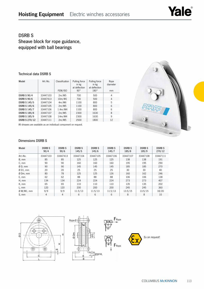
113
Hoisting Equipment Electric winches accessories
DSRB SSheave block for rope guidance, equipped with ball bearings
Dimensions DSRB S
Model DSRB S 90/4
DSRB S 90/6
DSRB S 145/5
DSRB S 145/6
DSRB S 145/7
DSRB S 185/8
DSRB S 185/9
DSRB S 270/12
Art.-No. 33447103 33447413 33447104 33447105 33447106 33447107 33447108 33447111B, mm 85 85 125 125 125 138 138 191C, mm 90 90 160 160 160 195 195 290Ø D, mm 90 90 145 145 145 185 185 270Ø D1, mm 20 20 25 25 25 30 30 40Ø Dm, mm 80 78 125 125 126 160 162 246E, mm 62 62 88 88 88 106 106 138H, mm 134 134 224 224 224 273 273 407K, mm 65 65 110 110 110 135 135 202L, mm 120 120 200 200 200 245 245 360Ø M/M1, mm 9/9 9/9 11.5/13 11.5/13 11.5/13 13.5/15 13.5/15 18/20S, mm 4 4 6 6 6 8 8 10
Model Art.-No. Classification
FEM/ISO
Pulling force in kg
at deflection 90°
Pulling force in kg
at deflection 180°
Rope diameter
mm
DSRB S 90/4 33447103 2m/M5 700 500 4DSRB S 90/6 33447413 1Dm/M1 700 500 4DSRB S 145/5 33447104 4m/M6 1100 800 5DSRB S 145/6 33447105 2m/M5 1100 800 6DSRB S 145/7 33447106 1 Am/M4 1100 800 6DSRB S 185/8 33447107 2m/M5 2300 1630 8DSRB S 185/9 33447108 1 Am/M4 2300 1630 9DSRB S 270/12 33447111 2m/M5 2500 1800 12
All sheaves are available as an individual component on request.
Technical data DSRB S
Ex on request!
Rope-Ø
FRope
FRopeRope-Ø
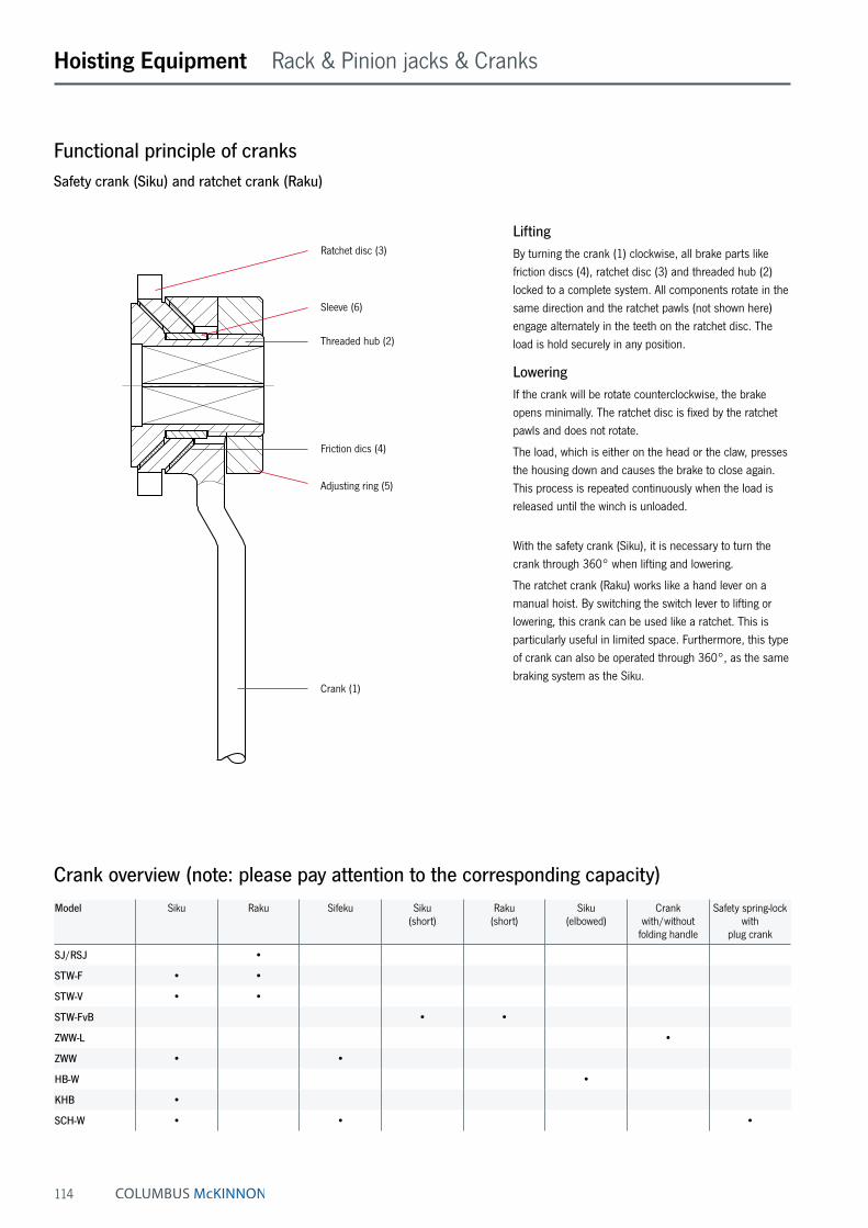
114
LiftingBy turning the crank (1) clockwise, all brake parts like friction discs (4), ratchet disc (3) and threaded hub (2) locked to a complete system. All components rotate in the same direction and the ratchet pawls (not shown here) engage alternately in the teeth on the ratchet disc. The load is hold securely in any position.
LoweringIf the crank will be rotate counterclockwise, the brake opens minimally. The ratchet disc is fixed by the ratchet pawls and does not rotate.
The load, which is either on the head or the claw, presses the housing down and causes the brake to close again. This process is repeated continuously when the load is released until the winch is unloaded.
With the safety crank (Siku), it is necessary to turn the crank through 360° when lifting and lowering.
The ratchet crank (Raku) works like a hand lever on a manual hoist. By switching the switch lever to lifting or lowering, this crank can be used like a ratchet. This is particularly useful in limited space. Furthermore, this type of crank can also be operated through 360°, as the same braking system as the Siku.
Functional principle of cranksSafety crank (Siku) and ratchet crank (Raku)
Crank overview (note: please pay attention to the corresponding capacity)Model Siku Raku Sifeku Siku
(short)Raku
(short)Siku
(elbowed)Crank
with/without folding handle
Safety spring-lock with
plug crank
SJ/RSJ •
STW-F • •
STW-V • •
STW-FvB • •
ZWW-L •
ZWW • •
HB-W •
KHB •
SCH-W • • •
Friction dics (4)
Adjusting ring (5)
Threaded hub (2)
Sleeve (6)
Ratchet disc (3)
Crank (1)
Hoisting Equipment Rack & Pinion jacks & Cranks
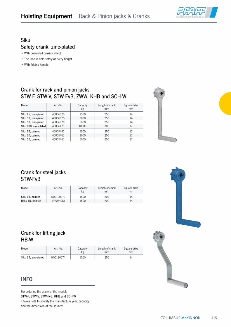
115
SikuSafety crank, zinc-plated• With one-sided braking effect.
• The load is held safely at every height.
• With folding handle.
Hoisting Equipment Rack & Pinion jacks & Cranks
INFO
For ordering the crank of the models STW-F, STW-V, STW-FvB, KHB and SCH-W it takes note to specify the manufacture year, capacity and the dimension of the square!
Crank for rack and pinion jacksSTW-F, STW-V, STW-FvB, ZWW, KHB and SCH-WModel Art.-No. Capacity
kg Length of crank
mmSquare drive
mm
Siku 15, zinc-plated 40006026 1500 250 14Siku 30, zinc-plated 40006026 3000 250 14Siku 50, zinc-plated 40006026 5000 250 14Siku 100, zinc-plated 40006171 10000 300 17
Siku 15, painted 40005461 1500 250 17Siku 30, painted 40005461 3000 250 17Siku 50, painted 40005461 5000 250 17
Crank for steel jacksSTW-FvBModel Art.-No. Capacity
kg Length of crank
mmSquare drive
mm
Siku 15, painted N00190073 1500 200 14Raku 15, painted 192034961 1500 200 14
Crank for lifting jackHB-WModel Art.-No. Capacity
kg Length of crank
mmSquare drive
mm
Siku 15, zinc-plated N00190074 1500 250 14

116
Hoisting Equipment Rack & Pinion jacks & Cranks
Crank for steel jacksSJ and RSJModel Art.-No. Capacity
kg Length of crank
mmSquare drive
mm
Siku 15, painted N00190008 1500 230 12Siku 30, painted N00190022 3000 250 14Siku 50, painted N00190053 5000 275 14Siku 100, painted N00190044 10000 300 17
Raku 15, painted 192037671 1500 230 12Raku 30, painted 192037672 3000 250 14Raku 50, painted 192037672 5000 250 14Raku 100, painted 192037673 10000 300 17
Crank for steel jacksSTW-F, STW-V and STW-FvBModel Art.-No. Capacity
kg Length of crank
mmSquare drive
mm
Raku 15, zinc-plated 40010237 1500 250 14Raku 30, zinc-plated 40010237 3000 250 14Raku 50, zinc-plated 40010237 5000 250 14Raku 100, zinc-plated 40008213 10000 300 17
Raku 15, painted 40004840 1500 250 17Raku 30, painted 40004840 3000 250 17Raku 50, painted 40004840 5000 250 17
Rachet pawl kit for Siku and RakuP13 for 1.5 t, 3.0 t and 5.0 tArt.-No. 40003808
P14 for 10.0 tArt.-No. N040004648
Siku & RakuSafety ratchet crank• Lifting or lowering movement adjustable by turning
a lever.
• The load is held safely at every height.
• With folding handle.
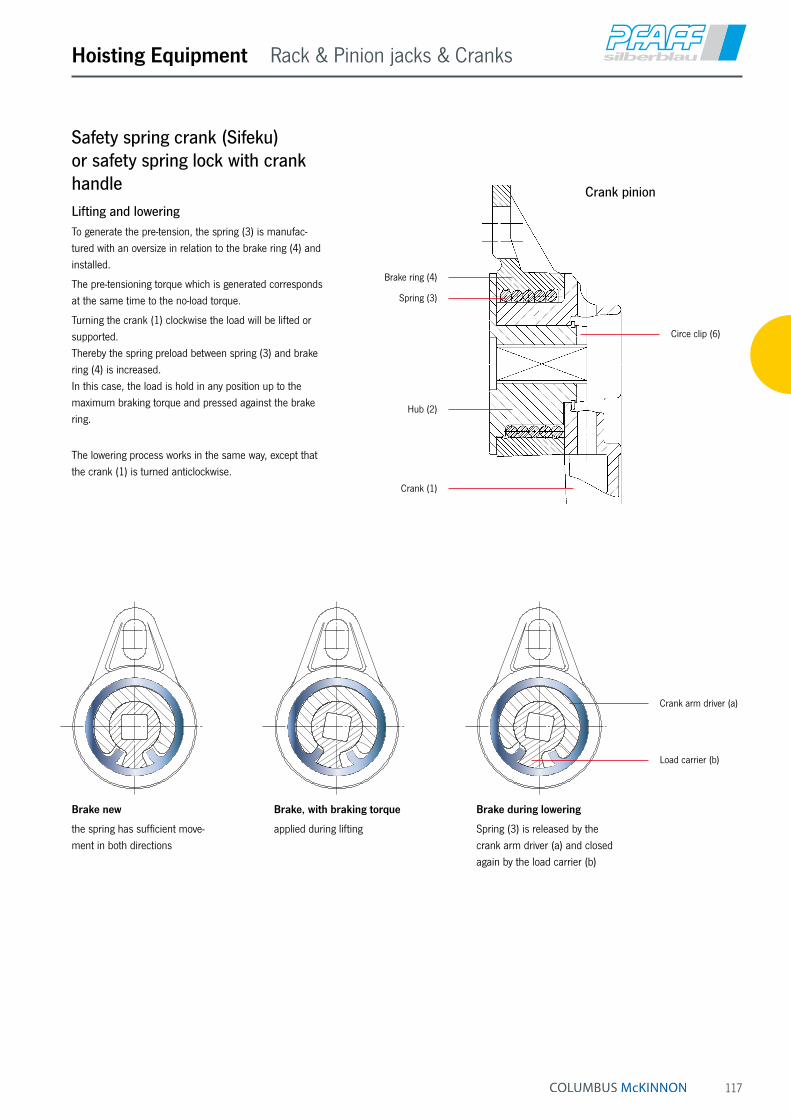
117
Hoisting Equipment Rack & Pinion jacks & Cranks
Safety spring crank (Sifeku) or safety spring lock with crank handleLifting and loweringTo generate the pre-tension, the spring (3) is manufac-tured with an oversize in relation to the brake ring (4) and installed.
The pre-tensioning torque which is generated corresponds at the same time to the no-load torque.
Turning the crank (1) clockwise the load will be lifted or supported. Thereby the spring preload between spring (3) and brake ring (4) is increased. In this case, the load is hold in any position up to the maximum braking torque and pressed against the brake ring.
The lowering process works in the same way, except that the crank (1) is turned anticlockwise.
Brake new
the spring has sufficient move-ment in both directions
Brake, with braking torque
applied during lifting
Brake during lowering
Spring (3) is released by the crank arm driver (a) and closed again by the load carrier (b)
Crank pinion
Crank (1)
Hub (2)
Brake ring (4)
Spring (3)
Circe clip (6)
Crank arm driver (a)
Load carrier (b)
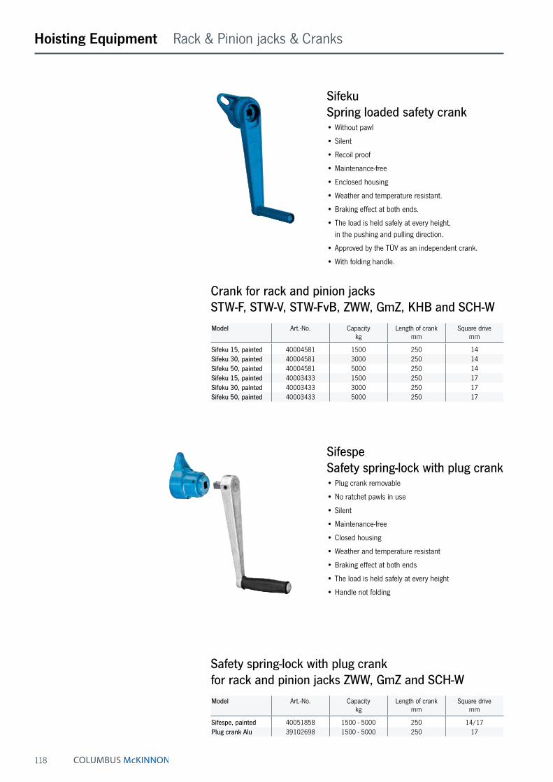
118
Safety spring-lock with plug crank for rack and pinion jacks ZWW, GmZ and SCH-WModel Art.-No. Capacity
kg Length of crank
mmSquare drive
mm
Sifespe, painted 40051858 1500 - 5000 250 14/17Plug crank Alu 39102698 1500 - 5000 250 17
SifespeSafety spring-lock with plug crank• Plug crank removable
• No ratchet pawls in use
• Silent
• Maintenance-free
• Closed housing
• Weather and temperature resistant
• Braking effect at both ends
• The load is held safely at every height
• Handle not folding
Model Art.-No. Capacitykg
Length of crankmm
Square drivemm
Sifeku 15, painted 40004581 1500 250 14Sifeku 30, painted 40004581 3000 250 14Sifeku 50, painted 40004581 5000 250 14Sifeku 15, painted 40003433 1500 250 17Sifeku 30, painted 40003433 3000 250 17Sifeku 50, painted 40003433 5000 250 17
Crank for rack and pinion jacksSTW-F, STW-V, STW-FvB, ZWW, GmZ, KHB and SCH-W
SifekuSpring loaded safety crank• Without pawl
• Silent
• Recoil proof
• Maintenance-free
• Enclosed housing
• Weather and temperature resistant.
• Braking effect at both ends.
• The load is held safely at every height, in the pushing and pulling direction.
• Approved by the TÜV as an independent crank.
• With folding handle.
Hoisting Equipment Rack & Pinion jacks & Cranks
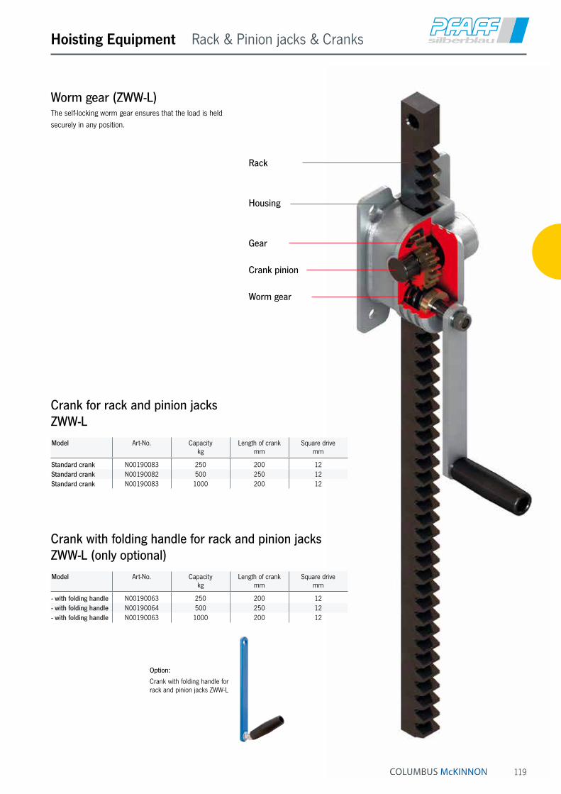
119
Hoisting Equipment Rack & Pinion jacks & Cranks
Worm gear (ZWW-L)The self-locking worm gear ensures that the load is held securely in any position.
Crank pinion
Worm gear
Housing
Gear
Rack
Model Art-No. Capacitykg
Length of crankmm
Square drivemm
Standard crank N00190083 250 200 12Standard crank N00190082 500 250 12Standard crank N00190083 1000 200 12
Crank for rack and pinion jacks ZWW-L
Model Art-No. Capacitykg
Length of crankmm
Square drivemm
- with folding handle N00190063 250 200 12- with folding handle N00190064 500 250 12- with folding handle N00190063 1000 200 12
Crank with folding handle for rack and pinion jacks ZWW-L (only optional)
Option:
Crank with folding handle for rack and pinion jacks ZWW-L

120
SJSteel jack acc. to DIN 7355Capacity 1500 - 10000 kgMechanical steel jacks can basically be used to lift almost all kinds of loads in maintenance and repair, ship build-ing, construction as well as agriculture.
Steel winches are used for supporting, placing lifted loads underneath and for assembly work. The Raku as a standard crank enables working in limited spaces, as it can be used like a ratchet in the direction of lifting and lowering. Alternatively, you can work with the crank 360°.
The field of application includes maintenance and repair, shipbuilding, the construction sector and agriculture.
Features• The precisely machined gear box with optimal gear ra-
tio ensures a minimum of effort and smooth operation.
• The load is supported either on the claw or the head of the steel jack.
• By turning the operating lever the jack moves smoothly and conveniently up and down along the rack.
• The load is held securely in any position. Inside the load brake the axial brake pressure is generated by the load itself, thus, it is proportional to the size of the load.
• No reduction of capacity on the claw.
Hoisting Equipment Rack & Pinion jacks
Model SJ 15 SJ 30 SJ 50 SJ 100
A, mm 725 735 730 800B, mm 164 200 190 252C mm 140 140 170 170D, mm 76 83 108 124E, mm 38 38 52 65F, mm 70 70 80 85G, mm 60 65 71 86N, mm 225 249 275 300
Dimensions SJ
Technical data SJ Raku
Model Art.-No.Raku
Capacity
kg
Height A
mm
Lift ¹
mm
Hand effort at WLL
daN
Weight
kg
SJ 15 N01900005 1500 725 360 28 17SJ 30 N01900002 3000 735 360 28 20SJ 50 N01900003 5000 730 350 28 27SJ 100 N01900006 10000 800 410 56 43
¹ Height of lift = Height + Lift
Lift

121
Hoisting Equipment Rack & Pinion jacks
STW-FSteel jacks acc. to DIN 7355 with fixed lifting clawCapacity 1500 - 10000 kgSteel jacks are traditional hoisting equipment for universal application in the forest and agricultural sector, in the industrial sector for assembly activities and many other fields of application.
Features• The robust steel design and a toothed rack of solid
material increase the service life of the jack.
• Low wear owing to hardened gearing parts and precisely machined teething.
• The precisely machined gears with a high degree of efficiency guarantees low crank forces.
• The load is supported either on the claw or the head of the steel jack.
• Robust base plate for a high level of stability.
• No reduction of capacity on the claw.
Model STW-F
with fixed lifting claw and Sifeku
Technical data STW-F Raku
Model Art.-No.Raku
Capacity
kg
Height A
mm
Lift ¹
mm
Hand effort at WLL
daN
Weight
kg
STW-F 15 40022008 1500 720 350 28 12STW-F 30 40022013 3000 720 350 28 21STW-F 50 40022019 5000 720 300 28 26STW-F 100 40051708 10000 792 300 28 42
¹ Height of lift = Height + Lift
Technical data STW-F Siku
Model Art.-No.Siku
Capacity
kg
Height A
mm
Lift ¹
mm
Hand effort at WLL
daN
Weight
kg
STW-F 15 40021975 1500 720 350 28 12STW-F 30 40021984 3000 720 350 28 21STW-F 50 40051705 5000 720 300 28 26STW-F 100 40051707 10000 792 300 40 42
¹ Height of lift = Height + Lift
Model STW-F 15 STW-F 30 STW-F 50 STW-F 100
A, mm 720 720 720 792B, mm 130 130 145 145C, mm 140 140 155 155D, mm 90 90 110 125E, mm 50 50 68 80F, mm 60 61 62 85G, mm 60 65 70 85N, mm 250 250 250 300
Dimensions STW-F
Lift
INFO
STW-F Sifeku on request.

122
STW-V 1.5 t/3.0 t/5.0 t
STW-VSteel jacks acc. to DIN 7355 with adjustable lifting clawCapacity 1500 - 10000 kgThe design of the steel jack allows for loads to be picked up and lowered from different heights over the entire length of the steel jack. The adjustable claw is simply set to the appropriate ap-plication height in the load bar for this purpose.
Features• The claw can be moved to any position on the
adjusting rail.
• The load is supported either on the claw or the head of the steel jack.
• Robust base plate for a high level of stability.
• No reduction of capacity on the claw.
STW-V 10.0 t
Hoisting Equipment Rack & Pinion jacks
Model Art.-No.Siku
Capacity
kg
Height A
mm
Lift ¹
mm
Hand effort at WLL
daN
Weight
kg
STW-V 15 N01905000 1500 725 350 28 17STW-V 30 N01905001 3000 725 350 28 23STW-V 50 N01905002 5000 725 300 28 29STW-V 100 N01905003 10000 792 300 40 46
¹ Height of lift = Height + Lift
Technical data STW-V Siku
Model Art.-No.Raku
Capacity
kg
Height A
mm
Lift ¹
mm
Hand effort at WLL
daN
Weight
kg
STW-V 15 N01905004 1500 725 350 28 17STW-V 30 N01905005 3000 725 350 28 23STW-V 50 N01905006 5000 725 300 28 29STW-V 100 N01905007 10000 792 300 40 46
¹ Height of lift = Height + Lift
Technical data STW-V Raku
Model STW-V 15 STW-V 30 STW-V 50 STW-V 100
A, mm 725 725 725 800B, mm 130 130 140 140C, mm 140 140 160 160D, mm 90 100 110 140E, mm 50 50 68 76F, mm 70 70 70 70G, mm 80 80 80 85H, mm
Claw freely adjustable on load bar
(55 mm steps)
191J, mm 297K, mm 403L, mm 509M, mm 615N, mm 250 250 250 300
Dimensions STW-V
INFO
STW-V Sifeku on request

123
Hoisting Equipment Rack & Pinion jacks
STW-FvBSteel jacks acc. to DIN 7355 with fixed lifting claw shortened designCapacity 1500 kgWherever low headroom dimensions are required, the steel jack of shortened design is used.
Features• The robust steel design and a toothed rack of solid
material increase the service life of the jack.
• Low wear owing to hardened gearing parts and precisely machined teething.
• The precisely machined gears with a high degree of efficiency guarantees low crank forces.
• The load is supported either on the claw or the head of the steel jack.
• Robust base plate for a high level of stability.
• No reduction of capacity on the claw.
Model Art.-No.Siku
Capacity
kg
Height A
mm
Lift ¹
mm
Hand effort at WLL
daN
Weight
kg
STW-FvB 15 30014000 1500 600 300 28 11
¹ Height of lift = Height + Lift
Technical data STW-FvB Siku
Model Art.-No.Raku
Capacity
kg
Height A
mm
Lift ¹
mm
Hand effort at WLL
daN
Weight
kg
STW-FvB 15 30014002 1500 600 300 28 11
¹ Height of lift = Height + Lift
Technical data STW-FvB Raku
Model STW-FvB 15
A, mm 600B, mm 130C, mm 140D, mm 90E, mm 50F, mm 60G, mm 60N, mm 200
Dimensions STW-FvB
Lift
INFO
STW-FvB Sifeku on request
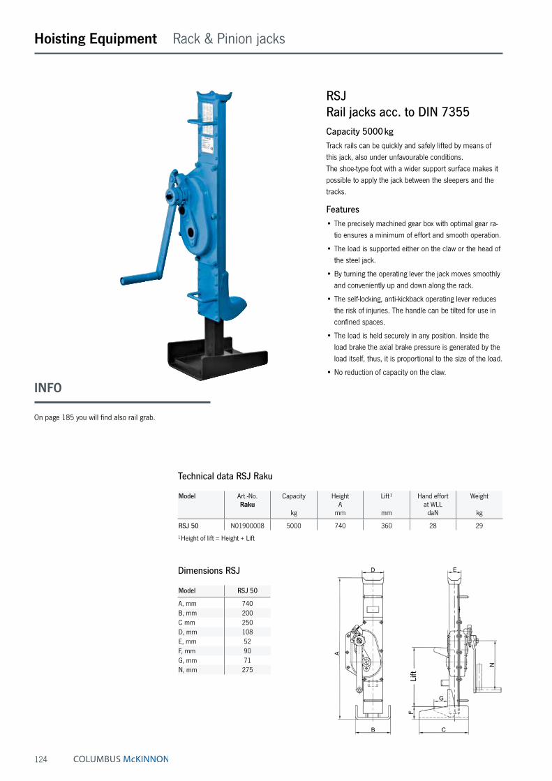
124
RSJRail jacks acc. to DIN 7355Capacity 5000 kgTrack rails can be quickly and safely lifted by means of this jack, also under unfavourable conditions. The shoe-type foot with a wider support surface makes it possible to apply the jack between the sleepers and the tracks.
Features• The precisely machined gear box with optimal gear ra-
tio ensures a minimum of effort and smooth operation.
• The load is supported either on the claw or the head of the steel jack.
• By turning the operating lever the jack moves smoothly and conveniently up and down along the rack.
• The self-locking, anti-kickback operating lever reduces the risk of injuries. The handle can be tilted for use in confined spaces.
• The load is held securely in any position. Inside the load brake the axial brake pressure is generated by the load itself, thus, it is proportional to the size of the load.
• No reduction of capacity on the claw.
Hoisting Equipment Rack & Pinion jacks
Model Art.-No.Raku
Capacity
kg
Height A
mm
Lift ¹
mm
Hand effort at WLL
daN
Weight
kg
RSJ 50 N01900008 5000 740 360 28 29
¹ Height of lift = Height + Lift
Technical data RSJ Raku
Dimensions RSJ
Model RSJ 50
A, mm 740B, mm 200C mm 250D, mm 108E, mm 52F, mm 90G, mm 71N, mm 275
Lift
INFO
On page 185 you will find also rail grab.
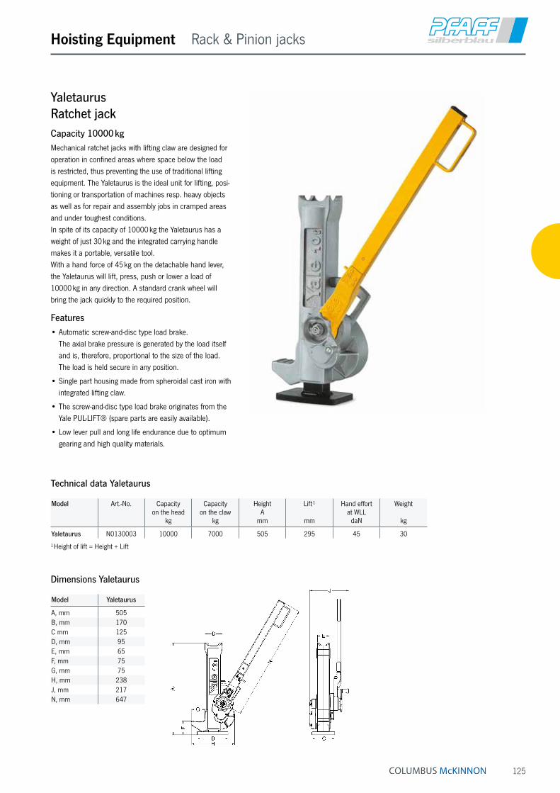
125
Hoisting Equipment Rack & Pinion jacks
YaletaurusRatchet jackCapacity 10000 kgMechanical ratchet jacks with lifting claw are designed for operation in confined areas where space below the load is restricted, thus preventing the use of traditional lifting equipment. The Yaletaurus is the ideal unit for lifting, posi-tioning or transportation of machines resp. heavy objects as well as for repair and assembly jobs in cramped areas and under toughest conditions. In spite of its capacity of 10000 kg the Yaletaurus has a weight of just 30 kg and the integrated carrying handle makes it a portable, versatile tool. With a hand force of 45 kg on the detachable hand lever, the Yaletaurus will lift, press, push or lower a load of 10000 kg in any direction. A standard crank wheel will bring the jack quickly to the required position.
Features• Automatic screw-and-disc type load brake.
The axial brake pressure is generated by the load itself and is, therefore, proportional to the size of the load. The load is held secure in any position.
• Single part housing made from spheroidal cast iron with integrated lifting claw.
• The screw-and-disc type load brake originates from the Yale PUL-LIFT® (spare parts are easily available).
• Low lever pull and long life endurance due to optimum gearing and high quality materials.
Technical data Yaletaurus
Model Art.-No. Capacity on the head
kg
Capacity on the claw
kg
Height A
mm
Lift ¹
mm
Hand effort at WLL
daN
Weight
kg
Yaletaurus N0130003 10000 7000 505 295 45 30
¹ Height of lift = Height + Lift
Dimensions Yaletaurus
Model Yaletaurus
A, mm 505B, mm 170C mm 125D, mm 95E, mm 65F, mm 75G, mm 75H, mm 238J, mm 217N, mm 647

126
ZWW-L Capacity 300 kg u. 600 kg
ZWW-L Capacity 1200 kg
ZWW Capacity 1500 kg
ZWW Capacity 10000 kg
Hoisting Equipment Rack & Pinion jacks
ZWW-L and ZWWWall-mounted rack and pinion jacksCapacity 300 - 10000 kgWall-mounted rack and pinion jacks are used for lifting, lowering, pulling and pushing of loads.
Features• Robust steel design with precisely machined worm and
spur gears for smooth and easy manual operation.
• Solid steel rack with additional bore hole for fastening of the load.
• Low wear owing to hardened gearing parts and pre-cisely machined teething.
• Up to 1200 kg lifting load for pushing or pulling loads are equal.
• At standard tensile load from 1500 - 10000 kg. Compressive load possible on request.
• Rigid wall mounting.
Options• Improved corrosion protection owing to zinc-plating or
special coating of rack (from capacity 1500 kg).
• Different rack length on request.
• Symmetrical toothing for model ZWW on request.
• Crank with folding handle for model ZWW-L.
Technical data ZWW-L
Model Art.-No. Tensile or pressure load
kg
Rack lengthmm
Lift
mm
Lift per crank rotation
mm
Hand effort at WLL
daN
Weight
kg
ZWW-L 300/400 NO1905011 300 600 400 11 10 5.4ZWW-L 600/400 NO1905012 600 600 400 11 15 6.0ZWW-L 300/600 NO1905013 300 800 600 11 10 5.9ZWW-L 600/600 NO1905014 600 800 600 11 15 6.5ZWW-L 1200/600 NO1905015 1200 800 600 3.6 14 9.5ZWW-L 300/800 NO1905016 300 1000 800 11 10 6.4ZWW-L 600/800 NO1905017 600 1000 800 11 15 7.0ZWW-L 1200/800 NO1905018 1200 1000 800 3.6 14 10.6ZWW-L 600/1000 NO1905020 600 1200 1000 11 15 7.5ZWW-L 1200/1000 NO1905021 1200 1200 1000 3.6 14 11.7ZWW-L 600/1200 NO1905023 600 1400 1200 11 10 6.0
We are pleased to send you our new Atex catalogue in PDF format.
INFO
ZWW-L with capacities of 600 and 1000 kg are also avail-able in explosion-proof design.

127
Hoisting Equipment Rack & Pinion jacks
Model Art.-No.Sifeku
Tensile loadkg
Rack lengthmm
Lift
mm
Lift per crank rotation
mm
Hand effort at WLL
daN
Weight
kg
ZWW 1500/800 40055131 1500 1090 800 14 28 11ZWW 3000/565 40056138 3000 975 565 9 28 19ZWW 5000/700 40057134 5000 1170 700 4.5 28 28
Technical data ZWW with Sifeku
Model Art.-No.Siku
Tensile loadkg
Rack lengthmm
Lift
mm
Lift per crank rotation
mm
Hand effort at WLL
daN
Weight
kg
ZWW 10000/700 40058009 10000 1240 700 3.2 40 55
Technical data ZWW with Siku
Model ZWW-L 300 ZWW-L 600 ZWW-L 1200 ZWW 1500 ZWW 3000 ZWW 5000 ZWW 10000
A, mm 20 20 25 35 45 50 60B, mm 20 25 35 25 30 40 50C, mm – – – 215 280 330 380Ø D, mm 11 13 16,5 21 21 21 30E, mm 16 20 20 20 25 25 30F, mm 130 130 127 135 165 140 160G, mm 119 119 98 151 212 219 269H, mm 200 200 180 310 395 400 480I, mm – – 35 168 179 197 200J, mm 38 35 30 26 31 37 40K, mm – – – 100 120 120 140L, mm 60 60 140 130 160 160 180M, mm 170 170 140 260 305 320 410Ø N, mm 11 11 13 13 15 17 21O, mm – – 100 110 120 105 125P, mm – – – 40 50 50 60Q, mm 10 10 – 8 10 10 10R, mm 200 250 200 250 250 250 300S, mm 110 110 110 130 130 130 250T, mm – – – 42 86 109 150U, mm – – – 43 53 70 88X, mm – – – 20 25 45 30Ø Z, mm – – – – – – –
Dimensions ZWW and ZWW-L
ZWW, Capacity 1500 - 10000 kgZWW-L, Capacity 1200 kgZWW-L, Capacity 300 - 600 kg
Rack
leng
thLi
ft
Rack
leng
thLi
ft
Rack
leng
thLi
ft

128
Hoisting Equipment Rack & Pinion jacks
ZWW-L combinationsCapacity 1000 kgWhere it is important to lift as evenly as possible (level-ling), wall-mounted rack and pinion wall jacks can also be coupled, whereby the direction - depending on the model - is irrelevant.
The wall mounted rack and pinion jacks can be combine about 3/4" and/or 1" pipes (DIN 2440). When connect-ing pipes over a length of 2 m, we recommend the pipes to stabilize so that it does not droop in the middle.
We like to advise you in this case.
On systems with several racks in line to the crank axis
• Self-locking action in every gear unit
• Crank force = 15 kg with a total load of 1000 kg
• Connection to 3/4" tube (DIN 2440) on building side
On systems with several racks in line at 90° to the crank axis
• Self-locking action only gear unit with crank
• Crank force = 15 kg, at a maximum total load of 1000 kg
• Connection to 1" tube (DIN 2440) on building side
• This combination is also possible for model ZWW-L 250 and model ZWW-L 500.
On systems with several racks across a surface area
• Self-locking action in all gear units in the crank axis
• Crank force = 15 kg with a total load of 1000 kg
• Connection 3/4" and 1" tube (DIN 2440) on building side

129
Hoisting Equipment Rack & Pinion jacks

130
Supporting roller (option)
Hoisting Equipment Rack & Pinion jacks
HB-WLifting jackCapacity 1500 kgThe stable lifting jack with integrated 1.5 t steel jack for supporting tube and bar material.
Features• Load will be fixed in each position safely by a load
brake system.
• Large base plate for a high level of stability.
• Wheels for easy transport.
Option• The attachable support roller facilitates the sliding of
heavy loads.
Model Art.-No.Siku
Capacity
kg
Height
mm
Lift ¹
mm
Hand effort at WLL
daN
Lift per crank rotation
mm
Weight
kg
HB-W 1500 N01900014 1500 650 350 28 15 40
¹ Height of lift = Height + Lift
Technical data HB-W
Model Art.-No. Capacity
kg
Height with supporting
roller in mm
Weight
kg
Supporting roller 30060011 1500 705 5
Technical data supporting roller HB-A
Model HB-W 1500
A, mm 300B, mm 500C on, mm 650D off, mm 1000E, mm 100F, mm 320G, mm 300H, mm 385
Dimensions HB-W
Crank
in special design on request
Art.-No. N00190074
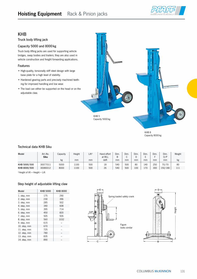
131
Hoisting Equipment Rack & Pinion jacks
KHBTruck body lifting jack
Capacity 5000 and 8000 kgTruck body lifting jacks are used for supporting vehicle bridges, swap bodies and trailers; they are also used in vehicle construction and freight forwarding applications.
Features• High-quality, torsionally stiff steel design with large
base plate for a high level of stability.
• Hardened gearing parts and precisely machined teeth-ing for improved handling and low wear.
• The load can either be supported on the head or on the adjustable claw.
KHB 8 Capacity 8000 kg
Model Art.-No.Siku
Capacity
kg
Height
mm
Lift ¹
mm
Hand effort at WLL
daN
Dim. B
mm
Dim. C
mm
Dim. D
mm
Dim. E
mm
Dim. F
mm
Dim. O/Pmm
Weight
kg
KHB 5000/500 30077011 5000 1100 500 18 540 500 80 140 250 70/70 80KHB 8000/500 30080012 8000 1100 500 26 540 500 100 170 300 150/180 111
¹ Height of lift = Height + Lift
Technical data KHB Siku
KHB 5 Capacity 5000 kg
Model KHB 5000 KHB 8000
1. step, mm 175 2902. step, mm 230 3963. step, mm 285 5024. step, mm 340 6085. step, mm 395 7146. step, mm 450 8207. step, mm 505 9268. step, mm 560 10329. step, mm 615 –10. step, mm 670 –11. step, mm 725 –12. step, mm 780 –13. step, mm 835 –14. step, mm 890 –
Step height of adjustable lifting claw
Hei
ght
Spring loaded safety crank
Figure looks similar
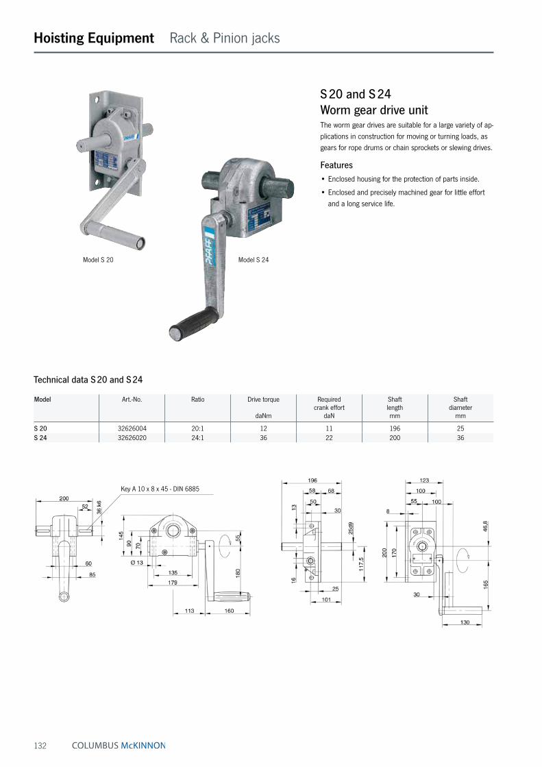
132
Hoisting Equipment Rack & Pinion jacks
S 20 and S 24Worm gear drive unitThe worm gear drives are suitable for a large variety of ap-plications in construction for moving or turning loads, as gears for rope drums or chain sprockets or slewing drives.
Features• Enclosed housing for the protection of parts inside.
• Enclosed and precisely machined gear for little effort and a long service life.
Technical data S 20 and S 24
Model Art.-No. Ratio Drive torque
daNm
Required crank effort
daN
Shaft lengthmm
Shaft diameter
mm
S 20 32626004 20:1 12 11 196 25S 24 32626020 24:1 36 22 200 36
Key A 10 x 8 x 45 - DIN 6885
Model S 20 Model S 24

133
Hoisting Equipment Rack & Pinion jacks
Model SCH-W 15 SCHW-30 SCHW-50 SCH-W 100
A, mm 35 45 50 60B, mm 25 30 40 50C, mm 140 160 145 165D, mm 85 60 45 65E, mm 125 204 189 235F, mm 78 92 100 112G, mm 175 230 260 320H, mm 310 395 400 480I, mm 33.5 39.5 51 59J, mm 43.3 53.1 69.5 88.3K, mm 121 138 81 84L, mm 230 230 230 290M, mm 90 90 90 115N, mm 153 158 173 183O, mm 52.5 55 61 66P, mm 52.5 55 64 70Ø Q, mm 14 14 14 14R, mm 7 7 7 8S, mm 76.5 85.5 88 100T, mm 100.5 108.5 120 140U, mm 113 121 132 185V, mm 86 94 105 –W, mm 136 144 155 –X, mm 130 130 130 250Y, mm 250 250 250 300
Dimensions SCH-W
SCH-WSluice gate jackCapacity 1500 - 10000 kgThe reliable sluice gate jack for opening and closing gates in sluices.
Features• The spring loaded safety crank permanently holds the
sluice gate closed with pressure.
• Hardened gearing parts and precisely machined teeth-ing for improved handling and low wear.
Model Art.-No.Sifeku
Tensile or pressure load ¹
kg
Rack lengthmm
Lift
mm
Hand effort at WLL
daN
Weight
kg
SCH-W 15 40051714 1500 1200 800 28 18SCH-W 30 40051717 3000 1250 800 28 23SCH-W 50 40051720 5000 1350 900 28 32
¹ The pressure force is reduced with a larger lift (loading case II to Euler)
Technical data SCH-W Sifeku
Model Art.-No.Siku
Tensile or pressure load ¹
kg
Rack lengthmm
Lift
mm
Hand effort at WLL
daN
Weight
kg
SCH-W 100 40051722 10000 1550 1000 40 56
Technical data SCH-W Siku INFO
Please fill in the questionnaire on the next page for sluice gate jack systems.
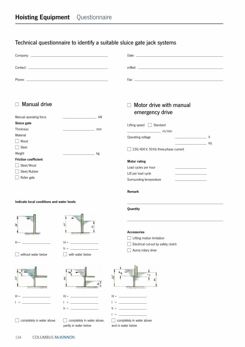
134
H =
l =
completely in water above
H =
l =
h =
completely in water above, partly in water below
H =
l =
h =
i =
completely in water above and in water below
H =
without water below
H =
h =
with water below
Hoisting Equipment Questionnaire
Technical questionnaire to identify a suitable sluice gate jack systems
Company: Date:
Contact: e-Mail:
Phone: Fax:
Manual drive
Manual operating force kN
Sluice gate
Thickness mm
Material
Wood
Steel
Weight kg
Friction coefficient
Steel/Wood
Steel/Rubber
Roller gate
Indicate local conditions and water levels
Motor drive with manual emergency drive
Lifting speed Standard
m/min
Operating voltage V
Hz
230/400 V, 50 Hz three-phase current
Motor rating
Load cycles per hour
Lift per load cycle
Surrounding temperature
Remark
Quantity
Accessories
Lifting motion limitation
Electrical cut-out by safety clutch
Auma rotary drive

135
Arrangement
Crank version
(Retaining springs not possible for 10 t model)
Date
Name
Application
Arrangement Crank version
Safety crank Spring loaded safety crank
Safety retaining spring with removable
crankArrangement I
Arrangement II
Arrangement II.1
Arrangement II.2
Arrangement III
Hoisting Equipment Questionnaire
Technical questionnaire to identify a suitable sluice gate jack systems

136
Crane Systems User information
INFO
INFO
For information on training please see page 4.
This user information presents a general review regarding the application of cranes and does not substitute the existing operating instructions for specific products!
Lifting and slewing operations may be carried out by competent users (trained in theory and practice) only. When operated correctly, our cranes will offer the highest degree of safety in line with long life ex-pectancy and avoid damage to products and people.
Yalesystems cranes are manufactured in accordance with the machinery directive 2006/42/EC and the latest DIN 15018 H2 B2 (gantry cranes H2 B3) and correspond to the VDE regulations.
All components are mechanically shot blast, then primed and coated with RAL 1023 (yellow) paint, D.F.T. approx. 60 micron.
Modification of delivery conditionDesign and finish of the cranes may not be modified by e.g. installation of outside supplied parts, bending, welding, grinding, removal of parts, added bores, removal of safety devices like locking mechanisms, locking pins, safety latches etc.
Limitations of operationTemperatureCranes may normally be operated at ambient tempera-tures between - 10 °C up to + 50 °C. These values are approximate and may deviate from the specific givings of the product concerned. The accurate data are given in the current operating instructions.
Chemicals
Cranes may not be operated without hesitation in the area of chemicals or chemical vapours – consult our specialists for advice. Cranes which have been subject to chemicals or vapours must be taken out of service and inspected by us.
Transport of peopleTransport of people with cranes is generally forbidden!
Operation in danger zonesLifting or transport of loads must be avoided while personnel are in the danger zone. People are not allowed to pass over or under a suspended load.
Electrical hazards Please consult the specific operating instructions for pos-sible electrical hazards. Electrical connections may only be performed by authorized persons resp. companies!
Maintenance and repairTo ensure safe operation, all cranes must be subjected to regular inspections according to the maintenance instruc-tions given by the manufacturer. For legal obligations refer to DGUV Vorschrift 52 (BGV D6).
Depending on the frequency and impact of applications, the crane has to be maintained, at least once per year or in case of obvious damages, by competent persons resp. inspectors.
Repairs and inspections may only be carried out by competent persons resp. inspectors who use original spare parts. Repairs and inspections must be recorded consecutively.
InspectionsThe contractor has to make sure that powered cranes are inspected prior to initial operation and after significant modifications by a competent person. This is also ap-plicable for hand operated cranes with a capacity of more than 1000 kg.
For cranes according to § 3a para. 3 DGUV Vorschrift 52 (BGV D6) the inspection before initial operation consists of advance survey, inspection of building and quality acceptance.
The inspection prior to initial operation is not required for cranes, which are delivered ready-to-use and with certifi-cate of a type approval or EC declaration of conformity.

137
Crane Systems Questionnaire
Gantry crane
Capacity (max.) kg
Gantry width – inside – a mm
Gantry width – outside – A mm
Beam clearance UK mm
or: ceiling clearance H mm
or: overall height B mm
or: highest hook position mm
Accessories
Increased paint thickness
Hot-dip galvanizing
Power supply
Round cable for booms ≤ 4.5 m
Festooned cable, recommended for booms > 4.5 m
Suspended control
Trolleys
With push trolley
With geared trolley
With electric trolley (single speed)
With electric trolley (2 speeds)
Technical questionnaire to identify the suitable crane system
Company: Date:
Contact: e-Mail:
Phone: Fax:
Wall-mounted jib crane Floor-mounted jib crane For outdoor use
Capacity (max.) kg
Slewing range
Boom length A mm
Boom clearance UK mm
or: ceiling clearance H mm
or: overall height B mm
or: highest hook position mm
Accessories
Increased paint thickness
Hot-dip galvanizing
Boom locks
Slewing range stoppers
Electrically driven slewing gear
Slewing brake, recommended for outdoor cranes and/or booms > 5 m
Power supply
Round cable for booms ≤ 4.5 m
Festooned cable, recommended for booms > 4.5 m
Suspended control
Mounting for wall-mounted jib crane
Threaded rods/anchor bolts
Pillar embracing
Mounting for floor-mounted jib crane
Anchors and template
Standard base plate (welded) incl. anchors/rawlplug
Dowel base plate (bolted) incl. anchors/rawlplug
Hoists
Manual hoists
Electric chain hoist (single speed)
Electric chain hoist (2 speeds)
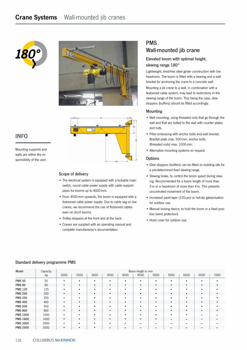
138
Crane Systems Wall-mounted jib cranes
PMSWall-mounted jib craneElevated boom with optimal height, slewing range 180°Lightweight, twist-free steel girder construction with low headroom. The boom is fitted with a bearing and a wall bracket for anchoring the crane to a concrete wall.
Mounting a jib crane to a wall, in combination with a festooned cable system, may lead to restrictions in the slewing range of the boom. This being the case, slew stoppers (buffers) should be fitted accordingly.
Mounting• Wall mounting, using threaded rods that go through the
wall and that are bolted to the wall with counter plates and nuts.
• Pillar embracing with anchor bolts and wall bracket. Bracket plate max. 500 mm, anchor bolts (threaded rods) max. 1000 mm.
• Alternative mounting systems on request.
Options• Slew stoppers (buffers) can be fitted on building site for
a pre-determined fixed slewing range.
• Slewing brake, to control the boom speed during slew-ing. Recommended for a boom length of more than 5 m or a headroom of more than 4 m. This prevents uncontrolled movement of the boom.
• Increased paint layer (120 µm) or hot-dip galvanisation for outdoor use.
• Manual locking device, to hold the boom in a fixed posi-tion (wind protection).
• Hoist cover for outdoor use.
Scope of delivery• The electrical system is equipped with a lockable main
switch, round cable power supply with cable support pipes for booms up to 4000 mm.
• From 4500 mm upwards, the boom is equipped with a festooned cable power supply. Due to cable sag on low cranes, we recommend the use of festooned cables even on short booms.
• Trolley stoppers at the front and at the back.
• Cranes are supplied with an operating manual and complete manufacturer‘s documentation.
Standard delivery programme PMS
Model Capacity Boom length in mmkg 2000 2500 3000 3500 4000 4500 5000 5500 6000 6500 7000
PMS 50 50 • • • • • • • • • • •PMS 80 80 • • • • • • • • • • •PMS 125 125 • • • • • • • • • • •PMS 200 200 • • • • • • • • • • •PMS 250 250 • • • • • • • • • • •PMS 400 400 • • • • • • • • • • •PMS 500 500 • • • • • • • • • • •PMS 800 800 • • • • • • • • • • •PMS 1000 1000 • • • • • • • • • – –PMS 1600 1600 • • • • • • • – – – –PMS 2000 2000 • • • • • – – – – – –PMS 2500 2500 • • • – – – – – – – –
INFO
Mounting supports and walls are within the re-sponsibility of the user.

139
Crane Systems User information
Mounting systems wall-mounted jib cranes
Wall mounting, using threaded rods going through the wall and being fixed to the wall with counter plates and nuts.
Pillar embracing with anchor bolts and wall bracket (bracket plate max. 500 mm, anchor bolts max. 1000 mm)
INFO
If wall-mounted jib cranes are mounted directly on the wall and festooned cable power supply is used, the slew-ing range may be limited depending on the size of the hoist.
Further fastening possibilities such as weld-on brackets, ceiling mounting etc. on request.

140
PFSPFloor-mounted jib craneElevated boom with optimal height, slewing range 270°Lightweight, twist-free steel girder construction with low headroom. The boom is fitted with a bearing, pillar made from reinforced steel pipe.
Depending on the size of the hoist and in combination with festooned power cables, restrictions in the slewing range of the boom may be possible.
Mounting• Base flange with anchor bolts and template.
• Anchoring the base plate (welded) including mortar cartridges, anchor studs (complete with nuts, locknuts and washers).
• Anchoring the dowel base plate (bolted) including mortar cartridges, anchor studs (complete with nuts, locknuts and washers).
• Mobile unit for changeable location.
Options• Slew stoppers (buffers) can be fitted on building site for
a pre-determined fixed slewing range.
• Slewing brake, to control the boom speed during slew-ing. Recommended for a boom length of more than 5 m or a headroom of more than 4 m. This prevents uncontrolled movement of the boom.
• Increased paint layer (120 µm) or hot-dip galvanisation for outdoor use.
• Manual locking device, to hold the boom in a fixed posi-tion (wind protection).
• Hoist cover for outdoor use.
Crane Systems Floor-mounted jib cranes
Scope of delivery• The electrical system is equipped with a lockable main
switch, round-cable power supply with cable support pipes for booms up to 4000 mm.
• From 4500 mm upwards, the boom is equipped with a festooned cable power supply. Due to cable sag on low cranes, we recommend the use of festooned cables even on short booms.
• Trolley stoppers at the front and at the back.
• Cranes are supplied with an operating manual and complete manufacturer‘s documentation.
Standard delivery programme PFSP
Model Capacity Boom length in mmkg 2000 2500 3000 3500 4000 4500 5000 5500 6000 6500 7000
PFSP 50 50 • • • • • • • • • • •PFSP 80 80 • • • • • • • • • • •PFSP 125 125 • • • • • • • • • • •PFSP 200 200 • • • • • • • • • • •PFSP 250 250 • • • • • • • • • • •PFSP 400 400 • • • • • • • • • • •PFSP 500 500 • • • • • • • • • • •PFSP 800 800 • • • • • • • • • • •PFSP 1000 1000 • • • • • • • • • – –PFSP 1600 1600 • • • • • • • – – – –PFSP 2000 2000 • • • • • – – – – – –PFSP 2500 2500 • • • – – – – – – – –
INFO
Mounting systems, please see page 144.

141
Crane Systems Floor-mounted jib cranes
PFMFloor-mounted jib craneElevated boom with optimal height, slewing range 360°Lightweight, twist-free steel girder construction with low headroom. Compact rotating head for ideal construction dimensions; access from above ensures easy assembly. The boom is fitted with a roller bearing, pillar made from reinforced steel pipe.
Depending on the size of the hoist and in combination with festooned power cables, restrictions in the slewing range of the boom may be possible.
Mounting• Base flange with anchor bolts and template.
• Anchoring the base plate (welded) including mortar cartridges, anchor studs (complete with nuts, locknuts and washers).
• Anchoring the dowel base plate (bolted) including mortar cartridges, anchor studs (complete with nuts, locknuts and washers).
• Mobile unit for changeable location.
Options• Slew stoppers (buffers) can be fitted on building site for
a pre-determined fixed slewing range.
• Slewing brake, to control the boom speed during slew-ing. Recommended for a boom length of more than 5 m or a headroom of more than 4 m. This prevents uncontrolled movement of the boom.
• Increased paint layer (120 µm) or hot-dip galvanisation for outdoor use.
• Manual locking device, to hold the boom in a fixed posi-tion (wind protection).
• Hoist cover for outdoor use.
Scope of delivery• The electrical system is equipped with a lockable main
switch, round-cable power supply with cable support pipes for booms up to 4000 mm.
• From 4500 mm upwards, the boom is equipped with a festooned cable power supply. Due to cable sag on low cranes, we recommend the use of festooned cables even on short booms.
• Trolley stoppers at the front and at the back.
• Cranes are supplied with an operating manual and complete manufacturer‘s documentation.
Standard delivery programme PFM
Model Capacity Boom length in mmkg 2000 2500 3000 3500 4000 4500 5000 5500 6000 6500 7000
PFM 50 50 • • • • • • • • • • •PFM 80 80 • • • • • • • • • • •PFM 125 125 • • • • • • • • • • •PFM 200 200 • • • • • • • • • • •PFM 250 250 • • • • • • • • • – –PFM 400 400 • • • • • • • – – – –PFM 500 500 • • • • • • – – – – –PFM 800 800 • • • – – – – – – – –PFM 1000 1000 • • – – – – – – – – –
INFO
Mounting systems, please see page 144.

142
Crane Systems Floor-mounted jib cranes
PFPFloor-mounted jib craneElevated boom with optimal height, slewing range 360°Heavy, robust twist-free steel girder construction. Structural steel crane-boom. Compact rotating head for ideal construction dimensions; access from above ensures easy assembly. The boom is fitted with a roller bearing, pillar made from reinforced steel pipe.
Depending on the size of the hoist and in combination with festooned power cables, restrictions in the slewing range of the boom may be possible.
Mounting• Base flange with anchor bolts and template.
• Anchoring the dowel base plate (bolted) including mortar cartridges, anchor studs (complete with nuts, locknuts and washers).
Options• Electrically driven slewing gear.
• Slew stoppers (buffers) can be fitted on building site for a pre-determined fixed slewing range.
• Limit switches to limit the boom slewing range (before hitting a fixed object the motor switches off automatically).
• Increased paint layer (120 µm) or hot-dip galvanisation for outdoor use.
• Manual locking device, to hold the boom in a fixed posi-tion (wind protection).
• Hoist cover for outdoor use.
Scope of delivery• The electrical system is equipped
with a lockable main switch, round-cable power supply with cable support pipes for booms up to 4000 mm.
• From 4500 mm upwards, the boom is equipped with a festooned cable power supply. Due to cable sag on low cranes, we recommend the use of festooned cables even on short booms.
• Trolley stoppers at the front and at the back.
• Cranes are supplied with an operat-ing manual and complete manufac-turer‘s documentation.
Standard delivery programme PFP
Model Capacity Boom length in mmkg 2000 2500 3000 3500 4000 4500 5000 5500 6000 6500 7000
PFP 500 500 • • • • • • • • • • •PFP 800 800 • • • • • • • • • • •PFP 1000 1000 • • • • • • • • • • •PFP 1600 1600 • • • • • • • • • • –PFP 2000 2000 • • • • • • • • • – –PFP 2500 2500 • • • • • • • – – – –PFP 3200 3200 • • • • • – – – – – –

143
Crane Systems User information
Mounting systems for floor-mounted jib cranes
Anchor bolts with template for preparation of the foundation through the customer.
Standard base plate (welded) for anchor-bolt connection on existing concrete floor instead of welded-on base flange (only for operation inside a building) incl. HVZ dynamic anchor bolts.
Dowel base plate for anchor-bolt connection on existing concrete floor (only for operation inside a building) incl. HVZ dynamic anchor bolts.
Baut
eild
icke
m
in.
Baut
eild
icke
m
in.
INFO
Further capacities and boom lengths on request.
Further fastening possibilities such as weld-on brackets, ceiling mounting etc. on request.
Safety distances in accordance with the accident prevention regulations for cranes DGUV Vorschrift 52 (BGV D6) § 11 and § 32The following safety distances are only valid for floor-controlled cranes, without platforms, walkways or similar, on the jib with a load capacity of less than 10 t.
Movement manual
Safety distance
So = Top
Ss = Side
Su = Bottom
Lifting 100* 100* 100*
Movement power-driven, floor-controlled
Safety distance
So = Top
Ss = Side
Su = Bottom
Lifting 100* 100* 100*Lifting and travelling 100* 100* 500Lifting, travelling and slewing 100* 100* (500) 500
Safety distances for cranes with a load capacity up to 10000 kg *No regulation (100 mm recommended)Ss… for power-driven slewing motion, the safety distance must be complied with, if the possible crushing point is within the traffic and working area.In general, the traffic and working area ranges from the upper edge of the ground up to 2.5 m room height.

144
Crane Systems User information
Operating conditions for standard and intermediate base plates• The thickness of the concrete floor slab for M 12 x 95
HVC dynamic anchor bolts must be min. 190 mm.
• The thickness of the concrete floor slab for M 16 x 105 HVC dynamic anchor bolts must be min. 210 mm.
• The concrete floor slab must be horizontal and even.
• The concrete quality must meet min. B25 or C20/25.
• Mounting with through bolts consisting of base plate, through bolts and counter plates (for ceiling thick-nesses up to 350 mm).
• Floor/wall mounting or floor/ceiling mounting on request.
Base plate for fastening pillar-mounted slewing jibs and slewing cranes without foundationSome pillar-mounted slewing jibs and slewing cranes can be mounted by means of a standard base plate or an dowel base plate. No foundation is required, easy and quick assembly on the customer’s existing reinforced concrete slab is possible. Potential tripping hazard by protruding locknuts, unmarked or unsecured plate edges must be clearly marked.
• The installation location of the crane must be selected in such a way that the base plate is mounted outside of traffic routes according to the German regulations for workplaces AStV para. 2. If this is not possible, the plate must be secured or marked in such a way that a hazard is avoided (e.g. by warning hatching along the edge of the plate).
• The base plate with tripping points must not protrude into escape routes or limit their prescribed min. widths.
• The measures for reducing hazards caused by tripping points must be taken by the operating company in cooperation with the safety expert.
• A warning sign as hazard reduction is a minimal measure and may not be sufficient in certain cases (e.g. in spite of warning signs, tripping incidences occur frequently, the warning sign is not recognised sufficiently in advance).
The smallest possible projection of the chemical anchor over the crane base plate “X” with an M12 an-chor is approx. 33 mm, with M16 approx. 37 mm. This dimension can only be reached, if the concrete floor slab exceeds the above-mentioned min. thickness. The max. projection of the chemical anchor, measured
from floor level “Y”, is approx. 73 mm for M12 anchors and approx. 86 mm for M16 anchors, with the relevant min. floor slab thickness.
INFO
INFO
Plate dimensions, quantity, dimension and position of the chemical anchors depend on the crane type, load capac-ity and boom length of the crane (details and technical data according to the relevant crane data sheet).
Due to cable sag, we recommend that on low cranes festooned cables be used, even for a short boom length.

145
TDLMoveable gantry craneYalesystems gantry crane for use in all areas, from crafts-man‘s workshops, garages and industrial use. They are suitable for low to medium weight capacities and are also for outdoor use.
The cranes are moved by hand and are not dependant on a rail system. The guidelines for moving Yalesystems gantry cranes and transporting loads should be strictly followed.
Options• Increased paint layer (120 µm) or hot-dip galvanisation
for outdoor use.
• Hoist cover for outdoor use.
Scope of delivery• 3-part construction with 2 robust rectangular steel-bar
supports and 1 load carrier beam.
• Manually moveable
• Parking brake by threaded spindle.
• Power supply by festooned cables incl. flat cables, C type mounting rail, cable trolley, support arms and towing trolleys.
• Cranes are supplied with an operating manual and complete manufacturer‘s documentation.
Crane Systems Moveable gantry cranes
Boom clearance (UK): Standard 2500 mm, other dimensions on request.
Gantry width - inside (dimension a): TDL-500/TDL-1000: Boom length A less 455 mm TDL-2000/TDL-3200: Boom length A less 500 mm
Standard delivery programme TDL
Model Capacity Boom length in mmkg 2500 3000 3500 4000 4500 5000 5500 6000
TDL 500 500 • • • • • • • •TDL 1000 1000 • • • • • • • •TDL 2000 2000 • • • • • • • •TDL 3200 3200 • • • • • • • •
INFO
Further capacities and boom lengths on request.

146
C-Rail
Rail support bracket
Rail connector
Girder clip
Support arm
Cable trolley
Towing trolley
End clamp
Towing arm
Flat cable
Main switch
Hoisting Equipment Power supply
Festooned cable systemThe Yale festooned cable system kit contains all the parts necessary to install a power supply.
Features• The PVC flat cable 4 x 2.5 mm² is suitable for all elec-
tric hoists with a power consumption of up to 25 A.
• The line sag is 700 mm. The cable and towing trolleys are made from plastic and can carry loads of up to 10 daN.
• The rollers are fitted with bronze bushes resp. ball bearings.
• The C-rail, rail support brackets and rail connectors are zinc-plated for added protection against corrosion.
Options• Mounting kit consisting of support arm and girder clips
for connection to the beam.
• Towing arm for towing trolley.
Scope of delivery• 1 End clamp
• 1 End stop
• 1 Towing trolley
• 2 End caps
• 2 FI-fittings with locknuts
• 1 Main switch 400 V, 50 Hz
INFO
Quantity of units dependant on track length.
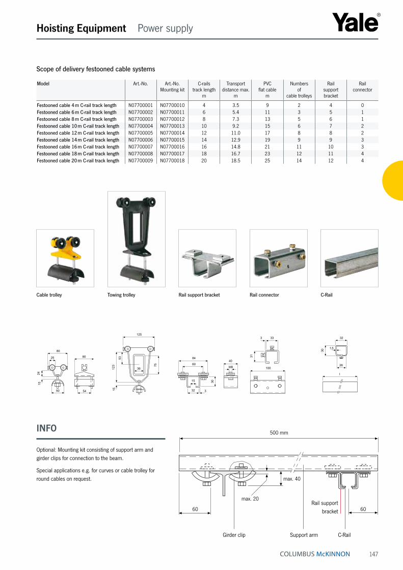
147
C-RailGirder clip Support arm
INFO
Optional: Mounting kit consisting of support arm and girder clips for connection to the beam.
Special applications e.g. for curves or cable trolley for round cables on request.
Hoisting Equipment Power supply
Rail support bracket60
max. 40
max. 20
60
500 mm
Scope of delivery festooned cable systems
Model Art.-No. Art.-No.Mounting kit
C-rails track length
m
Transport distance max.
m
PVC flat cable
m
Numbers of
cable trolleys
Rail support bracket
Rail connector
Festooned cable 4 m C-rail track length N07700001 N07700010 4 3.5 9 2 4 0Festooned cable 6 m C-rail track length N07700002 N07700011 6 5.4 11 3 5 1Festooned cable 8 m C-rail track length N07700003 N07700012 8 7.3 13 5 6 1Festooned cable 10 m C-rail track length N07700004 N07700013 10 9.2 15 6 7 2Festooned cable 12 m C-rail track length N07700005 N07700014 12 11.0 17 8 8 2Festooned cable 14 m C-rail track length N07700006 N07700015 14 12.9 19 9 9 3Festooned cable 16 m C-rail track length N07700007 N07700016 16 14.8 21 11 10 3Festooned cable 18 m C-rail track length N07700008 N07700017 18 16.7 23 12 11 4Festooned cable 20 m C-rail track length N07700009 N07700018 20 18.5 25 14 12 4
Towing trolley
100333
31
I32
1,5
12
26
30
100333
31
I32
1,5
12
26
30
M8
4084
60
15
32
30
3
125
36123
53
15
75
54
8025
80
50
2415
Cable trolley Rail support bracket Rail connector C-Rail