Control of Tensile Stress in Prestressed Concrete Members ...
Upload
xn--90aefy5bCategory
view
0download
0
Materials Science and Engineering A 533 (2012) 107– 118
Contents lists available at SciVerse ScienceDirect
Materials Science and Engineering A
jo ur n al hom epage: www.elsev ier .com/ locate /msea
Tensile properties of an AlCrCuNiFeCo high-entropy alloy in as-cast and wrought
conditions
A.V. Kuznetsova,∗, D.G. Shaysultanova, N.D. Stepanova, G.A. Salishcheva, O.N. Senkovb,c
a Laboratory of Bulk Nanostructured Materials, Belgorod State University, Pobeda 85, Belgorod 308015, Russiab Air Force Research Laboratory, Materials and Manufacturing Directorate, Wright-Patterson Air Force Base, OH 45433, USAc UES, Inc., 4401 Dayton-Xenia Rd., Dayton, OH 45432, USA
a r t i c l e i n f o
Article history:
Received 30 September 2011
Received in revised form
19 November 2011
Accepted 21 November 2011
Available online 27 November 2011
Keywords:
Electron microscopy
Mechanical characterization
High entropy alloy
Thermomechanical processing
Grain refinement
Plasticity
a b s t r a c t
Extensive multistep forging at 950 ◦C was applied to the cast AlCuCrFeNiCo high-entropy alloy to trans-
form the cast coarse dendritic structure into a fine equiaxed duplex structure consisting of the mixture of
BCC and FCC phases, with the average grain/particle size of ∼1.5 ± 0.9 �m. Tensile properties of the alloy
in the as-cast and forged conditions were determined in the temperature range of 20–1000 ◦C. The hot
forged alloy was stronger and more ductile during testing at room temperature, than the as-cast alloy.
The yield stress (YS), ultimate tensile strength (UTS), and tensile ductility (ı) of the forged condition were
1040 MPa, 1170 MPa, and 1%, respectively, against 790 MPa, 790 MPa and 0.2% for the as-cast condition.
In both conditions, the alloy showed brittle to ductile transition (BDT), with a noticeable increase in the
tensile ductility within a narrow temperature range. In the as-cast condition, this transition occurred
between 700 and 800 ◦C, while in the forged condition, it was observed between 600 and 700 ◦C. With
an increase in the testing temperature above the BDT, a continuous decrease in tensile flow stress and
an increase in tensile ductility were observed. In the temperature range of 800–1000 ◦C, the forged alloy
showed superplastic behavior. The tensile elongation was above 400% and reached 860% at 1000 ◦C.
© 2011 Elsevier B.V. All rights reserved.
1. Introduction
Modern technological developments and progress in engineer-
ing, particularly in the aerospace industry, require the development
and utilization of new structural materials that would provide
higher performance compared to the currently used structural
materials. In the last decade, a new class of materials, so called high-
entropy alloys (HEAs) was proposed and developed [1–3]. These
alloys contain five to thirteen principal elements at equimolar or
near-equimolar compositions, thus the atomic fractions of each
element cannot be less than 5% and more than 35% [1]. The high
entropy of mixing has been found to prevent formation of inter-
metallic phases and these alloys predominantly consist of a mixture
of simple solid solutions and favorable combination of compression
strength and ductility [1,4–13].
Many HEAs have high hardness, strength, wear resistance,
and their microstructure is very stable against heat treatment
[1,14,15]. This combination of properties is attractive for a wide
range of applications; however, the main obstacle for using such
∗ Corresponding author. Tel.: +7 4722 585416; fax: +7 3472 585415.
E-mail addresses: [email protected], [email protected] (A.V. Kuznetsov).
materials is low ductility and brittleness of many HEAs, especially
at room temperature. Annealing has been found to improve ductil-
ity of cast HEAs [9,16]. Due to their low ductility, almost all reported
mechanical properties of high entropy alloys were obtained by
compression testing or measuring hardness. Only several publica-
tions are yet available where tensile properties of HEAs are reported
[10,17]. It is necessary to point out that almost all reported proper-
ties of HEAs were obtained in cast conditions and the properties of
cast alloys are known to be almost always inferior to the properties
of wrought alloys. Such structural constituents as shrinkage poros-
ity, coarse dendritic structure, chemical heterogeneity, metastable
eutectic at grain boundaries weaken mechanical properties of
cast alloys. The microstructure and properties of castings can be
improved by thermo-mechanical treatment, including extensive
hot working [18–22]. Unfortunately, no publications have yet been
available in the open literature on the effect of hot working pro-
cesses on the properties of HEAs.
In this paper, microstructure and tensile properties of a severe
plastically deformed AlCrCuNiFeCo high entropy alloy are pre-
sented and compared with those of the cast alloy. This alloy was
selected for study because it has been most widely studied among
all other HEAs [1,9,23–25] and the approximate phase diagram has
been reported [24], which allowed selection of the temperature
range for the thermomechanical treatment.
0921-5093/$ – see front matter © 2011 Elsevier B.V. All rights reserved.doi:10.1016/j.msea.2011.11.045
108 A.V. Kuznetsov et al. / Materials Science and Engineering A 533 (2012) 107– 118
Table 1Chemical composition of the studied alloy.
Al Cr Cu Ni Fe Co
Atomic % 16.16 ± 0.63 15.86 ± 0.05 17.42 ± 0.01 16.65 ± 0.23 15.96 ± 0.15 17.07 ± 0.19
Weight % 8.20 ± 0.40 15.65 ± 0.05 20.95 ± 0.05 18.55 ± 0.25 17.80 ± 0.10 18.10 ± 0.20
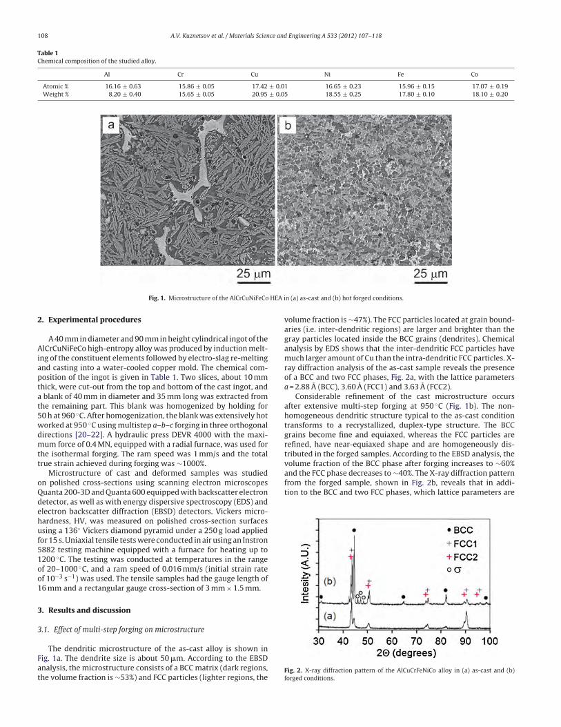
Fig. 1. Microstructure of the AlCrCuNiFeCo HEA in (a) as-cast and (b) hot forged conditions.
2. Experimental procedures
A 40 mm in diameter and 90 mm in height cylindrical ingot of the
AlCrCuNiFeCo high-entropy alloy was produced by induction melt-
ing of the constituent elements followed by electro-slag re-melting
and casting into a water-cooled copper mold. The chemical com-
position of the ingot is given in Table 1. Two slices, about 10 mm
thick, were cut-out from the top and bottom of the cast ingot, and
a blank of 40 mm in diameter and 35 mm long was extracted from
the remaining part. This blank was homogenized by holding for
50 h at 960 ◦C. After homogenization, the blank was extensively hot
worked at 950 ◦C using multistep a–b–c forging in three orthogonal
directions [20–22]. A hydraulic press DEVR 4000 with the maxi-
mum force of 0.4 MN, equipped with a radial furnace, was used for
the isothermal forging. The ram speed was 1 mm/s and the total
true strain achieved during forging was ∼1000%.
Microstructure of cast and deformed samples was studied
on polished cross-sections using scanning electron microscopes
Quanta 200-3D and Quanta 600 equipped with backscatter electron
detector, as well as with energy dispersive spectroscopy (EDS) and
electron backscatter diffraction (EBSD) detectors. Vickers micro-
hardness, HV, was measured on polished cross-section surfaces
using a 136◦ Vickers diamond pyramid under a 250 g load applied
for 15 s. Uniaxial tensile tests were conducted in air using an Instron
5882 testing machine equipped with a furnace for heating up to
1200 ◦C. The testing was conducted at temperatures in the range
of 20–1000 ◦C, and a ram speed of 0.016 mm/s (initial strain rate
of 10−3 s−1) was used. The tensile samples had the gauge length of
16 mm and a rectangular gauge cross-section of 3 mm × 1.5 mm.
3. Results and discussion
3.1. Effect of multi-step forging on microstructure
The dendritic microstructure of the as-cast alloy is shown in
Fig. 1a. The dendrite size is about 50 �m. According to the EBSD
analysis, the microstructure consists of a BCC matrix (dark regions,
the volume fraction is ∼53%) and FCC particles (lighter regions, the
volume fraction is ∼47%). The FCC particles located at grain bound-
aries (i.e. inter-dendritic regions) are larger and brighter than the
gray particles located inside the BCC grains (dendrites). Chemical
analysis by EDS shows that the inter-dendritic FCC particles have
much larger amount of Cu than the intra-dendritic FCC particles. X-
ray diffraction analysis of the as-cast sample reveals the presence
of a BCC and two FCC phases, Fig. 2a, with the lattice parameters
a = 2.88 A (BCC), 3.60 A (FCC1) and 3.63 A (FCC2).
Considerable refinement of the cast microstructure occurs
after extensive multi-step forging at 950 ◦C (Fig. 1b). The non-
homogeneous dendritic structure typical to the as-cast condition
transforms to a recrystallized, duplex-type structure. The BCC
grains become fine and equiaxed, whereas the FCC particles are
refined, have near-equiaxed shape and are homogeneously dis-
tributed in the forged samples. According to the EBSD analysis, the
volume fraction of the BCC phase after forging increases to ∼60%
and the FCC phase decreases to ∼40%. The X-ray diffraction pattern
from the forged sample, shown in Fig. 2b, reveals that in addi-
tion to the BCC and two FCC phases, which lattice parameters are
Fig. 2. X-ray diffraction pattern of the AlCuCrFeNiCo alloy in (a) as-cast and (b)
forged conditions.

A.V. Kuznetsov et al. / Materials Science and Engineering A 533 (2012) 107– 118 109
Fig. 3. Grain/particle size distribution in the AlCuCrFENiCo alloy after hot forging at
950 ◦C with the total true strain e = 10. Note the logarithmic scale of X-axis.
similar to those in the as-cast condition, a � phase (enriched with
Cr and Fe) is also present in the forged alloy. Characteristic small-
intensity peaks from the � phase are located between (1 1 1) and
(2 0 0) peaks of the FCC phases. These peaks are absent in the as-cast
condition. The duplex microstructure of the forged alloy is charac-
terized by a lognormal distribution of grain/particles sizes, Fig. 3,
and the average grain/particle size is estimated to be 1.5 ± 0.9 �m
along the cross-section of the forged material. The high value of
the standard deviation (s = 0.9 �m) is due to large variations of the
grain/particle sizes (from 0.2 to 6.1 �m) in the microstructure.
3.2. Mechanical properties
Fig. 4 shows typical tensile behavior at ε = 10−3 s−1 and differ-
ent temperatures of (a) as-cast and (b) hot forged samples of the
studied alloy. The values of the yield stress (YS), �0.2, ultimate ten-
sile stress (UTS), �u, and elongation to fracture, ı, of these samples
at different temperatures are given in Table 2. At room tempera-
ture, the as-cast alloy is brittle and it fractures immediately after
yielding, so that YS and UTS have the same values of 790 MPa and
the fracture strain ı = 0.2%. After hot forging, the alloy becomes
stronger and shows some ductility at room temperature. Namely,
its YS = 1040 MPa, UTS = 1170 MPa and ı = 1.0%.
A noticeable increase in the tensile ductility of the cast
alloy (from ∼4.7% to 12.1%) occurs in the temperature range of
700–800 ◦C, which is likely caused by the brittle-to-ductile tran-
sition (BDT). This increase in tensile ductility is accompanied with
a noticeable decrease in tensile strength. For example, YS decreases
from 350 MPa to 161 MPa and UTS decreases from 360 MPa to
180 MPa with an increase in temperature from 700 ◦C to 800 ◦C (see
Fig. 4a and Table 2). A further increase in testing temperature to
1000 ◦C results in a continuous decrease in YS to 37 MPa and UTS
to 44 MPa, and an increase in tensile ductility of the cast alloy to
ı = 77%. Analysis of the deformation curves of the cast alloy samples
(Fig. 4a) shows that in the temperature range 700–1000 ◦C a peak
stress is achieved shortly after yielding followed by an apparent
decrease in tensile stress with further deformation. The total elon-
gation is mainly controlled by the duration of this strain-softening
stage. The apparent decrease in tensile stress after reaching the
peak stress is likely due to strain localization and neck formation.
One may therefore suggest that the increase in the duration of the
softening stage is due to slowing down the neck development with
an increase in temperature.
The forged alloy shows a strong BDT behavior, with a rapid
increase in tensile ductility from 1.3% to 63%, in the tempera-
ture range of 600–700 ◦C (see Fig. 4b and Table 2), i.e. at a lower
temperature than the as-cast alloy. The associated drop in the YS
(from 300 MPa to 63 MPa) and UTS (from 350 MPa to 91 MPa) is
much more rapid than that of the cast alloy. At temperatures above
the BDT, the forged alloy is considerably softer and much more
deformable than the cast alloy. For example, at T = 800 ◦C, the UTS
Fig. 4. Typical stress–strain curves of the as-cast (a) and hot forged (b) samples deformed at different temperatures and the initial strain rate of 10−3 s−1.
Table 2Tensile properties of the AlCrCuNiFeCo alloy samples in as-cast condition and after multistep forging.
Temperature condition 20 ◦C 300 ◦C 600 ◦C 700 ◦C 800 ◦C 900 ◦C 1000 ◦C
As-cast
�0.2, MPa 790 – 542 350 161 88 37
�u, MPa 790 – 551 360 180 100 44
ı, % 0.2 – 0.4 4.7 12.1 30 77
Forged
�0.2, MPa 1040 810 300 63 22 14 9
�u, MPa 1170 880 350 91 26 18 22
ı, % 1.0 0.4 1.3 63 604 405 864

110 A.V. Kuznetsov et al. / Materials Science and Engineering A 533 (2012) 107– 118
Fig. 5. Photographs of tensile samples after deformation at 1000 ◦C: (a) a non-deformed sample; (b) as-cast sample (ı = 77%); and (c) forged sample (ı = 864%). ε = 10−3 s−1.
of the alloy in as-cast condition (�castu = 180 MPa) is more than 6
times higher than in the forged condition (�forgeu = 26 MPa) and
even at T = 1000 ◦C the cast condition is ∼3 times stronger than the
forged condition (�castu = 44 MPa and �forge
u = 14 MPa). It is inter-
esting to note that the BDT in the cast and forged alloys occurs at
almost the same UTS values of ∼350 MPa and thus the shift of the
BDT temperature of the forged alloy towards lower temperature
range can be associated with the stronger temperature dependence
of the UTS of the forged alloy. The forged samples exhibit steady-
state flow and very high elongation at temperatures above BDT,
which reaches 604% at 800 ◦C and 864% at 1000 ◦C (Fig. 4b and
Table 2). Fig. 5 shows photographs of as-cast and forged samples
after tensile deformation at 1000 ◦C. Though the cast sample illus-
trates pronounced strain localization (necking) and final fracture
by shear at ı = 77%, the forged sample shows very homogeneous
flow, high resistance to neck formation, and very high elongation
of ı = 864%. It is expected that very high elongation and low flow
stress of the forged alloy is an indication of superplastic behavior
at T = 800–1000 ◦C.
The Vickers microhardness of the tensile samples tested at dif-
ferent temperatures is tabulated in Table 3. Microhardness of the
as-cast samples is always higher than that of the forged sam-
ples. Microhardness of slightly deformed neck regions (at 20 ◦C,
600 ◦C and 700 ◦C) is almost the same as the microhardness of non-
deformed head regions. On the other hand, severely deformed neck
regions of the forged samples (700–1000 ◦C) and as-cast samples
(1000 ◦C) have noticeably smaller microhardness than the head
regions of the respective samples, which is due to development
of porosity in the highly deformed regions (see below). A notice-
able increase in microhardness can be seen in the as-cast specimen
after holding and tensile deformation at 800 ◦C, which is proba-
bly due to aging associated with phase transformations (�-phase
precipitation) in this temperature range [10].
3.3. Microstructure evolution during tensile deformation
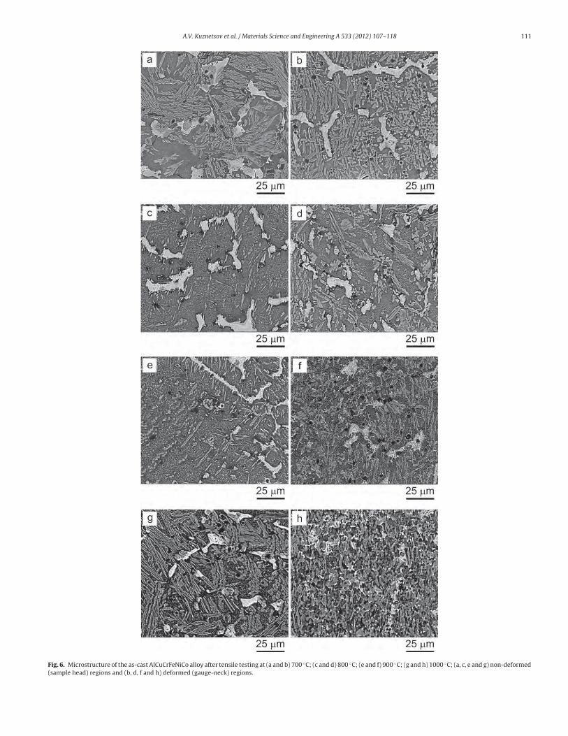
SEM backscatter images of the microstructure of the non-
deformed (head) and deformed (gauge-neck) regions of the tensile
samples of the as-cast alloy after deformation at 700 ◦C, 800 ◦C,
900 ◦C and 1000 ◦C are shown in Fig. 6. Different outlook of the FCC
particles inside dendrites in different samples is probably due to
their plate-like morphology and different orientation of dendritic
grains. No noticeable changes in the dendritic microstructure of
the as-cast condition are identified after deformation at 700 ◦C and
800 ◦C: the microstructure remains similar to that of the as-cast
alloy in both head and neck regions (Fig. 6a–d). During deformation
at 900 ◦C, fragmentation and globularization of coarse FCC particles
are observed in the gauge region, while no noticeable changes are
detected in the head (non-deformed) region (Fig. 6e and f). After
deformation at 1000 ◦C, the microstructure in the gauge region
completely transforms into a recrystallized duplex grain struc-
ture with homogeneously distributed near-equiaxed FCC particles
(Fig. 6h). The average particle size (BCC and FCC) is ∼2.4 ± 1.0 �m.
It is worth noting that holding of the sample at 1000 ◦C for the
same time, but without deformation, does not lead to any notice-
able visual changes in the cast dendritic structure, at least at the
used magnifications (compare Fig. 1a and Fig. 6g).
Tensile deformation in the temperature range from 20 ◦C to
1000 ◦C of the forged alloy samples does not change the morphol-
ogy of the forged microstructure (Fig. 7). However, grain/particle
coarsening is noted after deformation at 900 ◦C and 1000 ◦C. For
example, the average grain/particle size in non-deformed (head)
region increases from 1.5 �m (as-forged condition) to 2.5 �m after
deformation at 900 ◦C and to 2.8 �m after deformation at 1000 ◦C.
The grain/particle size in the heavily deformed neck region is
slightly smaller (i.e. 2.2 �m at 900 ◦C and 2.6 �m at 1000 ◦C) than
in the non-deformed region of respective specimens (see Table 4),
which may indicate some deformation-induced particle fragmen-
tation.
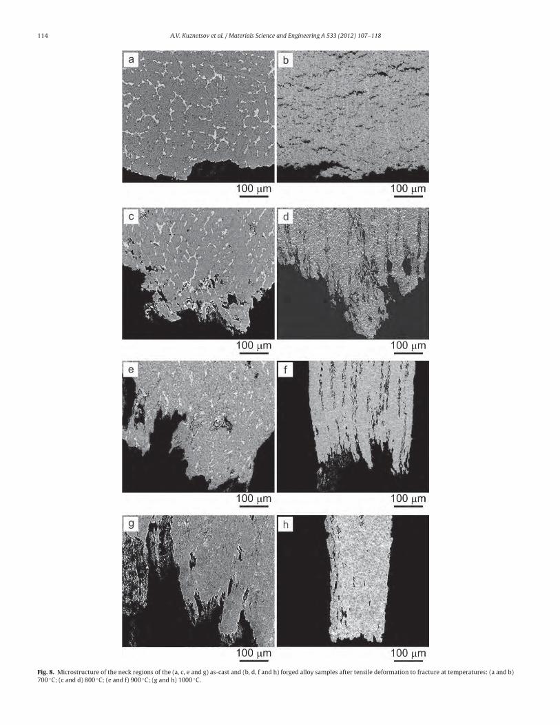
3.4. Porosity development in tensile tested samples
The as-cast samples deformed by tension in the temperature
range of 20–700 ◦C do not show any porosity in the deformed region
(Fig. 8a). Fracture of these samples occurs by crack propagation,
mainly along inter-dendritic regions. After tensile deformation at
800 ◦C and 900 ◦C of the as-cast samples, cracks developed at the
interfaces of the FCC/BCC particles tend to blunt and transform to
pores due to plastic deformation of surrounding areas (Fig. 8c and
e). The cracks leading to fracture propagate along the interfaces,
which are ∼45◦ to the tensile direction. The pore morphology of
the as-cast sample deformed at 1000 ◦C (ı = 77%) is different from
the described above. At this temperature, the pores are elongated
in the tensile direction due to heavy deformation of surrounding
matrix and fracture occurs by local necking and thinning of inter-
pore areas (Fig. 8g).
Tensile deformation at T > 600 ◦C of the initially forged alloy
samples results in a considerable amount of pores and cracks inside
wide area under the fracture surface (Fig. 8b, d, f and h). While
at 700 ◦C the pores are formed and developed along interfaces of
the FCC particles, which are nearly perpendicular to the tension
direction, and thus form chains in the radial directions (Fig. 8b),
at higher temperatures the pores are elongated in the longitudi-
nal direction (Fig. 8d, f and h). Superplastic-like behavior in this
temperature range (800–1000 ◦C) resists strain localization and
necking between the nearest elongated pores and results in forma-
tion of very long pores. A detailed analysis of the microstructure
of these samples shows that, similar to the as-cast condition, the
A.V. Kuznetsov et al. / Materials Science and Engineering A 533 (2012) 107– 118 111
Fig. 6. Microstructure of the as-cast AlCuCrFeNiCo alloy after tensile testing at (a and b) 700 ◦C; (c and d) 800 ◦C; (e and f) 900 ◦C; (g and h) 1000 ◦C; (a, c, e and g) non-deformed
(sample head) regions and (b, d, f and h) deformed (gauge-neck) regions.

112 A.V. Kuznetsov et al. / Materials Science and Engineering A 533 (2012) 107– 118
Fig. 7. Microstructure of the forged alloy samples after tensile deformation to fracture at temperatures (a and b) 600 ◦C; (c and d) 700 ◦C; (e and f) 800 ◦C; (g and h) 900 ◦C;
(i and j) 1000 ◦C; (a, c, e, g and i) non-deformed (head) regions and (b, d, f, h and j) deformed (gauge-neck) regions.

A.V. Kuznetsov et al. / Materials Science and Engineering A 533 (2012) 107– 118 113
Fig. 7. (Continued).
pores and cracks are initiated at the interfaces between BCC and
FCC phases.
Fig. 9a shows the temperature dependence of the volume frac-
tion of pores in the neck regions of the as-cast and forged samples
after tensile testing to fracture. With an increase in the testing
temperature from 700 ◦C to 1000 ◦C the amount of neck poros-
ity increases from 0.1% to 1.0% in the cast samples. At the same
time, the neck porosity in the forged samples rapidly increases
from 0.2% at 600 ◦C to 10.5% at 700 ◦C, reaches the maximum
value of 12.5% at 900 ◦C and then decreases to 7.9% at 1000 ◦C.
The high amount of porosity in the neck region of the forged
samples is mainly associated with high tensile deformation of
these samples at T = 800–1000 ◦C. To take this into account, the
volume fractions of pores are normalized to the respective total
strains, and the results are given in Fig. 9b. The volume fraction
of pores developed per 1% elongation is almost temperature inde-
pendent for the cast material and is ∼0.01–0.02%. At the same
time, the volume fraction of pores developed per 1% elongation
in the forged samples has maximum of 0.17% at 700 ◦C, rapidly
decreases to ∼0.02–0.03% at 800 ◦C and remains almost indepen-
dent on temperature (within the experimental error) in the range
of 800–1000 ◦C.
3.5. Fractography
The SEM images of fracture surfaces of the cast and forged
samples tensile tested at 20 ◦C are shown in Fig. 10a–d, respec-
tively. At low magnification, the as-cast alloy sample has a coarse
faceted appearance of the fracture surface (Fig. 10a), whereas the
forged sample has fine granular appearance of the fracture surface
(Fig. 10c). This observation is consistent with the much smaller
grain/particle size of the forged condition than the cast condi-
tion. Higher magnification images confirm brittle, quazi-cleavage,
fracture of the as-cast alloy, with such characteristic features as
flat facets, angular faceted steps, river-pattern markings, cleavage
feathers and tongues (Fig. 10b). At the same time, higher magnifica-
tion images from the fracture surface of the forged sample confirm
mixed type of brittle and ductile fracture (Fig. 10d). The brittle type
fracture is reflected by the presence of flat facets with characteristic
river-pattern markings inside large dimples, while the ductile type
fracture is reflected in numerous dimples of different diameters
surrounding the flat facets. It is likely that during tensile deforma-
tion of the forged sample, cracks are formed at the interfaces of the
BCC and FCC particles by brittle fracture and then the crack open-
ing into voids occurs by plastic deformation of nearest, more ductile
regions, as it is seen in Fig. 8b.
SEM images of the fracture surfaces of the as-cast alloy sam-
ples after tensile fracture in the BDT range at 700 ◦C and 800 ◦C are
shown in Fig. 11a–d, respectively. Fracture at 700 ◦C (beginning of
the BDT) is somewhat similar to fracture at 20 ◦C [compare Fig. 11a
and b and Fig. 10a and b] in a sense that the quazi-cleavage facets
dominate. However, the microstructure features, such as angular
faceted steps, river-pattern markings and cleavage feathers, are
finer at 700 ◦C, which is indirect indication of dislocation activity in
the cleaved BCC phase before fracture. Indeed, the angular faceted
steps are generally associated with crossing dislocation walls con-
sisting of screw dislocations; thus higher number density of these
steps indicates an increased number density of screw dislocations
in the samples deformed at 700 ◦C than in the samples deformed
at 20 ◦C. Additionally, the presence of plastically formed hills and
Table 3Vickers microhardness of as-cast and forged AlCrCuNiFeCo alloy samples after tensile testing at different temperatures.
Testing temperature (◦C) 20 600 700 800 900 1000
As-cast condition
Head 463 ± 12.7 – 433 ± 17.6 472 ± 15.6 469 ± 15.3 405 ± 9.5
Neck 439 ± 14.1 – 449 ± 15.3 498 ± 20.6 445 ± 33.3 372 ± 26.9
Forged condition
Head 432 ± 3.4 432 ± 11.4 410 ± 2.1 419 ± 2. 7 418 ± 3.4 392 ± 2.1
Neck 420 ± 2.6 435 ± 13.4 332 ± 5.7 349 ± 5.3 334 ± 4.9 388 ± 5.7
Table 4The average particle size and standard deviation (in �m) in the duplex structure of the forged AlCrCuNiFeCo alloy samples after tensile deformation at given temperatures.
Testing temperature (◦C) 600 700 800 900 1000
Particle size (�m) non-deformed (head) region 1.5 ± 0.8 1.6 ± 0.9 1.9 ± 1.0 2.5 ± 1.3 2.8 ± 1.3
Deformed (neck) region 1.6 ± 0.8 1.5 ± 0.8 1.6 ± 0.9 2.2 ± 1.1 2.6 ± 1.4
114 A.V. Kuznetsov et al. / Materials Science and Engineering A 533 (2012) 107– 118
Fig. 8. Microstructure of the neck regions of the (a, c, e and g) as-cast and (b, d, f and h) forged alloy samples after tensile deformation to fracture at temperatures: (a and b)
700 ◦C; (c and d) 800 ◦C; (e and f) 900 ◦C; (g and h) 1000 ◦C.

A.V. Kuznetsov et al. / Materials Science and Engineering A 533 (2012) 107– 118 115
Fig. 9. (a) Volume percent of pores in the neck region of the samples after tensile deformation to fracture as a function of the testing temperature and (b) the same data
normalized to the total elongation (% pores per 1% elongation) (ε = 10−3 s−1).
dimples is an indication of a ductile-type fracture mode in the as-
cast alloy sample after deformation at 700 ◦C.
Fractographs of the as-cast alloy sample after tensile fracture
at 800 ◦C are very different from described above. First, large pores
developed during plastic deformation are seen at low magnification
(Fig. 11c). Many of these pores are connected with secondary cracks
and form chains. Second, the size and fraction of quazi-cleavage
facets considerably decrease and new fine features of globular
appearance are now present in the fracture surface (Fig. 11c and
d). These fine globules can form during heavy local plastic defor-
mation and dynamic recrystallization of the near-fracture region
of the deformed sample. Indeed, the sample cross-section in this
region is estimated by SEM to be ∼1.0 mm × 2.2 mm, which results
in the local plastic strain of ∼200%, i.e. much higher than the
total elongation of 12.1%. Oxidation of thin edges of ductile dim-
ples, hills and tongues during holding at 800 ◦C can also led to
Fig. 10. SEM images of the fracture surfaces of tensile samples after tensile testing deformation at room temperature: (a and b) as-cast and (c and d) hot forged conditions.

116 A.V. Kuznetsov et al. / Materials Science and Engineering A 533 (2012) 107– 118
Fig. 11. SEM images of the fracture surfaces of the as-cast samples after tensile testing to fracture at (a and b) 700 ◦C and (c and d) 800 ◦C.
fragmentation and formation of oxidized globules in these regions.
The blunt appearance of the fracture surface features is an indica-
tion of the surface oxidation.
Fig. 12 illustrates SEM images of fracture surfaces of the forged
alloy samples, which were tensile fractured at 600 ◦C (a) and
700 ◦C (b). The fracture morphology at 600 ◦C (below BDT) is com-
pletely identical to that at 20 ◦C (compare with Fig. 10d). Namely,
mixed type of brittle and ductile fracture is clearly seen. Simi-
lar to 20 ◦C sample, the brittle type fracture is reflected by the
presence of flat facets with characteristic river-pattern markings
inside large dimples, while the ductile type fracture is reflected
in numerous dimples of different diameters surrounding the flat
facets. The facture at 700 ◦C (above BDT) shows mainly duc-
tile fracture with large dimples 2–5 �m in size. This finding is
consistent with growth of the experienced total elongation up
to 63%.
4. Discussion
Results described in previous sections demonstrate that hot
working by multi-step forging of the AlCrCuNiFeCo high entropy
alloy considerably modifies and refines the microstructure of the
cast condition, improves tensile ductility and strength at room
temperature, decreases brittle-to-ductile transition temperature
by ∼100 ◦C, and makes the alloy superplastic in the temperature
range of 800–1000 ◦C.
4.1. Effect of hot deformation on microstructure
Thermomechanical processing is known to be an effective
method and is widely used for the homogenization and modifi-
cation of the coarse dendritic structure of cast metallic materials
aiming at improving mechanical properties [19–22]. The current
work shows that it can also be successfully applied to multi-
component high entropy alloys. In particular, the cast ingot of
the AlCrCuNiFeCo alloy was extensively hot worked by multi-
step forging at 950 ◦C without any evidence of cracking, and
a coarse dendritic structure of casting (the dendrite size is
50 �m) was completely transformed into a fine-grained duplex
mixture of the BCC matrix and FCC particles, with an average
grain/particle size of 1.5 �m and the relative volume fraction of
the BCC and FCC phases of ∼60% and ∼40%, respectively. Small
amount of a complex � phase was also identified in the forged
alloy.
4.2. Effect of microstructure on tensile properties
The refined microstructure of the hot forged material improves
strength and ductility at room temperature as compared to the

A.V. Kuznetsov et al. / Materials Science and Engineering A 533 (2012) 107– 118 117
Fig. 12. SEM images of the fracture surfaces of hot forged samples after tensile testing to fracture at (a) 600 ◦C and (b) 700 ◦C.
initial cast condition. This is apparently due to grain refinement,
which is known to effectively reduce strain localization and local
stress concentrations at grain boundaries [26]. Elementary cracks
associated with trans-granular brittle fracture are smaller and more
work is required to propagate them in a critical-size crack to break
the forged alloy with a refined grain structure than the coarse-
grained as-cast alloy, thus explaining increased fracture strength
and improved ductility. The alloy in both as-cast and forged con-
ditions shows an obvious BDT, which is likely due to the presence
of the high volume fraction (∼60%) of the BCC phase. Presence of
the ductile fracture mode in addition to the major brittle fracture
mode in the samples fractured below BDT indicates that the brittle
fracture in this alloy is preceded by local plastic deformation, prob-
ably in more ductile FCC phase. This plastic deformation is more
extensive in the fine-grained forged condition than in the coarse-
grained cast condition. Grain refinement by hot forging reduces the
BDT temperature by about 100 ◦C in comparison with the as-cast
condition. At the same time, the BDT is noted to start at almost
the same UTS value of ∼350 MPa in both microstructural condi-
tions. These observations clearly indicate that the shift of the BDT
towards lower temperatures is associated with a stronger temper-
ature dependence of the YS and UTS and, therefore, more rapid
decrease in the resistance to dislocation motion and stress relax-
ation with an increase in temperature in the forged alloy than in
the as-cast alloy. Indeed, the forged alloy has higher area density
of grain boundaries and interfaces than the as-cast alloy, and the
grain boundary areas generally soften much faster with an increase
in temperature towards the equicohesive temperature than trans-
granular regions [27].
A noticeable increase in ductility and decrease in tensile
strength observed at temperatures above the BDT are probably
due to activation of grain boundary sliding (GBS) accommodated
by diffusion-controlled processes. A more pronounced drop in the
tensile strength and an increase in the tensile ductility in the
forged alloy are again associated with finer grain structure, result-
ing in a more extensive GBS and dynamic recovery. Moreover,
GBS-controlled plastic deformation is characterized by high strain
rate sensitivity of the flow stress, which resists strain localiza-
tion and neck formation and promotes superplastic deformation
[22,28,29]. Such superplastic behavior results in the very long
steady-state plastic flow of the forged alloy in the temperature
range of 800–1000 ◦C. On the other hand, higher resistance to
plastic deformation of the cast dendritic structure produces condi-
tions for initiation of dynamic recrystallization, which refines the
grain structure in heavy deformed regions of the cast samples at
800–1000 ◦C.
5. Conclusion
1. Extensive hot working by multi-step forging considerably
refined the dendritic structure of the cast AlCuCrFeNiCo alloy
and led to formation of fine equiaxed duplex structure with the
grain/particle size of ∼1.5 �m.
2. At room temperature, the AlCuCrFeNiCo alloy was stronger and
more ductile after hot working than in as-cast condition. For
example, in as cast condition the ultimate tensile strength (UTS)
was 790 MPa and the alloy fractured at yielding (∼0.2% plastic
strain). At the same time, after hot working, the ultimate tensile
strength increased to 1170 MPa and the tensile fracture occurred
after 1% plastic strain.
3. In both as-cast and hot working conditions, the alloy shows brit-
tle to ductile transition (BDT), with a considerable increase in
the tensile ductility within a narrow temperature range. In the
as-cast condition, this transition occurred when the testing tem-
perature reached 700–800 ◦C range, while in the hot worked
condition, it was observed in the 600–700 ◦C range. In both con-
ditions, the UTS decreased with an increase in temperature and
the BDT occurred when the UTS values drop to ∼350 MPa. The
decrease in the BDT temperature was explained by grain/particle
refinement during hot working.
4. At temperatures above the BDT temperature, a consider-
able decrease in the tensile flow stress was observed. For
example the UTS of as-cast alloy decreased from 350 MPa at
700 ◦C to 180 MPa at 800 ◦C and to 44 MPa at 1000 ◦C. The
decrease in the tensile strength of the hot worked alloy sam-
ples with an increase in temperature was much stronger:
the UTS decreased from 350 MPa at 600 ◦C to 91 MPa at
700 ◦C and to 14 MPa at 1000 ◦C. The decrease in the tensile
strength was accompanied with a noticeable increase in tensile
ductility.
5. In the temperature range of 800–1000 ◦C, the hot worked alloy
showed a superplastic-like behavior. The tensile elongation was
above 400% and reached 860% at 1000 ◦C. In spite of void devel-
opment during tensile deformation in this temperature range,
no necks were developed, which is an indirect indication of high
strain rate sensitivity of the forged alloy in this temperature
range.

118 A.V. Kuznetsov et al. / Materials Science and Engineering A 533 (2012) 107– 118
Acknowledgement
This work was supported by the Ministry of Science and Educa-
tion of Russian Federation, grant no. 02.740.11.5184.
References
[1] J.-W. Yeh, S.-K. Chen, S.-J. Lin, J.-Y. Gan, T.-S. Chin, T.-T. Shun, C.-H. Tsau, S.-Y.Chang, Adv. Eng. Mater. 6 (5) (2004) 299–303.
[2] J.-W. Yeh, Ann. Chim.: Sci. Mater. 31 (2006) 633–648.[3] J.-W. Yeh, Y.-L. Chen, S.-J. Lin, S.-K. Chen, Mater. Sci. Forum 560 (2007) 1–9.[4] Y.J. Zhou, Y. Zhang, Y.L. Wang, G.L. Chen, Mater. Sci. Eng. A 454–455 (2007)
260–265.[5] Y.J. Zhou, Y. Zhang, Y.L. Wang, G.L. Chen, Appl. Phys. Lett. 90 (2007) 181904-
1–181904-3.[6] Y.J. Zhou, Y. Zhang, F.J. Wang, Y.L. Wang, G.L. Chen, J. Alloys Compd. 466 (2008)
201–204.[7] Y.P. Wang, B.S. Li, M.X. ren, C. Yang, H.Z. Fu, Mater. Sci. Eng. A 491 (2008)
154–158.[8] F.J. Wang, Y. Zhang, Mater. Sci. Eng. A 496 (2008) 214–216.[9] L.H. Wen, H.C. Kou, J.S. Li, H. Chang, X.Y. Xue, L. Zhou, Intermetallics 17 (2009)
266–269.[10] C.W. Tsai, M.H. Tsai, J.W. Yeh, C.C. Yang, J. Alloys Compd. 490 (2010) 160–165.[11] J.M. Zhu, H.M. Fu, H.F. Zhang, A.M. Wang, H. Li, Z.Q. Hu, Mater. Sci. Eng. A 527
(2010) 6975–6979.[12] O.N. Senkov, G.B. Wilks, J.M. Scott, D.B. Miracle, Intermetallics 19 (2011)
698–706.[13] O.N. Senkov, J.M. Scott, S.V. Senkova, D.B. Miracle, C.F. Woodward, J. Alloys
Compd. 509 (2011) 6043–6048.
[14] C.-W. Tsai, Y.-L. Chen, M.-H. Tsai, J.-W. Yeh, T.-T. Shun, S.-K. Chen, J. AlloysCompd. 486 (2009) 427–435.
[15] O.N. Senkov, G.B. Wilks, D.B. Miracle, C.P. Chuang, P.K. Liaw, Intermetallics 18(2010) 1758–1765.
[16] K.B. Zang, Z.Y. Fu, J.Y. Zhang, J. Shi, W.M. Wang, H. Wang, Y.C. Wang, Q.J. Zhang,J. Alloys Compd. 502 (2010) 295–299.
[17] T.-T. Shun, Y.-C. Du, J. Alloys Compd. 479 (2009) 157–160.[18] R.Z. Valiev, I.V. Alexandrov, Bulk Nanostructured Metallic Materials,
Akademkniga, Moscow, 2007, p. 398.[19] G.A. Salishchev, R.M. Imayev, O.N. Senkov, V.M. Imayev, N.K. Gabdullin, M.R.
Shagiev, A.V. Kuznetsov, F.H. (Sam) Froes, Mater. Sci. Eng. A 286/2 (2000)236–243.
[20] G.A. Salishchev, R.I. Imayev, O.N. Senkov, F.H. Froes, JOM 52 (12) (2000) 46–48.[21] S.V. Zherebtsov, G.A. Salishchev, R.M. Galeyev, O.R. Valiakhmetov, S.Y. Mironov,
S.L. Semiatin, Scripta Mater. 51 (2004) 1147–1151.[22] R.M. Imayev, N.K. Gabdullin, G.A. Salishchev, O.N. Senkov, V.M. Imayev, F.H.
Froes, Acta Mater. 47 (1999) 1809–1821.[23] C.J. Tong, M.R. Chen, S.K. Chen, J.W. Yeh, T.T. Shun, S.J. Lin, S.Y. Chang, Metall.
Mater. Trans. A 36A (2005) 1263–1271.[24] C.J. Tong, Y.L. Chen, S.K. Chen, J.W. Yeh, T.T. Shun, C.H. Tsau, S.J. Lin, S.Y. Chang,
Metall. Mater. Trans. A 36A (2005) 881–893.[25] F.J. Wang, Y. Zhang, G.L. Chen, H.A. Davies, Int. J. Mod. Phys. B 6–7 (2009)
1254–1259.[26] P. Haasen, Physical Metallurgy, 3rd ed., University Press, Cambridge, UK, 1996.[27] V.M. Imayev, R.M. Imayev, G.A. Salishchev, Intermetallics 8 (2000) 1–6.[28] T.G. Nieh, J. Wadsworth, O.D. Sherby, Superplasticity in Metals and Ceram-
ics (Cambridge Solid State Science Series), University Press, Cambridge,UK, 1997.
[29] M.M. Schwartz, New Materials, Processes and Methods Technology, CRC Press,Boca Raton, FL, USA, 2005.
Copyright © 2022 FDOKUMEN