Series 1 OQ - Die Cast Machinery
42
• • ' I • 1261-D B-001-0-00 • Siebe comp.ny Series 1 OQ 1/4 DIN Process and Temperature Controller Key Standard Features: • 0.3% Accuracy • 300 millisecond Control Response • Universa/..TC, mVDC, VDC & mADC Input ·A JTM Self · Tune ·Auto Comp™ Sensor Break ·Designed to meet IEC IP65 Sealed Front ·Selectable "Cor °F ·Loop Break • Setpoint Ramp ·Selectable Decimal Point ·Pass Code--Security • 8 Large Tactile Feedback Keys ·Second Setpoint and Tuning Constant ·Indicator (no Control Output) Introduction The 100 is a versatile microprocessor-based 1/4 DIN controller which can be used to display and control temperature, pressure, level and flow variables. Front panel programming allows a single 100 to meet a wide variety of plant and test facility applications. Thermo- couple, mADC, mVDC and VDC inputs can be changed in the field without the addition of hardware or recalibration. Universal input including RTD is offered as an option. Selection of alarm types, scaling, oc or °F, setpoint limits, decimal point location and sensor break response is ma<;Je from the keypad without having to locate hard-to-find internal jumpers or switches. Typical applications Include: Furnaces Ovens Plastics processing machines Packaging machinery Food equipment Solder lines Printing equipment Curing, baking and drying equipment Barber-Colman pioneered control technology by intro- ducing the first 1/4 DIN single-loop controller with auto- Copyright rtJ 1994, Barber-Colman Company Lt:ll.l - I - ;l - '-i L-tv'·5- 5 Position Statement February, 1994 The 100 Is a modern /ow-cost controller with a short depth (4.2") case, Ideal for OEM's, cost-sensitive placements and system upgrade applications. malic tuning. The new Barber-Colman A TTM Self Tune provides automatic tuning with completely hands-off, no-operator-involved PID tuning at startup. The yellow AT LED glows steadily to indicate that tuni ng is occu r- ring. The LED turns off when tuning is complete or flashes if tuning is unsuccessful. The AT button can be pressed to cancel tuning depending on the autotuning status. Autotuning incorporates an adaptive tuning os- cillation monitor that automatically retunes the controller should conditions change. The oscillation monitor can be turned off once the desired performance is achieved or it can be left on to provide continuous adaptive tuning . The loop break function provides early warning tha t something in the control loop has failed . If the controller fails to progress toward setpoint, the LB ( loop Bre ak) LED turns on. The loop break function can also be programmed to one of the optional alarms. The ad - vanced Auto CompTM sensor break function minimizes process upsets due to sensor break by providing tor the selection of a preset manual percentage output or the last stable output when a sensor fails. The second setpoint function saves se tup ti me by pro- viding a second setpoint and tuning constants stored in memory and available by pressing the se tpoint se lect
-
Upload
khangminh22 -
Category
Documents
-
view
0 -
download
0
Transcript of Series 1 OQ - Die Cast Machinery

•
•
' I
•
ProductlnPorma~on 1261-D B-001-0-00
• Siebe comp.ny
Series 1 OQ 1/4 DIN Process and Temperature Controller
Key Standard Features: • 0.3% Accuracy • 300 millisecond Control Response • Universa/..TC, mVDC, VDC & mADC Input ·A JTM Self· Tune ·Auto Comp™ Sensor Break ·Designed to meet IEC IP65 Sealed Front ·Selectable "Cor °F ·Loop Break • Setpoint Ramp ·Selectable Decimal Point ·Pass Code--Security • 8 Large Tactile Feedback Keys ·Second Setpoint and Tuning Constant ·Indicator (no Control Output)
Introduction
The 100 is a versatile microprocessor-based 1/4 DIN controller which can be used to display and control temperature, pressure, level and flow variables. Front panel programming allows a single 100 to meet a wide variety of plant and test facility applications. Thermocouple, mADC, mVDC and VDC inputs can be changed in the field without the addition of hardware or recalibration. Universal input including RTD is offered as an option. Selection of alarm types, scaling, oc or °F, setpoint limits, decimal point location and sensor break response is ma<;Je from the keypad without having to locate hard-to-find internal jumpers or switches.
Typical applications Include:
Furnaces Ovens Plastics processing machines Packaging machinery Food equipment Solder lines Printing equipment Curing, baking and drying equipment
Barber-Colman pioneered control technology by introducing the first 1/4 DIN single-loop controller with auto-
Copyright rtJ 1994, Barber-Colman Company
OE.~AVL.f ~£c..V~IT'< c:.oDii~
Lt:ll.l - I t...fV·~ - ;l L.£11·~ - ~ L~"·~- '-i L-tv'·5- 5
Position Statement
February, 1994
The 100 Is a modern /ow-cost controller with a short depth (4.2") case, Ideal for OEM's, cost-sensitive placements and system upgrade applications.
malic tuning. The new Barber-Colman A TTM Self Tune provides automatic tuning with comp letely hands-off, no-operator-involved PID tuning at startup. The yellow AT LED glows steadily to indicate that tuning is occurring. The LED turns off when tuning is complete or flashes if tuning is unsuccessful. The AT button can be pressed to cancel tuning depending on the autotuning status. Autotuning incorporates an adaptive tuning oscillat ion monitor that automatically retunes the controller should conditions change. The oscillation monitor can be turned off once the desired performance is achieved or it can be left on to provide continuous adaptive tuning.
The loop break function provides early warning that someth ing in the control loop has failed. If the controller fails to progress toward setpo int, the LB (loop Break) LED turns on. The loop break function can also be programmed to one of the optional alarms. The advanced Auto CompTM sensor break function minimizes process upsets due to sensor break by providing tor the selection of a preset manual percentage output or the last stable output when a sensor fails.
The second setpoint function saves setup time by providing a second setpoint and tun ing constants stored in memory and available by pressing the setpoint se lect

One ?-segment LED (green) shows Tuning Set # (and setpoint) or Ramp Status
Eleven 3 mm diameter LED annunciators: Out 1 (green) Out 2 (green) Aim 1 (red) Aim 2 (red) Prog (green) Auto (green) Man (yellow) AT (yellow) LBIHBO (red) •c (green) RS (green)
Barber-Co/man@
button. The SET# (Tuning Set number) LED indicates which Tuning Set (and setpoint) is active. The second Tuning Set can also be se lected remotely using the optional contact closure input function. Provided as a standard feature is a programmable setpoint ramp up and ramp down function which operates whenever the setpoint is changed. This is helpful in startups and applications where rapid changes cannot be tolerated. Powerup selections allow precise definition of the powerup process so that when power is applied the controller will powerup in either automatic control, a preset percentage or the last condition of automatic or manual control.
100 options include dual outputs and dual alarms, auto/ manual control, two contact closure inputs for remotely selecting controller states (auto/manual, second tuning set, toggle output action, sample and hold, freeze reset, and halt) and a hardware lock function .
Features/Benefits
Low Initial and Total Cost The 100 offers rugged construction, a front designed to be sealed to water and dust (IEC IP65). built-in noise immunity that is designed to meet IEC 801-2 tor electrostatic discharge and IEC 801-4 tor power line noise spikes and inputs and outputs.
Easy Installation The 4.2 inch panel depth fits virtually all panel sizes. Adapter plates tor non-1/4 DIN cutouts are available.
Fast Setup and Configuration The 100 is precontigured by model number. Inputs, outputs and alarm types are preset. which saves valuable setup time. Final setup and configuration are done
1261 ·08·001-0-00
Four ?-segment LEOs (orange) for process value (PV) display
Four ?-segment LEOs (green) to r setpoint value (SV) display
Eight Tactile Keys: Auto-tune/Function Auto/Manual Display Setpoint Se lect SetUp Up Arrow Down Arrow Run/Hold
from the front using a spreadsheet structure which allows rapid movement from function to funct ion.
Human Eng ineered Eight tactile feedback keys provide direct access to important funct ions such as auto/manual, autotuning, operating displays and setup.
Easy Setpolnt Change Pressing the Up or Down arrow key changes the set point.
Color Coded Displays The dual seven-segment displays and the status LED's conform to IEC guidelines featuring red only for alarm indications.
Scaleable Control Functions Programmable setpoint limits prevent unsafe changes to setpoints. Programmable output limits can be set from 0% to 100% (1 05% for analog outputs). All input ranges are scaleable to useable high and low limits and DC analog inputs are programmable from -1999 to9999 with up to 3 decimal places.
Load Line Function The advanced load line function allows par1icu1ar load requirements to be matched to the controller's load line setting in order to minimize overshoot at startup.
Flexible Bimodal Heat/Cool Control Cooling outputs can be programmed for linear, tan or non-linear water cooling.
Pass Code Security Lock The 100 offers five levels of security using separate 4· digit pass codes. An optional hardware lock provides maximum security.
Page 2 ol 12
'
•

. .
(!)
/
KEYS
[lAUTO-TUHEJ] FUNCTION
•• [( AUTO Jl lolAHUAL
[ DISPLAY JJ
I( SETPOIHT )I SELECT
EJ)
(@J (00)
GEJ 0
, 26,-08-001 -0-00
OUT 1 e OUT 2 •
Status Annunciators
Out 1 (green) is lit when Output 1 is ON
Out 2 (green) is lit when Output 2 is ON
AUol1.
ALII 2 •
Aim 1 (red) flashes (lit steadily il acknowledged) when Alarm 1 is ON
Aim 2 (red) !lashes (lit steadily if acknowledged) when Alarm 2 is ON
PROG.
AUTO.
Prog (green) is lit when a Ramp/Soak program is running (not presently used)
Auto (green) is lit when the controller is in the Automatic control mode
MAll.
AT e LB/HBO •
Man (yellow) is lit when the controller is in the manual (percent out) control mode
AT (yellow) is lit while automatic tuning is taking place; flashes if tuning fails
LBIHBO (red) flashes when a loop break or heater burnout occurs
·c • Degrees C (green) is lit when temperature is being displayed in Celsius
RSe AS (green) is lit when remote setpoint is functioning (not presently used)
Ol!T 1%
Ol!T 2% - Out1% (green dash) is lit when SV display is showing Output 1 percent out
Out2% (green dash) is lit when SV display is showing Output 2 percent out
Key Functions
Operating Mode Setup Mode Configuration Mode
Cancels ' startup· automatic tuning Steps the display through a particu- Steps the display through a particu-constants. (Press again tore-initiate larsetup function. Once in the Setup lar configuration function Once 1n tuning) . mode, press the Setup key repeat- the Configuration mode. press the
edly to reach the proper se tup June- Setup key repeatedly to reach the tion (e .g., 'tun1'). Then use this key proper configuration function (e.g., to step through the Junction. "SEC' ). Then use this key to step
through the function .
Toggles the controller between Au- Not Used. In Calibration, initiates tomatic and Manual(% Out) control. calibration or input signal.
Steps through a loop ol operating Returns the controller to the Re turns the controller to the displays: Setpoint, % Out (heating operating mode. operating mode . and/or cooling), Second Setpoint and Deviation from Setpoint.
Toggles the con troller between Steps the display backward through Steps the display backward through Setpoint and Tuning Constants 1 {a a particular setup function (like the a particular configuration function T is displayed on the small 7-seg- function key in revers~). (like the function key in reverse). ment display) and Setpoint and Tun-ing Constants 2 (a '2' is displayed on the small ?-segment display).
Steps the controller through two dil- Steps the controller forward one Steps the controller forward one lerent modes. Press (and release) Setup functional group. Configuration functional group. and the controller goes to Setup (SETU) mode. Press {and hold 4 seconds) and the controller goes to Configuration (CONF) mode. Out-pu ts are ON in Setup. Outputs are OFF in Configuration.
During Automatic control, pressing Increases/decreases the Setup pa- Increases/decreases the Configu-an arrow key increases or decreases rameter on display or selects a mode ration parameter on display or sa-the control setpoint. During Manual ol operation for a Setup parameter. lects a mode of operation for a Con-control, pressing an arrow key in- With a numeric display, the longer figuration parameter. With a numeric creases or decreases the percent an arrow key is pressed, the laster display, the longer an arrow key is output. With a numeric display, the the rate of change. pressed, the laster the rate of longer an arrow key is pressed, the change. faster the rate or change.
Not presently used. Steps the controller backward one Steps the controller backward one Setup functional group (like the Setup Configuration functional group (like key in reverse). the Setup key in reverse) .
Page 3 of 12

Optional Features
Outputs Control output 1 can be either a form C re lay, pulse noncontact DC voltage for solid state re lays, 24/260 VAC solid state switching triac, 4-20 mADC current, or 0-10 VDC voltage. Control output 1 and 2 have the same selections except that the control output 2 relay is a form A. Any combination of the available types is allowable.
Output limits are settable from 0% to 100% (1 05% for analog outputs). DC output signal levels are scaleable in the field , meaning that the 0-10 VDC output can be set to 1-5 VDC out without recalibrating. The 4-20 mADC output is scaleable anywhere from 0-21 mADC.
The on/off hysteresis is adjustable for both outputs. Used with the spread adjustment, each output can be individually gapped or overlapped with respect to setpoint, providing advanced deadband settability.
Universal Inputs The standard Series 100 accepts eleven ANSI thermocouple types as we ll as the common DC mV, mA and voltage inputs. It an RTD input (or the capabil ity to select universally in the field I rom RTD, thermocouple, DC mV, mA or voltage) is requ ired, order the optional 100 DIN (0.003850/0/oC) RTD input. Changing inputs in the field involves selecting a menu item. Recalibration is not required. Field changing between thermocouple and RTD involves adding or removing the Balco resistor on the input terminals at the back of the case.
Auto/Manual In automatic control, pressing the auto/manual key changes to manual control (the Auto LED goes out and the Man LED lights) while the setpoint is replaced with a bumpless transfer to a percent output indication. If Output 1 is active, the upper bar of the lett-most seven segment display will be li t. If Output 2 is active, the lower bar of the left-most seven segment display will be lit.
Contact Inputs for Remote Switching Two contact inputs are available for remote switching from automatic to manual control (se lectable bumpless or preset percent out). second local setpoint and tuning constants , toggle output direction (e .g., reverse to direct). freeze reset, sample and hold, and halt (halt provides a preset safe manual percentage to shut down a process or bring it to a sate operating level).
Alarms Up to two alarms are available. Alarm type can be configured in the field by changing a menu item. Choices include high deviation, low deviation, deviation band, deviation range, process low, process high and loop break. A unique standby function can be used to ignore an alarm (helpful with machine startups). The standby
126t-08-001-0·00
function can be set from 0 to 100 minutes. After the time expires, the alarm functions normally.
Alarm outputs can be configured as non-latching or latching. Non-latching alarms de energize when an alarm is acknowledged or when the condition clears. Latching alarms remain on after an alarm is acknowledged and turn off when the condition clears. If the condition clears before the alarm is acknowledged, the LED will continue to flash and the alarm will remain energized.
Specifications Consult the Operator Manual for "as shipped" or "default" values of the variables listed here.
Control Modes On/Off; Proportional; Proportional/Integral; Proportionav Integral/Derivative (all with Load Line); Proportional! Derivative with Manual Reset ; None (for Indicator).
Proportional Band 0.1% to 200.0% of Input Scale (Input Low to High).
Integral (Reset) 0 to 3600 seconds in 1 second steps (0 indicates oH).
Derivative (Rate) 0 to 2400 seconds in 1 second steps (0 indicates off) .
Load Line 0% to 100% (of Demand) in 1% steps.
Cycle Time 0 to 120 seconds in 1 second steps.
Powerup Modes Automatic; Manual; or Prev ious (can be Automatic or Manual depending on the mode when powered down). Manual powers up with a preset manual percent out.
Output On/Off Hysteresis o to 10% of Input Scale (Input Low to High) in steps of the Input Scale (depending on the location of the user programmed decimal point).
Output Limits Minimum Power (0 Percent Out) to Max imum Power ( 100 Percent Out)( 105% tor analog outputs) .
Control Action Single Output- Reverse (Heating); Direct (Cooling).
Dual Output- Reverse (Output 1 Reverse acting; Output 2 Direct acting) . Direct (Output 1 Direct acting; Output 2 Reverse acting).
Response Time 300 milliseconds.
Page 4 of 12
6
•

•
••
•
Setpolnt Limits Minimum (Setpoint Low) and maximum (Setpoint High) limits can be set anywhere within Input Scale (Scale Low to Scale High).
Setpolnt Ramp 0.1 to 9999 units per minute depending on decimal point location (separate entry for ramp up and ramp down). Operational whenever setpoints change (from front of instrument or contact closure). On powerup, the process reading is used as the initial setpoint.
DC Inputs Current 4 to 20 mADC -1999 to 9999 Voltage 0 to 5 VDC -1999 to 9999 Vottage 1 to 5 VDC -1999 to 9999 Voltage 0 to 10 VDC -1999 to 9999 Voltage 0 to 100 mVDC -1999 to 9999 Voltage -10 to 10 mVDC -1999 to 9999 Voltage 0 to 10 mVDC -1999 to 9999
DC input levels can be assigned limits anywhere within a range of -10 to 100 mVDC; 0 to 20 rnA; orO to 10 VDC.
Input Impedance Millivolt, Volt. Thermocouple: 10 Megohm minimum.
Current: 250 ohms nominal.
Thermocouple and RTD Inputs Type K, ·1 oo 0 f to 2400 °f; -75 oc to 1320 °C Type J, -100 °f to 1600 °F; -75 octo 875 oc Type E. ·1 oo •F to 1600 °F; -75 oc to 875 oc TypeR, 0 °f to 3100 Of; -20 octo 1705 oc Type S, 0 •f to 3100 °F; -20 octo 1705 ·c Type B, 100 •f to 3100 °F; 37 °C to 1817 oc PL-11, 0 •F to 2500 •F; -20 octo 1375 oc Type C, 0 •f to 4200 •f; -20 oc to 2320 oc Type N, -100 °F to 2400 °F; -75 oc to 1320 oc Ni!Ni Mo 32 •f to 2500 •F; o •c to 1371 ·c Type T, -350 •F to 700 °F; -215 •c to 375 •c RTD 385 -199.9 °F to 999.9 •F; -199.9 •c to 850.0 oc
Accuracy not guaranteed for Type B below 200°C orfor Types R and S below 1 oooc.
RTD 3-wire Platinum, 100 D (0.00385DJDJ°C), per IEC 751 and DIN 43760.
Input Lead Res istance 200D maximum (any control input).
Contact Closure Inputs 2 contacts, 1.5 rnA max. current; 200D max. resistance (leads and contacts); 500 msec. minimum closure.
Input Protection Common Mode Rejection (Thermocouple & RTD only) Common mode voltages from 0 to 240 VAC will not shift the control operating point more than 0.1% of span.
1261-DB-001-0-00
Common Mode Rejection (Analog Inputs) Common mode voltages from -1 to 1 0 VDC will not shift the control operating point more than 0.5% of span .
Series Mode Rejection 60 db at 50 or 60 Hz for all input signals from 0 to 250 mVAC RMS.
Sensor Break Protection (Burn Mode) On- Outputs go to the "on" condition (maximum percent out demand for PID and "on" for onloH).
Off- Outputs go to the "off" cond ition (minimum percent out demand for PIO and "off" tor onloff)(as shipped).
Safe- Outputs go to the safety out percent demand specified by the user.
AutoComp- Output is determined by the autocomp type chosen. If the autocomp type is "manual percent," then the output will go to the preset manual percent output entered by the user. If the autocomp type is "process" and the control output demand is stable, then the output will freeze at the present process demand percent output. If the "steady state" conditions have not been met the output will go to the preset manual percent output entered by the user.
Input Isolat ion to Ground 500 VDC .
Accuracy ±0.3% of span typical (±1 digit of display).
Input Resolution Thermocouples- 0.1 oc or 0 f (under 999 counts); 1 oc or °F (over 999 counts).
Analog- 0.02% of full scale span.
Control Outputs Output 1 Relay- Form C, SPOT. NO, NC and Common contacts. 120/240 VAC, 2 Amp, resistive load; 200 VA inductive load.
Output 2 Relay- Form A, SPST. NO and Common contacts . 120/240 VAC , 2 Amp, resistive load: 200 VA inductive load.
Triac Output - 1.0 Amp continuous, 24 to 240 VAC, resistive, 8 Amp inrush. Minimum load 50 mA.
Non-Contact Voltage- On: 12 VOC; Off: 0.1 VDC or less, into 1 K Ohm minimum load.
Current- 0 to 21 rnA (shipped 4 to 20 rnA), isolated, short circuit protected both leads to ground. 600 Ohm
Page 5 of t 2
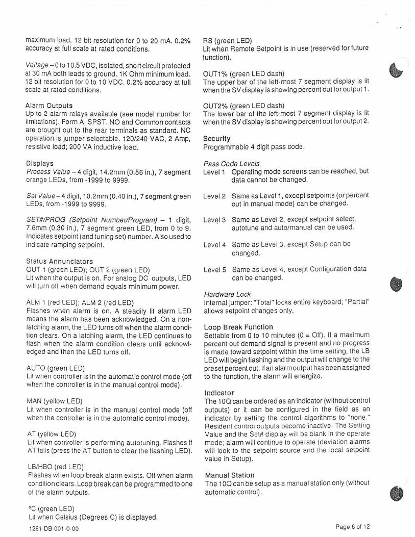
maximum load. 12 bit resolution for 0 to 20 mA. 0.2% accuracy at full scale at rated conditions .
Voltage- 0 to 10.5 VDC, isolated, short circuit protected at 30 rnA both leads to ground. 1 K Ohm minimum load. 12 bit resolution for 0 to 10 VDC. 0.2% accuracy at full scale at' rated conditions.
Alarm Outputs Up to 2 alarm relays available (see model number for limitations). Form A, SPST. NO and Common contacts are brought out to the rear terminals as standard. NC operation is jumper selectable. 120/240 VAC, 2 Amp, resistive load; 200 VA inductive load.
Displays Process Value- 4 digit, 14.2mm (0.56 in.), 7 segment orange LEOs, from -1999 to 9999.
Set Value - 4 digit, 1 0.2mm (0.40 in.), 7 segment green LEOs. from -1999 to 9999.
SET#!PROG (Setpoint Number/Program) - 1 digit, 7.6mm (0.30 in.). 7 segment green LED, from 0 to 9. Indicates setpoint (and tuning set) number. Also used to indicate ramping setpoint.
Status Annunciators OUT 1 (green LED); OUT 2 (green LED) Lit when the output is on. For analog DC outputs, LED will turn off when demand equals minimum power.
ALM 1 (red LED); ALM 2 (red LED) Flashes when alarm is on. A steadily lit alarm LED means the alarm has been acknowledged. On a nonlatching alarm, the LED turns off when the alarm condition clears. On a latching alarm, the LED continues to flash when the alarm condition clears until acknowledged and then the LED turns off.
AUTO (green LED) Lit when controller is in the automatic control mode (off when the controller is in the manual control mode).
MAN (yellow LED) Lit when controller is in the manual control mode (off when the controller is in the automatic control mode).
AT (yellow LED) Lit when controller is periorming autotuning. Flashes if AT fa ils (press the AT button to clear the flashing LED).
LB/HBO (red LED) Flashes when loop break alarm exists. Off when alarm condition clears. Loop break can be programmed to one ol the alarm outputs.
oc (green LED) Lit when Celsius (Degrees C) is displayed.
1261·08-001-0-00
RS (green LED) Lit when Remote Setpo int is in use (reserved for future function).
OUT1% (green LED dash) The upper bar of the left-most 7 segment display is lit when the SV display is showing percent out for output 1.
OUT2% (green LED dash) The lower bar of the left-most 7 segment display is lit when the SV display is showing percent out for output 2.
Security Programmable 4 digit pass code.
Pass Code Levels Level1 Operating mode screens can be reached, but
data cannot be changed.
Level 2 Same as Level1, except setpoints (or percent out in manual mode) can be changed.
Level 3 Same as Level 2, except setpoint select, autotune and auto/manual can be used.
Level 4 Same as Level 3, except Setup can be changed.
Level 5 Same as Level 4, except Conf iguration data can be changed .
Hardware Lock Internal jumper: "Total" locks entire keyboard; "Part ial" allows setpoint changes only.
Loop Break Function Settable from 0 to 10 minutes (0 =Off). II a maximum percent out demand signal is present and no progress is made toward setpoint within the time setting, the LB LED will begin flash ing and the output will change to the preset percent out. If an alarm output has been assigned to the function, the alarm will energize.
Indicator The 100 can be ordered as an indicator (without control outputs) or it can be conf igured in the field as an indicator by setting the control algorithms to "none ." Resident control outputs become inactive. The Setting Value and the Set# display will be blank in the operate mode; alarm will continue to operate (deviation alarms will look to the setpoint source and the local setpoint value in Setup).
Manual Station The 1 00 can be setup as a manual station on ly (without automatic control).
Page 6 of 12
•
•

~·
•
MODEL Field No.
1 o DD-DDD o 0-DDD-D-DD 2 3 4 5 6 7 8 9 10 11 12 13 14 15
Flold 3. CONTROLLER SIZE 0 -Quarter DIN
Field 4. CONTROL OUTPUT 1 V- Indicator (No Output) 1 - Relay (Form C) 2- Pulse Non-Contact Voltage for SSR (12 VDC) 3- Currant (4-20 mA) 4 - Voltage (0-1 0 VDC) T- Triac (24-260 VAC, 1 A)
Field 5. CONTROL OUTPUT 2* 0- Nona 1 - Relay (Form A) 2 - Pulse Non-Contact Voltage for SSR (12 VDC) 3 - Currant (4-20 mA) 4- Voltage (0-10 VDC) T- Triac (24-260 VAC, 1A) 'Control Output 2 is NOT available with a combination of Control Output 1 Form C Relay (Option 1) and Alarm 2.
Fields 6, 7. INPUT 1 Universal Input (field selectable) forTC, Current, Millivoltage and Voltage inputs . Ordering RTD input provides field selectable RTD, TC, Currant, Millivoltage and Voltage inputs.
Thermocouple (Decimal Point Programmable up to 1 digit) KF- Type K, -100 •F to 2400 •F KC- Type C, -75 •c to 1320 •c JF -Type J, -100 •F to 1600 •F JC - Type J , -75 •c to 875 •c EF - Type E, -100 •F to 1600 •F EC- Type E, -75 •c to 875 •c RF ·TypeR, 0 •F to 3100 •F RC - Type R, -20 •c to 1705 •c SF· TypeS, 0 •Fto 3100 •F sc - Types, -2o •c to 1705 •c BF- TypaB, 1oo •Fto 31oo•F BC - Type B, 37 •c to 1817 •c PF - Type P, 0 •F to 2500 •F PC- Type P, -20 •c to 1375 •c CF - Type C, 0 •F to 4200 •F cc - Type c, -20 •c to 2320 •c NF- Type N, -100 •F to 2400 •F NC - Type N, -75 •c to 1320 •c MF - NiJNi Mo, 32 •F to 2500 •F MC- Ni!Ni Mo, 0 •c to 1371 •c TF - Type T, -350 •F to 700 •F • TC - Type T, -215 •c to 375 •c • 'Decimal Point is NOT Programmable with Type T
Current and Voltage (Decimal Point Programmable up to 3 digits) C1- Current 4 to 20 mADC -1999 to 9999 V1 - Voltage 0 to 5 VDC -1999 to 9999 V2- Voltage 1 to 5 VDC -1999 to 9999 V3- Voltage 0 to 10 VDC -1999 to 9999 V4- Voltage Oto100mVDC -1999to9999 V5- Voltage -10to 10mVDC -1999to9999 V6 - Voltage Oto 10mVDC -1999to9999
1261 -DB-001-0-00
Fields 6, 7. INPUT 1 (continued) RTD (Decimal Point Programmable up to 1 digit) SF- PLT1 00 DIN (0.00385nJnJ•C) -199.9 GF to 999.9 •F BC- PL T1 00. DIN (0.00385n.ln.JOC) -199.9 •c to 850.0 •c
Field 9. ADVANCED OPTIONS 0- None 1 - Auto/Manual
Field 10. CONTACT CLOSURES 0- None 1 - Dual Contact Closure, programmable to Manual Select', Second Local Satpoint and Tuning Constants, Toggle Output Action, Sample & Hold, Freeze Reset and Halt. • Note that Auto/Manual option must be ordered for Manual Select.
Field 11. ALARM 2* Form A Relay; shipped NO, field configurable to NO/NC; field configurable Standby and Latching function. 0 - None 1 - High Deviation 2 - Low Deviation 3- Deviation Band (daenergized in the band) 4 - Deviation Range Band (energized in the band) 5 - Process High 6- Process Low 8 - Loop Break Relay • Alarm 2 is NOT available with a combination of Control Output 1 Form C Relay (Option 1) and Control Output 2.
Field 12. POWER SUPPLY 0 - 85 to 264 VAC, 48/62 Hz
Field 13. ALARM 1 Form A Relay; shipped NO, field configurable to NO/NC; field configurable Standby and Latching function. 0- None .. 1 - High Deviation 2 - Low Deviation 3- Deviation Band (deenargized in the band) 4- Deviation Range Band (energized in the band) 5 - Process High 6 - Process Low B -Loop Break Relay
Fields 14, 15. SPECIALS 00- Nona 01 - Shipped without Housing (order Housing separately) 02 - Hardware Security Lock
Page 7 of 12

Controller Wiring Examples
Pow« Supply
CD E.ARTH GROUND
SUPPLY
85 TO~ VAC
r---~"-·'-"-'· =···'·'-';''··::~======::=; Control Output 1
Relay
!
I I
Alarm 2 Raley
s~ ~j
2A 1201240 VAC
Alarm 1 Re lay
·tJ @)-2A 120/240 VAC
..... ·.
Alarm Output Re lays
Control Output 2 DC, Triac, Pulse DC
CD+ SLOT 2
®-
Control Output 1 DC, Triac, Pu lse DC
® + SLOT 1
@ -
Control Output 2 Relay
5~ @:~
2A 1201240 VAC
Convol Output l Re!ay·(a Form C Relay.) reqwes,:Jocatlng Alatm$ on Term~nals 7 & 8 ·and ·9 & 1'0. li:,·ALL o!h~·cases, Alarms BJe located· on Terminals 4, 5 &·6 .
1261·08-001 -0-00
Power Supply:
Contact Closur&s
~ CC1 '<.!/o--
f-0\ CC2 ~o--
SLOT 7
33 COM
Control Input VDC, mVDC, TIC, mADC
@+ SLOT 5
@-
Earth Ground
85 to 264 VAC, 48/62 Hz.
Control & Alarm Relay Contacts: 2 Amp, 120/240 VAC (resisl tve) 200 VA, 120/240 VAC (inductive)
DC Outputs:
Control Input ATD
:~~~: SLOT 5
@) RTD B (Remove Batco)
4 to 20 mAde, 0 to 10 Vdc and Pulse Output 12 Vdc
Triac Output: 1 Amp, 24 to 240 VAC (50 mA minimum load)
Page 8 ol12
•

•
•
Display Screen Examples
Operating Displays
'C py CVT I I -,,-, -, CVT I
.wll RS I. 11:1 :1 :;~ sv
C>Vn% I -1 J:t -1 ::. J cumr. I. I LJ L
•T
Ul / teo
Process and Setpolnt displayed with 3 decimal places
'C P'l CVT I ,- ,-, -, CVT I
.wl I R$ :II- I=
~· lj sv PROO CVTI% ,-, ,-, 1-1 ·:· cumr. Ll L/ L/
u UIIHIIO
Screen for changing Setpolnt 2
Setup Displays
CVT 1
CVT I
J.llll
AT
UIH&O
'C PV
CIL RS I J_l
sv I II 1-1 I Lt. L/
10.0% Proportional Band
Configuration Displays
'C P'l CVT 1 I_ 1_1 Cl C CVT I
.wl 1 R$ /_ _J/ _,
.wl I u sv I'ROQ CVTI% I I J.IJTO 1:: c: LJ IU.H =
u U I HIIO
Type J Thermocouple selected
1261·08-001-Q-00
'C f>(
CVT I I -11-11-1 CVT I
AUI I R9 JJ:- /_//_/
:ilj r;(
ovn"' - I I 1-1 IU.H • I cumr. ILl
AT
UI I HBO
Controller In Manual Mode {PV = 1200, Out 1 = 40%)
'C f>(
OUT 1 ,,-, OUT I -AUI1
RS 11:1 :,: [j sv
CVTI% I ,- I I A:· J cumr. '-' r:: L/ u
LIIHBO
Screen showing deviation from Setpolnt
'C P'l CVT 1 C 1.: L CVT I
.lUI 1 R$ _, /_ /_ /_/.
::~ L1l sv CVTI% ,- 1- ,-A:· I = -' J:: 1:: -'
AT
UlillBO
Security Level 5 active
'C P'l CVT 1 L 1_1 Cl I CVT I
AUI I RS /_ _JJ I
.wll u sv I'ROQ CVTI% 1-1 I I J.IJTO ,- ,- II I IU.H =
AT
l.I / HIIO
Process High selected as Alarm Type 1
Page 9 o f 12
+ +
+ +
102.4mm 1-o~l--- (4.030") ~
minimum
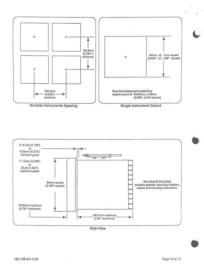
Multiple Instruments Spacing
3.18mm(0.125") to
9.52mm (0.375") minimum panel
(0.438") 11.12mm to
25.40 ( maximu
1.COO") m panel
maximum 19.05mm (0.750" m aximum)
l
1261 -08-001 -0-00
r 96mm square
(3. 780" square)
j ~
120.6mm (4.750") minimum
""" "=
I 92mm, +0, -1 mm square + (3.622", +0, -.039" square)
__l Note that waterproof installations require cutout of 90.63mm, ±.38mm
(3.568", ±.015 square)
Single Instrument Cutout
= = = = = = = F=
F=
Mounting Kit (included) contains gaskets, mounting brackets,
screws and mounting instructions.
106.7mm maximum ........ . (4.20 maxtmum)
Side VIew
Page10of12
~·

. '
This page Intentionally lett blank .
•
• 1261·08-001 ·0·00 ·Page 11 of 12
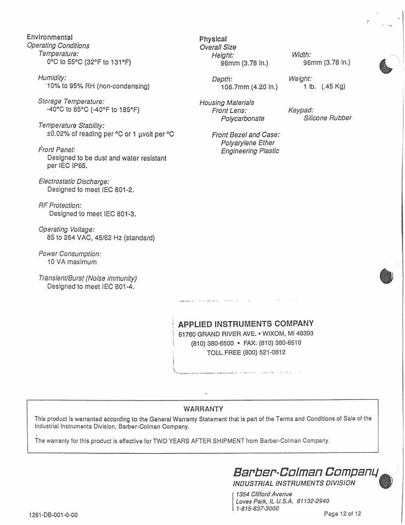
Environmental Operating Conditions
Temperature: ooc to 55°C (32°F to 131 °F}
Humidity: ·1 0% to 95% RH (non-condensing)
Storage Temperature: ·40°C to 85°C ( ·40°F to 185°F)
Temperature Stability: ±0.02% of reading per oc or 1 j..l.VOit per oc
Front Panel: Designed to be dust and water resistant per IEC IP65.
Electrostatic Discharge: Designed to meet I EC 801-2.
RF Protection: Designed to meet IEC 801 -3.
Operating Voltage: 85 to 264 VAC, 48/62 Hz (standard)
Power Consumption: 10 VA maximum
Transient/Burst (Noise immunity) Designed to meet IEC 801-4.
Physical Overall Size
Height: 96mm (3.78 in.)
Depth: 106.7mm (4.20 in.)
Housing Materials Front Lens:
Polycarbonate
Front Bezel and Case: Polyarylene Ether Engineering Plastic
Width: 96mm (3. 78 in.)
Weight: 1 lb. (.45 Kg)
Keypad: Silicone Rubber
APPLIED INSTRUMENTS COMPANY 51760 GRAND RIVER AVE. • WIXOM, Ml 48393
(810} 380-6500 • FAX: (810) 380-6510
TOI::L FREE (800} 521·0612
'-·--·---·-·· ·-·---··· ··--·--· - .... - -· . .... ·- . .. .
WARRANTY
This product is warranted according to the General Warranty Statement that is part of the Terms and Condit ions of Sale of the Industrial Instruments Division, Barber-Colman Company.
The warranty for this product is eHective for TWO YEARS AFTER SHIPMENT from Barber-Colman Company.
•
Barber-Caiman CampanLJ . INDUSTRIAL INSTRUMENTS DIVISION •
1261·DB-oo1-o-oo 1
1354 Clifford Avenue Loves Park, JL U.S.A. 61132·2940 1-815-637-3000
Page 12 of 12
• SS.W com,.ny
Instruct/an manual
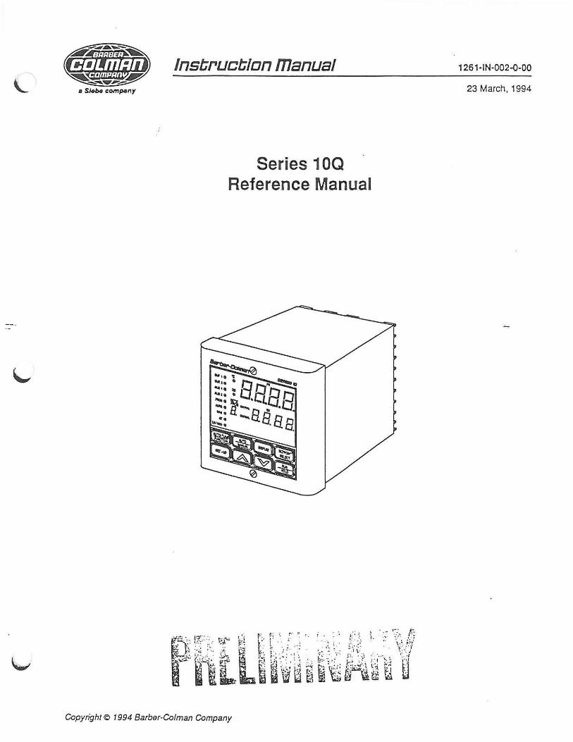
Series 10Q Reference Manual
Copyright CD 1994 Barber-Colman Company
1261-IN-002-Q-00
23 March, 1994

Section Table of Contents Page
1. Introduction ........ ................................................................................. ............ .............. ........... 5 2. First Time Operation ........ ........................................ ..... ........................ ..................................... ............ 6 3. Installing the Controller ................... ....................................................................................................... 8 4. Wiring the Controller ......................................................... .................................................................. . 1 0
4.1 Power Supply Wiring .............................................................................................................. 1 0 4.2 Control Output 1 Wiring ......................... ................................................................................. 1 0 4.3 Control Output 2 Wiring ........ ..... ............................................................................................. 11 4.4 Contact Input Wiring ............................... ................................................................................ 11 4.5 Alarm Wiring .................................................................................... ....................................... 12 4.6 Control Input Wiring ............................................................................................. :: ................. 13
5. Jumper and Switch Locations .................................................................................................. : ........... 14 5.1 Hardware Security ............................... .......................................... ....................................... .. 14 5.2 Relay Contacts ....................................... .... ........ ......................... ........ .. ........ ......................... 15
6. The Operating Mode ........ ................................................................... ............ ..................................... 16 6.1 Automatic Operation ............................................................................................................... 16 6.2 Manual Operation ................................................ ................................................ ................... 18 6.3 Indicator Operation .................................... .......... ... ...... .......................................................... 19
7. The Setup Mode ............................................................................................................... ............. 20 7.1 Security Setup ........................................................................................................................ 21
7.1.1 Password Enter ................................................................................................... 21 7.2 System Setup ............................. .. ............................ .................... .......................................... 23
7.2.1 Software Version/Revision ..................................... :.;;;.·~ ............................ ... 23 7.3 Loop Setup ......................................................................... m·::;:;.,:~'::-. .J::: ............................... 24
7.3.1 Setpoint Source .......................................................... ::'~I-~ . .::.~ ............................... 24 7.3.2 Setpoint Select Key Enable .......... ....... ... .......... !E1;.~tC:-::: .. L .................. .. ....... .. 24 7 .3.3 Auto/Manual Key Enable ................................... ft_:;f,:;i.~:,·:~::;:~:~ .................... .. .. ...... 24 7.3.4 Power:up Type ........................................... ........ ~*~~.:-!!.::;.:_. .............................. 25 7.3.5 Setpotnt Ramp Enable ...................................... .~o_; ...... :: .............................. ........ . 25 7.3.6 Ramp Rate Up ............ , ..................... ..... ............ -$'~~~~:,~;;~::... ................... .......... 25 7.3.7 Ramp Rate Down ........ ........... .... ........................ ~~ ............................................ .. 25
7.4 Control Setup ......................................................................... \:::-:.~.:··.:. :::·_: .. : ...................... ....... 26 7.4.1 Setpoint Low Limit .......... ........ .. .......................... a:::::·~.;~.-._.:.:::.:.:. ............................ 26 7.4.2 Setpoint High Limit ........ ..................................... -r .. -.:, .. :· . .-:::: .. ::~ .............. . ......... ..... 26 7.4.3 Output 1 H~s~eresis ................. ...................... ...... ~;,:~·.:-;~, .: :.-~ .......... ............ ...... 27 7.4.4 Output 1 Mtn1mum Power ...................... ................ , ................ ; ............... ... ........... 27 7.4.5 Output 1 Maximum Power ..................... .............. .-.:~: ... :· ....... :._ ........................... . 27 7.4.6 Output 1 Slew Fitter ... ................... ...................... .. ~~~~:::.;:,:: . .:.., ............................ 27 7.4. 7 Output 2 Hysteresis ................... ........................... t§~::.::;.,.:~: .. ~~ .................. ......... 27 7.4.8 Output 2 Minimum Power ............. ........................ ~·;.~~-~~ .. - , .... ,.:_ .. .......................... 28 7.4.9 Output 2 Maximum Power ......................... ............ :::r:-:·.::;.~·~.:.;· ........................... 28 7.4.1 0 Output 2 Slew Fitter .............................................. :::·::::_ ~:.=:.:.:.~::.=-........................... 28 7.4.11 Manual Percent Preset .......................................... L.£;~; :: .... :. ;;~·: ........................... 29
7.5 Autotune Setup ................................................ .......................... ::::-.:...~·~.: .. :.:.: . .-: .......................... 30 7.5.1 Autotune Type ....................................................... :::.:~·.:: ..... ,:.:·.:: .......................... 30 7.5.2 Autotune Response ........ .... ................................... .r-.. ,.·:.L_:·,~;~ ."~·-.......... ... ........... 30 7.5.3 Adaptive Tune Enable ..................................................... ..... :: .. : .... .. ... ... .............. 30
7.6 Tuning Set 1 & 2 Setup ........................................................ ........... .......... .............................. 31 7.6.1 Setpoint 1 (or 2) .................... ............................................................................... 31 7.6.2 Proportional Band 1 .......................................... ...................................... .... ......... 31 7.6.3 Load Line 1 ......................................... .. ........ .......... ........................ ........... ... ....... 31 7.6.4 Reset 1 ................... .......................... .................................. ................................. 31 7.6.5 Rate 1 ................................................................................................... .... .... ....... 32 7.6.6 Cycle Time 1 ........................... ............................................................................ 32 7.6.7 Spread 1 ................... ... ....... ... ............................................. ................................. 32 7.6.8 Proportional Band 2 ..................................................................................... .... .... 32 7.6.9 Load Line 2 ................. ......................................................................................... 32 7.6.10 Reset2 ...................... ..................................................................... ..................... 33 7.6.11 Rate 2 ..................................... .............. ........................ ....................................... 33 7.6.12 Cycle Time 2 ................ ............ .................... ............. .......................................... 33 7.6.13 Spread2 ................................................................................................... ........... 33
7.7 Input Setup ........................................... ............................. ........................... ................... ... ... 34 7.7.1 Slot 5 Input Type ................................... ........................................... ........... .. ...... 34
1261 -IN-002-0-00 Page 2 of 72

Section Table of Contents (cont'd) Page
7.7.2 Slot 5 Engineering Units .................. .................................................. ............... ... 35 7.7.3 Slot 5 Sensor Correction ...... ................ ..... ...................................... .................... 35
( 7.7.4 Slot 5 Fmer Window ............................................................................................ 35 7.7.5 Slot 5 Decimal Setting ................................................ .. .................... ......... .... ...... 35
7.8 Alarm Setup ............... .................................... ............................ ...... ....... ................................ 36 7.8.1 Alarm 1 Acknowledge .......................................................................................... 36 7.8.2 Alarm 1 Setpoint ........................... ....................................................................... 36 7.8.3 Alarm 1 Hysteresis .............................................................................................. 37 7.8.4 Alarm 2 Acknowledge ........................................................................... ............... 37 7.8.5 Alarm 2 Setpoint ................................................................... .... .................... ... .... 38 7.8.6 Alarm 2 Hysteresis .............................................................................................. 38 7.8.7 Loop Break Setting ............. ................ .......................... ...................................... . 38
8. The Configuration Mode ...................................................................................................................... 39 8.1 Security Configuration ............................................................................................................ 40
8.1.1 Security Type ..................................................... ................. .. ...................... ........ 40 8.1.2 Set Code 1 through 5 .......................................................... ................................ 40
8.2 Loop Configuration ................................................................................................................. 41 8.2.1 Tuning Set Limit .................................................................................................. 41 8.2.2 Sensor Break (Burn) Mode ... .... ...... ................................................................ .... .41 8.2.3 Auto Compensation Type .................... ........................ ........................................ 42 8.2.4 Auto/Manual Transfer Type ....... ............................................ .......... .. .... .. ............ 42
8.3 Control Configuration .................................... ......................... ................ ........................ .. ....... 43 8.3.1 Algorithm 1 ....................................................... ................. ..... ............................. 43 8.3.2 Control Action 1 .......... ...................................... ....................... .................... ........ 43 8.3.3 PID Type 1 ............................. .. .................................................................. .. ....... 44
~:~ :~ ~:bo~~~~ ~ : :::::::::::::::: :::::::::: : : : ::::::::::::~:~~-:~~~}~::::::::::: ::: :: :::::: :::::::: : :::::: ::::: ::: :: 8.3.6 . Sat:ty Out Percent ............... .. .............. ft:.::::-,:~-: :· .. ·:::_; .............................................. 45
8.4 Input Configuration ..................................................... ~ ............ , ... ~:.-.... ............ ............................ 46 8.4.1 Slot 5 Hardware Type ......................... .. :~:~':::.::.:· ...... · ............................................ .46 8.4.2 Slot 5 Sensor Type ............................... ~:;· .. :~.:... ... :.:: .................................... ...... .... 46 8.4.3 Slot 5 Assignment ................................ F;:::r::7'..:.~:--~- .-- ·--··· .. ··· ...... ........................... 47 8.4.4 Slot 5 Input Scale Low ........................... ,. ............................................................ 47 8.4.5 Slot 5 Input Scale High ......................... ~:.. ........................................................... .47 8.4.6 Slot 5 Input S~gnal L?w ......................... ~~·:: ·· : ........................................... ............ 4 7 8.4.7 Slot 5 Input S1gnal H1gh ................. ........ ':'::~·=: ....................................................... .47 8.4.8 Slot 6 Hardware Type ........................... ~~.' .......... . : ........... ........................ .......... ... 48 8.4.9 Slot 7 Hardware Type ........................... ~·~; ... ; ... : .... , ..................................... ........... 48 8.4.1 0 Slot 7 Contact 1 Definition .............. ...... ::.:.. . ~ ............. : ................... ..................... ... . 48 8.4.11 Slot 7 Contact 2 Definition ........ ............ i· •. :; .... .-....... ::~ ............................................ 49
8.5 Output Configuration .......................... ...... ..... ................ ,': ..... : ... :. ,'" ........................................... 50 8.5.1 Slot 1 Hardware Type ........................... ~~:: .......... .... : ............................................ 50 8.5.2 Slot 1 Assignment ......................... ....... ~~:~ 1: •. :.: .. ' .. ,-~ ........ . ...... ........ ................. . .... 50 8.5.3 Slot 1 Output Signal Low ..... ................. , ... ~: ............ :· ............... ........... ................... 50 8.5.4 Slot 1 Output Signal High ..................... :~ ·.~ ... : .. ...... ::: ......................................... ... 51 8.5.5 Slot 2 Hardware Type ........... ................. ~.~-~: ....... ~~.: .......................... ............... .... 51 8.5.6 Slot 2 Assignment ................................ .':-::: .. : ..... : .. : __ ............................................ 51 8.5.7 Slot 2 Output Signal Low ...................... .-.Jts'"'·.:· .... ::·.-: .................... ....... ............ .. .... 51 8.5.8 Slot 2 Output Signal High ..................... .':':.--: .... .-.. ~.--;: .':' ............................................. 52 8.5.9 Slot 3 Hardware Type .......................................................................................... 52 8.5.1 0 Slot 3 Assignment ...................................................................................... ......... 52 8.5.11 Slot 4 Hardware Type ............. .. ....... , ......................................................... .......... 52 8.5.12 Slot 4 Assignment .......................................... ............................ ...................... .. . 53
8.6 Alarm Configuration ... ..... .... ............................... ..................................................................... 54 8.6.1 Alarm 1 Type ....... ... .......................................................................... , .................. 54 8.6.2 Alarm 1 Standby Time ... , ........................... ............................. ......................... .... 55 8.6.3 Alarm 1 Latch Enable ...................... .................................... .. ............ , .. ............... 55 8.6.4 Alarm 2 Type ............................................................ , ... ........ ...... ......................... 55 8.6.5 Alarm 2 Standby Time ................... ............... .. ................................................... .. 55 8.6.6 Alarm 2 Latch Enable .......................................................................................... 56
8.7 Calibration ...................... ................................................................... , ................ .................. 57 8.7.1 Slot Slnput Signal Low .. .... ...... .... .... ....... .. ...................... ..................................... 58
1261-IN-002-0-00 Page 3 of 72

- · --
Section Table of Contents (cant' d) Page
8.7.2 Slot 5 Input Signal High .......... ............................................... .............. ................ 56 8.7.3 Slot 5 Compensation Low ................. , ............................. .. .... ....... ................... .... 59 8. 7.4 Slot 5 Compensation High ................................................................................... 60
8.8 Diagnostics ....................................................................... ..................................................... 61 8.8.1 Load Default Configuration ...................................................................... ....... ..... 61 8.8.2 Load Default Setpoints ..... ............................... .................................................... 61 8.8.3 Display Test ......................................................................................................... 61 8.8.4 Switch Test ..................................................... .. ..... ....... ... .................................... 62
8.9 Vector Screens ....... ..... .......................................................... ............... .... ....... ..... .................. 63 9. Controller Specifications ............................... ....................................................................................... 67 10. Controller Model Number ....... ........................ .................................... ....................... ........................... 70 11. How Auto tuning Works ................. ....... ..... ........................................................................................... 71 12. How Adaptive Tuning Works ............................................................................................................... 72
Figure Page
2.1 The Front of the Controller .............................................................................................................. 6
3.1 3.2 3.3
4.1
5.1 5.2 5.3
7.1
8.1 8.2 8.3
11.1
12.1
Table
2.1 2.2
5.1
7.1 7.2
8.1 8.2 8.3
Single Instrument Cutout ..... ......................................................................................... .......... ....... .. 8 Multiple Instruments Spacing .......................................................... .................................... ....... .. ... 8 Mounting the Case ................................................................................ r.:.:.,,w.~ .. -.~~ ......... ................... 9
· . . ·.~~.::~·~ ·. ~·:.)~ ... - ... 4
Controller Wiring Label .................................................................... ... ............. :;;; . .-.-:· ....... ............... 1 ~~--. :~·:: .. ·-. ?'
··. ' Hardware Security Switch Location ....................................................... ~;-~.:· .. \ .~:;:: :~: ..................... 14 Relay Switch Positions ............................................... _. ..... ... ................... 'fP.::r::,-:-~'f::::.. \;i; ........ ............. 15 Alarm Relay Jumper Locations ....................................................... ....... ~' ...... ::: .. ... :: ..................... 15
r..:::::c~~~:.2· ... ~Y ~ The Setup Loop ............. .............................. .......................................... t.i ............... .. ................... 20
!';;;:,::-;··:,.:· .. · · ~·.:-
The Configuration Loop ..................................................................... .... . :;::-;:;:;:,:::·::::·::. .................... 39 Calibration Connections (Zero & Span) ................................................. E::.·.-:: .. : ... _.:_. ..................... 57 Calibration Connections (Cold Junction Compensation) ........................ !E:.: ·~~:- --·::: .. ·:·: ................... 59
Autotuning Graph ............................. .......... ..... ....................................... ~~~jL::'.':' ~ . ;_ ,· ::: · ··· ............... 71
Adaptive Tuning Graph .......................................................................... (:~:-:: .. ~·. ;·.~ -~-.·:_, ....... ............. 72
~,~: ... :·. ·~ ;, : t:~'·' .. 7'. · ·• .,.. Page
S . c- · · ·.··:·. 7
tatus Annunctators .... .............................................................................. :_::::.:-,-, .. :. \ .. _._ .................... .. Key Functions ...................................................................... .. .. ............ r: .. ~ ••... -: ... .-~ · : ::· ······· .. ..... ...... 7
lN" "o·,·· " ·: Hardware Security Switch Positions .............................................. ..... ..... ;:-:-.· ..... :.: .. ;· ...................... 14
Input Types .................................................................................... .................... .............. .. .... 34 Alarm Acknowledgement Scheme ... ....................................................... .. ............... ..................... 36
Input Types ................................ ............................... ..................... ........... .... ....... .................. 46 Setup Defautts .......... ................. ......... ............... ...................... ......... ............ ... ..................... ...... 65 Configuration Defautts ................................................................................................ .. ... ....... ... .... 66
1261 ·IN-002-0-00 Page 4 of 72
L
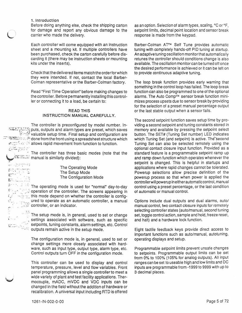
1. Introduction Before doing anything else, check the shipping carton for damage and report any obvious damage to the carrier who made the delivery.
Each controller will come equipped with an instruction sheet and a mounting kit. If multiple controllers have been purchased, check the carton carefully before discarding it (there may be instruction sheets or mounting kits under the inserts}.
Check that the delivered items match the orderforwhich they were intended. If not, contact the local BarberColman representative or the Barber-Colman factory.
Read "First Time Operation" before making changes to the controller. Before permanently installing this controller or connecting it to a load, be certain to :
READ THIS INSTRUCTION MANUAL CAREFULLY.
The controller is preconfigured by model number. ln~~ki.:;.:..:.~_':::~ puts, outputs and alarm types are preset, which saves
~~- : · ,:'/· valuable setup time. Final setup and configuration are ::..-· ~~w.-;.::::·:· : . . ;:.::: done from the front using a spreadsheet structure which
.... , _. _.~.- : !_ <·- > allows rapid movement from function to function.
.~~~ :::~. / ~·,~ ~- .;· . · The controller has three basic modes (note that the
\._,;.l3:::7.:-~~:· manual is similarly divided}: .1-
,_. .. : . :' ... : ;
r, ... · .l. ··. . ~
;~·:. : - . _· -· .-:. ;
The Operating Mode The Setup Mode The Configuration Mode
·• . . . · .·· · ·.· The operating mode is used for ·normal" day-to-day
·~ · ·._ :· · __ : ·: .. . ;= operation of the controller. The screens appearing in ;:~: ···. :: · .. : _ this mode depend on whether the controller is config.. .. . .. , .. _ ured to operate as an automatic controller, a manual
:,..._·;,,\ controller, or an indicator.
.... : .. The setup mode is, in general, used to set or change ' · .. .. ·, settings associated with software, such as specific :..;.:: :.:. . .. , . . setpoints, tuning constants, alarm settings, etc. Control
-· · · outputs remain active in the setup mode.
The configuration mode is, in general, used to set or change settings more closely associated with hardware, such as input type, output type, alarm type, etc. Control outputs turn OFF in the configuration mode.
This controller can be used to d isplay and control temperature, pressure, level and flow variables. Front panel programming allows a single controller to meet a wide variety of plant and test facility applications. Thermocouple, mADC, mVDC and VDC inputs can be changed in the field without the addition of hardware or recalibration. A universal input including RTD is offered
1261 -IN-002-0-00
as an option. Selection of alarm types , scaling, oc or °F, setpoint limits, decimal point location and sensor break response is made from the keypad.
Barber-Colman A~ Self Tune provides automatic tuning with completely hands-oH PID tuning at startup. An adaptive tuning oscillation monitor that automatically retunes the controller shou ld conditions change is also available. The oscillation monitor can be turned off once the desired performance is achieved or it can be left on to provide continuous adaptive tuning.
The loop break function provides early warning that something in the control loop has failed. The loop break function can also be programmed to one of the optional alarms. The Auto Compnc sensor break function minimizes process upsets due to sensor break by providing for the selection of a preset manual percentage output or the last stable output when a sensor fails.
The second setpoint fu nction saves setup time by providing a second setpoint and tuning constants stored in memory and available by pressing the setpoint select button. The SET# (Tuning Set number} LED indicates which Tuning Set (and setpoint) is active. The'-second Tuning Set can also be selected remotely using the optional contact closure input function. Provided as a standard feature is a programmable setpoint ramp up and ramp down function which operates whenever the setpoint is changed. This is helpful in startups and applications where rapid changes cannot be tolerated. Powerup selections allow precise definition of the powerup process so that when power is applied the controllerwill powerup in either automatic control, manual control using a preset percentage, or the last condition of automatic or manual control.
Options include dual outputs and dual alarms, auto/ manual control, two contact closure inputs for remote ly selecting controlle r states (auto/manual, second tun ing set, toggle control action, sample and hold, freeze reset, and halt} and a hardware lock function.
Eight tactile feedback keys provide direct access to important functions such as auto/manual, autotuning, operating displays and setup.
Programmable setpoint limits prevent unsafe changes to setpoints. Programmable output limits can be set from 0% to 100% (105% for analog outputs}. All input ranges can be set to useable high and low limits and DC inputs are programmable from -1999 to 9999 with up to 3 decimal places.
Page 5 of 72

One ?-segment LED (green) shows Tuning Set # (and setpoint) or Ramp Status
Eleven 3 mm diameter LED annunciators:
Barber-Colman@
sv
Four ?-segment LEOs (orange) for process value (PV) display
Four ?-segment LEOs (green)
(
Out 1 (green) Out 2 (green) Aim 1 (red) Aim 2 (red) Prog (green) Auto (green) Man (yellow) AT (yellow) LBIHBO (red) •c (green) RS (green)
SETW PROG our 1~ - ,-, a ,....,
for setpoint value (SV) display
B. arr"' - Ll. Ll. Ll. ue ~
Out 1% (LED dash) Out 2% (LED dash) f----./
Eight Tactile Keys : Auto-Tune/Function Auto/Manual Display Setpoint Select Set Up Up Arrow Down Arrow Run/Hold
"~2:~~ .. ~~-~·:~~~ ... · .. -- ---~
'----- -----------------------------------'····.--7,: ·· .. : ~'
Figure 2.1 The Front of the Controller ..,.- - . .. ;:. .. _ ...
2. First T ime Operation Before permanently installing this controller or connecting rt to a load, proceed through this instruction manual in an orderly manner:
A. Go to the section of this manual labeled "Wiring the Controller." Follow the instructions given there for wiring the controller to a suitable power supply. DO NOT connect input wiring or output wiring atthe present time.
Note that the controllerw/JJ be shipped "as ordered" by the model number.
B. Go to the section of the manual labeled "Output Configuration: Follow the instructions given there for entering the Output Configuration mode. Check that the controller model number (on the side of the case and listed in the section "Controller Model Number") is in agreement with your application (Output Signal Low and High are the only changes possible).
C. Go to the section of the manual labeled "Input Configuration." Follow the instructions given there for entering the Input Configuration mode. Check that the controller model number (on the side of the case and listed in the section "Controller Model Number") is in agreement wrth your application.
D. Go to the section of the manual labeled "Alarm Configuration." Follow the instructions given there for entering the Alarm Configuration mode. Check that the controller model number (on the side of the case and listed in the section "Controller Model Number") is in agreement with your application.
1261-IN-002-0-00
E. Go to the section of the manual labeled "Contr;i(:::.- · .\ . -:'.~:. ·: . Configuration." Follow the instructions given there for ::·_.-.- .. · entering the Control Configuration mode. Check that the ~- ... ~ . - .: controller model number (on the side of the case and ~ . ·. listed in the section "Controller Model Number") is in ~. ··· .\.., agreement with your application. "·· ·
F. Go to the section of the manual labeled "Loop .:. Configuration." Follow the instructions given there for ::: . entering the Loop Configuration mode. Check that the .:. · · · ~· . controller model number (on the side of the case and .. - .:· · .-,: ~ listed in the section "Controller Model Number") is in · .. · · agreement with your application. ~ ~-- :. ,.
G. Go to the section of the manual labeled "Input Setup." ;:~: ---~:· ·· . . Follow the instructions given there for entering the Input -~ ·• Setup mode. Make any changes necessary for your appl ication (pay attention to engineering units).
H. Go to the section of the manual labeled "Control Setup." Follow the instructions given there for entering the Control Setup mode. Make any changes or entries necessary for your application.
I. Go to the section of the manual labeled "Loop Setup." Follow the instructions given there for entering the Loop Setup mode. Make any changes or entries necessary for your application.
J. Go to the section of the manual labeled "Autotu ne Setup." Follow the instructions given there for entering the Auto tune Setup mode. Make any changes or entries necessary for your application.
Page 6 of 72

•
t: ~3 .. ~ ., ..... · ... - ;.;· ...
• . ,
l ~· · :--.... : .. · .. ~ ··'": .. . . · .... ;
·- . .. ·· :.-~~ ,·. ~ .. "
I ..
~
!
' '
.
. · · . . . ..
/
. .
Ol1T 1 •
OUT 2 •
AUol 1 e AUol 2 •
PROG e AUTO e IUH.
ATe
lB / HBO • 'C. RSe
Table 2.1 Status Annunciators
Out 1 (green) is lit when Output 1 is ON
Out 2 (green) is lit when Output 2 is ON
Aim 1 (red) flashes (lit steadily if acknowledged) when Alann 1 is ON
Aim 2 (red) Rashes (lit steadily if acknowledged) when Alann 2 is ON
Prog (green) is lit when a Ramp/Soak program is running (not presently used)
Auto (green) is lit when the controller is In the Automatic control mode
Man (yellow) is lit (flashes if by Contact Input) when the controller is in the manual (% out) control mode
AT (yellow) is lit while automatic tuning is taking place: flashes if tuning fails
LBIHBO (red) flashes when a loop break or heater burnout occurs
Degrees C (green) is lit when temperature is being displayed in Celsius
AS (green) is lit when remote setpoint is functioning (not presently used)
OUT 1% Out1% (green dash) is lit when SV display is showing Output 1 percent out
OUT 2'1. - Out2% (green dash) is lit when SV display is showing Output 2 percent out
Table 2.2 Key Functions
KEYS Operating Mode Setup Mode Configuration Mode
Cancels "startup· automatic tuning Steps the cisplay through a particu· Steps the display through a particu-constants. (Press again tore-initiate Jar setup function. Once in the Setup Jar configuration function. Once in
~~UT~TUNE)] tuning). mode, press the Setup key repeat- the Configuration mode, pras.s the
FVNCTlON edly to reach the proper setup tunc- Setup key repeatedly to reach the lion (e.g., ·nm1"). Then use this kay proper configuration function (e.g ., to step through the function. "SEC"). Then use this key to step
through the function.
[( AUTO Jl Toggles the controller between Au- Not Used. In Calibration, initiates tomatic and Manual(% Out) control. calibration of input signal. IIANUAL
(8) Steps through a loop of operating Returns the controller to the Returns the controller to the displays: Setpoint, % Out (heating operating mode. operating mode. and/or cooling), Second Setpointand Deviation from Setpoint.
Toggles the controller between Steps the dsplay backward through Steps the display backward through Setpoint and Tuning Constants 1 (a a particular setup function (like the a particular configuration function
((ss~~] "1" is displayed on the small 7-seg- function key in reverse) . (like the function key in reverse) . ment display) and SetpointandTun-ing Constants 2 (a "2" is displayed on the small 7-segment display) .
Steps the controller through two dif- Steps the controller forward one Steps the controller forward one ferent modes. Press (and release) Setup functional group. Configuration functional group.
EJJ and the controller goes to Setup (SETU) mode. Press (and hold 4 seconds) and the controller goes to Configuration (CONF) mode. Out-puts are ON in Setup. Outputs are OFF in Configuration.
During Automatic control, pressing Increases/decreases the Setup pa- Increases/decreases the Configu-
[@) an arrow key Increases ordeaeases rameter on display or selects a mode ration parameter on display or se-the control setpoinl During Manual of operation for a Setup parameter. lects a mode of operation for a Con-control, pressing an arrow key in- With a numeric display, the longer figuration parameter. With a numeric
OOJ creases or decreases the percent an arrow key is pressed, the faster display, the longer an arrow key is output. With a numeric display, the the rate of change. pressed, the faster the rate of longer an arrow key is pressed, the change. faster the rate of change.
~ Not presently used. Steps the controller backward one Steps the controller backward one
Setup functional group (like the Setup Configuration functional group (like 0
key in reverse). the Setup key in reverse).
1 261 -IN-002-0-00 Page 7 of 72

K. Go to the section of the manual labeled "Tuning Set 1 and 2 Setup." Follow the instructions given there for entering the Tuning Set 1 (or 2) Setup mode. Make any changes or entries necessary for your application.
L. Go to the section of the manual labeled "Alarm Setup." Follow the instructions given there for entering the Alarm Setup mode. Make any changes or entries necessary for your application.
M. Go to the section of the manual labeled "Security Configuration." Follow the instructions given there for entering the Security Configuration mode. Make any changes or entries necessary for your specific needs.
N. Once the controller is configured and setup to your specific control needs, go to the section of the manual labeled "Installing the Controller" and prepare the panel for controller installation.
0. Return to the section of the manual labeled "Wiring the Controller'' and complete whatever wiring is necessary for your specific needs.
P. Once the controller is connected to a load and power is applied, make certain to observe both the controller and the load until you are certain that the controller is operating properly and is indeed in control of the load.
3. Installing the Controller The installation kit contains the following parts:
Oty. Description 1 Front Gasket
Rear Gasket 2 Mounting Brackets 2 Mounting Screws
Instruction Sheet
Part Number 27-269 27-271 13-5156-100 11-3906 1261-MF-001-0-XX
106.7mm maximum case depth (4.20" maximum case depth)
+
Note that waterproof installations
92mm. +0, -1mm square (3.622", .o. -.039" square)
require cutout of 90.63mm, ±.38mm square (3.563", ±.015' square)
Figure 3.1 Single Instrument Cutout
1261-IN-002-0-00
Make certain that the surrounding environment conforms to the controller specifications regarding temperature (0°C to 55°C; 32°F to 131°F) and humidity (1 0% to 95% RH, non-condensing).
Follow all applicable local and national electrical codes during Installation.
Cutouts Make any cutouts as shown in figure 3.1 and 3.2. Remove any sharp edges or burrs from the openings. To make the installation easy and to avoid heat buildup, allow as much room as possible between openings.
Installation There are two gaskets included with this installation kit. One is meant to be installed between the controller and the case (the controller must first be removed from the case). The other is meant to be installed between the case and the panel.
In order for the controller to pass IEC IP65 dust and water protection specifications, both gaskets MUST be installed (in fact, it is recommended to install the gaskets even if they are not "required") . Follow this procedure :
r:: ~ · ..,... r· ...:.... ,;..' . : .:: . .
1. Use a medium-sized, flat bladed screwdriver to loosen (until the threads disengage) the screw at the TOP of the controller face.
. ; , .. : .. 1· ·,'' · ' I .• • , •'
2. Use the screwdriver to rotate the screw at the BOT- ~::_ ~_- . .J TOM of the face in a counterclockwise direction. This •· · ·· ··
r-~··:: will cause the controller to be ejected from the case. , .. . Once the jackscrew is free (and the controller is clear ~· .. . _ · of its contacts) , remove the controller from the case. ~-:- ..
3. Carefully remove the gaskets from their cardboard t.?-.~~- . protector. The front gasket has an adhesive coating ~-:!:! . :·· : ·.
1% . ,, .. · ~· "":,' '· . ·_ ~ .
+ + ---+--,---
+
102.4mm ~(4.030")~
minimum
120.6mm (4.750")
minimum
Figure 3.2 Multiple Instruments Spacing
Page 8 of 72
.. . . . - ... . .. . l .. ".::.i--:~~- .
. I
I ~
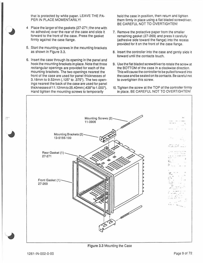
that is protected by white paper. LEAVE THE PAPER IN PLACE MOMENTARILY!
4 Place the larger of the gaskets (27-271; the one wijh no adhesive) over the rear of the case and slide ij forward to the front of the case. Press the gasket firmly against the case flange .
5. Start the mounting screws in the mounting brackets as shown in Figure 3.3.
6. Insert the case through its opening in the panel and hook the mounting brackets in place. Note that three rectangular openings are provided for each of the mounting brackets. The two openings nearest the front of the case are used for panel thicknesses of 3.18mm to 9 .52mm (.125" to .375"). The two openings nearest the back of the case are used for panel thicknesses of 11 .12mmto 25.40mm (.438"to 1.000") . Hand tighten the mounting screws to temporarily
Front Gasket (1)----27-269
hold the case in position, then return and tighten them firmly in place using a flat bladed screwdriver. BE CAREFUL NOT TO OVERTIGHTEN!
7. Remove the protective paper from the smaller remaining gasket (27-269) and press it carefully (adhesive side toward the flange) into the recess provided for it on the front of the case flange.
8. Insert the controller into the case and gently slide it forward until the contacts touch.
9. Use the flat bladed screwdriver to rotate the screw at the BOTIOM of the case in a clockwise direction. This will cause the controller to be pulled forward into the case and be seated on its contacts. Be careful not to overtighten this screw.
10. Tighten the screw at the TOP of the controller firmly in place. BE CAREFUL NOT TO OVERTIGHTEN!
·· . ....... , .. ""'' - -.
,. ,.
:- ....
. - . ·:. ' ·
I .' .• • . . . ' . .. ..
! - ·-'•
. ' , · . . . ... . . - .
Figure 3.3 Mounting the Case
1261-IN-002-0-00 Page 9 of 72

4. Wiring the Controller Observe all Local and National Wiring Codes.
Wire using #6 ring lugs and up to 14 AWG stranded wire maximum or wire using 16 AWG stranded wire maximum.
4.1 Power Supply Wiring Check Field 12 of the 15-digit controller model number (see the label on the side of the case) .
A "0" indicates the controller is equipped with the standard universal (85 to 264 VAC, 48/62 Hz) power supply.
Power Supply
CD EARTH GROUND
SUPPLY 85 TO 264 VAC
G) L1 50 to 60 Hz
XXXX·XXXXX·XXO-X-XX L-----85 to 264 VAC
Earth Ground _......;..._.,_H
l2-----H-2
L1----4+-3
Earth Ground
wire to Machine or Chassis Ground
4.2 Control Output 1 Wiring Check Field 4 of the 15-digit controller model number (see the label on the side of the case) . A "1" in Field 4 indicates the controller is equipped with a Form C Relay for Control Output 1. In this case, Output 1 occupies Slot 3 (and Slot 4)(Terminals 4, 5 and 6) of the controller. Any other kind of Control Output 1 would occupy Slot 1 (Terminals 9 and 10) of the controller.
Control Output 1 Relay
HC~ SI..OT4
c Sl..-;3 i Ho@--l
2A 12!11240 VAC
XXX1-XXXXX-XXX-X-XX Fonn "C" Relay J Output 1, Slot 3 (and 4)
XXXO-XXXXX-XXX-X-XX Output 1 T
1 = Relay (Fonn C)
l2 ~, ·§I L...---5§
,~---6§
2A, 240 VAC resistive max. load
(shown wired to NO contact}
w.-=. :· .. ~;-::-'''"•,
E.:,:~:: ·. :: ·:_ :~
cr:-:-: ·:· .:·; ·: r·· :. ·:·: ·: ... ~:.· r··.=~·~·~: :·::.· .. :~:~ .... . t ·. C ... .- - r ·.
f. .- .·:
f ... 1:' •
'· [" .. .,. . . ~ -·
E i.e
r;·_ ~.
.... .
Control Output 1 DC, Triac, Pulse DC
®+ SI..OT1
v = Indicator (No Output) 2 = Pulse Non-Contact Voltage for SSR (12 VDC) 3 = Current (4-20 rnA)
T =Triac L2 l1
=r===,:::ll @-
2 = 12 VDC for SSR
Solid State + Relay
1K0hm minimum load
1261-IN-002-0-00
4 = Voltage (0.10 VOC) T = Triac (24-260 VAC, 1 A}
3 =Current
Current Device
+
600 Ohm maximum load
1A, 240 VAC resistive max. load
SOmA minimum load
4 =Voltage
Voltage Device
+
1K Ohm minimum load (current limited to 30 mA max.)
Page 10 of 72

&::.;.;... .· ... · .. '.:
c· : ~->· · ...... f.. .: .. ··, .. · t~ ·.:_ .:: :.-·::: ,.-:· .. :·:·: · ........ .
...... : . . :-·.-.::·· ····· ··:
r:·· . ... : .
4.3 Control Output 2 Wiring Check Field 5 of the 15-digit controller model number (see the label on the side of the case) . A "0" in Field 5 indicates the controller is NOT equipped with a second Output. If an Output 2 exists, it will occupy Slot 2 (Terminals 7 and 8) of the controller.
Control Output 2 DC, Triac, Pulse DC
0+ SLOT2
®-
Control Outpu t 2 Relay
XXXX-9XXXX-XXX-X-XX Output 2 ----J-1 = Form A Relay 2 = Pulse Non-Contact Voltage for SSR (12 VDC) 3 = Current (4-20 mA) 4 = Voltage (0-10 VDC) T = Triac (24-260 V AC, 1 A)
L2 L1
:....------:::1 2A, 240 VAC resistive max. load
(NO contact)
T =Triac L2 L1
1...------:11 1A, 240 VAC resistive max. load
SOmA minimum load
2 = 12 VDC for SSR 3 =Current 4 =Voltage
Solid State + Relay
1KOhm minimum load
Current Device
+
600 Ohm maximum load
7JID 8~
Voltage Devlca
+
1 K Ohm minimum load (current limited to 30 mA max.)
r.: · · . .. 4.4 Contact Input Wiring l" , ~ · . .· Check Field 10 of the 15-digit controller model number (see the label on the side of the case) . r:-· · .. · :_·, .. --~ A ·o· in Field 10 indicates the controller is NOT equipped with the dual contact closure option.
C .
r::~ ..
. . . . A "1" in Field 10 indicates the controller is equipped with the dual contact closure option. .:., .. : . . · .. The contact closure option always occupies Slot 7 (Terminals 31, 32 and 33) of the controller .
. ··~·' Refer to Input Configuration . . ' .. · -~--~
Contact Closures
CC1 ®----~ CC2 '<!;!;I----
SLOT7
33 cow
XXXX-XXXXX-1 XX-X-XX ....__ ____ Contact Closure
131 -'- I Contact 1 32
33
---'----1 Contact 2 ____ __..._ Common
6.5 VDC nominal open circuit voltage between Common (Terminal 33) and Terminals 31 & 32. Maximum resistance (lead resistance plus contact) Is 200 Ohms.
Note that contacts are assumed to be Normally Open, but opening or closing the contacts Initiates a change (see Input Configuration).
1261 -IN-002-0 -00 Page 11 of 72
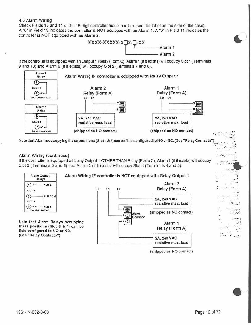
4.5 Alarm Wiring Check Fields 13 and 11 of the 15-digit controller model number (see the label on the side of the case) . A "0" in Field 13 indicates the controller is NOT equipped with an Alarm 1. A "0" in Field 11 indicates the controller is NOT equipped with an Alarm 2.
XXXX-XXXXX-XOX-D-XX 1 L..-----Aiarm 1
L--------Alarm 2
If the controller is equipped with an Output 1 Relay (Form C), Alarm 1 (if it exists) will occupy Slot 1 (Terminals 9 and 1 0) and Alarm 2 (if it exists) will occupy Slot 2 (Terminals 7 and 8).
Alarm 2 Relay
s~ ~j
2A 12012-40 VAC
Alarm1 Relay
Alarm Wiring IF controller Is equipped with Relay Output 1
Alarm 2 Alarm 1 Relay (Form A) Relay (Form A) l2 l1 l2 L1
I 711 I
;I 8§ I
2A, 240 VAC 2A, 240 VAC resistive max. load resistive max. load
(shipped as NO contact) (shipped as NO contact) ~::-.~-.·~ · .. --·~ .. ~~-~
Note that Alarms occupying these positions (Slot 1 &2) can be fie ld configured to NO or NC. (See "Relay Contacts") . .0 0
• ·.'
0
-::·:~:· ~::::- .: . . . . . . -~
Alarm Wiring (continued) If the controller is equipped with any Output 1 OTHER THAN Relay (Form C), Alarm 1 (if it exists) will occupy Slot 3 (Terminals 5 and 6) and Alarm 2 (if it exists) will occupy Slot 4 (Terminals 4 and 5).
Alarm Output Relays
Alarm Wiring IF controller Is NOT equipped with Relay Output 1
Alarm 2
Note that Alarm Relays occupying these positions (Slot 3 & 4) can be field configured to NO or NC. (See "Relay Contacts")
L2 l1 L2
"'"""' §
Relay (Form A)
2A, 240 VAC resistive max. load
(shipped as NO contact)
Alarm 1 Relay (Form A)
2A, 240 VAC resistive max. load
(shipped as NO contact)
--~
..... ' ~·~::~ :-=· - .
C·
~ . :;:
..... ,
··: ··:
-.~ .. .. .-..
o•• -· .
.0 1261-IN-002-0-00 Page 12 of 72

---.. - . · ..
4.6 Control Input Wiring Check Fields 6 and 7 of the 15-digit controller model number (see the label on the side of the case). An "SF" or "SC" in these two fields indicates the controller is equipped with the optional universal input which includes RTD input (and has been shipped from the factory configured for an RTD input) . Note that wnh an "SF" or "SC" in Fields 6 and 7, the input type is field selectable to thermocouple, current, voltage, millivo~age or RTD (see Input Configuration). If anything other than "SF" or "SC" appears in Fields 6 and 7, the input type is field selectable to any input except RTD.
Input 1 always occupies Slot 5 (Terminals 37, 38 and 39) of the controller.
XXXX-XOOXX-XXX-X-XX Control Input 1 :r
RTD SF - PL T1 00 DIN, •F 8C- PL T1 00 DIN, •c
Control Input VOC, mVDC, TIC, mADC
@+ SLOT S
@-
Current and Voltage C1 - Current (4 to 20 mA) V1 - Vohage (0 to 5 VDC) V2 - Vohage (1 to 5 VDC) V3 - Vohage (0 to 10 VDC) V4- Voltage (Oto 100 mVDC) VS- Vottage(-10to 10mVDC) V6 - Vohage {0 to 10 mVDC)
Thermocouple KF - Type K, •F KC - Type K, •c JF- Type J, •F JC- Type J, •c EF - Type E, •F EC - Type E, •c RF - Type R, •F RC - Type R, •c SF - Type S, •F sc - Type s, •c 8F - Type 8 , •F 8C- Type 8, •c
PF- PL-11, •F PC- PL-11, •c CF - Type C, •F cc - Type c. •c NF- Type N, •F NC- Type N, •c MF - Ni/Ni Mo, •F MC- Ni/Ni Mo, •c TF - Type T, •F TC - Type T, ~c
- . -··'"' . , -~: Control Input
RTD
ALL Inputs EXCEPT RTD
RTD ONLY
.- • . ..
'- . . . _.; _ -_
;- ·-..,.. ... ·· . ... . I "" • ..... ..
~- .
:~::: SLOTS
@ RTOB
137
38-- + 39-- ~
37~RTDB 38 RTD A
39 RTD B
{Remove compensating resistor)
Note that the controller comes equipped with a temperature compensation resistor connected across Terminals 37 and 39. (R.mow RKiator)
This resistor should be left in place for all Input types {Including volts, millivolts and current) EXCEPT RTDs.
Keep ALL Thermocouple Wiring (or Input Sensor Wiring) Physically Separated from ALL other Wiring.
Although normal electrical interference on the sensor leads is effectively eliminated by internal fi~ers, high vo~age spikes and inductive transients coupled over
into the sensor circun may bypass the filter system.
WARNING! Hazardous Extraneous Voltage capable of causing Severe Injury or Death may exist between Thermocouple Leads and Ground. Disconnecting the Instrument
Power Source may not remove this Voltage. Measure for the presence of Voltage between each Sensor Lead and Ground Before Servicing.
1261-IN-002-0-00
Do NOT place power wiring and sensor wiring in either the same conduit or wiring trough.
If shielded thermocouple leads are used, the shields must be insulated electrically and terminated at one location, preferably
the chassis of the controller (Teminal #40) .
Page 13 of 72

C'T\. OUT 1' ~~,.....__, Oil I llfp.Y
NC:J .... ,.., .... ..,
:~
® + + +
~ ... .... .., -S~OT 1 DC, 1'\AM, Triac
@) - -
@ SI.OU
'Den OIIT 11111N S~OT 1, ~ AlliiN S~OTS l 6 '-0cnOIIT11111HSLOT l64
PLEASC SEE INSTRUCTION r.tANUAL FOR PROPER CONNECTIONS AS DEANEO BV MOOEL NUt.IBER IWlf IN USA
Figure 4.1 Controller Wiring Label
5. Jumper and Switch Locations
5.1 Hardware Security
c.:.::-;~ ·:·. : ... -::;. ~-,--:.;. . :··'''
7·.:~~ =,-.. .. , '
··- . . . -=-· ·· ... ·.--L_ .·~ . • . • . . . •
c. •• • ••
r c. ,;! v . • .. • .
-.
r :
' • . • I . •,
Check Fields 14 and 15 of the controller model number (see the label on the side of the case) . An "02" in Fields 14 and 15 indicates the controller is equipped with the hardware security option. If the hardware security option has been installed, the controller will have a switch (SW1) located on the "lnpuUCPU" board (see Figure 5.1 ) .
Use a non-metaJ/Ic object to change switch positions!
52 51
Open
Closed
~f Efl~
00
XXXX-XXXXX-XXX-X-02 L Hardware Security Option
D 0 0 0
Figure 5.1 Hardware Security Switch Location
52 51 Action Open Open Software Lock Only (as shipped) Open Closed Partial Hardware LockJarrow k~s functionl Closed Open Total Hardware Lock (keypad totallydisabled) Closed Closed Software & Hardware Lock both OFF (no securi!l')
Table 5.1 Hardware Security Switch Positions
.:....
1261-IN-002-0-00 Page 14 of 72

{
4_.. .. , •.. ·--~- . -·
. . •.
--
--~~- ~;:·_~
.. .
·-
...... _ . , . .. -~ -,
. -.~ - . .., .. . .. .. : • :-·:
l -
5.2 Relay Contacts Check Field 4 of the 15-digit controller model number (see the label on the side of the case). A "1" in Field 4 indicates the controller is equipped with a Form C Relay for Control Output 1. In this case . Alarm1 (if present) occupies Slot 1 (Terminals 9 and 1 0) of the controller. Output 2 (if present) or Alarm 2 (if present) occupies Slot 2 (Terminals 7 and 8). Note that the controller can NOT have a Form C Relay Output 1 and both an Output 2 (of any kind) and an Alarm 2 . Alarm 1 and/or Alarm 2 can be switched from NO to NC. Note that if Relay Output 2 occupies Slot 2 it can NOT be changed from NO to NC (shipped NO).
XXX1-XXXXX-XXX-X-XX Form "C" Relay Output 1 __ -JT
Alarm 1 Relay (if present)
Output 2 (if present) or Alarm 2 (if present). If Alarm 2 is here, it can be switched from NO to NC as shown.
Toggle Switch for NC operation
Figure 5.2 Relay Switch Positions
(continued next page)
Toggle Switch for NO operation
Relay Contacts (continued) 'If Field 4 has any character other than a "1 ·(Form C Relay), Alarm 1 (if it exists) will occupy Slot 3 (Terminals 5 and 6) and Alarm 2 (if it exists) will occupy Slot 4 (Terminals 4 and 5) . Alarm 1 and/or Alarm 2 can be switched from NO to NC by relocating the jumpers shown in Figure 5.3 below .
XXX[}XXXXX-XXX-X-XX Any Character except "1"-----'
f!lNO NO[!l
/r~~~~~~~ Alarm 1 ~ /Alarm 2
K1
Figure 5.3 Alarm Relay Jumper Locations
1261-IN-002-0-00 Page 15 of 72
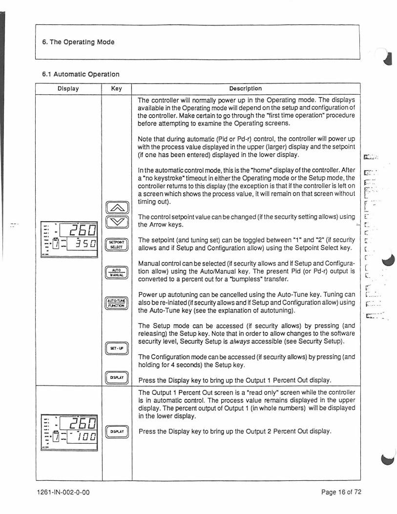
6. The Operating Mode
6.1 Automatic Operation
Display Key
1261-IN-002-0-00
Description
The controller will normally power up in the Operating mode. The displays available in the Operating mode will depend on the setup and configuration of the controller. Make certain to go through the "first time operation" procedure before attempting to examine the Operating screens.
Note that during automatic (Pid or Pd-r) control, the controller will power up with the process value displayed in the upper (larger) display and the setpoint (if one has been entered) displayed in the lower display. E;L.:,::
In the automatic control mode, this is the "home" display of the controller. After a "no keystroke" timeout in either the Operating mode or the Setup mode, the controller retums to this display (the exception is that if the controller is left on a screen which shows the process value, it will remain on that screen without timing out).
The control setpoint value can be changed (if the security setting allows) using
c:~· . ·
r.:: ~~ [- .. r .. .. L .. E ..
the Arrow keys. -'- i.'.
The setpoint (and tuning set) can be toggled between "1" and "2" (if security allows and if Setup and Configuration allow) using the Setpoint Select key.
Manual control can be selected (if security allows and if Setup and Configuration allow) using the Auto/Manual key. The present Pid (or Pd-r) output is converted to a percent out for a "bumpless" transfer.
Power up autotuning can be cancelled using the Auto-Tune key. Tuning can also be re-iniated (if security allows and if Setup and Configuration allow) using the Auto-Tune key (see the explanation of autotuning).
The Setup mode can be accessed (if security allows) by pressing (and releasing) the Setup key. Note that in order to allow changes to the software security level, Securtty Setup is always accessible (see Securtty Setup).
The Configuration mode can be accessed (if security allows) by pressing (and holding for 4 seconds) the Setup key.
Press the Display key to bring up the Output 1 Percent Out display.
The Output 1 Percent Out screen is a "read only" screen while the controller is in automatic control. The process value remains displayed in the upper display. The percent output of Output 1 (in whole numbers) will be displayed in the lower display.
Press the Display key to bring up the Output 2 Percent Out display.
Page 16 of 72
( r ... (
["
' t .
l.
r·· r. . L ••.. • • . •
r .. :. _: . c:· ~- -~

•
E.G:.: .. . - ·~ ·.
EE;·.-~ .. . :: f"?:::: :: f~·. . ..· . t:.- ··.~·· . . f!:··· .. ·::· ~ .. ·.
-- L. ~· .. · .. :.__ ..
...
~ ~:...,. ·:
~(~
~r.:··. ·. :-· ....
!i:':. ·. :-.~: r . .-... : ... ,
.. ~.~<·. : .. ···.
.. -:: ...
'
.
The Operating Mode (continued)
Automatic Operation (continued)
Display Key Description
The Output 2 Percent Out screen is a "read only" screen while the contro ller
-· :j2"EQ is in automatic control. This display will only appear if the controller is equipped -· -· B with the optional Output 2. The process value remains displayed in the upper
~·(j :i-.
n display. The percent output of Output 2 (in whole numbers) will be displayed u in the lower display.
~·-
Press the Display key to bring up the Setpoint Ramp display.
The Setpoint Ramp screen appears only if the Setpoint Ramp function has :: :~?so been enabled (see Loop Setup). The upper display will show the process value
~·tj :1 . and the lower display will show the setpoint as it ramps either up or down gso according to the ramp rate settings (see Loop Setup). The Set# display will
·- BJ show an "r." Note that if the setpoint is not currently ramping to a different
I ~t{ql setting, the present set point wiff appear on the lower display. Note also that on power up, this display will ramp from the process value to the present set point.
I ~ Lf Bl Press the Display key to bring up the Setpoint display. ~
I :1 4 71
The Setpoint screen is used to display the "other" local setpoint. If Setpoint
Q§J) (and Tuning Set) 1 is in control (a "1" showing in the Set# display), then
:: : rs p· 2 Setpoint 2 wiff be displayed here.lf Setpoint (and Tuning Set) 2 is in control (a
(W) "2" showing in the Set# display). then Setpoint 1 will be displayed here.
~·Lfl-:1 . 2 75 The arrow keys can be used to increase or decrease whichever setpoint is .
BJ ·- displayed.
Press the Display key to bring up the Deviation display .
The Deviation screen is a ·read only" screen used to display the difference (in
:: ~f -·qn engineering units) between the process value and setpoint. A negative _, - u
BJ number indicates that the process value is below setpoint by the amount
~·[j~d E u displayed. A positive number (no sign) indicates that the process value is above setpoint by the am<>unt displayed.
~-
Press the Display key to return to the normal automatic control screen.
This screen will remain on display during normal operation as an automatic -· :12.ETI controller. -· -· ~·lj ~I j50
w-
1261-IN-002-0-00 Page 17 of 72

The Operating Mode (continued}
6.2 Manual Operation
Display
~~ :r r:rsu ~. [j : j,__: ---40
~~:o=l-. ol otpo-.-up _ D Dual Ou1pvt 1- . I
Kay Description
The controller will normally power up in the Operating mode. The displays available in the Operating mode will depend on the setup and configuration of the controller. Make certain to go through the •first time operation· procedure before attempting to examine the Operating screens.
Note that during manual (percent out) control, the controller will power up with the process value displayed in the upper (larger) display and the percent out displayed in the lower display. The percent output at power up is determined by the manual percent preset setting. Note that switching outputs (relays, triacs or SSR's) will be converted to time proportioning based on the manual percent out set here and the Cycle Time setting (default cycle time is 30 seconds- see Tuning Set 1 & 2 Setup).
cJ
r;z;.:.::~ .: .. -
£":1~ ::~ . : ..
~-~::-:- -: . : :
r-:..,_~-~~·~1::.:~ ,.
r•-- ... . <.:. . ~- .
The percent output can be changed (if the security setting allows) using the Arrow keys. Note that if manual control has been initiated by means of the optional contact input function, it will NOT be possible to change the percent output using the Arrow keys. ~ t.. ·
('._: .
1261-IN-002-0-00
Automatic control can be selected (if security allows and if Setup and Configuration allow) using the Auto/Manual key. Note that if manual control has been initiated by means of the optional contact input function, it will NOT be possible to switch to automatic control using the Auto/Manual key.
The Setup mode can be accessed (if security allows) by pressing (and releasing) the Setup key. Note that in order to allow changes to the software security level, Security Setup is always accessible (see Security Setup).
The Configuration mode can be accessed (if security allows) by pressing (and holding for 4 seconds) the Setup key.
This screen will remain on display during normal operation as a manual controller.
Page 18 of 72
r · \ ', ,
[ -. : ·
,. ~ .. (':. •.
~--
~ · / f,.. • ••
(_"" ' -

•
e.::..: . .-.,· .. ·.':': .. :.'
..... ,. ~ . . . . ·:~· . . :..: .. :.. . .:. . · .. · '
!. o..l'
' t' . . . .... - .-
':" ' . .
• ••• r · .. [ :· ·-
r .. . . ; t/ . .. . ... . -
..... · ' · ....
f " ..... ,, c: . . ·
.... ·. r:::.:~ ·- ·_ .·.' .. ·'
•
The Operating Mode (continued)
6.3 Indicator Operation
Display Key Description
The controller will normally power up in the Operating mode. The displays available in the Operating mode will depend on the setup and configuration of the controller. Make certain to go through the "first time operation" procedure before attempting to examine the Operating screens.
Note that during indicator operation, the controller will power up with the process value displayed in the upper (larger) display and nothing disp layed in the lower display. The single seven segment display will also be blank.
The Setup mode can be accessed (if security allows) by pressing (and
-· : r 2EO releasing) the Setup key. Note that in order to allow changes to the software -· security level, Security Setup is always accessible (see Security Setup). -· EJJ ~ L1=i -The Configuration mode can be accessed (if security allows) by pressing (and
w•- holding for 4 seconds) the Setup key.
Note that the controller can be purchased as an indicator only (with no outputs) or the control algorithms can both be set to "none" (see Control Configuration). As an indicator, any control outputs will be set to the "off" condit ion. Every key on the keypad is disabled in the Operating mode except for the Setup key .
Any currently configured process alarms will continue to operate. Any currently configured deviation alarms will cease to exist (since there are no control setpoints from which to deviate). Any currently configured loop break alarms will cease to exist (since there are no control loops to be broken) .
This screen will remain on display during normal operation as an indicator.
1261-IN-002-0-00 Page 19 of 72

7. The Setup Mode
r;-E"~ SeOJrity System Loop Control AutoTune Tuning Tuning Input Set 1 Set2
Alarm
s E c lis Y s IlL .0
Security -----1
Password
Sy~em ---------~ Software Version/Revision
Loop ---------------------' Setpoint Source Setpoint Select Key Enable Auto/Manual Key Enable Powerup Type Setpoint Ramp Enable Ramp Rate Up Ramp Rate Down
Control ---------------_J Setpoint Low Limit Setpoint High Limit Hysteresis Out 1 Minimum Power Out 1 Maximum Power Out 1 Slew Fitter Out 1 Hysteresis Out 2 Minimum Power Out 2 Maximum Power Out 2 Slew Fitter Out 2 Manual Percent Preset
Autotune Autotune Type Autotune Response Adaptive Tune Enable
Tuning Set 1 ------------------------...J Setpoint 1 Proportional Band 1 Load Line 1 Reset (Integral) 1 Rate (Derivative) 1 Cycle Time 1 Spread 1 Proportional Band 2 Load Line 2 Reset (Integral) 2 Rate (Derivative) 2 Cycle Time 2 Spread 2
1261-IN-002-0-00
Figure 7.1 The Setup Loop
Input-
liRL r I
At ann Alarm Ack 1 Setting 1
, Hysteresis 1 Alarm Ack 2 Setting 2 Hysteresis 2 Loop Break
Type, Slot 5 Eng. Units, Slot 5 Sensor Correct, Slot 5 Filter Window, Slot 5 Dec. Locate, Slot 5
Tuning Set 2 Setpoint 2 Proportional Band 1 Load Line 1 Reset (Integral) 1 Rate (Derivative) 1 Cycle Time 1 Spread 1 Proportional Band 2 Load Line 2 Reset (Integral) 2 Rate (Derivative) 2 Cycle Time 2 Spread 2
Page 20 of 72
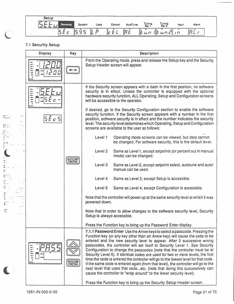
L
:.· .. ', 1 .. .
'
r """~ ...
r '-' ·.
~' .
r' r
'· c.· c
Setup
[SI}Lu"'ljii!IJ{•iji•l11,• system Loop
~ E c Jls 9 s IlL P Control AutcTune Tuning
Set 1 Tuning Set2 Input Alarm
IIRL r I 7.1 Security Setup
Display Key Description
From the Operating mode, press and re lease the Setup key and the Security -· :l I cOO -· Setup Header screen will appear. -· E] ~ ~:j!2DD f.--
If the Security screen appears with a dash in the first position , no software -· ~fSC";--· - ccu security is in effect. Unless the controller is equipped with the optional -· ~ L) :Is£ c -
hardware security function, ALL Operating, Setup and Configuration screens will be accessible to the operator.
··-If desired, go to the Security Configuration section to enable the software
lsE c sl security function. If the Security screen appears with a number in the first position, software security is in effect and the number indicates the security level. The security level determines which Operating, Setup and Configuration screens are available to the user as follows:
.. Level 1 Operating mode screens can be viewed, but data cannot
be changed. For software security, this is the default level.
Level 2 Same as Level1, except setpoints (or percent out in manual
~ mode) can be changed.
Level3 Same as Level2, except setpoint select, autotune and auto/ manual can be used.
Level4 Same as Level3, except Setup is accessible.
LevelS Same as Level4, except Configuration is accessible.
Note that the controller will power up at the same security level at which it was powered down.
Note that in order to allow changes to the software security level, Security Setup is always accessible.
Press the Function key to bring up the Password Enter display.
7 .1.1 Password Enter Use the Arrow keys to select a passcode . Pressing the Function key (or any key other than an Arrow key) will cause the code to be
(@) entered and the new security level to appear. After 3 successive wrong
:: :rpR"S S passcodes, the controller will set itself to Security Level 1. See Security
OOJ Configuration to change the passcodes (note that the controller must be at
~ L]:[ .
Security Level 5) . If identical codes are used for two or more levels, the first
~ time the code is entered the controller will go to the lowest level for that code. -- If the same code is entered again (from that level), the controller w ill go to the next level that uses that code ... etc. (note that doing this successively can cause the controller to "wrap around" to the lower security level).
Press the Function key to bring up the Security Setup Header screen.
1261 -IN-002-0-00 Page 21 of 72
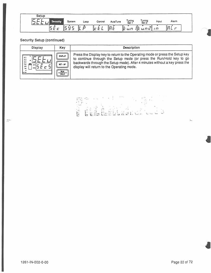
AutoTune Tuning Tuning Input Set 1 Set2
Alarm
Setup
f5I~Iu"l~II!IJ{•IJ'•j11,• system Loop Control
liRL r I s £ c Is 9 s IlL P
Security Setup (continued)
Display Key
8 -· :rsElu -· -· EJJ ~ [j :ls E c s ·- ~
1261-IN-002-0-00
Description
Press the Display key to return to the Operating mode or press the Setup key to continue through the Setup mode (or press the Run/Hold key to go backwards through the Setup mode). After 4 minutes without a key press the display will return to the Operating mode.
- ···: ,··· ,: ....... I ·, 1•
·' i..- .· t ·· t"".'
,, . .. .. ~
~~; ~;, :; :~~;.':'. LL ~- ,: L; \_, ~,; ~~ ~ : '-·· .· . . '- · · .... ·-· ....
Page 22 of 72
I

) 7.2 System Setup
Display Key Description
From the Operating mode, press and release the Setup key. :: :r 1200 E] Press the Setup key a second time and the System Setup Header screen will
~ !jj:jt2oo appear.
·-Note that there are presently no System Setup functions available to the user .
. ~=-c"~ System Setup does contain a ~read only" Software Version screen. :: · Sctu ~ Lj :js 9 5 ~ Press the Function key to bring up the Software Version screen.
·-7.2.1 Software Version/Revision The Software Version screen displays the
~f[f "~ - · I C version and revision level of the software included with the controller (in the :: · r: r S ~ LJ :j " ~ format VV.RR, where "VV" is the Version number and "RR" is the revision level
LDD of the Version) . --
·-Press the Function key to bring up the System Setup Header screen.
BJ Press the Display key to return to the Operating mode or press the Setup key
:: :rsE"t u to continue th rough the Setup mode (or press the Run/Hold key to go
~ Lj :js 9 5 E] backwards through the Setup mode). After 4 minutes without a key press the display will return to the Operating mode.
·- ~
1261-IN-002-0-00 Page 23 of 72

Setup f"Fr~~
I:J C J:: W Security System - Control
SEc llsfls l~kfL Auto Tune
l§f Tuning Tuning Input Set 1 Set 2
Alarm
7.3 Loop Setup
Display Key Description
From the Operating mode, press and release the Setup key. -· :r7?"11o -· -· a Press the Setup key two more times and the Loop Setup Header screen will ~ lj :[ /200 appear.
·-Loop functions include setpoint (tuning set) source, setpoint (tuning set) select
:: :rsE"t· u key enable, auto/manual select key enable, power up type, setpoint ramp 1 ..
~ LJ~IL P ~) enable, ramp up setpoint, and ramp down setpoint. ~
w·- Press the Function key to bring up the Setpoint Source display. 1-:-: .. 7.3.1 Setpolnt Source The Setpoint Source determines the controlling setpoint AND tuning constants. SP 1 is the default setting. Currently, the only ..
-· :[slo"~ (@) choices are SP 1 and SP 2. Choosing SP 1 causes the controller to use the ·-
-· setpoint and constants entered in Tuning Set 1 ("tun 1"). Choosing SP 2"'_ : -· causes the controller to use the setpoint and constants entered in Tuning Set ~ [j:[sP I [MJ -
2 ("tun 2"). Note that changing from SP 1 to SP 2 and vice-versa can also be 1-
W•- accomplished from the Operating mode (if setpoint select below is enabled).
jsP 21 ~ Note that the contact input function has priority over the Setpoint Source (see Input Configuration). Note that Tuning Set Limit may limit this function (see Loop Configuration). I
I .
Press the Function key to bring up the Setpoint Select Enable screen. r ·
7.3.2 Setpolnt Select Key Enable The Setpoint Select Key Enable screen ,· r
' determines whether or not the controller can be switched between SP 1 and ,.
-· : 1s~osL (@) SP 2 from the Operating mode. "Yes" is the default setting. Choosing "Yes" • -· -· causes the Setpoint Select key to function. Choosing "No" causes the Setpoint
~ [j -:[YEs ..
(M) Select key to not function. In the Operating mode, with Setpoint Select
w•- enabled, pressing the Setpoint Select key will cause the controller to toggle
In~ I ~ between Tuning Set 1 and Tuning Set 2. Note that Tuning Set Limit may limit this function (see Loop Configuration).
Press the Function key to bring up the Auto/Manual Key Enable screen.
7.3.3 Auto/Manual Key Enable The Auto/Manual Key Enable screen deter-mines whether or not the Auto/Manual key functions. This screen will not
(option) appear unless the option has been purchased. "No" is the default setting. Choosing •no• causes the Auto/Manual key to not function. Choosing "yes" -· :'A-nn (G&] allows the Auto/Manual key to function. In the Operating mode, with the Auto/ -· -· Manual key enabled, pressing the Auto/Manual key will cause the controller to
~ Lj:[n ~ (M] toggle between automatic (PID type) and manual (Percent Out) control.
W•- Individual LEOs on the controllerfrontwill indicate the type of control. Pressing
lYE s I ~ the Up or Down Arrow keys when in the manual mode will change the Percent Output of the controller (refer to the Operating mode). Note that the contact input function has priority over the Auto/Manual key (see Input Configuration).
Press the Function key to bring up the Powerup Type screen.
1261-IN-002-0-00 Page 24 of 72
(
_)

Alarm
l§i, I Loop Setup (continued)
Display Key Description
7.3.4 Powerup Type The Powerup Type screen determines the powerup mode oft he controller. · Auto" is the defau~ setting. Choosing "auto• causes the
:: :p,"u,o controller to power up in automatic (PID type) control. Choosing •man· causes
[~)) the controller to power up in the manual (Percent Out) mode (using the Manual
~ [j:lR ~ c D Percent Preset setting - see Control Setup) . Choosing "prev• causes the
(00) controller to power up in the mode in which it was powered down (either ~·- automatic or manual) .
In,; R nl ~ Note that if the controller is powered down in the Configuration mode, it will
IP;Eui then power up in the Configuration mode . Once the controller is put in the Operating mode, it will be in the "proper" type as determined by this variable.
Press the Function key to bring up the Setpoint Ramp Enable screen.
7.3.5 Setpolnt Ramp Enable The Setpoint Ramp Enable screen determines :: :rsp-, P [~J) whether or not the set point ramp function will execute when the control setpoint is changed. "No" is the defau~ setting. Choosing "no" causes the ramp fu~~ction
~ u:ln ~ ["V)) not to execute. Any setpoint change will be implemented as a "step· change.
- Choosing "yes" causes the ramp function to execute. Setpoint changes will
lYE s I ~ occur according to the Ramp Up or Ramp Down settings below.
Press the Function key to bring up the Ramp Rate Up setting screen.
[~)) 7.3.6 Ramp Rate Up The Ramp Rate Up setting determines the rate at which
-· :FP-uP the control setpoint will move from the present setpoint to a higher setpoint. -· ~· (00) Entry is in engineering units per minute. 9999 is the default setting. The range
~ Lj:iq q q q of the setting is from 1 to 9999 units per minute.
~ ~-- Press the Function key to bring up the Ramp Rate Down setting screen.
[~J) 7.3.7 Ramp Rate Down The Ramp Rate Down setting determines the rate at ~FP~ :: · Pdn which the control setpoint will move from the present setpoint to a lower
~ [j:[q q q q ["V)) setpoint. Entry is in engineering units per minute. 9999 is the default setting. The range of the setting is from 1 to 9999 units per minute.
- ~ Press the Function key to bring up the Loop Setup Header screen.
B Press the Display key to return to the Operating mode or press the Setup key
:: :rsE-t- u to continue through the Setup mode (or press the Run/Hold key to go
~Lj :~,6 B backwards through the Setup mode). After 4 minutes without a key press the display will return to the Operating mode.
~-- ~ rt: ~-'·-::, t~:· · ~:
~-..
t~: ~ .. ·:. ! .
I . '
1 261-IN-002-0-00 Page 25 of 72

Setup
~-~ Security System Loop AutoTune Tuning Tuning Input Set 1 Set2
Alarm
I§C , I s E c lis 9 s lk P
7.4 Control Setup
Display
:: :l/200 ~ [j:l /2 00
:: :rsP1 o ~ [j -:1 .: 7 5
~~ :IH ld 5 7 ~tj~
. I 1
··-
1261 -IN-002·0-00
Key Description
From the Operating mode, press and release the Setup key.
(( SET · UP ] Press the Setup repeatedly until the Contro l Setup Header screen appears.
(@ (00) (8)
The Control settings include setpoint low and high, Output 1 hysteresis, Output 1 minimum and maximum power, Output 2 hysteresis, Output 2 minimum and r- :· · .. · ·.-.. · ~ maximum power, and manual percent preset output.
Press the Function key to bring up the Setpoint Low Limit screen. f ·
'· 7.4.1 Setpolnt Low Limit The Setpoint Low Limit screen determines the ·. lowest setting the control setpoint can assume. The default setting will be the r Input Scale Low setting. The range will be from the Input Scale Low setting to :· the Setpoint High Limit. Note that whenever the Input type is changed, this r
setting changes to match the Input Scale Low setting of whichever input has~~ been chosen (see Input Configuration). :
Press the Function key to bring up the Setpoint High Limit screen.
7.4.2 Setpolnt High Limit The Setpoint High Limit screen determines the highest setting the control setpoint can assume. The default setting will be the Input Scale High setting. The range will be from the Setpoint Low Limit to the Input Scale High setting. Note that whenever the Input type is changed, this setting changes to match the Input Scale High setting of whichever input has been chosen (see Input Configuration}.
Press the Function key to bring up the Output 1 Hysteresis screen.
7.4.3 Output 1 Hysteresis The Output 1 Hysteresis setting determines the hysteresis applied to a switching Output 1. This screen appears only if Control Algorithm 1 is "on/off." The default setting is one (engineering unit). The range is 10% of the Input Scale (Input Scale High -Input Scale Low).
Hy.ter~sle
(Reverse Acting Output) Setpoint
I I
ON ~.. I
l OFF __ _j t , , I Hys I
Process Value
Hysteresle (Direct Acting Output)
SetpOint I I
Process Value
Press the Function key to bring up the Output 1 Minimum Power screen.
Page 26 of 72

(
c:. ~ .: .. :. - ~-- .:'.
~.- - ··
f-' ~ - . . . y ... .. ·~ . ~
.•.
.···· ·:·· .
..
.. ~ r J
.. ... ' \ ;...
. ~t: . -.
..
Setup
~~ Security System Loop · , ·I AutoTune Tuning 5&!1
Tuning Set2
Input At arm
SEc lis 9s gr ~~ f L I~ f ~~ ~ n I~ ~ n 211~ ,; IIRL r I
Control Setup (continued)
Display Key
(@) -· :prftL J -· ~· (00) ~·
[j :1 M - n - u -. ~ --
[~) -· ~ rp-,:"Ff' -· ~· .. r 1 (00] ~·
LJ-l - 1nn - I UU -. ~ ~--
[~) -· :1sL F I -· -· I (00) -· L1~1 - 100 --.
~ ~--
1261 -IN-002-0-00
Description
7.4.4 Output 1 Minimum Power The Output 1 Minimum Power setting determines the minimum demand percent allowed at Output 1 when using Pid or Pd-rcontrol. lf Control Algorithm 1 calls for a demand of less than this setting, this setting will be used as the output. This screen will not appear unless Control Algorithm 1 is Pid or Pd-r (see Control Configuration). If the Pid type for Control Algorithm 1 is FAN, the default setting is 20%; otherwise the default is 0%. The range is from 0% to the Output 1 Maximum Power setting.
Press the Function key to bring up the Maximum Power 1 screen.
7.4.5 Output 1 Maximum Power The Output 1 Maximum Power setting determines the maximum demand percent allowed at Output 1 when using Pid or Pd-r control. If Control Algorithm 1 calls for a demand of more than this setting, this setting will be used as the output. This screen will not appear unless Control Algorithm 1 is Pid or Pd-r (see Control Configurat ion) . The default setting is 100%. The range is from Output 1 Minimum Power to 100% (105% for an analog output) .
--
Press the Function key to bring up the Output 1 Slew Filter screen.
7.4.6 Output 1 Slew Filter The Output 1 Slew Filter setting limits the maximum change in demand from one update to the next. This screen will not appear unless Control Algorithm 1 is Pid or Pd-r (see Control Configuration). The default setting is 100%. The range is from 1% to 100%.
Note that the controller update time is approximately 150 milliseconds (so that a setting of 10% for the slew filter would cause a change in demand to be spread over 1.5 seconds).
Press the Function key to bring up the Output 2 Hysteresis screen .
7.4.7 Output 2 Hysteresis The Output 2 Hysteresis setting determines the hysteresis applied to a switching Output 2. This screen appears only if Control Algorithm 2 is "on/off." The default setting is one (engineering unit). The range is 10% of the Input Scale (Input Scale High- Input Scale Low).
Hyateruls (ReverH Acting Output)
SetpOint
I I
ON ~ ., I
LFF __ _j l .. I Hys I
Process Value
Hyaterasla (Oireet Acting Output)
SetpOint
I (
Process Value
Press the Function key to bring up the Output 2 Minimum Power screen.
Page 27 of 72

Setup
~~ Serurity System loop Au1oTune Tuning Tuning Input Set, Set 2
Alarm
s E c lis 9 s IlL P
Control Setup (continued)
Display Key Description
7.4.8 Output 2 Minimum Power The Output 2 Minimum Power setting
[A)) determines the minimum demand percent allowed at Output 2 when using Pid
:: :~"R or Pd-rcontrol.lf Control Algorithm 2 calls for a demand of less than this setting,
[wJ) this setting will be used as the output. This screen will not appear unless the
~ u -=1 " D controller is equipped with a second (optional) output and Control Algorithm 2 is either Pid or Pd-r (see Control Configuration). If the Pid type for Control
·- ~ Algorithm 2 is FAN, the default setting is 20%; otherwise the default is 0%. The range is from 0% to the Maximum Power 2 setting.
Press the Function key to bring up the Output 2 Maximum Power screen.
7.4.9 Output 2 Maximum Power The Output 2 Maximum Power setting
[A)) determines the maximum demand percent allowed at Output 2 when using Pid
·r "~ or Pd-r control. If the Control Algorithm 2 calls for a demand of more than this
:: - rH2 setting, this setting will be used as the output. This screen will not appear
~ rJ =I
" (00) unless the controller is equipped with a second (optional) output and Control tnn Algorithm 2 is either Pid or Pd-r (see Control Configuration) . The defau It setting · I U U
··- ~ is 100%. The range is from Minimum Power 2 to 100% (105% for an analog output) .
Press the Function key to bring up the Output 2 Slew Filter screen.
7 .4.1 0 Output 2 Slew Filter The Output 2 Slew Fitter setting limits the maximum change in demand from one update to the next. This screen will not
(@) appear unless Control Algorithm 2 is Pid or Pd-r (see Control Configuration). -· :[sL "F 2 The default setting is 100%. The range is from 1% to 100%. -· ~ · (00) ~ LJ -=1
tnn Note that the controller update time is approximately 150 milliseconds (so that I U U
··- ~ a setting of 10% for the slew filter would cause a change in demand to be spread over 1.5 seconds) .
Press the Function key to bring up the Manual Percent Preset screen.
1261-IN-002-0-00 Page 28 of 72
·-------
f'- -,r • F ... -;, ~ -- ~ . l
' . '
~ L
(
-· '-
.· -
•

Setup
[S"E_~ Security System Loop AutcTune Tuning Tuning Input Sell Set2
Alarm
s E c II s fl s lk p
Control Setup (continued)
Display Key
1261-IN-002·0-00
Description
7.4.11 Manual Percent Preset The Manual Percent Preset setting determines output demand if the Manual Mode is selected in any of the following ways :
1. "Manual" is selected as a Contact Input (see Input Configuration) AND the Auto/Manual Transfer type is "Manual Percent" (see Loop Configuration) .
2. The controller powers up in the Manual Mode because the power up type was set to "Manual" (or "Previous" and the previous setting was manual- see Loop Setup).
3. A sensor break occurs and the sensor break action is set to" Autocomp" (see Loop Configuration) AND the autocompensation type is set to "Manual Percent" (see Loop Configuration). The default setting is 0%. The range for a controller with a single output is 0% to 100% (1 05% for analog outputs). The range for a controller with two outputs is from 100% Output 1 to 100% Output 2 (1 05% for analog outputs) . . -
=I IV ol SV - oun .. - 1 r1 r1
OUT?Io I Ll L/ 0°/• Out, Single Output 1 00% Out, Output 1
:1: IV nl SV
oun' 1 n n OUT2'I. - I Ll Ll
O<r. Out, Dual Output 1 00°/• Out, Output 2
Press the Function key to bring up the Control Header screen.
Press the Display key to return to the Operating mode or press the Setup key to continue through the Setup mode (or press the Run/Hold key to go backwards through the Setup mode). After 4 minutes without a key press the display will return to the Operating mode.
Page 29 of 72

Setup
Alarm rst~..:S=-=f=-·~=t-=-=u=-t-_Se70J_n_· r.;--, 1_Sy•s-te_m__,,...-.L,....oo_p___,,..--Co.n_tro_l--,- Ts::'!~g T~!~g Input
5 E c lis Y 5 IlL P lk f L l[tfLJ~r-u...-. n-J~jl,--c--=-~n-2...,11,... ,----~-.II'R----;[.--,--,
J 7.5 Autotune Setup
Display Key Description
From the Operating mode, press and release the Setup key.
-· :r lcroo -· Press the Setup key repeatedly until the Autotune Setup Header screen -· BJ ~ Uj:[/200 appears. Note that in order for the AT Setup Header screen to appear, at least
one Algorithm must be set to "Pid" or Pd-r" (see Control Configuration) and the ·- corresponding control action must be set to "rEV" (see also Control Configu-
ration) .
The Autotune settings include auto tune type, autotune response, and adaptive :: :15f"~ -tune enable. -·
~ tj:jR f ~ Press the Function key to bring up the Autotune Type screen. ~
.. ··- .
7.5.1 Autotune Type The Autotune Type setting determines whether or not ':; .
-· :~Cfu.f= o Q§J) automatic tuning will be active. "nonE" is the default setting. Choosing "nonE" ,.,
-· . . -· disables autotuning. Choosing "powerup" will cause automatic (Pid or Pd-r) '. ~ Lj:jn~ nf
I .
(00) tuning to occur at startup (it is not necessary to press the Autotune key). Note c [:
that the tuning constants will be stored in whichever Tuning Set is active at the ··- {
IP; u.PI ~ time tuning is performed. Refer to the section "How Autotuning Works." i:· .
Press the Function key to bring up the Autotune Response setting. '·
·. 7.5.2 Autotune Response The Autotune Response setting determines the -~.
type of damping that the autotuning routines will attempt to accomplish. In .. . Q§J) order for this display to appear, the Autotune Type must be something other :: :r;: E"SP than "nonE." "1.0" (critically damped) is the default setting. The range is from I
~ L]:[ " (00) "0.5" (overdamped) to "1.5" (underdamped).lf the autotuning constants cause : tn "ringing· in the process, decrease this setting and redo autotuning. If the LLJ I
··- ~ autotuning constants cause the process to come up to temperature too slowly, increase this setting and redo autotuning.
.... -4 • •
f
1.. ..
Press the Function key to bring up the Adaptive Tune Enable screen.
7.5.3 Adaptive Tune Enable The Adaptive Tune Enable setting determines -· :lf{dRP (@) whether or not adaptive tuning (the oscillation monitor) is active. "No" is the -· -· default setting. Choosing "no" disables the oscillation monitor and leaves the
~ LJ:in ~ (MJ autotuning constants intact. Choosing "yes" enables the oscillation monitor, which will then be used to try to eliminate cyclical oscillations of the process ··-
lYE s I ~ by adjusting the tuning constants. Refer to the section "How Adaptive Tuning Works.·
Press the Function key to bring up the AT Setup Header screen.
EJ Press the Display key to return to the Operating mode or press the Setup key
-· : [sE-c-~ to continue through the Setup mode (or press the Run/Hold key to go -· backwards through the Setup mode). Atter 4 minutes without a key press the -· BJ ~ Lj:[Rf display will return to the Operating mode.
··- ~ _.,
1261-IN-002-0-00 Page 30 of 72