Operating Instructions - Die Cast Machinery, LLC
31
300 (DG) Operating Instructions SWISS MADE Zertifiziertes Qualitätssystem ISO 9001 Reg. Nr. 11265 301 (DG)
-
Upload
khangminh22 -
Category
Documents
-
view
0 -
download
0
Transcript of Operating Instructions - Die Cast Machinery, LLC
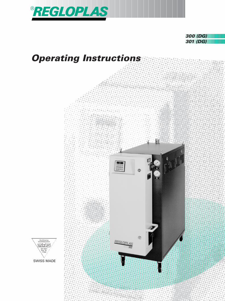
300 (DG)
Operating Instructions
SWISS MADE
Zertifiziertes Qualitätssystem
ISO 9001Reg. Nr.11265
301 (DG)
1
English
Operating Instructions
English
Service
Subject to change without notice
27
Operating InstructionsTemperature Control Unit300 (DG) • 301 (DG)Contents
1. Safety instructions 28 2. Range of application 28 3. Commissioning 28 4. Switching on 30 5. Switching off 33 6 Changing the consumer. Shutting the unit down for more than one month. Restarting the unit 33 7. Maintenance 33 8. Ordering replacement parts 35 9. Transport 3510. Optional features 3611. Trouble-shooting 3612. Technical data 37
Guidelines for handling hoses 39
Service 41
EC declaration of confirmity 56
28
1. Safety instructions
• Emergency Off: Switch off the yellow/red main switch on the temperature control unit.• Thermal oil is flammable under certain conditions. Therefore:
– Do not place the unit near a heat source (e.g. furnace in a die-casting plant).– Always keep the heat insulation of the unit clean. Insulation saturated with thermal oil is a
fire risk.– Repair any leaks in the temperature control circuit immediately (the unit, interconnecting
lines, consumer, etc.)• Burning thermal oil can be extinguished using the following:
– AFFF spray-foam fire extinguishers– Powder fire extinguisher (avoid use in dust-sensitive installations, e.g. computer controls,
EDP, etc.)– CO2 fire extinguisher (backfire danger, not always suitable)
A fire extinguisher suitable for use with the equipment located in the room and compatiblewith all applicable safety regulations shall be provided by the operator and kept accessibleat all times.
• Never use the unit without side panels.• Keep all sprays and cleaning agents containing solvent away from the unit.• Danger of injury from escaping hot thermal oil. Therefore:
– When operating at high outlet temperatures, cool the unit down and switch it off beforedisconnecting any line of the temperature control circuit.
– Make sure that the pump is not running.• In installations in which malfunction of the temperature control system could endanger
operating personnel or cause significant damage to the installation, an independent moni-toring device capable of shutting the installation down reliably must be installed for processsupervision.
• The unit shall not be used in areas endangered by explosion.• This instruction manual should be kept by the operator.
Please ensure that these instructions are read. This will prevent unnecessary costs and prob-lems during commissioning and will avoid production breakdown.
2. Range of application
The temperature control unit is designed for heating or cooling injection moulds, die-casting dies, ex-truders, calenders, mixers, and other consumers in areas not endangered by explosion.The unit is built for operation with thermal oil up to 300 °C.For technical data, see Section 12.
3. Commissioning
3.1 UnpackingDo not tip the unit. Heat transfer fluid left over from the test run could flow out and saturate the insu-lation.
3.2 Setting upThe unit is designed for an ambient temperature of 10 to 40 °C. When positioning the unit, ensure thatsufficient ventilation is provided. The distance between units resp. between unit and wall must be atleast 10 cm.Place the unit on a level surface and engage the wheel brake.Do not place the unit in the vicinity of a heat source (e.g. furnace in a die-casting plant) as the thermaloil is flammable under certain conditions.
29
3.3 Inspecting the consumerBefore connecting the temperature control unit to the consumer, check the following points:1 Test for free flow through the channels.2 Remove fluid residue and contamination using compressed air: Foreign objects, such as metal
chips, could damage the pump.3 Remove rust, scale and oil deposits, which drastically reduce the exchange of heat between con-
sumer and heat transfer fluid and increase the pressure drop in the consumer.The unit can be cleaned using the Regloplas descaling unit REG (→ “Regloplas Temperature Con-trol Units” booklet, Section “REG”).Oil deposits can be removed using System Cleaner SR 80 (→“Regloplas Temperature ControlUnits” booklet, data sheet “SR 80”).
4 When converting from water or steam to thermal oil, any remaining water in the consumerand in the pipe connections must be completely removed: steam pressure caused by heat-ing could cause an accident!Proceed according to Section 7.3.
3.4 Water qualityIn order to avoid damage to the unit cooler, the water used must meet the following specifications:Total hardness 5 to 22.5 °epH value 7 to CCE*Conductivity max. 1000 µS/cm*CCE = calcium carbonate equilibrium
The addition of corrosion inhibitor RK 93 is strongly recommended (→ “Regloplas Temperature ControlUnits” booklet, data sheet “RK 93”).
3.5 Interconnecting linesSee also page 39.– Outlet and inlet: Use only pressure and heat-resistant all-metal hoses with conical fittings in accord-
ance with DIN 3863 (→ “Regloplas Temperature Control Units” booklet, Section “Accessories”).When the connection is made with tubes, expansion must be taken into account. The hoses shallbe routed to prevent accidental contact.
– Cooling water mains: The pressure must be at least 2 bar. For connection to communal watersupply mains, prevailing regulations and safety measures shall be observed (e.g. connection to theunit via a system separator). Use only pressure-tight flexibles (→ “Regloplas Temperature ControlUnits” booklet, Section “Accessories”).
– Water drain: Must be non-return and open at all times.The hose shall be attached such that any steam emissions at the beginning of cooling do not con-stitute a danger.A leaky cooler could cause oil to flow into the drainage water; observe local regulations.
– Overflow pipe of the expansion vessel: Must be open at all times.For safety reasons, the cooling circuit must be connected at all times.
3.6 Electrical connections1 Compare mains voltage and frequency with rating plate.2 Check value of the back-up fuse with data on the wiring diagram and current input on the rating
plate.3 Observe local rules and safety regulations when connecting unit to mains.
The cores of the connecting cable shall be marked in accordance with IEC standards:3P E yellow/green
black-brown-blue
30
3.7 Filling the heat transfer fluidAfter inspecting the consumer and making the hose and electrical connections, proceed as follows:1 Switch on main switch at the unit.
In the RT 45 control system, operation checkout runs for approx. 3 s. While the test is running, 6dots will appear on the two displays (display 1, page 31). When the test has concluded positively,the display will go off. The RT 45 is now ready for operation (operation mode “stand-by”).The message “oFF” will then appear on the display at the right.If a different message appears, see Section 4.2 and the separate RT 45 “Operating Instructions”,Section 6.2.
2 Open vents and any shut-off valves on the consumer.3 Using a funnel, pour the thermal oil into the filling port slowly until the red level-monitor indicator
lamp goes out. The lamp is located on the top of the unit, at the rear near the filling port. For fillingquantity, see table “Technical data”, Section 12.Note: Each time the thermal oil is refilled, the unit and the temperature control circuit must beevacuated as follows: Switch on the unit. To avoid overheating the heating elements due to initialair pockets in the temperature control circuit, the outlet pressure in the unit is monitored by meansof a minimum-pressure switch. This switch will stop heating should the pressure drop below theminimum (0.7 bar) and trigger the flow alarm.Adjust the set-point value to approximately 10 °C; operate the unit at this value for approximately10 minutes to evacuate the system.Recommended thermal oils: Regloplas RO 150 or RO 300, Santotherm 66 or BP Transcal SA(→ “Regloplas Temperature Control Units” booklet, Section “Accessories”).We recommend the addition of system cleaner SR 80 as a preventive measure (→ “RegloplasTemperature Control Units” booklet, Section “SR 80”).
4 Do not close the vent consumer valve until oil flows steadily.5 Since fresh thermal oil contains moisture, it is essential that the moisture be removed before use
as described in Section 7.3, steps 4 and 5.
4. Switching on (Fig. 1)
1 Switch on the unit using the “On/Off” switch at the RT 45.The set-point value “SP1” or “SP2” will appear on the display at the right, and the actual value“S1” of internal sensor Sn1 or “S2” of the external sensor Sn2 on the display at the left.In normal operation, the system is always controlled via the external sensor. If the external sensoris not connected, the controller will switch to the internal sensor automatically.For further possible displays, see Section 4.2 or RT 45 “Operating Instructions”, Section 6.2.
2 Continue filling heat transfer fluid until the pump runs without interruption and the level indicatorlamp goes out, i.e. a sufficient amount of fluid is circulating in the temperature control circuit (unit,interconnecting lines, consumer. etc.).
3 Check the temperature control circuit for leaks.
4.1 Adjustment elementsAdjust the required set-point value using the ∆ or ∇ (5) key.Please refer to RT 45 “Operating Instructions” for further adjustment values, e.g. upper and lowerlimit of the fluid and the consumer temperatures.
31
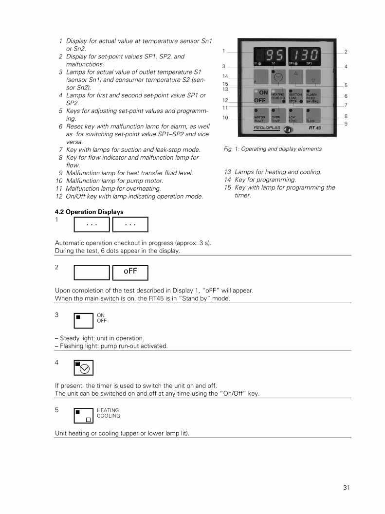
Fig. 1: Operating and display elements
13 Lamps for heating and cooling.14 Key for programming.15 Key with lamp for programming the
timer.
1 Display for actual value at temperature sensor Sn1or Sn2.
2 Display for set-point values SP1, SP2, andmalfunctions.
3 Lamps for actual value of outlet temperature S1(sensor Sn1) and consumer temperature S2 (sen-sor Sn2).
4 Lamps for first and second set-point value SP1 orSP2.
5 Keys for adjusting set-point values and programm-ing.
6 Reset key with malfunction lamp for alarm, as wellas for switching set-point value SP1–SP2 and viceversa.
7 Key with lamps for suction and leak-stop mode. 8 Key for flow indicator and malfunction lamp for
flow. 9 Malfunction lamp for heat transfer fluid level.10 Malfunction lamp for pump motor.11 Malfunction lamp for overheating.12 On/Off key with lamp indicating operation mode.
4.2 Operation Displays1
Automatic operation checkout in progress (approx. 3 s).During the test, 6 dots appear in the display.
2
Upon completion of the test described in Display 1, “oFF” will appear.When the main switch is on, the RT45 is in “Stand by” mode.
3
– Steady light: unit in operation.– Flashing light: pump run-out activated.
4
If present, the timer is used to switch the unit on and off.The unit can be switched on and off at any time using the “On/Off” key.
5
Unit heating or cooling (upper or lower lamp lit).
. . . . . .
oFF
ONOFF
HEATINGCOOLING
1
3
14
1513
1211
10
2
4
5
6
7
89
32
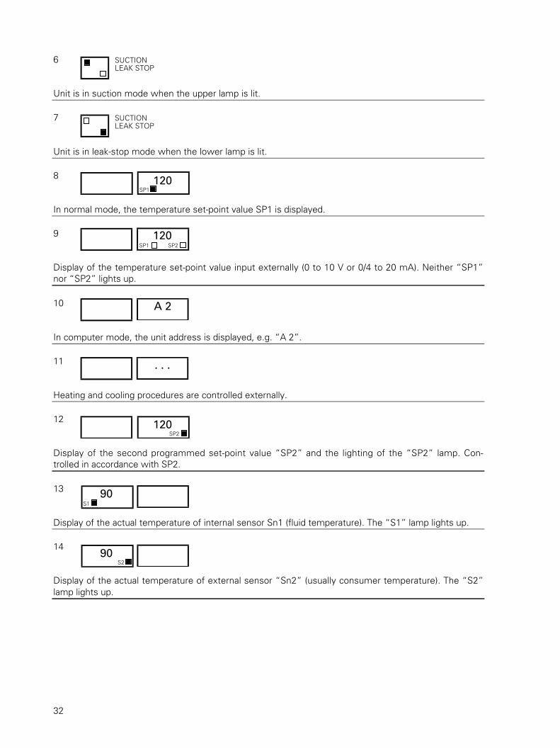
6
Unit is in suction mode when the upper lamp is lit.
7
Unit is in leak-stop mode when the lower lamp is lit.
8
In normal mode, the temperature set-point value SP1 is displayed.
9
Display of the temperature set-point value input externally (0 to 10 V or 0/4 to 20 mA). Neither “SP1”nor “SP2” lights up.
10
In computer mode, the unit address is displayed, e.g. “A 2”.
11
Heating and cooling procedures are controlled externally.
12
Display of the second programmed set-point value “SP2” and the lighting of the “SP2” lamp. Con-trolled in accordance with SP2.
13
Display of the actual temperature of internal sensor Sn1 (fluid temperature). The “S1” lamp lights up.
14
Display of the actual temperature of external sensor “Sn2” (usually consumer temperature). The “S2”lamp lights up.
SUCTIONLEAK STOP
SUCTIONLEAK STOP
A 2
. . .
120 SP1
120 SP1 SP2
120 SP2
90 S2
90 S1
33
5. Switching off
5.1 Using “On/Off” keyDepending on the temperature of the heat transfer fluid, the switching-off program runs as follows:– All displays are extinguished with the exception of “oFF” in the right-hand display. Pump and con-
trol system are switched off. RT 45 switches to standby mode.– The “On/Off” display flashes: The pump continues to run. The unit cools until the fluid has
reached the programmed pump run-out temperature “PtE”. The pump and control system are thenswitched off. The RT 45 switches to stand by mode. All displays are extinguished except of “oFF”.
5.2 By previous draining of the consumerSee Section 10.
6. Changing the consumer. Shuting the unit down for more than onemonth. Restarting the unit.
Before detaching the connecting line, ensure that the unit is switched off and that all circuits are pres-sureless.Drain the unit completely and store in a dry place between 10 and 40 °C for the period that it is not inuse.Under certain conditions, water may condense in the unit; therefore, steps 2 through 5 in Section 7.3must be performed before the unit is switched on.
7. Maintenance
7.1 Periodic inspections and maintenanceIn order to facilitate maintenance work, the RT 45 control system is equipped with a service-intervaldisplay. We recommend that the corresponding service interval be entered, e.g. 2000 hours. For pro-gramming, see “RT 45 Operating Instructions”, Section 4.2, item “S. 0.”.Please note that these instructions are based on a daily operating time of 8 hours. When working mo-re than one shift per day, the inspection and service intervals must be shortened accordingly.Faulty parts must be repaired or replaced immediately.• Inspection and maintenance procedures shall be performed by trained personnel only.• Maintenance of electrical components shall be performed by electricians only.• Switch the unit off before disconnecting the mains.• Change control insert only when the main switch is off.• To avoid the hazards associated with the magnetic fields produced by magnetic-drive pumps,
please take the following precautions:– Persons with pacemakers and/or implanted metal components must maintain sufficient
distance from these pumps and should not perform maintenance/repair procedures.– When sliding magnetic drive components together, the motor shall be held such that mag-
netic forces cannot cause fingers to be trapped between the components.– Adequate distance shall be maintained between the pump and computers, diskettes, credit
cards, electronic watches, etc.
7.1.1 Daily inspection/maintenanceCheck the temperature control circuit (unit, interconnecting lines, consumer, etc.) for leaks. Find thecause and remove the leaked fluid. Replace any insulation on which oil has been spilled immediatelyand clean up any oil spills.
34
7.1.2 Monthly inspections/maintenance1 Check for free intake of cooling air for the pump motor at the intake aperture.
Clean with compressed air by blowing from the inside.2 Clean filter as required.
7.1.3 Semi-annual inspection/maintenance1 Check for correct function and cleanliness of the level control.
Drain the unit via the drain plug. Switch the unit using the “On/Off” key. The “Low Level” lampshould light up and the pump should switch off within max. 20 s. Remove and clean the level con-trol switch.
2 Check for correct function of the safety thermostat:Attention: The temperature control circuit (interconnecting lines, consumer, etc.) must be suitablefor the check temperature.Adjust set-point value at the controller to 320 °C.If necessary for the functional test, set the value “S–
–” to 320 °C, as described in the separate
“RT 45 Operating Instructions”.As soon as the actual value of the temperature has reached 320 °C, the display lamp “Over Temp”should light up and the heater switch off.
3 Check the electrical equipment: earth connections and contactors; check for any loose terminals,etc.
4 Test the oil after approx. 1000 operating hours (equivalent to approx. six months in 1-shift opera-tion). To determine whether the oil can continue to be used, it must be analyzed, preferably by themanufacturer. Darkening of the oil is no indication of its condition.For the test, approx. 1 litre of the used fluid will be needed. For safety reasons, the sample shouldbe taken at a low temperature (approx. 30 °C. Oil vapour is flammable). The sample must bemarked with address, date of sampling, outlet temperature and type of fluid.Normally, the analysis is performed by the manufacturer at cost.
5 Dismantle solenoid valve as shown in drawing (→ Service, page 52): check diaphragm for scalingand damage. Test for easy movement of core and spring pin. Clean or replace these parts as re-quired.
7.1.4 Annual inspection/maintenanceReplace the oil after approx. 2000 operating hours (equivalent to approx. one year in 1-shift operation).This, however, is an approximate value. Under certain conditions (high temperature, narrow bores ofthe consumer, predominantly heating, etc.) the oil may have to be changed more frequently(→ 7.2).
7.2 Replacing heat transfer fluidReplace the heat transfer fluid as follows:1 Drain the unit and the consumer completely via their respective drain plugs.2 Clean the unit and the consumer as described in Sections 7.3 and 7.4 and in accordance with the
number of operating hours.3 Refill as described in Section 3.7.
7.3 Converting the consumer from water to thermal oil.Procedure in case condensation water has formed.
1 Check consumer for scaling. The unit can be cleaned with the aid of the REG unit (→ “RegloplasTemperature Control Units” booklet, data sheet “REG”).
2 Attention: All residue in the temperature control circuit (hose connections, consumer, etc.) mustbe completely removed. Steam pressure built up during heating can cause accidents. Procedure:
3 Fill the unit with thermal oil as described in Section 3.7.4 Let the unit run at 100 °C for at least 30 minutes.5 Once no boiling sounds can be heard, raise the temperature to the operating temperature in incre-
ments of 10 °C. As long as boiling sounds can be heard, continue running the unit at the sametemperature. The installation is then ready for operation with thermal oil.
35
7.4 CleaningExercise caution when using cleaning solvents: due to the risk of explosion, do not blowthrough the unit; flush it.When using solvents, observe manufacturer’s instructions for use. Thermal oil and solvents canbe flammable under certain conditions; do not clean near heat sources.We recommend carrying out the following cleaning procedure every time heat transfer fluid is addedor replaced. Under unfavourable operating conditions, this procedure should be carried out more fre-quently. This applies in particular to steps 5 and 6.1 Drain unit via the drain plug.2 Clean circuit filter.3 Check cooler for scaling; clean using descaling unit REG as necessary.4 If the oil is particularly dirty or the pressure gauge registers high pressure, dismantle and clean the
heaters.5 Dismantle level switch and clean.6 Dismantle the cooling system solenoid valve as shown in appended drawing (→ Service, page 53):
check diaphragm for scaling and damage. Test for free movement of core and spring pin. Clean orreplace these parts as needed.
8. Ordering replacement parts
Use only original replacement parts.To ensure efficient ordering of replacement parts and to avoid errors, we need the following details:1 Unit type2 Serial number3 Voltage4 FrequencyThis information can be found on the unit rating plate.5 Item number of the part. This number can be found on the drawings and diagrams in this instruc-
tion manual (→ Service) as well as on the electrical diagrams in the electrical compartment of theunit.
9. Transport
Before shipping, drain the unit completely by opening the drain plug; due to the risk of freezing at lowtemperatures (cracking of the cooling pipes), blow out as follows:1 Adjust set-point value to 0 °C at the controller.2 Ensure that the “Cooling” light is lit, i.e. the solenoid valve of the cooling system is open.3 Blow out cooler using compressed air at a maximum pressure of 6 bar.4 Do not tilt the unit. Residual heat transfer fluid within the unit could flow out and saturate the heat
insulation, creating a fire risk.5 Use the original packing material.6 Mark the top clearly.

36
10. Optional features
10.1 Leak-stop mode and consumer draining by suctionBy reversing the pump’s direction of rotation, the heat transfer fluid can be suctioned through the con-sumer.Note:– Leak-stop mode with thermal oil: Pump performance is greatly reduced during heating, resulting in
significant thermal load on the oil. Therefore, the oil must be checked or replaced at correspond-ingly shorter intervals. See Sections 7.1.3, step 4, and 7.1.4.
– Suction mode: The volume of heat transfer fluid in the consumer must be less than the expansionvolume in the unit (see table “Technical data”, Section 12), otherwise the unit will overflow.
Leak-stop modeThe unit can be set to leak-stop mode by pressing the “Suction/Leak-stop” key once. The lower lampof the key will light up. Leak-stop mode is possible only when the set-point value is between 0 and250 °C.Suction modeThe unit can be set to suction mode by pressing the “Suction/Leak Stop” key twice; the consumerconnected to the unit will be drained. The upper lamp will light up.Suction is possible only when the fluid temperature S1 is below the programmed pump run-out tem-perature “PtE”. If this is not the case, the unit will first cool down to this value.Suction and leak-stop modes can be interrupted by pressing the “On/Off” key.By pressing the “On/Off” button again (wait until the “Suction/Leak-Stop” lamp goes off), the unit willbe switched back to normal mode.
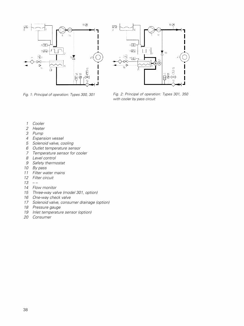
10.2 Cooler by pass circuitThe unit is equipped with a cooler by pass circuit to reduce the thermal load on the heater material andincrease controlling performance (undershooting of the temperature) during the cooling procedure.Operation (Fig. 2)Heating: The three-way valve (15) is open in direction 15-2, i.e. cooler (1) is by passed.The heat transfer fluid flows as follows: 15-2-3-20-15.Cooling: The three-way valve (15) is open in direction 15-2, i.e. the heat transfer fluid flows throughtthe cooler.The flow of the heat transfer fluid is as follows: 15-1-2-3-20-15.The cooling sequence functions as follows:If the outlet temperature is higher than the set-point value at the controller, the three-way valve isopened by the servo motor so that the heat transfer fluid circulates through the cooler. The three-wayvalve control is continuous.
10.3 Flow rate measurementMax. operating temperature 350 °C.When the “Flow” key is pressed, the flow rate will be shown in l/min in the right display. The unit canbe programmed to monitor the minimum flow rate, i. e. alarm when flow rate is too low. For instruc-tions, see “RT 45 Operating Instructions”, Sections 7.1 and 7.3 (“FLC”).
11. Trouble-shooting
For malfunction displays on the RT 45 control system, see “RT 45 Operating Instructions”, Section6.2.
37
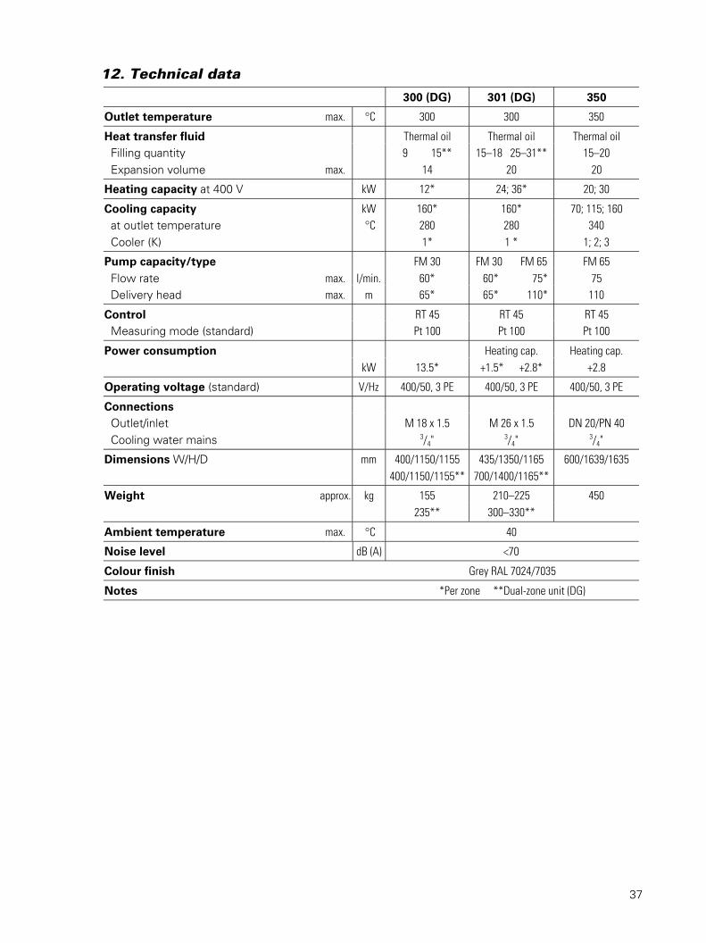
12. Technical data
300 (DG) 301 (DG) 350
Outlet temperature max. °C 300 300 350
Heat transfer fluid Thermal oil Thermal oil Thermal oil Filling quantity 9 15** 15–18 25–31** 15–20 Expansion volume max. 14 20 20
Heating capacity at 400 V kW 12* 24; 36* 20; 30
Cooling capacity kW 160* 160* 70; 115; 160 at outlet temperature °C 280 280 340 Cooler (K) 1* 1 * 1; 2; 3
Pump capacity/type FM 30 FM 30 FM 65 FM 65 Flow rate max. l/min. 60* 60* 75* 75 Delivery head max. m 65* 65* 110* 110
Control RT 45 RT 45 RT 45 Measuring mode (standard) Pt 100 Pt 100 Pt 100
Power consumption Heating cap. Heating cap.kW 13.5* +1.5* +2.8* +2.8
Operating voltage (standard) V/Hz 400/50, 3 PE 400/50, 3 PE 400/50, 3 PE
Connections Outlet/inlet M 18 x 1.5 M 26 x 1.5 DN 20/PN 40 Cooling water mains 3/4"
3/4"3/4"
Dimensions W/H/D mm 400/1150/1155 435/1350/1165 600/1639/1635400/1150/1155** 700/1400/1165**
Weight approx. kg 155 210–225 450235** 300–330**
Ambient temperature max. °C 40
Noise level dB (A) <70
Colour finish Grey RAL 7024/7035
Notes *Per zone **Dual-zone unit (DG)
38
1 Cooler 2 Heater 3 Pump 4 Expansion vessel 5 Solenoid valve, cooling 6 Outlet temperature sensor 7 Temperature sensor for cooler 8 Level control 9 Safety thermostat10 By pass11 Filter water mains12 Filter circuit13 – –14 Flow monitor15 Three-way valve (model 301, option)16 One-way check valve17 Solenoid valve, consumer drainage (option)18 Pressure gauge19 Inlet temperature sensor (option)20 Consumer
Fig. 1: Principal of operation: Types 300, 301 Fig. 2: Principal of operation: Types 301, 350with cooler by pass circuit
39
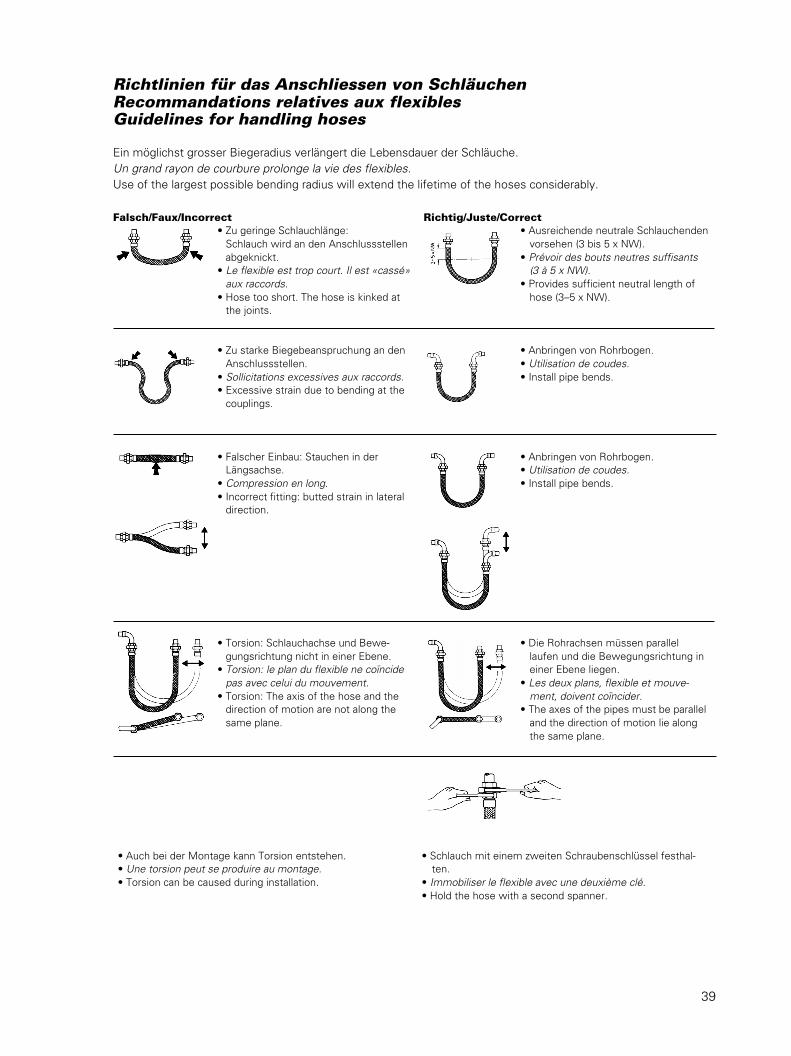
Richtlinien für das Anschliessen von SchläuchenRecommandations relatives aux flexiblesGuidelines for handling hoses
Ein möglichst grosser Biegeradius verlängert die Lebensdauer der Schläuche.Un grand rayon de courbure prolonge la vie des flexibles.Use of the largest possible bending radius will extend the lifetime of the hoses considerably.
Falsch/Faux/Incorrect Richtig/Juste/Correct• Zu geringe Schlauchlänge:
Schlauch wird an den Anschlussstellenabgeknickt.
• Le flexible est trop court. Il est «cassé»aux raccords.
• Hose too short. The hose is kinked atthe joints.
• Zu starke Biegebeanspruchung an denAnschlussstellen.
• Sollicitations excessives aux raccords.• Excessive strain due to bending at the
couplings.
• Falscher Einbau: Stauchen in derLängsachse.
• Compression en long.• Incorrect fitting: butted strain in lateral
direction.
• Torsion: Schlauchachse und Bewe-gungsrichtung nicht in einer Ebene.
• Torsion: le plan du flexible ne coïncidepas avec celui du mouvement.
• Torsion: The axis of the hose and thedirection of motion are not along thesame plane.
• Ausreichende neutrale Schlauchendenvorsehen (3 bis 5 x NW).
• Prévoir des bouts neutres suffisants(3 à 5 x NW).
• Provides sufficient neutral length ofhose (3–5 x NW).
• Anbringen von Rohrbogen.• Utilisation de coudes.• Install pipe bends.
• Anbringen von Rohrbogen.• Utilisation de coudes.• Install pipe bends.
• Die Rohrachsen müssen parallellaufen und die Bewegungsrichtung ineiner Ebene liegen.
• Les deux plans, flexible et mouve-ment, doivent coïncider.
• The axes of the pipes must be paralleland the direction of motion lie alongthe same plane.
• Auch bei der Montage kann Torsion entstehen.• Une torsion peut se produire au montage.• Torsion can be caused during installation.
• Schlauch mit einem zweiten Schraubenschlüssel festhal-ten.
• Immobiliser le flexible avec une deuxième clé.• Hold the hose with a second spanner.
41
Service300 (DG) • 301 (DG)
Achtung
Das Elektroschema befindet sich im Elektroteil des Gerätes.Bei Bestellung von Ersatzteilen immer Gerätenummer angeben.
Attention
Le schéma électrique se trouve dans la partie électrique de l’appareil.Toujours indiquer le numéro de l’appareil quand vous commandez les pièces de rechange.
Note
The electrical diagram is located in the electrical compartment of the unit.Always state the unit serial number when ordering replacement parts.
42
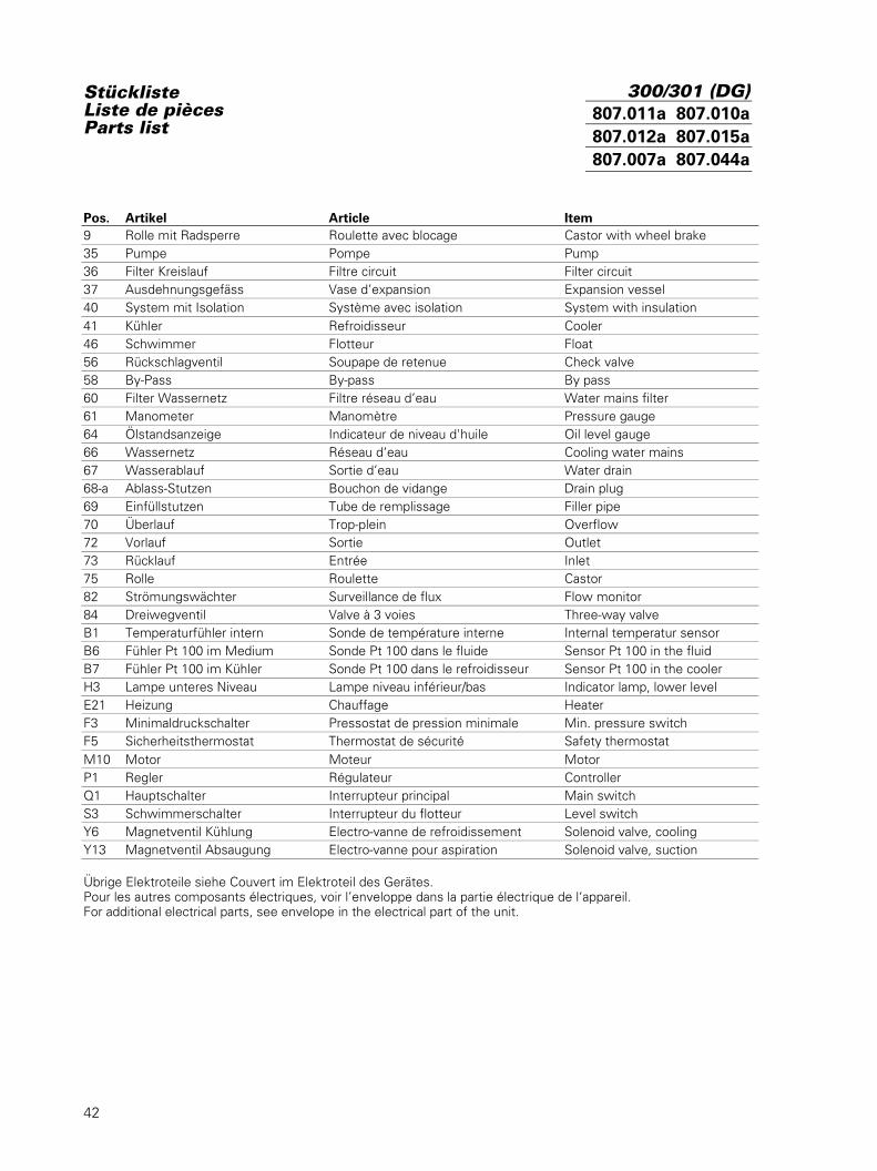
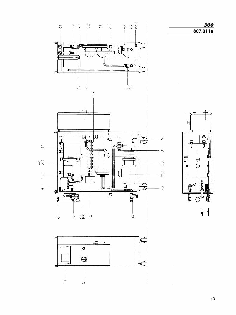
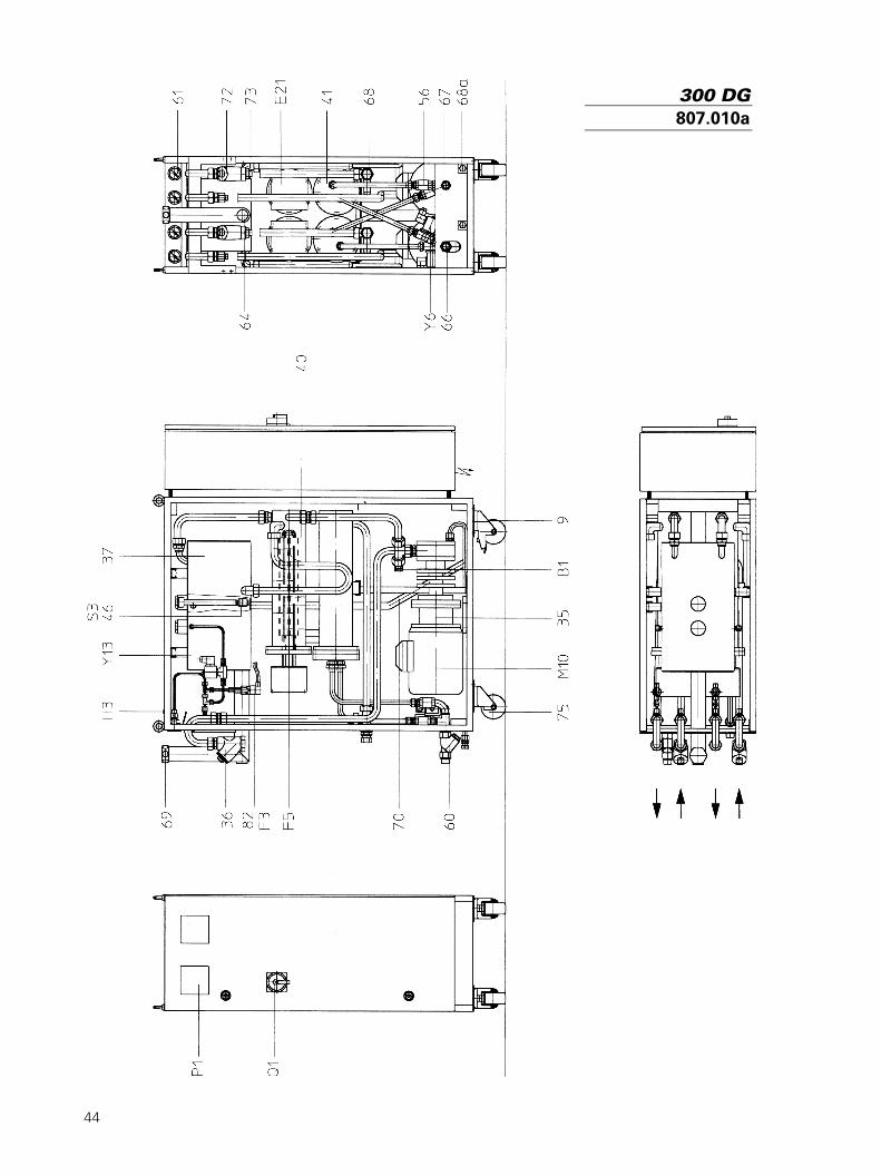
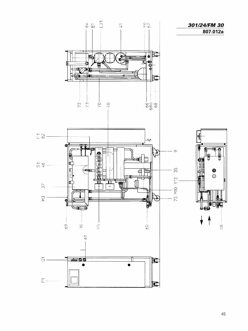
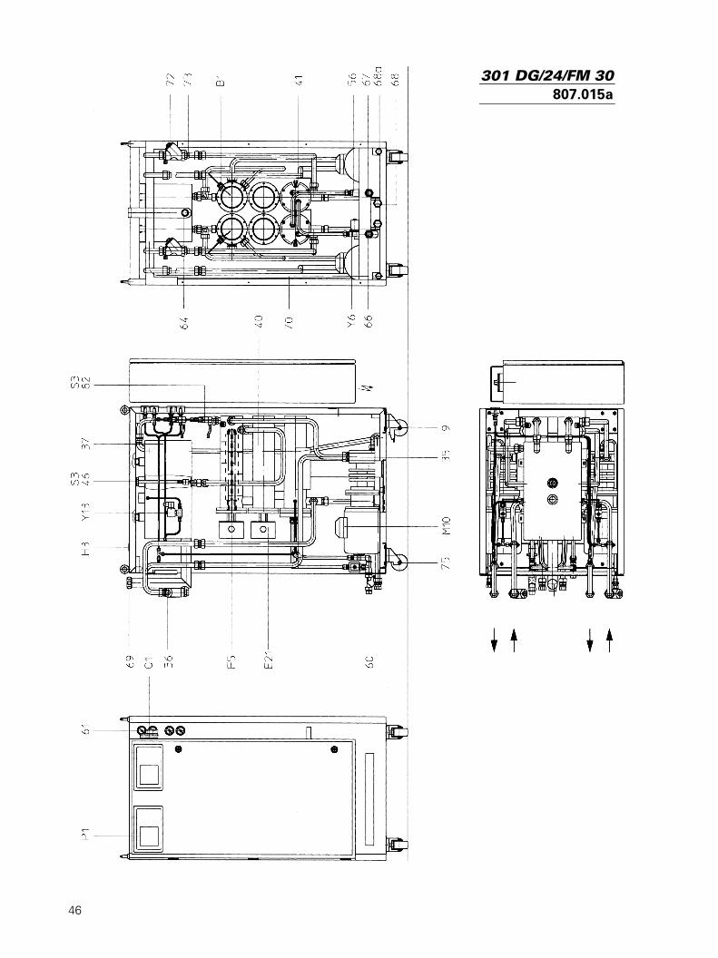
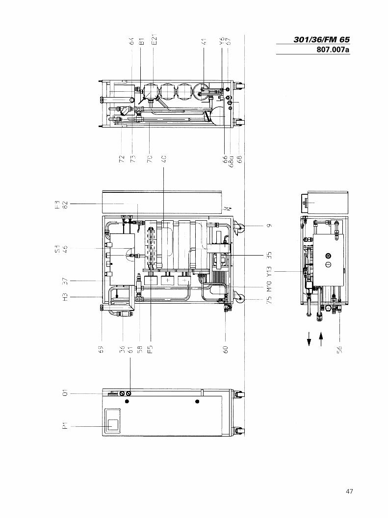
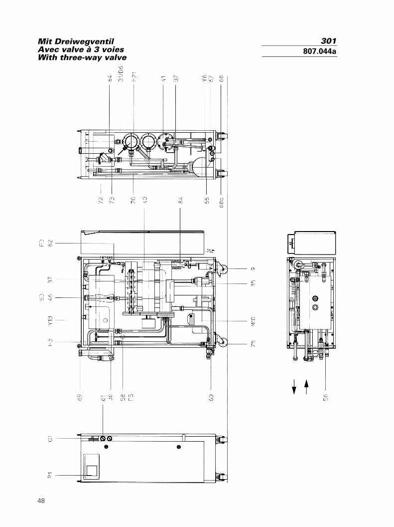
StücklisteListe de piècesParts list
Pos. Artikel Article Item9 Rolle mit Radsperre Roulette avec blocage Castor with wheel brake35 Pumpe Pompe Pump 36 Filter Kreislauf Filtre circuit Filter circuit37 Ausdehnungsgefäss Vase d’expansion Expansion vessel40 System mit Isolation Système avec isolation System with insulation41 Kühler Refroidisseur Cooler46 Schwimmer Flotteur Float56 Rückschlagventil Soupape de retenue Check valve58 By-Pass By-pass By pass60 Filter Wassernetz Filtre réseau d’eau Water mains filter61 Manometer Manomètre Pressure gauge64 Ölstandsanzeige Indicateur de niveau d'huile Oil level gauge66 Wassernetz Réseau d‘eau Cooling water mains67 Wasserablauf Sortie d’eau Water drain68-a Ablass-Stutzen Bouchon de vidange Drain plug69 Einfüllstutzen Tube de remplissage Filler pipe70 Überlauf Trop-plein Overflow72 Vorlauf Sortie Outlet73 Rücklauf Entrée Inlet75 Rolle Roulette Castor82 Strömungswächter Surveillance de flux Flow monitor84 Dreiwegventil Valve à 3 voies Three-way valveB1 Temperaturfühler intern Sonde de température interne Internal temperatur sensorB6 Fühler Pt 100 im Medium Sonde Pt 100 dans le fluide Sensor Pt 100 in the fluidB7 Fühler Pt 100 im Kühler Sonde Pt 100 dans le refroidisseur Sensor Pt 100 in the coolerH3 Lampe unteres Niveau Lampe niveau inférieur/bas Indicator lamp, lower levelE21 Heizung Chauffage HeaterF3 Minimaldruckschalter Pressostat de pression minimale Min. pressure switchF5 Sicherheitsthermostat Thermostat de sécurité Safety thermostatM10 Motor Moteur MotorP1 Regler Régulateur ControllerQ1 Hauptschalter Interrupteur principal Main switchS3 Schwimmerschalter Interrupteur du flotteur Level switchY6 Magnetventil Kühlung Electro-vanne de refroidissement Solenoid valve, coolingY13 Magnetventil Absaugung Electro-vanne pour aspiration Solenoid valve, suction
Übrige Elektroteile siehe Couvert im Elektroteil des Gerätes.Pour les autres composants électriques, voir l’enveloppe dans la partie électrique de l‘appareil.For additional electrical parts, see envelope in the electrical part of the unit.
300/301 (DG)807.011a 807.010a807.012a 807.015a807.007a 807.044a
43
300807.011a
44
300 DG807.010a
45
301/24/FM 30807.012a
46
301 DG/24/FM 30807.015a
47
301/36/FM 65807.007a
48
Mit DreiwegventilAvec valve à 3 voiesWith three-way valve
301807.044a
49
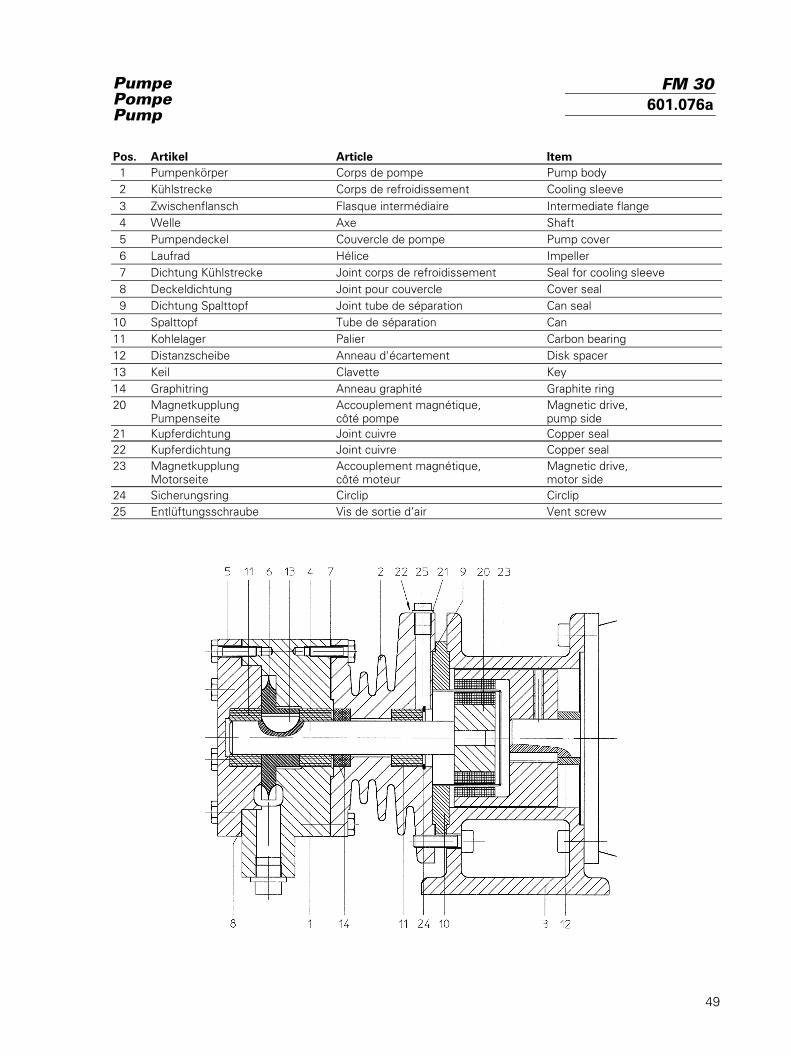
PumpePompePump
Pos. Artikel Article Item 1 Pumpenkörper Corps de pompe Pump body 2 Kühlstrecke Corps de refroidissement Cooling sleeve 3 Zwischenflansch Flasque intermédiaire Intermediate flange 4 Welle Axe Shaft 5 Pumpendeckel Couvercle de pompe Pump cover 6 Laufrad Hélice Impeller 7 Dichtung Kühlstrecke Joint corps de refroidissement Seal for cooling sleeve 8 Deckeldichtung Joint pour couvercle Cover seal 9 Dichtung Spalttopf Joint tube de séparation Can seal10 Spalttopf Tube de séparation Can11 Kohlelager Palier Carbon bearing12 Distanzscheibe Anneau d'écartement Disk spacer13 Keil Clavette Key14 Graphitring Anneau graphité Graphite ring20 Magnetkupplung Accouplement magnétique, Magnetic drive,
Pumpenseite côté pompe pump side21 Kupferdichtung Joint cuivre Copper seal22 Kupferdichtung Joint cuivre Copper seal23 Magnetkupplung Accouplement magnétique, Magnetic drive,
Motorseite côté moteur motor side24 Sicherungsring Circlip Circlip25 Entlüftungsschraube Vis de sortie d‘air Vent screw
FM 30601.076a
50
PumpePompePump
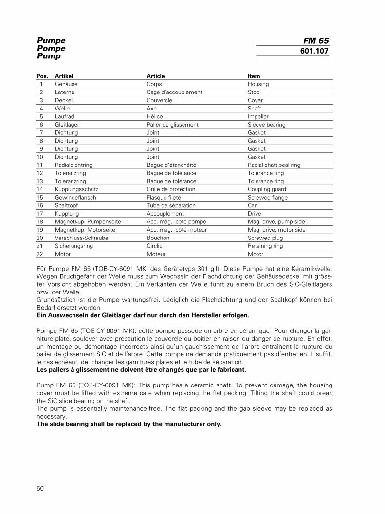
Pos. Artikel Article Item 1 Gehäuse Corps Housing 2 Laterne Cage d’accouplement Stool 3 Deckel Couvercle Cover 4 Welle Axe Shaft 5 Laufrad Hélice Impeller 6 Gleitlager Palier de glissement Sleeve bearing 7 Dichtung Joint Gasket 8 Dichtung Joint Gasket 9 Dichtung Joint Gasket10 Dichtung Joint Gasket11 Radialdichtring Bague d’étanchéité Radial-shaft seal ring12 Toleranzring Bague de tolérance Tolerance ring13 Toleranzring Bague de tolérance Tolerance ring14 Kupplungsschutz Grille de protection Coupling guard15 Gewindeflansch Flasque fileté Screwed flange16 Spalttopf Tube de séparation Can17 Kupplung Accouplement Drive18 Magnetkup. Pumpenseite Acc. mag., côté pompe Mag. drive, pump side19 Magnetkup. Motorseite Acc. mag., côté moteur Mag. drive, motor side20 Verschluss-Schraube Bouchon Screwed plug21 Sicherungsring Circlip Retaining ring22 Motor Moteur Motor
Für Pumpe FM 65 (TOE-CY-6091 MK) des Gerätetyps 301 gilt: Diese Pumpe hat eine Keramikwelle.Wegen Bruchgefahr der Welle muss zum Wechseln der Flachdichtung der Gehäusedeckel mit gröss-ter Vorsicht abgehoben werden. Ein Verkanten der Welle führt zu einem Bruch des SiC-Gleitlagersbzw. der Welle.Grundsätzlich ist die Pumpe wartungsfrei. Lediglich die Flachdichtung und der Spaltkopf können beiBedarf ersetzt werden.Ein Auswechseln der Gleitlager darf nur durch den Hersteller erfolgen.
Pompe FM 65 (TOE-CY-6091 MK): cette pompe possède un arbre en céramique! Pour changer la gar-niture plate, soulever avec précaution le couvercle du boîtier en raison du danger de rupture. En effet,un montage ou démontage incorrects ainsi qu’un gauchissement de l’arbre entraînent la rupture dupalier de glissement SiC et de l’arbre. Cette pompe ne demande pratiquement pas d’entretien. Il suffit,le cas échéant, de changer les garnitures plates et le tube de séparation.Les paliers à glissement ne doivent être changés que par le fabricant.
Pump FM 65 (TOE-CY-6091 MK): This pump has a ceramic shaft. To prevent damage, the housingcover must be lifted with extreme care when replacing the flat packing. Tilting the shaft could breakthe SiC slide bearing or the shaft.The pump is essentially maintenance-free. The flat packing and the gap sleeve may be replaced asnecessary.The slide bearing shall be replaced by the manufacturer only.
FM 65601.107
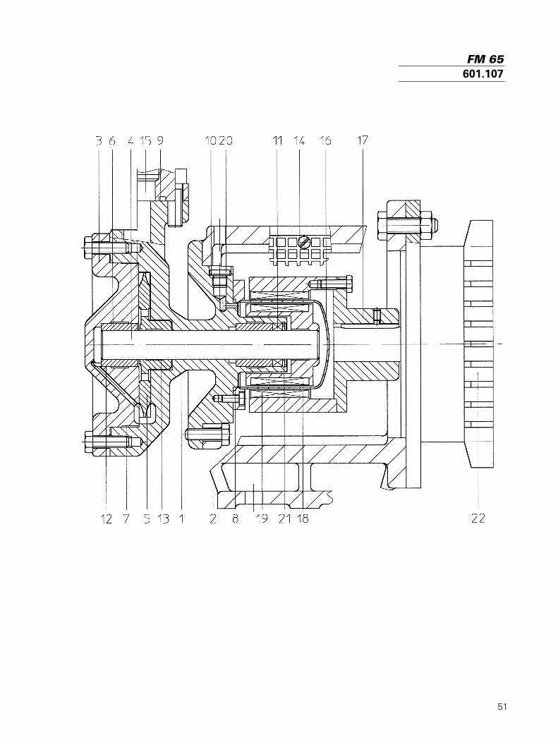
51
FM 65601.107
52
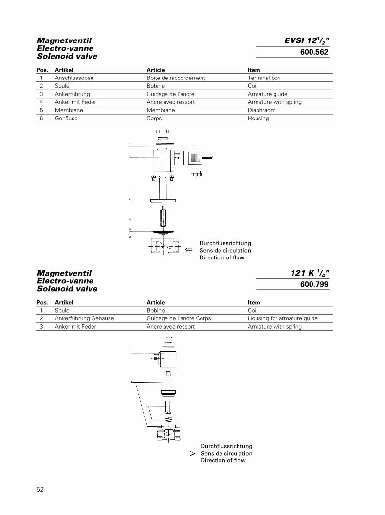
MagnetventilElectro-vanneSolenoid valve
Pos. Artikel Article Item 1 Anschlussdose Boîte de raccordement Terminal box 2 Spule Bobine Coil 3 Ankerführung Guidage de l'ancre Armature guide 4 Anker mit Feder Ancre avec ressort Armature with spring 5 Membrane Membrane Diaphragm 6 Gehäuse Corps Housing
MagnetventilElectro-vanneSolenoid valve
Pos. Artikel Article Item 1 Spule Bobine Coil 2 Ankerführung Gehäuse Guidage de l'ancre Corps Housing for armature guide 3 Anker mit Feder Ancre avec ressort Armature with spring
DurchflussrichtungSens de circulationDirection of flow
⇐
DurchflussrichtungSens de circulationDirection of flow ∇
EVSI 121/2"600.562
121 K 1/4"600.799
53
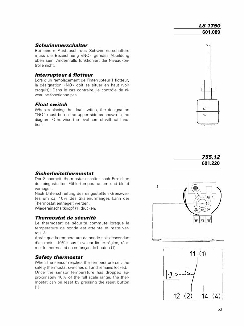
SchwimmerschalterBei einem Austausch des Schwimmerschaltersmuss die Bezeichnung «NO» gemäss Abbildungoben sein. Andernfalls funktioniert die Niveaukon-trolle nicht.
Interrupteur à flotteurLors d’un remplacement de l’interrupteur à flotteur,la désignation «NO» doit se situer en haut (voircroquis). Dans le cas contraire, le contrôle de ni-veau ne fonctionne pas.
Float switchWhen replacing the float switch, the designation“NO” must be on the upper side as shown in thediagram. Otherwise the level control will not func-tion.
SicherheitsthermostatDer Sicherheitsthermostat schaltet nach Erreichender eingestellten Fühlertemperatur um und bleibtverriegelt.Nach Unterschreitung des eingestellten Grenzwer-tes um ca. 10% des Skalenumfanges kann derThermostat entriegelt werden.Wiedereinschaltknopf (1) drücken.
Thermostat de sécuritéLe thermostat de sécurité commute lorsque latempérature de sonde est atteinte et reste ver-rouillé.Après que la température de sonde soit descendued’au moins 10% sous la valeur limite réglée, réar-mer le thermostat en enfonçant le bouton (1).
Safety thermostatWhen the sensor reaches the temperature set, thesafety thermostat switches off and remains locked.Once the sensor temperature has dropped ap-proximately 10% of the full scale range, the ther-mostat can be reset by pressing the reset button(1).
LS 1750601.089
755.12601.220
54
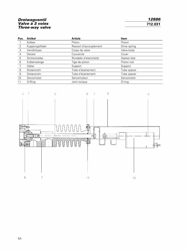
DreiwegventilValve à 3 voiesThree-way valve
Pos. Artikel Article Item 1 Kolben Piston Piston 2 Kupplungsfeder Ressort d’accouplement Drive spring 3 Ventilkörper Corps de valve Valve body 4 Deckel Couvercle Cover 5 Dichtscheibe Rondelle d’étanchéité Gasket disk 6 Kolbenstange Tige de piston Piston rod 7 Halter Support Support 8 Distanzrohr Tube d’écartement Tube spacer 9 Distanzrohr Tube d’écartement Tube spacer10 Servomotor Servomoteur Servomotor11 O-Ring Joint torique O-ring
12886712.031
56
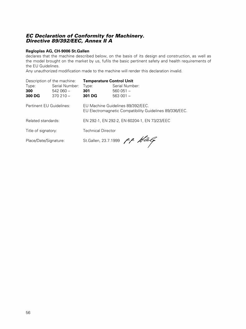
EC Declaration of Conformity for Machinery.Directive 89/392/EEC, Annex II A
Regloplas AG, CH-9006 St.Gallendeclares that the machine described below, on the basis of its design and construction, as well asthe model brought on the market by us, fufils the basic pertinent safety and health requirements ofthe EU Guidelines.Any unauthorized modification made to the machine will render this declaration invalid.
Description of the machine: Temperature Control UnitType: Serial Number: Type: Serial Number:300 542 060 – 301 560 051 –300 DG 370 210 – 301 DG 563 001 –
Pertinent EU Guidelines: EU Machine Guidelines 89/392/EEC.EU Electromagnetic Compatibility Guidelines 89/336/EEC.
Related standards: EN 292-1, EN 292-2, EN 60204-1, EN 73/23/EEC
Title of signatory: Technical Director
Place/Date/Signature: St.Gallen, 23.7.1999

Regloplas AGFlurhofstrasse 158CH-9006 St. Gallen
Tel. + 41 71 282 58 00Fax + 41 71 282 58 40
E-mail [email protected] www.regloplas.com
• • •
• • •
• • •
• • •
• • •
• • •
• •
• • •
• • •
• • •
• • •
• • •
• • •
•
• • •
• • •
• • •
• • •
• • •
• • •
• •
• • •
• • •
• • •
• • •
• • •
• • •
•
• • •
• • •
• • •
• • •
• • •
• • •
• •
• • •
• • •
• • •
• • •
• • •
• • •
•
• • •
• • •
• • •
• • •
• • •
• • •
• •
• • •
• • •
• • •
• • •
• • •
• • •
•
• • •
• • •
• • •
• • •
• • •
• • •
• •
• • •
• • •
• • •
• • •
• • •
• • •
•
• • •
• • •
• • •
• • •
• • •
• • •
• •
• • •
• • •
• • •
• • •
• • •
• • •
•
• • •
• • •
• • •
• • •
• • •
• • •
• •
• • •
• • •
• • •
• • •
• • •
• • •
•
• • •
• • •
• • •
• • •
• • •
• • •
• •
• • •
• • •
• • •
• • •
• • •
• • •
•
• • •
• • •
• • •
• • •
• • •
• • •
• •
• • •
• • •
• • •
• • •
• • •
• • •
•
• • •
• • •
• • •
• • •
• • •
• • •
• •
• • •
• • •
• • •
• • •
• • •
• • •
•
• • •
• • •
• • •
• • •
• • •
• • •
• •
• • •
• • •
• • •
• • •
• • •
• • •
•
• • •
• • •
• • •
• • •
• • •
• • •
• •
• • •
• • •
• • •
• • •
• • •
• • •
•
• • •
• • •
• • •
• • •
• • •
• • •
• •
• • •
• • •
• • •
• • •
• • •
• • •
•
• • •
• • •
• • •
• • •
• • •
• • •
• •
• • •
• • •
• • •
• • •
• • •
• • •
•
• • •
• • •
• • •
• • •
• • •
• • •
• •
• • •
• • •
• • •
• • •
• • •
• • •
•
• • •
• • •
• • •
• • •
• • •
• • •
• •
• • •
• • •
• • •
• • •
• • •
• • •
•
• • •
• • •
• • •
• • •
• • •
• • •
• •
• • •
• • •
• • •
• • •
• • •
• • •
•
• • •
• • •
• • •
• • •
• • •
• • •
• •
• • •
• • •
• • •
• • •
• • •
• • •
•
• • •
• • •
• • •
• • •
• • •
• • •
• •
• • •
• • •
• • •
• • •
• • •
• • •
•
• • •
• • •
• • •
• • •
• • •
• • •
• •
• • • • •
•
• • • • •
•
• • • • •
•
• • • • •
•
• • • • •
•
• • • • •
•
• • • • •
•
• • • • •
•
• • • • •
•
• • •
• •
•
• • • • •
•
• • • • •
•
• • • • •
•
• • • • •
•
• • • • •
•
• • • • •
•
• • • • •
• • •
• • •
• • •
• • •
• • •
• •
• • •
• • •
• • •
• • •
• • •
• • •
• •
• • •
• • •
• • •
• • •
• • •
• • •
•
• • •
• • •
• • •
• • •
• • •
• • •
• •
• • •
• • •
• • •
• • •
• • •
• • •
•
• • •
• • •
• • •
• • •
• • •
• • •
• •
BA 300–301/0101/de/fr/en