7000 Series - EGM, LLC.
17
23 * Pilot operated valves require the minimum pressure differential specified for proper valve operation. ** Maximum fluid temperatures are provided for Class F coils. Valves with FKM seals (letter “V” in 10th position of pressure vessel number) can be used at fluid temperatures up to 240°F on DC and 250°F on AC provided a Class H coil is used. *** UL/CSA Approval Information: S S =Safety Shutoff GP = General Purpose Blank =Not Approved See page 136 for additional agency approval information. 1/4”-’2’ Family SS valve also available with FKM seals. General Purpose Two-Way Direct Lift and Pilot Operated Valves 7000 Series 7321 PILOT OPERATED BRASS VALVES– NORMALLY CLOSED, NBR SEALS ‘K’, ‘8’ and 1/4” ‘2’ Family valves also available with FKM seals Operating Pressure Differential (PSI) MAX.** Pipe Orifice Maximum Fluid Pressure Size Size Cv AC Ratings DC Ratings Temp. Vessel UL/CSA*** Const. NPT (inch) Factor Min.* 10 watt 22 watt 10 watt 22 watt (F) Number Approval Ref. 1/4” 1/4 0.76 5 300 300 185 73212BN2MN00 SS 10 7/16 2.0 3 150 60 150 185 7321KBN2RN00 SS 98 3/8” 1/2 2.4 5 300 300 185 73212BN3SN00 SS 11 5/8 3.0 5 150 150 185 73218BN3TN00 SS 12 7/16 2.5 3 150 60 150 185 7321KBN3SN00 SS 98 1/2” 1/2 2.8 5 300 300 185 73212BN4TN00 SS 11 5/8 4.0 5 150 150 185 73218BN4UN00 SS 12 7/16 2.5 3 150 60 150 185 7321KBN4SN00 SS 98 3/4” 3/4 7.3 5 300 300 185 73212BN52N00 SS 13 3/4 5.0 5 150 150 185 73218BN5VN00 SS 12 25/32 9.6 5 230 230 185 7321GBN53N00 SS 14 1” 1 11.0 5 300 300 185 73212BN63N00 SS 13 1 1/16 13.5 5 125 125 185 73218BN64N00 SS 15 1 12.5 5 230 230 185 7321GBN64N00 SS 14 1 1/4” 1 1/8 15.0 5 125 125 185 73218BN75N00 SS 15 1 1/8 19.3 5 230 230 185 7321GBN76N00 SS 14 1 1/2” 1 1/4 22.5 5 125 125 185 73218BN87N00 SS 16 1 9/16 29.0 5 230 200 230 185 7321GBN88N00 SS 14 2” 1 9/16 38.6 5 230 200 230 185 7321GBN99N00 SS 14 #12 7321 PILOT OPERATED STAINLESS STEEL VALVES – NORMALLY CLOSED, NBR SEALS Operating Pressure Differential (PSI) MAX.** Pipe Orifice Maximum Fluid Pressure Size Size Cv AC Ratings DC Ratings Temp. Vessel UL/CSA*** Const. NPT (inch) Factor Min.* 10 watt 22 watt 10 watt 22 watt (F) Number Approval Ref. 1/4” 1/4 0.76 5 300 300 185 73212SN2MN00 SS 17 #98 Port Identification: 1-IN/ 2-OUT Dimension Valve H P C L 7321KBN4SXXX 3.56 2.97 1.96 2.17 7321KBN2RXXX 3.56 2.97 1.96 1.97 7321KBN3SXXX 3.56 2.97 1.96 1.97 “X” denotes multiple digit combinations for brevity. Flow arrow on body indicates flow directio n – ports are not marked. Port Identification: P- IN/ - -OUT Dimension Valve H P C L R 73218BN3TXXX 4.38 3.84 2.81 2.64 1.39 73218BN4UXXX 4.38 3.84 2.81 2.64 1.39 73218BN5VXXX 4.59 3.94 2.91 2.72 1.43 “X” denotes multiple digit combinations for brevity.
-
Upload
khangminh22 -
Category
Documents
-
view
1 -
download
0
Transcript of 7000 Series - EGM, LLC.
2 3
* Pilot operated valves require the minimum pressure differential specified for proper valveoperation.
** Maximum fluid temperatures are provided for Class F coils. Valves with FKM seals (letter “V” in10th position of pressure vessel number) can be used at fluid temperatures up to 240°F on DC
and 250°F on AC provided a Class H coil is used.*** UL/CSA Approval Information: SS=Safety Shutoff GP=General Purpose Blank=Not Approved
See page 136 for additional agency approval information.1/4”-’2’ Family SS valve also available with FKM seals.
General Purpose Two-Way DirectLift and Pilot Operated Valves7000 Series
7321 PILOT OPERATED BRASS VALVES– NORMALLY CLOSED, NBR SEALS ‘K’, ‘8’ and 1/4” ‘2’ Family valves also available with FKM seals
Operating Pressure Differential (PSI) MAX.**Pipe Orifice Maximum Fluid PressureSize Size Cv AC Ratings DC Ratings Temp. Vessel UL/CSA*** Const.NPT (inch) Factor Min.* 10 watt 22 watt 10 watt 22 watt (F) Number Approval Ref.
1/4” 1/4 0.76 5 300 300 185 73212BN2MN00 SS 107/16 2.0 3 150 60 150 185 7321KBN2RN00 SS 98
3/8” 1/2 2.4 5 300 300 185 73212BN3SN00 SS 115/8 3.0 5 150 150 185 73218BN3TN00 SS 12
7/16 2.5 3 150 60 150 185 7321KBN3SN00 SS 98
1/2” 1/2 2.8 5 300 300 185 73212BN4TN00 SS 115/8 4.0 5 150 150 185 73218BN4UN00 SS 127/16 2.5 3 150 60 150 185 7321KBN4SN00 SS 98
3/4” 3/4 7.3 5 300 300 185 73212BN52N00 SS 133/4 5.0 5 150 150 185 73218BN5VN00 SS 12
25/32 9.6 5 230 230 185 7321GBN53N00 SS 14
1” 1 11.0 5 300 300 185 73212BN63N00 SS 131 1/16 13.5 5 125 125 185 73218BN64N00 SS 15
1 12.5 5 230 230 185 7321GBN64N00 SS 14
1 1/4” 1 1/8 15.0 5 125 125 185 73218BN75N00 SS 151 1/8 19.3 5 230 230 185 7321GBN76N00 SS 14
1 1/2” 1 1/4 22.5 5 125 125 185 73218BN87N00 SS 161 9/16 29.0 5 230 200 230 185 7321GBN88N00 SS 14
2” 1 9/16 38.6 5 230 200 230 185 7321GBN99N00 SS 14
# 1 2
7321 PILOT OPERATED STAINLESS STEEL VALVES–NORMALLY CLOSED, NBR SEALSOperating Pressure Differential (PSI) MAX.**
Pipe Orifice Maximum Fluid Pressure Size Size Cv AC Ratings DC Ratings Temp. Vessel UL/CSA*** Const.NPT (inch) Factor Min.* 10 watt 22 watt 10 watt 22 watt (F) Number Approval Ref.
1/4” 1/4 0.76 5 300 300 185 73212SN2MN00 SS 17
# 9 8 Port Identification: 1-IN/ 2 -OUT
DimensionValve H P C L
7321KBN4SXXX 3.56 2.97 1.96 2.177321KBN2RXXX 3.56 2.97 1.96 1.977321KBN3SXXX 3.56 2.97 1.96 1.97“X” denotes multiple digit combinations for brevity.
Flow arrow on body indicates flow directio n–ports are not marked.
Port Identification: P- IN/ - -OUT
DimensionValve H P C L R
73218BN3TXXX 4.38 3.84 2.81 2.64 1.3973218BN4UXXX 4.38 3.84 2.81 2.64 1.3973218BN5VXXX 4.59 3.94 2.91 2.72 1.43“X” denotes multiple digit combinations for brevity.
1 2 8
Technical InformationIntroduction
Solenoid valves are highly engineered productswhich can be utilized in many diverse and uniquefluid system applications. In addition to operationalfunctionality, selecting the best product for a givenapplication must also consider safety, reliability,media compatibility and suitability for the operatingenvironment. This section provides a brief overviewof the components and functional varieties ofsolenoid valves available from Skinner Valve. Amore detailed and complete discussion on solenoidvalve technology is provided in the Skinner ValveTechnical Reference Manual.
General Information
Valve Construction and Basic OperationA solenoid valve is operated by opening or closingan orifice in the valve body which permits orprevents flow through the valve. The orifice isopened or closed through the use of a plunger thatis raised and lowered within a sleeve tube byenergizing a solenoid. The bottom and /or top of theplunger contain soft elastomeric seals, which closeoff the orifice in the body or the stop respectively.
The solenoid assembly consists of a coil, plungerand sleeve assembly. In a normally closed valve aplunger return spring holds the plunger against theorifice, preventing flow through the valve. Whencurrent flows through the coil, a magnetic field isproduced which turns the stop into an electro-magnet that attracts the magnetic plunger. Thisaction compresses the return spring, allows thebody orifice to open and permits fluid to flowthrough the valve.
Effective operation of a solenoid valve is
dependent upon the efficiency of the magneticcircuit through which the flux travels. If the fluxpath is designed with a high level of magneticefficiency, (i.e., with low resistance), the level ofavailable magnetic force is improved. This isaccomplished by the use of magnetically, highlyconductive materials throughout the circuit.
Pressure VesselThe combination of a body, sleeve assembly andplunger make a pressure vessel. The pressurevessel is the device that contains the process fluid.It can be completely enclosed, permitting removal ofthe enclosure and coil without intruding on theprocess stream.
The body of a valve contains the inlet and outletports and is the part through which flow passeswhen a valve is open. For most valves the fluidpasses through an orifice, which is opened andclosed as a result of plunger actuation. Solenoidvalves are available in a wide variety of bodymaterials. Brass, stainless steel, aluminum andplastic are some of the materials from which mostvalve bodies are made. The material for any givenapplication is generally dictated by the operatingenvironment, the process fluid and economics.
The sleeve assembly consists of three parts- theflange, tube, and stop. The flange and stop aremade of magnetic material to contain and directmagnetic flux through the plunger. The tube ismade of non-magnetic material to make certain thatthe flux is directed through the plunger rather thanaround it.
Since the inside surface of the sleeve assemblycontacts the process fluid, it is subjected to thesame line pressure as the valve body. To providethe required strength and integrity, Skinner utilizes awelded sleeve assembly. In addition to withstandinghigh pressures without harm, the welded construc-tion allows the flux gap to be minimized. This
increases the efficiency of the magnetic circuit andalso allows for high cycle life.
The plunger is always the element that opens andcloses a valve. Several different plunger configur-ations have been developed to support the widevariety of solenoid valve designs required to fill theneeds of our customers.
Plunger seals may also be made from a variety ofmaterials. Seal material selection depends on theparticular process fluid, fluid temperature, operatingpressure differential, leakage rate and cycle liferequirements. Typical seal materials are NBR, FKM,Ethylene Propylene (EPDM), Neoprene and PTFE.Skinner Valve also uses a special synthetic gemmaterial (RUBY) in applications of high temperatureand/or pressure conditions.
Skinner Valve plunger assemblies, whenappropriate, use floating top and bottom seals toenhance valve performance. Floating seals permitthe plunger to generate a larger actuation force toopen against the pressure differential in the valve.This enables the valve to operate at higher pressureratings.
Coils and EnclosuresSolenoid valve coils are the heart of the operatingmechanism of a valve. A coil is the component of anelectromagnet which, when supplied with an electriccurrent (AC or DC), produces a magnetic field. Thisgenerates a magnetic force that attracts the plunger.
Solenoid valve coil enclosures perform threeimportant functions. The enclosure is necessary tocomplete the electromagnetic flux path of thesolenoid, provide protection from contact with thecoil, and protect the coil against environmentalconditions. The coil enclosure may also provide ameans for accommodating a variety of electricalconnections. Skinner Valve offers enclosures ofvarious types to suit most applications.
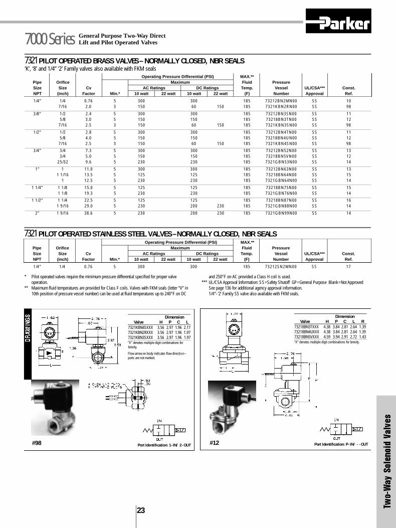
Coils are rated by insulation classes that correspond to a maximumallowable coil temperature. The maximum allowable coiltemperature is the temperature to which the coil can be exposedwithout experiencing thermal degradation of the magnet wireinsulation. These classes and corresponding maximum temperaturelevels are:
PermissibleNominal Temp. by Change Temp. Rise
Class of Resistance Above 25°C (77°F)Class Temperature Method (UL) Ambient Temp.
A 105°C (221°F) 110°C (230°F) 85°C (153°F)B 130°C (266°F) 120°C (248°F) 95°C (171°F)F 155°C (311°F) 140°C (284°F) 115°C (207°F)H 180°C (356°F) 160°C (320°F) 135°C (243°F)
Coils meeting Classes F and H are sometimes referred to as “HighTemperature Coils”. These ratings are summarized graphically inFigure 1.
Figure 1
1 2 9
Valve Sizing– Determining the Flow Rate of a Valve*
Air and Gas ServiceTo properly size a valve for air or gas service, fourspecific parameters must be known:
• Upstream pressure (inlet pressure to thevalve)
• Pressure differential (or downstreampressure, the outlet pressure of the valve)
• Actual flow through the valve in SCFM, orCv required to yield the desired flow
• The gas that will be flowing through thevalve, and it’s specific gravity
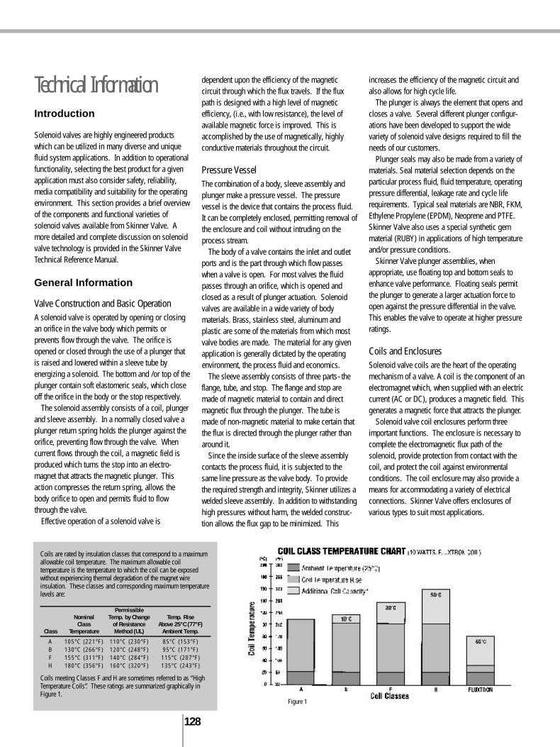
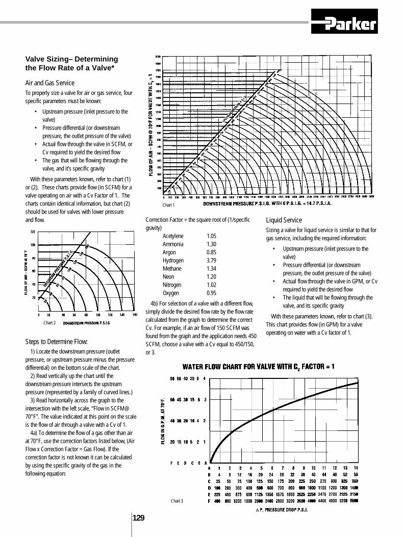
With these parameters known, refer to chart (1) or (2). These charts provide flow (in SCFM) for avalve operating on air with a Cv Factor of 1. Thecharts contain identical information, but chart (2)should be used for valves with lower pressure and flow.
Steps to Determine Flow:1) Locate the downstream pressure (outlet
pressure, or upstream pressure minus the pressuredifferential) on the bottom scale of the chart.
2) Read vertically up the chart until thedownstream pressure intersects the upstreampressure (represented by a family of curved lines.)
3) Read horizontally across the graph to theintersection with the left scale, “Flow in SCFM@70°F”. The value indicated at this point on the scaleis the flow of air through a valve with a Cv of 1.
4a) To determine the flow of a gas other than airat 70°F, use the correction factors listed below, (AirFlow x Correction Factor = Gas Flow). If thecorrection factor is not known it can be calculatedby using the specific gravity of the gas in thefollowing equation:
Correction Factor = the square root of (1/specificgravity)
Acetylene 1.05Ammonia 1.30Argon 0.85Hydrogen 3.79Methane 1.34Neon 1.20Nitrogen 1.02Oxygen 0.95
4b) For selection of a valve with a different flow,simply divide the desired flow rate by the flow ratecalculated from the graph to determine the correctCv. For example, if an air flow of 150 SCFM wasfound from the graph and the application needs 450SCFM, choose a valve with a Cv equal to 450/150,or 3.
Liquid ServiceSizing a valve for liquid service is similar to that forgas service, including the required information:
• Upstream pressure (inlet pressure to thevalve)
• Pressure differential (or downstreampressure, the outlet pressure of the valve)
• Actual flow through the valve in GPM, or Cvrequired to yield the desired flow
• The liquid that will be flowing through thevalve, and its specific gravity
With these parameters known, refer to chart (3).This chart provides flow (in GPM) for a valveoperating on water with a Cv factor of 1.
Chart 2
Chart 1
Chart 3
1 3 0
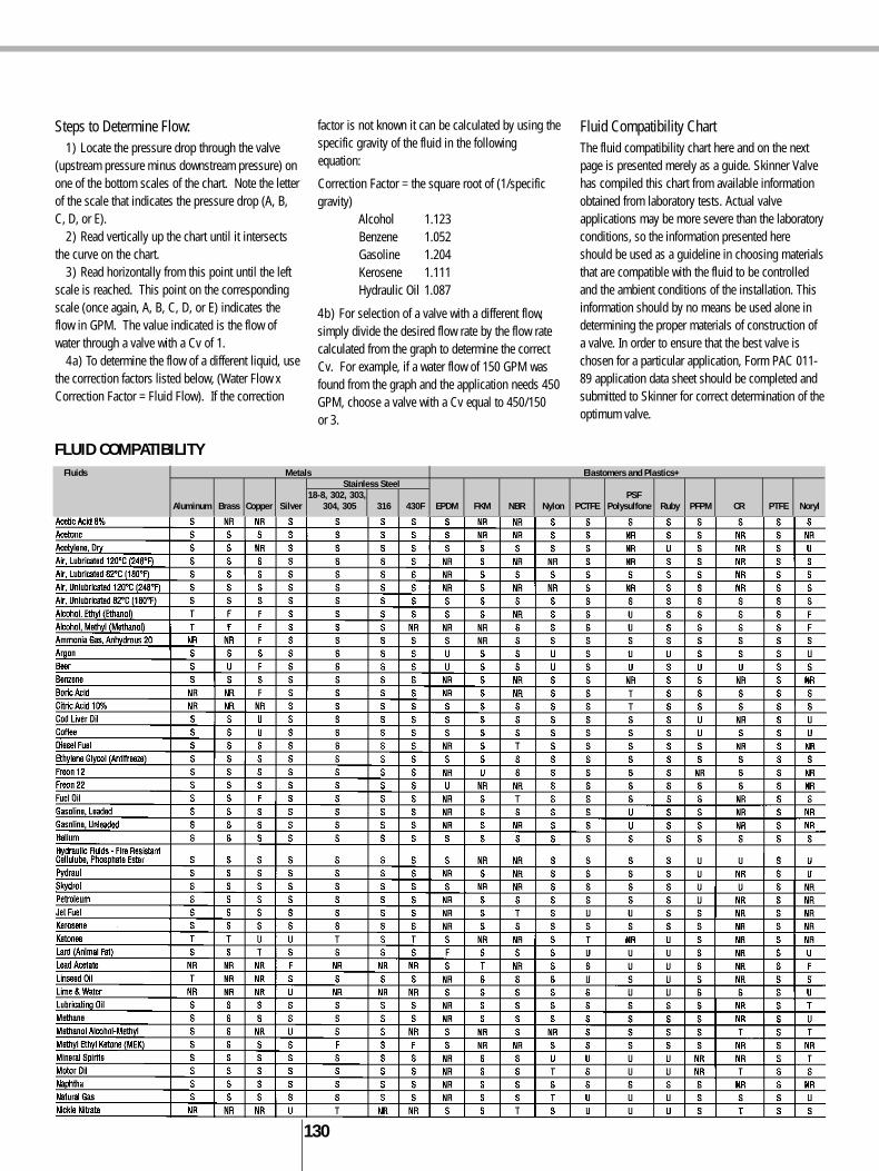
Steps to Determine Flow:1) Locate the pressure drop through the valve
(upstream pressure minus downstream pressure) onone of the bottom scales of the chart. Note the letterof the scale that indicates the pressure drop (A, B,C, D, or E).
2) Read vertically up the chart until it intersectsthe curve on the chart.
3) Read horizontally from this point until the leftscale is reached. This point on the correspondingscale (once again, A, B, C, D, or E) indicates theflow in GPM. The value indicated is the flow ofwater through a valve with a Cv of 1.
4a) To determine the flow of a different liquid, usethe correction factors listed below, (Water Flow xCorrection Factor = Fluid Flow). If the correction
factor is not known it can be calculated by using thespecific gravity of the fluid in the followingequation:
Correction Factor = the square root of (1/specificgravity)
Alcohol 1.123Benzene 1.052Gasoline 1.204Kerosene 1.111Hydraulic Oil 1.087
4b) For selection of a valve with a different flow,simply divide the desired flow rate by the flow ratecalculated from the graph to determine the correctCv. For example, if a water flow of 150 GPM wasfound from the graph and the application needs 450GPM, choose a valve with a Cv equal to 450/150 or 3.
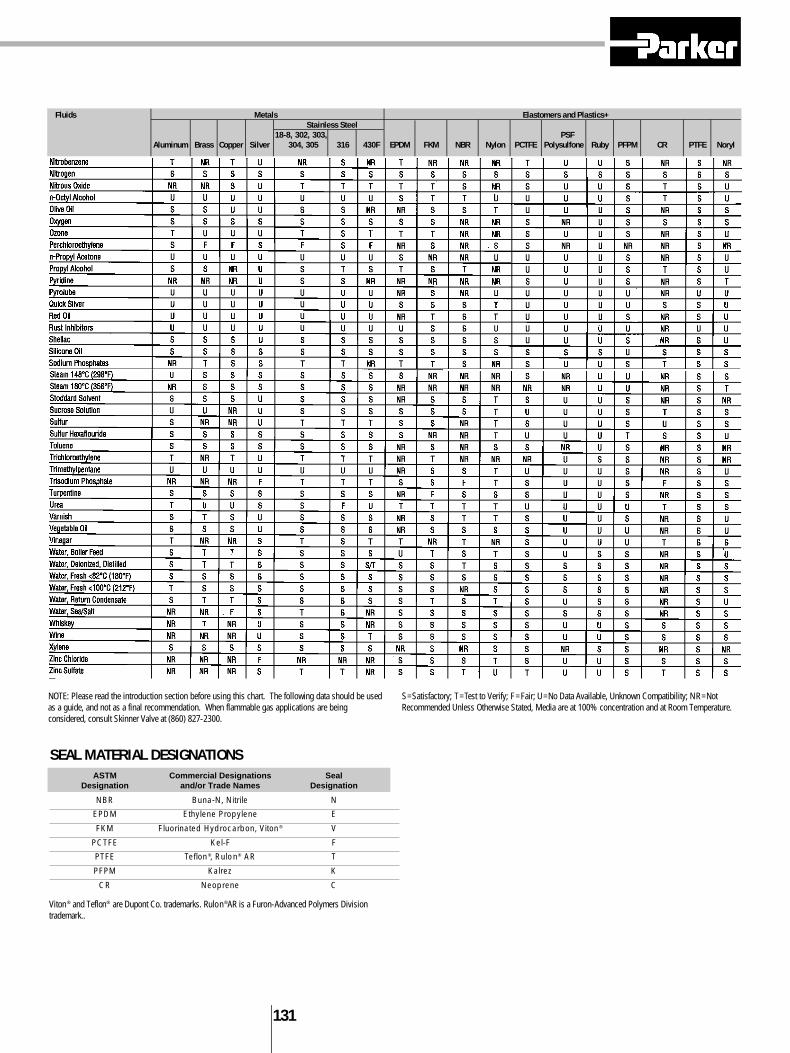
Fluid Compatibility ChartThe fluid compatibility chart here and on the nextpage is presented merely as a guide. Skinner Valvehas compiled this chart from available informationobtained from laboratory tests. Actual valveapplications may be more severe than the laboratoryconditions, so the information presented hereshould be used as a guideline in choosing materialsthat are compatible with the fluid to be controlledand the ambient conditions of the installation. Thisinformation should by no means be used alone indetermining the proper materials of construction ofa valve. In order to ensure that the best valve ischosen for a particular application, Form PAC 011-89 application data sheet should be completed andsubmitted to Skinner for correct determination of theoptimum valve.
FLUID COMPATIBILITYFluids Metals Elastomers and Plastics+
Stainless Steel18-8, 302, 303, PSF
Aluminum Brass Copper Silver 304, 305 316 430F EPDM FKM NBR Nylon PCTFE Polysulfone Ruby PFPM CR PTFE Noryl
1 3 1
SEAL MATERIAL DESIGNATIONS
Viton® and Teflon® are Dupont Co. trademarks. Rulon®AR is a Furon-Advanced Polymers Divisiontrademark..
ASTM Commercial Designations SealDesignation and/or Trade Names Designation
NBR Buna-N, Nitrile N
EPDM Ethylene Propylene E
FKM Fluorinated Hydrocarbon, Viton® V
PCTFE Kel-F F
PTFE Teflon®, Rulon® AR T
PFPM Kalrez K
CR Neoprene C
Fluids Metals Elastomers and Plastics+Stainless Steel
18-8, 302, 303, PSFAluminum Brass Copper Silver 304, 305 316 430F EPDM FKM NBR Nylon PCTFE Polysulfone Ruby PFPM CR PTFE Noryl
NOTE: Please read the introduction section before using this chart. The following data should be usedas a guide, and not as a final recommendation. When flammable gas applications are beingconsidered, consult Skinner Valve at (860) 827-2300.
S=Satisfactory; T=Test to Verify; F=Fair; U=No Data Available, Unknown Compatibility; NR=NotRecommended Unless Otherwise Stated, Media are at 100% concentration and at Room Temperature.
1 3 2
DESCRIPTION OF SIGNIFICANT DIGITS
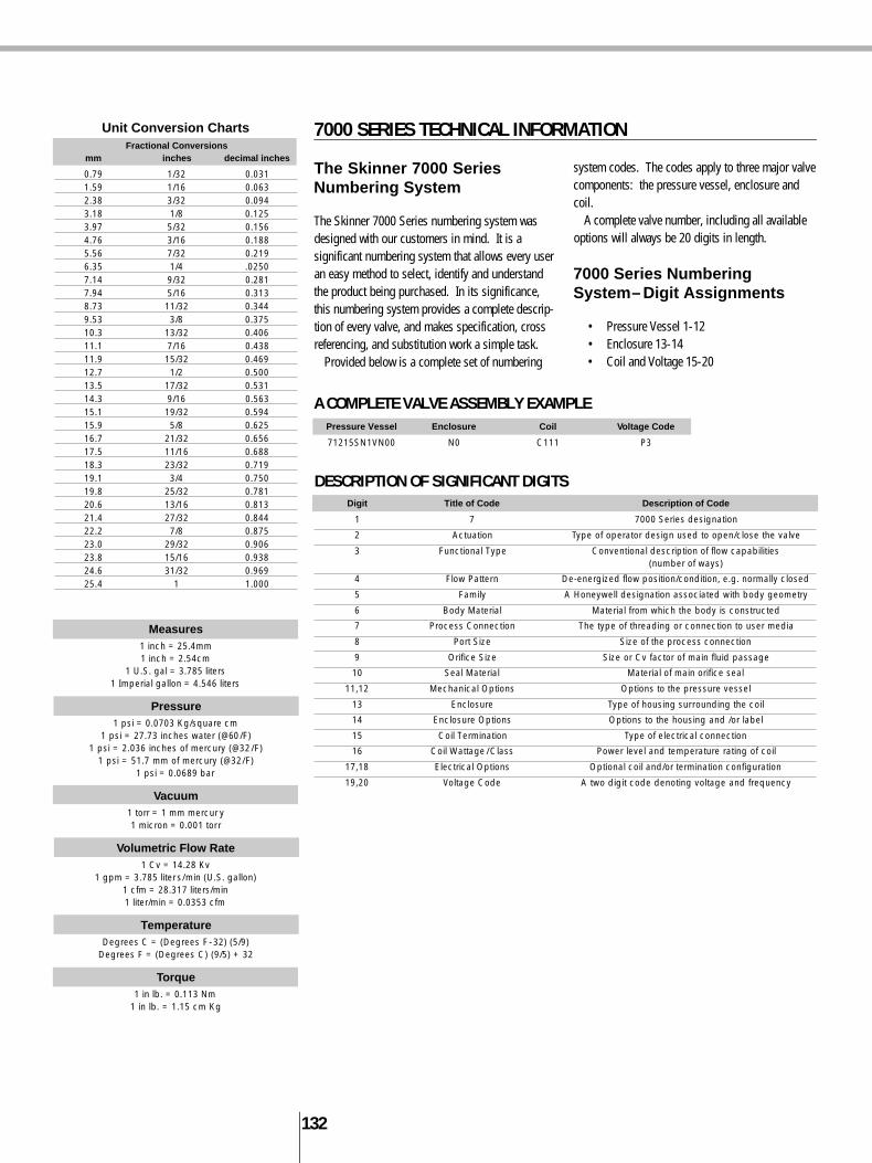
Unit Conversion ChartsFractional Conversions
mm inches decimal inches
0.79 1/32 0.0311.59 1/16 0.0632.38 3/32 0.0943.18 1/8 0.1253.97 5/32 0.1564.76 3/16 0.1885.56 7/32 0.2196.35 1/4 .02507.14 9/32 0.2817.94 5/16 0.3138.73 11/32 0.3449.53 3/8 0.37510.3 13/32 0.40611.1 7/16 0.43811.9 15/32 0.46912.7 1/2 0.50013.5 17/32 0.53114.3 9/16 0.56315.1 19/32 0.59415.9 5/8 0.62516.7 21/32 0.65617.5 11/16 0.68818.3 23/32 0.71919.1 3/4 0.75019.8 25/32 0.78120.6 13/16 0.81321.4 27/32 0.84422.2 7/8 0.87523.0 29/32 0.90623.8 15/16 0.93824.6 31/32 0.96925.4 1 1.000
The Skinner 7000 Series Numbering System
The Skinner 7000 Series numbering system wasdesigned with our customers in mind. It is asignificant numbering system that allows every useran easy method to select, identify and understandthe product being purchased. In its significance,this numbering system provides a complete descrip-t i o n of every valve, and makes specification, crossreferencing, and substitution work a simple task.
Provided below is a complete set of numbering
system codes. The codes apply to three major valvecomponents: the pressure vessel, enclosure andcoil.
A complete valve number, including all availableoptions will always be 20 digits in length.
7000 Series NumberingSystem– Digit Assignments
• Pressure Vessel 1-12• Enclosure 13-14• Coil and Voltage 15-20
7000 SERIES TECHNICAL INFORMATION
A COMPLETE VALVE ASSEMBLY EXAMPLE
Measures1 inch = 25.4mm1 inch = 2.54cm
1 U.S. gal = 3.785 liters1 Imperial gallon = 4.546 liters
Pressure1 psi = 0.0703 Kg/square cm
1 psi = 27.73 inches water (@60/F)1 psi = 2.036 inches of mercury (@32/F)
1 psi = 51.7 mm of mercury (@32/F)1 psi = 0.0689 bar
Vacuum1 torr = 1 mm mercur y1 micron = 0.001 torr
Volumetric Flow Rate1 Cv = 14.28 Kv
1 gpm = 3.785 liters/min (U.S. gallon)1 cfm = 28.317 liters/min1 liter/min = 0.0353 cfm
TemperatureDegrees C = (Degrees F-32) (5/9)
Degrees F = (Degrees C) (9/5) + 32
Torque1 in lb. = 0.113 Nm
1 in lb. = 1.15 cm Kg
Pressure Vessel Enclosure Coil Voltage Code
71215SN1VN00 N0 C111 P3
Digit Title of Code Description of Code
1 7 7000 Series designation
2 Actuation Type of operator design used to open/close the valve
3 Functional Type Conventional description of flow capabilities(number of ways)
4 Flow Pattern De-energized flow position/condition, e.g. normally closed
5 Family A Honeywell designation associated with body geometry
6 Body Material Material from which the body is constructed
7 Process Connection The type of threading or connection to user media
8 Port Size Size of the process connection
9 Orifice Size Size or Cv factor of main fluid passage
10 Seal Material Material of main orifice seal
11,12 Mechanical Options Options to the pressure vessel
13 Enclosure Type of housing surrounding the coil
14 Enclosure Options Options to the housing and /or label
15 Coil Termination Type of electrical connection
16 Coil Wattage/Class Power level and temperature rating of coil
17,18 Electrical Options Optional coil and/or termination configuration
19,20 Voltage Code A two digit code denoting voltage and frequency

1 3 3
1 2 3 4 5 6 7 8 9 10 11 & 12Actuation Functional Flow Family* Body Threading/ Pipe Orifice Seals/+ Mech. Options
Type Pattern Material Process Size Code# ElastomersConnection (NPT)
7 1 Direct Acting 3 Three-Way 3-Way Valves 1 A Aluminum A SAE 1 1/8” A C CR 00 No Option2 Direct Lift 4 Four-Way 1 Normally Closed 2 B Brass E Male NPT 2 1/4” B E EPDM A2 Silver Shading Ring3 Pilot Operated 2 Normally Open pressure 3 L Noryl F Flange 3 3/8” C F PCTFE CA Cylinder ”A” normally open to pressure inlet
Int. Pilot Supply in/out of body4 Pilot Operated Ext. 3 Multi/Dual Purpose 4 M Zinc G BSP-Parallel 4 1/2” D K PFPM CB Cylinder “B” normally open to pressure inlet
Pilot Supply Die Cast5 Remote Pressure operated 8 Diverting 5 R 316 SS R BSP-Taper 5 3/4” E L Nylon C0 4-Step Variable Closing6 Manual/Mech. Operated 9 Normally Open pressure 6 S 430F SS J Bib Fitting 6 1” F M Metal J0 Pilot Exhaust Return Pipe
in the sleeve, pressureout the body
4-Way Valves 8 T Teflon N NPT (Female 7 1 1/4” G N NBR J1 Exhaust Adaptor NutNational Pipe
Thread)1 2-position, single 9 V 303 SS S Subbase 8 1 1/2” H R Ruby M0 Manual Override
operator Mounted2 3-position, dual E T Barbed Fitting 9 2” J T PTFE MC Manual Override w/Var. Closing
operator center closed3 3-position, dual F K U PTFE MJ Manual Override w/Exhaust Return Pipe
operator center open4 3-position, dual G L V FKM MR Manual Override w/Main Stream Metering
operator center open6 2-position, dual H M M5 Manual Override w/Exhaust Adaptor
operator bi-stable7 2-position, dual K N R0 Sleeve Exhaust Metering
operator bi-stable,with latching
L P R1 Mainstream MeteringT Q R2 Adjustable Bypass
V R S0 Steam Service RatedS W0 Anti-Water Hammer (fixed)T N0 Cleaned for oxygen serviceUV
0 thru 9
PRESSURE VESSEL NUMBERING 2-WAY VALVESFor reference only. Consult catalog listings for available combinations.
Note: These tables are provided to interpret product specifications. It should not be used ro create avalve number without reference to the catalog listings or consultation with Skinner Valve personnel.
* The family designator is assigned to organize products by physical similarity.# Orifice codes relate to a range of Cv factors and sizes. They are listed in ascending order.+ Reference Seal Material Designations, page 131.
1 2 3 4 5 6 7 8 9 10 11 & 12Actuation Functional Flow Family* Body Threading/ Pipe Orifice Seals/+ Mech. Options
Type Pattern Material Process Size Code# ElastomersConnection (NPT)
7 1 Direct Acting 2 Two-Way 1 Normally Closed 1 A Aluminum A SAE 1 1/8” A C CR 00 No Option2 Direct Lift 2 Normally Open 2 B Brass E Male NPT 2 1/4” B E EPDM A2 Silver Shading Ring
pressure in/out of body3 Pilot Operated 3 Multi/Dual purpose 4 L Noryl F Flange 3 3/8” C F PCTFE C0 4-Step Variable Closing
Internal Pilot Supply4 Pilot Operated 9 Normally Open pressure 5 R 316 SS G BSP-Parallel 4 1/2” D K PFPM J1 Exhaust Adaptor Nut
External Pilot Supply in the body, pressureout the sleeve
5 Remote Pressure 6 S 430F SS R BSP-Taper 5 3/4” E L Nylon M0 Manual OverrideOperated
6 Manual/Mech. Operated 8 T Teflon J Bib Fitting 6 1” F M Metal MC Manual Override w/Var. Closing9 V 303 SS N NPT(Female 7 1 1/4” G N NBR M5 Manual Override w/Exhaust Adaptor
Nat’l Pipe thread) F T Barbed Fitting 8 1 1/2” H R Ruby R0 Sleeve Exhaust MeteringG 9 2” J T PTFE R1 Mainstream MeteringH K U PTFE R2 Adjustable BypassK L V FKM S0 Steam S e rvice RatedV M W0 Anti-Water Hammer (fixed)
N N0 Cleaned for oxygen servicePQRSTUV
0 thru 9
PRESSURE VESSEL NUMBERING 3- AND 4-WAY VALVESFor reference only. Consult catalog listings for available combinations.

1 3 4
Coil Picture Enclosure Description Applicable Code Coils
A0 Standard Connection, 7/8” exit to accommodate strain relief, J111, J222, adapter or fittings for lead wires, NEMA Type 2 J322, F611, J611
B0 1/2” Conduit Connection for attachment of conduit, 1/2” NPT F611, J611fittings or BX cable, NEMA Type 2
F0 Yoke for use where open enclosure is suitable F611, J611
G0 Watertight, 1/2” conduit hub accommodating 1/2” NPT fittings F611, J611or BX cable, NEMA Type 4X
J0 Splice box, 7/8” exit allowing for internal splice, NEMA Type 2 J111, J222, J322, F611, J611
M1 Magnelatch, 1/2” conduit hub for attachment of conduit, G011, J0111/2” NPT fittings or BX cable, NEMA Type 2
M2 Magnelatch, leaded with grommet connection, NEMA Type 2 G011, J011
N0 Nut and Washer All Integrated Coils
ELECTRICAL ENCLOSURE OPTIONS
ENCLOSURE, COIL AND VOLTAGE NUMBERING 2-, 3- AND 4-WAY VALVES
+ See Note on page 133. * Fluxtron only
13 & 14 15 & 16 17 & 18 19 & 20Enclosure Coil Construction Terminations and Voltage
Type and Type Option Codes
A0 7/8” Knockout Integrated Coils 00 Standard DIN, Screw, Tab Coils (no leads) B2 24/60B0 1/2” Conduit C1 1/2” NPT Conduit, 10 Watt Class F, NEMA 4X 11 Class F Coils with 18” leads C1 12VDCF0 Yoke C2 1/2” NPT Conduit, 10 Watt Class H, NEMA 4X 22 Class H Coils with 18” leads C2 24VDCG0 Water Tight C3 1/2” NPT Conduit, 22 Watt Class H, NEMA 4X GL C1,C2,C3 & H1,H2, H3 Coils with Ground lead C4 48VDCJ0 Junction Box D1 DIN, 10 Watt Class F D1 All DIN Coils with Cable Gland Connector C6 120VDCM1 Magnelatch D2 DIN, 10 Watt Class H D2 All DIN Coils with 1/2” Conduit Connector P0* 24,50/60
1/2” ConduitM2 Magnelatch D3 DIN, 22 Watt Class H D4 D1,D2,D4 coils for timer assembly with fixed-off and P3 110/50-120/60
Grommet adjustable on-timeN0 Nut and Washer H1 1/2” NPT Conduit, 10 Watt Class F, NEMA 7, 9 DB All DIN Coils with Terminal Box Q3 220/50-240/60
H2 1/2” NPT Conduit, 10 Watt Class H, NEMA 7, 9 TB S1,S2,S3 Coils with Terminal Box Q8 440/50-480/6H3 1/2” NPT Conduit, 22 Watt Class H, NEMA 7, 9 S1 Hazardous stainless steel yoke with 18” leads and ground lead 2K 208/60L1 18” leads, 10 Watt Class F 2W* 110-120,50/60L2 18” leads, 10 Watt Class H 3W* 220-240,50/60L3 18” leads, 22 Watt Class HS1 Screw Terminal, 10 Watt Class FS2 Screw Terminal, 10 Watt Class HS3 Screw Terminal, 22 Watt Class HT1 1/4” Tab Terminal, 10 Watt Class F
Conventional Coils
J1 18” leads, 10 Watt Class FJ2 18” leads, 10 Watt Class HJ3 18” leads, 22 Watt Class H
Specialty Coils
F6 Fluxtron 4-wire, 1 Watt moldedJ6 Fluxtron 2-wire, 1 Watt moldedJ0 Magnelatch 2-wire DC onlyG0 Magnelatch 3-wire AC/DC (DC pulse)
A coil enclosure is needed to complete the magneticflux path of conventional molded coils and specialtycoils. The enclosure can also serve to protect thecoil and provide a means to accommodate theelectrical connection. This section describes themost common electrical enclosure options available.
7000 Series Enclosure Options
7000 Series integrated coils incorporate thesefeatures into a one-piece assembly which requiresonly a nut and washer (enclosure code N0) to fastento the pressure vessel. The 7000 Series conven-tional enclosure selection is provided to comple-ment the integrated coil offering providing flexibilityin product type and installation.
1 3 5
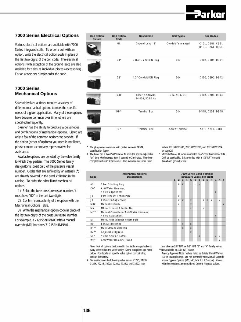
Coil Option Coil Option Description Coil Types Coil CodesPicture Code
GL Ground Lead 18” Conduit Terminated C1GL, C2GL, C3GLH1GL, H2GL, H3GL
D1* Cable Gland DIN Plug DIN D1D1, D2D1, D3D1
D2* 1/2” Conduit DIN Plug DIN D1D2, D2D2, D3D2
D4# Timer, 12-48VDC DIN, AC & DC D1D4, D2D4, D3D424-120, 50/60 Hz
DB^ Terminal Box DIN D1DB, D2DB, D3DB
TB^ Terminal Box Screw Terminal S1TB, S2TB, S3TB
Mechanical Options 7000 Series Valve FamiliesCode Descriptions (pressure vessel 5th digit)
1 2 3 4 5 6 8 9 E F G K T
A2 Silver Shading Ring X X x x x
C0* Anti-Water Hammer,4 step adjustment x
J0 Pilot Exhaust Return Pipe x
J1 Exhaust Adapter Nut x x x x x x x
M0# Manual Override x x x
M5 M0 w/ Exhaust Adapter Nut x x
MC* Manual Override w/ Anti-Water Hammer,4 step Adjustment x
MJ M0 w/ Pilot Exhaust Return Pipe x
R0 Exhaust Metering x x
R1** Main Stream Metering x x
R2** Adjustable Bypass x
S0* Steam Service Rated x x x
W0* Anti-Water Hammer, Fixed x
Note: Not all options designated in this table are applicable toevery valve within the valve family. Some exceptions are notedbelow. For details on specific valve option compatibility,consult the factory.
# Not available on the following valve series: 71225, 71295,7122K, 72218, 72228, 7221G, 7322G, and 73222. Not
available on 3/8” NPT or 1/2” NPT “5” and “K” family valves.**Not available on 3/8” NPT valves.
Agency Approval Note: Valves listed as Safety Shutoff Valves(SS in catalog listings) are not permitted with Manual Overrideand/or Bypass Options (M0, MC, M5, R1, R2 above). Valveswith these options are considered General Purpose Valves.
7000 Series Electrical Options
Various electrical options are available with 7000Series integrated coils. To order a coil with anoption, write the electrical option code in place ofthe last two digits of the coil code. The electricaloptions (with exception of the ground lead) are alsoavailable for sales as individual pieces (accessories).For an accessory, simply order the code.
7000 Series Mechanical Options
Solenoid valves at times requires a variety ofdifferent mechanical options to meet the specificneeds of a given application. Many of these optionshave become common over time, others arespecified infrequently.
Skinner has the ability to produce wide varietiesand combinations of mechanical options. Listed areonly a few of the common options we provide. Ifthe option (or set of options) you need is not listed,please contact a company representative forassistance.
Available options are denoted by the valve familyto which they pertain. The 7000 Series familydesignator is position 5 of the pressure vesselnumber. Codes that are suffixed by an asterisk (*)are already covered in the product listing in thecatalog. To order the other listed mechanicaloptions:
1) Select the base pressure vessel number. Itmust have “00” in the last two digits.
2) Confirm compatibility of the option with theMechanical Options Table.
3) Write the mechanical option code in place ofthe last two digits of the pressure vessel number.For example, a 71215SN1MN00 with a manualoverride (M0) becomes 71215SN1MNM0.
* The plug comes complete with gasket to meets NEMAspecification Type 4
# The timer has a fixed “off” time of 12 minutes and an adjustable“on” time which ranges from 1 second to 2 minutes. The timercomplete with 24” 3-wire cable. Also available on Timer Drain
Valves 7321KBY61640, 7321KBY63200, and 7321KBY6320Aon page 25.
^ Meets NEMA 4, 4X when connected to a Screw Terminal or DINCoil, as applicable. It is provided with a 1/2” NPT conduitthread and ground screw.

1 3 6
Agency Approvals
Most Skinner solenoid valves are approved byUnderwriter’s Laboratories (UL) and certified by theCanadian Standards Association (CSA). The tablebelow summaries the specific approvals obtained,which are dependent upon the combination ofapproved pressure vessels, coils and enclosures forboth ordinary and hazardous locations.
UL approved valves are also CSA certified. NOTE: Agencyapproval is contingent upon factory assembly of solenoidvalves.
* Coil voltage must also be approved. See pages 12 and 13.**Pressure vessels must be approved as Safety Shutoff (SS) or
General Purpose (GP) valves. See catalog sections.
Response Time
The response time of a solenoid valve depends onmany factors such as voltage, frequency, pressure,media, temperature (including coil) and the type ofvalve. Variations in these factors can have asignificant effect on the response time. Thefollowing tabulation lists the approximate responsetimes for several different types of valves. Thetimes given are for the valves to go from closedposition to open or from open position to closed.
Response Time Valve Type (milliseconds)
Direct Acting Valves 4-15Small Pilot Operated Piston Valves 30-90Large Pilot Operated Piston Valves 100-150Small Pilot Operated Diaphragm Valves 30-60Large Pilot Operated Diaphragm Valves 60-160Direct Lift Diaphragm Valves 30-60
Valve Type Up To(cycles/min)
Direct Acting Valves 600Small Pilot Operated Piston Valves 400Large Pilot Operated Piston Valves 150Small Pilot Operated Diaphragm Valves 300Large Pilot Operated Diaphragm Valves 200Direct Lift Diaphragm Valves 200
Operating Speed (Cycle Rates)
Operating speed is defined as the maximum numberof cycles (On/Off) per minute that a solenoid valveis capable of completing. It is dependent upon theresponse time characteristics of the valve. Many ofour small, short stroke, direct acting valves arecapable of operating at rates over 2,000 cycles perminute. However, for normal operation lower cyclerates as shown are usually recommended.
Agency Approved Solenoid Valve CombinationsEnclosure Coil* Metallic Bodied Pressure Vessels Plastic Bodied
Code Type/Option (Aluminum, Brass, Stainless Steel, Zinc) Pressure Vessels**(Noryl, Teflon)
NPT ported BSPported FLG mounted All Porting Types
N0 C111, C222, C322N0 C1GL, C2GL, C3GLN0 D1DB, D2DB, D3DB
A0,B0,G0,J0 F611, J611 ULListedA0,J0 J111, J222, J322
N0 H111, H222, H322N0 H1GL, H2GL, H3GLN0 S1TB, S2TB, S3TBN0 D100, D1D1, D1D2N0 D200, D2D1, D2D2N0 D300, D3D1, D3D2 ULComponent RecognizedF0 F611, J611N0 L111, L222, L322N0 S100, S200, S300N0 T100
Vacuum
While many of our solenoid valves with elastomericseals listed in this catalog can be used on vacuum,the standard 100% production leakage test does notascertain that the valves are sufficiently tight forsevere vacuum applications. We do, however,design, produce, and test many vacuum valves tomeet specific customer requirements. Therefore, weinvite you to consult us for your vacuum valveapplications.
Fluid Temperature Limitations
32°F Minimum Fluid Temperature if moisture ispresent. Otherwise minus 40°F for direct actingvalves with NBR seals, minus 10°F with FKM seals(minus 10°F for “4” family valves). For exceptions,consult Skinner.
Types of Protection of Solenoids for Hazardous EnvironmentsStandards are established by the European Committee for Electro-Technical Standards (CENELEC). Degreesof Protection of electrical parts and operating temperatures are defined by various European standards.
The following charts show the Degree of Protection for the selected coils along with the maximum surfacetemperatures for each temperature code classification.
Protection Class Degree of Protection
IP-65 Protection against ingress of dust (dust proof)Protection against contact with internal partsProtection against a water jet from a nozzle from all directions
IP-67 Protection against ingress of dust (dust proof)Protection against contact with internal partsProtection against water when the equipment is immersed in waterunder specific pressure and time conditions
Temperature Maximum AllowableClassification Surface Temperature
°C °FT1 450 842T2 300 572T3 200 392T4 135 257T5 100 212T6 85 185
1 3 7
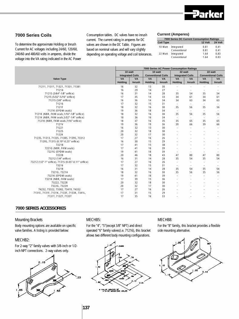
7000 Series AC Power Consumption Ratings10 watt 10 watt 22 watt 22 watt
Integrated Coils Conventional Coils Integrated Coils Conventional CoilsValve Type VA VA VA VA VA VA VA VA
Holding Inrush Holding Inrush Holding Inrush Holding Inrush
71211, 71311, 71321, 71331, 71381 16 32 13 30 - - - -71214 16 29 14 27 - - - -
71215 (3/64”-1/8” orifice) 16 31 14 28 35 54 35 5471215 (5/32”-5/16” orifice) 17 35 14 33 34 61 34 61
71215 (3/8” orifice) 16 36 14 34 34 63 34 6371216 17 32 15 31 - - - -7121F 18 32 16 30 35 56 35 56
7121K (EPDM seals) 19 36 18 34 - - - -7121K (NBR, FKM seals,1/16”-1/8” orifice) 18 32 16 30 35 56 35 567121K (NBR, FKM seals,5/32”-1/4” orifice) 18 36 16 34 - - - -
7121K (NBR, FKM seals,7/16” orifice) 18 37 16 35 35 65 35 657121V 19 36 19 36 39 66 39 6671221 16 32 13 30 - - - -71225 20 32 18 30 - - - -7122K 20 32 17 30 - - - -
71235, 71313, 71335, 71385, 71395, 73312 17 27 16 26 - - - -71295, 71315 (0.19”-0.25” orifice) 16 30 15 29 - - - -
72218 17 41 15 38 - - - -7221G (NBR, FKM seals) 17 41 16 39 - - - -
7221G (EPDM seals) 19 41 18 39 - - - -72228 20 46 18 43 47 80 47 80
73212 (1/4” orifice) 16 31 14 28 35 54 35 5473212 (1/2”-1” orifice), 71315 (0.05”-0.11” orifice) 17 27 16 26 - - - -
73216 17 32 15 31 - - - -73218 16 31 14 28 35 54 35 54
7321G, 7321H 18 32 16 30 35 56 35 567321K (EPDM seals) 19 41 18 39 - - - -
7321K (NBR, FKM seals) 17 39 15 36 - - - -73222, 73228 20 32 18 30 - - - -7322G, 7322H 20 32 17 30 - - - -
74232, 73322, 73382, 73419, 74332 17 27 16 26 - - - -7131E, 7131F, 7131K, 7133F, 7133K, 7341L, 17 31 15 29 - - - -
7131T, 7132T, 7133T 17 35 16 33 - - - -
7000 SERIES ACCESSORIES
Mounting BracketsBody mounting options are available on specificvalve families. A listing is provided below:
MECHB2:For 2-way “2” family valves with 3/8-inch or 1/2-inch NPT connections. 2-way valves only.
MECHB5:For the “4”, “5”(except 3/8” NPT) and directoperated “6” family valves(i.e. 71216), this bracketallows two different body mounting configurations.
MECHB8:For the “8” family, this bracket provides a flexibleside mounting alternative.
7000 Series Coils
To determine the approximate Holding or InrushCurrent for AC voltages including 24/60, 120/60,240/60 and 480/60 volts in amperes, divide thevoltage into the VA rating indicated in the AC Power
Consumption tables. DC valves have no inrushcurrent. The current rating in amperes for DCvalves are shown in the DC Table. Figures arebased on nominal values and will vary slightlydepending on operating voltage and coil tolerances.
Current (Amperes)7000 Series DC Current Consumption Ratings
Coil Type 12 Volt 24 Volt
10 Watt Integrated 0.81 0.41Conventional 0.81 0.41
22 Watt Integrated 1.64 0.83Conventional 1.64 0.83

1 3 8
7000 Series Solenoid Valve Seal Materials
7000 Series solenoid valves are constructed withthe finest elastomeric and plastic seal materialsavailable to ensure dependable bubbletight opera -tion and long life. Most of the valves in the catalogutilize a single seal material whether a plunger sealor a flange seal. However, many valve designsrequire a variety of different sealing materials.
The 7000 Series numbering system delineates thetenth digit for description of the main orificeseal– the seal that actually prevents flow through thevalve. For direct acting valves this represents the
plunger seal and for pilot operated valves thisrepresents the diaphragm. Since every seat materialcannot be specified in the significant valve number,the following table can be used to determine theadditional seat materials used.
Example: Valve No. 71215SN1EF00
Tenth digit F = Kel F seal material. Since this is adirect acting valve, the plunger seal is PCTFE.From the table at left, we see that when a plungerseal is PCTFE, the flange seal is FKM. (this valvehas no diaphragm)
Example: Valve No. 73218BN3TE00
Tenth digit E = EPDM seal material. Since this is
a pilot operated valve, the diaphragm is EPDM.From the table above, we see that when thediaphragm is EPDM, the plunger and flange seal isEPDM.
Standard Seal Material CombinationsFlange Diaphragm Piston
Seal Seal Seal
NBR NBR NBRFKM FKM FKMRuby FKM FKM
PCTFE FKM FKMPFPM PTFE PTFEEPDM EPDM EPDMPTFE PTFE PTFECR CR CR
Note: See Seal Material Designation Chart page 131.
Seal Material DesignationsASTM Commercial Designations 7000 Series
Designation and/or Trade Names SealDesignation
NBR Buna-N, Nitrile NEPDM Ethylene Propylene EFKM Fluorinated Hydrocarbon, V
Viton®
PCTFE Kel-F FPTFE Teflon®, Rulon®AR TPFPM Kalrez K
CR Neoprene C
Viton ® and Teflon® are Dupont Co. trademarks.Rulon®AR is a Furon–Advanced Polymers Division trademark
Non-Standard Seal Material Combinations
There are some exceptions to the above standard.The following valve types do not conform to thetable of standard seal material combinations and aretherefore specified in this table. Non-metallic orificematerials are specified where applicable.
NOTE: There may exist especially exacting application requirements which would necessitate a moredetailed description of the various components and materials employed in the construction of Skinnersolenoid valves. In such cases, contact the factory so that we may provide you with more detailedinformation.
NOTE: There may exist especially exacting application requirements which would necessitate a moredetailed description of the various components and materials employed in the construction of Skinnersolenoid valves. In such cases, contact the factory so that we may provide you with more detailedinformation.
2-Way ValvesCatalog Orifice Plunger Flange Diaphragm Piston OtherNumber (if non-metallic) Seal Seal Seal Seal Seal
71216SN1BL00 Nylon - NBR - - -71216SN2BL0071216SN1GL0071216SN2GL00
71216SN1FU00 Rulon - NBR - - -71216SN2FU00
71216SN1JT00 PTFE - NBR - - -71216SN2JT00
72228BN3TES0 - FKM EPDM EPDM - EPDM, FKM72228BN4UES072228BN5VES0
73216BN2MT00 Nylon - NBR - PTFE NBR
73216SN2MT00 Polysulfone - NBR - PTFE NBR
73222BN2MN00 - FKM NBR - NBR NBR73222SN2MN00
3- and 4-Way ValvesCatalog Orifice Plunger Flange Diaphragm Piston OtherNumber (if non-metallic) Seal Seal Seal Seal Seal
7131EBN2LN00 FKM - - - NBR NBR7131FBF4LV00 FKM - - - - FKM7133FBF4LV007341LAN1HN00 FKM - - - NBR NBR7341LMN2NN00 FKM - - - NBR NBR

1 3 9
S100, S200, S300-Screw Te r m i n a t i o n s
D100, D200, D300-DIN Terminations (DIN 43650 and ISO 4400)
L111, L222-Leaded Te r m i n a t i o n s
T 1 00-Tab Te r m i n a t i o n s
Integrated Coils and Terminal Box Dimensions
The valve construction reference drawings provide outline dimensions for allpressure vessels contained in this catalog. They are shown with the 1/2”conduit style integrated coil as standard. The individual coil drawings on thispage provide dimensions for the other 7000 Series integrated coils. To applythese coil dimensions to any of the standard valve construction references, adatum line (cL) has been included which corresponds to the conduit hubcenterline dimension of the 1/2” conduit style integrated coil.
* Option DB: Slotted Head (#8-32 TH’D)Option TB: 9/64 Socket Head(M3X0.05TH’D)
Option DB, TB-Terminal Box
All dimensions in inches.

1 4 0
3000 Series Numbering System DesignatorsPressure 1 Series Designation 3 3000 Series
Vessel 2 Operations 1 Direct Acting, 6 Watt9 Direct Acting, 3 Watt
3 Ways 2 Two-Way(Functional Type) 3 Three-Way
4 Flow Pattern 1 Normally Closed3 Multipurpose8 Directional9 Normally Open, Ported Sleeve
5 Family B B
6 Body Material B BrassJ Operator (No Body)S 303 Stainless Steel
7 Process Connection A Male Straight ThreadN Female National Pipe ThreadR BSP Taper
8 Pipe Size 1 1/8”6 5/16-24 UNF7 3/4-32 UNF
9 Orifice A 1/32”E 3/64”G 1/16”J 5/64”L 3/32”N 1/8”Q 5/32”
10 Seal Material C CRE EPDMN NBRV FKM
11 Mechanical Option 00 None12 AD 1/8” NPT Sleeve Adapter
C# Aluminum, Female 1/8” NPT, 2, 3, or 4 Station Cavity Manifold BlockHT Helium Leak TestedN0 Cleaned for Oxygen ServiceR1 Bottom Metering
Housing 13 Housing BB 1/2” Conduit14 N0 No Housing (Integrated Coil)
RR GrommetYY Yoke
Coil 15 Coil Designation M1S1 Integrated Molded, 1/4” Tab, 6W*, Class BMC11 Integrated Class F, 1/2” Conduit 18” Leads, 6W, NEMA 4XMH11 Integrated Class F, 1/2” Conduit 18” Leads, 6W, NEMA 4X, 7, 9
16 M3J5 Integrated Molded, 12” Leads, 6W, Class B17 M4S1 Integrated Molded, 1/4” Tab, 3W, Class B18 M6J5 Integrated Molded, 12” Leads, 3W, Class B
T1J1 Taped 12” Leads, 6W, Class BT3J1 Taped 12” Leads, 3W, Class B
19 Voltage Code P0 24/50-60 Hz AC20 P3 110/50 Hz, 120/60 Hz AC
Q3 220/50 Hz, 240/60 Hz ACC0 6 VDCC1 12 VDCC2 24 VDC
* For all 6 watt Coils, actual wattage for 24/60 Volts is 7.5.
3000 SERIES TECHNICAL INFORMATION

1 4 1
Electrical Enclosure Options
A coil enclosure is needed to complete the magneticflux path of conventional molded coils and specialtycoils. The enclosure can also serve to protect thecoil and provide a means to accommodate theelectrical connection. This section describes themost common electrical enclosure optionsavailable.
3000 Series Enclosure Options3000 Series integrated coils are a one-pieceassembly which requires only a nut and washer(enclosure code N0) to fasten to the pressurevessel. The 3000 Series conventional enclosureselection complements the integrated coil offeringproviding flexibility in product type and installation.
3000 Series Repair Kits/Accessories
Repair kits are available for all Skinner 3000 Seriesvalves. These kits include a new plunger assemblyand plunger return spring. Specify the kit you needby the part number listed, which corresponds to thetype of valve and seal material to be rebuilt.
Coils
To determine the approximate Holding or InrushCurrent for AC voltages including 24/60, 120/60,240/60 and 480/60 volts in amperes, divide thevoltage into the VA rating indicated in the AC Power
Consumption tables. DC valves have no inrushcurrent. The current rating in amperes for DCvalves are shown in the DC Table. Figures arebased on nominal values and will vary slightlydepending on operating voltage and coil tolerances.
Coil Picture Enclosure Description ApplicableCode CoilsRR Grommet Enclosure T1J1, T3J1
BB 1/2” Conduit Connection T1J1, T3J1
YY Yoke. For use where open enclosure is suitable T1J1, T3J1
N0 Nut and Washer for Integrated Molded coils M1S1, M4S1M3J5, M6J5
N0 Nut and Washer for 1/2” Conduit NEMA coils MC11, HC11
Flow Pattern NBR Neoprene EPDM FKM
2-Way Normally Closed 3K3121N 3K3121C 3K3121E 3K3121V2-Way Normally Open 3K3129N 3K3129C 3K3129E 3K3129V3-Way Normally Closed 3K3131N 3K3131C 3K3131E 3K3131V3-Way Normally Open 3K3139N 3K3139C 3K3139E 3K3139V3-Way Multipurpose 3K3133N 3K3133C 3K3133E 3K3133V3-Way Directional Control 3K3138N 3K3138C 3K3138E 3K3138V
Universal Mounting Bracket–B19-006 Brass Adaptor with Gasket = 300-22-003 SS Adaptor with Gasket = 300-22-004
A, B, C, MB and V9 SeriesCurrent (Amperes) DC Current Consumption Ratings
AC Power Consumption RatingsVA VA Coil Type
Valve Series Holding Inrush Valve Series 6 Volt 12 Volt 24 Volt 120 Volt
Two-way B 17 9.7 Two-way B 1.05 0.53 0.26 0.05Three-way B 19 12 Three-way B 1.05 0.53 0.26 0.05Two-way C 25 16 Two-way C 1.17 0.58 0.29 0.06Three-way C 25 16 Three-way C 1.17 0.58 0.29 0.06Two-way A 122 49 Two-way A - - - -Three-way A 82 40 Three-way A 2.33 1.17 0.58 0.12Three-way MB 12 6.5 Three-way MB 0.83 0.42 0.21 0.04Four-way MB 12 6.5 Four-way MB 0.83 0.42 0.21 0.04Four-way V9* 32.5 17.5 Four-way V9* 1.42 0.71 0.35 0.07
* Per coil * Per coil
A, B, C, MB AND V9 SERIES INFORMATION
1 4 2
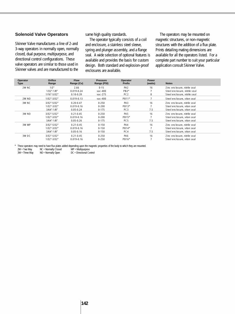
Operator Orifice Flow Pressure Operator PowerType Range Range (Cv) Range (PSI) Prefix (watts) Notes
2W NC 1/2” 2.66 0-15 PA2 16 Zinc enclosure, nitrile seal1/32”-1/8” 0.019-0.24 vac-400 PB2* 7 Steel enclosure, nitrile seal1/16”-5/32” 0.10-0.39 vac-275 PC2 8 Steel enclosure, nitrile seal
2W NO 1/32”-3/32” 0.019-0.13 vac-400 PB11* 7 Steel enclosure, viton seal
3W NC 3/32”-5/32” 0.20-0.47 0-250 PA3 16 Zinc enclosure, nitrile seal1/32”-3/32” 0.019-0.16 0-200 PB13* 7 Steel enclosure, viton seal3/64”-1/8” 0.05-0.24 0-175 PC3 7.5 Steel enclosure, viton seal
3W NO 3/32”-5/32” 0.21-0.45 0-250 PA5 16 Zinc enclosure, nitrile seal1/32”-3/32” 0.019-0.16 0-200 PB15* 7 Steel enclosure, viton seal3/64”-1/8” 0.05-0.26 0-175 PC5 7.5 Steel enclosure, viton seal
3W MP 3/32”-5/32” 0.21-0.45 0-150 PA4 16 Zinc enclosure, nitrile seal1/32”-3/32” 0.019-0.16 0-150 PB14* 7 Steel enclosure, viton seal3/64”-1/8” 0.05-0.16 0-150 PC4 7.5 Steel enclosure, viton seal
3W DC 3/32”-5/32” 0.21-0.45 0-250 PA6 16 Zinc enclosure, nitrile seal1/32”-3/32” 0.019-0.16 0-250 PB16* 7 Steel enclosure, viton seal
* These operators may need to have flux plates added depending upon the magnetic properties of the body to which they are mounted.2W = Two Way NC = Normally Closed MP = Multipurpose3W = Three Way NO = Normally Open DC = Directional Control
Solenoid Valve Operators
Skinner Valve manufactures a line of 2-and3-way operators in normally open, normallyclosed, dual purpose, multipurpose, anddirectional control configurations. Thesevalve operators are similar to those used inSkinner valves and are manufactured to the
same high quality standards.The operator typically consists of a coil
and enclosure, a stainless steel sleeve,spring and plunger assembly, and a flangeseal. A wide selection of optional features isavailable and provides the basis for customdesign. Both standard and explosion-proofenclosures are available.
The operators may be mounted onmagnetic structures, or non-magneticstructures with the addition of a flux plate.Prints detailing mating dimensions areavailable for all the operators listed. For acomplete part number to suit your particularapplication consult Skinner Valve.
1 4 3
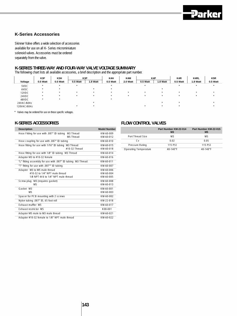
K-Series Accessories
Skinner Valve offers a wide selection of accessoriesavailable for use on all K- Series microminiaturesolenoid valves. Accessories must be orderedseparately from the valve.
K-SERIES THREE-WAY AND FOUR-WAY VALVE VOLTAGE SUMMARYThe following chart lists all available accessories, a brief description and the appropriate part number.
* Valves may be ordered for use on these specific voltages.
K3F K3H K3P K4H K4M K4P K4R K4RL K5RVoltage 0.5 Watt 0.5 Watt 0.5 Watt 1.8 Watt 0.5 Watt 2.0 Watt 0.5 Watt 1.8 Watt 0.5 Watt 1.8 Watt 0.5 Watt
5VDC * * * * * * * *6VDC * * * * *
12VDC * * * * * * * * * * *24VDC * * * * * * * * * * *48VDC * * *
24VAC/60Hz * * * *120VAC/60Hz * * * * * *
K-SERIES ACCESSORIES FLOW CONTROL VALVESDescription Model Number
Hose Fitting for use with .087” ID tubing M3 Thread KM-60-009M5 Thread KM-60-012
Hose coupling for use with .087” ID tubing KM-60-010
Hose fitting for use with 1/16” ID tubing M3 Thread KM-60-015#10-32 Thread KM-60-018
Hose fitting for use with 1/8” ID tubing M3 Thread KM-60-014
Adapter M3 to #10-32 female KM-60-016
“L” fitting assembly for use with .087” ID tubing M3 Thread KM-60-011
”T” fitting for use with .087”” ID tubing KM-60-007
Adapter M3 to M5 male thread KM-60-006#10-32 to 1/4” NPT male thread KM-60-0041/8 NPT th’d to 1/4” NPT male thread KM-60-005
Screw plug M3 (requires gasket) KM-60-008M5 KM-60-013
Gasket M3 KM-60-001M5 KM-60-003
Spacer for PCB mounting with 2 screws KM-60-002
Nylon tubing .087” ID, 65 foot roll KM-22-018
Exhaust muffler M5 KM-60-017
Exhaust restrictor M5 K08-001
Adapter M5 male to M3 male thread KM-60-021
Adapter #10-32 female to 1/8” NPT male thread KM-60-022
Part Number KM-22-014 Part Number KM-22-015M3 M5
Port Thread Size M3 M5
Cv 0.02 0.05
Pressure Rating 115 PSI 115 PSI
Operating Temperature 40-140°F 40-140°F