Dräger Polytron 7000 - Thorne & Derrick
144
Dräger Polytron 7000 (approved as type P3U and P3FB) Transmitter for electrochemical Sensors Instructions for Use 00123758_4.eps
-
Upload
khangminh22 -
Category
Documents
-
view
1 -
download
0
Transcript of Dräger Polytron 7000 - Thorne & Derrick

Dräger Polytron 7000 (approved as type P3U and P3FB)Transmitter for electrochemical SensorsInstructions for Use
0012
3758
_4.e
ps
Dan Macey
2
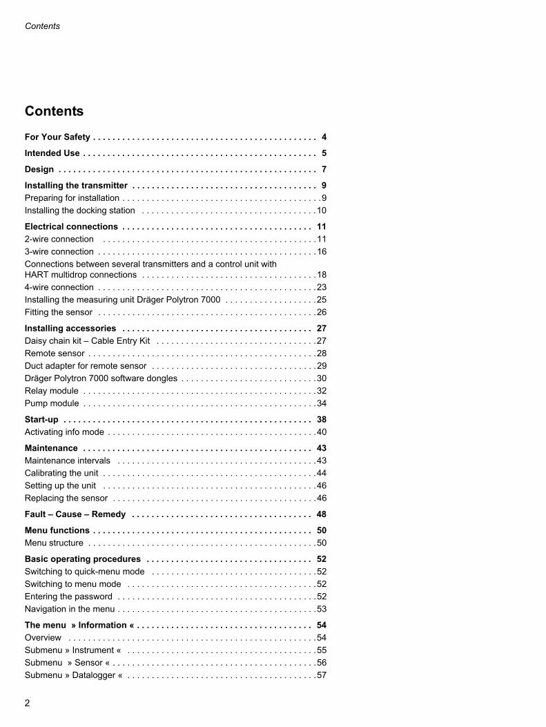
Contents
Contents
For Your Safety . . . . . . . . . . . . . . . . . . . . . . . . . . . . . . . . . . . . . . . . . . . . . . 4
Intended Use . . . . . . . . . . . . . . . . . . . . . . . . . . . . . . . . . . . . . . . . . . . . . . . . 5
Design . . . . . . . . . . . . . . . . . . . . . . . . . . . . . . . . . . . . . . . . . . . . . . . . . . . . . 7
Installing the transmitter . . . . . . . . . . . . . . . . . . . . . . . . . . . . . . . . . . . . . . 9
Preparing for installation . . . . . . . . . . . . . . . . . . . . . . . . . . . . . . . . . . . . . . . . .9
Installing the docking station . . . . . . . . . . . . . . . . . . . . . . . . . . . . . . . . . . . .10
Electrical connections . . . . . . . . . . . . . . . . . . . . . . . . . . . . . . . . . . . . . . . 11
2-wire connection . . . . . . . . . . . . . . . . . . . . . . . . . . . . . . . . . . . . . . . . . . . .11
3-wire connection . . . . . . . . . . . . . . . . . . . . . . . . . . . . . . . . . . . . . . . . . . . . .16
Connections between several transmitters and a control unit with HART multidrop connections . . . . . . . . . . . . . . . . . . . . . . . . . . . . . . . . . . . .18
4-wire connection . . . . . . . . . . . . . . . . . . . . . . . . . . . . . . . . . . . . . . . . . . . . .23
Installing the measuring unit Dräger Polytron 7000 . . . . . . . . . . . . . . . . . . .25
Fitting the sensor . . . . . . . . . . . . . . . . . . . . . . . . . . . . . . . . . . . . . . . . . . . . .26
Installing accessories . . . . . . . . . . . . . . . . . . . . . . . . . . . . . . . . . . . . . . . 27
Daisy chain kit – Cable Entry Kit . . . . . . . . . . . . . . . . . . . . . . . . . . . . . . . . .27
Remote sensor . . . . . . . . . . . . . . . . . . . . . . . . . . . . . . . . . . . . . . . . . . . . . . .28
Duct adapter for remote sensor . . . . . . . . . . . . . . . . . . . . . . . . . . . . . . . . . .29
Dräger Polytron 7000 software dongles . . . . . . . . . . . . . . . . . . . . . . . . . . . .30
Relay module . . . . . . . . . . . . . . . . . . . . . . . . . . . . . . . . . . . . . . . . . . . . . . . .32
Pump module . . . . . . . . . . . . . . . . . . . . . . . . . . . . . . . . . . . . . . . . . . . . . . . .34
Start-up . . . . . . . . . . . . . . . . . . . . . . . . . . . . . . . . . . . . . . . . . . . . . . . . . . . 38
Activating info mode . . . . . . . . . . . . . . . . . . . . . . . . . . . . . . . . . . . . . . . . . . .40
Maintenance . . . . . . . . . . . . . . . . . . . . . . . . . . . . . . . . . . . . . . . . . . . . . . . 43
Maintenance intervals . . . . . . . . . . . . . . . . . . . . . . . . . . . . . . . . . . . . . . . . .43
Calibrating the unit . . . . . . . . . . . . . . . . . . . . . . . . . . . . . . . . . . . . . . . . . . . .44
Setting up the unit . . . . . . . . . . . . . . . . . . . . . . . . . . . . . . . . . . . . . . . . . . . .46
Replacing the sensor . . . . . . . . . . . . . . . . . . . . . . . . . . . . . . . . . . . . . . . . . .46
Fault – Cause – Remedy . . . . . . . . . . . . . . . . . . . . . . . . . . . . . . . . . . . . . 48
Menu functions . . . . . . . . . . . . . . . . . . . . . . . . . . . . . . . . . . . . . . . . . . . . . 50
Menu structure . . . . . . . . . . . . . . . . . . . . . . . . . . . . . . . . . . . . . . . . . . . . . . .50
Basic operating procedures . . . . . . . . . . . . . . . . . . . . . . . . . . . . . . . . . . 52
Switching to quick-menu mode . . . . . . . . . . . . . . . . . . . . . . . . . . . . . . . . . .52
Switching to menu mode . . . . . . . . . . . . . . . . . . . . . . . . . . . . . . . . . . . . . . .52
Entering the password . . . . . . . . . . . . . . . . . . . . . . . . . . . . . . . . . . . . . . . . .52
Navigation in the menu . . . . . . . . . . . . . . . . . . . . . . . . . . . . . . . . . . . . . . . . .53
The menu » Information « . . . . . . . . . . . . . . . . . . . . . . . . . . . . . . . . . . . . 54
Overview . . . . . . . . . . . . . . . . . . . . . . . . . . . . . . . . . . . . . . . . . . . . . . . . . . .54
Submenu » Instrument « . . . . . . . . . . . . . . . . . . . . . . . . . . . . . . . . . . . . . . .55
Submenu » Sensor « . . . . . . . . . . . . . . . . . . . . . . . . . . . . . . . . . . . . . . . . . .56
Submenu » Datalogger « . . . . . . . . . . . . . . . . . . . . . . . . . . . . . . . . . . . . . . .57
2

Contents
The menu » Calibration « . . . . . . . . . . . . . . . . . . . . . . . . . . . . . . . . . . . . 58
Overview . . . . . . . . . . . . . . . . . . . . . . . . . . . . . . . . . . . . . . . . . . . . . . . . . . .58
Submenu » Zero calibration « . . . . . . . . . . . . . . . . . . . . . . . . . . . . . . . . . . .58
Submenu » Span cal. « . . . . . . . . . . . . . . . . . . . . . . . . . . . . . . . . . . . . . . . .59
Autocalibration . . . . . . . . . . . . . . . . . . . . . . . . . . . . . . . . . . . . . . . . . . . . . . .60
The menu » Settings « . . . . . . . . . . . . . . . . . . . . . . . . . . . . . . . . . . . . . . . 62
Overview . . . . . . . . . . . . . . . . . . . . . . . . . . . . . . . . . . . . . . . . . . . . . . . . . . .62
Submenu » Instrument « . . . . . . . . . . . . . . . . . . . . . . . . . . . . . . . . . . . . . . .63
Submenu » Communication « . . . . . . . . . . . . . . . . . . . . . . . . . . . . . . . . . . .70
Submenu » Sensor « . . . . . . . . . . . . . . . . . . . . . . . . . . . . . . . . . . . . . . . . . .76
Submenu » Datalogger « . . . . . . . . . . . . . . . . . . . . . . . . . . . . . . . . . . . . . . .79
Polytron 7000 Operation via LON . . . . . . . . . . . . . . . . . . . . . . . . . . . . . . 82
Polytron 7000 Operation via PROFIBUS PA . . . . . . . . . . . . . . . . . . . . . 83
Technical Data . . . . . . . . . . . . . . . . . . . . . . . . . . . . . . . . . . . . . . . . . . . . . 87
Relay module . . . . . . . . . . . . . . . . . . . . . . . . . . . . . . . . . . . . . . . . . . . . . . . .90
Pump module . . . . . . . . . . . . . . . . . . . . . . . . . . . . . . . . . . . . . . . . . . . . . . . .91
Order List . . . . . . . . . . . . . . . . . . . . . . . . . . . . . . . . . . . . . . . . . . . . . . . . . 92
Sensors . . . . . . . . . . . . . . . . . . . . . . . . . . . . . . . . . . . . . . . . . . . . . . . . . . . .93
Accessories . . . . . . . . . . . . . . . . . . . . . . . . . . . . . . . . . . . . . . . . . . . . . . . . .93
Calibration accessories . . . . . . . . . . . . . . . . . . . . . . . . . . . . . . . . . . . . . . . .94
ATEX approval . . . . . . . . . . . . . . . . . . . . . . . . . . . . . . . . . . . . . . . . . . . . . 95
Metrological certificate of approval . . . . . . . . . . . . . . . . . . . . . . . . . . . 117
Section 5 of the Suitability Test Report . . . . . . . . . . . . . . . . . . . . . . . . . . .117
Overview of the adjustment ranges . . . . . . . . . . . . . . . . . . . . . . . . . . . . . .118
Information on DrägerSensor O2 (6809720) . . . . . . . . . . . . . . . . . . . . . . .119
Information on DrägerSensor O2-LS (6809630) . . . . . . . . . . . . . . . . . . . . .121
IECEx approval . . . . . . . . . . . . . . . . . . . . . . . . . . . . . . . . . . . . . . . . . . . . 123
UL approval . . . . . . . . . . . . . . . . . . . . . . . . . . . . . . . . . . . . . . . . . . . . . . . 127
CSA approval . . . . . . . . . . . . . . . . . . . . . . . . . . . . . . . . . . . . . . . . . . . . . 132
Declaration of Conformity . . . . . . . . . . . . . . . . . . . . . . . . . . . . . . . . . . . 138
Drilling templates . . . . . . . . . . . . . . . . . . . . . . . . . . . . . . . . . . . . . . . . . . 139
Dräger docking station . . . . . . . . . . . . . . . . . . . . . . . . . . . . . . . . . . . . . . . .139
Remote sensor . . . . . . . . . . . . . . . . . . . . . . . . . . . . . . . . . . . . . . . . . . . . . .141
Duct adapter . . . . . . . . . . . . . . . . . . . . . . . . . . . . . . . . . . . . . . . . . . . . . . . .141
3

For Your Safety
For Your Safety
Strictly follow the Instructions for UseAny use of the apparatus requires full understanding and strict observation of these instructions.The apparatus is only to be used for purposes specified here.
MaintenanceThe unit must be inspected and serviced regularly by suitably qualified persons. Repair and general overhaul of the apparatus may only be carried out by trained service personnel.We recommend that a service contract be obtained with DrägerService and that all repairs also be carried out by them. Only authentic Dräger spare parts may be used for maintenance.Observe chapter "Maintenance Intervals".
Use in areas subject to explosion hazardsEquipment and components which are used in explosion-hazard areas and which have been inspected and approved in accordance with international or European explosion-protection regulations may be used only under the specified conditions. The equipment or components may not be modified in any manner. The use of faulty or incomplete parts is forbidden. The appropriate regulations must be observed at all times when carrying out repairs on the equipment or components. If the transmitter has been installed with a suitable safety barrier, its case may be opened or the sensor may be changed while the transmitter is operating.
AccessoriesUse only accessories shown in the Ordering List.
CAUTIONWhen the transmitter is installed in Ex areas Class II, Div. 1 & 2, Group E, F, G the opening of the housing (inclusive sensor replacement) must not be done when connected to power (power must be turned off or the area has to be declassified). Explosion hazard!If the transmitter is equipped, either when delivered or subsequently, with the relay module and/or the pump module, the complete unit is no longer approved for use in explosion-hazard areas. The use of the Dräger Polytron 7000 equipped with a pump module and/or relay module in explosion-hazard areas is forbidden! Explosion hazard!Not suitable for use in oxygen-enriched atmospheres, i.e. oxygen content exceeds 21 vol. %. Explosion hazard!
When used in transmitters with pump module, the O2 LS sensor (68 09 630) must always be installed at vibration-free locations. If used in this combination, vibrations may cause the measured value to deviate outside of the permis-sible range.
In applications where category 1G (Zone 0) or EPL Ga devices are required, intense electrostatic charging processes must be avoided.
4

Intended Use
Intended Use
Dräger Polytron® 7000 Transmitter for electrochemical sensors
— For stationary, continuous monitoring of gas concentrations in ambient air, with built-in DrägerSensor®.
— Automatic configuration of transmitter to suit the built-in DrägerSensor.
— The measuring range may be selected, but it is dependent on the sensor installed.
— With 4 to 20 mA interface, LON communication, Foundation Fieldbus or PROFIBUS PA.
— For installation alternatively in Ex areas zone 0, 1, 2 corresponding to device category 1G, 2G, 3G or Class I, Class II, Div. 1 & 2 hazardous area.For further details, see the installation notes.
— Optionally compatible with HART® for connection to a suitable control unit.— Optionally available with pump module for the continuous supply of the gas/air mixture to be tested to the transmitter.
_______________
® Polytron is a registered trademark of Dräger.DrägerSensor is a registered trademark of Dräger.HART is a registered trademark of HCF, Austin, Texas, USA
CAUTIONNo explosion protection. Explosion hazard!
5
Intended Use
If used together with a control unit (e. g. Regard without a safety barrier) or equipped with a relay module:
— Warning before any hazardous gas concentrations are reached.— Automatic implementation of counter measures (for example, connection of an additional ventilation).— Warning for device errors; display of necessary maintenance work.— Special calibration mode (blocking of alarm triggering, display of calibration mode, one-man calibration).
Detection of oxygen in accordance with EN 50104
Measuring function for the explosion protection
BVS 03 ATEX E 406 X
Measurement of oxygen
PFG No. 41300504
CAUTIONNo explosion protection. Explosion hazard!
CAUTIONIf the Dräger Polytron 7000 transmitter is used for the detection of oxygen, at least one alarm relay must be config-ured as latching.
Dräger Polytron 7000 4 to 20 mAwith/without display and keypadwith/without relay and pump modulein connection with DrägerSensor
Measuring range Testing standard
O2 LS (6809630)O2 (6809720)
0 to 25 Vol.-% O2 EN 50104 (neutralization measure-ment)
Dräger Polytron 7000 4 to 20 mAwith/without display and keypadwith/without relay and pump modulein connection with DrägerSensor
Measuring range Testing standard
O2 LS (6809630)O2 (6809720)
0 to 25 Vol.-% O2 EN 50104 (oxygen deficiency and excess of oxygen)
6

Design
0022
3758
_1_1
.eps
Design
The Dräger Polytron 7000 was developed specifically as a modular system which permits the user to select one of many different configurations.
Dräger Polytron 7000 transmitter with display and keypad and optional for operation with a Palm Pilot 515 and infrared interface or a hand-held HART-compatible operating device or an HART-compatible operating station connected at any point to the 2-wire cable.
This version is suitable for installations where a display of measured value is required on site and where access is easy for the operator.The transmitter is operated directly via a built-in keypad and display.
Optional extras:
Pump moduleThis module draws in the gas to be measured from a remote location and pumps it into the Dräger Polytron 7000 transmitter.
Relay moduleThis module permits the local switching of actuators, alarm generators, etc. on the basis of the measured gas concentration.
CAUTIONThis option is only possible without explosion protection approval. Explosion hazard!
CAUTIONThis option is only possible without explosion protection approval. Explosion hazard!
If the Dräger Polytron 7000 transmitter is used in connection with the relay module for detecting oxygen according to EN 50104, the transmitter has to be equipped with software version 8.0 or higher.
7

Design
Daisy-chain kitFor the connection of several Dräger Polytron 7000 transmitters to one bus line (multidrop installation). This option does not affect the explosion-protec-tion approval of the transmitter.
Duct extensionFor mounting the Polytron 7000 transmitters on a duct.Used to measure the gas concentration in the duct. This option does not affect the explosion-protection approval of the transmitter.
Remote sensorFor installation of the sensor at a distance of up to 30 m away from the Dräger Polytron 7000 transmitter. This option does not affect the explosion-protection approval of the transmitter.
Duct adapter for remote sensorFor mounting a remote sensor on a duct for measuring the gas concentration in the duct. This option does not affect the explosion-protection approval of the transmitter.
Dräger Polytron 7000 software donglesFor activation of additional functions of the Dräger Polytron 7000. This option does not affect the explosion-protection approval of the transmitter.
8

Installing the transmitter
Installing the transmitter
Preparing for installation
The performance and effectiveness of the entire system depends essentially on the position chosen for installing the transmitter.The following should be noted during installation:
— Local requirements and regulations governing the installation of gas meas-uring systems.
— Relevant regulations concerning the connection and routing of electric pow-er supply and signal lines.
— The full scope of environmental factors to which the transmitter may be ex-posed (ambient conditions: see Technical data, page 87).
— Physical properties of the gas to be measured:For gases with a density lower than that of air, the transmitter must be lo-cated above any possible leak or at the highest point at which large concen-trations of gas may occur.For gases and vapours with a density greater than that of air, the transmitter must be located below a possible leak or at the lowest point at which such gases and vapours may occur.
— The specific uses (e.g. possible leaks, ventilation conditions, etc.).— Accessibility for the necessary maintenance work (see Installation instruc-
tions for the Polytron docking station).— All other factors and conditions which could have a negative effect on the
installation and operation of the system (such as vibrations or varying tem-peratures).
— We recommend installing a reflective shield if the unit is exposed to strong sunlight.
— The transmitter must be installed vertically (sensor facing downwards).— The transmitter has been tested with regard to its weather-resistance and
may be installed out of doors. Use of a splash guard is recommended to protect the sensor from splashing water, dust and wind.
The Dräger Polytron 7000 transmitter consists of several components:— Dräger docking station
This can be pre-installed anywhere and contains the electrical installation components.
— The measuring unit Dräger Polytron 7000 contains the electronics of the transmitter.
If the measuring unit is not fitted immediately after installing the docking sta-tion, the latter should be covered with the raincover provided (dust and water protection) to protect against dust and splashing water.
NOTEIn explosion-hazard areas:Observe the national regulations concerning electrical equipment in explo-sion-hazard areas.
9

Installing the transmitter
0042
3758
_1.e
ps
1
0052
3758
_1.e
ps
2
0062
3758
_1.e
ps
3
Installing the docking station
— If the transmitter is to be installed in a Zone 2 explosion-hazard area, select a location with low exposure to mechanical risk.
— Docking station is installed vertically (transmitter with sensor facing down) in an area with low vibrations and stable temperatures – near the possible leak.
— A space of at least 15 cm (6") must be maintained above the transmitter for installation of the measuring unit.
— A space of at least 10 cm (4") – preferably 30 cm (12") – must be maintained below the docking station to permit access for maintenance.
Unpack the docking station.1 Remove raincover (protection against dust and splashing water).
2 Remove the 4-pole terminal block (Part No. 83 16 268), keep it in a safe place and insert it again after completion of the installation work.
A drilling template is provided on page 139. The mounting holes are 66 ±4mm (2.6 ± 0.16") apart.
If the measuring unit is not to be mounted at this time: Refit the raincover (protection against dust and splashing water).
For Multidrop installation only:(see page 18)
Installing the Daisy Chain kit
Part No. 83 17 2823 Break or drill out the prepared breakthrough for the second cable gland
from the inside of the docking station.The hole should have a diameter of 20.5 mm.
Check that the docking station has no loose parts, and clean it if necessary. Insert the nut of the cable gland into the docking station. Screw in the cable gland from the outside of the docking station and tighten
it.
CAUTIONSpacers (e.g. mounting bracket 68 09 951) must be used to prevent any twisting of the housing when installed on uneven surfaces.
10

Electrical connections
0072
3758
_1.e
ps
1
X8
2
+24
V0
V0
VS
igna
l
Electrical connections
— The electrical wiring may be laid and connected only by a qualified electri-cian, who must also comply with the appropriate regulations – a screened or unscreened cable (such as LiY, LiYCY) may be used.
2-wire connection
— Connection to central device with at least 2-wire cable, 0.5 (AWG 20) to 2.5 mm2 (AWG 13).
Installing the 4 to 20 mA current loop on the transmitter
— For currents of 3 to 22 mA, a DC voltage between 16.5 V DC (3 mA), or 8.0 V DC (22 mA) and 30 V DC must be present at the transmitter.
Fit 2-wire connecting cable in cable gland, cut to length and strip ends (approx. 80 mm / 3.15").
Shorten the shield (if installed) to prevent short-circuiting: Connect cable1 Use a 4-pole terminal block (X8), Part No. 83 16 268, for the
Dräger Polytron 7000 – Observe the polarity of the connections.Cut excess wires short or
2 secure them in centre terminals (Part No. 83 16 422).1 Slide connecting terminal back into holder. Secure cable in holder. Fold up the installation notes and place them in the Dräger docking station
for future use during commissioning. Refit raincover (protection against dust and splashing water).
Connecting to the central unit
Connect shield to earth of central unit (e.g. housing, earth bar, etc.).
Connecting the Dräger Polytron 7000 transmitter to a Dräger control unit (such as Regard, QuadGard, Unigard or Polytron):— Further information about the connection can be found in the instructions
for the Dräger control unit.
Connecting the Dräger Polytron 7000 transmitter to control units with a 4 to 20 mA interfaced made by other manufacturers:— For operation together with control units made by other manufacturers, care
must be taken that the voltage at the transmitter does not drop below 16.5 V at a current of 3 mA and 8.0 V at a current of 22 mA. The supply voltage, the resistance of the cable and the load and the resistance of any installed safety barrier must be taken into account.
— Further information about the connection can be found in the instructions for the control unit being used.
11

Electrical connections
oop) Note
Suitable only for 2-wire
Suitable only for 2-wire
oop) Note
Suitable only for 2-wire
Suitable only for 2-wire
Suitable only for 2-wire
Suitable only for 2-wire
Suitable for 2-wire and 3-wire
Suitable for 2-wire and 3-wire
Installing transmitter in mines where firedamp may occur
— Install a safety barrier with the appropriate explosion protection approval (device category M1) between the transmitter and the control unit.
— Only safety barriers or power supply units with the following characteristics may be used: UO (VOC) = 30 V, IO (ISC) = 0.3 A, PO = 700 mW.
— Make sure the maximum permissible capacitance and inductance connect-ed to the safety barrier or power supply are not exceeded (taking into ac-count the line as well). The safety-related input parameters of the transmitter are as follows: Ci = 0 nF, Li = 50 µH.
Installing the transmitter in areas subject to explosion hazards of zone 0, 1 or Div. 1 Install a safety barrier with the appropriate explosion protection approval
(category 1, 2 or Div. 1) between the transmitter and the control unit.— Only safety barriers with the following characteristics may be used: Uo (Voc)
30 V, Io (Isc) 0.3 A, Po 700 mW.— Take care that the maximum permissible capacitance and inductance of
connections to the safety barrier are not exceeded, also taking the cable into account. The safety-related input parameters of the transmitter are: Ci = 5 nF, Li = 50 µH.
Transmitter supply units(without HART-communication between Ex/Non-Ex area)The following safety barriers are provided as examples only. Selected barriers must be acceptable to the authority having jurisdiction and comply with the assigned P3U entity parameters also taking the cable into account.
SMART transmitter supply units(with HART-communication between Ex/Non-Ex area)The following safety barriers are provided as examples only. Selected barriers must be acceptable to the authority having jurisdiction and comply with the assigned P3U entity parameters also taking the cable into account.
Manufacturer Type suitable for R Cable (L
MTL MTL 5541 Zone 0, Div. 1 350
Pepperl & Fuchs KFD2–CR–Ex1.30 200 Zone 0, Div. 1 400
Manufacturer Type suitable for R Cable (L
Endress + Hauser
RN 221 N–B1 (ATEX) Zone 0 380
RN 221 N–C1 (FM) Div. 1 380
RN 221 N–D1 (CSA) Div. 1 380
RN 221 N–E1 (TIIS) 380
MTL MTL 5541 Zone 0, Div. 1 400
Pepperl & Fuchs KFD2–STC4–Ex1 Zone 0, Div. 1 300
12

Electrical connections
0092
3758
_1_e
n .
eps
-hazard area
rrier
Control unit
Earth point
4 ... 20 mA
0 V
+
–
+
— The cable resistances given apply for a load resistance of 250 . Higher load resistances can drastically reduce the permissible cable resistance!
When other barriers have been selected, care must be taken that the volt-ages on the transmitter do not fall below the following values when barrier parameters and cable resistance are taken into account:16.5 V for a current of 3 mA and 8.0 V for a current of 22 mA.
If HART communication is to be used, the HART specifications must also be observed.
The maximum possible cable lengths can be found in the table on page 19. In each case, use the line marked "Number of transmitters = 1".
— Connect shielding to earth point and/or 0 V (Ex i).
Installing the transmitters in explosion-hazard areas of zone 2— Use only supply units or a safety barrier of the device category 3.— Only supply units or safety barriers with the following characteristics may
be used: UO (VOC) ≤ 30 V, IO (ISC) ≤ 0.3 A, PO ≤ 700 mW.— Take care that the maximum permissible capacitance and inductance of
connections to the supply unit are not exceeded, also taking the cable into account.The safety-related input parameters of the transmitter are:Ci = 5 nF, Li = 50 µH.
The maximum possible cable lengths can be found in the table on page 21. In this table, select the line, " Number of transmitters = 1".
CAUTIONThe category 1 marking has to be cut out from the rating-plate label. Once the unit has been used after installation in the above manner, it may never be installed in explosion-hazard areas of zone 0 or zone 1 (device category 1 or 2). Explosion hazard!
Non-explosionExplosion-hazard area, zone 0, 1 or Div. 1
Safety baEx i
PA
4 to 20 mA
+24 V
13

Electrical connections
0082
3758
_1_e
n.ep
s
n-hazard area
Control unit
4 ... 20 mA
0 V
+
–
+
0102
3758
_4.e
ps1
X7 X8
2
FB –
FB +
Installing the transmitters in non-explosion-hazard areas:
The maximum possible cable lengths can be found in the table on page 21. In this table, select the line, " Number of transmitters = 1".
Installing fieldbus communication on the transmitter
— The transmitter can be connected to a certified intrinsically safe fieldbus system, which supports FISCO (Fieldbus intrinsically safe concept).
— The PROFIBUS PA transmission technology for intrinsically safe applica-tions is MBP. MBP stands for:– Manchester Coding (M)– Bus Powered (BP)
— 5 transmitters can be connected to a segment with a typical segment cur-rent of 100 mA.
Install the 2-wire connection cable in the cable gland, cut it to length and strip off the insulation (approx. 80 mm).
Shorten the shield (if installed) to prevent short-circuiting. Connect cable:1 Use a 4-pole terminal block (X7), Part No. 83 16 268, for the
Dräger Polytron 7000 – Observe the polarity of the connections. Cut excess wires short or
2 secure them in center terminals (Part No. 83 16 422).1 Slide connecting terminal back into holder. Secure cable in holder. Fold up the installation notes and place them in the Dräger docking station
for future use during commissioning. Refit raincover (protection against dust and splashing water).
CAUTIONThe explosion-protection markings has to be removed from the transmitter. Once the transmitter has been used after installation in this manner, it may never be installed in explosion-hazard areas.
CAUTIONInsert 4-pole (X7) terminal block into left holder.
Non-explosiowithout a safety barrier
4 to 20 mA
+24 V
Explosion-hazard area, zone 2 or non-explosion hazard
14

Electrical connections
Installing the transmitter in areas subject to explosion hazards of Zone 0 or Zone 1: Only safety barriers with the following characteristics may be used:
Umax 24 V, Imax 0.38 A, Pmax 5.32 W or those which correspond to the FISCO model ia or ib.
— The safety-related input parameters of the transmitter are as follows:Ci = 5 nF, Li = 10 µH.
— The transmitter may only be connected in 2-wire connection to the left 4-fold terminal block (X7) of the docking station. No electrical connections may be made to the right 4-fold terminal block (X8).
Installing the transmitter in areas subject to explosion hazards of Zone 2:— Make sure that the supply unit corresponds with the FISCO model ic and
that the maximum permissible capacitance and inductance of connections to the supply unit are not exceeded, (also take the cable into account).
— The safety-related input parameters of the transmitter are:Ci = 5 nF, Li = 10 µH.
— The transmitter may only be connected in 2-wire connection to the left 4-fold terminal block (X7) of the docking station. No electrical connections may be made to the right 4-fold terminal block (X8).
Connection to the control unit
Connect shield to earth of central unit (e.g. housing, earth bar, etc.).
CAUTIONThe category 1 marking has to be cut out from the rating-plate label. Once the unit has been used after installation in the above manner, it may never be installed in explosion-hazard areas of Zone 0 or Zone 1 (device category 1 or 2). Explosion hazard!
CAUTIONIn the case of PROFIBUS devices, the shield must only be connected on one side of the cable to earth.
15

Electrical connections
0112
3758
_1.e
ps
1
X8
+24
V0
V0
VS
igna
l
3-wire connection
— Connection to central device with at least 3-wire cable, 0.5 (AWG 20) to 2.5 mm2 (AWG 13).
Installing the 4 to 20 mA current loop on the transmitter
Install the 3-wire connection cable in the cable gland, cut it to length and strip off the insulation (about 80 mm).
Shorten the shield (if installed) to prevent short-circuiting: Connect cable1 4-pin terminal for Dräger Polytron 7000 – observe polarity.
Slide connecting terminal back into holder. Secure cable in holder. Fold up the installation notes and place them in the Dräger docking station
for future use during commissioning. Refit raincover (protection against dust and splashing water).
Connection to the control unit
Connect shield to earth of central unit (e.g. housing, earth bar, etc.).
Connecting the Dräger Polytron 7000 transmitter to a Dräger control unit (such as Regard, QuadGard, Unigard or Polytron):— Further information about the connection can be found in the instructions
for the Dräger control unit.— When operated from the mains supply, the Polytron control unit provides a
supply voltage of at least 20 V. This must be taken into account when de-termining the maximum cable length (see the table on page 21).
— Unigard is not suitable for the connection of a Polytron 7000 transmitter equipped with a relay or pump module.
Connecting the Dräger Polytron 7000 transmitter to control units with a 4 to 20 mA interfaced made by other manufacturers:— Further information about the connection can be found in the instructions
for the control unit being used.
Installing the transmitter in non-explosion-hazard areas:
— When installing a transmitter in a non-explosion-hazard area, connect the cable shield and the negative pole of the supply voltage to earth at the switch cabinet or distribution panel.
CAUTIONThe supplied ferrite sleeves are to be used when installing the transmitter in three-wire technology.A ferrite sleeve must be pushed onto each core prior to connecting the cable to the four-pole terminal in the docking station.
CAUTIONRemove the explosion-protection markings from the transmitter. Once the transmitter has been used after installation in this manner, it may never be installed in explosion-hazard areas. Explosion hazard!
16

Electrical connections
0122
3758
_1_e
n.ep
sControl unit
4 ... 20 mA
0 V
+
–
+
— Ensure that the supply voltage provided by the control unit (ignoring the load resistance) is at least as high as specified in the tables of page 21 to page 22.
— If digital communication in accordance with HART is to be used, the load resistance of the supply unit must lie between 230 and 500
— The permissible cable lengths are shown in the tables on page 21 to page 22. In each case, use the line marked "Number of transmitters = 1".
Non-explosion-hazard area
17

Electrical connections
R Cable (Total)
for up to 6 transmitters
for up to 7 transmitters
50 – – –
27 20
10 – – –
Connections between several transmitters and a control unit with HART multidrop connections
Each transmitter must first be put into service separately. Use the menu item "Polling Address" to assign a different polling address in the range "1" to "15" to each transmitter which is to be connected to the multidrop cable (see page 70). It is best to assign sequential polling addresses, starting with "1".
Installing the transmitters in areas subject to explosion hazards of zone 0 or zone 1 Depending on the supply unit, up to 7 transmitters can be connected to a 2-
wire or 3-wire cable.The second cable gland is used for the cable to the next transmitter.
Install a safety barrier with the appropriate explosion protection approval (category 1, 2 or Div. 1) between the transmitter and the control unit.
— Only safety barriers with the following characteristics may be used: Uo (Voc) 30 V, Io (Isc) 0.3 A, Po 700 mW.
— Take care that the maximum permissible capacitance and inductance of connections to the safety barrier are not exceeded, also taking the cable into account. The safety-related input parameters of the transmitter are: Ci = 5 nF, Li = 50 µH.
— The safety barrier must be capable of transmitting the communications sig-nals in both directions between the explosion-hazard area and the non-ex-plosion-hazard area. Several manufacturers offer special SMART transmitter supply units for this purpose.
SMART transmitter supply units(with HART-communication between Ex/Non-Ex area)The following safety barriers are provided as examples only and have not been certified for use in combination with the P3U. Selected barriers must be acceptable to the authority having jurisdiction and comply with the assigned P3U entity parameters also taking the cable into account.
— If a HART hand-held terminal is used, the permissible values may be lower. Observe the safety-related parameters of the hand-held terminal.
Manufacturer Type suitable for for up to 5 transmitters
Endress + Hauser
RN 221 N–B1 (ATEX)
Zone 0
120 RN 221 N–C1 (FM)Div. 1
RN 221 N–D1 (CSA)
RN 221 N–E1 (TIIS)
MTL MTL 5042 Zone 0, Div. 1
33
Pepperl & Fuchs KFD2–STC4–Ex1 Zone 0, Div. 1
90
18

Electrical connections
le cable length1.5 mm2
375 pF/m2.5 mm2
400 pF/m828 m 792 m801 m 766 m774 m 740 m747 m 714 m720 m 689 m693 m 663 m828 m 792 m801 m 766 m774 m 740 m747 m 714 m720 m 689 m693 m 663 m666 m 637 m828 m 792 m801 m 766 m774 m 740 m747 m 714 m720 m 689 m421 m 663 m828 m 792 m801 m 766 m774 m 740 m747 m 714 m720 m 689 m693 m 663 m666 m 637 m
— The cable resistances given apply for the maximum possible number of transmitters as well as a load resistance of 250 . Higher load resistances can drastically reduce the maximum possible cable resistance!
The following tables show permissible combinations of transmitters, supply voltages and maximum possible cable lengths.
— The capacitance values are typical values for commercially available shielded cables with PVC insulation. The use of cables with different capac-ity values will result in other cable lengths.
Transmitter supply unit
Number of trans-mitters
Maximum possib0.5 mm2
265 pF/m0.75 mm2
320 pF/m
Endress + Hauser:
RN 221 N
1 1042 m 921 m2 1007 m 890 m3 972 m 860 m4 936 m 829 m5 901 m 799 m6 702 m 768 m
MTL:MTL 5042
1 463 m 695 m2 463 m 695 m3 463 m 695 m4 463 m 695 m5 463 m 695 m6 379 m 569 m7 281 m 421 m
Pepperl & Fuchs:KFD2–STC4–Ex1
1 1042 m 921 m2 1007 m 890 m3 972 m 860 m4 936 m 829 m5 901 m 799 m6 140 m 211 m
Stahl:9160/13–11–11
1 1042 m 921 m2 1007 m 890 m3 972 m 860 m4 936 m 829 m5 901 m 799 m6 865 m 768 m7 281 m 421 m
19

Electrical connections
0152
3758
_1.e
ps
0 V
0 V
Sig
nal
24 V
0 V
0 V
Sig
nal
24 V
X7 X8
Installing the transmitters in explosion-hazard areas of zone 2 without a safety barrier— Use only supply units of the device category 3. For safety reasons, we recommend that not more than 8 transmitters be
connected to a 2-wire or 3-wire cable.— Take care that the maximum permissible capacitance and inductance of
connections to the supply unit are not exceeded, also taking the cable into account.The safety-related input parameters of the transmitter are:Ci = 5 nF, Li = 50 µH.
Installing the transmitter in non-explosion-hazard areas: For safety reasons, we recommend that not more than 8 transmitters be
connected to a 2-wire or 3-wire cable.If the transmitters are equipped with relay or pump modules, not more than 4 transmitters should be connected to one cable.The second cable gland is used for the cable to the next transmitter.
The following tables show permissible combinations of transmitters, supply voltages and maximum possible cable lengths.
— The capacitance values are typical values for commercially available shielded cables with PVC insulation. The use of cables with different capac-ity values will result in other cable lengths.
CAUTIONThe category 1 marking has to be cut out from the rating-plate label. Once the unit has been used after installation in the above manner, it may never be installed in explosion-hazard areas of zone 0 or zone 1 (device category 1 or 2). Explosion hazard!
CAUTIONThe explosion-protection marking has to be removed from the transmitter. Once the transmitter has been used after installation in this manner, it may never be installed in explosion-hazard areas. Explosion hazard!
0 V
0 V
Sig
nal
24 V
0 V
0 V
Sig
nal
24 V
0 V
0 V
Sig
nal
24 V
X7X8 X8
20

Electrical connections
load resistance of 250 1.5 mm2
375 pF/m2.5 mm2
400 pF/m
828 m 792 m
801 m 766 m
774 m 740 m
747 m 714 m
747 m 714 m
720 m 689 m
693 m 663 m
666 m 637 m
639 m 611 m
612 m 586 m
612 m 586 m
584 m 560 m
557 m 534 m
530 m 508 m
503 m 482 m
476 m 456 m
234 m 390 m
sistance of not more than 500 1.5 mm2
375 pF/m2.5 mm2
400 pF/m
828 m 792 m
431 m 718 m
287 m 479 m
216 m 359 m
828 m 792 m
579 m 766 m
386 m 643 m
289 m 482 m
828 m 792 m
644 m 766 m
429 m 715 m
322 m 537 m
Transmitter without relay or pump module (2-wire):
Transmitter with relay module (3-wire):
Minimum supply voltage
Number of trans-mitters
Maximum cable length with a
0.5 mm2
265 pF/m0.75 mm2
320 pF/m
20 V
1 1042 m 921 m
2 1007 m 890 m
3 972 m 860 m
4 585 m 829 m
24 V
4 936 m 829 m
5 901 m 799 m
6 865 m 768 m
7 830 m 737 m
8 794 m 707 m
9 390 m 585 m
28 V
9 758 m 676 m
10 722 m 645 m
11 687 m 614 m
12 651 m 584 m
13 616 m 553 m
14 334 m 502 m
15 78 m 117 m
Minimum supply voltage
Number of trans-mitters
Maximum cable length with a load re
0.5 mm2
265 pF/m0.75 mm2
320 pF/m
20 V
1 287 m 431 m
2 144 m 216 m
3 96 m 144 m
4 72 m 108 m
24 V
1 386 m 579 m
2 193 m 289 m
3 129 m 193 m
4 96 m 145 m
28 V
1 429 m 644 m
2 215 m 322 m
3 143 m 215 m
4 107 m 161 m
21

Electrical connections
a load resistance of not more than 500
1.5 mm2
375 pF/m2.5 mm2
400 pF/m
482 m 792 m
241 m 401 m
161 m 268 m
120 m 201 m
699 m 792 m
349 m 582 m
233 m 388 m
175 m 291 m
406 m 586 m
203 m 338 m
135 m 226 m
102 m 169 m
812 m 792 m
406 m 677 m
271 m 451 m
203 m 338 m
a load resistance of not more than 500
1.5 mm2
375 pF/m2.5 mm2
400 pF/m
329 m 548 m
164 m 274 m
110 m 183 m
82 m 137 m
482 m 792 m
241 m 401 m
161 m 268 m
120 m 201 m
269 m 448 m
134 m 224 m
90 m 149 m
67 m 112 m
537 m 792 m
269 m 448 m
179 m 298 m
134 m 224 m
Transmitter with pump module (3-wire):
Transmitter with relay and pump modules (3-wire):
Minimum supply voltage
Maximum pos-sible
flow-rate
Number of transmitters
Maximum cable length with
0.5 mm2
265 pF/m0.75 mm2
320 pF/m
20 V 0.5 L/min
1 161 m 241 m
2 80 m 120 m
3 54 m 80 m
4 40 m 60 m
24 V
1.0 L/min
1 233 m 349 m
2 116 m 175 m
3 78 m 116 m
4 58 m 87 m
1.5 L/min
1 135 m 203 m
2 68 m 102 m
3 45 m 68 m
4 34 m 51 m
28 V
1 271 m 406 m
2 135 m 203 m
3 90 m 135 m
4 68 m 102 m
Minimum supply voltage
Maximum pos-sible
flow-rate
Number of transmitters
Maximum cable length with
0.5 mm2
265 pF/m0.75 mm2
320 pF/m
20 V 0.5 L/min
1 110 m 164 m
2 55 m 82 m
3 37 m 55 m
4 27 m 41 m
24 V
1.0 L/min
1 161 m 241 m
2 80 m 120 m
3 54 m 80 m
4 40 m 60 m
1.5 L/min
1 90 m 134 m
2 45 m 67 m
3 30 m 45 m
4 22 m 34 m
28 V
1 179 m 269 m
2 90 m 134 m
3 60 m 90 m
4 45 m 67 m
22

Electrical connections
0572
3758
_1.e
ps
0 V
Sig
nal
Sig
nal
24 V
0 V
Sig
nal
Sig
nal
24 V
X8X7
4-wire connection
— Connection to central device with at least 4-wire cable, 0.5 (AWG 20) to 2.5 mm2 (AWG 13).
Installing the LON Communication on the transmitter
— For installation using LON communication up to 63 Polytron 7000 can be connected to a four wire cable in any configuration including bus, star, loop and mixed.
Insert the 4-wire connecting cable in the cable gland, cut it to length and strip the insulation (approx. 80 mm).
Shorten the shield (if installed) to prevent short-circuiting: Connect cable1 4-pin terminal for Dräger Polytron 7000 – observe polarity.
Slide connecting terminal back into holder. Secure cable in holder. Fold up the installation notes and place them in the Dräger docking station
for future use during commissioning. Refit raincover (protection against dust and splashing water).
Installing the transmitter in non-explosion-hazard areas:
CAUTIONWith 4-core connection the transmitter has no Ex protection. Once the trans-mitter has been used after installation in this manner, it may never be installed in explosion-hazard areas. Explosion hazard!
0 V
Sig
nal
Sig
nal
24 V
0 V
Sig
nal
Sig
nal
24 V
0 V
Sig
nal
Sig
nal
24 V
X7 X8
X8
23

Electrical connections
0132
3758
_4.e
ps
1
X7 X8
2
FB –
FB +
+24
V0
V
Installing fieldbus communication on the transmitter
— The PROFIBUS PA transmission technology for intrinsically safe applica-tions is MBP. MBP stands for:– Manchester Coding (M)– Bus Powered (BP)
— 5 transmitters can be connected to a segment with a typical segment cur-rent of 100 mA.
Install the 4-wire connection cable in the cable gland, cut it to length and strip off the insulation (approx. 80 mm).
Shorten the shield (if installed) to prevent short-circuiting. Connect cable:
1 4-pin terminal block for Dräger Polytron 7000, observing the polarity.2 4-pin terminal block for Dräger Polytron 7000, observing the polarity. Slide connecting terminal back into holder. Secure cable in holder. Fold up the installation notes and place them in the Dräger docking station
for future use during commissioning. Refit raincover (protection against dust and splashing water).
Installing the transmitter in 4-wire connection:
CAUTIONWith 4-core connection the transmitter has no Ex protection. Once the trans-mitter has been used after installation in this manner, it may never be installed in explosion-hazard areas. Explosion hazard!
24

Electrical connections
0162
3758
_1.e
ps
2
3 1
0542
3758
_1_e
n.ep
s
on off
Installing the measuring unit Dräger Polytron 7000
Remove the rain cover from the previously installed docking station. Examine seal for signs of dirt and clean if necessary.1 Check position of eccentric catches and correct if necessary.
The eccentric opening must point upwards, engaged position.
Check the polarity and cable routing and check that the connector is se-curely seated; rectify as necessary (see the installation notes for the Poly-tron docking station).
Unpack the Dräger Polytron 7000 measuring unit.
Setting the switch for the backup battery
Check the position of the switch on the bottom of the unit.This switch must be set to "on"; otherwise, the time, date and data saved in the Datalogger and the Event Logger will be lost in the case of a power fail-ure.
2 Insert the measuring unit about halfway up the docking station and slide it in as far as it will go.
3 Lower the unit along the front edge of the docking station. About 5 mm be-fore its hits the stop, the resistance will increase as the connector engages with the socket on the printed circuit board.
1 Turn the eccentric catches clockwise with an Allen key to lock the measur-ing unit ( = approx. 180o).
CAUTIONUse only a 5 mm Allen key without a ball head.
NOTECheck that the terminals in the docking station are correctly aligned if the connector does not engage correctly!
Ensure that the front bottom of the measuring unit is flush with the bottom of the Docking Station. Apply pressure to the measuring unit until it "clicks" into place. If the fronts are not flush, the measuring unit is not completely sealed and could get water inside the transmitter!
25
Electrical connections
0172
3758
_1.e
ps
1
Polytron
OK
Fitting the sensor
1 Remove bayonet ring from transmitter, remove dummy plate. Remove sensor from packaging. Remove the short-circuit strap from the sensor (if it is fitted). There is a coded connector on the back of the sensor. Place the sensor in
the opening with the connector at the back and the Dräger logo at the front.Before plugging the connector in the socket, ensure that they are identically coded. Incorrect connection can damage the sensor!
Secure sensor in transmitter with bayonet ring.
If necessary, calibrate the sensor as described on page 44. If pre-calibrated sensors are used, the alarm chain must be tested with, for
example, the bump test.
26

Installing accessories
0182
3758
_1.e
ps
1
0192
3758
_2.e
ps
2 3
X7 X8
Installing accessories
Various accessories are available for the Dräger Polytron 7000 transmitter and may also be installed later.
Daisy chain kit – Cable Entry Kit
Intended useDaisy chain kit – 83 17 282:— For the connection of several transmitters to one bus cable (daisy chain or
multidrop connection)
Contents of the kit— Cable gland with nut, 4-pole orange terminal block
Preparing the docking station Install the docking station as described in the installation notes 90 23 760.1 Break or drill out the prepared breakthrough for the second cable gland
from the inside of the docking station.The hole should have a diameter of 20.5 mm.
Check that the docking station has no loose parts, and clean it if necessary. Insert the nut of the cable gland into the docking station. Screw in the cable gland from the outside of the docking station and tighten
it.
Electrical connections Connect the wiring as described in the installation notes for the docking
station (90 23 760).2 Insert the 4-pole terminal block into the holder on the mounting plate.
If necessary: refit the raincover (protection against dust and splashing water).
Installing the measuring unit Install the measuring unit as described in the installation notes 90 23 759.
— Due to the second terminal block, the resistance when installing the meas-uring unit is slightly higher.Make sure that the measuring unit is fully lowered and hits the stop.
NOTEThe two 4-pole terminal blocks for input (3) and output (2) are electrically connected 1:1 to each other inside the transmitter.
27

Installing accessories
0202
3758
_1.e
ps
1
1
0212
3758
_1.e
ps
2
3
Remote sensor
Intended useRemote Sensor Adapter Polytron 7000 - 83 17 275:— For installation of the sensor at a distance of up to 30 m from the
Polytron 7000 transmitter.
Remote Cable + Sensor plug 5 m Polytron 7000 – 83 17 270Remote Cable + Sensor adapter, 15 m Polytron 7000 – 83 17 998,Remote Cable + Sensor plug 30 m Polytron 7000 – 83 17 999:
If a Remote Sensor Adapter with sensor is used on a transmitter installed in accordance with device category 3:
If a Remote Sensor Adapter with sensor is used on a transmitter installed in a non-explosion-hazard area:
Wall mounting1 Drill the holes for the mounting plate. (A drilling template is provided for this
on page 141). The mounting holes are 50 ±4 mm apart. Screw the mounting plate of the remote sensor adapter to the wall at the
desired position.2 Slide the case of the remote sensor on to the mounting plate until it snaps
into position.
Installing the sensor3 Unscrew the bayonet ring from the transmitter and remove the blanking
disc. Remove sensor from packaging. Insert the sensor in the opening with the "Dräger" logo pointing to the front. Secure the sensor with the bayonet ring.
CAUTIONThe cable of the remote adapter may be shortened at the end with the con-nector. The cable may not be extended. The use of a different cable is not permitted!
CAUTIONRemove the Category 1 marking from the transmitter. After being installed in the manner described here, the accessory may never be used in explosion-hazard areas of zone 0 or zone 1 (device category 1 or 2)! Explosion hazard!
CAUTIONRemove the explosion-protection marking from the transmitter. After being installed in the manner described here, the accessory may never be used in explosion-hazard areas! Explosion hazard!
28
Installing accessories
0222
3758
_1_e
n.ep
s
5
Sensor plug
0232
3758
_1.e
ps
11
0242
3758
_1.e
ps23
Connecting to the Polytron 7000
4 Connect the plug of the Remote Cable (cable length 5, 15 or 30 m) to the remote sensor adapter and secure it by turning the ring clockwise.
5 Insert the sensor plug in the opening on the Dräger Polytron 7000 transmit-ter with the "Dräger" logo pointing to the front.
Secure the sensor plug with the bayonet ring.
Duct adapter for remote sensor
PurposeDuct adapter for remote sensor – 83 17 617:— For mounting a remote sensor on a pipe or duct,— For measuring the gas concentration in the pipe or duct.
Mounting Drill a hole for the sensor opening (diameter 35+1 mm) at the desired meas-
uring point on the pipe. Button the sealing sleeve into the hole. Align the retaining clip so that it is centred on the hole.1 Drill the holes for the securing screws. A drilling template is provided on
page 141.
2 Loosen the bayonet ring of the remote sensor.3 Place the retaining clip on the pipe of the case and install the bayonet ring
again. Insert the sensor opening into the sealing sleeve. Turn the retaining clip to the correct position and screw it down.
NOTEThe remote sensor is recognised automatically by the transmitter. No further installation steps are required.
4
Remote sensor adapter
Connector
Remote Cable5 m / 15 m / 30 m
29

Installing accessories
0252
3758
_1.e
ps
2
1
Removal/changing the sensor Loosen the securing screws. Swing the retaining clip to one side. Pull the remote sensor out of the sealing sleeve. Change the sensor. Install the remote sensor again.
Dräger Polytron 7000 software dongles
Intended useDräger Polytron 7000 software dongle – 83 17 618, 83 17 619 or 83 17 860:— For activating additional functions in the Dräger Polytron 7000:
Installing the software dongles1 Release the measuring unit with an Allen key by turning the eccentric catch-
es counter-clockwise ( = approx. 180o).
2 Push the measuring unit up to about half height and then pull it forwards out of the docking station.
— The unit must be disconnected from the mains!
NOTETo avoid faulty measurements, pay close attention to the fitting of the sensor in the sealing sleeve!
Data Dongle83 17 618Colour-code blue
— Activates the Event Logger, the Datalogger and the graphical concentration display.
Sensor Dongle83 17 619Colour-code silver
— Activates the sensor self-test.
Sensor Diagnostic Don-gle83 17 860Colour-code green
— Activates the sensor self-test, the display of the remaining sensor lifetime and the sensor diagnostic function.
NOTEUse only a 5 mm Allen key without a ball head.
30

Installing accessories
0262
3758
_1.e
ps
Polytron
OK
3
4
3
0272
3758
_1.e
ps
5
6
5 5
0282
3758
_1.e
ps
7
8
3 Bend the snap-hooks on the cover of the measuring unit slightly outwards to release them.
4 Remove the cover.
5 Hold the dongle with the "Dräger" logo pointing towards the measuring unit. Then insert the dongle into any of the three slots.Up to three dongles may be installed simultaneously.
Place the cover on the measuring unit and press it down until it snaps into position.
7 Slide the measuring unit into the docking station and lower it into position, see page 25.
8 Turn the eccentric catches clockwise with an Allen key to lock the measur-ing unit ( = approx. 180o)
.
CAUTION6 Take care that pressure is applied only to the sleeve (6) of measuring unit.
Pressure on the inner structure can damage the unit.
NOTECorrect operation of the software dongle can be checked by switching the measuring unit on and selecting the menu items » Information «, » Instrument «, » Module « from the unit menu, see page 55.
31

Installing accessories
0292
3758
_1.e
ps
2
1
0302
3758
_1.e
ps
Polytron
OK
3 3
Relay module
Intended useRelay module – to order:— For switching of actuators, alarm generators, etc. on the basis of the meas-
ured gas concentration.— The unit must be disconnected from the mains!
Preparing the docking station Remove any existing explosion-protection label from the docking station.1 Release the measuring unit with an Allen key by turning the eccentric catch-
es counter-clockwise ( = approx. 180o).
2 Slide the measuring unit halfway upwards and then pull it forward out of the docking station.
Converting the measuring unit3 Bend the snap-hooks on the cover of the measuring unit slightly outwards
to release them. Remove the cover.
CAUTIONIf a Polytron 7000 is subsequently equipped with the relay module and/or the pump module, the complete unit loses its explosion-protection approval. The user must ensure that no related approval markings are left on the Poly-tron 7000. The explosion-protection markings has to be removed from the transmitter.The use of the Polytron 7000 with a pump module and/or relay module installed is not permitted in explosion-hazard areas! Explosion hazard!
NOTEFor operation with the relay module, the transmitter must have a 3-wire con-nection to the control unit.
CAUTIONUse only a 5 mm Allen key without a ball head.
32

Installing accessories
0312
3758
_1.e
ps
4
5
0322
3758
_1.e
ps
Polytron
OK
6
0332
3758
_1.e
ps
7
8
4 Plug the connection cable into the male connector behind the display, en-suring that the cable is not twisted.
Place the relay module on the measuring unit and snap it into position on both sides.In order to make this step easier, the relay cover may be removed.
After connecting the relay module to the measuring unit:6 Fit the cover again.
Mounting the measuring unit with relay module7 Slide the measuring unit with relay module into the docking station and low-
er it into position, see page 25.8 Turn the eccentric catches clockwise with an Allen key to lock the measur-
ing unit ( = approx. 180o).
Connecting the devices to be switchedThe relay module has three 3 potential-free outputs, each capable of switch-ing 250 V / 5 A:— A1 relay (switches when the A1 gas alarm is active)— A2 relay (switches when the A2 gas alarm is active)— Fault relay (switches in the case of a device fault)Setting the alarm thresholds: see page 64.
Connect the devices to be switched to the cable sockets.Cable sockets of the following types may be used:
CAUTION5 Take care that pressure is applied only to the sleeve of measuring unit.
Pressure on the inner structure can damage the unit.
— Binder Type 692 Part No. 99–0210–00–04— Amphenol Type C16-1 Part No. T 3109–001— Hirschmann Type CA3 LD Part No. 934–125–100— Dräger Safety Part No. 18 90 086
33
Installing accessories
1
2
3
4
04
42
37
58
_1
.ep
s03
4237
58_1
.eps
2
1
0352
3758
_1.e
ps
33
Pin assignments of the built-in plug on the relay module:(see also the inside of the relay cover)
Note the assignments of the relay outputs on the relay cover. Insert and lock the plug. Close the relay cover.
Pump module
Intended usePump module – to order:1 For drawing measuring gas from a remote site into the Dräger Polytron
7000 transmitter.
Preparing the docking station Remove any existing approval label/explosion-protection label from the
docking station.1 Release the measuring unit with an Allen key by turning the eccentric catch-
es counter-clockwise ( = approx. 180o).
2 Slide the measuring unit halfway upwards and then pull it forward out of the docking station.
3 Special gush holes are provided on the left and right-hand sides of the sen-sor recess. The glass tubes of the pump can be inserted in these holes.Punch or drill the holes all the way through the docking station from inside. Each hole should have a 6 mm channel.Then deburr the holes from the outside.
1 normally closed2 common3 normally open4 not connected
CAUTIONIf a Polytron 7000 is subsequently equipped with the relay module and/or the pump module, the complete unit loses its explosion-protection approval. The user must ensure that no related approval markings are left on the Poly-tron 7000. Remove or cut away any existing approval label.The use of the Polytron 7000 with a pump module and/or relay module installed is not permitted in explosion-hazard areas! Explosion hazard!Suitable explosion protection measures such as flame traps are required when drawing measuring gas from potentially explosive atmospheres!
NOTEFor operation with the pump module the electrical connection must be done in 3-wire connection.
CAUTIONThe Polytron 7000 must be disconnected from the supply voltage before the pump module is installed. Explosion hazard!
CAUTIONUse only a 5 mm Allen key without a ball head.
34

Installing accessories
0362
3758
_1.e
ps
4 4
0372
3758
_1.e
ps
Polytron
OK
1 1
0382
3758
_1.e
ps
2
0392
3758
_1.e
ps
3
4
3
4 Check, from the bottom side of the docking station, that the holes go all the way through.
Check that the docking station has no loose parts, and clean it if necessary.3 Remove the O-rings from the glass tube and insert them into the grooves
on the bottom of the docking station.
Installing the pump in the transmitter1 Bend the snap-hooks on the cover of the measuring unit slightly outwards
to release them. Remove the cover.
2 Plug the pump connecting cable to the terminal strip.
3 Slide the glass tube into the holes on the sides of the case and insert the pump module into its holder. Lay the hoses so that they lie inside the case.
Place the cover on the measuring unit and press it down until it snaps into position.
Insert the measuring unit about halfway up the docking station and slide it in as far as it will go.
Lower the unit along the front edge of the docking station. About 5 mm be-fore its hits the stop, the resistance will increase as the connector engages with the socket on the printed circuit board.
CAUTION4 Take care that pressure is applied only to the sleeve of measuring unit.
Pressure on the inner structure can damage the unit.
35

Installing accessories
0402
3758
_1.e
ps
5
6
0602
3758
.eps
OK
12
5 Slide the measuring unit with pump module into the docking station and lower it into position, see page 25.
6 Turn the eccentric catches clockwise with an Allen key to lock the measur-ing unit ( = approx. 180o).
Installing the sensor and pump adapter Unscrew the bayonet ring from the transmitter and remove the blanking
disc. Place the sensor in the opening with the Dräger logo facing the front, and
push upwards gently until the connector engages.1 Place the fastening ring over the sensor opening.2 Secure the sensor with the bayonet ring.
The assembly direction of the pump adapter is determined by the gas flow direction between pump and sensor:— Connectors for intake and exhaust air point to the left, the symbol is vis-
ible from the front; the pump is positioned in front of the sensor in gas flow direction; the sensor is positioned on the positive pressure side of the pump. This is the preferred operating mode for all sensors.
— Connectors for intake and exhaust air point to the right, the symbol is visible from the front; the pump is positioned behind the sensor in gas flow direction; the sensor is positioned on the negative pressure side of the pump. This operating mode should only be selected for special reasons.
Insert the pump adapter sleeves into the holes on the underside of the docking station. The seal slides over the sensor.
1 Turn the securing ring clockwise until the pump adapter is secure.
Notes on installation of the inlet lineThe material selected for the inlet hose or inlet pipe and the length of the inlet line will affect the reaction time of the measured signal. In the worst cases, reactions with the selected material, or absorption in this material, will prevent a measurable gas concentration from reaching the sensor.— Please contact your Dräger sales partner for choice on suitable selection of
tubing/hose.— Maximum permissible pressure difference between flow inlet and the envi-
ronment of the transmitter: 50 mbar
CAUTIONThis operating mode is not permissible for DrägerSensor O2 LS (6809630) and DrägerSensor O2 (6809720)!
++
––
36

Installing accessories
— The pressure difference between the flow inlet and the environment of the transmitter can cause an additional measurement error.
CAUTIONIn order to check for leaks, we recommend that you measure the flow at the inlet point and behind the transmitter before using the pump module for the first time and every six months thereafter.
Do not block the lower gas line of the pump adapter. This can damage the gas sensor.
37

Start-up
Pioneering Solutions Polytron 7000
A0
01
_e
n.e
ps
A0
03
_e
n.e
ps
SWversion: 8.0
29.10.11 11:47
A0
04
_d
e.e
ps
H2S ppm
in 00 : 01 : 30Sensor ready
A0
05
_e
n.e
ps
H2S ppm
0.0
Start-up
Switch on power supply.The transmitter begins its warm-up routine:
— Depending on the type of sensor installed, the warming-up period time may last between 5 minutes and 12 hours. See the related information in the op-erating instructions for the sensor. The warm-up phase may take longer in extremely high or low temperatures.
When the sensor has warmed up: Calibrate sensor, page 44, when a pre-calibrated sensor is not used.
— Transmitter is ready for use. Check the transmission of the signals between to the control unit and the
initiation of alarms, see the function group » Analogue interface « on page 71.
— The software version, the date and the time are displayed.
NOTE
For the correct operation and functionality it is important to set the date and time.
— The sensor is now warming up. The remaining warming-up time for the sensor is displayed.
NOTE
Note on the operation with relay module:During the warm-up period, the relay module indicates a fault. Alarms A1 and A2 are not indicated during the warm-up period.
— The sensor is ready for use.
38

Start-up
A0
06
_e
n.e
ps
O2 Vol.%
20.9
A0
13
_e
n.e
ps
O2 A1
19.0A
00
7_
en
.ep
s
O2 Vol.%
Y Y Y Y
A0
08
_e
n.e
ps
O2 Vol.%
X X X X
Analogue signal— A current between 4 and 20 mA flows through the transmitter during normal
operation. This current is proportional to the gas concentration.— The Dräger Polytron 7000 transmitter uses various current values to indi-
cate the operational status of the transmitter:
Display
An alarm is triggered:
Current Meaning
4 mA1)
1) Output current on delivery. The values may deviate by ±0.5 mA depending on the set offset current.
Zero point
20 mA1) Full-scale value
<3.2 mA1) Transmitter fault
3.8 mA ... 4 mA1) Sensor drift below zero point
20 mA ... 20.5 mA1) Full-scale value exceeded
>23 mA Fault in analogue output
static signal: 3.4 mA1)
dynamic AC signal: 5 mA 1)for 0.4 seconds
and 3 mA1) for 0.7 seconds
Maintenance signal and signal during the warm-up period(configured on delivery: static)
Every 10 seconds2) for 1 second2) <3.2 mA1)2)
2) Factory setting. Can be configured as desired, page 71.
Warning signal (factory setting: off)
CAUTIONExceeding or falling below the transmitter supply voltage specified in the technical data can lead to an incorrect display of the analogue signal!
— In measuring mode, the display shows the actual gas concentration, e.g.:
— when rising above - for O2 also when falling below - the alarm levels for the concentration alarm,
— When the full scale deflection is exceeded:The special symbol » « is displayed instead of the measurement value.
— The measured value drops below the measuring range:The special symbol » « is displayed instead of the measurement value.
39
Start-up
04
32
37
58
_1
.ep
s
Polytron
OKM
H2S ppm
0.0
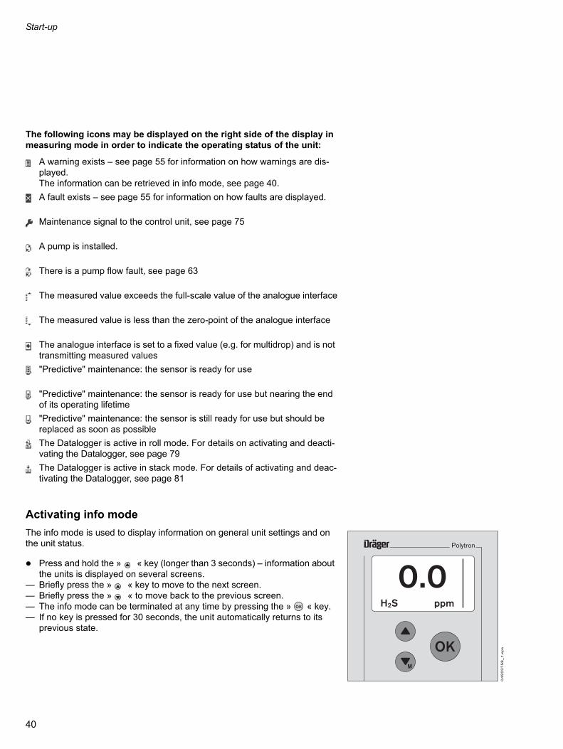
The following icons may be displayed on the right side of the display in measuring mode in order to indicate the operating status of the unit:
Activating info mode
The info mode is used to display information on general unit settings and on the unit status.
Press and hold the » « key (longer than 3 seconds) – information about the units is displayed on several screens.
— Briefly press the » « key to move to the next screen.— Briefly press the » « to move back to the previous screen.— The info mode can be terminated at any time by pressing the » « key.— If no key is pressed for 30 seconds, the unit automatically returns to its
previous state.
A warning exists – see page 55 for information on how warnings are dis-played.The information can be retrieved in info mode, see page 40.
A fault exists – see page 55 for information on how faults are displayed.
Maintenance signal to the control unit, see page 75
A pump is installed.
There is a pump flow fault, see page 63
The measured value exceeds the full-scale value of the analogue interface
The measured value is less than the zero-point of the analogue interface
The analogue interface is set to a fixed value (e.g. for multidrop) and is not transmitting measured values
"Predictive" maintenance: the sensor is ready for use
"Predictive" maintenance: the sensor is ready for use but nearing the end of its operating lifetime
"Predictive" maintenance: the sensor is still ready for use but should be replaced as soon as possible
The Datalogger is active in roll mode. For details on activating and deacti-vating the Datalogger, see page 79
The Datalogger is active in stack mode. For details of activating and deac-tivating the Datalogger, see page 81
M
OK
40

Start-up
A0
09
_e
n.e
ps
07.11.2011 12:34SW Version : 8.0Part No. : 8317778Serial No. : ARUA0001DeviceCode: 00006317
Instrument Info1/4
A0
10
_e
n.e
ps
2/4
Sensorname: O2Part No. : 6809630Serial No. : XXXXXXXEEPROM Typ : 1EEPROM Vers.: 1
Sensor Info
A0
11
_e
n.e
ps
3/4
Gasname : O2Range : 25.00 Vo4–20 SP : 25.00 VoAlarm A1 : 19.00 VoAlarm A2 : 23.00 Vo
Sensor Config.
A0
14
_e
n.e
ps
4/4
Power : XXX %Fault : X.X l/minWarning : X.X l/minOp.time : XXXX h
Pump info
Example of info mode:Screen 1Instrument informationLine 1 – Date and timeLine 2 – Software versionLine 3 – Unit Part No.Line 4 – Unit Serial No.Line 5 – Unit code
Screen 2Sensor information:Line 1 – Sensor nameLine 2 – Sensor Part No.Line 3 – Sensor Serial No.Line 4 – EEPROM typeLine 5 – EEPROM version
Screen 3Sensor configuration:Line 1 – Gas nameLine 2 – Measuring range (can not be change) and unit of measurementLine 3 – Measuring range for the analogue interface. Displayed only, if the analogue interface card is installedLine 4 – A1 alarm threshold and unit of measurement1)
Line 5 – A2 alarm threshold and unit of measurement1)
1) Displayed only if a relay module is fitted!
Screen 4 2)
Pump Infos:Line 1 – Pump flowLine 2 – Threshold errorLine 3 – Threshold warningLine 4 – Pump run time
2) Displayed only if a pump module is fitted!
41

Start-up
If "xx.xx.xx xx:xx" is displayed instead of the date and time, or if an incorrect date and time are displayed:(only after the cock has been reset due to a power failure) Set the date and time, see page 67.
CAUTIONIf the date and time are not set correctly, some functions (such as calibration) cannot be executed!
42

Maintenance
Maintenance
Maintenance intervals
Before starting operation: Check the calibration, see page 44. Check the transmission of signals to the control unit and the triggering of
alarms, page 74.
At regular intervals,to be defined by the person responsible for the gas warning installation: Check the transmission of signals to the control unit and the triggering of
alarms, page 74.
If a selective filter specific to the sensor is being used: Replace the selective filter –
See the related operating instructions for the sensor for details of the ca-pacity of the selective filter being used.
At regular intervals defined in accordance with the sensor being used by the person responsible for the gas warning system: Calibrate the sensor, see page 44.
The interval for regular calibration depends on the sensor being used and on the operating conditions.The transmitter calculates, from the selected calibration interval (see page 56), when the next calibration is due.Specific calibration data for the sensor, see the operating instructions for the sensor.
Every six months: Inspection by specialists.
The inspection intervals must be established in each individual case and shortened if necessary, depending on technical safety considerations, en-gineering conditions and the technical requirements of the equipment.We recommend that a service agreement be concluded with DrägerService and that repairs also be carried out by them.
When using the pump module: In order to check for leaks, measure the flow at the inlet point and behind
the transmitter.
As required: Replace sensor, page 46.
43

Maintenance
0482
3758
_1.e
ps1
Polytron
OK
Calibrating the unit
— Ensure that the sensor is warmed up before it is calibrated. See the sensor data sheet for the warming-up time.
— For some sensors (such as oxygen sensors) the function » zero-point calibration « is simply a test of the sensor function. The zero point is not ac-tually calibrated since this is not necessary for these sensors.
— For critical applications, the calibration intervals should be defined in ac-cordance with the recommendations in EN 500731), EN45544-42) and na-tional regulations.
Note the calibration sequence!
First check the zero point and calibrate it if necessary, immediately after this, check the sensitivity and adjust it as necessary.
— Never calibrate the sensitivity before calibrating the zero point.
— Calibration cannot be carried out if the date and time are not set. Setting the date and the time, page 67.
— Calibration menu, page 58 to page 59.
— Zero gas and test gas: see the information in the sensor data sheet and on the pages 118 to 121.
Calibrating with test gas
Use a test-gas cylinder with pressure-reduction valve (a stainless-steel pressure reduction valve for aggressive gases). Observe the information in the sensor data sheet.
1 Mount a calibration adapter Part No. 68 06 978 (with two hose connectors) on the Polytron 7000.
Vent the test gas leaving the adapter into a fume cupboard or into the open air (with a hose connected to the second connector on the calibration adapter).
1) EN 50073 – Guidelines for selection, installation, use and maintenance of devices for the detection and measurement of flammable gases and oxygen.
2) EN 45544-4 – Electrical devices for the direct detection and direct concentration measurement of toxic gases and vapours – Part 4: Guidelines for selection, installa-tion, use and maintenance.
CAUTIONTest gas must not be inhaled. Risk to health! Care must be taken about the risks which can arise when using test gas; hazard instructions and safety advice must be observed.For details, see appropriate DIN Safety Data Sheets.
44

Maintenance
0502
3758
_1.e
ps
OK
68 07 407
0492
3758
_1.e
ps
OK
+
0512
3758
_1.e
ps
OK68 07 407
68 04 620
+
Calibration with test-gas ampoules
Use the calibration flask (Part No. 68 03 407) – Observe the information in the sensor data sheet.
Follow the instructions printed on the calibration flask and enclosed with the test-gas ampoules.
For units without a pump:1 Fit the adapter and calibration bottle to the Polytron 7000.
Break the test-gas ampoule inside the calibration flask. Wait until the measured value has settled (see the operating instructions for
the sensor for the necessary waiting period). Then carry out calibration.
For units with a pump:— The pump adapter is already installed on the Polytron 7000.
Insert the adapter (Part No. 68 04 620) in the calibration flask – connect the hoses.
Break the test-gas ampoule inside the calibration flask and wait until the measured value has settled (see the operating instructions for the sensor for the necessary waiting period). Then carry out calibration.
45

Maintenance
0422
3758
_1.e
ps
1
Polytron
OK
Setting up the unit
Individual settings can be made:— via the keypad in menu mode— via the HART interface,— with the Dräger hand-held terminal (DHHT)
Replacing the sensor
The sensor can be replaced, if necessary, without interrupting the power sup-ply in the explosion-hazard area.Use only DrägerSensors which are approved for use with the Dräger Polytron 7000 transmitter.
In the menu » Settings «, select the submenu » Sensor « and then the func-tion » Change sensor « – page 76.
1 Remove bayonet ring from transmitter; pull out old sensor. Remove sensor from packaging. Make sure that it is approved for use with
the transmitter. Remove the short-circuit strap from the sensor (if it is fitted). There is a coded connector on the back of the sensor. Place the sensor in
the opening with the connector at the back and the Dräger logo at the front.Before plugging the connector in the socket, ensure that they are identically coded. Incorrect connection can damage the sensor!
1 Secure sensor in transmitter with bayonet ring.
It is possible to mark the transmitter with the label enclosed in the packag-ing. It will then be easy to identify the type of gas for which the transmitter is intended if there is a mains failure.
Check sensor function.— If an identical sensor (sensor with the same Part No.) was previously in-
stalled, the complete configuration of the transmitter remains unchanged. Otherwise, the transmitter is configured with the default values (see the op-erating instructions for the sensor).See also » Sensorlock «, page 77.
NOTEAfter setting up the unit automatically with the copy function of the Dräger Handheld Terminals, the plausibility of the settings must be checked.
46

Maintenance
Disposal of electrochemical sensors:— Sensors must be disposed of as special waste.
Note the relevant waste disposal regulations.Further information can be obtained from the relevant local authority and from appropriate waste disposal companies.
Sensor-diagnosis function
This function is active only if the Polytron 7000 is equipped with a sensor diag-nosis dongle (Part No. 83 17 860).— Extended sensor self-test function, taking such things as the temperature,
gas monitoring and remaining sensitivity into account.— During normal operation, the sensor status is indicated by the sensor-diag-
nosis icon in the display:
CAUTIONDo not throw sensors into the fire – explosion hazard.Do not open sensors forcibly – risk of caustic burns.
The sensor is ready
The sensor is ready, but is approaching the end of its operating lifetime
The sensor is still ready, but it should be replaced as soon as possible
47

Fault – Cause – Remedy
th the menu items » Settings «, it. device «, page 68.gain: have the transmitter checked
r checked by DrägerService.
r checked by DrägerService.
odule, page 34.
r blockages, pump flow.
ons.
f the relay module or fit it again.
r and install it again, page 46.ists, check the sensor plug or install
r and install it again, page 46.gain: have the transmitter checked
ensor, see the ordering list on
with the menu items » Settings «, or-EC «, » Init. sensor «, page 78.gain: have the transmitter checked
n, page 58.
alibration, page 59.
, page 46.
ontacts; otherwise have the transmit-gerService.
tion, page 60. Make sure that the f other gases.
, page 46.
e sensor data sheet.
Fault – Cause – Remedy
If the display will not function: Have the transmitter checked by DrägerService.The fault and warning numbers shown in the following tables are displayed in the menu under » Information «, » Instrument «, » Fault « or » Warnings « – see page 55.
Fault number Cause Remedy
# 1 Serious data error in unit –various causes.
Initialise the unit wi» Instrument «, » InIf this error occurs aby DrägerService.
# 2 Serious unit fault –various causes.
Have the transmitte
# 61 Data error on the interface card –various causes
Have the transmitte
# 63 Hardware fault or software error in the pump module.
Change the pump m
# 64 Gas flow of the pump module falls below the configured fault threshold.Reliable measurements are no longer possible.
Check the hoses foIf necessary adjust
# 65 Open-circuit in 3-wire cable. Check the connecti
# 67 Bad contact of the relay module. Check connector o
# 100 Unit cannot detect a sensor. Remove the sensoIf the problem persa new sensor.
# 101 Sensor data error in the unit. Remove the sensoIf this error occurs aby DrägerService.
# 102 Unit does not support this sensor version.
Use a compatible spage 93.
# 103 Sensor data error in the unit. Initialise the sensor» Sensor «, » SensIf this error occurs aby DrägerService.
# 106 Zero-point not correctly. Zero-point calibratio
# 107 Sensitivity calibration not executed cor-rectly.
Repeat sensitivity c
# 108 Sensor data error. Replace the sensor
# 109 Unit fault. Check the sensor cter checked by Drä
# 121 Fresh-air calibration (first step of auto-calibration) not executed correctly.
Repeat autocalibraambient air is free o
# 125 Sensor not ready. Replace the sensor
# 129 Electrolyte liquid evaporates Refill electrolyte. Se
48

Fault – Cause – Remedy
tion » Sensor lock «, page 77 or use ame Part No. as the one which
ontacts. Remove and reinstall the s. If the problem persists, install a 6.
r and install it again. If the problem w sensor, page 46.
ith the menu items » Settings «, nit. device «, page 68. again: have the transmitter checked
Then clear and restart the Datalog-
as soon as possible. Then clear and ger.
me, page 67.
ction in the menu » Settings «, W dongle «, » XXX dongle «,
re dongle, page 30.
or blockages,t pump flow.
ion, page 58.
the specified temperature range (see e of the sensor).
r, page 46.
it, page 44.
ng.
or has fully warmed up.
ure to high gas concentrations. If this lace the sensor, page 46.
r, page 46.
ee sensor data sheet.
it from the mains and restart it. again: have the transmitter checked
# 130 The function » Sensor lock « is active. A sensor with a different Part No. has been inserted.
Deactivate the funca sensor with the swas removed.
# 134 Bad contact between the sensor and the sensor card.
Check the sensor csensor several timenew sensor, page 4
# 136 Sensor hardware fault. Remove the sensopersists, install a ne
Warning number Cause Remedy
# 1 Data error in the unit. Certain functions such as the Datalogger or the dongle functions may not be available.
Initialise the unit w» Instrument «, » IIf this error occursby DrägerService.
# 51 Datalogger is in stack mode and is 100 % full. No more data can be recorded.
Read out the data.ger
# 52 Datalogger is in stack mode and is 90 % full.
Read out the data restart the Datalog
# 53 No valid date and/or time is set. Set the date and ti
# 58 Software dongle was removed without logging off.
Deactivate the fun» Instrument «, » Spage 69.
Hardware fault in the software dongle. Change the softwa
# 64 Pump gas flow falls below the warning threshold.Reliable measurements are no longer possible.
Check the hoses fIf necessary adjus
# 106 Increased zero-point offset. Zero-point calibrat
# 111 Sensor is not working in the specified temperature range.
Operate sensor in Instructions for Us
# 112 Sensor near end of life. Replace the senso
# 114 Calibration interval expired. Recalibrate the un
# 115 Sensor was operate for too long with a high concentration.
Reduce overgassi
# 119 Sensor is not yet fully warmed up. An increased measuring error must be expected.
Wait until the sens
# 120 The sensor has been exposed to an excessively high gas concentration for a long period.
Reduce the exposdoes not help, rep
# 131 Bad sensor, no longer operating. Replace the senso
# 132 Electrolyte liquid evaporates. Measure-ments will soon no longer possible.
Refill electrolyte. S
# 135 Information such as the Part No. and the Serial No. is not available.
Disconnect the unIf this error occursby DrägerService.
Fault number Cause Remedy
49
Menu functions
Menu functions
The menu can be operated, as desired:— from the keypad (with integrated display) of the transmitter,— from a HART-compatible Hand Held Terminal (HHT),— from a HART-compatible control unit or— from a Polytron 7000 Palm Pilot 515 (non-Ex version) or
Palm Pilot 515x Ex version.
If the keypad is used, the menus can be operated with the three keys » «, » « and » « as well as via display.
Key » «— Use this key to move upwards through the menus.
Key » «— Use this key to move downwards through the menus.— If the key is held down for more than 3 seconds, the main menu is opened.— If the key is held down for longer than 1 second and less then 3 seconds,
the quick menu is opened (the Info menu is displayed without prompting for a password).
Key » «— This key is used to confirm inputs and selected menus and functions
Menu structure
Overview: page 51.
The unit has two operating modes: measuring mode and menu mode.Menu mode contains the menus » Information «, » Calibration « and » Settings «.
Menu » Information «
The menu » Information « can be opened by any user. However, the user is unable to make any changes with this menu option.
Menu » Calibration «
This menu permits routine operations needed for the regular maintenance of the transmitters.It should be accessible to persons who are responsible for such maintenance. If the maintenance password is entered, only this menu is accessible.
Menu » Settings «
This menu permits the setting of individual transmitter and sensor parameters. It should be accessible to authorised persons from the measuring and regula-tion department or the work safety department. If the password for this menu is entered, the menu » Calibration « is also accessible.
MOK
M
OK
50

Menu functions
The passwords for the menus » Calibration « and » Settings « can be changed at any time, page 67.
Default password settings when the unit leaves the factory:
Overview of the menu structure
Information about the sub-menus and function: See the specified page.
Password for the menu » Calibration «: _ _ _ 1
Password for the menu » Settings «: _ _ _ 2
back to measure
Information page 54 Information
Calibration page 58 Instrument page 55
Settings page 62 Sensor page 56
Datalogger page 57
Calibration
Zero calibration page 58
Span calibration page 59
Autocalibration page 60
Settings
Instrument page 63
Communication page 70
Sensor page 76
Datalogger page 79
51

Basic operating procedures
Basic operating procedures
Switching to quick-menu mode
Switching to menu mode
Press the » « for longer than 3 seconds. You will then be prompted for the password.
Entering the password
In measuring mode:
Press the » « for longer than 1 second but less than 3 seconds to open the quick menu.Information on the status and the settings of the transmitter can be queried here, see page 54.
Press the » « for longer than 3 seconds. You will then be prompted for the password.
Use the » « key to move to the line » Enter password « and press the » « key.The password entry screen appears.
Use the » « and » « keys to set each of the four positions of the password and press the » « key to confirm each position.
— After you have confirmed the last position, the menu corresponding to the entered password is opened.If the entered password is invalid, a suitable error message is displayed.
M
01
92
37
58
_e
n.e
psback to mesure
Instrument
SensorDatalogger
M
M 1/3
Back to measure
Enter password
01
52
37
58
_e
n.e
ps
M
OK
01
62
37
58
_e
n.e
ps 2/3
Password
_ _ _ _
OK
M
01
72
37
58
_e
n.e
ps 2/3
Password
0 _ _ _
01
82
37
58
_e
n.e
ps 3/3
back to mesure
Enter password
Wrong pwdlevel
9 9 9 9
52

Basic operating procedures
Navigation in the menu
Graphical symbols (icons) simplify the navigation through the various menus:Together with the text » Back «, » Menu «, etc. »— Exit from the menu or return to previous menu.
Closed folder— This item contains further functions or sub-menus.
Open folder— The functions and sub-menus shown here are contained in this
item.
Function— If activated, functions can be executed in a single step or several
steps.
Selection activated— Press the » « key for functions which can be selected and acti-
vated.
List closed / complete to the top— There are no further functions, menus or sub-menus above those
currently displayed.
List can be scrolled up— There are further functions, menus or sub-menus above those cur-
rently displayed.
List closed / complete to the bottom— There are no further functions, menus or sub-menus below those
currently displayed.
List can be scrolled down— There are further functions, menus or sub-menus below those cur-
rently displayed.
Next— Execute the related action.
Number of current screen / total number of screens within the func-tion.
Input— Data input with the » « and » « keys.
OK
3/3
2/2
M
53

The menu » Information «
ument
ings page 55
ts page 55
t codes page 55
ules page 55
or
ty page 56
Cal. Date page 56
Cal. Date page 56
or temperature page 56
logger
logr. status page 57
graph page 57
The menu » Information «
The menu » Information « contains all information about the unit status, the sensors and the Datalogger.
Overview
Information Information
Calibration Instrument page 55 Instr
Settings Sensor page 56 Warn
Datalogger page 57 Faul
Faul
Mod
Sens
Vitali
Last
Next
Sens
Data
Data
Show
54
The menu » Information «
Submenu » Instrument «
The submenu » Instrument Info « contains all functions for interrogating the unit status.
Warnings
— This function displays any existing warnings in clear text with the warning number, see page 49.The icon » « is displayed if any warnings are active.
Select the menu items » Information «, » Instrument « and » Warnings « in this order, pressing the » « key after each selection.
— Any existing warnings are displayed in clear text.If more than one warning exists, the number of the currently displayed warning and the total number of warnings are displayed in the top right cor-ner (example: 1/3 = screen 1 of 3).
Faults
— This function displays any existing faults in clear text with the error number, see page 48.If a fault code exists, the icon » « is displayed.
Select the menu items » Information «, » Instrument « and » Faults « in this order, pressing the » « key after each selection.
— Any existing faults are displayed in clear text.If more than one fault exists, the number of the currently displayed fault and the total number of faults are displayed in the top right corner (example: 1/2 = screen 1 of 2).
Fault codes
— This function displays any existing faults / warning codes in the form of a table.If a fault code exists, the icon » « is displayed.
Select the menu items » Information «, » Instrument « and » Fault codes « in this order, pressing the » « key after each selection.
— Any existing faults are displayed in the form of numerical codes in a table. If all numerical groups are displayed with the value » 00 «, no faults exist.
Modules
— All installed hardware modules are displayed.
Select the menu items » Information «, » Instrument « and » Modules « in this order, pressing the » « key after each selection.
OK
OK
OK
OK
55

The menu » Information «
— A list of all possible modules is displayed. The installed modules are indi-cated by a » «. Modules which are not installed are marked with a » «.
Use the » « and » « keys to select individual modules and press the » « key to display more detailed information.
Submenu » Sensor «
The submenu » Sensor « contains the functions for interrogating the sensor status.
Sensor vitality
This function is active only if the Polytron 7000 transmitter is equipped with the sensor diagnostic dongle, see page 30.— This function displays the remaining sensitivity of the sensor. Select the menu items » Information «, » Sensor « and » Vitality « in this or-
der, pressing the » « key after each selection.
— The current Sensor Vitality is displayed.— Dräger Safety recommends that the sensor is exchange when the Sensor
Vitality value is less than 25.
Last calibration date
— This function displays the date of the last calibration. Select the menu items » Information «, » Sensor « and » Last cal. date « in
this order, pressing the » « key after each selection.
— The date of the last calibration is displayed.
Next calibration date
— This function displays the date on which calibration is next due. Select the menu items » Information «, » Sensor « and » Next cal. date « in
this order, pressing the » « key after each selection.
— The date on which the sensor is next due for calibration is displayed.
Sensor temperature
— This function displays the current sensor temperature and the maximum sensor temperature which has been recorded.
Select the menu items » Information «, » Sensor « and » Show sensortemp. « in this order, pressing the » « key after each selection.
— The current sensor temperature and the maximum sensor temperature which has been recorded are displayed.
M
OK
OK
OK
OK
OK
56
The menu » Information «
Submenu » Datalogger «
The submenu » Datalogger « contains the functions for interrogating the Datalogger.
Datalogger status
This function is active only if the Polytron 7000 transmitter is equipped with the data dongle 83 17 618, see page 30.— This function displays the status of the Datalogger and the Eventlogger.
Select the menu items » Information «, » Datalogger « and » Datalogr status « in this order, pressing the » « key after each selection.
— The current status of the Datalogger and the Eventlogger is displayed:
— Activating / deactivating the Datalogger: see page 79.— Activating / deactivating the Eventlogger: see page 79.
Show graph
This function is active only if the Polytron 7000 transmitter is equipped with the data dongle 83 17 618, see page 30.— The measured values of the sensor are displayed graphically on a time axis
of 15 minutes.
Select the menu items » Information «, » Datalogger « and » Show graph « in this order, pressing the » « key after each selection.
Datalogr. : on or off (the Datalogger is on or off)
Evntlogr. : on or off (the Eventlogger is on or off)
OK
OK
57

The menu » Calibration «
cal. page 58
H2S 1)
ly installed in the unit.
page 58
calibration
H2S 1)page 59
The menu » Calibration «
The menu » Calibration « contains all functions needed for the calibration and adjustment of the installed sensor.
Notes on handling the calibration gas and calibration accessories can be found in the section "Maintenance" on page 44.
If the calibration functions have not been operated for 60 minutes, the device will switch back to the measuring mode.
Overview
Submenu » Zero calibration «
The submenu » Zero calibration « contains the functions for calibrating / adjusting the zero point of the installed sensor.
Zero-point calibration / adjustment
Calibration procedure (using an EC–H2S sensor as an example): Select the menu items » Calibration «, » Zero calibration « and » EC–
H2S « in this order, pressing the » « key after each selection.— The maintenance signal is transmitted on the analogue interface.— The alarm and fault relays are not triggered.— The message » Supply zero gas with flow rate 500 mL/min" is displayed Connect zero gas to the sensor (for some sensors, N2 must be used – see
information in the section "Maintenance" on page 44). Select » Next « and press the » « key.
— The current value and the expired time are now displayed.When the displayed value has stabilised:
Select » Accept value « and press the » « key.— The message » Zero calibration running « is displayed
— The required value and the actual value are now displayed.If these are correct as displayed:
Select » Back to menu « and press the » « key. Disconnect the flow of zero gas.
Information
Calibration Calibration
Settings Zero calibration page 58 Zero
Span calibration page 59 EC–
1) The sensor shown in the overview serves only as an example and may differ from the sensor actual
Auto calibration page 60
Span
EC–
OK
OK
OK
OK
58
The menu » Calibration «
Zero-point calibration can be aborted at any time: Use the » « key to move to » Back « and press the » « key.
Submenu » Span cal. «
The submenu » Span cal. « Contains all functions for calibrating the sensitiv-ity of the installed sensor.
Sensitivity calibration
Calibration procedure (using an EC–H2S sensor as an example): Select the menu items » Calibration «, » Span calibration « and » EC–
H2S « in this order, pressing the » « key after each selection.— The maintenance signal is transmitted on the analogue interface.— The alarm and fault relays are not triggered.— The values for the calibration gas are displayed, for example:
— The calibration gas, concentration and unit can be changed: Select » Cal. gas « and press the » « key. Select the desired calibration
gas from the list and press the » « key again.
Select » Concentr. « and press the » « key. Set the calibration gas con-centration (same procedure as for input of a password).
Select » Unit « and press the » « key: Select the desired unit from the list and press the » « key again.
If the settings agree with the available calibration gas: Select » Next « and press the » « key.
— The message » Supply gas: H2S with flow rate 500 ml/min « is displayed.— Connect calibration gas (see the information in the section "Maintenance"
on page 44) to the sensor. Select » Next « and press the » « key.
— The current value and the expired time are now displayed.When the displayed value has stabilised:
Select » Accept value « and press the » « key.
— In the display the maximum value and the current value as well as the re-mainder of the sensor vitality are represented as a bar indication.
Cal. gas : H2SUnit : ppmConcentr. : 000025
OK
OK
OK
OK
OK
OK
OK
OK
OK
OK
59

The menu » Calibration «
If these are correct as displayed: Select » Next « and press the » « key. Disconnect the flow of calibration gas.
— The calibration interval and the date of the next calibration are displayed. Select » Back to menu « and press the » « key.
Sensitivity calibration can be aborted at any time: Use the » « key to move to » Back « and press the » « key.
Autocalibration
Autocalibration consists of fresh-air calibration followed by sensitivity calibra-tion. This function is intended only for users who are familiar with the unit, since the sequence of actions may result in calibration errors.The function can be activated or deactivated with the menu sequence » Settings «, » Sensor «, » Autocal. «.
Calibration procedure (using an EC-H2S sensor as an example): Select the menu items "Calibration" and "Autocal." in this order, pressing
the » « key after each selection.
— The maintenance signal is transmitted on the analogue interface.
— The message » Fresh-air calibration running « is displayed. Expose the sensor to the ambient air (for some sensors, a zero gas such
as N2 must be used – see the information in the section "Maintenance" on page 44).Then:
— The values for the calibration gas are then displayed, for example:
— The current value and the calibration gas concentration are now displayed.
The calibration operation depends on whether the selected calibration gas supports so-called autostability.
— Autostability is supported:When the displayed value has stabilised:
Select » Accept value « and press the » « key.
— Autostability is not supported:The instrument evaluates the stability of the signal and automatically exe-cutes the calibration procedure.
CAUTIONAn alarm could be triggered in the central unit for as long as the calibration gas concentration is pending!
CAUTIONThe sensor must be supplied with fresh air, otherwise calibration errors may occur!
Cal. gas : H2SUnit : ppmConcentr. : 000025
OK
OK
OK
OK
OK
60

The menu » Calibration «
— The required value and the actual value are now displayed.
Disconnect the flow of calibration gas.
If these are correct as displayed: Select » Accept value « and press the » « key.
CAUTIONAn alarm could be triggered in the central unit for as long as the calibration gas concentration is pending!
OK
61

The menu » Settings «
Instrument
Pump 1)
th a pump module, see page 34.
page 63
Alarm 2)
th a relay module, see page 32.
page 64
Passwords page 67
Date and time page 67
Time format page 68
Language page 68
Function key page 68
Device init page 68
SW Dongle page 69
Communication
Hart interface 3)
th the appropriate interface card.
page 70
Analogue interface 3)page 71
LON Interface 3)page 75
PA/FF Interface 3)page 76
Sensor
Change sensor page 76
Set Autocal. page 77
Sensor test page 77
Sensor lock page 77
EC–H2S 4)
nsor actually installed in the unit.
page 78
Datalogger
Datalogr. on/off 5)
th the data dongle 83 17 618, see page 30.
page 79
Cfg Datalogger 5)page 79
Clear Datalogger 5)page 81
Clear Eventlogr. 5)page 81
The menu » Settings «The menu » Settings « contains all functions needed for individual configura-tion of the unit.
OverviewInformation
Calibration
Settings Settings
Instrument page 63
Communication page 70
1) This menu function can be executed only if the Polytron 7000 transmitter is equipped wi
Sensor page 76
2) This menu function can be executed only if the Polytron 7000 transmitter is equipped wi
Datalogger page 79
3) This menu function can be executed only if the Polytron 7000 transmitter is equipped wi4) The sensor shown in the overview serves only as an example and may differ from the se5) This menu function can be executed only if the Polytron 7000 transmitter is equipped wi
62

The menu » Settings «
0532
3758
_1.e
ps
OK
+
L/min
Submenu » Instrument «
The submenu » Instrument « can be used to make various instrument set-tings.
Pump
This group contains the setting functions for the pump.
– Pump output
— This function is used to set the pump output. Select the menu items » Settings «, » Instrument «, » Pump « and » Pump
output « in this order, pressing the » « key after each selection.— The maintenance signal is transmitted on the analogue interface, and the
display reads: » Flow alarm will be de-energised. Please use a flow meter «.
Connect a pump adapter and a flowmeter.
Select » Next « and press the » « key. Use the » « and » « keys to set the pump output. Monitor the change
on the flowmeter.
Select » Next « and press the » « key.— The flow thresholds are displayed –
Flow threshold for fault: 0.3 L/min Flow threshold for warning: 0.4 L/min
NOTEChoose the response time as low as possible and the pump output as high as possible.
OK
OK
M
OK
63

The menu » Settings «
– Operating time
— This function is used to display the operating time of the pump. Select the menu items » Settings «, » Instrument «, » Pump « and
» Operating time « in this order, pressing the » « key after each selec-tion.
— The actual operating time of the pump is displayed in hours.
Alarm / Relay settings
Alarms can be output via a relay and a digital interface if a relay module is installed. This group contains the setting functions for the alarms.
– Alarm on/off
— This function is used to enable and disable alarm monitoring. Select the menu items » Settings «, » Instrument «, » Alarm « and » Alarm
on/off « in this order, pressing the » « key after each selection.
Select » Enable « or » Disable « and press the » « key to activate.
– Set alarm A1
— This function is used to change the alarm configuration for alarm A1. Select the menu items » Settings «, » Instrument «, » Alarm « and « alarm
A1 « in this order, pressing the » « key after each selection.
Use the » « and » « keys to set each position of the threshold value for the alarm A1 and press the » « key to confirm the setting.
Press the » « key to confirm the complete alarm threshold value. The setting for the alarm threshold A1 is displayed.
— The function for setting the alarm direction is opened. Select » Rising « or » Falling « and press the » « key to activate your se-
lection. Select » Next « and press the » « key.
— The function for setting the self-hold function of the A1 alarm is opened. Select » Latching « or » Non latching « and press the » « key to acti-
vate. Select » Next « and press the » « key.
Note: » Latching « means that the relay must be manually acknowledged after the alarm condition is no longer fulfilled, » Non latching « means that the relay is automatically acknowledged after the alarm condition is no long-er fulfilled.
— The function for setting the A1 acknowledgement is opened.
CAUTIONIn the normal state, the relays of the relay module are energised. Therefore, the state of the relay changes if the power supply is interrupted!
CAUTIONIf the alarm is disabled, no alarms will be signalled via the relay or the HART interface!A warning » « appears on the display!
OK
OK
OK
OK
M
OK
OK
OK
OK
OK
OK
64

The menu » Settings «
Alarm condition not fulfilledAcknowledge-
ment button actu-ated
Acknowledge-ment button not
actuated
Alarm deactivated Alarm activated
Alarm deactivated Alarm activated
Alarm is automati-cally deactivated when condition is no longer fulfilled
Alarm is automati-cally deactivated when condition is no longer fulfilled
Alarm is automati-cally deactivated when condition is no longer fulfilled
Select » Can be acknowledged « or » Cannot be acknowledged « and press the » « key to activate.Note: » Can be acknowledged « means that the relay can be reset when the alarm condition is fulfilled. » Cannot be acknowledged « means that the relay can only be reset after the alarm condition is no longer fulfilled.
Overview of alarm settings
— The function for setting the A1 hysteresis is opened.This function allows the user to set a bandwidth in which a tripped relay stays in its status until the gas concentration is outside this bandwidth. With this function relays will not "chatter" at the alarm set point. E.g. A1 set point is 40 ppm, hysteresis is set to 3 ppm. Alarm A1 will come on at 40 ppm and will stay active until the concentration falls below 37 ppm.
Select the line for input of the hysteresis and press the » « key to switch to edit mode.
Use the » « and » « keys to set each digit of the value and press the » « key to confirm the setting.
Select » Next « and press the » « key.
— The settings of the A1 are indicated. To confirm select » Confirm « and press the » « key.— The settings for alarm A1 are now complete.
– Set alarm A2
— This function is used to change the alarm configuration for alarm A2.
Select the menu items "Settings «, "Instrument «, "Alarm « and "alarm A2 « in this order, pressing the » « key after each selection
CAUTIONIf an alarm has been configured as » Can be acknowledged «, it can also be reset when the alarm condition is fulfilled. In the case of safety-relevant switching operations, the alarm must be configured as » Cannot be can be acknowledged «.
Alarm condition fulfilledAcknowledge-
ment button actu-ated
Acknowledge-ment button not
actuatedAlarm configurationLatching Can be
acknowledgedAlarm deactivated Alarm activated
Cannot be acknowledged
Alarm activated Alarm activated
Non latchingCan be
acknowledgedAlarm deactivated Alarm activated
Cannot be acknowledged
Alarm activated Alarm activated
OK
OK
M
OK
OK
OK
OK
65

The menu » Settings «
— The settings are made in the same manner as for alarm A1.
– Set ack.
— This function is used to enable or disable the acknowledgement of the alarms with the » « key.
Select the menu items » Settings «, » Instrument «, » Alarm « and » Set ack. « in this order, pressing the » « key after each selection.
Select » Enable « or » Disable « and press the » « key to activate.
– Test alarm A1
— This function simulates the A1 alarm state for testing purposes.
Select the menu items » Settings «, » Instrument «, » Alarm « and » Test alarm A1 « in this order, pressing the » « key after each selection.
— The function » Test A1 status « is opened. Select » Enable « or » Disable « and press the » « key to activate.
— When the function is enabled, the relay and the interfaces are set to the A1 alarm state.
– Test alarm A2
— This function simulates the A2 alarm state for testing purposes.
Select the menu items » Settings «, » Instrument «, » Alarm « and » Test alarm A2 « in this order, pressing the » « key after each selection.
— The function » Test A2 status « is opened. Select » Enable « or » Disable « and press the » « key to activate.
— When the function is enabled, the relay and the interfaces are set to the A2 alarm state.
CAUTIONIf the functions » Disable acknowledgement « and » Alarm setting latching « are combined, an alarm can only be acknowledged by interrupting the power supply of the Polytron 7000 transmitter!
If an alarm has been configured as » Can be acknowledged «, it can also be reset when the alarm condition is fulfilled. In the case of safety-relevant switching operations, the alarm must be configured as » Cannot be acknowledged «.
OK
OK
OK
OK
OK
OK
OK
66

The menu » Settings «
– Test fault
— This function simulates the fault alarm state for testing purposes.
Select the menu items » Settings «, » Instrument «, » Alarm « and » Test fault alarm « in this order, pressing the » « key after each selection.
— The function » Test fault status « is opened. Select » Enable « or » Disable « and press the » « key to activate.
— When the function is enabled, the relay and the interfaces are set to the fault alarm state.
Passwords
This group contains the setting functions for the passwords.
– Password Calibration
— This function is used to change the password for the menu » Calibration «. Select the menu items » Settings «, » Instrument «, » Passwords « and
» Password Cal. « in this order, pressing the » « key after each selec-tion.
Select the line for password input and press the » « key to switch to edit mode.
Use the » « and » « keys to set each position of the password and press the » « key to confirm the setting.
Press the » « key to confirm the complete password.
– Password Settings
— This function is used to change the password for the menu » Settings «. Select the menu items » Settings «, » Instrument «, » Passwords « and
» Password Cfg. « in this order, pressing the » « key after each selec-tion.
Select the line for password input and press the » « key to switch to edit mode.
Use the » « and » « keys to set each position of the password and press the » « key to confirm the setting.
Press the » « key to confirm the complete password.
Date and time
— This function is used to set the date and / or time.
Select the menu items « Settings «, « Instrument « and « Date and time « in this order, pressing the » « key after each selection.
Select the desired input line (Date or Time) and press the » « key to switch to edit mode.
Use the » « and » « keys to set the value and press the » « key to confirm the setting.
OK
OK
OK
OK
M
OK
OK
OK
OK
M
OK
OK
OK
OK
MOK
67

The menu » Settings «
Time format
— This function is used to set the display format for the date and/or time.
Select the menu items « Settings «, « Instrument « and « Time format « in this order, pressing the » « key after each selection.
Select the desired input line (Date format or Time format) and press the » « key to switch to edit mode.
Use the » « and » « keys to select the desired format (European or US) and press the » « key to confirm the setting.
Language
— This function is used to set the language for the menus.
Select the menu items « Settings «, « Instrument « and « Language « in this order, pressing the » « key after each selection.
Select the desired language from the list and press the » « key to acti-vate.
Function key
— This function is used to set the function which is to be activated when the function key (the » « key) is pressed briefly.Default setting: Fault report.
Select the menu items » Settings «, » Instrument « and » Function key « in this order, pressing the » « key after each selection.
Select the desired function and press the » « key to activate. An icon corresponding to the selected function appear on the right side of the dis-play. Possible selections:
— In measuring mode, briefly pressing the » « key will now activate the selected function.
Show graph– the measured values are displayed on a time axis, see page 57
Fault report – existing faults are displayed in clear text, see page 55
Notice report
– existing warnings are displayed in clear text, see page 55
Fault codes – existing fault codes are displayed in a numerical table, see page 55
OK
OK
M
OK
OK
OK
OK
OK
68

The menu » Settings «
Initialise device
This function resets all parameters of the transmitter to the factory default set-tings.This affects the following parameters:
It also affects the setting parameters for:
Select the menu items » Settings «, » Instrument « and » Device init. « in this order, pressing the » « key after each selection.
Select » Confirm « and press the » « key to initialise the device.
SW dongle
This group permits the deactivation of individual dongles before they are removed or in the case of a fault in a dongle.A dongle can be reactivated only by restarting the unit.
– Data dongle Select the menu items » Settings «, » Instrument «, » SW dongle « and
» Data dongle « in this order, pressing the » « key after each selection.
Select the line » Disable function « and press the » « key to disable the data dongle.
– Sensor test dongle Select the menu items » Settings «, » Instrument «, » SW dongle « and
» Sensor test dongle « in this order, pressing the » « key after each se-lection.
Select the line » Disable function « and press the » « key to disable the sensor test dongle.
– Diagnosis dongle Select the menu items » Settings «, » Instrument «, » SW dongle « and
» Diagnosis dongle « in this order, pressing the » « key after each se-lection.
Select the line » Disable function « and press the » « key to disable the diagnosis dongle.
— Sensor lock.— Gas selection (if the sensor is suitable for measuring several different
gases).— Units in the measured value display (normally ppm).— Measuring range for the 4 to 20 mA interface.— Gas configuration of the calibration gas (if the sensor is suitable for cali-
bration with a replacement gas).— Calibration interval The sensor-specific default values can be found in the
related sensor data sheet.
— Pump output— Alarm parameters— Passwords— Language— Function key— HART interface— Datalogger— Analogue interface
OK
OK
OK
OK
OK
OK
OK
OK
69
The menu » Settings «
Submenu » Communication «
The submenu » Communication « permits various settings to by made for the interfaces.
HART interface
This group contains the setting functions for the HART interface.
– Polling address
The polling address configures the transmitter either for the analogue mode (4 to 20 mA) or the multidrop mode. Setting the polling address to " 0 " enables the analogue mode (4 to 20 mA). To enter multidrop mode, the polling address must be set to a value in the range from " 1 " to " 15 ", which disables the analogue interface and freezes it to a constant current of approx. 3 mA. In order to enable the central controller to request the unique identifier (unam-biguous HART address) using HART command #0, all transmitters located on one cable trunk need to be configured with a different polling address. It is best to assign sequential polling addresses, starting with "1".This setting corresponds to the HART command #6 ("Write Polling Address").
Select the menu items » Settings «, » Communication «, » Hart interface « and » Polling address « in this order, pressing the » « key after each se-lection.
Use the » « and » « keys to set each position of the polling address and press the » « key to confirm the setting.
Press the » « key to confirm the complete polling address.
– Unique Identifier
This function can be used to read out the unique identifier (unique HART address), which must be known for the addressing in almost all HART com-mands. However, knowledge of the unique identifier is necessary only for sys-tems which are not able to read out the unique identifier with the HART command #0 in the short-frame format or the HART command #11. The dis-play corresponds to the address returned by the HART command #0 ("Read Unique Identifier") or #11 ("Read Unique Identifier associated with Tag").
Select the menu items » Settings «, » Communication «, » Hart interface « and » Identifier « in this order, pressing the » « key after each selection.
— The unique identifier will be displayed.
OK
M
OK
OK
OK
70
The menu » Settings «
– Tag
The tag may be used to mark a specific transmitter. It can comprise up to 8 alphanumeric characters. It can also serve as an address, in order to read the unique identifier using HART command #11 ("Read Unique Identifier associated with Tag"), from the transmitter, even if the polling address is unknown.This presumes that an unambiguous tag has been configured before.
Select the menu items » Settings «, » Communication «, » Hart interface « and » Tag « in this order, pressing the » « key after each selection.
Use the » « and » « keys to set each position of the tag and press the » « key to confirm the setting.
Press the » « key to confirm the complete tag.
Analogue interface
This group contains the functions needed for the test and setting functions.
Settings for the analogue interface
– Analogue set point / Set measurement range
When the measuring range of the analogue interface must be adjusted.Here corresponds: 0 ppm = 4 mA; Analogue signal = 20 mA— According to the standard, the standard measuring range of the sensor au-
tomatically ends here.
– Warning on/off
This function is used to switch the warning signal » « on the analogue interface on and off. If the presence of a warning is to be signalled via the ana-logue interface, the warning signal must be switched on. In the case of a warning, the current on the analogue interface is switched for one second to the state "Warning". For the rest of the time, the measured signal is transmit-ted. The interval between the warning signals and the level of the analogue signal can be configured as desired, see "Warning signal" on page 72 and "Warning level" on page 72.
Select the menu items » Settings «, » Communication «, » Analogue interface « and » Warning on/off « in this order, pressing the » « key af-ter each selection.
Select » Enable « or » Disable « and press the » « key to activate.
OK
M
OK
OK
OK
OK
71

The menu » Settings «
– Warning interval
This function is used to set the interval between the warning signals » « on the analogue interface.
Select the menu items » Settings «, » Communication «, » Analogue interface « and » Warning interval « in this order, pressing the » « key after each selection.
Use the » « and » « keys to set each position of the time interval (in seconds) for T1 and T2 and press the » « key to confirm the setting.
Press the » « key to confirm the complete time interval.
– Warning level
— This function is used to set the current on the analogue interface for the warning signal » «.
Select the menu items » Settings «, » Communication «, » Analogue interface « and » Warning level « in this order, pressing the » « key after each selection.
Use the » « and » « keys to set each position of the current value and press the » « key to confirm the setting.
Press the » « key to confirm the complete current value.
– Maintenance signal
— This function is used to set the signal type on the analogue interface for the maintenance signal » «.
Select the menu items » Settings «, » Communication «, » Analogue interface « and » Maintenance signal « in this order, pressing the » « key after each selection.
Select the » static « or » dynamic signal type, as required, and activate it by pressing the » « key.
Note:The » static « signal type is a DC current signal whose current value can be configured (see » Maintenance level «).
OK
M
OK
0552
3758
_1_e
n.ep
s
t [s]
T 1
4
20[mA]
T 2
3
Measured value
OK
OK
M
OK
OK
OK
OK
72

The menu » Settings «
The » dynamic « signal type is an AC signal with the following characteristic:
– Maintenance level
— This function is used to set the current on the analogue interface for the maintenance signal » «.
Select the menu items » Settings «, » Communication «, » Analogue interface « and » Warning level « in this order, pressing the » « key after each selection.
Use the » « and » « keys to set each position of the current value and press the » « key to confirm the setting.
Press the » « key to confirm the complete current value.
– Offset current
— Provides for the adjustment of the zero point signal (4 mA signal). Select » Settings «, » Communication «, » Analogue interface « and
» Offset current « in this order, pressing the » « key after each selection. Use the » « key for marking the input value for the current value and se-
lect it with the » « key. Use the » « or » « keys for selecting the desired sign (+/-) for the in-
put. By pressing the » « key, select the desired input field and enter the de-
sired current correction value with the » « or » « keys. A maximum input of +/- 0,500 mA of the factory-preset 4 mA current value is possible.
Press the »« key to confirm the completely adjusted current value.
0592
3758
_1_d
e.ep
s
t [s]
1,1
[mA]
0,7
5
3
OK
M
OK
OK
OK
M
OK
M
OK
M
OK
73

The menu » Settings «
Test functions for the analogue interface
– Test analogue
— This function is used to set various currents in the range 3 to 22 mA on the analogue interface.
Select the menu items » Settings «, » Communication «, » Analogue interface « and » Test analogue « in this order, pressing the » « key af-ter each selection.
If the alarms are disabled in the control unit, confirm the message » Switch off all alarms « by pressing the » « key.
Use the » « and » « keys to set each position of the current value and press the » « key to confirm the setting.
Use the »» « and » « keys to select the state » Set current output « and press the » « key to activate.
— The selected current is transmitted on the analogue interface.
Use the » « and » « keys to select the line » Next « and press the » « key to confirm the selection. The function is terminated.
When the alarms in the control unit have been enabled again, confirm the message » Switch on all alarms « by pressing the » « key.
– Test fault
— This function is used to set the analogue interface to the fault signal » «.
Select the menu items » Settings «, » Communication «, » Analogue interface « and » Test fault « in this order, pressing the » « key after each selection.
Use the » « and » « keys to select » Enable « and press the » « key to activate.
— The current for the fault signal is transmitted on the analogue interface.
Use the » « and » « keys to select » Disable « and press the » « key to activate.
— The current for the fault signal is switched off.
– Test warning
— This function is used to set the analogue interface to the warning signal » «.
NOTEThese functions may trigger alarms in the control unit! If necessary, the alarms should be disabled in the control unit before using the functions.
NOTEThese functions may trigger alarms in the control unit! If necessary, the alarms should be disabled in the control unit before using the functions.
NOTEThese functions may trigger alarms in the control unit! If necessary, the alarms should be disabled in the control unit before using the functions.
OK
OK
M
OK
M
OK
M
OK
OK
OK
MOK
MOK
74

The menu » Settings «
Select the menu items » Settings «, » Communication «, » Analogue interface « and » Test warning « in this order, pressing the » « key after each selection.
Use the » « and » « keys to select » Enable « and press the » « key to activate.
— The current for the warning signal is transmitted on the analogue interface.
Use the » « and » « keys to select » Disable « and press the » « key to activate.
— The current for the warning signal is switched off.
– Test maintenance
— This function is used to set the analogue interface to the maintenance signal » «.
Select the menu items » Settings «, » Communication «, » Analogue interface « and » Test maintenance « in this order, pressing the » « key after each selection.
Use the » « and » « keys to select » Enable « and press the » « key to activate.
— The current for the maintenance signal is transmitted on the analogue inter-face.
Use the » « and » « keys to select » Disable « and press the » « key to activate.
— The current for the maintenance signal is switched off.
LON Interface
This function group contains the functions for the LON interface. For details of operation with LON, see also “Polytron 7000 Operation via LON” on page 82.
– Neuron ID
Every Polytron 7000 has a Neuron ID. The Neuron ID uniquely defines the Neuron chip on the LON network.To display the Neuron ID: Select the menu items » Settings «, » Communication «, » LON Interface «
and » Neuron ID «, pressing the » « key after each selection.— The Neuron ID is displayed.
– Service PIN
The Polytron 7000 can be commissioned by sending its Neuron ID to the LON network with the aid of the function "Service PIN". Select the menu items » Settings «, » Communication «, » LON Interface «
and » Service PIN « pressing the » « key after each selection.
NOTEThese functions may trigger alarms in the control unit! If necessary, the alarms should be disabled in the control unit before using the functions.
OK
MOK
MOK
OK
MOK
MOK
OK
OK
75

The menu » Settings «
Use the » « and » « to select » Confirm « and press the » « key to activate this selection.
— The Neuron ID of the Polytron 7000 is transmitted.
PA/FF interface
Provides for the address distribution for the Profibus PA interface. Select » Settings «, » Communication «, » PA/FF Interface « and » PA
address « in this order, pressing the » « key after each selection. Select the line for the address input by using the » « key and confirm
with the » « key. Address entry by pressing the » « key for selecting the desired position
of the input position with subsequent address entry (range 1-126) by press-ing the » « or » « keys.
Confirm adjusted address with the » « key.
Submenu » Sensor «
The submenu » Sensor « can be used to make various settings for the installed sensor.
Change sensor
— This function can be used to change a sensor while the unit is running with-out sending a fault alarm to the control unit. It also ensures that all sensor data currently in the microprocessor can be saved to the EEPROM of the sensor before the sensor plug is disconnected.
— In principle, a sensor can be replaced at any time. However, for technical safety reasons, a fault alarm will be activated until a new sensor is connect-ed, in case a sensor is disconnected accidentally.
Select the menu items » Settings «, » Sensor « and » Change sensor « in this order, pressing the » « key after each selection.
— The maintenance signal is transmitted on the analogue interface, and the display reads: » Please remove sensor«.
Remove the old sensor and plug in the new one (see page 46).When the new sensor has been installed:
The message » Loading database, please wait « is displayed.
When the sensor data have been loaded:— The message » Database is loaded « is displayed.
Select » Back to menu « and press the » « key.— The maintenance signal on the analogue interface remains until the sensor
operates normally.The duration of the warming-up period depends on the type of sensor and its history. If, for example, the sensor had already been warmed up on an-other transmitter and it was disconnected only for a short time, the warm-ing-up period may be shorter than that shown in the operating instructions for the sensor.See the operating instructions for the sensor for the maximum warming-up period.If the old sensor is replaced with an identical sensor (with the same Part No.), the configuration of the transmitters (gas type, measuring range, cal-ibration gas, calibration interval) remains unchanged.Otherwise, the default values for the sensor (see the operating instructions
MOK
OK
M
OK
OK
M
OK
OK
OK
76

The menu » Settings «
for the sensor) are used by the transmitter if the sensor-lock function (page 77) is disabled.
Autocalibration setting
— This function is used to enable and disable the autocalibration (page 60). Select the menu items » Settings «, » Sensor « and » Set autocal. « in this
order, pressing the » « key after each selection. Select » Enable « or » Disable « and press the » « key to activate.
— Autocalibration from the menu "Calibration" can be used only if this function is enabled.
Sensor test
This group contains the setting functions for the sensor selftest.These functions can be used only if the Polytron 7000 transmitter is equipped with the Sensor Dongle 83 17 619 or the Sensor Diagnostic Dongle 83 17 860, see page 30.
– Sensor test setting
— This function can be used to activate or reactivate the sensor selftest.
Select the menu items « Settings «, « Sensor « and « Set sensor test « in this order, pressing the » « key after each selection.
Use the » « and » « keys to select « Enable « or « Disable « and press the » « key to activate.
— If the sensor selftest is enabled, the transmitter continually tests the sensor in order to ensure reliable operation. If the sensor does not pass the selft-est, a suitable warning or fault is generated.
– Sensor self-test
— This function is used to start the sensor self-test.
Select the menu items « Settings «, « Sensor «, » ECXX « and « Sensor self-test «.
If a sensor self-test can be executed (depending on sensor or device sta-tus): Use » « to select » Start sensor self-test «, then press » « but-ton to start.
— After a few seconds the result is indicated in the display.
To terminate the function: Select » Back to menu « and press the » « key.
– Sensor lock
— This function is used to enable or disable the sensor lock.
Select the menu items » Settings «, » Sensor « , « EC–O2 « and » Sensor lock « in this order, pressing the » « key after each selection.
OK
OK
OK
M
OK
MOK
OK
OK
77

The menu » Settings «
Select » Enable « or » Disable « and press the » « key to activate.
Sensor configuration
(using an EC–O2 sensor as an example):
This group contains the setting functions for the sensor.
– Gas setting
— This function is used to change the settings for the gas to be measured.
Select the menu items » Settings «, » Sensor « , « EC–O2 « and » Set gas « in this order, pressing the » « key after each selection.
When several measuring gases of the sensor are displayed: Use the » « and » « keys to select from the list of measuring gases
and the » « key to activate.— The selected gas is indicated.
Use the » « and » « keys to select the unit of measurement (e.g. Vol.%) from the list and press the » « key to activate.
— The overview of the settings are displayed.
— If the settings are correct: Use the » « key to select the line » Confirm « and press the » « key.
– Sensor initialisation
— This function is used to set all parameters of the sensors back to the factory default values.
Select the menu items » Settings «, » Sensor «, » EC–O2 « and » Sensor init. « in this order, pressing the » « key after each selection.
Select » Confirm « and press the » « key to initialise the sensor.
– Set calibration interval
— This function is used to set the calibration interval.
Select the menu items » Settings «, » Sensor «, » EC–O2 « and » Set cal. Int. « in this order, pressing the » « key after each selection.
Enable = The transmitter will accept a new sensor only if it has the same Part No. (=Dräger Order No.) as the old sen-sor and thus the same sensor type.
Disable = The transmitter will accept other sensor types. In this case, the transmitter uses the default settings for the new sensor, which means that the transmitter configu-ration will be changed.
OK
OK
M
OK
M
OK
MOK
OK
OK
OK
78

The menu » Settings «
Use the » « and » « keys to set each position of the calibration inter-val (in days) and press the » « key to confirm the setting.To confirm the entered calibration interval:
Select » Confirm « and press the » « key.
Submenu » Datalogger «
The submenu » Datalogger « permits various settings to be made for the Datalogger and the Eventlogger.These functions are available only if the Polytron 7000 transmitter is equipped with the Data Dongle 83 17 618, see page 30.The contents of the Datalogger or Eventlogger can be evaluated only with the PC software GasVision (Version 5.5 or higher). The contents of the Datalog-ger for the previous 15 minutes can be viewed with the menu sequence » Information «, » Datalogger « and » Show graph «, page 57.
Datalogger:The Datalogger saves the measured values in accordance with the configura-tion set under » Set Datalogger «. The Datalogger can save at least 3000 measured values. If the data is saved at intervals of one minute, this is suffi-cient for a monitoring period of 50 hours. The monitoring period can be extended considerably by using the setting » Trigger « (page 80).
Eventlogger:The Eventlogger saves unit and sensor events (such as: A1 threshold value exceeded; flow fault in pump). The Eventlogger can save a maximum of 100 events
Logger on/off
— This function is used to enable or disable the Data- or Eventlogger.
Select the menu items » Settings «, » Datalogger « and » Datalgr. On/off « in this order, pressing the » « key after each selection.
Select » Enable « or » Disable « and press the » « key to activate.
Datalogger setting
This group contains the setting functions for the Datalogger.
– Sample time
— This function can be used to set the sample time for the Datalogger.
Select the menu items » Settings «, » Datalogger «, » Set Datalogger « and » Sample time « in this order, pressing the » « key after each selec-tion.
Select the desired sample time from the list and press the » « key to activate it (» «).
M
OK
OK
OK
OK
OK
OK
79

The menu » Settings «
– Peak / average
— This function can be used to select whether the Datalogger is to save peak or average values.
Select the menu items » Settings «, » Datalogger «, » Set Datalogger « and » Peak/average « in this order, pressing the » « key after each se-lection.
Select » Peak « or » Average « and press the » « key to activate.
– Trigger on/off
— This function can be used to enable or disable the threshold criterion for saving of concentration values.
— If this function is enabled and a suitable trigger value is selected, it is pos-sible to monitor the measured values for a longer period.
Select the menu items » Settings «, » Datalogger «, » Set Datalogger « and » Peak/average « in this order, pressing the » « key after each se-lection.
Select » Enable « or » Disable « and press the » « key to activate.
– Trigger value
— This function can be used to set the trigger value.This value refers proportionally to the whole measuring range.Example: with a measuring range of 500 ppm a trigger value of 2 % is en-tered. Then the datalogger will only store measured values (refer to the last stored measured value) that deviate by more than 10 ppm.
Select the menu items » Settings «, » Datalogger «, » Set Datalogger « and » Trigger value « in this order, pressing the » « key after each se-lection.
Use the » « and » « keys to set each position of the trigger value and press the » « key to confirm the setting.
Press the » « key to confirm the complete trigger value.
Peak The maximum concentration value measured during the selected sample time is saved.
Average The average of all concentration values measured during the selected sample time is saved.
Enable Concentration values are saved only if they exceed the threshold set under » Trigger value « (referred to the previously saved value).
Disable All measured values which occur during the sample time are saved.
OK
OK
OK
OK
OK
M
OK
OK
80
The menu » Settings «
– Stack/roll
— This function can be used to set the operating mode of the Datalogger and the Eventlogger.
Select the menu items » Settings «, » Datalogger «, » Set Datalogger « and » Stack/roll « in this order, pressing the » « key after each selection.
Select » Stack « or » Roll « and press the » « key to activate (» «).
Clear Datalogger
— This function is used to delete all data from the Datalogger.
Select the menu items » Settings «, » Datalogger « and » Clear Datalogger « in this order, pressing the » « key after each selection.
— The message » Clear Datalogger data « is displayed. Use the » « key to select the line » Confirm « and press the » « key.— The data are deleted from the Datalogger.
Clear Eventlogger
— This function is used to delete all data from the Eventlogger.
Select the menu items » Settings «, » Datalogger « and » Clear Eventlogger « in this order, pressing the » « key after each selection.
— The message » Clear Eventlogger data « is displayed. Use the » « key to select the line » Confirm « and press the » « key.— The data are deleted from the Eventlogger.
Roll when the Datalogger storage space is use up, the oldest data will be overwritten first
Stack when the Datalogger storage is full, no further data can be saved. An appropriate warning is generated.
OK
OK
OK
MOK
OK
MOK
81

Polytron 7000 Operation via LON
Polytron 7000 Operation via LON
There are 3 LED’s behind the display window that indicate the different status of the Polytron 7000.— The red LED indicates an error.— The orange LED indicates communication with the central controller via LON of LON specific data e.g. sending the
Service PIN.— The green LED indicates the correct operation of the Polytron 7000 when it is continuously on.
When the green LED flashes it indicates a warning in the Polytron 7000.
Every Polytron 7000 has a Neuron ID. The Neuron ID uniquely defines the Neuron chip on the LON network.To view the Neuron ID: Select menu items » Settings «, » Communication «, » LON Interface « and » Neuron ID «.
To commission the device the Neuron ID can be sent to the controller via LON using the Service PIN function. Select menu items » Settings «, » Communication «, » LON Interface « and » Service PIN «. Select » Confirm « and press the » « key to sent the Neuron ID.
Use the Polytron 7000 Plugin for configuration and commissioning the Polytron 7000 via LON.The plugin is available for free download under:http://www.echelon.com/products/integration/plugin/
Polytron 7000 Operation via Foundation Fieldbus
For the Polytron 7000, three support files are available: two device description files (FFO and SYM) and a capability file (CFF).
Use the Polytron 7xxx Foundation Fieldbus Manuel for configuration and commissioning the Polytron 7000 via LON.The Manual is available for free download under: http://www.draeger.com
1 By connecting the Foundation Fieldbus jumper, the following Foundation Fieldbus functions are activated:
Simulate: If the Foundation Fieldbus jumper has been connected, the simulate function can be activated by SW or via the fieldbus. The fieldbus master then receives defined simulation values. This may be helpful when commissioning or maintaining the fieldbus system.
Writeprotect: If the Foundation Fieldbus jumper has been connected, all writeable parameters of the fieldbus transmitter can only be read. The jumper must be set during commissioning to enable parametrisation of the transmitter.
OK
0582
3758
_1.e
ps
1
82

Polytron 7000 Operation via PROFIBUS PA
Polytron 7000 Operation via PROFIBUS PA
For the Polytron 7000 PROFIBUS PA transmitter, a GSD file and a DD file (for the SIMATIC PDM) are available.For the Polytron 7000, a DTM is also available.
Use the Polytron 7xxx PROFIBUS PA Manual for configuration and commissioning the Polytron 7000.The manual is available for free download under: http://www.draeger.com
Structure of primary value:
Primary value PROFIBUS PA and Foundation Fieldbus:
description: quality sub-status limit value
bits: 7 6 5 4 3 2 1 0
PRIMARY_VALUE Quality – The quality used will be determined by highest priority condition
ValueBit 7, 6
Name Description
0 Bad The value is not useful
1 Uncertain The quality of the value is less than normal, but the value may still be useful.
2 Good (Non-cascade The quality of the value is good. Possible alarm conditions may be indicated by the sub-status. Alarm indication is applies only to the PV and primary output parameters not in the cascade path.
3 Good (Cascade) The value may be used in control.
BAD sub-status
ValueBit 5, 4, 3, 2
Name Description
0 Non-specific There is no specific reason why the value is bad. Used for propagation.
1 Configuration Error Set if the value is not useful because there is some other problem with the block, depending on what specific manufacturer can detect.
2 Not Connected Set if this input is not referenced in by a link object within the resource.
3 Device Failure Set if the source of the value is affected by a device failure.
4 Sensor Failure Set if the device can determine this condition. The Limits define which direction has been exceeded.
5 No Communication, with last usable value
Set if this value had been set by communication, which has now failed.
6 No Communication, with no usable value
Set if there has never been any communication with this value since it was last Out of Service.
7 Out of Service The value is not reliable because the block is not being evaluated, and may be under construction by a configurer. Set if the block mode is O/S.
83

Polytron 7000 Operation via PROFIBUS PA
Uncertain sub-status
ValueBit 5, 4, 3, 2
Name Description
0 Non-specific There is no specific reason why the value is uncertain. Used for propagation.
1 Last Usable Value Whatever was writing this value has stopped doing so. (This happens when an input is disconnected by a configurer.)
2 Substitute Set when the value is written when the block is not Out of Service.
3 Initial Value Set when the value of an input parameter is written while the block is Out of Service.
4 Sensor Conversion not Accurate
Set if the value is at one of the sensor limits. The Limits define which direction has been exceeded. Also set if the device can determine that the sensor has reduced accuracy (e.g. degraded analyzer), in which case no imits are set.
5 Engineering Unit Range Violation
Set if the value lies outside of the range of values defined for this parameter. The Limits define which direction has been exceeded.
6 Sub-normal Set if a value derived from multiple values has less than the required number of Good sources.
Good (Non-cascade) sub-status
ValueBit 5, 4, 3, 2
Name Description
0 Non-specific There is no specific reason why the value is good. No error or special condition is associated with this value.
1 Active Block Alarm Set if the value is good and the block has an active Block Alarm.
2 Active Advisory Alarm Set if the value is good and the block has an active Alarm with a priority less than 8.
3 Active Critical Alarm Set if the value is good and the block has an active Alarm with a priority greater than or equal to 8.
4 Unacknowledged Block Alarm
Set if the value is good and the block has an unacknowledged Block Alarm.
5 Unacknowledged Advi-sory Alarm
Set if the value is good and the block has an unacknowledged Alarm with a priority less than 8.
6 Unacknowledged Criti-cal Alarm
Set if the value is good and the block has an unacknowledged Alarm with a priority greater than or equal to 8.
84

Polytron 7000 Operation via PROFIBUS PA
PROFIBUS PA:
Coding of the Physical Block Parameter DIAGNOSIS
Octet
Bit Mnemonic Description
1 0 DIA_HW_ELECTR Hardware failure of the electronic
1 1 DIA_HW_MECH Hardware failure mechanics
1 2 DIA_TEMP_MOTOR Motor- temperature too high
1 3 DIA_TEMP_ELECTR Electronic temperature too high
1 4 DIA_MEM_CHKSUM Memory error
1 5 DIA_MEASUREMENT Failure in measurement
1 6 DIA_NOT_INIT Device not initialized (No selfcalibration)
1 7 DIA_INIT_ERR Selfcalibration failed
2 0 DIA_ZERO_ERR Zero point error (limit position)
2 1 DIA_SUPPLY Power supply failed (electrical, pneumatic)
2 2 DIA_CONF_INVAL Configuration not valid
2 3 DIA_WARMSTART New-start-up (warmstart up) carried out.
2 4 DIA_COLDSTART Re-start-up (coldstart up) carried out.
2 5 DIA_MAINTAINANCE Maintenance required
2 6 DIA_CHARACT Characterization invalid
2 7 IDENT_NUMBER_VIOLATION
Set to 1 (one), if the Ident_Number of the running cyclic data transfer and the value of Physical Block IDENT_NUMBER_SELECTOR parameter are different.
3 0...7 reserved Reserved
4 0...6 reserved Reserved
4 7 EXTENSION_AVAILABLE More diagnosis information is available
Coding of the Physical Block Parameter DIAGNOSIS_EXTENSION
Octet
Bit Mnemonic Description
1 0 DIA_SENSOR_ERR Sensor failure
1 1 DIA_OTHER An error has occurred that was not identified.
1 2 DIA_SOFTWARE_ERR The software has detected an error.
1 3 DIA_CALIBRATION_ERR An error occurred during calibration of the device or a calibration error has been detected during operation of the device.
1 4 DIA_MAINTAINCANCE_SOON
Maintenance required soos
85

Polytron 7000 Operation via PROFIBUS PA
Foundation Fieldbus:
Resource Block and Transducer Block
BLOCK_ERR: The block error parameter reflects the error status of associated hard-ware or software components and directly impacts the correct operation of a block. Block errors will notified as block alarms.
Value
Error Description
0 Other
1 Block Configuration Error
2 Link Configuration Error
3 Simulate Active For the resource block, Simulate Active will be used to indicate that the simulate hardware jumper is present. An active state (1) of this attribute will indicate that the jumper is present and that it is possible for the user to enable simulation in an input or output class function block.
4 Local Override
5 Device Fault State Set
6 Device Needs Mainte-nance Soon
7 Sensor Failure detected by this block/process variable has a status of BAD, Sensor Failure
8 Output Failure
9 Memory Failure detected by this block/back calculation input has a status of BAD, Device Failure
10 Lost Static Data
11 Lost NV Data
12 Readback Check Failed
13 Device Needs Mainte-nance Now
14 Power-up
14 Out-of-Service
Transducer block XD_ERROR: An additional parameter, XD_ERROR, must be used to hold the single error subcode that the manufacturer considers most important when one or more errors occur. BLOCK_ERR will have bit 0 set whenever XD_ERROR is non-zero.
Value
Error Description
16 Unspecified error An error has occurred that was not identified.
17 General error An error has occurred that could not be classified as one of the errors below.
18 Calibration error An error occurred during calibration of the device or a calibration error has been detected during operation of the device.
19 Configuration error An error occurred during configuration of the device or a configuration error has been detected during operation of the device.
20 Electronics Failure An electronic component has failed.
21 Mechanical Failure A mechanical component has failed.
22 I/O Failure An I/O failure has occurred
23 Data Integrity Error Indicates that data stored within the system may no longer be valid due to NVM checksum failure, Data verify after write failure, etc.
24 Software Error The software has detected an error. This could be caused by an improper interrupt service routine, an arithmetic overflow, a watchdog timer, etc.
25 Algorithm Error The algorithm used in the transducer block produced an error. This could be due to an overflow, data reasonableness failure, etc.
86

Technical Data
Technical Data
The measuring range and the measuring properties depend on which type of sensor is installed – see the operating instructions for the sensor being used.
CE markings 1)
1) EN 50270 – For the display valid for table 2.1 and for table 3.1 is assessment criterion B.EN 50270: For HART-Communication with connected Remote-Sensor valid for table 3.1 is assessment criterion B.
— Devices and protective systems for use for the intended pur-pose in explosion-hazard area (Directive 94/9/EC)
— Electromagnetic compatibility (Directive 2004/108/EC) max. influence on sensor: 2 x repeatability
Ingress protection IP 66 / IP 67, according to EN 60 529 / IEC 529 (NEMA 4)
Approvals Polytron 7000 is approved as type P3U and type P3FB.
ATEX Device markings in accordance with 94/9/EC
— Type P3U & P3FB: II 1G / I M1Ex ia IIC T4 Ga (–40 oC ≤ Ta ≤ +65 oC)Ex ia IIC T6 Ga (–40 oC ≤ Ta ≤ +40 oC)Ex ia I Ma (–40 oC ≤ Ta ≤ +65 oC)
II 3GEx ic IIC T4 Gc (–40 oC ≤ Ta ≤ +65 oC)Ex ic IIC T6 Gc (–40 oC ≤ Ta ≤ +40 oC)
BVS 03 ATEX E 406 XPower Supply: Ui = 30 V, Ii = 0,3 A, Pi = 700 mW, Ci = 5 nF, Li = 50 µH
Year of manufacture (indicated by Serial No.) 2)
Dräger Safety, 23560 Lübeck, Germany
2) Year of construction is coded by the third letter in the serial number shown on the rating plate: A = 2009, B = 2010, C = 2011, D = 2012, E = 2013 etc.Example: Serial No. ARDH-0054: the third letter is D, which means that the unit was manufactured in 2012.
— Type P3U: Safety parameters for the supply voltage and signalling circuit (outermost terminals of the docking station):Ui = 30 V, Ii = 0.3 A, Pi = 700 mW, Ci = 5 nF, Li = 50 µH
— Type P3FB: FISCO Field DevicePower Supply: Ui = 24 V, Ii = 0.38 A, Pi = 5.32 W, Ci = 5 nF, Li = 10 µH
0158
0158
87
Technical Data
IECEx– Type P3U & P3FB:
Ex ia IIC T4 Ga (–40 oC ≤ Ta ≤ +65 oC)Ex ia IIC T6 Ga (–40 oC ≤ Ta ≤ +40 oC)Ex ia I Ma (–40 oC ≤ Ta ≤ +65 oC)Ex ic IIC T4 Gc (–40 oC ≤ Ta ≤ +65 oC)Ex ic IIC T6 Gc (–40 oC ≤ Ta ≤ +65 oC)IECEx BVS 04 0003 XYear of construction (via serial number) 1)
Dräger Safety, 23560 Lübeck, Germany
– Typ P3U : Power supply: Ui = 30 V, Ii = 0.3 A, Pi = 700 mW,Ci = 5 nF, Li = 50 µH
– Typ P3FB: FISCO Field DevicePower Supply: Ui = 24 V, Ii = 0,38 A, Pi = 5,32 W, Ci = 5 nF, Li = 10 µH
UL (Underwriters Laboratories Inc.)– Type P3U & P3FB: Only as to Intrinsic Safety for use in Hazardous
LocationsClass I, Div. 1, Groups A, B, C, DClass II, Div. 1, Groups E, F, GUse in accordance with Dräger Control Drawing SE20105.T4: –40 Ta +65 oC, T6: –40 Ta +40 oC.Not tested in oxygen enriched atmospheres (>21 % O2).
– Typ P3U: Power Supply: Vmax = 30 V, Imax = 0,3 A, Pi = 700 mW, Ci = 5 nF, Li = 50 µH
– Typ P3FB: FISCO Field DevicePower Supply: Vmax = 24 V, Imax = 0,38 A, Pmax = 5,32 W,
Ci = 5 nF, Li = 10 µHCSA (Canadian Standards Association)– Type P3U & P3FB: Intrinsic safe
Class I, Div. 1, Groups A, B, C, DClass II, Div. 1, Groups E, F, G
Use in accordance with Dräger Control Drawing SE20106.
– Typ P3U: Power supply: Vmax = 30 V, Imax = 0.3 A, Pmax = 700 mW, Ci = 5 nF, Li = 50 µH
– Typ P3FB: FISCO Field DevicePower Supply: Vmax = 24 V, Imax = 0,38 A, Pmax = 5,32 W,
Ci = 5 nF, Li = 10 µH
NRTL/C
® LR97594
88

Technical Data
Signal transmission to central unitAnalogue— Measured-value signal 4 mA to 20 mA— Drift below zero point 3.8 mA to 4 mA— Full-scale value exceeded 20 mA to 20.5 mA— Unit fault <3.2 mA— Maintenance signal 3.4 mA
Options which can be switched on or off:— Warning Fault signal for 1 second every 10 seconds 1)
1) Can be configured as desired. Factory setting: disabled.2) Actual supply voltage at the transmitter.
Digital HART compatible,transmission on two- or three-wire, shielded cable
Analogue (4 to 20 mA) signal transmission (2-wire)— Supply voltage (w/o pump or relay module)— for a current of 3 mA 16.5 V DC to 30 V DC— For a current of 22 mA min. 8.0 V DC at the transmitter— AC component <0.5 VSS
Analogue (4 to 20 mA) signal transmission (3-wire)— Supply voltage — 12 V DC to 30 V DC (w/o pump or relay module)— AC component <0.5 VSS— Load resistance 0 ohm to 40 [ohm/volt] x (US
2) – 4 V)
Digital signal transmission (2-wire) 16.5 V DC to 30 V DC— AC component <0.2 VSS ; <2.2 mVeff (500 to 10 000 Hz)— Load resistance 0 ohm to 40 [ohm/volt] x (US
2) – 4 V)
Digital signal transmission (3-wire)— supply voltage 12 V DC to 30 V DC (w/o pump or relay module)— AC component <0.2 VSS— load resistance 230 ohm to 40 [ohm/volt] x (US
2) – 4 V), max. 600 ohm
Digital signal transmission (4-wire)— supply voltage 12 V DC to 30 V DC (w/o pump or relay module)— AC component <0.2 VSS— load resistance 230 ohm to 40 [ohm/volt] x (US
2) – 4 V), max. 600 ohm
PROFIBUS PA— Communication rate 31.25 kBaud— Data volume 244 Byte— Bus length max. 1900m — Segment size max. 32 slaves— Physical layer IEC 61158-2; digital, bit-synchronous, Manchester Encoding— Segment current 18.1 mA
Foundation Fieldbus:— Communication rate 31.25 kBaud— Data volume 128 Byte— Bus length max. 1900m — Segment size max. 240 nodes— Physical layer IEC 61158-2; digital, bit-synchronous, Manchester Encoding
89

Technical Data
Power consumption (without analogue signal transmission)
typical 50 mW
Cable inlet M20 x 1.5; cable diameter 6 mm (0.24") to 12 mm (0.47")
Wire cross-section 0.5 mm2 (AWG 20) to 2.5 mm2 (AWG 13)
Weight approx. 0.9 kg / 2.0 lb, without pump and relay module.
Ambient conditions Specifications for the sensor: see sensor data sheetfor operation –40 to 65 oC (–40 to 160oF) 1)
700 to 1300 hPa (20.7 to 38.4 inch Hg)0 to 100 % relative humidity, non condensing
1) The legibility of the display is restricted at temperatures below –20 oC (–5 oF). Operation of the transmitters becomes more difficult at subzero temperatures due to the increasing slowness of the display.
2) Actual supply voltage at the transmitter.
during storage –40 to 70 oC (–40 to 150oF)700 to 1300 hPa (20.7 to 38.4 inch Hg)0 to 100 % relative humidity, non condensing
Relay moduleCAUTION
The relay module is not covered by the explosion protection approvals.Use is not permitted in explosion-hazard areas! Explosion hazard!
Supply voltage (DC) 12 V to 30 V at the transmitter
Relay outputs
— logical channels A1, A2, fault
— principle normally energised (for fail-safe operation)
— contacts 1-pole changeover (SPDT)
— contact rating 5 A at 30 V DC; 5 A at 250 V AC
Ambient conditions
for operation –40 to 65 oC (–40 to 160oF)700 to 1300 hPa (20.7 to 38.4 inch Hg)0 to 100 % relative humidity, non condensing
during storage –40 to 70 oC (–40 to 150oF)700 to 1300 hPa (20.7 to 38.4 inch Hg)0 to 100 % relative humidity, non condensing
CE markings — Electromagnetic compatibility (Directive 2004/108/EC)
— Low-voltage equipment (Directive 2006/95/EC), when used with transmit-ter)
90

Technical Data
Pump moduleCAUTION
The pump module is not covered by the explosion protection approvals.Use is not permitted in explosion-hazard areas! Explosion hazard!
Supply voltage (DC)— for an output of 0.5 L/min 12 V to 30 V at the transmitter— for an output of 1.0 L/min 16 V to 30 V at the transmitter— for an output of 1.5 L/min 20 V to 30 V at the transmitter
Power consumption— for an output of 0.5 L/min <2 W— for an output of 1.0 L/min <4 W— for an output of 1.5 L/min <6 W
Output— Setting range approx. 0.5 l/min to 1.5 l/min (approx. 30 % to 100 %)— Factory setting 0.5 L/min
Flow warning— Factory setting 0.4 L/min
Flow alarm— Factory setting 0.3 L/min
Hose connectors— Internal hose diameter 5 mm
Materials used in the gas path— Pump adapter PP, Viton— Gas guides PP, glass— Dust filter PE— Pump EPDM, PTFE, Niro
Ambient conditionsfor operation 0 to 55 oC (32 to 130oF)
700 to 1300 hPa (20.7 to 38.4 inch Hg)0 to 100 % relative humidity, non condensing
during storage –40 to 70 oC (–40 to 150oF)700 to 1300 hPa (20.7 to 38.4 inch Hg)0 to 100 % relative humidity, non condensing
CE markings — Electromagnetic compatibility (Directive 2004/108/EC), when used with transmitter
91

Order List
Order List
Part name and description Order No.
Dräger Polytron 7000 4 to 20 mA D, with display and keypad
83 17 610
Dräger Polytron 7000 4 to 20 mA D with relay module, with display and keypad
83 17 636
Dräger Polytron 7000 4 to 20 mA D with pump module, with display and keypad
83 17 637
Dräger Polytron 7000 4 to 20 mA D with relay and pump modules, with display and keypad
83 17 638
Dräger Polytron 7000 4 to 20 mA HART D, with display and keypad
83 17 710
Dräger Polytron 7000 4 to 20 mA HART D with relay module, with display and keypad
83 17 776
Dräger Polytron 7000 4 to 20 mA HART D with pump module, with display and keypad
83 17 777
Dräger Polytron 7000 4 to 20 mA HART D with relay and ump modules, with display and keypad
83 17 778
Dräger Polytron 7000 LON D, with display and keypad
83 17 810
Dräger Polytron 7000 LON D with relay module,with display and keypad
83 17 816
Dräger Polytron 7000 LON D with pump module,with display and keypad
83 17 817
Dräger Polytron 7000 LON D with relay andpump modules, with display and keypad
83 17 818
Dräger Polytron 7000 PB, with PROFIBUS modulewith display and keypad
83 19 430
Dräger Polytron 7000 PB, with PROFIBUS module, relay module, display and keypad
83 19 427
Dräger Polytron 7000 PB, with PROFIBUS module, pump module, display and keypad
83 19 436
Dräger Polytron 7000 PB, with PROFIBUS module, relay module and pump module, display and keypad
83 19 438
Dräger Polytron 7000 FF, with Foundation Fieldbus mod-ule, with display and keypad
83 19 440
Dräger Polytron 7000 FF, with Foundation Fieldbus mod-ule, relay module, with display and keypad
83 19 428
Dräger Polytron 7000 FF, with Foundation Fieldbus mod-ule, pump module, display and keypad
83 19 437
92

Order List
Dräger Polytron 7000 FF, with Foundation Fieldbus mod-ule, relay module and pump module, display and keypad
83 19 439
Dräger Docking Station 83 17 990
SensorsDrägerSensor AC 68 10 595
DrägerSensor Cl2 68 09 665
DrägerSensor CO 68 09 605
DrägerSensor CO LS 68 09 620
DrägerSensor COCl2 68 09 930
DrägerSensor H2 68 09 685
DrägerSensor H2S 68 10 435
DrägerSensor H2S 68 09 610
DrägerSensor H2S HC 68 09 710
DrägerSensor H2O2 68 09 705
DrägerSensor H2O2 HC 68 09 675
DrägerSensor HCl 68 09 640
DrägerSensor HCN 68 09 650
DrägerSensor Hydrazine 68 10 180
DrägerSensor Hydride 68 09 635
DrägerSensor Hydride SC 68 09 980
DrägerSensor NH3 68 09 680
DrägerSensor NH3 HC 68 09 645
DrägerSensor NO 68 09 625
DrägerSensor NO HC 68 09 715
DrägerSensor NO2 68 09 655
DrägerSensor O2 68 09 720
DrägerSensor O2 LS 68 09 630
DrägerSensor O3 68 10 290
DrägerSensor OV1 (Organic Vapours) 68 10 740
DrägerSensor OV2 (Organic Vapours) 68 10 745
DrägerSensor SO2 68 09 660
AccessoriesPump module on request
Relay module on request
Cable Entry Set – Daisy Chain 83 17 282
Remote sensor 83 17 275
Remote adapter, 5 m 83 17 270
Remote adapter, 15 m 83 17 998
Remote adapter, 30 m 83 17 999
Part name and description Order No.
93

Order List
Duct adapter for remote sensor 83 17 617
Dräger Polytron 7000 Data Dongle 83 17 618
Dräger Polytron 7000 Sensor Dongle 83 17 619
Dräger Polytron 7000 Sensor Diagnostic Dongle 83 17 860
Pump adapter for AC sensor used with 68 09 380 83 17 976
Gas Vision 83 14 034
CC Vision 64 08 515
IR data cable, USB DIRA 83 17 409
Calibration accessoriesCalibration adapter 68 06 978
Calibration adapter V 68 10 536
Calibration adapter for AC sensor 68 09 380
Calibration flask 68 03 407
Adapter for calibration flask 68 04 620
Manual pump 68 01 933
Test-gas ampoules and calibration gas, see operating instructions for the DrägerSensor being used
Part name and description Order No.
94

ATEX approval
ATEX approval
95

ATEX approval
96
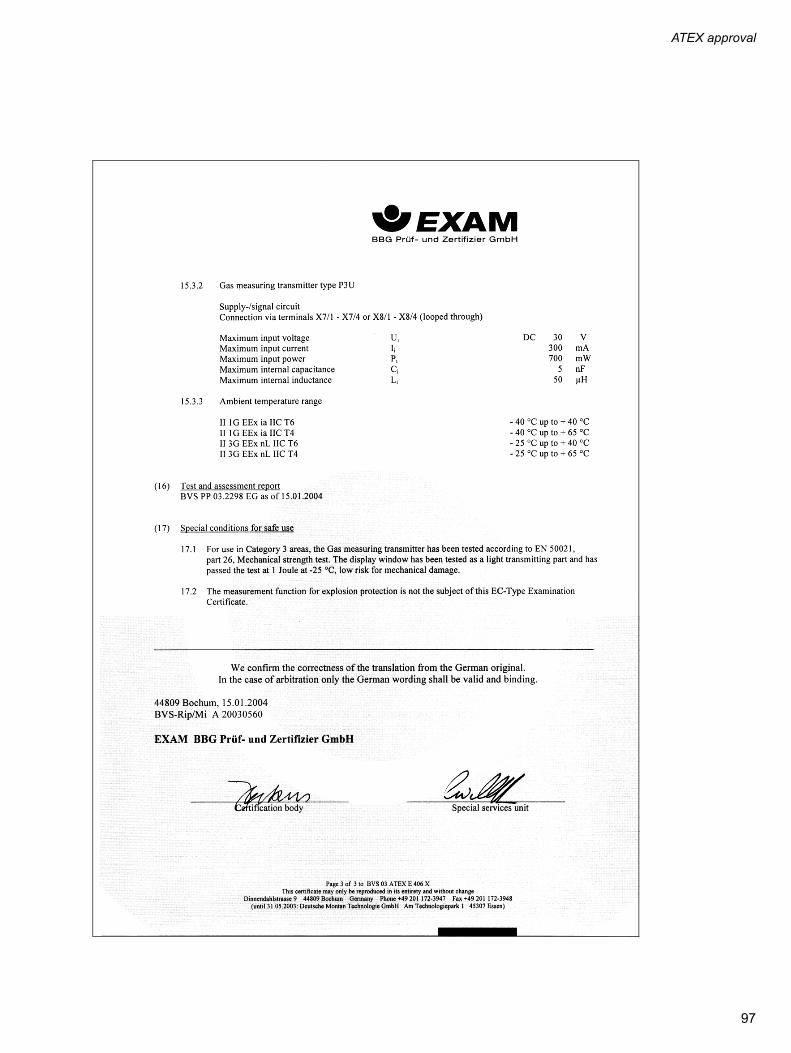
ATEX approval
97

ATEX approval
98

ATEX approval
99

ATEX approval
100

ATEX approval
101

ATEX approval
102
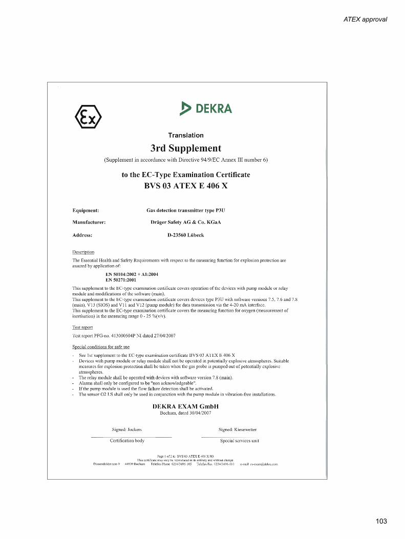
ATEX approval
103

ATEX approval
104

ATEX approval
105

ATEX approval
106

ATEX approval
107

ATEX approval
108
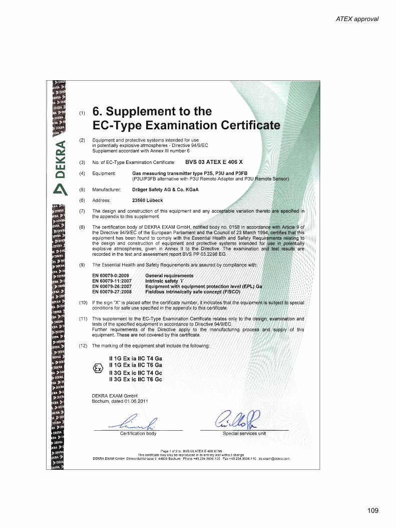
ATEX approval
109

ATEX approval
110

ATEX approval
111

ATEX approval
112
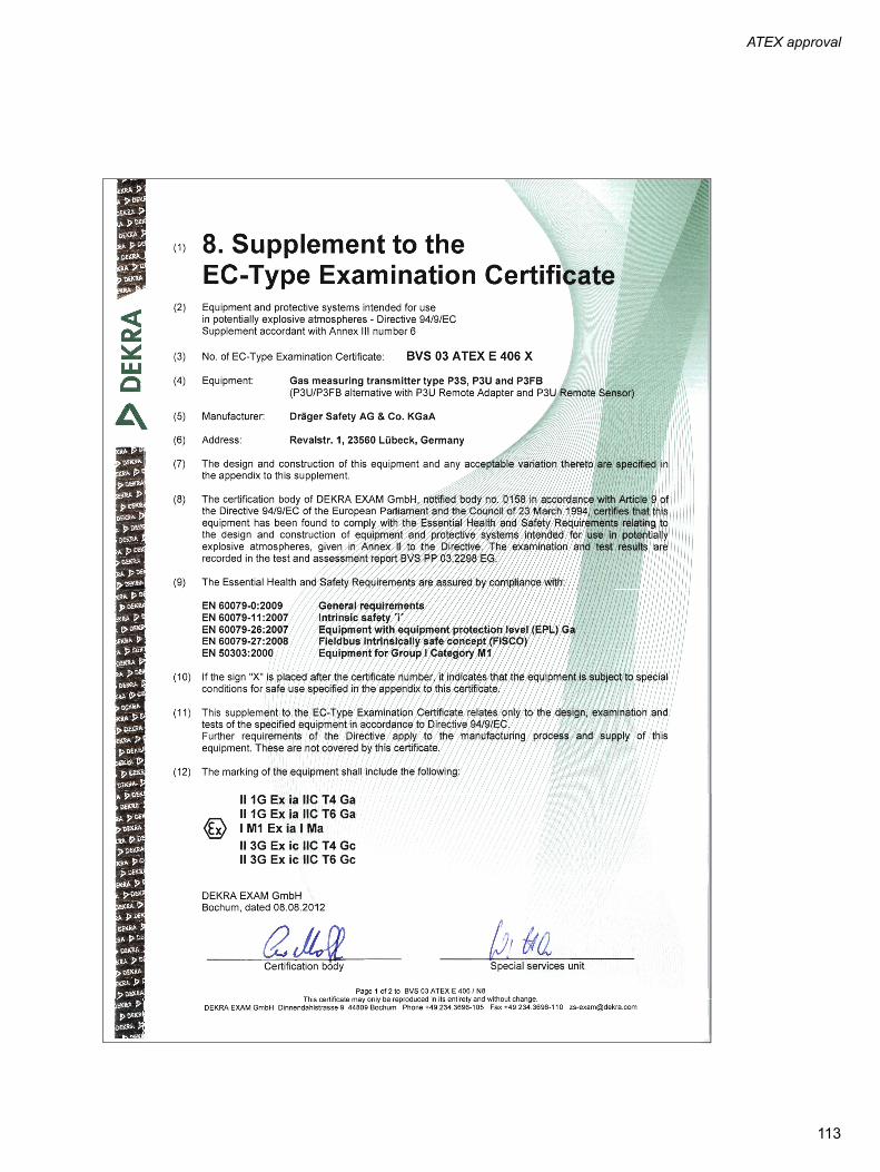
ATEX approval
113

ATEX approval
114

115
ATEX approval
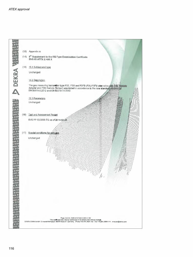
ATEX approval
116

Metrological certificate of approval
Metrological certificate of approval
Neutralization measurements for the explosion protection according to BVS 03 ATEX E 406 X and monitoring of oxy-gen deficiency or excess of oxygen according to EN 50104, PFG No. 41300504.
Section 5 of the Suitability Test Report
5. Notes on use
On the basis of the measurement results contained in the test reports with PFG no. 41300504P, 41300504P NI, 41300504P NII and 41300504P NIII and on the basis of the specifications on oxygen measurement in the measuring range 0 to 25 % O2 (with regard to the intended use of monitoring the ambient air for lacking or excess oxygen), the transmitter P3U (Polytron 7000) of the company Dräger Safety AG & Co. KGaA is appropriate if its characteristics and design correspond to the documents mentioned in the test reports with PFG no. 41300504P, 41300504P NI, 41300504P NII and 41300504P NIII, if it is operated accordingly and if the following terms are met:
— The operating instructions supplied to the EXAM and having been checked have to be strictly observed. When using the gas detector, ensure that the operating conditions are complied with as contained in the operating instructions.
— The relay module only must be operated with devices of the software versions 7.8, 7.9 or 8.0 (main).
— Alarms only must be configured as "non-acknowledgeable".
— When using the pump module, the flow alarm has to be activated (software versions 7.8 or 7.9 (main)).
— Using the sensor O2 LS in connection with the pump module only is allowed at vibration-free installation places.
— Before using the gas detector, check if the configuration times are low enough so that the warning function triggered by the device is performed so quickly that safety-critical situations can be avoided. If required, the alarm setpoint has to be set significantly above (if required, depending on the application, also below) the safety-related limit value.
— The BG information BGI 836 (3) has to be observed.
— The devices have to be provided with a permanent type plate which contains the following information next to information about the manufacturer, the type and the manufacturing number:
"PFG no. 41300504"
— Other labelling regulations remain unaffected by this specification. By means of this type plate, the manufacturing company confirms that the devices dispose of the properties and technical characteristics described in this report. Each device which is not provided with this type plate does not correspond to the present report.
— On request, the operator has to receive a complete printout of this report as well as of the reports with the PFG no. 41300504, 41300504 NI and 41300504 NII.
CAUTIONNot suitable for use in oxygen-enriched atmospheres, i.e. oxygen content exceeds 21 vol. %. Explosion hazard!
117

Metrological certificate of approval
Overview of the adjustment ranges
page Adjustment range Default value Note
Calibration gas concentra-tion
52 3,750 ppm to 262,500 ppm2,997 ppm to 1,050,000 ppm
209,000 ppm209,000 ppm
for DrägerSensor O2-LS (6809630)for DrägerSensor O2 (6809720)
A1 alarm threshold 57 999 ppm to 250,000 ppm999 ppm to 1,000,000 ppm
190,000 ppm190,000 ppm
for DrägerSensor O2-LS (6809630)for DrägerSensor O2 (6809720)
A1 alarm direction 57 exceeding/falling below falling belowfalling below
for DrägerSensor O2-LS (6809630)for DrägerSensor O2 (6809720)
A1 alarm latching 57 latching/non-latching latching latching
for DrägerSensor O2-LS (6809630)for DrägerSensor O2 (6809720)
A1 alarm acknowledge-ment
58 acknowledgeable/not acknowledgea-ble
not acknowledgeable/not acknowledgeable
for DrägerSensor O2-LS (6809630)for DrägerSensor O2 (6809720)
A1 alarm hysteresis 58 dropping below A1 alarm:999 ppm to 2,500,000 ppm – A1999 ppm to 1,000,000 ppm – A1exceeding A1 alarm:999 ppm to A1 – 999 ppm999 ppm to A1 – 999 ppm
0 ppm0 ppm
0 ppm0 ppm
for DrägerSensor O2-LS (6809630)for DrägerSensor O2 (6809720)
for DrägerSensor O2-LS (6809630)for DrägerSensor O2 (6809720)
A2 alarm threshold 58 999 ppm to 250,000 ppm999 ppm to 1,000,000 ppm
230,000 ppm230,000 ppm
for DrägerSensor O2-LS (6809630)for DrägerSensor O2 (6809720)
A2 alarm direction 58 exceeding/falling below exceeding exceeding
for DrägerSensor O2-LS (6809630)for DrägerSensor O2 (6809720)
A2 alarm latching 58 latching/non-latching latching latching
for DrägerSensor O2-LS (6809630)for DrägerSensor O2 (6809720)
A2 alarm acknowledge-ment
58 acknowledgeable/not acknowledgea-ble
not acknowledgeable/not acknowledgeable
for DrägerSensor O2-LS (6809630)for DrägerSensor O2 (6809720)
A2 alarm hysteresis 58 dropping below A2 alarm:999 ppm to 2,500,000 ppm – A2999 ppm to 1,000,000 ppm – A2exceeding A2 alarm:999 ppm to A2 – 999 ppm 999 ppm to A2 – 999 ppm
0 ppm0 ppm
0 ppm0 ppm
for DrägerSensor O2-LS (6809630)for DrägerSensor O2 (6809720)
for DrägerSensor O2-LS (6809630)for DrägerSensor O2 (6809720)
Analogue measuring range
64 49,988 ppm to 250,000 ppm49,988 ppm to 1,000,000 ppm
250,000 ppm250,000 ppm
for DrägerSensor O2-LS (6809630)for DrägerSensor O2 (6809720)
Settings for calibration interval
70 0 to 540 days0 to 366 days
270 days183 days
for DrägerSensor O2-LS (6809630)for DrägerSensor O2 (6809720)
Pump output 56 0 % to 100 % 30 %
Alarm 57 On / Off ON
Set acknowledgement 58 On / Off ON
Warning on/off 64 On / Off Off
Warning interval T1 65 2 s to 60 s 10 s
Warning interval T2 65 1 s to 59 s 1 s
Warning level 65 3 mA to 22 mA 3 mA
Maintenance level 65 3 mA to 22 mA (2-wire)1 mA to 22 mA (3-wire)
3.4 mA
Autocalibration setting 68 On / Off Off
– Sensor test setting 69 On / Off ON
Sensor lock 69 On / Off Off
Logger on/off 71 On / Off ON
Peak / average 72 Peak value/ average value Average
Trigger on/off 72 On / Off ON
Trigger value 72 0 % to 20 % 1 %
Stack/roll 73 overwrite/hold Roll
Offset current 74 -0.5 mA to +0.5 mA 0 mA
Display of operating mode Standard / no display Standard
Relay setting Normally excited / excitation after alarm
Normally excited
Contrast 68 0 to 100 % 33 %
118

Metrological certificate of approval
two-electrode-sensor for measurement of oxy-nection with a suitable Dräger transmitter.
sured value time setting may increase.
Information on DrägerSensor O2 (6809720)
Principle of measurement: The DrägerSensor O2 (6809720) is an electrochemical gen (O2) in air. The sensor can only be operated in con
Reaction at the measuring electrode: O2 + 2 H2O + 4 e– => 4 OH–
Reaction at the counter-electrode: 2 Pb => 2 Pb2+ + 4 e–
Ambient conditions:
Operational Characteristics –5 oC to 40 oC, temporarily –20 oC to 55 oC
700 hPa to 1300 hPa
10 to 95 % relative humidity, non condensing
Storage 0 oC to 40 oC
700 hPa to 1300 hPa
30 to 70 % relative humidity, non condensing
Measured value time setting:
t0...20 <12 seconds
t0...90 <30 seconds
Note: In the case of temperatures below –5 oC, the mea
Calibration:
Flow rate: 0.5 L/min
Zero gas Nitrogen (99.9 Vol.-% N2)
Calibration gas Oxygen / nitrogen – mixed gas
Warming-up time:
Sensor is ready to operate after 15 minutes
Sensor is ready to calibrate after 2 hours
119

Metrological certificate of approval
Cross sensitivities
No cross sensitivities against pollution gases with a range up to 100 ppm. For gases in a concentration range larger than 1 Vol.-%: see table. The influence of the O2 displacement is in not taken into account in the table (partial pressure measurement).
Increased sensor drift can be caused by high sour gas concentrations (> 1 Vol.-%), which could make shorter calibra-tion intervals necessary. The sensor service life is reduced in dependence on the duration and the concentration of the sour gases (e.g. lifetime in atmospheres containing CO2: 5000 Vol.-% CO2 x hours).Organic solvents (e.g. acetone, propyl alcohol, etc.) dissolve in the plastic parts of the sensor. If allowed to react over several days in larger concentrations (> 1 Vol.-%), these substances can cause sensor drift can which could make shorter calibration intervals necessary. This will not reduce the sensor service life.
Gas / vapour Chemical symbol Gas concentration Measurement value deviationin Vol.-% O2
acetone CH3COCH3 1 Vol.-% 0.1
ethane C2H6 10 Vol.-% 0.1
ethanol C2H5OH 1 Vol.-% 0.1
ethylene C2H4 5 Vol.-% 0.1
ethine C2H2 2 Vol.-% 0.1
carbon dioxide CO2 5 Vol.-% 0.1
carbon monoxide CO 1 Vol.-% 0.1
methane CH4 10 Vol.-% 0.1
methanol CH3OH 1 Vol.-% 0.1
propane C3H8 5 Vol.-% 0.1
hydrogen H2 10 Vol.-% 0.1
120

Metrological certificate of approval
Information on DrägerSensor O2-LS (6809630)
Cross sensitivities
The table shows the reactions of the sensor to other gases than the measured gas (cross sensitivities). The listed val-ues are typical and are valid for new sensors. The table does not lay a claim on completeness. Gas mixtures can be displayed as the sum of all components. Gases with negative sensitivity can cancel out a positive sensor display. The influence of the O2 displacement is in not taken into account in the table.Example:With 2 Vol.-% ethylene in the air – measurement value deviation due to cross sensitivities (table value) = –1 Vol.-% O2 O2 displacement caused by 2 Vol.-% ethylene (2% of 20 Vol.-% O2) = –0.4 Vol.-% O2Polytron transmitter display (20.9 – 1 – 0.4) = 19.5 Vol.-% O2.
Principle of measurement: The DrägerSensor O2-LS (6809630) is an electrochemical three-electrode-sensor for measurement of oxygen (O2) in air. The sensor can only be operated in connection with a suitable Dräger transmitter. The sensor cannot be used for oxygen measurements in the presence of helium!
Reaction at the measuring electrode: O2 + 4 H+ + 4 e– => 2 H2O
Reaction at the counter-electrode: 2 H2O => O2 + 4 H+ + 4 e–
Ambient conditions:
Operational Characteristics -40 oC to 60 oC, short-term up to 65 oC
700 hPa to 1300 hPa
5 to 95 % relative humidity, non condensing
storage (in original packaging) 0 oC to 40 oC
Measured value time setting:
t0...20: <12 seconds
t0...90 <30 seconds
Calibration:
Flow rate: 0.5 L/min
Zero gas Nitrogen (99.9 Vol.-% N2)
Calibration gas Oxygen / nitrogen - mixed gas
Warming-up time:
Sensor is ready to operate after 90 minutes
Sensor is ready to calibrate after 6 hours
Gas / vapour Chemical symbol Gas concentration Measurement value devia-tion in Vol.-%
with dust filteracetaldehyde CH3CHO 50 ppm no influence
acrylonitrile H2C=CH–CN 80 ppm no influence
ammonia NH3 50 ppm no influence
arseniuretted hydrogen AsH3 3 ppm no influence
butadiene CH2CHCHCH2 50 ppm no influence
tert-butylmercaptane (CH3)3CSH 4 ppm no influence
chlorine Cl2 8 ppm no influence
hydrogen chloride HCl 20 ppm no influence
hydrocyanic acid HCN 20 ppm no influence
boroethane B2H6 5 ppm no influence
1.1-dichloroethane C2H4Cl2 50 ppm no influence
diethylamine (C2H5)2NH 100 ppm no influence
diethyl ether (C2H5)2O 400 ppm 0.1 (–) *
epichlorhydrine C2H3OCH2Cl 35 ppm no influence
ethanol C2H5OH 250 ppm no influence
121

Metrological certificate of approval
1 (–) *
0.5 (–) *
2 (–) *
no influence
no influence
no influence
0.1 (–) *
no influence
no influence
no influence
no influence
no influence
0.2 (–) *
no influence
no influence
no influence
no influence
no influence
no influence
no influence
no influence
no influence
no influence
1.5 (–) *
no influence
entrations or over a longer period of
t always be installed at vibration-free to deviate outside of the permissible
tion Measurement value devia-tion in Vol.-%
with dust filter
(–) * Negative display.
ethylene C2H4 2 Vol.-%
ethine C2H2 1 Vol.-%
ethylene oxide C2H4O 20 ppm
hydrogen fluoride HF 15 ppm
formaldehyde HCHO 40 ppm
carbon dioxide CO2 5 Vol.-%
carbon monoxide CO 100 ppm
methyl methacrylate CH2C(CH3)COOCH3 50 ppm
methylamine CH3NH2 100 ppm
carbonyl chloride COCl2 1 ppm
phosphine PH3 10 ppm
i-propyl alcohol (CH3)2CHOH 500 ppm
propylene CH3CHCH2 50 ppm
sulphur dioxide SO2 20 ppm
hydrogen sulfide H2S 20 ppm
hydrogen selenide SeH2 5 ppm
hydrosilicon SiH4 5 ppm
nitrogen dioxide NO2 50 ppm
nitrogen monoxide NO 20 ppm
styrene C6H5CHCH2 30 ppm
tetrahydrofurane C4H8O 60 ppm
tetrahydrothiophene C4H8S 5 ppm
vinyl chloride C2H3Cl 50 ppm
hydrogen H2 1 Vol.-%
hydrogen peroxide H2O2 5 ppm
CAUTIONThe influence of unsaturated hydrocarbons, alcohols or hydrogen in higher conctime (dose approx. 100,000 ppm x hours) will let the sensor drop out.
When used in transmitters with pump module, the O2 LS sensor (68 09 630) muslocations. If used in this combination, vibrations may cause the measured valuerange.
Gas / vapour Chemical symbol Gas concentra
122

IECEx approval
IECEx approval
123

IECEx approval
124

IECEx approval
125

IECEx approval
126

UL approval
UL approval
127

UL approval
128

UL approval
The depicted page is part of the UL certificate but refers to the Polytron 3000.
129

UL approval
130

UL approval
131

CSA approval
CSA approval
132

CSA approval
133
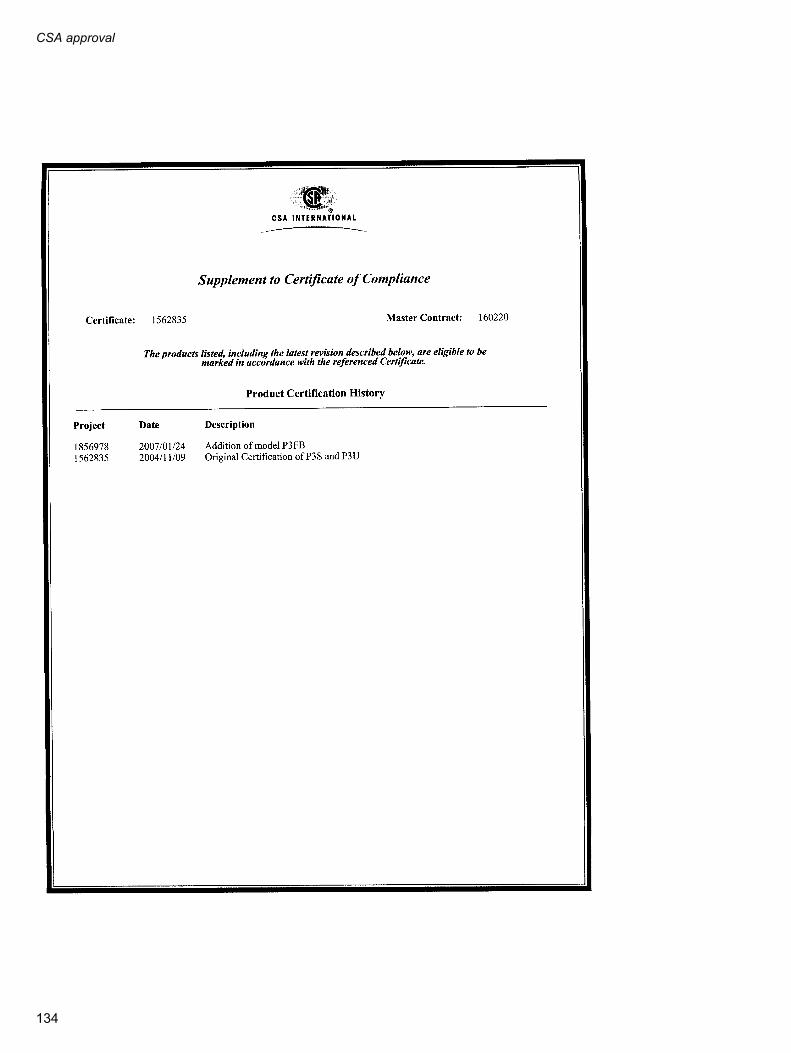
CSA approval
134

CSA approval
The depicted page is part of the CSA certificate but refers to the Polytron 3000.
135
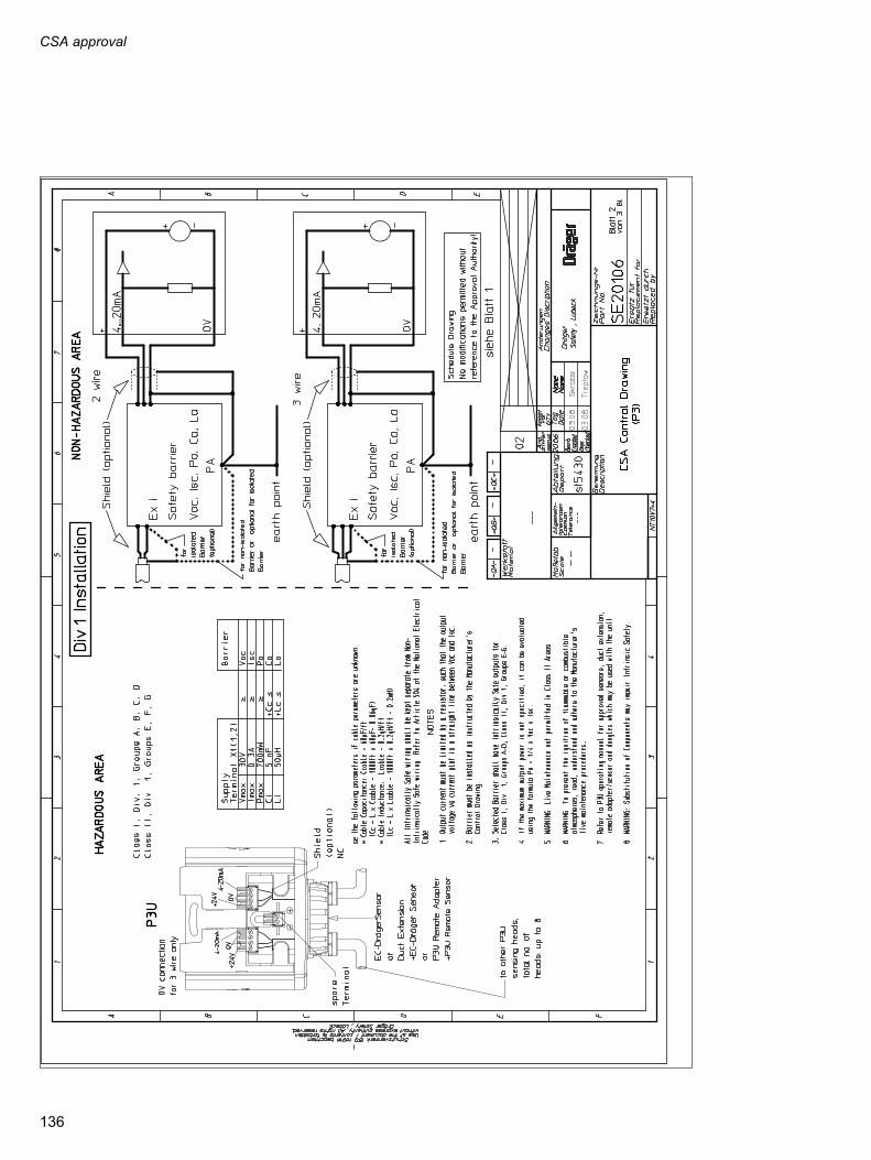
CSA approval
136

CSA approval
137
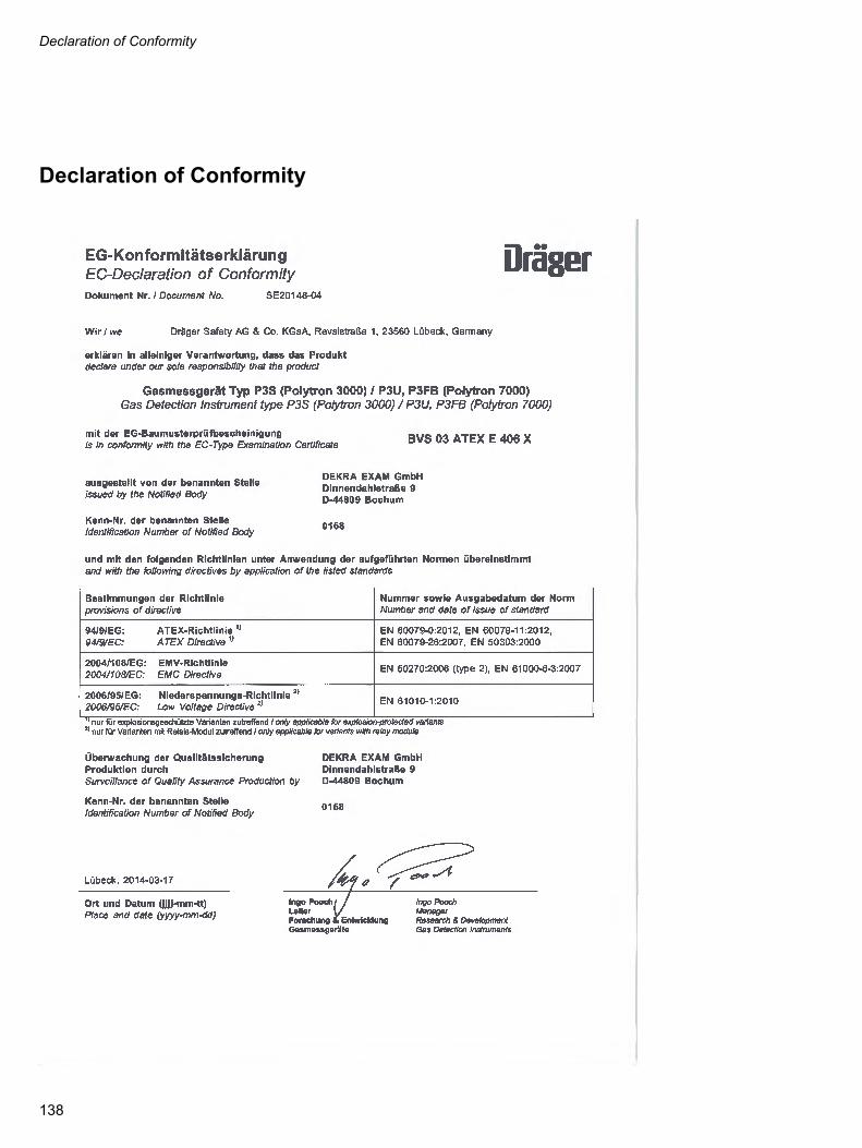
Declaration of Conformity
Declaration of Conformity
138

139
Drilling templates
Drilling templates
Dräger docking station
66 ±
4 m
m
0452
3758
_1.e
ps

140

141
Drilling templates
Remote sensor
Duct adapter
50 ±
4 m
m
0462
3758
_1.e
ps04
7237
58_1
.eps94 mm ± 1 mm
Ø 35 ± 1 mm


90 33 002 - GA 4683.100 en© Dräger Safety AG & Co. KGaAEdition 08 - October 2014 (Edition 01 - September 2003)Subject to alteration
Dräger Safety AG & Co. KGaARevalstraße 1D-23560 LübeckGermanyTel. +49 451 8 82 - 27 94Fax +49 451 8 82 - 49 91www.draeger.com
Dan Macey
2