Agilent 1290 Infinity II Evaporative Light Scattering Detector
Upload
khangminh22Category
view
0download
0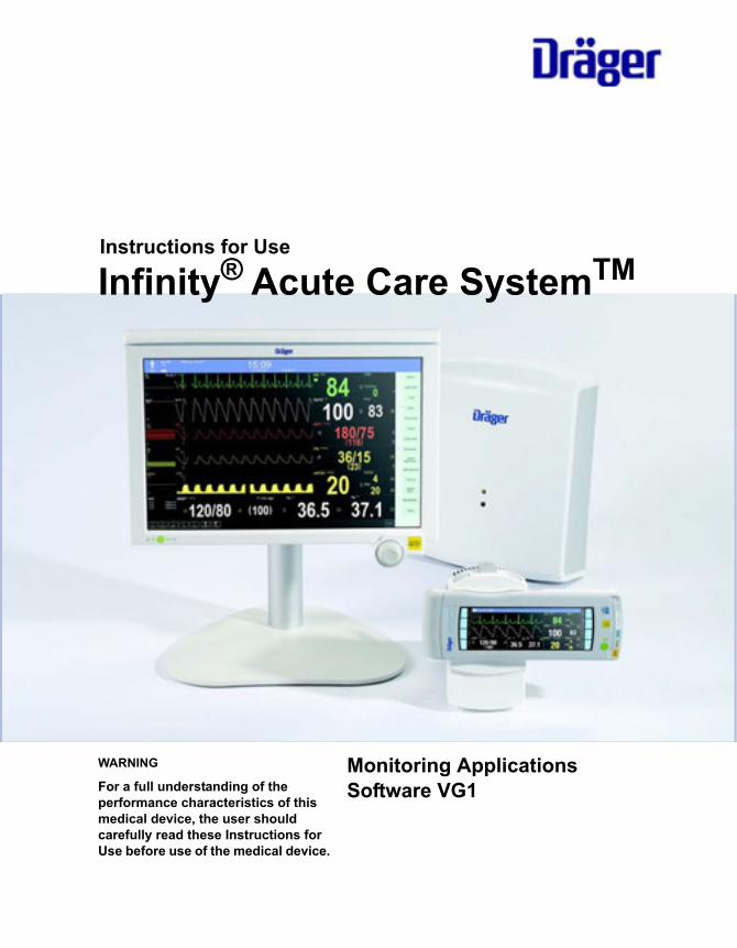
Instructions for Use
Infinity® Acute Care SystemTM
Monitoring ApplicationsSoftware VG1
WARNING
For a full understanding of the performance characteristics of this medical device, the user should carefully read these Instructions for Use before use of the medical device.

2 Instructions for Use Infinity Acute Care System - Monitoring Applications SW VG1
Working with these Instructions for Use
The title of the main chapter
in the header line helps with the orientation and navigation.
The instructions for the user
combine text and illustrations, providing a comprehensive overview of the system. The information is presented as sequential steps of action, allowing the user to learn directly how to use the device.
The text
provides explanations and instructs the user step-by-step in the practical use of the product, with short, clear instructions in an easy-to-follow sequence.
1 Consecutive numbers indicate steps of action, with the numbering restarting with “1” for each new sequence of actions.
� Bullet points indicate individual actions or different options for action.
– Dashes indicate the listing of data, options or objects.
The illustrations
establish the relationship between the text and the device. Elements mentioned in the text are highlighted. Unnecessary details are omitted.
Schematic renderings of screen images guide the user and allow to reconfirm actions performed. The actual screen images differ in look or in configuation.
A Letters denote elements referred to in the text.
Typing conventions in this manual
Any text shown on the screen is printed in bold and italics, for example, ECG, or Current alarms.
Trademarks
Infinity®, Hemo4®, Hemo2®, MPod®, Innovian®, DrägerService®, MCableTM, Medical CockpitTM, and Acute Care SystemTM are trademarks of Dräger.
Masimo® and Masimo SET® (Signal Extraction Technology) are trademarks of Masimo Corporation.
NellcorTM, OxiMaxTM and SatSecondsTM are trademarks of Nellcor Puritan Bennett, LLC.
ViewSonic® is a registered trademark of ViewSonic Corporation in the U.S. and other countries.
Edwards Vigileo® and Edwards Vigilance® are trademarks of Edwards Lifesciences LLC.

Instructions for Use Infinity Acute Care System - Monitoring Applications SW VG1 3
Definitions
Abbreviations and Symbols
Please refer to "Device Symbols" on page 23 and to "Abbreviations" on page 26 for explanations.
WARNINGA WARNING statement provides important information about a potentially hazardous situation which, if not avoided, could result in death or serious injury.
CAUTIONA CAUTION statement provides important information about a potentially hazardous situation which, if not avoided, may result in minor or moderate injury to the user or patient or in damage to the equipment or other property.
NOTEA NOTE provides additional information intended to avoid inconveniences during operation.

4 Instructions for Use Infinity Acute Care System - Monitoring Applications SW VG1
This page is intentionally left blank
Instructions for Use Infinity Acute Care System - Monitoring Applications SW VG1 5
Contents
Definitions. . . . . . . . . . . . . . . . . . . . . . . . . . . . . 3Abbreviations and Symbols . . . . . . . . . . . . . . . 3
For Your Safety and That of Your Patients. . 9
General Warnings and Cautions . . . . . . . . . . . 12
Intended Use . . . . . . . . . . . . . . . . . . . . . . . . . . 15
Infinity Acute Care System . . . . . . . . . . . . . . . 16
System Overview . . . . . . . . . . . . . . . . . . . . . . 17
Overview. . . . . . . . . . . . . . . . . . . . . . . . . . . . . . 18Infinity ® Medical CockpitTM (Cockpit) . . . . . . . 18Infinity® PS250 Comm Hub (PS250) . . . . . . . . 19Infinity®M540 Patient Monitor (M540) . . . . . . . 19Infinity® M500 Docking Station (M500) . . . . . . 20Additional Hardware . . . . . . . . . . . . . . . . . . . . . 21Device Symbols . . . . . . . . . . . . . . . . . . . . . . . . 23Abbreviations . . . . . . . . . . . . . . . . . . . . . . . . . . 26
Operating Concept . . . . . . . . . . . . . . . . . . . . . 29
Operating Concept Overview . . . . . . . . . . . . . . 30The IACS Components. . . . . . . . . . . . . . . . . . . 31M540-and-Cockpit Communication . . . . . . . . . 32Communicating with the Infinity® Network . . . . 33Communication Management. . . . . . . . . . . . . . 36Remote Control and Remote View . . . . . . . . . . 38Secondary Display . . . . . . . . . . . . . . . . . . . . . . 40User Interface. . . . . . . . . . . . . . . . . . . . . . . . . . 40Header Bar . . . . . . . . . . . . . . . . . . . . . . . . . . . . 41Monitoring Area . . . . . . . . . . . . . . . . . . . . . . . . 42Main-Menu Bar and Quick-Access Toolbar . . . 45Filtering the Parameter Content . . . . . . . . . . . . 47Auto vs. Manual Display Modes . . . . . . . . . . . . 47Auto-View Setup Toolbar . . . . . . . . . . . . . . . . . 48Customising the Display. . . . . . . . . . . . . . . . . . 48Parameter Priority . . . . . . . . . . . . . . . . . . . . . . 52Views . . . . . . . . . . . . . . . . . . . . . . . . . . . . . . . . 53Profiles . . . . . . . . . . . . . . . . . . . . . . . . . . . . . . . 54Standby Mode. . . . . . . . . . . . . . . . . . . . . . . . . . 55Privacy Mode . . . . . . . . . . . . . . . . . . . . . . . . . . 56
Assembly. . . . . . . . . . . . . . . . . . . . . . . . . . . . . 57
Assembly Overview . . . . . . . . . . . . . . . . . . . . . 58Docking/Undocking the M540. . . . . . . . . . . . . . 59
Locking/Unlocking the M540 . . . . . . . . . . . . . . 60Connecting the System Cables . . . . . . . . . . . . 61
Getting Started. . . . . . . . . . . . . . . . . . . . . . . . 63
Overview of Monitoring a Patient . . . . . . . . . . 64Turning the IACS On/Off . . . . . . . . . . . . . . . . . 64The Demographics Page. . . . . . . . . . . . . . . . . 65Admitting a Patient . . . . . . . . . . . . . . . . . . . . . 66Discharging a Patient . . . . . . . . . . . . . . . . . . . 67Patient Categories. . . . . . . . . . . . . . . . . . . . . . 68
Alarms . . . . . . . . . . . . . . . . . . . . . . . . . . . . . . 71
Overview of Alarms . . . . . . . . . . . . . . . . . . . . . 72Alarm Priorities . . . . . . . . . . . . . . . . . . . . . . . . 73Alarm Processing . . . . . . . . . . . . . . . . . . . . . . 73Enabling or Disabling Alarm Validation . . . . . . 75Visual Alarm Signals . . . . . . . . . . . . . . . . . . . . 76Audible Alarm Signals . . . . . . . . . . . . . . . . . . . 78Testing Visual and Audible Alarm Signals . . . . 79Viewing Current Alarm Messages . . . . . . . . . . 80Special Alarm Behaviour . . . . . . . . . . . . . . . . . 80Pre-Silencing Alarms. . . . . . . . . . . . . . . . . . . . 82Pausing Active Alarm Tones . . . . . . . . . . . . . . 83Enabling or Disabling Audible Alarm Signals . 84Pausing Alarm Monitoring Temporarily . . . . . . 84Enabling or Disabling Alarm Monitoring Permanently . . . . . . . . . . . . . . . . . . . . . . . . . . 85Configuring a Patient’s Alarm Settings . . . . . . 85Alarm Setup for an Individual Parameter . . . . 87Alarm Setup for Multiple Parameters . . . . . . . 89Alarm Setup for Arrhythmia . . . . . . . . . . . . . . . 91Alarm Setup for ST . . . . . . . . . . . . . . . . . . . . . 93Auto-Setting All Alarm Limits. . . . . . . . . . . . . . 95Alarm History and Stored Events . . . . . . . . . . 96The Alarm History . . . . . . . . . . . . . . . . . . . . . . 97Viewing a Snapshot of a Single Event. . . . . . . 98Remote Alarm Control. . . . . . . . . . . . . . . . . . . 99External Device Disconnection Alarm . . . . . . . 100The Code Button . . . . . . . . . . . . . . . . . . . . . . . 100Alarm Ranges and Defaults . . . . . . . . . . . . . . 101
Trends/Data Dialogue Windows . . . . . . . . . . 109
Overview . . . . . . . . . . . . . . . . . . . . . . . . . . . . . 110Trends . . . . . . . . . . . . . . . . . . . . . . . . . . . . . . . 110

6 Instructions for Use Infinity Acute Care System - Monitoring Applications SW VG1
Trend Graphs . . . . . . . . . . . . . . . . . . . . . . . . . . 112The Trends Graph Page. . . . . . . . . . . . . . . . . . 112Available Functions on the Trends Graph Page113Trend Table. . . . . . . . . . . . . . . . . . . . . . . . . . . . 115Available Functions on the Trends Table Page 116Graph Vitals Page . . . . . . . . . . . . . . . . . . . . . . 117Mini-trends . . . . . . . . . . . . . . . . . . . . . . . . . . . . 119Labs Page . . . . . . . . . . . . . . . . . . . . . . . . . . . . 120
Calculations . . . . . . . . . . . . . . . . . . . . . . . . . . 121
Overview . . . . . . . . . . . . . . . . . . . . . . . . . . . . . 122The Calculation Page . . . . . . . . . . . . . . . . . . . . 123The Results Page. . . . . . . . . . . . . . . . . . . . . . . 125Laboratory Data . . . . . . . . . . . . . . . . . . . . . . . . 126Calculation Equations. . . . . . . . . . . . . . . . . . . . 127Drug Calculations . . . . . . . . . . . . . . . . . . . . . . . 131The Drug Calculation Page . . . . . . . . . . . . . . . 131Customised Drug List . . . . . . . . . . . . . . . . . . . . 132Drug Calculator Equations . . . . . . . . . . . . . . . . 134
ECG, Arrhythmia, and ST Segment. . . . . . . . 137
Overview of ECG and Heart Rate Monitoring . 139ECG Precautions . . . . . . . . . . . . . . . . . . . . . . . 140Connecting the 3-, 5-, 6-Lead Wire Sets for ECG Monitoring . . . . . . . . . . . . . . . . . . . . . . . . 140Connecting the Lead Wire Set for 12-Lead Monitoring. . . . . . . . . . . . . . . . . . . . . . . . . . . . . 141Connecting the Lead Wires for Neonatal Monitoring. . . . . . . . . . . . . . . . . . . . . . . . . . . . . 142Patient Preparation for ECG Monitoring. . . . . . 143ECG Display. . . . . . . . . . . . . . . . . . . . . . . . . . . 144ECG Electrode Colours . . . . . . . . . . . . . . . . . . 145Electrode Placement . . . . . . . . . . . . . . . . . . . . 14612-Lead Monitoring . . . . . . . . . . . . . . . . . . . . . 149Accessing the ECG Setup Page . . . . . . . . . . . 149ECG Parameter Setup Functions. . . . . . . . . . . 150Monitoring Paced Patients . . . . . . . . . . . . . . . . 153Pacemaker Precautions . . . . . . . . . . . . . . . . . . 154Optimising Pacer Processing . . . . . . . . . . . . . . 156Arrhythmia Monitoring Overview . . . . . . . . . . . 156Selecting ARR Leads . . . . . . . . . . . . . . . . . . . . 157ARR Modes . . . . . . . . . . . . . . . . . . . . . . . . . . . 157ARR Display . . . . . . . . . . . . . . . . . . . . . . . . . . . 159Accessing the ARR Setup Page. . . . . . . . . . . . 160ARR Parameter Setup Functions . . . . . . . . . . . 160Monitoring ST Overview . . . . . . . . . . . . . . . . . . 161Standard ST Monitoring . . . . . . . . . . . . . . . . . . 161TruST 12-Lead Monitoring . . . . . . . . . . . . . . . . 162
12-Lead ST Monitoring . . . . . . . . . . . . . . . . . . 162Connecting Lead Wire Sets for ST Monitoring 162ST Display . . . . . . . . . . . . . . . . . . . . . . . . . . . . 163The ST-Complex Pages . . . . . . . . . . . . . . . . . 163ST Measuring Points . . . . . . . . . . . . . . . . . . . . 166ST Reference . . . . . . . . . . . . . . . . . . . . . . . . . 166ST Alarm Settings . . . . . . . . . . . . . . . . . . . . . . 167Accessing the ST Settings Setup Page. . . . . . 167ST Setup Functions. . . . . . . . . . . . . . . . . . . . . 168Learning/Relearning QRS Pattern. . . . . . . . . . 170
Impedance Respiration (RRi) . . . . . . . . . . . . 171
Overview of Respiration Monitoring . . . . . . . . 172Respiration Precautions . . . . . . . . . . . . . . . . . 172Connecting the 3-, 5-, 6-Lead Wire Sets for RRi Monitoring. . . . . . . . . . . . . . . . . . . . . . . . . 173Connecting the Lead Wire Set for 12-Lead Monitoring . . . . . . . . . . . . . . . . . . . . . . . . . . . . 174Connecting the Lead Wires for Neonatal Monitoring . . . . . . . . . . . . . . . . . . . . . . . . . . . . 175Patient Preparation for Respiration Monitoring . . . . . . . . . . . . . . . . . . . . . . . . . . . . 175Respiration Display . . . . . . . . . . . . . . . . . . . . . 176Adjusting the Detection Threshold and Turn on the Respiration Marker. . . . . . . . . . . . 177Respiration Measuring Modes. . . . . . . . . . . . . 178Accessing the Respiration Setup Page. . . . . . 178Respiration Parameter Setup Functions . . . . . 179
SpO2 and Pulse Rate with Masimo SET MCable . . . . . . . . . . . . . . . . . . . . . . . . . . . . . . 181
Overview of SpO2 Monitoring . . . . . . . . . . . . . 182SpO2 Precautions . . . . . . . . . . . . . . . . . . . . . . 182Connecting the Masimo SET MCable . . . . . . . 184Patient Preparation . . . . . . . . . . . . . . . . . . . . . 185SpO2 Display. . . . . . . . . . . . . . . . . . . . . . . . . . 186Accessing the SpO2 Setup Page. . . . . . . . . . . 186SpO2 Parameter Setup Functions . . . . . . . . . . 187
SpO2 and Pulse Rate with Nellcor Oximax MCable . . . . . . . . . . . . . . . . . . . . . . . . . . . . . . 189
Overview of SpO2 Monitoring . . . . . . . . . . . . . 190SpO2 Precautions . . . . . . . . . . . . . . . . . . . . . . 191Connecting the Nellcor Oximax MCable . . . . . 192Patient Preparation . . . . . . . . . . . . . . . . . . . . . 193SpO2 Display. . . . . . . . . . . . . . . . . . . . . . . . . . 194Accessing the SpO2 Setup Page. . . . . . . . . . . 194

Instructions for Use Infinity Acute Care System - Monitoring Applications SW VG1 7
SpO2 Parameter Setup Functions . . . . . . . . . . 195
Temperature . . . . . . . . . . . . . . . . . . . . . . . . . . 197
Overview of Temperature Monitoring . . . . . . . . 198Connecting the Temperature Sensors . . . . . . . 198Temperature Display. . . . . . . . . . . . . . . . . . . . . 201Accessing the Temperature Setup Page . . . . . 202Temperature Parameter Setup Functions. . . . . 202
Non-Invasive Blood Pressure (NIBP) . . . . . . 203
Overview of NIBP Monitoring . . . . . . . . . . . . . . 204NIBP Precautions . . . . . . . . . . . . . . . . . . . . . . . 204Connecting the NIBP Hose and Cuff . . . . . . . . 206Patient Preparation for NIBP Monitoring . . . . . 207NIBP Display . . . . . . . . . . . . . . . . . . . . . . . . . . 208NIBP Measurement Modes . . . . . . . . . . . . . . . 209Venous Stasis . . . . . . . . . . . . . . . . . . . . . . . . . . 212Accessing the NIBP Setup Page . . . . . . . . . . . 212NIBP Parameter Setup Functions . . . . . . . . . . 213
Invasive Blood Pressure (IBP) . . . . . . . . . . . 215
Overview of IBP Monitoring . . . . . . . . . . . . . . . 216IBP Precautions . . . . . . . . . . . . . . . . . . . . . . . . 218Connecting the Hemo4 pod and Hemo2 pod . . 219Connecting the MPod - QuadHemo . . . . . . . . . 220Connecting the Dual Hemo MCable . . . . . . . . . 221Patient Preparation. . . . . . . . . . . . . . . . . . . . . . 221IBP Display. . . . . . . . . . . . . . . . . . . . . . . . . . . . 222Labelling IBP Pressure Channels. . . . . . . . . . . 223Standard Labels . . . . . . . . . . . . . . . . . . . . . . . . 224Pressure Label Conflicts. . . . . . . . . . . . . . . . . . 224Zeroing an IBP Transducer . . . . . . . . . . . . . . . 225Pulmonary Wedge Pressure. . . . . . . . . . . . . . . 227Starting Wedge Measurements from the Pods . . . . . . . . . . . . . . . . . . . . . . . . . . . . . . . . . 228Accessing the IBP Setup Page. . . . . . . . . . . . . 230IBP Parameter Setup Functions. . . . . . . . . . . . 231
Cardiac Output (C.O.). . . . . . . . . . . . . . . . . . . 233
Overview of Cardiac Output (C.O.) Monitoring. . . . . . . . . . . . . . . . . . . . . . . . . . . . . 234C.O. Precautions . . . . . . . . . . . . . . . . . . . . . . . 234Connecting the C.O. Hardware . . . . . . . . . . . . 235Patient Preparation for C.O. Monitoring . . . . . . 237C.O. Display . . . . . . . . . . . . . . . . . . . . . . . . . . . 238C.O. Computation Constant . . . . . . . . . . . . . . . 239C.O. Measuring Modes. . . . . . . . . . . . . . . . . . . 241
Saving the C.O. Value . . . . . . . . . . . . . . . . . . . 244The Procedures C.O. Average Page. . . . . . . . 245Accessing the C.O. Setup Page . . . . . . . . . . . 246C.O. Parameter Setup Functions . . . . . . . . . . 246
Carbon Dioxide Concentrations (CO2) . . . . 249
Overview of CO2 Monitoring . . . . . . . . . . . . . . 250CO2 Precautions . . . . . . . . . . . . . . . . . . . . . . . 251Connecting the CO2 Sensor . . . . . . . . . . . . . . 252Patient Preparation for CO2 Monitoring. . . . . . 253CO2 Display. . . . . . . . . . . . . . . . . . . . . . . . . . . 253Accessing the CO2 Setup Page . . . . . . . . . . . 256CO2 Parameter Setup Functions. . . . . . . . . . . 256
External Device - Ventilator . . . . . . . . . . . . . 259
Overview of Ventilation . . . . . . . . . . . . . . . . . . 260Ventilator Precautions . . . . . . . . . . . . . . . . . . . 262Ventilator Display. . . . . . . . . . . . . . . . . . . . . . . 263Loops. . . . . . . . . . . . . . . . . . . . . . . . . . . . . . . . 263The Show-All Page . . . . . . . . . . . . . . . . . . . . . 264Accessing the Ventilator Setup Pages . . . . . . 264Ventilator Paw Setup Functions . . . . . . . . . . . 265Ventilator Setup Functions . . . . . . . . . . . . . . . 265CO2Setup Functions . . . . . . . . . . . . . . . . . . . . 266
External Device - Continuous Cardiac Output (CCO) . . . . . . . . . . . . . . . . . . . . . . . . . . . . . . . 267
Overview of CCO . . . . . . . . . . . . . . . . . . . . . . 268CCO Precautions . . . . . . . . . . . . . . . . . . . . . . 270The Show-All Page . . . . . . . . . . . . . . . . . . . . . 270Accessing the CCO/SvO2 Setup Pages . . . . . 271SvO2 Setup Functions . . . . . . . . . . . . . . . . . . 271
System Configuration . . . . . . . . . . . . . . . . . . 273
Overview . . . . . . . . . . . . . . . . . . . . . . . . . . . . . 274The Screen Setup Pages . . . . . . . . . . . . . . . . 274Screen Setup – General Settings Setup Page . . . . . . . . . . . . . . . . . . . . . . . . . . . . . . . . 275Screen Setup – Modes Setup Page . . . . . . . . 276Screen Setup – Auto-View Setup Page . . . . . 277Configuring Parameters for Display . . . . . . . . 279Screen Setup – Views Setup Page. . . . . . . . . 282Screen Setup – View-Editor Setup Page . . . . 283The Alarms Pages. . . . . . . . . . . . . . . . . . . . . . 286Recordings/Reports Page . . . . . . . . . . . . . . . . 290Biomed Setup Pages. . . . . . . . . . . . . . . . . . . . 292Biomed IT Setup . . . . . . . . . . . . . . . . . . . . . . . 299

8 Instructions for Use Infinity Acute Care System - Monitoring Applications SW VG1
Profile Setup. . . . . . . . . . . . . . . . . . . . . . . . . . . 304Saving Profiles . . . . . . . . . . . . . . . . . . . . . . . . . 305Configuring Profiles . . . . . . . . . . . . . . . . . . . . . 307Managing Views and Profiles . . . . . . . . . . . . . . 309Transferring Profiles . . . . . . . . . . . . . . . . . . . . . 310
Reports/Recordings . . . . . . . . . . . . . . . . . . . . 313
Overview . . . . . . . . . . . . . . . . . . . . . . . . . . . . . 314R50N Recorder . . . . . . . . . . . . . . . . . . . . . . . . 314Timed Recordings . . . . . . . . . . . . . . . . . . . . . . 315Continuous Recordings . . . . . . . . . . . . . . . . . . 317Causes for Automatic Cancellation of Recordings . . . . . . . . . . . . . . . . . . . . . . . . . . . . 317Reports . . . . . . . . . . . . . . . . . . . . . . . . . . . . . . . 318Print Screen . . . . . . . . . . . . . . . . . . . . . . . . . . . 319
IT Applications (Options). . . . . . . . . . . . . . . . 321
Overview . . . . . . . . . . . . . . . . . . . . . . . . . . . . . 322Configuring IT Tabs . . . . . . . . . . . . . . . . . . . . . 322Accessing an IT Tab . . . . . . . . . . . . . . . . . . . . . 323Supported IT Applications . . . . . . . . . . . . . . . . 324
Problem Solving . . . . . . . . . . . . . . . . . . . . . . . 325
Overview . . . . . . . . . . . . . . . . . . . . . . . . . . . . . 326Device Communication Messages . . . . . . . . . . 326ECG . . . . . . . . . . . . . . . . . . . . . . . . . . . . . . . . . 328ST. . . . . . . . . . . . . . . . . . . . . . . . . . . . . . . . . . . 330ARR . . . . . . . . . . . . . . . . . . . . . . . . . . . . . . . . . 331Respiration (RRi) . . . . . . . . . . . . . . . . . . . . . . . 332SpO2. . . . . . . . . . . . . . . . . . . . . . . . . . . . . . . . . 334NIBP . . . . . . . . . . . . . . . . . . . . . . . . . . . . . . . . . 337Temperature . . . . . . . . . . . . . . . . . . . . . . . . . . . 339IBP . . . . . . . . . . . . . . . . . . . . . . . . . . . . . . . . . . 340Cardiac Output . . . . . . . . . . . . . . . . . . . . . . . . . 343CO2 . . . . . . . . . . . . . . . . . . . . . . . . . . . . . . . . . 345Recording Status Messages. . . . . . . . . . . . . . . 348
Cleaning and Disinfection . . . . . . . . . . . . . . . 349
Overview of General Precautions. . . . . . . . . . . 350Approved Agents . . . . . . . . . . . . . . . . . . . . . . . 350Cockpit Components . . . . . . . . . . . . . . . . . . . . 351
Maintenance . . . . . . . . . . . . . . . . . . . . . . . . . . 353
Overview . . . . . . . . . . . . . . . . . . . . . . . . . . . . . 354Maintenance of the IACS Components . . . . . . 355Safety Inspections . . . . . . . . . . . . . . . . . . . . . . 356
Disposal . . . . . . . . . . . . . . . . . . . . . . . . . . . . . 359
Technical Data . . . . . . . . . . . . . . . . . . . . . . . . 361
Overview . . . . . . . . . . . . . . . . . . . . . . . . . . . . . 362Infinity® PS250 Comm Hub. . . . . . . . . . . . . . . 362Infinity ®MCable - Nurse Call . . . . . . . . . . . . . 363Infinity R50N . . . . . . . . . . . . . . . . . . . . . . . . . . 364Secondary Display . . . . . . . . . . . . . . . . . . . . . 365Electromagnetic Compatibility . . . . . . . . . . . . . 365

Instructions for Use Infinity Acute Care System - Monitoring Applications SW VG1 9
For Your Safety and That of Your Patients
For Your Safety and That of Your Patients
Strictly follow these Instructions for Use. . . . . . 10Maintenance. . . . . . . . . . . . . . . . . . . . . . . . . . . 10Accessories . . . . . . . . . . . . . . . . . . . . . . . . . . . 10Safe Connection with Other Electrical Equipment . . . . . . . . . . . . . . . . . . . . . . . . . . . . 10Electrical Safety . . . . . . . . . . . . . . . . . . . . . . . . 11Networking . . . . . . . . . . . . . . . . . . . . . . . . . . . . 11Patient Safety . . . . . . . . . . . . . . . . . . . . . . . . . . 11
General Warnings and Cautions . . . . . . . . . . 12
EU Directive 2002/96/EC (WEEE) . . . . . . . . . . 12Note on EMC/ESD Risk for the Device Function . . . . . . . . . . . . . . . . . . . . . . . . . . . . . . 12Site of Operation. . . . . . . . . . . . . . . . . . . . . . . . 13Defibrillator Precautions . . . . . . . . . . . . . . . . . . 13Electrosurgery . . . . . . . . . . . . . . . . . . . . . . . . . 14Virus Protection . . . . . . . . . . . . . . . . . . . . . . . . 14
10 Instructions for Use Infinity Acute Care System - Monitoring Applications SW VG1
For Your Safety and That of Your Patients
Strictly follow these Instructions for Use
Maintenance
Accessories
Safe Connection with Other Electrical Equipment
WARNINGTo maintain patient safety, adhere to all WARNINGS and CAUTIONS listed in these Instructions for Use and on equipment labels.
WARNINGRepair of the device may only be carried out by trained service personnel. Regular annual maintenance (functional and safety tests) according to IEC 62353-1 is recommended, regardless of national regulations or laws (for example, accident prevention regulations). Connecting this medical device to other medical devices could result in additional maintenance requirements. Consult the documentation for these other devices or software to identify additional requirements.
Dräger recommends contracting with DrägerService for any repairs. Use only authentic Dräger repair parts during maintenance. Using non-Dräger repair parts may adversely affect the operation of the device (see the “Maintenance” chapter).
WARNINGThe Infinity Acute Care System (IACS) Monitoring Accessories Instructions for Use lists the accessories that have been tested and are approved for use with the device. Using any other accessories may adversely affect the operation of the device.
WARNINGAny devices, or combination of devices, not complying with the requirements described in these Instructions for Use may adversely affect the operation of the Infinity® Acute Care SystemTM - Monitoring Applications (IACS). Before using the IACS with other devices, consult the accompanying documentation of all connected devices. Only equipment tested and approved by Dräger should be connected to the Infinity network, otherwise the operation of the Infinity network may be adversely affected.
Connect only passive USB devices to the IACS Cockpit.
WARNINGTo protect the patient from possible injury due to electrical shock, peripheral devices should only be connected to a monitor within the same room. The installer or service provider should verify that the leakage current of the interconnected system meets the electrical safety requirements of IEC 60601-1 and IEC 60601-1-1.
The leakage current increases when multiple medical devices are connected to a patient. Make sure that the electrical isolation of each device is suitable for the intended application.
Connect only equipment that is set up and tested according to IEC standards for the analogue and digital signal inputs and outputs.
Instructions for Use Infinity Acute Care System - Monitoring Applications SW VG1 11
For Your Safety and That of Your Patients
Electrical Safety
Networking
When networking electrical devices, the resulting system must meet the requirements of the following standards (this is the responsibility of the technical personnel):
– IEC 60601-1 (EN 60601-1)Medical electrical equipment Part 1: General requirements for safety
– IEC 60601-1-1 (EN 60601-1-1)Medical electrical equipment Part 1-1: General requirements for safetyCollateral standard: Safety requirements for medical electrical systems
– IEC 60601-1-2 (EN 60601-1-2)Medical electrical equipment Part 1-2: General requirements for safetyCollateral standard: Electromagnetic compatibility; requirements and tests
– IEC 60601-1-4 (EN 60601-1-4)Medical electrical equipment Part 1-4: General requirements for safetyCollateral standard: Programmable electrical medical systems
If you have any questions regarding safe networking of Dräger equipment, contact DrägerService.
Follow the Assembly Instructions and Instructions for Use.
Patient Safety
The design of the equipment, the accompanying literature, and the labelling on the equipment consider that the purchase and use of the equipment is restricted to trained professionals, and that certain inherent characteristics of the equipment are known to the trained operator. Instructions, warning, and caution statements are, therefore, limited largely to the specifications of the Dräger design.
This publication excludes references to various hazards which are obvious to a medical professional and operator of this equipment, to the consequences of product misuse, and to potentially adverse effects in patients with abnormal conditions. Product modification or misuse can be dangerous.
WARNINGBecause of the danger of electric shock, never remove the cover of any device while it is in use or plugged into a power socket.
CAUTIONConnect the Infinity® PS250 Comm Hub power cable only to hospital-grade electrical power sockets to make sure that it is properly earthed.
CAUTIONTo avoid injuring the patient, do not touch any connector or mounting screw on the device when you are touching the patient. Do not allow the conductive parts of electrodes and cables to contact other conductive parts or ground.
CAUTIONThe IACS Cockpit, which is the display of the Infinity Acute Care System, should only be used with software authorised by Dräger. Using unauthorised software or unauthorised modifications of operating system settings may adversely affect the operation of the device.

For Your Safety and That of Your Patients
12 Instructions for Use Infinity Acute Care System - Monitoring Applications SW VG1
General Warnings and Cautions
The following WARNINGS and CAUTIONS apply to general operations of the device. WARNINGS and CAUTIONS specific to subsystems or particular features appear with those topics in later sections of the manual.
EU Directive 2002/96/EC (WEEE)
This device is subject to EU Directive 2002/96/EC (WEEE). It is not registered for use in private households, and may not be disposed of at municipal collection points for waste of electrical and electronic equipment. Dräger Medical has authorised a firm to dispose of this device properly. For detailed information, contact your local Dräger Medical organisation.
Note on EMC/ESD risk for the device function
Electromedical devices are subject to special precautionary measures concerning EMC and must be installed and put into operation in accordance with the EMC information included on page 365.
Portable and mobile RF communications equipment can affect medical electrical equipment.
WARNINGTo avoid explosions, devices should not be used in the presence of flammable anaesthetic mixture including oxygen, ether, nitrous oxide, or cyclopropane.
WARNINGFollow local regulations for safe disposal of batteries. To prevent fire or explosion, never dispose of batteries in fire.
WARNINGTo avoid electric shock, inspect all cables before use. Never use cables that appear cracked, worn, or damaged in any way (doing so may compromise performance or put the patient at risk).
CAUTIONTo avoid injuring the patient, disconnect all sensors, that will not be used during transport, before moving the patient.
CAUTIONRead all cleaning instructions (for example, originating from the disinfectant manufacturer and the hospital) carefully before cleaning the device. Refer to the chapter entitled "Cleaning and Disinfection" on page 349 for device-specific cleaning instructions. Moisture may damage the circuits, compromise critical performance and present a safety risk.
WARNINGDo not operate the device in the following areas: magnetic resonance imaging (MRI) environments, aircraft, ambulance, home, or hyperbaric chambers.
WARNINGWhen placing the device, make sure that adequate airflow exists. To prevent overheating, position the device with at least 5 cm (2 in) of space all around. Do not cover the device with blankets or bed sheets. To prevent burns to the patient, avoid direct contact between external surfaces and the patient.

Instructions for Use Infinity Acute Care System - Monitoring Applications SW VG1 13
For Your Safety and That of Your Patients
Site of Operation
Only use devices (monitors, MPods, MCables, and accessories) in areas that meet the environmental requirements outlined in the technical data section.
Defibrillator Precautions
The IACS and the peripheral devices are protected against high-frequency interference from defibrillators and electrosurgical units and against 50-Hz and 60-Hz power line interference.
WARNINGConnector pins with an electrostatic discharge (ESD) warning sign should not be touched and no connections should be made between
these connectors without implementing the ESD protective measures. Such precautionary procedures may include wearing electrically isolated or antistatic clothing, shoes, and gloves, or touching a ground stud before and during connecting the pins. All staff involved in connecting devices with an ESD warning sign should be trained in ESD precautionary procedures.
WARNINGTo avoid interfering with device operation, do not operate devices (monitors, MPods, MCables, and accessories) within 10 m (33 feet) of equipment that emits microwave or other high-frequency emissions.
WARNINGMake sure that the device is properly mounted and secured to prevent injury. Make sure the requirements for the maximum load and slope of floor are met. Consult the documentation of the mounting manufacturer for detailed information.
WARNINGTo minimise the risk of patient strangulation, carefully position and secure sensor cables. Also position the sensor cables to minimise inductive loops.
CAUTIONTo prevent overheating, do not place the device in direct sunlight or near radiant heaters.
CAUTIONAfter extended exposure in a cold environment, acclimatise the device carefully so that condensation does not form on the electronic parts and damage the device.
CAUTIONTo avoid damaging the touch-sensitive screen, do not allow sharp instruments to touch the front panel of the devices.
CAUTIONTo avoid short-circuiting and otherwise damaging the device, Dräger recommends that no fluids come in contact with the IACS devices when they are connected to a power socket. If fluids are accidentally spilled on the equipment, remove the affected device from service as soon as possible and have technical personnel verify that patient safety is not compromised.
CAUTIONTo prevent burns and electric shock due to rerouting of electrical current through electrodes, do not position the defibrillator pads near any electrodes or sensors.
CAUTIONOnly defibrillate across the chest.

For Your Safety and That of Your Patients
14 Instructions for Use Infinity Acute Care System - Monitoring Applications SW VG1
Electrosurgery
Observe the following precautions during electrosurgery to reduce electrosurgical unit (ESU) interference and improve operator and patient safety.
Virus ProtectionCAUTIONUsing ECG electrodes and cables specified by Dräger protects the device from damage during defibrillation and reduces noise and other interference on the ECG waveform.
WARNINGFor better performance and to reduce the hazard of burns during surgery, always use accessories designed for ESU environments. Do not use skin temperature sensors.
WARNINGTo reduce the hazard of burns during electrosurgery, keep the sensor or transducer (ECG, pressure, SpO2) and their associated cables away from the surgical site, the ESU return electrode, and earth ground.
NOTECover internally placed temperature sensors with temperature probe sheaths.
CAUTIONThe Infinity Acute Care System (IACS) does not have virus-protection software and relies, therefore, on the firewall of your institution to prevent access to infected files. While setting up IT applications to access the web sites, evaluate each web site with regard to possible virus infection.

Instructions for Use Infinity Acute Care System - Monitoring Applications SW VG1 15
Intended Use
Intended Use
Infinity Acute Care System . . . . . . . . . . . . . . 16
Indications for Use . . . . . . . . . . . . . . . . . . . . . . 16

Intended Use
16 Instructions for Use Infinity Acute Care System - Monitoring Applications SW VG1
Infinity Acute Care System
The IACS is intended for multi-parameter, physiologic patient monitoring of adult, paediatric, and neonatal patients in environments where patient care is provided by trained healthcare professionals.
The IACS obtains the physiologic, multi-parameter data from the connection to the M540 monitor and optional medical devices and displays. The transfer of this data is accomplished by the Infinity network.
The IACS and any connected optional hardware are not intended for use in the following hospital environments:
– Hyperbaric chambers
– Environments containing MRI equipment
Indications for Use
The M540 monitors the following parameters:
– Heart rate
– Arrhythmia (adult and paediatric only)
– 12-Lead Monitoring
– ST-segment analysis including TruST (adult and paediatric only)
– 12-lead ST-segment analysis (adult and paediatric only)
– Apnoea
– Respiratory rate
– Invasive pressure
– Non-invasive pressure
– Temperature
– Cardiac output
– Arterial oxygen saturation
– Pulse rate (SpO2)
– Mainstream etCO2
Instructions for Use Infinity Acute Care System - Monitoring Applications SW VG1 17
System Overview
System Overview
Overview . . . . . . . . . . . . . . . . . . . . . . . . . . . . . 18
Infinity ® Medical CockpitTM (Cockpit) . . . . . 18
Infinity® PS250 Comm Hub (PS250) . . . . . . . 19
Infinity® M540 Patient Monitor (M540) . . . . . 19
Infinity® M500 Docking Station (M500) . . . . . 20
M500 Front Panel . . . . . . . . . . . . . . . . . . . . . . . 20M500 Back Panel . . . . . . . . . . . . . . . . . . . . . . . 20
Additional Hardware. . . . . . . . . . . . . . . . . . . . 21
Device Symbols . . . . . . . . . . . . . . . . . . . . . . . 23
Abbreviations . . . . . . . . . . . . . . . . . . . . . . . . . 26

System Overview
18 Instructions for Use Infinity Acute Care System - Monitoring Applications SW VG1
Overview
These Instructions for Use describe the Cockpit, the primary display and user interface of the Infinity® Acute Care SystemTM - Monitoring Applications(IACS). Specifically, these Instructions for Use describe the setup tasks and features available on the Cockpit. For detailed information on the M540 patient monitor, refer to the Infinity Acute Care System - Infinity M540 Instructions for Use.
Some terms used in these Instructions for Use:
– Cockpit – refers to the Infinity ® C700 Medical CockpitTM or the Infinity ® C500 Medical CockpitTM
– M540 – refers to the Infinity®M540 transport component and patient connection point of the IACS.
– M500 – refers to the Infinity® M500 Docking Station that secures the M540, provides communication between the M540 and the Cockpit, and charges the battery in the M540.
– PS250 – refers to the Infinity® PS250 Comm Hub
– Docking the M540 – refers to placing the M540 on the M500.
– Undocking the M540 – refers to removing the M540 from the M500 for patient transport.
The following diagram shows the basic components of the IACS. In addition, you can connect various hardware to expand the viewing and monitoring capabilities (see "Additional Hardware" on page 21).
A C500/ C700
B PS250
C M500
D M540
Infinity ® Medical CockpitTM (Cockpit)
The Cockpit is the primary display and user interface for the IACS and is available in the following sizes:
– C500 – 43 cm (17 in) wide screen
– C700 – 50 cm (20.1 in) wide screen
For detailed description regarding the front and back panel of the Cockpit, refer to the Infinity Acute Care System - Infinity Medical Cockpits Instructions for Use.
001
A B
D
C
Instructions for Use Infinity Acute Care System - Monitoring Applications SW VG1 19
System Overview
Infinity® PS250 Comm Hub (PS250)
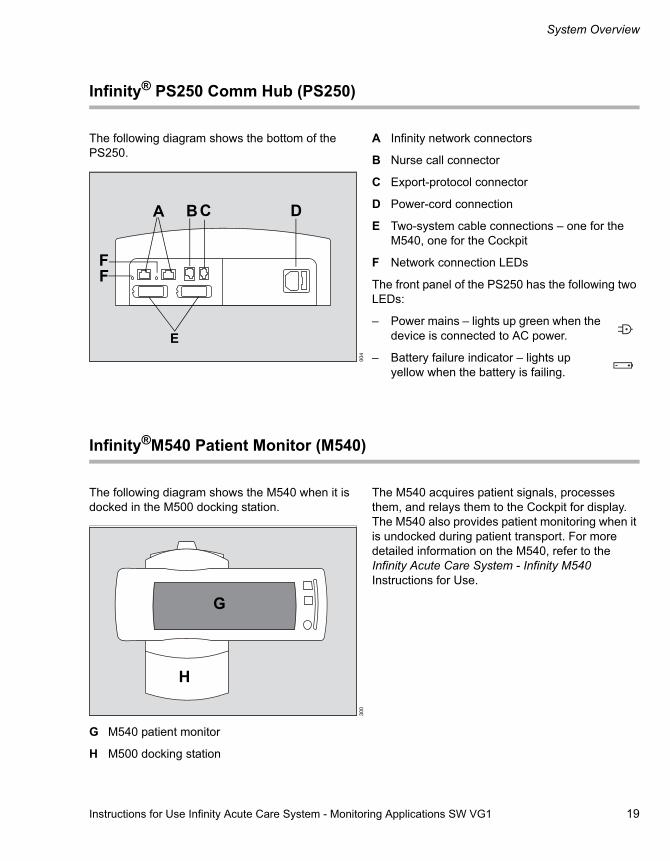
The following diagram shows the bottom of the PS250.
A Infinity network connectors
B Nurse call connector
C Export-protocol connector
D Power-cord connection
E Two-system cable connections – one for the M540, one for the Cockpit
F Network connection LEDs
The front panel of the PS250 has the following two LEDs:
– Power mains – lights up green when the device is connected to AC power.
– Battery failure indicator – lights up yellow when the battery is failing.
Infinity®M540 Patient Monitor (M540)
The following diagram shows the M540 when it is docked in the M500 docking station.
G M540 patient monitor
H M500 docking station
The M540 acquires patient signals, processes them, and relays them to the Cockpit for display. The M540 also provides patient monitoring when it is undocked during patient transport. For more detailed information on the M540, refer to the Infinity Acute Care System - Infinity M540 Instructions for Use.
004
A CB D
E
FF
300
G
H
System Overview
20 Instructions for Use Infinity Acute Care System - Monitoring Applications SW VG1
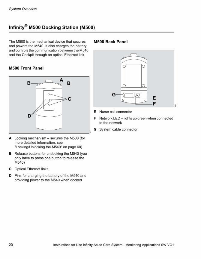
Infinity® M500 Docking Station (M500)
The M500 is the mechanical device that secures and powers the M540. It also charges the battery, and controls the communication between the M540 and the Cockpit through an optical Ethernet link.
M500 Front Panel
A Locking mechanism – secures the M500 (for more detailed information, see "Locking/Unlocking the M540" on page 60)
B Release buttons for undocking the M540 (you only have to press one button to release the M540)
C Optical Ethernet links
D Pins for charging the battery of the M540 and providing power to the M540 when docked
M500 Back Panel
E Nurse call connector
F Network LED – lights up green when connected to the network
G System cable connector
301
A BB
C
D
302F
G E

Instructions for Use Infinity Acute Care System - Monitoring Applications SW VG1 21
System Overview
Additional Hardware
The following table lists the additional devices that can be connected to the IACS.
Device Description ConnectionInfinity® MCable - Masimo SET Measures the percentage of
functional haemoglobin saturated with oxygen (%SpO2) and reports the perfusion index (PI).
Connects directly to the SpO2 connector of the M540 (see page 184 and page 192).
Infinity® MCable - Nellcor TM OxiMaxTM
Measures the percentage of functional haemoglobin saturated with oxygen (%SpO2).
Hemo4® pod
Infinity® MPod - QuadHemo
Measures up to four pressures, cardiac output, and temperature.
Connects directly to the Hemo connector of the M540 (see information starting on page 219).
Hemo2® pod Measures up to two pressures, cardiac output, and temperature.
Infinity® MCable - Dual Hemo Measures up to two pressures.
Infinity MCable - Mainstream CO2 Measures mainstream CO2. Connects directly to the CO2 connector of the M540 (see page 252).
Infinity ®MCable - Nurse Call Provides remote notification of medium- and high-priority alarm conditions.
Connects to the PS250 (see page 19) or to the M500 (see page 20).
Infinity® MCable - Analogue/Sync Provides a sync pulse to synchronise defibrillators to the heart beat of the patient during cardioversion. The cable analogue-out function provides an ECG and arterial blood pressure signal to a device, such as the intra-aortic balloon pump.
Connects to the Temp/Aux connector of the M540 or to the CO2 connector with a y-cable.
Secondary video display Extends the viewing capabilities of a Cockpit to an additional video display. Secondary displays mirror the content of the Cockpit.
Connects to a Cockpit using the DVI 1 connector located on the back panel (see the Infinity Acute Care System - Medical Cockpit Instructions for Use).
R50N recorder Produces timed and continuous recordings.
Connects to the Infinity network or the PS250.
Laser printer Prints various reports and Cockpit print screens.
Connects to the Infinity network.

System Overview
22 Instructions for Use Infinity Acute Care System - Monitoring Applications SW VG1
Device Symbols
Read accompanying documents for specific safety information
Lower alarm limits
Attention: consult accompanying documents
Upper alarm limits
Access to trend pages Autoset alarm limits
Access to special procedure pages Alarm monitoring is disabled temporarily.
Access to alarm functions Alarm monitoring is disabled permanently.
Access to the standby and privacy modes, and access to discharging a patient
Audible alarm tone is paused temporarily
Access to pre-configured Views and layouts
Audible alarm tone is turned off permanently
Access to parameter-setup pages Change clinical password
Adult patient category Respiration value
Paediatric patient category Heart blip that flashes with each detected pulse

Instructions for Use Infinity Acute Care System - Monitoring Applications SW VG1 23
System Overview
Neonatal patient category The pacer detection is enabled; the heart symbol flashes with each detected paced pulse
Battery-status LED Scrolls to additional tabs and setup pages
Battery-charging error Power on/off
DC power mains Non-disposable part
Function/setting is unlocked Device part number and revision
Function/setting is locked. Device serial number
Data entry with numeric keypad Date of manufacture
Trend configuration Complete screen calibration procedure
On-screen keyboard access Repeat screen calibration procedure
Nurse call
Display filter. When selected, only the connected parameters and associated setup pages are displayed. When deselected, all parameters and associated setup pages are displayed.
Manufacturer IPX1 Degree of protection against liquid ingress

System Overview
24 Instructions for Use Infinity Acute Care System - Monitoring Applications SW VG1
The parameter is excluded from display.
Zeroing all pressures
The parameter is represented as a waveform and a parameter box.
The parameter is represented as a parameter box only.
Save modifications (for example, changes to a view).
Import functions (for example, importing profiles).
Save as a symbol. ESD warning
Directive 93/42/EECConcerning Medical Devices

Instructions for Use Infinity Acute Care System - Monitoring Applications SW VG1 25
System Overview
Abbreviations
The following table lists the abbreviations used in these Instructions for Use and those that are displayed on the Cockpit. For any abbreviations of parameters originating from the external devices, refer to the corresponding Instructions for Use.
Abbreviations Description%paced percentage of paced beats
ASY Asystole
AIVR Accelerated idioventricular rhythm
alv alveolar
apn apnoea
ARR arrhythmia
ART arterial pressure
ART D ART diastolic value
ART M ART mean value
ART S ART systolic value
ARTF artefact
aVF ECG-lead aVF
Avg average
aVL ECG-lead aVL
aVR ECG-lead aVR
aw airway
BGM bigeminy
BRADY bradycardia
BSA body surface area
CCO continuous cardiac output
CCI continuous cardiac index
C.O. cardiac output
C.O. avg cardiac output average
C20/C dyn compliance over the last 20% breath/dyn compliance total
Cdyn dynamic lung compliance
CI cardiac index
CISPR International Special Committee on Radio-Interference
CO2 carbon dioxide concentration
CPP cerebral perfusion pressure
CPT ventricular couplet
Cuff continuous pressure value during measurement
CVP central venous pressure
DHCP Dynamic Host Configuration Protocol
DNS Domain Name System
DO2 oxygen delivery
ds dead space
dV1- dV6 derived chest leads
DVI Digital Visual Interface
dyn dynamic
ECG electrocardiogram
EDV end diastolic volume
EDVI end diastolic volume index
EF ejection fraction
ESV end systolic volume
ESVI end systolic volume index
et end-tidal (in combination with gas values)
ext external
FV flow-volume loop
GP1 – 4 D general pressure 1-4 diastolic value
GP1 – 4 M GP 1 – 4 mean value
GP1 – 4 S GP 1 – 4 systolic value
Hgb haemoglobin
HR heart rate
I ECG-lead I
IACS Infinity Acute Care System

System Overview
26 Instructions for Use Infinity Acute Care System - Monitoring Applications SW VG1
I:E inspiratory-to-expiratory ratio
I:E I-Part inspiratory:expiratory ratio (inspiratory component)
I:E E-Part inspiratory:expiratory ratio (exspiratory component)
IBP invasive blood pressure
ICP intracranial pressure
ICS Infinity CentralStation
II ECG-lead II
III ECG-lead III
in inspiratory (in combination with gas values)
Inj injectate temperature
inO2 inspired O2
iRaw dynamic inspiratory airway resistance
LA left arm (ECG)
LA left arterial pressure
LV left ventricular pressure
LV D LV diastolic value
LV M LV mean value
LV S LV systolic value
man manual
mand mandatory
max maximum
min. minimal
MV total minute volume
MValv alveolar mixed minute volume
MVds dead space minute volume
MVe total expiratory minute volume
MVe s spontaneous expiratory minute volume
MVi total inspiratory minute volume
MVi s spontaneous inspiratory minute volume
MVleak leakage minute volume
MVspon spontaneous minute volume
NIBP non-invasive blood pressure
NIBP D NIBP diastolic value
NIBP M NIBP mean value
NIBP S NIBP systolic value
Occlusion Press
occlusion pressure
PA pulmonary arterial pressure
PA D PA diastolic value
PA M PA mean value
PA S PA systolic value
Pat ID patient ID
Pause pause pressure
Paw airway pressure
PAW min. minimum airway pressure
PCO2 partial pressure of CO2 in blood
PI Perfusion index (SpO2)
PEEP positive-end expiratory pressure
PIP peak inspiratory pressure
PLS pulse rate from SpO2
PLS ART arterial pressure – pulse rate
Pmean mean airway pressure
PV pressure-volume loop
PVC/min rate of PVC per minute
PWP pulmonary wedge pressure
R resistance
RA right arm (ECG)
RA right atrial pressure
Raw resistance (airway)
Resp respiration
RF right foot (ECG)
RRc respiratory rate (CO2)
RRi respiratory rate (impedance)
RRv respiratory rate (ventilator)
RRs respiratory rate, spontaneous
RUN ventricular run

Instructions for Use Infinity Acute Care System - Monitoring Applications SW VG1 27
System Overview
RV right ventricular pressure
RV D RV diastolic value
RV M RV mean value
RV S RV systolic value
SaO2 arterial oxygen saturation
SpO2 pulse oxygen saturation
ST(x) ST-deviation of lead (x)
stat static
STd(x) ST-deviation of derived leads (dV1 to dV6)
support pressure support
SV stroke volume
SVI stroke volume index
SvO2 venous oxygen saturation
SVR systemic vascular resistance
SVRI systemic vascular resistance index
SVT supraventricular tachycardia
SVV stroke volume variation
TACH tachycardia
Tblood blood temperature
Ti set inspired time
Tinj injectate temperature
Trapped VOL trapped volume
TruST algorithm that provides a TruST-12-lead ECG (including derived chest leads dV1, dV3, dV4, dV6) using a 6-lead wire set that provides ECG leads I, II, III, aVL, aVR, aVF, V2, V5.
TVe tidal volume, expiratory
TV d aw tidal volume dead space
TVd aw% tidal volume relative dead space
TVi set tidal volume setting, inspired
V chest lead from a 5- or 6-lead wire set.
V+ second chest lead from a 6-lead wire set
V1 - V6 ECG chest leads V1 - V6
Vent ventilation
VCO2 CO2 production
VESA Video Electronics Standard Association
VF ventricular fibrillation
VO2 oxygen consumption
VTACH ventricular tachycardia
wfm Waveform

28 Instructions for Use Infinity Acute Care System - Monitoring Applications SW VG1
This page intentionally left blank

Instructions for Use Infinity Acute Care System - Monitoring Applications SW VG1 29
Operating Concept
Operating Concept
Operating Concept Overview . . . . . . . . . . . . 30
The IACS Components. . . . . . . . . . . . . . . . . . 31
M540 and Cockpit Communication. . . . . . . . 32
Docking the M540. . . . . . . . . . . . . . . . . . . . . . . 32Undocking the M540. . . . . . . . . . . . . . . . . . . . . 33
Communicating with the Infinity® Network . 33
Supported Banners. . . . . . . . . . . . . . . . . . . . . . 34Loss of Power. . . . . . . . . . . . . . . . . . . . . . . . . . 35Network Data Transfer . . . . . . . . . . . . . . . . . . . 35
Communication Management . . . . . . . . . . . . 36
Remote Control and Remote View . . . . . . . . 38
Remote View . . . . . . . . . . . . . . . . . . . . . . . . . . 38Using Remote View Functions . . . . . . . . . . . . . 39Remote Control from the ICS (Infinity CentralStation) . . . . . . . . . . . . . . . . . . . . . . . . . 39IT Applications . . . . . . . . . . . . . . . . . . . . . . . . . 39
Secondary Display . . . . . . . . . . . . . . . . . . . . . 40
User Interface . . . . . . . . . . . . . . . . . . . . . . . . . 40
Header Bar . . . . . . . . . . . . . . . . . . . . . . . . . . . 41
Monitoring Area . . . . . . . . . . . . . . . . . . . . . . . 42
Parameter Boxes . . . . . . . . . . . . . . . . . . . . . . . 42Waveforms . . . . . . . . . . . . . . . . . . . . . . . . . . . . 43Freezing/Stopping Waveforms . . . . . . . . . . . . . 43Dialogue Windows and Setup Pages . . . . . . . . 44
Main-Menu Bar and Quick-Access Toolbar . 45
Main-Menu Bar . . . . . . . . . . . . . . . . . . . . . . . . . 45Quick-Access Toolbar. . . . . . . . . . . . . . . . . . . . 46
Filtering the Parameter Content . . . . . . . . . . 47
Auto vs. Manual Display Modes . . . . . . . . . . 47
Auto View Mode . . . . . . . . . . . . . . . . . . . . . . . . 47Manual View Mode . . . . . . . . . . . . . . . . . . . . . . 47
Auto-View Setup Toolbar . . . . . . . . . . . . . . . 48
Customising the Display . . . . . . . . . . . . . . . 48
Touchscreen Versus Mouse . . . . . . . . . . . . . . 48Screen Brightness . . . . . . . . . . . . . . . . . . . . . . 48Calibrating the Touchscreen . . . . . . . . . . . . . . 48Cockpit Screen in Split Screen Mode . . . . . . . 49Cockpit Screen with Mini-Trends. . . . . . . . . . . 50Cockpit Screen with IT Tabs . . . . . . . . . . . . . . 51
Parameter Priority . . . . . . . . . . . . . . . . . . . . . 52
Configuring the Parameter Priority and Display. . . . . . . . . . . . . . . . . . . . . . . . . . . . . . . 52Parameter Priority List. . . . . . . . . . . . . . . . . . . 52
Views . . . . . . . . . . . . . . . . . . . . . . . . . . . . . . . 53
Selecting a View . . . . . . . . . . . . . . . . . . . . . . . 53The View Editor . . . . . . . . . . . . . . . . . . . . . . . . 53
Profiles . . . . . . . . . . . . . . . . . . . . . . . . . . . . . . 54
Managing Profiles and Views . . . . . . . . . . . . . 54Transferring Profiles . . . . . . . . . . . . . . . . . . . . 54
Standby Mode . . . . . . . . . . . . . . . . . . . . . . . . 55
Privacy Mode . . . . . . . . . . . . . . . . . . . . . . . . . 56

30 Instructions for Use Infinity Acute Care System - Monitoring Applications SW VG1
Operating Concept
Operating Concept Overview
The IACS is a fully networked solution that offers patient monitoring, therapy, and IT applications at the point of care.
Dräger developed the IACS to solve problems common in the acute care environment. As a result, the IACS provides standardised user interfaces, improves workplace ergonomics and flexibility, centralises patient information at the point of care, and provides the ability to automatically backfill information after patient transport.
The central component of the IACS is the Infinity® Medical CockpitTM. This medical-grade workstation provides centralised viewing and control of Infinity monitoring systems and IT applications at the point of care. The Cockpit is available in two sizes. The C700 is a 20-inch (50.8 cm), and the C500 is a 17-inch (43.2 cm) widescreen. Both offer a large viewing angle, extended screen configuration capabilities, and a fanless design.
The common Dräger-standardised user interface offers intuitive operation via a touchscreen and a rotary knob. A 360-degree alarm bar alerts you to the alarm conditions of a patient.

Instructions for Use Infinity Acute Care System - Monitoring Applications SW VG1 31
Operating Concept
The IACS Components
The following diagram shows a possible IACS configuration.
A C500/C700
B The DVI cable
C Secondary display (option)
D The USB cable
E Keyboard and mouse (option)
F Device connectivity cable (option)
G M540 patient monitor
H M500 docking station
I System cables – MS20614, MS20135
J R50N recorder
K AC power
L Infinity network
M Nurse call MPod (option)
N PS250
O Hospital network
P Ethernet cable
005
AC
EF
G
H
I
I
JKL
M
ON
PP
P
B
D

32 Instructions for Use Infinity Acute Care System - Monitoring Applications SW VG1
Operating Concept
M540-and-Cockpit Communication
Communication between the M540 and the Cockpit starts as soon as the M540 is docked in the M500 (see page 59). The M540 acquires physiological signals from the patient and relays them to the Cockpit for display. The Cockpit makes the patient data available to the Infinity network.
When the M540 is docked, the Cockpit assumes all acoustic alarm signal enunciation. However, alarms are always reported visually at the Cockpit and at the M540..
The only exceptions are Cockpit-specific alarm messages such as External device disconnected for which the M540 does not report any audible and visual alarm signals.
When the M540 is docked, any changes to the patient setup, such as alarm limits made on the Cockpit, are automatically transferred to the M540 (and vice versa).
Docking the M540
As soon as you dock the M540 in the M500, the following happens at the Cockpit:
– The message Connecting to M540 appears in the centre of the Cockpit screen.
– The Cockpit makes the data of the M540 available to the Infinity network.
Docking to the same Cockpit
If you undock an M540 from a Cockpit and later dock the M540 to the same Cockpit, the data collection continues seamlessly. The Cockpit automatically retrieves any data the M540 collected while on patient transport, and merges it with the data set for that patient.
NOTEIf you also want alarms to sound at the M540 when it is docked, select the alarm tone volume at the M540 manually. For information, refer to the M540 Instructions for Use.
NOTEIf the M540 cannot communicate with the Cockpit, the Cockpit sounds an alarm. In addition, an alarm indicating a loss of communication is broadcast over the network to the Infinity Central Station (ICS) provided the patient is admitted there. The M540 continues to monitor the patient.
NOTEIf you dock an M540 with a patient category that differs from the one selected on the Cockpit, the setting of the Cockpit changes to match the one of the M540.

Instructions for Use Infinity Acute Care System - Monitoring Applications SW VG1 33
Operating Concept
Docking to a different Cockpit
If you undock an M540 from a Cockpit and later dock the M540 to a different Cockpit, the original data is automatically retrieved over the network by the new Cockpit. The new Cockpit then automatically merges this data with any data the M540 collected while on patient transport. The original Cockpit automatically discharges the patient once all patient data are transferred.
If not all patient data was transferred, the message Transfer of data incomplete appears in the header bar of the new Cockpit. In this case, the original Cockpit does not discharge the patient.
Undocking the M540
When you undock the M540, the following happens:
– The message disconnected from M540 appears in the centre of the Cockpit screen.
– The message Bed disconnected appears at the ICS.
– Several buttons remain active on the main-menu bar of the Cockpit:
– Alarms... for accessing the alarm history
– Trends/Data... for accessing the trend data
– Start/Standby... for accessing the Start tab where you can initiate a patient discharge.
The current patient data is no longer available to the Infinity network, including parameter values acquired via the device connectivity option.
Communicating with the Infinity® Network
When the M540 is docked on the M500 and the IACS is connected to the network, the patient data is available on the Infinity network. If the connection to the Infinity network is lost, the Cockpit sounds an alarm tone at 100% for any active alarm or any new alarm condition.
Communicating with the Infinity network has the following benefits:
– Patient data is sent across the Infinity network to connected devices.
– The alarm status of the patient is reported to the Infinity network and its connected devices. If multiple alarm conditions are present, the alarm with the highest alarm priority is reported.
– The patient can be admitted at the ICS (Infinity CentralStation) for central monitoring.
– From other Infinity monitors, you can view the Cockpits within the same monitoring unit using the remote view function (see page 39).
– From the Cockpit, you can view other bedside monitors (including other Cockpits) in the same monitoring unit using the remote view function (see page 38).
CAUTIONBefore you connect the M540 to a different Cockpit, make sure that the units of measure align between the two devices. Differing units of measure could result in loss of data or a patient discharge.

Operating Concept
34 Instructions for Use Infinity Acute Care System - Monitoring Applications SW VG1
Supported Banners
The following banners appear on the Cockpit and are supported on the Infinity network:
– All alarms off when the all alarms pause feature is set to No timeout (see page 286) and you select the All alarms off button.
– All alarms paused with the count-down timer when a time is selected in the All alarms paused feature (see page 286) and you select the All alarms paused button.
– Audio paused with the count-down timer when you press the Audio paused key.
– The Patient category indicator (Adult, Paediatric, Neonatal)
– Standby, Discharge, Privacy
The following banners appear in the header bar of the Cockpit:
– Audio Alarms Off when you press the Code button on the main-menu bar and the alarm volume off feature is set to Yes (see page 289).
– HR alarms off – appears under the following circumstances:
– when the HR alarm limits feature is disabled and the ASY/VF alarms feature is set to Always on (see page 287).
– when the HR alarm limits feature is disabled and the basic arrhythmia feature is enabled and the ASY/VF alarms feature is set to Follow HR Alarms (see page 287).
– HR, ASY, VF off when the arrhythmia monitoring is disabled (see page 91), the arrhythmia feature is set to Follow HR Alarms (see page 287), and the HR alarms are disabled (see page 87).
– The OR mode appears in the header bar when you enable the OR mode (see page 276).
– The All Alarms Off: Bypass appears in the header bar when you enable the cardiac bypass mode (see page 276).
– The battery symbol indicates the status of the sytem battery charge.
The following banners appear on the waveform channels of the Cockpit:
– The Filter:ESU appears on the ECG waveform when the filter setting is set to ESU (see page 151).
– Filter: OFF appears on the ECG waveform when the filter setting is set to Off (see page 151).
– The message Waveforms stopped appears on all waveforms when you press the Freeze button on the main-menu bar (see page 43).
– The Pacer on, Pacer off or Pacer Fusion appears when the corresponding function is enabled or disabled, see page 151)
The following banners appear in the centre of the Cockpit screen:
– Privacy, touch screen to return appears when the privacy mode is enabled (see page 56).
– Standby, touch screen to resume monitoring appears when the standby mode is enabled (see page 55).
– Discharged, touch screen to initiate monitoring appears after you discharge a patient (see page 67).

Instructions for Use Infinity Acute Care System - Monitoring Applications SW VG1 35
Operating Concept
Loss of Power
A loss of power has the following effect:
– The Cockpit switches to battery power for up to 5 minutes before performing a safe shutdown that preserves the integrity of the patient data.
– A serious alarm is triggered at the Cockpit and the message Please plug in power supply appears. This message disappears when you dock an M540.
– The M540 switches to battery power for up to 3.5 hours before performing a safe shutdown that preserves the integrity of the patient data.
Network Data Transfer
You can transfer patient data over the Infinity network to the Cockpit from the following devices:
– Infinity Delta/Delta XL/Kappa (software version VF7 and higher)
– Other IACS monitoring Cockpits
Contact your technical personnel for information regarding compatibility of devices.
The following data is included in a patient data transfer:
– Patient demographic information
– Trends
– Events
– Calculation results and laboratory data
The following diagram shows the Transfer page which is used for patient data transfers.
A The Care area selection arrow
B The Current patient column
C The Device name column
D The Start transfer button
NOTEYou can also transfer patient data by undocking and redocking an M540.
006
A
BC
D
Start/Standby
Operating Concept
36 Instructions for Use Infinity Acute Care System - Monitoring Applications SW VG1
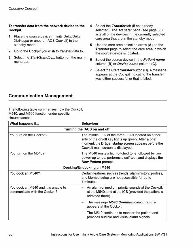
To transfer data from the network device to the Cockpit
1 Place the source device (Infinity Delta/Delta XL/Kappa or another IACS Cockpit) in the standby mode.
2 Go to the Cockpit you wish to transfer data to.
3 Select the Start/Standby... button on the main-menu bar.
4 Select the Transfer tab (if not already selected). The Transfer page (see page 35) lists all of the devices in the currently selected care area that are in the standby mode.
5 Use the care area selection arrow (A) on the Transfer page to select the care area in which the source device is located.
6 Select the source device in the Patient name column (B) or Device name column (C).
7 Select the Start transfer button (D). A message appears at the Cockpit indicating the transfer was either successful or that it failed.
Communication Management
The following table summarises how the Cockpit, M540, and M500 function under specific circumstances.
What happens if... BehaviourTurning the IACS on and off
You turn on the Cockpit? The middle LED of the three LEDs located on either side of the on/off key lights up green. After a brief moment, the Dräger startup screen appears before the Cockpit main screen is displayed.
You turn on the M540? The M540 emits a high-pitched tone followed by two power-up tones, performs a self-test, and displays the New Patient prompt.
Docking/Undocking an M540You dock an M540? Certain features such as trends, alarm history, profiles,
and biomed setup are not accessible for up to 1 minute.
You dock an M540 and it is unable to communicate with the Cockpit?
– An alarm of medium priority sounds at the Cockpit, at the M540, and at the ICS (provided the patient is admitted there).
– The message M540 Communication failure appears at the Cockpit.
– The M540 continues to monitor the patient and provides audible and visual alarm signals.

Instructions for Use Infinity Acute Care System - Monitoring Applications SW VG1 37
Operating Concept
Alarm BehaviourAn M540, whose audible alarm signals have been paused, docks to a Cockpit?
All audible alarm signals are paused for 2 minutes on both devices.
You dock an M540 with an alarm pause state, which is different from that of the Cockpit?
Both devices observe the remaining alarm pause interval.
Connection/Power ProblemsIf there is a power failure? – The LEDs on the front panels indicate that the
Cockpit and the M540 are on battery power.
– The Cockpit sounds an alarm of medium priority and switches to battery power for up to 5 minutes before performing a safe shutdown.
– The M540 switches to battery power for up to 3.5 hours before shutting down.
The system cable is disconnected from the power supply or the M500?
– The Cockpit sounds an alarm tone of low priority.
– The Cockpit displays the message Please plug in system cable in the header bar and the message Disconnected from M540 appears in the monitoring area.
– The Cockpit no longer displays any parameters and waveforms.
The Cockpit loses communication with the ICS?
– The Cockpit sounds an alarm tone for a new alarm condition at 100% if the alarm tone volume is disabled. If the alarm tone volume was enabled, the Cockpit sounds an alarm tone at 50% for any new alarm condition.
– The Cockpit tries to restore the link.
– The ICS displays an Offline message indicating that the communication with the bed is lost.
The Cockpit loses communication with an external device?
– The Cockpit tries to restore the link.
– An alarm sounds and the message External device disconnected appears on the ICS if the feature is enabled (see "The external device disconnected the alarm control." on page 287).
What happens if... Behaviour

Operating Concept
38 Instructions for Use Infinity Acute Care System - Monitoring Applications SW VG1
Remote Control and Remote View
When a Cockpit is connected to the Infinity network, data can be shared among Infinity devices that are connected to the network. From the Cockpit you can view other Infinity devices and
perform several remote functions. You can also allow other Infinity devices to view a Cockpit and perform remote functions by enabling the remote control feature (see page 296).
Remote View
The remote view function allows you to review patient data from other Infinity monitors within the same monitoring unit. If you are viewing another Cockpit, the remote view window shows the Auto View (see page 47) of the second Cockpit.
The remote view feature also allows you to pause audible alarm signals and request the timed and continuous recordings of the remote device.
MiscellaneousThe Cockpit and the M540 are monitoring a patient and you put either device in the standby mode?
Both devices are put in the standby mode.
The Cockpit and the M540 are monitoring a patient and you discharge the patient on either device?
The patient is discharged from both devices.
A function, such as initiating a NIBP measurement, is requested at the M540 and almost simultaneously on the Cockpit?
The function is cancelled on both devices.
What happens if... Behaviour

Instructions for Use Infinity Acute Care System - Monitoring Applications SW VG1 39
Operating Concept
To access the Remote View
1 Select the Views... button on the main-menu bar to access the Views... dialogue.
2 Select the Remote view tab. This dialogue lists all of the beds in the monitoring unit of the Cockpit.
3 Select a bed from the list in the Views... dialogue to access the remote view of an individual patient.
4 Select the Connect button.
The following diagram shows a remote view.
A The Disconnect button
B The Audio Pause button
C The Continuous Recording button
D The Timed Recording button
Using Remote View Functions
From the Remote View dialogue window, you can perform the following functions (the letters in parentheses refer to the Remote View dialogue diagram):
– Select the Disconnect button (A) to save the remote view.
– Select the Audio Pause button (B) to pause audible alarm signals at the remote device.
– Select the Continuous Recording (C) or Timed Recording (D) buttons to request a recording of the remote device.
Remote Control from the ICS (Infinity CentralStation)
When a Cockpit communicates with the Infinity network, you can admit the patient at the ICS for central monitoring. Once admitted, you can perform the following remote functions from the ICS for a Cockpit patient.
– To pause audible alarm signals
– Change the alarm limits
– Make changes to the arrhythmia setup
If several devices modify the patient settings of a single Cockpit, the last update is always implemented. For detailed information on performing these functions of the ICS, refer to the Infinity Central Station Instructions for Use.
IT Applications
Several optional IT applications provide remote access to patient information from the Cockpit. For example, the PatientWatch application (accessible using the Infinity Gateway) allows you to view up to four different bedside monitors that are connected to the Infinity network. If configured, IT applications are accessible by selecting a tab on the Cockpit. For more information, see "IT Applications (Options)" on page 321.
007A B C D
Views...

Operating Concept
40 Instructions for Use Infinity Acute Care System - Monitoring Applications SW VG1
Secondary Display
To extend the display capabilities of a Cockpit, you can connect a secondary display to the DVI connector of the Cockpit using one of two LCOM cable types which have been qualified by Dräger:
The secondary display duplicates the content of the Cockpit screen. It does not produce any audible alarm signals and does not support any user interaction. A secondary display has to meet certain technical specifications (see page 365). Dräger has qualified the ViewSonic, 19-inch (48.3 cm) widescreen high-resolution display. The ViewSonic has a display resolution of 1680 x 1050 pixels.
User Interface
The following sections describe the user interface of the Cockpit when it is connected to an M540.
The screen of a monitoring Cockpit is divided into the following main areas:
A Header Bar
B Main-Menu Bar
C Auto-view toolbar (if enabled)
D Monitoring Area
For a more detailed overview of general user interface components of the IACS, refer to the Infinity Acute Care System - Medical Cockpit Instructions for Use.
Cable type Length Part numberDVI to DVI 0.91 m (3 ft) CTLDVI-DL-MM3
1.52 m (5 ft) CTLDVI-DL-MM5
3.04 m (10 ft) CTLDVI-DL-MM10
4.75 m (15 ft) CTLDVI-DL-MM15
DVI to VGA 0.91 m (3 ft) CTLDVI-HD-MM3
1.52 m (5 ft) CTLDVI-HD-MM5
3.04 m (10 ft) CTLDVI-HD-MM10
4.75 m (15 ft) CTLDVI-HD-MM15
008
A
B
C
D

Instructions for Use Infinity Acute Care System - Monitoring Applications SW VG1 41
Operating Concept
Header Bar
The blue header bar appears along the top of the Cockpit screen: It is always visible regardless of what is displayed in the monitoring area.
A The Patient Category field
B The System Data field
C The Patient Name field
D The Date and Time field
E The Alarm Message field
F The Alarm Banner field
The Patient Category field
The Patient Category field (A) of the header bar identifies the currently selected patient category. It contains one of the following symbols:
– Adult
– Paediatric
– Neonate
Touching this field opens the Start/Standby... dialogue window for accessing the Demographics page (see page 66).
The System Data field
The System Data field (B) of the header bar contains the following information:
– Device label
– Care area
– Monitoring mode (for example, OR mode) or the battery symbol indicating the battery status for the PS250
Touching this field opens the System setup dialogue with the Biomed password keypad.
The Patient Name field
The Patient Name field (C) of the header bar shows the patient name. Touching this field opens the Demographics page (see page page 66).
The content of the Patient Name field changes when you select the Code button on the main-menu bar to activate a set of user-defined emergency monitoring functions. In this case, the Patient Data field displays a timer along with a Stop and a Reset button. For more information on the Code function, see page 100.
The Date and Time field
The Date/Time field (D) of the header bar contains the current date and time. Touching this field opens the System setup dialogue with the Biomed password keypad.
The Alarm Message field
The Alarm Message field (E) of the header bar is reserved for alarm and technical messages. The background colour of the alarm message corresponds to the alarm priority (see page 76).
The following table illustrates how the alarm message field is subdivided.
A maximum of two messages can be displayed side by side. If more than two patient alarm messages are active simultaneously, the More... button appears. Selecting this button accesses the Current alarms page (see "Viewing Current Alarm Messages" on page 80).
009
A B C D E F
More... Alarm message Alarm message
Local technical messages
Network-related messages

Operating Concept
42 Instructions for Use Infinity Acute Care System - Monitoring Applications SW VG1
The Alarm Banner field
The Alarm Banner field (F) of the header bar (see page 41) indicates the current alarm status. It is reserved for one of the following indicators:
– and the message Audio paused plus a count-down timer (appears when you press the Audio paused fixed key located next to the rotary knob).
– and the message Audio off when the audible alarm signals are disabled.
– the message All alarms paused, and a count-down timer when the alarm monitoring is disabled temporarily.
– and the message All alarms off when the alarm monitoring is disabled permanently.
For more detailed information on alarm monitoring, see the Alarms chapter.
Monitoring Area
The monitoring area of the Cockpit screen contains waveforms and parameter boxes that report the current vital signs of the patient. The monitoring area can also contain dialogue windows, mini-trends, an auto-view toolbar, ST parameters, vent loops, and so on. The appearance of the monitoring area depends on the selected view, which controls the layout and content of the screen (see "Views" on page 53). The appearance of the monitoring area also depends on whether or not the split screen mode or mini trend display is selected (see page 277).
When you open a dialogue window, waveform channels and parameter boxes are reduced to fit on the right side of the screen (see illustration on page 44). This display behaviour prevents the vital signs from being obscured while you are performing setup tasks.
Selecting the Home button on the main-menu bar or pressing on the rotary knob closes any open dialogue windows and refreshes the screen.
Parameter Boxes
Each parameter box contains real-time values of a parameter and a combination of the following information:
– Parameter labels (including dynamic pressure labels)
– Alarm limits (or crossed-triangle symbols when alarms are turned off)
– Units of measure (can be turned on/off)
– ECG heart blip (and pacer blip for paced pulses), RRi blip, and SpO2 blip
– Time stamps
– Countdown timers and time stamps for NIBP
– Special source labels (for example, PLS for HR signal source for pulse oximetry)
– Parameter-specific message fields for NIBP and SpO2
When a parameter is in alarm, the parameter box flashes in the colour of the alarm grade and an error message appears in the header bar. The parameter boxes displayed on the Cockpit for each parameter are described in detail in each parameter chapter. For detailed information on layout strategies of parameter boxes, refer to the Infinity Acute Care System - Medical Cockpit Instructions for Use.

Instructions for Use Infinity Acute Care System - Monitoring Applications SW VG1 43
Operating Concept
Waveforms
The Cockpit displays a minimum of 6 seconds of waveform data per waveform channel at a sweep speed of 25 mm/s when no dialogue windows are open. The amount of displayed waveforms depend on the size of the Cockpit.
When the waveform option is enabled, the Cockpit displays up to 16 waveforms.
The following features allow you to customise the waveforms:
– Changing the colours for individual parameters (see for example how to change the colour for ECG on page 151)
– Changing the sweep speeds (see page 275)
Waveforms are drawn from left to right and can contain the following information:
– Signal scales
– Grids
– Units of measure
– Parameter labels
– Pacer spikes
– QRS synchronisation markers
– Respiration waveform markers to indicate breath detection
– Banners (see page 34)
Freezing/Stopping Waveforms
� Select the Freeze button on the main-menu bar.
All waveforms stop and the message Waveforms stopped appears on each waveform channel. After approximately 60 seconds, the waveforms start scrolling again. To restart the waveforms earlier, select the Freeze button again.
Freezing waveforms does not affect continuous monitoring of all parameters and does not freeze waveforms on the M540.
NOTEIf the acquired signal does not fit in the waveform channel, the top of the waveform may appear clipped.

Operating Concept
44 Instructions for Use Infinity Acute Care System - Monitoring Applications SW VG1
Dialogue Windows and Setup Pages
The following diagram shows how the monitoring area appears when you access a dialogue window. The left side is reserved for the dialogue window while the right side displays the monitoring area (F) with real-time data. A dialogue window contains horizontal tabs (B) that open setup pages. Some setup pages also contain vertical tabs (E) which access subordinate setup pages.
You can access a dialogue window by selecting the corresponding button followed by dots on the main-menu bar. For example, the Alarms... button opens the Alarms dialogue window. You can also access parameter-specific dialogue windows and setup pages directly by selecting the corresponding parameter boxes on the main screen. For example, if you select the heart-rate (HR) parameter box, the Sensor parameters dialogue window with the ECG-setup page appears.
A Dialogue window title
B Horizontal tabs – the selected tab appears light blue.
C Button that closes the dialogue window.
D Display filter on/off button for switching between a display that shows only connected parameters or one that shows all parameters.
E Vertical tabs for accessing additional setup pages – the selected tab appears light blue.
F The monitoring area showing vital signs in real time.
G The setup page that contains groups of related settings in the selected tab.
010
AB B B B B B
CD
EEEEEEE
FG

Instructions for Use Infinity Acute Care System - Monitoring Applications SW VG1 45
Operating Concept
Main-Menu Bar and Quick-Access Toolbar
The following diagram shows the main-menu bar with the quick-access symbols and a quick-access toolbar. The main-menu bar and the quick-access symbols are located along the right edge of the screen and are always visible. The quick-access toolbars are visible after you select the corresponding quick-access symbol.
A Quick-access symbols
B Main-menu bar buttons
C Quick-access toolbar
Main-Menu Bar
The following buttons appear on the main-menu bar.
011
ABBBBBBBB
C
Alarms... Opens the Alarms dialogue window
Mark event Stores an event in the alarm history
Code Executes pre-configured functions during an emergency
Views... Opens the Views dialogue window
Print screen (1) Prints the contents of the current screen on a connected laser printer
Freeze Stops all waveforms for 60 seconds
Trends/Data... Opens the Trends/Data dialogue window
Procedures... Opens the Procedures dialogue window
Sensor parameters...
Opens the Sensor parameters dialogue window
NIBP start/stop Starts or stops an NIBP measurement. The button remains selected during a measurement. To cancel the measurement, select the button again.
Zero all (1) Zeroes all pressures
System setup... Opens the System setup dialogue window
Start/Standby Opens the Start/Standby dialogue window
Home Returns to the main screen and closes any dialogue window.
(1) This button only appears on the main-menu bar for the C700.
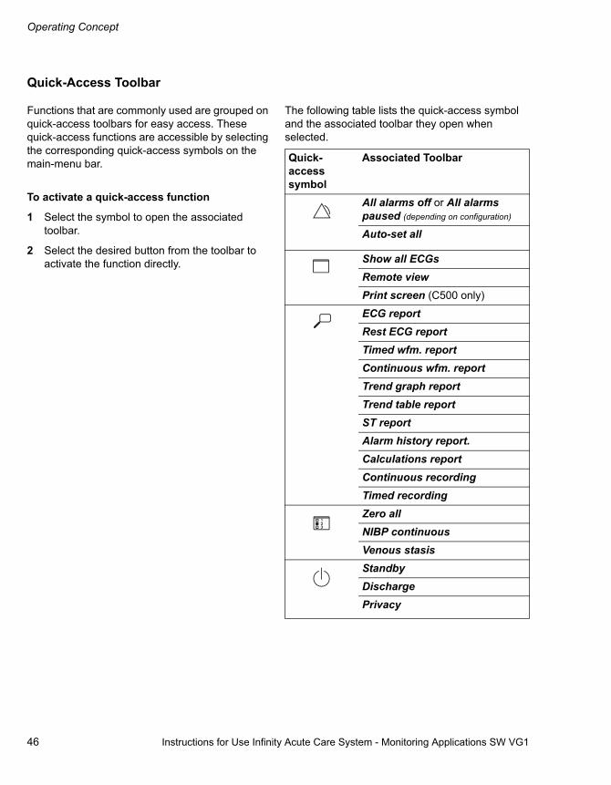
Operating Concept
46 Instructions for Use Infinity Acute Care System - Monitoring Applications SW VG1
Quick-Access Toolbar
Functions that are commonly used are grouped on quick-access toolbars for easy access. These quick-access functions are accessible by selecting the corresponding quick-access symbols on the main-menu bar.
To activate a quick-access function
1 Select the symbol to open the associated toolbar.
2 Select the desired button from the toolbar to activate the function directly.
The following table lists the quick-access symbol and the associated toolbar they open when selected.
Quick-access symbol
Associated Toolbar
All alarms off or All alarms paused (depending on configuration)
Auto-set all
Show all ECGsRemote viewPrint screen (C500 only)
ECG reportRest ECG reportTimed wfm. reportContinuous wfm. reportTrend graph reportTrend table reportST reportAlarm history report.Calculations reportContinuous recordingTimed recordingZero allNIBP continuousVenous stasisStandbyDischargePrivacy
Instructions for Use Infinity Acute Care System - Monitoring Applications SW VG1 47
Operating Concept
Filtering the Parameter Content
You can filter the content of the displayed parameters with the display filter button, which appears in the following dialogue windows:
– The parameter setup window of the Trends/Data dialogue window (see page 114); this also includes the setup page for the mini-trend display.
– The Sensor parameters dialogue window where it appears to the right of the parameter tabs.
– The Alarms dialogue window (see page 89).
You can toggle the display from unfiltered to filtered using this filter button. When the display filter button appears on the light green background, the filter is enabled. This means that only the parameters that are connected are displayed. Any parameter that is not being actively monitored is removed from the screen, including parameter-specific setup buttons or tabs.
Touching the button again changes the background to dark green and disables the display filter. All parameters, including associated setup buttons or tabs, are displayed.
Auto vs. Manual Display Modes
The user interface has two display modes: Auto View and Manual View.
Auto View Mode
The Auto View mode is a plug-and-play concept where the content of the main screen depends on the connected parameter signals. For example, as soon as you connect an SpO2 MCable, the associated parameters become available for display. When you disconnect the MCable, the parameters are removed from the screen automatically.
Manual View Mode
In the manual mode, you can select parameters for display even if they are not yet connected. In this mode, the parameter selection list in the Auto view setup page (see page 53) contains all parameters. The parameters that are not connected appear grey in the parameter selection list. In addition, the display filter button is disabled.
To select the display mode
1 Select System setup... from the main-menu bar.
2 Select the Screen setup tab.
3 Select the Auto view tab located along the right side of the System setup dialogue.
4 Select the Auto or Manual button next to the Display mode menu selection.

Operating Concept
48 Instructions for Use Infinity Acute Care System - Monitoring Applications SW VG1
Auto-View Setup Toolbar
The auto-view setup toolbar appears in the auto-view mode at the bottom of the screen when it is enabled (see page 277). The auto-view setup toolbar also appears along the bottom of the screen whenever you select a View that contains an auto-view component.
The auto-view setup toolbar allows you to configure the parameter priority and display status of a parameter.
It functions dynamically with the Auto view setup page (see page 277) where you can select the maximum amount of ’waveforms’ and ’parameter box’ fields and determine the parameter priority. Any changes made on the auto-view setup toolbar are reflected on the Auto view setup page and vice versa.
Customising the Display
You can control the screen brightness, select how to interact with the Cockpit, and customise the monitoring area to suit your clinical workflow needs.
Touchscreen vs. Mouse
You can interact with the Cockpit using the touchscreen or a mouse. If you want to use a mouse but cannot see the cursor after the mouse has been connected, press the Alt and F10 keyboard keys simultaneously to display the cursor.
Screen Brightness
You can control the brightness of the Cockpit screen by selecting night-and-day mode (see page 275). The night mode reduces the luminance of the screen so it is less disturbing to a patient while providing enough contrast for the clinical staff. During the night-time mode, the entire background of the screen appears almost black. All buttons turn dark grey.
Calibrating the Touchscreen
If the touchscreen of the Cockpit is out of alignment, you can calibrate it. During the calibration of the screen, no waveforms are displayed on the Cockpit. Therefore, you should never calibrate the screen while monitoring a patient.
To calibrate the touchscreen
1 Press the rotary knob until the Calibrate Touch Screen popup appears (requires several seconds).
2 Select the Calibrate button in the popup or press the rotary knob again to access the calibration screen.
3 Touch the red dots that appear on the screen in sequence.
4 Select the green checkmark symbol to complete the calibration procedure.

Instructions for Use Infinity Acute Care System - Monitoring Applications SW VG1 49
Operating Concept
Cockpit Screen in Split-Screen Mode
When the split-screen mode is enabled (see page 278), the monitoring area of the Cockpit is reduced to accommodate a display panel. The larger right side continues to display the real-time
parameters while the left side displays either a trend table, vent loops, ECG show all, ECG/Vent or ECG/ST, or ST parameters (see page 277).
The following diagram shows how the screen is divided up in the split-screen mode.
A Header Bar
B The main screen menu bar
C The auto-view setup toolbar (if enabled)
D The monitoring area with real-time vital signs
E The split-screen panel (content depends on user selection)
012
A
B
C
DE

Operating Concept
50 Instructions for Use Infinity Acute Care System - Monitoring Applications SW VG1
Cockpit Screen with Mini-Trends
When the mini-trend display is enabled, a panel appears to the left of the monitoring area. Mini trends are updated continuously.
NIBP mini trends can either be represented in tabular or graphical format (see page 278). All other parameters appear only as graphical trends. For more information on mini-trends see page 119.
The following diagram shows what the screen looks like when the split screen mode and the mini trends are activated at the same time. If the split screen mode is not activated, the mini-trend panel shifts to the left edge of the screen.
A Header Bar
B The main screen menu bar
C The auto-view setup toolbar (if enabled)
D The monitoring area with real-time vital signs
E The mini-trend panel
F The split-screen panel (content depends on user selection)
013
A
B
C
DE F
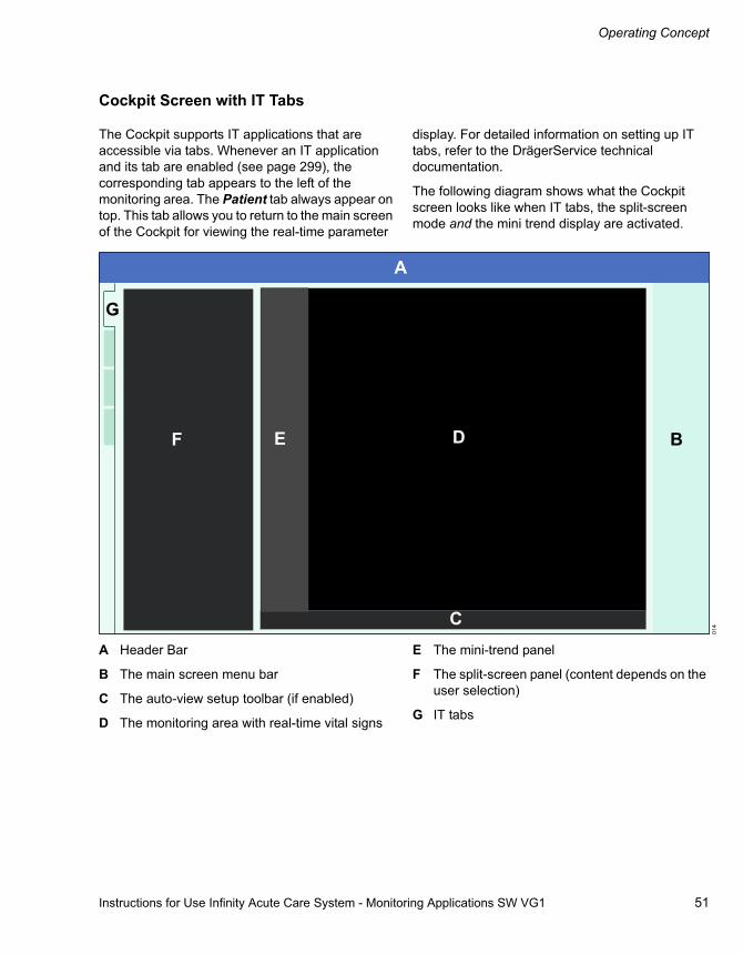
Instructions for Use Infinity Acute Care System - Monitoring Applications SW VG1 51
Operating Concept
Cockpit Screen with IT Tabs
The Cockpit supports IT applications that are accessible via tabs. Whenever an IT application and its tab are enabled (see page 299), the corresponding tab appears to the left of the monitoring area. The Patient tab always appear on top. This tab allows you to return to the main screen of the Cockpit for viewing the real-time parameter
display. For detailed information on setting up IT tabs, refer to the DrägerService technical documentation.
The following diagram shows what the Cockpit screen looks like when IT tabs, the split-screen mode and the mini trend display are activated.
A Header Bar
B The main screen menu bar
C The auto-view setup toolbar (if enabled)
D The monitoring area with real-time vital signs
E The mini-trend panel
F The split-screen panel (content depends on the user selection)
G IT tabs 01
4
A
B
C
DEF
G

Operating Concept
52 Instructions for Use Infinity Acute Care System - Monitoring Applications SW VG1
Parameter Priority
The parameter priority determines what position a parameter occupies on the screen. The number of parameters appearing as waveforms and parameter boxes depends also on the selected Waveforms setting (see page 278).
In the auto-view setup page (see page 277) you determine the display location and display status of each parameter. In the auto-view mode, you can also use the auto-view setup toolbar to change the parameter priority (see page 280). In the manual mode, you can only change the parameter priority in the Auto-view setup page.
Configuring the Parameter Priority and Display
The location of a parameter in the window determines not only where a parameter appears on the screen but also how it is displayed. Parameters are arranged in descending order in the window and occupy the same position on the screen. For example, the top parameter in the parameter selection window occupies the top spot on the main screen. For more information, see "Configuring Parameters for Display" on page 279.
Parameter Priority List
The priority list appears in the parameter selection window of the Auto-view setup page (see page 277). You can change the parameter priority by switching the position of the parameters in the Auto-view setup page. For more information, see "To configure the parameter priority and display from the auto-view setup toolbar." on page 280.
The following list shows the default parameter priority list. Pressures without assigned labels appear as GP1, GP2, GP3, or GP4.
1 ECG (ST)
2 SpO2
3 RRi
4 ART
5 PA
6 CVP
7 RA
8 LA
9 LV
10 LA
11 RV
12 ICP
13 NIBP
14 T (temperature)
15 T1
16 CO2
17 C.O. (not available in the neonatal mode)
18 GP1
19 GP2
20 GP3
21 GP4
22 SpO2
23 etCO2
24 Vent
25 Paw

Instructions for Use Infinity Acute Care System - Monitoring Applications SW VG1 53
Operating Concept
Views
Each Cockpit supports eight pre-configured Dräger views and, as an option, up to eight custom views. Views control the content and the appearance of the screen.
During a monitoring session, you can always switch to a different view to adjust the screen layout to the needs of the current monitoring session.
Views can be shared among various profiles which are pre-configured setups. This sharing of views eliminates time-consuming setup tasks. You can also assign views to each profile (see page 308).
Selecting a View
You can reconfigure the screen by selecting a different view.
To select a view
1 Select the Views... button on the main-menu bar.
2 Select the Views tab if it is not already selected to open a popup with pre-configured views.
3 Select the desired View from the Custom views (option) or the Dräger views selection lists.
The monitoring area is configured accordingly.
The View Editor
The view editor (option) allows authorised personnel to create and modify customised views. Dräger views cannot be modified. Access to the view editor is password-protected. For more information, see page 283.

Operating Concept
54 Instructions for Use Infinity Acute Care System - Monitoring Applications SW VG1
Profiles
Cockpits are adaptable to different CareAreas™. This adaptability is partially due to profiles which allow clinical personnel to create unique setups for the patient population of specific CareAreas™.
A profile consists of user-defined settings which are customised for each patient category (adult, paediatric, neonate). For example, a profile may be unique to an adult patient population in a high-acuity OR setting, while another caters to neonatal patients in a low-acuity OR setting. A profile ’remembers’ the patient and device settings for future use. With a profile time-consuming setup tasks that would otherwise have to be repeated for each monitoring session are eliminated.
For each patient category, you can set up and save five unique profiles. Each Cockpit also has a Dräger default profile that cannot be changed.
A profile includes the following settings:
– Alarm limits and trend scales for each parameter depend on the selected patient category.
– Parameter colour and alarm archive status regardless of the selected patient category.
– Settings unique to each parameter that can be set up in the parameter-setup pages for each patient category.
Whenever a patient is admitted, a previously defined default profile is assigned to that monitoring session.
Whenever an M540 is docked, the profile of the connected Cockpit overwrites any profile settings of the M540.
After a patient discharge, all patient data is deleted and the current profile is restored.
Managing Profiles and Views
Each patient category (adult, paediatric, neonatal) has its own unique profiles. For example, if you activate the neonatal patient category, only the profiles defined for the neonatal patient category are selectable. This is unlike views which can be shared among all patient categories.
The following profile functions are available (for detailed instructions, see "Profile Setup" on page 304):
– Selecting a profile
– Saving a profile (password-protected)
– Transferring a profile (password-protected)
– Deleting a profile
– Entering a profile name and description
– Assigning a profile to a default view (default profiles are automatically activated after a restart or a patient discharge).
Transferring Profiles
Profiles can be transferred to other Cockpits in the password-protected Profile transfer page. This eliminates time consuming duplicate setup tasks. You can transfer profiles either over the network or with a USB memory stick (see page 311).

Instructions for Use Infinity Acute Care System - Monitoring Applications SW VG1 55
Operating Concept
Standby Mode
You can temporarily interrupt patient monitoring by placing the Cockpit and the M540 in the standby mode. Selecting the standby mode on the Cockpit automatically activates the standby mode on the M540 and vice versa. Likewise, taking a patient out of standby on one device does the same at the other device. The standby mode has the following effect:
– All patient data is removed from display on the Cockpit and the M540
– All monitoring (including audible and visual alarm signals) is suppressed
– Active alarms are considered acknowledged
– All recordings are cancelled
– The banner Standby, touch screen to resume monitoring is displayed in the centre of the Cockpit screen
To place the Cockpit in the standby mode
1 Select the symbol next to the Start/Standby... button on the main-menu bar to display the Standby toolbar
2 Select the Standby button on the toolbar
or
1 Select the Start/Standby... button on the main-menu bar to display the Standby dialogue window
2 Select the Start tab if it is not already selected
3 Select the Standby button next to the menu selection Monitor
The banner Standby, touch screen to resume monitoring appears in the centre of the Cockpit screen
To take the Cockpit out of the standby mode
� Touch the screen to resume monitoring the vital signs of the patient.

Operating Concept
56 Instructions for Use Infinity Acute Care System - Monitoring Applications SW VG1
Privacy Mode
The privacy mode is only possible when the patient is admitted at the Infinity CentralStation (ICS). In the privacy mode, the patient monitoring continues but the patient data are removed from Cockpit and M540 and only appear on the ICS.
Selecting the privacy mode on the Cockpit automatically activates the privacy mode on the M540 and vice versa. Likewise, taking a patient out of the privacy mode on one device does the same at the other device. The privacy mode is cancelled automatically when the connection to the Infinity network is disrupted.
Activating the privacy mode has the following effect:
– All patient data is removed from the Cockpit display and the M540, but continues to be displayed at the ICS
– The alarm bar is disabled
– Audible alarm signals are only provided at the ICS
– The banner Privacy, touch screen to return is displayed in the centre of the Cockpit screen
To place the Cockpit in the privacy mode
1 Select the symbol next to the Start/Standby... button on the main-menu bar
2 Select Privacy on the toolbar
or
1 Select the Start/Standby... button on the main-menu bar
2 Select the Start tab if it is not already selected
3 Select Privacy next to the menu selection Display
The banner Privacy, touch screen to return is displayed in the centre of the Cockpit screen
To take the Cockpit out of the privacy mode
� Touch the screen to ractivate the display of the patient data.

Instructions for Use Infinity Acute Care System - Monitoring Applications SW VG1 57
Assembly
Assembly
Assembly Overview . . . . . . . . . . . . . . . . . . . . 58
Commercially Available Mounting Solutions. . . 58
Docking/Undocking the M540 . . . . . . . . . . . . 59
Locking/Unlocking the M540 . . . . . . . . . . . . . 60
Connecting the System Cables. . . . . . . . . . . 61
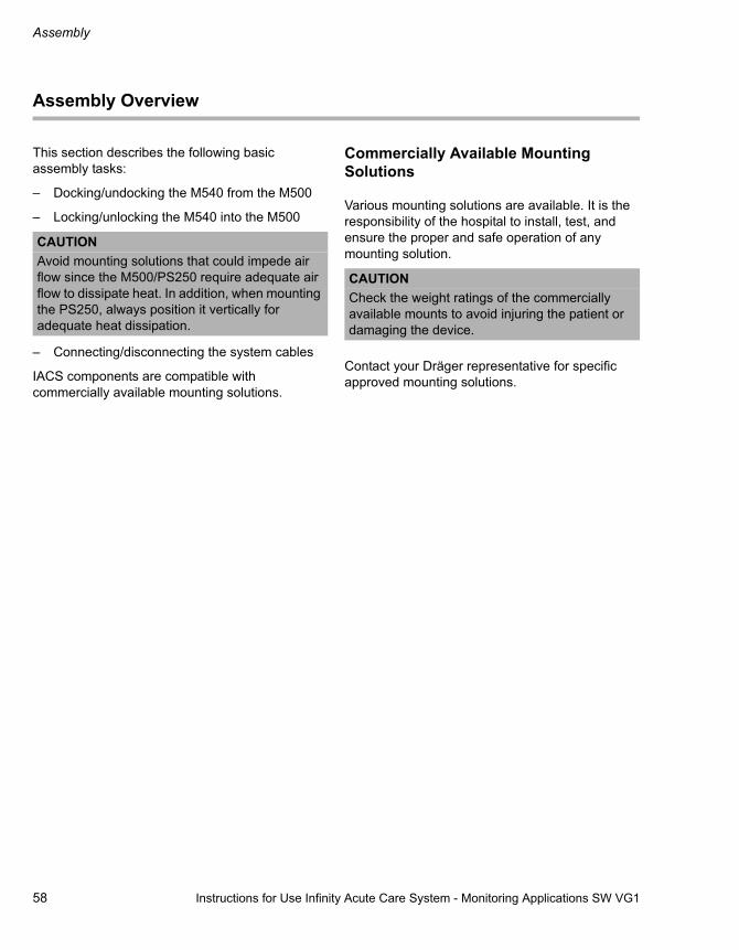
Assembly
58 Instructions for Use Infinity Acute Care System - Monitoring Applications SW VG1
Assembly Overview
This section describes the following basic assembly tasks:
– Docking/undocking the M540 from the M500
– Locking/unlocking the M540 into the M500
– Connecting/disconnecting the system cables
IACS components are compatible with commercially available mounting solutions.
Commercially Available Mounting Solutions
Various mounting solutions are available. It is the responsibility of the hospital to install, test, and ensure the proper and safe operation of any mounting solution.
Contact your Dräger representative for specific approved mounting solutions.
CAUTIONAvoid mounting solutions that could impede air flow since the M500/PS250 require adequate air flow to dissipate heat. In addition, when mounting the PS250, always position it vertically for adequate heat dissipation.
CAUTIONCheck the weight ratings of the commercially available mounts to avoid injuring the patient or damaging the device.

Instructions for Use Infinity Acute Care System - Monitoring Applications SW VG1 59
Assembly
Docking/Undocking the M540
The following diagram shows the side and front panels of the M500 which holds the M540 in place.
A M500 locking tab
B M540 patient monitor
C M500
D Swivel mount (optional) and mounting clamp
To dock the M540
1 Press the M540 (B) into the M500 (C) until it ‘clicks’ into place. When docking the M540, align the curved portion of the M540 with the curved portion of the M500.
2 Make sure the locking tab (A) is in the locked position to fasten the M540 into place.
To lock the M540 into place permanently, see "Locking/Unlocking the M540" on page 60.
To undock the M540
1 Push the locking tab (A) of the M500 to the front. If the locking tab does not move, it has been permanently locked. See page 60 for information on how to unlock the locking tab.
2 Hold the M540 firmly and press one of the release buttons of the M500.
3 Pull the M540 (B) out of the M500 (C).
300
305
B
C Front View
A
Side View
B
A
CD
306
Side View
B C
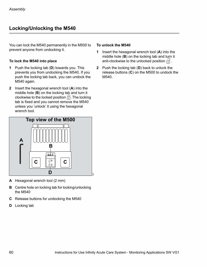
Assembly
60 Instructions for Use Infinity Acute Care System - Monitoring Applications SW VG1
Locking/Unlocking the M540
You can lock the M540 permanently in the M500 to prevent anyone from undocking it.
To lock the M540 into place
1 Push the locking tab (D) towards you. This prevents you from undocking the M540. If you push the locking tab back, you can undock the M540 again.
2 Insert the hexagonal wrench tool (A) into the middle hole (B) on the locking tab and turn it clockwise to the locked position .The locking tab is fixed and you cannot remove the M540 unless you ’unlock’ it using the hexagonal wrench tool.
A Hexagonal wrench tool (2 mm)
B Centre hole on locking tab for locking/unlocking the M540
C Release buttons for undocking the M540
D Locking tab
To unlock the M540
1 Insert the hexagonal wrench tool (A) into the middle hole (B) on the locking tab and turn it anti-clockwise to the unlocked position .
2 Push the locking tab (D) back to unlock the release buttons (C) on the M500 to undock the M540.
307
Top view of the M500
A
CC
D
B

Instructions for Use Infinity Acute Care System - Monitoring Applications SW VG1 61
Assembly
Connecting the System Cables
Connecting the system cables involves two main steps:
– Connecting a system cable to the PS250 and the Cockpit
– Connecting a system cable to the PS250 and the M500
To connect the system cable to the PS250 and the Cockpit
1 Connect one end of the system cable to the system connector on the back of the Cockpit (refer to the IACS Infinity Medical Cockpit Instructions for Use)
2 Connect the other end of the system cable to one of the two PS250 system connectors (A)
To connect the system cable to the PS250 and the M500
1 Connect one end of the system cable to the M500 system connector (B).
004
A
Bottom View of PS250
306
B
Side View of the M500

62 Instructions for Use Infinity Acute Care System - Monitoring Applications SW VG1
This page is intentionally left blank

Instructions for Use Infinity Acute Care System - Monitoring Applications SW VG1 63
Getting Started
Getting Started
Overview of Monitoring a Patient. . . . . . . . . 64
Turning the IACS On/Off . . . . . . . . . . . . . . . . 64
The Demographics Page . . . . . . . . . . . . . . . . 65
Admitting a Patient. . . . . . . . . . . . . . . . . . . . . 66
Admitting a Patient using Get HIS . . . . . . . . . . 67
Discharging a Patient. . . . . . . . . . . . . . . . . . . 67
Patient Categories . . . . . . . . . . . . . . . . . . . . . 68
Selecting the Patient Category . . . . . . . . . . . . . 68

Getting Started
64 Instructions for Use Infinity Acute Care System - Monitoring Applications SW VG1
Overview of Monitoring a Patient
This chapter describes the necessary steps to start monitoring a patient on the IACS.
Specifically, this section describes how to:
– Turn the IACS on/off
– Admit/discharge a patient on the Cockpit
– Change the patient category
Turning the IACS On/Off
Before monitoring a patient on the IACS, the Cockpit and the M540 must be turned on. The following steps assume that the M540 has been docked in the M500 (for information see "Docking/Undocking the M540" on page 59).
To turn the Cockpit on
� Press the on/off key (B) of the Cockpit.
The two LEDs (A) on either side of the on/off key light up green. The Cockpit emits a power-up tone and performs a self-test. After a brief moment, the Dräger startup screen appears before the Cockpit main screen is displayed.
To turn the M540 on
� Press the on/off key (C) of the M540.
The M540 emits a high-pitched tone followed by two power-up tones, performs a self-test and displays the New Patient prompt. Select Discharge to delete the patient data or Cancel to continue monitoring the patient and append the new data to the previous data set. The main screen appears.
The audible alarm signals are paused for 2 minutes.
003A AB
300
C

Instructions for Use Infinity Acute Care System - Monitoring Applications SW VG1 65
Getting Started
To turn the Cockpit off
� Press the on/off key located in the lower-left corner of the Cockpit > select Shutdown in the shutdown dialogue box.
To turn the M540 off
1 Press and hold the on/off key. The power-off dialogue window appears.
2 Select the Shutdown button in the dialogue window.
The Demographics Page
The following diagram shows the Demographics page where you can perform the following functions:
– Admit a patient manually (see page 66)
– Admit a patient over the network via the "Get HIS" feature (see page 67)
– Discharge a patient (see page 67)
– Change the patient category (see page 69)
A The Patient name keyboard symbol
B The Patient ID keyboard symbol
C The Physician name keyboard symbol
D The Get HIS button
E The Patient category buttons (Adult, Paediatric, Neonate)
F The Birth date fields
G The Admit date fields
H The Gender fields
I The Weight keypad symbol
J The Height keypad symbol
All demographic data entered on the Demographics page is available to the network. Demographic data is not deleted when you turn the Cockpit off and on. To delete the demographic data, discharge the patient.
015
ABC
D
E E E
F F FG G GH H H
IJ
Start/Standby
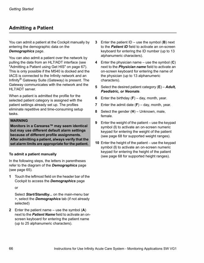
Getting Started
66 Instructions for Use Infinity Acute Care System - Monitoring Applications SW VG1
Admitting a Patient
You can admit a patient at the Cockpit manually by entering the demographic data on the Demographics page.
You can also admit a patient over the network by pulling the data from an HL7/ADT interface (see "Admitting a Patient using Get HIS" on page 67). This is only possible if the M540 is docked and the IACS is connected to the Infinity network and an Infinity® Gateway Suite (Gateway) is present. The Gateway communicates with the network and the HL7/ADT server.
When a patient is admitted the profile for the selected patient category is assigned with the patient settings already set up. The profiles eliminate repetitive and time-consuming setup tasks.
To admit a patient manually
In the following steps, the letters in parentheses refer to the diagram of the Demographics page (see page 65).
1 Touch the leftmost field on the header bar of the Cockpit to access the Demographics page
or
Select Start/Standby... on the main-menu bar >, select the Demographics tab (if not already selected)
2 Enter the patient name – use the symbol (A) next to the Patient Name field to activate an on-screen keyboard for entering the patient name (up to 25 alphanumeric characters).
3 Enter the patient ID – use the symbol (B) next to the Patient ID field to activate an on-screen keyboard for entering the ID number (up to 13 alphanumeric characters).
4 Enter the physician name – use the symbol (C) next to the Physician name field to activate an on-screen keyboard for entering the name of the physician (up to 13 alphanumeric characters).
5 Select the desired patient category (E) – Adult, Paediatric, or Neonate.
6 Enter the birthday (F) – day, month, year.
7 Enter the admit date (F) – day, month, year.
8 Select the gender (H) – Unknown, male, female.
9 Enter the weight of the patient – use the keypad symbol (I) to activate an on-screen numeric keypad for entering the weight of the patient (see page 68 for supported weight ranges).
10 Enter the height of the patient – use the keypad symbol (I) to activate an on-screen numeric keypad for entering the height of the patient (see page 68 for supported height ranges).
WARNINGMonitors in a Carearea™ may seem identical but may use different default alarm settings because of different profile assignments. After admitting a patient, always verify that the set alarm limits are appropriate for the patient.

Instructions for Use Infinity Acute Care System - Monitoring Applications SW VG1 67
Getting Started
Admitting a Patient using Get HIS
You can populate the Demographics page automatically by pulling the demographic data of a patient from the network. The prerequisite for this network data transfer is the Infinity® Gateway with an interface to the hospital Admit, Discharge, Transfer (ADT) system. The Hospital Information System (HIS) searches the database for the patient demographic data by using the patient ID.
To admit a patient via Get HIS
1 Touch the leftmost field on the header bar to access the Demographics page directly
or
Select Start/Standby... on the main-menu bar >, select the Demographics tab (if not already selected)
2 Enter the patient ID – use the symbol (B) next to the Patient ID field to activate an on-screen keyboard for entering the ID number (up to 13 alphanumeric characters).
3 Select the Get HIS button (D) in the Demographics page (see page 65). The Get HIS button appears greyed out and is not selectable when the HIS is not available or when the Cockpit is not connected to it
Discharging a Patient
You can discharge a patient from the Cockpit or from the M540. Discharging a patient from either device causes a discharge at the other device. Refer to the "Infinity Acute Care System - Infinity M540 Instructions for Use" for detailed information on how to discharge a patient from the M540.
Discharging a patient has the following effect on the Cockpit:
– All patient demographic data is removed from the screen
– All trend and event data is deleted
– Any active recordings are cancelled
– The profile with defined patient settings is restored
– The message Discharged, touch screen to initiate monitoring appears
To discharge a patient
1 Touch the leftmost field on the header bar of the Cockpit to access the Demographics page > select the Start tab (if not already selected)
or
Select Start/Standby... on the main-menu bar >, select the Start tab (if not already selected)
2 Select the Discharge button. A pop-up window with the message Caution discharge will delete patient data appears
3 Select the Discharge button in the pop-up window
Discharging a patient may take some time during which the message Please wait appears on the screen. Once the patient is discharged, the message Discharged, touch screen to initiate monitoring appears in the centre of the screen

Getting Started
68 Instructions for Use Infinity Acute Care System - Monitoring Applications SW VG1
Patient Categories
Each patient category has specific profiles associated with it. Profiles are a set of patient settings that have been pre-configured by the factory or the hospital (for more information see "Profiles" on page 54).
The Cockpit supports the following patient categories:
If an M540 docks with a different patient category from the one selected on the Cockpit the following happens:
– The Cockpit aligns its patient category to the M540 patient category setting
– During the patient category alignment, the M540 continues to monitor the patient
– The profile changes to the default profile for the new patient category and the message Please wait is displayed
– As soon as the Cockpit has switched to the new patient category, the patient data is automatically transferred to the Cockpit from the M540 that has been monitoring the patient
Selecting the Patient Category
If the Patient profile selection feature is enabled (see page 295) you can change the patient category and select a profile from a list of pre-configured profiles from the Start page. If the feature is disabled, you can only change the patient category from the Demographics page.
After changing the patient category, the new patient category label and symbol appear in the leftmost field of the header bar (see page 41). The height and weight values are no longer displayed after changing the patient category.
A patient category change does not affect the following settings: the patient and physician names, patient ID, birth date, and admit date.
Patient Category
Typical Age Range
Weight Height
Adult 12 years to 40 years
30 kg to 350 kg (66 lbs to 660 lbs)
120 cm to 250 cm (45 in. to 100 in.)
Paediatric 0 yr to 12 years 5 kg to 50 kg (10 lbs to 110 lbs) 50 cm to 200 cm (20 in. to 80 in.)
Neonate 0 year 0 g to 10,000 g (0 oz to 351 oz) 20 cm to 80 cm (5 in to 30 in)

Instructions for Use Infinity Acute Care System - Monitoring Applications SW VG1 69
Getting Started
To change the patient category from the Start setup page
The following steps are only possible when the Patient profile selection feature is enabled (see page 295).
1 Touch the leftmost field on the header bar to access the Demographics setup page directly
or
Select Start/Standby... on the main-menu bar > select the Start tab (if not already selected)
2 Select the desired patient category button (Adult, Paediatric, Neonate) next to the selection Category
3 Press the rotary knob to confirm the setting
4 Select a profile using the down arrow next to the selection Profile.
The Cockpit switches to the new patient category and the selected profile.
To change the patient category in the Demographics setup page
1 Touch the leftmost field on the header bar to access the Demographics setup page directly
or
Select Start/Standby... on the main-menu bar >, select the Demographics tab (if not already selected)
2 Select the desired patient category button (Adult, Paediatric, Neonate) next to the selection Patient Category
3 Press the rotary knob to confirm the setting
The Cockpit switches to the new patient category and the default profile for the new patient category.

70 Instructions for Use Infinity Acute Care System - Monitoring Applications SW VG1
This page is intentionally left blank

Instructions for Use Infinity Acute Care System - Monitoring Applications SW VG1 71
Alarms
Alarms
Overview of Alarms . . . . . . . . . . . . . . . . . . . . 72
Alarm Priorities. . . . . . . . . . . . . . . . . . . . . . . . 73
High-Priority Alarm Conditions . . . . . . . . . . . . . 73Medium-Priority Alarm Conditions . . . . . . . . . . 73Low-Priority Alarm Conditions . . . . . . . . . . . . . 73
Alarm Processing . . . . . . . . . . . . . . . . . . . . . . 73
Latching and Non-Latching Alarm Behaviour . . 74Multiple Alarm Conditions. . . . . . . . . . . . . . . . . 74
Enabling or Disabling Alarm Validation . . . . 75
Visual Alarm Signals . . . . . . . . . . . . . . . . . . . 76
Alarm Bar . . . . . . . . . . . . . . . . . . . . . . . . . . . . . 77
Audible Alarm Signals . . . . . . . . . . . . . . . . . . 78
Adjusting the Alarm Tone . . . . . . . . . . . . . . . . . 79
Testing Visual and Audible Alarm Signals . . 79
Viewing Current Alarm Messages. . . . . . . . . 80
Special Alarm Behaviour . . . . . . . . . . . . . . . . 80
ASY/VF Alarms. . . . . . . . . . . . . . . . . . . . . . . . . 80SpO2 Desaturation Alarms . . . . . . . . . . . . . . . . 80NIBP/SpO2 Interlock Alarms. . . . . . . . . . . . . . . 81Privacy Mode . . . . . . . . . . . . . . . . . . . . . . . . . . 81Standby Mode. . . . . . . . . . . . . . . . . . . . . . . . . . 81Cardiac Bypass Mode . . . . . . . . . . . . . . . . . . . 81OR Mode . . . . . . . . . . . . . . . . . . . . . . . . . . . . . 82French NFC Mode . . . . . . . . . . . . . . . . . . . . . . 82
Pre-Silencing Alarms . . . . . . . . . . . . . . . . . . . 82
Pausing Active Alarm Tones . . . . . . . . . . . . . 83
Enabling or Disabling an Audible Alarm Signals. . . . . . . . . . . . . . . . . . . . . . . . . . . . . . . 84
Pausing Alarm Monitoring Temporarily . . . . 84
Enabling or Disabling Alarm Monitoring Permanently . . . . . . . . . . . . . . . . . . . . . . . . . . 85
Configuring a Patient’s Alarm Settings. . . . 85
Enabling/Disabling Alarms . . . . . . . . . . . . . . . 86Upper and Lower Alarm Limits . . . . . . . . . . . . 86Archive Function . . . . . . . . . . . . . . . . . . . . . . . 86
Alarm Setup for an Individual Parameter . . 87
Changing Alarm Settings for a Single Parameter . . . . . . . . . . . . . . . . . . . . . . . . . . . . 88
Alarm Setup for Multiple Parameters . . . . . 89
Changing General Alarm Settings. . . . . . . . . . 90
Alarm Setup for Arrhythmia . . . . . . . . . . . . . 91
Configuring ARR Alarm Settings . . . . . . . . . . . 91
Alarm Setup for ST . . . . . . . . . . . . . . . . . . . . 93
Configuring ST Alarm Settings . . . . . . . . . . . . 94
Auto-Setting All Alarm Limits. . . . . . . . . . . . 95
Alarm History and Stored Events . . . . . . . . 96
The Alarm History . . . . . . . . . . . . . . . . . . . . . 97
Viewing a Snapshot of a Single Event. . . . . 98
Remote Alarm Control . . . . . . . . . . . . . . . . . 99
Alarm Groups . . . . . . . . . . . . . . . . . . . . . . . . . 99Infinity ®MCable-Nurse Call. . . . . . . . . . . . . . . 99
External Device Disconnection Alarm. . . . . 100
The Code Button . . . . . . . . . . . . . . . . . . . . . . 100
Alarm Ranges and Defaults . . . . . . . . . . . . . 101
Arrhythmia Ranges and Defaults . . . . . . . . . . 106

Alarms
72 Instructions for Use Infinity Acute Care System - Monitoring Applications SW VG1
Overview of Alarms
The Cockpit and the M540 produce audible and visual alarm signals to alert you to alarm conditions ranging from alarm limit violations, arrhythmia calls, and network issues.
Each alarm condition is assigned one of three alarm priorities: high (life-threatening), medium (serious), and low (advisory). Each alarm priority has unique audible and visual alarm signals.
In addition to the visual and audible alarm signals, alarm messages appear in the header bar of the Cockpit and in the alarm message field of the M540. For some parameters, such as NIBP and SpO2, certain alarm messages are displayed in the parameter box of the Cockpit only. All alarm conditions and associated alarm messages are described in detail in the ’Problem Solving’ chapter starting on page 325.
The colour of an alarm message corresponds to the priority of the associated alarm condition (see "Alarm Priorities" on page 73).
Physiological alarms for a patient can be set up to generate automatic recordings and/or store alarms for later event review in the alarm history. Furthermore, a physiological alarm can also activate an external alarm device such as a nurse call system. Special monitoring modes (see page 80), such as cardiac bypass mode, affect the regular alarming behaviour.
When connected to the Infinity network, the Cockpit and the M540 can be configured to report alarm conditions occurring at other monitors that are also connected to the Infinity network.
For detailed instructions regarding the alarm functions of the M540, refer to the Infinity Acute Care System - M540 Instructions for Use.
Instructions for Use Infinity Acute Care System - Monitoring Applications SW VG1 73
Alarms
Alarm Priorities
Each alarm condition is assigned to one of three priorities: high (life-threatening), medium (serious) or low (advisory). Visual and audible alarm signals indicate the level of the alarm priority. For more information on how alarm priorities affect alarm reporting, see "Visual Alarm Signals" on page 76 and "Audible Alarm Signals" on page 78.
High-Priority Alarm Conditions
All high-priority alarms are physiological alarm conditions that can be life-threatening and require immediate intervention.
An example of a high-priority alarm condition is asystole.
Medium-Priority Alarm Conditions
Most medium-priority alarms report physiological alarm conditions, that require prompt attention but may not be life-threatening.
An example of a medium-priority alarm condition is a respiratory-rate limit violation.
Low-Priority Alarm Conditions
All low-priority alarms alert you to technical issues that may compromise the ability of the system to monitor the patient.
An example of a low-priority alarm condition is an artefact on the ECG waveform.
Alarm Processing
When you dock an M540 on the M500 (see page 59), all visual and audible alarm signals are automatically transferred to the Cockpit. Audible alarm signals only sound at the Cockpit not at the M540 by default. If you also want alarms to sound at the M540 when it is docked, select the alarm tone volume at the M540 manually (refer to the Infinity Acute Care System - M540 Instructions for Use).
The Cockpit provides audible and visual alarm signals for parameters originating from monitors in its alarm group (see page 99). In addition, the Cockpit reports technical alarms affecting the Infinity network.
When you undock the M540 from the M500 (see page 59), all alarm monitoring stops at the Cockpit but continues on the M540.
NOTEAlarm monitoring is not available for the following parameters: cardiac output (C.O.), injectate temperature (Tinj), pulmonary wedge pressure (PWP), paced beats (% Paced), perfusion index (PI) for the Masimo SET MCable, any parameter displayed on the Cockpit using the device connectivity option.

Alarms
74 Instructions for Use Infinity Acute Care System - Monitoring Applications SW VG1
Latching and Non-Latching Alarm Behaviour
When an alarm condition no longer exists, the associated audible and visual alarm signals behave in one of two ways:
– The alarm signals automatically stop when the alarm condition ceases to exist. This type of alarm is called a non-latching alarm condition.
– The alarm signals continue until you acknowledge the alarm even though the alarm condition has ceased to exist. This type of alarm is called a latching alarm condition.
In general, high-priority alarms are latching alarm conditions while low-priority alarm conditions are non-latching. Exceptions to this alarm behaviour are listed on page 80.
The alarm priority of a latching alarm condition determines how the alarm signals behave after the alarm condition ceases to exist:
– A latched alarm condition of high priority is identified by the standard audible and visual alarm signals (see "Visual Alarm Signals" on page 76).
– A latched alarm condition of medium priority is downgraded to a status message which appears in the header bar. The alarm header does not flash, and there are no audible alarm signals.
To acknowledge a latched alarm condition
Select one of the following two keys:
– The yellow key on the front panel of the Cockpit
– The key on the front panel of the M540
or
– Select the All alarms off/All alarms paused button (the name and function of the button depends on the Cockpit configuration – see page 286). To access the button, press the quick-access symbol next to the Alarms... button on the main-menu bar.
The latched alarm signals are cleared and all audible and visual latched alarm signals disappear.
Multiple Alarm Conditions
During multiple alarm conditions, the Cockpit and the M540 report the most recently detected alarm condition of highest priority. When several alarm conditions occur simultaneously, the parameter boxes flash for all alarming parameters. The alarm condition with the highest priority determines which audible alarm signal is generated, how the alarm bar and the parameter box appear, and what alarm message appears in the header bar.

Instructions for Use Infinity Acute Care System - Monitoring Applications SW VG1 75
Alarms
Enabling or Disabling Alarm Validation
When the alarm validation is enabled (see page 275), an alarm condition must exist for a certain time before audible and visual alarm signals are triggered. This feature reduces nuisance alarms.
When the alarm validation is enabled, the time between the detection and enunciation of a parameter falling outside the set alarm limits equals the time of detection plus the assigned alarm
validation delay. For HR, adding the delay time may exceed the maximum of 10 seconds allowed by AAMI EC13 and IEC 60601-2-27.
The following table lists which parameters have an alarm validation time. Parameters that do not appear in the table have no validation times and audible and visual alarm signals are triggered almost immediately.
Parameter Upper Alarm Limit Lower Alarm LimitECG/Heart rate (HR) 6 s 6 s
Pulse rate (PLS) 6 s 10 s
ST segment analysis (ST) 15-60 s (selectable) (1)
60 s
Respiratory rate (RRi) 14 s 14 s
Pulse oximetry (SpO2) (2) 6 s 10 s
Invasive blood pressure (IBP) 10 s 4 s(1) Select the validation period for the ST upper-limit alarm in the ST-setup page (see "Alarm Setup for ST" on page 93).(2) For Nellcor OxiMax SpO2: the SatSeconds alarm time overrides the alarm validation setting (see page 196).

Alarms
76 Instructions for Use Infinity Acute Care System - Monitoring Applications SW VG1
Visual Alarm Signals
Each alarm priority has its own distinct visual alarm signals. When the M540 is docked on the M500, only the Cockpit provides audible alarm signals. However, visual alarm signals (see page 76) appear on the Cockpit and the M540.
The alarm message in the header bar is the only visual alarm signal if an alarming parameter is not included in the current screen view or the alarm bar is disabled. For more information on alarm messages, see page 78.
Alarm Priority Parameter Box Alarm Message Field (1) in Header Bar
Alarm Bar (if enabled, see page 287)
High (life-threatening)(for example, asystole, ventricular fibrillation)
Flashing red background Red background Flashing red
Medium (serious)(for example, alarm limit violations)
Flashing yellow background
Yellow background Flashing yellow
Low (advisory)(for example, disconnected lead)
Solid cyan background Cyan background No visual signal
(1) Note: Cockpit alarm messages are designed to be legible from a distance of 1 metre (3.3 feet) to 2 metres (6.6 feet). M540 alarm messages are legible at arm’s length.

Instructions for Use Infinity Acute Care System - Monitoring Applications SW VG1 77
Alarms
Visual Alarm Indicators on the Cockpit
A Alarm message field in the blue header bar
B Alarming parameter box
C Alarm bar
Visual Alarm Indicators on the M540
Alarm Bar
The alarm bar on the Cockpit and the M540 visually announce high- and medium-priority alarm conditions (see page 73).
However, the alarm bar is inactive when:
– Only low-priority alarm conditions exist.
– The alarm bar is disabled (see page 287).
– Cardiac bypass or privacy modes are activated (see page 81).
– Alarm monitoring is disabled (see page 85).
016
B CA
309
A
BC

Alarms
78 Instructions for Use Infinity Acute Care System - Monitoring Applications SW VG1
Audible Alarm Signals
During an alarm, the Cockpit also provides distinct audible alarm signals for each alarm priority in addition to visual alarm signals (see page 76). The specific characteristics of these audible alarm signals depend on the selected alarm tone pattern. The available alarm tone patterns are: IEC fast, IEC slow, and Infinity.
When audible alarm signals are paused, the alarm bar and the parameter box stop flashing but remain lit up in the respective alarm colour.
If multiple alarm conditions exist simultaneously, an audible alarm signal sounds for the alarm condition with the highest priority.
NOTENormally, audible alarm signals only sound at the Cockpit, not at the M540. Therefore, all audible alarm signals are transferred automatically from the M540 to the Cockpit once you dock the M540. However, if you want alarms to sound at both devices, select the alarm tone volume at the M540 manually.
Alarm Priority IEC fast IEC slow InfinityHigh The following tone
sequence is repeated every 4.5 s:
Four beeps > one higher-pitched beep > short pause > four beeps > one higher-pitched beep
The following tone sequence is repeated every 8 s:
Four beeps > one higher-pitched beep > short pause > four beeps > one higher-pitched beep
Continuous two-tone sequence
Medium The following tone sequence is repeated every 7 s:
Two beeps > one lower-pitched beep
The following tone sequence is repeated every 15 s:
Two beeps > one lower-pitched beep
Two tones > short pause
Low Two beeps repeated every 16 s)
Two beeps (no repetition) Low tone repeated every 30 s)

Instructions for Use Infinity Acute Care System - Monitoring Applications SW VG1 79
Alarms
Adjusting the Alarm Tone
The volume of the alarm tone is adjustable. Make sure that you set the volume of the alarm tone, so it can be heard during the noisiest times.
You can only disable the alarm tone, if the patient is connected to the Infinity network or the Cockpit is in OR mode. When the alarm tone is disabled, the banner Audio Alarms Off appears in the header bar of the Cockpit. If the Cockpit loses its connection to the Infinity network while an active alarm is present, the alarm tone sounds at 100%. If no active alarm is present, the loss of connection to the Infinity network produces an alarm tone at 50%. In either case, the alarm tone volume selection Off disappears. If the Cockpit resumes its connection with the Infinity network, the previously active setting for the alarm tone volume is reinstated.
To adjust the alarm tone volume
1 Select the Alarms... button on the main-menu bar.
2 Select the Settings tab.
3 Select either the desired setting next to the Alarm volume button. The available settings are:
– Off (if the patient is connected to the Infinity network or the Cockpit is in OR mode)
– 10% to 100% in increments of 10%.
Testing Visual and Audible Alarm Signals
The alarm bar and the speakers of the M540 and the Cockpit are automatically tested during startup. You can also test alarm signals by creating an alarm condition (for example, by lowering the HR upper-alarm limits). To end the test, restore the alarm limits to the previous setting (see "Configuring a Patient’s Alarm Settings" on page 85).
NOTEIf the Alarm volume off feature is enabled in the Code setup page (see page 289), the alarm volume is automatically reduced to its minimum setting when you select the Code button on the main-menu bar.

Alarms
80 Instructions for Use Infinity Acute Care System - Monitoring Applications SW VG1
Viewing Current Alarm Messages
The Cockpit identifies each alarm condition according to the alarm priorities low, medium, and high (see page 73 for details). In addition to visual and audible alarm signals, alarm messages in the header bar identify each alarm condition. The header bar can display two messages simultaneously. If more than two patient alarm conditions are active at the same time, the button More appears to the left of the alarm message field (see page 41). Selecting this button activates the Current alarms page. This page lists all of the currently active alarms in a table.
Specifically, you can review the following information for each alarm condition:
– How long the alarm has been active (duration).
– The alarm priority of the alarm condition (! = low priority; !! = medium priority; !!! = high priority).
– Alarm message (for detailed information on the cause and possible remedies, see the chapter ’Problem Solving’).
To access the Current alarms page:
� Select the More button to the left of the alarm message field in the header bar (only visible when more than two patient alarm conditions are active).
or
1 Select the Alarms... button on the main-menu bar.
2 Select the Current alarms tab.
Special Alarm Behaviour
Enabling any of the following features alters the normal alarm enunciation behaviour:
– ASY/VF alarm feature
– SpO2 desaturation alarm
– NIBP/SpO2 interlock function
– Privacy, Standby, Cardiac bypass, and OR modes
– French NFC Mode
ASY/VF Alarms
You can control the alarming behaviour for ventricular fibrillation (VF) and asystole (ASY) alarms. To make sure that VF and ASY alarms are always reported, even when HR alarms and ARR monitoring are disabled, set the ASY/VF Alarms selection in the Alarms General Settings page to Always On. If you select Follow HR alarms,
asystole and ventricular fibrillation alarm conditions are only enunciated when either HR alarms or ARR monitoring is also enabled. To enable or disable this feature, see page 286.
If you select Follow HR and disable HR and ARR alarm monitoring, the banner HR, ASY, VF Alarms Off appears.
SpO2 Desaturation Alarms
In neonatal mode, the alarm priority is upgraded to high priority if the SpO2 value falls more than 10% below the lower SpO2 alarm limit.
Instructions for Use Infinity Acute Care System - Monitoring Applications SW VG1 81
Alarms
NIBP/SpO2 Interlock Alarms
To avoid SpO2 nuisance alarms during an active NIBP measurement, select NIBP/SpO2 Interlock On in the Alarms General Settings page. When the feature is enabled, all SpO2 alarms are disabled during an active NIBP measurement. To enable or disable this feature, see page 287.
Privacy Mode
When the privacy mode is enabled, the following happens at the Cockpit:
– Patient data are removed from the Cockpit and the M540 and are only visible at the ICS.
– The Cockpit and at the M540 display the alarm message Privacy, touch screen to resume monitoring.
– The alarm bar is disabled.
– Audible alarm signals are only provided at the ICS.
– Home is the only active button on the main-menu bar of the Cockpit; all other buttons are inactive.
You can enable the privacy mode only if the patient is also admitted at the ICS. To enable or disable this feature, see page 56.
Standby Mode
When the standby mode is enabled, the following happens at the Cockpit:
– All monitoring (including audible and visual alarm signals) is suppressed.
– All data are removed from the screen.
– The message Standby, touch screen to resume monitoring appears at the ICS, at the Cockpit, and the M540.
To enable or disable this feature, see page 56. Home is the only active button on the main-menu bar of the Cockpit; all other buttons are inactive.
Cardiac Bypass Mode
When the cardiac bypass mode is enabled, the following happens at the Cockpit:
– All alarm monitoring (including arrhythmia alarms), and the alarm bar are disabled.
– The message All Alarms Off: Bypass appears in the upper-right corner of the screen.
To enable or disable this feature, see page 276. Cardiac bypass mode is not available if French NFC mode is enabled.

Alarms
82 Instructions for Use Infinity Acute Care System - Monitoring Applications SW VG1
OR Mode
When the OR mode is enabled, the following happens at the Cockpit
– Alarm messages for medium-priority and high-priority alarms clear when the alarm condition no longer exists.
To enable or disable this feature, see page 276.
French NFC Mode
When this mode is enabled, the following happens at the Cockpit:
– HR alarms cannot be disabled.
– The alarm pause period cannot last longer than 3 min.
– You cannot enable the cardiac bypass mode when the French NFC mode is enabled. If the cardiac bypass mode was enabled before French NFC mode was turned on, the cardiac bypass mode is disabled.
To enable or disable this feature, see page 295.
Pre-Silencing Alarms
This function allows you to concentrate on a procedure without being interrupted by continuous audible alarm signals arising from potential alarm conditions. When you pre-silence alarms, the following happens at the Cockpit:
– Visual alarms are reported as usual (see page 76).
– The alarm message Audio paused appears in the far-right field of the header bar along with a countdown timer and the following symbol:
To pre-silence alarms
� Press the yellow key on the Cockpit. Pressing the key again cancels the pre-silence state.

Instructions for Use Infinity Acute Care System - Monitoring Applications SW VG1 83
Alarms
Pausing Active Alarm Tones
You can pause, or silence, audible alarm signals for 2 minutes. The following happens when you pause alarms:
– All audible alarm signals are paused for a maximum of 2 minutes. If the same alarm condition occurs again after the alarm has been paused, no audible or visual alarm signals are generated.
– The parameter box and the alarm bar stop blinking but appear solid in the alarm colour corresponding to the alarm level (see page 76).
– The alarm message continues to be displayed in the header bar.
– The Audio paused banner appears in the far-right field of the header bar along with a countdown timer and the following symbol:
If the condition of the patient is still unchanged after the pause period, the audible alarm signal is reactivated.
If one or more new alarm condition occurs during an active audio pause period, the following happens at the Cockpit:
– A single alarm tone sequence consisting of several distinct tones sounds in addition to the visual alarm signals for any new alarm condition of a higher priority than the previous alarm condition. Any alarm condition of equal or lower alarm priority than the paused alarm does not generate any visual or audible alarm signals.
– The parameter box of the new alarming parameter flashes while the parameter box of the previously paused alarm remains highlighted.
The alarm messages for the alarm condition with the highest alarm priority rotate in the alarm message field of the header bar (see page 41). The rotating alarm messages include alarm messages for paused alarm conditions.
To pause audible alarm signals
� Press the yellow key on the Cockpit.
or
� Press the yellow key on the M540.
To reactivate audible alarm signals during an audio pause, select the same buttons again.

Alarms
84 Instructions for Use Infinity Acute Care System - Monitoring Applications SW VG1
Enabling or Disabling Audible Alarm Signals
Disabling audible alarm signals is a password-protected function (see page 286).
You can disable alarm tones permanently. When you disable alarm tones, the following happens:
– Alarm tones no longer announce alarm conditions.
– The message Audio alarms off appears in the far-right field of the header bar and the following symbol:
After disabling audible alarm signals permanently, you can enable them again (see page 286). When you enable audible alarm signals, the following happens when an alarm condition occurs:
– Audible alarm signals sound (page 78).
– Alarm messages appear in the header bar (page 76).
Pausing Alarm Monitoring Temporarily
If the password-protected alarm pause feature is enabled (see page 286), you can pause alarm monitoring temporarily. The alarm pause duration is adjustable from 1 minute to 5 minutes.
The following happens when you pause alarm monitoring:
– Audible and visual alarm signals for new alarm conditions are suppressed for all parameters until alarm monitoring begins again.
– Alarm signals for any active alarm condition stop immediately.
– The alarming parameter box and alarm bar return to the pre-alarm state.
– Alarm messages are removed from the alarm message field in the header bar.
– The far-right field of the header bar turns yellow and displays the alarm message All alarms paused, a countdown timer, and the following symbol:
– The message All alarms paused is recorded in the alarm history (see page 96).
To pause alarm monitoring temporarily
1 Select the symbol next to the Alarms... button on the main-menu bar of the Cockpit.
2 Select the All alarms paused button.
As soon as the alarm pause period ends, the Cockpit generates audible and visual alarm signals as needed.
To enable alarm monitoring
� Select the All alarms paused button before the alarm pause period ends to cancel the alarm pause.
NOTEIf the French NFC mode is enabled (see page 295), you cannot pause alarm monitoring for more than 3 minutes.
NOTEIf the Cockpit is connected to the network and the patient is admitted at the ICS, the message Alarms paused also appears at the ICS.

Instructions for Use Infinity Acute Care System - Monitoring Applications SW VG1 85
Alarms
Enabling or Disabling Alarm Monitoring Permanently
If the password-protected alarm -pause feature is set to no timeout (see page 286), the following happens:
– All audible and visual alarm signals for new alarm conditions are suppressed for all parameters until alarm monitoring is manually enabled again.
– Audible alarm signals for any active alarm condition stop immediately.
– The alarming parameter box and alarm bar return to the pre-alarm state.
– Alarm messages are removed from the alarm message field in the header bar.
– The far-right field of the header bar turns yellow and displays the message All alarms off and the following symbol:
– The message All alarms off is recorded in the alarm history (see page 97).
To enable alarm monitoring permanently
1 Select the symbol next to the Alarms button on the main-menu bar of the Cockpit.
2 Select the All alarms off button on the toolbar.
To enable alarm monitoring after disabling
1 Select the symbol next to the Alarms button on the main-menu bar of the Cockpit.
2 Select the All alarms off button again on the toolbar.
The Cockpit provides audible and visual alarm signals again when it detects a new alarm condition.
Configuring a Patient’s Alarm Settings
The following section describes the available alarm features and settings. You can adjust the alarm settings for an individual parameter in the respective parameter-specific setup page. Or, you can set up the alarm settings of multiple parameters in one setup page. When setting alarm limits, make sure they are appropriate for the patient’s condition.
WARNINGIf No Timeout is assigned to the alarm-off period, no counter appears and alarms remain deactivated until you enable them again.
WARNINGNever leave a patient unattended when alarm monitoring is permanently disabled. Always enable alarm monitoring again as soon as possible.
NOTEIf the Cockpit is connected to the network, the message All alarms off also appears at the ICS .

Alarms
86 Instructions for Use Infinity Acute Care System - Monitoring Applications SW VG1
Enabling/Disabling Alarms
Except for the following parameters, you can enable or disable the alarm function for individual parameters:
– Asystole and ventricular fibrillation (for these arrhythmia events you cannot disable alarms unless the ASY/VF feature is set to Follow HR)
– Cardiac output (C.O.)
– Injectate temperature (Tinj)
– Pulmonary wedge pressure (PWP)
– Paced beats (% paced)
– Perfusion index (PI)
– Parameters originating from a device that is displaying its values on the Cockpit using the device connectivity option
When you disable alarms, no audible and visual alarm signals are triggered for that parameter. When alarm monitoring is disabled, a crossed-out triangle (A) appears in the parameter box.
When you enable the alarm function for a parameter, the set alarm limits replace the crossed-out triangle.
Upper and Lower Alarm Limits
You can configure manually the upper and lower alarm limits of a parameter to trigger audible and visual alarm signals if a parameter goes above or below the set limits. You can also auto-set the alarm limits of all parameters quickly based on a percentage. For more information on the Auto set function, see page 96.
Archive Function
Depending on the active archive setting, the following happens in response to an alarm limit violation:
– An automatic strip recording (see chapter Reports/Recordings)
– An electronic event storage in the alarm history for later review (see page 97)
For information on configuring the archive function, see page 90.
030
A
WARNINGSetting alarm limits to extreme values may prevent certain alarm conditions from being detected and from being enunciated with audible and visual alarm signals.

Instructions for Use Infinity Acute Care System - Monitoring Applications SW VG1 87
Alarms
Alarm Setup for an Individual Parameter
If you are only changing the alarm settings of an individual parameter, use the parameter-specific setup page which includes the alarm setup.
The following diagram shows an example of a parameter-specific setup page. Regardless of the parameter, buttons for adjusting the alarm settings always appear at the top. The alarm-setup portion looks different depending on the parameter.
For example, the following diagram shows a setup page for a composite parameter, such as NIBP. There are separate alarm settings for each composite parameter (systolic, diastolic, and mean).
A Alarm on/off buttons for each parameter
B Auto set button
C Upper-limits button for each parameter
D Lower-limits button for each parameter
E Archive buttons
F Parameter-specific monitoring settings 01
7
A A A BC C C
D D DEEE
F
Sensor parameters

Alarms
88 Instructions for Use Infinity Acute Care System - Monitoring Applications SW VG1
Changing Alarm Settings for a Single Parameter
In the following steps, the letters in parenthesis refer to the diagram of the parameter-specific setup page (see page 87).
To configure the alarm settings
1 Select Sensor parameters... on the main-menu bar >, select the desired parameter tab (for example, ECG).
or
Select the parameter box to access the parameter-setup page directly.
2 Select the Alarm on/off button (B), to enable or disable alarm monitoring. A crossed-out triangle appears in the parameter box when alarm monitoring is disabled.
3 Select the Lower setup button (D) to adjust the lower alarm limits.
4 Select the Upper setup button (C) to adjust the upper alarm limits.
5 Select one of the following settings for the Archive buttons (E) to determine what happens in response to an alarm:
– Off – no event is stored and no recording is generated.
– Store – stores the event for later review (see page 97).
– Rec – generates a timed recording.
– Str/Rec – stores an event for later review and generates a timed recording.
WARNINGSetting alarm limits to extreme values may prevent certain alarm conditions from being detected and from being enunciated with audible and visual alarm signals.
NOTEIf the French NFC mode is enabled (see page 295), you cannot disable HR alarms.

Instructions for Use Infinity Acute Care System - Monitoring Applications SW VG1 89
Alarms
Alarm Setup for Multiple Parameters
The following diagram shows the General setup page where you configure alarm settings for all available parameters. The setup page consists of a table with setup rows for each parameter. Each setup row consists of several fields for configuring the individual alarm settings. When you select a field to configure a setting, an orange border highlights the selected row.
A Parameter labels column
B Alarm on/off column
C Lower limits column
D Parameter values
E Upper limits column
F Archive column
G General, ARR, and ST tabs
H Display filter button
I Auto-set all button (see "Auto-Setting All Alarm Limits" on page 95)
018
A B C D E F GGG
HI
Alarms
Alarms
90 Instructions for Use Infinity Acute Care System - Monitoring Applications SW VG1
Changing General Alarm Settings
In the following steps, the letters in parentheses refer to the diagram of the General setup page (see page 89). Alarm ranges and defaults are listed starting on page 106.
To configure the alarm settings of multiple parameters
1 Select the Alarms... button on the main-menu bar.
2 Select the Limits tab (if not already selected).
3 Select the General tabs along the right edge of the page.
4 Use the display filter button (I) to determine whether the table displays all parameters or only parameters that are currently connected.
5 Select the corresponding button in the Alarm on/off column (B), to enable or disable alarm monitoring. A crossed-out triangle appears in the parameter box when alarm monitoring is disabled.
6 Select the corresponding button in the Lower column (C) to adjust the upper alarm limits.
7 Select the corresponding button in the Upper column (E) to adjust the lower alarm limits.
8 Use one of the following settings in the Archive column (E) to determine what happens in response to an alarm:
– Off – no event is stored and no recording is generated.
– Store – stores the event for later review (see page 97).
– Rec – generates a timed recording.
– Str/Rec – generates a timed recording and stores the event.
9 Select the Auto set all button (I), to auto-adjust the alarm limits of all parameters. For more information see page 96.
WARNINGSetting alarm limits to extreme values may prevent certain alarm conditions from being detected and from being enunciated with audible and visual alarm signals.

Instructions for Use Infinity Acute Care System - Monitoring Applications SW VG1 91
Alarms
Alarm Setup for Arrhythmia
The following diagram shows the Limits ARR setup page where you configure alarm settings for arrhythmia parameters. This setup page consists of a table with setup rows for each arrhythmia parameter. Each setup row consists of several fields for configuring the individual ARR alarm settings. When you select a field on this setup page, an orange border highlights the selected row.
A Limits tab
B Arrhythmia category column for identifying the ARR label
C Alarm priority column for selecting an alarm priority
D Rate column for setting the rate
E Count column for setting the count
F Archive column
G ARR tab
H ARR mode buttons
I The Relearn button
Configuring ARR Alarm Settings
In addition to ARR alarm settings, the Limits ARR setup page also allows you to select the arrhythmia mode (see page 157) and initiate the relearn process of ECG leads (see page 170). In the following steps, the letters in parentheses refer to the diagram of the Limits ARR setup page. Alarm ranges and defaults are listed starting on page 106.
019
AB C D E
H H
FG
Alarms
HI

Alarms
92 Instructions for Use Infinity Acute Care System - Monitoring Applications SW VG1
To change the ARR alarm settings
1 Select the Alarms... button on the main-menu bar.
2 Select the Limits tab (if not already selected).
3 Select the ARR tab on the right side.
4 Select the corresponding setup button in the Alarm priority column (C) to select the alarm priority. A crossed-out triangle appears when alarm monitoring is disabled. The priority for asystole and ventricular fibrillation events cannot be changed. The alarm priority ’high’ is always assigned to these categories.
5 Select the corresponding setup button in the Rate column (D) to set the rate.
6 Select the corresponding setup button in the Count column (E) to set the count.
7 Use one of the following settings in the Archive column (E) to determine what happens in response to an alarm:
– Off – no event is stored and no recording is generated.
– Store – stores the event for later review (see page 97).
– Rec – generates a timed recording.
– Str/Rec – generates a timed recording and stores the event.
8 Select the desired arrhythmia mode using the ARR mode buttons (H).

Instructions for Use Infinity Acute Care System - Monitoring Applications SW VG1 93
Alarms
Alarm Setup for ST
The following diagram shows the ST Limits setup page where you configure alarm settings for ST parameters. This setup page consists of a table with setup rows for each ST parameter. Each setup row has several fields for configuring the individual ST alarm settings. When you select a field on this setup page, an orange frame highlights the selected row to mark your place on the setup page.
A
A Limits tabB Parameter label column
C Alarm on/off column
D Lower limits column
E Actual parameter values
F Upper limits column
G Archive column
H ST tab
I Auto set all button
J Event duration button
K ST relearn button 02
0
AB C D E F
GHI
GH
I
Alarms
JK

Alarms
94 Instructions for Use Infinity Acute Care System - Monitoring Applications SW VG1
Configuring ST Alarm Settings
Some of the ST alarm settings described are also available on the ST alarms setup page (see page 167). In the following steps, the letters in parentheses refer to the diagram of the ST Limits setup page (see page 93). Alarm ranges and defaults are listed starting on page 101.
To change the ST alarm settings
1 Select the Alarms... button on the main-menu bar.
2 Select the Limits tab (if not already selected).
3 Select the ST tab on the right side of the Limits page.
4 Select the setup button in the Alarm column (C), to enable or disable alarm monitoring. A crossed-out triangle appears in the parameter box when alarm monitoring is disabled.
5 Select the corresponding setup button in the Lower column (D) to adjust the lower alarm limits.
6 Select the corresponding setup button in the Upper column (F) to adjust the upper alarm limits.
7 Use one of the following settings in the Archive column (G) to determine what happens in response to an alarm:
– Off – no event is stored and no recording is generated.
– Store – stores the event for later review (see page 97).
– Rec – generates a timed recording.
– Str/Rec – generates a timed recording and stores the event.
8 Use the Auto set all (I) button to adjust the alarm limits for all ST parameters (see page 96).
9 Use the Event duration button (J) to select a time an upper ST-alarm limit has to be violated before an alarm is triggered (see page 75).
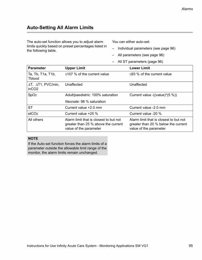
Instructions for Use Infinity Acute Care System - Monitoring Applications SW VG1 95
Alarms
Auto-Setting All Alarm Limits
The auto-set function allows you to adjust alarm limits quickly based on preset percentages listed in the following table.
You can either auto-set:
– Individual parameters (see page 96)
– All parameters (see page 96)
– All ST parameters (page 96)
Parameter Upper Limit Lower LimitTa, Tb, T1a, T1b, Tblood
≤ 107 % of the current value ≤ 93 % of the current value
ΔT, ΔT1, PVC/min, inCO2
Unaffected Unaffected
SpO2 Adult/paediatric: 100% saturation
Neonate: 98 % saturation
Current value -((value)*(5 %))
ST Current value +2.0 mm Current value -2.0 mm
etCO2 Current value +25 % Current value -20 %
All others Alarm limit that is closest to but not greater than 25 % above the current value of the parameter
Alarm limit that is closest to but not greater than 20 % below the current value of the parameter
NOTEIf the Auto-set function forces the alarm limits of a parameter outside the allowable limit range of the monitor, the alarm limits remain unchanged.

Alarms
96 Instructions for Use Infinity Acute Care System - Monitoring Applications SW VG1
To Auto-Set an Individual Parameter
1 Select the parameter box of the desired parameter.
2 Select the Auto set button located in the upper-right corner of each parameter setup page.
or
1 Select Sensor parameters... on the main-menu bar.
2 Select the tab of the desired parameter.
3 Select the Auto set button located in the upper-right corner of each parameter setup page.
To auto-set all parameters
� Select the symbol next to the Alarms... button on the main-menu bar > Auto set all.
or
1 Select the Alarms... button on the main-menu bar.
2 Select the Limits tab.
3 Select the Auto set all button which is located in the lower-right corner below the parameter setup table.
To auto-set all ST parameters
1 Select the Alarms... button on the main-menu bar.
2 Select the Limits tab.
3 Select the ST side tab to access the ST-setup page.
4 Select the Auto set all button which is located below the ST-setup table.
Alarm History and Stored Events
The alarm history is an electronic record of alarms and events. The alarm history records an entry when:
– An alarm occurs for a parameter, including arrhythmia, and ST whose archive function is set to Store or Store/Record. These alarm events are marked with the symbol and can be viewed in greater detail (see page 98).
– You select the Mark Event button from the main-menu bar. These alarm events are also marked with the symbol and can be viewed in greater detail (see page 98).
– You pause alarms using the All alarms paused/All alarms off button (see page 83).
– You activate the cardiac bypass mode (see page 81).
– You activate the standby mode (see page 55)
– You select a different patient category (see page page 66).
– You audio-pause an alarm.
The alarm history stores up to 150 events. When the storage capacity of 150 events is reached, new events replace the oldest events.
If a higher-priority alarm occurs less than 5 seconds from a previous alarm, the higher-priority alarm event is stored while the previous one is deleted.

Instructions for Use Infinity Acute Care System - Monitoring Applications SW VG1 97
Alarms
The Alarm History
The following diagram shows an alarm history. When you select any field on the table, a frame highlights the selected row. For information on what conditions prompt an entry to be stored in the alarm history, see page 96.
To access the alarm history:
1 Select the Alarms... button on the main-menu bar.
2 Select the Alarm history tab.
A Alarm history tab.
B Identifies an event
C Date of the alarm
D Time the alarm was stored
E Duration of the alarm
F Alarm priority
G Alarm message
H Print button
I Buttons for filtering the alarm history
To filter the alarm history
The alarm history can be filtered according to different categories.
1 Select the Alarms... button on the main-menu bar.
2 Select the Alarm history tab.
3 Use the left button (K) to restrict the alarm history to one of the following alarm conditions:
– All
– Arrhythmia
– High-priority
– Medium-priority
– Low-priority
4 Use the second left button (J) to restrict the alarm history to one of the following settings:
– Time
– Priority
– Message021
AB C D E F G
Alarms
H
I02
1
JK

Alarms
98 Instructions for Use Infinity Acute Care System - Monitoring Applications SW VG1
Viewing a Snapshot of a Single Event
20 seconds of waveform and parameter data are stored automatically in the alarm history when:
– A parameter whose recording archive feature is set to Store or Store/Record (see page 86) violates set alarm limits
– You select the Mark Event button on the main-menu bar.
In both instances, events with stored waveform and parameter data are identified on the alarm history by the following symbol . Such an event consists of a snapshot of all connected parameter values and waveforms. Of the 20-second event capture, 10 seconds were recorded before and 10 seconds were recorded after the event occurred.
To View a Snapshot of a Stored Event
1 Select Alarms... on the main-menu bar.
2 Select the Alarm history tab.
3 Select the row of the event marked with the symbol that you wish to view.
The following diagram shows the event snapshot screen.
A Event header showing the date, time, duration, priority, and alarm message.
B Parameter values area
C Delete button for deleting the current event
D Print button
E Zoom-out button
F Zoom-in button
G Navigation arrows for scrolling through events
H Select event button
I Waveform area
NOTETo return to the alarm history, select the Select event button. 02
2
Alarms
A
B
C
DEF
G
GH
IK
G
I

Instructions for Use Infinity Acute Care System - Monitoring Applications SW VG1 99
Alarms
Remote Alarm Control
When the Cockpit is connected to the Infinity network, it communicates with other Infinity monitors (including other monitoring Cockpits) that support remote viewing functions. Furthermore, the patient of any monitor that is connected to the network can be admitted at the ICS for central monitoring.
If you are viewing another monitor in remote view, you can audio-pause alarms at the remote bed. You can also allow remote devices to audio-pause alarms at the Cockpit provided the remote control feature is enabled (see page 296).
A Cockpit that is connected to the Infinity network automatically relays alarms to the ICS. A network interruption causes the following to happen:
– The message Network Alarm appears in the message field of the Cockpit.
– The Cockpit sounds a tone at maximum volume until you change the volume setting manually.
Alarm Groups
The Cockpit can receive alarm messages from other monitors that are connected to the Infinity network. However, these monitors must be in the same monitoring unit and in the same alarm group as the Cockpit.
The alarm-group feature allows you to configure several monitors (including the ICS) as members of a group. All alarms that occur at any of the monitors within the group are broadcast to all the members in the alarm group, typically in less than two seconds. If multiple monitors in the alarm group are in alarm simultaneously, each alarm message rotates in the header bar of the Cockpit and in the alarm message field of each monitor. Technical personnel with access to the necessary password configure alarm groups and monitoring units (see page 286).
Infinity ®MCable - Nurse Call
You can attach a Nurse Call MCable to the PS250 (see page 19) and connect it to an external nurse call system. Whenever the M540 produces a medium-priority or high-priority alarm, a nurse call system is activated to provide remote notification of the alarm condition.

Alarms
100 Instructions for Use Infinity Acute Care System - Monitoring Applications SW VG1
External Device Disconnection Alarm
If the external device alarm feature is enabled at the Cockpit (see page 287) and an external device is disconnected from the Cockpit, the following happens at the ICS and at the Cockpit:
– An alarm tone of low priority sounds.
– The message External device disconnected appears.
The Code Button
You can configure a set of monitoring functions that can be activated during emergency care by selecting the Code button on the main-menu bar. Depending on which of these settings are enabled, (see page 289) any of the following happens when you select the Code button:
– A continuous recording starts.
– NIBP measurements start in continuous mode.
– The alarm volume of the alarm condition with the highest priority is automatically reduced to the minimum setting.
In addition to activating the pre-configured features, a timer appears in the header bar with the following two buttons:
– Stop for stopping the timer. The label of the button changes to Start.
– Reset button for resetting the timer to zero.
The Code button does not function unless the M540 is docked.

Instructions for Use Infinity Acute Care System - Monitoring Applications SW VG1 101
Alarms
Alarm Ranges and Defaults
Parameter Alarm limit range Upper-limit defaults
Lower-limit defaults
Archive-default setting
HR adult
Increment: 5 bpm
Upper: 25 to 300 bpm
Lower: 20 to 295 bpm
120 (adult)
150 (paediatric)
170 (neonatal)
45 (adult)
50 (paediatric)
80 (neonatal)
Store/record (adult/paediatric)
Off (neonatal)
STVM/STCVM
Increment: 0.1 mm or 0.01 mV
Upper: 0.1 to 45.0 mm
0.01 to 4.50 mV
Lower: 0.0 to 44.9 mm
0.00 to 4.49 mV
1.0 mm (0.1 mV)
0.0 mm (0 mV) Off
ST
Increment: 0.1 mm or 0.01 mV
Upper: -14.9 to 15.0 mm
-1.49 to 1.50 mV
Lower: -15.0 to 14.9 mm
-1.50 to 1.49 mV
1.0 mm
(0.1 mV)
-1.0 mm
(-0.1 mV)
Off
RRi (adult)
Increment: 1
Upper: 6 to 100
Lower: 5 to 99 (adult)
30 5 Off
RRi (paediatric, neonate)
Increment: 1
Upper: 6 to 145
Lower: 5 to 144
80 20 Off
PLS
Increment of 5
Upper: 35 to 235
Lower: 30 to 230
120 (adult)
150 (paediatric)
180 (neonate)
45 (adult)
50 (paediatric)
80 (neonate)
Off
SpO2
Increment: 1%
Upper: 21 to 100%
Lower: 20 to 99%
100% (adult, paediatric)
95%(neonate)
85% Off
NIBP S adult
Increment: 1 mmHg or 0.1 kPa
Upper: 11 to 250 mmHg
1.5 to 33.3 kPa
Lower: 10 to 249 mmHg
1.3 to 33.2 kPa
160 mmHg
21.3 kPa
90 mmHg
12.0 kPa
Off

Alarms
102 Instructions for Use Infinity Acute Care System - Monitoring Applications SW VG1
NIBP S paediatric
Increment: 1 mmHg or 0.1 kPa
Upper: 11 to 170 mmHg
1.5 to 22.7 kPa
Lower: 10 to 169 mmHg
1.3 to 22.6 kPa
120 mmHg
16 kPa
50 mmHg
6.7 kPa
Off
NIBP S neonate
Increment: 1 mmHg or 0.1 kPa
Upper: 11 to 130 mmHg
1.4 to 17.3 kPa
Lower: 10 to 129 mmHg
1.3 to 17.2 kPa
80 mmHg
10.7 kPa
50 mmHg
6.7 kPa
Off
NIBP D adult
Increment: 1 mmHg or 0.1 kPa
Upper: 11 to 250 mmHg
1.4 to 33.3 kPa
Lower: 10 to 249 mmHg
1.3 to 33.2 kPa
110 mmHg
14.7 kPa
50 mmHg
6.7 kPa
Off
NIBP D paediatric
Increment: 1 mmHg or 0.1 kPa
Upper: 11 to 170 mmHg
1.4 to 22.7 kPa
Lower: 10 to 169 mmHg
1.3 to 22.6 kPa
80 mmHg
10.7 kPa
35 mmHg
4.7 kPa
Off
NIBP D neonate
Increment: 1 mmHg or 0.1 kPa
Upper: 11 to 130 mmHg
1.4 to 17.3 kPa
Lower: 10 to 129 mmHg
1.3 to 17.2 kPa
60 mmHg
8 kPa
25 mmHg
3.3 kPa
Off
NIBP M adult
Increment: 1 mmHg or 0.1 kPa
Upper: 11 to 250 mmHg
1.4 to 33.3 kPa
Lower: 10 to 249 mmHg
1.3 to 33.2 kPa
125 mmHg
16.7 kPa
60 mmHg
8.0 kPa
Off
NIBP M paediatric
Increment: 1 mmHg or 0.1 kPa
Upper: 11 to 170 mmHg
1.4 to 22.7 kPa
Lower: 10 to 169 mmHg
1.3 to 22.6 kPa
85 mmHg
11.3 kPa
40 mmHg
5.3 kPa
Off
Parameter Alarm limit range Upper-limit defaults
Lower-limit defaults
Archive-default setting

Instructions for Use Infinity Acute Care System - Monitoring Applications SW VG1 103
Alarms
NIBP M neonate
Increment: 1 mmHg or 0.1 kPa
Upper: 11 to 130 mmHg
1.4 to 17.3 kPa
Lower: 10 to 129 mmHg
1.3 to 17.2 kPa
70 mmHg
9.3 kPa
40 mmHg
5.3 kPa
Off
ΔTx
Increment: 0.1 oC or 0.1 ± 0.2 oF
Upper: 0.1 to 39.0 oC
0.2 to 70.2 oF
Lower: 0.0 to 38.9 oC
0.0 to 70.0 oF
1.0 oC
3.6 oF
0.0 oC
0.0 oF
Off
Txa/b
Increment: 0.1 oC or 0.1 oF
Upper: 0.1 to 50.0 oC
32.2 to 122.0 oF
Lower: 0.0 to 49.9 oC
32.0 to 121.8oF
39.0 oC
102.2 oF
34.0 oC
93.2 oF
Off
IBP S adult
Increment: 1 mmHg or 0.1 kPa
Upper: -24 to 300 mmHg
-3.2 to 40.0 kPa
Lower: -25 to 299 mmHg
-3.3 to 39.9 kPa
160 mmHg (21.3 kPa) for GP1-4, ART, LV
35 mmHg (4.7 kPa) for PA, RV
90 mmHg (12.0 kPa) for GP1-4, ART
75 mmHg (10.0 kPa) for LV
10 mmHg (1.3 kPa) for PA, RV
Off
IBP S paediatric/neonate
Increment: 1 mmHg or 0.1 kPa
Upper: -24 to 300 mmHg
-3.2 to 40.0 kPa
Lower: -25 to 299 mmHg
-3.3 to 39.9 kPa
120 mmHg (16.0 kPa) for GP1-4, ART, LV
35 mmHg (4.7 kPa) for PA, RV
50 mmHg (6.7 kPa) for GP1-4, ART
75 mmHg (10.0 kPa) for LV
10 mmHg (1.3 kPa) for PA, RV
Off
Parameter Alarm limit range Upper-limit defaults
Lower-limit defaults
Archive-default setting

Alarms
104 Instructions for Use Infinity Acute Care System - Monitoring Applications SW VG1
IBP D adult
Increment: 1 mmHg or 0.1 kPa
Upper: -24 to 300 mmHg
-3.2 to 40.0 kPa
Lower: -25 to 299 mmHg
-3.3 to 39.9 kPa
110 mmHg (14.7 kPa) for GP1-4, ART
25 mmHg (0.3 kPa) for LV
13 mmHg (1.7 kPa) for PA, RV
50 mmHg (6.7 kPa) for GP1-4, ART
2 mmHg (0.3 kPa) for PA, LV, RV
Off
IBP D paediatric
Increment: 1 mmHg or 0.1 kPa
Upper: -24 to 300 mmHg
-3.2 to 40.0 kPa
Lower: -25 to 299 mmHg
-3.3 to 39.9 kPa
80 mmHg (10.7 kPa) for GP1-4, ART
25 mmHg (3.3 kPa) for LV
13 mmHg (1.7 kPa) for PA, RV
30 mmHg (4.0 kPa) for GP1-4, ART
2 mmHg (0.3 kPa) for PA, LV, RV
Off
IBP D neonate
Increment: 1 mmHg or 0.1 kPa
Upper: -24 to 300 mmHg
-3.2 to 40.0 kPa
Lower: -25 to 299 mmHg
-3.3 to 39.9 kPa
80 mmHg (10.7 kPa) for GP1-4, ART
25 mmHg (3.3 kPa) for LV
13 mmHg (1.7 kPa) for PA, RV
35 mmHg (4.7 kPa) for GP1-4, ART
2 mmHg (0.3 kPa) for PA, LV, RV
Off
IBP M adult
Increment: 1 mmHg or 0.1 kPa
Upper: -24 to 300 mmHg
-3.2 to 40.0 kPa
Lower: -25 to 299 mmHg
-3.3 to 39.9 kPa
125 mmHg (16.7 kPa) for GP1-4, ART
80 mmHg (10.7 kPa) for LV
20 mmHg (2.7 kPa) for LA, ICP, CVP
17 mmHg (2.3 kPa) for PA, RV
12 mmHg (1.6 kPa) for RA
60 mmHg (8.0 kPa) for GP1-4, ART
40 mmHg (5.3 kPa) for LV
7 mmHg (0.9 kPa) for PA, RV
2 mmHg (0.3 kPa) for RA, ICP
0 mmHg (0.0 kPa) for LA, CVP
Off
Parameter Alarm limit range Upper-limit defaults
Lower-limit defaults
Archive-default setting
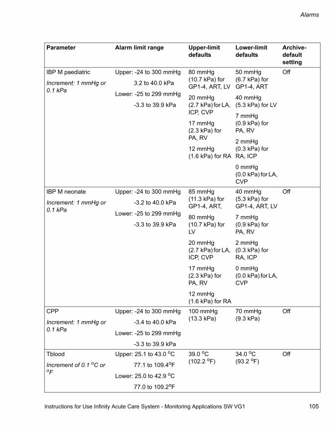
Instructions for Use Infinity Acute Care System - Monitoring Applications SW VG1 105
Alarms
IBP M paediatric
Increment: 1 mmHg or 0.1 kPa
Upper: -24 to 300 mmHg
3.2 to 40.0 kPa
Lower: -25 to 299 mmHg
-3.3 to 39.9 kPa
80 mmHg (10.7 kPa) for GP1-4, ART, LV
20 mmHg (2.7 kPa) for LA, ICP, CVP
17 mmHg (2.3 kPa) for PA, RV
12 mmHg (1.6 kPa) for RA
50 mmHg (6.7 kPa) for GP1-4, ART
40 mmHg (5.3 kPa) for LV
7 mmHg (0.9 kPa) for PA, RV
2 mmHg (0.3 kPa) for RA, ICP
0 mmHg (0.0 kPa) for LA, CVP
Off
IBP M neonate
Increment: 1 mmHg or 0.1 kPa
Upper: -24 to 300 mmHg
-3.2 to 40.0 kPa
Lower: -25 to 299 mmHg
-3.3 to 39.9 kPa
85 mmHg (11.3 kPa) for GP1-4, ART,
80 mmHg (10.7 kPa) for LV
20 mmHg (2.7 kPa) for LA, ICP, CVP
17 mmHg (2.3 kPa) for PA, RV
12 mmHg (1.6 kPa) for RA
40 mmHg (5.3 kPa) for GP1-4, ART, LV
7 mmHg (0.9 kPa) for PA, RV
2 mmHg (0.3 kPa) for RA, ICP
0 mmHg (0.0 kPa) for LA, CVP
Off
CPP
Increment: 1 mmHg or 0.1 kPa
Upper: -24 to 300 mmHg
-3.4 to 40.0 kPa
Lower: -25 to 299 mmHg
-3.3 to 39.9 kPa
100 mmHg (13.3 kPa)
70 mmHg (9.3 kPa)
Off
Tblood
Increment of 0.1 oC or oF
Upper: 25.1 to 43.0 oC
77.1 to 109.4oF
Lower: 25.0 to 42.9 oC
77.0 to 109.2oF
39.0 oC (102.2 oF)
34.0 oC (93.2 oF)
Off
Parameter Alarm limit range Upper-limit defaults
Lower-limit defaults
Archive-default setting

Alarms
106 Instructions for Use Infinity Acute Care System - Monitoring Applications SW VG1
Arrhythmia Ranges and Defaults
RRc
Increment of 1 bpm
Upper: 6 to 150 bpm
Lower: 5 to 149 bpm
30 bpm (adult)
60 bpm (paediatric/neonate)
5 bpm (adult)
20 bpm (paediatric/neonate)
Off
inCO2
Increment of 1 mmHg, 0.1 kPa, or 0.1%
Upper: 2 to 10 mmHg
0.3 to 1.3 kPa
0.3 to 1.3%
Lower: not user-selectable
4 mmHg (0.5 kPa, 0.5%)
Not applicable Off
etCO2
Increment of 1 mmHg, 0.1 kPa, or 0.1%
Upper: 6 to 100 mmHg
0.8 to 13.3 kPa
0.8 to 13.2%
Lower: 5 to 99 mmHg
0.7 to 13.2 kPa
0.7 to 13.0%
50 mmHg (6.7 kPa, 6.6 %)
30 mmHg (4.0 kPa, 3.9%)
Off
PVC/min
Increment of 1
Upper: 1 to 50 10 Not applicable Off
Parameter Alarm limit range Upper-limit defaults
Lower-limit defaults
Archive-default setting
Parameter Alarm grade default
Rate (default) Count (default) Alarm archive factory default
ASY High Not adjustable Not adjustable Store/record
VF High Not adjustable Not adjustable Store/record
VTACH High ≥ 100 to 200 (≥ 120)
Increments of 10
≥ 5 to 15 (≥ 10)
Increments of 1
Store/record
ARTF Off Not adjustable Not adjustable Off
RUN Medium Not adjustable (Rate = VTACH)
3 to VT count - 1 (3 to 9) changes based on VTACH
Store/record
AIVR Medium Not adjustable (= VTACH rate -1 (≤ 119)
Not adjustable (≥ 3) Off
SVT Medium ≥ 120 to 200 (≥ 150)
Increments of 10
≥ 3 to 10 (≥ 3)
Increments of 1
Store/record

Instructions for Use Infinity Acute Care System - Monitoring Applications SW VG1 107
Alarms
CPT Low Not adjustable Not adjustable Store/record
BGM Low Not adjustable Not adjustable Store/record
TACH Off ≥ 100 to 200 (≥ 130)
Increments of 10
≥ 5 to 15 (≥ 8)
Increments of 1
Off
BRADY Off ≤ 30 to 105
(adult ≤ 50; paediatric ≤60)
Increment of 5
Not adjustable
(≥ 8)
Off
PAUSE Off 1 to 3.5 (2.5)
Increments of 0.5
Not adjustable Off
Parameter Alarm grade default
Rate (default) Count (default) Alarm archive factory default

108 Instructions for Use Infinity Acute Care System - Monitoring Applications SW VG1
This page is intentionally left blank

Instructions for Use Infinity Acute Care System - Monitoring Applications SW VG1 109
Trends/Data Dialogue Windows
Trends/Data Dialogue Windows
Overview . . . . . . . . . . . . . . . . . . . . . . . . . . . . . 110
Trends . . . . . . . . . . . . . . . . . . . . . . . . . . . . . . . 110
Trending Behaviour . . . . . . . . . . . . . . . . . . . . . 111Special Characters and Symbols . . . . . . . . . . . 111
Trend Graphs . . . . . . . . . . . . . . . . . . . . . . . . . 112
The Trends Graph Page . . . . . . . . . . . . . . . . . 112
Accessing the Trends Graph Page. . . . . . . . . . 112
Available Functions on the Trends Graph Page . . . . . . . . . . . . . . . . . . . . . . . . . . . . . . . . . 113
Displaying the Trend Cursor. . . . . . . . . . . . . . . 113Changing Trend Scales . . . . . . . . . . . . . . . . . . 113Configuring the Trends Graph Page. . . . . . . . . 114Navigating Through the Trend Graphs . . . . . . . 114Printing a Graphical Trend Report . . . . . . . . . . 114
Trend Table . . . . . . . . . . . . . . . . . . . . . . . . . . . 115
Accessing the Trends Table Page . . . . . . . . . . 115
Available Functions on the Trends Table Page . . . . . . . . . . . . . . . . . . . . . . . . . . . . . . . . . 116
Configuring the Trends Table Page . . . . . . . . . 116Navigating Through the Trend Table . . . . . . . . 116Printing a Tabular Trend Report . . . . . . . . . . . . 116Tabular Trends in the Split-Screen Mode . . . . . 117
Graph Vitals Page . . . . . . . . . . . . . . . . . . . . . . 117
Accessing the Graph Vitals Page . . . . . . . . . . . 118Configuring the Graph Vitals Page . . . . . . . . . . 118Navigating Through the Graph Vitals Data. . . . 119Printing a Graph Vitals Report . . . . . . . . . . . . . 119
Mini-trends . . . . . . . . . . . . . . . . . . . . . . . . . . . 119
Configuring the Mini-Trend Display . . . . . . . . . 119
Labs Page . . . . . . . . . . . . . . . . . . . . . . . . . . . . 120
Accessing Laboratory Data . . . . . . . . . . . . . . . 120
Trends/Data Dialogue Windows
110 Instructions for Use Infinity Acute Care System - Monitoring Applications SW VG1
Overview
The Trends/Data dialogue window provides a comprehensive data review of the following data:
– Trends
– Laboratory data
– All ECG leads (see page 152)
– ST complexes (see page 163)
– Loops (see page 263)
– Haemodynamic calculations and results (see page 123)
Except for the trend data, all other data is also accessible in the individual parameter dialogue windows.
To access the Trends/Data dialogue window
1 Select the Trends/Data... button from the main-menu bar.
2 Select the desired tab to access the desired data (Trends, ECG, Respiratory/Ventilation, Hemo, Labs).
Trends
The Cockpit stores up to 96 hours of continuous and discrete trend values. Trend data is sampled every 30 seconds at the Cockpit where the trend display is updated automatically. Trend updates at the Cockpit are reflected on connected network devices every 60 seconds.
You can view trend data in a graphical or tabular format. You can also customise the trend display by selecting which parameters are displayed and by selecting the time period of the trended parameters.
The Cockpit maintains one trend database per patient. If you dock an M540 that was previously docked at another Cockpit, the trend data from the previous Cockpit is transferred over the network to the new Cockpit, provided a patient ID was entered.
If you undock an M540, trending is suspended on the Cockpit but the trend data remains intact. When you redock the M540, any new trend data collected during patient transport is transferred to the Cockpit. Transferring the trend data may take a brief moment, during which time trends are not accessible.
Refer to the Infinity Acute Care System - M540 Instructions for Use for a detailed description of the M540 trend functions.
Instructions for Use Infinity Acute Care System - Monitoring Applications SW VG1 111
Trends/Data Dialogue Windows
Trending Behaviour
A trended parameter can either be represented in a tabular or graphical format. The following sections explain how the different parameter groups are plotted in the graphical trends.
Continuous Parameters
The following parameters are continuously trended and appear as a single, continuous line, or band on the graphical trends (see page 25 for definitions of abbreviations):
– ECG parameters: HR, %paced, ST, PVC/min
– Respiratory parameters: RRi
– IBP parameters: for a complete list of invasive blood pressure parameters, see page 216.
– CO2 parameters: etCO2, inCO2, RRc
– C.O. parameter:Tblood
– Temperature parameters: Ta, Tb, ΔT, T1a, T1b, and ΔT1
– Continuous cardiac output parameters using the device connectivity option: SvO2, Tblood, CCO, CCI, VO2, DO2, SaO2, SVR, SVRI, EDV, EDVI, ESV, ESVI, EF, SV, SVI, SVV
– Ventilation parameters using the device connectivity option: PIP, MAP, PEEP, TVe, MVe, RRv, Pause, I:E, I:E I-Part, I:E, E-Part, inO2, Cdyn, Raw, PAW min, Occlusion Press, MVe s, RRs, Trapped Vol, AW-Temp, VCO2, TVd aw, TVD aw%, etCO2
– Pulse oximetry parameters: SpO2, PLS, PI (only for Masimo SET MCable)
Discrete Parameters
The following discrete parameters are plotted uniquely in graphical trends.
– NIBP consists of three lines forming a band showing the diastolic, mean, and systolic values.
– PWP and C.O. appear as crosshairs
– Laboratory data are shown as a single, continuous line with time stamps
Special Characters and Symbols
In addition to parameters, certain conditions, such as disconnected leads, artefacts, and so on, are also identified on graphical and tabular trends.
Event Character/SymbolAsystole ASY
Ventricular fibrillation VF
Apnoea APN
No parameter values are available
* * *
Out-of-range value +++ (high) - - - (low)
Relearning LRN
Interruption in power or patient is put into the standby mode.
No values

Trends/Data Dialogue Windows
112 Instructions for Use Infinity Acute Care System - Monitoring Applications SW VG1
Trend Graphs
A trend graph plots the behaviour of parameters over time. Trend graphs are continuously updated, with the most recent data appearing on the right
side of the Trends/Data dialogue. You can customise the content of the Trends Graph page by selecting which parameters are displayed.
The Trends Graph Page
The Trends Graph page contains up to four separate trend windows. Each trend window accommodates the trend graphs of up to five selectable parameters. For each parameter, the trend panel also displays trend scales, units of measure, and the parameter label.
The following diagram shows the Trends Graph page.
A Trends tab
B The Graph tab – accesses graphical trends
C The Table tab – accesses tabular trends
D The Graph vitals tab – accesses the graphical trends of a set of pre-configured trend parameters
E Trend setup symbol
F Scroll keys
G Print button
H The Grids on/off button
I The Graphs button
J The Views button
K The Trend windows
Directly below the Trend windows is a time scale that correlates with the selected time interval.
Accessing the Trends Graph Page
1 Select the Trends/Data... button from the main-menu bar.
2 Select the Trends tab (if not already selected).
3 Select the Graph tab (A) (if not already selected).
023
Trends/DataA
BCD
E
FGHIJ
K
K
K
K

Instructions for Use Infinity Acute Care System - Monitoring Applications SW VG1 113
Trends/Data Dialogue Windows
Available Functions on the Trends Graph Page
The Trends Graph page has several functions that allow you to interact with and customise the graphical trend display.
Displaying the Trend Cursor
The cursor is a vertical line that pinpoints a specific time for all parameters. It extends through all trend windows. Whenever you display the cursor, pop-ups appear next to each trend window. They display the parameter labels, units of measure and the parameter values that correspond to the position of the cursor. The top pop-up shows the exact time and date the cursor pinpoints on the graphs.
To display the cursor
1 Access the Graph page (see page 112).
2 Touch any point on the Graph page to display the cursor.
3 Use the rotary knob to move the cursor to a specific point on the trend data.
To hide the cursor
The cursor and the associated popups disappear automatically after a brief time of no user interaction. You can hide the cursor immediately as follows:
� Press the rotary knob.
Changing Trend Scales
The trend scales appear to the left of each trended parameter. You can change these scales at any time provided the trend cursor is not displayed. Hide the cursor by pressing the rotary knob before you change the trend scales.
To change the trend scales
1 Access the Graph page (see page 112)
2 Touch the trend scale value you wish to change. A trend scale window appears.
3 Select the buttons in the popup to adjust the upper and/or lower trend scale(s).
4 Use the rotary knob to dial to the desired setting.
5 Press the rotary knob to confirm your selection.

Trends/Data Dialogue Windows
114 Instructions for Use Infinity Acute Care System - Monitoring Applications SW VG1
Configuring the Trends Graph Page
The following sections list the various methods for customising the content of the Graph page. Refer to the diagram on page 112 for the locations of the buttons used to perform these setup functions.
To configure the Trends Graph page
1 Access the Graph page (see page 112).
2 Select the Grids on/off buttons (H) to display or hide the background grid.
3 Select the Graphs button (I) and use the rotary knob to select how many trend windows are displayed. You can select from 1 to 4 trend windows.
4 Use the View button (J) to select how much time is displayed on the Graph page. The available settings are: 1 h, 2 h, 4 h, 8 h, 12 h, 1 day, 2 days, 3 days, 4 days.
5 Select the trend setup symbol next to a trend window to activate the Setup dialogue window. You can select up to five parameters for each trend window. Select OK to confirm your selection.
6 Use the display filter button to toggle between displaying all parameters or only those parameters that are connected.
Navigating Through the Trend Graphs
The trend data base for a patient may contain more data than can be displayed on the Graph page. You can navigate through the entire trend data using the scroll bar. It is located below the trend graphs at the bottom of the Graph page.
The scroll bar consists of single- and double-arrow keys and a moveable navigation bar. The double arrows scroll through larger portions than the single arrows. If more trend data are stored than are currently displayed, you can also drag the navigation bar located between the arrows to the desired location. As you navigate through the trend data, the time line right above the scroll bar changes to display the time and date corresponding to the displayed graphs.
Printing a Graphical Trend Report
The content of a graphical trend report depends on the system setup (see page 290).
To print a graphical trend report
1 Access the Graph page (see page 112).
2 Scroll to the desired trend data.
3 Select the Print button (G) on the Trends Graph page (see page 112).
NOTEWhen you select certain parameters such as, for example, SpO2, a dialogue opens asking you for an additional selection. In such cases, select the OK button in the dialogue and in the Setup dialogue.
NOTEYou can also request a printout of the current graphical trends display by selecting the Print screen button on the main-menu bar.

Instructions for Use Infinity Acute Care System - Monitoring Applications SW VG1 115
Trends/Data Dialogue Windows
Trend Table
The trends table displays data columns. Trend data are updated according to the selected time scale. For example, if the current time scale is 15 minutes, the trend display is updated every 15 minutes. A time stamp above each column marks the interval during which the data in that column were collected. The displayed value is the last acquired value during that interval. The column on the right side is reserved for the most recent data. Certain parameters and special conditions, such as artefacts, are represented in unique ways (see page 111).
The following diagram shows the trends Table page which displays stored trend data in tabular format.
A Trends tab
B Parameter-label column
C The Parameters column
D Latest trend data
E The Graph tab (see page 112)
F The Table tab
G The Graph vitals tab (see page 117)
H Scroll keys and scroll bar
I Print button
J The Setup button
K The Views button
Accessing the Trends Table Page
1 Select the Trends/Data... Button on the main-menu bar.
2 Select the Trends tab (if not already selected).
3 Select the Table tab (G) (if not already selected).
024
AB E
FG
H
J
C C
IK
Trends/Data
C D
H

Trends/Data Dialogue Windows
116 Instructions for Use Infinity Acute Care System - Monitoring Applications SW VG1
Available Functions on the Trends Table Page
The Trends Table page has several functions that allow you to customise the tabular trend display.
Configuring the Trends Table Page
The following sections list the various ways available for customising the content of the Table page. Refer to the diagram depicting the Table (see page page 115) for the locations of the buttons used to perform the setup functions.
To configure the Trends Table page
1 Access the Table page (see page 112).
2 Select the trend setup symbol at the bottom of the Table page to display the Setup dialogue window. You can select the desired parameters and assign them to the tabular trend display.
The Auto-sort button in the dialogue window allows you to sort the parameter list according to the parameter priority list in the Auto view setup page (see page 53).
3 Use the View button (K) the time intervals of the trend columns. The available settings are: 1 min, 5 min, 10 min, 15 min (default), 30 min, 1 h.
Navigating Through the Trend Table
The trend data base for a patient may contain more data than can be displayed on the Table page. You can navigate through the entire trend data using the scroll bars. They are located at the bottom and along the right side of the Table page.
The scroll bars consist of single- and double-arrow keys and a moveable navigation bar. The double arrows scroll through larger portions than the single arrows. If more trend data are stored than are currently displayed, use the rotary knob or drag the navigation bar located between the arrow keys to the desired location.
Printing a Tabular Trend Report
The content of a tabular trend report depends on the system setup (see page 290).
To print a tabular trend report
1 Access the Table page (see page 112).
2 Scroll to the desired trend data.
3 Select the Print button (L).
NOTEYou can also request a printout of the current graphical trends display by selecting the Print screen button on the main-menu bar. The print screen prints on the connected laser printer.

Instructions for Use Infinity Acute Care System - Monitoring Applications SW VG1 117
Trends/Data Dialogue Windows
Tabular Trends in the Split-Screen Mode
You can display the tabular trends on the main screen by activating the split-screen mode for tabular trends in the Auto-view setup page.
When this split screen mode is activated, a tabular trend panel occupies the left side of the monitoring area. You can perform the same setup and viewing functions as for the regular tabular trends.
To activate the split-screen mode
1 Select the System setup... button from the main-menu bar.
2 Select the Auto-view tab.
3 Select the button next to the Split screen menu selection.
4 Dial to the Trend table selection using the rotary knob.
The layout of the monitoring area changes and displays the tabular trend panel.
Graph Vitals Page
The Cockpit has a pre-configured set of trends which are displayed on the Graphs vitals page. This set of parameters consists of parameters from the M540, if available.
This pre-configured display consists of the following set of commonly trended parameters displayed in four graphical windows:
Window 1 (top) HR, SpO2, and RRi
Window 2 NIBP
Window 3 Ta, Tb
Window 4 CO2

Trends/Data Dialogue Windows
118 Instructions for Use Infinity Acute Care System - Monitoring Applications SW VG1
The following diagram shows the Graph vitals page.
A Trends tab
B The Graph tab – accesses graphical trends
C The Table tab – accesses the trend table
D The Graph vitals tab – accesses the graphical trends of the vitals parameters
E Scroll keys and scroll bar
F Print button
G The Grids on/off button
H The Graphs button
I The Views button
Accessing the Graph Vitals Page
1 Select the Trends/Data... Button on the main-menu bar.
2 Select the Trends tab (if not already selected).
3 Select the Graph vitals tab (D).
Configuring the Graph Vitals Page
The following sections list the various methods for customising the content of the Graph vitals page. Refer to the diagram for the locations of the buttons used to perform these setups.
To configure the Graph Vitals page
1 Access the Graph Vitals page.
2 Select the Grids on/off buttons (G), to display or hide the background grid.
3 Select the Graphs button (H) and use the rotary knob to select how many trend windows are displayed. You can select from 1 to 4 trend windows.
4 Use the View button (I) to select how much time is displayed. The available settings are: 1 h, 2 h, 4 h, 8 h, 12 h, 1 day, 2 days, 3 days, 4 days.
025
AB
EFG
C
Trends/Data
D
HI

Instructions for Use Infinity Acute Care System - Monitoring Applications SW VG1 119
Trends/Data Dialogue Windows
Navigating Through the Graph Vitals Data
The trend data base for a patient may contain more data than can be displayed on the Graph vitals page. You can navigate through the entire trend data using the scroll bar. It is located below the trend graphs at the bottom of the Graph vitals page.
The scroll bar consists of single- and double-arrow keys and a moveable navigation bar. The double arrows scroll through larger portions than the single arrows. If more trend data are stored than are currently displayed, you can also manually drag the navigation bar located between the arrows to the desired location. As you navigate through the trend
data, the time line right above the scroll bar displays the time and date corresponding to the displayed graphs.
Printing a Graph Vitals Report
You can request a printout of the current graphs vital display.
To print a graph vitals report
1 Access the Graph vitals page (see page 112).
2 Scroll to the desired trend data.
3 Select the Print button (F) located in the lower-right corner of the Graph vitals page (see page 117).
Mini-trends
When the mini-trend display is enabled (see page 277), a panel appears to the left of the monitoring area of the main screen. The colours of the mini-trend correspond to the selected parameter colour. The mini-trend display is updated every 5 seconds.
Once activated, the mini-trend display is visible even when a dialogue window is displayed. A dialogue window always occupies the left side of the screen while the right side of the screen displays the real-time parameters including the mini-trends.
If you activate the split-screen mode (see page 278), the mini display is not affected and shifts to the right along with the real-time parameter display.
Configuring the Mini-Trend Display
In the System Setup dialogue, you can enable or disable the mini-trend display and select the mini-trend display duration. You can also select how the NIBP parameter appears in the mini-trends.
NOTEAlthough CCO, CCI, and Tblood are trended, there are no CCO parameters included in the mini-trend display.
NOTEIf the mini-trends are displayed, you can change the mini-trend scale and the duration by touching the displayed values. A pop-up appears, allowing you to change these settings directly.

Trends/Data Dialogue Windows
120 Instructions for Use Infinity Acute Care System - Monitoring Applications SW VG1
To configure the mini-Trend display
1 Select the System setup... button on the main-menu bar to activate the System setup... dialogue.
2 Select the Auto-view tab along the right side of the System setup dialogue.
3 Select the button next to Mini-Trends.
4 Select one of the following buttons: Off (disables the mini-trend display), 10 min, 15 min, 20 min, 30 min (default), 45 min, 1 h, 90 min, 2 h, 6 h, 12 h, 24 h.
5 Select the button next to NIBP Trend.
6 Use the rotary knob to select either Graphic or Numeric. The selected setting determines how the parameter is represented on the mini-trend display.
Labs Page
Laboratory data are sent to the Cockpit over the Infinity network. Whenever new laboratory data are available, the following happens at the Cockpit:
– An attention tone sounds provided the attention tone feature is enabled (see page 275).
– The message New lab data available appears in the header bar. This message disappears when you access the lab data.
Laboratory data are made available to the Infinity network and are accessible from the ICS, Infinity Gateway and other devices that support remote viewing capabilities.
Accessing Laboratory Data
1 Select the Trends/Data... button from the main-menu bar.
2 Select the Labs tab to display the Labs page.
3 Select a laboratory in the laboratory data selection field (A).
The detailed laboratory data are displayed in the laboratory results window (B).
The following diagram shows the Labs page. A Laboratory data selection field
B Laboratory results window (including category, label, value, units of measure, range, and time)
026
Trends/Data
A
B

Instructions for Use Infinity Acute Care System - Monitoring Applications SW VG1 121
Calculations
Calculations
Overview . . . . . . . . . . . . . . . . . . . . . . . . . . . . . 122
Calculating the Body Surface Area. . . . . . . . . . 122
The Calculation Page . . . . . . . . . . . . . . . . . . . 123
Performing Calculations . . . . . . . . . . . . . . . . . . 123
The Results Page . . . . . . . . . . . . . . . . . . . . . . 125
Viewing and Saving Calculations . . . . . . . . . . . 125
Laboratory Data . . . . . . . . . . . . . . . . . . . . . . . 126
Capturing Laboratory Data . . . . . . . . . . . . . . . . 126
Calculation Equations . . . . . . . . . . . . . . . . . . 127
Haemodynamic Parameters . . . . . . . . . . . . . . . 127Oxygenation and Ventilation Parameters . . . . . 129
Drug Calculations. . . . . . . . . . . . . . . . . . . . . . 131
The Drug Calculation Page . . . . . . . . . . . . . . 131
Performing Drug Calculations. . . . . . . . . . . . . . 132
Customised Drug List . . . . . . . . . . . . . . . . . . 132
Customising the Drug List . . . . . . . . . . . . . . . . 133
Drug Calculator Equations . . . . . . . . . . . . . . 134

Calculations
122 Instructions for Use Infinity Acute Care System - Monitoring Applications SW VG1
Overview
The Cockpit performs physiological calculations using data acquired by the M540 and other devices. The Cockpit stores derived parameters and displays them on the Results page.
When the Cockpit is connected to the network, you can obtain laboratory data through the Calculations page.
The Cockpit can also be configured to calculate drug-related parameters, including concentration, rate, total dose, and total volume.
In addition to these standard calculation features, two additional features are available with the PhysioCalcs software option:
– Haemodynamics – The Cockpit calculates haemodynamic parameters based on cardiac output, invasive blood pressure, and other data (see page 127).
– Haemo/Oxy/Vent Calculations – This locked option provides oxygenation, and ventilation calcualtions (see page 129) in addition to haemodynamic parameter calculations.
Calculating the Body Surface Area
The HT (height) and current WT (weight) values are used to compute the BSA (body surface area) in m2. For adult and paediatric patients, these values are pulled automatically from the Demographics page which is populated during patient admission (see page 66). Because of highly fluctuating body weight, you must enter the weight manually for neonates. This is to make sure that the most current value is used to calculate the BSA.
The BSA value is required for all indexed calculations, such as the cardiac index (CI). The available units for height are cm and inches. The available units for weight are kg, g, ounces, lb.
The following Boyd or DuBois equations are used to compute the BSA.
The Boyd equation is used for patients whose weight is less than15 kg and whose height is less than 80 cm:
BSA = WT(0.7285 - 0.0188 x (log10WT)) x HT0.3 x 0.0003207
The DuBois equation is used for all other patients:
BSA = WT0.425 x HT0.725 x 0.007184

Instructions for Use Infinity Acute Care System - Monitoring Applications SW VG1 123
Calculations
The Calculation Page
The following diagram shows the Calculation page for calculating haemodynamic, oxygenation, and ventilation parameters.
A The Calculations tab
B The Capture values button
C The Capture labs button (see page 126)
D The Capture results button (see page 125)
E The Results tab
F The Labs parameter buttons
G The Weight and Height buttons
H The BSA value
I The Oxygenation and Ventilation parameters
J The Haemodynamics parameter values
Performing Calculations
Calculations are based on automatically captured and on manually entered values. In paediatric and adult mode, the current height and weight used to compute the BSA value, are taken from the Admit page the first time you capture any values. In neonatal mode you must enter the weight manually. The height is taken from the Demographics page, if available.
027
A
B C D E
F
G
I
H
J
Procedures
NOTEBefore performing a calculation, measure pulmonary wedge pressure and cardiac output (if desired) because some of the calculated values cannot be determined without these parameter values.

Calculations
124 Instructions for Use Infinity Acute Care System - Monitoring Applications SW VG1
To perform a calculation
In the following steps, the letters in parentheses correspond to the diagram of the Calculation page (see page 123).
1 Select the Procedures... button on the main-menu bar.
2 Select the Calculations tab (if not already selected).
3 Select the Capture values button (B). The Cockpit populates the available parameter buttons with the current values.
4 Edit or add any value by selecting the button next to a parameter label to activate a pop-up with a keypad. The pop-up displays the valid range of the selected parameter. Any modified value is identified by the symbol #.
5 Select the Enter button on the keypad pop-up to confirm your input. Any value that has been altered manually is identified with the symbol #.
6 Repeat steps 4 and 5 for additional parameters.
7 Select the Calculate results button (D). The calculated values are listed in the Results page.
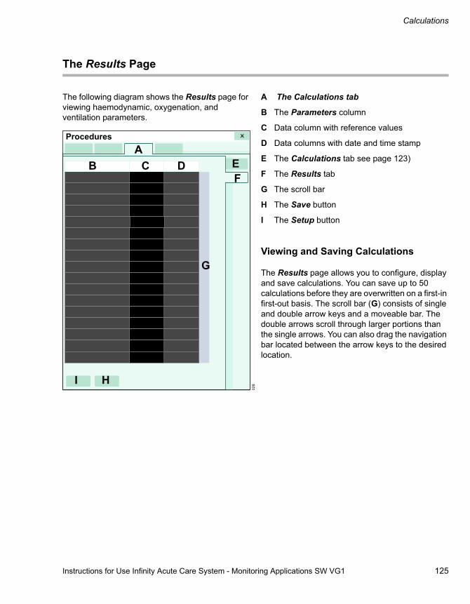
Instructions for Use Infinity Acute Care System - Monitoring Applications SW VG1 125
Calculations
The Results Page
The following diagram shows the Results page for viewing haemodynamic, oxygenation, and ventilation parameters.
A The Calculations tab
B The Parameters column
C Data column with reference values
D Data columns with date and time stamp
E The Calculations tab see page 123)
F The Results tab
G The scroll bar
H The Save button
I The Setup button
Viewing and Saving Calculations
The Results page allows you to configure, display and save calculations. You can save up to 50 calculations before they are overwritten on a first-in first-out basis. The scroll bar (G) consists of single and double arrow keys and a moveable bar. The double arrows scroll through larger portions than the single arrows. You can also drag the navigation bar located between the arrow keys to the desired location.
028
AB C D E
H
G
F
I
Procedures

Calculations
126 Instructions for Use Infinity Acute Care System - Monitoring Applications SW VG1
To view calculations
In the following steps, the letters in parentheses correspond to the diagram for the Results page (see page 125).
1 Select the Procedures... button on the main-menu bar.
2 Select the Calculations tab (if not already selected).
3 Select the Results tab (if not already selected).
4 Select the Setup button (I) to activate a pop-up window for selecting which parameters are included and excluded from display. The parameters on the dark background are selected for display, the ones on light backgrounds are not.
The Auto-sort button in the dialogue window allows you to sort the parameter list according to the parameter priority list in the Auto view
setup page (see page 53). If you add parameters to the parameter priority list, you must order these parameters manually.
5 Select the OK button in the pop-up window to confirm your selection. The list of parameters is adjusted accordingly on the Results page.
To save calculations
1 Select the Procedures... button on the main-menu bar.
2 Select the Calculations tab (if not already selected).
3 Select the Results tab.
4 Select the column of calculations you wish to save as the reference values. An orange frame highlights the selected column.
5 Select the Save button (H) to save the selected calculations.
Laboratory Data
You can include the laboratory data in calculations of the derived parameters.
Capturing Laboratory Data
The connected blood-analysis device determines which laboratory parameters are available. You can review the results on the Results page (see page 125). From there, you can also save the calculations and configure the display.
To capture the laboratory data
1 Select the Procedures... button on the main-menu bar.
2 Select the Calculations > Calculation tabs.
3 Select the Capture labs button (B) on the Calculation page (see page 123).

Instructions for Use Infinity Acute Care System - Monitoring Applications SW VG1 127
Calculations
Calculation Equations
The following section describes which monitored parameters and equations the Cockpit uses to calculate haemodynamic, oxygenation and ventilation calculations.
Haemodynamic Parameters
The Cockpit uses the following monitored parameter values for the haemodynamic calculations.
Label Description Available UnitsART S Systolic arterial pressure mmHg, kPa
ART M Mean arterial pressure mmHg, kPa
ART D Diastolic arterial pressure mmHg, kPa
CO, CCO Cardiac output (continuous, intermittent) L/min
CVP Central venous pressure mmHg, kPa
HR Heart rate bpm
PA M Mean pulmonary artery pressure mmHg, kPa
PWP Pulmonary capillary wedge pressure mmHg, kPa

Calculations
128 Instructions for Use Infinity Acute Care System - Monitoring Applications SW VG1
The Cockpit uses the values in the preceding table plus the BSA value to calculate the following derived haemodynamic values.
Label Description Equation Available UnitsCI, CCI Cardiac index
(continuous)CO / BSA, CCO / BSA L/min/m2
LHCPP Left heart coronary perfusion pressure
ART D - PWP mmHg, kPa
LVSW Left ventricular stroke work
0.0136 x (ART M - PWP) x SV g x m
LVSWI Left ventricular stroke work index
0.0136 x (ART M - PWP) x SVI g x m/m2
PVR Pulmonary vascular resistance
79.96 x (PA M - PWP) / CO) dyn x s/cm5
PVRI Pulmonary vascular resistance index
79.96 x ((PA M - PWP) / CI) dyn x s/cm5/m2
RPP Rate-pressure product ART S x HR mmHg/min
RVSW Right ventricular stroke work
0.0136 x (PA M - CVP) x SV g x m
RVSWI Right ventricular stroke work index
0.0136 x (PA M - CVP) x SVI g x m/m2
SV Stroke volume CO x 1000 / HR mL
SVI Stroke volume index 1000 x (CI / HR) mL/m2
SVR Systemic vascular resistance
79.96 x (ART M - CVP) / CO dyn x s/cm5
SVRI Systemic vascular resistance index
79.96 x (ART M - CVP) / CI dyn x s/cm5/m2
TPR Total pulmonary resistance
79.96 x PA M / CO dyn x s/cm5
TVR Total vascular resistance 79.96 x ART M / CO dyn x s/cm5

Instructions for Use Infinity Acute Care System - Monitoring Applications SW VG1 129
Calculations
Oxygenation and Ventilation Parameters
The Cockpit uses the following parameter values for the oxygenation and ventilation calculations. All of these calculations are monitored parameter values except for PaO2, PaCO2, Hgb and SaO2, which are laboratory values.
Label Description UnitsHgb Haemoglobin concentration g/dl
inO2 Inspired oxygen %
PaCO2 Arterial CO2 pressure mmHg
PaO2 Arterial oxygen pressure mmHg
Pause Pause (plateau) pressure cmH2O, mbar
Pb Barometric pressure mmHg, kPa
PeCO2 Mixed expired CO2 pressure mmHg
PEEP Peak end expiratory pressure cmH2O, mbar
PIP Peak inspiratory pressure cmH2O, mbar
RRc, RRv Respiratory rate, cardiac, venous /min
SaO2 Arterial oxygen saturation %
SpO2 Venous oxygen saturation %
TVe Expired tidal volume ml

Calculations
130 Instructions for Use Infinity Acute Care System - Monitoring Applications SW VG1
The Cockpit uses the values in the preceding table, the laboratory values, and the BSA value to calculate the following derived oxygenation and ventilation parameter values.
Label Description Derivation Available Units
C(a-v)O2 Arteriovenous oxygen difference
CaO2 - CvO2 ml/dl
CaO2 Arterial oxygen content 0.0134 x Hgb x SaO2 ml/dlCdyn Dynamic compliance TV e / (PIP - PEEP) ml/cmH2OCs Static lung compliance TV e / (Pause - PEEP) ml/cmH2OCvO2 Venous oxygen content 0.0134 x Hgb x SvO2 ml/dlDO2 Oxygen availability,
delivery, or transport10 x CaO2 x CO ml/min
DO2l Oxygen availability (or delivery) index
10 x CaO2 x CI ml/min/m2
MValv Alveolar minute volume (TVe - TV phy) x RR ml/minMVe Expired minute volume (TVe x RR) / 1000 L/minMV/CO Ventilation cardiac output
ratioMV alv / CO No units
O2ER Oxygen extraction ratio (CaO2 - CvO2) / CaO2 No unitsP(A-a)O2 Alveolar-arterial oxygen
differenceiO2 x (PB -47) - PaCO2 -PaO2 mmHg, kPa
Qs/Qt Intrapulmonary right-left shunt (percentage shunt)
%
TVd phy Tidal volume dead space (physiological)
TVe x (1 - PeCO2 / PaCO2) ml
TVd /TVphy Ratio of tidal volume dead space to tidal volume dead space (physiological)
Vd phy / TVe No units
VO2 Oxygen consumption 10 x C(a-v) O2 x CO ml/minVO2l Oxygen consumption
index10 x C(a-v) O2 x CI ml/min/m2
Hgb 1.34 0.0031 PAO2 CaO2–×+×Hgb 1.34 0.0031 PAO2 CvO2–×+×------------------------------------------------------------------------------------------------------ 100×
NOTEWhen multiple sources are available, the RR order of priority is RRi, RRc, RRv.

Instructions for Use Infinity Acute Care System - Monitoring Applications SW VG1 131
Calculations
Drug Calculations
The Cockpit calculates the infusion rates of up to 44 drugs and displays titration tables. Forty of these drugs are pre-configured and four can be customised for a specific patient session.
Information pertaining to patient-specific drugs is automatically deleted when you discharge the patient.
Data pertaining to default drugs is not deleted when a patient is discharged. For more information on how to create a customised drug list, see page 132.
The Drug Calculation Page
The following diagram shows the Drug Calculation page where you perform drug dosage calculations. Once you enter the required information, a titration table with the calculated dose and rate values appears.
A Select the drug list arrow button
B Setup button for customising the drug list (see page 132)
C Titration table
D Drug infusion parameter list
To access the Drug Calculation page
1 Select the Procedures... button on the main-menu bar.
2 Select the Drug dosage tab (if not already selected).
3 Select the Drug calculation tab (if not already selected).
029
AB
C
DE
Procedures

Calculations
132 Instructions for Use Infinity Acute Care System - Monitoring Applications SW VG1
Performing Drug Calculations
You can either select drugs from a pre-configured drug list (see page 132) or enter drugs manually to compute the desired dose and rate values and display them on the titration table (D).
To perform a drug calculation
In the following steps, the letters in parentheses correspond to the diagram for the Drug calculation page (see page 131).
4 Access the Drug calculation page (see page 131).
5 Select the arrow key (B) to activate the drug list containing pre-configured drugs.
6 Select the desired drug. The pre-configured values for amount, dose, and units are assigned to the drug infusion parameter list (E).
7 Add the other infusion parameters such as Rate by selecting the corresponding button and entering the values on the keypad.
8 Select Enter on the keypad to confirm your selection.
The titration table appears once you have entered the necessary information. The blue entry in the titration table corresponds to the entered value. The rest of the calculations are centred around this value.
Customised Drug List
Customising a drug list requires a clinical password. The drug list contains up to 40 drugs with the following pre-configured settings: the name, amount, volume, dose, and unit of measure. Once configured, a drug and its settings are stored as defaults and become available for selection in the Drug calculation page (see page 131).
The drug list also contains four ’untitled’ drugs which are available if the pre-configured drugs do not meet the current drug calculation needs. These drugs are place-holders for generic drug dosage calculations.

Instructions for Use Infinity Acute Care System - Monitoring Applications SW VG1 133
Calculations
The following diagram shows the Drug dosage setup page where you customise the drug list.
A The Drug Dosage tab
B The Select drug field and selection arrow
C The Edit drug name field
D The Setup tab
E The Amount button
F The Volume button
G The Dose units field and selection arrow
H The Save drug button
Customising the Drug List
Accessing the Drug dosage setup page requires a password. In the following steps, the letters in parentheses correspond to the diagram for the Drug dosage setup page.
To customise the drug list
1 Select the Procedures... button on the main-menu bar.
2 Select the Drug dosage > Setup tabs.
3 Enter the password on the keypad.
4 Select the Enter to display the Setup page.
5 Use the arrow in the Select drug field (B) to activate a list of existing drug names. Select an existing drug name for editing or an ’Untitled’ entry for adding a new drug name. The selected drug is assigned to the Edit drug name field (B).
6 Select the pencil symbol next to the Edit drug name field (C) to activate an on-screen keyboard.
7 Edit or enter a drug name using the on-screen keyboard. A maximum of 25 alphanumeric characters are available.
8 Select the Enter button on the keyboard.
9 Select the Amount button (E) to activate a pop-up with a keypad for adding the amount. Use the arrow symbol to activate a list of assigned units of measure.
10 Select the Enter button. The amount is assigned to the Amount field (E). The unit is assigned to the Dose units field (G).
11 Select the Volume button (F) to activate a pop-up with a keypad for adding the volume. Use the arrow symbol to activate a list of assigned units of measure.
12 Select the Enter button. The volume is assigned to the Volume field (F). The unit is assigned to the Dose units field (G).
13 Select the Save drug button (H) to save all of the drug and all of its attributes.
031
ABC D
EF
G
Procedures
H

Calculations
134 Instructions for Use Infinity Acute Care System - Monitoring Applications SW VG1
Drug Calculator Equations
The following table lists the variables and equations used to perform the drug rate calculations.
The following table lists the available ranges for each category on the Drug calculation page.
Variables Description EquationAmount The weight of the drug Concentration x volume
Volume The volume in which the drug is dissolved
Drug amount / concentration
Concentration Drug quantity / solution volume Drug amount / volume
Rate Infused volume per unit of time Dose / concentration
Duration The time over which the infusion is administered
User-selectable
Dose The amount of a drug the physician prescribes, standardised by weight and time
Rate x concentration
or
Rate x concentration / weight
Total dose Total dose over duration Dose x duration
Total volume Total volume over duration Rate x duration
Parameter Range and unitsWeight 0.1 kg to 350 kg (adult, paediatric)
1 g to 10000 g (neonate)
Amount 0.01 to 100,000,000,000 microgrammes (μg), m units, mEg, mmol
0.01 to 100,000,000 milligrammes (mg), units, mol
0.01 to 100,000 grammes (mg), k units
0.01 to 100 m units
Volume 0.01 to 10,000 ml
Concentration 0.01 to 100,000,000,000 μg/ml, m units/ml, mEg/ml, mmol/ml
0.01 to 100,000,000 mg/ml, units/ml, mol/ml
0.01 to 100,000 g/ml, k units/ml
0.01 to 100 m units/ml
Rate 0.01 to 10,000 ml/h
Duration 0.01 to 10,000 h

Instructions for Use Infinity Acute Care System - Monitoring Applications SW VG1 135
Calculations
Dose (per hour) 0.01 to 100,000,000,000 μg/h, mEq/h, m units/h, mmol/h
0.01 to 100,000,000 mg/h, units/h, mol/h
0.01 to 10,000 g/h, k units/h
0.01 to 100 m units/h
Dose (per minute) 0.01 to 1,666,666,666.66 μg/min, mEq/minh, m units/min, mmol/min
0.01 to 1,666,666.66 mg/min, units/min, mol/min
0.01 to 1,666.66 g/min, k units/min
0.01 to 1.66 m units/min
Dose/weight (per hour)
Adult and paediatric:
0.01 to 100,000,000,000, μg/kg/h, m units/kg/h, mmol/kg/h
0.01 to 100,000,000 mg/kg/h, units/kg/h, mol/kg/min or h
0.01 to 100,000 g/kg/h, k units/kg/h
0.01 to 100 m units/kg/h
Neonatal:
0.01 to 100,000,000,000, μg/g/h, m units/g/h, mEq/g/h, mmol/g/h
0.01 to 100,000,000 mg/g/h, units/g/h, mol/g/h
0.01 to 100,000 g/g/h, k units/g/h
0.01 to 100 m units/g/h
Dose/weight (per minute)
Adult and paediatric:
0.01 to 1,666,666,666.66 μg/kg/min, mEq/kg/min, m units/kg/min, mmol/min
Neonatal:
0.01 to 1,666,666,666.66 μg/g/min, mEq/g/min, m units/g/min, mmol/min
Adult, paediatric and neonatal:
0.01 to 1,666,666.66 mg/g/min, units/g/min
0.01 to 1,666.66 g/kg/min, k units/kg/min
0.01 to 1.66 m units/kg/min
Total dose 0.01 to 100,000,000,000 μg, m units, mEq, mmol
0.01 to 100,000,000 mg, units, mol
0.01 to 100,000 g, k units
0.01 to 100 m units
Total volume 0.01 to 10,000 ml
Parameter Range and units

136 Instructions for Use Infinity Acute Care System - Monitoring Applications SW VG1
This page is intentionally left blank

Instructions for Use Infinity Acute Care System - Monitoring Applications SW VG1 137
ECG, Arrhythmia, and ST Segment
ECG, Arrhythmia, and ST Segment
Overview of ECG and Heart Rate Monitoring . . . . . . . . . . . . . . . . . . . . . . . . . . . . 139
ECG Signal Processing and Display . . . . . . . . 139Supported Parameters . . . . . . . . . . . . . . . . . . . 139
ECG Precautions . . . . . . . . . . . . . . . . . . . . . . 140
Connecting the 3-, 5-, 6-Lead Wire Sets for ECG Monitoring . . . . . . . . . . . . . . . . . . . . . . . 140
Connecting the Lead Wire Set for 12-Lead Monitoring . . . . . . . . . . . . . . . . . . . . . . . . . . . . 141
Connecting the Lead Wires for Neonatal Monitoring . . . . . . . . . . . . . . . . . . . . . . . . . . . . 142
Patient Preparation for ECG Monitoring . . . 143
Electrosurgery . . . . . . . . . . . . . . . . . . . . . . . . . 143
ECG Display . . . . . . . . . . . . . . . . . . . . . . . . . . 144
ECG Parameter Box. . . . . . . . . . . . . . . . . . . . . 144ECG Waveforms. . . . . . . . . . . . . . . . . . . . . . . . 145
ECG Electrode Colours . . . . . . . . . . . . . . . . . 145
Electrode Placement . . . . . . . . . . . . . . . . . . . 146
Standard Configuration, Three Electrodes (IEC/AHA). . . . . . . . . . . . . . . . . . . . . . . . . . . . . 146Standard Configuration, Five Electrodes (IEC/AHA). . . . . . . . . . . . . . . . . . . . . . . . . . . . . 146Pacer Configuration, Five Electrodes (IEC/AHA). . . . . . . . . . . . . . . . . . . . . . . . . . . . . 147Standard Configuration, Six Electrodes (IEC/AHA). . . . . . . . . . . . . . . . . . . . . . . . . . . . . 14712-Lead Configuration, Ten Electrodes for 12-Lead Rest ECG Monitoring (AHA) . . . . . . . . . . 14812-Lead Configuration, Ten Electrodes for 12-Lead Rest ECG Monitoring (IEC) . . . . . . . . . . . 148
12-Lead Monitoring . . . . . . . . . . . . . . . . . . . . 149
Accessing the ECG Setup Page . . . . . . . . . . 149
ECG Parameter Setup Functions . . . . . . . . . 150
Monitoring Paced Patients . . . . . . . . . . . . . . 153
Pacemaker Precautions . . . . . . . . . . . . . . . . 154
Pacer Fusion Mode . . . . . . . . . . . . . . . . . . . . . 154Device Interference with Pacemaker Monitoring . . . . . . . . . . . . . . . . . . . . . . . . . . . . 155
Optimising Pacer Processing . . . . . . . . . . . 156
Arrhythmia Monitoring Overview. . . . . . . . . 156
Selecting ARR Leads . . . . . . . . . . . . . . . . . . 157
ARR Modes . . . . . . . . . . . . . . . . . . . . . . . . . . 157
ARR Display . . . . . . . . . . . . . . . . . . . . . . . . . . 159
Combined HR/ARR Parameter Box . . . . . . . . 159Separate ARR Parameter Box . . . . . . . . . . . . 159
Accessing the ARR Setup Page. . . . . . . . . . 160
ARR Parameter Setup Functions . . . . . . . . . 160
Monitoring ST Overview . . . . . . . . . . . . . . . . 161
Standard ST Monitoring . . . . . . . . . . . . . . . . 161
TruST 12-Lead Monitoring . . . . . . . . . . . . . . 162
12-Lead ST Monitoring . . . . . . . . . . . . . . . . . 162
Connecting Lead Wire Sets for ST Monitoring . . . . . . . . . . . . . . . . . . . . . . . . . . . 162
ST Display . . . . . . . . . . . . . . . . . . . . . . . . . . . 163
The ST-Complex Pages. . . . . . . . . . . . . . . . . 163
The General ST-Complex Pages . . . . . . . . . . 164Zooming in on an ST Complex . . . . . . . . . . . . 165
ST Measuring Points . . . . . . . . . . . . . . . . . . . 166
Adjusting ST Measuring Points . . . . . . . . . . . . 166
ST Reference . . . . . . . . . . . . . . . . . . . . . . . . . 166

138 Instructions for Use Infinity Acute Care System - Monitoring Applications SW VG1
ECG, Arrhythmia, and ST Segment
Saving ST Reference Points . . . . . . . . . . . . . . 166
ST Alarm Settings . . . . . . . . . . . . . . . . . . . . . 167
Accessing the ST Settings Setup Page . . . . 167
ST Setup Functions . . . . . . . . . . . . . . . . . . . . 168
Learning/Relearning QRS Pattern . . . . . . . . 170
Manual Relearning . . . . . . . . . . . . . . . . . . . . . . 170

Instructions for Use Infinity Acute Care System - Monitoring Applications SW VG1 139
ECG, Arrhythmia, and ST Segment
Overview of ECG and Heart Rate Monitoring
The M540 calculates and displays the heart rate, identifies paced beats, reports arrhythmia conditions, measures ST deviations, and relays these values to the Cockpit for display. ECG and heart rate monitoring is for adult, paediatric, and neonatal patients.
3-, 5-, 6-, and 10-lead wire sets are available for adult and paediatric ECG monitoring (including TruST). A neonatal ECG adaptor cable is available for connecting individual ECG leads for neonatal monitoring.
12-lead monitoring is of diagnostic quality and can be used with our optional Rest ECG analysis.
Refer to the Infinity Acute Care System - M540 Instructions for Use for a detailed description of the M540 ECG functions.
The ECG monitoring functions are configurable in the ECG setup pages (see page 150).
Before performing any monitoring functions, refer to the section "For Your Safety and That of Your Patients" starting on page 9.
ECG Signal Processing and Display
The M540 identifies QRS complexes with amplitudes between 0.2 mV and 5.0 mV and a QRS width of 70 ms to 120 ms for adult and paediatric patients. For neonates, the M540 identifies QRS complexes with widths between 40 ms to 100 ms. It calculates heart rates within a range of 15 beats to 300 beats per minute, using the R-R intervals of the last 10 seconds. This calculation excludes the two longest and the two shortest R-R intervals. The M540 averages the remaining intervals and displays the result as the current heart rate in the HR parameter box.
During dual-channel processing, a weight is assigned to each channel depending on its level of artefact. The cleaner channel always receives the greater weight. When a channel exceeds a certain level of artefact, it is excluded from the composite signal, and the M540 shifts to single-channel processing. If both channels experience excessive artefact, the message ECG Artefact appears until at least one channel is sufficiently free of artefact.
During an artifact, asterisks (* * *) replace the heart rate value. When the artefact clears, QRS processing resumes without initiating a relearning phase.
Arrhythmia monitoring and the selected arrhythmia mode affect the display of the HR parameter box. For detailed information, see "ARR Display" on page 159.
Parameter-specific error messages are listed in the chapter "Problem Solving" starting on page 325.
Supported Parameters
– ECG: HR (heart rate), %Paced (paced beats)
– ST STI, STII, STIII, STaVR, STaVL, STaVF, STV, STV+, STV1 to STV6, STVM, STCVM, STdV1, STdV3, STdV4, STdV6
– Arrhythmia ARR (ASY, VF, ARTF, VTACH, RUN, AIVR, SVT, CPT, BGM, TACH, BRADY, PAUSE; see page 157 for a description of these ARR modes) and PVC/min

ECG, Arrhythmia, and ST Segment
140 Instructions for Use Infinity Acute Care System - Monitoring Applications SW VG1
ECG Precautions
Refer to the following sections for general precautions:
– "Electrical Safety" on page 11
– "Electrosurgery" on page 14
– "Defibrillator Precautions" on page 13
Connecting the 3-, 5-, 6-Lead Wire Sets for ECG Monitoring
1 Insert the 3-,5-, or 6-lead wire set (B) into the recessed channel (A) on the side of the M540.
Orient the lead wire set so the exposed pins face towards you as you push it firmly into the channel.
2 Insert the spacer (C) to protect the unused ECG-lead pins.
3 Connect the lead wires to the patient. For information on applying the electrodes to the patient, refer to the illustrations starting on page 140.
WARNINGDo not select TruST leads for ECG signal processing. If the QRS morphology of a TruST lead differs from that of its equivalent conventional lead, always refer to the conventional lead.
WARNINGTo prevent patient injury, always verify the timing of the SYNC pulse before attempting cardioversion.
WARNINGDo not rely solely on the ECG when monitoring seizure-prone patients. Electrical artefacts of non-cardiac origin, such as a seizure, may prevent detection of certain arrhythmias.
312
A
BC

Instructions for Use Infinity Acute Care System - Monitoring Applications SW VG1 141
ECG, Arrhythmia, and ST Segment
Connecting the Lead Wire Set for 12-Lead Monitoring
1 Insert the 6-lead wire set (B) and the 4-lead wire set (C) into the recessed channel (A) on the side of the M540.
Orient the lead wire sets so the exposed pins face towards you as you push them firmly into the channel.
2 Connect the lead wires to the patient. For information on applying the electrodes to the patient, refer to the illustrations starting on page 140.
311
BC
A

ECG, Arrhythmia, and ST Segment
142 Instructions for Use Infinity Acute Care System - Monitoring Applications SW VG1
Connecting the Lead Wires for Neonatal Monitoring
1 Insert the ECG adaptor cable (B) into the recessed channel (A) on the side of the M540.
Orient the ECG adaptor cable so the exposed pins face towards you as you push it firmly into the channel.
2 Insert the spacer (C) to protect the unused ECG-lead pins on the M540.
3 Connect the individual neonatal ECG lead wires (E) to the neonatal ECG adaptor cable (D).
For information on applying the electrodes to the patient, refer to the illustrations starting on page 140.
313
A
BC
E
D
Instructions for Use Infinity Acute Care System - Monitoring Applications SW VG1 143
ECG, Arrhythmia, and ST Segment
Patient Preparation for ECG Monitoring
The following tips provide optimal ECG monitoring results, but must never replace hospital-approved practices or manufacturer’s recommendations.
Follow hospital procedures for proper skin preparation. Dräger recommends Ag/AgCl disposable electrodes. Never use disposable electrodes after their expiration date and make sure that there is enough gel and that the gel has not dried out.
P- and T-waves with amplitudes exceeding 0.2 mV can be interpreted as QRS complexes. To allow detection of low heart rate conditions under these circumstances, place the lead with the highest R-wave in channel ECG1. If P- and T-waves continue to be misinterpreted, reposition the electrodes or use a pulse oximeter to monitor the pulse rate.
To maintain a clear signal, change electrodes every 24 to 48 hours or more often when the following occurs:
– ECG signal degradation
– Excessive patient perspiration
– Skin irritation
The illustrations starting on page 140 show various ECG-electrode configurations. Consider the following when selecting the electrode sites:
– Surgery – keep electrodes as far from the surgical site as possible, while maintaining a clinically useful lead configuration. Place the cable and lead wires as far from the ESU as possible and perpendicular to the ESU cables.
– Burn Patients – use sterile electrodes. Clean the equipment thoroughly and follow hospital infection control procedures.
Electrosurgery
The integrated ESU suppression can improve the performance of the monitor during electrosurgery, reduces noise on ECG waveforms, and protects the patient from burns.
To minimise interference from the electrosurgical unit
1 Select the HR parameter box.
or
Select Sensor parameters... from the main-menu bar > ECG tab > Settings 2 tab.
2 Select ESU next to the Filter selection.
NOTE12-lead monitoring is not available when the ESU filter is enabled. Likewise, the ESU filter selection is not available when you are using 12-lead monitoring.

ECG, Arrhythmia, and ST Segment
144 Instructions for Use Infinity Acute Care System - Monitoring Applications SW VG1
ECG Display
On the Cockpit, the ECG display consists of:
– The ECG parameter box
– The ECG waveforms
– The Show all page that displays up to 12 leads
The ECG parameter box appears differently when you activate the arrhythmia monitoring. For more details, see page 159.
ECG Parameter Box
The ECG parameter box contains the following elements:
A Parameter label
B Upper/lower alarm limits or crossed-triangle symbol when alarms are turned off
C Heart rate value – during an artefact, asterisks (***) replace the HR value)
D A heart blip that flashes with each detected pulse (if the pacer detection is enabled, the symbol appears as when a paced beat is detected).
During brief artefact episodes, the parameter box does not display a heart rate value.
030
A
B
C
D

Instructions for Use Infinity Acute Care System - Monitoring Applications SW VG1 145
ECG, Arrhythmia, and ST Segment
ECG Waveforms
The ECG waveform contains the following elements:
A Lead label
B The selected waveform scale
C The message field indicating the filter and pacer setting. For example, the message Pacer off appears if you disable the pacer detection.
If the pacer detection is enabled (see page 151), blue pacer spikes identify paced beats. The pacer spikes are printed on strip recordings. Depending on the selected lead wire set and the ECG cable type, a waveform channel displays up to 3 ECG waveforms.
To select the number of leads and the lead wire set, see page 150.
ECG Electrode Colours
Electrodes are labeled and colour-coded according to IEC and AHA.
042
A B C
The lead wire set
Available ECG Leads
Three electrodes
I, II, or III
Five electrodes I, II, III, aVR, aVL, aVF, V (1)
Six electrodes Standard: I, II, III, aVR, aVL, aVF, V, V+ (1)
TruST: I, II, III, aVR, aVL, aVF, dV1, V2, dV3, dV4, V5, dV6 (2)
6 + 4 electrodes I, II, III, aVR, aVL, aVF, V1-V6 (3)
NOTE(1) V and V+ are chest leads(2) The letter ’d’ indicates a derived lead(3) Using a 6-lead and a 4-lead wire set provides
12 monitored ECG leads
IEC AHA/USL yellow LA black
F green LL red
R red RA white
C/C2 white/white and yellow V/V2 brown/brown and yellow
N black RL green
C+/C5 grey and white/white and black V+/V5 grey and brown/brown and orange
C6 white and violet V6 brown and violet
C4 white and brown V4 brown and blue
C3 white and green V3 brown and green
C1 white and red V1 brown and red

ECG, Arrhythmia, and ST Segment
146 Instructions for Use Infinity Acute Care System - Monitoring Applications SW VG1
Electrode Placement
Standard Configuration, Three Electrodes (IEC/AHA)
Standard Configuration, Five Electrodes (IEC/AHA)
314
315
316
317

Instructions for Use Infinity Acute Care System - Monitoring Applications SW VG1 147
ECG, Arrhythmia, and ST Segment
Pacer Configuration, Five Electrodes (IEC/AHA)
Standard Configuration, Six Electrodes (IEC/AHA)31
8
319
320 321

ECG, Arrhythmia, and ST Segment
148 Instructions for Use Infinity Acute Care System - Monitoring Applications SW VG1
12-Lead Configuration, Ten Electrodes for 12-Lead Rest ECG Monitoring (AHA)
12-Lead Configuration, Ten Electrodes for 12-Lead Rest ECG Monitoring (IEC)
324
322

Instructions for Use Infinity Acute Care System - Monitoring Applications SW VG1 149
ECG, Arrhythmia, and ST Segment
12-Lead Monitoring
The standard 12-lead monitoring is only available when you use a 6-lead and a 4-lead wire set. The 12-lead monitoring using a 10-lead wire set is a locked option that must be purchased separately. Place the chest electrodes in positions V1 through V6 as shown on page 146.
The TruST 12-lead monitoring offers real-time assessment of ST segment deviations with only six electrodes. TruST uses the conventional 6-lead standard electrode placement (see page 147),
measuring 8 leads and interpolating 4 chest leads. TruST is available in adult and paediatric modes, but not in neonatal mode.
You can view all ECG waveforms, including TruST, on the All Leads page (see page 152). For information on how to enable TruST, see page 152.
Accessing the ECG Setup Page
1 Select the HR parameter box to select the ECG setup page directly.
or
Select Sensor parameters... from the main-menu bar > ECG tab to access the ECG setup page. If you cannot see the tab, select the following two symbols located in the upper-right corner of the dialogue window: symbol and the display filter button.
2 Select the Setting1, Settings 2, Show all tabs.
The top portion of the page contains the Auto set and Alarm buttons for configuring the alarm functions. For detailed alarm setup information, see "Configuring a Patient’s Alarm Settings" on page 85.
WARNINGDo not select TruST leads for ECG signal processing. If the QRS morphology of a TruST lead differs from that of its equivalent conventional lead, always refer to the conventional lead.

ECG, Arrhythmia, and ST Segment
150 Instructions for Use Infinity Acute Care System - Monitoring Applications SW VG1
ECG Parameter Setup Functions
All ECG setup functions take place in the ECG setup dialogue.
Selection Available Settings DescriptionSettings 1 page
Pulse tone volume
Off, 5, 10 (default) to 100% in increments of 10%
Sets the volume of the pulse tone.
Tone source ECG (default), SpO2 Sets the source of the pulse tone.
HR source – ECG (default) – derives the heart rate from the ECG signal.
– ART – derives the heart rate from the arterial pressure signal. The HR parameter box label changes to APR and appears in the colour of ART.
– SpO2 – derives the heart rate from the pulse oximetry signal. The HR parameter box label changes to PLS and appears in the colour of SpO2.
– Auto – derives the heart rate either from the ECG signal or other available sources. If an ECG signal is not available, the M540 switches to ART, and then to SpO2.
Selects a different source for the heart rate when the ECG channel is unavailable due to an artefact resulting from surgical procedures.
Waveforms 1, 2 (default), 3 Selects the number of displayed waveforms.
Leads – Three electrodes: I, II, III
– Five electrodes: I, II, III, aVR, aVL, aVF, V
– Six electrodes: I, II, III, aVR, aVL, aVF, V, V+
– Six electrodes (with TruST enabled): I, II, III, aVR, aVL, aVF, dV1, V2, dV3, dV4, V5, dV6
– Ten electrodes: I, II, III, aVR, aVL, aVF, V1-V6
– Default for lead1: II
– Default for lead2: V (with TruST and a 10-lead wire sets, the default is: V2)
– Default for lead3: aVF
Assigns specific leads for each waveform depending on which lead mode is selected.
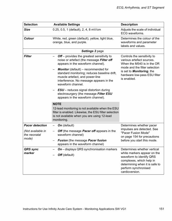
Instructions for Use Infinity Acute Care System - Monitoring Applications SW VG1 151
ECG, Arrhythmia, and ST Segment
Size 0.25, 0.5, 1 (default), 2, 4, 8 mV/cm Adjusts the scale of individual ECG waveforms.
Colour White, red, green (default), yellow, light blue, orange, blue, and purple.
Determines the colour of the waveforms and parameter labels and values.
Settings 2 page
Filter – Off – provides the greatest sensitivity to noise or artefact (the message Filter off appears in the waveform channel).
– Monitor (default) – recommended for standard monitoring; reduces baseline drift, muscle artefact, and power-line interference. No message appears in the waveform channel.
– ESU – reduces signal distortion during electrosurgery (the message Filter ESU appears in the waveform channel).
Controls the sensitivity to various artefact sources. When the M540 is in the OR mode and the filter selection is set to Monitoring, the hardware low-pass ESU filter is enabled.
Pacer detection
(Not available in the neonatal mode)
– On (default)
– Off (the message Pacer off appears in the waveform channel)
– Fusion (the message Pacer fusion appears in the waveform channel)
Determines whether pacer impulses are detected. See "Pacer Fusion Mode" on page 154 for precautions before you start this mode.
QRS sync marker
– On – displays QRS synchronisation markers
– Off (default)
Determines whether vertical white markers appear on the waveform to identify QRS complexes, which help in determining when it is safe to perform synchronised cardioversion.
Selection Available Settings Description
NOTE12-lead monitoring is not available when the ESU filter is enabled. Likewise, the ESU filter selection is not available when you are using 12-lead monitoring.

ECG, Arrhythmia, and ST Segment
152 Instructions for Use Infinity Acute Care System - Monitoring Applications SW VG1
Cable type
(TruST is only available with a 6-lead wire set)
– Auto detect (default)
– 3-, 5-, 6-electrodes, and 12 leads
When set to Auto detect, it detects automatically the number of connected lead wires. If the auto-detect mode does not detect the connected lead wire set, it allows you to select the cable type manually. "12" denotes a combination of a 6-lead and 4-lead wire set for 12-lead monitoring.
ARR Processing ECG1, ECG1 & 2 (default) ECG1 setting – arrhythmia processing occurs only on the lead displayed in the waveform channel 1.
ECG 1 & 2 settings – arrhythmia processing occurs on the leads displayed in the waveform channel 1 and 2.
Size all ECG 0.25, 0.5, 1 (default), 2, 4, 8 mV/cm Sets the amplitude of ALL displayed ECG leads.
TruST 12-lead
(Not selectable in the neonatal mode. TruST is only available when a 6-lead wire set is connected)
On, Off (default) Determines whether TruST monitoring is available.
Resp monitoring – On (default for neonate)
– Off (default for adult/paediatric)
Turns respiration monitoring on and off.
Show All page
This page displays all available leads (up to 12).
Selection Available Settings Description
NOTEThe ECG1 & 2 selection is not available if the neonatal patient category is selected.
Instructions for Use Infinity Acute Care System - Monitoring Applications SW VG1 153
ECG, Arrhythmia, and ST Segment
Monitoring Paced Patients
When the pacer detection is enabled, the M540 uses the following specifications to identify a pulse as a pacer pulse:
Amplitude: ±2 to ±700 mV Width (dp): 0.2 ms to 2.0 msRise/Fall times (min.): 0.1 dp, 100 msOvershoot (min.): 0.025 dp, 2 mVRecharge time constant: 4 ms to 100 ms
If a QRS complex occurs within 250 ms of a pacer impulse, it is also considered a paced beat. A paced beat is identified as followed:
– In the HR parameter box, the letter ’P’ appears next to the flashing heart symbol when a pacer pulse is detected.
– On the ECG waveform, blue spikes appear to identify pacer spikes.
When the pacer detection is disabled, the message Pacer off, appears in the top ECG channel.
To optimise the pacer monitoring, follow the guidelines on page 156.
To turn the pacer detection on/off
1 Select the HR parameter box to select the ECG setup page directly.
or
Select Sensor parameters... from the main-menu bar > ECG tab to access the ECG setup page.
2 Select the Settings 2 tab.
3 Select On next to the pacer detection.
NOTEThe pacer detection is disabled automatically in the neonatal mode or when the ESU filter is turned on.

ECG, Arrhythmia, and ST Segment
154 Instructions for Use Infinity Acute Care System - Monitoring Applications SW VG1
Pacemaker Precautions
The M540 has been tested for the pacer pulse rejection. However, it is impossible to anticipate every clinically possible waveform characteristic. For the paced patient, the M540 could, therefore, miscount heart rates and misinterpret rate-dependent arrhythmias. False low-rate alarms can result under the following conditions:
– Fused beats and asynchronous pacemakers when coupling intervals are in the range of +10 ms to -90 ms
– 700-mV pacer pulses followed by QRS complexes smaller than 0.5 mV
– Asynchronous pacemaker pulses with overshoot
Pacer Fusion Mode
Pacer Fusion mode offers increased detection sensitivity to fused paced beats, thereby reducing false asystole and low heart rate alarms.
WARNINGMake sure the pacer detection is turned OFF for patients without pacemakers. Make sure it is ON for patients with pacemakers. Disabling the pacemaker detection for paced patients may result in pacemaker pulses being counted as regular QRS complexes, which could prevent an asystole alarm from being detected. Always verify that the pacer detection status is correct for the patient. Be aware that setting the ECG filter option to ESU disables the pacemaker detection automatically.
WARNINGInterference from a monitor may cause some rate-adaptive implantable pacemakers to pace at unnecessarily high rates. Be extra-vigilant with patients when using these types of pacemakers.
WARNINGAlways keep pacemaker patients under close surveillance and monitor their vital signs carefully. – Do not assess the patient’s condition
exclusively from the heart and respiratory rate values that the monitor displays and the rate alarms that are generated. Heart rate meters may continue to count the pacemaker rate during cardiac arrest or some arrhythmias.
– Some pacemakers (especially external pacemakers with body surface electrodes) emit pulses with amplitudes far exceeding the 700 mV maximum amplitude specified for the M540. The M540 may incorrectly detect these large pacemaker pulses as valid QRS complexes and may fail to detect cardiac arrest.
WARNINGImpedance respiration and pacemaker detection are inoperative when the ESU Filter is selected. Refer to the Electrosurgery section for general safety precautions.
WARNINGPay close attention to the pacemaker patients being monitored in the 'Fusion' mode because this mode may increase the risk of falsely counting pacemaker spikes as QRS complexes, thus failing to detect cardiac arrest.

Instructions for Use Infinity Acute Care System - Monitoring Applications SW VG1 155
ECG, Arrhythmia, and ST Segment
Device Interference with Pacemaker Monitoring
The following devices can interfere with pacemaker monitoring.
Impedance-Derived Rate Response Pacemakers
These pacemakers emit pulses that adjust the pacemaker rate to the respiratory rate. These pulses could be falsely interpreted as pacer pulses. For impedance-derived rate response pacemakers, modify the electrode placement until the blue spikes on the waveform disappear since they are not related to real pacer impulses.
Infusion or Roller Bypass Pumps
Interference from these devices can cause pacer spikes to appear on the waveform although the ECG appears normal. To determine if the pump is the cause of the artefact, turn it off, if possible. To minimise the artefact, choose the lead with the best signal or replace the electrodes. Rerouting the invasive pressure tubing away from the infusion tubing can also improve the ECG signals.
Line Isolation Devices
To minimise the effect of line isolation devices, which can cause temporary disturbances in the ECG signal, follow these precautions:
– Choose the lead with the best signal for ECG monitoring.
– Check the ECG electrodes; replace them, if necessary.
Transcutaneous Electrical Nerve Stimulators
Signals from the transcutaneous electrical nerve stimulators (TENS) often resemble the pacer signals and can be labelled as such. The M540 can reject valid QRS complexes, which follow misinterpreted TENS signals. If the TENS signals continue to register as pacer spikes, turn off the pacer detection (see page 151).
CAUTIONThe fusion mode pacer detection is not intended for use with large-signal, unipolar pacemakers. It is intended for use only with biphasic pacemakers. Please observe the following:– Select the 'Fusion' mode only in situations
where it becomes necessary to suppress repeated false asystole and/or false low heart rate alarms.
– Before selecting the 'Fusion' mode, be certain that the patient has a biphasic pacemaker (external or implanted) and that it is accurately programmed as appropriate for that patient.
– Do not use the ’Fusion’ mode if you are uncertain as to what type of pacemaker is being used.
NOTEThe displayed heart rate may be incorrect if the pacemaker pulse wanders through the ECG waveform (ineffective pacing). During the wandering pacemaker test required by IEC 60601-2-27 and ANSI/AAMI EC13, the displayed heart rate varied between 15 and 30 bpm (rather than consistently being 30 bpm). The displayed heart rate was not affected by the presence of pacemaker pulses during any of the other standard pacemaker tests.

ECG, Arrhythmia, and ST Segment
156 Instructions for Use Infinity Acute Care System - Monitoring Applications SW VG1
Optimising Pacer Processing
You can minimise interference and optimise ECG signal acquisition and processing for paced patients.
To optimise the pacer processing
1 Select the HR parameter box to select the ECG setup page directly.
or
Select Sensor parameters... from the main-menu bar > ECG tab to access the ECG setup page.
2 Select the Settings 2 tab.
3 Select On next to the Pacer detection. Select the lead with the least interference and highest R-wave for display in ECG channel 1.
4 Select the Filter setting Monitor or OFF and determine which setting provides the clearest signal.
Arrhythmia Monitoring Overview
The M540 performs arrhythmia (ARR) monitoring on adult and paediatric patients and relays these values to the Cockpit for display. Arrhythmia monitoring is not available for neonates. To make sure that asystole and ventricular fibrillation alarms are reported even when HR alarm monitoring and arrhythmia monitoring are turned off, set the ASY/VF Alarms selection in the Alarms General settings page to Always On (see page 286).
The selected arrhythmia mode (see page 157) controls which arrhythmia parameters are monitored and how they are displayed.
Refer to the Infinity Acute Care System - M540 Instructions for Use for a detailed description of the M540 ARR functions.
The ARR monitoring functions have configurable parameter-specific setup pages (see page 160).
Before performing any monitoring functions, refer to the section "For Your Safety and That of Your Patients" starting on page 9.
WARNINGWhen the HR alarm and ARR monitoring is disabled, the monitor cannot generate ASY/VF alarms. To enable the ASY/VF alarms, set the ASY/VF alarms to “Always ON”.
NOTEThe banner HR Alarms Off appears in the rightmost field in the header bar whenever you turn the HR alarms off, or set the ASY/VF Alarm feature to Always On, or disable the HR alarm monitoring.
The HR, ASY, VF off banner appears when the arrhythmia monitoring is disabled, the ASY/VF Alarms feature is set to Follow HR Alarms, and the HR alarms are disabled.
NOTEIf the French NFC mode is enabled (see page 295), you cannot disable HR alarms.

Instructions for Use Infinity Acute Care System - Monitoring Applications SW VG1 157
ECG, Arrhythmia, and ST Segment
Selecting ARR Leads
An appropriate lead selection is essential for accurate ARR monitoring. It is ideal to assign the two best leads to the top two waveform channels. The following two options are available:
– ECG1 (single-channel option) – dedicates processing to the lead in the top channel.
– ECG 1 & 2 (Dual-channel option) – determines the heart rate and ARR based on the leads in the two top channels.
To select ARR Leads
1 Select the HR parameter box to select the ECG setup page directly.
or
Select Sensor parameters... from the main-menu bar > ECG tab to access the ECG setup page.
2 Select the Settings 2 tab.
3 Select the button next to ECG 1 or ECG1 & 2 and select the desired lead.
ARR Modes
If the ARR monitoring is enabled, the selected ARR mode (basic or advanced) determines how many events are monitored. When the ASY/VF alarm setting is set to Always on, asystoles and ventricular fibrillation events are always reported, even when the ARR monitoring is disabled.
The following table lists which ARR events are reported with each monitoring mode.
ARR monitoring off (the following events are detected, if at least one ECG is displayed)
ASY Asystole 4 seconds pass without the detection of a valid QRS complex.
VFIB Ventricular fibrillation The sinusoidal waveform with fibrillation characteristics.(1)
The basic ARR monitoring mode (the following additional events are detected)
VTACH Ventricular Tachycardia
N or more PVCs are detected in a time interval T = (60 * (N - 1)) / R, where N is the VT count and R is the VT rate. (2)
PVC Premature Ventricular Contraction
The PVC alarm limit is exceeded. The PVC parameter value represents the number of QRS complexes classified as PVCs over an 1-minute time interval.
ARTF Artefact More than 50% of beats in the last minute were classified as questionable.
The advanced ARR monitoring mode (the following additional events are detected)
BRADY Bradycardia Eight or more consecutive normal beats, with an average rate ≤ bradycardia rate setting. (3)
RUN Ventricular Run Series of 3 to N-1 consecutive PVCs with a beat-to-beat rate ≥ the VT rate. (2)

ECG, Arrhythmia, and ST Segment
158 Instructions for Use Infinity Acute Care System - Monitoring Applications SW VG1
To select the ARR modes
1 Select the HR parameter box to select the ECG setup page directly
or
Select Sensor parameters... from the main-menu bar > ECG tab to access the ECG setup page.
2 Select the ARR settings tab.
3 Select one of the following modes next to the ARR mode button, located below the arrhythmia alarm setup table:– Off – Basic– Advanced (option)
AIVR Accelerated Idioventricular Rhythm
Series of 3 or more PVCs with a rate less than the VT rate.
SVT Supraventricular Tachycardia
N or more consecutive normal beats, with a beat-to-beat rate greater than or equal to the SVT setting. (2)
CPT Ventricular Couplet Sequence of beats with the pattern: normal, PVC, PVC, normal.
The advanced ARR monitoring mode (the following additional events are detected)
BGM Ventricular bigeminy Sequence of beats with the pattern: normal, PVC, normal, PVC, normal.
TACH Tachycardia N or more consecutive normal beats, with a beat-to-beat rate ≥ TACH rate setting. (2) (4)
PAUSE Pause Sequence of two beats classified as normal or PVC, with an interval ≥ pause rate value in sec (±100 ms).
NOTE(1) Certain ventricular tachycardias have sinusoidal waveforms closely resembling ventricular fibrillation.
Because of the similarities between these waveforms, such types of ventricular tachycardia can be classified as ventricular fibrillation, the more serious of the two conditions.
(2) N is the event count set in the count column of the ARR setup table (see page 160).(3) In the neonatal mode, you set alarm limits for BRADY in the alarm setup page. The M540 alarms for
this event as a limit violation.(4) A PVC or another abnormal beat breaks the analysis sequence and restarts analysis.

Instructions for Use Infinity Acute Care System - Monitoring Applications SW VG1 159
ECG, Arrhythmia, and ST Segment
ARR Display
When the ARR monitoring is enabled, the ARR events appear in the HR parameter box or in a separate parameter box, depending on how many ECG leads are selected for display.
When the ARR monitoring is turned off (see page 158) and at least one ECG waveform is displayed, asystole and ventricular fibrillation events are still reported.
Combined HR/ARR Parameter Box
When one or two ECG leads are selected for display and the ARR monitoring is enabled, all ARR values and labels appear in the HR parameter box.
A HR parameter label
B ARR label
C Area reserved for actual event calls (for example, BRDY) or the message LEARN
D PVC/min label
E Upper/lower alarm limits or crossed-triangle symbol when alarms are turned off
F Number of Premature Ventricular Contractions (PVC) per minute
G Heart rate – during an artefact, asterisks (***) replace the HR value
H A heart blip that pulsates with each detected pulse (if the pacer detection is turned on, the symbol appears as when a paced beat is detected).
Separate ARR Parameter Box
When three ECG channels are selected for display and the ARR monitoring is enabled, all values and labels appear in a separate parameter box below the HR parameter box.
I ARR label
J PVC/min label
K Upper/lower alarm limits or crossed-triangle symbol when alarms are turned off
L Number of Premature Ventricular Contractions (PVC) per minute
M Area reserved for actual event call (for example, BRDY) or the message LEARN
NOTETo make sure that asystole and ventricular fibrillation alarms are reported even when the HR monitoring is turned off, set the ASY/VF Alarms selection in the Alarms general settings page to Always On(see page 286).
032
A B
CD
E
FG
H
033
I J
K
LM
ECG, Arrhythmia, and ST Segment
160 Instructions for Use Infinity Acute Care System - Monitoring Applications SW VG1
Accessing the ARR Setup Page
1 Select the HR parameter box to select the ECG setup page directly
or
Select Sensor parameters... from the main-menu bar > ECG tab to access the ECG setup page.
2 Select the ARR settings tab.
ARR Parameter Setup Functions
All ARR setup functions take place in the ARR setup page.
Selection Settings DescriptionThe ARR Mode Off, Basic (default), Advanced (locked option) Selects which events are
reported (see page 157 for more detail).
Relearn None Establishes a new QRS baseline.
Alarm functions See "Alarm Setup for Arrhythmia" on page 91 for details on the ARR alarm functions available.
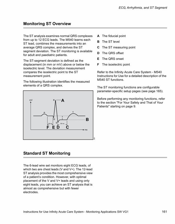
Instructions for Use Infinity Acute Care System - Monitoring Applications SW VG1 161
ECG, Arrhythmia, and ST Segment
Monitoring ST Overview
The ST analysis examines normal QRS complexes from up to 12 ECG leads. The M540 learns each ST lead, combines the measurements into an average QRS complex, and derives the ST segment deviation. The ST monitoring is available for adult and paediatric patients.
The ST-segment deviation is defined as the displacement (in mm or mV) above or below the isoelectric level. The deviation measurement compares the isoelectric point to the ST measurement point.
The following illustration identifies the measured elements of a QRS complex.
A The fiducial point
B The ST level
C The ST measuring point
D The QRS offset
E The QRS onset
F The isoelectric point
Refer to the Infinity Acute Care System - M540 Instructions for Use for a detailed description of the M540 ST functions.
The ST monitoring functions are configurable parameter-specific setup pages (see page 165).
Before performing any monitoring functions, refer to the section "For Your Safety and That of Your Patients" starting on page 9.
Standard ST Monitoring
The 6-lead wire set monitors eight ECG leads, of which two are chest leads (V and V+). The 12-lead ST analysis provides the most comprehensive view of a patient’s condition. However, with optimal placement of the V and V+ leads and using only eight leads, you can achieve an ST analysis that is almost as comprehensive but with fewer electrodes.
326
A
B
CDE F
ECG, Arrhythmia, and ST Segment
162 Instructions for Use Infinity Acute Care System - Monitoring Applications SW VG1
TruST 12-Lead Monitoring
This feature offers real-time assessment of 12 ST-segment deviations, with only six electrodes, which provide eight measured ECG leads and four derived chest leads. The derived leads are identified by adding the letter ‘d’ before the lead label. When TruST monitoring is enabled, the V-
lead defaults to V2 and the V+ lead defaults to V5. Although you can select derived leads for display, they are excluded from ARR and QRS processing.
ECG and ST reports contain the label ’d’ to identify a derived lead.
12-Lead ST Monitoring
During the 12-lead ST monitoring, the M540 acquires 12 ST leads in addition to the following:
– ST Vector Magnitude (STVM) — the magnitude (mm or mV) of the ST vector. It is a summary vector, combining the ST values from all 12 leads. STVM is trended and has its own alarm limits.
– ST Change in Vector Magnitude (STCVM) – the change of magnitude (mm or mV) between the current ST vector and the ST vector at the time of the last reference. STCVM values also show a change in the location of the ST vector over time.
To enable or disable ST Monitoring
You can turn the ST monitoring on or off at any time.
1 Select the HR parameter box to select the ECG setup page directly
or
Select Sensor parameters... from the main-menu bar > ECG tab to access the ECG setup page.
2 Select the ST settings tab.
3 Select On or Off next to ST monitoring.
Connecting Lead Wire Sets for ST Monitoring
The ST monitoring uses the following lead configurations for each available ST monitoring mode:
– Standard ST monitoring – uses the standard 3-, 5-, and 6-lead wire sets. For more information, see the diagrams starting on page 146).
– TruST – provides 12-lead ST monitoring with a 6-lead wire set (see page 140).
– 12-lead ST monitoring – uses the standard 12-lead ECG configuration with ten electrodes (see page 140).

Instructions for Use Infinity Acute Care System - Monitoring Applications SW VG1 163
ECG, Arrhythmia, and ST Segment
ST Display
When the ST alarms are enabled, the Cockpit alarms for all ST leads whether they are displayed or not. In either case, the ST parameter box flashes and the alarming lead is identified in the header bar.
When the ST monitoring is turned on, the current ST values are displayed in a separate parameter box below the HR parameter box.
A Selected ST lead labels
B Upper/lower alarm limits or crossed-triangle symbol when alarms are turned off
C Selected ST deviation values
D Unit of measure (can be turned on or off)
The ST-Complex Pages
You can view all ST complexes or zoom in on a single ST complex to view it in greater detail.
The following functions are available in either view:
– Changing the ISO point
– Changing the ST measuring point
– Relearning the QRS morphology
– Saving a reference complex
– Requesting an ST report
In all trends, a solid white vertical line on the ST trend graphs marks changes in ST measuring points along with a time stamp.
034
A A A
B
CCC
D

ECG, Arrhythmia, and ST Segment
164 Instructions for Use Infinity Acute Care System - Monitoring Applications SW VG1
The General ST-Complex Pages
The following diagram shows the ST complexes page. The number of displayed ST complexes depends on the connected lead wire set.
A The ECG tab
B The ST complex tab
C The Save reference button
D The Print button for generating an ST report
E The ST button
F The Reference On/Off button
G The ISO button
H The Relearn button
I ST panels for each monitored ST lead (including amplitude, ST measuring point, ISO point, and reference point)
J The ST label (unique for each ST lead)
To access the ST Complex page:
1 Select the HR parameter box to select the ECG setup page directly
or
Select Sensor parameters... from the main-menu bar > ECG tab to access the ECG setup page.
2 Select the ECG tab (if not already selected).
3 Select the ST complex tab (if not already selected).
035
Sensor parameters A
B
I
J
CD
EF
GH

Instructions for Use Infinity Acute Care System - Monitoring Applications SW VG1 165
ECG, Arrhythmia, and ST Segment
Zooming in on an ST Complex
The following diagram shows a single ST complex when you zoom in on one ST complex. To zoom in on a single ST complex, touch an ST panel on the ST complexes page (see page 164).
A The ECG tab
B Amplitude
C The ST complex tab
D The Save reference button – saves the displayed ST complex as a reference point
E The Print button for printing an ST report
F The Reference On/Off button
G The ST button
H The Lead button for selecting the desired lead
I The ISO button
J The Show all button – accesses the general ST-complexes screen
K The Relearn button (see page 170)
L The ST label (unique for each ST lead)
036
ASensor parameters
B
C
DE
GFH
IJK
L

ECG, Arrhythmia, and ST Segment
166 Instructions for Use Infinity Acute Care System - Monitoring Applications SW VG1
ST Measuring Points
You can change the ST measuring points and isoelectric point from the general or from the single ST-complexes page (see illustrations on page 164). In both pages, the setup buttons for changing the measuring points are located at the bottom of the screen. Changing the measuring point of one complex adjusts the measuring points for all ST complexes.
Adjusting ST Measuring Points
Whenever you adjust the isoelectric and ST measuring points, the ST deviation is recomputed. During this computation, the changing ST-deviation values appear yellow. The values appear green when the computation is completed.
To change the ST measuring points
1 Select the HR parameter box to select the ECG setup page directly
or
Select Sensor parameters... from the main-menu bar > ECG tab to access the ECG setup page.
2 Select the ST complex tab (C) to display the general ST-complexes page.
3 Select an individual ST panel to zoom in on a single ST complex.
4 Select the ISO button (I) and use the rotary knob to dial to the desired setting.
5 Select the ST button (G) and use the rotary knob to adjust the ST measuring.
ST Reference
You can save the ST reference complexes as reference points for future ST deviation measurement comparisons. The first time you relearn the QRS complexes, the current ST data are saved as reference data. The original ST reference data are updated each time you save the ST references.
Saving ST Reference Points
You can save the ST reference from the general ST-complexes page (see page 164) and the single ST-complex page (see page 163). Saving a reference point in either screen, saves all currently displayed ST complexes as reference points.
To save the ST reference points
1 Select the HR parameter box to select the ECG setup page directly
or
Select Sensor parameters... from the main-menu bar > ECG tab to access the ECG setup page.
2 Select the ST complex tab to display the general ST-complexes page.
3 Select an individual ST panel to zoom in on a single ST complex.
4 Select the Save reference button (in either ST complex page) and use the rotary knob to dial to the desired setting.

Instructions for Use Infinity Acute Care System - Monitoring Applications SW VG1 167
ECG, Arrhythmia, and ST Segment
ST Alarm Settings
The ST alarms setup page allows you to configure the following ST-specific alarm settings:
– Enabling or disabling the individual ST alarms
– Setting the upper and lower ST alarm limits
– Configuring the alarm archive function
– Auto-setting all ST limits
For more detailed information on how to configure these functions, see "Alarm Setup for ST" on page 93.
To access the ST alarm setup page:
1 Select the HR parameter box to select the ECG setup page directly
or
Select Sensor parameters... from the main-menu bar > ECG tab to access the ECG setup page.
2 Select the ST alarms tab to display the setup page.
Accessing the ST Settings Setup Page
1 Select the HR parameter box to select the ECG setup page directly
or
Select Sensor parameters... from the main-menu bar > ECG tab to access the ECG setup page.
2 Select the ST settings tab.
ECG, Arrhythmia, and ST Segment
168 Instructions for Use Infinity Acute Care System - Monitoring Applications SW VG1
ST Setup Functions
All ST setup functions take place in the ST settings setup page.
Selection Available Settings Description
ST monitoring
Not available in the neonatal mode
On (default), Off Turns the ST monitoring on/off and determines whether an ST parameter box is displayed and ST parameters are trended.
TruST 12-lead
TruST is only available with a 6-lead wire set.
On, Off (default) Turns the TruST monitoring on or off (see page 155).
ST relearn
(not available if ECG is not connected, in the neonatal mode, or ST monitoring is Off)
Not applicable Purges stored average ST complexes, blanks displayed average ST complexes, and learns the arrhythmia and dominant QRS pattern.
ST lead1
ST lead 2
ST lead 3
– Three electrodes: STI, STII,STIII
– Five electrodes: STI, STII, STIII, STaVR, STaVL,STaVF, STV
– Six electrodes: STI, STII, STIII, STaVR, STaVL,STaVF, STV, STV+
– Six electrodes (with TruST enabled): STI, STII, STIII, STaVR, STaVL,STaVF, STdV1, STV2, STdV3, STdV4, STV5, STdV6
– Ten electrodes: STI, STII, STIII, STaVR, STaVL,STaVF, STV1, STV2, STV3, STV4, STV5, STV6, STCVM, and STVM
– Default for ST lead1: STI
– Default for ST lead2: STaVL
– Default for ST lead3: STV (with TruST and a 10-lead wire sets, the default is: STV2)
Selects an ST lead for analysis and display.

Instructions for Use Infinity Acute Care System - Monitoring Applications SW VG1 169
ECG, Arrhythmia, and ST Segment
Event duration Off, 15, 30, 45, 60 (default) sec Defines a period during which an alarm condition must persist before alarm signals are generated.
ST Mini Trend – Three electrodes: STI, STII,STIII
– Five electrodes: STI, STII, STIII, STaVR, STaVL,STaVF, STV
– Six electrodes: STI, STII, STIII, STaVR, STaVL,STaVF, STV, STV+
– Six electrodes (with TruST enabled): STI, STII, STIII, STaVR, STaVL,STaVF, STdV1, STV2, STdV3, STdV4, STV5, STdV6
– Ten electrodes: STI, STII, STIII, STaVR, STaVL,STaVF, STV1, STV2, STV3, STV4, STV5, STV6, STCVM, and STVM
– Default: STII
Selects an ST lead for inclusion in the ST mini-trend display.
Selection Available Settings Description

ECG, Arrhythmia, and ST Segment
170 Instructions for Use Infinity Acute Care System - Monitoring Applications SW VG1
Learning/Relearning QRS Pattern
The M540 creates a reference template by learning the dominant QRS pattern of a patient. The reference template is stored for reference and all subsequent beats and rhythms are compared against it and classified either as normal or irregular.
The M540 can only learn the QRS pattern of the leads that are selected for ARR processing. If only one lead is available, the M540 only learns on one lead. If no lead wire set is connected, the M540 cannot perform a learning phase. In this case, an error message is displayed.
The M540 starts a learning phase automatically when:
– ARR monitoring is turned on
– A different ARR mode is selected
– Different ECG leads are selected for ARR processing
– The cable type is changed
During the learning phase, which lasts approximately 30 to 40 seconds, the message ARR Relearning appears in the message field. In addition, and message LEARN appears in the ECG parameter box.
If ST monitoring is turned on, ST deviations are also recomputed during the learning phase.
Manual Relearning
Relearn the QRS pattern of a patient when:
– Leads are reconnected or electrodes are repositioned.
– Eight hours have passed since the last learning phase.
– Questionable ARR calls appear on the ECG.
– Other significant changes appear on the ECG.
You can initiate a relearning phase from the arrhythmia and the ST-setup pages.
To relearn from the ARR-setup page
1 Select the HR parameter box to select the ECG-setup page
or
Select Sensor parameters... from the main-menu bar > ECG tab to access the ECG setup page.
2 Select the ARR settings tab.
3 Select Relearn.
To relearn from the ST-setup page
1 Select the HR parameter box to select the ECG-setup page
or
Select Sensor parameters... from the main-menu bar > ECG tab to access the ECG setup page.
2 Select the ST settings tab.
3 Select Relearn.

Instructions for Use Infinity Acute Care System - Monitoring Applications SW VG1 171
Impedance Respiration (RRi)
Impedance Respiration (RRi)
Overview of Respiration Monitoring. . . . . . . 172
Supported Parameters . . . . . . . . . . . . . . . . . . . 172
Respiration Precautions . . . . . . . . . . . . . . . . 172
Connecting the 3-, 5-, 6-Lead Wire Sets for RRi Monitoring . . . . . . . . . . . . . . . . . . . . . 173
Connecting the Lead Wire Set for 12-Lead Monitoring . . . . . . . . . . . . . . . . . . . . . . . . . . . . 174
Connecting the Lead Wires for Neonatal Monitoring . . . . . . . . . . . . . . . . . . . . . . . . . . . . 175
Patient Preparation for Respiration Monitoring . . . . . . . . . . . . . . . . . . . . . . . . . . . . 175
Respiration Display . . . . . . . . . . . . . . . . . . . . 176
Respiration Parameter Box . . . . . . . . . . . . . . . 176Respiration Markers . . . . . . . . . . . . . . . . . . . . . 177
Adjusting the Detection Threshold and Turning on the Respiration Marker . . . . . . . . 177
Respiration Measuring Modes . . . . . . . . . . . 178
Accessing the Respiration Setup Page . . . . 178
Respiration Parameter Setup Functions . . . 179

Impedance Respiration (RRi)
172 Instructions for Use Infinity Acute Care System - Monitoring Applications SW VG1
Overview of Respiration Monitoring
The M540 measures the impedance respiration by passing a harmless high-frequency current between two ECG electrodes on the chest of the patient. The electrical resistance (impedance) between the electrodes varies with the expansion and contraction of the chest during inspiration and expiration. The M540 displays a respiration waveform and respiratory rate value from these impedance changes and relays this information to Cockpit for display.
The M540 uses ECG leads I or II for breath detection, regardless of the lead selected for QRS processing.
The respiration monitoring is for adult, paediatric and neonatal patients. The M540 can use the respiration signal for central apnoea monitoring.
Refer to the Infinity Acute Care System - M540 Instructions for Use for a detailed description of the M540 respiration functions.
The RRi monitoring functions are configurable in the parameter-specific setup page (see page 178).
Before performing any monitoring functions, refer to the section "For Your Safety and That of Your Patients" starting on page 9. Parameter-specific error messages are listed on page 332.
Supported Parameters
RRi – the respiration rate measured by impedance (RRi values is not displayed when the ESU filter is enabled – see page 151).
Respiration Precautions
WARNINGThe safety and effectiveness of the respiration measurement method in the detection of apnoea, particularly the apnoea of prematurity and apnoea of infancy, have not been established.
WARNINGThis device does not monitor obstructive apnoea. Patients at risk for respiratory crises should be observed closely.
WARNINGThe large amplitude pacemaker pulses (100 mV or greater) may interfere with the monitor ability to measure or detect respiration.
WARNINGThe monitor reports an apnoeic event when no breaths are reported within the established apnoea period. Therefore, do not rely on impedance respiration monitoring as the sole method for detecting cessation of breathing. Dräger Medical recommends the monitoring of additional parameters that indicate the patient’s oxygenation status, such as etCO2 and SpO2. Heart rate limit alarms should also be enabled and set appropriately.
WARNINGImpedance respiration and pacemaker detection are inoperative when the ESU Filter is selected. Refer to the Electrosurgery section for general safety precautions.

Instructions for Use Infinity Acute Care System - Monitoring Applications SW VG1 173
Impedance Respiration (RRi)
Connecting the 3-, 5-, 6-Lead Wire Sets for RRi Monitoring
1 Insert the 3-,5-, or 6-lead wire set (B) into the recessed channel (A) on the side of the M540.
Orient the lead wire set so the exposed pins face towards you as you push it firmly into the channel.
2 Insert the spacer (C) to protect the unused ECG-lead pins.
3 Connect the lead wires to the patient. For information on applying the electrodes to the patient, refer to the illustrations starting on page 146.
312
A
BC

Impedance Respiration (RRi)
174 Instructions for Use Infinity Acute Care System - Monitoring Applications SW VG1
Connecting the Lead Wire Set for 12-Lead Monitoring
1 Insert the 4-lead wire set (B) and the 6-lead wire set (C) into the recessed channel (A) on the side of the M540.
Orient the lead wire sets so the exposed pins face towards you as you push them firmly into the channel.
2 Connect the lead wires to the patient. For information on applying the electrodes to the patient, refer to the illustrations starting on page 146.
311
B C
A

Instructions for Use Infinity Acute Care System - Monitoring Applications SW VG1 175
Impedance Respiration (RRi)
Connecting the Lead Wires for Neonatal Monitoring
1 Insert the ECG adaptor cable (B) into the recessed channel (A) on the side of the M540.
Orient the ECG adaptor cable so the exposed pins face towards you as you push it firmly into the channel.
2 Insert the spacer (C) to protect the unused ECG-lead pins on the M540.
3 Connect the individual neonatal ECG lead wires (E) to the neonatal ECG adaptor cable (D).
For information on applying the electrodes to the patient, refer to the illustrations starting on page 146.
Patient Preparation for Respiration Monitoring
The following tips regarding the skin preparation and proper electrode placement provide strong signals with minimal artefact, but must never replace hospital-approved practices or manufacturer’s recommendations. Because ECG electrodes are used for respiration monitoring, see illustrations starting on page 146 for information on electrode placement.
Follow the same precautions for respiratory monitoring as for ECG monitoring (see page 140) and observe the following general recommendations:
– Place the electrodes so they generate the clearest possible signals with minimal artefact.
– Electrodes that adhere tightly and have a large conductive area provide the best results. Use a 5-lead wire set to improve the respiration signal (where the F electrode for IEC or RL electrode for AHA is the neutral electrode).
313
A
BC
E
D

Impedance Respiration (RRi)
176 Instructions for Use Infinity Acute Care System - Monitoring Applications SW VG1
– For adult and paediatric patients, position the electrodes to span the maximum expansion and contraction of the lungs. This is especially important in the case of deep abdominal breathers.
– For neonates, place the RA and LA electrodes at the midaxillary line. Position the LL electrode below the diaphragm and umbilicus. Avoid the liver area and ventricles of the heart to prevent blood flow artefact.
Respiration Display
On the Cockpit, the respiration display consists of:
– Respiration parameter box
– Respiration waveform
Respiration parameter box
The respiration parameter box contains the following elements:
A Impedance respiration rate label (RRi)
B Upper/lower alarm limits or crossed-triangle symbols if alarms are turned off
C The respiratory rate value
D The lung symbol that blinks with each detected breath
327
328
037
A
B
C
D

Instructions for Use Infinity Acute Care System - Monitoring Applications SW VG1 177
Impedance Respiration (RRi)
Respiration Markers
The following diagram shows how white vertical markers on the respiration waveform can identify each detected breath. To enable or disable the display of respiration markers, see page 178.
Respiration markers indicate the time of breath detection, not the beginning, or end of respiration. If respiration markers also appear during an artefact, set the respiration measuring mode to manual and adjust the breath detection threshold so only valid breaths are counted.
Adjusting the Detection Threshold and Turn on the Respiration Marker
1 Select the respiration parameter box to select the Resp setup page directly
or
Select Sensor parameters... from the main-menu bar > Resp. tab to access the Resp. setup page.
2 Select the Settings 1 tab (if not already selected).
3 Select On next to the Resp. marker.
4 Select Manual next to the Mode.
5 Select the button next to Size and use the rotary knob to dial to the lowest value where the RESP marker appears.
356

Impedance Respiration (RRi)
178 Instructions for Use Infinity Acute Care System - Monitoring Applications SW VG1
Respiration Measuring Modes
The following respiration measuring modes are available:
– Auto (default) – generally used for patients with regular breathing patterns. It uses the optimal breath-detection threshold calculated at the beginning of respiration monitoring.
– Manual – used for adult or paediatric patients whose breathing patterns show excessive variation, or for neonates with irregular breathing rhythms, whose respiration signals may, otherwise, not be reliably evaluated. The M540 does not set a breath-detection threshold at the beginning of respiration monitoring. Instead, the adjustments you make to the waveform size (see page 179) alter the breath detection sensitivity of the monitor.
To select the desired respiration mode, see page 179.
Accessing the Respiration Setup Page
1 Select the respiration parameter box to select the RESP setup page directly
or
Select Sensor parameters... from the main-menu bar > Resp tab to access the ECG setup page. If you cannot see the tab, select the following two symbols located in the upper-right corner of the dialogue window: symbol of the display filter button.
2 Select the Settings 1 and Settings 2 tabs.
The top portion of the Settings 1 page contains the Auto set and Alarm buttons for configuring the alarm functions. For detailed alarm setup information, see "Configuring a Patient’s Alarm Settings" on page 85.
WARNINGIf the respiration waveform size is set too low in the Manual mode, shallow breaths may not be counted. If it is set too high, cardiac artefacts will be counted as breaths. Therefore, always use the respiration marker to verify the breath detection at the desired amplitude.

Instructions for Use Infinity Acute Care System - Monitoring Applications SW VG1 179
Impedance Respiration (RRi)
Respiration Parameter Setup Functions
All respiration setup functions take place in the RESP setup page.
Selection Available Settings Description
Settings 1 Setup page
Resp. lead I, II (default) Selects the lead for respiration monitoring.
Relearn None Initiates a relearning of the respiration signal.
Mode Auto (default), Manual (see page 178 for more details).
Determines the processing mode for the breath-related impedance change.
Size 10% – 100% (in 10 % increments) – default: 50%
Adjusts the waveform size and/or breath-detection threshold, according to the selected respiration setting. – Auto-mode – Waveform
size only, without affecting the breath-detection threshold.
– Manual mode – Waveform size and breath-detection threshold.
Resp. marker On, Off (default) Superimposes a vertical line on the respiration waveform when a breath is detected (see page 177).
Resp. monitoring – On (default in the neonatal mode)
– Off (default for the adult/paediatric mode)
Turns respiration monitoring on or off.
Colour Red, green, blue, yellow, light blue (default), purple, orange, white.
Determines the colour of the waveforms, parameter labels, and values.
Settings 2 Setup page
Coincidence detect
On, Off (default) Determines whether you are alerted when the respiratory rate is within 20% of the heart rate, which is an indication that the M540 is counting heart beats as respiration.

Impedance Respiration (RRi)
180 Instructions for Use Infinity Acute Care System - Monitoring Applications SW VG1
RRi apnoea time Off, 10, 15 (default), 20, 25, 30 sec Determines how long an apnoea has to last before an alarm is triggered.
Apnoea archive – Off
– Str/Rec – a recording as well as an event storage is triggered automatically in response to an apnoea.
– Store (default) – a waveform segment is stored in response to an apnoea.
– Rec – a recording is triggered automatically in response to an apnoea.
Determines what happens in response to an apnoea.
Selection Available Settings Description

Instructions for Use Infinity Acute Care System - Monitoring Applications SW VG1 181
SpO2 and Pulse Rate with Masimo SET MCable
SpO2 and Pulse Rate with Masimo SET MCable
Overview of SpO2 Monitoring . . . . . . . . . . . . 182
Supported Parameters . . . . . . . . . . . . . . . . . . . 182
SpO2 Precautions . . . . . . . . . . . . . . . . . . . . . . 182
Connecting the Masimo SET MCable . . . . . . 184
Patient Preparation. . . . . . . . . . . . . . . . . . . . . 185
Applying the Sensor . . . . . . . . . . . . . . . . . . . . . 185
SpO2 Display. . . . . . . . . . . . . . . . . . . . . . . . . . 186
Accessing the SpO2 Setup Page. . . . . . . . . . 186
SpO2-Parameter Setup Functions. . . . . . . . . 187

SpO2 and Pulse Rate with Masimo SET MCable
182 Instructions for Use Infinity Acute Care System - Monitoring Applications SW VG1
Overview of SpO2 Monitoring
SpO2 monitoring is only possible with an SpO2 MCable. The Infinity® MCable - Masimo SET (Masimo SET MCable) supports motion-tolerant pulse oximetry using Signal Extraction Technology (SET). It enhances the quality of SpO2 monitoring. It also allows you to measure accurately and effectively the percentage of functional haemoglobin saturated with oxygen (%SpO2) in the arterial blood of the patient.
A sensor applied to the patient measures the absorption levels of red and infrared light. The Masimo SET MCable uses the difference between the two measurements to calculate the percentage of saturated haemoglobin (SpO2). Because light absorption varies with blood volume and blood volume varies with pulse rate, the Masimo SET MCable can also derive a pulse rate (PLS).
The Masimo SET MCable also provides a perfusion index (PI) value. This parameter identifies impaired organ perfusion which can lead to tissue hypoxia.
The values and the waveform are displayed on the M540 and on the Cockpit.
SpO2 measurements are for adult, paediatric and neonatal patients.
Refer to the Infinity Acute Care System - M540 Instructions for Use for a detailed description of the M540 SpO2 functions.
The SpO2 monitoring functions are configurable in the parameter-specific setup page (see page 187).
Before performing any monitoring functions, refer to the section "For Your Safety and That of Your Patients" starting on page 9. Parameter-specific error messages are listed on page 334.
Supported Parameters
– Saturation (SpO2)
– Pulse rate (PLS)
– Perfusion index (PI)
SpO2 Precautions
Interfering Substances: Carboxyhaemoglobin may erroneously increase the measurement values. The level of increase is approximately equal to the amount of carboxyhaemoglobin present. Dyes, or any substance containing dyes that change arterial pigmentation, may cause erroneous measurement values.
NOTEInformation about the wavelength range may be useful during photodynamic therapy. For details, see the technical data chapter of the M540 Instructions for Use.
WARNINGHigh oxygen levels may predispose a premature infant to retrolental fibroplasia. If this is a consideration, do NOT set the high alarm limit to 100%, which is equivalent to switching the alarm off. Transcutaneous pO2 monitoring is recommended for premature infants receiving supplemental oxygen.

Instructions for Use Infinity Acute Care System - Monitoring Applications SW VG1 183
SpO2 and Pulse Rate with Masimo SET MCable
WARNINGUse only Masimo-specified sensors. Other sensors may not provide adequate protection against defibrillation and may put the patient at risk.
WARNINGTo reduce the hazard of burns during surgery, keep the sensor or transducer (ECG, temperature, pressure, SpO2) and their associated cables away from the surgical site, the electrosurgical unit return electrode, and earth ground.
WARNINGInspect the application site every two to three hours to ensure skin quality and correct optical alignment. If the skin quality changes, move the sensor to another site. Change the application site at least every four hours.
CAUTIONDo not immerse the sensor or patient cable in any liquid. Moisture may present a safety risk.
NOTEA pulse oximeter is an early warning device. It provides an approximation of arterial oxygen saturation only. Use of a laboratory co-oximeter is recommended for a complete understanding of a patient condition.
NOTEA pulse oximeter can be used during defibrillation, but the readings may be inaccurate for up to 20 seconds.
NOTEPossession or purchase of the Masimo SET MCable SpO2 cable does not convey any express or implied licence to use the device with unauthorised sensors or cables which would, alone, or in combination with this device, fall within the scope of one or more of the patents relating to this device.
NOTEPurchase of this instrument confers no express or implied licence under any Masimo patent to use this instrument with any oximetry sensor, that is not manufactured or licenced by Masimo. For a list of approved sensors, see the Accessories and the M540 Instructions for Use.
NOTEDo not use a functional tester to assess the accuracy of a pulse oximeter probe or a pulse oximeter monitor. Since the pulse oximeter measurements are statistically distributed, only about two-thirds of those measurements can be expected to fall within ± A rms of a value measured by a CO oximeter.
NOTEA functional tester can be used to measure the total error of a pulse oximeter monitor-probe system if a particular calibration curve has been independently demonstrated to be accurate for that system. The functional tester can then measure how accurate a particular pulse oximeter is in reproducing the calibration curve.

SpO2 and Pulse Rate with Masimo SET MCable
184 Instructions for Use Infinity Acute Care System - Monitoring Applications SW VG1
Connecting the Masimo SET MCable
The Masimo SET MCable connects directly to the M540.
To connect the Masimo SET MCable
1 Attach the Masimo SET MCable (B) to the blue SpO2 connector (A) of the M540.
2 Attach the intermediate cable (D) to the connector of the Masimo SET MCable (C).
3 Attach the appropriate Masimo LNCS sensor to the end of the intermediate cable (E) - see page 185 for more information.
329
A
B
C
E
D

Instructions for Use Infinity Acute Care System - Monitoring Applications SW VG1 185
SpO2 and Pulse Rate with Masimo SET MCable
Patient Preparation
The following tips provide optimal SpO2 monitoring results, but must never replace hospital-approved practices or manufacturer’s recommendations.
The accuracy of SpO2 monitoring depends largely on the strength and quality of the SpO2 signal.
If a finger is used as a monitoring site, remove any nail polish. Cut the finger nails of the patient, if necessary.
The signal may vary due to the following conditions:
– Placement of a sensor that is too tight
– Patient experiences hypotension, severe vasoconstriction, severe anaemia, or hypothermia
– Arterial occlusion proximal to the sensor
– Patient is in cardiac arrest or is in shock
– Bright light causing erratic measurement or missing values. Cover the sensor with opaque material if it is likely to be exposed to direct bright light.
– Significant levels of dysfunctional haemoglobins (HbCO or MetHb)
– Intravascular dyes such as indocyanine green or methylene blue
– Excessive patient movement
– Venous pulsations
– Placement of a sensor on an extremity with a blood pressure cuff, arterial catheter, or intravascular line
Applying the Sensor
If you are using a reusable sensor, make sure it is clean before applying it to the patient.
Follow the recommendations of the manufacturer.
To apply the sensor
1 Select the size and type of sensor that is best suited for your patient. Follow the recommendations of the manufacturer.
2 Position the sensor correctly and attach it to your patient.
3 Connect the sensor to the Masimo SET MCable (see page 184).
NOTEOnly use Masimo sensors with the Masimo SET MCable. Read the instructions provided with the sensor for optimal application techniques and for safety information. Never use damaged sensors.
WARNINGInspect the application site every two to three hours to ensure skin quality and correct optical alignment. If the skin quality changes, move the sensor to another site. Change the application site at least every four hours.
330
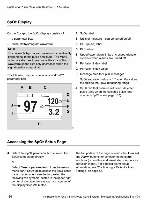
SpO2 and Pulse Rate with Masimo SET MCable
186 Instructions for Use Infinity Acute Care System - Monitoring Applications SW VG1
SpO2 Display
On the Cockpit, the SpO2 display consists of:
– a parameter box
– pulse-plethysmogram waveform
The following diagram shows a typical SvO2 parameter box.
A SpO2 label
B Units of measure – can be turned on/off
C PLS (pulse) label
D PLS value
E Upper/lower alarm limits or crossed-triangle symbols when alarms are turned off.
F Perfusion index label
G Perfusion index value
H Message area for SpO2 messages
I SpO2 saturation value or *** when the values fall outside the SpO2 measuring range.
J SpO2 blip that pulsates with each detected pulse (only when the selected pulse tone source is SpO2 – see page 187).
Accessing the SpO2 Setup Page
� Select the SpO2 parameter box to select the SpO2 setup page directly
or
Select Sensor parameters... from the main-menu bar > SpO2 tab to access the SpO2 setup page. If you cannot see the tab, select the following two symbols located in the upper-right corner of the dialogue window: symbol of the display filter button.
The top portion of the page contains the Auto set and Alarm buttons for configuring the alarm functions (no audible and visual alarm signals for perfusion index). For detailed alarm setup information, see "Configuring a Patient’s Alarm Settings" on page 85.
NOTEThe pulse-plethysmogram waveform is not directly proportional to the pulse amplitude. The M540 automatically tries to maximise the size of this waveform so the size only decreases when the signal quality is marginal.
038
A B C
DEFG
H
I
J

Instructions for Use Infinity Acute Care System - Monitoring Applications SW VG1 187
SpO2 and Pulse Rate with Masimo SET MCable
SpO2 Parameter Setup Functions
All SpO2 setup functions take place in the SpO2 setup dialogue (see "Accessing the SpO2 Setup Page" on page 186).
Selection Available Settings DescriptionPulse tone volume
Off, 5%, 10% (default), 20%, 30%, 40%, 50%, 60%, 70%, 80%, 100%
Sets the volume of the pulse tone.
Tone source – ECG (default) – SpO2
Selects the source of the pulse tone which affects the parameter box display (see page 186). For the SpO2 selection, the higher the pitch of the tone, the higher the SpO2 saturation percentage.
Waveform size 10%, 20%, 30%, 40% (default), 50%, 60%, 70%, 80%, 90%, 100%
Sets the amplitude of the SpO2 waveforms.
If the waveform height exceeds the display size of the channel, the waveform appears clipped (this does not affect the SpO2 signal processing).
Sensitivity mode – Normal (default) – standard mode
– APOD (adaptive probe off detection) – the least sensitive mode for detecting a reading on patients with low perfusion. Provides the best detection for detached sensors. This mode is useful for patients at particular risk for sensors becoming detached, such as children or patients who are restless.
– Max – provides maximum sensitivity for poor signals
Determines the level of detection sensitivity.
FastSat mode On, Off (default) Enables rapid tracking of arterial oxygen saturation changes.NOTE
The pod enables this mode automatically when the averaging time is set at 2 s to 4 s or 4 s to 6 s. When this mode is enabled automatically, you cannot disable it.

SpO2 and Pulse Rate with Masimo SET MCable
188 Instructions for Use Infinity Acute Care System - Monitoring Applications SW VG1
Averaging time – 2 s to 4 s, 4 s to 6 s, 8 s (default), 10 s, 12 s, 14 s, 16 s
Determines how quickly the reported SpO2 value responds to changes in the patient oxygen saturation.
Colour Red, green, blue, yellow, light blue, purple, orange, white (default).
Determines the colour of the waveforms and parameter labels/values.
Selection Available Settings Description
NOTEA longer averaging time provides a more accurate result than a shorter time when difficult readings have to be calculated.

Instructions for Use Infinity Acute Care System - Monitoring Applications SW VG1 189
SpO2 and Pulse Rate with Nellcor Oximax MCable
SpO2 and Pulse Rate with Nellcor Oximax MCable
Overview of SpO2 Monitoring . . . . . . . . . . . . 190
Supported Parameters . . . . . . . . . . . . . . . . . . . 190
SpO2 Precautions . . . . . . . . . . . . . . . . . . . . . . 191
Connecting the Nellcor Oximax MCable . . . 192
Patient Preparation. . . . . . . . . . . . . . . . . . . . . 193
Applying the Sensor . . . . . . . . . . . . . . . . . . . . . 193
SpO2 Display. . . . . . . . . . . . . . . . . . . . . . . . . . 194
Accessing the SpO2 Setup Page. . . . . . . . . . 194
SpO2-Parameter Setup Functions. . . . . . . . . 195

SpO2 and Pulse Rate with Nellcor Oximax MCable
190 Instructions for Use Infinity Acute Care System - Monitoring Applications SW VG1
Overview of SpO2 Monitoring
SpO2 monitoring is only possible with an SpO2 MCable.The M540 uses the Infinity® MCable - Nellcor TM OxiMaxTM (Nellcor Oximax MCable) to measure the percentage of functional haemoglobin saturated with oxygen (% SpO2) and derive a pulse rate (PLS) continuously. The values are displayed on the M540 and the Cockpit.
A sensor applied to the patient measures the absorption levels of red and infrared light. The Nellcor Oximax MCable uses the difference between the two measurements to calculate the percentage of saturated haemoglobin (SpO2). Because light absorption varies with blood volume and blood volume varies with pulse rate, the Nellcor Oximax MCable can also derive a pulse rate (PLS).
SpO2 measurements are for adult, paediatric and neonatal patients.
Refer to the Infinity Acute Care System - Infinity M540 Instructions for Use for a detailed description of the M540 SpO2 functions.
The SpO2 monitoring functions are configurable in the parameter-specific setup page (see page 194).
Before performing any monitoring functions, refer to the section "For Your Safety and That of Your Patients" starting on page 9. Parameter-specific error messages are listed on page 334.
Supported Parameters
– Saturation (SpO2)
– Pulse rate (PLS)
NOTEInformation about the wavelength range may be useful during photodynamic therapy. For details, see the technical data chapter of the M540 Instructions for Use.
Instructions for Use Infinity Acute Care System - Monitoring Applications SW VG1 191
SpO2 and Pulse Rate with Nellcor Oximax MCable
SpO2 Precautions
Interfering Substances: Carboxyhaemoglobin may erroneously increase the measurement values. The level of increase is approximately equal to the amount of carboxyhaemoglobin present. Dyes, or any substance containing dyes that change arterial pigmentation, may cause erroneous measurement values.
-------------------------------------------------------------------
WARNINGHigh oxygen levels may predispose a premature infant to retrolental fibroplasia. If this is a consideration, do NOT set the high alarm limit to 100%, which is equivalent to switching the alarm off. Transcutaneous pO2 monitoring is recommended for premature infants receiving supplemental oxygen.
WARNINGA pulse oximeter should not be used as an apnoea monitor.
WARNINGUse only Nellcor-specified sensors. Other sensors may not provide adequate protection against defibrillation and may put the patient at risk.
WARNINGTo reduce the hazard of burns during surgery, keep the sensor or transducer (ECG, temperature, pressure, SpO2) and their associated cables away from the surgical site, the electrosurgical unit return electrode, and earth ground.
WARNINGInspect the application site every two to three hours to ensure skin quality and correct optical alignment. If the skin quality changes, move the sensor to another site. Change the application site at least every four hours.
CAUTIONDo not immerse the sensor or patient cable in any liquid. Moisture may present a safety risk.
NOTEA pulse oximeter is an early warning device. It provides an approximation of arterial oxygen saturation only. Use of a laboratory co-oximeter is recommended for a complete understanding of a patient condition.
NOTEA pulse oximeter can be used during defibrillation, but the readings may be inaccurate for up to 20 seconds.
NOTEPurchase of this instrument confers no express or implied licence under any Nellcor patent to use this instrument with any oximetry sensor, that is not manufactured or licenced by Nellcor. For a list of approved sensors, see the Accessories and the M540 Instructions for Use.
NOTEDo not use a functional tester to assess the accuracy of a pulse oximeter probe or a pulse oximeter monitor. Since the pulse oximeter measurements are statistically distributed, only about two-thirds of those measurements can be expected to fall within ± A rms of a value measured by a CO oximeter.
NOTEA functional tester can be used to measure the total error of a pulse oximeter monitor-probe system if a particular calibration curve has been independently demonstrated to be accurate for that system. The functional tester can then measure how accurate a particular pulse oximeter is in reproducing the calibration curve.

SpO2 and Pulse Rate with Nellcor Oximax MCable
192 Instructions for Use Infinity Acute Care System - Monitoring Applications SW VG1
Connecting the Nellcor Oximax MCable
The Nellcor Oximax MCable cable connects directly to the M540.
To connect the Nellcor Oximax MCable
1 Connect the Nellcor Oximax MCable connector (B) to the blue SpO2 connector (A) of the M540.
2 Attach the intermediate cable (D) to the connector of the Nellcor Oximax MCable (C).
3 Attach the appropriate sensor cable to the end of the intermediate cable (E) - see page 193 for more information.
331
A
B
C
D
E

Instructions for Use Infinity Acute Care System - Monitoring Applications SW VG1 193
SpO2 and Pulse Rate with Nellcor Oximax MCable
Patient Preparation
The following tips provide optimal SpO2 monitoring results, but must never replace hospital-approved practices or manufacturer’s recommendations.
The accuracy of SpO2 monitoring depends largely on the strength and quality of the SpO2 signal.
If a finger is used as a monitoring site, remove any nail polish. Cut the finger nails of the patient, if necessary, for better sensor placement.
Pulses may be counted erroneously due to the following conditions:
– Placement of a sensor that is too tight
– Patient experiences hypotension, severe vasoconstriction, severe anaemia, or hypothermia
– Arterial occlusion proximal to the sensor
– Patient is in cardiac arrest or is in shock
– Bright light causing erratic measurement or missing values. Cover the sensor with opaque material if it is likely to be exposed to direct bright light.
– Significant levels of dysfunctional haemoglobins (HbCO or MetHb)
– Intravascular dyes such as indocyanine green or methylene blue
– Excessive patient movement
– Venous pulsations
– Placement of a sensor on an extremity with a blood pressure cuff, arterial catheter, or intravascular line
Applying the Sensor
If you are using a reusable sensor, make sure it is clean before applying it to the patient.
Follow the recommendations of the manufacturer.
To apply the sensor
1 Select the size and type of sensor that is best suited for your patient. Follow the recommendations of the manufacturer.
2 Position the sensor correctly and attach it to your patient.
Connect the sensor to the Nellcor Oximax MCable (see page 192).
WARNINGInspect the application site every two to three hours to ensure skin quality and correct optical alignment. If the skin quality changes, move the sensor to another site. Change the application site at least every four hours.
NOTERead the instructions provided with the sensor for optimal application techniques and for safety information. Never use damaged sensors. Doing so may compromise performance.
330

SpO2 and Pulse Rate with Nellcor Oximax MCable
194 Instructions for Use Infinity Acute Care System - Monitoring Applications SW VG1
SpO2 Display
On the Cockpit, the SpO2 display consists of:
– a parameter box
– pulse-plethysmogram waveform
The following diagram shows a typical SpO2 parameter box.
A SpO2 label
B Units of measure – can be turned on/off
C PLS (pulse) label
D PLS value
E Upper/lower alarm limits or crossed-triangle symbols when alarms are turned off.
F Message area for SpO2 messages
G The SpO2 saturation value
H SpO2 blip that pulsates with each detected pulse (only when the selected pulse tone source is SpO2 – see page 194).
Accessing the SpO2 Setup Page
� Select the SpO2 parameter box to select the SpO2 setup page directly
or
Select Sensor parameters... from the main-menu bar > SpO2 tab to access the SpO2 setup page. If you cannot see the tab, select the following two symbols located in the upper-right corner of the dialogue window: symbol of the display filter button.
The top portion of the page contains the Auto set and Alarm buttons for configuring the alarm functions. For detailed alarm setup information, see "Configuring a Patient’s Alarm Settings" on page 85.
NOTEThe pulse-plethysmogram waveform is not directly proportional to the pulse amplitude. The M540 automatically tries to maximise the size of this waveform so the size only decreases when the signal quality is marginal.
039
A B C
DE
F
G
H

Instructions for Use Infinity Acute Care System - Monitoring Applications SW VG1 195
SpO2 and Pulse Rate with Nellcor Oximax MCable
SpO2 Parameter Setup Functions
All SpO2 setup functions take place in the SpO2 setup page.
Selection Settings DescriptionPulse tone volume
Off, 5%, 10% (default), 20%, 30%, 40%, 50%, 60%, 70%, 80%, 100%
Sets the volume of the pulse tone.
Tone source – ECG (default)– SpO2
Selects the source of the pulse tone which affects the parameter box display (see page 194). For the SpO2 selection, the higher the pitch of the tone, the higher the SpO2 saturation percentage.
Waveform size 10%, 20%, 30%, 40% (default), 50%, 60%, 70%, 80%, 90%, 100%
Sets the amplitude of the SpO2 waveforms.
If the waveform height exceeds the display size of the channel, the waveform appears clipped (without affecting the SpO2 signal processing).
Response mode – Fast – averaging time is 2 s to 4 s
– Normal (default) – during normal measurement conditions, the averaging time is 4 seconds to 6 seconds
Determines how quickly the reported SpO2 value responds to changes in the patient oxygen saturation.
NOTEThe setting ’Normal’ is less sensitive to artefacts, but slower to alarm. The setting ’Fast’ is quicker to alarm, but more sensitive to artefacts.

SpO2 and Pulse Rate with Nellcor Oximax MCable
196 Instructions for Use Infinity Acute Care System - Monitoring Applications SW VG1
SatSeconds alarm time
Off (default), 10 s, 25 s, 50 s, 100 s This function analyses desaturation events by multiplying their duration (seconds) by the number of percentage points the patient exceeds the alarm limit.
Colour Red, green, blue, yellow, light blue, purple, orange, white (default).
Determines the colour of the waveforms and parameter labels/values.
Selection Settings Description
NOTEThis feature eliminates nuisance alarms caused by brief and numerous violations of lower and upper alarm limits. This selection overrides the alarm validation setting (see page 75) and the SpO2 high-priority desaturation alarm for neonatal patients.

Instructions for Use Infinity Acute Care System - Monitoring Applications SW VG1 197
Temperature
Temperature
Overview of Temperature Monitoring . . . . . . 198
Connecting the Temperature Sensors . . . . . 198
Connecting the Temperature Sensors to the M540. . . . . . . . . . . . . . . . . . . . . . . . . . . . . . . . . 199Connecting the Temperature Sensors to the Haemodynamic Pods . . . . . . . . . . . . . . . . . . . . 200
Temperature Display . . . . . . . . . . . . . . . . . . . 201
Accessing the Temperature Setup Page . . . 202
Temperature Parameter Setup Functions . . 202

Temperature
198 Instructions for Use Infinity Acute Care System - Monitoring Applications SW VG1
Overview of Temperature Monitoring
The M540 measures and displays the following temperature values and relays them to the Cockpit for display.
– Surface body temperature
– Core temperature
Temperature monitoring is intended for adult, paediatric and neonatal patients.
The Temp monitoring functions are configurable in the parameter-specific setup page (see page 202).
Refer to the Infinity Acute Care System - M540 Instructions for Use for a detailed description of the M540 temperature functions.
Before performing any monitoring functions, refer to the section "For Your Safety and That of Your Patients" starting on page 9. Parameter-specific error messages are listed on page 339.
Supported Parameters– Ta/T1a: absolute temperature values
– Tb/T1b: absolute temperature values
– ΔT/ΔT1: delta temperature values
Connecting the Temperature Sensors
You can connect temperature sensors directly to the M540 or to one of the following haemodynamic pods:
– MPod - QuadHemo
– Hemo4® pod
– Hemo2® pod
NOTEThe temperature functions and associated probes should be calibrated every two years by qualified personnel to maintain an accuracy of ± 0.1ºC (± 0.2ºF).

Instructions for Use Infinity Acute Care System - Monitoring Applications SW VG1 199
Temperature
Connecting the Temperature Sensors to the M540
You can connect a single- or dual-temperature sensor to the M540 directly. The dual-temperature sensor cable monitors two temperatures simultaneously.
To connect a dual-temperature sensor
1 Connect the temperature sensors (D) to the connectors (C) of the dual-temperature adaptor cable.
2 Connect the connector (B) of the dual-temperature adaptor cable to the M540 Temp/Aux connector (A).
To connect a single-temperature sensor
� Connect a temperature sensor (E) directly to the M540 Temp/Aux connector (A).
333
A
B
CC
D
E
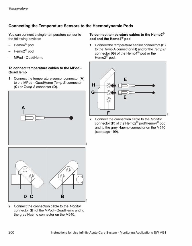
Temperature
200 Instructions for Use Infinity Acute Care System - Monitoring Applications SW VG1
Connecting the Temperature Sensors to the Haemodynamic Pods
You can connect a single-temperature sensor to the following devices:
– Hemo4® pod
– Hemo2® pod
– MPod - QuadHemo
To connect temperature cables to the MPod - QuadHemo
1 Connect the temperature sensor connector (A) to the MPod - QuadHemo Temp B connector (C) or Temp A connector (D).
2 Connect the connection cable to the Monitor connector (B) of the MPod - QuadHemo and to the grey Haemo connector on the M540.
To connect temperature cables to the Hemo2® pod and the Hemo4® pod
1 Connect the temperature sensor connectors (E) to the Temp A connector (H) and/or the Temp B connector (G) of the Hemo4® pod or the Hemo2® pod.
2 Connect the connection cable to the Monitor connector (F) of the Hemo2® pod/Hemo4® pod and to the grey Haemo connector on the M540 (see page 199).
332
334
A
D C B
335
E
E
F
GH
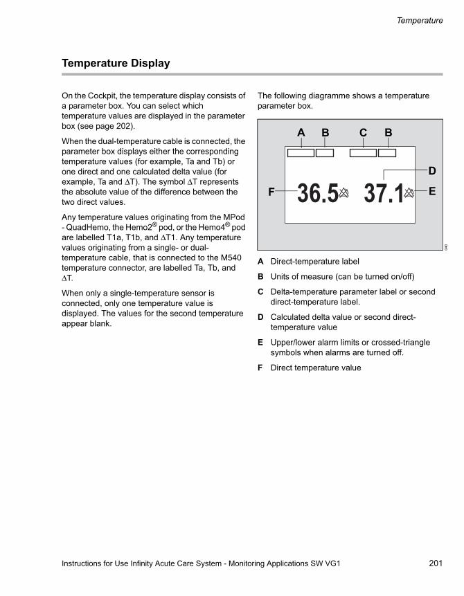
Instructions for Use Infinity Acute Care System - Monitoring Applications SW VG1 201
Temperature
Temperature Display
On the Cockpit, the temperature display consists of a parameter box. You can select which temperature values are displayed in the parameter box (see page 202).
When the dual-temperature cable is connected, the parameter box displays either the corresponding temperature values (for example, Ta and Tb) or one direct and one calculated delta value (for example, Ta and ΔT). The symbol ΔT represents the absolute value of the difference between the two direct values.
Any temperature values originating from the MPod - QuadHemo, the Hemo2® pod, or the Hemo4® pod are labelled T1a, T1b, and ΔT1. Any temperature values originating from a single- or dual-temperature cable, that is connected to the M540 temperature connector, are labelled Ta, Tb, and ΔT.
When only a single-temperature sensor is connected, only one temperature value is displayed. The values for the second temperature appear blank.
The following diagramme shows a temperature parameter box.
A Direct-temperature label
B Units of measure (can be turned on/off)
C Delta-temperature parameter label or second direct-temperature label.
D Calculated delta value or second direct-temperature value
E Upper/lower alarm limits or crossed-triangle symbols when alarms are turned off.
F Direct temperature value
040
A B C B
D
EF

Temperature
202 Instructions for Use Infinity Acute Care System - Monitoring Applications SW VG1
Accessing the Temperature Setup Page
� Select the temperature parameter box to select the Temp setup page directly.
or
Select Sensor parameters... from the main-menu bar > Temp (Temp 1) tab to access the Temp setup page. If you cannot see the tab,
select the following two symbols located in the upper-right corner of the dialogue window: symbol of the display filter button.
The top portion of the page contains the Auto set and Alarm buttons for configuring the alarm functions. For detailed alarm setup information, see "Configuring a Patient’s Alarm Settings" on page 85.
Temperature Parameter Setup Functions
All temperature setup functions take place in the Temp/Temp 1 setup dialogue (see "Accessing the Temperature Setup Page" on page 202).
Selection Available Settings DescriptionParameters – Ta – Tb (T1a – T1b)
– Ta – ΔT (T1a – ΔT1)
– Tb – ΔT (T1b – ΔT1)
Selects which parameters are displayed in the parameter box.
Colour Red, green, blue, yellow, light blue, purple, orange, and white (default).
Determines the colour of the parameter labels and values.
NOTEThe default is always the previous setting before a restore default was initiated.

Instructions for Use Infinity Acute Care System - Monitoring Applications SW VG1 203
Non-Invasive Blood Pressure (NIBP)
Non-Invasive Blood Pressure (NIBP)
Overview of NIBP Monitoring . . . . . . . . . . . . 204
Supported Parameters . . . . . . . . . . . . . . . . . . . 204
NIBP Precautions . . . . . . . . . . . . . . . . . . . . . . 204
Connecting the NIBP Hose and Cuff . . . . . . 206
Patient Preparation for NIBP Monitoring . . . 207
Applying the NIBP Cuff. . . . . . . . . . . . . . . . . . . 207
NIBP Display . . . . . . . . . . . . . . . . . . . . . . . . . . 208
Continuous NIBP Mode . . . . . . . . . . . . . . . . . . 208Interval NIBP Mode . . . . . . . . . . . . . . . . . . . . . 209
NIBP Measurement Modes . . . . . . . . . . . . . . 209
Single Measurement Mode. . . . . . . . . . . . . . . . 210Interval Measurements Mode. . . . . . . . . . . . . . 210
Venous Stasis . . . . . . . . . . . . . . . . . . . . . . . . . 212
Enabling or Disabling Venous Stasis . . . . . . . . 212
Accessing the NIBP Setup Page . . . . . . . . . . 212
NIBP Parameter Setup Functions . . . . . . . . . 213
Non-Invasive Blood Pressure (NIBP)
204 Instructions for Use Infinity Acute Care System - Monitoring Applications SW VG1
Overview of NIBP Monitoring
The M540 uses the oscillometric method to acquire and process non-invasive blood pressure (NIBP) signals and sends the results to the Cockpit for display. Blood pressure measurements are determined by the oscillometric method and are equivalent to those obtained by intra-arterial methods, within the limits prescribed by the Association for Advancement of Medical Instrumentation, Electronic Automated Sphygmomanometers (AAMI/ANSI SP-10).
The NIBP measurements are for adult, paediatric and neonatal patients.
To protect the patient from excessive inflation limits, the blood pressure cuff automatically deflates when:
– A measurement exceeds 2 minutes in adult and paediatric mode
– A measurement exceeds 90 seconds in neonatal mode
Refer to the Infinity Acute Care System - M540 Instructions for Use for a detailed description of the M540 NIBP functions.
The NIBP monitoring functions are configurable in the parameter-specific setup page (see page 212).
Before performing any monitoring functions, refer to the section "For Your Safety and That of Your Patients" starting on page 9. Parameter-specific error messages are listed on page 337.
Supported Parameters
– NIBP-S – non-invasive pressure, systolic value
– NIBP-D – non-invasive pressure, diastolic value
– NIBP-M – non-invasive pressure, mean value
NIBP Precautions
NOTEThe NIBP functionality should be calibrated every 2 years by technically qualified personnel as described in the Service manual.
WARNINGRapid, prolonged cycling of non-invasive pressure measurements have on occasion been associated with petaechia, ischaemia, purpura, or neuropathy. Make sure that the cuff is properly attached and check the cuff site regularly to prevent the cuff pressure from impeding the blood flow.
WARNINGObstructions may cause the cuff to inflate and deflate improperly and result in inaccurate measurement values. Check the hose and cuff for damage and dirt. Do not allow the hose and cuff to come in contact with fluids, and make sure that they are not compressed or kinked.
WARNINGDo not place the cuff on injured or breached skin because cuff compression could further damage the tissue.

Instructions for Use Infinity Acute Care System - Monitoring Applications SW VG1 205
Non-Invasive Blood Pressure (NIBP)
WARNINGDo not place the cuff on a limb with either an intra-arterial line or a vascular prosthesis because cuff compression will impede perfusion.
WARNINGAccurate NIBP measurements depend on the correct size and type of the blood pressure cuff in relation to the patient's arm circumference. The wrong sized cuff, or cuffs outside the range or size manufactured by Dräger Medical, can cause inaccurate measurements. Use only Dräger Medical approved cuffs and make sure that the correct size is used for each patient.
WARNINGTo reduce the possibility of pumping air into the patient’s blood vessels, never connect pneumatic connectors to an intravascular system.
WARNINGBefore monitoring neonates and infants:– Select the correct cuff size and hose.– Select the neonatal or paediatric patient
category, if not already selected. This provides the appropriate inflation for neonates, infants, and paediatric patients.
NOTEThe accuracy of the oscillometric blood pressure signal can decrease (up to loss of measurement) under the following conditions:– weak pulses– irregular pulses– patient movement artefacts– tremor artefacts– respiratory artefacts
NOTEA systolic blood pressure higher than the current high inflation limit may trigger a NIBP low inflation limit message. When this message appears, manually check the blood pressure of the patient.

Non-Invasive Blood Pressure (NIBP)
206 Instructions for Use Infinity Acute Care System - Monitoring Applications SW VG1
Connecting the NIBP Hose and Cuff
The NIBP intermediate hose connects directly to the M540.
To connect the NIBP hose and cuff
1 Select a NIBP cuff size that is appropriate for the patient.
2 Connect the NIBP hose (C) to the intermediate hose (B).
3 Connect the NIBP intermediate hose to the NIBP connector (A) of the M540.
336
+
A
B
C

Instructions for Use Infinity Acute Care System - Monitoring Applications SW VG1 207
Non-Invasive Blood Pressure (NIBP)
Patient Preparation for NIBP Monitoring
The following tips provide optimal NIBP monitoring results, but must never replace hospital-approved practices or manufacturer’s recommendations.
Accurate NIBP measurements depend on the correct size and type of the blood pressure cuff in relation to the arm circumference of the patient. The wrong sized cuff, or cuffs outside the range or size manufactured by Dräger Medical, can cause inaccurate measurements. Use only Dräger Medical approved cuffs and make sure that the correct size is used for each patient.
Applying the NIBP Cuff
Weak or irregular pulses, patient movement, tremors, or respiratory artefacts can affect the accuracy of NIBP measurements and even cause them to fail. Before applying the cuff, read the precautions listed on page 204.
We recommend that you do not apply the cuff on a limb that is already used for other measurements. Make sure that other patient connections do not interfere with each other.
The following diagramme depicts a typical cuff by Dräger Medical.
A Index line
B Artery marker
C Range labels
D Size indicator
To apply the NIBP cuff
1 Place the cuff 2 cm to 5 cm (1 inch to 2 inches) above or below the elbow (or around the middle of the thigh). Place the cuff with the "this side to patient" label against the skin.
2 Place the artery marker (B) over the artery pointing to the hand or the foot. The cuff label ’index’ (A) must fall within the range labels (C).
3 Wrap the cuff snugly around the limb without impeding the blood flow.
337
BD
A
C C

Non-Invasive Blood Pressure (NIBP)
208 Instructions for Use Infinity Acute Care System - Monitoring Applications SW VG1
NIBP Display
On the Cockpit, the NIBP display consists of a parameter box.
When a measurement is in progress, the background of the lower part of the parameter box turns white.
During low systolic or diastolic pulse amplitudes or significant motion artefacts, the parameter box may only display a mean value. If the M540 is in the venous stasis mode, the cuff pressure and the label Stasis appears in the NIBP parameter box.
If you cannot apply the cuff at the heart level, adjust the displayed systolic and diastolic NIBP values as follows: add 8 mmHg (1.1 kPa) for each 10 cm (4 inches) above the heart; subtract 8 mmHg (1.1 kPa) – for each 10 cm (4 inches) below the heart.
Continuous NIBP Mode
The following diagram shows a parameter box when the continuous NIBP mode is selected (see page 211).
A The NIBP parameter label
B Unit of measure (can be turned on/off)
C Time since the last NIBP measurement
D Mean pressure value
E Alarm limits or crossed-triangle symbols when alarms are turned off
F Time remaining before the continuous mode is terminated
G The Cont. mode label
H Units of measure
I Inflation pressure value
J The Inflation pressure label
K Systolic/diastolic pressure value
041
A B C
DE
FGHIJ
K

Instructions for Use Infinity Acute Care System - Monitoring Applications SW VG1 209
Non-Invasive Blood Pressure (NIBP)
Interval NIBP Mode
The following diagram shows a parameter box when the interval NIBP mode is selected (see page 211 for more information).
A The NIBP parameter label
B Unit of measure (can be turned on/off)
C Time since the last NIBP measurement
D Last mean pressure value
E Alarm limits or crossed-triangle symbols when alarms are turned off
F Selected inflation interval (see page 212)
G Inflation pressure value or progress bar
H The Auto label (after the measurement is completed, a progress bar replaces the label to indicate the time before the start of the next measurement)
I Systolic and diastolic pressure values
NIBP Measurement Modes
The following NIBP measurement modes are available:
– Single
– Interval
– Continuous
The selected mode affects the appearance of the NIBP parameter box (see page 208).
Before taking any NIBP measurements, read the precautions on page 204.
At the beginning of a measurement, the M540 inflates the cuff to a pressure that is 25 mmHg (3.2 kPa) for the adult/paediatric mode and 30 mmHg (4 kPa) for the neonate mode above the previously detected systolic value. If the M540 cannot obtain a valid measurement, it reinflates the cuff to the maximum inflation pressure provided the measurement cycle has not timed-out. If the M540 cannot obtain a measurement within the measurement cycle, no further attempts are made until the next scheduled interval or until you initiate a single measurement.
The last NIBP measurement value is displayed in the parameter box until the new measurement is completed. New values appear at the end of a measurement, at which point a chime also sounds if the corresponding function was enabled (see page 212).
043
A B C
DE
FGH
I
WARNINGPress the NIBP Start/Stop fixed key to deflate the cuff rapidly if an adverse effect occurs on the patient.

Non-Invasive Blood Pressure (NIBP)
210 Instructions for Use Infinity Acute Care System - Monitoring Applications SW VG1
Single Measurement Mode
Single measurement mode allows you to start measurements when needed. You can start and stop a single measurement at the M540 and at the Cockpit.
To start a single measurement
Do one of the following:
� Press the NIBP key on the front of the M540 Press the key again to stop the measurement
or
� Press the NIBP start/stop button on the main-menu bar of the Cockpit. Press the button again to stop the measurement.
Interval Measurements Mode
In the interval mode, the M540 initiates measurements at set intervals. Changing the interval setting during a measurement resets the interval timer. If you select an other interval setting after the interval mode was disabled, you must select the NIBP start/stop button on the menu bar for interval measurements to start.
You can still take single measurements during an interval cycle.
Interval measurements are not possible during:
– The venous stasis mode – the measurements resume immediately after the cuff deflates.
– The cardiac bypass mode – select the NIBP start/stop button to resume interval measurement after exiting the cardiac bypass mode.
– The standby mode – select the NIBP start/stop button to resume interval measurement after exiting the standby mode.
Aligning Interval Mode Settings Between Cockpit and M540
If the interval mode is disabled on the Cockpit and an M540 with the interval mode enabled is docked while a measurement is in progress, the NIBP measurement is cancelled automatically. In addition, the interval mode is disabled on the M540.
If the interval mode is enabled on both devices but you dock an M540 with a different interval time, the NIBP measurement continues. However, the M540 interval time is adjusted to the Cockpit setting at the end of the measurement.
If you turn the M540 off and on again, and the interval mode is enabled on both Cockpit and M540, select the NIBP start/stop button to resume the interval mode.
WARNINGBecause NIBP measurements occur intermittently, a patient's condition may change between measurements. Therefore, do not rely on NIBP alarms alone to notify you of the changing condition of a patient.

Instructions for Use Infinity Acute Care System - Monitoring Applications SW VG1 211
Non-Invasive Blood Pressure (NIBP)
To enable or disable the interval mode.
1 Select the NIBP parameter box to select the NIBP setup page directly
or
Select Sensor parameters... from the main-menu bar > NIBP tab to access the NIBP setup page.
2 Select Interval time and make your selection. The available settings are: Off, 1 min, 2 min, 2.5 min, 3 min, 5 min, 10 min, 15 min, 20 min, 30 min, 45 min, 60 min, 120 min, 240 min.
3 Press the NIBP start/stop button on the main-menu bar if you change the mode setting from Off to another setting (otherwise, the interval measurements will not start).
To stop the interval measurements
� Press the NIBP start/stop button on the main-menu bar.
Continuous Measurements
In the continuous mode, the M540 continuously initiates NIBP measurements over a 5-minute period.
A <10 second (±1 second) minimum interval between the end of one measurement and the start of another provides minimal perfusion of the limb.
To enable or disable the continuous mode
1 Select the NIBP parameter box to select the NIBP setup page directly
or
Select Sensor parameters... from the main-menu bar > NIBP tab to access the NIBP setup page.
2 Select On or Off next to the Continuous mode.
To stop the continuous measurements
� Press the NIBP start/stop button on the main-menu bar .
or
� Disable the Continuous mode in the NIBP setup page (see page 213).
WARNINGWhen using the continuous mode, observe the patient closely and verify the limb perfusion clinically. Be extra-vigilant when using the continuous mode on neonates or haemodynamically compromised patients.
NOTEThe continuous NIBP mode prevents you from enabling venous stasis.

Non-Invasive Blood Pressure (NIBP)
212 Instructions for Use Infinity Acute Care System - Monitoring Applications SW VG1
Venous Stasis
By maintaining a constant cuff pressure, the M540 stops the blood flow to the lower extremity of the cuffed limb long enough to cannulate a patient. In this mode, the cuff occludes the limb for about as long as a NIBP measurement takes (approximately 2 minutes for adults and approximately 1 minute for neonates).
Enabling or Disabling Venous Stasis
To enable or disable the venous stasis
1 Select the NIBP parameter box to select the NIBP setup page directly.
or
Select Sensor parameters... from the main-menu bar > NIBP tab to access the NIBP setup page.
2 Make sure the NIBP continuous mode is not turned on (see page 213).
3 Select On next to Venous stasis.
During active venous stasis, the NIBP parameter box reports the remaining time and displays the message Stasis in the parameter box. As soon as venous stasis is terminated, the parameter box resumes its previous appearance (see page 208).
The interval measurements are suspended during venous stasis but resume immediately after the cuff deflates.
Accessing the NIBP Setup Page
� Select the NIBP parameter box to select the NIBP setup page directly.
or
Select Sensor parameters... from the main-menu bar > NIBP tab to access the NIBP setup page. If you cannot see the tab, select the following two symbols located in the upper-right corner of the dialogue window: symbol and the display filter button.
The top portion of the page contains the Auto set and Alarm buttons for configuring the alarm functions. For detailed alarm setup information, see "Configuring a Patient’s Alarm Settings" on page 85.
WARNINGDo not use venous stasis on a limb that is unsuitable for NIBP measurements (for example, an arm with a catheter). If the patient experiences adverse reactions, immediately press the NIBP Start/Stop menu button to deflate the cuff.
NOTEMake sure the continuous NIBP mode is not enabled (see page 212) because it prevents you from using the venous stasis mode.
NOTEWhen the venous stasis mode begins, an attention tone sounds.

Instructions for Use Infinity Acute Care System - Monitoring Applications SW VG1 213
Non-Invasive Blood Pressure (NIBP)
NIBP Parameter Setup Functions
All IBP setup functions take place in the NIBP setup dialogue (see "Accessing the NIBP Setup Page" on page 212).
Selection Available Settings DescriptionInterval time
(The cardiac bypass mode automatically disables interval measurements)
Off (default), 1 min, 2 min, 2.5 min, 3 min, 5 min, 10 min, 15 min, 20 min, 25 min, 30 min, 45 min, 60 min, 120 min, 240 min.
Defines intervals for NIBP measurements.
The inflation mode
Adult (default), paediatric, neonatal: Sets the threshold for maximum cuff inflation.
The continuous mode
On, Off (default) Initiates successive NIBP measurements for 5 min.
Chime On, Off (default) Determines if a tone sounds at the end of a completed NIBP measurement.
Venous Stasis On, Off (default) Stops blood flow to the lower part of the cuffed limb for a fixed time.
Colour Red, green, blue, yellow, light blue, purple, orange, white (default).
Determines the colour of the parameter values.

214 Instructions for Use Infinity Acute Care System - Monitoring Applications SW VG1
This page is intentionally left blank

Instructions for Use Infinity Acute Care System - Monitoring Applications SW VG1 215
Invasive Blood Pressure (IBP)
Invasive Blood Pressure (IBP)
Overview of IBP Monitoring. . . . . . . . . . . . . . 216
Supported Parameters . . . . . . . . . . . . . . . . . . . 216IBP Pods. . . . . . . . . . . . . . . . . . . . . . . . . . . . . . 216
IBP Precautions . . . . . . . . . . . . . . . . . . . . . . . 218
Connecting the Hemo4 Pod and Hemo2 Pod. . . . . . . . . . . . . . . . . . . . . . . . . . . . . . . . . . 219
Connecting the MPod - QuadHemo . . . . . . . 220
Connecting the Dual Hemo MCable . . . . . . . 221
Patient Preparation. . . . . . . . . . . . . . . . . . . . . 221
IBP Display . . . . . . . . . . . . . . . . . . . . . . . . . . . 222
IBP Parameter Box. . . . . . . . . . . . . . . . . . . . . . 222Large Mean Value . . . . . . . . . . . . . . . . . . . . . . 222IBP Waveforms. . . . . . . . . . . . . . . . . . . . . . . . . 222
Labelling IBP Pressure Channels . . . . . . . . . 223
Standard Labels . . . . . . . . . . . . . . . . . . . . . . . 224
Pressure Label Conflicts . . . . . . . . . . . . . . . . 224
Pod-M540 Label Conflicts . . . . . . . . . . . . . . . . 224
Zeroing an IBP Transducer . . . . . . . . . . . . . . 225
Zeroing a Specific Transducer . . . . . . . . . . . . . 225Zeroing all Pressure Transducers (SmartZero) . . . . . . . . . . . . . . . . . . . . . . . . . . . 226
Pulmonary Wedge Pressure . . . . . . . . . . . . . 227
Starting Wedge Measurements from the Pods. . . . . . . . . . . . . . . . . . . . . . . . . . . . . . . . . 228
Starting Wedge Measurements from the Cockpit . . . . . . . . . . . . . . . . . . . . . . . . . . . . . . . 229
Accessing the IBP Setup Page . . . . . . . . . . . 230
IBP Parameter Setup Functions . . . . . . . . . . 231

Invasive Blood Pressure (IBP)
216 Instructions for Use Infinity Acute Care System - Monitoring Applications SW VG1
Overview of IBP Monitoring
The M540 acquires, processes, and displays invasive blood pressure (IBP) signals and relays the data to the Cockpit. Several pods are available for monitoring the invasive pressure. Monitoring more than two pressures simultaneously requires the Multi-IBP option.
The IBP measurements are for adult, paediatric and neonatal patients.
Refer to the Infinity Acute Care System - M540 Instructions for Use for a detailed description of the M540 IBP functions.
The IBP monitoring functions are configurable in the parameter-specific setup page (see "IBP Parameter Setup Functions" on page 231).
Before performing any monitoring functions, refer to the section "For Your Safety and That of Your Patients" starting on page 9. Parameter-specific error messages are listed on page 340.
Supported Parameters
See page 223 for available IBP-pressure labels.
– Systolic pressures: GP1 S to GP4 S, ART S, PA S, LV S, RV S
– Diastolic pressures: GP1 D to GP4 D, ART D, PA D, LV D, RV D
– Mean pressures: GP1 M to GP4 M, ART M, PA M, LV M, RV M
– Additional pressures: ICP, CVP, LA, RA,
– If both ART and ICP are connected, the algorithm computes the difference between ICP and mean ART and reports it as CPP.
IBP Pods
IBP signals originate from the following haemodynamic pods:
– Hemo4® pod
– Hemo2® pod
– Infinity® MPod - QuadHemo (MPod - QuadHemo)
– Infinity® MCable - Dual Hemo (Dual Hemo MCable)
Hemo4 pod
This pod measures up to four pressures, cardiac output, and temperature.
A SmartZero key for zeroing all pressures simultaneously (see page 225)
B Key for starting a cardiac output measurement
C Wedge button for starting wedge pressure measurements
D Pressure-label windows
E Transducer slots
338
NOTEThe connectors for temperature and cardiac output are located on the side panel of the haemodynamic pod.
A B C
D
E E E E

Instructions for Use Infinity Acute Care System - Monitoring Applications SW VG1 217
Invasive Blood Pressure (IBP)
.Hemo2 pod
This pod measures up to four pressures, cardiac output, and temperature.
A SmartZero key for zeroing all pressures simultaneously (see page 225)
B Key for starting a cardiac output measurement
C Wedge button for starting wedge pressure measurements
D Pressure-label windows
E Transducer slots
MPod - QuadHemo
This pod measures up to four pressures, cardiac output, and temperature.
F SmartZero key for zeroing all pressures simultaneously (see page 225)
G Key for starting a cardiac output measurement
H Wedge button for starting wedge pressure measurements
I Intermediate cables for attaching the transducers
339
NOTEThe connectors for temperature and cardiac output are located on the side panel of the haemodynamic pod.
A B C
D
E E
340
NOTEThe connectors for temperature and cardiac output are located on the side panel of the haemodynamic pod.
F G H
I I

Invasive Blood Pressure (IBP)
218 Instructions for Use Infinity Acute Care System - Monitoring Applications SW VG1
Dual Hemo MCable
This MCable measures up to two pressures. A The Dual Hemo MCable connector that connects to the M540.
B Transducer adaptor cables for attaching the transducers.
IBP Precautions
There are additional warnings regarding the pulmonary wedge pressure on page 227.
341
A
B
WARNINGTo prevent patient injury, never reuse a single-use transducer.
WARNINGDo not use the ‘Smart Zero’ function if any pressure waveform is flat (nearly static). Open all stopcocks to air, then use the Zero key on the Cockpit instead.

Instructions for Use Infinity Acute Care System - Monitoring Applications SW VG1 219
Invasive Blood Pressure (IBP)
Connecting the Hemo4 pod and Hemo2 pod
The Hemo4 pod and Hemo2 pod connect directly to the M540. The following diagram shows where the grey hemoconnector (A) is located on the side of the M540.
To connect the Hemo4 pod and Hemo2 pod
1 Attach the IBP adaptor (G) to the bottom of the Hemo4 pod/Hemo2 pod.
2 Connect one end of the connection cable (C) to the Hemo4 pod or the Hemo2 pod connector (B).
3 Connect the other end of the connection cable (C) to the grey haemoconnector of the M540 (A).
4 Attach the transducers to the transducer slot (E).
5 Connect the transducer adaptor cables (D) to the transducer cable (F).
310
A
342
Front View Side View
C
B
FG
DD
E

Invasive Blood Pressure (IBP)
220 Instructions for Use Infinity Acute Care System - Monitoring Applications SW VG1
Connecting the MPod - QuadHemo
The MPod - QuadHemo connects directly to the M540.
To connect the MPod - QuadHemo
1 Connect one end of the connection cable (C) to the connector located on the right side of the MPod - QuadHemo (B).
2 Connect the other end of the connection cable (E) to the grey Haemo connector of the M540 (A).
3 Insert the transducers into the transducer slot (D).
4 Connect the transducer cables (F) to the transducer adaptor cable (G).
The transducer adaptor cables are permanently fastened to the back of the MPod - QuadHemo.
343
C
B
A
D D D
E
G
F

Instructions for Use Infinity Acute Care System - Monitoring Applications SW VG1 221
Invasive Blood Pressure (IBP)
Connecting the Dual Hemo MCable
The Dual Hemo MCable connects directly to the M540.
To connect the Dual Hemo MCable
1 Attach the transducers (D) to the transducer adaptor cables (C).
The transducer adaptor cables are permanently fastened to the Dual Hemo MCable.
2 Connect the Dual Hemo MCable connector (B) to the grey Haemo connector (A) on the M540.
Patient Preparation
The following tips provide optimal IBP monitoring results, but must never replace hospital-approved practices or manufacturer’s recommendations.
– When preparing the patient, make sure there are no air bubbles in the sensor or the stopcock.
– For maximum signal strength, choose the shortest possible length of the high-pressure tubing. Shorter tubing reduces signal attenuation but is more susceptible to motion artefacts. High-pressure tubing limits signal dampening.
344
A
B
D D
CC
NOTEIf air bubbles appear in the tubing system, flush the system with the infusion solution again. Air bubbles may lead to wrong pressure measurement values.

Invasive Blood Pressure (IBP)
222 Instructions for Use Infinity Acute Care System - Monitoring Applications SW VG1
IBP Display
On the Cockpit, the IBP display consists of:
– a parameter box
– Waveform
IBP Parameter Box
The content of the IBP parameter boxes depends on whether the parameter is pulsatile or non-pulsatile. Parameter boxes for pulsatile pressures (ART, LV, PA, RV, GP1, GP2, GP3, GP4) display systolic, diastolic, and mean pressure values. Parameter boxes for non-pulsatile pressures (LA, RA, CVP, ICP) display only the mean pressure value.
If the M540 detects a static pressure, the algorithm computes only the mean pressure. A static pressure condition occurs when the maximum and minimum values of a pulsatile pressure signal differ by less than 3 mmHg (0.4 kPa).
The IBP parameter box contains the following elements:
A IBP parameter label
B Unit of measure (can be turned on/off)
C Mean pressure value
D Alarm limits or crossed-triangle symbols when alarms are turned off
E Systolic/diastolic pressure values
Large Mean Value
The IBP mean value can either be displayed in regular or large font size.
To enable the large mean value display
1 Select the IBP parameter box to select the IBP setup page directly.
or
Select Sensor parameters... from the main-menu bar.
2 Select the desired IBP tab (for example, GP1) along the right side of the IBP page.
3 Select On next to Large mean.
IBP Waveforms
IBP waveforms are either displayed in separate waveform channels or in overlapped format. When overlapped, the waveform area increases to combine multiple waveforms. For each IBP waveform, a corresponding parameter box is displayed. To enable the overlap display for adjacent pressure waveforms, see page 278 in the System Configuration chapter.
044
A B
CD
E

Instructions for Use Infinity Acute Care System - Monitoring Applications SW VG1 223
Invasive Blood Pressure (IBP)
Labelling IBP Pressure Channels
The IBP pressure label determines how a signal is analysed and reported. The M540 takes the pressure labels from the connected pod or MCable provided the transducers are connected. When a new label is assigned to a pressure channel, the M540 clears the parameters and conditions set for the previous label (including alarms and waveform scales) and replaces them with the settings of the new label. When the M540 is docked on the M500, all pressure labels are transferred to the Cockpit.
The following rules apply to labelling pressure channels:
– If no pressure labels are assigned, the labels GP1 to GP4 are automatically assigned depending on how many pressures are connected.
– The zero value, the date, and time are associated with the pressure channel remain unchanged even if a new label is assigned.
To assign a pressure label manually
1 Select the IBP parameter box to select the IBP setup page directly.
or
Select Sensor parameters... from the main-menu bar > IBP tab to access the IBP setup page.
2 Select the desired IBP tab (labelled GP1, GP2, GP3, or GP4) along the right side of the IBP page.
3 Select the button next to Label and choose the label from the list (see the following table).
NOTEIf the Cockpit displays the generic pressure labels (GP1, GP2, GP3, GP4), the displays on the Hemo2 and Hemo4 pods are labelled P1a, P1b, P1c, P1d.
NOTECertain pressure labels have extra selections in their corresponding Cockpit parameter-setup pages. For example, from the PA page, you can start a Wedge pressure and from the ICP page, you can set a minimum scale.

Invasive Blood Pressure (IBP)
224 Instructions for Use Infinity Acute Care System - Monitoring Applications SW VG1
Standard Labels
The M540 detects the labels automatically from the haemodynamic pod, provided a transducer is connected. The M540 transfers the labels to the Cockpit. You can also label pressure channels manually.
The following table lists the available IBP labels.
Pressure Label Conflicts
Each pressure label is assigned to one location. If you try to reuse a label, you must confirm it. The M540 assigns the label to the currently selected parameter box and places an automatic pressure label (GP1 to GP4) in the previous location.
Pod-M540 Label Conflicts
The haemodynamic pods store pressure labels like the M540. When a pod with previously stored labels is connected, different pressure labels may exist for the same channel, thus causing a conflict.
If a transducer is connected to the pod, the label stored in the pod prevails. The M540 assigns that parameter label to the pressure-label list box. If no transducer is connected to the pod, the label stored in the M540 has priority.
IBP LabelsLabel Pressure Type Measured Pressures Measurement RangeART Arterial pressure Systolic, diastolic, mean -50 mmHg to +400
mmHg
-6.6 kPa to 53.3 kPa
-
LV Left ventricular pressure
PA Pulmonary arterial pressure
RV Right ventricular pressure
CVP Central venous pressure Mean
CPP (1) Central perfusion pressure
RA Right atrial pressure
LA Left atrial pressure
ICP Intracranial pressure
Generic LabelsGP1 to GP4 Systolic, diastolic, mean
NOTE(1) The CPP value is only calculated when ICP and ART (M) pressure values are available.

Instructions for Use Infinity Acute Care System - Monitoring Applications SW VG1 225
Invasive Blood Pressure (IBP)
Zeroing an IBP Transducer
To establish accurate IBP values, zero the transducer according to the hospital protocol at least once a day. Perform additional zeroing under the following circumstances:
– After introducing a catheter into the vascular system of the patient.
– Before each monitoring session.
– Each time you use a new transducer or tubing.
– Whenever you connect the transducer cable to the monitor.
– If the reported pressure values seem incorrect.
– When the message IBP check zero appears.
For zeroing to be successful, a pressure must be stable for at least 3 seconds. Messages report the status of the zeroing process. The time and date of the last successful zero is recorded on the IBP page. Check the IBP waveform and repeat the zeroing procedure if the zeroing fails because the pressures are not static. If the procedure fails after two attempts, replace the transducer or consult your technical personnel.
If the attention tone is enabled (see page 275), a tone sounds upon successful zeroing.
Zeroing a Specific Transducer
This procedure allows you to select a specific transducer for zeroing. You can also initiate the procedure from the M540 (see Infinity Acute Care System - M540 Instructions for Use for details).
To zero a specific transducer
1 Select the IBP parameter box to select the IBP setup page directly.
or
Select Sensor parameters... from the main-menu bar > IBP tab to access the IBP setup page.
2 Select the desired IBP tab (for example, ART) along the right side of the IBP page.
3 Align the transducer stopcock to the heart level of the patient.
4 Close the transducer stopcock to the patient and open it to air.
5 Select the button next to Zero in the IBP setup page.
If the zeroing of the transducer is successful, the message Zero accepted appears. If zeroing failed, the message Did not zero appears. In that case, repeat steps three to five.

Invasive Blood Pressure (IBP)
226 Instructions for Use Infinity Acute Care System - Monitoring Applications SW VG1
Zeroing all Pressure Transducers (SmartZero)
This procedure zeroes all pressure transducers simultaneously.
You can perform a SmartZero from the Hemo4 pod, Hemo2 pod, the MPod - QuadHemo or the Cockpit. The M540 determines which of the transducers are open to air and then zeroes them.
To zero all pressure transducers from the haemodynamic pods
1 Align the stopcocks to the heart level of the patient.
2 Close the stopcocks to the patient, and open them to air.
3 Press the SmartZero button (A) on the Hemo4® pod, Hemo2 pod, or the MPod - QuadHemo.
4 Verify that the transducers have been zeroed. If zeroing failed, repeat steps two and three.
WARNINGDo not use the ‘Smart Zero’ function if any pressure waveform is flat (nearly static). Open all stopcocks to air, then use the Zero key on the Cockpit instead.
339
AHemo2 Pod
338
340
AHemo4 Pod
AQuadHemo MPod

Instructions for Use Infinity Acute Care System - Monitoring Applications SW VG1 227
Invasive Blood Pressure (IBP)
To zero all pressure transducers from the Cockpit
1 Align the stopcocks to the heart level of the patient.
2 Close the stopcocks to the patient, and open them to air.
3 Select the Zero all button on the main-menu bar (C700).
or
Select the symbol next to the Sensor parameters... button on the main-menu bar (C500).
or
Select the IBP parameter box to access the IBP setup page > select the Zero button.
4 Verify that the transducers have been zeroed. If zeroing failed, repeat the procedure.
Pulmonary Wedge Pressure
When the M540 is docked, you can calculate a pulmonary wedge pressure (PWP) from the Hemo4® pod, Hemo2® pod, and the MPod - QuadHemo or the Wedge page on the Cockpit. You cannot request wedge pressures directly from the M540.
During PWP measurements, only the mean PA pressure is displayed.
WARNINGFor the safety of the patient, keep the balloon-inflation time to the minimum necessary to acquire an accurate PWP value. Prolonged inflation of the balloon can result in pulmonary haemorrhage or infarction.
WARNINGThe PA catheter may move into the wedge position before the balloon is inflated. One sign of this “catheter drift” is that the PWP waveform becomes wedge-shaped. Follow your hospital clinical guidelines to correct the catheter’s position.
WARNINGDo not over-inflate the balloon because an over-inflated balloon can rupture the pulmonary artery.
WARNINGAlarm monitoring for invasive pressures, if enabled, is temporarily disabled to prevent nuisance alarms. The parameter box does not display a crossed triangle symbol because alarm monitoring is automatically enabled upon completion of a wedge pressure measurement.

Invasive Blood Pressure (IBP)
228 Instructions for Use Infinity Acute Care System - Monitoring Applications SW VG1
Starting Wedge Measurements from the Pods
To start a wedge pressure measurement
1 Press the Wedge key (A) on the Hemo2 pod, Hemo4 pod, or the MPod - QuadHemo. The message Inflate Balloon, then press Start appears on the Cockpit.
2 Press the Wedge key (A) again to start.
– PA alarms are turned off temporarily.
– The message Wedge in progress appears on the Cockpit and the measurement begins. A PWP value is displayed at the bottom of the Wedge page on the Cockpit within 10 seconds. The message Deflate balloon and save Wedge to finish appears.
3 Press the Wedge key (A) again to save the value.The following happens on the Wedge page of the Cockpit (see page 229):
– The message Wedge in progress appears in the message field.
– A new PWP value calculated during the next 10 seconds appears. An attention tone sounds at the end of the calculation if it was enabled (see page 275). Also, the message Deflate balloon and press save Wedge to finish appears in the message field.
– The PA and reference waveforms are stopped, and the message Waveforms stopped appears above the PA scale in the display window.
After a successful wedge measurement, the PA waveform resumes its previous size and sweep speed. PA systolic and diastolic values are displayed again, and PA alarms are restored to the values before entering Wedge mode.
339
338
AHemo2 Pod
AHemo4 Pod
340
AQuadHemo MPod

Instructions for Use Infinity Acute Care System - Monitoring Applications SW VG1 229
Invasive Blood Pressure (IBP)
Starting Wedge Measurements from the Cockpit
The following diagram shows the Wedge page where you start Wedge measurements manually. The wedge pressure value is saved automatically when:
– You close the Wedge page.
– 240 seconds have elapsed after the wedge pressure was started and a valid PWP value exists.
A The Prepare wedge button
B The Start wedge button
C The Freeze/Adjust button
D The Save wedge button
E The Cancel wedge button
F The message field
G PWP value
H PWP results window
I The Scale button
J The Sweep speed button
K The Reference waveform
To start a wedge measurement
1 Select the PA parameter box (if displayed) > select the Start wedge button.
or
Select the Procedures button from the main-menu bar >, select the Wedge tab (if not already selected).
2 Verify that the PA catheter has been properly inserted.
3 Select the Prepare wedge button (A). The following happens:
– PA alarms are turned off temporarily.
– The message Inflate Balloon. Press start Wedge appears in the message field (F). Only the PA mean value appears in the parameter box (the diastolic/systolic values are blanked).
– The button Start Wedge appears.
4 Use the Scale button (I) to change the scale, if necessary.
5 Use the Sweep speed (J) button to select a different sweep speed for the waveform, if necessary.
6 Use the Reference waveform button (K) to select a reference waveform (available settings: None, RRi).
7 Select the Start wedge button (B). – The message Wedge in progress appears
in the message field (F).
045
Procedures
A B C D
I
JK
EF
H
G
I

Invasive Blood Pressure (IBP)
230 Instructions for Use Infinity Acute Care System - Monitoring Applications SW VG1
– A new PWP value (G) calculated during the next 10 seconds appears. An attention tone sounds at the end of the calculation if it was enabled (see page 275). Also, the message Deflate balloon and press Save wedge to finish appears in the message field (F).
– The PA and reference waveforms are stopped, and the message Waveforms stopped appears above the PA scale in the display window (H).
– A horizontal cursor is drawn through the PA waveform.
8 Select one of the following buttons:– The Freeze/Adjust button (C) to alter the
PWP value manually. – The Save wedge button (D) to save the new
value (it is stored in the trend function).– Cancel wedge (E) to cancel the
measurement.
After a successful wedge measurement, the PA and RESP waveforms resume their previous sizes and sweep speeds. PA systolic and diastolic values are displayed again, and PA alarms are restored to the values before entering Wedge mode.
Accessing the IBP Setup Page
� Select the IBP parameter box to select the IBP setup page directly.
or
Select Sensor parameters... from the main-menu bar > IBP tab to access the IBP setup page. If you cannot see the tab, select the following two symbols located in the upper-right corner of the dialogue window: symbol and the display filter button.
The top portion of the page contains the Auto set and Alarm buttons for configuring the alarm functions. For detailed alarm setup information, see "Configuring a Patient’s Alarm Settings" on page 85.

Instructions for Use Infinity Acute Care System - Monitoring Applications SW VG1 231
Invasive Blood Pressure (IBP)
IBP Parameter Setup Functions
All IBP setup functions take place in the IBP setup dialogue (see "Accessing the IBP Setup Page" on page 230).
Selection Available Settings Description Zero Not applicable Zero's only the pressure indicated
on the IBP page and displays the time and date of the last zeroing (see page 225).
Label ART, PA, CVP, LA, LV, RV, RA, ICP, GP1 to GP4.
The defaults are as follows:
– Channel 1: GP1
– Channel 2: GP2
– Channel 3: GP3
– Channel 4: GP4
Allows you to assign a label to each pressure channel.
Scale [mmHg] – 5, 10, 15, 20, 25, 30, 35, 40, 50, 75, 100, 125, 150, 175, 200, 225, 250, 300 mmHg
– 1, 2, 3, 4, 5, 6, 8, 10, 12, 14, 16, 18, 20, 24, 30, 32, 36, 40 kPa
– GP1-4, ART, LV:200 mmHg (30 kPa) for adults150 mmHg (20 kPa) for paediatrics100 mmHg (16 kPa) for neonates
– PA, RV: 50 mmHg (12 kPa)
– ICP, CVP, LA, RA: 20 mmHg (4 kPa)
Controls the upper scale of the pressure waveform.
Filter [Hz] 8 Hz and 16 Hz (default) Selects the filter setting applied to the IBP signal.
Large mean] On, off (default) Determines whether the mean IBP value appears in large or normal font.
NOTEThe lower scale value is either -5 mmHg (-0.7 kPa) for pressures labelled CVP, RA, LA or 0 mmHg (0 kPa) for other pressure labels.
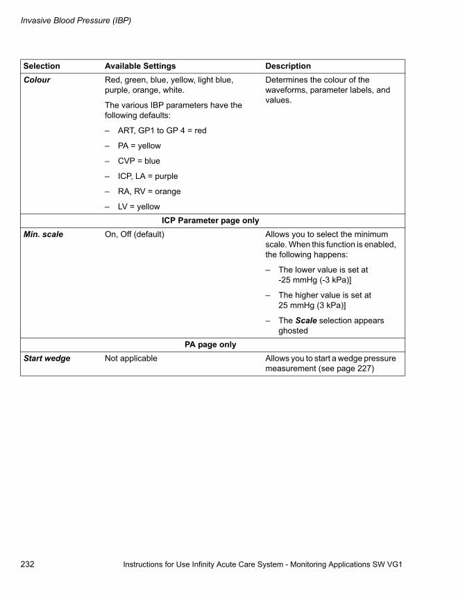
Invasive Blood Pressure (IBP)
232 Instructions for Use Infinity Acute Care System - Monitoring Applications SW VG1
Colour Red, green, blue, yellow, light blue, purple, orange, white.
The various IBP parameters have the following defaults:
– ART, GP1 to GP 4 = red
– PA = yellow
– CVP = blue
– ICP, LA = purple
– RA, RV = orange
– LV = yellow
Determines the colour of the waveforms, parameter labels, and values.
ICP Parameter page onlyMin. scale On, Off (default) Allows you to select the minimum
scale. When this function is enabled, the following happens:
– The lower value is set at-25 mmHg (-3 kPa)]
– The higher value is set at 25 mmHg (3 kPa)]
– The Scale selection appears ghosted
PA page onlyStart wedge Not applicable Allows you to start a wedge pressure
measurement (see page 227)
Selection Available Settings Description

Instructions for Use Infinity Acute Care System - Monitoring Applications SW VG1 233
Cardiac Output (C.O.)
Cardiac Output (C.O.)
Overview of Cardiac Output (C.O.) Monitoring . . . . . . . . . . . . . . . . . . . . . . . . . . . . 234
C.O. Measurement Method . . . . . . . . . . . . . . . 234Supported Parameters . . . . . . . . . . . . . . . . . . . 234
C.O. Precautions. . . . . . . . . . . . . . . . . . . . . . . 234
Connecting the C.O. Hardware . . . . . . . . . . . 235
Patient Preparation for C.O. Monitoring . . . . 237
C.O. Display . . . . . . . . . . . . . . . . . . . . . . . . . . 238
C.O. Computation Constant. . . . . . . . . . . . . . 239
C.O. Measuring Modes. . . . . . . . . . . . . . . . . . 241
Auto-Mode Measurements . . . . . . . . . . . . . . . . 241Manual Mode Measurements . . . . . . . . . . . . . . 243
Saving the C.O. Value. . . . . . . . . . . . . . . . . . . 244
The Procedures C.O. Average Page . . . . . . . 245
Accessing the C.O. Setup Page . . . . . . . . . . 246
C.O. Parameter Setup Functions . . . . . . . . . 246
Cardiac Output (C.O.)
234 Instructions for Use Infinity Acute Care System - Monitoring Applications SW VG1
Overview of Cardiac Output (C.O.) Monitoring
The M540 uses the thermodilution method to compute cardiac output (C.O.) for adult and paediatric patients. C.O. monitoring is not intended for neonatal patients.
The QuadHemo MPod, Hemo4 pod, and Hemo2 pod connect to the M540 and acquire the blood, and the injectate temperatures are used to compute the C.O. value.
Although the M540 processes the C.O. algorithms, you can only view the data and execute C.O. functions on the Cockpit.
C.O. Measurement Method
A solution of known temperature and volume is injected into the bloodstream in the right atrium. A thermistor in the catheter tip continuously measures the temperature of the blood as it leaves the heart. The injectate mixes with and cools the surrounding blood. The blood reaches its minimum temperature relatively quickly and then warms up slowly until it returns to the baseline blood temperature. The total drop in blood temperature is inversely related to the C.O. of the patient. The lower the C.O. value, the more the injectate cools the blood.
When computing the C.O., the M540 takes the following factors into account:
– Injectate volume, temperature, density, and specific heat of the fluid that is being injected
– Baseline blood temperature, density, and specific heat of the fluid
– Temperature changes of the blood injectate mixture
– Area under the temperature curve
The M540 supports the automatic and manual measuring modes.
The C.O. monitoring functions are configurable in the parameter-specific setup page and the Procedures C.O. page (see page 245).
Before performing any monitoring functions, refer to the section "For Your Safety and That of Your Patients" starting on page 9. Parameter-specific error messages are listed on page 340.
Supported Parameters
– C.O. – Cardiac output
– Tblood – blood temperature
– Tinj – injectate temperature
C.O. Precautions
WARNINGAn incorrect computation constant may yield incorrect C.O. measurements and put the patient at risk. Confirm that the manually entered computation constant is correct for the catheter you are using.
WARNINGVerify that you enter the patient’s current weight (not his or her ‘admission’ weight). Failure to enter an accurate weight value can result in inaccurate calculations and put the patient at risk.

Instructions for Use Infinity Acute Care System - Monitoring Applications SW VG1 235
Cardiac Output (C.O.)
Connecting the C.O. Hardware
You can connect the haemodynamic cable to one of the following devices:
– MPod - QuadHemo
– Hemo4 pod
– Hemo2 pod
The intermediate cable from any of the above devices connects directly to the M540.
To connect the C.O. hardware to the MPod - QuadHemo
1 Connect the haemodynamic intermediate cable connector (B) to the haemoconnector (A) of the M540.
2 Connect the other end of the haemodynamic intermediate cable (C) to the QuadHemo MPod connector (D).
3 Connect the C.O. intermediate cable connector (E) to the C.O. connector of the QuadHemo MPod (F).
4 Connect the catheter and the thermistor cables (H) to the C.O. intermediate cable connectors (G).
345
B
C
D
A
E
F
G
H

Cardiac Output (C.O.)
236 Instructions for Use Infinity Acute Care System - Monitoring Applications SW VG1
To connect the C.O. hardware to the Hemo4 pod and the Hemo2 pod
1 Connect the haemodynamic intermediate cable connector (B) to the haemoconnector (A) of the M540.
2 Connect the other end of the haemodynamic intermediate cable (C) to the Hemo4 pod/Hemo2 pod connector (D).
3 Connect the C.O. intermediate cable connector (E) to the C.O. connector of theHemo4 pod/Hemo2 pod (E).
4 Connect the catheter and the thermistor cables (H) to the C.O. intermediate cable connector (G).
346
B
A
C
DE
F
G
H

Instructions for Use Infinity Acute Care System - Monitoring Applications SW VG1 237
Cardiac Output (C.O.)
Patient Preparation for C.O. Monitoring
The following tips provide optimal C.O. monitoring results, but must never replace hospital-approved practices or manufacturer’s recommendations.
– Follow the recommendations of the manufacturer. Dräger Medical recommends that you place pre-filled syringes or the closed injectate delivery system into an ice bath.
– Check the ice bath regularly and add ice to maintain a temperature between 0 °C (32 °F) and 5 °C (41 °F). The accuracy of measurements done with the thermodilution method increases as the temperature of the injectate approaches 0 °C (32 °F).
– Verify the injectate volume.
– Verify the proper selection of catheter type and size or computation constant if Other is chosen for the catheter type.
– Use an in-line injectate system. Systems that measure the injectate temperature in the ice bath can introduce errors. These errors happen because the injectate temperature changes between its removal from the ice bath and the injection.
– If you fill your syringes manually, fill them with the same volume each time. The recommended amount is 10 cc for adults and 5 cc for paediatric patients. Do not touch the body of the syringe to avoid warming the injectate.
– Inject the entire volume in one swift, continuous motion.
– Perform the injection at the end of expiration. Taking successive C.O. measurements at different points in the respiratory cycle provides different measurements, especially for patients on mechanical ventilators.
– Discard results that are widely different from the general trend, and results associated with irregularly shaped waveforms.
NOTEFor the most accurate results when using an injectate at room temperature, use a 10 cc injectate volume unless clinically contraindicated.

Cardiac Output (C.O.)
238 Instructions for Use Infinity Acute Care System - Monitoring Applications SW VG1
C.O. Display
On the Cockpit, the C.O. display consists of a parameter box.
A C.O. label
B Time stamp of the last saved C.O. average (this area is blank if no measurements have been taken over the past 24 hours)
C Blood temperature label
D Blood temperature (Tblood) value – acquired from the haemodynamic pod
E Upper/lower alarm limits or crossed-triangle symbol when alarms are turned off.
F Injectate temperature label
G Injectate temperature value
H Previously saved C.O. value – average of a series of saved measurements04
6
A B C
DEF
GH

Instructions for Use Infinity Acute Care System - Monitoring Applications SW VG1 239
Cardiac Output (C.O.)
C.O. Computation Constant
The computation constant compensates for the specific characteristics of the C.O. catheters. If you use a Baxter, BD/Ohmeda, or Arrow catheter, the computation constant is automatically selected. If you choose Other as a catheter type (see page 246), enter a computation constant that corresponds to the catheter, its size, injectate volume, and injectate temperature.
Consult the documentation included with the catheter for computation constants, and select one that corresponds to the used injectate volume and temperature.
To enter a computation constant manually
Make sure the catheter type ’Other’ is selected (see page 246), otherwise the button Comp. constant is not available on the Procedures C.O. page.
1 Access the C.O. setup page (see page 246)
or
Access the Procedures C.O. page (see page 245)
2 Select the keypad symbol next to Comp. constant to open a numeric keypad.
3 Enter the correct computation constant for the type of catheter being used (refer to the tables on page 240).
4 Select Enter on the keypad to confirm the value.
WARNINGAn incorrect computation constant may yield incorrect C.O. measurements and put the patient at risk. Confirm that the manually entered computation constant is correct for the catheter you are using.

Cardiac Output (C.O.)
240 Instructions for Use Infinity Acute Care System - Monitoring Applications SW VG1
The following tables list the computation constants for Baxter, BD/Ohmeda, and Arrow catheters.
Baxter Computation Constants
Injectate Temperature (IT)Sensor connected IT sensor disconnected
CatheterSize
InjectateVolume IT = -5° to + 16 ° IT = 16 ° to 27 °C IT = 0 °C
7F 10 cc 0.561 0.608 0.542
7F 5 cc 0.259 0.301 0.247
7.5F 10 cc 0.574 0.595 0.564
7.5F 5 cc 0.287 0.298 0.257
5F 5 cc 0.285 0.307 0.270
BD/Ohmeda Computation Constants
Injectate Temperature (IT)Sensor connected IT sensor disconnected
CatheterSize
InjectateVolume IT = -5° to + 16 ° IT = 16 ° to 27 °C IT = 0 °C
7.5F 10 cc 0.579 0.628 0.566
7.5F 5 cc 0.281 0.309 0.270
7.5F 3 cc 0.160 0.181 0.151
7F 10 cc 0.579 0.628 0.566
7F 5 cc 0.281 0.309 0.270
7F 3 cc 0.160 0.181 0.151
5F 5 cc 0.291 0.316 0.279
5F 3 cc 0.170 0.188 0.160

Instructions for Use Infinity Acute Care System - Monitoring Applications SW VG1 241
Cardiac Output (C.O.)
C.O. Measuring Modes
Two C.O. measuring modes are available: automatic and manual. If unstable blood temperatures, artefact, or other conditions are preventing automatic measurements, switch to manual mode.
If the attention tone is not disabled (see page 275), a tone sounds when the C.O. value has been computed.
Auto-Mode Measurements
In the auto mode, the message Inject when ready appears in the Procedures C.O. page of the Cockpit when the baseline blood temperature is stable. If the blood temperature becomes unstable, the message Inject when ready is replaced by the message Poor Baseline. To select the automatic C.O. mode, see page 246.
Arrow Computation Constants
Catheter Size
InjectateVolume IT = -1°C (± 1 °C) IT = 24 °C (± 1 °C)
7.5F 10 cc 0.532 0.586
7.5F 5 cc 0.249 0.265
7.5F 3 cc 0.131 0.155
7F 10 cc 0.541 0.601
7F 5 cc 0.250 0.273
7F 3 cc 0.134 0.156
5F 5 cc 0.267 0.303
5F 3 cc 0.157 0.192

Cardiac Output (C.O.)
242 Instructions for Use Infinity Acute Care System - Monitoring Applications SW VG1
To start a measurement in the auto mode
1 Press the C.O. Start key (A) on the QuadHemo MPod or the Hemo4 pod/Hemo2 pod.
or
Select the Start C.O. button on the Procedures C.O. page (see page 245).
2 Wait for a tone to sound and the Inject when ready message to appear on the Cockpit to indicate that a stable blood temperature has been detected. Do not perform an injection before the Inject when ready message appears.
3 Inject the saline solution into the bloodstream. A thermodilution waveform appears, displaying the change in blood temperature. If the blood temperature becomes unstable, the measurement is cancelled automatically.
4 Repeat step 2 to take an additional measurement, making sure to wait for the Inject when ready message.
The Procedures C.O. page (see page 245) stores up to five C.O. averages with time stamps. Each value panel is touch-sensitive and allows you to include or exclude a value from the calculation of the average. Any value that is crossed out is excluded from the average. If you touch the panel again, the value re-appears and will be included in the average.
To save the C.O. average, see page 244
340
339
Quad Hemo MPod A
AHemo2 Pod
338
AHemo4 Pod

Instructions for Use Infinity Acute Care System - Monitoring Applications SW VG1 243
Cardiac Output (C.O.)
Manual Mode Measurements
If automatic measurements are not possible due to unstable blood temperatures or other causes, switch to the manual mode. To select the manual C.O. mode, see page 247.
To start a measurement in the manual mode
1 Press the C.O. Start key (A) on the QuadHemo MPod or the Hemo4 pod/Hemo2 pod.
or
Select Procedures... from the main-menu bar then select the C.O. tab to access the Procedures C.O. page. Select the C.O. Start button on the Cockpit. Inject the saline solution immediately.
2 Repeat steps 1 and 2 for additional measurements.
The Procedures C.O. page (see page 245) stores up to five C.O. averages with time stamps. Each value panel is touch-sensitive and allows you to include or exclude a value from the calculation of the average. Any value that is crossed out is excluded from the average. If you touch the panel again, the value re-appears and will be included in the average.
To save the C.O. average, see page 244.
340
339
Quad Hemo MPod A
AHemo2 Pod
338
AHemo4 Pod

Cardiac Output (C.O.)
244 Instructions for Use Infinity Acute Care System - Monitoring Applications SW VG1
Saving the C.O. Value
After completing a measurement, you can store the C.O. average. Closing the Procedures C.O. page without saving the C.O. value(s) causes any unsaved values to be lost.
To save the C.O. value manually
1 Select Procedures... from the main-menu bar.
2 Select the C.O. tab to access the Procedures C.O. page.
3 Select the Save C.O. average button.
The stored C.O. value and the time stamp are stored in the trend function and the parameter box.

Instructions for Use Infinity Acute Care System - Monitoring Applications SW VG1 245
Cardiac Output (C.O.)
The Procedures C.O. Average Page
Different injection techniques cause variations in C.O. measurements. To compensate for such discrepancies, you can review up to five measurements and use them to compute a C.O. average. The following diagram shows the Procedures C.O. average page where you can start and save C.O. measurements, and compare stored averages.
A Start C.O. button (only available in manual mode - see page 243)
B Save C.O. average button
C Most recent C.O. average
D Blood and injectate temperature value fields
E Waveform field
F Up to five C.O. measurements with time stamps. Each value panel is touch-sensitive and allows you to include or exclude a value from the calculation of the average. Any value that is crossed out is excluded from the average. If you touch the panel again, the value re-appears and will be included in the average.
G Catheter type button
H Catheter size button
I Injectate volume button
If you select the catheter type Other (see page 246), a button appears at the bottom of the page. This button accesses a keypad for entering a computation constant.
047
X
A BC
D
E
F F F F
GHI
Procedures

Cardiac Output (C.O.)
246 Instructions for Use Infinity Acute Care System - Monitoring Applications SW VG1
Accessing the C.O. Setup Page
� Select the C.O. parameter box to select the C.O. setup page directly.
or
Select Sensor parameters... from the main-menu bar > C.O. tab to access the C.O. setup page. If you cannot see the tab, select the following two symbols located in the upper-right corner of the dialogue window: symbol of the display filter button.
The top portion of the page contains the Auto set and Alarm buttons for configuring the alarm functions. For detailed alarm setup information, see "Configuring a Patient’s Alarm Settings" on page 85.
C.O. Parameter Setup Functions
All C.O. setup functions take place in the C.O. setup page.
Selection Available Settings DescriptionCatheter type – BD/Ohmeda (default)
– Edwards/Baxter
– Arrow
– Other
Displays the currently selected catheter type.
Catheter Size – 5F, 7F (default), 7.5F Displays the currently selected catheter size.
Injectate volume [cc]
3.0, 5.0, or 10.0 (default) Displays the currently selected volume of the injectate.
NOTEIf Other is selected for Catheter type, this button is not available.
NOTEIf Other is selected for Catheter type, this button is not available.

Instructions for Use Infinity Acute Care System - Monitoring Applications SW VG1 247
Cardiac Output (C.O.)
Comp. constant
This selection only appears if the Catheter type Other was selected.
0.100 to 0.999
0.542 (default)
The computation constant must be entered manually if the catheter type Other was selected (see page 246). The computation constant depends on the injectate volume and temperature according to the specific values provided by the catheter.
C.O. mode – Auto mode (default)
– Manual mode
Determines the C.O. measurement mode (see page 241).
Start the C.O. N/A Starts the C.O. measurement (see page page 241).
Colour White (default); there is no colour selection for C.O.
Determines the colour of the waveforms, parameter labels, and values.
Selection Available Settings Description

248 Instructions for Use Infinity Acute Care System - Monitoring Applications SW VG1
This page is intentionally left blank

Instructions for Use Infinity Acute Care System - Monitoring Applications SW VG1 249
Carbon Dioxide Concentrations (CO2)
Carbon Dioxide Concentrations (CO2)
Overview of CO2 Monitoring . . . . . . . . . . . . . 250
Supported Parameters . . . . . . . . . . . . . . . . . . . 250
CO2 Precautions . . . . . . . . . . . . . . . . . . . . . . . 251
Connecting the CO2 Sensor . . . . . . . . . . . . . 252
Patient Preparation for CO2 Monitoring . . . . 253
CO2 Display. . . . . . . . . . . . . . . . . . . . . . . . . . . 253
CO2-Parameter Box . . . . . . . . . . . . . . . . . . . . . 253Capnogrammes . . . . . . . . . . . . . . . . . . . . . . . . 254Troubleshooting . . . . . . . . . . . . . . . . . . . . . . . . 254
Accessing the CO2-Setup Page . . . . . . . . . . 256
CO2-Parameter Setup Functions. . . . . . . . . . 256
Carbon Dioxide Concentrations (CO2)
250 Instructions for Use Infinity Acute Care System - Monitoring Applications SW VG1
Overview of CO2 Monitoring
The M540 provides fast and continuous mainstream measurements of carbon dioxide concentrations (CO2) in the airway of intubated patients. The M540 acquires signals from a CO2 sensor (Infinity MCable Mainstream CO2) which fits over a mainstream airway adaptor. The lightweight, reusable CO2 mainstream sensor provides sensitive and accurate measurements. It uses non-dispersive infrared technology to measure CO2 in respiratory gases.
The CO2 monitoring is available for adult, paediatric and neonatal patients.
As respiratory gases flow through the airway adaptor, the sensor analyses the expired and inspired air of the patient by sending a beam of infrared light through transparent ports in the airway adaptor while detecting changes in CO2 absorption levels.
Refer to the Infinity Acute Care System - M540 Instructions for Use for a detailed description of the M540 CO2 functions.
Before performing any monitoring functions, refer to the section "For Your Safety and That of Your Patients" starting on page 9. Parameter-specific error messages are listed on page 345.
Supported Parameters
– etCO2 – end-tidal CO2
– inCO2 – inspired CO2
– RRc – respiration rate as calculated from the capnogramme

Instructions for Use Infinity Acute Care System - Monitoring Applications SW VG1 251
Carbon Dioxide Concentrations (CO2)
CO2 Precautions
Refer to "Site of Operation" on page 13 for general precautions.
WARNINGRRc apnoea alarms are NOT reported if the setting RRc apnoea time is set to Off in the CO2 setup page and the RRc alarm feature is disabled. To generate RRc apnoea alarms, enable the RRc alarms and select an RRc apnoea time.
WARNINGThe safety and effectiveness of the respiration measurement method in the detection of apnoea, particularly the apnoea of prematurity and apnoea of infancy, have not been established.
WARNINGThe patient monitors that measure CO2, anaesthetic agents, and/or respiratory mechanics are not intended to be used as an apnoea monitor and/or recording device. While these products provide an apnoea alarm, that alarm condition is initiated based on the elapsed time since the last breath was detected. The clinical diagnosis of a true apnoeic event, however, requires multiple physiological signals.
WARNINGCO2 alarms do not activate until the first breath is detected after turning on the monitor or discharging a patient.
WARNINGThe surface temperature of the sensor may rise to 43°C (109°F). Prolonged exposure to the patient's skin may result in a burn.
CAUTIONLeaks in the breathing circuit (for example, an uncuffed endotracheal tube or a damaged airway adaptor) may significantly affect CO2 the measurement values.
CAUTIONTo avoid accidental disconnections, do not apply excessive tension to any sensor cable.
CAUTIONTo prevent leakage, make sure the airway adaptor is firmly connected to the breathing circuit.
CAUTIONCheck the CO2 mainstream sensor for damage before use. A damaged CO2 sensor may impair electrical isolation or may introduce debris into the breathing circuit.
NOTECO2 accessories that come in contact with the patient do not contain latex.
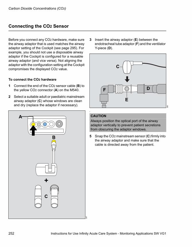
Carbon Dioxide Concentrations (CO2)
252 Instructions for Use Infinity Acute Care System - Monitoring Applications SW VG1
Connecting the CO2 Sensor
Before you connect any CO2 hardware, make sure the airway adaptor that is used matches the airway adaptor setting of the Cockpit (see page 295). For example, you should not use a disposable airway adaptor if the Cockpit is configured for a reusable airway adaptor (and vice versa). Not aligning the adaptor with the configuration setting at the Cockpit compromises the displayed CO2 value.
To connect the CO2 hardware
1 Connect the end of the CO2 sensor cable (B) to the yellow CO2 connector (A) on the M540.
2 Select a suitable adult or paediatric mainstream airway adaptor (C) whose windows are clean and dry (replace the adaptor if necessary).
3 Insert the airway adaptor (E) between the endotracheal tube adaptor (F) and the ventilator Y-piece (D).
4
5 Snap the CO2 mainstream sensor (C) firmly into the airway adaptor and make sure that the cable is directed away from the patient.
347
A
B
C
348
CAUTIONAlways position the optical port of the airway adaptor vertically to prevent patient secretions from obscuring the adaptor windows.
C
E
DF
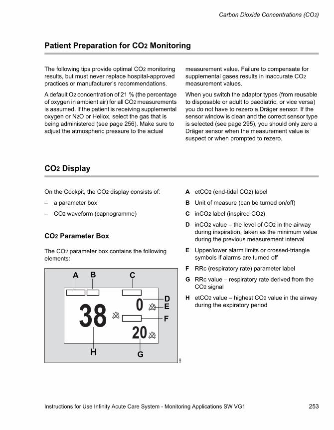
Instructions for Use Infinity Acute Care System - Monitoring Applications SW VG1 253
Carbon Dioxide Concentrations (CO2)
Patient Preparation for CO2 Monitoring
The following tips provide optimal CO2 monitoring results, but must never replace hospital-approved practices or manufacturer’s recommendations.
A default O2 concentration of 21 % (the percentage of oxygen in ambient air) for all CO2 measurements is assumed. If the patient is receiving supplemental oxygen or N2O or Heliox, select the gas that is being administered (see page 256). Make sure to adjust the atmospheric pressure to the actual
measurement value. Failure to compensate for supplemental gases results in inaccurate CO2 measurement values.
When you switch the adaptor types (from reusable to disposable or adult to paediatric, or vice versa) you do not have to rezero a Dräger sensor. If the sensor window is clean and the correct sensor type is selected (see page 295), you should only zero a Dräger sensor when the measurement value is suspect or when prompted to rezero.
CO2 Display
On the Cockpit, the CO2 display consists of:
– a parameter box
– CO2 waveform (capnogramme)
CO2 Parameter Box
The CO2 parameter box contains the following elements:
A etCO2 (end-tidal CO2) label
B Unit of measure (can be turned on/off)
C inCO2 label (inspired CO2)
D inCO2 value – the level of CO2 in the airway during inspiration, taken as the minimum value during the previous measurement interval
E Upper/lower alarm limits or crossed-triangle symbols if alarms are turned off
F RRc (respiratory rate) parameter label
G RRc value – respiratory rate derived from the CO2 signal
H etCO2 value – highest CO2 value in the airway during the expiratory period
048
A B C
DEF
GH

Carbon Dioxide Concentrations (CO2)
254 Instructions for Use Infinity Acute Care System - Monitoring Applications SW VG1
Capnogrammes
The Cockpit also displays an instantaneous CO2 waveform or capnogramme.
A Expiratory plateau (level of CO2 in lungs ceases to increase significantly)
B End-tidal concentration point (end of expiration phase, where CO2 is measured)
C Onset of inspiration phase
D Expiration phase
E Baseline during inspiration
Troubleshooting
In addition to evaluating the clinical status of a patient, capnogrammes can help troubleshoot problems with the equipment.
The following table shows how capnogrammes can be used to identify common problems.
349
A B
CDE
Description Cause CapnogrammeAlveolar plateau showing a downward slope that merges with a descending limb.
– Inadequate seal around the endotracheal tube
– Leaky or deflated endotracheal or tracheostomy cuff
– Artificial airway that is too small for the patient

Instructions for Use Infinity Acute Care System - Monitoring Applications SW VG1 255
Carbon Dioxide Concentrations (CO2)
Elevated waveform baseline with corresponding increase in CO2 level.
Rebreathing due to one of the following causes:
– Disposable airway adaptor is used although the Cockpit is configured for the reusable adaptor type
– Contaminated airway adaptor (dirty window)
– CO2 Zero drift
– Insufficient expiratory time
– Faulty expiratory valve
– Inadequate inspiratory flow
– Malfunction of a CO2 absorber system
– Partial rebreathing circuits
Description Cause CapnogrammeChange in slope of ascending limb. Possible absence of an alveolar plateau.
Obstruction caused by one of the following:
– Partial obstruction in the expiratory limb of the breathing circuit
– Foreign body in the upper airway
– Partially kinked or occluded artificial airway
– Herniated endotracheal or tracheostomy tube cuff
– Bronchospasm
Elevated baseline, with a pronounced slope on the descending limb.
– A faulty ventilator circuit valve
– Rebreathing (see above)

Carbon Dioxide Concentrations (CO2)
256 Instructions for Use Infinity Acute Care System - Monitoring Applications SW VG1
Accessing the CO2 Setup Page
� Select the CO2 parameter box to select the CO2 setup page directly.
or
Select Sensor parameters... from the main-menu bar > CO2 tab to access the CO2 setup page. If you cannot see the tab, select the following two symbols located in the upper-right corner of the dialogue window: symbol and the display filter button.
The top portion of the setup page contains the Auto set and Alarm buttons for configuring the alarm functions. For detailed alarm setup information, see "Configuring a Patient’s Alarm Settings" on page 85.
CO2 Parameter Setup Functions
All CO2 setup functions take place in the CO2 setup page. Before you connect any CO2 hardware, make sure the airway adaptor that is used, matches the airway adaptor setting at the Cockpit (see page 295).
Selection Available Settings DescriptionZero
(only available if a CO2 device is connected)
Not applicable Zero's the CO2 sensor, if necessary. The CO2 sensor stores a new zero point for CO2 measurements.
Scale – 0 mmHg to 40 mmHg (default), 0 mmHg to 60 mmHg, 0 mmHg to 80 mmHg, 0 mmHg to 100 mmHg
– 0 to 5 kPa (default), 0 kPa to 8 kPa, 0 kPa to 12 kPa, 0 kPa to 16 kPa
– 0 % to 5 % (default), 0 % to 8 %, 0 % to 12 %, 0 % to 16 %
Adjusts the size of the CO2 waveform.
NOTEThe sensor must be removed from the airway adaptor before zeroing. The sensor is zeroed in room air. Do not breathe on the airway adaptor during zeroing.

Instructions for Use Infinity Acute Care System - Monitoring Applications SW VG1 257
Carbon Dioxide Concentrations (CO2)
Atm. pressure 570 to 800 mmHg
Default: 760 mmHg
Determines the atmospheric pressure setting of the sensor and compensates for pressure effects. Failure to compensate for pressure can cause inaccurate measurements.
Gas compensation
Air (default), N2O/O2, O2 > 50 %, HeliOx Compensates for supplemental oxygen, N2O or Heliox. Failure to compensate for supplemental oxygen can cause inaccurate measurements.
RRc apnoea time Off (default), 10, 15, 20, 25, 30 sec Specifies the time the M540 waits before reporting a cessation of breathing as an apnoea event.
Apnoea archive Off, Record, Store (default), Str./Rec. Determines what happens in response to an apnoea.
Colour Red, green, blue, yellow (default), light blue, purple, orange, white.
Determines the colour of the waveforms and parameter labels/values.
Selection Available Settings Description

258 Instructions for Use Infinity Acute Care System - Monitoring Applications SW VG1
This page is intentionally left blank

Instructions for Use Infinity Acute Care System - Monitoring Applications SW VG1 259
External Device - Ventilator
External Device - Ventilator
Overview of Ventilation . . . . . . . . . . . . . . . . . 260
Vent Central Option . . . . . . . . . . . . . . . . . . . . . 260External Device Alarms . . . . . . . . . . . . . . . . . . 260Supported Parameters . . . . . . . . . . . . . . . . . . . 261
Ventilator Precautions . . . . . . . . . . . . . . . . . . 262
Ventilator Display . . . . . . . . . . . . . . . . . . . . . . 263
Loops. . . . . . . . . . . . . . . . . . . . . . . . . . . . . . . . 263
The Show-All Page . . . . . . . . . . . . . . . . . . . . . 264
Accessing the Ventilator Setup Pages . . . . . 264
Ventilator Paw Setup Functions . . . . . . . . . . 265
Ventilator Setup Functions . . . . . . . . . . . . . . 265
CO2 Setup Functions . . . . . . . . . . . . . . . . . . . 266
External Device - Ventilator
260 Instructions for Use Infinity Acute Care System - Monitoring Applications SW VG1
Overview of Ventilation
The device connectivity option enables the Cockpit to display parameter values, waveforms, and loops from standalone ventilators. Within 30 seconds of connecting a ventilator, the data appear at the Cockpit. The ventilator monitoring functions are configurable in the parameter-specific setup page (see page 265).
Before performing any monitoring functions, refer to the section "For Your Safety and That of Your Patients" starting on page 9. Parameter-specific error messages are listed on page 326.
Vent Central Option
Any external-device ventilator parameters displayed at the Cockpit are also broadcast to the Infinity network. If the patient is admitted at the ICS (Infinity CentralStation), you can review additional ventilator-related information via the Vent Central option. For example, you can review the ventilator settings of each parameter and the current ventilation mode. For more detailed information, refer to the Infinity Central Station Instructions for Use.
External Device Alarms
Alarms from the ventilator are transmitted to the Infinity network and made available for alarm enunciation at the ICS. For more information, refer to the Infinity Central Station Instructions for Use.
If the external device alarm feature is enabled at the Cockpit (see page 287) and an external device is disconnected from the Cockpit, the following happens at the Cockpit and at the ICS provided the patient is admitted at the ICS:
– An alarm tone of low priority sounds.
– The message External device disconnected is displayed.

Instructions for Use Infinity Acute Care System - Monitoring Applications SW VG1 261
External Device - Ventilator
Supported Parameters
The following table lists all parameters supported with the device connectivity option. However, the ventilator in use determines which of these parameters are available to the Cockpit and the
network. You can review the settings for all ventilator parameters at the ICS (they are not displayed at the Cockpit). The ventilators provide the range and resolution for all parameters.
Parameter Label UnitEnd-tidal CO2 etCO2 mmHg, kPa, %
Minimum airway pressure (1), (2) PAW min. mbar
Occlusion pressure (1) Occlusion Press mbar
Trapped volume (1) Trapped VOL ml
Gas temperature (1) AW-Temp oC
Dead space (2) TVd aw ml
Peak inspiratory pressure (2) PIP mbar or cmH2O
Mean airway pressure ((2) MAP mbar or cmH2O
Peak-end expiratory airway pressure (2) PEEP mbar or cmH2O
Tidal volume, expiratory (2) TVe ml or L
Minute volume, expired (2) MVe L/min
Respiratory rate (2) RRv min.
Inspired O2 (2) inO2 (Cockpit label)
iO2* (network label)
%
Relative dead space (2) TVd aw% %
Minute volume, expired, spontaneous (2) MV e s L/min
Respiratory rate, spontaneous (2) RRs br/m
Pause pressure (2) Pause cmH2O
inspiratory:expiratory ratio (2) I:E No units
inspiratory:expiratory ratio (inspiratory component) (2)
I:E I-Part No units
inspiratory:expiratory ratio (expiratory component) (2)
I:E E-Part No units
Dynamic compliance (2) Cdyn L/bar
Resistance (2) Raw mbar/L/s
Tidal volume setting, inspired (2) TVi set ml or L
CO2 production (2) VCO2 ml/min(1) This parameter is only available on the Infinity network. It is not available at the Cockpit.
(2) This parameter is also displayed in the Show All page (see page 264).
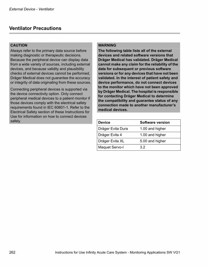
External Device - Ventilator
262 Instructions for Use Infinity Acute Care System - Monitoring Applications SW VG1
Ventilator Precautions
CAUTIONAlways refer to the primary data source before making diagnostic or therapeutic decisions. Because the peripheral device can display data from a wide variety of sources, including external devices, and because validity and plausibility checks of external devices cannot be performed, Dräger Medical does not guarantee the accuracy or integrity of data originating from these sources.
Connecting peripheral devices is supported via the device connectivity option. Only connect peripheral medical devices to a patient monitor if those devices comply with the electrical safety requirements found in IEC 60601-1. Refer to the Electrical Safety section of these Instructions for Use for information on how to connect devices safely.
WARNINGThe following table lists all of the external devices and related software versions that Dräger Medical has validated. Dräger Medical cannot make any claim for the reliability of the data for subsequent or previous software versions or for any devices that have not been validated. In the interest of patient safety and device performance, do not connect devices to the monitor which have not been approved by Dräger Medical. The hospital is responsible for contacting Dräger Medical to determine the compatibility and guarantee status of any connection made to another manufacturer’s medical devices.
Device Software versionDräger Evita Dura 1.00 and higher
Dräger Evita 4 1.00 and higher
Dräger Evita XL 5.00 and higher
Maquet Servo-I 3.2

Instructions for Use Infinity Acute Care System - Monitoring Applications SW VG1 263
External Device - Ventilator
Ventilator Display
The Cockpit displays the following loops and parameters:
– Airway-pressure waveform (paw) and associated parameter box
– Expiratory flow waveform and associated flow/volume (vent) parameter box
– CO2 and associated parameter box
– Loops
The following diagram shows a ventilator parameter box.
A Primary parameter label
B Second parameter label
C Third parameter label
D Third parameter value
E Second parameter value
F Primary parameter value
Loops
Loops offer important information about the response of the patient to mechanical ventilation. You can review loops in two pages: Pressure/volume and Flow/volume.
Pressure/volume loops illustrate changes in compliance, resistance, and work of breathing. A mechanical breath plots in an anti-clockwise direction, while a spontaneous breath plots in a clockwise direction. Inspiration starts at a point defined by the baseline pressure and the volume level at the beginning of inspiration.
Flow/volume loops also report mechanical and spontaneous breaths. Inspiration begins at the origin and moves upwards and clockwise. Expiration plots below the horizontal axis and progresses anti-clockwise to the original starting point.
049
A B C
DEF
External Device - Ventilator
264 Instructions for Use Infinity Acute Care System - Monitoring Applications SW VG1
To view loops
1 Select the Sensor parameters... button on the main-menu bar.
2 Select the Ventilator tab. If you cannot see the tab, select the following two symbols located in the upper-right corner of the dialogue window:
symbol of the display filter button.
3 Select the PV loop tab to view pressure/volume loops or select the FV loop tab to view the flow/volume loops.
4 Select the Loops tab to view all loops in one dialogue window.
5 Select the Loop draw button at the bottom of the page to choose how many loops are drawn on top of each other before the screen is cleared.
6 Select the Save reference button at the bottom of the page if you want to save a loop for future analysis and comparison.
The Show-All Page
The Show all page displays the values of the currently monitored ventilator parameters (see page 261).
Accessing the Ventilator Setup Pages
1 Select Sensor parameters... from the main-menu bar > Ventilator tab to access the Ventilator setup page. If you cannot see the tab, select the following two symbols located in the upper-right corner of the dialogue window: symbol of the display filter button.
2 Select either the Paw or the Vent tabs to access the respective setup pages.

Instructions for Use Infinity Acute Care System - Monitoring Applications SW VG1 265
External Device - Ventilator
Ventilator Paw Setup Functions
See page 264 for information on how to access this setup page.
Ventilator Setup Functions
See page 264 for information on how to access this setup page.
Selection Available Settings DescriptionPaw scale [mbar] 10, 15, 20, 25 (default), 30, 40, 50, 60, 70, 80,
100, 120Determines the scale of the displayed Paw waveform.
Parameter 1 MAP, PEEP, PIP (default) Selects the primary parameter in the Paw parameter box.
Parameter 2 MAP (default), PEEP, PIP Selects the second parameter in the Paw parameter box.
Parameter 3 MAP, PEEP (default), PIP Selects the third parameter in the Paw parameter box.
Colour Red, green, blue, yellow, light blue (default), purple, orange, white.
Determines the colour of all ventilation parameter boxes, waveforms,.and loops.
Selection Available Settings DescriptionFlow scale [L/min]
5, 10, 15, 20 (default in neonatal mode), 35, 50, 100 (default in adult and paediatric modes), 150, 200
Determines the scale of the displayed Flow waveform.
Vol scale [ml] 5, 10, 25, 50 (default in neonatal mode), 75, 100, 250, 500, 1000 (default in paediatric and adult modes), 1500
Determines the scale of the displayed Volume waveform.
Parameter 1 Mve (default), RRv, TVe Selects the primary parameter in the Vent parameter box.
Parameter 2 Mve, RRv (default), TVe Selects the second parameter in the Vent parameter box.
Parameter 3 Mve, RRv, TVe (default) Selects the third parameter in the Vent parameter box.
Colour Red, green, blue, yellow, light blue (default), purple, orange, white.
Determines the colour of all ventilation parameter boxes, waveforms,.and loops.

External Device - Ventilator
266 Instructions for Use Infinity Acute Care System - Monitoring Applications SW VG1
CO2Setup Functions
See page 264 for information on how to access this setup page.
Selection Available Settings DescriptionCO2 scale – 0 - 40 (default), 0 - 60, 0 - 80, 0 - 100
(mmHg)
– 0.0 - 5.0 (default), 0.0, -8.0, 0.0 - 12.0, 0.0 - 16.0 (kPa)
– 0 - 5 (default), 0 - 8, 0 - 12, 0 - 16 (%)
Determines the scale of the displayed CO2 waveform.
Atm. pressure 570 to 800 (mmHg) Determines the atmospheric pressure setting.
Colour Red, green, blue, yellow (default), light blue, purple, orange, white.
Determines the colour of the CO2 parameter box and waveform.

Instructions for Use Infinity Acute Care System - Monitoring Applications SW VG1 267
External Device - Continuous Cardiac Output (CCO)
External Device - Continuous Cardiac Output (CCO)
Overview of CCO . . . . . . . . . . . . . . . . . . . . . . 268
External Device Alarms . . . . . . . . . . . . . . . . . . 268Supported Parameters . . . . . . . . . . . . . . . . . . . 269
CCO Precautions . . . . . . . . . . . . . . . . . . . . . . 270
The Show-All Page . . . . . . . . . . . . . . . . . . . . . 270
Accessing the CCO/SvO2 Setup Page . . . . . 271
SvO2 Setup Functions . . . . . . . . . . . . . . . . . . 271

External Device - Continuous Cardiac Output (CCO)
268 Instructions for Use Infinity Acute Care System - Monitoring Applications SW VG1
Overview of CCO
The device connectivity option enables the Cockpit to display parameter values from a continuous cardiac output device. Within 30 seconds of connecting the device, the data appear at the Cockpit. The following cardiac output devices are supported:
– Edwards Vigilance II SvO2/CCO (all software versions)
– Edwards Vigileo SvO2/CCO (all software versions)
The CCO monitoring functions are configurable in the parameter-specific setup page (see page 271).
Before performing any monitoring functions, refer to the section "For Your Safety and That of Your Patients" starting on page 9.
External Device Alarms
If the external device alarm feature is enabled at the Cockpit (see page 287) and an external device is disconnected from the Cockpit, the following happens at the Cockpit and at the ICS provided the patient is admitted at the ICS:
– An alarm tone of low priority sounds.
– The message External device disconnected appears.

Instructions for Use Infinity Acute Care System - Monitoring Applications SW VG1 269
External Device - Continuous Cardiac Output (CCO)
Supported Parameters
The following table lists the supported parameters displayed on the Cockpit, originating from external CCO devices that are supporting and monitoring these parameters. The range and resolution for all parameters are provided by the CCO device.
Parameter Label UnitVenous oxygen saturation SvO2 %
Blood temperature Tblood oC
Continuous cardiac output CCO L/min
Continuous cardiac output index (1) CCI L/min/m2
Oxygen consumption VO2 ml/min
Oxygen delivery DO2 ml/min
Arterial oxygen saturation SaO2 %
Systemic vascular resistance (2) SVR dyn x s/cm5
Systemic vascular resistance index (1), (2) SVRI dyn x s/cm5/m2
End diastolic volume EDV ml
End diastolic volume index (1) EDVI ml/m2
End systolic volume ESV ml
End systolic volume index (1) ESVI ml/m2
Ejection fraction EF %
Stroke volume (3) SV ml
Stroke volume index (1) SVI ml/m2
Stroke volume variation (1) SVV (only supported by Vigileo)
%
NOTE(1) Indexed parameters require the height-and-weight value from Cockpit.(2) The calculated value at the Cockpit requires the values for ART m and CVP from the Cockpit.(3) This is a calculated value at the Cockpit.

External Device - Continuous Cardiac Output (CCO)
270 Instructions for Use Infinity Acute Care System - Monitoring Applications SW VG1
CCO Precautions
The Show-All Page
The Show all page displays the values of the currently monitored CCO/SvO2 parameters.
To access the CCO/SvO2 Show all page
1 Select the Sensor parameters... button from the main-menu bar.
2 Select the CCO tab.If you cannot see the tab, select the following two symbols located in the upper-right corner of the dialogue window: symbol and the display filter button.
3 Select the Show all tab.
or
1 Select the Trends/Data... button from the main-menu bar.
2 Select the Hemo tab.
3 Select the Show all tab
WARNINGTo reduce the risk of patient injury due to electrical shock, always position the external device connectivity cable as far from the patient as possible. Make sure that any cables or other conducting devices do not come in contact with the patient. The device connectivity cable is electrically isolated from the monitor and any peripheral devices, but the cable enclosure is not electrically isolated from the peripheral device itself.
WARNINGThe Cockpit does not enunciate alarms for external device parameters.
CAUTIONAlways refer to the primary data source before making diagnostic or therapeutic decisions. Because the peripheral device can display data from a wide variety of sources, including external devices, and because validity and plausibility checks of external devices cannot be performed, Dräger Medical does not guarantee the accuracy or integrity of data originating from these sources.
Connecting peripheral devices is supported via the device connectivity option. Only connect peripheral medical devices to a patient monitor if those devices comply with the electrical safety requirements found in IEC 60601-1. Refer to the Electrical Safety section of these Instructions for Use for information on how to connect devices safely.

Instructions for Use Infinity Acute Care System - Monitoring Applications SW VG1 271
External Device - Continuous Cardiac Output (CCO)
Accessing the CCO/SvO2 Setup Pages
1 Select the Sensor parameters... button from the main-menu bar
2 Select the CCO tab If you cannot see the tab, select the following two symbols located in the upper-right corner of the dialogue window: symbol and the display filter button
SvO2 Setup Functions
Selection Available Settings DescriptionParameter 1 SVO2 (default), Tblood, CCO, CCI, VO2,
DO2, SaO2, SVR, SVRI, EDV, EDVI, ESV, ESVI, EF, SV, SVI, SVV
Selects the primary parameter in the CCO parameter box.
Parameter 2 SVO2, Tblood, CCO (default), CCI, VO2, DO2, SaO2, SVR, SVRI, EDV, EDVI, ESV, ESVI, EF, SV, SVI, SVV
Selects the second parameter in the CCO parameter box.
Parameter 3 SVO2, Tblood, CCO, CCI, VO2, DO2, SaO2, SVR (default), SVRI, EDV, EDVI, ESV, ESVI, EF, SV, SVI, SVV
Selects the third parameter in the CCO parameter box.
Colour Red, green, blue, yellow, light blue, purple, orange, white (default).
Determines the colour of the parameter box.

272 Instructions for Use Infinity Acute Care System - Monitoring Applications SW VG1
This page is intentionally left blank
Instructions for Use Infinity Acute Care System - Monitoring Applications SW VG1 273
System Configuration
System Configuration
Overview . . . . . . . . . . . . . . . . . . . . . . . . . . . . . 274
The Screen Setup Pages . . . . . . . . . . . . . . . . 274
Screen Setup – General Settings Setup Page . . . . . . . . . . . . . . . . . . . . . . . . . . . . . . . . . 275
Screen Setup – Modes Setup Page. . . . . . . . 276
Screen Setup – Auto-View Setup Page . . . . 277
Configuring the Auto-View Settings . . . . . . . . . 278
Configuring Parameters for Display . . . . . . . 279
The Parameter Selection Window . . . . . . . . . . 279Configuring the Parameter Priority and Display . . . . . . . . . . . . . . . . . . . . . . . . . . . . . . . 280
Screen Setup – Views Setup Page . . . . . . . . 282
Screen Setup – Views Editor Setup Page . . 283
The Alarms Pages . . . . . . . . . . . . . . . . . . . . . 286
Alarms Setup - General Settings Page. . . . . . . 286Alarm Setup – Volume/Tone Setup Page . . . . . 288Alarm Setup – Code Setup Page . . . . . . . . . . . 289
Recordings/Reports Page . . . . . . . . . . . . . . . 290
Recorder/Reports Setup Page . . . . . . . . . . . . . 290Rest ECG Report Setup Page . . . . . . . . . . . . . 291Reports Setup Page . . . . . . . . . . . . . . . . . . . . . 292
Biomed Setup Pages . . . . . . . . . . . . . . . . . . . 292
Biomed Setup – Country Setup Page. . . . . . . . 293Biomed Setup – Units-of-Measure Setup Page . . . . . . . . . . . . . . . . . . . . . . . . . . . . . . . . . 294Biomed Setup – Bedside-Setup Setup Page . . 295Biomed Setup – Name Service Setup Page. . . 296Biomed Setup – Network Setup Page . . . . . . . 297Biomed Setup – Printer Setup Page. . . . . . . . . 297Biomed Setup – Recorder Setup Page . . . . . . 298Biomed Setup – Service Setup Page . . . . . . . . 298
Biomed IT Setup . . . . . . . . . . . . . . . . . . . . . . . 299
Enabling/Disabling IT-Tab Feature . . . . . . . . . 299Configuring IT Tabs – Web-Browser Setup . . . 299Adding a Web-Browser Page . . . . . . . . . . . . . 300Deleting a Web-Browser Page . . . . . . . . . . . . 301Configuring Citrix Applications . . . . . . . . . . . . 301Configuring IT Tabs . . . . . . . . . . . . . . . . . . . . . 302
Profile Setup . . . . . . . . . . . . . . . . . . . . . . . . . 304
Selecting a Profile . . . . . . . . . . . . . . . . . . . . . . 304
Saving Profiles . . . . . . . . . . . . . . . . . . . . . . . 305
Modifying an Existing Profile . . . . . . . . . . . . . . 305Saving a New Profile . . . . . . . . . . . . . . . . . . . . 306
Configuring Profiles . . . . . . . . . . . . . . . . . . . 307
Configuring the Patient-Specific Profiles . . . . . 308
Managing Views and Profiles . . . . . . . . . . . . 309
Managing Views . . . . . . . . . . . . . . . . . . . . . . . 309
Transferring Profiles . . . . . . . . . . . . . . . . . . . 310
Transferring Profiles over the Network . . . . . . 310Importing and Exporting Profiles Using an USB Memory Stick. . . . . . . . . . . . . . . . . . . . . . . . . . 311
System Configuration
274 Instructions for Use Infinity Acute Care System - Monitoring Applications SW VG1
Overview
This chapter describes the System setup dialogue window, which consists of several setup pages for configuring the Cockpit. Some of these setup pages are password-protected and only accessible to authorised personnel.
The System setup dialogue window consists of the following setup pages:
– Screen setup (see page 274)
– Alarms (see page 286)
– Recordings/Reports (see page 290)
– Biomed (see page 292)
– Profiles (see page 304)
Most setup pages consist of selections for configuring individual features. In the following sections, these setup pages are presented as tables which list each menu selection, the available settings, and a description. Some setup pages are more complex and are therefore described in more detail. Where necessary, diagrams clarify additional setup procedures.
The Screen Setup Pages
Several Screen Setup pages are available for configuring the layout and the content of the screen.
To access the Screen Setup pages
1 Select the System setup... button on the main-menu bar.
2 Select the Screen Setup tab (if not already selected).
3 Select one of the following tabs to access the corresponding setup page:
– General Settings
– Modes
– Auto-view (if the Auto-view setup toolbar is visible along the bottom of the screen, you can also select the Setup button in the lower-right corner of the screen to access the Auto-view setup page)
– Views (a password is required)
– View editor (a password is required)

Instructions for Use Infinity Acute Care System - Monitoring Applications SW VG1 275
System Configuration
Screen Setup – General Settings Setup Page
The following table lists the available settings of the General Settings setup page. Your selection takes effect immediately. To access this setup page, see page 274.
Selection Settings DescriptionMonitoring sweep speed [mm/s]
6.25, 12.5, 25 (default), 50 Sets the sweep speed of the waveforms.
Respiratory sweep speed [mm/s]
6.25 (default), 12.5, 25, 50 Sets the sweep speed of the respiratory waveform.
Parameter-units display
On, Off (default) Turns the display of parameter units in the parameter boxes on or off.
Attention tone volume [%]
– Off
– 5, 10 to 100 in increments of 10% (default 40%)
Determines the volume of the attention tone or disables it.
Brightness [%] 10 to 100 (default) in increments of 10%
Adjusts the brightness of the Cockpit screen. The M540 is not affected by this setting.
Night time 00:00 to 24:00 Sets the start and end times of the night-time mode. During the night-time mode, the entire background of the screen appears almost black. All buttons turn dark grey.

System Configuration
276 Instructions for Use Infinity Acute Care System - Monitoring Applications SW VG1
Screen Setup – Modes Setup Page
The following table lists the available settings of the Modes setup page. The settings on this setup page affect the alarm functions (see page 81). To access this setup page, see page 274.
Selection Settings DescriptionOR mode On, Off (default) Turns the OR mode on or off. Alarm functions
are affected when the OR mode is turned on (see page 82).
Cardiac bypass On, Off (default) Turns the cardiac bypass mode on or off. Alarm functions are affected when the cardiac bypass mode is turned on (see page 81).
NOTEThis mode is not available when the French NFC mode is enabled (see page 295).

Instructions for Use Infinity Acute Care System - Monitoring Applications SW VG1 277
System Configuration
Screen Setup – Auto-View Setup Page
The following diagram shows the Auto-view page. This setup page also functions dynamically with the auto-view setup toolbar (see page 280). To access this setup page, see page 274.
A The Auto display mode selection button
B The Manual display mode selection button
C Display filter button
D The Auto-view tab
E The Waveforms button
F The Layout button
G The Pressure overlap on/off button
H The Parameter boxes button
I The Layout button
J The Split screen button
K The Mini-trends selection button
L The NIBP-trend button
M The Toolbar button
N The Parameter selection window
050
A B C
DEFG
HIJ
KLM
System setup
N
N
N
System Configuration
278 Instructions for Use Infinity Acute Care System - Monitoring Applications SW VG1
Configuring the Auto-View Settings
You can perform various functions in the Auto-view setup page. The following settings describe the general settings of the Auto-view page. For detailed information on setting up the display attributes of a parameter, see Configuring Parameters for Display on page279.
To configure the available settings
In the following steps, the letters in parentheses correspond to the diagram for the Auto-view setup page (see page 277).
1 Access the Auto-view setup page (see page 274).
2 Select the display mode by selecting one of the following two buttons next to the Display mode:
– Auto (B) to select the auto-display mode (see page 47).
– Manual (C) to select the manual display mode (see page 47).
3 Select the Waveforms button (E) to determine the number of waveforms that can be selected in the parameter-selection window (N). The number of waveforms available for selection depends on the purchased software and hardware options:
– Without any options, the available settings are: 10 waveforms for C500; 12 waveforms for C700.
– With the options, the available settings are: 1 to 16 waveforms.
Select the Layout button (F) and either Left or Right (default) to determine if the waveforms appear to the left or to the right of the parameter boxes.
4 Select the Pressure overlap On (default) or Off button (G) to enable or disable the pressure-overlap mode. This feature works only if the pressure waveforms are displayed in adjacent channels.
5 Select the Parameter boxes button (H) and use the rotary knob to select the desired number of parameter boxes for display. The available selections are: Off, 1, 2, 3 (default), 4, 5, 6.
6 Select the Layout button (I) and select either Top or Bottom (default) to determine if the parameter boxes appear along the bottom or the top of the screen.
7 Select the Split screen button (J). The available selections are: None (default), Trend table, Vent loops, ST params, ECG show all, ECG/vent, ECG/ST.
If you select ’None’, the monitoring area contains only real-time parameters. Any other selection divides the monitoring area into two windows. The right window continues to display the real-time parameters. The left side can contain one of the following: trend table, vent loops, ECG show-all leads, ECG/Vent, ECG/ST. For more detail see Cockpit Screen in Split-Screen Mode on page49.
8 Select the Mini-trends button (K) to enable or disable the mini-trend display or select a trend display time (see page 50). The available selections are: Off, 10 min, 15 min, 20 min, 30 min (default), 45 min, 1 h, 90 min, 2 h, 6 h, 12 h, 24 h.
9 Select the button next to the Toolbar On (default) or Off button (M) to enable or disable the auto-view setup toolbar (see page 278).

Instructions for Use Infinity Acute Care System - Monitoring Applications SW VG1 279
System Configuration
Configuring Parameters for Display
The parameter-selection window (C) of the Auto-view setup page controls where a parameter appears on the screen, how it is displayed (as a waveform and/or as a parameter box), or if it is excluded from display. To access this setup page, see page 274.
The Parameter Selection Window
The parameter-selection window (C) in the Auto-view setup page determines where a parameter appears on the screen and how it is displayed.
The selected display mode determines how the parameter-selection window behaves:
– If you select the Auto button (B) next to the Display mode, the parameter-selection window functions dynamically with the auto-view setup toolbar (see page 280). You can also determine the content of the parameter list by using the display filter button . When it appears on a dark green background, all parameters are displayed in the parameter-selection window, even if they are not connected. Parameters that are not connected appear grey. However, as soon as you connect a parameter, the corresponding label appears black, and occupies the assigned location on the screen.
When the display filter button appears on the light green background, the parameter-selection window contains only connected parameters.
– If you select the Manual button (C) next to the Display mode, all parameters are listed. In this case, the display filter button is disabled. If a parameter is not connected, the corresponding label appears grey. However, unlike in the auto mode, the parameter label and/or waveform occupies a space on the screen even though it is not connected yet.
050
AB C
System setup

System Configuration
280 Instructions for Use Infinity Acute Care System - Monitoring Applications SW VG1
Configuring the Parameter Priority and Display
In the parameter-selection window, one of the following three display symbols appears next to each parameter label identifying how the parameter will be displayed on the screen:
the parameter appears as a waveform and as a parameter box.
the parameter appears as a parameter box.
the parameter will not be displayed.
Parameters are arranged in descending order in the window and occupy the same position on the screen. For example, the top parameter in the parameter-selection window occupies the top location on the screen.
If you are in the auto-display mode, you can configure a parameter in two ways:
– From the Auto-view setup page.
– From the auto-view setup toolbar which appears at the bottom of the screen if enabled .
In the manual display mode, you can configure a parameter only from the Auto-view setup page.
To configure the parameter priority and display from the Auto-view setup page
In the following steps, the letters in parentheses correspond to the diagram for the Auto-view setup page (see page 277).
1 Access the Auto-view setup page (see page 274).
2 Select the number of waveforms to be displayed using the Waveforms button (D).
3 Select the number of parameter boxes to be displayed using the Parameter boxes button (G).
4 Select the parameter and use the rotary knob to move it up or down the parameter-selection window to the desired position. As you move the parameter up or down the list, the display symbol next to the parameter may change. For example, a parameter that was previously set to be displayed as a parameter box and a waveform , will only appear as a parameter box as you are moving it down the list.
5 Press the rotary knob to confirm the selection.
To configure the parameter priority and display from the auto-view setup toolbar.
When enabled (see page 277), the auto-view setup toolbar appears along the bottom of the screen whenever you activate a View with an auto-view component. The auto-view setup toolbar functions dynamically with the parameter-selection window of the Auto-view setup page (see page 279). Whatever changes you make in one place is reflected in the other.
Each connected parameter is represented as a small field on the auto-view setup toolbar. The following illustration is an example of how the auto-view setup toolbar identifies the display mode of parameters on the main screen. The symbols above the parameter label identify the three different display modes and are identical to the symbols in the parameter-selection window in the Auto-view setup page.
051
A B C

Instructions for Use Infinity Acute Care System - Monitoring Applications SW VG1 281
System Configuration
A A parameter with the symbol on the auto-view setup toolbar appears as a waveform and a parameter box on the main screen. Parameters in this display mode always appear on the left side of the auto-view setup toolbar.
B A parameter with the symbol on the auto-view setup toolbar appears only as a parameter box on the main screen. Parameters in this display mode always appear in the centre of the auto-view setup toolbar.
C A parameter with the symbol on the auto-view setup toolbar is excluded from display on the main screen. Parameters in this display mode always appear on the right side of the auto-view setup toolbar.
In the Auto-view setup page (see page 277), you can select the maximum amount of ’waveforms’ and ’parameter box’ fields and determine the parameter priority. The number of parameters you can select depends on the locked option.
For example, if you select five waveforms and three parameter box fields in the Auto-view setup page, the auto-view setup toolbar consists of five waveform fields and three parameter fields. If more parameters are available than there are fields assigned to the auto-view setup toolbar, the additional parameters are relegated to the ’not displayed’ status.
You can either display or hide the auto-view setup toolbar (see page 278). You can change the display mode of a parameter-display mode by switching its position on the auto-view setup toolbar.
To change the display status of a parameter
1 Select the field on the auto-view setup toolbar of the parameter whose display mode you wish to change. A yellow frame highlights the selected field.
2 Use the rotary knob to move the parameter to the desired place on the auto-view setup toolbar. Whatever position you move it to determine the display status of the parameter (pay attention to the symbol that changes as you turn the rotary knob to select a new position).
For example, if a parameter is assigned to the ’no display’ status , turn the rotary knob to the left until the field appears in the ’waveform’ portion of the auto-view setup toolbar and you see the symbol change to the following symbol
.
3 Press the rotary knob to confirm your selection. The new parameter and the previous parameter switch positions on the auto-view setup toolbar and the screen changes accordingly.
Any changes you make on the auto-view setup toolbar are immediately reflected on the Auto-view setup page (see page 277) and vice versa.
NOTEIf the auto-view setup toolbar is displayed, you can access the Auto-view page by selecting the Setup button at the right edge of the auto-view bar.

System Configuration
282 Instructions for Use Infinity Acute Care System - Monitoring Applications SW VG1
Screen Setup – Views Setup Page
The Views page displays all available views which control how information is presented on the screen. The Views page consists of custom views and Dräger views. You can select any view and save changes to custom views. Dräger views can be selected, but they cannot be changed.
To save changes to a custom view
1 Select the System setup... button on the main-menu bar.
2 Select the Screen Setup tab (if not already selected).
3 Select the Views tab. A password pop-up appears.
4 Enter the clinical password and select the Enter button.
5 Select the view whose name is followed with an asterisk and appears in italics (for example, OR general * ). This display convention identifies a view that has been modified and whose changes have not yet been saved.
6 Select the Save view button. This button does not execute any function if you select it and no custom views are available to be saved.
7 Press the rotary knob.
NOTEYou can also save changes to a custom view from the view-editor page.

Instructions for Use Infinity Acute Care System - Monitoring Applications SW VG1 283
System Configuration
Screen Setup – View-Editor Setup Page
In addition to the eight Dräger views, each Cockpit can have eight custom views. The view editor is an option (see page 303) that allows you to create, modify, and save custom views.
The following diagram shows the View editor setup page.
A The View field and arrow button
B The Template field and arrow button
C The View editor tab
D The Save view symbol.
E The Save view as symbol.
F The Layout panel
To access the view editor
1 Select the System setup... button on the main-menu bar.
2 Select the Screen setup tab > View editor tab.
3 Enter the password and select the Enter button.
NOTEAlthough the Cockpit can display many parameters and waveforms, use discretion when building custom views to make sure clinically relevant information is not obscured or unreadable.
052
AB
D E C
System setup
F F

System Configuration
284 Instructions for Use Infinity Acute Care System - Monitoring Applications SW VG1
To create/modify a custom view
In the following steps, the letters in parentheses correspond to the diagram for the View editor setup page (see page 283).
1 Access the View editor setup page.
2 Select the arrow button next to the View field (A) to modify an existing view.
or
Select the arrow button next to the Template field (B) to select the basic template of the layout for creating a new View. The layout template (F) shows how the screen will be divided up once it is configured.
3 Touch a panel of the selected layout template to select a content. The following Content pop-up appears.
4 Select the top arrow button (G) which allows you to select one of the following contents:
– Parameters
– Waveforms
– Applications
5 Select the bottom arrow button (H) and make your selection based on the content you chose. For example, if you chose Waveforms in step 4, you can now select the ECG lead for display.
6 Repeat steps 4 - 6 for all panels in the selected layout template.
To save changes to an existing view
You can either change an existing view or use the ’save as’ function to save a view under a new name.
After modifying a view, the associated label appears in the italics font and is followed by an asterisk. For example, the OR general* label identifies a view that has been changed but whose changes have not been saved.
1 Access the View editor setup page (see page 283).
2 Select the Save view button in the 'View editor' page (see diagram on page page 283). The changes are saved and the label of the view no longer appears in italics and the asterisk is removed.
NOTEAlthough the Cockpit can display many parameters and waveforms, use discretion when building custom views to make sure clinically relevant information is not obscured or unreadable.
053
GH
NOTEYou can only change custom views. Dräger views (factory default) cannot be changed.

Instructions for Use Infinity Acute Care System - Monitoring Applications SW VG1 285
System Configuration
To save a view under a new name
1 Access the View editor setup page (see page 283).
2 Select the Save view button in the view editor. The following Save view pop-up appears.
3 Select the View name button (A) to activate a keyboard for entering the view name.
4 Select the Save view button (B) or proceed with step 5 if you want to assign the view to profiles.
5 Select the Show profiles button (C) to expand the pop-up (see the following diagram). The pop-up expands to show the profiles stored in each patient category. The content of the pop-up depends on the configured profiles.
6 Select the boxes (C) next to the profiles in each patient category that you wish to assign this view to. Check marks appear when you select a box.
7 Select the Save view button (B) to save the settings.
054
A
BC
056
A
B
C
D
CCC

System Configuration
286 Instructions for Use Infinity Acute Care System - Monitoring Applications SW VG1
The Alarms Pages
The password-protected Alarms pages are for configuring the general alarm settings.
To access the Alarms Pages
1 Select the System setup... from the main-menu bar. A password pop-up appears.
2 Enter the password and select the Enter button.
3 Select one of the following tabs to access the respective setup page:
– General Settings
– Volume/Tone
– Code
Alarms Setup - General Settings Page
The following table lists the available settings of the General Settings setup page.
Selection Settings DescriptionAll alarms paused – 1 min, 2 min (default),
3 min, 4 min, 5 minThe button on the alarm toolbar changes to All alarms paused (this button is accessible by selecting the symbol on the quick-access toolbar, see page 46). When selected, all alarm functions are temporarily suppressed for the selected time. The alarm function is automatically activated when the alarm pause timer times out.
– No timeout The button on the alarm toolbar changes to All alarms off (this button is accessible by selecting the symbol on the quick-access toolbar, see page 46). When selected, all alarm functions are suppressed until you select the button again to activate the alarm function again.
– Disabled The All alarms paused button on the alarm toolbar is greyed out and you cannot temporarily or permanently disable alarm monitoring.
Alarm validation On (default), Off When this function is enabled, alarm conditions are verified for a certain time before triggering the audible and optical alarm signals (see page 75). This feature reduces nuisance alarms.

Instructions for Use Infinity Acute Care System - Monitoring Applications SW VG1 287
System Configuration
SpO2 Alarm delay On (default), Off When this function is enabled, an SpO2 lower alarm limit violation must persist for 10 seconds before triggering the audible and optical alarm signals.
The 'Alarm limits' display
On (default), Off Determines whether alarm limits appear in the parameter boxes.
The Alarm bar is enabled
On (default), Off Determines whether the alarm bar flashes during an alarm.
The Alarm group Keypad for configuring an alarm group.
Allows you to configure several monitors as members of a group. All alarms that occur at any of the monitors within the group are broadcast to all other members in the alarm group.
NIBP/SpO2 Interlock
On, Off (default) On – the SpO2 alarm function is disabled during NIBP measurements (for more details, see NIBP/SpO2 Interlock Alarms on page81).
Off – the SpO2 alarm function is enabled during NIBP measurements.
ASY/VF Alarms – Always on (default)
– Follow the HR alarm
Always On – the ASY/VF alarm functions are always enabled.
Follow the HR alarm – the ASY and VF alarm settings follow the setting of the HR alarms.
Pacer detection mode
Advanced, Basic (default) Advanced – you can select the fusion mode in the ECG setup page (see page 151).
Basic – the fusion mode is not selectable.
The external device disconnected the alarm control.
On (default), Off When this function is enabled and an external device is disconnected, an alarm of low priority sounds at the Cockpit. In addition, the message External Device disconnected is displayed in the header bar of the Cockpit and at the ICS, provided the patient has been admitted.
Selection Settings Description
NOTEThe alarm validation feature must be enabled.
WARNINGIf you select Follow the HR alarms, ASY and VF alarms conditions are not reported if the HR and ARR alarm functions are turned off.

System Configuration
288 Instructions for Use Infinity Acute Care System - Monitoring Applications SW VG1
Alarm Setup – Volume/Tone Setup Page
The following table lists the available settings of the Volume/Tone setup page which controls various tone settings. To access this setup page, see page 286.
Selection Settings DescriptionAlarm volume 10% to 100% (in increments of
10%); default is 50%Determines the volume of the alarm tone.
Pulse tone volume – Off
– 5%, 10% (default) to 100% (in increments of 10%)
Determines the volume of the pulse tone.
Attention tone volume
– Off
– 5%, 10% (default) to 100% (in increments of 10 %)
Determines the volume of the attention tone or disables it.
The Alarm reminder is enabled
On (default), Off When this function is enabled and the alarm volume is turned off, an alert tone sounds every 30 seconds at 50% of the alarm volume following the audio-pause period of 120 seconds.
Tone set Infinity (default), IEC fast, IEC slow
Determines the type of alarm tone in use (for more information, see Audible Alarm Signals on page78).
NOTEMake sure the alarm tone volume is set so it can be heard in the monitoring environment.
NOTEIf the Cockpit is in OR mode or assigned to a ICS, you can disable the tone completely.

Instructions for Use Infinity Acute Care System - Monitoring Applications SW VG1 289
System Configuration
Alarm Setup – the Code Setup Page
For urgent care, you can enable or disable a set of individual monitoring functions that can be activated simultaneously when you select the Code button on the main-menu bar.
When the Code button is pressed, a timer along with a Stop and a Reset button appears in the header bar.
The following table lists the available settings of the Code setup page. To access this setup page, see page 286.
Selection Settings DescriptionContinuous recording
On, Off (default) – On – a continuous recording starts when you select the Code button.
– Off – no recording starts when you select the Code button.
The Continuous NIBP Mode
On, Off (default) – On – a continuous NIBP measurements starts when you select the Code button.
– Off – no NIBP measurements start when you select the Code button.
Alarm volume off Yes, No (default) – Yes – the alarm volume is set to its minimum setting when you press the Code button.
– No – the audible alarm signals for any active alarm are not affected when you press the Code button.

System Configuration
290 Instructions for Use Infinity Acute Care System - Monitoring Applications SW VG1
Recordings/Reports Page
The Recordings/Reports setup pages configure general recording and report settings.
To access the Recording/Report pages
1 Select the System setup... from the main-menu bar.
2 Select the Recordings/Reports tab.
3 Select one of the following tabs to access the respective setup page:
– Recorder setup
– Rest ECG report
– The Reports setup
Recorder/Reports Setup Page
The following table lists the available settings of the Recorder/Reports page.
Selection Settings DescriptionDelay 6 s, 10 s (default), 15 s Determines the amount of delay (pre-event)
data included in a timed recording. Delay data refers to data that originated before the recording was initiated. A marker on the strip recording marks where the delay data end and the real-time data start.
Duration 6 s, 10 s, 15 s, 20 s (default) Determines the length of a timed recording.
Speed 1.00 mm/sec, 6.25 mm/sec, 12.50 mm/sec, 25.00 mm/sec (default), 50.00 mm/sec
Determines the recording speed.
The Waveform selection
Auto (default), Manual – Auto – the top two displayed waveforms are automatically selected for recordings. If no waveforms are on display, no recording is generated.
– Manual – the two selected waveforms under Waveform 1 and Waveform 2 are printed.
Waveform 1 Select the parameter under the Waveform selection setting (the factory default is ECG Lead II)
Assigns the selected waveform to the top channel on R50N recordings, provided the Waveform selection is set to Manual.
Waveform 2 Select the parameter under the Waveform selection setting (the factory default is ECG Lead V)
Assigns the selected waveform to the bottom channel on R50N recordings, provided the Waveform selection is set to Manual.

Instructions for Use Infinity Acute Care System - Monitoring Applications SW VG1 291
System Configuration
Rest ECG Report Setup Page
Appropriate settings are crucial for optimal 12-lead analysis. The following table lists the available settings of the Rest ECG Report setup page which controls various settings. To access this setup page, see page 290.
The Alarm waveform
On (default), Off When this function is enabled, the waveform of an alarming parameter of medium or high priority is printed in the second recording channel provided the archive function is enabled (see page 90).
Selection Settings Description
Selection Settings DescriptionGender Unknown (default), Male,
FemaleThe selected information is included in the report.
Race Unknown (default), Caucasian, Asian, African, Other
Medication 1 No meds, unknown (default), list of medicationsMedication 2
Condition 1 Selection list with several choices to indicate the patient medical condition. (Unknown is the default)
Condition 2
Notes List of entries for annotating the condition of the patient. (None is the default)
Rest ECG report Print button The button is greyed out and not selectable when:
– The patient is not admitted at the ICS.
– The Rest ECG-analysis feature is not enabled at the ICS.
– The 12-lead option is not unlocked.
– The required 12-lead option is disconnected.

System Configuration
292 Instructions for Use Infinity Acute Care System - Monitoring Applications SW VG1
Reports Setup Page
The following table lists the available settings of the Reports setup page which controls various tone settings. To access this setup page, see page 290.
Biomed Setup Pages
This section describes several pages accessible only to authorised personnel. All Biomed pages are password-protected.
To access the Biomed Setup Pages
1 Select the System setup... from the main-menu bar.
2 Select the Biomed tab.
3 Enter the password and select Enter.
4 Select one of the following tabs:
– Country
– Units of measure
– Bedside setup
– Name service
– Network setup (select either the Infinity or Hospital tab)
– Printer setup
– Recorder setup
– Service
– IT setup (select the desired tab such as Web browser, Innovian, and so on.)
Selection Settings DescriptionThe Waveform delay
6 s, 10 s (default), 15 s Determines the amount of delay (pre-event) data included in a timed waveform report. Delay data refer to data that originated before the report was initiated. A marker on the report marks where the delay data end and the real-time data start.
The Waveform duration
10 s, 20 s (default) Determines the length of a waveform report.
The Trend duration
1 hr, 2 ,hr, 4 hr, 8 hr, 12 hr, 24 hr (default), 48 hr, 72 hr, 96 hr
Determines the graphical trend interval on the graphical trend report.
Table interval 1 min, 5 min, 10 min, 15 min (default), 30 min, 60 min
Determines the tabular trend interval on the tabular trend report.

Instructions for Use Infinity Acute Care System - Monitoring Applications SW VG1 293
System Configuration
Biomed Setup – Country Setup Page
The following table lists the available settings of the Country setup page. To access this setup page, see page 292.
Selection Settings Description
Language English (United States), German (Germany), French (France), Spanish (Traditional sort ), Italian (Italy), Finnish, Danish, Norwegian (Bokmal), Portuguese (Brazil), Swedish, English (United Kingdom), Dutch (Netherlands), Japanese, Russian, Turkish,Polish, Greek, Hungarian, Chinese (PRC), Czech
Selects the language of the Cockpit screen text. You must select the language of the M540 independently.
Time zone An user-selectable list of time zones
Allows you to configure the Cockpit for the local time zone.
Daylight savings On, Off (default) Allows you to disable/enable automatic activation of daylight savings time based on the regional setting.
Time The time-and-date field Allows you to set the regional time and date.

System Configuration
294 Instructions for Use Infinity Acute Care System - Monitoring Applications SW VG1
Biomed Setup – Units-of-Measure Setup Page
The following table lists the available settings of the Units of measure setup page; you can configure the units for all parameter groups. To access this setup page, see page 292. Select the Apply button after making your selection.
Selection Settings Description
Pressure kPa Assigns the selected unit of measure to the parameter. Whenever you change a unit of measure, the Cockpit discharges the patient.etCO2 kPa, %
Temperature C (Celsius) default, F (Fahrenheit)
Weight – kg (default), lbs (adult, paediatric)
– oz or g (neonate)
Height cm (default), in
ST mm (default), mV
CAUTIONBefore you connect the M540 to a different Cockpit, make sure that the units of measure align between the two devices. Differing units of measure could result in loss of data or a patient discharge.
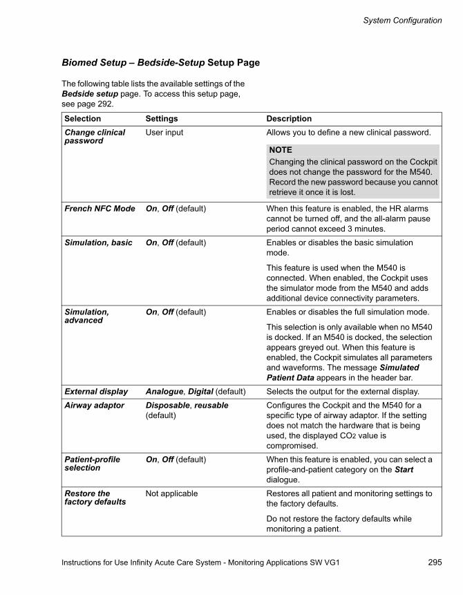
Instructions for Use Infinity Acute Care System - Monitoring Applications SW VG1 295
System Configuration
Biomed Setup – Bedside-Setup Setup Page
The following table lists the available settings of the Bedside setup page. To access this setup page, see page 292.
Selection Settings DescriptionChange clinical password
User input Allows you to define a new clinical password.
French NFC Mode On, Off (default) When this feature is enabled, the HR alarms cannot be turned off, and the all-alarm pause period cannot exceed 3 minutes.
Simulation, basic On, Off (default) Enables or disables the basic simulation mode.
This feature is used when the M540 is connected. When enabled, the Cockpit uses the simulator mode from the M540 and adds additional device connectivity parameters.
Simulation, advanced
On, Off (default) Enables or disables the full simulation mode.
This selection is only available when no M540 is docked. If an M540 is docked, the selection appears greyed out. When this feature is enabled, the Cockpit simulates all parameters and waveforms. The message Simulated Patient Data appears in the header bar.
External display Analogue, Digital (default) Selects the output for the external display.
Airway adaptor Disposable, reusable (default)
Configures the Cockpit and the M540 for a specific type of airway adaptor. If the setting does not match the hardware that is being used, the displayed CO2 value is compromised.
Patient-profile selection
On, Off (default) When this feature is enabled, you can select a profile-and-patient category on the Start dialogue.
Restore the factory defaults
Not applicable Restores all patient and monitoring settings to the factory defaults.
Do not restore the factory defaults while monitoring a patient.
NOTEChanging the clinical password on the Cockpit does not change the password for the M540. Record the new password because you cannot retrieve it once it is lost.
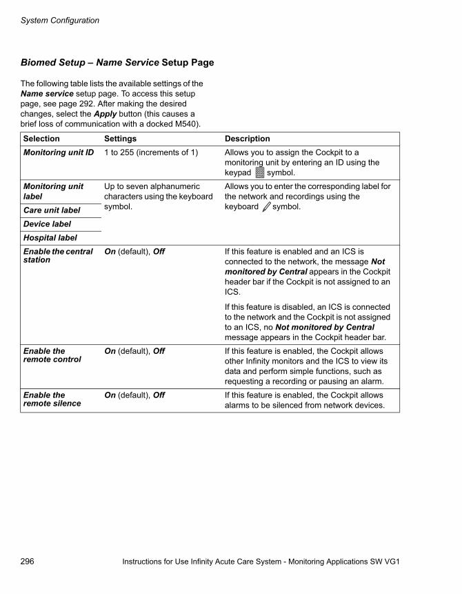
System Configuration
296 Instructions for Use Infinity Acute Care System - Monitoring Applications SW VG1
Biomed Setup – Name Service Setup Page
The following table lists the available settings of the Name service setup page. To access this setup page, see page 292. After making the desired changes, select the Apply button (this causes a brief loss of communication with a docked M540).
Selection Settings DescriptionMonitoring unit ID 1 to 255 (increments of 1) Allows you to assign the Cockpit to a
monitoring unit by entering an ID using the keypad symbol.
Monitoring unit label
Up to seven alphanumeric characters using the keyboard symbol.
Allows you to enter the corresponding label for the network and recordings using the keyboard symbol.Care unit label
Device labelHospital labelEnable the central station
On (default), Off If this feature is enabled and an ICS is connected to the network, the message Not monitored by Central appears in the Cockpit header bar if the Cockpit is not assigned to an ICS.
If this feature is disabled, an ICS is connected to the network and the Cockpit is not assigned to an ICS, no Not monitored by Central message appears in the Cockpit header bar.
Enable the remote control
On (default), Off If this feature is enabled, the Cockpit allows other Infinity monitors and the ICS to view its data and perform simple functions, such as requesting a recording or pausing an alarm.
Enable the remote silence
On (default), Off If this feature is enabled, the Cockpit allows alarms to be silenced from network devices.

Instructions for Use Infinity Acute Care System - Monitoring Applications SW VG1 297
System Configuration
Biomed Setup – Network Setup Page
The following table lists the available settings for configuring the Infinity and the hospital network settings in the Infinity and the Hospital setup pages. To access the setup pages, see page 292. After making the desired changes, select the Apply button to activate them.
Biomed Setup – Printer Setup Page
The following table lists the available settings of the Printer setup page. To access this setup page, see page 292. After making the desired changes, select the Apply button.
Selection Settings DescriptionDHCP Disabled (default), enabled When the Dynamic Host Configuration
Protocol (DHCP) is enabled, the settings for IP address, Subnet mask, Gateway, and Primary DNS are pulled automatically from the server.
IP address User-selectable Allows you to select an IP address manually (the DHCP setting has to be set to Disabled).
Subnet mask User-selectable Allows you to select a subnet mask (the DHCP setting has to be set to Disabled).
Gateway User-selectable Allows you to select a gateway (the DHCP setting has to be set to Disabled).
Primary DNS User-selectable Allows you to set up the primary Domain Name System (DNS) – the DHCP setting has to be set to Disabled.
Selection Settings DescriptionPrinter IP address User-selectable Allows you to configure the IP address for
printing reports on a network printer.
Printer type User-selectable Allows you to select the type of laser printer used for printing reports.
Paper size Letter, Legal, A4 Allows you to select the printer paper.
Print test page Select the Print screen button to verify that the printer is working properly.

System Configuration
298 Instructions for Use Infinity Acute Care System - Monitoring Applications SW VG1
Biomed Setup – Recorder Setup Page
The following table lists the available settings of the Recorder setup page. To access this setup page, see page 292.
Biomed Setup – Service Setup Page
The following table lists the available settings of the Service setup page. To access this setup page, see page 292.
A The Biomed tab
B The 'Product identification' field displaying software-specific information (for example, the software version, and so on).
C Select this button to copy all logs to the connected USB device.
D Select this button to export the current profiles to the connected USB device.
E Select this button to import the profiles from the connected USB device.
F The window displays status messages relating to the function that is being executed.
G The Service button for accessing Service-related functions, such as unlocking options (refer to the Technical documentation available from DrägerService for detailed information).
Selection Settings DescriptionPrimary recorder Recorders are available for
selection once they are connected to the network.
Selects a recorder as the primary recorder for printing recordings.
Secondary recorder Selects the secondary recorder for printing recordings if the primary recorder is not available.
055
A
B
C
DE
F
G
System setup

Instructions for Use Infinity Acute Care System - Monitoring Applications SW VG1 299
System Configuration
Biomed IT Setup
The IT-setup page consists of several setup pages for performing the following IT-specific tasks:
– Enabling or disabling all IT tabs
– Configuring a web browser
– Configuring Citrix applications
– Configuring IT applications
Enabling/Disabling IT-Tab Feature
The Cockpit supports IT applications (options) that are accessible via IT tabs (see Supported IT Applications on page324). When an IT application is configured and the tab is enabled, the corresponding IT tab appears along the left edge of the screen as soon as the IT tab feature is enabled. Regardless of how many IT tabs are configured, the top tab is always labelled Patient and provides access to the Cockpit main screen which displays the patient’s vital signs.
To enable/disable the IT-tab feature
1 Access the IT setup page (see page 292).
2 Select the IT tabs button.
3 Select the On or Off button next to the IT tabs selection.
Configuring IT Tabs – Web-Browser Setup
You can set up a web browser as an IT tab that contains several pre-configured Web pages. These Web pages are accessible from a pull-down dialogue under the configured IT tab (see Accessing an IT Tab on page323).
CAUTIONThe Infinity Acute Care System (IACS) does not have virus-protection software and relies, therefore, on the firewall of your institution to prevent access to infected files. While setting up IT applications to access the web sites, evaluate each website with regard to possible virus infection.

System Configuration
300 Instructions for Use Infinity Acute Care System - Monitoring Applications SW VG1
The following diagram shows the Web-browser setup page. The left side displays a selection list which is reserved for pre-configured websites. The right side is for setting up new sites or for editing existing ones. The site with the asterisks is the default site that appears automatically when you access the corresponding IT tab.
A The Web-browserr tab
B IT-setup tabs for accessing setup pages of the corresponding IT applications.
C Symbol for accessing additional IT applications
D The Name button
E The URL button
F The Default button
G The Block Popups on/off buttons
H The Full Trust on/off buttons
I The Tab visible on/off buttons
J Selection window with pre-defined web sites.
K The Add button
L The Delete button
Adding a Web-Browser Page
In the following steps, the letters in parentheses refer to the diagram of the Web browser setup page.
To add a web-browser page
1 Access the Web Browser setup page (see page 292).
2 Select the Add button (L). The label Undefined appears in the selection list (K) as a placeholder.
3 Select the following buttons to configure the corresponding settings:
– Select the symbol next to the Name menu selection (D) to activate an on-screen keyboard for changing the label Undefined to an actual name.
– Select the symbol next to the URL menu selection (E) to activate an on-screen keyboard for entering the URL.
– Select the Default on/off buttons (F) to disable/enable this site as a default in the selection list (J).
– Select the Block popups on/off button (G) to allow or prevent pop-ups from appearing on the website.
– Select Full Trust on/off button (H) to select the security setting for this web site.
4 Select the Tab visible on/off buttons (I), to display or hide the IT tab.
Once a web browser is correctly set up, you should be able to access the web site under the corresponding IT tab (for more information, see Accessing an IT Tab on page323).
057
A
C
DE
FG
BKL
B B B B
FG
H H
II
J
System setup

Instructions for Use Infinity Acute Care System - Monitoring Applications SW VG1 301
System Configuration
Deleting a Web-Browser Page
In the following steps, the letters in parentheses refer to the diagram of the Web browser setup page on page 299.
To delete a web-browser page
1 Access the Web Browser setup page (see page 292).
2 Select the web site you wish to delete in the selection list.
3 Select the Delete button (K).
Configuring Citrix Applications
The following diagram shows the Application setup page for configuring Citrix applications. Citrix allows you to access remote applications without running the actual application on the Cockpit.
A Application tab
B IT tabs
C The Name symbol and field
D The Name column
E The Value column
F List of Citrix applications
G The Tab visible on/off buttons
H The Edit button
I The Delete button
J The Add button
066
AB B B B BC
D E
F
GHI
GJ
System setup

System Configuration
302 Instructions for Use Infinity Acute Care System - Monitoring Applications SW VG1
To configure a Citrix Application
In the following steps, the letters in parentheses correspond to the diagram for the Application page (see page 301).
1 Access the Application setup page (see page 292).
2 Select the symbol next to the Name menu selection (C) to activate an on-screen keyboard for changing the name of the label appearing on the IT tab that you will use to access the application (the name of the actual tab in the IT setup page does not change).
3 Define the following settings in the Name (D) and Values columns (E) for any application that runs on Citrix:
– The IP address of the PC you are accessing
– The communication port used for the application
– The application you will be running using Citrix
Configuring IT Tabs
The following diagram shows an example of an IT setup page. When the IT applications option is unlocked, the IT tabs appear with the corresponding label of a pre-configured URL address.
A The Biomed tab
B IT-setup tabs for accessing setup pages of the corresponding IT applications.
C The Name button and description field
D The URL button and description field
E The Full Trust on/off buttons
F The Block Popups on/off buttons
G The Tab visible on/off buttons
059
AB
CD
EFF
G
G G
E
B B B B B
System setup

Instructions for Use Infinity Acute Care System - Monitoring Applications SW VG1 303
System Configuration
To configure an IT-application tab
In the following steps, the letters in parentheses correspond to the diagram for the IT setup page (see page 302).
1 Access the IT setup page (see page 292).
2 Select the tab of the IT application you wish to configure.
3 Select the following buttons to configure the corresponding settings:
– Select the symbol next to the Name menu selection (C) to activate an on-screen keyboard for changing the name of the label appearing on the IT tab that you will use to access the application (the name of the actual tab in the IT setup page does not change).
– Select the symbol next to the URL menu selection (D) to activate an on-screen keyboard for entering the URL.
– Select the Full Trust on/off buttons (F) to select the security setting for this web site.
– Select the Block pop-ups on/off button (F) to allow or prevent pop-ups from appearing on the website.
4 Select the Tab visible on/off buttons (G), to display or hide the tab.
Once an IT application is correctly set up, you should be able to configure the web site under the corresponding IT tab (for more information, see Accessing an IT Tab on page323).
CAUTIONThe URL address shows a pre-configured string. Do not change any portion of the string, except for the <server name>, to preserve the correct information.

System Configuration
304 Instructions for Use Infinity Acute Care System - Monitoring Applications SW VG1
Profile Setup
A profile ’remembers’ the patient and device settings for future use. Profiles eliminate time-consuming setup tasks that would otherwise have to be repeated for each monitoring session. Each patient category has one default profile. All tasks related to profiles take place in the Profiles pages.
Selecting a Profile
The following diagram shows the Select Profile page where you can select a profile with the pre-configured patient and device settings.
A The Profiles button
B Select the profile button
C The Adult selection button
D The Paediatric selection button
E The Neonate selection button
F The Profile arrow button
G Description window of the selected profile
To select a profile
1 Select the System setup... button on the main-menu bar.
2 Select the Profiles tab (A) > Select the profile tab (B).
3 Select the desired patient category button:
– Adult (C)
– Paediatric (E)
– Neonate (D)
4 Select the arrow button next the Profile menu selection (F) to display a list of profiles within the selected patient category. If available, a description of the selected profile appears in the description field (G).
058
AB
C D EF
G
System setup
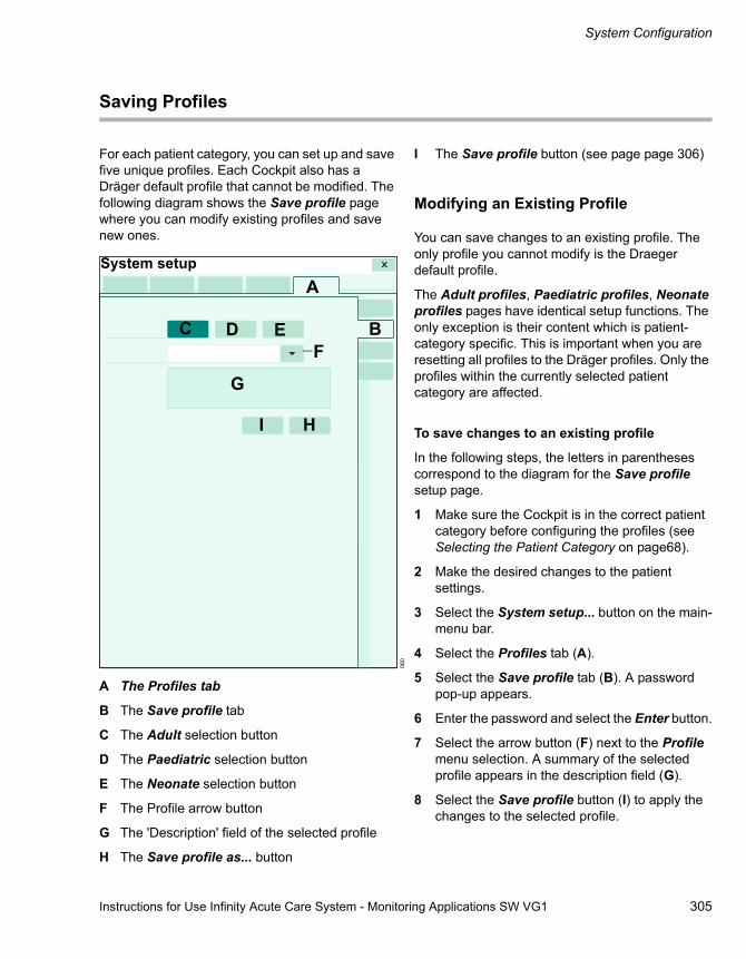
Instructions for Use Infinity Acute Care System - Monitoring Applications SW VG1 305
System Configuration
Saving Profiles
For each patient category, you can set up and save five unique profiles. Each Cockpit also has a Dräger default profile that cannot be modified. The following diagram shows the Save profile page where you can modify existing profiles and save new ones.
A The Profiles tab
B The Save profile tab
C The Adult selection button
D The Paediatric selection button
E The Neonate selection button
F The Profile arrow button
G The 'Description' field of the selected profile
H The Save profile as... button
I The Save profile button (see page page 306)
Modifying an Existing Profile
You can save changes to an existing profile. The only profile you cannot modify is the Draeger default profile.
The Adult profiles, Paediatric profiles, Neonate profiles pages have identical setup functions. The only exception is their content which is patient-category specific. This is important when you are resetting all profiles to the Dräger profiles. Only the profiles within the currently selected patient category are affected.
To save changes to an existing profile
In the following steps, the letters in parentheses correspond to the diagram for the Save profile setup page.
1 Make sure the Cockpit is in the correct patient category before configuring the profiles (see Selecting the Patient Category on page68).
2 Make the desired changes to the patient settings.
3 Select the System setup... button on the main-menu bar.
4 Select the Profiles tab (A).
5 Select the Save profile tab (B). A password pop-up appears.
6 Enter the password and select the Enter button.
7 Select the arrow button (F) next to the Profile menu selection. A summary of the selected profile appears in the description field (G).
8 Select the Save profile button (I) to apply the changes to the selected profile.
060
A
BC D E
G
I H
F
System setup

System Configuration
306 Instructions for Use Infinity Acute Care System - Monitoring Applications SW VG1
Saving a New Profile
You can also save a profile under a new name and assign it to an existing view using the Save profile pop-up window depicted below.
A The Profile name field and setup button
B The Description field and setup button
C The Default view field and selection button
D The Save profile button
To save a new profile
1 Repeat steps 1 - 6 for saving changes to an existing profile (see page 305).
2 Select the Save profile as... button (I) in the Save profile page (see diagram on page 309). The Save profile pop-up window appears.
3 Select the setup buttons next to Profile name (A), Description (B), and Default view (C) to enter the corresponding information.
4 Select the Save profile button (D).
061
AB
CD

Instructions for Use Infinity Acute Care System - Monitoring Applications SW VG1 307
System Configuration
Configuring Profiles
The following diagram shows a patient-specific Profiles setup page for configuring profiles. These setup pages allow you to modify existing profiles, such as the name of the profile, the profile description, and so on.
There are three pages for each patient category (adult, paediatric, and neonate).
A The Adult setup tab
B The Paediatric setup tab
C The Neonate setup tab
D The Views tab
E The Set as default button
F Delete the profile button
G The Profile name field and setup button
H The Description field and setup button
I The Views button
J The Default view field and selection arrow
K Selection list of available profiles
To access the patient-specific Profiles setup pages:
1 Select the System setup... button from the main-menu bar.
2 Select the Profiles tab.
3 Select the Profiles/views tab.
4 Select either the Adult (A), Neonate (B), Paediatric (C) tabs to access the patient category-specific setup pages.
062
A B C DEF
GHI
J
K
System setup

System Configuration
308 Instructions for Use Infinity Acute Care System - Monitoring Applications SW VG1
Configuring the Patient-Specific Profiles
In the following steps, the letters in parentheses correspond to the diagram for the patient-specific Profiles setup page.
To configure the profiles
1 Access the patient-specific profiles setup page.
2 Select the desired profile in the selection list (L).
3 Select one or more of the following buttons:
– Select the Set as default button (E) to designate the selected profile as the new default profile for the selected patient category. After each patient discharge or a restart of the Cockpit, the default profile is automatically loaded when that patient category is selected.
– Select the Delete profile button (F) to delete the selected profile.
– Use the button next to the Profile name field (G) of the profile-setup page to name the profile. The name appears in the Select profile page (see page 304).
– Use the button next to the Description field (H) of the profile-setup page to add or modify an existing description. The description appears in the Select profile page (see page 304) when you select a profile.
– Select the arrow button next to the Default view field (I) and select the View that you wish to designate as the default View.

Instructions for Use Infinity Acute Care System - Monitoring Applications SW VG1 309
System Configuration
Managing Views and Profiles
The following diagram shows the Views setup page within the Profiles dialogue. This setup page allows you to manage Views, that are part of profiles.
A The Views tab
B The Delete view button
C The View name field and setup button
D The Profiles... button
E The Views selection list
Managing Views
You can perform several configuration tasks regarding Views, which are part of profiles.
To manage Views and Profiles
In the following steps, the letters in parentheses correspond to the diagram for the Views setup page.
1 Select the System setup... button from the main-menu bar.
2 Select the Profiles tab.
3 Select the Views tab (A).
4 Select the desired View in the selection list (L).
5 Select one or more of the following buttons:
– Select one or more of the following buttons:
– Use the button next to the View name field (C) to add or modify a View name.
– Select the Profiles... button (D). A pop-up window appears where you select the profiles you wish to assign this View to. Select the OK button in the pop-up window to confirm your selection.
– Select the Delete view button (B).
063
AB
CD
E
System setup

System Configuration
310 Instructions for Use Infinity Acute Care System - Monitoring Applications SW VG1
Transferring Profiles
You can transfer profiles over the network or via an USB memory stick.
Transferring Profiles over the Network
Transferring profiles over the network is only possible among Cockpits within the same monitoring unit. The following diagram shows the Profile transfer page, which consists of a list of connected devices within the monitoring unit.
A The Profiles tab
B The Device name column
C The Status column
D The Profile transfer tab
E The Start transfer button
F The Clear selection button
G The Select all button
To transfer a profile over the network
1 Select the System setup... button on the main-menu bar.
2 Select the Profiles > Profile transfer tabs.
3 Enter the clinical password. The Profile transfer page which lists all the devices in the care unit appears.
4 Select a device from the list or select one of the following buttons:
– The Select all button (G) to select all devices to transfer profiles to.
– The Clear selection button (F) to remove any selection from the device list.
5 Select the Start transfer button (E) to start the profile transfer.
The profiles are transferred to the target Cockpit, but are not implemented until you select a new profile.
NOTEWhenever you use the transfer-profile function, all existing profiles for all patient categories are transferred simultaneously.
064
System setupA
B C
D
EFG

Instructions for Use Infinity Acute Care System - Monitoring Applications SW VG1 311
System Configuration
Importing and Exporting Profiles Using an USB Memory Stick
You can also import and export profiles from one Cockpit to another using an USB memory stick. Unlike transferring profiles over the network, using an USB memory stick has the advantage that the Cockpits do not have to reside in the same monitoring unit.
To export profiles to an USB device
1 Insert an USB memory stick into one of the USB ports of the Cockpit with profiles you wish to transfer.
2 Select the System setup... button from the main-menu bar.
3 Select the Biomed tab.
4 Enter the Biomed password and select the Enter button.
5 Select the Service tab.
6 Select the Export profile button to export all profiles to the USB device.
To import profiles from an USB memory stick
1 Insert the USB device in the USB port of the Cockpit, where you wish to transfer the profiles to.
2 Select the System setup... button from the main-menu bar.
3 Select the Biomed tab.
4 Enter the Biomed password.
5 Select the Service tab.
Select the Import profile button to transfer all profiles from the USB device to the Cockpit.

312 Instructions for Use Infinity Acute Care System - Monitoring Applications SW VG1
This page is intentionally left blank

Instructions for Use Infinity Acute Care System - Monitoring Applications SW VG1 313
Reports/Recordings
Reports/Recordings
Overview . . . . . . . . . . . . . . . . . . . . . . . . . . . . . 314
R50N Recorder . . . . . . . . . . . . . . . . . . . . . . . . 314
Replacing the Recorder Paper . . . . . . . . . . . . . 314
Timed Recordings . . . . . . . . . . . . . . . . . . . . . 315
Remote Recordings . . . . . . . . . . . . . . . . . . . . . 315Automatic Alarm Recordings . . . . . . . . . . . . . . 316Manual Timed Recordings . . . . . . . . . . . . . . . . 316
Continuous Recordings. . . . . . . . . . . . . . . . . 317
Causes for Automatic Cancellation of Recordings . . . . . . . . . . . . . . . . . . . . . . . . . . . 317
Reports . . . . . . . . . . . . . . . . . . . . . . . . . . . . . . 318
Rest ECG Report . . . . . . . . . . . . . . . . . . . . . . . 319
Print Screen . . . . . . . . . . . . . . . . . . . . . . . . . . 319

Reports/Recordings
314 Instructions for Use Infinity Acute Care System - Monitoring Applications SW VG1
Overview
The Cockpit offers a real-time record of its monitoring results on an R50N recorder. In addition, you can request various reports and print screens which are printed on a laser printer.
The content of the recordings and reports depend on the configured settings. You can customise the recording and report settings in the Recordings/Reports setup pages (see page 290).
Messages relating to recordings and reports are listed on page 348.
R50N Recorder
Timed and continuous strip recordings are printed on an R50N recorder, which is connected to the network or to the PS250 using a cross-over cable.
A Stop key – stops a recording in progress
B mm/s key – does not function
Replacing the Recorder Paper
To replace the paper
1 Open the paper door and remove the empty paper roll and any paper remaining in the printing mechanism.
2 Place a new paper roll with the printed side facing up into the spool holder. Unroll a few centimetres of paper from the bottom.
3 Align the paper roll with the paper guides, and close the door. (If not aligned properly, the paper may jam.)
4 Generate a timed recording to verify that the recorder is connected properly, and the paper is loaded correctly.
354
AB

Instructions for Use Infinity Acute Care System - Monitoring Applications SW VG1 315
Reports/Recordings
Timed Recordings
From the Cockpit, you can request timed strip recordings that are printed on an R50N recorder (see page 314). Timed recordings can be requested manually or triggered automatically depending on the configured alarm settings.
If a signal source becomes unavailable, for example due to a disconnected lead or a cable, while a recording is printing, the associated parameter data and waveform appear as blank data on the strip recording.
A timed recording contains data of a specified duration, which is configurable from 6 seconds to 20 seconds (see "Recordings/Reports Page" on page 290). A timed recording contains delay data that originated before the recording was
initiated and real-time data that were acquired after the recording started. The ratio of delay and real-time data is configurable (see page 290). Strip recordings also include pacer spikes if present.
The header of a timed recording contains the following information:
– Parameter values at the time the recording starts printing
– Patient name and ID number
– Date and time
The following diagram shows a typical timed recording.
A Patient name
B Patient ID
C Monitoring unit
D Date
E Time
F Selected delay time
G Selected recording speed
H Origin of recording request (for example, Bed timed)
I Parameter labels and units of measure
Remote Recordings
You can also request a recording from another monitor or the ICS. Remote recordings use the delay, duration, and speed recorder settings of the Cockpit, not the remote device from which you request the recording.
355
AB C D
EFG
H I

Reports/Recordings
316 Instructions for Use Infinity Acute Care System - Monitoring Applications SW VG1
Automatic Alarm Recordings
When the alarm waveform feature is enabled (see page 290), timed alarm recordings are generated automatically whenever a parameter whose archive function is enabled goes beyond the set alarm limits.
Alarm recordings are also generated when an arrhythmia event with an alarm classification of high or medium priority occurs.
The following sections describe how to set up a parameter or arrhythmia event to generate an automatic alarm recording.
To enable/disable the Archive function of a parameter
1 Select the parameter box of the parameter whose alarm function you wish to enable or disable to access that parameter setup page directly.
or
Select Sensor parameters... from the main-menu bar > select the desired parameter tab to access the setup page.
2 Select the button next to the Archive setting and select either Str., Str/Rec, Rec to generate a recording or Off to disable the feature.
To assign an alarm grade to arrhythmia events
1 Select the Alarms... button on the main-menu bar.
2 Select the Limits tab (if not already selected).
3 Select the ARR tab along the right side to display the ARR setup page.
4 Touch the field in the Alarm column of the parameter, whose alarm grade you want to modify.
5 Select the field in the Archive column and select either Str., Str/Rec, Rec to generate a recording or Off to disable the feature.
6 Press the rotary knob to confirm the setting.
Manual Timed Recordings
To request a timed recording manually
1 Select the symbol next to the Trends/Data button on the main-menu bar.
2 Select the Timed recording button.

Instructions for Use Infinity Acute Care System - Monitoring Applications SW VG1 317
Reports/Recordings
Continuous Recordings
Continuous recordings are almost identical to timed recordings (see illustration on page 315). The only difference is that a continuous recording runs until you manually interrupt it - unlike a timed recording, which runs for a specified time.
The waveform labels, scale bars, and the scales are printed once for each parameter.
To request a continuous recording
� Select the symbol next to the Trends/Data button on the main-menu bar > Continuous recording.
Causes for Automatic Cancellation of Recordings
Any active timed or continuous recording is automatically cancelled under the following circumstances:
– If the Cockpit loses its connection to the network. The recordings resume when the network connection is restored.
– If you place the Cockpit in the standby mode.
– If you discharge a patient .

Reports/Recordings
318 Instructions for Use Infinity Acute Care System - Monitoring Applications SW VG1
Reports
From the Cockpit, you can request the following reports, which can be printed on any compatible laser printer:
– ECG report – prints the waveforms of the connected ECG leads
– Rest ECG report (processed by the ICS, see page 319)
– Timed waveform report – prints waveform strips of all currently displayed waveforms (the waveform duration and delay time settings are configurable, see page 292)
– Continuous waveform report – prints waveform strips of all currently displayed waveforms (prints a maximum of five pages)
– ST report – prints the ST complexes currently displayed on ST screen
– Trend graph report – prints the contents of the trend graphs according to the selected Trend duration setting (see page 292)
– Trend table report – prints the contents of the trend table according to the selected Trend interval setting (see page 292)
– Alarm history report – prints the contents of the Alarm history screen
– Calculations report – prints the calculations results currently displayed in the Calculations page
The reports are printed based on pre-configured settings (see page 292). The header of all reports contains the following information:
– Report title
– Patient name and ID number
– Hospital name
– Care unit
– Bed name
– Parameter labels and values (for ECG, ST, timed waveform and continuous waveform reports only)
The footer of each report contains the data and the page number.
To request a report
1 Select the symbol next to the Trends/Data... button on the main-menu bar.
2 Select the desired report from the list of available reports.

Instructions for Use Infinity Acute Care System - Monitoring Applications SW VG1 319
Reports/Recordings
Rest ECG Report
This 12-lead diagnostic report is generated in different stages. Although you request the report at the Cockpit, the M540 collects the actual ECG data, and the ICS prints it. Therefore, the patient must be admitted at the ICS, and the Rest ECG analysis option must be installed at the ICS.
The report is available in several formats that can be customised at the ICS (refer to the Infinity Central Station Instructions for Use). You can also configure the content of a Rest ECG report, see "Rest ECG Report Setup Page" on page 291.
Print Screen
A print screen is an exact replica of the current display. Whenever you request a print screen, it is printed on the connected laser printer.
To generate a print screen
� Select the Print screen button on the main-menu bar.

320 Instructions for Use Infinity Acute Care System - Monitoring Applications SW VG1
This page is intentionally left blank
Instructions for Use Infinity Acute Care System - Monitoring Applications SW VG1 321
IT Applications (Options)
IT Applications (Options)
Overview . . . . . . . . . . . . . . . . . . . . . . . . . . . . . 322
Configuring IT Tabs . . . . . . . . . . . . . . . . . . . . 322
Web Browser . . . . . . . . . . . . . . . . . . . . . . . . . . 322
Accessing an IT Tab . . . . . . . . . . . . . . . . . . . . 323
Supported IT Applications. . . . . . . . . . . . . . . 324

IT Applications (Options)
322 Instructions for Use Infinity Acute Care System - Monitoring Applications SW VG1
Overview
The Cockpit supports several IT applications. Each application is an option that is accessible by selecting a tab appearing on the left side of the monitoring area (see "Cockpit Screen with IT Tabs" on page 51). Whenever IT tabs are displayed, the
top IT tab is always labelled Patient and allows you to access the monitoring screen that displays the current patient’s vital signs.
If you are using a keyboard, you can activate a mouse cursor on the Cockpit by pressing the ALT F10 keys simultaneously.
Configuring IT Tabs
Only authorised personnel with the Biomed password can configure IT tabs. In the IT setup page you can enable or disable each tab and configure specific settings, such as the blocking of popups and so on. For detailed information, see "Biomed IT Setup" on page 299.
If the Cockpit loses communication with an application, a message appears in the corresponding IT application page. The Cockpit tries to establish communication with the IT application as quickly as possible.
Web Browser
In addition to IT applications, you can also setup a web browser with pre-configured web sites (see "Configuring IT Tabs – Web-Browser Setup" on page 299). Once you access the web browser IT tab, you can choose from all of the websites that were pre-configured under the Biomed tab.
CAUTIONThe Infinity Acute Care System (IACS) does not have virus-protection software and relies, therefore, on the firewall of your institution to prevent access to infected files. While setting up IT applications to access the web sites, evaluate each web site with regard to possible virus infection.

Instructions for Use Infinity Acute Care System - Monitoring Applications SW VG1 323
IT Applications (Options)
Accessing an IT Tab
The following diagram is an example of a web page. After a browser has been successfully configured (see page 300), you can select it by clicking the corresponding IT tab. Whatever IT
application is displayed, the Cockpit header bar is always visible to report the patient’s vital status. The top IT tab is the Patient tab that returns you to the main screen displaying the patient’s vital signs.
A The Patient tab always returns you to the main screen with the patient’s vital signs.
B Pre-configured IT tab(s)
C Navigation buttons
D Button for selecting pre-configured web pages
065
A
B
D
C
NOTERefreshing certain IT applications may disconnect the application and require you to login again.

IT Applications (Options)
324 Instructions for Use Infinity Acute Care System - Monitoring Applications SW VG1
Supported IT Applications
If you dock a new M540 and admit the patient at the Cockpit, the content of some application tabs changes to reflect the data of the new patient. Similarly, if you discharge a patient, all IT tabs reflect that the patient is discharged. The following table lists the supported IT applications.
Name of Application Supported Software version
Description
Innovian® Solution Suite
This application includes:– Innovian Critical Care
(formerly known as ChartAssist)
– Innovian Peri-operative Care
VF5 Clinical Flowsheet application.
The tab can be configured to display a single patient.
Whenever you access the Innovian tab, the local patient is displayed or the admit screen is presented if the local patient has not yet been admitted to the Innovian Solution Suite application.
For more information, refer to the Innovian Solution Suite Instructions for Use.
MegaCare® VF4 An ECG-archiving application that allows you to view, analyse, compare, edit and confirm ECG examinations. The tab can display multiple patients.
Infinity® Symphony Suite VF7 An application that provides retrospective analysis of patient information stored on the ICS (Infinity CentralStation).
The tab can be configured to run a single patient.
RemoteView (Gateway PatientWatch)
VF5 Allows you to review up to 4 different bedside monitors from the Cockpit.
Application ICA client version 11.0.0.5357
Supports IT applications using a Citrix server.
NOTEThe single patient tab requires that the M540 is docked.
NOTEPatientWatch is only supported in English and does not support remote control.

Instructions for Use Infinity Acute Care System - Monitoring Applications SW VG1 325
Problem Solving
Problem Solving
Overview . . . . . . . . . . . . . . . . . . . . . . . . . . . . . 326
Device Communication Messages . . . . . . . . 326
ECG . . . . . . . . . . . . . . . . . . . . . . . . . . . . . . . . . 328
ST . . . . . . . . . . . . . . . . . . . . . . . . . . . . . . . . . . . 330
ARR . . . . . . . . . . . . . . . . . . . . . . . . . . . . . . . . . 331
Respiration (RRi) . . . . . . . . . . . . . . . . . . . . . . 332
SpO2. . . . . . . . . . . . . . . . . . . . . . . . . . . . . . . . . 334
NIBP . . . . . . . . . . . . . . . . . . . . . . . . . . . . . . . . . 337
Temperature . . . . . . . . . . . . . . . . . . . . . . . . . . 339
IBP . . . . . . . . . . . . . . . . . . . . . . . . . . . . . . . . . . 340
Cardiac Output . . . . . . . . . . . . . . . . . . . . . . . . 343
CO2. . . . . . . . . . . . . . . . . . . . . . . . . . . . . . . . . . 345
Recording Status Messages . . . . . . . . . . . . . 348
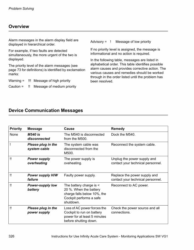
Problem Solving
326 Instructions for Use Infinity Acute Care System - Monitoring Applications SW VG1
Overview
Alarm messages in the alarm display field are displayed in hierarchical order.
For example, if two faults are detected simultaneously, the more urgent of the two is displayed.
The priority level of the alarm messages (see page 73 for definitions) is identified by exclamation marks:
If no priority level is assigned, the message is informational and no action is required.
In the following table, messages are listed in alphabetical order. This table identifies possible alarm causes and provides corrective action. The various causes and remedies should be worked through in the order listed until the problem has been resolved.
Device Communication Messages
Warning = !!! Message of high priority
Caution = !! Message of medium priority
Advisory = ! Message of low priority
Priority Message Cause RemedyNone M540 is
disconnectedThe M540 is disconnected from the M500.
Dock the M540.
! Please plug in the system cable
The system cable was disconnected from the M500.
Reconnect the system cable.
!! Power supply overheating
The power supply is oveheating.
Unplug the power supply and contact your technical personnel.
!! Power supply H/W failure
Faulty power supply. Replace the power supply and contact your technical personnel.
!! Power-supply low battery
The battery charge is < 20 %. When the battery charge falls below 10%, the Cockpit performs a safe shutdown.
Reconnect to AC power.
!! Please plug in the power supply
Loss of AC power forces the Cockpit to run on battery power for at least 5 minutes before shutting down.
Check the power source and all connections.

Instructions for Use Infinity Acute Care System - Monitoring Applications SW VG1 327
Problem Solving
! Power supply failure
Faulty power supply. Unplug the power supply and contact your technical personnel.
None Not monitored by Central
The Cockpit is connected to the Infinity network but is not assigned to a central station.
Admit the patient at the central station.
None Duplicate IP address
The IP address or domain name is already in use.
Assign an unique IP address or domain name.
! The external device is disconnected.
An external device is no longer communicating with the Cockpit.
Check the external device connections.
None Offline The Cockpit is disconnected from the Infinity network.
– Check the network connectivity.
None Silenced at remote Remote alarm silence initiated from the central station or another Cockpit.
Information only - no action required.
None Remote relearn The indicated function was initiated from the central station.
None Remote limit change
Priority Message Cause Remedy

Problem Solving
328 Instructions for Use Infinity Acute Care System - Monitoring Applications SW VG1
ECG
Priority Message Problem Solution!! HR > (alarm limit)
HR < (alarm limit)
The parameter value is above/below the set upper/lower alarm limits.
– Check the patient and treat, if necessary.
– Change the alarm limits.
!!! Asystole The reported arrhythmia was detected.
– Check the patient and treat, if necessary.!!! Ventricular Fibrillation
!!! Bradycardia
(neonatal patient category)
!! HR out of range, high (1)
The parameter value is above the measurement range of the monitor.
! ECG artefact (2) – Patient's movement (shivering, tremors)
– Bad electrode contact
– Excessive signal-noise interference from auxiliary equipment
– Check the electrodes and reapply, if necessary.
– Make sure that the patient's skin is properly prepped.
– Isolate the patient from the auxiliary equipment, if possible.
! The ECG is unplugged
ECG Leads Off
The lead-off condition detected is due to:
– Broken cable(s)
– Disconnected ECG lead wires
– Loose lead wire(s)
– Wrong lead selected
– Dried out electrode gel
The ECG cable(s) is/are disconnected from the M540.
– Replace defective cable(s)
– Reapply gel on disposable electrodes.
– Select another ECG lead for processing.
– If monitoring augmented leads, verify that the number of selected leads in the ECG setup page is correct.
– Check cable(s) and connection(s)
– Replace cable(s), if necessary
(1) In the parameter box, the parameter value is replaced by +++(2) In the parameter box, the parameter value is replaced by ***

Instructions for Use Infinity Acute Care System - Monitoring Applications SW VG1 329
Problem Solving
None
None
None
None
None
None
LA Lead Off
LL Lead Off
RA Lead Off
RL Lead Off
V Lead Off
V1-V6 Lead Off
V+ Lead Off
The indicated lead is no longer attached to the patient.
Reattach the electrode to the patient.
Rest ECG MessagesNone The ECG-collecting
waveformsThe rest ECG was initiated. Instruct the patient to lie still.
None ECG busy The central station is already processing a report.
Wait a few minutes before requesting the report again.
None Sending the ECG data Information only. Information only - no action required.
None ECG cannot connect Connection to central station is not possible.
– Check that the patient is admitted at the central station.
– Check that the central station has the Rest ECG option activated.
None ECG report complete The Rest ECG report has been printed.
Information only - no action required.
None ECG comm failure The external device is not available.
Check the configuration at the central station.
Priority Message Problem Solution

Problem Solving
330 Instructions for Use Infinity Acute Care System - Monitoring Applications SW VG1
ST
Priority Message Problem Solution!! ST <x> > (alarm limit)
ST <x> < (alarm limit)
The parameter value is above/below the set upper/lower alarm limits.
– Check the patient and treat, if necessary.
– Change the alarm limits.
!! ST<x> out of range (low) (1)
The parameter value is above/below the measurement range of the monitor.
– Check the patient and treat, if necessary.
– Check the placement of electrodes and change their position, if necessary.
!! ST<x> out of range (high) (2)
! Cannot analyse ST (3) The algorithm cannot determine ST values due to artefacts, the absence of normal beats, or invalid leads.
– Perform a relearn (see page 163)
– Check electrodes; re-apply, if necessary.
– Make sure that the patient's skin is properly prepared.
– Isolate the patient from the auxiliary equipment, if possible.
– Inspect and replace defective cable(s) and wire(s).
– Reapply gel on reusable electrode(s).
– Reapply the electrode(s). Make sure that the patient's skin is properly prepared.
– If a lead or electrode cannot be replaced, select another ST lead for processing.
(1) In the parameter box, the parameter value is replaced by - - -(2) In the parameter box, the parameter value is replaced by +++(3) In the parameter box, the parameter value is replaced by ***

Instructions for Use Infinity Acute Care System - Monitoring Applications SW VG1 331
Problem Solving
ARR
! The ECG unplugged (3)
The ECG lead wires are disconnected from the M540.
Check the cables and connections; replace if necessary.
None ST relearn ST relearn is in progress. Information only - no action required.
(3) In the parameter box, the parameter value is replaced by ***
Priority Message Problem Solution
Priority Message Problem Solution!!! Asystole The indicated arrhythmia
was detected .Check the patient and treat, if necessary.
Some messages only appear when the full arrhythmia option is installed.
!!! Ventricular Fibrillation
!!! ARR Ventricular Tachycardia (1, 2)
!! ARR Run (1, 2)
!! ARR Accelerated Idioventricular Rhythm (1.2)
! ARR Supraventricular Tachycardia (1, 2)
! ARR Couplet (1, 2)
! ARR Bigeminy (1,2)
! ARR Tachycardia (1, 2)
! ARR Bradycardia (1,2)
! ARR PAUSE (1,2)
!! ARR artefact (1,2)
None ARR cannot learn After 100 beats, the M540 cannot determine the dominant normal complex on any lead selected for QRS processing.
– Check the electrode preparation.
– Reapply electrodes, if necessary.
NOTE(1) These arrhythmia events can have one of three alarm priorities : high, medium, or low.(2) For these arrhythmia events, you can disable the alarms.
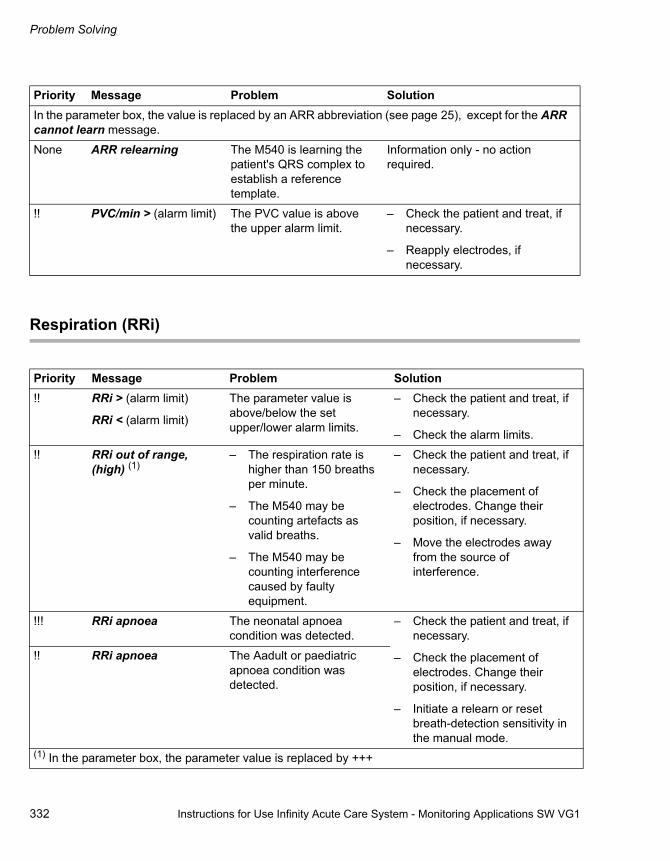
Problem Solving
332 Instructions for Use Infinity Acute Care System - Monitoring Applications SW VG1
Respiration (RRi)
In the parameter box, the value is replaced by an ARR abbreviation (see page 25), except for the ARR cannot learn message.
None ARR relearning The M540 is learning the patient's QRS complex to establish a reference template.
Information only - no action required.
!! PVC/min > (alarm limit) The PVC value is above the upper alarm limit.
– Check the patient and treat, if necessary.
– Reapply electrodes, if necessary.
Priority Message Problem Solution
Priority Message Problem Solution!! RRi > (alarm limit)
RRi < (alarm limit)
The parameter value is above/below the set upper/lower alarm limits.
– Check the patient and treat, if necessary.
– Check the alarm limits.
!! RRi out of range, (high) (1)
– The respiration rate is higher than 150 breaths per minute.
– The M540 may be counting artefacts as valid breaths.
– The M540 may be counting interference caused by faulty equipment.
– Check the patient and treat, if necessary.
– Check the placement of electrodes. Change their position, if necessary.
– Move the electrodes away from the source of interference.
!!! RRi apnoea The neonatal apnoea condition was detected.
– Check the patient and treat, if necessary.
– Check the placement of electrodes. Change their position, if necessary.
– Initiate a relearn or reset breath-detection sensitivity in the manual mode.
!! RRi apnoea The Aadult or paediatric apnoea condition was detected.
(1) In the parameter box, the parameter value is replaced by +++

Instructions for Use Infinity Acute Care System - Monitoring Applications SW VG1 333
Problem Solving
RRi coincidence The heart rate and respiration rate fall within 20 % of each other.
– Check the patient and treat, if necessary.
– Check and change the electrode placement if you receive a coincidence message until you obtain a clear respiration signal.
! RRi lead Off (2) The respiration lead has been invalid for 10 seconds.
– Check the patient and treat, if necessary.
– Make sure that the patient's skin is prepared properly.
– Isolate the patient from the auxiliary equipment, if possible.
– Check the electrode(s) and gel and reapply, if necessary.
– Inspect and replace the defective cables and wires.
– If a lead or electrode cannot be replaced, select another lead for processing (in the RRi setup page).
! RRi artefact (2) A persistent artefact was detected.
! RRi high impedance (2)
A high respiration impedance was detected.
! RRi lead unavailable Faulty or disconnected electrodes.
None RRi relearning Relearn is in progress. Information only – no action required.
(2) In the parameter box, the parameter value is replaced by ***
Priority Message Problem Solution

Problem Solving
334 Instructions for Use Infinity Acute Care System - Monitoring Applications SW VG1
SpO2
Priority
Message Problem Solution
!! SpO2 > (alarm limit)
SpO2 < (alarm limit)
The parameter value is above/below the set upper/lower alarm limits.
– Check the patient and treat, if necessary.
– Change the alarm limits.
!! PLS > (alarm limit)
PLS < (alarm limit)
The pulse rate is outside the current upper/lower alarm limits.
!! PLS out of range, (low) (2)
PLS out of range, (high) (3)
The parameter value is above/below the measurement range of the monitor.
!! SpO2The sensor is unplugged (1)
The SpO2 intermediate cable is unplugged.
– Verify that the cable and the sensor are properly connected.
– Check for a defective sensor.
None SpO2 searching (1) The sensor is searching for valid pulses to compute a measurement value.
Verify proper sensor application.
(1) In the parameter box, the parameter value is replaced by *** (For Masimo SET MCable only: The perfusion index (PI) value is replaced by ***)
(2) In the parameter box, the parameter value is replaced by - - -(3) In the parameter box, the parameter value is replaced by +++
NOTEIn the neonatal mode, the priority changes to high (!!!) if the SpO2 value falls more than 10% below the lower limit. This does not occur when using SatSeconds alarm time with the Nellcor OxiMax MCable.

Instructions for Use Infinity Acute Care System - Monitoring Applications SW VG1 335
Problem Solving
! SpO2 artefact (1)
(Masimo SET MCable only)
A persistent artefact is due to the patient's movement or a faulty sensor.
– Make sure the SpO2 sensor is properly attached to the patient and all cables are properly connected.
– The patient must be calm.
– Contact Dräger Medical Technical support.
!! SpO2 has no measurement
Due to a lack of stable measurements, the M540 has not been able to compute a valid calculation within the last 30 seconds.
Contact Dräger Medical Technical support.
! SpO2 sensor failure Hardware failure – Make sure the SpO2 sensor is properly attached to the patient and all cables are properly connected.
– Contact Dräger Medical Technical support.
! SpO2 has low perfusion Masimo SET MCable reports low perfusion.
Check the patient and treat, if necessary.
! SpO2 sensor is off (1) The Masimo SET MCable has detected that the SpO2 sensor is no longer attached to the patient.
Reattach the SpO2 sensor.
! SpO2 HW failure Masimo SET MCable or Nellcor Oximax MCable hardware failure
– Check for a defective MCable
– Power-cycle the M540 to clear the message.
– Contact Dräger Medical Technical support.
(1) In the parameter box, the parameter value is replaced by *** (For Masimo SET MCable only: the perfusion index (PI) value is replaced by ***)
Priority
Message Problem Solution

Problem Solving
336 Instructions for Use Infinity Acute Care System - Monitoring Applications SW VG1
! SpO2 has low signal IQ Masimo SET MCable detects low SQI level
– Check the patient and treat, if necessary.
– Make sure the SpO2 sensor is attached properly to the patient .
– Check all cable connections.
! SpO2 check sensor SpO2 sensor is detecting too much ambient light.
– Make sure the SpO2 sensor is attached properly to the patient .
– Check all cable connections.
! SpO2 MCable is incompatible
An incompatible pod is in use.
Contact your technical personnel.
! SpO2 MCable is unplugged (1)
The SpO2 MCable is disconnected from the M540.
Check connections to M540.
! SpO2 unrecognised sensor (1)
An incompatible sensor is connected.
– Connect the right type of sensor.
– Contact your technical personnel.
(1) In the parameter box, the parameter values are replaced by *** (For Masimo SET MCable only: The perfusion index (PI) value is replaced by ***)
Priority
Message Problem Solution

Instructions for Use Infinity Acute Care System - Monitoring Applications SW VG1 337
Problem Solving
NIBP
Priority Message Problem Solution!! NIBP S > (alarm limit)
NIBP S < (alarm limit)
The parameter value is above/below the upper/lower alarm limits.
– Check the patient and treat, if necessary.
– Change the alarm limits.!! NIBP D > (alarm limit)
NIBP D < (alarm limit)
!! NIBP M > (alarm limit)
NIBP M < (alarm limit)
!! NIBP low-inflation limit (1, 2)
The pressure of the patient is greater than the maximum allowed cuff inflation pressure.
Select the next higher inflation limit setting.
! NIBP mean only (1) The pulse amplitude is too small or too high for the M540 to derive systolic and diastolic pressure values but sufficient to report a mean pressure value.
– Check the patient and treat, if necessary.
– Check the hose and cuff
– Check the size and the placement of the cuff.
! NIBP cannot measure (1, 2) The pulse profile is too poor to establish a reliable measurement (usually due to a persistent motion artefact).
– Check the patient and treat, if necessary.
– Move the cuff to a limb with less movement.
– Restart the measurement. If the message does not clear, contact your technical personnel or Dräger Medical Technical Support.
(1) In the parameter box, the parameter value is replaced by ***(2) This message, preceded by Last measurement failed!, also appears in the parameter box.
NOTEIn the parameter box, the following message appears: Last measurement failed low inflation
NOTEIn the parameter box, the following message appears: Cannot measure.

Problem Solving
338 Instructions for Use Infinity Acute Care System - Monitoring Applications SW VG1
! NIBP measurement timeout (1, 2)
An NIBP measurement has exceeded time-out limit.
Repeat the measurement.
! NIBP overpressure (1, 2) The cuff pressure has exceeded the overpressure threshold.
– Check the patient and treat, if necessary.
– Check the cuff for obstructions.
– Repeat the measurement.
! NIBP open line (1, 2) There was no significant increase in the cuff pressure during the inflation cycle.
Make sure that the hose and cuff are properly connected to the monitor.
! NIBP blocked line (1, 2) The inflation rate is too high during the inflation cycle or the time to evacuate the residual cuff pressure at the end of the deflation cycle is too short.
– Select a different cuff.
– Check the hose and cuff for damage.
– Restart the measurement. If the message does not clear, contact Dräger Medical Technical Support.
! NIBP cuff leak (1, 2) The drop in the cuff pressure at the end of the inflation cycle is too great.
– Check the hose and cuff for leaks. Replace, if necessary.
– Restart the measurement. If the message does not clear, contact Dräger Medical Technical Support.
!! NIBP H/W failure – NIBP measurement circuit failure
– NIBP is zero, out of range or faulty transducer
Check all hardware, contact Dräger Medical Technical support.
(1) In the parameter box, the parameter value is replaced by ***(2) This message, preceded by Last measurement failed!, also appears in the parameter box.
Priority Message Problem Solution
NOTEIn the parameter box, the following message appears: Open line.
NOTEIn the parameter box, the following message appears: Blocked line.
NOTEIn the parameter box, the following message appears: Cuff leak.
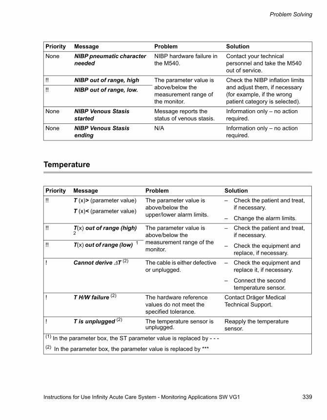
Instructions for Use Infinity Acute Care System - Monitoring Applications SW VG1 339
Problem Solving
Temperature
None NIBP pneumatic character needed
NIBP hardware failure in the M540.
Contact your technical personnel and take the M540 out of service.
!! NIBP out of range, high The parameter value is above/below the measurement range of the monitor.
Check the NIBP inflation limits and adjust them, if necessary (for example, if the wrong patient category is selected).
!! NIBP out of range, low.
None NIBP Venous Stasis started
Message reports the status of venous stasis.
Information only – no action required.
None NIBP Venous Stasis ending
N/A Information only – no action required.
Priority Message Problem Solution
Priority Message Problem Solution!! T (x)> (parameter value)
T (x)< (parameter value)
The parameter value is above/below the upper/lower alarm limits.
– Check the patient and treat, if necessary.
– Change the alarm limits.
!! T(x) out of range (high) 2
The parameter value is above/below the measurement range of the monitor.
– Check the patient and treat, if necessary.
– Check the equipment and replace, if necessary.
!! T(x) out of range (low) 1
! Cannot derive ΔT (2) The cable is either defective or unplugged.
– Check the equipment and replace it, if necessary.
– Connect the second temperature sensor.
! T H/W failure (2) The hardware reference values do not meet the specified tolerance.
Contact Dräger Medical Technical Support.
! T is unplugged (2) The temperature sensor is unplugged.
Reapply the temperature sensor.
(1) In the parameter box, the ST parameter value is replaced by - - -(2) In the parameter box, the parameter value is replaced by ***

Problem Solving
340 Instructions for Use Infinity Acute Care System - Monitoring Applications SW VG1
IBP
Priority Message Problem Solution!! IBP S > (parameter value)
IBP S < (parameter value)
The parameter value is above/below the upper/lower alarm limits.
– Check the patient and treat, if necessary.
– Change the alarm limits.!! IBP D > (parameter value)
IBP D < (parameter value)
!! IBP M > (parameter value)
IBP M < (parameter value)
!! CPP > (parameter value)
CPP <(parameter value)
!! IBP out of range, (high) (2)
The pressure signal is above/below the measurement range of the monitor.
– Check the patient and treat, if necessary.
– Check the equipment and replace, if necessary.
!! IBP out of range, (low) (1) The pulse rate falls outside the measuring range of the monitor.
– Check the patient and treat, if necessary.
– Check the equipment and replace, if necessary.
!! <IBP S> out of range, (high) (2)
!! <IBP S> out of range, (low) (1)
!! <IBP D> out of range, (high) (2)
!! <IBP D> out of range, (low) (1)
!! <IBP M> out of range, (high) (2)
!! <IBP B> out of range, (low) (1)
!! CPP out of range, (high) (2)
!! CPP out of range, (low) (1)
(1) In the parameter box, the parameter value is replaced by - - -(2) In the parameter box, the parameter value is replaced by +++

Instructions for Use Infinity Acute Care System - Monitoring Applications SW VG1 341
Problem Solving
! <IBP> check zero The IBP zero value stored in the M540 was lost and the transducer requires zeroing.
Zero the transducer.
!! <IBP> static pressure The static pressure is detected on a pulsatile signal due to:
– a physiological condition, such as an asystole
– a transducer that is closed to the patient
– a catheter tip that is lodged against a vessel wall
– a clot on the catheter tip
– Check the patient and treat, if necessary.
– Open the system to the patient by turning the stopcock.
– Follow hospital procedures for dislodging catheters.
– Follow hospital procedures for clotted catheters.
! <IBP> is unplugged (1) The pressure transducer for the specified parameter is either unplugged or defective.
– During an active pressure: Reconnect or replace the cable.
– During an inactive pressure: Turn off alarms.
! <IBP> H/W failure IBP hardware failure. – Check the hardware and replace, if necessary.
– Call your technical personnel or Dräger Medical Technical Support.
! The HemoPod is unplugged (1)
The IBP pod is disconnected. Check the equipment and replace, if necessary.
None <IBP> zero accepted Transducer zeroing was successful.
Information only - no action required.
None <IBP> did not zero Transducer zeroing failed because of:
– excessive signal noise
– a non-static waveform
– Keep all tubing motionless, then re-zero.
– Change the transducer.
– Check the stopcock, then re-zero.
(1) In the parameter box, the parameter value is replaced by ***
Priority Message Problem Solution

Problem Solving
342 Instructions for Use Infinity Acute Care System - Monitoring Applications SW VG1
None <IBP> did not zero - offset error
Transducer zeroing failed because the static pressure was too high or too low.
– Keep all tubing motionless.
– Replace the transducer.
– Check the stopcock and zero again
None Inflate balloon and press 'Start Wedge' to begin
Action is required to start the wedge measurement.
Press the Start Wedge button to begin the wedge measurement.
None Wedge is in progress Information only. Information only - no action required.
None Deflate the balloon. Press 'Save Wedge' to finish.
Action is required to complete the wedge measurement.
Press the Start Wedge button to begin the wedge measurement.
Priority Message Problem Solution
NOTEThis message appears in the 'Wedge' dialogue
NOTEThis message appears in the 'Wedge' dialogue
NOTEThis message appears in the 'Wedge' dialogue

Instructions for Use Infinity Acute Care System - Monitoring Applications SW VG1 343
Problem Solving
Cardiac Output
Priority Message Problem Solution
!! Tblood > (parameter value)
Tblood < (parameter value)
The blood temperature is outside the alarm limits because of:
– a physiological condition
– inappropriate alarm limits
– a defective sensor
– Check the patient and treat, if necessary.
– Change the alarm limits.
!! Tblood out of range, (high)
Tblood out of range, (low)
The blood temperature is outside the measurement range because of a defective sensor.
Check the equipment and replace, if necessary.
None C.O. out of range, (high)
C.O. out of range, (low)
The C.O. is greater than 20 litres/min or less than 0.5 litres/min because of:
– a physiological condition
– an unstable baseline
– an incorrect injectate volume, catheter size, or computation constant
– a defective catheter, cable, or cartridge
– Check the patient and treat, if necessary.
– Use a cooler injectate.
– Enter the correct values in the C.O. page.
– Repeat the measurement. If the message persists, replace the defective components.
None The C.O. injectate is too cold
The injectate temperature is too cold during the measurement process.
– Use an injectate within the correct temperature range of -5°C to +30°C.
– Check the equipment and replace, if necessary.
None The C.O. injectate is too warm
The injectate is warmer than +30 °C during the C.O. measurement.
– Use an injectate within the correct temperature range of -5°C to +30°C.
– Check the probe connection. If the problem persists, replace the probe.
– Repeat the measurement. If the message persists, replace the defective components.

Problem Solving
344 Instructions for Use Infinity Acute Care System - Monitoring Applications SW VG1
None C.O. has no temperature change.
No change in blood temperature during the C.O. measurement.
– Repeat the measurement.
– Use a larger injectate volume.
– Repeat the measurement. If the problem persists, replace the catheter.
– Use a cooler injectate.
None The C.O. uses a cooler injectate.
– The difference between the temperature of the blood and the injectate is less than 5 °C.
– The injectate temperature is greater than 25.
Use a colder injectate.
None The C.O. injectate is set to 20 oC!
No injectate probe was connected. The M540 assumes a temperature of 20°C.
Attach an injectate probe.
! The C.O. transducer is unplugged.
A cable or transducer has become disconnected.
– Reconnect the cable or transducer.
– Replace the defective part, if the message persists.
None The C.O. has a poor baseline.
A poor blood temperature baseline exists during the C.O. measurement.
– Follow hospital procedures.
– Repeat the measurement.
– Replace the defective components, if the message persists.
! C.O. pod fault - bad ref.
The C.O. reference values do not meet the specified tolerances.
– Remove and reconnect the pod.
– Repeat the measurement.
– Replace the pod and contact Dräger Medical Technical Support if the message persists.
Priority Message Problem Solution

Instructions for Use Infinity Acute Care System - Monitoring Applications SW VG1 345
Problem Solving
CO2
! C.O. catheter fault - bad ref.
The C.O. blood thermistor calibration resistor does not meet the specified tolerance.
– Check the catheter and replace, if necessary.
– Contact your technical personnel or Dräger Medical Technical Support.
None The C.O. duplicate device is connected
Multiple C.O. sources are connected. This includes CCO devices connected via the device connectivity option.
Disconnect duplicate C.O. sources.
None C.O. - check the injectate probe
The injectate probe is not connected or became disconnected during a measurement.
Connect the probe and repeat the measurement.
Priority Message Problem Solution
Priority Message Problem Solution!! CO2 > (parameter value)
CO2 < (parameter value)The parameter value is above/below the upper/lower alarm limits.
– Check the patient and treat, if necessary.
– Change the alarm limits.
! CO2 is unplugged (1) The CO2 sensor is disconnected.
Check the CO2 connections.
! CO2 H/W failure (1) CO2 sensor hardware failure.
Contact your technical personnel.
!! CO2 out of range (1) The parameter signal is outside the measuring range of the monitor.
– Check the patient and treat, if necessary.
– Check the equipment and replace, if necessary.
(1) In the parameter box, the parameter value is replaced by ***

Problem Solving
346 Instructions for Use Infinity Acute Care System - Monitoring Applications SW VG1
None CO2 is warming up The mainstream sensor is going through the warm-up cycle.
– Wait for the mainstream sensor to warm up. During the warm-up, the accuracy is reduced.
– If the message persists longer than 15 min after the sensor has warmed up, and the ambient temperature is above 10oC, contact Dräger Medical Technical Support.
! CO2 incompatible sensor (2)
– The M540 has detected that the used mainstream sensor is not compatible with the selected sensor type setting (reusable/disposable)
– Secretions in the adaptor
– The sensor has a zero drift
– High inspiratory CO2 concentration
– Use the airway adaptor type the system is configured for or adjust the airway adapter setting (see page 295).
– If the message persists, clean or replace the airway adaptor.
– If the message persists even though the correct airway adaptor type is selected and the airway adaptor is clean, zero the sensor.
– If the message still persists, the inspiratory CO2 value might not be accurate. Check the patient and ventilation.
Priority Message Problem Solution
NOTEYou cannot zero the sensor when this message is displayed and the ambient temperature is above 10oC (50oF).
When the ambient temperature is below 10oC (50oF), the message can persist longer than 15 minutes. In this case, it is possible to zero the sensor after the message has been displayed for at least 10 minutes.

Instructions for Use Infinity Acute Care System - Monitoring Applications SW VG1 347
Problem Solving
(2) In the parameter box, the parameter value is replaced by ***
! The CO2 sensor is too warm.
The CO2 mainstream sensor is too warm due to the ambient temperature.
– Unspecified accuracy at ambient temperatures above 40 °C.
– The sensor will return to normal operation at ambient temperatures below 40 °C. If not, replace the sensor and contact Dräger Medical Technical Support.
! CO2 Check the airway adaptor
– The mainstream sensor is not properly seated on the adaptor
– There are secretions in the adaptor
– There is a sensor zero drift
– Make sure the mainstream sensor is attached properly to the adaptor.
– If the message persists, clean or replace the airway adaptor.
– If the message persists even though the airway adaptor is clean, zero the sensor.
None CO2 zero is in progress
The CO2 zeroing is in progress.
Information only – no action required.
None CO2 zero failed Zeroing of the sensor has failed or the sensor is defective.
– Try to zero the sensor again, making sure not to breathe on the sensor.
– If zeroing fails again, replace the sensor and contact Dräger Medical Technical Support, if the message persists.
None CO2 please zero Instructional message for the mainstream sensor only.
Zero the mainstream sensor.
Priority Message Problem Solution

Problem Solving
348 Instructions for Use Infinity Acute Care System - Monitoring Applications SW VG1
Recording Status Messages
Priority Message Problem SolutionNone The primary or
secondary recorder is not connected.
A recording was requested, but no recorder is available.
Try again, then contact your technical personnel.
None The primary or secondary recorder is out of paper
A recording was requested, but the recorder is out of paper.
Replace the recorder paper (see page 314)
None The primary or secondary recorder door is open.
The recorder door is open. Close the door of the recorder.
None The timed recording is started.
The requested recording is being printed.
Information only - no action required.
None The continuous recording is started.
None The timed recording request is accepted.
The recorder is not available and the requested recording is queued or stored for later printing.
None The continuous recording request is accepted.
None The timed recording is finished.
The requested recording is printed.
None The continuous recording is finished.
None The timed recording is cancelled.
The requested recording was manually cancelled.
None The continuous recording is cancelled.
None The recording is not accepted
The assigned recorder is not available and the recording request was ignored.
Contact your technical personnel to check the recorder assignment.
None There is a primary or secondary recorder failure.
The recording request was not accepted due to a recorder hardware failure.
Contact your technical personnel.
None The excess artefact recording is cancelled.
The recording request was not accepted due to an artefact.
Check the ECG-lead connections; contact your technical personnel.

Instructions for Use Infinity Acute Care System - Monitoring Applications SW VG1 349
Cleaning and Disinfection
Cleaning and Disinfection
Overview of General Precautions . . . . . . . . . 350
Approved Agents . . . . . . . . . . . . . . . . . . . . . . 350
Cockpit Components . . . . . . . . . . . . . . . . . . . 351

Cleaning and Disinfection
350 Instructions for Use Infinity Acute Care System - Monitoring Applications SW VG1
Overview of General Precautions
Clean and disinfect the device or device parts before each maintenance step – and also when returning for repair.
The cleaning agents and methods listed on page 350 are approved for the following devices:
– Cockpit (Infinity C500/C700)
– PS250
Before cleaning any device, read the general safety precautions under "General Warnings and Cautions" on page 12.
For cleaning instructions regarding the M540 and devices that connect to it, refer to the Infinity Acute Care System - M540 Instructions for Use.
Approved Agents
Clean and disinfect the product as per the hospital-approved protocol. Agents tested by Dräger Medical and shown to have no harmful effect on the materials at the time of testing utilised in the device include:
– Isopropyl alcohol (40% solution)
– ComplianceTM – not to be used on the touch screen (7.35% hydrogen peroxide, 0.23% peracetic acid, 92.42% inert ingredients)
– Sporox II – not to be used on the touch screen (7.5% hydrogen peroxide, 0.85% phosphoric acid, and 91.65% inert ingredients)
– Dismozon® pur
Cockpit Plastic Housing
Dräger Medical makes no claims regarding the efficacy of the listed chemicals, their methods as a means for disinfecting, the ability of the agents to control infection, their environmental impact, safe handling, or any related precautions in their use. Refer to the information provided by the manufacturer of the cleaning solution for more information in these areas.
WARNINGBecause of the danger of electric shock, never remove the cover of any device while it is in operation or connected to power.
WARNINGDo not immerse or rinse the device and its peripherals. If you spill liquid on the device (including the battery or accessories), or accidentally immerse it in liquid, disconnect the device from the power source and allow it to dry completely for at least 24 to 48 hours. Contact your technical personnel regarding the continued safety of the device and its peripherals before placing it back in operation.
CAUTIONTo avoid damaging the device, do not use sharp tools or abrasives. Never immerse electrical connectors in water or other liquids. Avoid letting fluids puddle near the edge of the screen while you are cleaning it.
CAUTIONIf using alcohol, it should only be a 40% diluted solution. Higher concentrations could damage the device.
Instructions for Use Infinity Acute Care System - Monitoring Applications SW VG1 351
Cleaning and Disinfection
Cockpit Components
Use only the approved cleaning agents listed under "Approved Agents".
To clean the Cockpit components
1 Wipe the Cockpit housing with a cloth moistened with a soap solution. Use an ammonia-based glass cleaner to clean the touch screen.
2 Dry thoroughly with a lint-free cloth.
To disinfect the Cockpit
1 Disinfect the surfaces with a gauze pad moistened with diluted alcohol (40% solution).
2 Dry thoroughly with a lint-free cloth.
NOTEDo not clean the front panel of the device while monitoring a patient. Before cleaning, take the device out of operation.
NOTEDo not spray the cleaner directly on the touch screen. The cleaning liquid must be applied on a cloth or tissue before cleaning the surface of the device.

352 Instructions for Use Infinity Acute Care System - Monitoring Applications SW VG1
This page is intentionally left blank

Instructions for Use Infinity Acute Care System - Monitoring Applications SW VG1 353
Maintenance
Maintenance
Overview . . . . . . . . . . . . . . . . . . . . . . . . . . . . . 354
Maintenance of the IACS Components . . . . 355
Safety Inspections . . . . . . . . . . . . . . . . . . . . . 356
Scope of Safety Inspection for the Cockpit (C500/C700) . . . . . . . . . . . . . . . . . . . . . . . . . . . 356Scope of Safety Inspection for the PS250 . . . . 356Scope of Safety Inspection for the M540 . . . . . 357

Maintenance
354 Instructions for Use Infinity Acute Care System - Monitoring Applications SW VG1
Overview
This chapter describes the necessary maintenance steps to be performed by your technical personnel for the proper functioning of the equipment. For complete instructions on how to perform the required maintenance, refer to the Technical Service Document which can be obtained from Dräger.
WARNINGIf the device is mechanically damaged, or if it is not working properly, do not use it. Contact your technical personnel.
CAUTIONThis device must be inspected and serviced at regular intervals. A record must be kept on this preventive maintenance. We recommend obtaining a service contract with DrägerService through your vendor. For repairs, we recommend that you contact DrägerService.
CAUTIONWhen servicing devices from Dräger Medical, always use replacement parts that are qualified to Dräger standards. Dräger Medical cannot guarantee or endorse the safe performance of third-party replacement parts for use with the devices.
CAUTIONIf you spill liquid on the equipment, battery or accessories or immerse these components in liquid, allow them to dry completely for at least 24 hours to 48 hours. Contact your hospital technical personnel to test any such component is fully operational before putting it back in clinical use.

Instructions for Use Infinity Acute Care System - Monitoring Applications SW VG1 355
Maintenance
Maintenance of the IACS Components
The normal inspection interval for a Cockpit is 24 months. This interval is shorter if a device with a shorter inspection interval, that depends on the Cockpit for its proper function, is connected to the Cockpit.
CAUTIONThis device must be inspected and serviced at regular intervals. A record must be kept on this preventive maintenance. We recommend obtaining a service contract with DrägerService through your vendor. For repairs, we recommend that you contact DrägerService.
NOTEThe following table provides an overview of the recommended maintenance intervals for the IACS components (Infinity C500, C700, and PS250).
Device part Maintenance interval and tasksNIBP air intake filter of the M540 – Exchange after two years.
– Dispose of the part with normal domestic waste.
Internal M540 battery and internal PS250 battery – Service during regular inspections.
– Exchange at least every two years by trained service personnel.
– Check the battery once a year. If necessary, trained service personnel must replace it.
Inspection of all devices Exchange every two years by trained service personnel.
Safety inspection of all devices Every year by trained service personnel according to hospital protocol. For the scope of the safety inspections, see page 356.
NOTEIf the NIBP air filter seems dirty or damaged, replace it before the recommended two years. The NIBP air filter should be replaced, if the M540 was exposed to liquid. See "Exchanging the ambient air filter" in the Technical documentation which is available from DrägerService.
NOTEDo not disassemble the Ni-MH battery inside the PS250 power supply. Aside from the required two-year maintenance recommended for the entire IACS, this battery requires no additional routine maintenance. NOTE
During high-performance use of this device, the battery must be checked more often.

Maintenance
356 Instructions for Use Infinity Acute Care System - Monitoring Applications SW VG1
Safety Inspections
Scope of Safety Inspection for the Cockpit (C500/C700)
The following safety inspections are no substitute for the inspection and maintenance indicated by the manufacturer, including the preventive exchange of parts subject to wear. For technical documentation, contact your local DrägerService representative.
1 Check the accompanying documents and determine if the Instructions for Use are available.
2 Check that the equipment is complete and ready for use according to the Instructions for Use.
3 Verify that the device in combination with other system components is in good working condition. Specifically, verify the following:
– All labels are complete and legible
– There is no visible damage
4 Check that the device meets the electrical safety requirements according to IEC62353, Medical electrical equipment - recurrent test and test after repair of medical electrical equipment.
5 Verify that the visual and audible alarm signals function properly.
6 Verify that the following device features operate according to the Instructions for Use:
– Verify the LEDs
– Perform the device checks
Scope of Safety Inspection for the PS250
The following safety inspections are no substitute for the inspection and maintenance indicated by the manufacturer, including the preventive exchange of parts subject to wear. For technical documentation, contact your local DrägerService representative.
1 Check the accompanying documents and determine if the Instructions for Use are available.
2 Verify that the device in combination with other system components is in good working condition. Specifically, verify the following:
– All labels are complete and legible.
– There is no visible damage
– Fuses which are accessible from the outside comply with the specified values.
3 Check that the device meets the electrical safety requirements according to IEC62353, Medical electrical equipment - recurrent test and test after repair of medical electrical equipment.
4 Verify the following safety features:
– The power LED and the battery indicator LED function properly.
– The C500/C700 are powered correctly.
– Check the correct functioning of the Infinity ®MCable - Nurse Call.
5 Perform a functional test of the internal battery.
CAUTIONPerform the safety inspecitions in the specified intervals. Otherwise, the correct functioning of the device may be compromised.

Instructions for Use Infinity Acute Care System - Monitoring Applications SW VG1 357
Maintenance
Scope of Safety Inspection for the M540
The following safety inspections are no substitute for the inspection and maintenance indicated by the manufacturer, including the preventive exchange of parts subject to wear. For technical documentation, contact your local DrägerService representative.
1 Check the accompanying documents and determine if the Instructions for Use are available.
2 Check that the equipment is complete and ready for use according to the Instructions for Use.
3 Verify that the device in combination with other system components is in good working condition. Specifically, verify the following:
– All labels are complete and legible.
– There is no visible damage.
4 Check that the device meets the electrical safety requirements according to IEC62353, Medical electrical equipment - recurrent test and test after repair of medical electrical equipment.
5 Verify the following safety features:
– Correct functioning of the visual and audible alarm signals.
– Correct functioning of the Audio Pause button located on the front panel of the device.
– Correct functioning of the NIBP overpressure sensor (including the valves and the pump).
6 Verify that the following M540 features operate according to the Instructions for Use:
– Perform a functional test of the internal battery.
– Perform the device checks (for example, communication with the IACS, front panel buttons, alarm bar, and correct functioning of monitored parameters).

358 Instructions for Use Infinity Acute Care System - Monitoring Applications SW VG1
This page is intentionally left blank

Instructions for Use Infinity Acute Care System - Monitoring Applications SW VG1 359
Disposal
Disposal
EU Directive 2002/96/EC (WEEE) . . . . . . . . . . 360

Disposal
360 Instructions for Use Infinity Acute Care System - Monitoring Applications SW VG1
EU Directive 2002/96/EC (WEEE)
This device is subject to EU Directive 2002/96/EC (WEEE). It is not registered for use in private households, and may not be disposed of at municipal collection points for waste of electrical and electronic equipment. Dräger Medical has authorised a firm to dispose of this device in the proper manner. For more detailed information, please contact your local Dräger Medical organisation.

Instructions for Use Infinity Acute Care System - Monitoring Applications SW VG1 361
Technical Data
Technical Data
Overview . . . . . . . . . . . . . . . . . . . . . . . . . . . . . 362
Infinity® PS250 Comm Hub . . . . . . . . . . . . . . 362
Infinity ®MCable-Nurse Call . . . . . . . . . . . . . . 363
Infinity R50N . . . . . . . . . . . . . . . . . . . . . . . . . . 364
Secondary Display . . . . . . . . . . . . . . . . . . . . . 365
Electromagnetic Compatibility . . . . . . . . . . . 365

Technical Data
362 Instructions for Use Infinity Acute Care System - Monitoring Applications SW VG1
Overview
This chapter contains the technical data for the following devices of the Infinity® Acute Care SystemTM - Monitoring Applications:– PS250 power supply– Minimal technical requirements for the
secondary display– Infinity ®MCable - Nurse Call For technical data of the Infinity C500/C700, refer to the Infinity ® Medical CockpitTM Instructions for Use.
For the following information, refer to the Infinity Acute Care System - M540 Instructions for Use:
– MPods and MCables that connect directly to the M540.
– Specifications, such as measuring ranges of individual parameters
The IACS is intended to be connected to one patient at a time.
Infinity® PS250 Comm Hub
Physical SpecificationsDimensions (W x D x H) 27.76 cm x 11.68 cm x 34.59 cm (10.93 in. x 4.60 in. x
13.62 in.)
Weight 5.5 kg (12 lbs)
Cooling Convection
Connections – RS232
– Alarm output
– System cable
– Infinity network (Ethernet)
– Potential equalisation connector (earthing lug)
Environmental Specifications Humidity (non-condensing) Operating: 20 % to 95 %
Storage: 20 % to 95 %
Temperature Operating:0 oC to 40 oC (0 oF to 104 oF)Storage: -20 oC to 60 oC (-4 oF to 140 oF)
NOTEThe PS250 has an operating temperature range of 0 - 40 °C (0 - 104 °F). When the battery is being charged at ambient temperatures below 5 °C (41 °F), the yellow LED on the PS250 may light up.

Instructions for Use Infinity Acute Care System - Monitoring Applications SW VG1 363
Technical Data
Infinity ®MCable - Nurse Call
Atmospheric pressure Operating: 485 mmHg to 795 mmHg (70 kPa to 106 kPa)Storage: 375 mmHg to 795 mmHg (50 kPa to 106 kPa)
Protection against electrical shock Type CF
Protection against water ingress IPX1 per IEC 60529 – protected against harmful effects of water
Electrical SpecificationsInput voltage 100 to 240 VAC 50/60 Hz, 6 A
Mode of Operation Continuous
Dräger NiMH Battery Pack
Operating time: approximately 5 min
Recharging time: 8 hours
DC output +24 V nominal, SELV per IEC 60601-1
Physical AttributesConnections Connects to the Infinity® PS250 Comm Hub
Connection via cable 8417370 only
Cable signals during the non-alarm state
Cable 1 (NO normally open): white
Cable 2 (COM common): brown
Cable 3 (NO normally closed): green
Mode of Operation Continuous
Power RequirementsOutput voltage During the alarm state: minimal signal for 3 s @
>16 VDuring the non-alarm state: less than 1 s @ ≥ 18 V
Input voltage 24 V DC maximum
1
2
3

Technical Data
364 Instructions for Use Infinity Acute Care System - Monitoring Applications SW VG1
Infinity R50N
Input current 1 A DC maximum
Switching capacity 15 W maximum
Risk ManagementProtection against electrical shock Three contacts from the open cable have an
electrical isolation of 1.5k VAC
Environmental RequirementsOperation
Temperature 5°C to 55°C (41°F to 131°F)
Relative humidity 5% to 95%, non-condensing
Atmospheric pressure 375mmHg to 825mmHg (50kPa to 110kPa)
Storage
Temperature range -20°C to 60°C ( -4°F to 140°F)
Relative humidity 5% to 95%, non-condensing
Atmospheric pressure 375mmHg to 825mmHg (50kPa to 110kPa)
Physical AttributesSize (H x W x D) 180 mm x 120 mm x 222 mm
(7.1 in x 4.7 in x 8.7 in)
Weight 1.6 kg (3.6 lbs)
Connections AC power
X14 Infinity network connector
Potential equalisation connector (earthing lug)
Power RequirementsInput voltage 100 to 240 VAC 50/60 Hz, 1 A
Risk ManagementProtection class Class 1
Protection against liquid ingress IPX0 per IEC 60529
Mode of Operation Continuous
Environmental RequirementsOperation
Temperature 15 °C to 40°C (55 °F to 104 °F)

Instructions for Use Infinity Acute Care System - Monitoring Applications SW VG1 365
Technical Data
Secondary Display
A secondary display has to meet the minimum technical specifications outlined in the following table. For information on how to connect a secondary display to the IACS, see page 40.
Electromagnetic Compatibility
The separation distances are written with regard to the Cockpit. The numbers provided will not guarantee faultless operation, but should provide reasonable assurance of such. This information may not be applicable to other medical electrical equipment, and older equipment may be particularly susceptible to interference.
General Notes
Medical electrical equipment needs special precautions regarding electromagnetic compatibility (EMC) and needs to be installed and put into service according to the EMC information provided in this manual.
Portable and mobile RF communications equipment can affect medical electrical equipment.
Cables and accessories not specified within the Instructions for Use are not authorised. Using other cables and/or accessories may adversely impact safety, performance and electromagnetic compatibility (increased emission and decreased immunity).
Relative humidity 30% to 95%, non-condensing
Atmospheric pressure 550 mmHg to 775 mmHg (73 kPa to 103 kPa)
Storage
Temperature range -20 °C to 40 °C (-4 °F to 104 °F)
Relative humidity 10% to 95%, non-condensing without packaging
Atmospheric pressure 375 mmHg to 795 mmHg (50 kPa to 106 kPa)
General RequirementsResolution 20 inch (35 cm) display: 1440 x 900
17 inch (35 cm) display: 1680 x 1050
Maximum supported distance 7.6 m (25.0 ft)
Display delay 250 ms in reference to the patient signal
Connection to Cockpit DVI-I 1 connector only
CAUTIONThe equipment should not be used adjacent to or stacked with other equipment; if adjacent or stacked use is inevitable, the equipment should be observed to verify normal operation in the configuration in which it will be used.

Technical Data
366 Instructions for Use Infinity Acute Care System - Monitoring Applications SW VG1
Low level signals, such as ECG, are particularly susceptible to interference from electromagnetic energy. While the equipment meets the testing described below, it is not a guarantee of perfect operation, the ‘quieter’ the electrical environment the better. In general, increasing the distance between electrical devices decreases the likelihood of interference.
NOTEThe equipment is intended for use in the electromagnetic environments specified below. The user of this equipment should assure that it is used in such an environment.
Electromagnetic EmissionsEmissions Compliance according to... Electromagnetic environmentRF emissions (CISPR 11) Group 1 The equipment uses RF energy only
for its internal function. Therefore, its RF emissions are very low and are not likely to cause any interference in nearby electronic equipment.*
CISPR Emissions Classification Class B The equipment is suitable for use in all establishments including domestic establishments and those directly connected to the public low-voltage power network that supplies buildings used for domestic purposes.
Harmonic emissions (IEC 61000-3-2)
Class A
Voltage fluctuations / flicker (IEC 61000-3-3)
Complies
Electromagnetic ImmunityImmunity against...
IEC 60601-1-2 test level Compliance level (of device)
Electromagnetic environment
Electrostatic discharge, ESD
(IEC 61000-4-2)
Contact discharge: ± 6 kV
Air discharge: ± 8 kV
± 6 kV
± 8 kV
Floors should be wood, concrete or ceramic tile. If floors are covered with synthetic material, the relative humidity should be at least 30%.
Electrical fast transients / bursts(IEC 61000-4-4)
PS250 lines: ± 2 kVLonger input / output lines: ± 1 kV
± 2 kV
± 1 kV
Mains power quality should be of a typical commercial or hospital environment.

Instructions for Use Infinity Acute Care System - Monitoring Applications SW VG1 367
Technical Data
Surges on AC mains lines
(IEC 61000-4-5)
Common mode: ± 2 kV
Differential mode: ± 1 kV
± 2 kV
± 1 kV
Mains power quality should be of a typical commercial or hospital environment.
Electromagnetic ImmunityImmunity against...
IEC 60601-1-2 test level Compliance level (of device)
Electromagnetic environment
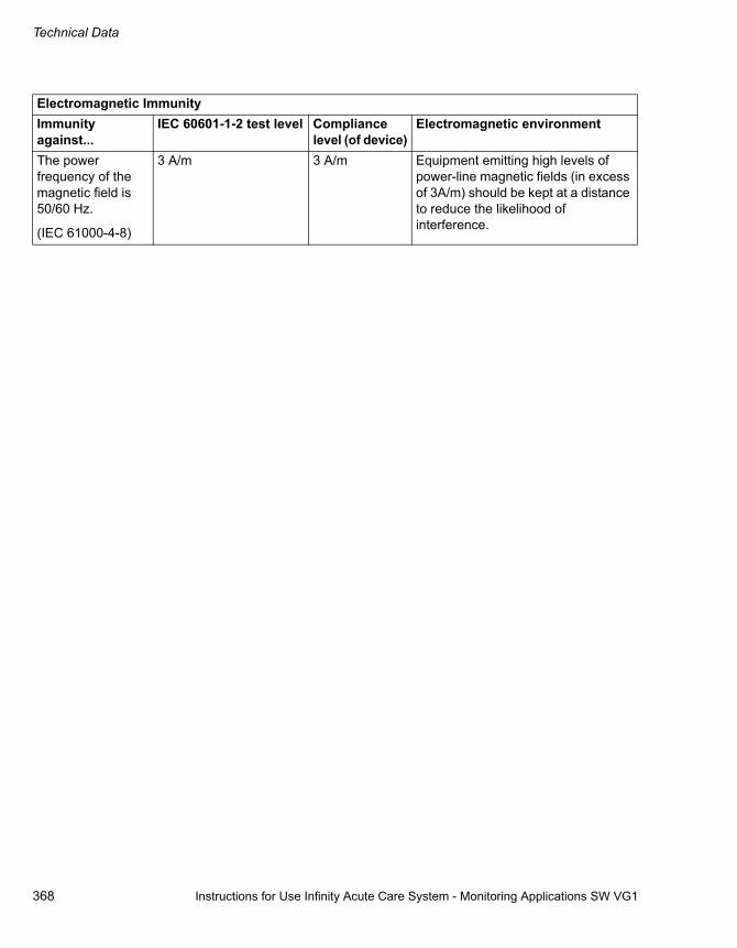
Technical Data
368 Instructions for Use Infinity Acute Care System - Monitoring Applications SW VG1
The power frequency of the magnetic field is 50/60 Hz.
(IEC 61000-4-8)
3 A/m 3 A/m Equipment emitting high levels of power-line magnetic fields (in excess of 3A/m) should be kept at a distance to reduce the likelihood of interference.
Electromagnetic ImmunityImmunity against...
IEC 60601-1-2 test level Compliance level (of device)
Electromagnetic environment

Instructions for Use Infinity Acute Care System - Monitoring Applications SW VG1 369
Technical Data
Voltage dips and short interruptions on AC mains input lines(IEC 61000-4-11)
Dip >95%, 0.5 periodsDip 60%, 5 periodsDip 30%, 25 periodsDip >95%, 5 seconds
>95%, 0.5 periods60%, 5 periods30%, 25 periods>95%, 5 seconds
Mains power should be of a typical commercial or hospital environment. If the user requires continued operation during power-mains interruptions, ensure that the batteries are installed and charged. Ensure the battery life exceeds the longest anticipated power outages or provide additional uninterruptible power source.
Conducted RF
The RF is coupled into lines.
(IEC 61000-4-6)
Radiated RF(IEC 61000-4-3)
150 kHz – 80 MHz
80 MHz – 2.5 GHz
3 Vrms
3 V/m
[V1] V
[E1] V/m
Portable and mobile RF communications equipment should not be used any closer to any part of the device, including cables, than the recommended separation distance calculated from the equation applicable to the frequency of the transmitter as below.
The recommended separation distance
where P is the maximum output power rating of the transmitter in watts (W) according to the transmitter manufacturer and d is the recommended separation distance in metres (m).
Field strengths from fixed RF transmitters, as determined by an electromagnetic site survey, should be less than the compliance level in each frequency range.
Interference may occur in the vicinity of equipment marked with the following symbol:
Electromagnetic ImmunityImmunity against...
IEC 60601-1-2 test level Compliance level (of device)
Electromagnetic environment
d 3.5V1------- P=
d 3.5E1------- P= 80 MHz to 800 MHz
d 7E1------ P= 800 MHz to 2.5 GHz

370 Instructions for Use Infinity Acute Care System - Monitoring Applications SW VG1
This page intentionally left blank
a) Field strengths from fixed transmitters, such as the base stations for radio (mobile/cordless) telephones and land mobile radios, amateur radio, AM and FM radio broadcast and TV broadcast cannot be predicted theoretically with accuracy. To assess the electromagnetic environment due to fixed RF transmitters, an electromagnetic site survey should be considered. If the measured field strength in the location, in which the equipment is used, exceeds the applicable RF compliance level above, the equipment should be observed to verify normal operation. If abnormal performance is observed, additional measures may be necessary, such as re-orienting or re-locating the equipment.
b) Over the frequency range of 150kHz to 80MHz, field strengths should be less than 3 V/m.
Electromagnetic ImmunityImmunity against...
IEC 60601-1-2 test level Compliance level (of device)
Electromagnetic environment
Recommended Separation DistancesRecommended separation distances between portable and mobile RF telecommunication devices and the Cockpitmax.PEIRP (W)
150 kHz to 2.5 GHz 3 V/m Distance * (m)
150 kHz to 2.5 GHz 1 V/m Distance * (m)
Comments (if applicable)
0.001 0.06 0.17
0.003 0.10 0.30
0.010 0.18 0.55
0.030 0.32 0.95 For example: WLAN 5250 / 5775 (Europe)
0.100 0.58 1.73 For example: WLAN 2440 (Europe), Bluetooth
0.200 0.82 2.46 For example: WLAN 5250 (not in Europe)
0.250 0.91 2.75 For example: DECT-devices
1.000 1.83 5.48 For example: GSM 1800 / GSM 1900 / UMTS mobile phones, WLAN 5600 (not in Europe)
2.000 2.60 7.78 For example: GSM 900 mobile phones
3.000 3.16 9.49
Information regarding separation distances (IEC 60601-1-2:2001, Tables 204 and 206)

Instructions for Use Infinity Acute Care System - Monitoring Applications SW VG1 371
This index also lists all abbreviations with the corresponding definitions (for example ARR = Arrhythmia).
I:E = inspiratory-to-expiratory ratio27
Numerics12-Lead Monitoring . . . . . . . . . . . . . . . . . 149, 16212-lead wire set for ECG, connecting . . . . . . . 1413-, 5-, 6-lead wire sets for ECG, connecting . . 140
AAdjusting archive settings for ST . . . . . . . . . . . . 94Admit data . . . . . . . . . . . . . . . . . . . . . . . . . . . . . 65Admitting a Patient
Manually . . . . . . . . . . . . . . . . . . . . . . . . . . . 67Over the network . . . . . . . . . . . . . . . . . . . . . 67
Adult patient categoryDefinition . . . . . . . . . . . . . . . . . . . . . . . . . . . 68Selecting . . . . . . . . . . . . . . . . . . . . . . . . . . . 68
Airway-adaptor type, selecting . . . . . . . . . . . . 295AIVR = accelerated idioventricular rhythmAlarm archive
Individual parameter . . . . . . . . . . . . . . . . . . 88Multiple parameters . . . . . . . . . . . . . . . . . . . 90ST . . . . . . . . . . . . . . . . . . . . . . . . . . . . . . . . 94
Alarm barDescription of feature . . . . . . . . . . . . . . . . . . 77Turning on/off . . . . . . . . . . . . . . . . . . . . . . . 287
Alarm behaviourCardiac bypass mode . . . . . . . . . . . . . . . . . 81French NFC Mode . . . . . . . . . . . . . . . . . . . . 82multiple alarms . . . . . . . . . . . . . . . . . . . . . . . 74NIBP/SpO2 interlock . . . . . . . . . . . . . . . . . . 81OR mode . . . . . . . . . . . . . . . . . . . . . . . . . . . 82Privacy Mode . . . . . . . . . . . . . . . . . . . . . . . . 81Special alarms . . . . . . . . . . . . . . . . . . . . . . . 80SpO2 desaturation . . . . . . . . . . . . . . . . . . . . 80Standby Mode . . . . . . . . . . . . . . . . . . . . . . . 81
Alarm conditionslatching . . . . . . . . . . . . . . . . . . . . . . . . . . . . 74non-latching . . . . . . . . . . . . . . . . . . . . . . . . . 74
Alarm defaults . . . . . . . . . . . . . . . . . . . . . . . . . 101Alarm groups
Setting up . . . . . . . . . . . . . . . . . . . . . . . . . . 287Alarm history . . . . . . . . . . . . . . . . . . . . . . . . 96, 97Alarm light, see Alarm barAlarm limits
Adjusting . . . . . . . . . . . . . . . . . . . . . . . . . . . 89Auto-set all . . . . . . . . . . . . . . . . . . . . . . . . . . 96Display on/off . . . . . . . . . . . . . . . . . . . . . . . 287
Alarm messagesViewing current message . . . . . . . . . . . . . . 80
Alarm monitoringMultiple parameters, on/off . . . . . . . . . . . . . 90Single alarm on/off . . . . . . . . . . . . . . . . . . . 88ST on/off . . . . . . . . . . . . . . . . . . . . . . . . . . . 94Turning it on/off . . . . . . . . . . . . . . . . . . . . . . 85
Alarm priorities, see Alarm gradesAlarm processing . . . . . . . . . . . . . . . . . . . . . . . 73Alarm ranges . . . . . . . . . . . . . . . . . . . . . . . . . 101Alarm review, stored events . . . . . . . . . . . . . . . 96Alarm setup . . . . . . . . . . . . . . . . . . . . . . . . . . . 89
Auto-set limits . . . . . . . . . . . . . . . . . . . . . . . 89Changing alarm limits . . . . . . . . . . . . . . . . . 89Remote control . . . . . . . . . . . . . . . . . . . . . . 99ST . . . . . . . . . . . . . . . . . . . . . . . . . . . . . . . . 93
Alarm toneSelecting the tone type . . . . . . . . . . . . . . . 288Setting the volume . . . . . . . . . . . . . . . . . . 288
Alarm validationList of parameter validation times . . . . . . . . 75Turning the feature on/off . . . . . . . . . . . . . 286
Alarm volumeSelecting . . . . . . . . . . . . . . . . . . . . . . . . . . 288Turning the feature on/off . . . . . . . . . . . . . 289
AlarmsExternal devices . . . . . . . . . . . . . . . . 260, 268
Alarms on/off . . . . . . . . . . . . . . . . . . . . . . . . . . 89alv = alveolarAnalogue sync MCable . . . . . . . . . . . . . . . . . . 21Analogue vs. digital selection . . . . . . . . . . . . . 295apn = apnoeaApnoea archive, CO2 . . . . . . . . . . . . . . . . . . . 257Apnoea time (CO2) . . . . . . . . . . . . . . . . . . . . 257Applications, available . . . . . . . . . . . . . . . . . . 324ARR
Configuring settings . . . . . . . . . . . . . . . . . . 92Defaults . . . . . . . . . . . . . . . . . . . . . . . . . . . 106Display . . . . . . . . . . . . . . . . . . . . . . . . . . . 159Messages . . . . . . . . . . . . . . . . . . . . . . . . . 331Modes . . . . . . . . . . . . . . . . . . . . . . . . . . . . 157Relearning . . . . . . . . . . . . . . . . . . . . . . . . 160Selecting the leads . . . . . . . . . . . . . . . . . . 157Selecting the mode . . . . . . . . . . . . . . . . . . 158
ARR = arrhythmiaARR processing, selecting leads . . . . . . . . . . 152Arrhythmia, see ARRArrow computation constants . . . . . . . . . . . . . 240ART = arterial pressureART D, M, S = arterial pressure diastolic (diastolic, mean, systolic) . . . . . . . . . . . . . . . . . . . . . . . . . 26Artefact, reducing . . . . . . . . . . . . . . . . . . . . . . 155ARTF = artefact . . . . . . . . . . . . . . . . . . . . . . . . 26

372 Instructions for Use Infinity Acute Care System - Monitoring Applications SW VG1
Assembling the IACS hardware . . . . . . . . . . . . 57Assigning the default view to the profile . . . . . 308ASY = asystoleAtmospheric pressure setting . . . . . . . . . 257, 266Attaching the M540 . . . . . . . . . . . . . . . . . . . . . . 59Attention tone volume, selecting . . . . . . . 275, 288Audio alarm
Turning the reminder on/off . . . . . . . . . . . . 288Auto-Measuring Mode
C.O. . . . . . . . . . . . . . . . . . . . . . . . . . . . . . . 241Resp . . . . . . . . . . . . . . . . . . . . . . . . . . . . . 178
Auto-Setting Alarm Limits . . . . . . . . . . . . . . . . . 95Averaging the C.O. . . . . . . . . . . . . . . . . . . . . . 244aVF = ECG leadAvg = averageaVL = ECG leadaVR = ECG leadaw = Airway
BBaxter computation constants . . . . . . . . . . . . . 240BD/Ohmeda computation constants . . . . . . . . 240BGM = bigeminy . . . . . . . . . . . . . . . . . . . . . . . . 26Boyd equation . . . . . . . . . . . . . . . . . . . . . . . . . 122BRADY = bradycardiaBrightness of screen . . . . . . . . . . . . . . . . . . . . . 48BSA = Body Surface Area
CC.O.
Auto Mode . . . . . . . . . . . . . . . . . . . . . . . . . 241Catheter Size . . . . . . . . . . . . . . . . . . . . . . . 246Catheter type display . . . . . . . . . . . . . . . . . 246Colour . . . . . . . . . . . . . . . . . . . . . . . . . . . . 247Computation constant, entering . . . . . . . . . 247Connections . . . . . . . . . . . . . . . . . . . . . . . . 235Injectate volume, selecting . . . . . . . . . . . . 246Manual mode . . . . . . . . . . . . . . . . . . . . . . . 243measuring modes . . . . . . . . . . . . . . . . . . . 241Messages . . . . . . . . . . . . . . . . . . . . . . . . . 343Mode, selecting . . . . . . . . . . . . . . . . . . . . . 247Monitoring Principles . . . . . . . . . . . . . . . . . 234Patient preparation . . . . . . . . . . . . . . . . . . 237Precautions . . . . . . . . . . . . . . . . . . . . . . . . 234Saving the average . . . . . . . . . . . . . . . . . . 244Starting a measurement . . . . . . . . . . . . . . 243Starting the measurement . . . . . . . . . . . . . 247
C.O. = cardiac outputC.O. avg = cardiac output averageC20/C = dynamic complianceCable type for ECG, selecting . . . . . . . . . . . . . 152
Calculating the Body Surface Area . . . . . . . . 122Calculations
Calculations results . . . . . . . . . . . . . . . . . 125Drug Calculations . . . . . . . . . . . . . . . . . . . 131Haemodynamic calculations . . . . . . . . . . . 127Haemodynamic Parameters . . . . . . . . . . . 128Laboratory Data . . . . . . . . . . . . . . . . . . . . 126Oxy/vent calculations . . . . . . . . . . . . . . . . 129Oxygenation and Ventilation Parameters . 130Performing Calculations . . . . . . . . . . . . . . 123Saving calculations . . . . . . . . . . . . . . . . . . 126Viewing stored calculations . . . . . . . 126, 132
Calibrating the Touchscreen . . . . . . . . . . . . . . 48Cardiac bypass mode
Alarms . . . . . . . . . . . . . . . . . . . . . . . . . . . . 81Message . . . . . . . . . . . . . . . . . . . . . . . . . . . 81
Cardioversion . . . . . . . . . . . . . . . . . . . . . . . . . . 21Care unit, assigning . . . . . . . . . . . . . . . . . . . . 296Catheters
Size display, C.O. . . . . . . . . . . . . . . . . . . . 246Type, C.O. . . . . . . . . . . . . . . . . . . . . . . . . 246
Cause/remedy messages . . . . . . . . . . . . . . . . 326CCO
Display . . . . . . . . . . . . . . . . . . . . . . . . . . . 270External device connectivity option . . . . . 269Monitoring Principles . . . . . . . . . . . . . . . . 268Parameter selection . . . . . . . . . . . . . . . . . 271Precautions . . . . . . . . . . . . . . . . . . . . . . . . 270Supported Parameters . . . . . . . . . . . . . . . 269View all parameters . . . . . . . . . . . . . . . . . 270
CCO = continuous cardiac outputCdyn = dynamic lung complianceCentral station connection is on/off . . . . . . . . 296CI = cardiac index . . . . . . . . . . . . . . . . . . . . . . 26CISPR = international special committee on radio-interferenceCitrix applications, configuring . . . . . . . . . . . . 301Cleaning . . . . . . . . . . . . . . . . . . . . . . . . . . . . . 350Clinical password, configuring . . . . . . . . . . . . 295CO2 . . . . . . . . . . . . . . . . . . . . . . . . . . . . . . . . . 26
Apnoea archive, selecting . . . . . . . . . . . . 257Apnoea time selection . . . . . . . . . . . . . . . 257Capnogrammes . . . . . . . . . . . . . . . . . . . . 254Colour, selecting . . . . . . . . . . . . . . . . . . . . 257Connecting the sensor . . . . . . . . . . . . . . . 252Display . . . . . . . . . . . . . . . . . . . . . . . . . . . 253Gas compensation selection . . . . . . . . . . 257Messages . . . . . . . . . . . . . . . . . . . . . . . . . 345Patient preparation . . . . . . . . . . . . . . . . . . 253Precautions . . . . . . . . . . . . . . . . . . . . . . . . 251Scale, selecting . . . . . . . . . . . . . . . . . . . . 266Waveform amplitude selection . . . . . . . . . 256Zeroing . . . . . . . . . . . . . . . . . . . . . . . . . . . 256

Instructions for Use Infinity Acute Care System - Monitoring Applications SW VG1 373
Cockpit, turning on/off . . . . . . . . . . . . . . . . . . . . 64Coincidence detection (Resp.) . . . . . . . . . . . . 179Colour
C.O. . . . . . . . . . . . . . . . . . . . . . . . . . . . . . . 247CCO . . . . . . . . . . . . . . . . . . . . . . . . . . . . . . 271CO2 . . . . . . . . . . . . . . . . . . . . . . . . . . . . . . 257ECG setup . . . . . . . . . . . . . . . . . . . . . . . . . 151IBP . . . . . . . . . . . . . . . . . . . . . . . . . . . . . . . 232NIBP . . . . . . . . . . . . . . . . . . . . . . . . . . . . . 213Resp . . . . . . . . . . . . . . . . . . . . . . . . . . . . . 179SpO2 . . . . . . . . . . . . . . . . . . . . . . . . . 188, 196Temp . . . . . . . . . . . . . . . . . . . . . . . . . . . . . 202Ventilator . . . . . . . . . . . . . . . . . . . . . . 265, 271
Computation constantsBaxter, BD/Ohmeda, Arrow . . . . . . . . . . . . 240
Configuring alarm settings . . . . . . . . . . . . . . . . . 88Configuring arrhythmia settings . . . . . . . . . . . . . 92Conflicts between pressure labels . . . . . . . . . . 224Connections
12-Lead Wire Set . . . . . . . . . . . . . . . . . . . . 1413-, 5-, 6-lead wire sets . . . . . . . . . . . . . . . . 140cardiac output . . . . . . . . . . . . . . . . . . . . . . 235Dual Hemo MCable . . . . . . . . . . . . . . . . . . 221ECG lead wire sets . . . . . . . . . . . . . . . . . . 140Hemo2 pod . . . . . . . . . . . . . . . . . . . . . . . . 219Hemo4 pod . . . . . . . . . . . . . . . . . . . . . . . . 219Neonatal ECG monitoring . . . . . . . . . . . . . 142QuadHemo MPod . . . . . . . . . . . . . . . . . . . 220SpO2 (Masimo) . . . . . . . . . . . . . . . . . . . . . 184SpO2 (Nellcor) . . . . . . . . . . . . . . . . . . . . . . 192
Continuous recordingTurning it on/off . . . . . . . . . . . . . . . . . . . . . 289
CPP = cerebral perfusion pressureCPT = coupletCurrent alarm messages . . . . . . . . . . . . . . . . . . 80CVP = central venous pressure
DDaylight savings time, on/off . . . . . . . . . . . . . . 293Default profile, selecting . . . . . . . . . . . . . . . . . 308Defaults
Alarms . . . . . . . . . . . . . . . . . . . . . . . . . . . . 101arrhythmia . . . . . . . . . . . . . . . . . . . . . . . . . 106
Defibrillator precautions . . . . . . . . . . . . . . . . . . . 13Deleting a profile . . . . . . . . . . . . . . . . . . . . . . . 308Device Connectivity . . . . . . . . . . . . . . . . . 260, 268Device label, entering . . . . . . . . . . . . . . . . . . . 296DHCP, on/off . . . . . . . . . . . . . . . . . . . . . . . . . . 297Disabling alarm monitoring . . . . . . . . . . . . . . . . 85Discharging a Patient . . . . . . . . . . . . . . . . . . . . 67Disinfecting . . . . . . . . . . . . . . . . . . . . . . . . . . . 350Display
ARR . . . . . . . . . . . . . . . . . . . . . . . . . . . . . 159CCO . . . . . . . . . . . . . . . . . . . . . . . . . . . . . 270CO2 . . . . . . . . . . . . . . . . . . . . . . . . . . . . . 253ECG . . . . . . . . . . . . . . . . . . . . . . . . . . . . . 144IBP . . . . . . . . . . . . . . . . . . . . . . . . . . . . . . 222NIBP . . . . . . . . . . . . . . . . . . . . . . . . . . . . . 208RESP . . . . . . . . . . . . . . . . . . . . . . . . . . . . 176SpO2 (Masimo SET) . . . . . . . . . . . . . . . . . 186SpO2 (Nellcor OxiMax) . . . . . . . . . . . . . . . 194ST . . . . . . . . . . . . . . . . . . . . . . . . . . . . . . . 163Temperature . . . . . . . . . . . . . . . . . . . . . . . 201Ventilator . . . . . . . . . . . . . . . . . . . . . . . . . . 263
Display filter . . . . . . . . . . . . . . . . . . . . . . . . . . . 47Display mode, selecting the Auto or Manual mode 278Display status, parameters . . . . . . . . . . . . . . . 281Display, customising . . . . . . . . . . . . . . . . . . . . . 48Disposable airway-adapter configuration . . . . 295DNS, configuring . . . . . . . . . . . . . . . . . . . . . . 297Docking station, description . . . . . . . . . . . . . . . 20Docking the M540 . . . . . . . . . . . . . . . . . . . 32, 59Drug Calculations . . . . . . . . . . . . . . . . . . . . . . 131Drug list, customising . . . . . . . . . . . . . . . . . . . 132ds = dead spaceDual Hemo MCable, connecting to M540 . . . . 221Dual Hemo MCable, description . . . . . . . . . . . 218DuBois equations . . . . . . . . . . . . . . . . . . . . . . 122Duration of timed recordings . . . . . . . . . 290, 292dyn = dynamic
EECG
12-Lead Monitoring . . . . . . . . . . . . . . 149, 162Cable type, selecting . . . . . . . . . . . . . . . . 152Changing the amplitude of all leads . . . . . 152Channel selection . . . . . . . . . . . . . . . . . . . 150Colour . . . . . . . . . . . . . . . . . . . . . . . . . . . . 151Connecting 12-lead wire set . . . . . . . . . . . 141Connecting lead wire sets . . . . . . . . . . . . . 140Display . . . . . . . . . . . . . . . . . . . . . . . . . . . 144Electrode Placement . . . . . . . . . . . . . . . . . 146HR source . . . . . . . . . . . . . . . . . . . . . . . . . 150Infusion pumps . . . . . . . . . . . . . . . . . . . . . 155Patient preparation . . . . . . . . . . . . . . . . . . 150Pulse tone source . . . . . . . . . . . . . . . . . . . 150Pulse tone volume . . . . . . . . . . . . . . . . . . 150QRS sync marker, on/off . . . . . . . . . . . . . 151Roller bypass pumps . . . . . . . . . . . . . . . . 155Safety information . . . . . . . . . . . . . . . . . . . 140Selecting waveforms for display . . . . . . . . 150TENS signals . . . . . . . . . . . . . . . . . . . . . . 155TruST 12-lead on/off . . . . . . . . . . . . . . . . . 152

374 Instructions for Use Infinity Acute Care System - Monitoring Applications SW VG1
Waveform amplitude setting . . . . . . . . . . . 151EDV = end diastolic volumeEF = ejection fractionElectric shock, precautions . . . . . . . . . . . . . . . . 11Electrode placement, ECG, RESP . . . . . . . . . 146Electromagnetic
compatibility . . . . . . . . . . . . . . . . . . . . . . . . 365Equations
Boyd . . . . . . . . . . . . . . . . . . . . . . . . . . . . . . 122DuBois . . . . . . . . . . . . . . . . . . . . . . . . . . . . 122haemodynamic . . . . . . . . . . . . . . . . . . . . . 127
ESU interference, pacemakers . . . . . . . . 143, 156ESV = end systolic volumeESVI = end systolic volume indexet = end-tidalEvents
Marking . . . . . . . . . . . . . . . . . . . . . . . . . . . . 96Storing manually . . . . . . . . . . . . . . . . . . . . . 96
ext = externalExternal alarm system . . . . . . . . . . . . . . . . . . . . 99External device alarm . . . . . . . . . . . . . . . . . . . 100External devices
Alarms . . . . . . . . . . . . . . . . . . . . . . . . 260, 268Supported cardiac output devices . . . . . . . 268
FFactory defaults, restoring . . . . . . . . . . . . . . . . 295FastSat mode, SpO2 . . . . . . . . . . . . . . . . . . . . 187Filtering IBP signal . . . . . . . . . . . . . . . . . . . . . 231Filtering the display . . . . . . . . . . . . . . . . . . . . . . 47Fire wall protection . . . . . . . . . . . . . . . . . . . . . . 14Flow scale . . . . . . . . . . . . . . . . . . . . . . . . . . . . 265Freezing waveforms . . . . . . . . . . . . . . . . . . . . . 43French NFC Mode
Alarms . . . . . . . . . . . . . . . . . . . . . . . . . . . . . 82on/off . . . . . . . . . . . . . . . . . . . . . . . . . . . . . 295
Fusion mode . . . . . . . . . . . . . . . . . . . . . . . . . . 154FV = flow-volume loop
GGateway, configuring . . . . . . . . . . . . . . . . . . . . 297Graphical trend report
Selecting the trend duration . . . . . . . . . . . . 292Graphical trends
Activating the trend cursor . . . . . . . . . . . . . 113
HHaemodynamic calculations . . . . . . . . . . . . . . 127Hardware
Additional hardware . . . . . . . . . . . . . . . . . . . 21
Connecting the CO2 sensor . . . . . . . . . . . 252connecting to IACS . . . . . . . . . . . . . . . . . . . 21
Hemo2 pod . . . . . . . . . . . . . . . . . . . . . . . . . . . 217Hemo4 and Hemo2, connecting to M540 . . . . 219Hemo4 pod . . . . . . . . . . . . . . . . . . . . . . . . . . . 216Hgb = haemoglobinHIS (Hospital Information System) . . . . . . . . . . 67Hospital label, configuring . . . . . . . . . . . . . . . 296HR source, selecting . . . . . . . . . . . . . . . . . . . 150
II E = inspiratory-to-expiratory ratioIBP . . . . . . . . . . . . . . . . . . . . . . . . . . . . . . . . . . 27
Available pressure labels . . . . . . . . . . . . . 231Colour, selecting . . . . . . . . . . . . . . . . . . . . 232Filter selection . . . . . . . . . . . . . . . . . . . . . 231Labelling pressure channels . . . . . . . . . . . 223Large mean display on/off . . . . . . . . . . . . 231Large mean value display . . . . . . . . . . . . . 222Messages . . . . . . . . . . . . . . . . . . . . . . . . . 340Minimum scale, selecting . . . . . . . . . . . . . 232Patient preparation . . . . . . . . . . . . . . . . . . 221Precautions . . . . . . . . . . . . . . . . . . . . . . . . 218Pressure Label Conflicts . . . . . . . . . . . . . . 224Scale, selecting . . . . . . . . . . . . . . . . . . . . 231Standard labels . . . . . . . . . . . . . . . . . . . . . 224Starting wedge measurement . . . . . . . . . . 232Wedge pressure . . . . . . . . . . . . . . . . . . . . 227Zeroing a Specific Sensor . . . . . . . . . . . . 225Zeroing all sensors . . . . . . . . . . . . . . . . . . 226Zeroing pressures . . . . . . . . . . . . . . . . . . . 231
ICP = intracranial pressureImpedance-derived pacemakers . . . . . . . . . . 155in = inspiratory (with gas values)Infinity network communication . . . . . . . . . . . . 33Infusion pumps, artefact . . . . . . . . . . . . . . . . . 155Inj = injectate temperatureInjectate volume, C.O. . . . . . . . . . . . . . . . . . . 246inO2 = inspired O2Intended Use . . . . . . . . . . . . . . . . . . . . . . . . . . 16Interval measurement mode . . . . . . . . . . . . . . 210IP address, entering . . . . . . . . . . . . . . . . . . . . 297iRaw = dynamic inspiratory airway resistanceISO points, changing . . . . . . . . . . . . . . . . . . . 163IT applications, available . . . . . . . . . . . . . . . . 324IT setup . . . . . . . . . . . . . . . . . . . . . . . . . . . . . 299IT tabs . . . . . . . . . . . . . . . . . . . . . . . . . . . . . . . 51IT tabs, on/off . . . . . . . . . . . . . . . . . . . . . . . . . 299
LLA = Left arm (ECG)

Instructions for Use Infinity Acute Care System - Monitoring Applications SW VG1 375
LA = left arterial pressureLaboratory data, capturing . . . . . . . . . . . . . . . . 126Labs, reviewing data . . . . . . . . . . . . . . . . . . . . 120Language selection . . . . . . . . . . . . . . . . . . . . . 293Latching alarms . . . . . . . . . . . . . . . . . . . . . . . . . 74Lead-wire sets, connecting . . . . . . . . . . . . . . . 140Leads, selecting for ARR . . . . . . . . . . . . . . . . . 157Limit alarm ranges . . . . . . . . . . . . . . . . . . . . . . 101Limits, see also alarm limitsLoops . . . . . . . . . . . . . . . . . . . . . . . . . . . . . . . . 263LV D = left ventriculat pressure, diastolicLV D, S = left venous, diastolic, systolicLV S = left ventriculat pressure, systolic
MM500, description . . . . . . . . . . . . . . . . . . . . . . . 20M540 description . . . . . . . . . . . . . . . . . . . . . . . . 19M540, docking . . . . . . . . . . . . . . . . . . . . . . . . . . 32M540, turning on/off . . . . . . . . . . . . . . . . . . . . . . 64M540-and-IACS Communication . . . . . . . . . . . . 32Main-menu bar, description . . . . . . . . . . . . . . . . 45Maintenance . . . . . . . . . . . . . . . . . . . . . . . . . . 355man = manualmand = mandatoryManual measurement mode
C.O. . . . . . . . . . . . . . . . . . . . . . . . . . . . . . . 243Resp . . . . . . . . . . . . . . . . . . . . . . . . . . . . . 178
Marking events . . . . . . . . . . . . . . . . . . . . . . . . . 96Masimo SET MCable, connecting . . . . . . . . . . 184max = maximumMeasuring modes
NIBP . . . . . . . . . . . . . . . . . . . . . . . . . . . . . 209Menu buttons . . . . . . . . . . . . . . . . . . . . . . . . . . . 45Messages
arrhythmia . . . . . . . . . . . . . . . . . . . . . . . . . 331C.O. . . . . . . . . . . . . . . . . . . . . . . . . . . . . . . 343CO2 . . . . . . . . . . . . . . . . . . . . . . . . . . . . . . 345IBP . . . . . . . . . . . . . . . . . . . . . . . . . . . . . . . 340Printing . . . . . . . . . . . . . . . . . . . . . . . . . . . . 348Resp . . . . . . . . . . . . . . . . . . . . . . . . . . . . . 332Rest ECG . . . . . . . . . . . . . . . . . . . . . . . . . . 329SpO2 . . . . . . . . . . . . . . . . . . . . . . . . . . . . . 334ST . . . . . . . . . . . . . . . . . . . . . . . . . . . . . . . 330Temperature . . . . . . . . . . . . . . . . . . . . . . . 339
min. = minimalMini-trends
Description . . . . . . . . . . . . . . . . . . . . . . . . . 119Seting up the screen area . . . . . . . . . . . . . 119The display mode . . . . . . . . . . . . . . . . . . . . 50
Mini-trends, on/off . . . . . . . . . . . . . . . . . . . . . . 278Monitoring sweep speed, selecting . . . . . . . . . 275Monitoring unit label, entering . . . . . . . . . . . . . 296
Monitoring unit, assigning . . . . . . . . . . . . . . . . 296Multiple alarm conditions . . . . . . . . . . . . . . . . . 74MV = total minute volumeMValv = alveolar mixed minute volumeMVds = dead space ventilationMVe = total expiratory minute volumeMVespon = spontaneous expiratory minute volumeMVi = total inspiratory minute volumeMVispon = spontaneous inspiratory minute volumeMVleak = leakage minute volumeMVspon = spontaneous minute volume
NNaming a profile . . . . . . . . . . . . . . . . . . . . . . . 308Nellcor Oximax MCable . . . . . . . . . . . . . . . . . 189Nellcor Oximax MCable, connecting . . . . . . . 192Neonatal ECG monitoring, connections . . . . . 142Neonatal patient category
Definition . . . . . . . . . . . . . . . . . . . . . . . . . . . 68Selecting . . . . . . . . . . . . . . . . . . . . . . . . . . . 68
Network communication . . . . . . . . . . . . . . . . . . 33Network Setup . . . . . . . . . . . . . . . . . . . . . . . . 297Network transfer . . . . . . . . . . . . . . . . . . . . . . . . 35Networking, precautions . . . . . . . . . . . . . . . . . . 11NIBP
Chime on/off . . . . . . . . . . . . . . . . . . . . . . . 213Colour setup . . . . . . . . . . . . . . . . . . . . . . . 213Continuous mode . . . . . . . . . . . . . . . . . . . 211Interlock feature on/off . . . . . . . . . . . . . . . 287Interval measurement mode . . . . . . . . . . . 210Interval time . . . . . . . . . . . . . . . . . . . . . . . 213measuring modes . . . . . . . . . . . . . . . . . . . 209Single measurement mode . . . . . . . . . . . . 210The continuous mode, on/off . . . . . . 213, 289The inflation mode, selecting . . . . . . . . . . 213Venous stasis, on/off . . . . . . . . . . . . . . . . 213
NIBP = non-invasive blood pressureNIBP mini-trends . . . . . . . . . . . . . . . . . . 119, 120NIBP/SpO2
Interlock alarms . . . . . . . . . . . . . . . . . . . . . 81Non-latching alarms . . . . . . . . . . . . . . . . . . . . . 74Nurse call
Technical data . . . . . . . . . . . . . . . . . . . . . 363Nurse call system . . . . . . . . . . . . . . . . . . . . . . . 99
OOcclusion Press = occlusion pressureOperating Concept . . . . . . . . . . . . . . . . . . . . . . 29Optimising Pacer Processing . . . . . . . . . 143, 156Options
Device connectivity . . . . . . . . . . . . . . 260, 268

376 Instructions for Use Infinity Acute Care System - Monitoring Applications SW VG1
OR modeAlarms . . . . . . . . . . . . . . . . . . . . . . . . . . . . . 82on/off . . . . . . . . . . . . . . . . . . . . . . . . . . . . . 276
Oxy_Vent calculations . . . . . . . . . . . . . . . . . . . 129
PPA D, M, S = pulmonary arterial pressure, diastolic, mean, systolicPacemaker
Detection, on/off . . . . . . . . . . . . . . . . . . . . . 153Fusion mode . . . . . . . . . . . . . . . . . . . . . . . 154Impedance-derived . . . . . . . . . . . . . . . . . . 155Infusion pumps . . . . . . . . . . . . . . . . . . . . . 155Minimising ESU interference . . . . . . . 143, 156mode selection . . . . . . . . . . . . . . . . . . . . . . 287Precautions . . . . . . . . . . . . . . . . . . . . . . . . 154Roller bypass pumps . . . . . . . . . . . . . . . . . 155TENS . . . . . . . . . . . . . . . . . . . . . . . . . . . . . 155
Paediatric patient categoryDefinition . . . . . . . . . . . . . . . . . . . . . . . . . . . 68Selecting . . . . . . . . . . . . . . . . . . . . . . . . . . . 68
ParameterChanging the display status . . . . . . . . . . . . 281
Parameter boxesNumber, selecting . . . . . . . . . . . . . . . . . . . 278Top or bottom . . . . . . . . . . . . . . . . . . . . . . 278
Parameter Priority . . . . . . . . . . . . . . . . . . . . . . . 52Parameter-units, selecting . . . . . . . . . . . . . . . . 275Parameters
Configuring the display . . . . . . . . . . . . . . . 280Priority . . . . . . . . . . . . . . . . . . . . . . . . . . . . 280
Patient CategorySelecting . . . . . . . . . . . . . . . . . . . . . . . . 68, 69Types . . . . . . . . . . . . . . . . . . . . . . . . . . . . . . 68
Patient discharge . . . . . . . . . . . . . . . . . . . . . . . . 67Patient monitor, description . . . . . . . . . . . . . . . . 19Patient preparation
cardiac output . . . . . . . . . . . . . . . . . . . . . . 237CO2 . . . . . . . . . . . . . . . . . . . . . . . . . . . . . . 253ECG . . . . . . . . . . . . . . . . . . . . . . . . . . . . . . 150IBP . . . . . . . . . . . . . . . . . . . . . . . . . . . . . . . 221RESP . . . . . . . . . . . . . . . . . . . . . . . . . . . . . 175SpO2 . . . . . . . . . . . . . . . . . . . . . . . . . 185, 193
Patient profile, selecting . . . . . . . . . . . . . . . . . 295Patient Safety . . . . . . . . . . . . . . . . . . . . . . . . . . 11PatientWatch . . . . . . . . . . . . . . . . . . . . . . . . . . 324Pausing alarm monitoring . . . . . . . . . . . . . . . . . 84Pausing alarm tones . . . . . . . . . . . . . . . . . . . . . 83Paw = airway pressurePAW min.Paw scale, adjusting . . . . . . . . . . . . . . . . . . . . 265PCO2 = partial pressure of CO2 in blood
PEEP = positive-end expiratory pressurePI = Perfusion index (SpO2)PIP = peak inspiratory pressurePLS = pulse ratePLS ART = arterial pressurePmean = mean airway pressurePre-configured Code Settings . . . . . . . . . . . . 100Precautions
C.O. . . . . . . . . . . . . . . . . . . . . . . . . . . . . . 234CCO . . . . . . . . . . . . . . . . . . . . . . . . . . . . . 270CO2 . . . . . . . . . . . . . . . . . . . . . . . . . . . . . 251ECG . . . . . . . . . . . . . . . . . . . . . . . . . . . . . 140IBP . . . . . . . . . . . . . . . . . . . . . . . . . . . . . . 218Respiration . . . . . . . . . . . . . . . . . . . . . . . . 172SpO2 . . . . . . . . . . . . . . . . . . . . . . . . 182, 191
Pressure channels, labelling . . . . . . . . . . . . . 223Pressure Label Conflicts . . . . . . . . . . . . . . . . 224Pressure overlap, on/off . . . . . . . . . . . . . . . . . 278Primary recorder, selecting . . . . . . . . . . . . . . 298Printing
Graphical trend report . . . . . . . . . . . . . . . . 114Priority level, of alarm messages . . . . . . . . . . 326Priority, parameters . . . . . . . . . . . . . . . . . . . . . 52Privacy alarms . . . . . . . . . . . . . . . . . . . . . . . . . 81Privacy Mode . . . . . . . . . . . . . . . . . . . . . . . . . . 56Problem Solving . . . . . . . . . . . . . . . . . . . . . . . 326Profiles . . . . . . . . . . . . . . . . . . . . . . . . . . . . . . . 54
Adding a description . . . . . . . . . . . . . . . . . 308Adding the default view . . . . . . . . . . . . . . 308Default profile, assigning . . . . . . . . . . . . . 308Deleting a profile . . . . . . . . . . . . . . . . . . . . 308Modifying . . . . . . . . . . . . . . . . . . . . . . . . . 305Naming a profile . . . . . . . . . . . . . . . . . . . . 308Selecting . . . . . . . . . . . . . . . . . . . . . . . . . . 304Setup functions . . . . . . . . . . . . . . . . . . . . . 304Transferring . . . . . . . . . . . . . . . . . . . . 54, 310
PS250Power supply, description . . . . . . . . . . . . . . 19Technical specifications . . . . . . . . . . . . . . 362
Pulse tonesignal source (SpO2) . . . . . . . . . . . . 187, 195Source, selecting . . . . . . . . . . . . . . . . . . . 150Volume, selecting . . . . . . . . . . . . . . . . . . . 150
PV = pressure-volume loopPVC/min = rate of PVC per minutePWP . . . . . . . . . . . . . . . . . . . . . . . . . . . . . 27, 230
QQRS sync marker, on/off . . . . . . . . . . . . . . . . 151Quad Hemo pod, description . . . . . . . . . . . . . 217QuadHemo pod, connecting to M540 . . . . . . . 220
Instructions for Use Infinity Acute Care System - Monitoring Applications SW VG1 377
RR50N recorder . . . . . . . . . . . . . . . . . . . . . . . . . . 21RA = right arm (ECG)RA = right atrial pressureRaw = resistance (airway)Recorder
Primary recorder, selecting . . . . . . . . . . . . 298Recording speed . . . . . . . . . . . . . . . . . . . . 290Secondary recorder, selecting . . . . . . . . . . 298
RecordingsAlarm recordings . . . . . . . . . . . . . . . . . . . . 316Continuous recordings . . . . . . . . . . . . . . . . 317Delay setting . . . . . . . . . . . . . . . . . . . 290, 292Duration of . . . . . . . . . . . . . . . . . . . . . . . . . 290Messages . . . . . . . . . . . . . . . . . . . . . . . . . 348Remote Recordings . . . . . . . . . . . . . . . . . . 315The Alarm waveform is on/off . . . . . . . . . . 291The waveform selection . . . . . . . . . . . . . . . 290timed . . . . . . . . . . . . . . . . . . . . . . . . . . . . . 315
Regional time/date selection . . . . . . . . . . . . . . 293Remote control
Alarms . . . . . . . . . . . . . . . . . . . . . . . . . . . . . 99from the central station (ICS) . . . . . . . . . . . . 39Recordings . . . . . . . . . . . . . . . . . . . . . . . . . 315
Remote notification of alarms . . . . . . . . . . . . . . 99Remote view functions . . . . . . . . . . . . . . . . . . . 39Removing the M540 . . . . . . . . . . . . . . . . . . . . . 59Repairs . . . . . . . . . . . . . . . . . . . . . . . . . . . . . . . 10Reports, types . . . . . . . . . . . . . . . . . . . . . . . . . 318Resp
lead selection . . . . . . . . . . . . . . . . . . . . . . . 179measuring modes . . . . . . . . . . . . . . . . . . . 178
Resp = respirationRespiration
Apnoea archive selection . . . . . . . . . . . . . . 180coincidence detection, on/off . . . . . . . . . . . 179Colour selection . . . . . . . . . . . . . . . . . . . . . 179Connecting leads, 12-lead . . . . . . . . . . . . . 173Connecting leads, neonates . . . . . . . . . . . 175marker on/off . . . . . . . . . . . . . . . . . . . . . . . 179Messages . . . . . . . . . . . . . . . . . . . . . . . . . 332mode selection . . . . . . . . . . . . . . . . . . . . . . 179monitoring on/off . . . . . . . . . . . . . . . . 152, 179Patient preparation . . . . . . . . . . . . . . . . . . 175Precautions . . . . . . . . . . . . . . . . . . . . . . . . 172waveform size selection . . . . . . . . . . . . . . . 179
Respiratory sweep speed, selecting . . . . . . . . 275Rest ECG report
Configuring . . . . . . . . . . . . . . . . . . . . . . . . 291Description . . . . . . . . . . . . . . . . . . . . . . . . . 319
Restore the factory defaults . . . . . . . . . . . . . . . 295Results page for calculations . . . . . . . . . . . . . . 125
Reusable airway-adapter configuration . . . . . 295Reviewing events . . . . . . . . . . . . . . . . . . . . . . . 96RF = right foot (ECG)Roller bypass pumps . . . . . . . . . . . . . . . . . . . 155RR s = respiratory rate, spontaneousRRc = respiratory rate (CO2)RRi = respiratory rate (impedance)RRv = respiratory rate (ventilator)RUN = ventricular runRV = right ventricular pressureRV D = right ventricular pressure, diastolicRV M = right ventricular pressure, meanRV S = right ventricular pressure, systolic
SSafety
Accessories . . . . . . . . . . . . . . . . . . . . . . . . 10C.O. . . . . . . . . . . . . . . . . . . . . . . . . . . . . . 234CCO . . . . . . . . . . . . . . . . . . . . . . . . . . . . . 270CO2 . . . . . . . . . . . . . . . . . . . . . . . . . . . . . 251Connecting other equipment . . . . . . . . . . . . 10Defibrillator precautions . . . . . . . . . . . . . . . 13Electric shock . . . . . . . . . . . . . . . . . . . . . . . 11Electrosurgery . . . . . . . . . . . . . . . . . . . . . . . 14IBP . . . . . . . . . . . . . . . . . . . . . . . . . . . . . . 218Maintenance . . . . . . . . . . . . . . . . . . . . . . . . 10Networking . . . . . . . . . . . . . . . . . . . . . . . . . 11Pacemaker Precautions . . . . . . . . . . . . . . 154Patient Safety . . . . . . . . . . . . . . . . . . . . . . . 11Respiration . . . . . . . . . . . . . . . . . . . . . . . . 172Site of Operation . . . . . . . . . . . . . . . . . . . . . 13
Saving calculations . . . . . . . . . . . . . . . . . . . . . 126Scale, IBP, selecting . . . . . . . . . . . . . . . . . . . 231Screen brightness, selecting . . . . . . . . . . . . . 275Screen layout . . . . . . . . . . . . . . . . . . . . . . . . . . 53
IT tabs . . . . . . . . . . . . . . . . . . . . . . . . . . . . . 51Mini-trends . . . . . . . . . . . . . . . . . . . . . . . . . 50Split screen . . . . . . . . . . . . . . . . . . . . . 49, 278
Screen, adjusting brightness . . . . . . . . . . . . . . 48Secondary display
Technical specifications . . . . . . . . . . . . . . 365Secondary recorder, selecting . . . . . . . . . . . . 298Sensitivity mode . . . . . . . . . . . . . . . . . . . . . . . 187Sensor zeroing, IBP . . . . . . . . . . . . . . . . . . . . 225Setting alarm limits, see Alarm limitsSignal source, SpO2 . . . . . . . . . . . . . . . . . . . 195Silencing alarm tones . . . . . . . . . . . . . . . . . . . . 83Single measurement mode . . . . . . . . . . . . . . 210Single parameter alarms, on/off . . . . . . . . . . . . 88Site of operation, precautions . . . . . . . . . . . . . . 13Six-Lead ST Monitoring . . . . . . . . . . . . . . . . . 161SmartZero (IBP) . . . . . . . . . . . . . . . . . . . . . . . 226

378 Instructions for Use Infinity Acute Care System - Monitoring Applications SW VG1
Special alarm conditions . . . . . . . . . . . . . . . . . . 80Split screen, setting up . . . . . . . . . . . . . . . . . . 278SpO2 . . . . . . . . . . . . . . . . . . . . . . . . . . . . . . . . . 28
Alarm delay on/off . . . . . . . . . . . . . . . . . . . 287applying sensor . . . . . . . . . . . . . . . . . . . . . 193Averaging time, selecting . . . . . . . . . . . . . . 188Colour . . . . . . . . . . . . . . . . . . . . . . . . . . . . 188Desaturation Alarms . . . . . . . . . . . . . . . . . . 80FastSat mode . . . . . . . . . . . . . . . . . . . . . . 187measurement method . . . . . . . . . . . . 182, 190Messages . . . . . . . . . . . . . . . . . . . . . . . . . 334Patient preparation . . . . . . . . . . . . . . 185, 193Precautions . . . . . . . . . . . . . . . . . . . . 182, 191pulse tone on/off . . . . . . . . . . . . . . . . 187, 195pulse tone, on/off . . . . . . . . . . . . . . . . . . . . 195selecting signal source . . . . . . . . . . . . . . . 187Sensitivity mode . . . . . . . . . . . . . . . . . . . . . 187SpO2 tone volume, selecting . . . . . . . . . . . 187waveform size . . . . . . . . . . . . . . . . . . 187, 195
ST12-Lead ST Monitoring . . . . . . . . . . . . . . . 1616-Lead ST Monitoring . . . . . . . . . . . . . . . . 161Alarm on/off . . . . . . . . . . . . . . . . . . . . . . . . . 94Alarm setup . . . . . . . . . . . . . . . . . . . . . . . . . 93Event duration . . . . . . . . . . . . . . . . . . . . . . . 94ISO points . . . . . . . . . . . . . . . . . . . . . . . . . 163Measurement points, changing . . . . . . . . . 163Messages . . . . . . . . . . . . . . . . . . . . . . . . . 330
Standard labels, IBP . . . . . . . . . . . . . . . . . . . . 224Standby Mode . . . . . . . . . . . . . . . . . . . . . . . . . . 55
Alarm behaviour . . . . . . . . . . . . . . . . . . . . . . 81stat = staticSTd(x) . . . . . . . . . . . . . . . . . . . . . . . . . . . . . . . . 28Sterilising . . . . . . . . . . . . . . . . . . . . . . . . . . . . . 350Stopping waveforms . . . . . . . . . . . . . . . . . . . . . 43Storing calculations . . . . . . . . . . . . . . . . . . . . . 126Storing priorities, see Alarm archiveSubnet mask, entering . . . . . . . . . . . . . . . . . . 297support = pressure supportSV = stroke volumeSVI = stroke volume indexSvO2SVR = systemic vascular resistanceSVT = supraventricular tachycardiaSVV = stroke volume variationSymbols, description . . . . . . . . . . . . . . . . . . . . . 23Symphony application . . . . . . . . . . . . . . . . . . . 324System cable, connecting . . . . . . . . . . . . . . . . . 61System Overview . . . . . . . . . . . . . . . . . . . . . . . 31
TTabular interval on a report . . . . . . . . . . . . . . . 292
Tabular trend reportPrinting . . . . . . . . . . . . . . . . . . . . . . . . . . . 116Selecting an interval . . . . . . . . . . . . . . . . . 292
Tabular trends in the split-screen mode . . . . . 117TACH = tachycardiaTblood = blood temperatureTechnical data
Nurse call . . . . . . . . . . . . . . . . . . . . . . . . . 363PS250 power supply . . . . . . . . . . . . . . . . . 362
TemperatureDual-temperature cable . . . . . . . . . . . . . . 200Messages . . . . . . . . . . . . . . . . . . . . . . . . . 339Monitoring Principles . . . . . . . . . . . . . . . . 198Parameter selection . . . . . . . . . . . . . . . . . 202
Temporarily pausing alarm monitoring . . . . . . . 84TENS signals . . . . . . . . . . . . . . . . . . . . . . . . . 155The 'All alarms paused' button . . . . . . . . . . . . 286The auto-view setup toolbar, on/off . . . . . . . . 278The Code Button . . . . . . . . . . . . . . . . . . . . . . 100The Continuous NIBP Mode
on/off . . . . . . . . . . . . . . . . . . . . . . . . . . . . . 213Turning on/off . . . . . . . . . . . . . . . . . . . . . . 289
The Demographics page . . . . . . . . . . . . . . . . . 65The Innovian Solution Suite application . . . . . 324The MegaCare application . . . . . . . . . . . . . . . 324The night-time screen mode . . . . . . . . . . . . . . 275The simulation mode, on/off . . . . . . . . . . . . . . 295The split-screen mode . . . . . . . . . . . . . . . . . . . 49
Tabular trends . . . . . . . . . . . . . . . . . . . . . 117The timed recording duration . . . . . . . . . 290, 292The view-editor page . . . . . . . . . . . . . . . . . . . 283Ti set = inspired timeTime zone, selecting . . . . . . . . . . . . . . . . . . . 293Timed recordings . . . . . . . . . . . . . . . . . . . . . . 315Tinj = injectate temperatureTone volume
Alarm tones . . . . . . . . . . . . . . . . . . . . . . . 288Attention tone . . . . . . . . . . . . . . . . . . . . . . 275Selecting . . . . . . . . . . . . . . . . . . . . . . . . . . 288SpO2 pulse tone, on/off . . . . . . . . . . 187, 195
Transfer of patient data . . . . . . . . . . . . . . . . . . 35Transferring profiles . . . . . . . . . . . . . . . . . . . . 310Trend duration on a report . . . . . . . . . . . . . . . 292Trend graphs
Cursor, activating . . . . . . . . . . . . . . . . . . . 113Customising the trend display . . . . . . . . . 114Navigating through the trend data . . . . . . 114Printing report . . . . . . . . . . . . . . . . . . . . . . 114Trend scales, changing . . . . . . . . . . . . . . 113
Trend scales . . . . . . . . . . . . . . . . . . . . . . . . . . 113Trend Table . . . . . . . . . . . . . . . . . . . . . . . . . . 115
Customising tabular trends . . . . . . . . . . . . 116Navigating through the trend data . . . . . . 116

Instructions for Use Infinity Acute Care System - Monitoring Applications SW VG1 379
Printing report . . . . . . . . . . . . . . . . . . . . . . 116Trends
Mini-trends . . . . . . . . . . . . . . . . . . . . . . . . . 119Trend graphs . . . . . . . . . . . . . . . . . . . . . . . 112
Trends Graph page . . . . . . . . . . . . . . . . . . . . . 112Trends Graph Vitals page . . . . . . . . . . . . . . . . 117Troubleshooting . . . . . . . . . . . . . . . . . . . . . . . . 326TruST . . . . . . . . . . . . . . . . . . . . . . . . . . . . . . . . . 28
12-lead on/off . . . . . . . . . . . . . . . . . . . . . . . 152Turning on the Cockpit . . . . . . . . . . . . . . . . . . . 64Turning on the M540 . . . . . . . . . . . . . . . . . . . . . 64TV d awTVd aw%TVeTVi set . . . . . . . . . . . . . . . . . . . . . . . . . . . . . . . . 28Twelve-Lead ST Monitoring . . . . . . . . . . . . . . . 161Typing conventions . . . . . . . . . . . . . . . . . . . . . . . 2
UUndocking the M540 . . . . . . . . . . . . . . . . . . . . . 59
VV = chest leadV+ = second chest leadV1 - V6 = chest lead positions V1 - V6Validating alarm conditions . . . . . . . . . . . . . . . . 75VCO2 = CO2 productionVenous stasis, on/off . . . . . . . . . . . . . . . . 212, 213VENT = ventilationVentilator
Display . . . . . . . . . . . . . . . . . . . . . . . . . . . . 263External device connectivity option . . . . . . 261Monitoring Principles . . . . . . . . . . . . . . . . . 260Supported Parameters . . . . . . . . . . . . . . . . 261
Ventilator loops . . . . . . . . . . . . . . . . . . . . . . . . 263Ventilator parameters, review all . . . . . . . . . . . 264Ventilator setup
Atmospheric pressure setting . . . . . . . . . . 266CO2 scale . . . . . . . . . . . . . . . . . . . . . . . . . 266Colour selection . . . . . . . . . . . . . . . . . 265, 271Flow scale . . . . . . . . . . . . . . . . . . . . . . . . . 265Parameter selection . . . . . . . . . . . . . . . . . . 265Paw scale . . . . . . . . . . . . . . . . . . . . . . . . . 265Volume scale . . . . . . . . . . . . . . . . . . . . . . . 265
VESA = video electronics standard associationViews
Creating . . . . . . . . . . . . . . . . . . . . . . . . . . . 284Modifying . . . . . . . . . . . . . . . . . . . . . . . . . . 284Saving . . . . . . . . . . . . . . . . . . . . . . . . . . . . 284Saving changes . . . . . . . . . . . . . . . . . . . . . 282
Views, description . . . . . . . . . . . . . . . . . . . . . . . 53
Virus Protection . . . . . . . . . . . . . . . . . . . . . . . . 14Vitals trends . . . . . . . . . . . . . . . . . . . . . . . . . . 117VO2Volume (vent) scale . . . . . . . . . . . . . . . . . . . . 265VTACH = ventricular tachycardia
WWaveform size, SpO2 . . . . . . . . . . . . . . . . . . 195Waveforms
Left or right . . . . . . . . . . . . . . . . . . . . . . . . 278Number, selecting . . . . . . . . . . . . . . . . . . . 278Selecting . . . . . . . . . . . . . . . . . . . . . . . . . . 150SpO2 amplitude . . . . . . . . . . . . . . . . . . . . 187Stopped . . . . . . . . . . . . . . . . . . . . . . . . . . . 43
Web browser, adding a page . . . . . . . . . . . . . 300Web Browser, configuring . . . . . . . . . . . . . . . 299Web browser, deleting a page . . . . . . . . . . . . 301Wedge pressure . . . . . . . . . . . . . . . . . . . . . . . 227Wedge, starting the measurement . . . . . . . . . 232
ZZeroing
A specific sensor, IBP . . . . . . . . . . . . . . . . 225All sensors, IBP . . . . . . . . . . . . . . . . . . . . 226

These Instructions for Use only apply to Infinity® Acute Care SystemTM - Monitoring Applications SW VG1 with the Serial No.:If no Serial No. has been filled in by Dräger, these Instructions for Use are provided for general information only and are not intended for use with any specific machine or unit.This document is provided for customer information only, and will not be updated or exchanged without customer request.
Directive 93/42/EEC concerning Medical Devices
Dräger Medical GmbHMoislinger Allee 53 – 55D-23542 LübeckGermany+49 451 8 82-0
FAX +49 451 8 82-20 80http://www.draeger.com
Distributed in the U.S. by
Dräger Medical, Inc.3135 Quarry RoadTelford, PA 18969-1042U.S.A.(215) 721-5400(800) 4DRAGER(800 437-2437)
FAX (215) 723-5935http://www.draeger.com
In Europe, Middle East, Africa, Latin America, Asia Pacific distributed by
Dräger Medical GmbH Moislinger Allee 53 – 55D-23542 LübeckGermany+49 451 8 82-0
FAX +49 451 8 82-20 80http://www.draeger.com
MS20969 – RI02 – enUK © Draeger Medical Systems, Inc.Edition: 3 – 2010-10(Edition: 1 – 2008-07)Dräger reserves the right to make modifications to the equipment without prior notice.
Copyright © 2022 FDOKUMEN