Supplement to instructions for use - Dräger
40
Supplement to instructions for use SW 2.n WARNING To properly use this medical device, read and comply with the instructions for use and this supplement. Status: – Infinity Acute Care System Workstation Critical Care and Neonatal Care – Infinity Acute Care System Evita Infinity V500 – Infinity Acute Care System Babylog VN500
-
Upload
khangminh22 -
Category
Documents
-
view
0 -
download
0
Transcript of Supplement to instructions for use - Dräger

Supplement toinstructions for use
SW 2.nWARNINGTo properly use this medical device, read and comply with the instructions for use and this supplement.
Status:
– Infinity Acute Care SystemWorkstation Critical Care and Neonatal Care
– Infinity Acute Care System Evita Infinity V500
– Infinity Acute Care SystemBabylog VN500

2
Supplement to instructions for use
This supplement applies only to the listed medical devices and updates the information of the respec-tive instructions for use. Each chapter indicates the medical devices to which the information applies.
Keep this supplement with the current instructions for use of the respective medical device.
Where changes to screen content affect all of the medical devices, the screen is displayed which shows the maximum number of functions.
Devices delivered as of July 22, 2014 meet the re-quirements of the 3rd edition of the IEC 60601-1 standard.
Typographical conventions
Applies to:– Workstation Critical Care and Neonatal Care– Evita Infinity V500– Babylog VN500
Use of terms
Dräger uses the term "Accessory" not only for ac-cessories in the sense of IEC 60601-1, but also for consumable parts, removable parts, and attached parts.
The designation "Infinity Acute Care System" is omitted hereafter in this document.
Medical device Part number ofinstructions for use
Infinity Acute Care SystemWorkstation Critical Care and Neonatal Care
9052077
Infinity Acute Care SystemEvita Infinity V500
9052160
Infinity Acute Care SystemBabylog VN500
9038983

3
For your safety and that of your patients
For your safety and that of your patients
General safety information
Applies to:– Workstation Critical Care and Neonatal Care– Evita Infinity V500– Babylog VN500
Device combinations
This device can be operated in combination with other Dräger devices or with devices from other manufacturers. Observe the accompanying docu-ments of the individual devices.
If a device combination is not approved by Dräger, the safety and the functional state of the individual devices can be compromised. The operating or-ganization must ensure that the device combination complies with the applicable editions of the relevant standards for medical devices.
Device combinations approved by Dräger meet the requirements of the following standards:– IEC 60601-1, 3rd edition (general requirements
for safety, device combinations, software-con-trolled functions)– IEC 60601-1-2 (electromagnetic compatibil-
ity)– IEC 60601-1-8 (alarm systems)
Or:– IEC 60601-1, 2nd edition (general require-
ments for safety)– IEC 60601-1-1 (device combinations)– IEC 60601-1-2 (electromagnetic compatibil-
ity)– IEC 60601-1-4 (software-controlled func-
tions)– IEC 60601-1-8 (alarm systems)
Training
Training for users is available via the Dräger organ-ization responsible (see www.draeger.com).

For your safety and that of your patients
4
Product-specific safety information
Applies to:– Evita Infinity V500– Babylog VN500
WARNING
Risk of malfunction
Unauthorized modifications to the medical de-vice lead to malfunctions.
This medical device must not be modified un-less authorized by the manufacturer.
WARNING
Risk of fire
The use of unapproved O2 pressure reducers can lead to excess pressure which can cause a fire.
When supplying the ventilator with oxygen from a compressed gas cylinder, only use pressure reducers compliant with ISO 10524. Slowly open the pressure reducer manually. Do not use tools.
WARNING
Risk of unnoticed change in inspiratory O2 concentration
If an additional flow is delivered by an external flow source, the actual O2 concentration deliv-ered may deviate from the displayed values.
Use additional monitoring, e.g., external SpO2 monitoring, if necessary.
WARNING
Risk of patient injury
If leakages are present, e.g., with non-invasive ventilation, the actual tidal volume may devi-ate from the measured values for VTe and VTi.
Activate leakage compensation and monitor the measured value for VT. Minimize or rem-edy all leakages.
CAUTION
Risk of patient injury
An additional flow delivered by an external flow source can affect the measured values for airway pressure and flow.
CAUTION
Risk of malfunction
The touch screen has a sensitive surface. Dam-age to the surface may cause the touch-sensitive controls not to work properly.
Do not operate the screen with sharp objects.

5
Application
Application
Applies to:– Evita Infinity V500– Babylog VN500
Environment of use
Do not operate the device with helium or helium mixtures.

Overview
6
Overview
Applies to:– Evita Infinity V500– Babylog VN500
Range of functions
Connecting accessories
Accessories can be attached to the following hold-ers:– Universal holder with standard rail (G93140)– Humidifier holder, can be swiveled (G93111)– Humidifier holder, side rail (8416325)
Observe the permitted maximum distance to the trolley and the permitted maximum load, see "Max-imum loads of holders" on page 8.
Abbreviations
Abbreviation Explanation
BTPS Body Temperature Pressure Satu-rated, measured values based on the condition of the patient's lungs, body temperature 37 °C (98.6 °F), water vapor-saturated gas, ambi-ent pressure and airway pressure
Vds Serial dead space, volume up to CO2 cuvette

7
Overview
Symbols
Symbol Explanation
Attention!
Warning! Strictly follow these instructions for use.
Label with notice: "Transport within the hospital"
Nominal weight and maximum weight (for information, see chapter "Technical data")
Temperature limitation during storage
Ambient pressure
Relative humidity
Use by
Keep dry
nom. 58 kg (128 lbs)max. 133 kg (293 lbs)

Assembly and preparation
8
Assembly and preparation
Applies to:– Evita Infinity V500– Babylog VN500
Safety information
Prepare trolley 2 – 90 cm
Securing accessories to the standard rail
Maximum loads of holders
The following information applies to the holders:
WARNING
Risk of tipping over
Do not tilt the device by more than 5°.
Holder Position of the holder Maximum load
Possible accesso-ries
Maximum distance to side rail
Universal holder with standard rail (G93140)
On the front of the trol-ley
10 kg (22 lbs)
Breathing gas humid-ifier, medication neb-ulizer
–
Humidifier holder, can be swiveled (G93111)
On the side of the trolley 5 kg (11 lbs)
Breathing gas humid-ifier
–
Humidifier holder, side rail (8416325)
On the side rails of the ventilation unit1)
1) Maximum load on the side rails of the ventilation unit: 5 kg (11 lbs) per side rail
5 kg2) (11 lbs)
2) If a hinged arm is attached to the side rails of the ventilation unit in addition to the humidifier holder (8416325), the maximum load of 5 kg (11 lbs) per side rail must be observed. The humidifier holder can then only support 4 kg (8.8 lbs).
Breathing gas humid-ifier
10 cm (3.9 in)
IACS hinged arm (MP00690)
On the side rails of the ventilation unit1)
1 kg (2.2 lbs)
Breathing hoses 100 cm (39.4 in)

9
Assembly and preparation
Preparing the Medical Cockpit
Using the MEDIBUS or the MEDIBUS.X protocol
Preparing the ventilation unit
Safety information for the use of HMEs, bacterial filters, and breathing circuits
Installing a neonatal flow sensor
If a neonatal flow sensor and HME are used in the patient categories Neo. or Ped. pat., the HME must be installed between the neonatal flow sensor and the patient connection.
WARNING
Risk of patient injury
All data transferred via the MEDIBUS interface are for information only and must not be used as the sole basis for diagnostic or therapeutic decisions. The MEDIBUS interface is not in-tended for use with a distributed alarm system according to IEC 60601-1-8:2012.
CAUTION
Additional components in the breathing circuit such as bacterial filters, HME or CO2 cuvettes may increase the dead space, compressible vol-ume, and resistance.
Particular care and monitoring are required when using additional components.
Before checking the breathing circuit (see instruc-tions for use, chapter "Getting started"), attach all necessary additional components up to the pa-tient connection.
WARNING
Increased resistance
Medication nebulization and active humidifi-cation may increase the resistance of addi-tional components.
Check the breathing circuit regularly for signs of increased resistance and replace additional components if necessary.

Assembly and preparation
10
Connecting the mains power supply
Connecting the nurse call
Transportation of patients within the hospital
When transporting the patient within the hospital, grasp the trolley handle firmly and push the device in longitudinal direction.
WARNING
Risk of electric shock and of device failure
If the device is connected to a power socket with incorrect mains voltage or without a pro-tective ground, the user can be injured and the device damaged.
Only connect the power cable to power sock-ets with a protective ground and the correct mains voltage. Observe the technical data.
NOTE
The mains power socket in use must be freely ac-cessible during operation.
WARNING
Risk of patient injury
All data transferred via the nurse call are for information only and must not be used as the sole basis for diagnostic or therapeutic deci-sions. The nurse call is not intended for use with a distributed alarm system according to IEC 60601-1-8:2012.

11
Assembly and preparation
Transport within the hospital
Transport refers to any movement of the medical device without the patient that does not serve to po-sition the medical device.
Increasing the tipping stability
Swivel the control and display unit (Medical Cockpit) until it is centrally aligned with the ven-tilation unit.
Set the hinged arms to minimum extension.
Drain the water container of the breathing gas humidifier.
Secure the breathing gas humidifier to the trol-ley, not to the side rails of the ventilation unit.
Do not attach any additional parts to the side rails of the ventilation unit.
If fitted, slide the bed coupling into its retracted position.
Grasp the trolley handle firmly and push the de-vice in longitudinal direction.
Safety information for patient transport within the hospital also applies, see instructions for use.

Getting started
12
Getting started
Applies to:– Evita Infinity V500– Babylog VN500
The Start/Standby > Start/Standby page is organized as follows:
– The text on the combined button (A) changes depending on the mode in use:– Standby– Start ventilation
– The results of the last system check are displayed (B).
The Start/Standby dialog window cannot be closed with the X button (C).
Checking readiness for operation
Performing the breathing circuit check
Starting the breathing circuit check
Prerequisite: The page System check (A) > Breathing circ. check (B) is open. The check has been started.
4 When requested by the device in the instruction field (E): Seal the patient connection port, e.g., with a sterile glove. Confirm with OK (F).
5 When requested, open the patient connection port. Confirm with OK (F).
12
5
Start/Standby
A B
C
10
3_
ne
u
Start/Standby
A
BEF
C
D

13
Getting started
Display of results of the breathing circuit check
Prerequisite: The System check page (A) is opened.
Touch the Check results tab (B).
The detailed results of the check are displayed.
Checking the switch to battery operation
Unplug the mains plug.
The device switches to battery operation without in-terruption. The Battery activated alarm is dis-played.
Plug the power cable back in.
The device switches back to mains operation. The Battery activated alarm message goes out.
Checking the alarm signaling
When the system check has been successfully com-pleted, the device is ready for operation. The alarm signaling can also be checked. The description of alarm signaling can be found in the instructions for use in chapter "Alarms." Additional information on alarm criteria can be found in the instructions for use in chapter "Alarm – Cause – Remedy."
High-priority alarm message
1 Start ventilation.
2 After 2 minutes set the upper alarm limit for MVe to a value below the measured value MVe.
The MV high alarm is triggered.
Medium-priority alarm message
For Evita Infinity V500:
1 Start ventilation.
2 Set the upper alarm limit for VT to a value below the measured value VT.
The VT high alarm is triggered.
For Babylog VN500:
1 Start ventilation.
2 Switch on the additional setting Volume Guar-antee .
3 Reduce the upper alarm limit for Paw until the VT not reached, Pmax active alarm is trig-gered.
Low-priority alarm message
1 Start ventilation.
2 In the Special maneuvers > Maneuvers dialog window, press and hold the Man. insp./hold button until the Inspiratory hold interrupted alarm is triggered.
10
3_
2
C Compliance [mL/mbar]
D Flow [L/min]
E Inspiratory resistance [mbar/L/s]
F Expiratory resistance [mbar/L/s]
Start/Standby
C
A
B
D E F
Getting started
14
Checking alarm limits
The alarm limits for a settable alarm can be checked by setting the alarm limits appropriately. When the alarm limit is exceeded, the correspond-ing alarm is triggered. Additional information on set-ting alarm limits can be found in the instructions for use, chapter "Setting alarm limits."
Test of the acoustic alarm system
The acoustic alarm system need not be tested by the user. The device tests the functions of the acoustic alarm system automatically during the de-vice check.

15
Operation
Operation
Special maneuvers
Applies to:– Evita Infinity V500– Babylog VN500
Oxygen enrichment for suction maneuver
Closed suction
Medication nebulization
Applies to:– Evita Infinity V500– Babylog VN500
Safety information on medication nebulization
WARNING
Risk of patient injury during suction in a closed breathing circuit
Using closed suction systems produces neg-ative pressure in the patient's airways. This leads to impaired ventilation and therefore to impaired gas exchange.
Observe patient condition.
CAUTION
Ventilation impaired
If unapproved pneumatic medication nebulizers are used, the actually delivered tidal volume and O2 concentration may deviate from the displayed values.
Only use the medication nebulizers listed in the current list of accessories.
CAUTION
Ventilation impaired
Aerosols can impair the proper functioning of the expiratory valve.
When using medication nebulization, shorten the reprocessing cycles for the expiratory valve.

Operation
16
Continuous medication nebulization
Prerequisite: The Special maneuvers > Nebulization page is open.
Press the (A) button.
Continuous medication nebulization is started. The message Continuous nebulization in progress. is displayed.
Medication nebulization is interrupted every 30 minutes and the flow sensor is calibrated. After the flow sensor has been calibrated, medication nebulization is continued.
When medication nebulization is used in the patient category Neo. or Ped. pat. and the neonatal flow sensor has thus been removed, medication nebuli-zation is not interrupted.
If the parameter field for continuous nebulization Cont. neb. has been configured for display, the du-ration of medication nebulization is displayed.
Mains power supply / DC power supply
Applies to:– Evita Infinity V500– Babylog VN500
Battery charging
The battery charge display applies to both charging and discharging.
08
6_
ne
u
∞
Special maneuvers
A

17
Monitoring
Monitoring
Flow monitoring
Applies to:– Evita Infinity V500– Babylog VN500
Calibrating Infinity ID flow sensors
Applies to:– Evita Infinity V500
Starting the calibration of the Infinity ID flow sensor
1 Touch the Sensors/ Parameters... button in the main menu bar.
The device opens the Sensors/Parameters dialog window.
2 Touch the Flow sensor tab (A).
3 Touch the Start button (B).
4 The device displays information about the calibration in field (D). Button (E) is preselected. Confirm with the rotary knob.
The device uses the next inspiratory phase for calibration of the Infinity ID flow sensor. Short inspiratory times are extended to approximately 1 second.
The device displays information about the calibration in the message field (C).
At the completion of calibration, the Start button (B) turns pale green.
WARNING
Risk of fire
Residual vapors of easily flammable disinfectants (e.g., alcohols) and deposits that were not removed during reprocessing can ignite when the flow sensor is in use.– Ensure particle-free cleaning and
disinfection.– After disinfection, allow the flow sensor to
air for at least 30 minutes.– Before inserting the flow sensor check for
visible damage and soiling, such as residual mucus, medication aerosols, and particles.
– Replace flow sensors when damaged, soiled, or not particlefree.
110
AB
E
CSensors/Parameters
D

Alarms
18
Alarms
Applies to:– Evita Infinity V500– Babylog VN500
Displaying information on alarms
Acknowledging alarm messages
Alarm messages that can be acknowledged are listed in the instructions for use in chapter "Alarm – Cause – Remedy." For alarm messages that can be acknowledged the "Remedy" column in the table contains the information that the alarm message can be acknowledged by pressing the ALARM RE-SET button and confirming with the rotary knob.
The following alarm messages that can be ac-knowledged are not listed:
– Suction maneuver overused?
– PEEP high (!!)
– Flow sensor? Ventilation impaired (Evita Infinity V500)
– Low Flow PV Loop maneuver overused? (Evita Infinity V500)
Alarm history
The alarm history is part of the logbook. The length of the alarm history depends on the number of log-book entries.
When the logbook reaches its maximum size, the oldest entry in the logbook is deleted as each new entry is logged.
Switching the device off and on are not recorded in the logbook.
Setting the volume of the alarm tone
The lower value for the volume of the alarm tone is limited by the configured minimum volume of the alarm tone. The minimum volume is configured on page System setup > Alarms > Alarm vol./tone, see chapter "Setting the alarm tone" on page 19.
WARNING
Missing alarms in loud environments
Alarm situations are not detected.
Set the volume of the alarm tone so that alarms can be heard.

19
Configuration
Configuration
Applies to:– Evita Infinity V500– Babylog VN500
Information on configuration
The Exchange intervals page has been renamed to System status. Information on the exchange inter-vals can be found at System setup > System sta-tus > Exchange intervals. Additional information regarding the System status page can be found on page 21.
The System status page is password-protected.
Configuring alarm settings
Setting the alarm tone
Setting the minimum alarm volume
Configuring the minimum alarm volume sets the lower limit of the factory setting for the volume of the alarm tone (10 % to 100 %). This allows the setting range to be adjusted to the acoustical situa-tion at operation site.
Prerequisite: The System setup > Alarms > Alarm vol./tone page is opened.
1 Touch the (A) button.
2 Set the value for the minimum volume by turn-ing the rotary knob and push to confirm.
WARNING
Missing alarms in loud environments
Alarm situations are not detected.
Set the volume of the alarm tone so that alarms can be heard.
14
9_
ne
u
System setup
A
B CD E

Configuration
20
Setting the priority of the battery alarm
The device offers the following priorities for battery alarms:
The Battery activated alarm message indicating the changeover to battery operation can be config-ured as a high- or medium-priority alarm when Dräger ventilation is selected.
Touch the Medium (D) or High (E) button and confirm.
Depending on the setting (IEC/CEI or Dräger venti-lation), alarm messages have the following priority:
B IEC/CEI Priority of the battery alarm in ac-cordance with IEC 60601-2-12
C Dräger ventilation
Priority of the battery alarm ac-cording to Dräger
Alarm message Priority IEC/CEI Priority Dräger ventilation
Battery activated Low-priority alarm message High-priority or medium-priority alarm message
Battery low Medium-priority alarm message High-priority alarm message
Battery discharged High-priority alarm message High-priority alarm message

21
Configuration
System status
The System status page contains the following in-formation:
– General status information on maintenance and operating hours
– Exchange intervals
1 Touch the System setup... button in the main menu bar.
2 Touch the System status tab (A).
3 Enter password and confirm with Enter.
Displaying general status information
Touch the General status tab (B).
The following information is displayed:
15
9_
ne
u
System setup
A
BC
D
E
F
G
C Next service due
D Cockpit Operating hours: Standby
Operating hours: Running
E Ventilation unit Operating hours: Standby
Operating hours: Running
Battery installation date
F Gas supply unit (GS500)
Operating hours: Blower
Installation date
G Power supply unit (PS500)
Installation date

Alarm – Cause – Remedy
22
Alarm – Cause – Remedy
Applies to:– Evita Infinity V500– Babylog VN500
Alarm priority
Alarm message Cause Remedy
! 100 Air supply low, GS500 active
Air supply insufficient to deliver the required flow and pressure.
Air is supplied by the gas supply unit GS500.
Air supply is not required when FiO2 = 100 Vol.%.
Check connection to Air supply.
Make sure supply pressure is greater than 3 bar (43.5 psi).
Consider readjusting ventilation settings.
Remove connection to Air supply if alarm condition persists (to avoid reverse flow into the Air supply).
Central Air supply insufficient.
Gas delivery system is supplied with Air delivered by GS500.
Check connection to central air supply and to gas supply unit GS500.
Make sure that the supply pressure is greater than 3 bar (43.5 psi).
Adjust ventilation settings, if necessary.
!! 140 Airway pressure negative (averaged)Applies only to Babylog VN500.
Average airway pressure has fallen below –2 mbar(–2 cmH2O).
Disconnect tube for suctioning.
Check patient condition.
Check ventilation settings.
! 200 Alarm limit not confirmed One or more alarm limits have been changed but not confirmed.
If necessary, change these alarm limits and confirm the change with the rotary knob.

23
Alarm – Cause – Remedy
! 201 Battery activated The ventilation unit is powered by the battery as there is no mains power supply.– If PS500 is not con-
nected, the maximum operating time is 30 minutes.
– If PS500 is connected, the maximum operating time is 360 minutes.
Connect device to the mains power supply.
! 127 Battery charging deferred Battery charging is deferred to prevent battery overheating. The device can be used normally.
Battery charging continues automatically and is indicated by a flashing segment in the battery symbol.
!!! 254 Battery discharged The remaining operating time of the battery is less than 5 minutes.
Connect device immediately to the mains power supply.
!!! 250 Battery low The battery is almost discharged.
Connect device to the mains power supply.
!! 251 Battery low The battery is almost discharged.
Connect device to the mains power supply.
! 100 Continuous nebulization activated
Continuous nebulization was activated by the user.
To end continuous nebulization, press the "Cancel" button if required.
!!! 253 Device failure A system failure was detected.
Disconnect patient from the device and continue ventilation without delay using another independent ventilator.
Call DrägerService.
!!! 253 Device failure (10) A failure was detected by the safety software system.
Disconnect patient from the device and continue ventilation without delay using another independent ventilator.
Call DrägerService.
Alarm priority
Alarm message Cause Remedy

Alarm – Cause – Remedy
24
!!! 253 Device failure (11) A failure was detected during the start-up phase.
Disconnect patient from the device and continue ventilation without delay using another independent ventilator.
Call DrägerService.
!!! 253 Device failure (12) A system failure was detected.
Disconnect patient from the device and continue ventilation without delay using another independent ventilator.
Call DrägerService.
!! 090 Device failure (13) The broken wire detection for the flow sensor is faulty.
Ventilation functions are not affected.
Call DrägerService.
!!! 237 Device failure (2) Internal safety system failure.
Do not use this device for ventilation therapy.
Call DrägerService.
!! 140 PEEP high Expiratory valve or breathing circuit obstructed.
Check breathing circuit and expiratory valve.
Check for condensate.
Expiratory resistance increased.
Check viral/bacterial filter. Replace it if necessary.
Device failure. Disconnect patient from the device and continue ventilation without delay using another independent ventilator.
Call DrägerService.
!!! 140 PEEP lowApplies only to Babylog VN500.
Measured PEEP is 3 mbar (3 cmH2O) less than set PEEP.
Check breathing circuit for tight connections.
Check whether the expiratory valve is properly engaged.
Make sure that the tube or mask is connected correctly.
Alarm priority
Alarm message Cause Remedy

25
Alarm – Cause – Remedy
! 200 Setting not confirmed One or more settings have been changed but not confirmed.
If necessary, change these settings and confirm the change with the rotary knob.
!!! 255 Standby mode activated Device has been switched to standby mode.
Acknowledge standby mode by touching "ALARM RESET" button and confirm with rotary knob.
! 200 Ventilation mode not confirmed
The ventilation mode has been changed but not confirmed.
If necessary, change the ventilation mode and confirm the change with the rotary knob.
Alarm priority
Alarm message Cause Remedy

Cleaning, disinfection and sterilization
26
Cleaning, disinfection and sterilization
Applies to:– Evita Infinity V500– Babylog VN500
Safety information on reprocessing
The components filled with contaminated gas dur-ing normal operation and in the event of a fault must be reprocessed.
During normal operation the expiratory valve, along with the ejector and muffler, are filled with contami-nated gas.
In the event of a fault, the inspiratory unit may be contaminated.
Additional information on reprocessing can be found in the instructions for use.
Reprocessing list
Semi-critical medical devices
Safety information concerning the reprocessing of the neonatal flow sensor:
Items which can be reprocessed
Recom-mended re-processing in-tervals
Pre-cleaning
Machine cleaning and disinfection
Manual Steriliza-tionCleaning Disinfec-
tion
Breathing hoses Per patient/weekly According to the corresponding instructions for use
NOTE
– Do not use brushes for reprocessing the sensor insert and do not use a syringe on the sensor insert.
– For reprocessing the housing use lint-free brushes only.

27
Maintenance
Maintenance
Applies to:– Evita Infinity V500– Babylog VN500
Overview
WARNING
Risk of patient injury
Performing maintenance work during ventila-tion endangers the patient.
Only perform maintenance work when no pa-tient is connected to the device.

Technical data
28
Technical data
Ambient conditions
Applies to:– Evita Infinity V500– Babylog VN500
During operation
Altitude Up to 3000 m (9842 ft)
Set values
Applies to:– Evita Infinity V500– Babylog VN500
The desired parameters can be set without loss of accuracy using the therapy controls. The control-led parameters – pressure, flow, volume, and O2 concentration – can only be applied with the accu-racy of the associated measured values.
The accuracies indicated apply only under the fol-lowing conditions:– The device is ready for operation, see chapter
"Getting started."– Any accessories being used are approved for
the device, see the list of accessories.– The type of humidification is selected correctly
in the Start/Standby > Br. circuit/ Humidifier dialog window.
The tolerances do not include the measurement uncertainty of external test equipment. This infor-mation is available on request.
O2 concentration
T0 ... 90 Test conditions as per ISO 80601-2-12:2011, Sec. 201.12.1.104
Adults (Evita Infinity V500)
<35 s
Pediatric patients <35 s
Neonates <15 s

29
Technical data
Performance characteristics
Applies to:– Evita Infinity V500– Babylog VN500
Medication nebulization For 5, 10, 15, 30 minutes, continuously (∞)
Accuracy of measured valuesDepending on the patient category, the accuracies indicated for the measured values apply to the fol-lowing performance characteristics of the breath-ing circuit.
Breathing circuit for adults including additional components (Evita Infinity V500)
Compliance ≤3 mL/mbar (or mL/hPa or mL/cmH2O)
Inspiratory resistance ≤10 mbar/L/s at 30 L/min
≤10 hPa/L/s at 30 L/min
≤10 cmH2O/L/s at 30 L/min
Expiratory resistance ≤10 mbar/L/s at 30 L/min
≤10 hPa/L/s at 30 L/min
≤10 cmH2O/L/s at 30 L/min
Breathing circuit for pediatric patients including additional components
Compliance ≤1.5 mL/mbar (or mL/hPa or mL/cmH2O))
Inspiratory resistance ≤44 mbar/L/s at 15 L/min
≤44 hPa/L/s at 15 L/min
≤44 cmH2O/L/s at 15 L/min
Expiratory resistance ≤44 mbar/L/s at 15 L/min
≤44 hPa/L/s at 15 L/min
≤44 cmH2O/L/s at 15 L/min
Breathing circuit for neonates including addi-tional components
Compliance ≤1.5 mL/mbar (or mL/hPa or mL/cmH2O))
Inspiratory resistance ≤44 mbar/L/s at 15 L/min
≤44 hPa/L/s at 15 L/min
≤44 cmH2O/L/s at 15 L/min
Expiratory resistance ≤44 mbar/L/s at 15 L/min
≤44 hPa/L/s at 15 L/min
≤44 cmH2O/L/s at 15 L/min

Technical data
30
Displayed measured values
Applies to:– Evita Infinity V500– Babylog VN500
O2 measurement (inspiratory side)
Inspiratory O2 concentration (in dry air) FiO2
Drift of measurement accuracy 0.2 Vol% in 6 hours (in accordance with ISO 21647, ISO 80601-2-55) The measured val-ues of the O2 measurement are barometrically pressure compensated.
CO2 measurement in mainstream
End-expiratory CO2 concentration etCO2
Measurement conditions Respiratory rate (adults): 6 to 40/minRespiratory rate (pediatric patients): 40 to 100/minInspiratory time: >250 msExpiratory time: >250 ms
Applies to:– Evita Infinity V500
Flow measurement (expiratory)
Tidal volume measurement
Volume trapped in the lungs (deter-mined by the PEEPi maneuver)
Vtrap
Range 0 to 1500 mL BTPS
Accuracy ±12 % of the measured value or ±12 mL, whichever is greater, under calibration conditions (1013 mbar (1013 cmH2O), dry gas, 20 °C (68 °F)), 5 % CO2, flow sensor flap closed and no leakage
Exhaled CO2 per breath VTCO2
Range 0 to 550 mL BTPS
Accuracy ±12 %
Displayed calculated values
Applies to:– Evita Infinity V500
Static compliance (determined by Low Flow PV loop maneuver) Cstat
0 to 500 mL/mbar (or mL/hPa or mL/cmH2O)

31
Technical data
Monitoring
Applies to:– Evita Infinity V500– Babylog VN500
Sound pressure level LPA of alarm signals meas-ured in accordance with IEC 60601-1-8 and A1:2012 (3rd edition)
Alarm tone sequence IEC/CEI
Range for high-priority alarms according to volume setting
Approx. 55 dB(A) to 72 dB(A)
Range for medium-priority alarms accord-ing to volume setting
Approx. 52 dB(A) to 69 dB(A)
Range for low-priority alarms according to volume setting
Approx. 49 dB(A) to 67 dB(A)
Alarm tone sequence Dräger ventilation
Range for high-priority alarms according to volume setting
Approx. 55 dB(A) to 72 dB(A)
Range for medium-priority alarms accord-ing to volume setting
Approx. 53 dB(A) to 70 dB(A)
Range for low-priority alarms according to volume setting
Approx. 45 dB(A) to 62 dB(A)
Range for power supply failure alarm and auxiliary alarm
Approx. 70 dB(A) to 75 dB(A)
Operating data
Applies to:– Evita Infinity V500– Babylog VN500
Mains power supply
Inrush current Approx. 8 to 24 A peakApprox. 6 to 17 A quasi-RMS
Degree of protection against ingress of liquids and particles
IP21 Protection against particles with a diameter of more than 12.5 mm (0.47 in) Protection against vertically dripping water

Technical data
32
Noise emission in accordance with ISO 80601-2-12:2011 under consideration of ISO 4871:2009 and ISO 3744:2010
A-class mean surface sound pressure level (LPA) with a radius of 2 m (79 in)
Approx. 33 dBApprox. 43.5 dB with GS500
Uncertainty (k) 3.5 dB
A-class surface sound pressure level (LWA) Approx. 46 dBApprox. 57.5 dB with GS500
Uncertainty (k) 3.5 dB
Weight
Ventilation unit Approx. 17 kg (37.5 lbs)
Medical Cockpit with holder Approx. 8 kg (17.6 lbs)
Trolley Approx. 33 kg (72.8 lbs)
PS500 Approx. 27 kg (59.5 lbs)
GS500 Approx. 10.5 kg (23 lbs)
Nominal weight (weight of ventilation unit and Medical Cockpit on trolley)
Nom. 58 kg (128 lbs)
Maximum weight (permitted maximum total weight)
max. 133 kg (293 lbs)
Maximum load
Universal holder with standard rail (G93140) 10 kg (22 lbs)
Humidifier holder, can be swiveled (G93111) 5 kg (11 lbs)
Humidifier holder, side rail (8416325) 5 kg (11 lbs) If a hinged arm is attached to the side rails of the ventilation unit in addition to the humidifier holder (8416325), the maximum load of 5 kg (11 lbs) per side rail must be observed. The humidifier holder can then only support 4 kg (8.8 lbs).
Operating data (cont.)

33
Technical data
Essential performance characteristics
Applies to:– Evita Infinity V500– Babylog VN500
The essential performance consists in a controlled and monitored patient ventilation with user-defined settings for the monitoring functions– minimum and maximum tidal volume,– maximum airway pressure,– minimum and maximum O2 concentration in the
breathing gas,
or, if a set limit is exceeded, an appropriate alarm.
Additionally, the integrated monitoring alarms in the following situations:– Failure of the external power supply– Battery discharge– Failure of the gas supply
Technical data
34
Automatic alarm limits
Pressure monitoring
Applies to:– Evita Infinity V500– Babylog VN500
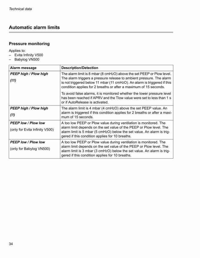
Alarm message Description/Detection
PEEP high / Plow high
(!!!)
The alarm limit is 8 mbar (8 cmH2O) above the set PEEP or Plow level. The alarm triggers a pressure release to ambient pressure. The alarm is not triggered below 11 mbar (11 cmH2O). An alarm is triggered if this condition applies for 2 breaths or after a maximum of 15 seconds.
To avoid false alarms, it is monitored whether the lower pressure level has been reached if APRV and the Tlow value were set to less than 1 s or if AutoRelease is activated.
PEEP high / Plow high
(!!)
The alarm limit is 4 mbar (4 cmH2O) above the set PEEP value. An alarm is triggered if this condition applies for 2 breaths or after a maxi-mum of 15 seconds.
PEEP low / Plow low
(only for Evita Infinity V500)
A too low PEEP or Plow value during ventilation is monitored. The alarm limit depends on the set value of the PEEP or Plow level. The alarm limit is 5 mbar (5 cmH2O) below the set value. An alarm is trig-gered if this condition applies for 10 breaths.
PEEP low / Plow low
(only for Babylog VN500)
A too low PEEP or Plow value during ventilation is monitored. The alarm limit depends on the set value of the PEEP or Plow level. The alarm limit is 3 mbar (3 cmH2O) below the set value. An alarm is trig-gered if this condition applies for 10 breaths.

35
Technical data
Volume monitoring
Applies to: – Evita Infinity V500
The expiratory minute volume MVe is monitored within the set alarm limits.
The inspiratory tidal volume VTi or, when leakage compensation is switched on, the leakage-compen-sated tidal volume VT is monitored within the set alarm limits.
Because the device ensures the minimum inspira-tory tidal volume when volume-controlled ventila-tion modes or pressure-controlled ventilation modes with Volume Guarantee are selected, it is not possible to set the lower alarm limit for VTi or VT manually.
Applies to:– Babylog VN500
The expiratory minute volume MVe is monitored in the patient category Ped. pat. and in the case of in-vasive ventilation in the patient category Neo. within the set alarm limits.
The minimum tidal volume is monitored only when Volume Guarantee is activated. To accomplish this, with leakage compensation switched off the value VTi is monitored in the patient category Ped. pat., and the value VTe is monitored in the patient cate-gory Neo.. When leakage compensation is acti-vated, VT is generally used and the automatically set alarm limit VT low is monitored, whereby the limit VT low corresponds to 90 % of the selected VT.
Electromagnetic compatibility
Applies to:– Workstation Critical Care and Neonatal Care
The references for the tables have been updated:
– Electromagnetic environment: Information regarding electromagnetic emis-sions (IEC 60601-1-2, table 1)
– Electromagnetic immunity:Information regarding electromagnetic immu-nity (IEC 60601-1-2, tables 2, 3, and 4)
– Recommended separation distances to porta-ble and mobile RF telecommunication devices:Information regarding separation distances (IEC 60601-1-2, tables 5 and 6)

Technical data
36
Connections to IT networks
Applies to:– Evita Infinity V500– Babylog VN500
Data can be exchanged in an IT network using wired and wireless technologies. IT networks in-clude all data interfaces (e.g., RS232, LAN, USB, printer interface) described in standards and con-ventions.
During operation, this device can exchange infor-mation with other devices by means of IT networks and supports the following functions:
– Display of waveforms and parameter data
– Signaling of alarms
– Transfer of device settings and patient data
– Service mode, access to logbooks
Connecting this device to a network that incorpo-rates other devices or making subsequent changes to that network can lead to new risks for patients, users, and third parties. Before the device is con-nected to the network or the network is changed, these risks must be identified, analyzed, and eval-uated, and appropriate measures taken.
Examples of subsequent changes to the network:
– Changing the network configuration
– Removing devices from the network
– Adding new devices to the network
– Performing upgrades or updates on devices that are connected to the network
Information on connecting to the network
Prerequisites
This device must only be connected to the network by service personnel. The IT representative of the hospital must be consulted in advance.
The following documents must be observed:
– Accompanying documents of this device
– Description of the network interface
– Description of the network-based alarm sys-tems
Dräger recommends complying with IEC 80001-1 (risk management for IT networks with medical de-vices).
Serial interfaces
The following interfaces are supported:
– RS232 interfaces complying with EIA RS-232 (CCITT V.24/V.28) for the following applica-tions:– MEDIBUS, MEDIBUS.X– Connection to medical devices from other
manufacturers

37
Technical data
Consequences of using an unsuitable network
If the network does not meet the requirements, dan-gerous situations can result. The following situa-tions can occur with this device:
– Due to an insecure decentralized alarm system:– Alarms or data are transmitted at the wrong
time.– Alarms are not transmitted.
– During an interruption of the network connec-tion:
– Suppressed alarms or alarm tones are not reactivated, but remain suppressed.
– Alarms are not transmitted.
– Without firewall and antivirus software:– Data are not protected.– Device settings are changed.– The device generates false alarms or no
alarms.
– Data are sent incomplete, sent to the wrong de-vice, or not sent at all.
– Patient data are intercepted, falsified, or dam-aged.
– Data have incorrect time stamps.
Electrical requirements of connected devices and networks
The analog and digital ports are only appropriate for connecting devices or networks that have a nomi-nal voltage on the network side of max. 24 V DC and meet the requirements of one of the following standards:
– IEC 60950-1: Ungrounded SELV circuits
– IEC 60601-1 (as of 2nd edition): Touchable secondary circuits

Principles of operation
38
Principles of operation
Applies to:– Evita Infinity V500– Babylog VN500
Pneumatic functional description
An active breathing gas humidifier and an pneu-matic medication nebulizer can also be installed. Additional information can be found in the instruc-tions for use in the chapters "Assembly and prepa-ration" and "Operation."
Flow reduction Anti Air Shower
When the Anti Air Shower function is activated and a disconnection is detected during ventilation, the flow is reduced until reconnection is detected. Simultaneously, the Disconnection? alarm is dis-played. With non-invasive ventilation, the time be-fore the alarm is triggered can be delayed with Tdisconnect. The minute ventilation can be re-duced due to the already reduced flow.

39
This page intentionally left blank.

Manufacturer
Dräger Medical GmbHMoislinger Allee 53 – 55D-23542 LübeckGermany+49 451 8 82-0
FAX +49 451 8 82-20 80http://www.draeger.com
Distributed in US by
Draeger Medical, Inc.3135 Quarry RoadTelford, PA 18969-1042U.S.A.(215) 721-5400(800) 4DRAGER(800 437-2437)
FAX (215) 723-5935http://www.draeger.com
9054354 – enUS© Dräger Medical GmbHEdition: 2 – 2015-01(Edition: 1 – 2014-01)Dräger reserves the right to make modifications to the device without prior notice. As of 2015-08:
Dräger Medical GmbHchanges toDrägerwerk AG & Co. KGaA