Zeus and Torches (Berlin Paian nr 6870 from the Egyptian Museum in Berlin)
Upload
khangminh22Category
view
0download
0
Instructions for use
Zeus Infinity Empowered
Anesthesia workstation systemSoftware 2.n
WARNINGTo properly use this medical device, read and comply with these instruc-tions for use.

2 Instructions for use Zeus Infinity Empowered SW 2.n
Typographical conventions
Screen reproductions
The illustrations of products and screen contents may, depending on configuration and equipment, differ from the actual products.
Use of terms
Dräger uses the term "Accessory" not only for ac-cessories in the sense of IEC 60601-1, but also for consumable parts, removable parts, and attached parts.
The product "Zeus Infinity Empowered" is also re-ferred to as "Zeus IE".
1 Consecutive numbers indicate steps of action, with the numbering restarting with "1" for each new sequence of actions.
l Bullet points indicate individual actions or differ-ent options for action.
– Dashes indicate the listing of data, options, or objects.
(A) Letters in parentheses refer to elements in the related illustration.
A Letters in illustrations denote elements referred to in the text.
> The "greater than" symbol indicates the naviga-tion path in a dialog window.
Bold italic text is used to identify labeling on the device and text displayed on the screen.

Instructions for use Zeus Infinity Empowered SW 2.n 3
Trademarks
Definition
Trademark Trademark ownerAutoFlow®
Dräger
Zeus®
Drägersorb® 800 Plus
Drägersorb® Free
Forta®
SpiroLife®
DrägerService®
VacuSmart®
Infinity®
Quik Fil® Abbott Laboratories
Masimo®
Masimo CorporationMasimo SET®
Signal Extraction Technology (SET)®
Nellcor® Covidian
Nellcor OxiMax®
IVDock™
DrägerTrident™Dräger Fill™BIS™ Aspect Medical Systems
Inc.Bispectral Index™Saf-T-Fill™ Baxter
Incidin Extra N® Ecolab
Buraton 10F® Schülke & Mayr
Gigasept FF®
Trademark Trademark owner
WARNINGA WARNING statement provides important in-formation about a potentially hazardous situa-tion which, if not avoided, could result in death or serious injury.
CAUTIONA CAUTION statement provides important infor-mation about a potentially hazardous situation which, if not avoided, may result in minor or mod-erate injury to the user or patient or in damage to the medical device or other property.
NOTEA NOTE provides additional information intended to avoid inconvenience during operation.

4 Instructions for use Zeus Infinity Empowered SW 2.n
Definition of target groups
For this product, users, service personnel, and ex-perts are defined as target groups.
These target groups must have received instruction in the use of the product and must have the neces-sary training and knowledge to use, install, reproc-ess, maintain, or repair the product.
The product must be used, installed, reprocessed, maintained, or repaired exclusively by defined tar-get groups.
Users
Users are persons who use the product in accord-ance with its intended use.
Service personnel
Service personnel are persons who are responsible for the maintenance of the product.
Service personnel must be trained in the mainte-nance of medical devices and install, reprocess, and maintain the product.
Experts
Experts are persons who perform repair or complex maintenance work on the product.
Experts must have the necessary knowledge and experience with complex maintenance work on the product.
Abbreviations and Symbols
Explanations are listed in Chapter "Overview" in sections "Abbreviations" and "Symbols".

Instructions for use Zeus Infinity Empowered SW 2.n 5
Contents
Contents
Trademarks . . . . . . . . . . . . . . . . . . . . . . . . . . . 3
For your safety and that of your patients. . . 9
General safety information . . . . . . . . . . . . . . . . 10Product-specific safety information. . . . . . . . . . 15
Application . . . . . . . . . . . . . . . . . . . . . . . . . . . 19
Intended use. . . . . . . . . . . . . . . . . . . . . . . . . . . 20Data exchange, ports . . . . . . . . . . . . . . . . . . . . 22
Overview . . . . . . . . . . . . . . . . . . . . . . . . . . . . . 23
Components . . . . . . . . . . . . . . . . . . . . . . . . . . . 24Abbreviations . . . . . . . . . . . . . . . . . . . . . . . . . . 33Symbols . . . . . . . . . . . . . . . . . . . . . . . . . . . . . . 38Product labels. . . . . . . . . . . . . . . . . . . . . . . . . . 40
Operating concept . . . . . . . . . . . . . . . . . . . . . 41
Screen . . . . . . . . . . . . . . . . . . . . . . . . . . . . . . . 42Screen layout . . . . . . . . . . . . . . . . . . . . . . . . . . 44Using the touch screen. . . . . . . . . . . . . . . . . . . 47Color concept . . . . . . . . . . . . . . . . . . . . . . . . . . 48Overview of the menu structure . . . . . . . . . . . . 49
Assembly and preparation . . . . . . . . . . . . . . 57
Before initial use. . . . . . . . . . . . . . . . . . . . . . . . 58Zeus IE as a ceiling device. . . . . . . . . . . . . . . . 59Establishing the mains power supply . . . . . . . . 60Establishing the gas supply . . . . . . . . . . . . . . . 63Connecting anesthetic gas receiving system (AGS) . . . . . . . . . . . . . . . . . . . . . . . . . . . . . . . . 65Replacing or filling the CO2 absorber . . . . . . . . 66Connecting hoses. . . . . . . . . . . . . . . . . . . . . . . 69Preparing optional patient monitoring. . . . . . . . 72Connecting IV system. . . . . . . . . . . . . . . . . . . . 73DIVA metering modules for anesthetic agents. . . . . . . . . . . . . . . . . . . . . . . . . . . . . . . . 74DIVA metering module with Dräger Fill filling system. . . . . . . . . . . . . . . . . . . . . . . . . . . 77DIVA metering module with safety filling device . . . . . . . . . . . . . . . . . . . . . . . . . . . . . . . . 80Quik Fil sevoflurane safety filling system . . . . . 84Filling system for desflurane. . . . . . . . . . . . . . . 87
Startup . . . . . . . . . . . . . . . . . . . . . . . . . . . . . . 89
Device check . . . . . . . . . . . . . . . . . . . . . . . . . . 90Switching on Zeus IE. . . . . . . . . . . . . . . . . . . . 94Checklist . . . . . . . . . . . . . . . . . . . . . . . . . . . . . 95Self test . . . . . . . . . . . . . . . . . . . . . . . . . . . . . . 96Automatic self test (Auto self test). . . . . . . . . . 99Pretest . . . . . . . . . . . . . . . . . . . . . . . . . . . . . . . 100Displaying the test results . . . . . . . . . . . . . . . . 101Displaying the test results during operation . . 104Startup in emergencies . . . . . . . . . . . . . . . . . . 105
Operation . . . . . . . . . . . . . . . . . . . . . . . . . . . . 107
Start settings . . . . . . . . . . . . . . . . . . . . . . . . . . 108Changing patient data . . . . . . . . . . . . . . . . . . . 112Integrated SmartPilot View (optional) . . . . . . . 114Gas delivery . . . . . . . . . . . . . . . . . . . . . . . . . . 115Ventilation . . . . . . . . . . . . . . . . . . . . . . . . . . . . 122Web access (optional) . . . . . . . . . . . . . . . . . . . 138IV system – IVenus . . . . . . . . . . . . . . . . . . . . . 140End of operation . . . . . . . . . . . . . . . . . . . . . . . 156
Alarms . . . . . . . . . . . . . . . . . . . . . . . . . . . . . . 159
Alarm behaviour at power on . . . . . . . . . . . . . 160Display alarms. . . . . . . . . . . . . . . . . . . . . . . . . 160Alarm info . . . . . . . . . . . . . . . . . . . . . . . . . . . . 161Alarm log . . . . . . . . . . . . . . . . . . . . . . . . . . . . . 161Alarm limits . . . . . . . . . . . . . . . . . . . . . . . . . . . 162Suspending alarms . . . . . . . . . . . . . . . . . . . . . 166Alarm recorder (optional with hemodynamic and Infinity network) . . . . . . . . . . . . . . . . . . . . 167All limits . . . . . . . . . . . . . . . . . . . . . . . . . . . . . . 168Autoset limits . . . . . . . . . . . . . . . . . . . . . . . . . . 172Suppressing the alarm tone . . . . . . . . . . . . . . 177Set ranges of the patient monitoring alarm limits . . . . . . . . . . . . . . . . . . . . . . . . . . . . . . . . 179Trends and diagnosis windows . . . . . . . . . . . . 184
Monitoring . . . . . . . . . . . . . . . . . . . . . . . . . . . 187
Overview of the monitoring . . . . . . . . . . . . . . . 188Device monitoring . . . . . . . . . . . . . . . . . . . . . . 189Patient monitoring . . . . . . . . . . . . . . . . . . . . . . 197

Contents
6 Instructions for use Zeus Infinity Empowered SW 2.n
Fault – Cause – Remedy . . . . . . . . . . . . . . . . 249
Failure behavior . . . . . . . . . . . . . . . . . . . . . . . . 250Power outage . . . . . . . . . . . . . . . . . . . . . . . . . . 250Gas failure . . . . . . . . . . . . . . . . . . . . . . . . . . . . 251Ventilator failure . . . . . . . . . . . . . . . . . . . . . . . . 252Anesthetic gas delivery failure (DIVA failure) . . 252Mixer and DIVA failure . . . . . . . . . . . . . . . . . . . 252Rotary safety knob Anesth. Ventilator Off for ventilation . . . . . . . . . . . . . . . . . . . . . . . . . . 253In the event of partial system failures. . . . . . . . 253In the event of device failure . . . . . . . . . . . . . . 254Failure behavior DPS . . . . . . . . . . . . . . . . . . . . 255Messages Zeus IE . . . . . . . . . . . . . . . . . . . . . . 255Metering module faults . . . . . . . . . . . . . . . . . . . 317
Configuration . . . . . . . . . . . . . . . . . . . . . . . . . 321
Configuration information . . . . . . . . . . . . . . . . . 322System setup . . . . . . . . . . . . . . . . . . . . . . . . . . 323Configuring the screen . . . . . . . . . . . . . . . . . . . 329Configuring basic settings . . . . . . . . . . . . . . . . 335Other functions of the system. . . . . . . . . . . . . . 353Service functions . . . . . . . . . . . . . . . . . . . . . . . 356
Cleaning, disinfection, and sterilization. . . . 357
Disassembly . . . . . . . . . . . . . . . . . . . . . . . . . . . 358Dismantling components . . . . . . . . . . . . . . . . . 360Reprocessing methods. . . . . . . . . . . . . . . . . . . 367Reprocessing list . . . . . . . . . . . . . . . . . . . . . . . 371Care instructions for monitoring accessories . . 376Assembly . . . . . . . . . . . . . . . . . . . . . . . . . . . . . 378
Maintenance . . . . . . . . . . . . . . . . . . . . . . . . . . 383
Overview . . . . . . . . . . . . . . . . . . . . . . . . . . . . . 384Inspection . . . . . . . . . . . . . . . . . . . . . . . . . . . . . 385Preventive maintenance. . . . . . . . . . . . . . . . . . 387Repair . . . . . . . . . . . . . . . . . . . . . . . . . . . . . . . . 389
Disposal . . . . . . . . . . . . . . . . . . . . . . . . . . . . . 391
Disposal of the medical device. . . . . . . . . . . . . 392Disposing of accessories . . . . . . . . . . . . . . . . . 392Disposal of non-rechargeable batteries . . . . . . 393
Technical data . . . . . . . . . . . . . . . . . . . . . . . . 395
General information. . . . . . . . . . . . . . . . . . . . . 396Identification . . . . . . . . . . . . . . . . . . . . . . . . . . 397Classification . . . . . . . . . . . . . . . . . . . . . . . . . . 397Latex-free . . . . . . . . . . . . . . . . . . . . . . . . . . . . 398Penetration values of IBF filter . . . . . . . . . . . . 398Screen . . . . . . . . . . . . . . . . . . . . . . . . . . . . . . . 398Power supply. . . . . . . . . . . . . . . . . . . . . . . . . . 399Ambient conditions . . . . . . . . . . . . . . . . . . . . . 400Alarm tone sequence IEC . . . . . . . . . . . . . . . . 400Central gas supply. . . . . . . . . . . . . . . . . . . . . . 401Gas delivery, control mode FG ctrl. . . . . . . . . . 404Gas delivery, control mode Auto control . . . . . 404Ventilation . . . . . . . . . . . . . . . . . . . . . . . . . . . . 405Breathing system. . . . . . . . . . . . . . . . . . . . . . . 407Fresh-gas outlet for non-rebreathing system (optional) . . . . . . . . . . . . . . . . . . . . . . . 408Airway resistances . . . . . . . . . . . . . . . . . . . . . 408Measuring system . . . . . . . . . . . . . . . . . . . . . . 409O2-, CO2 and anesthetic gas measurement . . 411Anesthetic gas measurement (infrared spectroscopy) . . . . . . . . . . . . . . . . . . . . . . . . . 412Anesthetic gas metering modules . . . . . . . . . . 413Data communication . . . . . . . . . . . . . . . . . . . . 413General safety standards for anesthesia workstations . . . . . . . . . . . . . . . . . . . . . . . . . . 414Modules for patient monitoring . . . . . . . . . . . . 416Hemodynamic modules. . . . . . . . . . . . . . . . . . 416Trident Pod (NMT). . . . . . . . . . . . . . . . . . . . . . 417BISx pod . . . . . . . . . . . . . . . . . . . . . . . . . . . . . 418Monitoring specifications . . . . . . . . . . . . . . . . . 418ECG. . . . . . . . . . . . . . . . . . . . . . . . . . . . . . . . . 418Non-invasive blood pressure measurement (NIBP) . . . . . . . . . . . . . . . . . . . . . . . . . . . . . . . 420Invasive blood pressure (IBP) . . . . . . . . . . . . 422Wedge measurement . . . . . . . . . . . . . . . . . . . 422Cardiac output (C.O.) . . . . . . . . . . . . . . . . . . . 423Pulse oximetry (SpO2). . . . . . . . . . . . . . . . . . . 423Temperature . . . . . . . . . . . . . . . . . . . . . . . . . . 426Neuromuscular Transmission Monitoring NMT. . . . . . . . . . . . . . . . . . . . . . . . . . . . . . . . . 426Anesthesia depth monitoring BIS . . . . . . . . . . 428Essential performance. . . . . . . . . . . . . . . . . . . 429EMC Declaration . . . . . . . . . . . . . . . . . . . . . . . 430Device combinations . . . . . . . . . . . . . . . . . . . . 435Connections to IT networks. . . . . . . . . . . . . . . 436

Instructions for use Zeus Infinity Empowered SW 2.n 7
Contents
Description . . . . . . . . . . . . . . . . . . . . . . . . . . . 439
Gas flow diagram . . . . . . . . . . . . . . . . . . . . . . . 440Gas control loops . . . . . . . . . . . . . . . . . . . . . . . 441Ventilation. . . . . . . . . . . . . . . . . . . . . . . . . . . . . 446Ventilation modes . . . . . . . . . . . . . . . . . . . . . . . 446Appendix. . . . . . . . . . . . . . . . . . . . . . . . . . . . . . 451
Index . . . . . . . . . . . . . . . . . . . . . . . . . . . . . . . . 455

8 Instructions for use Zeus Infinity Empowered SW 2.n
This page was intentionally left blank.

Instructions for use Zeus Infinity Empowered SW 2.n 9
For your safety and that of your patients
For your safety and that of your patients
General safety information . . . . . . . . . . . . . . 10
Strictly follow these instructions for use . . . . . . 10Maintenance. . . . . . . . . . . . . . . . . . . . . . . . . . . 10Safety checks . . . . . . . . . . . . . . . . . . . . . . . . . . 10Metrological checks*. . . . . . . . . . . . . . . . . . . . . 10Accessories . . . . . . . . . . . . . . . . . . . . . . . . . . . 11Connected devices. . . . . . . . . . . . . . . . . . . . . . 11Not for use in areas of explosion hazard . . . . . 12Safe connection with other electrical equipment. . . . . . . . . . . . . . . . . . . . . . . . . . . . . 12Patient safety . . . . . . . . . . . . . . . . . . . . . . . . . . 12Patient monitoring. . . . . . . . . . . . . . . . . . . . . . . 12Information on electromagnetic compatibility . . 13Sterile accessories . . . . . . . . . . . . . . . . . . . . . . 13Installing accessories . . . . . . . . . . . . . . . . . . . . 14Storing the instructions for use . . . . . . . . . . . . . 14Training. . . . . . . . . . . . . . . . . . . . . . . . . . . . . . . 14
Product-specific safety information . . . . . . . 15

For your safety and that of your patients
10 Instructions for use Zeus Infinity Empowered SW 2.n
General safety information
The following WARNING and CAUTION state-ments apply to general operation of the medical de-vice. WARNING and CAUTION statements specific to subsystems or particular features of the medical device appear in the respective sections of these instructions for use or in the instructions for use of another product being used with this device.
Strictly follow these instructions for use
Maintenance
Safety checks*
The medical device must be subject to regular safety checks. See chapter "Maintenance".
Metrological checks*
The medical device must undergo regular metro-logical checks. See chapter "Maintenance".
WARNINGRisk of incorrect operation and of incorrect use
Any use of the medical device requires full un-derstanding and strict observation of all sec-tions of these instructions for use. The medi-cal device must only be used for the purpose specified under "Intended use" on page 20 and in conjunction with appropriate patient monitoring (see page 12).
Strictly observe all WARNING and CAUTION statements throughout these instructions for use and all statements on medical device la-bels. Failure to observe these safety informa-tion statements constitutes a use of the medi-cal device that is inconsistent with its intended use.
WARNINGRisk of medical device failure and patient in-jury
The medical device must be inspected and serviced regularly by service personnel. Re-pair and complex maintenance carried out on the medical device must be performed by ex-perts.
If the above is not complied with, medical de-vice failure and patient injury may occur. Ob-serve chapter "Maintenance".
Dräger recommends DrägerService for a serv-ice contract and for repairs. Dräger also rec-ommends using original Dräger parts for maintenance.
* Only applies in the Federal Republic of Germany

Instructions for use Zeus Infinity Empowered SW 2.n 11
For your safety and that of your patients
Accessories Connected devices
WARNINGRisk due to incompatible accessories
Dräger has tested only the compatibility of ac-cessories listed in the current list of accesso-ries. If other, incompatible accessories are used, there is a risk of patient injury due to medical device failure.
Dräger recommends that the medical device is only used together with accessories listed in the current list of accessories.
WARNINGRisk of operating errors and incorrect use
Strictly observe the instructions for use of all accessory parts, e.g.:– Water traps– Flow sensors– CLIC adapter– CLIC absorber– Soda lime– Breathing hoses– Masks– Filter– Endotracheal suction– Vaporizer– Manual resuscitator– AGSS terminal unit
WARNINGRisk of electric shock and device malfunction
Any connected devices or device combina-tions not complying with the requirements mentioned in these instructions for use can compromise the correct functioning of the medical device and lead to an electric shock. Before using the medical device, refer to and strictly comply with the instructions for use of all connected devices and device combina-tions.
WARNINGRisk of device malfunction
The medical device may be operated in combi-nation with other Dräger devices or with de-vices from third party manufacturers. If a de-vice combination is not approved by Dräger, the safety and the functionality of the individ-ual devices may be compromised.– The operating organization must ensure
that the device combination complies with the applicable editions of the relevant standards for medical devices.
– Strictly observe assembly instructions and instructions for use for each networked de-vice.

For your safety and that of your patients
12 Instructions for use Zeus Infinity Empowered SW 2.n
Not for use in areas of explosion hazard
Safe connection with other electrical equipment
Patient safety
The design of the medical device, the accompany-ing documentation, and the labeling on the medical device are based on the assumption that the pur-chase and the use of the medical device are re-stricted to persons familiar with the inherent char-acteristics of the medical device.
Instructions and WARNING and CAUTION state-ments are therefore largely limited to the specifics of the Dräger medical device.
The instructions for use do not contain any informa-tion on the following points:
– Dangers that are obvious to the user
– Consequences of obvious improper use of the medical device
– Possible negative impacts on patients with var-ious underlying diseases
Medical device modification or misuse can be dan-gerous.
Patient monitoring
The user of the medical device is responsible for choosing a suitable patient monitoring system that provides appropriate information on medical device performance and patient condition.
Patient safety can be achieved by a wide variety of means ranging from electronic surveillance of med-ical device performance and patient condition to di-rect observation of clinical signs.
The responsibility for selecting the best level of pa-tient monitoring lies solely with the user of the med-ical device.
WARNINGRisk of explosion and fire
This medical device is neither approved nor certified for use in areas where oxygen con-centrations greater than 25 Vol.% or combus-tible or explosive gas mixtures are likely to oc-cur.
CAUTIONRisk of patient injury
Connections to electrical devices not listed in these instructions for use may only be made when approved by each respective device manufac-turer.

Instructions for use Zeus Infinity Empowered SW 2.n 13
For your safety and that of your patients
Information on electromagnetic compat-ibility
General information on electromagnetic compatibil-ity (EMC) according to international EMC standard IEC 60601-1-2:
Medical electrical equipment is subject to special precautionary measures concerning electromag-netic compatibility (EMC) and must be installed and put into operation in accordance with the provided EMC information (see page 430).
Portable and mobile radio frequency communica-tion equipment can affect medical electrical equip-ment.
Sterile accessoriesWARNINGRisk of electric shock
Do not connect connectors with an ESD warn-ing symbol and do not touch their pins without implementing ESD protective measures. Such protective measures can include antistatic clothing and shoes, touching a potential equi-lization pin before and during connection of the pins, or using electrically insulating and antistatic gloves.
All relevant users must be instructed in these ESD protective measures.
WARNINGRisk of device failure
Electromagnetic fields can compromise proper operation of the device. Electromag-netic fields are generated by, e.g., radio fre-quency communication equipment such as:– Mobile phones– Radio frequency electrosurgical equip-
ment– Defibrillators– Shortwave therapy equipment
Use radio frequency equipment only with a sufficient safety clearance of at least 20 cm (7.9 in).
WARNINGRisk of electric shock
The connection of devices to auxiliary power sockets can lead to an increased leakage cur-rent. If the protective ground of one of these devices fails, the leakage current may rise above the permissible values.– Only connect with the approval of the re-
spective device manufacturer. – Have the leakage current checked by serv-
ice personnel. – If the permissible value is exceeded, use a
mains power socket on a wall instead of the auxiliary power socket of the device.
CAUTIONRisk of medical device failure and patient injury
Do not use accessories in sterile packaging if the packaging has been opened, damaged, or if there are other signs that the accessories are not ster-ile.
Reuse, reprocessing, and sterilization of disposa-ble products is not permitted.
For your safety and that of your patients
14 Instructions for use Zeus Infinity Empowered SW 2.n
Installing accessories
Strictly observe the instructions for use and assem-bly instructions.
Storing the instructions for use
Training
Training for users is available from the Dräger or-ganization responsible, see www.draeger.com.
CAUTIONRisk of device failure
Install the accessory on the basic device in ac-cordance with the instructions of the basic device. Check for secure connection to the basic device.
CAUTIONRisk of operating errors
Instructions for use must be kept accessible to the user.

Instructions for use Zeus Infinity Empowered SW 2.n 15
For your safety and that of your patients
Product-specific safety information
WARNINGRisk of misinterpretation
Misdiagnosis or misinterpretation of the measured values or other parameters may en-danger the patient.
Do not make therapeutic decisions based solely on individual measured values and monitoring parameters. Therapeutic deci-sions must be made solely by the user.
WARNINGRisk of malfunction
Unallowed modifications to the medical de-vice lead to malfunctions.
This medical device may not be modified with-out permission from Dräger.
WARNINGRisk of malfunction
Device failure or user errors may compromise the correct functioning of the device. The medical device does not react automatically to certain changes in the patient condition, oper-ating errors, or failure of components.
Continuously monitor the medical device so that corrective measures can be initiated im-mediately.
WARNINGRisk of device failures
The device may fail if the power supply is in-terrupted.
Always connect the device on an uninterrupt-ible power supply.
WARNINGRisk of not hearing the alarm tone
Dräger recommends the user to remain in the vicinity of the anesthesia machine, i.e. within a distance of up to 4 meters (12 ft). This facili-tates fast recognition and response in the event of an alarm.
WARNINGRisk of insufficient ventilation
Device failure or operating errors can lead to ventilation failure.– To ensure immediate remedial action in
case of device failure, the device may only be operated under permanent supervision of users.
– The general safety standards for anesthe-sia systems require that a manual resusci-tator be kept at the ready for emergency ventilation.
WARNINGRisk of burns
Do not use humidifiers or heated hoses!

For your safety and that of your patients
16 Instructions for use Zeus Infinity Empowered SW 2.n
WARNINGRisk of fire
The flow sensor may ignite medications or other substances that are easily flammable.– Do not nebulize medications or other sub-
stances that are easily flammable or spray them into the device.
– Do not use substances containing alcohol.– Do not allow flammable or explosive sub-
stances to enter the breathing system or the breathing circuit.
– Do not use cyclopropane or ether.
WARNINGRisk due to flow measurement failure
Deposits which are not removed during re-processing may damage the measuring wires in the flow sensor or cause fire.– Before inserting the flow sensor check for
visible damage, soiling, and particles. Re-peat this check regularly.
– Replace flow sensors when damaged, soiled, or not particlefree.
WARNINGRisk of strangulation
Make connection to the patient carefully.
WARNINGZeus IE must not be used with magnetic reso-nance imaging (MRI, NMR, NMI). Device oper-ation may be affected, thus placing the patient at risk.
WARNINGDevice contamination possible
Only operate Zeus IE with airway filters.
WARNINGRisk of burns
Conductive breathing hoses or face masks may cause burns during HF surgery.
Do not use this type of hose and mask com-bined with HF surgery.
WARNINGRisk of patient injury
When using near-patient filters do not scav-enge at the patient end! In the event of steno-sis or increased filter resistance the patient may be injured by vacuum.
WARNINGRisk of equipment malfunction
Only have network functions configured by authorized, trained personnel.
Errors in configuration can impair operation of the device and the network.
WARNINGRisk of patient injury
The following operating states are prohibited when the patient is connected:– Standby– Self test– Leak test– Leakage assistant– Pretest– Service mode
No monitoring is possible in these operating states. During the test, pressures and concen-trations may occur in the system which are hazardous to the patient!

Instructions for use Zeus Infinity Empowered SW 2.n 17
For your safety and that of your patients
CAUTIONRisk of crushing
Movable device parts or attached components may cause crushing due to clamping. Pay special attention to edges, movable parts, and corners when working with the following components:– Column cover– Breathing system cover– Drawers– Extensible writing tray– Swivel arms for mounted devices– Accessories such as gas cylinders, vaporiz-
ers, CLIC absorber, and CLIC adapter
CAUTIONRisk of crushing
If the writing tray is not correctly locked in place, objects can fall down or fingers and breathing hoses, for example, can be pinched.
Make sure that the writing tray is correctly locked when folding down or sliding into the device.
CAUTIONRisk of tipping over during transport
The medical device may tip over if handled incor-rectly. Observe the following points when trans-porting medical devices:– The medical device may only be moved by
people who have the physical ability to do so.– To improve the maneuverability, transport the
device with 2 persons.– When transporting over inclines, around cor-
ners, or over thresholds (e.g., through doors or in elevators), make sure that the medical device does not bump against anything.
– Clear the writing tray and fold it down com-pletely or slide it into the device.
– Do not pull the medical device over hoses, ca-bles, or other obstacles lying on the floor.
– Do not activate the brake while the medical device is being moved.
– Use only the handles provided to push or pull the device.
CAUTIONHealth risk
Operate Zeus IE with connected anesthetic gas scavenging system (AGSS) only.
CAUTIONDo not use silicone spray! Silicone spray may cause breathing system valves to stick.
CAUTIONDo not use DIVA metering modules which have been dropped or damaged. Any damage may re-sult in faulty metering.

For your safety and that of your patients
18 Instructions for use Zeus Infinity Empowered SW 2.n
CAUTIONRisk of tipping over
When transporting the device and all the hinged arms are swung inward to the center of the device and locked, make sure that the slope of the floor does not exceed ±10°.
If the transport position is not maintained, the maximum slope of the floor is reduced to ±5°.
NOTEDo not cover or close off the vents on the device. Make sure there is an adequate supply of air. Oth-erwise, the device may overheat.
NOTERisk of injury
Handle the DIVA metering module with care and prevent it from tilting and falling down.
NOTEOperate in sufficiently ventilated rooms or the CO2 measurement may otherwise be impaired.
NOTEThe ambient conditions specified in the Technical Data must be observed during operation and stor-age of the device.
NOTEThere may be a restriction of ambient conditions owing to mounted accessories or specifications issued by the anesthetic agent manufacturer.
NOTEIn a closed system, foreign gases can accumulate in the breathing gas with longer surgery times, e.g., by decomposition of the breathing gas.
Increased concentrations of foreign gases can be prevented by regularly flushing the breathing sys-tem.

Instructions for use Zeus Infinity Empowered SW 2.n 19
Application
Application
Intended use . . . . . . . . . . . . . . . . . . . . . . . . . . 20
Application . . . . . . . . . . . . . . . . . . . . . . . . . . . . 20Ventilation modes . . . . . . . . . . . . . . . . . . . . . . . 20Device monitoring. . . . . . . . . . . . . . . . . . . . . . . 20Patient monitoring (optional). . . . . . . . . . . . . . . 21Monitoring. . . . . . . . . . . . . . . . . . . . . . . . . . . . . 21Gas supply . . . . . . . . . . . . . . . . . . . . . . . . . . . . 22Gas disposal. . . . . . . . . . . . . . . . . . . . . . . . . . . 22Breathing system . . . . . . . . . . . . . . . . . . . . . . . 22
Data exchange, ports . . . . . . . . . . . . . . . . . . . 22

Application
20 Instructions for use Zeus Infinity Empowered SW 2.n
Intended use
Zeus IE enables all forms of general anesthesia (in-halation anesthesia, balanced anesthesia and total intravenous anesthesia) and regional anesthesia, as well as the monitoring of regional anesthesia.
Anesthesia is conducted with automatic ventilation, manual ventilation or spontaneous breathing with an oxygen ratio of at least 25 %, using a mixture of Air (medical compressed air) or nitrous oxide with pure oxygen and additional delivery of volatile an-esthetic agents and/or intravenous drugs.
Application
The Anesthesia workstation system Zeus IE is de-signed for use in medical rooms, operating rooms and induction and recovery rooms.
Applications range from adults to pediatric patients and neonates.
Ventilation is accomplished on the patient through a laryngeal mask, a mask, or an endotracheal tube.
The breathing system can be used either with par-tial rebreathing (low flow or minimal flow) or with complete rebreathing (closed system).
Non-rebreathing system with external fresh-gas outlet, for manual ventilation for connection to Bain or Magill system for example (optional).
Zeus IE is equipped with modules for drug meter-ing, for patient and device monitoring and for venti-lation.
Ventilation modes
Volume-controlled ventilation at constant inspira-tion flow Volume Control
Volume-controlled ventilation with decelerating in-spiratory flow Volume Control AutoFlow; synchronization of Sync.(VC) and Pressure Sup-port breaths if required.
Pressure-controlled ventilation Pressure Control; synchronization of Sync.(PC) and Pressure Sup-port breaths if required.
Pressure-supported ventilation at constant positive airway pressure Pressure Support
Manual ventilation/spontaneous breathing with and without CPAP MAN/SPON
Device monitoring
The following are displayed as measured val-ues:
– Airway pressure PIP– Airway pressure Plat– Airway pressure PEEP– Airway pressure Mean– Minute volume MV– Tidal volume VT– Respiratory rate RR– CO2, inspiratory and expiratory– O2, inspiratory and expiratory– N2O, inspiratory and expiratory– Anesthetic agent concentration, inspiratory and
expiratory

Instructions for use Zeus Infinity Empowered SW 2.n 21
Application
The following are displayed as curves:
– Airway pressure Paw– Inspiratory and expiratory flow or volume curves– Capnogram– Oxigram– PV FV Loops
Additionally there are chronological trends of meas-ured values (trends) as well as a log book available.
Patient monitoring (optional)
The following are displayed as measured val-ues:
– Heart rate ECG HR/PLS– ST segment ST segm.– Oxygen saturation SpO2– Non-invasive blood pressure NIBP– Invasive blood pressure IBP– Cardiac output C.O./ Calculat.– Temperature Temp– Degree of muscle relaxation: Single, TOF, PTC– Depth of hypnosis BIS– Wedge pressure PWP
The following are displayed as curves:
– Electrocardiogram ECG (up to 3 curves)– Plethysmogram SpO2– Invasive blood pressure IBP (up to 10 curves)– Electroencephalogram EEG
Additionally there are chronological trends of meas-ured values (trends) as well as a log book available.
Monitoring
The monitoring of the patient is ensured by adjust-able alarm limits.
Device monitoring
– Airway pressure Paw– Expiratory minute volume MVe– Apnea
– Tidal volume, inspiratory VTi– Inspiratory anesthetic gas concentration– Recognition of anesthesia gas mixtures– Inspiratory O2 and N2O concentrations FiO2,
inN2O– Inspiratory and expiratory CO2 concentrations
inCO2, etCO2
Patient monitoring*
– Heart rate HR– ST segment ST– Oxygen saturation SpO2– Non-invasive blood pressure NIBP– Invasive blood pressure IBP– Temperature T1, T2– Relaxometry measurement TOF– Depth of hypnosis measurement BIS– Arrhythmia detection (optional)
Applicable inhalation anesthetic agents
– Isoflurane– Sevoflurane– Desflurane
Applicable intravenous drugs
All suitable medications permitted for anesthesia and for metering with syringe pumps (optional).
Applicable gas mixtures for the carrier gas
– O2/Air– O2/N2O
* depending on the options installed

Application
22 Instructions for use Zeus Infinity Empowered SW 2.n
Gas supply
The plug formats of the Zeus IE anesthesia work-station are selectable and comply with the custom-ary formats in the particular country.
Zeus IE has connections for O2, Air or N2O backup gas cylinders, which must be equipped with pres-sure reducers and pressure sensors.
Gas disposal
The anesthetic gas receiving system (AGS) must be used as a required accessory. The AGS is con-nected to an appropriately marked connecting noz-zle on Zeus IE.
Breathing system
Interfaces to the patient are the 22 mm ∅-sockets on the breathing system for the connection of EN 12342-compliant breathing hoses.
For breathing systems without rebreathing, e.g., Bain system, an external fresh-gas outlet is availa-ble (optional).
Data exchange, ports
MEDIBUS is a software protocol for data transfer between Zeus IE and external medical or non-med-ical devices (e.g., hemodynamic monitors, data management systems, or computers) via an RS232 interface.
Before transferring data, ensure strict compliance with the following documents:
– MEDIBUS.X, Rules and Standards for Imple-mentation (9052607)
– MEDIBUS.X, Profile Definition for Data Com-munication V1.n (9052608)
– MEDIBUS, Supported Data SW 1.n (9040096)
Serial ports
Two serial ports, COM 1 and COM 2, are provided for data communication using the Dräger MEDI-BUS data protocol.
The COM 3 serial port can only be used in conjunc-tion with the Integrated SmartPilot View option.
USB interface
The USB ports enable data exchange with Dräger USB storage media.
Network interface
Zeus IE can be connected to a network using the following interfaces.
– Infinity network connection in conjunction with patient monitoring (optional).
– Network ports for remote diagnosis, printers, and web applications, e.g., WebView (optional).
If a corresponding service contract has been obtained, the function Remote Service can be executed via a network connection and the hos-pital network.
For further information on connections to IT net-works, see page 436.

Instructions for use Zeus Infinity Empowered SW 2.n 23
Overview
Overview
Components . . . . . . . . . . . . . . . . . . . . . . . . . . 24
Front . . . . . . . . . . . . . . . . . . . . . . . . . . . . . . . . . 24Breathing system view . . . . . . . . . . . . . . . . . . . 25Connection for oxygen therapy. . . . . . . . . . . . . 25Connection field for patient monitoring and IV-system (optional) . . . . . . . . . . . . . . . . . . . . . 26Rear with doors open . . . . . . . . . . . . . . . . . . . . 27Connections to the gas supply block . . . . . . . . 28Connections to the back of the device Zeus IE . . . . . . . . . . . . . . . . . . . . . . . . . . . . . . . 29Connections to the back of the screen . . . . . . . 30Connections, power supply and additional sockets . . . . . . . . . . . . . . . . . . . . . . . . . . . . . . . 31DIVA metering modules . . . . . . . . . . . . . . . . . . 32
Abbreviations . . . . . . . . . . . . . . . . . . . . . . . . . 33
Symbols. . . . . . . . . . . . . . . . . . . . . . . . . . . . . . 38
Product labels. . . . . . . . . . . . . . . . . . . . . . . . . 40

Overview
24 Instructions for use Zeus Infinity Empowered SW 2.n
Components
Front
A Operating panel – Screen
B Transport handles
C Pull-out writing table
D DIVA metering modules, 2 pieces
E Unlock buttons for DIVA metering modules
F Central brake
G Drawer
H Endotracheal suction
I Drägersorb CLIC disposable absorber (or reusable absorber)
J Output from O2 flow meter
K External fresh-gas outlet, optional
L O2 flow meter for regional anesthesia
M Self-test adapter
N Breathing system with APL valve
O Bracket with infusion apparatus stand
P IV system (IVenus) consisting of: IVDock (ba-sis) and up to 4 Module DPS (Dynamic Pres-sure System) syringe pumps, optional
001
A
BC
DE
G
H
MNO
P
L
J
F
I
K

Instructions for use Zeus Infinity Empowered SW 2.n 25
Overview
Breathing system view
A O2 flush button O2+
B Mechanical pressure gauge for airway pressure
C Safety rotary knob Anesth. Ventilator Off
D Safety rotary knob for O2 emergency delivery O2
E APL valve
F Self-test adapter
G O2 flow meter for regional anesthesia
H Output from O2 flow meter
I External fresh-gas outlet (ext. FG outlet), op-tional
J Expiratory port
K Breathing bag nozzle
L CO2 absorber
M Protect water trap
N CO2 water trap with connection point for sample line
O Inspiratory port
Connection for oxygen therapy
The additional oxygen flow meter (A) delivers a set flow of pure oxygen, e.g., for oxygen metering through a nasal cannula. The supplemental oxygen can be used in each ventilation mode:– Standby – Zeus IE off,
as long as the central O2 supply is connected.
211
Connection of internal sample line to the Protect water trap
Connection of sample line to the CO2 water trap
A B C D
FGH
LMN
EO
I
KJ
A
212
O2
A

Overview
26 Instructions for use Zeus Infinity Empowered SW 2.n
Connection field for patient monitoring and IV-system (optional)
SpO2 measurement with SmartPod SpO2
Without optional patient monitoring, only the con-nection to the optional IV system is installed.
SpO2 measurement without SpO2 SmartPod (optional)
147
009
MULTIMED Connection for accessories to measure electrocardiography (ECG HR/PLS) and body tempera-ture (Temp)
HEMOMED 1 Connection for accessories to measure invasive blood pressures (IBP) and cardiac output (C.O.)
Aux/Hemo 2/3 Connection for accessories to measure more invasive blood pres-sures (More IBP) and cardiac out-put (C.O./ Calculat.)
Connection for anesthesia effect monitoring accessories (Trident pod, BISx pod)
NIBP
Aux / Hemo 2 Aux / Hemo 3
SpO2
HEMOMED 1 MULTIMED
IV-System Sync.
NIBP Connection for accessories to measure non-invasive blood pres-sure (NIBP)
SpO2 Connection for accessories to measure oxygen saturation (SpO2) according to the technology marked (Masimo SET or Nellcor OxiMax)
Sync. Connection for synchronization of a defibrillator
IV system Connection for Dräger IV system (IVenus)
146

Instructions for use Zeus Infinity Empowered SW 2.n 27
Overview
Without optional patient monitoring, only the con-nection to the optional IV system is installed.
Rear with doors open
A Mount for cylinder pressure reducer
B Gas supply block
C Backup gas cylinders with pressure reducers
D Waste gas connector
E 3 ports for DrägerService (behind the left-hand backup gas cylinder and above the AGS)
F Anesthetic gas receiving system (AGS)
G Auxiliary power sockets
H Circuit breaker
Use only in an emergency to interrupt battery charging and to switch off the device with the exception of the screen. To disconnect the en-tire device from the power supply, unplug the mains plug.
I Electrical connections for cylinder pressure sensors
010
MULTIMED Connection for accessories to measure oxygen saturation (SpO2), electrocardiography (ECG HR/PLS), and body temper-ature (Temp)
HEMOMED 1 Connection for accessories to measure invasive blood pressures (IBP) and cardiac output (C.O.)
Aux/Hemo 2/3 Connection for accessories to measure more invasive blood pres-sures (More IBP) and cardiac out-put (C.O./ Calculat.)
Connection for anesthesia effect monitoring accessories (Trident pod, BISx pod)
NIBP Connection for accessories to measure non-invasive blood pres-sure (NIBP)
Sync. Connection for synchronization of a defibrillator
IV system Connection for Dräger IV system (IVenus)
NIBP
Aux / Hemo 2 Aux / Hemo 3
HEMOMED 1 MULTIMED
IV-System
Sync.
173
A
B
C
D
F
G
H
I
EE E

Overview
28 Instructions for use Zeus Infinity Empowered SW 2.n
Connections to the gas supply block
A Connection of central N2O supply
B Connection for N2O backup gas cylinder
C Connection of central Air supply
D Connection for Air backup gas cylinder
E Connection of central O2 supply
F Connection of O2 backup gas cylinder
The Air outlet option and the O2 outlet option are not shown in this figure.
084
A B C D E F

Instructions for use Zeus Infinity Empowered SW 2.n 29
Overview
Connections to the back of the device Zeus IE
View with doors open.
Ports relevant to the user:
A COM 1, RS232 interface, MEDIBUS
B COM 2, RS232 interface, MEDIBUS
C COM 3, RS232 interface
D Ethernet 1 and Ethernet 2, hospital network port, optional
E Ethernet 3, Infinity Network socket
Only connect printers which have been approved by Dräger to the Ethernet 1 port.
(see Printer settings page 340)
026
WARNINGRisk of electric shock
Connecting devices to interfaces (COM 1, COM 2, COM 3, RS232, MEDIBUS) may result in an increase in leakage current. If the protec-tive ground of one of these devices fails, the leakage current may rise above the permissi-ble values.
Only connect with the approval of the respec-tive device manufacturer.Have the leakage current checked by service personnel.If the permissible value is exceeded, discon-nect the devices from the interfaces in use.
WARNINGRisk of patient injury
Data transmitted over the MEDIBUS interface are for information purposes only and are not intended as the sole basis for diagnostic or therapeutic decisions. The data accessible via this interface are not intended for use with a distributed alarm system conforming to IEC 60601-1-8:2012 (in the context of remote monitoring).
CAUTIONUser intervention in internal device interfaces is prohibited. This may impair correct functioning of the device.
A B C D E

Overview
30 Instructions for use Zeus Infinity Empowered SW 2.n
Connections to the back of the screen
Variant 1 – C500
A COM 1, COM 2
B USB ports
C one USB port on each side
Variant 2 – C500
A USB ports
B LAN ports
C RS232 interface
Variant 3 – C700
A USB ports
B LAN ports
C RS232 interface
CAUTIONUnsupported USB devices
USB devices that are not supported or have too high a current consumption may impair correct device operation.
Use only supported USB devices with a maximum current consumption of 500 mA.
CAUTIONUSB devices with their own mains power supply
USB devices with their own mains power supply (e.g., USB printers) may endanger patients and users.
Connect only USB devices that do not have their own mains power supply to Zeus IE.
025A
C C
B02
001
7
A AB
A C
A C
BA A

Instructions for use Zeus Infinity Empowered SW 2.n 31
Overview
Connections, power supply and addi-tional sockets
View with doors open, from above:
A Mains power supply
Secure the plug with screws!
B Automatic fuse
Can be reset after tripping.
C Equipotential connection
D Auxiliary sockets for auxiliary devices
Electronically fused, can be reset after the fuse has tripped.
170
NOTEAuxiliary sockets are not supplied by the uninter-ruptible power supply UPS and are not supplied with power in the event of a mains power failure!
WARNINGDo not connect HF surgery devices to the aux-iliary sockets because interference can impair Zeus IE functionality!
AB
C
D

Overview
32 Instructions for use Zeus Infinity Empowered SW 2.n
DIVA metering modules
A DIVA metering module with Quik Fil filling de-vice or Dräger Fill
B DIVA metering module with desflurane filling system (Saf-T-Fill)
C DIVA metering module with safety filling device
D Filling port
E Locking cap
F Release for desflurane lock
G Lever to release the locking bolt
H Locking bolt for safety filling device
I Drain plug (recessed, 2.5 mm hexagon socket)
J Filling level, inspection glass window
K Overflow hole
L Name of anesthetic agent
063
064
A B C
Isoflurane
Sevoflurane
Desflurane
L
J
D
E
F
H
G
I
K

Instructions for use Zeus Infinity Empowered SW 2.n 33
Overview
Abbreviations
Abbreviation Explanation% Percent (1/100)
% Tplat : Ti Ratio of inspiratory pause time to inspiration time
° Angular degree
°C Degrees Celsius, unit of tempera-ture
°F Degrees Fahrenheit
A Amps, electric power unit
Agent/AGas Anesthetic gas
AGS Anesthetic gas receiving system
AGSS Anesthetic gas scavenging system
Air Medical compressed air
APL Adjustable pressure limitation
ART Arterial blood pressure
ART D Arterial blood pressure, diastole
ART M Arterial blood pressure, mean pres-sure
ART S Arterial blood pressure, systole
ARTF Artefact
ATPD Ambient temperature and pres-sure, dry
Battery Battery
BCT Burst count
BIS Bispectral analysis
BMI Body Mass Index
bpm Beats per minute
BSA Body surface area
BSR Burst suppression ratio
BTPS Body Temperature Pressure Satu-rated (measurement at body tem-perature of 37 °C, current ambient pressure and with steam-saturated gas, measuring point e.g. lung)
C.O. Cardiac output
CAL Calibration
Cardiac by-pass mode
Heart-lung machine mode
Cdyn Dynamic compliance (patient)
Cdyn Patient compliance
CI Cardiac index
cm Centimeter, unit of length
CO Carbon monoxide
COM Serial port
CPAP Continuous positive airway pres-sure
CPP Cerebral perfusion pressure
CS Central supply for O2, N2O, Air and vacuum
CV Cardiovascular
CVP Central venous pressure
CVP M Central venous pressure
dB (A) Decibel, rated sound level unit
DES Desflurane
DIVA Direct injection of volatile agents, anesthetic agent delivery
∆O2 Difference between inspiratory and expiratory O2 concentration
∆Psupp / Psupp
Pressure support level above PEEP
EAB European pharmacopoeia
ECG Electrocardiography
EEG Electroencephalogram
EMG Electromyography
EN European standard
ENF Enflurane
ESU Electrosurgical unit
etCO2 End-expiratory CO2 concentration
Abbreviation Explanation

Overview
34 Instructions for use Zeus Infinity Empowered SW 2.n
etDES Expiratory desflurane concentra-tion
etENF Expiratory enflurane concentration
etHAL Expiratory halothane concentration
etISO Expiratory isoflurane concentration
etO2 Expiratory O2 concentration
etSEV Expiratory sevoflurane concentra-tion
exp., et Expiratory
FG Fresh gas
FG DES DES concentration in the fresh gas
FG ENF ENF concentration in the fresh gas
FG flow Fresh-gas flow
FG HAL HAL concentration in the fresh gas
FG ISO ISO concentration in the fresh gas
FG O2 O2 concentration in the fresh gas
FG SEV SEV concentration in the fresh gas
FGF Fresh-gas flow
FiO2 Inspiratory O2 concentration
Flow Fresh-gas flow
GP1 D,GP2 D
Locally non-specific blood pressure (General Pressure), diastoleGP 1 corresponds to the 1st meas-urement channelGP 2 corresponds to the 2nd measurement channel
GP1 M,GP2 M
Locally non-specific blood pressure (General Pressure), mean pres-sureGP 1 corresponds to the 1st meas-urement channelGP 2 corresponds to the 2nd measurement channel
GP1 S,GP2 S
Locally non-specific blood pressure (General Pressure), systoleGP 1 corresponds to the 1st meas-urement channelGP 2 corresponds to the 2nd measurement channel
Abbreviation ExplanationHAL Halothane
HF surgery High-frequency surgery
HME filter Heat and moisture exchange filter
hPa Hectopascal
HR Heart rate
Hz Hertz, oscillations per second
i/e O2 Ratio of inspiratory to expiratory O2 concentration
i/e VA Ratio of inspiratory to expiratory anesthetic agent concentration
I:E RatioInspiratory time : Expiratory time
IBF Integrated bacterial filter
IBP Invasively measured blood pres-sure
IBW Ideal body weight
ICP Intracranial pressure
ICP M Mean intracranial pressure
IEC International Electrotechnical Com-mission
in Inspiratory
inch Inch, unit of length
inCO2 Inspiratory CO2 concentration
inDes Inspiratory desflurane concentra-tion
inDESmax Maximum inspiratory desflurane limitation
inEnf Inspiratory enflurane concentration
InfR 1 Infusion rate 1
inHal Inspiratory halothane concentra-tion
inIso Inspiratory isoflurane concentration
inISOmax Maximum inspiratory isoflurane limitation
inN2O Inspiratory N2O concentration
inSev Inspiratory sevoflurane concentra-tion
Abbreviation Explanation
Instructions for use Zeus Infinity Empowered SW 2.n 35
Overview
inSEVmax Maximum inspiratory sevoflurane limitation
insp. Inspiratory
inVA Inspiratory anesthetic gas concen-tration
ISO Isoflurane
IV Intravenous
kg Kilogram, unit of mass
kPa Kilopascal
kV Kilovolt, unit of voltage
L Liter, unit of cubic measure
LA Left atrial
LA M Left atrial blood pressure, mean pressure
lbs. Pound; unit of mass
LED Light emitting diode
LV Left ventricular
LV D Left ventricular blood pressure, di-astole
LV M Left ventricular blood pressure, mean pressure
LV S Left ventricular blood pressure, systole
LVSWI Left ventricular stroke volume index
MAC Minimum Alveolar Concentration
Man. Manual
MAN/SPON Manual ventilation / Spontaneous breathing
mbar Millibar, unit of pressure
Mean Mean pressure
min Minute, unit of time
min. Minimum
MinFG flow Minimum fresh-gas flow
mL Milliliter, unit of cubic measure
mmHg Pressure, millimeters on a mercury column
Abbreviation ExplanationMPa Megapascal, unit of pressure
MPBetreibV German medical devices operator ordinance
MRI Magnetic resonance imaging
ms Millisecond, unit of time
MV Minute volume
MVe Expiratory minute volume
MVespon Expiratory spontaneously breathed minute volume
N2 Nitrogen
N2O Nitrous oxide
NaOH Sodium hydroxide
NIBP Non-invasive blood pressure
NIBP D Non-invasive blood pressure, dias-tole
NIBP M Non-invasive blood pressure, mean pressure
NIBP S Non-invasive blood pressure, sys-tole
NMT Neuromuscular transmission
NO Nitrogen oxide
NTPD Normal temperature pressure dry(20 °C, 1013 hPa, dry)
O2 Oxygen
O2 upt. Oxygen uptake
OR Operating room
ORC Oxygen ratio controlled
PA Pulmonary artery
Pa Pascal (1 mbar = 100 Pa or 1 hPa), unit of pressure
PA D Pulmonary artery blood pressure, diastole
PA M Pulmonary artery blood pressure, mean pressure
PA S Pulmonary artery blood pressure, systole
Paw Airway pressure
Abbreviation Explanation

Overview
36 Instructions for use Zeus Infinity Empowered SW 2.n
PEEP Positive end-expiratory pressure
PGA Patient gas analyzer
Pinsp Inspiratory pressure
PIP Peak inspiratory pressure
Plat Plateau pressure/end-inspiratory airway pressure
PLS Pulse
Pmax Maximum pressure
Pmean Mean pressure
Pplat Plateau pressure
ppm Parts per million (1/1000000)
psi pounds per square inch
PTC Post Tetanic Count
PVC Premature ventricular contraction
PVC/min Premature ventricular contrac-tion/min
PVR Pulmonary vascular resistance
PVRI Pulmonary vascular resistance in-dex
PWP Pulmonary wedge pressure
PWR Total power
R Resistance
RA Right atrial
RA M Right atrial blood pressure, mean pressure
rel. Relative
RR Respiratory rate
RRmand Mandatory respiratory rate
RRspon Spontaneous respiratory rate
RV Right ventricular
RV D Right ventricular blood pressure, diastole
RV M Right ventricular blood pressure, mean pressure
RV S Right ventricular blood pressure, systole
Abbreviation ExplanationRVSWI Right ventricular stroke volume in-
dex
s., sec. Second, unit of time
SEF Spectral Edge Frequency
SELV Safety Extra Low Voltage
SEV Sevoflurane
SGA System gas analysis
Slope Slope rise time
SNGL Single Twitch, single stimulation
SpO2 Oxygen saturation of the blood
Spont Spontaneous
SQI Signal Quality Index
ST ANT ST anterior
ST INF ST inferior
ST LAT ST lateral
STPD Standard temperature pressure dry (0 °C, 101.3 kPa, dry)
SV Stroke volume
SVI Stroke volume index
SVR Systemic vascular resistance
SVRI Systemic vascular resistance index
Sync. Synchronized, intermittent manda-tory ventilation
T NMT Skin temperature when measuring neuromuscular transmission
T1 Temperature, measuring point 1
t10 ... 90 Time taken by a control process to achieve 10 to 90 % of the final value
T2 Temperature, measuring point 2
TBlood Blood temperature
Te Expiratory time
TFT Thin film transistor (screen technol-ogy)
Ti Inspiratory time
Abbreviation Explanation

Instructions for use Zeus Infinity Empowered SW 2.n 37
Overview
TOF Train of four (series of 4 measured values)
TOFR TOF ratio
UPS Uninterruptible power supply
USB Universal Serial Bus (computer in-terface)
V.tach Ventricular tachycardia
VAC Volts, alternating current
VDC Volts, direct current
Vent. standby Ventilator standby
Vol. Ctrl. AutoFlow
Volume Control AutoFlow ventila-tion mode
Vol.% Percentage gas component rela-tive to the total volume
Vol.%SL Vol.% at a standard atmospheric pressure of 1013 hPa (sea level)
VT Tidal volume
VTe Expiratory tidal volume
VTi Inspiratory tidal volume
VTmand Mandatory tidal volume
VTspon Spontaneously breathed tidal vol-ume
xMAC Multiple of MAC
Abbreviation Explanation

Overview
38 Instructions for use Zeus Infinity Empowered SW 2.n
Symbols
Symbol ExplanationManufacturer
Date of manufacture
WEEE label, Directive 2002/96/EC
Use by
Caution! Observe the accompany-ing documentation! (symbol)
Attention! (safety sign)
Observe the instructions for use (symbol on TurboVent 2 MK05045)
Warning! Strictly follow these in-structions for use
Protection class type B (body)
Protection class type BF (body float-ing)
Protection class type BF (body float-ing, defibrillation protected)
Protection class type CF (defibrilla-tion-protected)
ESD warning label, observe the warning statement, see "Information on electromagnetic compatibility" on page 13''
Caution when touching hot sur-faces.
Serial number
Order number
Lot number
Storage temperature
Relative humidity
Atmospheric pressure
Do not use if package damaged
Do not reuse
YYYY-MM
SN
REVLOT
Mains power supply (AC voltage)
Potential equalization connector
Group views, screen displays
Group trends/data, information on the course of ventilation
Group special procedure
Group alarms
Group configuration, system set-tings and settings for sensors
Group Start/Standby
System on or off (at the key on screen)
Pulse rate
Lower and upper alarm limits
Upper alarm limit
lower alarm limit
– – Alarm limit is switched off
* * * * Enter 4-digit access code
OK, accept the setting selected
Close dialog window
Charge state of internal battery 88 to 100 %
Charge state of internal battery 63 to <88 %
Charge state of internal battery 38 to <63 %
Charge state of internal battery 13 to <38 %
Charge state of internal battery 0 to <13 %
Charge state unknown
Power supply from the internal bat-tery
Symbol Explanation
?%

Instructions for use Zeus Infinity Empowered SW 2.n 39
Overview
Symbol for Uptake mode (closed system)
Flush symbol
Patient category neonates
Patient category pediatric patients
Patient category adults
Suppress alarm tone (additional information is displayed below the symbol: 2 minutes, All)Alarm off
Alarms temporarily switched off
DIVA, unlocking
Safety rotary knob Anesth. Ventila-tor Off for stopping delivery of anes-thetic agent, ventilation, and deliv-ery of fresh-gas (0.5 L/min of O2 will continue to be delivered, however)
Safety rotary knob O2 for emer-gency O2 delivery
CO2 absorber bypass
Biomed service
Connection to Infinity network avail-able
No connection to Infinity network
Non-rebreathing system on external fresh-gas outlet
Masimo SET logo indicates that the monitor is configured with Masimo SET functionality only. Only Masimo sensors and intermediate cables may be used with the Masimo SET module.
Symbol Explanation
Anaesth.Ventilator
Emerg. Off
O2
The Nellcor Oximax logo indicates that the monitor is configured with Nellcor Oximax functionality. Only intermediate cables and sensors recommended by Dräger may be used.
Connection for internal sample line to the Protect water trap
Connection for sample line to the CO2 water trap
Symbol Explanation

Overview
40 Instructions for use Zeus Infinity Empowered SW 2.n
Product labels
Product label ExplanationWhen connecting auxiliary devices, be aware of the leakage current.
Label on right side of door
When transporting the device, move all hinged arms to the transport po-sition. To do this, swing all hinged arms inward to the center of the device and lock them.
Label on left side of door
When transporting the device, make sure that the slope of the floor does not exceed ±10°. If the transport position is not maintained, the maximum slope of the floor is reduced to ±5°. Risk of tipping over!
max.800mm
max.800mm

Instructions for use Zeus Infinity Empowered SW 2.n 41
Operating concept
Operating concept
Screen . . . . . . . . . . . . . . . . . . . . . . . . . . . . . . . 42
Variant 1 . . . . . . . . . . . . . . . . . . . . . . . . . . . . . . 42Variant 2 and variant 3 . . . . . . . . . . . . . . . . . . . 43
Screen layout . . . . . . . . . . . . . . . . . . . . . . . . . 44
Main menu bar . . . . . . . . . . . . . . . . . . . . . . . . . 45Buttons in system standby . . . . . . . . . . . . . . . . 46
Using the touch screen . . . . . . . . . . . . . . . . . 47
Using the dialog windows. . . . . . . . . . . . . . . . . 47Therapy bar . . . . . . . . . . . . . . . . . . . . . . . . . . . 47
Color concept . . . . . . . . . . . . . . . . . . . . . . . . . 48
Therapy controls. . . . . . . . . . . . . . . . . . . . . . . . 48Waveforms and parameters . . . . . . . . . . . . . . . 48Color coding for anesthetic agents and medical gases. . . . . . . . . . . . . . . . . . . . . . . . . . 48
Overview of the menu structure . . . . . . . . . . 49
Operating concept
42 Instructions for use Zeus Infinity Empowered SW 2.n
Screen
Variant 1
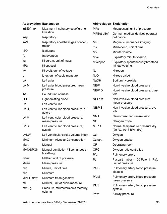
All the controls are on the screen.
A The screen is touch-sensitive (touch screen) and can also be operated with gloves. Touch lightly to call up functions or dialog windows.
B Rotary knob for selecting and confirming set-tings
C On/Off button to turn the device On/Off
D LED for status display of the power supply for grid operation: – Green = mains supply sufficient– Off = no mains supply present
E LED for status display of the power supply for battery operation: – Green = battery charged– Yellow = battery capacity less than 50 %– Off = battery capacity less than 10 %
F LEDs for status display of the gas supply from backup gas cylinders (O2, Air, N2O)– Green = pressure sufficient– Green, flashing = pressure slightly below
level– Off = pressure not sufficient
G LEDs for status display of the gas supply from the central gas supply (O2, Air, N2O)– Green = pressure sufficient– Off = pressure not sufficient
H Alarm pause functionPress the Audio paused key to suppress the audible alert of all active alarms for 2 minutes. For additional information, see page 177.
I The alarm bar on the front and back indicates alarm conditions:– Red = high-priority alarm condition– Yellow = medium-priority alarm condition
050
CAUTIONTouch and hold the On/Off button for 4 sec. to turn the screen off. Ventilation is continued. A fresh-gas flow of 0.5 L/min with 100 % O2 is delivered. Anesthetic agent metering is switched off. Use a manual pressure gauge to check ventilation and ventilate manually if necessary.
Touch the On/Off button again to turn the screen back on.
O2 Air N2O O2 Air N2O
A
B
CD E
G F
I
H

Instructions for use Zeus Infinity Empowered SW 2.n 43
Operating concept
Variant 2 and variant 3
All the controls are on the screen.
A The screen is touch-sensitive (touch screen) and can also be operated with gloves. Touch lightly to call up functions or dialog windows.
B Rotary knob for selecting and confirming set-tings
C On/Off key to switch the device on/off
D LED for status display of the power supply for grid operation: – Green = mains supply sufficient– Off = no mains supply present
E LED for status display of the power supply for battery operation: – Green = battery charged– Yellow = battery charge less than 50 %– Off = battery charge less than 10 %
F LEDs for status display of the gas supply from the central gas supply (O2, Air, N2O)– Green = pressure sufficient– Off = pressure not sufficient
G LEDs for status display of the gas supply from the backup gas cylinders (O2, Air, N2O)– Green = pressure sufficient– Green, flashing = pressure slightly below
level– Off = pressure not sufficient
H Alarm pause function
Press the button to suppress the audible alert of all active alarms for 2 minutes. For addi-tional information, see page 177.
I The alarm bar on the front and back indicates alarm conditions:– Red = high-priority alarm condition– Yellow = medium-priority alarm condition
021
O2 Air N2O O2 Air N2O
A
BC
D
E F GH
I

Operating concept
44 Instructions for use Zeus Infinity Empowered SW 2.n
Screen layout
The screen is divided into fields.
A Header bar with fields for:– Patient data. Touch to open the Patient
setup dialog window, see page 112– Alarm messages. Touch to open the Alarms
dialog window, see page 160.– Date, time, location, and stopwatch. Touch
to access the stopwatch settings and to change the stopwatch display settings, see page 354
– Indication that the audible alarms have been suppressed and display of the time that the alarms remain suppressed.
B Monitoring area with fields for:– Loops and fresh-gas settings.
When activated, the size of the waveforms is reduced.
– Mini-trends.When activated, the size of the waveforms is reduced.
– Module for SPV (on C700 option)When activated, the size of the waveforms is reduced.
– Waveforms.– Parameter modules: 7 waveform modules
(vertical area) and 5 data modules (horizon-tal area), (on C700 option, 8 waveform mod-ules and 6 data modules). Touch the param-eter boxes to set the parameter settings in the Sensors/Parameters dialog window, see page 188.
C Main menu bar with buttons to:– Open dialog windows– Activate functions
D Therapy bar with fields for:– Breathing-gas control
Touch the headline of the field to open the MixGas settings dialog window, see page 115. Touch a therapy control to select it.
– Ventilation control.Touch the headline of the field to open the Ventilation settings dialog window. Touch a therapy control to select it.
– Additional data modules (maximum of two, three on C700 option)On IV System option: Field for syringe pump control (on C700 option, an additional data module), see page 141. Touch the headline of the field to open the Infusion settings di-alog window, see page 142.Without the IV System option, the data mod-ule can be freely selected.
301
1:35A
B C
D

Instructions for use Zeus Infinity Empowered SW 2.n 45
Operating concept
Main menu bar
The main menu bar contains fixed assigned but-tons and configurable buttons. The buttons are as-signed to groups. Touching a button opens the cor-responding dialog window or activates the corresponding function.
Fixed assigned buttons
A The Alarms button opens the Alarms dialog window. Among other things, this dialog window can be used to set alarm limits, see page 162.
B The Views button opens the Views dialog win-dow. This dialog window is used to choose be-tween various user-defined views.
C The Home button closes all open dialogs and immediately returns to the main screen.
D The Screen setup button opens the Screen setup dialog window. This dialog window is used to configure the screen, see page 329.
E The Trends/Data button opens the Trends/Data dialog window. This dialog is used to call up the diagnosis windows.
F The NIBP start/NIBP stop button starts or stops the NIBP measurement.
G Start/Standby button – in standby mode, it opens the Startup dialog– in Vent. standby mode, it switches into
Standby mode– during operation, it switches into Standby
mode after confirmation.
Configurable buttons
Additional buttons for directly accessing functions or dialog windows can be configured. These but-tons are automatically assigned to the correspond-ing group, see "Configuring the screen" on page 329.
100
A
BC
D
E
F
G

Operating concept
46 Instructions for use Zeus Infinity Empowered SW 2.n
Buttons in system standby
A Web access button (optional), see page 138.
B The Biomed service button opens the dialog window to configure protected settings (Basic settings, access code required), Data simula-tion, Service call, Service access, Service mode, see page 356.
C The System setup button opens the System setup dialog window to load and save system configurations, see page 323.
D The Trends/Data button opens the Trends/Data dialog window to call up the diag-nosis windows, see page 184.
E The Device test button opens the dialog win-dow for Self test, Leak test, Leakage assist-ant, Pretest, see page 96.
F The Start/Standby button opens the Startup dialog to start a new case, see page 109.
300
ABCDE
F
Standby
Self test will start at 07:15Last self test 04.Sep 2008 17:03
Run self test at least every 24 hours
completed/ operable
Do not connect patient! Touch the Start/Standby

Instructions for use Zeus Infinity Empowered SW 2.n 47
Operating concept
Using the touch screen
Using the dialog windows
Dialog windows consist of one or several pages which are displayed by touching the corresponding horizontal or vertical tab. Dialog windows contains elements for operating the device and informing the user on current settings. Dialog windows can be opened by touching a button in the main menu bar or by touching the respective parameter field on the screen.
A Dialog window title
B The horizontal tabs indicate primary topics. Touch the relevant tab to open a page.
C The vertical tabs open secondary topics. Touch the relevant tab to open a page.
D Touch the button to close the dialog window.If the color of the button is yellow, the dialog window can also be closed by pressing the ro-tary knob.
Therapy bar
The therapy bar on the main screen contains the therapy controls for the active Ventilation settings and the MixGas settings.
A Button to open the MixGas settings dialog win-dow. The active setting for the mixed gas is dis-played.
B Button to open the Ventilation settings dialog window. The active ventilation settings are dis-played.
C Therapy controls for the mixed gas setting
D Therapy controls for the ventilation settings
305
1
2
AB
D
C
301
A BC D

Operating concept
48 Instructions for use Zeus Infinity Empowered SW 2.n
Color concept
Therapy controls
Set values or operating states
1 Touch the therapy control. The color turns yel-low.
2 Turn the rotary knob to set the value.
3 Press the rotary knob to confirm the value. The color of the therapy control turns dark green or bright green.
In the following chapters of the instructions for use, this sequence of action is simply written: "Use the rotary knob to set and confirm the value."
Waveforms and parameters
The screen setup is used to set the colors for the waveforms and measured values, see page 334.
Color coding for anesthetic agents and medical gases
Standardized color coding in accordance with ISO 5359 / ISO 32 / ISO 5360 is used to identify an-esthetic agents and medical gases.
The colors for O2, Air, and N2O are adapted to lo-cally applicable standards.
306
Gray Non-operable element.
Dark gray Currently not operable, function ac-tivated
Yellow Selected function, not yet confirmed with rotary knob.
Light green Operable element, function not acti-vated.
Dark green Operable element, function acti-vated.
420
Screen setup

Instructions for use Zeus Infinity Empowered SW 2.n 49
Operating concept
Overview of the menu structure
Basic settings Access code required
– General settings – General– Units– Printer– USB devices– Alarm standard– Date/Time– Trend order
– Drug library Manage drugs, access code required
– Event recorder – User log
– Web access – Web acc. 1 to 4
– NIBP/SpO2 Calibration of NIBP/SpO2, Selection of SpO2 sensor type (optional)
– Infinity config. – Network config.– Recorder config.
– MediBus config. – COM 1– COM 2
– Disable options

Operating concept
50 Instructions for use Zeus Infinity Empowered SW 2.n
– More settings – Gas prices– Ventilation settings– Ventilation modes– VA/N2O– Calculat. settings– Total consumpt.
Basic settings Access code required
System setup
– Manage setups – Profiles– Views
– Sensors/ Parameters Overview of the selected settings
– IBP Overview of the selected settings
– MixGas/ Ventilation Overview of the selected settings
– Infusion Overview of the selected settings
– Alarms Overview of the selected settings
– Screen layout Overview of the selected settings
– Basic settings Overview of the selected settings
– Autoset limits Overview of the selected settings

Instructions for use Zeus Infinity Empowered SW 2.n 51
Operating concept
Screen setup– Screen layout – General
– Waveforms– Data– Web access
– Customize buttons Manage buttons
– Brightn./ Volume – General
– Colors Assign parameters a color
Sensors/Parameters– ECG – ECG HR/PLS
– ECG ST– ECG C.O.– ST segm.– More ECG
– SpO2 – SpO2
– NIBP – NIBP
– IBP – Config.– IBP sites/ Channels– Cal.– Wedge
– Temp – Temp
– C.O./ Calculat. – C.O.– Config.– Cardiac calculat.

Operating concept
52 Instructions for use Zeus Infinity Empowered SW 2.n
– BIS/NMT – NMT– BIS– Imped. check
– Anesth./ Ventilation – CO2
– Oxygen– Flow– Paw– Volatile agent– PV FV Loops
Sensors/Parameters (Cont.)
Infusion settings– Infusion 1 – General
– Advanced
– Infusion 2 – General– Advanced
– Infusion 3 – General– Advanced
– Infusion 4 – General– Advanced
Trends/Data– Overview – Graph. trend
– Tab. trend
– Hemodyn. – Graph. trend– Tab. trend– ST view– Cardiac calculat.– Calculat. trends

Instructions for use Zeus Infinity Empowered SW 2.n 53
Operating concept
– BIS/NMT – Graph. trend– Tab. trend– All EEG values
– Infusion – Graph. trend– Tab. trend
– Ventilat./ Oxygenat. – Graph. trend– Tab. trend– Resp. mech.
– Gases/ Anesth. – Graph. trend– Tab. trend– Current flows– Total consumpt.
– System – Test details
Trends/Data (Cont.)
Alarms– Alarm info Detailed alarm information
– Alarm log Overview of alarms
– Alarm limits – Noninvasive– Invasive– Ventilation– Anesth.– Infusion
– Suspend Suppressing alarms
– Alarm recorder – Recorder trigger– Recorder config.

Operating concept
54 Instructions for use Zeus Infinity Empowered SW 2.n
– All limits – Hemodyn.– IBP– More IBP– Arrhythmia– Anesth.– Infusion
– Autoset limits – Hemodyn.– IBP– Anesth./ Ventilation
Alarms (Cont.)
Test details
– Checklist – Supplies/ Safety
– Breathing system
– Suction/ Y-piece
– Test results – Test result 1
– Test result 2
– Test info
– Auto self test
– Test history
– Leakage assistant
– System info
– Service Access code required

Instructions for use Zeus Infinity Empowered SW 2.n 55
Operating concept
Ventilation settings– Vent. standby
– MAN/SPON Set parameters
– Vol. Ctrl. AutoFlow Set parameters
– Volume Control Set parameters
– Pressure Control Set parameters
– Pressure Support Set parameters
– External FG outlet Set parameters
MixGas settings– Fresh-gas control Settings for metering mode
– Auto control Settings for metering mode
Patient setupChange patient data

56 Instructions for use Zeus Infinity Empowered SW 2.n
This page was intentionally left blank.

Instructions for use Zeus Infinity Empowered SW 2.n 57
Assembly and preparation
Assembly and preparation
Before initial use. . . . . . . . . . . . . . . . . . . . . . . 58
Charging the battery for emergency operation. . . . . . . . . . . . . . . . . . . . . . . . . . . . . . 58Installing flow sensors . . . . . . . . . . . . . . . . . . . 58
Zeus IE as a ceiling device . . . . . . . . . . . . . . 59
Features . . . . . . . . . . . . . . . . . . . . . . . . . . . . . . 59Docking Zeus IE with the ceiling supply unit . . 59
Establishing the mains power supply . . . . . 60
Establishing potential equalization . . . . . . . . . . 61Connecting the attachments. . . . . . . . . . . . . . . 61Electrical fuse for auxiliary sockets. . . . . . . . . . 62
Establishing the gas supply . . . . . . . . . . . . . 63
Connecting the compressed gas hose . . . . . . . 63Connecting backup gas cylinders for O2, Air or N2O . . . . . . . . . . . . . . . . . . . . . . . . . . . . . . . 63
Connecting anesthetic gas receiving system (AGS) . . . . . . . . . . . . . . . . . . . . . . . . . 65
Replacing or filling the CO2 absorber . . . . . 66
Instructions on absorber operation. . . . . . . . . . 66Filling the reusable CO2 absorber . . . . . . . . . . 66Using disposable CO2 absorbers . . . . . . . . . . . 67
Connecting hoses . . . . . . . . . . . . . . . . . . . . . 69
Connecting adult breathing hoses . . . . . . . . . . 69Connecting pediatric and neonatal breathing hoses . . . . . . . . . . . . . . . . . . . . . . . . 70Note about using bacterial filters, endotracheal tubes, Y-pieces, breathing hoses, soda lime, and other accessories for breathing systems . . . . . . . . . . . . . . . . . . . . . . 71Note about the total resistance of the breathing system and connected accessories. . . . . . . . . . . . . . . . . . . . . . . . . . . . 72Recommended breathing system accessories for the ventilation of adults and pediatric patients . . . . . . . . . . . . . . . . . . . . . . . 72
Preparing optional patient monitoring . . . . . 72
Connecting IV system . . . . . . . . . . . . . . . . . . 73
DIVA metering modules for anesthetic agents . . . . . . . . . . . . . . . . . . . . . . . . . . . . . . . 74
Inserting and removing the DIVA metering module. . . . . . . . . . . . . . . . . . . . . . . . . . . . . . . 74Fill the DIVA metering modules . . . . . . . . . . . . 75Transportation of filled DIVA metering modules. . . . . . . . . . . . . . . . . . . . . . . . . . . . . . 76
DIVA metering module with Dräger Fill filling system . . . . . . . . . . . . . . . . . . . . . . . . . 77
When filling during operation. . . . . . . . . . . . . . 77Finishing the filling process . . . . . . . . . . . . . . . 78Emptying the DIVA metering module . . . . . . . 79
DIVA metering module with safety filling device . . . . . . . . . . . . . . . . . . . . . . . . . . . . . . . 80
When filling during operation. . . . . . . . . . . . . . 80Finishing the filling process . . . . . . . . . . . . . . . 82Emptying the DIVA metering module . . . . . . . 83
Quik Fil sevoflurane safety filling system. . 84
Filling during operation . . . . . . . . . . . . . . . . . . 84Finishing the filling process . . . . . . . . . . . . . . . 85Emptying the DIVA metering module . . . . . . . 86
Filling system for desflurane . . . . . . . . . . . . 87
Filling during operation . . . . . . . . . . . . . . . . . . 87Finishing the filling process . . . . . . . . . . . . . . . 87Emptying the DIVA metering module . . . . . . . 88

Assembly and preparation
58 Instructions for use Zeus Infinity Empowered SW 2.n
Before initial use
Charging the battery for emergency op-eration
Zeus IE has an integrated uninterruptible power supply (UPS) which maintains the electrical supply to the device in the event of mains failure for at least 30 minutes provided the battery is charged.
Switchover to battery operation takes place auto-matically in the event of a failure. The Mains sup-ply failure message appears.
The battery is automatically recharged if the mains plug has been inserted.
Charge the battery for 10 hours before the initial use:
1 Insert the mains plug of the Zeus IE workstation into the mains power socket.
The power supply must correspond to the voltage indicated on the rating plate.
2 Check whether the circuit breaker on the right next to the gas supply block is pressed.
The green LED (A) with the symbol lights up.
Leave Zeus IE connected to the electrical power supply for 10 hours. It does not need to be switched on.
When the battery is charged, the green LED (B) lights up with the .
Installing flow sensors
CAUTIONBefore the device is used for the first time, all parts which conduct breathing gas or which come into direct contact with the patient must be treated as described in the chapter "Care".
The device must have adjusted to current room temperature sufficiently for it to be operating within a temperature range of +15 °C to +35 °C.
050
O2 Air N2O O2 Air N2O
A B
WARNINGRisk of fire
Residual vapors of highly flammable disin-fectants (e.g., alcohols) and deposits that were not removed during reprocessing may ignite when the flow sensor is in use.– Ensure particle-free cleaning and disinfec-
tion.– After disinfection, allow the flow sensor to
air for at least 30 minutes.– Before inserting the flow sensor check for
visible damage and soiling, such as resid-ual mucus, medication aerosols, and parti-cles.
– Replace flow sensors when damaged, soiled, or not particlefree.

Instructions for use Zeus Infinity Empowered SW 2.n 59
Assembly and preparation
Remove the breathing system, see page 363.
1 Unscrew inspiratory and expiratory connecting nozzles (A) for breathing hoses.
2 Insert both SpiroLife flow sensors (B).
3 Screw connecting nozzles (A) back on again (use only blue, non-rotatable nozzles).
Fit the breathing system again and lock it in place.
Zeus IE as a ceiling device
Features
Zeus IE can be used in conjunction with the "Forta lift" ceiling supply unit.
The Zeus IE anesthesia device can be connected to the ceiling supply unit using a corresponding de-vice mount and the appropriate operating unit.
Docking Zeus IE with the ceiling supply unit
039
A B
CAUTIONTo use Zeus IE in combination with a ceiling sup-ply unit safely, it is essential to follow the Forta lift instructions for use.

Assembly and preparation
60 Instructions for use Zeus Infinity Empowered SW 2.n
Establishing the mains power supply
The mains voltage must correspond to the voltage range indicated on the rating plate.
1 Plug the IEC line socket (A) into the device. Se-cure with the screws.
2 Insert the mains plug into a wall socket. The LED with the symbol , situated on the screen housing, turns green.
3 Check whether the circuit breaker (B) is pressed. Pressed is indicated by a white circle on a black background.
174
WARNINGRisk of electric shock
If the device is connected to a power socket with incorrect mains voltage or without a pro-tective ground, persons may be injured and the device may be damaged.
Only connect the device to power sockets with the permissible mains voltage and a protec-tive ground.
264
A
B
CAUTIONOnly press the circuit breaker if the screen has completely failed.
The circuit breaker disconnects Zeus IE, except for the screen, from the battery and from the ex-ternal power supply.
To disconnect the entire device from the power supply, unplug the mains plug.

Instructions for use Zeus Infinity Empowered SW 2.n 61
Assembly and preparation
Establishing potential equalization
Differences in electrical potential between devices can be reduced by potential equalization.
Potential equalization does not replace the protec-tive ground connection.
During operation, the potential equalization con-nectors must be readily accessible and the connec-tion must be able to be disconnected without the use of tools.
1 Connect the potential equalization cable to the potential equalization pin (A) on the device.
2 Connect the potential equalization cable to a potential equalization connector of the hospital (e.g., wall, ceiling supply unit, operating table).
Connecting the attachments
Connect the attachments to the auxiliary sock-ets on the back.
015
A
NOTEIf the mains power fails, devices connected to the auxiliary power sockets are not supplied from the uninterruptible power supply.
Do not connect any life-supporting devices to the auxiliary power sockets of the anesthesia work-station.
Ensure an alternative power supply for connected devices.
CAUTIONPatient hazard due to risk of electric shock
Observe the maximum current input of the auxil-iary devices (see relevant instructions for use).
WARNINGConnection of devices to the auxiliary sockets of the anesthesia device can cause an in-crease in the entire discharge current beyond the permissible value if the protective conduc-tor of a device fails. Therefore when connect-ing devices to the auxiliary sockets, the total leakage current has to be checked according to IEC 60601-1-1.
When the permissible values for the entire dis-charge current are exceeded, devices must not be connected to the auxiliary sockets of the anesthesia device, but to a separate wall socket.
If this is ignored, it can put the patient and user at risk.

Assembly and preparation
62 Instructions for use Zeus Infinity Empowered SW 2.n
Electrical fuse for auxiliary sockets
If an automatic fuse trips:
1 Remedy the malfunction.
2 Then switch on switch (A) on the automatic fuse.
The fuse is active again.
CAUTIONFor devices with power input with 8 A electronic main fuse:
In the first 2 minutes after activating the Zeus IE, no power may be drawn on the auxiliary sockets because the total current fuse of the Zeus IE may otherwise trip and the device may switch to bat-tery operation.
If the main fuse trips, the alarm Mains supply failure appears. In this case, wait for the power-on procedure and then reactivate the main fuse.
Put connected devices into operation only after this time.
CAUTIONTo ensure electrical safety, only connect devices to the serial ports (COM 1, COM 2, or COM 3), or devices and networks to the network interface (Ethernet connection), which have a maximum nominal voltage of 24 VDC and which meet one of the following standards:– IEC 60950-1: Ungrounded SELV circuits– IEC 60601-1 (as of 2nd edition): Exposed sec-
ondary circuits
015
A A

Instructions for use Zeus Infinity Empowered SW 2.n 63
Assembly and preparation
Establishing the gas supply
Connecting the compressed gas hose
1 Screw on the compressed-gas hoses of the central gas supply (CS) for O2, Air, N2O to the front connections of the gas supply block. The three ports on the back are intended for the backup gas cylinders.
One Air outlet and one O2 outlet are optionally available.
2 Connect the compressed-gas hoses to the gas supply block.
3 Insert the plugs of the compressed-gas hoses into the wall supply valves.
4 All LEDs (A) turn green, the pressure values are between 2.7 and 6.9 bar. The LEDs are switched off at gas pressures of <2.7 bar or if the gas hose is disconnected.
Connecting backup gas cylinders for O2, Air or N2O
Caution when handling compressed gas cylinders:
WARNINGRisk due to gas supply failure
All gas supplies (central gas supply, gas cylin-ders) must be correctly connected since oth-erwise the backup system (gas cylinders) will not be available if gas supply fails.– Make sure that all compressed gas hoses
are correctly connected to the rear side of the device.
– After connecting the gas supply, check for correct function.
– Even when the anesthesia machine is con-nected to the central gas supply, the gas cylinders should remain at the device with valves closed as backup.
050
O2 Air N2O O2 Air N2OA
WARNINGRisk of explosion
Do not oil or grease the O2 cylinder valves or O2 pressure reducers and do not handle with greasy fingers.
WARNINGRisk of explosion
Only use pressure reducers listed in the List of Accessories Follow the instructions for use of the pressure reducers used.
CAUTIONRisk of injury
Open/close the cylinder valves slowly by hand. Do not use any tools!
CAUTIONRisk of injury
Have leaky or tight cylinder valves repaired pro-fessionally!
CAUTIONRisk of explosion
If the cylinder valves are open, gas can be re-moved unnoticeably from the gas cylinders (in-stead of from the central gas supply) during CS operation. Always keep the cylinder valves closed during CS operation.

Assembly and preparation
64 Instructions for use Zeus Infinity Empowered SW 2.n
It is recommended to leave the gas cylinders as a backup on the device even if there is a connection to the central gas supply.
The backup Air cylinder, which is not illustrated, is connected to the gas inlet for the Air cylinder.
At the back of the device:
1 Place full gas cylinders into the cylinder holders.
2 Secure the gas cylinders with straps (A).
3 Screw on the gas cylinders in the mount (B).
4 Connect the pressure sensor cable.
5 Open the cylinder valves (C).
The LEDs for the status of the cylinder pressures should light up green. When the LEDs are switched off, check that the sensor plug and the pressure re-ducer are positioned correctly and the cylinder pressure is sufficient.
6 Close the cylinder valves again.
179
C
A
B

Instructions for use Zeus Infinity Empowered SW 2.n 65
Assembly and preparation
Connecting anesthetic gas receiving system (AGS)
In combination with Dräger anesthesia workstations and their modules, the anesthetic gas receiving sys-tem meets the requirements of the general safety standards (ISO 8835-3 and ISO 80601-2-13).
The anesthetic gas receiving system does not work as a stand-alone system, but is used as one of 3 components of an anesthetic gas scavenging system (AGSS).
1 Connect the transfer hose to the waste gas con-nector (A) on Zeus IE and to the port of the re-ceiving system (B).
2 Plug the scavenging hose onto the port (C) of the receiving system.
3 Connect the plug of the scavenginghose (D) to the terminal unit of the disposal system.
Follow the instructions for use of the anesthetic gas receiving system (AGS).
180
CAUTIONIncreased occupational exposure
Do not deliver any anesthetic agent if the AGS is not connected!
A
C
D
B
WARNINGRisk of patient injury
A vacuum can be created in the breathing sys-tem and in the patient's lung if the side open-ings on the receiving system are covered.
Always make sure that the side openings on the receiving system are not blocked.

Assembly and preparation
66 Instructions for use Zeus Infinity Empowered SW 2.n
Replacing or filling the CO2 absorber
Instructions on absorber operation
When the breathing system is not used:
Only fill the absorber cannister just before use!
Zeus IE can be used with disposable Drägersorb CLIC CO2 absorbers or reusable CO2 absorbers.
Filling the reusable CO2 absorber
Recommendation: Use only Drägersorb 800 Plus or Drägersorb FREE.
Do not use any fracture lime! Increased dust yield may impair the functionality of Zeus IE.
CAUTIONRisk of patient injury
For operation without CO2 monitoring (gas analy-sis failed or sample line blocked), set a fresh-gas flow that is higher than the minute volume to pre-vent an increase in the inspiratory CO2 concentra-tion.
CAUTIONRisk of patient injury
There is no CO2 absorption while replacing the absorber! Monitor inspiratory CO2 and set fresh-gas flow higher than minute volume if necessary to prevent an increase in inspiratory CO2 concen-tration.
CAUTIONAfter replacing the absorber, check that the breathing system is positioned horizontally in the mount to prevent a loss of gas.
CAUTIONImmediately after replacing the absorber during operation, proceed directly with a check for leak-tightness by conducting manual ventilation and perform a leak test at the next opportunity to elim-inate possible leaks.
WARNINGRisk of patient injury
Do not flush soda lime in the anesthesia sys-tem with dry gases for an unnecessarily long period of time!
The soda lime loses moisture. If the level of moisture falls below the minimum, undesira-ble reactions usually occur, irrespective of the type of lime and the inhalation anesthetic be-ing used:– reduced CO2 absorption– increased heat development in the CO2 ab-
sorber and hence a high breathing-gas temperature
– Formation of CO– Absorption and/or decomposition of inha-
lation anesthetic
CAUTIONIf you do not use an IBF absorber filter, the blower may become contaminated.

Instructions for use Zeus Infinity Empowered SW 2.n 67
Assembly and preparation
1 Turn the CO2 absorber (A) counterclockwise and remove downwards.
2 Remove the IBF absorber filter (B) using the re-cessed handles in the filter.
3 Empty out the used soda lime and dispose of according to the soda lime instructions for use.
4 Fill the CO2 absorber with fresh soda lime up to the upper mark.
5 Insert new IBF absorber filter. Only use undam-aged filters, as exterior damage to the filter de-creases protection!
6 Attach CO2 absorber to the breathing system from the bottom and turn clockwise until it en-gages.
Using disposable CO2 absorbers
Optional CLIC adapter
The CLIC adapter makes it possible to use Drägersorb CLIC 800 Plus or Drägersorb CLIC Free disposable CO2 absorbers, see instructions for use of disposable CO2 absorb-ers.
No IBF filter is required if using the recommended cartridges (dust filter is already integrated in the cartridge).
Fitting the CLIC adapter
Insert the CLIC adapter into the breathing sys-tem from below and turn clockwise as far as it will go. Make sure that the unlock button (A)
is facing the front and visible to the user.
018
A
B
005
A
B

Assembly and preparation
68 Instructions for use Zeus Infinity Empowered SW 2.n
Pulling out the used absorber
1 Press the unlock button (A): the holder flips open.
2 Slide the disposable CO2 absorber (C) out of the holder (B).
3 Dispose of the used absorber.
Information about disposal is available in the in-structions for use of the Drägersorb CLIC absorber.
Installing the new CO2 absorber
1 Shake the disposable CO2 absorber before in-serting, e.g. by inverting it several times to loosen the soda lime.
2 Remove the seal from the new disposable CO2 absorber.
3 Slide the new disposable CO2 absorber (C) as far as possible into the holder (B) until you hear it snap into place in the CLIC adapter.
068
A
C

Instructions for use Zeus Infinity Empowered SW 2.n 69
Assembly and preparation
Connecting hoses
Connecting adult breathing hoses
1 Breathing hoses (A) – connect to the inspiratory and expiratory ports of the breathing system and the Y-piece.
2 Attach hose water traps (B) attach at the lowest point to collect the condensate.
3 Connect the Y-piece (C) and elbow (D).
4 HME filter or filter (E) – connect to the elbow on the Y-piece.
5 Connect the sample line (F) on the filter and on the CO2 water trap.
WARNINGRisk of burns to the patient's airways/mucous membranes
A defect in the ventilator or the DIVA metering module can lead to an increased breathing-gas temperature.
To prevent the risk of burns, the length of the breathing hose may not be less than 110 cm.
WARNINGRisk of patient injury
When using near-patient filters do not scav-enge at the patient end!
In the event of stenosis or increased filter re-sistance the patient may be injured by vac-uum.
NOTEZeus IE is manufactured without natural rubber latex.
To minimize the risk of exposure to latex, use breathing bags and breathing hoses manufac-tured without natural rubber latex.
176
WARNINGRisk of burns when using HF surgery equip-ment
Do not use any antistatic or conductive breathing hoses!
NOTEOnly scavenge from the near-patient filter, other-wise the measured values may be incorrect.
AA
FFDC
E
B

Assembly and preparation
70 Instructions for use Zeus Infinity Empowered SW 2.n
6 Connect the breathing bag (G) with the con-necting nozzle to the breathing bag hose and attach to the angled nozzle. Insert the breathing bag downward, hanging in the direction of the floor, into the mount.
It is recommended that only Dräger-approved breathing bags be used. Otherwise, device opera-tion may be restricted.
Connecting pediatric and neonatal breathing hoses
Using a near-patient filter
1 Connect breathing hoses (A) to the inspiration and expiration nozzles of the breathing system using the large sleeves. Connect the small sleeves with Y-piece.
2 Attach hose water traps (B) attach at the lowest point to collect the condensate.
3 Connect the Y-piece (C) and spacer (D).
4 Attach the HME filter or filter (E) to the spacer on the Y-piece.
5 Connect the sample line (F) on the filter and on the CO2 water trap.
6 Connect the breathing bag (G) with the con-necting nozzle to the breathing bag hose and attach to the angled nozzle of the breathing sys-tem. Insert the breathing bag downward, hang-ing in the direction of the floor, into the mount.
It is recommended that only Dräger-approved breathing bags be used. Otherwise, device opera-tion may be restricted.
Determining system compliance and leakage
1 Connect Y-piece with filter (G) to the self-test adapter firmly.
2 Perform leak test, see page 136.
149
267
G
AA
C
E
FF
G D
B27
2
G
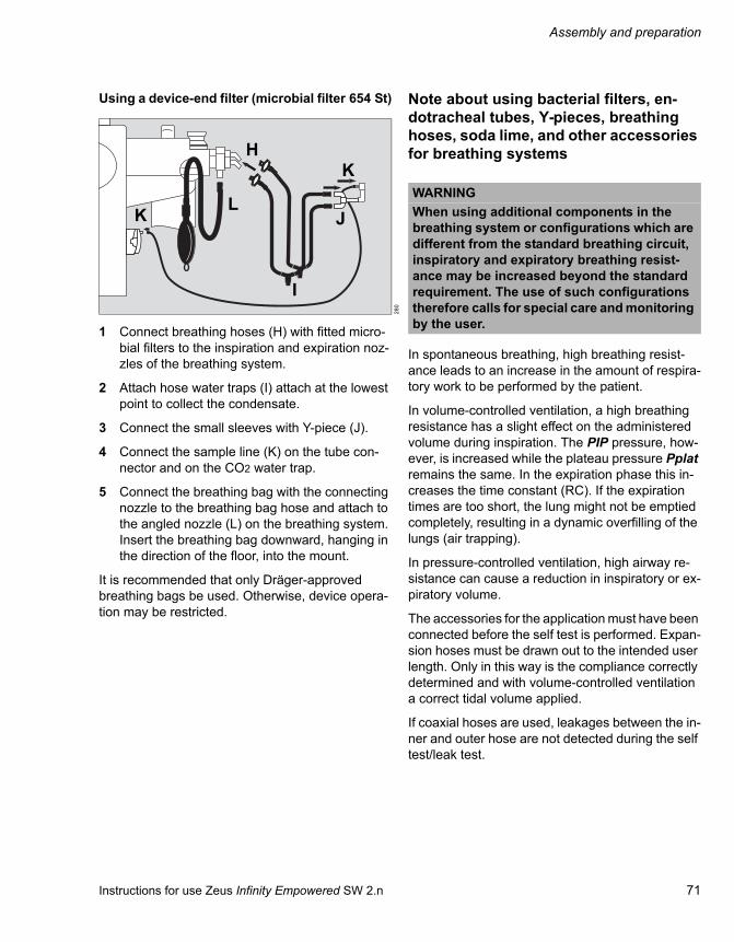
Instructions for use Zeus Infinity Empowered SW 2.n 71
Assembly and preparation
Using a device-end filter (microbial filter 654 St)
1 Connect breathing hoses (H) with fitted micro-bial filters to the inspiration and expiration noz-zles of the breathing system.
2 Attach hose water traps (I) attach at the lowest point to collect the condensate.
3 Connect the small sleeves with Y-piece (J).
4 Connect the sample line (K) on the tube con-nector and on the CO2 water trap.
5 Connect the breathing bag with the connecting nozzle to the breathing bag hose and attach to the angled nozzle (L) on the breathing system. Insert the breathing bag downward, hanging in the direction of the floor, into the mount.
It is recommended that only Dräger-approved breathing bags be used. Otherwise, device opera-tion may be restricted.
Note about using bacterial filters, en-dotracheal tubes, Y-pieces, breathing hoses, soda lime, and other accessories for breathing systems
In spontaneous breathing, high breathing resist-ance leads to an increase in the amount of respira-tory work to be performed by the patient.
In volume-controlled ventilation, a high breathing resistance has a slight effect on the administered volume during inspiration. The PIP pressure, how-ever, is increased while the plateau pressure Pplat remains the same. In the expiration phase this in-creases the time constant (RC). If the expiration times are too short, the lung might not be emptied completely, resulting in a dynamic overfilling of the lungs (air trapping).
In pressure-controlled ventilation, high airway re-sistance can cause a reduction in inspiratory or ex-piratory volume.
The accessories for the application must have been connected before the self test is performed. Expan-sion hoses must be drawn out to the intended user length. Only in this way is the compliance correctly determined and with volume-controlled ventilation a correct tidal volume applied.
If coaxial hoses are used, leakages between the in-ner and outer hose are not detected during the self test/leak test.
280
H
J
K
K L
I
WARNINGWhen using additional components in the breathing system or configurations which are different from the standard breathing circuit, inspiratory and expiratory breathing resist-ance may be increased beyond the standard requirement. The use of such configurations therefore calls for special care and monitoring by the user.

Assembly and preparation
72 Instructions for use Zeus Infinity Empowered SW 2.n
Note about the total resistance of the breathing system and connected acces-sories
In these instructions for use, the chapter Technical Data indicates the inspiratory and expiratory breathing resistance of the breathing system with-out breathing hoses. Therefore, it is possible to de-termine the resulting resistance on the patient when using different hose sets and/or filters.
The following formula is used to calculate the re-sistance (R):
RExpiration = RBreathingSys_exsp + RExpHose + RExpFilter
RInspiration = RBreathingSys_insp + RInspHose + RBreathingBagHose + RInspFilter
Only resistance data obtained under the same flow conditions may be added up, e.g., for adults, the re-sistance data at 60 L/min, for pediatric patients at 30 L/min and for neonates at 5 L/min.
If a filter is used on the Y-piece, the resistance for both the inspiratory and expiratory direction must be taken into account.
The standard for anesthesia breathing systems (ISO 8835-2) specifies a total resulting pressure drop at 60 L/min of 6.0 hPa max., both inspiratory and expiratory.
Follow the instructions for use of the respective accessories.
Recommended breathing system accessories for the ventilation of adults and pedi-atric patients
Only use the accessories listed in the List of Acces-sories for Zeus IE.
Preparing optional patient monitoring
Connect cables and modules for patient moni-toring, see page 197.
VT range Manual breathing bag Hose set Recommended ventilation mode10 to 200 mL 0.5 to 1 L Pediatric All modes
(Volume Control only from 20 mL upwards)
50 to 200 mL 1 L Pediatric All modes
100 to 300 mL 1 L Adults All modes
300 to 700 mL 2 L Adults All modes
>700 mL 3 L Adults All modes

Instructions for use Zeus Infinity Empowered SW 2.n 73
Assembly and preparation
Connecting IV system
Assemble the IV-system (optional) according to the instructions for use for Module DPS syringe pumps.
Attaching to a retaining arm (A) (optional)
1 Insert infusion apparatus stand into the retain-ing arm and fasten with the clamping screw.
2 Attach the IV system to the infusion apparatus stand. Check to make sure the IV system is se-cure.
3 A carrying handle (B) can be fitted to the top sy-ringe pump.
– Insert the carrying handle into the mounting slot of the top syringe pump and lower it.
– Turn the clamping screw until the carrying handle is securely attached.
4 Connect the cable connection (C) between the IV system and the IV system connection in the connection field for patient monitoring.
Attaching to an infusion apparatus
1 Attach the IV system to the pole of the infusion apparatus stand. Check to make sure the IV system is secure.
2 Check the stability of the infusion apparatus stand.
3 Connect the cable connection (C) between the IV system and the IV system connection in the connection field for patient monitoring.
– Use extension cable if necessary.
For stability reasons, an additional attachment to the infusion apparatus stand is necessary from three syringe pumps upwards.
Use an additional screw clamp.
Using Quicklock
1 Secure the connector with Quicklock until it can be felt and heard to have engaged.
2 To unlock, squeeze the Quicklock on both sides and remove the connector.
Use port saver
To protect the IV socket on Zeus IE, it is recom-mended that an adapter (port saver) be used.
1 Attach the adapter to the IV connection point on Zeus IE.
2 Insert the IVDock plug into the adapter.
Replace the adapter if worn.
The positions of the Module DPS syringe pumps on the IVDock (basis) determine the identification of the syringe pumps for syringe pump control (1 to 4), see page 141.
171
A
B
C
DPS 4
DPS 3
DPS 2
DPS 1
IV Dock

Assembly and preparation
74 Instructions for use Zeus Infinity Empowered SW 2.n
DIVA metering modules for anesthetic agents
The device can be operated with one or two DIVA metering modules. The selection of the slot is arbi-trary.
Fill the DIVA metering module with the appropri-ate anesthetic agent.
– Filling can be done with the DIVA metering module plugged in or outside of the device.
– Filling is also possible during anesthesia.
– Before the internal self test of the device, the DIVA metering modules must be filled and connected in order to ensure a complete test.
Inserting and removing the DIVA meter-ing module
The DIVA metering module can be exchanged in all operating states (switched off, on standby or during anesthesia).
Plugging in the DIVA metering module
Insert the DIVA metering module into the slot until it can be felt and heard to have engaged.
Removing the DIVA metering module
Keep the unlock button (A) pressed and remove the DIVA metering module.
WARNINGStoring the DIVA metering module– only when empty (except if supplied for im-
minent clinical use)– in well-ventilated rooms– not over 40 °C
Empty the DIVA metering module for periodic maintenance and for transportation!
040
NOTEPressing the unlock button during operation re-sults in immediate shutdown of the DIVA metering module! This can lead to a rapid drop in anes-thetic agent concentration in the breathing gas.
A A

Instructions for use Zeus Infinity Empowered SW 2.n 75
Assembly and preparation
Sight glasses
The DIVA metering modules have a sight glass with marks for minimum and maximum filling levels. A third mark in the lower section indicates that a en-tire anesthetic agent bottle (250 mL) can be refilled.
Filling devices
The following filling devices are possible for the dif-ferent anesthetic agents:
Fill the DIVA metering modules
If the brand name is different, ensure correct as-signment, e.g., by the color coding of the DIVA me-tering module and anesthetic agent bottle.
Standardized color coding in accordance with ISO 5359 / ISO 32 / ISO 5360 is used to identify an-esthetic agents and medical gases.
Anesthetic agents from different manufacturers with different brand names can be metered in the DIVA metering module from a technical viewpoint individually or mixed if they are equal in composi-tion as well as their physical and chemical features and if they are approved for pharmaceutical use.
Close the drain plug before filling!
CAUTIONRisk of injury
Place DIVA metering modules only on firm, hori-zontal surfaces. The DIVA metering module can be damaged when dropped.
004
Isoflurane Safety filling system/Dräger Fill
Sevoflurane Quik Fil Safety filling system/Dräger Fill
Desflurane Desflurane filling system
250 mL
CAUTIONHazardous to health
Only fill DIVA metering modules in areas with ad-equate ventilation.
Do not spill any anesthetic agents and do not in-hale anesthetic vapor.
NOTEObserve the expiration date and storage temper-ature of the anesthetic agent.
WARNINGRisk of patient injury
Make sure the name of the anesthetic agent and the color coding on the DIVA metering module and anesthetic agent bottle agree. Otherwise, hazardous anesthetic agent mix-tures may develop or mistakes can be made.
WARNINGRisk of patient injury
Do not allow any detergents or substances not intended for use to enter the filling system. The anesthetic agent may be contaminated.

Assembly and preparation
76 Instructions for use Zeus Infinity Empowered SW 2.n
Transportation of filled DIVA metering modules
The DIVA metering module can be transported in any position. The filling device must be properly closed.
Transportation in filled state
– Only within the scope of regular clinical opera-tion, not for storage and dispatch
– Only with ambient conditions in accordance with the technical data
– The DIVA metering module may remain filled provided operating interruptions do not exceed 6 months; otherwise, empty the DIVA metering module.
The anesthesia machine can be moved around the workplace when the DIVA metering module is plugged in and locked.
WARNINGRisk of patient injury
Do not use anesthetic agents that were emp-tied from a DIVA metering module, but dispose of in a proper manner. Otherwise, the anes-thetic agents may be contaminated, mixed with others or used by mistake.
CAUTIONIncreased occupational exposure
When emptying the DIVA metering module, do not fill the anesthetic agent bottle up to the brim! This can cause anesthetic agent to be released into the atmosphere.
CAUTIONHealth risk
Fill the DIVA metering modules only up to a tem-perature of 40 °C, otherwise anesthetic agent can escape.
CAUTIONIncreased occupational exposure
When filling during the warm-up phase of the DIVA metering module, anesthetic agent may es-cape.
Only fill the DIVA metering module after the warm-up phase.
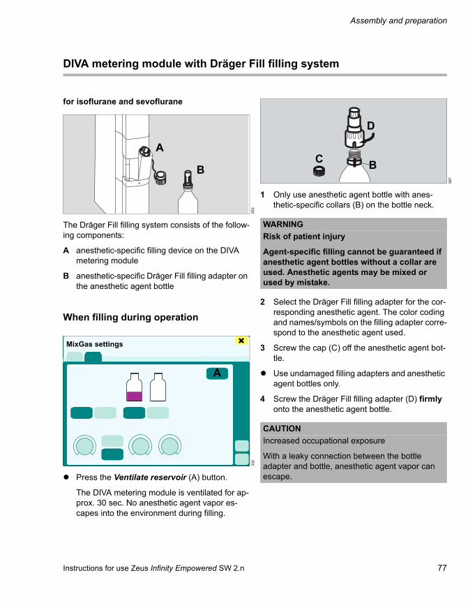
Instructions for use Zeus Infinity Empowered SW 2.n 77
Assembly and preparation
DIVA metering module with Dräger Fill filling system
for isoflurane and sevoflurane
The Dräger Fill filling system consists of the follow-ing components:
A anesthetic-specific filling device on the DIVA metering module
B anesthetic-specific Dräger Fill filling adapter on the anesthetic agent bottle
When filling during operation
Press the Ventilate reservoir (A) button.
The DIVA metering module is ventilated for ap-prox. 30 sec. No anesthetic agent vapor es-capes into the environment during filling.
1 Only use anesthetic agent bottle with anes-thetic-specific collars (B) on the bottle neck.
2 Select the Dräger Fill filling adapter for the cor-responding anesthetic agent. The color coding and names/symbols on the filling adapter corre-spond to the anesthetic agent used.
3 Screw the cap (C) off the anesthetic agent bot-tle.
Use undamaged filling adapters and anesthetic agent bottles only.
4 Screw the Dräger Fill filling adapter (D) firmly onto the anesthetic agent bottle.
053
332
A
B
MixGas settings
A
067
WARNINGRisk of patient injury
Agent-specific filling cannot be guaranteed if anesthetic agent bottles without a collar are used. Anesthetic agents may be mixed or used by mistake.
CAUTIONIncreased occupational exposure
With a leaky connection between the bottle adapter and bottle, anesthetic agent vapor can escape.
B
D
C

Assembly and preparation
78 Instructions for use Zeus Infinity Empowered SW 2.n
5 Screw the locking cap (E) off the filling device slowly so that any pressure which has built up in the DIVA metering module can escape slowly.
6 Introduce the anesthetic agent bottle with the filling adapter (F) into the filling opening. When doing so, turn the anesthetic agent bottle clock-wise until the coded area has engaged in the filling opening.
Do not turn the anesthetic agent bottle counter-clockwise. The filling adapter might become de-tached from the anesthetic agent bottle
7 Press the anesthetic agent bottle (G) up to the stop into the filling opening and keep it pressed.
Avoid excessive force and tilting of the anes-thetic agent bottle!
8 Watch the filling level in the sight glass (H).
9 The supply will be interrupted automatically when the maximum mark is reached.
10 Fill the DIVA metering module to the maximum mark at the most.
11 If the DIVA metering module is filled beyond the maximum mark, the anesthetic agent flows out through an overflow hole (I).
Finishing the filling process
1 Reduce the pressure in the anesthetic agent bottle and slowly pull out the anesthetic agent bottle.
2 Check the filling level in the sight glass (H) – DIVA metering module must hang or stand ver-tically during checking.
3 Screw on the locking cap (J).
Screw the Dräger Fill filling adapter from the an-esthetic agent bottle and
4 use the screw cap (K) to close the anesthetic agent bottle.
061
062
F
E
K
J
H
G
I
CAUTIONIncreased occupational exposure
Firmly screw on the locking cap. Otherwise, anes-thetic agent can escape.
NOTEDo not store the anesthetic agent bottle with the Dräger Fill filling adapter screwed on. The Dräger Fill filling adapter is no substitute for the bottle cap.

Instructions for use Zeus Infinity Empowered SW 2.n 79
Assembly and preparation
Emptying the DIVA metering module
1 Hold empty anesthetic agent bottle (A) under the drain opening on the bottom of the DIVA me-tering module.
2 Screw the locking cap (B) off the filling opening.
3 Use a screwdriver for hexagon sockets to open the drain plug (C).
4 Close the drain valve again after emptying.
5 Close the anesthetic agent bottle with the cap.
6 Close the DIVA metering module with the lock-ing cap (B).
263
WARNINGRisk of patient injury
Do not use anesthetic agents that were emp-tied from a DIVA metering module, but dispose of in a proper manner. Otherwise, the anes-thetic agents may be contaminated, mixed with others or used by mistake.
A
BC

Assembly and preparation
80 Instructions for use Zeus Infinity Empowered SW 2.n
DIVA metering module with safety filling device
for isoflurane
The safety filling system consists of the following components:
A anesthetic-specific filling device on the DIVA metering module
B anesthetic-specific Dräger filling adapter
C anesthetic-specific collar and threads on the bottle neck
Recommendations
– Use only anesthetic agent bottles with an anes-thetic-specific collar on the bottle neck.
– Use only Dräger filling devices.
– Use filling adapters with a non-return valve only.
– Use undamaged filling adapters and anesthetic agent bottles only.
– If the filling adapter is not firmly and tightly con-nected to the anesthetic agent bottle and the DIVA metering module, the anesthetic agent can flow out.
When filling during operation
1 Touch the Ventilate reservoir (A) button before filling.
The DIVA metering module is ventilated for ap-prox. 30 sec. No anesthetic agent vapor es-capes into the environment during filling.
2 Select the filling adapter for the appropriate an-esthetic agent.
The color coding and names/symbols on the fill-ing adapter correspond to the anesthetic agent used.
3 Screw the filling adapter (D) firmly onto the an-esthetic agent bottle.
051
AB
C
332
052
MixGas settings
A
D
E

Instructions for use Zeus Infinity Empowered SW 2.n 81
Assembly and preparation
4 Turn the square end (E) of the filling adapter so that the holes point downwards.
5 Pull out the locking bolt (F) and fold it down.
6 Hold the anesthetic agent bottle downwards.
The holes of the filling adapter point down-wards.
7 Insert the filling adapter (G) into the opening of the filling device up to the stop.
8 Tighten the lever (H) – do not use excessive force.
The lever is not flush with the front side of the DIVA metering module when filling.
Increased effort can cause damage to the seal and lead to release of fresh gas and anesthetic agent.
9 Swivel the anesthetic agent bottle (I) slowly to an overhead position and keep it in this position.
10 Watch the filling level (J) in the sight glass.
The supply will be interrupted automatically when the maximum mark is reached.
CAUTIONIncreased occupational exposure
With a leaky connection between the bottle adapter and anesthetic agent bottle, anesthetic agent vapor can escape.
055
056
F
G
H
057
NOTEThe seals on the DIVA metering module and the filling adapter are wearing parts: check them and have them exchanged by trained personnel if nec-essary.
I
J

Assembly and preparation
82 Instructions for use Zeus Infinity Empowered SW 2.n
Finishing the filling process
1 Swivel the anesthetic agent bottle (A) down-wards.
2 Check the filling level with the sight glass (B). The DIVA metering module must be in an up-right position.
3 Swivel the lever (C).
4 Pull out the filling adapter (D).
5 Insert the locking bolt (E) and press in com-pletely.
6 Close the lever (C).
Otherwise, fresh gas and anesthetic agent va-por could escape after switching on and trans-porting the DIVA metering module.
If the lever cannot be closed completely, disengage the lever and depress the locking bolt completely, otherwise the locking bolt will not seal and the gas-ket seal may be damaged.
7 Unscrew the filling adapter and close the anes-thetic agent bottle with the cap.
To use anesthetic agents in a safe and environmen-tally-friendly manner, please follow the following in-structions:05
805
9
A
4B
C
D
E
C
NOTEDo not store any anesthetic agent bottles with the filling adapter unscrewed! Anesthetic agent will be released!
NOTEClose the anesthetic agent bottle, even if it has been emptied. Allow remaining anesthetic agent in the filling adapter and anesthetic agent bottle to evaporate under an extractor hood, otherwise an-esthetic agent vapor will be released.

Instructions for use Zeus Infinity Empowered SW 2.n 83
Assembly and preparation
Emptying the DIVA metering module
1 Hold empty anesthetic agent bottle (A) under the drain opening on the bottom of the DIVA me-tering module.
2 Swivel the lever slowly.
3 Pull out the locking bolt and fold it down.
4 Use a screwdriver for hexagon sockets to open the drain plug (B).
5 Close the drain plug again after emptying.
6 Insert the locking bolt again and press in up to the stop.
7 Close the lever.
8 Close the anesthetic agent bottle.
265
A
B

Assembly and preparation
84 Instructions for use Zeus Infinity Empowered SW 2.n
Quik Fil sevoflurane safety filling system
The safety filling system consists of the following components:
A Anesthetic-specific filling device on the DIVA metering module
B Anesthetic-specific adapter on the anesthetic agent bottle.
Filling during operation
1 Press the Ventilate reservoir (A) button.
The DIVA metering module is ventilated for ap-prox. 1 minute. No anesthetic agent vapor es-capes into the environment during filling.
2 Unscrew the cap (B) from the bottle adapter.
The bottle adapter must be positioned firmly and tightly on the anesthetic agent bottle and must be undamaged.
053
332
AB
MixGas settings
A
060
CAUTIONIncreased occupational exposure
With a leaky connection between the bottle adapter and anesthetic agent bottles, anesthetic agent vapor can escape.
B

Instructions for use Zeus Infinity Empowered SW 2.n 85
Assembly and preparation
3 Screw the locking cap (C) off the filling device slowly so that any pressure which has built up in the DIVA metering module can escape slowly.
4 Insert the anesthetic agent bottle with the bars into the respective grooves (D) of the filling opening. Only use anesthetic agent bottles with suitable bars!
Press the anesthetic agent bottle up to the stop into the filling opening and keep it pressed.
Avoid excessive force and tilting of the anes-thetic agent bottle!
Watch the filling level in the sight glass.
The supply will be interrupted automatically when the maximum mark is reached.
Finishing the filling process
1 Reduce the pressure in the anesthetic agent bottle (A) and slowly pull out the anesthetic agent bottle.
2 Check the filling level in the sight glass (B) – DIVA metering module must stand vertically during checking.
Screw the cap onto the bottle adapter.
Always keep the anesthetic agent bottle closed!
061
C
D
062
CAUTIONIncreased occupational exposure
Firmly screw on the locking cap. Otherwise, anes-thetic agent can escape.
B
A

Assembly and preparation
86 Instructions for use Zeus Infinity Empowered SW 2.n
Emptying the DIVA metering module
1 Screw empty anesthetic agent bottle (A) into the drain opening on the bottom of the DIVA meter-ing module.
2 Unscrew the locking cap (B) of the filling device.
3 Use a screwdriver for hexagon sockets to open the drain plug (C).
4 Close the drain valve again after emptying.
5 Remove the anesthetic agent bottle and close it with the cap.
6 Close the DIVA metering module with the lock-ing cap (B).
263
B
C
A

Instructions for use Zeus Infinity Empowered SW 2.n 87
Assembly and preparation
Filling system for desflurane
The filling system consists of the following compo-nents:
A Anesthetic-specific filling device on the DIVA metering module
B Unlock button on the DIVA metering module
C Anesthetic-specific adapter on the anesthetic agent bottle
Filling during operation
1 Touch the unlock button (A).
2 Pull out the locking cover (B) of the DIVA meter-ing module.
3 Open the desflurane anesthetic agent bottle and insert the bottle neck (C) into the filling opening until it engages.
4 Keep the anesthetic agent bottle pressed.
The anesthetic agent bottle is equipped with an internal valve to prevent spilling.
5 Watch the filling level in the sight glass. The DIVA metering module must be in a vertical po-sition when checking.
Finishing the filling process
1 Reduce the pressure in the anesthetic agent bottle.
2 Touch the unlock button.
3 Pull out the anesthetic agent bottle and close it.
4 Insert the locking cap of the DIVA metering module into the filling device until it engages.
065
054
A B
C
A
BC
NOTEIncreased occupational exposure
Fill the DIVA metering module to the maximum mark only!
If filled beyond the maximum mark, excess desflu-rane may splash out of the filling device when re-moving the anesthetic agent bottle.

Assembly and preparation
88 Instructions for use Zeus Infinity Empowered SW 2.n
Emptying the DIVA metering module
1 Attach an empty anesthetic agent bottle.
2 Turn the DIVA metering module with the anes-thetic agent bottle attached upside down and push.
3 After emptying in this position, touch the unlock button and remove the anesthetic agent bottle.
4 Turn the DIVA metering module upright and close it with the locking cover.
5 Close the anesthetic agent bottle.
066

Instructions for use Zeus Infinity Empowered SW 2.n 89
Startup
Startup
Device check. . . . . . . . . . . . . . . . . . . . . . . . . . 90
Checking the central gas supply. . . . . . . . . . . . 90Checking the backup gas cylinders . . . . . . . . . 90Checking the O2 flush. . . . . . . . . . . . . . . . . . . . 91Checking the O2 emergency delivery . . . . . . . . 91Checking the breathing system . . . . . . . . . . . . 91Checking the APL valve . . . . . . . . . . . . . . . . . . 92Emergency ventilation bag . . . . . . . . . . . . . . . . 92Checking the anesthetic gas scavenging system AGSS . . . . . . . . . . . . . . . . . . . . . . . . . . 92Checking the O2 flow meter . . . . . . . . . . . . . . . 93
Switching on Zeus IE . . . . . . . . . . . . . . . . . . . 94
Checklist . . . . . . . . . . . . . . . . . . . . . . . . . . . . . 95
Supply & safety. . . . . . . . . . . . . . . . . . . . . . . . . 95Breathing system . . . . . . . . . . . . . . . . . . . . . . . 95Suction & Y-piece . . . . . . . . . . . . . . . . . . . . . . . 95
Self test . . . . . . . . . . . . . . . . . . . . . . . . . . . . . . 96
Preparing the self test. . . . . . . . . . . . . . . . . . . . 96Starting the self test manually. . . . . . . . . . . . . . 96
Automatic self test (Auto self test) . . . . . . . . 99
Pretest . . . . . . . . . . . . . . . . . . . . . . . . . . . . . . . 100
Displaying the test results . . . . . . . . . . . . . . . 101
Test results . . . . . . . . . . . . . . . . . . . . . . . . . . . . 101Test info . . . . . . . . . . . . . . . . . . . . . . . . . . . . . . 101Automatic self test . . . . . . . . . . . . . . . . . . . . . . 102Test history . . . . . . . . . . . . . . . . . . . . . . . . . . . . 102Leakage assistant. . . . . . . . . . . . . . . . . . . . . . . 103System info. . . . . . . . . . . . . . . . . . . . . . . . . . . . 104Service . . . . . . . . . . . . . . . . . . . . . . . . . . . . . . . 104
Displaying the test results during operation . . . . . . . . . . . . . . . . . . . . . . . . . . . . . 104
Startup in emergencies . . . . . . . . . . . . . . . . . 105

Startup
90 Instructions for use Zeus Infinity Empowered SW 2.n
Device check
Prerequisites
– The device has been reprocessed, see chapter "Cleaning, disinfection, and sterilization", and assembled ready for operation.
– The gas supply, anesthetic gas scavenging sys-tem and power supply must be connected.
– Optional: Filled backup gas cylinders are con-nected.
– The emergency ventilation bag, e.g., Dräger Resutator 2000, is on the device.
Checking the central gas supply
Check gas pressures:
All LEDs (A) turn green. The pressure values are between 2.7 and 6.9 bar.
If gas pressures fall below 2.7 bar, the LEDs go out.
Checking the backup gas cylinders
Immediately change over to cylinder supply in the event of a central gas supply failure:
1 Open the cylinder valves (A) slowly.
If the pressure is sufficient, all LEDs (B) turn green (see page 63):– O2 greater than 50 bar– Air greater than 50 bar– N2O greater than 30 bar
If the LEDs are not green, the pressure values lie below the threshold value:– O2 less than 20 bar– Air less than 20 bar– N2O less than 30 bar
2 Make sure that the sensor plug and the cable to the pressure reducer are connected properly.
3 Close the cylinder valves again after the capac-ity test.
050
O2 Air N2O O2 Air N2OA
179
NOTEIf cylinder valves are open during operation with central gas supply: Risk of gas being drawn from backup gas cylinders.
A A

Instructions for use Zeus Infinity Empowered SW 2.n 91
Startup
Checking the O2 flush
The O2 flush is available for flushing and filling the breathing system and the breathing bag with oxy-gen quickly (approx. 35 L/min), bypassing anes-thetic agent delivery.
There is a knob (A) on each side of the breathing system with identical functions.
1 Manually close the filter on the Y-piece or con-nect the test lung.
2 Press the O2+ knob (A).
3 The breathing bag fills; the filling process can be heard.
Checking the O2 emergency delivery
1 Manually close the filter on the Y-piece or con-nect the test lung.
2 Press O2 rotary safety knob (A) to unlock it and adjust O2 flow by turning.
3 The breathing bag fills.
4 Turn the O2 rotary safety knob (A) back to the original position and push it in.
Checking the breathing system
1 It is complete and engaged. The hoses are firmly connected.
2 New soda lime, not discolored violet.03
804
2
A A
A
047
CAUTIONRisk of device failure
To avoid a backflow of condensed water into the breathing system, the hoses between the patient and breathing system must have sufficient slack.
The condensate in the hose must be continuously monitored and, if necessary, disposed of or dis-charged to the hose water traps. Standing water impairs device operation!

Startup
92 Instructions for use Zeus Infinity Empowered SW 2.n
Checking the APL valve
(for manual checking in cases of emergency)
1 Adjust the pressure to 20 mbar (A).
2 Manually close the filter on the Y-piece or con-nect the test lung.
3 Manually ventilate with breathing bag.
4 Check the pressure limits on the mechanical pressure gauge (B).
Emergency ventilation bag
Example: Dräger Resutator 2000 (not shown).
The emergency ventilation bag is present on the device and its functionality has been checked.
Checking the anesthetic gas scavenging system AGSS
The anesthetic gas scavenging system (AGSS) must conform to ISO 8835-3.
1 Transfer hose (A) is connected to the nozzle on the back of the device and to the receiving sys-tem (AGS).
2 The scavenging hose is connected to the re-ceiving system, the plug (B) is in the Dräger wall socket, which has a green indicator.
3 The float in the AGS hangs between the two markings.
Follow the instructions for use of the anesthetic gas receiving systems (AGS) and the anes-thetic gas scavenging system (AGSS).
215
A
B
WARNINGRisk of patient injury
A vacuum can be created in the breathing sys-tem and in the patient's lung if the side open-ings on the receiving system are covered.
Always make sure that the side openings on the receiving system are not blocked.
044
A
B

Instructions for use Zeus Infinity Empowered SW 2.n 93
Startup
Checking the O2 flow meter
1 Open the adjustment knob counterclockwise. The ball ascends steadily in the measuring tube.
2 Close the adjustment knob.
212
O2

Startup
94 Instructions for use Zeus Infinity Empowered SW 2.n
Switching on Zeus IE
Touch the On/Off button (A).
Manual ventilation and O2 emergency delivery are possible at all times.
Anesthetic agent is not delivered yet!
The initial screen appears after switching the de-vice on.
The start may be delayed due to database mainte-nance.
The device switches to the self test mode automat-ically. The Test details > Checklist dialog window appears.
050
WARNINGPerform the self test once a day in order to check the operational reliability of the device and hence minimize the risk of exposing the patient to a hazard!
618
O2 Air N2O O2 Air N2O
A
310
Test details
Self test
Self test

Instructions for use Zeus Infinity Empowered SW 2.n 95
Startup
Checklist
Use the checklist (A) to make sure the device is ready for operation.
The checklist consists of the following test steps:
– Supplies Safety (B)– Breathing system (C)– Suction unit Y-piece (D)
Call up the test steps one after the other and work through the checklist.
Supply & safety
1 Touch the Supplies/ Safety tab (B).
2 Perform the following test steps:
– Power supply – Central gas supply – Gas cylinders – Emergency breathing bag – O2 flush – O2 emergency delivery
Breathing system
1 Touch the Breathing system tab (C).
2 Perform the following test steps:
– Anesthetic gas scavenging system – Breathing system – Manual breathing bag – APL valve – Soda lime
Suction & Y-piece
1 Touch the Suction/ Y-piece tab (D).
2 Perform the following test steps:
– Endotracheal suction – Microbial filters – Y-piece – Sample line – Watertraps
The checklist can also be called up during opera-tion.
1 Switch to the system standby screen.
2 Touch the Device test button.
The Test details dialog window will be opened.
3 Touch the Checklist tab (A).
310
CAUTIONThe checklist is part of the self test and must be applied each time before operation. Otherwise device operation may be impaired.
Test details
Self test
Self test
A BCD

Startup
96 Instructions for use Zeus Infinity Empowered SW 2.n
Self test
Preparing the self test
1 Place the Y-piece (A) with the filter firmly onto the cone (self-test adapter).
2 Connect sample line to the filter.
3 Set APL valve to 20 mbar.
4 Switch off manual O2 supply.
Starting the self test manually
The self test can only be started from the system standby screen.
1 Touch the Device test button (A).
The Test details dialog window will be opened.
2 Touch the Self test button (B).
3 Touch the Name of tester button (C).
4 Enter a new name or select a name from an ex-isting list of the last six testers. Names can also be deleted from the list.
5 The Start (D) button automatically turns yellow. Confirm with rotary knob.
WARNINGRisk of patient injury
The self test must never be performed when a patient is connected!
CAUTIONIncreased occupational exposure
When filling during the warm-up phase of the DIVA metering module, anesthetic agent may es-cape.
Only fill the DIVA metering module after the warm-up phase.
048
A
302
435
A
Test details
Self test
Self test
B
C D

Instructions for use Zeus Infinity Empowered SW 2.n 97
Startup
The self test starts. The Start button (D) is dark green.
The total time of the test is approx. 8 minutes. Two progress indicators (E) show the elapsed time in %.
The top bar displays the Pretest. The pretest takes approx. 1 minute. The device is tested for the fol-lowing most frequent errors:– Large leak– Y-piece not connected properly– APL valve setting– Central supply status of O2 and Air– Flow sensors inoperable
If a problem is determined in the pretest, informa-tion about the cause and how to remedy the prob-lem appears above the progress bar.
When the problem has been remedied, touch the Repeat pretest button.
After the pretest, the following options are available to continue the self test:
– Pretest passed:– Self test continues automatically.– At the end of the self test, the current test re-
sult is displayed.
– Pretest failed:
Call up the cause of the error via the Test info tab.
Perform the pretest again or start the self test directly to obtain accurate error analy-sis.
A failed pretest does not change the last self test re-sult.
The pretest can be activated as a separate test in preparation for the automatic self test, see page 100.
The bottom progress bar displays the progress of the self test.
During the self test, the Test results (F) page dis-plays the results of the previous test.
If the self test is passed, the device displays the completed /operable message on a green back-ground. The self test did not identify any errors and the device automatically switches to the Startup di-alog. Zeus IE can be put into operation.
If the self test is failed, one of the following mes-sages appears:
– completed/partly operable on a yellow back-ground. The user can decide based on the cause of the error (see "Test info" on page 101) whether the self test should be repeated or ter-minated after remedying the error.
– completed/not operable on a red background. The user must repeat the Self test after remedy-ing the error.
Repeating the self test:
Touch the Repeat button (G). All tests are re-peated.
436
Test details
Self test
Self test
E
437
Self test
Test details
Self test
F
GH

Startup
98 Instructions for use Zeus Infinity Empowered SW 2.n
Terminating the self test:
Touch the Cancel button (H).
If the self test is canceled during the test sequence, the canceled message appears instead of com-pleted.
If the self test failed, the Test details dialog window remains open.
There is an audible tone at the end of the self test.
The system standby screen displays the following information (I):
– Exchange water traps at least every 4 weeks.
– Last self test date and time– Run self test at least every 24 hours – Last test result (with colored background).
Test of the alarm system
The alarm system is automatically checked during the self test. Additionally, the loudspeaker is auto-matically checked when a new case is started.
501
I

Instructions for use Zeus Infinity Empowered SW 2.n 99
Startup
Automatic self test (Auto self test)
The start of the automatic self test is set in the gen-eral Basic settings, see page 336.
Before the start of the self test, a message (A) about the upcoming automatic self test appears on the standby screen.
The message contains the following information:
– Exchange water traps at least every 4 weeks.
– Self test will start at: Time (countdown 4 minutes before start)
– Last self test: Date and time– Run self test at least every 24 hours – Last test result (with colored background).
The countdown can be interrupted by:
– Touching the Cancel Autotest button (B)
– Opening the startup dialog
The countdown is replaced by –:–.
The automatic self test is repeated after 24 hours.
500
AB

Startup
100 Instructions for use Zeus Infinity Empowered SW 2.n
Pretest
The pretest can be started as a separate test in preparation for the automatic self test the next day. This ensures that the typical errors in the self test, see page 97, no longer occur.
The pretest is called up from the standby screen.
1 Touch the Device test button.
2 Touch the Pretest button (A).
The Start button (B) automatically turns yellow.
3 Confirm with rotary knob.
The pretest starts. The button turns dark green.
A progress indicator shows the elapsed time in % during the test. If a problem is found in the pretest, information about the cause and how to remedy the problem appears in the text display.
After the problem has been remedied:
Touch the Repeat button (B) (Start). The pre-test continues.
Or cancel the pretest:
Touch the Cancel button (C).
435
A
B
Test details
Pretest
Pretest
C

Instructions for use Zeus Infinity Empowered SW 2.n 101
Startup
Displaying the test results
Test results
Calling up the test results:
Touch the Test results tab (A).
All results of the last test are displayed and saved until the next test or a restart.
The test result is displayed in color:
Test info
Calling up the test info:
Touch the Test info tab (A) or View details tab (B).
All faults from the self test or leak test are listed.
The user receives the following information about troubleshooting:– Fault (C)– Cause and remedy (D)– Graphic presentation of the system compo-
nents
In addition to the image, important system data is displayed:– Central supply pressure and cylinder pressure– Leaks and compliance, with the time of the last
measurement– Battery capacity– Anesthetic agent quantity in the DIVA metering
module
316
Green test successful
Red test unsuccessful
Gray not tested
Test details
A
319
SEVISO
Test detailsA
B
C D

Startup
102 Instructions for use Zeus Infinity Empowered SW 2.n
Automatic self test
Touch the Auto self test tab (A).
The automatic self test is set as standard in the general basic settings, see page 336.
The default values can be changed for the next test:– Time-controlled self test starts at (B)– Time-controlled self test (C) On/Off
The new values apply to the next automatic self test. After the next automatic self test is completed, the values are reset to the default values.
Factory setting: Off
When activating On, the following messages ap-pear:
– Auto self test is enabled. Conduct Pretest. Check start time.
When activating Off, the following message ap-pears:– Auto self test is disabled.
Test history
Calling up the test history:
Touch the Test history tab (A).
The results of previous tests are displayed with the following information:
– Date and Time– Test – Name of tester – Number of test loops – Result
If a test did not detect any faults but is incomplete, the result is indicated with canceled.
317
Time-controlled self test starts at
Time-controlled self test
Test detailsA
BC
316
Test detailsA

Instructions for use Zeus Infinity Empowered SW 2.n 103
Startup
Leakage assistant
The Leakage assistant facilitates leak detection in the breathing system. Test pressure and leakage-flow values are displayed continuously, so that a re-duction in the leakage is immediately apparent by manually checking the connections.
Starting the leakage assistant:
Touch the Leakage assistant button (A). The Start button (B) turns dark green automatically.
The leakage assistant starts.
The test pressure is 25 to 30 mbar and indicated in the form of broken lines on the pressure display.
If the patient subsystem is the cause of the leak, a leak value above 100 mL/min is displayed in red. For other causes, a leak value above 500 mL/min is displayed in red.
A message indicates where the cause of the leak can be found and provides information about how to remedy the problem.
Leaving the leakage assistant:
Touch the Cancel button (C).
Notes on leaks:
Leaks are determined separately in the mechanical subsystem and the system as a whole. (See "Gas flow diagram" on page 440.)
Leak test 1:
– Leak test in near-patient breathing system. Leaks up to 100 mL/min are tolerated.
– The leak value is relevant to automatic ventila-tion.
Leak test 2:
– Leak test in the system as a whole. Leaks up to 500 mL/min are tolerated.
– The leak value is relevant to manual and spon-taneous breathing.
315
Test details
A
BC
246
BagAbsorber
Leak test 2Leak test 1
Lung
BlowerFlow sensor, insp.
Pressure sensorFlow sensor, exp.
Circle flow
Pressure sensor
Flow valve

Startup
104 Instructions for use Zeus Infinity Empowered SW 2.n
System info
The System info page contains information about the device configuration.
Calling up the system info:
Touch the System info tab (A).
Service
An access code is required to display the following service-related information:
– System info – Info log – Service info – More Info – System data – DIVA data – GMZ Data – Access codes – Apollo Software.
Displaying the test results during operation
1 Touch the Trends/Data button.
The Trends/Data dialog window will be opened.
2 Touch the System tab (A).
The Test details dialog window appears.
3 Touch the Test results tab (B).
316
Test details A
320
Trends/Data
A
B

Instructions for use Zeus Infinity Empowered SW 2.n 105
Startup
Startup in emergencies
1 Touch the button (A) on the screen.
2 Set the rotary safety knob O2 (B) for O2 emer-gency delivery to the required O2 flow:Range 0 to 12 L/min
3 Start manual ventilation.
Wait for the software to launch and for electronics test to end. The device only performs a minimum test.
After switching on, the device opens the Test de-tails dialog window.
WARNINGUse only in urgent cases if there is no time for the self test!
If a self test is not completed, malfunctions can go undiscovered!
Pay special attention during operation!
050
071
NOTEDuring this phase, no anesthetic gas delivery is possible!
O2 Air N2O O2 Air N2O
A
B
316
Test details
Self test
C

Startup
106 Instructions for use Zeus Infinity Empowered SW 2.n
Canceling the self test
Touch the Cancel button (C). The button turns yellow. Confirm with rotary knob.
No message appears on the system standby screen. The Startup dialog dialog window will be opened.
The Ventilator MAN/SPON button (D) is shown in yellow. If the Startup dialog is confirmed with the rotary know, the devices switches automatically to the Ventilator MAN/SPON mode with the preset profile.
Touch the MAN/SPON field (F).
The Ventilation settings dialog window opens.
1 Touch the button for the required ventilation mode.
2 Adjust the fresh-gas settings if necessary.
3 Return the safety rotary knob O2 to 0 and push in.
312
323
Startup dialog
D
MAN/SPON. F
NOTEThe warm-up phase of the DIVA metering mod-ules takes approx. 2 minutes. No anesthetic gas can be delivered during this time!
The leak and compliance test is not performed. The levels of accuracy indicated under "Technical data" (e.g. flow measurement) cannot be guaran-teed.
WARNINGIn order to ensure device features in an emer-gency operation, check APL valve and breath-ing system operation by ventilating manually in MAN/SPON ventilation mode.

Instructions for use Zeus Infinity Empowered SW 2.n 107
Operation
Operation
Start settings. . . . . . . . . . . . . . . . . . . . . . . . . . 108
Export of case data. . . . . . . . . . . . . . . . . . . . . . 108Startup dialog . . . . . . . . . . . . . . . . . . . . . . . . . . 109Patient transfer (optional) . . . . . . . . . . . . . . . . . 111
Changing patient data . . . . . . . . . . . . . . . . . . 112
Patient categories and set ranges . . . . . . . . . . 113Influence of weight and age on the device settings: . . . . . . . . . . . . . . . . . . . . . . . . . . . . . . 114
Integrated SmartPilot View (optional). . . . . . 114
Gas delivery . . . . . . . . . . . . . . . . . . . . . . . . . . 115
Nitrous oxide-free system. . . . . . . . . . . . . . . . . 115Adjusting mixed gas . . . . . . . . . . . . . . . . . . . . . 115Control mode Fresh-gas control . . . . . . . . . . . . 116Control mode Auto control . . . . . . . . . . . . . . . . 118Uptake mode . . . . . . . . . . . . . . . . . . . . . . . . . . 121Safety instructions for the control mode Auto control . . . . . . . . . . . . . . . . . . . . . . . . . . . 121
Ventilation . . . . . . . . . . . . . . . . . . . . . . . . . . . . 122
Starting ventilation . . . . . . . . . . . . . . . . . . . . . . 122Ventilation mode MAN/SPON (manual/spontaneous) . . . . . . . . . . . . . . . . . . . 124Ventilation mode Volume Control AutoFlow . . . 126Ventilation mode Volume Control . . . . . . . . . . . 127Ventilation mode Pressure Control . . . . . . . . . . 128Ventilation mode Pressure Support . . . . . . . . . 130Changing the ventilation mode. . . . . . . . . . . . . 130Set ranges and default values for the ventilation modes . . . . . . . . . . . . . . . . . . . . . . . 131Ventilating pediatric patients and neonates . . . 132Using non-rebreathing systems . . . . . . . . . . . . 132Directing fresh gas to the external outlet . . . . . 133Special events during ventilation . . . . . . . . . . . 134Changing the patient . . . . . . . . . . . . . . . . . . . . 134Checking the soda lime . . . . . . . . . . . . . . . . . . 135Changing the HME filter or filter . . . . . . . . . . . . 135Leak test . . . . . . . . . . . . . . . . . . . . . . . . . . . . . . 136
Web access (optional) . . . . . . . . . . . . . . . . . . 138
Launching a web application . . . . . . . . . . . . . . 139
IV system – IVenus . . . . . . . . . . . . . . . . . . . . 140
Information and safety instructions on the IV application. . . . . . . . . . . . . . . . . . . . . . . . . . 140Safety concept. . . . . . . . . . . . . . . . . . . . . . . . . 141Controls for IV . . . . . . . . . . . . . . . . . . . . . . . . . 141Infusion dialog window . . . . . . . . . . . . . . . . . . 142Starting the Module DPS on Zeus IE. . . . . . . . 143Administering an infusion . . . . . . . . . . . . . . . . 144Administering a bolus . . . . . . . . . . . . . . . . . . . 146Select drug . . . . . . . . . . . . . . . . . . . . . . . . . . . 148Simultaneous replacement of syringe and drug . . . . . . . . . . . . . . . . . . . . . . . . . . . . . . . . . 148Drug library . . . . . . . . . . . . . . . . . . . . . . . . . . . 149Module DPS – transport concept . . . . . . . . . . 153Displaying infusion trends . . . . . . . . . . . . . . . . 154Setup for the IV system . . . . . . . . . . . . . . . . . . 155
End of operation . . . . . . . . . . . . . . . . . . . . . . 156
3

Operation
108 Instructions for use Zeus Infinity Empowered SW 2.n
Start settings
Prerequisite
The device has passed the self test or the self test was canceled due to an urgent emergency.
Export of case data
Case data can only be exported in Standby mode.
Prerequisite: USB storage medium is installed and is connected to a USB port. Detailed information about connecting and installing can be found in the instructions for use.
The data are stored in the "Draeger\ExportData" di-rectory. Each exported case is contained in a sepa-rate compressed archive in .tar.gz format. Each ar-chive contains files with data in csv format, depending on the options that have been enabled. The archive name includes the following informa-tion:– Case ID– Date and time of the start of the case
Exporting case data
1 In the main menu bar, touch the Export case data (A) button.
The case data and the associated time stamps are displayed in the list (B). Information for the export is displayed in field (C), e.g., USB stick is ready.
Exporting selected case data
2 Select a case with the rotary knob or with the ar-row keys (D).
The patient data for the selected case are dis-played in field (E). This line may be empty if there are no patient data available for the case.
3 Touch the Export selected button (F).
Exporting all case data
Touch the Export all button (G).
302
A
502
Export case data
G F E
BD
C
D

Instructions for use Zeus Infinity Empowered SW 2.n 109
Operation
Startup dialog
The Startup dialog dialog window on the standby screen opens in the following cases:
– Automatically after the self test was successful or canceled
– By touching the screen below the upper blue bar and on the left next to the soft keys
– By touching the Start/Standby button (A).– When applying 2 mechanical breaths using the
breathing bag– When connecting an IV system to Zeus or a
connected IV system is started, i.e.:– IV-Dock is connected to Zeus with a
switched-on pump.– IV-Dock is already connected to Zeus, a
switched-on pump is mounted.– IV-Dock is already connected to Zeus,
mounted pump is switched on.
Opening the Startup dialog dialog window on the ventilator standby screen:
Prerequisite: The Vent. standby mode has been selected during ongoing ventilation of a patient.
The Startup dialog dialog window appears if:
– Zeus IE detects two mandatory breaths applied by manual breathing bag
The current profile is selected.
1. Select profile (Select profile)
The user can set the profiles displayed on the but-tons (B) in the System setup dialog window, see page 323. Only the buttons that have assigned profiles are displayed. The five factory profiles are preset. The default profile is preselected and has a dark green background.
Selecting other profiles
1 Touch the More profiles button (K).
The profile selection list (profile setup see page 323) appears. The current profile has a dark green background.
2 Select and confirm the profile using the rotary knob.
The selected profile is displayed on the button (B).
3 Close selection list:
Touch the More profiles button (K).
312
Startup dialog
Standby
A
BCD E FGH
J I
K

Operation
110 Instructions for use Zeus Infinity Empowered SW 2.n
Alternative:
Touch the Continue case button (C).
All the therapy settings are preserved when Con-tinue case is selected. All trends and the alarm log are carried forward. Depending on the basic config-uration, the anesthetic agent concentration will ei-ther be set to 0 or the last selected value will be re-tained.
If the startup dialog has been closed, the last se-lected profile is displayed on the Continue case button with the corresponding symbol.
2. Set details (Set details)
1 Touch the Weight (D), Age button (E) or Height button (F).
2 Use the rotary knob to set and confirm the value.
RR and VT are dependent on the IBW = of the pa-tient if Radford or Define was selected, see dialog Basic settings > More settings > Calculat. set-tings. The patient category has an influence on the computation of the IBW =.
3. Check settings (Check settings)
The upper display field (G) shows the current set-tings of gas delivery and ventilation for the selected profile.
The lower display field (H) shows the IV settings for the selected profile (optional).
4. Start (Start)
After completion of each user action within the Star-tup dialog, the Ventilator MAN/SPON button (J) is activated. Confirmation per rotary knob closes the Startup dialog dialog window and switches to the MAN/SPON ventilation mode.
Alternative:
Touch the Ventilator standby button (I) and confirm with the rotary knob to close the startup dialog dialog window and to switch to Vent. standby.
Changing IV data (optional)
Touch the More IV settings button (L).
The 4 blocks of the IV configuration appear con-taining all relevant pump data. Drug data and as-signments can be changed.
Closing the page:
Touch the More IV settings button (L).
Patient data Patient category Influenced parameter
Weight (IBW =) Neonates RR, VT
Height (IBW =) Pediatric patients,Adults
RR, VT 312
Startup dialog
L
Standby

Instructions for use Zeus Infinity Empowered SW 2.n 111
Operation
Patient transfer (optional)
When connected to an Infinity network, it is possi-ble to transfer patient data (trend data, demo-graphic data).
Demographic data is sent to Zeus IE directly.
Trend data is only available for subsequent transfer (to monitors or other Zeus IE systems) or for print-out (via Infinity network).
The transferred patient is automatically always a New patient.... Zeus IE suggests the best profile.
1 Touch the Patient transfer button (A). The but-ton turns dark green.
The following information is displayed (B):– Bed– Patient name– Unit (only with Multiview workstation in the Infin-
ity network).
2 The selected bed is shown in yellow. Confirm with rotary knob.
All buttons are gray and the Transfering patient data, please wait! message is displayed during the patient transfer. After the transfer, the patient data is updated and the page closes.
472
Startup dialog
AB

Operation
112 Instructions for use Zeus Infinity Empowered SW 2.n
Changing patient data
Open the Patient setup dialog window during op-eration:
Touch the field for patient data (A).
The dialog window contains buttons for the various patient data.
The keyboard window appears for text input for the following settings:– Name (B)– ID (C)
Specific features of the keyboard:In contrast with a normal PC keyboard, the Shift and AltGr- buttons do not reset automatically. The button must be touched a second time for it to switch back.
Enter text and press Enter or confirm with ro-tary knob.
Setting the following patient data:
– Weight (E)– Height (F)– Age (D)– Date of birth (H)
1 Touch the respective button.
2 Use the rotary knob to set and confirm the value.
The year of birth changes automatically when age is entered, and vice versa.
Gender (G) setting:
Touch the Female or Male button.
Print case (I) (optional):
Touch the Graphic or Tab. button.
The graphic or tabular trends of the entire patient are printed.
323
468
A
3
Patient setup
B
C
D
EFGH
I

Instructions for use Zeus Infinity Empowered SW 2.n 113
Operation
Patient categories and set ranges
The patient categories are as follows:
The factory-supplied profiles correspond to the three patient categories. A change in patient cate-gory can only be made by selecting a new profile.
– Neonates
– Pediatric patients
– Adults
Factory-set profile
Weight(kg)
Age(years)
Height(cm)
Dräger Neo.
5 0 60
Dräger Ped. 1
20 6 100
Dräger Ped. 2
40 12 150
Dräger Adult 1
80 60 180
Dräger Adult 2
100 60 180
WARNINGBy selecting a patient category, values for pa-tient weight and age, which have an effect on patient and ventilation settings, are prese-lected.
The selected patient category should always match the patient.
WARNINGWhen acknowledging the settings selected, the user accepts responsibility for their suita-bility.
Patient category
Parameter Recommended set ranges1)
1) For settings outside these ranges, the Check patient category alarm appears.
Neonates Age 0 to 2 years
Weight 0.3 to 10 kg
Height 20 to 80 cm
Pediatric pa-tients
Age 0 to 16 years
Weight 5 to 50 kg
Height 50 to 200 cm
Adults Age 12 to 130 years
Weight 30 to 300 kg
Height 120 to 300 cm

Operation
114 Instructions for use Zeus Infinity Empowered SW 2.n
Influence of weight and age on the device settings:
Integrated SmartPilot View (optional)
SmartPilot View* is only available in the adult (Adult) patient category.
Touch the SmartPilot button (A).
Integrated SmartPilot View is optionally displayed or hidden in the left-hand area (B) of the screen.
The view can be saved in a profile (Profiles).
More detailed information can be found in the SmartPilot View instructions for use (9054084, 1st edition).
Patient data Influenced parameter Algorithm RemarkWeight Tidal volume: VT Radford / User / VT from profile Setting is performed
only in standby mode.
Respiratory rate: RR Radford / User / RR from profile Setting is performed only in standby mode.
∆Psupp cancelation >20 kg: 4.0 s
≤20 kg: 1.5 s
Internal respiratory phase detection
>20 kg: Criteria for adults
≤20 kg: Criteria for pediatric pa-tients
Alarm limit setting for Exp. time too short
>20 kg: 6.0 L/min
≤20 kg: 2.0 L/min
Internal circle flow in fresh-gas mode
>20 kg: 6 L/min x Ti/(Ti + Te)
≤20 kg: 1 L/min x Ti/(Ti + Te)
Age xMAC Age-dependent after Mapleson
* only in conjunction with Variant 3 – C700
503
1:35
AB

Instructions for use Zeus Infinity Empowered SW 2.n 115
Operation
Gas delivery
Zeus IE can be operated in the manual fresh-gas delivery mode (FG ctrl. control mode) and in the closed control loop (Auto ctrl. control mode).
In contrast to conventional fresh-gas delivery, the automatic control of oxygen, carrier gas and anes-thetic agent takes place in a closed control loop.
Nitrous oxide-free system
A nitrous oxide-free device system can be config-ured under Basic settings > More settings > VA/N2O (see page 350).
Throughout the system in nitrous oxide-free opera-tion, N2O monitoring and N2O setting elements are turned off.
Adjusting mixed gas
1 Touch the MixGas standby button (A).
The MixGas settings dialog window containing the control modes opens.
Switch control mode to:– FG ctrl. (Fresh-gas control) or– Auto ctrl. (Auto control)
WARNINGIf face masks are used, the end expiratory an-esthetic agent measurement may be incorrect on account of the leak to be expected. Do not operate the device in the Auto ctrl. control mode.
WARNINGIf even minute quantities of volatile anesthetic agents have to be avoided for medical rea-sons, e.g., malignant hyperthermia:– Remove DIVA metering modules from
Zeus IE.– Change filters and hoses.– Replace soda lime.– Change absorber filter in the breathing
system.
CAUTIONMixed gas is only delivered if a ventilation mode is active.
329
MixGas standbyA

Operation
116 Instructions for use Zeus Infinity Empowered SW 2.n
Control mode Fresh-gas control
Setting the fresh-gas concentration manually
1 Touch the FG ctrl. tab (A).
2 Confirm with rotary knob.
3 Touch the O2+Air or O2+N2O button (B) for the carrier gas required.
4 The color changes to yellow, confirm with rotary knob.
5 Touch the button (C) for the anesthetic agent re-quired (ISO, SEV, DES).
The anesthetic agents displayed correspond to the connected DIVA metering modules.
6 The color changes to yellow, confirm with rotary knob.
Settings:– O2 fresh-gas concentration FG O2 (D)– Fresh-gas flow Flow (E)– Fresh-gas concentration of the anesthetic
agent FG DES, FG ISO, FG SEV (F)
7 Touch the therapy control of the parameter.
8 Use the rotary knob to set and confirm the value.
The set values are transferred to the system.
When selecting the therapy control for the anes-thetic-gas concentration for the first time, the initial value is preset automatically (see page 350).
Button (G) opens the Ventilation settings dia-log window
Button (H) opens the Alarms dialog window
After closing the MixGas settings dialog window, the most important therapy controls (I) are shown in the lower part of the screen and can be used di-rectly.
Set O2 concentration to 100 %.
Touch the 100% O2 button (J).
The color of the therapy control (K) turns yellow and indicates a value of 100 %.
Use the rotary knob to set and confirm the value.
330
AMixGas settings
B C
D E F GH
338
Fresh-gas control Volume Control – CMV -AF
I
JK

Instructions for use Zeus Infinity Empowered SW 2.n 117
Operation
Default settings:Parameter Setting range Default settings:
Neo Ped1 Ped2, Adult1, Adult2
Carrier gas Air or N2O N2O N2O N2O
Fresh-gas flow 0 to 18 L/min 2 L/min 4 L/min 6 L/min
Fresh-gas flow for external fresh-gas outlet
3 to 18 L/min 6 L/min 6 L/min 6 L/min
FG O2 25 to 100 Vol.% 90 Vol.% 100 Vol.% 100 Vol.%
FG ISO 0 to 5 Vol.% 0 Vol.% 0 Vol.% 0 Vol.%
FG SEV 0 to 8 Vol.% 0 Vol.% 0 Vol.% 0 Vol.%
FG DES 0 to 18 Vol.% 0 Vol.% 0 Vol.% 0 Vol.%

Operation
118 Instructions for use Zeus Infinity Empowered SW 2.n
Control mode Auto control
Automatic concentration control
The expiratory anesthetic agent content and inspiratory oxygen content of the breathing gas are measured, compared with the set nominal values, and readjusted. For a detailed description see chapter "Descriptions", see page 441.
In Auto control mode, the level of fresh-gas flow is selected automatically. Fresh-gas flow is limited downwards by minimum flow.
Activating Auto control mode:
1 Touch the Auto control (A) tab and confirm with rotary knob.
Selecting the carrier gas:
2 Touch the O2+Air or the O2+N2O button (B).
3 The color of the button turns yellow. Confirm with rotary knob.
Selecting the anesthetic agent:
4 Touch the ISO, SEV or DES button (C). The an-esthetic agents displayed correspond to the connected DIVA metering modules.
5 The color of the button turns yellow. Confirm with rotary knob.
Other parameters:
– FiO2 (D) (target value inspiratory O2 concentra-tion)
– Flush flow (E) (Flush flow)
– MinFG flow (F) (Minimum fresh-gas flow)– etSEV, etISO, etDES (G) (target value expira-
tory anesthetic gas concentration)– inSEVmax, inISOmax, inDESmax (H) (limit
value maximum inspiratory anesthetic agent concentration)
Touch button (I). The Ventilation settings dia-log window appears
Touch button (J). The Alarms dialog window appears
Setting parameters:
6 Touch the therapy control of the respective pa-rameter.
7 Use the rotary knob to set and confirm the value.
The set values are transferred to the system.
332
MixGas settings
A
B C
D EF
G H IJ
WARNINGRisk of patient injury
The user must adjust maximum inspiratory anesthetic agent concentration to suit the pa-tient. Otherwise there is a risk of concentra-tion levels being too high or too low.

Instructions for use Zeus Infinity Empowered SW 2.n 119
Operation
Setting mixed gas in the therapy bar on the main screen
After closing the MixGas settings dialog window, the most important therapy controls are displayed in the therapy bar of the main page and can be set there directly.
Setting the inspiratory O2 concentration:
1 Touch the (L) button.
2 Use the rotary knob to set and confirm the value.
If 100% O2 should be delivered:
3 Touch the 100% O2 button (K). The color of the therap ycontrol turns yellow and the value 100 is displayed.
4 Confirm with rotary knob.
Setting the flushing flow:
1 Touch the Flush flow button (M).
2 Use the rotary knob to set and confirm the value (max. 18 L/min).
The button color changes to dark green and dis-plays the set value. The fresh-gas flow is increased for 60 s to the set value. The text Flushing is dis-played above the virtual flow tubes.
Interrupting the flush flow:
Touch the (N) button.
The flushing flow is interrupted and displays the set MinFG Flow (closed or minimum fresh-gas flow).
338
KL
MN

Operation
120 Instructions for use Zeus Infinity Empowered SW 2.n
Default settings:Parameter Setting range Default settings:
Neo Ped1 Ped2, Adult1, Adult2
Carrier gas
Air or N2O1)
1) A nitrous oxide-free device system can be configured under Basic settings.
0 to 100 Vol.% Air
0 to 75 Vol.% N2O
N2O N2O N2O
FiO2 25 to 100 Vol.% 100 Vol.% 100 Vol.% 100 Vol.%
MinFG flow ; 0.25 to 18 L/min
Flush flow 3 to 18 L/min 4 L/min 6 L/min 6 L/min
etISO 0 to 5 Vol.% 0 Vol.% 0 Vol.% 0 Vol.%
inISOmax 0 to 5 Vol.% 4 Vol.% 4 Vol.% 4 Vol.%
etSEV 0 to 8 Vol.% 0 Vol.% 0 Vol.% 0 Vol.%
inSEVmax 0 to 8 Vol.% 8 Vol.% 8 Vol.% 8 Vol.%
etDES 0 to 18 Vol.% 0 Vol.% 0 Vol.% 0 Vol.%
inDESmax 0 to 18 Vol.% 12 Vol.% 12 Vol.% 18 Vol.%

Instructions for use Zeus Infinity Empowered SW 2.n 121
Operation
Uptake mode
Operating mode: Closed system
In Uptake mode, leak and uptake are compensated automatically. The system operates at minimum fresh-gas flow.
Set the button MinFG flow (A) to .
For detailed information, see "Display of the flow tubes" on page 196.
Safety instructions for the control mode Auto control
332
WARNINGRisk of patient injury
If in the Auto control control mode the HighFlow mode (fresh-gas flow >12 L/min) is set automatically due to the failure of a com-ponent, the anesthetic agent concentration must be adjusted manually. The text Auto-matic flushing is displayed above the flow tubes.
In HighFlow mode, the depth of anesthesia may otherwise be too shallow because the ex-piratory concentration target value is used as the fresh-gas concentration target value.
MixGas settings
A
WARNINGIf the volatile anesthetic agent is changed on Zeus IE, an anesthetic agent mixture can form in the breathing system:
Do not switch to the Auto control control mode for at least 15 minutes.
Set a high fresh-gas flow until the accumu-lated anesthetic agent has been scav-enged.
In the Auto control control mode, the system flushes automatically (for 15 minutes at a fresh-gas flow of >12 L/min) after changing the volatile anesthetic agent.
CAUTIONIf the Auto control cutoff message is displayed, switch to the manual fresh-gas control mode to avoid any unnecessarily high gas or anesthetic gas consumption!
CAUTIONIf the DIVA metering module is activated, do not remove it while the Auto control control mode is running or else the anesthetic agent will be washed out at a high fresh-gas flow.

Operation
122 Instructions for use Zeus Infinity Empowered SW 2.n
Ventilation
Starting ventilation
Opening the Ventilation settings dialog window:
Touch the (A) button.
The following ventilation modes are available:
– Vent. standby – MAN/SPON – Vol. Ctrl. AutoFlow – Volume Control – Pressure Control – Pressure Support – External FG outlet (optional)
Selecting the ventilation mode:
Touch the corresponding tab, e.g., (B). The color turns yellow. Confirm with rotary knob.
Setting ventilation parameters:
1 Touch the corresponding therapy control.
2 Use the rotary knob to set and confirm the value.
3 Touch the button to close the dialog window.
Direct switching to the MixGas sett. dialog window (C) and Alarms dialog window (D) is possible from all ventilation modes.
329
334
A
Ventilation settings
B33
5
Ventilation settings
CD

Instructions for use Zeus Infinity Empowered SW 2.n 123
Operation
Setting ventilation parameters in the therapy bar on the main screen
After closing the Ventilation settings dialog win-dow, the most important therapy controls are dis-played in the therapy bar of the main page and can be set there directly.
Example: Volume-controlled ventilation with con-stant flow
Activate MAN/SPON ventilation mode:
Touch the MAN/SPON button (E).
338
Volume Control – CMV E

Operation
124 Instructions for use Zeus Infinity Empowered SW 2.n
Ventilation mode MAN/SPON (man-ual/spontaneous)
In the MAN/SPON ventilation mode (A), the patient can be ventilated manually using the manual breathing bag.
Set maximum airway pressure at the APL valve.
CPAP level is preset.
Setting ventilation parameters in the therapy bar on the main screen
After closing the Ventilation settings dialog win-dow, the most important therapy controls are dis-played in the therapy bar of the main page and can be set there directly.
Button (B) shows the last selected ventilation mode or initially the ventilation mode preselected in the basic settings (see page 350).
Switching to the previous ventilation mode:
Touch the (B) button and confirm with rotary knob.
The volumeter function (C) is used for monitoring and evaluating ventilation with spontaneous breathing and manual ventilation in the MAN/SPON ventilation mode.
Applying the volumeter function
The top progress indicator shows the current inspir-atory and expiratory tidal volume VT. The expira-tory tidal volume is also displayed numerically. The progress indicator tracks the inspiratory and expir-atory tidal volume VT. At the end of inspiration, the tidal volume delivered is represented by a bar. The leak in tidal volume is displayed at the end of the expiration phase.
The bottom progress indicator shows the measured minute volume. The expiratory minute volume is also displayed numerically. The current expiratory minute volume is re-determined for each breathing cycle and the elapsed time is displayed in seconds alongside the progress indicator, with the accumu-lated volume above it.
Starting the volumeter
Specifying the CPAP level:
1 Touch the therapy control (A).
2 Use the rotary knob to set and confirm the value.
3 Touch screen in the area of the progress indica-tor.
On the progress indicator, the individual breaths are separated by segments. After 60 seconds, the volumeter stops automatically. The measured val-ues are displayed for 4 minutes and then cleared.
If the volumeter is pressed again before the 60 seconds have elapsed, the volumeter stops and the values are cleared. If pressed again, the volum-eter is restarted.
336
337
Ventilation settings
A
MAN/SPON600
1200
5.245 s
B
C33
7
MAN/SPON600
12005.2
45 sA

Instructions for use Zeus Infinity Empowered SW 2.n 125
Operation
Setting the APL valve
Set the valve head to the desired maximum air-way pressure.
Settings between the grid marks are also possible.
Quick release
Release pressure from the breathing system by lifting the valve head.
Spontaneous
Turn the valve head of the APL valve left as far as it will go.
The dots coincide and the valve head is lifted.
The pressure limitation is cancelled, the valve is open for free spontaneous breathing and the set CPAP level is used.
012
CAUTIONRisk of patient injury
Even with automatic ventilation, the APL valve must be adjusted to a pressure that is safe for the patient!
003
20 3010
002

Operation
126 Instructions for use Zeus Infinity Empowered SW 2.n
Ventilation mode Volume Control Auto-Flow
Volume Control AutoFlow with decelerating inspira-tion flow
Fixed mandatory minute volume MV adjusted with tidal volume VT and respiratory rate RR.
For patients with and without spontaneous breath-ing.
The patient can breathe spontaneously at any time (free deep breathing ability). Spontaneous breath-ing can be supported with Pressure Support.
Adjust volume-controlled ventilation with autoflow, synchronization, synchronization/Psupp:
A Maximum airway pressure Pmax
B Tidal volume VT
C Respiratory rate RR
D Positive end-expiratory pressure PEEP
E Switching synchronization on and off Sync.Switching on provides synchronization and, if set, activation of the set pressure support.
F Flow trigger threshold Trigger for synchroniza-tion of mandatory breathAn exceeded trigger threshold is represented in the pressure curve by triangles.
G Pressure support ∆Psupp
H Inspiration time Ti or I:EIn the configuration (see page 349), specify whether Ti or the I:E ratio is used.
I Pressure rise time Slope
258
WARNINGRisk of patient injury
Do not use Volume Control AutoFlow ventila-tion mode with intrinsic PEEP (alarm mes-sage: Exp. time too short). Expiratory flow does not return to the base line. This can cause an excessive pressure rise in ventila-tion pressure.
CAUTIONThe administered volume may be lower than the set volume if there is a leak!
t
t
1
fast rise time
without spontaneous breathing
with spontaneous breathing
slow rise time
Pressure support ∆Psupp
fast rise time
slow rise time
Trigger window for insp. and exp. synchronization
Paw
PEEP
Flow RR
Pinsp
Ti 339
Ventilation settings
A B C D
E F G H I

Instructions for use Zeus Infinity Empowered SW 2.n 127
Operation
Ventilation mode Volume Control
Volume Control with constant flow
Volume-controlled ventilation with fixed mandatory minute volume MV, adjusted with tidal volume VT and respiratory rate RR.
For patients without spontaneous breathing.
Adjust ventilation pattern with ventilation parame-ters:
A Maximum airway pressure Pmax
B Tidal volume VT
C Respiratory rate RR
D Positive end-expiratory pressure PEEP
E Inspiration time Ti or I:EIn the configuration (see page 349), specify whether Ti or the I:E ratio is used.
F Pause time % Tplat
259
WARNINGRisk of patient injury
Do not use Volume Control ventilation mode with intrinsic PEEP (alarm message: Exp. time too short). Expiratory flow does not return to the base line. This can cause an excessive pressure rise in ventilation pressure.
CAUTIONThe administered volume may be lower than the set volume if there is a leak!
1
t
t
Insp. Flow
% Tplat
(configura-ble)
Paw
PEEP
FlowRR
Ti
Pplat
Te
Pmax
340
Ventilation settings
A B C D
E F

Operation
128 Instructions for use Zeus Infinity Empowered SW 2.n
Ventilation mode Pressure Control
Pressure-controlled ventilation combined with free spontaneous breathing during the entire breathing cycle and adjustable pressure support on PEEP level. The mandatory portion of total minute volume MV is adjusted with inspiration pressure Pinsp and respiratory rate RR.
For patients with and without spontaneous breath-ing.
The patient can breathe spontaneously at any time (free deep breathing ability). Spontaneous breath-ing can be supported with Pressure Support.
Adjust ventilation pattern with ventilation parame-ters:
A Inspiration pressure Pinsp
B Respiratory rate RR
C Positive end-expiratory pressure PEEP
D Switching synchronization on and off Sync.Switching on provides synchronization and, if set, activation of the set pressure support.
E Flow trigger threshold Trigger for synchroniza-tion of mandatory breaths. An exceeded trigger threshold is represented in the pressure curve by triangles.
F Pressure support ∆Psupp
G Inspiration time Ti or I:EIn the configuration (see page 349), specify whether Ti or the I:E ratio is used.
H Pressure rise time Slope
Inspiration pressure Pinsp is adjusted in absolute terms while pressure support Psupp is adjusted relative to the PEEP level.
258
341
t
t
1
fast rise time
without spontaneous breathing
with spontaneous breathing
slow rise time
Pressure support, ∆Psupp
fast rise time
slow rise time
Trigger window for insp. and exp. synchronization
Paw
PEEP
FlowRR
Pinsp
Ti
Ventilation settings
A B C
D E F G H

Instructions for use Zeus Infinity Empowered SW 2.n 129
Operation
PEEP modifications
Depending on configuration in the basic settings, the inspiration pressure Pinsp can be automatically changed when modifying the PEEP value, see page 349.
For dependent setting of the change in Pinsp:
1 Touch the PEEP therapy control (I).
The color turns yellow. The value of ventilation pa-rameter Pinsp (J) also turns yellow.
2 Set PEEP and confirm with the rotary knob.
The value for Pinsp is automatically adjusted.
342
Ventilation settings
J I

Operation
130 Instructions for use Zeus Infinity Empowered SW 2.n
Ventilation mode Pressure Support
Continuous Positive Airway Pressure/Pressure Support
Spontaneous breathing at an increased pressure level to increase the functional residual capacity. Spontaneous breathing can be supported with Pressure Support. For patients with spontaneous breathing.
Adjust ventilation pattern with ventilation parame-ters:
A Minimum respiratory rate RRminThe minimum respiratory rate RRmin defines the period, after which a mechanically triggered, pressure-supported breath is administered if it has not been triggered by spontaneous trigger-ing.
B Positive end-expiratory pressure PEEP
C Flow trigger threshold Trigger for synchroniza-tion of spontaneous breathsAn exceeded trigger threshold is represented in the pressure curve by triangles.
D Pressure support ∆Psupp
E Pressure rise time Slope
Changing the ventilation mode
If the ventilation mode is changed, the presets from the parameters of the preceding ventilation mode are adopted or suitably derived.
Identical parameters are adopted directly.
When changing from pressure-controlled Pressure Control ventilation mode to volume-controlled ven-tilation modes, a mechanical VT is determined over 10 breaths and preset.
In addition, Pplat is set as a new Pinsp when changing from volume-controlled ventilation modes to Pressure Control (see following table).
260
343
Trigger indicatorApnea ventilation
Trigger indicator
Flow trigger Flow trigger No trigger
Flow
Paw
Time [s]
Time [s]Slope
1/RRmin
∆Psupp
1/RRmin
Ventilation settings
A B
C D E

Instructions for use Zeus Infinity Empowered SW 2.n 131
Operation
Set ranges and default values for the ventilation modes
Set point Vol. Ctrl. AutoFlow /Volume Control
Pressure Control Pressure Support MAN/SPON
VT VT (measured) ––– ––– –––
Pinsp ––– Pplat ––– –––
Ti X X ––– –––
Te X X ––– –––
PEEP X X ––– –––
∆Psupp X X X –––
Slope X1)
1) Only applies to Vol. Ctrl. AutoFlow.
X X –––
CPAP ––– ––– X/PEEP X
Trigger X1) X X –––
––– Is not adopted.
X Is adopted
Ventilation parameter Setting range Factory default valueNeo Ped1 Ped2 Adult1 Adult2
Tidal volume VT [mL] 20 to 1500 30 150 300 600 700
Respiratory rate RR [1/min] 3 to 80 30 25 20 12 10
Inspiration time Ti [sec.] 0.2 to 10 depending on RR, I:E
RRmin [1/min] 12 6 6 3 3
I:E ratio 4:1 to 1:4 1:1 1:2 1:2 1:2 1:2
Maximum airway pressure Pmax [mbar] 8 to 70 15 20 40 40 40
CPAP [mbar] Off, 3 to 10 Off Off Off Off Off
Positive end expiratory pressure PEEP [mbar]
Off, 3 to 35 Off Off Off Off Off
Inspiration pressure Pinsp [mbar] 3 to 70 10 15 15 15 15
Pressure support ∆Psupp [mbar] 0 to 70 0 0 0 0 0
Pressure rise time Slope [sec.] 0 to 2 0 0 0 0 0
Flow trigger sensitivity Trigger [L/min] 0.3 to 15 3 3 6 6 6

Operation
132 Instructions for use Zeus Infinity Empowered SW 2.n
Ventilating pediatric patients and neonates
If the tidal volume VT is less than 200 mL:
Use suitable ventilation accessories, see table page 72.
If the tidal volume VT is less than 20 mL or un-blocked tubes are used (leaks possible), ventilate with Pressure Control.
In the Auto control control mode, an automatic in-crease in fresh-gas flow is possible. Consequently, in the MAN/SPON ventilation mode, the ventilation pressure can reach the maximum airway pressure adjusted at the APL valve.
For this reason:
Always adjust maximum airway pressure at the APL valve according to the patient!
Using non-rebreathing systems
Only available with the option External FG outlet.
Example: Bain system
Prepare Bain system according to the relevant instructions for use.
WARNINGLimiting device performance
Observe weight setting! Weight determines in-ternal circle flow.
WARNINGWith neonates, monitor the inspiratory CO2 concentration as an indicator of pendulum respiration.
WARNINGRisk of patient injury
The user must assess the risks of switching over to 100% O2 and take action if necessary.
WARNINGInsufficient gas supply to the patient
Non-rebreathing systems are only suitable and intended for manual ventilation or sponta-neous ventilation and may only be connected up to the external fresh-gas outlet.
CAUTIONRisk of gas contamination!
In A-cone operation, the sample gas withdrawn is returned to the internal breathing system. Flush the breathing system each time the patient or anesthetic agent changes.
NOTEFor the prescribed monitoring of O2, CO2 and an-esthetic gases. the sample line must be con-nected to the elbow and the CO2 water trap of Zeus IE.
269
AB
C

Instructions for use Zeus Infinity Empowered SW 2.n 133
Operation
1 Screw sample line (A) onto the Luer-Lock of the elbow and connect it to the Luer-Lock of the CO2 water trap on Zeus IE.
When using elbows without sample line con-nection point:
Place the T-piece with filter directly on the elbow.
Or
Use the Luer-Lock of a filter if necessary.
2 Connect the fresh-gas hose (B) of the Bain sys-tem to the external fresh-gas outlet.
3 The anesthetic gas scavenging hose of the non-rebreathing system can be connected to the Y-piece (C) of the breathing system of Zeus IE.
Observe the instructions for use of the Bain sys-tem.
Directing fresh gas to the external outlet
1 Touch the External FG outlet tab (A). The color turns yellow.
The following message appears: MixGas will be switched to Fresh-gas control automati-cally.
2 Confirm with rotary knob.
3 Set fresh-gas values.
Settings:– O2 fresh-gas concentration FG O2 (B)– Fresh-gas flow Flow (C)– Fresh-gas concentration of the anesthetic
agent FG DES, FG ISO, FG SEV (D)
4 Touch the therapy control of the parameter.
5 Use the rotary knob to set and confirm the value.
The set values are transferred to the system.
After closing the Ventilation settings dialog win-dow, the External fresh-gas outlet mode is dis-played in the lower part of the screen.
NOTEIf the Ext. fresh-gas outlet is switched on when in the Auto control control mode, the Zeus IE ac-tivates the Fresh-gas control control mode auto-matically.
470
Ventilation settings
A
Ext. fresh-gas outlet
Check fresh-gas settings.
B C D
MixGas will be switched to Fresh-gas control au-tomatically.
344
External fresh-gas outlet

Operation
134 Instructions for use Zeus Infinity Empowered SW 2.n
Special events during ventilation
Water trap is full
Remove water trap.
Empty and replace water trap, see page 361.
Soda lime is used up
Remove absorber container in fresh-gas or standby mode.
Replace soda lime, see page 66.
DIVA metering module is empty
Refill the DIVA metering module, see page 75.
Switch over to full DIVA metering module or
Change DIVA metering module, see page 74.
Suction system is full
Change suction bottle.
Insert empty backup bottle (see relevant in-structions for use).
Changing the patient
Patient data can only be configured in the Startup dialog (see page 109) dialog from the standby screen, from a ventilation mode, and from Vent. Standby using the New patient button.
Changing the patient from ventilation mode
1 Touch the Start/Standby button (A).
All settings previously modified in operation are preserved.
The System standby? dialog window will be opened.
2 Confirm Stop ventilation? button (B) with ro-tary knob.
Or continue ventilation:
Close dialog window.
Pressing the rotary knob automatically switches the device to the system standby screen.
3 Call up the Startup dialog and configure, see page 109.
NOTEStarting a new case clears the data of the preced-ing case!
469
1:35 1:35
System standby?
A
B

Instructions for use Zeus Infinity Empowered SW 2.n 135
Operation
Changing the patient from the ventilator standby
1 Switch to Vent. Standby.
Prerequisite: The New patient button has been configured, see page 332.
2 Touch the New patient button (C).
The startup dialog opens.
3 Perform configuration, see page 109.
Checking the soda lime
Check the soda lime in the following cases:
– Soda lime in the absorber is violet.
– Inspiratory CO2 concentration inCO2 is 5 mmHg or more.
Replace soda lime, see page 66.
Changing the HME filter or filter
The filter on the Y-piece must be changed after each patient. Connect the sample line again if nec-essary.
Remove old filter.
Attach new filter firmly.31
247
3
Startup dialog
C
NOTEObserve hospital regulations for infectious pa-tients! Dispose of the old filter according to hospi-tal hygiene regulations.

Operation
136 Instructions for use Zeus Infinity Empowered SW 2.n
Leak test
– Checking all breathing gas-conducting compo-nents for leaks
– Determining compliance for volume correction
– Calibration of the flow sensors
The leak test can only be performed in system standby.
Perform leak test, if:– the breathing system was opened with the twist
locks– the soda lime was replaced– the breathing filters were replaced– the sample line was replaced– the breathing hoses were replaced– the flow sensors were replaced
Starting the leak test
1 Touch the Device test button (A).
WARNINGRisk of patient injury
Do not perform leak test when a patient is con-nected! In this operating state, it is not possi-ble to monitor the patient. During the test, pressures and concentrations may occur in the system which are hazardous to the pa-tient!
CAUTIONAfter each change of patient, a leak test must be performed to rule out the possibility of major leaks.
048
NOTEBefore starting the leak test, plug the filter onto the self-test adapter and connect the sample line.
300
Standby
Standby
A

Instructions for use Zeus Infinity Empowered SW 2.n 137
Operation
The Test details dialog window will be opened.
2 Touch the Leak test button (B).
3 Follow the instructions in the field (D).
4 Touch the Start button (C) and confirm with ro-tary knob.
If during leak test it is detected that the last self test was unsuccessful or that, after activating the device, no self test was performed at all, the following message appears next to the name field of the tester: Self test required!
310
CAUTIONIf the leak test has been canceled, it can lead to leaks not being detected.
Pay special attention during operation.
B
C
Test details
D

Operation
138 Instructions for use Zeus Infinity Empowered SW 2.n
Web access (optional)
Touch the Web access button (A) on the sys-tem standby screen (example) or during opera-tion.
The dialog window shows the web application. En-abled accesses are shown in green and non-ena-bled accesses are shown in gray.
The LED indicates the status of the web applica-tions:– Gray: Not enabled– Green: Web application launched– Red: Web application stopped
Only web applications approved by Dräger can be used.
Applications approved as web applications in con-junction with Zeus IE:
– WebViewer Version VF4– WebViewer Version VF5
The specified applications can be used with the fol-lowing restrictions:
308
AWeb access screen 1
Functions Function restrictionsSaving the diagno-sis log to a file if no patient data is transferred.
A text box opens: "Unable to open file".
Saving the diagno-sis log to a file if pa-tient data is trans-ferred.
It can be saved, but the files cannot be opened and viewed again.
Saving the trend data to a file.
A text box opens: "Error in output file selection"
Calling up the help function.
The help function cannot be launched.
Application display As the display is very small, the alarms, alarm limits, curve identifiers, etc. are difficult to read.

Instructions for use Zeus Infinity Empowered SW 2.n 139
Operation
Launching a web application
Prerequisite: Configure the Web access button in the Screen setup > Customize buttons dialog window, see page 332.
1 Touch the Web access button (A).
The Web access screen 1 dialog window will be opened.
2 Touch the button (B) for the respective web ap-plication (1 to 4).
The LED (C) turns from red to green. The button turns dark green. If another application is launched, the button for the web application launched previ-ously turns light green.
Exiting web application
1 Select the web application to be stopped. But-ton turns dark green.
2 Touch the Stop button (D).
The current application is exited.
486
Web access screen 1
BC
D
A

Operation
140 Instructions for use Zeus Infinity Empowered SW 2.n
IV system – IVenus
Information and safety instructions on the IV application
Operation of the Module DPS syringe pump and other safety instructions are explained in separate instructions for use.
Attach IVDock and Module DPS to Zeus IE, see page 73. Note the respective instructions for use before using these modules.
The Module DPS syringe pump can be remotely controlled with IVDock on Zeus IE. Module DPS may also be operated independently.
Remote control via Zeus IE is not possible until op-eration of the Module DPS syringe pump is termi-nated. The control panels for the IV system on the screen remain gray for that period of time (i.e. they are not operable).
If there is an interruption in the data link between Zeus IE and IVDock, the pumps cannot be re-motely controlled. The syringe pumps then con-tinue running at the set metering and can be con-trolled independently of Zeus IE.
If remote control of a syringe pump is not possible, the syringe pumps must be reconfigured.
Observe the Module DPS instructions for use:
1 Activate configuration group PAr.
2 Set syringe selection PAr 4.
3 Set at least one syringe type to SEL.
If any malfunctions should occur on Zeus IE (IVe-nus), the syringe pumps can be controlled inde-pendently of Zeus IE:
Remove the IVDock plug from the IV socket on Zeus IE. Observe the instructions for use of the Module DPS syringe pump!
WARNINGRisk of patient injury
Synchronous or parallel and overlapping op-erations of the pump and Zeus IE may lead to operating errors.
The current operations must be completed or interrupted, before new operations are under-taken with other devices (Module DPS or Zeus IE).
WARNINGRisk of patient injury
When starting the Module DPS syringe pump, the syringe size, syringe type and drug name must be confirmed directly on the Module DPS syringe pump. To eliminate the risk of incor-rect settings and ensure the patient's safety, the user must check must check on the sy-ringe pump and on Zeus IE that the correct drug is being used with the correct dose.
WARNINGRisk of patient injury
Only use weight-related metering from a pa-tient weight of 5 kg upwards.
Correct adjustment of patient weight is re-quired because otherwise in the event of weight-based metering the drug may be me-tered incorrectly.
NOTEWhen the IVDock plug is disconnected from the IV socket on Zeus IE, the base (IVDock) is no longer supplied with power. Each Module DPS is powered by its own battery. Pay attention to the battery warning! Infusion is automatically stopped when the battery is empty.

Instructions for use Zeus Infinity Empowered SW 2.n 141
Operation
Safety concept
When a pump is operated by Zeus IE for the first time or after a change of drug, a dialog window (A) appears showing the parameters which determine metering.
If the application time of the bolus is >180 seconds, this dialog window also appears. The value of the bolus rate appears in yellow.
Controls for IV
By connecting the IV system IVenus to Zeus IE, operation of the Module DPS syringe pumps is con-trolled via the screen. Zeus IE can control up to 4 Module DPS syringe pumps.
Module DPS syringe pumps are controlled from:
A The Infusion settings dialog window for all set-tings
Or
B The field for IV control in the lower part of the screen for direct access to key functions
The gas supply is then displayed in the data modules area.
During operation, the Module DPS syringe pumps are controlled via the IV control field.
476
WARNINGRisk of patient injury
To eliminate the risk of incorrect settings and ensure the patient's safety, the patient data and/or IV settings must be checked on the sy-ringe pump and on Zeus IE.
1
A
345
463
1 2 3 4
A
B
Infusion settings
ATRAC
3.00
Inf mg/kg/h
Start bolus
C
D
1
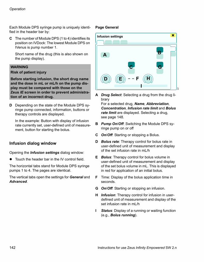
Operation
142 Instructions for use Zeus Infinity Empowered SW 2.n
Each Module DPS syringe pump is uniquely identi-fied in the header bar by:
C The number of Module DPS (1 to 4) identifies its position on IVDock: The lowest Module DPS on IVenus is pump number 1.
Short name of the drug (this is also shown on the pump display).
D Depending on the state of the Module DPS sy-ringe pump connected, information, buttons or therapy controls are displayed.
In the example: Button with display of infusion rate currently set, user-defined unit of measure-ment, button for starting the bolus.
Infusion dialog window
Opening the Infusion settings dialog window:
Touch the header bar in the IV control field.
The horizontal tabs stand for Module DPS syringe pumps 1 to 4. The pages are identical.
The vertical tabs open the settings for General and Advanced.
Page General
A Drug Select: Selecting a drug from the drug li-braryFor a selected drug, Name, Abbreviation, Concentration, Infusion rate limit and Bolus rate limit are displayed. Selecting a drug, see page 148.
B Pump On/Off: Switching the Module DPS sy-ringe pump on or off
C On/Off: Starting or stopping a Bolus.
D Bolus rate: Therapy control for bolus rate in user-defined unit of measurement and display of the set infusion rate in mL/h
E Bolus: Therapy control for bolus volume in user-defined unit of measurement and display of the set bolus volume in mL. This is displayed in red for application of an initial bolus.
F Time: Display of the bolus application time in seconds.
G On/Off: Starting or stopping an infusion.
H Infusion: Therapy control for infusion in user-defined unit of measurement and display of the set infusion rate in mL/h
I Status: Display of a running or waiting function (e.g., Bolus running).
WARNINGRisk of patient injury
Before starting infusion, the short drug name and the dose in mL or mL/h on the pump dis-play must be compared with those on the Zeus IE screen in order to prevent administra-tion of an incorrect drug.
347
Infusion settings
A B
C
D E F
G
HI

Instructions for use Zeus Infinity Empowered SW 2.n 143
Operation
Page Advanced
Page for the setting limits of infusion and bolus ad-ministration
J Max.bol.rate: Limits the bolus rate saved in the profile.*Therapy control for the maximum bolus rate in user-defined unit of measurement and display of the set maximum bolus rate in mL/h
K Bolus: Therapy control for the bolus in user-de-fined unit of measurement and display of the set Bolus in mL. This is displayed in red for applica-tion of an initial bolus.
L Bolus rate: Therapy control for bolus rate in user-defined unit of measurement and display of the set infusion rate in mL/h
M Bolus time: Display of the Bolus application time in seconds.
N Max.inf.rate: Limits the infusion rate saved in the profile.Therapy control for the maximum infusion rate in user-defined unit of measurement and dis-play of the set maximum infusion rate in mL/h
O Infusion: Therapy control for infusion in user-defined unit of measurement and display of the set infusion rate in mL/h
Setting parameters:
1 Touch the therapy control of the respective pa-rameter.
2 Use the rotary knob to set and confirm the value.
The set values are transferred to the system.
Starting the Module DPS on Zeus IE
Prerequisite:
Suitable drug settings have been loaded with the profile setup or selected from the Infusion settings dialog window.
Switching on the Module DPS
If a Module DPS syringe pump which is switched off is connected to Zeus IE:
Touch the Start pump button (A).
Or
In the Infusion settings (see page 142) dialog window, touch the Pump On button.
Confirm with the rotary knob.
The Module DPS syringe pump is switched on. Zeus IE checks information from the syringe pump being used. The default values are set.
348
* Bolus rate = speed of bolus administration
J K
L
M
N
O
Infusion settings
491
1 ATRAC
A

Operation
144 Instructions for use Zeus Infinity Empowered SW 2.n
Confirming the syringe
Zeus IE prompts the user to confirm the syringe, which is being used on the Module DPS syringe pump (size and make):
1 Confirm syringe at pump .
The LED in the (B) button on the syringe pump flashes in green.
2 Press the (B) key.
The LED continues to flash in green.
Confirming the drug
Zeus IE prompts the user to confirm the drug being used on the Module DPS:
1 Confirm drug at pump .
The LED in the (B) button on the syringe pump flashes in green.
2 Press the (B) key.
The LED continues to flash in green.
An infusion or a bolus application can be com-menced only after the syringe size and the drug have been confirmed on the syringe pump and after visual inspection of the assigned Module DPS sy-ringe pump on Zeus IE.
Administering an infusion
The Check patient and pump settings! dialog window appears if:
– There is a change of patient via system standby.– The syringe barrel clasp (flap) has been opened
and all the pumps have stopped.– A pump which is stopped is connected to
Zeus IE.– A pump which is running is connected to
Zeus IE.
Starting the infusion
Touch the Start infusion button (A).
Or
In the Infusion settings (see page 142) dialog window, touch the On button for the Infusion.
The LED in the (B) button on the syringe pump goes out and the infusion starts.
270B
463
1 ATRAC
A

Instructions for use Zeus Infinity Empowered SW 2.n 145
Operation
Checking patient data/weight
Before starting the first infusion, check the patient weight entered and correct if necessary. The indi-vidual IV deliveries are related to that weight.
Checking the patient and pump settings
The device prompts the user to check the following patient and IV settings:– Patient weight– Number of Module DPS syringe pumps– Drug name– Abbreviation– Concentration– Bolus volume (This is displayed in red during an
initial bolus.)– Infusion rate– Bolus rate– Bolus time
A new drug can be selected for each syringe pump:
Touch the Change drug button (A).
For each syringe pump, the delivery can be limited to mL/h (B), if there is no appropriate drug in the drug library:
1 Touch the respective button.
2 Use the rotary knob to set and confirm the value.
The set values are transferred to the system.
Entering the infusion rate and starting the infu-sion
1 Touch the Start infusion button (A).
The therapy control (B) for the infusion rate is dis-played with the preset value.
2 Use the rotary knob to set and confirm the value.
Infusion is started. The selected metering rate is displayed on the button (A).
In the infusion dialog, the infusion rate can be ad-justed without simultaneously starting infusion, see page 142.
WARNINGRisk of patient injury
When the pump settings are displayed, check the patient data and/or IV settings on the sy-ringe pump and on Zeus IE to eliminate the risk of incorrect settings.
464
4
3
2
1
Check patient and pump settings!
A B
467
CAUTIONA very heavy patient weight can lead to infusion rates of more than 1200 mL/h when converting the weight-based metering rate. 1200 mL/h is the maximum infusion rate that can be set on Zeus IE, depending on syringe size.
A
B
1 ATRAC 1 ATRAC

Operation
146 Instructions for use Zeus Infinity Empowered SW 2.n
Extreme settings on the syringe pump, which lead to a delivery rate of >1200 mL/h, may under certain circumstances be a departure from the set range of the infusion therapy control or bolus therapy control. This is indicated on the therapy control by > max.
Check concentration and weight setting, and adjust if necessary. Select suitable metering.
Syringe change
If the content of a syringe is used up completely during the course of an infusion, it can be replaced with another syringe filled with the same drug when the syringe pump is on. The simultaneous replace-ment of syringe and drug is described on page 148.
Stopping the infusion
1 Touch the Start infusion button (A).
The therapy control (B) for the infusion rate is dis-played with the preset value.
2 Set 0 with the rotary knob and confirm.
Infusion is stopped.
Stopping the infusion in the Infusion settings dialog window
Touch the Off button (C) and confirm with rotary knob.
If an infusion is restarted, the infusion rate value last set is displayed on the therapy control.
Administering a bolus
A bolus can be started after switching on a Module DPS syringe pump or during an infusion. The initial bolus is displayed in red.
After the second bolus and after transporting the Module DPS to Zeus IE, the maintenance bolus is loaded. If the bolus is changed for the maintenance bolus, that dose is loaded and administered for the following maintenance boluses.
Checking patient data/weight
Before starting the initial bolus, the correct patient weight must be entered as when starting a first in-fusion, see page 144.
Starting a bolus
Touch the Start bolus button (A).
Or
In the Infusion settings (see page 142) dialog window, touch the On button for the Bolus.
347
Infusion settings
C
463
ATRAC1
A

Instructions for use Zeus Infinity Empowered SW 2.n 147
Operation
Setting bolus
1 Touch the Start bolus button (A).
The therapy control (B) for the bolus volume is dis-played with the preset value.
2 Use the rotary knob to set and confirm the value.
The bolus starts.
The set value for the bolus is displayed. The pump symbol indicates the Bolus running function by displaying a moving plunger head.
If a bolus is started during an infusion, infusion con-tinues after the end of the bolus.
Stopping a bolus
Touch the Stop bolus button (C) and confirm.
Bolus administration stops. Infusion stops.
Stopping the infusion in the Infusion settings dialog window
Touch the Off button (D) and confirm with rotary knob.
If bolus administration has not finished, the remain-ing quantity is administered when the bolus is re-started.
If the application time of the bolus is >180 seconds, a dialog window appears, see page 141.
465
ATRAC1
B
466
347
C
ATRAC1
D
Infusion settings

Operation
148 Instructions for use Zeus Infinity Empowered SW 2.n
Select drug
The selectable drugs are stored in the drug library, see page 149.
In the Infusion settings > General dialog window:
1 Touch the Select button (A) and confirm with ro-tary knob.
The Select drug dialog window will be opened.
The drug list (B) shows all the drugs stored with the following information:
– Name – Abbreviation
2 Select a drug from the drug list (B) using the ro-tary knob.
The settings (C) for the drug selected are displayed alongside the drug list:
– Concentration – Bolus rate – Maximum bolus rate – Bolus rate limit – Infusion rate – Maximum infusion rate – Infusion rate limit – Initial bolus – Maintenance bolus
3 Press rotary knob.
The drug selected is applied. The dialog window closes.
Simultaneous replacement of syringe and drug
If an empty syringe is replaced with a syringe filled with another drug during the course of an infusion:
1 Remove the empty syringe from the pump.
2 Select the drug on Zeus IE.
3 Insert new syringe.
4 Confirm the new drug on the syringe pump.
347
422
A
Infusion settings
Select drug
B
C

Instructions for use Zeus Infinity Empowered SW 2.n 149
Operation
Drug library
The drug data is managed in the drug library. Ac-cess is access code-protected, see "Drug library" on page 344.
In the Basic settings dialog window:
1 Touch the Drug library tab (A).
The dialog window to enter the access code for the drug library appears.
2 Enter access code for the drug library and con-firm.
The Drug library dialog window will be opened.
B Drug list with the following information:– Name – Abbreviation
C The settings for the drug selected are displayed alongside the drug list:
– Concentration – Bolus rate – Maximum bolus rate – Bolus rate limit – Infusion rate – Maximum infusion rate – Infusion rate limit – Initial bolus – Maintenance bolus – Last modified
D The Delete, Edit, and Add buttons are used to change the settings for drugs.
E The Import and Export buttons are used to save drug library data to USB storage media and from to load this data into another Zeus IE.
423
425
Basic settings
A
Drug library
B
C
D E
CAUTIONComputer viruses
Mass storage devices can contain computer vi-ruses which can impair the operation of Zeus IE.– Check mass storage devices for computer vi-
ruses before using them with Zeus IE.– Do not use any mass storage device contain-
ing computer viruses with Zeus IE.

Operation
150 Instructions for use Zeus Infinity Empowered SW 2.n
Basic setting
Touch the Edit button (D).
The Drug editor dialog window will be opened.
Touch the General settings tab (F).
The basic drug settings are displayed:G NameH AbbreviationI ConcentrationJ Concentration unit: µg/mL, mg/mLK Quantity unit: mL, mg, µg/kg, mg/kgL Time unit: min, h
Setting dose
Touch the Dose settings tab (M).
The infusion and bolus delivery settings are dis-played:N Infusion rate (mL/h)O Maximum infusion rate (mL/h)P Initial bolus (mL)Q Maintenance bolus (mL)R Bolus rate (mL/h)S Maximum bolus rate (mL/h)
Units can be defined by the user and may vary.
426
NOTEIf a drug is stored in a profile, the abbreviation cannot be changed. The drug must first be re-moved from the profile.
Drug editor
F
GH
IJ
K
L
427
M
N
O
P
Q
R
S
Drug editor

Instructions for use Zeus Infinity Empowered SW 2.n 151
Operation
Setting the limits
Touch the Limit settings tab (T).
The infusion and bolus limit settings are displayed:U Infusion rate limit (mL/h)V Bolus rate limit (mL/h)
Units can be defined by the user and may vary.
Color
Touch the Color tab (W).
The color coding settings of the respective drug are displayed.
428
NOTEThese limits cannot be changed during operation
Delivery beyond these set limits is possible. A vi-olation of these limits is announced.
T
U V
Drug editor
429
Drug editor
W

Operation
152 Instructions for use Zeus Infinity Empowered SW 2.n
Adding new drugs
Touch the Add button in the Drug library dialog window.
The Drug editor dialog window will be opened.
Entering basic drug data:
1 Touch the Name button (X). A keyboard window opens.
2 Use the BackSp button in the keyboard window to delete the placeholder No drug.
3 Enter name and confirm with the rotary knob.
If the name entered is not accepted, there is al-ready a drug with this name in the drug library. Choose a new name.
Zeus IE offers an abbreviation (Y) for the drug name. The abbreviation for the drug name must be unique. 5 characters (letters, numbers) must be en-tered. Do not use special characters!Examples:– PROP1 = Propofol 1 %– PROP2 = Propofol 2 %
Entering a new abbreviation:
4 Touch the Abbreviation button (Y). A keyboard window opens.
5 Use the BackSp button in the keyboard window to delete the placeholder for the abbreviation.
6 Enter name and confirm with the rotary knob.
7 Set and confirm Concentration (Z) values with the rotary knob.
8 Touch the Concentration unit required and confirm with the rotary knob.
Setting the dose for the new drug:
Touch the Dose settings tab (M).
The infusion and bolus delivery settings are dis-played.
1 Touch the buttons of the respective parameters.
2 Use the rotary knob to set and confirm the value.
426
Drug editor
XY
Z
WARNINGRisk of patient injury
If the same drug has different concentrations, e.g., Propofol 1 % or Propofol 2 %, an unam-biguous name and abbreviation must be se-lected.
427
MDrug editor

Instructions for use Zeus Infinity Empowered SW 2.n 153
Operation
Editing a drug
In the Drug library dialog window:
1 Select a drug from the list using the rotary knob.
2 Touch the Edit button.
3 Edit settings in the basic data and deliveries and confirm with the rotary knob.
If you make changes to drugs which are stored in a profile, the modified data from the drug library is transferred to the profile.
Deleting a drug
In the Drug library dialog window:
1 Select a drug from the list using the rotary knob.
2 Touch the Delete button and confirm with rotary knob.
The drug is deleted.
Drug library import/export
In the Drug library dialog window:
1 Touch the Export or Import button.
2 Insert USB storage media and follow the in-structions in the dialog window, see page 149.
3 Confirm with rotary knob.
Module DPS – transport concept
If a Module DPS syringe pump which is switched on is plugged into the IVDock, the syringe pump set-tings are applied by Zeus IE, even if a new patient is loaded.
CAUTIONRisk of patient injury
After transferring a drug library, check the drug configurations to eliminate the risk of incorrect settings.
NOTEThe basic configurations of the pumps may be partially changed when connecting to Zeus IE. The changes to the basic configurations are pre-served even after disconnection from Zeus IE. They can be manually reset on the pump if re-quired (see instructions for use for the Module DPS).
NOTEThe data for the manual bolus are not automati-cally adopted in the trend display for IV data if:– a manual bolus is started via the syringe pump
while Zeus is still in General Standby
or– the syringe pump has not yet been remotely
operated by the Zeus.
Only when the pump has been confirmed on Zeus, the data from manually started boluses will be adopted into the trend memory.

Operation
154 Instructions for use Zeus Infinity Empowered SW 2.n
Displaying infusion trends
Open Trends/Data dialog window, see page 184.
Touch the Infusion tab (A).
The information about infusions which have already been administered and ones which are still running is displayed.
Graphic trend display
After touching the Infusion tab (A), the Graph. trend page (B) is preselected.
The following graphic trends for syringe pumps 1 to 4 are displayed from top to bottom:– InfR 1 to InfR 4– administered volume Vtot
The scaling limits are:
– Maximum infusion rate – Maximum bolus rate
For each Module DPS syringe pump, the current data is, relating to the position of the cursor, indi-cated as a numerical value next to the graphic trend displays:– Name and Concentration– Selected infusion– Delivery rate– Volume actually administered Vtot
Adapting scalings to the maximum values adminis-tered:
Touch the Auto scale button (C).
Displaying the cursor with time information:
1 Touch the Cursor button (D).
2 Move cursor by turning the rotary knob.
The zoom function is used to change the time win-dow shown:
Touch the Zoom + / Zoom - (E)/(F) button.
Tabular trend display
Open tabular display of the data from syringe pumps 1 to 4:
Touch the Tab. trend button (G).
Select Interval [min] for creating a new row in the table:
Touch the corresponding button (H) (1, 2, 3, 5, 10, 15, 30 min).
351
1200
0
1200
0
1200
0
1200
0
1
2
3
4
ATrends/Data
B
CDEF
353
Trends/Data
G
H
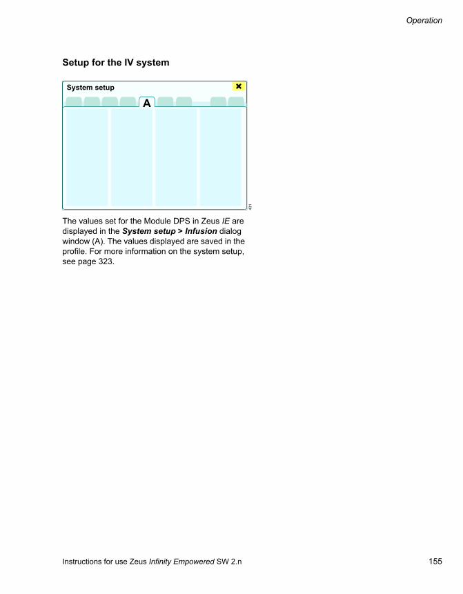
Instructions for use Zeus Infinity Empowered SW 2.n 155
Operation
Setup for the IV system
The values set for the Module DPS in Zeus IE are displayed in the System setup > Infusion dialog window (A). The values displayed are saved in the profile. For more information on the system setup, see page 323.
431
System setup
A

Operation
156 Instructions for use Zeus Infinity Empowered SW 2.n
End of operation
Switching Zeus IE into system standby
1 Touch the Start/Standby button (A).
All settings previously modified in operation are preserved.
The System standby? dialog window will be opened.
2 Confirm Stop ventilation? button (B) with ro-tary knob.
Or continue ventilation:
Close dialog window.
Pressing the rotary knob automatically switches the device to the system standby screen.
System standby is the standby mode in which:– Fresh gas is switched off– Quick start dialog window appears– Electrical power consumption is minimal– Operation can be resumed quickly– The device can be switched off
Switching off Zeus IE
1 Touch the On/Off button (C).
The Shut down? dialog window will be opened.
469
300
System standby?
A
B
Standby
Standby
050
O2 Air N2O O2 Air N2O
C

Instructions for use Zeus Infinity Empowered SW 2.n 157
Operation
2 Touch the Shut down button (D).
The system shuts down.
3 Close O2 emergency delivery if necessary.
If the device is in system standby for longer than 90 minutes, the Zeus IE may need a warm-up phase of 3 minutes before anesthetic agent deliv-ery can resume.
When Zeus IE is not in use
Leave the device connected to the mains sup-ply. The green LED with the symbol sym-bol lights up.
1 Close the backup gas cylinders (if used).
2 Disconnect supply hoses from the central sup-ply, roll up and hang over the storage place on the back of the device.
3 Pull the connector of the anesthetic gas scav-enging system out of the wall socket.
4 Pull off the hose of the anesthetic gas scaveng-ing system.
Without connection to the mains supply
307
WARNINGRemove gas supply hoses from the wall termi-nal units (central supply).
If the gas supply hoses remain connected to the wall terminal units, even minor internal leaks may lead to contamination of the supply gases.
NOTEAs the DIVA metering modules cool down slowly (when using desflurane), metering accuracy is temporarily reduced if Zeus IE is shut down and put back into operation immediately.
Shut down?
D
NOTECharge the battery at least every 4 weeks or else there will be no uninterruptible power supply avail-able when the device is put into operation, see page 58.

158 Instructions for use Zeus Infinity Empowered SW 2.n
This page was intentionally left blank.

Instructions for use Zeus Infinity Empowered SW 2.n 159
Alarms
Alarms
Alarm behaviour at power on . . . . . . . . . . . . 160
Display alarms . . . . . . . . . . . . . . . . . . . . . . . . 160
Alarm priorities and signals . . . . . . . . . . . . . . . 160
Alarm info . . . . . . . . . . . . . . . . . . . . . . . . . . . . 161
Alarm log . . . . . . . . . . . . . . . . . . . . . . . . . . . . . 161
Alarm limits . . . . . . . . . . . . . . . . . . . . . . . . . . . 162
Calling up via limit violations during operation. . . . . . . . . . . . . . . . . . . . . . . . . . . . . . 162Calling up via the alarm message field. . . . . . . 162Non-invasive patient monitoring (optional) . . . . 163Invasive blood pressure monitoring (optional). . . . . . . . . . . . . . . . . . . . . . . . . . . . . . 163Ventilation. . . . . . . . . . . . . . . . . . . . . . . . . . . . . 164Anesthesia . . . . . . . . . . . . . . . . . . . . . . . . . . . . 164Infusion (optional) . . . . . . . . . . . . . . . . . . . . . . . 165
Suspending alarms . . . . . . . . . . . . . . . . . . . . 166
Direct suspension of alarms using buttons in the main menu bar . . . . . . . . . . . . . . . . . . . . 166
Alarm recorder (optional with hemodynamic and Infinity network) . . . . . . . 167
All limits. . . . . . . . . . . . . . . . . . . . . . . . . . . . . . 168
Hemodynamics. . . . . . . . . . . . . . . . . . . . . . . . . 168BP. . . . . . . . . . . . . . . . . . . . . . . . . . . . . . . . . . . 169Other BPs. . . . . . . . . . . . . . . . . . . . . . . . . . . . . 169Arrhythmia . . . . . . . . . . . . . . . . . . . . . . . . . . . . 170Anesthesia . . . . . . . . . . . . . . . . . . . . . . . . . . . . 170Infusion. . . . . . . . . . . . . . . . . . . . . . . . . . . . . . . 171
Autoset limits . . . . . . . . . . . . . . . . . . . . . . . . . 172
Setting Autoset limits for the Hemodyn. area . . 173Setting Autoset limits for the IBP area . . . . . . . 173Setting Autoset limits for the Anesth./ Ventilation area. . . . . . . . . . . . . . . . . . . . . . . . . 173Adjusting the lower and upper limit values according to set points and patient demographic data. . . . . . . . . . . . . . . . . . . . . . . 174
Suppressing the alarm tone . . . . . . . . . . . . . 177
Set ranges of the patient monitoring alarm limits. . . . . . . . . . . . . . . . . . . . . . . . . . . 179
Device-related . . . . . . . . . . . . . . . . . . . . . . . . . 179Patient-related . . . . . . . . . . . . . . . . . . . . . . . . . 180Arrhythmia detection . . . . . . . . . . . . . . . . . . . . 182
Trends and diagnosis windows . . . . . . . . . . 184

Alarms
160 Instructions for use Zeus Infinity Empowered SW 2.n
Alarm behaviour at power on
After switching from system standby to operation, all non-technical alarms are deactivated for one minute to allow sufficient time to select a suitable setting.
Display alarms
The alarm messages appear in the alarm message field (A) of the header bar.
If more alarms occur simultaneously than can be displayed in the alarm message field, the All alarms button (B) is displayed for further alarms.
Touch the All alarms button.
The Alarms >Alarm info dialog window opens. In-formation about all currently active alarms appears.
Alarm priorities and signals
Different background colors in the alarm message field identify the priority of active alarm messages. The alarm-related parameter e.g., (C), flashes in the color based on the alarm priority.
Alarms of highest priority
– The alarm message requires immediate action.
– Text on a red background
– The corresponding parameter flashes
– Continuous tone sequence
Medium-priority alarms
– The alarm message requires immediate action.
– Text on a yellow background
– The corresponding parameter flashes
– A tone sequence sounds every 30 seconds
Alarms of lower priority
– The alarm messages require attention and, if necessary, action.
– Text on a cyan-colored background
– Single tone sequence
301
1:35AB
C

Instructions for use Zeus Infinity Empowered SW 2.n 161
Alarms
Alarm info
Touch alarm message field.
The Alarms >Alarm info dialog window (A) opens with all currently active alarm messages.
All current alarms are listed in chronological order with the following information:B DurationC PrioD AlarmsE Alarm limitsF CauseG RemedySee also alarm messages from page 255.
Alarm log
The alarm log records all alarm messages that have occurred, but are no longer active in chrono-logical order (maximum 200).
Touch the Alarm log tab (A).
All alarms that occur are listed in chronological or-der with the following information:B DateC Time D PriorityE Patient alarmsE Technical alarms
See also alarm messages from page 255.
The Graph.trend (G) and Tab. trend (H) buttons open the dialog windows for trend display as a curve or table at the time of the selected alarm.
The alarm log is cleared:– At the start of a new case– When switching on the system– In the event of a total power failure of more than
5 min (after the batteries are empty)
356
!!!
!!!
!!
Alarms
AB C D E
F G35
8
!!!
!!!
!!
!!!!
!
!!
!
!!
Alarms
AB C E F
G H
D

Alarms
162 Instructions for use Zeus Infinity Empowered SW 2.n
Alarm limits
Calling up via limit violations during op-eration
If limit violations occur during operation, the corre-sponding parameter flashes, e.g., (A).
1 Touch the respective parameter field.
The Sensors/Parameters dialog window will be opened.
2 Touch the button.
The Alarms > Alarm limits dialog window opens for the parameter selected.
3 Touch the button of the alarm limit to be modi-fied. The button turns yellow.
4 Set the required value by turning the rotary knob and push to confirm.
Or
1 Touch the Alarms button (C).
The Alarms > Alarm limits dialog window ap-pears. The alarm-related limit is preselected, the button is yellow.
2 Set the required value by turning the rotary knob and push to confirm.
Calling up via the alarm message field
Touch alarm message field (B).
The Alarms dialog window will be opened.
Touch the Alarm limits tab (D).
The Alarm limits dialog window will be opened. The vertical tabs (E) lead to the different user con-figurations.
The following user configurations (E) with the cor-responding upper (F) and lower (G) alarm limits can be displayed:– Noninvasive (optional)– Invasive (optional)– Ventilation – Anesth. – Infusion (optional)
1 Touch the vertical tab of the user configuration of the alarm limit to be modified.
2 Touch the button of the alarm limit to be modi-fied. The button turns yellow.
301
1:35
A
BC
359
WARNINGRisk of patient injury
The user must set the alarm limits according to the patient and activate if necessary. Other-wise, there is a risk that patient monitoring is not ensured.
DAlarms
FG
EH

Instructions for use Zeus Infinity Empowered SW 2.n 163
Alarms
3 Set the required value by turning the rotary knob and push to confirm.
The graphic displays a 30-minute trend of the alarm-related parameter. The broken lines (H) in the graphic represent the alarm limits and are moved accordingly.
If the alarm limit of the parameter is being moni-tored, the color of the button is dark green – other-wise it is bright green.
Non-invasive patient monitoring (op-tional)
Touch the Noninvasive button (A).
The following upper and lower alarm limits can be configured:B HR (heart rate)C SpO2 (blood oxygen saturation)D NIBP S/NIBP D/NIBP M
Blood pressure depending on the set parame-ter: S, D, or M
E T1 (temperature, measuring point 1)F T2 (temperature, measuring point 2)G TBlood (blood temperature)
monitored for C.O. measurementH NMT (TOF count)I BIS (BIS index)
Invasive blood pressure monitoring (op-tional)
Touch the Invasive button (A).
The alarm limits can be configured depending on the selected parameter (B) S, D or M. Only the alarm limits of the blood pressure sensors currently connected are shown.
359
Alarms
A
B C D E F G H I
360
Alarms
A
B

Alarms
164 Instructions for use Zeus Infinity Empowered SW 2.n
Ventilation
Touch the Ventilation button (A).
The following upper and lower alarm limits can be configured:B etCO2 (Endexpiratory CO2 content of the
breathed air)C inCO2 (Inspiratory CO2 content of the breathed
air)D FiO2 (Inspiratory O2 content of the breathed air)E MVe (Expiratory minute volume)F VTi (Inspiratory tidal volume)G Paw (airway pressure)H Brody Factor
Leakage detection in closed operation, see "Set ranges of the patient monitoring alarm limits" on page 179.
The alarm limits set are displayed on the wave-forms as a broken line.
Anesthesia
Touch the Anesth. button (A).
The following upper and lower alarm limits can be configured:B Inspiratory N2O content of the breathed air
(inN2O) These buttons only appear if N2O is se-lected as the carrier gas.
C Inspiratory anesthetic agent content of the breathed air (depending on the selected anes-thetic agent, e.g., inIso).
361
Alarms
A
B C D E F G H
362
Alarms
AB C

Instructions for use Zeus Infinity Empowered SW 2.n 165
Alarms
Infusion (optional)
Touch the Infusion button (A).
The upper alarm limits are only displayed if the sy-ringe pumps are connected to Zeus IE.
The following upper alarm limits can be configured:B Infusion pressureC Infusion volume
KVO function*
If the KVO function is activated in the syringe pump, the syringe pump does not shut down if the upper alarm limit for the infusion volume is exceeded. KVO appears on the pump display. The infusion continues at a low infusion rate. The syringe pump cannot be remote-controlled.
1 Switch off syringe pump.
2 Increase volume alarm limit on Zeus IE.
3 Switch syringe pump back on.
479
* Keep Vein Open
1
Alarms
AB C
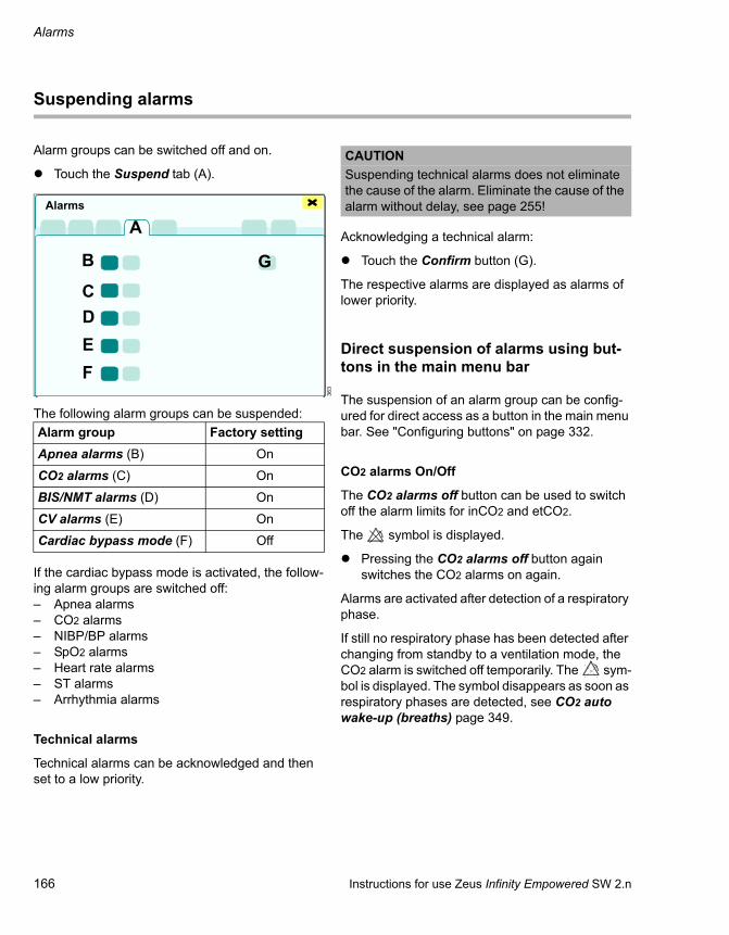
Alarms
166 Instructions for use Zeus Infinity Empowered SW 2.n
Suspending alarms
Alarm groups can be switched off and on.
Touch the Suspend tab (A).
The following alarm groups can be suspended:
If the cardiac bypass mode is activated, the follow-ing alarm groups are switched off:– Apnea alarms– CO2 alarms– NIBP/BP alarms– SpO2 alarms– Heart rate alarms– ST alarms– Arrhythmia alarms
Technical alarms
Technical alarms can be acknowledged and then set to a low priority.
Acknowledging a technical alarm:
Touch the Confirm button (G).
The respective alarms are displayed as alarms of lower priority.
Direct suspension of alarms using but-tons in the main menu bar
The suspension of an alarm group can be config-ured for direct access as a button in the main menu bar. See "Configuring buttons" on page 332.
CO2 alarms On/Off
The CO2 alarms off button can be used to switch off the alarm limits for inCO2 and etCO2.
The symbol is displayed.
Pressing the CO2 alarms off button again switches the CO2 alarms on again.
Alarms are activated after detection of a respiratory phase.
If still no respiratory phase has been detected after changing from standby to a ventilation mode, the CO2 alarm is switched off temporarily. The sym-bol is displayed. The symbol disappears as soon as respiratory phases are detected, see CO2 auto wake-up (breaths) page 349.
363
Alarm group Factory settingApnea alarms (B) On
CO2 alarms (C) On
BIS/NMT alarms (D) On
CV alarms (E) On
Cardiac bypass mode (F) Off
Alarms
A
B
CDEF
G
CAUTIONSuspending technical alarms does not eliminate the cause of the alarm. Eliminate the cause of the alarm without delay, see page 255!

Instructions for use Zeus Infinity Empowered SW 2.n 167
Alarms
Alarm recorder (optional with hemodynamic and Infinity network)
Select alarms for which the alarm recorder auto-matically starts when they occur.
Touch the Alarm recorder tab (A).
B Recorder triggersSelection of alarms that start the alarm recorder
C Recorder config.Specification of the alarm recorder parameters
Calling up Recorder triggers:
1 Touch the Recorder triggers tab (B).
2 The arrow keys ( ) are used to add or re-move available Trigger alarms (D) for the alarms Active triggers (E).
3 Use the Apply changes button (F) to confirm the changes.
Calling up Recorder config.:
1 Touch the Recorder config. tab (C).
The following settings can be configured:G Record alarms: OFF/ONH Recorder speedI Recorder delayJ DurationK Waveform 1L Waveform 2M Alarm waveform: OFF/ON
2 Adjust settings.
3 Use the rotary knob to set and confirm the value.
4 Use the Apply changes button (N) to confirm the changes.
WARNINGNational and international standards specify minimum monitoring with alarm functions. These regulations may not be complied with if the alarm function of the monitoring parame-ter etCO2 is disabled!
357
Alarms
ABC
D E
F 364
Alarms
GHIJKLM N
A
C

Alarms
168 Instructions for use Zeus Infinity Empowered SW 2.n
All limits
Settings of all alarm limits
Alarm limits not currently required can also be set.
Touch the All limits tab (A).
Alarm limits can be set for the following areas:– Hemodyn. (optional)– IBP (optional)– More IBP (optional)– Arrhythmia (optional)– Anesth.– Infusion (optional)
1 Touch the tab (B) of the respective area.
2 Touch the button of the alarm limit to be modi-fied. The button turns yellow.
3 Set the required value by turning the rotary knob and push to confirm.
Hemodynamics
Touch the Hemodyn. tab (A).
The alarm limits of the following parameters can be configured:B HR (heart rate)C SpO2 (blood oxygen saturation)D NIBP S (systolic blood pressure)E NIBP D (diastolic blood pressure)F NIBP M (mean blood pressure)G T1 (temperature, measuring point 1)H T2 (temperature, measuring point 2)I TBlood (blood temperature)J Brady (bradycardia)
Setting the detection threshold for bradycardia (only in the Neonates and Pediatrics patient cat-egories with ext. arrhythmia off)Factory setting: Off; 20 to 100 1/min
K ST LAT (ST lateral)L ST INF (ST inferior)M ST ANT (ST anterior)N NMT (TOF count)O BIS (BIS index)
365
A
B
Alarms
365
Alarms
AB C D E F G H I J
K L M N O

Instructions for use Zeus Infinity Empowered SW 2.n 169
Alarms
BP
Touch the IBP tab (A).
The alarm limits of the following parameters can be configured:B ART S (artery systolic blood pressure)C ART D (artery diastolic blood pressure)D ART M (mean artery blood pressure)E PA S (pulmonary artery systolic blood pressure)F PA D (pulmonary artery diastolic blood pres-
sure)G PA M (mean pulmonary artery blood pressure)H CVP M (mean central venous pressure)I GP1 S (non-specific systolic blood pressure)
(General Purpose)J GP1 D (non-specific diastolic blood pressure)
(General Purpose)K GP1 M (non-specific mean blood pressure)
(General Purpose)
Other BPs
Touch the More IBP tab (A).
The alarm limits of the following parameters can be configured:B LV S (left ventricular systolic blood pressure)C LV D (left ventricular diastolic blood pressure)D LV M (mean left ventricular blood pressure)E RV S (right ventricular systolic blood pressure)F RV D (right ventricular diastolic blood pressure)G RV M (mean right ventricular blood pressure)H LA M (mean pressure for left atrium)I RA M (mean pressure for right atrium)J GP2 S (other non-specific systolic blood pres-
sure) (General Purpose)K GP2 D (other non-specific diastolic blood pres-
sure) (General Purpose)L GP2 M (other non-specific mean blood pres-
sure) (General Purpose)M ICP M (mean intracranial pressure)N CPP M (cerebral perfusion pressure)
366
Alarms
AB C D E F G H
I J K
367
Alarms
AB C D E F G H I
J K L M N

Alarms
170 Instructions for use Zeus Infinity Empowered SW 2.n
Arrhythmia
Touch the Arrhythmia tab (A).
The following parameters can be configured de-pending on the option used:B Dual lead processing: Off/On.C Arrhythmia monitoring:
– Adv. (optional)– Basic – Off
Specify the settings for Rate and Count when an arrhythmia event is reported.
Setting the Rate
Touch button, set the required value and con-firm.
For ASY, VF and ARTF the rate cannot be changed.
Setting the Count
Touch button, set the required value and con-firm.
Set ranges, see "Set ranges of the patient monitor-ing alarm limits" on page 179
Anesthesia
Touch the Anesth. tab (A).
The alarm limits of the following parameters can be configured:B inN2O (Inspiratory N2O content of the breathed
air)C inHal (Inspiratory anesthetic agent concentra-
tion of the breathed air)D inEnf (Inspiratory anesthetic agent concentra-
tion of the breathed air)E inIso (Inspiratory anesthetic agent concentra-
tion of the breathed air)F inSev (Inspiratory anesthetic agent concentra-
tion of the breathed air)G inDes (Inspiratory anesthetic agent concentra-
tion of the breathed air)H etCO2 (Endexpiratory CO2 content of the
breathed air)I inCO2 (Inspiratory CO2 content of the breathed
air)J FiO2 (Inspiratory O2 content of the breathed air)K MVe (Expiratory minute volume)L VTi (Inspiratory tidal volume)M Paw (airway pressure)N Brody Factor
368
Alarms
A
V.tach>=
V.run>=
AIVR<=
SVT>=
Tach>=
Brady<=
Pause PVC
BC
369
WARNINGRisk of patient injury
The user must adjust maximum inspiratory VA concentration to suit the patient or else there is a risk of concentration levels being too high or too low.
Alarms
A
B C D E F G
H I J K L M N

Instructions for use Zeus Infinity Empowered SW 2.n 171
Alarms
Infusion
Touch the Infusion tab (A).
The upper alarm limits can be configured for all for syringe pumps:B Press. (Set pressure limit)C Vol. (Set volume limit)
Alarm limits not currently required are also dis-played, e.g., for pumps not plugged in.
350
1 2 3 4
Alarms
AB C
Set ranges for alarm limitsAlarm Setting range Factory default values
Pressure (mmHg)
100 to 1600 (5 and 10 mL syringe)
100 to 1500 (20 mL syringe)
100 to 1100 (50 mL syringe)
500
Volume (mL) 0 to 900 0
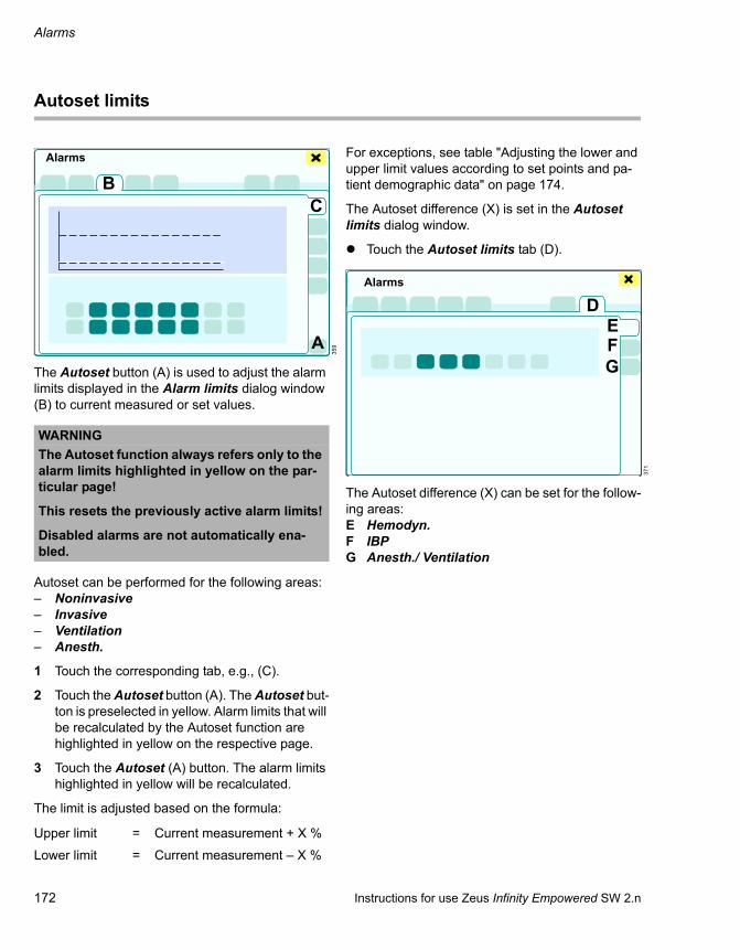
Alarms
172 Instructions for use Zeus Infinity Empowered SW 2.n
Autoset limits
The Autoset button (A) is used to adjust the alarm limits displayed in the Alarm limits dialog window (B) to current measured or set values.
Autoset can be performed for the following areas:– Noninvasive – Invasive – Ventilation – Anesth.
1 Touch the corresponding tab, e.g., (C).
2 Touch the Autoset button (A). The Autoset but-ton is preselected in yellow. Alarm limits that will be recalculated by the Autoset function are highlighted in yellow on the respective page.
3 Touch the Autoset (A) button. The alarm limits highlighted in yellow will be recalculated.
The limit is adjusted based on the formula:
For exceptions, see table "Adjusting the lower and upper limit values according to set points and pa-tient demographic data" on page 174.
The Autoset difference (X) is set in the Autoset limits dialog window.
Touch the Autoset limits tab (D).
The Autoset difference (X) can be set for the follow-ing areas:E Hemodyn.F IBPG Anesth./ Ventilation
359
WARNINGThe Autoset function always refers only to the alarm limits highlighted in yellow on the par-ticular page!
This resets the previously active alarm limits!
Disabled alarms are not automatically ena-bled.
Upper limit = Current measurement + X %
Lower limit = Current measurement – X %
Alarms
A
BC
371
Alarms
DEFG

Instructions for use Zeus Infinity Empowered SW 2.n 173
Alarms
Setting Autoset limits for the Hemodyn. area
Touch the Hemodyn. tab (A).
The following parameters can be configured:B HR (heart rate)C SpO2 (blood oxygen saturation)D NIBP S (systolic blood pressure)E NIBP D (diastolic blood pressure)F NIBP M (mean blood pressure)G T1 (temperature, measuring point 1)H T2 (temperature, measuring point 2)I TBlood (blood temperature, monitored for C.O.
measurement)
Setting Autoset limits for the IBP area
Touch the IBP tab (A).
The following parameters can be configured:B ART S, ART D, ART M (artery blood pressure
values)C PA S, PA D, PA M (pulmonary arterial blood
pressure values)D CVP M (mean central venous pressure)E GP1 S, GP1 D, GP1 M (non-specific (general
pressure) blood pressure values)F LV S, LV D, LV M (left ventricular blood pres-
sure values)G RV S, RV D, RV M (right ventricular blood pres-
sure values)H LA M (mean pressure for left atrium)I RA M (mean pressure for right atrium)J GP2 S, GP2 D, GP2 M (non-specific (general
pressure) blood pressure values)K ICP M (mean pressure for intracranial blood
pressure)
Setting Autoset limits for the Anesth./ Ventilation area
Touch the Anesth./ Ventilation tab (A).
The following parameters can be configured:B inN2O (inspiratory N2O content of the breathed
air)C inHal, inEnf, inIso, inSev, inDes (inspiratory
anesthetic agent concentration)D etCO2 (expiratory CO2 content)E MVe (expiratory minute volume)F Paw (airway pressure)
371
372
Alarms
AB C D E F G H I
Alarms
AB C D E
F G H I
J K
373
Alarms
AB C
D E F

Alarms
174 Instructions for use Zeus Infinity Empowered SW 2.n
Adjusting the lower and upper limit val-ues according to set points and patient demographic data
Alarm limit Algorithm Remark Default values (Range) forAdult2
Adult1
Ped2 Ped1 Neo1
Autoset IBP:ART S (mmHg)
see page 173 40 %(OFF, 20 to 80)
ART D (mmHg)
see page 173 40 %(OFF, 20 to 80)
ART M (mmHg)
see page 173 40 %(OFF, 20 to 80)
LV S (mmHg)
see page 173 40 %(OFF, 20 to 80)
LV D(mmHg)
see page 173 40 %(OFF, 20 to 80)
LV M (mmHg) see page 173 40 %(OFF, 20 to 80)
GP1 S, GP2 S (mmHg)
see page 173 40 %(OFF, 20 to 80)
GP1 D, GP2 D (mmHg)
see page 173 40 %(OFF, 20 to 80)
GP1 M, GP2 M (mmHg)
see page 173 40 %(OFF, 20 to 80)
PA S (mmHg) see page 173 40 %(OFF, 20 to 80)
PA D (mmHg) see page 173 40 %(OFF, 20 to 80)
PA M (mmHg)
see page 173 40 %(OFF, 20 to 80)
RV S (mmHg)
see page 173 40 %(OFF, 20 to 80)
RV D (mmHg)
see page 173 40 %(OFF, 20 to 80)
RV M (mmHg)
see page 173 40 %(OFF, 20 to 80)
CVP M (mmHg)
see page 173 40 %(OFF, 20 to 80)

Instructions for use Zeus Infinity Empowered SW 2.n 175
Alarms
LA M (mmHg)
see page 173 40 %(OFF, 20 to 80)
RA M (mmHg)
see page 173 40 %(OFF, 20 to 80)
ICP M (mmHg)
see page 173 40 %(OFF, 20 to 80)
Autoset Hemodynamics:ART S (mmHg)
see page 173 40 %(OFF, 20 to 80)
ART D (mmHg)
see page 173 40 %(OFF, 20 to 80)
ART M (mmHg)
see page 173 40 %(OFF, 20 to 80)
HR/PLS see page 173 40 %(OFF, 20 to 80)
SpO2 see page 173 A fixed value is set 100 %(fixed)
98 %(fixed)
SpO2 current value – X % absolute
absolute Autoset 5 % absolute (OFF, 2 to 10)
NIBP S see page 173 40 %(OFF, 20 to 80)
NIBP D see page 173 40 %(OFF, 20 to 80)
NIBP M see page 173 40 %(OFF, 20 to 80)
T1 see page 173 7 %(OFF, 5 to 20)
T2 see page 173 7 %(OFF, 5 to 20)
TBlood see page 173 7 %(OFF, 5 to 20)
Autoset ventilation/anesthesia:inN2O see page 173 40 %
(OFF, 20 to 80)
inHal see page 173 40 %(OFF, 20 to 80)
Alarm limit Algorithm Remark Default values (Range) forAdult2
Adult1
Ped2 Ped1 Neo1

Alarms
176 Instructions for use Zeus Infinity Empowered SW 2.n
inIso see page 173 40 %(OFF, 20 to 80)
inEnf see page 173 40 %(OFF, 20 to 80)
inDes see page 173 40 %(OFF, 20 to 80)
inSev see page 173 40 %(OFF, 20 to 80)
etCO2 see page 173 40 %(OFF, 20 to 80)
MVe MVe + X %(at least 2 L/min)
Volume-controlled:
MVe calculated from set points, otherwise from measured val-ues
40 %(20 to 80)
50 %(20 to 80)
MVe MVe – X % (at least 0.5 L/min)
Volume-controlled:
MVe calculated from set points, otherwise from measured val-ues
40 %(20 to 80)
50 %(20 to 80)
Paw PIP + X mbar Autoset with adjust-able absolute differ-ence in relation to PIP pressure
10 mbar (OFF, 5 to 20)
Alarm limit Algorithm Remark Default values (Range) forAdult2
Adult1
Ped2 Ped1 Neo1
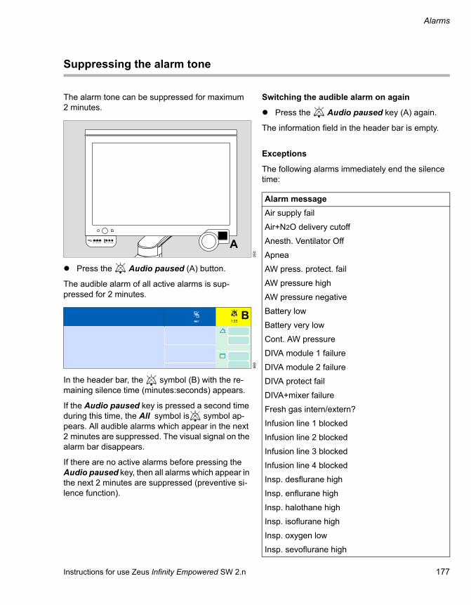
Instructions for use Zeus Infinity Empowered SW 2.n 177
Alarms
Suppressing the alarm tone
The alarm tone can be suppressed for maximum 2 minutes.
Press the Audio paused (A) button.
The audible alarm of all active alarms is sup-pressed for 2 minutes.
In the header bar, the symbol (B) with the re-maining silence time (minutes:seconds) appears.
If the Audio paused key is pressed a second time during this time, the All symbol is symbol ap-pears. All audible alarms which appear in the next 2 minutes are suppressed. The visual signal on the alarm bar disappears.
If there are no active alarms before pressing the Audio paused key, then all alarms which appear in the next 2 minutes are suppressed (preventive si-lence function).
Switching the audible alarm on again
Press the Audio paused key (A) again.
The information field in the header bar is empty.
Exceptions
The following alarms immediately end the silence time:
050
469
O2 Air N2O O2 Air N2O A
1:35 1:35B
Alarm messageAir supply fail
Air+N2O delivery cutoff
Anesth. Ventilator Off
Apnea
AW press. protect. fail
AW pressure high
AW pressure negative
Battery low
Battery very low
Cont. AW pressure
DIVA module 1 failure
DIVA module 2 failure
DIVA protect fail
DIVA+mixer failure
Fresh gas intern/extern?
Infusion line 1 blocked
Infusion line 2 blocked
Infusion line 3 blocked
Infusion line 4 blocked
Insp. desflurane high
Insp. enflurane high
Insp. halothane high
Insp. isoflurane high
Insp. oxygen low
Insp. sevoflurane high

Alarms
178 Instructions for use Zeus Infinity Empowered SW 2.n
Insp. vol. agent high
Internal safety fan failed
N2O supply fail
Oxygen supply fail
Power supply temp high
Pump 1 battery empty
Pump 1 failure
Pump 1 operation failed
Pump 2 battery empty
Pump 2 failure
Pump 2 operation failed
Pump 3 battery empty
Pump 3 failure
Pump 3 operation failed
Pump 4 battery empty
Pump 4 failure
Pump 4 operation failed
Remove DIVA module 1
Remove DIVA module 2
Safety O2 opened
Safety settings active
Syringe 1 empty
Syringe 2 empty
Syringe 3 empty
Syringe 4 empty
VA delivery failure
Ventilator failure
Alarm message

Instructions for use Zeus Infinity Empowered SW 2.n 179
Alarms
Set ranges of the patient monitoring alarm limits
Device-related
Alarm Setting range Default value of factory profileAdult 2 Adult 1 Ped 2 Ped 1 Neo 1
etCO2 (Vol.%) 0.1 to 9.9; Off 7
etCO2 (Vol.%) Off; 0 to 9.8 3
inCO2 (Vol.%) 0 to 1.4; Off 1
FiO2 (Vol.%) 19 to 100; Off Off 90
FiO2 (Vol.%) 18 to 99 20
inHal (Vol.%) 0.1 to 7.0 2.1
inHal (Vol.%) Off; 0 to 6.9 Off
inIso (Vol.%) 0.1 to 7.0 3.1
inIso (Vol.%) Off; 0 to 6.9 Off
inEnf (Vol.%) 0.1 to 9.9 4.3
inEnf (Vol.%) Off; 0 to 9.8 Off
inDes (Vol.%) 0.1 to 21.9 17.5
inDes (Vol.%) Off; 0 to 21.8 Off
inSev (Vol.%) 0.1 to 9.9 6 7 8
inSev (Vol.%) Off; 0 to 9.8 Off
N2O (Vol.%) 1 to 82 82
N2O (Vol.%) 0 to 81; Off Off
MVe (L/min) 0.1 to 39.0; Off Off
MVe (L/min) 0 to 38.9 4 0.8 0.2
Paw (mbar) 5 to 100 40 25 20
VTi (L/0.01) 0.02 to 2.0; Off 1.2 0.5 0.1
Brody Factor 1.5 to 5.0, Off 2.5

Alarms
180 Instructions for use Zeus Infinity Empowered SW 2.n
Patient-related
Alarm Setting range Default value of factory profileAdult 2 Adult 1 Ped 2 Ped 1 Neo 1
HR (1/min) 25 to 300 120 135 150 180
HR (1/min) 20 to 295 45 50 60 80
Brady Limit 20 to 100; Off – – 50 50 60
PVC (1/min) 1 to 50 50 50 50 50 –
ST (mm) –9.9 to 10 2
ST (mm) –10 to 9.9 –2
ART S (mmHg) 0 to 300 160 120 80
ART S (mmHg) –5 to 295 90 50
ART D (mmHg) 0 to 300 80 80 60
ART D (mmHg) –5 to 295 50 30 25
ART M (mmHg) 0 to 300 125 90 70
ART M (mmHg) –5 to 295 60 50 40
LV S (mmHg) 0 to 300 160
LV S (mmHg) –5 to 295 75
LV D (mmHg) 0 to 300 25
LV D (mmHg) –5 to 295 5
LV M (mmHg) 0 to 300 80
LV M (mmHg) –5 to 295 40
GP1 S, GP2 S (mmHg) 0 to 300 160 120
GP1 S, GP2 S (mmHg) –5 to 295 90 50
GP1 D, GP2 D (mmHg) 0 to 300 110 80
GP1 D, GP2 D (mmHg) –5 to 295 50 35
GP1 M, GP2 M (mmHg) 0 to 300 125 85
GP1 M, GP2 M (mmHg) –5 to 295 60 40
PA S (mmHg) 0 to 120 35
PA S (mmHg) –5 to 115 10
PA D (mmHg) 0 to 120 15
PA D (mmHg) –5 to 115 5
PA M (mmHg) 0 to 120 20
PA M (mmHg) –5 to 115 10
RV S (mmHg) 0 to 120 35

Instructions for use Zeus Infinity Empowered SW 2.n 181
Alarms
RV S (mmHg) –5 to 115 10
RV D (mmHg) 0 to 120 15
RV D (mmHg) –5 to 115 5
RV M (mmHg) 0 to 120 20
RV M (mmHg) –5 to 115 10
CVP M (mmHg) 0 to 120 20
CVP M (mmHg) –5 to 115 0
LA M (mmHg) 0 to 120 20
LA M (mmHg) –5 to 115 0
RA M (mmHg) 0 to 120 15
RA M (mmHg) –5 to 115 5
ICP M (mmHg) –20 to 120 20
ICP M (mmHg) –25 to 115 5
CPP M (mmHg) –20 to 300 100
CPP M (mmHg) –25 to 295 70
SpO2 71 to 100 100 95
SpO2 70 to 99 90 85
NIBP S (mmHg) Neo: 15 to 130Ped: 15 to 170Adult: 15 to 250
160 120 80
NIBP S (mmHg) Neo: 10 to 125Ped: 10 to 165Adult: 10 to 245
90 50 50
NIBP D (mmHg) Neo: 15 to 130Ped: 15 to 170Adult: 15 to 250
80 80 60
NIBP D (mmHg) Neo: 10 to 125Ped: 10 to 165Adult: 10 to 245
50 30 25
NIBP M (mmHg) Neo: 15 to 130Ped: 15 to 170Adult: 15 to 250
125 90 70
NIBP M (mmHg) Neo: 10 to 125Ped: 10 to 165Adult: 10 to 245
60 50 40
T1/T2 (°C) –4.9 to 50 39
Alarm Setting range Default value of factory profileAdult 2 Adult 1 Ped 2 Ped 1 Neo 1

Alarms
182 Instructions for use Zeus Infinity Empowered SW 2.n
Arrhythmia detection
T1/T2 (°C) –5 to 49.9 34
TBlood (°C) 25.1 to 43 39
TBlood (°C) 25 to 42.9 34
TOF-Count 1 to 4; Off 4
TOF-Count 0 to 3; Off 0
BIS 15 to 100; Off 100
BIS 0 to 95; Off 10
Alarm Setting range Default value of factory profileAdult 2 Adult 1 Ped 2 Ped 1 Neo 1
Alarm Setting range Resolu-tion/incre-
ment
Default value of factory profileAdult 2 Adult 1 Ped 2 Ped 1 Neo 1
ASYAlarm On/Off On On On On Off
Rate – – – – – –
Count – – – – – –
VFAlarm On/Off On On On On Off
Rate – – – – – –
Count – – – – – –
V.tachAlarm On/Off On On On On Off
Rate 100 to 200 10 ≥120 ≥120 ≥120 ≥120 –
Count 5 to 15 1 ≥10 ≥10 ≥10 ≥10 –
V.runAlarm On/Off On On On On Off
Rate 100 to 200 10 ≥120 ≥120 ≥120 ≥120 –
Count 3 to (VTcount –1) 1 3 to 9 3 to 9 3 to 9 3 to 9 –
AIVRAlarm On/Off On On On On Off
Rate 100 to 200(<VTcount –1)
10 119 119 119 119 –
Count count >3 3 3 3 3 –

Instructions for use Zeus Infinity Empowered SW 2.n 183
Alarms
SVTAlarm On/Off On On On On Off
Rate 120 to 200 10 150 150 150 150 –
Count 3 to 10 1 3 3 3 3 –
BGMAlarm On/Off On On On On Off
Rate – – – – –
Count n/a – – – – –
TachAlarm On/Off On On On On Off
Rate 100 to 200 10 130 130 130 130 –
Count n/a 8 8 8 8 –
BradyAlarm On/Off On On On On Off
Rate 30 to 105 5 50 50 50 50 –
Count n/a 8 8 8 8 –
PauseAlarm On/Off On On On On Off
Rate 1.0 to 3.5 0.5 2.5 2.5 2.5 2.5 –
Count n/a – – – – –
Alarm Setting range Resolu-tion/incre-
ment
Default value of factory profileAdult 2 Adult 1 Ped 2 Ped 1 Neo 1

Alarms
184 Instructions for use Zeus Infinity Empowered SW 2.n
Trends and diagnosis windows
Zeus IE saves measured values and trend data. Trends are displayed in graphic or tabular form and can be printed (with Infinity network option).
Printing graphic trend display
The graphic trend always starts with the current time and prints the entire trend from the time the pa-tient case started.
Printing tabular trend display
The entire trend with the selected interval time from the start of the patient case is printed.
Diagnosis windows
Measured values in different applications, arranged according to different parameters are saved and displayed in the Trends/Data dialog window.
Touch the Trends/Data button (A).
The Trends/Data dialog window will be opened.
Horizontal tabs open the diagnosis windows. Verti-cal tabs show graphic, tabular displays and other figures.
The following applications can be selected:B Overview
Trends of: HR, NIBP, ART, CVP, etCO2, i/e O2, SpO2, i/e VA, Paw, MV
C Hemodyn.Trends of: HR, ART, CVP, PLS, NIBP, PA, RA, SpO2, T1, T2, Pmean, C.O.
Cardiac calculat.: C.O., HR, ART M, CVP, PA M, PWP, CI, SV, SVI, SVR, SVRI, PVR, PVRI, LVSWI, RVSWI, BSAST view: inferior, lateral, anterior
D BIS/NMTTrends of: BIS, SQI, EMG, BSR, BCT, SEF, PWR, SNGL, TOF, TOFR, PTC
E InfusionTrends of: Infusion data (option, see page 154)
F Ventilat./ Oxygenat.Trends of: etCO2, MV, i/e O2, SpO2, Paw, C, R, RRmand, RRspon, VT
Resp. mech.: – Pressure: PIP, Plat, Mean, PEEP– Lung: Cdyn, R– Ventilator: Circle flow– Vol: MVe, VTi, VTe, RR, VTmand, RRmand,
MVespon, VTspon, RRspon
469
1:35 1:35
A
374
Trends/Data
B C D E F G H

Instructions for use Zeus Infinity Empowered SW 2.n 185
Alarms
G Gases/ Anesth.Trends of: xMAC, i/e VA, ART, NIBP, HR, N2O, O2 upt., RRspon, T NMT, TOF, SQI, BIS
Current flows:– Fresh-gas control: System closed– Current flows: O2, Air, N2O, Total– Injected anesth. agent (fl.)
Total consumpt.:– Gas amount since start: O2, Air, N2O– Volatile agent amount since start– Gas costs since start: O2, Air, N2O– Volatile agent costs since start
H SystemAutomatically opens the page Test details > Test history.

186 Instructions for use Zeus Infinity Empowered SW 2.n
This page was intentionally left blank.

Instructions for use Zeus Infinity Empowered SW 2.n 187
Monitoring
Monitoring
Overview of the monitoring . . . . . . . . . . . . . . 188
Device monitoring . . . . . . . . . . . . . . . . . . . . . 189
CO2. . . . . . . . . . . . . . . . . . . . . . . . . . . . . . . . . . 189Oxygen . . . . . . . . . . . . . . . . . . . . . . . . . . . . . . . 190Flow . . . . . . . . . . . . . . . . . . . . . . . . . . . . . . . . . 190Airway pressure Paw . . . . . . . . . . . . . . . . . . . . 192Anesthetic agent. . . . . . . . . . . . . . . . . . . . . . . . 193Loop displays . . . . . . . . . . . . . . . . . . . . . . . . . . 194Infusion. . . . . . . . . . . . . . . . . . . . . . . . . . . . . . . 196Display of the flow tubes. . . . . . . . . . . . . . . . . . 196O2 uptake / Uptake monitoring . . . . . . . . . . . . . 196
Patient monitoring . . . . . . . . . . . . . . . . . . . . . 197
Connection field for patient monitoring . . . . . . . 197Accessories for patient monitoring . . . . . . . . . . 199Electrocardiography ECG. . . . . . . . . . . . . . . . . 208Pulse oximetry SpO2 . . . . . . . . . . . . . . . . . . . . 217Non-invasive blood pressure NIBP. . . . . . . . . . 220Invasive blood pressure measurement IBP . . . 225Temperature . . . . . . . . . . . . . . . . . . . . . . . . . . . 233Cardiac output (C.O.) . . . . . . . . . . . . . . . . . . . . 234Anesthesia effect monitoring . . . . . . . . . . . . . . 238

Monitoring
188 Instructions for use Zeus Infinity Empowered SW 2.n
Overview of the monitoring
Comprehensive patient monitoring is vital in an-esthesia. The Zeus IE provides the facility to moni-tor the patient in terms of his vital parameters (e.g., heart rate, blood pressure, O2 saturation) and pri-mary signals (e.g., ECG). Patient signals are re-ceived via various modules and sensors.
Opening dialog window
Touch parameter field e.g. (A).
The corresponding page opens in the Sensors/Pa-rameters dialog window.
Or
Touch the area of the loop display (B).
The Sensors/Parameters > Anesth./ Ventilation > PV FV Loops dialog window appears.
Or
If the Sensors/ Parameters button is configured (see page 332):
Touch the Sensors/ Parameters button (C).
The Sensors/Parameters dialog window will be opened.
For hemodynamic patient monitoring (optional), the following pages can be configured:D ECGE SpO2F NIBPG IBPH TempI C.O./ Calculat.J BIS/NMT
For device monitoring, the following page can be configured:K Anesth./ Ventilation
The parameter fields are configured in the Screen setup > Screen layout > Data dialog window, see page 332.
Parameter module
If "---" is displayed in a parameter module, the measured value is invalid or out of date.
If an apnea alarm or an asystole alarm occurs, no measurements will be displayed in the CO2 and HR/PLS parameter modules. The length of time the alarm has already been present is displayed in the relevant parameter module.
309
00
1200
mL/mbar mbar/L/s
20A
B
C
389
Sensors/Parameters
D KE F G H I J

Instructions for use Zeus Infinity Empowered SW 2.n 189
Monitoring
Device monitoring
Touch the Anesth./ Ventilation tab (A).
An overview of current settings for ventilation and anesthesia is displayed.
The dialog window displays the following pages:B CO2 (setting the amplitude of CO2 scale)C Oxygen (setting the amplitude of O2 scale)D Flow (setting the amplitude of Flow scale and
Vol. scale, Waveform selection)E Paw (setting the amplitude of Paw scale)F Volatile agent (setting the amplitude of VA
scale)G PV FV Loops (setting and selecting the loops)
CO2
The parameter box CO2 displays– the inspiratory (in) CO2 concentration in the
breathing gas– the expiratory (et) CO2 concentration in the
breathing gas– the respiratory rate RR from the CO2 signal
Additionally after touching the Display all button (prerequisite: Display all button has been config-ured, see page 332):– Currently set alarm limits
404
Sensors/Parameters
ABCDEFG
225
73 24753
23
CO2et
mmHgRR
in
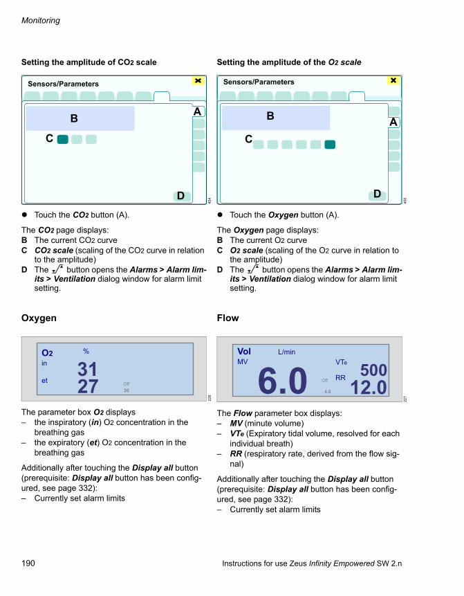
Monitoring
190 Instructions for use Zeus Infinity Empowered SW 2.n
Setting the amplitude of CO2 scale
Touch the CO2 button (A).
The CO2 page displays:B The current CO2 curveC CO2 scale (scaling of the CO2 curve in relation
to the amplitude)D The button opens the Alarms > Alarm lim-
its > Ventilation dialog window for alarm limit setting.
Oxygen
The parameter box O2 displays– the inspiratory (in) O2 concentration in the
breathing gas– the expiratory (et) O2 concentration in the
breathing gas
Additionally after touching the Display all button (prerequisite: Display all button has been config-ured, see page 332):– Currently set alarm limits
Setting the amplitude of the O2 scale
Touch the Oxygen button (A).
The Oxygen page displays:B The current O2 curveC O2 scale (scaling of the O2 curve in relation to
the amplitude)D The button opens the Alarms > Alarm lim-
its > Ventilation dialog window for alarm limit setting.
Flow
The Flow parameter box displays:– MV (minute volume)– VTe (Expiratory tidal volume, resolved for each
individual breath)– RR (respiratory rate, derived from the flow sig-
nal)
Additionally after touching the Display all button (prerequisite: Display all button has been config-ured, see page 332):– Currently set alarm limits
404
226
Sensors/Parameters
AB
C
D
2731
20
O2in
et
%
Off
405
227
Sensors/Parameters
AB
C
D
5006.0 12.04.0
VolMV VTe
RROff
L/min

Instructions for use Zeus Infinity Empowered SW 2.n 191
Monitoring
Setting the amplitudes of Flow scale and Vol. scale and Waveform selection
Touch the Flow button (A).
The Flow page displays:B The current Flow curveC Flow scale (scaling of the Flow curve in relation
to the amplitude for the flow)D Vol. scale (scaling of the Flow curve in relation
to the amplitude for the volume)E Waveform selection: represent Flow or Vol.
as a waveformF The button opens the Alarms > Alarm lim-
its > Ventilation dialog window for alarm limit setting.
406
Sensors/Parameters
AB
CD
E
F

Monitoring
192 Instructions for use Zeus Infinity Empowered SW 2.n
Airway pressure Paw
The Paw parameter box displays:– PIP (peak pressure)– Pmean (mean pressure)– PEEP (positive end-expiratory pressure)
Additionally after touching the Display all button (prerequisite: Display all button has been config-ured, see page 332):– Pplat (plateau pressure)– currently set alarm limits
Setting the amplitude of the Paw scale
Touch the Paw button (A).
The Paw page displays:B The current Paw curveC Paw scale (scaling of the Paw curve in relation
to the amplitude)D The button opens the Alarms > Alarm lim-
its > Ventilation dialog window for alarm limit setting.
228
229
1330 14
PawPIP
mbarPmean
PEEP
23 530
40
13PawPIP
Pplat
mbarPmean
PEEPAuto
407
Sensors/Parameters
A
B
C
D

Instructions for use Zeus Infinity Empowered SW 2.n 193
Monitoring
Anesthetic agent
The Volatile agent parameter box display can be varied:
Display 1
– Inspiratory (in) and expiratory (et) values of the anesthetic agent, of N2O and O2
Display 2
– Inspiratory (in) and expiratory (et) values of the anesthetic agent
– xMAC (MAC* multiple)
If a second anesthetic agent is measured, it is dis-played instead of N2O.
An age-adjusted MAC multiple is used, see page 114.
Setting the amplitude of the Volatile agent scale
Touch the Volatile agent button (A).
The Volatile agent page displays:B The current curve for the volatile anesthetic
agentC VA scale (scaling of this curve in relation to the
amplitude)D The button opens the Alarms > Alarm lim-
its > Anesth. dialog window for alarm limit set-ting
230
* MAC – Minimum Alveolar Concentration
231
1.22.2 60 37
50 27
Iso N20 O2%in
et
1.22.2 2.4
1.4 2.3
xMACSevIsoin
et
408
Sensors/Parameters
A
B
C
D

Monitoring
194 Instructions for use Zeus Infinity Empowered SW 2.n
Loop displays
Loops are a graphic representation of the respira-tory monitoring data collected by the ventilator. Pressure/volume loop and flow/volume loops pro-vide important information about the response of the patient to the ventilation.
Configuration see page 331.
Pressure/volume loops
Pressure/volume loops show changes in the com-pliance, resistance and respiratory work.
The loop of a mechanically generated breath is plotted in an counterclockwise direction. The loop of a spontaneous breath is plotted in a clockwise di-rection. The inspiration starts at a point which is de-fined via the base pressure and the volume at the beginning of inspiration. The loops show the appro-priate values for dynamic compliance (Cdyn).
Flow/volume loops
Flow/volume loops plot mechanical and spontane-ous breaths in the same manner. Inspiration starts at the starting point of the loop and is then plotted upwards and from the left-hand side to the right-hand side (clockwise). Expiration is plotted below the horizontal axis from right to left, back to the starting point.
Display of ventilation loops
Older loops are deleted and replaced by the current loops. Up to six reference loops can be saved and displayed. Reference loops are used as compari-son points to evaluate the current loops.
Touch the Save button (A).
The current loop is saved as a blue curve with its time. The loops in progress are overlaid on it in black.
Touch the Recall button (B).
The saved loops (maximum 6) are recalled by con-tinuous touching. The sequence of the loops is dis-played at the top right along with the respective time saved.
Displaying values for compliance Cdyn and resist-ance R:
Touch the screen between the Save and Recall buttons.
232
00
1200
20
09:20:45
A
Volume I
B
Paw

Instructions for use Zeus Infinity Empowered SW 2.n 195
Monitoring
Displaying the Save and Recall buttons again:
Touch the screen in the area of the values for compliance and resistance again.
In Vent. standby ventilation mode, no PV loops can be displayed because of the absence of respi-ration phase triggering. Instead of the loop display, Vent. standby is displayed.
Setting and selecting loops
Touch the PV FV Loops button (C).
The PV FV Loops page displays:D Paw/Vol, Flow/Vol (possible loop displays)E Auto, Volume, Customized (scaling of the
loops)F Volume (scaling of the volume)G Paw (scaling of the pressure axis)H Flow (scaling of the flow axis)I Loop selection: Paw/Vol, Flow/Vol (display of
the loop that will be transferred to the screen)J The button opens the Alarms > Alarm lim-
its > Ventilation dialog window for alarm limit setting.
234
00
1200
20
09:20:45
24 2
Volume I
Paw
CdynmL/mbar
Rmbar/L/s
409
Sensors/Parameters
C
D
EFGHI J

Monitoring
196 Instructions for use Zeus Infinity Empowered SW 2.n
Infusion
For every two Module DPS syringe pumps, a pa-rameter field can be displayed containing:– Pump number– Drug names– Vtot mL (volume administered up to that point in
time)– Trest min (time until the syringe is empty)
Touch parameter field.
The current alarm limit setting appears.
Display of the flow tubes
A The current flows of the anesthetic agent, e.g., Iso, and of the gases O2, Air, and N2O are dis-played.
B The status display indicates the status of gas delivery (fresh-gas control mode, closed sys-tem, current fresh-gas flows, etc.).
C The O2 uptake display is used for leakage de-tection when operating in a closed system. If the device is in Uptake mode, the complete O2 up-take of the patient is displayed.
O2 uptake / Uptake monitoring
Zeus IE uses the Brody formula for uptake monitor-ing: O2 uptake = 10 x KG3/4
KG is based on the body weight set for the patient.
Uptake monitoring is first activated 3 min after achieving the mode.
The theoretically calculated O2 uptake is compared to the measured O2 uptake in the system. If the measured value exceeds the calculated value, the background of the O2 uptake display begins to flash in yellow.
The user can set the sensitivity of the alarm using the Brody factor, see page 164.
Touch the display of the O2 uptake.
The Alarms > Ventilation dialog window opens, see page 164. The Brody-Factor button is yellow and can be adjusted.
Touch the display of the flow tubes.
The Trends/Data > Current flows dialog window appears.
477
162
1 2Vtot
mL
Trest
min
00.140.28
1810
10.5
0
10050
10
10.5
0
System closed
O2 N2O Iso
L/min mL/h
O2 uptake 324 mL/minBC
A

Instructions for use Zeus Infinity Empowered SW 2.n 197
Monitoring
Patient monitoring
Zeus IE patient monitoring (optional) provides the following functions:
A ECG (electrocardiography), see page 208
B SpO2 (oxygen saturation), see page 217
The SpO2 measurement can be carried out via the SpO2 SmartPod or without the SpO2* SmartPod.
C NIBP (non-invasive blood pressure), see page 220
D IBP (invasive blood pressure), see page 225
E Temp (temperature), see page 233
F C.O./ Calculat. (cardiac output), see page 234
G BIS/NMT (anesthesia effect monitoring), see page 238
The parameters can be displayed as measured val-ues in configurable parameter boxes.
The ECG, SpO2, IBP and BIS parameters can also be displayed as mini-trends.
Connection field for patient monitoring
The connection field for patient monitoring is on the left-hand side next to the breathing system.38
9
* optional
Sensors/Parameters
A B C D E F G
148
WARNINGCare must be taken to ensure that the pods are fitted securely and cannot drop. Route and at-tach the sensor cables and catheter tubes to the patient in such a way that if cables, tubes or the device are moved the patient will not be injured.

Monitoring
198 Instructions for use Zeus Infinity Empowered SW 2.n
SpO2 measurement with SmartPod SpO2
The connection field has the following connections:
A HEMOMED 1Connection for accessories to measure 1 to 4 invasive blood pressures (IBP) and C.O.
B MULTIMEDConnection for accessories to measure 3 to 6 ECG leads and 1 or 2 temperatures
C Aux/Hemo 2/3Connections for accessories to measure 1 to 4 invasive blood pressures and C.O. as well as for anesthesia effect monitoring (Trident pod, BISx pod)
D NIBPConnection to measure the non-invasive blood pressure
E SpO2Connection to measure oxygen saturation (sen-sor technology must be identified)
F IV systemConnection of Module DPS for intravenous an-esthesia (optional)
G SyncSynchronization connection for defibrillators
SpO2 measurement without SpO2 SmartPod (optional)
The connection field has the following connections:
H HEMOMED 1Connection for accessories to measure 1 to 4 invasive blood pressures (IBP) and C.O.
I MULTIMEDConnection for accessories to measure SpO2, 3 to 6 ECG leads and 1 or 2 temperatures
J Aux/Hemo 2/3Connections for accessories to measure 1 to 4 invasive blood pressures and C.O. as well as for anesthesia effect monitoring (Trident pod, BISx pod)
K NIBPConnection to measure the non-invasive blood pressure
L SyncSynchronization connection for defibrillators
M IV systemConnection of Module DPS for intravenous an-esthesia (optional)
009
NIBP
Aux / Hemo 2 Aux / Hemo 3
SpO2
HEMOMED 1 MULTIMED
IV-System Sync.
A B
C
D E
F G
010
NIBP
Aux / Hemo 2 Aux / Hemo 3
HEMOMED 1 MULTIMED
IV-System
Sync.
H I
J
K L
M

Instructions for use Zeus Infinity Empowered SW 2.n 199
Monitoring
Accessories for patient monitoring
Zeus IE con-nection field
Accesso-ries
ECG SpO2 NIBP BP Temp. C.O. NMT/ TOF
BIS
MULTIMED MUL-TIMED 5 cable
3 to 5 electrodes
1 sensor1)
1) optional for measurement without SmartPod SpO2
1 or 2 sensors2)
2) depends on the use of a Y-cable
MUL-TIMED 6 cable
3 to 6 electrodes
1 Sensor1) 1 or 2 sensors2)
MUL-TIMED PLUS OR cable
3 to 6 electrodes
1 Sensor1) 1 or 2 sensors2)
HEMOMED 1 Y-cable 1 or 2 pressure trans-ducer(s)2)
HemoMed Pod
4 pressure transducers
x
Aux/Hemo 2 or Aux/ Hemo 3
Hemo2 Pod
2 pressure transducers
2 sensors x
Hemo4 Pod
4 pressure transducers
2 sensors x
Quad Hemo Pod
4 pressure transducers
2 sensors x
Trident pod 1 NMT sensor
BISx pod 1 BIS sensor
SpO23 Masimo SET cable
1 Masimo sensor3)
3) omitted for measurement without SmartPod SpO2
Nellcor Ox-iMax cable
1 Nellcor sensor3)
NIBP NIBP hose 1 sen-sor

Monitoring
200 Instructions for use Zeus Infinity Empowered SW 2.n
Patient monitoring and the hemodynamic modules are largely protected against high-frequency inter-ference which may be caused by defibrillations, HF surgery devices or by 50/60 Hz power current inter-ference. The pressure transducers recommended on the List of Accessories protect patients during HF surgery and protect against burns during defi-brillation. If non-approved pressure transducers are used, this protection is no longer guaranteed.
Note about HF surgery
To ensure the safety of patient and personnel and to reduce interference from high-frequency signals, follow safety instructions during HF surgery.
Connection for ECG accessories
A For the display of 3, 5 or 6 ECG leads, different cables can be connected to the MULTIMED connection on the Zeus IE.– MULTIMED 5 cable– MULTIMED 6 cable– MULTIMED PLUS OR cable
WARNINGTo increase performance and to reduce the risk of burns, always use the accessories pro-vided for HF surgery.
WARNINGTo prevent the risk of burns, keep sensors and pressure transducers (ECG, temperature, pressure, SpO2, BISx) and their associated ca-bles away from the operation site, the back electrodes of the electrosurgical unit and the grounding.
WARNINGAlways use a high-frequency adapter block (ESU filter) from Dräger or a MULTIMED Plus OR cable with compatible electrode cables. Doing so reduces high-frequency interference and protects the patient against burns that may be caused by voltage being emitted by the high-frequency surgery device. For better performance, set the ECG filter option to "ESU".
WARNINGPacemaker detection is not available if the ESU filter or MULTIMED Plus OR cable is used.
NOTEFor HF surgery, the heart rate should be deter-mined from the SpO2 signal instead of the ECG signal.
NOTEIf using temperature sensors (rectal, esophageal), they must have a protective sheath.
185
A
optionally without SmartPod SpO2
A

Instructions for use Zeus Infinity Empowered SW 2.n 201
Monitoring
Connecting MULTIMED 5/6 cable
B MULTIMED cable
C ESU block for protection from interference due to high-frequency surgery
D ECG cable (3, 5 or 6 leads) for connection to the electrodes applied to the patient
E Connection socket for temperature cable Two temperature sensors may be connected via a Y-cable.
F Connection socket for SpO2 cable*
1 Insert white ECG standard lead wire set (D) into the ESU block (C). If a MULTIMED 5 cable is used, leave the V+ connection vacant.
2 Connect ESU block (C) to the MULTIMED cable (B).
5-pin and 6-pin ESU blocks are available.
3 All electrode inputs must be covered.
Use ESU block during HF surgery only.
Connecting MULTIMED PLUS OR cable
G MULTIMED PLUS OR cable with integrated ESU block
H ECG cable (3, 5 or 6 leads) for connection to the electrodes applied to the patient
I Connection socket for temperature cableTwo temperature sensors may be connected via a Y-cable.
J Connection socket for SpO2 cable*
Insert white ECG standard lead wire set (D) into the MULTIMED PLUS OR Pod (C).
Connection for NIBP accessories
Press the plug of the NIBP hose firmly into the NIBP socket (A) at the connection field of the hemodynamic monitoring on Zeus IE and con-nect the other end of the hose to the connection on the cuff.
142
* optional for measurement without SpO2 SmartPod
BCD
EF
143
185
GH
IJ
A
optionally without SmartPod SpO2
A

Monitoring
202 Instructions for use Zeus Infinity Empowered SW 2.n
Connection for IBP accessories
For invasive blood pressure measurement, four al-ternatives are available on Zeus IE:– Y-cable– Hemo2 Pod– Hemo4 Pod– HemoMed Pod– Quad Hemo Pod
Y-cable
The Y-cable can be used to connect two IBP pres-sure transducers to measure two invasive blood pressures. The Y-cable is connected to the HEMOMED 1 connection on the Zeus IE connec-tion field, see page 197.
A Connectors for the connection to Zeus IE
B Y-cable
C Intermediate cable
D IBP pressure transducer
Hemo2 Pod, Hemo4 Pod, HemoMed Pod and Quad Hemo Pod
Hemodynamic monitoring modules which perform the following measurements with only one monitor connection:– Cardiac output– 2 invasive blood pressure measurements
(Hemo2) or– 4 invasive blood pressure measurements
(Hemo4, HemoMed and Quad Hemo)
Hemo2 and Hemo4 must be connected to an Aux/Hemo 2/3 (F) on Zeus IE.
The HemoMed Pod must be connected to the HEMOMED 1 connection (E) on Zeus IE.
In contrast to the Hemo2 and Hemo4 Pods, the HemoMed Pod has no LCD displays on the module and no temperature connections.
The Quad Hemo Pod has two temperature connec-tions and no LCD display.
Hemo2 Pod, Hemo4 Pod and HemoMed Pod
The modules have three buttons:G The SmartZero key performs the zeroing
of all pressure transducers connected to the module which are open to atmospheric pres-sure.
H The C.O. Start key starts measuring cardiac output.
I The Wedge key starts measuring pulmonary wedge pressure.
136
185
AB
CD
E
F
optionally without SmartPod SpO2
E
F
135
G H I

Instructions for use Zeus Infinity Empowered SW 2.n 203
Monitoring
Quad Hemo Pod
J The SmartZero key performs the zeroing of all pressure transducers connected to the module which are open to atmospheric pres-sure.
K The C.O. Start key starts measuring cardiac output.
L The Wedge key starts measuring pulmonary wedge pressure.
Connecting hemodynamic modules (pods)
Connecting Hemo2, Hemo4 and HemoMed
1 Establish a connection to the Zeus IE connec-tion field.
On the HemoMed Pod, the connection (M) for Zeus IE is located on the left side.
On the Hemo2 and Hemo4 Pods, the connection (N) for Zeus IE is located on the right side.
2 Connect pressure transducer cables (O) to the adapter block on the rear of the module.
3 Insert the pressure transducers (P) on the front panel of the module. Insert the pressure trans-ducers into the slide-in compartment corre-sponding to the module connection.
103
135
J K L
M
133
160
158
N
O
P

Monitoring
204 Instructions for use Zeus Infinity Empowered SW 2.n
Connecting the Quad Hemo Pod
1 Establish a connection to the Zeus IE connec-tion field.
Q Connection for C.O.R Connection for Zeus IE
2 Connect the red end of the Pod communication cable (T) to connection (R). Connect the other end (S) to the Aux/Hemo2 or Aux/Hemo3 con-nection on Zeus IE.
3 Insert the pressure transducers into the trans-ducer slots (U).
4 Connect the pressure transducer adapter ca-bles (V) to the intermediate cables (W).
Temperature measurement connection
A MULTIMED cable is used to connect the temper-ature measurement to the MULTIMED connection on the Zeus IE connection field, see page 197.
A MULTIMED Pod
B Temperature sensorA Y-cable has to be used for the measurement of 2 temperatures.
102
101
Q R
T
S
U U U
V
W
138
A
B

Instructions for use Zeus Infinity Empowered SW 2.n 205
Monitoring
SpO2 measurement connection
Two technologies are available for the SpO2 meas-urement:– SmartPod Masimo SET*– SmartPod Nellcor OxiMax*
or – Dräger Oxisure**
The SpO2 measurement is carried out using the fol-lowing connections:
A Integrated SmartPod or
B Multimed**
SpO2 measurement with SmartPod SpO2
The technology to be used is marked on the con-nection field for patient monitoring, next to the con-nection for SpO2 (integrated SmartPod).
Select the accessories (connecting cable and SpO2 sensor) based on the technology used.
C Connecting cableD SpO2 sensor
185
* Measurement using SpO2 SmartPod** optional for measurement without SpO2 SmartPod
A
optionally without SmartPod SpO2
B
150
C
D

Monitoring
206 Instructions for use Zeus Infinity Empowered SW 2.n
SpO2 measurement without SmartPod SpO2*
The SpO2 measurement is carried out using the MULTIMED connections.
Select the accessories (connecting cable and SpO2 sensor) based on the technology used.
E MULTIMED cableF Connecting cableG SpO2 sensor
C.O. measurement connection
The accessory for C.O. measurement can be con-nected to all hemodynamic modules. The connec-tion is located on the right side for all modules.
A Injectate
B Injectate temperature sensor
C Proximal lumen
D Thermistor T-piece
E Three-way tap
F C.O. Y-cable
G C.O. catheter cable
H Catheter connection
I Thermodilution catheter
J Distal lumen
K Balloon lumen
* optional
152
E
F
G
137
A
BC
D
E
F
GHI
JK

Instructions for use Zeus Infinity Empowered SW 2.n 207
Monitoring
Connection for anesthesia effect monitoring
Trident and BisX pods are connected to the Aux/Hemo 2/3 connections on Zeus IE connection field, see page 197.
Trident NMT pod
A Covered connection, currently no function
B LED for displaying activated stimulation
C Connection for NMT accessories: accelerome-ter, electrodes
D Socket for BISx pod
E To the Zeus IE connection field (Pod Com ca-ble)
Infinity BISx pod
F Pod Com cable to the Zeus IE connection field or to the Trident pod
G Sensor cable for connecting the BIS sensor
Connection for synchronization of a defibrillator
For synchronization, a defibrillator can be con-nected to the Sync. connection (A) on the Zeus IE connection field.
279
!
AB
C
D
E
276
185
BISX
FG
A
optionally without SmartPod SpO2
A

Monitoring
208 Instructions for use Zeus Infinity Empowered SW 2.n
Electrocardiography ECG
Zeus IE provides the following functions:– ECG display– Heart rate display– Detection of arrhythmia events– ST analysis– Display of ECG data
The HR/PLS parameter box displays:– Heart rate– Lead– ST value
Additionally after touching the Display all button (prerequisite: Display all button has been config-ured, see page 332):– Currently set alarm limits
Determining mean values from the ECG
The monitor detects QRS complexes with ampli-tudes between 0.2 and 5.0 mV and a QRS width of 70 to 120 ms for adults and 40 to 100 ms for ne-onates, see notes regarding QRS detection in the "Fault – Cause – Remedy" chapter. The heart rate is calculated within a range of 15 to 300 bpm by means of the RR intervals in the last 10 seconds, where the two longest and two shortest RR inter-vals are excluded from the calculation. The aver-age is created from the remaining intervals and this result is displayed as the current heart rate in the HR parameter field of the main screen.
ECG safety instructions
Observe the internal instructions of the hospital!
Remove unprotected electrodes from the pa-tient before defibrillation.
ECG with pacemakers
Special care must be taken with pacemaker pa-tients in ECG analysis.
While monitoring pacemaker patients, QRS com-plexes may possibly not be counted correctly. A threshold alarm for the lower heart rate may occur by mistake:
– For fusion beats and asynchronous pacemak-ers with coupling intervals between +10 and –90 ms.
– For asynchronous pacemakers with overshootWith certain pacemaker patients, Zeus IE can-not accurately measure heart rate as well as frequency-dependent arrhythmia events.
224
60 12045
HR/PLS II
ST
bpm
WARNINGConductive parts of the electrodes and con-nections (including the neutral electrode) must not come into contact with other con-ductive parts (including grounded parts). Risk of electric shock.
WARNINGDefibrillation electrodes must never be placed over ECG electrodes or ECG leads. A dis-charge could prevent defibrillation and cause injuries to clinical staff and the patient.
WARNINGEvoked potential equipment can cause faults in ECG monitoring.
WARNINGTurn on pacemaker detection for pacemaker patients only. Turn off pacemaker detection for patients without pacemakers.
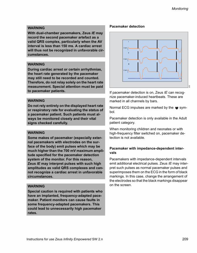
Instructions for use Zeus Infinity Empowered SW 2.n 209
Monitoring
Pacemaker detection
If pacemaker detection is on, Zeus IE can recog-nize pacemaker-induced heartbeats. These are marked in all channels by bars.
Normal ECG impulses are marked by the sym-bol.
Pacemaker detection is only available in the Adult patient category.
When monitoring children and neonates or with high-frequency filter switched on, pacemaker de-tection is not available.
Pacemaker with impedance-dependent inter-vals
Pacemakers with impedance-dependent intervals emit additional electrical pulses. Zeus IE may inter-pret such pulses as normal pacemaker pulses and superimposes them on the ECG in the form of black markings. In this case, change the arrangement of the electrodes so that the black markings disappear on the screen.
WARNINGWith dual-chamber pacemakers, Zeus IE may record the second pacemaker artefact as a valid QRS complex, particularly when the AV interval is less than 150 ms. A cardiac arrest will thus not be recognized in unfavorable cir-cumstances.
WARNINGDuring cardiac arrest or certain arrhythmias, the heart rate generated by the pacemaker may still need to be recorded and counted. Therefore, do not relay solely on the heart rate measurement. Special attention must be paid to pacemaker patients.
WARNINGDo not rely entirely on the displayed heart rate or respiratory rate for evaluating the status of a pacemaker patient. Such patients must al-ways be monitored closely and their vital signs checked carefully.
WARNINGSome makes of pacemaker (especially exter-nal pacemakers with electrodes on the sur-face of the body) emit pulses which may be much higher than the 700 mV maximum ampli-tude specified for the pacemaker detection system of the monitor. For this reason, Zeus IE may interpret pulses with such high amplitudes as valid QRS complexes and can-not recognize a cardiac arrest in unfavorable circumstances.
WARNINGSpecial caution is required with patients who have an implanted, frequency-adapted pace-maker. Patient monitors can cause faults in some frequency-adapted pacemakers. This could lead to unnecessarily high pacemaker rates.
233

Monitoring
210 Instructions for use Zeus Infinity Empowered SW 2.n
ECG with HF surgery
To prevent interference and ensure patient and staff safety, observe the following during HF surgery:
On the HF surgery device, select the neutral electrode with the largest contact surface and place it as near as possible to the operation site.
Ascertain the heart rate via the SpO2 signal or arterial blood pressure instead of via the ECG.
Internal temperature sensors (rectal, esopha-geal) have a protective sheath.
Interference from other sources
The use of infusion or reel pumps or other electrical devices during patient monitoring may lead to ECG artefacts, whereby Zeus IE might display pace-maker markers although the ECG is normal.
To determine the interference source, the corre-sponding device may need to be switched off. If this eliminates the artefacts, the device is probably the cause of the interference.
Electrical interference emitted from insulation com-ponents can briefly overlap or interrupt the ECG signal.
The signals from transcutaneous electrical nerve stimulators (TENS) are similar to pacemaker pulses and can be misinterpreted as such by Zeus IE. Valid QRS complexes after a misinter-preted TENS signal may possibly be rejected by Zeus IE.
WARNINGECG leads, temperature sensors, pressure measuring accessories, SpO2 sensors, and in-termediate cables must be kept away from the grounding as well as the electrosurgical de-vice and its cables.
WARNINGWhen using HF surgery devices, only use blue Dräger ECG leads or a high-frequency adapter block for conventional cables, see separate list of accessories. The blue leads and the adapter block guard against high-frequency interference and protect the patient against burns, which can be caused by voltage being emitted by the HF surgery device.
WARNINGWhen using a high-frequency adapter block and blue shielded cables, pacemaker detec-tion is not available. This also applies when the ESU ECG filter is selected.

Instructions for use Zeus Infinity Empowered SW 2.n 211
Monitoring
Preparing ECG
Patients
Careful preparation of the skin as well as correct positioning of the electrodes is crucial for the gen-eration of distinct signals.
Electrodes
Both reusable and disposable electrodes are avail-able.
Arrange the electrodes in such a way that an optimum ECG signal is received by Zeus IE. The amplitude of the P- and T-waves should not be less than one third of QRS amplitude.
Position electrodes as far from the operation site as possible.
Instructions for burns
Only use sterile electrodes.
The electrodes must be attached with a water-tight plaster (approx. 5 cm wide) or with sterile adhesive tape and protected against liquids.
Electrode positioning
217
218
3-lead standard / 5-lead standard
5-lead standard / 6-lead for pacemaker
ECG color codingECG cable Europe (IEC 1) USA (IEC 2)LA Yellow Black
LF Green Red
RA Red White
RF Black Green
V White Brown
V+ Gray / white Gray / brown

Monitoring
212 Instructions for use Zeus Infinity Empowered SW 2.n
ECG signal processing and display
The number of ECG leads available depends on the cable and lead wire sets used:
ECG connection cable Lead wire set
Display channels Leads available
MULTIMED 5, 6, MULTIMED PLUS OR
3-lead ECG 1 or ECG 2 or ECG 3 I, II, III
MULTIMED 5, 6, MULTIMED PLUS OR
5-lead ECG 1, ECG 2, ECG 3 I, II, III, aVR, aVL, aVF, V
MULTIMED 6, MULTIMED PLUS OR
6-lead ECG 1, ECG 2, ECG 3 I, II, III, aVR, aVL, aVF, V, V+

Instructions for use Zeus Infinity Empowered SW 2.n 213
Monitoring
ECG – Arrhythmia detection
Arrhythmia detection is available for adult and pedi-atric patients, but not for neonates. The type of ar-rhythmia monitoring (Adv. (optional), Basic or OFF) determines the type of events which are re-ported.
Zeus IE uses the results of QRS processing for the arrhythmia analysis.
Arrhythmia reference pattern
Zeus IE creates a reference pattern from the de-tected dominant QRS morphology of the patient (learning phase).
The learning phase takes approx. 30 to 40 seconds. If Zeus IE detects more than 100 QRS complexes, but fewer than 16 similar beats, the Un-able to learn message appears. During the learn-ing phase, no arrhythmia alarms are reported and no arrhythmia data is included in the trend memory. The Relearn message appears.
ARR level ARR parameters reportedOff ASY (asystole)
VF (ventricular fibrillation)
ARTF (artefact)
Basic ASY (asystole)
VF (ventricular fibrillation)
ARTF (artefact)
VT (ventricular tachycardia)
Advanced (optional)
ASY (asystole)
VF (ventricular fibrillation)
V.tach (ventricular tachycardia)
V.run (ventricular run)
AIVR (accelerated idioventricular rhythm)
SVT (supraventricular tachycardia)
CPT (ventricular couplet)
BGM (ventricular bigeminy)
Tach (sinus tachycardia)
Brady (sinus bradycardia)
Pause (pause)
ARTF (artefact)
PVC (premature ventricular contrac-tion)
WARNINGElectrical artefacts arising from a cause other than heart disease, e.g., attacks/spasms, may prevent the detection of certain arrhythmias. In the case of patients prone to attacks, the user should not solely rely on the ECG.
NOTEArrhythmia detection is not reliable for all patients. Zeus IE only classifies QRS complexes of 0.20 mV, with widths of 70 ms. An artefact (ARTF) can occur if the ECG signal fails to meet these minimum requirements. Arrhythmia detection can be switched off if the QRS complexes of a patient do not meet these minimum requirements. Heart rate monitoring will continue.
NOTEIn the neonatal patient category a bradycardia is a low heart rate alarm. The setting can be made irrespective of the heart rate alarm, see page 168.

Monitoring
214 Instructions for use Zeus Infinity Empowered SW 2.n
Beat and rhythm classification
The beat classification refers to the analysis of indi-vidual beats.
All detected beats are analyzed by Zeus IE for the heart rate calculation; however, questionable beats are excluded from arrhythmia detection.
The rhythm classification refers to the analysis of beat sequences.
Zeus IE compares the sequence of the last eight beats with the saved beat sequences. If two or more events are detected at the same time, Zeus IE reports an alarm for the event with the highest priority.
Automatic learning and relearning
If the ECG cables are connected to the patient, Zeus IE starts a learning phase in the following sit-uations:– After switching on Zeus IE– When leaving the system standby mode– After switching on arrhythmia detection– When changing the lead in the ECG channels
ECG-HF (ECG1) or ECG-ST (ECG2) while processing one or two ECG signals
ECG – ST monitoring
Zeus IE can detect and display deviations in the ST segment of the QRS complex relating to an isoelec-tric baseline.
This is done by measuring voltage values and com-paring them at two measurement points, the isoe-lectric point and ST measurement point. The isoe-lectric point defines the zero voltage (no electrical activity = 0 mm) and appears on the horizontal time axis as basic setting 28 ms before the beginning of the QRS complex. The ST measurement point ap-pears in the ST segment between the end of the QRS complex (J point) and the T segment as basic setting 80 ms after the end of the QRS complex.
247
Voltage
[mV]
Isoelectric measuring point ST measuring point
ST level
Time [s]
QRS start QRS end ST deviation

Instructions for use Zeus Infinity Empowered SW 2.n 215
Monitoring
Settings on Zeus IE
Touch the ECG tab (A).
The dialog window for ECG monitoring appears.
The dialog window displays the screens for setting ECG functions:B ECG HR/PLS (First ECG channel)C ECG ST (Second ECG channel)D ECG C.O. (Third ECG channel)E ST segm. (ST segment analysis)F More ECG
The possible settings of the three ECGs (ECG HR/PLS, ECG ST, ECG C.O.) are identical.G Waveform display of the respective ECG leadH ECG leadI ECG amplitude
The normal QRS detection threshold of the monitor lies at approx. 0.35 mV depending on the QRS width. This threshold is used for chan-nel amplitude x0.25, x0.5, x1, x2, x4.
For a channel amplitude of x8, the QRS detec-tion threshold is reduced to approx. 0.2 mV. In this case, these QRS complexes of low ampli-tude can be included in calculating the heart rate at a QRS width of 70 and 120 ms.
J Pulse tone volume [%]K Autoscale all causes automatic rescaling of all
ECG leads onceL Relearn: Manual starting of the ECG learning
phase, e.g., in order to redetermine the refer-ence QRS complex after electrode reposition-ing
M The button opens the Alarms > Alarm lim-its > Noninvasive dialog window for alarm limit setting.
N Auto: Waveform scaling is adapted on a contin-uous basis. The maximum level selectable is x 4.
ST segment analysis
With the ST analysis, QRS complexes, which have been classified as normal beats, are analyzed by three to seven (optional) selected ECG derivatives. Zeus IE learns each ST derivative, whereby the measured values and morphology of normal beats are collected in an average QRS complex. ST devi-ations are created in the comparison to this aver-age. If ST deviation is switched on, ST values are saved in the trend (see page 184).
Setting and evaluating the ST segment analysis:
Touch the ST segm. tab (A).
389
Sensors/Parameters
ABCDEF
G
HIJ
K L M
N
391
Sensors/Parameters
ACDEFG
H I J
B

Monitoring
216 Instructions for use Zeus Infinity Empowered SW 2.n
ST screen display (optional)
In the display of the advanced ST option, all availa-ble leads are displayed.
Measuring points
The start point and end point of the QRS complex are determined automatically.
For a reliable measurement of the ST deviations, the position of the ST Iso point and ST meas. point on the display (B) can be adjusted.
Setting measuring positions:
Touch the respective button. Use the rotary knob to put the cursor on the required place and confirm.
The following settings are possible:C ST iso point: Setting the measuring position for
the isoelectric pointD ST meas. point: Setting the measuring position
for the ST measuring pointE ST trend scale: Amplitude setting for the ST
trendsF ST event duration: Setting the time after which
there will be an alarm if there has been an unin-terrupted limit transgression
G ST monitoring: Switching the ST segment analysis On/Off
H Save referenceI ST view, opens ST view in the Trends/Data di-
alog windowJ The button opens the Alarms >All limits >
Hemodyn. dialog window for alarm limit setting of the measured values ST LAT, ST INF, ST ANT.
Display of hemodynamic data, ST analysis, ad-vanced ST analysis (optional)
Touch the ST view button (I).
Or
In the Trends/Data > Hemodyn. dialog win-dow, touch the ST view button, see page 184.
The example for the ECG lead II shows the display of the current QRS complexes (green) and the one-time measurement of the reference complexes (red) above each other. In addition, a short time trend of 30 minutes of the ascertained ST rise/fall is applied.
223
0.1 0.1 0.1 0.1
0.1 0.1 0.1
ST mmI II III
aVL aVR aVF V V+
459
8
-8
ST view
inferior lateral anterior
30 min
II

Instructions for use Zeus Infinity Empowered SW 2.n 217
Monitoring
More ECG settings
Touch the More ECG tab (A).
The More ECG page is used to adjust the following settings:B Arrhythmia monitoring: Adv., Basic, and OffC Heart rate/ Pulse source: ECG, ART, SpO2,
Auto
When Auto is set, the source is selected ac-cording to the availability of the parameter (or-der: ECG, ART, SpO2).
D Cable type: 3-lead, 5-lead, 6-lead, Auto detect.Zeus IE can detect the type of lead wire set. Manual selection is only necessary with lead wire sets which are not detected.Always check the selection of cable type before beginning the ECG monitoring since a previous setting is kept.
E ECG filter: ESU, Monit., OffThe ESU setting suppresses high-frequency in-terference of HF surgery devices. The Monit. setting suppresses baseline drift, motion artefacts and low-frequency electrical in-terference.When using a high-frequency adapter block or shielded cables, pacemaker detection is not available if the ECG filter setting ESU is se-lected.
F Pacer detection: On, Off
Optimize pacemaker detection
1 Switch on pacemaker detection.
2 Select the lead with the fewest fault signals and the highest R-wave for display in the uppermost channel.
3 Touch the Monit. button.
Switch the monitor filter on and off several times to ascertain the clearest signal.G Arrhythmia, opens the Alarms > All limits >
Arrhythmia dialog window for setting the alarm limits for Arrhythmia monitoring.
H The button opens the Alarms > Alarm lim-its > Noninvasive dialog window for alarm limit setting.
Pulse oximetry SpO2
The method of pulse oximetry is based on the prin-ciple of percentage measurement of functional he-moglobin (oxygenated hemoglobin).
Zeus IE offers three processing algorithms:
– Masimo SET,
– Nellcor Oximax
or
– Dräger Oxisure*
A photosensor measures the absorption of red and infrared light. Since oxyhemoglobin (oxygenated blood) and deoxyhemoglobin (deoxygenated blood) absorb red light differently, but absorb infra-red light almost identically, the portion of oxygen-ated blood can be calculated from the different ab-sorption factor. As oxygen saturation of the blood changes cyclically with blood volume and blood vol-ume itself depends on the pulse rate, the pulse rate (pulse) can likewise be determined with the aid of SpO2 monitoring.
390
Sensors/Parameters
A
BCDEF
G H
* optional for measurement without SpO2 SmartPod

Monitoring
218 Instructions for use Zeus Infinity Empowered SW 2.n
SpO2 safety instruction
Good vascular circulation is important for SpO2 monitoring. In the event of shock, hypothermia, anemia or after administration of vasoactive medi-cations that impair circulation, the SpO2 values may not be reliable.
Patient preparation
Nail varnish must be removed at the sensor ap-plication site.
Cut finger nails as needed.
Bright ambient light can lead to unreliable measuring results.
Tips for avoiding artefacts
Do not continue to use damaged sensors with un-covered electrical contacts – risk of electric shock.
Do not tighten the adhesive strap too firmly.
Never use two adhesive straps as this can lead to venous pulsation. The pulse signal can fail.
High intrathoracic pressure, Valsalva’s maneuver or other consecutive impairments of venous back-flow can cause venous pulsation. The pulse signal can fail.
Avoid positioning the sensor on extremities with ar-terial catheter, blood pressure cuff, or intravascular venous infusion. Otherwise the pulse signal may fail and measurement may be inaccurate.
Substantial amounts of dyshemoglobins such as carboxyhemoglobin or methemoglobin can lead to inaccurate measurements.
Intravascular dyes such as methylene blue can lead to inaccurate measurements.
Electrocautery can influence the measuring accu-racy. Arrange the cables of the device and the sen-sor as far away as possible from the electrocautery and its neutral electrode.
Sensor performance may be impaired by strong movements of the patient and lead to inaccurate measurements. Change the application site to re-duce motion artefacts.
WARNINGSensors and application sites must be checked every two to three hours. If the skin is being irritated by the sensor or if circulation is being impaired, the sensor must be posi-tioned at a different site immediately.
WARNINGOnly sensors approved by Dräger may be used. Other sensors may not provide ade-quate protection during defibrillation. Note the instructions for use of the SpO2 sensors.
WARNINGFor Nellcor and Masimo, only intermediate ca-bles recommended by Dräger with a lock may be used. Other cables must not be used.
WARNINGNever use a pulse oximeter as an apnea mon-itoring device.
WARNINGCarboxyhemoglobin may erroneously in-crease readings. The degree of the deviation corresponds approximately with the actual percentage of carboxyhemoglobin. Dyes and substances containing dyes that change arte-rial pigmentation can also generate incorrect measurements.

Instructions for use Zeus Infinity Empowered SW 2.n 219
Monitoring
SpO2 screen display
Zeus IE displays SpO2 saturation values and the pulse rate in the SpO2 parameter box. The appro-priate curve field represents the SpO2 curve (pulse plethysmogram).
Additionally after touching the Display all button (prerequisite: Display all button has been config-ured, see page 332):– Currently set alarm limits
Settings on Zeus IE
Touch the SpO2 tab (A).
The dialog window for SpO2 monitoring appears.
This page displays:B The current SpO2 curve (plethysmogram)C Plethysmogram scale: Scaling of the SpO2
curve in relation to the amplitudeD Pulse tone volume [%]
E SpO2 averaging: Fast, NormalNormal:– Using Masimo-SET: On average, 8 seconds– Using Nellcor OxiMax: On average,
8 seconds– Using MultiMed*: 90 % of the SpO2 change
is displayed within 30 seconds (this setting is less susceptible to artefacts, however alarm messages occur more slowly).
Fast:– Using Masimo-SET: On average, 2 to
4 seconds– Using Nellcor OxiMax: On average, 2 to
4 seconds– Using MultiMed*: 90 % of the SpO2 change
is displayed within 15 seconds (this setting is more susceptible to artefacts, however alarm messages occur more quickly).
F Pulse tone modulation (depending on the sat-uration rate): On, Off
G NIBP interlock: On, OffSwitches SpO2 alarms off during an NIBP measurement. The SpO2 value is frozen and displayed in gray for the duration of NIBP meas-urement.
H The button opens the Alarms > Alarm lim-its > Noninvasive dialog window for alarm limit setting.
Test note and accuracy of the blood oxygen me-ter (Oxymeter)
To comply with the ISO 9919 standard, do not check the measurement accuracy of the blood oxy-gen meter (Oxymeter) with a functional test unit or a patient simulator.
222
392
99 67100 90
SpO2 %
PLS
Sensors/Parameters
A
B
CDEFG
H
* optional for measurement without SpO2 SmartPod

Monitoring
220 Instructions for use Zeus Infinity Empowered SW 2.n
Non-invasive blood pressure NIBP
The NIBP system of Zeus IE inflates a blood pres-sure cuff which is placed round the arm or leg of the patient and then releases the air again. According to the oscillometric procedure, Zeus IE calculates the systolic, diastolic and mean pressure values for adult, pediatric and neonatal patients. Single meas-urements, intermittent measurements and continu-ous measurements over 5 minutes can be per-formed.
Safety cut-off
The air is automatically released from the cuff if a measurement on adults and pediatric patients takes longer than 2 minutes and longer than 60 seconds with neonates. This protects the patient against excessively long cuff pressure. There are overpressure thresholds for each patient category that cause the air to be released automatically out of the cuff when an excessive cuff pressure occurs.
Selecting and positioning the cuff
Select cuff according to the circumference of the limbs. The cuff sizes are shown on the cuff (see list of accessories).
If SpO2 and NIBP are measured on the same limb and the interlock function (see page 219) is on, make sure that SpO2 monitoring interrupts the alarm during an NIBP measurement.
Position the cuff as close as possible to the height of the heart. If this is not possible, the measured values must be corrected: for every 10 cm that the cuff is positioned above or below the height of the heart, 8 mmHg must be added or deducted respectively.
WARNINGBlocking the hose can generate incorrect measured values because the cuff is not prop-erly inflated or the air cannot escape again.
Check the cuff and hose for damage and soil-ing. The cuff and hose must not come into contact with liquids and must not be squeezed or clamped.
NOTEPosition the cuff in such a way that no pressure is exerted on the joints.
In the case of patients suffering from spasms, vi-olent tremors or certain arrhythmias, it may not be possible to obtain reliable NIBP measurements.
WARNINGThe reliability of NIBP measurements is mostly dependent on choosing the appropri-ate NIBP cuff. An incorrect cuff size or use of a cuff which does not fall within the size range of cuffs manufactured by Dräger can lead to incorrect measurements. Only use cuffs ap-proved by Dräger. The circumference of the limbs must always match the marks on the cuff.
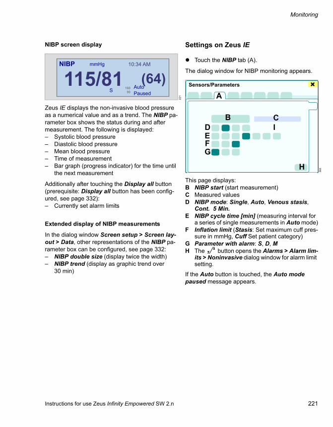
Instructions for use Zeus Infinity Empowered SW 2.n 221
Monitoring
NIBP screen display
Zeus IE displays the non-invasive blood pressure as a numerical value and as a trend. The NIBP pa-rameter box shows the status during and after measurement. The following is displayed:– Systolic blood pressure– Diastolic blood pressure– Mean blood pressure– Time of measurement– Bar graph (progress indicator) for the time until
the next measurement
Additionally after touching the Display all button (prerequisite: Display all button has been config-ured, see page 332):– Currently set alarm limits
Extended display of NIBP measurements
In the dialog window Screen setup > Screen lay-out > Data, other representations of the NIBP pa-rameter box can be configured, see page 332:– NIBP double size (display twice the width)– NIBP trend (display as graphic trend over
30 min)
Settings on Zeus IE
Touch the NIBP tab (A).
The dialog window for NIBP monitoring appears.
This page displays:B NIBP start (start measurement)C Measured valuesD NIBP mode: Single, Auto, Venous stasis,
Cont. 5 Min.E NIBP cycle time [min] (measuring interval for
a series of single measurements in Auto mode)F Inflation limit (Stasis: Set maximum cuff pres-
sure in mmHg, Cuff Set patient category)G Parameter with alarm: S, D, MH The button opens the Alarms > Alarm lim-
its > Noninvasive dialog window for alarm limit setting.
If the Auto button is touched, the Auto mode paused message appears.
221
115/81 (64)160 90
10:34 AMNIBP mmHg
AutoPausedS
393
A
B CDEFG
H
I
Sensors/Parameters

Monitoring
222 Instructions for use Zeus Infinity Empowered SW 2.n
Starting the NIBP measurement
In the Sensors/Parameters dialog window, touch the NIBP start button (B).
Or
In the main menu bar, touch the NIBP start (J) button.
The NIBP measurement is performed.
Measuring intervals
The measurements are taken at the intervals set under NIBP mode (B).
Exception: All intervals which are a multiple of 5 minutes synchronize from the second measure-ment to 5-minute steps of the current time so that they are in the measuring grid of the trend display.
In the Venous stasis mode, the cuff is inflated for up to 2 minutes. Pressure values, see page 223.
In the Cont. 5 Min. mode, single measurements are continuously taken over 5 minutes.
Parameter boxes of NIBP measurements
Single measurements (Single mode)
Start and stop single measurement:
Touch the NIBP start or NIBP stop button.
301
1:35
J
216
145/82160 90
(105)
118/81160 90
18
118/81160 90
(94)
118/81160 90
(94)
118/81160 90
86
5 minS
Cont.S
NIBP
NIBP
NIBP
NIBP
NIBP
mmHg
mmHg
mmHg
mmHg
mmHg
10:12Cuff
S
10:08
10:12Cuff
S Stasis
S
10:12
15 min
10:12
Single measurement
Continuous measurement
Stasis measurement
Auto measurement (5 min)
Auto measurement (15 min)

Instructions for use Zeus Infinity Empowered SW 2.n 223
Monitoring
Intermittent measurements (Auto mode)
Start intermittent measurements:
Touch the NIBP start button.
If a new interval time is set during the intermittent measurements in progress, the interval elapsed time meter is reset. A bar graph indicates the time remaining until the next measurement.
If the Auto mode is active, additional single meas-urements can be performed at any time. The meas-uring interval is not interrupted. To minimize the re-striction of blood circulation, the next measurement is started after 30 seconds at the earliest.
Aborting a running intermittent measurement:
Touch the NIBP stop button.
Zeus IE cancels the current measurement and con-tinues the measuring interval with the next meas-urement.
Continuous measurements for 5 minutes (Cont. 5 Min. mode)
During continuous measurements, Zeus IE per-forms NIBP measurements continuously over a pe-riod of 5 minutes. If a technical NIBP alarm ap-pears, Zeus IE interrupts the continuous measurements. A threshold value transgression does not lead to an abort.
If changing to continuous measurements, Zeus IE terminates the Auto mode.
Aborting a running continuous measurement:
Touch the NIBP stop button.
Repeated measurements:
If the inflation limit is set to Adult 270 (see page 221) and there is a weak pulse profile, Zeus IE cancels the measurement in progress and starts a second measuring attempt. If a second at-tempt fails, an alarm message is displayed.
Venostasis (Venous stasis mode)
By inflating the cuff and maintaining a constant cuff pressure, the blood supply to the lower part of the limbs can be stopped for long enough to attach in-fusion catheters. If venostasis is selected, the blood supply to the limbs remains blocked for as long as NIBP measurement lasts. The duration of the ven-ostasis generated by the cuff is dependent on the set inflation limit and the patient category selected.
WARNINGPerform continuous measurements only for a short time and with constant patient monitor-ing! The circulation of the limbs must be con-tinuously checked. Special care must be taken with neonates and patients with circulatory problems!
Short successive measurements, as well as measurements over a long period, can cause petechial bleeding, ischaemia, purpura or neuropathy. To prevent congestion, the cuff must be applied properly and its correct fit as well as the circulation in the limbs must be checked regularly.
WARNINGVenostasis must not be applied where an NIBP measurement should not be performed (e.g. on an arm to which a catheter is already con-nected).
If the venostasis has a negative impact on the patient, the cuff pressure can be released im-mediately by touching the NIBP stop button.

Monitoring
224 Instructions for use Zeus Infinity Empowered SW 2.n
During venostasis, the Stasis message, the cuff pressure and the time remaining are displayed in the parameter box.
Aborting venostasis:
Touch the NIBP stop button.
After concluding the venostasis, the Single mode is activated.
Inflation limits Neonates Pediatric patients AdultsCuff pressure (mmHg) Neo. 140: 40 ±3 Ped. 180: 60 ±4 Adult 270: 80 ±5
Inflation time (s) 60 ±2.5 120 ±5 120 ±5

Instructions for use Zeus Infinity Empowered SW 2.n 225
Monitoring
Invasive blood pressure measurement IBP
Signals for invasive blood pressure monitoring (IBP) are received via a Y-cable, one or more he-modynamic modules or via a combination of these devices.
A pressure transducer converts pressures into electronic signals for the Zeus IE.
These pressure signals are filtered to eliminate ar-tefacts.
Zeus IE detects individual beats by calculating threshold values from the running average of the systolic and diastolic pressures.
IBP parametersPar. Pressure Measured value Measuring rangeART Arterial Systolic, diastolic, mean –50 to 400 [mmHg]
LV Left ventricular Systolic, diastolic, mean
PA Pulmonary arterial Systolic, diastolic, mean –50 to 400 [mmHg]
RV Right ventricular Systolic, diastolic, mean
CVP Central venous Medium
RA Right atrial Medium
LA Left atrial Medium
ICP Intracranial Medium
GP1 Unspecific, 1 Systolic, diastolic, mean –50 to 400 [mmHg]
GP2 Unspecific, 2 Systolic, diastolic, mean

Monitoring
226 Instructions for use Zeus Infinity Empowered SW 2.n
IBP safety instructions Preparing catheters
– Use high-pressure catheters and keep them as short as possible.
Short catheters reduce signal attenuation and faults caused by motion artefacts.
High-pressure catheters reduce signal attenua-tion.
– Make sure that any air is removed from the sys-tem.
Air bubbles may attenuate the signal and this can lead to incorrect measured systolic values.
WARNINGDisposable pressure transducers may not be reused.
WARNINGWhile measuring the wedge pressure, the alarms for the systolic, diastolic and mean pressure from the PA measuring point are temporarily switched off.
WARNINGTo protect the patient while measuring the wedge pressure, the balloon should only be inflated for sufficient time to allow accurate measurement of the PWP value. Otherwise, there is a risk of pulmonary bleeding or infarc-tion.
WARNINGDo not inflate the balloon excessively during wedge pressure measurement. An overin-flated balloon can cause damage to the pul-monary artery wall.
WARNINGThe PA catheter may reach the wedge position during a wedge pressure measurement before the balloon has been inflated. If the PA curve appears in wedge form, there may be such a catheter fluctuation. If this is the case, take ap-propriate clinical measures to correct the po-sition of the catheter
WARNINGThe Zeus IE and the hemodynamic pods from Dräger are protected against mains current in-terference at 50 and 60 Hz. The pressure transducers approved by Dräger protect the patient against burns during HF surgery and defibrillation. If non-approved pressure trans-ducers are used, this protection can no longer be guaranteed. Approved pressure transduc-ers are on the separate list of accessories.

Instructions for use Zeus Infinity Empowered SW 2.n 227
Monitoring
Preparing pressure transducers
Zeroing
Pressure transducers must be zeroed under the fol-lowing conditions:– Immediately after inserting the catheter into the
circulatory system of the patient– After connecting the pressure transducer to a
module– Before starting monitor operation– Before inputting a calibration factor– After exchanging the breathing circuit or pres-
sure dome
Adjust static pressure transducers individually:
Touch the Zero button in the Sensors/Parame-ters > IBP > Cal. dialog window.
Zeroing several static pressure transducers simul-taneously:
Prerequisite: The Zero all BPs button has been configured, see page 332.
Touch the Zero all BPs button.
Or
Press SmartZero button on the hemody-namic module (see page 202).
In the IBP curve, the Zeroing message appears with a yellow background in the top right field. After zeroing has been completed, the message fades out again independent of whether the zeroing was successful or not.

Monitoring
228 Instructions for use Zeus Infinity Empowered SW 2.n
The following table shows the zeroing steps:
Calibration
Disposable pressure transducers do not have to be calibrated since they are calibrated by the manu-facturer to a calibration constant of 100.
For reusable pressure transducers, however, a cal-ibration constant must be entered again after lengthy use to obtain reliable measuring results in future (see page 230).
Individual zeroing of a pressure transducer from the screen
Simultaneous SmartZero zeroing
1 Make sure the pressure transducer is at the height of the heart. If no Dräger modules are used for invasive blood pressure measurement (see page 225), Dräger recommends using pressure trans-ducer holders so that the pressure transducers can be positioned at the correct height.
2 Close the three-way tap in the direction of the patient and open it in the direction of the air.
3 Press the parameter box of the pressure trans-ducer to be zeroed.
4 Touch the Cal. tab.
5 Touch the required parameter.
3 Touch the SmartZero button on the he-modynamic module to be zeroed or touch the Zero all BPs button. Zeus IE detects which pressure transducers are open and zeroes them.
6 Touch the Zero button.
Note:
The time of the last successful zeroing procedure is displayed.
If the zeroing could not be performed, the message ART nonstatic, for example, is displayed in the alarm message field.
Check waveform display.
If the waveform shows pressure spikes of more than 3 mm during the zeroing, repeat the zeroing pro-cedure.
If a pressure transducer cannot be zeroed after a second attempt, it should be replaced or DrägerService should be consulted.
CAUTIONIf an IBP parameter which is still to be measured is physiologically almost static (flat), do not use the SmartZero function. The channels to be ze-roed must be zeroed individually with the Zero button instead. Otherwise the zeroing of the cor-responding channel will be incorrect.
CAUTIONPerform zeroing before calibration!
The pressure transducer must be zeroed within five minutes before calibration. Otherwise, this will lead to incorrect measurements.

Instructions for use Zeus Infinity Empowered SW 2.n 229
Monitoring
IBP screen display
The display in the IBP parameter box depends on whether a pulsating or a non-pulsating pressure is being monitored. Parameter boxes in which pulsat-ing pressure parameters are shown (ART, LV, PA, RV, GP1, GP2) indicate systolic, diastolic and mean pressure values. The illustration shows a typ-ical parameter box of a pulsating pressure.
Parameter boxes for non-pulsating pressure pa-rameters (LA, RA, CVP, ICP) only show the mean pressure value.
IBP curves can be represented individually or over-laid. In the overlaid representation, each pressure curve can have its own scaling.
The following pressure parameters are perma-nently assigned to the four curves: ART, CVP, PA, and RA.
Additionally after touching the Display all button (prerequisite: Display all button has been config-ured, see page 332):– Currently set alarm limits
Catheter positions
The pressure designation and catheter position de-termine how the pressure signal is processed and transferred to Zeus IE.
Date and time for the last zero adjustment and last calibration as well as the calibration constant con-cern the specific pressure processing channel and remain for this channel even if there is a change in catheter position or pressure designation.
In the Sensors/Parameters > IBP > IBP sites/ Channels dialog window, up to twelve IBP sources are displayed in a matrix of 3 x 4 (up to 10 sources can be measured simultaneously).
The signals are displayed in rows 1 to 3:
– Row 1: Data from the HemoMed Pod or the Y-cable
– Rows 2 and 3: Data from Hemo2 or Hemo4 which are recorded via the Aux./Hemo 2/3 pressure connections on Zeus IE
Pressure parameters can be given a designation at any time. If a parameter is designated without con-nected accessories, then the following possibilities arise:
– With direct connection of the pressure trans-ducer cable, the adjusted measuring points are used.
220
167/69160 90
200
0
(106)
18 25 5
ART mmHg
S
CVP mmHg
ART
394
Sensors/Parameters

Monitoring
230 Instructions for use Zeus Infinity Empowered SW 2.n
When Hemo2/4 pods, which can save their own designations, are connected results are as follows:
– The pod already has a pressure transducer ca-ble connected to the viewed channel (transpor-tation with patient). Zeus IE adopts the measur-ing point setting of the pod and the previous setting on Zeus IE is overwritten.
– The pod has no pressure transducer cable con-nected to the viewed channel (new configura-tion). Preselection of the measuring point is taken over by Zeus IE. The pod saves this set-ting. See also: Designation conflicts.
If a pressure transducer cable is connected to a channel, the appropriate button turns dark green (active). Open inputs are shown in light green (inac-tive). The buttons in the matrix are never gray since the preselection of a measuring point is possible on any channel at any time.
Designation conflicts
The pressure designations are saved both in the Hemo2 and Hemo4 Pods and in Zeus IE. Designa-tion conflicts between module and Zeus IE occur when a module with a previously saved catheter position is reconnected to Zeus IE.
The pressure designation stored in the module has priority if a pressure transducer is connected.
Settings on Zeus IE
Configuration
In the Sensors/Parameters > IBP dialog win-dow, touch the Config. tab (A).
The Config. page displays:B The measured curve for the current catheter po-
sitionC IBP meas. site (ART, LV, PA, RV, CVP, RA, LA,
ICP, GP1, GP2)D IBP scale: Amplitude setting for the respective
measuring point (Auto: Display optimized for maximum and minimum values, ±25 mmHg setting only selectable for ICP)
E Parameter with alarm: S, D, M (only for pulsat-ing measuring points)
F IBP filter [Hz]: 8, 16, 32 (filter default for the blood pressure channels)
G The button opens the Alarms > Alarm lim-its > Invasive dialog window for alarm limit set-ting.
395
Sensors/Parameters
AB
C
DEF
G

Instructions for use Zeus Infinity Empowered SW 2.n 231
Monitoring
Catheter position
Touch the IBP sites/ Channels tab (H).
The assignment of measuring points to IBP chan-nels and connection positions is determined.
Each measuring point can be assigned only once!
If a measuring point already assigned is then as-signed to a different channel, the previous channel loses that measuring point and is "de-designated".
Calibration
Touch the Cal. tab (I). Calibration of individual catheter positions
J IBP meas. site: (ART, LV, PA, RV, CVP, RA, LA, ICP, GP1, GP2),
K Zero individual blood pressure (only acti-vated when a pressure gauge is connected)
L Calibration factor (only activated when a pres-sure gauge is connected)
CPP measurement
CPP = ARTM–ICP
The CPP parameter is created and displayed (in the lower parameter box of ICP), if both ICP and ART are being monitored simultaneously and are delivering valid measured values. If any of the measured values are invalid or the measuring points have not been configured, CPP is invalid as well.
394
549
Sensors/Parameters
H
Sensors/Parameters
IJ
KL
235
99 5020
60
ICP mmHg
CPP

Monitoring
232 Instructions for use Zeus Infinity Empowered SW 2.n
Wedge pressure measurement
The PWP parameter describes the pressure that is measured distal to the blocked balloon during tem-porary closure (blocking) of the pulmonary artery using a balloon catheter (e.g., pulmonary artery catheter). The mean value is determined over a pe-riod of 10 seconds from the measured PA values.
Touch the Wedge tab (M).
The Wedge page displays:N The wedge curveO Position of the mean value determined on the
curveP Speed (feed rate of the curve)Q IBP scale (scaling of the amplitude of the
curve)R Note fieldS The button opens the Alarms > Alarm lim-
its > Invasive dialog window for alarm limit set-ting.
Performing Wedge pressure measurement
Perform the usual preparations in the hospital.
Performing PWP measurement:
1 Make sure that the PA catheter has been prop-erly inserted and that the catheter tip is in the pulmonary artery.
2 In the Sensors/Parameters > IBP dialog win-dow, touch the Wedge (M) button.
Or
Press the Wedge switch on the hemodynamic module.
When the dialog window is opened, the note field (R) displays: Press "Wedge" to start measure.
Starting the measurement:
3 Touch the Wedge (U) button*.
The measurement starts.
The following is displayed in the note field (R): Wedge measurement in progress
Aborting the measurement:
Touch the Quit button (X).
The dialog window closes.
401
Sensors/Parameters
PA Auto
M
N
PQ
O
R
S
401
* Alternatively, the Wedge switch on the hemodynamic module can also be pressed.
Sensors/Parameters
PA Auto
M
R
U V W X Y
T

Instructions for use Zeus Infinity Empowered SW 2.n 233
Monitoring
After measurement, a horizontal line (T) over the PA curve displays the current PWP value and the time of measurement (in yellow). The PA curve is frozen.
The following is displayed in the note field (R): De-flate ballon, check or change and confirm PWP.
The button (V) with the measured value is yellow. The value can be changed.
4 Confirm with the rotary knob.
The button turns bright green. The value can still be changed.
The following is displayed in the note field (R): Press "Save" to save value in cardiac calcula-tions and to finish.
Saving measured values:
5 Touch the Save button (W).
The PWP value is saved* and the dialog window closed.
If there is no confirmation within 4 minutes, the PWP value is saved.
Open the Trends/Data > Hemodyn. > Cardiac calculat. dialog window:
6 Touch the Calculations button (Y).
The PWP value is displayed with the time of meas-urement.
7 Touch the Save button.
The PWP value is saved.
Temperature
Zeus IE can measure body and skin temperatures.
Safety with high frequency and defibrillation
Temperature screen display
The Temperature parameter box displays:– the measuring unit (°C)– the measuring position of the sensor– the associated temperature
Additionally after touching the Display all button (prerequisite: Display all button has been config-ured, see page 332):– Currently set alarm limits
* Alternatively, the Wedge switch on the hemodynamic module can also be pressed.
NOTEThe temperature measuring function and the tem-perature sensors must be calibrated every two years by qualified personnel so that a measuring accuracy of ±0.1 °C is maintained.
WARNINGTo avoid burns, the temperature sensors must be covered with a protective rubber sheath during HF surgery or defibrillation. Skin sen-sors must not be used with these applica-tions.
236
37,7 39,034,0
39,034,0
36,4Temp
Axil.
Nasal
°C
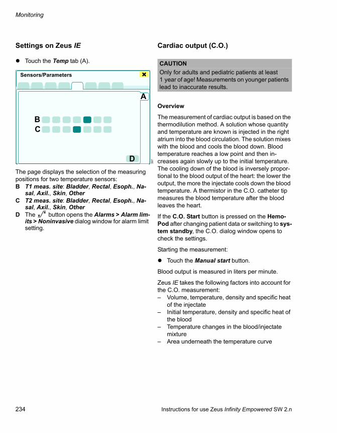
Monitoring
234 Instructions for use Zeus Infinity Empowered SW 2.n
Settings on Zeus IE
Touch the Temp tab (A).
The page displays the selection of the measuring positions for two temperature sensors:B T1 meas. site: Bladder, Rectal, Esoph., Na-
sal, Axil., Skin, OtherC T2 meas. site: Bladder, Rectal, Esoph., Na-
sal, Axil., Skin, OtherD The button opens the Alarms > Alarm lim-
its > Noninvasive dialog window for alarm limit setting.
Cardiac output (C.O.)
Overview
The measurement of cardiac output is based on the thermodilution method. A solution whose quantity and temperature are known is injected in the right atrium into the blood circulation. The solution mixes with the blood and cools the blood down. Blood temperature reaches a low point and then in-creases again slowly up to the initial temperature. The cooling down of the blood is inversely propor-tional to the blood output of the heart: the lower the output, the more the injectate cools down the blood temperature. A thermistor in the C.O. catheter tip measures the blood temperature after the blood leaves the heart.
If the C.O. Start button is pressed on the Hemo-Pod after changing patient data or switching to sys-tem standby, the C.O. dialog window opens to check the settings.
Starting the measurement:
Touch the Manual start button.
Blood output is measured in liters per minute.
Zeus IE takes the following factors into account for the C.O. measurement:– Volume, temperature, density and specific heat
of the injectate– Initial temperature, density and specific heat of
the blood– Temperature changes in the blood/injectate
mixture– Area underneath the temperature curve
397
Sensors/Parameters
A
BC
D
CAUTIONOnly for adults and pediatric patients at least 1 year of age! Measurements on younger patients lead to inaccurate results.

Instructions for use Zeus Infinity Empowered SW 2.n 235
Monitoring
Measuring accuracy
Take the following measures to ensure optimal measuring accuracy:
Observe the attached instructions provided by the catheter manufacturer. Filled syringes or the closed autoinjector should be placed in an ice bath.
Check the temperature of the ice bath. It should be lie between 0 °C and 5 °C. The accuracy of the measurements increases as injectate tem-perature gets closer to 0 °C.
Check the volume of the injectate.
Check catheter constant.
If syringes are filled manually, the same volume should always be used (normally 10 cc for adults and 5 cc for pediatric patients).
Administer the injectate quickly at the end of a respiration cycle.
If C.O. measurements are performed succes-sively at different times in the respiration cycle, then the results may deviate from each other, particularly in ventilated patients.
Measured values which deviate from the gen-eral trend or correspond to a very irregular curve segment are not considered when deter-mining the average.
If an injectate having room temperature is used, 10 cc must be injected. Only deviate from this volume when there are important clinical rea-sons.
C.O. screen display
The C.O. parameter box displays:– C.O. (cardiac output): The saved average value
of the last measuring series (in L/min)– TBlood (blood temperature)– Time of the creation of the average value– CI (Cardiac Index)
Calculation: CI = C.O. / Body surface area
Additionally after touching the Display all button (prerequisite: Display all button has been config-ured, see page 332):– Currently set alarm limits
In automatic measuring mode, you must wait for the Inject now message for the injection of the in-jectate. The message appears if the initial temper-ature of the blood is stable.
Once Zeus IE detects a drop in blood temperature after injection of the injectate, the C.O. values are created. If fluctuations in the initial blood tempera-ture occur, the Inject now message disappears and Zeus IE interrupts measurement until the initial temperature is stable again.
The mean value is continuously calculated with each single measurement which is performed or discarded.
In the C.O. dialog window, the value appears in the next available display field and the value in the stor-age field is updated.
If all free storage fields are allocated, the oldest C.O. curve is deleted or a storage field must be de-leted manually:
Touch the Delete C.O. trial button.
214
4.8 37.13.1243.0
25.0
C.O. L/min
TBlood
CI
11:26
WARNINGAlways ensure before a C.O. measurement that the settings are appropriate for the cathe-ters actually used. Otherwise, measurements may be unreliable, causing a wrong assess-ment of the patient's status.

Monitoring
236 Instructions for use Zeus Infinity Empowered SW 2.n
Settings on Zeus IE
Different measuring methods can result in different measuring results for the same patient. To compen-sate for the differences, up to four consecutively generated C.O. values can be displayed. The mean value is continuously calculated with each single measurement which is performed or discarded. Any number of measuring attempts can be per-formed one after the other.
Performing C.O. measurement
In the Sensors/Parameters > C.O./ Calculat. dialog window, touch the C.O. tab (A).
The C.O. page displays:B The largest field with the temperature change
and calculated value of the measurement that has just been performed
C The previous measurements are displayed in the 4 smaller fields
D Manual start: Start of C.O. measurementE Delete C.O. trial: Entry is deletedF C.O.average: Display of the running average
valueG C.O. complete: Ending the C.O. measurementH Cancel: Cancellation of a measuring series
without saving a new measured value. The dia-log window closes.
I The button opens the Alarms > Alarm lim-its > Noninvasive dialog window for alarm limit setting.
Closing the dialog window via always leads to the cancellation of the C.O. measurement currently in progress. Measurements in a measuring series that have already been completed are retained so that the measuring series can be finished later if necessary.
Configuration
Touch the Config. tab (J).
The settings on the Config. page can only be mod-ified at the beginning of a new measuring series.
The Config. page displays:K Catheter type: Baxter, Spectra. Ohmeda, Ar-
row, Other
If catheters from Baxter, Spectra. Ohmeda or Arrow are used, the catheter constant is auto-matically specified. The catheter constant can be changed as needed, e.g., if volume or tem-perature of the injectate is changed.
If catheters from other manufacturers (P) are used, the selection fields for Catheter size and Injection volume are shown in gray. A compu-tation constant (O) must first be entered.
457
Sensors/Parameters
A
B
C
D
E
G H IF
398
WARNINGThe input of a wrong catheter constant can lead to inaccurate measured results and pos-sibly to a wrong medical diagnosis. If the cath-eter constant was entered manually, make sure an appropriate catheter is used.
Sensors/Parameters
JKLMNO
P

Instructions for use Zeus Infinity Empowered SW 2.n 237
Monitoring
L Catheter sizeM Injection volumeN Baseline detection mode: Auto, Man.O Computation constant: The setting for the
computation constant for the selection of cathe-ter type Other (P).
C.O. calculations
Touch the Cardiac calculat. (Q) tab.
The Cardiac calculat. page contains the results of four C.O. measurements, derived hemodynamic parameters and the mean values calculated from them.
Hemodynamic calculations
If C.O. measurements are performed, Zeus IE au-tomatically calculates different derived hemody-namic parameters, provides them with a time marker and stores them in a special database.
The values in the dark fields may be entered and modified manually.
Touch the Save button (R).
The table data is ultimately saved in the calculation trends, see page 184. At least the C.O. or PWP value must be measured. The time in the calcula-tion trends is the time when the Save button was touched.
Hemodynamic parameters
A calculation is based on the values from the follow-ing hemodynamic parameters:
399
1 2 3 4
Sensors/Parameters
Q
R
AVG
CAUTIONTo obtain reliable calculation results, the following should be observed:
Ensure that the patient data has been entered correctly.
A measurement of the pulmonary wedge pres-sure and a measurement of the cardiac output must be performed. Otherwise, the result display is incomplete.
Parameter DesignationHR Current heart rate
ART M Current mean arterial pressure
PA M Current mean pulmonary artery pressure
PWP Latest value of the pulmonary wedge pressure
CVP Current central venous pressure
C.O. Latest value of cardiac output
Weight Entered body weight of the patient
WARNINGMake sure that the present weight is not the patient's weight on admission, but the current weight. An incorrect weight can lead to incor-rect calculation results and hence, an incor-rect clinical assessment and treatment of the patient.

Monitoring
238 Instructions for use Zeus Infinity Empowered SW 2.n
Zeus IE calculates the following hemodynamic pa-rameters with the indicated units of measurement:
Anesthesia effect monitoring
Anesthesia effect monitoring is suitable for adults and pediatric patients at least 1 year of age.
Connect the anesthesia effect monitoring acces-sory to the Aux/Hemo 2/3 connector:
– InfinityTrident SmartPod for neuromuscular monitoring is based on the electrical stimulation of peripheral nerves and measures the me-chanical response of the associated group of muscles. The NMT parameter (neuromuscular transmission/muscular blockade) indicates the patient's muscle relaxation.
– Infinity BISx SmartPod for measuring seda-tion effects is based on BIS-XP technology. The BISx parameter (bispectral index) indicates the effects of sedation on the brain.
Neuromuscular Transmission Monitor-ing (NMT)
The pulses are sent via two stimulation electrodes over the nervus ulnaris. The NMT sensor consists of an accelerometer (acceleration measuring trans-ducer) and measures muscle response (muscular blockade) to the pulses. Skin temperature is also measured using a temperature sensor.
At the start of measurement, the non-relaxed pa-tient is exposed to test pulses in order to determine the supramaximal current. At the determined su-pramaximal current, 4 pulses are applied in order to determine a reference measure for the muscle re-sponse for a non-relaxed patient.
Operating modes: TOF, Single, PTC
Single Twitch
A single pulse is applied. The response of the pulse is compared to the reference pulse.
TOF
Train of Four – A series of 4 pulses is applied. The number of stimuli answered or the ratio of the first response to the fourth one indicate the degree of muscle relaxation.
PTC
Post Tetanic CountA 50 Hz signal is applied for 5 seconds. After a pause of 5 seconds, up to 20 1 Hz signals occur. The number displayed indicates the responses counted. Only perform on a patient under sufficient sedation!
Parameter DesignationBSA Body surface area [m2]
CI Intermittent cardiac index [L/min/m2]
LVSWI Left ventricular stroke work index [g x m/m2]
RVSWI Right ventricular stroke work index [g x m/m2]
PVR Pulmonary vascular resistance in-dex [dynes x sec./cm–5]
PVRI Pulmonary vascular resistance in-dex [dynes x sec./cm–5/m2]
SV Stroke volume [mL]
SVI Stroke volume index [mL/m2]
SVR Systemic vascular resistance [dyn x sec./cm–5]
SVRI Systemic vascular resistance index [dyn x sec./cm–5/m2]

Instructions for use Zeus Infinity Empowered SW 2.n 239
Monitoring
NMT safety instructions
NOTEThe NMT module is not supported in neonatal mode.
NOTEDo not use the NMT temperature sensor for measuring core body temperature.
NOTEThe NMT module produces high-frequency pulses. Make sure they do not interfere with other sensitive equipment.
NOTEDo not use the NMT pod in the presence of com-bustible anesthetic gases.
CAUTIONOnly use accessories approved by Dräger. Other-wise, correct functioning may be impaired.
WARNINGTake special care when using electrodes with a current density of >2 mA eff./cm2! Only use electrodes which are suitable for use with pe-ripheral nerves stimulators!
WARNINGSimultaneous use of HF surgery and the NMT pod on the same extremity of the patient can lead to burns caused by the electrodes of the pod and to a fault in the pod.
WARNINGDo not touch active NMT electrodes. Active stimulation is indicated on the NMT pod. Oth-erwise there is a risk that measuring results will be distorted.
WARNINGOnly attach the electrodes as described. In-correct positioning of the electrodes can seri-ously endanger the patient! Do not attach electrodes to places where inflammation or in-jury is apparent. Electrodes must not be laid across the chest.
WARNINGRisk of patient injury
NMT modules must not be used on patients with heart pacemakers unless this is in-structed by a medical specialist. Before using the NMT monitoring, check whether the stimu-lation has an effect on the heart pacemaker.
WARNINGWhen using the NMT Pod, maintain a distance of 1 meter from shortwave and microwave equipment. Otherwise, correct measurements will not be possible.
WARNINGWith patients who have nervous or neuromus-cular problems, it may occur that they re-spond incorrectly to nerve stimulation. Unu-sual patterns may be displayed in the NMT module while relaxation is monitored.
WARNINGTo avoid electric shock all the cables must be checked carefully before use. No liquids must be allowed to drip onto connectors, elec-trodes or electrical leads.
WARNINGCheck cables and sensors for damage before use. Otherwise there is a danger of electric shock and the possibility of distorting meas-urement results.

Monitoring
240 Instructions for use Zeus Infinity Empowered SW 2.n
Preparing for NMT
1 Attach the black stimulation electrode (A) and the red stimulation electrode (B) to the arm (above the nervus ulnaris).
2 Connect the pod connecting cable (C) to the Tri-dent pod and to the Aux/Hemo 2/3 connector on Zeus IE.
3 Attach the NMT sensor (D) to the thumb and in-dex finger. Secure with a rubber band.
4 Connect the electrodes and NMT sensor to the NMT accessory cable (E).
5 Connect the NMT accessory cable to the Tri-dent pod (F).
WARNINGRisk of burns
When fitting the module, make sure there is sufficient air ventilation/heat dissipation and that there can be no direct contact between the patient and the exterior of the module.
WARNINGMake sure that there is no contact between the electrodes and other conducting parts.
Cover stimulation electrodes with insulating material so that, e.g., catheters are not sub-jected to stimulation.
278
Trig
NMT
EEG
Monitor!
A B
C
DE
F

Instructions for use Zeus Infinity Empowered SW 2.n 241
Monitoring
Settings on Zeus IE
In the Sensors/Parameters > BIS/NMT dialog window, touch the NMT tab (A).
The NMT page displays:B Stimulation: NMT start buttonC Mode of the measurement: Single, TOF, PTCD Interval: Time intervals for applying a pulse
In PTC mode, no time interval can be selected. In TOF mode, the interval of 1 s cannot be se-lected (grayed out).
E Pulse width [µs]: Duration of the applied pulse in µs
F Current [mA]: When the Auto current mode is selected, the button remains disabled (gray).
G Current mode: Selection for setting stimulation current:
Auto: A suitable stimulation current between 5 and 60 mA is determined in conjunction with each new referencing procedure, ensuring reli-able measurement and minimizing the load on the patient.
Man: Pulse value which can be set with the ro-tary knob, 5 to 60 mA in 5 mA incrementsIf the value is changed in current mode Man, a new reference value is determined!
H Delete reference: Clear button to delete the saved reference pulse and the supramaximal current determined.
I The button opens the Alarms > Alarm lim-its > Noninvasive dialog window for alarm limit setting.
Starting the NMT measurement
In the Sensors/Parameters > BIS/NMT > NMT dialog window, touch the NMT start (J) button.
Or if the NMT start button is configured (see page 332):
In the main menu bar, touch the NMT start but-ton.
At the start of measurement, the NMT pod emits stimulation pulses in order to determine the upper stimulation current intensity (supramaximal cur-rent). Then 4 pulses are applied for reference measurement.
In the ensuing single mode measurements, the NMT pod compares the measurements with the ref-erence measurement.
The supramaximal current and the reference are determined again after the start of a measurement:
– if a Trident pod or sensors have previously been connected or
– if the pulse width is changed.
Current mode Use Auto.
Determine supramaximal current and reference pulse on the non-relaxed patient!
400
Sensors/Parameters
ABCDEFGH I
WARNINGNMT nerve stimulation can be painful for a pa-tient not under sedation. Only administer the stimuli after sufficient sedation.
421
Sensors/Parameters
JK

Monitoring
242 Instructions for use Zeus Infinity Empowered SW 2.n
If no supramaximal current can be determined for the current measurement, the device uses 60 mA.
If no reference measure can be determined, a de-vice-internal reference is used.
Single Twitch
A single pulse is applied. Muscle response to this pulse is measured and compared with the refer-ence pulse.
The NMT pod repeats stimulation at the set time in-terval.
If the value for stimulation current or pulse width is changed, a new reference value will be determined!
Settings on Zeus IE for Single Twitch
Select Single measuring mode (K) and confirm with NMT start button (J).
NMT screen display
The parameter box for Single Twitch indicates the muscle response as a bar graph and as a numerical value in %.
Example: A display of 90 means that muscle re-sponse is 90 % of the reference pulse.
Additionally after touching the Display all button (prerequisite: Display all button has been config-ured, see page 332):– Currently set alarm limits
Skin temperature is displayed.
60 seconds after a successful single or TOF meas-urement, the measured value is deleted.
TOF
Train of Four – A series of 4 pulses is applied. The number of pulses answered indicates the degree of muscle relaxation. The NMT pod repeats stimula-tion at the set time interval.
TOF settings on Zeus IE
Select TOF measuring mode (L) and confirm with NMT start button (J).
213
210
90100
040 11:34
NMT %Ratio Temp °C
Single
100
040
NMT %Temp °C
Single15 min
487
Sensors/Parameters
LJ

Instructions for use Zeus Infinity Empowered SW 2.n 243
Monitoring
TOF ratio screen display
Muscle response to each individual pulse is meas-ured and displayed as a bar graph.
The ratio of the fourth pulse to the first pulse, T4/T1, is displayed as a TOF ratio in %, e.g. 48.
After 15 seconds, the last measured value is de-leted. The time until the next measurement is dis-played as a bar graph.
TOF count screen display
If fewer than 4 stimulation pulses are detected, the TOF count value is displayed, e.g., 1.
TOF count – number of pulses that produced a re-sponse.
For TOF count, an upper and a lower alarm limit can be set, see page 163.
PTC (Post Tetanic Count)
A 50 Hz signal is applied for 5 seconds. After a pause of 5 seconds, there will be up to 20 1 Hz sig-nals.
PTC settings on Zeus IE
Select PTC measuring mode (M) and confirm with NMT start button (J).
PTC screen display
The number of pulses answered is displayed. While measurement is taking place the measured value is grayed out.
209
208
207
100
0 48 40 11:38
NMT %Ratio
TOF
Temp °C
100
040
NMT %Temp °C
TOF
5 min
100
0 1 40 11:39
NMT %Count
TOF
Temp °C
WARNINGOnly perform on a patient under sufficient se-dation when there are no further TOF re-sponses! PTC stimulation on a conscious pa-tient is very painful.
488
205
Sensors/Parameters
MJ
1 40
NMTCount
%Temp °C
PTC

Monitoring
244 Instructions for use Zeus Infinity Empowered SW 2.n
The measured value remains up to the next meas-urement (Auto mode is not possible).
BIS monitoring
The BISx module plots the electroencephalogram (brain wave). The brain wave reflects all brain activ-ity produced in the cortical region of the brain.
The electric signals from the brain are picked up by an easy-to-apply Multi-Sensor (BIS sensor), proc-essed in the BISx pod and displayed on Zeus IE.
The BIS index calculated indicates a number be-tween 1 and 100. The value of 100 indicates a con-scious patient while values below 70 indicate suffi-cient sedation/hypnosis.
This table reflects a general association between clinical state and BIS values.
The areas are based on a multi-center study.
For the BIS values and BIS areas, it must be as-sumed that they are free of artefacts that could in-fluence the measurement.
BISx technology is the latest generation of BIS technology, which features enhanced screening against artefacts from external HF surgery equip-ment and filters out any EMG influences.
The BIS index provides insight to the cerebral sta-tus and is not a measurement of drug concentra-tion. The cerebral cortex responds very sensitively to external influences, drugs and pathological proc-esses. The BIS index decreases during normal sleep and also during administration of hypnotic drugs.
However, the values during normal sleep do not fall as low as those during anesthesia.
The BIS index is determined as an average over a period of 15 seconds and generated every second.
206
BIS area Clinical state100 Conscious
Response to normal voice
80 Light/moderate sedation
Possible response to loud com-mands or gentle pushing / shaking
60 General anesthesia
Low probability of explicit memory
No response to verbal stimulus
40 Deep hypnosis
20 Burst Suppression
0 Baseline EEG
10 40 11:41
NMT %Count Temp °C
PTC

Instructions for use Zeus Infinity Empowered SW 2.n 245
Monitoring
Settings on Zeus IE
In the Sensors/Parameters > BIS/NMT dialog window, touch the BIS tab (A).
The BIS page displays:B EEG waveform displayC EEG scale: Selection of the scale for the EEG
waveform in µVD Smoothing rate [s]: Selection of the smoothing
rate used to calculate the BIS value average– 15 s (basic setting): Increased responsive-
ness to changes (e.g., induction or waking).– 30 s: A smoother trend (with reduced varia-
bility and sensitivity to artefact)E Filter:
– On: Filter out interference from the raw EEG signal
– Off: Display of the raw EEG without filterF remaining applications for SRS sensorG The button opens the Alarms > Alarm lim-
its > Noninvasive dialog window for alarm limit setting.
Displaying all BISx parameters
Touch the All EEG values button (H).
The following is displayed:I BIS: Bispectral index (0 to 100)
Continuously processed EEG parameters which correspond to the state of consciousness of the patient: 100 = conscious, 0 = base line
J SQI: Signal quality index (0 to 100 %)Measurement of signal quality for the EEG channel source which is calculated based on impedance data, artefact and other variables.
K EMG: Electromyographic display (0 to 100 dB)The output (in dB) in the frequency range 70 to 110 Hz is marked with EMG. This frequency range contains the percentage of muscular ac-tivity and of other high-frequency artefacts on the total output.
L BSR: Burst suppression ratio (0 to 100 %)Indication of an inactive EEG. The suppression rate is the timer percentage of the last 63-sec-ond period in which the signal is recognized as "in the suppressed state".Example: BSR = 11 (isoelectric over 11 % of the last 63-second period or 7 seconds)
M SEF: Spectral edge frequency (0.5 to 30.00 Hz)Frequency at which 95 % of the total energy lies below and 5 % of the total energy lies above
N PWR: Total output (40 to 100 dB)Measurement of the absolute total output in the frequency range of 0.5 to 30 Hz
O BCT: Burst count (0 to 30)Alternative to BSR to quantify the suppression in the EEG. It shows the number of EEG bursts in the last minute. The burst count is only acti-vated if an extension sensor is connected. The BCT value is empty for all other sensor types.
403
Sensors/Parameters
AB
CDE
GHF
458
All EEG values
I
JK
L
M
NO

Monitoring
246 Instructions for use Zeus Infinity Empowered SW 2.n
Patient preparation
Careful preparation of the skin as well as correct positioning of the electrodes is crucial for the gen-eration of distinct signals.
BIS safety instructions
CAUTIONOnly use accessories approved by Dräger. Other-wise, correct functioning may be impaired.
WARNINGTo avoid electric shock all the cables must be checked carefully before use. No liquids must be allowed to drip onto connectors, elec-trodes or electrode leads.
WARNINGCheck cables and sensors for damage before use. Risk of electric shock and distortion of measuring results.
CAUTIONUse undamaged sensors and packaging only.
WARNINGConductive parts of the electrodes and con-nections (including the neutral electrode) must not come into contact with other con-ductive parts (including grounded parts).
WARNINGWhen using an electrocautery scalpel during surgery the scalpel must not come into con-tact with the BIS sensor. Risk of electric shock!
WARNINGThe electrodes should not be located between the operating field and the return electrode of the electrosurgical device. Otherwise, there may be a risk of burns if the neutral surgical high-frequency electrode is faulty.
WARNINGIf a BISx pod and a defibrillator are being used simultaneously, do not position the BIS sen-sor between the defibrillator and the patient! Risk of electric shock!
WARNINGWhen fitting the module, make sure there is sufficient heat dissipation and that there can be no direct contact between the patient and the exterior of the module. Risk of burns!
WARNINGOperation of the BISx module during magnetic resonance imaging (MRI) is not supported at present.
WARNINGTo prevent strangulation risks the BIS sensor cable must be positioned and attached care-fully.
CAUTIONA correctly positioned BISx module is attached to the infusion apparatus stand, bars of the bed or the bed sheet.
CAUTIONIn the event of a continuous reduction in BIS sig-nal, skin irritations or intense perspiration replace the sensor more frequently.
NOTEWhen interpreting the BIS together with other clin-ical signs available, a clinical assessment must al-ways be used in addition. Solely relying on the BIS when administering intraoperative anesthetic agents and sedatives is not recommended.

Instructions for use Zeus Infinity Empowered SW 2.n 247
Monitoring
Attaching the BIS sensor
Follow instructions on the sensor package for skin preparation and correct positioning.
1 Observe the instructions and numbering of electrodes on the sensor!
2 Position the adult sensor at an oblique angle across the forehead:– Electrode 1 approx. 5 cm above the nose– Electrode 4 above the eyebrow– Electrode 3 between the corner of the eye
and the hairline
3 For good contact on the skin carefully press all the electrodes onto the forehead with a finger-tip, for at least 5 seconds.
4 Fix the sensor in place with adhesive tape or plaster.
5 Connect the patient connecting cable (A) to the sensor. Lay and secure the cable carefully.
6 Connect the pod connecting cable (B) to the Aux/Hemo 2/3 connector (see page 197) or to the Trident NMT pod (see page 238).
7 Attach the BISx pod to a bracket or infusion ap-paratus stand using the clip on the back of the pod.
NOTEArtefacts and inferior signal quality can lead to in-correct BIS values. Possible artefacts can be caused by inadequate skin contact (high imped-ance), muscular activity or rigidity, head and body movements, repeated eye movements, incorrect sensor positioning and unusual or excessive elec-trical interference.
NOTECarefully interpret BIS values for:– Patients with known neurological diseases– Patients taking other psychoactive drugs – Children under one year of age
284
CAUTIONOnly use the BISx Quatro sensor (for adults), the BISx Pediatric sensor (pediatric applications) or the BIS SRS sensor! Otherwise, incorrect meas-uring results will be obtained.
12
4
3
275
BISX
A
B

Monitoring
248 Instructions for use Zeus Infinity Empowered SW 2.n
Impedance test
As soon as the sensor is connected to Zeus IE an automatic impedance test commences to test the quality of the BIS electrode connection.
The dialog window for the impedance test can be opened via Sensors/Parameters > BIS/NMT > Im-ped. check (A).
The page displays:B EEG waveform displayC EEG scale: Scale for the EEG waveform in µVD SEF display: Selection of an additional param-
eter displayed in the parameter box
Spectral edge frequency SEF: 0.5 to 30 Hz in 0.1 Hz increments
Total power PWR: 40 to 100, in 1 dB increments (in the frequency range of 0.3 to 110 Hz)
Burst count BCT: 0 to 30 in 1-unit increments
E Check sensor: Start button for the manual sensor check with display of starting time
F Electrode status: Electrodes 1 to 4, depending on the sensor being used
G The button opens the Alarms > Alarm lim-its > Noninvasive dialog window for alarm limit setting.
After the first impedance test, the color of the Start button (E) changes from gray to green. Further im-pedance test can be manually started. Zeus IE re-ports the general status of the impedance testing as follows:
Pass – means that the impedance testing based on the impedance of the combined electrodes was successful.
Close dialog window and continue BIS monitor-ing.
Fail – means that the impedance testing failed.
Press the electrodes on again firmly, improve positioning
Replace sensor if necessary
NOTEBefore commencing BIS monitoring make sure the sensor is connected up properly and that it has passed the impedance check.
CAUTIONThe impedance check signal emitted by the BISx module can cause interference with other equip-ment (e.g. evoked potential monitors).
402
Sensors/Parameters
AB
CDEF
G
NOTEAn automatic sensor impedance check is per-formed whenever a BIS sensor is connected to the sensor cable.
NOTEWhen the sensor impedance check has been completed, all the signal status messages and alarms are suspended for 60 seconds. The time is required in order to restore signal quality.

Instructions for use Zeus Infinity Empowered SW 2.n 249
Fault – Cause – Remedy
Fault – Cause – Remedy
Failure behavior . . . . . . . . . . . . . . . . . . . . . . . 250
Power outage . . . . . . . . . . . . . . . . . . . . . . . . . 250
Gas failure . . . . . . . . . . . . . . . . . . . . . . . . . . . . 251
Ventilator failure . . . . . . . . . . . . . . . . . . . . . . . 252
Anesthetic gas delivery failure (DIVA failure) . . . . . . . . . . . . . . . . . . . . . . . . . . . . . . . 252
Mixer and DIVA failure . . . . . . . . . . . . . . . . . . 252
Rotary safety knob Anesth. Ventilator Off for ventilation . . . . . . . . . . . . . . . . . . . . . . 253
In the event of partial system failures . . . . . 253
Screen error . . . . . . . . . . . . . . . . . . . . . . . . . . . 254
In the event of device failure . . . . . . . . . . . . . 254
Failure behavior DPS . . . . . . . . . . . . . . . . . . . 255
Messages Zeus IE. . . . . . . . . . . . . . . . . . . . . . 255
Alarm – Cause – Remedy . . . . . . . . . . . . . . . . 256
Metering module faults . . . . . . . . . . . . . . . . . 317
In operation. . . . . . . . . . . . . . . . . . . . . . . . . . . . 317When filling and emptying . . . . . . . . . . . . . . . . 318

Fault – Cause – Remedy
250 Instructions for use Zeus Infinity Empowered SW 2.n
Failure behavior
In the event of an alarm and device-related failures, the corresponding alarm message appears in the alarm message field (A).
Power outage
If the power goes out, Zeus IE automatically switches over to the integrated uninterruptible power supply (UPS).
With a fully charged battery, operation is main-tained for at least 30 minutes.
The Mains supply failure message appears in the alarm message field.
The remaining battery capacity is displayed in per-cent in the system field (B).
Example: 82 %
If the battery capacity is low, one of the following messages appears:– Battery low: Battery capacity <20 %
Or– Battery very low: Battery capacity <10 %. The
device may switch off at any time!
In the event of a power failure and empty batteries, Zeus IE enables manual ventilation and spontane-ous breathing with 100% O2.
– The ventilator, gas and anesthetic agent de-livery as well as monitoring are inoperable.
– The DIVA metering modules are locked.
1 Unlock the O2 rotary safety knob for emergency O2 delivery by pressing it and set it to the re-quired O2 flow. Range 0 to 12 L/min. Use pres-sure gauge to monitor the pressure.
During this phase, anesthetic agent delivery is not possible!
2 Ventilate the patient manually!
3 Recharge the empty battery by plugging in the power cable for at least 10 hours.
301
1:35A B
CAUTIONRisk of patient injury
The Basis (IVDock) is no longer supplied with power. Each Module DPS is powered by its own battery. Pay attention to the battery warning! Infu-sion is automatically stopped when the battery is empty. Charge the battery as soon as possible.

Instructions for use Zeus Infinity Empowered SW 2.n 251
Fault – Cause – Remedy
Gas failure
Zeus IE displays the following messages in the event of a gas failure:
– Air supply fail,– N2O supply fail or– Oxygen supply fail.
Open the corresponding cylinder valve of the backup gas cylinders (optional) located at the back.
Restore central gas supply.
If backup gas is available for the failed gas, the cor-responding LED below the screen lights up.
– In the event of an O2 failure, Zeus IE delivers 100 % Air. Anesthetic gas delivery is locked.
– In the event of an N2O failure, Zeus IE delivers 100 % O2.
– In the event of an Air failure, Zeus IE delivers 100 % O2.
The amount of fresh-gas flow (L/min) remains con-stant.
Operation of fresh-gas delivery is still possible when supply of one gas fails. For example, in the case of N2O failure, the device can switch to carrier gas Air or 100% O2.
WARNINGRisk of contamination of the gas supply
In the event of lengthy outages, disconnect the relevant gas from the gas supply! Other-wise, contamination of the central supply can occur.
CAUTIONPatient risk!
If O2 and Air fail, the patient must be immediately ventilated with the separate emergency breathing bag!
CAUTIONRisk of patient recovering consciousness
Anesthetic agent delivery requires Air as driving gas.
If the Air supply fails, the delivery will only be con-tinued for a further 10 minutes approximately!

Fault – Cause – Remedy
252 Instructions for use Zeus Infinity Empowered SW 2.n
Ventilator failure
Zeus IE displays the following message in the event of ventilator failure:
Ventilator failure
If the ventilator fails, only manual ventilation or spontaneous breathing is possible. All other venti-lation modes are unavailable. The gas and anes-thetic agent delivery unit is ready for further use. Select the fresh-gas control mode and check the breathing system or blower spindle visually and acoustically after the end of ventilation.
Anesthetic gas delivery failure (DIVA failure)
If gas delivery is switched off due to internal device errors, the FG ISO button (example), see page 116, or etISO button (example), see page 118, is no longer available. If necessary, select the FG ctrl. mode and set a low fresh-gas flow.
Ventilation is still operational.
Zeus IE displays the following message in the event of anesthetic gas delivery failure:
VA delivery failure
Continue anesthesia with IV agents
Contact DrägerService
Mixer and DIVA failure
If gas delivery and gas mixing are switched off due to internal device errors, ventilation remains opera-tional.
Zeus IE indicates the failure with:
DIVA+mixer failure
Press the rotary safety knob O2 to move it out and adjust the O2 flow by turning.
The breathing bag fills; the filling process can be heard.
Anesthetic agent is not delivered!
After switching off the device, return the rotary safety know for O2 to the original position and push it in.
CAUTIONRisk of patient injury
If the ventilator fails, only manual ventilation or spontaneous breathing is possible.
Manually ventilate the patient. Using the mechan-ical airway manometer, check whether ventilation continues. Contact DrägerService!

Instructions for use Zeus Infinity Empowered SW 2.n 253
Fault – Cause – Remedy
Rotary safety knob Anesth. Ventilator Off for ventilation
If ventilation and delivery have to be immediately canceled due to internal device errors:
1 Press the rotary safety knob Anesth. Ventila-tor Off to move it out.
2 Turn the rotary safety knob Anesth. Ventilator Off (A) fully counterclockwise.
– Ventilation stops.– Anesthetic agent delivery is locked.– Fresh-gas delivery is stopped. However,
0.5 L/min O2 will continue to be delivered.– Patient monitoring remains activated.
Zeus IE indicates the failure with:
Anesth. Ventilator Off
If necessary:
Ventilate the patient by hand with the emer-gency oxygen supply and the breathing bag!
1 Press the rotary safety knob O2 (B) to move it out.
2 Turn the rotary safety knob O2 (B) and adjust the O2 flow.
The breathing bag fills; the filling process can be heard.
Anesthetic agent is not delivered!
After switching off the device, return the rotary safety knobs Anesth. Ventilator Off (A) and O2 (B) to the original position and push in.
In the event of partial system failures
Zeus IE indicates component failure:
– DIVA+mixer failure
– Patient monitoring fail
Touch the Software reset? button (A) in the header bar if necessary.
The device performs a warm start.
Reboot: Takes approx. 30 seconds to 3 minutes. Monitoring is unavailable during this time.
– Ventilation continues (fresh-gas mode at 0.5 L/min; with external fresh-gas outlet option: 3 L/min).
– Check ventilation with manual pressure gauge. Perform manual ventilation if necessary.
097
A B
326
ACAUTIONRisk of patient injury
Anesthetic gas is not delivered.

Fault – Cause – Remedy
254 Instructions for use Zeus Infinity Empowered SW 2.n
After the Reboot:
– Safety settings are activated, i.e. all the settings are retained.
Exception for gas delivery: delivers 0.5 L/min of O2 without anesthetic agent.
To acknowledge the Safety settings active alarm:
Press the Audio paused key.
Screen error
The screen does not respond to operation. It has failed or the display is faulty.
The screen can be rebooted if necessary:
1 Touch and hold the On/Off button for a least 4 seconds.
The screen turns off.
2 After the screen turns off, touch the On/Off but-ton again.
Reboot: Zeus IE performs a warm start of the screen which takes approx. 3 minutes. Monitoring is unavailable during this time.
– Ventilation continues (fresh-gas mode at 0.5 L/min; with optional ext. FG outlet: 3 L/min).
– Check ventilation with manual pressure gauge. Perform manual ventilation if necessary.
After the Reboot:
– Safety settings are activated, i.e. all the settings are retained.
Exception for gas delivery: delivers 0.5 L/min of O2 without anesthetic agent.
To acknowledge the Safety settings active alarm:
Press the Audio paused key.
In the event of device failure
If the device no longer responds or if the screen fails, the following must be observed:
Anesth. Ventilator Off means:– Ventilation: Manual/Spontaneous– Gas delivery: 0.5 L/min of O2– Anesthetic agent delivery: Off
1 Press the rotary safety knob O2 (B) to move it out.
2 Turn the rotary safety knob O2 (B) and adjust the O2 flow.
3 If necessary, fill the breathing bag via O2 flush O2+.
Contact DrägerService and use a substitute an-esthesia machine.
CAUTIONRisk of patient injury
Anesthetic gas is not delivered.
CAUTIONBased on the mechanical airway manometer, check whether ventilation continues. Manually ventilate the patient if necessary!
If necessary, press the rotary safety knob Anesth. Ventilator Off to move it out and activate by turn-ing clockwise to switch the ventilation and gas de-livery to manual emergency operation.
Ensure anesthesia. No anesthetic gases are de-livered. Patient risk!

Instructions for use Zeus Infinity Empowered SW 2.n 255
Fault – Cause – Remedy
Failure behavior DPS
If Zeus IE is unable to operate a Module DPS sy-ringe pump, the reasons can be as follows:
– Module DPS is not a Dräger syringe pump and has a software version which is not compatible. Zeus IE cannot operate it. The syringe pump continues to run.
– Incorrect configuration, see page 140.
Observe Module DPS instructions for use.
A syringe pump which has stopped and is then or already connected to Zeus IE generates the alarm message Infusion 1 stopped on Zeus IE after one minute.
Messages Zeus IE
The alarm messages are displayed in the message field of the header bar in hierarchical order.
Different background colors indicate the priority lev-els of the alarms.
Zeus IE divides alarm messages by priority into three categories:
To classify the alarms within an alarm category, in-ternal priority figures are indicated in the following table. The most critical alarm is given the number 255. Lower numbers indicate a lower alarm priority.
In the tables for Alarm info and Alarm log, see page 161, the priority of the alarm messages is also indicated by exclamation points.
Up to four high or medium-priority alarms from the following four alarm areas can be displayed simul-taneously:– Anesthesia– Hemodynamics (optional)– Ventilation– Infusion (optional)
From each alarm area at least one high-priority alarm is displayed, given that there is an active alarm.
Alarms are displayed according to priority, down-wards from top to bottom and from left to right.
Low-priority alarms are only displayed in the right-hand field of the alarm message field, the maximum being four alarms.
The following table lists the alarm messages in al-phabetical order. If an alarm occurs, the table helps identify the cause and to quickly remedy by means of the provided corrective actions. The possible causes and remedial measures should be looked through in the order they are listed until the alarm is resolved.
The alarm messages with cause and remedy are also displayed in the Alarms >Alarm info dialog window.
Warning (red) High priority
Caution (yellow) Medium priority
Note (cyan) Low priority

Fault – Cause – Remedy
256 Instructions for use Zeus Infinity Empowered SW 2.n
Alarm – Cause – Remedy
Classifi-cation
Pri-ority
Alarm text Cause Remedy
Note 150 2 mixed volatile agents
A second volatile agent was detected.
Switch to fresh gas mode until the second gas is washed out. Check the con-tent of DIVA module.
Caution 060 3 mixed volatile agents
A mixture of more than 2 vol-atile agents detected!
Fresh-gas control: flush with high fresh-gas flow. Auto control: system flushes automatically. Check content of DIVA module.
Caution 000 Acc. idioventr. rhythm
Series of 3 or more PVCs with a rate less than the VT rate.
Check patient and take ap-propriate action.
Caution 000 Action incomplete The last requested action did not work.
Please try again.
Note 255 Agent low alarms off
In Ventilator standby mode, the lower alarm limits for agent monitoring are disa-bled.
Check measured values.
Note 050 Air central supply high
Air central supply pressure too high. Air pressure higher than 8x100 kPa.
Check central Air supply. System must not be used at high pressures.
Note 200 Air central supply low
Air central supply pressure is low. Wall outlet is faulty. Air plug is not connected to wall outlet.
Check DIVA delivery. Check O2 concentration. Remove Air plug from wall outlet. Connect Air plug to wall outlet.
Caution 200 Air cylinder empty Air cylinder empty or not open (<20*100 kPa) and AIR central supply is low.
Reduce fresh-gas flow, use Auto control mode. Open or exchange Air cylinder. Check insp. O2 concentra-tion. Check central Air sup-ply.
Note 225 Air cylinder low Air cylinder pressure is low (20 – 55*100 kPa) and Air supply is low.
Prepare exchange of Air cylinder. Check Air supply.

Instructions for use Zeus Infinity Empowered SW 2.n 257
Fault – Cause – Remedy
Note 005 Air cylinder sensor fail
Air high pressure sensor not connected. Sensor failure.
Connect sensor. Check sensor. Call DrägerService.
Caution 255 Air supply fail Air supply failed. Central supply not connected. Com-pressed Air hose kinked.
Check central Air supply. Check connections. Open optional Air cylinder. Pre-pare IV Anesthesia.
Note 224 Air supply low Air supply low. Supply pres-sure between 180 and 260 kPa.
Check central supply.
Caution 255 Air+N2O delivery cutoff
Air+N2O delivery locked. Carrier gas was terminated by protection system. Mixer switches to 100 % O2
Check insp. concentration. Use IV anesthesia if neces-sary. Call DrägerService.
Caution 000 Air+N2O delivery failure
Carrier gas delivery failure! Mixer switches to 100 % O2 concentration!
Check inspiratory concentration. Use IV anesthesia if necessary. Call DrägerService.
Caution 200 Air+N2O delivery failure
Carrier gas delivery failure. Mixer switches to 100 % O2 concentration!
Check inspiratory concen-trations. Use IV anesthesia if necessary. Call DrägerService.
Note 200 Alarms acknowl-edged
Alarms have been acknowl-edged by pressing the Audio paused key. Alarm cause is still valid.
Check acknowledged pa-rameter.
Note 050 All alarms off All non-technical alarms are suspended for 1min in order to prevent false alarms.
This alarm will be deacti-vated automatically.
Warning 255 Anesth. Ventilator Off
Safety switch:Ventilator off activated. Ventilator, mixer and DIVA switch off.
Only use switch in an emer-gency. Ventilate manually. Open safety O2 valve. Use alternative anesthesia!
Classifi-cation
Pri-ority
Alarm text Cause Remedy

Fault – Cause – Remedy
258 Instructions for use Zeus Infinity Empowered SW 2.n
Warning 180 Apnea No automatic ventilation. No breath detected for 30 sec. No spont/ass. ventilation: No breath detected for 60 sec.
Ventilate patient by hand immediately! Check tubes for disconnection! Check ability to breath spontane-ously!
Caution 250 Apnea No automatic ventilation: No breath detected for 15 sec. No spont/ass. ventilation: No breath detected for 30 sec.
Ventilate patient by hand immediately! Check tubes for disconnection! Check ability to breath spontane-ously!
Note 050 Apnea alarms off Apnea alarms are sus-pended. To be used only dur-ing intubation, suctioning and manual ventilation.
Please pay special atten-tion! To be used only during intubation and suctioning
Warning 180 Apnea CO2 No automatic ventilation: No CO2 breath detected for 30 sec. No spont/ass. venti-lation: No breath detected by CO2 for 60 sec.
Ventilate patient by hand immediately! Check tubes for disconnection! Check ability to breath spontane-ously!
Caution 250 Apnea CO2 No automatic ventilation: No CO2 breath detected for 15 sec. No spont/ass. venti-lation: No breath detected by CO2 for 30 sec.
Ventilate patient by hand immediately! Check tubes for disconnection! Check ability to breath spontane-ously!
Note 175 Apnea flow No sufficient flow dynamics. Flow sensor not calibrated.
To check and calibrate, per-form self test or leak test.
Warning 180 Apnea flow No automatic ventilation: No flow breath detected for 30 sec. No spont/ass. venti-lation: No breath detected by flow for 60 sec.
Ventilate patient by hand immediately! Check tubes for disconnection! Check ability to breath spontane-ously!
Caution 250 Apnea flow No automatic ventilation: No flow breath detected for 15 sec. No spont/ass. venti-lation: No breath detected by flow for 30 sec.
Ventilate patient by hand immediately! Check tubes for disconnection! Check ability to breath spontane-ously!
Classifi-cation
Pri-ority
Alarm text Cause Remedy

Instructions for use Zeus Infinity Empowered SW 2.n 259
Fault – Cause – Remedy
Warning 180 Apnea pressure No automatic ventilation: No press. breath detected for 30 sec. No spont/ass. venti-lation: No breath detected by press. for 60 sec.
Ventilate patient by hand immediately! Check tubes for disconnection! Check ability to breath spontane-ously!
Caution 250 Apnea pressure No automatic ventilation: No press. breath detected for 15 sec. No spont/ass. venti-lation: No breath detected by press. for 30 sec.
Ventilate patient by hand immediately! Check tubes for disconnection! Check ability to breath spontane-ously!
Caution 025 Apnea ventilation No Pressure Support cycle triggered within time limit.
Check patient. Use manda-tory ventilation. Use lower flow trigger level.
Note 050 ART check zero Pressure transducer for specified parameter requires zeroing. The blood pressure zero of monitor may not cor-respond to the peripheral de-vice.
Zero the transducer.
Caution 090 ART D high Invasive pressure value out-side alarm limits.
Check patient and take ap-propriate action. Change the alarm limits if required. Check equipment and re-place if necessary.
Caution 090 ART D low Invasive pressure value out-side alarm limits.
Check patient and take ap-propriate action. Change the alarm limits if required. Check equipment and re-place if necessary.
Note 025 ART hardware fail Invasive blood pressure hardware failure.
Check hardware and re-place. Call DrägerService.
Caution 090 ART M high Invasive pressure value out-side alarm limits.
Check patient and take ap-propriate action. Change the alarm limits if required. Check equipment and re-place if necessary.
Classifi-cation
Pri-ority
Alarm text Cause Remedy

Fault – Cause – Remedy
260 Instructions for use Zeus Infinity Empowered SW 2.n
Caution 100 ART M low Invasive pressure value out-side alarm limits.
Check patient and take ap-propriate action. Change the alarm limits if required. Check equipment and re-place if necessary.
Note 150 ART nonstatic Press. transducer zeroing failed because of: Excessive signal noise A non-static waveform
Keep all tubing motionless, then rezero. Change the transducer. Check 3-way tap, then rezero.
Caution 050 ART out of range Invasive pressure signal out of measurement range.
Check patient and take ap-propriate action. Access the Pressure Labels menu and assign correct label. Check equipment and replace if necessary.
Caution 125 ART S high Invasive pressure value out-side alarm limits.
Check patient and take ap-propriate action. Change the alarm limits if required. Check equipment and re-place if necessary.
Caution 130 ART S low Invasive pressure value out-side alarm limits.
Check patient and take ap-propriate action. Change the alarm limits if required. Check equipment and re-place if necessary.
Warning 250 ART static Static pressure: -No pulse, -Press. transducer line blocked, -Catheter tip lodged against vessel wall, -Clot on the catheter tip.
Check patient and take ap-propriate action. Open sys-tem by turning the 3-way tap. Follow procedure for dislodging catheters. Fol-low procedure for clotted catheters.
Note 050 ART transducer fail Pressure transducer failed. Invasive pressure cannot be measured.
Check transducer and con-nections. Exchange trans-ducer.
Classifi-cation
Pri-ority
Alarm text Cause Remedy

Instructions for use Zeus Infinity Empowered SW 2.n 261
Fault – Cause – Remedy
Note 025 ART transducer unplugged
Pressure transducer for specified parameter is either unplugged or defective.
Active pressure: reconnect or replace the cable. Inac-tive pressure: turn off alarms.
Note 050 ART zeroing Mercury calibration in progress.
Complete calibration before you begin monitoring the patient.
Warning 255 Asystole No valid QRS complex de-tected for the last 6 sec.
Check the patient's condi-tion!
Warning 200 'Audio paused' key stuck
Key is stuck or was pressed for more than 10 seconds.
Press 'Audio paused' re-peatedly. If alarm condition persists, 'Audio paused' cannot be used anymore.
Caution 075 Auto control cutoff Unable to operate in Auto control mode. - Water trap? / - Sample line blocked? - sample line leak? - High tube leak? - MixGas? / - Soda lime exhausted?
Select mode: Fresh-gas control
Note 255 Auto control cut-off/high-flow
Unable to operate in Auto control mode. - Water trap? / -Sample line blocked? - Sample line leak? - High tube leak? - MixGas? / -Soda lime exhausted?
Select mode: Fresh-gas control!
Caution 255 AW press. protect. fail
Airway pressure measure-ment not plausible. Electr. protection system for airway pressure failed.
Check airway pressure sensors. Observe pressure gauge. Press 'Anesthesia ventilation off' switch. Venti-late manually. Perform self test.
Warning 250 AW pressure high Upper limit of breathing pres-sure or Pmax exceeded.
Check settings for Pmax and Paw alarm limit. Check spontaneous breathing.
Classifi-cation
Pri-ority
Alarm text Cause Remedy

Fault – Cause – Remedy
262 Instructions for use Zeus Infinity Empowered SW 2.n
Warning 250 AW pressure high Protection system: airway pressure higher than set-point. Stenosis or patient coughs.
Observe pressure gauge. Ventilate manually.
Caution 250 AW pressure low Airway pressure too low. Ventilation pressure not suf-ficient. Leakage of low fresh gas.
Check breathing circle leak-age. Check for adequate fresh gas flow.
Warning 220 AW pressure nega-tive
Mean airway pressure lower than –2 cmH2O. Airway pressure lower than –10 cmH2O. Bronchus suc-tioning. Inspiration reservoir insufficient.
Disconnect tube when suc-tioning. Increase fresh gas flow or use O2-flush.
Note 175 AW pressure sen-sor failure
Airway pressure measure-ment not plausible. Insuffi-cient dynamic response.
Check airway pressure sensors. Perform self test.
Note 175 AW pressure sen-sor failure
Insp.+exp. pressure sensor failed. No pressure monitor. Ventilator controlled by tur-bine speed.
Terminate automatic ventilation. Ventilate patient manually. Call DrägerService.
Note 170 Bag pressure sen-sor fail
Failure of manual vent. bag pressure sensor. Automatic Fresh-gas control not possi-ble!
System automatically in-creases fresh gas flow. Call DrägerService.
Note 150 Battery failure Battery of the uninterruptible power supply failed.
Exchange battery. Call DrägerService.
Caution 020 Battery low The capacity of the uninter-ruptible power supply is low (<50 %).
Restore power supply. Pre-pare for man. ventilation. Minimize power consump-tion. Check battery capacity display. If capacity is <10 % the device may be switched off!
Classifi-cation
Pri-ority
Alarm text Cause Remedy

Instructions for use Zeus Infinity Empowered SW 2.n 263
Fault – Cause – Remedy
Warning 150 Battery very low The capacity of the uninter-ruptible power supply is ex-hausted (<10 %).
Restore power supply. Pre-pare for man. ventilation. Minimize power consump-tion. Check battery capacity display. If capacity is <10 % the device may be switched off!
Caution 100 BIS high BIS value above higher alarm limit. Patients hypnotic state not appropriate.
Check patient. Treat, if nec-essary. Increase agent dose if necessary. Change alarm limit as appropriate.
Caution 100 BIS low BIS value below lower alarm limit.
Check patient. Treat, if nec-essary. Decrease agent dose if necessary. Change alarm limit as appropriate.
Caution 050 BIS out of range BIS parameter value out of range.
Check patient and treat, if necessary.
Caution 050 BIS out of range BIS parameter value out of range.
Check patient and treat, if necessary.
Note 210 BIS signal quality poor
SQI (Signal Quality Index) value goes below 50 %.
Check sensor. This may oc-cur as a result of artefact caused e.g. by eyeblinks or motion. Isolate patient from auxiliary equipment. Isolate patient from extraneous movement or vibration. Check patient. Treat, if nec-essary.
Note 050 BIS/NMT alarms off
BIS and NMT alarms sus-pended
Watch measured values to monitor patients status.
Classifi-cation
Pri-ority
Alarm text Cause Remedy

Fault – Cause – Remedy
264 Instructions for use Zeus Infinity Empowered SW 2.n
Note 100 BISX impedance check failed
BISx pod failed the sensor impedance check.
Retry impedance check. Re-prep the electrodes and retry. Replace sensor, if necessary and perform manual impedance check.
Note 100 BISX impedance check in progress
BISx pod is performing sen-sor impedance check.
Wait until impedance check is completed. Cancel check and retry.
Note 100 BISX pod discon-nected
BISx-Pod not connected. Check cables and connec-tions. Exchange BISx-pod, if necessary.
Note 105 BISX pod failed BISx pod self test failed. BISx pod hardware failure. BISx pod software failure.
Check BISx pod connec-tion. Call your biomed serv-ice or DrägerService.
Note 020 BISX pod initialis-ing
BISx pod is performing star-tup test.
Wait until test is completed.
Note 100 BISX replace sen-sor
Unknown sensor type. Too many uses./ Sensor worn out. Invalid sensor.
Remove unknown/worn out/invalid sensor and re-place with new/compatible sensor.
Note 100 BISX sensor dis-connected
Sensor malfunctioning or disconnected.
Check cables and connec-tions. Replace sensor, if necessary.
Note 100 BISx sensor has expired
Unknown sensor type. Too many uses./ Sensor worn out. Invalid sensor.
Remove unknown/worn out/invalid sensor and re-place with new/compatible sensor.
Note 100 BISx sensor will ex-pire after this ses-sion
The usage limit for the BISx SRS sensor has been reached.
Prepare a new BISx SRS sensor for next application.
Note 250 Bolus 1 rate high Pump 1 Bolus Rate Limit ex-ceeded
Check the bolus rate of the pump. Adjust settings if necessary.
Classifi-cation
Pri-ority
Alarm text Cause Remedy

Instructions for use Zeus Infinity Empowered SW 2.n 265
Fault – Cause – Remedy
Note 250 Bolus 2 rate high Pump 2 Bolus Rate Limit ex-ceeded
Check the bolus rate of the pump. Adjust settings if necessary.
Note 250 Bolus 3 rate high Pump 3 Bolus Rate Limit ex-ceeded
Check the bolus rate of the pump. Adjust settings if necessary.
Note 250 Bolus 4 rate high Pump 4 Bolus Rate Limit ex-ceeded
Check the bolus rate of the pump. Adjust settings if necessary.
Note 210 Breathing system not locked
The breathing system is not properly locked.
Insert the breathing system and lock it properly.
Note 100 C.O. blood temp. high
Blood temperature is outside alarm limits: A physiological condition. Inappropriate alarm limits. A defective sen-sor or cartridge.
Check the patient and take appropriate action. Change alarm limits. Check equip-ment and replace if neces-sary.
Note 100 C.O. blood temp. low
Blood temperature is outside alarm limits: A physiological condition. Inappropriate alarm limits. A defective sen-sor or cartridge.
Check the patient and take appropriate action. Change alarm limits. Check equip-ment and replace if neces-sary.
Note 100 C.O. check injec-tate probe
Injectate temperature probe not connected during a measurement.
Connect the probe and re-peat the measurement.
Note 100 C.O. complete The C.O. average has been saved.
Nothing required.
Note 100 C.O. hardware fail C.O. measurement system failed.
Exchange components. Call DrägerService.
Note 100 C.O. injectate temp = 0°C?
No injectate probe is con-nected. Monitor assumes temperature of 0 °C. Refer-ence resistance too high or low. Unknown catheter type.
Use either 0 °C injectate or temp. probe. Repeat meas-urement. Check catheter and reconnect pod. Call DrägerService.
Classifi-cation
Pri-ority
Alarm text Cause Remedy

Fault – Cause – Remedy
266 Instructions for use Zeus Infinity Empowered SW 2.n
Note 100 C.O. no temp change
Temperature change was <0.1°, because: C.O. started without injecting. Injected volume too small or too warm. Defective catheter.
Repeat the measurement. Use a larger injectate vol-ume. Use colder injectate. Replace the catheter.
Note 200 C.O. out of range C.O. out of range due to: A physiological condition. Un-stable baseline, incorrect inj. volume, catheter size, comp. constant. Defective catheter, cable, or cartridge.
Check the patient and take appropriate action. Use cooler injectate. Enter the correct values in C.O. menu. Repeat the meas-urement.
Note 100 C.O. transducer fail C.O. transducer failed. Check and reconnect C.O. transducer. Replace com-ponent. Call DrägerService.
Note 100 C.O. unplugged A cable or transducer has been disconnected.
Reconnect the cable or transducer. If message per-sists, replace defective part.
Note 100 C.O. unstable baseline
Temperature curve did not return to baseline within 30 sec. after C.O.-start Un-stable patient temperature. Defective catheter, cable, cartridge.
Follow hospital procedures. Repeat the measurement. If message persists, re-place the defective compo-nents.
Note 100 C.O. use cooler in-jectate
Injectate is warmer than +27 °C. Temp.difference <5 °C. Injectate probe not connected. Defective cable or hemodynamic pod.
Use a cooler injectate within –5° to +27 °C. Check probe connection. Repeat the measurement. Replace the probe.
Note 050 Cardiac bypass mode
All cardiovascular alarms and apnea alarms are sus-pended. Use only during Cardiac Bypass operation.
Please pay special atten-tion! After manoeuvre or Cardiac Bypass operation reactivate alarms immedi-ately.
Classifi-cation
Pri-ority
Alarm text Cause Remedy

Instructions for use Zeus Infinity Empowered SW 2.n 267
Fault – Cause – Remedy
Caution 100 Check NIBP cuff size
Pulsations are too small to determine blood pressure.
Check the cuff size. Move the cuff to another limb.
Caution 010 Check patient cate-gory
Patient age, height or weight do not match the values that are typical for the selected patient category.
Check patient category and patient data. Change pa-tient category or patient data, if necessary. This alarm be confirmed by pressing the Audio paused key.
Note 000 CO2 measurement not accurate
Measured CO2-values out of specified accuracy. Calibra-tion not possible.
If message occures repeat-edly call DrägerService.
Note 200 CO2 sensor failure Failure of CO2 sensor. Monitor ventilation by minute volume. Call DrägerService.
Caution 010 CO2 water tr./samp. line?
CO2 sample line blocked. CO2 water trap or gas meas-urement system blocked. CO2 water trap full or ex-pired. Gas measurement and auto delivery not possi-ble.
Check CO2 sample line and CO2 water trap. Check filter at the Y-piece and gas measurement system. Ex-change, if necessary. Ex-change water trap at least every 4 weeks.
Note 255 CO2 water trap or sample line blocked
CO2 sample line blocked. CO2 water trap or gas meas-urement system blocked. CO2 water trap full or ex-pired.
Check CO2 sample line and CO2 water trap. Check filter at the Y-piece and the gas measurement system. Ex-change, if necessary. Ex-change water trap at least every 4 weeks.
Warning 150 Cont. AW pressure Airway Pressure above (auto-) limit for more than 15 s.
Check airway. Release pressure!
Classifi-cation
Pri-ority
Alarm text Cause Remedy

Fault – Cause – Remedy
268 Instructions for use Zeus Infinity Empowered SW 2.n
Caution 100 CPP M high Invasive pressure value out-side alarm limits.
Check patient and take ap-propriate action. Change the alarm limits if required.
Caution 090 CPP M low Invasive pressure value out-side alarm limits.
Check patient and take ap-propriate action. Change the alarm limits if required.
Note 050 CV alarms off All cardiovascular alarms suspended.
Please pay special atten-tion! To be used only during startup. After manoeuvre reactivate alarms immedi-ately!
Note 050 CVP check zero Pressure transducer for specified parameter requires zeroing. The blood pressure zero of monitor may not cor-respond to the peripheral de-vice.
Zero the transducer.
Note 025 CVP hardware fail Invasive blood pressure hardware failure.
Check hardware and re-place. Call DrägerService.
Caution 090 CVP M high Invasive pressure value out-side alarm limits.
Check patient and take ap-propriate action. Change the alarm limits if required. Check equipment and re-place if necessary.
Caution 100 CVP M low Invasive pressure value out-side alarm limits.
Check patient and take ap-propriate action. Change the alarm limits if required. Check equipment and re-place if necessary.
Note 150 CVP nonstatic Press. transducer zeroing failed because of: Excessive signal noise A non-static waveform
Keep all tubing motionless, then rezero. Change the transducer. Check 3-way tap, then rezero.
Classifi-cation
Pri-ority
Alarm text Cause Remedy

Instructions for use Zeus Infinity Empowered SW 2.n 269
Fault – Cause – Remedy
Caution 050 CVP out of range Invasive pressure signal out of measurement range.
Check patient and take ap-propriate action. Access the Pressure Labels menu and assign correct label. Check equipment and replace if necessary.
Note 050 CVP transducer fail Pressure transducer failed. Invasive pressure cannot be measured.
Check transducer and con-nections. Exchange trans-ducer.
Note 025 CVP transducer unplugged
Pressure transducer for specified parameter is either unplugged or defective.
Active pressure: reconnect or replace the cable. Inac-tive pressure: turn off alarms.
Note 050 CVP zeroing Mercury calibration in progress.
Complete calibration before you begin monitoring the patient.
Note 255 Deactivate CBM mode
Cardiovascular activity de-tected. Device is in cardiac bypass mode.
Deactivate cardiac bypass mode!
Caution 100 DIVA Air supply pres. low
Pressure supply of vol. agent delivery failed. Leakage at pressure connection of mod-ule. Failure of delivery mod-ule.
Check central Air supply! Check connection of the module. Exchange the de-livery module.
Caution 070 DIVA module 1 empty
No volatile agent in DIVA module 1.
Fill up the module immedi-ately. Before opening the lock: ventilate reservoir. Fill-ing is possible during oper-ation.
Warning 030 DIVA module 1 fail-ure
DIVA module 1 or port 1 failed. Or DIVA module 1 was terminated by protection system.
Use alternative port. Ex-change module.
Classifi-cation
Pri-ority
Alarm text Cause Remedy

Fault – Cause – Remedy
270 Instructions for use Zeus Infinity Empowered SW 2.n
Caution 110 DIVA module 1 in-compat.
Software of DIVA module 1 is not compatible. Module can-not be used.
Use module with compati-ble software. Call DrägerService.
Note 050 DIVA module 1 level low
Filling level of DIVA module 1 <50 mL.
Fill up the module as soon as possible. Filling is possi-ble during operation.
Caution 070 DIVA module 2 empty
No vol. agent in DIVA mod-ule 2
Fill the module. Before opening the lock ventilate reservoir
Warning 030 DIVA module 2 fail-ure
DIVA module 2 or port 2 failed. Or DIVA module 2 was terminated by protection system.
Use alternative port. Ex-change the module.
Caution 110 DIVA module 2 in-compat.
Software of DIVA module 2 is not compatible Module can-not be used.
Use module with compati-ble software. Call DrägerService.
Note 050 DIVA module 2 level low
Filling level of DIVA module 2 <50 mL.
Fill up the module as soon as possible. Filling is possi-ble during operation.
Note 255 DIVA module war-mup
DIVA module is being warmed up. Delivery will start after approx. 2 min.!
Wait until the warm up proc-ess is finished.
Caution 000 DIVA off! Module removed
DIVA delivery interrupted! Module removed. In Auto control mode agent will be washed out quickly.
Use fresh gas mode to stop wash out. Insert DIVA mod-ule. Use 2nd DIVA module.
Caution 010 DIVA protect fail DIVA protection system failed. Protection system is monitoring with extended alarm limits.
Use mode Fresh-gas con-trol. Set fresh-gas flow higher than 3 L/min. NOTE: At lower flows DIVA will be terminated. Call DrägerService.
Classifi-cation
Pri-ority
Alarm text Cause Remedy

Instructions for use Zeus Infinity Empowered SW 2.n 271
Fault – Cause – Remedy
Warning 045 DIVA+mixer cutoff DIVA and mixer failure. DIVA and mixer delivery inter-rupted.
Open O2 Safety valve. Con-tinue anesthesia with IV drug. Call DrägerService.
Warning 045 DIVA+mixer failure DIVA and mixer failed. Deliv-ery not possible.
Open safety O2 supply. Continue anesthesia with IV drug.
Note 120 Drug data read er-ror
Error while reading drug data from USB stick or internal database.
Check and reinsert the USB stick. Restart import proce-dure. Check drug library.
Note 120 Drug data write er-ror
Error while writing drug data to USB stick or internal data-base. USB stick full or write protected.
Check and reinsert the USB stick. Insert a USB stick that has enough space. Re-move write protection. Check drug library.
Note 000 ECG hardware fail-ure
ECG hardware failure de-tected by 1 mV test at star-tup.
Call DrägerService.
Note 000 ECG/Baseline arte-fact
ECG beats are disturbed. Patient movements, shivers, tremors. Bad electrode con-tact. Excessive signal noise interference from auxiliary equipment. Artefact is block-ing arrhythmia classification.
Check electrode applica-tion. Isolate patient from auxiliary equipment.
Caution 020 Empty syringe 1 mode
Pump 1 is running in 'Empty syringe mode'.
Replace syringe 1, if neces-sary.
Caution 020 Empty syringe 2 mode
Pump 2 is running in 'Empty syringe mode'.
Replace syringe 2, if neces-sary.
Caution 020 Empty syringe 3 mode
Pump 3 is running in 'Empty syringe mode'.
Replace syringe 3, if neces-sary.
Caution 020 Empty syringe 4 mode
Pump 4 is running in 'Empty syringe mode'.
Replace syringe 4, if neces-sary.
Classifi-cation
Pri-ority
Alarm text Cause Remedy

Fault – Cause – Remedy
272 Instructions for use Zeus Infinity Empowered SW 2.n
Caution 120 etCO2 high Upper limit of endexp. CO2- concentration exceeded for 2 breath. cycles.
Check ventilation! Check capnogram! Check insp. CO2-alarm and concentra-tion!
Caution 020 etCO2 low Endexp. CO2 concentration fell below lower limit for 2 breath. cycles.
Check ventilation! Check capnogram!
Note 050 Event from web appl.
An active web application sent an event.
Please check all web appli-cations.
Note 175 Exp. flow sensor failure
Failure of expiratory flow sensor: – Sensor not con-nected or defective.
Perform leak test incl. au-tom. calibration! Exchange sensor and perform leak test!
Note 175 Exp. pressure sen-sor fail
Failure of exp. pressure sen-sor. No measurement of breathing pressure.
Check breathing pressure! Call DrägerService.
Caution 160 Exp. resistance high
Expiratory resistance is in-creased compared to self test. – Stenosis or high re-sistance in exp. hose, tube or filter.
Check exp. hose, tube and filter.
Note 060 Exp. time too short End expiratory patient flow higher than 6/2 L/min (Adult/Ped.) – Increased exp. resistance – Expiratory time too short
Check exp. Resistance. Check patient filter at the Y-piece. – Increase exp. time.
Note 100 Flow sensor cal re-quest
Flow measurement not cali-brated. Measurement may be inaccurate.
Use etCO2 to monitor venti-lation. Perform leak test.
Warning 255 Fresh gas in-tern/extern?
Failed to switch between ex-ternal and internal fresh gas outlet. No fresh gas is deliv-ered to the requested breathing system!!!
Check fresh gas flow and anesthetic delivery. Switch again between internal and external outlet. If fresh gas flow is not available use emergency breathing bag. Call DrägerService.
Classifi-cation
Pri-ority
Alarm text Cause Remedy

Instructions for use Zeus Infinity Empowered SW 2.n 273
Fault – Cause – Remedy
Warning 255 Fresh gas in-tern/extern?
Failed to switch between ex-ternal and internal fresh gas outlet. No fresh gas is deliv-ered to the requested breathing system!!!
Check fresh gas flow and anesthetic delivery. Switch again between internal and external outlet. If fresh gas flow is not available use emergency breathing bag. Call DrägerService.
Warning 044 Fresh-gas flow < 3 L/min
DIVA protection system failed and fresh-gas flow lower than 3 L/min.
Set fresh gas flow higher than 3L/min. NOTE:At lower flows DIVA will be ter-minated.
Note 005 Gas supply sens. failure
Sensor for cylinder pressure failed.
Check sensor plug. Ex-change high pressure sen-sor. Call DrägerService.
Note 050 GP1 check zero Pressure transducer for specified parameter requires zeroing. The blood pressure zero of monitor may not cor-respond to the peripheral de-vice.
Zero the transducer.
Caution 090 GP1 D high Invasive pressure value out-side alarm limits.
Check patient and take ap-propriate action. Change the alarm limits if required. Check equipment and re-place if necessary.
Caution 090 GP1 D low Invasive pressure value out-side alarm limits.
Check patient and take ap-propriate action. Change the alarm limits if required. Check equipment and re-place if necessary.
Classifi-cation
Pri-ority
Alarm text Cause Remedy

Fault – Cause – Remedy
274 Instructions for use Zeus Infinity Empowered SW 2.n
Note 025 GP1 hardware fail Invasive blood pressure hardware failure.
Check hardware and re-place. Call DrägerService.
Caution 090 GP1 M high Invasive pressure value out-side alarm limits.
Check patient and take ap-propriate action. Change the alarm limits if required. Check equipment and re-place if necessary.
Caution 100 GP1 M low Invasive pressure value out-side alarm limits.
Check patient and take ap-propriate action. Change the alarm limits if required. Check equipment and re-place if necessary.
Note 150 GP1 nonstatic Press. transducer zeroing failed because of: Excessive signal noise A non-static waveform
Keep all tubing motionless, then rezero. Change the transducer. Check 3-way tap, then rezero.
Caution 050 GP1 out of range Invasive pressure signal out of measurement range.
Check patient and take ap-propriate action. Access the Pressure Labels menu and assign correct label. Check equipment and replace if necessary.
Caution 125 GP1 S high Invasive pressure value out-side alarm limits.
Check patient and take ap-propriate action. Change the alarm limits if required. Check equipment and re-place if necessary.
Caution 130 GP1 S low Invasive pressure value out-side alarm limits.
Check patient and take ap-propriate action. Change the alarm limits if required. Check equipment and re-place if necessary.
Classifi-cation
Pri-ority
Alarm text Cause Remedy

Instructions for use Zeus Infinity Empowered SW 2.n 275
Fault – Cause – Remedy
Warning 250 GP1 static Static pressure: -No pulse, -Press. transducer turned off, -Catheter tip lodged against vessel wall, -Clot on the catheter tip
Check patient and take ap-propriate action. Open sys-tem by turning the 3-way tap. Follow procedure for dislodging catheters. Fol-low procedure for clotted catheters.
Note 050 GP1 transducer fail Pressure transducer failed. Invasive pressure cannot be measured.
Check transducer and con-nections. Exchange trans-ducer.
Note 025 GP1 transducer unplugged
Pressure transducer for specified parameter is either unplugged or defective.
Active pressure: reconnect or replace the cable. Inac-tive pressure: turn off alarms.
Note 050 GP1 zeroing Mercury calibration in progress.
Complete calibration before you begin monitoring the patient.
Note 050 GP2 check zero Pressure transducer for specified parameter requires zeroing. The blood pressure zero of monitor may not cor-respond to the peripheral de-vice.
Zero the transducer.
Caution 090 GP2 D high Invasive pressure value out-side alarm limits.
Check patient and take ap-propriate action. Change the alarm limits if required. Check equipment and re-place if necessary.
Caution 090 GP2 D low Invasive pressure value out-side alarm limits.
Check patient and take ap-propriate action. Change the alarm limits if required. Check equipment and re-place if necessary.
Classifi-cation
Pri-ority
Alarm text Cause Remedy

Fault – Cause – Remedy
276 Instructions for use Zeus Infinity Empowered SW 2.n
Note 025 GP2 hardware fail Invasive blood pressure hardware failure.
Check hardware and re-place. Call DrägerService.
Caution 090 GP2 M high Invasive pressure value out-side alarm limits.
Check patient and take ap-propriate action. Change the alarm limits if required. Check equipment and re-place if necessary.
Caution 100 GP2 M low Invasive pressure value out-side alarm limits.
Check patient and take ap-propriate action. Change the alarm limits if required. Check equipment and re-place if necessary.
Note 150 GP2 nonstatic Press. transducer zeroing failed because of: Excessive signal noise A non-static waveform
Keep all tubing motionless, then rezero. Change the transducer. Check 3-way tap, then rezero.
Caution 050 GP2 out of range Invasive pressure signal out of measurement range.
Check patient and take ap-propriate action. Access the Pressure Labels menu and assign correct label. Check equipment and replace if necessary.
Caution 125 GP2 S high Invasive pressure value out-side alarm limits.
Check patient and take ap-propriate action. Change the alarm limits if required. Check equipment and re-place if necessary.
Caution 130 GP2 S low Invasive pressure value out-side alarm limits.
Check patient and take ap-propriate action. Change the alarm limits if required. Check equipment and re-place if necessary.
Classifi-cation
Pri-ority
Alarm text Cause Remedy
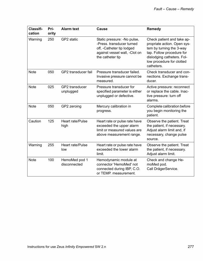
Instructions for use Zeus Infinity Empowered SW 2.n 277
Fault – Cause – Remedy
Warning 250 GP2 static Static pressure: -No pulse, -Press. transducer turned off, -Catheter tip lodged against vessel wall, -Clot on the catheter tip
Check patient and take ap-propriate action. Open sys-tem by turning the 3-way tap. Follow procedure for dislodging catheters. Fol-low procedure for clotted catheters.
Note 050 GP2 transducer fail Pressure transducer failed. Invasive pressure cannot be measured.
Check transducer and con-nections. Exchange trans-ducer.
Note 025 GP2 transducer unplugged
Pressure transducer for specified parameter is either unplugged or defective.
Active pressure: reconnect or replace the cable. Inac-tive pressure: turn off alarms.
Note 050 GP2 zeroing Mercury calibration in progress.
Complete calibration before you begin monitoring the patient.
Caution 125 Heart rate/Pulse high
Heart rate or pulse rate have exceeded the upper alarm limit or measured values are above measurement range.
Observe the patient. Treat the patient, if necessary. Adjust alarm limit and, if necessary, change pulse source.
Warning 255 Heart rate/Pulse low
Heart rate or pulse rate have exceeded the lower alarm limit.
Observe the patient. Treat the patient, if necessary. Adjust alarm limit.
Note 100 HemoMed pod 1 disconnected
Hemodynamic module at connector 'HemoMed' not connected during IBP, C.O. or TEMP. measurement.
Check and change He-moMed pod. Call DrägerService.
Classifi-cation
Pri-ority
Alarm text Cause Remedy

Fault – Cause – Remedy
278 Instructions for use Zeus Infinity Empowered SW 2.n
Note 105 HemoMed pod 1 HW fail
Hemodynamic module at connector 'HemoMed' failed during IBP, C.O. or TEMP. measurement.
Check and change module. Call DrägerService.
Note 100 HemoMed pod 2 disconnected
Hemodynamic module at connector 'Aux/Hemo 2' not connected during IBP, C.O. or TEMP. measurement.
Check and change cables. Call DrägerService.
Note 105 HemoMed pod 2 HW fail
Hemodynamic module at connector 'Aux/Hemo 2' failed during IBP, C.O. or TEMP. measurement.
Check and change module. Call DrägerService.
Note 100 HemoMed pod 3 disconnected
Hemodynamic module at connector 'Aux/Hemo 3' not connected during BP, C.O. or TEMP. measurement.
Check and change cables. Call DrägerService.
Note 105 HemoMed pod 3 HW fail
Hemodynamic module at connector 'Aux/Hemo 3' failed during BP, C.O. or TEMP. measurement.
Check and change module. Call DrägerService.
Note 050 ICP check zero Pressure transducer for specified parameter requires zeroing. The blood pressure zero of monitor may not cor-respond to the peripheral de-vice.
Zero the transducer.
Note 025 ICP hardware fail Invasive blood pressure hardware failure.
Check hardware and re-place. Call DrägerService.
Caution 100 ICP M high Invasive pressure value out-side alarm limits.
Check patient and take ap-propriate action. Change the alarm limits if required. Check equipment and re-place if necessary.
Classifi-cation
Pri-ority
Alarm text Cause Remedy

Instructions for use Zeus Infinity Empowered SW 2.n 279
Fault – Cause – Remedy
Caution 090 ICP M low Invasive pressure value out-side alarm limits.
Check patient and take ap-propriate action. Change the alarm limits if required. Check equipment and re-place if necessary.
Note 150 ICP nonstatic Press. transducer zeroing failed because of: Excessive signal noise A non-static waveform
Keep all tubing motionless, then rezero. Change the transducer. Check 3-way tap, then rezero.
Caution 050 ICP out of range Invasive pressure signal out of measurement range.
Check patient and take ap-propriate action. Access the Pressure Labels menu and assign correct label. Check equipment and replace if necessary.
Note 050 ICP transducer fail Pressure transducer failed. Invasive pressure cannot be measured.
Check transducer and con-nections. Exchange trans-ducer.
Note 025 ICP transducer un-plugged
Pressure transducer for specified parameter is either unplugged or defective.
Active pressure: reconnect or replace the cable. Inac-tive pressure: turn off alarms.
Note 050 ICP zeroing Mercury calibration in progress.
Complete calibration before you begin monitoring the patient.
Note 250 Infusion 1 rate high Pump 1 Infusion Rate Limit exceeded
Check the infusion rate of the pump. Adjust settings if necessary.
Note 040 Infusion 1 stopped The infusion has been stopped or a stopped pump has been connected.
Start infusion, check pump settings.
Note 250 Infusion 2 rate high Pump 2 Infusion Rate Limit exceeded
Check the infusion rate of the pump. Adjust settings if necessary.
Classifi-cation
Pri-ority
Alarm text Cause Remedy

Fault – Cause – Remedy
280 Instructions for use Zeus Infinity Empowered SW 2.n
Note 040 Infusion 2 stopped The infusion has been stopped or a stopped pump has been connected.
Start infusion, check pump settings.
Note 250 Infusion 3 rate high Pump 3 Infusion Rate Limit exceeded
Check the infusion rate of the pump. Adjust settings if necessary.
Note 040 Infusion 3 stopped The infusion has been stopped or a stopped pump has been connected.
Start infusion, check pump settings.
Note 250 Infusion 4 rate high Pump 4 Infusion Rate Limit exceeded
Check the infusion rate of the pump. Adjust settings if necessary.
Note 040 Infusion 4 stopped The infusion has been stopped or a stopped pump has been connected.
Start infusion, check pump settings.
Warning 100 Infusion line 1 blocked
Occlusion at line 1 detected. Pressure limit reached. Infu-sion 1 stopped.
Check infusion line 1 and connection to the patient. Increase pressure alarm limit. Restart infusion.
Caution 100 Infusion line 1 blocked?
The line 1 pressure in-creased rapidly. Pressure alarm limit is nearly reached.
Check infusion line and connection to the patient. Increase pressure alarm limit, if necessary.
Warning 100 Infusion line 2 blocked
Occlusion at line 2 detected. Pressure limit reached. Infu-sion 2 stopped.
Check infusion line 2 and connection to the patient. Increase pressure alarm limit. Restart infusion 2.
Caution 100 Infusion line 2 blocked?
The line 2 pressure in-creased rapidly. Pressure alarm limit is nearly reached.
Check infusion line and connection to the patient. Increase pressure alarm limit, if necessary.
Classifi-cation
Pri-ority
Alarm text Cause Remedy

Instructions for use Zeus Infinity Empowered SW 2.n 281
Fault – Cause – Remedy
Warning 100 Infusion line 3 blocked
Occlusion at line 3 detected. Pressure limit reached. Infu-sion 3 stopped.
Check infusion line 3 and connection to the patient. Increase pressure alarm limit. Restart infusion 3.
Caution 100 Infusion line 3 blocked?
The line 3 pressure in-creased rapidly. Pressure alarm limit is nearly reached.
Check infusion line and connection to the patient. Increase pressure alarm limit, if necessary.
Warning 100 Infusion line 4 blocked
Occlusion at line 4 detected. Pressure limit reached. Infu-sion 4 stopped.
Check infusion line 4 and connection to the patient. Increase pressure alarm limit. Restart infusion 4.
Caution 100 Infusion line 4 blocked?
The line 4 pressure in-creased rapidly. Pressure alarm limit is nearly reached.
Check infusion line and connection to the patient. Increase pressure alarm limit, if necessary.
Note 100 Infusion running Infusion is still runnig. Re-mote control and alarm dis-play of the IV system is ter-minated.
Control infusion rate at the pump. Return to operating mode to remote control the pumps.
Caution 100 Infusion system fail Infusion system failed. Press reset button, if sys-tem reboot is desired. Sys-tem will not be available for some minutes!
Caution 119 Insp. CO2 high Upper limit of insp. CO2- concentration exceeded for 2 breath. cycles. Soda lime exhausted.
Increase fresh gas flow! Ex-change soda lime!
Caution 255 Insp. desflurane high
Insp. vol. agent higher than alarm limit for 30 sec.
Check volatile agent deliv-ery setting! Check fresh gas flow!
Caution 255 Insp. desflurane high
Insp. vol. agent mixture higher than 3 xMAC.
Check DIVA settings and fresh gas flow.
Classifi-cation
Pri-ority
Alarm text Cause Remedy

Fault – Cause – Remedy
282 Instructions for use Zeus Infinity Empowered SW 2.n
Note 255 Insp. desflurane high
Insp. vol. agent higher than alarm limit for 30 sec.
Check volatile agent deliv-ery setting! Check fresh gas flow!
Caution 060 Insp. desflurane low
Inspiratory Desflurane con-centration fell below lower limit for 2 breaths.
Check volatile agent deliv-ery setting! Check fresh gas flow! Check function and liquid level of DIVA. Check CO2-sample line for leak-age!
Caution 255 Insp. enflurane high
Insp. vol. agent higher than alarm limit for 30 sec.
Check DIVA settings and fresh gas flow.
Caution 255 Insp. enflurane high
Insp. vol. agent mixture higher than 3 xMAC.
Check DIVA settings and fresh gas flow.
Note 255 Insp. enflurane high
Insp. vol. agent higher than alarm limit for 30 sec.
Check DIVA settings and fresh gas flow.
Caution 060 Insp. enflurane low Inspiratory Enflurane con-centration fell below lower limit for 2 breath. Cycles.
Check volatile agent deliv-ery setting! Check fresh gas flow! Check function and liquid level of DIVA. Check CO2-sample line for leak-age!
Note 180 Insp. flow sensor failure
Failure of inspiratory flow sensor: – Sensor not con-nected or defective
Perform leaktest incl. au-tom. calibration! Exchange sensor and perform leaktest!
Caution 255 Insp. halothane high
Insp. vol. agent higher than alarm limit for 30 sec.
Check volatile agent deliv-ery setting! Check fresh gas flow!
Caution 255 Insp. halothane high
Insp. vol. agent mixture higher than 3 xMAC.
Check DIVA settings and fresh gas flow.
Note 255 Insp. halothane high
Insp. vol. agent higher than alarm limit for 30 sec.
Check volatile agent deliv-ery setting! Check fresh gas flow!
Classifi-cation
Pri-ority
Alarm text Cause Remedy

Instructions for use Zeus Infinity Empowered SW 2.n 283
Fault – Cause – Remedy
Caution 060 Insp. halothane low Inspiratory Halothane con-centration fell below lower limit for 2 breath. cycles.
Check volatile agent deliv-ery setting! Check fresh gas flow! Check function and liquid level of DIVA. Check CO2-sample line for leak-age!
Caution 255 Insp. isoflurane high
Insp. vol. agent higher than alarm limit for 30 sec.
Check volatile agent deliv-ery setting! Check fresh gas flow!
Caution 255 Insp. isoflurane high
Insp. vol. agent mixture higher than 3 xMAC.
Check DIVA settings and fresh gas flow.
Note 255 Insp. isoflurane high
Insp. vol. agent higher than alarm limit for 30 sec.
Check volatile agent deliv-ery setting! Check fresh gas flow!
Caution 060 Insp. isoflurane low Inspiratory Isoflurane con-centration fell below lower limit for 2 breath. cycles.
Check volatile agent deliv-ery setting! Check fresh gas flow! Check function and liquid level of DIVA. Check CO2-sample line for leak-age!
Caution 000 Insp. MAC > 3 Insp. vol. agent concentra-tion too high. Insp.3 MAC ex-ceeded.
Check DIVA settings and fresh gas flow.
Caution 255 Insp. MAC > 5 Insp. vol. agent concentra-tion too high. Insp.5 MAC ex-ceeded.
Check DIVA settings and fresh gas flow.
Caution 020 Insp. N2O high Upper limit of insp. N2O- concentration exceeded for 2 breath. cycles.
Check O2-setting! Check fresh gas flow! Flush with high fresh gas flow!
Caution 000 Insp. N2O low Inspiratory N2O concentra-tion fell below lower limit for 2 breath. cycles.
Check N2O supply! Check O2-setting! Check fresh gas flow!
Warning 180 Insp. O2 low Protect. System: Insp. O2 concentration lower than 21 %!.
Check O2 concentration. Check O2 supply. Use Fresh-gas control mode.
Classifi-cation
Pri-ority
Alarm text Cause Remedy

Fault – Cause – Remedy
284 Instructions for use Zeus Infinity Empowered SW 2.n
Caution 000 Insp. oxygen high Upper limit of insp. Oxygen- concentration exceeded for 2 breath. cycles.
Check Oxygen delivery set-ting! Check fresh gas flow!
Warning 180 Insp. oxygen low Inspiratory Oxygen concen-tration fell below lower limit for 2 breath. cycles.
Check O2 supply! Check Oxygen delivery setting! Check fresh gas flow! Check SpO2 concentration!
Note 175 Insp. pressure sen-sor fail
Failure of insp. pressure sensor. Measurement of breathing pressure may be inaccurate. Breathing press. is measured by exp. sensor.
Check breathing pressure! Call DrägerService.
Caution 160 Insp. resistance high
Inspiratory resistance is in-creased compared to self-test – Stenosis or high resist-ance in insp. hose, tube or fil-ter.
Check insp. hose, tube and filter.
Caution 255 Insp. sevoflurane high
Insp. vol. agent higher than alarm limit for 30 sec.
Check volatile agent deliv-ery setting! Check fresh gas flow!
Caution 255 Insp. sevoflurane high
Insp. vol. agent mixture higher than 3 xMAC.
Check DIVA settings and fresh gas flow.
Note 255 Insp. sevoflurane high
Insp. vol. agent higher than alarm limit for 30 sec.
Check volatile agent deliv-ery setting! Check fresh gas flow!
Caution 060 Insp. sevoflurane low
Inspiratory Sevoflurane con-centration fell below lower limit for 2 breath. cycles.
Check volatile agent deliv-ery setting! Check fresh gas flow! Check function and liquid level of DIVA. Check CO2-sample line for leak-age!
Caution 254 Insp. vol. agent high
Volatile agent in inspiration higher than setpoint.
Use Fresh-gas control mode.
Classifi-cation
Pri-ority
Alarm text Cause Remedy

Instructions for use Zeus Infinity Empowered SW 2.n 285
Fault – Cause – Remedy
Caution 255 Insp. vol. agent high
Insp. vol. agent mixture higher than 3 xMAC.
Check DIVA settings. Check fresh-gas flow.
Caution 250 Internal safety fan failed
The safety fan for internal gas evacuation failed. If there is an internal leakage, the O2 concentration in the interior of the device may in-crease. Danger of fire!
Shut down as soon as pos-sible. Call DrägerService.
Warning 100 IV remote control failed
Remote control of infusion was terminated by the safety system! Infusion is contin-ued.
Check infusion setting at pump. Control infusion at pump. To restart remote control System needs to be restarted.
Caution 200 IV system discon-nected
Communication error to IV-System. Cable discon-nected.
Check connection of the IVDock to system, replace cable or IVDock. Call DrägerService.
Note 125 IVDock incompati-ble
IVDock has unknown ver-sion.
Exchange IVDock. Control infusion directly at the pump. Call DrägerService.
Note 100 KVO pump 1 Volume limit of infusion 1 has been reached. 'Keep vein open' function is activated. Infusion continues with a low infusion rate (1 mL/h).
Check infusion. Check vol-ume alarm limit. To change KVO configuration at the pump refer to the module DPS instructions.
Note 100 KVO pump 2 Volume limit of infusion 2 has been reached. 'Keep vein open' function is activated. Infusion continues with a low infusion rate (1 mL/h).
Check infusion. Check vol-ume alarm limit. To change KVO configuration at the pump refer to the module DPS instructions.
Note 100 KVO pump 3 Volume limit of infusion 3 has been reached. 'Keep vein open' function is activated. Infusion continues with a low infusion rate (1 mL/h).
Check infusion. Check vol-ume alarm limit. To change KVO configuration at the pump refer to the module DPS instructions.
Classifi-cation
Pri-ority
Alarm text Cause Remedy
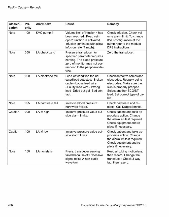
Fault – Cause – Remedy
286 Instructions for use Zeus Infinity Empowered SW 2.n
Note 100 KVO pump 4 Volume limit of infusion 4 has been reached. 'Keep vein open' function is activated. Infusion continues with a low infusion rate (1 mL/h).
Check infusion. Check vol-ume alarm limit. To change KVO configuration at the pump refer to the module DPS instructions.
Note 050 LA check zero Pressure transducer for specified parameter requires zeroing. The blood pressure zero of monitor may not cor-respond to the peripheral de-vice.
Zero the transducer.
Note 020 LA electrode fail Lead-off condition for indi-cated lead detected: -Broken cable - Loose lead wire - Faulty lead wire - Wrong lead -Dried out gel -Bad con-tact.
Check defective cables and electrodes. Reapply gel to electrodes. Make sure the skin is properly prepped. Select another ECG/ST lead. Set correct type of ca-ble.
Note 025 LA hardware fail Invasive blood pressure hardware failure.
Check hardware and re-place. Call DrägerService.
Caution 090 LA M high Invasive pressure value out-side alarm limits.
Check patient and take ap-propriate action. Change the alarm limits if required. Check equipment and re-place if necessary.
Caution 100 LA M low Invasive pressure value out-side alarm limits.
Check patient and take ap-propriate action. Change the alarm limits if required. Check equipment and re-place if necessary.
Note 150 LA nonstatic Press. transducer zeroing failed because of: Excessive signal noise A non-static waveform
Keep all tubing motionless, then rezero. Change the transducer. Check 3-way tap, then rezero.
Classifi-cation
Pri-ority
Alarm text Cause Remedy

Instructions for use Zeus Infinity Empowered SW 2.n 287
Fault – Cause – Remedy
Caution 050 LA out of range Invasive pressure signal out of measurement range.
Check patient and take ap-propriate action. Access the Pressure Labels menu and assign correct label. Check equipment and replace if necessary.
Note 050 LA transducer fail Pressure transducer failed. Invasive pressure cannot be measured.
Check transducer and con-nections. Exchange trans-ducer.
Note 025 LA transducer un-plugged
Pressure transducer for specified parameter is either unplugged or defective.
Active pressure: reconnect or replace the cable. Inac-tive pressure: turn off alarms.
Note 050 LA zeroing Mercury calibration in progress.
Complete calibration before you begin monitoring the patient.
Note 000 Leads invalid Lead-off condition detected: -Broken cable - Loose lead wire -Faulty lead wire - Wrong lead -Dried out gel -Bad contact.
Check defective cables and electrodes. Reapply gel to electrodes. Make sure the skin is properly prepped. Select another ECG/ST lead. Set correct type of ca-ble.
Caution 045 Leak or fresh gas low
Fresh gas deficiency!. Tidal volume cannot not be deliv-ered. Leak in breathing cir-cle.
Increase fresh gas flow. Check O2- and vol. agent settings. Check breathing circle and manual breathing bag for leakage.
Note 100 Leakage or fresh gas low
Fresh gas deficiency! Man-ual breathing bag not filled sufficiently. Leak in breathing circle.
Increase fresh gas flow. Check O2- and vol. agent settings. Check breathing circle and manual breathing bag for leakage.
Classifi-cation
Pri-ority
Alarm text Cause Remedy
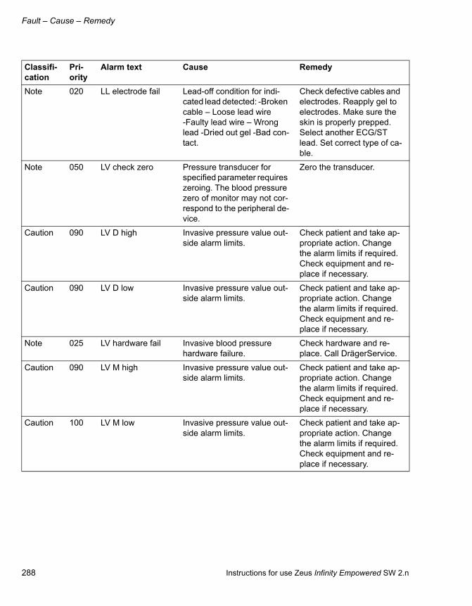
Fault – Cause – Remedy
288 Instructions for use Zeus Infinity Empowered SW 2.n
Note 020 LL electrode fail Lead-off condition for indi-cated lead detected: -Broken cable – Loose lead wire -Faulty lead wire – Wrong lead -Dried out gel -Bad con-tact.
Check defective cables and electrodes. Reapply gel to electrodes. Make sure the skin is properly prepped. Select another ECG/ST lead. Set correct type of ca-ble.
Note 050 LV check zero Pressure transducer for specified parameter requires zeroing. The blood pressure zero of monitor may not cor-respond to the peripheral de-vice.
Zero the transducer.
Caution 090 LV D high Invasive pressure value out-side alarm limits.
Check patient and take ap-propriate action. Change the alarm limits if required. Check equipment and re-place if necessary.
Caution 090 LV D low Invasive pressure value out-side alarm limits.
Check patient and take ap-propriate action. Change the alarm limits if required. Check equipment and re-place if necessary.
Note 025 LV hardware fail Invasive blood pressure hardware failure.
Check hardware and re-place. Call DrägerService.
Caution 090 LV M high Invasive pressure value out-side alarm limits.
Check patient and take ap-propriate action. Change the alarm limits if required. Check equipment and re-place if necessary.
Caution 100 LV M low Invasive pressure value out-side alarm limits.
Check patient and take ap-propriate action. Change the alarm limits if required. Check equipment and re-place if necessary.
Classifi-cation
Pri-ority
Alarm text Cause Remedy

Instructions for use Zeus Infinity Empowered SW 2.n 289
Fault – Cause – Remedy
Note 150 LV nonstatic Press. transducer zeroing failed because of: Excessive signal noise A non-static waveform
Keep all tubing motionless, then rezero. Change the transducer. Check 3-way tap, then rezero.
Caution 050 LV out of range Invasive pressure signal out of measurement range.
Check patient and take ap-propriate action. Access the Pressure Labels menu and assign correct label. Check equipment and replace if necessary.
Caution 125 LV S high Invasive pressure value out-side alarm limits.
Check patient and take ap-propriate action. Change the alarm limits if required. Check equipment and re-place if necessary.
Caution 130 LV S low Invasive pressure value out-side alarm limits.
Check patient and take ap-propriate action. Change the alarm limits if required. Check equipment and re-place if necessary.
Warning 250 LV static Static pressure: -No pulse, -Press. transducer turned off, -Catheter tip lodged against vessel wall, -Clot on the catheter tip
Check patient and take ap-propriate action. Open sys-tem by turning the 3-way tap. Follow procedure for dislodging catheters. Fol-low procedure for clotted catheters.
Note 050 LV transducer fail Pressure transducer failed. Invasive pressure cannot be measured.
Check transducer and con-nections. Exchange trans-ducer.
Note 025 LV transducer un-plugged
Pressure transducer for specified parameter is either unplugged or defective.
Active pressure: reconnect or replace the cable. Inac-tive pressure: turn off alarms.
Classifi-cation
Pri-ority
Alarm text Cause Remedy

Fault – Cause – Remedy
290 Instructions for use Zeus Infinity Empowered SW 2.n
Note 050 LV zeroing Mercury calibration in progress.
Complete calibration before you begin monitoring the patient.
Caution 000 Mains supply fail-ure
Power failure. A fully charged battery allows at least 30 min of operation.
Restore central power sup-ply. Check circuit breakers. Check battery capacity dis-play. If capacity is < 10 % the device may switch off!
Caution 020 Minute volume high Upper alarm limit of minute volume exceeded.
Check alarm limit. Check minute volume and respira-tory rate.
Caution 200 Minute volume low Exp. minute volume lower than lower limit. Leakage in breathing system; hose blocked. Volume deficiency during press. limitation. Fresh-gas flow too low.
Check limit setting. Check tube, hoses and breath. system. Check Pmax and Pinsp setting. Increase fresh gas flow.
Warning 255 Mixer+DIVA failure Mixer and DIVA not opera-ble. Setting of ventilator not possible!
Open safety O2 valve. Con-tinue case with IV drug. Check ventilation. Switch 'AN-VENTILATOR OFF'.
Warning 255 Mixer+DIVA failure Mixer and DIVA not opera-ble. Setting of ventilator not possible!
Open safety O2 valve. Con-tinue case with IV drug. Check ventilation. Switch 'AN-VENTILATOR OFF'.
Note 100 MultiMed Pod dis-connected
MultiMed cable not con-nected or faulty during 3, 5, or 6-lead monitoring.
Check cables and connec-tions and replace if neces-sary.
Note 105 MultiMed Pod HW failure
MultiMed cable failed during 3, 5, or 6-lead monitoring.
Check and change MultiMed cable. Call DrägerService.
Note 050 N2O central supply high
N2O supply pressure too high. N2O-pressure >8x 100 kPa.
Check central supply.
Classifi-cation
Pri-ority
Alarm text Cause Remedy

Instructions for use Zeus Infinity Empowered SW 2.n 291
Fault – Cause – Remedy
Note 100 N2O central supply low
N2O central supply pressure is low. Wall outlet is faulty. N2O plug is not connected to wall outlet.
Open N2O cylinder. Re-move N2O plug from wall outlet. Connect N2O plug to wall outlet.
Caution 200 N2O cylinder empty N2O cylinder empty or not open (<30x100 kPa) and N2O supply lower than 1.8x 100 kPa! Mixer contin-ues with Air delivery!
Reduce fresh-gas flow, use Auto control mode. Open or exchange N2O cylinder. Check insp. concentrations. Check N2O supply.
Note 005 N2O cylinder sen-sor fail
N2O high pressure sensor not connected. Sensor fail-ure.
Connect sensor. Check sensor. Call DrägerService.
Note 025 N2O in fresh gas Carrier gas Air is in use but N2O was detected in fresh gas or in system.
Use O2-Flush! Disconnect N2O supply and cylinder
Note 190 N2O sensor failure N2O sensor failed. No N2O-Monitoring possible
Observe insp. O2 concen-tration. Call DrägerService.
Caution 255 N2O supply fail N2O supply failed. Hose not plugged into wall socket or hose kinked.
Open N2O cylinder. Check central supply and hoses.
Note 224 N2O supply low N2O supply pressure too low. N2O pressure between 180 and 260 kPa N2O-deliv-ery not within specification.
Check N2O supply.
Caution 200 NIBP blocked line The inflation rate is too high during the inflation cycle or the time to dump the residual cuff pressure at end of the deflation cycle is too short.
Select a different cuff. Check the hose and cuff for damage. Restart the meas-urement. If message does not clear call DrägerService.
Caution 200 NIBP cannot meas-ure
No sufficient pulse after 45 seconds. Pulse too low for D/S values. Not enough adequate pulsations within two minutes.
Check the patient and take appropriate action. Move cuff to a limb with less movement. Check the hose and cuff. Check size and placement of cuff.
Classifi-cation
Pri-ority
Alarm text Cause Remedy

Fault – Cause – Remedy
292 Instructions for use Zeus Infinity Empowered SW 2.n
Caution 090 NIBP D high Non invasive pressure value outside alarm limits.
Check patient and take ap-propriate action. Change the alarm limits if required. Check equipment and re-place if necessary.
Caution 090 NIBP D low Non invasive pressure value outside alarm limits.
Check patient and take ap-propriate action. Change the alarm limits if required. Check equipment and re-place if necessary.
Note 050 NIBP hardware fault
Non invasive blood pressure measurement failed.
Call DrägerService
Note 050 NIBP hose un-plugged
NIBP hose is unplugged. Reconnect the hose.
Caution 200 NIBP inflation fail Systolic pressure is higher than inflation limit. Pump or valves have been energized for longer than 2 minutes (90 sec. neonatal mode).
Select higher inflation limit setting. Check hose and cuff for obstructions. Dis-connect and reconnect cuff. Replace if necessary. Call DrägerService.
Caution 090 NIBP M high Non invasive pressure value outside alarm limits.
Check patient and take ap-propriate action. Change the alarm limits if required. Check equipment and re-place if necessary.
Caution 100 NIBP M low Non invasive pressure value outside alarm limits.
Check patient and take ap-propriate action. Change the alarm limits if required. Check equipment and re-place if necessary.
Caution 200 NIBP open line Inflation time during cuff in-flation cycle is too long or in-flation rate is too low.
Check to ensure that the hose and cuff are properly connected to the monitor. Check the cuff size to be suitable for the patient.
Classifi-cation
Pri-ority
Alarm text Cause Remedy

Instructions for use Zeus Infinity Empowered SW 2.n 293
Fault – Cause – Remedy
Caution 250 NIBP press exceed Cuff overpressure circuit has failed.
Do not use NIBP measure-ment. Call DrägerService.
Caution 210 NIBP press leak NIBP hose/cuff hose discon-nected? Leakage in NIBP hose/cuff?
Check connections! Re-place cuff or hose!
Caution 125 NIBP S high Non invasive pressure value outside alarm limits.
Check patient and take ap-propriate action. Change the alarm limits if required. Check equipment and re-place if necessary.
Caution 130 NIBP S low Non invasive pressure value outside alarm limits.
Check patient and take ap-propriate action. Change the alarm limits if required. Check equipment and re-place if necessary.
Caution 200 NIBP time exceed A measurement took longer than 2 minutes (adult or pediatric) or 90 seconds (ne-onatal) and was aborted (e.g. motion artefact).
Repeat the measurement.
Note 100 NIBP zero out of range
Monitor is unable to zero transducer within 30 sec-onds from start of NIBP pro-gram, usually because of motion artefact.
Check the patient and take appropriate action. Move cuff to a limb with less movement. Call DrägerService.
Note 100 NMT artefact Excessive signal noise due to patient´s move-ment/tremor or interference from auxiliary equipment.
Check electrodes. Reapply, if necessary. Isolate patient from auxiliary equipment, if necessary. Isolate patient from extraneous movement or vibration.
Note 250 NMT check elec-trodes
Current cannot be delivered. Electrodes or connections not properly placed/function-ing.
Check electrode. Reapply, if necessary. Check cable connections.
Classifi-cation
Pri-ority
Alarm text Cause Remedy

Fault – Cause – Remedy
294 Instructions for use Zeus Infinity Empowered SW 2.n
Note 200 NMT check sensor Sensor malfunctioning or disconnected.
Check sensor application. Replace accelerometer sensor, if necessary.
Note 100 NMT check temp sensor
Temperature cable broken or missing.
Check temperature sensor. Replace, if necessary.
Note 125 NMT initializing Pod is performing power-up tests. Supramaximal current and reference twitch being detected. Pod is re-calibrat-ing due to a rapid change in twitch amplitude.
Wait until self tests are com-pleted. Wait until references are established.
Note 150 NMT single out of range
Single mode parameter value falls outside the meas-uring range (high).
Check patient. Treat, if nec-essary.
Note 150 NMT temp out of range
Temperature value falls out-side the measuring range (high/low).
Check patient. Treat, if nec-essary. Check sensor. Re-place, if necessary.
Note 150 NMT temp out of range
Temperature value falls out-side the measuring range (high/low).
Check patient. Treat, if nec-essary. Check sensor. Re-place, if necessary.
Note 100 NMT using internal reference
Reference twitch could not be established. Patient might have been relaxed before reference was established.
Check electrodes and sen-sor. Continue measurement using internal reference or change to TOF mode.
Note 250 O2 central supply low
O2 central supply pressure is low. Wall outlet is faulty. O2 plug is not connected to wall outlet.
Check if O2 is delivered to the patient. Open O2 cylin-der. Remove O2 plug from wall outlet. Connect O2 plug to wall outlet.
Warning 100 O2 delivery low ac-curacy
O2 delivery is working, but not within the specified toler-ance. A large deviation may lead to the termination of N2O or Air delivery.
Check inspiratory O2 concentration. Call DrägerService.
Note 250 O2 sensor failure O2-Sensor failed. Auto con-trol delivery is not available.
Ensure sufficient oxygena-tion. Call DrägerService.
Note 050 Oxygen central supply high
Oxygen supply pressure too high. O2-pressure >8x 100 kPa.
Check central supply.
Classifi-cation
Pri-ority
Alarm text Cause Remedy

Instructions for use Zeus Infinity Empowered SW 2.n 295
Fault – Cause – Remedy
Warning 134 Oxygen cylinder empty
O2 cylinder empty or not open (<20*100 kPa) and O2 supply lower than 1.8*100 kPa! Mixer contin-ues with Air delivery!
Reduce fresh-gas flow, use Auto control mode. Open or exchange O2 cylinder. Check insp. O2 concentra-tion. Check O2 supply.
Note 255 Oxygen cylinder low
O2-cylinder pressure low. O2 cylinder nearly emptied.
Use filled O2 cylinder. Re-store central supply.
Note 005 Oxygen cylinder sensor fail
O2 high pressure sensor not connected. Sensor failure.
Connect sensor. Check sensor. Call DrägerService.
Warning 135 Oxygen supply fail Oxygen supply failed. Hose not plugged into wall socket or hose kinked.
Open O2-cylinder. Check central supply. Check wall connector.
Note 254 Oxygen supply low Oxygen supply too low. O2 supply between 180 and 260 kPa. O2-delivery not within specification.
Check O2 supply. Prepare O2 backup cylinders.
Note 050 PA check zero Pressure transducer for specified parameter requires zeroing. The blood pressure zero of monitor may not cor-respond to the peripheral de-vice.
Zero the transducer.
Caution 090 PA D high Invasive pressure value out-side alarm limits.
Check patient and take ap-propriate action. Change the alarm limits if required. Check equipment and re-place if necessary.
Caution 090 PA D low Invasive pressure value out-side alarm limits.
Check patient and take ap-propriate action. Change the alarm limits if required. Check equipment and re-place if necessary.
Note 025 PA hardware fail Invasive blood pressure hardware failure.
Check hardware and re-place. Call DrägerService.
Caution 090 PA M high Invasive pressure value out-side alarm limits.
Check patient and take ap-propriate action. Change the alarm limits if required. Check equipment and re-place if necessary.
Classifi-cation
Pri-ority
Alarm text Cause Remedy

Fault – Cause – Remedy
296 Instructions for use Zeus Infinity Empowered SW 2.n
Caution 100 PA M low Invasive pressure value out-side alarm limits.
Check patient and take ap-propriate action. Change the alarm limits if required. Check equipment and re-place if necessary.
Note 150 PA nonstatic Press. transducer zeroing failed because of: Excessive signal noise A non-static waveform
Keep all tubing motionless, then rezero. Change the transducer. Check 3-way tap, then rezero.
Caution 050 PA out of range Invasive pressure signal out of measurement range.
Check patient and take ap-propriate action. Access the Pressure Labels menu and assign correct label. Check equipment and replace if necessary.
Caution 125 PA S high Invasive pressure value out-side alarm limits.
Check patient and take ap-propriate action. Change the alarm limits if required. Check equipment and re-place if necessary.
Caution 130 PA S low Invasive pressure value out-side alarm limits.
Check patient and take ap-propriate action. Change the alarm limits if required. Check equipment and re-place if necessary.
Warning 250 PA static Static pressure: -No pulse, -Press. transducer turned off -Catheter tip lodged against vessel wall, -Clot on the catheter tip
Check patient and take ap-propriate action. Open sys-tem by turning the 3-way tap. Follow procedure for dislodging catheters. Fol-low procedure for clotted catheters.
Note 050 PA transducer fail Pressure transducer failed. Invasive pressure cannot be measured.
Check transducer and con-nections. Exchange trans-ducer.
Note 025 PA transducer un-plugged
Pressure transducer for specified parameter is either unplugged or defective.
Active pressure: reconnect or replace the cable. Inac-tive pressure: turn off alarms.
Classifi-cation
Pri-ority
Alarm text Cause Remedy

Instructions for use Zeus Infinity Empowered SW 2.n 297
Fault – Cause – Remedy
Note 050 PA zeroing Mercury calibration in progress.
Complete calibration before you begin monitoring the patient.
Caution 100 Patient monitoring fail
Complete patient monitoring component failed.
Press reset button, if sys-tem repair is desired. Sys-tem will not be available for appr. 30 sec.!
Caution 000 Pause Sequence of two beats clas-sified as normal or PVC, with interval? pause rate value in seconds (100 ms)
Check patient and take ap-propriate action.
Caution 060 PEEP high Measured PEEP 5 mbar above setpoint for more than 10 breaths.
Check breathing system. Exchange autom exp. valve. Call DrägerService.
Caution 050 PEEP/Pmax valve failure
PEEP/Pmax valve is defec-tive or the PEEP is higer than the setting.
Check breathing pressure and volume. Ventilate man-ually. Check breathing sys-tem for dust particles. Call DrägerService.
Note 050 Perform self test No self test performed within 24 hours.
Perform self test.
Note 190 PGA fan failure Fan failure in patient gas measuring module.
Call DrägerService.
Caution 045 Pinsp not attained Due to a low fresh-gas flow or leakage the set inspiratory pressure could not be at-tained.
Increase fresh-gas flow, seal leaks. Provide suffi-cient ventilation.
Caution 080 Pinsp not attained Due to time settings the set inspiratory pressure could not be attained.
If necessary, adjust ventila-tion settings for Pinsp, Pres-sure Support/PEEP, slope, frequency and I/E. Provide sufficient ventilation.
Caution 080 Pmax lim/VT not at-tained
Due to time settings or Pmax limitation the set volume could not be attained. Pa-tient compliance or resist-ance have changed.
If necessary, adjust ventila-tion settings for slope, fre-quency and I/E. Check Pmax settings. Provide suffi-cient ventilation.
Note 200 Power supply com-munic. fail
Communication failure of power supply. Battery, temp. and voltage monitor not available.
Use system only in case of emergency. Call DrägerService.
Classifi-cation
Pri-ority
Alarm text Cause Remedy

Fault – Cause – Remedy
298 Instructions for use Zeus Infinity Empowered SW 2.n
Caution 250 Power supply temp high
Power supply temperature too high.
Minimize power consump-tion. Ventilate manually. Switch off device as soon as possible. Call DrägerService.
Caution 000 Press.supp. time limited
Pressure support cycle was aborted. The OFF criterion (flow <25 % of max. insp. flow) was not reached within 4 sec.
Check for tube/mask leak-age. Check patient settings. Use Pressure Control.
Note 000 Printer error Could not access any printer. Choose another printer, if available. Call DrägerService.
Caution 100 Protect sensor war-mup
Protection sensor is not available. Agent delivery re-quires a fresh gas flow >3 L/min.
Latest after 1/2 hour the protect sensor calibrates again. After this the delivery may be available again. Use fresh gas flow >3 L/min.
Note 255 Protect water trap blocked
Protect water trap or gas measurement system blocked. Protect water trap full or expired.
Check Protect water trap and gas measurement sys-tem – exchange, if neces-sary. Exchange water trap at least every 4 weeks.
Caution 010 Protect water trap? Protect water trap or gas measurement system blocked. Protect water trap full or expired.
Check Protect water trap and gas measurement sys-tem – exchange, if neces-sary. Exchange water trap at least every 4 weeks.
Caution 040 Pump 1 battery empty
Infusion 1 stopped. Battery of pump 1 discharged.
Reconnect IVDock to sys-tem for power supply or ex-change battery. Call DrägerService.
Note 040 Pump 1 battery low Battery nearly empty. Reconnect IVDock to sys-tem for power supply or ex-change battery. Call DrägerService.
Caution 200 Pump 1 failure Infusion 1 stopped. Pump detected internal failure.
Exchange pump 1. Call DrägerService.
Note 120 Pump 1 incompati-ble
Pump 1 hardware or soft-ware version not compatible. Remote control not possible.
Control infusion at pump. Replace pump for remote control.
Classifi-cation
Pri-ority
Alarm text Cause Remedy
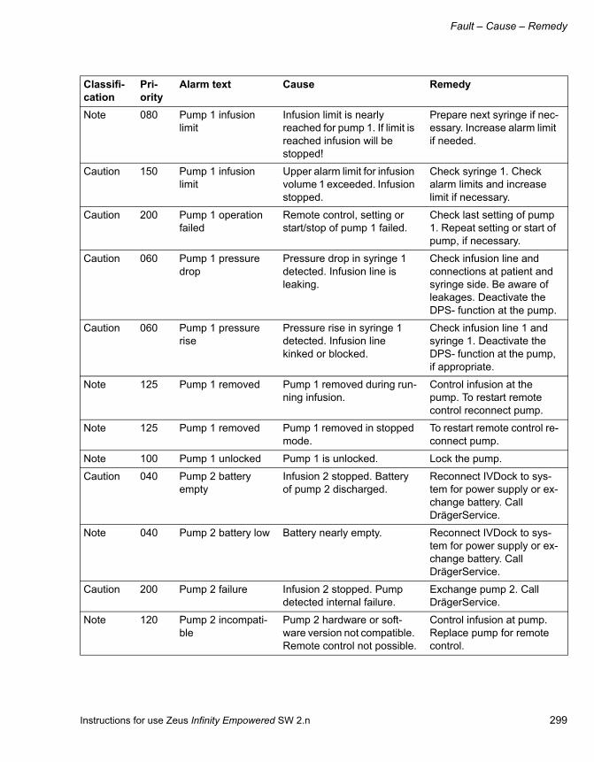
Instructions for use Zeus Infinity Empowered SW 2.n 299
Fault – Cause – Remedy
Note 080 Pump 1 infusion limit
Infusion limit is nearly reached for pump 1. If limit is reached infusion will be stopped!
Prepare next syringe if nec-essary. Increase alarm limit if needed.
Caution 150 Pump 1 infusion limit
Upper alarm limit for infusion volume 1 exceeded. Infusion stopped.
Check syringe 1. Check alarm limits and increase limit if necessary.
Caution 200 Pump 1 operation failed
Remote control, setting or start/stop of pump 1 failed.
Check last setting of pump 1. Repeat setting or start of pump, if necessary.
Caution 060 Pump 1 pressure drop
Pressure drop in syringe 1 detected. Infusion line is leaking.
Check infusion line and connections at patient and syringe side. Be aware of leakages. Deactivate the DPS- function at the pump.
Caution 060 Pump 1 pressure rise
Pressure rise in syringe 1 detected. Infusion line kinked or blocked.
Check infusion line 1 and syringe 1. Deactivate the DPS- function at the pump, if appropriate.
Note 125 Pump 1 removed Pump 1 removed during run-ning infusion.
Control infusion at the pump. To restart remote control reconnect pump.
Note 125 Pump 1 removed Pump 1 removed in stopped mode.
To restart remote control re-connect pump.
Note 100 Pump 1 unlocked Pump 1 is unlocked. Lock the pump.
Caution 040 Pump 2 battery empty
Infusion 2 stopped. Battery of pump 2 discharged.
Reconnect IVDock to sys-tem for power supply or ex-change battery. Call DrägerService.
Note 040 Pump 2 battery low Battery nearly empty. Reconnect IVDock to sys-tem for power supply or ex-change battery. Call DrägerService.
Caution 200 Pump 2 failure Infusion 2 stopped. Pump detected internal failure.
Exchange pump 2. Call DrägerService.
Note 120 Pump 2 incompati-ble
Pump 2 hardware or soft-ware version not compatible. Remote control not possible.
Control infusion at pump. Replace pump for remote control.
Classifi-cation
Pri-ority
Alarm text Cause Remedy

Fault – Cause – Remedy
300 Instructions for use Zeus Infinity Empowered SW 2.n
Note 080 Pump 2 infusion limit
Infusion limit is nearly reached for pump 2. If limit is reached infusion will be stopped!
Prepare next syringe if nec-essary. Increase alarm limit if needed.
Caution 150 Pump 2 infusion limit
Upper alarm limit for infusion volume 2 exceeded. Infusion stopped.
Check syringe 2. Check alarm limits and increase limit if necessary.
Caution 200 Pump 2 operation failed
Remote control, setting or start/stop of pump 2 failed.
Check last setting of pump 2. Repeat setting or start of pump, if necessary.
Caution 060 Pump 2 pressure drop
Pressure drop in syringe 2 detected. Infusion line is leaking.
Check infusion line and connections at patient and syringe side. Be aware of leakages. Deactivate the DPS- function at the pump.
Caution 060 Pump 2 pressure rise
Pressure rise in syringe 2 detected. Infusion line kinked or blocked.
Check infusion line 2 and syringe 2. Deactivate the DPS- function at the pump, if appropriate.
Note 125 Pump 2 removed Pump 2 removed during run-ning infusion.
Control infusion at the pump. To restart remote control reconnect pump.
Note 125 Pump 2 removed Pump 2 removed in stopped mode.
To restart remote control re-connect pump.
Note 100 Pump 2 unlocked Pump 2 is unlocked. Lock the pump.
Caution 040 Pump 3 battery empty
Infusion 3 stopped. Battery of pump 3 discharged.
Reconnect IVDock to sys-tem for power supply or ex-change battery. Call DrägerService.
Note 040 Pump 3 battery low Battery nearly empty. Reconnect IVDock to sys-tem for power supply or ex-change battery. Call DrägerService.
Caution 200 Pump 3 failure Infusion 3 stopped. Pump detected internal failure.
Exchange pump 3. Call DrägerService.
Note 120 Pump 3 incompati-ble
Pump 3 hardware or soft-ware version not compatible. Remote control not possible.
Control infusion at pump. Replace pump for remote control.
Classifi-cation
Pri-ority
Alarm text Cause Remedy

Instructions for use Zeus Infinity Empowered SW 2.n 301
Fault – Cause – Remedy
Note 080 Pump 3 infusion limit
Infusion limit is nearly reached for pump 3. If limit is reached infusion will be stopped!
Prepare next syringe if nec-essary. Increase alarm limit if needed.
Caution 150 Pump 3 infusion limit
Upper alarm limit for infusion volume 3 exceeded. Infusion stopped.
Check syringe 3. Check alarm limits and increase limit if necessary.
Caution 200 Pump 3 operation failed
Remote control, setting or start/stop of pump 3 failed.
Check last setting of pump 3. Repeat setting or start of pump, if necessary.
Caution 060 Pump 3 pressure drop
Pressure drop in syringe 3 detected. Infusion line is leaking.
Check infusion line and connections at patient and syringe side. Be aware of leakages. Deactivate the DPS- function at the pump.
Caution 060 Pump 3 pressure rise
Pressure rise in syringe 3 detected. Infusion line kinked or blocked.
Check infusion line 3 and syringe 3. Deactivate the DPS- function at the pump, if appropriate.
Note 125 Pump 3 removed Pump 3 removed during run-ning infusion.
Control infusion at the pump. To restart remote control reconnect pump.
Note 125 Pump 3 removed Pump 3 removed in stopped mode.
To restart remote control re-connect pump.
Note 100 Pump 3 unlocked Pump 3 is unlocked. Lock the pump.
Caution 040 Pump 4 battery empty
Infusion 4 stopped. Battery of pump 4 discharged.
Reconnect IVDock to sys-tem for power supply or ex-change battery. Call DrägerService.
Note 040 Pump 4 battery low Battery nearly empty. Reconnect IVDock to sys-tem for power supply or ex-change battery. Call DrägerService.
Caution 200 Pump 4 failure Infusion 4 stopped. Pump detected internal failure.
Exchange pump 4. Call DrägerService.
Note 120 Pump 4 incompati-ble
Pump 4 hardware or soft-ware version not compatible. Remote control not possible.
Control infusion at pump. Replace pump for remote control.
Classifi-cation
Pri-ority
Alarm text Cause Remedy

Fault – Cause – Remedy
302 Instructions for use Zeus Infinity Empowered SW 2.n
Note 080 Pump 4 infusion limit
Infusion limit is nearly reached for pump 4. If limit is reached infusion will be stopped!
Prepare next syringe if nec-essary. Increase alarm limit if needed.
Caution 150 Pump 4 infusion limit
Upper alarm limit for infusion volume 4 exceeded. Infusion stopped.
Check syringe 4. Check alarm limits and increase limit if necessary.
Caution 200 Pump 4 operation failed
Remote control, setting or start/stop of pump 4 failed.
Check last setting of pump 4. Repeat setting or start of pump, if necessary.
Caution 060 Pump 4 pressure drop
Pressure drop in syringe 4 detected. Infusion line is leaking.
Check infusion line and connections at patient and syringe side. Be aware of leakages. Deactivate the DPS- function at the pump.
Caution 060 Pump 4 pressure rise
Pressure rise in syringe 4 detected. Infusion line kinked or blocked.
Check infusion line 4 and syringe 4. Deactivate the DPS- function at the pump, if appropriate.
Note 125 Pump 4 removed Pump 4 removed during run-ning infusion.
Control infusion at the pump. To restart remote control reconnect pump.
Note 125 Pump 4 removed Pump 4 removed in stopped mode.
To restart remote control re-connect pump.
Note 100 Pump 4 unlocked Pump 4 is unlocked. Lock the pump.
Caution 000 PVC high Premature ventricular con-tractions: PVCs per minute have exceeded the upper alarm limit.
Check patient and take ap-propriate action.
Note 050 RA check zero Pressure transducer for specified parameter requires zeroing. The blood pressure zero of monitor may not cor-respond to the peripheral de-vice.
Zero the transducer.
Note 020 RA electrode fail Lead-off condition for indi-cated lead detected: -Broken cable - Loose lead wire - Faulty lead wire - Wrong lead -Dried out gel -Bad contact.
Check defective cables and electrodes. Reapply gel to electrodes. Make sure the skin is properly prepped. Select another ECG/ST lead. Set correct type of ca-ble.
Classifi-cation
Pri-ority
Alarm text Cause Remedy

Instructions for use Zeus Infinity Empowered SW 2.n 303
Fault – Cause – Remedy
Note 025 RA hardware fail Invasive blood pressure hardware failure.
Check hardware and re-place. Call DrägerService.
Caution 090 RA M high Invasive pressure value out-side alarm limits.
Check patient and take ap-propriate action. Change the alarm limits if required. Check equipment and re-place if necessary.
Caution 100 RA M low Invasive pressure value out-side alarm limits.
Check patient and take ap-propriate action. Change the alarm limits if required. Check equipment and re-place if necessary.
Note 150 RA nonstatic Press. transducer zeroing failed because of: Excessive signal noise A non-static waveform
Keep all tubing motionless, then rezero. Change the transducer. Check 3-way tap, then rezero.
Caution 050 RA out of range Invasive pressure signal out of measurement range.
Check patient and take ap-propriate action. Access the Pressure Labels menu and assign correct label. Check equipment and replace if necessary.
Note 050 RA transducer fail Pressure transducer failed. Invasive pressure cannot be measured.
Check transducer and con-nections. Exchange trans-ducer.
Note 025 RA transducer un-plugged
Pressure transducer for specified parameter is either unplugged or defective.
Active pressure: reconnect or replace the cable. Inac-tive pressure: turn off alarms.
Note 050 RA zeroing Mercury calibration in progress.
Complete calibration before you begin monitoring the patient.
Note 000 Relearn Monitor has begun 10-sec-ond capture of rest ECG waveforms.
Prevent movement of the patient.
Warning 030 Remove DIVA module 1
Anesth. agent from DIVA module 1 may get to the sys-tem.
Remove DIVA module 1. Call DrägerService.
Warning 030 Remove DIVA module 2
Anesth. agent from DIVA module 2 may get to the sys-tem.
Remove DIVA module 2. Call DrägerService.
Classifi-cation
Pri-ority
Alarm text Cause Remedy

Fault – Cause – Remedy
304 Instructions for use Zeus Infinity Empowered SW 2.n
Note 150 Replace SpO2 sen-sor
The SpO2 sensor is defec-tive or of wrong type.
Replace SpO2 sensor.
Note 020 RL electrode fail Lead-off condition for indi-cated lead detected: -Broken cable - Loose lead wire - Faulty lead wire - Wrong lead -Dried out gel -Bad con-tact.
Check defective cables and electrodes. Reapply gel to electrodes. Make sure the skin is properly prepped. Select another ECG/ST lead. Set correct type of ca-ble.
Warning 200 Rotary knob stuck Rotary knob is stuck or was pressed for more than 10 seconds.
Press and turn rotary knob repeatedly. If alarm condi-tion persists, settings can-not be adjusted anymore.
Note 050 RV check zero Pressure transducer for specified parameter requires zeroing. The blood pressure zero of monitor may not cor-respond to the peripheral de-vice.
Zero the transducer.
Caution 090 RV D high Invasive pressure value out-side alarm limits.
Check patient and take ap-propriate action. Change the alarm limits if required. Check equipment and re-place if necessary.
Caution 090 RV D low Invasive pressure value out-side alarm limits.
Check patient and take ap-propriate action. Change the alarm limits if required. Check equipment and re-place if necessary.
Note 025 RV hardware fail Invasive blood pressure hardware failure.
Check hardware and re-place. Call DrägerService.
Caution 090 RV M high Invasive pressure value out-side alarm limits.
Check patient and take ap-propriate action. Change the alarm limits if required. Check equipment and re-place if necessary.
Caution 100 RV M low Invasive pressure value out-side alarm limits.
Check patient and take ap-propriate action. Change the alarm limits if required. Check equipment and re-place if necessary.
Classifi-cation
Pri-ority
Alarm text Cause Remedy

Instructions for use Zeus Infinity Empowered SW 2.n 305
Fault – Cause – Remedy
Note 150 RV nonstatic Press. transducer zeroing failed because of: Excessive signal noise A non-static waveform
Keep all tubing motionless, then rezero. Change the transducer. Check 3-way tap, then rezero.
Caution 050 RV out of range Invasive pressure signal out of measurement range.
Check patient and take ap-propriate action. Access the Pressure Labels menu and assign correct label. Check equipment and replace if necessary.
Caution 125 RV S high Invasive pressure value out-side alarm limits.
Check patient and take ap-propriate action. Change the alarm limits if required. Check equipment and re-place if necessary.
Caution 130 RV S low Invasive pressure value out-side alarm limits.
Check patient and take ap-propriate action. Change the alarm limits if required. Check equipment and re-place if necessary.
Warning 250 RV static Static pressure -No pulse, -Press. transducer turned off, -Catheter tip lodged against vessel wall, -Clot on the catheter tip
Check patient and take ap-propriate action. Open sys-tem by turning the 3-way tap. Follow procedure for dislodging catheters. Fol-low procedure for clotted catheters.
Note 050 RV transducer fail Pressure transducer failed. Invasive pressure cannot be measured.
Check transducer and con-nections. Exchange trans-ducer.
Note 025 RV transducer un-plugged
Pressure transducer for specified parameter is either unplugged or defective.
Active pressure: reconnect or replace the cable. Inac-tive pressure: turn off alarms.
Note 050 RV zeroing Mercury calibration in progress.
Complete calibration before you begin monitoring the patient.
Caution 150 Safety O2 opened Safety O2 valve opened. Ad-ditional O2 fresh gas is deliv-ered.
To be used in case of emer-gency only. Observe O2- and vol. agent concentra-tion. At the end of operation close the valve!
Classifi-cation
Pri-ority
Alarm text Cause Remedy

Fault – Cause – Remedy
306 Instructions for use Zeus Infinity Empowered SW 2.n
Warning 255 Safety settings ac-tive
Due to MIXER + DIVA fail-ure, safety settings have been activated.
Check for additional mes-sages. Check O2 and DIVA settings.
Note 180 Sample line dis-connected?
Sample line leakage! Check CO2 sample line or water trap -CO2-.
Warning 100 SC: Internal error A software runtime error has occured. SmartCare is not available.
A software reset is required before SmartCare can be restarted. Press 'Software reset?' button. The system will reboot and be available again after approximately 30 seconds.
Warning 110 SC: Patient not suitable
SmartCare cannot be contin-ued. Patient values are not within the etCO2 and VT ranges.
Check patient data. Check patient condition. Check ventilation settings.
Caution 095 SC: Recovery failed
SmartCare could not induce spontaneous breathing dur-ing recovery.
Check patient medication. Check settings for Trigger. Wait until patient is ready for recovery.
Note 195 SC: Respiratory drive might be suffi-cient
The patient might be ready for extubation.
Check the respiratory drive of the patient to determine if the patient can be extu-bated.
Note 195 SC: Respiratory drive sufficient
The respiratory drive is suffi-cient.
Consider extubating the pa-tient.
Warning 100 SC: Severe hypov-entilation
etCO2 is too high. Check ventilation parame-ters.
Caution 085 SC: Spont. breath-ing detected
Spontaneous breathing oc-curred during controlled ven-tilation.
Check patient medication. Allow spontaneous breath-ing.
Note 195 SC: Spontaneous breathing insuffi-cient
Spontaneous breathing ac-tivity of patient is insufficient.
Check patient medication. Check settings for Trigger.
Caution 100 Service access al-lowed
Warning: The service access via cable connection is al-lowed! Ensure that no pa-tient is connected.
After finishing service deac-tivate 'Service access al-lowance'!
Caution 000 Setting not con-firmed
Setting or change not con-firmed within the timeout of 15 sec.
Repeat last setting or change if needed.
Classifi-cation
Pri-ority
Alarm text Cause Remedy

Instructions for use Zeus Infinity Empowered SW 2.n 307
Fault – Cause – Remedy
Caution 250 Simulated patient data
Patient data is simulated by software.
Use simulated patient data for demonstration purposes only.
Warning 000 Sinus bradycardia 8 or more consecutive nor-mal beats, with an average rate < sinus bradycardia rate setting. In neonatal mode: heart rate lower BRDY-Set-ting
Check patient and take ap-propriate action. Check Ar-rhythmia settings. Neona-tal: Check BRADY settings.
Warning 000 Sinus bradycardia 8 or more consecutive nor-mal beats, with an average rate < sinus bradycardia rate setting. In neonatal mode: heart rate lower BRDY-Set-ting
Check patient and take ap-propriate action. Check Ar-rhythmia settings. Neona-tal: Check BRADY settings.
Warning 120 SmartCare can-celed
Patient values are not within the etCO2 and VT ranges. A technical problem occured.
Check patient condition. Remedy technical alarms. Check ventilation settings.
Note 100 Sound system er-ror
The sound system failed. There will be no audible alarms.
Only use system in case of emergency. Observe visual messages at all times.
Caution 125 SpO2 high SpO2 is above the current upper alarm limit.
Observe the patient and take appropriate action.
Note 100 SpO2 HW failure SpO2 measurement system hardware failure.
Call DrägerService.
Warning 250 SpO2 low SpO2 is below the current lower alarm limit.
Observe the patient and take appropriate action.
Note 250 SpO2 pulse search The monitor has not been able to compute a valid measurement within the last 30 seconds because of un-stable measurement condi-tions.
Ensure the SpO2 sensor is properly attached to the pa-tient and all cables are properly connected. Call DrägerService.
Note 150 SpO2 sensor con-nected?
Too much or insufficient light is reaching the sensor or measurement artefact Weak signal due to poor perfusion or low body temperature.
Check sensor attachment Check patient's condition. Check sensor and cables. Relocate sensor to another extremity.
Note 100 SpO2 sensor invalid
The monitor does not recog-nize the connected sensor as valid.
Check for defective or unapproved sensor. Replace the sensor. Call DrägerService.
Classifi-cation
Pri-ority
Alarm text Cause Remedy

Fault – Cause – Remedy
308 Instructions for use Zeus Infinity Empowered SW 2.n
Note 200 SpO2 sensor un-plugged
Sensor cable not connected to the MultiMed pod.
Check to ensure that cables are securely connected. Check for defective sensor.
Note 010 SQI too low for BIS SQI (Signal Quality Index) value goes below 15 %.
Check sensor. This may oc-cur as a result of artefact caused e.g. by eyeblinks or motion. Isolate patient from auxiliary equipment. Isolate patient from extraneous movement or vibration. Check patient. Treat, if nec-essary.
Caution 200 ST aVF high ST value is outside the upper or lower alarm limit.
Observe the patient care-fully and treat if clinically in-dicated. Change the alarm limits.
Caution 200 ST aVF low ST value is outside the upper or lower alarm limit.
Observe the patient care-fully and treat if clinically in-dicated. Change the alarm limits.
Caution 200 ST aVL high ST value is outside the upper or lower alarm limit.
Observe the patient care-fully and treat if clinically in-dicated. Change the alarm limits.
Caution 200 ST aVL low ST value is outside the upper or lower alarm limit.
Observe the patient care-fully and treat if clinically in-dicated. Change the alarm limits.
Caution 200 ST aVR high ST value is outside the upper or lower alarm limit.
Observe the patient care-fully and treat if clinically in-dicated. Change the alarm limits.
Caution 200 ST aVR low ST value is outside the upper or lower alarm limit.
Observe the patient care-fully and treat if clinically in-dicated. Change the alarm limits.
Note 160 ST cannot analyze The monitor cannot deter-mine ST values owing to: -Absence of normal beats -Artefact
Perform a 'Relearn'. Calm the patient. Check elec-trodes and skin contact. Isolate from auxiliary equip-ment if possible.
Classifi-cation
Pri-ority
Alarm text Cause Remedy

Instructions for use Zeus Infinity Empowered SW 2.n 309
Fault – Cause – Remedy
Caution 200 ST I high ST value is outside the upper or lower alarm limit.
Observe the patient care-fully and treat if clinically in-dicated. Change the alarm limits.
Caution 200 ST I low ST value is outside the upper or lower alarm limit.
Observe the patient care-fully and treat if clinically in-dicated. Change the alarm limits.
Caution 200 ST II high ST value is outside the upper or lower alarm limit.
Observe the patient care-fully and treat if clinically in-dicated. Change the alarm limits.
Caution 200 ST II low ST value is outside the upper or lower alarm limit.
Observe the patient care-fully and treat if clinically in-dicated. Change the alarm limits.
Caution 200 ST III high ST value is outside the upper or lower alarm limit.
Observe the patient care-fully and treat if clinically in-dicated. Change the alarm limits.
Caution 200 ST III low ST value is outside the upper or lower alarm limit.
Observe the patient care-fully and treat if clinically in-dicated. Change the alarm limits.
Caution 200 ST V high ST value is outside the upper or lower alarm limit.
Observe the patient care-fully and treat if clinically in-dicated. Change the alarm limits.
Caution 200 ST V low ST value is outside the upper or lower alarm limit.
Observe the patient care-fully and treat if clinically in-dicated. Change the alarm limits.
Caution 200 ST V+ high ST value is outside the upper or lower alarm limit.
Observe the patient care-fully and treat if clinically in-dicated. Change the alarm limits.
Caution 200 ST V+ low ST value is outside the upper or lower alarm limit.
Observe the patient care-fully and treat if clinically in-dicated. Change the alarm limits.
Classifi-cation
Pri-ority
Alarm text Cause Remedy

Fault – Cause – Remedy
310 Instructions for use Zeus Infinity Empowered SW 2.n
Caution 000 SV tachycardia Superventricular tachycar-dia: N or more consecutive normal beats, with a beat-to-beat rate greater than or equal to the SVT setting.
Check patient and take ap-propriate action.
Note 050 Sync fail Defibrillator sync. output failed
Call DrägerService.
Caution 210 Sync. ventilation failure
Insp. and exp. flow sensor failed. No triggering for as-sisted ventilation available.
Observe sensor error mes-sages. Use alternative ven-tilator mode.
Warning 130 Syringe 1 empty Infusion 1 stopped. Syringe 1 empty.
Control syringe and patient. Replace syringe, if neces-sary. To drain syringe com-pletely, confirm the green button at the pump. (Only possible, if 'Empty syringe mode' is configured).
Caution 050 Syringe 1 nearly empty
Syringe 1 nearly empty. 5 min until end of infusion or 10 % volume left. (depend-ing on infusion rate and type of syringe)
Control syringe. Prepare filled syringe, if necessary.
Caution 125 Syringe 1 unlocked Infusion 1 can not start while clasp is unlocked.
Lock clasp at the pump 1. Control right position of the syringe. and start infusion or bolus.
Warning 130 Syringe 2 empty Infusion 2 stopped. Syringe 2 empty.
Control syringe and patient. Replace syringe, if neces-sary. To drain syringe com-pletely, confirm the green button at the pump. (Only possible, if 'Empty syringe mode' is configured).
Classifi-cation
Pri-ority
Alarm text Cause Remedy

Instructions for use Zeus Infinity Empowered SW 2.n 311
Fault – Cause – Remedy
Caution 050 Syringe 2 nearly empty
Syringe 2 nearly empty. 5 min until end of infusion or 10 % volume left. (depend-ing on infusion rate and type of syringe)
Control syringe. Prepare filled syringe, if necessary.
Caution 125 Syringe 2 unlocked Infusion 2 can not start while clasp is unlocked.
Lock clasp at the pump 2. Control right position of the syringe. and start infusion or bolus.
Warning 130 Syringe 3 empty Infusion 3 stopped. Syringe 3 empty.
Control syringe and patient. Replace syringe, if neces-sary. To drain syringe com-pletely, confirm the green button at the pump. (Only possible, if 'Empty syringe mode' is configured).
Caution 050 Syringe 3 nearly empty
Syringe 3 nearly empty. 5 min until end of infusion or 10 % volume left. (depend-ing on infusion rate and type of syringe)
Control syringe. Prepare filled syringe, if necessary.
Caution 125 Syringe 3 unlocked Infusion 3 can not start while clasp is unlocked.
Lock clasp at the pump 3. Control right position of the syringe. and start infusion or bolus.
Warning 130 Syringe 4 empty Infusion 4 stopped. Syringe 4 empty.
Control syringe and patient. Replace syringe, if neces-sary. To drain syringe com-pletely, confirm the green button at the pump. (Only possible, if 'Empty syringe mode' is configured).
Caution 050 Syringe 4 nearly empty
Syringe 4 nearly empty. 5 min until end of infusion or 10 % volume left. (depend-ing on infusion rate and type of syringe)
Control syringe. Prepare filled syringe, if necessary.
Classifi-cation
Pri-ority
Alarm text Cause Remedy

Fault – Cause – Remedy
312 Instructions for use Zeus Infinity Empowered SW 2.n
Caution 125 Syringe 4 unlocked Infusion 4 can not start while clasp is unlocked.
Lock clasp at the pump 4. Control right position of the syringe. and start infusion or bolus.
Note 050 System restart re-quired
System has been running for more than 7 days.
Shut down and restart the device at the next opportu-nity.
Caution 050 System restart re-quired
System has been running for more than 14 days.
Shut down and restart the device at the next opportu-nity.
Warning 255 System restart re-quired
Internal system error. Shut down and restart the device as soon as possible.
Caution 150 T1 out of range Temperature value greater or less than measuring range
Check the patient and take appropriate action. Check equipment and replace if necessary.
Caution 150 T2 out of range Temperature value greater or less than measuring range
Check the patient and take appropriate action. Check equipment and replace if necessary.
Caution 000 Tachy Sinus tachycardia: N or more consecutive normal beats, with a beat-to-beat rate >= TACH rate setting.
Check patient and take ap-propriate action.
Note 050 Temp 1 hardware fail
Temperature measurement system failure.
Call DrägerService.
Caution 210 Temp 1 high Temperature exceeds upper alarm limit.
Check the patient and take appropriate action. Check equipment and replace if necessary.
Caution 020 Temp 1 low Temperature exceeds lower alarm limit.
Check the patient and take appropriate action. Check equipment and replace if necessary.
Classifi-cation
Pri-ority
Alarm text Cause Remedy

Instructions for use Zeus Infinity Empowered SW 2.n 313
Fault – Cause – Remedy
Note 050 Temp 1 unplugged Cable defective or un-plugged.
Check equipment and re-place if necessary.
Note 050 Temp 2 hardware fail
Temperature measurement system failure.
Call DrägerService.
Caution 200 Temp 2 high Temperature exceeds upper alarm limit.
Check the patient and take appropriate action. Check equipment and replace if necessary.
Caution 020 Temp 2 low Temperature exceeds lower alarm limit.
Check the patient and take appropriate action. Check equipment and replace if necessary.
Note 050 Temp 2 unplugged Cable defective or un-plugged.
Check equipment and re-place if necessary.
Caution 080 Tidal vol. high (Pmin ltd.)
At minimum airway pressure tidal volume is higher then set. – Breathing settings not adequate. – Patient breathes spontaneously.
Change ventilation mode or VT settings.
Caution 080 Tidal volume high Pressure Control: Upper limit of insp. tidal volume has been exceeded multiple times. Volume Control: VTset x 1.3 exceeded.
Observe minute volume. Check alarm limit of insp. tidal volume and Pinsp set-ting.
Note 100 Tidal volume high Pressure Control: Upper limit insp. tidal volume reached. Volume Control: VTset x 1.3 exceeded.
Check alarm limit of insp.tidal volume. Switch off AutoFlow mode.
Caution 045 Tidal volume not at-tained
Due to fresh-gas deficiency the set volume could not be attained.
Increase fresh-gas flow, seal leaks. Provide suffi-cient ventilation.
Note 210 Time synchroniza-tion
The clock has been synchro-nized with system time.
This message will disap-pear automatically after 15 seconds.
Classifi-cation
Pri-ority
Alarm text Cause Remedy

Fault – Cause – Remedy
314 Instructions for use Zeus Infinity Empowered SW 2.n
Caution 125 TOF count high TOF count is higher than the the set alarm limit.
Check patient, treat if nec-essary. Change alarm limit as appropriate.
Caution 250 TOF count low TOF count is lower than the set alarm limit.
Check patient, treat if nec-essary. Change alarm limit as appropriate.
Note 100 Too many pumps Maximum number of pumps exceeded. System only sup-ports up to 4 pumps.
Only 4 pumps are displayed and can be controlled.
Note 100 Trident pod discon-nected
Trident pod not connected to system.
Check cables and connec-tions. Replace cables, if necessary.
Note 105 Trident pod hard-ware fail
Trident pod hardware failure. An unsupported pod is con-nected.
Check Trident pod connection. Disconnect unsupported pod and reconnect Trident pod. Call DrägerService.
Note 150 Two BISx pods de-tected
A second BISx Pod is con-nected.
Remove the BISx pod that was connected last.
Note 100 Two NMT pods de-tected
A second NMT pod is con-nected.
Remove the NMT pod that was connected last.
Note 150 Two SpO2 sensors detected
A second SpO2 sensor is connected.
Remove the SpO2 sensor connected last.
Note 000 Unable to learn No dominant complex for QRS processing found after 100 beats and until the end of learning phase. Learning will be continued.
Check electrode applica-tion. Check leads. Choose another lead for QRS processing.
Note 020 V electrode fail Lead-off condition for indi-cated lead detected: -Broken cable – Loose lead wire -Faulty lead wire – Wrong lead -Dried out gel -Bad con-tact.
Check defective cables and electrodes. Reapply gel to electrodes. Make sure the skin is properly prepped. Select another ECG/ST lead. Set correct type of ca-ble.
Note 020 V+ electrode fail Lead-off condition for indi-cated lead detected: -Broken cable - Loose lead wire -Faulty lead wire - Wrong lead -Dried out gel -Bad con-tact.
Check defective cables and electrodes. Reapply gel to electrodes. Make sure the skin is properly prepped. Select another ECG/ST lead. Set correct type of ca-ble.
Classifi-cation
Pri-ority
Alarm text Cause Remedy

Instructions for use Zeus Infinity Empowered SW 2.n 315
Fault – Cause – Remedy
Warning 045 VA delivery cutoff DIVA failure. DIVA delivery interrupted.
Continue anesthesia with IV drug. Call DrägerService.
Warning 045 VA delivery failure Failure of anesthetic agent delivery system! Or delivery terminated by protection sys-tem. Delivery was switched off!
Continue anesthesia with IV drug. Call DrägerService.
Warning 045 VA delivery off Failure of anesthetic agent delivery.
Continue anesthesia with IV drug. Call DrägerService.
Warning 255 Vent+mixer+DIVA cutoff
Failure of Ventilator, mixer and DIVA. Mixer and DIVA interrupted.
Open O2 Safety valve. Monitor ventilation by press. gauge. Call DrägerService.
Warning 255 Vent. fibr. / Vent. tach.
Ventricular fibrillation: The monitor identifies a sinusoi-dal waveform with fibrillation characteristics.
Check patient and take ap-propriate action.
Note 100 Vent. turbine temp. high
Temperature of ventilator tur-bine is too high.
Reduce breathing pres-sure! Ventilate manually!
Warning 135 Ventilator failure Failure of automatic ventila-tion: - Ventilator turbine failed - Temperature of venti-lator too high.
Ventilate manually! Switch to Fresh-gas control! Check breathing system and tur-bine. Call DrägerService.
Caution 000 Ventr. bigeminy Sequence of beats with the pattern: normal, PVC, nor-mal, PVC, normal
Check patient and take ap-propriate action.
Caution 000 Ventr. couplet Sequence of beats with the pattern: normal, PVC, PVC, normal
Check patient and take ap-propriate action.
Warning 000 Ventr. tachycardia Ventricular tachycardia: N or more PVCs are detected in an interval T = (60 * (N – 1)) / R, where N = VT count and R = VT-rate
Check patient and take ap-propriate action.
Caution 000 Ventricular run Ventricular run: Series of 3 to N-1 consecutive PVCs with a beat-to-beat rate > the VT rate.
Check patient and take ap-propriate action.
Classifi-cation
Pri-ority
Alarm text Cause Remedy

Fault – Cause – Remedy
316 Instructions for use Zeus Infinity Empowered SW 2.n
Note 250 Vol. agent sensor failure
Volatile agent sensor not op-erable.
Continue anesthesia with IV drug. Call DrägerService.
Caution 210 Volume-controlled vent. fail
Volume controlled ventilation failed because of flow sensor failure.
Use pressure controlled ventilation.
Caution 060 Wrong volatile agent detected
Detected agent is different from selected type: – The agent has been changed – The DIVA module contains the wrong agent
Check MAC values! Man. delivery: flush with high fresh gas flow Auto-deliv-ery: system flushes auto-matically! Exchange the DIVA module, check con-tent!
Classifi-cation
Pri-ority
Alarm text Cause Remedy

Instructions for use Zeus Infinity Empowered SW 2.n 317
Fault – Cause – Remedy
Metering module faults
In operation
Fault Cause RemedyNo metering or too high/low metering.
The metering module is empty. Refill the metering module.
No anesthetic agent concentra-tion set at the device.
Set anesthetic agent concentra-tion at the device.
No metering module connected Connect metering module.
The automatic anesthetic agent detector indicates a different an-esthetic agent from the metering module.
Device error or incorrect filling. Do not activate the metering module!
Contact DrägerService
Smell of anesthetic agent, re-lease of anesthetic agent va-por.
Leakage at the interface or meter-ing module faulty
(Self test failed.)
Do not activate the metering module!
Change metering module.
Contact DrägerService about the faulty metering module or if the error message occurs again.
The lock of the filling device is not tightened or the seal is defective.
Tighten the lock of the filling de-vice firmly and check the seal. Contact DrägerService if neces-sary.
Drain plug is not closed.
(Not with DES)
Tighten drain plug.
The lever of the safety filling de-vice is too slack so the seal is not under sufficient pressure.
Have the lever readjusted.
Contact DrägerService
The locking bolt of the filling de-vice is not completely inserted.
Loosen the lever, depress the locking bolt completely, retighten the lever.
The sight glass display is faulty. Contact DrägerService
Anesthetic gas scavenging sys-tem AGSS is not connected
Connect the AGSS.
Anesthetic agent leaking. The locking bolt/cap is not locked. Lock it.

Fault – Cause – Remedy
318 Instructions for use Zeus Infinity Empowered SW 2.n
When filling and emptying
Smell of anesthetic agent dur-ing or after transport/storage.
In the event of an extreme rise in temperature and/or drop in at-mospheric pressure, anesthetic agent vapor can escape or liquid anesthetic agent can leak as a re-sult of pressure in the metering module.
Do not inhale the anesthetic agent vapor. Air the room. Allow the metering module to settle at room temperature. Observe the application range of the filled metering module.
Fault Cause Remedy
Fault Cause RemedyAnesthetic agent flows out of the drain port.
Drain valve not closed. Close drain valve.
Anesthetic agent is escaping at the cylinder thread.
The filling adapter is not screwed firmly onto the bottle.
Screw the filling adapter on firmly.
The seal in the screw cap of the filling adapter is missing or dam-aged.
Check the seal.
Contact DrägerService
Anesthetic agent is escaping at the filling device.
The filling adapter is not com-pletely inserted or the lever is not firmly tightened.
Loosen the lever, insert the filling adapter completely, tighten the lever.
The lever is not pressing firmly enough onto the filling adapter.
Have the lever readjusted.
Contact DrägerService
The filling adapter is damaged. Use another filling adapter.
Contact DrägerService
The seal of the filling device is damaged.
Check the seal of the metering module.
Contact DrägerService
Anesthetic agent flows out of the overflow hole.
The metering module is filled above maximum.
Empty metering module up to the maximum mark.
The locking bolt cannot be pulled out.
The lever is not sufficiently opened or the lever is incorrectly adjusted.
Open the lever further or have it readjusted.
Anesthetic agent does not flow out when emptying.
The locking bolt/cap is closed. Open the locking bolt/cap.
Close again tightly after empty-ing.

Instructions for use Zeus Infinity Empowered SW 2.n 319
Fault – Cause – Remedy
Anesthetic agent flows out when emptying with Quik Fil.
The bottle is not completely screwed on or incorrectly screwed on so the bottle valve does not open.
Unscrew the bottle from the emptying tool, then screw it on again.
Escaping anesthetic agent when filling/emptying the des-flurane metering module
The O-ring on the anesthetic agent bottle is damaged.
Remove bottle from the filling de-vice. Perform the process again with a new bottle.
Escaping anesthetic agent or saturated vapor from opened desflurane filling device (lock-ing cover is removed from fill-ing port).
Leaking valve or sealing com-pound in the desflurane filling de-vice.
Close the filling device with the locking cover. Contact DrägerService.
Remove bottle when filling before it has been emptied completely.
Close the filling device with the locking cover.
Fault Cause Remedy

320 Instructions for use Zeus Infinity Empowered SW 2.n
This page was intentionally left blank.

Instructions for use Zeus Infinity Empowered SW 2.n 321
Configuration
Configuration
Configuration information . . . . . . . . . . . . . . . 322
System setup . . . . . . . . . . . . . . . . . . . . . . . . . 323
Manage setups for Profiles and Views . . . . . . . 323Loading profiles/views . . . . . . . . . . . . . . . . . . . 324Saving profiles/views . . . . . . . . . . . . . . . . . . . . 324Renaming profiles/views. . . . . . . . . . . . . . . . . . 325New profiles/views . . . . . . . . . . . . . . . . . . . . . . 325Assigning or deleting profile keys. . . . . . . . . . . 326Deleting Profiles/Views. . . . . . . . . . . . . . . . . . . 326Profiles Default . . . . . . . . . . . . . . . . . . . . . . . . . 327Protecting profiles/views. . . . . . . . . . . . . . . . . . 327Overview of additional settings. . . . . . . . . . . . . 328
Configuring the screen . . . . . . . . . . . . . . . . . 329
Screen layout . . . . . . . . . . . . . . . . . . . . . . . . . . 329Configuring buttons . . . . . . . . . . . . . . . . . . . . . 332Configuring brightness and volume . . . . . . . . . 334Configuring colors. . . . . . . . . . . . . . . . . . . . . . . 334
Configuring basic settings . . . . . . . . . . . . . . 335
General settings . . . . . . . . . . . . . . . . . . . . . . . . 336Infusion. . . . . . . . . . . . . . . . . . . . . . . . . . . . . . . 344Event recorder . . . . . . . . . . . . . . . . . . . . . . . . . 344Configuring web applications . . . . . . . . . . . . . . 345NIBP/SpO2 . . . . . . . . . . . . . . . . . . . . . . . . . . . . 346Infinity configuration (optional) . . . . . . . . . . . . . 346Configuring MediBus . . . . . . . . . . . . . . . . . . . . 347Disabling options . . . . . . . . . . . . . . . . . . . . . . . 348More settings . . . . . . . . . . . . . . . . . . . . . . . . . . 348
Other functions of the system. . . . . . . . . . . . 353
Help dialog window. . . . . . . . . . . . . . . . . . . . . . 353Stopwatch dialog window . . . . . . . . . . . . . . . . . 354
Service functions . . . . . . . . . . . . . . . . . . . . . . 356
Service call dialog window . . . . . . . . . . . . . . . . 356

Configuration
322 Instructions for use Zeus Infinity Empowered SW 2.n
Configuration information
Zeus IE is provided with comprehensive features for configuring all settings to suit different applica-tions.
Zeus IE settings are divided into three groups:– Basic settings– Profile settings– View settings
The basic settings contain the settings that are made once for a department or a device location and then not usually modified again. These set-tings, which can only be accessed in system standby with the aid of an access code, include for example: units of measurement, language, current time, and communication settings.
The profile settings contain the settings for venti-lation, gas delivery, IV delivery, screen, and alarm limits as well as presets for the patient data (age, weight, etc.). For different patient categories and applications up to 16 different so-called user-pro-
grammable profiles can be generated and saved. A profile contains both, profile settings and view settings.
The following non-deletable profiles are supplied by the manufacturer:– Neonatal (5 kg)– Pediatric patients 1 (20 kg)– Pediatric patients 2 (40 kg)– Adults 1 (80 kg)– Adults 2 (100 kg)
When starting a new case, the profile defined by the user as the default is always loaded.
The view settings contain the parameters for dis-playing data and curves as well as the sensor set-tings. This defines color, appearance, curve scal-ing, etc. Up to 16 views can be generated and saved. For example, a view can be saved with or without IV data display.
When starting a new case, the view settings are provided by the profile selected.
248
Zeus IE settings
Profile settings(ventilation settings, screen settings, alarms, etc.)
View settings(curves, tone volume, color, etc.)
Basic settings(units, languages, prices, drug library, etc.)
Profiles(5 factory profiles, up to 16 user profiles)
View(1 factory view, up to 16 user views)
Calling up during op-eration or in system standby
Load/Save Load/Save

Instructions for use Zeus Infinity Empowered SW 2.n 323
Configuration
System setup
Prerequisite: The System setup button has been configured, see page 332.
In the main menu bar, touch the System setup button (A).
The System setup dialog window will be opened.
The following settings can be configured in the System setup dialog window:– Manage setups – Sensors/ Parameters – IBP – MixGas/ Ventilation – Infusion – Alarms – Screen layout – Basic settings – Autoset limits
Manage setups for Profiles and Views
In the main menu bar, touch the System setup button.
The System setup > Manage setups dialog win-dow appears.
The Manage setups page displays two vertical tabs:– Profiles (B) – Views (C)
Touch the Profiles tab (B).
The page for setting the profiles with the following options appears:D Button for deleting the assigned order of the
profile keysE Five buttons (profile keys) for determining the
order of the profiles for the startup dialog F Buttons for administration of the presets
The following is displayed for each profile:G Profile name: Dräger Neo., Dräger Ped. 1,
Dräger Ped. 2, Dräger Adult 1, Dräger Adult 2 or user-defined profiles
H Categ.: Symbols for adults , pediatric pa-tients , neonates
I Key: Assigned profile keyJ Last change: Date and timeK Default: Indication that the profile is preset
(tick)L Protected: Indication that the profile is saved
and access code protected (lock icon)
311
00
1200
mL/mbar mbar/L/s
20
A
410
2
3
1
2
3
4
5
4
3
System setup
BCD
EF
G H I J K L

Configuration
324 Instructions for use Zeus Infinity Empowered SW 2.n
Touch the Views tab (C).
The page for view settings with the following op-tions appears:M Buttons for administration of the presets
The following is displayed for each view:N View nameO Last change: Date and timeP Protected: Indication that the profile is saved
and access code protected (lock icon)
Loading profiles/views
The Manage setups > Profiles > or Views page opens.
1 Select the desired profiles/views from the Pro-file name list or the View name list using the ro-tary knob.
2 Touch the Load button (A) and confirm with ro-tary knob.
The saved settings of the profiles or views selected overwrite all current settings. Profiles can only be changed in standby mode. Views can be adapted during operation. The screen shows the name of the selected profile in the patient data field (below the patient name), see page 44.
Saving profiles/views
The Manage setups > Profiles > or Views page opens.
If the profiles/views have not been access code protected, profiles/views that already exist can be overwritten using Save.
Touch the Save button (A) and confirm with ro-tary knob.
313
410
C
System setup
M
N O P
1
2
3
4
5
System setup
A
CAUTIONThe applicability of the data from the loaded con-figuration must be checked individually by the user for each patient to eliminate the risk of incor-rect settings and ensure the patient's safety.
410
1
2
3
4
5
System setup
A

Instructions for use Zeus Infinity Empowered SW 2.n 325
Configuration
Renaming profiles/views
The Manage setups > Profiles > or Views page opens.
1 Select the required profiles or views from the Profile name list or View name list with the ro-tary knob.
2 Touch the Rename button (A).
A keyboard with the current name opens.
3 Change the name and confirm with rotary knob.
The required name is thus activated.
The Dräger default Profiles/Dräger default views cannot be changed.
New profiles/views
The Manage setups > Profiles > or Views page opens.
1 All settings saved to the new profile or to the new view must be checked before saving and corrected, if necessary.
2 Touch the Profiles or Views tab.
3 Touch the New button (A).
A keyboard field appears.
4 Give the profile or view a meaningful name (e.g., Adult) and confirm with Enter or by pressing the rotary knob.
The name appears as the current profile in the pa-tient data field (below the profile name), see page 44.
410
1
2
3
4
5
System setup
A
410
1
2
3
4
5
System setup
A

Configuration
326 Instructions for use Zeus Infinity Empowered SW 2.n
Assigning or deleting profile keys
The page Manage setups > Profiles opens.
Assigning profile keys
Use the vertical buttons (A) to assign the profiles to the 5 profile keys in the Startup dialog (see page 109).
1 Use the rotary knob to select the required profile from the list.
2 Select button 1 to 5 and confirm with rotary knob.
Deleting assigned profile keys
The button (B) can be used to delete the assigned profile key. In this case, the corresponding profile key does not appear in the Startup dialog (see page 109). A profile marked with Default can-not be deleted from the startup dialog.
1 Select the required profile with the rotary knob.
2 Touch the (C) button and confirm with rotary knob.
The profile key does not appear in the startup dia-log.
Deleting Profiles/Views
The Manage setups > Profiles > or Views page opens.
1 Touch the Profiles or Views tab.
2 Use the rotary knob to select the profile or view to be deleted from the Profile name list or View name list.
3 Touch the Delete button (A) and confirm with ro-tary knob.
The required setting is then deleted. Access code protected profiles or views must be unlocked be-forehand!
Dräger default profiles/Dräger default views and the loaded profile or view currently active cannot be deleted.
410
1
2
3
4
5
A
B
System setup
415
1
2
3
4
5
System setup
A

Instructions for use Zeus Infinity Empowered SW 2.n 327
Configuration
Profiles Default
The Default property defines the default setting which is loaded when the device is switched on (not with Views).
Only profiles that are assigned to a profile key can be defined as the default.
The Manage setups > Profiles page opens.
If a specific start setting is required:
1 Use the rotary knob to select the required profile from the Profile name list.
2 Touch the Default button (A).
3 Enter access code and confirm with rotary knob.
The Default button is now dark green. This profile is preset after switching on the device and when calling up new patient data (default setting).
Protecting profiles/views
With the Protect property, the profile or view setting cannot be renamed, deleted or saved.
The Manage setups > Profiles > or Views page opens.
1 Touch the Profiles or Views tab.
2 Use the rotary knob to select the profile or the view to be protected from the Profile name list or the View name list.
3 Touch the Protect button (A).
The button turns dark green and the dialog window for the access code opens.
4 Enter the access code and confirm with rotary knob.
Release profiles/views
Unlocking protected profiles or views:
1 Select the profile or view.
2 Touch the Protect button.
3 Enter the access code and confirm with rotary knob.
The required setting is then unlocked.
410
1
2
3
4
5
System setup
A
410
1
2
3
4
5
System setup
A

Configuration
328 Instructions for use Zeus Infinity Empowered SW 2.n
Overview of additional settings
The other horizontal tabs show the parameters and presets of:
A Sensors/ Parameters (see page 197)
B IBP (see page 225)
C MixGas/ Ventilation (see page 189)
D Infusion (see page 142)
E Alarms with the monitored lower and upper lim-its (see page 162)
F Screen layout (see page 329)
G Basic settingsBasic settings can only be changed in system standby in the Biomed service dialog window and are access code protected, see page 335.
H Autoset limits
Touch the Edit button (I).
The respective dialog window appears. Corre-sponding changes can be made (not with Infu-sion tab).
412
System setup
A B C D E F
I
G H

Instructions for use Zeus Infinity Empowered SW 2.n 329
Configuration
Configuring the screen
In the main menu bar, touch the Screen setup (A) button.
The Screen setup > Screen layout dialog window appears.
The following settings can be configured in the Screen setup dialog window:
– Screen layout – Customize buttons – Brightn./ Volume – Colors
Screen layout
The Screen layout (A) shows the settings for:
A General
B Waveforms
C Data
D Web access
301
1:35
A
432
Screen setup
ABCDE

Configuration
330 Instructions for use Zeus Infinity Empowered SW 2.n
Screen layout General
The Screen layout > General page (A) opens.
The following screen settings can be configured:B Display mode: Day light, Day dark, Night
– Day light: Displays a bright background with bright buttons and dialog windows
– Day dark: Displays a dark background with bright buttons and dialog windows
– Night: Displays a completely darkened background
C Waveform speed: Hemodynamics [mm/s]D Waveform speed: Ventilation [mm/s]E Ventilation waveforms: Waveform Filled or as
a LineF Waveform smoothing: On, Off
If lines are selected for displaying the wave-forms, smoothing can be switched on or off.
G Display mini trends: On, OffH Additional monitoring field:
– Loop,– O2, CO2,– HR, NIBP,– HR, NIBP, SpO2,– Off
Other displays of parameters as loop or trend display in combination with the flow tubes, see page 194.
Display of mini-trends
1 Touch the On button for Display mini trends (G).
If the Off button under Additional monitoring field has not been activated:
– The parameters currently set are displayed as a mini-trend between the current curve and the loop display and flow tubes.
If the Off button under Additional monitoring field has been activated:
– The parameters current set are displayed as a mini-trend on the left next to the current param-eter curves.
Trend length is 30 minutes (intervals of 5 minutes). The individual parameters can be called up under the following displays in the Trends/Data dialog window for an accurate analysis:
– Graph. trend display– Tab. trend display, see page 184.
432
ABCDEFG
H
Screen setup

Instructions for use Zeus Infinity Empowered SW 2.n 331
Configuration
Setting mini-trends / loops for additional monitoring
For displaying mini-trends and/or ventilation loops with display of flow tubes:
1 Touch the buttons– Loop,– O2, CO2,– HR, NIBP
or – HR, NIBP, SpO2
under the Additional monitoring field option.
The option selected is displayed on the screen above the flow tubes as a loop or mini-trend.
2 Touch the Off button for Additional monitoring field.
Loops, mini-trends and flow tubes are not dis-played.
If the Display mini trends option has been acti-vated, the parameters current set are displayed as a mini-trend on the left next to the current parame-ter curves.
Display of ventilation loops, see page 194 and flow tubes, see page 196.
The loops are always displayed in combination with the flow tubes.
Changing curve configuration
Maximum 7 curves can be selected. Exception: For the IBP comb. module, 4 IBP curves are displayed in one field at double the height.
1 Touch the Waveforms tab (A).
2 The arrow keys ( ) can be used to add curves to the configuration from the Available list (B) or to remove curves from the configura-tion from the Displayed list (C).
The Up or Down buttons (D) can be used to configure the position of the curves on the screen.
3 Touch the Apply changes button (E) to apply the changes.
433
Screen setup
AB C
D
E

Configuration
332 Instructions for use Zeus Infinity Empowered SW 2.n
Configuring data
Maximum 5 data fields can be configured.
1 Touch the Data tab (A).
2 The arrow keys ( ) can be used to add data to the configuration from the Available list (B) or to remove data from the configuration from the Displayed list (C).
If a certain area on the screen should remain empty, it must be selected from the Available (Empty) list.
The Up and Down buttons (D) can be used to configure the position of the data on the screen. The parameters are positioned on the screen from right to left. The top most parameter in the list is displayed on the far right.
3 Touch the Apply changes button (E) to apply the changes.
If all data parameters are removed from the Dis-played list (C), the line with the data modules disappears from the monitoring area.
Configuring web access (optional)
Web access on the screen is activated in the Screen setup > Web access dialog window.
1 Select the appropriate web access (A).
The dialog window for logging on opens.
2 Touch the Stop button (B).
The web access is closed.
Web access is configured in the Basic settings > Web access dialog window, see page 345.
Configuring buttons
For direct access to a function or to open a page di-rectly, additional buttons can be configured in the main menu bar. These buttons are spatially as-signed to the corresponding group.
Touch the Customize buttons tab (A).
447
Screen setup
A
B C
D
E 474
418
A B
Screen setup
A
CD
E
B

Instructions for use Zeus Infinity Empowered SW 2.n 333
Configuration
A list (B) of all configurable buttons opens. The fol-lowing buttons can be selected:– Open dialog: Screen setup– Open dialog: Brightness/Volume– Open dialog: Help– Open dialog: New patient– Open dialog: Patient setup– Open dialog: Sensors/Parameters– Open dialog: System setup– Open dialog: Web access– Direct action: Zero all BPs– Direct action: Stop all pumps– Direct action: Display all– Direct action: Print screen– Direct action: Apnea alarms off– Direct action: CO2 alarms off– Direct action: Print case– Direct action: CBM mode on– Direct action: Freeze waveforms– Direct action: CV alarms off– Direct action: Neuro alarms off– Direct action: NMT start– Direct action: Switch to next web application– Direct action: SmartPilot– Direct action: Recorder start– Direct action: Confirm technical alarms– Web access 1 to 4
Configuring buttons in the main menu bar
1 Select the required button from the list (B).
The button (C) displays the selected button and its function. The group assignment icon is displayed at the same time.
2 Touch the (C) button.
The selected button is automatically assigned to the respective group in the main menu bar.
Repositioning buttons in the main menu bar
The associated buttons are repositioned in the re-spective group in the main menu bar.
1 Touch the Change button position button (D).
All buttons in the main menu bar are displayed in yellow.
Select the button to be moved from the main menu bar.
The color of the selected button remains yellow and all other buttons turn green.
2 Move the selected button and confirm with the rotary knob.
Removing buttons from the main menu bar
1 Touch the Remove button button (D).
All buttons that can be deleted are displayed in the main menu bar in yellow.
2 Touch the respective button.
The button is removed from the main menu bar.

Configuration
334 Instructions for use Zeus Infinity Empowered SW 2.n
Configuring brightness and volume
Touch the Brightn./ Volume tab (A).
The following settings can be configured:B Screen brightness [%]C Alarm tone volume [%]D Pulse tone volume [%]
Configuring colors
Assigning or changing the colors for individual pa-rameters.
1 Touch the Colors tab (A).
2 Select the respective parameters from the list (B).
3 Touch the required color (C).
All parameters with the same color are listed under Assigned params (D).
434
WARNINGRisk of not hearing the alarm tone
During operation in louder environments, the acoustical alarm signals might not be heard.
Always set the alarm tone to be sufficiently loud.
Screen setup
A
B
C
D
420
Screen setup
AB C
D

Instructions for use Zeus Infinity Empowered SW 2.n 335
Configuration
Configuring basic settings
Basic settings can only be configured from the sys-tem standby screen.
1 Touch the Biomed service button (A) in system standby.
The Biomed service dialog window opens.
The following settings can be configured in the Bi-omed service dialog window:B Basic settings (access code required)C Data simulation (access code required), only
visible on units with integrated patient monitor-ing
D Service callE Service access (access code required)F Service mode (access code required)
2 Touch the On button under Basic settings (B).
The Access: Basic settings dialog window opens. The 4-digit access code can be entered.
300
303
A
BCDEF
Biomed service
304
Access: Basic settings

Configuration
336 Instructions for use Zeus Infinity Empowered SW 2.n
Entering the access code
1 Touch numeric keys.
2 Then touch .
If the access code is correct, the Basic settings di-alog window opens.
The horizontal tabs (A) for the basic settings con-tain the settings for:– General settings – Infusion – Event recorder – Web access – NIBP/SpO2 – Infinity config. – MediBus config. – Disable options – More settings
More settings are possible on the vertical tabs (B).
General settings
The General settings page (A) displays the follow-ing vertical tabs:B GeneralC UnitsD PrinterE USB devicesF Alarm standardG Date/TimeH Trend order
423
2
1Basic settingsA
B
423
Basic settings
ABCDEFGH

Instructions for use Zeus Infinity Empowered SW 2.n 337
Configuration
General
The General settings > General page opens. The following settings are possible:
A Language: Language selection of the user in-terface
B Location: The keyboard can be used to enter a name for the location/site of the device.
C Gas color standard: ISO, Neutral
D Flow-volume loop: ISO, DrägerThese buttons are used to define the coordinate axes for the flow/volume loop display. When ISO is selected, the display is the inverse of the Dräger display.
E Access to colors/ customize buttons: Allowed, Denied
F Access to config. profile keys 1-5: Allowed, DeniedIf Denied is enabled, the profile key assignment cannot be changed and the profile keys cannot be seen in the System setup dialog window, see page 323.
G Export/Import of setups: A USB stick can be used to export and import profile and view set-ups as well as basic settings.
Exporting and importing setups
Touch the Export/Import of setups button (F).
The Export and import of setups dialog window will be opened.
1 Touch the Export/ Import tab (G).
A message with corresponding instructions is dis-played.
2 Insert the USB stick into the USB port.
423
NOTESelect only languages which can be understood!
Basic settings
A
B
CDEF
G
CAUTIONComputer viruses
Mass storage devices can contain computer vi-ruses which can impair the operation of Zeus IE.– Check mass storage devices for computer vi-
ruses before using them with Zeus IE.– Do not use any mass storage device contain-
ing computer viruses with Zeus IE.
448
Export and import of setups
GH I

Configuration
338 Instructions for use Zeus Infinity Empowered SW 2.n
Exporting setups:
Prerequisite: USB stick has been installed, see page 341
Touch the Export setup to USB stick button (H) and confirm with rotary knob.
All profile and view setups are exported to a USB stick.
Importing setups:
Prerequisite: USB stick has been installed, see page 341
3 Touch the Import setup from USB stick button (I) and confirm with rotary knob.
Data from the USB stick is imported into a separate database.
Installation of profiles and views
After selecting the Install views or Install profiles tab (J), all available profile and view setups are dis-played.
1 Select the respective views or profiles from the Imported views or Imported profiles (K) and Installed views or Installed profiles (L) lists.
2 Touch the Install button (M) and confirm with rotary knob.
The selected views or profiles applied to the sys-tem.
Installation of basic settings
1 Touch the Basic settings tab (N).
2 Touch the Install button (O) and confirm with ro-tary knob.
The imported basic settings overwrite the current basic settings.
A reboot is required if the imported settings over-write previously activated or deactivated options.
Touch the Press to reboot button (P) and con-firm with rotary knob.
450
Export and import of setups
JK L
M
327
Export and import of setups
N
O P

Instructions for use Zeus Infinity Empowered SW 2.n 339
Configuration
Installing all
A complete configuration is applied to the system from the USB stick without having to individually se-lect views or profiles. The existing profiles or views are deleted.
1 Touch the Install all tab (Q).
A message featuring information regarding the soft-ware version to be installed or information about which configurations are installed appears.
2 Touch the Install all button (R) and confirm with rotary knob.
The process is cancelled if the menu changes to the startup dialog or the device test is activated.
The drug library is not part of the profile and has to be imported separately, see page 149.
Units
The General settings > Units page opens.
The following settings are possible:
A N2O: %, kPa
B CO2: %, mmHg, kPa
C Volatile anesthetic agent: %SL, kPa
D Gas measurem. correction: BTPS, normal
E Gas supply: kPa, kPa x 100, MPa, bar, psi
F Temperature: °C, °F
G NIBP, IBP: mmHg, kPa
H Weight: kg, lbs.
I Height: cm, inch
J Airway pressure: hPa, kPa, mbar
449
Export and import of setups
Q
R
446
Basic settings
ABCD
FGHI
E J

Configuration
340 Instructions for use Zeus Infinity Empowered SW 2.n
Printer
The General settings > Printer page opens.
The list of available printers (defined in the operat-ing system) appears. The settings are made by DrägerService.
The printer selected here only prints the current screen.
The network printer, which is connected via the In-finity network, can print out all graphic and tabular trends.
With regard to the following printers, Dräger has given approval confirming correct data exchange:
– Zeus IE with HP Laser Jet 4250N
– Zeus IE with HP Laser Jet 4015N
– Zeus IE with HP Laser Jet 600
443
CAUTIONDanger resulting from incorrect connection of the printer
If incorrect printer cables are used, these cables may cause the leakage current to exceed the per-missible requirement for medical devices and may present a hazard if the patient comes into contact with them.
If the printer is connected to the LAN port, use printer cable MK04638. Connect the printer cable corresponding to the labeling for the cable on the printer.
Basic settings
CAUTIONIf office equipment or components such as a printer or network switch are used in conjunction with Zeus IE, the products must conform to pro-tection class 1 and meet the requirements of IEC 60950-1.
Such devices or components must not be con-nected to the auxiliary Zeus IE sockets. They may only be connected via Ethernet.
These devices or components must be installed outside the patient environment (1.5 m round the patient bed or operating table) and must not be touched by the user at the same time as the pa-tient.
If ignored, it can put the patient and user at risk.
CAUTIONDo not touch electrical contacts of connected data cables and patients simultaneously. The electric data cables could place the patient at risk or measurement signals could be affected.
CAUTIONIf additional medical devices are plugged into the auxiliary sockets, the user must ensure that the requirements of IEC 60601-1-1 are met.
Plugging medical devices into the auxiliary sock-ets can bring about a considerable increase in dis-charge current above permitted levels.
If ignored, it can put the patient and user at risk.

Instructions for use Zeus Infinity Empowered SW 2.n 341
Configuration
USB devices
The General settings > USB devices page opens. Additional components can be installed. The Zeus IE supports mass storage and input devices.
Starting the installation:
1 Touch the Install new device button (A).
2 Connect the USB device to be installed.Observe the message on the screen.
After successful installation, the The following de-vices have been detected message appears on the screen.
CAUTIONUnsupported USB devices
USB devices that are not supported or have too high a current consumption may impair correct device operation.
Use only supported USB devices with a maximum current consumption of 500 mA.
CAUTIONUSB devices with their own mains power supply
USB devices with their own mains power supply (e.g., USB printers) may endanger patients and users.
Connect only USB devices that do not have their own mains power supply to Zeus IE.
CAUTIONComputer viruses
Mass storage devices can contain computer vi-ruses which can impair the operation of Zeus IE.– Check mass storage devices for computer vi-
ruses before using them with Zeus IE.– Do not use any mass storage device contain-
ing computer viruses with Zeus IE.
314
A
Basic settings

Configuration
342 Instructions for use Zeus Infinity Empowered SW 2.n
Alarm standard
The General settings > Alarm standard page opens.
The following settings are possible:
A Alarm bar LED: On, Off
When the alarm bar LED is activated, it lights up according to the color of the alarms.– Technical alarm: no alarm color– Medium priority alarm (caution): yellow,
alarm bar flashes yellow– Highest priority alarm (warning): red, alarm
bar flashes red
B Rotary knob LED: On, Off, Auto
When activating the rotary knob LED function, the LED edge of the rotary knob on the screen lights up based on the setting:– On: Continuous blue (not in standby and
self test)– Auto: Blue depending on the display mode
of the screen setting (only Day light)– Off: None
If confirmation is required, the LED edge lights up yellow independent of these settings.
C Minimum alarm volume: 10 to 100 in steps of 10
The buttons for minimum alarm volume are used to set the minimum volume with which an alarm tone is signaled.
In the Screen setup > Brightn./ Volume dialog window, the Alarm tone volume [%] setting is limited accordingly.
442
Basic settings
ABC

Instructions for use Zeus Infinity Empowered SW 2.n 343
Configuration
Date, time
The General settings > Date/Time page opens.
The following settings can be configured:
A Date
B Time
If the date and time settings are changed, the color of the button (J) switches to green. After touching the button (J), the local clock of the device is ad-justed to these settings and the settings are trans-ferred to the Infinity Network (if available).
C Date format: Default, M-D-Y, D-M-Y
D Time format: Default, 12, 24
E Constant readiness for operation: On, OffWhen the function is activated, a continuous working day is defined. The gas measurement is then permanently ready for use. The buttons for the start and end of the working day are not active.
F Operating time begins at: Enter time
G Operating time ends at: Enter time
H Time-controlled self test starts at: Enter time
I Time-controlled self test: On, Off
J Autostart self test after power up: On, Off
K Apply date/time
If Zeus IE is in an Infinity network, the date and time are specified by the network.
The information (L) Time synchronization with Infinity network is active. is displayed.
Sorting trends
The General settings > Trend order page opens.
On the Trend order page, each column (A) corre-sponds to a certain tabular trend. The order in which the parameters in the respective trend are displayed can be configured with the buttons (B).
1 Touch the Trend order tab (C).
2 Touch the parameter or select it with the rotary knob.
3 Set the desired order with the buttons (B).
441
Basic settings
ABCD
EFG
HIJK
L
493
Basic settings
A A A A A
B
B C

Configuration
344 Instructions for use Zeus Infinity Empowered SW 2.n
Infusion
The page Infusion > General (A) opens.
For all syringe pumps, the standard alarm limit can be configured for each syringe size:B Pressure
Touch the corresponding button and set the de-sired value.
The standard alarm limits are automatically acti-vated if the drug is changed during operation. For setting ranges, see chapter "Alarms > All limits > In-fusion" on page 171".
Drug library
The drug data is managed in the drug library.
Touch the Drug library tab (C).
The Access code dialog window opens. The 4-digit access code can be entered.
The full description, see "Drug library" on page 149.
Event recorder
The Event recorder > User log page opens.
All setting changes and events are documented.
Use the buttons (A) and (B) to scroll up and down in the log book.
Use the Refresh button (C) to display the last event in the log book.
600
Basic settings
A
B
601
440
Basic settings
c
Basic settings
A B C

Instructions for use Zeus Infinity Empowered SW 2.n 345
Configuration
Configuring web applications
The options for web access make it possible to dis-play and run applications from the hospital intranet. An option is required for each application.
The Web access > Web acc. 1 page opens.
The following settings can be configured:
A Application name (button label): To call up the web application directly
B Web access dialog: Name displayed in the web dialog
C Application name (button list): List identifier to program the buttons for calling up the web application directly
D Intranet address: Specifies the intranet ad-dress of the web application
E Display scroll bar: To turn the lateral scrollbar on and off in a web application
F All web applications are displayed on the se-lected screen
G Tab with the available web applications (Web acc. 1 – Web acc. 4). The pages have an iden-tical layout.
1 Touch the (A), (B), (C), (D) buttons.
The keyboard field to enter names opens.
2 Enter the data for all other web applications.
Configuring buttons to call up web applications directly
The following buttons must be configured to call up web access:– Web access to call up the web application set-
tings during operation– Next web application to toggle between the
active application windows directly– Buttons (name freely selectable) to call up a
specific web application directly
Open the dialog window to configure the Screen setup >Web access buttons, see page 332.
CAUTIONOnly have network functions configured by trained personnel! Errors in configuration can im-pair operation of the device and the network.
CAUTIONThe Zeus IE includes a firewall for operation in a hospital network in order to provide a maximum level of network security. In addition, the user is required to implement and maintain normal state-of-the-art security and precautions in the network. If not, device performance may be affected.
413
Basic settings
ABCD
EF
G

Configuration
346 Instructions for use Zeus Infinity Empowered SW 2.n
NIBP/SpO2
The page Basic settings > NIBP/SpO2 opens.
After replacement of the NIBP module, DrägerService performs a calibration of the pres-sure transducer.
A Characterization: to characterize the sensor: Start / Stop
B Cal. check: Start / Stop
C NIBP: pressure
D SpO2: Sensor: Nellcor, Masimo*
E Apply changes
Infinity configuration (optional)
The Infinity network connects monitors and other Dräger medical devices to the network center and to each other, offering a variety of different monitor-ing functions.
Depending on the software version number and the monitors connected, incompatibilities may occur in the network. Not all alarms and functions of the In-finity network are supported.
Further details are available from your Dräger prod-uct specialist.
Network configuration
The page Infinity config. > Network config. opens.
The following settings can be configured:
A Bed name
B Care unit
C Hospital name
D Monitoring unit
E IDS label
Configure settings:
1 Touch the respective button.
The keyboard window opens for text input.
2 Enter text and confirm with rotary knob.
439
* optional only for SpO2 measurement without SpO2 SmartPod
NOTEThe sensor type can only be switched over if the sensor is not plugged in.
Basic settings
ABCD
E
489
Basic settings
ABCDE
FGHIJ
K

Instructions for use Zeus Infinity Empowered SW 2.n 347
Configuration
Other settings:F IP address
G NetmaskH Default routeI Printer IP
J Alarm groupK Apply changes
Recorder configuration
The page Infinity config. > Recorder config. opens.
The following settings can be configured:
L Recorder 1
M Recorder 2
N Primary recorder
O Secondary recorder
P Apply changes
Configure settings:
1 Touch the respective button.
The keyboard window opens for text input.
2 Enter text and confirm with rotary knob.
Configuring MediBus
The page MediBus config. > COM 1 opens.
The following settings for the COM 1 and COM 2 buttons can be configured:
A Baud rate: Speed of data transfer (1200, 2400, 4800, 9600, 19200, 38400)
B Parity: No, Even, Odd
C Stop bits: 1, 2
D MIB/IDS filter: On, Off (if Dräger patient moni-toring is connected via the COM port)
E Commands to MediBus device: On, Off (Zeus IE suppresses the Time changed com-mand)
F MediBus version: SW 3.n, SW 4.n, MEDI-BUS.X (unified Dräger protocol standard, see separate instructions for use 9040096, 9052607, 9052608)
G Port: On, Off
The Activate button (H) must be touched after any change to the settings is made for the change to ap-ply.
490
Basic settings
LMNO
P
438
Basic settings
A
BCDEF
G
HI

Configuration
348 Instructions for use Zeus Infinity Empowered SW 2.n
The Set default button (I) resets MediBus to the default values:– Port: Off – Baud rate: 9600 – Parity: Even – Stop bits: 1 – MIB/IDS filter: On – Commands to MediBus device: On (COM 1)– MediBus version: SW 4.n
Check the following device settings in the De-vice identification list:– Device number – Device name – Device version – MediBus version
Check the following device settings in the Linked device list:– Device number – Device name – Device version – MediBus version
Status: not connected or connected
Disabling options
The page Basic settings > Disable options opens.
Enabled options can be disabled and again ena-bled. The button On is preset. If an option is gener-ally not enabled, the On button is grayed out and the Off button enabled.
Changes take effect only after activating the Adopt Restart button (L). The Cancel button (M) cancels the process.
The following options can be switched off:
A Patient monitor
B ST segment analysis
C Display waveforms on screen 2
D IVenus - remote control
E Ext. fresh-gas outlet
F Extended arrhythmia
G Infinity network
H Web access 1
I Web access 2
J Web access 3
K Web access 4
More settings
The following settings can be configured in the Ba-sic settings > More settings dialog window:– Gas prices – Ventilation settings (ventilation settings)– Ventilation modes (ventilation modes)– VA/N2O (volatile anesthetic agent/N2O)– Calculat. settings (calculation settings)– Total consumpt.
452
Basic settings
ABCDEF
GHIJK
L M

Instructions for use Zeus Infinity Empowered SW 2.n 349
Configuration
Gas prices
The More settings > Gas prices page opens.
The following gas price settings can be configured:
A 1 mL Iso
B 1 mL Sev
C 1 mL Des
D 1 L O2
E 1 L N2O
F 1 L Air
1 Touch the respective anesthetic agent.
The keyboard field is enabled.
2 Enter the gas price and touch the button (G) to confirm.
An accurate overview for calculating the anesthetic agent costs incurred per operation is displayed in the dialog window Trends/Data > Gases/ Anesth. > Total consumpt. (see page 184).
Ventilation settings
The More settings > Ventilation settings page opens.
The following ventilation settings can be config-ured:
A Pinsp adjustment during PEEP setting: Yes, No
Yes: When the PEEP value is changed, Pinsp is automatically adapted so that the difference re-mains constant.
No: Automatic adaptation does not take place. The Pinsp value must be set later separately if necessary.
B I/E ratio setting if synchronization is off: Yes, No
The following settings involve behavior during non-synchronized ventilation:
Yes: I:E ratio adjustable
No: Ti adjustable
C MV alarms during cardiac bypass mode: Yes, No
Configuration option to specify whether in CBM mode you want MV monitoring to remain acti-vated or not.
D CO2 auto wake-up (breaths) Setting the number of breaths (CO2 Auto Wakeup), for ac-tivating the CO2 alarm.
445
Basic settings
A
B
C
D
E
F G
444
Basic settings
ABCD

Configuration
350 Instructions for use Zeus Infinity Empowered SW 2.n
Ventilation modes
The More settings > Ventilation settings page opens.
Ventilation modes that are not made available to the user can be disabled here.
The following ventilation modes can be disabled:
A Pressure Control
B Volume Control AutoFlow
C Volume Control
D Pressure Support
Factory setting: On
E Default mode for quick access: Selection of the ventilation mode immediately selectable at the start.– MAN/SPON – Pressure Control – Vol. Ctrl. AutoFlow – Volume Control – Pressure Support – External FG outlet
Factory setting: Vol. Ctrl. AutoFlow
VA/N2O
The page More settings > VA/N2O opens.
The following settings can be configured:
A Inhibit N2O supply alarms: Suppressed are:– Alarms– Messages– Displays and settings
Yes: Nitrous-oxide-related alarms, messages, displays, and settings are suppressed.
No: Nitrous-oxide-related alarms, messages, displays, and settings are enabled.
Factory setting: No
B Start with Fresh-gas control/Auto control: FG ctrl., Auto ctrl.
Specify the control mode when starting a new case.
Factory setting: FG ctrl.
C Switching to Standby will set the agent set-ting to 0: Yes, No
When the function is deactivated, the current anesthetic gas setting is retained in the follow-ing situations:– Switching to the Vent. standby mode– Changing to the Standby mode and then
continuing with the case
453
Basic settings
ABCD
E
454
Basic settings
ABCD

Instructions for use Zeus Infinity Empowered SW 2.n 351
Configuration
D Vol. agent defaults:Specify the start values for the volatile anes-thetic agentsIf an anesthetic gas concentration control is se-lected for the first time, the values in the respec-tive control are displayed in the MixGas set-tings dialog, see page 115.
Factory settings:
Calculation settings
The page More settings > Calculat. settings opens.
Configuration of the calculation criteria for prelimi-nary calculation of the VT and RR settings.
A Selection: Radford, Define, Off
Radford: The preliminary calculation of VT and RR is based on the Radford algorithm. The waveforms from Radf.VT (male), Radf.VT (fem.) and Radf. RR are displayed in the graphic.
Define: The preliminary calculation of VT and RR is based on the markers entered under (E). The waveforms from VT and RR are displayed in the graphic.
Off: No preliminary calculation of VT and RR takes place.
B Reset to Radford: Reset
The Reset button resets the user's definitions to the default values.
FG ISO = 0.0 Vol.%SL
FG SEV = 0.0 Vol.%SL
FG DES = 0.0 Vol.%SL
etISO = 0.0 Vol.%SL
etSEV = 0.0 Vol.%SL
etDES = 0.0 Vol.%SL
455
150012501000
750
500250
80
60
40
20
00
15.02.0 65.0 100.0
Basic settings
VT R
Weight
AB
CD
VT
f
E

Configuration
352 Instructions for use Zeus Infinity Empowered SW 2.n
The following table (E) shows the default values:
C All: All waveforms are displayed. The various waveform colors are assigned in a legend.
D Active: Only the enabled waveforms are dis-played. The various waveform colors are as-signed in a legend.
Total consumption
The page More settings > Total consumpt. opens.
A Total consumption: The consumption of O2, Air, N2O and the volatile anesthetic agent since startup of Zeus IE are displayed
B Consumption since reset: The consumption of O2, Air, N2O and the volatile anesthetic agents since the last reset are displayed
C Reset: Sets all values for O2, Air, N2O and the volatile anesthetic agents to 0. The time of last reset is displayed in (D).
Weightkg
VTmL
RR1/min
2 15 35
15 110 26
65 450 13
100 700 10
456
Basic settings
A B
C D

Instructions for use Zeus Infinity Empowered SW 2.n 353
Configuration
Other functions of the system
Help dialog window
Prerequisite: The Help button has been configured, see page 332.
In the main menu bar, touch the Help button (A).
The Help dialog window will be opened.
Content
The table of contents of the help function is shown.
Touch the Content button (A).
An overview with links appears.
Touching the underlined subjects opens another level or information page.
WARNINGThe help function is not a substitute for the in-structions for use! This function does not nec-essarily correspond to the current instruc-tions for use. Maloperation possible.
375
A
386
? Help
A

Configuration
354 Instructions for use Zeus Infinity Empowered SW 2.n
Index
The letters of the alphabet and a keyword list are shown. Information on individual subjects can be accessed.
Touch the Index button (A).
An overview with links appears
Touching a letter opens the list with the assigned keywords.B Back: The pages are turned back one by one.
C Forward: The pages are turned forward one by one.
D Page up: The displayed page is moved down.
E Page down: The displayed page is moved up.
Stopwatch dialog window
Touch the button in the header bar (A) for:– Date– Time– Location and stopwatch
The Stopwatch dialog window will be opened.
The following settings can be configured:
Countdown:B Countdown timerC Countdown time: Format: H:MM:SS
D Reset: The start time is loaded into the timer.
E Start: Countdown is started.
F Stop: Countdown is stopped.
G Silence button: The alarm tone can be switched on or off when 00:00:00 is reached. The button (F) can be used to turn off the alarm tone. The alarm is also displayed visually in the header bar.
Triggered alarms can be deleted again via Re-set.
387
?Help
A B C D E
375
388
A
Stopwatch
BC
D
L
E FG
H I J K

Instructions for use Zeus Infinity Empowered SW 2.n 355
Configuration
Stopwatch:
H Stopwatch
I Start: The clock runs forward from 00:00:00 af-ter start.
J Stop: The clock is stopped.
K Reset: The clock is reset to 00:00:00.
The stopwatch, the timer function, and the sta-tus of its alarm are displayed in the header bar after the function has been started. The display disappears again after the function is reset.
L Clock size: Toggle display size between Large and Small
Large: Standard display of time of day and du-ration of the surgery. If the countdown counter or the stopwatch is running, the duration of the surgery is replaced by the corresponding value.
Small: Standard display of– Location– Date– Time– Duration of the surgery
If the countdown counter is running, the date is replaced by the countdown counter. If the stop-watch is running, the time of day is replaced by the stopwatch.
If the countdown and stopwatch have been acti-vated at the same time, the display switches to Small regardless of the preset display.
151

Configuration
356 Instructions for use Zeus Infinity Empowered SW 2.n
Service functions
Service call dialog window
Use the Service Call function to communicate with the Remote Call Server at DrägerService.
Prerequisites:
– Remote service is enabled.
– Zeus IE is provided with a service contract cov-ering use of the Remote Service System (Serv-ice call).
– The settings for external communication have been configured by DrägerService.
– Zeus IE is connected to a data network (Ether-net), see page 29.
Calling up Service call
1 Touch the Biomed service button (A) on the system standby screen.
2 Touch the Service call button.
The Service call dialog window will be opened.
The following settings can be configured:
B Info table: The Remote Call Server informs the user about the status of data exchange (progress, completion, result).
C Time of error: Touching the button opens a di-alog window to enter the time of the event.
D Description: Touching the button opens a dia-log window to enter a problem description.
E Remote Device Check / Remote Inspection: Touching the button establishes the connection to the Remote Call Server for agreed, regular data transfers without any current problem.
F Help ticket: Touching the button establishes the connection to the Remote Call Server for current events with acute need for action.
Service mode and service access dialog windows
These modes are protected by a special access code. They are reserved for DrägerService exclu-sively.
460
Service call
B CE
D A
F
WARNINGCalling up the service mode is prohibited when a patient is connected. In this operating state, it is not possible to monitor the patient. During the process, pressures and concentra-tions may occur in the system which are haz-ardous to the patient.

Instructions for use Zeus Infinity Empowered SW 2.n 357
Cleaning, disinfection, and sterilization
Cleaning, disinfection, and sterilization
Disassembly . . . . . . . . . . . . . . . . . . . . . . . . . . 358
Observe before disassembling. . . . . . . . . . . . . 358Disassembly sequence. . . . . . . . . . . . . . . . . . . 358Note on removable accessories, consumable parts, and attached parts . . . . . . . 359
Dismantling components. . . . . . . . . . . . . . . . 360
After each patient . . . . . . . . . . . . . . . . . . . . . . . 360Daily . . . . . . . . . . . . . . . . . . . . . . . . . . . . . . . . . 360Water trap for gas sensors . . . . . . . . . . . . . . . . 361Removing the CO2 absorber . . . . . . . . . . . . . . 362Breathing system . . . . . . . . . . . . . . . . . . . . . . . 363Dismantling the anesthetic gas receiving system (AGS) . . . . . . . . . . . . . . . . . . . . . . . . . . 365Removing the endotracheal suction system (optional). . . . . . . . . . . . . . . . . . . . . . . . . . . . . . 366
Reprocessing methods . . . . . . . . . . . . . . . . . 367
Classification of medical devices . . . . . . . . . . . 367Testing of procedures and agents . . . . . . . . . . 367Uncritical medical devices . . . . . . . . . . . . . . . . 368Semicritical medical devices. . . . . . . . . . . . . . . 368Visual inspection. . . . . . . . . . . . . . . . . . . . . . . . 369Sterilization . . . . . . . . . . . . . . . . . . . . . . . . . . . . 370
Reprocessing list . . . . . . . . . . . . . . . . . . . . . . 371
Uncritical medical devices . . . . . . . . . . . . . . . . 371Semicritical medical devices. . . . . . . . . . . . . . . 373Surfaces of Zeus IE, pressurized gas hoses, cables, and DIVA metering modules. . . 374Screen of Zeus IE. . . . . . . . . . . . . . . . . . . . . . . 374SpiroLife flow sensor . . . . . . . . . . . . . . . . . . . . 375
Care instructions for monitoring accessories . . . . . . . . . . . . . . . . . . . . . . . . . . . 376
Patient cables. . . . . . . . . . . . . . . . . . . . . . . . . . 376Reusable ECG electrodes . . . . . . . . . . . . . . . . 376NIBP cuff . . . . . . . . . . . . . . . . . . . . . . . . . . . . . 376Hemo modules . . . . . . . . . . . . . . . . . . . . . . . . . 376IBP pressure transducers . . . . . . . . . . . . . . . . . 376Pressure transducer plates for the hemo modules . . . . . . . . . . . . . . . . . . . . . . . . . . . . . . 376SpO2 sensors . . . . . . . . . . . . . . . . . . . . . . . . . . 377
Temperature sensors. . . . . . . . . . . . . . . . . . . . 377Trident pod, BISx pod . . . . . . . . . . . . . . . . . . . 377
Assembly . . . . . . . . . . . . . . . . . . . . . . . . . . . . 378
Assembling the breathing system . . . . . . . . . . 378Assembling the CO2 absorber. . . . . . . . . . . . . 379Attaching the breathing hoses. . . . . . . . . . . . . 380Assembling the anesthetic gas receiving system (AGS) . . . . . . . . . . . . . . . . . . . . . . . . . 380Removing the endotracheal suction system . . 381

Cleaning, disinfection, and sterilization
358 Instructions for use Zeus Infinity Empowered SW 2.n
Disassembly
Observe before disassembling
Switch off the device and accessory devices and remove their mains plugs.
Disassembly sequence
1 Unscrew the sample line and dispose of.
2 Remove the water trap.
3 Remove the CO2 absorber:
The CLIC absorber (disposable) or
The reusable CO2 absorber:
4 Remove the breathing bag.
5 Disassemble the breathing circuit and the fil-ters.
6 Remove the breathing system.
– Unlock the lateral twist locks.
– Withdraw the assembled breathing system vertically upwards.
7 Unscrew the CLIC adapter (optional).
8 Remove the flow sensors.– Loosen and pull out the expiratory port.– Loosen and pull out the inspiratory port.– Remove the flow sensors.
9 Remove the upper housing of the breathing system.
– Open the five quick-release screws by turn-ing them 90° counterclockwise.
– Lift off the upper housing of the breathing system.
10 Screw off the APL valve.
11 Remove the TurboVent 2 blower module.– Unscrew the CO2 absorber from the
breathing system.
– Remove and dispose of the soda lime dust filter (optional).
– Empty the CO2 absorber.
– Remove the absorber insert from the ab-sorber container. Leave the inner and outer sealing rings on the absorber in-sert.
WARNINGRisk of damage to breathing system
If the APL valve is not disassembled before the breathing system is reprocessed, this can lead to leakages in the breathing system.
Always remove the APL valve prior to reproc-essing.
NOTETo prevent accidental penetration of soda lime into the breathing system, do not transport the breathing system with a filled reusable CO2 ab-sorber.

Instructions for use Zeus Infinity Empowered SW 2.n 359
Cleaning, disinfection, and sterilization
Note on removable accessories, con-sumable parts, and attached parts
Consult the appropriate instructions for use:
Accessories and consumable parts
– Flow sensors
– CLIC adapter
– CLIC absorber
– Breathing hoses
– Filter
– Breathing bag
– Masks
– Water trap
– DIVA modules
Attached parts
– Endotracheal suction
– Hinged arms
– Monitors
– Sensors and cables
– IT systems
– Workstation light
Disposable articles without instructions for use
– Soda lime dust filter
– Sample lineCAUTIONRisk of injury to patients due to failure of accesso-ries
Disposable items have been designed, tested, and manufactured exclusively for single use. Re-use, reprocessing or sterilization can result in fail-ure of the accessory and injury to the patient.
Do not reuse, reprocess or sterilize disposable items.
WARNINGRisk of infection
Used sample lines may be infectious due to the breathing gases that passed through them.
Exchange the sample line regularly, see table "Semicritical medical devices".
WARNINGMaterial damage due to disinfectants
When the sample line is disinfected and resi-dues of the agent remain in the sample line, these residues can get into the water trap and the gas measurement module later. This may result in faulty measurements.
Sample lines are disposable items and may not be disinfected.

Cleaning, disinfection, and sterilization
360 Instructions for use Zeus Infinity Empowered SW 2.n
Dismantling components
After each patient
After a change of patient, only the HME filter or the filter must be replaced at the device end.
HME filter or filter (A):
Pull the HME filter off the nozzle of the Y-piece and dispose of according to the relevant instruc-tions for use.
Observe hospital regulations for infectious patients!
Daily
Sample gas line (B):
Disconnect sample line from the CO2 water trap and the filter on the Y-piece.
HME filter or filter (A):
Pull the HME filter off the nozzle of the Y-piece and dispose of according to the relevant instruc-tions for use.
Y-piece (C):
Remove Y-piece
Breathing hoses (D):
Remove the breathing hoses from the nozzles of the Y-piece and the breathing system.
Do not damage the breathing hoses!
When attaching or removing the breathing hoses always hold them at the connection sleeve and not at the spiral ribbing! Otherwise the spiral ribbing can become detached from the sleeve.
Breathing hoses with damaged spiral ribbing can be kinked and interrupt ventilation!
Breathing bag (E):
Remove breathing bag and breathing bag hose.
046
A
B
CDD
E
B
016

Instructions for use Zeus Infinity Empowered SW 2.n 361
Cleaning, disinfection, and sterilization
Water trap for gas sensors
Zeus IE is equipped with two water traps to protect the device monitoring system:
– Protect: Water trap in the internal sample line
– CO2: Water trap for the patient sample line
Emptying and replacing water traps
Note the instructions for use of the water trap.
Empty the water trap:– When the filling level has reached the upper
mark.– When a message appears on the screen.
Replace the water trap: – When the maximum period of use is reached.
Emptying the water trap
1 Remove hose (A) and pull off water trap (B).
2 Insert an empty syringe (C) without canula, at least 20 mL, into the blue connector (D).
3 Extract water, remove the syringe and dispose of the full syringe as infectious hospital waste.
Observe the hospital's hygiene regulations!
4 Push the water trap (B) into the holder again un-til it engages and connect hose (A).
CAUTIONWater traps must be changed after 4 weeks of use at the latest. If they are used for a longer period, the diaphragm could become permeable, allowing water and bacteria into the measuring system. Contamination has a negative effect on gas anal-ysis, which can fail completely.
CAUTIONAvoid using aerosols in the breathing system. Do not use a water trap in conjunction with drug neb-ulization. Do not allow any alcohol or deter-gent/disinfectant to come into contact with the in-side of the water trap. Do not wash, rinse or sterilize a water trap. Such substances can dam-age the diaphragm and the measuring system.
CAUTIONThe presence of organic detergents or gases con-taining freon can affect the measuring accuracy of the gas measurement.
014
093
A
B
CD

Cleaning, disinfection, and sterilization
362 Instructions for use Zeus Infinity Empowered SW 2.n
Replacing the water trap
1 Remove hose (A) and pull off water trap (B).
2 Label the new water trap on the marked field with the current date.
3 Push the water trap (B) into the holder again un-til it engages.
Removing the CO2 absorber
Reusable absorber
1 Turn the CO2 absorber (A) counterclockwise and remove downwards.
2 Pull the IBF absorber filter and absorber insert (B) out of the CO2 absorber, leaving the internal and external sealing rings on the absorber in-sert.
3 Empty the soda lime, see also page 66. Ob-serve the instructions for use of the absorber.Dispose of the soda lime and IBF absorber filter according to the relevant instructions for use.
4 Prepare the CO2 absorber for cleaning and dis-infection in the cleaning and disinfection ma-chine.
Connection for internal sample line to the Protect water trap
Connection for sample line to the CO2 water trap
CAUTIONDo not put the device into operation without a wa-ter trap. Water and bacteria can get into the meas-uring system. Contamination has a negative ef-fect on gas analysis, which can fail completely. Risk of device contamination.
CAUTIONDo not spray the O-rings of the water trap holder with silicon spray. Silicone may get into the meas-uring cell and distort gas analysis.
018
A
B

Instructions for use Zeus Infinity Empowered SW 2.n 363
Cleaning, disinfection, and sterilization
Drägersorb CLIC disposable absorber
1 Press the unlock button (B): the holder flips open.
2 Slide the disposable absorber (D) out of the holder.
3 Dispose of the used absorber, observe the Drägersorb CLIC instructions for use, see also page 67.
Breathing system
Remove the breathing system
1 Unlock both lateral twist locks (A).
2 Pull off the breathing system by the handle (B) upwards.
To achieve optimum drying, sterilization at a maximum temperature of 134 °C (maximum 10 min) is possible after removal.
3 Unscrew nozzles.
4 Remove both SpiroLife flow sensors (C).
5 Remove the APL valve (D) by turning the knurled nut (E) counterclockwise.
068
B
D
019
177
007
A
B
C
D
E

Cleaning, disinfection, and sterilization
364 Instructions for use Zeus Infinity Empowered SW 2.n
Opening the breathing system
1 Open the five quick-release screws (A) with a 6 mm Allen key (supplied) by turning them 90° counterclockwise.
2 Remove the upper plate.
3 Prepare the housing parts for cleaning and dis-infection in the cleaning and disinfection ma-chine.
Clean the APL valve and connecting nozzles sepa-rately.
Removing the TurboVent 2 blower module
1 Using a suitable aid (e.g., a coin), open the quick-release screws (A) by turning them 90° counterclockwise.
2 Remove the blower module (B) from the breath-ing system mount.
Perform a self test after sterilizing and changing the blower module.
In conjunction with the TurboVent 2 MK05045 blower module, the IBF filter can be replaced by a dust filter.
Device-end breathing system interface
Clean the interface to the breathing system using wipe-down disinfection only.
043
287
NOTEDo not chemically disinfect/clean the blower mod-ule and do not dismantle it.
A
A
B
WARNINGOnly remove when the device is switched off! Trained personnel only!
WARNINGIf the absorber filter, HME filter, or the filters on the device have not been installed, the blower module may have become contaminated. It is recommended that the blower module be re-processed before changing the patient.
WARNINGMake sure that no liquids come into contact with the openings of the measuring, suction and delivery nozzles.
Make sure that no liquids get into the open-ings of the ventilator or into the valve actua-tors.

Instructions for use Zeus Infinity Empowered SW 2.n 365
Cleaning, disinfection, and sterilization
Dismantling the anesthetic gas receiving system (AGS)
1 Disconnect the suction hose (A) from the re-ceiving system on the back of Zeus IE.
2 Remove the transfer hose (B).
3 Remove the anesthetic gas receiving system (C); refer to the respective instructions for use.
4 Turn the buffer-volume container (D) counter-clockwise by 45° and remove it.
5 Unscrew the union nut (E).
6 Unscrew the flow tube (F) from the connection housing (H).
Do not place the flow tube in the cleaning and disinfection machine, wipe disinfection only!
7 Unscrew the union nut (G) and remove the par-ticle filter.
Follow the hospital hygiene regulations and rele-vant instructions for use for disposal.
8 Prepare the individual parts for disinfection and cleaning in the cleaning and disinfection ma-chine.
To achieve optimum drying of the buffer-volume container, sterilization can be performed after re-moval at a maximum temperature of 134 °C (maxi-mum of 10 min).
022
023
A
B
BC
•
D
E
F
G
H

Cleaning, disinfection, and sterilization
366 Instructions for use Zeus Infinity Empowered SW 2.n
Removing the endotracheal suction sys-tem (optional)
1 Detach the suction hose (A) to the endotracheal suction hose.
2 Detach the vacuum hose (B).
3 Grasp the bottle cap by the silicone sleeve (D) and pull it off.
4 Take the secretion collection bottle and the rins-ing bottle (E) out of the holder and empty them.
5 Remove the filter (C) from the base of the en-dotracheal suction unit. Remove the vacuum hose.
Change the filter every 14 days.
6 Unbutton the silicone sleeve (F) from the cover of the secretion collection bottle.
7 Pull the overflow protection float (G) out of the riser pipe.
When using the disposable VacuSmart container:
Dispose of the VacuSmart container and hose con-taining the infectious secretion according to regula-tions.
033
024
A
BC
D
E E
FG
WARNINGRisk of infection
The contents of the suction bottle can be highly infectious.– Wear protective gloves when emptying the
suction container.– Follow the hospital hygiene regulations.

Instructions for use Zeus Infinity Empowered SW 2.n 367
Cleaning, disinfection, and sterilization
Reprocessing methods
Classification of medical devices
For reprocessing, the medical devices and their components are classified according to their type of application and the resulting risks:
– Non-critical medical devices: Surfaces accessible to users and patients, e.g., device surfaces, cables
– Semi-critical medical devices:parts carrying breathing gas, e.g., breathing hoses, masks
Testing of procedures and agents
The cleaning, disinfection, and sterilization of med-ical devices were tested using the following proce-dures and agents. The following agents showed good material compatibility and effectiveness at the time of the test:
Uncritical medical devices
Manual disinfection with simultaneous cleaning:
– Incidin Extra N from Ecolab
– Buraton 10F from Schülke & Mayr (for use on the monitor only)
Semi-critical medical devices
Manual cleaning:
– Neodisher FA, Neodisher Medizym from Dr. Weigert
Manual disinfection:
– Gigasept FF from Schülke & Mayr
Machine cleaning:
– Neodisher FA, Neodisher Medizym from Dr. Weigert
Machine disinfection:
– Thermal, 93 °C (199.4 °F) for 10 minutes
Sterilization:
– Hot steam, 134 °C (273.2 °F) for 5 minutes
WARNINGRisk of infection
Use validated reprocessing procedures when reprocessing the device and accessories.

Cleaning, disinfection, and sterilization
368 Instructions for use Zeus Infinity Empowered SW 2.n
Uncritical medical devices
Manual disinfection with simultaneous cleaning
When selecting a suitable disinfectant, adhere to the country-specific lists of disinfectants. The list of the German Association for Applied Hygiene (Ver-bund für Angewandte Hygiene VAH) applies in Ger-man-speaking countries.
Strictly observe the manufacturer's specifications on the disinfectants. Manufacturers may change the composition of disinfectants over time.
Procedures:
1 Remove soiling immediately with a cloth soaked in disinfectant.
2 Perform surface disinfection by scrubbing and wiping.
3 Remove disinfectant residues after the contact time has elapsed.
Semicritical medical devices
Manual cleaning
Perform manual cleaning preferably under running water and with commercially available cleaning agents (pH ≤12).
Procedures:
1 Wash off surface soiling under flowing water.
2 Use cleaning agents in accordance with the manufacturer’s instructions. Make sure that all surfaces and interior spaces to be cleaned can be reached. Use suitable brushes if necessary.
3 Thoroughly rinse components under running water until cleaning agent residues are no longer discernible.
4 Inspect components for visible soiling and dam-age. Repeat manual cleaning if necessary.
WARNINGRisk of electric shock or device failure
Liquid that enters into the device can cause the device to malfunction or may damage the device and endanger the patient.
Only disinfect the device surface and cables using the moist scrub-wipe disinfection method and ensure that no fluid enters the de-vice.

Instructions for use Zeus Infinity Empowered SW 2.n 369
Cleaning, disinfection, and sterilization
Manual disinfection
When selecting a suitable disinfectant, adhere to the country-specific lists of disinfectants. The list of the German Association for Applied Hygiene (Ver-bund für Angewandte Hygiene VAH) applies in Ger-man-speaking countries.
Strictly observe the manufacturer's specifications on the disinfectants. Manufacturers may change the composition of disinfectants over time.
Procedures:
1 Immerse items in disinfectant.
2 After the contact time has elapsed, rinse the components thoroughly under running water until disinfectant residues are no longer discern-ible.
3 Inspect components for visible soiling and dam-age. Repeat manual disinfection if necessary.
4 Shake off all excess water. Allow components to dry thoroughly.
Machine cleaning and disinfection
Perform machine cleaning and disinfection with a washer-disinfector conforming to EN ISO 15883, preferably with a cart for anesthesia accessories and ventilation accessories.
Procedures:
1 Strictly observe the instructions for use of the washer-disinfector.
2 Position the parts in the basket in a stable posi-tion. Make sure that all interior spaces and sur-faces are completely flushed and water can drain off freely.
3 Use a suitable cleaning agent.
4 Select a suitable program, preferably anesthe-sia program.
– Cleaning must be carried out at 40 °C to 60 °C (104 °F to 140 °F) for at least 5 min.
– Thermal disinfection must be performed at 80 °C to 95 °C (176 °F to 203 °F) and with corresponding contact time.
5 Carry out final rinsing with demineralized water.
6 Immediately remove the components from washer-disinfector.
7 Inspect components for visible soiling and dam-age. If necessary, repeat the program or per-form manual cleaning or manual disinfection.
8 Allow components to dry thoroughly.
Visual inspection
Check all parts for damage and outward signs of wear such as cracking, brittleness or severe hard-ening, and residues of contamination.
WARNINGRisk from faulty accessories
Even reusable accessories have a limited maximum period of use, e.g., residues from disinfectants can attack the material in the autoclave. Signs of external wear can show up, e.g., cracks, deformation, discoloration, or delamination).
If signs of external wear occur, replace the af-fected accessory.

Cleaning, disinfection, and sterilization
370 Instructions for use Zeus Infinity Empowered SW 2.n
Sterilization
Sterilization eliminates living microorganisms from semi-critical medical devices and dries residual wa-ter in the interior of components.
Sterilize only components that have been cleaned and disinfected.
For sterilization, use a vacuum steam sterilizer (in accordance with DIN EN 285), preferably with frac-tional vacuum.
Sterile accessories
WARNINGRisk of fire
Residual vapors of highly flammable disin-fectants (e.g., alcohols) and deposits that were not removed during reprocessing may ignite when the flow sensor is in use.– Ensure particle-free cleaning and disinfec-
tion.– After disinfection, allow the flow sensor to
air for at least 30 minutes.– Before inserting the flow sensor check for
visible damage and soiling, such as resid-ual mucus, medication aerosols, and parti-cles.
– Replace flow sensors when damaged, soiled, or not particlefree.
CAUTIONRisk of failure of flow measurement
Improper reprocessing and soiling, such as de-posits or particles, may damage the flow sensor:– No machine cleaning or disinfection of the
sensor insert– No plasma sterilization or radiation steriliza-
tion– No compressed air– No water jets, compressed air, brushes, or
similar to be used on the sensor insert– No ultrasonic bath– Clean and disinfect the flow sensor in accord-
ance with the corresponding instructions for use.
– For disinfecting the flow sensor use only clean disinfectant solutions.
CAUTIONThese medical devices have been designed, tested, and manufactured exclusively for single use. Disposable products must not be reused, re-processed, or sterilized. Reuse, reprocessing, or sterilization may lead to failure of the medical de-vices and injury to the patient.
CAUTIONDo not used sterile packed accessories if the packing has been opened or damaged or there are other indications of non-sterility. Reprocess-ing and re-sterilization of disposable articles are not permitted.
WARNINGDo not allow any alcohol or alcoholic agents to get into the sample line openings! Alcohol may distort the measuring results.

Instructions for use Zeus Infinity Empowered SW 2.n 371
Cleaning, disinfection, and sterilization
Reprocessing list
Applicable to non-infectious patients.
The reprocessing list contains guiding values only. The instructions of the hospital’s infection control officer take precedence.
Uncritical medical devices
Items which can be reprocessed Recommended reprocessing intervals
Manual
Cleaning Disinfection
Control elements and device sur-faces including:
After each patient Outside Outside
– Screen
– Rotary knob
– Rotary safety knobs
– O2 flush button
– APL valve
– Writing tray
– Handles on trolley
– Standard rails
– Drawer handle
– Clic adapter, Clic absorber

Cleaning, disinfection, and sterilization
372 Instructions for use Zeus Infinity Empowered SW 2.n
Other surfaces which are fre-quently touched:
Daily Outside Outside
– Side parts of the housings of the screen and of other patient monitors
– Accessory parts
– Storage trays
– Shelf
– Hinged arms
– Probes of compressed gas hoses
– Mains plug
– Gas cylinder valves
– Transfer hose of the anes-thetic gas receiving system
– Cables and hoses that lie on floor
– Brake
– DIVA metering modules
Surfaces which are touched less frequently:
Weekly Outside Outside
– Network cables and data ca-bles
– Compressed gas hoses
– Pressure reducers
– Gas cylinders
– Drawer surfaces, outside and inside
– Anesthetic gas receiving sys-tem
– Lamp
– Holder for sample line
Items which can be reprocessed Recommended reprocessing intervals
Manual
Cleaning Disinfection

Instructions for use Zeus Infinity Empowered SW 2.n 373
Cleaning, disinfection, and sterilization
Semicritical medical devices
Items which can be re-processed
Recommended reprocessing in-tervals
Prelimi-nary
cleaning
Machine cleaning and disinfection
Manual Sterilization
Cleaning Disinfec-tion
Breathing system: Weekly Yes Yes Possible Possible Possible
– Breathing system housing (upper and lower part)
– Inspiratory/expira-tory ports, APL valve
– Inspiratory valve, expiratory valve
– Bag elbow
– Breathing hoses After each pa-tient
Observe the associated instructions for use.
Absorber container and absorber insert
Weekly Yes Yes Possible Possible Possible
Soda lime dust filter Replace after each refilling of soda lime.
No No No No No
Blower moduleTurboVent 2
As needed No No Only outside
Only out-side
Yes
Minimum of 60 sterilization
cycles
Sample line Replacement only
– When the sample line is fitted to the filter on the Y-piece.
Daily
– When the sample line is fitted di-rectly to the Y-piece and the fil-ters are fitted to the breathing sys-tem.
After each pa-tient
No No No No No
Breathing system mount
Weekly Yes No Only outside
Only out-side
No
AGS Weekly Observe the associated instructions for use.

Cleaning, disinfection, and sterilization
374 Instructions for use Zeus Infinity Empowered SW 2.n
Surfaces of Zeus IE, pressurized gas hoses, cables, and DIVA metering mod-ules
Screen of Zeus IE
Endotracheal suction After each pa-tient
Observe the associated instructions for use.
SpiroLife flow sensor Weekly Observe the associated instructions for use.
Items which can be re-processed
Recommended reprocessing in-tervals
Prelimi-nary
cleaning
Machine cleaning and disinfection
Manual Sterilization
Cleaning Disinfec-tion
WARNINGDo not allow any liquids to get into the device openings! This can damage the device. Do not treat the surface of the device with products containing alcohol or else the surface may be damaged!
WARNINGDo not allow any detergents or substances not intended for use to enter the DIVA metering module. The anesthetic agent may be contam-inated. Risk of patient injury.
WARNINGDue to a risk of electric shock, the device cover may not be removed if in operation or a power supply is connected.
CAUTIONDo not used sharp tools or abrasives. Never put electrical connections in water or other liquids.
CAUTIONDo not put the screen and its accessories in liquid or rinse with liquids. If liquids accidentally get on the device, immediately unplug the device from the power supply. Contact service personnel to obtain information about further device safety be-fore putting the device back into operation.
NOTENever clean the front of the screen while monitor-ing a patient. Put the device out of operation be-fore cleaning.
CAUTIONWhen using alcohol, a solution diluted to 40 % should be used. Higher concentrations can dam-age the device.
CAUTIONDo not spray disinfectant on the touch screen di-rectly. The cleaning agent must be transferred to a cloth or towel before cleaning the surface.

Instructions for use Zeus Infinity Empowered SW 2.n 375
Cleaning, disinfection, and sterilization
SpiroLife flow sensor
Reprocess the flow sensor in accordance with the corresponding instructions for use.
CAUTIONRisk of failure of flow measurement
Improper reprocessing and soiling, such as de-posits or particles, may damage the flow sensor:– No machine cleaning or disinfection of the
sensor insert– No plasma sterilization or radiation steriliza-
tion– No compressed air– No water jets, compressed air, brushes, or
similar to be used on the sensor insert– No ultrasonic bath– Clean and disinfect the flow sensor in accord-
ance with the corresponding instructions for use.
– For disinfecting the flow sensor use only clean disinfectant solutions.
WARNINGRisk of fire
Residual vapors of highly flammable disin-fectants (e.g., alcohols) and deposits that were not removed during reprocessing may ignite when the flow sensor is in use.– Ensure particle-free cleaning and disinfec-
tion.– After disinfection, allow the flow sensor to
air for at least 30 minutes.– Before inserting the flow sensor check for
visible damage and soiling, such as resid-ual mucus, medication aerosols, and parti-cles.
– Replace flow sensors when damaged, soiled, or not particlefree.

Cleaning, disinfection, and sterilization
376 Instructions for use Zeus Infinity Empowered SW 2.n
Care instructions for monitoring accessories
Patient cables
Only rub down patient cables with a cloth soaked in soapy water.
Dry thoroughly with a lint-free cloth.
Patient cables can be disinfected with a cloth soaked in diluted alcohol or an aldehyde-based disinfectant.
Dry thoroughly with a lint-free cloth.
Reusable ECG electrodes
Remove any deposits from the electrodes regularly with a small brush (toothbrush or the like). With re-usable electrodes, the gel remnants must be re-moved from the electrodes under running water with a soft brush. Only rub down electrodes with a cloth soaked in soapy water.
To disinfect, rub the electrodes with a cloth soaked in diluted alcohol or an aldehyde-based disinfect-ant. Dry thoroughly with a lint-free cloth.
NIBP cuff
Rub the cuff with a cloth dipped in soapy water, in diluted bleach (1:10), an aldehyde-based disinfect-ant or an alcohol or phenol solution.
Hemo modules
IBP pressure transducers
Pressure transducers and accessories must al-ways be treated with extreme care. The pressure transducer diaphragm must not be exposed to ex-cessive pressure. Pressure transducers must not be subjected to water, steam or hot-air sterilization and must not come into contact with ether, chloro-form or similar chemicals. The connection plug must always be protected against moisture.
Follow the instructions supplied with the pressure transducer for cleaning and sterilization!
Pressure transducer plates for the hemo modules
The pressure transducer connecting plates of the hemodynamic modules may be removed for clean-ing and rinsed down in hot soap and water.
CAUTIONThe cuff may be dipped into a cleaning solution but make sure the solution does not flow into the hose opening or else the device will not operate properly.
WARNINGDanger of damaging the medical device
Do not immerse the device or its accessories in liquids, or rinse them with liquids. If the de-vice comes into contact with a liquid, discon-nect it from the power supply immediately. Al-low the device to dry completely for 24 to 48 hours. Contact service personnel to obtain further information about device safety before putting the device back into operation.
CAUTIONDo not autoclave hemo modules.

Instructions for use Zeus Infinity Empowered SW 2.n 377
Cleaning, disinfection, and sterilization
SpO2 sensors
Rub down reusable sensors with a cloth soaked in a soapy water. To disinfect, the sensor may be rubbed down with a cloth moistened in diluted alco-hol (70 %). Dry thoroughly with a lint-free cloth. The sensor must be completely dry before the next use.
Temperature sensors
Clean sensor with hydrogen peroxide (H2O2; 3 %) or alcohol (70 %) and disinfect with an aldehyde-based disinfectant.
Sterilize the sensor with ethylene oxide. In so do-ing, the thermistor must not come into contact with liquid ethylene oxide.
During gas sterilization, a temperature of 45 °C must not be exceeded. Degas the sensors after sterilization and allow them to air-dry for 24 hours.
Trident pod, BISx pod
Do not allow any liquids to get into the pods. Only rub down with a cloth soaked in soapy water.
Do not autoclave the pods!
CAUTIONThese cleaning instructions apply to reusable sensors only.
CAUTIONDo not irradiate or autoclave sensors or cables or immerse them in water or other liquids. It can cause malfunctions.
CAUTIONDo not use any disinfectants containing phenol; disinfectants can be absorbed by vinyl plastics. Do not use any highly aromatic agents or any chlorine, acetone, ether or ester compounds!

Cleaning, disinfection, and sterilization
378 Instructions for use Zeus Infinity Empowered SW 2.n
Assembly
Assembling the breathing system
1 Visual inspection of the surface seal and ce-ramic disks in the valves.
2 Insert ventilator (A) in the breathing system mount.
3 Tighten the quick-release screws for the ventila-tor by turning them 90° clockwise.
4 Attach cover fitting properly.
5 Tighten all 5 quick-release screws by turning them 90o clockwise, using a 6 mm Allen key (supplied).
6 Fit the APL valve (B) vertically on the upper part of the breathing system housing.
The mark (C) must point in the direction of the user when the breathing system is installed.
7 Tightly screw the knurled nut (D) clockwise.
8 Insert the two SpiroLife flow sensors (E) into the breathing system and screw in place with the nozzles (only use the blue, non-rotatable connecting nozzles)
WARNINGRisk of fire
Residual vapors of highly flammable disin-fectants (e.g., alcohols) and deposits that were not removed during reprocessing may ignite when the flow sensor is in use.– Ensure particle-free cleaning and disinfec-
tion.– After disinfection, allow the flow sensor to
air for at least 30 minutes.– Before inserting the flow sensor check for
visible damage and soiling, such as resid-ual mucus, medication aerosols, and parti-cles.
– Replace flow sensors when damaged, soiled, or not particlefree.
091
A
006
156
CAUTIONDo not spray the nozzles on the breathing system with silicone spray! Silicone spray can get into the breathing system and cause the valves to stick.
B
CD
E

Instructions for use Zeus Infinity Empowered SW 2.n 379
Cleaning, disinfection, and sterilization
9 Attach the breathing system (F) to the ventilator vertically from above.
10 Lock the breathing system with the two lateral twist locks (G) by turning as far as they will go.
Assembling the CO2 absorber
Filling the CO2 absorber and installing the IBF absorber filter
1 Push the insert (A) into the CO2 absorber com-pletely.
Recommendation:
Use only Drägersorb 800 Plus or Drägersorb Free! Do not use any powdered lime since an increased dust yield can impair the func-tionality of Zeus IE!
2 Insert the IBF absorber filter (B) in such a way that the writing is legible and the filter engages.
3 Attach CO2 absorber (C) to the breathing sys-tem from the bottom and turn clockwise as far as it will go.
IBF absorber filter
Drägersorb CLIC disposable absorber
1 Shake the disposable CO2 absorber before in-serting, e.g. by inverting it several times to loosen the soda lime.
2 Remove the seal from the new disposable CO2 absorber.
244
NOTEMake sure the soda lime does not dry out.
027
CAUTIONFill CO2 absorber with fresh soda lime to the up-per mark. Otherwise, operational reliability may be restricted.
F
G
A
B
C
WARNINGIf the absorber filter, HME filter or the filters at the device have been forgotten, it may be that the blower has been contaminated. It is rec-ommended to reprocess the ventilator before changing the patient.
069
D

Cleaning, disinfection, and sterilization
380 Instructions for use Zeus Infinity Empowered SW 2.n
3 Slide the new disposable CO2 absorber on the holder (D).
4 Press the CO2 absorber into the device (D) until it engages. See also: page 67.
Attaching the breathing hoses
For operation in a closed system, hose water traps can be used in order to collect the condensate (at-tach at the lowest point).
1 Attach the breathing hoses (A) to the inspiration and expiration nozzles of the breathing system and connect to the Y-piece.
2 Attach the HME filter (B) or filter to the nozzle of the Y-piece.
3 Establish the Luer-Lock connection (C) of the sample line between the HME filter of the Y-piece and the CO2 water trap.
4 Connect the breathing bag (D) with the connec-tion nozzle to the breathing hose. Attach the shorter breathing hose to the angled nozzle and attach the breathing bag to the bag holder so that it hangs down.
For perfect operation in a closed system, the use of Dräger breathing bags (see list of accessories) is recommended.
Assembling the anesthetic gas receiving system (AGS)
1 Install particle filter, tighten the union nut (A).
2 Screw on the flow tube (B).
3 Tighten the union nut (C).
4 Reattach the buffer-volume container (D).
WARNINGCheck the breathing hoses for damage before each use. Do not use damaged breathing hoses.
028
AA B
C
C
D
WARNINGDo not use any antistatic or conductive breathing hoses!
Risk of burns when using HF surgery equip-ment.
NOTEZeus IE is manufactured without natural rubber latex.
To minimize the risk of exposure to latex, use breathing bags and breathing hoses manufac-tured without natural rubber latex.
029
•
A
B
C
D

Instructions for use Zeus Infinity Empowered SW 2.n 381
Cleaning, disinfection, and sterilization
Connecting anesthetic gas receiving system (AGS)
The anesthetic gas scavenging system (AGSS) must conform to ISO 8835-3 and ISO 80601-2-13.
5 Attach the transfer hose to the waste gas nozzle (E) at the lower rear section of the device and to the side nozzle (E) of the receiving system.
6 Plug the suction hose onto the nozzle (F) of the receiving system.
7 Connect the plug (G) to the suction hose.
8 Make sure the second nozzle on the receiving system (H) is closed off.
Follow the instructions for use of the anesthetic gas receiving system (AGS).
Removing the endotracheal suction sys-tem
1 Insert the overflow protection float (A) into the riser pipe until it engages. The ball is freely to move and does not fall out.
2 Attach the silicone sleeve (B) uniformly to the cover of the secretion collecting bottle.
3 Put the secretion collecting bottle into the inner sleeve, put the rinsing bottle into the outer sleeve.
If you are using the VacuSmart disposable con-tainer, observe the relevant instructions for use.
031
WARNINGRisk of patient injury
A vacuum can be created in the breathing sys-tem and in the patient's lung if the side open-ings on the receiving system are covered.
Always make sure that the side openings on the receiving system are not blocked.
E
EF
G
H
024
AB

382 Instructions for use Zeus Infinity Empowered SW 2.n
This page was intentionally left blank.

Instructions for use Zeus Infinity Empowered SW 2.n 383
Maintenance
Maintenance
Overview . . . . . . . . . . . . . . . . . . . . . . . . . . . . . 384
Inspection . . . . . . . . . . . . . . . . . . . . . . . . . . . . 385
Safety checks . . . . . . . . . . . . . . . . . . . . . . . . . . 385Metrological checks . . . . . . . . . . . . . . . . . . . . . 386
Preventive maintenance . . . . . . . . . . . . . . . . 387
Repair . . . . . . . . . . . . . . . . . . . . . . . . . . . . . . . 389

Maintenance
384 Instructions for use Zeus Infinity Empowered SW 2.n
Overview
This chapter describes the required maintenance measures required to maintain the proper function-ing of the medical device. Maintenance measures must be performed by the personnel responsible.
Definitions of the terms used in maintenance
WARNINGRisk of infection
The responsible personnel may become in-fected with pathogenic germs. Clean and dis-infect device or device components before each maintenance step, also before returning for repair.
WARNINGRisk of electric shock
There are conducting components under the housing cover.– Do not remove the housing cover.– Maintenance measures must be performed
by the personnel responsible. For repairs and complex maintenance tasks, Dräger recommends DrägerService.
WARNINGRisk of fire
When replacing the battery, short-circuits or excessive temperatures can occur, resulting in fire or explosion.
The battery must only be replaced by experts.
Term DefinitionMaintenance All measures (inspection, preventive maintenance, repair) intended to
maintain and restore the functional condition of a medical device
Inspection Measures intended to determine and assess the actual state of a medical device
Service Recurrent specified measures intended to maintain the functional condition of a medical device
Repair Measures intended to restore the functional condition of a medical device after a device malfunction

Instructions for use Zeus Infinity Empowered SW 2.n 385
Maintenance
Inspection
Inspections must be carried out regularly according to the following guidelines and within the specified intervals. Technical documentation is available on request.
Safety checks
The safety checks are no substitute for service measures indicated by the manufacturer, including the preventive replacement of wearing parts.
1 Check the accompanying documents:
– Latest instructions for use are available
2 Check the following functions according to the instructions for use:
– Perform self test.
– Check O2 measurement.
– Check CO2 measurement and anesthetic gas measurement.
– Check flow measurement.
– Check pressure measurement.
– Check battery backup for correct function-ing.
– Check concentration delivery of metering module.
– Check ECG measurement.
– Check SpO2 measurement.
– Check NIBP measurement.
– Check IBP measurement.
– Check body temperature measurement.
The permissible tolerances for the measurement parameters can be found in the appropriate instruc-tions for use.
3 Check the accuracies of the following gas measurement functions (PGA and SGA):
– Check O2 measurement.
– Check CO2 measurement.
Checks Interval Personnel responsibleInspection and maintenance Annually on site Experts
Safety inspections1)
1) Designation applies in the Federal Republic of Germany; it corresponds to the "Recurring safety-related inspection" safety checks in Austria.
Annually on site Experts
Metrological checks every 2 years Experts
WARNINGRisk of malfunction of the medical device
If the safety checks are not regularly per-formed, the medical device might not function properly.
Perform the safety checks in the specified in-tervals.
Ambient air 21 Vol.%:
Accuracy ±3 Vol.%
100 Vol.%: Accuracy –5 Vol.%
CO2 5 Vol.% Accuracy ±0.83 Vol.%

Maintenance
386 Instructions for use Zeus Infinity Empowered SW 2.n
– Check anesthetic gas measurement.
– Check the sampling rate for patient gas analysis.Accuracy 200 mL ±20 mL/min
– Check the gas measurement modules for leaks.Leakage accuracy at –200 mbar <20 mbar/min
4 Verify that the device combination is in good condition:
– Labels are complete and legible
– No visible damage
– Fuses which are accessible from the out-side are in compliance with the specified values
5 Check the fittings of the medical device for com-pleteness according to the instructions for use.
6 Check the electrical safety according to IEC 62353.
7 Check safety features:
– Function of the alarm device
Metrological checks
The following measurement functions must be checked at the specified intervals:
– Temperature (every 2 years, see MTK test sticker)
– Non-invasive blood pressure (every 2 years, see MTK test sticker)
Observe the applicable regulations.
PGA:
Isoflurane1 Vol.%
Accuracy ±0.35 Vol.%
Sevoflurane 1 Vol.%
Accuracy ±0.35 Vol.%
N2O 70 Vol.% Accuracy ±7.6 Vol.%
SGA:
Desflurane2 Vol.%
Accuracy ±0.5 Vol.%
N2O 60 Vol.% Accuracy ±6.8 Vol.%

Instructions for use Zeus Infinity Empowered SW 2.n 387
Maintenance
Preventive maintenance
The following table shows the service intervals:
WARNINGRisk of faulty components
Device failures might result from wear and material fatigue of components.
To maintain the function of all components, this device must be inspected and serviced at the intervals specified by the manufacturer.
User-specific intervalsAGS filter Exchange if clogged.
IBF absorber filter Exchange after 20 operating hours.
Filter of the endotracheal suction sys-tem
Exchange every 14 days.
Flow sensors Exchange if calibration is no longer possible or in the event of er-ror message Exp. flow sensor failure or Insp. flow sensor fail-ure.
They may be incinerated with little pollution at temperatures over 800 °C.
Plug of the bacterial filter in the en-dotracheal suction system
Exchange after 2 years.
Water trap (CO2 Protect) Replace in the event of contamination or the message Sample line disconnected? (if the sample line is open and not kinked) but at least every 4 weeks. Follow the hospital hygiene regula-tions and relevant instructions for use for disposal.
NIBP measurement to be checked annually by trained personnel

Maintenance
388 Instructions for use Zeus Infinity Empowered SW 2.n
Replacement by DrägerService or a technician specifically trained for this purposeLead-gel battery UPS (2 pcs.) After 3 years or the message Battery failure have it replaced by
trained personnel. Dispose of it in accordance with the local waste disposal regulations.
Pressure controller (8417029) of the gas supply block, (3 pcs.)
Replace after 6 years by DrägerService or a technician specifi-cally trained for this purpose.
Sample gas return line filter Replace by trained personnel after 1 year.
Filters upstream of pressure sensors Replace by trained personnel after 1 year.
Filter mat of the power unit Replace by trained personnel after 1 year.
Diaphragms in the breathing system (3 pcs.)
Replace after 2 years by trained personnel.
Sinter filter – gas supply block (3 pcs.) Replace after 2 years by DrägerService or a technician specifi-cally trained for this purpose.
Dust filter – device ventilation Annual visual inspection, to be replaced by trained personnel af-ter 3 years.
Central supply pressure reducers – fresh-gas mixer (3 pcs.)
Replace after 6 years by trained personnel.
Replacement by trained personnelFilter mat for gas measuring module Replace annually by trained personnel.
NBP air filter in the Apollo drawer Replace after 2 years by trained personnel.
O-rings (6870522) on water trap holder, (2 pcs.)
Replace after 2 years by trained personnel.
O-ring (6870529) on water trap holder Replace after 2 years by trained personnel.
Small sealing rings (8602998) breath-ing system, (6 pcs.)
Replace after 3 years by trained personnel.
Large sealing rings (M33729) breath-ing system, (3 pcs.)
Replace after 3 years by trained personnel.
Guide sleeves (MK03310) DIVA me-tering module, (2 pcs.)
Replace after 3 years by trained personnel.
Valve body (MK01580) DIVA meter-ing module, (2 pcs.)
Replace after 3 years by trained personnel.
O-rings (MK02884) DIVA metering module, (2 pcs.)
Replace after 3 years by trained personnel.
Distance washers (MK03284) DIVA metering module, (2 pcs.)
Replace after 3 years by trained personnel.
Lithium batteries for the Diana and Verona circuit boards
Replace after 6 years by trained personnel.
Lithium battery for the Dirona circuit board (alternative)
Replace after 6 years by trained personnel.

Instructions for use Zeus Infinity Empowered SW 2.n 389
Maintenance
Repair
For repairs, Dräger recommends DrägerService and the use of authentic Dräger parts.

390 Instructions for use Zeus Infinity Empowered SW 2.n
This page was intentionally left blank.

Instructions for use Zeus Infinity Empowered SW 2.n 391
Disposal
Disposal
Disposal of the medical device . . . . . . . . . . . 392
For countries subject to the EU Directive 2002/96/EC. . . . . . . . . . . . . . . . . . . . . . . . . . . . 392
Disposing of accessories . . . . . . . . . . . . . . . 392
Disposal of non-rechargeable batteries . . . . 393

Disposal
392 Instructions for use Zeus Infinity Empowered SW 2.n
Disposal of the medical device
At the end of its service life, have the medical de-vice appropriately disposed of in accordance with applicable laws and regulations.
For countries subject to the EU Directive 2002/96/EC
This device is subject to EU Directive 2002/96/EC (WEEE). In order to comply with its registration ac-cording to this directive, this device may not be dis-posed of at municipal collection points for waste electrical and electronic equipment. Dräger has au-thorized a company to collect and dispose of this device. To initiate collection or for further informa-tion, visit Dräger on the Internet at www.draeger.com. Use the Search function with the keyword "WEEE" to find the relevant informa-tion. If access to Dräger's website is not possible, contact the local Dräger Organization.
Disposing of accessories
When disposing of the following accessory parts, observe the hospital hygiene regulations and the respective instructions for use:
– Flow sensor
– Breathing hoses
– Filter, HME, HMEF
– Breathing bag
– Masks
– Water trap
– CLIC absorber
– Soda lime
Dispose on the following articles according to hos-pital hygiene regulations:
– Sample line
– Soda lime dust filter
– AGS
WARNINGRisk of infection
The device and its components must be disin-fected and cleaned before disposal!

Instructions for use Zeus Infinity Empowered SW 2.n 393
Disposal
Disposal of non-rechargeable batteries
Do not recharge batteries.
The following applies to the Federal Republic of Germany: According to the battery law, the end user is obligated to return batteries containing toxic material to the distributor or the public waste man-agement organization. The battery used in this de-vice must therefore be removed by experts prior to disposal of the device. In countries other than Ger-many the respective national regulations must be complied with.
WARNINGRisk of explosion and chemical burns
Improper handling of batteries can result in explosions and chemical burns.– Do not throw batteries in the fire.– Do not force batteries open.

394 Instructions for use Zeus Infinity Empowered SW 2.n
This page was intentionally left blank.

Instructions for use Zeus Infinity Empowered SW 2.n 395
Technical data
Technical data
General information . . . . . . . . . . . . . . . . . . . . 396
Identification . . . . . . . . . . . . . . . . . . . . . . . . . . 397
Classification . . . . . . . . . . . . . . . . . . . . . . . . . 397
Latex-free . . . . . . . . . . . . . . . . . . . . . . . . . . . . 398
Penetration values of IBF filter . . . . . . . . . . . 398
Screen . . . . . . . . . . . . . . . . . . . . . . . . . . . . . . . 398
Power supply . . . . . . . . . . . . . . . . . . . . . . . . . 399
Ambient conditions . . . . . . . . . . . . . . . . . . . . 400
Alarm tone sequence IEC . . . . . . . . . . . . . . . 400
Central gas supply . . . . . . . . . . . . . . . . . . . . . 401
Gas delivery, control mode FG ctrl. . . . . . . . 404
Gas delivery, control mode Auto control . . . 404
Ventilation . . . . . . . . . . . . . . . . . . . . . . . . . . . . 405
Breathing system . . . . . . . . . . . . . . . . . . . . . . 407
Fresh-gas outlet for non-rebreathing system (optional) . . . . . . . . . . . . . . . . . . . . . . 408
Airway resistances . . . . . . . . . . . . . . . . . . . . . 408
Measuring system . . . . . . . . . . . . . . . . . . . . . 409
O2-, CO2 and anesthetic gas measurement . . . . . . . . . . . . . . . . . . . . . . . . . 411
Anesthetic gas measurement (infrared spectroscopy) . . . . . . . . . . . . . . . . . . . . . . . . . 412
Anesthetic gas metering modules . . . . . . . . 413
Data communication . . . . . . . . . . . . . . . . . . . 413
General safety standards for anesthesia workstations . . . . . . . . . . . . . . . . . . . . . . . . . . 414
Modules for patient monitoring. . . . . . . . . . . 416
Hemodynamic modules . . . . . . . . . . . . . . . . . 416
Trident Pod (NMT) . . . . . . . . . . . . . . . . . . . . . 417
BISx pod . . . . . . . . . . . . . . . . . . . . . . . . . . . . . 418
Monitoring specifications . . . . . . . . . . . . . . . 418
ECG. . . . . . . . . . . . . . . . . . . . . . . . . . . . . . . . . 418
Non-invasive blood pressure measurement (NIBP) . . . . . . . . . . . . . . . . . . . 420
Invasive blood pressure (IBP) . . . . . . . . . . . 422
Wedge measurement . . . . . . . . . . . . . . . . . . 422
Cardiac output (C.O.) . . . . . . . . . . . . . . . . . . 423
Pulse oximetry (SpO2) . . . . . . . . . . . . . . . . . 423
Temperature . . . . . . . . . . . . . . . . . . . . . . . . . . 426
Neuromuscular Transmission Monitoring NMT . . . . . . . . . . . . . . . . . . . . . . . 426
Anesthesia depth monitoring BIS . . . . . . . . 428
Essential performance . . . . . . . . . . . . . . . . . 429
EMC Declaration . . . . . . . . . . . . . . . . . . . . . . 430
General information. . . . . . . . . . . . . . . . . . . . . 430Electromagnetic emissions . . . . . . . . . . . . . . . 430Electromagnetic environment . . . . . . . . . . . . . 431Electromagnetic immunity . . . . . . . . . . . . . . . . 432Recommended safety clearance for portable and mobile high-frequency communication equipment . . . . . . . . . . . . . . . 434Reduced separation distances to portable and mobile radio frequency communication devices . . . . . . . . . . . . . . . . . . . . . . . . . . . . . . 434
Device combinations . . . . . . . . . . . . . . . . . . 435
Connections to IT networks . . . . . . . . . . . . . 436
Information on connecting to the IT network . . 436

Technical data
396 Instructions for use Zeus Infinity Empowered SW 2.n
Percentages relate to the measured value, not to the scale end.
If tolerances are stated both as a percentage and as an absolute figure, it is always the higher figure which applies!
General information
Units of measurement for pressure 1 hPa = 1 mbar = 1 cmH2O100 kPa = 0.1 MPa = 1 bar = 1 kPa x 100
All specified tolerances apply for 20 °C (68 °F), 60 % relative humidity, and 1013 hPa (760 mmHg).
The accuracies indicated below change according to ambient pressure, temperature, and relative hu-midity. If one of the ambient conditions is changed up to the permissible limit, the accuracy of the cor-responding value can change by up to 50 %. If more than one of the ambient conditions are changed, the accuracy may change by up to 100 %.
Example: Accuracy of a measured pressure value: ±4 % under standard conditions. At 10 °C, the ac-curacy changes to ±6 % and at 10 °C and 20 % relative humidity to ±8 %.
All patient-related volumes and flow values are standardized to the conditions in the lung. (BTPS)
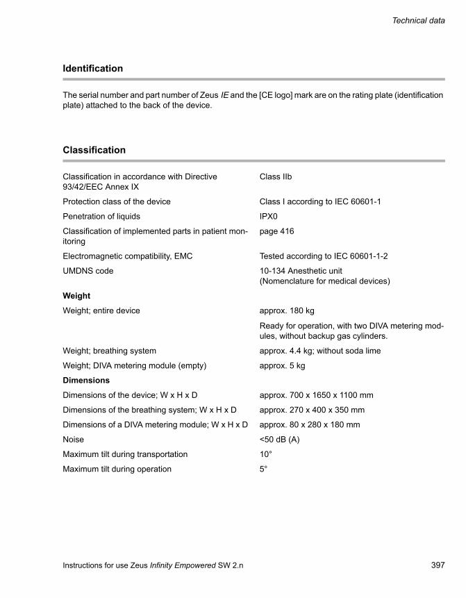
Instructions for use Zeus Infinity Empowered SW 2.n 397
Technical data
Identification
The serial number and part number of Zeus IE and the [CE logo] mark are on the rating plate (identification plate) attached to the back of the device.
Classification
Classification in accordance with Directive 93/42/EEC Annex IX
Class IIb
Protection class of the device Class I according to IEC 60601-1
Penetration of liquids IPX0
Classification of implemented parts in patient mon-itoring
page 416
Electromagnetic compatibility, EMC Tested according to IEC 60601-1-2
UMDNS code 10-134 Anesthetic unit(Nomenclature for medical devices)
Weight
Weight; entire device approx. 180 kg
Ready for operation, with two DIVA metering mod-ules, without backup gas cylinders.
Weight; breathing system approx. 4.4 kg; without soda lime
Weight; DIVA metering module (empty) approx. 5 kg
Dimensions
Dimensions of the device; W x H x D approx. 700 x 1650 x 1100 mm
Dimensions of the breathing system; W x H x D approx. 270 x 400 x 350 mm
Dimensions of a DIVA metering module; W x H x D approx. 80 x 280 x 180 mm
Noise <50 dB (A)
Maximum tilt during transportation 10°
Maximum tilt during operation 5°

Technical data
398 Instructions for use Zeus Infinity Empowered SW 2.n
Latex-free
Zeus IE is manufactured without natural latex
Penetration values of IBF filter
Before conditioning NaCl transmission factor 0.41 % at 15 L/min in ac-cordance with EN13328-1
After conditioning NaCl transmission factor 0.18 % at 15 L/min in ac-cordance with EN13328-1
Before conditioning NaCl transmission factor 0.84 % at 30 L/min in ac-cordance with EN13328-1
After conditioning NaCl transmission factor 0.35 % at 30 L/min in ac-cordance with EN13328-1
Screen
Variant 1 – C500
Type Resistive touch screen
Size (H x W x D) 284 mm x 414 mm x 95 mm
Weight (without mounting): 7 kg
Resolution 1440 x 900
Contrast (minimum) 500:1
Viewing angle Horizontal: 130°, Vertical: 100°
Variant 2 – C500
Type Resistive touch screen
Size (H x W x D) 321 mm x 416 mm x 100 mm
Weight (without mounting): 7 kg
Resolution 1440 x 900
Contrast (minimum) 500:1
Viewing angle Horizontal: 140°, Vertical: 130°

Instructions for use Zeus Infinity Empowered SW 2.n 399
Technical data
Variant 3 – C700
Type Resistive touch screen
Size (H x W x D) 376 mm x 490 mm x 136 mm
Weight (without mounting): 9.5 kg
Resolution 1680 x 1050
Contrast (minimum) 800:1
Viewing angle Horizontal: 160°, Vertical: 160°
Power supply
Operating voltage 100 VAC to 240 VAC; 50/60 Hz
Power consumption during the power-on proce-dure
530 W
Zeus IE equipped with:– Hemodynamic patient monitoring– Module DPS– 2 DIVA metering modules
Maximum current consumption Depending on variant, 8 A, 12 A or 14 A max. with power drawn from auxiliary power sockets.
Auxiliary power socket Up to 2, depending on variant, separately fused via 3 A or 4 A circuit breakers.
Do not connect any HF surgery devices to the aux-iliary power socket because high levels of interfer-ence may impair Zeus IE functionality!
Uninterruptible power supply (UPS) With a fully charged battery: at least 30 minutes; up to 90 minutes, depending on the ventilation param-eters.
No supply to auxiliary sockets!
Screen (Cont.)

Technical data
400 Instructions for use Zeus Infinity Empowered SW 2.n
Ambient conditions
Temperature range for the device
Operation +15 to +35 °C
Storage / transportation –15 to +40 °C
Relative humidity
Operation 25 % to 85 %, no condensation
Storage / transportation 25 % to 85 %, no condensation
Air pressure
Operation 700 to 1060 hPa
Storage / transportation 500 to 1060 hPa
CO2 content of ambient air
Operation 300 to 800 ppm
When transporting filled DIVA metering modules, the specifications of the anesthetic agent manu-facturer must be observed. Only store and transport DIVA metering modules if they are empty! (page 76).
Alarm tone sequence IEC
Sound pressure level L(A) of the alarm tones at the workstation, measured in accordance with IEC 60601-1-8
Alarm volume (high priority) Settable from approximately 52 dB(A) to 70 dB(A)
Alarm volume (medium priority) Settable from approximately 51 dB(A) to 69 dB(A)
Alarm volume (low priority) Settable from approximately 50 dB(A) to 68 dB(A)
Auxiliary alarm ≥55 dB(A) and ≤75 dB(A)
Mains supply failure alarm ≥55 dB(A) and ≤75 dB(A)

Instructions for use Zeus Infinity Empowered SW 2.n 401
Technical data
Central gas supply
Pneumatic connections Central gas supply (CS): O2, N2O, Air.
Backup gas cylinders: 2 cylinders, 3 liters each (O2, Air or N2O)
Anesthetic gas scavenging system.
Vacuum central supply (optional).
Anesthetic gas scavenging system Nominal nozzle diameter 27 mm or ISO cone 30 mm; (according to EN 1281-1)
Required composition of gases
O2, Medically pure (Europ. Pharmacopoeia)
Minimum O2 concentration: 99.5 %
N2O Medically pure (Europ. Pharmacopoeia)
Air Dew point: >5 °C below ambient temperature at 0.5 MPa (5 bar)
Oil content: <0.1 mg/m3
Particles: Dust-free air; filtered with pore size <1 µm
Required input pressures (central supply) for O2, N2O and Air
Nominal pressure range 270 to 690 kPa
Pressure range with guaranteed function (not specified).
180 to 1000 kPa
At an input pressure of <180 kPa and >1000 kPa the device and any other similarly designed devices connected to the central supply can no longer me-ter gases.
Inspiratory O2 concentration
Insp. O2 concentration Max. deviation
≤35 Vol.%
>35 Vol.% ≤60 Vol. %
>60 Vol.%
–3 Vol.%
–5 Vol.%
–7 Vol.%

Technical data
402 Instructions for use Zeus Infinity Empowered SW 2.n
Maximum gas withdrawal
O2 125 L/min(including O2 flush, O2 emergency delivery and maximum gas consumption at the O2 outlet)
Air 160 L/min(including internal supply of the bronchial aspirator and maximum gas consumption at the Air outlet)
N2O 20 L/min
Optional gas supply outlets The output pressure corresponds to the respective input pressure
O2 outlet(at maximum O2 gas delivery)
max. 41 L/min at 2.8 kPa x 100
Air outlet(at maximum Air gas delivery) anduse, no external consumers(e.g., suction))
max. 39 L/min at 2.8 kPa x 100
Driving gas consumption Air <1.5 L/min
Fresh-gas flow, control mode FG ctrl.: 0.25 to 18 L/min (STPD)
Accuracy ±10 %
Resolution 0.1 L/min
Fresh-gas flow, control mode Auto control: 0 to 18 L/min
Accuracy ±0.05 L/min or ±10 %
Resolution with flowMIN = "Uptake": 0.015 L/min otherwise
Resolution with flowMIN: 0.1 L/min
Central gas supply (Cont.)

Instructions for use Zeus Infinity Empowered SW 2.n 403
Technical data
O2 concentration in the fresh gas,Control mode FG ctrl.
25 to 100 Vol.% (measured under ATPD condi-tions)
Accuracy depends on the carrier gas and the nom-inal O2 concentration set:
O2 set concentration
25 Vol.%30 Vol.%40 Vol.%50 Vol.%60 Vol.%70 Vol.%80 Vol.%90 Vol.%100 Vol.%Resolution 1 Vol.%
Carrier gas N2O
±3.75 Vol.%±4.2 Vol.%±4.8 Vol.%±5.0 Vol.%±4.8 Vol.%±4.2 Vol.%±3.2 Vol.%±1.8 Vol.%0 Vol.%
Carrier gas Air
±0.8 Vol.%±1.6 Vol.%±2.9 Vol.%±3.7 Vol.%±4.0 Vol.%±3.7 Vol.%±3.0 Vol.%±1.8 Vol.%0 Vol.%
Inspiratory O2 concentration in the fresh gas, con-trol mode Auto control
25 to 100 Vol.% (maximum achievable O2 concen-tration because of 100 % relative air humidity in the breathing system = 93 Vol.%. Corrected to BTPS conditions)
Accuracy: ±(2.5 Vol.% + 2.5 % of the measured value) in accordance with ISO 21647
Resolution: 1 Vol.%
ORC function Delivery of ≥250 mL/min O2
>35 L/min
0 to 12 L/min
Accuracy: ±35 % or ±2 L/min
O2 flush
O2 safety flow
Central gas supply (Cont.)

Technical data
404 Instructions for use Zeus Infinity Empowered SW 2.n
Gas delivery, control mode FG ctrl.
Concentration of volatile anesthetic agents in the fresh gas
Isoflurane 0 to 5 Vol.%SL (max. 1000 mL/min saturated steam)
Accuracy: ±20 % or 0.2 Vol.%SL
Resolution: 0.1 Vol.%SL
Sevoflurane 0 to 8 Vol.%SL (max. 1000 mL/min saturated steam)
Accuracy: ±20 % or 0.2 Vol.%SL
Resolution: 0.1 Vol.%SL
Desflurane 0 to 18 Vol.%SL (max. 1500 mL/min saturated steam)
Accuracy: ±20 % or 0.2 Vol.%SL
Resolution: 0.2 Vol.%SL
Gas delivery, control mode Auto control
Exp. concentration of volatile anesthetic agent (With automatic control)
Isoflurane 0 to 2.5 Vol.%SL (max. 1000 mL/min saturated steam)
Accuracy: ±20 % or 0.2 Vol.%SL
Resolution: 0.1 Vol.%SL
Sevoflurane 0 to 5 Vol.%SL (max. 1000 mL/min saturated steam)
Accuracy: ±20 % or 0.2 Vol.%SL
Resolution: 0.1 Vol.%SL
Desflurane 0 to 12 Vol.%SL (max. 1500 mL/min saturated steam)
Accuracy: ±20 % or 0.2 Vol.%SL
Resolution: 0.2 Vol.%SL

Instructions for use Zeus Infinity Empowered SW 2.n 405
Technical data
Maximum inspiratory concentration of volatile an-esthetic agents
(inspiratory limit with automatic control)
Isoflurane 0 to 5 Vol.%SL
Accuracy: ±20 % or 0.2 Vol.%SL
Resolution: 0.1 Vol.%SL
Sevoflurane 0 to 8 Vol.%SL
Accuracy: ±20 % or 0.2 Vol.%SL
Resolution: 0.1 Vol.%SL
Desflurane 0 to 18 Vol.%SL
Accuracy: ±20 % or 0.2 Vol.%SL
Resolution: 0.2 Vol.%SL
Ventilation
Electronically controlled radial-flow compressor in conjunction with electrically controlled proportional valve, fresh-gas decoupled.
Ventilation modes Volume Control
Volume Control AutoFlow, with/without Sync.(VC)
Pressure Control, with/without Sync.(PC)
CPAP
MAN/SPON
Optional:
Pressure Support. Support for Volume Control AutoFlow, Pressure Control and CPAP
Pressure limitation Pmax for Volume Control and Volume Control AutoFlow
(PEEP + 5) or (PEEP + Psupp) to 70 hPa
Accuracy: ±10 % or ±2 hPa
Resolution: 1 hPa
Inspiration pressure Pinsp
for Pressure Control
PEEP to 70 hPa
Accuracy: ±10 % or at least ±2 hPa
Resolution 1 hPa
Gas delivery, control mode Auto control (Cont.)

Technical data
406 Instructions for use Zeus Infinity Empowered SW 2.n
Pressure Support (Pressure support) Psupp
for Pressure Control, Volume Control AutoFlow and CPAP
PEEP to 70 hPa
Accuracy: ±10 % or at least ±2 hPa
Resolution 1 hPa
CPAP MAN/SPON ventilation: 0 and 3 to 10 hPa
Accuracy: ±10 % or ±2 hPa
Resolution: 1 hPa
PEEP for Volume Control, Pressure Control, CPAP/Pres-sure Support:0 and 3 to 35 hPa; up to (Pmax –5 hPa) or (Pmax – Psupp)
Accuracy: ±10 % or ±2 hPa
Resolution: 1 hPa
Tidal volume (VT) Accuracy:
<100 mL: ±10 % or ±15 mL (under calibration con-ditions)
>100 mL: ±10 % (under calibration conditions)
Resolution:
20 to 100 mL: 1 mL
100 to 500 mL: 5 mL
>500 mL: 10 mL
Respiratory rate (RR) 3 to 80 1/min
Accuracy: ±1 1/min
Resolution: 1 1/min
Inspiratory time Ti 0.2 to 10 seconds
Accuracy: ±0.1 seconds
Resolution: 0.1 seconds
Respiratory time ratio Ti:Te 4 : 1 to 1 : 4
Inspiratory pause ratio % Tplat:Ti with Volume Control and Volume Control AutoFlow
20 to 50 %
Accuracy: ±20 %
Resolution 5 %
Rise time Slope for Pressure Control, Volume Con-trol AutoFlow, and for Pressure Support breaths
0 to 2 seconds
Resolution: 0.1 seconds
Ventilation (Cont.)

Instructions for use Zeus Infinity Empowered SW 2.n 407
Technical data
Inspiratory flow 180 L/min +10 % maximum Resulting from the VT or Pinsp and Ti settings
Trigger 0.3 to 15 L/min
Resolution:
0.3 to 1 L/min: 0.1 L/min
1 to 15 L/min: 1.0 L/min
Breathing system
Total volume (without breathing hoses) approx. 2.0 liter with absorber container
Compliance (without breathing circuit) With MAN/SPON ventilation: approx. 2 mL/hPa
With automatic ventilation: <0.2 mL/hPa
Absorber volume 1500 mL
"Drägersorb 800 plus" soda lime binds approx. 150 liters of CO2
Safety pressure control valve 85 ±10 hPa
Patient connections ISO cone 22 mm
Breathing system leak <150 mL/min at 30 hPa, standardized to BTPS conditions
Pressure control valve APL Setting range: 5 to 70 hPa
Accuracy: ±15 % of set value or ±3 hPa at 20 L/min
Auxiliary valve –18 hPa ± 3.5 hPa
Ventilation (Cont.)

Technical data
408 Instructions for use Zeus Infinity Empowered SW 2.n
Fresh-gas outlet for non-rebreathing system (optional)
Connection ISO cone (male), ∅ 22 mm diameter with ISO cone (female), ∅15 mm diameter
Pressure Max. 80 hPa at 18 L/min
Fresh-gas flow 3 to 18 L/min
For tolerances see fresh-gas delivery
Airway resistances
Airway resistances, in a dry state without patient hoses (insp. + exp.)
Inspiratory Expiratory
In accordance with ISO 8835-2 at a flow of 60 L/min (depending on the configuration of the breathing system, both the insp. and exp. value may deviate by ±0.3 hPa)
1.2 hPa 5.5 hPa
289
Pinsp (hPa) with standard absorber
Pexp (hPa) with standard absorber
Flow (L/min)
Pres
sure
(hPa
)

Instructions for use Zeus Infinity Empowered SW 2.n 409
Technical data
Measuring system
Pressure measurement (piezo-resistive)
Airway pressure, real-time curve Paw: –20 to 100 hPa
Measured values PEEP, PIP, Pplat; Pmean Measuring range: –20 to 100 hPa
Resolution: 1 hPa
Accuracy: ±4 % or ±2 hPa
Central supply pressure (CS) Measuring range: 0 to 9.8 kPa x 100
Resolution: 0.1 kPa x 100
Accuracy: ±0.1 kPa x 100
Cylinder pressure ("SilverLine" pressure reducer) Measuring range: 0 to 250 kPa x 100
Resolution: 1 kPa x 100
Accuracy: ±10 kPa x 100
Pressure gauge (mechanical) Measuring range: –20 to 80 hPa
Accuracy: ±5 mbar of the reading
Flow measurement (hot-wire anemometry)
Flow real-time curve Measuring range: –180 to 180 L/min
Resolution: 0.1 L/min
Accuracy at 60 L/min: ±10 % (under calibration con-ditions)
Volume real-time curve Measuring range: –200 to 2000 mL
Resolution: 1 mL
Accuracy at 60 L/min: ±10 % (under calibration con-ditions)
Tidal volume VT (inspiratory and expiratory) Measuring range: 0 to 4000 mL
Resolution: 1 mL
Accuracy:
<100 mL: ±10 % or ±15 mL (under calibration con-ditions)
>100 mL: ±10 % (under calibration conditions)

Technical data
410 Instructions for use Zeus Infinity Empowered SW 2.n
Minute volume MV (spontaneous or mandatory) Measuring range: 0 to 40 L/min
Resolution: 0.1 L/min
Accuracy: ±10 % (under calibration conditions)
T90 value on the display: approx. 45 s
Respiratory rate (RR or RRspon) Measuring range: 0 to 150 1/min
Resolution: 1 1/min
Accuracy: ±1 1/min
T90 value on the display: approx. 45 s
Patient compliance Cdyn Measuring range: 0 to 300 mL/hPa
Resolution: 1 mL/hPa
Qualitative value only!
Average: 10 breaths
Patient resistance R Measuring range: 0 to 200 hPa/L/s
Resolution: 1 hPa/L/s
Qualitative value only!
Average: 10 breaths
O2 flow tube Setting range: 0 to 16 L/min
Accuracy: ±10 % of the set value
Response time of the whole system(according to ISO 80601-2-55)
4 +2 seconds
Measuring system (Cont.)

Instructions for use Zeus Infinity Empowered SW 2.n 411
Technical data
O2-, CO2 and anesthetic gas measurement
All measurements from side stream (sample gas measurements) and under calibration conditions.
Sampling rate 200 mL/min ±20 mL/min
Delay time for sampling typically <4 sec. depending on sample gas line
Response time t10…90 O2 <500 ms
Response time t10…90 CO2 <350 ms
Response time t10…90 anesthetic gases <500 ms
Warm-up phase after switching on Specified accuracy: typically after 14 min; max. ≤20 min
ISO accuracy: approx. 4 min
Dependence of accuracy on respiratory rate (I:E ratio 1 : 1)
Specified accuracy: up to 40 1/min
ISO accuracy: up to 60 1/min
O2 measurement (paramagnetic)
Measuring range: 0 to 100 Vol.%
Resolution: 1 Vol.%
Accuracy: ±(2.5 Vol.% + 2.5 % of the measured value) in accordance with ISO 21647
CO2measurement
Concentration in [Vol.%]: Measuring range: 0 to 10 Vol.%
Resolution: 0.1 Vol.%
Accuracy: ±(0.43 Vol.% + 8 % of the measured value) in accordance with ISO 21647
Partial pressure in [mmHg]: Measuring range: 0 to 78 mmHg
Resolution: 1 mmHg
Accuracy: ±(3 mmHg + 8 % of the measured value) in accordance with ISO 21647
Partial pressure in [kPa]: Measuring range: 0 to 10 kPa
Resolution: 0.1 kPa
Accuracy: ±(0.4 kPa + 8 % of the measured value) in accordance with ISO 21647

Technical data
412 Instructions for use Zeus Infinity Empowered SW 2.n
Anesthetic gas measurement (infrared spectroscopy)
Measuring ranges of the anesthetic gases:
Halothane Measuring range: 0 to 8.5 Vol.%
Enflurane Measuring range: 0 to 10 Vol.%
Isoflurane Measuring range: 0 to 8.5 Vol.%
Sevoflurane Measuring range: 0 to 10 Vol.%
Desflurane Measuring range: 0 to 20 Vol.%
Accuracy of anesthetic gas measurement: ±(0.2 Vol.% + 15 % of the measured value) in ac-cordance with ISO 21647Drift of measuring accuracy is compensated by cy-clic zeroing.
Resolution of anesthetic gas measurement: 0.1 Vol.%
N2O Measuring range: 0 to 100 Vol.%Accuracy: ±(2.0 Vol.% + 8 % of the measured value) in accordance with ISO 21647Resolution: 1 Vol.%
xMAC Measuring range: 0 to 9.9 xMACResolution: 0.01 xMACDisplay: based on the expiratory measured valuesAlarms: based on the inspiratory measured values
All gases
Anesthetic gas detection AutomaticPrimary gas: from 0.3 Vol.%Secondary gas: from 0.4 Vol.%
Cross sensitivity
3 ‰ alcohol1 ‰ acetone or methane100 ppm NO or COWater steam saturated at 37 °C
Distortion <0.2 Vol.% for anesthetic gas, CO2, and N2O measurement.Distortion <1 Vol.% for O2 measurement.

Instructions for use Zeus Infinity Empowered SW 2.n 413
Technical data
Anesthetic gas metering modules
Maximum tipping angle / sloped position During operation in device: 5° max.During storage/transport: Any
Filling volume Total volume: 315 mLBetween max./3rd mark: 250 mL
Anesthetic agent loss <1.0 mL liquid in 24 hours in storage or transport.
Data communication
Removable media USB ports
Serial ports COM1 and COM2
Connector 9-pin, Sub-D
Pin allocation:
1 CD (carrier detect)
2 RX (receive)
3 TX (transmit)
4 DTR (data terminal ready)
5 GND (ground)
6 DSR (data set ready)
7 RTS (request to send)
8 CTS (clear to send)
9 RI (ring indicator)
Data protocol MEDIBUS
Settings:
Speed 1200, 2400, 4800, 9600, 19200, 38400 baud
Parity Even
Number of data bits 8
Number of stop bits 1
Connections for IV system (optional)
Standard RS232:
Connector 9-pin, Sub-D
Network ports RJ-45 Cat. 5

Technical data
414 Instructions for use Zeus Infinity Empowered SW 2.n
General safety standards for anesthesia workstations
Relevant standards
In addition to the standards listed here, this medi-cal device meets various other standards, e.g., standards concerning special national require-ments.
IEC 60601-1 2nd editionMedical electrical equipment
Part 1:General requirements for safety
IEC 60601-1-2Medical electrical equipment
Part 1-2:General requirements for safety, Collateral stand-ard: Electromagnetic compatibility requirements and tests
IEC 60601-1-4Medical electrical equipment
Part 1-4General requirements for safety, Collateral stand-ard: Programmable medical electrical systems
IEC 60601-1-8Medical electrical equipment
Part 1-8:General requirements for safety, Collateral stand-ard: General requirements, tests and guidance for alarm systems in medical electrical systems
IEC 60601-2-13Medical electrical equipment
Part 2-13:Particular requirements for the safety and essential performance of anesthetic systems
ISO 8835-2Systems for inhalation anesthesia
Part 2:Anesthesia breathing systems
ISO 8835-3Systems for inhalation anesthesia
Part 3:Transfer and receiving systems of active anaes-thetic gas scavenging systems
ISO 8835-4Systems for inhalation anesthesia
Part 4:Anesthetic vaporizers
ISO 8835-5Systems for inhalation anesthesia
Part 5:Anesthesia ventilators
ISO 21647Medical electrical equipment
Particular requirements for the basic safety and es-sential performance of respiratory gas monitors
EN 1060-1 Non-invasive blood pressure measuring equipment
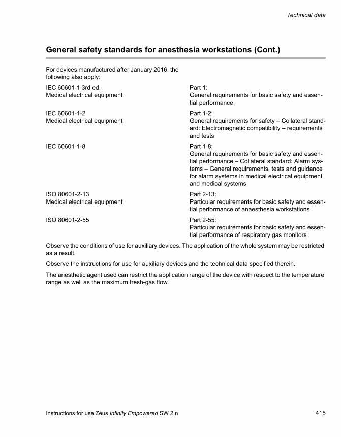
Instructions for use Zeus Infinity Empowered SW 2.n 415
Technical data
For devices manufactured after January 2016, the following also apply:
IEC 60601-1 3rd ed.Medical electrical equipment
Part 1:General requirements for basic safety and essen-tial performance
IEC 60601-1-2Medical electrical equipment
Part 1-2:General requirements for safety – Collateral stand-ard: Electromagnetic compatibility – requirements and tests
IEC 60601-1-8 Part 1-8:General requirements for basic safety and essen-tial performance – Collateral standard: Alarm sys-tems – General requirements, tests and guidance for alarm systems in medical electrical equipment and medical systems
ISO 80601-2-13Medical electrical equipment
Part 2-13:Particular requirements for basic safety and essen-tial performance of anaesthesia workstations
ISO 80601-2-55 Part 2-55:Particular requirements for basic safety and essen-tial performance of respiratory gas monitors
Observe the conditions of use for auxiliary devices. The application of the whole system may be restricted as a result.
Observe the instructions for use for auxiliary devices and the technical data specified therein.
The anesthetic agent used can restrict the application range of the device with respect to the temperature range as well as the maximum fresh-gas flow.
General safety standards for anesthesia workstations (Cont.)

Technical data
416 Instructions for use Zeus Infinity Empowered SW 2.n
Modules for patient monitoring
Hemodynamic modules
Operation Hard keys (C.O. Start, IBP Cal, Wedge)
Indicators and displays HemoMed, Quad Hemo: none
Hemo2: two 4-digit LCD displays
Hemo4: four 4-digit LCD displays
Connections Hemo2: 2 invasive pressure parameters, C.O., 2 temperatures, one cable for connecting the mod-ule to Zeus IE
Hemo4: 4 invasive pressure parameters, C.O., one cable for connecting the module to Zeus IE
Quad Hemo and HemoMed: 4 invasive pressure parameters, C.O., 2 temperatures, one cable for connecting the module to Zeus IE
Dimensions (H x W x D) Hemo2, Hemo4, HemoMed: 140 x 205 x 60 mm
Quad Hemo: 110 x 205 x 80 mm
Weights Hemo2: 0.7 kg (incl. pressure transducer block)
Hemo4 and HemoMed: 0.9 kg (incl. 2 pressure transducer blocks)
Quad Hemo: 0.48 kg (incl. 4 pressure transducer cables)
Temperature range, operation: Hemo2, Hemo4, HemoMed: 10 °C to 40 °C
Quad Hemo: 0 °C to 45 °C
Temperature range, storage: Hemo2, Hemo4, HemoMed: –20 °C to 50 °C
Quad Hemo: –40 °C to 70 °C
Relative air humidity, operation: Hemo2, Hemo4, HemoMed: 20 % to 90 %, non-condensing
Quad Hemo: 10 % to 95 %, non-condensing
Relative air humidity, storage: Hemo2, Hemo4, HemoMed: 10 % to 95 %, (with packaging)
Quad Hemo: 10 % to 95 % (with packaging)

Instructions for use Zeus Infinity Empowered SW 2.n 417
Technical data
Air pressure, operation: Hemo2, Hemo4, HemoMed: 525 to 795 mmHg (70 to 106 kPa)
Quad Hemo: 480 to 795 mmHg (64 to 106 kPa)
Air pressure, storage: 375 to 795 mmHg (50 to 106 kPa)
Type of applied part Type CF as per IEC 60601-1
Defibrillation protection according to IEC 60601-2-34
Trident Pod (NMT)
Indicators and displays yellow, LED for active stimulation
Connections Pod COM: for connecting to Zeus IE
NMT cable
EEG: for connecting the BISx pod
Dimensions (H x W x D) 36 x 132 x 140 mm
Weight 595 g
Temperature range, operation:
Temperature range, storage:
10 °C to 40 °C
–20 °C to 40 °C
Relative air humidity, operation:
Relative air humidity, storage:
20 % to 90 %, non-condensing
20 % to 90 % (with packaging)
Air pressure, operation:
Air pressure, storage:
525 to 795 mmHg (70 to 106 kPa)
375 to 795 mmHg (50 to 106 kPa)
Electrical specifications Type CF as per IEC 60601-1
IEC 60601-2-40; specification for electromyo-graphs and devices for evoked potentials
Hemodynamic modules (Cont.)

Technical data
418 Instructions for use Zeus Infinity Empowered SW 2.n
Monitoring specifications
BISx pod
Connections Pod COM: for connecting to Zeus IE
Sensor cable
Dimensions (H x W x D) 114.5 x 95.3 x 63.5 mm
Weight 227 g
Temperature range, operation:
Temperature range, storage:
10 °C to 40 °C
–20 °C to 40 °C
Relative air humidity, operation:
Relative air humidity, storage:
20 % to 90 %, non-condensing
20 % to 90 % (with packaging)
Air pressure, operation:
Air pressure, storage:
525 to 795 mmHg (70 to 106 kPa)
375 to 795 mmHg (50 to 106 kPa)
Electrical specifications Type BF as per IEC 60601-1
Defibrillation protection according to IEC 60601-2-26
ECG
Display Up to 3 leads
Leads for adults and pediatric I, II, III, aVR, aVL, aVF, V, V+, (aVR/aVL/aVF/V only with five-lead wire set.
V+ only with six-lead wire set)
Leads for neonates I, II, III, aVR, aVL, aVF, V, V+, (aVR/aVL/aVF/V only with five-lead wire set.
V+ only with six-lead wire set
Measuring range 15 to 300 bpm
Accuracy ±2 bpm or ±1 %
QRS detection Amplitude: 0.5 to 5.0 mV
Duration: 70 to 120 ms (adult and children); 40 to 120 ms (neonates)

Instructions for use Zeus Infinity Empowered SW 2.n 419
Technical data
Frequency ranges Filter = Monitor: 0.5 to 40 Hz
Filter = ESU: 0.5 to 16 Hz
Filter = OFF: 0.05 to 40 Hz
Electrical specifications Type CF as per IEC 60601-1
Defibrillation protection according to IEC 60601-2-27
Arrhythmia detection Only for adults and children; not for neonates
Pacemaker detection For adults and children on leads I, II and III, not for neonates
Pacemakers with the following features can be de-tected
Amplitude ±2 to ±700 mV
Width (dp) 0.2 to 2.0 ms
Rise/fall (min) 0.1 dp, 100 ms
Overshoot (min) 0.025 ap, 2 mV
Recharge constant 4 to 100 ms
ST segment analysis
Leads for the analysis 3-lead wire set: I, II, III (one lead selectable)
5-lead wire set: I, II, III, aVR, aVL, aVF or V (three leads selectable without ST option, all leads with ST option)
6-lead wire set: I, II, III, aVR, aVL, aVF, V or V+ (three leads selectable without ST option, all leads with ST option)
Isoelectric point Setting range: Start of the QRS complex up to ref-erence point
Basic setting: Start of the QRS –28 ms
ST measuring point Reference point up to end of the QRS complex
Basic setting: End of the QRS +80 ms
ST complex Length: 892 ms (225 units)
Frequency response: 0.05 to 40 Hz
Update interval 15 seconds, with at least one normal beat
Trend time (ST display) 30 minutes
Trend resolution One data point every 30 seconds
Duration of the ST alarm OFF, 15, 30, 45, 60 seconds
ECG (Cont.)

Technical data
420 Instructions for use Zeus Infinity Empowered SW 2.n
Classification Caution
Alarm On/Off Off: No alarms generated
Automatic alarm limits Current measured value ±2 mm
Response time to changes in heart rate
Change in heart rate from 90 to 120 bpm Range: 3.4 to 7.1 sAverage: 5.3 s
Change in heart rate from 90 to 40 bpm Range: 6.3 to 8.6 sAverage: 7.4 s
ECG (Cont.)
Non-invasive blood pressure measurement (NIBP)
Parameter display Systolic, diastolic, mean
Measuring principle Oscillometry
Modes of operation Manual (single measurement), continuous (5 min-utes), interval or stasis
Interval times 1, 2, 3, 5, 10, 15, 30 min
Measuring ranges (adults), 270 mmHg Heart rate: 40 to 240 bpm
NIBP (systolic): 30 to 250 mmHg
NIBP (mean): 20 to 230 mmHg
NIBP (diastolic): 10 to 210 mmHg
Measuring ranges (children), 180 mmHg Heart rate: 40 to 240 bpm
NIBP (systolic): 30 to 170 mmHg
NIBP (mean): 20 to 150 mmHg
NIBP (diastolic): 10 to 130 mmHg
Measuring ranges (neonates), 140 mmHg Heart rate: 40 to 240 bpm
NIBP (systolic): 30 to 130 mmHg
NIBP (mean): 20 to 110 mmHg
NIBP (diastolic): 10 to 100 mmHg
Connections Quick-release hose connector with single airway

Instructions for use Zeus Infinity Empowered SW 2.n 421
Technical data
Default inflation pressure Adults: 160 mmHg ±10 mmHg
Children: 120 mmHg ±10 mmHg
Neonates: 110 mmHg ±10 mmHg
Inflation pressure after a valid measurement (±10 mmHg)
Adult: Previous systolic pressure +25 mmHg
Children: Previous systolic pressure +25 mmHg
Neonatal: Previous systolic pressure +30 mmHg
Maximum cuff pressure Adults: 265 mmHg ±5 mmHg
Children: 180 mmHg ±10 mmHg
Neonates: 142 mmHg ±10 mmHg
Minimum cuff pressure necessary for measure-ment
Adults: 110 mmHg ±10 mmHg
Children: 90 mmHg ±10 mmHg
Neonates: 70 mmHg ±10 mmHg
Maximum inflation time Adults: 2 min ±1 s
Children: 2 min ±1 s
Neonates: 90 s ±1 s (60 s according to French law)
Software safety cut-off Adults: 273 mmHg ±3 mmHg
Children: 215 mmHg ±3 mmHg
Neonates: 153 mmHg ±3 mmHg
Hardware safety cut-off Adults and children: 300 mmHg ±30 mmHg
Neonates: 170 mmHg ±20 mmHg
Static cuff pressure accuracy ±3 mmHg
Calibration range Adults/children: 10 to 260 mmHg ±3 mmHg
Neonates: 10 to 150 mmHg ±3 mmHg
Electrical specifications Type CF as per IEC 60601-1
Defibrillation protection according to IEC 60601-2-30
Non-invasive blood pressure measurement (NIBP) (Cont.)

Technical data
422 Instructions for use Zeus Infinity Empowered SW 2.n
Invasive blood pressure (IBP)
Measuring principle Resistive pressure transducer
Resolution 1 mmHg
Measuring range –50 to 400 mmHg
Frequency ranges DC up to 8 Hz,
DC up to 16 Hz and
DC up to 32 Hz (adjustable)
Accuracy ±1 mmHg or ±3 %, excluding the pressure trans-ducer
Zero calibration range ±200 mmHg
Transducer specifications Permitted pressure transducers with a resistance of 200 to 3000 Ω and an equivalent pressure sensitiv-ity of 5 µV/V/mmHg ±10 %
Electrical specifications Type CF as per IEC 60601-1
Defibrillation protection according to IEC 60601-2-34
Wedge measurement
Pressure measuring range 10 to 120 mmHg
Deflection rate 6.25 to 50 mm/s

Instructions for use Zeus Infinity Empowered SW 2.n 423
Technical data
Cardiac output (C.O.)
Parameter display Cardiac output, blood temperature, injectate tem-perature
Measuring principle Thermodilution
Measuring range Cardiac output: 0.5 to 20 L/min
Blood temperature: 25 °C to 43 °C
Injectate temperature: –5 °C to +30 °C
Accuracy Cardiac output: ±5 % (with 0 °C injectate)
Injectate temperature: ±0.25 °C
Electrical specifications Type CF as per IEC 60601-1
Defibrillation protection according to IEC 60601-1A2
Pulse oximetry (SpO2)
Parameter display Saturation (% SpO2), pulse rate
Absorption spectrophotometry
SpO2: 70 to 100 %
Pulse rate: 30 to 250 bpm
70 to 100 %
0 to 100 %
2 seconds
30 seconds (in the event of artefact or other errors)
Measuring principle
Measuring range
Calibration range
Display range
Display update period
Maximum update delay

Technical data
424 Instructions for use Zeus Infinity Empowered SW 2.n
SpO2 accuracy Measuring accuracy in Adult mode (1):
SpO2:
0 to 69 % not specified
70 to 100 % sensor-specific, specified as follows:
Nellcor(2, 3):
OxiMAX MAX-A, OxiMAX MAX-AL, Oxi-MAX MAX-P, OxiMAX MAX-N, OxiMAX MAX-I ±2
Nellcor:
DS100A ±3
Masimo(2, 3):
LNOPADT, LNOPPED, LNOPNEO, LNOPNEO SS, LNOP-YI ±2
Masimo:
LNOP-DCI, LNOP-DCIP, NR125 ±2
EAR ±3.5
Pulse:
±3 bpm or ±3 % (whichever is higher)
Measuring accuracy in Neonatal mode (1, 2, 3, 4):
SpO2:
0 to 69 % not specified
70 to 100 % sensor-specific, specified as follows:
Nellcor:
N-25, OxiMAX MAX-N ±3
Masimo:
LNOPNEO, LNOPNEO SS, LNOP-YI ±3
Pulse:
±3 bpm or ±3 % (whichever is higher)
Pulse oximetry (SpO2) (Cont.)

Instructions for use Zeus Infinity Empowered SW 2.n 425
Technical data
Note:
1 SpO2 levels of accuracy are expressed as ± "X" figures between specified saturation values. SpO2 measuring accuracy is speci-fied with 1 SD (standard deviation), which represents approx. 68 % of the population.
2 Saturation: In the event of movement, the levels of accuracy have to be expanded by ±1 digit (5, 6) (ECG monitoring necessary).
3 Pulse: In the event of movement, the levels of accuracy have to be expanded by ±2 bpm or ±2 % (whichever is greater) (5, 6) (ECG monitoring necessary).
4 Accuracy tolerance for neonates is ±1 digit higher than for adults in order to take into consideration the theoretical effects of fetal hemoglobin in neonatal blood.
5 For Masimo devices movement is defined as follows:
– regular rubbing/knocking with an ampli-tude of 1 to 2 cm at a regular frequency of 2 to 4 Hz.
or
– irregular movement with an amplitude of 2 to 3 cm at a frequency of 1 to 5 Hz.
6 For Nellcor devices, movement is defined as irregular rubbing/knocking with an amplitude of 1 to 2 cm at a regular frequency of 1 to 4 Hz.
SpO2 alarms Upper limit: adjustable between 71 and 100 %
Lower limit: adjustable between 70 and 99 %
Nominal wavelength Nellcor: Red: 660 nm, Infrared: 910 nm
Masimo: Red: 660 nm, Infrared: 905 nm
Pulse oximetry (SpO2) (Cont.)

Technical data
426 Instructions for use Zeus Infinity Empowered SW 2.n
Power of radiation sources Nellcor: Red: 3 mW (max.), Infrared: 4 mW (max.)
Masimo: Red: 0.9 mW (max.), Infrared: 0.9 mW (max.)
Note: LED is voltage-limited by a hardware mecha-nism.
Electrical specifications Type CF as per IEC 60601-1
Defibrillation protection according to IEC 60601-1A2
Temperature
Parameter display Absolute temperature
Measuring range –5 °C to 50 °C (absolute)
Resolution ±0.1 °C
Accuracy ±0.1 °C (absolute)
Average response time <2.5 seconds
Sensor accuracy ±0.1 °C; 0 °C to 50 °C
Electrical specifications Type CF as per IEC 60601-1
Defibrillation protection according to IEC 60601-1A2
Neuromuscular Transmission Monitoring NMT
Stimulation modes Single Twitch (Single), Train of Four (TOF), Post Tetanic Count (PTC)
Range for stimulation current Auto: Display only; 60 mA max. up to 6.6 kΩ; based on the reference pulse at start
Man: 5 to 60 mA in 5 mA increments
Pulse width 100, 200 or 300 µs
Measuring intervals None, 1 s, 10 s, 20 s, 1 min, 5 min, 15 min, 30 min
Pulse oximetry (SpO2) (Cont.)

Instructions for use Zeus Infinity Empowered SW 2.n 427
Technical data
Measuring ranges T NMT: 20 to 40 °C
Single twitch: 0 to 200 % of the reference pulse
TOF Ratio: 0 to 150 %
TOF Count: 0 to 4 (number of stimulations) if TOF Ratio <20 % or if the number of stimulations <4
PTC: 0 to 20 (number of stimulations)
Accuracy T NMT: ±1 °C
Single twitch: ±10 %
TOF-Ratio: ±10 %
Display resolution T NMT: 1 °C
Single twitch: 1 %
TOF-Ratio: 1 %
TOF-Count/PTC: 1
Trend display ranges Single twitch: 0 to 200 %, 5 % increments
TOF Ratio: 0 to 150 %, 5 % increments
TOF Count: 0 to 4, 1-unit increments
PTC: 0 to 20, 1-unit increments
Electrical specifications Type CF as per IEC 60601-1
Defibrillation protection according to IEC 60601-1A2
Associated standards IEC 60601-2-40; specification for electromyo-graphs and devices for evoked potentials
Neuromuscular Transmission Monitoring NMT (Cont.)

Technical data
428 Instructions for use Zeus Infinity Empowered SW 2.n
Anesthesia depth monitoring BIS
Parameter Bispectral Index BIS
Signal Quality Index SQI
Electromyography EMG
Burst Suppression Ratio BSR
Spectral Edge Frequency SEF
Burst Count BCT
Total Power PWR
Measuring ranges and accuracy BIS: 0 to 100 ±1
SQI: 0 to 100 % ±0.1 %
EMG: 30 to 80 dB ±1 dB / 0 to 100 dB (in frequency range 70 to 110 Hz)
BSR: 0 to 100 % ±0.1 %
SEF: 0.5 to 30 Hz ±0.01 Hz (parameters selectable)
BCT: 0 to 30 ±1
PWR: 40 to 100 dB (in the frequency range from 0.5 to 30 Hz)
Sensor impedance test PASS: Impedance <7.5 kΩ
Filter High filter: off, on, auto
Low filter: off, on
Notch filter: off/on
Averaging time 15, 30 seconds
EEG waveform display range 50, 100, 250, 500 µV, Auto
Trend display ranges BIS: 0 to 100
EMG: 0 to 100
SQI: 0 to 100
BSR: 0 to 100
BCT: 0 to 30
SEF: 0 to 30
PWR: 0 to 100

Instructions for use Zeus Infinity Empowered SW 2.n 429
Technical data
Essential performance
The essential performance features comprise:
General
– Supply of the anesthesia workstation with O2
If the O2 supply (central gas supply or gas cyl-inder) fails, an alarm is issued.
– Supply of the patient with adequately oxygen-ated breathing gas
If the breathing gas contains insufficient levels of O2, an alarm is issued.
– Patients are not supplied with excessively high anesthetic gas concentrations
If excessively high anesthetic gas concentra-tions are delivered, an alarm is issued.
– Monitoring of the airway pressure and the expir-atory minute volume
Alarms are issued depending on the set alarm limits.
Gas measurement
– Accuracy of the gas measurements
– Generation of alarms when defined alarm limits are transgressed
If the gas measurement fails, an alarm is is-sued.
WARNINGThe following parameters are not monitored in neonates: arrhythmia, cardiac output, and ST segment analysis. No alarm will be activated.

Technical data
430 Instructions for use Zeus Infinity Empowered SW 2.n
EMC Declaration
General information
The EMC conformity of the device has been evalu-ated in conjunction with the external cables, trans-ducers, and accessories specified in the list of ac-cessories. Other accessories which do not affect EMC conformity may be used if no other reasons forbid their use (see other sections of these instruc-tions for use). The use of non-compliant accesso-ries may result in increased emissions or de-creased immunity of the medical device.
The medical device may only be used adjacent to or stacked with other devices when the configura-tion is approved by Dräger. If adjacent or stacked use of non-approved configurations is inevitable, verify normal operation of the medical device in the configuration in which it will be used. In any case, strictly observe the instructions for use of the other devices.
Electromagnetic emissions
When using wireless networking, be aware that the system operates at 2.4 GHz range. Other equip-ment, even if compliant with CISPR emission re-quirements, can interfere with reception of wireless data. When selecting wireless systems (wireless communication media, pager systems, etc.) for use in installations where wireless networking is used, care must always be used to ensure that operating frequencies are compatible. For example, selecting wireless communication media that operate at 2.4 GHz will likely cause difficulty with the network-ing components. Low-level signals such as ECG signals are particular susceptible to interference from electromagnetic energy. Even if the equip-ment meets the test requirements described below, smooth operation cannot be guaranteed – the ‘qui-eter‘ the electrical environment the better. In gen-eral, increasing the distance between electrical de-vices decreases the likelihood of interference.
Detailed radio frequency characteristics
Communication devices in accordance with IEEE 802.11b:
– 2412 to 2472 MHz
– DSSS (direct-sequence spread spectrum) lim-ited to 100 mW
– Applicable to access points and client adapters
Communication devices in accordance with IEEE 802.15.1:
– 2400 to 2485 MHz
– FHSS (frequency-hopping spread spectrum) limited to 2.5 mW
See the instructions for use of the wireless devices for further details.

Instructions for use Zeus Infinity Empowered SW 2.n 431
Technical data
Electromagnetic environment
The medical device is intended for use in an elec-tromagnetic environment as specified in the follow-ing. The user must ensure that the medical device is used in such an environment.
Transmissions Compliancewith
Electromagnetic environment
Radio frequency emissions (CISPR 11)
Group 1 The medical device uses radio frequency energy only for its internal function. There-fore, its radio frequency emissions are very low and are not likely to cause any interfer-ence in nearby electronic equipment.
Class A The medical device is not specified for op-eration in residential buildings and such equipment as is directly (without trans-former) connected to the same low voltage network as the residential building.
Harmonic emissions (IEC 61000-3-2)
Not applicable
Transmission of voltage fluctuations / flicker(IEC 61000-3-3)
Not applicable
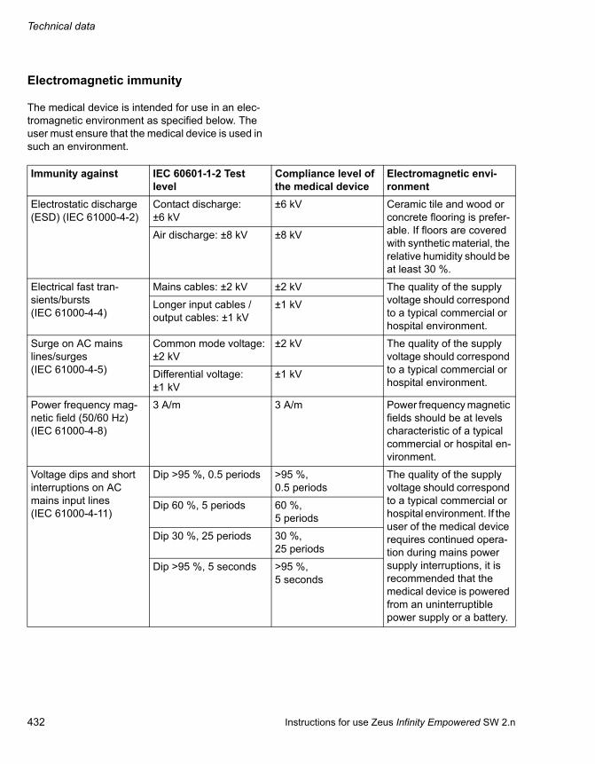
Technical data
432 Instructions for use Zeus Infinity Empowered SW 2.n
Electromagnetic immunity
The medical device is intended for use in an elec-tromagnetic environment as specified below. The user must ensure that the medical device is used in such an environment.
Immunity against IEC 60601-1-2 Test level
Compliance level of the medical device
Electromagnetic envi-ronment
Electrostatic discharge (ESD) (IEC 61000-4-2)
Contact discharge: ±6 kV
±6 kV Ceramic tile and wood or concrete flooring is prefer-able. If floors are covered with synthetic material, the relative humidity should be at least 30 %.
Air discharge: ±8 kV ±8 kV
Electrical fast tran-sients/bursts (IEC 61000-4-4)
Mains cables: ±2 kV ±2 kV The quality of the supply voltage should correspond to a typical commercial or hospital environment.
Longer input cables / output cables: ±1 kV
±1 kV
Surge on AC mains lines/surges (IEC 61000-4-5)
Common mode voltage: ±2 kV
±2 kV The quality of the supply voltage should correspond to a typical commercial or hospital environment.
Differential voltage: ±1 kV
±1 kV
Power frequency mag-netic field (50/60 Hz) (IEC 61000-4-8)
3 A/m 3 A/m Power frequency magnetic fields should be at levels characteristic of a typical commercial or hospital en-vironment.
Voltage dips and short interruptions on AC mains input lines (IEC 61000-4-11)
Dip >95 %, 0.5 periods >95 %,0.5 periods
The quality of the supply voltage should correspond to a typical commercial or hospital environment. If the user of the medical device requires continued opera-tion during mains power supply interruptions, it is recommended that the medical device is powered from an uninterruptible power supply or a battery.
Dip 60 %, 5 periods 60 %,5 periods
Dip 30 %, 25 periods 30 %,25 periods
Dip >95 %, 5 seconds >95 %,5 seconds

Instructions for use Zeus Infinity Empowered SW 2.n 433
Technical data
Radiated radio fre-quency interference (IEC 61000-4-3)
80 MHz to 2.5 GHz: 10 V/m
10 V/m Recommended minimum distance from portable and mobile radio devices with transmitting power PEIRP to the medical device in-cluding its cables:
1.84 m x √PEIRP [watts]1)
(6.04 ft x √PEIRP [watts])
Conducted radio fre-quency (IEC 61000-4-6)
150 kHz to 80 MHz: 10 V within the ISM bands2)
10 V Recommended minimum distance from portable and mobile radio devices with transmitting power PEIRP to the medical device in-cluding its cables:
(1.84 m x √PEIRP [watts])1)
(6.04 ft x √PEIRP [watts])
150 kHz to 80 MHz: 3 V outside the ISM bands2)
3 V
1) For PEIRP, insert the highest possible "equivalent isotropic radiated power" of the adjacent radio frequency transmitter. High-frequency transmission may also occur in the vicinity of devices with the symbol . Field strengths from fixed, port-able, or mobile radio frequency transmitters at the location of the medical device should be less than 3 V/m in the frequency range from 150 kHz to 2.5 GHz and less than 1 V/m above 2.5 GHz.
2) ISM bands in this frequency range are: 6.765 MHz to 6.795 MHz; 13.553 MHz to 13.567 MHz; 26.957 MHz to 27.283 MHz; 40.66 MHz to 40.70 MHz.
Immunity against IEC 60601-1-2 Test level
Compliance level of the medical device
Electromagnetic envi-ronment

Technical data
434 Instructions for use Zeus Infinity Empowered SW 2.n
Recommended safety clearance for portable and mobile high-frequency communi-cation equipment
The following separation distances are in accord-ance with the specifications of IEC 60601-1-2.
Reduced separation distances to portable and mobile radio frequency communica-tion devices
The following separation distances are based on additional tests performed by Dräger to determine the minimum separation distances absolutely nec-essary. These reduced safety clearances apply only to mobile high-frequency communication equipment that uses the standards specified.
Max. PEIRP (W) 150 kHz to 2.5 GHz All other frequencies Examples0.03 0.32 m (1.05 ft) 0.96 m (3.15 ft) WLAN 5250/5775 (Europe)
0.10 0.58 m (1.90 ft) 1.75 m (5.74 ft) WLAN 2440 (Europe)
0.17 0.76 m (2.49 ft) 2.28 m (7.48 ft) Bluetooth, RFID 2.5 GHz
0.20 0.82 m (2.69 ft) 2.47 m (8.10 ft) WLAN 5250 (not in Europe)
0.25 0.92 m (3.02 ft) 2.76 m (9.06 ft) UMTS mobile phones
0.41 1.18 m (3.87 ft) 3.53 m (11.58 ft) Cordless DECT devices
0.82 1.67 m (5.48 ft) 5.00 m (16.40 ft) RFID 13.56 MHz
1.00 1.84 m (6.04 ft) 5.52 m (18.11 ft) WLAN 5600 (not in Europe)
1.64 2.36 m (7.74 ft) 7.07 m (23.20 ft) GSM 1800/GSM 1900
3.28 3.33 m (10.93 ft) 10.00 m (32.81 ft) GSM 900 mobiles, RFID 868 MHz
Mobile high-frequency communication equipment with ... Safety clearanceGSM 850, GSM 900, RFID 868 MHz (limited to 2 W ERP) 0.30 m (12 in)
GSM 1800, GSM 1900 (limited to 1 W ERP) 0.30 m (12 in)
UMTS, DECT (limited to 0.25 W ERP) 0.15 m (6 in)
Bluetooth, WLAN 2450, RFID 2450 (limited to 0.1 W ERP) 0.30 m (12 in)

Instructions for use Zeus Infinity Empowered SW 2.n 435
Technical data
Device combinations
This device can be operated in combination with other Dräger devices or with devices from other manufacturers. Observe the accompanying docu-ments of the individual devices.
If a device combination is not approved by Dräger, the safety and the functionality of the individual de-vices may be compromised. The operating organi-zation must ensure that the device combination complies with the applicable editions of the relevant standards for medical devices.
Device combinations approved by Dräger meet the requirements of the following standards (where ap-plicable):
– IEC 60601-1, 3rd edition (general requirements for safety, device combinations, software-con-trolled functions) – IEC 60601-1-2 (electromagnetic compatibil-
ity) – IEC 60601-1-8 (alarm systems)
Or:
– IEC 60601-1, 2nd edition (general require-ments for safety) – IEC 60601-1-1 (device combinations)– IEC 60601-1-2 (electromagnetic compatibil-
ity) – IEC 60601-1-4 (software-controlled func-
tions) – IEC 60601-1-8 (alarm systems)

Technical data
436 Instructions for use Zeus Infinity Empowered SW 2.n
Connections to IT networks
Data can be exchanged across an IT network by using wired and wireless technologies. An IT net-work can be any data interface (e.g., RS232, LAN, USB, printer interface) that is described in stand-ards and conventions.
During operation, this device can exchange infor-mation with other devices by means of IT networks and supports the following functions:
– Display of waveforms and parameter data
– Signaling of alarms
– Recording, storing, and printing
– Remote control (e.g., alarm management)
– Access to saved patient data
– Transfer of device settings and patient data
– Service mode, access to logbooks
Connecting this device to a network that incorpo-rates other devices or making subsequent changes to that network can lead to new risks for patients, users, and third parties. Before the device is con-nected to the network or the network is changed, these risks must be identified, analyzed, and eval-uated, and appropriate measures taken.
Examples of subsequent changes to the network:
– Changing the network configuration
– Removing devices from the network
– Adding new devices to the network
– Performing upgrades or updates on devices that are connected to the network
Information on connecting to the IT net-work
Prerequisites
This device must only be connected to the network by service personnel. The IT representative of the hospital must be consulted in advance.
The following documents must be followed:
– Accompanying documents of this device
– Descriptions of the network
– Description of the network-based alarm sys-tems
Dräger recommends observing IEC 80001-1 (Risk management for IT networks incorporating medical devices).
LAN networks
– LAN networks are usually configured in a star topology. Individual devices can be combined into groups by means of layer-n switches. Other data traffic is decoupled by means of separate VLAN networks. Configure the network settings of the device in accordance with these instruc-tions for use and the network specifications.
– Specifications for LAN connections are de-scribed in the following standards:– Wired networks: IEEE 802.3– Wireless networks: IEEE 802.11 (b, g, n)
– If the device is used with a layer-2 switch or a layer-3 switch, the port settings on the network switch must be configured. Before the device is shipped, Dräger can configure the network set-tings of the device so that they correspond with the specifications of the operating organization.

Instructions for use Zeus Infinity Empowered SW 2.n 437
Technical data
– This device exchanges data with other medical devices over the LAN network. The network must support the following transmissions and protocols:– TCP/IP– Unicast (static or dynamic addressing with
the ARP or RARP network protocols)– Multicast– Broadcast– IGMP (Version 2)
This device can join or leave an IP multicast group by using the IGMP network protocol.
Serial ports
This device supports the following ports:
– RS232 ports conforming to EIA RS232 (CCITT V.24/V.28) for the following applica-tions:– MEDIBUS, MEDIBUS.X– Paging systems– Connections to medical devices from other
manufacturers
– Ports based on USB 1.1 or USB 2.0 (e.g., mouse, keyboard, hard disk, USB stick, CD drive)
Consequences of using an unsuitable network
If the network does not have the required charac-teristics, hazardous situations can result. The fol-lowing situations can occur with this device:
– Due to an insecure decentralized alarm system:– Alarms are not transmitted.– Alarms or data are transmitted with a delay.– False alarms are triggered.
– During an interruption of the network connec-tion:– Alarms are not transmitted.
– Without firewall and antivirus software:– Data are not protected.– Device settings are changed.– The device generates false alarms or no
alarms.
– Data are sent incomplete, sent to the wrong de-vice, or not sent at all.
– Patient data are intercepted, falsified, or dam-aged.
– Data have incorrect time stamps.
– An overload of the device due to very high net-work loading (e.g., caused by denial-of-service attacks) can lead to deactivation of the inter-face. The interface will only be available again after the device has been restarted. In rare cases, a warm boot may take place and may oc-cur repeatedly.
Requirements for the electrical characteristics of connected devices and networks
The LAN ports and the serial ports are only suitable for connection of devices or networks that have a nominal voltage of at most 24 VDC on the network side and that meet the requirements of one of the following standards:
– IEC 60950-1: Ungrounded SELV circuits
– IEC 60601-1 (as of 2nd edition): Exposed sec-ondary circuits

438 Instructions for use Zeus Infinity Empowered SW 2.n
This page was intentionally left blank.

Instructions for use Zeus Infinity Empowered SW 2.n 439
Description
Description
Gas flow diagram . . . . . . . . . . . . . . . . . . . . . . 440
Fresh-gas control mode . . . . . . . . . . . . . . . . . . 441ORC function (Oxygen Ratio Controller) . . . . . 441Anesthetic agent delivery . . . . . . . . . . . . . . . . . 441
Gas control loops . . . . . . . . . . . . . . . . . . . . . . 441
Concentration control loops (Auto control control mode) . . . . . . . . . . . . . . . . . . . . . . . . . . 441Volume control loop (Auto control, MinFG flow control mode = "Uptake") . . . . . . . . . . . . . 442Inspiratory oxygen concentration control . . . . . 442Expiratory anesthetic agent concentration control. . . . . . . . . . . . . . . . . . . . . . . . . . . . . . . . 443Restrictions to the metering of anesthetic agent concentration . . . . . . . . . . . . . . . . . . . . . 444Flush phases . . . . . . . . . . . . . . . . . . . . . . . . . . 444Safety concept (HighFlow operation) . . . . . . . . 445O2 emergency delivery . . . . . . . . . . . . . . . . . . . 445O2 flush. . . . . . . . . . . . . . . . . . . . . . . . . . . . . . . 445Additional oxygen delivery for regional anesthesia . . . . . . . . . . . . . . . . . . . . . . . . . . . . 445
Ventilation . . . . . . . . . . . . . . . . . . . . . . . . . . . . 446
Flow measurement and volume delivery . . . . . 446
Ventilation modes. . . . . . . . . . . . . . . . . . . . . . 446
Pressure Control (Pressure-controlled ventilation) . . . . . . . . . . . . . . . . . . . . . . . . . . . . 446Volume Control AutoFlow. . . . . . . . . . . . . . . . . 447AutoFlow start behavior . . . . . . . . . . . . . . . . . . 448Ventilation mode Pressure Support . . . . . . . . . 449Synchronization with Vol. Ctrl. AutoFlow (Sync. = ON). . . . . . . . . . . . . . . . . . . . . . . . . . . 450
Appendix . . . . . . . . . . . . . . . . . . . . . . . . . . . . . 451
Units and standards . . . . . . . . . . . . . . . . . . . . . 451

Description
440 Instructions for use Zeus Infinity Empowered SW 2.n
Gas flow diagram
A Non-return valve to anesthetic gas scavenging system (AGSS)
B APL valve
C PEEP/PMAX valve
D Expiratory valve
E Pressure sensor airway pressure
F SpiroLife expiration flow sensor
G Patient's lung
H SpiroLife inspiration flow sensor
I Inspiratory valve
J CO2 absorber
K Option CO2 Clic absorber, unlocked position
L Safety valve in breathing system (excess pres-sure)
M Inspiration pressure sensor
N Pressure gauge
O Additional air valve
P Blower
Q Pressure sensor – breathing bag
R Breathing bag
S Microbial filter sample gas return line
T Gas analysis
U CO2 water trap
V External area for the leak test: for manual venti-lation
W Closed circulatory system valve
X Man/Spont changeover valve
250
P
P
PM
JK
LM
N
O
PQ
R S
T
U
VW
XMan
Spont
Fresh gas/AGasO2 flush/emergency-O2
A
B C D
E
F
G
HI

Instructions for use Zeus Infinity Empowered SW 2.n 441
Description
Fresh-gas control mode
According to common anesthesia systems, in the FG ctrl. control mode, the mixed gas and the anes-thetic agent are introduced into the breathing circle as a fresh gas mixture. In this control mode, mixed-gas metering devices and anesthetic agent meter-ing devices emulate the functionality of a vaporizer.
ORC function (Oxygen Ratio Controller)
In the uncontrolled operating modes, the minimum metered fresh-gas flow is 0.25 L/min STPD (Stand-ard Temperature Pressure Dry). The set point is limited so that at least 25 Vol.% O2 and an O2 flow of at least 250 mL/min (STPD) is delivered.
Anesthetic agent delivery
Anesthetic agent delivery takes place independ-ently of the carrier gas. The anesthetic agent is sup-plied to the breathing system and fresh-gas outlet (optional) through a heated pipe in the form of sat-urated steam either direct or mixed with the carrier gas.
It is possible to connect two anesthetic agent me-tering modules with identical or different anesthetic agents.
Gas control loops
During anesthesia, the user must ensure an ade-quate oxygen supply and sufficient depth of an-esthesia for the patient. The former is ensured by setting an inspiratory O2 concentration. The latter, the assurance of sufficient depth of anesthesia, is achieved by setting the expiratory anesthetic agent concentration. Zeus IE can be run in normal opera-tion (Auto control control mode), in a closed circuit (Uptake mode) or a semi-closed circuit (FGmin ≥0.5 L/min). In both operating modes, the gas con-centration is controlled in the breathing system (in-spiratory O2 control loop) and the gas concentra-tion exhaled by the patient (expiratory anesthetic agent (VA) control loop). The O2 and VA concentra-tions metered in the fresh gas will normally deviate very substantially from the concentrations in the cir-cle system.
Concentration control loops (Auto con-trol control mode)
Set values (target values for the control loops) are the inspiratory oxygen concentration and the expir-atory anesthetic agent concentration.
A scavenging concentration measurement at the Y-piece (patient gas analysis) and a second scav-enging concentration measurement in the inspira-tion pathway (supervisor gas analysis) deliver measured values for O2, N2O, CO2, and anesthetic gas.
Patient gas analysis is subjected to further process-ing for gas monitoring. Secondly, this sensor sup-plies the actual inspiratory and expiratory values for the concentration control loops.
In MAN/SPON mode, the gas control loop is not ac-tive.

Description
442 Instructions for use Zeus Infinity Empowered SW 2.n
Volume control loop (Auto control, MinFG flow control mode = "Uptake")
The level in the breathing bag is determined by a pressure sensor. The volume control loop keeps the level in the breathing bag constant. The uptake of the patient as well as possible leakages can be compensated in conjunction with the concentration control loop for oxygen. Thus a patient uptake measurement for oxygen is available. If there is too much gas in the breathing system, the gas is drained into the anesthetic gas scavenging system via the excess gas outlet.
In MAN/SPON mode, the volume control loop is not active.
Inspiratory oxygen concentration con-trol
The controller determines the volume and concen-tration of the fresh-gas flow to be metered. The lat-ter cannot fall below the fresh-gas flow set by the user (MinFG flow).
To achieve the new set value quickly (T90 typically <60 s), the fresh-gas flow is automatically in-creased with an increase in the O2. A higher O2 concentration is achieved by metering pure oxygen (considering the set anesthetic gas concentration).
251
P
V
Closed system
Pressure sensor Gas mixing
system
Deficit Excess
252
Set value Inspiratory oxygen concentra-tion (set point [Vol.%])
Measured values Inspiratory oxygen concentra-tion measured by patient gas an-alyzer (PGA) (actual value)
Additional meas-ured values
Expiratory oxygen concentration measured in terms of released breath at the Y-piece
End tidal CO2 value measured in terms of released breath at the Y-piece
Minute volume
Control value Control of mixed gas metering with the controlled variables
Volume of fresh-gas flow [L/min]
O2 concentration of fresh-gas flow [Vol.%]
Patient gas analysis
PatientBlower
FG mixer
Set valueFiO2 = 30 %
FiO2 = 30 %O2, agents, CO2
Exp. valve
Circle flow

Instructions for use Zeus Infinity Empowered SW 2.n 443
Description
If the O2 set value is lowered, the fresh-gas flow is not increased beyond the set minimum flow. In Up-take mode, the O2 concentration drops solely on account of the O2 uptake flow.
To set a lower O2 concentration, carrier gas is added and the oxygen concentration cannot fall be-low 21 Vol.% in the fresh gas. Regulation in the car-rier gas N2O is thus identical to that of the carrier gas Air.
Oxygen metering by means of emergency O2 deliv-ery, O2 flush or additional O2 delivery lead to an in-crease in O2 concentration.
Due to the release of nitrogen (N2) into the system by the patient, the O2 uptake cannot be balanced in Uptake mode. This leads to a drop in O2 concen-tration. If the inspiratory O2 concentration drops be-low the O2 set value by a predefined value (de-pending on the O2 set value), the Uptake mode is exited. The fresh-gas flow is automatically in-creased until the set value for O2 is reached again.
The table below summarizes this control mode:
The oxygen control loop considers a humidity of 7 Vol.% in the breathing system. The maximum achievable inspiratory oxygen concentration in con-trol mode is therefore only 93 Vol.%, additionally re-duced by the anesthetic agent concentration in the circle system.
Expiratory anesthetic agent concentra-tion control
The anesthetic agent is supplied as saturated steam to the breathing system. Circle flow and minute volume provide for an even mixing of breathing gas. To achieve the new set value quickly (T90-VAINSP typically <120 s, the flow is automati-cally increased with the increase in the set value of expiratory anesthetic agent. The T90 time of expir-atory anesthetic agent concentration depends on
Insp. O2 set value Maximum deviation≤35 Vol.% –3 Vol.%
>35 Vol.% ≤60 Vol.% –5 Vol.%
>60 Vol.% –7 Vol.%
254
Set value Expiratory VA concentration (set point [Vol.%SL] or [kPa])
Limitation Inspiratory VA concentration (set point [Vol.%SL] or [kPa])
Measured values Expiratory VA concentration measured in terms of released breath at the Y-piece (actual value)
Additional meas-ured values
Inspiratory VA concentration measured at the Y-piece
End tidal CO2 value measured in terms of released breath at the Y-piece
Minute volume
Control value Measured value smaller than set value of anesthetic gas flow [L/min] supplied as saturated steam to breathing system.
Measured value larger than set value of mixed gas flow [L/min]
Anesthetic agent delivery
Patient gas analysis
O2, agents, CO2etISO = 2.0 Vol.%
Set valueetISO = 2.0 Vol.%
Exp. valve
Circle flow
PatientBlower
Vapor

Description
444 Instructions for use Zeus Infinity Empowered SW 2.n
minute volume). An excess of 15 % versus the ex-piratory set value is allowed. The scavenging of ex-cess anesthetic agent starts when this limit value is exceeded. To scavenge the excess anesthetic gas (T90 VAINSP typically <120 s), anesthetic gas flow is stopped and the fresh-gas flow is increased if the anesthetic gas set value decreases.
Expiratory anesthetic agent control is limited by a two-phase inspiratory limit. The level of the first limit (Prime Dose) is adjusted by the user inVAmax. The maximum allowed level of Prime Dose is depend-ent on the anesthetic agent used.
Prime Dose is only enabled if the expiratory anes-thetic gas set point is increased by more than 20 % in relation to the current value. The difference be-tween the expiratory anesthetic gas set value and measured inspiratory VA concentration must be greater than 0.5 MAC. Prime Dose is only then en-abled if a major change in expiratory set value is performed.
If the patient has already been subjected to induc-tion, the Prime Dose is prevented from becoming active at the same time.
The second stage is a fixed limit for the Steady State Dose. The level of the Steady State Dose is dependent on the anesthetic agent used.
Restrictions to the metering of anes-thetic agent concentration
The maximum anesthetic agent quantity delivered by the anesthetic agent metering system is limited (1.0 L/min vapor for isoflurane and sevoflurane as well as 1.5 L/min vapor for desflurane). The set concentration or the set partial pressure is no longer achieved with large fresh-gas flows.
Flush phases
If an anesthetic agent mixture consisting of several different anesthetic gases is detected by the patient gas analyzer, normal operation is stopped. If the concentration of the anesthetic gases metered first is too high that it can still be identified, the device switches to HighFlow operation (flow >12 L/min).
Regular flush phases during normal operation must prevent the uptake of foreign gases. In contrast to HighFlow operation, the control loops (O2 and an-esthetic agent) remain active during the flush phase. Only the rate of mixed gas flow is increased. The flush flow rate is 12 L/min.
256
Steady
AGas uptake
"Prime Dose" in
inDesetDESinDESmaxinDes Set
Time (seconds)
Vol.%Anesthetic gas
inDESmax
Duration Prime Dose3 min for isoflurane, sevoflurane and desflu-
rane
Level of the Steady State Dose1.0 Vol.%
for isoflurane, sevoflurane
2.0 Vol.%
for desflurane
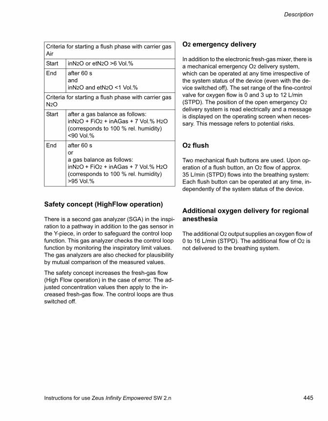
Instructions for use Zeus Infinity Empowered SW 2.n 445
Description
Safety concept (HighFlow operation)
There is a second gas analyzer (SGA) in the inspi-ration to a pathway in addition to the gas sensor in the Y-piece, in order to safeguard the control loop function. This gas analyzer checks the control loop function by monitoring the inspiratory limit values. The gas analyzers are also checked for plausibility by mutual comparison of the measured values.
The safety concept increases the fresh-gas flow (High Flow operation) in the case of error. The ad-justed concentration values then apply to the in-creased fresh-gas flow. The control loops are thus switched off.
O2 emergency delivery
In addition to the electronic fresh-gas mixer, there is a mechanical emergency O2 delivery system, which can be operated at any time irrespective of the system status of the device (even with the de-vice switched off). The set range of the fine-control valve for oxygen flow is 0 and 3 up to 12 L/min (STPD). The position of the open emergency O2 delivery system is read electrically and a message is displayed on the operating screen when neces-sary. This message refers to potential risks.
O2 flush
Two mechanical flush buttons are used. Upon op-eration of a flush button, an O2 flow of approx. 35 L/min (STPD) flows into the breathing system: Each flush button can be operated at any time, in-dependently of the system status of the device.
Additional oxygen delivery for regional anesthesia
The additional O2 output supplies an oxygen flow of 0 to 16 L/min (STPD). The additional flow of O2 is not delivered to the breathing system.
Criteria for starting a flush phase with carrier gas Air
Start inN2O or etN2O >6 Vol.%
End after 60 sandinN2O and etN2O <1 Vol.%
Criteria for starting a flush phase with carrier gas N2O
Start after a gas balance as follows:inN2O + FiO2 + inAGas + 7 Vol.% H2O (corresponds to 100 % rel. humidity) <90 Vol.%
End after 60 sora gas balance as follows:inN2O + FiO2 + inAGas + 7 Vol.% H2O (corresponds to 100 % rel. humidity) >95 Vol.%

Description
446 Instructions for use Zeus Infinity Empowered SW 2.n
Ventilation
Flow measurement and volume delivery
Depending on the compliance of the lung to the compliance of the breathing circuit, the volume sup-plied by the ventilation device is distributed be-tween the lung of the patient and the breathing cir-cuit inserted between the device and the patient. Deviations resulting for the delivered volume are low for adult patients. This is due to their relatively high lung compliance in relation to the much lower compliance of the breathing hoses. Only the vol-ume attained and surrendered by the lung is rele-vant to the efficiency of ventilation. Larger differ-ences are possible during pediatric ventilation. Zeus IE basically compensates for the influence of hose compliance to volume controlled ventilation. Zeus IE ascertains the compliance of the breathing hoses during the device check before ventilation.
Depending on airway pressure, Zeus IE increases the tidal volume by the amount remaining in the breathing hoses.
The expiratory minute volume and tidal volume are measured with the aid of two internal flow sensors. Measurement is adjusted for hose compliance. The volume of the measured gas and the volume of the delivered gas depend, however, on the ambient conditions of temperature and pressure in the breathing system. In lung physiology, the minute volume and tidal volume are related to the condi-tions in the lung: 37 °C body temperature, lung pressure, 100 % rel. humidity (BTPS). The meas-ured values for MV and VT calculated by Zeus IE as well as the set point for VT always relate to BTPS conditions. Leakages which occur at the pa-tient end are taken into consideration by Zeus IE neither during volume measurement nor during vol-ume delivery.
Ventilation modes
Pressure Control (Pressure-controlled ventilation)
This ventilation mode is identified as pressure-con-trolled or time-controlled ventilation during which the patient can always breathe spontaneously. Pressure Control is thus often described as the time-controlled change between two CPAP levels.
Controlled ventilation is achieved via the time-con-trolled pressure change which corresponds to the pressure-controlled ventilation (Pressure Control). The constant possibility of spontaneous breathing allows, however, a fluent transition of controlled ventilation up to complete spontaneous breathing without changing the ventilation mode. The change-over from the expiratory pressure level to
the inspiratory pressure level and also the change from the inspiratory pressure level to the expiratory pressure level are synchronized with the patient's spontaneous breathing. Good adaptation to the spontaneous breathing behavior of the patient is thus achieved.
The respiratory rate of changes is also kept con-stant during synchronization via the "trigger win-dow" with a fixed position in time.

Instructions for use Zeus Infinity Empowered SW 2.n 447
Description
The trigger window is 25 % of set inspiratory time at the upper pressure level (Pinsp), but a maximum of 5 seconds or 25 % of Te (Te = time of expiration). However, on the PEEP level the maximum is 5 seconds. The trigger window can be switched off.
The good adaptation to the spontaneous breathing of the patient results in a low sedation requirement and thus a quicker return of the patient to spontane-ous breathing. Recent clinical experience validates this.
As with all pressure-controlled ventilation modes, a non-fixed tidal volume VT is specified for the pa-tient. The tidal volume is primarily the result of the pressure difference between the set points for PEEP and Pinsp.
Modifications of lung compliance and the airways as well as active counter-breathing of the patient can modify the tidal volume. This is a desired effect in this ventilation mode.
Knowing the non-constant tidal volume and thus also the minute volume, an adequate setting of the alarm limits for minute volume must be observed.
To set the necessary difference between the two pressure levels, the display of the expiratory meas-ured tidal volume VTe is used. An increase in the difference causes a higher pressure-controlled ventilation breath.
As in synchronization with Vol. Ctrl. AutoFlow, the time pattern is adjusted with the parameters of the basic setting for respiratory rate RR and inspiration time Ti. The lower pressure level is adjusted with the parameter PEEP, the upper pressure level with the parameter Pinsp.
During synchronization of pressure-controlled ven-tilation with Vol. Ctrl. AutoFlow, only the Pinsp set-ting needs to be modified while the time pattern is maintained.
The steepness of the increase from the lower pres-sure level to the upper pressure level is controlled by the Slope setting. The effective time for the pres-sure rise cannot become larger than the set inspi-ration time Ti. Thus it is ensured that the upper pressure level Pinsp is achieved safely during inspi-ration. The transition from controlled ventilation
over the weaning phase towards complete sponta-neous breathing occurs via a gradual reduction of inspiration pressure Pinsp and/or the respiratory rate RR.
Volume Control AutoFlow
The volume mode Vol. Ctrl. AutoFlow guarantees the application of an adjusted tidal volume by grad-ual adaptation of the mechanical inspiration pres-sure to lung conditions.
Spontaneous breathing is possible at any time. The pressure patterns and flow patterns of the mechan-ical inspiratory breaths correspond to those of pres-sure-controlled ventilation.
The calculated inspiration pressure Pinsp adapts to the current lung parameters (resistance R, compli-ance Cdyn) and the spontaneous breathing re-quirements of the patient. Pinsp is always the mini-mum ventilation pressure. This ventilation pressure is required to fill the compliance of the lung with the required tidal volume VT.
With modifications of lung compliance, the plateau pressure changes accordingly, as is always the case with volume-controlled ventilation forms. With AutoFlow, the modifications occur at ventilation pressure in up to 3 mbar steps from ventilation breath to ventilation breath.
If the selected mechanical inspiration time Ti is greater than or equal to the lung filling time, Pinsp exactly equals plateau pressure. If the inspiration time is shorter than the fill time of the lung, the in-spiration flow at the end of the inspiration time does not drop to zero. This can be detected from the flow curve. In this case too, AutoFlow sets the minimum Pinsp under these conditions, which is, however, above plateau pressure. Here the user must decide whether an extension of inspiration time is useful in order to further decrease the ventilation pressure.
If the set inspiration time Ti is longer than the fill time of the lung, then the patient can breathe in and out spontaneously within the remaining time at the level of plateau pressure. Inspiration flow and expi-ration flow adapt automatically to the needs of the

Description
448 Instructions for use Zeus Infinity Empowered SW 2.n
patient. The inspiration pressure does not change with spontaneous breathing in the current ventila-tion breath. The result of tidal volume determination is, however, taken into account in the following breath.
Due to the spontaneous breathing efforts of the pa-tient or compliance modifications of the lung, the tidal volume in the individual ventilation breaths can deviate from the adjusted tidal volume VT. How-ever, in an average time, a tidal volume is applied which corresponds to the set volume VT.
AutoFlow start behavior
When starting an AutoFlow ventilation mode (Sync., Sync./Pressure Support and Volume Con-trol), a series of test breaths is first required to as-sess the lung parameters. These test breaths com-prise the basis for calculation of the ventilation pressure.
Algorithm of the AutoFlow function
1. nd start breath
In the first test breath an inspiration pressure of 5 mbar above PEEP is applied. This is the smallest ventilation pressure which is possible with the Auto-Flow ventilation. After this test breath a new target pressure is achieved with the help of the measured tidal volume.
2. nd start breath
In the second test breath the ventilation pressure is adjusted to 75 % of the calculated target pressure; however, it has a maximum of only up to 15 mbar above PEEP.
From the 3rd breath
From the third inspiration breath after the start of the AutoFlow ventilation, the ventilation pressure is adjusted to the calculated target pressure. Each further breath readjustment of the inspiratory pres-sure is limited to ±3 mbar.
Disconnection
After disconnection is detected and reconnection has occurred, AutoFlow starts with the 1st start breath.
Pressure limitation
The lowest ventilation pressure is 5 mbar or Psupp above PEEP. It is the higher value which applies. The maximum ventilation pressure is restricted by the upper pressure limit Pmax set by the user. If a pressure limitation is set, the required tidal volume is no longer applied. This is signaled to the user by a Pmax lim/VT not attained alarm.
Volume monitoring
During AutoFlow ventilation, automatic volume monitoring is active. If a tidal volume larger than 130 % of the value set by the user is applied, this results in abandonment of the inspiration breath. The ventilation pressure is reduced to 75 % of the current pressure and the pressure limitations of the second start breath apply. If this ventilation pres-sure also results in a volume high alarm at the next inspiration breath, then the ventilation pressure will once again be reduced to 75 %.
VT adjustment:
After adjustment of tidal volume by the user, the breath readjustment of inspiratory pressure is lim-ited to +3 mbar. The lowering of ventilation pres-sure in the following inspiration breath after a VT adjustment is not limited.

Instructions for use Zeus Infinity Empowered SW 2.n 449
Description
Ventilation mode Pressure Support
For pressure support of insufficient spontaneous breathing
In a similar way to how the anesthetist senses the restarting of spontaneous breathing in the patient at the breathing bag and supports it manually, the de-vice can support insufficient spontaneous breath-ing.
The device takes over the inspiration work partially, but the patient, however, retains control of sponta-neous breathing.
The CPAP system supplies the spontaneously breathing patient with breathing gas, even with low inspiration efforts.
When the spontaneous inspiration flow reaches the set value of the flow trigger, the pressure support Pressure Support is started. The device then gen-erates a pressure rise, which can be adjusted for
the patient's breathing requirement, up to the preselected Psupp. pressure. The time for the pres-sure increase is adjustable from 0 to 2 seconds.
In the event of a rapid increase in pressure, Zeus IE supports the insufficient spontaneous respiration of the patient with high peak flow.
In the case of a slow increase in pressure, Zeus IE starts gently with an even inspiration flow. The pa-tient must do more breathing work, and the breath-ing musculature is trained.
With an adapted pressure rise and Psupp pressure, the patient determines the required inspiration flow with breathing activity.
If the inspiration flow decreases to 25 % of the pre-viously supplied maximum value and no later than 4 seconds (1.5 seconds for pediatric ventilation), the pressure support Pressure Support is termi-nated.
If the time criterion takes effect three times consec-utively, Zeus IE issues a warning and highlights the possibility of a leaky ventilation system.
The period is defined by the minimum respiratory rate RRmin after a mechanically triggered, pres-sure-supported breath is applied. This pressure-supported breath is not initiated by spontaneous triggering.
Upon cancellation of the Pressure Support cycle, the device triggers the Apnea ventilation alarm. Check whether a lower flow trigger is set or there is a switchover to mandatory breathing.
257
t
t
25 % Insp. flow for adults
25 % Insp. flow for pediatrics
Start of inspiration End of inspiration
4 s max.Flow
=Target for ideal airway pressure
Phase
I II
Psupp
CPAP
Paw

Description
450 Instructions for use Zeus Infinity Empowered SW 2.n
Synchronization with Vol. Ctrl. AutoFlow (Sync. = ON)
Synchronized intermittent mandatory ventilation
This ventilation mode designates a hybrid form of mechanical ventilation and spontaneous breathing with volume-controlled and pressure-controlled ventilation.
During synchronization with Vol. Ctrl. AutoFlow the patient can only breathe spontaneously in predeter-mined, regular pause times while mandatory venti-lation breaths ensure minimum ventilation in the meantime. This minimum ventilation is predeter-mined with the two set points, tidal volume VT and respiratory rate RR and results from the product VTe*RR.
The ventilation sample is determined with the set points tidal volume VT, Flow, respiratory rate RR and inspiration time Ti.
The flow trigger of the device ensures that the man-datory ventilation breath is triggered within a "trig-ger window" with spontaneous inspiration. This pre-vents the mandatory ventilation breath from being applied during spontaneous expiration.
The trigger window is 25 % of set inspiratory time at the upper pressure level (Pinsp), but a maximum of 5 seconds or 25 % of the time of expiration Te. However, on the PEEP level the maximum is 5 seconds. The trigger window can be switched off.
Since synchronization of the mandatory ventilation breath shortens the effective Sync. time and thus would undesirably increase the effective respiratory rate, Zeus IE extends the following spontaneous breathing time by the missing time difference ∆T. Elevation of the Sync. respiratory rate is thus avoided. The factor RR responsible for minimum ventilation in addition to tidal volume VT remains constant. If the patient has inspired a substantial volume at the beginning of the trigger window, the device reduces the following mandatory ventilation breath. The time for the inspiratory flow phase and inspiration time is shortened. Thus the tidal volume VT remains constant and overfilling of the lungs is avoided.
In the spontaneous breathing phases, the patient can be assisted with Pressure Support.
In the course of further weaning, the respiratory rate RR is further reduced at the device and thus the spontaneous breathing time is prolonged. This continues until finally the necessary minute volume is mainly covered by spontaneous breathing. The mandatory portion cannot be reduced to "zero".
258
t
t
1
fast rise time
without spontaneous breathing
with spontaneous breath-ing
slow rise time
Pressure support, ∆Psupp
fast rise time
slow rise time
Trigger window for insp. and exp. synchronization
Paw
PEEP
FlowRR
Pinsp
Ti

Instructions for use Zeus Infinity Empowered SW 2.n 451
Description
Appendix
Units and standards
Fresh-gas flow
The set point of fresh-gas flow is an STPD value. The displayed delivery and consumption values (O2 uptake and gas consumption) are also stand-ardized to STPD conditions.
Very high set values (e.g., 100% O2 at 18 L/min) can no longer be delivered. The maximum deliver-able flow for O2, Air and N2O is 18 L/min NTPD re-spectively. The set point is limited internally so that the set concentration is still achieved.
The anesthetic gas metering device is also a mass-flow metering device standardized according to NTPD requirements. Changes in ambient condi-tions do not become apparent in the fresh-gas con-centration since the mixed gas and anesthetic gas metering devices adapt their flows simultaneously.
Oxygen concentration
The setting and measurement of oxygen concen-tration always takes place in Vol.%.
Anesthetic agent concentration
The setting and measurement of anesthetic agent concentration can either be performed in partial pressures Vol.%SL or kPa. With this type of setting, the user no longer has to consider the level. The physiological effect is dependent on partial pres-sure in contrast to the setting in Vol.%.
CO2 concentration
The concentration setting for CO2 display in Zeus IE can be either BTPS or normal (without correction). The appropriate correction then applies both to concentration setting and to concentration measurement.
MAC definition
MAC (Minimum Alveolar Concentration) is the an-esthetic gas concentration in the blood at which 50 % of patients no longer respond to a skin inci-sion with movement.
The integrated MAC algorithm is based on the MAC values as indicated (see table). It is the information on the slip accompanying the anesthetic agents which is binding.
The MAC values depend on the age of the patient. The specified values relate to an age of 40 years.
Age-dependent MAC values
The MAC values used in Zeus IE are adjusted for age. Therefore make sure the patient's age is en-tered correctly. Calculation follows the equation from W.W. Mapleson (British Journal of Anesthesia 1996, P. 179-185). The equation applies to patients >1 year of age.
MACage-corrected = MAC40 x 10(–0.00269 x (Age –40))
1 MAC corresponds to: (at 100% O2)
Halothane 0.77 Vol.%
Enflurane 1.7 Vol.%
Isoflurane 1.15 Vol.%
Desflurane 6.0 Vol.%
Sevoflurane 2.1 Vol.%
N2O 105 Vol.%

Description
452 Instructions for use Zeus Infinity Empowered SW 2.n
xMAC display
Zeus IE indicates the MAC multiple (xMAC), which is determined from the present expiratory measure-ments and the age-dependent MAC values. In the case of gas mixtures the respective multiples for ni-trous oxide and the anesthetic agents are added in accordance with the following equation.
253
00
1
2
3
4
5
6
7
8
9
10 20 30 40 50 60 70 80
MAC as a function of age
Desflurane
SevofluraneEnfluraneIsofluraneHalothane
Age (years)
Vol.%
1/20 N2O
xMAC =
exp. conc. Anaesth1
+
exp. conc. Anaesth2
+
exp. conc. N2O
MACage-corrected Anesth1 MACage-corrected Anesth2 MACage-corrected N2O
Example:
etSEV = 1.5 Vol.%; et N2O = 60 %; age = 10 years
MACage-corrected of SEV: MAC10 = 2.2 Vol.%
MACage-corrected of N2O: MAC10 = 125 Vol.%
xMAC = 0.7 + 0.5 = 1.2

Instructions for use Zeus Infinity Empowered SW 2.n 453
Description
Mixture detection
Zeus IE automatically detects the anesthetic gas used and switches the measurement and monitor-ing of anesthetic gas concentration to the gas de-tected.
If a mixture of two volatile anesthetic agents is de-tected, the concentration of the secondary agent is displayed after 0.4 hPa or 0.4 Vol.%SL.

454 Instructions for use Zeus Infinity Empowered SW 2.n
This page was intentionally left blank.

Instructions for use Zeus Infinity Empowered SW 2.n 455
Index
Index
AAccessories for patient monitoring . . . . . . . . . 199Additional oxygen delivery . . . . . . . . . . . . . . . . 445Adjust mixed gas . . . . . . . . . . . . . . . . . . . . . . . 115Adjusting the AutoSet limits . . . . . . . . . . . . . . . 174Advanced infusion settings . . . . . . . . . . . . . . . 143Airway pressure Paw . . . . . . . . . . . . . . . . . . . . 192Alarm behaviour at power on . . . . . . . . . . . . . . 160Alarm info . . . . . . . . . . . . . . . . . . . . . . . . . . . . 161Alarm limits . . . . . . . . . . . . . . . . . . . . . . . . . . . 162Alarm log . . . . . . . . . . . . . . . . . . . . . . . . . . . . . 161Alarm priorities and signals . . . . . . . . . . . . . . . 160All limits . . . . . . . . . . . . . . . . . . . . . . . . . . . . . . 168Anesthesia effect monitoring . . . . . . . . . . . . . . 238Anesthesia ventilation off . . . . . . . . . . . . . . . . . 253Anesthetic delivery . . . . . . . . . . . . . . . . . . . . . 441Anesthetic gas delivery failure . . . . . . . . . . . . . 252Anesthetic gas receiving system (AGS) . . . . . . 65Appendix . . . . . . . . . . . . . . . . . . . . . . . . . . . . . 451Arrhythmia reference pattern . . . . . . . . . . . . . . 213Assembling the anesthetic gas receiving system (AGS) . . . . . . . . . . . . . . . . . . . . . . . . . 380Assembling the breathing system . . . . . . . . . . 378Assembling the CO2 absorber . . . . . . . . . . . . . 379Assembly . . . . . . . . . . . . . . . . . . . . . . . . . . . . . 378Assigning or delete profile keys . . . . . . . . . . . . 326Attach the BIS sensor . . . . . . . . . . . . . . . . . . . 247Attach the breathing hoses . . . . . . . . . . . . . . . 380Automatic learning and relearning . . . . . . . . . . 214Automatic Self test . . . . . . . . . . . . . . . . . . . . . . 102Automatic self test . . . . . . . . . . . . . . . . . . . . . . . 99AutoSet limits . . . . . . . . . . . . . . . . . . . . . . . . . . 172
BBackup gas cylinders . . . . . . . . . . . . . . . . . . . . . 63Basic settings . . . . . . . . . . . . . . . . . . . . . . . . . 322Beat and rhythm classification . . . . . . . . . . . . . 214BIS monitoring . . . . . . . . . . . . . . . . . . . . . . . . . 244BIS safety instructions . . . . . . . . . . . . . . . . . . . 246BIS setting on Zeus IE . . . . . . . . . . . . . . . . . . . 245BP . . . . . . . . . . . . . . . . . . . . . . . . . . . . . . . . . . 225BP safety instructions . . . . . . . . . . . . . . . . . . . 226BP settings on Zeus IE . . . . . . . . . . . . . . . . . . 230Brightness / tone volume . . . . . . . . . . . . . . . . . 334
CC.O. . . . . . . . . . . . . . . . . . . . . . . . . . . . . . . . . 234C.O. calculations . . . . . . . . . . . . . . . . . . . . . . 237C.O. measurement connection . . . . . . . . . . . . 206C.O. measuring accuracy . . . . . . . . . . . . . . . . 235C.O. screen display . . . . . . . . . . . . . . . . . . . . 235Calculation settings . . . . . . . . . . . . . . . . . . . . 351Calibration . . . . . . . . . . . . . . . . . . . . . . . 228, 231Cardiac output (C.O.) . . . . . . . . . . . . . . . . . . . 234Care list . . . . . . . . . . . . . . . . . . . . . . . . . . . . . 378Catheter positions . . . . . . . . . . . . . . . . . . . . . 229Ceiling unit . . . . . . . . . . . . . . . . . . . . . . . . . . . . 59Change patient data . . . . . . . . . . . . . . . . . . . . 112Changing the patient . . . . . . . . . . . . . . . . . . . 134Charging the battery for emergency operation . . . . . . . . . . . . . . . . . . . . . . . . . . . . . 58Check emergency breathing bag . . . . . . . . . . . 92Check Settings . . . . . . . . . . . . . . . . . . . . . . . . 110Check the backup gas cylinders . . . . . . . . . . . . 90Check the central gas supply . . . . . . . . . . . . . . 90Checking patient data/weight . . . . . . . . . . . . . 145Checking the anesthetic gas scavenging system AGSS . . . . . . . . . . . . . . . . . . . . . . . . . . 92Checking the APL valve . . . . . . . . . . . . . . . . . . 92Checking the breathing system . . . . . . . . . . . . 91Checking the O2 emergency delivery . . . . . . . . 91Checking the O2 flow meter . . . . . . . . . . . . . . . 93Checking the O2 flush . . . . . . . . . . . . . . . . . . . 91Checking the soda lime . . . . . . . . . . . . . . . . . 135Checklist . . . . . . . . . . . . . . . . . . . . . . . . . . . . . . 95Cleaning . . . . . . . . . . . . . . . . . . . . . . . . . . . . . 370Cleaning, disinfection, and sterilization . . . . . 357CLIC adapter Zeus IE . . . . . . . . . . . . . . . . . . . . 67CO2 . . . . . . . . . . . . . . . . . . . . . . . . . . . . . . . . 189CO2 alarms On/Off . . . . . . . . . . . . . . . . . . . . . 179Color concept . . . . . . . . . . . . . . . . . . . . . . . . . . 48Concentration control loop . . . . . . . . . . . . . . . 441Configurable buttons . . . . . . . . . . . . . . . . . . . . 45Configuration . . . . . . . . . . . . . . . . . . . . . 321, 322Configuring basic settings . . . . . . . . . . . . . . . 335Configuring buttons . . . . . . . . . . . . . . . . 332, 333Configuring colors . . . . . . . . . . . . . . . . . . . . . 334Configuring data . . . . . . . . . . . . . . . . . . . . . . . 332Configuring MediBus . . . . . . . . . . . . . . . . . . . 347Configuring the screen . . . . . . . . . . . . . . . . . . 329

Index
456 Instructions for use Zeus Infinity Empowered SW 2.n
Configuring web access . . . . . . . . . . . . . . . . . 332Configuring web applications . . . . . . . . . . . . . 345Confirm technical alarms . . . . . . . . . . . . . . . . . 166Connect hemodynamic modules (pods) . . . . . 203Connect hoses . . . . . . . . . . . . . . . . . . . . . . . . . 69Connect IV system . . . . . . . . . . . . . . . . . . . . . . 73Connect the attachments . . . . . . . . . . . . . . . . . . 61Connecting the anesthetic gas receiving system (AGS) . . . . . . . . . . . . . . . . . . . . . . . . . 381Connecting the Quad Hemo . . . . . . . . . . . . . . 204Connection field for patient monitoring . . . . . . 197Connection for anesthesia effect monitoring . . 207Connection for ECG accessories . . . . . . . . . . 200Connection for IBP accessories . . . . . . . . . . . 202Connection for NIBP accessories . . . . . . . . . . 201Connection for synchronization of a defibrillator . . . . . . . . . . . . . . . . . . . . . . . . . . . . 207Continuous measurements . . . . . . . . . . . . . . . 223Control mode Auto Control . . . . . . . . . . . . . . . 118Control mode Fresh Gas Control . . . . . . . . . . 116Controls for IV . . . . . . . . . . . . . . . . . . . . . . . . . 141CPP measurement . . . . . . . . . . . . . . . . . . . . . 231Cuff . . . . . . . . . . . . . . . . . . . . . . . . . . . . . . . . . 220Curve configuration . . . . . . . . . . . . . . . . . . . . . 331
DData protocol . . . . . . . . . . . . . . . . . . . . . . . . . . 413Date, time . . . . . . . . . . . . . . . . . . . . . . . . . . . . 343Delete a drug . . . . . . . . . . . . . . . . . . . . . . . . . . 153Deleting profiles/views . . . . . . . . . . . . . . . . . . . 326Descriptions . . . . . . . . . . . . . . . . . . . . . . . . . . . 439Designation conflicts . . . . . . . . . . . . . . . . . . . . 230Device check . . . . . . . . . . . . . . . . . . . . . . . . . . . 90Device monitoring . . . . . . . . . . . . . . . . . . . . . . 189Disable options . . . . . . . . . . . . . . . . . . . . . . . . 348Disinfection . . . . . . . . . . . . . . . . . . . . . . . . . . . 370Dismantling the anesthetic gas receiving system (AGS) . . . . . . . . . . . . . . . . . . . . . . . . . 365Display of the flow tubes . . . . . . . . . . . . . . . . . 196Display of ventilation loops . . . . . . . . . . . . . . . 194Displaying alarms . . . . . . . . . . . . . . . . . . . . . . 160Displaying test results . . . . . . . . . . . . . . . . . . . 101Disposal . . . . . . . . . . . . . . . . . . . . . . . . . . . . . . 391DIVA metering module with safety filling device . . . . . . . . . . . . . . . . . . . . . . . . . . . . . . . . 80DIVA metering modules . . . . . . . . . . . . . . . . . . . 32Drägersorb 800 Plus . . . . . . . . . . . . . . . . . . . . 379Drägersorb CLIC . . . . . . . . . . . . . . . . . . . . . . . 379Drägersorb Free . . . . . . . . . . . . . . . . . . . . . . . 379Drug editor . . . . . . . . . . . . . . . . . . . . . . . . . . . . 150Drug library . . . . . . . . . . . . . . . . . . . . . . . 149, 344
EECG . . . . . . . . . . . . . . . . . . . . . . . . . . . . . . . . 208ECG – Arrhythmia detection . . . . . . . . . . . . . . 213ECG – ST monitoring . . . . . . . . . . . . . . . . . . . 214ECG settings on Zeus IE . . . . . . . . . . . . . . . . 215ECG signal processing and display . . . . . . . . 212ECG with HF surgery . . . . . . . . . . . . . . . . . . . 210ECG with pacemakers . . . . . . . . . . . . . . . . . . 208Editing a drug . . . . . . . . . . . . . . . . . . . . . . . . . 153Electrocardiography . . . . . . . . . . . . . . . . . . . . 208Electrode positioning . . . . . . . . . . . . . . . . . . . 211EMC Declaration . . . . . . . . . . . . . . . . . . . . . . 430Emergency oxygen delivery . . . . . . . . . . . . . . 445Emptying and replacing water traps . . . . . . . . 361End of operation . . . . . . . . . . . . . . . . . . . . . . . 156Event recorder . . . . . . . . . . . . . . . . . . . . . . . . 344Expiratory anesthetic agent concentration control . . . . . . . . . . . . . . . . . . . . . . . . . . . . . . . 443Exporting setups . . . . . . . . . . . . . . . . . . . . . . . 338
FFailure behavior . . . . . . . . . . . . . . . . . . . . . . . 250Fault – Cause – Remedy . . . . . . . . . . . . . . . . 249Fill the absorber . . . . . . . . . . . . . . . . . . . . . . . . 66Fill the DIVA metering modules . . . . . . . . . . . . 75Filling devices . . . . . . . . . . . . . . . . . . . . . . . . . . 75Filling level indications . . . . . . . . . . . . . . . . . . . 75Filling system for desflurane . . . . . . . . . . . . . . . 87Filling the reusable CO2 absorber . . . . . . . . . . 66Fixed assigned buttons . . . . . . . . . . . . . . . . . . 45Flow . . . . . . . . . . . . . . . . . . . . . . . . . . . . . . . . 190Flow/volume loops . . . . . . . . . . . . . . . . . . . . . 194Flush phases . . . . . . . . . . . . . . . . . . . . . . . . . 444
GGas control loops . . . . . . . . . . . . . . . . . . . . . . 441Gas delivery . . . . . . . . . . . . . . . . . . . . . . . . . . 115Gas failure . . . . . . . . . . . . . . . . . . . . . . . . . . . 251Gas flow diagram . . . . . . . . . . . . . . . . . . . . . . 440Gas prices . . . . . . . . . . . . . . . . . . . . . . . . . . . 349General infusion settings . . . . . . . . . . . . . . . . 142General screen layout . . . . . . . . . . . . . . . . . . 330

Instructions for use Zeus Infinity Empowered SW 2.n 457
Index
HHeader bar . . . . . . . . . . . . . . . . . . . . . . . . . . . . . 44HME filter . . . . . . . . . . . . . . . . . . . . . . . . . . . . . 135
IIBF absorber filter . . . . . . . . . . . . . . . . . . . . . . 379If Zeus IE is not being used . . . . . . . . . . . . . . . 157Impedance test . . . . . . . . . . . . . . . . . . . . . . . . 248Importing setups . . . . . . . . . . . . . . . . . . . . . . . 338Infinity BISx pod . . . . . . . . . . . . . . . . . . . . . . . . 207Infinity configuration . . . . . . . . . . . . . . . . . . . . . 346Influence of weight and age on the device settings . . . . . . . . . . . . . . . . . . . . . . . . . . . . . . 114Infusion settings . . . . . . . . . . . . . . . . . . . . . . . . 142Initial use . . . . . . . . . . . . . . . . . . . . . . . . . . . . . . 58Inspiratory oxygen concentration control . . . . . 442Install flow sensors . . . . . . . . . . . . . . . . . . . . . . 58Installation of profiles and views . . . . . . . . . . . 338Installing all . . . . . . . . . . . . . . . . . . . . . . . . . . . 339Interference . . . . . . . . . . . . . . . . . . . . . . . . . . . 210Intermittent measurements . . . . . . . . . . . . . . . 223Invasive blood pressure measurement . . . . . . 225IT networks . . . . . . . . . . . . . . . . . . . . . . . . . . . 436
LLeak test . . . . . . . . . . . . . . . . . . . . . . . . . . . . . 136Leakage assistant . . . . . . . . . . . . . . . . . . . . . . 103Load profiles/views . . . . . . . . . . . . . . . . . . . . . 324Loop displays . . . . . . . . . . . . . . . . . . . . . . . . . . 194
MMAC . . . . . . . . . . . . . . . . . . . . . . . . . . . . . . . . . 451Main menu bar . . . . . . . . . . . . . . . . . . . . . . . . . . 44Maintenance . . . . . . . . . . . . . . . . . . . . . . . . . . 383Manual/Spontaneous . . . . . . . . . . . . . . . . . . . . 124Measured values . . . . . . . . . . . . . . . . . . . . . . . . 20MEDIBUS . . . . . . . . . . . . . . . . . . . . . . . . . . . . 413Metering module error . . . . . . . . . . . . . . . . . . . 317Metering modules (DIVA) . . . . . . . . . . . . . . . . . 74Metrological checks . . . . . . . . . . . . . . . . . . . . . . 10Mini-trends . . . . . . . . . . . . . . . . . . . . . . . . . . . . 330Module DPS . . . . . . . . . . . . . . . . . . . . . . . . . . 143Module DPS – transport concept . . . . . . . . . . . 153Monitoring . . . . . . . . . . . . . . . . . . . . . . . . . . . . 187Monitoring area . . . . . . . . . . . . . . . . . . . . . . . . . 44More ECG settings . . . . . . . . . . . . . . . . . . . . . 217More settings . . . . . . . . . . . . . . . . . . . . . . . . . . 348MULTIMED 5/6 cable . . . . . . . . . . . . . . . . . . . 201MULTIMED PLUS OR cable . . . . . . . . . . . . . . 201
NNetwork configuration . . . . . . . . . . . . . . . . . . . 346Neuromuscular Transmission Monitoring (NMT) . . . . . . . . . . . . . . . . . . . . . . . . . . . . . . . 238New drugs . . . . . . . . . . . . . . . . . . . . . . . . . . . 152New profiles/views . . . . . . . . . . . . . . . . . . . . . 325NIBP . . . . . . . . . . . . . . . . . . . . . . . . . . . . 220, 420NIBP basic settings . . . . . . . . . . . . . . . . . . . . 346NIBP measuring intervals . . . . . . . . . . . . . . . . 222NIBP screen display . . . . . . . . . . . . . . . . . . . . 221NIBP settings on Zeus IE . . . . . . . . . . . . . . . . 221NMT . . . . . . . . . . . . . . . . . . . . . . . . . . . . . . . . 238NMT safety instructions . . . . . . . . . . . . . . . . . 239NMT settings on Zeus IE . . . . . . . . . . . . . . . . 241Non-invasive blood pressure . . . . . . . . . . . . . 220Non-rebreathing systems . . . . . . . . . . . . . . . . 132Notes on leaks . . . . . . . . . . . . . . . . . . . . . . . . 103
OO2 . . . . . . . . . . . . . . . . . . . . . . . . . . . . . . . . . . 190Online help . . . . . . . . . . . . . . . . . . . . . . . . . . . 353Operating concept . . . . . . . . . . . . . . . . . . . . . . 41ORC function . . . . . . . . . . . . . . . . . . . . . . . . . 441Other functions of the system . . . . . . . . . . . . . 353Oxygen flush . . . . . . . . . . . . . . . . . . . . . . . . . 445
PPacemaker detection . . . . . . . . . . . . . . . . . . . 209Parameter boxes of NIBP measurements . . . 222Partial system failure . . . . . . . . . . . . . . . . . . . 253Particular alarms . . . . . . . . . . . . . . . . . . . . . . 177Patient and pump settings . . . . . . . . . . . . . . . 145Patient transfer . . . . . . . . . . . . . . . . . . . . . . . . .111PEEP modifications . . . . . . . . . . . . . . . . . . . . 129Power outage . . . . . . . . . . . . . . . . . . . . . . . . . 250Prepare ECG . . . . . . . . . . . . . . . . . . . . . . . . . 211Prepare self test . . . . . . . . . . . . . . . . . . . . . . . . 96Preparing catheters . . . . . . . . . . . . . . . . . . . . 226Preparing for NMT . . . . . . . . . . . . . . . . . . . . . 240Preparing pressure transducers . . . . . . . . . . . 227Pressure/volume loops . . . . . . . . . . . . . . . . . . 194Pretest . . . . . . . . . . . . . . . . . . . . . . . . . . . . . . 100Printer . . . . . . . . . . . . . . . . . . . . . . . . . . . . . . . 340Profile Default . . . . . . . . . . . . . . . . . . . . . . . . . 327Profile settings . . . . . . . . . . . . . . . . . . . . . . . . 322Protecting profiles/views . . . . . . . . . . . . . . . . . 327PTC . . . . . . . . . . . . . . . . . . . . . . . . . . . . . . . . 243Pulse oximetry . . . . . . . . . . . . . . . . . . . . . . . . 217PWP . . . . . . . . . . . . . . . . . . . . . . . . . . . . . . . . 232

Index
458 Instructions for use Zeus Infinity Empowered SW 2.n
QQuad Hemo . . . . . . . . . . . . . . . . . . . . . . . . . . . 203Quick release . . . . . . . . . . . . . . . . . . . . . . . . . 125Quik Fil . . . . . . . . . . . . . . . . . . . . . . . . . . . . . . . 84
RRecorder configuration . . . . . . . . . . . . . . . . . . 347Removable media . . . . . . . . . . . . . . . . . . . . . . 413Removing buttons . . . . . . . . . . . . . . . . . . . . . . 333Removing the breathing system . . . . . . . . . . . 363Removing the CO2 absorber . . . . . . . . . . . . . . 362Removing the endotracheal suction system . . . . . . . . . . . . . . . . . . . . . . . . . . . . . . . . . 366, 381Renaming profiles/views . . . . . . . . . . . . . . . . . 325Replacement by DrägerService . . . . . . . . . . . 388Replacement by trained personnel . . . . . . . . . 388Repositioning buttons . . . . . . . . . . . . . . . . . . . 333Restrictions to anesthetic agent delivery . . . . . 444
SSafety concept (HighFlow operation) . . . . . . . 445Saving profiles/views . . . . . . . . . . . . . . . . . . . . 324Screen . . . . . . . . . . . . . . . . . . . . . . . . . . . . . . . . 42Screen layout . . . . . . . . . . . . . . . . . . . . . . . . . 329Select profile . . . . . . . . . . . . . . . . . . . . . . . . . . 109Selecting a drug . . . . . . . . . . . . . . . . . . . . . . . 148Serial ports . . . . . . . . . . . . . . . . . . . . . . . . . . . 413Service Call . . . . . . . . . . . . . . . . . . . . . . . . . . . 356Service functions . . . . . . . . . . . . . . . . . . . . . . . 356Service Mode . . . . . . . . . . . . . . . . . . . . . . . . . 356Service notes for monitoring accessories . . . . 376Set and select loops . . . . . . . . . . . . . . . . . . . . 195Set APL valve . . . . . . . . . . . . . . . . . . . . . . . . . 125Set details . . . . . . . . . . . . . . . . . . . . . . . . . . . . 110Set drug dose . . . . . . . . . . . . . . . . . . . . . . . . . 150Setting ranges of the monitoring alarms . . . . . 179Sevoflurane filling system . . . . . . . . . . . . . . . . . 84Single measurements . . . . . . . . . . . . . . . . . . . 222Single Twitch . . . . . . . . . . . . . . . . . . . . . . . . . . 242SpiroLife flow sensor . . . . . . . . . . . . . . . . . . . . 375SpO2 measurement connection . . . . . . . . . . . 205SpO2 safety instructions . . . . . . . . . . . . . . . . . 218SpO2 settings on the Zeus IE . . . . . . . . . . . . . 219ST measuring points . . . . . . . . . . . . . . . . . . . . 216ST screen display . . . . . . . . . . . . . . . . . . . . . . 216ST segment analysis . . . . . . . . . . . . . . . . . . . . 215Start . . . . . . . . . . . . . . . . . . . . . . . . . . . . . . . . . 110Start NIBP measurement . . . . . . . . . . . . . . . . . 222Start settings . . . . . . . . . . . . . . . . . . . . . . . . . . 108Start the self test manually . . . . . . . . . . . . . . . . 96
Starting a bolus . . . . . . . . . . . . . . . . . . . . . . . . 146Starting in emergencies . . . . . . . . . . . . . . . . . 105Starting NMT measurement . . . . . . . . . . . . . . 241Starting the infusion . . . . . . . . . . . . . . . . . . . . 144Startup dialog . . . . . . . . . . . . . . . . . . . . . . . . . 109Stopping a bolus . . . . . . . . . . . . . . . . . . . . . . . 147Stopping the infusion . . . . . . . . . . . . . . . . . . . 146Stopwatch dialog window . . . . . . . . . . . . . . . . 354Suppress alarm tone . . . . . . . . . . . . . . . . . . . 177Suspending alarms . . . . . . . . . . . . . . . . . . . . . 166Switch audible alarm on again . . . . . . . . . . . . 177Syringe change . . . . . . . . . . . . . . . . . . . . . . . 146System info . . . . . . . . . . . . . . . . . . . . . . . . . . . 104System setup . . . . . . . . . . . . . . . . . . . . . . . . . 323

Instructions for use Zeus Infinity Empowered SW 2.n 459
Index
TTechnical data . . . . . . . . . . . . . . . . . . . . . . . . . 395
Airway resistances . . . . . . . . . . . . . . . . . . . 408Ambient conditions . . . . . . . . . . . . . . . . . . 400Anesthetic gas measurement . . . . . . . . . . 412Anesthetic gas metering modules . . . . . . . 413BIS . . . . . . . . . . . . . . . . . . . . . . . . . . . . . . . 428BISx pod . . . . . . . . . . . . . . . . . . . . . . . . . . 418BP . . . . . . . . . . . . . . . . . . . . . . . . . . . . . . . 422Breathing system . . . . . . . . . . . . . . . . . . . . 407C.O. . . . . . . . . . . . . . . . . . . . . . . . . . . . . . . 423Central gas supply . . . . . . . . . . . . . . . . . . . 401Classification . . . . . . . . . . . . . . . . . . . . . . . 397Control mode Auto Control . . . . . . . . . . . . 404Control mode FG met. . . . . . . . . . . . . . . . . 404Data communication . . . . . . . . . . . . . . . . . 413Dimensions . . . . . . . . . . . . . . . . . . . . . . . . 397ECG . . . . . . . . . . . . . . . . . . . . . . . . . . . . . . 418Essential performance . . . . . . . . . . . . . . . . 429Flow measurement . . . . . . . . . . . . . . . . . . 409Fresh gas outlet for non-rebreathing system . . . . . . . . . . . . . . . . . . . . . . . . . . . . 408Hemodynamic modules . . . . . . . . . . . . . . . 416Identification . . . . . . . . . . . . . . . . . . . . . . . . 397Latex-free . . . . . . . . . . . . . . . . . . . . . . . . . . 398Measuring system . . . . . . . . . . . . . . . . . . . 409NMT . . . . . . . . . . . . . . . . . . . . . . . . . . . . . . 426NMT pod . . . . . . . . . . . . . . . . . . . . . . . . . . 417O2 measurement . . . . . . . . . . . . . . . . . . . . 411O2, CO2 and anesthetic gas . . . . . . . . . . . 411Power supply . . . . . . . . . . . . . . . . . . . . . . . 399Pressure measurement . . . . . . . . . . . . . . . 409Screen . . . . . . . . . . . . . . . . . . . . . . . . . . . . 398SpO2 . . . . . . . . . . . . . . . . . . . . . . . . . . . . . 423ST segment analysis . . . . . . . . . . . . . . . . . 419Temperature . . . . . . . . . . . . . . . . . . . . . . . . 426Ventilation . . . . . . . . . . . . . . . . . . . . . . . . . 405Wedge measurement . . . . . . . . . . . . . . . . . 422Weight . . . . . . . . . . . . . . . . . . . . . . . . . . . . 397
Temperature . . . . . . . . . . . . . . . . . . . . . . . . . . 233Temperature measurement connection . . . . . . 204Temperature screen display . . . . . . . . . . . . . . 233Temperature settings on Zeus IE . . . . . . . . . . . 234Test history . . . . . . . . . . . . . . . . . . . . . . . . . . . 102Test info . . . . . . . . . . . . . . . . . . . . . . . . . . . . . . 101Therapy bar . . . . . . . . . . . . . . . . . . . . . . . . . . . . 44Therapy controls . . . . . . . . . . . . . . . . . . . . . . . . 48TOF . . . . . . . . . . . . . . . . . . . . . . . . . . . . . . . . . 242Total consumption . . . . . . . . . . . . . . . . . . . . . . 352Touch screen . . . . . . . . . . . . . . . . . . . . . . . . . . . 42Transportation of filled DIVA metering modules . . . . . . . . . . . . . . . . . . . . . . . . . . . . . . . 76
Trends and diagnosis windows . . . . . . . . . . . 184Trident NMT pod . . . . . . . . . . . . . . . . . . . . . . . 207TurboVent . . . . . . . . . . . . . . . . . . . . . . . . . . . . 364
UUnits . . . . . . . . . . . . . . . . . . . . . . . . . . . . . . . . 339Unlocking profiles/views . . . . . . . . . . . . . . . . . 327USB devices . . . . . . . . . . . . . . . . . . . . . . . . . . 341USB ports . . . . . . . . . . . . . . . . . . . . . . . . . . . . 413Use port saver . . . . . . . . . . . . . . . . . . . . . . . . . 73User-specific intervals . . . . . . . . . . . . . . . . . . 387
VVA/ N2O . . . . . . . . . . . . . . . . . . . . . . . . . . . . . 350VacuSmart . . . . . . . . . . . . . . . . . . . . . . . . . . . 381Venostasis . . . . . . . . . . . . . . . . . . . . . . . . . . . 223Ventilation . . . . . . . . . . . . . . . . . . . . 122, 189, 446Ventilation modes . . . . . . . . . . . . . . . 20, 350, 446Ventilation settings . . . . . . . . . . . . . . . . . . . . . 349Ventilator failure . . . . . . . . . . . . . . . . . . . . . . . 252View settings . . . . . . . . . . . . . . . . . . . . . . . . . 322Volume control loop . . . . . . . . . . . . . . . . . . . . 442Volumeter function . . . . . . . . . . . . . . . . . . . . . 124
WWaveforms . . . . . . . . . . . . . . . . . . . . . . . . . . . . 21Wedge pressure measurement . . . . . . . . . . . 232
ZZeroing . . . . . . . . . . . . . . . . . . . . . . . . . . . . . . 227Zeus IE messages . . . . . . . . . . . . . . . . . . . . . 255

These instructions for use apply only to Zeus Infinity Empowered SW 2.n with the Serial No.:If no Serial No. has been filled in by Dräger, these instructions for use are provided for general information only and are not intended for use with any specific device.These instructions for use are provided for customer information only and will only be updated or exchanged upon customer request.
Directive 93/42/EECconcerning medical devices
Manufacturer
Dräger Medical GmbHMoislinger Allee 53-55D-23542 LübeckGermany+49 451 8 82-0
FAX +49 451 8 82-20 80http://www.draeger.com
As of 2015-08:Dräger Medical GmbHchanges toDrägerwerk AG & Co. KGaA
9054908 – GA 5133.035 en© Dräger Medical GmbHEdition: 1 – 2015-02Dräger reserves the right to make modifications to the device without prior notice.
Copyright © 2022 FDOKUMEN