
ApolloTM - Dräger
232
Emergency Care · Perioperative Care · Critical Care · Perinatal Care Because you care WARNING: For a full understanding of the performance characteristics of this equipment, the user should carefully read this manual before operating. Inhalation Anesthesia Machine Software 3.2n Operating Instructions Apollo TM
-
Upload
khangminh22 -
Category
Documents
-
view
2 -
download
0
Transcript of ApolloTM - Dräger

Emergency Care · Perioperative Care · Critical Care · Perinatal Care Because you care
WARNING:For a full understanding of the performance characteristics of this equipment, the user should carefully read this manual before operating.
Inhalation Anesthesia MachineSoftware 3.2nOperating Instructions
ApolloTM


ContentsP
art N
umbe
r: 90
38
237,
6th
edi
tion
Chapter 1. IntroductionContents . . . . . . . . . . . . . . . . . . . . . . . . . . . . . . . . . . . . . . . . . . . . . . . . . . . . . . . . . . . . . . . . . . . . . . . . . . . 1Working with These Operating Instructions. . . . . . . . . . . . . . . . . . . . . . . . . . . . . . . . . . . . . . . . . . . . . . . . . 3
Header Line. . . . . . . . . . . . . . . . . . . . . . . . . . . . . . . . . . . . . . . . . . . . . . . . . . . . . . . . . . . . . . . . . . . . . . 3Page Body. . . . . . . . . . . . . . . . . . . . . . . . . . . . . . . . . . . . . . . . . . . . . . . . . . . . . . . . . . . . . . . . . . . . . . . 3Left-Hand Column - the Text. . . . . . . . . . . . . . . . . . . . . . . . . . . . . . . . . . . . . . . . . . . . . . . . . . . . . . . . . 3Right-Hand Column - the Illustrations . . . . . . . . . . . . . . . . . . . . . . . . . . . . . . . . . . . . . . . . . . . . . . . . . . 3Typing Conventions . . . . . . . . . . . . . . . . . . . . . . . . . . . . . . . . . . . . . . . . . . . . . . . . . . . . . . . . . . . . . . . 3Trademarks . . . . . . . . . . . . . . . . . . . . . . . . . . . . . . . . . . . . . . . . . . . . . . . . . . . . . . . . . . . . . . . . . . . . . . 4Definitions . . . . . . . . . . . . . . . . . . . . . . . . . . . . . . . . . . . . . . . . . . . . . . . . . . . . . . . . . . . . . . . . . . . . . . . 4Symbols and Abbreviations. . . . . . . . . . . . . . . . . . . . . . . . . . . . . . . . . . . . . . . . . . . . . . . . . . . . . . . . . . 4Notice . . . . . . . . . . . . . . . . . . . . . . . . . . . . . . . . . . . . . . . . . . . . . . . . . . . . . . . . . . . . . . . . . . . . . . . . . . 4
Important Safety Information . . . . . . . . . . . . . . . . . . . . . . . . . . . . . . . . . . . . . . . . . . . . . . . . . . . . . . . . . . . . 5Operator’s Responsibility for Patient Safety . . . . . . . . . . . . . . . . . . . . . . . . . . . . . . . . . . . . . . . . . . . 5Safe Connection with Other Electrical Equipment . . . . . . . . . . . . . . . . . . . . . . . . . . . . . . . . . . . . . . . . 6Indications for Use . . . . . . . . . . . . . . . . . . . . . . . . . . . . . . . . . . . . . . . . . . . . . . . . . . . . . . . . . . . . . . . . 6Intended Use. . . . . . . . . . . . . . . . . . . . . . . . . . . . . . . . . . . . . . . . . . . . . . . . . . . . . . . . . . . . . . . . . . . . . 6Medibus Protocol . . . . . . . . . . . . . . . . . . . . . . . . . . . . . . . . . . . . . . . . . . . . . . . . . . . . . . . . . . . . . . . . . 6General Warnings and Cautions . . . . . . . . . . . . . . . . . . . . . . . . . . . . . . . . . . . . . . . . . . . . . . . . . . . . . . 7Accessory Weight Limits . . . . . . . . . . . . . . . . . . . . . . . . . . . . . . . . . . . . . . . . . . . . . . . . . . . . . . . . . . . 11
Symbol Definition. . . . . . . . . . . . . . . . . . . . . . . . . . . . . . . . . . . . . . . . . . . . . . . . . . . . . . . . . . . . . . . . . . . . 13Abbreviations. . . . . . . . . . . . . . . . . . . . . . . . . . . . . . . . . . . . . . . . . . . . . . . . . . . . . . . . . . . . . . . . . . . . . . . 14
Chapter 2. System ComponentsContents . . . . . . . . . . . . . . . . . . . . . . . . . . . . . . . . . . . . . . . . . . . . . . . . . . . . . . . . . . . . . . . . . . . . . . . . . . 17Overview . . . . . . . . . . . . . . . . . . . . . . . . . . . . . . . . . . . . . . . . . . . . . . . . . . . . . . . . . . . . . . . . . . . . . . . . . . 19Machine Front View. . . . . . . . . . . . . . . . . . . . . . . . . . . . . . . . . . . . . . . . . . . . . . . . . . . . . . . . . . . . . . . . . . 19Machine Rear View . . . . . . . . . . . . . . . . . . . . . . . . . . . . . . . . . . . . . . . . . . . . . . . . . . . . . . . . . . . . . . . . . . 20Gas Supply Block . . . . . . . . . . . . . . . . . . . . . . . . . . . . . . . . . . . . . . . . . . . . . . . . . . . . . . . . . . . . . . . . . . . 21Interface Panel . . . . . . . . . . . . . . . . . . . . . . . . . . . . . . . . . . . . . . . . . . . . . . . . . . . . . . . . . . . . . . . . . . . . . 22Vaporizers (Optional). . . . . . . . . . . . . . . . . . . . . . . . . . . . . . . . . . . . . . . . . . . . . . . . . . . . . . . . . . . . . . . . . 23Vaporizer Exclusion Systems . . . . . . . . . . . . . . . . . . . . . . . . . . . . . . . . . . . . . . . . . . . . . . . . . . . . . . . . . . 23
Dräger Vapor® Interlock 2 System (Optional) . . . . . . . . . . . . . . . . . . . . . . . . . . . . . . . . . . . . . . . . . . . 23Selectatec (Optional) . . . . . . . . . . . . . . . . . . . . . . . . . . . . . . . . . . . . . . . . . . . . . . . . . . . . . . . . . . . . . . 23Dräger Auto Exclusion 2-Vaporizer Mount (Optional) . . . . . . . . . . . . . . . . . . . . . . . . . . . . . . . . . . . . . 24Dräger Auto Exclusion 3-Vaporizer Mount (Optional) . . . . . . . . . . . . . . . . . . . . . . . . . . . . . . . . . . . . . 24
APL Valve . . . . . . . . . . . . . . . . . . . . . . . . . . . . . . . . . . . . . . . . . . . . . . . . . . . . . . . . . . . . . . . . . . . . . . . . . 25O2 Flush . . . . . . . . . . . . . . . . . . . . . . . . . . . . . . . . . . . . . . . . . . . . . . . . . . . . . . . . . . . . . . . . . . . . . . . . . . 26Auxiliary Oxygen Flowmeter . . . . . . . . . . . . . . . . . . . . . . . . . . . . . . . . . . . . . . . . . . . . . . . . . . . . . . . . . . . 26Writing Table . . . . . . . . . . . . . . . . . . . . . . . . . . . . . . . . . . . . . . . . . . . . . . . . . . . . . . . . . . . . . . . . . . . . . . . 26Gas Flow Diagram. . . . . . . . . . . . . . . . . . . . . . . . . . . . . . . . . . . . . . . . . . . . . . . . . . . . . . . . . . . . . . . . . . . 27
Chapter 3. User InterfaceContents . . . . . . . . . . . . . . . . . . . . . . . . . . . . . . . . . . . . . . . . . . . . . . . . . . . . . . . . . . . . . . . . . . . . . . . . . . 29Overview . . . . . . . . . . . . . . . . . . . . . . . . . . . . . . . . . . . . . . . . . . . . . . . . . . . . . . . . . . . . . . . . . . . . . . . . . . 31Main Screen Display . . . . . . . . . . . . . . . . . . . . . . . . . . . . . . . . . . . . . . . . . . . . . . . . . . . . . . . . . . . . . . . . . 31User Controls. . . . . . . . . . . . . . . . . . . . . . . . . . . . . . . . . . . . . . . . . . . . . . . . . . . . . . . . . . . . . . . . . . . . . . . 31
Standard Function Keys . . . . . . . . . . . . . . . . . . . . . . . . . . . . . . . . . . . . . . . . . . . . . . . . . . . . . . . . . . . 32Main Confirm Knob . . . . . . . . . . . . . . . . . . . . . . . . . . . . . . . . . . . . . . . . . . . . . . . . . . . . . . . . . . . . . . . 32Standby Key . . . . . . . . . . . . . . . . . . . . . . . . . . . . . . . . . . . . . . . . . . . . . . . . . . . . . . . . . . . . . . . . . . . . 32Flow Control Knobs. . . . . . . . . . . . . . . . . . . . . . . . . . . . . . . . . . . . . . . . . . . . . . . . . . . . . . . . . . . . . . . 33Ventilation Control Keys . . . . . . . . . . . . . . . . . . . . . . . . . . . . . . . . . . . . . . . . . . . . . . . . . . . . . . . . . . . 33
Selecting Ventilation Mode or Aux. Gas Outlet (optional) . . . . . . . . . . . . . . . . . . . . . . . . . . . . . . 33Setting/Selecting Ventilation Parameters . . . . . . . . . . . . . . . . . . . . . . . . . . . . . . . . . . . . . . . . . . . 34
Apollo Operator’s Manual i

ContentsP
art Num
ber: 90 38 237, 6th edition
Monitoring/Configuration Control Keys . . . . . . . . . . . . . . . . . . . . . . . . . . . . . . . . . . . . . . . . . . . . . . . . 34Setting/Selecting Monitoring Functions . . . . . . . . . . . . . . . . . . . . . . . . . . . . . . . . . . . . . . . . . . . . 34
System LED Indicators . . . . . . . . . . . . . . . . . . . . . . . . . . . . . . . . . . . . . . . . . . . . . . . . . . . . . . . . . . . . . . . 35Screen Colors . . . . . . . . . . . . . . . . . . . . . . . . . . . . . . . . . . . . . . . . . . . . . . . . . . . . . . . . . . . . . . . . . . . . . . 35
Colors of Parameter Settings/Values in Menus . . . . . . . . . . . . . . . . . . . . . . . . . . . . . . . . . . . . . . 36
Chapter 4. System SetupContents . . . . . . . . . . . . . . . . . . . . . . . . . . . . . . . . . . . . . . . . . . . . . . . . . . . . . . . . . . . . . . . . . . . . . . . . . . 37Overview . . . . . . . . . . . . . . . . . . . . . . . . . . . . . . . . . . . . . . . . . . . . . . . . . . . . . . . . . . . . . . . . . . . . . . . . . . 39Charging the Battery for Emergency Operation . . . . . . . . . . . . . . . . . . . . . . . . . . . . . . . . . . . . . . . . . . . . 39
When Apollo Is Not in Use . . . . . . . . . . . . . . . . . . . . . . . . . . . . . . . . . . . . . . . . . . . . . . . . . . . . . . . . . 40Installing the Breathing System and Flow Sensors . . . . . . . . . . . . . . . . . . . . . . . . . . . . . . . . . . . . . . . . . . 40Filling and Installing the Absorber . . . . . . . . . . . . . . . . . . . . . . . . . . . . . . . . . . . . . . . . . . . . . . . . . . . . . . . 42Installing the Drägersorb CLIC Adapter (Optional) . . . . . . . . . . . . . . . . . . . . . . . . . . . . . . . . . . . . . . . . . . 43Connecting the Gas Supply. . . . . . . . . . . . . . . . . . . . . . . . . . . . . . . . . . . . . . . . . . . . . . . . . . . . . . . . . . . . 44
Connecting Pipeline Supply of N2O, Air, and O2 . . . . . . . . . . . . . . . . . . . . . . . . . . . . . . . . . . . . . . . . 44Connecting the Backup Gas Cylinders for N2O, Air, and O2 . . . . . . . . . . . . . . . . . . . . . . . . . . . . . . . 45
Connecting the Scavenger System . . . . . . . . . . . . . . . . . . . . . . . . . . . . . . . . . . . . . . . . . . . . . . . . . . . . . . 48Connecting the AGS Scavenger System (Optional) . . . . . . . . . . . . . . . . . . . . . . . . . . . . . . . . . . . . . . 48Connecting the Passive Scavenger System (Optional) . . . . . . . . . . . . . . . . . . . . . . . . . . . . . . . . . . . 49
Connecting the Suction System (Optional) . . . . . . . . . . . . . . . . . . . . . . . . . . . . . . . . . . . . . . . . . . . . . . . . 49Installing Vaporizers . . . . . . . . . . . . . . . . . . . . . . . . . . . . . . . . . . . . . . . . . . . . . . . . . . . . . . . . . . . . . . . . . 50Installing the Manual Breathing Bag Arm . . . . . . . . . . . . . . . . . . . . . . . . . . . . . . . . . . . . . . . . . . . . . . . . . 50Connecting the Breathing Hoses. . . . . . . . . . . . . . . . . . . . . . . . . . . . . . . . . . . . . . . . . . . . . . . . . . . . . . . . 50Installing the Water Trap and Sample Line . . . . . . . . . . . . . . . . . . . . . . . . . . . . . . . . . . . . . . . . . . . . . . . . 51Connecting AC Power . . . . . . . . . . . . . . . . . . . . . . . . . . . . . . . . . . . . . . . . . . . . . . . . . . . . . . . . . . . . . . . . 53
Connecting Auxiliary Devices . . . . . . . . . . . . . . . . . . . . . . . . . . . . . . . . . . . . . . . . . . . . . . . . . . . . . . . 53Connecting the Apollo to Mains Power . . . . . . . . . . . . . . . . . . . . . . . . . . . . . . . . . . . . . . . . . . . . . . . . 54
Chapter 5. Preuse CheckoutContents . . . . . . . . . . . . . . . . . . . . . . . . . . . . . . . . . . . . . . . . . . . . . . . . . . . . . . . . . . . . . . . . . . . . . . . . . . 55Overview . . . . . . . . . . . . . . . . . . . . . . . . . . . . . . . . . . . . . . . . . . . . . . . . . . . . . . . . . . . . . . . . . . . . . . . . . . 57Checking the Workstation According to the Check List. . . . . . . . . . . . . . . . . . . . . . . . . . . . . . . . . . . . . . . 57System Compliance Test. . . . . . . . . . . . . . . . . . . . . . . . . . . . . . . . . . . . . . . . . . . . . . . . . . . . . . . . . . . . . . 65Leak Tests . . . . . . . . . . . . . . . . . . . . . . . . . . . . . . . . . . . . . . . . . . . . . . . . . . . . . . . . . . . . . . . . . . . . . . . . . 66Emergency Start . . . . . . . . . . . . . . . . . . . . . . . . . . . . . . . . . . . . . . . . . . . . . . . . . . . . . . . . . . . . . . . . . . . . 68
Chapter 6. Operation SummaryContents . . . . . . . . . . . . . . . . . . . . . . . . . . . . . . . . . . . . . . . . . . . . . . . . . . . . . . . . . . . . . . . . . . . . . . . . . . 71Overview . . . . . . . . . . . . . . . . . . . . . . . . . . . . . . . . . . . . . . . . . . . . . . . . . . . . . . . . . . . . . . . . . . . . . . . . . . 73Typical Operation . . . . . . . . . . . . . . . . . . . . . . . . . . . . . . . . . . . . . . . . . . . . . . . . . . . . . . . . . . . . . . . . . . . 73
Loading Default Settings . . . . . . . . . . . . . . . . . . . . . . . . . . . . . . . . . . . . . . . . . . . . . . . . . . . . . . . . . . . 73Entering the Patient’s Age. . . . . . . . . . . . . . . . . . . . . . . . . . . . . . . . . . . . . . . . . . . . . . . . . . . . . . . . . . 73Entering the Patient’s Ideal Body Weight (optional) . . . . . . . . . . . . . . . . . . . . . . . . . . . . . . . . . . . . . . 74Setting Fresh-Gas Flow . . . . . . . . . . . . . . . . . . . . . . . . . . . . . . . . . . . . . . . . . . . . . . . . . . . . . . . . . . . 74Setting Vaporizer Concentration . . . . . . . . . . . . . . . . . . . . . . . . . . . . . . . . . . . . . . . . . . . . . . . . . . . . . 75Setting Ventilation Mode . . . . . . . . . . . . . . . . . . . . . . . . . . . . . . . . . . . . . . . . . . . . . . . . . . . . . . . . . . . 75
Changing Patients . . . . . . . . . . . . . . . . . . . . . . . . . . . . . . . . . . . . . . . . . . . . . . . . . . . . . . . . . . . . . . . . . . . 76Switch to Standby Mode . . . . . . . . . . . . . . . . . . . . . . . . . . . . . . . . . . . . . . . . . . . . . . . . . . . . . . . . . . . 76Change the Absorbent . . . . . . . . . . . . . . . . . . . . . . . . . . . . . . . . . . . . . . . . . . . . . . . . . . . . . . . . . . . . 76Replace the CLIC Adapter Absorber (Optional) . . . . . . . . . . . . . . . . . . . . . . . . . . . . . . . . . . . . . . . . . 77Perform the Leak Test. . . . . . . . . . . . . . . . . . . . . . . . . . . . . . . . . . . . . . . . . . . . . . . . . . . . . . . . . . . . . 79
Activating the CO2 Bypass Function (Optional) . . . . . . . . . . . . . . . . . . . . . . . . . . . . . . . . . . . . . . . . . . . . 80Ending Operation. . . . . . . . . . . . . . . . . . . . . . . . . . . . . . . . . . . . . . . . . . . . . . . . . . . . . . . . . . . . . . . . . . . . 81
ii Apollo Operator’s Manual

ContentsP
art N
umbe
r: 90
38
237,
6th
edi
tion
Chapter 7. VentilationContents . . . . . . . . . . . . . . . . . . . . . . . . . . . . . . . . . . . . . . . . . . . . . . . . . . . . . . . . . . . . . . . . . . . . . . . . . . 83Overview . . . . . . . . . . . . . . . . . . . . . . . . . . . . . . . . . . . . . . . . . . . . . . . . . . . . . . . . . . . . . . . . . . . . . . . . . . 85Manual/Spontaneous Ventilation. . . . . . . . . . . . . . . . . . . . . . . . . . . . . . . . . . . . . . . . . . . . . . . . . . . . . . . . 86
Setting the APL Valve . . . . . . . . . . . . . . . . . . . . . . . . . . . . . . . . . . . . . . . . . . . . . . . . . . . . . . . . . . . . . 86Starting Manual/Spontaneous Ventilation . . . . . . . . . . . . . . . . . . . . . . . . . . . . . . . . . . . . . . . . . . . . . . 87
Volume-Controlled Ventilation . . . . . . . . . . . . . . . . . . . . . . . . . . . . . . . . . . . . . . . . . . . . . . . . . . . . . . . . . . 89Starting Volume-Controlled Ventilation . . . . . . . . . . . . . . . . . . . . . . . . . . . . . . . . . . . . . . . . . . . . . . . . 89Synchronized Volume-Controlled Ventilation . . . . . . . . . . . . . . . . . . . . . . . . . . . . . . . . . . . . . . . . . . . 91Synchronized Volume-Controlled Ventilation with Pressure Support (Optional). . . . . . . . . . . . . . . . . 92
Pressure-Controlled Ventilation. . . . . . . . . . . . . . . . . . . . . . . . . . . . . . . . . . . . . . . . . . . . . . . . . . . . . . . . . 93Starting Pressure-Controlled Ventilation . . . . . . . . . . . . . . . . . . . . . . . . . . . . . . . . . . . . . . . . . . . . . . . 93Synchronized Pressure-Controlled Ventilation . . . . . . . . . . . . . . . . . . . . . . . . . . . . . . . . . . . . . . . . . . 95Synchronized Pressure-Controlled Ventilation with Pressure Support (Optional) . . . . . . . . . . . . . . . 96
Pressure Support Ventilation (Optional) . . . . . . . . . . . . . . . . . . . . . . . . . . . . . . . . . . . . . . . . . . . . . . . . . . 97Starting Pressure Support Ventilation . . . . . . . . . . . . . . . . . . . . . . . . . . . . . . . . . . . . . . . . . . . . . . . . . 98
When Changing Between Ventilation Modes . . . . . . . . . . . . . . . . . . . . . . . . . . . . . . . . . . . . . . . . . . . . . 100Automatic Parameter Changes . . . . . . . . . . . . . . . . . . . . . . . . . . . . . . . . . . . . . . . . . . . . . . . . . . . . . . . . 100
TINSP Changes . . . . . . . . . . . . . . . . . . . . . . . . . . . . . . . . . . . . . . . . . . . . . . . . . . . . . . . . . . . . . . . . 100Frequency Changes . . . . . . . . . . . . . . . . . . . . . . . . . . . . . . . . . . . . . . . . . . . . . . . . . . . . . . . . . . . . . 101PEEP Changes . . . . . . . . . . . . . . . . . . . . . . . . . . . . . . . . . . . . . . . . . . . . . . . . . . . . . . . . . . . . . . . . . 101
Auxiliary Common Gas Outlet (CGO) Ventilation (Optional) . . . . . . . . . . . . . . . . . . . . . . . . . . . . . . . . . . 102To divert fresh gas to the auxiliary CGO: . . . . . . . . . . . . . . . . . . . . . . . . . . . . . . . . . . . . . . . . . . . . . 103
Ventilating Children . . . . . . . . . . . . . . . . . . . . . . . . . . . . . . . . . . . . . . . . . . . . . . . . . . . . . . . . . . . . . . . . . 105
Chapter 8. MonitoringContents . . . . . . . . . . . . . . . . . . . . . . . . . . . . . . . . . . . . . . . . . . . . . . . . . . . . . . . . . . . . . . . . . . . . . . . . . 107Overview . . . . . . . . . . . . . . . . . . . . . . . . . . . . . . . . . . . . . . . . . . . . . . . . . . . . . . . . . . . . . . . . . . . . . . . . . 109Standard Screen . . . . . . . . . . . . . . . . . . . . . . . . . . . . . . . . . . . . . . . . . . . . . . . . . . . . . . . . . . . . . . . . . . . 109
Customizing the Standard Screen Display . . . . . . . . . . . . . . . . . . . . . . . . . . . . . . . . . . . . . . . . . . . . 110Displayed Parameters . . . . . . . . . . . . . . . . . . . . . . . . . . . . . . . . . . . . . . . . . . . . . . . . . . . . . . . . . . . . . . . 111Gas Measurement . . . . . . . . . . . . . . . . . . . . . . . . . . . . . . . . . . . . . . . . . . . . . . . . . . . . . . . . . . . . . . . . . . 117Loops (Optional) . . . . . . . . . . . . . . . . . . . . . . . . . . . . . . . . . . . . . . . . . . . . . . . . . . . . . . . . . . . . . . . . . . . 120Datalog . . . . . . . . . . . . . . . . . . . . . . . . . . . . . . . . . . . . . . . . . . . . . . . . . . . . . . . . . . . . . . . . . . . . . . . . . . 121Screen Timer . . . . . . . . . . . . . . . . . . . . . . . . . . . . . . . . . . . . . . . . . . . . . . . . . . . . . . . . . . . . . . . . . . . . . . 122The Data Screen . . . . . . . . . . . . . . . . . . . . . . . . . . . . . . . . . . . . . . . . . . . . . . . . . . . . . . . . . . . . . . . . . . . 123The Trend Screen . . . . . . . . . . . . . . . . . . . . . . . . . . . . . . . . . . . . . . . . . . . . . . . . . . . . . . . . . . . . . . . . . . 124Monitoring Mode . . . . . . . . . . . . . . . . . . . . . . . . . . . . . . . . . . . . . . . . . . . . . . . . . . . . . . . . . . . . . . . . . . . 126SpO2 Measurement (Optional) . . . . . . . . . . . . . . . . . . . . . . . . . . . . . . . . . . . . . . . . . . . . . . . . . . . . . . . . 127
Tips to Prevent Artifacts . . . . . . . . . . . . . . . . . . . . . . . . . . . . . . . . . . . . . . . . . . . . . . . . . . . . . . . . . . 129
Chapter 9. AlarmsContents . . . . . . . . . . . . . . . . . . . . . . . . . . . . . . . . . . . . . . . . . . . . . . . . . . . . . . . . . . . . . . . . . . . . . . . . . 131Alarm Priorities . . . . . . . . . . . . . . . . . . . . . . . . . . . . . . . . . . . . . . . . . . . . . . . . . . . . . . . . . . . . . . . . . . . . 133
Alarm Indications. . . . . . . . . . . . . . . . . . . . . . . . . . . . . . . . . . . . . . . . . . . . . . . . . . . . . . . . . . . . . . . . 133Downgrading Alarm Priorities . . . . . . . . . . . . . . . . . . . . . . . . . . . . . . . . . . . . . . . . . . . . . . . . . . . . . . 134Setting the Alarm Tone and Volume . . . . . . . . . . . . . . . . . . . . . . . . . . . . . . . . . . . . . . . . . . . . . . . . . 134
Alarm Display . . . . . . . . . . . . . . . . . . . . . . . . . . . . . . . . . . . . . . . . . . . . . . . . . . . . . . . . . . . . . . . . . . . . . 135Suppressing Alarms . . . . . . . . . . . . . . . . . . . . . . . . . . . . . . . . . . . . . . . . . . . . . . . . . . . . . . . . . . . . . . . . 136
Silencing Audible Alarms . . . . . . . . . . . . . . . . . . . . . . . . . . . . . . . . . . . . . . . . . . . . . . . . . . . . . . . . . 136Disabling Alarms . . . . . . . . . . . . . . . . . . . . . . . . . . . . . . . . . . . . . . . . . . . . . . . . . . . . . . . . . . . . . . . . 136
Limit-Based Alarms Activated in Respective Ventilation Modes . . . . . . . . . . . . . . . . . . . . . . . . . . . . . . . 138Disabling/Enabling Alarms Globally During Operation . . . . . . . . . . . . . . . . . . . . . . . . . . . . . . . . . . . . . . 139
CO2 Alarms ON->off. . . . . . . . . . . . . . . . . . . . . . . . . . . . . . . . . . . . . . . . . . . . . . . . . . . . . . . . . . . . . 139
Apollo Operator’s Manual iii

ContentsP
art Num
ber: 90 38 237, 6th edition
SpO2 Alarms On/Off (optional) . . . . . . . . . . . . . . . . . . . . . . . . . . . . . . . . . . . . . . . . . . . . . . . . . . . . . 140Bypass Mode . . . . . . . . . . . . . . . . . . . . . . . . . . . . . . . . . . . . . . . . . . . . . . . . . . . . . . . . . . . . . . . . . . 140
Displaying and Setting Alarm Limits . . . . . . . . . . . . . . . . . . . . . . . . . . . . . . . . . . . . . . . . . . . . . . . . . . . . 141Auto-Set of Alarm Limits . . . . . . . . . . . . . . . . . . . . . . . . . . . . . . . . . . . . . . . . . . . . . . . . . . . . . . . . . . 143
Chapter 10. ConfigurationContents . . . . . . . . . . . . . . . . . . . . . . . . . . . . . . . . . . . . . . . . . . . . . . . . . . . . . . . . . . . . . . . . . . . . . . . . . 145Overview . . . . . . . . . . . . . . . . . . . . . . . . . . . . . . . . . . . . . . . . . . . . . . . . . . . . . . . . . . . . . . . . . . . . . . . . . 147Configuring the Default Settings in Standby . . . . . . . . . . . . . . . . . . . . . . . . . . . . . . . . . . . . . . . . . . . . . . 147
System Settings . . . . . . . . . . . . . . . . . . . . . . . . . . . . . . . . . . . . . . . . . . . . . . . . . . . . . . . . . . . . . . . . 149Parameters . . . . . . . . . . . . . . . . . . . . . . . . . . . . . . . . . . . . . . . . . . . . . . . . . . . . . . . . . . . . . . . . . . . . 150Interfaces Logbook . . . . . . . . . . . . . . . . . . . . . . . . . . . . . . . . . . . . . . . . . . . . . . . . . . . . . . . . . . . . . . 151Screen Layout . . . . . . . . . . . . . . . . . . . . . . . . . . . . . . . . . . . . . . . . . . . . . . . . . . . . . . . . . . . . . . . . . . 152Alarm Limits . . . . . . . . . . . . . . . . . . . . . . . . . . . . . . . . . . . . . . . . . . . . . . . . . . . . . . . . . . . . . . . . . . . 153Ventilator and Gas Supply . . . . . . . . . . . . . . . . . . . . . . . . . . . . . . . . . . . . . . . . . . . . . . . . . . . . . . . . 156System Information . . . . . . . . . . . . . . . . . . . . . . . . . . . . . . . . . . . . . . . . . . . . . . . . . . . . . . . . . . . . . . 159Exiting Standby Configuration. . . . . . . . . . . . . . . . . . . . . . . . . . . . . . . . . . . . . . . . . . . . . . . . . . . . . . 159
Configuration During Operation. . . . . . . . . . . . . . . . . . . . . . . . . . . . . . . . . . . . . . . . . . . . . . . . . . . . . . . . 160Volumes/Alarms . . . . . . . . . . . . . . . . . . . . . . . . . . . . . . . . . . . . . . . . . . . . . . . . . . . . . . . . . . . . . . . . 161Param Settings . . . . . . . . . . . . . . . . . . . . . . . . . . . . . . . . . . . . . . . . . . . . . . . . . . . . . . . . . . . . . . . . . 162Datalog Entries . . . . . . . . . . . . . . . . . . . . . . . . . . . . . . . . . . . . . . . . . . . . . . . . . . . . . . . . . . . . . . . . . 163System Info . . . . . . . . . . . . . . . . . . . . . . . . . . . . . . . . . . . . . . . . . . . . . . . . . . . . . . . . . . . . . . . . . . . . 164Exiting Configuration . . . . . . . . . . . . . . . . . . . . . . . . . . . . . . . . . . . . . . . . . . . . . . . . . . . . . . . . . . . . . 164
Chapter 11. Cleaning and MaintenanceContents . . . . . . . . . . . . . . . . . . . . . . . . . . . . . . . . . . . . . . . . . . . . . . . . . . . . . . . . . . . . . . . . . . . . . . . . . 165Apollo Cleaning and Disinfection. . . . . . . . . . . . . . . . . . . . . . . . . . . . . . . . . . . . . . . . . . . . . . . . . . . . . . . 167
Disassembling Components . . . . . . . . . . . . . . . . . . . . . . . . . . . . . . . . . . . . . . . . . . . . . . . . . . . . . . . 167Cleaning and Disinfection Guidelines . . . . . . . . . . . . . . . . . . . . . . . . . . . . . . . . . . . . . . . . . . . . . . . . . . . 173
Proper Cleaning/Disinfection Sequence . . . . . . . . . . . . . . . . . . . . . . . . . . . . . . . . . . . . . . . . . . . . . . 173Cleaning/Disinfection Objective and Methods. . . . . . . . . . . . . . . . . . . . . . . . . . . . . . . . . . . . . . . . . . 173Disinfecting/Cleaning/Sterilizing . . . . . . . . . . . . . . . . . . . . . . . . . . . . . . . . . . . . . . . . . . . . . . . . . . . . 175
Care List for Apollo Components. . . . . . . . . . . . . . . . . . . . . . . . . . . . . . . . . . . . . . . . . . . . . . . . . . . . . . . 178Reassembling Components . . . . . . . . . . . . . . . . . . . . . . . . . . . . . . . . . . . . . . . . . . . . . . . . . . . . . . . . . . 179Apollo Maintenance . . . . . . . . . . . . . . . . . . . . . . . . . . . . . . . . . . . . . . . . . . . . . . . . . . . . . . . . . . . . . . . . . 185
Definitions . . . . . . . . . . . . . . . . . . . . . . . . . . . . . . . . . . . . . . . . . . . . . . . . . . . . . . . . . . . . . . . . . . . . . 185Maintenance intervals . . . . . . . . . . . . . . . . . . . . . . . . . . . . . . . . . . . . . . . . . . . . . . . . . . . . . . . . . . . . 185Routine Maintenance . . . . . . . . . . . . . . . . . . . . . . . . . . . . . . . . . . . . . . . . . . . . . . . . . . . . . . . . . . . . 186
Chapter 12. TroubleshootingContents . . . . . . . . . . . . . . . . . . . . . . . . . . . . . . . . . . . . . . . . . . . . . . . . . . . . . . . . . . . . . . . . . . . . . . . . . 189Overview . . . . . . . . . . . . . . . . . . . . . . . . . . . . . . . . . . . . . . . . . . . . . . . . . . . . . . . . . . . . . . . . . . . . . . . . . 191Power Failure . . . . . . . . . . . . . . . . . . . . . . . . . . . . . . . . . . . . . . . . . . . . . . . . . . . . . . . . . . . . . . . . . . . . . 191Gas Failure . . . . . . . . . . . . . . . . . . . . . . . . . . . . . . . . . . . . . . . . . . . . . . . . . . . . . . . . . . . . . . . . . . . . . . . 192Ventilator Failure . . . . . . . . . . . . . . . . . . . . . . . . . . . . . . . . . . . . . . . . . . . . . . . . . . . . . . . . . . . . . . . . . . . 193Fresh Gas Delivery Failure . . . . . . . . . . . . . . . . . . . . . . . . . . . . . . . . . . . . . . . . . . . . . . . . . . . . . . . . . . . 194Ventilator and Fresh Gas Delivery Failure. . . . . . . . . . . . . . . . . . . . . . . . . . . . . . . . . . . . . . . . . . . . . . . . 195Display Failure. . . . . . . . . . . . . . . . . . . . . . . . . . . . . . . . . . . . . . . . . . . . . . . . . . . . . . . . . . . . . . . . . . . . . 196User Interface Failure . . . . . . . . . . . . . . . . . . . . . . . . . . . . . . . . . . . . . . . . . . . . . . . . . . . . . . . . . . . . . . . 196System Failure. . . . . . . . . . . . . . . . . . . . . . . . . . . . . . . . . . . . . . . . . . . . . . . . . . . . . . . . . . . . . . . . . . . . . 196Alarm – Cause – Remedy . . . . . . . . . . . . . . . . . . . . . . . . . . . . . . . . . . . . . . . . . . . . . . . . . . . . . . . . . . . . 197
Chapter 13. SpecificationsContents . . . . . . . . . . . . . . . . . . . . . . . . . . . . . . . . . . . . . . . . . . . . . . . . . . . . . . . . . . . . . . . . . . . . . . . . . 207
iv Apollo Operator’s Manual

ContentsP
art N
umbe
r: 90
38
237,
6th
edi
tion
Specifications . . . . . . . . . . . . . . . . . . . . . . . . . . . . . . . . . . . . . . . . . . . . . . . . . . . . . . . . . . . . . . . . . . . . . 209Ambient Conditions . . . . . . . . . . . . . . . . . . . . . . . . . . . . . . . . . . . . . . . . . . . . . . . . . . . . . . . . . . . . . . 209Physical Dimensions . . . . . . . . . . . . . . . . . . . . . . . . . . . . . . . . . . . . . . . . . . . . . . . . . . . . . . . . . . . . . 209Monitor Screen . . . . . . . . . . . . . . . . . . . . . . . . . . . . . . . . . . . . . . . . . . . . . . . . . . . . . . . . . . . . . . . . . 209Operating Data . . . . . . . . . . . . . . . . . . . . . . . . . . . . . . . . . . . . . . . . . . . . . . . . . . . . . . . . . . . . . . . . . 210Electrical Data . . . . . . . . . . . . . . . . . . . . . . . . . . . . . . . . . . . . . . . . . . . . . . . . . . . . . . . . . . . . . . . . . . 210Fresh Gas Data. . . . . . . . . . . . . . . . . . . . . . . . . . . . . . . . . . . . . . . . . . . . . . . . . . . . . . . . . . . . . . . . . 211Auxiliary O2 Flowmeter . . . . . . . . . . . . . . . . . . . . . . . . . . . . . . . . . . . . . . . . . . . . . . . . . . . . . . . . . . . 211Breathing System . . . . . . . . . . . . . . . . . . . . . . . . . . . . . . . . . . . . . . . . . . . . . . . . . . . . . . . . . . . . . . . 212Auxiliary Common Gas Outlet (CGO) (Optional) . . . . . . . . . . . . . . . . . . . . . . . . . . . . . . . . . . . . . . . 212Ventilator . . . . . . . . . . . . . . . . . . . . . . . . . . . . . . . . . . . . . . . . . . . . . . . . . . . . . . . . . . . . . . . . . . . . . . 213Measuring Systems. . . . . . . . . . . . . . . . . . . . . . . . . . . . . . . . . . . . . . . . . . . . . . . . . . . . . . . . . . . . . . 214Frequency Measurement . . . . . . . . . . . . . . . . . . . . . . . . . . . . . . . . . . . . . . . . . . . . . . . . . . . . . . . . . 215O2, CO2, and Anesthetic Gas Measurement . . . . . . . . . . . . . . . . . . . . . . . . . . . . . . . . . . . . . . . . . . 216Interfaces . . . . . . . . . . . . . . . . . . . . . . . . . . . . . . . . . . . . . . . . . . . . . . . . . . . . . . . . . . . . . . . . . . . . . 219CLIC Adapter Technical Data . . . . . . . . . . . . . . . . . . . . . . . . . . . . . . . . . . . . . . . . . . . . . . . . . . . . . . 219AGS Scavenger . . . . . . . . . . . . . . . . . . . . . . . . . . . . . . . . . . . . . . . . . . . . . . . . . . . . . . . . . . . . . . . . 220Latex Use . . . . . . . . . . . . . . . . . . . . . . . . . . . . . . . . . . . . . . . . . . . . . . . . . . . . . . . . . . . . . . . . . . . . . 221Electromagnetic Interference Resistance . . . . . . . . . . . . . . . . . . . . . . . . . . . . . . . . . . . . . . . . . . . . . 221Relevant Standards. . . . . . . . . . . . . . . . . . . . . . . . . . . . . . . . . . . . . . . . . . . . . . . . . . . . . . . . . . . . . . 221
Apollo Operator’s Manual v


Chapter 1 - Introduction Contents
Apollo Operator’s M
Par
t Num
ber:
90 3
8 23
7, 6
th e
ditio
n
Introduction
ContentsWorking with These Operating Instructions ............................................................... 3
Header Line ......................................................................................................... 3
Page Body ........................................................................................................... 3
Left-Hand Column - the Text ................................................................................ 3
Right-Hand Column - the Illustrations .................................................................. 3
Typing Conventions ............................................................................................. 3
Trademarks .......................................................................................................... 4
Definitions ............................................................................................................ 4
Symbols and Abbreviations ................................................................................. 4
Notice .................................................................................................................. 4
Important Safety Information ..................................................................................... 5
Operator’s Responsibility for Patient Safety ........................................................ 5
Safe Connection with Other Electrical Equipment ............................................... 6
Indications for Use ............................................................................................... 6
Intended Use ....................................................................................................... 6
General Warnings and Cautions .......................................................................... 7
Accessory Weight Limits .................................................................................... 11
Symbol Definition .................................................................................................... 13
Abbreviations ........................................................................................................... 14
anual 1


Working with These Operating Instructions Chapter 1 - IntroductionP
art N
umbe
r: 90
38
237,
6th
edi
tion
Working with These Operating Instructions
Figure 1. Example of a Body Page
Header LineThe header line on each page contains the title of the chapter and the title of the subsection that begins on that page. This helps you find your way quickly from subject to subject.
Page BodyThe page body in these Operating Instructions combines text and illustrations. The information is presented as sequential steps of action, giving the user hands-on experience in learning how to use the Apollo machine.
Left-Hand Column - the TextThe text in the left-hand column provides explanations and step-by-step instructions on the practical use of the machine.
Bullet points indicate separate actions. Numbers are used both to refer to relevant details in the illustrations and to specify the sequence of actions where several actions are described.
Right-Hand Column - the IllustrationsThe illustrations provide visual reference for the text and for locating the various parts of the equipment. Elements mentioned in the text are highlighted. Renderings of screen displays guide the user and provide a way to reconfirm actions performed.
Typing ConventionsUser controls are designated as >Control Name<, e.g.:
>PEEP<
Screen messages and screen options are printed in bold, e.g.:
Default Alarm Limits
Overview Chapter 10 - Configuration
Apollo Operator’s Manual 149
Pa
rt N
um
be
r: 9
0 3
8 2
37
, 6
th e
ditio
n
Overview
The user can configure settings on the Apollo in
Standby mode as well as during operation. Standby
configuration allows the user to save a complete set
of defaults that are invoked automatically when the
machine is switched on (see “Configuring the Default
Settings in Standby” below). The configuration
settings that can be made during operation are more
limited and are valid only until the machine is
switched off (see “Configuration During Operation”
on page 162).
Configuring the Default Settings in Standby
Figure 111. Location of Standby Config KeyThe default settings are a set of saved ventilation,
gas monitoring, and alarm settings that are valid
whenever the machine is switched on and are
activated via the soft key >Restore Default
Settings< in the Standby screen.
To configure the default settings:
1. Press the standby key > <, and press the
confirm knob.
2. Press the >Default Config< soft key (1 in Figure
111).
The user is prompted to enter a password in
order to prevent unauthorized changes to basic
functions (see Figure 112). The 4-digit password
is assigned at the factory. If desired, the
password can be changed or the password
function can be disabled altogether by
DrägerService.
Figure 112. Password Screen3. Turn the confirm knob to select the first digit of
the password, and press the knob to confirm.
Continue entering the remaining password digits
in the same manner. The password is
represented as a line of asterisks (****) below the
numbers.
When the password is entered correctly, the first
configuration screen is displayed (Figure 113.).
The configured values are effective immediately.
1
Apollo Operator’s Manual 3

Chapter 1 - Introduction Working with These Operating Instructions
Part N
umber: 90 38 237, 6th edition
TrademarksThe Dräger® name and logo, DrägerService®, Drägersorb®, and Vapor® are registered trademarks of Dräger.
Selectatec® is a registered trademark of Datex-Ohmeda.
All other products or brand names are trademarks of their respective owners.
Definitions
NOTE: A NOTE provides additional information intended to avoid inconvenience during operation.
Symbols and AbbreviationsPlease refer to “Symbol Definition” on page 13 and “Abbreviations” on page 14 for explanations.
NoticeThis document is provided for customer information only, and will not be updated or exchanged without customer request.
WARNING !A WARNING statement provides important information about a potentially hazardous situation which, if not avoided, could result in death or serious injury.
CAUTION ! A CAUTION statement provides important information about a potentially hazardous situation which, if not avoided, may result in minor or moderate injury to the user or patient or in damage to the equipment or other property.
4 Apollo Operator’s Manual

Important Safety Information Chapter 1 - IntroductionP
art N
umbe
r: 90
38
237,
6th
edi
tion
Important Safety Information
Operator’s Responsibility for Patient Safety
The design of the equipment, the accompanying literature, and the labeling on the equipment take into consideration that the purchase and use of the equipment are restricted to trained professionals, and that certain inherent characteristics of the equipment are known to the trained operator. Instructions, warnings, and caution statements are limited, therefore, largely to the specifics of the Dräger design.
This publication excludes references to various hazards which are obvious to a medical professional and operator of this equipment, to the consequences of product misuse, and to potentially adverse effects in patients with abnormal conditions. Product modification or misuse can be dangerous.
Patient monitoringThe operators of the anesthesia system must recognize their responsibility for choosing appropriate safety monitoring that supplies adequate information on equipment performance and patient conditions. Patient safety may be achieved through a wide variety of different means, ranging from electronic surveillance of equipment performance and patient condition to simple, direct observation of clinical signs.
The responsibility for the selection of the best level of patient monitoring lies solely with the equipment operator.
Maintenance
Accessories
WARNING !Strictly follow this Operator's Instruction Manual.
Any use of the device requires full understanding and strict observation of all portions of these instructions. The device is only to be used for the purpose specified under “Indications for Use” on page 6 and “Intended Use” on page 6, and in conjunction with appropriate patient monitoring. Observe all WARNINGS and CAUTIONS as rendered throughout this manual and all statements on device labels.
WARNING !The device must be inspected and serviced regularly by trained service personnel. Repair of the device may also only be carried out by trained service personnel.We recommend that a service contract be obtained with DrägerService and that all repairs also be carried out by them. We recommend that only authentic Dräger repair parts be used for maintenance. Otherwise, the correct functioning of the device may be compromised
WARNING !Draeger Medical recommends using the accessory parts listed in the order list (8603528). Otherwise, the correct functioning of the device may be compromised.
Dräger Medical GmbH
Apollo Operator’s Manual 5

Chapter 1 - Introduction Important Safety Information
Part N
umber: 90 38 237, 6th edition
Safe Connection with Other Electrical Equipment
Systems must meet the requirements in accordance with IEC/EN 60601-1-1 and IEC/EN 60601 -1-2.
General information on electromagnetic compatibility (EMC) according to the international EMC standard IEC 60601-1-2: 2001Medical electrical equipment needs special precautions regarding electromagnetic compatibility (EMC) and needs to be installed and put into service according to the EMC information provided in the technical documentation available from DrägerService upon request.
Portable and mobile RF communications equipment can affect medical electrical equipment.
Pins of connectors identified with the ESD warning symbol shall not be touched and not be connected unless ESD precautionary procedures are used. Such precautionary
procedures may include anti-static clothing and shoes, the touch of a ground stud before and during connecting the pins, or the use of electrically isolating and anti-static gloves. All staff involved in the above shall receive instruction in these procedures.
Indications for UseThe Apollo is indicated as a continuous flow anesthesia system. The Apollo may be used for manually assisted or automatic ventilation, delivery of gases and anesthetic vapor, and monitoring of oxygen and CO2 concentration, breathing pressure, respiratory volume, and anesthetic agent concentration and identification..
Intended UseThe Apollo is an inhalation anesthesia machine for use in operating, induction, and recovery rooms. It can be used with rebreathing systems, semi-closed to virtually closed systems with low flow and minimal flow techniques, and non-rebreathing systems (with the Auxiliary Common Gas Outlet).
It may be used with O2, N2O, and air supplied by a medical gas pipeline system or by externally mounted gas cylinders. Anesthetic agent can be delivered via vaporizers mounted on the machine.
The Apollo is equipped with a compact breathing system, providing fresh gas decoupling, PEEP, and pressure limitation. It has an electrically driven and electronically controlled ventilator.
The following ventilation modes are available:
• Volume Controlled Ventilation, with activation of synchronization, pressure support (optional)
• Pressure Controlled Ventilation, with activation of synchronization, pressure support (optional)
• Manual Ventilation• Spontaneous Breathing• Pressure-Assisted Spontaneous Breathing in
Pressure Support Mode (Optional)Monitoring is provided for:
• airway pressure• volume• inspiratory and expiratory concentrations of O2,
N2O, CO2, and anesthetic agent• SpO2 (optional)
Medibus ProtocolMedibus is a software protocol for use in transferring data between the Apollo and an external medical or non-medical device (e.g., hemodynamic monitors, data management systems, or a Windows-based computer via the RS-232 interface)..
WARNING !Electrical connections to equipment not listed in these Instructions for Use should only be made following consultations with the respective manufacturers and shall be in compliance with national medical device regulations.
CAUTION ! Restriction of Distribution
Federal Law (U.S.) restricts this device to sale by, or on the order of, a physician.
CAUTION ! Data transferred via Medibus interfaces is for information only and is not intended as a basis for diagnosis or therapy decisions.
6 Apollo Operator’s Manual

Important Safety Information Chapter 1 - IntroductionP
art N
umbe
r: 90
38
237,
6th
edi
tion
The system must meet the requirements about medical electrical equipment in accordance to IEC/EN 60601-1-1 and IEC/EN 60601-1-2.
General Warnings and CautionsThe following warnings and cautions apply to general operation and maintenance of the Apollo. Additional warnings and cautions about installing and operating specific parts appear with those topics in later sections of this manual.
General Precautions
WARNING !In order to protect patients and users from electrical hazards, it is imperative that all systems consisting of electrical medical devices and other electrical devices, such as but not limited to PCs, printers, etc., be mounted exclusively by trained personnel.
WARNING !This anesthesia system will not respond automatically to certain changes in patient condition, operator error, or failure of components. The system is designed to be operated under the constant surveillance and control of a qualified operator.
WARNING !Each institution and user has a duty to independently assess, based on its, his, or her unique circumstances, what components to include in an anesthesia system. However, Draeger Medical, in the interest of patient safety, strongly recommends the use of an oxygen analyzer, pressure monitor, volume monitor, and end-tidal CO2 monitor in the breathing circuit at all times.
WARNING !Explosive anesthetics, such as ether or cyclopropane, must not be used due to the risk of fire.
WARNING !Apollo must not be used with nuclear spin tomography (MRT, NMR, NMI). Operation of the workstation may be impaired and the patient may be endangered.
WARNING !Drugs or other substances based on flammable solvents, such as alcohol, must not be introduced into the patient system due to the risk of fire. Adequate ventilation must be ensured if highly flammable substances are used for disinfection.
WARNING !Always keep a manual ventilator at hand. If ventilation of the patient is no longer assured due to an obvious fault in the equipment, the patient must be immediately ventilated with a separate emergency ventilator.
WARNING !No third-party components shall be attached to the anesthesia machine, ventilator, or breathing system (except for certain approved exceptions). Contact DrägerService for further information.
WARNING !Do not apply unregulated suction to the patient circuit when using this device.
Apollo Operator’s Manual 7

Chapter 1 - Introduction Important Safety Information
Part N
umber: 90 38 237, 6th edition
WARNING !The Apollo anesthesia system must be serviced only by properly trained technicians.
WARNING !A test for leakage current must be performed by qualified biomedical engineering personnel before use if the Apollo is interfaced with other equipment.
WARNING !A preuse checkout procedure must be performed immediately before each use of the Apollo. A recommended procedure is provided in this manual.
WARNING !Do not use Apollo in areas of explosion hazard. This anesthesia system is neither approved nor certified for use in areas where combustible or explosive gas mixtures (e.g., O2 or agent-enriched environments) are likely to occur.
WARNING !Portable and mobile radio communication equipment such as cellular radio telephones can interfere with electromedical devices (see “Electromagnetic Interference Resistance” on page 221).
WARNING !When moving the anesthesia machine, remove all monitors and equipment from the top shelf, and use only the machine handles. The anesthesia machine should only be moved by people who are physically capable of handling its weight. Draeger Medical recommends that two people move the anesthesia machine to aid in its maneuverability. Exercise special care so that the machine does not tip when moving up or down inclines, around corners, and across thresholds (for example, in door frames and elevators). Do not attempt to pull the machine over any hoses, cords, or other obstacles on the floor.
WARNING !To avoid electrical shock hazard:
• Due to the risk of electric shock, do not remove any component cover. Refer any servicing to DrägerService.
• Use only hospital-grade grounded electrical outlets and power cord.
• This device is to be used only in rooms with line power installations complying with national safety standards for hospital patient rooms (e.g., IEC 601.1, “Safety of Medical Equipment”).
• Make sure the external equipment is hospital-grade grounded before connecting the equipment.
• Disconnect the power supply from the electrical outlet before cleaning or servicing. Let it dry completely before reconnecting it to the electrical outlet. Always ensure that the clamp for the power cord, at the power supply end, is tight thus preventing an accidental disconnect from the unit.
• Do not connect additional external equipment other than equipment specified by Draeger Medical.
8 Apollo Operator’s Manual

Important Safety Information Chapter 1 - IntroductionP
art N
umbe
r: 90
38
237,
6th
edi
tion
WARNING !If it is suspected that fluids were spilled into the device, remove the Apollo from service as soon as is practical. Turn the power switch off, unplug the main power cord, and contact the appropriate trained service provider to evaluate the device before placing it back into service.
WARNING !Only configure the Apollo for optional accessory mounting systems using one of the permitted combinations listed in this manual (see “Accessory Weight Limits” on page 11. Use of any other configuration may create a tip hazard.
WARNING !Care must be taken when connecting the patient. Risk of strangulation!
WARNING !Although designed to minimize the effects of ambient radio-frequency interference, the Apollo may be adversely affected by the operation of electrosurgical equipment, defibrillators, or shortwave/microwave diathermy equipment in the vicinity.
WARNING !To ensure patient safety:
• This device must be used by, or on the order of, a physician.
• Constant attention by a qualified professional is needed whenever a patient is under anesthesia or connected to a ventilator. Some equipment malfunctions may pass unnoticed in spite of the monitor alarms.
• Always make sure that alarm limits are set and alarms are active when monitoring a patient. Do not rely exclusively on the audible alarm system for patient monitoring. Adjusting the alarm volume to a low level during patient monitoring can jeopardize the patient.
• If the accuracy of any value display is in doubt, first determine the patient’s vital signs by alternate means before verifying that the monitor is working correctly.
• If the display loses patient data, it is possible that active monitoring is not being performed. Close patient observation or alternate monitoring devices should be used until monitor function is restored.
CAUTION ! Apply the central brake when the anesthesia machine is in use.
Apollo Operator’s Manual 9

Chapter 1 - Introduction Important Safety Information
Part N
umber: 90 38 237, 6th edition
Precautions during Operation
Precautions During Maintenance
CAUTION ! To avoid pinching, keep hands free of edges when:• moving or folding down the writing table• using the drawers• moving the ventilator unit• handling or adjusting arm-mounted accessories
(e.g., external monitoring)• handling or installing vaporizers, backup
cylinders, optional CLIC adapters/absorbers, or any attached accessories
CAUTION ! Do not place more than 100 pounds on top of the Apollo top shelf.
CAUTION ! Do not place more than 44 pounds on the tabletop.
CAUTION ! Device for use in health care facilities only and exclusively by persons with specific training and experience in its use.
WARNING !The machine must only be used under the supervision of qualified medical staff, so that help is immediately available if malfunctions occur or the patient has insufficient spontaneous breathing.
CAUTION ! Accumulation of metabolic products may occur during low flow anesthesia, therefore monitoring of oxygen concentration is mandatory. Flushing the circuit with fresh gas at regular intervals may be necessary, particularly if decreasing oxygen concentrations are measured.
CAUTION ! Maintenance
This device must be inspected and serviced at regular intervals. A record must be kept on this preventive maintenance. We recommend obtaining a service contract with DrägerService through your vendor.
For repairs we recommend that you contact DrägerService.
10 Apollo Operator’s Manual

Important Safety Information Chapter 1 - IntroductionP
art N
umbe
r: 90
38
237,
6th
edi
tion
Accessory Weight LimitsThe following figures specify the maximum safe weight limits for accessories mounted to the Apollo.
In addition to the arm-mounted accessory weight limits, the following mounted accessory weights may not be exceeded:
• 30 lb. maximum on either side of machine for accessories mounted close to the machine side
• 100 lb. maximum for accessories mounted to the top shelf.
Figure 2. Accessory Weight Limits - Apollo Left Side
CAUTION: Maximum weight per arm 30 lb./ 13.6 kg.
OptionWeight
8.0 in.
20.3 cm
12.0 in.
30.5 cm
16.0 in.
40.6 cm
10 lb. / 4.5 kg
15 lb. / 6.8 kg
5 lb. / 2.3 kg
0 lb. / 0 kg
20 lb. / 9.1 kg
25 lb. / 11.4 kg
30 lb. / 13.6 kgApollo Left Side
Accessory Option
Mount Arm Length
CAUTION: POSSIBLE TIP
OVER HAZARD IF MOUNTING
ACCESSORIES EXCEED
APPROVED LIMITS
20.0 in.
50.8 cm
4.0 in.
10.2 cm
Approved
Mounting Limits
Option
Weight
OP00695
Apollo Operator’s Manual 11

Chapter 1 - Introduction Important Safety Information
Part N
umber: 90 38 237, 6th edition
Figure 3. Accessory Weight Limits - Apollo Right Side
CAUTION: Maximum weight per arm 30 lb./ 13.6 kg.
8.0 in.
20.3 cm
12.0 in.
30.5 cm
16.0 in.
40.6 cm
Apollo Right Side
Accessory Option
Mount Arm Length
20.0 in.
50.8 cm
4.0 in.
10.2 cm
Approved
Mounting Limits
10 lb. / 4.5 kg
15 lb. / 6.8 kg
5 lb. / 2.3 kg
0 lb. / 0 kg
20 lb. / 9.1 kg
25 lb. / 11.4 kg
30 lb. / 13.6 kg
Option
Weight
CAUTION: POSSIBLE TIP
OVER HAZARD IF MOUNTING
ACCESSORIES EXCEED
APPROVED LIMITS
OP00694
12 Apollo Operator’s Manual

Symbol Definition Chapter 1 - IntroductionP
art N
umbe
r: 90
38
237,
6th
edi
tion
Symbol DefinitionThe following symbols appear on the Apollo and are defined below.
Symbol Meaning
Suppress alarm tone for 2 minutes; change priority of technical alarms and acknowledge them
Display standard screen
Display the three monitoring screens in succession
Standby/operation switch
Access more user options/screens
Pulse rate
Action in progress
Upper and lower alarm limits
Upper alarm limit only
Lower alarm limit only
Alarm monitoring inactive
O2 alarm disabled (no valid CO2 breath)
Upper and lower alarm limits disabled
Upper alarm limit disabled
Lower alarm limit disabled
Alarm limit disabled
4-digit password entered
Protection class type B (body)
♥u
g_
>
<
--
****
m
Protection class type BF (body floating)
Connection for equipotential bonding
Attention: consult accompanying documents.
Close menu, return to preceding menu
Non-rebreathing system at common gas outlet
Remaining battery power for the internal uninterruptible power supply (UPS)
Manual ventilation
Automatic ventilation
Connector for piped medical gas supply
Backup gas cylinder
UL test mark
Plug system for Vapor units
Electrostatic device (ESD) sensitivity
Connection for halogen lamp
Surface hot; do not touch.
Symbol Meaning
m
P
z
r xx%
Apollo Operator’s Manual 13

Chapter 1 - Introduction Abbreviations
Part N
umber: 90 38 237, 6th edition
Abbreviations
Abbreviation Meaning
Agent Anesthetic gas
AGS Anesthesia Gas Scavenging System
Air Compressed air for medical use
APL Adjustable Pressure Limitation
ATPS Measuring conditions at ambient temperature, current atmospheric pressure and with saturated gas
Aux CGO Auxiliary Common Gas Outlet
BTPS Measuring conditions at body temperature, current atmospheric pressure and with saturated gas
CAL Calibration
cmH2O centimeters of water
Compl. Compliance
CPAT Patient compliance
∆O2 Difference between inspiratory and expiratory O2
∆PPS Pressure difference for pressure support in pressure support mode
∆VT Difference between inspiratory and expiratory tidal volume
Des Desflurane
etCO2 End-expiratory CO2 concentration
Enf. Enflurane
ex./exp. Expiratory
FG Fresh gas
FiCO2 Inspiratory CO2 concentration
FiO2 Inspiratory O2 concentration
FLOW Expiratory flow
Freq. Frequency
Freq.MIN Mandatory minimum frequency in pressure support mode
Hal. Halothane
I:E Ratio of inspiration time to expiration time
in./insp. Inspiratory
in Des Inspiratory desflurane concentration
in Enf Inspiratory enflurane concentration
in Hal Inspiratory halothane concentration
in Iso Inspiratory isoflurane concentration
in Sev Inspiratory sevoflurane concentration
INOP Inoperable
Iso. Isoflurane
MAC Minimum Alveolar Concentration
mbar millibar
Man Spont Manual ventilation/spontaneous breathing
MEAN Mean pressure
MV Expiratory minute volume
MVLEAK Difference between inspiratory and expiratory minute volume
MVMEAS Measured minute volume
N2O Nitrous oxide
NiBP Non-invasive blood pressure
NTPD Normal temperature pressure dry(20°C, 1013 hPa, dry)
O2 Oxygen
Pa Pascal (1 mbar = Pa x 100)
Abbreviation Meaning
14 Apollo Operator’s Manual

Abbreviations Chapter 1 - IntroductionP
art N
umbe
r: 90
38
237,
6th
edi
tion
PAW Airway pressure
PEAK Peak pressure
PEEP Positive end-expiratory pressure
PINSP Pressure limitation in pressure mode
PLAT Plateau pressure
Pleth Plethysmogram
PMAX Pressure limitation in volume mode
Press Mode Pressure modePressure-controlled ventilation
Press. Supp. Pressure support modePressure-assisted ventilation
PS Pressure support
Sev. Sevoflurane
SORC Sensitive Oxygen Ratio Controller
SpO2 Functional O2 saturation
sync Synchronization
TIP : TINSP Ratio of inspiratory pause time to inspiration time
TINSP Inspiration time
TSLOPE Rise time
UPS Uninterruptible power supply
VAC Vacuum (e.g., for secretion suction)
Vent. Ventilation symbols
Vol. Volumeter
Vol Mode Volume modeVolume-controlled ventilation
VT Tidal volume
VTINSP Measured inspiratory tidal volume
Abbreviation Meaning
Apollo Operator’s Manual 15


Chapter 2 - System Components Contents
Apollo Operator’s M
Par
t Num
ber:
90 3
8 23
7, 6
th e
ditio
n
System Components
ContentsOverview ................................................................................................................. 19
Machine Front View ................................................................................................. 19
Machine Rear View ................................................................................................. 20
Gas Supply Block .................................................................................................... 21
Interface Panel ........................................................................................................ 22
Vaporizers (Optional) ............................................................................................... 23
Vaporizer Exclusion Systems .................................................................................. 23
Dräger Vapor® Interlock 2 System (Optional) .................................................... 23
Selectatec (Optional) ......................................................................................... 23
Dräger Auto Exclusion 2-Vaporizer Mount (Optional) ........................................ 24
Dräger Auto Exclusion 3-Vaporizer Mount (Optional) ........................................ 24
APL Valve ................................................................................................................ 25
O2 Flush .................................................................................................................. 26
Writing Table ............................................................................................................ 26
Gas Flow Diagram ................................................................................................... 27
anual 17


Overview Chapter 2 - System ComponentsP
art N
umbe
r: 90
38
237,
6th
edi
tion
OverviewThis section identifies the major physical components of the Apollo anesthesia machine and provides a brief description of specific parts.
Machine Front View
2
3
5678
9
1011
12
15
16
1718
19
20
221
4
13
14
21
1 Lighting control (dimmer) location 12 Central brake
2 Screen with user interface 13 Footrest
3 Confirm knob 14 Drawers (2) (for storage)
4 Fresh-gas flow controls: O2, Air, N2O 15 Scavenger (optional)
5 Mains power switch 16 Suction system (optional)
6 Total flow meter 17 Flexible breathing bag arm
7 O2 flush 18 Auxiliary oxygen flowmeter
8 Writing table 19 Water trap with sample line connection
9 Breathing system 20 Vaporizer units with interlock system (optional)
10 Release button for ventilator unit 21 Auxiliary AC outlet (for Desflurane vaporizer)
11 Absorber (optional: disposable Drågersorb® CLIC) 22 Top shelf (for external monitors)
Apollo Operator’s Manual 19

Chapter 2 - System Components Machine Rear View
Part N
umber: 90 38 237, 6th edition
Machine Rear View
1
23
5
67
8
9
10
11
4
1 Auxiliary outlet panel 7 AC power connector
2 Cylinder tank yoke bar 8 Gas supply block
3 Cooling air filter 9 Connector for optional halogen lamp
4 Type plate 10 Connectors (3) for cylinder pressure sensors (covered; access from behind gas supply block)
5 Cylinder support bar 11 Interface panel
6 Scavenger connector
20 Apollo Operator’s Manual

Gas Supply Block Chapter 2 - System ComponentsP
art N
umbe
r: 90
38
237,
6th
edi
tion
Gas Supply Block
1 N2O cylinder connection
2 Air cylinder connection
3 O2 cylinder connection
4 O2 pipeline connection
5 Air pipeline connection
6 N2O pipeline connection
1 2 3
56 4
Apollo Operator’s Manual 21

Chapter 2 - System Components Interface Panel
Part N
umber: 90 38 237, 6th edition
Interface Panel
*not for sale in the U.S.
CO
M 1
CO
M 2
IV S
yste
m
Sp
O2
!C
autio
n!
Consu
lt
Acc
om
panyi
ng
Docu
ments
ES
D
Sensi
tivity
4
3
2
1
1 Dräger Base IV system*
2 COM 2, MEDIBUS interface
3 COM 1, MEDIBUS interface
4 SpO2 sensor connection (optional)
22 Apollo Operator’s Manual

Vaporizers (Optional) Chapter 2 - System ComponentsP
art N
umbe
r: 90
38
237,
6th
edi
tion
Vaporizers (Optional)The Dräger Vapor® anesthetic agent vaporizers are used to enrich the fresh gas with a precisely metered quantity of vapor from the liquid anesthetic agent being used, i.e. Isoflurane, Halothane, Enflurane, Sevoflurane, or Desflurane.
When using a Desflurane vaporizer, it must be connected to mains power. The auxiliary power outlet (IEC/EN 60320-2-2/F) near the vaporizer exclusion system is provided for that purpose.
For complete information, consult the appropriate Instructions for Use provided with the vaporizer.
Note: Do not mount the vaporizer park holder close to the operable vaporizer.
Vaporizer Exclusion SystemsThe exclusion systems available for the Apollo are described below.
Figure 4. Dräger Vapor Interlock 2 SystemDräger Vapor® Interlock 2 System (Optional)The Dräger Interlock 2 system is used to ensure that only one of two vaporizers can be used at a time. It has a selector lever used to select which vaporizer is enabled.
Moving the selector lever away from the desired vaporizer allows that vaporizer to be used and the other to be locked out of use.
Note that the selector lever (1 in Figure 4) is shown in the center position. This ensures that both vaporizers are in the locked position. Also, this is the recommended position for the selector lever when moving the Apollo.
Selectatec (Optional)The interlock system for the Selectatec is built into the vaporizers. When a vaporizer is selected for use, the interlocking index pins will protrude from the sides of the vaporizer thereby not allowing the adjacent vaporizer to be opened. For more specific information on the Selectatec, refer to the Selectatec Vaporizer’s instruction manual.
OP00520
1
Apollo Operator’s Manual 23

Chapter 2 - System Components Vaporizer Exclusion Systems
Part N
umber: 90 38 237, 6th edition
Dräger Auto Exclusion 2-Vaporizer Mount (Optional)This system has an automatic interlock system that ensures only one vaporizer can be used at a time. When one of the two vaporizers is selected for use (opened), the interlock mechanism within that vaporizer’s mounting system is activated automatically, preventing the other vaporizer from being used.
Note: Only vaporizers labeled as “AUTO EXCLUSION” vaporizers are compatible with the Dräger Auto Exclusion 2-Vaporizer Mount. See Table 1 for the Auto Exclusion Vaporizer technical data.
When using a Desflurane vaporizer, it must be plugged into the auxiliary power outlet located on the side of the machine above the vaporizer mount.
Figure 5. Dräger Auto Exclusion 3-Vaporizer MountDräger Auto Exclusion 3-Vaporizer Mount (Optional)This system has an automatic interlock system that ensures only one vaporizer can be used at a time. When any one of the three vaporizers is selected for use (opened), the interlock mechanism within that vaporizer’s mounting system is activated automatically, preventing the other two vaporizers from being used.
Note: Only vaporizers labeled as “AUTO EXCLUSION” vaporizers are compatible with the Dräger Auto Exclusion 3-Vaporizer Mount. See Table 1 for the Auto Exclusion Vaporizer technical data.
When using a Desflurane vaporizer, it must be plugged into the auxiliary power outlet located on the side of the machine above the vaporizer mount.
Note: The Desflurane vaporizer should be installed in the far left position (1 in Figure 5) with the Dräger Auto Exclusion 3-Vaporizer Mount in order to have optimum viewing area of the display screen.
Table 1: Dräger Auto Exclusion Vaporizer Technical Data
Normal Operating Range
≤ 10 L/min Dräger Vapor 2000 Instruction for Use Manual’s delivered concentration accuracy values apply.
Extended Operating Range
>10 ≤ 15 L/min Dräger auto exclusion vaporizer concentration output accuracy may be reduced.
24 Apollo Operator’s Manual

APL Valve Chapter 2 - System ComponentsP
art N
umbe
r: 90
38
237,
6th
edi
tion
APL ValveThe APL valve has two functions. It limits the maximum pressure during manual ventilation and exhausts excess gas into the scavenger system during manual and spontaneous ventilation.
The APL valve is connected to the patient airway through the ventilator. It functions only when the ventilator is in Manual/Spontaneous mode.
The adjustment knob (1 in Figure 6) is used to select between spontaneous and manual modes of ventilation. It’s labeled to indicated approximate pressure settings.
Figure 6. APL ValveFor spontaneous ventilation:
Pressure is released for spontaneous ventilation when the adjustment knob is rotated fully counterclockwise, when the index mark on the knob lines up with the index mark on the bottom of the APL valve (2 in Figure 6). Spontaneous ventilation eliminates both resistance to patient exhalation and the need to readjust back pressure.
For manual ventilation:
In manual mode, the APL valve adjustment knob can be rotated to change the approximate pressure at which gas will flow through the valve and into the scavenging system. Clockwise rotation of the adjustment knob increases the pressure, and counterclockwise rotation of the adjustment knob decreases the pressure. Pulling up on the APL valve knob will temporarily relieve pressure.
Note: The APL valve is automatically excluded from the breathing circuit whenever an automatic ventilator mode is selected. It is suggested that even in automatic ventilation, the APL valve is adjusted to a pressure that is safe for the patient.
1
2
WARNING !Route all lines/cables away from the APL valve to prevent interference with the APL adjustment knob. Lines/cables caught underneath the APL adjustment knob could interfere with the proper functioning of this valve.
Apollo Operator’s Manual 25

Chapter 2 - System Components O2 Flush
Part N
umber: 90 38 237, 6th edition
Figure 7. Location of O2 FlushO2 FlushA manually operated O2 flush valve is located on the front of the machine (1 in Figure 7). When actuated, the valve delivers an unmetered flow of at least 35 L/min to the breathing system and breathing bag while bypassing the ventilator. The Apollo does not have to be switched on to use the O2 flush.
• To operate the O2 flush, push the O2+ button. Oxygen flows into the breathing system without anesthetic gas as long as the button is pushed in.
Auxiliary Oxygen FlowmeterFigure 8. Auxiliary Oxygen FlowmeterThe auxiliary oxygen flowmeter delivers a metered
flow of pure oxygen, used, for example in the delivery of oxygen through a nasal cannula. Auxiliary oxygen can be used in any ventilation mode, in Standby, or even if the machine is switched off.
Writing TableFigure 9. Writing TableThe Apollo is equipped with a writing table (1 in
Figure 9) which can be moved left or right or folded down completely for convenient positioning.
To fold down the writing table, support the table with one hand, then pull up on the release knob (2 in Figure 9) and fold down. To bring the table up again, swing it upward until it clicks into place.
1
2
4
6
8
10
O2
1
2
26 Apollo Operator’s Manual

Gas Flow Diagram Chapter 2 - System ComponentsP
art N
umbe
r: 90
38
237,
6th
edi
tion
Gas Flow Diagram
Apollo Operator’s Manual 27


Chapter 3 - User Interface Contents
Apollo Operator’s M
Par
t Num
ber:
90 3
8 23
7, 6
th e
ditio
n
User Interface
ContentsOverview ................................................................................................................. 31
Main Screen Display ............................................................................................... 31
User Controls .......................................................................................................... 31
Standard Function Keys ................................................................................... 32
Main Confirm Knob ........................................................................................... 32
Standby Key ..................................................................................................... 32
Flow Control Knobs .......................................................................................... 33
Ventilation Control Keys ................................................................................... 33
Monitoring/Configuration Control Keys ............................................................. 34
System LED Indicators ............................................................................................ 35
Screen Colors .......................................................................................................... 35
anual 29


Overview Chapter 3 - User InterfaceP
art N
umbe
r: 90
38
237,
6th
edi
tion
OverviewThis chapter provides a description of the Apollo user interface, which enables you to view and change monitoring, ventilation, and status information using keys and rotary knobs.
Figure 10. Standard Monitor Screen Layout
Main Screen DisplayThe screen display is organized into four functional areas:
• gas measurement
• monitoring
• fresh gas delivery
• ventilation
Figure 10 illustrates the general functional areas and identifies the following smaller screen elements:
User ControlsChanges to system settings and screen displays are made using rotary knobs, “hard keys” (keys with permanently defined functions), and “soft keys” (keys with variable functions). All controls are described in the following paragraphs.
GasMeasurement
Monitoring
Delivery
1 2 3 4 5
7
Fresh Gas
8
9
10
12
11
6
Ventilation
Status field; displays information about the current operating modeNumeric field for gas and agent measurement values
Alarm field; displays alarm messages
User-configurable graphics field for curves and bar graphs
Numeric field for monitored parameter values
Monitoring/configuration soft keys
Standard function keys; for selecting monitoring screens and silencing alarms
Prompt field; displays messages for the user
Ventilation parameter soft keys
Ventilation mode hard keys
User-configurable monitoring area
Fresh gas bar graphs (virtual flow tubes)
1
2
3
4
5
6
7
8
9
10
11
12
Apollo Operator’s Manual 31

Chapter 3 - User Interface User Controls
Part N
umber: 90 38 237, 6th edition
Standard Function KeysThree keys for standard functions are located on the right side of the display screen (1 in Figure 11):
Figure 11. Standard Function Keys
Main Confirm KnobFigure 12. Location of Main Confirm Knob & Standby KeyThe main confirm knob is located on the bottom right
side of the screen (1 in Figure 12). It is the main control used to select and confirm all monitoring and system settings:
• turn the confirm knob to change or select a value or parameter (clockwise rotation increases a value; counterclockwise rotation decreases a value).
• push the confirm knob to set a value or confirm a selection. If the selection is not confirmed, the value or parameter will not change.
Standby KeyThe standby key (2 in Figure 12) is used to switch between operating and standby modes.
• to set the machine to standby mode, press the standby key > <. Then push the confirm knob to confirm.
The standby key is also used to enter monitoring mode while in standby (see “Monitoring Mode” on page 126 for more information).
1
press this key to suppress audible alarms for two minutes; or to change the priority of technical alarms and acknowledge them
press this key to display in succession the three available monitoring screens: standard, data, and trend
press this key to display the standard monitoring screen
1 2
32 Apollo Operator’s Manual

User Controls Chapter 3 - User InterfaceP
art N
umbe
r: 90
38
237,
6th
edi
tion
Flow Control KnobsFigure 13. Flow Control KnobsThree control knobs for the adjustment of nitrous
oxide, air, and oxygen flow are located below their respective virtual flowmeters in the bottom left of the display (1 in Figure 13). They are labeled and color-coded. The oxygen flow control is also touch-coded with a fluted knob.
• to increase flow, turn the appropriate flow control knob counterclockwise
• to decrease flow, turn the appropriate flow control knob clockwise
Ventilation Control KeysFigure 14. Location of Ventilation Control KeysVentilation functions are controlled using two sets of
keys located at the bottom of the screen.
The ventilation hard keys (1 in Figure 14) are used primarily to select the ventilation mode: <Man Spont<, >Vol Mode<, >Press Mode<, and >Press. Supp.< (optional). The last hard key >Aux CGO< is used to select the optional auxiliary common gas outlet.
Selecting Ventilation Mode or Aux. Gas Outlet (optional)1. Press the appropriate ventilation hard key. The
key’s LED and the status field will flash.
2. Press the confirm knob to confirm the selection.
The ventilation soft keys (2 in Figure 14), located above the hard keys, are used to set ventilation parameters. These keys have variable functions, depending on the operating status or ventilation mode.
N2O Air O2
+ + +_ _ _
1
1
2
Apollo Operator’s Manual 33

Chapter 3 - User Interface User Controls
Part N
umber: 90 38 237, 6th edition
Setting/Selecting Ventilation ParametersExample: setting PEEP
1. Press the soft key >PEEP<.
2. Rotate the confirm knob until the desired value is displayed.
3. Push the confirm knob to confirm the new value. If the new value is not confirmed within 15 seconds, it automatically reverts to the original value.
Figure 15. Location of Monitoring/Configuration KeysMonitoring/Configuration Control Keys
The majority of monitoring and configuration functions are performed using the vertical column of soft keys along the right side of the screen (1 in Figure 15). These keys have variable functions and their labels change according to which monitoring screen is selected (standard, data, or trend). An arrow ( ) on the soft key label indicates that pressing that key will bring up a second set of soft keys with further user options.
Setting/Selecting Monitoring FunctionsExample: change lower alarm limit for etCO2:
1. Press the soft key >Alarm Limits< (2 in Figure 15). The alarm limits menu is displayed on the screen.
2. Turn the confirm knob to select the low alarm limit value for etCO2 (see Figure 16).
Figure 16. Alarm Limits Menu3. Push the confirm knob to confirm the selection.
4. Turn the confirm knob until the desired alarm value is displayed.
5. Push the confirm knob to confirm the new alarm limit value.
6. Exit the alarm limits menu by either:
• confirming the close symbol >z< with the confirm knob, or
• pressing the > < key.
2
1
Alarm Limits Menu
34 Apollo Operator’s Manual

System LED Indicators Chapter 3 - User InterfaceP
art N
umbe
r: 90
38
237,
6th
edi
tion
System LED IndicatorsFigure 17. LED Indicators
A number of LED indicators are located at the bottom of the front panel. They can light up green or red, or can remain extinguished, to indicate gas supply and machine power status.
The pipeline supply LEDs (1 in Figure 17 ) can be either green, which indicates pipeline is connected and pressure is adequate, or off (extinguished). If the pipeline pressure transducer is inoperable, the corresponding LED will flash green.
If the backup gas cylinder is connected and pressure is adequate, the corresponing LED (2 in Figure 17) will be green. If the backup gas cylinder is connected, but the pressure is inadequate and the pipeline supply is not available, the LED will flash red. If the backup cylinder is not connected, the LED will be dark (extinguished).
The Battery and AC Power LEDs (3 in Figure 17) have two states: green or off (extinguished). The LED that is green indicates the active power source.
Screen ColorsColors are used on the screen to indicate the status of soft keys and to highlight operating sequences.
Ventilation Soft Keys
The ventilation soft keys appear green when operable and turn yellow when selected. Once the value is changed and confirmed, the soft key turns back to green.
1 32
Color Meaning
Green active, can be operated
Yellow selected, ready to set/confirm
Black leads to another menu or operating function
Gray not yet active, presettings
Orange highlights current selection
Gray type not available for selection
Apollo Operator’s Manual 35

Chapter 3 - User Interface Screen Colors
Part N
umber: 90 38 237, 6th edition
Some values change automatically when another parameter soft key is selected, and those values will be displayed in yellow in addition to the selected parameter.
Keys shown in gray indicate presettings that are not yet active.
Values shown in gray indicate that:
• there is a discrepancy between set and actual values, or
• specified accuracy is not being maintained
Monitoring/Configuration Soft Keys
The monitoring soft keys along the right side of the screen appear green when operable. When selected, they may remain green or may turn black to display another menu or function.
Colors of Parameter Settings/Values in MenusCurrently selected parameters and values in menu screens appear on an orange background. Currently selected submenus are framed in a blue border. Parameters in gray type are inactive and cannot be selected.
36 Apollo Operator’s Manual

Chapter 4 - System Setup Contents
Apollo Operator’s M
Par
t Num
ber:
90 3
8 23
7, 6
th e
ditio
n
System Setup
ContentsOverview ................................................................................................................. 39
Charging the Battery for Emergency Operation ...................................................... 39
When Apollo Is Not in Use ................................................................................. 40
Installing the Breathing System and Flow Sensors ................................................. 40
Filling and Installing the Absorber ........................................................................... 42
Installing the Drägersorb CLIC Adapter (Optional) .................................................. 43
Connecting the Gas Supply ..................................................................................... 44
Connecting Pipeline Supply of N2O, Air, and O2 .............................................. 44
Connecting the Backup Gas Cylinders for N2O, Air, and O2 ............................ 45
Connecting the Scavenger System ......................................................................... 48
Connecting the AGS Scavenger System (Optional) .......................................... 48
Connecting the Passive Scavenger System (Optional) ..................................... 49
Connecting the Suction System (Optional) ............................................................. 49
Installing Vaporizers ................................................................................................ 50
Installing the Manual Breathing Bag Arm ................................................................ 50
Connecting the Breathing Hoses ............................................................................. 50
Installing the Water Trap and Sample Line .............................................................. 51
Connecting AC Power ............................................................................................. 53
Connecting Auxiliary Devices ............................................................................ 53
Connecting the Apollo to Mains Power .............................................................. 54
anual 37


Overview Chapter 4 - System SetupP
art N
umbe
r: 90
38
237,
6th
edi
tion
OverviewThis section of the manual provides information on how to set up and install all system components needed to prepare the Apollo for use. The setup procedure shall be followed by the performance of the Periodic Manufacturer’s Procedure.
Charging the Battery for Emergency OperationApollo has a built-in uninterruptible power supply (UPS) which maintains the power supply for at least 30 minutes (up to 90 minutes, depending on the ventilation parameters) in the event of a mains power failure, provided that the battery is fully charged.
Switching to battery power takes place automatically and is indicated on the screen by the message: POWER FAIL.
The battery recharges automatically when the workstation is plugged into the mains, but only up to a maximum ambient temperature of 95° F/35o C.
Figure 18. Location of AC Power LEDThe battery must be charged for 10 hours before using the workstation for the first time:
1. Plug the mains power plug of the Apollo workstation into the mains outlet. The mains voltage must correspond to that specified on the rating plate on the back of the machine.
The green LED labeled >N AC Power< lights up (1 in Figure 18).
2. Leave the Apollo connected to the mains for 10 hours. The workstation does not have to be switched on.
WARNING !Use only clean and disinfected parts to prevent infection of patient or user.
1
Caution !The devices connected to auxiliary power sockets will not be powered by the UPS in the event of a power failure.
Apollo Operator’s Manual 39

Chapter 4 - System Setup Installing the Breathing System and Flow Sensors
Part N
umber: 90 38 237, 6th edition
When Apollo Is Not in UseObserve the following if the Apollo is not used for an extended period of time:
• Unplug the gas pipeline hoses from the wall central gas supply.
• Close the cylinder valves on the backup gas cylinders.
• Leave the workstation connected to the mains at all times. The green LED labeled >N AC Power< lights up (1 in Figure 18).
Installing the Breathing System and Flow Sensors
Figure 19. Installing the Flow Sensors1. Press the release button on the ventilator unit and pull it out.
2. Loosen the three sealing screws on the ventilator (1 in Figure 19) a quarter turn counterclockwise with the wrench supplied.
3. Pull the breathing system up and out by the handle (2 in Figure 19).
4. Insert the flow sensors (3 in Figure 19) into the two port connections on the breathing system, with the electric connection on each sensor facing down in the slot.
Note: Flow sensors must be recalibrated after replacement by performing the power-on self test (see Chapter 5).
WARNING !The battery must be charged at least every four weeks. Allowing it to run low can lead to damage.
3
34
41
11
2
40 Apollo Operator’s Manual

Installing the Breathing System and Flow Sensors Chapter 4 - System SetupP
art N
umbe
r: 90
38
237,
6th
edi
tion
Figure 20. Installing the Breathing System5. Orient the inspiratory and expiratory ports (4 in Figure 19) so that the key on each port lines up with the slot. Install the ports and tighten by turning clockwise.Carefully seat the breathing system onto the ventilator module, and tighten the three sealing screws (1 in Figure 20) on the ventilator cover.
11
1➡
Apollo Operator’s Manual 41

Chapter 4 - System Setup Filling and Installing the Absorber
Part N
umber: 90 38 237, 6th edition
Filling and Installing the Absorber
Figure 21. Installing the Absorber Canister1. Push the insert fully into the absorber canister (1 in Figure 21).
2. Fill the absorber canister with fresh soda lime up to the MAX mark.
3. Fit the canister into position below the breathing system, and turn counterclockwise as far as possible..
Note: The optional disposable Drägersorb CLIC absorber can also be used instead of the reusable absorber described above.
➡
➡
➥1
WARNING !Absorbent is caustic and is a strong eye, skin, and respiratory tract irritant. Use care when handling the absorbent to avoid spills.
Caution !It is recommended that Drägersorb 800 Plus or Drägersorb FREE be used. Do not use powdered soda lime, as a higher dust load may impair functionality of the Apollo workstation.
WARNING !Do not flush dry gas continuously for unnecessarily long periods through the soda lime in the anesthesia system!The soda lime will dehydrate. If the moisture level falls below a minimum level, undesirable reactions generally occur, regardless of the type of soda lime and the inhalation anesthetic used:• reduced CO2 absorption• increased heat generation in the absorber
and therefore, increased breathing gas temperature
• CO formation• Absorption or breakdown of the inhalation
anesthetic agentThese reaction can endanger the patient.
42 Apollo Operator’s Manual

Installing the Drägersorb CLIC Adapter (Optional) Chapter 4 - System SetupP
art N
umbe
r: 90
38
237,
6th
edi
tion
Installing the Drägersorb CLIC Adapter (Optional)The appropriate adapter must be installed by qualified experts, e.g., DrägerService.
Figure 22. Mounting the CLIC AdapterTo click the absorber into place:
1. Press the button; the mounting swings open.
• Before fitting, shake the disposable absorber, e.g. by turning it upside down several times in order to loosen up the soda lime.
• Remove seal from new disposable absorber.
• Slide the new disposable absorber onto the mounting and
2. Push the absorber into the machine until it engages.
WARNING !The disposable absorber must be clicked into place before switching on the Apollo.This ensures that the absorber is included in the leak and compliance test for the machine.
1
2
Apollo Operator’s Manual 43

Chapter 4 - System Setup Connecting the Gas Supply
Part N
umber: 90 38 237, 6th edition
Connecting the Gas Supply
Figure 23. Pipeline ConnectionsConnecting Pipeline Supply of N2O, Air, and O2
1. Connect the gas fitting on each pipeline supply hose to the corresponding fitting on the gas supply block on the rear of the machine (see Figure 23).
2. Connect the other end of each pipeline supply hose to the appropriate functioning wall outlet.
3. Ensure that the pipeline pressures are between 50 and 55 psi (see “Operating Data” on page 210 for ranges) by checking that the three pipeline LEDs on the front machine panel (1 in Figure 24) are illuminated green.
Figure 24. Location of Pipeline Pressure LEDsIf the pipeline pressure LEDs remain dark, it means that the pressure is below 39 psi or that the hoses are not connected properly.
WARNING !Oil and grease may combine explosively with oxygen or nitrous oxide. For this reason, oil and grease must never come in contact with pipelines, cylinders, cylinder valves, gauges, fittings, etc., which conduct oxygen or nitrous oxide within the machine.
N2OPipelineConnection
O2PipelineConnection
AirPipelineConnection
WARNING !Carefully check hoses each time you connect a machine to a wall outlet to ensure that both ends of the hose are indexed for the same gas. Pipeline delivery hoses used between wall outlets and anesthesia machines have caused accidents when, during assembly, an oxygen fitting was placed on one end of the hose and a nitrous oxide fitting on the other end.
1
44 Apollo Operator’s Manual

Connecting the Gas Supply Chapter 4 - System SetupP
art N
umbe
r: 90
38
237,
6th
edi
tion
Connecting the Backup Gas Cylinders for N2O, Air, and O2
Figure 25. Cylinder Yoke LocationsThe Apollo is equipped with ANSI standard pin-indexed hanger yokes for E-size cylinders (O2 yoke standard, N2O and air yokes optional). The cylinder yokes are located on the back of the machine as shown in Figure 25.
.
WARNING !When attaching a cylinder, ensure that only one washer is installed between the cylinder and the yoke gas inlet. The use of multiple washers will inhibit the pin-index safety system. Be sure to verify the presence of the index pins each time a cylinder is installed. Never attempt to override the pin-index safety system.
WARNING !Close the backup gas cylinders during operation unless they are necessary. If the backup cylinders are left open while operating with the central gas supply, gas may be taken from the cylinders.
CAUTION ! Even if the gas supply is connected to a medical gas pipeline, the cylinders should remain on the device in reserve.
CAUTION ! If cylinder valves are leaky or difficult to open or close, they must be repaired in accordance with the manufacturer’s specifications.
WARNING !Use only pressure reducing adapters from Dräger.
Apollo Operator’s Manual 45

Chapter 4 - System Setup Connecting the Gas Supply
Part N
umber: 90 38 237, 6th edition
The numbers in boldface in Step 1 below refer to Figure 26.
Figure 26. Pin-Index Cylinder Mounting1. Connect a gas cylinder (1) to its yoke as
specified below:
a. Remove the old washer (2) and install a new washer on the seat of the yoke gas inlet connection.
b. Verify that the two index pins (3) below the gas inlet (4) are present.
c. Insert the head (5) of the gas cylinder into the yoke from below. Ensure that the gas outlet and indexing holes on the cylinder head align with the gas inlet and index pins of the yoke assembly (6). Engage the indexing holes with the index pins.
Figure 27. Cylinder Connectionsd. Turn the yoke handle (7) clockwise against
the cylinder head, so that the point of the yoke handle bolt is aligned with the indent on the back of the cylinder head.Verify that the washer is in place, the index pins are engaged, and the cylinder hangs vertically.
e. Tighten the yoke firmly.
Note: When required, the cylinder valve (8) is opened using the cylinder wrench (9) that is provided.
2. Connect the hose from each cylinder to the corresponding fitting on the gas supply block on the back of the machine (see Figure 27).
3. Open the cylinder valves.
OP00347A
67
9
3
4
8
2
5
1
N2OCylinderConnection
O2CylinderConnection
AirCylinderConnection
46 Apollo Operator’s Manual

Connecting the Gas Supply Chapter 4 - System SetupP
art N
umbe
r: 90
38
237,
6th
edi
tion
4. To ensure that the cylinder pressures are adequate, check that the gauges above the cylinder yokes indicate pressures recommended in Table 2 below. Also, if the cylinder pressures are adequate, the cylinder pressure LEDs on the front machine panel (1 in Figure 28) are illuminated green.
Figure 28. Location of Cylinder Pressure LEDsIf the cylinder pressure LEDs remain dark, it means that the cylinder pressure is inadequate or that the cylinders are not connected properly.
5. Close the cylinder valves.
Table 2. Recommended Cylinder Gas PressuresCylinders attached to the hanger yokes must contain gas at the recommended pressures shown in Table 2. (Indicated pressures are for E-size cylinders at 70°F/21°C.) Cylinders measuring less than the minimum recommended pressure (PSI - MIN) should be replaced with new, full cylinders.
1
GAS PSI/bar - FULL(typical full load) PSI/bar - MIN
Air 1900/131 1000/69
Nitrous Oxide 745/51 600/42
Oxygen 1900/131 1000/69
Apollo Operator’s Manual 47

Chapter 4 - System Setup Connecting the Scavenger System
Part N
umber: 90 38 237, 6th edition
Connecting the Scavenger SystemThe Apollo can be equipped with one of two kinds of scavenger systems to provide the best match with the hospital’s waste gas disposal system.
Connecting the AGS Scavenger System (Optional)The AGS scavenger system is used with vacuum waste gas disposal systems.
Figure 29. AGS Scavenger System1. Install the AGS scavenger on the machine by sliding its bracket onto the two shoulder screws on the side of the machine.
2. Connect one end of the transfer hose to the fitting on the scavenger (1 in Figure 29).
3. Connect the other end of the transfer hose to the scavenger connection on the back of the anesthesia machine (2 in Figure 29).
4. Connect the waste gas vacuum hose to the output connection on the scavenger (3 in Figure 29).
5. Connect the other end of the vacuum hose to the hospital waste gas disposal system.
Note: Activate hospital vacuum system before using scavenger system.
Note: During use, the float indicator in the flow indicator should stay between the upper and lower marks. If necessary, regulate flow using the flow adjustment valve (4 in Figure 29).
WARNING !The scavenger hoses must not be pinched, kinked, or blocked in any manner.
13
4
2
WARNING !Do not block the openings in the AGS system. Blocking the openings could result in a shortage of fresh gas in the breathing system.
48 Apollo Operator’s Manual

Connecting the Suction System (Optional) Chapter 4 - System SetupP
art N
umbe
r: 90
38
237,
6th
edi
tion
Connecting the Passive Scavenger System (Optional)The passive scavenger system is used only with non-recirculating exhaust systems. It is not meant to be used with vacuum disposal systems.
Figure 30. Passive Scavenger System1. Install the passive scavenger on the machine by sliding its bracket onto the two shoulder screws on the side of the machine.
Note: Remove the socket from the scavenger hose before connecting.
2. Connect one end of the transfer hose to the side fitting on the scavenger (1 in Figure 30).
3. Connect the other end of the transfer hose to the scavenger connection on the back of the anesthesia machine (2 in Figure 30).
4. Connect the waste gas hose to the bottom connection on the scavenger (3 in Figure 30).
5. Connect the other end of the hose to the hospital waste gas disposal system.
For detailed information on the passive scavenger system, refer to separate Instructions for Use.
Connecting the Suction System (Optional)
Figure 31. Suction System Bracket and RegulatorThe optional suction system for the Apollo consists of a suction regulator and a bracket that attaches to the side of the anesthesia machine. The bracket is used to hold the regulator and a suction bottle assembly of the customer’s choice.
1. Attach the suction system bracket to the side rail on the left side of the anesthesia machine.
2. Mount the suction regulator (1 in Figure 31) onto the bracket.
3. Prepare the suction bottle assembly according the Instructions for Use provided with the bottle.
4. Install the bottle assembly in the slide mount (2 in Figure 31) on the bracket.
WARNING !The scavenger hoses must not be pinched, kinked, or blocked in any manner.
12
Apollo Operator’s Manual 49

Chapter 4 - System Setup Installing Vaporizers
Part N
umber: 90 38 237, 6th edition
5. Make all necessary connections between the suction bottle, suction regulator, and piped vacuum system as specified in the Instructions for Use provided with the bottle assembly.
Installing VaporizersInstall vaporizers as directed in the appropriate Instructions for Use supplied with the vaporizers available for use with the Apollo.
Installing the Manual Breathing Bag Arm
Figure 32. Breathing Bag Arm Connection1. Slide the bag arm assembly onto the breathing
bag port on the side of the breathing system (1 in Figure 32).
2. Tighten the two thumb screws (2 in Figure 32) to secure.
3. Attach the 90° fitting to the end of the bag arm (3 in Figure 32), and attach the breathing bag to the other end of the fitting.
Connecting the Breathing Hoses
WARNING !Breathing bags used on the Apollo must comply with current ANSI standards.
1
22
3
WARNING !Breathing hoses used on the Apollo must comply with current ANSI standards.
WARNING !Do not use antistatic or conductive breathing hoses. There is a risk of burns when using high frequency electro-surgical equipment.
50 Apollo Operator’s Manual

Installing the Water Trap and Sample Line Chapter 4 - System SetupP
art N
umbe
r: 90
38
237,
6th
edi
tion
Figure 33. Breathing Hose and Water Trap Connections1. Connect 22 mm (0.87 in) breathing hoses to the inspiratory and expiratory ports on the breathing system (1 in Figure 33).
2. Connect the other end of the breathing hoses to a Y-piece (2 in Figure 33), or to the optional filter on the Y-piece.
Installing the Water Trap and Sample Line1. Push the new or empty water trap into its holder
on the front of the machine(3 in Figure 33) until it clicks into place.
2. Connect one end of the sample line to the Luer fitting on the water trap (4 in Figure 33).
3. Connect the other end of the sample line to the Luer fitting on the Y-piece (2 in Figure 33). Ensure that all Luer fittings are securely connected.
Note: Use only original sample line. Other lines may change the technical data of the device.
Note: For sample lines available for use with the Apollo, see the Accessories List, P/N 8603528.
1 1
2
4
3
CAUTION ! Sample gas lines are single-use articles and must not be disinfected.Disinfectants can damage the sample gas line and the diaphragm of the water trap.
WARNING !The water trap must be replaced after a service life of four weeks.The diaphragm could become brittle after an extended period of use, allowing water and bacteria to get into the measurement system. The contamination affects the gas measurement, or the gas measurement may fail as a result.
Apollo Operator’s Manual 51

Chapter 4 - System Setup Installing the Water Trap and Sample Line
Part N
umber: 90 38 237, 6th edition
CAUTION ! Do not allow any alcohol or cleaning agents/disinfectants to come into contact with the inside of the water trap.Do not wash, flush or sterilize the water trap.These substances can damage the diaphragm and the measurement system.
WARNING !Route all lines/cables away from the APL valve to prevent interference with the APL adjustment knob. Lines/cables caught underneath the APL adjustment knob could interfere with the proper functioning of this valve.
CAUTION ! Do not put the device into operation without a water trap.Danger of contamination of device.
CAUTION ! Do not spray the O-rings of the water trap holder with silicone spray.Silicone can get into the measuring cuvette and distort the gas measurement.
WARNING !Avoid the use of aerosols in the breathing system.Do not use the water trap in conjunction with drug nebulization.These substances can damage the diaphragm and the measurement system.
52 Apollo Operator’s Manual

Connecting AC Power Chapter 4 - System SetupP
art N
umbe
r: 90
38
237,
6th
edi
tion
Connecting AC PowerFigure 34. Location of Auxiliary Outlets on Back of
MachineConnecting Auxiliary DevicesThe Apollo has two auxiliary outlets on the back of the machine (1 in Figure 34). Each outlet is rated 4 amps and is protected by circuit breakers.
• connect the external device to an outlet on the back of the machine
There is also a dedicated (2 amp) outlet for a Desflurane vaporizer on the side of the machine, above the vaporizer mount (1 in Figure 35). This outlet is protected by safety fuses.
• install the Desflurane vaporizer in its mount and connect it to the outlet on the side of the machine
Figure 35. Location of Desflurane Outlet
1
2
CO
M1
CO
M2
IVS
yste
m
SpO
2!
Cautio
n!
Consult
Accom
panyin
g
Docum
ents
ES
D
Seneltiv
ity
!WARNING !Connecting equipment to the auxiliary outlets may cause the patient leakage current to rise above the permitted values if a protective earth conductor should fail. The risk of electric shock cannot be excluded in such cases.
1WARNING !
Additional power adapter sockets must not be connected to the auxiliary outlets.
CAUTION ! Do not connect HF surgical devices to the auxiliary outlets
CAUTION ! The auxiliary outlets are not powered by the uninterruptible power supply (UPS) in the event of a power failure.
Apollo Operator’s Manual 53

Chapter 4 - System Setup Connecting AC Power
Part N
umber: 90 38 237, 6th edition
If a circuit breaker is tripped (position 0):
1. Remedy the fault.
2. Press the switch on the circuit breaker into position 1.
In cases of a blown safety fuse:
1. Remedy the fault.
2. Have the safety fuse replaced by an electrician.
Connecting the Apollo to Mains PowerFigure 36. Location of AC Power LEDThe mains voltage must correspond to that specified
on the rating plate on the back of the machine.
• Plug the mains power plug of the Apollo workstation into the mains outlet. The green LED labeled >N AC Power< lights up (1 in Figure 36).
Note: The main circuit breaker for the machine is located on the back of the machine below the pipeline connections and behind the cylinder mounts (2 in Figure 34).
1
54 Apollo Operator’s Manual

Chapter 5 - Preuse Checkout Contents
Apollo Operator’s M
Par
t Num
ber:
90 3
8 23
7, 6
th e
ditio
n
Preuse Checkout
ContentsOverview ................................................................................................................. 57
Checking the Workstation According to the Check List ........................................... 57
System Compliance Test ......................................................................................... 65
Leak Tests ............................................................................................................... 66
Emergency Start ...................................................................................................... 68
anual 55


Overview Chapter 5 - Preuse CheckoutP
art N
umbe
r: 90
38
237,
6th
edi
tion
OverviewThe preuse checkout procedure must be performed to ensure that the Apollo is ready for use. This is a recommended procedure. Follow the institution’s policies for specific procedures.
If the Apollo fails any checkout routine, do not use the machine until corrective action is taken. If indicated, contact an authorized representative of DrägerService for inspection of the unit.
Checking the Workstation According to the Check ListThe preuse checkout procedure consists of a manual procedure performed by the user, followed by an automated self test. The manual procedure is summarized in the check list that is displayed after the machine is powered on.
Before starting the checkout procedure, ensure the following conditions are met:
• the machine is prepared and assembled as specified in the Routine Maintenance and System Setup sections of this manual
• the gas supply and power supply are connected
WARNING !Do not insert any additional components into or modify the Apollo after the checkout procedure has been started.
WARNING !Patient hoses should be adjusted to the appropriate lengths prior to performing the leak and compliance tests. Inappropriate hose length affects compliance and can result in incorrect tidal volume delivery to the patient.
Apollo Operator’s Manual 57

Chapter 5 - Preuse Checkout Checking the Workstation According to the Check List
Part N
umber: 90 38 237, 6th edition
Figure 37. Location of Main Power Switch1. Power on the machine by pressing the main power switch on the front of the machine (1 in Figure 37). An acoustic tone sounds.
All LEDs and the loudspeakers are tested. After about 20 seconds, the initial screen is displayed. Apollo then loads its software and tests internal memory.
After about 35 seconds, a check list for manual tests to be performed by the user is displayed (Figure 38). Check the components as instructed on the screen and in this procedure. (Following the completion of this manual procedure, the user can initiate the automated self test by pressing the >Start Self Test< key (1 in Figure 38), or by pressing the confirm knob.)
Figure 38. Check List ScreenIf the checkout procedure has to be interrupted, for example, for a quick start in an emergency:
• press the >Cancel Test> key (2 in Figure 38), and proceed as specified in “Emergency Start” on page 68. The self test can be cancelled up to ten consecutive times.
WARNING !Connect the electrical power cable to a hospital-grade live AC receptacle that accepts and properly grounds the power cable. Do not use “cheater plugs”. The term “cheater plug” implies any and all electrical plugs or other devices that can inhibit or prohibit the proper grounding of the anesthesia machine.
1
2CAUTION ! Cancelling the self test may lead to limited functionality. Greater clinical attention is required during operation if the self test has been interrupted. The clinician should perform a complete power-up self test as soon as is practical.
58 Apollo Operator’s Manual

Checking the Workstation According to the Check List Chapter 5 - Preuse CheckoutP
art N
umbe
r: 90
38
237,
6th
edi
tion
2. Check the pipeline gas supply by verifying that the pipeline LEDs on the front panel light up green (1 in Figure 39). The LEDs light up green when all pipeline supplies are available and the pressures are between 39 psi and 100 psi.
Figure 39. Location of Pipeline and Cylinder Pressure LEDsIf the LEDs remain dark, it means that the
pipeline gas pressure is less than 39 psi or that the hoses are not connected.
Note: Only the gas supplies selected in the Standby Configuration screen will be checked during the self test and normal operation. Either pipeline or cylinder O2 (or both) must be selected in the Standby Configuration screen (see page 156).
3. Check the cylinder gas supply:
a. Using the provided cylinder wrench, slowly open the cylinder valves.
b. Verify that the cylinder pressure LEDs light up green (2 in Figure 39). The LEDs light up green when the cylinder pressure for O2 and air is over 290 psi and the pressure for N2O is over 145 psi.
The cylinder pressures are shown in the Check List screen.
c. Close the cylinder valves.
Note: A blinking cylinder pressure LED indicates that the cylinder pressure transducer on the back of the machine is disconnected.
Figure 40. Component Locations4. Test the O2 flush (O2 must be connected for this
test):
a. Occlude the Y-piece.
b. Press the O2+ button on the front of the machine (1 in Figure 40).
c. Verify that the breathing bag inflates with an audible flow.
5. Test the Auxiliary O2 flowmeter. Adjust the flow knob (2 in Figure 40) and make sure the float moves freely over the full range of the flowmeter.
6. Test the function of the fresh-gas flow control knobs (3 in Figure 40). Adjust the flow control knob for each available gas and verify that the float moves freely over the full range of the total flow flowmeter (4 in Figure 40).
1 2
2 13
4
5
Apollo Operator’s Manual 59

Chapter 5 - Preuse Checkout Checking the Workstation According to the Check List
Part N
umber: 90 38 237, 6th edition
7. Verify that the breathing bag is properly installed and ready for operation (5 in Figure 40).
8. Verify that the vaporizers are installed and ready for use.
Figure 41. Dräger Interlock 2 System with Vapor 2000 Vaporizers
Note: Refer to the appropriate Instructions for Use for the vaporizer being used. Vapor 2000 is shown and described below.
Note: The Apollo automated self test does not check for internal vaporizer leakage. Therefore, after filling or changing vaporizers, the standby leak test should be performed on each respective vaporizer (see page 79).
For the Dräger Interlock 2 System:
a. Make sure that the vaporizers are mounted straight and seated securely on the mounts, and that the locking levers are in their locked (left) positions (1 in Figure 41).
b. Check the sight glass (2 in Figure 41) to make sure that the filling level is adequate.
c. Make sure the handwheel is set to “0” and the button is engaged (3 in Figure 41).
d. Check the interlock mechanism. Move the selector lever to the left (4 in Figure 41 example) to lock the left vaporizer. Turn the handwheel on the right vaporizer to a position other than “0”, and ensure that the left vaporizer remains locked in its “0” position.
Repeat test for other vaporizer.
e. Turn both handwheels to “0” positions.
For the Dräger Auto Exclusion System:
a. Make sure that the vaporizers are mounted straight and seated securely on the mounts, and that the locking levers are in their locked (left) positions.
b. Check the sight glass to make sure that the filling level is adequate.
c. Make sure the handwheel is set to “0” and the button is engaged.
1 1
4 00
33
2 2
WARNING !Note the vaporizer flow limits. For example, for the Vapor 2000, flow is 0.25 to 15 L/min, or 0.25 to 10 L/min at concentrations higher than 5%.
60 Apollo Operator’s Manual

Checking the Workstation According to the Check List Chapter 5 - Preuse CheckoutP
art N
umbe
r: 90
38
237,
6th
edi
tion
d. Check the interlock mechanism. Turn the handwheel on one vaporizer to a position other than “0”, and ensure that the other vaporizer remains locked in its “0” position.
Repeat test for second vaporizer.
e. Turn both handwheels to “0” positions.
Note: For three-vaporizer mounts, perform this test for all three vaporizers.
9. Check the breathing system:
a. Make sure patient hoses are securely connected, with optional filters inserted.
b. Ensure there is fresh carbon dioxide absorbent in the canister, without discoloration.
Figure 42. Location of Absorb. Change KeyNote: If the absorbent is changed during this procedure, the date and time can be logged by pressing the >Absorb. changed< key on the check list screen (1 in Figure 42). The label of the key then changes to >Undo Change<, and can be pushed again to undo the absorbent change information. The absorbent change information will be logged in the system when the automatic test is started.
Note: Drain any water that may have collected in the ventilator diaphragm during use (see page 165 for diaphragm location and disassembly instructions).
1
WARNING !Correct operation of the workstation may be impaired by condensation flowing back into the breathing system and ventilator diaphragm. To help prevent condensation, install water traps in patient hoses.
Apollo Operator’s Manual 61
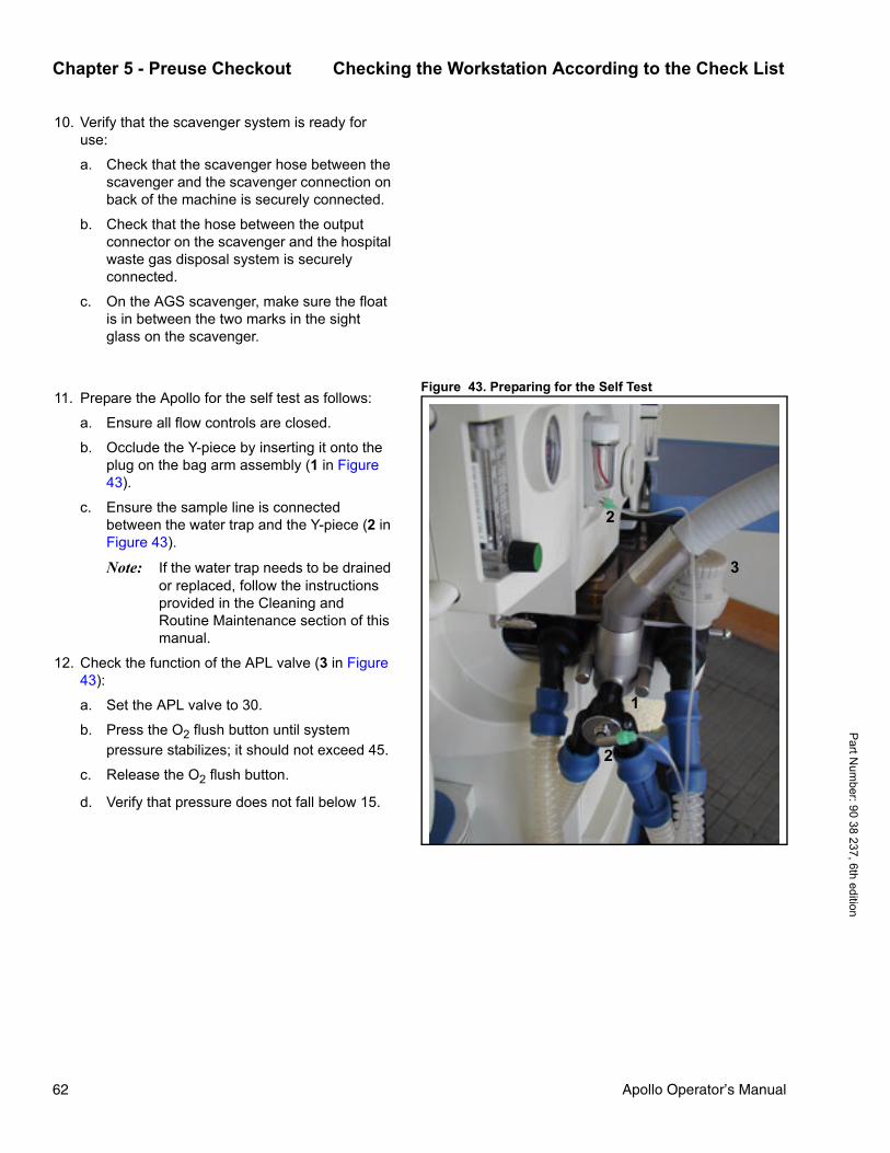
Chapter 5 - Preuse Checkout Checking the Workstation According to the Check List
Part N
umber: 90 38 237, 6th edition
10. Verify that the scavenger system is ready for use:
a. Check that the scavenger hose between the scavenger and the scavenger connection on back of the machine is securely connected.
b. Check that the hose between the output connector on the scavenger and the hospital waste gas disposal system is securely connected.
c. On the AGS scavenger, make sure the float is in between the two marks in the sight glass on the scavenger.
Figure 43. Preparing for the Self Test11. Prepare the Apollo for the self test as follows:
a. Ensure all flow controls are closed.
b. Occlude the Y-piece by inserting it onto the plug on the bag arm assembly (1 in Figure 43).
c. Ensure the sample line is connected between the water trap and the Y-piece (2 in Figure 43).
Note: If the water trap needs to be drained or replaced, follow the instructions provided in the Cleaning and Routine Maintenance section of this manual.
12. Check the function of the APL valve (3 in Figure 43):
a. Set the APL valve to 30.
b. Press the O2 flush button until system pressure stabilizes; it should not exceed 45.
c. Release the O2 flush button.
d. Verify that pressure does not fall below 15.
1
2
2
3
62 Apollo Operator’s Manual

Checking the Workstation According to the Check List Chapter 5 - Preuse CheckoutP
art N
umbe
r: 90
38
237,
6th
edi
tion
Figure 44. Check List Screen
13. If all checks in the check list are completed successfully, press the confirm knob or the >Start Self Test< key on the check list screen (1 in Figure 44) to begin the Apollo automated self test.
The automatic self test lasts approximately three minutes. The bar graph at the top of the Self Test screen shows the progress of the test (Figure 45).
The tests that are performed are listed on the screen. A clock symbol >u< is displayed in the small circle next to the component that is currently being tested. As each component test is finished, the clock symbol is replaced by a color code that indicates the result of the test.
Figure 45. Self Test Screen
1
Green Test completed successfully.
Yellow Workstation can be used with restrictions.
The error that was found during the test is posted in the window at the bottom of the screen with information on how to remedy the problem (Figure 46).
The user can either press the confirm knob to repeat the test, or can confirm the error by pressing the >Accept< key displayed on the screen. If the error is accepted, the workstation starts operation without this function.
Red Operation of the workstation is impossible or not permitted. The error must be remedied and the test must be repeated.
The self-test can no longer be cancelled at this point.
CAUTION ! Functions highlighted in yellow during the self test may not meet specifications and therefore merit further investigation and resolution by a properly trained technician.
Apollo Operator’s Manual 63

Chapter 5 - Preuse Checkout Checking the Workstation According to the Check List
Part N
umber: 90 38 237, 6th edition
Figure 46. Non-Critical Error During Self Test
Figure 47. Standby Screen Following Self-TestWhen the self test is completed, the system switches to Standby mode. The results of the self test are indicated on the screen by a color-coded circle (1 in Figure 47): a green circle means the test was successful, a yellow circle means the machine is conditionally functional, and an empty circle means that the self test was aborted. In addition, a message containing instructions for further procedures, if any, appears in the middle of the screen (2 in Figure 47).
Figure 48. Self Test Results ScreenMore specific results can be displayed by pressing the >Self Test Results< key on the Standby screen (3 in Figure 47). The Self Test Results screen appears (Figure 48).
The Self Test Results screen contains the >Absorb. changed< key (1 in Figure 48). If the absorbent is changed between cases, this key can be pressed to log the date and time. The label of the key then changes to >Undo Change<, and can be pushed again to undo the absorbent change information. The absorbent change information will be logged in the system when the Self Test Results screen is exited.
WARNING !Errors highlighted in red during the self test must be remedied before starting operation (for example, if there is no O2 supply).
CAUTION ! If the flow sensor or gas sensor is not operational, adequate substitute monitoring must be ensured before starting the workstation.
1
3
2
1
64 Apollo Operator’s Manual

System Compliance Test Chapter 5 - Preuse CheckoutP
art N
umbe
r: 90
38
237,
6th
edi
tion
Cancelling the Self Test
Figure 49. Cancelling Self TestTo cancel the self test before completion, for example, for a quick start in an emergency:
• press the >Cancel Test> key (1 in Figure 49), and proceed as specified in “Emergency Start” on page 68. The self test can be cancelled up to ten consecutive times.
System Compliance TestThe Apollo determines the current compliance of the patient system with any filters, hoses, and a Y-piece.
The system compliance test result is indicated on the Self Test Results screen by the red/yellow/green indicator and by posting the compliance value.
The compliance value is used during volume-controlled ventilation to correct for the reduction of tidal volume due to system compliance. For more information, see “Compliance Compensation” on page 89.
1CAUTION !
Cancelling the self test may lead to limited functionality. Greater clinical attention is required during operation if the self test has been interrupted. The clinician should perform a complete power-up self test as soon as is practical.
Apollo Operator’s Manual 65

Chapter 5 - Preuse Checkout Leak Tests
Part N
umber: 90 38 237, 6th edition
Leak TestsFigure 50. Mechanical Ventilation Leak TestThe Apollo tests for leaks in the mechanical
subsystem and in the Man/Spont system.
Figure 50 shows the components tested in the mechanical ventilation branch. This branch is tested with positive pressure. Leaks are indicated on the Self Test Results screen by the red/yellow/green indicator and by posting the leak value in mL/min (Leak (system) test result in Figure 48).
Figure 51 shows the components tested in the Man/Spont leak test. This test is performed with sub-atmospheric pressure. Leaks are indicated on the Self Test Results screen by the red/yellow/green indicator and by posting the leak value if it’s over 150 mL/min (Leak (Man/Spont) result in Figure 48).
The Apollo determines the current leakage of the breathing system and breathing hoses. The system tolerates leakage of up to 150 mL/min.
For leaks of more than 150 mL/min:
• check the components of the breathing system, repair any leaks, and repeat the leak test.
Note: Carry out leak test after changing breathing hoses, vaporizers or soda lime.
Figure 51. Man/Spont Ventilation Leak TestPossible causes of leaks include:
• Leaks in the breathing circuit or disconnection of circuit components
• CO2 canister not seated properly• Gas sampling line cracked or disconnectedIf a leak is reported, check the following:
• Verify that the breathing bag is secured tightly and not leaking.
• Ensure that the patient hoses, filters, and Y-piece are tightly connected and not leaking.
• Remove the inspiratory and expiratory 22 mm (0.87 in) port connectors and ensure that the O-rings are present and in good condition.
• Ensure that both flow sensors are present and not cracked or broken.
• Ensure that the bag arm connection to the breathing system is secured tightly and not leaking.
• Verify that the gas sampling line connections are tight and free of cracks or damage.
• Verify that the vaporizer fill and drain ports are tight and closed and that the vaporizers are properly secured to the vaporizer mount.
66 Apollo Operator’s Manual

Leak Tests Chapter 5 - Preuse CheckoutP
art N
umbe
r: 90
38
237,
6th
edi
tion
• Remove the absorber canister and verify that the lip of the canister and mating surface on the breathing system are free of dust and granules. Verify canister is tight. If a CLIC adapter is being used, verify it is properly secured.
• Ensure that the breathing system cover plate is securely tightened with the 5 hex head fasteners.
• Ensure that the 15 mm (0.59 in) leak test connector is not scratched or damaged.
• Visually inspect the gaskets and valves within the breathing system for possible leaks or damage.
Additional suggestions to isolate components of the breathing circuit for leaks:
Patient Sample Line Isolation:
• Remove the gas sample line from the patient circuit and occlude the Luer connection on the patient circuit.
• Perform leak test.
Isolation of Patient Circuit:
• Remove the patient circuit from the breathing system.
• Install a known tight 22 mm (0.87 in) hose between the inspiration and expiration ports.The breathing bag must be on the bag arm.
• Perform leak test.
Isolation of Vaporizers
• Remove the vaporizers from the vaporizer mount.
• Perform leak test.
Note: The Apollo automated self test does not check for internal vaporizer leakage. Therefore, after filling or changing vaporizers, perform the leak test on each respective vaporizer.
Apollo Operator’s Manual 67

Chapter 5 - Preuse Checkout Emergency Start
Part N
umber: 90 38 237, 6th edition
Emergency StartThe emergency start procedure shortens the self test when the Apollo must be operational immediately. The emergency start procedure can be performed up to ten times in succession. After ten cancellations, the system will not allow another cancellation and a complete self test must be performed.
Figure 52. Apollo Front Panel
1. Power on the machine by pressing the main power switch on the front of the machine (1 in Figure 52). An acoustic tone sounds.
2. Check that all vaporizers are closed.
3. Set an appropriate fresh-gas flow using the oxygen flow control knob (2 in Figure 52). Verify adequate flow by checking the total flow meter (3 in Figure 52).
4. Start manual ventilation.
5. Continue manual ventilation while the software is internally loaded and the electronics are tested. After about 35 seconds, the Check List screen appears.
Figure 53. Check List Screen6. Press the >Cancel Test< key on the Check List
screen (1 in Figure 53). The machine runs through a minimal self test that lasts about 10 seconds. Manual ventilation is interrupted during this time, but spontaneous breathing can continue. After the minimal self test, the workstation switches to standby mode.
2
3
WARNING !This procedure should only be used in emergency situations. There is a risk of undetected limitations or impaired functionality if the anesthesia machine is operated without having gone through the self test.
1
68 Apollo Operator’s Manual

Emergency Start Chapter 5 - Preuse CheckoutP
art N
umbe
r: 90
38
237,
6th
edi
tion
Note: The >Cancel Test< key is also available in the self test screen.
WARNING !The leak and compliance tests are not performed if the self test is cancelled, and no leak and compliance information is available. The accuracy levels specified in the Specifications chapter of this manual cannot be guaranteed.
CAUTION ! Cancelling the self test may lead to limited functionality. Greater clinical attention is required during operation if the self test has been interrupted. The clinician should perform a complete power-up self test as soon as is practical.
Apollo Operator’s Manual 69


Chapter 6 - Operation Summary Contents
Apollo Operator’s M
Par
t Num
ber:
90 3
8 23
7, 6
th e
ditio
n
Operation Summary
ContentsOverview ................................................................................................................. 73
Typical Operation .................................................................................................... 73
Loading Default Settings ................................................................................... 73
Entering the Patient’s Age ................................................................................. 73
Entering the Patient’s Ideal Body Weight (optional) .......................................... 74
Setting Fresh-Gas Flow ..................................................................................... 74
Setting Vaporizer Concentration ........................................................................ 75
Setting Ventilation Mode .................................................................................... 75
Changing Patients ................................................................................................... 76
Switch to Standby Mode .................................................................................... 76
Change the Absorbent ....................................................................................... 76
Replace the CLIC Adapter Absorber (Optional) ................................................ 77
Perform the Leak Test ....................................................................................... 79
Activating the CO2 Bypass Function (Optional) ...................................................... 80
Ending Operation .................................................................................................... 81
anual 71


Overview Chapter 6 - Operation SummaryP
art N
umbe
r: 90
38
237,
6th
edi
tion
OverviewThis section of the manual summarizes basic operation of the Apollo, including starting operation, changing patients, and ending operation. Specific information on setting ventilation and monitoring parameters is provided in later chapters of the manual.
Figure 54. Standby ScreenTypical OperationOperation of the Apollo begins with the Standby screen which is displayed after the initial self tests. This screen allows the user to restore default settings and enter the patient parameters needed to begin a case.
Loading Default SettingsThe default settings are a set of saved ventilation, gas monitoring, and alarm parameters that have been previously configured in the Standby screen (see “Configuring the Default Settings in Standby” on page 147 for complete instructions). They are valid whenever the Apollo is switched on and are restored in the Standby screen as described below.
1. Press the >Restore Default Settings< key on the Standby screen (1 in Figure 54).
2. Press the confirm knob to confirm the restore.
Entering the Patient’s AgeThe patient age influences the calculation of the MAC factor, volumeter scale, the vertical axis of loop and ventilation monitoring graphs, alarm limits for (optional) SpO2 monitoring, and the automatic volume adjustment of the Breathing Sound Emulator (BSE) module (see page 149). In addition, the trigger sensitivities and software algorithms for suppressing artifacts are also modified based on age, thus influencing the quality of ventilation in spontaneous breathing modes.
The patient age parameter is available in the Standby screen as well as in all ventilation modes. Changing the patient’s age during operation immediately impacts the parameters described above.
1. Press the >Age< key on the Standby screen (2 in Figure 54).
2. Turn the confirm knob until the correct patient age is displayed, and press the knob to confirm.
12 3
Apollo Operator’s Manual 73

Chapter 6 - Operation Summary Typical Operation
Part N
umber: 90 38 237, 6th edition
Entering the Patient’s Ideal Body Weight (optional)The patient’s ideal body weight is the actual weight minus estimated excess fat. The entered ideal body weight influences the ventilator default settings for tidal volume (VT) and frequency (Freq), as well as the alarm limits for expiratory minute volume (MV) during operation.
The patient ideal body weight parameter is available in the Standby screen as well as in all ventilation modes. Changing the patient’s ideal body weight parameter during operation does not change the actual parameters described above.
1. Press the >Weight< button on the Standby screen (3 in Figure 54).
2. Turn the confirm knob until the correct weight is displayed, and press the knob to confirm.
Setting Fresh-Gas FlowSet the fresh-gas flow to desired levels using the flow control knobs on the front panel of the machine.
SORC (Sensitive Oxygen Ratio Controller)
The Apollo is equipped with an O2 minimum delivery system to avoid hypoxic gas mixtures when N2O is selected as the carrier gas. At flow rates of 200 mL/min and above, the N2O concentration can be freely set between 0 and 79%.
During an O2 shortage, the SORC limits the N2O concentration in the fresh gas, so that the O2 concentration does not fall below 21%. When the N2O flow control is open and the O2 flow control is closed (or O2 flow is less than 200 mL/min), the SORC prevents N2O flow. During N2O failure, O2 can still be administered.
The SORC is not active when air is selected as the carrier gas and 100% air can be metered throughout the entire flow range.
CAUTION ! Accumulation of metabolic products may occur during low flow anesthesia, therefore monitoring of oxygen concentration is mandatory. Flushing the circuit with fresh gas at regular intervals may be necessary, particularly if decreasing oxygen concentrations are measured.
74 Apollo Operator’s Manual

Typical Operation Chapter 6 - Operation SummaryP
art N
umbe
r: 90
38
237,
6th
edi
tion
Fresh Gas Failure DetectionDuring operation, the Apollo checks that the piston cylinder unit has a sufficient level of fresh gas.
If the message "FGAS LOW OR LEAK" appears, increase the fresh-gas flow; identify and repair leak.
Setting Vaporizer ConcentrationNote: Refer to the appropriate Instructions for Use
for the vaporizer being used. Vapor 2000 is shown and described below.
For the Dräger Interlock 2 exclusion system:
Figure 55. Setting Vaporizer Concentration - Dräger Interlock 2 Exclusion System
1. Lock the unused vaporizer by moving the selector lever completely towards it. For example, to lock the left vaporizer, move the lever to the left (1 in Figure 55.).
2. With the handwheel set to “T” position on the unlocked vaporizer, press the button and engage the handwheel at “0” (2 in Figure 55.) Wait five seconds for the pressure to balance.
3. Press the button and turn the handwheel counterclockwise to set the required anesthetic gas concentration (3 in Figure 55.).
For the Dräger Auto Exclusion system:
1. Close any open vaporizers.
2. With the handwheel set to “T” position, press the button and engage the handwheel at “0”. Wait five seconds for the pressure to balance.
3. Press the button and turn the handwheel counterclockwise to set the required anesthetic gas concentration.
Setting Ventilation ModeSet the ventilation mode as described in the “Ventilation” section of this manual.
10 0
2
3
Apollo Operator’s Manual 75

Chapter 6 - Operation Summary Changing Patients
Part N
umber: 90 38 237, 6th edition
Changing PatientsFollow the steps below for successive patient cases.
Switch to Standby Mode• Press the standby key > <, and confirm
with the confirm knob.The functions of the workstation are switched off. All the current settings from the previous case are retained, including gas delivery and ventilation parameters, alarm limits, and patient age and weight.
To activate the default settings instead of using the current settings:
• Press the >Restore Default Settings< key on the Standby screen, and press the confirm knob.The default settings for gas delivery, ventilation, and alarm limits are restored.
Enter the new patient’s age and ideal body weight (optional) as instructed on page 73, and proceed.
Change the AbsorbentReplace the absorbent when:
• the inspiratory CO2 concentration exceeds 5 mmHg,or
• the indicator color changes from white to violet. The color indicator can regenerate slowly and the soda lime may revert to white, but its absorption capacity is nevertheless spent. You should therefore dispose of used absorbers immediately.
With the system in standby mode:
1. Swing the writing tray out of the way.
2. Press the release button on the ventilator unit, and pull the unit out.
3. Turn the absorber canister clockwise and remove it.
4. Empty the used soda lime and dispose of it.
5. Fill the absorber canister to upper mark with fresh soda lime.
6. Fit the canister into position below the breathing system, and turn it counterclockwise as far as possible.
76 Apollo Operator’s Manual

Changing Patients Chapter 6 - Operation SummaryP
art N
umbe
r: 90
38
237,
6th
edi
tion
7. Push the breathing system back in until it clicks into place.
8. Perform the leak test as described on page 79.
9. Reset the absorbent change log to actual date (see page 64).
Note: The disposable Drägersorb CLIC absorber can be used instead of the reusable absorber system described above.
Replace the CLIC Adapter Absorber (Optional)Replace the CLIC absorber when:
• the inspiratory CO2 concentration exceeds 5 mmHg,or
• the indicator color changes from white to violet. The color indicator can regenerate slowly and the soda lime may revert to white, but its absorption capacity is nevertheless spent. You should therefore dispose of used absorbers immediately.
The disposable absorber can be replaced during operation. The valve in the mounting ensures that the breathing system remains tightly sealed when the absorber is removed.
Note: Since a leak test cannot be performed during operation, no leak and compliance information on the changed absorber is available. Greater attention is required during operation.
• To replace the CLIC absorber:Replace the disposable absorber to ensure continuous CO2 absorption in the breathing system.
1. Press the button: the absorber swings open on its mounting. At the same time, the breathing system is sealed, and ventilation continues.
2. Remove the disposable absorber from the mounting.
Apollo Operator’s Manual 77

Chapter 6 - Operation Summary Changing Patients
Part N
umber: 90 38 237, 6th edition
3. Mount the new disposable absorber as follows:
• Before fitting, shake the disposable absorber, e.g. by turning it upside down several times in order to loosen up the soda lime.
• Remove seal from new disposable absorber.
• Slide the new disposable absorber onto the mounting and
4. Push the absorber into the machine until it engages.
5. After ending the case, perform a leak test to determine leak and compliance data.
6. Reset the absorbent change log to actual date (see page 64).
78 Apollo Operator’s Manual

Changing Patients Chapter 6 - Operation SummaryP
art N
umbe
r: 90
38
237,
6th
edi
tion
Perform the Leak Test
Note: The leak test should be performed each time the absorbent, breathing hoses, patient filters, or water trap have been changed, or when a vaporizer has been changed or filled.
Figure 56. Standby ScreenWith the system in standby mode:
1. Set the handwheel of the vaporizer being tested to a concentration of at least 0.2 Vol.%.
2. Press the >Leak Test< key on the Standby screen (1 in Figure 56).
3. The following prompt is displayed:
“Before starting leak test, close the Y-piece, connect the sample line and make sure that all flow controls are closed. If vaporizer leaks need to be tested, open respective vaporizer to at least 0.2 Vol.%. Press confirm knob to start the leak test.”Perform the actions as instructed.
The leakage test for volume mode/pressure mode takes approximately 90 seconds. System compliance is then determined for volume correction and the overall system is checked for leaks in the breathing system. The breathing bag and hose are also checked. Leakage is tested in the mechanical branch and in the overall system.
Figure 57. Leak Test Results ScreenNote: For complete information on the leak
test, see page 65.
Note: For more information on the system compliance, see “Compliance Compensation” on page 89.
4. When the results of the test are posted, press the >Exit< key (1 in Figure 57) to return to the Standby screen.
5. Turn the handwheel of the vaporizer being tested to the “0” position.
6. Repeat leak test for each additional installed vaporizer, if present.
WARNING !Do not perform the leak test with a patient connected to the workstation.
1
1
Apollo Operator’s Manual 79

Chapter 6 - Operation Summary Activating the CO2 Bypass Function (Optional)
Part N
umber: 90 38 237, 6th edition
Activating the CO2 Bypass Function (Optional)
Figure 58. Release Button on CLIC Adapter• To activate the CO2 bypass function, press the release button (1 in Figure 58); the disposable absorber swings open on its mounting. The breathing system is sealed at the same time and ventilation continues.
Figure 59. Pushing CLIC Adapter Back into Place• To deactivate the CO2 bypass function, swing the disposable absorber (2 in Figure 59) back into the system until it engages.
1
WARNING !CO2 is not absorbed in the breathing system when the absorber is swung out.
2
80 Apollo Operator’s Manual

Ending Operation Chapter 6 - Operation SummaryP
art N
umbe
r: 90
38
237,
6th
edi
tion
Ending OperationTo set the Apollo to standby mode:
• Press the standby key > <, and press the confirm knob.The workstation is now in standby. The fresh-gas flow should be turned off.
Figure 60. Apollo Shut Down ScreenTo turn the Apollo off completely (from standby):
1. Press the main power switch on the front of the machine.
An acoustic tone sounds, and the shut down screen shown in Figure 60 is displayed during a 10-second shut down delay.
Note: During the shut down delay, the Apollo can be restarted immediately by pressing the main power switch again.
2. Make sure the flow control valves are closed.
3. Disconnect the pipeline supply hoses from the wall supply outlets.
4. Close the cylinder valves.
5. Disconnect the scavenging hose.
Note: Leave the Apollo plugged into mains power in order to charge the UPS.
WARNING !If the hoses remain connected to the wall outlets, minute internal leaks may lead to contamination of the gases.
WARNING !It is strongly recommended that the Apollo be switched off once a day in order to carry out the power-on self test.
WARNING !Remove any water that may have accumulated in the ventilator diaphragm. Larger quantities of condensation may impair operation of the workstation and/or lead to failure of the equipment.
Apollo Operator’s Manual 81

Chapter 6 - Operation Summary Ending Operation
Part N
umber: 90 38 237, 6th edition
WARNING !The flow control valves should be closed when the machine is in the standby mode or when it is switched off.
82 Apollo Operator’s Manual

Chapter 7 - Ventilation Contents
Apollo Operator’s M
Par
t Num
ber:
90 3
8 23
7, 6
th e
ditio
n
Ventilation
ContentsOverview ................................................................................................................. 85
Manual/Spontaneous Ventilation ............................................................................. 86
Setting the APL Valve ........................................................................................ 86
Starting Manual/Spontaneous Ventilation .......................................................... 87
Presetting the Manual/Spontaneous Mode .................................................. 87
Starting the Manual/Spontaneous Ventilation Mode .................................... 87
Volume-Controlled Ventilation ................................................................................. 89
Starting Volume-Controlled Ventilation .............................................................. 89
Presetting the Volume Ventilation Mode ...................................................... 89
Starting the Volume Ventilation Mode .......................................................... 90
Synchronized Volume-Controlled Ventilation ..................................................... 91
Synchronized Volume-Controlled Ventilation with Pressure Support (Optional) 92
Pressure-Controlled Ventilation ............................................................................... 93
Starting Pressure-Controlled Ventilation ............................................................ 93
Presetting the Pressure Ventilation Mode ................................................... 93
Starting the Pressure Ventilation Mode ........................................................ 94
Synchronized Pressure-Controlled Ventilation .................................................. 95Synchronized Pressure-Controlled Ventilation with Pressure Support (Optional) ... 96
Pressure Support Ventilation (Optional) .................................................................. 97
Starting Pressure Support Ventilation ................................................................ 98
Presetting the Pressure Support Ventilation Mode ...................................... 98
Starting the Pressure Support Ventilation Mode .......................................... 98
When Changing Between Ventilation Modes ........................................................ 100
Automatic Parameter Changes ............................................................................. 100
Frequency Changes ........................................................................................ 101
PEEP Changes ................................................................................................ 101
TINSP Changes ............................................................................................... 100
Auxiliary Common Gas Outlet (CGO) Ventilation (Optional) ................................. 102
To divert fresh gas to the auxiliary CGO: ......................................................... 103
Presetting the auxiliary CGO monitoring ................................................... 103
anual 83

Chapter 7 - Ventilation Contents
84
Starting auxiliary CGO monitoring .............................................................. 103
Ending Auxiliary CGO Ventilation ............................................................... 105
Ventilating Children ................................................................................................ 105
Part N
umber: 90 38 237, 6th edition
Apollo Operator’s Manual

Overview Chapter 7 - VentilationP
art N
umbe
r: 90
38
237,
6th
edi
tion
OverviewThe Apollo supports the following ventilation modes:
• manual/spontaneous ventilation• volume-controlled ventilation (with or without
synchronization and optional pressure support)• pressure-controlled ventilation (with or without
synchronization and optional pressure support)• pressure support ventilation (optional)
In addition, the optional auxiliary common gas outlet (CGO) is available for use of non-rebreathing systems.
This section of the manual contains descriptions of these modes, along with complete instructions for setting the corresponding ventilation parameters.
CAUTION ! Check or adapt alarm limits each time the ventilation mode is changed or when the settings are modified while a patient is being ventilated. Some alarm limits may be automatically modified when the ventilation is changed or the settings are modified.
Apollo Operator’s Manual 85

Chapter 7 - Ventilation Manual/Spontaneous Ventilation
Part N
umber: 90 38 237, 6th edition
Manual/Spontaneous VentilationFigure 61. APL Valve - Spontaneous Mode Setting To use the manual/spontaneous ventilation mode,
the user must first set the APL valve to the appropriate mode and then select the mode using the >Man Spont< key on the front display panel.
Setting the APL ValveFor manual ventilation:
• Turn the APL valve adjustment knob to the desired pressure. Clockwise rotation increases the pressure, and counterclockwise rotation decreases the pressure.
The patient can be ventilated by hand using the breathing bag. The pressure will be limited to the value set on the APL valve.
To temporarily relieve pressure:
• Pull up on the APL valve knob
For spontaneous breathing:
• Rotate the APL valve adjustment knob fully counterclockwise, until the index mark on the knob lines up with the index mark on the bottom of the valve (1 in Figure 61).
The valve is now open for spontaneous patient breathing.
1
86 Apollo Operator’s Manual

Manual/Spontaneous Ventilation Chapter 7 - VentilationP
art N
umbe
r: 90
38
237,
6th
edi
tion
Starting Manual/Spontaneous VentilationPresetting the Manual/Spontaneous Mode
Prior to activating Man/Spont mode, the user can preset the Man/Spont parameters.
Figure 62. Man/Spont Screen1. Press the >Man Spont< key located at the
bottom of the display panel (1 in Figure 62). The LED on the key and the status field at the top of the screen (2 in Figure 62) flash on and off.
The soft keys for the ventilation parameters valid for ManSpont mode are displayed on a gray background (4 in Figure 62). This means that they are not yet active.
2. Press the soft key for the parameter to be changed; its color changes to yellow to indicate that it’s selected.
3. Turn the confirm knob to adjust the parameter to the desired value, and press the knob to confirm (3 in Figure 62).
Continue to set the values for the other parameter.
The parameters that can be set for ManSpont mode are shown in Table 3, along with their adjustment ranges and factory default values.
The patient’s ideal body weight is the actual weight minus estimated excess fat.
Starting the Manual/Spontaneous Ventilation Mode
Table 3 . Adjustment ranges and factory default values for Man/Spont mode parameters 4. When all the Man/Spont parameters have been
preset, press the confirm knob to start Man/Spont ventilation (3 in Figure 62).
The parameter soft keys turn green and display the preset parameter values. The “Man/Spont” indication in the status field stops flashing and is displayed continuously. Manual/spontaneous ventilation begins.
5. Set an appropriate fresh-gas flow. Verify adequate flow by checking the total flow meter.
1
4
2
3
Ventilation parameter(Man/Spont mode)
Adjustment range
Factory default value1
1. Site defaults can be set instead.
>Age< [years] <1 to 120 40
Ideal body weight>Weight<2 [kg/lb]
2. Optional
1 to 120 kg,1 to 240 lb
--
Apollo Operator’s Manual 87

Chapter 7 - Ventilation Manual/Spontaneous Ventilation
Part N
umber: 90 38 237, 6th edition
If a Man/Spont parameter has to be changed during ventilation:
• Press the soft key for the parameter to be changed, turn the confirm knob to the desired value, and press knob to confirm.
Note: Man/Spont mode can also be started without presetting values:
• Press the >Man Spont< key located at the bottom of the display panel, and press the confirm knob. Default parameter values are used.
or
• If in Standby or Monitoring mode, set fresh-gas flow. This activates manual/spontaneous ventilation automatically. Default parameter values are used.
Certain alarms are disabled automatically in manual/spontaneous mode to avoid artifacts. See the “Alarms” chapter in this manual for a list of alarms active in manual/spontaneous mode.
Note: There is 15-second timeout period for making ventilation mode changes, with a 5-second audible tone sequence after the first 10 seconds. If the new setting is not confirmed within the timeout period, the current ventilation setting remains in effect.
88 Apollo Operator’s Manual

Volume-Controlled Ventilation Chapter 7 - VentilationP
art N
umbe
r: 90
38
237,
6th
edi
tion
Volume-Controlled VentilationFigure 63. Respiratory Cycle - Volume ModeThe Apollo has a volume-controlled ventilation mode
with fixed mandatory tidal volume (VT) and frequency (Freq). Synchronization can be activated, as well as variable pressure support for spontaneous breathing efforts (optional).
The respiratory cycle (see Figure 63) is defined through the frequency (Freq), the inspiratory time (TINSP), the magnitude of the inspiration flow, the inspiratory pause time (TIP:TINSP) and the tidal volume (VT). Synchronization and pressure support are controlled by the sensitivity of the flow trigger and the level of ∆PPS. The maximum time interval for controlled ventilation is set via the frequency. In order to maintain a constant frequency, a time interval triggered prematurely is compensated in the next cycle.
Compliance Compensation
Ventilator compliance compensation is continuously applied during volume-controlled ventilation so that the tidal volume delivered to the patient corresponds to the Vt setting. Ventilator compliance is determined during the leak test performed in Standby mode. To have compliance compensation work accurately, it is important that the patient hoses used during the leak test match the type of hoses used during the proce-dure.
Figure 64. Volume Mode ScreenNote: When the ventilator settings for volume mode cause the ventilator to operate at its limits of performance, it is not possible for the Apollo to apply compliance compensation. If the ventilator's performance limit is reached, it is not possible to increment the Vt setting using the Vt soft key.
Starting Volume-Controlled VentilationPresetting the Volume Ventilation Mode
Prior to activating volume mode, the user can preset the volume mode parameters.
1. Press the >Vol Mode< key located at the bottom of the display panel (1 in Figure 64). The LED on the key and the status field at the top of the screen (2 in Figure 64) flash on and off.
The row of soft keys for the ventilation parameters valid for volume mode are displayed on a gray background (3 in Figure 64). This means that they are not yet active.
Pressure
Time [s]
Flow
TINSP TEXP
Time [s]
1/Freq.
PMAX
PPEAK
PPLAT
TIP
Trigger
on
Trigger indicator
PPS
on
Flow-trigger window
Trigger indicator
TSLOPE
PPS
Flow trigger
25%
1
3
4
2
Apollo Operator’s Manual 89

Chapter 7 - Ventilation Volume-Controlled Ventilation
Part N
umber: 90 38 237, 6th edition
Table 4. Adjustment ranges and factory default values for volume mode parameters 2. Press the soft key for the parameter to be
changed; its color changes to yellow to indicate that it’s selected.
3. Turn the confirm knob to adjust the parameter to the desired value, and press the knob to confirm (4 in Figure 64).
Continue to set the values for the other parameters.
The parameters that can be set for volume mode are shown in Table 4, along with their adjustment ranges and factory default values.
Starting the Volume Ventilation Mode
4. When all the parameters have been preset, press the confirm knob to start volume ventilation (4 in Figure 64).
The parameter soft keys turn green and display the preset parameter values. The “Volume” indication in the status field stops flashing and is displayed continuously. Volume ventilation begins.
If a volume parameter has to be changed during ventilation:
• Press the soft key for the parameter to be changed, turn the confirm knob to the desired value, and press knob to confirm.
Note: Volume mode can also be started without presetting values:
• Press the >Vol Mode< key located at the bottom of the display panel, and press the confirm knob. Default parameter values are used.
Note: There is 15-second timeout period for making ventilation mode changes, with a 5-second audible tone sequence after the first 10 seconds. If the new setting is not confirmed within the timeout period, the current ventilation setting remains in effect.
Ventilation parameter(volume mode)
Adjustment range
Factory default value 1
1. Site defaults can be set instead.
Pressure limitation >PMAX< [cmH2O]
10 to 70min. PEEP +10
40
Tidal volume>VT< [mL]
20 to 14002
2. Optionally 10 to 1400 mL.
600
Frequency>Freq<3,4 [bpm]
3. Depending on the configuration, the inspiratory time (TINSP) can be automatically changed together with adjustment of the frequency so that the resultant ratio of inspiration to expiration (I:E) remains constant. Only applies if trigger = OFF. See the “Configuration” chapter.
3 to 80 12
>TINSP<4 [sec.]
4. The resultant ratio of inspiration to expiration (I : E) is also displayed in parallel.
0.2 to 6.7 1.7
Insp. pause time : insp. time>TIP : TINSP< [%]
0 to 60 10
>PEEP< [cmH2O] 0 to 20 max. PMAX –10
0
Trigger sensitivity >Trigger< [L/min]
OFF,0.3 to 15
3.0 (Press. Supp. Mode)
OFF (Vol./Press. Mode)
Pressure support >∆PPS<5 [cmH2O]
5. Optional.
OFF,3 to 50
max. PMAX–PEEP
5 (PressSupp. Mode)
OFF (Vol./Press. Mode)
Rise time>TSLOPE< [sec.]
0.0 to 2.0 0.0
>Age< [years] <1 to 120 40
Ideal body weight>Weight<5 [kg/lb]
1 to 120 kg,1 to 240 lb
--
90 Apollo Operator’s Manual

Volume-Controlled Ventilation Chapter 7 - VentilationP
art N
umbe
r: 90
38
237,
6th
edi
tion
Synchronized Volume-Controlled Ventilation
Figure 65. Volume Mode Screen with SynchronizationSynchronization is activated by entering a value for the trigger sensitivity using the >Extra Settings< parameter soft key:
1. Press the >Extra Settings< soft key on the Volume mode screen (1 in Figure 65). New soft keys appear, including the trigger sensitivity >Trigger< (2 in Figure 65).
2. Press the soft key >Trigger<. The key turns yellow and shows the last trigger value that was set. The “sync” indication in the status field flashes on and off (3 in Figure 65).
3. Turn the confirm knob to adjust the trigger to the desired value, and press the knob to confirm (4 in Figure 65).
When the trigger value is confirmed, the “sync” indication in the status field stops flashing and is displayed steadily.
A ventilation stroke triggered by the patient is represented by a continuous vertical black line in the pressure curve and in the flow curve (trigger indicator). The active window for the stroke triggered by the patient corresponds to the last 25% of the applicable expiratory time. The actual trigger status is shown above the ventilation parameter soft keys.
12
3
4
Apollo Operator’s Manual 91

Chapter 7 - Ventilation Volume-Controlled Ventilation
Part N
umber: 90 38 237, 6th edition
Synchronized Volume-Controlled Ventilation with Pressure Support (Optional)
Figure 66. Volume Mode Screen with Optional Pressure Support
Pressure support is activated by entering a value for the level of support using the >∆PPS< parameter soft key:
1. Press the >∆PPS< soft key on the Volume mode screen (1 in Figure 66). The key turns yellow, and the last value that was set for pressure support is displayed, together with the last value set for the trigger sensitivity above it (2 in Figure 66). The “PressSupp” indication in the status field flashes on and off (3 in Figure 66).
2. Turn the confirm knob to adjust the pressure support to the desired value, and press the knob to confirm (4 in Figure 66).
When the value is confirmed, the ”Press Supp” indication in the status field stops flashing and is displayed steadily.
If the patient was being ventilated without synchronization when pressure support is activated, synchronization will be activated automatically with the last trigger setting used. The “sync” indication will appear in the status field (3 in Figure 66).
Synchronization is maintained (trigger remains on at the set value) when pressure support is deactivated (set to “OFF”).
Pressure support (∆PPS) is automatically deactivated when the trigger is deactivated (set to “OFF”). Trigger status is shown above the ventilation parameter soft keys (2 in Figure 66).
1
2
4
3
92 Apollo Operator’s Manual

Pressure-Controlled Ventilation Chapter 7 - VentilationP
art N
umbe
r: 90
38
237,
6th
edi
tion
Pressure-Controlled VentilationFigure 67. Respiratory Cycle - Pressure ModeThe Apollo has a pressure-controlled ventilation
mode with fixed pressure limitation (PINSP) and frequency (Freq). Synchronization can be activated, as well as variable pressure support for spontaneous breathing efforts (optional).
A continuous pressure is applied to the patient during the inspiratory time (TINSP) (refer to Figure 67). The rate at which the pressure curve rises is preset via the rise time TSLOPE. Synchronization and pressure support are controlled by the sensitivity of the flow trigger and the level of ∆PPS. The maximum time interval for controlled ventilation is set via the frequency. In order to maintain a constant frequency, a time interval triggered prematurely is compensated in the next cycle.
Changes in lung compliance and ventilation parameters influence the tidal volume.
Starting Pressure-Controlled VentilationPresetting the Pressure Ventilation Mode
Figure 68. Pressure Mode ScreenPrior to activating pressure mode, the user can preset the pressure mode parameters.
1. Press the >Press Mode< key located at the bottom of the display panel (1 in Figure 68). The LED on the key and the status field at the top of the screen (2 in Figure 68) flash on and off.
The row of soft keys for the ventilation parameters valid for pressure mode are displayed on a gray background (3 in Figure 68). This means that they are not yet active.
2. Press the soft key for the parameter to be changed; its color changes to yellow to indicate that it’s selected.
3. Turn the confirm knob to adjust the parameter to the desired value, and press the knob to confirm (4 in Figure 68).
Continue to set the values for the other parameters.
The parameters that can be set for pressure mode are shown in Table 5, along with their adjustment ranges and factory default values.
Pressure
Time [s]
Flow
TINSP TEXP
Time [s]
1/Freq.
PINSP
TSLOPE
Trigger
on
Trigger indicator
PPS
on
Flow-trigger window
PPS
Flow trigger
Trigger indicator
25%
1
2
3
4
Apollo Operator’s Manual 93

Chapter 7 - Ventilation Pressure-Controlled Ventilation
Part N
umber: 90 38 237, 6th edition
Starting the Pressure Ventilation Mode
4. When all the parameters have been preset, press the confirm knob to start pressure ventilation (4 in Figure 68).
Table 5. Adjustment ranges and factory default values for pressure mode parameters
The parameter soft keys turn green and display the preset parameter values. The “Pressure” indication in the status field stops flashing and is displayed continuously. Pressure ventilation begins.
If a pressure parameter has to be changed during ventilation:
• Press the soft key for the parameter to be changed, turn the confirm knob to the desired value, and press knob to confirm.
Note: Pressure mode can also be started without presetting values:
• Press the >Press Mode< key located at the bottom of the display panel, and press the confirm knob. Default parameter values are used.
Note: There is 15-second timeout period for making ventilation mode changes, with a 5-second audible tone sequence after the first 10 seconds. If the new setting is not confirmed within the timeout period, the current ventilation setting remains in effect.
Ventilation parameter(pressure mode
Adjustment range
Factory default value1
1. Site defaults can be configured instead.
Pressure limitation>PINSP< [cmH2O]
5 to 70min. PEEP +5
15
Frequency>Freq<2,3 [bpm]
2. Depending on the configuration, the inspiratory time (TINSP) can be automatically changed together with adjustment of the frequency so that the resultant ratio of inspiration to expiration (I : E) remains constant. Only applies if trigger = OFF. See the “Configuration” chapter.
3 to 80 12
Inspiratory time>TINSP<3
3. The resultant ratio of inspiration to expiration (I : E) is also displayed in parallel.
0.2 to 6.7 1.7
>PEEP<4 [cmH2O]
4. Depending on the configuration, the pressure limit (PINSP) can be changed automatically together with adjustment of the PEEP value.See the “Configuration” chapter.
0 to 20max. PINSP –5
0
Trigger sensitivity>Trigger< [L/min]
OFF,0.3 to 15
3.0 (Press. Supp. Mode)
OFF (Vol./Press. Mode)
Pressure support>∆PPS<5 [cmH2O]
5. Optional.
OFF,3 to 50
max. PMAX–PEEP
5 (Press. Supp. Mode)
OFF (Vol./Press. Mode)
Rise time>TSLOPE< [sec.]
0.0 to 2.0 0.0
>Age< [years] <1 to 120 40
Ideal body weight>Weight<5 [kg/lb]
1 to 120 kg,1 to 240 lb
--
94 Apollo Operator’s Manual

Pressure-Controlled Ventilation Chapter 7 - VentilationP
art N
umbe
r: 90
38
237,
6th
edi
tion
Synchronized Pressure-Controlled Ventilation
Figure 69. Pressure Mode with SynchronizationSynchronization is activated by entering a value for the trigger sensitivity using the >Extra Settings< parameter soft key:
1. Press the >Extra Settings< soft key on the Pressure mode screen (1 in Figure 69). New soft keys appear, including the trigger sensitivity >Trigger< (2 in Figure 69).
2. Press the soft key >Trigger<. The key turns yellow and shows the last trigger value that was set. The “sync” indication in the status field flashes on and off (3 in Figure 69).
3. Turn the confirm knob to adjust the trigger to the desired value, and press the knob to confirm (4 in Figure 69).
When the trigger value is confirmed, the “sync” indication in the status field stops flashing and is displayed steadily.
A ventilation stroke triggered by the patient is represented by a continuous vertical black line in the pressure curve and in the flow curve (trigger indicator). The active window for the stroke triggered by the patient corresponds to the last 25% of the applicable expiratory time. The actual trigger status is shown above the ventilation parameter soft keys.
12
3
4
Apollo Operator’s Manual 95

Chapter 7 - Ventilation Pressure-Controlled Ventilation
Part N
umber: 90 38 237, 6th edition
Synchronized Pressure-Controlled Ventilation with Pressure Support (Optional)
Figure 70. Pressure Mode with Optional Pressure SupportPressure support is activated by entering a value for the level of support using the >∆PPS< parameter soft key:
1. Press the >∆PPS< soft key on the Pressure mode screen (1 in Figure 70). The key turns yellow, and last value that was set for pressure support is displayed, together with the last value set for the trigger sensitivity above it (2 in Figure 70). The “PressSupp” indication in the status field flashes on and off (3 in Figure 70).
2. Turn the confirm knob to adjust the pressure support to the desired value, and press the knob to confirm (4 in Figure 70).
When the value is confirmed, the ”Press Supp” indication in the status field stops flashing and is displayed steadily.
If the patient was being ventilated without synchronization when pressure support is activated, synchronization will be activated automatically with the last trigger setting used. The “sync” indication will appear in the status field (3 in Figure 70).
Synchronization is maintained (trigger remains on at the set value) when pressure support is deactivated (set to “OFF”).
Pressure support (∆PPS) is automatically deactivated when the trigger is deactivated (set to “OFF”). Trigger status is shown above the ventilation parameter soft keys (2 in Figure 70).
1
2
3
4
96 Apollo Operator’s Manual

Pressure Support Ventilation (Optional) Chapter 7 - VentilationP
art N
umbe
r: 90
38
237,
6th
edi
tion
Pressure Support Ventilation (Optional)
Figure 71. Respiratory Cycle - Pressure Support ModeThe Apollo has an optional pressure-assisted ventilation mode. It is intended to reduce the work of breathing and is indicated for use only in patients who are breathing spontaneously. Patients who are not making spontaneous breathing efforts are not candidates for pressure support ventilation.
Pressure support ventilation is triggered by the patient’s spontaneous effort to breathe. Most anesthetic agents will cause patients to have reduced ventilatory responses to carbon dioxide and to hypoxemia. Therefore, patient triggered modes of ventilation may not produce adequate ventilation. Additionally, the use of neuromuscular blocking agents will interfere with patient triggering.
Synchronization and pressure support for the spontaneous breathing efforts are controlled via the sensitivity of the flow trigger and the level of ∆PPS. The rate at which the pressure curve rises is preset via the rise time TSLOPE. Refer to Figure 71.
The maximum inspiratory time for a spontaneous breathing stroke varies with age. It is equal to not more than 1.5 seconds in patients under the age of 4, and not more than 4 seconds in patients with a set age of 4 years or more.
Inspiration is ended as soon as the actual inspiration flow drops below 25% of the inspiratory peak flow. Any leakage is compensated at the actual airway pressure at the same time.
Apnea ventilation can be additionally set via the minimum frequency (FreqMIN). The ventilator is automatically triggered via FreqMIN if there is no spontaneous breathing activity by the patient. This is not a mandatory ventilation stroke by the ventilator; the patient can end the stroke triggered by the ventilator at any time by breathing spontaneously. This stroke is not identified by a trigger indicator. Apnea ventilation can also be deactivated again by setting the FreqMIN to “OFF”.
Apnea ventilation is intended to provide some degree of gas exchange if the patient’s respiratory rate falls below the desired minimum setting. It is not intended as a primary mode of ventilation.
Pressure
Time [s]
Flow
TSLOPE
Time [s]
1/Freq.MIN
Trigger indicator
PPS
Trigger indicator
Apneaventilation
Flow trigger Flow trigger No trigger
25% 25%
1/Freq.MIN
Apollo Operator’s Manual 97

Chapter 7 - Ventilation Pressure Support Ventilation (Optional)
Part N
umber: 90 38 237, 6th edition
Figure 72. Pressure Support Mode ScreenStarting Pressure Support VentilationPresetting the Pressure Support Ventilation Mode
Prior to activating pressure support mode, the user can preset the pressure support mode parameters.
1. Press the >Press. Supp.< key located at the bottom of the display panel (1 in Figure 72). The LED on the key and the status field at the top of the screen (2 in Figure 72) flash on and off.
The row of soft keys for the ventilation parameters valid for pressure support mode are displayed on a gray background (3 in Figure 72). This means that they are not yet active.
2. Press the soft key for the parameter to be changed; its color changes to yellow to indicate that it’s selected.
3. Turn the confirm knob to adjust the parameter to the desired value, and press the knob to confirm (4 in Figure 72).Continue to set the values for the other parameters.
The parameters that can be set for pressure support mode are shown in Table 6, along with their adjustment ranges and factory default values.
Note: The rise time should be set such that the plateau pressure is reached within 1/3 of the patient inspiration time.
Starting the Pressure Support Ventilation Mode
4. When all the parameters have been preset, press the confirm knob to start pressure support ventilation (4 in Figure 72).
The parameter soft keys turn green and display the preset parameter values. The “Press. Support” indication in the status field stops flashing and is displayed continuously. Pressure support ventilation begins.
1
2
3
4
98 Apollo Operator’s Manual

Pressure Support Ventilation (Optional) Chapter 7 - VentilationP
art N
umbe
r: 90
38
237,
6th
edi
tion
Table 6 . Adjustment ranges and factory default values for pressure support mode parameters
If a pressure support parameter has to be changed during ventilation:
• Press the soft key for the parameter to be changed, turn the confirm knob to the desired value, and press knob to confirm.
Note: Pressure support mode can also be started without presetting values:
• Press the >Press. Supp< key located at the bottom of the display panel, and press the confirm knob. Default parameter values are used.
Note: There is 15-second timeout period for making ventilation mode changes, with a 5-second audible tone sequence after the first 10 seconds. If the new setting is not confirmed within the timeout period, the current ventilation setting remains in effect.
Ventilation parameter(pressure support mode)
Adjustment range
Factory default value1
1. Site defaults can be set instead.
Minimum frequency2 >FreqMIN< [bpm]
2. The inspiratory time is limited by adjustment of Freq.MIN to yield a maximum ratio of 1:1 for (I : E), thus ensuring an adequate expiratory time.
OFF, 3 to 20 3
>PEEP< [cmH2O] 0 to 20 0
Trigger sensitivity>Trigger< [L/min]
0.3 to 15 3.0
Pressure support>∆PPS< [mbar]
3 to 50 5
Rise time>TSLOPE< [sec.]
0.0 to 2.0 0.0
>Age< [years] <1 to 120 40
Ideal body weight>Weight<3 [kg/lb]
3. Optional
1 to 120 kg,1 to 240 lb
--
Apollo Operator’s Manual 99

Chapter 7 - Ventilation When Changing Between Ventilation Modes
Part N
umber: 90 38 237, 6th edition
When Changing Between Ventilation ModesWhen changing to a different ventilation mode, the presettings are adopted or appropriately derived from the parameters of the preceding mode. Presettings that are identical in both ventilation modes are adopted directly (e.g., Freq, TINSP, ∆PPS, Trigger).
When changing from volume-controlled to pressure-controlled ventilation, the measured plateau pressure is adopted as the new value for PINSP. If a valid plateau pressure value is not available, the last value used in the case will be used as the preset value (the preset value of PINSP will be at least PEEP + 5). The PAW low alarm limit will be pre-set to PINSP-2 if the alarm limit was higher than PINSP-2 during volume-controlled ventilation.
When changing from pressure-controlled to volume-controlled ventilation, the new tidal volume (VT) is adopted from the measured minute volume (MV) and the set frequency (Freq). Only the minute volume applied by the ventilator is taken into account; pressure-supported breathing strokes by the patient are disregarded.
When changing from automatic ventilation modes to the optional pressure-support mode, the set PEEP, ∆PPS, and trigger values are adopted. If ∆PPS and/or trigger were set to “OFF”, the last values used are adopted in pressure support mode. In all other cases the configured default settings are used. The PAW low alarm limit will be pre-set to PEEP+∆PPS-2 if the alarm limit was higher than PEEP+∆PPS-2 during automatic ventilation mode.
When changing from the optional pressure-support mode to automatic ventilation modes, the set PEEP, ∆PPS, and trigger values are adopted. The last values that were set are used for the other parameters and the configured default settings in all other cases.
Automatic Parameter ChangesWith the proper configuration setting in the Standby Configuration screen, certain ventilation parameters change automatically when a related parameter is changed. See the “Configuration” chapter for complete information.
TINSP ChangesTSLOPE may be reduced simultaneously if TINSP is reduced.
100 Apollo Operator’s Manual

Automatic Parameter Changes Chapter 7 - VentilationP
art N
umbe
r: 90
38
237,
6th
edi
tion
Frequency ChangesFigure 73. Automatic Freq/TINSP ChangeIf so configured, the inspiratory time (TINSP) will be
automatically changed when the frequency (Freq) is changed in volume-controlled or pressure-controlled ventilation modes (without synchronization), so that the resultant ratio of inspiration to expiration (I:E) remains constant.
To make a combined Freq/TINSP parameter change:
1. Press the >Freq< soft key on the Volume or Pressure mode screen. The Freq key lights up yellow, along with the value for TINSP, to indicate that both values will change (1 in Figure 73).
2. Turn the confirm knob to adjust the Freq value. The TINSP value is adjusted at the same time.
3. When the desired Freq value is displayed, press the confirm knob to set the value. Both the Freq and the TINSP keys turn green and the I:E ratio remains constant.
PEEP ChangesFigure 74. Automatic PEEP/PINSP ChangeIf so configured, the inspiratory pressure (PINSP) will
be automatically changed when the PEEP value is changed in the pressure-controlled ventilation mode.
To make a combined PEEP/PINSP parameter change:
1. Press the >PEEP< soft key on the Volume or Pressure mode screen. The PEEP key lights up yellow, along with the value for PINSP, to indicate that both values will change (1 in Figure 74).
2. Turn the confirm knob to adjust the PEEP value. The PINSP value is adjusted at the same time.
3. When the desired PEEP value is displayed, press the confirm knob to set the value. Both the PEEP and the PINSP keys turn green.
In addition, if so configured, the PAW low alarm limit will be automatically changed when the PEEP value is changed.
1 1
1 1
Apollo Operator’s Manual 101

Chapter 7 - Ventilation Auxiliary Common Gas Outlet (CGO) Ventilation (Optional)
Part N
umber: 90 38 237, 6th edition
Auxiliary Common Gas Outlet (CGO) Ventilation (Optional)
Figure 75. Auxiliary CGO - Bain Circuit shownNote: The Bain system is shown in this example. Prepare the system as instructed in the corresponding Instructions for Use.
For prescribed monitoring of O2, CO2, air, and anesthetic gases:
1. Connect the sample line to the Luer lock connection on the mask manifold and to the water trap connection on the front of the Apollo (1 in Figure 75).
For mask manifolds without a sample line connector:
• Place a T-piece with filter between the mask pipe and fresh gas connection port.
or:• where applicable, use a Luer
lock filter connection.
Connect the fresh gas hose of the Bain system to the auxiliary common gas outlet (2 in Figure 75).
Connect the gas scavenging system hose of the non-rebreathing system (3 in Figure 75) to the Y-piece of the Apollo breathing system.
Follow the Instructions for Use provided with the non-rebreathing system.
WARNING !Only non-rebreathing systems with a breathing bag or additional pressure relief valve may be used on the Apollo. Check the fresh-gas flow and inflation of breathing bag; do not use non-rebreathing systems if the flow is insufficient.
3
2
1
1
102 Apollo Operator’s Manual

Auxiliary Common Gas Outlet (CGO) Ventilation (Optional) Chapter 7 - VentilationP
art N
umbe
r: 90
38
237,
6th
edi
tion
To divert fresh gas to the auxiliary CGO:Figure 76. Auxiliary CGO Ventilation Screen
Presetting the auxiliary CGO monitoring
Prior to activating auxiliary CGO monitoring, the user can preset the auxiliary CGO parameters.
2. Press the >Aux CGO< key located at the bottom of the display panel (1 in Figure 76). The LED on the key and the status field at the top of the screen (2 in Figure 76) flash on and off.
The soft keys for the parameters valid for auxiliary CGO monitoring are displayed on a gray background (4 in Figure 76). This means that they are not yet active.
3. Press the soft key for the parameter to be changed; its color changes to yellow to indicate that it’s selected.
4. Turn the confirm knob to adjust the parameter to the desired value, and press the knob to confirm (3 in Figure 76).
Continue to set the values for the other parameter.
The parameters that can be set for auxiliary CGO monitoring are shown in Table 7, along with their adjustment ranges and factory default values.
The patient’s ideal body weight is the actual weight minus estimated excess fat.
Starting auxiliary CGO monitoring
Table 7 . Adjustment ranges and factory default values for auxiliary CGO monitoring parameters 5. When all the auxiliary CGO monitoring
parameters have been preset, press the confirm knob to start auxiliary CGO monitoring (3 in Figure 76).
The parameter soft keys turn green and display the preset parameter values. The “Aux CGO” indication in the status field stops flashing and is displayed continuously. Auxiliary CGO monitoring begins.
6. Set an appropriate fresh-gas flow. The fresh gas supply must be equal to at least twice the minute volume in order to exclude rebreathing.
1
2
3
4
Ventilation parameter(auxiliary CGO monitoring)
Adjustment range
Factory default value1
1. Site defaults can be set instead.
>Age< [years] <1 to 120 40
Ideal body weight>Weight<2 [kg/lb]
2. Optional
1 to 120 kg,1 to 240 lb
--
Apollo Operator’s Manual 103

Chapter 7 - Ventilation Auxiliary Common Gas Outlet (CGO) Ventilation (Optional)
Part N
umber: 90 38 237, 6th edition
If an auxiliary CGO monitoring parameter has to be changed during ventilation:
• Press the soft key for the parameter to be changed, turn the confirm knob to the desired value, and press knob to confirm.
Note: Auxiliary CGO monitoring can also be started without presetting values:
• Press the >Aux CGO< key located at the bottom of the display panel, and press the confirm knob. Default parameter values are used.
Note: There is 15-second timeout period for making ventilation mode changes, with a 5-second audible tone sequence after the first 10 seconds. If the new setting is not confirmed within the timeout period, the current ventilation setting remains in effect.
Airway pressure (PAW) and the mandatory frequency (Freq), PPEAK, and PMEAN are measured at the auxiliary common gas outlet.
Pressure measurement may be impaired by activating the oxygen flush.
The minute volume (MV) and tidal volume (VT) are not measured.
Certain alarms are disabled automatically in order to avoid artifacts. See the “Alarms” chapter for complete information.
Excess fresh gas can be discharged into the anesthetic gas scavenging line via the breathing system of the Apollo. For this purpose, the non-rebreathing system must be connected to the Y-piece of the breathing hoses connected to the breathing system.
WARNING !If the bag does not inflate, switch to the Apollo internal breathing system.
CAUTION ! Ambient air may become contaminated with anesthetic agent when using non-rebreathing systems.
104 Apollo Operator’s Manual

Ventilating Children Chapter 7 - VentilationP
art N
umbe
r: 90
38
237,
6th
edi
tion
Ending Auxiliary CGO Ventilation
1. Press any ventilation mode key, other than >Aux CGO<. The LED of the selected ventilation mode key and the status field flash on and off.
2. Press the confirm knob. The ventilation is switched to the Apollo internal rebreathing system.
Note: When changing back to the Apollo rebreathing system, reconnect the sample line to the Y-piece.
Ventilating ChildrenFollow the instructions below for tidal volumes (VT) of less than 200 mL.
1. Attach a 0.5 L breathing bag to the breathing bag arm.
2. Connect low compliance Pediatric or Neonatal breathing hoses to the breathing system and the Y-piece.
3. Connect the sample line to the Y-piece and to the water trap on the front of the machine.
4. Perform a leak test as specified “Perform the Leak Test” on page 79 of this manual.
WARNING !Use pediatric hoses.
WARNING !Microbial filters should not be used on the inspiratory and expiratory ports, because this increases system compliance.
Apollo Operator’s Manual 105


Chapter 8 - Monitoring Contents
Apollo Operator’s M
Par
t Num
ber:
90 3
8 23
7, 6
th e
ditio
n
Monitoring
ContentsOverview ............................................................................................................... 109
Standard Screen .................................................................................................... 109
Customizing the Standard Screen Display ...................................................... 110
Selecting a Default Layout ......................................................................... 110
Modifying Current Layout .......................................................................... 110
Adjusting Display Brightness ...................................................................... 111
Displayed Parameters ............................................................................................ 111
CO2 Concentration ..................................................................................... 111
O2 Concentration ....................................................................................... 111
Anesthetic Gas .......................................................................................... 112
Airway Pressure ........................................................................................ 112
Respiratory Flow and Volume .................................................................... 112
SpO2 Concentration (Optional) ................................................................. 112
Loops (Optional) ........................................................................................ 112
Virtual Flow Tubes ..................................................................................... 113
Gas Supply Module ................................................................................... 113
Ventilation Source Module ......................................................................... 113
VT/PAW Module ........................................................................................ 114
Delta VT Module ........................................................................................ 114
The Low Flow Wizard ................................................................................ 115
Volumeter Module ...................................................................................... 116
Gas Measurement ................................................................................................. 117
Calibration ................................................................................................. 117
CO2 and O2 .............................................................................................. 117
Anesthetic agents ...................................................................................... 117
Minimum alveolar concentration (MAC) definition ..................................... 118
Calculating the MAC factors ...................................................................... 118
Loops (Optional) .................................................................................................... 120
Datalog .................................................................................................................. 121
Screen Timer ......................................................................................................... 122
anual 107

Chapter 8 - Monitoring Contents
108
The Data Screen .................................................................................................... 123
The Trend Screen .................................................................................................. 124
Monitoring Mode .................................................................................................... 126
SpO2 Measurement (Optional) .............................................................................. 127
Part N
umber: 90 38 237, 6th edition
Apollo Operator’s Manual

Overview Chapter 8 - MonitoringP
art N
umbe
r: 90
38
237,
6th
edi
tion
OverviewThe Apollo has three basic screens for the display of monitoring information: standard, data, and trend. The gas measurement and gas delivery windows remain displayed in all three screens, but the information presented in the graphical/numerical window will change, depending on the selected screen and user configuration.
This section of the manual defines all monitoring parameters and provides instructions for selecting and configuring monitoring screens and parameters.
Standard ScreenFigure 77. Standard ScreenTo display the standard screen, press one of the
following hard keys on right side of the screen:
• Press the > < key to display the standard screen directly (1 in Figure 77)or
• Press the > < key one or two times in succession until the standard screen is displayed (2 in Figure 77)
The left side of the standard screen displays the gas measurement and gas delivery windows which remain displayed on the screen at all times during operation (refer to Figure 77).
The graphical/numerical window displays the majority of Apollo parameter information and can be customized by the user for screen layout and/or content. The top portion contains real-time curves and corresponding numeric values for monitored parameters, and the bottom portion contains modules that are configured by the user and provide various types of ventilation and system information.
The monitoring/configuration soft keys allow the user to customize the display and provide access to additional functions.
For a list of monitored parameters, see “Displayed Parameters” on page 111.
1
2
Gas MeasurementDisplay
Graphical/NumericalDisplay
Fresh Gas DeliveryDisplay
Monitoring/ConfigurationSoft Keys
Apollo Operator’s Manual 109

Chapter 8 - Monitoring Standard Screen
Part N
umber: 90 38 237, 6th edition
Customizing the Standard Screen DisplaySelecting a Default Layout
Figure 78. Standard Screen - Screen Layout WindowThe user can select a default screen layout for the standard screen. The selection determines the three curves that are displayed, as well as the three modules that are shown below the curves.
Three default layouts are available. They can only be configured in the Standby Configuration screen. See the “Configuration” section of the manual for complete information.
1. Press the >Screen Layout< key on the standard screen (1 in Figure 78). The screen layout window appears (2 in Figure 78), with the currently selected layout highlighted.
2. Turn the confirm knob to select a different layout, and press the knob to confirm.
The screen layout window is removed and the standard screen is displayed with the selected layout.
Modifying Current LayoutFigure 79. Standard Screen - Screen Config. WindowThe user can also modify the layout of the currently
selected screen:
1. Press the >Screen Layout< key on the standard screen (1 in Figure 78). The screen layout window appears (2 in Figure 78).
2. Turn the confirm knob to select the >Config screen< option, and press the knob to confirm. The screen configuration window appears (1 in Figure 79).
The top three options in the configuration window are used to select the curves to be displayed, and the bottom three options determine the modules to be displayed below the curves.
3. Turn the confirm knob to select an option, and press the knob to confirm. The option becomes highlighted in yellow.
4. Turn the confirm knob until the desired curve or module is displayed, and press knob to confirm.
Continue to select other curves/modules.
5. Exit the config window by either:
• confirming the exit symbol >z< with the confirm knob, or
• pressing the > < key.
1
2
1
110 Apollo Operator’s Manual

Displayed Parameters Chapter 8 - MonitoringP
art N
umbe
r: 90
38
237,
6th
edi
tion
Adjusting Display Brightness
Figure 80. Brightness Adjustment WindowTo adjust the brightness level of the display:
1. Press the >Screen Layout< key on the standard screen (1 in Figure 78). The screen layout window appears (2 in Figure 78).
2. Turn the confirm knob to select the >Brightness< option, and press the knob to confirm. The brightness adjustment window appears with the current brightness level highlighted in yellow (1 in Figure 80).
3. Turn the confirm knob to adjust the brightness level (from 1 to 16), and press the knob to confirm.
Displayed ParametersThe following parameters are displayed on the Apollo.
Note: The specific parameters that are displayed will vary, depending on the selected screen and user configuration.
CO2 Concentration• Curve display• Numerical display:
- etCO2 (end-tidal CO2 concentration)- FiCO2 (fractional inspiratory CO2
concentration)• Trend curve for CO2Note: The CO2 curve can be displayed in gray,
dark gray, red, yellow, blue, or green. This setting can be configured by an authorized DrägerService representative.
O2 Concentration• Curve display• Numerical display:
- FiO2 (fractional inspiratory O2 concentration)- exO2 (expiratory O2 concentration)- ∆O2 (difference between inspiratory and
expiratory O2 concentration)• Trend curve for O2
1
Apollo Operator’s Manual 111

Chapter 8 - Monitoring Displayed Parameters
Part N
umber: 90 38 237, 6th edition
Anesthetic Gas• Curve display• Numerical display:
- inAgent (inspiratory gas concentration)- exAgent (expiratory gas concentration)
• MAC (minimum alveolar concentration)• Trend curve for anesthetic gases and MAC
Airway Pressure• Curve display (PAW)• Numerical display:
- PEAK (peak pressure)- PLAT (plateau pressure)- PEEP (positive end-expiratory pressure)- MEAN (mean pressure) (only on data screen)
• Bar graph
Respiratory Flow and Volume• Curve display for flow (insp/exp)• Numerical display:
- MV (expiratory minute volume)- VT (tidal volume)- VTINSP (measured inspiratory tidal volume)- ∆VT (difference between inspiratory and
expiratory tidal volume)- Freq (respiratory rate)- MVLEAK (difference between the inspiratory
and expiratory minute volume) (only on data screen)
- CPAT* (patient lung compliance) (only on data screen)
• Trend curve for MV and CPAT• VT bar graph*CPAT = with mandatory breaths.
SpO2 Concentration (Optional)• Curve display (plethysmogram)• Numerical display:
- SpO2 (functional O2 saturation level of blood)- ♥ (pulse rate)
• Trend curve for SpO2 and pulse
Loops (Optional)Shows two pairs of measured values that are plotted against each other. Each pair appears as a loop: the Pressure/Volume loop and the Flow/Volume loop. See “Loops (Optional)” on page 120 for more detailed information.
VT
(PLAT - PEEP)
112 Apollo Operator’s Manual

Displayed Parameters Chapter 8 - MonitoringP
art N
umbe
r: 90
38
237,
6th
edi
tion
Virtual Flow TubesThis is an indication (in bar graph and numeric form) of the individual flows actually delivered by the fresh gas control valves.
Gas Supply ModuleShows pipeline and cylinder gas supply pressures in tabular form.
Ventilation Source ModuleShows the indicators for the ventilation sources (with the active source highlighted) and displays the PAW real-time signal.
Manual ventilation (Man/Spont)
Non-rebreathing system at the common gas outlet
Automatic ventilation
Apollo Operator’s Manual 113

Chapter 8 - Monitoring Displayed Parameters
Part N
umber: 90 38 237, 6th edition
VT/PAW ModuleShows the tidal volume (VT) and airway pressure (PAW) as bar graphs, as well as a numerical value for tidal volume. See “Volumeter Module” on page 116 for more information on the tidal volume graph.
Delta VT ModuleShows the tidal volume (VT) and airway pressure (PAW) as bar graphs, as well as a numerical value for inspiratory tidal volume (VTINSP), expiratory tidal volume (VT), and the difference between inspiratory and expiratory tidal volume (∆VT). See “Volumeter Module” on page 116 for more information on the tidal volume graph.
114 Apollo Operator’s Manual

Displayed Parameters Chapter 8 - MonitoringP
art N
umbe
r: 90
38
237,
6th
edi
tion
The Low Flow Wizard.
The low flow wizard shows bar graphs for the minimum required flow (leak and uptake) and for the total fresh-gas flow. Both graphs have the same scale.
The total fresh-gas flow bar graph has three ranges:
Gas consumption depends on patient uptake, leakage, and the CO2 volume converted in the absorber.
If fresh gas data is unavailable, the bar graph will be inactive and the text will appear grayed out.
WARNING !This tool should not be used when higher flows are required such as during induction, emergence, or other times when rapid changes to the concentration of gases in the circuit are desired, or when the chemical pharmacology of the agent being used indicates otherwise.
Indication Bar graph color Meaning
too much yellow fresh gas delivery is more than 1 L/min above the gas consumption (leak + uptake)
efficient green fresh gas delivery efficient
too little red fresh gas delivery less than minimum flow required (leak + uptake)
Apollo Operator’s Manual 115

Chapter 8 - Monitoring Displayed Parameters
Part N
umber: 90 38 237, 6th edition
Volumeter ModuleThe volumeter module shows the tidal volume (VT) and minute volume as bar graphs. The scales can be configured by the user (see the “Configuration” chapter for more information.)
Tidal Volume (Upper) GraphThe tidal volume graph increases during the inspiratory flow and decreases during the expiratory flow. A blue vertical line remains on the graph to indicate the inspiratory volume, while the bar recedes from the line to indicate the expiratory phase.
The expiratory tidal volume is shown in numerics above the graph. Leakage is indicated by the bar remaining in the graph at the end of the expiratory phase..
The Minute Volume (Lower) GraphThe minute volume, or volumeter, provides a graphical and numerical indication of the expiratory minute volume. Each unit in the graph represents one breath. The total volume is shown above the graph and the expired time is shown beside the graph in seconds. The measured values are displayed for four minutes and then deleted.
To start the volumeter:
• Push the confirm knob.The measurement begins and stops automatically after 60 seconds. The volumeter is stopped if the confirm knob is pushed again within 60 seconds; the values are deleted and the confirm knob must be pushed again to restart.
Inspiratory phase Expiratory phase End of expiratory phase
116 Apollo Operator’s Manual

Gas Measurement Chapter 8 - MonitoringP
art N
umbe
r: 90
38
237,
6th
edi
tion
Gas MeasurementThe concentration of O2, CO2 and of the anesthetic agents N2O, halothane, enflurane, isoflurane, desflurane, and sevoflurane is measured.
Apollo automatically identifies the anesthetic agent used and adjusts the measurement and monitoring of the anesthetic gas concentration to suit the gas identified.
When no anesthetic agent is applied, the message “No agent” appears below the O2/N2O measurement.
.
Figure 81. Example of Calibration MessagesCalibrationThe gas measuring module is calibrated automatically when the workstation is started and then every two hours after that.
O2 calibration is performed parallel to the gas measuring module every eight hours.
During calibration, messages informing the user about the calibration appear on the screen (1 and 2 in Figure 81), and the measurement values are replaced with the word “CAL” (3 in Figure 81).
CO2 and O2
The CO2 and O2 concentrations are side-stream measured, thus delaying an indication of the real-time values by approximately four seconds. The displayed CO2 and O2 curves are not synchronized with the pressure and flow curves.
If apnea occurs, the display for etCO2 is replaced by the message "Apnea". The apnea time [min:sec] is displayed instead of the measured value.
Anesthetic agentsThe anesthetic agents are side-stream measured in the same way as CO2 and O2.
WARNING !The presence of aerosols in the breathing circuit should be avoided, as the displayed agent concentrations and/or the water trap membrane may be affected.The presence of organic cleaning agents or gases contaning haloalkanes (e.g., CFC) will impair the accuracy of the integrated gas analyzer.
1
2 3
Apollo Operator’s Manual 117

Chapter 8 - Monitoring Gas Measurement
Part N
umber: 90 38 237, 6th edition
Minimum alveolar concentration (MAC) definition1 MAC is equal to the anesthetic gas concentration at 760 mmHg at which 50% of all patients no longer respond to a stimulation of the nerves.
The values listed in the table below are used to calculate the MAC factor. These values are merely guideline values and are still subject to debate. The current MAC values listed in the instructions enclosed with the anesthetic gases are binding.
Figure 82. Influence of Age on MAC
The MAC value depends on the patient's age. The above values refer to the age of 40 years.
If there is a mixture of two volatile agents, the concentration of the secondary agent is displayed if the MAC factor is 0.1 MAC or greater. The gas with the higher expiratory MAC factor is displayed above the secondary gas.
A secondary agent becomes the primary agent if its MAC factor exceeds the MAC factor of the primary agent by 0.2 MAC.
A mixture of more than two volatile anesthetic agents cannot be reliably detected.
Calculating the MAC factorsThe MAC value is a simple navigation aid for determining the dosage of anesthetic agent.
Apollo takes into account age correction, altitude correction and mixture calculation. The influence of other medication (opiates or intravenous hypnotics) is not taken into account when calculating MAC factors.
The measured values used for calculating the MAC factor are the end-expiratory concentrations. Partial pressures are taken into account.
The displayed value is calculated at 760 mmHg as follows:
0.2*N2O
Desflurane
Sevoflurane
Enflurane
Isoflurane
Halothane
Age (years)
Influence of age on the MAC value1 MAC
Halothane 0.77%Enflurane 1.7%Isoflurane 1.15%Desflurane 6.65%Sevoflurane 2.1%N2O 105%
f =exp. conc. agent1 +
exp. conc. agent2 +exp. conc. N2O
MAC (age) agent1 MAC (age) agent2 MAC (age) N2O
118 Apollo Operator’s Manual

Gas Measurement Chapter 8 - MonitoringP
art N
umbe
r: 90
38
237,
6th
edi
tion
Age-corrected MAC factors are calculated according to W.W. Mapleson (British Journal of Anaesthesia 1996, pages 179-185), whose formula only applies for patients >1 year old:
MAC = MAC 40 x 10 (-0.00269 x (age - 40))
The formula shows the reciprocal relationship existing between MAC and age.
Age 1 is used for calculation if the age is <1:
Example:
Expiratory concentrations of 0.9 Vol.% isoflurane and 50 Vol.% N2O are measured for a 60-year-old patient.
1 MAC isoflurane at 60 years equals 1.01 according to the formula above.
1 MAC N2O at 60 years equals 92.4 according to the formula above.
The total MAC factor is calculated as follows:
In other words, 1.4 MAC is obtained with the current concentration. For a 20-year-old patient, the same concentration yields a MAC factor of 1.1.
.
Note: The user can configure whether or not the MAC factor shall be displayed AND whether or not the MAC factor shall be corrected for patient age (see page 150 and page 162).
0.9 Vol.% Iso +
50 Vol.% N2O = 1.4
1.01 (MAC Iso) 92.4 (MAC N2O)
WARNING !Age-based MAC values only apply if the patient’s age is greater than or equal to 1 year. If the patient is younger than 1 year, age-based MAC for 1 year shall apply.
Apollo Operator’s Manual 119

Chapter 8 - Monitoring Loops (Optional)
Part N
umber: 90 38 237, 6th edition
Loops (Optional)To display the loops screen:
Figure 83. Loops Key on Standard Screen• Press the >Loops< soft key on the standard screen.
The P/V loop and the Flow/Vol loop are displayed on the screen in place of the two lower curves (refer to Figure 84). Each loop remains displayed for three breathing cycles; the color intensity of the loop decreases with each cycle.
The scale of the Pressure and Flow axes depends on the scale selected for the real-time pressure and flow curves. The Volume axis for both loops is the same as the scale in the VT/PAW module.
See the “Configuration” chapter for more information on scale configuration.
Figure 84. Loops ScreenTo display the current loop in a different color to use it as a reference:
• Press the >Save reference< soft key while in the loops screen (1 in Figure 84). The soft key label changes to >Delete reference<.
The reference loop can be deleted by pressing the >Delete reference< soft key or by changing to Standby mode.
To remove the loops from the screen:
• Press the >Exit Loops< soft key while in the loops screen (2 in Figure 84). The loops are removed and the two lower curves are displayed again.
1
12
120 Apollo Operator’s Manual

Datalog Chapter 8 - MonitoringP
art N
umbe
r: 90
38
237,
6th
edi
tion
DatalogFigure 85. Datalog Soft Key - Standard ScreenThe datalog is a chronological record of measured
values and events that occur during the case. The Apollo automatically records events such as performed or cancelled self-tests, changes of agent, and changes of ventilation mode (followed by the date). At the end of each case, the case duration, the use of each fresh gas, patient uptake, and total use of anesthetic agent are recorded.
The datalog can also be configured by the user to record each Warning or Caution or to record patient parameter data at specified intervals of 1, 2, 5, or 10 minutes. Each Warning or Caution entry is followed by the measured values recorded at the time of the alarm’s occurrence. See the “Configuration” section of the manual for more information.
The datalog can be displayed from the standby screen, the standard screen, or the data screen. It consists of two pages: Page 1 lists standard patient parameters; Page 2 lists more standard parameters as well as optional parameters, such as SpO2 and pulse.
To display the datalog:
• Press the >Datalog< soft key on the standby screen, data screen, or standard screen (1 in Figure 85).
Figure 86. Page 1 of the DatalogDuring operation page 1 of the log book is displayed on the screen in place of the curves (see Figure 86).
To display the second page of the datalog:
• Press the >Page 2< soft key on the datalog screen (1 in Figure 86)
During operation page 2 of the log book is displayed on the screen in place of the curves.
To return to the previous screen:
• Press the >Exit Datalog< soft key (2 in Figure 86)or
• Press the > < key on the side of the monitor screen
To delete datalog data:
The datalog can be cleared only when the Apollo is in Standby. Datalog and trend data are cleared simultaneously. Complete instructions are provided in “Deleting Trend Data” on page 125.
1
1
2
Apollo Operator’s Manual 121

Chapter 8 - Monitoring Screen Timer
Part N
umber: 90 38 237, 6th edition
Screen Timer
Figure 87. Location of Start Timer Key - Standard ScreenThe timer function allows the user to time an event using a soft key available in any operating mode.
To start the timer:
• Press the >Start timer< soft key (1 in Figure 87) on the standard, data, or trend screen.
To stop the timer:
Figure 88. Stop Timer Soft Key• Press the >Stop< soft key (1 in Figure 88). The measured time is displayed on the key.
To reset the timer to zero after it’s stopped:
Figure 89. Reset Timer Soft Key• Press the >Reset timer< soft key (1 in Figure 89). The time is reset and the key label changes back to >Start timer<.
1
1
1
122 Apollo Operator’s Manual

The Data Screen Chapter 8 - MonitoringP
art N
umbe
r: 90
38
237,
6th
edi
tion
The Data ScreenFigure 90. Location of Next KeyTo display the data screen:
• Press the > < key one or two times in succession until the data screen is displayed (1 in Figure 90).
Figure 91. The Data Screen
The data screen displays numerical values with their units of measure in a tabular format.
It shows patient data for all monitored parameters, including data for optional SpO2 and pulse (if available). System compliance (CSYS) and leakage (LeakSYS), along with the date and time of the last leak test, are displayed in the middle left part of the data screen. The modules displayed below the numerical values are the same as those configured for the standard screen (see “Customizing the Standard Screen Display” on page 110).
1
Apollo Operator’s Manual 123

Chapter 8 - Monitoring The Trend Screen
Part N
umber: 90 38 237, 6th edition
The Trend ScreenFigure 92. Location of Next KeyTo display the trend screen:
• Press the > < key one or two times in succession until the trend screen is displayed (1 in Figure 92).
The trend screen displays measurement data over a time interval beginning with the measurement’s commencement up to a maximum of eight hours. Data older than eight hours is erased.
It displays up to four graphical trends on the screen at one time (see Figure 93). The following trend combinations can be selected:
• Agents (MAC, N2O, primary agent, secondary agent)
• MV/CPAT/CO2/O2• SpO2, pulse (optional)
Figure 93. Trend Screen - Agent Trends Shown
To display a particular trend combination:
• Press the appropriate soft key on the trend screen:>Agents< (1 in Figure 93),
>MV/CPAT/CO2/O2< (2 in Figure 93),
or >SpO2 Pulse< (3 in Figure 93)
The >SpO2 Pulse< soft key appears only if the data is available.
The trends for parameters that have inspiratory/expiratory values are displayed as bar graphs, with the expiratory value indicated by a black line. Gas trends are color-coded.
Trend Zoom FunctionThe zoom function allows the user to magnify a portion of the trend display. It becomes available after 30 minutes of trend data is collected.
The zoom window appears as a rectangle on the trend. The rectangle can be moved by the user to select the area to magnify.
To select the area for magnification:
• Turn the confirm knob to move the zoom rectangle to the desired area
To enlarge the selected area:
• With the zoom rectangle positioned where desired, push the confirm knob. The area
1
123
4
124 Apollo Operator’s Manual

The Trend Screen Chapter 8 - MonitoringP
art N
umbe
r: 90
38
237,
6th
edi
tion
becomes magnified to the full width of the trend display.After a corresponding period of operation, a new frame will appear on the trend which can also be enlarged.
To display the complete trend again:
• Press the >Trend Full View< soft key on the trend screen (4 in Figure 93). The complete trend is displayed again.The >Trend Full View< soft key is not available if there is less than 30 minutes of trend data.
Deleting Trend DataFigure 94. Delete Trend Key on Standby ScreenTrend data can be cleared only when the Apollo is in
Standby. Trend data and datalog data are cleared simultaneously.
To delete all trend/datalog data:
1. Press the Standby key > < located on the side of the monitor screen, and push the confirm knob to confirm.
2. Press the >Delete Trend< soft key on the Standby screen (1 in Figure 94).
A confirmation screen appears with new soft keys and the prompt: “Press >Delete< to delete trend curves and Datalog entries.” (refer to Figure 95).
3. • Press the >Delete< soft key to delete all trend and datalog data (1 in Figure 95).
Figure 95. Confirm Cancel Screen in Standbyor• Press the >Cancel Delete< soft key to
cancel the deletion (2 in Figure 95).
1
1
2
Apollo Operator’s Manual 125

Chapter 8 - Monitoring Monitoring Mode
Part N
umber: 90 38 237, 6th edition
Monitoring ModeFigure 96. Standby ScreenThe monitoring mode is a special mode that can be
activated only in Standby and is used for specific types of monitoring, e.g., sidestream CO2 monitoring during supplemental O2 via nasal cannula with SpO2 monitoring. There is no fresh gas delivery in monitoring mode and the machine is not in any ventilation mode.
The alarms that are active in monitoring mode are comparable to those in Man/Spont mode (see the “Alarms” chapter for more information.)
If fresh-gas flow is activated while in monitoring mode, the system switches to Man/Spont mode.
To start the monitoring mode: (machine must be in Standby)
• Press the >Monitor Mode< soft key on the Standby screen (1 in Figure 96).or
• Press the Standby key > < (2 in Figure 96).
The monitoring screen appears (see Figure 97). Its format is the same as the standard screen, but no ventilation soft keys are displayed and the indication “Monitoring” is shown in the status field.
Figure 97. Monitoring Mode ScreenTo exit monitoring mode and return to Standby:
• Press the Standby key > < (1 in Figure 97), and confirm by pressing the confirm knob (2 in Figure 97).
To exit monitoring mode and begin ventilation:
• Press any of the ventilation keys at bottom of the display panel (3 in Figure 97), and confirm by pressing the confirm knob (2 in Figure 97).
1
2
12
3
126 Apollo Operator’s Manual

SpO2 Measurement (Optional) Chapter 8 - MonitoringP
art N
umbe
r: 90
38
237,
6th
edi
tion
SpO2 Measurement (Optional)Selecting a SensorOnly Nellcor sensors may be used (see the Accessories List, P/N 8603528) for list of available sensors).
The new Oximax modules implemented in the Apollo are only compatible with the new Oximax sensors (purple probe or white probe for MAX FAST).
Only the DEC-8 or DEC-4 extension lead (purple plug connector) may be used.
The new sensors are backward-compatible with all modules already used in the field in older Dräger machines.
The following table provides guidelines for selecting a specific sensor.
DURASENSOR™ and OXIMAX™ are registered trademarks.
WARNING !Follow the Instructions for Use for the SpO2 sensor being used. Incorrect positioning may cause injuries.
Sensor type: OXIMAX™MAX N
OXIMAX™MAX I
OXIMAX™MAX P
DURASENSOR™DS-100 A
OXIMAX™MAX A
OXIMAX™MAX R
OXIMAX™MAX FAST
Age group Neonates/Adults
Infants Children Adults
Weight of the patient
<3 to >40 kg(<6.6 to >88 lb)
1 to 20 kg(2.2 to 44 lb)
10 to 50 kg(22 to 110 lb)
>40 kg(>88 lb)
>30 kg(>66 lb)
>50 kg(>110 lb)
>40 kg(>88 lb)
Duration of use
Short and long-term monitoring Short-term monitoring
Short and long-term monitoring
Mobility of the patient
Limited activity Inactive patients only
Limited activity Inactive patients only, must be checked at least every 8 hours
Limited activity
Preferred measuring point
Ball of the foot Toe Finger Nose Forehead
Sterilitya Sterile packaging
Sterile packaging
Sterile packaging
––––––– Sterile packaging
Sterile packaging
Sterile packaging
a. In unopened and undamaged packaging
Apollo Operator’s Manual 127

Chapter 8 - Monitoring SpO2 Measurement (Optional)
Part N
umber: 90 38 237, 6th edition
Select a sensor in accordance with the following criteria:
• patient weight• patient mobility• possible application point• perfusion of the patient• duration of use
Figure 98. Location of SpO2 Sensor Connection
Connecting the SpO2 Sensor to the ApolloConnect the SpO2 sensor to the SpO2 sensor connection on the back of the machine (see Figure 98).
Figure 99. Applying the SpO2 SensorApplying the Durasensor DS-100 A (Example)The Durasensor DS-100 A is a reusable sensor for short-term monitoring of relatively immobile patients who weigh over 40 kg (88 lb).
The sensor is preferably positioned on the index finger, although other fingers can also be used. The little finger should be used if the patient is particularly large or obese.
• Open the clip slightly and slide the sensor onto the finger. The tip of the finger must touch the end of the sensor and the soft padding should rest on the nail and tip of the finger. The lead should be on top of the finger.
• Ensure that the finger is not compressed or hurt by the clip.
• Change the application site after not more than 4 hours in order to avoid a build-up of blood pressure (blocked circulation).
Follow the specific Instructions for Use when using other Nellcor sensors.
CO
M 1
CO
M 2
IV S
yste
m
SpO
2!
Cautio
n!
Consult
Accom
panyin
g
Docum
ents
ES
D
Sensiti
vity
SpO2 sensorconnection
128 Apollo Operator’s Manual

SpO2 Measurement (Optional) Chapter 8 - MonitoringP
art N
umbe
r: 90
38
237,
6th
edi
tion
Tips to Prevent Artifacts
WARNING !Only use Nellcor sensors in the recommended positions, otherwise incorrect measurements and injury may result.
WARNING !Damaged sensors with exposed electrical contacts must not be used – danger of electric shock.
WARNING !The adhesive strips must not be stretched unduly. Never use two strips together, as this may lead to venous pulsation and pulse signal failure.
WARNING !High intrathoracic pressure, pressure on the thorax, and other consecutive impairments of the venous flow can lead to venous pulsation and pulse signal failure.
CAUTION ! The pulse signal may fail in the presence of shock, low blood pressure, severe vasoconstriction, major anemia, hypothermia, arterial occlusion proximal to the sensor, and asystolia.
CAUTION ! The sensor must be protected from exposure to bright light (e.g., surgical lamps and direct sunlight), otherwise the pulse signal may fail or the results may be inaccurate.
CAUTION ! Intravascular dyes, such as methylene blue, may impair measurement accuracy.
CAUTION ! The sensor should not be positioned on limbs together with an arterial catheter, sphygmomanometer cuff, or intravascular venous infusion, otherwise the pulse signal may fail and measurements may be inaccurate.
CAUTION ! Measurement accuracy may be reduced in the presence of significant concentrations of dyshemoglobins, such as carboxyhemoglobin or methemoglobin.
CAUTION ! Electrocautery can impair measuring accuracy; the leads and sensor should therefore be positioned as far away from the electrocautery and its neutral electrode as possible.
CAUTION ! Sensor performance may be impaired and lead to inaccurate results if the patient moves violently. The sensor should be applied to a quiet/stable site in such cases, in order to reduce the risk of artifacts due to movement.
CAUTION ! The displayed plethysmogram is a relative indicator of the pulse amplitude. Its scale is not absolute and it is only used to judge the quality of the SpO2 measurement.
CAUTION ! The sensor must not be immersed in liquid – this may lead to malfunctions.
Apollo Operator’s Manual 129


Chapter 9 - Alarms Contents
Apollo Operator’s M
Par
t Num
ber:
90 3
8 23
7, 6
th e
ditio
n
Alarms
ContentsAlarm Priorities ...................................................................................................... 133
Alarm Indications ............................................................................................. 133
Downgrading Alarm Priorities .......................................................................... 134
Setting the Alarm Tone and Volume ................................................................ 134
Alarm Display ........................................................................................................ 135
Suppressing Alarms .............................................................................................. 136
Silencing Audible Alarms ................................................................................. 136
Disabling Alarms .............................................................................................. 136
Limit-Based Alarms Activated in Respective Ventilation Modes ............................ 138
Disabling/Enabling Alarms Globally During Operation .......................................... 139
CO2 Alarms ON->off ....................................................................................... 139
SpO2 Alarms On/Off (optional) ........................................................................ 140
Bypass Mode ................................................................................................... 140
Displaying and Setting Alarm Limits ...................................................................... 141
Auto-Set of Alarm Limits .................................................................................. 143
anual 131


Alarm Priorities Chapter 9 - AlarmsP
art N
umbe
r: 90
38
237,
6th
edi
tion
Alarm PrioritiesApollo alarms are organized into three categories based on urgency:
Figure 100. Alarm DisplayAlarm IndicationsAlarms are indicated to the user in three ways:
• a color-coded alarm message is displayed in the status field on the screen (1 in Figure 100)
• the LED alarm indicator lights up (2 in Figure 100)
• an acoustic tone is annunciated (see below)
If alarm limits are violated, the corresponding measured values on the screen will be highlighted on a colored background (3 in Figure 100) and will flash on and off. The colored background will reflect the color-coding of the alarm priority (red, yellow, white).
The specific way each alarm type is indicated is as follows:
For a complete list of Apollo alarm messages, see “Alarm – Cause – Remedy” on page 197 of this manual.
Warning:(red alarm field)
highest priority alarm, requiring immediate response
Caution:(yellow alarm field)
medium priority alarm, requiring prompt action
Advisory:(white alarm field)
low priority alarm/message that must be noted and action taken if necessary
1 3
24
Warning: - Warning messages flash on and off on a red background in the status field
- red LED alarm indicator flashes on and off
- a continuous tone sequence sounds
Caution: - Caution messages flash on and off on a yellow background in the status field
- yellow LED alarm indicator flashes on and off
- an intermittent tone sounds every 30 seconds
Advisory: - Advisory messages appear on a white background in the status field
- yellow LED alarm indicator lights continuously
- a single tone sounds (some lower priority advisories have no acoustic tone)
Apollo Operator’s Manual 133

Chapter 9 - Alarms Alarm Priorities
Part N
umber: 90 38 237, 6th edition
Alarms in Standby
Machine-related alarms, e.g., failure of equipment components and a number of special operating states, are indicated to the user in Standby mode. A message is displayed in the alarms field in the status field, but no acoustic tone is annunciated.
Downgrading Alarm PrioritiesCertain machine-related alarms can be downgraded from a Warning or Caution to a lower priority, or deleted completely (Advisories only). The specific alarms that can be downgraded or deleted are listed in the “Troubleshooting” section of this manual.
To downgrade/delete alarms:
• Press the key on the side of the monitor screen (4 in Figure 100).
Setting the Alarm Tone and VolumeThe alarm tone sequence and volume can be set by the user in the Standby configuration screen. See page 149 for complete instructions.
The alarm volume can also be set during operation (see page 161).
134 Apollo Operator’s Manual

Alarm Display Chapter 9 - AlarmsP
art N
umbe
r: 90
38
237,
6th
edi
tion
Alarm DisplayFigure 101. Multiple Alarms DisplayAlarm messages are displayed in the alarm field in
order of priority. Up to three messages can be displayed simultaneously. In some cases, the corresponding measured values are highlighted on the screen by a flashing background in addition to the alarm message.
If more than three alarms occur simultaneously, the symbol “ “ appears to the right of the alarm field (1 in Figure 101), and the soft key >Show All Alarms< is activated on the right side of the screen (2 in Figure 101). When this soft key is pressed, the upper curve display is replaced by up to six additional alarm fields for 15 seconds (see Figure 102).
The curve reappears when the soft key >Show All Alarms< is pressed again or when the 15 seconds have expired.
Figure 102. Additional Alarm Fields
1
2more▼
Apollo Operator’s Manual 135

Chapter 9 - Alarms Suppressing Alarms
Part N
umber: 90 38 237, 6th edition
Suppressing Alarms
Silencing Audible AlarmsThe audible alarms can be silenced for a period of two minutes.
To silence all audible alarms:
• Press the key on the side of the monitor screen (1 in Figure 103).
The yellow LED on the key lights, and the symbol “ “ appears in the status field on the screen, together with the time remaining in the silence period (mm:ss) (2 in Figure 103).
To enable the audible alarms again:
• Press the again. The yellow LED on the key goes out, the indication is removed from the status field, and all audible alarms are enabled.
Figure 103. Alarm IndicationsDisabling Alarms
Audio and visual alarms can be disabled by adjusting the default alarm limits in the Standby configuration screen. Certain alarms can also be disabled automatically, based on ventilation mode. See the “Configuration” chapter for complete information.
During operation certain alarms can be disabled globally (see “Disabling/Enabling Alarms Globally During Operation” on page 139) or individually in the alarm limits menu (see “Displaying and Setting Alarm Limits” on page 141).
Globally disabled alarms are identified by the symbol “ “ alongside the corresponding parameter (3 in Figure 103).
1
2 3CAUTION ! National standards require a minimum monitoring with some alarm functions. These standards may not be met if the alarm function of the etCO2 monitoring parameter is disabled.
CAUTION ! National standards require a minimum monitoring with some alarm functions. These standards may not be met if the alarm function of the SpO2 monitoring parameter is disabled.
136 Apollo Operator’s Manual

Suppressing Alarms Chapter 9 - AlarmsP
art N
umbe
r: 90
38
237,
6th
edi
tion
If only individual high or low alarm limits have been disabled, the corresponding symbol “ “ or “ “ will appear alongside certain parameters instead.
> <
Apollo Operator’s Manual 137

Chapter 9 - Alarms Limit-Based Alarms Activated in Respective Ventilation Modes
Part N
umber: 90 38 237, 6th edition
Limit-Based Alarms Activated in Respective Ventilation ModesWhen a ventilation mode is changed, the Apollo sets the alarms ON or OFF as indicated in the table below. Some alarms can be then be enabled or disabled manually by the user.
All apnea, apnea pressure, apnea volume, and apnea CO2 alarms are active after 35 seconds in the mechanical ventilation modes with a frequency of less than 6 bpm and in pressure support mode with a minimum frequency (FreqMIN) of less than 6 bpm or when set to OFF.
All apnea and limit-based O2, CO2, N2O, and Agent alarms are only active if a breath has already been detected.
Mode/ alarm
Man Spont
Volume Mode
Press. Mode
Pressure Supp. Mode Aux. CGO Monitoring Default value upon
delivery
SpO2
[%]><
ONON
ONON
ONON
ONON
ONON
ONON
--92
Pulse [bpm]
><
ONON
ONON
ONON
ONON
ONON
ONON
12050
etCO2
[mmHg]><
*
*
*. The alarms for etCO2 _, FiCO2 >, MV _, FiO2 > and inAgent < can be configured ON or OFF in Standby config. for switching to Man/Spont., Aux. CGO, and Monitoring mode. When the alarm limits are set to ON in Standby config., the value is adopted from the automatic ventilation mode. The default value for this configuration is OFF. (Exception: in Aux. CGO the MV alarms are always OFF.)
ONON
ONON
ONON
**
**
50 mmHg--
FiCO2
[mmHg]> * ON ON ON * * 5 mmHg
MV[L/min]
><
**
ONON
ONON
ONON
OFFOFF
**
123.0
FiO2
[Vol.%]><
*ON
ONON
ONON
ONON
*ON
*ON
--20
in Hal.[Vol.%]
><
ON*
ONON
ONON
ONON
ON*
ON*
1.5--
in Iso.[Vol.%]
><
ON*
ONON
ONON
ONON
ON*
ON*
2.3--
in Enf.[Vol.%]
><
ON*
ONON
ONON
ONON
ON*
ON*
3.4--
in Des.[Vol.%]
><
ON*
ONON
ONON
ONON
ON*
ON*
12.0--
in Sev.[Vol.%]
><
ON*
ONON
ONON
ONON
ON*
ON*
4.2--
PAW
[cmH2O]><
ONOFF
ONON
ONON
ONON
ONOFF
ONOFF
408
Apnea pressure OFF ON ON ON OFF OFF 8
Apnea volume OFF ON ON ON OFF OFF –––
Apnea CO2 ON†
†. In Man/Spont, Aux. CGO, and Monitoring mode, the alarm is active after 65 seconds.
–– The default value set upon delivery is outside the monitored range; the corresponding alarm limit is disabled
ON ON ON ON✝ ON✝ –––
138 Apollo Operator’s Manual

Disabling/Enabling Alarms Globally During Operation Chapter 9 - AlarmsP
art N
umbe
r: 90
38
237,
6th
edi
tion
Disabling/Enabling Alarms Globally During Operation
Figure 104. Location of >CO2 Alrm ON->Off< KeyCO2 Alarms ON->off
The soft key labeled >CO2 Alrm ON off< is used to disable inCO2, etCO2, and CO2 apnea alarms. It is available in the following modes:
• Man/Spont• Monitoring• Aux. CGO
To disable the CO2 alarms:
• Press the >CO2 Alrm ON off< key (1 in Figure 104) while in Man/Spont, Monitoring, or Aux. CGO mode.
The alarms are disabled, the symbol “ “ appears alongside the measured values for etCO2 and inCO2, and the soft key label changes to >CO2 Alrm off ON<
The alarms will be enabled when the >CO2 Alrm off ON< key is pushed or when any automatic ventilation mode is selected.
Figure 105. Location of >Config< KeyThe inCO2, etCO2, and CO2 apnea alarms can also be disabled/enabled while in any ventilation mode via the configuration screen:
1. Press the >Config< soft key (1 in Figure 105) in the standard or data screen.
The Volumes/Alarms configuration screen is displayed (refer to Figure 106).
2. Select and confirm the “Alarms On/Off” column using the confirm knob.
3. Select and confirm the “CO2” option using the confirm knob.
4. Select and confirm “On” or “Off” using the confirm knob.
1
1
Apollo Operator’s Manual 139

Chapter 9 - Alarms Disabling/Enabling Alarms Globally During Operation
Part N
umber: 90 38 237, 6th edition
Figure 106. Volumes/Alarms Configuration PageSpO2 Alarms On/Off (optional)
The SpO2 alarms can be disabled/enabled while in any ventilation mode via the configuration screen:
1. Press the >Config< soft key (1 in Figure 105) in the standard or data screen.
The Volumes/Alarms configuration screen is displayed (refer to Figure 106).
2. Select and confirm the “Alarms On/Off” column using the confirm knob.
3. Select and confirm the “SpO2” option using the confirm knob.
4. Select and confirm “On” or “Off” using the confirm knob.
Bypass ModeFigure 107. Bypass Mode IndicationThe bypass mode permits patient monitoring without
unnecessary alarms during extra-corporeal oxygenation of the patient by a heart lung machine.
All gas concentrations are measured independently of the breathing phase in bypass mode. It can be used in all active ventilation modes.
When bypass mode is activated, all CO2 alarms, pressure apnea alarms, and SpO2 monitoring alarms are automatically disabled.
To enable/disable bypass mode:
1. Press the >Config< soft key (1 in Figure 105) in the standard or data screen.The Volumes/Alarms configuration screen is displayed (refer to Figure 107).
2. Select and confirm the “Alarms On/Off” column using the confirm knob.
3. Select and confirm the “Bypass Mode” option using the confirm knob.
4. Select and confirm “On” or “Off” using the confirm knob.
The indication “Bypass Mode” is displayed in the status field when the mode is active (see Figure 107).
Bypass mode remains activated when changing ventilation modes; it is deactivated when the machine is set to Standby.
Deactivating bypass mode immediately enables all CO2 and pressure apnea alarms, but SpO2 measurement and alarms are enabled only when a pulse signal is detected.
Bypass Mode Indication
140 Apollo Operator’s Manual

Displaying and Setting Alarm Limits Chapter 9 - AlarmsP
art N
umbe
r: 90
38
237,
6th
edi
tion
Displaying and Setting Alarm Limits
Figure 108. Alarm Limits MenuThe user can configure alarms in the Standby configuration screen to be used as defaults (see the ”Configuration” chapter of this manual). In addition, the user can change alarm limits during operation via the alarms limits menu as described below.
The alarm limits menu can be displayed from all three basic screens (standard, data, and trend). It is used to change or disable alarm limits during operation to customize alarms to the patient.
To display the alarm limits menu during operation:
• Press the >Alarm Limits< soft key (1 in Figure 108).
When the alarm limits menu appears, the standard screen is automatically displayed, regardless of which screen was displayed previously. The alarm limits menu is displayed on the right side of the screen next to the curves (2 in Figure 108). The menu lists the parameters, their current measured values, and the current low and high alarm limits. The alarm limits also appear on the curves as dashed lines (3 in Figure 108).
A disabled alarm limit is indicated by two dashes (--). Alarm limits that have been disabled globally by the user (see page 139) are indicated in the alarm limits menu by the symbols “ “ and “ “. These symbols cannot be selected with the cursor.
Figure 109. Placing the CursorNote: If configured, the alarm limits menu is opened automatically whenever an alarm limit is violated. See the “Configuration” chapter of this manual for information on enabling/disabling this function.
To set an alarm limit:
1. Turn the confirm knob to place the cursor on the desired alarm limit (Figure 109 shows the cursor on the PAW low alarm limit), and push to confirm. The alarm limit becomes highlighted in yellow.
2. Turn the confirm knob until the desired value is displayed, and push to confirm.
The new alarm limit is now active. The cursor returns to the exit “z“ symbol.
1
23
> <
Cursor
Apollo Operator’s Manual 141

Chapter 9 - Alarms Displaying and Setting Alarm Limits
Part N
umber: 90 38 237, 6th edition
Adjustment range of the alarm limits during operation
To exit the alarm limits menu:
• confirm the exit symbol “z“ with the confirm knob, or
• press the > < key.
Alarm Adjustment range
SpO2[%]
><
51 to 99, --50 to 98
Pulse [bpm]
><
21 to 25020 to 249
etCO2[mmHg]
><
1 to 75, --0 to 74, --
FiCO2[mmHg]
> 1 to 10, --
MV[L/min]
><
0.1 to 20.0, --0 to 19.9, --
FiO2[Vol.%]
><
19 to 99, --18 to 98
in Hal.[Vol.%]
><
0.1 to 8.40 to 8.3, --
in Iso.[Vol.%]
><
0.1 to 8.40 to 8.3, --
in Enf.[Vol.%]
><
0.1 to 9.90 to 9.8, --
in Des.[Vol.%]
><
0.1 to 21.90 to 21.8, --
in Sev.[Vol.%]
><
0.1 to 9.90 to 9.8, --
PAW[cmH2O]
><
5 to 990 to 35
142 Apollo Operator’s Manual

Displaying and Setting Alarm Limits Chapter 9 - AlarmsP
art N
umbe
r: 90
38
237,
6th
edi
tion
Auto-Set of Alarm Limits
Figure 110. Auto-Set Alarm LimitsThe auto-set function automatically sets minute volume (MV) and airway pressure (PAW) alarm limits based on current parameters. The function is available in volume, pressure, and optional pressure-support mode when there are measured values for pressure and volume.
To auto-set MV and PAW alarm limits:
• Press the >Auto-set Limits< soft key (1 in Figure 110).
The alarm limits menu opens automatically. The MV and PAW limits are modified and appear highlighted on an orange background.
The new alarm limits for MV are calculated from the measured value for the minute volume (MV) in volume, pressure, and optional pressure-support mode, as shown below:
The displayed value may differ marginally due to rounding errors, since the values are calculated internally with much greater accuracy.
The new alarm limits for PAW are calculated on the basis of the mean values for PEAK, PLAT, and PEEP over the last four ventilation strokes. Spontaneous breaths by the patient and triggered pressure support strokes are not taken into account.
1
Volume mode, pressure mode, pressure support mode
MV high alarm limit[L/min]
MVMEAS x 1.4; min. 2.0
MV low alarm limit[L/min]
MVMEAS x 0.6; min. 0.3
Apollo Operator’s Manual 143

If the mean of the last (up to four) measured breaths cannot be calculated, the measured value of the last breath is used instead.
Volume mode, pressure mode, pressure support mode
PAW high alarm limit[cmH2O]
PEAK + 5 cmH2O orPLAT + 10 cmH2O,whichever is greater
PAW low alarm limit[cmH2O]
(PLAT – PEEP) x 0.6 + PEEP – 1, but at least3 cmH2O in vol. mode/press. mode/press. supp. mode

Chapter 10 - Configuration Contents
Apollo Operator’s M
Par
t Num
ber:
90 3
8 23
7, 6
th e
ditio
n
Configuration
ContentsOverview ............................................................................................................... 147
Configuring the Default Settings in Standby .......................................................... 147
System Settings ............................................................................................... 149
Alarm Volume ............................................................................................ 149
Breathing Sound ........................................................................................ 149
Pulse Volume (for SpO2, optional) ............................................................ 149
Alarm Tone Sequence ............................................................................... 149
Date/Time .................................................................................................. 149
Time Format .............................................................................................. 149
Language ................................................................................................... 149
Parameters ...................................................................................................... 150
Scaling ....................................................................................................... 150
Units ........................................................................................................... 150
Gas Monitoring .......................................................................................... 150
Optional Parameters .................................................................................. 150
Interfaces Logbook .......................................................................................... 151
Datalog Entry ............................................................................................. 151
COM PORT 1 MEDIBUS and COM PORT 2 MEDIBUS ........................... 151
Screen Layout ................................................................................................. 152
To configure Layout 1, Layout 2, or Layout 3: ........................................... 152
Alarm Limits ..................................................................................................... 153
Default Alarm Limits ................................................................................... 153
Default Agent Limits ................................................................................... 153
Alarms in Man/Spont ................................................................................. 153
Other Alarm Settings ................................................................................. 154
Adjustment Ranges for Default Alarm Limits ............................................. 155
Ventilator and Gas Supply ............................................................................... 156
Parameter Default Values .......................................................................... 156
Gas Supply Checks ................................................................................... 156
Body Weight Related Ventilator Settings ................................................... 156
anual 145

Chapter 10 - Configuration Contents
146
Part N
umber: 90 38 237, 6th edition
Ventilator Default Settings .......................................................................... 157
System Information .......................................................................................... 159
General information ................................................................................... 159
Activate Option ........................................................................................... 159
Trace 1, Trace 2, Trace 3 ........................................................................... 159
remote service ........................................................................................... 159
Exiting Standby Configuration .......................................................................... 159
Configuration During Operation ............................................................................. 160
Volumes/Alarms ............................................................................................... 161
Alarm Volume ............................................................................................. 161
Pulse Volume (for SpO2, optional) ............................................................. 161
Alarms On/Off ............................................................................................ 161
Param Settings ................................................................................................ 162
Scaling ....................................................................................................... 162
Units ........................................................................................................... 162
Agent Monitoring ........................................................................................ 162
Datalog Entries ................................................................................................ 163
Logbook entries triggered by ..................................................................... 163
System Info ...................................................................................................... 164
General info ............................................................................................... 164
Trace 1, Trace 2, Trace 3 ........................................................................... 164
Exiting Configuration ........................................................................................ 164
Apollo Operator’s Manual

Overview Chapter 10 - ConfigurationP
art N
umbe
r: 90
38
237,
6th
edi
tion
OverviewThe user can configure settings on the Apollo in Standby mode as well as during operation. Standby configuration allows the user to save a complete set of defaults that are invoked automatically when the machine is switched on (see “Configuring the Default Settings in Standby” below). The configuration settings that can be made during operation are more limited and are valid only until the machine is switched off (see “Configuration During Operation” on page 160).
Configuring the Default Settings in Standby
Figure 111. Location of Standby Config KeyThe default settings are a set of saved ventilation, gas monitoring, and alarm settings that are valid whenever the machine is switched on and are activated via the soft key >Restore Default Settings< in the Standby screen.
To configure the default settings:
1. Press the standby key > <, and press the
confirm knob.
2. Press the >Default Config< soft key (1 in Figure 111).
The user is prompted to enter a password in order to prevent unauthorized changes to basic functions (see Figure 112). The 4-digit password is assigned at the factory. If desired, the password can be changed or the password function can be disabled altogether by DrägerService.
Figure 112. Password Screen3. Turn the confirm knob to select the first digit of the password, and press the knob to confirm. Continue entering the remaining password digits in the same manner. The password is represented as a line of asterisks (****) below the numbers.
When the password is entered correctly, the first configuration screen is displayed (Figure 113.). The configured values are effective immediately.
1
Apollo Operator’s Manual 147

Chapter 10 - Configuration Configuring the Default Settings in Standby
Part N
umber: 90 38 237, 6th edition
Default settings are selected in the same way as described in Section 3 - User Interface:
Figure 113. System Settings Standby Configuration Screen
• active soft keys appear in green• the current settings are highlighted in orange • settings are selected by pushing the confirm
knob and will be highlighted in yellow;these values can be adjusted using the confirm knob
• the Exit >z< arrow is used to exit the menu or to return the user to the preceding level
There are seven screens that can be selected in Standby configuration by touching the corresponding soft key on the right side of the screen (see Figure 113.):
• System Settings• Parameters• Interfaces Logbook• Screen Layout• Alarm Limits• Ventilator and gas supply• System Info
A black soft key indicates which screen is currently active. Green soft keys indicate which screens are available for selection. Each configuration screen is described in the following paragraphs.
148 Apollo Operator’s Manual

Configuring the Default Settings in Standby Chapter 10 - ConfigurationP
art N
umbe
r: 90
38
237,
6th
edi
tion
System SettingsFigure 114. System Settings Standby Configuration
ScreenThe following settings can be selected in the System Settings Standby configuration screen (refer to Figure 114.):
Alarm Volume
- 1 is minimum volume*- 9 is maximum volume
*Settings 1 through 3 are not available per U.S. standards.
Note: The alarms NO O2 DELIVERY and NO O2 SUPPLY are always annunciated at the maximum volume, regardless of the setting.
Breathing Sound
- 0 is off- 9 is maximum volume
The breathing sound is produced by the Breathing Sound Emulator (BSE) module. This module transforms the measured inspiratory and expiratory flow values into an acoustic tone similar to a breathing sound. The sound volume is dependent on the set patient age in order to produce optimal volume at all flow levels.
All alarms are still audible with the breathing sound volume set to the maximum.
Pulse Volume (for SpO2, optional)
- 0 is off- 9 is maximum volume
Alarm Tone Sequence
- European Standard- Dräger
Date/Time
- day, month, year- hh:mm
Time Format
- 12 hrs.- 24 hrs.
Language
This selects the language of the display text.
- English (US)
WARNING !Ensure that the alarm volume is set to a sufficiently loud level.
Apollo Operator’s Manual 149

Chapter 10 - Configuration Configuring the Default Settings in Standby
Part N
umber: 90 38 237, 6th edition
ParametersFigure 115. Parameters Standby Configuration ScreenThe following settings can be selected in the
Parameters Standby configuration screen (refer to Figure 115):
Scaling
- CO2, PAW, Flow, Tidal Volume
The user can select a scale for each of the parameters above or can select the “auto” option.
If the “auto” option is selected for CO2, PAW, Flow, or O2, the Apollo will automatically adjust the scale to the next higher or lower scale if the current scale is exceeded.
If the “auto” option is selected for Tidal Volume, a suitable scale will be selected based on the set patient age:
• 0 to 2 years: 150 mL• >2 years to 10 years: 500 ML• >10 years: 1000 mL
Units
- CO2: mmHg, Vol.%, kPa
- PAW: hPa, mbar, cmH2O
- Supply Pressure: kPa, bar, psi
- Agents: Vol.%, kPa
- Weight: kg, lbs.
Gas Monitoring
- MAC display: Yes or No
This setting determines whether the MAC factor is displayed or not.
- Related to age: Yes or No
This setting determines whether the MAC factor is corrected for patient age or not. See page 118 for a detailed explanation of the MAC definition and calculation.
Optional Parameters
This setting determines whether SpO2 values are displayed or not (if available).
- SpO2: Yes or No
150 Apollo Operator’s Manual

Configuring the Default Settings in Standby Chapter 10 - ConfigurationP
art N
umbe
r: 90
38
237,
6th
edi
tion
Interfaces LogbookThe following settings can be selected in the Interfaces Logbook Standby configuration screen (refer to Figure 116.).
Figure 116. Interfaces Logbook Standby Configuration Screen
Datalog Entry
These settings determine when automatic entries will be made in the datalog.
- Time Interval: 1, 2, 5, 10 (minutes)Entries will be made at the specified time interval.
- Warning Alarms: Yes or NoEntries will be made with every occurrence of a warning alarm (if set to Yes).
- Caution Alarms: Yes or NoEntries will be made with every occurrence of a caution alarm (if set to Yes).
COM PORT 1 MEDIBUS and COM PORT 2 MEDIBUSThese settings are used for communication with external devices. Medibus is the Dräger medical equipment communications protocol.
- Baud RateThis is the data transmission rate (settings variable; refer to the Instructions for Use for the devices to be connected).
The Parity, Data bits, and Stop bits cannot be configured. They are shown for information purposes only.
Apollo Operator’s Manual 151

Chapter 10 - Configuration Configuring the Default Settings in Standby
Part N
umber: 90 38 237, 6th edition
Screen LayoutFigure 117. Screen Layout Standby Configuration ScreenThis screen is used to configure the three default
screen layouts that the user can select during operation: Layout 1, Layout 2, and Layout 3.
For each layout, the top three options (1 in Figure 117) are used to select the curves to be displayed, while the bottom three options (2 in Figure 117) determine the modules that are displayed below the curves.
To configure Layout 1, Layout 2, or Layout 3:
1. Using the confirm knob, select and confirm the desired layout.
2. Using the confirm knob, select and confirm a curve or module.
3. Using the confirm knob, change and confirm the selection.
Figure 118. Available OptionsWhen one of the curves or modules is selected, the available options are displayed at the bottom of the screen (1 in Figure 118). Any of the curves or modules can be configured as “blank”. Each curve or module can only be selected once; if the same curve or module is selected a second time, the previous one is automatically set to “blank”.
1
2
1
152 Apollo Operator’s Manual

Configuring the Default Settings in Standby Chapter 10 - ConfigurationP
art N
umbe
r: 90
38
237,
6th
edi
tion
Alarm LimitsFigure 119. Alarm Limits Standby Configuration ScreenThe following settings can be selected in the Alarm
Limits Standby configuration screen (refer to Figure 119).
Note: The new alarm limits configured in this screen are effective whenever the workstation is switched on and after pressing the >Restore Default Settings< soft key in Standby.
Default Alarm Limits
The high and low alarm limits for patient parameters can be adjusted within the ranges provided in table “Adjustment Ranges for Default Alarm Limits” on page 155.
Default Agent Limits
The high and low alarm limits for agent can be adjusted within the ranges provided in table “Adjustment Ranges for Default Alarm Limits” on page 155.
Alarms in Man/Spont
These settings control the status of the following alarms when the ventilation mode is switched from an automatic ventilation mode to Man/Spont, Aux. CGO, or Monitoring mode:
- FiO2 High- etCO2- FiCO2- MV- Agent (I) low- CO2 apnea alarm cascadeWhen the FiO2 High, etCO2, FiCO2, MV, and Agent (I) low settings are set to “Yes”, the alarm value is adopted from the automatic ventilation mode. When they are set to “No”, the alarms are disabled in Man/Spont, Aux. CGO, or Monitoring mode.
Apollo Operator’s Manual 153

Chapter 10 - Configuration Configuring the Default Settings in Standby
Part N
umber: 90 38 237, 6th edition
• When the CO2 apnea alarm cascade setting is set to “Yes”, the priority of the alarm changes depending on how long the alarm condition has been active:
• When the CO2 apnea alarm cascade setting is set to “No”, the alarm is always a Warning in Man/Spont, Pressure Support, Aux. CGO, or Monitoring mode.
Other Alarm Settings
These settings control the following alarm-related functions; they can be set to “Yes” or “No”.
- a setting that determines whether or not the alarm limits menu is automatically displayed when an alarm limit is violated
- a setting that determines whether MV and Pulse alarm limits are to be preset in relation to the patient’s ideal body weight and age
- a setting that determines the pressure at which the warning “O2 CYLINDER LOW” is displayed. This setting appears only if the O2 cylinder has been configured as a gas supply (see “Gas Supply Checks” on page 156).
Duration of CO2 Apnea Alarm
Alarm Priority (in Man/Spont, Pressure Support, Aux. CGO, or Monitoring mode)
0 to 30 seconds Advisory31 to 60 seconds Cautionmore than 60 seconds Warning
154 Apollo Operator’s Manual

Configuring the Default Settings in Standby Chapter 10 - ConfigurationP
art N
umbe
r: 90
38
237,
6th
edi
tion
Adjustment Ranges for Default Alarm Limits
Two dashes (--) indicate that the alarm is disabled.
Alarm trigger times are as follows:
All apnea, apnea pressure, apnea volume, and apnea CO2 alarms are active after 35 seconds in the mechanical ventilation modes with a frequency of less than 6 bpm and in pressure support mode with a minimum frequency (FreqMIN) of less than 6 bpm or when set to OFF.
Certain alarms can be disabled automatically in Man/Spont, Monitoring mode, and Aux. CGO mode (optional) (see page 153).
Alarm Adjustment range
Factory Default Value
SpO2[%]
><
51 to 99, --50 to 98
--92
Pulse [bpm]
><
21 to 25020 to 249
12050
etCO2[mmHg]
><
1 to 75, --0 to 74, --
50--
MV[L/min]
><
0.1 to 20.0, --0 to 19.9, --
123.0
FiO2[Vol.%]
><
19 to 99, --18 to 98
--20
in Hal.[Vol.%]
><
0.1 to 8.40 to 8.3, --
1.5--
in Iso.[Vol.%]
><
0.1 to 8.40 to 8.3, --
2.3--
in Enf.[Vol.%]
><
0.1 to 9.90 to 9.8, --
3.4--
in Des.[Vol.%]
><
0.1 to 21.90 to 21.8, --
12.0--
in Sev.[Vol.%]
><
0.1 to 9.90 to 9.8, --
4.2--
PAW[cmH2O]
><
5 to 990 to 35
408
Apnea pressure after 20 secondsApnea flow after 20 seconds Apnea CO2 after 20 seconds
(after 65 seconds in Man/Spont, monitoring mode, and Aux. CGO mode)
Apollo Operator’s Manual 155

Chapter 10 - Configuration Configuring the Default Settings in Standby
Part N
umber: 90 38 237, 6th edition
Ventilator and Gas SupplyFigure 120. Ventilator and Gas Supply Standby
Configuration ScreenThe following settings can be selected in the Ventilator and Gas Supply Standby configuration screen (refer to Figure 120.).
Parameter Default Values
This setting allows the user to set default ventilation parameters for volume, pressure, and optional pressure support modes.
To configure default ventilation parameters:
1. Using the confirm knob, select and confirm the desired ventilation mode. The ventilation parameter soft keys for the mode will become activated (see Figure 121).
Figure 121. Ventilation Parameter Soft Keys Activated2. Using the confirm knob, set the parameters (see “Setting/Selecting Ventilation Parameters” on page 34).
If the trigger has been pre-set to OFF in volume mode or pressure mode, the value configured under pressure support will automatically be adopted when synchronization is activated during operation. The same also applies with regard to adopting the value for ∆PPS, although this cannot be configured in the volume mode and pressure mode.
Gas Supply Checks
The settings selected in this screen determine which gas supplies will be checked during the self test and normal operation (Yes or No).
Body Weight Related Ventilator Settings
This setting determines whether VT and Freq presettings are to be based on patient weight.
1. Using the confirm knob, select and confirm “Yes” or “No”.
If “Yes” is selected, a table appears with predetermined weight classes and Vt and Freq settings (1 in Figure 122).
WARNING !Either pipeline O2 or cylinder O2 (or both) must be selected.
156 Apollo Operator’s Manual

Configuring the Default Settings in Standby Chapter 10 - ConfigurationP
art N
umbe
r: 90
38
237,
6th
edi
tion
2. Using the rotary knob, select and confirm the desired VT in accordance with the table below.
For weights between the four predetermined classes, the settings for VT and Freq are interpolated.
Figure 122 . Weight Related Ventilator Settings• To restore the factory default settings, select and confirm “Restore factory default presets” (2 in Figure 122) using the rotary knob.
Ventilator Default Settings
- PINSP adjusts with PEEP: (Yes or No)
If this setting is set to “Yes”, the inspiratory pressure (PINSP) will be automatically changed when the PEEP value is changed in pressure-controlled ventilation mode, so that the difference between PINSP and PEEP remains constant.
If this setting is set to “No”, PINSP will be unaffected by changes in the PEEP value.
- TINSP changes with freq. if synchronization is off: (Yes or No)
If this setting is set to “Yes”, the inspiratory time (TINSP) will be automatically changed when the frequency (Freq) is changed in volume-controlled or pressure-controlled ventilation modes (without synchronization), so that the resultant ratio of inspiration to expiration (I:E) remains constant.
If this setting is set to “No”, TINSP will be independent of the change in frequency, and the I:E ratio will change accordingly.
Weight VT [mL] Freq[lbs] Range of
settingsFactory settings [bpm]
4 10 to 25 10 3530 60 to 150 110 26
130 300 to 500 450 13200 550 to 800 700 10
1
2
Apollo Operator’s Manual 157

Chapter 10 - Configuration Configuring the Default Settings in Standby
Part N
umber: 90 38 237, 6th edition
- PAW low alarm limit adjusts with PEEP: (Yes or No)
If this setting is set to “Yes”, the low alarm limit for airway pressure (PAW) will be automatically changed when the PEEP value is changed.
If this setting is set to “No”, the low alarm limit for airway pressure (PAW) will be unaffected by changes in the PEEP value.
In the Pressure Mode, the PAW low alarm limit will not exceed the PINSP - 2. This is also true for changes to PINSP.
In the Pressure Support Mode, PEEP + ∆PPS - 2 will not be exceeded. This is also true for changes to ∆PPS.
158 Apollo Operator’s Manual

Configuring the Default Settings in Standby Chapter 10 - ConfigurationP
art N
umbe
r: 90
38
237,
6th
edi
tion
System InformationFigure 123.System Settings Standby Configuration
Screen: General Information PageThe system information Standby configuration screens display useful information and allow the activation of software options by an authorized DrägerService representative. It also allow access to the Remote Service Box
General information
- software versions of the individual components- software options- gas consumption and sampling rate of the patient
gas module- operating hours of individual components
Activate Option
Options are activated by entering a multi-digit code.
Figure 124. Activate Option ScreenThis setting allows an authorized DrägerService representative to activate software options.To activate an option:
1. Using the confirm knob, select and confirm the successive digits of the code (refer to Figure 124).
2. When the complete code is entered, select and confirm the “activate” option.
Trace 1, Trace 2, Trace 3
These selections display internal equipment states and parameters.
Figure 125. Remote Service Screenremote service
This key displays the Remote Service screen (Figure 125). Remote Service functionality is not yet available in the United States.
Exiting Standby Configuration• Press the >Exit< soft key on the main
configuration menu.
The default settings are effective immediately upon exiting Standby configuration and remain in effect over a power cycle.
Apollo Operator’s Manual 159

Chapter 10 - Configuration Configuration During Operation
Part N
umber: 90 38 237, 6th edition
Configuration During OperationFigure 126. Location of Config Soft KeyThe user can select or change certain monitoring and
alarm settings during operation. These settings are a subset of the defaults the user can configure in Standby configuration. However, unlike the defaults, these settings remain in effect only until the Apollo is switched off.
To configure settings during operation:
• Press the >Config< soft key (1 in Figure 126) while in the standard or data screen.The first of the configuration screens is displayed, overlaying the three curves and corresponding numeric data (see Figure 127).
Figure 127. Volumes/Alarms Configuration ScreenThe settings are selected/changed during operation in the same way as described in Section 3 - User Interface:
• active soft keys appear in green• the current settings are highlighted in orange;
these values can be adjusted using the confirm knob
• settings are selected by pushing the confirm knob
• fields highlighted in yellow return the user to the preceding menu level
• the Exit >z< arrow is used to exit the menu
There are four configuration screens that can be selected by touching the corresponding soft key on the right side of the screen (see Figure 127):
• Volume/Alarms• Param Settings• Datalog Entries• System Info
A black soft key indicates which screen is currently active. Green soft keys indicate which screens are available for selection. Each configuration screen is described in the following paragraphs.
1
160 Apollo Operator’s Manual

Configuration During Operation Chapter 10 - ConfigurationP
art N
umbe
r: 90
38
237,
6th
edi
tion
Volumes/Alarms
Figure 128. Volumes/Alarms Configuration ScreenThe following settings can be selected in the Volumes/Alarms configuration screen (refer to Figure 128).
Alarm Volume
- 1 is minimum volume*- 9 is maximum volume
*Settings 1 through 3 are not available per U.S. standards..
Note: The alarms NO O2 DELIVERY and NO O2 SUPPLY are always annunciated at the maximum volume, regardless of the setting.
Breathing Sound
- 0 is off- 9 is maximum volume
The breathing sound is produced by the Breathing Sound Emulator (BSE) module. This module transforms the measured inspiratory and expiratory flow values into an acoustic tone similar to a breathing sound. The sound volume is dependent on the set patient age in order to produce optimal volume at all flow levels.
All alarms are still audible with the breathing sound volume set to the maximum.
Pulse Volume (for SpO2, optional)
- 0 is off- 9 is maximum volume
Alarms On/Off
This setting is used to enable/disable CO2 alarms, optional SpO2 alarms, and bypass mode (see page 139 and page 140 for complete information).
WARNING !Ensure that the alarm volume is set to a sufficiently loud level.
Apollo Operator’s Manual 161

Chapter 10 - Configuration Configuration During Operation
Part N
umber: 90 38 237, 6th edition
Param SettingsFigure 129. Param Settings Configuration ScreenThe following settings can be selected in the Param
Settings configuration screen (refer to Figure 129).
Scaling- CO2, PAW, Flow, Tidal Volume, O2
The user can select a scale for each of the parameters above or can select the “auto” option.
If the “auto” option is selected for CO2, PAW, Flow, or O2, the Apollo will automatically adjust the scale to the next higher or lower scale if the current scale is exceeded.
If the “auto” option is selected for Tidal Volume, a suitable scale will be selected based on the set patient age:
• 0 to 2 years: 150 mL• >2 years to 10 years: 500 mL• >10 years: 1000 mL
Units
- CO2: mmHg, Vol.%, kPa
- PAW: hPa, mbar, cmH2O
- Agents: Vol.%, kPa
Agent Monitoring
- MAC display: Yes or No
This setting determines whether the MAC factor is displayed or not.
- Related to age: Yes or No
This setting determines whether the MAC factor is corrected for patient age or not. See page 118 for a detailed explanation of the MAC definition and calculation.
162 Apollo Operator’s Manual

Configuration During Operation Chapter 10 - ConfigurationP
art N
umbe
r: 90
38
237,
6th
edi
tion
Datalog EntriesFigure 130. Datalog Entries Configuration ScreenThe following settings can be selected in the Param
Settings configuration screen (refer to Figure 130).
Logbook entries triggered by
These settings determine when automatic entries will be made in the datalog.
- Time Interval: 1, 2, 5, 10 (minutes)Entries will be made at the specified time interval.
- Warning Alarms: Yes or NoEntries will be made with every occurrence of a warning alarm (if set to Yes).
- Caution Alarms: Yes or NoEntries will be made with every occurrence of a caution alarm (if set to Yes).
Apollo Operator’s Manual 163

Chapter 10 - Configuration Configuration During Operation
Part N
umber: 90 38 237, 6th edition
System InfoFigure 131. System Info Configuration ScreenThe system info configuration screens display the
following information:
General info
- software versions of the individual components- software options- gas consumption and sampling rate of the patient
gas module- operating hours of individual components
Trace 1, Trace 2, Trace 3
These selections display internal equipment states and parameters.
Exiting Configuration• Press the >Exit Config< soft key on the
configuration menu.
The settings are effective immediately and remain in effect until the machine is switched off.
164 Apollo Operator’s Manual

Chapter 11 - Cleaning and Maintenance Contents
Apollo Operator’s M
Par
t Num
ber:
90 3
8 23
7, 6
th e
ditio
n
Cleaning and Maintenance
ContentsApollo Cleaning and Disinfection ........................................................................... 167
Disassembling Components ............................................................................ 167
Removing the sample line ......................................................................... 167
Removing the water trap ........................................................................... 167
Removing the patient system hoses .......................................................... 168
Removing the absorber ............................................................................. 169
Removing the breathing system ................................................................ 169
Removing the ventilator diaphragm ........................................................... 169
Removing the flow sensors ....................................................................... 170
Opening the breathing system ................................................................... 170
Removing the AGS scavenger system (optional) ...................................... 171
Removing the passive scavenger system (optional): ................................ 172
Removing the suction system (optional) .................................................... 172
Cleaning and Disinfection Guidelines .................................................................... 173
Proper Cleaning/Disinfection Sequence .......................................................... 173
Cleaning/Disinfection Objective and Methods ................................................. 173
Disinfecting/Cleaning/Sterilizing ...................................................................... 175
Care List for Apollo Components ........................................................................... 178
Reassembling Components .................................................................................. 179
Assembling the breathing system .............................................................. 179
Inserting the flow sensors .......................................................................... 179
Installing the ventilator diaphragm ............................................................. 179
Installing the breathing system .................................................................. 180
Filling and installing the absorber .............................................................. 180
Installing the Manual Breathing Bag and Arm ........................................... 181
Connecting the Breathing Hoses ............................................................... 182
Installing the Water Trap and Sample Line ................................................ 182
Reassembling the AGS scavenger system (optional) ............................... 183
Connecting the AGS Scavenger System (optional) ................................... 183
Connecting the Passive Scavenger System (optional) .............................. 184
anual 165

Chapter 11 - Cleaning and Maintenance Contents
166
Part N
umber: 90 38 237, 6th edition
Connecting the Suction System (optional) ................................................. 184
Apollo Maintenance ............................................................................................... 185
Definitions ........................................................................................................ 185
Maintenance intervals ...................................................................................... 185
Routine Maintenance ....................................................................................... 186
Draining the Water Trap ............................................................................. 186
Replacing the Water Trap .......................................................................... 186
Apollo Operator’s Manual

Apollo Cleaning and Disinfection Chapter 11 - Cleaning and MaintenanceP
art N
umbe
r: 90
38
237,
6th
edi
tion
Apollo Cleaning and DisinfectionThis section of the manual provides complete instructions for the disassembly and cleaning of the Apollo anesthesia machine.
Note: Set the Apollo to Standby before disassembly.
Figure 132. Removing the Sample LineDisassembling ComponentsRemoving the sample line
• Disconnect the sample line from the Y-piece and the fitting on the water trap (see Figure 132).
Figure 133. Removing the Water TrapRemoving the water trap
• Pull the water trap straight out of its holder.
CAUTION ! Sample gas lines are single-use articles and must not be disinfected.Disinfectants can damage the sample gas line and the diaphragm of the water trap.
WARNING !The water trap must be replaced after a service life of four weeks.The diaphragm could become brittle after an extended period of use, allowing water and bacteria to get into the measurement system. The contamination affects the gas measurement, or the gas measurement may fail as a result.
CAUTION ! Do not allow any alcohol or cleaning agents/disinfectants to come into contact with the inside of the water trap.Do not wash, flush or sterilize the water trap.These substances can damage the diaphragm and the measurement system.
Apollo Operator’s Manual 167

Chapter 11 - Cleaning and Maintenance Apollo Cleaning and Disinfection
Part N
umber: 90 38 237, 6th edition
Removing the patient system hoses
Figure 134. Patient System Hoses• Disconnect the breathing hoses from the breathing system (1 in Figure 134).
• Disconnect the various parts of the hose system, including breathing hoses, Y-piece, connector, and optional Y-piece filter.
• Disconnect the breathing bag and arm (2 in Figure 134) by loosening the two thumb screws.
• Prepare the parts for cleaning and disinfection.
Figure 135. Proper Breathing Hose Removal
1
2
1
2
CAUTION ! Do not damage the breathing hoses when removing them. Always hold the hoses by the connection sleeve and not by the spiral ribbing when removing and connecting the breathing hoses, otherwise the spiral ribbing may be torn off the sleeve. Breathing hoses with damaged spiral ribbing can be easily kinked which can interrupt the gas flow.
Always check the breathing hoses for damage prior to use. Damaged breathing hoses must not be used.
168 Apollo Operator’s Manual

Apollo Cleaning and Disinfection Chapter 11 - Cleaning and MaintenanceP
art N
umbe
r: 90
38
237,
6th
edi
tion
Figure 136. Removing Absorber and Breathing SystemRemoving the absorber
1. Swing the writing table out of the way.
2. Press the release button on the ventilator unit and pull it out.
3. Turn the absorber canister clockwise and pull it down (1 in Figure 136).
Empty the soda lime from the canister.
4. Remove the insert from the absorber (2 in Figure 136). The inner and outer sealing ring remain on the absorber insert.
5. Prepare the absorber for cleaning and disinfection.
Removing the breathing system
Note: If the anesthesia machine had been used just prior to cleaning, allow the breathing system to cool for five minutes.
1. Loosen the three sealing screws on the ventilator (3 in Figure 136) a quarter turn counterclockwise with the wrench supplied.
2. Pull the breathing system up and out by the handle (4 in Figure 136).
Figure 137. Removing the Ventilator DiaphragmRemoving the ventilator diaphragm
• Remove the upper diaphragm (1 in Figure 137) and prepare it for cleaning and disinfection.
3
➡
➡
2
➡
1
3 33
4
WARNING !Absorbent is caustic and is a strong eye, skin, and respiratory tract irritant. Use care in handling the absorbent to avoid spills.
1
Apollo Operator’s Manual 169

Chapter 11 - Cleaning and Maintenance Apollo Cleaning and Disinfection
Part N
umber: 90 38 237, 6th edition
Removing the flow sensorsFigure 138. Removing the Flow Sensors1. Remove the inspiratory and expiratory ports (1 in
Figure 138) by turning counterclockwise.
2. Remove the flow sensors (2 in Figure 138).
Figure 139. Opening the Breathing System
Opening the breathing system
1. Loosen the five sealing screws (4 in Figure 139) a quarter turn counterclockwise with the key supplied.
2. Remove the cover.
3. Lift off the metal valve plate (1 in Figure 140).
4. Prepare the housing parts for cleaning and disinfection.
Figure 140. Removing the Valve Plate
2
21
1
CAUTION ! The flow sensors cannot be disinfected/cleaned by machine. SpiroLife flow sensors can be sterilized in high-temperature steam, but the Spirolog cannot. For more information, see “Care List for Apollo Components” on page 178.
4
4
44
4
1
170 Apollo Operator’s Manual

Apollo Cleaning and Disinfection Chapter 11 - Cleaning and MaintenanceP
art N
umbe
r: 90
38
237,
6th
edi
tion
Removing the AGS scavenger system (optional)Figure 141. AGS Scavenger System1. Remove the waste gas vacuum hose connected
between the hospital waste gas disposal system and the output connection (3 in Figure 141) on the scavenger.
2. Remove the transfer hose connected between the scavenger and the scavenger connection on the back of the anesthesia machine (1 and 2 in Figure 141).
3. Remove the scavenger system from the machine.
4. Prepare the parts for cleaning and disinfection.
Figure 142. AGS Scavenger Disassembly5. Disassemble the AGS scavenger:
• Remove the container for buffer volume.
• Unscrew the union nut (5 in Figure 142).
• Remove the flow tube (6 in Figure 142).
• Unscrew the union nut and remove the particle filter (7 in Figure 142).The particle filter can be disposed of with ordinary waste after being sealed (see “Maintenance intervals” on page 185).
13
4
2
CAUTION ! Scavenger flow tubes must not be placed in a cleaning and disinfection machine.
6
D
5
7
Apollo Operator’s Manual 171

Chapter 11 - Cleaning and Maintenance Apollo Cleaning and Disinfection
Part N
umber: 90 38 237, 6th edition
Removing the passive scavenger system (optional):Figure 143. Passive Scavenger System1. Remove the waste gas hose connected between
the hospital waste gas disposal system and the bottom connection on the scavenger (1 in Figure 143).
2. Remove the scavenger hose connected between the scavenger and the scavenger connection on the back of the anesthesia machine (2 in Figure 143).
3. Remove the scavenger system from the machine.
4. Prepare the parts for cleaning and disinfection.
Note: For cleaning/disinfection instructions for the passive scavenger system, refer to its Instructions for Use.
Figure 144. Suction System Bracket and RegulatorRemoving the suction system (optional)
1. Remove the suction bottle from the slide mount (1 in Figure 144).
2. Remove the suction regulator from the bracket (2 in Figure 144).
3. Remove the suction system bracket from the side rail on the side of the anesthesia machine.
4. If using disposable suction bottle, dispose of the bottle with infectious waste.
5. If using reusable suction bottle, empty the bottle and dispose of contents with infectious waste.
Note: For cleaning/disinfection instructions for the reusable suction bottle, refer to its Instructions for Use.
Note: For cleaning/disinfection instructions for the suction regulator, refer to its Instructions for Use.
1
2
2
1
21
WARNING !Always wear gloves when emptying suction bottle.
172 Apollo Operator’s Manual

Cleaning and Disinfection Guidelines Chapter 11 - Cleaning and MaintenanceP
art N
umbe
r: 90
38
237,
6th
edi
tion
Cleaning and Disinfection GuidelinesThese instructions apply to anesthesia machines after use with patients. Governmental regulations must also be observed in those cases where patients have notifiable diseases.
Material properties have been taken into account in the specified cleaning/disinfection instructions. Correct functioning of the anesthesia machine is not impaired by the recommended measures. They can be incorporated into the hospital's own hygiene schedules.
Follow the institution’s policies regarding specific methods and agents for cleaning and sterilization, subject to the criteria listed below. Determination of the need and frequency of sterilization of any particular component is the responsibility of the institution. Sterilization procedures should be performed according to procedures established by the institution, following the specific instructions provided by the manufacturer of the sterilizing equipment or agent to be used. Such policies, procedures, and instructions should ultimately be consistent with established principles of clinical microbiology and infection control.
Proper Cleaning/Disinfection SequenceIf equipment parts are to be cleaned by hand, they must always be disinfected first for personal protection.
When equipment parts are to be cleaned and disinfected by machine, they should always be cleaned first and then disinfected.
Cleaning/Disinfection Objective and MethodsThe purpose of the described cleaning/disinfection measures is to provide each patient with a reliably disinfected anesthetic machine, i.e., a machine free from all unhealthy micro-organisms. Sterility is required only for the intubation tube and bronchial aspiration catheter.
The following disinfection methods may be used:
• Disinfection by wiping the surface of the device (see “Choice of disinfectant” on page 175)
Apollo Operator’s Manual 173

Chapter 11 - Cleaning and Maintenance Cleaning and Disinfection Guidelines
Part N
umber: 90 38 237, 6th edition
• Mechanical cleaning with high-temperature disinfection (≥93oC (199oF) , ≥10 min). This is the preferred method for many Apollo components; a suitable cleaning agent must be added.
• Manual disinfection in a bath. Extensive personal protection is required due to inhalation of vapors.
Equipment parts should be cleaned and disinfected by machine for hygienic conditioning purposes (EN ISO 15883, in preparation).
Complex, thermally stable functional components, such as the breathing system, can be easily cleaned and disinfected by machine, but are not always dried sufficiently. Subsequent vacuum disinfection in hot steam or steam sterilization is recommended to dry off the remaining water.
• Vacuum disinfection in hot steam at 75oC (167oF) for 20 minutes or 105oC (221oF) for 1 minute, for example.
• Steam sterilization, for example at 121oC (250oF) for max. 20 minutes or 134oC (273oF) for max. 8 minutes. Higher temperatures may impair the service life of the functional components.
High-temperature disinfection does not have any cleaning effect. Such methods should therefore only be used on functional components which have already been cleaned by hand or by machine.
Machines, associated components, and equipment parts must be inspected visually and packaged for storage or transport. Simple packaging with corresponding labelling is sufficient for this purpose. This is not necessary if the components and equipment parts are not to be stored and/or transported.
WARNING !Remove any monitoring equipment mounted on the machine before transport. The writing table should also be free of all objects and folded down completely. If these precautions are not followed, the device may tip over and pose a risk to safety.
CAUTION ! When moving or folding down the writing table, keep hands clear of edges to avoid pinching.
174 Apollo Operator’s Manual

Cleaning and Disinfection Guidelines Chapter 11 - Cleaning and MaintenanceP
art N
umbe
r: 90
38
237,
6th
edi
tion
Disinfecting/Cleaning/Sterilizing Choice of disinfectant
Only products from the list of surface disinfectants may be used for disinfection. To ensure material compatibility, products based on the following agents may be used:
• Aldehydes• Quaternary ammonium compounds
All users are advised to use these agents.
Note: Testing was performed with Incidin Extra N and Incidur (wiping), and Gigasept FF and Korsolex Extra (disinfection by immersion).
The following products are not suitable and should not be used:
• Compounds containing phenols• Halogen-releasing compounds• Strong organic acids• Oxygen-releasing compounds
In addition to the main agents, disinfectants frequently also contain additives which may damage the materials used. The supplier/manufacturer of the cleaning agent/disinfectant should be contacted if there is any doubt as to the suitability of a product.
SurfacesSurfaces of Apollo, compressed gas hoses, and cables:
• Wipe off impurities with a damp disposable cloth.
• Disinfect with a wipe disinfectant. (Note the manufacturer's Instructions for Use.)
CAUTION ! Do not allow any liquids to enter openings in the device.
CAUTION ! Surfaces must not be treated with agents containing alcohol.
Apollo Operator’s Manual 175

Chapter 11 - Cleaning and Maintenance Cleaning and Disinfection Guidelines
Part N
umber: 90 38 237, 6th edition
Breathing system, absorber, and scavenger
• All parts of the breathing system, including ventilator diaphragm, Y-piece, breathing hoses, breathing bag (but not including the Spirolog flow sensors)
• parts of the absorber• parts of the AGS scavenging systemThese parts can be thermally disinfected in an automatic cleaning and disinfecting machine at 93 °C (199 °F) for 10 minutes. Only neutral cleaning agents and fully demineralized water may be used. Chemical disinfectants need not be added for thermal disinfection; they may cause corrosion.
Spirolog flow sensors
• Disinfect approx. 1 hour in 70% ethanol or isopropanol solution. Leave the sensor to dry in air for at least 30 minutes, otherwise the sensor may be damaged by remaining alcohol when calibrated.
• The flow sensor can be reused as long as it can be calibrated successfully.
• Do not clean the Spirolog flow sensor in a cleaning and disinfection machine or with compressed air, water jets, brushes, etc. These methods would damage the thin sensor wires inside.
SpiroLife flow sensors
• Disinfect approx. 1 hour in 70% ethanol or isopropanol solution. Leave the sensor to dry in air for at least 30 minutes, otherwise the sensor may be damaged by remaining alcohol when calibrated.
• The SpiroLife flow sensor may be sterilized at 134oC (273oF) in hot steam.
CAUTION ! The breathing system valve plate must be sterilized after washing in order to dry it. Correct operation of the machine may be impaired and lead to failure if the control areas in the valve plate are not dried completely.
CAUTION ! The Spirolog flow sensor cannot be sterilized.
176 Apollo Operator’s Manual

Cleaning and Disinfection Guidelines Chapter 11 - Cleaning and MaintenanceP
art N
umbe
r: 90
38
237,
6th
edi
tion
• Do not clean the SpiroLife flow sensor in a cleaning and disinfection machine or with compressed air, water jets, brushes, etc. These methods would damage the thin sensor wires inside.
• The flow sensor can be reused as long as it can be calibrated successfully.
• The flow sensor is not suitable for plasma or radiation sterilization.
CLIC Adapter
In the event of major condensation in the adapter (e.g. during minimum flow operation), disinfect the adapter in moist heat together with the disassembled breathing system after not more than 24 hours of operation. This will ensure that the adapter is cleaned, disinfected, and dried.
WARNING !If condensation flows back from the breathing tubes into the adapter (tubes routed upwards), the breathing tubes must be regularly drained at short intervals.
Apollo Operator’s Manual 177

Chapter 11 - Cleaning and Maintenance Care List for Apollo Components
Part N
umber: 90 38 237, 6th edition
Care List for Apollo ComponentsThe following table lists Apollo components with recommended processing methods. Processing refers to cleaning, disinfection, and/or sterilization, as appropriate for a given component.
The table is intended as a guide. Follow the institution’s policies regarding specific methods and agents for cleaning and sterilization.
The parts should be cleaned and disinfected by machine. If not, they must be disinfected by immersion and then cleaned.
CAUTION ! Apollo and its components must not be treated with formaldehyde vapors or ethylene oxide.
Component Processing Method Disinfection and cleaning Sterilization
in steam
Cleaning/disinfecting machine1
93oC (199oF)10 minutes
Wiping2 Disinfection by immersion2)
134oC (273oF)8 minutes
Apollo workstation No Outside3 No No
Power cable, connecting hoses No Yes No NoBreathing bag arm Yes Yes Yes8 Yes
Ventilator diaphragm4 Yes No Yes Yes
Cover of breathing system with APL valve
Yes5 No Yes Yes6
Middle and bottom part of breathing system
Yes5 No Yes Yes6
Expiratory port/inspiratory port Yes No Yes Yes
Absorber and insert Yes No Yes YesSpirolog flow sensors No No Yes7 No
SpiroLife flow sensors No No Yes7 Yes
AGS housing Yes Yes Yes NoAGS flow tube (without filter) No Yes No No
Container for AGS buffer volume Yes Yes Yes No
Transfer hose (connected to scavenger port on back of machine)
Yes Yes Yes No
Suction system regulator and bottle assembly
(Follow manufacturer’s instructions)
1. Only use neutral cleaning agents. Do not use disinfectants due to risk of corrosion.2. Use disinfectants based on aldehydes and quaternary ammonium compounds, see page 175.
Note: Testing was performed with Incidin Extra N and Incidur (wiping), and Gigasept FF and Korsolex Extra (disinfection by immersion).3. Do not use any agents containing alcohol.4. Remove any water which may have accumulated in the ventilator diaphragm.
Larger quantities of condensation may impair operation of the workstation and/or lead to failure of the equipment.5. Only with fully demineralized water.6. The valve plate must be sterilized after washing in order to dry it. Correct operation of the workstation may be impaired and lead to failure of the
workstation if the control areas in the valve plate are not dried completely.7. Disinfect the flow sensor in 70% ethanol or isopropanol solution for approx. 1 hour and leave to dry in air for at least 30 minutes.8. Use disinfectants based on glutaraldehyde and ortho phthaldehyde compounds.
Note: testing was performed with Cidex and Cidex OPA (disinfection by immersion).
178 Apollo Operator’s Manual

Reassembling Components Chapter 11 - Cleaning and MaintenanceP
art N
umbe
r: 90
38
237,
6th
edi
tion
Reassembling Components
Figure 145. Assembling the Breathing SystemAssembling the breathing system
1. Place the bottom section on a flat surface (1 in Figure 145).
2. Fit the metal valve plate onto the bottom section (2 in Figure 145).
3. Fit the cover securely on top of the valve plate (3 in Figure 145).
4. Tighten the five sealing screws a quarter turn clockwise (4 in Figure 145).
Inserting the flow sensors
Figure 146. Installing the Flow Sensors1. Insert the flow sensors (1 in Figure 146) into the two port connections on the breathing system, with the electric connection on each sensor facing down in the slot.
2. Orient the inspiratory and expiratory ports (2 in Figure 146) so that the key on each port lines up with the slot. Install the ports and tighten by turning clockwise.
Note: Flow sensors must be recalibrated after replacement by performing the power-on self test (see Chapter 5).
Figure 147. Inserting the Ventilator DiaphragmInstalling the ventilator diaphragm
• Insert the ventilator diaphragm so that the Dräger legend is visible (1 in Figure 147).
1
2
3
4
4
4 4
4
1
12
2
1
Apollo Operator’s Manual 179

Chapter 11 - Cleaning and Maintenance Reassembling Components
Part N
umber: 90 38 237, 6th edition
Installing the breathing systemFigure 148. Installing the Breathing System• Carefully seat the breathing system onto the
ventilator module, and tighten the three sealing screws (1 in Figure 148) on the ventilator cover.
Filling and installing the absorber
1. Push the insert fully into the absorber canister (2 in Figure 149).
2. Fill the absorber canister with fresh soda lime up to the MAX mark.
Figure 149. Installing the Absorber Canister
3. Fit the canister into position below the breathing system, and turn counterclockwise as far as possible.
4. Slowly push in the ventilator module until it engages.
11
1➡➡
➡
➥2
WARNING !Absorbent is caustic and is a strong eye, skin, and respiratory tract irritant. Use care in handling the absorbent to avoid spills.
CAUTION ! It is recommended that Drägersorb 800 Plus or Drägersorb FREE be used. Do not use powdered soda lime, as a higher dust load may impair functionality of the Apollo workstation.
180 Apollo Operator’s Manual

Reassembling Components Chapter 11 - Cleaning and MaintenanceP
art N
umbe
r: 90
38
237,
6th
edi
tion
5. Reset the absorbent change log to actual date (see page 64).
Note: The disposable Drägersorb CLIC absorber can also be used instead of the reusable absorber described above.
Installing the Manual Breathing Bag and ArmFigure 150. Breathing Bag Arm Connection
1. Slide the bag arm assembly onto the breathing bag port on the side of the breathing system (1 in Figure 150).
2. Tighten the two thumb screws (2 in Figure 150) to secure.
3. Attach the 90° fitting to the end of the bag arm (3 in Figure 150), and attach the breathing bag to the other end of the fitting.
WARNING !Do not flush dry gas continuously for unnecessarily long periods through the soda lime in the anesthesia system!The soda lime will dehydrate. If the moisture level falls below a minimum level, undesirable reactions generally occur, regardless of the type of soda lime and the inhalation anesthetic used:• reduced CO2 absorption• increased heat generation in the absorber
and therefore, increased breathing gas temperature
• CO formation• Absorption or breakdown of the inhalation
anesthetic agentThese reaction can endanger the patient.
1
22
3WARNING !Breathing bags used on the Apollo must comply with current ANSI standards.
Apollo Operator’s Manual 181

Chapter 11 - Cleaning and Maintenance Reassembling Components
Part N
umber: 90 38 237, 6th edition
Connecting the Breathing HosesFigure 151. Breathing Hose and Water Trap Connections
1. Connect 22 mm (0.87 in) breathing hoses to the inspiratory and expiratory ports on the breathing system (1 in Figure 151).
2. Connect the other end of the breathing hoses to a Y-piece (2 in Figure 151), or to the optional filter on the Y-piece.
Installing the Water Trap and Sample Line
1. Push the new or empty water trap into its holder on the front of the machine(3 in Figure 151) until it clicks into place.
2. Connect one end of the sample line to the Luer fitting on the water trap (4 in Figure 151).
3. Connect the other end of the sample line to the Luer fitting on the Y-piece (2 in Figure 151). Ensure that all Luer fittings are securely connected.
1 1
2
4
3WARNING !Breathing hoses used on the Apollo must comply with current ANSI standards.
WARNING !Do not use antistatic or conductive breathing hoses. There is a risk of burns when using high frequency electrosurgical equipment.
182 Apollo Operator’s Manual

Reassembling Components Chapter 11 - Cleaning and MaintenanceP
art N
umbe
r: 90
38
237,
6th
edi
tion
Reassembling the AGS scavenger system (optional)Figure 152. Reassembling the AGS Scavenger1. Install the particle filter and tighten the union nut
(1 in Figure 152).
2. Reinstall the flow tube (2 in Figure 152) with the scale facing the front of the machine, and tighten the union nut (3 in Figure 152).
3. Reinstall the buffer volume container into the scavenger body.
Connecting the AGS Scavenger System (optional)
The AGS scavenger system is used with vacuum waste gas disposal systems.
Figure 153. AGS Scavenger System1. Install the AGS scavenger on the machine by sliding its bracket onto the two shoulder screws on the side of the machine.
2. Connect one end of the transfer hose to the fitting on the scavenger (1 in Figure 153).
3. Connect the other end of the transfer hose to the scavenger connection on the back of the anesthesia machine (2 in Figure 153).
4. Connect the waste gas vacuum hose to the output connection on the scavenger (3 in Figure 153).
5. Connect the other end of the vacuum hose to the hospital waste gas disposal system.
Note: Activate hospital vacuum system before using scavenger system.
Note: During use, the float indicator in the flow indicator should stay between the upper and lower marks. If necessary, regulate flow using the flow adjustment valve (4 in Figure 153).
2
D
3
1
WARNING !The scavenger hoses must not be pinched, kinked, or blocked in any manner.
13
4
2
WARNING !Do not block the openings in the AGS scavenger system. Blocking the openings could result in a shortage of fresh gas in the breathing system.
Apollo Operator’s Manual 183

Chapter 11 - Cleaning and Maintenance Reassembling Components
Part N
umber: 90 38 237, 6th edition
Connecting the Passive Scavenger System (optional)
The passive scavenger system is used only with non-recirculating exhaust systems. It is not meant to be used with vacuum disposal systems.
Figure 154. Passive Scavenger System1. Install the passive scavenger on the machine by sliding its bracket onto the two shoulder screws on the side of the machine.
2. Connect one end of the transfer hose to the side fitting on the scavenger (1 in Figure 154).
3. Connect the other end of the transfer hose to the scavenger connection on the back of the anesthesia machine (2 in Figure 154).
4. Connect the waste gas hose to the bottom connection on the scavenger (3 in Figure 154).
5. Connect the other end of the hose to the hospital waste gas disposal system.
For detailed information on the passive scavenger system, refer to separate Instructions for Use.
Connecting the Suction System (optional)Figure 155. Suction System Bracket and Regulator
The optional suction system for the Apollo consists of a suction regulator and a bracket that attaches to the side of the anesthesia machine. The bracket is used to hold the regulator and a suction bottle assembly of the customer’s choice.
1. Attach the suction system bracket to the side rail on the left side of the anesthesia machine.
2. Mount the suction regulator (1 in Figure 155) onto the bracket.
3. Prepare the suction bottle assembly according the Instructions for Use provided with the bottle.
4. Install the bottle assembly in the slide mount (2 in Figure 155) on the bracket.
5. Make all necessary connections between the suction bottle, suction regulator, and piped vacuum system as specified in the Instructions for Use provided with the bottle assembly.
WARNING !The scavenger hoses must not be pinched, kinked, or blocked in any manner.
12
184 Apollo Operator’s Manual

Apollo Maintenance Chapter 11 - Cleaning and MaintenanceP
art N
umbe
r: 90
38
237,
6th
edi
tion
Apollo Maintenance
Definitions
Maintenance intervalsThe workstation and its components must be cleaned and disinfected before every maintenance operation, especially before returning for repair.
Inspection: examination of actual conditionService: measures to maintain specified conditionRepair: measures to restore specified conditionMaintenance: inspection, service, and repair, where
necessaryPreventive Maintenance: maintenance measures at regular
intervals
Water trap Replace when dirty or when the messageCHECK SAMPLE LINE is displayed (if the sample line is free of blockages and not kinked) and at least every four weeks.
O2 sensor Replacement of O2 sensors is not necessary in conjunction with consumption-free O2 measurement.
Flow sensors Replace when calibration is no longer possible or if an error message is displayed.
AGS filter Replace when blocked.Filter of the endotracheal aspiration system Replace every two weeks.
Nafion hose on patient gas module with bacterial filter Must be replaced every two years by authorized representative of DrägerService.
Filter mat, patient gas module Must be replaced once per year by authorized representative of DrägerService.Filter mat, power pack Must be replaced once per year by authorized representative of DrägerService.
Filter mat, housing cover Must be replaced every two years by authorized representative of DrägerService.
Dust filter, ventilator unit Must be replaced once per year by authorized representative of DrägerService.Upper diaphragm of ventilator unit Must be replaced after one year.
Lower diaphragm of ventilator unit + O-ring Must be replaced every three years by authorized representative of DrägerService.
O-rings, Vapor plug system Must be replaced once per year by authorized representative of DrägerService.Pressure reducer mixer for piped medical gas supply Must be replaced every six years by authorized representative of DrägerService.
Sintered filter, gas supply block Must be replaced every two years by authorized representative of DrägerService.
PEEP diaphragm, breathing system Must be replaced every two years by authorized representative of DrägerService.Man. Spont. – Automatic reversing diaphragm Must be replaced every two years by authorized representative of DrägerService.
Lead gel battery in UPS Must be replaced by authorized representative of DrägerService when the message BATTERY LOW is displayed or every three years.Must be disposed of in accordance with local waste disposal regulations.
Inspection and maintenance Must be carried out once per every 6 months by authorized representative of DrägerService.
Apollo Operator’s Manual 185

Chapter 11 - Cleaning and Maintenance Apollo Maintenance
Part N
umber: 90 38 237, 6th edition
Routine MaintenanceFigure 156. Removing the Water TrapDraining the Water Trap
The water trap must be drained when it becomes full or when a CHECK SAMPLE LINE alarm is posted (with the sample line correctly installed and free of any blockage).
1. To avoid damage, grip the water trap only by its ribbed surface as shown in Figure 156, and pull it out of its holder.
2. Insert an empty syringe (capacity 20 mL) without needle into the connection port as shown in Figure 157.
3. Draw off the water in the reservoir. Remove the syringe and dispose of it in an appropriate manner.
4. Push the water trap back into its holder until it clicks into place.
Figure 157. Draining the Water Trap with a SyringeReplacing the Water Trap
The water trap must be replaced under any of the following conditions:
• it becomes severely soiled• the CHECK SAMPLE LINE alarm message
persists even after the water trap has been drained (with the sample line correctly installed and free of any blockage)
• the water trap has been in use for its maximum life of four weeks
1. To avoid damage, grip the water trap only by its ribbed surface as shown in Figure 156, and pull it out of its holder. Dispose of it in an appropriate manner.
2. Mark the new water trap with the current date.
3. Push the new water trap into the holder until it clicks into place.
Recommendation:Because of the sophisticated nature of Draeger Medical anesthesia equipment and its critical importance in the operating room setting, it is highly recommended that only appropriately trained and experienced professionals, using authentic Draeger Medical spare parts, be permitted to service and maintain this equipment. Please contact DrägerService at (800) 543-5047 or (215) 721-5402 for service of this equipment. Draeger Medical also recommends that its anesthesia equipment be serviced at six-month intervals. Periodic Manufacturer's Certification Agreements are available for equipment manufactured by Draeger Medical. For further information concerning these agreements, contact DrägerService at (800) 543-5047 or (215) 721- 5402.
Technical customer documentation according to EN 60601 is available upon request.
RIBBED SURFACE
OP00661
CONNECTION
PORT
SYRINGE
WATER
TRAP
186 Apollo Operator’s Manual

Apollo Maintenance Chapter 11 - Cleaning and MaintenanceP
art N
umbe
r: 90
38
237,
6th
edi
tion
.
WARNING !The water trap must be replaced after a service life of four weeks.The diaphragm could become brittle after an extended period of use, allowing water and bacteria to get into the measurement system. The contamination affects the gas measurement, or the gas measurement may fail as a result.
CAUTION ! Do not allow any alcohol or cleaning agents/disinfectants to come into contact with the inside of the water trap.Do not wash, flush or sterilize the water trap.These substances can damage the diaphragm and the measurement system.
Apollo Operator’s Manual 187


Chapter 12 - Troubleshooting Contents
Apollo Operator’s M
Par
t Num
ber:
90 3
8 23
7, 5
th e
ditio
n
Troubleshooting
ContentsOverview ............................................................................................................... 191
Power Failure ........................................................................................................ 191
Gas Failure ............................................................................................................ 192
Ventilator Failure ................................................................................................... 193
Fresh Gas Delivery Failure .................................................................................... 194
Ventilator and Fresh Gas Delivery Failure ............................................................. 195
Display Failure ....................................................................................................... 196
User Interface Failure ............................................................................................ 196
System Failure ...................................................................................................... 196
Alarm – Cause – Remedy ..................................................................................... 197
anual 189


Overview Chapter 12 - TroubleshootingP
art N
umbe
r: 90
38
237,
5th
edi
tion
OverviewThis section discusses several types of failure that may occur on the Apollo and provides courses of action following the failure. An alphabetical list of all Apollo alarms and their causes and remedies is provided on page 197.
Note: If the remedies suggested in this section do not resolve a fault that may impair the proper functioning of the Apollo, use another device.
Figure 158. Power Fail Alarm MessagePower FailureIn the event of power failure the Apollo automatically switches to the built-in uninterruptible power supply (battery backup).
Provided that the battery is fully charged, operation will be continued for at least 30 minutes (up to 90 minutes, depending on the ventilation parameters).
The message “POWER FAIL” is displayed in the status field on the screen (1 in Figure 158), together with the remaining battery capacity in percent (2 in Figure 158).
If the battery is almost depleted, the message “BATTERY LOW” will be displayed.
Apollo permits manual ventilation with 100% O2 in the event of a power failure and depleted battery. The fresh gas measurements, ventilator, and monitoring are inactive.
In case of power failure:
• Close N2O and air flow valves• Check vaporizer setting• Set O2 flow to the desired level using the total
flow meter• Ventilate the patient manuallyNote: Refer to the total flow meter for approximate
flow (see the Specifications section of the manual for accuracy).
1 2
Apollo Operator’s Manual 191

Chapter 12 - Troubleshooting Gas Failure
Part N
umber: 90 38 237, 5th edition
Gas FailureFigure 159. NO O2 SUPPLY Alarm MessageIf the gas supply fails, the Apollo displays a message
in the status field at the top of the screen, corresponding to the failed gas: “NO AIR SUPPLY”, “NO N2O SUPPLY”, or “NO O2 SUPPLY” (see Figure 159).
• Open the valve on the corresponding backup cylinder at the back of the machine (see Figure 160)
• Restore the central pipeline gas supply
If there is no cylinder backup supply for the failed gas, the corresponding LED on the front panel of the machine will flash red.
In case of N2O or air failure, 100% O2 should be delivered; be sure to set the O2 to an appropriate flow.
In case of O2 failure, the SORC prevents hypoxic gas mixtures. Oxygen must be restored immediately.
Figure 160. Cylinder LocationsIf there is no cylinder backup supply for the failed gas, operation of the ventilator is still possible in automatic ventilation modes as the electrically driven piston ventilator does not need drive gas for operation. Disconnecting the breathing bag from the breathing bag arm enables the entrainment of ambient air, thus substituting the failed fresh gas.
• Disconnect breathing bag from breathing bag arm
• Continue ventilation using an automatic ventilation mode
.
WARNING !In the event of a prolonged pipeline supply failure, the pipeline supply hose must be disconnected from the wall supply; otherwise the central gas supply may become contaminated.
WARNING !Close the backup gas cylinders during operation unless they are necessary. If the backup cylinders are left open while operating with the central gas supply, gas may be taken from the cylinders.
192 Apollo Operator’s Manual

Ventilator Failure Chapter 12 - TroubleshootingP
art N
umbe
r: 90
38
237,
5th
edi
tion
Ventilator FailureFigure 161. Ventilator Failure MessagesIf the ventilator fails, the message “VENTILATOR
FAIL” is displayed in the status field on the screen (1 in Figure 161).
The ventilation soft keys are removed from the screen and a prompt appears advising the user how to proceed (2 in Figure 161):
“Ventilator failure!Only manual ventilation available.”
The machine automatically switches to Man/Spont mode.
• Ventilate the patient manually• If pressure or volume monitoring fails,
adequate substitute monitoring must be ensured.
.
.
CAUTION ! Entraining ambient air into the breathing system causes dilution of the existing gas composition. Observe gas concentrations at all times. Adequate alternative agents for maintaining anesthesia must be used (e.g., intravenous drugs). Expired gases may contaminate the environment. Ensure adequate ventilation.
1
2
WARNING !If the ventilator fails, the Apollo will automatically switch to the Man/Spont mode. The patient must be manually ventilated!.
WARNING !If pressure or volume monitoring fails, make sure adequate substitution monitoring is implemented!.
Apollo Operator’s Manual 193

Chapter 12 - Troubleshooting Fresh Gas Delivery Failure
Part N
umber: 90 38 237, 5th edition
Fresh Gas Delivery FailureFigure 162. Gas Mixer Failure
If the fresh gas mixer fails, the following message is displayed in the status field on the screen: “GAS MIXER FAIL” and the numerical values for the fresh-gas flows appear grayed out to indicate that they may be inaccurate.
The current ventilation mode remains active.
• Close N2O and air flow control valves• Check vaporizer setting• Set O2 flow to the desired level using the total
flow meter•Note: Refer to the total flow meter for approximate
flow (see the Specifications section of the manual for accuracy).
194 Apollo Operator’s Manual

Ventilator and Fresh Gas Delivery Failure Chapter 12 - TroubleshootingP
art N
umbe
r: 90
38
237,
5th
edi
tion
Ventilator and Fresh Gas Delivery Failure
Figure 163. Ventilator and Gas Mixer Failure Messages
If both the ventilator and gas mixer fail, the following message is displayed in the status field on the screen: “GAS + VENT FAIL”.
The ventilation soft keys are removed from the screen and a prompt appears advising the user how to proceed:
“Ventilator failure!Only manual ventilation possible.”
The machine automatically switches to Monitoring mode.
• Ventilate the patient manuallyNote: Refer to the total flow meter for approximate
flow (see the Specifications section of the manual for accuracy).
Apollo Operator’s Manual 195

Chapter 12 - Troubleshooting Display Failure
Part N
umber: 90 38 237, 5th edition
Display FailureIf there is no display on the monitor screen:
• Switch the machine off.• Set O2 flow to the desired level using the total
flow meter.• Check the vaporizer setting.• Ventilate patient by hand.• Provide adequate substitute monitoring.
User Interface FailureIf the keypads, confirm knob, or flow control knobs are not operational:
• Select the monitoring mode (see page 126).• Ventilate patient by hand.
Observe the total flow meter for approximate flow (see the Specifications section of the manual for accuracy).
System FailureIf the system no longer responds to an action:
1. Ventilate the patient by hand.
2. Switch the machine off and on again.
3. Cancel the self test.
4. Check the vaporizer setting.
5. Close all flow controls (except O2), and run 100% O2.
WARNING !If the breathing bag does not fill with fresh gas or manual ventilation is not possible:• check the oxygen supply; open cylinder
valves if necessaryIf fresh gas is still not delivered:
• close all flow controls• disconnect the patient from the
workstation and use another device• turn the workstation off
196 Apollo Operator’s Manual

Alarm – Cause – Remedy Chapter 12 - TroubleshootingP
art N
umbe
r: 90
38
237,
5th
edi
tion
Alarm – Cause – Remedy
Apollo divides alarm messages into three categories based on priority and identified by different colors:
The alarm messages are listed below in alphabetical order. The list is intended to help identify the cause of an alarm message and to remedy the fault rapidly.
Machine-related alarms identified by an asterisk (*) can be downgraded to a lower priority or canceled altogether by pressing the > < key. For these alarms the lower priority is shown following the “/” (if a dash (–) is shown, it means that alarm can be canceled).
Warning - message with high priority (red)Caution - message with medium priority (yellow)Advisory - message with low priority (white)
Priority Message Cause Remedy
Advisory 2 MIXED AGENTS A second anesthetic agent has been detected.
Wait for the transition phase to end after changing anesthetic agents. Check vaporizer filling level. Flush system if necessary. Check fresh gas settings.
Caution 3 MIXED AGENTS1 A mixture of more than two anesthetic agents has been detected.
Check vaporizer filling level. Flush system if necessary. Check fresh gas settings. Wait for transition phase to end.
Advisory AGENT SENSOR FAIL2 Anesthetic gas measurement system has failed.
Use external gas measuring system.Call DrägerService.
Advisory/ –
AIR CYLIND. CONNECT?* Pressure sensor of backup cylinder not connected.
Check pressure sensor connection.
Caution/Advisory
AIR CYLIND. EMPTY* Backup air cylinder empty and central air supply not available or not connected.
Use a new backup air cylinder. Use the central gas supply.
Caution AIR FLOW MEAS. FAIL Fresh-gas flow measurement for air has failed.
Use only oxygen as fresh gas and observe total flow meter.Check fresh-gas flow settings using total flow meter and set a fresh-gas flow greater than or equal to measured or set minute volume.Call DrägerService.
Advisory AIR PIPELINE FAIL Compressed air supply has failed. Open optional backup air cylinder.Check piped medical air supply.
Pipeline supply hose not connected or kinked.
Check connection to piped medical air supply.
Optional air cylinder is empty or closed. Connect a full air cylinder or open the cylinder valve.
Compressed air compressor has failed. Check compressor.
AdvisoryCautionWarning
APNEA3 Breathing/ventilation has stopped (detected by pressure, volume, and CO2 monitoring).
Patient must immediately be ventilated manually!Check patient's spontaneous breathing ability.Check ventilator settings.Check fresh gas setting.Check that everything is connected.Check hose system and tube.
1. The simultaneous presence of 3 agents cannot always be identified.2. Displayed in Standby mode only.3. Priority in accordance with maximum priority of the individual alarms.* Alarm can be downgraded to specified lower priority or canceled.
Apollo Operator’s Manual 197

Chapter 12 - Troubleshooting Alarm – Cause – Remedy
Part N
umber: 90 38 237, 5th edition
Priority Message Cause Remedy
Advisory APNEA CO21 Sample line not connected. Check sample line.
CautionWarning
No spontaneous breathing. Patient must immediately be ventilated manually!Check patient's spontaneous breathing ability.Check that everything is connected.Check hose system and tube.
Breathing/ventilation has stopped. Patient must immediately be ventilated manually!Check ventilator setting.
Caution APNEA FLOW2 Breathing has stopped. Patient must immediately be ventilated manually!
Warning Check patient's spontaneous breathing ability.
Check ventilator setting.
Insufficient supply of fresh gas. Check fresh gas setting.
Tube kinked. Leak in hose system.
Check hose system and tube.
Caution APNEA PRESSURE3 Breathing/ventilation has stopped. Patient must immediately be ventilated manually!
Warning Insufficient supply of fresh gas. Check fresh gas setting.
Leak or blockage in tube or hose system. Check hose system, tube, and microbial filter.
Patient not connected. Connect patient correctly.
Caution APNEA VENTILATION No spontaneous breathing efforts by the patient during pressure support mode.
Check the patient's trigger capability.
Set an adequate trigger.
Advisory BATTERY LOW The battery capacity of the uninterruptible power supply is almost exhausted (<20%).
Connect to mains power. Check patient's condition! Prepare manual ventilation with 100% O2.
1. Apnea alarms priorities are based on time:In automatic ventilation modes:Caution = Apnea CO2 for 0 to 30 seconds.Warning = Apnea CO2 for > 30 seconds.In ventilation modes Man/Spont, Pressure Support, Monitoring, Aux.CGO with “CO2 Alarm Cascade” configured to “Yes” (see page 153):Advisory = Apnea CO2 for 0 to 30 seconds.Caution = Apnea CO2 for 31 to 60 seconds.Warning = Apnea CO2 for > 60 seconds.In ventilation modes Man/Spont, Pressure Support, Monitoring, Aux.CGO with “CO2 Alarm Cascade” configured to “No” (see page 153):Warning = Apnea CO2 for >0 seconds.
2. Apnea alarms are categorized based on time:Caution = Apnea flow for 0 to 30 seconds.Warning = Apnea flow for > 30 seconds.
3. Apnea alarms are categorized based on time:Caution = Apnea pressure for 0 to 30 seconds.Warning = Apnea pressure for > 30 seconds.
198 Apollo Operator’s Manual

Alarm – Cause – Remedy Chapter 12 - TroubleshootingP
art N
umbe
r: 90
38
237,
5th
edi
tion
Priority Message Cause Remedy
Caution BATTERY LOW The battery capacity of the uninterruptible power supply is almost exhausted (<10%).
Connect to mains power. Check patient's condition! Prepare manual ventilation with 100% O2.
Warning BREATH. SYS. TEMP. HIGH Breathing system temperature too high. Check breathing system and breathing gas temperatures. Contact DrägerService.
Warning/Advisory
CHECK AUX CGO* Fault when switching over to auxiliary common gas outlet (aux. CGO).
Check fresh-gas flow at aux. CGO.Switch aux. CGO on and off several times. Use functional outlet.Call DrägerService.
Advisory CHECK SAMPLE LINE Sample line blocked or not connected. Check sample line, water trap, and filter in Y-piece, if applicable; replace if necessary.
Advisory CIRCUIT LEAK Leak in patient circle system. Check tube, hoses and filter.
Advisory CLOSE AIR CYLIND? Cylinder valve is open although central supply is available.
Close cylinder valve to avoid unintentionally drawing gas from the cylinder.
Advisory CLOSE N20 CYLIND? Cylinder valve is open although central supply is available.
Close cylinder valve to avoid unintentionally drawing gas from the cylinder.
Advisory CLOSE O2 CYLIND? Cylinder valve is open although central supply is available.
Close cylinder valve to avoid unintentionally drawing gas from the cylinder.
Advisory CO2 SENSOR FAIL1 CO2 gas measurement system has failed. Use external gas measuring system.Call DrägerService.
Advisory COM PORT 1 FAILCOM PORT 2 FAIL
Communication via the corresponding COM port has been interrupted.
Check the plug connection on Apollo and the on-line equipment.
Warning CONTINUOUS PRESSURE The breathing pressure exceeds the set limit for more than 15 seconds.
Check ventilation and/or spontaneous breathing of the patient.Check breathing hoses, breathing system, and gas scavenging system for correct functionality.Check alarm limit for correct setting.
Caution ET CO2 HIGH The end-expiratory CO2 concentration has exceeded the high alarm limit for at least two breaths.
Check ventilation.
Caution ET CO2 LOW The end-expiratory CO2 concentration has been below the low alarm limit for at least two breaths.
Check ventilation.
Advisory EXP. FLOW SENSOR FAIL1 Expiratory flow sensor has failed. Replace flow sensor (see page 179).
1. Displayed in Standby mode only.* Alarm can be downgraded to specified lower priority or canceled.
Apollo Operator’s Manual 199

Chapter 12 - Troubleshooting Alarm – Cause – Remedy
Part N
umber: 90 38 237, 5th edition
Priority Message Cause Remedy
Advisory FAN FAIL Fan for evacuating gases inside the device is defective.
Workstation must be switched off as quickly as possible!1
Call DrägerService.
Caution FG FLOW TOO HIGH Total fresh-gas flow is above 19 L/min. Reduce fresh-gas flow.Check vaporizer setting.
CautionWarning2
FG LOW OR LEAK3 fresh gas setting too low. Increase fresh-gas flow.
Leak. Repair leak.
Advisory GAS SENSOR FAIL4 Complete gas measurement system failure.
Use external gas measuring system.Call DrägerService.
Warning/Advisory
GAS MIXER FAIL* Fresh gas measurement is probably inaccurate or failed.Switch-over to auxiliary CGO may have failed.
Use only oxygen as fresh gas and check total flow meter. Call DrägerService.
Warning/Advisory
GAS + VENT FAIL.* Ventilator failed.Fresh gas measurement is probably inaccurate or failed.Switch-over to auxiliary CGO may have failed.
Patient must immediately be ventilated manually!Use only oxygen as fresh gas and check total flow meter. Call DrägerService.
Warning HIGH AIRWAY PRESSURE High alarm limit for the airway pressure has been exceeded.
Ventilation hose kinked. Check hose system and tube.
Stenosis.
Ventilation settings are not correct. Correct the ventilation settings.
Caution INCORRECT FG FLOW Reduced accuracy of fresh-gas flow measurement.
Reduce fresh-gas flow for each gas to below 12 L/min.Check total flow meter.Call DrägerService.
Caution INSP CO2 HIGH Soda lime in circle system exhausted. Increase fresh-gas flow. Replace soda lime.
Leak or fault in breathing system. Replace breathing system.
High ventilation frequencies5. Adjust alarm limits if necessary.
Dead space ventilation. Check ventilation settings.
Advisory INSP. FLOW SENSOR FAIL Inspiratory flow sensor is faulty. Replace flow sensor (see page 170).
1. Defective fans in combination with an internal leakage may lead to elevated O2 concentrations inside the workstation. Risk of fire!
2. The priority of the alarm message depends on the severity of the fresh gas shortage.3. If the alarms “VT NOT ACHIEVED” or “PINSP NOT ACHIEVED” occur additionally, a fresh gas deficiency in the system is remedied by
entraining ambient air. Monitor concentrations carefully as the breathing gas will be diluted.4. Displayed in Standby mode only.5. At high ventilation frequencies, the measured value cannot keep up completely with the gas concentration for reasons due to the system.* Alarm can be downgraded to specified lower priority or canceled.
200 Apollo Operator’s Manual

Alarm – Cause – Remedy Chapter 12 - TroubleshootingP
art N
umbe
r: 90
38
237,
5th
edi
tion
Priority Message Cause Remedy
CautionWarning1
Advisory
INSP. HAL. HIGH2) INSP. ISO. HIGH2)
INSP. ENF. HIGH2)
INSP. DES. HIGH2)
INSP. SEV. HIGH2)
Inspiratory anesthetic gas concentration exceeds 5 MAC.
Check vaporizer and fresh gas setting.
Inspiratory anesthetic gas concentration exceeds 3 MAC for more than 180 seconds.
Inspiratory anesthetic gas concentration exceeds 3 MAC and the expiratory con-centration exceeds 2.5 MAC for more than 30 seconds.
Inspiratory anesthetic gas concentration exceeds the high alarm limit for at least two breaths.
Caution INSP. HAL. LOW 3)
INSP. ISO. LOW3)
INSP. ENF. LOW3)
INSP. DES. LOW3)
INSP. SEV. LOW3)
Inspiratory anesthetic gas concentration has undershot the low alarm limit for at least two breaths.
Check vaporizer and fresh gas setting.Check breathing system and breathing bag.
Caution INSP. N2O HIGH Inspiratory N2O concentration exceeds the high alarm limit of 82%.
Check N2O concentration in the fresh-gas flow. Flush.
Caution INSP. O2 HIGH Inspiratory O2 concentration exceeds the high alarm limit.
Check O2 concentration in the fresh-gas flow.
Warning INSP. O2 LOW Inspiratory O2 concentration is below the low alarm limit.
Check O2 concentration and fresh gas setting.
Check O2 supply.
Check breathing system and breathing bag.
Warning/Advisory
INTERN. TEMP. HIGH* Temperature inside the device is too high. Check ambient conditions. Ensure air circulation at back of device.
Fan is defective. Call DrägerService.
Extreme, non-physiological ventilation settings.
Check ventilator settings.
1. Caution = insp. gas concentration > high alarm limit, orCaution = MAC > 3 for more than 180 seconds
Warning = MAC value > high alarm limit2. Advisory = insp. gas concentration > high alarm limit for 0 to 30 seconds. Caution = insp. gas concentration > high alarm limit for 31 to 180 seconds. Warning = insp. gas concentration > high alarm limit for > 180 seconds. or Warning = MAC value > high alarm limit.3. Alarms can be activated and deactivated in the default configuration for Man.Spont.* Alarm can be downgraded to specified lower priority or canceled.
Apollo Operator’s Manual 201

Chapter 12 - Troubleshooting Alarm – Cause – Remedy
Part N
umber: 90 38 237, 5th edition
Priority Message Cause Remedy
Caution LOSS OF CONFIG DATA Loss of settings and/or configuration data.
Check the current settings and default settings. Repeat settings if necessary. Call DrägerService.Alarm can be reset by pressing > <.
Caution MINUTE VOL. HIGH1 Measured minute volume has exceeded high alarm limit.
Correct the tidal volume or breathing rate.
Check spontaneous breathing.
Correct the trigger level if necessary when using pressure support mode.
Caution MINUTE VOL. LOW1 Measured minute volume is below low alarm limit.
Check breathing system. Check ventilator settings.
Correct the trigger level if necessary when using pressure support mode.
Check the patient's trigger capability.
Tube sealed/kinked. Check tube.
Leak. Check tube, hoses, filters, bellows, absorber.
Reduced tidal volume due to pressure limitation.
Correct ventilation settings.
Insufficient fresh-gas flow. Increase fresh-gas flow.
Advisory/ –
N2O CYLIND. CONNECT.?* Pressure sensor on backup cylinder not connected.
Check pressure sensor connection.
Warning/Advisory
N2O CYLIND. EMPTY* N2O backup cylinder empty or closed and central N2O supply not available or not connected.
Use a new N2O backup cylinder or open the cylinder valve.Use the central gas supply.
Caution N2O FLOW MEAS. FAIL Fresh-gas flow measurement for N2O has failed.
Use only oxygen as fresh gas and observe total flow meter.Check fresh-gas flow settings using total flow meter and set a fresh-gas flow greater than or equal to measured or set minute volume.Call DrägerService.
Advisory N2O SENSOR FAIL2 N2O gas measurement system has failed. Use external measuring system.Call DrägerService.
Advisory N2O PIPELINE FAIL N2O supply has failed. Open N2O backup cylinder. Check central gas supply.
Pipeline supply hose not connected or kinked.
Check connection to central supply.
N2O cylinder empty or closed. Connect a full N2O cylinder or open the cylinder valve.
1. Alarms can be activated and deactivated in the default configuration for Man.Spont.2. Displayed in Standby mode only.* Alarm can be downgraded to specified lower priority or canceled.
202 Apollo Operator’s Manual

Alarm – Cause – Remedy Chapter 12 - TroubleshootingP
art N
umbe
r: 90
38
237,
5th
edi
tion
Priority Message Cause Remedy
Caution NEGATIVE PRESSURE Insufficient supply of fresh gas. Set adequate fresh-gas flow on anesthesia machine. Flush system if necessary.
Bronchial aspiration during ventilation. Check bronchial aspiration.
Negative pressure due to fault in ventilator.
Check that upper diaphragm has been fitted correctly. Call DrägerService.
Anesthetic gas scavenging system faulty. Call DrägerService.
Warning/ Advisory
NO AIR SUPPLY* Compressed air supply has failed. Open optional backup air cylinder.Check piped medical air supply.1
Pipeline supply hose not connected or kinked.
Check connection to piped medical air supply.
Optional air cylinder is empty or closed. Connect a full air cylinder or open the cylinder valve.
Compressed air compressor has failed. Check compressor.
Warning/Advisory
NO FRESH GAS2* No fresh-gas flow set. Open flow control valves and adjust flow.
Warning/Advisory
NO N2O SUPPLY* N2O supply has failed. Open N2O backup cylinder. Check central gas supply.1
Pipeline supply hose not connected or kinked.
Check connection to central supply.
N2O cylinder empty or closed. Connect a full N2O cylinder or open the cylinder valve.
Warning NO O2 SUPPLY O2 supply has failed. Open O2 backup cylinder. Check central supply.
Pipeline supply hose not connected or kinked.
Check connection to central supply.1)
O2 cylinder empty or closed. Connect a full O2 cylinder or open the cylinder valve.
Warning NO SPO2 PULSE No pulse signal detected with the SpO2 measurement for approx. 10 seconds.
Check patient's condition!
Check application of the SpO2 sensor.
NiBP measurement on the same arm. Measure blood pressure on other arm.
Advisory/ –
O2 CYLIND. CONNECT.?* Pressure sensor of backup cylinder not connected.
Check pressure sensor connection.
1. Disconnect the connector from the wall supply in the event of a prolonged gas failure.Otherwise the central gas supply may become contaminated!
* Alarm can be downgraded to specified lower priority or canceled.2. This alarm can be deactivated by trained service personnel at customer request.
Apollo Operator’s Manual 203

Chapter 12 - Troubleshooting Alarm – Cause – Remedy
Part N
umber: 90 38 237, 5th edition
Priority Message Cause Remedy
Advisory O2 CYLIND. LOW Pressure has dropped below the pressure limit set for the O2 cylinder.
Use a new O2 backup cylinder. Use the central gas supply.
Warning/Advisory
O2 CYLIND. EMPTY* O2 backup cylinder empty or closed and central O2 supply not available or not connected.
Use a new O2 backup cylinder or open the cylinder valve. Use the central gas supply.
Caution O2 FLOW MEAS. FAIL Fresh-gas flow measurement for O2 has failed.
Use only oxygen as fresh gas and observe total flow meter.Check fresh-gas flow settings using total flow meter and set a fresh-gas flow greater than or equal to measured or set minute volume.Call DrägerService.
Caution O2 PIPELINE FAIL O2 supply has failed. Open O2 backup cylinder. Check central supply.
Pipeline supply hose not connected or kinked.
Check connection to central supply.
O2 cylinder empty or closed. Connect a full O2 cylinder or open the cylinder valve.
Caution O2 SENSOR FAIL1 O2 sensor is defective. Use external measuring system.Call DrägerService.
Caution PEEP HIGH Exp. pressure 5 cmH2O above PEEP for 2 breaths, or
Exp. pressure 5 cmH2O above PEEP in pressure support mode for more than 30 seconds.
In automatic ventilation modes check the ventilation parameters,
check the anesthetic gas scavenging line.
Caution PINSP NOT ACHIEVED The inspiratory pressure set in pressure mode is not achieved.
Check set ventilation parameters; repair leak if applicable.
fresh gas shortage Check fresh gas setting.
Caution/Advisory
POWER FAIL* Power failure. Restore central supply. Observe battery capacity. Prepare manual ventilation.
Short-circuit in one of the devices connected to an auxiliary outlet.
Unplug device connector from auxiliary outlet. Restore central supply.
Advisory POWER SPLY ERROR Internal fault in the power supply. Call DrägerService. Operation of the workstation can continue for the time being.
Advisory PRESS SENS ERROR Pressure sensor faulty. Perform self test. Call DrägerService.
Caution PRESSURE LIMITING Ventilator is operating with pressure limitation.
Check ventilator setting.
Tube kinked/stenosis. Check tube, hoses, and filter.
Microbial filter soiled on inspiration side. Check microbial filter.
Advisory PRESSURE RELIEF Internal pressure relief valve opened due to high system pressure.
Check APL valve settings.Check fresh gas settings.
1. Displayed in Standby mode only.* Alarm can be downgraded to specified lower priority or canceled.
204 Apollo Operator’s Manual

Alarm – Cause – Remedy Chapter 12 - TroubleshootingP
art N
umbe
r: 90
38
237,
5th
edi
tion
Priority Message Cause Remedy
Caution PULSE RATE HIGH High alarm limit for pulse has been exceeded.
Check patient's condition!Correct alarm limit if necessary.
Warning PULSE RATE LOW Pulse below low alarm limit. Check patient's condition!Check ventilation.
Warning/Caution1
REINSTALL VENTILATOR Breathing system has been installed incorrectly or incompletely.
Check correct installation of breathing system.
Check that upper diaphragm has been installed correctly.
Breathing system defective. Use a different breathing system.
Caution SETTING CANCELLED The last settings have not been accepted due to temporary errors.
Repeat settings. Alarm can be reset by pressing > <.
Advisory SPEAKER FAIL Speaker faulty. No alarm tone. Call DrägerService.
Advisory SPO2 FAIL2 SPO2 measurement system has failed. Use external measuring system.Call DrägerService.
Caution SPO2 HIGH Measured oxygen saturation value has exceeded high alarm limit.
Check ventilation.
Warning SPO2 LOW Measured oxygen saturation value is below low alarm limit.
Check ventilation. Check application of SpO2 sensor.
Check O2 concentration of fresh-gas flow.
Advisory SPO2 SENS. DISCONNECT. SpO2 sensor not connected. Check sensor connection.
Caution STOP FG FLOW Flow valve(s) still open during Standby. Close flow valve(s).
Warning/Advisory
VENTILATOR FAIL* Ventilator is no longer operational. Patient must immediately be ventilated manually!
Adequate substitute monitoring must be ensured if pressure and volume monitoring has failed.
Switch back to the desired ventilation mode after approx. 30 sec. Make sure that the rise time for pressure support is set to an adequate value (see page 98).
Call DrägerService.
Warning/Advisory
VENTILATOR UNLOCKED* Ventilator unit has not been locked correctly.
Push the ventilator in until it engages in the right position.3
Caution VT NOT ACHIEVED Set volume is not delivered. Repair leak. Correct pressure limitation or inspiration time if necessary.
Check fresh-gas flow setting.
1. If the alarms "APNEA PRESSURE" and "APNEA FLOW" occur additionally, the priority changes from "Caution" to "Warning".2. Displayed in Standby mode only.3. Anesthetic gas scavenging is not active when the ventilator unit is pulled out.
The ambient air may become contaminated with anesthetic agents!* Alarm can be downgraded to specified lower priority or canceled.
Apollo Operator’s Manual 205

Chapter 12 - Troubleshooting Alarm – Cause – Remedy
Part N
umber: 90 38 237, 5th edition
Condition Cause Remedy
“INOP” displayed instead of measured values
Values cannot be measured, sensor faulty.
Replace sensor if necessary. Ensure adequate substitute monitoring. Call DrägerService.
“CAL” displayed instead of measured values
Sensors are being calibrated. Wait until calibration is complete.
“ “ beside measured values
All alarms for the measured values concerned1 have been disabled.
Enable alarms in configuration menu (see page 141).
“ “ displayed beside O2 label
O2 alarm is inactive because no valid CO2 breath detected.
Check sample line. Wait until CO2 waveform has been detected.
Symbol , , or beside measured values
One or both alarm limits for the measured value concerned has/have been disabled.
Set alarm limits (see page 141).
Grayed out measured values The set value differs from the delivered value.The specified accuracy cannot be maintained.
“- -” (dashes) displayed instead of measured values
Alarm limit is disabled. Set alarm limits (see page 141).
1. Applies for all CO2 and SpO2 alarms.
g
_ > <
206 Apollo Operator’s Manual

Chapter 13 - Specifications Contents
Apollo Operator’s M
Par
t Num
ber:
90 3
8 23
7, 6
th e
ditio
n
Specifications
ContentsSpecifications ........................................................................................................ 209
Ambient Conditions ........................................................................................ 209
Physical Dimensions ...................................................................................... 209
Monitor Screen ............................................................................................... 209
Operating Data ............................................................................................... 210
Electrical Data ................................................................................................ 210
Fresh Gas Data .............................................................................................. 211
Auxiliary O2 Flowmeter .................................................................................. 211
Breathing System ........................................................................................... 212
Auxiliary Common Gas Outlet (CGO) (Optional) ............................................ 212
Ventilator ........................................................................................................ 213
Measuring Systems ........................................................................................ 214
Frequency Measurement ............................................................................... 215
O2, CO2, and Anesthetic Gas Measurement ................................................. 216
Interfaces ........................................................................................................ 219
CLIC Adapter Technical Data ......................................................................... 219
AGS Scavenger .............................................................................................. 220
Latex Use ....................................................................................................... 221
Electromagnetic Interference Resistance ....................................................... 221
Relevant Standards ........................................................................................ 221
anual 207


Specifications Chapter 13 - SpecificationsP
art N
umbe
r: 90
38
237,
6th
edi
tion
SpecificationsAll measurements and delivery data apply at 68°F and 760 mmHg.
Ambient Conditions
Physical Dimensions(Variations may occur depending on the configuration)
Monitor ScreenFlat screen, color, TFT, 12.1” diagonal,800 x 600 pixels
During operation
Temperature 59°F to 104°F(max. 95°F for charging the battery)
Air pressure 525 to 795 mmHg
Relative humidity 25% to 85% (no condensation)
CO2 concentration of the ambient air 300 to 800 ppm
During storage
Temperature –4°F to 140°FBattery: 5°F to 104°F
Air pressure 375 to 795 mmHg
Relative humidity 25% to 85% (no condensation)
Machine dimensions (W x H x D) approx. 33.5 x 59 x 31.5 in. (85 x 150 x 80 cm)
Top shelf dimensions (W x D) approx. 25 x 20 in. (63 x 51 cm)
Writing surface (W x D) approx. 13 x 18 in. (33 x 46 cm)
Breathing system dimensions (W x H x D) approx. 14.8 x 16 x 13.6 in. (37.5 x 40.5 x 34.5 cm)
Machine weight (ready for operation, without vaporizers and gas cylinders)
approx. 363 lbs. (165 kg)
Weight of breathing system without soda lime approx. 9.7 lbs. (4.4 kg)
Apollo Operator’s Manual 209

Chapter 13 - Specifications Specifications
Part N
umber: 90 38 237, 6th edition
Operating Data
Electrical Data
Operating voltage 100 to 127 VAC, 50-60 Hz, 12.4 A max.
Power input 200 W typically, max. 1.5 kW with power drawn from auxiliary outlets
Uninterruptible power supply Fully charged batteries: at least 30 minutes;Up to 90 minutes, depending on ventilation parameters(auxiliary outlets are not powered)
Auxiliary outlets 2 outlets with automatic circuit breakers rated at 4 A each,1 outlet for desflurane vaporizer rated 2 A; combined current for all outlets is 6A.The outlets are isolated against mains to reduce leakage current.
Connection for optional halogen lamp 12 V max. 10 W
Compressed gas supply at pipeline inlet
O2 39 psi to 100 psi at max. 78 L/min (including max. output flow)
N2O 39 psi to 100 psi at max. 18 L/min
Air 39 psi to 100 psi at max. 18 L/min
Dew point >41°F below ambient temperature
Oil content <0.1 mg/m3
Particles Dust-free air (filtered with pores <1 µm)
Driving gas consumption None
Noise emission in normal operation with ventilation (breathing sound set to OFF)
<50 dB(A)
Protection class
Workstation I, in accordance with IEC 601-1
SpO2 sensor Type BF electrically isolated from protective conductor
Electromagnetic compatibility (EMC) Tested to IEC 601-1-2
m
210 Apollo Operator’s Manual

Specifications Chapter 13 - SpecificationsP
art N
umbe
r: 90
38
237,
6th
edi
tion
Fresh Gas Data
Auxiliary O2 Flowmeter
Settings:
O2 concentration 21 to 100 Vol.%
Fresh-gas flow, dosing 0 to at least 12 L/min per gas (O2, N2O, Air)
Fresh-gas flow, electronic measuring 0 to 12 L/min volumetric flow per gas (O2, N2O, Air)
Accuracy ±10% or 0.12 L/min, whichever is greater
Resolution 0.01 L/min (from 0 to 0.2 L/min)
0.02 L/min (from >0.2 to 0.5 L/min)
0.05 L/min (from >0.5 to 1.0 L/min)
0.1 L/min (from >1 to 12 L/min)
Fresh-gas flow, total flowmeter 0 to 10 L/min
Accuracy ±10% full scale for 50% O2 / 50% N2Ocalibrated at 5 L/min
Resolution 0.5 L/min (from 0.5 to 2 L/min)
1.0 L/min (from 2 to 10 L/min)
O2 flush >35 L/min
Connection Staged connector for use with different hose diameters
Fresh-gas flow 0 to 10 L/min
Accuracy ± 5% of full scale
Resolution 0.5 L/min
Apollo Operator’s Manual 211

Chapter 13 - Specifications Specifications
Part N
umber: 90 38 237, 6th edition
Breathing System
Auxiliary Common Gas Outlet (CGO) (Optional)
Total gas volume (without breathing hoses, incl. absorber)
in Man. Spont typically 4.4 L
in automatic mode typically 4.7 L (incl. piston volume)
Compliance (without breathing hoses)
in Man. Spont typically 5.3 mL/cmH2O
in automatic mode typically 2.4 mL/cmH2O
Absorber volume 1.5 L
Total system leakage (as per EN 740) <150 mL/min at 30 cmH2O
Pressure limitation valve APL
Adjustment range 5 to 70 cmH2O
Accuracy between 5 and 15 L/min ±15% of measured value or ±3 cmH2O, whichever is greater
Resistance (as per ISO 8835-2, dry conditions) Absorber in normal operation(filled with Drägersorb® 800 Plus)
Drägersorb® CLIC, in normal operation(filled with Drägersorb® 800 Plus)
Inspiratory Expiratory Inspiratory Expiratory
at 5 L/min -4.6 cmH2O 4.0 cmH2O -4.5 cmH2O 4.2 cmH2O
at 10 L/min -4.3 cmH2O 4.2 cmH2O -4.0 cmH2O 4.3 cmH2O
Minimal Limited Pressure (as per ISO 8835-5) -3 cmH2O
Connection Dia 22mm ISO cone (male) with dia. 15mm ISO cone (female)
Pressure limitation max. 80 cmH2O at 18 L/min
Fresh-gas flow 0 to 18 L/min
(tolerances as in “Fresh Gas Data”, see page 211)
212 Apollo Operator’s Manual

Specifications Chapter 13 - SpecificationsP
art N
umbe
r: 90
38
237,
6th
edi
tion
Ventilator(electronically controlled, electrically driven piston ventilator, fresh gas decoupled)
* Due to gas measurement sampling and leaks (both at the patient and in the device), the maximum delivered tidal volume may be limited to 1100 mL with high PEEP settings and long expiratory phases.
** Due to gas measurement sampling and leaks (both at the patient and in the device), the end-expiratory PEEP value may be lower than specified at the end of long expiratory phases.
Ventilation modes Volume mode, pressure mode, pressure support mode (optional), synchronized volume and pressure modes
Settings:
Pressure limitation PMAX in volume mode (PEEP+10 cmH2O) to 70 cmH2O
Accuracy ±10% of setting or ±3 cmH2O, whichever is greater
Inspiration pressure PINSP in pressure mode (PEEP+5 cmH2O) to 70 cmH2O
Accuracy ±10% of setting or ±3 cmH2O, whichever is greater
Tidal volume VT (compliance-compensated) in volume mode
20 to 1400 mL*
with optional pressure support 10 to 1400 mL*
Accuracy (10 to 150 mL) ±10% of setting or ±10 mL, whichever is greater
Accuracy (over 150 mL) ±5% of setting or ±15 mL, whichever is greater
Frequency 3 to 80 bpm
Accuracy ±10% of setting or ±1 bpm, whichever is lower
TINSP 0.2 to 6.7 seconds
Insp./exp. time ratio I:E max. 5:1
Inspiration pause TIP : TINSP 0 to 60%
Inspiration flow Derived from VT and TINSP
in volume mode 0.1 to 100 L/min ±10%
in pressure mode max. 150 L/min +10%
PEEP
in volume mode 0 to 20 cmH2O (max. PMAX - 10 cmH2O)
in pressure mode 0 to 20 cmH2O (max. PINSP - 5 cmH2O)
Accuracy ±10% of setting or ±2 cmH2O, whichever is greater**
∆PPS 3 to 50 cmH2O (max. PINSP)
Trigger 0.3 to 15 L/min
TSLOPE, in pressure mode and pressure support mode
0 to 2 seconds
Apollo Operator’s Manual 213

Chapter 13 - Specifications Specifications
Part N
umber: 90 38 237, 6th edition
Measuring Systems
Pressure Measurement
Airway pressure
Range –20 to 99 cmH2O
Resolution of the measurement 0.1 cmH2O
Accuracy ±4% of the measured value or ±2 cmH2O, whichever is greater
PEEP, PPEAK, PLAT, PMEAN
Range –20 to 99 cmH2O
Resolution of the indication 1 cmH2O
Accuracy ±4% of the measured value or ±2 cmH2O, whichever is greater
Pressure at auxiliary common gas outlet
Range –20 to 99 cmH2O
Resolution of the measurement 0.1 cmH2O
Accuracy ±8% of the measured value or ±3 cmH2O, whichever is greater
PPEAK, PMEAN at auxiliary common gas outlet
Range –20 to 99 cmH2O
Resolution of the indication 1 cmH2O
Accuracy ±8% of the measured value or ±3 cmH2O, whichever is greater
Central supply pressure
Range 0 to 140 psi
Resolution of the indication 1.5 psi
Accuracy ±4% or ±3 psi
Cylinder pressure(applies for Pressure Reducer Silverline)
Range 0 to 3600 psi
Resolution of the indication 14.5 psi
Accuracy ±4% or ±87 psi
Breathing pressure gauge
Range –20 to 80 cmH2O
Resolution 5 cmH2O
Accuracy ±5% of the measured value or ±2 cmH2O, whichever is greater
214 Apollo Operator’s Manual

Specifications Chapter 13 - SpecificationsP
art N
umbe
r: 90
38
237,
6th
edi
tion
Frequency Measurement
Flow measurement(hot wire anemometry)
Flow
Range –180 to 180 L/min
Resolution of the measurement 0.1 L/min
Accuracy at 60 L/min ±8% of measured value
Tidal volume VT
Range 0 to 9999 mL
Resolution of the indication 1 mL
Accuracy ±8% of the measured value or ±5 mL, whichever is greater
Volume VTinsp
Range 0 to 9999 mL
Resolution of the indication 1 mL
Accuracy ±8% of the measured value or ±5 mL, whichever is greater
Minute volume MV
Range 0 to 99.9 L/min
Resolution of the indication 0.1 L/min
Accuracy ±8% of the measured value or ±0.1 L/min, whichever is greater
Compliance CPAT
Range 0 to 250 mL/cmH2O
Resolution of the indication 0.1 mL/cmH2O
Accuracy ±15% of the measured value or ±0.5 mL/cmH2O, whichever is greater
MVLEAK
Range 0 to 9.99 L/min
Resolution of the indication 0.01 L/min
Accuracy ±15% of (MVEXP + MVLEAK) or ±0.01 L/min, whichever is greater
Frequency Freq./spont. Freq.
Range 1 to 100 bpm
Resolution of the indication 1 bpm
Accuracy ±10% or ±1 bpm, whichever is lower (6 to 100 bpm);±0.3 bpm (<6 bpm)
Apollo Operator’s Manual 215

Chapter 13 - Specifications Specifications
Part N
umber: 90 38 237, 6th edition
O2, CO2, and Anesthetic Gas Measure-mentSide-stream sampling (the sampled flow is returned to the breathing system and taken into account for measurement and delivery). All values measured under calibration conditions ATPS, sampling rate in NTPD.
Sampling rate 200 mL/min ±20 mL/min
Delay for sampling (typical value, depends on sample line)
less than 4 seconds
Response time t10..90 O2 (ambient temp.>68°F) less than 500 ms
Response time t10..90 CO2 less than 350 ms
Response time t10..90 anesthetic agents less than 500 ms
O2 Measurement(consumption-free, paramagnetic measurement)
Measuring range 0 to 100 Vol.%
Resolution of the measurement 0.1 Vol.%
Resolution of the indication(for ins. O2, exp. O2)
1 Vol.%
Accuracy ±3 Vol.% in the measuring range 0 to 100 Vol.%
CO2 Measurement(infrared spectrometry)
Measuring range 0 to 76 mmHg
Resolution of the measurement 1 mmHg
Resolution of the indication(for inCO2, etCO2)
1 mmHg
Accuracy ±3.8 mmHg or ±12% of measured value, whichever is greater
Anesthetic Gas Measurement All values in Vol.% refer to ambient pressure 760 mmHg(infrared spectrometry)
Measuring range, anesthetic agent
Halothane 0 to 8.5 Vol.%
Isoflurane 0 to 8.5 Vol.%
Enflurane 0 to 10 Vol.%
Sevoflurane 0 to 10 Vol.%
Desflurane 0 to 20 Vol.%
Resolution of the measurement 0.1 Vol.%
Resolution of the indication(for insp. and exp. anesthetic agent)
0.1 Vol.%
Accuracy (at respiration rates of up to60 bpm and I:E ratio of 1:1)
±(0.15 Vol.% + 15% rel.)
216 Apollo Operator’s Manual

Specifications Chapter 13 - SpecificationsP
art N
umbe
r: 90
38
237,
6th
edi
tion
Measuring range, N2O 0 to 100 Vol.%
Resolution of the measurement 0.1 Vol.%
Resolution of the indication(for insp. and exp. N2O))
1 Vol.%
Accuracy ±(2 Vol.% + 8% rel.)
MAC factor, resolution of the indication 0.1
Anesthetic gas detection Automatic
Primary agent At least 0.3 Vol.% (typically 0.15 Vol.%)
Secondary agent At no later than 0.4 Vol.%1; becomes primary agent if more than 0.2 MAC above former primary agent on expiratory side.
Cross-sensitivity None referred to alcohol (<3000 ppm), acetone (<1000 ppm), methane, water vapor, NO, and CO
Drift of accuracy Compensated by cyclic zeroing of gas analyzer.
Fresh Gas and Agent Consumption Measurement
Fresh gas consumption per case 0 to 9999 L per gas (O2, N2O, Air)(O2 value not including gas used for the O2 flush and the auxiliary O2 flowmeter)
Accuracy ±10% or ±1 L, whichever is greater
Resolution 1 L
Total consumption of agent per case (liquid agent)
0 to 3000 mL per agent (Halothane, Isoflurane, Enflurane, Sevoflurane, Desflurane)
Accuracy typ. ±25% or ±2 mL, whichever is greater
Resolution 1 mL
Total patient consumption of agent per case (liquid agent)
0 to 3000 mL per agent (Halothane, Isoflurane, Enflurane, Sevoflurane, Desflurane)
Accuracy typ. ±25% or ±2 mL, whichever is greater
Resolution 1 mL1 Exception: If a measured desflurane concentration of at least 4 Vol.% is present, a mixed agent identification is available as soon as the measured concentration of the secondary agent reaches at least 10% of the desflurane concentration.
Apollo Operator’s Manual 217

Chapter 13 - Specifications Specifications
Part N
umber: 90 38 237, 6th edition
SpO2 Measurement (optional)(light absorption)
Measuring range SpO2 1 to 100%
Resolution of the indication 1%
Accuracy (depending on the sensor model, applies to DS-100 A)
Adults, between 70 and 100% SpO2 ±3%
Neonates, between 70 and 100% SpO2 ±4%
Actualization time Once per heartbeat
Pulse rate 20 to 250 bpm
Resolution of the indication 1 bpm
Accuracy ±3 bpm
Sensors
Type Nellcor sensors with Oximax technology
Wavelengths 660 nm (red)920 nm (infrared)
Light energy Infrared 1.5 to 4 mWStandard red 0.8 to 3 mW
Acoustic pulse signal A tone is generated for each detected pulse beat; pitch of the tone proportional to the oxygen saturation.
The displayed plethysmogram is a relative indicator of the pulse amplitude. Its scale is not absolute and it is only used to judge the quality of the SpO2 measurement.
218 Apollo Operator’s Manual

Specifications Chapter 13 - SpecificationsP
art N
umbe
r: 90
38
237,
6th
edi
tion
Interfaces
CLIC Adapter Technical Data
2 serial interfaces: COM1, COM2
Protocol MEDIBUS1 (COM 2 without real-time data)
Plug connector 9-pin sub-D, electrical isolation, 1.5 kV
Pin assignment
1 NC, not connected
2 TX, transmit
3 RX, receive
4 DTR, data terminal ready
5 GND, ground
6 DSR, data set ready
7 RTS, request to send
8 CTS, clear to send
9 NC, not connected
Shields DTR and DSR, as well as RTS and CTS are internally connected. Hardware handshake is not supported.
Settings 1200 or 9600 Baudeven parity8 data bits1 stop bit
Dräger Base IV system (not sold in the U.S.) For connecting IV systems
SpO2 For connecting an SpO2 sensor
1 typical delay of system alarms: 600 ms
Resistance Reduced by approx. 1 mbar in the bypass mode, depending on the breathing system of the anesthetic workstation
ComplianceNormal mode:Bypass mode:
typically 1.3 mL/mbartypically 0.4 mL/mbar
Leakage: <5 mL/min
Apollo Operator’s Manual 219

Chapter 13 - Specifications Specifications
Part N
umber: 90 38 237, 6th edition
AGS Scavenger
Technical Data of AGS Scavenger
Ambient conditionsDuring operation:
Temperature 59 °F to 86 °F
Atmospheric pressure 525 to 795 mmHg
Rel. humidity 0 to 98%, without condensation
During storage:
Temperature –4 °F to 158 °F
Atmospheric pressure 375 to 825 mmHg
Rel. humidity 0 to 98%, without condensation
Performance dataEffect on the anesthetic system/ventilator:
Increase in exhalation <0.5 cmH2O at 30 L/min
resistance <3.6 cmH2O at 75 L/min
Generated vacuum pressure <1 Pa (0.01 cmH2O)
Generated flow <50 mL/min
Effect on the environment:
Gas loss,
dependent on fresh gas flow & ventilation parameters <25 mL/min typical)
Operating dataOperating capacity of scavenging flow 30 to 50 L/min
Setting with service flow indicator 65 to 75 L/min
Particle filter pore width 0.1 mm
Particle filter resistance 5.1 cmH2O at 50 L/min
Supply performance requirements
across a flow resistance of 20 cmH2O min. 25 L/min suction f
across a flow resistance of 10 cmH2O max. 50 L/min suction
Dimensions (W x H x D) 4.7 in. x 13.8 in. x 7.9 in.
Weight, without hoses approx. 2.1 lbs.
220 Apollo Operator’s Manual

Specifications Chapter 13 - SpecificationsP
art N
umbe
r: 90
38
237,
6th
edi
tion
Latex UseThe Apollo is latex-free. Latex-free breathing bags and breathing hoses must be used for latex-free use.
Electromagnetic Interference ResistanceSafety distances (example) to portable and mobile radio communication equipment:
* PEIRP is the “equivalent isotropic radiated power” of the adjacent RF transmitter
** 3 V/m distance to transmitters with frequencies ranging from 150 kHz to 2.5 GHz, otherwise 1 V/m distance.
Relevant StandardsEN 740, Anesthetic workstations and their modules - Special Regulations, 1998
IEC 60601-1:1988, +A1:1991, + A2:1995: Medical electrical equipment - Part 1: General requirements for safety
IEC 60601-1-2:2001: Medical electrical equipment - Part 1-2: General requirements for safety - Collateral standard: Electromagnetic compatibility - Requirements and tests
ASTM F 1101-90 Standard Specification for Ventilators Intended for Use During Anesthesia
Max. PEIRP* (W)
3 V/m Distance ** (m)
1 V/m Distance (m)
Indication
0.001 0.06 0.17
0.003 0.10 0.30
0.010 0.18 0.55
0.030 0.32 0.95 e.g., WLAN 5250/5775 (Europe)
0.100 0.58 1.73 e.g., WLAN 2440 (Europe), Bluetooth
0.200 0.82 2.46 e.g., WLAN 5250 (Outside Europe)
0.250 0.91 2.75 e.g., DECT devices
1.000 1.83 5.48 e.g., E-Netz (German digital cellular telephone network), UMTS, GSM 1900 cellular telephone, WLAN 5600 (Outside Europe)
2.000 2.60 7.78 e.g., D-Netz (German digital cellular telephone network used by two providers) cellular telephones
3.000 3.16 9.49
Apollo Operator’s Manual 221

Chapter 13 - Specifications Specifications
Part N
umber: 90 38 237, 6th edition
ASTM F 1161-88 Standard Specification for Minimum Performance and Safety Requirements for Components and Systems of Anesthesia Gas Machines
ASTM F 1208-89 Standard Specification for Minimum Performance and Safety Requirements for Anesthesia Breathing Systems
Universal Medical Device Nomenclature System (UMDNS) Code: 10-134
The service conditions for supplementary equipment must be noted. These may restrict the area of use for the system as a whole.
Vaporizer units and the anesthetic agents used may restrict the area of use of the workstation as regards its temperature range and fresh-gas flow. The corresponding Instructions for Use of the supplementary equipment must be noted.
222 Apollo Operator’s Manual


These Operating Instructions apply only to Apollowith Serial No.:
If no Serial No. has been filled in by Draeger, these Instructions for Use are provided for general information only and are not intended for use with any specificmachine or device.
Manufactured by
Dräger Medical GmbHGermany
Moislinger Allee 53 – 55D-23542 Lübeck+49 451 8 82-0
FAX +49 451 8 82-20 80http://www.draeger.com
90 38 237 – GA 5132.500 enUS
©
Draeger reserves the right to make modifications to the equipment without prior notice
Dräger Medical GmbHEdition: 7 – 2010-09
Distributed by
Draeger Medical, Inc.3135 Quarry RoadTelford, PA 18969-1042
U.S.A.(215) 721-5400(800) 4DRAGER (800 437-2437)
FAX (215) 723-5935