ME363 Mechanics of machinery
13
Kinematics Fundamentals Kinematics ∗ Kinematics is the study of motion without regarding the forces. Basically it is the study of the geometry of the motion. Therefore the main tools in kinematics are geometry and calculus. Kinematic analysis involves determination of position, displacement, rotation, speed, velocity and acceleration of a mechanism. ∗ Prepared by Dr. Eyyup Aras, KSU, 2015 Spring ME363 Mechanics of machinery
-
Upload
khangminh22 -
Category
Documents
-
view
1 -
download
0
Transcript of ME363 Mechanics of machinery

Kinematics Fundamentals
Kinematics ∗
Kinematics is the study of motion without regarding the forces. Basically it is the study of the
geometry of the motion. Therefore the main tools in kinematics are geometry and calculus.
Kinematic analysis involves determination of position, displacement, rotation, speed, velocity
and acceleration of a mechanism.
∗ Prepared by Dr. Eyyup Aras, KSU, 2015 Spring
ME3
63 Mec
hanics
of m
achin
ery

Degrees of freedom (DOF) or Mobility
It is equal to the number of independent variables required to uniquely define the position of a
system in space at any given time. For example, we can uniquely define the position of the pen by
( )θ,, yx . The x, y and θ are independent coordinates therefore the DOF is 3.
Figure 1: A rigid body in a plane has 3 DOF
(Design of Machinery, Robert L. Norton, Fourth Edition)
Types of motion
In pure translation, all points on the body describe parallel paths with respect to each other.
In pure rotation, the body has a center point of rotation that has no motion with respect to a
stationary reference frame. All other points on the body describe arcs about that center.
Complex motion involves a simultaneous combination of rotation and translation.
Figure 2: A sketch of a lift platform
(Machines & Mechanisms, David H. Myszka, Fourth Edition)
∗
∗ Prepared by Dr. Eyyup Aras, KSU, 2015 Spring
ME3
63 Mec
hanics
of m
achin
ery

Figure 3: Lift table with links and joints.
(Machines & Mechanisms, David H. Myszka, Fourth Edition) ∗
Links
A link is a rigid body that has at least two nodes. Links are connected with other links to transmit
motion and forces. Nodes are points that connect two or more links. Link characterization by
number of nodes: binary (2 nodes), ternary (3 nodes), quaternary (4 nodes), pentagonal (5
nodes)…
Figure 4: Links of different order
(Design of Machinery, Robert L. Norton, Fourth Edition)
∗ Prepared by Dr. Eyyup Aras, KSU, 2015 Spring
ME3
63 Mec
hanics
of m
achin
ery

Joints
A joint is a connection between two or more links at their nodes, which allows certain motion
between the links. The motion allowed may be rotational (revolute joint) R, translational (sliding
or prismatic joint) P, or a combination of the two (roll-slide joint) RP.
Figure: (a) Pin joint(R) and (b) sliding joint (P)
By the number of DOF s∗
Figure 5: Number of degrees of freedom for joints (pairs)
(Design of Machinery, Robert L. Norton, Fourth Edition)
∗ Prepared by Dr. Eyyup Aras, KSU, 2015, Spring
ME3
63 Mec
hanics
of m
achin
ery

Note that full joint has 1 DOF and half joint has 2DOF. ∗
Figure 6: Pin joint and sliding joint are full joints, 1 DOF.
(Machines & Mechanisms, David H. Myszka, Fourth Edition)
Figure 7: A cam joint and a gear joint are half joints (roll-slide joint), 2 DOF. They allow both rotation
and sliding between two links. (Machines & Mechanisms, David H. Myszka, Fourth Edition)
By the type of contact
Lower pair describes joints with surface contact (a pin surrounded by a hole, and a prismatic joint)
Higher pair describes the joints with point or line contact (a disc – roll, slide, or roll-slide depending on
friction)
(a) (b)
Figure 8: (a) Lower pair (surface contact) 1 DOF, (b) higher pair (line contact) 1DOF or 2 DOF
(Design of Machinery, Robert L. Norton, Fourth Edition)
∗ Prepared by Dr. Eyyup Aras, KSU, 2015 Spring
ME3
63 Mec
hanics
of m
achin
ery

By the type of physical closure
Force closed joint requires some external force to keep it together.
Form closed joint is kept together or closed by its geometry.
(a) (b)
Figure 9: (a) Link against plane (force closed), half or RP joint, 2DOF
(b) Pin in slot (form closed) (Form closed), 2DOF
(Design of Machinery, Robert L. Norton, Fourth Edition)
By the number of links joined Order = number of links joined – 1
(a) (b)
Figure 10: (a) First order pin joint, two links joined, 1 DOF
(b) Second order pin joint, three links joined, 2 DOF
(Design of Machinery, Robert L. Norton, Fourth Edition)
s∗
∗ Prepared by Dr. Eyyup Aras, KSU, 2015, Spring
ME3
63 Mec
hanics
of m
achin
ery

Kinematic Chain s∗
A kinematic chain is an assembly of links and joints that is the mathematical model for a
mechanical system. Kinematic chain can be either open or closed. In a closed-loop kinematic
chain (Figure 10-a) each link is connected to two or more other links. An open-loop chain
(Figure 10-b) will have at least one link that is connected to only one other link.
(a) (b)
Figure 10: (a) Adjustable height platform (Courtesy Advance Lifts)
(b) Robotic arm (Courtesy of Motoman Inc.)
(Machines & Mechanisms, David H. Myszka, Fourth Edition)
Mechanism
Mechanism is a kinematic chain in which at least one link has been grounded or attached to the
frame of the reference. The frame is typically a part that has no motion. In the following example
a toggle clamp mechanism is shown. It is a combination of four links and frame is shown with
number 1.
Figure 11: Toggle clamp mechanism
(Machines & Mechanisms, David H. Myszka, Fourth Edition)
Machine
When a mechanism is required to transmit power or to do some particular type of work, it then
becomes a machine.
∗ Prepared by Dr. Eyyup Aras, KSU, 2015, Spring
ME3
63 Mec
hanics
of m
achin
ery

∗
∗ Prepared by Dr. Eyyup Aras, KSU, 2015 Spring
ME3
63 Mec
hanics
of m
achin
ery
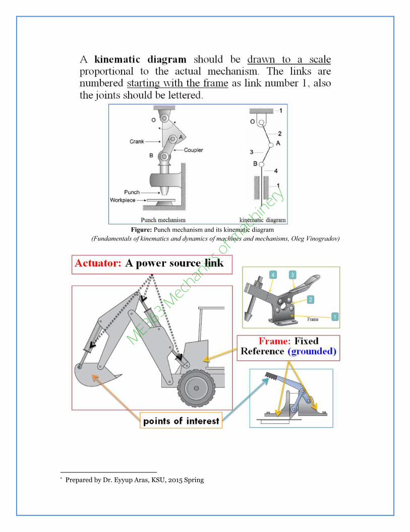
Figure: Punch mechanism and its kinematic diagram
(Fundamentals of kinematics and dynamics of machines and mechanisms, Oleg Vinogradov)
∗
∗ Prepared by Dr. Eyyup Aras, KSU, 2015 Spring
ME3
63 Mec
hanics
of m
achin
ery

(Machines & Mechanisms, David H. Myszka, Fourth Edition)
∗
∗ Prepared by Dr. Eyyup Aras, KSU, 2015 Spring
ME3
63 Mec
hanics
of m
achin
ery

(Design of Machinery, Robert L. Norton, Fourth Edition)
Example: The following figure shows a shear that is used to cut and trim electronic circuit board
laminates. Draw a kinematic diagram.
(Machines & Mechanisms, David H. Myszka, Fourth Edition)
s∗
1- Identify the frame: The large base that is bolted to the table can be chosen as the frame.
2- Identify all other links: Link 2: handle, Link3: Cutter, Link4: Bar that connects the cutter
with the handle
3- Identify the joints: Pin joints are used to connect (links 1 and 2), (links 2 and 3) and (Links 3
and 4). This joints are lettered A, B and C. The cutter slides up and down.
This sliding joint connects links (4 and 1), and is lettered D.
4- Identify any points of interest: The motion of the end of the handle is desired. Point of interest
is X.
5- Draw the kinematic diagram: the kinematic diagram is given as follows
∗ Prepared by Dr. Eyyup Aras, KSU, 2015, Spring
ME3
63 Mec
hanics
of m
achin
ery
Kinematic diagram of this example
(Machines & Mechanisms, David H. Myszka, Fourth Edition)
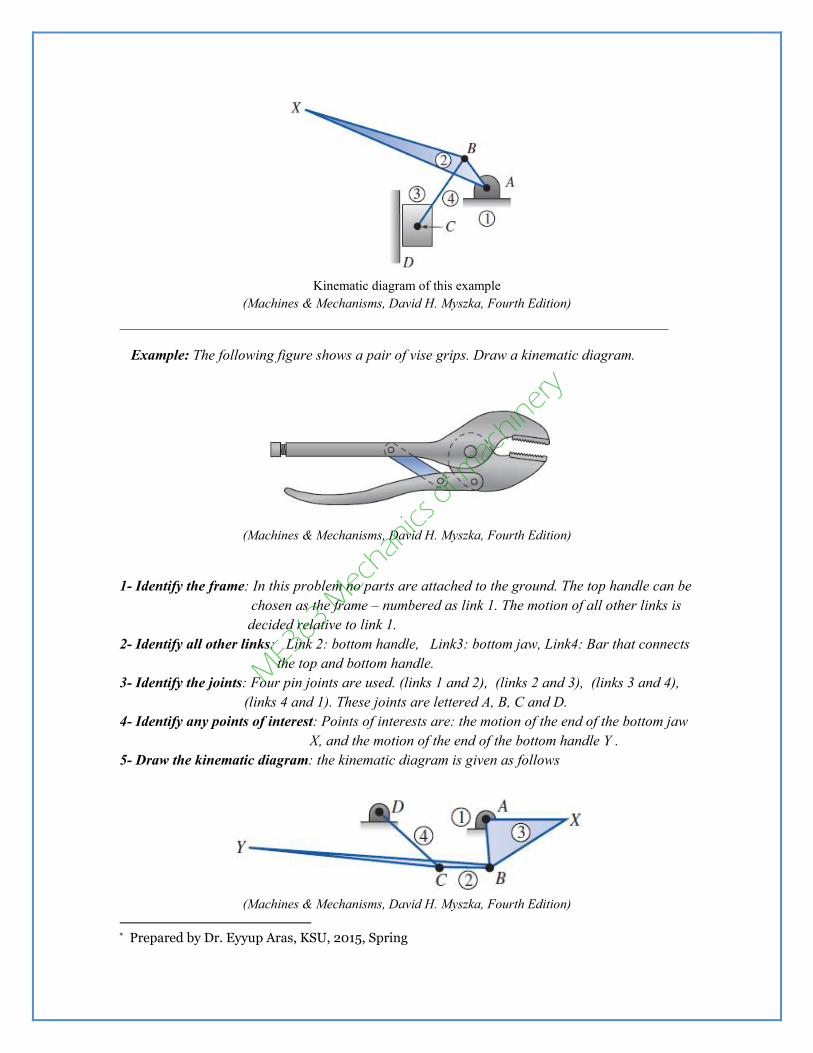
s∗Example: The following figure shows a pair of vise grips. Draw a kinematic diagram.
(Machines & Mechanisms, David H. Myszka, Fourth Edition)
1- Identify the frame: In this problem no parts are attached to the ground. The top handle can be
chosen as the frame – numbered as link 1. The motion of all other links is
decided relative to link 1.
2- Identify all other links: Link 2: bottom handle, Link3: bottom jaw, Link4: Bar that connects
the top and bottom handle.
3- Identify the joints: Four pin joints are used. (links 1 and 2), (links 2 and 3), (links 3 and 4),
(links 4 and 1). These joints are lettered A, B, C and D.
4- Identify any points of interest: Points of interests are: the motion of the end of the bottom jaw
X, and the motion of the end of the bottom handle Y .
5- Draw the kinematic diagram: the kinematic diagram is given as follows
(Machines & Mechanisms, David H. Myszka, Fourth Edition)
∗ Prepared by Dr. Eyyup Aras, KSU, 2015, Spring
ME3
63 Mec
hanics
of m
achin
ery

Exercises (all from Machines & Mechanisms, David H. Myszka, Fourth Edition)
1- A pair of pliers is sown in figure. Draw a kinematic diagram of the mechanism.
2- A mechanism is used to open the door of a heat-treating furnace is shown. Draw a kinematic
diagram of the mechanism. The end of the handle is a point of interest.
3- A sketch of a backhoe is shown in the figure. Draw a kinematic diagram of the mechanism.
s∗
∗ Prepared by Dr. Eyyup Aras, KSU, 2015, Spring
ME3
63 Mec
hanics
of m
achin
ery