MECHANICS OF MACHINERY
87
MECHANICS OF MACHINERY
-
Upload
khangminh22 -
Category
Documents
-
view
1 -
download
0
Transcript of MECHANICS OF MACHINERY

MECHANICS OF MACHINERY

Dynamics Kinematics:• It deals with the relative motions of different parts of a
mechanism without taking into consideration the forcesproducing the motions.
• Thus, it is the study, from a geometric point of view, to know
29-01-2019 2
• Thus, it is the study, from a geometric point of view, to knowthe displacement, velocity and acceleration of a part of amechanism.
Kinetics:• Studies the forces on the system which is in motion.• It deals with inertia forces which arises from the combined
effect of mass and motion of the machine parts

29-01-2019 3
Kinematics
Kinetics

Mechanism and MachineMechanism (a fundamental unit for kinematic study)
• If a number of bodies are assembled in such a way that themotion of one causes constrained and predictable motion tothe others, it is known as a mechanism.
29-01-2019 4
the others, it is known as a mechanism.• A mechanism transmits and modifies a motion.

Machine
• A machine is a mechanism or a combination of mechanismswhich, apart from imparting definite motions to the parts, alsotransmits and modifies the available mechanical energy into
29-01-2019 5
Mechanism and Machine
transmits and modifies the available mechanical energy intosome kind of desired work.

29-01-2019 6
Mechanism and Machine
Mechanisms
Can crusherSimple press
Rear-window wiper

29-01-2019 7
Machines
Bulldozer
Amusement Park Ride

29-01-2019 8
Machine Mechanism
Machine modifies mechanical workMechanism transmits and modifies
motion
Mechanism and Machine
A machine is a practical development of any mechanism
A mechanism is a part of a machine
A machine may have number of mechanism for transmitting mechanical
work or power
A mechanism is a skeleton outline of the machine to produce motion between
various links.

Terms and definitions
• Rigid body• A body is said to be rigid if it under the action of forces, it does not suffer
any distortion.• i.e , the distance between any points on the body remains constant
29-01-2019 9
• i.e , the distance between any points on the body remains constant
• Semi rigid body• Normally are flexible• Under loading condition acts as rigid body for limited purpose• Also called as resistant bodies• Eg. Belt under tension, fluid on compression

• Kinematic link
• A resistant body or a group of resistant bodies with rigid connections
preventing their relative movement is known as a link.
• It can be also defined as a member or a combination of members of a
mechanism, connecting other members and having motion relative to them
29-01-2019 10
• Links can be classified into binary, ternary and quaternary depending upon
their ends on which revolute or turning pairs can be placed
• It must contain two or more nodes

29-01-2019 11

• Joint• It is the connection between two or more links which allows some motion
between the connecting links.
• Kinematic pair• The two links or elements of a machine, when in contact with each other, are said
29-01-2019 12
Terms and definitions
• The two links or elements of a machine, when in contact with each other, are saidto form a pair.
• If the relative motion between them is completely or partially constrained (i.e. ina definite direction), the pair is known as kinematic pair.
The image cannot be displayed. Your computer may not have enough memory to open the image, or the image may have been corrupted. Restart your computer, and then open the file again. If the red x still appears, you may have to delete the image and then insert it again.

Constrained motion (or relative motion) can be broadly classified into three types.
• Completely constrained motion• Incompletely constrained motion• Partially (or successfully) constrained motion
• Completely constrained motion is a type of constrained motion in which relative motion between the links of a kinematic pair occurs in a definite direction by itself, irrespective of the external forces applied.
29-01-2019 13
itself, irrespective of the external forces applied.• In incompletely constrained motion, the relative motion between the links
depend on the direction of external forces acting on them. • Motion of a shaft inside a circular hole. Depending on the direction of
external forces applied, the shaft may slide or turn (or do both) inside the circular hole
• A kinematic pair is said to be partially or successfully constrained if the relative motion between its links occurs in a definite direction, not by itself, but by some other means.• Piston reciprocating inside a cylinder in an internal combustion engine.

• Degree of freedom• Number independent motions(translational or rotary) required to
completely specify the relative movement of a pair.• If DOF = + ve (mechanism)• If DOF = zero (structure)
• Structure( statics)
29-01-2019 14
• Mechanism (kinematics)• Machine ( kinetics )
Classification of kinematic pair• Based on type of contact between the elements
• Point, line, surface
29-01-2019 15
• If the type contact is point or line type they are called as the higher pair• If the contact type is area or surface , they are called as lower pair

• Based on the nature of mechanical constraints• Closed pair- When the elements of a pair are held together mechanically.• Unclosed pair- When two links of a pair are in contact due to the force of
gravity or spring force
29-01-2019 16
Classification of kinematic pair
• All lower pair and some higher pairs are closed pair

• According to nature of relative motion
29-01-2019 17
Classification of kinematic pair
Sliding pair Turning pair

• According to nature of relative motion
29-01-2019 18
Classification of kinematic pair
Rolling pair
Screw pair
Spherical pair

• Based on degree of freedom• Degree of freedom of a pair is defined as the number of independent
relative motion, both translational and rotational
29-01-2019 19
Classification of kinematic pair
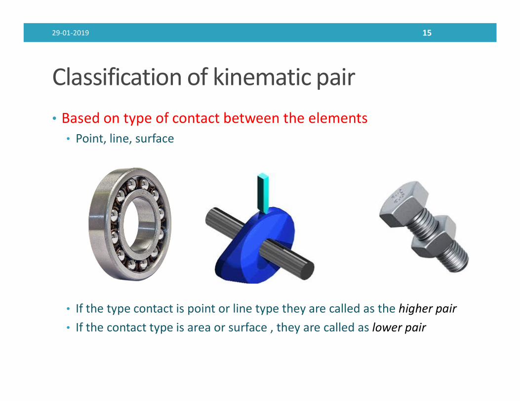
Classification of kinematic pairsa) Sphere- plane
No. of restraints= 1
Restraints on
Translatory motion= 1 Rotary motion=0
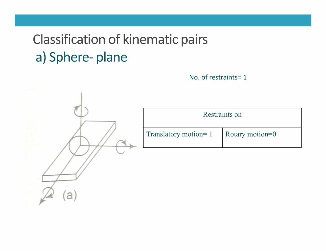
b) Sphere- cylinder
Restraints on
Translatory motion= 2 Rotary motion=0
No. of restraints= 2
Translatory motion= 2 Rotary motion=0

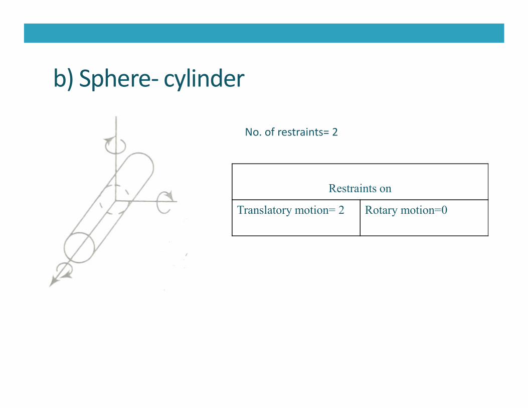
c) Cylinder- plane
Restraints on
Translatory motion= 1 Rotary motion=1
No. of restraints= 2
Translatory motion= 1 Rotary motion=1

d) Spheric
Restraints on
Translatory motion= 3 Rotary motion=0
No. of restraints= 3

e) Sphere- slotted cylinder
Restraints on
Translatory motion= 2 Rotary motion=1
No. of restraints= 3
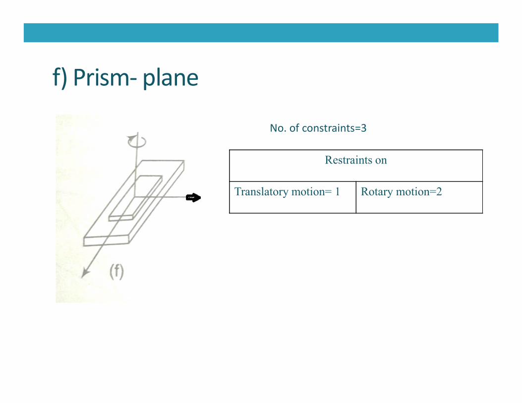
f) Prism- plane
Restraints on
Translatory motion= 1 Rotary motion=2
No. of constraints=3

g) Slotted- spheric
Restraints on
Translatory motion= 3 Rotary motion=1
No. of constraints=4

h) Cylinder
Restraints on
Translatory motion= 2 Rotary motion=2
No. of restraints=4

Degree of freedom for various joints
29-01-2019 28
Type of joint Nature of motion DOF
Hinges(Revolute) Turning 1
Slider Pure sliding 1
Cylindrical, cam , gear, ball bearing
Turning and slidingTurning and rolling
2
Rolling contact Pure rolling 1
Spheric 3

• Kinematic chain
• An assemblage of links and joints, interconnected in a way to provide acontrolled output motion in response to a supplied input motion.
• Motion of one link will create relative and definite motion on other link.
29-01-2019 29
• A redundant chain does not allow any motion of a link relative to theother.
• A kinematic chain with one link fixed is called as mechanism
• A redundant chain having one link fixed to ground is called structure

In short…..• A kinematic link is defined as a resistant body or a group of resistant
bodies with rigid connections preventing their relative movement.
• A kinematic pair is a joint of two links having relative motionbetween them.
29-01-2019 30
between them.
• A kinematic chain is an assembly of links in which the relativemotions of the links are possible and the motion of each relative tothe other is definite.
• If one of the links of a kinematic chain is fixed to the ground and themotions of any of the movable links results in definite motions ofothers, then it is known as mechanism.

• A mechanism may consist of a number of pairs belonging todiff. classes having different no. of restraints
• Ranging from single order mechanism (one restraints) to fifthorder(with five restraint)
• Sixth order mechanism is impossible
29-01-2019 31
Sixth order mechanism is impossible
• Mobility of a mechanism defines the number of degrees offreedom a mechanism posses.
• For space mechanism• F= 6(N-1) - 5 P1- 4P2- 3P3 - 2P4 – P5
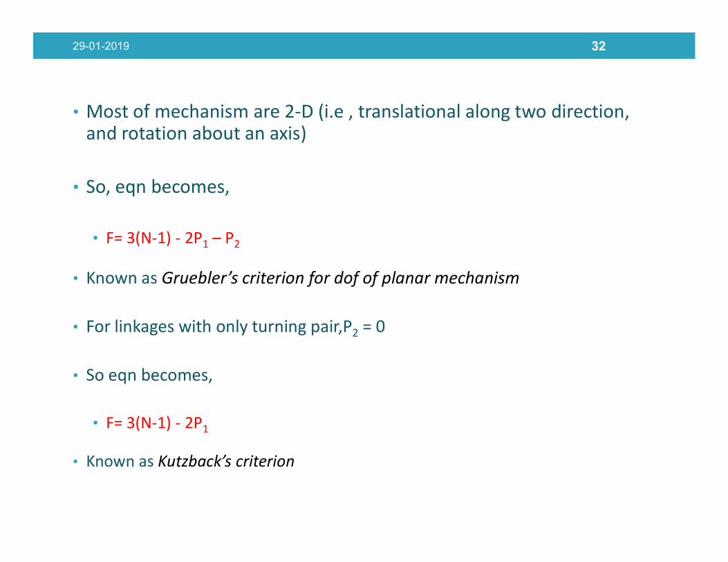
• Most of mechanism are 2-D (i.e , translational along two direction, and rotation about an axis)
• So, eqn becomes,
• F= 3(N-1) - 2P1 – P2
• Known as Gruebler’s criterion for dof of planar mechanism
29-01-2019 32
• Known as Gruebler’s criterion for dof of planar mechanism
• For linkages with only turning pair,P2 = 0
• So eqn becomes,
• F= 3(N-1) - 2P1
• Known as Kutzback’s criterion
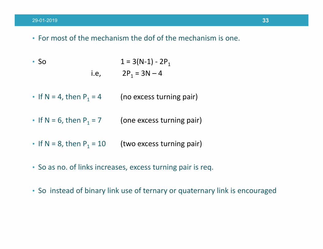
• For most of the mechanism the dof of the mechanism is one.
• So 1 = 3(N-1) - 2P1
i.e, 2P1 = 3N – 4
• If N = 4, then P1 = 4 (no excess turning pair)
• If N = 6, then P1 = 7 (one excess turning pair)
29-01-2019 33
If N = 6, then P1 = 7 (one excess turning pair)
• If N = 8, then P1 = 10 (two excess turning pair)
• So as no. of links increases, excess turning pair is req.
• So instead of binary link use of ternary or quaternary link is encouraged
29-01-2019 34
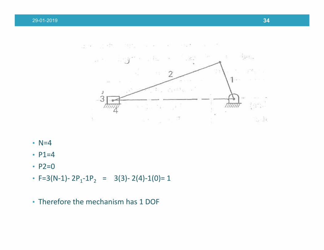
• N=4• P1=4• P2=0• F=3(N-1)- 2P1-1P2 = 3(3)- 2(4)-1(0)= 1
• Therefore the mechanism has 1 DOF

29-01-2019 35
• N=4• P1=3• P2=1• F=3(N-1)- 2P1-1P2 = 3(3)- 2(3)-1(1)= 2
• Therefore the mechanism has 2 DOF

29-01-2019 36
1
22

29-01-2019 37
3

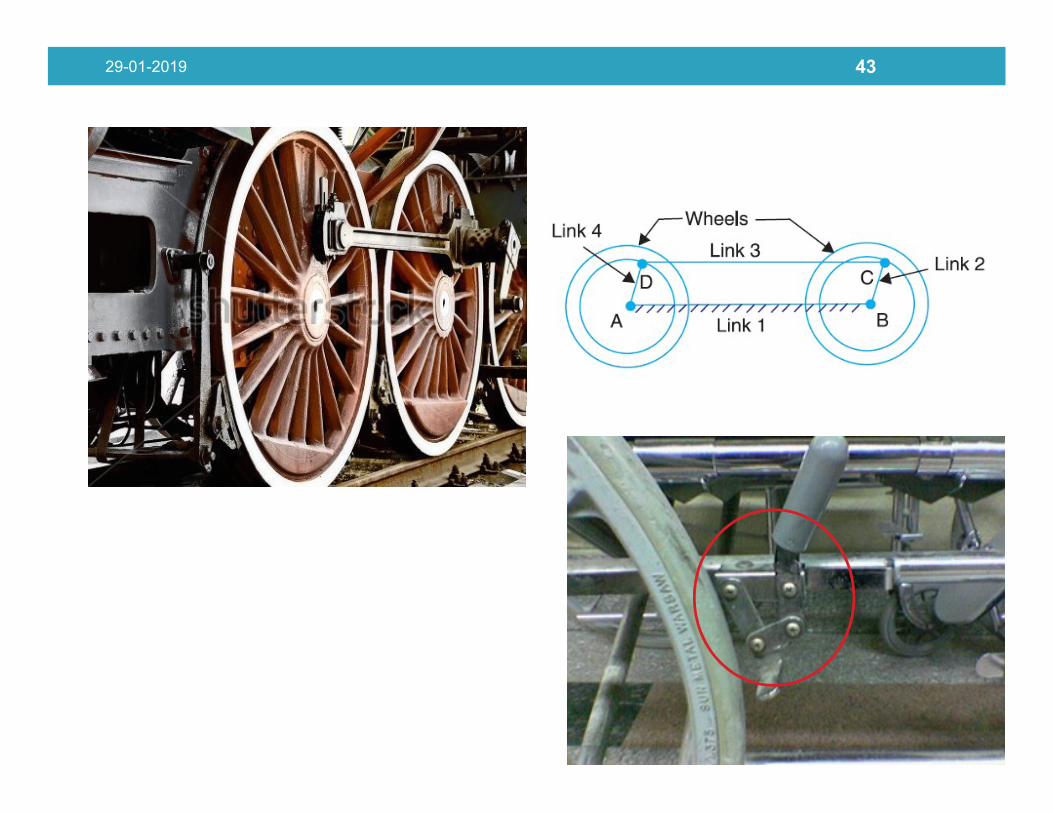
Four bar (link) mechanism
• Simple and versatile• Necessaties
• The length of longest link must be less than the sum of lengths of otherthree links.
• Grashof’s condition
29-01-2019 38
• Grashof’s condition• If (s + l) ≤ (a+b)• Then the linkage is grashof and at least one link may be capable of
complete revolution.• This is Class I Kinematic chain
• If not , its non- grashof known as
• Class II Kinematic chain

• Kinematic Inversions – Process of choosing different links of akinematic chain to be fixed or ground to obtain newmechanisms
• No of kinematic inversions is equal to no of links in the
29-01-2019 39
• No of kinematic inversions is equal to no of links in thekinematic chain
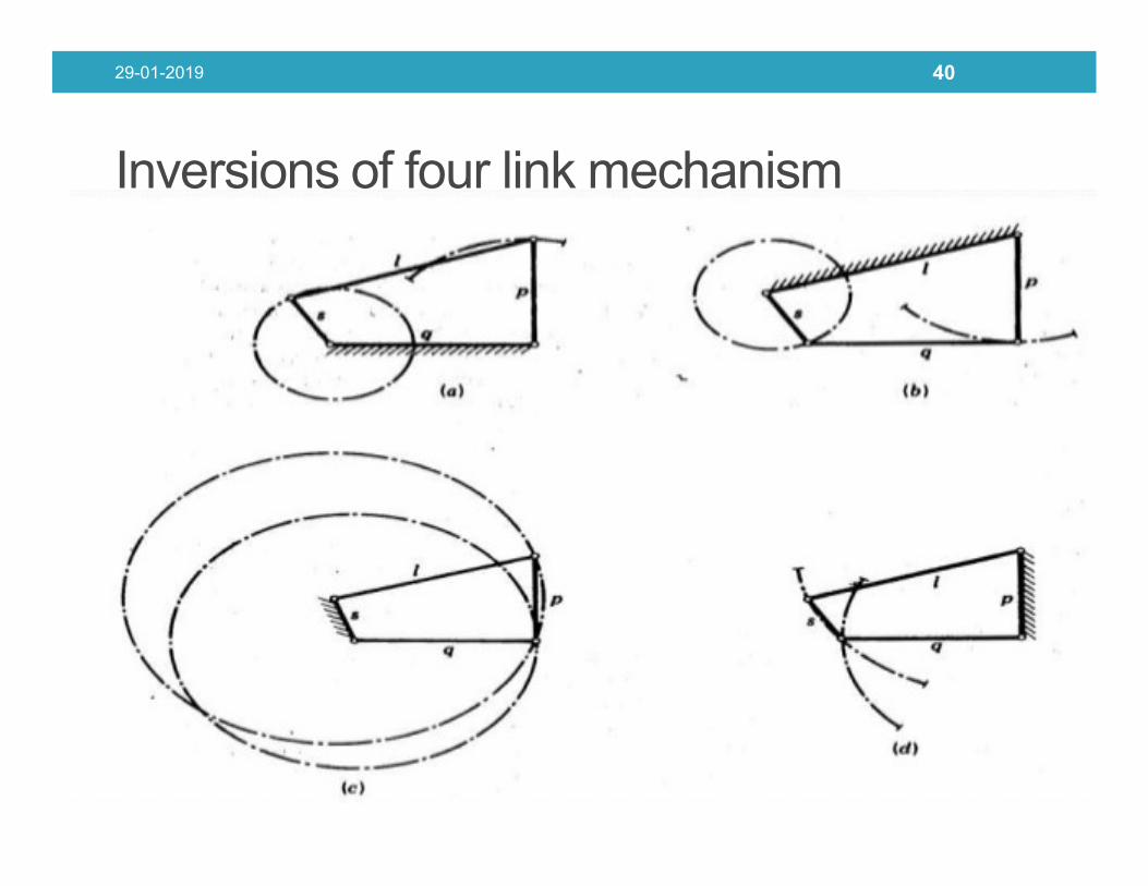
Inversions of four link mechanism
29-01-2019 40

29-01-2019 41
Oil pump

29-01-2019 42
29-01-2019 43
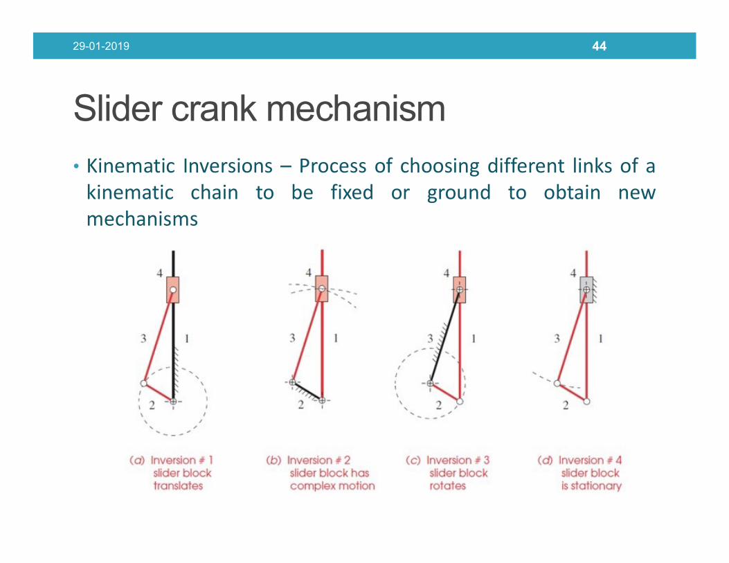
Slider crank mechanism
• Kinematic Inversions – Process of choosing different links of akinematic chain to be fixed or ground to obtain newmechanisms
29-01-2019 44
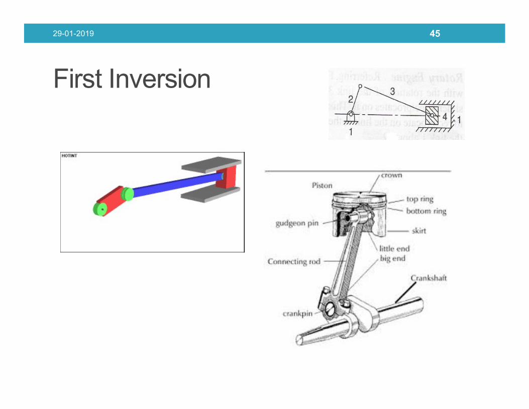
First Inversion
29-01-2019 45

Second inversion
29-01-2019 46
• Applications -• Whitworth Quick Return Mechanism
• Rotary Engine

• Rotary Engine
29-01-2019 47
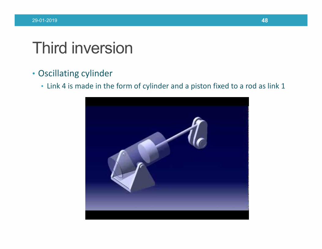
Third inversion
• Oscillating cylinder• Link 4 is made in the form of cylinder and a piston fixed to a rod as link 1
29-01-2019 48
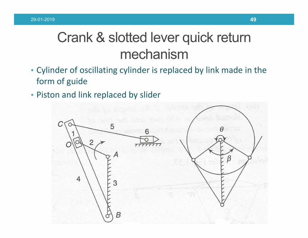
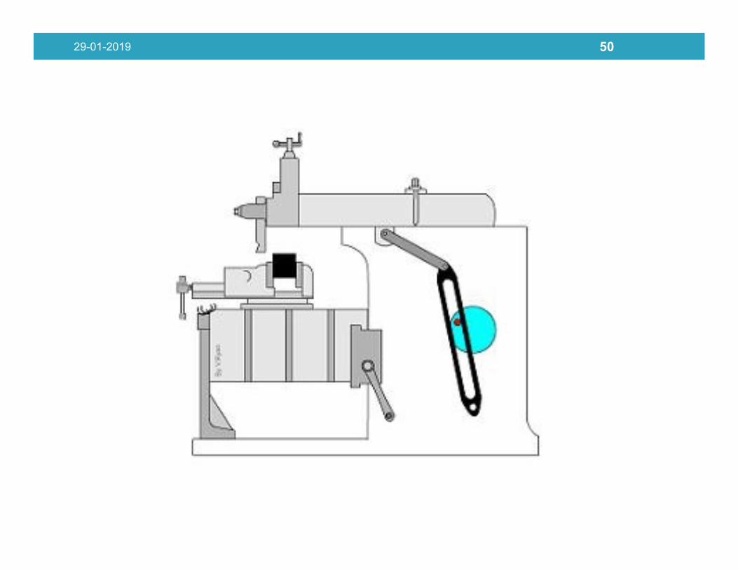
Crank & slotted lever quick return mechanism
• Cylinder of oscillating cylinder is replaced by link made in the form of guide
• Piston and link replaced by slider
29-01-2019 49
29-01-2019 50

Fourth inversion
29-01-2019 51
Fourth inversion is obtained by fixing link 4 of slider crank mechanism
Application: Hand pump

29-01-2019 52

29-01-2019 53

Whitworth quick return mechanism Crank and slotted lever mechanism
1. Crank of whitworth is longer than fixed link
1. Fixed link is longer than crank
2.The coupler link makes complete rotation about the pivot joint of fixed
2. Coupler link oscillates about the pivot
29-01-2019 54
rotation about the pivot joint of fixed link
pivot
3. For same dislacement, Coupler link connected to tool post is connected at the other side of main coupler link with respect to slider
3. Coupler link connected to tool post is connected at the same side of main coupler link with respect to slider, butafter the extreme position of slider

Double slider crank mechanism
• Four bar chain having two turning and sliding pairs such that
two pairs of the same kind are adjacent is known as double
slider crank chain
Link 4
Link 2
Link 3
Link 1
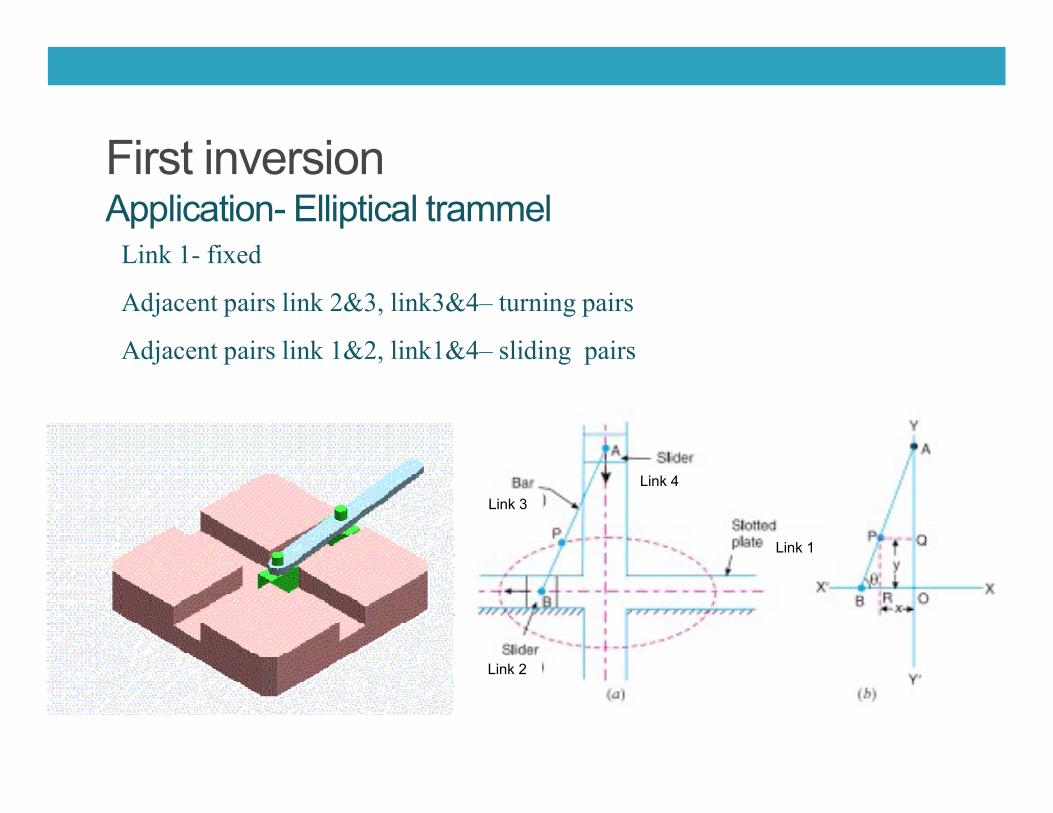
First inversionApplication- Elliptical trammel
Link 1- fixed
Adjacent pairs link 2&3, link3&4– turning pairs
Adjacent pairs link 1&2, link1&4– sliding pairs
Link 4
Link 2
Link 3
Link 1

Scotch yoke ( Second Inversion )• A scotch- yoke mechanism is used to convert the rotary motion to sliding motion.
• If any slide blocks of the first inversion is fixed second inversion is obtained
• As the crank 3 rotates the horizontal portion of the link 1 slides in the fixed link 4
• Used in control valve actuators in high pressure oil and gas pipe lines
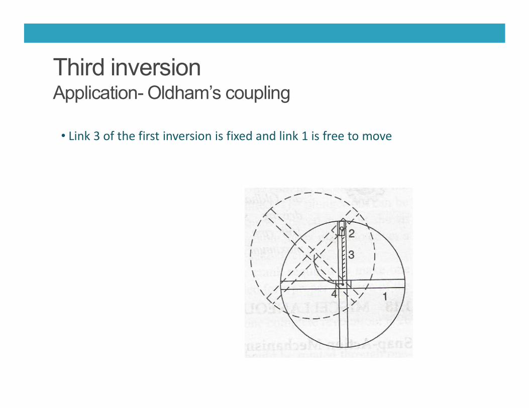
Third inversionApplication- Oldham’s coupling
• Link 3 of the first inversion is fixed and link 1 is free to move

Oldham’s coupling

Couplers curves
• For most of the mechanisms, output obtained from path traced by points on coupler link.
29-01-2019 60

Couplers curves
29-01-2019 61

APPROXIMATE STRAIGHT LINE MECHANISM(a) Watt’s Straight Line Mechanism (1784)
• Link AB & DE act as levers and ends A & E are fixed.
• On small displacement of the mechanism, the tracing point P traces the shape
of number 8 , a portion of which will be approximately straight , and hence also
an example for approximate straight line mechanism
L1:L2:L3 = 2:1:2

(b) Chebyshev linkage
•The Chebyshev linkage is a mechanical linkage that converts rotational motion to
approximate straight-line motion
•It was invented by the 19th century mathematician Pafnuty Chebyshev who studied
theoretical problems in kinematic mechanisms
L1:L2:L3:L4 = 4:5:2:5

(c) Hoekens linkage
•The Hoekens linkage is a four-bar mechanism that converts rotational
motion to approximate straight-line motion with approximate constant
velocity.
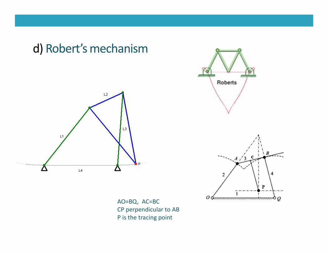
d) Robert’s mechanism
AO=BQ, AC=BCCP perpendicular to AB P is the tracing point

ACCURATE STRAIGHTLINE MECHANISM

Peaucellier–Lipkin linkage
The Peaucellier–Lipkin linkage invented in 1864, was the first
planar linkage capable of transforming rotary motion into
perfect straight-line motion and vice versa

Hart Mechanism
•O O1 is the fixed link•O1Q is the rotating link•Point Q moves in a circle with O1 and radius O1Q•ABCD is a trapezium so that AB=CD; BD parallel to AC•BO/BA= BQ/BC=DP/DA•Point P describes the straight line perpendicular to OO1

Scott- Russel Mechanism
OB=BS=BCCO perpendicular to OSS moves in a straight line along OS

INTERMITTENT MOTION MECHANISM

Ratchets and Escapements
•There are different forms of ratchets and escapements used in engineeringpractices•They are used in locks, clock works, jacks and many other mechanismrequiring some form of intermittent motion
Fig (a) shows one kind of ratchets which allowsthe motion of the gear in one direction

Above figure is an example for deadbeat escapement usedcommonly in pendulum clocks

A gravity escapement uses a small weight or a weak spring togive an impulse directly to the pendulum

Grass hopper escapement

Geneva mechanism
•It is an intermittent motion mechanism•Consists of a driving wheel D carrying a pin P which engages in a slot of the follower F•During one quarter revolution of the driving plate, the pin and follower remain incontact and hence the follower is turned by one quarter turn•During the remaining time of one revolution of the driver , the follower remains at restlocked in position by the circular arc

Steering gear mechanism
Fundamental Equation of Correct Steering

Types of Steering Gear
•Davis steering gear (which has sliding pairs)
•Ackermann steering gear (which has turning pairs)
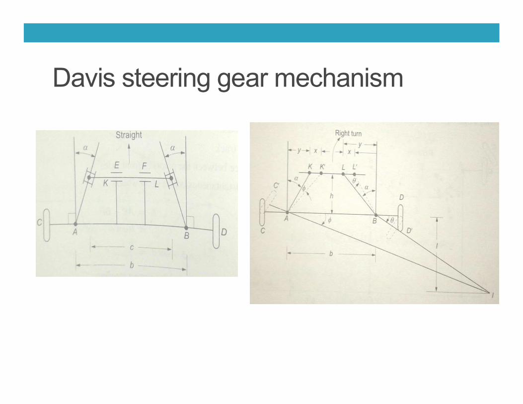
Davis steering gear mechanism

11
29-01-2019 79

29-01-2019 80

Ackermann steering gear
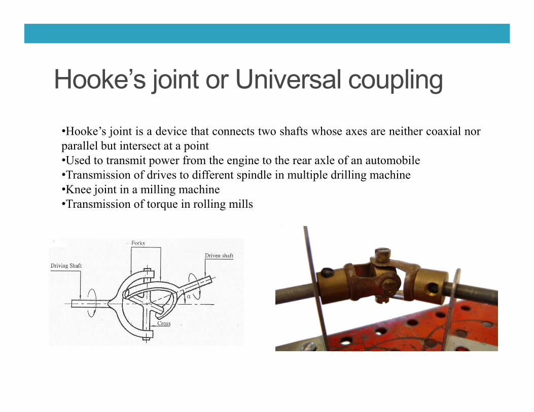
Hooke’s joint or Universal coupling
•Hooke’s joint is a device that connects two shafts whose axes are neither coaxial norparallel but intersect at a point•Used to transmit power from the engine to the rear axle of an automobile•Transmission of drives to different spindle in multiple drilling machine•Knee joint in a milling machine•Transmission of torque in rolling mills•Transmission of torque in rolling mills

Hooke’s joint or Universal coupling
• When driver shaft rotates with uniform speed,• The driven shaft rotates at continuously varying speed
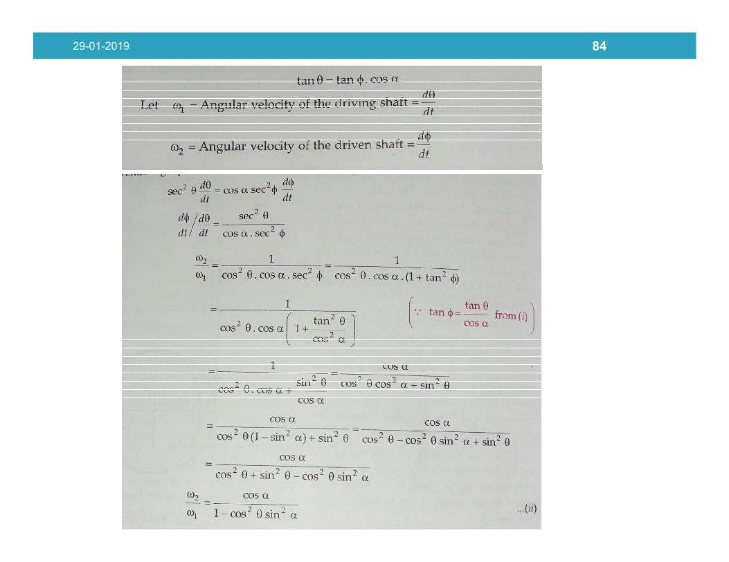
29-01-2019 84
• As a mechanism moves over a range of motion its geometry changes. If we are usinga mechanisms to transmit torque, or force then we must consider the ratio betweenthe input and output force in various positions.
• Mechanical Advantage• The advantage gained by the use of a mechanism in transmitting force• The ratio of the force that performs the useful work of a machine to the force
that is applied to the machine
• Transmission angle• Transmission angle is the angle between the coupling member and the
29-01-2019 85
• Transmission angle is the angle between the coupling member and theoutput member in a mechanism.
• As this angle approaches ±90°, the mechanical advantage of the mechanismtypically increases.
• Toggle position• Toggle positions occur when the mechanical advantage has near infinite.• Mechanisms which utilizes this is position is called as toggle mechanism.• Used for stone crushers

• PANTOGRAPH
29-01-2019 86
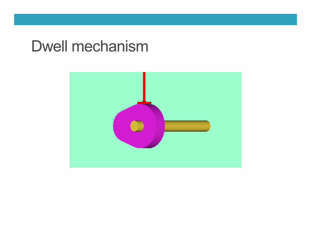
Dwell mechanism