KINEMATICS OF MACHINERY - ReferenceGlobe
94
SCCE MECH SHASHIKANTH KINEMATICS OF MACHINERY NOTES AS PER JNTUH BY Dr CH.SHASHIKANTH DEPARTMENT OF MECHANICAL ENGINEERING SREE CHAITANYA COLLEGE OF ENGINEERING KARIMNAGAR
-
Upload
khangminh22 -
Category
Documents
-
view
2 -
download
0
Transcript of KINEMATICS OF MACHINERY - ReferenceGlobe

SCCE MECH
SHASHIKANTH
KINEMATICS OF MACHINERY NOTES AS PER JNTUH BY Dr CH.SHASHIKANTH
DEPARTMENT OF MECHANICAL ENGINEERING
SREE CHAITANYA COLLEGE OF ENGINEERING
KARIMNAGAR

SCCE MECH
SHASHIKANTH
UNIT: 1
MECHANISMS
Machine Structure – Kinematic link, pair and chain – Grueblers criteria – Constrained motion
– Degrees of freedom - Slider crank and crank rocker mechanisms – Inversions – Applications –
Kinematic analysis of simple mechanisms – Determination of velocity and acceleration.
INTRODUCTION:
DEFINITION
The subject Theory of Machines may be defined as that branch of Engineering-
science, which deals with the study of relative motion between the various parts of a machine, and
forces which act on them. The knowledge of this subject is very essential for an engineer in designing
the various parts of machine.
The Theory of Machines may be sub-divided into the following four branches :
1. Kinematics. It is that branch of Theory of Machines which deals with the relative motion between
the
various parts of the machines’
2. Dynamics. It is that branch of Theory of Machines which deals with the forces and their effects,
while acting
upon the machine parts in motion.
3. Kinetics. It is that branch of Theory of Machines which deals with the inertia forces which arise
from the combined effect of the mass and motion of the machine parts.
4. Statics. It is that branch of Theory of Machines which deals with the forces and their effects while
the ma chine parts are at rest. The mass of the parts is assumed to be negligible.
Machine:
A machine consists of a number of parts or bodies we shall study the mechanisms of the
various parts or bodies from which the machine is assembled. This is done by making one of the parts
as fixed, and the relative motion of other parts is determined with respect to the fixed part.
Structure:
It is an assemblage of a number of resistant bodies (known as members) having no relative
motion between them and meant for carrying loads having straining action. A railway bridge, a roof
truss, machine frames etc., are the examples of a structure.
Kinematic link:
Each part of a machine, which moves relative to some other part, is known as a kinematic link
(or simply link) or element. A link may consist of several parts, which are rigidly fastened together,
so that they do not move relative to one another. For example, in a reciprocating steam engine piston,
piston rod and crosshead constitute one link ; connecting rod with big and small end bearings

SCCE MECH
SHASHIKANTH
constitute a second link ; crank, crank shaft and flywheel a third link and the cylinder, engine frame
and main bearings a fourth link.
A link or element need not to be a rigid body, but it must be a resistant body. A body is said to be a
resistant body if it is capable of transmitting the required forces with negligible deformation. Thus a
link should have the following two characteristics:
1. It should have relative motion, and
2. It must be a resistant body.
Types of Links:
In order to transmit motion, the driver and the follower may be connected by the following
three types of links:
1. Rigid link. A rigid link is one which does not undergo any deformation while transmitting motion.
Strictly speaking, rigid links do not exist. However, as the deformation of a connecting rod, crank etc.
of a reciprocating steam engine is not appreciable, they can be considered as rigid links.
2. Flexible link. A flexible link is one which is partly deformed in a manner not to affect
the transmission of motion. For example, belts, ropes, chains and wires are flexible links and transmit
tensile forces only.
3. Fluid link. A fluid link is one which is formed by having a fluid in a receptacle and the
motion is transmitted through the fluid by pressure or compression only, as in the case of hydraulic
presses, jacks and brakes.
kinematic Pair:
The two links or elements of a machine, when in contact with each other, are said to form
a pair. If the relative motion between them is completely or successfully constrained (i.e. in a definite
direction), the pair is known as kinematic pair. Let us discuss the various types of constrained
motions.
Classification of Kinematic Pairs:
The kinematic pairs may be classified according to the following considerations:
1. According to the type of relative motion between the elements.

SCCE MECH
SHASHIKANTH
The kinematic pairs according to type of relative motion between the elements may be
classified as discussed below:
(a) Sliding pair. When the two elements of a pair are connected in such a way that one can only slide
relative to the other, the pair is known as a sliding pair. The piston and cylinder, cross-head and
guides of a reciprocating steam engine, ram and its guides in shaper, tail stock on the lathe bed etc.
are the examples of a sliding pair. A little consideration will show that a sliding pair has a completely
constrained motion.
(b) Turning pair. When the two elements of a pair are connected in such a way that one can only
turn or revolve about a fixed axis of another link, the pair is known as turning pair. A shaft with
collars at both ends fitted into a circular hole, the crankshaft in a journal bearing in an engine, lathe
spindle supported in head stock, cycle wheels turning over their axles etc. are the examples of a
turning pair. A turning pair also has a completely constrained motion.
(c) Rolling pair. When the two elements of a pair are connected in such a way that one rolls over
another fixed link, the pair is known as rolling pair. Ball and roller bearings are examples of rolling
pair.
(d) Screw pair. When the two elements of a pair are connected in such a way that one element can
turn about the other by screw threads, the pair is known as screw pair. The lead screw of a lathe with
nut, and bolt with a nut are examples of a screw pair.
(e) Spherical pair. When the two elements of a pair are connected in such a way that one element
(with spherical shape) turns or swivels about the other fixed element, the pair formed is called a
spherical pair. The ball and socket joint, attachment of a car mirror, pen stand etc., are the examples
of a spherical pair.
2. According to the type of contact between the elements. The kinematic pairs according to the type
of contact between the elements may be classified as discussed below:
(a) Lower pair. When the two elements of a pair have a surface contact when relative motion takes
place and the surface of one element slides over the surface of the other, the pair formed is known as
lower pair. It will be seen that sliding pairs, turning pairs and screw pairs form lower pairs.
(b) Higher pair. When the two elements of a pair have a line or point contact when relative motion
takes place and the motion between the two elements is partly turning and partly sliding, then the pair
is known as higher pair. Pair of friction discs, toothed gearing, belt and rope drives, ball and roller
bearings and cam and follower are the examples of higher pairs.
3. According to the type of closure. The kinematic pairs according to the type of closure between the
elements may be classified as discussed below:
(a) Self closed pair. When the two elements of a pair are connected together mechanically in such a
way that only required kind of relative motion occurs, it is then known as self closed pair. The lower
pairs are self closed pair.
(b) Force - closed pair. When the two elements of a pair are not connected mechanically but are kept
in contact by the action of external forces, the pair is said to be a force-closed pair. The cam and
follower is an example of force closed pair, as it is kept in contact by the forces exerted by spring and
gravity.
Kinematic Chain:
When the kinematic pairs are coupled in such a way that the last link is joined to the first

SCCE MECH
SHASHIKANTH
link to transmit definite motion (i.e. completely or successfully constrained motion), it is called a
kinematic chain. In other words, a kinematic chain may be defined as a combination of kinematic
pairs, joined in such a way that each link forms a part of two pairs and the relative motion between
the links or elements is completely or successfully constrained. For example, the crank- shaft of an
engine forms a kinematic pair with the bearings which are fixed in a pair, the connecting rod with the
crank forms a second kinematic pair, the piston with the connecting rod forms a third pair and the
piston with the cylinder forms a fourth pair. The total combination of these links is a kinematic chain.
If each link is assumed to form two pairs with two adjacent links, then the relation between
the number of pairs ( p ) forming a kinematic chain and the number of links ( l ) may be expressed in
the form of an equation :
l = 2 p – 4
. . . (i)
Since in a kinematic chain each link forms a part of two pairs, therefore there will be as many links
as the number of pairs.
Another relation between the number of links (l) and the number of joints ( j ) which
constitute a kinematic chain is given by the expression :
The equations (i) and (ii) are applicable only to kinematic chains, in which lower pairs are used.
These equations may also be applied to kinematic chains, in which higher pairs are used. In that
case each higher pair may be taken as equivalent to two lower pairs with an additional element or
link.
Let us apply the above equations to the following cases to determine whether each of
them is a kinematic chain or not.
1. Consider the arrangement of three links A B, BC and C A with pin joints aA,B and C.
Number of links, l = 3
Number of pairs, p=3
and number of joints, j = 3
From equation (i), l=2p-3
3=2*3-4=2
L.H.S. > R.H.S
Now from equation (ii),`

SCCE MECH SHASHIKANTH
i.e. L.H.S. > R.H.S
Mechanism
When one of the links of a kinematic chain is fixed, the chain is known as mechanism. It
may be used for transmitting or transforming motion e.g. engine indicators, typewriter etc
A mechanism with four links is known as simple mechanism, and the mechanism with
more than four links is known as compound mechanism. When a mechanism is required to
transmit power or to do some particular type of work, it then becomes a machine. In such cases, the
various links or elements have to be designed to withstand the forces (both static and kinetic) safely.
A little consideration will show that a mechanism may be regarded as a machine in which each part
is reduced to the simplest form to transmit the required motion.
Forces Acting in a Mechanism
Consider a mechanism of a four bar chain, as shown in Fig. Let force FA newton is acting at the
joint A in the
direction of the velocity of A (vAm/s) which is perpendicular to the link D A. Suppose a force FB
newton is transmitted to the joint B in the direction of the velocity of B (i.e. vB m/s) which is
perpendicular to the link CB. If we neglect
the effect of friction and the change of kinetic energy of the link (i.e.), assuming the efficiency of
transmission as 100%), then by the principle of conservation of energy,

SCCE MECH SHASHIKANTH
Types of Kinematic Chains
The most important kinematic chains are those which consist of four lower pairs, each pair
being a sliding pair or a turning pair. The following three types of kinematic chains with four lower
pairs are important from the subject point of view
1. Four bar chain or quadric cyclic chain,
2. Single slider crank chain, and
3. Double slider crank chain.
These kinematic chains are discussed, in detail, in the following articles
Four Bar Chain or Quadric Cycle Chain
We have already discussed that the kinematic chain is a combination of four or more
kinematic pairs, such that the relative motion between the links or elements is completely
constrained. The simplest and the basic kinematic chain is a four bar chain or quadric cycle chain. It
consists of four links, each of them forms a turning pair at A, B, C and D. The four links may be of
different lengths. According to Grashof ’s law for a four bar mechanism, the sum of the shortest
and longest link lengths should not be greater than the sum of the remaining two link lengths if
there is to be continuous relative motion between the two links.
A very important consideration in designing a mechanism is to ensure that the input
crank makes a complete revolution relative to the other links. The mechanism in which no link
makes a complete revolution will not be useful. In a four bar chain, one of the links, in particular the
shortest link, will make a complete revolution relative to the other three links, if it satisfies the
Grashof ’s law. Such a link is known as crank or driver. A D (link 4) is a crank. The link BC (link
2) which makes a partial rotation or oscillates is known as lever or rocker or follower and the link
CD (link 3) which connects the crank and lever is called connecting rod or coupler. The fixed link
A B (link 1) is known as frame of the mechanism. When the crank (link 4) is the driver, the
mechanism is transforming rotary motion into oscillating motion.

SCCE MECH SHASHIKANTH
Single Slider Crank Chain
A single slider crank chain is a modification of the basic four bar chain. It consist of one sliding
pair and three turning pairs. It is, usually, found in reciprocating steam engine mechanism. This type
of mechanism converts rotary motion into reciprocating motion and vice versa. In a single slider
crank chain, as shown the links 1 and 2, links 2 and 3, and links 3 and 4 form three turning pairs
while the links 4 and 1 form a sliding pair.
The link 1 corresponds to the frame of the engine, which is fixed. The link 2 corresponds to
the crank ; link 3 corresponds to the connecting rod and link 4 corresponds to cross-head. As the
crank rotates, the cross-head reciprocates in the guides and thus the piston reciprocates in the
cylinder.
Double Slider Crank Chain
A kinematic chain which consists of two turning pairs and two sliding pairs is known as
double slider crank chain. We see that the link 2 and link 1 form one turning pair and link 2 and
link 3 form the second turning pair. The link 3 and link 4 form one sliding pair and link 1 and link 4
form the second sliding pair.
Grubler’s Criterion for Plane Mechanisms:
The Grubler’s criterion applies to mechanisms with only single degree of freedom joints
where the overall movability of the mechanism is unity. Substituting n = 1 and h = 0 in Kutzbach
equation, we have
1 = 3 (l – 1) – 2 j or 3l – 2j – 4 = 0
This equation is known as the Grubler's criterion for plane mechanisms with constrained motion.
A little consideration will show that a plane mechanism with a movability of 1 and only single
degree of freedom joints cannot have odd number of links. The simplest possible mechanisms of
this type are a four bar mechanism and a slider-crank mechanism in which l = 4 and j = 4
Types of Constrained Motions:
Following are the three types of constrained motions:
1. Completely constrained motion. When the motion between a pair is limited to a
definite direction irrespective of the direction of force applied, then the motion is said to be a
completely constrained motion. For example, the piston and cylinder (in a steam engine) form a pair
and the motion of the piston is limited to a definite direction (i.e. it will only reciprocate) relative to
the cylinder irrespective of the direction of motion of the crank. The motion of a square bar in a
square hole, and the motion of a shaft with collars at each end in a circular hole, are also examples
of completely constrained motion.
2. Incompletely constrained motion. When the motion between a pair can take place in more
than one direction, then the motion is called an incompletely constrained motion. The change in the
direction of impressed force may alter the direction of relative motion between the pair. A circular
bar or shaft in a circular hole, is an example of an incompletely constrained motion as it may either
rotate or slide in a hole. These both motions have no relationship with the other.
3. Successfully constrained motion. When the motion between the elements, forming a
pair, is such that the constrained motion is not completed by itself, but by some other means, then

SCCE MECH SHASHIKANTH
the motion is said to be successfully constrained motion. Consider a shaft in a foot-step bearing.
The shaft may rotate in a bearing or it may move upwards. This is a case of incompletely con
strained motion. But if the load is placed on the shaft to prevent axial upward movement of the
shaft, then the motion of the pair is said to be successfully constrained motion. The motion of an
I.C. engine valve (these are kept on their spring) and the piston reciprocating inside an engine
cylinder seat by a are also the examples of successfully constrained motion.
Degrees of Freedom for Plane Mechanisms:
In the design or analysis of a mechanism, one of the most important concern is the
number of degrees of freedom (also called movability) of the mechanism. It is defined as the
number of input parameters (usually pair variables) which must be independently controlled in order
to bring the mechanism into a useful engineering purpose. It is possible to determine the number of
degrees of
freedom of a mechanism directly from the number of links and the number and types of joints
which it includes.
Consider a four bar chain, as shown in Fig., A little consideration will show that only one variable
such as ϴ is needed to define the relative positions of all the links. In other words, we say that the
number of degrees of freedom of a four bar chain is one. Now, let us consider a five bar chain, as
shown in Fig., In this case two variables such as ϴ1 and ϴ2 are needed to define completely the
relative positions of all the links. Thus, we say that the number of degrees of freedom is * two.
In order to develop the relationship in general, consider two links A B and CD in a plane motion as
shown in fig i.

SCCE MECH SHASHIKANTH
The link AB with co-ordinate system O X Y is taken as the reference link (or fixed link). The
position of point P on the moving link CD can be completely specified by the three variables, i.e.
the co-ordinates of the point P denoted by x and y and the inclination θ of the link CD with X-axis
or link A B. In other words, we can say that each link of a mechanism has three degrees of freedom
before it is connected to any other link. But when the link CD is connected to the link A B by a
turning pair at A , the position of link CD is now determined by a single variable θ and thus has one
degree of freedom.
Slider crank–crank rocker mechanism:
A slider –mechanism in which OA is the crank moving with uniform angular velocity in the
clockwise direction. At point B, a slider moves on the fixed guide G. AB is the coupler joining A at
B. It is required to find the velocity of the slider at B.
Writing the velocity vector equation,
Vel. of B rel. to O = vel. Of B to A + vel. Of A rel. to O
Vbo= vba+vao; vbg=vao+vba
Vbo is replaced by vbg as O and G are two points on fixed link with zero relative between them.
Take the vector vao which is completely known.
Vao= ὼ.OA; ┴ to OA
Vba is ┴ AB, draw a line ┴ AB through a;
Through g draw a line parallel to the motion of B. the intersection of the two lines locates the point
b.
For the given configuration, the coupler AB has angular velocity in the counter- clockwise
direction, the magnitude being vba/ BA.
INVERSION:
We have already discussed that when one of links is fixed in a kinematic chain, it is called a
mechanism. So we can obtain as many mechanisms as the number of links in a kinematic chain by
fixing, in turn, different links in a kinematic chain. This method of obtaining different mechanisms
by fixing different links in a kinematic chain, is known as inversion of the mechanism.
It may be noted that the relative motions between the various links is not changed in any manner
through the process of inversion, but their absolute motions (those measured with respect to the
fixed link) may be changed drastically.

SCCE MECH SHASHIKANTH
APPLICATIONS:
INVERSIONS OF FOUR BAR CHAIN
Though there are many inversions of the four bar chain, yet the following are important from the
subject point of view :
1. Beam engine (crank and lever mechanism)
A part of the mechanism of a beam engine (also known as crank and lever mechanism) which
consists of four links . In this mechanism, when the crank rotates about the fixed centre A, the lever
oscillates about a fixed centre D. The end E of the lever CDE is connected to a piston rod which
reciprocates due to the rotation of the crank. In other words, the purpose of this mechanism is to
convert rotary motion into reciprocating motion.
2. Coupling rod of a locomotive (Double crank mechanism).
The mechanism of a coupling rod of a locomotive (also known as double crank
mechanism) which consists of four links. In this mechanism, the links AD and BC (having equal
length) act as cranks and are connected to the respective wheels. The link CD acts as a coupling rod
and the link A B is fixed in order to maintain a constant centre to centre distance between them. This
mechanism is meant for transmitting rotary motion from one wheel to the other wheel.
INVERSIONS OF SINGLE SLIDER CRANK CHAIN:
We have seen in the previous article that a single slider crank chain is a four-link
mechanism. We know that by fixing, in turn, different links in a kinematic chain, an inversion is
obtained and we can obtain as many mechanisms as the links in a kinematic chain. It is thus
obvious, that four inversions of a single slider crank chain are possible. These inversions are found
in the following
Mechanisms.
Pendulum pump or Bull engine.
In this mechanism, the inversion is obtained by fixing the cylinder or link 4 (i.e. sliding pair). In this
case, when the crank (link 2) rotates, the connecting rod (link 3) oscillates about a pin pivoted to the
fixed link 4 at A and the piston attached to the piston rod (link 1) reciprocates. The duplex pump
which is used to supply feed water to boilers have two pistons attached to link 1.
Crank and slotted lever quick return motion mechanism:
This mechanism is mostly used in shaping machines, slotting machines and in rotary internal
combustion engines. this mechanism, the link AC (i.e. link 3) forming the turning pair is fixed, The
link 3 corresponds to the connecting rod of a reciprocating steam engine. The driving crank CB
revolves with uniform angular speed about the fixed centre C. A sliding block attached to the
crankpin at B slides along the slotted bar AP and thus causes AP to oscillate about the pivoted point
A . A short link PR transmits the motion from AP to the ram which carries the tool and reciprocates
along the line of stroke R1R2. The line of stroke of the ram (i.e. R1R2) is perpendicular to AC
produced.
In the extreme positions, AP1 and AP2 are tangential to the circle and the cutting tool is at the end

SCCE MECH SHASHIKANTH
of the stroke. The forward or cutting stroke occurs when the crank rotates from the position CB1 to
CB2 (or through an angle â) in the clockwise direction. The return stroke occurs when the crank
rotates from the position CB2 to CB1 (or through angle á)
in the clockwise direction. Since the crank has uniform angular speed.
INVERSIONS OF DOUBLE SLIDER CRANK CHAIN
The following three inversions of a double slider crank chain are important from the subject point of
view :
Elliptical trammels.
It is an instrument used for drawing ellipses. This inversion is obtained by fixing the
slotted plate (link 4),The fixed plate or link 4 has two straight grooves cut in it, at right angles to
each other. The link 1 and link 3, are known as sliders and form sliding pairs with link 4. The link A
B (link 2) is a bar which forms turning pair with links 1 and 3. When the links 1 and 3 slide along
their respective grooves, any point on the link 2 such as P traces out an ellipse on the surface of link
4, A little consideration will show that AP and BP are the semi-major axis and semi-minor axis of
the ellipse respectively.
METHODS FOR DETERMINING THE VELOCITY OF A POINT ON A LINK:
Though there are many methods for determining the velocity of any point on a link in a
mechanism whose direction of motion (i.e. path) and velocity of some other point on the same link
is known in magnitude and direction, yet the following two methods are important from the subject
point of view.
1. Relative velocity method, and
2. Instantaneous centre method.
Velocity in mechanisms (relative velocity method)
RELATIVE VELOCITY OF TWO BODIES MOVING IN STRAIGHT LINES
Here we shall discuss the application of vectors for the relative velocity of two bodies moving along
parallel lines
and inclined lines, as shown in Fig. 1 (a) and 2 (a)
respectively. Consider two bodies A and B moving along parallel lines in the same direction with
absolute velocities vAand
vB such that vA> vB, as shown in Fig. 1 (a). The relative velocity of A with respect to B ,
From Fig.1 (b), the relative velocity of A with respect to B (i.e. vAB) may be written in the vector
form as follows:

SCCE MECH SHASHIKANTH
Now consider the body B moving in an inclined direction as shown in Fig. 2 (a). The relative
velocity of A with respect to B may be obtained by the law of parallelogram of velocities or triangle
law of velocities. Take any fixed point o and draw vector oa to represent vA in magnitude and
direction to some suitable scale. Similarly, draw vector ob to represent vB in magnitude and
direction to the same scale. Then vector ba represents the relative velocity of A with respect to B as
shown in Fig. 2 (b). In the similar way as discussed above, the relative velocity of A with respect to
B,

SCCE MECH SHASHIKANTH
From above, we conclude that the relative velocity of point A with respect to B (vAB) and the
relative velocity of point B with respect A (vBA) are equal in magnitude but opposite in direction,
i.e.
Motion of a Link
Consider two points A and B on a rigid link A B, as
shown in Fig 3 (a). Let one of the extremities (B) of the link
move relative to A , in a clockwise direction. Since the distance from A to B remains the same,
therefore there can be no
relative motion between A and B, along the line A B. It is thus obvious, that the relative motion of B
with respect to A must be perpendicular to A B.
Hence velocity of any point on a link with respect to another point on the same link is always
perpendicular to the line joining these points on the configuration (or space) diagram.

SCCE MECH SHASHIKANTH
Thus, we see from equation (iii), that the point c on the vector ab divides it in the same ratio as C
divides the link A B.
Note: The relative velocity of A with respect to B is represented by ba, although A may be a fixed
point. The motion between A and B is only relative. Moreover, it is immaterial whether the link
moves about A in a clockwise direction or about B in a clockwise direction. Velocity of a Point on
a Link by Relative Velocity Method The relative velocity method is based upon the relative velocity
of the various points of the link as discussed in Art..3. Consider two points A and B on a link as
shown in Fig..4 (a). Let the absolute velocity of the point A i.e. vA is known in magnitude and
direction and the absolute velocity of the point B i.e. vB is known in direction only. Then the
velocity of B may be determined by drawing the velocity diagram as shown in Fig. 4 (b). The
velocity diagram is drawn as follows :
1. Take some convenient point o, known as the pole.
2. Through o, draw oa parallel and equal to vA, to some suitable scale.
3. Through a, draw a line perpendicular to A B of Fig. 4 (a). This line will represent the
velocity of B with respect to A , i.e. vBA.

SCCE MECH SHASHIKANTH
4. Through o, draw a line parallel to vBintersecting the line of vBA at b.
5. Measure ob, which gives the required velocity of point B ( vB), to the scale
Velocities in Slider Crank Mechanism
In the previous article, we have discused the relative velocity method for the velocity of any point
on a link, whose direction of motion and velocity of some other point on the same link is known.
The same method may also be applied for the velocities in a slider crank mechanism. A slider crank
mechanism is shown in Fig. 5 (a). The slider A is attached to the connecting rod A B. Let the radius
of crank OB be r and let it rotates in a clockwise direction, about the point O with uniform angular
velocity ὼ rad/s. Therefore, the velocity of B i.e. vB is known in magnitude and direction. The
slider reciprocates along the line of stroke A O. The velocity of the slider A (i.e. vA) may be
determined by relative velocity method as discussed below :
1. From any point o, draw vector ob parallel to the direction of vB (or perpendicular to OB) such
that ob = vB= ὼ.r, to some suitable scale, as shown in Fig. 5 (b).

SCCE MECH SHASHIKANTH
2. Since A B is a rigid link, therefore the velocity of A relative to B is perpendicular to A B. Now
draw vector ba perpendicular to A B to represent the velocity of A with respect to B i.e. vAB.
3. From point o, draw vector oa parallel to the path of motion of the slider A (which is along AO
only). The vectors ba and oa intersect at a. Now oa represents the velocity of the slider A i.e. vA, to
the scale. The angular velocity of the connecting rod A B (ὼAB) may be determined as follows:
The direction of vector ab (or ba) determines the sense of ὼAB which shows that it is
anticlockwise.
PROBLEMS:
Example 1.
In a four bar chain ABCD, AD is fixed and is 150 mm long. The crank AB is 40 mm long and
rotates at 120 r.p.m. clockwise, while the link CD = 80 mm oscillates about D. BC and AD are of
equal length. Find the angular velocity of link CD when angle BAD =60°.
GIVEN :
NBA=120 r.p.m
ὼ=2π×120/60
=12.568 rad/s
BAD =60°
CD = 80 mm
SOLUTION:
Since the length of crank A B = 40 mm = 0.04 m, therefore velocity of B with respect to A or
velocity of B, (because A is a fixed point),
vBA= vB=ὼBA× A B = 12.568 × 0.04 = 0.503 m/s
First of all, draw the space diagram to some suitable scale, as shown in Fig. 6 (a). Now the velocity
diagram, as shown in Fig. 6(b), is drawn as discussed below :

SCCE MECH SHASHIKANTH
1. Since the link A D is fixed, therefore points a and d are taken as one point in the velocity
diagram. Draw vector ab perpendicular to B A, to some suitable scale, to represent the velocity of B
with respect to A or simply velocity of B (i.e. vBA or vB) such that
Vector ab = vBA= vB= 0.503 m/s
2. Now from point b, draw vector bc perpendicular to CB to represent the velocity of C with respect
to B (i.e. vCB) and from point d, draw vector dc perpendicular to CD to represent the velocity of C
with respect to D or simply velocity of C (i.e. vCD or vC). The vectors bc and dc intersect at c.
By measurement, we find that
vCD= vC = vector dc = 0.385 m/s
we know that velocity of link CD,
RESULT:
ὼCD=4.8 rad/s
Example 2.
In Fig.7, the angular velocity of the crank OA is 600 r.p.m. Determine the linear velocity of the
slider D and the angular velocity of the link BD, when the crank is inclined at an angle of 75° to the
vertical. The dimensions of various links are : OA = 28 mm ; AB = 44 mm ; BC 49 mm ; and BD
= 46 mm. The centre distance between the centres of rotation O and C is 65 mm. The path of travel
of the slider is 11 mm below the fixed point C. The slider moves along a horizontal path and OC is
vertical.

SCCE MECH SHASHIKANTH
Given
NAO=600 r.p.m
AB = 44 mm
OA = 28 mm
BC = 49 mm
BD = 46 mm
ὼAO=2π×600/60=62.84 rad/s
Solution:
since OA=28mm=0.028, therefore velocity of A with respect of O or velocity of O (because O is a
fixed point),
VAO =VA =ὼAO× OA=62.84 ×0.028=1.76m/s
Linear velocity of the slider D
First of all draw the space diagram, to some suitable scale, as shown in Fig. 8 (a). Now the velocity
diagram, as shown in Fig. 8 (b), is drawn as discussed below :
1. Since the points O and C are fixed, therefore these points are marked as one point, in the velocity
diagram. Now from point o, draw vector oa perpendicular to O A, to some suitable scale, to
represent the velocity of A with respect to O or simply velocity of A such that
vector oa= vAO= vA = 1.76 m/s

SCCE MECH SHASHIKANTH
2. From point a, draw vector ab perpendicular to A B to represent the velocity of B with respect A
(i.e. vBA) and from point c, draw vector cb perpendicular to CB to represent the velocity of B with
respect to C or simply velocity of B (i.e. vBC or vB). The vectors ab and cb intersect at b.
3. From point b, draw vector bd perpendicular to BD to represent the velocity of D with respect to B
(i.e. vDB) and from point o, draw vector od parallel to the path of motion of the slider D which is
horizontal, to represent the velocity of D (i.e. vD). The vectors bd and od intersect at d.
By measurement, we find that velocity of the slider D,
vD= vector od = 1.6 m/s
Angular velocity of the link BD
By measurement from velocity diagram, we find that velocity of D with respect to B,
vDB= vector bd = 1.7 m/s
Since the length of link BD = 46 mm = 0.046 m, therefore angular velocity of the link BD,
RESULTS:
VD=1.6 m/s
ὼBD=36.96 rad/s
Example 3
In a mechanism shown in Fig. 9, the crank OA is 100 mm long and rotates clockwise about O at
120 r.p.m. The connecting rod AB is 400 mm long. At a point C on AB, 150 mm from A, the rod CE
350 mm long is attached. This rod CE slides

SCCE MECH SHASHIKANTH
in a slot in a trunnion at D. The end E is connected by a link EF, 300 mm long to the horizontally
moving slider F.
For the mechanism in the position shown, find 1. velocity of F, 2. velocity of sliding of CE .
Given:
VAO=120r.p.m
ὼAO=2π×120/60=4π rad/s
SOLUTION:
Since the length of crank O A = 100 mm= 0.1 m, therefore velocity of A with respect to O or
velocity of A (because O is a fixed point),
vAO= vA= ὼAO× O A = 4 π× 0.1 = 1.26 m/s
1. Velocity of F
First of all draw the space diagram, to some suitable scale, as shown in Fig. 10 (a). Now the velocity
diagram, as shown in Fig. 10 (b), is drawn as discussed below
1. Draw vector oa perpendicular to A O, to some suitable scale, to represent the velocity of A with
respect to O or simply velocity of A (i.e. vAOor vA), such that
vector oa= vAO= vA= 1.26 m/s
2. From point a, draw vector ab perpendicular to A B to represent the velocity of B with respect to A
i.e. vBA, and from point o draw vector ob parallel to the motion of B (which moves along BO only)
to represent the velocity of B i.e. vB. The vectors ab and ob intersect at b.

SCCE MECH SHASHIKANTH
3. Since the point C lies on A B, therefore divide vector ab at c in the same ratio as C divides A B in
the space diagram. In other words,
ac/ab = AC/A B
4. From point c, draw vector cd perpendicular to CD to represent the velocity of D with respect to C
i.e. vDC, and from point o draw vector od parallel to the motion of CD, which moves along CD
only, to represent the velocity of D, i.e. vD.
5. Since the point E lies on CD produced, therefore divide vector cd at e in the same ratio as E
divides CD in the space diagram. In other words,
cd/ce= CD/CE
6. From point e, draw vector ef perpendicular to EF to represent the velocity of F with respect to E
i.e. vFE, and from point o draw vector of parallel to the motion of F, which is along FD to represent
the velocity of F i.e. vF.
By measurement, we find that velocity of F,
vF= vector of = 0.53 m/s
2. Velocity of sliding of CE in the trunnion
Since velocity of sliding of CE in the trunnion is the velocity of D, therefore velocity of sliding of
CE in the trunnion
= vector od = 1.08 m/s
3. Angular velocity of CE
By measurement, we find that linear velocity of C with respect to E,
vCE= vector ec = 0.44 m/s
Since the length CE = 350 mm = 0.35 m, therefore angular velocity of CE,

SCCE MECH SHASHIKANTH
RESULTS:
VF=0.53m/s
VCE=0.44m/s
ὼCE=1.26 rad/s
Example 4. In a mechanism as shown in Fig. 7.15, the various dimensions are : OC = 125mm ; CP
= 500 mm ; PA = 125 mm ; AQ = 250 mm and QE = 125 mm.
The slider P translates along an axis which is 25 mm vertically below point O. The crank OC
rotates uniformly at 120 r.p.m. in the anti-clockwise direction. The bell crank lever AQE rocks
about fixed centre Q.
Given
NCO=120 r.p.m
ὼCO=12.57 rad/s
SOLUTION :
We know that linear velocity of C with respect to O or velocity of C, (because O is as fixed point)
vCO= vC= ὼCO× OC = 12.57 × 0.125 = 1.57 m/s

SCCE MECH SHASHIKANTH
First of all, draw the space diagram, as shown in Fig. 7.12(a) to some suitable scale. Now the
velocity diagram, as shown in Fig. 12 (b) is drawn as discussed below :
1. Since the points O and Q are fixed, therefore these points are taken as one point in the velocity
diagram. From point o, draw vector oc perpendicular to OC, to some suitable scale, to represent
the velocity of C with respect to O or velocity of C, such that
vector oc = vCO= vC= 1.57 m/s
2. From point c, draw vector cp perpendicular to CP to represent the velocity of P with respect to C
(i.e. vPC) and from point o, draw vector op parallel to the path of motion of slider P (which is
horizontal) to represent the velocity of P (i.e. vP). The vectors cp and op intersect at p.
3. From point p, draw vector pa perpendicular to PA to represent the velocity of A with respect to
P (i.e. vAP) and from point q, draw vector qa perpendicular to Q A to represent the velocity of A
(i.e. vA). The vectors pa and qa intersect at a.
4. Now draw vector qe perpendicular to vector qa in such a way that
QE/QA = qe/qa
By measurement, we find that the velocity of point E,
vE = vector oe = 0.7 m/s
RESULT :
VE= 0.7 m/s
Example 5. Fig. 13 shows the structure of Whitworth quick return mechanism used in
reciprocating machine tools. The
various dimensions of the tool are as follows : OQ = 100 mm ; OP = 200 mm, RQ =150 mm and
RS = 500 mm.
The crank OP makes an angle of 60° with the vertical. Determine the velocity of the slider S
(cutting tool) when the crank rotates
at 120 r.p.m. clockwise. Find also the angular velocity of the link RS and the velocity of the sliding
block T on the slotted lever QT.

SCCE MECH SHASHIKANTH
GIVEN :
NPO= 120 r.p.m. or ὼPO= 2 π × 120/60 = 12.57 rad/s
SOLUTION :
Since the crank OP = 200 mm = 0.2 m, therefore velocity of P with respect to O or velocity of P
(because O is a fixed point),
vPO= vP= ὼPO× OP = 12.57 × 0.2 = 2.514 m/s
Velocity of slider S (cutting tool)
First of all draw the space diagram, to some suitable scale, as shown in Fig. 14 (a). Now the velocity
diagram, as shown in Fig. 14 (b) is drawn as discussed below :
1. Since O and Q are fixed points, therefore they are taken as one point in the velocity diagram.
From point o, draw vector op perpendicular to OP, to some suitable scale, to represent the velocity
of P with respect to O or simply velocity of P, such that
vector op = vPO= vP= 2.514 m/s
2. From point q, draw vector qt perpendicular to QT to represent the velocity of T with respect to Q
or simply velocity of T (i.e. vTQ or vT) and from point p draw vector pt parallel to the path of
motion of T (which is parallel to TQ) to represent the velocity of T with respect to P (i.e. vTP). The
vectors qt and pt intersect at t

SCCE MECH SHASHIKANTH
3. Since the point R lies on the link TQ produced, therefore divide the vector tq at r in the same
ratio as R divides TQ, in the space diagram. In other words,
qr/qt = QR/QT
The vector qr represents the velocity of R with respect to Q or velocity of R (i.e.vRQ or vR).
4. From point r, draw vector rs perpendicular to R S to represent the velocity of S with respect to R
and from point o draw vector or parallel to the path of motion of S (which is parallel to QS) to
represent the velocity of S (i.e vS). The vectors rs and os intersect at s.
By measurement, we find that velocity of the slider S (cutting tool),
vS= vector os = 0.8 m/s
Angular velocity of link RS
From the velocity diagram, we find that the linear velocity of the link R S,
vSR= vector rs = 0.96 m/s
Since the length of link R S = 500 mm = 0.5 m, therefore angular velocity of link R S,
RESULTS :
VS=0.8m/s,

SCCE MECH SHASHIKANTH
ὼRS=0.92 rad/s,
VTP=0.85 m/s.
Example 6 In the toggle mechanism, as shown in Fig. 15. the slider D is constrained to move on a
horizontal path. The crank OA is rotating in the counter-clockwise direction at a speed of 180
r.p.m. The dimensions of various links are as follows :
OA = 180 mm ; CB = 240 mm ; AB = 360 mm ; and BD = 540 mm.
For the given configuration, find : 1. Velocity of slider D, 2. Angular velocity of links AB, CB and
BD; 3. Velocities of rubbing on the pins of diameter 30 mm at A and D, and 4. Torque applied to
the crank
GIVEN:
NAO=180 r.p.m
ὼAO=18.85 rad/s
SOLUTION:
Since the crank length O A = 180 mm = 0.18 m, therefore velocity of A with respect to O or
velocity of A (because O is a fixed point),
vAO= vA= ὼAO× O A = 18.85 × 0.18 = 3.4 m/s
1. Velocity of slider D
First of all draw the space diagram, to some suitable scale, as shown in Fig. 16(a)Now the
velocity diagram, as shown in Fig. 16 (b), is drawn as discussed below :
1. Draw vector oa perpendicular to O A, to some suitable scale, to represent the velocity of A with
respect to O or velocity of A (i.e. vAOor vA,) such that
vector oa= vAO= vA= 3.4 m/s

SCCE MECH SHASHIKANTH
2. Since point B moves with respect to A and also with respect to C, therefore draw vector ab
perpendicular to A B to represent the velocity of B with respect to Ai.e. vBA, and draw vector cb
perpendicular to CB to represent the velocity of B with respect to C, i.e. vBC. The vectors ab and cb
intersect at b.
3. From point b, draw vector bd perpendicular to BD to represent the velocity of D with respect to B
i.e. vDB, and from point c draw vector cd parallel to the path of motion of the slider D (which is
along CD) to represent the velocity of D, i.e. vD. The vectors bd and cd intersect at d.
By measurement, we find that velocity of the slider D,
vD= vector cd = 2.05 m/s
2. Angular velocities of links AB, CB and BD
By measurement from velocity diagram, we find that
Velocity of B with respect to A ,
vBA= vector ab = 0.9 m/s
Velocity of B with respect to C,
vBC= vB = vector cb = 2.8 m/s
and velocity of D with respect to B,
vDB= vector bd = 2.4 m/s
We know that A B = 360 mm = 0.36 m ; CB = 240 mm = 0.24 m and BD = 540 mm = 0.54 m.

SCCE MECH SHASHIKANTH
3. Velocities of rubbing on the pins A and D
Given : Diameter of pins at A and D,
DA= DD = 30 mm = 0.03 m
Radius, rA= rD = 0.015 m
We know that relative angular velocity at A
= ὼBC – ὼBA+ ὼDB= 11.67 – 2.5 + 4.44 = 13.61 rad/s
and relative angular velocity at D
=ὼDB = 4.44 rad/s
Velocity of rubbing on the pin A
= 13.61 × 0.015 = 0.204 m/s = 204 mm/s
and velocity of rubbing on the pin D
= 4.44 × 0.015 = 0.067 m/s = 67 mm/s
4. Torque applied to the crank OA
Let TA= Torque applied to the crank O A, in N-m
Power input or work supplied at A
= TA× ὼAO= TA × 18.85 = 18.85 TAN-m
We know that force at D,
FD= 2 kN = 2000 N
Power output or work done by D,
= FD × vD = 2000 × 2.05 = 4100 N-m
Assuming 100 per cent efficiency, power input is equal to power output.
18.85 TA= 4100 or TA = 217.5 N-m
RESULTS:
TA=217.56 N-m
ὼAB=2.5 rad/s, ὼCB=11.67 rad/s

SCCE MECH SHASHIKANTH
Velocity in Mechanisms (Instantaneous Centre Method)
Introduction:
Sometimes, a body has simultaneously a motion of rotation as well as translation, Such as wheel
of a car, a sphere rolling (but not slipping) on the ground. Such a Motion will have the combined
effect of Rotation and translation. Consider a rigid link AB, which moves from its initial position
AB to A1B1 as shown in Fig
The instantaneous centre method is convenient and easy to apply in simple mechanisms, whereas
the relative velocity method may be used to any configuration diagram.
In actual practice, the motion of link A B is so gradual that it is difficult to see the two separate
motions. But we see the two separate motions, though the point B moves faster than the point A .
Thus, this combined motion of rotation and translation of the link A B may be assumed to be a
motion of pure rotation about some centre I, known as the instantaneous centre of rotation (also
called centre or virtual centre).
The position of instantaneous centre may be located as discussed below:
Since the points A and B of the link has moved to A1 and B1 respectively under the motion of
rotation (as assumed above), therefore the position of the centre of rotation must lie on the
intersection of the right bisectors of chords A A1 and B B1.
Let these bisectors intersect at I as shown in Fig.,

SCCE MECH SHASHIKANTH
which is the instantaneous centre of rotation or virtual centre of the link A B. From above, we see
that the position of the link AB goes on changing, therefore the centre about which the motion is
assumed to take place (i.e. the instantaneous centre of rotation also goes on changing. Thus the
instantaneous centre of a moving body may be defined as that centre which goes on changing from
one instant to another. The locus of all such instantaneous centres is known as centrode. A line
drawn through an instantaneous centre and perpendicular to the plane of motion is called
instantaneous axis. The locus of this axis is known as axode.
VELOCITY OF A POINT ON A LINK BY INSTANTANEOUS CENTRE METHOD:
The instantaneous centre method of analysing the motion in a mechanism is based upon the concept
that any displacement of a body (or a rigid link) having motion in one plane, can be considered as a
pure rotational motion of a rigid link as a whole about some centre, known as instantaneous centre
or virtual centre of rotation. Consider two points A and B on a rigid link. Let vA and vB be the
velocities of points A and B, whose directions are given by angles α and β as shown in Fig If vA is
known in magnitude and direction and vB in direction only, then the magnitude of vB may be
determined by the instantaneous centre method as discussed below :
Draw A I and BI perpendiculars to the directions vA and vB respectively. Let these lines intersect at
I, which is known as instantaneous centre or virtual centre of the link. The complete rigid link is to
rotate or turn about the centre I. Since A and B are the points on a rigid link, therefore there cannot
be any relative motion between them along the line A B.

SCCE MECH SHASHIKANTH
From the above equation, we see that
1. If vA is known in magnitude and direction and vB in direction only, then velocity of point B or
any other point C lying on the same link may be determined in magnitude and direction.
2. The magnitude of velocities of the points on a rigid link is inversely proportional to the distances
from the points to the instantaneous centre and is perpendicular to the line joining the point to the

SCCE MECH SHASHIKANTH
instantaneous centre.
Properties of the Instantaneous Centre:
The following properties of the instantaneous centre are important from the subject point of view:
1. A rigid link rotates instantaneously relative to another link at the instantaneous centre for the
configuration of the mechanism considered.
2. The two rigid links have no linear velocity relative to each other at the instantaneous centre. At
this point (i.e. instantaneous centre), the two rigid links have the same linear velocity relative to the
third rigid link. In other words, the velocity of the instantaneous centre relative to any third rigid
link will be same whether the instantaneous centre is regarded as a point on the first rigid link or on
the second rigid link.
Types of Instantaneous Centres:
The instantaneous centres for a mechanism are of the following three types:
1. Fixed instantaneous centres,
2. Permanent instantaneous centres, and
3. Neither fixed nor permanent instantaneous centres.
LOCATION OF INSTANTANEOUS CENTRES:
The following rules may be used in locating the instantaneous centres in a mechanism:
1. When the two links are connected by a pin joint (or pivot joint), the instantaneous centre lies on
the centre of the pin. Such a instantaneous centre is of permanent nature, but if one of the links is
fixed, the instantaneous centre will be of fixed type.
2. When the two links have a pure rolling contact (i.e. link 2 rolls without slipping upon the fixed
link 1 which may be straight or curved), the instantaneous centre lies on their point of contact. The
velocity of any point A on the link 2 relative to fixed link 1 will be perpendicular to I12A and is
proportional to I12A .
3. When the two links have a sliding contact, the instantaneous centre lies on the common normal at
the point of contact. We shall consider the following three cases:
(a) When the link 2 (slider) moves on fixed link 1 having straight surface the instantaneous centre
lies at infinity and each point on the slider have the same velocity.
(b) When the link 2 (slider) moves on fixed link 1 having curved surface the instantaneous centre
lies on the centre of curvature of the curvilinear path in the configuration at that instant.
(c)When the link 2 (slider) moves on fixed link 1 having constant radius of curvature the
instantaneous centre lies at the centre of curvature i.e. the centre of the circle, for all configuration
of the links.

SCCE MECH SHASHIKANTH
PROBLEMS:
Example 1. In a pin jointed four bar mechanism, as shown in Fig, AB = 300 mm, BC = CD = 360
mm, and AD = 600 mm. The angle BAD = 60°. The crank AB rotates uniformly at 100 r.p.m.
Locate all the instantaneous centres and find the angular velocity of the link BC.
Given
NAB= 100 r.p.m or
ὼAB= 2 π 100/60= 10.47 rad/s
BAD = 60°
BC = CD = 360 mm
AD = 600 mm
AB = 300 mm
Solution:
Since the length of crank A B = 300 mm = 0.3 m, therefore velocity of point B on link A B,
VAB=ὼ x AB= 10.47 x 0.3= 3.141 m/s
Location of instantaneous centres
The instantaneous centres are located as discussed below:
1. Since the mechanism consists of four links (i.e. n = 4 ), therefore number of instantaneous
centres,
2. For a four bar mechanism, the book keeping table may be drawn as discussed in fig 1
3. Locate the fixed and permanent instantaneous centres by inspection. These centres are I12,
I23, I34 and I14, as shown in Fig 1

SCCE MECH SHASHIKANTH
4. Locate the remaining neither fixed nor permanent instantaneous centres by Aronhold
Kennedy’s theorem. This is done by circle diagram as shown in Fig. 2. Mark four points
(equal to the number of links in a mechanism) 1, 2, 3, and 4 on the circle.
5. Join points 1 to 2, 2 to 3, 3 to 4 and 4 to 1 to indicate the instantaneous centres already

SCCE MECH SHASHIKANTH
located i.e. I12, I23, I34 and I14.
6. Join 1 to 3 to form two triangles 1 2 3 and 3 4 1. The side 13, common to both triangles, is
responsible for completing the two triangles. Therefore the instantaneous centre I13 lies on the
intersection of the lines joining the points I12 I23 and I34I14 as shown in Fig. 1 Thus centre I13 is
located. Mark number 5 (because four instantaneous centres have already been located)
on the dotted line 1 3.
7. Now join 2 to 4 to complete two triangles 2 3 4 and 1 2 4. The side 2 4, common to both
triangles, is responsible for completing the two triangles. Therefore centre I24 lies on the
intersection of the lines joining the points I23I34 and I12I14 as shown in Fig.1. Thus centre I24 is
located. Mark number 6 on the dotted line 2 4. Thus all the six instantaneous centres are located.
Angular velocity of the link BC
Let ὼBC= angular velocity of the link BC
Since B is also a point on link BC, therefore velocity of point B on link BC
VB=ὼBC x I13B
by measurements , we find that I13B = 500 mm = 0.5
RESULT:
ὼBC=6.282 m/s
Example 2. Locate all the instantaneous centres of the slider crank mechanism as shown in Fig..
The lengths of crank OB and connecting rod AB are 100 mm and 400 mm respectively. If the crank
rotates clockwise with an angular velocity of 10 rad/s, find: 1. Velocity of the slider A, and 2.
Angular velocity of the connecting rod AB.

SCCE MECH SHASHIKANTH
Given:
ὼOB=10 rad/sec
OB=100mm=0.1mm
AB=400mm=0.4mm
SOLUTION:
We know that linear velocity of the crank OB,
VOB= vB = ὼOB × OB= 10×0.1=1 m/s
Location of instantaneous centres
The instantaneous centres in a slider crank mechanism are located as discussed below:
1. since there are four links(i.e. n=4), therefore the number of instantaneous centres,
N= n (n-1) / 2
= 4 (4-1) / 2 = 6
2. For a four link mechanism, the book keeping table may be drawn as discussed.
3. Locate the fixed and permanent instantaneous centres by inspection. These centres are I12,
I23 and I34 as shown in fig 2. Since the slider (link 4) moves on a straight surface (link 1),
therefore the instantaneous centre I14 will be at infinity.
4. 4. Locate the other two remaining neither fixed nor permanent instantaneous centres, by
Aronhold Kennedy’s theorem. This is done by circle diagram as shown in fig 3. Mark four
points 1, 2, 3 and 4 (equal to the number of links in a mechanism) on the circle to indicate
I12, I23, I34 and I14.
5. 5. Join 1 to 3 to form two triangles 1 2 3 and 3 4 1 in the circle diagram. The side 1 3,
common to both triangles, is responsible for completing the two triangles. Therefore the
centre I13 will lie on the intersection of I12I23 and I14I34, produced if necessary. Thus
centre I13 is located. Join 1 to 3 by a dotted line and mark number 5 on it.
SCCE MECH SHASHIKANTH
6. Join 2 to 4 by a dotted line to form two triangles 2 3 4 and 1 2 4. The side 2 4, common to both
triangles, is responsible for completing the two triangles. Therefore the centre I24 lies on the
intersection of I23I34 and I12I14. Join 2 to 4 by a dotted line on the circle diagram and mark
number 6 on it. Thus all the six instantaneous centres are located.
By measurement, we find that
I13A = 460 mm = 0.46 m ; and I13B = 560 mm = 0.56 m
1. Velocity of the slider A
Let vA = Velocity of the slider A .
We know that vA /I13 A =vB /I13 B
=0.46/0.56 = 0.82 m/s
2. Angular velocity of the connecting rod AB
Let ὼAB= angular velocity of the connecting rod AB
We know that vA /I13 A =vB /I13 B = ὼAB
RESULT:
ὼAB= 1/0.56= 1.78 rad/s

SCCE MECH SHASHIKANTH
ὼAB=1.78 rad/s
Example 3. The mechanism of a wrapping machine, as shown in Fig. has the following
dimensions:
O1A = 100 mm; AC = 700 mm; BC = 200 mm; O3C = 200 mm; O2E = 400 mm; O2D = 200 mm
and BD = 150 mm.
The crank O1A rotates at a uniform speed of 100 rad/s. Find the velocity of the point E of the bell
crank lever by instantaneous centre method.
Given:
O1A = 100 mm; AC = 700 mm; BC = 200 mm; O3C = 200 mm; O2E = 400 mm; O2D = 200 mm
and BD = 150 mm
ὼ O1A=100 rad/s
solution:
We know that the linear velocity of crank O1A ,
VO1 A=VA=ὼO1A × O1A=100×0.1=10m/s
Now let us locate the required instantaneous centres as discussed below :
1. Since the mechanism consists of six links (i.e. n = 6), therefore number of instantaneous centres,
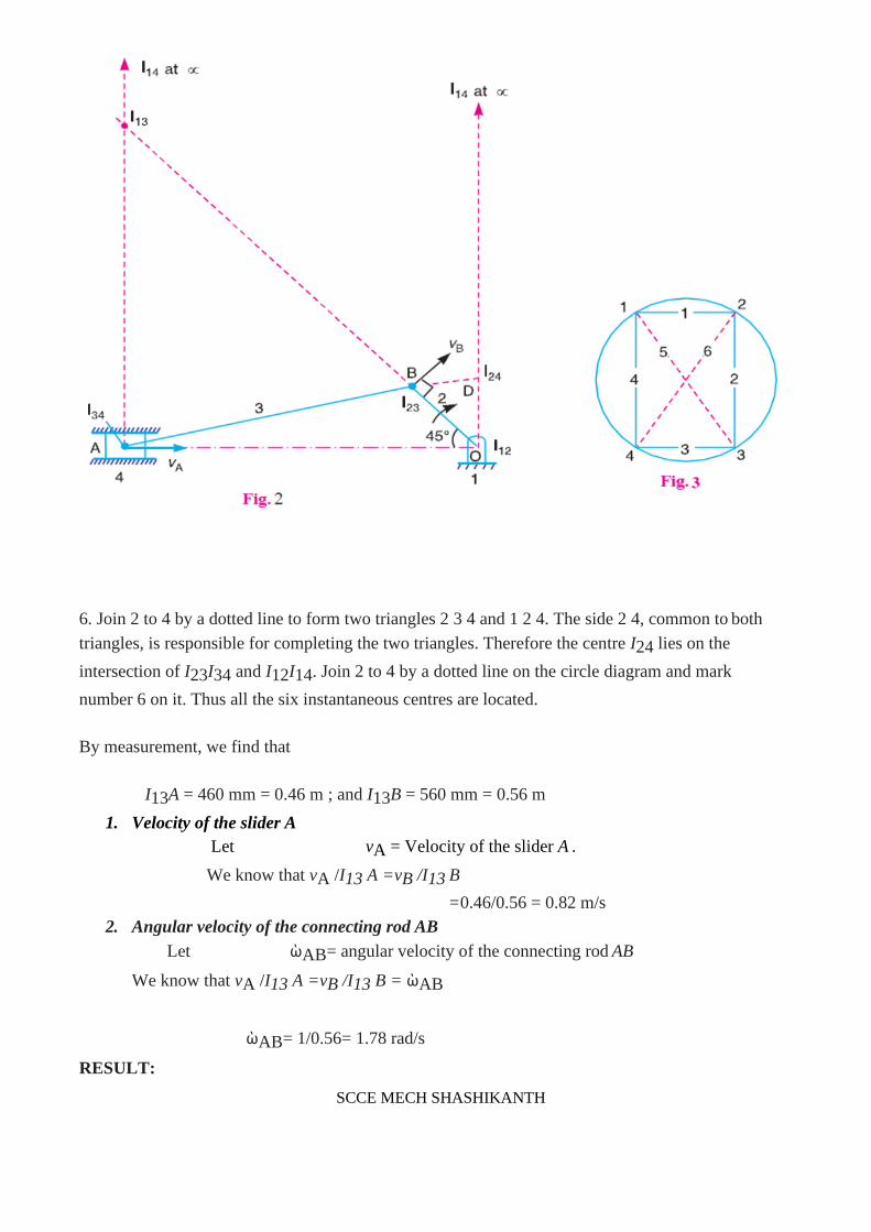
2. Since the mechanism has 15 instantaneous centres, therefore these centres may be listed in the
book keeping table, as discussed
SCCE MECH SHASHIKANTH
3. Locate the fixed and the permanent instantaneous centres by inspection. These centres are I12,
I23, I34, I35, I14, I56 and I16 as shown in Fig1
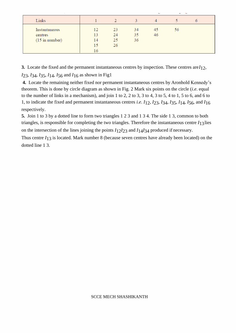
4. Locate the remaining neither fixed nor permanent instantaneous centres by Aronhold Kennedy’s
theorem. This is done by circle diagram as shown in Fig. 2 Mark six points on the circle (i.e. equal
to the number of links in a mechanism), and join 1 to 2, 2 to 3, 3 to 4, 3 to 5, 4 to 1, 5 to 6, and 6 to
1, to indicate the fixed and permanent instantaneous centres i.e. I12, I23, I34, I35, I14, I56, and I16
respectively.
5. Join 1 to 3 by a dotted line to form two triangles 1 2 3 and 1 3 4. The side 1 3, common to both
triangles, is responsible for completing the two triangles. Therefore the instantaneous centre I13 lies
on the intersection of the lines joining the points I12I23 and I14I34 produced if necessary.
Thus centre I13 is located. Mark number 8 (because seven centres have already been located) on the
dotted line 1 3.

SCCE MECH SHASHIKANTH
6. Join 1 to 5 by a dotted line to form two triangles 1 5 6 and 1 3 5. The side 1 5, common to both
triangles, is responsible for completing the two triangles. Therefore the instantaneous centre I15 lies
on the intersection of the lines joining the points I16I56 and I13I35 produced if necessary. Thus
centre I15 is located. Mark number 9 on the dotted line 1 5.
Note: For the given example, we do not require other instantaneous centres.
By measurement, we find that
I13A = 910 mm = 0.91 m ; I13B = 820 mm = 0.82 m ; I15B = 130 mm = 0.13 m ;
I15D = 50 mm = 0.05 m ; I16D = 200 mm = 0.2 m ; I16E = 400 mm = 0.4 m
Velocity of point E on the bell crank lever
Let vE= Velocity of point E on the bell crank lever,
vB= Velocity of point B, and

SCCE MECH SHASHIKANTH
vD= Velocity of point D.
We know that vA/I13A=VB/I13B
RESULTS:
VE = 6.92m/s
VD = 3.46m/s
VE = 6.92m/s
ACCELERATION IN MECHANISMS:
we have discussed in the velocities of various points in the mechanisms. Now we shall discuss the
acceleration of points in the mechanisms. The acceleration analysis plays a very important role in
the development of mechanisms and mechanisms.
Acceleration Diagram for a Link
Consider two points A and B on a rigid link as shown in Fig. 1 (a). Let the point B moves with
respect to A, with
an angular velocity of ὼ rad/s and let α rad/s2 be the angular acceleration of the link AB.

SCCE MECH SHASHIKANTH
We have already discussed that acceleration of a particle whose velocity changes both in magnitude
and direction at any instant has the following two components :
1. The centripetal or radial component, which is perpendicular to the velocity of the particle at the
given instant.
2. The tangential component, which is parallel to the velocity of the particle at the given instant.
Thus for a link A B, the velocity of point B with respect to A (i.e. vBA) is perpendicular to the link
A B as shown in Fig. 1 (a). Since the point B moves with respect to A with an angular velocity
of ὼ rad/s, therefore centripetal or radial component of the acceleration of B with respect to A ,
This radial component of acceleration acts perpendicular to the velocity vBA, In other words, it acts
parallel to the link A B .
We know that tangential component of the acceleration of B with respect to A ,
This tangential component of acceleration acts parallel to the velocity vBA. In other words, it acts
perpendicular to the link A B.
In order to draw the acceleration diagram for a link A B, as shown in Fig. 1 (b), from any point b',
draw vector b'x parallel to BA to represent the radial component of acceleration of B with

SCCE MECH SHASHIKANTH
ACCELERATION OF A POINT ON A LINK:
Consider two points A and B on the rigid link, as shown in Fig.2 (a). Let the acceleration
of the point A i.e. aA is known in magnitude and direction and the direction of path of B is given.
The acceleration of the point B is determined in magnitude and direction by drawing the
acceleration diagram as discussed below.
1. From any point o', draw vector o'a' parallel to the direction of absolute acceleration at
point A i.e. aA, to some suitable scale, as shown in Fig. 2 (b).
2. We know that the acceleration of B with respect to A i.e. aBA has the following two components:
(i)Radial component of the acceleration of B with respect to A i.e and aBA.(ii)Tangential
component of the acceleration B with respect to A i.e . These two aBA. Components are
mutually perpendicular.
3. Draw vector a'x parallel to the link A B (because radial component of the acceleration of B with
respect to A will pass through AB), such that
where vBA=Velocity of B with respect to A

SCCE MECH SHASHIKANTH
4. From point x, draw vector xb' perpendicular to A B or vector a'x (because tangential component
of B with respect to A i.e. aBA, perpendicular to radial component aBAr) and through o' draw a
line parallel to the path of B to represent the absolute acceleration of B i.e. aB. The vectors xb' and
o' b' intersect at b'. Now the values of aB and aBAt may be measured, to the scale.
5. By joining the points a' and b' we may determine the total acceleration of B with respect to A i.e.
aBA. The vector a' b' is known as acceleration image of the link A B.
6. For any other point C on the link, draw triangle a' b' c' similar to triangle ABC. Now vector b' c'
represents the acceleration of C with respect to B i.e. aCB, and vector a' c' represents the
acceleration of C with respect to A i.e. aCA. As discussed above, aCB and aCA will each have two
components as follows :
7. The angular acceleration of the link AB is obtained by dividing the tangential components of the
acceleration of B with respect to A t the length of the link. Mathematically, angular (aBA)
acceleration of the link AB,

SREE CHAITANYA COLLEGE OF ENGINEERING
DEPARTMENT OF MECHANICAL
Problems:
Example 1. The crank of a slider crank mechanism rotates clockwise at a constant speed of 300
r.p.m. The crank is 150 mm and the connecting rod is 600 mm long. Determine : 1. Linear
velocity and acceleration of the midpoint of the connecting rod, and 2. angular velocity and
angular acceleration of the connecting rod, at a crank angle of 45° from inner dead centre
position.
GIVEN:
NBO=300 r.p.m
OB=150mm=0.15mm
BA=600mm=0.6mm
ὼBO=31.42 rad/s
SOLUTION:
We know that linear velocity of B with respect to O or velocity of B,
vBO = vB = ὼBO × OB = 31.42 × 0.15 = 4.713 m/s
1. Linear velocity of the midpoint of the connecting rod
First of all draw the space diagram, to some suitable scale; as shown in Fig. 3 (a). Now the
velocity diagram, as shown in Fig. 3 (b), is drawn as discussed below:
1. Draw vector ob perpendicular to BO, to some suitable scale, to represent the velocity of B with
respect to O or simply velocity of B i.e. vBO or vB, such that
vector ob = vBO = vB = 4.713 m/s
2. From point b, draw vector ba perpendicular to B A to represent the velocity of A with respect
to B i.e. vAB, and from point o draw vector oa parallel to the motion of A (which is along A O)
to represent the velocity of A i.e. vA. The vectors ba and oa intersect at a.
By measurement, we find that velocity of A with respect to B,
vAB=vector ba =3.4 m / s
A v = vector oa = 4 m / s 3. In order to find the velocity of the midpoint D of the connecting rod A B, divide the vector ba at d in the same ratio as D divides A B, in the space diagram. In other words,
bd / ba = BD/BA

SREE CHAITANYA COLLEGE OF ENGINEERING
DEPARTMENT OF MECHANICAL
4. Join od. Now the vector od represents the velocity of the midpoint D of the connecting rod i.e.
vD.
By measurement, we find that
vD = vector od = 4.1 m/s
Acceleration of the midpoint of the connecting rod
We know that the radial component of the acceleration of B with respect to O or the acceleration
of B,
2. The acceleration of A with respect to B has the following two components:
(a) The radial component of the acceleration of A with respect to B i.e. aAB, rand
(b) The tangential component of the acceleration of A with respect to B i.e. aABt.These two
components are mutually perpendicular

SREE CHAITANYA COLLEGE OF ENGINEERING
DEPARTMENT OF MECHANICAL
Therefore from point b', draw vector b' x parallel to A B to represent aAB= 19.3 m/s and from
point x draw vector xa' perpendicular to vector b' x whose magnitude is yet unknown.
3. Now from o', draw vector o' a' parallel to the path of motion of A (which is along A O) to
represent the acceleration of A i.e. aA. The vectors xa' and o' a' intersect at a'. Join a' b'.
4. In order to find the acceleration of the midpoint D of the connecting rod A B, divide the vector
a' b' at d' in the same ratio as D divides A B. In other words
b’d/b’a=BD/BA
5. Join o' d'. The vector o' d' represents the acceleration of midpoint D of the connecting rod i.e.
aD.
By measurement, we find that
aD = vector o' d' = 117 m/s2
2. Angular velocity of the connecting rod
We know that angular velocity of the connecting rod A B
Angular acceleration of the connecting rod From the acceleration diagram, we find that
We know that angular acceleration of the connecting rod A B,
RESULTS:
VD=4.1m/s,
ὼAB=5.67rad/s
αAB=171.67 rad/s
Example 2. In the toggle mechanism shown in Fig. 4, the slider D is constrained to move on a
horizontal path. The crank OA is rotating in the counter-clockwise direction at a speed of 180
r.p.m. increasing at the rate of 50 rad/s2. The dimensions of the various links are as follows:
OA = 180 mm ; CB = 240 mm ; AB = 360 mm ; and BD = 540 mm.
For the given configuration, find 1. Velocity of slider D and angular velocity of BD, and 2.
Acceleration of slider D and angular acceleration of BD.

SREE CHAITANYA COLLEGE OF ENGINEERING
DEPARTMENT OF MECHANICAL
GIVEN:
NAO=180 r.p.m
OA=180mm
CB=240mm
AB=360mm
SOLUTION:
We know that velocity of A with respect to O or velocity of A ,
vAO = vA = ὼAO × O A = 18.85 × 0.18 = 3.4 m/s
1. Velocity of slider D and angular velocity of BD
First of all, draw the space diagram to some suitable scale, as shown in Fig. 5 (a). Now the
velocity diagram, as shown in Fig. 5 (b), is drawn as discussed below:
1. Since O and C are fixed points, therefore these points lie at one place in the velocity diagram.
Draw vector oa perpendicular to O A, to some suitable scale, to represent the velocity of A with
respect to O or velocity of A i.e. vAO or vA, such that
vector oa = vAO = vA = 3.4 m/s

SREE CHAITANYA COLLEGE OF ENGINEERING
DEPARTMENT OF MECHANICAL
2. Since B moves with respect to A and also with respect to C, therefore draw vector ab
perpendicular to A B to represent the velocity of B with respect to A i.e. vBA, and draw vector cb
perpendicular to CB to represent the velocity of B with respect to C ie. vBC. The vectors ab and
cb intersect at b.
3. From point b, draw vector bd perpendicular to BD to represent the velocity of D with respect
to B i.e. vDB, and from point c draw vector cd parallel to CD (i.e., in the direction of motion of
the slider D) to represent the velocity of D i.e. vD.
By measurement, we find that velocity of B with respect to A ,
vBA = vector ab = 0.9 m/s
Velocity of B with respect to C, vBC = vector cb = 2.8 m/s
Velocity of D with respect to B,
and velocity of slider D,
Angular velocity of BD
vDB = vector bd = 2.4 m/s
vD = vector cd = 2.05 m/s
We know that the angular velocity of BD,
2. Acceleration of slider D and angular acceleration of BD
Since the angular acceleration of OA increases at the rate of 50 rad/s2, i.e. α AO= 50 rad/s2,

SREE CHAITANYA COLLEGE OF ENGINEERING
DEPARTMENT OF MECHANICAL
therefore
Tangential component of the acceleration of A with respect to O,
Now the acceleration diagram, as shown in Fig. 5(c), is drawn as discussed below:
1. Since O and C are fixed points, therefore these points lie at one place in the acceleration
diagram. Draw vector o'x parallel to O A, to some suitable scale, to represent the radial
component of the acceleration of A with respect to O
2. From point x, draw vector xa' perpendicular to vector o'x or O A to represent the tangential
component of the acceleration of A with respect to O.
3. Join o'a'. The vector o'a' represents the total acceleration of A with respect to O or
acceleration of A i.e. aAO or aA
4. Now from point a', draw vector a'y parallel to A B to represent the radial component of the
acceleration of B with respect to A
5. From point y, draw vector yb' perpendicular to vector a'y or A B to represent the tangential
component of the acceleration of B with respect to A whose magnitude is yet unknown
6. Now from point c', draw vector c'z parallel to CB to represent the radial component of the
acceleration of B with respect to C

SREE CHAITANYA COLLEGE OF ENGINEERING
DEPARTMENT OF MECHANICAL
7. From point z, draw vector zb' perpendicular to vector c'z or CB to represent the tangential
component of the acceleration of B with respect to C. The vectors yb' and zb' intersect at b' aBC
Join c' b'. The vector c' b' represents the acceleration of B with respect to C i.e. aBC.
8. Now from point b', draw vector b's parallel to BD to represent the radial component of the
acceleration of D with respect to B
9. From point s, draw vector sd' perpendicular to vector b's or BD to represent the tangential
component of the acceleration of D with respect to B.
10. From point c', draw vector c'd' parallel to the path of motion of D (which is along CD) to
represent the acceleration of D i.e. aD. The vectors sd' and c'd' intersect at d'.
By measurement, we find that acceleration of slider D,
aD = vector c'd' = 13.3 m/s2
Angular acceleration of BD
By measurement, we find that tangential component of the acceleration of D with respect to B,
RESULTS:
aD=13.3 m/s2
ὼBD=4.5 rad/s
Example 3.
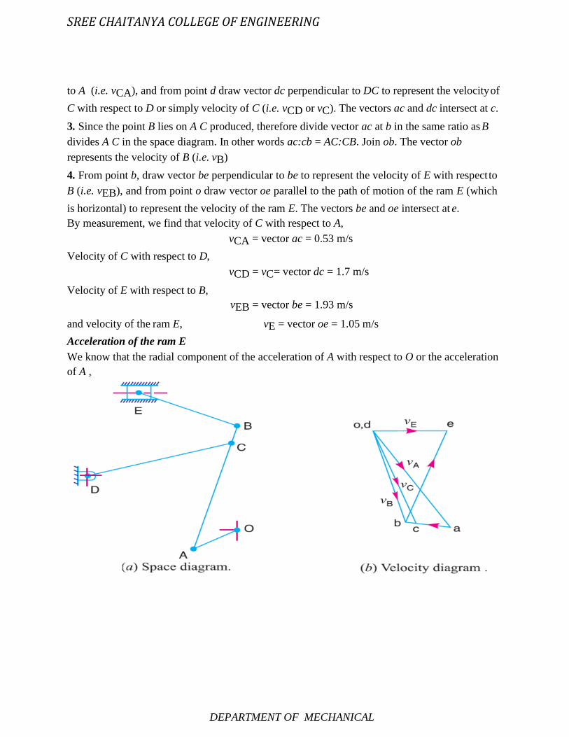
Fig. 6 shows the mechanism of a radial valve gear. The crank OA turns uniformly at 150 r.p.m
and is pinned at A to rod AB. The point C in the rod is guided in the circular path with D as
centre and DC as radius. The dimensions of various links are:
OA = 150 mm ; AB = 550 mm ; AC = 450 mm ; DC = 500 mm ; BE = 350 mm.
Determine velocity and acceleration of the ram E for the given position of the mechanism.

SREE CHAITANYA COLLEGE OF ENGINEERING
DEPARTMENT OF MECHANICAL
GIVEN :
NAO = 150 r.p.m.
ὼAO =0.15mm
A B = 550 mm = 0.55 m
A C = 450 mm = 0.45 m
DC = 500 mm = 0.5 m
BE = 350 mm = 0.35 m
SOLUTION:
We know that linear velocity of A with respect to O or velocity of A ,
vAO = vA = ὼAO × O A = 15.71 × 0.15 = 2.36 m/s
Velocity of the ram E
First of all draw the space diagram, as shown in Fig. 7 (a), to some suitable scale. Now the
velocity diagram, as shown in Fig. 7(b), is drawn as discussed below:
1. Since O and D are fixed points, therefore these points are marked as one point in the velocity
diagram. Draw vector oa perpendicular to O A, to some suitable scale, to represent the velocity
of A with respect to O or simply velocity of A , such that
vector oa = vAO= vA= 2.36 m/s
2. From point a, draw vector ac perpendicular to A C to represent the velocity of C with respect
SREE CHAITANYA COLLEGE OF ENGINEERING
DEPARTMENT OF MECHANICAL
to A (i.e. vCA), and from point d draw vector dc perpendicular to DC to represent the velocity of
C with respect to D or simply velocity of C (i.e. vCD or vC). The vectors ac and dc intersect at c.
3. Since the point B lies on A C produced, therefore divide vector ac at b in the same ratio as B
divides A C in the space diagram. In other words ac:cb = AC:CB. Join ob. The vector ob
represents the velocity of B (i.e. vB)
4. From point b, draw vector be perpendicular to be to represent the velocity of E with respect to
B (i.e. vEB), and from point o draw vector oe parallel to the path of motion of the ram E (which
is horizontal) to represent the velocity of the ram E. The vectors be and oe intersect at e.
By measurement, we find that velocity of C with respect to A,
vCA = vector ac = 0.53 m/s
Velocity of C with respect to D,
Velocity of E with respect to B,
vCD = vC= vector dc = 1.7 m/s
vEB = vector be = 1.93 m/s
and velocity of the ram E, vE = vector oe = 1.05 m/s
Acceleration of the ram E
We know that the radial component of the acceleration of A with respect to O or the acceleration
of A ,

SREE CHAITANYA COLLEGE OF ENGINEERING
DEPARTMENT OF MECHANICAL
The acceleration diagram, as shown in Fig. 7 (c), is drawn as discussed below
1. Since O and D are fixed points, therefore these points are marked as one point in the
acceleration diagram. Draw vector o'a' parallel to O A, to some suitable scale, to represent the
radial component of the acceleration of A with respect to O or simply the acceleration of A, such
that
2. From point d', draw vector d'x parallel to DC to represent the radial component of the
acceleration of C with respect to D, such that
3. From point x, draw vector xc' perpendicular to DC to represent the tangential component of the
acceleration of C with respect to D
4. Now from point a', draw vector a'y parallel to A C to represent the radial component of the
acceleration of C with respect to A , such that
5. From point y, draw vector yc' perpendicular to AC to represent the tangential component of
acceleration of C with respect to A
6. Join a'c'. The vector a'c' represents the acceleration of C with respect to A
7. Since the point B lies on A C produced, therefore divide vector a'c' at b' in the same ratio as
SREE CHAITANYA COLLEGE OF ENGINEERING
DEPARTMENT OF MECHANICAL
B divides A C in the space diagram. In other words, a'
c' : c' b' = A C : CB
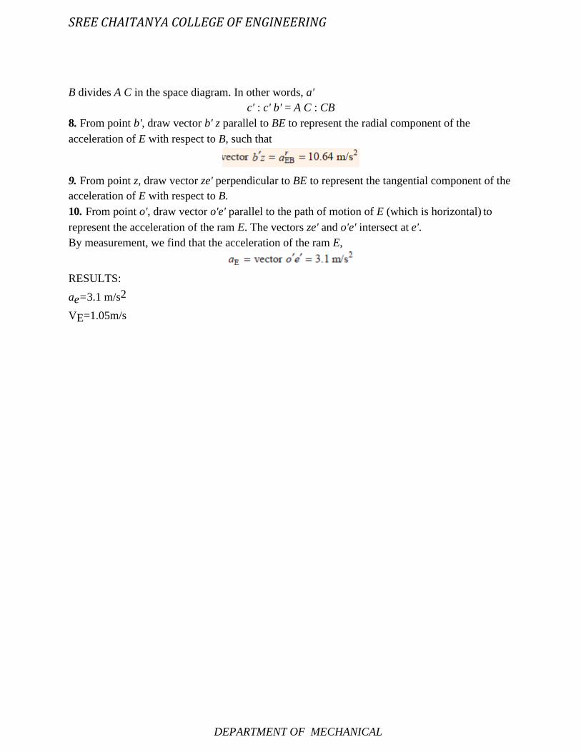
8. From point b', draw vector b' z parallel to BE to represent the radial component of the
acceleration of E with respect to B, such that
9. From point z, draw vector ze' perpendicular to BE to represent the tangential component of the
acceleration of E with respect to B.
10. From point o', draw vector o'e' parallel to the path of motion of E (which is horizontal) to
represent the acceleration of the ram E. The vectors ze' and o'e' intersect at e'.
By measurement, we find that the acceleration of the ram E,
RESULTS:
ae=3.1 m/s2
VE=1.05m/s

SREE CHAITANYA COLLEGE OF ENGINEERING
DEPARTMENT OF MECHANICAL
UNIT-2 FRICTION
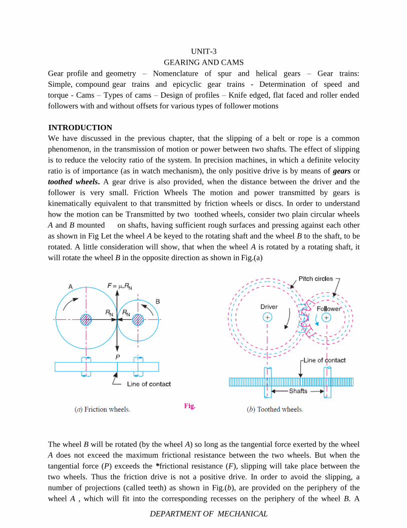
DEPARTMENT OF MECHANICAL
UNIT-3
GEARING AND CAMS
Gear profile and geometry – Nomenclature of spur and helical gears – Gear trains:
Simple, compound gear trains and epicyclic gear trains - Determination of speed and
torque - Cams – Types of cams – Design of profiles – Knife edged, flat faced and roller ended
followers with and without offsets for various types of follower motions
INTRODUCTION
We have discussed in the previous chapter, that the slipping of a belt or rope is a common
phenomenon, in the transmission of motion or power between two shafts. The effect of slipping
is to reduce the velocity ratio of the system. In precision machines, in which a definite velocity
ratio is of importance (as in watch mechanism), the only positive drive is by means of gears or
toothed wheels. A gear drive is also provided, when the distance between the driver and the
follower is very small. Friction Wheels The motion and power transmitted by gears is
kinematically equivalent to that transmitted by friction wheels or discs. In order to understand
how the motion can be Transmitted by two toothed wheels, consider two plain circular wheels
A and B mounted on shafts, having sufficient rough surfaces and pressing against each other
as shown in Fig Let the wheel A be keyed to the rotating shaft and the wheel B to the shaft, to be
rotated. A little consideration will show, that when the wheel A is rotated by a rotating shaft, it
will rotate the wheel B in the opposite direction as shown in Fig.(a)
The wheel B will be rotated (by the wheel A) so long as the tangential force exerted by the wheel
A does not exceed the maximum frictional resistance between the two wheels. But when the
tangential force (P) exceeds the *frictional resistance (F), slipping will take place between the
two wheels. Thus the friction drive is not a positive drive. In order to avoid the slipping, a
number of projections (called teeth) as shown in Fig.(b), are provided on the periphery of the
wheel A , which will fit into the corresponding recesses on the periphery of the wheel B. A
DEPARTMENT OF MECHANICAL
friction wheel with the teeth cut on it is known as toothed
wheel or gear. The usual connection to show the toothed wheels is by their **pitch circles.
Note : Kinematically, the friction wheels running without slip and toothed gearing are identical.
But due to the
possibility of slipping of wheels, the friction wheels can only be used for transmission of small
powers
ADVANTAGES AND DISADVANTAGES OF GEAR DRIVE
The following are the advantages and disadvantages of the gear drive as compared to belt,
rope and chain drives :
Advantages
1. It transmits exact velocity ratio.
2. It may be used to transmit large power.
3. It has high efficiency.
4. It has reliable service.
5. It has compact layout.
Disadvantages
1. The manufacture of gears require special tools and equipment.
2. The error in cutting teeth may cause vibrations and noise during operation.
CLASSIFICATION OF TOOTHED WHEELS
The gears or toothed wheels may be classified as follows :
1. According to the position of axes of the shafts. The axes of the two shafts between which
the motion is to be transmitted, may be
(a) Parallel, (b) Intersecting, and (c) Non-intersecting and non-parallel.
The two parallel and co-planar shafts connected by the gears is shown in Fig. 1. These
gears are called spur gears and the arrangement is known as spur gearing. These gears have
teeth parallel to the axis of the wheel as shown in Fig. 1. Another name given to the spur gearing
is helical gearing, in which the teeth are inclined to the axis. The single and double helical gears
connecting parallel shafts are shown in Fig. 1 (a) and (b) respectively. The double helical gears
are known as herringbone gears. A pair of spur gears are kinematically equivalent to a pair of
cylindrical discs, keyed to parallel shafts and having a line contact.
The two non-parallel or intersecting, but coplanar shafts connected by gears is shown in
Fig.1(c). These gears are called bevel gears and the arrangement is known as bevel gearing.
The bevel gears, like spur gears, may also have their teeth inclined to the face of the bevel, in
which case they are known as helical bevel gears.The two non-intersecting and non-parallel
i.e. non-coplanar shaft connected by gears is shown in Fig. 1(d). These gears are called skew
bevel gears or spiral gears and the arrangement is known as skew bevel gearing or spiral
gearing. This type of gearing also have a line contact, the rotation of which about the axes
generates the two pitch surfaces known as hyperboloids.

DEPARTMENT OF MECHANICAL
Notes : (a)When equal bevel gears (having equal teeth) connect two shafts whose axes are
mutually perpendicular, then the bevel gears are known as mitres.
(b)A hyperboloid is the solid formed by revolving a straight line about an axis (not in the same
plane), such that every point on the line remains at a constant distance from the axis.
(c) The worm gearing is essentially a form of spiral gearing in which the shafts are usually at
right angles.
2. According to the peripheral velocity of the gears. The gears, according to the peripheral
velocity of the gears may be classified as :
(a) Low velocity, (b) Medium velocity, and (c) High velocity.
The gears having velocity less than 3 m/s are termed as low velocity gears and gears having
velocity between 3 and 15 m/s are known as medium velocity gears. If the velocity of gears is
more than 15 m/s, then these are called high speed gears.
3. According to the type of gearing. The gears, according to the type of gearing may be
classified as :
(a) External gearing, (b) Internal gearing, and (c) Rack and pinion.
In external gearing, the gears of the two shafts mesh externally with each other as shown in Fig.
2(a). The larger of these two wheels is called spur wheel and the smaller wheel is called pinion.
In an external gearing, the motion of the two wheels is always unlike, as shown in Fig. 2(a).

DEPARTMENT OF MECHANICAL
In internal gearing, the gears of the two shafts mesh internally with each other as shown in Fig.
2 (b). The larger of these two wheels is called annular wheel and the smaller wheel is called
pinion. In an internal gearing, the motion of the two wheels is always like, as shown in Fig. 2(b).
Sometimes, the gear of a shaft meshes externally and internally with the gears in a *straight line,
as shown in Fig. 2 Such type of gear is called rack and pinion. The straight line gear is called
rack and the circular wheel is called pinion. A little consideration will show that with the help of
a rack and pinion, we can convert linear motion into rotary motion and vice-versa as shown in
Fig. 2
4. According to position of teeth on the gear surface.
The teeth on the gear surface may be
(a) straight, (b) inclined, and (c) curved.
We have discussed earlier that the spur gears have straight teeth where as helical gears have their
teeth inclined to the wheel rim. In case of spiral gears, the teeth are curved over the rim surface
NOMENCLATURE
The following terms, which will be mostly used in this chapter, should be clearly understood
at this stage. These terms are illustrated in Fig. 3
1. Pitch circle. It is an imaginary circle which by pure rolling action, would give the same
motion as the actual gear.

DEPARTMENT OF MECHANICAL
2. Pitch circle diameter. It is the diameter of the pitch circle. The size of the gear is usually
specified by the pitch circle diameter. It is also known as pitch diameter.
3. Pitch point. It is a common point of contact between two pitch circles.
4. Pitch surface. It is the surface of the rolling discs which the meshing gears have replaced
at the pitch circle.
5. Pressure angle or angle of obliquity. It is the angle between the common normal to two gear
teeth at the point of contact and the common tangent at the pitch point. It is usually denoted byΦ
6. Addendum. It is the radial distance of a tooth from the pitch circle to the top of the tooth.
7. Dedendum. It is the radial distance of a tooth from the pitch circle to the bottom of the tooth.
8. Addendum circle. It is the circle drawn through the top of the teeth and is concentric with
the pitch circle.
9. Dedendum circle. It is the circle drawn through the bottom of the teeth. It is also called
root circle.
10. Circular pitch. It is the distance measured on the circumference of the pitch circle from a
point of one tooth to the corresponding point on the next tooth. It is usually denoted by Pc.
Circular pitch, Pc=лD/T A little consideration will show that the two gears will mesh together
correctly, if the two wheels have the same circular pitch.
11. Diametral pitch. It is the ratio of number of teeth to the pitch circle diameter in millimetres.
It is denoted by Pd. P d=лD1/T1.
12. Module. It is the ratio of the pitch circle diameter in millimeters to the number of teeth.
It is usually denoted by m. Mathematically,
Module, m = D /T
13. Clearance. It is the radial distance from the top of the tooth to the bottom of the tooth, in a
meshing gear. A circle passing through the top of the meshing gear is known as clearance circle.
14. Total depth. It is the radial distance between the addendum and the dedendum circles of a
gear. It is equal to the sum of the addendum and dedendum.
15. Working depth. It is the radial distance from the addendum circle to the clearance circle. It is
equal to the sum of the addendum of the two meshing gears.
16. Tooth thickness. It is the width of the tooth measured along the pitch circle.
17. Tooth space . It is the width of space between the two adjacent teeth measured along the
pitch circle.
18. Backlash. It is the difference between the tooth space and the tooth thickness, as measured
along the pitch circle. Theoretically, the backlash should be zero, but in actual practice some
backlash must be allowed to prevent jamming of the teeth due to tooth errors and thermal
expansion.
19. Face of tooth. It is the surface of the gear tooth above the pitch surface.
DEPARTMENT OF MECHANICAL
20. Flank of tooth. It is the surface of the gear tooth below the pitch surface.
21. Top land. It is the surface of the top of the tooth.
22. Face width. It is the width of the gear tooth measured parallel to its axis.
23. Profile. It is the curve formed by the face and flank of the tooth.
24. Fillet radius. It is the radius that connects the root circle to the profile of the tooth.
25. Path of contact. It is the path traced by the point of contact of two teeth from the beginning
to the end of engagement.
26. *Length of the path of contact. It is the length of the common normal cut-off by the
addendum circles of the wheel and pinion.
27. ** Arc of contact. It is the path traced by a point on the pitch circle from the beginning to
the end of engagement of a given pair of teeth. The arc of contact consists of two parts, i.e.
(a) Arc of approach. It is the portion of the path of contact from the beginning of the
engagement to the pitch point.
(b) Arc of recess. It is the portion of the path of contact from the pitch point to the end of the
engagement of a pair of teeth.
Note : The ratio of the length of arc of contact to the circular pitch is known as contact ratio i.e.
number of pairs of teeth in contact.
GEAR TRAINS:
Introduction
Sometimes, two or more gears are made to mesh with each other to transmit power from one
shaft to another. Such a combination is called gear train or train of toothed wheels. The nature
of the train used depends upon the velocity ratio required and the relative position of the axes of
shafts. A gear train may consist of spur, bevel or spiral gears.
TYPES OF GEAR TRAINS
Following are the different types of gear trains, depending upon the arrangement of wheels :
1. Simple gear train, 2. Compound gear train, 3. Reverted gear train, and 4. Epicyclic gear train.
In the first three types of gear trains, the axes of the shafts over which the gears are mounted are
fixed relative to each other. But in case of epicyclic gear trains, the axes of the shafts on which
the gears are mounted may move relative to a fixed axis.
SIMPLE GEAR TRAIN
When there is only one gear on each shaft, as shown in Fig.4, it is known as simple gear train.
The gears are represented by their pitch circles. When the distance between the two shafts is
small, the two gears 1 and 2 are made to mesh with each other to transmit motion from one shaft
to the other, as shown in Fig. 4 (a). Since the gear 1 drives the gear 2, therefore gear 1 is called
the driver and the gear 2 is called the driven or follower.

DEPARTMENT OF MECHANICAL
It may be noted that the motion of the driven gear is opposite to the motion of driving gear. Since
the speed ratio (or velocity ratio) of gear train is the ratio of the speed of the driver to the speed
of the driven or follower and ratio of speeds of any pair of gears in mesh is the inverse of their
number of teeth, therefore It may be noted that ratio of the speed of the driven or follower to the
speed of the driver is known as train value of the gear train. Mathematically From above, we see
that the train value is the reciprocal of speed ratio.Sometimes, the distance between the two gears
is large. The motion from one gear to another, in such a case, may be transmitted by either of the
following two methods :
1. By providing the large sized gear, or 2. By providing one or more intermediate gears.
A little consideration will show that the former method (i.e. providing large sized gears) is very
inconvenient and uneconomical method ; whereas the latter method (i.e. providing one or more
intermediate gear) is very convenient and economical. It may be noted that when the number of
intermediate gears are odd, the motion of both the gears (i.e. driver and driven or follower) is like
as shown in Fig. 4 (b). But if the number of intermediate gears are even, the motion of the driven
or follower will be in the opposite direction of the driver as shown in Fig.4 (c).
Now consider a simple train of gears with one intermediate gear as shown in Fig. 4 (b).
Let N1= Speed of driver in r.p.m.,
N2= Speed of intermediate gear in r.p.m.,
N3= Speed of driven or follower in r.p.m.,
DEPARTMENT OF MECHANICAL
T1= Number of teeth on driver,
T2= Number of teeth on intermediate gear, and
T3= Number of teeth on driven or follower.
Since the driving gear 1 is in mesh with the intermediate gear 2, therefore speed ratio for these
two gears is
Similarly, as the intermediate gear 2 is in mesh with the driven gear 3, therefore speed ratio for
these two gears is
The speed ratio of the gear train as shown in Fig. 13.1 (b) is obtained by multiplying the
equations (i) and (ii).
Similarly, it can be proved that the above equation holds good even if there are any number of
intermediate gears. From above, we see that the speed ratio and the train value, in a simple train
of gears, is independent of the size and number of intermediate gears. These intermediate gears
are called idle gears, as they do not effect the speed ratio or train value of the system. The idle
gears are used for the following two purposes :
1. To connect gears where a large centre distance is required, and
2. To obtain the desired direction of motion of the driven gear (i.e. clockwise or anticlockwise).
COMPOUND GEAR TRAIN
When there are more than one gear on a shaft, as shown in Fig. 5, it is called a compound train
of gear. We have seen in Art. 5 that the idle gears, in a simple train of gears do not effect the
speed ratio of the system. But these gears are useful in bridging over the space between the driver
and the driven. But whenever the distance between the driver and the driven or follower has to be
bridged over by intermediate gears and at the same time a great ( or much less) speed ratio is
required, then the advantage of intermediate gears is intensified by providing compound gears on
intermediate shafts. In this case, each intermediate shaft has two gears rigidly fixed to it so that

DEPARTMENT OF MECHANICAL
they may have the same speed. One of these two gears meshes with the driver and the other with
the driven or follower attached to the next shaft as shown in Fig.5
In a compound train of gears, as shown in Fig. 5 the gear 1 is the driving gear mounted on shaft A,
gears 2 and 3 are compound gears which are mounted on shaft B. The gears 4 and 5 are also compound
gears which are mounted on shaft C and the gear 6 is the driven gear mounted on shaft D. Let N1= Speed of driving gear 1,
T1= Number of teeth on driving gear 1,
N2,N3..., N6= Speed of respective gears in r.p.m., and
T2,T3..., T6= Number of teeth on respective gears.
Since gear 1 is in mesh with gear 2, therefore its speed ratio is
N1 /N2=T2/ T1
Similarly, for gears 3 and 4, speed ratio is
N3 /N4=T4/ T3
and for gears 5 and 6, speed ratio is N5 /N6=T6/ T5
The speed ratio of compound gear train is obtained by multiplying the equations (i), (ii) and (iii),
The advantage of a compound train over a simple gear train is that a much larger speed reduction

DEPARTMENT OF MECHANICAL
from the first shaft to the last shaft can be obtained with small gears.
If a simple gear train is used to give a large speed reduction, the last gear has to be very large.
Usually for a speed reduction
in excess of 7 to 1, a simple train is not used and a compound train or worm gearing is employed
EPICYCLIC GEAR TRAIN
We have already discussed that in an epicyclic gear train, the axes of the shafts, over which the
gears are mounted, may move relative to a fixed axis. A simple epicyclic gear train is shown in
Fig. 6, where a gear A and the arm C have a common axis at O1about which they can rotate.
The gear B meshes with gear A and has its axis on the arm at O2, about which the gear B can
rotate. If the arm is fixed, the gear train is simple and gear A can drive gear B or vice- versa, but
if gear A is fixed and the arm is rotated about the axis of gear A (i.e. O1), then the gear B is
forced to rotate upon and around gear
A . Such a motion is called epicyclic and the gear trains arranged in such a manner that one or
more of their members move upon and around another member are known as epicyclic gear
trains (epi. means upon and cyclic means around). The epicyclic gear trains may be simple or
compound. The epicyclic gear trains are useful for transmitting high velocity ratios with gears of

DEPARTMENT OF MECHANICAL
moderate size in a comparatively lesser space. The epicyclic gear trains are used in the back gear
of lathe, differential gears of the automobiles, hoists, pulley blocks, wrist watches etc.Velocity
Ratioz of Epicyclic Gear Train
The following two methods may be used for finding out the velocity ratio of an epicyclic gear
train.
1. Tabular method, and 2. Algebraic method.
These methods are discussed, in detail, as follows :
1. Tabular method.
Consider an epicyclic gear train as shown in Fig.
Let TA = Number of teeth on gear A , and
TB = Number of teeth on gear B.
First of all, let us suppose that the arm is fixed. Therefore the axes of both the gears are also fixed
relative to each other. When the gear A makes one revolution anticlockwise, the gear B will
make *TA / TB revolutions, clockwise. Assuming the anticlockwise rotation as positive and
clockwise as negative, we may say that when gear A makes + 1revolution, then the gear B will
make (– TA/ TB) revolutions. This statement of relative motion is entered in the first row of the
table (see Table 13.1). Secondly, if the gear A makes + x revolutions, then the gear B will make
– x × TA/ TB revolutions. This statement is entered in the second row of the table. In other
words, multiply the each motion (entered in the first row) by x. Thirdly, each element of an
epicyclic train is given + y revolutions and entered in the third row. Finally, the motion of each
element of the gear train is added up and entered in the fourth row. A little consideration will
show that when two conditions about the motion of rotation of any two elements are known, then
the unknown speed of the third element may be obtained by substituting the given data in the
third column of the fourth row.

DEPARTMENT OF MECHANICAL
2. Algebraic method.
In this method, the motion of each element of the epicyclic train relative to the arm is set down in
the form of equations. The number of equations depends upon the number of elements in the gear
train. But the two conditions are, usually, supplied in any epicyclic train viz. some element is
fixed and the other has specified motion. These two conditions are sufficient to solve all the
equations ; and hence to determine the motion of any element in the epicyclic gear train. Let the
arm C be fixed in an epicyclic gear train as shown in Fig. 13.6. Therefore speed of the gear A
relative to the arm C.

DEPARTMENT OF MECHANICAL
PROBLEMS;
Example 1In an epicyclic gear train, an arm carries two gears A and B having 36 and 45 teeth
respectively. If the arm rotates at 150 r.p.m. in the anticlockwise direction about the centre
of the gear A which is fixed, determine the speed of gear B. If the gear A instead of being fixed,
makes 300 r.p.m. in the clockwise direction, what will be the speed of gear B ?
GIVEN :
TA= 36 ; TB= 45 ; NC= 150 r.p.m.
SOLUTION:
We shall solve this example, by tabular method .
1. Tabular method
First of all prepare the table of motions as given below :
Speed of gear B when gear A is fixed
Since the speed of arm is 150 r.p.m. anticlockwise, therefore from the fourth row of the table,
y = + 150 r.p.m.
Also the gear A is fixed, therefore
x + y = 0 or x = – y = – 150 r.p.m.
DEPARTMENT OF MECHANICAL
Speed of gear B when gear A makes 300 r.p.m. clockwise
Since the gear A makes 300 r.p.m. Clockwise, therefore from the fourth row of the table,
x + y = – 300 or x = – 300 – y = – 300 – 150 = – 450 r.p.m.
Speed of gear B,
EXAMPLE:2. train, the arm A carries two gears B and C and a compound gear D - E. The gear
B meshes with gear E and the gear C meshes with gear D. The number of teeth on gears B, C
and D are 75, 30 and 90 respectively. Find the speed and direction of gear C when gear B is
fixed and the arm A makes 100 r.p.m. clockwise.
GIVEN :
TB= 75 ; TC= 30 ; TD = 90 ;
NA= 100 r.p.m. (clockwise)
SOLTUION;
The reverted epicyclic gear train . First of all, let us find the number of teeth on gear E (TE). Let
dB, dC, dDand dEbe the pitch circle diameters of gears B, C, D and E respectively. From the
geometry of the figure,
Since the number of teeth on each gear,
dB+ dE= dC+ dD
for the same module, are proportional to their
pitch circle diameters, therefore
TB+ TE= TC+ TD
TE= TC+ TD– TB= 30 + 90 – 75 = 45
The table of motions is drawn as follow

DEPARTMENT OF MECHANICAL

DEPARTMENT OF MECHANICAL
Example:3.In an epicyclic gear train, the internal wheels A and B and compound wheels C and
D rotate independently about axis O. The wheels E and F rotate on pins fixed to the arm G. E
gears with A and C and F gears with B and D. All the wheels have the same module and the
number of teeth are : TC= 28; TD= 26; TE= TF= 18. 1. Sketch the arrangement ; 2. Find the
number of teeth on A and B ; 3. If the arm G makes 100 r.p.m. clockwise and A is fixed, find the
speed of B ; and 4. If the arm G makes 100 r.p.m. clockwise and wheel A makes 10 r.p.m.
counter clockwise ; find the speed of wheel B.
GIVEN :
TC= 28 ; TD= 26 ; TE= TF= 18
SOLUTION:
1. Sketch the arrangement
The arrangement is shown in Fig.
2. Number of teeth on wheels A and B
Let TA= Number of teeth on wheel A , and
TB= Number of teeth on wheel B.
If dA, dB, dC, dD, dEand dFare the pitch circle diameters of wheels A , B, C, D, E and F
respectively, then from the geometry of Fig.
dA= dC+ 2 dE
and dB = dD+ 2 dF
Since the number of teeth are proportional to their pitch circle diameters, for the same
module, therefore
TA= TC+ 2 TE= 28 + 2 × 18 = 64
and TB= TD+ 2 TF= 26 + 2 × 18 = 62
3. Speed of wheel B when arm G makes 100 r.p.m. clockwise and wheel A is fixed
First of all, the table of motions is drawn as given below

DEPARTMENT OF MECHANICAL
Since the arm G makes 100 r.p.m. clockwise, therefore from the fourth row of the table,
y = – 100
Also, the wheel A is fixed, therefore from the fourth row of the table,
x + y = 0 or x = – y = 100
speed of wheel B=4.2 r.p.m
4. Speed of wheel B when arm G makes 100 r.p.m. clockwise and wheel A makes 10 r.p.m.
counterclockwise
Since the arm G makes 100 r.p.m. clockwise, therefore from the fourth row of the
table
y = – 100
Also the wheel A makes 10 r.p.m. counter clockwise, therefore from the fourth row of the table,
DEPARTMENT OF MECHANICAL
CAM INTRODUCTION:
A cam is a rotating machine element which gives reciprocating or oscillating motion to
another element known as follower. The cam and the follower have a line contact and constitute
a higher pair. The cams are usually rotated at uniform speed by a shaft, but the follower motion is
pre- determined and will be according to the shape of the cam. The cam and follower is one of
the simplest as well as one of the most important mechanisms found in modern machinery today.
The cams are widely used for operating the inlet and exhaust valves of internal combustion
engines, automatic attachment of machineries, paper cutting machines, spinning and weaving
textile machineries, feed mechanism of automatic lathes etc.
Classification of Followers
The followers may be classified as discussed below:
1. According to the surface in contact.
The followers, according to the surface in contact, are as follows:
(a) Knife edge follower.
When the contacting end of the follower has a sharp knife edge, it is called a knife edge follower,
as shown in Fig.1 (a). The sliding motion takes place between the contacting surfaces (i.e. the
knife edge and the cam surface). It is seldom used in practice because the small area of
contacting surface results in excessive wear. In knife edge followers, a considerable side thrust
exists between the follower and the guide.
(b) Roller follower.
When the contacting end of the follower is a roller, it is called a roller follower, as shown in Fig.
1 (b). Since the rolling motion takes place between the contacting surfaces (i.e. the roller and the
cam), therefore the rate of wear is greatly reduced. In roller followers also the side thrust exists
between the follower and the guide. The roller followers are extensively used where more space
is available such as in stationary gas and oil engines and aircraft engines.
(c) Flat faced or mushroom follower.
When the contacting end of the follower is a perfectly flat face, it is called a flat-faced follower,
as shown in Fig. 1 (c). It may be noted that the side thrust between the follower and the guide is
much reduced in case of flat faced followers. The only side thrust is due to friction between the
contact surfaces of the follower and the cam. The relative motion between these surfaces is
largely of sliding nature but wear may be reduced by off-setting the axis of the follower, as
shown in Fig. 1 (f ) so that when the cam rotates, the follower also rotates about its own axis. The

DEPARTMENT OF MECHANICAL
flat faced followers are generally used where space is limited such as in cams which operate the
valves of automobile engines.
(d) Spherical faced follower
When the contacting end of the follower is of spherical shape, it is called a spherical faced
follower, as shown in Fig.1 (d). It may be noted that when a flat-faced follower is used in
automobile engines, high surface stresses are produced. In order to minimise these stresses, the
flat end of the follower is machined to a spherical shape.
2. According to the motion of the follower.
The followers, according to its motion, are of the following two types:
(a) Reciprocating or translating follower. When the follower reciprocates in guides as the cam
rotates uniformly, it is known as reciprocating or translating follower. The followers as shown in
Fig. 1 (a) to (d) are all reciprocating or translating followers.
(b) Oscillating or rotating follower. When the uniform rotary motion of the cam is converted

DEPARTMENT OF MECHANICAL
into predetermined oscillatory motion of the follower, it is called oscillating or rotating follower.
The follower, as shown in Fig .1 (e), is an oscillating or rotating follower.
3. According to the path of motion of the follower. The followers, according to its path of
motion, are of the following two types:
(a) Radial follower. When the motion of the follower is along an axis passing through the centre
of the cam, it is known as radial follower. The followers, as shown in Fig.1 (a) to (e), are all
radial followers.
(b) Off-set follower. When the motion of the follower is along an axis away from the axis of the
cam centre, it is called off-set follower. The follower, as shown in Fig.1 (f), is an off-set follower.
CLASSIFICATION OF CAMS
Though the cams may be classified in many ways, yet the following two types are important from
the subject point of view:
1. Radial or disc cam.
In radial cams, the follower reciprocates or oscillates in a direction perpendicular to the cam axis.
The cams as shown in Fig.2 are all radial cams.
2. Cylindrical cam.
In cylindrical cams, the follower reciprocates or oscillates in a direction parallel to the cam axis.
The follower rides in a groove at its cylindrical surface. A cylindrical grooved cam with a
reciprocating and an oscillating follower is shown in Fig.2 (a) and (b) respectively.
NOMENCALTURE:
Fig. shows a radial cam with reciprocating roller follower. The following terms are important in
order to draw the cam profile.
1. Base circle. It is the smallest circle that can be drawn to the cam profile.
2. Trace point. It is a reference point on the follower and is used to generate the pitch curve. In

DEPARTMENT OF MECHANICAL
case of knife edge follower, the knife edge represents the trace point and the pitch curve
corresponds to the cam profile. In a roller follower, the centre of the roller represents the trace
point.
3. Pressure angle. It is the angle between the direction of the follower motion and a normal to
the pitch curve. This angle is very important in designing a cam profile. If the pressure angle is
too large, a reciprocating follower will jam in its bearings.
4. Pitch point. It is a point on the pitch curve having the maximum pressure angle.
5. Pitch circle. It is a circle drawn from the centre of the cam through the pitch points.
6. Pitch curve. It is the curve generated by the trace point as the follower moves relative to the
cam. For a knife edge follower, the pitch curve and the cam profile are same whereas for a roller
follower, they are separated by the radius of the roller.
7. Prime circle. It is the smallest circle that can be drawn from the centre of the cam and tangent
to the pitch curve. For a knife edge and a flat face follower, the prime circle and the base circle
are identical. For a roller follower, the prime circle is larger than the base circle by the radius of
the roller.
8. Lift or stroke. It is the maximum travel of the follower from its lowest position to the topmost

DEPARTMENT OF MECHANICAL
position.
MOTION OF THE FOLLOWER
The follower, during its travel, may have one of the following motions.
1. Uniform velocity, 2. Simple harmonic motion, 3. Uniform acceleration and retardation,
and 4. Cycloidal motion
DISPLACEMENT, VELOCITY AND ACCELERATION DIAGRAMS WHEN THE
FOLLOWER MOVES WITH UNIFORM VELOCITY
The displacement, velocity and acceleration diagrams when a knife-edged follower moves with
uniform velocity are shown in Fig. 4 (a), (b) and (c) respectively. The abscissa (base) represents
the time (i.e. the number of seconds required for the cam to complete one revolution) or it may
represent the angular displacement of the cam in degrees. The ordinate represents the
displacement, or velocity or acceleration of the follower. Since the follower moves with uniform
velocity during its rise and return stroke, therefore the slope of the displacement curves must be
constant. In other words, AB1 and C1D must be straight lines. A little consideration will show
that the follower remains at rest during part of the cam rotation. The periods during which the
follower remains at rest are known as dwell periods, as shown by lines B1C1 and DE in Fig. 4
(a). From Fig. 4 (c), we see that the acceleration or retardation of the follower at the beginning
and at the end of each stroke is infinite.

DEPARTMENT OF MECHANICAL
This is due to the fact that the follower is required to start from rest and has to gain a velocity
within no time. This is only possible if the acceleration or retardation at the beginning and at the
end of each stroke is infinite. These conditions are however, impracticable. In order to have the
acceleration and retardation within
the finite limits, it is necessary to modify the conditions which govern the motion of the follower.
This may be done by rounding off the sharp corners of the displacement diagram at the beginning
and at the end of each stroke, as shown in Fig. 5 (a). By doing so, the velocity of the follower
increases gradually to its maximum value at the beginning of each stroke and decreases gradually
to zero at the end of each stroke as shown in Fig. 5 (b). The modified displacement, velocity and
acceleration diagrams are shown in Fig. 5. The round corners of the displacement diagram are
usually parabolic curves because the parabolic motion results in a very low acceleration of the
follower for a given stroke and cam speed.
DISPLACEMENT, VELOCITY AND ACCELERATION DIAGRAMS WHEN THE
FOLLOWER MOVES WITH SIMPLE HARMONIC MOTION
The displacement, velocity and acceleration diagrams when the follower moves with simple
harmonic motion are shown in Fig. 6 (a), (b) and (c) respectively. The displacement diagram is
drawn as follows:
1. Draw a semi-circle on the follower stroke as diameter.
2. Divide the semi-circle into any number of even equal parts (say eight).
3. Divide the angular displacements of the cam during out stroke and return stroke into the same
number of equal parts.
4. The displacement diagram is obtained by projecting the points as shown in Fig..6 (a). The
velocity and acceleration diagrams are shown in Fig.6 (b) and (c) respectively. Since the follower
moves with a simple harmonic motion, therefore velocity diagram consists of a sine curve and
the acceleration diagram is a cosine curve.

DEPARTMENT OF MECHANICAL
We see from Fig. 6 (b) that the velocity of the follower is zero at the beginning and at the end of
its stroke and increases gradually to a maximum at mid-stroke. On the other hand, the
acceleration of the follower is maximum at the beginning and at the ends of the stroke and
diminishes to zero at mid-stroke.
DISPLACEMENT, VELOCITY AND ACCELERATION DIAGRAMS WHEN THE
FOLLOWER MOVES WITH UNIFORM ACCELERATION AND RETARDATION
The displacement, velocity and acceleration diagrams when the follower moves with uniform
acceleration and retardation are shown in Fig. 8 (a), (b) and (c) respectively. We see that the
displacement diagram consists of a parabolic curve and may be drawn as discussed below :
1. Divide the angular displacement of the cam during outstroke ( èO) into any even number of
equal parts (say eight) and draw vertical lines through these points as shown in Fig. 8 (a).

DEPARTMENT OF MECHANICAL
2. Divide the stroke of the follower (S) into the same number of equal even parts.
3. Join Aa to intersect the vertical line through point 1 at B. Similarly, obtain the other points C,
D etc. as shown in Fig. 8 (a). Now join these points to obtain the parabolic curve for the out
stroke of the follower.
4. In the similar way as discussed above, the displacement diagram for the follower during
return stroke may be drawn. Since the acceleration and retardation are uniform, therefore the
velocity varies directly with the time. The velocity diagram is shown in Fig. 8 (b).

DEPARTMENT OF MECHANICAL
CONSTRUCTION OF CAM PROFILE FOR A RADIAL CAM
In order to draw the cam profile for a radial cam, first of all the displacement diagram for the
given motion of the follower is drawn. Then by constructing the follower in its proper position at
each angular position, the profile of the working surface of the cam is drawn. In constructing the
cam profile, the principle of kinematic inversion is used, i.e. the cam is imagined to be stationary
and the follower is allowed to rotate in the opposite direction to the cam rotation.The
construction of cam profiles for different types of follower with different types of motions are
discussed in the following examples.
Example 1. A cam is to give the following motion to a knife-edged follower :
1. Outstroke during 60° of cam rotation ;2. Dwell for the next 30° of cam rotation ;
3. Return stroke during next 60° of cam rotation, and 4. Dwell for the remaining 210° of cam
rotation. The stroke of the follower is 40 mm and the minimum radius of the cam is 50 mm. The
follower moves with uniform velocity during both the outstroke and return strokes. Draw the
profile of the cam when (a) the axis of the follower passes through the axis of the cam shaft, and
(b) the axis of the follower is offset by 20 mm from the axis of the cam shaft.
First of all, the displacement diagram, as shown in Fig.10, is drawn as discussed in the
following steps :
1. Draw a horizontal line AX = 360° to some suitable scale. On this line, mark AS = 60° to
represent outstroke of the follower, ST = 30° to represent dwell, TP = 60° to represent return
stroke and PX = 210° to represent dwell.
2. Draw vertical line AY equal to the stroke of the follower (i.e. 40 mm) and complete the
rectangle as shown in Fig. 10.
3. Divide the angular displacement during outstroke and return stroke into any equal number of
even parts (say six) and draw vertical lines through each point.
4. Since the follower moves with uniform velocity during outstroke and return stroke, there- fore
the displacement diagram consists of straight lines. Join AG and HP.
5. The complete displacement diagram is shown by AGHPX in Fig. 10.

DEPARTMENT OF MECHANICAL
(a) Profile of the cam when the axis of follower passes through the axis of cam shaft
The profile of the cam when the axis of the follower passes through the axis of the cam shaft,
as shown in Fig.11, is drawn as discussed in the following steps :
1. Draw a base circle with radius equal to the minimum radius of the cam (i.e. 50 mm) with O as
centre.
2. Since the axis of the follower passes through the axis of the cam shaft, therefore mark trace
point A, as shown in Fig. 11.
3. From OA, mark angle AOS = 60° to represent outstroke, angle SOT = 30° to represent
dwell and angle TOP = 60° to represent return stroke.
4. Divide the angular displacements during outstroke and return stroke (i.e. angle AOS and angle
TOP) into the same number of equal even parts as in displacement diagram.
5. Join the points 1, 2, 3 ...etc. and 0 ,1 , 2 , 3 , ... etc. with centre O and produce beyond the
base circle as shown in Fig.11.
6. Now set off 1B, 2C, 3D ... etc. and 0 H,1 J ... etc. from the displacement diagram.
7. Join the points A, B, C,... M, N, P with a smooth curve. The curve AGHPA is the complete
profile of the cam.

DEPARTMENT OF MECHANICAL
Notes : The points B, C, D ..... L, M, N may also be obtained as follows :
1. Mark AY = 40 mm on the axis of the follower, and set of Ab, Ac, Ad... etc. equal to the
distances 1B, 2C, 3D ... etc. as in displacement diagram.
2. From the centre of the cam O, draw arcs with radii Ob, Oc, Od etc. The arcs intersect the
produced lines O1, O2... etc. at B, C, D .... L, M, N.
(b) Profile of the cam when the axis of the follower is offset by 20 mm from the axis of the
cam
shaft
The profile of the cam when the axis of the follower is offset from the axis of the cam shaft, as
shown in Fig.12, is drawn as discussed in the following steps :
1. Draw a base circle with radius equal to the minimum radius of the cam (i.e. 50 mm) with
O as centre.
2. Draw the axis of the follower at a distance of 20 mm from the axis of the cam, which
intersects the base circle at A.
3. Join AO and draw an offset circle of radius 20 mm with centre O.
4. From OA, mark angle AOS = 60° to represent outstroke, angle SOT = 30° to represent
dwell and angle TOP = 60° to represent return stroke.
5. Divide the angular displacement during outstroke and return stroke (i.e. angle AOS and
angle TOP) into the same number of equal even parts as in displacement diagram.

DEPARTMENT OF MECHANICAL
6. Now from the points 1, 2, 3 ... etc. and 0 ,1 , 2 ,3 ... etc. on the base circle, draw
tangents to the offset circle and produce these tangents beyond the base circle as shown in Fig.12.
7. Now set off 1B, 2C, 3D ... etc. and 0 H,1 J ... etc. from the displacement diagram.
8. Join the points A, B, C ...M, N, P with a smooth curve. The curve AGHPA is the complete
profile of the cam.
Example :2.A cam, with a minimum radius of 25 mm, rotating clockwise at a uniform speed
is to be designed to give a roller follower, at the end of a valve rod, motion described below :
1. To raise the valve through 50 mm during 120° rotation of the cam ;
2. To keep the valve fully raised through next 30°;
3. To lower the valve during next 60°; and
4. To keep the valve closed during rest of the revolution i.e. 150° ;
The diameter of the roller is 20 mm and the diameter of the cam shaft is 25 mm. Draw the profile
of the cam when (a) the line of stroke of the valve rod passes through the axis of the cam shaft,
and (b) the line of the stroke is offset 15 mm from the axis of the cam shaft. The displacement
ofthe valve, while being raised and lowered, is to take place with simple harmonic motion.
Determine the maximum acceleration of the valve rod when the cam shaft rotates at 100 r.p.m.
Draw the displacement, the velocity and the acceleration diagrams for one complete revolution
of the cam.
Given :
S = 50 mm = 0.05 m ;
N = 100 r.p.m.
Since the valve is being raised and lowered with simple harmonic motion, therefore the
displacement diagram, as shown in Fig. 13 (a), is drawn in the similar manner as discussed in the
previous example.
Profile of the cam when the line of stroke of the valve rod passes through the axis of the
cam shaft

DEPARTMENT OF MECHANICAL
The profile of the cam, as shown in Fig. 14 is drawn as discussed in the following steps :
1. Draw a base circle with centre O and radius equal to the minimum radius of the cam
( i.e. 25 mm ).
2. Draw a prime circle with centre O and radius,
3. Draw angle AOS = 120° to represent raising or out stroke of the valve, angle SOT = 30° to
represent dwell and angle TOP = 60° to represent lowering or return stroke of the valve.
4. Divide the angular displacements of the cam during raising and lowering of the valve (i.e.
angle AOS and TOP ) into the same number of equal even parts as in displacement diagram.
5.Join the points 1, 2, 3, etc. with the centre O and produce the lines beyond prime circle as
shown in Fig. 14
6. Set off 1B, 2C, 3D etc. equal to the displacements from displacement diagram.
7. Join the points A, B, C ... N, P, A. The curve drawn through these points is known as pitch
curve.
8. From the points A, B, C ... N, P, draw circles of radius equal to the radius of the roller.
9. Join the bottoms of the circles with a smooth curve as shown in Fig. 14 This is the
required profile of the cam.

DEPARTMENT OF MECHANICAL
SREE CHAITANYA COLLEGE OF ENGINEERING
(a) Profile of the cam when the line of stroke is offset 15 mm from the axis of the cam shaft
The profile of the cam when the line of stroke is offset from the axis of the cam shaft, as
shown in Fig. 15may be drawn as discussed in the following steps :
1. Draw a base circle with centre O and radius equal to 25 mm.
2. Draw a prime circle with centre O and radius OA = 35 mm.
3. Draw an off-set circle with centre O and radius equal to 15 mm.
4. Join OA. From OA draw the angular displacements of cam i.e. draw angle AOS = 120°, angle
SOT = 30° and angle TOP = 60°.
5. Divide the angular displacements of the cam during raising and lowering of the valve into
the same number of equal even parts (i.e. six parts ) as in displacement diagram.
6. From points 1, 2, 3 .... etc. and 0 ,1 , 3 , ...etc. on the prime circle, draw tangents to the
offset circle.
7. Set off 1B, 2C, 3D... etc. equal to displacements as measured from displacement diagram.
8. By joining the points A, B, C ... M, N, P, with a smooth curve, we get a pitch curve.
9. Now A, B, C...etc. as centre, draw circles with radius equal to the radius of roller.
10. Join the bottoms of the circles with a smooth curve as shown in Fig.15. This is the
required profile of the cam.

DEPARTMENT OF MECHANICAL
SREE CHAITANYA COLLEGE OF ENGINEERING
Example :3.
A cam rotating clockwise at a uniform speed of 1000 r.p.m. is required to give a roller follower
the motion defined below :
1. Follower to move outwards through 50 mm during 120° of cam rotation,
2. Follower to dwell for next 60° of cam rotation,
3. Follower to return to its starting position during next 90° of cam rotation,
4. Follower to dwell for the rest of the cam rotation.
The minimum radius of the cam is 50 mm and the diameter of roller is 10 mm. The line of stroke
of the follower is off-set by 20 mm from the axis of the cam shaft. If the displacement of the
follower takes place with uniform and equal acceleration and retardation on both the outward
and return strokes, draw profile of the cam and find the maximum velocity and acceleration
during out stroke and return stroke.
SOLUTION;
Since the displacement of the follower takes place with uniform and equal acceleration and
retardation on both outward and return strokes, therefore the displacement diagram, as shown in
Fig. 16 is drawn in the similar manner as discussed in the previous example.
But in this case, the angular displacement and stroke of the follower is divided into eight equal
parts Now, the profile of the cam, as shown in Fig. 17, is drawn as discussed in the following
steps :
1. Draw a base circle with centre O and radius equal to the minimum radius of the cam (i.e. 50
mm).
2. Draw a prime circle with centre O and radius OA = Minimum radius of the cam + radius of
roller = 50 + 5 = 55 mm
3. Draw an off-set circle with centre O and radius equal to 20 mm.
4. Divide the angular displacements of the cam during out stroke and return stroke into eight
equal parts as shown by points 0, 1, 2 . . . and 0 ,1 , 2 . . . etc. on the prime circle in Fig. 17

DEPARTMENT OF MECHANICAL
SREE CHAITANYA COLLEGE OF ENGINEERING
5. From these points draw tangents to the off-set circle.
6. Set off 1B, 2C, 3D . . . etc. equal to the displacements as measured from the displacement
diagram.
7. By joining the points A, B, C . . . T, U, A with a smooth curve, we get a pitch curve.
8. Now from points A, B, C . . . T, U, draw circles with radius equal to the radius of the roller.
9. Join the bottoms of these circles with a smooth curve to obtain the profile of the cam as shown
in Fig. 17
Maximum velocity of the follower during out stroke and return stroke:
We know that angular velocity of the cam,

DEPARTMENT OF MECHANICAL
SREE CHAITANYA COLLEGE OF ENGINEERING
Maximum acceleration of the follower during out stroke and return stroke:
We know that the maximum acceleration of the follower during out stroke,
Example 4. Construct the profile of a cam to suit the following specifications :
Cam shaft diameter = 40 mm ; Least radius of cam = 25 mm ; Diameter of roller = 25 mm;
Angle of lift = 120° ; Angle of fall = 150° ; Lift of the follower = 40 mm ; Number of pauses are
two of equal interval between motions. During the lift, the motion is S.H.M. During the fall the
motion is uniform acceleration and deceleration. The speed of the cam shaft is uniform. The line
of stroke of the follower is off-set 12.5 mm from the centre of the cam.
Construction
First of all the displacement diagram, as shown in Fig18, is drawn as discussed in the
following steps :
1. Since the follower moves with simple harmonic motion during lift (i.e. for 120° of cam
rotation), therefore draw the displacement curve ADG in the similar manner as discussed.
2. Since the follower moves with uniform acceleration and deceleration during fall (i.e. for 150°
of cam rotation), therefore draw the displacement curve HLP consisting of double parabola as
discussed .Now the profile of the cam, when the line of stroke of the follower is off-set 12.5 mm
from the centre of the cam, as shown in Fig. 19, is drawn as discussed in the following steps :
1. Draw a base circle with centre O and radius equal to the least radius of cam (i.e. 25 mm).
2. Draw a prime circle with centre O and radius, OA = Least radius of cam + radius of roller =
25 + 25/2 = 37.5 mm

DEPARTMENT OF MECHANICAL
SREE CHAITANYA COLLEGE OF ENGINEERING
3. Draw a circle with centre O and radius equal to 20 mm to represent the cam shaft.
4. Draw an offset circle with centre O and radius equal to 12.5 mm.
5. Join OA. From OA draw angular displacements of the cam, i.e. draw angle AOS = 120° to
represent lift of the follower, angle SOT = 45° to represent pause, angle TOP = 150° to represent
fall of the follower and angle POA = 45° to represent pause
6. Divide the angular displacements during lift and fall (i.e. angle AOS and TOP) into the
same number of equal even parts (i.e. six parts) as in the displacement diagram.
7. From points 1, 2, 3 . . . etc. and 0 , 1 , 2 , 3. . . etc. on the prime circle, draw tangents to
the off-set circle.
8. Set off 1B, 2C, 3D . . . etc. equal to the displacements as measured from the displacement
diagram.
9. By joining the points A, B, C . . . M, N, P with a smooth curve, we get a pitch curve.
10. Now with A, B, C . . . etc. as centre, draw circles with radius equal to the radius of roller.
11. Join the bottoms of the circles with a smooth curve as shown in Fig. 19This is the required
profile of the cam.
Example 5.
It is required to set out the profile of a cam with oscillating follower for the
following motion :
(a) Follower to move outward through an angular displacement of 20° during 90° of cam
rotation ; (b) Follower to dwell for 45° of cam rotation ;(c) Follower to return to its original
position of zero displacement in 75° of cam rotation ; and (d) Follower to dwell for the
remaining period of the revolution of the cam.
The distance between the pivot centre and the follower roller centre is 70 mm and the roller
diameter is 20 mm. The minimum radius of the cam corresponds to the starting position of the
follower as given in (a). The location of the pivot point is 70 mm to the left and 60 mm above the
axis of rotation of the cam. The motion of the follower is to take place with S.H.M. during out
stroke and with uniform acceleration and retardation during return stroke.

DEPARTMENT OF MECHANICAL
SREE CHAITANYA COLLEGE OF ENGINEERING
Construction
We know that the angular displacement of the roller follower, Since the distance between the
pivot centre and the roller centre (i.e. radius A1A) is 70 mm, therefore length of arc AA2, as
shown in Fig. 20, along which the displacement of the roller actually takes place.
Since the angle is very small, therefore length of chord AA2 is taken equal to the length of arc
AA2. Thus in order to draw the displacement diagram, we shall take lift of the follower equal to
the length of chord AA2i.e. 24.5 mm.
The follower moves with simple harmonic motion during out stroke and with uniform
acceleration and retardation during return stroke. Therefore, the displacement diagram, as shown
in Fig. 21, is drawn in the similar way as discussed .
The profile of the cam, as shown in Fig. 22, is drawn as discussed in the following steps :
1. First of all, locate the pivot point A1 which is 70 mm to the left and 60 mm above the axis of
the cam.
2. Since the distance between the pivot centre A1 and the follower roller centre A is 70 mm and
the roller diameter is 20 mm, therefore draw a circle with centre A and radius equal to the radius
of roller i.e. 10 mm.

DEPARTMENT OF MECHANICAL
SREE CHAITANYA COLLEGE OF ENGINEERING
3. We find that the minimum radius of the cam = 60 10 50 mm , Radius of the prime circle, OA
= Min. radius of cam + Radius of roller = 50 + 10 = 60 mm
4. Now complete the profile of the cam in the similar way as discussed