6 Bernoulli Equation and - Fluid Mechanics and Machinery
39
180 $ Bernoulli Equation and Applications 6.0 INTRODUCTION In chapter five flow of ideal fluids was discussed. The main idea was the study of flow pattern. The determination of equal flow paths and equal potential lines was discussed. No attempt was made to determine the numerical value of these quantities. In this chapter the method of determination of the various energy levels at different locations in the flow is discussed. In this process first the various forms of energy in the fluid are identified. Applying the law of conservation of energy the velocity, pressure and potential at various locations in the flow are calculated. Initially the study is limited to ideal flow. However the modifications required to apply the analysis to real fluid flows are identified. The material discussed in this chapter are applicable to many real life fluid flow problems. The laws presented are the basis for the design of fluid flow systems. Energy consideration in fluid flow: Consider a small element of fluid in flow field. The energy in the element as it moves in the flow field is conserved. This principle of conservation of energy is used in the determination of flow parameters like pressure, velocity and potential energy at various locations in a flow. The concept is used in the analysis of flow of ideal as well as real fluids. Energy can neither be created nor destroyed. It is possible that one form of energy is converted to another form. The total energy of a fluid element is thus conserved under usual flow conditions. If a stream line is considered, it can be stated that the total energy of a fluid element at any location on the stream line has the same magnitude. 6.1 FORMS OF ENERGY ENCOUNTERED IN FLUID FLOW Energy associated with a fluid element may exist in several forms. These are listed here and the method of calculation of their numerical values is also indicated.
-
Upload
khangminh22 -
Category
Documents
-
view
3 -
download
0
Transcript of 6 Bernoulli Equation and - Fluid Mechanics and Machinery
180
�Bernoulli Equation and
Applications
6.0 INTRODUCTION
In chapter five flow of ideal fluids was discussed. The main idea was the study of flow pattern.The determination of equal flow paths and equal potential lines was discussed. No attemptwas made to determine the numerical value of these quantities.
In this chapter the method of determination of the various energy levels at differentlocations in the flow is discussed. In this process first the various forms of energy in the fluidare identified. Applying the law of conservation of energy the velocity, pressure and potentialat various locations in the flow are calculated. Initially the study is limited to ideal flow. Howeverthe modifications required to apply the analysis to real fluid flows are identified.
The material discussed in this chapter are applicable to many real life fluid flow problems.The laws presented are the basis for the design of fluid flow systems.
Energy consideration in fluid flow:
Consider a small element of fluid in flow field. The energy in the element as it moves inthe flow field is conserved. This principle of conservation of energy is used in the determinationof flow parameters like pressure, velocity and potential energy at various locations in a flow.The concept is used in the analysis of flow of ideal as well as real fluids.
Energy can neither be created nor destroyed. It is possible that one form of energy isconverted to another form. The total energy of a fluid element is thus conserved under usualflow conditions.
If a stream line is considered, it can be stated that the total energy of a fluid element atany location on the stream line has the same magnitude.
6.1 FORMS OF ENERGY ENCOUNTERED IN FLUID FLOW
Energy associated with a fluid element may exist in several forms. These are listed here andthe method of calculation of their numerical values is also indicated.

������������ ������������� ���� 181
VED
P-2\D:\N-fluid\Fld6-1.pm5
Ch
apte
r 6
6.1.1 Kinetic EnergyThis is the energy due to the motion of the element as a whole. If the velocity is V, then
the kinetic energy for m kg is given by
KE = mV
go
2
2 Nm (6.1.1)
The unit in the SI system will be Nm also called Joule (J)
{(kg m2/s2)/(kg m/N s2)}
The same referred to one kg (specific kinetic energy) can be obtained by dividing 6.1.1by the mass m and then the unit will be Nm/kg.
KE = Vgo
2
2 , Nm/kg (6.1.1b)
In fluid flow studies, it is found desirable to express the energy as the head of fluid in m.This unit can be obtained by multiplying equation (6.1.1) by go/g.
Kinetic head = Vg
gg
Vgo
o2 2
2 2= (6.1.2)
The unit for this expression will be m s
s m
2 2
2 = m
Apparantly the unit appears as metre, but in reality it is Nm/N, where the denominatoris weight of the fluid in N.
The equation in this form is used at several places particularly in flow of liquids. But theenergy associated physically is given directly only be equation 6.1.1.
The learner should be familiar with both forms of the equation and should be able tochoose and use the proper equation as the situation demands. When different forms of theenergy of a fluid element is summed up to obtain the total energy, all forms shouldbe in the same unit.
6.1.2 Potential EnergyThis energy is due to the position of the element in the gravitational field. While a zero
value for KE is possible, the value of potential energy is relative to a chosen datum. The valueof potential energy is given by
PE = mZ g/go Nm (6.1.3)
Where m is the mass of the element in kg, Z is the distance from the datum along thegravitational direction, in m. The unit will be (kg m m/s2) × (Ns2/kgm) i.e., Nm. The specificpotential energy (per kg) is obtained by dividing equation 6.1.3 by the mass of the element.
PE = Z g/g0 Nm/kg (6.1.3. b)
This gives the physical quantity of energy associated with 1 kg due to the position of thefluid element in the gravitational field above the datum. As in the case of the kinetic energy,the value of PE also is expressed as head of fluid, Z.
PE = Z (g/go) (go/g) = Z m. (6.1.4)

182 ��������������������������
VED
P-2\D:\N-fluid\Fld6-1.pm5
This form will be used in equations, but as in the case of KE, one should be familiar withboth the forms and choose the suitable form as the situation demands.
6.1.3 Pressure Energy (Also Equals Flow Energy)The element when entering the control volume has to flow against the pressure at that
location. The work done can be calculated referring Fig. 6.1.1.
Area – AFluid element
1
1L
P1
Control volume
2
2
Figure 6.1.1 Flow work calculation
The boundary of the element of fluid considered is shown by the dotted line, Force = P1A, distance to be moved = L, work done = P1AL = P1 mv as AL = volume = mass × specificvolume, v. ∴ flow work = P mv.
The pressure energy per kg can be calculated using m = 1. The flow energy is given by
FE = P.v = P/ρ, Nm/kg (6.1.5)
Note:N
mmkg
Nmkg2
3→
As in the other cases, the flow energy can also expressed as head of fluid.
FE = P g
go
ρ, m (6.1.5a)
As specific weight γ = ρ g/go, the equation is written as,
FE = P/γ, m (6.1.5b)
It is important that in any equation, when energy quantities are summed up consistentforms of these set of equations should be used, that is, all the terms should be expressed eitheras head of fluid or as energy (J) per kg. These are the three forms of energy encountered moreoften in flow of incompressible fluids.
6.1.4 Internal EnergyThis is due to the thermal condition of the fluid. This form is encountered in compressible
fluid flow. For gases (above a datum temperature) IE = cv T where T is the temperature abovethe datum temperature and cv is the specific heat of the gas at constant volume. The unit forinternal energy is J/kg (Nm/kg). When friction is significant other forms of energy is convertedto internal energy both in the case of compressible and incompressible flow.

������������ ������������� ���� 183
VED
P-2\D:\N-fluid\Fld6-1.pm5
Ch
apte
r 6
6.1.5 Electrical and Magnetic EnergyThese are not generally met with in the study of flow of fluids. However in magnetic
pumps and in magneto hydrodynamic generators where plasma flow in encountered, electricaland magnetic energy should also be taken into account.
6.2 VARIATION IN THE RELATIVE VALUES OF VARIOUS FORMS OFENERGY DURING FLOW
Under ideal conditions of flow, if one observes the movement of a fluid element along a streamline, the sum of these forms of energy will be found to remain constant. However, there may bean increase or decrease of one form of energy while the energy in the other forms will decreaseor increase by the same amount. For example when the level of the fluid decreases, it is possiblethat the kinetic energy increases. When a liquid from a tank flows through a tap this is whathappens. In a diffuser, the velocity of fluid will decrease but the pressure will increase. In aventurimeter, the pressure at the minimum area of cross section (throat) will be the lowestwhile the velocity at this section will be the highest.
The total energy of the element will however remain constant. In case friction is present,a part of the energy will be converted to internal energy which should cause an increase intemperature. But the fraction is usually small and the resulting temperature change will be sosmall that it will be difficult for measurement. From the measurement of the other forms, itwill be possible to estimate the frictional loss by difference.
6.3 EULER’S EQUATION OF MOTION FOR FLOW ALONG A STREAMLINE
Consider a small element along the stream line, the direction being designated as s.
Stream line
Elementconsidered
s
dsds
dzdz
dA
r
qP
V r g d s dA
P + . ds, V + . ds¶Ps
¶Vs
Figure 6.3.1 Euler’s equation of Motion – Derivation
The net force on the element are the body forces and surface forces (pressure). These areindicated in the figure. Summing this up, and equating to the change in momentum.
PdA – {P + (∂P/∂s} dA – ρg dA ds cos θ = ρ dA ds as (6.3.1)where as is the acceleration along the s direction. This reduces to,
1ρ
∂∂Ps + g cos θ + as = 0 (6.3.2)
184 ��������������������������
VED
P-2\D:\N-fluid\Fld6-1.pm5
(Note: It will be desirable to add go to the first term for dimensional homogeneity. As it is, thefirst term will have a unit of N/kg while the other two terms will have a unit of m/s2. Multiplying by go,it will also have a unit of m/s2).
as = dV/dt, as velocity, V = f(s, t), (t = time).
dV = ∂∂
∂∂
Vs
dsVt
dt+ dividing by dt,
dVdt
Vs
dsdt
Vt
= +∂∂
∂∂
As dsdt
= V,
and as cos θ = dz/ds, equation 6.3.2 reduces to,
1ρ
∂∂Ps + g
∂∂zs
+V∂∂
∂∂
Vs
Vt
+ = 0 (6.3.2. a)
For steady flow ∂V/∂t = 0. Cancelling ∂s and using total derivatives in place of partials asthese are independent quantities.
dpρ + gdz + VdV = 0 (6.3.3)
(Note: in equation 6.3.3 also it is better to write the first term as go.dp/ρ for dimensional homo-geneity).
This equation after dividing by g, is also written as,
dpγ + d
Vg
2
2
FHG
IKJ + dz = 0 or d
P Vg
zγ
+ +LNM
OQP
2
2 = 0 (6.3.4)
which means that the quantity within the bracket remains constant along the flow.This equation is known as Euler’s equation of motion. The assumptions involved are:1. Steady flow2. Motion along a stream line and3. Ideal fluid (frictionless)In the case on incompressible flow, this equation can be integrated to obtain Bernoulli
equation.
6.4 BERNOULLI EQUATION FOR FLUID FLOW
Euler’s equation as given in 6.3.3 can be integrated directly if the flow is assumed to beincompressible.
dPρ
+ gdz + VdV = 0, as ρ = constant
P
gzV
ρ+ +
2
2 = const. or
Pz
gg
Vgρ
+FHG
IKJ +
0
2
02 = Constant (6.4.1)
The constant is to be evaluated by using specified boundary conditions. The unit of theterms will be energy unit (Nm/kg).

������������ ������������� ���� 185
VED
P-2\D:\N-fluid\Fld6-1.pm5
Ch
apte
r 6
In SI units the numerical value of go = 1, kg m/N s2. Equation 6.4.1 can also be writtenas to express energy as head of fluid column.
Pz
Vgγ
+ +2
2 = constant (6.4.2)
(γ is the specific weight N/m3). In this equation all the terms are in the unit of head of the fluid.
The constant has the same value along a stream line or a stream tube. The first termrepresents (flow work) pressure energy, the second term the potential energy and the thirdterm the kinetic energy.
This equation is extensively used in practical design to estimate pressure/velocity inflow through ducts, venturimeter, nozzle meter, orifice meter etc. In case energy is added ortaken out at any point in the flow, or loss of head due to friction occurs, the equations will readas,
P Vg
z gg
Wh g
gP V
gz ggo o
f
o o o
1 12
1 2 22
2
2 2ρ ρ+ + + − = + + (6.4.3)
where W is the energy added and hf is the loss of head due to friction.
In calculations using SI system of units go may be omitting as its value is unity.
Example 6.1 A liquid of specific gravity 1.3 flows in a pipe at a rate of 800 l/s, from point 1 to point2 which is 1 m above point 1. The diameters at section 1 and 2 are 0.6 m and 0.3 m respectively. Ifthe pressure at section 1 is 10 bar, determine the pressure at section 2.
Using Bernoulli equation in the following form (6.4.2)
P
zV
gγ+ +
2
2 = constant,
Taking the datum as section 1, the pressure P2 can be calculated.
V1 = 0.8 × 4/π × 0.62 = 2.83 m/s, V2 = 0.8 × 4/π × 0.33 = 11.32 m/s
P1 = 10 × 105 N/m2, γ = sp. gravity × 9810. Substituting.
10 109810 1.3
02.83
2 9.81P
9810 1.31
11.322 9.81
5 22
2××
+ +×
=×
+ +×
Solving, P2 = 9.092 bar (9.092 × 10⁵ N/m2).
As P/γ is involved directly on both sides, gauge pressure or absolute pressure can be used withouterror. However, it is desirable to use absolute pressure to avoid negative pressure values (or use ofthe term vacuum pressure).
Example 6.2 Water flows through a horizontal venturimeter with diameters of 0.6 m and 0.2 m.The guage pressure at the entry is 1 bar. Determine the flow rate when the throat pressure is 0.5bar (vacuum). Barometric pressure is 1 bar.
Using Bernoulli’s equation in the form,
P1γ + Z1 +
Vg12
2 =
P2γ + Z2 +
Vg22
2
186 ��������������������������
VED
P-2\D:\N-fluid\Fld6-1.pm5
and noting Z1 = Z2, P1 = 2 × 10⁵ N/m2 (absolute)
P2 = 0.5 ×10⁵ N/m2 (absolute), γ = 9810 N/m3
V1 = Q × 4/(π × 0.602) = 3.54 Q, V2 = Q × 4/(π × 0.202) = 31.83Q
2 109810
5× + 0 +
3 542 9 81
2..×
Q2 = 0 5 10
9810
5. × + 0 +
31832 9 81
2 2..Q
×
Solving, Q = 0.548 m3/s, V1 = 1.94 m/s, V2 = 17.43 m/s.
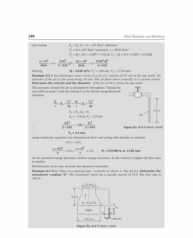
Example 6.3 A tap discharges water evenly in a jet at a velocity of 2.6 m/s at the tap outlet, thediameter of the jet at this point being 15 mm. The jet flows down vertically in a smooth stream.Determine the velocity and the diameter of the jet at 0.6 m below the tap outlet.
The pressure around the jet is atmospheric throughout. Taking thetap outlet as point 1 and also taking it as the datum using Bernoulliequation.
PZ
Vg
PZ
Vg
11
12
22
22
2 2γ γ+ + = + + ,
P1 = P2, Z2 = 0,
Z2 = – 0.6 m, V1 = 2.6 m/s
∴ 2 6
2 9 810 6
2 9 81
22
2..
..×
= − +×V
∴ V2 = 4.3 m/s.
using continuity equation (one dimensional flow) and noting that density is constant.
A1V1 = A2V2
π × 0154
2 × 2.6 =
π × D2
4 × 4.3, ∴ D = 0.01166 m or 11.66 mm
As the potential energy decreases, kinetic energy increases. As the velocity is higher the flow areais smaller.
Entrainment of air may increase the diameter somewhat.
Example 6.4 Water flows in a tapering pipe vertically as shown in Fig. Ex.6.4. Determine themanometer reading ‘‘h’’. The manometer fluid has a specific gravity of 13.6. The flow rate is100 l/s
0.1 m f
Q = 0.1 m /s3
0.6 m0.6 m
WaterWater
0.2 m f Mercury
A Bh
xm
1
2
Figure Ex. 6.4 Problem model
Figure Ex. 6.3 Problem model
0.6 m0.6 m
Jet
������������ ������������� ���� 187
VED
P-2\D:\N-fluid\Fld6-1.pm5
Ch
apte
r 6
The velocities at sections 1 and 2 are first calculated.
V1 = 4 × 0.1/ (π × 0.22) = 3.183 m/s,
V2 = 4 × 0.1/ (π × 0.12) = 12.732 m/s
It is desired to determine P1 – P2. Rearranging Bernoulli equation for this flow,
P P1 2−γ = 0.6 + (12.7322 – 3.1832)/(2 × 9.81) = 8.346 m of water
For water γ = 9810 N/m3. For the manometer configuration, considering the level AB and equatingthe pressures at A and B
P1γ + x + h =
P2γ
+ 0.6 + x + sh
(where x, h are shown on the diagram and s is specific gravity)
∴ P P1 2−
γ = 0.6 + h(s – 1), substituting the values,
8.346 = 0.6 + h(13.6 – 1)
∴ h = 0.6148 m or 61.48 cm
6.5 ENERGY LINE AND HYDRAULIC GRADIENT LINE
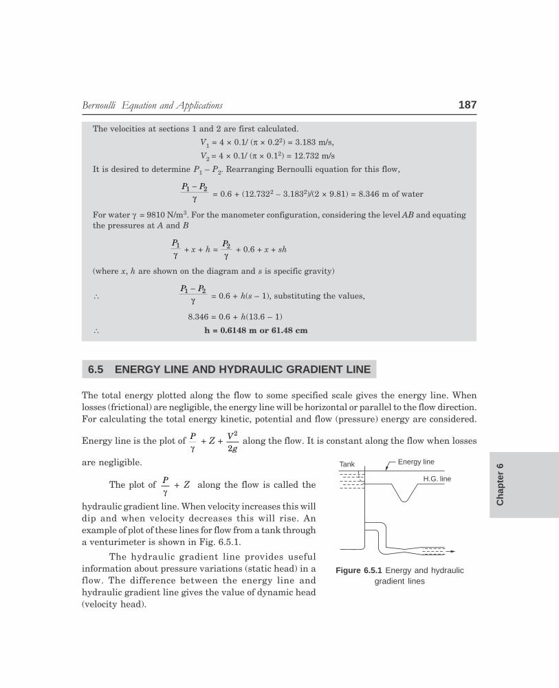
The total energy plotted along the flow to some specified scale gives the energy line. Whenlosses (frictional) are negligible, the energy line will be horizontal or parallel to the flow direction.For calculating the total energy kinetic, potential and flow (pressure) energy are considered.
Energy line is the plot of Pγ
+ Z + Vg
2
2 along the flow. It is constant along the flow when losses
are negligible.
The plot of Pγ
+ Z along the flow is called the
hydraulic gradient line. When velocity increases this willdip and when velocity decreases this will rise. Anexample of plot of these lines for flow from a tank througha venturimeter is shown in Fig. 6.5.1.
The hydraulic gradient line provides usefulinformation about pressure variations (static head) in aflow. The difference between the energy line andhydraulic gradient line gives the value of dynamic head(velocity head).
Tank Energy line
H.G. line
Figure 6.5.1 Energy and hydraulicgradient lines

188 ��������������������������
VED
P-2\D:\N-fluid\Fld6-1.pm5
A Bh
Datum
Z2
Z
A2P2
A1P1 Z1
1
Figure Ex. 6.5 Venturimeter-flow
6.6 VOLUME FLOW THROUGH A VENTURIMETER
Example 6.5 Under ideal conditions show that the volume flow through a venturimeter is given by
Q = A
A Ag
P PZ Z2
2 12 0 5
1 21 2
0 5
12
−
− + −FHG
IKJ
LNMM
OQPP/
.
.
b g{ }b g
γ
where suffix 1 and 2 refer to the inlet and the throat.
Refer to Fig. Ex. 6.5
Volume flow = A1 V1 = A2 V2
∴ V1 = AA
2
1V2, V1
2 = AA
2
1
2FHG
IKJ . V2
2,
∴ (V22 – V1
2) = V22 1 2
1
2
−FHG
IKJ
L
NMM
O
QPP
AA
Applying Bernoulli equation to the flow and considering section 1 and 2,
PZ
Vg
PZ
Vg
11
12
22
22
2 2γ γ+ + = + +
Rearranging,
2 1 21 2
0 5
gP P
Z Z− + −
RSTUVW
LNMM
OQPPγ
( ).
= V2 1 2
1
2 0 5
−FHG
IKJ
L
NMM
O
QPP
AA
.
V2 = 1
12
2 12 0 5
1 21 2
0 5
[ ( / ) ]( ).
.
−−
+ −RST
UVWLNMM
OQPPA A
gP P
Z Zγ
∴ Volume flow is
A2V2 = A
A Ag
P PZ Z2
2 12 0 5
1 21 2
0 5
12
[ ( / ) ]( ).
.
−− + −
RSTUVW
LNMM
OQPPγ (6.6.1)
This is a general expression and can be used irrespective ofthe flow direction, inclination from horizontal or verticalposition. This equation is applicable for orifice meters andnozzle flow meters also.
In numerical work consistent units should be used.
Pressure should be in N/m2, Z in m, A in m2 and then volumeflow will be m3/s.
A coeficient is involved in actual meters due to friction.
������������ ������������� ���� 189
VED
P-2\D:\N-fluid\Fld6-1.pm5
Ch
apte
r 6
Example 6.6 Show that when a manometric fluid of specific gravity S2 is used to measure the headin a venturimeter with flow of fluid of specific gravity S1, if the manometer shows a reading of hm,the volume flow is given by
Q = A
A Agh
SS
2
2 12 0 5
2
1
0 5
12 1
−−
FHG
IKJ
LNMM
OQPP( / )
.
.
Comparing the equation (6.6.1) with the problem at hand, it is seen that it is sufficient to prove,
h SS
P P2
1
1 2
11−
FHG
IKJ = −
γ + (Z2 – Z1)
Considering the plane A–B in the manometer and equating the pressures at A and B Fig. Ex. 6.5 :The manometer connection at the wall measures the static pressure only)
P1 + Z1 γ1 + hγ1 = P2 + Z2γ1 + hγ2
(P1 – P2) + (Z1 – Z1) γ1 = h(γ2 – γ1), dividing by γ1,
P P1 2
1
−γ
+ (Z1 – Z2) = hγγ
2
11−
FHG
IKJ = h
SS
2
11−
FHG
IKJ
Hence volume flow,
Q = A
A Agh
SS
2
2 12 0 5
2
1
0 5
12 1
[ ( / ) ] .
.
−−
FHG
IKJ
LNMM
OQPP (6.6.2)
This equation leads to another conclusion. The fluid head, H, causing the flow is equal to themanometer reading h[(S2/S1) – 1] and flow is independent of the inclination if the reading of themanometer and the fluids are specified.
i.e., As the manometer reading converted to head of flowing fluid, H = h[(S2/S1) – 1]
Q = A
A AgH2
2 12 0 5
0 5
12
[ ( / ) ][ ].
.
− (6.6.3)
If the pressure at various locations are specified, these equations are applicable for orifice andnozzle meters also.
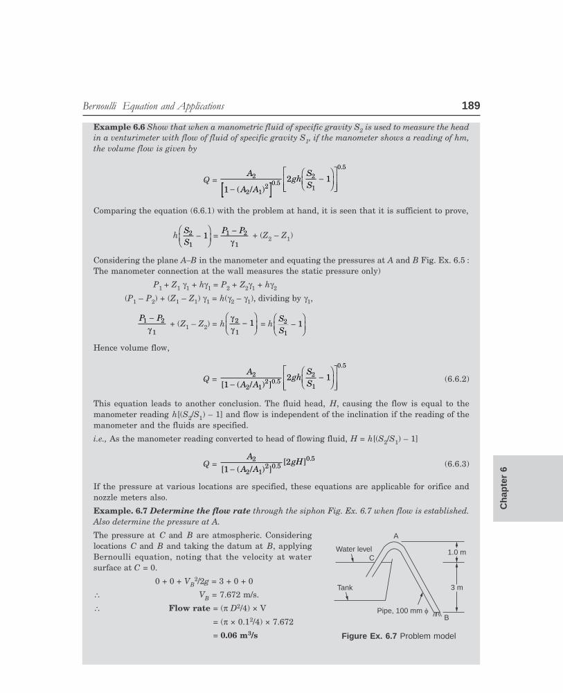
Example. 6.7 Determine the flow rate through the siphon Fig. Ex. 6.7 when flow is established.Also determine the pressure at A.
The pressure at C and B are atmospheric. Consideringlocations C and B and taking the datum at B, applyingBernoulli equation, noting that the velocity at watersurface at C = 0.
0 + 0 + VB2/2g = 3 + 0 + 0
∴ VB = 7.672 m/s.
∴ Flow rate = (π D2/4) × V
= (π × 0.12/4) × 7.672
= 0.06 m3/s Figure Ex. 6.7 Problem model
A
CWater level
Tank
Pipe, 100 mm fB
3 m3 m
1.0 m1.0 m

190 ��������������������������
VED
P-2\D:\N-fluid\Fld6-1.pm5
The velocity at A is the same as velocity at B. Now considering locations C and A,
3 + 0 + 0 = 4 + (PA/γ) + 7.6722/ (2 × 9.81)
∴ PA/γ = – 4m or – 4m of water head or 4m water-head below atmospheric pressure.
Check: Consider points A and B
4 + P V
gV
gA A B
γ+ =
2 2
2 2 + 0 + 0 as VA = VB, PA
γ = – 4 m checks.
Example. 6.8 Water flows in at a rate of 80 l/s from the pipe as shown in Fig. Ex. 6.8 and flowsoutwards through the space between the top and bottom plates. The top plate is fixed. Determinethe net force acting on the bottom plate. Assume the pressure at radius r = 0.05 m is atmospheric.
0.7 m
25 mm dr r
Bearing
0.1 m
1 2
Top plate(fixed)
Bottom plate
r
dr
Element considered
Figure Ex. 6.8 Problem model
Consider an element area of width dr (annular) in the flow region at a distance r as shown infigure. The pressure at this location as compared to point 1 can be determined using Bernoulliequation.
P1
γ + Z1 + V
gP1
22
2=
γ + Z2 + V
g2
2
2, P1 is atmospheric
As Z1 = Z2, P2 – P1 = γ
2g(V1
2 – V22)
V12 = (0.08/2π × 0.05 × 0.025)2 = 103.75
V22 = (0.08/2π × 0.025 × r)2 = 0.2594/r2
(P2 – P1) is the pressure difference which causes a force at the area 2πrdr at r.
The force on the element area of the bottom plate = 2πrdr (P2 – P1)
Substituting and nothing γ = ρg/g0, the elemental force dF is given by,
dF = ρ πrdr 103 750 2594
2..−L
NMOQPr
,
Integrating between the limits r = 0.05 to 0.35,
Net force = 1000 × π (103.75 (0.35 0.05 ) / 2) 0.2594 ln0.350.05
2 2− − FHG
IKJ
LNM
OQP = 17970 N
������������ ������������� ���� 191
VED
P-2\D:\N-fluid\Fld6-1.pm5
Ch
apte
r 6
6.7 EULER AND BERNOULLI EQUATION FOR FLOW WITH FRICTION
Compared to ideal flow the additional force that will be involved will be the shear force actingon the surface of the element. Let the shear stress be τ, the force will equal τ 2πr ds (where r isthe radius of the element, and A = π r2)
Refer Para 6.3 and Fig. 6.3.1. The Euler equation 6.3.3 will now read as
dPρ
+ VdV + gdZ – 2τ
ρdsr
= 0
dPγ
+ dV
g
2
2
FHG
IKJ + dZ –
2τγ
dsr
= 0
ds can also be substituted in terms of Z and θ
Bernoulli equation will now read as (taking s as the length)
P V
g1 1
2
2γ+ + Z1 =
P Vg
2 22
2γ+ + Z2 +
2τγ
sr
The last term is the loss of head due to friction and is denoted often as hL,hf in head offluid in metre height (check for the unit of the last term).
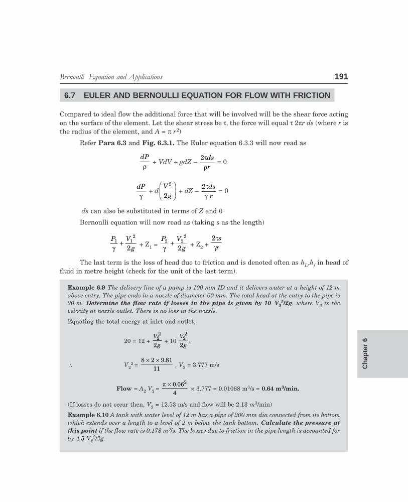
Example 6.9 The delivery line of a pump is 100 mm ID and it delivers water at a height of 12 mabove entry. The pipe ends in a nozzle of diameter 60 mm. The total head at the entry to the pipe is20 m. Determine the flow rate if losses in the pipe is given by 10 V2
2/2g. where V2 is thevelocity at nozzle outlet. There is no loss in the nozzle.
Equating the total energy at inlet and outlet,
20 = 12 + V
g22
2 + 10
Vg22
2,
∴ V22 =
8 2 9 8111
× × . , V2 = 3.777 m/s
Flow = A2 V2 = π × 0 06
4
2. × 3.777 = 0.01068 m3/s = 0.64 m3/min.
(If losses do not occur then, V2 = 12.53 m/s and flow will be 2.13 m3/min)
Example 6.10 A tank with water level of 12 m has a pipe of 200 mm dia connected from its bottomwhich extends over a length to a level of 2 m below the tank bottom. Calculate the pressure atthis point if the flow rate is 0.178 m3/s. The losses due to friction in the pipe length is accounted forby 4.5 V2
2/2g.
192 ��������������������������
VED
P-2\D:\N-fluid\Fld6-2.pm5
Taking location of the outlet of the pipe as the datum, using Bernoulli equation and accounting forfrictional drop in head (leaving out the atmospheric pressure which is the same at the water leveland at outlet).
14 = P2γ +
Vg22
2 + 4.5
Vg22
2
∴ V2 = 0.178/π × 0.1 × 0.1 = 5.67 m/s
14 – 5.5 ×5 67
2 9 81
2..×
= P2γ = 5 m of water head.
∴ P2 = 9810 × 5 N/m2 = 0.49 bar (above atmospheric pressure)
Example 6.11 A vertical pipe of diameter of 30 cm carrying water is reduced to a diameter of 15cm. The transition piece length is 6 m. The pressure at the bottom is 200 kPa and at the top it is 80kPa. If frictional drop is 2 m of water head, determine the rate of flow.
Considering the bottom as the datum,
200 109810
3× + 0 +
Vg12
2 =
80 109810
3× + 6 +
Vg22
2 +2
V22 = V1
2 (0.3/0.15)4 = 16V12
∴120 10
9810
3× – 8 = 15
Vg12
2, Solving, V1 = 2.353 and V2 = 9.411 m/s
∴ Flow rate = A1 V1 = A2V2 = 0.166 m3/s
6.8 CONCEPT AND MEASUREMENT OF DYNAMIC, STATIC AND TOTALHEAD
In the Bernoulli equation, the pressure term is known as static head. It is to be measured by aprobe which will be perpendicular to the velocity direction. Such a probe is called static probe.The head measured is also called Piezometric head. (Figure 6.8.1 (a))
The velocity term in the Bernoulli equation is known as dynamic head. It is measuredby a probe, one end of which should face the velocity direction and connected to one limb of amanometer with other end perpendicular to the velocity and connected to the other limb of themanometer. (Figure 6.8.1 (b))
The total head is the sum of the static and dynamic head and is measured by a singleprobe facing the flow direction. (Figure 6.8.1 (c))
The location of probes and values of pressures for the above measurements are shown inFig. 6.8.1.

������������ �������������� ���� 193
VED
P-2\D:\N-fluid\Fld6-2.pm5
Ch
apte
r 6
h
h
Statichead
VV
Dynamichead
(a)
Totalhead
(b) (c)
Figure 6.8.1 Pressure measurement
6.8.1 Pitot TubeThe flow velocity can be determined by
measuring the dynamic head using a device knownas pitot static tube as shown in Fig. 6.8.2. The holeson the outer wall of the probe provides the staticpressure (perpendicular to flow) and hole in the tubetip facing the stream direction of flow measures thetotal pressure. The difference gives the dynamicpressure as indicated by the manometer. The headwill be h (s – 1) of water when a differentialmanometer is used (s > 1).
The velocity variation along the radius in aduct can be conveniently measured by thisarrangement by traversing the probe across thesection. This instrument is also called pitot–statictube.
Example 6.12 The dynamic head of a water jet stream is measured as 0.9 m of mercury column.Determine the height to which the jet will rise when it is directed vertically upwards.
Considering the location at which the dynamic head is measured as the datum and converting thecolumn of mercury into head of water, and noting that at the maximum point the velocity is zero,
0.9 × 13.6 + 0 + 0 = 0 + 0 + Z ∴ Z = 12.24 m
Note. If the head measured is given as the reading of a differential manometer, then the headshould be calculated as 0.9 (13.6 – 1) m.
Pitottube
Dynamichead
Manometer
Static probe openings ( r to flow)
Total pressure probe (Facing flow)
Figure 6.8.2 Pitot-Static tube

194 ��������������������������
VED
P-2\D:\N-fluid\Fld6-2.pm5
Example 6.13 A diverging tube connected to the outlet of areaction turbine (fully flowing) is called ‘‘Draft tube’’. Thediverging section is immersed in the tail race water and thisprovides additional head for the turbine by providing a pres-sure lower than the atmospheric pressure at the turbine exit.If the turbine outlet is open the exit pressure will be atmos-pheric as in Pelton wheel. In a draft tube as shown in Fig. Ex.6.13, calculate the additional head provided by thedraft tube. The inlet diameter is 0.5 m and the flow velocityis 8 m/s. The outlet diameter is 1.2 m. The height of the inletabove the water level is 3 m. Also calculate the pressure at theinlet section.
Considering sections 1 and 2
P1γ +
Vg12
2 Z1 =
P1γ
+ V
g12
2 + Z2
Considering tail race level, 2 as the datum, and calulating the velocities
V1 = 8 m/s, V2 = 8 × 0 512
2
2..
= 1.39 m/s.
P2 = atmospheric pressure, Z2 = 0, Z1 = 3
P1γ
+ 8
2 9 81
2
× . + 3 =
1392 9 81
2..×
∴ P1γ
= – 6.16 m of water. (Below atmospheric pressure)
Additional head provided due to the use of draft tube will equal 6.16 m of water
Note: This may cause cavitation if the pressure is below the vapour pressure at the temperaturecondition. Though theoretically the pressure at turbine exit can be reduced to a low level, cavitationproblem limits the design pressure.
SOLVED PROBLEMS
Problem 6.1 A venturimeter is used to measure the volume flow. The pressure head isrecorded by a manometer. When connected to a horizontal pipe the manometer reading was hcm. If the reading of the manometer is the same when it is connected to a vertical pipe with flowupwards and (ii) vertical pipe with flow downwards, discuss in which case the flow is highest.
Consider equation 6.6.2
Q = A
A A
2
2 12 0.5
1 − /b g2 12
1
0.5
ghSS
−FHG
IKJ
LNMM
OQPP
Figure Ex. 6.13 Draft tube
0.5 m
3 m3 m
1
2Tail race
1.2
������������ �������������� ���� 195
VED
P-2\D:\N-fluid\Fld6-2.pm5
Ch
apte
r 6
As long as ‘h’ remains the same, the volume flow is the same for a given venturimeter asthis expression is a general one derived without taking any particular inclination.
This is because of the fact that the manometer automatically takes the inclination intoaccount in indicating the value of (Z1 – Z2).
Problem 6.2 Water flows at the rate of 600 l/s through a horizontal venturi with diameter0.5 m and 0.245 m. The pressure gauge fitted at the entry to the venturi reads 2 bar. Determinethe throat pressure. Barometric pressure is 1 bar.
Using Bernoulli equation and neglecting losses
P1
γ + V
g12
2 + Z1 =
P2
γ + V
g22
2 + Z2, P1 = 2 bar (gauge) = 3 bar (absolute) 3 × 10⁵ N/m2
V1 = Qd( / )π × 2 4
= 0 60 5 42
.( . / )π ×
= 3.056 m/s can also use
V2 = V1 DD
2
1
2FHG
IKJ
V2 = 0 6
0 245 42
.( . / )π × = 12.732 m/s, Substituting
3 109810
5× +
3 0562 9 81
2..×
+ 0 = P2
9810 +
12 7322 9 81
2..×
+ 0
∴ P2 = 223617 N/m2 = 2.236 bar (absolute) = 1.136 bar (gauge)
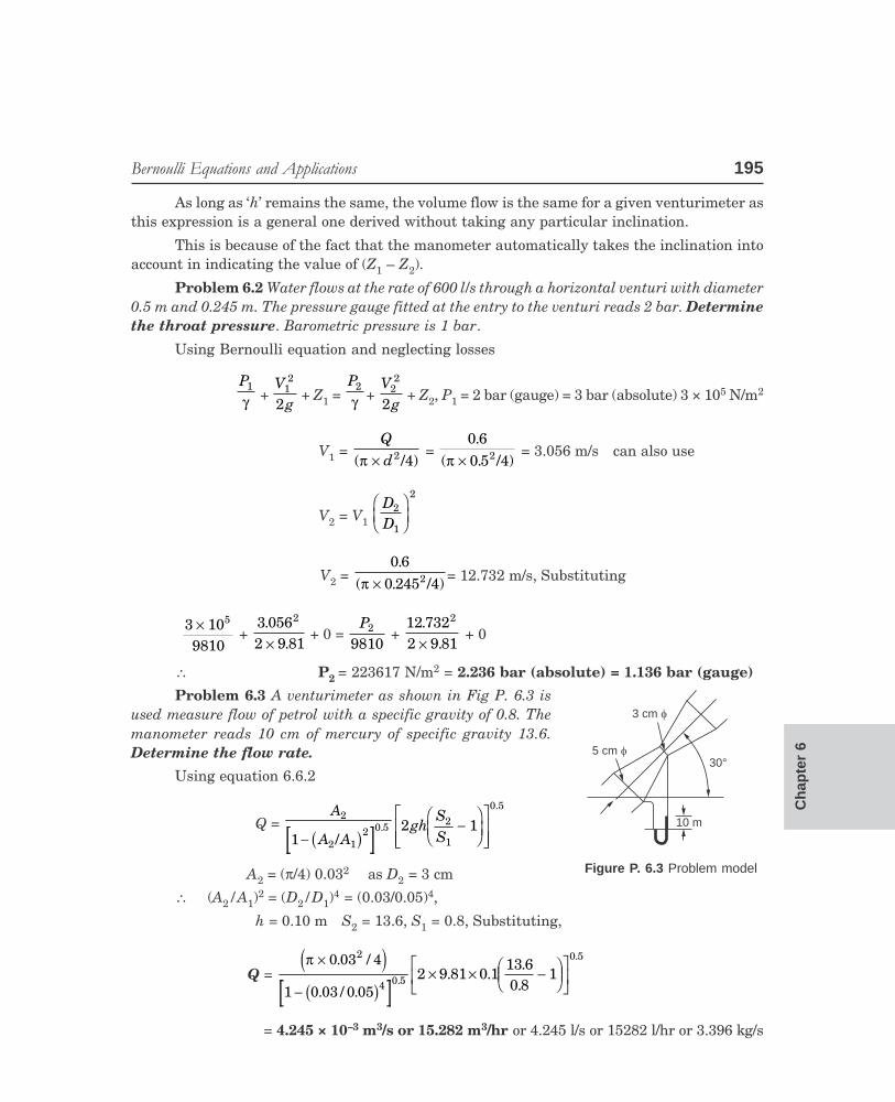
Problem 6.3 A venturimeter as shown in Fig P. 6.3 isused measure flow of petrol with a specific gravity of 0.8. Themanometer reads 10 cm of mercury of specific gravity 13.6.Determine the flow rate.
Using equation 6.6.2
Q = A
A A
2
2 12 0.5
1− /b g2 12
1
0.5
ghSS
−FHG
IKJ
LNMM
OQPP
A2 = (π/4) 0.032 as D2 = 3 cm
∴ (A2/A1)2 = (D2/D1)
4 = (0.03/0.05)4,
h = 0.10 m S2 = 13.6, S1 = 0.8, Substituting,
Q = π ×
−
0 03 4
1 0 03 0 05
2
4 0.5
. /
. / .
e jb g
2 9 81 0 113 60 8
10.5
× × −FHG
IKJ
LNM
OQP
. ...
= 4.245 × 10⁻³ m3/s or 15.282 m3/hr or 4.245 l/s or 15282 l/hr or 3.396 kg/s
10 m
30°
3 cm f
5 cm f
Figure P. 6.3 Problem model
196 ��������������������������
VED
P-2\D:\N-fluid\Fld6-2.pm5
Problem 6.4 A liquid with specific gravity 0.8 flows at the rate of 3 l/s through aventurimeter of diameters 6 cm and 4 cm. If the manometer fluid is mercury (sp. gr = 13.b)determine the value of manometer reading, h.
Using equation (6.6.2)
Q = A
A A
2
2 12 0.5
1 − /b g2 12
1
0.5
ghSS
−FHG
IKJ
LNMM
OQPP
A1 = π × 0 064
2. = 2.83 × 10⁻³ m2 ;
A2 = π × 0 04
4
2. = 1.26 × 10⁻³ m2
3 ×10–3 = 126 10
11010
2 9 8113 60 8
13
3
3
2 0.5
0.5.
...
×
− ××
FHG
IKJ
L
NMM
O
QPP
× × −FHG
IKJ
LNM
OQP
−
−
−1.262.83
h
Solving, h = 0.0146 m = 14.6 mm. of mercury column.
Problem 6.5 Water flows upwards in a vertical pipe line of gradually varying sectionfrom point 1 to point 2, which is 1.5m above point 1, at the rate of 0.9m3/s. At section 1 the pipedia is 0.5m and pressure is 800 kPa. If pressure at section 2 is 600 kPa, determine the pipediameter at that location. Neglect losses.
Using Bernoulli equation,
P1
γ + V
g12
2 + Z1 =
P2
γ + V
g22
2 + Z2
800 109810
3× +
0 9 4 0 5
2 9 81
2. / .
.
× ×
×
πe j+ 0 =
600 109810
3× +
V22
2 9 81× . +1.5
Solving, V2 = 19.37 m/s.
Flow = area × velocity, π × d2
2
4 ×19.37 = 0.9 m3/s
Solving for d2, Diameter of pipe at section 2 = 0.243 m
As (p/γ) is involved directly on both sides, gauge pressure or absolute pressure can beused without error. However it is desirable to use absolute pressure to aviod nagative pressurevalues.
Problem 6.6 Calculate the exit diameter, if at the inlet section of the draft tube thediameter is 1 m and the pressure is 0.405 bar absolute. The flow rate of water is 1600 l/s. Thevertical distance between inlet and outlet is 6 m.
������������ �������������� ���� 197
VED
P-2\D:\N-fluid\Fld6-2.pm5
Ch
apte
r 6
Applying Bernoulli equation between points 1 and 2, neglecting losses
P1
γ + V
g12
2 + Z1 =
P2
γ + V
g22
2 + Z2
V1 = Q
D
××
4
12π
= 1600 10 4
1
3
2
× ××
−
π = 2.04 m/s
P2 = atmospheric pressure; Z2 = 0 (datum); Z1 = 6 m
0 405 109810
5. × +
2 042 9 81
2..×
+ 6 = 1013 10
9810
5. × +
V22
2 9 81× . + 0 ∴ V2 = 0.531 m/s
AA
2
1 =
VV
1
2 =
D22
21 =
2 040 531
..
∴ D2 = 1.96 m
0.405 bar absolute means vacuum at the inlet section of the draft tube. This may cause‘‘cavitation’’ if this pressure is below the vapour pressure at that temperature. Thoughtheoretically the pressure at turbine exit, where the draft tube is attached, can be reduced to avary low level, cavitation problem limits the pressure level.
Problem 6.7 Water flows at the rate of 200 l/s upwards through a tapered vertical pipe.The diameter at the bottom is 240 mm and at the top 200 mm and the length is 5m. The pressureat the bottom is 8 bar, and the pressure at the topside is 7.3 bar. Determine the head lossthrough the pipe. Express it as a function of exit velocity head.
Applying Bernoulli equation between points 1 (bottom) and 2 (top) and considering thebottom level as datum.
P1
γ +
Vg12
2 + Z1 =
P2
γ +
Vg22
2 + Z2 + losses
8 109810
2× +
( ) / . ).
200 10 4 0 242 9 81
3 2 2× × ××
− π + 0
= 7 3 10
9810
5. ×+
( )/( )200 10 42
3 2× × ××
− π 0.29.81
2
+ 5 + losses
∴ Losses = 1.07 m
1.07 = XV
g22
2 = X
200 10 40 22
23 2
× ××
LNM
OQP
−
π ./ × 9.81 ∴ X = 0.516,
Loss of head = 0.516 V
g22
2

198 ��������������������������
VED
P-2\D:\N-fluid\Fld6-2.pm5
Problem 6.8 Calculate the flow rate of oil (sp. gravity, 0.8) in the pipe line shown inFig. P. 6.8. Also calculate the reading ‘‘h’’ shown by the differential manometer fitted to thepipe line which is filled with mercury of specific gravity 13.6.
Applying Bernoulli equation (neglecting losses) between points 1 and 2
P1
γ + V
g12
2 + Z1 =
P2
γ + V
g22
2 + Z2
P1 = 2 × 10⁵ N/m2; P2 = 0.8 ×10⁵ N/m2 ;
Z1 = 0, Z2 = 2 m
20.8 bar
2 m
0.2
1 2 bar
0.5h
Figure P. 6.8
Applying continuity equation between points 1 and 2
A1V1 = A2V2, V2 = V1
AA
1
2 = V1
ππ
××
FHG
IKJ
0 5 40 2 4
2
2. /. / = 6.25 V1
2 109810 0 8
5×× .
+ V1
2
2 9 81× .+ 0 =
0 8 109810 0 8
5..
×× +
6 25
2 9 811
2.
.
Vb g×
+ 2 ∴V1 = 2.62 m/s
Flow rate, Q = A1 V1 = π × 0 5
4
2. × 2.62 = 0.514 m3/s = 514 l/s
Using equation (6.6.2) (with A2 = 0.031 m2, A1 = 0.196 m2)
Flow rate, Q = A
A Agh
SS
2
2 12 0.5
2
1
0.5
12 1
−−
FHG
IKJ
LNMM
OQPP/b g
0.514 = 0 031
10 0310 196
2 9 8113 60 8
12 0.5
0.5.
.
.
...
− FHG
IKJ
LNMM
OQPP
× × −FHG
IKJ
LNM
OQP
h
Solving, h = 0.854 m

������������ �������������� ���� 199
VED
P-2\D:\N-fluid\Fld6-2.pm5
Ch
apte
r 6
Problem 6.9 Water flows at the rate of 400 l/s through the pipe with inlet (1) diameter of35 cm and (2) outlet diameter of 30 cm with 4m level difference with point 1 above point 2. If P1= P2 = 2 bar absolute, determine the direction of flow.
Consider datum as plane 2
Total head 1,2 109810
5× +
0.4 4/ 0.35
2 9.81
2 2× ×
×
πe j + 4 = 25.27 m water column
Total head at 2, 2 109810
5× +
0.4 4/ 0.3
2 9.81
2 2× ×
×
πe j + 0 = 22.02 m of water column
The total energy at all points should be equal if there are no losses. This result showsthat there are losses between 1 and 2 as the total energy at 2 is lower. Hence the flow willtake place from points 1 to 2.
Problem 6.10 Petrol of relative density 0.82 flows in a pipe shown Fig. P.6.10. Thepressure value at locations 1 and 2 are given as 138 kPa and 69 kPa respectively and point 2 is1.2m vertically above point 1. Determine the flow rate. Also calculate the reading of thedifferential manometer connected as shown. Mercury with S = 13.6 is used as the manometerfluid.
20.69 bar
0.15 m
1 1.38 bar
0.3 mh
B A
1.2 m1.2 m
Figure P. 6.10 Problem Model
Considering point 1 as a datum and using Bernoulli equation.
P1
γ +
Vg12
2 + Z1 =
P2
γ +
Vg22
2 + Z2, Z1 = 0, Z2 = 1.2 m, V2 = V1
AA
1
2 = V
DD1
12
22
FHG
IKJ
∴ V22 = V1
2 DD
14
24
FHG
IKJ = 16 V1
2 as D1/D2 = 2

200 ��������������������������
VED
P-2\D:\N-fluid\Fld6-2.pm5
v = 6 m/s1
10.3 m
3 m3 m
2
138 10
0 82 9810
3××.
+ V
g12
2 + 0 =
69 100 82 9810
3××.
+ 16 V
g12
2
FHG
IKJ + 1.2
138 69 100 82 9810
3−×
b g.
– 1.2 = 15V
g12
2. Solving, V1 = 3.106 m/s
∴ Volume flow = π × 0 3
4
2. × 3.106 = 0.22 m3/s or 180 kg/s
The flow rate is given by equation 6.6.2
Q = A
AA
ghSS
2
2
1
2 0.52
1
0.5
1
2 1
−FHG
IKJ
L
NMM
O
QPP
−FHG
IKJ
LNMM
OQPP
, SS
2
1 =
13 60 82
..
0.22 = π ×
− FHG
IKJ
LNMM
OQPP
× × −FHG
IKJ
LNM
OQP
0.15
0.150.3
9.8113.60.82
12
4 0.5
0.54
1
2/
h
Solving, h = 0.475 m of mercury column
Problem 6.11 Water flows downwards in a pipe as shownin Fig. P.6.11. If pressures at points 1 and 2 are to be equal,determine the diameter of the pipe at point 2. The velocityat point 1 is 6 m/s.
Applying Bernoulli equation between points 1 and 2(taking level 2 as datum)
P1
γ + 6
2 9 81
2
× . + 3 =
P2
γ + V
g22
2 + 0
as P1 = P2, V2 = 9.74 m/s
Using the relation A1 V1 = A2V2,
π × ×0 3 6
4
2. =
π × ×d2 9 744
.
∴ d = 0.2355 m.
Problem 6.12 A siphon is shown in Fig P. 6.12. Point A is 1m above the water level,indicated by point 1. The bottom of the siphon is 8m below level A. Assuming friction to benegligible, determine the speed of the jet at outlet and also the pressure at A.
Figure P. 6.11 Problem model

������������ �������������� ���� 201
VED
P-2\D:\N-fluid\Fld6-2.pm5
Ch
apte
r 6
Using Bernoulli equation, between 1 and 2.
11 m
A
8 m
2
Figure P. 6.12 Problem model
P1
γ +
Vg12
2 + Z1 =
P2
γ +
Vg22
2 + Z2 ,
P1 = P2 = atmospheric pressure.
Consider level 1 as datum. The velocity of water at the surface is zero.
∴ 0 + 0 = V
g22
2 – 7
∴ V2 = 7 2 9 81× × . = 11.72 m/s = VA
Considering surface 1 and level A. As flow is the same,
P1
γ + 0 + 0 = PA
γ + 1 +V
gA2
2
Considering P1/γ = 10.3 m of water,
PA
γ =
P1γ
– 1 – Vg22
2 = 10.3 – 1 – 7
= 2.3 m of water column (absolute)
Problem 6.13 A pipe line is set up to draw water from a reservoir. The pipe line has togo over a barrier which is above the water level. The outlet is 8 m below water level. Determinethe maximum height of the barrier if the pressure at this point should not fall below 1.0 mof water to avoid cavitation. Atmospheric pressure is 10.3 m.
Considering outlet level 3 as datum and water level as 1 and appyling Bernoulli equation,
Z3 = 0, Z1 = 8, V1 = 0, P1 = P3
∴ 8 = V
g32
2∴ V3 = 8 9 81 2× ×. = 12.53 m/s

202 ��������������������������
VED
P-2\D:\N-fluid\Fld6-2.pm5
WL 1
2
3
h
8 m
Figure P. 6.13 Problem model
Considering the barrier top as level 2
P2
γ + V
g22
2 + Z2 =
P3
γ + V
g32
2 + Z3, As V2 = V3, Z3 = 0, P2/γ = 1
1 + Z2 = 10.3
∴ Z2 = 9.3 m. Therefore the barrier can be 1.3 m above water level.
Problem 6.14 Determine the flow rate of water across the shutter in an open canal ifthe water level upstream of shutter is 5m and downstream is 2m. The width of the canal is 1mand flow is steady.
Applying Bernoulli equation between point 1 in the upstream and point 2 in thedownstream on both sides of the shutter, both surface pressures being atmospheric.
Vg12
2 + 5 =
Vg22
2 + 2 (1)
Applying continuity equation, flow rate, Q = A1V1 = A2V2
(1 × 5) V1 = (1 × 2) V2, � V2 = 2.5 V1, Substituting in equation (1),
V12
2 9 81× . + 5 =
2 5
2 9 811
2.
.
Vb g×
+ 2,
∴ V1 = 3.35 m/s, V2 = 8.37 m/s. Q = 16.742 m3/s,
Problem 6.15 Uniform flow rate is maintained at a shutter in a wide channel. Thewater level in the channel upstream of shutter is 2m. Assuming uniform velocity at any sectionif the flow rate per m length is 3m3/s/m, determine the level downstream.
Assume velocities V1 and V2 upstream and downstream of shutter and the datum as thebed level. Using Bernoulli equation
2 + V
g12
2 = h2 +
Vg22
2(A)
Considering unit width from continuity 1 × 2 × V1 = 1 × h2 × V2 (B)
∴ V2 = (2/h2) V1, from flow rate V1 = 3/2 = 1.5 m/s ∴ V2 = 3
2h

������������ �������������� ���� 203
VED
P-2\D:\N-fluid\Fld6-2.pm5
Ch
apte
r 6
Substituting
2 + 1.5
2 9.81
2
× = h2 +
32 9 81
2
2h × × .
Simplifying, this reduces to h23 – 2.1147 h2
2 + 0.4587 = 0
Solving, h2 can be 2 m, – 0.425 m, 0.54 m
h2 = 0.54 m is the acceptable answer. 2m being trivial.
Using B, 0.54 × V2 × 1 = 2 ×1.5 = 3. ∴ V2 = 5.56 m/s.
check using A, 2 + 0.1147 = 0.54 + 1.57 checks.
The difference between the dynamic head values will equal the difference between thedatum heads. This may be checked using the calculated velocity values.
Problem 6.16 A pump with centre line 2m above the sump water level develops 50mhead of water. The suction pipe is of 150 mm ID. The loss of head in the suction line is given by5 Vs
2/2g. The delivery line is of 100 mm dia and the loss in the line is 12 Vd2/2g. The water is
delivered through a nozzle of 75 mm dia. The delivery is at 30m above the pump centre line.Determine the velocity at the nozzle outlet and the pressure at the pump inlet.
Let the velocity at the nozzle be Vn
Velocity in the delivery pipe = Vd = Vn × 75
100
2
2 = 916
Vn
Velocity in suction pipe Vs= Vn 75150
2FHG
IKJ =
Vn
4
Kinetic head at outlet = V
gn2
2
Loss in delivery pipe = V
gd2
2 = 12 ×
916
2FHG
IKJ
Vgn2
2 = 3.797
Vgn2
2
Loss in suction pipe = V
gs2
2 =
516
V
gn2
2 = 0.3125
Vgn2
2
Equating the head developed to the static head, losses and kinetic head,
50 = 30 + 2 + V
gn2
2 [1 + 3.797 + 0.3125]
18 × 2 × 9.81 = Vn2 [5.109]
∴ Velocity at the nozzle Vn = 8.314 m/s
Pressure at suction : Taking datum as the water surface and also the velocity of thewater to be zero at the surface,
204 ��������������������������
VED
P-2\D:\N-fluid\Fld6-2.pm5
P1 as atmospheric, 10.3 m of water column, Kinetic head V2/2g, loss 5V2/2g
10.3 = P2γ
+ 2 + 8.314/42 9.81
2b g×
FHG
IKJ
× (5 + 1) (as Vs = Vn/4)
∴P2
γ = 10.3 – 3.321 m = 6.979 m absolute
or 3.321 m below atmospheric pressure.
Problem 6.17 A liquid jet at a velocity V0 is projected at angle θ. Describe the path of thefree jet. Also calculate the maximum height and the horizontal distance travelled.
The horizontal component of the velocity of jet is Vxo = V o cos θ. The vertical componentVzo = Vo sin θ.
In the vertical direction, distance travelled, Z, during time t, (using the second law ofNewton)
Z = Vzo t – (1/2) gt2 (A)
The distance travelled along x direction
X = Vxo t or t = X/Vxo (B)
Solving for t from B and substituting in A,
Z = VV
zo
xo X –
12
g
Vxo2
X2 (C)
Z value can be maximised by taking dz/dx and equating to zero
dzdx
= VV
zo
xo
– 12
g
Vxo2
2X,VV
zo
xo =
gX
Vxo2 ∴ X = VzoVxo/g
Substituting in C,
Zmax = VV
zo
xo.
V Vg
zo xo – 12
g
Vxo2
. V V
gzo xo2 2
2
= 12
Vgzo2
= V
g0
2 2
2sin θ
, Zmax = Vo2 sin2 θ/2g (D)
The maximum height is achieved when θ = 90°.
∴ Xmas = 2 times x as Zmax.
Xmax = 2Vo2 sin θ cos θ /g = Vo
2 sin 2θ/g (E)
Maximum horizontal reach is at θ = 45° or 2θ = 90° and for this angle it will reach halfthe vertical height.
This describes an inverted parabola as shown in Fig. P.6.17
Bernoulli equation shows that Zt + Vt2/2g = constant along the rejectory. Vt is the
velocity at that location when air drag is neglected. Pressure is assumed to be uniform all overthe trejectory as it is exposed to atmosphere all along its travel. Hence

������������ �������������� ���� 205
VED
P-2\D:\N-fluid\Fld6-2.pm5
Ch
apte
r 6
Zt + Vt2 /2g = constant for the jet.
(Note: Velocity at time t = Vzo t = V0 sin θ + a × t, where a = – g, so the velocity decreases,becomes zero and then turns – ve)
V20
2g
Vx20
2gV
2
2gJet path
Vx0
Total head = Energy grade line
V = V = constantx x0
z z0V = V – gt
P
Z
Vz0V0
qVx0 = V cos0 q
V0 sin q
0
Vx0 Vg
z0
X
Zmax =Vz 0
2
2g
Figure P. 6.17 Jet trejectory
Problem 6.18 A jet issuing at a velocity of 20 m/s is directed at 30° to the horizontal.Calculate the height cleared by the jet at 25m from the discharge location? Also determinethe maximum height the jet will clear and the corresponding horizontal location.
Ref Fig. P. 6.17
Vxo = Vo cos 30 = 20 cos 30 = 17.32 m/s;
Vzo = Vo sin 30 = 20 sin 30 = 10 m/s;
at time t, X = Vxot; Z = Vzo t – (1/2) gt2, Substituting for t as X/Vxo with X = 25 m
Z = VV
zo
xo X –
12
g
Vxo2
X2 (A)
Height cleared, Z25 = 10
17 32. × 25 –
12
9 8117 322
.
. × 252 = 4.215 m
Maximum height of the jet trajectory = V
gzo2
2 =
102 9 81
2
× . = 5.097 m
Corresponding horizontal distance = V V
gxo zo =
17 32 109 81
..
× = 17.66 m
Total horizontal distance is twice the distance travelled in reaching
Zmax = 35.32 m
It would have crossed this height also at 10.43 m from the starting point (check usingequations derived in Problem 6.17).
206 ��������������������������
VED
P-2\D:\N-fluid\Fld6-3.pm5
Problem 6.19 Determine the velocity of a jet directed at 40° to the horizontal to clear6 m height at a distance of 20m. Also determine the maximum height this jet will clear and thetotal horizontal travel. What will be the horizontal distance at which the jet will be again at 6mheight.
From basics, referring to Fig. P. 6.17,
Vxo = Vo cos 40, Vzo = Vo sin 40,
X = Vxo t, t = X
Vxo, Z = Vzo t – (1/2) gt2
Substituting for t as X/Vxo
Z = VV
zo
xoX –
12 2
g
Vxo X2 (A)
Substituting the values,
6 = VV V
o
o o
sincos
.cos
4040
2012
9 81 2040
2
2 2× − × ×
6 = 20 tan 40 – 12
9 81 2040
2
2 2.
cos×
Vo(B)
∴ Vo2 =
9 81 202 40 20 40 6
2
2.
cos ( tan )×
− = 310 ∴ Vo = 17.61 m/s.
Maximum height reached
= Vzo2/2g = (Vo sin 40)2/2g
= (17.61 × sin 40)2 /2 × 9.81 = 6.53 m
The X value corresponding to this is, (half total horizontal travel)
X = VxoVzo/g = 17.612 sin 40 cos 40/9.81 = 15.56 m.
This shows that the jet clears 6m height at a distance of 20 m as it comes down. The jetwould have cleared this height at a distance less than 15.56 m also. By symmetry, this can becalculated as – (20 – 15.56) + 15.56 = 11.12 m
check by substituting in equation B.
11.12 tan 40 – 12
× 9 81 1112
17 61 40
2
2 2
. .. cos
× = 6
When both Z and X are specified unique solution is obtained. Given Vo and Z, two valuesof X is obtained from equation A.
Problem 6.20 Determine the angle at which a jet with a given velocity is to be projectedfor obtaining maximum horizontal reach.
Refer Problem 6.17. X = Vxo t, Z = Vzo t – (1/2) gt2
The vertical velocity at any location/time is given by,
Vzt = dzdt
= Vzo – gt

������������ �������������� ���� 207
VED
P-2\D:\N-fluid\Fld6-3.pm5
Ch
apte
r 6
The horizontal distance travelled will be half the total distance travelled when
Vzt = 0 or t = Vzo/g
Total X distance travelled during time 2t.
X = 2 Vxo Vzo/g = 2 Vo2 cos θ sin θ/g = Vo
2 sin 2θ/g
For X to be maximum sin 2θ should be maximum or 2θ = 90° or
θθθθθ = 45°. For maximum horizontal reach, the projected angle should be 45°.
The maximum reach, X = Vo2/g as sin 2θ = 1.
Problem 6.21 Determined the angle at which a jet with an initial velocity of 20 m/sis to be projected to clear 4m height at a distance of 10 m.
Fall
Rise
4 m4 m
10 m10 m
29.3°
82.5°
Figure P. 6.21 Jet trejectory
Refer Problem 6.17, eqn. C
Z = VV
zo
xox –
12
2
2gx
Vxo
Substituting in terms of Vo and θ.
Z = VV
o
o
sincos
θθ x –
12
2
2 2gx
Vo cos θ = x tan θ – 12
gx
Vo
2
2 (sec2 θ)
Z = x tan θ – 12
2
2gx
Vo (1 + tan2 θ)
Substituting the given values, 4 = 10 tan θ – 12
9 81 1020
2
2. × (1 + tan2 θ)
Hence, tan2 θ – 8.155 tan θ + 4.262 = 0, solving tan θθθθθ = 7.594 or 0.5613
This corresponds to θθθθθ = 82.5° or 29.3°. In the first case it clears the height during thefall. In the second case it clears the height during the rise. See Fig. P.6.21.
208 ��������������������������
VED
P-2\D:\N-fluid\Fld6-3.pm5
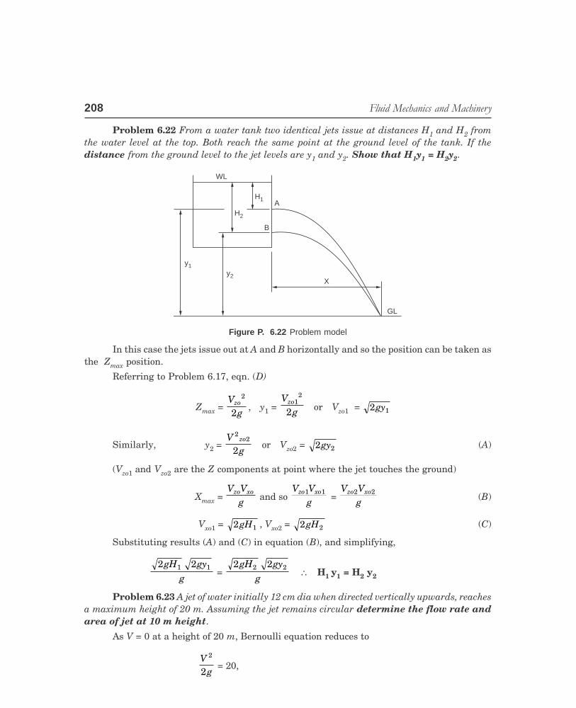
Problem 6.22 From a water tank two identical jets issue at distances H1 and H2 fromthe water level at the top. Both reach the same point at the ground level of the tank. If thedistance from the ground level to the jet levels are y1 and y2. Show that H1y1 = H2y2.
WL
H2
H1A
B
y2
y1
X
GL
Figure P. 6.22 Problem model
In this case the jets issue out at A and B horizontally and so the position can be taken asthe Zmax position.
Referring to Problem 6.17, eqn. (D)
Zmax = V
gzo
2
2, y1 =
Vg
zo12
2 or Vzo1 = 2 1gy
Similarly, y2 = V
gzo
22
2or Vzo2 = 2 2gy (A)
(Vzo1 and Vzo2 are the Z components at point where the jet touches the ground)
Xmax = V V
gzo xo
and so V V
gzo xo1 1
= V V
gzo xo2 2
(B)
Vxo1 = 2 1gH , Vxo2 = 2 2gH (C)
Substituting results (A) and (C) in equation (B), and simplifying,
2 21 1gH gy
g =
2 22 2gH gy
g∴ H1 y1 = H2 y2
Problem 6.23 A jet of water initially 12 cm dia when directed vertically upwards, reachesa maximum height of 20 m. Assuming the jet remains circular determine the flow rate andarea of jet at 10 m height.
As V = 0 at a height of 20 m, Bernoulli equation reduces to
V
g
2
2 = 20,

������������ �������������� ���� 209
VED
P-2\D:\N-fluid\Fld6-3.pm5
Ch
apte
r 6
∴ V = (20 × 9.81 × 2)0.5 = 19.809 m/s
Flow rate = area × velocity = π × 0 12
4
2. × 19.809 = 0.224 m3/s
When the jet reaches 10 m height, the loss in kinetic energy is equal to the increase inpotential energy. Consider this as level 2 and the maximum height as level 1 and ground asdatum,
P1 = P2, V1 = 0, Z2 = Z1 – 10 = (20 – 10) = 10
20 = 10 + V
g
220
2∴
Vg
22
2 = 10,
∴ V2 = (10 × 2 × 9.81)0.5 = 14 m/s
Flow rate = area × velocity, 0.224 = π × D2
4 × 14 ∴ D = 0.1427 m
Problem 6.24 Water is discharged through a 150 mm dia pipe fitted to the bottom of atank. A pressure gauge fitted at the bottom of the pipe which is 10 m below the water level shows0.5 bar. Determine the flow rate. Assume the frictional loss as 4.5V2
2/2g.
Applying Bernoulli equation between the water level, 1 and the bottom of the pipe, 2and this level as datum
P V
g1 1
2
2γ+ + Z1 =
P Vg
2 22
2γ+ + Z2 + losses
0 + 0 + 10 = 0 5 10
9810 2 9 81
52
2..
× +×V
+ 0 + 4.5 V2
2
2 9 81× .
Solving, V2 = 4.18 m/s
Flow rate = π × 0 15
4
2. × 4.18 = 0.0739 m3/s = 73.9 l/s.
Problem 6.25 An open tank of diameter Dcontaining water to depth ho is emptied by a smooth orificeat the bottom. Derive an expression for the time taken toreduce the height to h. Also find the time tmax for emptyingthe tank.
Considering point 1 at the top of the tank and point 2at the orifice entrance, and point 2 as datum
Patm + V
g12
2 + h =
Vg2
2
2 + patm
∴ Vg
h12
2+ =
Vg2
2
2
Also V12 = V2
2 dDLNM
OQP
4Figure P. 6.25 Problem model
DD
hh
h0h0
– dh
d

210 ��������������������������
VED
P-2\D:\N-fluid\Fld6-3.pm5
∴ V2 = 2
1 4gh
d D− ( / )
Let the level at the time considered be h.The drop in level dh during time dt is given by (as dh is negative with reference to
datum)
dhdt
V AA
dD
gh
dD
= − = − FHG
IKJ
− FHG
IKJ
2 2
1
2
4
2
1
Taking dD
FHG
IKJ
2
inside and rearranging
dhdt
gh
Dd
= −FHG
IKJ −
2
14
Separating variables and integrating
dhh
g
Dd
dtt
h
h
o
= −FHG
IKJ −
zz 2
14 0
.
22
14h hg
Dd
to − =FHG
IKJ −
.(A)
t = 2( ) /h hg
Dd
o −FHG
IKJ −
2
14 = h ho − /
g
Dd
/ 2
14F
HGIKJ − (B)
Equation (A) can be rearranged to give
hh
t g h
Dd
o
0 4
2
12
1
= −FHG
IKJ −
L
N
MMMMM
O
Q
PPPPP
/
(C)
Equation (B) will be useful to find the drop in head during a given time interval.Consider a numerical problem.Let D = 0.5 m, d = 0.025 m, ho = 0.5 m,Time for emptying is calculated as h = 0,
t = ho /
g
Dd
/ 2
14F
HGIKJ −
������������ �������������� ���� 211
VED
P-2\D:\N-fluid\Fld6-3.pm5
Ch
apte
r 6
= 0 5. /
9 81 2
0 50 025
14
. /
..
FHG
IKJ − = 127.7 seconds.
To find the drop in level in say 100 seconds.
hho
= −×
FHG
IKJ −
L
N
MMMMM
O
Q
PPPPP
1
2
100 9.81/ 2 0.5
0.50.25
14 = 0.0471
∴ Drop in head = 0.5 (1 – 0.0471) = 0.4764 m
In case d << D, then V2 = 2gh when head is h m
dhdt
A VA
= − 2 2
1 = – V2
dD
dD
ghFHG
IKJ = − F
HGIKJ
2 2
2.
Separating variables and integrating
dh
hh
h
oz = –
dD
g dttF
HGIKJ z
2
02 .
2 [ ho – h ] = dD
g tFHG
IKJ
2
2 .
In this case to empty the tank,
2 0 5. = 0 0250 5
2 9 812.
.. .F
HGIKJ × . t.
Solving t = 127.71 s.
The same answer because the same diameter of the orifice is used. Say d = 0.01 m, thentime for employing is 1130 sec.
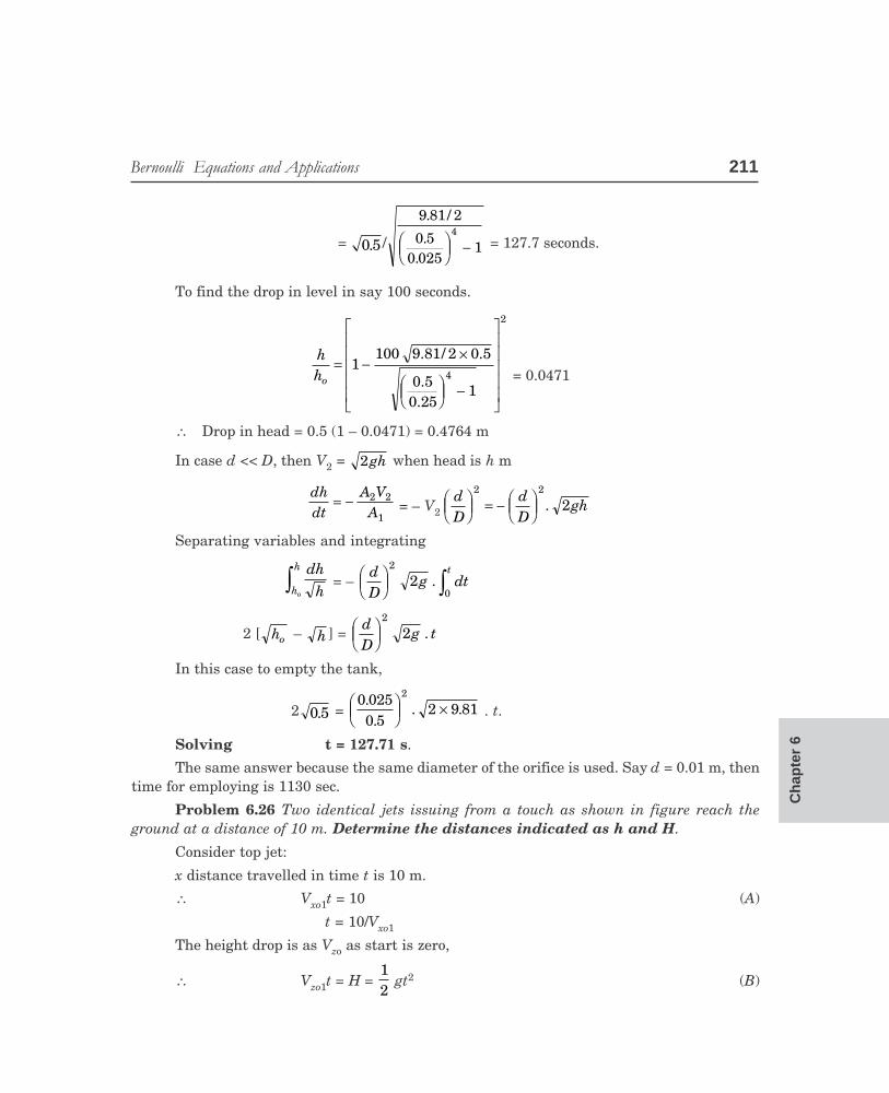
Problem 6.26 Two identical jets issuing from a touch as shown in figure reach theground at a distance of 10 m. Determine the distances indicated as h and H.
Consider top jet:
x distance travelled in time t is 10 m.
∴ Vxo1t = 10 (A)
t = 10/Vxo1
The height drop is as Vzo as start is zero,
∴ Vzo1t = H = 12
gt2 (B)

212 ��������������������������
VED
P-2\D:\N-fluid\Fld6-3.pm5
HH
hh
4 m4 m
Z
1
2
10 m10 m
3x
Figure P. 6.26 Problem model
Substituting for t
H = 12
g 100
2Vxo
∴ V2xo =
50gH
As jet issues from the nozzle it has any x directional velocity Vxo1, is present.
V2xo1 = 2 g4 = 8g (C) (as head available in 4 m)
Substituting, 8g = 50gH
or H = 6.25 m.
Considering the second jet.
Vxo2 t = 10, t = 10
2Vxo,
The head drop in (H – h) m. As in the previous case Vzoc = 0 at start
H – h = 12
gt2. Substituting
H – h = 12
g 1
22
V
Vo
xo
= 50
22
g
Vxo(D)
As at start only Vxo2 is present,
Vxo22 = (4 + h) g × 2
Substituting in (D)
H – h = 50
4 2g
h g( )+ × = 25
4 + h, as H = 6.25 m.
6.25 – h = 25
4 + h. This leads to
h2 – 2.25h = 0, or h = 2.25 m.
It may be also noted from problem 6.22.
H × 4 = (H – h) (4 + h).
6.25 × 4 = 4 × 6.25
Hence this condition is also satisfied.

������������ �������������� ���� 213
VED
P-2\D:\N-fluid\Fld6-3.pm5
Ch
apte
r 6
OBJECTIVE QUESTIONS
O Q. 6.1. Fill in the blanks:1. Kinetic energy of fluid element is due to its –––––––––––––––––.
2. The amount of kinetic energy per kg is given by the expression ––––––––––––––––– the unitused being head of fluid.
3. The kinetic energy in the unit Nm/kg is given by the expression –––––––––––––––––.
4. Potential energy of a fluid element is due to its –––––––––––––––––.
5. Potential energy of a fluid element in head of fluid is given by –––––––––––––––––.
6. Potential energy of a fluid element in Nm/kg is given by –––––––––––––––––.
7. Pressure energy or flow energy of a fluid element is given in head of fluid by the expression –––––––––––––––––.
8. Pressure energy or flow energy of a fluid element in the unit Nm/kg is given by the expression –––––––––––––––––.
9. Internal energy is due to ––––––––––––––––.
10. In the analysis of incompressible fluid flow, internal energy is rarely considered because –––––––––––––––––.
11. Electrical and magnetic energy become important in the flow of –––––––––––––––––.
Answers
(1) motion (2) V2/2g, where V is the velocity (3) V2/2go where go is the force conversion constanthaving a unit of m kg/Ns2 (4) location in the gravitational field. (5) Z, the elevation from datum(6) Zg/go, Z being elevation (7) (P/ρ) (go/g) = p/γ.go where γ is specific weight. (8) P/ρ (9) themicroscopic activity of atoms/molecules of the matter, exhibited by the temperature (10) tem-perature change is generally negligible (11) plasma.
O Q. 6.2. Fill in the blanks:1. Eulers equation is applicable for flow along a –––––––––––––––––.
2. Bernoulli equation is applicable for flows which are –––––––––––––––––.
3. Bernoulli equation states that the total head –––––––––––––––––.
4. Total head in a steady incompressible irrotational flow is the sum of –––––––––––––––––.
5. In steady flow along a horizontal level as the velocity increases the pressure ––––––––––––––.
6. The pressure along the diverging section of a venturi –––––––––––––––––.
7. Cavitation will occur when the pressure at a point –––––––––––––––––.
8. Draft tube ––––––––––––––––– the available head in the case of reaction turbines.
9. Energy line along the flow ––––––––––––––––– if there are no losses.
10. Hydraulic grade line represents the sum of ––––––––––––––––– along the flow.
11. If a pump supplies energy to the flow the energy line ––––––––––––––––– .
12. If there are frictional losses the energy grade line will ––––––––––––––––– .
Answers
(1) stream line (2) incompressible, steady and irrotational (3) remains constant if there are noirreversibilities (4) dynamic head, pressure head and potential head (5) decreases (6) increases(7) goes below the vapour pressure of the fluid at that temperature. (8) increases (9) will behorizontal parallel to the flow (10) pressure and potential head (11) will increase by a step (12) dip.

214 ��������������������������
VED
P-2\D:\N-fluid\Fld6-3.pm5
O Q. 6.3. Indicate whether the statement is correct or incorrect.1. Energy line along the direction of flow will dip if there are losses.
2. When a pump supplies energy to a flow stream, the energy line will decreases by a step.
3. For ideal flows the energy line will slope upward along the flow.
4. If velocity increases, the hydraulic grade line will dip along the flow direction.
5. If the differential manometer reading connected to a venturimeter is the same, the flow will beindependent of the position or flow direction.
6. For the same reading of the differential manometer connected to a vertical venturimeter, theflow rate will be larger if flow is downwards.
7. A pitot probe connected perpendicular to flow will indicate the total head.
8. A pitot probe facing the flow will indicate the dynamic head.
9. A pitot probe facing the flow will indicate the total head.
10. A pitot-static tube has probes both facing the flow and perpendicular to flow.
11. Flow will take place along hydraulic gradient.
12. Flow will take place along energy gradient.
Answers
Correct – 1, 4, 5, 9, 10, 11 Incorrect – 2, 3, 6, 7, 8, 12
O Q. 6.4. Choose the correct answer:1. For a free jet the maximum horizontal reach will depend on
(a) the angle of projection only (b) the initial velocity only
(c) the fluid flowing in the jet (d) the angle of projection and initial velocity.
2. Bernoulli equation is applicable for
(a) steady rotational flow (b) steady rotational compressible flow
(c) steady irrotational incompressible flow (d) unsteady irrotational incompressible flow
(e) all flows.3. In a steady flow along a stream line at a location in the flow, the velocity head is 6 m, the
pressure head is 3 m, the potential head is 4 m. The height of hydraulic gradient line at this lo-cation will be
(a) 13 m (b) 9 m (c) 10 m (d) 7 m
4. In a flow along a varying flow cross section, as the area decreases
(a) the energy line will slope up
(b) the hydraulic gradient line will slope up
(c) the hydraulic gradient line will slope down
(d) the energy line will slope down.
5. In a steady flow of incompressible fluid, as the diameter is doubled, the velocity will
(a) be halved (b) be doubled
(c) increase four fold (d) decrease four fold.
6. In steady flow in a varying section pipe if the diameter is doubled the kinetic energy will
(a) be doubled (b) increase 4 times
(c) increase 8 times (d) decrease to one sixteenth.

������������ �������������� ���� 215
VED
P-2\D:\N-fluid\Fld6-3.pm5
Ch
apte
r 6
7. In a source type of flow, the kinetic energy along the radius will vary (constant thickness of fluidalong radius)
(a) proportional to radius
(b) directly proportional to the square root of radius
(c) inversely proportional to the square of radius
(d) proportional to the fourth power of radius
8. In a vertical flow of incompressible fluid along a constant pipe section under steady conditions,the pressure along flow direction will
(a) remain constant (b) decrease
(c) increase (d) increase or decrease depending on the fluid.
9. The differential manometer connected to two points along a pipe line gives a reading of h m. Theflow will be
(a) highest if the pipe is horizontal
(b) independent of the slope of pipe and direction of flow
(c) highest if flow is downwards
(d) will depend on the fluid.
Answers
(1) d (2) c (3) d (4) c (5) d (6) d (7) c (8) b (9) b.
O Q. 6.5. Match the sets1. Set A Set B
1. Bernoulli equation (a) potential function
2. Continuity equation (b) stream line
3. Eulers equation (c) total head
4. Laplace equation (d) conservation of mass.
2. Set A Set B1. potential energy (a) plasma flow
2. kinetic energy (b) temperature
3. internal energy (c) position
4. electrical energy (d) velocity.
Answers
(1) 1c, 2d, 3b, 4a (2) 1c, 2d, 3b, 4a
EXERCISE PROBLEMS
E 6.1. A pipe inclined at 45° to the horizontal converges from 0.2 m dia to 0.1 m at the top over alength of 2 m. At the lower end the average velocity is 2m/s. Oil of specific gravity 0.84 flowsthrough the pipe. Determine the pressure difference between the ends, neglecting losses. If amercury manometer (specific gravity 13.6) is used to measure the pressure, determine thereading of the manometer difference in m of mercury. Oil fills the limbs over mercury in themanometer. (36.854 N/m2, 0.201m)

216 ��������������������������
VED
P-2\D:\N-fluid\Fld6-3.pm5
E 6.2. Oil of specific gravity of 0.9 flows through a venturimeter of diameters 0.4 and 0.2 m. A U-tube mercury manometer shows a head 0.63 m. Calculate the flow rate. (0.105 m3/s)
E 6.3. Water flows from a reservoir 240 m above the tip of a nozzle. The velocity at the nozzle outletis 66 m/s. The flow rate is 0.13 m3/s. Calculate (1) the power of the jet. (2) the loss in head dueto friction. (283.14 kW, 17.98 m)
E 6.4. Water flows in the middle floor tap at 3 m/s. Determine the velocities at the taps in the othertwo floors shown in Fig. E. 6.4.
V = ?
V = ?
3 m/s
3 m
2.2 m
1.8 m
Supply
Figure E. 6.4
E 6.5. Oil flows through a horizontal pipe will line which has a diameter of 0.45 m at the start. Aftersome distance the diameter of reduces to 0.3 m at which point the flow divides into pipes of0.15 m and 0.225 m diameter. The velocity at the beginning is 1.8 m/s. The velocity in the pipeline of 0.225 m dia is 3.6 m/s. If the pressure at the start is 20 m head of oil and the specificgravity of the oil is 0.91 determine the pressure at the fork and also at the end of the twobranch pipes. Neglect losses.
(V at fork = 4.05 m/s, V0.15 = 8.1 m/s, Pfork = 13.33 m, P0.15 = 16.821 m, P0.225 = 19.5 m)E. 6.6. A nozzle of 25 mm dia. directs a water jet vertically with a velocity of 12 m/s. Determine the
diameter of the jet and the velocity at a height of 6 m. (38.25 mm, 5.13 m/s)E 6.7. A pipe line is 36 m above datum. The pressure and velocity at a section are 410 kN/m2 and 4.8
m/s. Determine the total energy per kg with reference to the datum. (774.7 Nm.kg)E 6.8. The supply head to a water nozzle is 30 m gauge. The velocity of water leaving the nozzle is
22.5 m/s. Determine the efficiency and power that can be developed if the nozzle diameter is75mm. (84.3%, 25.2 kW)
E 6.9. The suction pipe of a pump slopes at 1 m vertical for 5 m length. If the flow velocity in thepipe is 1.8 m/s and if the pressure in the pipe should not fall by more than 7 m of water,determine the maximum length. (35.8 m)
E 6.10. The pressure at the entry to the pipe line of 0.15 m dia. is 8.2 bar and the flow rate at thissection is 7.5 m3/min. The pipe diameter gradually increases to 0.3 m and the levels rises by3 m above the entrance. Determine the pressure at the location. Neglect losses. (8.14 bar)
E 6.11. A tapering pipe is laid at a gradient of 1 in 100 downwards. The length is 300 m. The diameterreduces from 1.2 m to 0.6 m. The flow rate of water is 5500 l/min. The pressure at the upperlocation is 0.8 bar. Determine the pressure at the lower location. (0.73 bar)
E 6.12. A horizontal pipe carrying water is gradually tapering. At one section the diameter is 150 mmand flow velocity is 1.5 m/s. (i) If the drop in pressure is 1.104 bar at a reduced section deter-mine the diameter at the section. (ii) If the drop in pressure is 5 kN/m2, what will be thediameter? Neglect losses. (47.6 mm, 100 mm)
������������ �������������� ���� 217
VED
P-2\D:\N-fluid\Fld6-3.pm5
Ch
apte
r 6
E 6.13. The diameter of a water jet at nozzle exist is 75 mm. If the diameter at a height of 12 m is98.7mm, when the jet is directed vertically, determine the height to which the jet will rise.
(18 m)E 6.14. Calculate the height to which the jet, issuing at 18.8 m/s will rise when (i) The jet is directed
vertically (ii) when it is directed at 45°. Also find the horizontal distance travelled in thiscase. (18 m, 9 m, 9 m)
E 6.15. A jet directed at 30° reaches a maximum height of 3 m at a horizontal distance of 18 m.Determine the issuing velocity of the jet. (16.9 m/s)
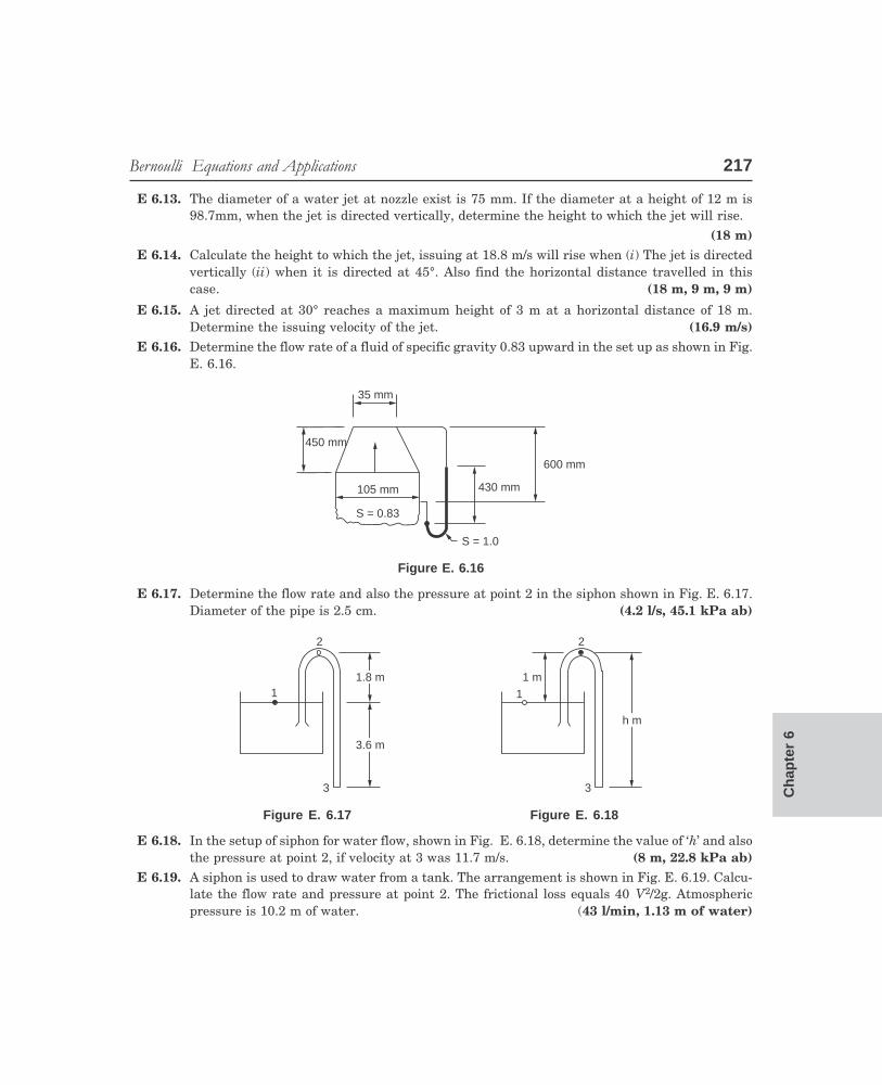
E 6.16. Determine the flow rate of a fluid of specific gravity 0.83 upward in the set up as shown in Fig.E. 6.16.
35 mm
450 mm
105 mm
S = 0.83
S = 1.0
430 mm
600 mm
Figure E. 6.16
E 6.17. Determine the flow rate and also the pressure at point 2 in the siphon shown in Fig. E. 6.17.Diameter of the pipe is 2.5 cm. (4.2 l/s, 45.1 kPa ab)
2
11.8 m
3.6 m
3
2
1
1 m
h m
3
Figure E. 6.17 Figure E. 6.18
E 6.18. In the setup of siphon for water flow, shown in Fig. E. 6.18, determine the value of ‘h’ and alsothe pressure at point 2, if velocity at 3 was 11.7 m/s. (8 m, 22.8 kPa ab)
E 6.19. A siphon is used to draw water from a tank. The arrangement is shown in Fig. E. 6.19. Calcu-late the flow rate and pressure at point 2. The frictional loss equals 40 V2/2g. Atmosphericpressure is 10.2 m of water. (43 l/min, 1.13 m of water)

218 ��������������������������
VED
P-2\D:\N-fluid\Fld6-3.pm5
WL
7.5 m
1.5 m
1
2
3 m
3
f 25 mm 1.3 m
5 m/s
1.5 m
y
y1
Figure E. 6.19 Figure E. 6.20
E 6.20. Water flows through a channel as shown in Fig. E. 6.20. Determine the possible values ofdepth of water down stream. Neglect losses. Assume uniform velocity of 5 m/s upstream.
E 6.21. Water flows up an inclined duct as shown in Fig. E. 6.21 Determine the possible depth ofwater upstream.
0.5 m
9.86 m/s
2.5 m
y
1.3 m
1 m OilS = 0.75
Water
f 10 mm
Figure E. 6.21 Figure E. 6.22
E 6.22. Neglecting losses, determine the flow rate in the setup shown in Fig. E. 6.22.
E 6.23. Derive an expression for the variation of jet radius r with distance y downwards for a jetdirected downwards. The initial radius is R and the head of fluid is H.
E 6.24. For the venturimeter shown in Fig. E. 6.24, determine the flow rate of water.
E 6.25. A horizontal pipe divides into two pipes at angles as shown in Fig. E. 6.25. Determine thenecessary forces along and perpendicular to the pipe to hold it in place. Assume that these areno losses.
Air
150 mm
200 mm
300 mm
70 k Pa60°
150 mm
300 mm
0.24 m /s3
0.36 m /s3
45°
540 mm
Figure E. 6.24 Figure E. 6.25