SPECI EICATIONS - Vintage Machinery
40
SPECI EICATIONS . . DIAL TYPE MILLING MACHINES TAE CINCINNATI MILLING MACHINE CO., CINCINNATI, OHIO, U. S. A. · I dllltp-Tbe C,acin.DaU M.u:ac MaebiJle ________________ --
-
Upload
khangminh22 -
Category
Documents
-
view
1 -
download
0
Transcript of SPECI EICATIONS - Vintage Machinery

SPECI EICATIONS
eUw~ DIAL TYPE
MILLING MACHINES
TAE CINCINNATI MILLING MACHINE CO CINCINNATI OHIO U S A middot CltIgt~ Idllltp-Tbe CacinDaU Muac MaebiJle Ctl~~________________-shy
DIAL TYPE MILLING MACHINES
BUILT IN THREE SIZES Nos 2 3 and 4
bull THREE STYLES
Plain Universal and Vertical
bull Medium Speed and High-Speed
Machine Illustrations Pages 3 to 9 Highligh ts of Design Pages 10 and 12 Operating Controls and Construction Details Pages 11 and 13 Ease of Set-Up and Manipulation Pages 14 and 15 Machine Description Pages 16 to 21 Dividing Head Pages 22 and 23 Attachments and Accessories Pages 24 to 27 Specifications and Dimensional Drawings Pages 28 to 36 Standard Equipment Page 37 Equipment Supplied At Extra Cost Page 38 Electrical Equipment Page 39
ATENT NOTICE-The machines and attadlments The design aAd specifications of the illustrated and descnbed in this booklet are protected mac1tinesiUustrated herein are subshyb Issued aDd pendiag UDited Stateeand Foreign Pa en s jet to change without notice
CINCINNATI Dial Type Milling Machines briefiy illustrated and described in this booklet offer possibilities for higher production in metal working shops of almost any size Here are the ways in which the Dial Types will help your shop
bull Theyre quickly set up more producing hours available during the day less nonproductive hours required for setting up different jobs
bull Theyre easy to operate and that means the elimination of production lag towards the end of the day It means a higher daily production with no increase in labor or overhead costs wider latitude in the physical abilities of your milling machine operators more satisfied operators
bull They have adequate spindle speeds and feeds for milling a wide variety of materials
bull Theyre accurate not only as a fine machine but also in producing your milled parts more accurately When the work is adjusted to the cutter the depth of cut equals the adjustment no more or no less
bull Theyre durable and when production is needed most theyre on the job
lit fiEPH
~Ii
ffil -w-~-tf
COVER ILLUSTRATION
A four-operation job of milling two fiats and two sets of rack teeth on rear control racks (Sketch of the part shown here) Production rate for first and second operations about 30 per hour for third and fourth operations about 36 per hour
Pas~ 3
CINCINNATI No3 PLAIN HIGH-SPEED DIAL TYPE
3d(1 Tvta a33dS-H91H Ntv1d e oN IlvNNDND
CINCINNATI No2 UNIVERSAL HIGH-SPEED DIAL TYPE
Page 6
3dlt1 11la a33dS-H91H 11S~3INn E oN IlvNNDND
CINCINNATI No 3 VERTICAL HIGH-SPEED DIAL TYPE
pa
3dAl 1vIO 033dS-HDIH Tv)IHJ3A E oN 11vNNDND
HIGHLIGHTS OF DESIGN
1 Power Speed and Feed Changes At Front and Rear Working Posishytions Controlled with single lever Without walking speeds and feeds may be changed to suit the job and cut
I High Spindle Speeds and Feeds Many kinds of materials from tough steel to aluminum may be milled at correct speeds and feeds (Medium speed machines also available)
3 Power Feeds Longitudinal Cross Vertical Engaged by single independent directional controls simplify operation for new men
4 Duplicate Set Of Control Levers At Operators Rear Working Posishytion When work-piece obscures cutter operator may manipulate machine from rear of table reduces spoilage
S Power Rapid Traverse Longitudinal Cross Vertical Minimizes cutting air saves time
6 Power Feed and Power Rapid Traverse To Vertical Head May be obtained for vertical machines Handy for die work boring etc
7 Touch-Control Starting and Stopping Light touch of starting lever front or rear starts or stops spindle drive Hydraulic mechanism engages clutch spool relieving operator of majority of starting and stopping effort
8 Smooth Streamlined Design Easy to keep clean
9 Pull-Out Quick-Adjusting Micrometer Dials Easy to set for hand adjustments no thumbscrews to lose
10 Automatic Motor Cut-Out Switch I f operator forgets to shut off power motor automatically stops when hinged cover at rear is opened
TURN TO PAGE 12 FOR TEN ADDITtONAL HIGHLIGHTS
Page 10
OUTER ARBOR SUPPORT
INNER ARBOR SUPPORT
REAR CONTROL POWER
RAPID TRAVERSE
PILOT WHEEL OVERARM
ADJUSTMENT
STARTING LEVER
SPEED CALCULA TOR
SPEED DIAL
REAR CONTROL POWER SPEED
AND FEED CHANGE
FEED DIAL
HAND TABLE ADJUSTMENT
REAR HAND CROSS ADJUSTMENT
REAR DIRECTIONAL CONTROL-POWER -=-shy
VERTICAL FEED
REAR HAND VERTICAL
A DJUSTMENT
REAR DIRECTIONAL CONTROL-POWER
CROSS FEED
REAR DIRECTIONAL CONTROL-POWER
TABLE FEED
OIL SHOT LUBRICA TlNG PUMP
(Universal M ac hines)
AN INDEX TO OPERATING CONTROLS AND CONSTRUCTION DETAILS Pasc 11 (UIYeI Machine IliuttratccJ)
HIGHLIGHTS OF DESIGN
~-A~ Beneitt (Concluded)
11 Speed Calculator For determining the correct spindle speed lengthens cutter life
12 One-Piece Overarm Brace It clamps to top of knee increases rigidity of machine for heavy cuts Short arbors can be used with braces
13 Rugged Proportions of Principal Casting Dampen out vibrations withstand heavy loads
14 Heavy MUltiple Disc Clutches Heavy duty multiple disc starting clutch starts spindle drive instantly plenty of reserve power for pulling the heaviest load heavy duty multiple disc brake stops spindle instantly safer for the operator
15 Simple Effective Lubrication Principally automatic prolongs mashychine life-span daily requirements can be handled very quickly
16 Rectangular Overarm Solid and rigid straight-edge alignment of overarm and arbor supports with centerline of spindle
17 Hand Cranks Automatically Disengaged When Released Safer for the operator
18 Enclosed Dividing Head Driving Mechanism Safer for the operator Provides leads of 25 to 100 (Leads from 010 to 1000 with special attachment)
19 Dividing Head Powerfully built withstands heavy cuts exceptionally accurate
COARSE HAND VERTICAL HEAD
ADJUSTMENT
POSITIVE MICROMETER
STOP
FINE HAND VERTICAL HE A D
ADJUSTME NT
FRONT DI RECTIONAL CONTR OL-POWER
TABLE FEED
FRONT CONTROL POWER SPEED
AND FEED CHA NGE
FRONT DIRECTIONAL CONTROL- POWER
CROSS FEED
TABLE DOGS
FRONT HA ND CROSS ADJUSTMENT
FR ONT DIRECTIONA L CONTROL-POWER
VERTICAL FEED
FRONT CONTROL POWER RA PID
TRAVERSE
FRONT HAND VERTIC A L
ADJUSTM ENT
SADDLE CL AMP
COOLA NT RETURN TUBE
OIL SHOT LU BRIC A TING PUMP
( Plain an d Vertical M achines)
KNEE CL A MP
AN INDEX TO OPERATING CONTROLS AND CONSTRUCTION DETAILS (Concluded) P4981 (Vertical Machift~ IIlultrated)
~ CINCI = NATI I EASY QUICK SET UPS
fi bull
POWER RAPID TRAVERSE CONTROL AT THE REAR
Engaging the table rapid traverse from the rear working position Without moving a step he can also engage the cross and vertical rapid traverse These handy rear controls duplicatshying all those in front of the machine allow him to make the necessary manipulations from the rear of the table when the work obscures the cutter
POWER RAPID TRA VERSE CONTROL AT THE FRONT
Engaging the power table rapid traverse from the normal front working position As soon as the rapid traverse lever ( in his right hand ) is released the table travel immediately changes to a feed rate Power vertical and cross rapid traverse may be engaged in a similar manner greatly reducing the time required to adjust the work to the cutter
Plgc 14
bull bull bull EASY O~ OPERATE
POWER SPEED AND FEED CHANGES AT THE FRONT
He changes speeds and feeds without walking without effort and one lever does both jobs A mere touch of the starting lever instantly stops the spindle Then with a flip of the speed-feed change lever the dial clicks around and when the desired reading lines up with the arrow hes all ready to go The machine does the work of shifting gears he merely swivels a lever and starts and stops the spindle drive
PULL-OUT QUICK ADJUSTING MICROMETER DIALS
He doesnt have to add or subtract mentally when adjusting the work to the cutter Just pull out the dial rotate it to match the zero mark with the starting line and then start the adjustment from zero Theres no play or looseness to throw the dial marks out of register with the zero line the clutch teeth take care of that Cross vertical and table hand adjustments front and rear have these dials
POw CR SPEED
q r r~ND FEED Of0 it ~(1(4~relttr Of t In~r~LcOlle~ 4YG(S cblltJge I be table tbere eJlellt to 1Igt0r
tdbullbull r ht doPii h th h d i tho Ob~ Pdfd d d ~td fdfo) f th d tS1er
ea tbe )) e gets Ino llJe to la tYPe ~ re dO
ay l1e
Pa 15
Easy to Operate Because the Dial Type Millers are easy
and convenient to manipulate the operator finds it easy to turn out more work without additional effort Here are the factors which contribute to this unusual ease of operation
First of all its no effort to change speeds or feeds and it may be done while standing either at the front or rear of middotthe table In any case the machine does the actual work of shifting gears while the operator merely swivels a small lever Theres no clashing or dead ending of gears for the shifting mechanism slides them in and out of mesh in perfect coordination While the shifting
MACHINE
lever is engaged say in the feed position the large easy-to-see feed dial clicks around to the various readings Incidentshyally it requires only a few seconds for a complete revolution As soon as the lever is released the dial stops and the proper gears are in mesh to produce the feed indishycated by the arrow
Engaging or disengaging the main drive clutch requires no more effort than a light touch on the starting lever Here again the machine does most of the work A hydraulic middotmechanism engages the clutch spool reducing the effort of starting to a small fraction of the conventional design
COMPLETE DUPLICATE REAR CONTROLS
The convenient arrangement of rear controls All within reach without walking or stretching
p s 16
DESCRIPTION
Convenient to Operate
All control levers are easy to reach-easy to engage Power feed levers for all feed movements-table cross and vertical-are independent directional controls Hand adjustments are provided with anti-friction bearings for easy and accurate adjustment of the work to the cutter
Safe to Operate
Dial Types are safe too There are no exposed rotating parts hand cranks and handwheels automatically disengage when released a built-in switch automatically stops the motor as soon as the hinged cover at the rear is opened when the spindle drive is disengaged a multiple disc brake autoshymatically and instantly stops the spindle
SPEED AND FEED LEVER
One lever changes spindle speeds and feeds This lever is located at the front of the saddle A similar lever is located at the rear working position
Horizontal machines are equipped with duplicate power and hand controls at the operators rear working position (behind the table at the left-hand side of the column) With this arrangement the work never obscures the operators view of the cutter for he can work from the front or rear as the job requires Quite naturally spoilage drops to a new low
STANDARD V-BELT DRIVE ACCESSIBLE COOLANT PUMP When the hinged cover is opened the motor automatically stops an important factor in safety
Pase middot17
~
Accurate Results
Several factors contribute to the better than average accuracy which may be obtained Liberal proportions of the principal castings plus the rigid double row precision anti-friction bearings for the spindle (self-compensating at the rear for temperature changes) fulfill the basic requirements for accurate results Wide bearing surfaces on top of the knee with narrow center guide construction promote smooth cross adjustment of the saddle All flat bearing surfaces are hand scraped to accurate gages The ample length of knee bearing on the column preshyvents the knee from sagging assures milled surfaces that are flat and parallel to the table Pull-out micrometer dials provide a simplified method of setting the dials before adjusting the work to the cutter
Rigid Construction
Dial Type Milling Machines are designed for miscellaneous milling operations and quite naturally they also handle the heavy stock removal jobs in their stride a cost-reducing asset for both tool room and production work
Notice the sturdy proportions of the principal castings shown to advantage in the several views of the complete machine throughout this booklet The column has the smooth lines so essential to a rigid and substantial supporting element It looks massive and the generous thickness of walls and heavy ribs substantiate the appearance The overarm of the horizontal machines is unusually heavy constituting a rigid support for the outer end of the arbor
CONSTANT VIGILANCE Many accuracy tests during assembly assure accurate
machines which will do accurate work
A one-piece overarm brace ties the knee to the overarm for those extra heavy cuts It clamps to the top of the knee forming the most effective arrangement for increasshying rigidity Then too short arbors can be used with this new brace since it may be clamped right next to the front of the saddle
Note the ample proportions of the knee saddle and table castings The knee bearing on the column and saddle bearing on the knee are exceptionally wide while the table has plenty of depth in addition to underneath surface-plate ribbing These are the proportions that resist twisting and deflections withstand the complex strains created by the cutting action
P se 18
OVERARM BRACE FOR
EXTRA HEAVY CUTS One-piece brace rigidly ties knee to overarm j adds strength to withstand those extra heavy cuts
MASSIVE VERTICAL HEAD Rear view of the No3 Vertical
Dial Type Massive proportions of upper part of colwnn add plenty of reserve strength for~eavy face milling operations
Pse 19
The Correct Speed
Each Dial Type Miller is now equipped with a speed calculator which enables the operator to quickly deshytermine the correct speed for the job at hand mental gymnastics no paper work Just take three known factors
No the
1 Diameter of cutter 2 Cutter material 3 Work material
Set the two dials on the speed calculator to indicate the first two of these factors and from the third read the answer Then with the power speed change lever change the spindle speed to the correct rpm- both exclusive Dial Type features
bull The Speed Calculator has the same spindle speeds as the speed dial Calculator illustrated is actual size as used on No 2 High-Speed Dial Type
The setting here is for a 3 diameter high-speed steel cutter Opposite the material to be milled (follow the arrow) will be found the correct spindle speed and the corresponding cutting speed of the cutter For exshyample SAE 1046 spindle speed 92 rpm cutting speed 72 feet per minute
Pate 20
Long Useful life-Spa n
C INC INN A T I Dial Type Milling Machines have many features and design characteristics that keep them young in performance when they become old in years
Lubrication is a relatively simple proshycedure All parts within the column are automatically lubricated by a pump and splash system all parts within the knee are likewise automatically lubricated by a pump and splash system while all parts within the saddle and housing are lubricated by a pressure oil-shot system High-grade materials are used throughout high content chrome-nickel steels for the gears and shafts Meehanite metal for all iron castshy
e ings Heat-treatments for gears spindles and shafts employ the latest scientific equipment Test after test-an inspection after each operation on every part-assures no faulty workmanship Adjustments can be taken care of by the average operator
All these factors combine to minimize maintenance expenditures And when you must turn out the work quickly the Dial Types are on the job and ready to go at a moments notice
PLENTY OF OIL WHERE ITS NEEDED
Pressure oil-shot system for the saddle and table parts No hard-to-find oil holes for the operator to overlook with a few strokes of the plunger the oil-shot pump takes care of all the saddle-housing-table bearing surfaces
~ ~2~u ~ ~
RIGID LONG -LIFE SPINDLE MOUNTING Double rows of precIsion anti-friction bearings autoshymatically lubricated rigidly support the spindle
PLEASING APPEARANCE TO THE LAST DETAIL
Coolant is conveyed to the cutter through armored metal braid hose and flexible copper tubing
21
Dividing
ACTUAL ACCUMULATIVE ERROR IN INDEXING DIVIDING HEAD MUST NOT
EXCEED 0015
Checking the indexing accuracy of a CINCINshyNATI Dividing Head by means of an Optical Micrometer and a circular scale graduated in degrees Each Dividing Head receives this test
Accuracy
0IS
144
P e 22
This circle and the __
line at the left gr trate CINCINNATI Head accuracy wire 018 in diameter trasted with a 12-foot UliLlllr circle represents to a true s
the maximum allowable ltlllUlllUshy lative error in standard CINNATI Dividing Heads
tually the wire is but 26~10 the circumference of the c
This is precision indexing
A CINCINNATI Universal Dividing Head is supshyplied as standard equipshyment with all Cincinshynati Universal Milling Machines The use of the Dividing Head equipshyped with the Wide Range D i v ide r (s u p P lie d at extra cost-see page 26 ) enables you to quickly select divisions from 2 up to 400000 without the use of change gears or addishytional index plates
Every CINCINNATI Dividing Head is thoroughly checked to give you a precision instrument of the highest order Accuracy is built in at the start
Fine materials correct design and special manufacturing facilishyties combined with the workshymanship of skilled craftsmen are definitely responsible for the close accuracy and fine performance of CINCINNATI Dividing Heads
Plse 23
ATTACHMENTS AND ACCESSORIES SUPPLIED AT EXTRA COST
PLAlN INDEX HEAD PRECISION MEASURING RACK INDEXING built with 12 middot and is swing for ordinary gear cutting and similar work that is machined by being indexed between centers It indexes three and five divisions-and all even numbers from 4 to 60 inclusive
bull Publication No M-1031
EQmPMENT helps you space holes accurately to very close limits Simple fast ideal for jig boring when holes are relatively close together
Publication No M-624-1
ATTACHMENT used with rack milling attachment It is connected to the leadscrew at end of table and consists of indexing and locking plate with cbange gears Different combinamiddot tions of gears enable ra cks of different pitches to be machined
bull Publication No Mmiddot920
RACK CUTTING ATTACHMENT
for cutting racks ordinarily used in connection with rack indexiog attachment Vise included takes work up to 5 y wide by 34 long
Publication No M-920
GEAR CUTTING ATTACHMENT for all classes of spur gear cutting and similar work requiring a high degree of accuracy Spiral milling head consists of this same attachment with driving shaft for connecting to machine leadscrew
bull Publication No M-1031
16 CIRCULAR MILLING ATTACHMENT
Hand feed is illustrated Has 16 diameter table Circumference graduated in degrees to facilitate angular settings
Publication No M-1035-1
MOTOR DRIVEN UNIVERSAL ATTACHMENT
mounted on special overarm for milling bevels flats and angles milling slots in jigs fixtures moulds dies and patterns Overshyarm can be used for regular arbor supportbull
bull Publication No M-1213
INDEXING EQmPMENT for circular milling attachment Indexing plates same as standard or high number plates used with the Universal Dividing Head
Publication No M-1035-1
20 AND 24 CIRCULAR MILLING ATTACHMENTS bull Power feed is shown Built with 20 and 24 diameter tables Dogs for automatic throwout are provided Table of attachment is graduated in degrees to facilitate angular settings Easy to set up Gives you the equivalent of a rotary table miller
Publication No M-1035-1
Page 24
HIGH-SPEED UNIVERSAL MILLING ATTACHMENT
has high speeds for small to medishyum size cutters Swivels to any angle in a plane parallel to the face of the machine column or 90 0 in a right angle plane Cross range 7 inches plus cross range of mashychine Can be equipped at extra cost with quill hand feed device and quick change adavter
bull Publication No M-803-1
SEMI-HIGH SPEED VERTICAL ATTACHMENT
will help you key seat die sink mill T slots and work of similar character Swivels through 360 degrees Spindle speeds 1 y times speeds of High-Speed Dial Types and 2 times speeds of Medium Speed Dial Types
bull Publication No M-963
SLOTTING ATTACHMENT bull For your operations where a slotter is not available for keywaying die and tool work Tool slide can be set any angle through 360 degrees Stroke from 0 (zero) to 4 Set of slotting tools supplied at extra cost
Puhlication No M-919-1
Nos 3 and 5 PLAINVISES used on Plain Machines Depth width and opening of jaws No 3shy1 x 6 Ys x 4 No 5-2 y x 8 x 7
bull Publication No M-l013
Nos 3 and 5 SWIVEL VISES used with Universal Millers Can be converted into plain vise by removing swivel base Depth of jaws etc same as correspondingsize of plain vises
bull Publication No M-l013
TOOL MAKERS UNIVERSAL VISE
for general tool room work Can be swiveled in vertical position up to and including 90 degreesshy360 degrees in a horizontal position
bull Publication No M-988
HEAVY VERTICAL ATTACHMENT
is ideal for your face milling where there is not enough work to keep a Vertical Milling Machine busy Spindle speeds same as machine
Publication No M-960-1
RAISING BLOCKS give increased range to your Dividing and Index Heads Heigh t of blocks 2 to 3
Publication No M-644-1
RIGHT ANGLE PLATE ior setting up Dividing Head or small fixtures at right angles to ta ble T slots Equipped with suitable tongue s trips to fit table T slots
bull Publication No M-644-1
HIGH NUMBER INDEXING ATTACHMENT
for regular dividing and plain and spiral heads Three special index plates Indexes all numbers up to and including 200 all even numshybers and those divisible by 5 up to 400 You can apply them to your old Dividing Head
Publication No M-987-1
UNIVERSAL SPIRAL ATTACHMENT
for milling spirals of any angle on a Plain Miller or angles greater than 45 degrees on a Universal Mills in horizontal angular or vertical plane Spindle speeds same as machine
Publication No M-804-1
ENCLOSED DRIVING MECHANshyISM FOR SPIRAL HEADS AND
DIVIDING HEADS Spirals can be milled advantageousshylyon Plain Machine equipped with Universal Spiral Milling Attachshyment and Universal Dividing Head equipped with standard enclosed driving mechanism Equipment includes set of change gears Lead range 2 Yz to 100 The open type driving mechanism is also available
Publication No M-1016-1
Paremiddotis
QUICK CHANGE ADAPTER ARBORS AND COLLETS
enable you to replace one cutter with another in 20 seconds or less Now many operations can be done with ODe setting of work
Publication No M-986
CAP-TYPE ARBOR SUPPORT mounted between slotting cutters allows you to quickly and easily remove the arbor without disturbshying tbe setting of tbe cutter gang
CAM MILLING ATTACHMENTshyPOWER OR HAND FEED
for milling face cams 16 in diamshyHIGH-SPEED ATTACHMENT 8 0eter and cylindrical cams in for Vertical and Horizontal mashy diameter Tbe change from face chines Used for die work and to cylindrical cam milling is readilyprofiling operations on metal made by taming the worm wbeel patterns also model aod experishy at rigbt angles to milling macbine mental work Spindle speed 16 spindle times spindle speed of HiAh-Speed Publication No M-867-1Dial Types and 34 times spindlespeed Medium Speed Dial Types
bull Publication No M-868
KEYWAY MILLING ATTACHMENT
for rounding out tbe ends of keyshyways Mounted on face of column and supported by overarm Quill adjustment and filed stops provide fast accurate method for positionshying cutter to deptb
SPECIAL TWO-SPINDLE VERTIshyCAL MILLING ATTACHMENT for milling channels in aero-engine baby rods etc Outer spindle bas botb borizontal and vertical adshyjustment for lining up witb inner spindle Deptb of cut is conshytrolled by knee adjustment
WIDE RANGE DIVIDER
with Cincinnati Universal Dividing Head gives you a rapid selection of divishysions from 2 to 400000 and aoy angle at intervals of six seconds without the use of change gears or additional index plates Keyways slots and boles can be quickly spaced in angular relationship to eacb other Can be used for indexing bevel or spiral gears Your presshyent Cincinnati Head can be rebuilt and equippedwitb the Wide RangeDivider at low cost Publication No M-972-1
CUTTER COOLANT PUMP Individually motor driven including ~ bp motor starter and piping May be easily installed 00 your macblDe
bull Publication M-908
FOUR-POSITIONTURRETSTOP FOR VERTICAL MILLERS POWER FEED AND RAPID TRA VshyERSE TO VERTICAL HEAD provides you with a faster J easier more accurate method of boring die-sinking and step-milling
Publication No M-I002
Plge 26
ATTACHMENTS and ACCESSORIES (Concluded) SUPPLIED AT1 EXTRA COST
ARBORS-No 50 SERIES TAPER For Cincinnati Plain and Universal Dial Type Milling Machines
(Complete Tabulation in Publication M-926-1)
_ = q J~I~jI~~ (1)Z=~ 1 oc _=- --- STYLE A 0
- I I- I =1~~gI=I~I~~blI=-- -1 - I - -shySTYLE 8 shy I~ INCH SIZES
Diameter Style Usable Length
of Cutter Space
Diameter of Bearing Collar
Keyway
Width Depth Code Name
Catalog Number
Va 1 1 1 1 lV lY 1 7(
t~ 1 )1 1)1 1)1 1)1 2 2 2
A A A A B A A A B B B B B B B B B
10 12 15 18 24 12 15 18 18 24 18 24 30 36 2 30 36
j1
2Ys v V
2 )1 V h middot ~ timiddot
h h h
2Jg h 2)1 V 2)1 V 2)1 V 2 2Y V 2Y V 2Y )1 ----_
j
~ h h h
~
i1
~ h h
TENAR ARTWA ARBAA ATARB ARBFA ARBCO AROGO ARBRU BETAR ONARB HAFAR FORAR ARBTY ARGOB AR~N T AR ARCOD
50shy )l8Al0 50-1 A12 60-1 A15 60-1 A18-4 60-1 B2-40 60-17(A12 50-17(A15 50-17(A18-50-17(Bll1-1 50-17(BU-6 50-1 WJ111- 50-1~BU 50-1 WJlIO- 50-1WJ36-
50-2 BU5 60-2 B30-5 50-2 B36-5
Not-Two suita ble bushings for 2Y diameter beariDg collars are included in the price of these arbors
bull SHELL END MILL ARBORS-Style C
For Cincinnati Plain Universal and Vertical Dial Type Milling Machines
- lt _ - p~a j - ~E~~~ 10 ~~~~~ t1_= ~J
Diameter Range of Code NameStud Catalos End Mills Diameter Number
17(-1 V j-i SHEMA 50- ~C~ 1-2 SEMCO 50- YC~
2 V-2 Yz-2 Y 1 SHEPU 60-1 C~3-3j-i 1Y SHEm 50-1 YC Ys ~)1-5 SHEBY1~ 50-1 j-iC ~
5)1-6 2 SEMOR 50-2 C Ys --_
Chrome nickel heat-treated screws for holding shell end mill on arbor are furnished with all arbors Wrenches are furnisbed with arbors 1 7(C Va 1)1C Ys and 2C Ys
bull QUICK CHANGE ADAPTER ARBORS AND COLLETS
For Cincinnati Plain Universal and Vertical Dial Type Milling Machines QUICK CHANGE ADAPTER COMPLETE CATALOG No NS-H5 Code Name-ADACO
Complet equipment consists of Nut Special Key Stop Lug Spanoer Wrench Stop Lug Screw Ring Four Ring Screws Socket Wrench
QUICK CHANGE QUICK CHANGE COLLETS SHELL END MILL ARBORS (Includes Draw-in Bolt)
Stud Inside Diameter Code Name Catalog No Taper Code Name
V Y
1 17( 1)1 2
ARABB ARDUI ARSHE ARTTA ARlCK AREMI
50shy )1 FC VB 60shy W FC VB 50-1 FC vshy60-1 Ji FC W 60-1 )1 FC vshy60-2 FC vshy
No 7 BampS No 9 BampS No 10 BampS No 11 BampS No ~ Morse No 3 Morse
COQUI COSEM COSBE COTTO CORlC COROB
Diameter Ran of End Mills
17(-1)1 1 -2
27(-2~2 Y3- 11 ~~
5V~
CatAlog No
50-NS-FEB 7 50-NS-FEB 9 50-NS-FEB 10 50-NS-FEB 11 50-NS-FEM ~
t~t~~~_~ODDElio -llto_rse
PIsc27
-- --
-- --------------- ---------------------------
----------
SPECIFICATIONS FOR CINCINNATI PLAIN
DIMENSIONAL DRAWING
I Olt~ shy1 --s~
~ ~ l L--l-~ ~~~Dl
i-----A---
1 gt
W-l10 1 0~Al~ -I 1 -6- f-I____ K J itO l ----_____ -2
- --X II ~-----T U----
~22~ ~~~~ ~~i~ 7-------- ----------M--~ i
APPROXIIolATt SHvE 0- rLOOR SkoC[
ri -----------AA----------~
1 irdltgt w
-ltgt w
GGI ~ - i-I
~wf --KK-shy
i-II NCTAP
TABLE AND T-SLOT FLOOR PLANSPINDLE NOSE SUH D4Hgt IlAN(j tO [ NO TH HO ~o S[lflES UIgt[1t
Size of Size of A B Min M ax D E F J K L M N P R Min Max Min MaxMachine Machine
C ~ ~ TNo2 No2 ~ h gtOM h h M-~ -~ I~I= No 3 33 )1 7 10 it 230 1 it 18 ~ 33lt 69 66 20 ~ 27 )1 40 6 20 n 23 y( 67 ~ No3
----------------1----shy -- --- ----- shyNo4 38 ) 7 11 y( 26 ys 1 it 22)1 33lt 59 66 20 ~ 320 40 6 8 0 20 n 27 y( 69 ~ No4
Size of Size ofX AA MM PP RRCC DD EE FF LL NNGG HH KKJJMachine IMin~ Max V W Machine
No2 No220 20 6 12)462 it it M YS 1)4 22 it 190 500 99 it 9901 20 49 Ys 6 it 27)1 30)1
No 3 23)4 67 ~ 700 29)1 32)1 No362 )1 3 )4 3)4 7 )1 16 ) it 1 Itt 27 ~ 17tr 57~116 )1 111 Y(--------H- l shy iHshy 30 ys 19 69~ 139 J11119 YSNo 4 27 y( 69 ~ 70 it 29)1 32)1 78)1 No43)4 3)4 8 16 ~
8 Ys 0
Pse i8
HIGH - SPEED DIAL TYPE MILLING MACHINES
GENERAL SPECIFICATIONS (MODEL ER)
No4 PlainNo 2 Plain No3 Plain
TABLE Working surface Size over all T-slots (number and size)
52Wx12W 52Wd2 K Three-fi
62Wx15W Et2 )1lt15tfThreeshy
78 )1d6)4 78)1gt16 W Three-H
Distance between T-slots 2h 3W W
RANGE Longitudinal Cross
28 10
34 12
42 a
VerUesl 19 20 20 Maximum distance from centerline of spindle to top of tsblbull 19h 20 20 Minimum distance from centerline of spindle to top of table 0 0 0
FULL WIDTH Column to brace 30 W 33 W 38W Column to inside of outer arbor support busblog-with brace in place 26 29Vs 3Hi
OVERARM-Rectsngular Diamptance from under-side to centerline of arbor 6 Ys 7Ys 7Ys
ARBOR SUPPORTS-Self-oiling (See stsndard equipment list page 37) Number 2 2
SPINDLE-Chrome nickel steel Flanged end with standard taper hole No 50 No 50 No 50 Diameter of nose Size of hole through
5 fr 178
5 fr 178
5 fr 178
Speed rpm (twenty-one in approximate geometrical proe-resolion) 20 25 32 39 47 182227 34 41 18 22 27 34 U 59 74 92 114 51 63 78 97 122 61637897122 142 178 220 270 162 188 230 286 152 188 2O 281 33 414 515 635 357 U5 550 675 357445560676 780 970 1200 840 1045 1300 840 1045 1300 1500
Reverse Yes Yes Yes
FEEDS-Inches per minute Number of feeds 32 32 32 Standard Range-Table and cross feeds )lt2 to 40 Yi to 40 ~ to 40
Low Series- Y2 t020= 4 Va ~1 11 2 Y8 2 7 3Vs 4Ys 6 7 9 Ys 12M 1620
HighSenes-1 to 40=1 1 ~1 )lt222y3 Y 4 ~ 6Y7~9~l1 Y 15 X 19 y 24 y 30 y 40
Full range of feeds is obtained by shifting auxiliary lever located on right side of machine (bracket of knee)
Vertical feeds are 8 ( 10 of table and crosgt feeds given above
OPERATING CONTROLS Hand crOS8 longitudinal and vertical adjustments Front and Rear Front and Rear Front and Rear Speed changes by power Fron t and Rear Front and Rear Front and Rear Feed changes by power Front and Rear Front and Rear Front and Rear Single independent cross longitudinal and vertical power feeds Front and Rear Front and Rear Front and Rear Spindle start and stop Front and Rear Front and Rear Front and Rear Power rapid traverse in all directions with spindle stationary or running Front and Rear Front and Rear Front and Rear
POWER RAPID TRAVERSE RATES Inches per minute Longitudinal 100 100 100 Cross 100 100 100 Vertical bull 80 80 80
DRIVE Pulley speed 600 r pm 600 rpm 600 r pm Horliepower rating (Also see Electrical Equipment Specifications lJ
) 5-7 ~ hp 7 ~-10 hp 10-16 h p
LUBRICATION Column and knee Automatic Automatic Automatic Saddle and ts ble Oil Shot Oil Shot Oil Shot
CLUTCH Multiple Disc Oil Multiple Disc Oi l Multiple Disc Oil
FLOOR SPACE 98x97h lUxl14 138x118 Area 66 sq ft 90 SQ ft 113 sq ft
SHIPPING WEIGHTS AND DATA-All weights are for enclosed multiple V belt motor drive or chain motor drive exclusive of motor And control equipment I
Net weight 6350 Ibs 8480 Ibs 9160 Ibs Gross weight domestic 7350 Ibs 9530 lbs 10600 Ibs Gross weight export 7650 Ibs 9SSO Ibs 10900 Ibs Approximate size of case SSx74 x62 94x80x62 100x84x64 Approximate cubic feet 196 227 263
CODE NAME-Chain motor drive exclusive of motor RISDI HISEE HlCIK
CODE NAME-Enclosed multiple V belt drive exclusive of motor HIALP HIBVE HITrP (Supplied as standard equipment unless otherwise specified )
STANDARD EQUIPMENT-Listed on Page 37 EQUIPMENT SUPPLIED AT EXTRA COST-Listed on Page 38
Pabullbull 19
SPECIFICATIONS FOR CINCINNATI UNIVERSAL
DIMENSIONAL DRAWING
f-- - -A ----1
~ 6 f--- - K_MUllJJltU1--- - i 2
22~~Ii~~~----+--------J - - - -------- - M - --T-- --+- - -middotu---j
PC-))1
P Oll IlU( SuoC OF lOO ll SP~(
~------AA ~I ------ r-X-
i I
j
- _ -
- shy shy ~ ------------=--+
[
X
II I u w
i-II NeTA
u w
~pp--
SPINDLE NOSE TABLE AND T-SLOT FLOOR PLAN SUOAPO r lIo lJ[ g [Itgt
t 0 ~o U ll i ts UjII[1t
Size 01 Machine
No 2
No 3
No4
Size 01 Machine
No 2
No3
No
C A B Min Max -shy-shy - - - -
30 )4 6gti 9 gti 19 -shy-shy- -D - --shy
E F J K L -shy-shy-shy-shy- -16 ~ S2n 60 )4 46 )4 19 -shy-shy-shy-shy-shy
sect T M N P R Min Max Min Max -shy-shy-shy-shy -shy -shy -shy - - -shy26n 4 4~ 7 ~ 0 18h 22n 60H shy-shy-shy-shy-shy-shy - - - - -shy
33 ~ 7 ~ 11 n 23 h 1 H
38 )4 7 llih 26 J1 1tt
18 ~ SSt 69 66 20 ~ 27 ~ h 6 8 ~ 0 19tr 2S )4 67 ~ ---shy -------shy - ----------shy22 ~ S3t 69 66 20 ~ 32h 4h 6 8~ o 19tr 27 )4 69 ~
MinUMax _V_~_X_~~ DD ~I GG HH JJ KK LL MM NN PP RR - -shy----shy -----shy
20 )4 48 ~ 64H 27 ~ 30 )1 62H 2h 2h 6 1 12 )4 H It J1 1 )4 22 ~ 19h 60H 99H 99h
23 )4 ~ 70h ~ 32 )1 62 )1 3 )4 3 )4 ~1 16 )4 -----shy- shy -----shy
H ~ 1 1tt 27 ~ 17tr 67 ~ 116 ~ 111 )4- ------ shy ---------shy-------shy -- ----shy-
27 )4 69 70 H 29 ~ 32 )1 78 J1 3 )4 8 )4 8 16 )4 H ~ 1 1tl SOh 191shy 69 139 J1 119 Yo
Size 01 Machine
No2
No S
No
Sizo of Machine
N o 2
No 3
No
HIGH -SPEED DIAL TYPE MILLING MACHINES
GENERAL SPECIFICATIONS (MODEL ER)
No ~ Universal No 3 Universal No 4 Universal
TABLE Workinamp ourlace bull bull bull Size o er all T-alota (number an4 sIze) bull
62 Ux12) 62 x12) Three-H
6~ 1x15) 6~7Sx16ffThreeshy
78~x16 ) 78Wx16) Three-H
Distance between T-slots Swivels-RlCht or left bull bull
2-rU
3W 7
3W 9
RANGE Longitudinal 28 34 411 Cross bull 10 12 U Vertical bull Muimum distance from centerline of spIndle to top of table bull bull MInimum distance from centerline of spIndle to top of table
18 18-r
0
19 19
0
1919i
FULL WIDTH Column to brace 30X 3i W S8 W Colwnn to inside of outer arbor support bushing-with brace in place 28 Vs 29~ 34W
OVERARM-RectanCular Ditance from under-ide to centerline of arbor 6)t 7 7W
ARBOR SUPPORTS-Self-oiling (See standard equipment list page 37) Number 2 2 2
DIVIDING HEAD (See standard equipment Ust page 37) Swin bull 10 12 a Take in length bull bull 28 38 W 52W Lead range with standard driving mechanism 2Vz to 100 2Y to 100 2Vz to 100
SPINDLE-Chrome nickel steel Flanged end with tandard taper hole No 60 No GO No 50 Diameter of nobullbull Size of hole tbrouCh Speed rpm (twenty-one In approximate geometrical proampTession)
5~1 20 15 U 39 47
6~1
18 22 27 34 41 5~1
18 22 2 U 41 69 7 92 11 61 6378 97 122 516378 97 1~2 1411 ITa 220 270 16~ 188230 286 162 188 230 286 3U a 6U 636 367446660675 3G7 G 650 876 7109TO1200 1500 840 IOU 1300 840 IOU 1300
Reverse Yes Yes Yes
FEEDS-Inches per minute Number of feeds Standard Range-Table and cross feeds
Low Serieashy ~ to 20= ~ ~ ji 1 1~ 1 ji 2)t 2~ 3 Yo ltI Gv 7
32 Yz to 40
32 Y to 40
32 Mil to 40
9~ 12~ 1G~ 20 HlCh Series-l to 0=1 1) 1~ 2 2ji 3 ~ ) 5~ 7) 9)1 11~
15 X 19 24 30 40 Full range of feeds is obtained by shiftin an auxiliary lever located on right side
of machine (bracket on knee) Vertical feeds are 8 10 of table and cross feeds given above
OPERATING CONTROLS Hand croso longitudinal and vertical adjustments Front and Rear Front and Rear Front and Rear Speed cbanges by power Front and Rear Front and Rear Front and Rear Feed changes by power Front and Rear Front and Rear Front and Rear Single independent cross longitudinal and vertical power feeds Front and Rear Front and Rear Front and R60r Spindle start and top Front and Rear Front and Rear Front and Rear Power rapid traverse in all directions with spindle stationary or running Front and Rear Front and Rear Front and Rear
POWER RAPID TRAVERSE RATES-Inches per minute Longitudinal bull 100 100 100 Cross 100 100 100 Vertical bull bull 80 80 SO
DRIVE PuUey-Speed 600 rpm 600 rpm 600 rpmHorsepower rating (Also ee Electrical Equipment Specifications) 5-7 ~ hp 7 1-10 hp 10-16 hp
LUBRICATION Column and knee bull Automatic Automatic Automatic Saddle and table bull Oil-5hot Oil-Shot OU-Shot
CLUTCH Multiple Dioc Oil Multiple Disc Oil Multiple Disc Oil
FLOOR SPACE 98x97 114x114 138118 Area 66 sq ft 90 sq ft 113 sq ft
SHIPPING WEIGHTS AND DATA-All weigbts are for enclosed multiple V belt motor drive or chain motor drive exclusive of motor and control equipment
Net weight 6700 lb bull 9100 Ibs 10100 Ibs Gross weigh t 7800 Ibs 10400 Ibs 11500 lb bull Gross weight export 8000 lbs 10750 Ibs 11900 lbs Approximate size of case 8874x52 94xSOx62 100x8 64 Approimate cubic feet 196 227 312
CODE NAME-Chain motor drive exclusive of motor HISIA HISGA HISO]
CODE NAME-Enclosed MUltiple V belt drive exclusive of motor HIMUL RIVEB RIPLE (Supplied as standard equipment unless otberwise specified)
STANDARD EQUIPMENT-Listed on Page 37 EQUIPMENT SUPPLIED AT EXTRA COST-Listed on Page 38
Page 31
SPECIFICATIONS FOR CINCINNATI VERTICAL
DIMENSIONAL DRAWING
(
= __11
-- shy---- shy
---1- I
-6- ~ ---- K ~~~~~--~ J 2 -22To~ At1I - ~------J ---- shy - shy - shy M
T
iiJ
I
- ---T---shy ----- shy -shy U----shy
------~--AA--------- -1
I
~ I
--- KK
I I
shyI shy
IJ o w o w
APPR Oll loIATE SI1II(
0 LOOR SPACE
x
- - shy pp
SPINDLE NOSE TABLE AND T-SLOT FLOOR PLAN
Size of Machine
No2
No3
No
Size of Machine
No II
No3
No
UloNOAIIO FlANGEI) [JIIO
WiTH NO iO SUIIl$ TER
degB C AM Mu M Mogt J K- shy -- shy - shy - shy - shy - shy --- shy14 0 18H 9h 21)j 33H 50~ 67(- shy --------- shy18 0 22 tt 10 tt 27 Yo 38 89 85
------------- shy18 0 22 tt 11 ~ 117 )j 38 59 85
X AA CC DD EE FF GG HH - shy - shy - shy - shy - shy - shy - shy
30 ~ 52 it 2 21 6 lilY tt It - shy -- I- - shy
32~ 62 ~ 3 ~ 3~ 7 ~ 15~ it
L
19
20~
20~
JJ - shyi
- shy1
S2~ I 78~ 3~ --- shy --- shy ~I-l-3~ 8 16~ it
T U Size of I ~ Min IMax Min Max V W Machine--- shy
26 tr 22 tr 50 0 110 9) 78 it 17 )j No I
SO h 277( 1 87 ~ 2S ~ 57 Y 86 Y 29)j No S ----------
SOn 117~ 69~ 27 ~ 69Y 8614 29 ~ No
KK LL MM NN pp RR Size of
Machine - shy - shy - shy - shy - shy - shy - shylY Un 17 it 600 99 tt 98Y - No I
--- shy - shy - shy - shy - shylii 310 16tr 57~ 115 ~ 111 No S
------------Iii 32)j 151 69Y 139~ 111 No
-NOTE-MAXIMUM dimenSIOn B 1S With head 10 extreme up position and knee 10 extreme down pOSItion Both uwts are reversed for MINIMUM dimension UB
Pase 32
HIGH - SPEED DIAL TYPE MILLING MACHINES
GENERAL SPECIFICATIONS (MODEL ER)
No2 Vertical No 3 Vertical No 4 Vertical
TABLE Working surface Size over all T-slon (number and size) Dlotance between T -slots
RANGE Lonitudinal Cross bull bull Vertical Head travel Ditance from spindle noe to top of table Throat distance centerline of splOdle to column
SPINDLE-Chrome nickel steel Flanged end with standard taper hole Diameter of nose Size of hole through bull Speeds rpm (twenty-one in approximate eometrical progression)
Reverse
FEEDS-Inches per minute Number of feeds Standard Range-Ta ble and cross feeds
Low Series-Y2 to 20= ~J ~-i 1 1 Ys 1 ~ 2 Ys 2 3 ~ s 4 )8 5 ~~ 7 9 l1 1~ l-i 15 H 20
High Series-1 to 40=1 1 ~ 172 2 2 ~ 3 K 7( 6 ~ 7 y( 91 11~2 1amp 19~ 2(~ 30~ (0
Full range of feeds is obtained by shifting an auxiliary lever located on right side of machine (bracket on knee)
Vertical feeds are 8 10 of table and cross feeds given above
OPERATING CONTROLS Hand cross and vertical adjustments bull Hand longitudinal adjustment Speed changes by power Feed changs by power Single Independent cross and vertical power feeds Sinamplo Independent longitudinal power feed Spindle tart and stop Power rapid traverse in all directions with spindle s tationary or running Rear hand adjustments cross and Yertical rear power feed controls cross and vertical are
supplied only on request and at extra cost
POWER RAPID TRAVERSE RATES-Inches per minute Lonitudlnal Cro Vertical
POWER TRAVERSE TO HEAD (S upplied at extra cost) Number of feeds Feed rates Feed range Rapid traverse rate (inches per minute)
DRIVE Pulley speed Horlepower rating (Also see CCElectrical Equipment Specifications)
LUBRICATION Column and knee bull Saddle and table
CLUTCH
FLOOR SPACE Area
SHIPPING WEIGHTS AND DATA-All weights are for enclosed multiple V belt motor drive or chain motor drive exclusive of motor and control equipment
Net weight Gross weight domestic
t~~~~rl~~~i~~p~r~a 8~ Approximate cubic feet bull
CODE NAME-Encloed chain motor drive exclusive of motor
CODE NAME-Enclosed multiple V belt drive exclusive of motor bull (Supplied as standard equipment unless otherwise specified on order)
52 tl I12 W 52 1tx12 ( Three-H
2
28 12 13 6 18 14 bull
No 50 5n 1 Ys
20 25 32 39 47 59 74 92 114 142178220270 3S3 U4 515 635 78097012001500
Yes
32 Ji to 40
Front Front and Rear Front and Rear Front and Rear
Front Front and Rear Front a nd Rear Front and Rear
100 100 80
16 6 Dial Readings
3 to 12 31
600 rpm 5-7)1 hp
Automatic Oil-Shot
Multiple Di sc Oil
98x79W 543 sq ft
7100 lbs 8SOO lb s 8500 lbs
88 x84x52 223
HILAC
HIELT
62 Wxl5 W 62 )1 x15 W Three-H
3W
34 16 16 6
22 18
No 50 511 lY
18 22 27 34 41 51637897 122 152 188 230 286 357445 550675 840 1045 1300
Yes
32 J-z to 40
Front Front and Rear Front and Rea r Front and Rear
Front Front and Rear Front and Rear Front and Rear
100 100 80
16 6 Dial Readings
3 to 12 31
600 rpm 7 )110 hp
Automatic Oil-Shot
Multiple Disc Oil
114x93 Ys 74 1 sq ft
9SOO lbs 10200 lbbull 10900 lbs 100x90x5(bull
282
mSAR
HIOPT
78 Y x16 W 78Wx16W Three-H
3W
42 16 16 6
22 18
No 50 511 l Y
18 22 27 34 U 51 6S 78 97 122 152 188 2S0 286 3574(5550675 840 1045 lS00
Yes
S2 2 to 40
Front Front and Rear Front and Rear Front and Rear
Front Front and Rear Front and Rear Fron t and Rear
100 100 80
16 6 Dial Readings
3 to 12 31
600 rpm 10-15 hp
Automatic Oil-Shot
Multiple Disc Oil
138 x95 91 sq ft
9950 lbbull 10800 lbs 11550 Ibs 100x90x5(
282
HISHT
HIQUI
STANDARD EQUIPMENT-Listed on Page 37 EQUIPMENT SUPPLIED AT EXTRA COST-Listed on Page 38
Page 33
SPECIFICAliONS FOR CINCINNA11
PLAn~ MEDIUM SPEED
GENERAL SPECIFICATIONS (MODEL ER)
No2 Plain No3 Pla in No 4 PI~in
TABLE Working surface Size over all T-s lots (number and size) Distance between Tmiddotslots
RANGE Longi tudinal Cross Vertical Maximum distance from centerline of spindle to top of table Minimum distance from centerline of spindle to top of table
FULL WIDTH Column to brace Column to inside of outer arbor support bushing-with brace in place
OVERARM-Rectangular Distance to centerline of arbor
ARBOR SUPPORTS-Self-oiling (See standard equipment list on page 37) Number
SPINDLE-Chrome nickel steel Flanged end with standard taper hole Diameter of nose Size of hole through Speeds rpm (s ixteen In approximate ampeometrical proampression)
Reverse
FEEDS-Inche per minute Number of feeds Standard range-Table and cross feeds
Y1) 1 1 t 1 ~ 2 Va 23 ~4 8 7YF gi 12 18~ 20 Vertical feeds are 8 10 of table and cross feed iPven above
OPERATING CONTROLS Hand cross longitudinal and vertical adjustments Speed changes by power Feed changes by power Single independent cross longitudinal and vertical power feeds Spindle start and stop Power rapid traverse in all directions with spindle stationary or running
POWER RAPID TRAVERSE RATES-Inches per minute (For standard feed series machines)
Longitudinal Cross Vertical
DRIVE Pulley speed Horsepower rating ( Als~~~e Ele~trical Equipment Specifications)
LUBRICATION Column and knee Saddle and table
CLUTCH
FLOOR SPACE Area
SIDPPING WEIGHTS AND DATA-All weights are for enclosed multiple V be lt motor drive or chain motor drive exclusive of motor and control equipment
Net weight Gross weight domesti c Gross weight export Approximate size of case Approximate cubic feet
CODE NAME-Enclosed chain motor drive exclusive of motor
CODE NAME--Enclosed multiple V belt drive exclusive of motoL (Supplied as standard equipment unless otherwise specified on order
62 H x12 Yi 52H x12 ~middot Three- H
2
28 10 19
19 t 0
30 W 26 Ys
6W
2
No 50 5 lW
20 26 32 (0 47 60 74 92 116 141 179222 262 331 4H 500
Yes
16 M to 20
Front and Iloar Front and Rear Front and Rear Front and R ear Front and Rear Front and Rear
100 100 SO
600 Lpm 5-7 ~ h p
Automatic Oil Shot
Multiple Disc Oil
98x97 66 sq It
6250 Ibs 7 250 Ibs 7450 lbs
8SxHx62 196
TOOMO
TUALP
62 )4x15 )1 62 ~x15 W Three- H
3 W
34 12 20
20 0
33 W 29 ~f
s 7
No 50 5t 1 Ys
18 22 27 33 40 51 63 78 96 123 151 187 ~23 281 350 460
Yes
7116
11 to 20
Front and Rear Front and Rear Front and Rear Front a nd Rear Front and Rear Front and Rear
100 100 SO
600 r pm 7 )1-10 h p
Automatic Oil Shot
Multiple Disc Oil
114 xl14 90 sq ft
S3S0 Ibs 9430 Ibs 9780 lbs
94x80x62 227
1MRIC
IMALP
78 ~x16 )1 78 ~x16 W Three-H
3W
42 14 20
20 O
38 W 3Hs
7 Ys
2
No 50 5 1 Ys
18 22 27 33 40 51 63 78 96 123 1511872232S1 350 450
Yes
16 Vz to 20
Front and Rear Front and Rear Front and Rear Front and Rear Front and Rear Front and Rear
100 100 80
600 rpm 10-15 hp
Automatic Oil Shot
Multiple Disc Oil
13Sx118 113 sq ft
9050 lbs 10400 Ibs 10800 Ibs 100xS4xU
263
IMLEC
IMENC
DIMENSIONAL DRAWING-Same as shown on Page 28 STANDARD EQUIPMENT-Listed on Page 37
EQUIPMENT SUPPLIED AT EXTRA COST-Listed on Page 38
Page 34
DIAL TYPE MILLING MACHINES
UNIVERSAL MEDIUM SPEED
GENERAL SPECIFICATIONS (MODEL ER)
No 2 Universal No3 Universal No4 Universal
TABLE Working surface 52 ttx12 W 62 yx15 W 78 W x16 W Size over all bull bull 52 Hx12 Y 62 Wx15 Y 78 Vx16 Y T-slots (number and size) Three- tV Three-H Three-H Distance between T-slots 2 3W 3W Swivels-Right or left 45 47 49
RANGE Longitudinal 28 34 42 Cross 10 12 14 Vertical bull 18 19 19 Maximum distance from centerline of spindle to top of table 18 19 191 Minimum distance from centerline of spindle to top of table bull O 0 0
FULL WIDTH Column to brace 30 W 33 W 38 W Column to inside of outer arbor support bushing-with brace in place 26 W 29 W 34W
OVERARM-Rectangular Distance to centerline of arbor 6 )1 7W 7y
ARBOR SUPPORTS-Self-oiling (See standard equipment list on page 37) Number 222
DIVIDING HEAD (See standard equipment list on page 37) Swing 10 12 14 Take in length 28 36W 52 W Lead range with standard driving mechanism 2W to 100 2) to 100 2W to 100
SPINDLE-Chrome nickel steel Flanged end with standard taper hole No 50 No 50 No 60 Diameter of nooe 5h 5h5Size of hole through 1 Vs 1 v 1 )1 Speeds r pm (sixteen in approximate geometrical progression) bull 20 25 32 40 47 18 22 27 33 40 18 22 27 S3 40
60 74 92 116 51637896123 516378 6 121 144179222 262 151187223281 151187223211 331414500 350450 350450
Reverse Yes Yes Yes
FEEDS-In inches per minute Number of feeds U U U Standard range-Table and cross feeds 2 to 20 Y2 to 20 --f to 20
V Yo 1 1 v 1 2 Va 2 3 4 ~ 5 i 7 Yo 9 )1 12 15 VB 20 Vertical feeds are 810 of table and cross feeds given above
OPERATING CONTROLS Hand cross longitudinal and vertical adjustments Front and Rear Front and Rear Front and Rear Speed changes by power Front and Rear Front and Rear Front and Roar Feed changes by power Front and Rear Front and Rear Front and Rear Single Independent cro longitudinal and vertical power feeds Front and Rear Front and Rear Front and Rear Spindle sart and stop Front and Rear Front and Rear Front and Rear Power rapid traverse in all directions with spindle stationary or running Front and Rear Front and Rear Front and Rear
POWER RAPID TRAVERSE RATES-Inches per minute (For standard feed series machines)
Longitudlnal 100 100 100 Cross 100 100 100 Vertical bull bull 80 80 80
DRIVE Pulley speed 600 rpm 600 rpm 600 rpm Horsepower rating (Also see Electrical Equipment Specifications) 5-7 V hp 7 V-10 hp 10-15 h p
LUBRICATION Column and knee bull bull bull Automatic Automatic Automatic Saddle and table bull Oil-Shot Oil-Shot Oil-Shot
CLUTCH Multiple Disc Oil Multiple Disc Oil Multiple Dic Oil FLOOR SPACE 98x97 114x114 138lt118
Area 66 sq ft 90 sq ft 113 sq ft SHIPPING WEIGHTS AND DATA-All weights are for enclosed mUltiple V belt
motor drive or chain motor drivel exclusive of motor and control equipment Net weight 6600 lbs 9000 lbs 10000 lbs Gross weight domestic 7700 lbs 10300 lbs 11400 lbs Gross weight export 7900 lbs 10650 lbs 11800 lbs Approximate size of case 88 x74x52 94 xSOx52 100x84 x64 Approximate cubic feet 196 227 312
CODE NAME-Enclosed chain motor drive exclusive of motor TULEC IMDRI IMFYZ CODE NAME-Enclosed multiple V belt drive exclusive of motor TUMUL IMUVB IMELD
(Supplied as standard equipment unless otherwise specified on order)
DIMENSIONAL DRAWING-Same as shown on Page 30 STANDARD EQUIPMENT-Listed on Page 37
EQUIPMENT SUPPLIED AT EXTRA COST-Listed on Page 38
Page 35
SPECIFICATIONS FOR CINCINNATI
VERTICAL MEDIUM SPEED
GENERAL SPECIFICATIONS (MODEL ER)
No 2 Vertical No3 Vertical No4 Vertical
TABLE Working surface Size over all T-slots (number and size) Distance between T-slots
RANGE Longitudinal Cross Vertical Head travel Distance fTom spindle nose to top of ta ble Throat distance centerline of spindle to column
SPINDLE-Chrome nickel steel Flanged end with standard taper hole Diameter of nose SI of hole through Speeds rpm (Sixteen iD approximate geometrical progression)
Reverse
FEEDS-Inches per minute Number of feeds Standard range-Table and cross feeds
~ ~ ~ I 1~ 1 v 2 Ya 2~ 3li 4li ex 7 l-i 9 Yo 12)115)120 Vertical feed are 8 10 of table and cross feed given above
OPERATINO CONTROLS Hand crOSs and vertical adjustments Hand longitudinal adjustment Speed change by power Feed changes by power Single Independent cross and vertical power feeds Single independent longitudinal power feed Spindle start and stop Power rapid traverse in all directions with spindle stationary or running Rear hand adjustments cross and vertical rear power feed controls cross and vertical
are suppUed only on request and at extra cost
POWER RAPID TRAVERSE RATES Inches per minute (For standard feed eries machines)
Longitudinal Cross Vertical
POWER TRAVERSE TO HEAD (Supplied at extra cost) Number of feeds Feed rates for machines having standard table feeds Feed rates for machines having low table feeds
Feed rsne Rapid traverse rate inches per minute
DRIVE
~~p~~r ~~iimiddotnmiddotg iAiso EIci~ic~i Equipment Sp~cificatio~~) LUBRICATION
Column and knee bull Saddle and ta ble bull
CLUTCH
FLOOR SPACE Area
SHIPPING WEIGHTS AND DATA-All weights are for enclosed mUltiple V bell motor drive or chain motor drive exclusive of motor and control equipment
Net weight Gross weiampht domestic Gross weight export Approximate size of caEe Approximate cubic feet
CODE NAME-Enclosed chain motor drive exclusive of motor
CODE NAME-Enclosed multiple V belt drive exclusive of motor (Supplied as stardard equipment unless otherwise opecified on order)
52Wx12 X 52Wx12W Tlue-W
2
28 12 lS 6 18 14
No 50 51Ys
20 26 3240 47 60 74 92 116 HI 179222 2S2 331 414 500
Yes
16 J to 20
Front Front and Rear Front and Rear Front and Rear
Front Front and Rear Front and Rear Front and Rear
100 100middot 80
16 ~ Dial Reading~Same as Dial
ReadingsW to 10
44
600 rpm 5-7 ~ hp
Automatic Oil-Shot
Multiple Disc Oil
98x79 W 543 sq fl
7 050 Ibs 8200 Ibs 8 400 Ibs
88x8x02 223
TUTOO
TUVEB
62 ~x15)4 62 ~-x15 Y Three-J-t
3W
34 16 lS 6
22 18
No 50 51Ys
18 22 27 33 40 51 6S 78 96 123 151 187223281 350 450
Yes
16 ~ to 20
Front Front and Rear Front and Rear Fron t and Rear
Front Front and Rear Front and Rear Front and Rear
100 100 80
16 ~ Dial Readings
Same as Dial Readings )1 to 10
44
600 r pm 7 J~-10 h p
Automatic Oil-Shot
Mulliple Disc Oil
114 x93 741 sq ft
9200 Ibs 10100 Ibs 10800 Ibs 100x90x54
282
IMRYE
IMEVE
78Wx16J4 78~x16 )4 Three-H
3W
42 lS 16 6
22 18
No 50 5h 1Vs
18 22 27 33 40 5163 78 96123 151 187 223 281 350 450
Yes
16 i to 20
Front Front and Roar Front and Rear Front and Rear
Front Front and Rear Front and Rear Front and Rear
100 100 eO
16 H Dial Readings
Same as Dial ReadingW to 10
44
600 rpm 10-15 hp
Automatic Oil-Shot
MUltiple Disc Oil
138x95 91 sq ft
9860 Ibs 10700 Ibs 11450 Ibs 100x90x54
283
IFORV
IMMUL
DIMENSIONAL DRAWING-Same as shown on Page 32 STANDARD EQUIPMENT-Listed on Page 37
EQUIPMENT SUPPLIED AT EXTRA COST-Listed on Page 38
Page 36
DIAL TYPE MILLING MACHINES
STANDARD EQUIPMENT-Supplied with the Machine
PLAIN MACHINES-HighmiddotSpeed and Medium Spud
ARBOR SUPPORTS No 2 Millers- one Style STANDARD FEED RANGE-High speed mashyB with 2 Ys adjustable arbor bushing and proshy chines Y2 to 40 Medium speed machines vided with lug for brace- one Style A with adshy Y2 to 20 justable arbor bushing for pilot end arbors Nos
ARBOR SUPPORT BUSHING ADAPTER M-013 and 4 Millers-one Style B with 2 Ys adjustshy
(includes adjustable bushingnut washer and screw)able arbor bushing without lug for brace-one for Style A arbors Nos 3 and 4 Machines only
style B with 2Ys adjustable arbor bushing and provided with lug for brace WRENCHES COOLANT PUMP
ADJUSTABLE ARBOR TIGHTENING ROD OVERARM BRACE
UNIVERSAL MACHINES-HighSpeed and Medium Speed
ARBOR SUPPORTS No 2 Millers-one Style B with 2Ys adjustable arbor bushing and proshyvided with lug for brace-one Style A with adjustable arbor bushing for pilot end arbors Nos 3 and 4 Millers-one Style B with 2 Ys adjustable arbor bushing without lug for braceshyone Style B with 2 Ys adjustable arbor bushing and provided with lug for brace
ARBOR SUPPORT BUSHING ADAPTER M-01 (includes adjustable bushing nut washer and screw) for Style A arbors Nos 3 and 4 Machines only
ADJUSTABLE ARBOR TIGHTENING ROD
STANDARD FEED RANGE-High speed mashychines Y2 to 40 Medium speed machines Y2 to 20
STANDARD UNIVERSAL DIVIDING HEAD EQUIPMENT including tailstock with 2-point adjustable center steady rest one plate for indexshying through 40 to 1 reduction-all numbers up to and including 60 all even numbers and those divisible by 5 up to 120 and many beyond one plate for direct indexing one center for headstock and provision for connecting head to enclosed driving mechanism segment Sizes (nominal swing) 10 for No 2 Machine 12 for No 3 Machine 14 for No 4 Machine
ENCLOSED DRIVING MECHANISM SEGshyMENT including change gears for spiral milling leads range from 2Y2 to 100 (only) for Standard Universal Dividing Heads
WRENCHES COOLANT PUMP
OVERARM BRACE
VERTICAL MACHINES- HighmiddotSpeed and Mdium Speed
ADJUSTABLE ARBOR TIGHTENING ROD STANDARD FEED RANGE-High speed mashychines Y2 to 40 Medium speed machines
WRENCHES COOLANT PUMP Y2 to 20
Pige 37
SPECIFICATIONS FOR CINCINNATI
EOUIPMENT SUPPLIED AT EXTRA COST (Not Included in Price of Standard (Basic) Machine) For Medium Speed and High-Speed Machines (See pages 22-27 for illustrations and brief descriptions)
PLAIN UNIVERSAL AND VERTICAL MACHINES 1 TABLE AND CROSS FEEDS Rack Milling Slotting Circular Milling Cam
(a) For Medium Speed Machines sixteen Milling High Number Indexing Attachment ~ to 10 or to 30 inches per minute for Dividing Head Spiral Milling Head etc
(b) For High-Speed Machines thirty-two 6 INDEX BASES RAISING BLOCKS RIGHT ~ to 20 inches per minute ANGLE PLATES
2 WIDE RANGE DIVIDER (applied to Standard 7 PRECISION MEASURING EQUIPMENTUniversal Dividing Head) for divisions from 2
(Recommended for short dimensions only)to 400000 hundreds of them exact and others compensated for the fractional remainder 8 PUMP CUTTER COOLANT individually
3 VISES CHUCKS AND CHUCK ADAPTERS motor driven including ~ HP motor manual starter and piping Code Name PUDIA
4 ARBORS ADAPTERS COLLETS QUICK CHANGE ADAPTERS Etc 9 ELECTRICAL MOTOR AND CONTROL
EQUIPMENT5 STANDARD ATTACHMENTS High-Speed Universal Heavy Vertical Universal Spiral 10 SPLASH GUARDS
PLAIN AND UNIVERSAL MACHINES ONLY 1 ARBOR SUPPORTS
(a) Style B with 2Ys adjustable arbor bushshy (b) Style B with 2 Ys adjustable arbor bushshying without lugs for brace for use on No2 ing without lug for braces for Nos 3 and 4 machines Code Name ARBBS Machines Code Name AJUSB
(c) Style A with adjustable arbOr No3 Machine Code Name ARTMY bushing for pilot end arbors No4 Machine Code Name ARMMF
PLAIN AND VERTICAL MACHINES ONLY 1 STANDARD UNIVERSAL DIVIDING HEAD 12 size for No3 Machine Code
AND EQUIPMENT including tailstock with Name HYDRA 2-point adjustable center steady rest one plate for indexing through 40 to 1 reduction-all 14 size for No4 Machine Code numbers up to and including 60 all even Name HEDPA numbers and those divisible by 5 up to 120 and 2 ENCLOSED DRIVING MECHANISM SEGshymany beyond those shown in the table of specishy MENT including change gears for spiral mill shyfication sheet one plate for direct indexing one
ing leads ranging from 2Y2 to 100 (only) for center for headstock and provision for connectshyStandard Universal Dividing Headsinghead to enclosed driving mechanism segment
10 size for No2 Machine Code No2 Machine Code Name DREDT Name HUTER Nos 3 and 4 Machines Code Name DREHS
VERTICAL MACHINES ONLY 1 POWER FEED AND POWER QUICK 3 REAR HAND ADJUSTMENTS AND REAR
TRAVERSE to the Vertical Head POWER FEED CONTROLS cross and vershy2 TURRET STOP four-position with dial indi- tical Supplied at factory only (Not supplied as
cator Code Name (In Field) TUMAC standard equipment on Vertical Machines) Code Name (Prior to Shipment) FOPST
UNIVERSAL MACHINES ONLY 1 LONG AND SHORT LEAD ATTACHMENT before machine is shipped
with a range 010 to 1000 inches or 024 to 2400 No 2 Machine Code Name LOSHO centimeters Must be installed at factory Nos 3 and 4 Machines Code Name LONSH
NOTE These feeds are optional at the time the order is placed When machines are equipped with the low ranges of feeds (gt-4 to 10 for the Medium Speed machines and gt-4 to 20 for the High-Speed machines) rapid traverse rates are cut in half
Pase 38
- --- --
DIAL TYPE MILLING MACHINES
ELECTRICAL EQUIPMENT The motors and controls listed below are suitable for the machines illustrated and described in this booklet
CHARACTERISTICS -
Current Voltage Speed RPMCycles PhaseI I I A C 60 2 or 3 220 440550 1800
A C 50 2 or 3 220 440550 1500I A C 150050 380 500 Etc 2 or 3
A C 25 15002 or 3 220 440 550
D C 1750 115 or 230 I - ~-
MOTOR HORSE POWER AND FRAME SIZES
No 4 MachineNo 2 Machine Nos 2 and 3 Machines Nos 3 and 4 Machines
NEMA I NEMANRMA NEMAH P H P H PH PFrame Frame FrameFrame I 7 )25 254 326284 324 1510 I 7 )25 254 326284 10 324 15
7)25 254 15 326284 10 324
284 155 10 364 3657Yz I 1510 I 5 I I 7Yz ~
-
7)2 H P motor totally enclosed ball bearing frame No 326 can not be used on No2 Dial Type
Open frame ball bearing motors are recommended
Motors larger than the following can not be used
No2 Dial Type-NEMA frame 326 No3 Dial Type-NEMA frame 364 No4 Dial Type-NEMA frame 365
A C MOTORS-Standard make NEMA frame normal torque low starting current (normal start shying current for 5 hp motors) floor mounted with conduit box on left viewing shaft end
D C MOTORS-Standard make shunt wound constant speed 40deg C continuous open rotation clockwise viewing shaft end floor mounted with conduit box on left viewing shaft end
A C CONTROLS-Standard make enclosed type full voltage magnetic starter with thermal overload protection For all A C circuits over 220 volts a control transformer and 110 volt coils are included to provide low voltage at the push button station-a safety feature
D C CONTROLS-Standard make enclosed type magnetic starter with definite time acceleration thermal overload protection and without dynamic braking
PUSH BUTTON STATION-Separate Start shyStop included with A C or D C controls
ORDERING INSTRUCTIONS - The following electrical data must accompany each order
(a) Voltage
(b) Current (A C or D C) If A C also include
1 Phase
2 Cycle
3 Control circuit voltage
(d) Horsepower speed and type of frame (open or totally enclosed) and motor bearing
Page 39
bull bull Right-A heavy stock removal job on a No2 Plain High Speed Machine Milling two sides of extension supports reducing a spherical shape of 1 diameter to a width of H
Below-Milling the keyway in a heat-treated bevel gear High Speed Dial Type Millers have the wide range of speeds and feeds so necessary in shops where one lot of parts may be tough hard steel and the next lot soft aluminum
Below-A No 3 Vertical Dial Type roughs and finishes from the solid a cast iron dovetail slide The turret stop attachment at the side of the vertical head assures a close limit of accuracy between the dovetail and the top surface
Left-The operator can always see the job on a Horizontal Dial Type because there are complete front and rear conshytrols This No4 Plain Dial Type faces both ends of the shell section of a tire building drum PPIN HD N tI
THE CINCINNATI MILLING MACHINE CO CINCINNATI 01U S A

DIAL TYPE MILLING MACHINES
BUILT IN THREE SIZES Nos 2 3 and 4
bull THREE STYLES
Plain Universal and Vertical
bull Medium Speed and High-Speed
Machine Illustrations Pages 3 to 9 Highligh ts of Design Pages 10 and 12 Operating Controls and Construction Details Pages 11 and 13 Ease of Set-Up and Manipulation Pages 14 and 15 Machine Description Pages 16 to 21 Dividing Head Pages 22 and 23 Attachments and Accessories Pages 24 to 27 Specifications and Dimensional Drawings Pages 28 to 36 Standard Equipment Page 37 Equipment Supplied At Extra Cost Page 38 Electrical Equipment Page 39
ATENT NOTICE-The machines and attadlments The design aAd specifications of the illustrated and descnbed in this booklet are protected mac1tinesiUustrated herein are subshyb Issued aDd pendiag UDited Stateeand Foreign Pa en s jet to change without notice
CINCINNATI Dial Type Milling Machines briefiy illustrated and described in this booklet offer possibilities for higher production in metal working shops of almost any size Here are the ways in which the Dial Types will help your shop
bull Theyre quickly set up more producing hours available during the day less nonproductive hours required for setting up different jobs
bull Theyre easy to operate and that means the elimination of production lag towards the end of the day It means a higher daily production with no increase in labor or overhead costs wider latitude in the physical abilities of your milling machine operators more satisfied operators
bull They have adequate spindle speeds and feeds for milling a wide variety of materials
bull Theyre accurate not only as a fine machine but also in producing your milled parts more accurately When the work is adjusted to the cutter the depth of cut equals the adjustment no more or no less
bull Theyre durable and when production is needed most theyre on the job
lit fiEPH
~Ii
ffil -w-~-tf
COVER ILLUSTRATION
A four-operation job of milling two fiats and two sets of rack teeth on rear control racks (Sketch of the part shown here) Production rate for first and second operations about 30 per hour for third and fourth operations about 36 per hour
Pas~ 3
CINCINNATI No3 PLAIN HIGH-SPEED DIAL TYPE
3d(1 Tvta a33dS-H91H Ntv1d e oN IlvNNDND
CINCINNATI No2 UNIVERSAL HIGH-SPEED DIAL TYPE
Page 6
3dlt1 11la a33dS-H91H 11S~3INn E oN IlvNNDND
CINCINNATI No 3 VERTICAL HIGH-SPEED DIAL TYPE
pa
3dAl 1vIO 033dS-HDIH Tv)IHJ3A E oN 11vNNDND
HIGHLIGHTS OF DESIGN
1 Power Speed and Feed Changes At Front and Rear Working Posishytions Controlled with single lever Without walking speeds and feeds may be changed to suit the job and cut
I High Spindle Speeds and Feeds Many kinds of materials from tough steel to aluminum may be milled at correct speeds and feeds (Medium speed machines also available)
3 Power Feeds Longitudinal Cross Vertical Engaged by single independent directional controls simplify operation for new men
4 Duplicate Set Of Control Levers At Operators Rear Working Posishytion When work-piece obscures cutter operator may manipulate machine from rear of table reduces spoilage
S Power Rapid Traverse Longitudinal Cross Vertical Minimizes cutting air saves time
6 Power Feed and Power Rapid Traverse To Vertical Head May be obtained for vertical machines Handy for die work boring etc
7 Touch-Control Starting and Stopping Light touch of starting lever front or rear starts or stops spindle drive Hydraulic mechanism engages clutch spool relieving operator of majority of starting and stopping effort
8 Smooth Streamlined Design Easy to keep clean
9 Pull-Out Quick-Adjusting Micrometer Dials Easy to set for hand adjustments no thumbscrews to lose
10 Automatic Motor Cut-Out Switch I f operator forgets to shut off power motor automatically stops when hinged cover at rear is opened
TURN TO PAGE 12 FOR TEN ADDITtONAL HIGHLIGHTS
Page 10
OUTER ARBOR SUPPORT
INNER ARBOR SUPPORT
REAR CONTROL POWER
RAPID TRAVERSE
PILOT WHEEL OVERARM
ADJUSTMENT
STARTING LEVER
SPEED CALCULA TOR
SPEED DIAL
REAR CONTROL POWER SPEED
AND FEED CHANGE
FEED DIAL
HAND TABLE ADJUSTMENT
REAR HAND CROSS ADJUSTMENT
REAR DIRECTIONAL CONTROL-POWER -=-shy
VERTICAL FEED
REAR HAND VERTICAL
A DJUSTMENT
REAR DIRECTIONAL CONTROL-POWER
CROSS FEED
REAR DIRECTIONAL CONTROL-POWER
TABLE FEED
OIL SHOT LUBRICA TlNG PUMP
(Universal M ac hines)
AN INDEX TO OPERATING CONTROLS AND CONSTRUCTION DETAILS Pasc 11 (UIYeI Machine IliuttratccJ)
HIGHLIGHTS OF DESIGN
~-A~ Beneitt (Concluded)
11 Speed Calculator For determining the correct spindle speed lengthens cutter life
12 One-Piece Overarm Brace It clamps to top of knee increases rigidity of machine for heavy cuts Short arbors can be used with braces
13 Rugged Proportions of Principal Casting Dampen out vibrations withstand heavy loads
14 Heavy MUltiple Disc Clutches Heavy duty multiple disc starting clutch starts spindle drive instantly plenty of reserve power for pulling the heaviest load heavy duty multiple disc brake stops spindle instantly safer for the operator
15 Simple Effective Lubrication Principally automatic prolongs mashychine life-span daily requirements can be handled very quickly
16 Rectangular Overarm Solid and rigid straight-edge alignment of overarm and arbor supports with centerline of spindle
17 Hand Cranks Automatically Disengaged When Released Safer for the operator
18 Enclosed Dividing Head Driving Mechanism Safer for the operator Provides leads of 25 to 100 (Leads from 010 to 1000 with special attachment)
19 Dividing Head Powerfully built withstands heavy cuts exceptionally accurate
COARSE HAND VERTICAL HEAD
ADJUSTMENT
POSITIVE MICROMETER
STOP
FINE HAND VERTICAL HE A D
ADJUSTME NT
FRONT DI RECTIONAL CONTR OL-POWER
TABLE FEED
FRONT CONTROL POWER SPEED
AND FEED CHA NGE
FRONT DIRECTIONAL CONTROL- POWER
CROSS FEED
TABLE DOGS
FRONT HA ND CROSS ADJUSTMENT
FR ONT DIRECTIONA L CONTROL-POWER
VERTICAL FEED
FRONT CONTROL POWER RA PID
TRAVERSE
FRONT HAND VERTIC A L
ADJUSTM ENT
SADDLE CL AMP
COOLA NT RETURN TUBE
OIL SHOT LU BRIC A TING PUMP
( Plain an d Vertical M achines)
KNEE CL A MP
AN INDEX TO OPERATING CONTROLS AND CONSTRUCTION DETAILS (Concluded) P4981 (Vertical Machift~ IIlultrated)
~ CINCI = NATI I EASY QUICK SET UPS
fi bull
POWER RAPID TRAVERSE CONTROL AT THE REAR
Engaging the table rapid traverse from the rear working position Without moving a step he can also engage the cross and vertical rapid traverse These handy rear controls duplicatshying all those in front of the machine allow him to make the necessary manipulations from the rear of the table when the work obscures the cutter
POWER RAPID TRA VERSE CONTROL AT THE FRONT
Engaging the power table rapid traverse from the normal front working position As soon as the rapid traverse lever ( in his right hand ) is released the table travel immediately changes to a feed rate Power vertical and cross rapid traverse may be engaged in a similar manner greatly reducing the time required to adjust the work to the cutter
Plgc 14
bull bull bull EASY O~ OPERATE
POWER SPEED AND FEED CHANGES AT THE FRONT
He changes speeds and feeds without walking without effort and one lever does both jobs A mere touch of the starting lever instantly stops the spindle Then with a flip of the speed-feed change lever the dial clicks around and when the desired reading lines up with the arrow hes all ready to go The machine does the work of shifting gears he merely swivels a lever and starts and stops the spindle drive
PULL-OUT QUICK ADJUSTING MICROMETER DIALS
He doesnt have to add or subtract mentally when adjusting the work to the cutter Just pull out the dial rotate it to match the zero mark with the starting line and then start the adjustment from zero Theres no play or looseness to throw the dial marks out of register with the zero line the clutch teeth take care of that Cross vertical and table hand adjustments front and rear have these dials
POw CR SPEED
q r r~ND FEED Of0 it ~(1(4~relttr Of t In~r~LcOlle~ 4YG(S cblltJge I be table tbere eJlellt to 1Igt0r
tdbullbull r ht doPii h th h d i tho Ob~ Pdfd d d ~td fdfo) f th d tS1er
ea tbe )) e gets Ino llJe to la tYPe ~ re dO
ay l1e
Pa 15
Easy to Operate Because the Dial Type Millers are easy
and convenient to manipulate the operator finds it easy to turn out more work without additional effort Here are the factors which contribute to this unusual ease of operation
First of all its no effort to change speeds or feeds and it may be done while standing either at the front or rear of middotthe table In any case the machine does the actual work of shifting gears while the operator merely swivels a small lever Theres no clashing or dead ending of gears for the shifting mechanism slides them in and out of mesh in perfect coordination While the shifting
MACHINE
lever is engaged say in the feed position the large easy-to-see feed dial clicks around to the various readings Incidentshyally it requires only a few seconds for a complete revolution As soon as the lever is released the dial stops and the proper gears are in mesh to produce the feed indishycated by the arrow
Engaging or disengaging the main drive clutch requires no more effort than a light touch on the starting lever Here again the machine does most of the work A hydraulic middotmechanism engages the clutch spool reducing the effort of starting to a small fraction of the conventional design
COMPLETE DUPLICATE REAR CONTROLS
The convenient arrangement of rear controls All within reach without walking or stretching
p s 16
DESCRIPTION
Convenient to Operate
All control levers are easy to reach-easy to engage Power feed levers for all feed movements-table cross and vertical-are independent directional controls Hand adjustments are provided with anti-friction bearings for easy and accurate adjustment of the work to the cutter
Safe to Operate
Dial Types are safe too There are no exposed rotating parts hand cranks and handwheels automatically disengage when released a built-in switch automatically stops the motor as soon as the hinged cover at the rear is opened when the spindle drive is disengaged a multiple disc brake autoshymatically and instantly stops the spindle
SPEED AND FEED LEVER
One lever changes spindle speeds and feeds This lever is located at the front of the saddle A similar lever is located at the rear working position
Horizontal machines are equipped with duplicate power and hand controls at the operators rear working position (behind the table at the left-hand side of the column) With this arrangement the work never obscures the operators view of the cutter for he can work from the front or rear as the job requires Quite naturally spoilage drops to a new low
STANDARD V-BELT DRIVE ACCESSIBLE COOLANT PUMP When the hinged cover is opened the motor automatically stops an important factor in safety
Pase middot17
~
Accurate Results
Several factors contribute to the better than average accuracy which may be obtained Liberal proportions of the principal castings plus the rigid double row precision anti-friction bearings for the spindle (self-compensating at the rear for temperature changes) fulfill the basic requirements for accurate results Wide bearing surfaces on top of the knee with narrow center guide construction promote smooth cross adjustment of the saddle All flat bearing surfaces are hand scraped to accurate gages The ample length of knee bearing on the column preshyvents the knee from sagging assures milled surfaces that are flat and parallel to the table Pull-out micrometer dials provide a simplified method of setting the dials before adjusting the work to the cutter
Rigid Construction
Dial Type Milling Machines are designed for miscellaneous milling operations and quite naturally they also handle the heavy stock removal jobs in their stride a cost-reducing asset for both tool room and production work
Notice the sturdy proportions of the principal castings shown to advantage in the several views of the complete machine throughout this booklet The column has the smooth lines so essential to a rigid and substantial supporting element It looks massive and the generous thickness of walls and heavy ribs substantiate the appearance The overarm of the horizontal machines is unusually heavy constituting a rigid support for the outer end of the arbor
CONSTANT VIGILANCE Many accuracy tests during assembly assure accurate
machines which will do accurate work
A one-piece overarm brace ties the knee to the overarm for those extra heavy cuts It clamps to the top of the knee forming the most effective arrangement for increasshying rigidity Then too short arbors can be used with this new brace since it may be clamped right next to the front of the saddle
Note the ample proportions of the knee saddle and table castings The knee bearing on the column and saddle bearing on the knee are exceptionally wide while the table has plenty of depth in addition to underneath surface-plate ribbing These are the proportions that resist twisting and deflections withstand the complex strains created by the cutting action
P se 18
OVERARM BRACE FOR
EXTRA HEAVY CUTS One-piece brace rigidly ties knee to overarm j adds strength to withstand those extra heavy cuts
MASSIVE VERTICAL HEAD Rear view of the No3 Vertical
Dial Type Massive proportions of upper part of colwnn add plenty of reserve strength for~eavy face milling operations
Pse 19
The Correct Speed
Each Dial Type Miller is now equipped with a speed calculator which enables the operator to quickly deshytermine the correct speed for the job at hand mental gymnastics no paper work Just take three known factors
No the
1 Diameter of cutter 2 Cutter material 3 Work material
Set the two dials on the speed calculator to indicate the first two of these factors and from the third read the answer Then with the power speed change lever change the spindle speed to the correct rpm- both exclusive Dial Type features
bull The Speed Calculator has the same spindle speeds as the speed dial Calculator illustrated is actual size as used on No 2 High-Speed Dial Type
The setting here is for a 3 diameter high-speed steel cutter Opposite the material to be milled (follow the arrow) will be found the correct spindle speed and the corresponding cutting speed of the cutter For exshyample SAE 1046 spindle speed 92 rpm cutting speed 72 feet per minute
Pate 20
Long Useful life-Spa n
C INC INN A T I Dial Type Milling Machines have many features and design characteristics that keep them young in performance when they become old in years
Lubrication is a relatively simple proshycedure All parts within the column are automatically lubricated by a pump and splash system all parts within the knee are likewise automatically lubricated by a pump and splash system while all parts within the saddle and housing are lubricated by a pressure oil-shot system High-grade materials are used throughout high content chrome-nickel steels for the gears and shafts Meehanite metal for all iron castshy
e ings Heat-treatments for gears spindles and shafts employ the latest scientific equipment Test after test-an inspection after each operation on every part-assures no faulty workmanship Adjustments can be taken care of by the average operator
All these factors combine to minimize maintenance expenditures And when you must turn out the work quickly the Dial Types are on the job and ready to go at a moments notice
PLENTY OF OIL WHERE ITS NEEDED
Pressure oil-shot system for the saddle and table parts No hard-to-find oil holes for the operator to overlook with a few strokes of the plunger the oil-shot pump takes care of all the saddle-housing-table bearing surfaces
~ ~2~u ~ ~
RIGID LONG -LIFE SPINDLE MOUNTING Double rows of precIsion anti-friction bearings autoshymatically lubricated rigidly support the spindle
PLEASING APPEARANCE TO THE LAST DETAIL
Coolant is conveyed to the cutter through armored metal braid hose and flexible copper tubing
21
Dividing
ACTUAL ACCUMULATIVE ERROR IN INDEXING DIVIDING HEAD MUST NOT
EXCEED 0015
Checking the indexing accuracy of a CINCINshyNATI Dividing Head by means of an Optical Micrometer and a circular scale graduated in degrees Each Dividing Head receives this test
Accuracy
0IS
144
P e 22
This circle and the __
line at the left gr trate CINCINNATI Head accuracy wire 018 in diameter trasted with a 12-foot UliLlllr circle represents to a true s
the maximum allowable ltlllUlllUshy lative error in standard CINNATI Dividing Heads
tually the wire is but 26~10 the circumference of the c
This is precision indexing
A CINCINNATI Universal Dividing Head is supshyplied as standard equipshyment with all Cincinshynati Universal Milling Machines The use of the Dividing Head equipshyped with the Wide Range D i v ide r (s u p P lie d at extra cost-see page 26 ) enables you to quickly select divisions from 2 up to 400000 without the use of change gears or addishytional index plates
Every CINCINNATI Dividing Head is thoroughly checked to give you a precision instrument of the highest order Accuracy is built in at the start
Fine materials correct design and special manufacturing facilishyties combined with the workshymanship of skilled craftsmen are definitely responsible for the close accuracy and fine performance of CINCINNATI Dividing Heads
Plse 23
ATTACHMENTS AND ACCESSORIES SUPPLIED AT EXTRA COST
PLAlN INDEX HEAD PRECISION MEASURING RACK INDEXING built with 12 middot and is swing for ordinary gear cutting and similar work that is machined by being indexed between centers It indexes three and five divisions-and all even numbers from 4 to 60 inclusive
bull Publication No M-1031
EQmPMENT helps you space holes accurately to very close limits Simple fast ideal for jig boring when holes are relatively close together
Publication No M-624-1
ATTACHMENT used with rack milling attachment It is connected to the leadscrew at end of table and consists of indexing and locking plate with cbange gears Different combinamiddot tions of gears enable ra cks of different pitches to be machined
bull Publication No Mmiddot920
RACK CUTTING ATTACHMENT
for cutting racks ordinarily used in connection with rack indexiog attachment Vise included takes work up to 5 y wide by 34 long
Publication No M-920
GEAR CUTTING ATTACHMENT for all classes of spur gear cutting and similar work requiring a high degree of accuracy Spiral milling head consists of this same attachment with driving shaft for connecting to machine leadscrew
bull Publication No M-1031
16 CIRCULAR MILLING ATTACHMENT
Hand feed is illustrated Has 16 diameter table Circumference graduated in degrees to facilitate angular settings
Publication No M-1035-1
MOTOR DRIVEN UNIVERSAL ATTACHMENT
mounted on special overarm for milling bevels flats and angles milling slots in jigs fixtures moulds dies and patterns Overshyarm can be used for regular arbor supportbull
bull Publication No M-1213
INDEXING EQmPMENT for circular milling attachment Indexing plates same as standard or high number plates used with the Universal Dividing Head
Publication No M-1035-1
20 AND 24 CIRCULAR MILLING ATTACHMENTS bull Power feed is shown Built with 20 and 24 diameter tables Dogs for automatic throwout are provided Table of attachment is graduated in degrees to facilitate angular settings Easy to set up Gives you the equivalent of a rotary table miller
Publication No M-1035-1
Page 24
HIGH-SPEED UNIVERSAL MILLING ATTACHMENT
has high speeds for small to medishyum size cutters Swivels to any angle in a plane parallel to the face of the machine column or 90 0 in a right angle plane Cross range 7 inches plus cross range of mashychine Can be equipped at extra cost with quill hand feed device and quick change adavter
bull Publication No M-803-1
SEMI-HIGH SPEED VERTICAL ATTACHMENT
will help you key seat die sink mill T slots and work of similar character Swivels through 360 degrees Spindle speeds 1 y times speeds of High-Speed Dial Types and 2 times speeds of Medium Speed Dial Types
bull Publication No M-963
SLOTTING ATTACHMENT bull For your operations where a slotter is not available for keywaying die and tool work Tool slide can be set any angle through 360 degrees Stroke from 0 (zero) to 4 Set of slotting tools supplied at extra cost
Puhlication No M-919-1
Nos 3 and 5 PLAINVISES used on Plain Machines Depth width and opening of jaws No 3shy1 x 6 Ys x 4 No 5-2 y x 8 x 7
bull Publication No M-l013
Nos 3 and 5 SWIVEL VISES used with Universal Millers Can be converted into plain vise by removing swivel base Depth of jaws etc same as correspondingsize of plain vises
bull Publication No M-l013
TOOL MAKERS UNIVERSAL VISE
for general tool room work Can be swiveled in vertical position up to and including 90 degreesshy360 degrees in a horizontal position
bull Publication No M-988
HEAVY VERTICAL ATTACHMENT
is ideal for your face milling where there is not enough work to keep a Vertical Milling Machine busy Spindle speeds same as machine
Publication No M-960-1
RAISING BLOCKS give increased range to your Dividing and Index Heads Heigh t of blocks 2 to 3
Publication No M-644-1
RIGHT ANGLE PLATE ior setting up Dividing Head or small fixtures at right angles to ta ble T slots Equipped with suitable tongue s trips to fit table T slots
bull Publication No M-644-1
HIGH NUMBER INDEXING ATTACHMENT
for regular dividing and plain and spiral heads Three special index plates Indexes all numbers up to and including 200 all even numshybers and those divisible by 5 up to 400 You can apply them to your old Dividing Head
Publication No M-987-1
UNIVERSAL SPIRAL ATTACHMENT
for milling spirals of any angle on a Plain Miller or angles greater than 45 degrees on a Universal Mills in horizontal angular or vertical plane Spindle speeds same as machine
Publication No M-804-1
ENCLOSED DRIVING MECHANshyISM FOR SPIRAL HEADS AND
DIVIDING HEADS Spirals can be milled advantageousshylyon Plain Machine equipped with Universal Spiral Milling Attachshyment and Universal Dividing Head equipped with standard enclosed driving mechanism Equipment includes set of change gears Lead range 2 Yz to 100 The open type driving mechanism is also available
Publication No M-1016-1
Paremiddotis
QUICK CHANGE ADAPTER ARBORS AND COLLETS
enable you to replace one cutter with another in 20 seconds or less Now many operations can be done with ODe setting of work
Publication No M-986
CAP-TYPE ARBOR SUPPORT mounted between slotting cutters allows you to quickly and easily remove the arbor without disturbshying tbe setting of tbe cutter gang
CAM MILLING ATTACHMENTshyPOWER OR HAND FEED
for milling face cams 16 in diamshyHIGH-SPEED ATTACHMENT 8 0eter and cylindrical cams in for Vertical and Horizontal mashy diameter Tbe change from face chines Used for die work and to cylindrical cam milling is readilyprofiling operations on metal made by taming the worm wbeel patterns also model aod experishy at rigbt angles to milling macbine mental work Spindle speed 16 spindle times spindle speed of HiAh-Speed Publication No M-867-1Dial Types and 34 times spindlespeed Medium Speed Dial Types
bull Publication No M-868
KEYWAY MILLING ATTACHMENT
for rounding out tbe ends of keyshyways Mounted on face of column and supported by overarm Quill adjustment and filed stops provide fast accurate method for positionshying cutter to deptb
SPECIAL TWO-SPINDLE VERTIshyCAL MILLING ATTACHMENT for milling channels in aero-engine baby rods etc Outer spindle bas botb borizontal and vertical adshyjustment for lining up witb inner spindle Deptb of cut is conshytrolled by knee adjustment
WIDE RANGE DIVIDER
with Cincinnati Universal Dividing Head gives you a rapid selection of divishysions from 2 to 400000 and aoy angle at intervals of six seconds without the use of change gears or additional index plates Keyways slots and boles can be quickly spaced in angular relationship to eacb other Can be used for indexing bevel or spiral gears Your presshyent Cincinnati Head can be rebuilt and equippedwitb the Wide RangeDivider at low cost Publication No M-972-1
CUTTER COOLANT PUMP Individually motor driven including ~ bp motor starter and piping May be easily installed 00 your macblDe
bull Publication M-908
FOUR-POSITIONTURRETSTOP FOR VERTICAL MILLERS POWER FEED AND RAPID TRA VshyERSE TO VERTICAL HEAD provides you with a faster J easier more accurate method of boring die-sinking and step-milling
Publication No M-I002
Plge 26
ATTACHMENTS and ACCESSORIES (Concluded) SUPPLIED AT1 EXTRA COST
ARBORS-No 50 SERIES TAPER For Cincinnati Plain and Universal Dial Type Milling Machines
(Complete Tabulation in Publication M-926-1)
_ = q J~I~jI~~ (1)Z=~ 1 oc _=- --- STYLE A 0
- I I- I =1~~gI=I~I~~blI=-- -1 - I - -shySTYLE 8 shy I~ INCH SIZES
Diameter Style Usable Length
of Cutter Space
Diameter of Bearing Collar
Keyway
Width Depth Code Name
Catalog Number
Va 1 1 1 1 lV lY 1 7(
t~ 1 )1 1)1 1)1 1)1 2 2 2
A A A A B A A A B B B B B B B B B
10 12 15 18 24 12 15 18 18 24 18 24 30 36 2 30 36
j1
2Ys v V
2 )1 V h middot ~ timiddot
h h h
2Jg h 2)1 V 2)1 V 2)1 V 2 2Y V 2Y V 2Y )1 ----_
j
~ h h h
~
i1
~ h h
TENAR ARTWA ARBAA ATARB ARBFA ARBCO AROGO ARBRU BETAR ONARB HAFAR FORAR ARBTY ARGOB AR~N T AR ARCOD
50shy )l8Al0 50-1 A12 60-1 A15 60-1 A18-4 60-1 B2-40 60-17(A12 50-17(A15 50-17(A18-50-17(Bll1-1 50-17(BU-6 50-1 WJ111- 50-1~BU 50-1 WJlIO- 50-1WJ36-
50-2 BU5 60-2 B30-5 50-2 B36-5
Not-Two suita ble bushings for 2Y diameter beariDg collars are included in the price of these arbors
bull SHELL END MILL ARBORS-Style C
For Cincinnati Plain Universal and Vertical Dial Type Milling Machines
- lt _ - p~a j - ~E~~~ 10 ~~~~~ t1_= ~J
Diameter Range of Code NameStud Catalos End Mills Diameter Number
17(-1 V j-i SHEMA 50- ~C~ 1-2 SEMCO 50- YC~
2 V-2 Yz-2 Y 1 SHEPU 60-1 C~3-3j-i 1Y SHEm 50-1 YC Ys ~)1-5 SHEBY1~ 50-1 j-iC ~
5)1-6 2 SEMOR 50-2 C Ys --_
Chrome nickel heat-treated screws for holding shell end mill on arbor are furnished with all arbors Wrenches are furnisbed with arbors 1 7(C Va 1)1C Ys and 2C Ys
bull QUICK CHANGE ADAPTER ARBORS AND COLLETS
For Cincinnati Plain Universal and Vertical Dial Type Milling Machines QUICK CHANGE ADAPTER COMPLETE CATALOG No NS-H5 Code Name-ADACO
Complet equipment consists of Nut Special Key Stop Lug Spanoer Wrench Stop Lug Screw Ring Four Ring Screws Socket Wrench
QUICK CHANGE QUICK CHANGE COLLETS SHELL END MILL ARBORS (Includes Draw-in Bolt)
Stud Inside Diameter Code Name Catalog No Taper Code Name
V Y
1 17( 1)1 2
ARABB ARDUI ARSHE ARTTA ARlCK AREMI
50shy )1 FC VB 60shy W FC VB 50-1 FC vshy60-1 Ji FC W 60-1 )1 FC vshy60-2 FC vshy
No 7 BampS No 9 BampS No 10 BampS No 11 BampS No ~ Morse No 3 Morse
COQUI COSEM COSBE COTTO CORlC COROB
Diameter Ran of End Mills
17(-1)1 1 -2
27(-2~2 Y3- 11 ~~
5V~
CatAlog No
50-NS-FEB 7 50-NS-FEB 9 50-NS-FEB 10 50-NS-FEB 11 50-NS-FEM ~
t~t~~~_~ODDElio -llto_rse
PIsc27
-- --
-- --------------- ---------------------------
----------
SPECIFICATIONS FOR CINCINNATI PLAIN
DIMENSIONAL DRAWING
I Olt~ shy1 --s~
~ ~ l L--l-~ ~~~Dl
i-----A---
1 gt
W-l10 1 0~Al~ -I 1 -6- f-I____ K J itO l ----_____ -2
- --X II ~-----T U----
~22~ ~~~~ ~~i~ 7-------- ----------M--~ i
APPROXIIolATt SHvE 0- rLOOR SkoC[
ri -----------AA----------~
1 irdltgt w
-ltgt w
GGI ~ - i-I
~wf --KK-shy
i-II NCTAP
TABLE AND T-SLOT FLOOR PLANSPINDLE NOSE SUH D4Hgt IlAN(j tO [ NO TH HO ~o S[lflES UIgt[1t
Size of Size of A B Min M ax D E F J K L M N P R Min Max Min MaxMachine Machine
C ~ ~ TNo2 No2 ~ h gtOM h h M-~ -~ I~I= No 3 33 )1 7 10 it 230 1 it 18 ~ 33lt 69 66 20 ~ 27 )1 40 6 20 n 23 y( 67 ~ No3
----------------1----shy -- --- ----- shyNo4 38 ) 7 11 y( 26 ys 1 it 22)1 33lt 59 66 20 ~ 320 40 6 8 0 20 n 27 y( 69 ~ No4
Size of Size ofX AA MM PP RRCC DD EE FF LL NNGG HH KKJJMachine IMin~ Max V W Machine
No2 No220 20 6 12)462 it it M YS 1)4 22 it 190 500 99 it 9901 20 49 Ys 6 it 27)1 30)1
No 3 23)4 67 ~ 700 29)1 32)1 No362 )1 3 )4 3)4 7 )1 16 ) it 1 Itt 27 ~ 17tr 57~116 )1 111 Y(--------H- l shy iHshy 30 ys 19 69~ 139 J11119 YSNo 4 27 y( 69 ~ 70 it 29)1 32)1 78)1 No43)4 3)4 8 16 ~
8 Ys 0
Pse i8
HIGH - SPEED DIAL TYPE MILLING MACHINES
GENERAL SPECIFICATIONS (MODEL ER)
No4 PlainNo 2 Plain No3 Plain
TABLE Working surface Size over all T-slots (number and size)
52Wx12W 52Wd2 K Three-fi
62Wx15W Et2 )1lt15tfThreeshy
78 )1d6)4 78)1gt16 W Three-H
Distance between T-slots 2h 3W W
RANGE Longitudinal Cross
28 10
34 12
42 a
VerUesl 19 20 20 Maximum distance from centerline of spindle to top of tsblbull 19h 20 20 Minimum distance from centerline of spindle to top of table 0 0 0
FULL WIDTH Column to brace 30 W 33 W 38W Column to inside of outer arbor support busblog-with brace in place 26 29Vs 3Hi
OVERARM-Rectsngular Diamptance from under-side to centerline of arbor 6 Ys 7Ys 7Ys
ARBOR SUPPORTS-Self-oiling (See stsndard equipment list page 37) Number 2 2
SPINDLE-Chrome nickel steel Flanged end with standard taper hole No 50 No 50 No 50 Diameter of nose Size of hole through
5 fr 178
5 fr 178
5 fr 178
Speed rpm (twenty-one in approximate geometrical proe-resolion) 20 25 32 39 47 182227 34 41 18 22 27 34 U 59 74 92 114 51 63 78 97 122 61637897122 142 178 220 270 162 188 230 286 152 188 2O 281 33 414 515 635 357 U5 550 675 357445560676 780 970 1200 840 1045 1300 840 1045 1300 1500
Reverse Yes Yes Yes
FEEDS-Inches per minute Number of feeds 32 32 32 Standard Range-Table and cross feeds )lt2 to 40 Yi to 40 ~ to 40
Low Series- Y2 t020= 4 Va ~1 11 2 Y8 2 7 3Vs 4Ys 6 7 9 Ys 12M 1620
HighSenes-1 to 40=1 1 ~1 )lt222y3 Y 4 ~ 6Y7~9~l1 Y 15 X 19 y 24 y 30 y 40
Full range of feeds is obtained by shifting auxiliary lever located on right side of machine (bracket of knee)
Vertical feeds are 8 ( 10 of table and crosgt feeds given above
OPERATING CONTROLS Hand crOS8 longitudinal and vertical adjustments Front and Rear Front and Rear Front and Rear Speed changes by power Fron t and Rear Front and Rear Front and Rear Feed changes by power Front and Rear Front and Rear Front and Rear Single independent cross longitudinal and vertical power feeds Front and Rear Front and Rear Front and Rear Spindle start and stop Front and Rear Front and Rear Front and Rear Power rapid traverse in all directions with spindle stationary or running Front and Rear Front and Rear Front and Rear
POWER RAPID TRAVERSE RATES Inches per minute Longitudinal 100 100 100 Cross 100 100 100 Vertical bull 80 80 80
DRIVE Pulley speed 600 r pm 600 rpm 600 r pm Horliepower rating (Also see Electrical Equipment Specifications lJ
) 5-7 ~ hp 7 ~-10 hp 10-16 h p
LUBRICATION Column and knee Automatic Automatic Automatic Saddle and ts ble Oil Shot Oil Shot Oil Shot
CLUTCH Multiple Disc Oil Multiple Disc Oi l Multiple Disc Oil
FLOOR SPACE 98x97h lUxl14 138x118 Area 66 sq ft 90 SQ ft 113 sq ft
SHIPPING WEIGHTS AND DATA-All weights are for enclosed multiple V belt motor drive or chain motor drive exclusive of motor And control equipment I
Net weight 6350 Ibs 8480 Ibs 9160 Ibs Gross weight domestic 7350 Ibs 9530 lbs 10600 Ibs Gross weight export 7650 Ibs 9SSO Ibs 10900 Ibs Approximate size of case SSx74 x62 94x80x62 100x84x64 Approximate cubic feet 196 227 263
CODE NAME-Chain motor drive exclusive of motor RISDI HISEE HlCIK
CODE NAME-Enclosed multiple V belt drive exclusive of motor HIALP HIBVE HITrP (Supplied as standard equipment unless otherwise specified )
STANDARD EQUIPMENT-Listed on Page 37 EQUIPMENT SUPPLIED AT EXTRA COST-Listed on Page 38
Pabullbull 19
SPECIFICATIONS FOR CINCINNATI UNIVERSAL
DIMENSIONAL DRAWING
f-- - -A ----1
~ 6 f--- - K_MUllJJltU1--- - i 2
22~~Ii~~~----+--------J - - - -------- - M - --T-- --+- - -middotu---j
PC-))1
P Oll IlU( SuoC OF lOO ll SP~(
~------AA ~I ------ r-X-
i I
j
- _ -
- shy shy ~ ------------=--+
[
X
II I u w
i-II NeTA
u w
~pp--
SPINDLE NOSE TABLE AND T-SLOT FLOOR PLAN SUOAPO r lIo lJ[ g [Itgt
t 0 ~o U ll i ts UjII[1t
Size 01 Machine
No 2
No 3
No4
Size 01 Machine
No 2
No3
No
C A B Min Max -shy-shy - - - -
30 )4 6gti 9 gti 19 -shy-shy- -D - --shy
E F J K L -shy-shy-shy-shy- -16 ~ S2n 60 )4 46 )4 19 -shy-shy-shy-shy-shy
sect T M N P R Min Max Min Max -shy-shy-shy-shy -shy -shy -shy - - -shy26n 4 4~ 7 ~ 0 18h 22n 60H shy-shy-shy-shy-shy-shy - - - - -shy
33 ~ 7 ~ 11 n 23 h 1 H
38 )4 7 llih 26 J1 1tt
18 ~ SSt 69 66 20 ~ 27 ~ h 6 8 ~ 0 19tr 2S )4 67 ~ ---shy -------shy - ----------shy22 ~ S3t 69 66 20 ~ 32h 4h 6 8~ o 19tr 27 )4 69 ~
MinUMax _V_~_X_~~ DD ~I GG HH JJ KK LL MM NN PP RR - -shy----shy -----shy
20 )4 48 ~ 64H 27 ~ 30 )1 62H 2h 2h 6 1 12 )4 H It J1 1 )4 22 ~ 19h 60H 99H 99h
23 )4 ~ 70h ~ 32 )1 62 )1 3 )4 3 )4 ~1 16 )4 -----shy- shy -----shy
H ~ 1 1tt 27 ~ 17tr 67 ~ 116 ~ 111 )4- ------ shy ---------shy-------shy -- ----shy-
27 )4 69 70 H 29 ~ 32 )1 78 J1 3 )4 8 )4 8 16 )4 H ~ 1 1tl SOh 191shy 69 139 J1 119 Yo
Size 01 Machine
No2
No S
No
Sizo of Machine
N o 2
No 3
No
HIGH -SPEED DIAL TYPE MILLING MACHINES
GENERAL SPECIFICATIONS (MODEL ER)
No ~ Universal No 3 Universal No 4 Universal
TABLE Workinamp ourlace bull bull bull Size o er all T-alota (number an4 sIze) bull
62 Ux12) 62 x12) Three-H
6~ 1x15) 6~7Sx16ffThreeshy
78~x16 ) 78Wx16) Three-H
Distance between T-slots Swivels-RlCht or left bull bull
2-rU
3W 7
3W 9
RANGE Longitudinal 28 34 411 Cross bull 10 12 U Vertical bull Muimum distance from centerline of spIndle to top of table bull bull MInimum distance from centerline of spIndle to top of table
18 18-r
0
19 19
0
1919i
FULL WIDTH Column to brace 30X 3i W S8 W Colwnn to inside of outer arbor support bushing-with brace in place 28 Vs 29~ 34W
OVERARM-RectanCular Ditance from under-ide to centerline of arbor 6)t 7 7W
ARBOR SUPPORTS-Self-oiling (See standard equipment list page 37) Number 2 2 2
DIVIDING HEAD (See standard equipment Ust page 37) Swin bull 10 12 a Take in length bull bull 28 38 W 52W Lead range with standard driving mechanism 2Vz to 100 2Y to 100 2Vz to 100
SPINDLE-Chrome nickel steel Flanged end with tandard taper hole No 60 No GO No 50 Diameter of nobullbull Size of hole tbrouCh Speed rpm (twenty-one In approximate geometrical proampTession)
5~1 20 15 U 39 47
6~1
18 22 27 34 41 5~1
18 22 2 U 41 69 7 92 11 61 6378 97 122 516378 97 1~2 1411 ITa 220 270 16~ 188230 286 162 188 230 286 3U a 6U 636 367446660675 3G7 G 650 876 7109TO1200 1500 840 IOU 1300 840 IOU 1300
Reverse Yes Yes Yes
FEEDS-Inches per minute Number of feeds Standard Range-Table and cross feeds
Low Serieashy ~ to 20= ~ ~ ji 1 1~ 1 ji 2)t 2~ 3 Yo ltI Gv 7
32 Yz to 40
32 Y to 40
32 Mil to 40
9~ 12~ 1G~ 20 HlCh Series-l to 0=1 1) 1~ 2 2ji 3 ~ ) 5~ 7) 9)1 11~
15 X 19 24 30 40 Full range of feeds is obtained by shiftin an auxiliary lever located on right side
of machine (bracket on knee) Vertical feeds are 8 10 of table and cross feeds given above
OPERATING CONTROLS Hand croso longitudinal and vertical adjustments Front and Rear Front and Rear Front and Rear Speed cbanges by power Front and Rear Front and Rear Front and Rear Feed changes by power Front and Rear Front and Rear Front and Rear Single independent cross longitudinal and vertical power feeds Front and Rear Front and Rear Front and R60r Spindle start and top Front and Rear Front and Rear Front and Rear Power rapid traverse in all directions with spindle stationary or running Front and Rear Front and Rear Front and Rear
POWER RAPID TRAVERSE RATES-Inches per minute Longitudinal bull 100 100 100 Cross 100 100 100 Vertical bull bull 80 80 SO
DRIVE PuUey-Speed 600 rpm 600 rpm 600 rpmHorsepower rating (Also ee Electrical Equipment Specifications) 5-7 ~ hp 7 1-10 hp 10-16 hp
LUBRICATION Column and knee bull Automatic Automatic Automatic Saddle and table bull Oil-5hot Oil-Shot OU-Shot
CLUTCH Multiple Dioc Oil Multiple Disc Oil Multiple Disc Oil
FLOOR SPACE 98x97 114x114 138118 Area 66 sq ft 90 sq ft 113 sq ft
SHIPPING WEIGHTS AND DATA-All weigbts are for enclosed multiple V belt motor drive or chain motor drive exclusive of motor and control equipment
Net weight 6700 lb bull 9100 Ibs 10100 Ibs Gross weigh t 7800 Ibs 10400 Ibs 11500 lb bull Gross weight export 8000 lbs 10750 Ibs 11900 lbs Approximate size of case 8874x52 94xSOx62 100x8 64 Approimate cubic feet 196 227 312
CODE NAME-Chain motor drive exclusive of motor HISIA HISGA HISO]
CODE NAME-Enclosed MUltiple V belt drive exclusive of motor HIMUL RIVEB RIPLE (Supplied as standard equipment unless otberwise specified)
STANDARD EQUIPMENT-Listed on Page 37 EQUIPMENT SUPPLIED AT EXTRA COST-Listed on Page 38
Page 31
SPECIFICATIONS FOR CINCINNATI VERTICAL
DIMENSIONAL DRAWING
(
= __11
-- shy---- shy
---1- I
-6- ~ ---- K ~~~~~--~ J 2 -22To~ At1I - ~------J ---- shy - shy - shy M
T
iiJ
I
- ---T---shy ----- shy -shy U----shy
------~--AA--------- -1
I
~ I
--- KK
I I
shyI shy
IJ o w o w
APPR Oll loIATE SI1II(
0 LOOR SPACE
x
- - shy pp
SPINDLE NOSE TABLE AND T-SLOT FLOOR PLAN
Size of Machine
No2
No3
No
Size of Machine
No II
No3
No
UloNOAIIO FlANGEI) [JIIO
WiTH NO iO SUIIl$ TER
degB C AM Mu M Mogt J K- shy -- shy - shy - shy - shy - shy --- shy14 0 18H 9h 21)j 33H 50~ 67(- shy --------- shy18 0 22 tt 10 tt 27 Yo 38 89 85
------------- shy18 0 22 tt 11 ~ 117 )j 38 59 85
X AA CC DD EE FF GG HH - shy - shy - shy - shy - shy - shy - shy
30 ~ 52 it 2 21 6 lilY tt It - shy -- I- - shy
32~ 62 ~ 3 ~ 3~ 7 ~ 15~ it
L
19
20~
20~
JJ - shyi
- shy1
S2~ I 78~ 3~ --- shy --- shy ~I-l-3~ 8 16~ it
T U Size of I ~ Min IMax Min Max V W Machine--- shy
26 tr 22 tr 50 0 110 9) 78 it 17 )j No I
SO h 277( 1 87 ~ 2S ~ 57 Y 86 Y 29)j No S ----------
SOn 117~ 69~ 27 ~ 69Y 8614 29 ~ No
KK LL MM NN pp RR Size of
Machine - shy - shy - shy - shy - shy - shy - shylY Un 17 it 600 99 tt 98Y - No I
--- shy - shy - shy - shy - shylii 310 16tr 57~ 115 ~ 111 No S
------------Iii 32)j 151 69Y 139~ 111 No
-NOTE-MAXIMUM dimenSIOn B 1S With head 10 extreme up position and knee 10 extreme down pOSItion Both uwts are reversed for MINIMUM dimension UB
Pase 32
HIGH - SPEED DIAL TYPE MILLING MACHINES
GENERAL SPECIFICATIONS (MODEL ER)
No2 Vertical No 3 Vertical No 4 Vertical
TABLE Working surface Size over all T-slon (number and size) Dlotance between T -slots
RANGE Lonitudinal Cross bull bull Vertical Head travel Ditance from spindle noe to top of table Throat distance centerline of splOdle to column
SPINDLE-Chrome nickel steel Flanged end with standard taper hole Diameter of nose Size of hole through bull Speeds rpm (twenty-one in approximate eometrical progression)
Reverse
FEEDS-Inches per minute Number of feeds Standard Range-Ta ble and cross feeds
Low Series-Y2 to 20= ~J ~-i 1 1 Ys 1 ~ 2 Ys 2 3 ~ s 4 )8 5 ~~ 7 9 l1 1~ l-i 15 H 20
High Series-1 to 40=1 1 ~ 172 2 2 ~ 3 K 7( 6 ~ 7 y( 91 11~2 1amp 19~ 2(~ 30~ (0
Full range of feeds is obtained by shifting an auxiliary lever located on right side of machine (bracket on knee)
Vertical feeds are 8 10 of table and cross feeds given above
OPERATING CONTROLS Hand cross and vertical adjustments bull Hand longitudinal adjustment Speed changes by power Feed changs by power Single Independent cross and vertical power feeds Sinamplo Independent longitudinal power feed Spindle tart and stop Power rapid traverse in all directions with spindle s tationary or running Rear hand adjustments cross and Yertical rear power feed controls cross and vertical are
supplied only on request and at extra cost
POWER RAPID TRAVERSE RATES-Inches per minute Lonitudlnal Cro Vertical
POWER TRAVERSE TO HEAD (S upplied at extra cost) Number of feeds Feed rates Feed range Rapid traverse rate (inches per minute)
DRIVE Pulley speed Horlepower rating (Also see CCElectrical Equipment Specifications)
LUBRICATION Column and knee bull Saddle and table
CLUTCH
FLOOR SPACE Area
SHIPPING WEIGHTS AND DATA-All weights are for enclosed multiple V belt motor drive or chain motor drive exclusive of motor and control equipment
Net weight Gross weight domestic
t~~~~rl~~~i~~p~r~a 8~ Approximate cubic feet bull
CODE NAME-Encloed chain motor drive exclusive of motor
CODE NAME-Enclosed multiple V belt drive exclusive of motor bull (Supplied as standard equipment unless otherwise specified on order)
52 tl I12 W 52 1tx12 ( Three-H
2
28 12 13 6 18 14 bull
No 50 5n 1 Ys
20 25 32 39 47 59 74 92 114 142178220270 3S3 U4 515 635 78097012001500
Yes
32 Ji to 40
Front Front and Rear Front and Rear Front and Rear
Front Front and Rear Front a nd Rear Front and Rear
100 100 80
16 6 Dial Readings
3 to 12 31
600 rpm 5-7)1 hp
Automatic Oil-Shot
Multiple Di sc Oil
98x79W 543 sq ft
7100 lbs 8SOO lb s 8500 lbs
88 x84x52 223
HILAC
HIELT
62 Wxl5 W 62 )1 x15 W Three-H
3W
34 16 16 6
22 18
No 50 511 lY
18 22 27 34 41 51637897 122 152 188 230 286 357445 550675 840 1045 1300
Yes
32 J-z to 40
Front Front and Rear Front and Rea r Front and Rear
Front Front and Rear Front and Rear Front and Rear
100 100 80
16 6 Dial Readings
3 to 12 31
600 rpm 7 )110 hp
Automatic Oil-Shot
Multiple Disc Oil
114x93 Ys 74 1 sq ft
9SOO lbs 10200 lbbull 10900 lbs 100x90x5(bull
282
mSAR
HIOPT
78 Y x16 W 78Wx16W Three-H
3W
42 16 16 6
22 18
No 50 511 l Y
18 22 27 34 U 51 6S 78 97 122 152 188 2S0 286 3574(5550675 840 1045 lS00
Yes
S2 2 to 40
Front Front and Rear Front and Rear Front and Rear
Front Front and Rear Front and Rear Fron t and Rear
100 100 80
16 6 Dial Readings
3 to 12 31
600 rpm 10-15 hp
Automatic Oil-Shot
Multiple Disc Oil
138 x95 91 sq ft
9950 lbbull 10800 lbs 11550 Ibs 100x90x5(
282
HISHT
HIQUI
STANDARD EQUIPMENT-Listed on Page 37 EQUIPMENT SUPPLIED AT EXTRA COST-Listed on Page 38
Page 33
SPECIFICAliONS FOR CINCINNA11
PLAn~ MEDIUM SPEED
GENERAL SPECIFICATIONS (MODEL ER)
No2 Plain No3 Pla in No 4 PI~in
TABLE Working surface Size over all T-s lots (number and size) Distance between Tmiddotslots
RANGE Longi tudinal Cross Vertical Maximum distance from centerline of spindle to top of table Minimum distance from centerline of spindle to top of table
FULL WIDTH Column to brace Column to inside of outer arbor support bushing-with brace in place
OVERARM-Rectangular Distance to centerline of arbor
ARBOR SUPPORTS-Self-oiling (See standard equipment list on page 37) Number
SPINDLE-Chrome nickel steel Flanged end with standard taper hole Diameter of nose Size of hole through Speeds rpm (s ixteen In approximate ampeometrical proampression)
Reverse
FEEDS-Inche per minute Number of feeds Standard range-Table and cross feeds
Y1) 1 1 t 1 ~ 2 Va 23 ~4 8 7YF gi 12 18~ 20 Vertical feeds are 8 10 of table and cross feed iPven above
OPERATING CONTROLS Hand cross longitudinal and vertical adjustments Speed changes by power Feed changes by power Single independent cross longitudinal and vertical power feeds Spindle start and stop Power rapid traverse in all directions with spindle stationary or running
POWER RAPID TRAVERSE RATES-Inches per minute (For standard feed series machines)
Longitudinal Cross Vertical
DRIVE Pulley speed Horsepower rating ( Als~~~e Ele~trical Equipment Specifications)
LUBRICATION Column and knee Saddle and table
CLUTCH
FLOOR SPACE Area
SIDPPING WEIGHTS AND DATA-All weights are for enclosed multiple V be lt motor drive or chain motor drive exclusive of motor and control equipment
Net weight Gross weight domesti c Gross weight export Approximate size of case Approximate cubic feet
CODE NAME-Enclosed chain motor drive exclusive of motor
CODE NAME--Enclosed multiple V belt drive exclusive of motoL (Supplied as standard equipment unless otherwise specified on order
62 H x12 Yi 52H x12 ~middot Three- H
2
28 10 19
19 t 0
30 W 26 Ys
6W
2
No 50 5 lW
20 26 32 (0 47 60 74 92 116 141 179222 262 331 4H 500
Yes
16 M to 20
Front and Iloar Front and Rear Front and Rear Front and R ear Front and Rear Front and Rear
100 100 SO
600 Lpm 5-7 ~ h p
Automatic Oil Shot
Multiple Disc Oil
98x97 66 sq It
6250 Ibs 7 250 Ibs 7450 lbs
8SxHx62 196
TOOMO
TUALP
62 )4x15 )1 62 ~x15 W Three- H
3 W
34 12 20
20 0
33 W 29 ~f
s 7
No 50 5t 1 Ys
18 22 27 33 40 51 63 78 96 123 151 187 ~23 281 350 460
Yes
7116
11 to 20
Front and Rear Front and Rear Front and Rear Front a nd Rear Front and Rear Front and Rear
100 100 SO
600 r pm 7 )1-10 h p
Automatic Oil Shot
Multiple Disc Oil
114 xl14 90 sq ft
S3S0 Ibs 9430 Ibs 9780 lbs
94x80x62 227
1MRIC
IMALP
78 ~x16 )1 78 ~x16 W Three-H
3W
42 14 20
20 O
38 W 3Hs
7 Ys
2
No 50 5 1 Ys
18 22 27 33 40 51 63 78 96 123 1511872232S1 350 450
Yes
16 Vz to 20
Front and Rear Front and Rear Front and Rear Front and Rear Front and Rear Front and Rear
100 100 80
600 rpm 10-15 hp
Automatic Oil Shot
Multiple Disc Oil
13Sx118 113 sq ft
9050 lbs 10400 Ibs 10800 Ibs 100xS4xU
263
IMLEC
IMENC
DIMENSIONAL DRAWING-Same as shown on Page 28 STANDARD EQUIPMENT-Listed on Page 37
EQUIPMENT SUPPLIED AT EXTRA COST-Listed on Page 38
Page 34
DIAL TYPE MILLING MACHINES
UNIVERSAL MEDIUM SPEED
GENERAL SPECIFICATIONS (MODEL ER)
No 2 Universal No3 Universal No4 Universal
TABLE Working surface 52 ttx12 W 62 yx15 W 78 W x16 W Size over all bull bull 52 Hx12 Y 62 Wx15 Y 78 Vx16 Y T-slots (number and size) Three- tV Three-H Three-H Distance between T-slots 2 3W 3W Swivels-Right or left 45 47 49
RANGE Longitudinal 28 34 42 Cross 10 12 14 Vertical bull 18 19 19 Maximum distance from centerline of spindle to top of table 18 19 191 Minimum distance from centerline of spindle to top of table bull O 0 0
FULL WIDTH Column to brace 30 W 33 W 38 W Column to inside of outer arbor support bushing-with brace in place 26 W 29 W 34W
OVERARM-Rectangular Distance to centerline of arbor 6 )1 7W 7y
ARBOR SUPPORTS-Self-oiling (See standard equipment list on page 37) Number 222
DIVIDING HEAD (See standard equipment list on page 37) Swing 10 12 14 Take in length 28 36W 52 W Lead range with standard driving mechanism 2W to 100 2) to 100 2W to 100
SPINDLE-Chrome nickel steel Flanged end with standard taper hole No 50 No 50 No 60 Diameter of nooe 5h 5h5Size of hole through 1 Vs 1 v 1 )1 Speeds r pm (sixteen in approximate geometrical progression) bull 20 25 32 40 47 18 22 27 33 40 18 22 27 S3 40
60 74 92 116 51637896123 516378 6 121 144179222 262 151187223281 151187223211 331414500 350450 350450
Reverse Yes Yes Yes
FEEDS-In inches per minute Number of feeds U U U Standard range-Table and cross feeds 2 to 20 Y2 to 20 --f to 20
V Yo 1 1 v 1 2 Va 2 3 4 ~ 5 i 7 Yo 9 )1 12 15 VB 20 Vertical feeds are 810 of table and cross feeds given above
OPERATING CONTROLS Hand cross longitudinal and vertical adjustments Front and Rear Front and Rear Front and Rear Speed changes by power Front and Rear Front and Rear Front and Roar Feed changes by power Front and Rear Front and Rear Front and Rear Single Independent cro longitudinal and vertical power feeds Front and Rear Front and Rear Front and Rear Spindle sart and stop Front and Rear Front and Rear Front and Rear Power rapid traverse in all directions with spindle stationary or running Front and Rear Front and Rear Front and Rear
POWER RAPID TRAVERSE RATES-Inches per minute (For standard feed series machines)
Longitudlnal 100 100 100 Cross 100 100 100 Vertical bull bull 80 80 80
DRIVE Pulley speed 600 rpm 600 rpm 600 rpm Horsepower rating (Also see Electrical Equipment Specifications) 5-7 V hp 7 V-10 hp 10-15 h p
LUBRICATION Column and knee bull bull bull Automatic Automatic Automatic Saddle and table bull Oil-Shot Oil-Shot Oil-Shot
CLUTCH Multiple Disc Oil Multiple Disc Oil Multiple Dic Oil FLOOR SPACE 98x97 114x114 138lt118
Area 66 sq ft 90 sq ft 113 sq ft SHIPPING WEIGHTS AND DATA-All weights are for enclosed mUltiple V belt
motor drive or chain motor drivel exclusive of motor and control equipment Net weight 6600 lbs 9000 lbs 10000 lbs Gross weight domestic 7700 lbs 10300 lbs 11400 lbs Gross weight export 7900 lbs 10650 lbs 11800 lbs Approximate size of case 88 x74x52 94 xSOx52 100x84 x64 Approximate cubic feet 196 227 312
CODE NAME-Enclosed chain motor drive exclusive of motor TULEC IMDRI IMFYZ CODE NAME-Enclosed multiple V belt drive exclusive of motor TUMUL IMUVB IMELD
(Supplied as standard equipment unless otherwise specified on order)
DIMENSIONAL DRAWING-Same as shown on Page 30 STANDARD EQUIPMENT-Listed on Page 37
EQUIPMENT SUPPLIED AT EXTRA COST-Listed on Page 38
Page 35
SPECIFICATIONS FOR CINCINNATI
VERTICAL MEDIUM SPEED
GENERAL SPECIFICATIONS (MODEL ER)
No 2 Vertical No3 Vertical No4 Vertical
TABLE Working surface Size over all T-slots (number and size) Distance between T-slots
RANGE Longitudinal Cross Vertical Head travel Distance fTom spindle nose to top of ta ble Throat distance centerline of spindle to column
SPINDLE-Chrome nickel steel Flanged end with standard taper hole Diameter of nose SI of hole through Speeds rpm (Sixteen iD approximate geometrical progression)
Reverse
FEEDS-Inches per minute Number of feeds Standard range-Table and cross feeds
~ ~ ~ I 1~ 1 v 2 Ya 2~ 3li 4li ex 7 l-i 9 Yo 12)115)120 Vertical feed are 8 10 of table and cross feed given above
OPERATINO CONTROLS Hand crOSs and vertical adjustments Hand longitudinal adjustment Speed change by power Feed changes by power Single Independent cross and vertical power feeds Single independent longitudinal power feed Spindle start and stop Power rapid traverse in all directions with spindle stationary or running Rear hand adjustments cross and vertical rear power feed controls cross and vertical
are suppUed only on request and at extra cost
POWER RAPID TRAVERSE RATES Inches per minute (For standard feed eries machines)
Longitudinal Cross Vertical
POWER TRAVERSE TO HEAD (Supplied at extra cost) Number of feeds Feed rates for machines having standard table feeds Feed rates for machines having low table feeds
Feed rsne Rapid traverse rate inches per minute
DRIVE
~~p~~r ~~iimiddotnmiddotg iAiso EIci~ic~i Equipment Sp~cificatio~~) LUBRICATION
Column and knee bull Saddle and ta ble bull
CLUTCH
FLOOR SPACE Area
SHIPPING WEIGHTS AND DATA-All weights are for enclosed mUltiple V bell motor drive or chain motor drive exclusive of motor and control equipment
Net weight Gross weiampht domestic Gross weight export Approximate size of caEe Approximate cubic feet
CODE NAME-Enclosed chain motor drive exclusive of motor
CODE NAME-Enclosed multiple V belt drive exclusive of motor (Supplied as stardard equipment unless otherwise opecified on order)
52Wx12 X 52Wx12W Tlue-W
2
28 12 lS 6 18 14
No 50 51Ys
20 26 3240 47 60 74 92 116 HI 179222 2S2 331 414 500
Yes
16 J to 20
Front Front and Rear Front and Rear Front and Rear
Front Front and Rear Front and Rear Front and Rear
100 100middot 80
16 ~ Dial Reading~Same as Dial
ReadingsW to 10
44
600 rpm 5-7 ~ hp
Automatic Oil-Shot
Multiple Disc Oil
98x79 W 543 sq fl
7 050 Ibs 8200 Ibs 8 400 Ibs
88x8x02 223
TUTOO
TUVEB
62 ~x15)4 62 ~-x15 Y Three-J-t
3W
34 16 lS 6
22 18
No 50 51Ys
18 22 27 33 40 51 6S 78 96 123 151 187223281 350 450
Yes
16 ~ to 20
Front Front and Rear Front and Rear Fron t and Rear
Front Front and Rear Front and Rear Front and Rear
100 100 80
16 ~ Dial Readings
Same as Dial Readings )1 to 10
44
600 r pm 7 J~-10 h p
Automatic Oil-Shot
Mulliple Disc Oil
114 x93 741 sq ft
9200 Ibs 10100 Ibs 10800 Ibs 100x90x54
282
IMRYE
IMEVE
78Wx16J4 78~x16 )4 Three-H
3W
42 lS 16 6
22 18
No 50 5h 1Vs
18 22 27 33 40 5163 78 96123 151 187 223 281 350 450
Yes
16 i to 20
Front Front and Roar Front and Rear Front and Rear
Front Front and Rear Front and Rear Front and Rear
100 100 eO
16 H Dial Readings
Same as Dial ReadingW to 10
44
600 rpm 10-15 hp
Automatic Oil-Shot
MUltiple Disc Oil
138x95 91 sq ft
9860 Ibs 10700 Ibs 11450 Ibs 100x90x54
283
IFORV
IMMUL
DIMENSIONAL DRAWING-Same as shown on Page 32 STANDARD EQUIPMENT-Listed on Page 37
EQUIPMENT SUPPLIED AT EXTRA COST-Listed on Page 38
Page 36
DIAL TYPE MILLING MACHINES
STANDARD EQUIPMENT-Supplied with the Machine
PLAIN MACHINES-HighmiddotSpeed and Medium Spud
ARBOR SUPPORTS No 2 Millers- one Style STANDARD FEED RANGE-High speed mashyB with 2 Ys adjustable arbor bushing and proshy chines Y2 to 40 Medium speed machines vided with lug for brace- one Style A with adshy Y2 to 20 justable arbor bushing for pilot end arbors Nos
ARBOR SUPPORT BUSHING ADAPTER M-013 and 4 Millers-one Style B with 2 Ys adjustshy
(includes adjustable bushingnut washer and screw)able arbor bushing without lug for brace-one for Style A arbors Nos 3 and 4 Machines only
style B with 2Ys adjustable arbor bushing and provided with lug for brace WRENCHES COOLANT PUMP
ADJUSTABLE ARBOR TIGHTENING ROD OVERARM BRACE
UNIVERSAL MACHINES-HighSpeed and Medium Speed
ARBOR SUPPORTS No 2 Millers-one Style B with 2Ys adjustable arbor bushing and proshyvided with lug for brace-one Style A with adjustable arbor bushing for pilot end arbors Nos 3 and 4 Millers-one Style B with 2 Ys adjustable arbor bushing without lug for braceshyone Style B with 2 Ys adjustable arbor bushing and provided with lug for brace
ARBOR SUPPORT BUSHING ADAPTER M-01 (includes adjustable bushing nut washer and screw) for Style A arbors Nos 3 and 4 Machines only
ADJUSTABLE ARBOR TIGHTENING ROD
STANDARD FEED RANGE-High speed mashychines Y2 to 40 Medium speed machines Y2 to 20
STANDARD UNIVERSAL DIVIDING HEAD EQUIPMENT including tailstock with 2-point adjustable center steady rest one plate for indexshying through 40 to 1 reduction-all numbers up to and including 60 all even numbers and those divisible by 5 up to 120 and many beyond one plate for direct indexing one center for headstock and provision for connecting head to enclosed driving mechanism segment Sizes (nominal swing) 10 for No 2 Machine 12 for No 3 Machine 14 for No 4 Machine
ENCLOSED DRIVING MECHANISM SEGshyMENT including change gears for spiral milling leads range from 2Y2 to 100 (only) for Standard Universal Dividing Heads
WRENCHES COOLANT PUMP
OVERARM BRACE
VERTICAL MACHINES- HighmiddotSpeed and Mdium Speed
ADJUSTABLE ARBOR TIGHTENING ROD STANDARD FEED RANGE-High speed mashychines Y2 to 40 Medium speed machines
WRENCHES COOLANT PUMP Y2 to 20
Pige 37
SPECIFICATIONS FOR CINCINNATI
EOUIPMENT SUPPLIED AT EXTRA COST (Not Included in Price of Standard (Basic) Machine) For Medium Speed and High-Speed Machines (See pages 22-27 for illustrations and brief descriptions)
PLAIN UNIVERSAL AND VERTICAL MACHINES 1 TABLE AND CROSS FEEDS Rack Milling Slotting Circular Milling Cam
(a) For Medium Speed Machines sixteen Milling High Number Indexing Attachment ~ to 10 or to 30 inches per minute for Dividing Head Spiral Milling Head etc
(b) For High-Speed Machines thirty-two 6 INDEX BASES RAISING BLOCKS RIGHT ~ to 20 inches per minute ANGLE PLATES
2 WIDE RANGE DIVIDER (applied to Standard 7 PRECISION MEASURING EQUIPMENTUniversal Dividing Head) for divisions from 2
(Recommended for short dimensions only)to 400000 hundreds of them exact and others compensated for the fractional remainder 8 PUMP CUTTER COOLANT individually
3 VISES CHUCKS AND CHUCK ADAPTERS motor driven including ~ HP motor manual starter and piping Code Name PUDIA
4 ARBORS ADAPTERS COLLETS QUICK CHANGE ADAPTERS Etc 9 ELECTRICAL MOTOR AND CONTROL
EQUIPMENT5 STANDARD ATTACHMENTS High-Speed Universal Heavy Vertical Universal Spiral 10 SPLASH GUARDS
PLAIN AND UNIVERSAL MACHINES ONLY 1 ARBOR SUPPORTS
(a) Style B with 2Ys adjustable arbor bushshy (b) Style B with 2 Ys adjustable arbor bushshying without lugs for brace for use on No2 ing without lug for braces for Nos 3 and 4 machines Code Name ARBBS Machines Code Name AJUSB
(c) Style A with adjustable arbOr No3 Machine Code Name ARTMY bushing for pilot end arbors No4 Machine Code Name ARMMF
PLAIN AND VERTICAL MACHINES ONLY 1 STANDARD UNIVERSAL DIVIDING HEAD 12 size for No3 Machine Code
AND EQUIPMENT including tailstock with Name HYDRA 2-point adjustable center steady rest one plate for indexing through 40 to 1 reduction-all 14 size for No4 Machine Code numbers up to and including 60 all even Name HEDPA numbers and those divisible by 5 up to 120 and 2 ENCLOSED DRIVING MECHANISM SEGshymany beyond those shown in the table of specishy MENT including change gears for spiral mill shyfication sheet one plate for direct indexing one
ing leads ranging from 2Y2 to 100 (only) for center for headstock and provision for connectshyStandard Universal Dividing Headsinghead to enclosed driving mechanism segment
10 size for No2 Machine Code No2 Machine Code Name DREDT Name HUTER Nos 3 and 4 Machines Code Name DREHS
VERTICAL MACHINES ONLY 1 POWER FEED AND POWER QUICK 3 REAR HAND ADJUSTMENTS AND REAR
TRAVERSE to the Vertical Head POWER FEED CONTROLS cross and vershy2 TURRET STOP four-position with dial indi- tical Supplied at factory only (Not supplied as
cator Code Name (In Field) TUMAC standard equipment on Vertical Machines) Code Name (Prior to Shipment) FOPST
UNIVERSAL MACHINES ONLY 1 LONG AND SHORT LEAD ATTACHMENT before machine is shipped
with a range 010 to 1000 inches or 024 to 2400 No 2 Machine Code Name LOSHO centimeters Must be installed at factory Nos 3 and 4 Machines Code Name LONSH
NOTE These feeds are optional at the time the order is placed When machines are equipped with the low ranges of feeds (gt-4 to 10 for the Medium Speed machines and gt-4 to 20 for the High-Speed machines) rapid traverse rates are cut in half
Pase 38
- --- --
DIAL TYPE MILLING MACHINES
ELECTRICAL EQUIPMENT The motors and controls listed below are suitable for the machines illustrated and described in this booklet
CHARACTERISTICS -
Current Voltage Speed RPMCycles PhaseI I I A C 60 2 or 3 220 440550 1800
A C 50 2 or 3 220 440550 1500I A C 150050 380 500 Etc 2 or 3
A C 25 15002 or 3 220 440 550
D C 1750 115 or 230 I - ~-
MOTOR HORSE POWER AND FRAME SIZES
No 4 MachineNo 2 Machine Nos 2 and 3 Machines Nos 3 and 4 Machines
NEMA I NEMANRMA NEMAH P H P H PH PFrame Frame FrameFrame I 7 )25 254 326284 324 1510 I 7 )25 254 326284 10 324 15
7)25 254 15 326284 10 324
284 155 10 364 3657Yz I 1510 I 5 I I 7Yz ~
-
7)2 H P motor totally enclosed ball bearing frame No 326 can not be used on No2 Dial Type
Open frame ball bearing motors are recommended
Motors larger than the following can not be used
No2 Dial Type-NEMA frame 326 No3 Dial Type-NEMA frame 364 No4 Dial Type-NEMA frame 365
A C MOTORS-Standard make NEMA frame normal torque low starting current (normal start shying current for 5 hp motors) floor mounted with conduit box on left viewing shaft end
D C MOTORS-Standard make shunt wound constant speed 40deg C continuous open rotation clockwise viewing shaft end floor mounted with conduit box on left viewing shaft end
A C CONTROLS-Standard make enclosed type full voltage magnetic starter with thermal overload protection For all A C circuits over 220 volts a control transformer and 110 volt coils are included to provide low voltage at the push button station-a safety feature
D C CONTROLS-Standard make enclosed type magnetic starter with definite time acceleration thermal overload protection and without dynamic braking
PUSH BUTTON STATION-Separate Start shyStop included with A C or D C controls
ORDERING INSTRUCTIONS - The following electrical data must accompany each order
(a) Voltage
(b) Current (A C or D C) If A C also include
1 Phase
2 Cycle
3 Control circuit voltage
(d) Horsepower speed and type of frame (open or totally enclosed) and motor bearing
Page 39
bull bull Right-A heavy stock removal job on a No2 Plain High Speed Machine Milling two sides of extension supports reducing a spherical shape of 1 diameter to a width of H
Below-Milling the keyway in a heat-treated bevel gear High Speed Dial Type Millers have the wide range of speeds and feeds so necessary in shops where one lot of parts may be tough hard steel and the next lot soft aluminum
Below-A No 3 Vertical Dial Type roughs and finishes from the solid a cast iron dovetail slide The turret stop attachment at the side of the vertical head assures a close limit of accuracy between the dovetail and the top surface
Left-The operator can always see the job on a Horizontal Dial Type because there are complete front and rear conshytrols This No4 Plain Dial Type faces both ends of the shell section of a tire building drum PPIN HD N tI
THE CINCINNATI MILLING MACHINE CO CINCINNATI 01U S A
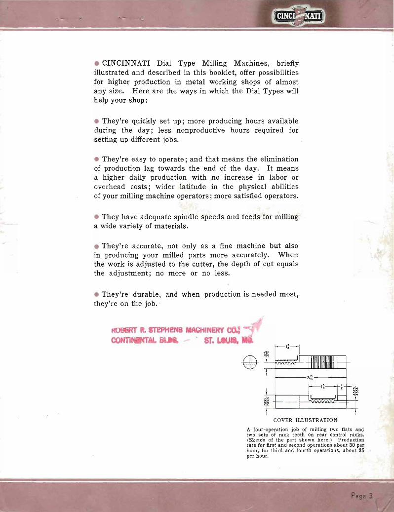
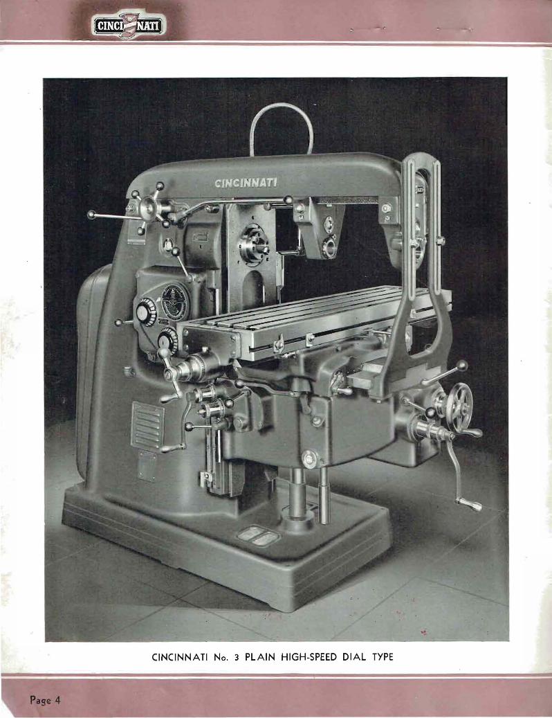
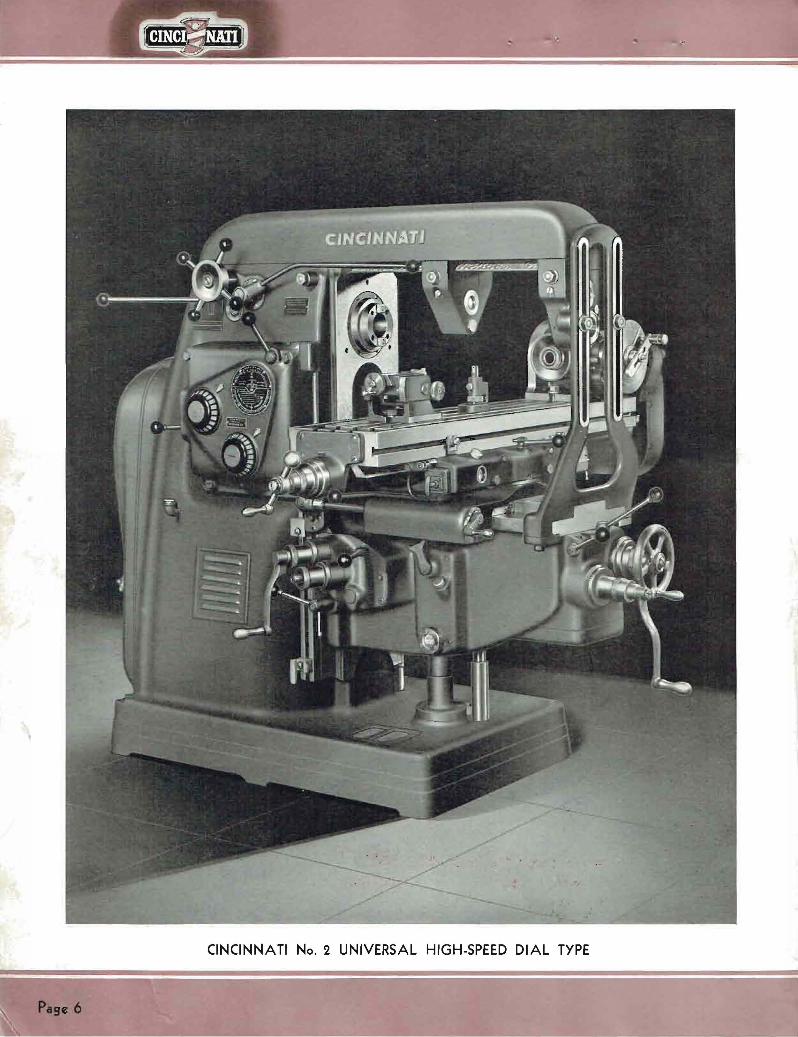
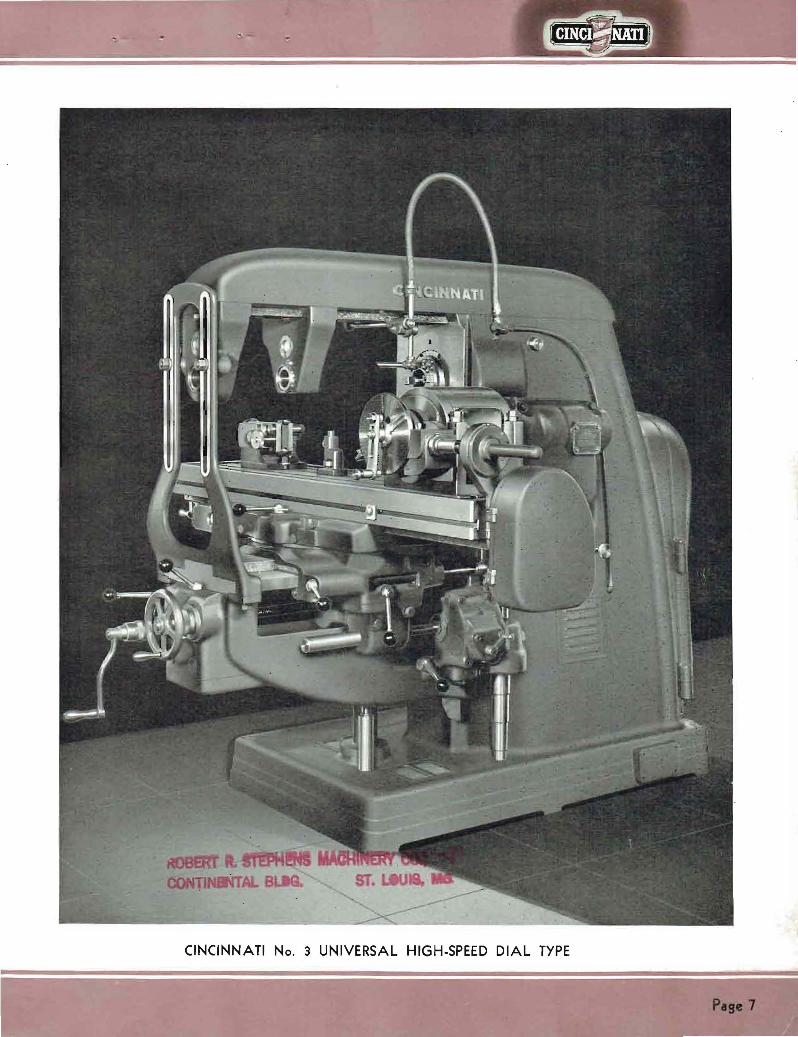

HIGHLIGHTS OF DESIGN
1 Power Speed and Feed Changes At Front and Rear Working Posishytions Controlled with single lever Without walking speeds and feeds may be changed to suit the job and cut
I High Spindle Speeds and Feeds Many kinds of materials from tough steel to aluminum may be milled at correct speeds and feeds (Medium speed machines also available)
3 Power Feeds Longitudinal Cross Vertical Engaged by single independent directional controls simplify operation for new men
4 Duplicate Set Of Control Levers At Operators Rear Working Posishytion When work-piece obscures cutter operator may manipulate machine from rear of table reduces spoilage
S Power Rapid Traverse Longitudinal Cross Vertical Minimizes cutting air saves time
6 Power Feed and Power Rapid Traverse To Vertical Head May be obtained for vertical machines Handy for die work boring etc
7 Touch-Control Starting and Stopping Light touch of starting lever front or rear starts or stops spindle drive Hydraulic mechanism engages clutch spool relieving operator of majority of starting and stopping effort
8 Smooth Streamlined Design Easy to keep clean
9 Pull-Out Quick-Adjusting Micrometer Dials Easy to set for hand adjustments no thumbscrews to lose
10 Automatic Motor Cut-Out Switch I f operator forgets to shut off power motor automatically stops when hinged cover at rear is opened
TURN TO PAGE 12 FOR TEN ADDITtONAL HIGHLIGHTS
Page 10
OUTER ARBOR SUPPORT
INNER ARBOR SUPPORT
REAR CONTROL POWER
RAPID TRAVERSE
PILOT WHEEL OVERARM
ADJUSTMENT
STARTING LEVER
SPEED CALCULA TOR
SPEED DIAL
REAR CONTROL POWER SPEED
AND FEED CHANGE
FEED DIAL
HAND TABLE ADJUSTMENT
REAR HAND CROSS ADJUSTMENT
REAR DIRECTIONAL CONTROL-POWER -=-shy
VERTICAL FEED
REAR HAND VERTICAL
A DJUSTMENT
REAR DIRECTIONAL CONTROL-POWER
CROSS FEED
REAR DIRECTIONAL CONTROL-POWER
TABLE FEED
OIL SHOT LUBRICA TlNG PUMP
(Universal M ac hines)
AN INDEX TO OPERATING CONTROLS AND CONSTRUCTION DETAILS Pasc 11 (UIYeI Machine IliuttratccJ)
HIGHLIGHTS OF DESIGN
~-A~ Beneitt (Concluded)
11 Speed Calculator For determining the correct spindle speed lengthens cutter life
12 One-Piece Overarm Brace It clamps to top of knee increases rigidity of machine for heavy cuts Short arbors can be used with braces
13 Rugged Proportions of Principal Casting Dampen out vibrations withstand heavy loads
14 Heavy MUltiple Disc Clutches Heavy duty multiple disc starting clutch starts spindle drive instantly plenty of reserve power for pulling the heaviest load heavy duty multiple disc brake stops spindle instantly safer for the operator
15 Simple Effective Lubrication Principally automatic prolongs mashychine life-span daily requirements can be handled very quickly
16 Rectangular Overarm Solid and rigid straight-edge alignment of overarm and arbor supports with centerline of spindle
17 Hand Cranks Automatically Disengaged When Released Safer for the operator
18 Enclosed Dividing Head Driving Mechanism Safer for the operator Provides leads of 25 to 100 (Leads from 010 to 1000 with special attachment)
19 Dividing Head Powerfully built withstands heavy cuts exceptionally accurate
COARSE HAND VERTICAL HEAD
ADJUSTMENT
POSITIVE MICROMETER
STOP
FINE HAND VERTICAL HE A D
ADJUSTME NT
FRONT DI RECTIONAL CONTR OL-POWER
TABLE FEED
FRONT CONTROL POWER SPEED
AND FEED CHA NGE
FRONT DIRECTIONAL CONTROL- POWER
CROSS FEED
TABLE DOGS
FRONT HA ND CROSS ADJUSTMENT
FR ONT DIRECTIONA L CONTROL-POWER
VERTICAL FEED
FRONT CONTROL POWER RA PID
TRAVERSE
FRONT HAND VERTIC A L
ADJUSTM ENT
SADDLE CL AMP
COOLA NT RETURN TUBE
OIL SHOT LU BRIC A TING PUMP
( Plain an d Vertical M achines)
KNEE CL A MP
AN INDEX TO OPERATING CONTROLS AND CONSTRUCTION DETAILS (Concluded) P4981 (Vertical Machift~ IIlultrated)
~ CINCI = NATI I EASY QUICK SET UPS
fi bull
POWER RAPID TRAVERSE CONTROL AT THE REAR
Engaging the table rapid traverse from the rear working position Without moving a step he can also engage the cross and vertical rapid traverse These handy rear controls duplicatshying all those in front of the machine allow him to make the necessary manipulations from the rear of the table when the work obscures the cutter
POWER RAPID TRA VERSE CONTROL AT THE FRONT
Engaging the power table rapid traverse from the normal front working position As soon as the rapid traverse lever ( in his right hand ) is released the table travel immediately changes to a feed rate Power vertical and cross rapid traverse may be engaged in a similar manner greatly reducing the time required to adjust the work to the cutter
Plgc 14
bull bull bull EASY O~ OPERATE
POWER SPEED AND FEED CHANGES AT THE FRONT
He changes speeds and feeds without walking without effort and one lever does both jobs A mere touch of the starting lever instantly stops the spindle Then with a flip of the speed-feed change lever the dial clicks around and when the desired reading lines up with the arrow hes all ready to go The machine does the work of shifting gears he merely swivels a lever and starts and stops the spindle drive
PULL-OUT QUICK ADJUSTING MICROMETER DIALS
He doesnt have to add or subtract mentally when adjusting the work to the cutter Just pull out the dial rotate it to match the zero mark with the starting line and then start the adjustment from zero Theres no play or looseness to throw the dial marks out of register with the zero line the clutch teeth take care of that Cross vertical and table hand adjustments front and rear have these dials
POw CR SPEED
q r r~ND FEED Of0 it ~(1(4~relttr Of t In~r~LcOlle~ 4YG(S cblltJge I be table tbere eJlellt to 1Igt0r
tdbullbull r ht doPii h th h d i tho Ob~ Pdfd d d ~td fdfo) f th d tS1er
ea tbe )) e gets Ino llJe to la tYPe ~ re dO
ay l1e
Pa 15
Easy to Operate Because the Dial Type Millers are easy
and convenient to manipulate the operator finds it easy to turn out more work without additional effort Here are the factors which contribute to this unusual ease of operation
First of all its no effort to change speeds or feeds and it may be done while standing either at the front or rear of middotthe table In any case the machine does the actual work of shifting gears while the operator merely swivels a small lever Theres no clashing or dead ending of gears for the shifting mechanism slides them in and out of mesh in perfect coordination While the shifting
MACHINE
lever is engaged say in the feed position the large easy-to-see feed dial clicks around to the various readings Incidentshyally it requires only a few seconds for a complete revolution As soon as the lever is released the dial stops and the proper gears are in mesh to produce the feed indishycated by the arrow
Engaging or disengaging the main drive clutch requires no more effort than a light touch on the starting lever Here again the machine does most of the work A hydraulic middotmechanism engages the clutch spool reducing the effort of starting to a small fraction of the conventional design
COMPLETE DUPLICATE REAR CONTROLS
The convenient arrangement of rear controls All within reach without walking or stretching
p s 16
DESCRIPTION
Convenient to Operate
All control levers are easy to reach-easy to engage Power feed levers for all feed movements-table cross and vertical-are independent directional controls Hand adjustments are provided with anti-friction bearings for easy and accurate adjustment of the work to the cutter
Safe to Operate
Dial Types are safe too There are no exposed rotating parts hand cranks and handwheels automatically disengage when released a built-in switch automatically stops the motor as soon as the hinged cover at the rear is opened when the spindle drive is disengaged a multiple disc brake autoshymatically and instantly stops the spindle
SPEED AND FEED LEVER
One lever changes spindle speeds and feeds This lever is located at the front of the saddle A similar lever is located at the rear working position
Horizontal machines are equipped with duplicate power and hand controls at the operators rear working position (behind the table at the left-hand side of the column) With this arrangement the work never obscures the operators view of the cutter for he can work from the front or rear as the job requires Quite naturally spoilage drops to a new low
STANDARD V-BELT DRIVE ACCESSIBLE COOLANT PUMP When the hinged cover is opened the motor automatically stops an important factor in safety
Pase middot17
~
Accurate Results
Several factors contribute to the better than average accuracy which may be obtained Liberal proportions of the principal castings plus the rigid double row precision anti-friction bearings for the spindle (self-compensating at the rear for temperature changes) fulfill the basic requirements for accurate results Wide bearing surfaces on top of the knee with narrow center guide construction promote smooth cross adjustment of the saddle All flat bearing surfaces are hand scraped to accurate gages The ample length of knee bearing on the column preshyvents the knee from sagging assures milled surfaces that are flat and parallel to the table Pull-out micrometer dials provide a simplified method of setting the dials before adjusting the work to the cutter
Rigid Construction
Dial Type Milling Machines are designed for miscellaneous milling operations and quite naturally they also handle the heavy stock removal jobs in their stride a cost-reducing asset for both tool room and production work
Notice the sturdy proportions of the principal castings shown to advantage in the several views of the complete machine throughout this booklet The column has the smooth lines so essential to a rigid and substantial supporting element It looks massive and the generous thickness of walls and heavy ribs substantiate the appearance The overarm of the horizontal machines is unusually heavy constituting a rigid support for the outer end of the arbor
CONSTANT VIGILANCE Many accuracy tests during assembly assure accurate
machines which will do accurate work
A one-piece overarm brace ties the knee to the overarm for those extra heavy cuts It clamps to the top of the knee forming the most effective arrangement for increasshying rigidity Then too short arbors can be used with this new brace since it may be clamped right next to the front of the saddle
Note the ample proportions of the knee saddle and table castings The knee bearing on the column and saddle bearing on the knee are exceptionally wide while the table has plenty of depth in addition to underneath surface-plate ribbing These are the proportions that resist twisting and deflections withstand the complex strains created by the cutting action
P se 18
OVERARM BRACE FOR
EXTRA HEAVY CUTS One-piece brace rigidly ties knee to overarm j adds strength to withstand those extra heavy cuts
MASSIVE VERTICAL HEAD Rear view of the No3 Vertical
Dial Type Massive proportions of upper part of colwnn add plenty of reserve strength for~eavy face milling operations
Pse 19
The Correct Speed
Each Dial Type Miller is now equipped with a speed calculator which enables the operator to quickly deshytermine the correct speed for the job at hand mental gymnastics no paper work Just take three known factors
No the
1 Diameter of cutter 2 Cutter material 3 Work material
Set the two dials on the speed calculator to indicate the first two of these factors and from the third read the answer Then with the power speed change lever change the spindle speed to the correct rpm- both exclusive Dial Type features
bull The Speed Calculator has the same spindle speeds as the speed dial Calculator illustrated is actual size as used on No 2 High-Speed Dial Type
The setting here is for a 3 diameter high-speed steel cutter Opposite the material to be milled (follow the arrow) will be found the correct spindle speed and the corresponding cutting speed of the cutter For exshyample SAE 1046 spindle speed 92 rpm cutting speed 72 feet per minute
Pate 20
Long Useful life-Spa n
C INC INN A T I Dial Type Milling Machines have many features and design characteristics that keep them young in performance when they become old in years
Lubrication is a relatively simple proshycedure All parts within the column are automatically lubricated by a pump and splash system all parts within the knee are likewise automatically lubricated by a pump and splash system while all parts within the saddle and housing are lubricated by a pressure oil-shot system High-grade materials are used throughout high content chrome-nickel steels for the gears and shafts Meehanite metal for all iron castshy
e ings Heat-treatments for gears spindles and shafts employ the latest scientific equipment Test after test-an inspection after each operation on every part-assures no faulty workmanship Adjustments can be taken care of by the average operator
All these factors combine to minimize maintenance expenditures And when you must turn out the work quickly the Dial Types are on the job and ready to go at a moments notice
PLENTY OF OIL WHERE ITS NEEDED
Pressure oil-shot system for the saddle and table parts No hard-to-find oil holes for the operator to overlook with a few strokes of the plunger the oil-shot pump takes care of all the saddle-housing-table bearing surfaces
~ ~2~u ~ ~
RIGID LONG -LIFE SPINDLE MOUNTING Double rows of precIsion anti-friction bearings autoshymatically lubricated rigidly support the spindle
PLEASING APPEARANCE TO THE LAST DETAIL
Coolant is conveyed to the cutter through armored metal braid hose and flexible copper tubing
21
Dividing
ACTUAL ACCUMULATIVE ERROR IN INDEXING DIVIDING HEAD MUST NOT
EXCEED 0015
Checking the indexing accuracy of a CINCINshyNATI Dividing Head by means of an Optical Micrometer and a circular scale graduated in degrees Each Dividing Head receives this test
Accuracy
0IS
144
P e 22
This circle and the __
line at the left gr trate CINCINNATI Head accuracy wire 018 in diameter trasted with a 12-foot UliLlllr circle represents to a true s
the maximum allowable ltlllUlllUshy lative error in standard CINNATI Dividing Heads
tually the wire is but 26~10 the circumference of the c
This is precision indexing
A CINCINNATI Universal Dividing Head is supshyplied as standard equipshyment with all Cincinshynati Universal Milling Machines The use of the Dividing Head equipshyped with the Wide Range D i v ide r (s u p P lie d at extra cost-see page 26 ) enables you to quickly select divisions from 2 up to 400000 without the use of change gears or addishytional index plates
Every CINCINNATI Dividing Head is thoroughly checked to give you a precision instrument of the highest order Accuracy is built in at the start
Fine materials correct design and special manufacturing facilishyties combined with the workshymanship of skilled craftsmen are definitely responsible for the close accuracy and fine performance of CINCINNATI Dividing Heads
Plse 23
ATTACHMENTS AND ACCESSORIES SUPPLIED AT EXTRA COST
PLAlN INDEX HEAD PRECISION MEASURING RACK INDEXING built with 12 middot and is swing for ordinary gear cutting and similar work that is machined by being indexed between centers It indexes three and five divisions-and all even numbers from 4 to 60 inclusive
bull Publication No M-1031
EQmPMENT helps you space holes accurately to very close limits Simple fast ideal for jig boring when holes are relatively close together
Publication No M-624-1
ATTACHMENT used with rack milling attachment It is connected to the leadscrew at end of table and consists of indexing and locking plate with cbange gears Different combinamiddot tions of gears enable ra cks of different pitches to be machined
bull Publication No Mmiddot920
RACK CUTTING ATTACHMENT
for cutting racks ordinarily used in connection with rack indexiog attachment Vise included takes work up to 5 y wide by 34 long
Publication No M-920
GEAR CUTTING ATTACHMENT for all classes of spur gear cutting and similar work requiring a high degree of accuracy Spiral milling head consists of this same attachment with driving shaft for connecting to machine leadscrew
bull Publication No M-1031
16 CIRCULAR MILLING ATTACHMENT
Hand feed is illustrated Has 16 diameter table Circumference graduated in degrees to facilitate angular settings
Publication No M-1035-1
MOTOR DRIVEN UNIVERSAL ATTACHMENT
mounted on special overarm for milling bevels flats and angles milling slots in jigs fixtures moulds dies and patterns Overshyarm can be used for regular arbor supportbull
bull Publication No M-1213
INDEXING EQmPMENT for circular milling attachment Indexing plates same as standard or high number plates used with the Universal Dividing Head
Publication No M-1035-1
20 AND 24 CIRCULAR MILLING ATTACHMENTS bull Power feed is shown Built with 20 and 24 diameter tables Dogs for automatic throwout are provided Table of attachment is graduated in degrees to facilitate angular settings Easy to set up Gives you the equivalent of a rotary table miller
Publication No M-1035-1
Page 24
HIGH-SPEED UNIVERSAL MILLING ATTACHMENT
has high speeds for small to medishyum size cutters Swivels to any angle in a plane parallel to the face of the machine column or 90 0 in a right angle plane Cross range 7 inches plus cross range of mashychine Can be equipped at extra cost with quill hand feed device and quick change adavter
bull Publication No M-803-1
SEMI-HIGH SPEED VERTICAL ATTACHMENT
will help you key seat die sink mill T slots and work of similar character Swivels through 360 degrees Spindle speeds 1 y times speeds of High-Speed Dial Types and 2 times speeds of Medium Speed Dial Types
bull Publication No M-963
SLOTTING ATTACHMENT bull For your operations where a slotter is not available for keywaying die and tool work Tool slide can be set any angle through 360 degrees Stroke from 0 (zero) to 4 Set of slotting tools supplied at extra cost
Puhlication No M-919-1
Nos 3 and 5 PLAINVISES used on Plain Machines Depth width and opening of jaws No 3shy1 x 6 Ys x 4 No 5-2 y x 8 x 7
bull Publication No M-l013
Nos 3 and 5 SWIVEL VISES used with Universal Millers Can be converted into plain vise by removing swivel base Depth of jaws etc same as correspondingsize of plain vises
bull Publication No M-l013
TOOL MAKERS UNIVERSAL VISE
for general tool room work Can be swiveled in vertical position up to and including 90 degreesshy360 degrees in a horizontal position
bull Publication No M-988
HEAVY VERTICAL ATTACHMENT
is ideal for your face milling where there is not enough work to keep a Vertical Milling Machine busy Spindle speeds same as machine
Publication No M-960-1
RAISING BLOCKS give increased range to your Dividing and Index Heads Heigh t of blocks 2 to 3
Publication No M-644-1
RIGHT ANGLE PLATE ior setting up Dividing Head or small fixtures at right angles to ta ble T slots Equipped with suitable tongue s trips to fit table T slots
bull Publication No M-644-1
HIGH NUMBER INDEXING ATTACHMENT
for regular dividing and plain and spiral heads Three special index plates Indexes all numbers up to and including 200 all even numshybers and those divisible by 5 up to 400 You can apply them to your old Dividing Head
Publication No M-987-1
UNIVERSAL SPIRAL ATTACHMENT
for milling spirals of any angle on a Plain Miller or angles greater than 45 degrees on a Universal Mills in horizontal angular or vertical plane Spindle speeds same as machine
Publication No M-804-1
ENCLOSED DRIVING MECHANshyISM FOR SPIRAL HEADS AND
DIVIDING HEADS Spirals can be milled advantageousshylyon Plain Machine equipped with Universal Spiral Milling Attachshyment and Universal Dividing Head equipped with standard enclosed driving mechanism Equipment includes set of change gears Lead range 2 Yz to 100 The open type driving mechanism is also available
Publication No M-1016-1
Paremiddotis
QUICK CHANGE ADAPTER ARBORS AND COLLETS
enable you to replace one cutter with another in 20 seconds or less Now many operations can be done with ODe setting of work
Publication No M-986
CAP-TYPE ARBOR SUPPORT mounted between slotting cutters allows you to quickly and easily remove the arbor without disturbshying tbe setting of tbe cutter gang
CAM MILLING ATTACHMENTshyPOWER OR HAND FEED
for milling face cams 16 in diamshyHIGH-SPEED ATTACHMENT 8 0eter and cylindrical cams in for Vertical and Horizontal mashy diameter Tbe change from face chines Used for die work and to cylindrical cam milling is readilyprofiling operations on metal made by taming the worm wbeel patterns also model aod experishy at rigbt angles to milling macbine mental work Spindle speed 16 spindle times spindle speed of HiAh-Speed Publication No M-867-1Dial Types and 34 times spindlespeed Medium Speed Dial Types
bull Publication No M-868
KEYWAY MILLING ATTACHMENT
for rounding out tbe ends of keyshyways Mounted on face of column and supported by overarm Quill adjustment and filed stops provide fast accurate method for positionshying cutter to deptb
SPECIAL TWO-SPINDLE VERTIshyCAL MILLING ATTACHMENT for milling channels in aero-engine baby rods etc Outer spindle bas botb borizontal and vertical adshyjustment for lining up witb inner spindle Deptb of cut is conshytrolled by knee adjustment
WIDE RANGE DIVIDER
with Cincinnati Universal Dividing Head gives you a rapid selection of divishysions from 2 to 400000 and aoy angle at intervals of six seconds without the use of change gears or additional index plates Keyways slots and boles can be quickly spaced in angular relationship to eacb other Can be used for indexing bevel or spiral gears Your presshyent Cincinnati Head can be rebuilt and equippedwitb the Wide RangeDivider at low cost Publication No M-972-1
CUTTER COOLANT PUMP Individually motor driven including ~ bp motor starter and piping May be easily installed 00 your macblDe
bull Publication M-908
FOUR-POSITIONTURRETSTOP FOR VERTICAL MILLERS POWER FEED AND RAPID TRA VshyERSE TO VERTICAL HEAD provides you with a faster J easier more accurate method of boring die-sinking and step-milling
Publication No M-I002
Plge 26
ATTACHMENTS and ACCESSORIES (Concluded) SUPPLIED AT1 EXTRA COST
ARBORS-No 50 SERIES TAPER For Cincinnati Plain and Universal Dial Type Milling Machines
(Complete Tabulation in Publication M-926-1)
_ = q J~I~jI~~ (1)Z=~ 1 oc _=- --- STYLE A 0
- I I- I =1~~gI=I~I~~blI=-- -1 - I - -shySTYLE 8 shy I~ INCH SIZES
Diameter Style Usable Length
of Cutter Space
Diameter of Bearing Collar
Keyway
Width Depth Code Name
Catalog Number
Va 1 1 1 1 lV lY 1 7(
t~ 1 )1 1)1 1)1 1)1 2 2 2
A A A A B A A A B B B B B B B B B
10 12 15 18 24 12 15 18 18 24 18 24 30 36 2 30 36
j1
2Ys v V
2 )1 V h middot ~ timiddot
h h h
2Jg h 2)1 V 2)1 V 2)1 V 2 2Y V 2Y V 2Y )1 ----_
j
~ h h h
~
i1
~ h h
TENAR ARTWA ARBAA ATARB ARBFA ARBCO AROGO ARBRU BETAR ONARB HAFAR FORAR ARBTY ARGOB AR~N T AR ARCOD
50shy )l8Al0 50-1 A12 60-1 A15 60-1 A18-4 60-1 B2-40 60-17(A12 50-17(A15 50-17(A18-50-17(Bll1-1 50-17(BU-6 50-1 WJ111- 50-1~BU 50-1 WJlIO- 50-1WJ36-
50-2 BU5 60-2 B30-5 50-2 B36-5
Not-Two suita ble bushings for 2Y diameter beariDg collars are included in the price of these arbors
bull SHELL END MILL ARBORS-Style C
For Cincinnati Plain Universal and Vertical Dial Type Milling Machines
- lt _ - p~a j - ~E~~~ 10 ~~~~~ t1_= ~J
Diameter Range of Code NameStud Catalos End Mills Diameter Number
17(-1 V j-i SHEMA 50- ~C~ 1-2 SEMCO 50- YC~
2 V-2 Yz-2 Y 1 SHEPU 60-1 C~3-3j-i 1Y SHEm 50-1 YC Ys ~)1-5 SHEBY1~ 50-1 j-iC ~
5)1-6 2 SEMOR 50-2 C Ys --_
Chrome nickel heat-treated screws for holding shell end mill on arbor are furnished with all arbors Wrenches are furnisbed with arbors 1 7(C Va 1)1C Ys and 2C Ys
bull QUICK CHANGE ADAPTER ARBORS AND COLLETS
For Cincinnati Plain Universal and Vertical Dial Type Milling Machines QUICK CHANGE ADAPTER COMPLETE CATALOG No NS-H5 Code Name-ADACO
Complet equipment consists of Nut Special Key Stop Lug Spanoer Wrench Stop Lug Screw Ring Four Ring Screws Socket Wrench
QUICK CHANGE QUICK CHANGE COLLETS SHELL END MILL ARBORS (Includes Draw-in Bolt)
Stud Inside Diameter Code Name Catalog No Taper Code Name
V Y
1 17( 1)1 2
ARABB ARDUI ARSHE ARTTA ARlCK AREMI
50shy )1 FC VB 60shy W FC VB 50-1 FC vshy60-1 Ji FC W 60-1 )1 FC vshy60-2 FC vshy
No 7 BampS No 9 BampS No 10 BampS No 11 BampS No ~ Morse No 3 Morse
COQUI COSEM COSBE COTTO CORlC COROB
Diameter Ran of End Mills
17(-1)1 1 -2
27(-2~2 Y3- 11 ~~
5V~
CatAlog No
50-NS-FEB 7 50-NS-FEB 9 50-NS-FEB 10 50-NS-FEB 11 50-NS-FEM ~
t~t~~~_~ODDElio -llto_rse
PIsc27
-- --
-- --------------- ---------------------------
----------
SPECIFICATIONS FOR CINCINNATI PLAIN
DIMENSIONAL DRAWING
I Olt~ shy1 --s~
~ ~ l L--l-~ ~~~Dl
i-----A---
1 gt
W-l10 1 0~Al~ -I 1 -6- f-I____ K J itO l ----_____ -2
- --X II ~-----T U----
~22~ ~~~~ ~~i~ 7-------- ----------M--~ i
APPROXIIolATt SHvE 0- rLOOR SkoC[
ri -----------AA----------~
1 irdltgt w
-ltgt w
GGI ~ - i-I
~wf --KK-shy
i-II NCTAP
TABLE AND T-SLOT FLOOR PLANSPINDLE NOSE SUH D4Hgt IlAN(j tO [ NO TH HO ~o S[lflES UIgt[1t
Size of Size of A B Min M ax D E F J K L M N P R Min Max Min MaxMachine Machine
C ~ ~ TNo2 No2 ~ h gtOM h h M-~ -~ I~I= No 3 33 )1 7 10 it 230 1 it 18 ~ 33lt 69 66 20 ~ 27 )1 40 6 20 n 23 y( 67 ~ No3
----------------1----shy -- --- ----- shyNo4 38 ) 7 11 y( 26 ys 1 it 22)1 33lt 59 66 20 ~ 320 40 6 8 0 20 n 27 y( 69 ~ No4
Size of Size ofX AA MM PP RRCC DD EE FF LL NNGG HH KKJJMachine IMin~ Max V W Machine
No2 No220 20 6 12)462 it it M YS 1)4 22 it 190 500 99 it 9901 20 49 Ys 6 it 27)1 30)1
No 3 23)4 67 ~ 700 29)1 32)1 No362 )1 3 )4 3)4 7 )1 16 ) it 1 Itt 27 ~ 17tr 57~116 )1 111 Y(--------H- l shy iHshy 30 ys 19 69~ 139 J11119 YSNo 4 27 y( 69 ~ 70 it 29)1 32)1 78)1 No43)4 3)4 8 16 ~
8 Ys 0
Pse i8
HIGH - SPEED DIAL TYPE MILLING MACHINES
GENERAL SPECIFICATIONS (MODEL ER)
No4 PlainNo 2 Plain No3 Plain
TABLE Working surface Size over all T-slots (number and size)
52Wx12W 52Wd2 K Three-fi
62Wx15W Et2 )1lt15tfThreeshy
78 )1d6)4 78)1gt16 W Three-H
Distance between T-slots 2h 3W W
RANGE Longitudinal Cross
28 10
34 12
42 a
VerUesl 19 20 20 Maximum distance from centerline of spindle to top of tsblbull 19h 20 20 Minimum distance from centerline of spindle to top of table 0 0 0
FULL WIDTH Column to brace 30 W 33 W 38W Column to inside of outer arbor support busblog-with brace in place 26 29Vs 3Hi
OVERARM-Rectsngular Diamptance from under-side to centerline of arbor 6 Ys 7Ys 7Ys
ARBOR SUPPORTS-Self-oiling (See stsndard equipment list page 37) Number 2 2
SPINDLE-Chrome nickel steel Flanged end with standard taper hole No 50 No 50 No 50 Diameter of nose Size of hole through
5 fr 178
5 fr 178
5 fr 178
Speed rpm (twenty-one in approximate geometrical proe-resolion) 20 25 32 39 47 182227 34 41 18 22 27 34 U 59 74 92 114 51 63 78 97 122 61637897122 142 178 220 270 162 188 230 286 152 188 2O 281 33 414 515 635 357 U5 550 675 357445560676 780 970 1200 840 1045 1300 840 1045 1300 1500
Reverse Yes Yes Yes
FEEDS-Inches per minute Number of feeds 32 32 32 Standard Range-Table and cross feeds )lt2 to 40 Yi to 40 ~ to 40
Low Series- Y2 t020= 4 Va ~1 11 2 Y8 2 7 3Vs 4Ys 6 7 9 Ys 12M 1620
HighSenes-1 to 40=1 1 ~1 )lt222y3 Y 4 ~ 6Y7~9~l1 Y 15 X 19 y 24 y 30 y 40
Full range of feeds is obtained by shifting auxiliary lever located on right side of machine (bracket of knee)
Vertical feeds are 8 ( 10 of table and crosgt feeds given above
OPERATING CONTROLS Hand crOS8 longitudinal and vertical adjustments Front and Rear Front and Rear Front and Rear Speed changes by power Fron t and Rear Front and Rear Front and Rear Feed changes by power Front and Rear Front and Rear Front and Rear Single independent cross longitudinal and vertical power feeds Front and Rear Front and Rear Front and Rear Spindle start and stop Front and Rear Front and Rear Front and Rear Power rapid traverse in all directions with spindle stationary or running Front and Rear Front and Rear Front and Rear
POWER RAPID TRAVERSE RATES Inches per minute Longitudinal 100 100 100 Cross 100 100 100 Vertical bull 80 80 80
DRIVE Pulley speed 600 r pm 600 rpm 600 r pm Horliepower rating (Also see Electrical Equipment Specifications lJ
) 5-7 ~ hp 7 ~-10 hp 10-16 h p
LUBRICATION Column and knee Automatic Automatic Automatic Saddle and ts ble Oil Shot Oil Shot Oil Shot
CLUTCH Multiple Disc Oil Multiple Disc Oi l Multiple Disc Oil
FLOOR SPACE 98x97h lUxl14 138x118 Area 66 sq ft 90 SQ ft 113 sq ft
SHIPPING WEIGHTS AND DATA-All weights are for enclosed multiple V belt motor drive or chain motor drive exclusive of motor And control equipment I
Net weight 6350 Ibs 8480 Ibs 9160 Ibs Gross weight domestic 7350 Ibs 9530 lbs 10600 Ibs Gross weight export 7650 Ibs 9SSO Ibs 10900 Ibs Approximate size of case SSx74 x62 94x80x62 100x84x64 Approximate cubic feet 196 227 263
CODE NAME-Chain motor drive exclusive of motor RISDI HISEE HlCIK
CODE NAME-Enclosed multiple V belt drive exclusive of motor HIALP HIBVE HITrP (Supplied as standard equipment unless otherwise specified )
STANDARD EQUIPMENT-Listed on Page 37 EQUIPMENT SUPPLIED AT EXTRA COST-Listed on Page 38
Pabullbull 19
SPECIFICATIONS FOR CINCINNATI UNIVERSAL
DIMENSIONAL DRAWING
f-- - -A ----1
~ 6 f--- - K_MUllJJltU1--- - i 2
22~~Ii~~~----+--------J - - - -------- - M - --T-- --+- - -middotu---j
PC-))1
P Oll IlU( SuoC OF lOO ll SP~(
~------AA ~I ------ r-X-
i I
j
- _ -
- shy shy ~ ------------=--+
[
X
II I u w
i-II NeTA
u w
~pp--
SPINDLE NOSE TABLE AND T-SLOT FLOOR PLAN SUOAPO r lIo lJ[ g [Itgt
t 0 ~o U ll i ts UjII[1t
Size 01 Machine
No 2
No 3
No4
Size 01 Machine
No 2
No3
No
C A B Min Max -shy-shy - - - -
30 )4 6gti 9 gti 19 -shy-shy- -D - --shy
E F J K L -shy-shy-shy-shy- -16 ~ S2n 60 )4 46 )4 19 -shy-shy-shy-shy-shy
sect T M N P R Min Max Min Max -shy-shy-shy-shy -shy -shy -shy - - -shy26n 4 4~ 7 ~ 0 18h 22n 60H shy-shy-shy-shy-shy-shy - - - - -shy
33 ~ 7 ~ 11 n 23 h 1 H
38 )4 7 llih 26 J1 1tt
18 ~ SSt 69 66 20 ~ 27 ~ h 6 8 ~ 0 19tr 2S )4 67 ~ ---shy -------shy - ----------shy22 ~ S3t 69 66 20 ~ 32h 4h 6 8~ o 19tr 27 )4 69 ~
MinUMax _V_~_X_~~ DD ~I GG HH JJ KK LL MM NN PP RR - -shy----shy -----shy
20 )4 48 ~ 64H 27 ~ 30 )1 62H 2h 2h 6 1 12 )4 H It J1 1 )4 22 ~ 19h 60H 99H 99h
23 )4 ~ 70h ~ 32 )1 62 )1 3 )4 3 )4 ~1 16 )4 -----shy- shy -----shy
H ~ 1 1tt 27 ~ 17tr 67 ~ 116 ~ 111 )4- ------ shy ---------shy-------shy -- ----shy-
27 )4 69 70 H 29 ~ 32 )1 78 J1 3 )4 8 )4 8 16 )4 H ~ 1 1tl SOh 191shy 69 139 J1 119 Yo
Size 01 Machine
No2
No S
No
Sizo of Machine
N o 2
No 3
No
HIGH -SPEED DIAL TYPE MILLING MACHINES
GENERAL SPECIFICATIONS (MODEL ER)
No ~ Universal No 3 Universal No 4 Universal
TABLE Workinamp ourlace bull bull bull Size o er all T-alota (number an4 sIze) bull
62 Ux12) 62 x12) Three-H
6~ 1x15) 6~7Sx16ffThreeshy
78~x16 ) 78Wx16) Three-H
Distance between T-slots Swivels-RlCht or left bull bull
2-rU
3W 7
3W 9
RANGE Longitudinal 28 34 411 Cross bull 10 12 U Vertical bull Muimum distance from centerline of spIndle to top of table bull bull MInimum distance from centerline of spIndle to top of table
18 18-r
0
19 19
0
1919i
FULL WIDTH Column to brace 30X 3i W S8 W Colwnn to inside of outer arbor support bushing-with brace in place 28 Vs 29~ 34W
OVERARM-RectanCular Ditance from under-ide to centerline of arbor 6)t 7 7W
ARBOR SUPPORTS-Self-oiling (See standard equipment list page 37) Number 2 2 2
DIVIDING HEAD (See standard equipment Ust page 37) Swin bull 10 12 a Take in length bull bull 28 38 W 52W Lead range with standard driving mechanism 2Vz to 100 2Y to 100 2Vz to 100
SPINDLE-Chrome nickel steel Flanged end with tandard taper hole No 60 No GO No 50 Diameter of nobullbull Size of hole tbrouCh Speed rpm (twenty-one In approximate geometrical proampTession)
5~1 20 15 U 39 47
6~1
18 22 27 34 41 5~1
18 22 2 U 41 69 7 92 11 61 6378 97 122 516378 97 1~2 1411 ITa 220 270 16~ 188230 286 162 188 230 286 3U a 6U 636 367446660675 3G7 G 650 876 7109TO1200 1500 840 IOU 1300 840 IOU 1300
Reverse Yes Yes Yes
FEEDS-Inches per minute Number of feeds Standard Range-Table and cross feeds
Low Serieashy ~ to 20= ~ ~ ji 1 1~ 1 ji 2)t 2~ 3 Yo ltI Gv 7
32 Yz to 40
32 Y to 40
32 Mil to 40
9~ 12~ 1G~ 20 HlCh Series-l to 0=1 1) 1~ 2 2ji 3 ~ ) 5~ 7) 9)1 11~
15 X 19 24 30 40 Full range of feeds is obtained by shiftin an auxiliary lever located on right side
of machine (bracket on knee) Vertical feeds are 8 10 of table and cross feeds given above
OPERATING CONTROLS Hand croso longitudinal and vertical adjustments Front and Rear Front and Rear Front and Rear Speed cbanges by power Front and Rear Front and Rear Front and Rear Feed changes by power Front and Rear Front and Rear Front and Rear Single independent cross longitudinal and vertical power feeds Front and Rear Front and Rear Front and R60r Spindle start and top Front and Rear Front and Rear Front and Rear Power rapid traverse in all directions with spindle stationary or running Front and Rear Front and Rear Front and Rear
POWER RAPID TRAVERSE RATES-Inches per minute Longitudinal bull 100 100 100 Cross 100 100 100 Vertical bull bull 80 80 SO
DRIVE PuUey-Speed 600 rpm 600 rpm 600 rpmHorsepower rating (Also ee Electrical Equipment Specifications) 5-7 ~ hp 7 1-10 hp 10-16 hp
LUBRICATION Column and knee bull Automatic Automatic Automatic Saddle and table bull Oil-5hot Oil-Shot OU-Shot
CLUTCH Multiple Dioc Oil Multiple Disc Oil Multiple Disc Oil
FLOOR SPACE 98x97 114x114 138118 Area 66 sq ft 90 sq ft 113 sq ft
SHIPPING WEIGHTS AND DATA-All weigbts are for enclosed multiple V belt motor drive or chain motor drive exclusive of motor and control equipment
Net weight 6700 lb bull 9100 Ibs 10100 Ibs Gross weigh t 7800 Ibs 10400 Ibs 11500 lb bull Gross weight export 8000 lbs 10750 Ibs 11900 lbs Approximate size of case 8874x52 94xSOx62 100x8 64 Approimate cubic feet 196 227 312
CODE NAME-Chain motor drive exclusive of motor HISIA HISGA HISO]
CODE NAME-Enclosed MUltiple V belt drive exclusive of motor HIMUL RIVEB RIPLE (Supplied as standard equipment unless otberwise specified)
STANDARD EQUIPMENT-Listed on Page 37 EQUIPMENT SUPPLIED AT EXTRA COST-Listed on Page 38
Page 31
SPECIFICATIONS FOR CINCINNATI VERTICAL
DIMENSIONAL DRAWING
(
= __11
-- shy---- shy
---1- I
-6- ~ ---- K ~~~~~--~ J 2 -22To~ At1I - ~------J ---- shy - shy - shy M
T
iiJ
I
- ---T---shy ----- shy -shy U----shy
------~--AA--------- -1
I
~ I
--- KK
I I
shyI shy
IJ o w o w
APPR Oll loIATE SI1II(
0 LOOR SPACE
x
- - shy pp
SPINDLE NOSE TABLE AND T-SLOT FLOOR PLAN
Size of Machine
No2
No3
No
Size of Machine
No II
No3
No
UloNOAIIO FlANGEI) [JIIO
WiTH NO iO SUIIl$ TER
degB C AM Mu M Mogt J K- shy -- shy - shy - shy - shy - shy --- shy14 0 18H 9h 21)j 33H 50~ 67(- shy --------- shy18 0 22 tt 10 tt 27 Yo 38 89 85
------------- shy18 0 22 tt 11 ~ 117 )j 38 59 85
X AA CC DD EE FF GG HH - shy - shy - shy - shy - shy - shy - shy
30 ~ 52 it 2 21 6 lilY tt It - shy -- I- - shy
32~ 62 ~ 3 ~ 3~ 7 ~ 15~ it
L
19
20~
20~
JJ - shyi
- shy1
S2~ I 78~ 3~ --- shy --- shy ~I-l-3~ 8 16~ it
T U Size of I ~ Min IMax Min Max V W Machine--- shy
26 tr 22 tr 50 0 110 9) 78 it 17 )j No I
SO h 277( 1 87 ~ 2S ~ 57 Y 86 Y 29)j No S ----------
SOn 117~ 69~ 27 ~ 69Y 8614 29 ~ No
KK LL MM NN pp RR Size of
Machine - shy - shy - shy - shy - shy - shy - shylY Un 17 it 600 99 tt 98Y - No I
--- shy - shy - shy - shy - shylii 310 16tr 57~ 115 ~ 111 No S
------------Iii 32)j 151 69Y 139~ 111 No
-NOTE-MAXIMUM dimenSIOn B 1S With head 10 extreme up position and knee 10 extreme down pOSItion Both uwts are reversed for MINIMUM dimension UB
Pase 32
HIGH - SPEED DIAL TYPE MILLING MACHINES
GENERAL SPECIFICATIONS (MODEL ER)
No2 Vertical No 3 Vertical No 4 Vertical
TABLE Working surface Size over all T-slon (number and size) Dlotance between T -slots
RANGE Lonitudinal Cross bull bull Vertical Head travel Ditance from spindle noe to top of table Throat distance centerline of splOdle to column
SPINDLE-Chrome nickel steel Flanged end with standard taper hole Diameter of nose Size of hole through bull Speeds rpm (twenty-one in approximate eometrical progression)
Reverse
FEEDS-Inches per minute Number of feeds Standard Range-Ta ble and cross feeds
Low Series-Y2 to 20= ~J ~-i 1 1 Ys 1 ~ 2 Ys 2 3 ~ s 4 )8 5 ~~ 7 9 l1 1~ l-i 15 H 20
High Series-1 to 40=1 1 ~ 172 2 2 ~ 3 K 7( 6 ~ 7 y( 91 11~2 1amp 19~ 2(~ 30~ (0
Full range of feeds is obtained by shifting an auxiliary lever located on right side of machine (bracket on knee)
Vertical feeds are 8 10 of table and cross feeds given above
OPERATING CONTROLS Hand cross and vertical adjustments bull Hand longitudinal adjustment Speed changes by power Feed changs by power Single Independent cross and vertical power feeds Sinamplo Independent longitudinal power feed Spindle tart and stop Power rapid traverse in all directions with spindle s tationary or running Rear hand adjustments cross and Yertical rear power feed controls cross and vertical are
supplied only on request and at extra cost
POWER RAPID TRAVERSE RATES-Inches per minute Lonitudlnal Cro Vertical
POWER TRAVERSE TO HEAD (S upplied at extra cost) Number of feeds Feed rates Feed range Rapid traverse rate (inches per minute)
DRIVE Pulley speed Horlepower rating (Also see CCElectrical Equipment Specifications)
LUBRICATION Column and knee bull Saddle and table
CLUTCH
FLOOR SPACE Area
SHIPPING WEIGHTS AND DATA-All weights are for enclosed multiple V belt motor drive or chain motor drive exclusive of motor and control equipment
Net weight Gross weight domestic
t~~~~rl~~~i~~p~r~a 8~ Approximate cubic feet bull
CODE NAME-Encloed chain motor drive exclusive of motor
CODE NAME-Enclosed multiple V belt drive exclusive of motor bull (Supplied as standard equipment unless otherwise specified on order)
52 tl I12 W 52 1tx12 ( Three-H
2
28 12 13 6 18 14 bull
No 50 5n 1 Ys
20 25 32 39 47 59 74 92 114 142178220270 3S3 U4 515 635 78097012001500
Yes
32 Ji to 40
Front Front and Rear Front and Rear Front and Rear
Front Front and Rear Front a nd Rear Front and Rear
100 100 80
16 6 Dial Readings
3 to 12 31
600 rpm 5-7)1 hp
Automatic Oil-Shot
Multiple Di sc Oil
98x79W 543 sq ft
7100 lbs 8SOO lb s 8500 lbs
88 x84x52 223
HILAC
HIELT
62 Wxl5 W 62 )1 x15 W Three-H
3W
34 16 16 6
22 18
No 50 511 lY
18 22 27 34 41 51637897 122 152 188 230 286 357445 550675 840 1045 1300
Yes
32 J-z to 40
Front Front and Rear Front and Rea r Front and Rear
Front Front and Rear Front and Rear Front and Rear
100 100 80
16 6 Dial Readings
3 to 12 31
600 rpm 7 )110 hp
Automatic Oil-Shot
Multiple Disc Oil
114x93 Ys 74 1 sq ft
9SOO lbs 10200 lbbull 10900 lbs 100x90x5(bull
282
mSAR
HIOPT
78 Y x16 W 78Wx16W Three-H
3W
42 16 16 6
22 18
No 50 511 l Y
18 22 27 34 U 51 6S 78 97 122 152 188 2S0 286 3574(5550675 840 1045 lS00
Yes
S2 2 to 40
Front Front and Rear Front and Rear Front and Rear
Front Front and Rear Front and Rear Fron t and Rear
100 100 80
16 6 Dial Readings
3 to 12 31
600 rpm 10-15 hp
Automatic Oil-Shot
Multiple Disc Oil
138 x95 91 sq ft
9950 lbbull 10800 lbs 11550 Ibs 100x90x5(
282
HISHT
HIQUI
STANDARD EQUIPMENT-Listed on Page 37 EQUIPMENT SUPPLIED AT EXTRA COST-Listed on Page 38
Page 33
SPECIFICAliONS FOR CINCINNA11
PLAn~ MEDIUM SPEED
GENERAL SPECIFICATIONS (MODEL ER)
No2 Plain No3 Pla in No 4 PI~in
TABLE Working surface Size over all T-s lots (number and size) Distance between Tmiddotslots
RANGE Longi tudinal Cross Vertical Maximum distance from centerline of spindle to top of table Minimum distance from centerline of spindle to top of table
FULL WIDTH Column to brace Column to inside of outer arbor support bushing-with brace in place
OVERARM-Rectangular Distance to centerline of arbor
ARBOR SUPPORTS-Self-oiling (See standard equipment list on page 37) Number
SPINDLE-Chrome nickel steel Flanged end with standard taper hole Diameter of nose Size of hole through Speeds rpm (s ixteen In approximate ampeometrical proampression)
Reverse
FEEDS-Inche per minute Number of feeds Standard range-Table and cross feeds
Y1) 1 1 t 1 ~ 2 Va 23 ~4 8 7YF gi 12 18~ 20 Vertical feeds are 8 10 of table and cross feed iPven above
OPERATING CONTROLS Hand cross longitudinal and vertical adjustments Speed changes by power Feed changes by power Single independent cross longitudinal and vertical power feeds Spindle start and stop Power rapid traverse in all directions with spindle stationary or running
POWER RAPID TRAVERSE RATES-Inches per minute (For standard feed series machines)
Longitudinal Cross Vertical
DRIVE Pulley speed Horsepower rating ( Als~~~e Ele~trical Equipment Specifications)
LUBRICATION Column and knee Saddle and table
CLUTCH
FLOOR SPACE Area
SIDPPING WEIGHTS AND DATA-All weights are for enclosed multiple V be lt motor drive or chain motor drive exclusive of motor and control equipment
Net weight Gross weight domesti c Gross weight export Approximate size of case Approximate cubic feet
CODE NAME-Enclosed chain motor drive exclusive of motor
CODE NAME--Enclosed multiple V belt drive exclusive of motoL (Supplied as standard equipment unless otherwise specified on order
62 H x12 Yi 52H x12 ~middot Three- H
2
28 10 19
19 t 0
30 W 26 Ys
6W
2
No 50 5 lW
20 26 32 (0 47 60 74 92 116 141 179222 262 331 4H 500
Yes
16 M to 20
Front and Iloar Front and Rear Front and Rear Front and R ear Front and Rear Front and Rear
100 100 SO
600 Lpm 5-7 ~ h p
Automatic Oil Shot
Multiple Disc Oil
98x97 66 sq It
6250 Ibs 7 250 Ibs 7450 lbs
8SxHx62 196
TOOMO
TUALP
62 )4x15 )1 62 ~x15 W Three- H
3 W
34 12 20
20 0
33 W 29 ~f
s 7
No 50 5t 1 Ys
18 22 27 33 40 51 63 78 96 123 151 187 ~23 281 350 460
Yes
7116
11 to 20
Front and Rear Front and Rear Front and Rear Front a nd Rear Front and Rear Front and Rear
100 100 SO
600 r pm 7 )1-10 h p
Automatic Oil Shot
Multiple Disc Oil
114 xl14 90 sq ft
S3S0 Ibs 9430 Ibs 9780 lbs
94x80x62 227
1MRIC
IMALP
78 ~x16 )1 78 ~x16 W Three-H
3W
42 14 20
20 O
38 W 3Hs
7 Ys
2
No 50 5 1 Ys
18 22 27 33 40 51 63 78 96 123 1511872232S1 350 450
Yes
16 Vz to 20
Front and Rear Front and Rear Front and Rear Front and Rear Front and Rear Front and Rear
100 100 80
600 rpm 10-15 hp
Automatic Oil Shot
Multiple Disc Oil
13Sx118 113 sq ft
9050 lbs 10400 Ibs 10800 Ibs 100xS4xU
263
IMLEC
IMENC
DIMENSIONAL DRAWING-Same as shown on Page 28 STANDARD EQUIPMENT-Listed on Page 37
EQUIPMENT SUPPLIED AT EXTRA COST-Listed on Page 38
Page 34
DIAL TYPE MILLING MACHINES
UNIVERSAL MEDIUM SPEED
GENERAL SPECIFICATIONS (MODEL ER)
No 2 Universal No3 Universal No4 Universal
TABLE Working surface 52 ttx12 W 62 yx15 W 78 W x16 W Size over all bull bull 52 Hx12 Y 62 Wx15 Y 78 Vx16 Y T-slots (number and size) Three- tV Three-H Three-H Distance between T-slots 2 3W 3W Swivels-Right or left 45 47 49
RANGE Longitudinal 28 34 42 Cross 10 12 14 Vertical bull 18 19 19 Maximum distance from centerline of spindle to top of table 18 19 191 Minimum distance from centerline of spindle to top of table bull O 0 0
FULL WIDTH Column to brace 30 W 33 W 38 W Column to inside of outer arbor support bushing-with brace in place 26 W 29 W 34W
OVERARM-Rectangular Distance to centerline of arbor 6 )1 7W 7y
ARBOR SUPPORTS-Self-oiling (See standard equipment list on page 37) Number 222
DIVIDING HEAD (See standard equipment list on page 37) Swing 10 12 14 Take in length 28 36W 52 W Lead range with standard driving mechanism 2W to 100 2) to 100 2W to 100
SPINDLE-Chrome nickel steel Flanged end with standard taper hole No 50 No 50 No 60 Diameter of nooe 5h 5h5Size of hole through 1 Vs 1 v 1 )1 Speeds r pm (sixteen in approximate geometrical progression) bull 20 25 32 40 47 18 22 27 33 40 18 22 27 S3 40
60 74 92 116 51637896123 516378 6 121 144179222 262 151187223281 151187223211 331414500 350450 350450
Reverse Yes Yes Yes
FEEDS-In inches per minute Number of feeds U U U Standard range-Table and cross feeds 2 to 20 Y2 to 20 --f to 20
V Yo 1 1 v 1 2 Va 2 3 4 ~ 5 i 7 Yo 9 )1 12 15 VB 20 Vertical feeds are 810 of table and cross feeds given above
OPERATING CONTROLS Hand cross longitudinal and vertical adjustments Front and Rear Front and Rear Front and Rear Speed changes by power Front and Rear Front and Rear Front and Roar Feed changes by power Front and Rear Front and Rear Front and Rear Single Independent cro longitudinal and vertical power feeds Front and Rear Front and Rear Front and Rear Spindle sart and stop Front and Rear Front and Rear Front and Rear Power rapid traverse in all directions with spindle stationary or running Front and Rear Front and Rear Front and Rear
POWER RAPID TRAVERSE RATES-Inches per minute (For standard feed series machines)
Longitudlnal 100 100 100 Cross 100 100 100 Vertical bull bull 80 80 80
DRIVE Pulley speed 600 rpm 600 rpm 600 rpm Horsepower rating (Also see Electrical Equipment Specifications) 5-7 V hp 7 V-10 hp 10-15 h p
LUBRICATION Column and knee bull bull bull Automatic Automatic Automatic Saddle and table bull Oil-Shot Oil-Shot Oil-Shot
CLUTCH Multiple Disc Oil Multiple Disc Oil Multiple Dic Oil FLOOR SPACE 98x97 114x114 138lt118
Area 66 sq ft 90 sq ft 113 sq ft SHIPPING WEIGHTS AND DATA-All weights are for enclosed mUltiple V belt
motor drive or chain motor drivel exclusive of motor and control equipment Net weight 6600 lbs 9000 lbs 10000 lbs Gross weight domestic 7700 lbs 10300 lbs 11400 lbs Gross weight export 7900 lbs 10650 lbs 11800 lbs Approximate size of case 88 x74x52 94 xSOx52 100x84 x64 Approximate cubic feet 196 227 312
CODE NAME-Enclosed chain motor drive exclusive of motor TULEC IMDRI IMFYZ CODE NAME-Enclosed multiple V belt drive exclusive of motor TUMUL IMUVB IMELD
(Supplied as standard equipment unless otherwise specified on order)
DIMENSIONAL DRAWING-Same as shown on Page 30 STANDARD EQUIPMENT-Listed on Page 37
EQUIPMENT SUPPLIED AT EXTRA COST-Listed on Page 38
Page 35
SPECIFICATIONS FOR CINCINNATI
VERTICAL MEDIUM SPEED
GENERAL SPECIFICATIONS (MODEL ER)
No 2 Vertical No3 Vertical No4 Vertical
TABLE Working surface Size over all T-slots (number and size) Distance between T-slots
RANGE Longitudinal Cross Vertical Head travel Distance fTom spindle nose to top of ta ble Throat distance centerline of spindle to column
SPINDLE-Chrome nickel steel Flanged end with standard taper hole Diameter of nose SI of hole through Speeds rpm (Sixteen iD approximate geometrical progression)
Reverse
FEEDS-Inches per minute Number of feeds Standard range-Table and cross feeds
~ ~ ~ I 1~ 1 v 2 Ya 2~ 3li 4li ex 7 l-i 9 Yo 12)115)120 Vertical feed are 8 10 of table and cross feed given above
OPERATINO CONTROLS Hand crOSs and vertical adjustments Hand longitudinal adjustment Speed change by power Feed changes by power Single Independent cross and vertical power feeds Single independent longitudinal power feed Spindle start and stop Power rapid traverse in all directions with spindle stationary or running Rear hand adjustments cross and vertical rear power feed controls cross and vertical
are suppUed only on request and at extra cost
POWER RAPID TRAVERSE RATES Inches per minute (For standard feed eries machines)
Longitudinal Cross Vertical
POWER TRAVERSE TO HEAD (Supplied at extra cost) Number of feeds Feed rates for machines having standard table feeds Feed rates for machines having low table feeds
Feed rsne Rapid traverse rate inches per minute
DRIVE
~~p~~r ~~iimiddotnmiddotg iAiso EIci~ic~i Equipment Sp~cificatio~~) LUBRICATION
Column and knee bull Saddle and ta ble bull
CLUTCH
FLOOR SPACE Area
SHIPPING WEIGHTS AND DATA-All weights are for enclosed mUltiple V bell motor drive or chain motor drive exclusive of motor and control equipment
Net weight Gross weiampht domestic Gross weight export Approximate size of caEe Approximate cubic feet
CODE NAME-Enclosed chain motor drive exclusive of motor
CODE NAME-Enclosed multiple V belt drive exclusive of motor (Supplied as stardard equipment unless otherwise opecified on order)
52Wx12 X 52Wx12W Tlue-W
2
28 12 lS 6 18 14
No 50 51Ys
20 26 3240 47 60 74 92 116 HI 179222 2S2 331 414 500
Yes
16 J to 20
Front Front and Rear Front and Rear Front and Rear
Front Front and Rear Front and Rear Front and Rear
100 100middot 80
16 ~ Dial Reading~Same as Dial
ReadingsW to 10
44
600 rpm 5-7 ~ hp
Automatic Oil-Shot
Multiple Disc Oil
98x79 W 543 sq fl
7 050 Ibs 8200 Ibs 8 400 Ibs
88x8x02 223
TUTOO
TUVEB
62 ~x15)4 62 ~-x15 Y Three-J-t
3W
34 16 lS 6
22 18
No 50 51Ys
18 22 27 33 40 51 6S 78 96 123 151 187223281 350 450
Yes
16 ~ to 20
Front Front and Rear Front and Rear Fron t and Rear
Front Front and Rear Front and Rear Front and Rear
100 100 80
16 ~ Dial Readings
Same as Dial Readings )1 to 10
44
600 r pm 7 J~-10 h p
Automatic Oil-Shot
Mulliple Disc Oil
114 x93 741 sq ft
9200 Ibs 10100 Ibs 10800 Ibs 100x90x54
282
IMRYE
IMEVE
78Wx16J4 78~x16 )4 Three-H
3W
42 lS 16 6
22 18
No 50 5h 1Vs
18 22 27 33 40 5163 78 96123 151 187 223 281 350 450
Yes
16 i to 20
Front Front and Roar Front and Rear Front and Rear
Front Front and Rear Front and Rear Front and Rear
100 100 eO
16 H Dial Readings
Same as Dial ReadingW to 10
44
600 rpm 10-15 hp
Automatic Oil-Shot
MUltiple Disc Oil
138x95 91 sq ft
9860 Ibs 10700 Ibs 11450 Ibs 100x90x54
283
IFORV
IMMUL
DIMENSIONAL DRAWING-Same as shown on Page 32 STANDARD EQUIPMENT-Listed on Page 37
EQUIPMENT SUPPLIED AT EXTRA COST-Listed on Page 38
Page 36
DIAL TYPE MILLING MACHINES
STANDARD EQUIPMENT-Supplied with the Machine
PLAIN MACHINES-HighmiddotSpeed and Medium Spud
ARBOR SUPPORTS No 2 Millers- one Style STANDARD FEED RANGE-High speed mashyB with 2 Ys adjustable arbor bushing and proshy chines Y2 to 40 Medium speed machines vided with lug for brace- one Style A with adshy Y2 to 20 justable arbor bushing for pilot end arbors Nos
ARBOR SUPPORT BUSHING ADAPTER M-013 and 4 Millers-one Style B with 2 Ys adjustshy
(includes adjustable bushingnut washer and screw)able arbor bushing without lug for brace-one for Style A arbors Nos 3 and 4 Machines only
style B with 2Ys adjustable arbor bushing and provided with lug for brace WRENCHES COOLANT PUMP
ADJUSTABLE ARBOR TIGHTENING ROD OVERARM BRACE
UNIVERSAL MACHINES-HighSpeed and Medium Speed
ARBOR SUPPORTS No 2 Millers-one Style B with 2Ys adjustable arbor bushing and proshyvided with lug for brace-one Style A with adjustable arbor bushing for pilot end arbors Nos 3 and 4 Millers-one Style B with 2 Ys adjustable arbor bushing without lug for braceshyone Style B with 2 Ys adjustable arbor bushing and provided with lug for brace
ARBOR SUPPORT BUSHING ADAPTER M-01 (includes adjustable bushing nut washer and screw) for Style A arbors Nos 3 and 4 Machines only
ADJUSTABLE ARBOR TIGHTENING ROD
STANDARD FEED RANGE-High speed mashychines Y2 to 40 Medium speed machines Y2 to 20
STANDARD UNIVERSAL DIVIDING HEAD EQUIPMENT including tailstock with 2-point adjustable center steady rest one plate for indexshying through 40 to 1 reduction-all numbers up to and including 60 all even numbers and those divisible by 5 up to 120 and many beyond one plate for direct indexing one center for headstock and provision for connecting head to enclosed driving mechanism segment Sizes (nominal swing) 10 for No 2 Machine 12 for No 3 Machine 14 for No 4 Machine
ENCLOSED DRIVING MECHANISM SEGshyMENT including change gears for spiral milling leads range from 2Y2 to 100 (only) for Standard Universal Dividing Heads
WRENCHES COOLANT PUMP
OVERARM BRACE
VERTICAL MACHINES- HighmiddotSpeed and Mdium Speed
ADJUSTABLE ARBOR TIGHTENING ROD STANDARD FEED RANGE-High speed mashychines Y2 to 40 Medium speed machines
WRENCHES COOLANT PUMP Y2 to 20
Pige 37
SPECIFICATIONS FOR CINCINNATI
EOUIPMENT SUPPLIED AT EXTRA COST (Not Included in Price of Standard (Basic) Machine) For Medium Speed and High-Speed Machines (See pages 22-27 for illustrations and brief descriptions)
PLAIN UNIVERSAL AND VERTICAL MACHINES 1 TABLE AND CROSS FEEDS Rack Milling Slotting Circular Milling Cam
(a) For Medium Speed Machines sixteen Milling High Number Indexing Attachment ~ to 10 or to 30 inches per minute for Dividing Head Spiral Milling Head etc
(b) For High-Speed Machines thirty-two 6 INDEX BASES RAISING BLOCKS RIGHT ~ to 20 inches per minute ANGLE PLATES
2 WIDE RANGE DIVIDER (applied to Standard 7 PRECISION MEASURING EQUIPMENTUniversal Dividing Head) for divisions from 2
(Recommended for short dimensions only)to 400000 hundreds of them exact and others compensated for the fractional remainder 8 PUMP CUTTER COOLANT individually
3 VISES CHUCKS AND CHUCK ADAPTERS motor driven including ~ HP motor manual starter and piping Code Name PUDIA
4 ARBORS ADAPTERS COLLETS QUICK CHANGE ADAPTERS Etc 9 ELECTRICAL MOTOR AND CONTROL
EQUIPMENT5 STANDARD ATTACHMENTS High-Speed Universal Heavy Vertical Universal Spiral 10 SPLASH GUARDS
PLAIN AND UNIVERSAL MACHINES ONLY 1 ARBOR SUPPORTS
(a) Style B with 2Ys adjustable arbor bushshy (b) Style B with 2 Ys adjustable arbor bushshying without lugs for brace for use on No2 ing without lug for braces for Nos 3 and 4 machines Code Name ARBBS Machines Code Name AJUSB
(c) Style A with adjustable arbOr No3 Machine Code Name ARTMY bushing for pilot end arbors No4 Machine Code Name ARMMF
PLAIN AND VERTICAL MACHINES ONLY 1 STANDARD UNIVERSAL DIVIDING HEAD 12 size for No3 Machine Code
AND EQUIPMENT including tailstock with Name HYDRA 2-point adjustable center steady rest one plate for indexing through 40 to 1 reduction-all 14 size for No4 Machine Code numbers up to and including 60 all even Name HEDPA numbers and those divisible by 5 up to 120 and 2 ENCLOSED DRIVING MECHANISM SEGshymany beyond those shown in the table of specishy MENT including change gears for spiral mill shyfication sheet one plate for direct indexing one
ing leads ranging from 2Y2 to 100 (only) for center for headstock and provision for connectshyStandard Universal Dividing Headsinghead to enclosed driving mechanism segment
10 size for No2 Machine Code No2 Machine Code Name DREDT Name HUTER Nos 3 and 4 Machines Code Name DREHS
VERTICAL MACHINES ONLY 1 POWER FEED AND POWER QUICK 3 REAR HAND ADJUSTMENTS AND REAR
TRAVERSE to the Vertical Head POWER FEED CONTROLS cross and vershy2 TURRET STOP four-position with dial indi- tical Supplied at factory only (Not supplied as
cator Code Name (In Field) TUMAC standard equipment on Vertical Machines) Code Name (Prior to Shipment) FOPST
UNIVERSAL MACHINES ONLY 1 LONG AND SHORT LEAD ATTACHMENT before machine is shipped
with a range 010 to 1000 inches or 024 to 2400 No 2 Machine Code Name LOSHO centimeters Must be installed at factory Nos 3 and 4 Machines Code Name LONSH
NOTE These feeds are optional at the time the order is placed When machines are equipped with the low ranges of feeds (gt-4 to 10 for the Medium Speed machines and gt-4 to 20 for the High-Speed machines) rapid traverse rates are cut in half
Pase 38
- --- --
DIAL TYPE MILLING MACHINES
ELECTRICAL EQUIPMENT The motors and controls listed below are suitable for the machines illustrated and described in this booklet
CHARACTERISTICS -
Current Voltage Speed RPMCycles PhaseI I I A C 60 2 or 3 220 440550 1800
A C 50 2 or 3 220 440550 1500I A C 150050 380 500 Etc 2 or 3
A C 25 15002 or 3 220 440 550
D C 1750 115 or 230 I - ~-
MOTOR HORSE POWER AND FRAME SIZES
No 4 MachineNo 2 Machine Nos 2 and 3 Machines Nos 3 and 4 Machines
NEMA I NEMANRMA NEMAH P H P H PH PFrame Frame FrameFrame I 7 )25 254 326284 324 1510 I 7 )25 254 326284 10 324 15
7)25 254 15 326284 10 324
284 155 10 364 3657Yz I 1510 I 5 I I 7Yz ~
-
7)2 H P motor totally enclosed ball bearing frame No 326 can not be used on No2 Dial Type
Open frame ball bearing motors are recommended
Motors larger than the following can not be used
No2 Dial Type-NEMA frame 326 No3 Dial Type-NEMA frame 364 No4 Dial Type-NEMA frame 365
A C MOTORS-Standard make NEMA frame normal torque low starting current (normal start shying current for 5 hp motors) floor mounted with conduit box on left viewing shaft end
D C MOTORS-Standard make shunt wound constant speed 40deg C continuous open rotation clockwise viewing shaft end floor mounted with conduit box on left viewing shaft end
A C CONTROLS-Standard make enclosed type full voltage magnetic starter with thermal overload protection For all A C circuits over 220 volts a control transformer and 110 volt coils are included to provide low voltage at the push button station-a safety feature
D C CONTROLS-Standard make enclosed type magnetic starter with definite time acceleration thermal overload protection and without dynamic braking
PUSH BUTTON STATION-Separate Start shyStop included with A C or D C controls
ORDERING INSTRUCTIONS - The following electrical data must accompany each order
(a) Voltage
(b) Current (A C or D C) If A C also include
1 Phase
2 Cycle
3 Control circuit voltage
(d) Horsepower speed and type of frame (open or totally enclosed) and motor bearing
Page 39
bull bull Right-A heavy stock removal job on a No2 Plain High Speed Machine Milling two sides of extension supports reducing a spherical shape of 1 diameter to a width of H
Below-Milling the keyway in a heat-treated bevel gear High Speed Dial Type Millers have the wide range of speeds and feeds so necessary in shops where one lot of parts may be tough hard steel and the next lot soft aluminum
Below-A No 3 Vertical Dial Type roughs and finishes from the solid a cast iron dovetail slide The turret stop attachment at the side of the vertical head assures a close limit of accuracy between the dovetail and the top surface
Left-The operator can always see the job on a Horizontal Dial Type because there are complete front and rear conshytrols This No4 Plain Dial Type faces both ends of the shell section of a tire building drum PPIN HD N tI
THE CINCINNATI MILLING MACHINE CO CINCINNATI 01U S A
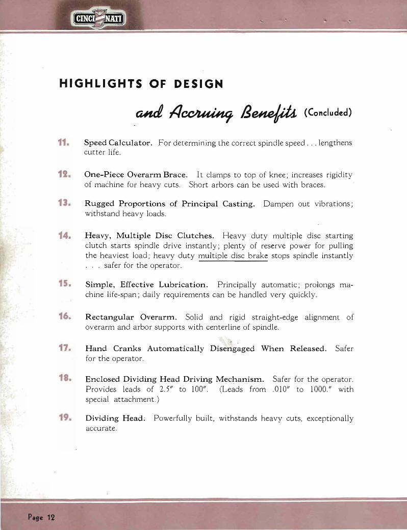

~
Accurate Results
Several factors contribute to the better than average accuracy which may be obtained Liberal proportions of the principal castings plus the rigid double row precision anti-friction bearings for the spindle (self-compensating at the rear for temperature changes) fulfill the basic requirements for accurate results Wide bearing surfaces on top of the knee with narrow center guide construction promote smooth cross adjustment of the saddle All flat bearing surfaces are hand scraped to accurate gages The ample length of knee bearing on the column preshyvents the knee from sagging assures milled surfaces that are flat and parallel to the table Pull-out micrometer dials provide a simplified method of setting the dials before adjusting the work to the cutter
Rigid Construction
Dial Type Milling Machines are designed for miscellaneous milling operations and quite naturally they also handle the heavy stock removal jobs in their stride a cost-reducing asset for both tool room and production work
Notice the sturdy proportions of the principal castings shown to advantage in the several views of the complete machine throughout this booklet The column has the smooth lines so essential to a rigid and substantial supporting element It looks massive and the generous thickness of walls and heavy ribs substantiate the appearance The overarm of the horizontal machines is unusually heavy constituting a rigid support for the outer end of the arbor
CONSTANT VIGILANCE Many accuracy tests during assembly assure accurate
machines which will do accurate work
A one-piece overarm brace ties the knee to the overarm for those extra heavy cuts It clamps to the top of the knee forming the most effective arrangement for increasshying rigidity Then too short arbors can be used with this new brace since it may be clamped right next to the front of the saddle
Note the ample proportions of the knee saddle and table castings The knee bearing on the column and saddle bearing on the knee are exceptionally wide while the table has plenty of depth in addition to underneath surface-plate ribbing These are the proportions that resist twisting and deflections withstand the complex strains created by the cutting action
P se 18
OVERARM BRACE FOR
EXTRA HEAVY CUTS One-piece brace rigidly ties knee to overarm j adds strength to withstand those extra heavy cuts
MASSIVE VERTICAL HEAD Rear view of the No3 Vertical
Dial Type Massive proportions of upper part of colwnn add plenty of reserve strength for~eavy face milling operations
Pse 19
The Correct Speed
Each Dial Type Miller is now equipped with a speed calculator which enables the operator to quickly deshytermine the correct speed for the job at hand mental gymnastics no paper work Just take three known factors
No the
1 Diameter of cutter 2 Cutter material 3 Work material
Set the two dials on the speed calculator to indicate the first two of these factors and from the third read the answer Then with the power speed change lever change the spindle speed to the correct rpm- both exclusive Dial Type features
bull The Speed Calculator has the same spindle speeds as the speed dial Calculator illustrated is actual size as used on No 2 High-Speed Dial Type
The setting here is for a 3 diameter high-speed steel cutter Opposite the material to be milled (follow the arrow) will be found the correct spindle speed and the corresponding cutting speed of the cutter For exshyample SAE 1046 spindle speed 92 rpm cutting speed 72 feet per minute
Pate 20
Long Useful life-Spa n
C INC INN A T I Dial Type Milling Machines have many features and design characteristics that keep them young in performance when they become old in years
Lubrication is a relatively simple proshycedure All parts within the column are automatically lubricated by a pump and splash system all parts within the knee are likewise automatically lubricated by a pump and splash system while all parts within the saddle and housing are lubricated by a pressure oil-shot system High-grade materials are used throughout high content chrome-nickel steels for the gears and shafts Meehanite metal for all iron castshy
e ings Heat-treatments for gears spindles and shafts employ the latest scientific equipment Test after test-an inspection after each operation on every part-assures no faulty workmanship Adjustments can be taken care of by the average operator
All these factors combine to minimize maintenance expenditures And when you must turn out the work quickly the Dial Types are on the job and ready to go at a moments notice
PLENTY OF OIL WHERE ITS NEEDED
Pressure oil-shot system for the saddle and table parts No hard-to-find oil holes for the operator to overlook with a few strokes of the plunger the oil-shot pump takes care of all the saddle-housing-table bearing surfaces
~ ~2~u ~ ~
RIGID LONG -LIFE SPINDLE MOUNTING Double rows of precIsion anti-friction bearings autoshymatically lubricated rigidly support the spindle
PLEASING APPEARANCE TO THE LAST DETAIL
Coolant is conveyed to the cutter through armored metal braid hose and flexible copper tubing
21
Dividing
ACTUAL ACCUMULATIVE ERROR IN INDEXING DIVIDING HEAD MUST NOT
EXCEED 0015
Checking the indexing accuracy of a CINCINshyNATI Dividing Head by means of an Optical Micrometer and a circular scale graduated in degrees Each Dividing Head receives this test
Accuracy
0IS
144
P e 22
This circle and the __
line at the left gr trate CINCINNATI Head accuracy wire 018 in diameter trasted with a 12-foot UliLlllr circle represents to a true s
the maximum allowable ltlllUlllUshy lative error in standard CINNATI Dividing Heads
tually the wire is but 26~10 the circumference of the c
This is precision indexing
A CINCINNATI Universal Dividing Head is supshyplied as standard equipshyment with all Cincinshynati Universal Milling Machines The use of the Dividing Head equipshyped with the Wide Range D i v ide r (s u p P lie d at extra cost-see page 26 ) enables you to quickly select divisions from 2 up to 400000 without the use of change gears or addishytional index plates
Every CINCINNATI Dividing Head is thoroughly checked to give you a precision instrument of the highest order Accuracy is built in at the start
Fine materials correct design and special manufacturing facilishyties combined with the workshymanship of skilled craftsmen are definitely responsible for the close accuracy and fine performance of CINCINNATI Dividing Heads
Plse 23
ATTACHMENTS AND ACCESSORIES SUPPLIED AT EXTRA COST
PLAlN INDEX HEAD PRECISION MEASURING RACK INDEXING built with 12 middot and is swing for ordinary gear cutting and similar work that is machined by being indexed between centers It indexes three and five divisions-and all even numbers from 4 to 60 inclusive
bull Publication No M-1031
EQmPMENT helps you space holes accurately to very close limits Simple fast ideal for jig boring when holes are relatively close together
Publication No M-624-1
ATTACHMENT used with rack milling attachment It is connected to the leadscrew at end of table and consists of indexing and locking plate with cbange gears Different combinamiddot tions of gears enable ra cks of different pitches to be machined
bull Publication No Mmiddot920
RACK CUTTING ATTACHMENT
for cutting racks ordinarily used in connection with rack indexiog attachment Vise included takes work up to 5 y wide by 34 long
Publication No M-920
GEAR CUTTING ATTACHMENT for all classes of spur gear cutting and similar work requiring a high degree of accuracy Spiral milling head consists of this same attachment with driving shaft for connecting to machine leadscrew
bull Publication No M-1031
16 CIRCULAR MILLING ATTACHMENT
Hand feed is illustrated Has 16 diameter table Circumference graduated in degrees to facilitate angular settings
Publication No M-1035-1
MOTOR DRIVEN UNIVERSAL ATTACHMENT
mounted on special overarm for milling bevels flats and angles milling slots in jigs fixtures moulds dies and patterns Overshyarm can be used for regular arbor supportbull
bull Publication No M-1213
INDEXING EQmPMENT for circular milling attachment Indexing plates same as standard or high number plates used with the Universal Dividing Head
Publication No M-1035-1
20 AND 24 CIRCULAR MILLING ATTACHMENTS bull Power feed is shown Built with 20 and 24 diameter tables Dogs for automatic throwout are provided Table of attachment is graduated in degrees to facilitate angular settings Easy to set up Gives you the equivalent of a rotary table miller
Publication No M-1035-1
Page 24
HIGH-SPEED UNIVERSAL MILLING ATTACHMENT
has high speeds for small to medishyum size cutters Swivels to any angle in a plane parallel to the face of the machine column or 90 0 in a right angle plane Cross range 7 inches plus cross range of mashychine Can be equipped at extra cost with quill hand feed device and quick change adavter
bull Publication No M-803-1
SEMI-HIGH SPEED VERTICAL ATTACHMENT
will help you key seat die sink mill T slots and work of similar character Swivels through 360 degrees Spindle speeds 1 y times speeds of High-Speed Dial Types and 2 times speeds of Medium Speed Dial Types
bull Publication No M-963
SLOTTING ATTACHMENT bull For your operations where a slotter is not available for keywaying die and tool work Tool slide can be set any angle through 360 degrees Stroke from 0 (zero) to 4 Set of slotting tools supplied at extra cost
Puhlication No M-919-1
Nos 3 and 5 PLAINVISES used on Plain Machines Depth width and opening of jaws No 3shy1 x 6 Ys x 4 No 5-2 y x 8 x 7
bull Publication No M-l013
Nos 3 and 5 SWIVEL VISES used with Universal Millers Can be converted into plain vise by removing swivel base Depth of jaws etc same as correspondingsize of plain vises
bull Publication No M-l013
TOOL MAKERS UNIVERSAL VISE
for general tool room work Can be swiveled in vertical position up to and including 90 degreesshy360 degrees in a horizontal position
bull Publication No M-988
HEAVY VERTICAL ATTACHMENT
is ideal for your face milling where there is not enough work to keep a Vertical Milling Machine busy Spindle speeds same as machine
Publication No M-960-1
RAISING BLOCKS give increased range to your Dividing and Index Heads Heigh t of blocks 2 to 3
Publication No M-644-1
RIGHT ANGLE PLATE ior setting up Dividing Head or small fixtures at right angles to ta ble T slots Equipped with suitable tongue s trips to fit table T slots
bull Publication No M-644-1
HIGH NUMBER INDEXING ATTACHMENT
for regular dividing and plain and spiral heads Three special index plates Indexes all numbers up to and including 200 all even numshybers and those divisible by 5 up to 400 You can apply them to your old Dividing Head
Publication No M-987-1
UNIVERSAL SPIRAL ATTACHMENT
for milling spirals of any angle on a Plain Miller or angles greater than 45 degrees on a Universal Mills in horizontal angular or vertical plane Spindle speeds same as machine
Publication No M-804-1
ENCLOSED DRIVING MECHANshyISM FOR SPIRAL HEADS AND
DIVIDING HEADS Spirals can be milled advantageousshylyon Plain Machine equipped with Universal Spiral Milling Attachshyment and Universal Dividing Head equipped with standard enclosed driving mechanism Equipment includes set of change gears Lead range 2 Yz to 100 The open type driving mechanism is also available
Publication No M-1016-1
Paremiddotis
QUICK CHANGE ADAPTER ARBORS AND COLLETS
enable you to replace one cutter with another in 20 seconds or less Now many operations can be done with ODe setting of work
Publication No M-986
CAP-TYPE ARBOR SUPPORT mounted between slotting cutters allows you to quickly and easily remove the arbor without disturbshying tbe setting of tbe cutter gang
CAM MILLING ATTACHMENTshyPOWER OR HAND FEED
for milling face cams 16 in diamshyHIGH-SPEED ATTACHMENT 8 0eter and cylindrical cams in for Vertical and Horizontal mashy diameter Tbe change from face chines Used for die work and to cylindrical cam milling is readilyprofiling operations on metal made by taming the worm wbeel patterns also model aod experishy at rigbt angles to milling macbine mental work Spindle speed 16 spindle times spindle speed of HiAh-Speed Publication No M-867-1Dial Types and 34 times spindlespeed Medium Speed Dial Types
bull Publication No M-868
KEYWAY MILLING ATTACHMENT
for rounding out tbe ends of keyshyways Mounted on face of column and supported by overarm Quill adjustment and filed stops provide fast accurate method for positionshying cutter to deptb
SPECIAL TWO-SPINDLE VERTIshyCAL MILLING ATTACHMENT for milling channels in aero-engine baby rods etc Outer spindle bas botb borizontal and vertical adshyjustment for lining up witb inner spindle Deptb of cut is conshytrolled by knee adjustment
WIDE RANGE DIVIDER
with Cincinnati Universal Dividing Head gives you a rapid selection of divishysions from 2 to 400000 and aoy angle at intervals of six seconds without the use of change gears or additional index plates Keyways slots and boles can be quickly spaced in angular relationship to eacb other Can be used for indexing bevel or spiral gears Your presshyent Cincinnati Head can be rebuilt and equippedwitb the Wide RangeDivider at low cost Publication No M-972-1
CUTTER COOLANT PUMP Individually motor driven including ~ bp motor starter and piping May be easily installed 00 your macblDe
bull Publication M-908
FOUR-POSITIONTURRETSTOP FOR VERTICAL MILLERS POWER FEED AND RAPID TRA VshyERSE TO VERTICAL HEAD provides you with a faster J easier more accurate method of boring die-sinking and step-milling
Publication No M-I002
Plge 26
ATTACHMENTS and ACCESSORIES (Concluded) SUPPLIED AT1 EXTRA COST
ARBORS-No 50 SERIES TAPER For Cincinnati Plain and Universal Dial Type Milling Machines
(Complete Tabulation in Publication M-926-1)
_ = q J~I~jI~~ (1)Z=~ 1 oc _=- --- STYLE A 0
- I I- I =1~~gI=I~I~~blI=-- -1 - I - -shySTYLE 8 shy I~ INCH SIZES
Diameter Style Usable Length
of Cutter Space
Diameter of Bearing Collar
Keyway
Width Depth Code Name
Catalog Number
Va 1 1 1 1 lV lY 1 7(
t~ 1 )1 1)1 1)1 1)1 2 2 2
A A A A B A A A B B B B B B B B B
10 12 15 18 24 12 15 18 18 24 18 24 30 36 2 30 36
j1
2Ys v V
2 )1 V h middot ~ timiddot
h h h
2Jg h 2)1 V 2)1 V 2)1 V 2 2Y V 2Y V 2Y )1 ----_
j
~ h h h
~
i1
~ h h
TENAR ARTWA ARBAA ATARB ARBFA ARBCO AROGO ARBRU BETAR ONARB HAFAR FORAR ARBTY ARGOB AR~N T AR ARCOD
50shy )l8Al0 50-1 A12 60-1 A15 60-1 A18-4 60-1 B2-40 60-17(A12 50-17(A15 50-17(A18-50-17(Bll1-1 50-17(BU-6 50-1 WJ111- 50-1~BU 50-1 WJlIO- 50-1WJ36-
50-2 BU5 60-2 B30-5 50-2 B36-5
Not-Two suita ble bushings for 2Y diameter beariDg collars are included in the price of these arbors
bull SHELL END MILL ARBORS-Style C
For Cincinnati Plain Universal and Vertical Dial Type Milling Machines
- lt _ - p~a j - ~E~~~ 10 ~~~~~ t1_= ~J
Diameter Range of Code NameStud Catalos End Mills Diameter Number
17(-1 V j-i SHEMA 50- ~C~ 1-2 SEMCO 50- YC~
2 V-2 Yz-2 Y 1 SHEPU 60-1 C~3-3j-i 1Y SHEm 50-1 YC Ys ~)1-5 SHEBY1~ 50-1 j-iC ~
5)1-6 2 SEMOR 50-2 C Ys --_
Chrome nickel heat-treated screws for holding shell end mill on arbor are furnished with all arbors Wrenches are furnisbed with arbors 1 7(C Va 1)1C Ys and 2C Ys
bull QUICK CHANGE ADAPTER ARBORS AND COLLETS
For Cincinnati Plain Universal and Vertical Dial Type Milling Machines QUICK CHANGE ADAPTER COMPLETE CATALOG No NS-H5 Code Name-ADACO
Complet equipment consists of Nut Special Key Stop Lug Spanoer Wrench Stop Lug Screw Ring Four Ring Screws Socket Wrench
QUICK CHANGE QUICK CHANGE COLLETS SHELL END MILL ARBORS (Includes Draw-in Bolt)
Stud Inside Diameter Code Name Catalog No Taper Code Name
V Y
1 17( 1)1 2
ARABB ARDUI ARSHE ARTTA ARlCK AREMI
50shy )1 FC VB 60shy W FC VB 50-1 FC vshy60-1 Ji FC W 60-1 )1 FC vshy60-2 FC vshy
No 7 BampS No 9 BampS No 10 BampS No 11 BampS No ~ Morse No 3 Morse
COQUI COSEM COSBE COTTO CORlC COROB
Diameter Ran of End Mills
17(-1)1 1 -2
27(-2~2 Y3- 11 ~~
5V~
CatAlog No
50-NS-FEB 7 50-NS-FEB 9 50-NS-FEB 10 50-NS-FEB 11 50-NS-FEM ~
t~t~~~_~ODDElio -llto_rse
PIsc27
-- --
-- --------------- ---------------------------
----------
SPECIFICATIONS FOR CINCINNATI PLAIN
DIMENSIONAL DRAWING
I Olt~ shy1 --s~
~ ~ l L--l-~ ~~~Dl
i-----A---
1 gt
W-l10 1 0~Al~ -I 1 -6- f-I____ K J itO l ----_____ -2
- --X II ~-----T U----
~22~ ~~~~ ~~i~ 7-------- ----------M--~ i
APPROXIIolATt SHvE 0- rLOOR SkoC[
ri -----------AA----------~
1 irdltgt w
-ltgt w
GGI ~ - i-I
~wf --KK-shy
i-II NCTAP
TABLE AND T-SLOT FLOOR PLANSPINDLE NOSE SUH D4Hgt IlAN(j tO [ NO TH HO ~o S[lflES UIgt[1t
Size of Size of A B Min M ax D E F J K L M N P R Min Max Min MaxMachine Machine
C ~ ~ TNo2 No2 ~ h gtOM h h M-~ -~ I~I= No 3 33 )1 7 10 it 230 1 it 18 ~ 33lt 69 66 20 ~ 27 )1 40 6 20 n 23 y( 67 ~ No3
----------------1----shy -- --- ----- shyNo4 38 ) 7 11 y( 26 ys 1 it 22)1 33lt 59 66 20 ~ 320 40 6 8 0 20 n 27 y( 69 ~ No4
Size of Size ofX AA MM PP RRCC DD EE FF LL NNGG HH KKJJMachine IMin~ Max V W Machine
No2 No220 20 6 12)462 it it M YS 1)4 22 it 190 500 99 it 9901 20 49 Ys 6 it 27)1 30)1
No 3 23)4 67 ~ 700 29)1 32)1 No362 )1 3 )4 3)4 7 )1 16 ) it 1 Itt 27 ~ 17tr 57~116 )1 111 Y(--------H- l shy iHshy 30 ys 19 69~ 139 J11119 YSNo 4 27 y( 69 ~ 70 it 29)1 32)1 78)1 No43)4 3)4 8 16 ~
8 Ys 0
Pse i8
HIGH - SPEED DIAL TYPE MILLING MACHINES
GENERAL SPECIFICATIONS (MODEL ER)
No4 PlainNo 2 Plain No3 Plain
TABLE Working surface Size over all T-slots (number and size)
52Wx12W 52Wd2 K Three-fi
62Wx15W Et2 )1lt15tfThreeshy
78 )1d6)4 78)1gt16 W Three-H
Distance between T-slots 2h 3W W
RANGE Longitudinal Cross
28 10
34 12
42 a
VerUesl 19 20 20 Maximum distance from centerline of spindle to top of tsblbull 19h 20 20 Minimum distance from centerline of spindle to top of table 0 0 0
FULL WIDTH Column to brace 30 W 33 W 38W Column to inside of outer arbor support busblog-with brace in place 26 29Vs 3Hi
OVERARM-Rectsngular Diamptance from under-side to centerline of arbor 6 Ys 7Ys 7Ys
ARBOR SUPPORTS-Self-oiling (See stsndard equipment list page 37) Number 2 2
SPINDLE-Chrome nickel steel Flanged end with standard taper hole No 50 No 50 No 50 Diameter of nose Size of hole through
5 fr 178
5 fr 178
5 fr 178
Speed rpm (twenty-one in approximate geometrical proe-resolion) 20 25 32 39 47 182227 34 41 18 22 27 34 U 59 74 92 114 51 63 78 97 122 61637897122 142 178 220 270 162 188 230 286 152 188 2O 281 33 414 515 635 357 U5 550 675 357445560676 780 970 1200 840 1045 1300 840 1045 1300 1500
Reverse Yes Yes Yes
FEEDS-Inches per minute Number of feeds 32 32 32 Standard Range-Table and cross feeds )lt2 to 40 Yi to 40 ~ to 40
Low Series- Y2 t020= 4 Va ~1 11 2 Y8 2 7 3Vs 4Ys 6 7 9 Ys 12M 1620
HighSenes-1 to 40=1 1 ~1 )lt222y3 Y 4 ~ 6Y7~9~l1 Y 15 X 19 y 24 y 30 y 40
Full range of feeds is obtained by shifting auxiliary lever located on right side of machine (bracket of knee)
Vertical feeds are 8 ( 10 of table and crosgt feeds given above
OPERATING CONTROLS Hand crOS8 longitudinal and vertical adjustments Front and Rear Front and Rear Front and Rear Speed changes by power Fron t and Rear Front and Rear Front and Rear Feed changes by power Front and Rear Front and Rear Front and Rear Single independent cross longitudinal and vertical power feeds Front and Rear Front and Rear Front and Rear Spindle start and stop Front and Rear Front and Rear Front and Rear Power rapid traverse in all directions with spindle stationary or running Front and Rear Front and Rear Front and Rear
POWER RAPID TRAVERSE RATES Inches per minute Longitudinal 100 100 100 Cross 100 100 100 Vertical bull 80 80 80
DRIVE Pulley speed 600 r pm 600 rpm 600 r pm Horliepower rating (Also see Electrical Equipment Specifications lJ
) 5-7 ~ hp 7 ~-10 hp 10-16 h p
LUBRICATION Column and knee Automatic Automatic Automatic Saddle and ts ble Oil Shot Oil Shot Oil Shot
CLUTCH Multiple Disc Oil Multiple Disc Oi l Multiple Disc Oil
FLOOR SPACE 98x97h lUxl14 138x118 Area 66 sq ft 90 SQ ft 113 sq ft
SHIPPING WEIGHTS AND DATA-All weights are for enclosed multiple V belt motor drive or chain motor drive exclusive of motor And control equipment I
Net weight 6350 Ibs 8480 Ibs 9160 Ibs Gross weight domestic 7350 Ibs 9530 lbs 10600 Ibs Gross weight export 7650 Ibs 9SSO Ibs 10900 Ibs Approximate size of case SSx74 x62 94x80x62 100x84x64 Approximate cubic feet 196 227 263
CODE NAME-Chain motor drive exclusive of motor RISDI HISEE HlCIK
CODE NAME-Enclosed multiple V belt drive exclusive of motor HIALP HIBVE HITrP (Supplied as standard equipment unless otherwise specified )
STANDARD EQUIPMENT-Listed on Page 37 EQUIPMENT SUPPLIED AT EXTRA COST-Listed on Page 38
Pabullbull 19
SPECIFICATIONS FOR CINCINNATI UNIVERSAL
DIMENSIONAL DRAWING
f-- - -A ----1
~ 6 f--- - K_MUllJJltU1--- - i 2
22~~Ii~~~----+--------J - - - -------- - M - --T-- --+- - -middotu---j
PC-))1
P Oll IlU( SuoC OF lOO ll SP~(
~------AA ~I ------ r-X-
i I
j
- _ -
- shy shy ~ ------------=--+
[
X
II I u w
i-II NeTA
u w
~pp--
SPINDLE NOSE TABLE AND T-SLOT FLOOR PLAN SUOAPO r lIo lJ[ g [Itgt
t 0 ~o U ll i ts UjII[1t
Size 01 Machine
No 2
No 3
No4
Size 01 Machine
No 2
No3
No
C A B Min Max -shy-shy - - - -
30 )4 6gti 9 gti 19 -shy-shy- -D - --shy
E F J K L -shy-shy-shy-shy- -16 ~ S2n 60 )4 46 )4 19 -shy-shy-shy-shy-shy
sect T M N P R Min Max Min Max -shy-shy-shy-shy -shy -shy -shy - - -shy26n 4 4~ 7 ~ 0 18h 22n 60H shy-shy-shy-shy-shy-shy - - - - -shy
33 ~ 7 ~ 11 n 23 h 1 H
38 )4 7 llih 26 J1 1tt
18 ~ SSt 69 66 20 ~ 27 ~ h 6 8 ~ 0 19tr 2S )4 67 ~ ---shy -------shy - ----------shy22 ~ S3t 69 66 20 ~ 32h 4h 6 8~ o 19tr 27 )4 69 ~
MinUMax _V_~_X_~~ DD ~I GG HH JJ KK LL MM NN PP RR - -shy----shy -----shy
20 )4 48 ~ 64H 27 ~ 30 )1 62H 2h 2h 6 1 12 )4 H It J1 1 )4 22 ~ 19h 60H 99H 99h
23 )4 ~ 70h ~ 32 )1 62 )1 3 )4 3 )4 ~1 16 )4 -----shy- shy -----shy
H ~ 1 1tt 27 ~ 17tr 67 ~ 116 ~ 111 )4- ------ shy ---------shy-------shy -- ----shy-
27 )4 69 70 H 29 ~ 32 )1 78 J1 3 )4 8 )4 8 16 )4 H ~ 1 1tl SOh 191shy 69 139 J1 119 Yo
Size 01 Machine
No2
No S
No
Sizo of Machine
N o 2
No 3
No
HIGH -SPEED DIAL TYPE MILLING MACHINES
GENERAL SPECIFICATIONS (MODEL ER)
No ~ Universal No 3 Universal No 4 Universal
TABLE Workinamp ourlace bull bull bull Size o er all T-alota (number an4 sIze) bull
62 Ux12) 62 x12) Three-H
6~ 1x15) 6~7Sx16ffThreeshy
78~x16 ) 78Wx16) Three-H
Distance between T-slots Swivels-RlCht or left bull bull
2-rU
3W 7
3W 9
RANGE Longitudinal 28 34 411 Cross bull 10 12 U Vertical bull Muimum distance from centerline of spIndle to top of table bull bull MInimum distance from centerline of spIndle to top of table
18 18-r
0
19 19
0
1919i
FULL WIDTH Column to brace 30X 3i W S8 W Colwnn to inside of outer arbor support bushing-with brace in place 28 Vs 29~ 34W
OVERARM-RectanCular Ditance from under-ide to centerline of arbor 6)t 7 7W
ARBOR SUPPORTS-Self-oiling (See standard equipment list page 37) Number 2 2 2
DIVIDING HEAD (See standard equipment Ust page 37) Swin bull 10 12 a Take in length bull bull 28 38 W 52W Lead range with standard driving mechanism 2Vz to 100 2Y to 100 2Vz to 100
SPINDLE-Chrome nickel steel Flanged end with tandard taper hole No 60 No GO No 50 Diameter of nobullbull Size of hole tbrouCh Speed rpm (twenty-one In approximate geometrical proampTession)
5~1 20 15 U 39 47
6~1
18 22 27 34 41 5~1
18 22 2 U 41 69 7 92 11 61 6378 97 122 516378 97 1~2 1411 ITa 220 270 16~ 188230 286 162 188 230 286 3U a 6U 636 367446660675 3G7 G 650 876 7109TO1200 1500 840 IOU 1300 840 IOU 1300
Reverse Yes Yes Yes
FEEDS-Inches per minute Number of feeds Standard Range-Table and cross feeds
Low Serieashy ~ to 20= ~ ~ ji 1 1~ 1 ji 2)t 2~ 3 Yo ltI Gv 7
32 Yz to 40
32 Y to 40
32 Mil to 40
9~ 12~ 1G~ 20 HlCh Series-l to 0=1 1) 1~ 2 2ji 3 ~ ) 5~ 7) 9)1 11~
15 X 19 24 30 40 Full range of feeds is obtained by shiftin an auxiliary lever located on right side
of machine (bracket on knee) Vertical feeds are 8 10 of table and cross feeds given above
OPERATING CONTROLS Hand croso longitudinal and vertical adjustments Front and Rear Front and Rear Front and Rear Speed cbanges by power Front and Rear Front and Rear Front and Rear Feed changes by power Front and Rear Front and Rear Front and Rear Single independent cross longitudinal and vertical power feeds Front and Rear Front and Rear Front and R60r Spindle start and top Front and Rear Front and Rear Front and Rear Power rapid traverse in all directions with spindle stationary or running Front and Rear Front and Rear Front and Rear
POWER RAPID TRAVERSE RATES-Inches per minute Longitudinal bull 100 100 100 Cross 100 100 100 Vertical bull bull 80 80 SO
DRIVE PuUey-Speed 600 rpm 600 rpm 600 rpmHorsepower rating (Also ee Electrical Equipment Specifications) 5-7 ~ hp 7 1-10 hp 10-16 hp
LUBRICATION Column and knee bull Automatic Automatic Automatic Saddle and table bull Oil-5hot Oil-Shot OU-Shot
CLUTCH Multiple Dioc Oil Multiple Disc Oil Multiple Disc Oil
FLOOR SPACE 98x97 114x114 138118 Area 66 sq ft 90 sq ft 113 sq ft
SHIPPING WEIGHTS AND DATA-All weigbts are for enclosed multiple V belt motor drive or chain motor drive exclusive of motor and control equipment
Net weight 6700 lb bull 9100 Ibs 10100 Ibs Gross weigh t 7800 Ibs 10400 Ibs 11500 lb bull Gross weight export 8000 lbs 10750 Ibs 11900 lbs Approximate size of case 8874x52 94xSOx62 100x8 64 Approimate cubic feet 196 227 312
CODE NAME-Chain motor drive exclusive of motor HISIA HISGA HISO]
CODE NAME-Enclosed MUltiple V belt drive exclusive of motor HIMUL RIVEB RIPLE (Supplied as standard equipment unless otberwise specified)
STANDARD EQUIPMENT-Listed on Page 37 EQUIPMENT SUPPLIED AT EXTRA COST-Listed on Page 38
Page 31
SPECIFICATIONS FOR CINCINNATI VERTICAL
DIMENSIONAL DRAWING
(
= __11
-- shy---- shy
---1- I
-6- ~ ---- K ~~~~~--~ J 2 -22To~ At1I - ~------J ---- shy - shy - shy M
T
iiJ
I
- ---T---shy ----- shy -shy U----shy
------~--AA--------- -1
I
~ I
--- KK
I I
shyI shy
IJ o w o w
APPR Oll loIATE SI1II(
0 LOOR SPACE
x
- - shy pp
SPINDLE NOSE TABLE AND T-SLOT FLOOR PLAN
Size of Machine
No2
No3
No
Size of Machine
No II
No3
No
UloNOAIIO FlANGEI) [JIIO
WiTH NO iO SUIIl$ TER
degB C AM Mu M Mogt J K- shy -- shy - shy - shy - shy - shy --- shy14 0 18H 9h 21)j 33H 50~ 67(- shy --------- shy18 0 22 tt 10 tt 27 Yo 38 89 85
------------- shy18 0 22 tt 11 ~ 117 )j 38 59 85
X AA CC DD EE FF GG HH - shy - shy - shy - shy - shy - shy - shy
30 ~ 52 it 2 21 6 lilY tt It - shy -- I- - shy
32~ 62 ~ 3 ~ 3~ 7 ~ 15~ it
L
19
20~
20~
JJ - shyi
- shy1
S2~ I 78~ 3~ --- shy --- shy ~I-l-3~ 8 16~ it
T U Size of I ~ Min IMax Min Max V W Machine--- shy
26 tr 22 tr 50 0 110 9) 78 it 17 )j No I
SO h 277( 1 87 ~ 2S ~ 57 Y 86 Y 29)j No S ----------
SOn 117~ 69~ 27 ~ 69Y 8614 29 ~ No
KK LL MM NN pp RR Size of
Machine - shy - shy - shy - shy - shy - shy - shylY Un 17 it 600 99 tt 98Y - No I
--- shy - shy - shy - shy - shylii 310 16tr 57~ 115 ~ 111 No S
------------Iii 32)j 151 69Y 139~ 111 No
-NOTE-MAXIMUM dimenSIOn B 1S With head 10 extreme up position and knee 10 extreme down pOSItion Both uwts are reversed for MINIMUM dimension UB
Pase 32
HIGH - SPEED DIAL TYPE MILLING MACHINES
GENERAL SPECIFICATIONS (MODEL ER)
No2 Vertical No 3 Vertical No 4 Vertical
TABLE Working surface Size over all T-slon (number and size) Dlotance between T -slots
RANGE Lonitudinal Cross bull bull Vertical Head travel Ditance from spindle noe to top of table Throat distance centerline of splOdle to column
SPINDLE-Chrome nickel steel Flanged end with standard taper hole Diameter of nose Size of hole through bull Speeds rpm (twenty-one in approximate eometrical progression)
Reverse
FEEDS-Inches per minute Number of feeds Standard Range-Ta ble and cross feeds
Low Series-Y2 to 20= ~J ~-i 1 1 Ys 1 ~ 2 Ys 2 3 ~ s 4 )8 5 ~~ 7 9 l1 1~ l-i 15 H 20
High Series-1 to 40=1 1 ~ 172 2 2 ~ 3 K 7( 6 ~ 7 y( 91 11~2 1amp 19~ 2(~ 30~ (0
Full range of feeds is obtained by shifting an auxiliary lever located on right side of machine (bracket on knee)
Vertical feeds are 8 10 of table and cross feeds given above
OPERATING CONTROLS Hand cross and vertical adjustments bull Hand longitudinal adjustment Speed changes by power Feed changs by power Single Independent cross and vertical power feeds Sinamplo Independent longitudinal power feed Spindle tart and stop Power rapid traverse in all directions with spindle s tationary or running Rear hand adjustments cross and Yertical rear power feed controls cross and vertical are
supplied only on request and at extra cost
POWER RAPID TRAVERSE RATES-Inches per minute Lonitudlnal Cro Vertical
POWER TRAVERSE TO HEAD (S upplied at extra cost) Number of feeds Feed rates Feed range Rapid traverse rate (inches per minute)
DRIVE Pulley speed Horlepower rating (Also see CCElectrical Equipment Specifications)
LUBRICATION Column and knee bull Saddle and table
CLUTCH
FLOOR SPACE Area
SHIPPING WEIGHTS AND DATA-All weights are for enclosed multiple V belt motor drive or chain motor drive exclusive of motor and control equipment
Net weight Gross weight domestic
t~~~~rl~~~i~~p~r~a 8~ Approximate cubic feet bull
CODE NAME-Encloed chain motor drive exclusive of motor
CODE NAME-Enclosed multiple V belt drive exclusive of motor bull (Supplied as standard equipment unless otherwise specified on order)
52 tl I12 W 52 1tx12 ( Three-H
2
28 12 13 6 18 14 bull
No 50 5n 1 Ys
20 25 32 39 47 59 74 92 114 142178220270 3S3 U4 515 635 78097012001500
Yes
32 Ji to 40
Front Front and Rear Front and Rear Front and Rear
Front Front and Rear Front a nd Rear Front and Rear
100 100 80
16 6 Dial Readings
3 to 12 31
600 rpm 5-7)1 hp
Automatic Oil-Shot
Multiple Di sc Oil
98x79W 543 sq ft
7100 lbs 8SOO lb s 8500 lbs
88 x84x52 223
HILAC
HIELT
62 Wxl5 W 62 )1 x15 W Three-H
3W
34 16 16 6
22 18
No 50 511 lY
18 22 27 34 41 51637897 122 152 188 230 286 357445 550675 840 1045 1300
Yes
32 J-z to 40
Front Front and Rear Front and Rea r Front and Rear
Front Front and Rear Front and Rear Front and Rear
100 100 80
16 6 Dial Readings
3 to 12 31
600 rpm 7 )110 hp
Automatic Oil-Shot
Multiple Disc Oil
114x93 Ys 74 1 sq ft
9SOO lbs 10200 lbbull 10900 lbs 100x90x5(bull
282
mSAR
HIOPT
78 Y x16 W 78Wx16W Three-H
3W
42 16 16 6
22 18
No 50 511 l Y
18 22 27 34 U 51 6S 78 97 122 152 188 2S0 286 3574(5550675 840 1045 lS00
Yes
S2 2 to 40
Front Front and Rear Front and Rear Front and Rear
Front Front and Rear Front and Rear Fron t and Rear
100 100 80
16 6 Dial Readings
3 to 12 31
600 rpm 10-15 hp
Automatic Oil-Shot
Multiple Disc Oil
138 x95 91 sq ft
9950 lbbull 10800 lbs 11550 Ibs 100x90x5(
282
HISHT
HIQUI
STANDARD EQUIPMENT-Listed on Page 37 EQUIPMENT SUPPLIED AT EXTRA COST-Listed on Page 38
Page 33
SPECIFICAliONS FOR CINCINNA11
PLAn~ MEDIUM SPEED
GENERAL SPECIFICATIONS (MODEL ER)
No2 Plain No3 Pla in No 4 PI~in
TABLE Working surface Size over all T-s lots (number and size) Distance between Tmiddotslots
RANGE Longi tudinal Cross Vertical Maximum distance from centerline of spindle to top of table Minimum distance from centerline of spindle to top of table
FULL WIDTH Column to brace Column to inside of outer arbor support bushing-with brace in place
OVERARM-Rectangular Distance to centerline of arbor
ARBOR SUPPORTS-Self-oiling (See standard equipment list on page 37) Number
SPINDLE-Chrome nickel steel Flanged end with standard taper hole Diameter of nose Size of hole through Speeds rpm (s ixteen In approximate ampeometrical proampression)
Reverse
FEEDS-Inche per minute Number of feeds Standard range-Table and cross feeds
Y1) 1 1 t 1 ~ 2 Va 23 ~4 8 7YF gi 12 18~ 20 Vertical feeds are 8 10 of table and cross feed iPven above
OPERATING CONTROLS Hand cross longitudinal and vertical adjustments Speed changes by power Feed changes by power Single independent cross longitudinal and vertical power feeds Spindle start and stop Power rapid traverse in all directions with spindle stationary or running
POWER RAPID TRAVERSE RATES-Inches per minute (For standard feed series machines)
Longitudinal Cross Vertical
DRIVE Pulley speed Horsepower rating ( Als~~~e Ele~trical Equipment Specifications)
LUBRICATION Column and knee Saddle and table
CLUTCH
FLOOR SPACE Area
SIDPPING WEIGHTS AND DATA-All weights are for enclosed multiple V be lt motor drive or chain motor drive exclusive of motor and control equipment
Net weight Gross weight domesti c Gross weight export Approximate size of case Approximate cubic feet
CODE NAME-Enclosed chain motor drive exclusive of motor
CODE NAME--Enclosed multiple V belt drive exclusive of motoL (Supplied as standard equipment unless otherwise specified on order
62 H x12 Yi 52H x12 ~middot Three- H
2
28 10 19
19 t 0
30 W 26 Ys
6W
2
No 50 5 lW
20 26 32 (0 47 60 74 92 116 141 179222 262 331 4H 500
Yes
16 M to 20
Front and Iloar Front and Rear Front and Rear Front and R ear Front and Rear Front and Rear
100 100 SO
600 Lpm 5-7 ~ h p
Automatic Oil Shot
Multiple Disc Oil
98x97 66 sq It
6250 Ibs 7 250 Ibs 7450 lbs
8SxHx62 196
TOOMO
TUALP
62 )4x15 )1 62 ~x15 W Three- H
3 W
34 12 20
20 0
33 W 29 ~f
s 7
No 50 5t 1 Ys
18 22 27 33 40 51 63 78 96 123 151 187 ~23 281 350 460
Yes
7116
11 to 20
Front and Rear Front and Rear Front and Rear Front a nd Rear Front and Rear Front and Rear
100 100 SO
600 r pm 7 )1-10 h p
Automatic Oil Shot
Multiple Disc Oil
114 xl14 90 sq ft
S3S0 Ibs 9430 Ibs 9780 lbs
94x80x62 227
1MRIC
IMALP
78 ~x16 )1 78 ~x16 W Three-H
3W
42 14 20
20 O
38 W 3Hs
7 Ys
2
No 50 5 1 Ys
18 22 27 33 40 51 63 78 96 123 1511872232S1 350 450
Yes
16 Vz to 20
Front and Rear Front and Rear Front and Rear Front and Rear Front and Rear Front and Rear
100 100 80
600 rpm 10-15 hp
Automatic Oil Shot
Multiple Disc Oil
13Sx118 113 sq ft
9050 lbs 10400 Ibs 10800 Ibs 100xS4xU
263
IMLEC
IMENC
DIMENSIONAL DRAWING-Same as shown on Page 28 STANDARD EQUIPMENT-Listed on Page 37
EQUIPMENT SUPPLIED AT EXTRA COST-Listed on Page 38
Page 34
DIAL TYPE MILLING MACHINES
UNIVERSAL MEDIUM SPEED
GENERAL SPECIFICATIONS (MODEL ER)
No 2 Universal No3 Universal No4 Universal
TABLE Working surface 52 ttx12 W 62 yx15 W 78 W x16 W Size over all bull bull 52 Hx12 Y 62 Wx15 Y 78 Vx16 Y T-slots (number and size) Three- tV Three-H Three-H Distance between T-slots 2 3W 3W Swivels-Right or left 45 47 49
RANGE Longitudinal 28 34 42 Cross 10 12 14 Vertical bull 18 19 19 Maximum distance from centerline of spindle to top of table 18 19 191 Minimum distance from centerline of spindle to top of table bull O 0 0
FULL WIDTH Column to brace 30 W 33 W 38 W Column to inside of outer arbor support bushing-with brace in place 26 W 29 W 34W
OVERARM-Rectangular Distance to centerline of arbor 6 )1 7W 7y
ARBOR SUPPORTS-Self-oiling (See standard equipment list on page 37) Number 222
DIVIDING HEAD (See standard equipment list on page 37) Swing 10 12 14 Take in length 28 36W 52 W Lead range with standard driving mechanism 2W to 100 2) to 100 2W to 100
SPINDLE-Chrome nickel steel Flanged end with standard taper hole No 50 No 50 No 60 Diameter of nooe 5h 5h5Size of hole through 1 Vs 1 v 1 )1 Speeds r pm (sixteen in approximate geometrical progression) bull 20 25 32 40 47 18 22 27 33 40 18 22 27 S3 40
60 74 92 116 51637896123 516378 6 121 144179222 262 151187223281 151187223211 331414500 350450 350450
Reverse Yes Yes Yes
FEEDS-In inches per minute Number of feeds U U U Standard range-Table and cross feeds 2 to 20 Y2 to 20 --f to 20
V Yo 1 1 v 1 2 Va 2 3 4 ~ 5 i 7 Yo 9 )1 12 15 VB 20 Vertical feeds are 810 of table and cross feeds given above
OPERATING CONTROLS Hand cross longitudinal and vertical adjustments Front and Rear Front and Rear Front and Rear Speed changes by power Front and Rear Front and Rear Front and Roar Feed changes by power Front and Rear Front and Rear Front and Rear Single Independent cro longitudinal and vertical power feeds Front and Rear Front and Rear Front and Rear Spindle sart and stop Front and Rear Front and Rear Front and Rear Power rapid traverse in all directions with spindle stationary or running Front and Rear Front and Rear Front and Rear
POWER RAPID TRAVERSE RATES-Inches per minute (For standard feed series machines)
Longitudlnal 100 100 100 Cross 100 100 100 Vertical bull bull 80 80 80
DRIVE Pulley speed 600 rpm 600 rpm 600 rpm Horsepower rating (Also see Electrical Equipment Specifications) 5-7 V hp 7 V-10 hp 10-15 h p
LUBRICATION Column and knee bull bull bull Automatic Automatic Automatic Saddle and table bull Oil-Shot Oil-Shot Oil-Shot
CLUTCH Multiple Disc Oil Multiple Disc Oil Multiple Dic Oil FLOOR SPACE 98x97 114x114 138lt118
Area 66 sq ft 90 sq ft 113 sq ft SHIPPING WEIGHTS AND DATA-All weights are for enclosed mUltiple V belt
motor drive or chain motor drivel exclusive of motor and control equipment Net weight 6600 lbs 9000 lbs 10000 lbs Gross weight domestic 7700 lbs 10300 lbs 11400 lbs Gross weight export 7900 lbs 10650 lbs 11800 lbs Approximate size of case 88 x74x52 94 xSOx52 100x84 x64 Approximate cubic feet 196 227 312
CODE NAME-Enclosed chain motor drive exclusive of motor TULEC IMDRI IMFYZ CODE NAME-Enclosed multiple V belt drive exclusive of motor TUMUL IMUVB IMELD
(Supplied as standard equipment unless otherwise specified on order)
DIMENSIONAL DRAWING-Same as shown on Page 30 STANDARD EQUIPMENT-Listed on Page 37
EQUIPMENT SUPPLIED AT EXTRA COST-Listed on Page 38
Page 35
SPECIFICATIONS FOR CINCINNATI
VERTICAL MEDIUM SPEED
GENERAL SPECIFICATIONS (MODEL ER)
No 2 Vertical No3 Vertical No4 Vertical
TABLE Working surface Size over all T-slots (number and size) Distance between T-slots
RANGE Longitudinal Cross Vertical Head travel Distance fTom spindle nose to top of ta ble Throat distance centerline of spindle to column
SPINDLE-Chrome nickel steel Flanged end with standard taper hole Diameter of nose SI of hole through Speeds rpm (Sixteen iD approximate geometrical progression)
Reverse
FEEDS-Inches per minute Number of feeds Standard range-Table and cross feeds
~ ~ ~ I 1~ 1 v 2 Ya 2~ 3li 4li ex 7 l-i 9 Yo 12)115)120 Vertical feed are 8 10 of table and cross feed given above
OPERATINO CONTROLS Hand crOSs and vertical adjustments Hand longitudinal adjustment Speed change by power Feed changes by power Single Independent cross and vertical power feeds Single independent longitudinal power feed Spindle start and stop Power rapid traverse in all directions with spindle stationary or running Rear hand adjustments cross and vertical rear power feed controls cross and vertical
are suppUed only on request and at extra cost
POWER RAPID TRAVERSE RATES Inches per minute (For standard feed eries machines)
Longitudinal Cross Vertical
POWER TRAVERSE TO HEAD (Supplied at extra cost) Number of feeds Feed rates for machines having standard table feeds Feed rates for machines having low table feeds
Feed rsne Rapid traverse rate inches per minute
DRIVE
~~p~~r ~~iimiddotnmiddotg iAiso EIci~ic~i Equipment Sp~cificatio~~) LUBRICATION
Column and knee bull Saddle and ta ble bull
CLUTCH
FLOOR SPACE Area
SHIPPING WEIGHTS AND DATA-All weights are for enclosed mUltiple V bell motor drive or chain motor drive exclusive of motor and control equipment
Net weight Gross weiampht domestic Gross weight export Approximate size of caEe Approximate cubic feet
CODE NAME-Enclosed chain motor drive exclusive of motor
CODE NAME-Enclosed multiple V belt drive exclusive of motor (Supplied as stardard equipment unless otherwise opecified on order)
52Wx12 X 52Wx12W Tlue-W
2
28 12 lS 6 18 14
No 50 51Ys
20 26 3240 47 60 74 92 116 HI 179222 2S2 331 414 500
Yes
16 J to 20
Front Front and Rear Front and Rear Front and Rear
Front Front and Rear Front and Rear Front and Rear
100 100middot 80
16 ~ Dial Reading~Same as Dial
ReadingsW to 10
44
600 rpm 5-7 ~ hp
Automatic Oil-Shot
Multiple Disc Oil
98x79 W 543 sq fl
7 050 Ibs 8200 Ibs 8 400 Ibs
88x8x02 223
TUTOO
TUVEB
62 ~x15)4 62 ~-x15 Y Three-J-t
3W
34 16 lS 6
22 18
No 50 51Ys
18 22 27 33 40 51 6S 78 96 123 151 187223281 350 450
Yes
16 ~ to 20
Front Front and Rear Front and Rear Fron t and Rear
Front Front and Rear Front and Rear Front and Rear
100 100 80
16 ~ Dial Readings
Same as Dial Readings )1 to 10
44
600 r pm 7 J~-10 h p
Automatic Oil-Shot
Mulliple Disc Oil
114 x93 741 sq ft
9200 Ibs 10100 Ibs 10800 Ibs 100x90x54
282
IMRYE
IMEVE
78Wx16J4 78~x16 )4 Three-H
3W
42 lS 16 6
22 18
No 50 5h 1Vs
18 22 27 33 40 5163 78 96123 151 187 223 281 350 450
Yes
16 i to 20
Front Front and Roar Front and Rear Front and Rear
Front Front and Rear Front and Rear Front and Rear
100 100 eO
16 H Dial Readings
Same as Dial ReadingW to 10
44
600 rpm 10-15 hp
Automatic Oil-Shot
MUltiple Disc Oil
138x95 91 sq ft
9860 Ibs 10700 Ibs 11450 Ibs 100x90x54
283
IFORV
IMMUL
DIMENSIONAL DRAWING-Same as shown on Page 32 STANDARD EQUIPMENT-Listed on Page 37
EQUIPMENT SUPPLIED AT EXTRA COST-Listed on Page 38
Page 36
DIAL TYPE MILLING MACHINES
STANDARD EQUIPMENT-Supplied with the Machine
PLAIN MACHINES-HighmiddotSpeed and Medium Spud
ARBOR SUPPORTS No 2 Millers- one Style STANDARD FEED RANGE-High speed mashyB with 2 Ys adjustable arbor bushing and proshy chines Y2 to 40 Medium speed machines vided with lug for brace- one Style A with adshy Y2 to 20 justable arbor bushing for pilot end arbors Nos
ARBOR SUPPORT BUSHING ADAPTER M-013 and 4 Millers-one Style B with 2 Ys adjustshy
(includes adjustable bushingnut washer and screw)able arbor bushing without lug for brace-one for Style A arbors Nos 3 and 4 Machines only
style B with 2Ys adjustable arbor bushing and provided with lug for brace WRENCHES COOLANT PUMP
ADJUSTABLE ARBOR TIGHTENING ROD OVERARM BRACE
UNIVERSAL MACHINES-HighSpeed and Medium Speed
ARBOR SUPPORTS No 2 Millers-one Style B with 2Ys adjustable arbor bushing and proshyvided with lug for brace-one Style A with adjustable arbor bushing for pilot end arbors Nos 3 and 4 Millers-one Style B with 2 Ys adjustable arbor bushing without lug for braceshyone Style B with 2 Ys adjustable arbor bushing and provided with lug for brace
ARBOR SUPPORT BUSHING ADAPTER M-01 (includes adjustable bushing nut washer and screw) for Style A arbors Nos 3 and 4 Machines only
ADJUSTABLE ARBOR TIGHTENING ROD
STANDARD FEED RANGE-High speed mashychines Y2 to 40 Medium speed machines Y2 to 20
STANDARD UNIVERSAL DIVIDING HEAD EQUIPMENT including tailstock with 2-point adjustable center steady rest one plate for indexshying through 40 to 1 reduction-all numbers up to and including 60 all even numbers and those divisible by 5 up to 120 and many beyond one plate for direct indexing one center for headstock and provision for connecting head to enclosed driving mechanism segment Sizes (nominal swing) 10 for No 2 Machine 12 for No 3 Machine 14 for No 4 Machine
ENCLOSED DRIVING MECHANISM SEGshyMENT including change gears for spiral milling leads range from 2Y2 to 100 (only) for Standard Universal Dividing Heads
WRENCHES COOLANT PUMP
OVERARM BRACE
VERTICAL MACHINES- HighmiddotSpeed and Mdium Speed
ADJUSTABLE ARBOR TIGHTENING ROD STANDARD FEED RANGE-High speed mashychines Y2 to 40 Medium speed machines
WRENCHES COOLANT PUMP Y2 to 20
Pige 37
SPECIFICATIONS FOR CINCINNATI
EOUIPMENT SUPPLIED AT EXTRA COST (Not Included in Price of Standard (Basic) Machine) For Medium Speed and High-Speed Machines (See pages 22-27 for illustrations and brief descriptions)
PLAIN UNIVERSAL AND VERTICAL MACHINES 1 TABLE AND CROSS FEEDS Rack Milling Slotting Circular Milling Cam
(a) For Medium Speed Machines sixteen Milling High Number Indexing Attachment ~ to 10 or to 30 inches per minute for Dividing Head Spiral Milling Head etc
(b) For High-Speed Machines thirty-two 6 INDEX BASES RAISING BLOCKS RIGHT ~ to 20 inches per minute ANGLE PLATES
2 WIDE RANGE DIVIDER (applied to Standard 7 PRECISION MEASURING EQUIPMENTUniversal Dividing Head) for divisions from 2
(Recommended for short dimensions only)to 400000 hundreds of them exact and others compensated for the fractional remainder 8 PUMP CUTTER COOLANT individually
3 VISES CHUCKS AND CHUCK ADAPTERS motor driven including ~ HP motor manual starter and piping Code Name PUDIA
4 ARBORS ADAPTERS COLLETS QUICK CHANGE ADAPTERS Etc 9 ELECTRICAL MOTOR AND CONTROL
EQUIPMENT5 STANDARD ATTACHMENTS High-Speed Universal Heavy Vertical Universal Spiral 10 SPLASH GUARDS
PLAIN AND UNIVERSAL MACHINES ONLY 1 ARBOR SUPPORTS
(a) Style B with 2Ys adjustable arbor bushshy (b) Style B with 2 Ys adjustable arbor bushshying without lugs for brace for use on No2 ing without lug for braces for Nos 3 and 4 machines Code Name ARBBS Machines Code Name AJUSB
(c) Style A with adjustable arbOr No3 Machine Code Name ARTMY bushing for pilot end arbors No4 Machine Code Name ARMMF
PLAIN AND VERTICAL MACHINES ONLY 1 STANDARD UNIVERSAL DIVIDING HEAD 12 size for No3 Machine Code
AND EQUIPMENT including tailstock with Name HYDRA 2-point adjustable center steady rest one plate for indexing through 40 to 1 reduction-all 14 size for No4 Machine Code numbers up to and including 60 all even Name HEDPA numbers and those divisible by 5 up to 120 and 2 ENCLOSED DRIVING MECHANISM SEGshymany beyond those shown in the table of specishy MENT including change gears for spiral mill shyfication sheet one plate for direct indexing one
ing leads ranging from 2Y2 to 100 (only) for center for headstock and provision for connectshyStandard Universal Dividing Headsinghead to enclosed driving mechanism segment
10 size for No2 Machine Code No2 Machine Code Name DREDT Name HUTER Nos 3 and 4 Machines Code Name DREHS
VERTICAL MACHINES ONLY 1 POWER FEED AND POWER QUICK 3 REAR HAND ADJUSTMENTS AND REAR
TRAVERSE to the Vertical Head POWER FEED CONTROLS cross and vershy2 TURRET STOP four-position with dial indi- tical Supplied at factory only (Not supplied as
cator Code Name (In Field) TUMAC standard equipment on Vertical Machines) Code Name (Prior to Shipment) FOPST
UNIVERSAL MACHINES ONLY 1 LONG AND SHORT LEAD ATTACHMENT before machine is shipped
with a range 010 to 1000 inches or 024 to 2400 No 2 Machine Code Name LOSHO centimeters Must be installed at factory Nos 3 and 4 Machines Code Name LONSH
NOTE These feeds are optional at the time the order is placed When machines are equipped with the low ranges of feeds (gt-4 to 10 for the Medium Speed machines and gt-4 to 20 for the High-Speed machines) rapid traverse rates are cut in half
Pase 38
- --- --
DIAL TYPE MILLING MACHINES
ELECTRICAL EQUIPMENT The motors and controls listed below are suitable for the machines illustrated and described in this booklet
CHARACTERISTICS -
Current Voltage Speed RPMCycles PhaseI I I A C 60 2 or 3 220 440550 1800
A C 50 2 or 3 220 440550 1500I A C 150050 380 500 Etc 2 or 3
A C 25 15002 or 3 220 440 550
D C 1750 115 or 230 I - ~-
MOTOR HORSE POWER AND FRAME SIZES
No 4 MachineNo 2 Machine Nos 2 and 3 Machines Nos 3 and 4 Machines
NEMA I NEMANRMA NEMAH P H P H PH PFrame Frame FrameFrame I 7 )25 254 326284 324 1510 I 7 )25 254 326284 10 324 15
7)25 254 15 326284 10 324
284 155 10 364 3657Yz I 1510 I 5 I I 7Yz ~
-
7)2 H P motor totally enclosed ball bearing frame No 326 can not be used on No2 Dial Type
Open frame ball bearing motors are recommended
Motors larger than the following can not be used
No2 Dial Type-NEMA frame 326 No3 Dial Type-NEMA frame 364 No4 Dial Type-NEMA frame 365
A C MOTORS-Standard make NEMA frame normal torque low starting current (normal start shying current for 5 hp motors) floor mounted with conduit box on left viewing shaft end
D C MOTORS-Standard make shunt wound constant speed 40deg C continuous open rotation clockwise viewing shaft end floor mounted with conduit box on left viewing shaft end
A C CONTROLS-Standard make enclosed type full voltage magnetic starter with thermal overload protection For all A C circuits over 220 volts a control transformer and 110 volt coils are included to provide low voltage at the push button station-a safety feature
D C CONTROLS-Standard make enclosed type magnetic starter with definite time acceleration thermal overload protection and without dynamic braking
PUSH BUTTON STATION-Separate Start shyStop included with A C or D C controls
ORDERING INSTRUCTIONS - The following electrical data must accompany each order
(a) Voltage
(b) Current (A C or D C) If A C also include
1 Phase
2 Cycle
3 Control circuit voltage
(d) Horsepower speed and type of frame (open or totally enclosed) and motor bearing
Page 39
bull bull Right-A heavy stock removal job on a No2 Plain High Speed Machine Milling two sides of extension supports reducing a spherical shape of 1 diameter to a width of H
Below-Milling the keyway in a heat-treated bevel gear High Speed Dial Type Millers have the wide range of speeds and feeds so necessary in shops where one lot of parts may be tough hard steel and the next lot soft aluminum
Below-A No 3 Vertical Dial Type roughs and finishes from the solid a cast iron dovetail slide The turret stop attachment at the side of the vertical head assures a close limit of accuracy between the dovetail and the top surface
Left-The operator can always see the job on a Horizontal Dial Type because there are complete front and rear conshytrols This No4 Plain Dial Type faces both ends of the shell section of a tire building drum PPIN HD N tI
THE CINCINNATI MILLING MACHINE CO CINCINNATI 01U S A
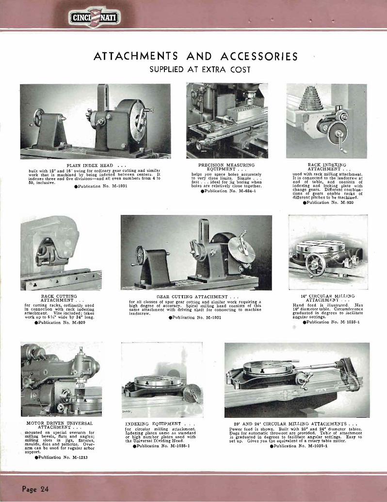
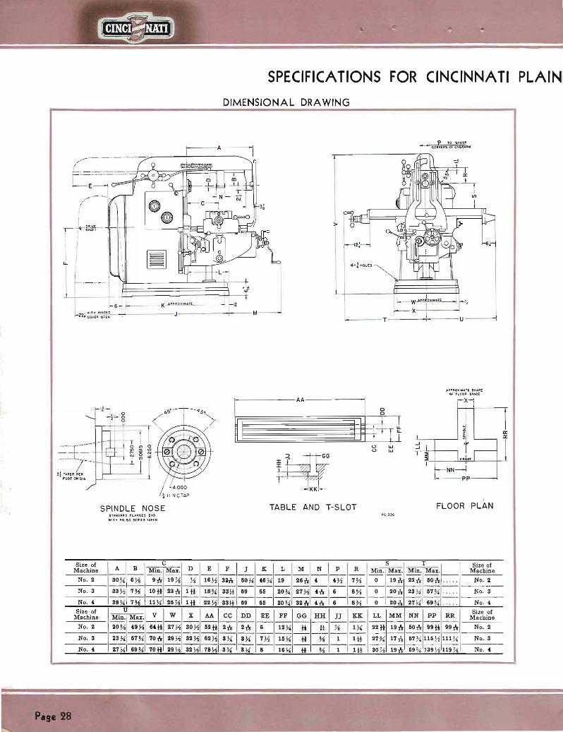

HIGH - SPEED DIAL TYPE MILLING MACHINES
GENERAL SPECIFICATIONS (MODEL ER)
No4 PlainNo 2 Plain No3 Plain
TABLE Working surface Size over all T-slots (number and size)
52Wx12W 52Wd2 K Three-fi
62Wx15W Et2 )1lt15tfThreeshy
78 )1d6)4 78)1gt16 W Three-H
Distance between T-slots 2h 3W W
RANGE Longitudinal Cross
28 10
34 12
42 a
VerUesl 19 20 20 Maximum distance from centerline of spindle to top of tsblbull 19h 20 20 Minimum distance from centerline of spindle to top of table 0 0 0
FULL WIDTH Column to brace 30 W 33 W 38W Column to inside of outer arbor support busblog-with brace in place 26 29Vs 3Hi
OVERARM-Rectsngular Diamptance from under-side to centerline of arbor 6 Ys 7Ys 7Ys
ARBOR SUPPORTS-Self-oiling (See stsndard equipment list page 37) Number 2 2
SPINDLE-Chrome nickel steel Flanged end with standard taper hole No 50 No 50 No 50 Diameter of nose Size of hole through
5 fr 178
5 fr 178
5 fr 178
Speed rpm (twenty-one in approximate geometrical proe-resolion) 20 25 32 39 47 182227 34 41 18 22 27 34 U 59 74 92 114 51 63 78 97 122 61637897122 142 178 220 270 162 188 230 286 152 188 2O 281 33 414 515 635 357 U5 550 675 357445560676 780 970 1200 840 1045 1300 840 1045 1300 1500
Reverse Yes Yes Yes
FEEDS-Inches per minute Number of feeds 32 32 32 Standard Range-Table and cross feeds )lt2 to 40 Yi to 40 ~ to 40
Low Series- Y2 t020= 4 Va ~1 11 2 Y8 2 7 3Vs 4Ys 6 7 9 Ys 12M 1620
HighSenes-1 to 40=1 1 ~1 )lt222y3 Y 4 ~ 6Y7~9~l1 Y 15 X 19 y 24 y 30 y 40
Full range of feeds is obtained by shifting auxiliary lever located on right side of machine (bracket of knee)
Vertical feeds are 8 ( 10 of table and crosgt feeds given above
OPERATING CONTROLS Hand crOS8 longitudinal and vertical adjustments Front and Rear Front and Rear Front and Rear Speed changes by power Fron t and Rear Front and Rear Front and Rear Feed changes by power Front and Rear Front and Rear Front and Rear Single independent cross longitudinal and vertical power feeds Front and Rear Front and Rear Front and Rear Spindle start and stop Front and Rear Front and Rear Front and Rear Power rapid traverse in all directions with spindle stationary or running Front and Rear Front and Rear Front and Rear
POWER RAPID TRAVERSE RATES Inches per minute Longitudinal 100 100 100 Cross 100 100 100 Vertical bull 80 80 80
DRIVE Pulley speed 600 r pm 600 rpm 600 r pm Horliepower rating (Also see Electrical Equipment Specifications lJ
) 5-7 ~ hp 7 ~-10 hp 10-16 h p
LUBRICATION Column and knee Automatic Automatic Automatic Saddle and ts ble Oil Shot Oil Shot Oil Shot
CLUTCH Multiple Disc Oil Multiple Disc Oi l Multiple Disc Oil
FLOOR SPACE 98x97h lUxl14 138x118 Area 66 sq ft 90 SQ ft 113 sq ft
SHIPPING WEIGHTS AND DATA-All weights are for enclosed multiple V belt motor drive or chain motor drive exclusive of motor And control equipment I
Net weight 6350 Ibs 8480 Ibs 9160 Ibs Gross weight domestic 7350 Ibs 9530 lbs 10600 Ibs Gross weight export 7650 Ibs 9SSO Ibs 10900 Ibs Approximate size of case SSx74 x62 94x80x62 100x84x64 Approximate cubic feet 196 227 263
CODE NAME-Chain motor drive exclusive of motor RISDI HISEE HlCIK
CODE NAME-Enclosed multiple V belt drive exclusive of motor HIALP HIBVE HITrP (Supplied as standard equipment unless otherwise specified )
STANDARD EQUIPMENT-Listed on Page 37 EQUIPMENT SUPPLIED AT EXTRA COST-Listed on Page 38
Pabullbull 19
SPECIFICATIONS FOR CINCINNATI UNIVERSAL
DIMENSIONAL DRAWING
f-- - -A ----1
~ 6 f--- - K_MUllJJltU1--- - i 2
22~~Ii~~~----+--------J - - - -------- - M - --T-- --+- - -middotu---j
PC-))1
P Oll IlU( SuoC OF lOO ll SP~(
~------AA ~I ------ r-X-
i I
j
- _ -
- shy shy ~ ------------=--+
[
X
II I u w
i-II NeTA
u w
~pp--
SPINDLE NOSE TABLE AND T-SLOT FLOOR PLAN SUOAPO r lIo lJ[ g [Itgt
t 0 ~o U ll i ts UjII[1t
Size 01 Machine
No 2
No 3
No4
Size 01 Machine
No 2
No3
No
C A B Min Max -shy-shy - - - -
30 )4 6gti 9 gti 19 -shy-shy- -D - --shy
E F J K L -shy-shy-shy-shy- -16 ~ S2n 60 )4 46 )4 19 -shy-shy-shy-shy-shy
sect T M N P R Min Max Min Max -shy-shy-shy-shy -shy -shy -shy - - -shy26n 4 4~ 7 ~ 0 18h 22n 60H shy-shy-shy-shy-shy-shy - - - - -shy
33 ~ 7 ~ 11 n 23 h 1 H
38 )4 7 llih 26 J1 1tt
18 ~ SSt 69 66 20 ~ 27 ~ h 6 8 ~ 0 19tr 2S )4 67 ~ ---shy -------shy - ----------shy22 ~ S3t 69 66 20 ~ 32h 4h 6 8~ o 19tr 27 )4 69 ~
MinUMax _V_~_X_~~ DD ~I GG HH JJ KK LL MM NN PP RR - -shy----shy -----shy
20 )4 48 ~ 64H 27 ~ 30 )1 62H 2h 2h 6 1 12 )4 H It J1 1 )4 22 ~ 19h 60H 99H 99h
23 )4 ~ 70h ~ 32 )1 62 )1 3 )4 3 )4 ~1 16 )4 -----shy- shy -----shy
H ~ 1 1tt 27 ~ 17tr 67 ~ 116 ~ 111 )4- ------ shy ---------shy-------shy -- ----shy-
27 )4 69 70 H 29 ~ 32 )1 78 J1 3 )4 8 )4 8 16 )4 H ~ 1 1tl SOh 191shy 69 139 J1 119 Yo
Size 01 Machine
No2
No S
No
Sizo of Machine
N o 2
No 3
No
HIGH -SPEED DIAL TYPE MILLING MACHINES
GENERAL SPECIFICATIONS (MODEL ER)
No ~ Universal No 3 Universal No 4 Universal
TABLE Workinamp ourlace bull bull bull Size o er all T-alota (number an4 sIze) bull
62 Ux12) 62 x12) Three-H
6~ 1x15) 6~7Sx16ffThreeshy
78~x16 ) 78Wx16) Three-H
Distance between T-slots Swivels-RlCht or left bull bull
2-rU
3W 7
3W 9
RANGE Longitudinal 28 34 411 Cross bull 10 12 U Vertical bull Muimum distance from centerline of spIndle to top of table bull bull MInimum distance from centerline of spIndle to top of table
18 18-r
0
19 19
0
1919i
FULL WIDTH Column to brace 30X 3i W S8 W Colwnn to inside of outer arbor support bushing-with brace in place 28 Vs 29~ 34W
OVERARM-RectanCular Ditance from under-ide to centerline of arbor 6)t 7 7W
ARBOR SUPPORTS-Self-oiling (See standard equipment list page 37) Number 2 2 2
DIVIDING HEAD (See standard equipment Ust page 37) Swin bull 10 12 a Take in length bull bull 28 38 W 52W Lead range with standard driving mechanism 2Vz to 100 2Y to 100 2Vz to 100
SPINDLE-Chrome nickel steel Flanged end with tandard taper hole No 60 No GO No 50 Diameter of nobullbull Size of hole tbrouCh Speed rpm (twenty-one In approximate geometrical proampTession)
5~1 20 15 U 39 47
6~1
18 22 27 34 41 5~1
18 22 2 U 41 69 7 92 11 61 6378 97 122 516378 97 1~2 1411 ITa 220 270 16~ 188230 286 162 188 230 286 3U a 6U 636 367446660675 3G7 G 650 876 7109TO1200 1500 840 IOU 1300 840 IOU 1300
Reverse Yes Yes Yes
FEEDS-Inches per minute Number of feeds Standard Range-Table and cross feeds
Low Serieashy ~ to 20= ~ ~ ji 1 1~ 1 ji 2)t 2~ 3 Yo ltI Gv 7
32 Yz to 40
32 Y to 40
32 Mil to 40
9~ 12~ 1G~ 20 HlCh Series-l to 0=1 1) 1~ 2 2ji 3 ~ ) 5~ 7) 9)1 11~
15 X 19 24 30 40 Full range of feeds is obtained by shiftin an auxiliary lever located on right side
of machine (bracket on knee) Vertical feeds are 8 10 of table and cross feeds given above
OPERATING CONTROLS Hand croso longitudinal and vertical adjustments Front and Rear Front and Rear Front and Rear Speed cbanges by power Front and Rear Front and Rear Front and Rear Feed changes by power Front and Rear Front and Rear Front and Rear Single independent cross longitudinal and vertical power feeds Front and Rear Front and Rear Front and R60r Spindle start and top Front and Rear Front and Rear Front and Rear Power rapid traverse in all directions with spindle stationary or running Front and Rear Front and Rear Front and Rear
POWER RAPID TRAVERSE RATES-Inches per minute Longitudinal bull 100 100 100 Cross 100 100 100 Vertical bull bull 80 80 SO
DRIVE PuUey-Speed 600 rpm 600 rpm 600 rpmHorsepower rating (Also ee Electrical Equipment Specifications) 5-7 ~ hp 7 1-10 hp 10-16 hp
LUBRICATION Column and knee bull Automatic Automatic Automatic Saddle and table bull Oil-5hot Oil-Shot OU-Shot
CLUTCH Multiple Dioc Oil Multiple Disc Oil Multiple Disc Oil
FLOOR SPACE 98x97 114x114 138118 Area 66 sq ft 90 sq ft 113 sq ft
SHIPPING WEIGHTS AND DATA-All weigbts are for enclosed multiple V belt motor drive or chain motor drive exclusive of motor and control equipment
Net weight 6700 lb bull 9100 Ibs 10100 Ibs Gross weigh t 7800 Ibs 10400 Ibs 11500 lb bull Gross weight export 8000 lbs 10750 Ibs 11900 lbs Approximate size of case 8874x52 94xSOx62 100x8 64 Approimate cubic feet 196 227 312
CODE NAME-Chain motor drive exclusive of motor HISIA HISGA HISO]
CODE NAME-Enclosed MUltiple V belt drive exclusive of motor HIMUL RIVEB RIPLE (Supplied as standard equipment unless otberwise specified)
STANDARD EQUIPMENT-Listed on Page 37 EQUIPMENT SUPPLIED AT EXTRA COST-Listed on Page 38
Page 31
SPECIFICATIONS FOR CINCINNATI VERTICAL
DIMENSIONAL DRAWING
(
= __11
-- shy---- shy
---1- I
-6- ~ ---- K ~~~~~--~ J 2 -22To~ At1I - ~------J ---- shy - shy - shy M
T
iiJ
I
- ---T---shy ----- shy -shy U----shy
------~--AA--------- -1
I
~ I
--- KK
I I
shyI shy
IJ o w o w
APPR Oll loIATE SI1II(
0 LOOR SPACE
x
- - shy pp
SPINDLE NOSE TABLE AND T-SLOT FLOOR PLAN
Size of Machine
No2
No3
No
Size of Machine
No II
No3
No
UloNOAIIO FlANGEI) [JIIO
WiTH NO iO SUIIl$ TER
degB C AM Mu M Mogt J K- shy -- shy - shy - shy - shy - shy --- shy14 0 18H 9h 21)j 33H 50~ 67(- shy --------- shy18 0 22 tt 10 tt 27 Yo 38 89 85
------------- shy18 0 22 tt 11 ~ 117 )j 38 59 85
X AA CC DD EE FF GG HH - shy - shy - shy - shy - shy - shy - shy
30 ~ 52 it 2 21 6 lilY tt It - shy -- I- - shy
32~ 62 ~ 3 ~ 3~ 7 ~ 15~ it
L
19
20~
20~
JJ - shyi
- shy1
S2~ I 78~ 3~ --- shy --- shy ~I-l-3~ 8 16~ it
T U Size of I ~ Min IMax Min Max V W Machine--- shy
26 tr 22 tr 50 0 110 9) 78 it 17 )j No I
SO h 277( 1 87 ~ 2S ~ 57 Y 86 Y 29)j No S ----------
SOn 117~ 69~ 27 ~ 69Y 8614 29 ~ No
KK LL MM NN pp RR Size of
Machine - shy - shy - shy - shy - shy - shy - shylY Un 17 it 600 99 tt 98Y - No I
--- shy - shy - shy - shy - shylii 310 16tr 57~ 115 ~ 111 No S
------------Iii 32)j 151 69Y 139~ 111 No
-NOTE-MAXIMUM dimenSIOn B 1S With head 10 extreme up position and knee 10 extreme down pOSItion Both uwts are reversed for MINIMUM dimension UB
Pase 32
HIGH - SPEED DIAL TYPE MILLING MACHINES
GENERAL SPECIFICATIONS (MODEL ER)
No2 Vertical No 3 Vertical No 4 Vertical
TABLE Working surface Size over all T-slon (number and size) Dlotance between T -slots
RANGE Lonitudinal Cross bull bull Vertical Head travel Ditance from spindle noe to top of table Throat distance centerline of splOdle to column
SPINDLE-Chrome nickel steel Flanged end with standard taper hole Diameter of nose Size of hole through bull Speeds rpm (twenty-one in approximate eometrical progression)
Reverse
FEEDS-Inches per minute Number of feeds Standard Range-Ta ble and cross feeds
Low Series-Y2 to 20= ~J ~-i 1 1 Ys 1 ~ 2 Ys 2 3 ~ s 4 )8 5 ~~ 7 9 l1 1~ l-i 15 H 20
High Series-1 to 40=1 1 ~ 172 2 2 ~ 3 K 7( 6 ~ 7 y( 91 11~2 1amp 19~ 2(~ 30~ (0
Full range of feeds is obtained by shifting an auxiliary lever located on right side of machine (bracket on knee)
Vertical feeds are 8 10 of table and cross feeds given above
OPERATING CONTROLS Hand cross and vertical adjustments bull Hand longitudinal adjustment Speed changes by power Feed changs by power Single Independent cross and vertical power feeds Sinamplo Independent longitudinal power feed Spindle tart and stop Power rapid traverse in all directions with spindle s tationary or running Rear hand adjustments cross and Yertical rear power feed controls cross and vertical are
supplied only on request and at extra cost
POWER RAPID TRAVERSE RATES-Inches per minute Lonitudlnal Cro Vertical
POWER TRAVERSE TO HEAD (S upplied at extra cost) Number of feeds Feed rates Feed range Rapid traverse rate (inches per minute)
DRIVE Pulley speed Horlepower rating (Also see CCElectrical Equipment Specifications)
LUBRICATION Column and knee bull Saddle and table
CLUTCH
FLOOR SPACE Area
SHIPPING WEIGHTS AND DATA-All weights are for enclosed multiple V belt motor drive or chain motor drive exclusive of motor and control equipment
Net weight Gross weight domestic
t~~~~rl~~~i~~p~r~a 8~ Approximate cubic feet bull
CODE NAME-Encloed chain motor drive exclusive of motor
CODE NAME-Enclosed multiple V belt drive exclusive of motor bull (Supplied as standard equipment unless otherwise specified on order)
52 tl I12 W 52 1tx12 ( Three-H
2
28 12 13 6 18 14 bull
No 50 5n 1 Ys
20 25 32 39 47 59 74 92 114 142178220270 3S3 U4 515 635 78097012001500
Yes
32 Ji to 40
Front Front and Rear Front and Rear Front and Rear
Front Front and Rear Front a nd Rear Front and Rear
100 100 80
16 6 Dial Readings
3 to 12 31
600 rpm 5-7)1 hp
Automatic Oil-Shot
Multiple Di sc Oil
98x79W 543 sq ft
7100 lbs 8SOO lb s 8500 lbs
88 x84x52 223
HILAC
HIELT
62 Wxl5 W 62 )1 x15 W Three-H
3W
34 16 16 6
22 18
No 50 511 lY
18 22 27 34 41 51637897 122 152 188 230 286 357445 550675 840 1045 1300
Yes
32 J-z to 40
Front Front and Rear Front and Rea r Front and Rear
Front Front and Rear Front and Rear Front and Rear
100 100 80
16 6 Dial Readings
3 to 12 31
600 rpm 7 )110 hp
Automatic Oil-Shot
Multiple Disc Oil
114x93 Ys 74 1 sq ft
9SOO lbs 10200 lbbull 10900 lbs 100x90x5(bull
282
mSAR
HIOPT
78 Y x16 W 78Wx16W Three-H
3W
42 16 16 6
22 18
No 50 511 l Y
18 22 27 34 U 51 6S 78 97 122 152 188 2S0 286 3574(5550675 840 1045 lS00
Yes
S2 2 to 40
Front Front and Rear Front and Rear Front and Rear
Front Front and Rear Front and Rear Fron t and Rear
100 100 80
16 6 Dial Readings
3 to 12 31
600 rpm 10-15 hp
Automatic Oil-Shot
Multiple Disc Oil
138 x95 91 sq ft
9950 lbbull 10800 lbs 11550 Ibs 100x90x5(
282
HISHT
HIQUI
STANDARD EQUIPMENT-Listed on Page 37 EQUIPMENT SUPPLIED AT EXTRA COST-Listed on Page 38
Page 33
SPECIFICAliONS FOR CINCINNA11
PLAn~ MEDIUM SPEED
GENERAL SPECIFICATIONS (MODEL ER)
No2 Plain No3 Pla in No 4 PI~in
TABLE Working surface Size over all T-s lots (number and size) Distance between Tmiddotslots
RANGE Longi tudinal Cross Vertical Maximum distance from centerline of spindle to top of table Minimum distance from centerline of spindle to top of table
FULL WIDTH Column to brace Column to inside of outer arbor support bushing-with brace in place
OVERARM-Rectangular Distance to centerline of arbor
ARBOR SUPPORTS-Self-oiling (See standard equipment list on page 37) Number
SPINDLE-Chrome nickel steel Flanged end with standard taper hole Diameter of nose Size of hole through Speeds rpm (s ixteen In approximate ampeometrical proampression)
Reverse
FEEDS-Inche per minute Number of feeds Standard range-Table and cross feeds
Y1) 1 1 t 1 ~ 2 Va 23 ~4 8 7YF gi 12 18~ 20 Vertical feeds are 8 10 of table and cross feed iPven above
OPERATING CONTROLS Hand cross longitudinal and vertical adjustments Speed changes by power Feed changes by power Single independent cross longitudinal and vertical power feeds Spindle start and stop Power rapid traverse in all directions with spindle stationary or running
POWER RAPID TRAVERSE RATES-Inches per minute (For standard feed series machines)
Longitudinal Cross Vertical
DRIVE Pulley speed Horsepower rating ( Als~~~e Ele~trical Equipment Specifications)
LUBRICATION Column and knee Saddle and table
CLUTCH
FLOOR SPACE Area
SIDPPING WEIGHTS AND DATA-All weights are for enclosed multiple V be lt motor drive or chain motor drive exclusive of motor and control equipment
Net weight Gross weight domesti c Gross weight export Approximate size of case Approximate cubic feet
CODE NAME-Enclosed chain motor drive exclusive of motor
CODE NAME--Enclosed multiple V belt drive exclusive of motoL (Supplied as standard equipment unless otherwise specified on order
62 H x12 Yi 52H x12 ~middot Three- H
2
28 10 19
19 t 0
30 W 26 Ys
6W
2
No 50 5 lW
20 26 32 (0 47 60 74 92 116 141 179222 262 331 4H 500
Yes
16 M to 20
Front and Iloar Front and Rear Front and Rear Front and R ear Front and Rear Front and Rear
100 100 SO
600 Lpm 5-7 ~ h p
Automatic Oil Shot
Multiple Disc Oil
98x97 66 sq It
6250 Ibs 7 250 Ibs 7450 lbs
8SxHx62 196
TOOMO
TUALP
62 )4x15 )1 62 ~x15 W Three- H
3 W
34 12 20
20 0
33 W 29 ~f
s 7
No 50 5t 1 Ys
18 22 27 33 40 51 63 78 96 123 151 187 ~23 281 350 460
Yes
7116
11 to 20
Front and Rear Front and Rear Front and Rear Front a nd Rear Front and Rear Front and Rear
100 100 SO
600 r pm 7 )1-10 h p
Automatic Oil Shot
Multiple Disc Oil
114 xl14 90 sq ft
S3S0 Ibs 9430 Ibs 9780 lbs
94x80x62 227
1MRIC
IMALP
78 ~x16 )1 78 ~x16 W Three-H
3W
42 14 20
20 O
38 W 3Hs
7 Ys
2
No 50 5 1 Ys
18 22 27 33 40 51 63 78 96 123 1511872232S1 350 450
Yes
16 Vz to 20
Front and Rear Front and Rear Front and Rear Front and Rear Front and Rear Front and Rear
100 100 80
600 rpm 10-15 hp
Automatic Oil Shot
Multiple Disc Oil
13Sx118 113 sq ft
9050 lbs 10400 Ibs 10800 Ibs 100xS4xU
263
IMLEC
IMENC
DIMENSIONAL DRAWING-Same as shown on Page 28 STANDARD EQUIPMENT-Listed on Page 37
EQUIPMENT SUPPLIED AT EXTRA COST-Listed on Page 38
Page 34
DIAL TYPE MILLING MACHINES
UNIVERSAL MEDIUM SPEED
GENERAL SPECIFICATIONS (MODEL ER)
No 2 Universal No3 Universal No4 Universal
TABLE Working surface 52 ttx12 W 62 yx15 W 78 W x16 W Size over all bull bull 52 Hx12 Y 62 Wx15 Y 78 Vx16 Y T-slots (number and size) Three- tV Three-H Three-H Distance between T-slots 2 3W 3W Swivels-Right or left 45 47 49
RANGE Longitudinal 28 34 42 Cross 10 12 14 Vertical bull 18 19 19 Maximum distance from centerline of spindle to top of table 18 19 191 Minimum distance from centerline of spindle to top of table bull O 0 0
FULL WIDTH Column to brace 30 W 33 W 38 W Column to inside of outer arbor support bushing-with brace in place 26 W 29 W 34W
OVERARM-Rectangular Distance to centerline of arbor 6 )1 7W 7y
ARBOR SUPPORTS-Self-oiling (See standard equipment list on page 37) Number 222
DIVIDING HEAD (See standard equipment list on page 37) Swing 10 12 14 Take in length 28 36W 52 W Lead range with standard driving mechanism 2W to 100 2) to 100 2W to 100
SPINDLE-Chrome nickel steel Flanged end with standard taper hole No 50 No 50 No 60 Diameter of nooe 5h 5h5Size of hole through 1 Vs 1 v 1 )1 Speeds r pm (sixteen in approximate geometrical progression) bull 20 25 32 40 47 18 22 27 33 40 18 22 27 S3 40
60 74 92 116 51637896123 516378 6 121 144179222 262 151187223281 151187223211 331414500 350450 350450
Reverse Yes Yes Yes
FEEDS-In inches per minute Number of feeds U U U Standard range-Table and cross feeds 2 to 20 Y2 to 20 --f to 20
V Yo 1 1 v 1 2 Va 2 3 4 ~ 5 i 7 Yo 9 )1 12 15 VB 20 Vertical feeds are 810 of table and cross feeds given above
OPERATING CONTROLS Hand cross longitudinal and vertical adjustments Front and Rear Front and Rear Front and Rear Speed changes by power Front and Rear Front and Rear Front and Roar Feed changes by power Front and Rear Front and Rear Front and Rear Single Independent cro longitudinal and vertical power feeds Front and Rear Front and Rear Front and Rear Spindle sart and stop Front and Rear Front and Rear Front and Rear Power rapid traverse in all directions with spindle stationary or running Front and Rear Front and Rear Front and Rear
POWER RAPID TRAVERSE RATES-Inches per minute (For standard feed series machines)
Longitudlnal 100 100 100 Cross 100 100 100 Vertical bull bull 80 80 80
DRIVE Pulley speed 600 rpm 600 rpm 600 rpm Horsepower rating (Also see Electrical Equipment Specifications) 5-7 V hp 7 V-10 hp 10-15 h p
LUBRICATION Column and knee bull bull bull Automatic Automatic Automatic Saddle and table bull Oil-Shot Oil-Shot Oil-Shot
CLUTCH Multiple Disc Oil Multiple Disc Oil Multiple Dic Oil FLOOR SPACE 98x97 114x114 138lt118
Area 66 sq ft 90 sq ft 113 sq ft SHIPPING WEIGHTS AND DATA-All weights are for enclosed mUltiple V belt
motor drive or chain motor drivel exclusive of motor and control equipment Net weight 6600 lbs 9000 lbs 10000 lbs Gross weight domestic 7700 lbs 10300 lbs 11400 lbs Gross weight export 7900 lbs 10650 lbs 11800 lbs Approximate size of case 88 x74x52 94 xSOx52 100x84 x64 Approximate cubic feet 196 227 312
CODE NAME-Enclosed chain motor drive exclusive of motor TULEC IMDRI IMFYZ CODE NAME-Enclosed multiple V belt drive exclusive of motor TUMUL IMUVB IMELD
(Supplied as standard equipment unless otherwise specified on order)
DIMENSIONAL DRAWING-Same as shown on Page 30 STANDARD EQUIPMENT-Listed on Page 37
EQUIPMENT SUPPLIED AT EXTRA COST-Listed on Page 38
Page 35
SPECIFICATIONS FOR CINCINNATI
VERTICAL MEDIUM SPEED
GENERAL SPECIFICATIONS (MODEL ER)
No 2 Vertical No3 Vertical No4 Vertical
TABLE Working surface Size over all T-slots (number and size) Distance between T-slots
RANGE Longitudinal Cross Vertical Head travel Distance fTom spindle nose to top of ta ble Throat distance centerline of spindle to column
SPINDLE-Chrome nickel steel Flanged end with standard taper hole Diameter of nose SI of hole through Speeds rpm (Sixteen iD approximate geometrical progression)
Reverse
FEEDS-Inches per minute Number of feeds Standard range-Table and cross feeds
~ ~ ~ I 1~ 1 v 2 Ya 2~ 3li 4li ex 7 l-i 9 Yo 12)115)120 Vertical feed are 8 10 of table and cross feed given above
OPERATINO CONTROLS Hand crOSs and vertical adjustments Hand longitudinal adjustment Speed change by power Feed changes by power Single Independent cross and vertical power feeds Single independent longitudinal power feed Spindle start and stop Power rapid traverse in all directions with spindle stationary or running Rear hand adjustments cross and vertical rear power feed controls cross and vertical
are suppUed only on request and at extra cost
POWER RAPID TRAVERSE RATES Inches per minute (For standard feed eries machines)
Longitudinal Cross Vertical
POWER TRAVERSE TO HEAD (Supplied at extra cost) Number of feeds Feed rates for machines having standard table feeds Feed rates for machines having low table feeds
Feed rsne Rapid traverse rate inches per minute
DRIVE
~~p~~r ~~iimiddotnmiddotg iAiso EIci~ic~i Equipment Sp~cificatio~~) LUBRICATION
Column and knee bull Saddle and ta ble bull
CLUTCH
FLOOR SPACE Area
SHIPPING WEIGHTS AND DATA-All weights are for enclosed mUltiple V bell motor drive or chain motor drive exclusive of motor and control equipment
Net weight Gross weiampht domestic Gross weight export Approximate size of caEe Approximate cubic feet
CODE NAME-Enclosed chain motor drive exclusive of motor
CODE NAME-Enclosed multiple V belt drive exclusive of motor (Supplied as stardard equipment unless otherwise opecified on order)
52Wx12 X 52Wx12W Tlue-W
2
28 12 lS 6 18 14
No 50 51Ys
20 26 3240 47 60 74 92 116 HI 179222 2S2 331 414 500
Yes
16 J to 20
Front Front and Rear Front and Rear Front and Rear
Front Front and Rear Front and Rear Front and Rear
100 100middot 80
16 ~ Dial Reading~Same as Dial
ReadingsW to 10
44
600 rpm 5-7 ~ hp
Automatic Oil-Shot
Multiple Disc Oil
98x79 W 543 sq fl
7 050 Ibs 8200 Ibs 8 400 Ibs
88x8x02 223
TUTOO
TUVEB
62 ~x15)4 62 ~-x15 Y Three-J-t
3W
34 16 lS 6
22 18
No 50 51Ys
18 22 27 33 40 51 6S 78 96 123 151 187223281 350 450
Yes
16 ~ to 20
Front Front and Rear Front and Rear Fron t and Rear
Front Front and Rear Front and Rear Front and Rear
100 100 80
16 ~ Dial Readings
Same as Dial Readings )1 to 10
44
600 r pm 7 J~-10 h p
Automatic Oil-Shot
Mulliple Disc Oil
114 x93 741 sq ft
9200 Ibs 10100 Ibs 10800 Ibs 100x90x54
282
IMRYE
IMEVE
78Wx16J4 78~x16 )4 Three-H
3W
42 lS 16 6
22 18
No 50 5h 1Vs
18 22 27 33 40 5163 78 96123 151 187 223 281 350 450
Yes
16 i to 20
Front Front and Roar Front and Rear Front and Rear
Front Front and Rear Front and Rear Front and Rear
100 100 eO
16 H Dial Readings
Same as Dial ReadingW to 10
44
600 rpm 10-15 hp
Automatic Oil-Shot
MUltiple Disc Oil
138x95 91 sq ft
9860 Ibs 10700 Ibs 11450 Ibs 100x90x54
283
IFORV
IMMUL
DIMENSIONAL DRAWING-Same as shown on Page 32 STANDARD EQUIPMENT-Listed on Page 37
EQUIPMENT SUPPLIED AT EXTRA COST-Listed on Page 38
Page 36
DIAL TYPE MILLING MACHINES
STANDARD EQUIPMENT-Supplied with the Machine
PLAIN MACHINES-HighmiddotSpeed and Medium Spud
ARBOR SUPPORTS No 2 Millers- one Style STANDARD FEED RANGE-High speed mashyB with 2 Ys adjustable arbor bushing and proshy chines Y2 to 40 Medium speed machines vided with lug for brace- one Style A with adshy Y2 to 20 justable arbor bushing for pilot end arbors Nos
ARBOR SUPPORT BUSHING ADAPTER M-013 and 4 Millers-one Style B with 2 Ys adjustshy
(includes adjustable bushingnut washer and screw)able arbor bushing without lug for brace-one for Style A arbors Nos 3 and 4 Machines only
style B with 2Ys adjustable arbor bushing and provided with lug for brace WRENCHES COOLANT PUMP
ADJUSTABLE ARBOR TIGHTENING ROD OVERARM BRACE
UNIVERSAL MACHINES-HighSpeed and Medium Speed
ARBOR SUPPORTS No 2 Millers-one Style B with 2Ys adjustable arbor bushing and proshyvided with lug for brace-one Style A with adjustable arbor bushing for pilot end arbors Nos 3 and 4 Millers-one Style B with 2 Ys adjustable arbor bushing without lug for braceshyone Style B with 2 Ys adjustable arbor bushing and provided with lug for brace
ARBOR SUPPORT BUSHING ADAPTER M-01 (includes adjustable bushing nut washer and screw) for Style A arbors Nos 3 and 4 Machines only
ADJUSTABLE ARBOR TIGHTENING ROD
STANDARD FEED RANGE-High speed mashychines Y2 to 40 Medium speed machines Y2 to 20
STANDARD UNIVERSAL DIVIDING HEAD EQUIPMENT including tailstock with 2-point adjustable center steady rest one plate for indexshying through 40 to 1 reduction-all numbers up to and including 60 all even numbers and those divisible by 5 up to 120 and many beyond one plate for direct indexing one center for headstock and provision for connecting head to enclosed driving mechanism segment Sizes (nominal swing) 10 for No 2 Machine 12 for No 3 Machine 14 for No 4 Machine
ENCLOSED DRIVING MECHANISM SEGshyMENT including change gears for spiral milling leads range from 2Y2 to 100 (only) for Standard Universal Dividing Heads
WRENCHES COOLANT PUMP
OVERARM BRACE
VERTICAL MACHINES- HighmiddotSpeed and Mdium Speed
ADJUSTABLE ARBOR TIGHTENING ROD STANDARD FEED RANGE-High speed mashychines Y2 to 40 Medium speed machines
WRENCHES COOLANT PUMP Y2 to 20
Pige 37
SPECIFICATIONS FOR CINCINNATI
EOUIPMENT SUPPLIED AT EXTRA COST (Not Included in Price of Standard (Basic) Machine) For Medium Speed and High-Speed Machines (See pages 22-27 for illustrations and brief descriptions)
PLAIN UNIVERSAL AND VERTICAL MACHINES 1 TABLE AND CROSS FEEDS Rack Milling Slotting Circular Milling Cam
(a) For Medium Speed Machines sixteen Milling High Number Indexing Attachment ~ to 10 or to 30 inches per minute for Dividing Head Spiral Milling Head etc
(b) For High-Speed Machines thirty-two 6 INDEX BASES RAISING BLOCKS RIGHT ~ to 20 inches per minute ANGLE PLATES
2 WIDE RANGE DIVIDER (applied to Standard 7 PRECISION MEASURING EQUIPMENTUniversal Dividing Head) for divisions from 2
(Recommended for short dimensions only)to 400000 hundreds of them exact and others compensated for the fractional remainder 8 PUMP CUTTER COOLANT individually
3 VISES CHUCKS AND CHUCK ADAPTERS motor driven including ~ HP motor manual starter and piping Code Name PUDIA
4 ARBORS ADAPTERS COLLETS QUICK CHANGE ADAPTERS Etc 9 ELECTRICAL MOTOR AND CONTROL
EQUIPMENT5 STANDARD ATTACHMENTS High-Speed Universal Heavy Vertical Universal Spiral 10 SPLASH GUARDS
PLAIN AND UNIVERSAL MACHINES ONLY 1 ARBOR SUPPORTS
(a) Style B with 2Ys adjustable arbor bushshy (b) Style B with 2 Ys adjustable arbor bushshying without lugs for brace for use on No2 ing without lug for braces for Nos 3 and 4 machines Code Name ARBBS Machines Code Name AJUSB
(c) Style A with adjustable arbOr No3 Machine Code Name ARTMY bushing for pilot end arbors No4 Machine Code Name ARMMF
PLAIN AND VERTICAL MACHINES ONLY 1 STANDARD UNIVERSAL DIVIDING HEAD 12 size for No3 Machine Code
AND EQUIPMENT including tailstock with Name HYDRA 2-point adjustable center steady rest one plate for indexing through 40 to 1 reduction-all 14 size for No4 Machine Code numbers up to and including 60 all even Name HEDPA numbers and those divisible by 5 up to 120 and 2 ENCLOSED DRIVING MECHANISM SEGshymany beyond those shown in the table of specishy MENT including change gears for spiral mill shyfication sheet one plate for direct indexing one
ing leads ranging from 2Y2 to 100 (only) for center for headstock and provision for connectshyStandard Universal Dividing Headsinghead to enclosed driving mechanism segment
10 size for No2 Machine Code No2 Machine Code Name DREDT Name HUTER Nos 3 and 4 Machines Code Name DREHS
VERTICAL MACHINES ONLY 1 POWER FEED AND POWER QUICK 3 REAR HAND ADJUSTMENTS AND REAR
TRAVERSE to the Vertical Head POWER FEED CONTROLS cross and vershy2 TURRET STOP four-position with dial indi- tical Supplied at factory only (Not supplied as
cator Code Name (In Field) TUMAC standard equipment on Vertical Machines) Code Name (Prior to Shipment) FOPST
UNIVERSAL MACHINES ONLY 1 LONG AND SHORT LEAD ATTACHMENT before machine is shipped
with a range 010 to 1000 inches or 024 to 2400 No 2 Machine Code Name LOSHO centimeters Must be installed at factory Nos 3 and 4 Machines Code Name LONSH
NOTE These feeds are optional at the time the order is placed When machines are equipped with the low ranges of feeds (gt-4 to 10 for the Medium Speed machines and gt-4 to 20 for the High-Speed machines) rapid traverse rates are cut in half
Pase 38
- --- --
DIAL TYPE MILLING MACHINES
ELECTRICAL EQUIPMENT The motors and controls listed below are suitable for the machines illustrated and described in this booklet
CHARACTERISTICS -
Current Voltage Speed RPMCycles PhaseI I I A C 60 2 or 3 220 440550 1800
A C 50 2 or 3 220 440550 1500I A C 150050 380 500 Etc 2 or 3
A C 25 15002 or 3 220 440 550
D C 1750 115 or 230 I - ~-
MOTOR HORSE POWER AND FRAME SIZES
No 4 MachineNo 2 Machine Nos 2 and 3 Machines Nos 3 and 4 Machines
NEMA I NEMANRMA NEMAH P H P H PH PFrame Frame FrameFrame I 7 )25 254 326284 324 1510 I 7 )25 254 326284 10 324 15
7)25 254 15 326284 10 324
284 155 10 364 3657Yz I 1510 I 5 I I 7Yz ~
-
7)2 H P motor totally enclosed ball bearing frame No 326 can not be used on No2 Dial Type
Open frame ball bearing motors are recommended
Motors larger than the following can not be used
No2 Dial Type-NEMA frame 326 No3 Dial Type-NEMA frame 364 No4 Dial Type-NEMA frame 365
A C MOTORS-Standard make NEMA frame normal torque low starting current (normal start shying current for 5 hp motors) floor mounted with conduit box on left viewing shaft end
D C MOTORS-Standard make shunt wound constant speed 40deg C continuous open rotation clockwise viewing shaft end floor mounted with conduit box on left viewing shaft end
A C CONTROLS-Standard make enclosed type full voltage magnetic starter with thermal overload protection For all A C circuits over 220 volts a control transformer and 110 volt coils are included to provide low voltage at the push button station-a safety feature
D C CONTROLS-Standard make enclosed type magnetic starter with definite time acceleration thermal overload protection and without dynamic braking
PUSH BUTTON STATION-Separate Start shyStop included with A C or D C controls
ORDERING INSTRUCTIONS - The following electrical data must accompany each order
(a) Voltage
(b) Current (A C or D C) If A C also include
1 Phase
2 Cycle
3 Control circuit voltage
(d) Horsepower speed and type of frame (open or totally enclosed) and motor bearing
Page 39
bull bull Right-A heavy stock removal job on a No2 Plain High Speed Machine Milling two sides of extension supports reducing a spherical shape of 1 diameter to a width of H
Below-Milling the keyway in a heat-treated bevel gear High Speed Dial Type Millers have the wide range of speeds and feeds so necessary in shops where one lot of parts may be tough hard steel and the next lot soft aluminum
Below-A No 3 Vertical Dial Type roughs and finishes from the solid a cast iron dovetail slide The turret stop attachment at the side of the vertical head assures a close limit of accuracy between the dovetail and the top surface
Left-The operator can always see the job on a Horizontal Dial Type because there are complete front and rear conshytrols This No4 Plain Dial Type faces both ends of the shell section of a tire building drum PPIN HD N tI
THE CINCINNATI MILLING MACHINE CO CINCINNATI 01U S A

DIAL TYPE MILLING MACHINES
UNIVERSAL MEDIUM SPEED
GENERAL SPECIFICATIONS (MODEL ER)
No 2 Universal No3 Universal No4 Universal
TABLE Working surface 52 ttx12 W 62 yx15 W 78 W x16 W Size over all bull bull 52 Hx12 Y 62 Wx15 Y 78 Vx16 Y T-slots (number and size) Three- tV Three-H Three-H Distance between T-slots 2 3W 3W Swivels-Right or left 45 47 49
RANGE Longitudinal 28 34 42 Cross 10 12 14 Vertical bull 18 19 19 Maximum distance from centerline of spindle to top of table 18 19 191 Minimum distance from centerline of spindle to top of table bull O 0 0
FULL WIDTH Column to brace 30 W 33 W 38 W Column to inside of outer arbor support bushing-with brace in place 26 W 29 W 34W
OVERARM-Rectangular Distance to centerline of arbor 6 )1 7W 7y
ARBOR SUPPORTS-Self-oiling (See standard equipment list on page 37) Number 222
DIVIDING HEAD (See standard equipment list on page 37) Swing 10 12 14 Take in length 28 36W 52 W Lead range with standard driving mechanism 2W to 100 2) to 100 2W to 100
SPINDLE-Chrome nickel steel Flanged end with standard taper hole No 50 No 50 No 60 Diameter of nooe 5h 5h5Size of hole through 1 Vs 1 v 1 )1 Speeds r pm (sixteen in approximate geometrical progression) bull 20 25 32 40 47 18 22 27 33 40 18 22 27 S3 40
60 74 92 116 51637896123 516378 6 121 144179222 262 151187223281 151187223211 331414500 350450 350450
Reverse Yes Yes Yes
FEEDS-In inches per minute Number of feeds U U U Standard range-Table and cross feeds 2 to 20 Y2 to 20 --f to 20
V Yo 1 1 v 1 2 Va 2 3 4 ~ 5 i 7 Yo 9 )1 12 15 VB 20 Vertical feeds are 810 of table and cross feeds given above
OPERATING CONTROLS Hand cross longitudinal and vertical adjustments Front and Rear Front and Rear Front and Rear Speed changes by power Front and Rear Front and Rear Front and Roar Feed changes by power Front and Rear Front and Rear Front and Rear Single Independent cro longitudinal and vertical power feeds Front and Rear Front and Rear Front and Rear Spindle sart and stop Front and Rear Front and Rear Front and Rear Power rapid traverse in all directions with spindle stationary or running Front and Rear Front and Rear Front and Rear
POWER RAPID TRAVERSE RATES-Inches per minute (For standard feed series machines)
Longitudlnal 100 100 100 Cross 100 100 100 Vertical bull bull 80 80 80
DRIVE Pulley speed 600 rpm 600 rpm 600 rpm Horsepower rating (Also see Electrical Equipment Specifications) 5-7 V hp 7 V-10 hp 10-15 h p
LUBRICATION Column and knee bull bull bull Automatic Automatic Automatic Saddle and table bull Oil-Shot Oil-Shot Oil-Shot
CLUTCH Multiple Disc Oil Multiple Disc Oil Multiple Dic Oil FLOOR SPACE 98x97 114x114 138lt118
Area 66 sq ft 90 sq ft 113 sq ft SHIPPING WEIGHTS AND DATA-All weights are for enclosed mUltiple V belt
motor drive or chain motor drivel exclusive of motor and control equipment Net weight 6600 lbs 9000 lbs 10000 lbs Gross weight domestic 7700 lbs 10300 lbs 11400 lbs Gross weight export 7900 lbs 10650 lbs 11800 lbs Approximate size of case 88 x74x52 94 xSOx52 100x84 x64 Approximate cubic feet 196 227 312
CODE NAME-Enclosed chain motor drive exclusive of motor TULEC IMDRI IMFYZ CODE NAME-Enclosed multiple V belt drive exclusive of motor TUMUL IMUVB IMELD
(Supplied as standard equipment unless otherwise specified on order)
DIMENSIONAL DRAWING-Same as shown on Page 30 STANDARD EQUIPMENT-Listed on Page 37
EQUIPMENT SUPPLIED AT EXTRA COST-Listed on Page 38
Page 35
SPECIFICATIONS FOR CINCINNATI
VERTICAL MEDIUM SPEED
GENERAL SPECIFICATIONS (MODEL ER)
No 2 Vertical No3 Vertical No4 Vertical
TABLE Working surface Size over all T-slots (number and size) Distance between T-slots
RANGE Longitudinal Cross Vertical Head travel Distance fTom spindle nose to top of ta ble Throat distance centerline of spindle to column
SPINDLE-Chrome nickel steel Flanged end with standard taper hole Diameter of nose SI of hole through Speeds rpm (Sixteen iD approximate geometrical progression)
Reverse
FEEDS-Inches per minute Number of feeds Standard range-Table and cross feeds
~ ~ ~ I 1~ 1 v 2 Ya 2~ 3li 4li ex 7 l-i 9 Yo 12)115)120 Vertical feed are 8 10 of table and cross feed given above
OPERATINO CONTROLS Hand crOSs and vertical adjustments Hand longitudinal adjustment Speed change by power Feed changes by power Single Independent cross and vertical power feeds Single independent longitudinal power feed Spindle start and stop Power rapid traverse in all directions with spindle stationary or running Rear hand adjustments cross and vertical rear power feed controls cross and vertical
are suppUed only on request and at extra cost
POWER RAPID TRAVERSE RATES Inches per minute (For standard feed eries machines)
Longitudinal Cross Vertical
POWER TRAVERSE TO HEAD (Supplied at extra cost) Number of feeds Feed rates for machines having standard table feeds Feed rates for machines having low table feeds
Feed rsne Rapid traverse rate inches per minute
DRIVE
~~p~~r ~~iimiddotnmiddotg iAiso EIci~ic~i Equipment Sp~cificatio~~) LUBRICATION
Column and knee bull Saddle and ta ble bull
CLUTCH
FLOOR SPACE Area
SHIPPING WEIGHTS AND DATA-All weights are for enclosed mUltiple V bell motor drive or chain motor drive exclusive of motor and control equipment
Net weight Gross weiampht domestic Gross weight export Approximate size of caEe Approximate cubic feet
CODE NAME-Enclosed chain motor drive exclusive of motor
CODE NAME-Enclosed multiple V belt drive exclusive of motor (Supplied as stardard equipment unless otherwise opecified on order)
52Wx12 X 52Wx12W Tlue-W
2
28 12 lS 6 18 14
No 50 51Ys
20 26 3240 47 60 74 92 116 HI 179222 2S2 331 414 500
Yes
16 J to 20
Front Front and Rear Front and Rear Front and Rear
Front Front and Rear Front and Rear Front and Rear
100 100middot 80
16 ~ Dial Reading~Same as Dial
ReadingsW to 10
44
600 rpm 5-7 ~ hp
Automatic Oil-Shot
Multiple Disc Oil
98x79 W 543 sq fl
7 050 Ibs 8200 Ibs 8 400 Ibs
88x8x02 223
TUTOO
TUVEB
62 ~x15)4 62 ~-x15 Y Three-J-t
3W
34 16 lS 6
22 18
No 50 51Ys
18 22 27 33 40 51 6S 78 96 123 151 187223281 350 450
Yes
16 ~ to 20
Front Front and Rear Front and Rear Fron t and Rear
Front Front and Rear Front and Rear Front and Rear
100 100 80
16 ~ Dial Readings
Same as Dial Readings )1 to 10
44
600 r pm 7 J~-10 h p
Automatic Oil-Shot
Mulliple Disc Oil
114 x93 741 sq ft
9200 Ibs 10100 Ibs 10800 Ibs 100x90x54
282
IMRYE
IMEVE
78Wx16J4 78~x16 )4 Three-H
3W
42 lS 16 6
22 18
No 50 5h 1Vs
18 22 27 33 40 5163 78 96123 151 187 223 281 350 450
Yes
16 i to 20
Front Front and Roar Front and Rear Front and Rear
Front Front and Rear Front and Rear Front and Rear
100 100 eO
16 H Dial Readings
Same as Dial ReadingW to 10
44
600 rpm 10-15 hp
Automatic Oil-Shot
MUltiple Disc Oil
138x95 91 sq ft
9860 Ibs 10700 Ibs 11450 Ibs 100x90x54
283
IFORV
IMMUL
DIMENSIONAL DRAWING-Same as shown on Page 32 STANDARD EQUIPMENT-Listed on Page 37
EQUIPMENT SUPPLIED AT EXTRA COST-Listed on Page 38
Page 36
DIAL TYPE MILLING MACHINES
STANDARD EQUIPMENT-Supplied with the Machine
PLAIN MACHINES-HighmiddotSpeed and Medium Spud
ARBOR SUPPORTS No 2 Millers- one Style STANDARD FEED RANGE-High speed mashyB with 2 Ys adjustable arbor bushing and proshy chines Y2 to 40 Medium speed machines vided with lug for brace- one Style A with adshy Y2 to 20 justable arbor bushing for pilot end arbors Nos
ARBOR SUPPORT BUSHING ADAPTER M-013 and 4 Millers-one Style B with 2 Ys adjustshy
(includes adjustable bushingnut washer and screw)able arbor bushing without lug for brace-one for Style A arbors Nos 3 and 4 Machines only
style B with 2Ys adjustable arbor bushing and provided with lug for brace WRENCHES COOLANT PUMP
ADJUSTABLE ARBOR TIGHTENING ROD OVERARM BRACE
UNIVERSAL MACHINES-HighSpeed and Medium Speed
ARBOR SUPPORTS No 2 Millers-one Style B with 2Ys adjustable arbor bushing and proshyvided with lug for brace-one Style A with adjustable arbor bushing for pilot end arbors Nos 3 and 4 Millers-one Style B with 2 Ys adjustable arbor bushing without lug for braceshyone Style B with 2 Ys adjustable arbor bushing and provided with lug for brace
ARBOR SUPPORT BUSHING ADAPTER M-01 (includes adjustable bushing nut washer and screw) for Style A arbors Nos 3 and 4 Machines only
ADJUSTABLE ARBOR TIGHTENING ROD
STANDARD FEED RANGE-High speed mashychines Y2 to 40 Medium speed machines Y2 to 20
STANDARD UNIVERSAL DIVIDING HEAD EQUIPMENT including tailstock with 2-point adjustable center steady rest one plate for indexshying through 40 to 1 reduction-all numbers up to and including 60 all even numbers and those divisible by 5 up to 120 and many beyond one plate for direct indexing one center for headstock and provision for connecting head to enclosed driving mechanism segment Sizes (nominal swing) 10 for No 2 Machine 12 for No 3 Machine 14 for No 4 Machine
ENCLOSED DRIVING MECHANISM SEGshyMENT including change gears for spiral milling leads range from 2Y2 to 100 (only) for Standard Universal Dividing Heads
WRENCHES COOLANT PUMP
OVERARM BRACE
VERTICAL MACHINES- HighmiddotSpeed and Mdium Speed
ADJUSTABLE ARBOR TIGHTENING ROD STANDARD FEED RANGE-High speed mashychines Y2 to 40 Medium speed machines
WRENCHES COOLANT PUMP Y2 to 20
Pige 37
SPECIFICATIONS FOR CINCINNATI
EOUIPMENT SUPPLIED AT EXTRA COST (Not Included in Price of Standard (Basic) Machine) For Medium Speed and High-Speed Machines (See pages 22-27 for illustrations and brief descriptions)
PLAIN UNIVERSAL AND VERTICAL MACHINES 1 TABLE AND CROSS FEEDS Rack Milling Slotting Circular Milling Cam
(a) For Medium Speed Machines sixteen Milling High Number Indexing Attachment ~ to 10 or to 30 inches per minute for Dividing Head Spiral Milling Head etc
(b) For High-Speed Machines thirty-two 6 INDEX BASES RAISING BLOCKS RIGHT ~ to 20 inches per minute ANGLE PLATES
2 WIDE RANGE DIVIDER (applied to Standard 7 PRECISION MEASURING EQUIPMENTUniversal Dividing Head) for divisions from 2
(Recommended for short dimensions only)to 400000 hundreds of them exact and others compensated for the fractional remainder 8 PUMP CUTTER COOLANT individually
3 VISES CHUCKS AND CHUCK ADAPTERS motor driven including ~ HP motor manual starter and piping Code Name PUDIA
4 ARBORS ADAPTERS COLLETS QUICK CHANGE ADAPTERS Etc 9 ELECTRICAL MOTOR AND CONTROL
EQUIPMENT5 STANDARD ATTACHMENTS High-Speed Universal Heavy Vertical Universal Spiral 10 SPLASH GUARDS
PLAIN AND UNIVERSAL MACHINES ONLY 1 ARBOR SUPPORTS
(a) Style B with 2Ys adjustable arbor bushshy (b) Style B with 2 Ys adjustable arbor bushshying without lugs for brace for use on No2 ing without lug for braces for Nos 3 and 4 machines Code Name ARBBS Machines Code Name AJUSB
(c) Style A with adjustable arbOr No3 Machine Code Name ARTMY bushing for pilot end arbors No4 Machine Code Name ARMMF
PLAIN AND VERTICAL MACHINES ONLY 1 STANDARD UNIVERSAL DIVIDING HEAD 12 size for No3 Machine Code
AND EQUIPMENT including tailstock with Name HYDRA 2-point adjustable center steady rest one plate for indexing through 40 to 1 reduction-all 14 size for No4 Machine Code numbers up to and including 60 all even Name HEDPA numbers and those divisible by 5 up to 120 and 2 ENCLOSED DRIVING MECHANISM SEGshymany beyond those shown in the table of specishy MENT including change gears for spiral mill shyfication sheet one plate for direct indexing one
ing leads ranging from 2Y2 to 100 (only) for center for headstock and provision for connectshyStandard Universal Dividing Headsinghead to enclosed driving mechanism segment
10 size for No2 Machine Code No2 Machine Code Name DREDT Name HUTER Nos 3 and 4 Machines Code Name DREHS
VERTICAL MACHINES ONLY 1 POWER FEED AND POWER QUICK 3 REAR HAND ADJUSTMENTS AND REAR
TRAVERSE to the Vertical Head POWER FEED CONTROLS cross and vershy2 TURRET STOP four-position with dial indi- tical Supplied at factory only (Not supplied as
cator Code Name (In Field) TUMAC standard equipment on Vertical Machines) Code Name (Prior to Shipment) FOPST
UNIVERSAL MACHINES ONLY 1 LONG AND SHORT LEAD ATTACHMENT before machine is shipped
with a range 010 to 1000 inches or 024 to 2400 No 2 Machine Code Name LOSHO centimeters Must be installed at factory Nos 3 and 4 Machines Code Name LONSH
NOTE These feeds are optional at the time the order is placed When machines are equipped with the low ranges of feeds (gt-4 to 10 for the Medium Speed machines and gt-4 to 20 for the High-Speed machines) rapid traverse rates are cut in half
Pase 38
- --- --
DIAL TYPE MILLING MACHINES
ELECTRICAL EQUIPMENT The motors and controls listed below are suitable for the machines illustrated and described in this booklet
CHARACTERISTICS -
Current Voltage Speed RPMCycles PhaseI I I A C 60 2 or 3 220 440550 1800
A C 50 2 or 3 220 440550 1500I A C 150050 380 500 Etc 2 or 3
A C 25 15002 or 3 220 440 550
D C 1750 115 or 230 I - ~-
MOTOR HORSE POWER AND FRAME SIZES
No 4 MachineNo 2 Machine Nos 2 and 3 Machines Nos 3 and 4 Machines
NEMA I NEMANRMA NEMAH P H P H PH PFrame Frame FrameFrame I 7 )25 254 326284 324 1510 I 7 )25 254 326284 10 324 15
7)25 254 15 326284 10 324
284 155 10 364 3657Yz I 1510 I 5 I I 7Yz ~
-
7)2 H P motor totally enclosed ball bearing frame No 326 can not be used on No2 Dial Type
Open frame ball bearing motors are recommended
Motors larger than the following can not be used
No2 Dial Type-NEMA frame 326 No3 Dial Type-NEMA frame 364 No4 Dial Type-NEMA frame 365
A C MOTORS-Standard make NEMA frame normal torque low starting current (normal start shying current for 5 hp motors) floor mounted with conduit box on left viewing shaft end
D C MOTORS-Standard make shunt wound constant speed 40deg C continuous open rotation clockwise viewing shaft end floor mounted with conduit box on left viewing shaft end
A C CONTROLS-Standard make enclosed type full voltage magnetic starter with thermal overload protection For all A C circuits over 220 volts a control transformer and 110 volt coils are included to provide low voltage at the push button station-a safety feature
D C CONTROLS-Standard make enclosed type magnetic starter with definite time acceleration thermal overload protection and without dynamic braking
PUSH BUTTON STATION-Separate Start shyStop included with A C or D C controls
ORDERING INSTRUCTIONS - The following electrical data must accompany each order
(a) Voltage
(b) Current (A C or D C) If A C also include
1 Phase
2 Cycle
3 Control circuit voltage
(d) Horsepower speed and type of frame (open or totally enclosed) and motor bearing
Page 39
bull bull Right-A heavy stock removal job on a No2 Plain High Speed Machine Milling two sides of extension supports reducing a spherical shape of 1 diameter to a width of H
Below-Milling the keyway in a heat-treated bevel gear High Speed Dial Type Millers have the wide range of speeds and feeds so necessary in shops where one lot of parts may be tough hard steel and the next lot soft aluminum
Below-A No 3 Vertical Dial Type roughs and finishes from the solid a cast iron dovetail slide The turret stop attachment at the side of the vertical head assures a close limit of accuracy between the dovetail and the top surface
Left-The operator can always see the job on a Horizontal Dial Type because there are complete front and rear conshytrols This No4 Plain Dial Type faces both ends of the shell section of a tire building drum PPIN HD N tI
THE CINCINNATI MILLING MACHINE CO CINCINNATI 01U S A

SPECIFICATIONS FOR CINCINNATI
VERTICAL MEDIUM SPEED
GENERAL SPECIFICATIONS (MODEL ER)
No 2 Vertical No3 Vertical No4 Vertical
TABLE Working surface Size over all T-slots (number and size) Distance between T-slots
RANGE Longitudinal Cross Vertical Head travel Distance fTom spindle nose to top of ta ble Throat distance centerline of spindle to column
SPINDLE-Chrome nickel steel Flanged end with standard taper hole Diameter of nose SI of hole through Speeds rpm (Sixteen iD approximate geometrical progression)
Reverse
FEEDS-Inches per minute Number of feeds Standard range-Table and cross feeds
~ ~ ~ I 1~ 1 v 2 Ya 2~ 3li 4li ex 7 l-i 9 Yo 12)115)120 Vertical feed are 8 10 of table and cross feed given above
OPERATINO CONTROLS Hand crOSs and vertical adjustments Hand longitudinal adjustment Speed change by power Feed changes by power Single Independent cross and vertical power feeds Single independent longitudinal power feed Spindle start and stop Power rapid traverse in all directions with spindle stationary or running Rear hand adjustments cross and vertical rear power feed controls cross and vertical
are suppUed only on request and at extra cost
POWER RAPID TRAVERSE RATES Inches per minute (For standard feed eries machines)
Longitudinal Cross Vertical
POWER TRAVERSE TO HEAD (Supplied at extra cost) Number of feeds Feed rates for machines having standard table feeds Feed rates for machines having low table feeds
Feed rsne Rapid traverse rate inches per minute
DRIVE
~~p~~r ~~iimiddotnmiddotg iAiso EIci~ic~i Equipment Sp~cificatio~~) LUBRICATION
Column and knee bull Saddle and ta ble bull
CLUTCH
FLOOR SPACE Area
SHIPPING WEIGHTS AND DATA-All weights are for enclosed mUltiple V bell motor drive or chain motor drive exclusive of motor and control equipment
Net weight Gross weiampht domestic Gross weight export Approximate size of caEe Approximate cubic feet
CODE NAME-Enclosed chain motor drive exclusive of motor
CODE NAME-Enclosed multiple V belt drive exclusive of motor (Supplied as stardard equipment unless otherwise opecified on order)
52Wx12 X 52Wx12W Tlue-W
2
28 12 lS 6 18 14
No 50 51Ys
20 26 3240 47 60 74 92 116 HI 179222 2S2 331 414 500
Yes
16 J to 20
Front Front and Rear Front and Rear Front and Rear
Front Front and Rear Front and Rear Front and Rear
100 100middot 80
16 ~ Dial Reading~Same as Dial
ReadingsW to 10
44
600 rpm 5-7 ~ hp
Automatic Oil-Shot
Multiple Disc Oil
98x79 W 543 sq fl
7 050 Ibs 8200 Ibs 8 400 Ibs
88x8x02 223
TUTOO
TUVEB
62 ~x15)4 62 ~-x15 Y Three-J-t
3W
34 16 lS 6
22 18
No 50 51Ys
18 22 27 33 40 51 6S 78 96 123 151 187223281 350 450
Yes
16 ~ to 20
Front Front and Rear Front and Rear Fron t and Rear
Front Front and Rear Front and Rear Front and Rear
100 100 80
16 ~ Dial Readings
Same as Dial Readings )1 to 10
44
600 r pm 7 J~-10 h p
Automatic Oil-Shot
Mulliple Disc Oil
114 x93 741 sq ft
9200 Ibs 10100 Ibs 10800 Ibs 100x90x54
282
IMRYE
IMEVE
78Wx16J4 78~x16 )4 Three-H
3W
42 lS 16 6
22 18
No 50 5h 1Vs
18 22 27 33 40 5163 78 96123 151 187 223 281 350 450
Yes
16 i to 20
Front Front and Roar Front and Rear Front and Rear
Front Front and Rear Front and Rear Front and Rear
100 100 eO
16 H Dial Readings
Same as Dial ReadingW to 10
44
600 rpm 10-15 hp
Automatic Oil-Shot
MUltiple Disc Oil
138x95 91 sq ft
9860 Ibs 10700 Ibs 11450 Ibs 100x90x54
283
IFORV
IMMUL
DIMENSIONAL DRAWING-Same as shown on Page 32 STANDARD EQUIPMENT-Listed on Page 37
EQUIPMENT SUPPLIED AT EXTRA COST-Listed on Page 38
Page 36
DIAL TYPE MILLING MACHINES
STANDARD EQUIPMENT-Supplied with the Machine
PLAIN MACHINES-HighmiddotSpeed and Medium Spud
ARBOR SUPPORTS No 2 Millers- one Style STANDARD FEED RANGE-High speed mashyB with 2 Ys adjustable arbor bushing and proshy chines Y2 to 40 Medium speed machines vided with lug for brace- one Style A with adshy Y2 to 20 justable arbor bushing for pilot end arbors Nos
ARBOR SUPPORT BUSHING ADAPTER M-013 and 4 Millers-one Style B with 2 Ys adjustshy
(includes adjustable bushingnut washer and screw)able arbor bushing without lug for brace-one for Style A arbors Nos 3 and 4 Machines only
style B with 2Ys adjustable arbor bushing and provided with lug for brace WRENCHES COOLANT PUMP
ADJUSTABLE ARBOR TIGHTENING ROD OVERARM BRACE
UNIVERSAL MACHINES-HighSpeed and Medium Speed
ARBOR SUPPORTS No 2 Millers-one Style B with 2Ys adjustable arbor bushing and proshyvided with lug for brace-one Style A with adjustable arbor bushing for pilot end arbors Nos 3 and 4 Millers-one Style B with 2 Ys adjustable arbor bushing without lug for braceshyone Style B with 2 Ys adjustable arbor bushing and provided with lug for brace
ARBOR SUPPORT BUSHING ADAPTER M-01 (includes adjustable bushing nut washer and screw) for Style A arbors Nos 3 and 4 Machines only
ADJUSTABLE ARBOR TIGHTENING ROD
STANDARD FEED RANGE-High speed mashychines Y2 to 40 Medium speed machines Y2 to 20
STANDARD UNIVERSAL DIVIDING HEAD EQUIPMENT including tailstock with 2-point adjustable center steady rest one plate for indexshying through 40 to 1 reduction-all numbers up to and including 60 all even numbers and those divisible by 5 up to 120 and many beyond one plate for direct indexing one center for headstock and provision for connecting head to enclosed driving mechanism segment Sizes (nominal swing) 10 for No 2 Machine 12 for No 3 Machine 14 for No 4 Machine
ENCLOSED DRIVING MECHANISM SEGshyMENT including change gears for spiral milling leads range from 2Y2 to 100 (only) for Standard Universal Dividing Heads
WRENCHES COOLANT PUMP
OVERARM BRACE
VERTICAL MACHINES- HighmiddotSpeed and Mdium Speed
ADJUSTABLE ARBOR TIGHTENING ROD STANDARD FEED RANGE-High speed mashychines Y2 to 40 Medium speed machines
WRENCHES COOLANT PUMP Y2 to 20
Pige 37
SPECIFICATIONS FOR CINCINNATI
EOUIPMENT SUPPLIED AT EXTRA COST (Not Included in Price of Standard (Basic) Machine) For Medium Speed and High-Speed Machines (See pages 22-27 for illustrations and brief descriptions)
PLAIN UNIVERSAL AND VERTICAL MACHINES 1 TABLE AND CROSS FEEDS Rack Milling Slotting Circular Milling Cam
(a) For Medium Speed Machines sixteen Milling High Number Indexing Attachment ~ to 10 or to 30 inches per minute for Dividing Head Spiral Milling Head etc
(b) For High-Speed Machines thirty-two 6 INDEX BASES RAISING BLOCKS RIGHT ~ to 20 inches per minute ANGLE PLATES
2 WIDE RANGE DIVIDER (applied to Standard 7 PRECISION MEASURING EQUIPMENTUniversal Dividing Head) for divisions from 2
(Recommended for short dimensions only)to 400000 hundreds of them exact and others compensated for the fractional remainder 8 PUMP CUTTER COOLANT individually
3 VISES CHUCKS AND CHUCK ADAPTERS motor driven including ~ HP motor manual starter and piping Code Name PUDIA
4 ARBORS ADAPTERS COLLETS QUICK CHANGE ADAPTERS Etc 9 ELECTRICAL MOTOR AND CONTROL
EQUIPMENT5 STANDARD ATTACHMENTS High-Speed Universal Heavy Vertical Universal Spiral 10 SPLASH GUARDS
PLAIN AND UNIVERSAL MACHINES ONLY 1 ARBOR SUPPORTS
(a) Style B with 2Ys adjustable arbor bushshy (b) Style B with 2 Ys adjustable arbor bushshying without lugs for brace for use on No2 ing without lug for braces for Nos 3 and 4 machines Code Name ARBBS Machines Code Name AJUSB
(c) Style A with adjustable arbOr No3 Machine Code Name ARTMY bushing for pilot end arbors No4 Machine Code Name ARMMF
PLAIN AND VERTICAL MACHINES ONLY 1 STANDARD UNIVERSAL DIVIDING HEAD 12 size for No3 Machine Code
AND EQUIPMENT including tailstock with Name HYDRA 2-point adjustable center steady rest one plate for indexing through 40 to 1 reduction-all 14 size for No4 Machine Code numbers up to and including 60 all even Name HEDPA numbers and those divisible by 5 up to 120 and 2 ENCLOSED DRIVING MECHANISM SEGshymany beyond those shown in the table of specishy MENT including change gears for spiral mill shyfication sheet one plate for direct indexing one
ing leads ranging from 2Y2 to 100 (only) for center for headstock and provision for connectshyStandard Universal Dividing Headsinghead to enclosed driving mechanism segment
10 size for No2 Machine Code No2 Machine Code Name DREDT Name HUTER Nos 3 and 4 Machines Code Name DREHS
VERTICAL MACHINES ONLY 1 POWER FEED AND POWER QUICK 3 REAR HAND ADJUSTMENTS AND REAR
TRAVERSE to the Vertical Head POWER FEED CONTROLS cross and vershy2 TURRET STOP four-position with dial indi- tical Supplied at factory only (Not supplied as
cator Code Name (In Field) TUMAC standard equipment on Vertical Machines) Code Name (Prior to Shipment) FOPST
UNIVERSAL MACHINES ONLY 1 LONG AND SHORT LEAD ATTACHMENT before machine is shipped
with a range 010 to 1000 inches or 024 to 2400 No 2 Machine Code Name LOSHO centimeters Must be installed at factory Nos 3 and 4 Machines Code Name LONSH
NOTE These feeds are optional at the time the order is placed When machines are equipped with the low ranges of feeds (gt-4 to 10 for the Medium Speed machines and gt-4 to 20 for the High-Speed machines) rapid traverse rates are cut in half
Pase 38
- --- --
DIAL TYPE MILLING MACHINES
ELECTRICAL EQUIPMENT The motors and controls listed below are suitable for the machines illustrated and described in this booklet
CHARACTERISTICS -
Current Voltage Speed RPMCycles PhaseI I I A C 60 2 or 3 220 440550 1800
A C 50 2 or 3 220 440550 1500I A C 150050 380 500 Etc 2 or 3
A C 25 15002 or 3 220 440 550
D C 1750 115 or 230 I - ~-
MOTOR HORSE POWER AND FRAME SIZES
No 4 MachineNo 2 Machine Nos 2 and 3 Machines Nos 3 and 4 Machines
NEMA I NEMANRMA NEMAH P H P H PH PFrame Frame FrameFrame I 7 )25 254 326284 324 1510 I 7 )25 254 326284 10 324 15
7)25 254 15 326284 10 324
284 155 10 364 3657Yz I 1510 I 5 I I 7Yz ~
-
7)2 H P motor totally enclosed ball bearing frame No 326 can not be used on No2 Dial Type
Open frame ball bearing motors are recommended
Motors larger than the following can not be used
No2 Dial Type-NEMA frame 326 No3 Dial Type-NEMA frame 364 No4 Dial Type-NEMA frame 365
A C MOTORS-Standard make NEMA frame normal torque low starting current (normal start shying current for 5 hp motors) floor mounted with conduit box on left viewing shaft end
D C MOTORS-Standard make shunt wound constant speed 40deg C continuous open rotation clockwise viewing shaft end floor mounted with conduit box on left viewing shaft end
A C CONTROLS-Standard make enclosed type full voltage magnetic starter with thermal overload protection For all A C circuits over 220 volts a control transformer and 110 volt coils are included to provide low voltage at the push button station-a safety feature
D C CONTROLS-Standard make enclosed type magnetic starter with definite time acceleration thermal overload protection and without dynamic braking
PUSH BUTTON STATION-Separate Start shyStop included with A C or D C controls
ORDERING INSTRUCTIONS - The following electrical data must accompany each order
(a) Voltage
(b) Current (A C or D C) If A C also include
1 Phase
2 Cycle
3 Control circuit voltage
(d) Horsepower speed and type of frame (open or totally enclosed) and motor bearing
Page 39
bull bull Right-A heavy stock removal job on a No2 Plain High Speed Machine Milling two sides of extension supports reducing a spherical shape of 1 diameter to a width of H
Below-Milling the keyway in a heat-treated bevel gear High Speed Dial Type Millers have the wide range of speeds and feeds so necessary in shops where one lot of parts may be tough hard steel and the next lot soft aluminum
Below-A No 3 Vertical Dial Type roughs and finishes from the solid a cast iron dovetail slide The turret stop attachment at the side of the vertical head assures a close limit of accuracy between the dovetail and the top surface
Left-The operator can always see the job on a Horizontal Dial Type because there are complete front and rear conshytrols This No4 Plain Dial Type faces both ends of the shell section of a tire building drum PPIN HD N tI
THE CINCINNATI MILLING MACHINE CO CINCINNATI 01U S A
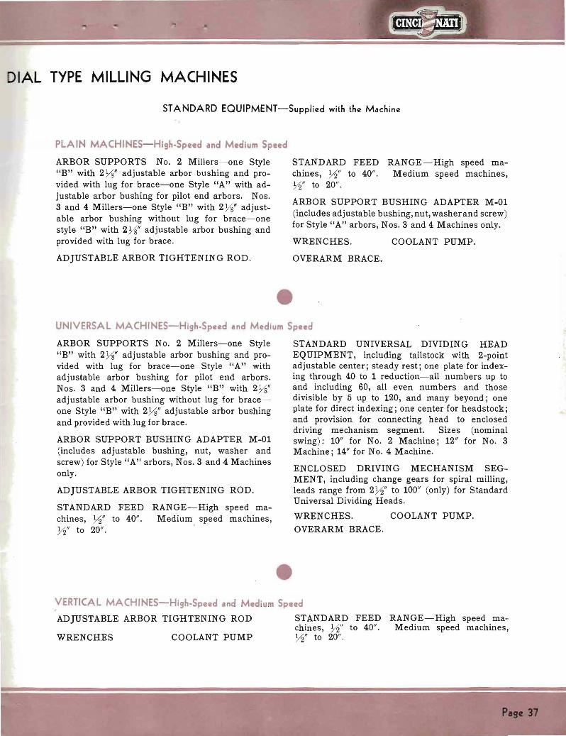
DIAL TYPE MILLING MACHINES
STANDARD EQUIPMENT-Supplied with the Machine
PLAIN MACHINES-HighmiddotSpeed and Medium Spud
ARBOR SUPPORTS No 2 Millers- one Style STANDARD FEED RANGE-High speed mashyB with 2 Ys adjustable arbor bushing and proshy chines Y2 to 40 Medium speed machines vided with lug for brace- one Style A with adshy Y2 to 20 justable arbor bushing for pilot end arbors Nos
ARBOR SUPPORT BUSHING ADAPTER M-013 and 4 Millers-one Style B with 2 Ys adjustshy
(includes adjustable bushingnut washer and screw)able arbor bushing without lug for brace-one for Style A arbors Nos 3 and 4 Machines only
style B with 2Ys adjustable arbor bushing and provided with lug for brace WRENCHES COOLANT PUMP
ADJUSTABLE ARBOR TIGHTENING ROD OVERARM BRACE
UNIVERSAL MACHINES-HighSpeed and Medium Speed
ARBOR SUPPORTS No 2 Millers-one Style B with 2Ys adjustable arbor bushing and proshyvided with lug for brace-one Style A with adjustable arbor bushing for pilot end arbors Nos 3 and 4 Millers-one Style B with 2 Ys adjustable arbor bushing without lug for braceshyone Style B with 2 Ys adjustable arbor bushing and provided with lug for brace
ARBOR SUPPORT BUSHING ADAPTER M-01 (includes adjustable bushing nut washer and screw) for Style A arbors Nos 3 and 4 Machines only
ADJUSTABLE ARBOR TIGHTENING ROD
STANDARD FEED RANGE-High speed mashychines Y2 to 40 Medium speed machines Y2 to 20
STANDARD UNIVERSAL DIVIDING HEAD EQUIPMENT including tailstock with 2-point adjustable center steady rest one plate for indexshying through 40 to 1 reduction-all numbers up to and including 60 all even numbers and those divisible by 5 up to 120 and many beyond one plate for direct indexing one center for headstock and provision for connecting head to enclosed driving mechanism segment Sizes (nominal swing) 10 for No 2 Machine 12 for No 3 Machine 14 for No 4 Machine
ENCLOSED DRIVING MECHANISM SEGshyMENT including change gears for spiral milling leads range from 2Y2 to 100 (only) for Standard Universal Dividing Heads
WRENCHES COOLANT PUMP
OVERARM BRACE
VERTICAL MACHINES- HighmiddotSpeed and Mdium Speed
ADJUSTABLE ARBOR TIGHTENING ROD STANDARD FEED RANGE-High speed mashychines Y2 to 40 Medium speed machines
WRENCHES COOLANT PUMP Y2 to 20
Pige 37
SPECIFICATIONS FOR CINCINNATI
EOUIPMENT SUPPLIED AT EXTRA COST (Not Included in Price of Standard (Basic) Machine) For Medium Speed and High-Speed Machines (See pages 22-27 for illustrations and brief descriptions)
PLAIN UNIVERSAL AND VERTICAL MACHINES 1 TABLE AND CROSS FEEDS Rack Milling Slotting Circular Milling Cam
(a) For Medium Speed Machines sixteen Milling High Number Indexing Attachment ~ to 10 or to 30 inches per minute for Dividing Head Spiral Milling Head etc
(b) For High-Speed Machines thirty-two 6 INDEX BASES RAISING BLOCKS RIGHT ~ to 20 inches per minute ANGLE PLATES
2 WIDE RANGE DIVIDER (applied to Standard 7 PRECISION MEASURING EQUIPMENTUniversal Dividing Head) for divisions from 2
(Recommended for short dimensions only)to 400000 hundreds of them exact and others compensated for the fractional remainder 8 PUMP CUTTER COOLANT individually
3 VISES CHUCKS AND CHUCK ADAPTERS motor driven including ~ HP motor manual starter and piping Code Name PUDIA
4 ARBORS ADAPTERS COLLETS QUICK CHANGE ADAPTERS Etc 9 ELECTRICAL MOTOR AND CONTROL
EQUIPMENT5 STANDARD ATTACHMENTS High-Speed Universal Heavy Vertical Universal Spiral 10 SPLASH GUARDS
PLAIN AND UNIVERSAL MACHINES ONLY 1 ARBOR SUPPORTS
(a) Style B with 2Ys adjustable arbor bushshy (b) Style B with 2 Ys adjustable arbor bushshying without lugs for brace for use on No2 ing without lug for braces for Nos 3 and 4 machines Code Name ARBBS Machines Code Name AJUSB
(c) Style A with adjustable arbOr No3 Machine Code Name ARTMY bushing for pilot end arbors No4 Machine Code Name ARMMF
PLAIN AND VERTICAL MACHINES ONLY 1 STANDARD UNIVERSAL DIVIDING HEAD 12 size for No3 Machine Code
AND EQUIPMENT including tailstock with Name HYDRA 2-point adjustable center steady rest one plate for indexing through 40 to 1 reduction-all 14 size for No4 Machine Code numbers up to and including 60 all even Name HEDPA numbers and those divisible by 5 up to 120 and 2 ENCLOSED DRIVING MECHANISM SEGshymany beyond those shown in the table of specishy MENT including change gears for spiral mill shyfication sheet one plate for direct indexing one
ing leads ranging from 2Y2 to 100 (only) for center for headstock and provision for connectshyStandard Universal Dividing Headsinghead to enclosed driving mechanism segment
10 size for No2 Machine Code No2 Machine Code Name DREDT Name HUTER Nos 3 and 4 Machines Code Name DREHS
VERTICAL MACHINES ONLY 1 POWER FEED AND POWER QUICK 3 REAR HAND ADJUSTMENTS AND REAR
TRAVERSE to the Vertical Head POWER FEED CONTROLS cross and vershy2 TURRET STOP four-position with dial indi- tical Supplied at factory only (Not supplied as
cator Code Name (In Field) TUMAC standard equipment on Vertical Machines) Code Name (Prior to Shipment) FOPST
UNIVERSAL MACHINES ONLY 1 LONG AND SHORT LEAD ATTACHMENT before machine is shipped
with a range 010 to 1000 inches or 024 to 2400 No 2 Machine Code Name LOSHO centimeters Must be installed at factory Nos 3 and 4 Machines Code Name LONSH
NOTE These feeds are optional at the time the order is placed When machines are equipped with the low ranges of feeds (gt-4 to 10 for the Medium Speed machines and gt-4 to 20 for the High-Speed machines) rapid traverse rates are cut in half
Pase 38
- --- --
DIAL TYPE MILLING MACHINES
ELECTRICAL EQUIPMENT The motors and controls listed below are suitable for the machines illustrated and described in this booklet
CHARACTERISTICS -
Current Voltage Speed RPMCycles PhaseI I I A C 60 2 or 3 220 440550 1800
A C 50 2 or 3 220 440550 1500I A C 150050 380 500 Etc 2 or 3
A C 25 15002 or 3 220 440 550
D C 1750 115 or 230 I - ~-
MOTOR HORSE POWER AND FRAME SIZES
No 4 MachineNo 2 Machine Nos 2 and 3 Machines Nos 3 and 4 Machines
NEMA I NEMANRMA NEMAH P H P H PH PFrame Frame FrameFrame I 7 )25 254 326284 324 1510 I 7 )25 254 326284 10 324 15
7)25 254 15 326284 10 324
284 155 10 364 3657Yz I 1510 I 5 I I 7Yz ~
-
7)2 H P motor totally enclosed ball bearing frame No 326 can not be used on No2 Dial Type
Open frame ball bearing motors are recommended
Motors larger than the following can not be used
No2 Dial Type-NEMA frame 326 No3 Dial Type-NEMA frame 364 No4 Dial Type-NEMA frame 365
A C MOTORS-Standard make NEMA frame normal torque low starting current (normal start shying current for 5 hp motors) floor mounted with conduit box on left viewing shaft end
D C MOTORS-Standard make shunt wound constant speed 40deg C continuous open rotation clockwise viewing shaft end floor mounted with conduit box on left viewing shaft end
A C CONTROLS-Standard make enclosed type full voltage magnetic starter with thermal overload protection For all A C circuits over 220 volts a control transformer and 110 volt coils are included to provide low voltage at the push button station-a safety feature
D C CONTROLS-Standard make enclosed type magnetic starter with definite time acceleration thermal overload protection and without dynamic braking
PUSH BUTTON STATION-Separate Start shyStop included with A C or D C controls
ORDERING INSTRUCTIONS - The following electrical data must accompany each order
(a) Voltage
(b) Current (A C or D C) If A C also include
1 Phase
2 Cycle
3 Control circuit voltage
(d) Horsepower speed and type of frame (open or totally enclosed) and motor bearing
Page 39
bull bull Right-A heavy stock removal job on a No2 Plain High Speed Machine Milling two sides of extension supports reducing a spherical shape of 1 diameter to a width of H
Below-Milling the keyway in a heat-treated bevel gear High Speed Dial Type Millers have the wide range of speeds and feeds so necessary in shops where one lot of parts may be tough hard steel and the next lot soft aluminum
Below-A No 3 Vertical Dial Type roughs and finishes from the solid a cast iron dovetail slide The turret stop attachment at the side of the vertical head assures a close limit of accuracy between the dovetail and the top surface
Left-The operator can always see the job on a Horizontal Dial Type because there are complete front and rear conshytrols This No4 Plain Dial Type faces both ends of the shell section of a tire building drum PPIN HD N tI
THE CINCINNATI MILLING MACHINE CO CINCINNATI 01U S A
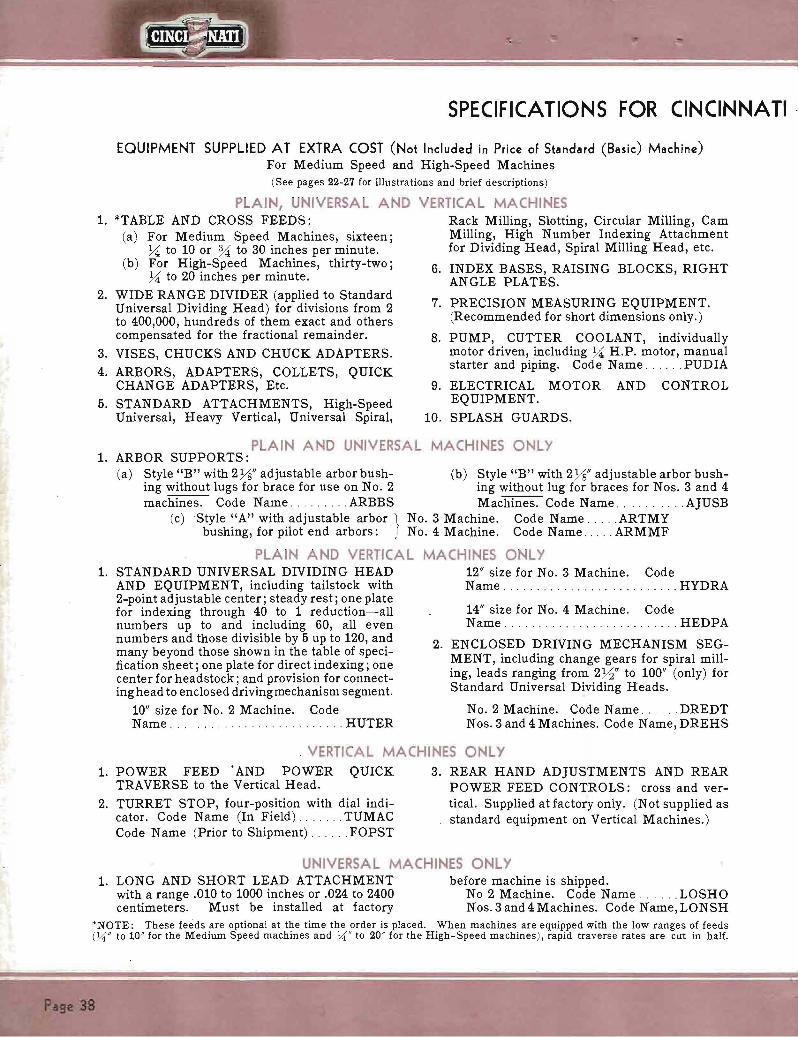