INSTRUCTION MANUAL - Die Cast Machinery, LLC
68
CIRCULATING OIL TEMPERATURE CONTROL SYSTEMS INSTRUCTION MANUAL INSTALLATION, OPERATION, MAINTENANCE, PARTS FEATURES: OPTIONS: ENGINEERING SYSTEMS MODEL NUMBER HC7109-SV SERIAL NUMBER 48466 HC SERIES UNIT + I ZONE OF CONTROL + 20 GPM TO 100 PSI PUMP CAPA CITY + 2 HP TEFC MOTOR + 9 KW HEATING CAPACITY PER ZONE + 500°F MAXIMUM OPERATING TEMPERATURE + BARBER COLMAN TEMPERATURE CONTROLLER + HIGH TEMPERATURE SAFETY SHUT OFF + 25 GALLON RESERVOIR TANK + 208 VOLTS, 3 PHASE, 60 HERTZ + 31.8 TOTAL AMP DRAW + LOW PRESSURE SAFETY SHUT OFF + LOW PRESSURE SAFETY SHUT OFF ON RETURN LINE + MOTOR, HEATER & TRANSFORMER FUSING + PROCESS PURGE VIA DRUM REVERSE SWITCH + LOW FLUID LEVEL SWITCH + GLYCERIN GAUGES MOKON DIV., PROTECTIVE CLOSURES CO. INC. A SUBSIDIARY OF MARK IV IND. INC. 2150 ELMWOOD AVE., BUFFALO, N.Y. 14207 PHONE: (716) 876-9951 FAX: (716) 874-8048
-
Upload
khangminh22 -
Category
Documents
-
view
0 -
download
0
Transcript of INSTRUCTION MANUAL - Die Cast Machinery, LLC
CIRCULATING OIL TEMPERATURE CONTROL SYSTEMS
INSTRUCTION MANUAL INSTALLATION, OPERATION, MAINTENANCE, PARTS
FEATURES:
OPTIONS:
ENGINEERING SYSTEMS
MODEL NUMBER HC7109-SV
SERIAL NUMBER 48466
HC SERIES UNIT + I ZONE OF CONTROL + 20 GPM TO 100 PSI PUMP CAP A CITY + 2 HP TEFC MOTOR + 9 KW HEATING CAPACITY PER ZONE + 500°F MAXIMUM OPERATING TEMPERATURE + BARBER COLMAN TEMPERATURE CONTROLLER + HIGH TEMPERATURE SAFETY SHUT OFF + 25 GALLON RESERVOIR TANK + 208 VOLTS, 3 PHASE, 60 HERTZ + 31.8 TOTAL AMP DRAW
+ LOW PRESSURE SAFETY SHUT OFF + LOW PRESSURE SAFETY SHUT OFF ON RETURN LINE + MOTOR, HEATER & TRANSFORMER FUSING + PROCESS PURGE VIA DRUM REVERSE SWITCH + LOW FLUID LEVEL SWITCH + GLYCERIN GAUGES
MOKON DIV., PROTECTIVE CLOSURES CO. INC. A SUBSIDIARY OF MARK IV IND. INC.
2150 ELMWOOD AVE., BUFFALO, N.Y. 14207 PHONE: (716) 876-9951
FAX: (716) 874-8048
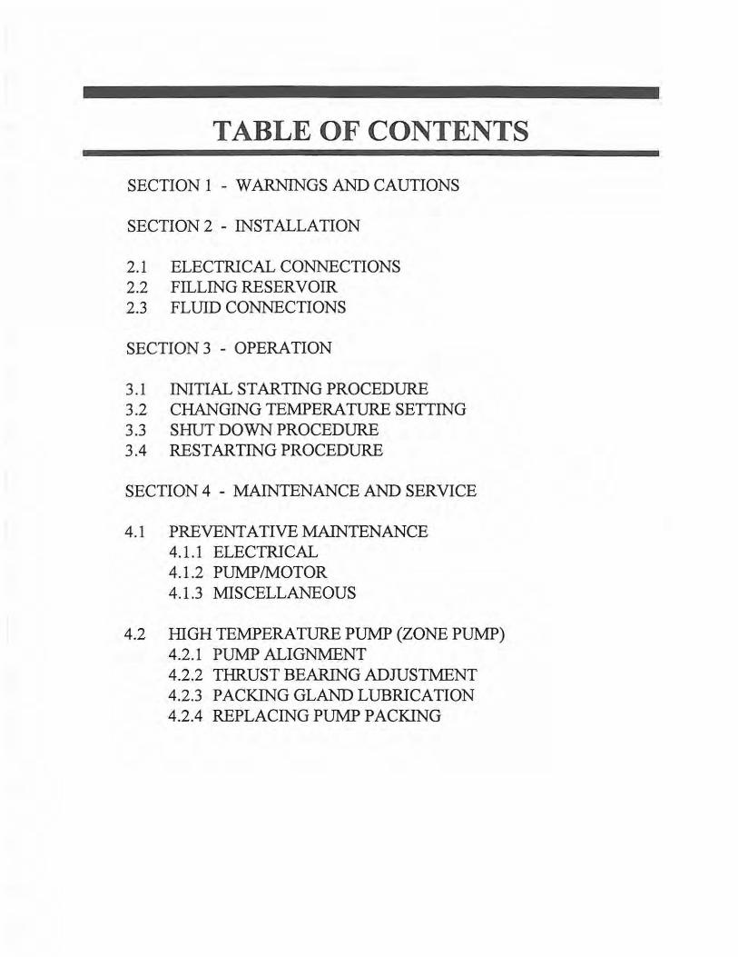
TABLE OF CONTENTS
SECTION 1 - WARNINGS AND CAUTIONS
SECTION 2 - INSTALLATION
2.1 ELECTRICAL CONNECTIONS 2.2 FILLING RESERVOIR 2.3 FLUID CONNECTIONS
SECTION 3 - OPERATION
3.1 INITIAL STARTING PROCEDURE 3.2 CHANGING TEMPERATURE SETTING 3.3 SHUT DOWN PROCEDURE 3.4 RESTARTING PROCEDURE
SECTION 4 - MAINTENANCE AND SERVICE
4.1 PREVENTATIVEMAINTENANCE 4.1.1 ELECTRICAL 4.1.2 PUMP/MOTOR 4.1.3 MISCELLANEOUS
4.2 HIGH TEMPERATURE PUMP (ZONE PUMP) 4.2.1 PUMP ALIGNMENT 4.2.2 THRUST BEARING ADJUSTMENT 4.2.3 PACKING GLAND LUBRICATION 4.2.4 REPLACING PUMP PACKING
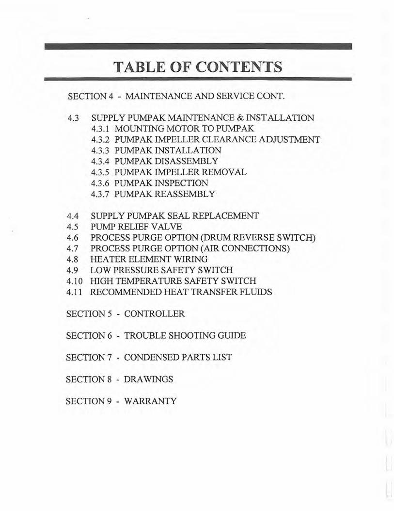
TABLE OF CONTENTS
SECTION 4 - MAINTENANCE AND SERVICE CONT.
4.3 SUPPLY PUMP AK MAINTENANCE & INST ALLA TI ON 4.3.1 MOUNTING MOTOR TOPUMPAK 4.3.2 PUMPAK IMPELLER CLEARANCE ADJUSTMENT 4.3.3 PUMPAK INSTALLATION 4.3.4 PUMPAKDISASSEMBLY 4.3.5 PUMPAKIMPELLERREMOVAL 4.3.6 PUMPAK INSPECTION 4.3.7 PUMPAKREASSEMBLY
4.4 SUPPLY PUMP AK SEAL REPLACEMENT 4.5 PUMPRELIEFVALVE 4.6 PROCESS PURGE OPTION (DRUM REVERSE SWITCH) 4. 7 PROCESS PURGE OPTION (AIR CONNECTIONS) 4.8 HEATERELEMENTWIRING 4.9 LOW PRESSURE SAFETY SWITCH 4.10 HIGH TEMPERATURE SAFETY SWITCH 4.11 RECOMMENDED HEAT TRANSFER FLUIDS
SECTION 5 - CONTROLLER
SECTION 6 - TROUBLE SHOOTING GUIDE
SECTION 7 - CONDENSED PARTS LIST
SECTION 8 - DRAWINGS
SECTION 9 - WARRANTY
SECTION 1 - WARNINGS AND CAUTIONS PLEASE READ AND UNDERSTAND THIS SECTION BEFORE OPERATING UNIT!
1.1 - ELECTRICAL WARNING
The Mokon unit, as with all high voltage electrical equipment, should be connected according to all£ state and local codes. All installation, maintenance, service, repair, adjustment and operation should ~ be done only by appropriately trained electrical personnel who have read and completely understood ~ this instruction manual. To the right is a symbol for ELECTRICAL DANGER. When it is seen on the following pages of this manual, care should be taken to avoid possible electric shock. All maintenance and service should be performed with the power OFF except where noted.
1.2 - HOT FLUID WARNING
Exercise EXTREME CAUTION while working on or in the area of the Mokon Temperature ..------. Controi System. The high temperature of the fluid will cause the process lines, the system ~ components and the metal cabinetry to become VERY HOT and therefore, they should NOT be ~ touched. To the right is a symbol for SURFACE MAY BE HOT, HIGH TEMPERATURE. . .. 111l1llli1111.,,1111il1o
When it is seen on the following pages of this manual, care should be taken to avoid possible bums. All maintenance and service should be performed with the unit completely cooled. It is advisable to plug the process ports of any unused zones so that if a wrong button is pressed, heat transfer fluid will not be pumped through them.
1.3 - COLD WEATHER CAUTION
If the Mokon unit will be moved from your plant and will be subjected to freezing temperatures, the water in the heat exchanger must be completely drained and/or sufficient antifreeze added to prevent serious water damage from freezing.
1.4 - PUMP CAVITATION WARNING
The process utilizing a Mokon Circulating Hot Oil system should be pressure tested PRIOR to use. It is essential that all water be removed from the process prior to charging with oil. Water concentration as low as 500 PPM in the oil will result in pump cavitation at about 220°F operating temperature.
SECTION 2 - INSTALLATION
2.1 - ELECTRICAL CONNECTIONS
WARNING: THE MOKON UNIT, AS WITH ALL HIGH VOLTAGE ELECTRICAL EQUIPMENT, SHOULD BE CONNECTED ACCORDING TO ALL APPLICABLE STATE~ AND LOCAL CODES. ALL INSTALLATION, MAINTENANCE, SERVICE, REPAIR, 7 ADJUSTMENT AND OPERATION SHOULD BE DONE ONLY BY APPROPRIATELY TRAINED ELECTRICAL PERSONNEL WHO HAVE READ AND COMPLETELY UNDERSTOOD THIS INSTRUCTION MANUAL.
BEFORE OPERATING UNIT THE GROUNDING WIRE MUST BE CONNECTED. THE GROUNDING WIRE IS THE GREEN WIRE CONNECTED TO THE FRAME OF THE UNIT.
Connect green wire to the ground screw (labeled GND) located in the electrical box. Connect power lines Ll(red), L2(white), L3(black) to the disconnect switch inside the electrical box. Overcurrent protection of the supply conductors should be sized according to Article 670 of The National Electrical Code (NEC), 1996.
2.2 - FILLING RESERVOIR
Fill the reservoir with heat transfer fluid (see section 4.11 for recommended fluids) through the fill port located on the front of the unit. Fill to the highest level on the sight glass. See the specifications on the front cover for the total fluid capacity.
Note: On initial start up, while purging the air from the system, it may be necessary to add additional heat transfer fluid to the reservoir to compensate for the volume of fluid consumed by this process.
WARNING: ON A STANDARD SYSTEM, A MINIMUM OPERATING FLUID LEVEL OF 1/2 FULL IS RECOMMENDED (OPTIMUM FLUID LEVEL IS 3/4 FULL). IT MUST BE MAINTAINED AT ALL TIMES. IF THE PROPER FLUID LEVEL IS NOT MAINTAINED, SERIOUS DAMAGE MAY OCCUR TO THE MOKON SYSTEM. IT IS MANDATORY TO PERIODICALLY INSPECT THE FLUID LEVEL SIGHT GLASS AND ADD HEAT TRANSFER FLUID IF REQUIRED.

2.3 - FLUID CONNECTIONS
.---. EXERCISE EXTREME CAUTION WHILE WORKING ON OR IN THE AREA OF THE ~ MOKON TEMPERATURE CONTROL SYSTEM. THE ffiGH TE:MPERATURE OF THE ~ FLUID WILL CAUSE THE PROCESS LINES, THE SYSTEM COMPONENTS AND THE ... 1i1!1illl1!11.i.11111!.. METAL CABINETRY TO BECOME VERY HOT AND THEREFORE, THEY SHOULD
NOT BE TOUCHED.
There are four (4) convenient and clearly marked connections, "To Process" (one for each zone), "From Process" (one for each zone), "Supply Water" and "Drain Water." (Note: Quick disconnects should not be used on any of the connections, they will restrict the flow.)
USE FULL SIZE UNRESTRICTED IDGH TEMPERATURE, INSULATED HOSE OR PIPE FOR EACH CONNECTION.
1. To Process: Connect the port(s) to the process inlet(s), through which heat transfer fluid will enter the process.
2. From Process: Connect the port(s) to the process outlet(s), from which heat transfer fluid will leave the process.
3. Supply Water: Connect the port to an adequate source of cold, clean supply water.
4. Drain Water: Connect the port to drain (or return line in an inplant closed recirculation system).
SECTION 3 -OPERATION
NOTE: Prior to starting the Mokon unit it may be necessary to tighten the mechanical fittings on the piping. Vibration caused during transport can loosen the fittings. Before proceeding, check and tighten all of the mechanical fittings.
3.1 - INITIAL STARTING PROCEDURE
1. Fill the Mokon unit with heat transfer fluid. (See section 2.2)
2. Turn on the water supply connected to the Mokon unit. (See section 2.3)
3. Turn on the electrical main disconnect switch. (See section 2.1)
NOTE: The front cover of the unit must be removed for the procedures in steps 4 & 5.
4. For each zone, check the motor rotation by turning on the unit momentarily (press the "Start" button then the "Stop" button) As the pump slows down, check the motor rotation. If the motor is not rotating in the direction of the arrow label located on the motor housing (clockwise from the lead end), reverse any two power cord leads (see section 2.1) to change the direction of motor rotation.
5. For each zone, check the pump alignment. See section 4.2. l.
6. Restart the unit and set the controller to the minimum temperature. See section 5 for specific controller operation instructions.
NOTE: If a low pressure safety switch is provided on the unit (see specifications on front cover), the start button must be held in for up to 30 seconds in order to build adequate pressure to start the unit.
3.1 - INITIAL STARTING PROCEDURE CONT.
7. Allow the unit to run for approximately 5 to 10 minutes at the minimum temperature to purge the air from the system. The air is purged from the system when the pressure gauge reading is steady (typically between 40 to 80 PSI depending on the restrictions in your process) and when the pump runs smooth and steady.
If the above procedure does not eliminate the air from the system, turn the unit off then on, once or twice to break up the air pockets.
NOTE: The air purge button may be pressed to eliminate air in the system at any time during operation.
8. Set the controller to the desired temperature. The unit will reach the setpoint temperature. See section 5 for specific controller instructions.
3.2 - CHANGING TEMPERATURE SETTING
If a new temperature setting is required while the unit is in operation, adjust the controller to the new desired setpoint temperature. See section 5 for specific controller instructions.
3.3 - SHUT DOWN PROCEDURE
COOL THE UNIT BY REDUCING THE SETPOINT TEMPERATURE TO 150°F OR LOWER. DO NOT SHUT UNIT OFF AT ELEVATED TEMPERATURES. THIS COULD BE DETRIMENTAL TO FLUID AND UNIT LIFE. When the unit has reached 150°F or lower, push the stop button. The water and main electrical power to the Mokon unit may be turned off if desired, but is not necessary unless the unit is being relocated or for prolonged shut down.
3.4 - RESTARTING PROCEDURE
1. If the water lines and main electrical power have not been disconnected, refer to section 3.1.6 to restart the unit.
2. If the water lines and/or the main electrical power has been disconnected, refer to section 2.1 for electrical connections, section 2.3 for water connections and section 3.1 for initial starting procedure.
SECTION 4 - MAINTENANCE & SERVICE
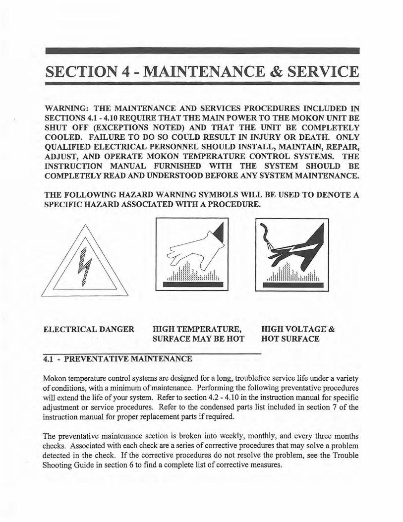
WARNING: THE MAINTENANCE AND SERVICES PROCEDURES INCLUDED IN SECTIONS 4.1 - 4.10 REQUIRE THAT THE MAIN POWER TO THE MO KON UNIT BE SHUT OFF (EXCEPTIONS NOTED) AND THAT THE UNIT BE COMPLETELY COOLED. FAILURE TO DO SO COULD RESULT IN INJURY OR DEATH. ONLY QUALIFIED ELECTRICAL PERSONNEL SHOULD INSTALL, MAINTAIN, REPAIR, ADJUST, AND OPERATE MOKON TEMPERATURE CONTROL SYSTEMS. THE INSTRUCTION MANUAL FURNISHED WITH THE SYSTEM SHOULD BE COMPLETELY READ AND UNDERSTOOD BEFORE ANY SYSTEM MAINTENANCE.
THE FOLLOWING HAZARD WARNING SYMBOLS WILL BE USED TO DENOTE A SPECIFIC HAZARD ASSOCIATED WITH A PROCEDURE.
ELECTRICAL DANGER HIGH TEMPERATURE, SURFACE MAY BE HOT
4.1 - PREVENTATIVE MAINTENANCE
HIGH VOL TAGK & HOT SURFACE
Mokon temperature control systems are designed for a long, troublefree service life under a variety of conditions, with a minimum of maintenance. Performing the following preventative procedures will extend the life of your system. Refer to section 4.2 - 4.10 in the instruction manual for specific adjustment or service procedures. Refer to the condensed parts list included in section 7 of the instruction manual for proper replacement parts if required.
The preventative maintenance section is broken into weekly, monthly, and every three months checks. Associated with each check are a series of corrective procedures that may solve a problem detected in the check. If the corrective procedures do not resolve the problem, see the Trouble Shooting Guide in section 6 to find a complete list of corrective measures.
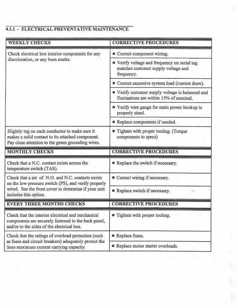
4.1.1 - ELECTRICAL PREVENTATIVE MAINTENANCE
I WEEKL y CHECKS I CORRECTIVE PROCEDURES
Check electrical box interior components for any • Correct component wiring. discoloration, or any burn marks.
• Verify voltage and frequency on serial tag matches customer supply voltage and frequency.
• Correct excessive system load (current draw).
• Verify customer supply voltage is balanced and fluctuations are within 15% of nominal.
• Verify wire gauge for main power hookup is properly sized.
• Replace components if needed.
Slightly tug on each conductor to make sure it • Tighten with proper tooling. (Torque makes a solid contact to its attached component. components to specs) Pay close attention to the green grounding wires.
MONTHLY CHECKS CORRECTIVE PROCEDURES
Check that a N.C. contact exists across the • Replace the switch if necessary. temperature switch (T AS).
Check that a set of N.O. and N.C. contacts exists • Correct wiring if necessary. on the low pressure switch (PS), and verify properly wired. See the front cover to determine if your unit • Replace switch if necessary. . ..
includes this option.
EVERY THREE MONTHS CHECKS CORRECTIVE PROCEDURES
Check that the interior electrical and mechanical • Tighten with proper tooling. components are securely fastened to the back panel, and/or to the sides of the electrical box.
Check that the ratings of overload protection (such • Replace fuses. as fuses and circuit breakers) adequately protect the lines maximum current carrying capacity. • Replace motor starter overloads.
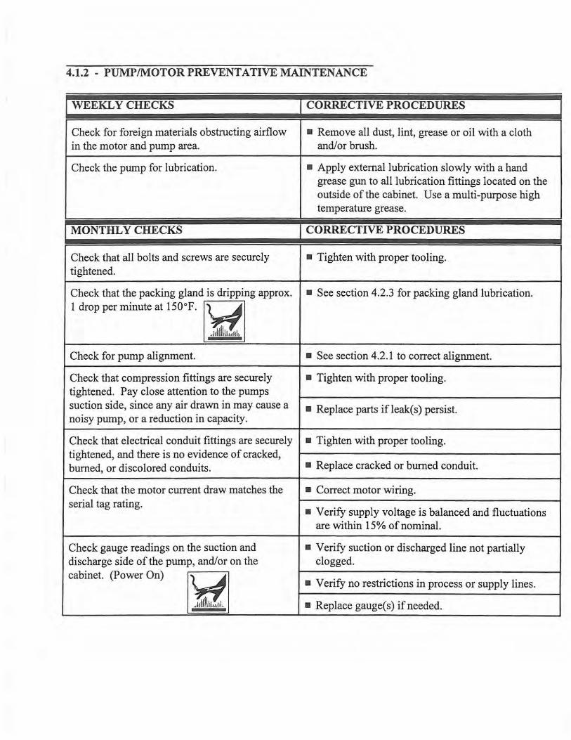
4.1.2 - PUMP/MOTOR PREVENTATIVE MAINTENANCE
I WEEKL y CHECKS I CORRECTIVE PROCEDURES
Check for foreign materials obstructing airflow • Remove all dust, lint, grease or oil with a cloth in the motor and pump area. and/or brush.
Check the pump for lubrication. • Apply external lubrication slowly with a hand grease gun to all lubrication fittings located on the outside of the cabinet. Use a multi-purpose high temperature grease.
I MONTHLY CHECKS I CORRECTIVE PROCEDURES
Check that all bolts and screws are securely • Tighten with proper tooling. tightened.
Check that the packing gland is dripping approx. • See section 4.2.3 for packing gland lubrication. 1 drop per minute at 150°F.
'r.t Check for pump alignment. • See section 4.2. l to correct alignment.
Check that compression fittings are securely • Tighten with proper tooling. tightened. Pay close attention to the pumps suction side, since any air drawn in may cause a • Replace parts ifleak(s) persist. noisy pump, or a reduction in capacity.
Check that electrical conduit fittings are securely • Tighten with proper tooling. tightened, and there is no evidence of cracked, burned, or discolored conduits. • Replace cracked or burned conduit.
Check that the motor current draw matches the • Correct motor wiring. serial tag rating.
• Verify supply voltage is balanced and fluctuations are within 15% of nominal.
Check gauge readings on the suction and • Verify suction or discharged line not partially discharge side of the pump, and/or on the clogged. cabinet. (Power On) y • Verify no restrictions in process or supply lines.
,,,1i1l1llll1lil.r.11 ~l,, • Replace gauge( s) if needed.
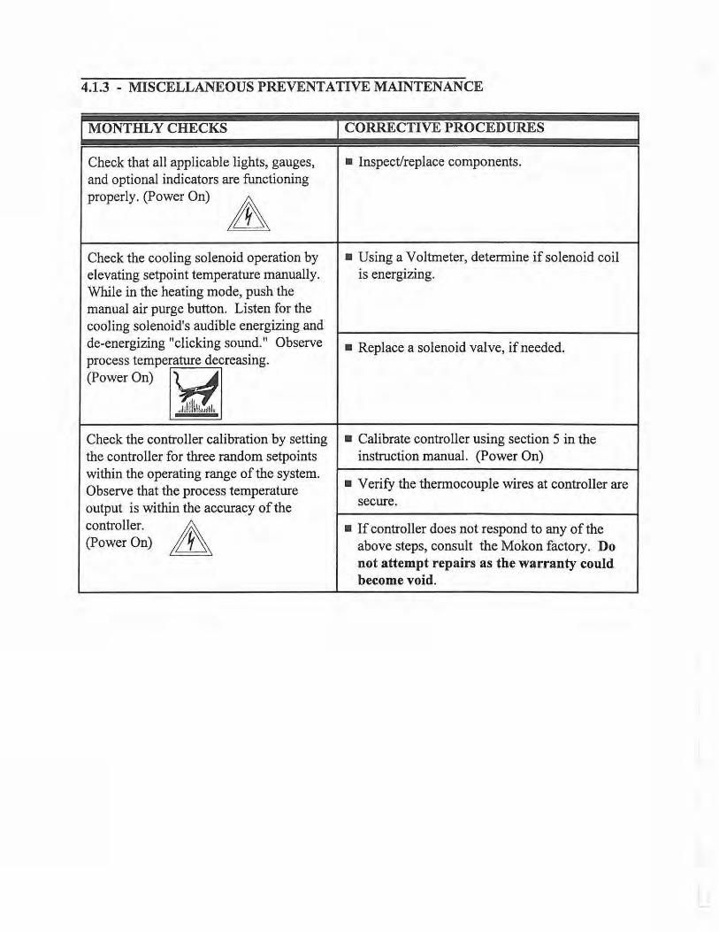
4.1.3 - MISCELLANEOUS PREVENTATIVE MAINTENANCE
I MONTHL y CHECKS
Check that all applicable lights, gauges, and optional indicators are functioning properly. (Power On)
Check the cooling solenoid operation by elevating setpoint temperature manually. While in the heating mode, push the manual air purge button. Listen for the cooling solenoid's audible energizing and de-energizing "clicking sound." Observe process temperature decreasing. (PowerOn) y
... i:.!i.:ll11:!.1.nilil"
Check the controller calibration by setting the controller for three random setpoints within the operating range of the system. Observe that the process temperature output is within the accuracy of the
controller. & (Power On) ~
I CORRECTIVE PROCEDURES
• Inspect/replace components.
• Using a Voltmeter, determine if solenoid coil is energizing.
• Replace a solenoid valve, if needed.
• Calibrate controller using section 5 in the instruction manual. (Power On)
• Verify the thermocouple wires at controller are secure.
• If controller does not respond to any of the above steps, consult the Mokon factory. Do not attempt repairs as the warranty could become void.
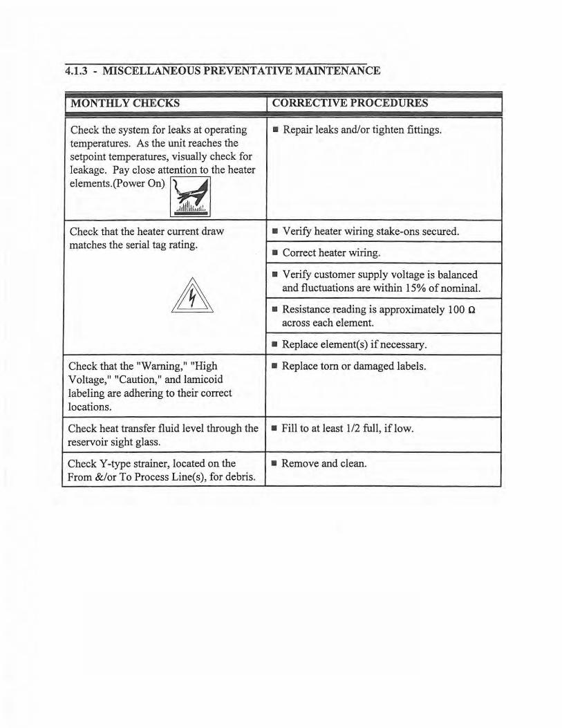
4.1.3 - MISCELLANEOUS PREVENTATIVE MAINTENANCE
I MONTHLY CHECKS I CORRECTIVE PROCEDORES
Check the system for leaks at operating • Repair leaks and/or tighten fittings. temperatures. As the unit reaches the setpoint temperatures, visually check for leakage. Pay close attention to the heater elements.(Power On) 1'Ji Check that the heater current draw • Verify heater wiring stake-ons secured. matches the serial tag rating.
• Correct heater wiring.
A • Verify customer supply voltage is balanced
and fluctuations are within 15% of nominal.
• Resistance reading is approximately 100 Cl across each element.
• Replace element(s) if necessary.
Check that the "Warning," "High • Replace tom or damaged labels. Voltage," "Caution," and lamicoid labeling are adhering to their correct locations.
Check heat transfer fluid level through the • Fill to at least 1/2 full, if low. reservoir sight glass.
Check Y-type strainer, located on the • Remove and clean. From &/or To Process Line(s), for debris.
4.2 - HIGH TEMPERATURE PUMP (ZONE PUMP) MAINTENANCE
WARNING: DISASSEMBLING THE VIKING PUMP WILL VOID THE PUMP MANUFACTURERS WARRANTY AS WELL AS THE MOKON WARRANTY.
DANGER: BEFORE OPENING ANY VIKING PUMP OR LIQUID CHAMBER (PUMPING CHAMBER, RESERVOIR, JACKET, ETC.) BE SURE:
1. THAT ANY PRESSURE IN CHAMBER HAS BEEN COMPLETELY VENTED THROUGH SUCTION OR DISCHARGE LINES OR OTHER APPROPRIATE OPENINGS OR CONNECTIONS.
2. THAT THE DRIVING MEANS (MOTOR) HAS BEEN "LOCKED OUT" OR MADE NON-OPERATIONAL SO THAT IT CANNOT BE STARTED WHILE WORK IS BEING DONE ON THE PUMP.
FAILURE TO FOLLOW THE ABOVE LISTED PRECAUTIONARY MEASURES MAY RESULT IN SERIOUS INJURY.
The Viking pumps are designed for long, trouble-free service life under a wide variety of application conditions with a minimum of maintenance. The following points will help provide long service life.
LUBRICATION: External lubrication must be applied slowly with a hand gun to all lubrication fittings every 500 hours of operation with multipurpose grease. DO NOT OVER-GREASE.
CLEANING PUMP: Keep pump as clean as possible. This makes inspection, adjustment and repair work easier and helps prevent overlooking a dirt covered grease fitting when lubricating.
STORAGE: If the pump is to be stored, or not to be used for six months or so, the pump must be drained and a light coat of non-detergent SAE 30 weight oil must be applied to all internal pump parts. Lubricate fittings and apply grease to the pump shaft extension. Viking suggests rotating the pump shaft, by hand, one complete revolution every 30 days to circulate the oil.
UP SEAL OUTER ENO CAP
SH..FT
LOCKNUT
I REF. NO. I QTY
1 1
2 1
3 1
4 2
5 1
6 1
7 l
8 I
9 1
10 2
11 2
12 6
13 1
14 l
UP SEAL INNER ENO CAP
PACKING RINGS
BRl.CKET
"
I DESCRIPTION
Locknut
Lockwasher
End Cap (Outer)
Lip Seal for End Cap
PACKING RETAINER WASHER
Bearing Spacer Collar (Outer)
Ball Bearing
Bearing Spacer Collar (Inner)
End Cap (Inner)
Packing Gland Adjustment Collar
Adjustment Collar Nut
Adjustment Collar Capscrew
Packing Rings
Packing Retainer Washer
Bracket Bushing (Carbon Graphite)
I
PIPE PLUG
REF. NO.
15
16
17
18
19
20
21
22
23
24
25
26
27
ROTOR
QTY
2
1
8
1
l
l
l
1
1
l
1
l
8
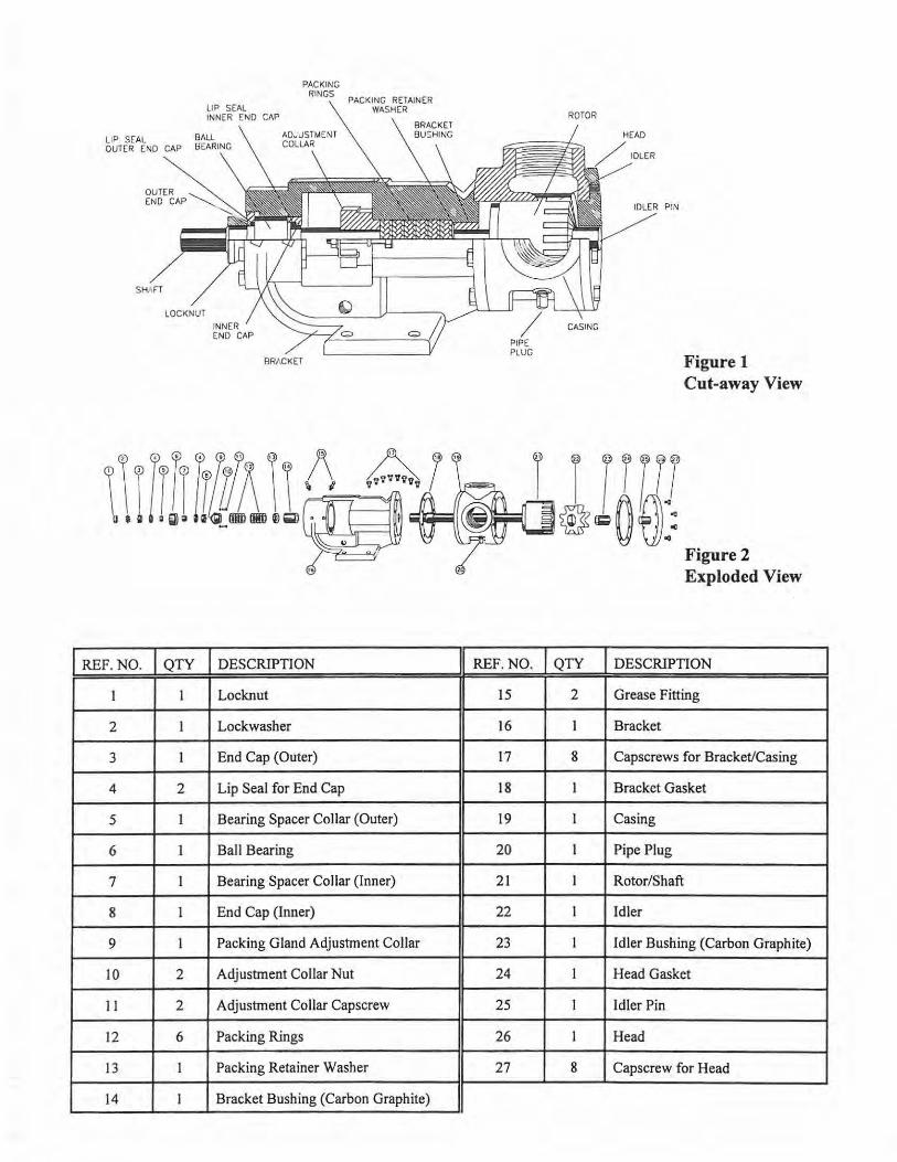
Figure 1 Cut-away View
Figure 2 Exploded View
DESCRIPTION
Grease Fitting
Bracket
Capscrews for Bracket/Casing
Bracket Gasket
Casing
Pipe Plug
Rotor/Shaft
Idler
Idler Bushing (Carbon Graphite)
Head Gasket
Idler Pin
Head
Capscrew for Head
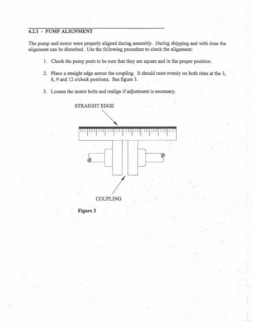
4.2.1 - PUMP. ALIGNMENT
The pump and motor were properly aligned during assembly. Durillg shipping and with time the alignment can be disturbed. Use the following procedure to chec~ the alignment:
I. Check the pump ports to be sure that they are square and in the proper position.
2. Place a straight edge across the coupling. It should reset evenly on both rims at the 3, 6, 9 and 12 o'clock positions. See figure 3.
3. Loosen the motor bolts and realign if adjustment is necessary.
STRAIGHT EDGE
~ I 1 1
I COUPLING
Figure 3
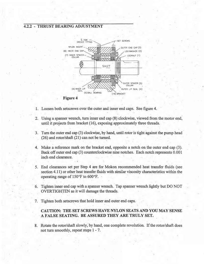
4.2.2 - THRUST BEARING ADJUSTMENT
NYLON INSERT _
Figure 4
OUTER END CAP (3)
LOCKWASHER (2)
OUTER SPACER (5) COLLAR
OUTER LIP SEAL ( 4)
( 16) BRACKET
1. Loosen both setscrews over the outer and ~nne_r end caps. See figure 4.
2. Using a spanner wrench, turn inner end cap (8)"clockwise, viewed.from the motor end, until it projects from brack_et (16), exposing approximately thr~e threads. · .
3. Turn the outer end cap (3) clockwi.se,_ by hand, until rotor is tight against the pump head . (26) and rotor/shaft (21) can not h~ turned.
4. Make a reference mark on the bracket end, opposite a notch on the outer end cap (3). Back off outer end cap (3) counterclockwise nine notches. Each notch repres·ents 0. 001 inch end clearance.
5. End clearances set per Step .4 are for Mokon recommended ·heat transfer fluids (see . section 4.11) or other heat transfer fluids with similar viscosity characteristics within the operating range of 150°F .to. 600°F~ ·
· · 6. Tighten inner end cap with a.spanner wrench. Tap spanner wrench lightly but DO NOT OVERTIGH)"EN as it will damage the thread~.
7. Tighten both setscrews that hold inner and outer end caps.
CAUTION: THE SET SCREWS HA.VE NYLON SEATS AND YOU MAY SENSE · A FALSE SEATING. BE ASSURED THEY ARE.TRULY SET.
8. ·Rotate the rotor/shaft slowly," by hand, one complete revolution. If the rotor/shaft does not turn ~moothl y, repeat steps 1 - 7.
4.2.3 - PACKING GLAND LUBRICATION
The Pwnp gland should drip approximately 1 drop per minute at 150 °F operating temperature.
EXERCISE EXTREME CAUTION WHILE WORKING ON OR IN THE AREA OF THE MOKON TEMPERATURE CONTROL SYSTEM. THE HIGH TEMPERATURE OF THE FLUID WILL CAUSE THE PROCESS LINES, SYSTEM COMPONENTS AND METAL CABINETRY TO BECOME VERY HOT AND THEREFORE THEY SHOULD NOT BE TOUCHED.
To check/correct the packing gland lubrication:
1. Remove the front and back panels from the unit (unit should not be on at this point). 2. Remove the splash guard from the pwnp gland area. 3. Start pwnp by pressing the start button. 4. Set temperature controller to 150°F. (See section 5 for controller instructions) 5. Observe the oil dripping from the packing gland. If it is not dripping at the
recommended 1 drip per minute, adjustment is needed. NOTE: If installing new packing rings it will be necessary to allow the unit to run for a period of time before checking the dripping rate of the oil.
6. The pumps adjustment collar mechanism consists of two capscrews (11 ), one on each side. They may be tightened to decrease the dripping or loosened to increase the dripping. See figure 2.
NOTE: The adjustment collar capscrews must be EVENLY tightened or loosened, one flat at a time, to achieve proper adjustment. Failure to do so will result in damage to the pump. Overtightening will destroy the packing.
4.2.4 - REPLACING PUMP PACKING
To replace the pwnp packing:
1. Loosen the adjustment collar capscrews (11). 2. Remove the adjustment collar (9). 3. Using a packing hook, remove the packing rings (12). 4. Install new packing rings (12), staggering the joints left to right. Lubricate the packing
rings with oil, grease or graphite to aid assembly. A length of pipe will help seat each packing ring. Install the same quantity of rings removed. (Typically, 6 - 7 rings.)
5. Replace the adjustment collar (9). Make sure that it is installed squarely. 6. Reinstall the capscrews (11). Tighten wrench tight then back off until gland is slightly
loose. NOTE: The capscrews must be tightened EVENLY. 7. See section 4.2.3 to check &/or correct the packing gland lubrication.
I REF. NO.
I
2
3
4
5
6
7
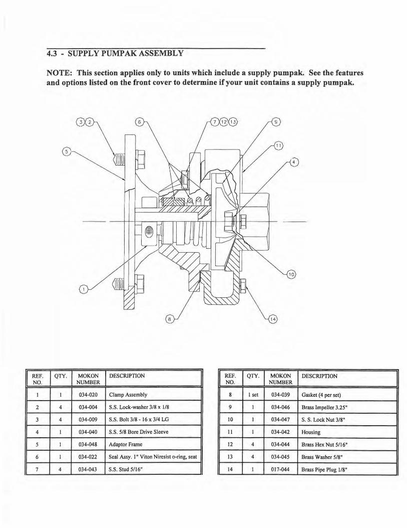
4.3 - SUPPLY PUMP AK ASSEMBLY
NOTE: This section applies only to units which include a supply pumpak. See the features and options listed on the front cover to determine if your unit contains a supply pumpak.
9
4
10
I QTY. , MOKON I DESCRIPTION I NUMBER I REF. I QTY. , MOKON I DESCRIPTION NO. NUMBER
I 034-020 Clamp Assembly 8 1 set 034-039 Gasket (4 per set)
4 034-004 S.S. Lock-washer 3/8 x 1/8 9 I 034-046 Brass Impeller 3.25"
4 034-009 S.S. Bolt 3/8 - 16 x 3/4 LG 10 I 034-047 S. S. Lock Nut 3/8"
I 034-040 S.S. 518 Bore Drive Sleeve II 1 034-042 Housing
I 034-048 Adaptor Frame 12 4 034-044 Brass Hex Nut 5/16"
I 034-022 Seal Assy. I" Viton Niresist o-ring, seat 13 4 034-045 Brass Washer 5/8"
4 034-043 S.S. Stud 5/16" 14 I 017-044 Brass Pipe Plug 1/8"
I
4.3 - SUPPLY PUMPAK MAINTENANCE & INSTALLATION
NOTE: This section applies only to units which include a supply pumpak. See the features and options listed on the front cover to determine if your unit contains a supply pumpak.
The supply pumpak consists of a housing, adaptor frame, stainless steel sleeve, shaft seal, seal spring, impeller, drive clamp, gaskets, impeller lock nut, and stainless steel fasteners. See the previous page for a drawing and a parts breakdown.
The impeller is threaded onto the shaft sleeve and locked in place by a lock nut. The shaft sleeve is machined to precisely fit the shaft on the recommended motor. No provision is made for an internal drive key and none is required. The drive clamp assembly replaces internal drive keys, securely locks the shaft sleeve to the motor shaft, and serves additionally as a liquid slinger to protect your motor.
The mechanical seal is the self-adjusting, greaseless type being lubricated by the liquid in the pump. It requires no maintenance and provides long and trouble-free operation. Because the seal is lubricated by liquid in the pump, THE PUMP SHOULD NEVER BE OPERA TED WITHOUT LIQUID IN THE HOUSING.
4.3.1 - MOUNTING MOTOR TO PUMPAK
I. Check the rotation of the motor to be sure it coincides with the required rotation of the PUMP AK assembly.
2. Loosen the drive clamp assembly (1) but do not remove. NOTE: If the motor shaft is a keyed shaft, remove the key before installing the Mokon Pumpak. The drive clamp assembly on the Mokon Pumpak is all that is required to drive the pump.
3. Slide the Pumpak assembly onto the motor drive shaft (4), aligning the holes in the adaptor frame (5) with tapped holes in the motor mounting face, until adaptor frame (5) contacts the motor mounting face.
4. Install two S.S. bolts (3) (diagonally opposite) and tighten to secure the Pumpak assembly to the motor.
5. Center the drive clamp assembly (I) and tighten. 6. Proceed to section 4.3 .2 to check the impeller clearance.
4.3.2 - SUPPLY PUMP AK IMPELLER CLEARANCE ADJUSTMENT
Remove the strip stock shim from the suction eye of the pump housing. This shim was inserted to establish clearance between the face of the impeller and the housing. Rotate the motor slowly, by hand, to make certain that the impeller does not rub the housing or the adaptor frame. If the impeller does not rub install and tighten the remaining S.S. bolts to secure the Pumpak to the motor.
If the impeller rubs, the impeller clearance can be adjusted by the following procedure:
1. Loosen the drive clamp assembly (1), but do not remove. 2. Move impeller (9) either forward or backward using a screwdriver or move impeller drive
sleeve forward.
If the impeller still rubs after using the above procedure, it can then be adjusted as follows:
1. Remove the S.S. studs (7) and the housing (11 ). 2. Loosen the drive clamp assembly (1), but do not remove. 3. Remove the gaskets (8) from the housing (11). 4. Replace the housing (11), pushing against the impeller face. Secure the housing with two
S.S. studs (7), 180° apart. 5. Tighten the drive clamp assembly (1). 6. Remove the housing (11) and install one gasket (8). 7. Replace the housing (11) securing with two S.S. studs (7) 180 ° apart. 8. Rotate the motor shaft to check that the impeller does not rub. If it does, return to step 6 and
add another gasket. If not, install and tighten all remaining S.S. studs (7).
If none of the above procedure stops the impeller from rubbing, CONSULT THE FACTORY.
4.3.3 - SUPPLY PUMPAK INSTALLATION
Use high temperature Teflon tape or high temperature RTV on all connections and be sure all fittings are airtight, especially on the suction side of the pump. An air leak on the suction side of the pump will prevent proper operation.
4.3.4 - SUPPLY PUMP AK DISASSEMBLY
1. Close the gate valve on the reservoir tank. 2. Remove the S.S. studs (7) holding the housing (11) to the adapter. 3. Remove the S.S. bolts (3) which hold the adaptor frame (5) to the motor. 4. Loosen the drive clamp assembly (1) and remove the PUMP AK.
The seal seat and seat cup will remain in the pump adaptor frame. If not damaged or worn, do not remove. If necessary, remove the adaptor frame counter bore with a piece of wood or a screwdriver handle inserted through the adaptor frame from the drive end. A sharp tap or two is usually sufficient to knock out the seal seat. Use caution when removing the seal seat so as not to damage the face or distort the metal seat.
4.3.S - SUPPLY PUMP AK IMPELLER REMOVAL
1. Remove the seal bellows and the spring assembly (6). NOTE: The seal bellows will be bonded to the shaft sleeve and will require some patience and caution to remove in order not to damage the seal bellows and cage.
2. Place the impeller drive sleeve (4) between two pieces of wood in a vise. Take care so as not to damage sleeve.
3. Remove the impeller S.S. lock nut (10) from the end of the shaft sleeve. Unthread the impeller (9) by turning counterclockwise (left hand).
4.3.6 - SUPPLY PUMP AK INSPECTION
Check all parts for wear. For ease ofreassembly, the shaft sleeve should have all nicks and burrs removed. Replace damaged parts with new parts. Inspect the seal seat and seal cup for grooves, scuff marks, or other deterioration. If a perfect lapped surface remains on the seal seat, it may be reused. If the seal cup is in good condition it may be reused. If the seal seat, cup, washer, or bellows are damaged or worn a new seal assembly should be installed (see section 4.4).
4.3.7 - SUPPLY PUMP AK REASSEMBLY
Clean all castings with mild cleaning solvent such as kerosene. All dirt and foreign matter should be removed.
Reassemble the Pumpak. See section 4.3.1 for instructions on mounting the motor to the Pumpak.
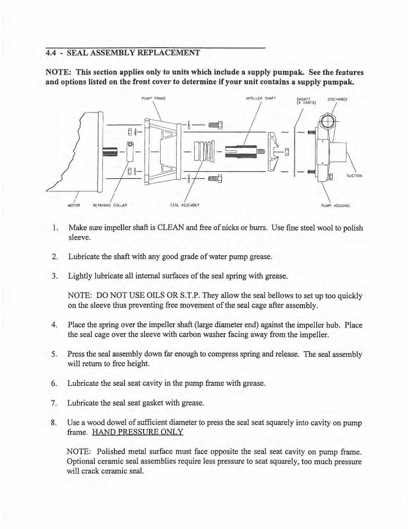
4.4 - SEAL ASSEMBLY REPLACEMENT
NOTE: This section applies only to units which include a supply pumpak. See the features and options listed on the front cover to determine if your unit contains a supply pumpak.
I MOTOR
I RETAINING COLLAR
PUMP f"RAM( IMPELLER SHAn
I - ~- ~ I
SEAL AS3EMBLY
CASKET ( 4 PARTS)
DISCHARGE
\ SUCTION
PUMP HOUSING
1. Make sure impeller shaft is CLEAN and free of nicks or burrs. Use fine steel wool to polish sleeve.
2. Lubricate the shaft with any good grade of water pump grease.
3. Lightly lubricate all internal surfaces of the seal spring with grease.
NOTE: DO NOT USE OILS OR S.T.P. They allow the seal bellows to set up too quickly on the sleeve thus preventing free movement of the seal cage after assembly.
4. Place the spring over the impeller shaft (large diameter end) against the impeller hub. Place the seal cage over the sleeve with carbon washer facing away from the impeller.
5. Press the seal assembly down far enough to compress spring and release. The seal assembly will return to free height.
6. Lubricate the seal seat cavity in the pump frame with grease.
7. Lubricate the seal seat gasket with grease.
8. Use a wood dowel of sufficient diameter to press the seal seat squarely into cavity on pump frame. HAND PRESSURE ONLY
NOTE: Polished metal surface must face opposite the seal seat cavity on pump frame. Optional ceramic seal assemblies require less pressure to seat squarely, too much pressure will crack ceramic seal.
4.4 - SEAL ASSEMBLY REPLACEMENT CONT.
9. Place the impeller and the seal assembly in the pump housing. Affix the gasket on the frame over the drive sleeve onto the housing.
10. Attach the pump frame to pump head with bolts and secure evenly. Install the shaft retaining collar onto the shaft and attach entire assembly to motor. Tighten the retaining collar with an Allen wrench.
11. See maintenance section 4.2.2 to adjust impeller clearance.
4.5 - PUMP RELIEF VAL VE
NOTE: THE PUMP RELIEF VAL VE IS NOT TO BE USED AS A PROCESS BYPASS!
There is a pump relief valve on each pumping circuit. The pump relief valve is set at 100 PSI on MR, HC, HA, XC and XA Series; 60 PSI on MK Series units. When restrictions in the process are such that it will not accept the full pump output at less than the set pressure, this valve opens and maintains full oil flow over heaters regardless of the flow to the process.
This valve has been factory set and should not require further adjustments. If it is necessary to recalibrate, CONSULT THE MO KON FACTORY.
4.6 - PROCESS PURGE OPTION (DRUM REVERSE SWITCH)
To facilitate mold changes with a minimum amount of oil loss from the hoses and the process, a reverse flow purge system is provided as an option. (See the front cover to determine if your unit includes this option.)
NOTE: If additional fluid has been added to the Mokon system after the initial start up, it will be necessary to drain the excess fluid prior to using the process purge as to avoid overflowing the reservoir tank.
The following is the procedure to utilize this process purge option:
1. Turn the controller to the minimum setting and wait until the process temperature is below 130°F. (See the section 5 for controller instructions.)
2. Shut off the zone by pressing the "Stop" button. 3. Turn the three position selector switch labeled "Drum Reverse" to the "Reverse" position. 4. Start the pump by pressing and holdin~ in the "Start" button. The "Start" button must be
pressed and held during the entire reverse purge sequence. The fluid in the process loop will be returned to the reservoir.
5. Turn the pump off by releasing the "Start" button. 6. Turn the three position selector switch to the forward position. 7. Repeat steps 1 - 6 for each zone. 8. Refer to section 3.1.6 to restart the unit.
NOTE: The time required to purge the system is based on the hold up volume of the process.
4.7 - PROCESS PURGE OPTION (AIR CONNECTIONS)
To facilitate mold changes with a minimum amount of oil loss from the hoses and the process, a process purge system via air is provided as an option. (See the front cover to determine if your unit includes this option.)
NOTE: If additional fluid has been added to the Mokon system after the initial start up, it will be necessary to drain the excess fluid prior to using the process purge as to avoid overflowing the reservoir tank.
The following is the procedure to utilize this process purge option:
1. Turn the controller to the minimum setting and wait until the process temperature is below 130°F. (See the section 5 for controller instructions.)
2. Shut off the zone by pressing the "Stop" button. 3. Open the steel gate valve located on the "From Process" connection on the unit. 4. Connect the Air Supply to the Air Inlet on the unit.
WARNING: AIR SUPPLY PRESSURE SHOULD NOT EXCEED 15 PSIG.
5. Slowly open the steel gate valve located on the "To Process" connection on the unit. The fluid in the process loop will be returned to the reservoir.
6. After the system is purged, close the steel gate valves on both the "To Process" connection and the "From Process" connection.
7. Repeat steps 1 - 6 for each zone. 8. Refer to section 3.1.6 to restart the unit.
NOTE: The time required to purge the system is based on the hold up volume of the process and the air supply to the unit.
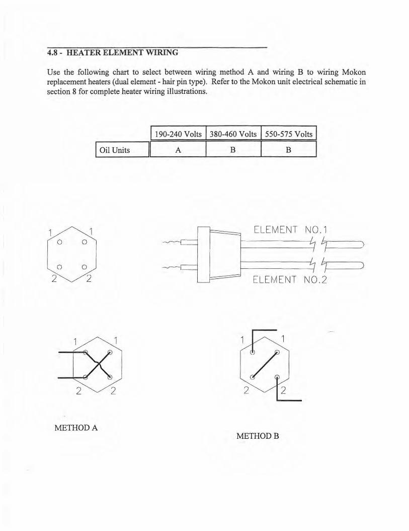
4.8 - HEATER ELEMENT WIRING
Use the following chart to select between wiring method A and wiring B to wiring Mokon replacement heaters (dual element - hair pin type). Refer to the Mokon unit electrical schematic in section 8 for complete heater wiring illustrations.
I 190-240 Volts 1380-460 Volts 1550-575 Volts I I Oil Units ~ A I B I B I
1 1 ELEMENT N0 . 1 0 0 7 )
0 0 7 )
2 2 ELE~A ENT N0.2
METHOD A METHODB
4.9 - LOW PRESSURE SAFETY SWITCH (OPTIONAL)
Mokon units are equipped with an optional low pressure safety shut down switch. This switch incorporates an interlock to prevent the operation of the unit should the heat transfer fluid be insufficient. The switch is factory set at 5 PSI and should not be adjusted without WRITTEN CONSENT FROM THE MOKON FACTORY.
4.10 - HIGH TEMPERATURE SAFETY SWITCH (STANDARD)
The High Temperature Safety Cut Off is located in the heater manifold. This switch is factory set to shut the Mokon unit off at the following temperature limits:
MK/MR Series units HCIHA Series units XC!XA Series units
460°F 510°F 6l0°F
The switch should not be adjusted without WRITTEN CONSENT FROM THE MOKON FACTORY.
4.11 - RECOMMENDED HEAT TRANSFER FLUIDS
Mokon recommends the following heat transfer fluids for use in Mokon units. A short description of each fluid is given including the recommended application and the manufacturing company name and address. The important technical characteristics are also outlined in a chart following the descriptions.
When operating the Mokon system, routine fluid samples should be analysized. Fluid samples for analysis should be taken whenever a fluid related problem is suspected. A fluid sample should be taken from a flowing line and cooled below 100°F before placing in a clean sample container and sent to the heat transfer fluid manufacturer for analysis. The information gathered from the sample can be useful in developing heat transfer fluid maintenance program.
All Mokon Oil units are tested thoroughly for leaks, component operation and accuracy (calibration) prior to shipment. The heat transfer fluid used in the testing was CALFLO.
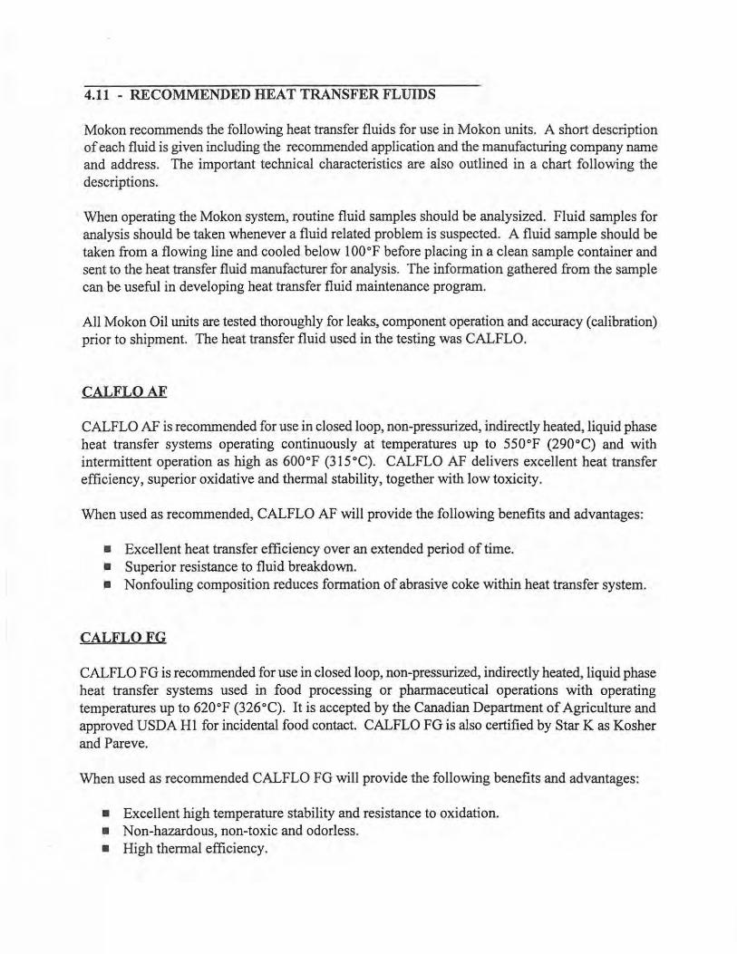
CALFLOAF
CALFLO AF is recommended for use in closed loop, non-pressurized, indirectly heated, liquid phase heat transfer systems operating continuously at temperatures up to 550°F (290°C) and with intermittent operation as high as 600°F (315°C). CALFLO AF delivers excellent heat transfer efficiency, superior oxidative and thermal stability, together with low toxicity.
When used as recommended, CALFLO AF will provide the following benefits and advantages:
• Excellent heat transfer efficiency over an extended period of time. • Superior resistance to fluid breakdown. • Nonfouling composition reduces formation of abrasive coke within heat transfer system.
CALFLOFG
CALFLO FG is recommended for use in closed loop, non-pressurized, indirectly heated, liquid phase heat transfer systems used in food processing or pharmaceutical operations with operating temperatures up to 620°F (326°C). It is accepted by the Canadian Department of Agriculture and approved USDA HI for incidental food contact. CALFLO FG is also certified by Star K as Kosher and Pareve.
When used as recommended CALFLO FG will provide the following benefits and advantages:
• Excellent high temperature stability and resistance to oxidation. • Non-hazardous, non-toxic and odorless. • High thermal efficiency.

4.11 - RECOMMENDED HEAT TRANSFER FLUIDS CONT.
CALFLOHTF
CALFLO HTF is recommended for use in closed loop, non-pressurized, indirectly heated, liquid phase heat transfer systems with operating temperatures up to 620°F (326°C) and film temperatures up to 650°F (343°C). CALFLO HTF is a unique heat transfer fluid which combines the thermal efficiency and cleanliness of paraffinic hydrocarbon with the high temperature stability of a chemical synthetic.
When used as recommended CALFLO HTF will provide the following benefits and advantages:
• Chemically inert, low volatility. • Non-hazardous, non-toxic and odorless. • Superior resistance to fluid breakdown.
CALFLO AF may be used safely in the Mokon MK, MR, HC and HA series units. CALFLO FG and HTF may be used safely in the Mokon MK, MR, HC, HA, XC and XA series units.
To receive more information on CALFLO products, contact:
PETRO-CANADA PRODUCTS 4060 Peachtree Road (Suite D-390) Atlanta, GA 30319 (800) 267-5968
MOBILTHERM 603
Mobiltherm 603 is recommended for use in closed systems where the maximum bulk oil temperature does not exceed 550°F (287.8°C) and where the minimum shut down temperatures are not below 25 °F(-4 °C). It is particularly applicable where high heat transfer rates, or high heat flow rates at reasonably low temperatures are desired. Mobiltherm 603 is suitable for systems with combined heating and cooling cycles because it functions efficiently at both low and high temperatures and withstands repeated thermal cycling.
After long periods of operation, coke deposits can form on heat transfer surfaces, reducing heat transfer efficiency. Mobil therm oils resist thermal cracking and chemical oxidation, and maintain in solution any decomposition products that form. They have good heat transfer efficiency and their viscosities are such that they can be pumped readily at both start up and operating temperatures.

4.11 - RECOMMENDED HEAT TRANSFER FLUIDS CONT.
When used as recommended Mobiltherm heat transfer oils will provide the following benefits and advantages:
• Resistance to thermal cracking • Freedom from sludge and coke deposits • Longer service life • Easy starting of cold systems • High heat transfer rates • Protection against corrosion
The Mobiltherm 603 may be used safely in the Mokon MK, MR, and HC and HA series units.
To receive more information on Mobiltherm 603, contact:
Mobil Oil Corporation Technical Publications 3225 Gallows Road Fairfax, Virginia 22037-0001
MULTITHERM PG-1
The MUL TITHERM PG-1 is a high quality food grade heat transfer fluid for use in closed loop, liquid phase heating and cooling systems with operating temperature up to 600°F. MUL TITHERM PG-1 meets the specifications of21CFR72.878 which covers the use of White Mineral Oils in Food according to the limits and conditions of the regulation. It is also chemically acceptable for use as a heat transfer fluid in plants operating under the Federal Meat and Poultry Inspection Program.
MULTITHERM PG-1 may be used safely in the Mokon MK, MR, HC, HA, XC and XA series units.
To receive more information on the MULTITHERM PG-1, contact:
Multitherm Corporation 125 South Front Street Colwyn, PA 19023 (610) 461-6442 (800) 225-7440
4.11 - RECOMMENDED HEAT TRANSFER FLUIDS CONT.
PARATHERMNF
The PARATHERM NF is formulated for service to 600°F. The Paratherm NF fluid provides excellent heat transfer and is low in viscosity. It is highly efficient, thermally stable and cost effective. If severely overheated, the PARA THERM NF fluid resists fouling by forming small carbon granules. These granules remain in suspension and can be filtered out easily.
PARATHERM NF may be used safely in the Mokon MK, MR, HC, HA, XC and XA series units.
To receive more information about PARATHERM NF, contact:
Paratherm Corporation 1050 Colwell Road Conshohocken PA, 19428 (610) 941-4900 (800) 222-3611
THERMINOL 66
THERMINAL 66 heat transfer fluid is designed for use in non-pressurized/low pressure, indirect heating systems with maximum bulk temperatures up to 650°F and film temperatures up to 705°F. It delivers efficient, dependable, uniform process heat with no need for high pressures. The high boiling point ofTHERMINOL 66 helps reduce the volatility and fluid leakage problems associated with other fluids.
THERMINOL 66 may be used safely in the Mokon MK, MR, HC, HA, XC and XA series units.
To receive more information about THERMINAL 66, contact:
Monsanto The Chemical Group 800 N. Lindbergh Blvd. St. Louis, MO 63167

RECOMMENDED HEAT TRANSFER FLUIDS FOR MOKON SYSTEMS
Fluid Name Density @60°F Flash Point Fire Point Autoignition Viscosity Max Operating For Use in
Ob/gal) COC (°F) COC ( 0 F) Temp (°F) (cSt) Temo (°F) Mokon Units
Calflo AF 7.14 400 437 650 31.2@ 104°F
550 MK,MR,
.72@600°F HC,HA
Calflo FG 7.11 408 457 662
15.0@ 104°F 620
MK,MR, (Food Grade) .70@550°F HC,HA, XC, XA
Calflo HTF 7.14 414 462 670 35.6@ 104°F
620 MK,MR,
.73 @600°F HC,HA, XC, XA
Mobiltherm 603 © 340 © 670 20.4@ 104°F
550 MK,MR,
4.0 @212°F HC,HA
Multitherm PG 1 7.30 340 385 690
20.5@ 104°f 600
MK,MR, (Food Grade) .46 @600°F HC,HA, XC, XA
Paratherm NF 7.25 345 385 690 19.0@ 104°F
600 MK,MR,
.49@600°F HC,HA, XC, XA
Therminol 66 8.39 375 420 750 33.9@ 50°F
650 MK,MR,
.43 @650°F HC,HA, XC, XA
© Not listed in literature
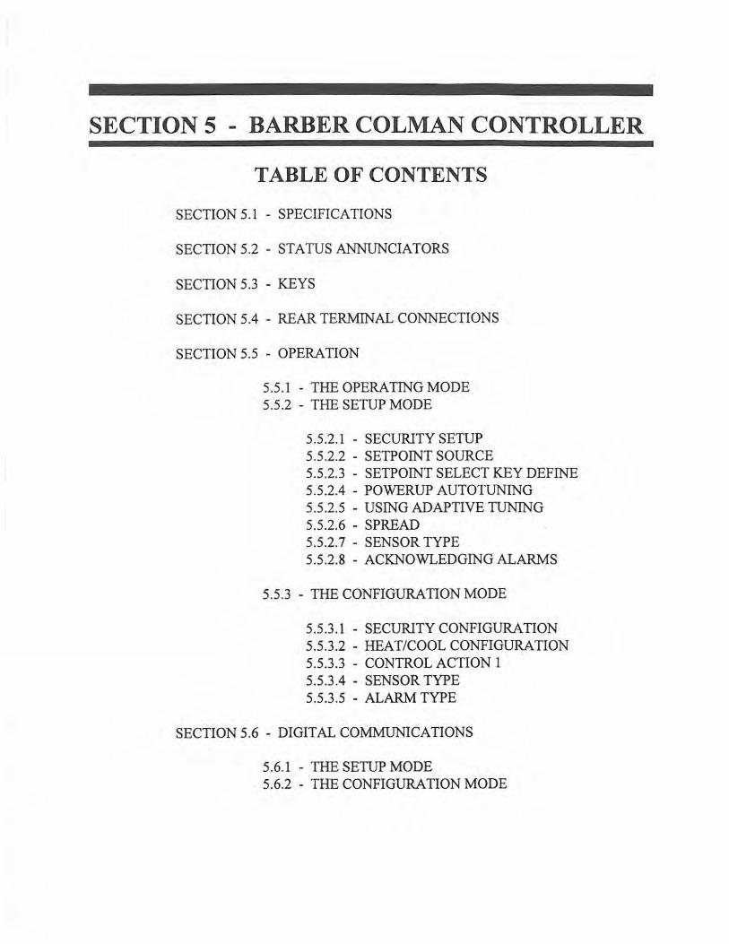
SECTION 5 - BARBER COLMAN CONTROLLER
TABLE OF CONTENTS
SECTION 5.1 - SPECIFICATIONS
SECTION 5.2 - STATUS ANNUNCIATORS
SECTION 5.3 - KEYS
SECTION 5.4 - REAR TERMINAL CONNECTIONS
SECTION 5.5 - OPERATION
5.5.1 - THE OPERATING MODE 5.5.2 - THE SETUP MODE
5.5.2.1 - SECURITY SETUP 5.5.2.2 - SETPOINT SOURCE 5.5.2.3 - SETPOINT SELECT KEY DEFINE 5.5.2.4 - POWERUP AUTOTUNING 5.5.2.5 - USING ADAPTIVE TUNING 5.5.2.6 - SPREAD 5.5.2.7 - SENSOR TYPE 5.5.2.8 - ACKNOWLEDGING ALARMS
5.5.3 - THE CONFIGURATION MODE
5.5.3.l - SECURITY CONFIGURATION 5.5.3.2 - HEAT/COOL CONFIGURATION 5.5.3.3 - CONTROL ACTION 1 5.5.3.4 - SENSOR TYPE 5.5.3.5 - ALARM TYPE
SECTION 5.6 - DIGITAL COMMUNICATIONS
5.6.1 - THE SETUP MODE 5.6.2 - THE CONFIGURATION MODE
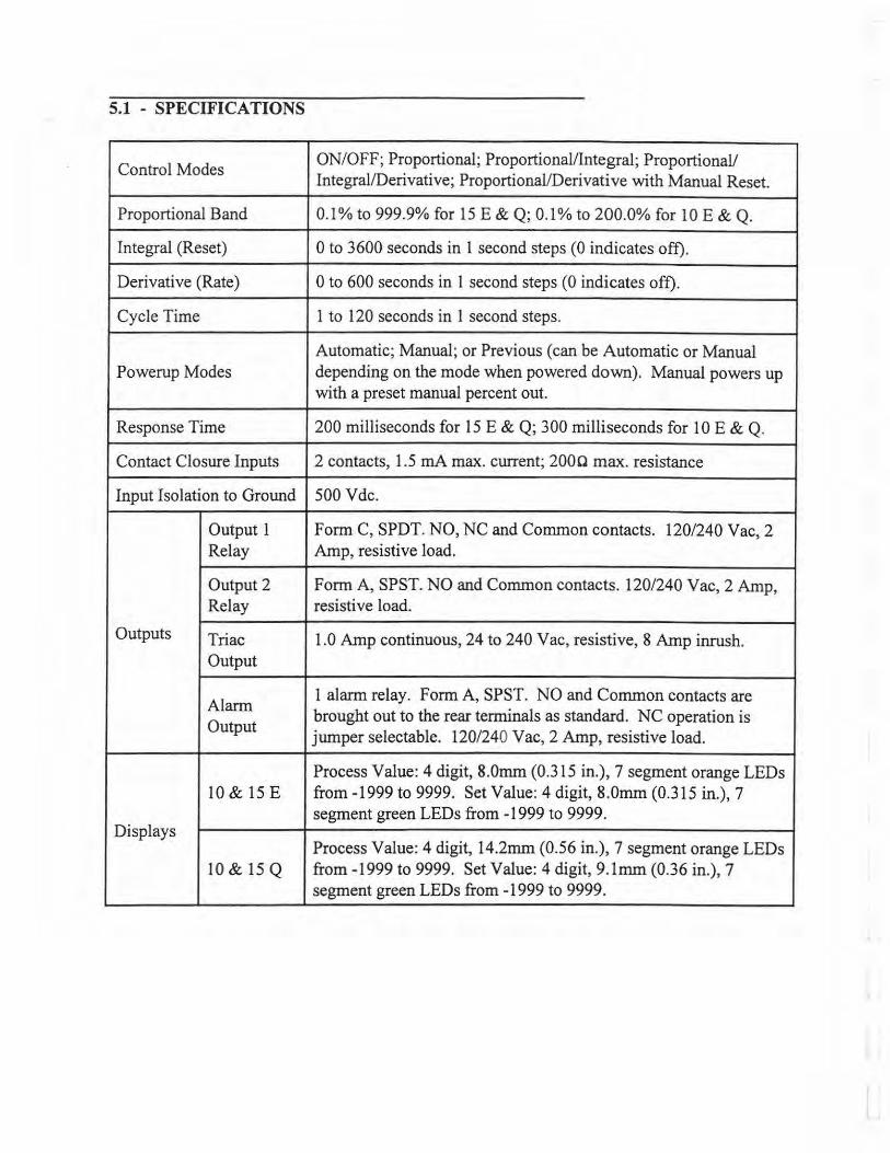
5.1 - SPECIFICATIONS
Control Modes ON/OFF; Proportional; Proportional/Integral; Proportional/ Integral/Derivative; Proportional/Derivative with Manual Reset.
Proportional Band 0.1% to 999.9% for 15 E & Q; 0.1% to 200.0% for 10 E & Q.
Integral (Reset) 0 to 3600 seconds in 1 second steps (0 indicates off).
Derivative (Rate) 0 to 600 seconds in 1 second steps (0 indicates off).
Cycle Time 1 to 120 seconds in 1 second steps.
Automatic; Manual; or Previous (can be Automatic or Manual Powerup Modes depending on the mode when powered down). Manual powers up
with a preset manual percent out.
Response Time 200 milliseconds for 15 E & Q; 300 milliseconds for 10 E & Q.
Contact Closure Inputs 2 contacts, 1.5 mA max. current; 2000 max. resistance
Input Isolation to Ground 500 Vdc.
Output 1 Form C, SPDT. NO, NC and Common contacts. 120/240 Vac, 2 Relay Amp, resistive load.
Output 2 Form A, SPST. NO and Common contacts. 120/240 Vac, 2 Amp, Relay resistive load.
Outputs Triac 1.0 Amp continuous, 24 to 240 Vac, resistive, 8 Amp inrush. Output
Alarm 1 alarm relay. Form A, SPST. NO and Common contacts are
Output brought out to the rear terminals as standard. NC operation is jumper selectable. 120/240 Vac, 2 Amp, resistive load.
Process Value: 4 digit, 8.0mm (0.315 in.), 7 segment orange LEDs 10 & 15 E from-1999 to 9999. Set Value: 4 digit, 8.0mm (0.315 in.), 7
segment green LEDs from -1999 to 9999. Displays
Process Value: 4 digit, 14.2mrn (0.56 in.), 7 segment orange LEDs 10 & 15 Q from -1999 to 9999. Set Value: 4 digit, 9.lmrn (0.36 in.), 7
segment green LEDs from -1999 to 9999.
5.1 - SPECIFICATIONS CONT.
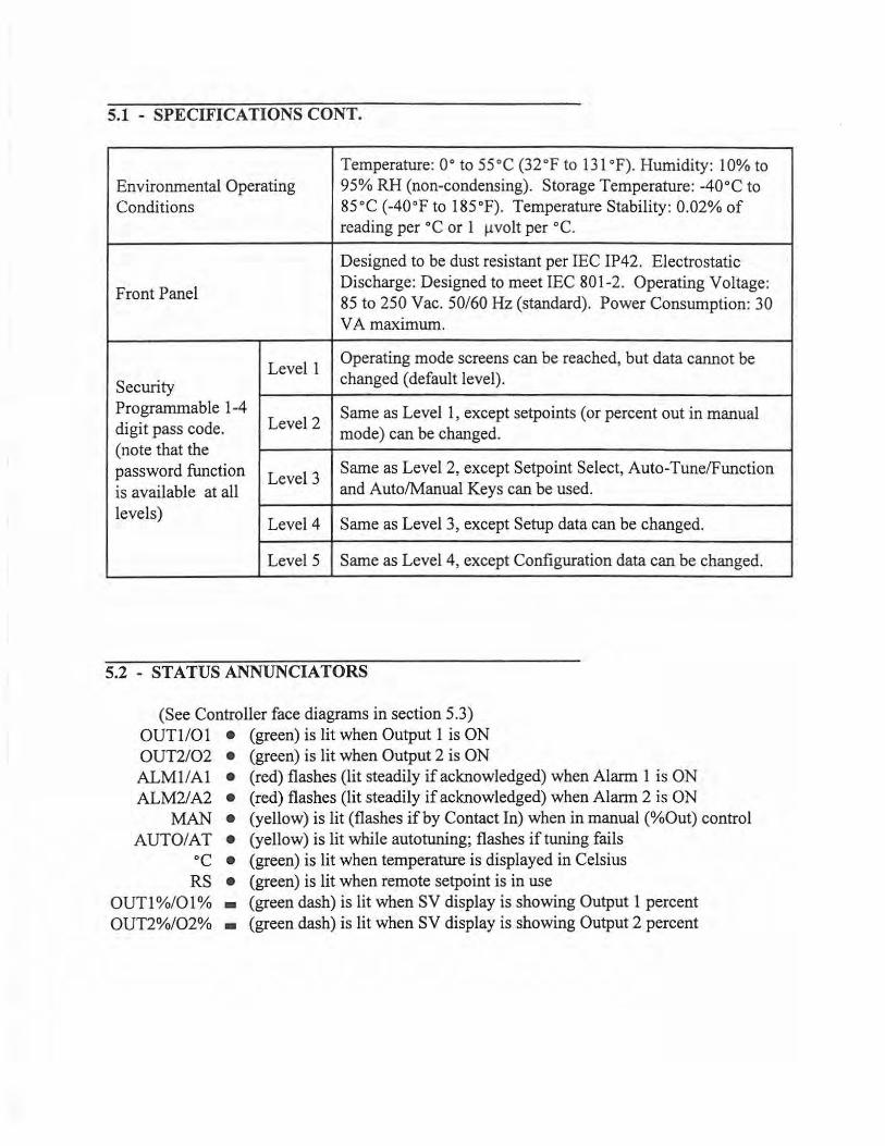
Temperature: 0° to 55°C (32°F to 131°F). Humidity: 10% to Environmental Operating 95% RH (non-condensing). Storage Temperature: -40°C to Conditions 85°C (-40°F to 185°F). Temperature Stability: 0.02% of
reading per °C or 1 µvolt per °C.
Designed to be dust resistant per IEC IP42. Electrostatic
Front Panel Discharge: Designed to meet IEC 801-2. Operating Voltage: 85 to 250 Vac. 50/60 Hz (standard). Power Consumption: 30 VA maximum.
Level 1 Operating mode screens can be reached, but data cannot be
Security changed (default level).
Programmable 1-4 Level 2
Same as Level 1, except setpoints (or percent out in manual digit pass code. mode) can be changed. (note that the password function is available at all
Level 3 Same as Level 2, except Setpoint Select, Auto-Tune/Function and Auto/Manual Keys can be used.
levels) Level 4 Same as Level 3, except Setup data can be changed.
Level5 Same as Level 4, except Configuration data can be changed.
5.2 - STATUS ANNUNCIATORS
(See Controller face diagrams in section 5.3) OUTl/01 • (green) is lit when Output 1 is ON OUT2/02 • (green) is lit when Output 2 is ON ALMl/Al • (red) flashes (lit steadily if acknowledged) when Alarm 1 is ON ALM2/ A2 • (red) flashes (lit steadily if acknowledged) when Alarm 2 is ON
MAN • (yellow) is lit (flashes if by Contact In) when in manual (%Out) control AUTO/AT • (yellow) is lit while autotuning; flashes if tuning fails
°C • (green) is lit when temperature is displayed in Celsius RS • (green) is lit when remote setpoint is in use
OUTl %/01 % • (green dash) is lit when SV display is showing Output 1 percent OUT2%/02% • (green dash) is lit when SV display is showing Output 2 percent
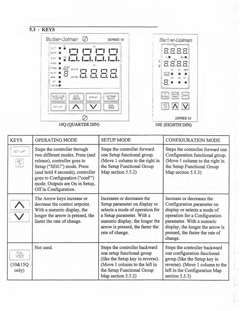
5.3 - KEYS
KEYS
r------; ; SE~ -uP J
, ___ I sE-:-.
' D ! ~
' /\ ' :
v i I : '
I R.UN >-i')LD I
I
(10&15Q only)
SERIES 10 Ba:t ~r-C©ima:ro I
!1:;,;;· • -~ 1-1 1-1 ""1-1 1-1 I I! 0U'2 • I
I - - - -
'i ~V I
I: •.:.• !:.' !:.' !:.' I
: ._v· • : 1-1. 1-1. 1-1. 1-1. I : ' ""'' • S/ I
' '-'· '-'· '-'· '-'·i !I ·: . RS . j
~ :· 1_
1 1_
1sv
1_,
1_
1 !
OJ ! : l:i. .::i. l:i. r::i. ! 1 I ?ROG • SE-N/ ! I ?~~c our::>: 1-1 1-1 1-1 1-1 l'. Auf:l • LI - - - -j
1
: MA" e 1- 1 cum; 1-1. 1-1. 1-1. 1-1.
I AT •
,i-S/"B • !
' ' II Ci A1 MAN~
SE-Ni e • e ·
II PROC ! I ::2 A2 AT I ' 1-1
I,,-, •• • J 1.l - • J
I ,,r:=l! A=v;o=-=,vN=E ,) AUTO DISPLAY i1 11 SETPOINT ; '"V'ICT 0"1 'J ~L I• ' SEL~CT
1 a [ZSJ [[sui m 0 ::ERIES 10
IOQ (QUARTER DIN) 1 OE (EIGHTH DIN)
OPERA TING MODE SETUP MODE CONFIGURATION MODE
Steps the controller through Steps the controller forward Steps the controller forward one two different modes. Press (and one Setup functional group. Configuration functional group. release), controller goes to (Move 1 column to the right in (Move 1 column to the right in Setup ("SEtU") mode. Press the Setup Functional Group the Setup Functional Group (and hold 4 seconds), controller Map section 5.5.2) Map section 5.5.3) goes to Configuration ("conF") mode. Outputs are On in Setup, Off in Configuration.
The Arrow keys increase or Increases or decreases the Increase or decreases the decrease the control setpoint. Setup parameter on display or Configuration parameter on With a numeric display, the selects a mode of operation for display or selects a mode of longer the arrow is pressed, the a Setup parameter. With a operation for a Configuration faster the rate of change. numeric display, the longer the parameter. With a numeric
arrow is pressed, the faster the display, the longer the arrow is rate of change. pressed, the faster the rate of
change.
Not used. Steps the controller backward Steps the controller backward one setup functional group one configuration functional (like the Setup key in reverse). group (like the Setup key in (Move 1 column to the left in reverse). (Move 1 column to the the Setup Functional Group left in the Configuration Map Map section 5.5.2) section 5.5.3)
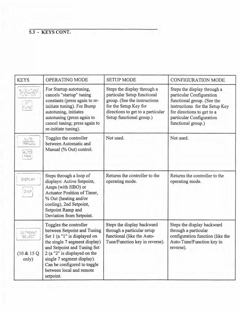
5.3 - KEYS CONT.
KEYS OPERA TING MODE SETUP MODE CONFIGURATION MODE
A'J -:-TJ~: For Startup autotuning, Steps the display through a Steps the display through a =- ,.; \ ~: ... :~:~~ ! cancels "startup" tuning particular Setup functional particular Configuration : ,--~ constants (press again to re- group. (See the instructions functional group. (See the 1 / , ~ I
;~:., '\Cl initiate tuning). For Bump for the Setup Key for instructions for the Setup Key \___J
autotuning, initiates directions to get to a particular for directions to get to a autotuning (press again to Setup functional group.) particular Configuration cancel tuning; press again to functional group.) re-initiate tuning).
! .\.,IC 1 Toggles the controller Not used. Not used.
: -- j ' ~A'\ J,.,;_ I between Automatic and
;A:.,".'Ql Manual(% Out) control.
i ' i 1,1AN , .__,
·- Steps through a loop of Returns the controller to the Returns the controller to the ' DiS;:>~Av !
displays: Active Setpoint, operating mode. operating mode. ' ;
f~ Amps (with HBO) or ; J.sPJ Actuator Position of Timer,
% Out (heating and/or cooling), 2nd Setpoint, Setpoint Ramp and Deviation from Setpoint.
Toggles the controller Steps the display backward Steps the display backward
'.:~7PQt'.\JT between Setpoint and Tuning through a particular setup through a particular
' SE_:'.:CT Set 1 (a " 1 " is displayed on functional (like the Auto- configuration function (like the !
the single 7 segment display) Tune/Function key in reverse). Auto-Tune/Function key in and Setpoint and Tuning Set reverse).
(10 & 15 Q 2 (a "2" is displayed on the only) single 7 segment display).
Can be configured to toggle between local and remote setpoint.
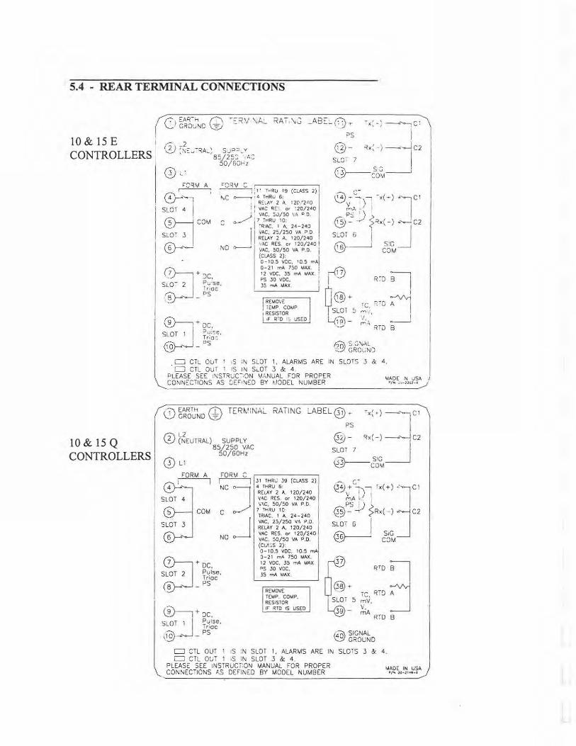
5.4 - REAR TERMINAL CONNECTIONS
10 & 15 E CONTROLLERS
10 & 15 Q CONTROLLERS
_A8E:...0) T
0"'.r1 SLOT 4 I ©---i COM
s~T ~ I ©-"--'
=CR~ : • , ; ; 11 T,..qu 19 (CtASS 2) I r-.C <>------ · 4 T-<RU 6 :
, RE~AY 2 A, 1 20 '2•0 ! 1 VAC qE 0' : 20/240 1 1 VAC, SV/50 \..\ P 0.
,,/ 1 7 iHRU 10: c I lR'AC. 1 A, 24-240
11 VAC, 2~/250 VA ?.O RELAY 2 A, 120/240 I
. . AC RES. C• 1 20/240 I NO <>---- V/>C, 50/50 VA P.O. j
(CLASS 2): I 0- 10.S VCe, 10.5 mA 0-21 mA 750 ... AX. I 12 voe. JS mA 11.Ax. : PS JO voe. I 35 mA MAX. I
~+JC, SL07 :J Pvse. Tr1oc ~ p-· ';!_./' - ::> I REMO'.<:
TE,,.P. COMP. 1 RESISTOR . • F R' O 1, USED
?S i 0_1)- -<X: -) -·~ C2
SLOT 7 I /,'<\ _ _ _ S G _____, \:...~COM
r0 I R~D
O@+ ~c. r.ro
I SLOT 5 "" L.{i?)- 'I ,.:..:.; _,,,.
RTu
h;v.. S G\JAL :!:..';!GROUND
~ ~ __J B
c:J CTL OUT 1 1S :N SLOT 1, ALARMS ARE IN SLOTS 3 & 4. c:J CTL OUT 1 !S IN s~oT 3 & 4 .
PLEASE SEE !NSTRuc-.oN M>-NUAL FOR PROPER CONNECTIONS AS C.EF• "IED BY t.10DEL NUMBER
IAADE N JSA •/M . ~-1n:z~x
,";'\EARTH II\ TER~' iNAL RATING ;,,.ABEL!JP + \...:,./ GROUND \_°"=,,./ \:::,;J ~x(~)-"']Cl
h\ L2 ~(NEUTRAL) SUPPLY
85/250 VAC 50/60Hz
0 L1
FORM A
& SLOT 4
5
SLOT 3
~
COM
FOR\A C
I J 1 THRt; 39 (CLASS 2)
NC 14 THRU 6: RELAY 2 A, 120/240 \'~C RES or 120/240
c ,,._/' 1"i~·Rco;~o VA p 0
TRIAC, 1 A, 24-240 VAC, 2S/250 V,\ P.O. RELAY 2 A. 120/240
NO VAC RES. or 120/240 VAC, 50/SO VA P.O. (Cu\,S 2): 0-10.5 voe. 10.s mA 0-21 mA 750 MAX. 12 voe. 35 mA w.x. PS JO voe. JS mA MAX.
REMOV£ TEMP. COMP. RES;STQR
©---i+ oc. SLOT 1 I P.,1se. ' I Tnoc ,§------1 _ PS
1r RTO IS USED
PS
Q}J - ~x(-)- C2
SLOT 7 _J Li"t\__3 SIG <.~COM
«v+'~)' r x(+) .·1c1 \ I '
P't t) t' @- -;..-' Rx( - ) •"'--l C2
SLOT 6 J ~ S1G ~COM
rv RTD
~· T 5 iC. RT9 mV, ,.
- '· mA RTD
IA~ SIGNAL ~GROUND
81 J B
c:J '.:TL OUT 1 1S !N SLOT 1. ALARMS ARE IN SLOTS 3 & 4. CJ CTL O:JT 1 ·S iN SLOT 3 & 4 .
PLEASE SEE :NSTRUCi!ON MANUAL FOR PROPER CON!\JECTIONS t.S DEFINED BY MODEL NUMBER
>.4AOE IN USA P/ "f 2U-2U9-•
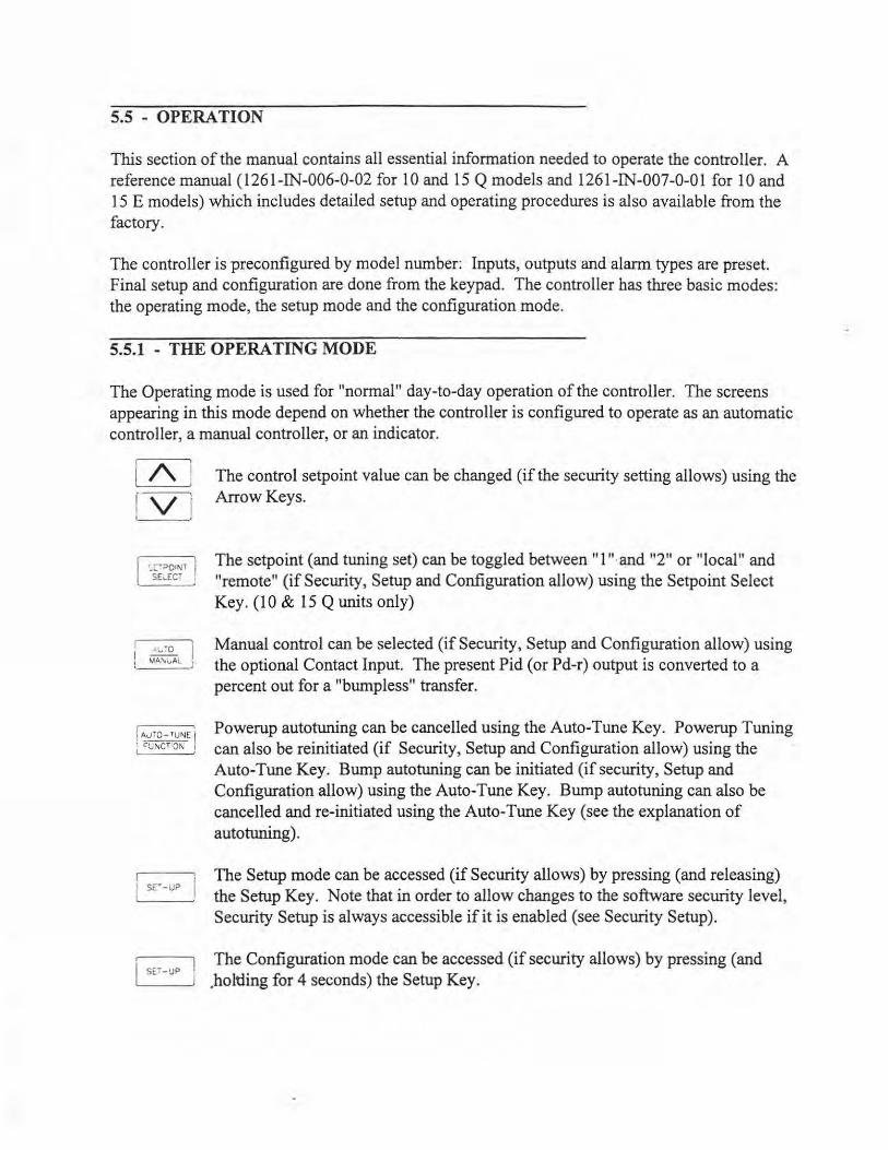
5.5 - OPERATION
This section of the manual contains all essential information needed to operate the controller. A reference manual (1261-IN-006-0-02 for 10 and 15 Q models and 1261-IN-007-0-01for10 and 15 E models) which includes detailed setup and operating procedures is also available from the factory.
The controller is preconfigured by model number: Inputs, outputs and alarm types are preset. Final setup and configuration are done from the keypad. The controller has three basic modes: the operating mode, the setup mode and the configuration mode.
5.5.1 - THE OPERATING MODE
The Operating mode is used for "normal" day-to-day operation of the controller. The screens appearing in this mode depend on whether the controller is configured to operate as an automatic controller, a manual controller, or an indicator.
i I\ f V I
:_:::T?QINT I SE~Ecr '
! AJTO- fUNE i ' ~vr-.CT'ON I
I sc:·-up
i SET-UP
The control setpoint value can be changed (if the security setting allows) using the Arrow Keys.
The setpoint (and tuning set) can be toggled between" l "·and "2" or "local" and "remote" (if Security, Setup and Configuration allow) using the Setpoint Select Key. (10 & 15 Q units only)
Manual control can be selected (if Security, Setup and Configuration allow) using the optional Contact Input. The present Pid (or Pd-r) output is converted to a percent out for a "bumpless" transfer.
Powerup autotuning can be cancelled using the Auto-Tune Key. Powerup Tuning can also be reinitiated (if Security, Setup and Configuration allow) using the Auto-Tune Key. Bump autotuning can be initiated (if security, Setup and Configuration allow) using the Auto-Tune Key. Bump autotuning can also be cancelled and re-initiated using the Auto-Tune Key (see the explanation of autotuning).
The Setup mode can be accessed (if Security allows) by pressing (and releasing) the Setup Key. Note that in order to allow changes to the software security level, Security Setup is always accessible if it is enabled (see Security Setup).
The Configuration mode can be accessed (if security allows) by pressing (and .holtling for 4 seconds) the Setup Key.

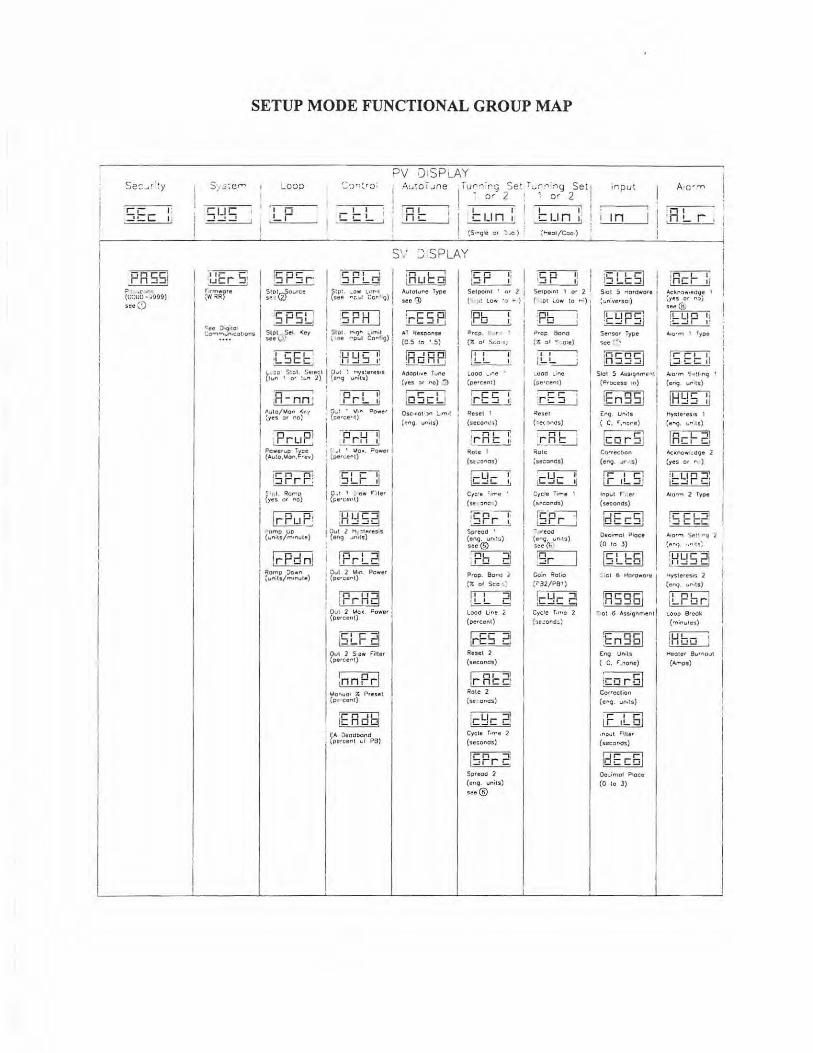
5.5.2 - THE SETUP MODE
The setup mode is, in general, used to set or change settings associated with the control, such as ramp rate, tuning constants, alarm settings, etc. Control outputs remain active in the setup mode.
The following is a map of the Setup Mode Functional groups. Below each function is a description which, in some cases, includes a reference for more information. To enter the Setup Mode press and release the Setup Key. Further pressing of the Setup Key will take you from functional group to functional group (left to right across the map). Pressing the Run/Hold Key will take you in reverse from functional group to functional group (right to left across the map).
Note: the Run/Hold Key is only included on 10 and 15 Q units. You can not move to the left on 10 and 15 E units.
Once in a functional group, pressing the Auto-Tune/Function Key will step you through the functional group (top to bottom). Pressing the SP Select/Advance Key will take you in reverse (bottom to top) through a functional group.
Note: the SP Select/ Advance Key is only included on 10 and 15 Q units. You can not move in reverse on 10 and 15 E units. See section 5.3 for specific key functions.
Se-: .... r':y
·r o 1: 11c I ,
SETUP MODE FUNCTIONAL GROUP MAP
-;:;v 0 1SPi...AY S: 3:ef"" Loo::> i:~,,.., ~ro : A:...~oTune · Ju,..~irg Set r ...,r""' ;:ig Set I I i O' 2 ~ 1 or 2 :
1 I I ! I I ! c:un , c: u n !
~S·rg'e or 'Lo) {~ea t/Coo )
~ L!c; I 0 0 --!- ,- -.
0 0 I !....I L c: !.... nc
S\' DISPLAY
;UE r 5: I !5 P 5 r I 5 PL d I rw~~re :~~taro:.rce l (~~;,· ~~~l Lc~;~'"9)
«• o~;,. I 'S PSLJ ! Soc~ :.~~!, 0 I :.; :>""7:-:':''c::1t1ons ! i!~\.)~I. ""iey I \ ae " Pt..l Co"l•g) i
I LSE b : ;H ~S :! I \,- .~eel 1· Ou~1s
(ti.., I o• : .. n 2) (e"'9 u n1ls)
I~~ ; H -nn ·
I Aul~ :res er no)
J :PruP! r~~~:~~n:i::v )
lr- n n . ::irrr:
lrPuP! 1~omp vc (u"•ts/n..,,ute)
!rPdnl . R:omp :>c.wn I ~units/m1r>ute)
~ .rrt.e. ; T;'~,c~~i" Pcwer I I r~ I l.CC...Q_g
I QvO 2 ~o• Pow"' {percent}
15LF 21 I ~l 2 S-f!.w f'ilter
d>erce"1)
I ~.~~.~ ~.~~. I• (o cono)
iE Rd bl ! F;A Oeod bond ! (percent ul PB)
~ ;nlle !:!i AulOIUt'C Type
see I])
!rESP! AT Respons.
(C.5 to '.5}
!Rd RP! Adopt111e lune
(yes or "O) "':)
~ !i::J=iC~ I
Osc·uot l"" :_.,,.,,l 1 ' ~ "9 · u,.,its )
"Ci'i 1; I td.!:.__!. I
Selpoml 1 nr 2 / ( ,it :.cw ·r, '" )
1
,
~I I ~ ,
=>rep. ! r :
(1; or Seo !: I ~ 1 b_b____t I
LOOd .... ne (percent)
IF"""FI ·re :J 1:
Reset 1
(secol'1~ ' )
~ irnc ..J.! ~ole 1
Cyc1e !'i rro e
{st :inc )
i lii I• · ~rr ,
Spreed ' (enq. un11 ~) see @
: DL .:l ~
Prop. Bo,.u 2 (1; of Seo •.:
ILL 21 Load Line 2
(pe1ce n1)
Resel :l (uconas)
~ 1r ne e Rote 2 (sr ones}
!c~c 2l Cycle T»Tie 2
(seconds)
Soreoo 2 (en9. units)
see@
I
i I I i
I
~ I ·::ir •1 I
Se1po1ri1 1 O" 2 , ( 1c:t i.e.., :o ... ;) I
:nc--1 DL__J
?'CP aono {?. ot -: 01e )
~ IJ,,,,b____j
_ooo ~;ne
(pe•cent)
·r~ c; I
~ Reset
("._ec 1"<'.Js )
~ rnc I
Rote
\secor>es)
:ycle Ti"'e I
(s.N:ond:i:)
ISPr ·! - 1teOCI
(e"9· uM:o) ">CC (b
!Sr I Coiiri Ratio
('32/PBt)
1-Ll- ;:ii 1 l.... ~ '- =t
Cycle T:r"e !st.:ona_ ,
;r.put
'I n 1
~l_n~~' I :n !.... r_!
:cn:::1':l ~ .
$101 S "'tOtdwore I'
:1,.n :ve ' SOI)
lt:~PS i ·1
Sef"SCf Type
o;ee 1~' I n J
Slo! !> Ass19nmr.,! (Process ~n)
'' nr- 1 !en.::;::i (1'19 Ul"\olS
{ C, r ,.,one )
!cwrSI Co•rectten
(en9, "'" ·-S)
rro---ri j r 1L::J !
Input F ... er
(second$)
Ot!cimal ?toce
(O to 3)
[illEJ • :co 6 Ho<O• O<e I ~ I
- ·ot 6 A'J'siqnrnent J
~ ' Eng Unils
( C. r,nol'le)
Cor1eel1on
(e,.9 . ..1n.ts}
.nput r :11er
(sec::or>os)
~ Qe_imol Ptace
(0 to 3)
~ :ncr 11 A.ckno w•edqe I (yes or ,.o) !lee (b,1 :Lup 11 ~
A.1orm ~ ... ~ l1nq I
(eoq. """:11)
~ Hyste•es•s 1
{e"'q. U"'· IS)
lnn,L;:i! ~
Ac11.ncwo.dqe 2 {yes or ,., )
Alarm 2 ryoe
! C CL~! ~
Aio•"1 lie~· "Q 2 {enq ' •"'l'I ~
:uu• • 1 · 11.....:~Ci
Hysleres13 2 (enq. ul"'•ts)
:or=ICI 1Lrwr1 t.oop B•eoit ('ninutes)
~ l11 0W i Heoier Burnout
(.\!Tops)

5.5.2 - THE SETUP MODE CONT.
1 - SECURITY SETUP
STEP DESCRIPTION
1. From the operating mode, press and release the Setup Key and the Security Setup Header screen will appear in the "SV" display.
2. If the "SV" display shows a dash after "Sec", no software security is in effect. Unless the controller is equipped with an optional hardware security function, ALL Operating, Setup and Configuration screens will be accessible to the operator. If the hardware security switch has been set to "Closed/Closed," NO OTHER Security Setup or Configuration screens will appear.
If the "SV" display shows a number after "Sec," software security is in effect and the number indicates the level of security ( 1-4 ). See the specifications in section 5.1 for a description of the security levels.
The controller will power up at the same security level at which it was powered down. In order to allow changes to the software security level, Security Setup is always accessible if software security is enabled.
Press the Auto-Tune/Function Key to bring up the Passcode Enter display.
3. Use the Arrow Keys to select a passcode. The Passcode can be any number from 0-9999. Pressing the Auto-Tune/Function Key (or any Key other than an Arrow Key) will cause the code to be entered and the new security level will appear if the code is correct. After 3 successive wrong passcodes, the controller will set itself to Security level 1. See Security Configuration to change passcodes (the controller must be at security level 5 to change the passcode ). If identical codes are used for 2 or more levels, the first time the code is entered the controller will go tho the lowest level for that code. If the same code is enter again (from that level), the controller will go to the next level for that code ... etc. Doing this successively will cause the controller to "wrap around'' to the lower security level.
Press the Auto-Tune/Function Key to bring up the Security Setup Header screen.
4. Press the Display Key to return to the Operating mode or press the Setup Key to continue through the Setup mode (or press the Run/Hold Key to go backwards through the Setup mode for 10 & 15 Q units). After 4 minutes without a key press the display will return to the Operating mode.
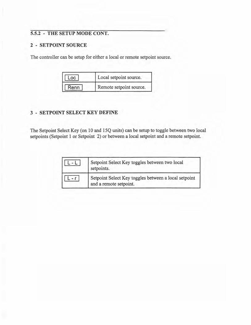
5.5.2 - THE SETUP MODE CONT.
2 - SETPOINT SOURCE
The controller can be setup for either a local or remote setpoint source.
I Loe I Local setpoint source.
I Renn I Remote setpoint source.
3 - SETPOINT SELECT KEY DEFINE
The Setpoint Select Key (on 10 and 15Q units) can be setup to toggle between two local setpoints (Setpoint 1 or Setpoint 2) or between a local setpoint and a remote setpoint.
IL-LI Setpoint Select Key toggles between two local setpoints.
I L -r I Setpoint Select Key toggles between a local setpoint and a remote setpoint.

5.5.2 - THE SETUP MODE CONT.
4 - POWERUP AUTOTUNING
The following conditions must be met before Powerup Autotuning can be used:
1. The controller must be in the automatic control mode (the "MAN" LED will be unlit). 2. Algorithm 1 must be set to PID (see Control Configuration). 3. Action 1 must be reverse (heat) (see Control Configuration). 4. The autotune type must be powerup (see Auto-Tune Setup). 5. There must be a minimum 15% of scale difference between process value and
setpoint.
Once the controller meets these conditions, go to the Operating mode and use the Setpoint Select Key to bring up the Tuning Set in which the autotuned constants are to be stored (observe the SP #display). Note: for 10 and 15 E units the Setpoint Select can only be changed-through the Loop Setup Functional Group. Check Loop Setup if the Setpoint Select Key does not function (it may be disabled). Remember that any tuning constants presently stored in the chosen Tuning Set will be overwritten once autotuning is complete. Make certain the proper control setpoint has been entered (in the Operating mode it will appear in the lower display).
Press the Auto-tune Key or cycle power to the controller. The AT LED will be steadily lit, indicating that tuning is occurring. The AT LED will turn off once the autotune sequence is successful. A blinking AT light indicates that the process value did not fall below the AT Setpoint and autotuning has failed. Check the control setpoint and input scale (see Input Configuration) to see if it is physically possible for the process value to reach the Auto-Tune Setpoint. If so, allow the process to cool and try again. Autotuning can be stopped by pressing the Auto-Tune Key (the AT LED will turn oft). It can be restarted either on powerup or by pressing the Auto-Tune Key.
Once the Autotune sequence is successful, the newly calculated tuning constants will overwrite the Tuning Set currently on single-digit display. If there is a cooling output (with a PID algorithm), the same reset and rate terms calculated for heating will be used, but the proportional band for the cooling output will be dependent on the PID Type chosen for the cooling output. Once tuning is complete, the Autotune type should be changed to "nonE" (see Auto-Tune Setup) or the next time the controller powers up, it will attempt to retune.

5.5.2 - THE SETUP MODE CONT.
5 - USING ADAPTIVE TUNING
If adaptive tuning has been selected, the controller will continuously monitor the movement of the process value. If this movement is determined to be a "valid" oscillation and the deviation is large enough, then the autotuning constants will be adjusted.
The following conditions must be met before Adaptive tuning can be used:
1. The controller must be in the automatic control mode (the "MAN" LED will be unlit). 2. Algorithm 1 must be sen to PID (see Control Configuration). 3. Action 1 must be reverse (heat) (see Control Configuration). 4. Adaptive tune Enable must be set to "yes" (see Auto-Tune Setup).
As long as these conditions are met and the controller remains in the Operating mode, Adaptive tuning will function. Nothing on the display will indicate that Adaptive tuning is executing.
Once the adaptive tuning routine is complete, the new tuning constants overwrite those in the currently used Tuning Set. Adaptive tuning can be stopped by setting Adaptive Tune Enable to "no" (see Auto-Tune Setup). Note that Adaptive tune Enable will reset itself to "no" after three tuning attempts.
6 - SPREAD
The Spread settings determine the amount of offset from setpoint of control action. Zero (engineering units) is the default setting. The range is ± 10% of the input scale (Input Scale High - Input Scale Low).
I SPr1 I
I SPr2 I
I SPr I
For Spread 1, if the setting is positive, it is subtracted from setpoint. If the setting is negative, it is added to setpoint (setpoint is overlapped).
For Spread 2, ifthe setting is positive, it is added to setpoint. If the setting is negative, it is subtracted from setpoint (setpoint is overlapped).
Spread appears without a number for Heat/Cool control. The setting is always positive and it is added to setpoint.
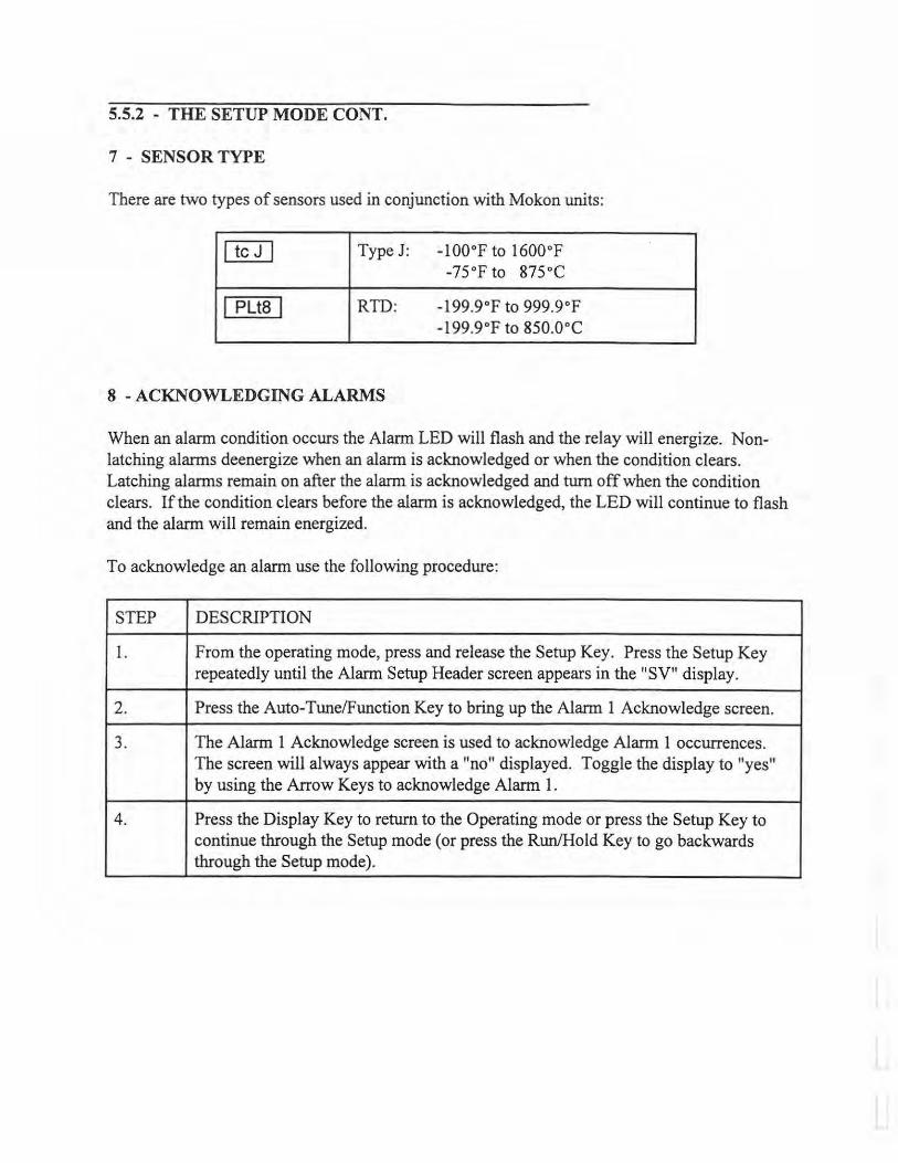
5.5.2 - THE SETUP MODE CONT.
7 - SENSOR TYPE
There are two types of sensors used in conjunction with Mokon units:
I tc J I Type J: -100°F to 1600°F -75°F to 875 °C
I PUS I RTD: -199.9°F to 999.9°F -199.9°F to 850.0°C
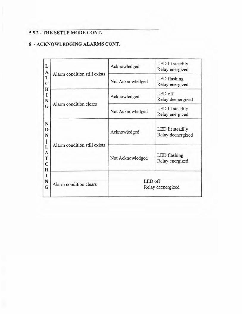
8 - ACKNOWLEDGING ALARMS
When an alarm condition occurs the Alarm LED will flash and the relay will energize. Nonlatching alarms deenergize when an alarm is acknowledged or when the condition clears. Latching alarms remain on after the alarm is acknowledged and turn off when the condition clears. If the condition clears before the alarm is acknowledged, the LED will continue to flash and the alarm will remain energized.
To acknowledge an alarm use the following procedure:
STEP DESCRJPTION
1. From the operating mode, press and release the Setup Key. Press the Setup Key repeatedly until the Alarm Setup Header screen appears in the "SV" display.
2. Press the Auto-Tune/Function Key to bring up the Alarm 1 Acknowledge screen.
3. The Alarm 1 Acknowledge screen is used to acknowledge Alarm 1 occurrences. The screen will always appear with a "no" displayed. Toggle the display to "yes" by using the Arrow Keys to acknowledge Alarm 1.
4. Press the Display Key to return to the Operating mode or press the Setup Key to continue through the Setup mode (or press the Run/Hold Key to go backwards through the Setup mode).
5.5.2 - THE SETUP MODE CONT.
8 - ACKNOWLEDGING ALARMS CONT.
LED lit steadily L Acknowledged Relay energized A Alarm condition still exists LED flashing T
Not Acknowledged Relay energized c
H LED off I Acknowledged Relay deenergized N
Alarm condition clears LED lit steadily G
Not Acknowledged Relay energized
N LED lit steadily 0 Acknowledged Relay deenergized N
I Alarm condition still exists L
LED flashing A Not Acknowledged
Relay energized T c H I
LED off N Alarm condition clears
Relay deenergized G

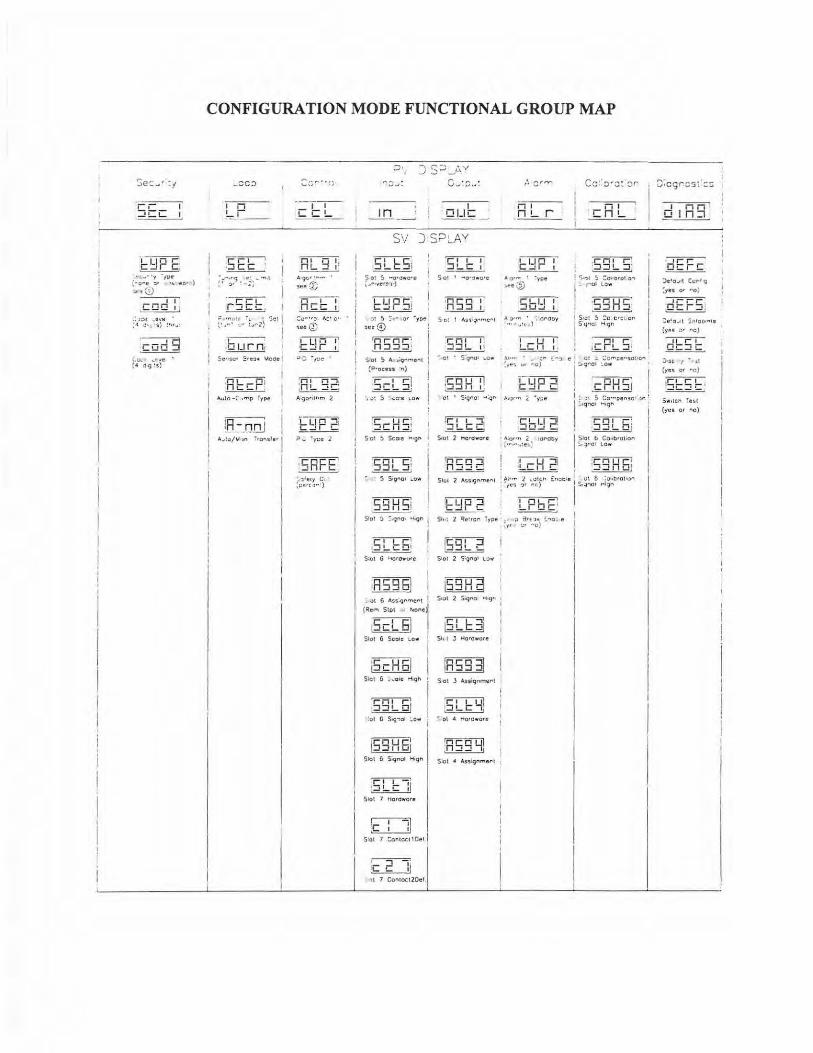
5.5.3 - THE CONFIGURATION MODE
The configuration mode is, in general, used to set or change settings more closely associated with hardware, such as input type, output type, alarm type, etc. Control outputs are OFF in the configuration mode.
The following is a map of the Configuration Mode Functional groups. Below each function is a description, which in some cases, includes a reference for more information. To enter the Configuration Mode press and hold the Setup Key. Further pressing of the Setup Key will take you from functional group to functional group (left to right across the map). Pressing the Run/Hold Key will take you in reverse from functional group to functional group (right to left across the map).
Note: the Run/Hold Key is only included on 10 and 15 Q units. You can not move to the left on 10 and 15 E units.
Once in a functional group, pressing the Auto-Tune/Function Key will step you through the functional group (top to bottom). Pressing the SP Select/ Advance Key will take you in reverse (bottom to top) through a functional group.
Note: the SP Select/ Advance Key is only included on 10 and 15 Q units. You can not move in reverse on 10 and 15 E units. See section 5 .3 for specific key functions.
·;-=-~
~cc 1
·cL10 Fi ~
• ~-· ·y • 1ue {"O"e 'J.' • 1. wo• ) ~ ~ (!.) ---,- 1
.co o 1 1
.; >C~ _e 11e :" o·•. s/ :.,r.,:
'-C.;• ._ru!
~' <' c; ~s}
CONFIGURATION MODE FUNCTIONAL GROUP MAP
_oc::i
I I I
~-·---
"-rFI r~cc: ,
~~~;·t~.-~JAi1 5e: ! -,---. ~ I
Serisc• :•e:>c lotcoe I
.nnLr nr1 ~
A..ifo < •""P fype
'
·--.-.-!__ c: !_
n 1 o t: n L. ....! I '
Aqc• ...... •
jee ~
-n--,--1 nee 1
"lee@
l[f1"1i' ,r:: _, r , J : ·,:;i! •
:R: q ;J: . - --A·gofilhm 2
E~P2 ?_ 'yce l
'c; i L :::i': --L... I
~ o: !> -a•owc·e ~ 4•.,ve·~,·J
LLI or-; ~
• :>: 5 : f' · o• ·ype oee©
'Rs gs: 'itot ~ A. .;g..,me.,I
{P•oceu :n)
5cL5! , .:>: 5 · .wo·e 1..ow
.c;-ur::: _ L_ I I-!,
Sot 5 Sca1e • ron
~q : c:;~ ____ , !'. • 5 Sl(J"'o1 ... ow
Slol :.i '.:' .qno• ~.gn I
s:ot 6 l.tord .... ure
TI'EDEl ~
I i
• .;>l 6 Ass.9rmer-t 1 (Ref9\ Slot r /liione
C-! C l ~
Slot 6 Sca le lo•
~ -Slol G ... ofc "i1gh
;ssL6i !ol G 519-iol ~ow
i I I
1•nur-1 I .:::i:::::i1 1ul Slol 6 S19nol H19h
~ ·:::iu:: :1
Slot 7 Hardware
~ ~
S'ot 1 :ontcct I Del I
.-----,.-= I c !:: :i 'll 7 Contoct20ef.
I
I C!LIC
~ ~
S 0 1 ' ... o .. :u1o•e
~ ~
S•ot 1 A3'~Ql"me"I
?Qlll ~
,.•Ct • S'9no1 1..C.,
ic;: ~ ;J1 ----· Soot 2 l"IOt dwote
I I I n!... r
Lun 1 '--'r I
• o•- · ·ye• .... ~ •LI.I I ~
7' .. :·:::1.'.) ::crooy
-, - -u--1 !...C:1_1_1_.
.\I•" • • ·; ., (-'J f!
:-.ff!'o VI '"10)
• o\..01'" 2 1,oro::y . ~ ....... :e11.:
Sh : 2 Qe~rcn Type .c· >? 3 •t ~oe ~.,o. e ~l' ' :.:r ··c}
IC 0"!"5I ,::J:JL C, $1ol 2 5:9no1 lO fY
i59Hd S101 2 5.iq,..01 »liq.., •
I
iSLl::3i Sil t .J Hardware
~ -S1ot J Assiqnmert
'c• Lui !...J!.... L Ii
"' ot • t-loro wore
1Rc;q Lii ~
S:Cl ' Assiqnmer1
I 1 I · en!...
:c;q: 5: ·--- . '. c:...,, !> :o+•orol o., l .... ol l ow
I ---~ i 93HS l s•o!~,.
s ·cr'lc\ H19"
' C! .:. ~CP'lte .. SO!;O"' ~ qrol ~ow
r.ur cr11:::::i l
: 1: 5 Co• .... per•sc ~•Qt'IOI 1-oiqr-
•o• , . ·:J...JLC!i
Slot b Coubtol;on ~ ~OI LO.,...
I n ii 01n:1
~ ~
:>c'o.i•l Cc,;ro'q ~yts o• '"O}
~ tocr:J! Je10 .. 1t !:fll DO"'IS
(yes o• ,.,o )
tn==""I OC::JC
.).'~ I • .i: (yes or "'O)
!5~5~ : $ #1lcrt ~HI
(yes Of "0)
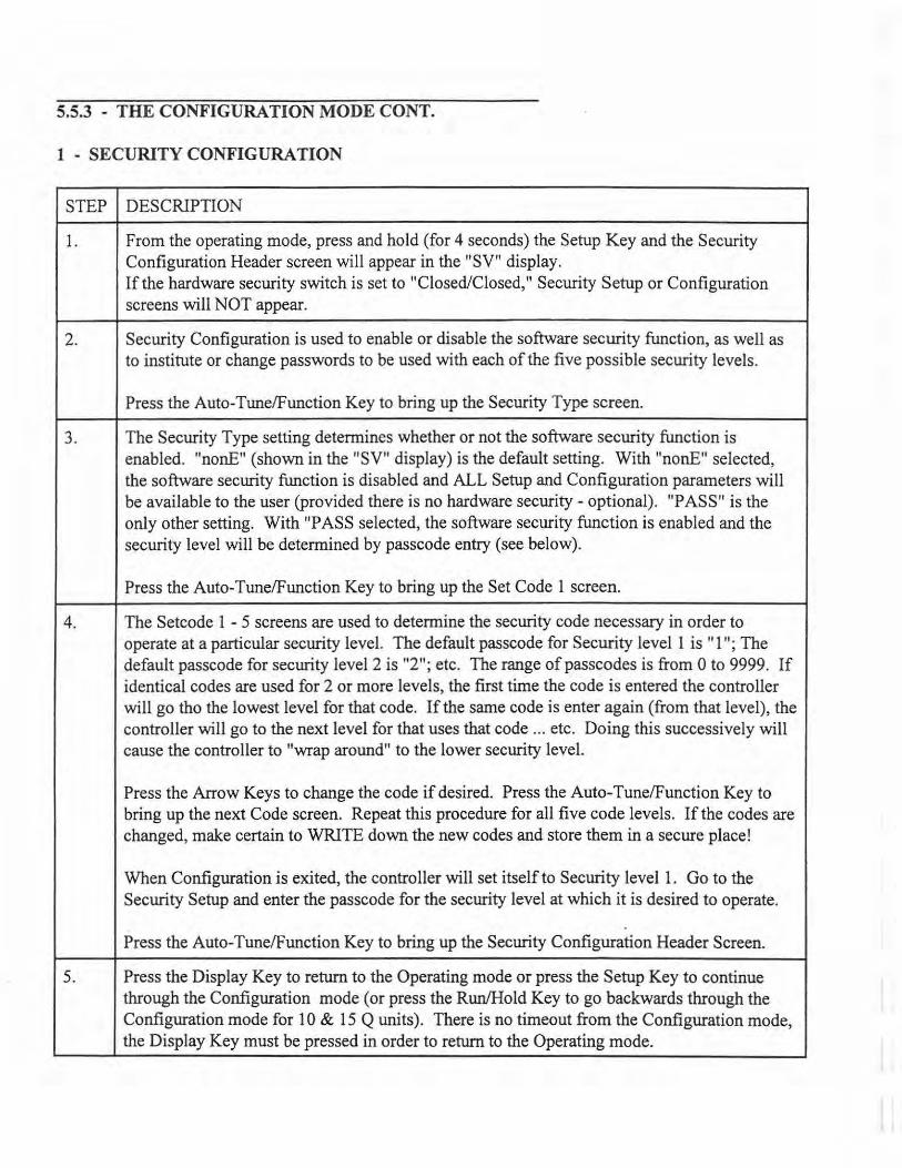
5.5.3 - THE CONFIGURATION MODE CONT.
1 - SECURITY CONFIGURATION
STEP DESCRIPTION
1. From the operating mode, press and hold (for 4 seconds) the Setup Key and the Security Configuration Header screen will appear in the "SV" display. If the hardware security switch is set to "Closed/Closed,'' Security Setup or Configuration screens will NOT appear.
2. Security Configuration is used to enable or disable the software security function, as well as to institute or change passwords to be used with each of the five possible security levels.
Press the Auto-Tune/Function Key to bring up the Security Type screen.
3. The Security Type setting determines whether or not the software security function is enabled. "nonE" (shown in the "SV" display) is the default setting. With "nonE" selected, the software security function is disabled and ALL Setup and Configuration parameters will be available to the user (provided there is no hardware security - optional). "PASS" is the only other setting. With "PASS selected, the software security function is enabled and the security level will be determined by passcode entry (see below).
Press the Auto-Tune/Function Key to bring up the Set Code 1 screen.
4. The Setcode 1 - 5 screens are used to determine the security code necessary in order to operate at a particular security level. The default passcode for Security level 1 is "1 "; The default passcode for security level 2 is "2"; etc. The range of passcodes is from 0 to 9999. If identical codes are used for 2 or more levels, the first time the code is entered the controller will go tho the lowest level for that code. If the same code is enter again (from that level), the controller will go to the next level for that uses that code ... etc. Doing this successively will cause the controller to "wrap around" to the lower security level.
Press the Arrow Keys to change the code if desired. Press the Auto-Tune/Function Key to bring up the next Code screen. Repeat this procedure for all five code levels. If the codes are changed, make certain to WRITE down the new codes and store them in a secure place!
When Configuration is exited, the controller will set itself to Security level 1. Go to the Security Setup and enter the passcode for the security level at which it is desired to operate.
Press the Auto-Tune/Function Key to bring up the Security Configuration Header Screen.
5. Press the Display Key to return to the Operating mode or press the Setup Key to continue through the Configuration mode (or press the Run/Hold Key to go backwards through the Configuration mode for 10 & 15 Q units). There is no timeout from the Configuration mode, the Display Key must be pressed in order to return to the Operating mode.
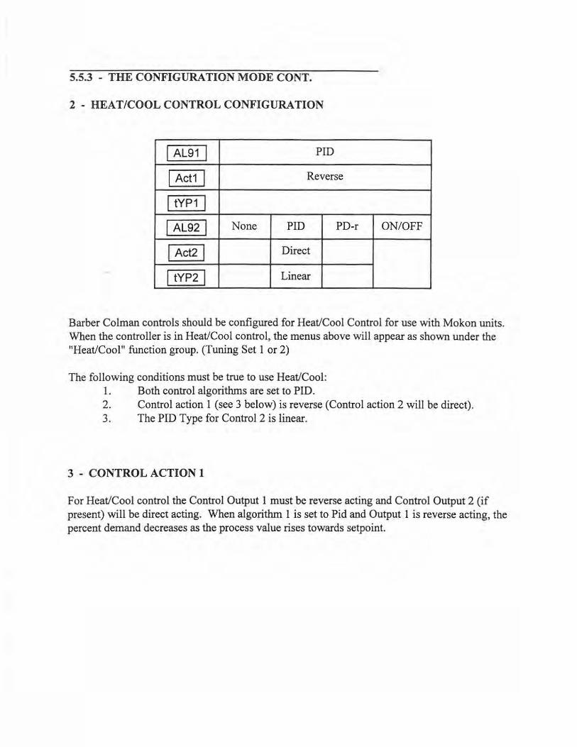
5.5.3 - THE CONFIGURATION MODE CONT.
2 - HEAT/COOL CONTROL CONFIGURATION
AL91 PID
Act1 Reverse
tYP1
AL92 None PID PD-r ON/OFF
Act2 Direct
tYP2 Linear
Barber Colman controls should be configured for Heat/Cool Control for use with Mokon units. When the controller is in Heat/Cool control, the menus above will appear as shown under the "Heat/Cool'1 function group. (Tuning Set 1 or 2)
The following conditions must be true to use Heat/Cool: 1. Both control algorithms are set to PID. 2. Control action 1 (see 3 below) is reverse (Control action 2 will be direct). 3. The PID Type for Control 2 is linear.
3 - CONTROL ACTION 1
For Heat/Cool control the Control Output 1 must be reverse acting and Control Output 2 (if present) will be direct acting. When algorithm 1 is set to Pid and Output 1 is reverse acting, the percent demand decreases as the process value rises towards setpoint.
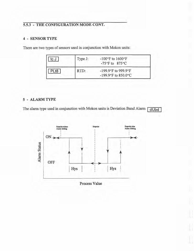
5.5.3 - THE CONFIGURATION MODE CONT.
4 - SENSOR TYPE
There are two types of sensors used in conjunction with Mokon units:
I tc J I Type J: -100°F to 1600°F -75°F to 875°C
I Plt8 I RTD: -199.9°F to 999.9°F -199.9°F to 850.0°C
5 - ALARM TYPE
The alarm type used in conjunction with Mokon units is Deviation Band Alarm I dUbd I
Sctpoint minUJ Alarm Setting
I : I I 1 ON> ..i;: 1
Sctpoinl
I I I I I I
r.ll I I ~ : I - y :
1 1 OFF r·._ _ ..__ ___ .. +--! • _ _._____r !
j Hys I
J Hys
Process Value
Sctpoinl plUJ
A~Sctting
I I

5.6 - DIGITAL COMMUNICATIONS
The following descriptions are for controllers which are equipped with optional digital communications.
PROTOCOL STRUCTURE
Command Not Supported When this bit is set to "1," it means that the command is not supported by the controller
Command Not Executed When this bit is set to "l," it means that the command requested was not executed or no action was taken. Reasons for this could be that the controller has been told not to perform the selected command, that the controller determined that executing the command would result in an unsafe condition, that the data was invalid or that there was a communication link error.
Invalid Preamble When this bit is set to" 1," it means that the preamble was in error, such as when an invalid RES byte or an invalid preamble length was received. This condition could result from a communication link error.
Communication Error When this bit is set to "1," it means the communication link experienced an error. This could result from a framing error, CRC error being undetected or a protocol violation.
Control Characters Since any of the 256 combinations of 8 bits may occur in data message, the controller must be able to distinguish between control characters and data. The control characters that can be recognized must always be a character sequence started with a DLE (lOh). When a DLE occurs in the data stream, the host computer must send a second DLE character immediately following the first. The controller will discard one of the DLE characters and treat them as data.
If the controller encounters DLE SYN (lOh 16h) within the data stream, it treats both as idle characters and discards both characters.
Security In normal operation, the controller has 5 different security levels which control the limits of the operator's actions. Digital communications are not limited by security level.
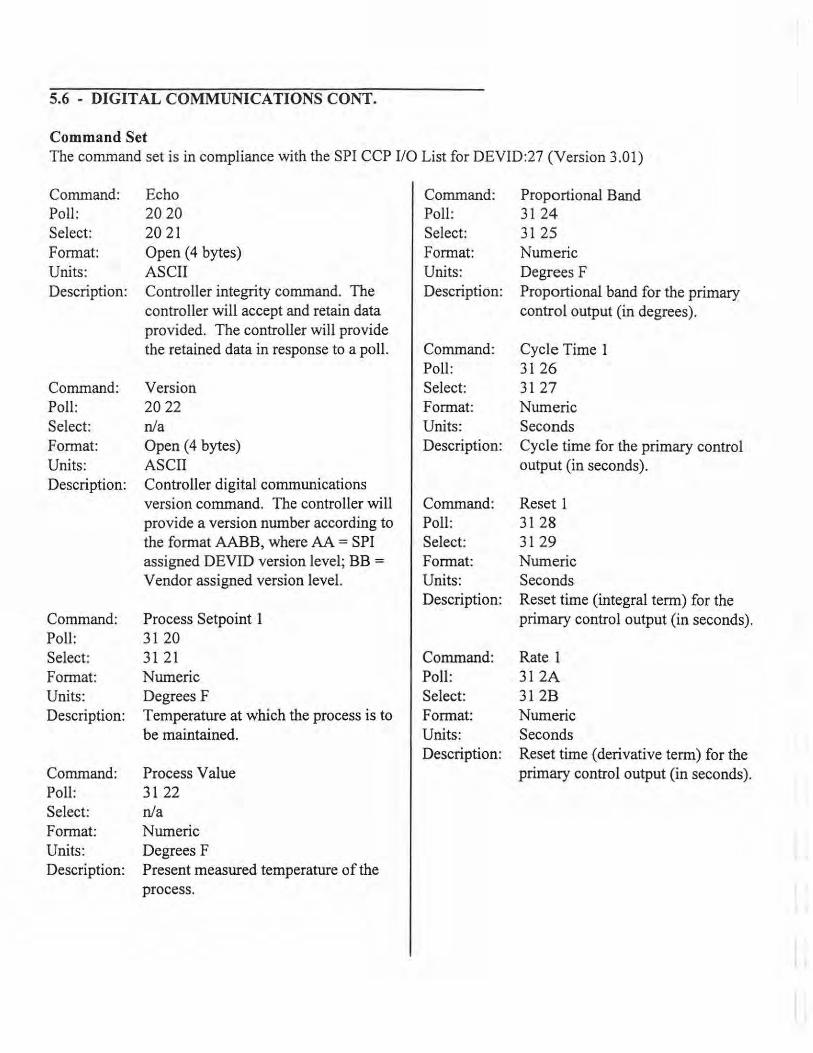
5.6 - DIGITAL COMMUNICATIONS CONT.
Command Set The command set is in compliance with the SPI CCP 110 List for DEVID:27 (Version 3.01)
Command: Poll: Select: Format: Units: Description:
Command: Poll: Select: Format: Units: Description:
Command: Poll: Select: Format: Units: Description:
Command: Poll: Select: Format: Units: Description:
Echo 20 20 20 21 Open ( 4 bytes) ASCII Controller integrity command. The controller will accept and retain data provided. The controller will provide the retained data in response to a poll.
Version 20 22 n/a Open ( 4 bytes) ASCII Controller digital communications version command. The controller will provide a version number according to the format AABB, where AA = SPI assigned DEVID version level; BB =
Vendor assigned version level.
Process Setpoint 1 31 20 31 21 Numeric Degrees F Temperature at which the process is to be maintained.
Process Value 31 22 n/a Numeric Degrees F Present measured temperature of the process.
Command: Poll: Select: Format: Units: Description:
Command: Poll: Select: Format: Units: Description:
Command: Poll: Select: Format: Units: Description:
Command: Poll: Select: Format: Units: Description:
Proportional Band 31 24 31 25 Numeric Degrees F Proportional band for the primary control output (in degrees).
Cycle Time 1 31 26 31 27 Numeric Seconds Cycle time for the primary control output (in seconds).
Reset 1 31 28 31 29 Numeric Seconds Reset time (integral term) for the primary control output (in seconds).
Rate 1 312A 312B Numeric Seconds Reset time (derivative term) for the primary control output (in seconds).
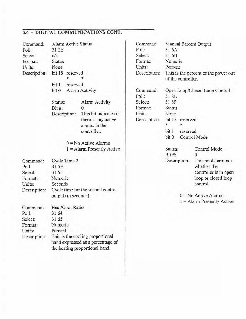
5.6 - DIGITAL COMMUNICATIONS CONT.
Command: Poll: Select: Format: Units: Description:
Command: Poll: Select: Format: Units: Description:
Command: Poll: Select: Format: Units: Description:
Alarm Active Status 31 2E n/a Status None bit 15 reserved
* * bit 1 bit 0
reserved Alarm Activity
Status: Bit#:
Alarm Activity 0
Description: This bit indicates if there is any active alarms in the controller.
0 =No Active Alarms 1 =Alarm Presently Active
Cycle Time 2 315E 31 SF Numeric Seconds Cycle time for the second control output (in seconds).
Heat/Cool Ratio 31 64 31 65 Numeric Percent This is the cooling proportional band expressed as a percentage of the heating proportional band.
Command: Poll: Select: Format:
Manual Percent Output 31 6A 31 6B Numeric
Units: Percent Description: This is the percent of the power out
of the controller.
Command: Poll: Select: Format: Units: Description:
Open Loop/Closed Loop Control 31 8E 31 8F Status None bit 15 reserved
* * bit 1 reserved bit 0 Control Mode
Status: Bit # :
Control Mode 0
Description: This bit determines whether the controller is in open loop or closed loop control.
0 =No Active Alarms 1 = Alarm Presently Active
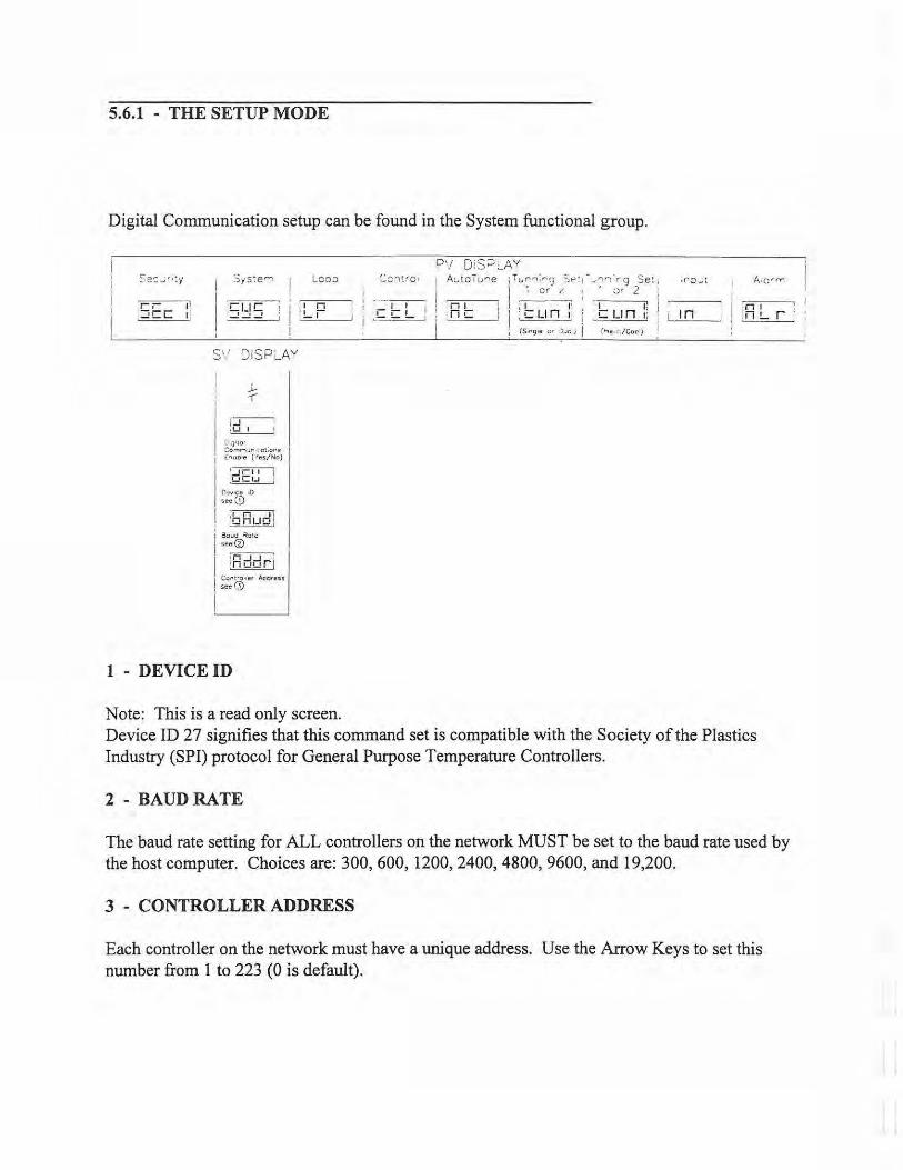
5.6.1 - THE SETUP MODE
Digital Communication setup can be found in the System functional group.
Sys:ern I
S" '.)!SPL_AY
I ~ ..,-I,.-, -II ~0 I I
L.;;•to• ::omr"'l: . .u•· • ot;ons
I! <~~~;~:cs/lo)
f\'!v•ce 10 see(!)
I ~ ' ..Q_fil!QJ '. Bovd ~o:e ! see@
!~ j 1nwor1
1 ;::R)·ter Aod1en
I
1 - DEVICE ID
Loop
Note: This is a read only screen.
P'/ DtS;:::i:_AY A~toTure jTt...in,..,;,.,(j s~- 1- .... '1~ ... g Se:
~-~ I ~- : · 0' 2
· H t: I I : t: u n :; i t: u n :! j {S.rtg;e ;;r J..ic ; / { '"' ~ V Coc )
I - , n-~ I ,-=n ,..,., , -......,:
~-~ , :n!....r · I
Device ID 27 signifies that this command set is compatible with the Society of the Plastics Industry (SPI) protocol for General Purpose Temperature Controllers.
2 - BAUDRATE
The baud rate setting for ALL controllers on the network MUST be set to the baud rate used by the host computer. Choices are: 300, 600, 1200, 2400, 4800, 9600, and 19,200.
3 - CONTROLLER ADDRESS
Each controller on the network must have a unique address. Use the Arrow Keys to set this number from 1 to 223 (0 is default).
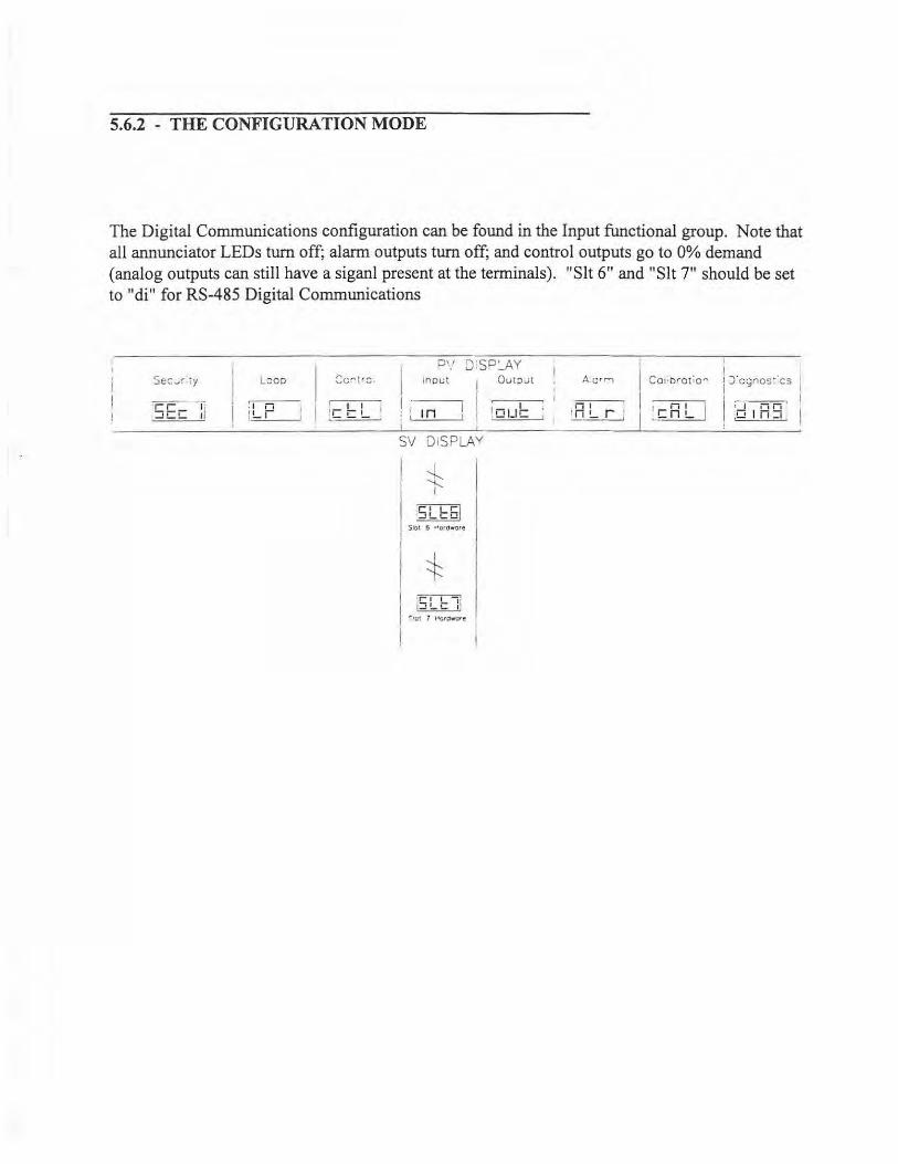
5.6.2 - THE CONFIGURATION MODE
The Digital Communications configuration can be found in the Input functional group. Note that all annunciator LEDs turn off; alarm outputs tum off; and control outputs go to 0% demand (analog outputs can still have a siganl present at the terminals) . "Slt 6 11 and "Slt 7" should be set to "di" for RS-485 Digital Communications
L:ico
· I I I
J!....r i-L ,1
~~ !__ -
P1.' o:sP:...AY I inoL:t I Out;:>ut
1:- - - 1 :' Jn I l n11~
I I · - - -I ' SV DISPLAY
S lot 6 ... crdwo'e I I
I * ' ~ , ~ I '"•ct 7 l"'QtClwore
'
i"i I ·n!.... r : _ _ ..=...c.___J
j Co;;brotio-
1 : t;J:iLJ I
I j )'cgnos:'cs
I I I II I
Dl n :i
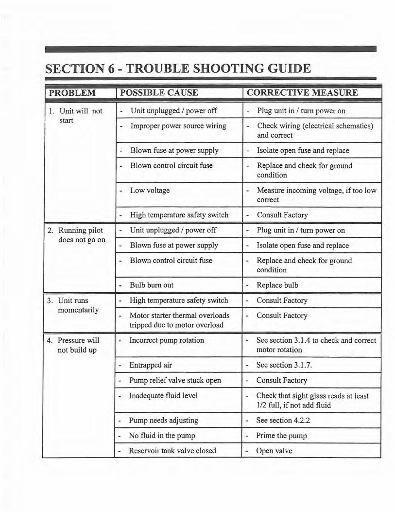
SECTION 6 - TROUBLE SHOOTING GUIDE
jPROBLEM I POSSIBLE CAUSE I CORRECTIVE MEASURE
1. Unit will not - Unit unplugged I power off - Plug unit in I turn power on start
Improper power source wiring Check wiring (electrical schematics) - -and correct
- Blown fuse at power supply - Isolate open fuse and replace
- Blown control circuit fuse - Replace and check for ground condition
- Low voltage - Measure incoming voltage, if too low correct
- High temperature safety switch - Consult Factory
2. Running pilot - Unit unplugged I power off - Plug unit in I turn power on does not go on
Blown fuse at power supply Isolate open fuse and replace - -
- Blown control circuit fuse - Replace and check for ground condition
- Bulb burnout - Replace bulb
3. Unit runs - High temperature safety switch - Consult Factory momentarily
Motor starter thermal overloads Consult Factory - -tripped due to motor overload
4. Pressure will - Incorrect pump rotation - See section 3 .1.4 to check and correct not build up motor rotation
- Entrapped air - See section 3.1.7.
- Pump relief valve stuck open - Consult Factory
- Inadequate fluid level - Check that sight glass reads at least 1/2 full, if not add fluid
- Pump needs adjusting - See section 4.2.2
- No fluid in the pump - Prime the pump
- Reservoir tank valve closed - Open valve
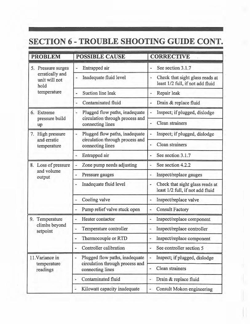
SECTION 6 - TROUBLE SHOOTING GUIDE CONT.
jPROBLEM I POSSIBLE CAUSE I CORRECTIVE
5. Pressure surges - Entrapped air - See section 3 .1 . 7 erratically and
Inadequate fluid level Check that sight glass reads at unit will not - -hold least 1 /2 full, if not add fluid
temperature - Suction line leak - Repair leak
- Contaminated fluid - Drain & replace fluid
6. Extreme - Plugged flow paths, inadequate - Inspect; if plugged, dislodge pressure build circulation through process and up connecting lines - Clean strainers
7. High pressure - Plugged flow paths, inadequate - Inspect; if plugged, dislodge and erratic circulation through process and temperature connecting lines - Clean strainers
- Entrapped air - See section 3.1.7
8. Loss of pressure - Zone pump needs adjusting - See section 4.2.2 and volume output - Pressure gauges - Inspect/replace gauges
- Inadequate fluid level - Check that sight glass reads at least 1/2 full, if not add fluid
- Cooling valve - Inspect/replace valve
- Pump relief valve stuck open - Consult Factory
9. Temperature - Heater contactor - Inspect/replace component climbs beyond
Temperature controller Inspect/replace controller setpoint - -
- Thermocouple or RTD - Inspect/replace component
- Controller calibration - See controller section 5
11. Variance in - Plugged flow paths, inadequate - Inspect; if plugged, dislodge temperature circulation through process and readings connecting lines - Clean strainers
- Contaminated fluid - Drain & replace fluid
- Kilowatt capacity inadequate - Consult Mokon engineering
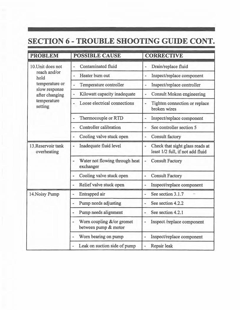
SECTION 6 - TROUBLE SHOOTING GUIDE CONT.
jPROBLEM I POSSIBLE CAUSE I CORRECTIVE
IO.Unit does not - Contaminated fluid - Drain/replace fluid reach and/ or
Heater burn out hold - - Inspect/replace component
temperature or -slow response
Temperature controller - Inspect/replace controller
after changing - Kilowatt capacity inadequate - Consult Mokon engineering
temperature - Loose electrical connections - Tighten connection or replace setting
broken wires
- Thermocouple or R TD - Inspect/replace component
- Controller calibration - See controller section 5
- Cooling valve stuck open - Consult factory
13 .Reservoir tank - Inadequate fluid level - Check that sight glass reads at overheating least 1/2 full, if not add fluid
- Water not flowing through heat - Consult Factory exchanger
- Cooling valve stuck open - Consult Factory
- Relief valve stuck open - Inspect/replace component
14.Noisy Pump - Entrapped air - See section 3 .1. 7 ...
- Pump needs adjusting - See section 4.2.2
- Pump needs alignment - See section 4.2.1
- Worn coupling &/or gromet - Inspect /replace component between pump & motor
- Worn bearing on pump - Inspect/replace component
- Leak on suction side of pump - Repair leak
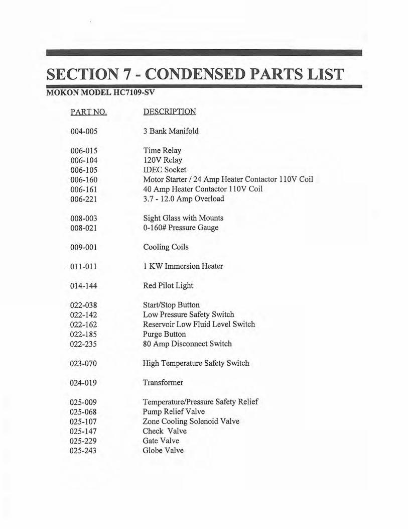
SECTION 7 - CONDENSED PARTS LIST MOKON MODEL HC7109-SV
PART NO.
004-005
006-015 006-104 006-105 006-160 006-161 006-221
008-003 008-021
009-001
011-011
014-144
022-038 022-142 022-162 022-185 022-235
023-070
024-019
025-009 025-068 025-107 025-147 025-229 025-243
DESCRIPTION
3 Bank Manifold
Time Relay 120V Relay IDEC Socket Motor Starter I 24 Amp Heater Contactor 11 OV Coil 40 Amp Heater Contactor 11 OV Coil 3.7 - 12.0 Amp Overload
Sight Glass with Mounts 0-160# Pressure Gauge
Cooling Coils
1 KW Immersion Heater
Red Pilot Light
Start/Stop Button Low Pressure Safety Switch Reservoir Low Fluid Level Switch Purge Button 80 Amp Disconnect Switch
High Temperature Safety Switch
Transformer
Temperature/Pressure Safety Relief Pump Relief Valve Zone Cooling Solenoid Valve Check Valve Gate Valve Globe Valve
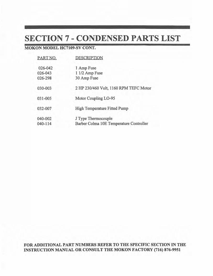
SECTION 7-CONDENSED PARTS LIST MOKON MODEL HC7109-SV CONT.
PART NO.
026-042 026-043 026-298
030-003
031-005
032-007
040-002 040-114
DESCRIPTION
1 Amp Fuse 1 1/2 Amp Fuse 30 Amp Fuse
2 HP 230/460 Volt, 1160 RPM TEFC Motor
Motor Coupling L0-95
High Temperature Fitted Pump
J Type Thermocouple Barber Colma 1 OE Temperature Controller
FOR ADDITIONAL PART NUMBERS REFER TO THE SPECIFIC SECTION IN THE INSTRUCTION MANUAL OR CONSULT THE MOKON FACTORY (716) 876-9951
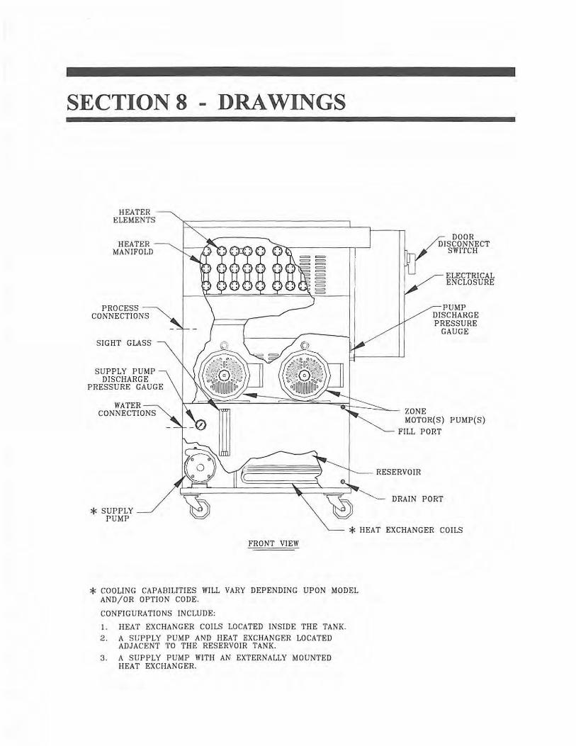
SECTIONS
HEATER ELEMENTS
PROCESS CONNECTIONS
SI GHT GLASS
SUPPLY PUMP DISCHARGE
PRESSURE GAUGE
* SUPPLY PUMP
DRAWINGS
ZONE
DOOR DISCONNECT
SWITCH
ELECTRICAL ENCLOSURE
PUMP DISCHARGE PRESSURE
GAUGE
MOTOR(S) PUMP{S)
FILL PORT
RESERVOIR
* HEAT EXCHANGER COILS
FRONT VIEW
* COOLING CAPABILITIES WILL VARY DEPENDING UPON MODEL AND/OR OPTION CODE.
CONFI GURATIONS INCLUDE:
1. HEAT EXCHANGER COILS LOCATED INSIDE THE TANK.
2. A SUPPLY PUMP AND HEAT EXCHANGER LOCATED ADJACENT TO THE RESERVOIR TANK.
3. A SUPPLY PUMP WITH AN EXTERNALLY MOUNTED HEAT EXCHANGER.
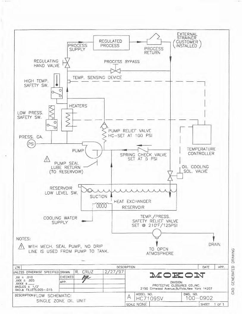
REGULATING HAND VALVE
HIGH TEMP. SAFETY SW.
LOW PRESS. SAFETY SW.
PRESS. GA.
l
PROCESS SUPPLY
HEATERS
PSI~------'--__,_--~
REGULATED PROCESS
PROCESS BYPASS
PROCESS RETURN
PUMP RELIEF VALVE HC-SET AT 100 PSI
-
EXTERNAL STRAINER
(CUSTOMER) INSTALLED
I I
I
I
I I I
TEMPERATURE CONTROLLER
ill PUMP SEAL ~
LUBE RETURN
SPRING CHECK VALVE SET AT 5 PSI
I OIL COOLI NG SOL. VALVE
NOTES:
(TO RESERVOIR)
RESERVOIR LOW LEVEL SW.
COOLING WATER SUPPLY
SUCTION --""<~""'--- HEAT EXCHANGER
RESERVOIR
TEMP./PRESS . SAFETY RELIEF VALVE SET @ 210"F/125PSI
Lt, WITH MECH. SEAL PUMP, NO DRIP LINE IS USED FROM PUMP TO TANK.
DRAIN
LTR
UNLESS OTHERWISE SPECIFIED DRAWN R. CRUZ .XX ± .010 .xxx ± .005 .xxxx ±_ ANGLES ± 1 /2° RAD.& FILLETS.005-.015
CHECKED
APP.
DESCRIPTION FLOW SCHEMATIC:
SINGLE ZONE OI L UNIT
DESCRIPTION
2 27 97
A
TO OPEN ATMOSPHERE
DIVISION
DATE
PROTECTIVE CLOSURES CO.,INC. 2150 Elmwood Avenue,Buffolo,New York 14207
MODEL NO. owe. No. HC7109SV 100-0902
APP.
SCALE NONE SHEET 1 OF 1
0 z :s: <{ (l:'.
0
0 w f<{ (l:'.
w z w 0
0 <{ u
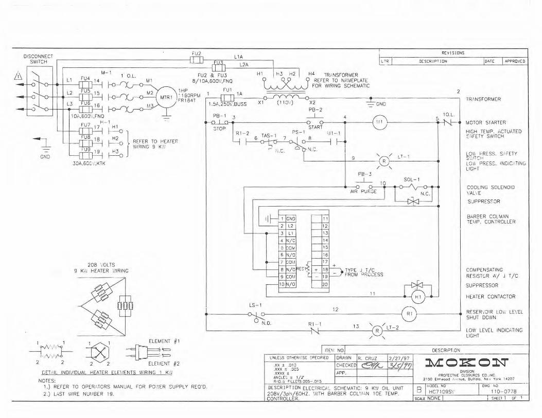
DISCONNECT SWITCH
M-1 1 O.L.
Ml
FIJ2
FU2 & FU3 8/ 1 OA,600\',FNQ
llA
l/A
REVISIONS
t!_R I DESCRIPTION JDAT[ I APPROVED I Hl I H3 H2 I H4 TRP-JSFORMER
Cf C(9 Cf REFER TO NA!AEPLATE
1HP 1160RP!A l'"R184T
FUl lA ~ FOR WIRING SCHEMATIC
2
X1 ( 11 :::r ) TRANSFORMER -GND
O• 600' ,FNQ 10.L. 1 '" H-1
FU7 17 A} LJ----l--..ITll H2
3TOP
X2 5 PB-2 ~
a1-o ~4 111 PS-1 3 START
+----o__Lo • PS-1 •,t 1-· 1 R1-2 TAS-1 7 ~8 I
MOTOR STARTER
HIGH TEMP. i:.CTUJ.TED ~:.FETY SWITCH
-i ~ REFER TO HEATH:: V'llRING 9 K !'
GND A 30A.6:JC ',KTK
208 ·.oLTS 9 K'., HEATER ·:.'IRING
1 1 -r\ .'. . ·\ ,. J--2 2 t8l
2 2
ELEMENT #1
~'= -=U-J=='- '=
EltttENT #2
CET IL INDl'/IDUAL HEATER ELWENTS WIRING 1 K .'i
NOTES: 1.) REFER TO OPER.; TCRS MANUAL FOR PO.'.'ER SUPPLY REO'D.
2.) L.,ST WIRE NUtlSER 19.
LT- 1 ~ , , I /:::-: _:.:_ ___ I ,... .. r ---+~9 ___ -Q-• Lv. / '. L0\11 1--R[SS. S FETY s·:.ncH L0'1\ PRESS. INOIC. TIN(, LIGHT
LS-1 12
N .O. Rl- 1
ITE'.I. NO
PB-3 _J_
AIR
TYPE .J T/C FROM PRCCESS
11
13 ' / '
SOL-1
Rl ';--~~~~~~~..i.
DESCRIPTION
COOLING SOLENOID \'AL':E
SUPPRES:JR
84ReER COLMAN TEI IP. CONTROLLER
COMPENSATING RESISTGR W/ J T/C
SUPPRESSOR
HEATER CONTACTOR
RESER·;J!R Lm. LE\'El SHUT DOWN
LOW LEVEL INDICi:.TING LIGHT
l'NLEoS QTH(R;•::sE ~P(CIFIEO I DRAWN 2/27/97 lv.I:OK:O~ .xx ± .:llo
.xxx ± .005
. xxxx ± ANCLE~ z 1/[ R D.!.: FILLETS.005- .015
CHECKED!
APP .
DE SCRI PT I ON ELECTR:C.t ~ SCHEMATIC: 9 KW OIL UNIT 208V /3ph/60HZ. \VITH BARBER CCU I :.N 1 OE TEMP. CONTROLLER.
DIVISION PROTECTIVE CLOSURES CO .. INC.
2150 (lmwood A ,,ue. Bvffolo. Ne • York 14207
r f•JOt'
B I HC7109S'.' I EL NO I OIYG '"' n._,,.. f.,0
110-0778
SCALE NONE SHEET 1 er 1
SECTION 9 - ONE YEAR WARRANTY
All new temperature control systems manufactured by the MOKON DIVISION OF PROTECTIVE CLOSURES CO., INC., are guaranteed to be free from defective material or workmanship for one ( 1) year from the date of purchase. MOKON'S obligation under the WARRANTY SHALL BE LIMITED, TO THE ORIGNAL CUSTOMER, TO REPAIR OR REPLACE DEFECTIVE PART(S) OF THE TEMPERATURE CONTROL SYSTEM, UPON CUSTOMER COMPLIANCE WITH THE INSTRUCTIONS CONTAINED HEREIN. Upon discovery of any alleged defect, it is the customer's responsibility to contact the MOKON Service Department with the complete model number, serial number and the date of purchase. The customer has the option to have a MOKON service technician come to its facilities if it issues a Purchase Order agreeing to pay for all reasonable transportation, food and lodging costs if the problem is not covered by this warranty. Repair and replacement in the manner provided above shall constitute a fulfillment of all liabilities ofMOKON concerning the quality of the temperature control system.
No allowances, credits or reimbursements will be made for any replacement or repair made or provided for by the customer unless authorized in advance, in writing, by the MOKON DIVISION.
THEW ARRANTY SET FORTH ABOVE IS IN LIEU OF ANY AND ALL OTHER WARRANTIES EXPRESS OR IMPLIED INCLUDING WARRANTIES OF MERCHANTABILITY AND FITNESS FOR A PARTICULAR PURPOSE. MOKON SHALL IN NO EVENT BE LIABLE FOR ANY CONSEQUENTIAL DAMAGES OR FOR ANY BREACH OF WARRANTY IN AN AMOUNT EXCEEDING THE ORIGINAL PRICE.
DATE _J_/__.7 f ___ Cf...,._J ___ _
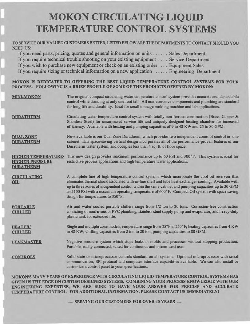
MOKON CIRCULATING LIQUID TEMPERATURE CONTROL SYSTEMS
TO SERVICE OUR VALUED CUSTOMERS BEITER, LISTED BELOW ARE TIIE DEPARTMENTS TO CONTACT SHOULD YOU NEED US:
If you need parts,· pricing, quotes and general information .on units . . . . . . Sales Department If you require technical trouble shooting on your existing equipment . . . . Service Department If you wish to purchase new equipment or check on an existing order . . . Equipment Sales If you require sizing or technical information ~n a new application . . . . . Engineering Department
MO KON IS DEDICATED TO OFFERING THE BEST LIQUID TEMPERATURE CONTROL SYSTEMS FOR YOUR PROCESS. FOLLOWING IS A BRIEF PROFILE OF SOME OF THE PRODUCTS OFFERED BY MOKON:
MINI-MO KON
DURATHERM
DUAL ZONE DURATHERM
The original compact circulating water temperature control system provides accurate and dependable control while standing at only one foot tall. All non-corrosive components and plumbing are standard for long life and durability. Ideal for small tonnage molding machine and lab applications.
Circulating water temperature control system with totally non-ferrous construction (Brass, Copper & Stainless Steel) for unsurpassed service life and uniquely designed heating chamber for increased efficiency. Available with heating and pumping capacities of9 to 48 KW and 25 to 80 GPM.
Now available is our Dual Zone Durathenn, which provides two independent zones of control in one cabinet. This space-saving vertical design incorporates all of the perfonnance-proven features of our Durathenn water system, and occupies less than 4 sq. ft. of floor space.
HIGHER TEMPERATURE/ This new design provides maximum perfonnance up to 60 PSI and 300°F. This system is ideal for HIGHER PRESSURE restrictive process applications and high temperature water applications. DURATHERM
CIRCULATING Q!L
PORTABLE CHILLER
HEATER/ CHILLER
LEAK MASTER
CONTROLS
A complete line of high temperature control systems which incorporate the cool oil reservoir that eliminates thennal shock associated with in-line shell and tube heat exchanger cooling. Available with up to three zones of independent control within the same cabinet and pumping capacities up to 30 GPM and 100 PSI with a maximum operating temperature of 600°F. Compact Oil system with space saving design for temperatures to 350°F.
Air and water cooled portable chillers range from 1/2 ton to 20 tons. Corrosion-free construction consisting ofnonferrous or PVC plumbing, stainless steel supply pump and evaporator, and heavy-duty plastic tank for extended life.
Single and multiple zone models; temperature range from 35°F to 250°F; heating capacities from 4 KW to 48 KW; chilling capacities from 2 ton to 20 ton; pumping capacities to 80 GPM.
Negative pressure system which stops leaks in molds and processes without stopping production. Portable, easily connected, suited for continuous and intennittent use.
Solid state or microprocessor controls standard on all systems. Optional microprocessor with serial communication, SPI protocol and computer interface capabilities available. We can also install or customize a control panel to your specifications.
MOKON'S MANY YEARS OF EXPERIENCE WITH CffiCULATING LIQUID TEMPERATURE CONTROL SYSTEMS HAS GIVEN US THE EDGE ON CUSTOM DESIGNED SYSTEMS. COMBINING YOUR PROCESS KNOWLEDGE WITH OUR ENGINEERING EXPERTISE, WE ARE SURE TO HA VE YOUR ANSWER FOR PRECISE AND ACCURATE TEMPERATURE CONTROL. FOR ADDITIONAL INFORMATION, PLEASE CONTACT US IMMEDIATELY!
- SERVING OUR CUSTOMERS FOR OVER 40 YEARS -