
Petroleum Development Oman LLC
35
Petroleum Development Oman L.L.C. SP-1103 Specification for Electrical Engineering Design Document ID SP-1103 Document Type Specification Security Unrestricted Discipline Electrical Owner UEE (CFDH-Electrical) Issue Date May-21 Version 9.1 Keywords: This document is the property of Petroleum Development Oman, LLC. Neither the whole nor any part of this document may be disclosed to others or reproduced, stored in a retrieval system, or transmitted in any form by any means (electronic, mechanical, reprographic recording or otherwise) without prior written consent of the owner.
-
Upload
khangminh22 -
Category
Documents
-
view
2 -
download
0
Transcript of Petroleum Development Oman LLC

Petroleum Development Oman L.L.C.
SP-1103
Specification for Electrical Engineering Design
Document ID SP-1103
Document Type Specification
Security Unrestricted
Discipline Electrical
Owner UEE (CFDH-Electrical)
Issue Date May-21
Version 9.1
Keywords: This document is the property of Petroleum Development Oman, LLC. Neither the whole nor any part of this document may be disclosed to others or reproduced, stored in a retrieval system, or transmitted in any form by any means (electronic, mechanical, reprographic recording or otherwise) without prior written consent of the owner.

Petroleum Development Oman LLC
Revision:9.1 Effective: May-21
Page 2 Specification for Electrical Engineering Design Printed 08/09/21
The controlled version of this CMF Document resides online in Livelink®. Printed copies are UNCONTROLLED.
This page was intentionally left blank

Petroleum Development Oman LLC
Revision:9.1 Effective: May-21
Page 3 Specification for Electrical Engineering Design Printed 08/09/21
The controlled version of this CMF Document resides online in Livelink®. Printed copies are UNCONTROLLED.
ii Document Authorisation
Authorised for Issue
Document Authorisation
Document Authority
(CFDH)
Document Custodian Document Reviewer
Haddabi, Salim UEE
Date : 07-01-2021 12:00 AM
Kindi, Nabil UEE3
Date : 07-01-2021 12:00 AM
Siyabi, Nada UEE32
Date : 07-01-2021 12:00 AM
User Note:
The requirements of this document are mandatory. Non-compliance shall only be authorised by the Document Owner or his Delegate through Variance Tracking Tool approval.
A controlled copy of the current version of this document is on PDO's EDMS. Before making reference to this document, it is the user's responsibility to ensure that any hard copy, or electronic copy, is current. For assistance, contact the Document Custodian or the Document Author.
Users are encouraged to participate in the ongoing improvement of this document by providing constructive feedback.

Petroleum Development Oman LLC
Revision:9.1 Effective: May-21
Page 4 Specification for Electrical Engineering Design Printed 08/09/21
The controlled version of this CMF Document resides online in Livelink®. Printed copies are UNCONTROLLED.
iii Revision History
The following is a brief summary of the 4 most recent revisions to this document. Details of all revisions prior to these are held on file by the issuing department.
Version No.
Date Author Scope / Remarks
Version 9.1
May 21 Al Siyabi, Nada UEE32
Updated with PDO Standard Electrical equipment requisition data sheets.
Version 9.0
Dec. 20
Al Siyabi, Nada UEE32
Updated & revised SP for supplement and amendment to international standards
Version 8.0
Dec. 19
Al Siyabi, Nada UEE32
Updated & revised SP with DEP rev
Version 4.0
Feb 06 Wim Moelker,UIE/1
Minor corrections/updates made
Version 5.0
Oct.,11 Saif Al Harthy, UIE/4
Updated clauses in line with latest issue of DEP. Reformatted as per latest PDO SP format
Version 6.0
Nov. 16
Naamani, Noora UIE44
Revised to harmonize with DEP Rev: Feb 2014.This has been a major technical revision and the changes are too numerous to list.
Version 7.0
Oct. 18 Naamani, Noora UIE44
Re-titled, reflect continuous improvement and address deviations.
iv Related Business Processes
Code Business Process (EPBM 4.0)
v Related Corporate Management System (CMS) Documents
The related CMS Documents can be retrieved from the Corporate Management System application CMS.

Petroleum Development Oman LLC
Revision:9.1 Effective: May-21
Page 5 Specification for Electrical Engineering Design Printed 08/09/21
The controlled version of this CMF Document resides online in Livelink®. Printed copies are UNCONTROLLED.
TABLE OF CONTENTS
ii Document Authorisation ................................................................................................ 3
iii Revision History ............................................................................................................. 4
iv Related Business Processes ......................................................................................... 4
v Related Corporate Management System (CMS) Documents ....................................... 4
1 INTRODUCTION ........................................................................................................... 7
1.1 PURPOSE................................................................................................................................... 7
1.2 APPLICABLE STANDARDS, SPECIFICATIONS AND CODES ................................................. 7
1.3 COMPLIANCE WITH STANDARDS ........................................................................................... 7
1.4 PRODUCT/ASSET WARRANTY ................................................................................................ 7
2 AMENDMENT / SUPPLEMENT .................................................................................... 8
2.1 SITE CLIMATIC AND INDOOR CONDITIONS ........................................................................... 8
2.2 OPERATIONAL SAFETY AND RELIABILITY ............................................................................. 8
2.3 PROTECTION AGAINST EXPLOSION AND FIRE HAZARDS................................................... 8
2.4 CERTIFICATES, DECLARATIONS AND TEST REPORTS.......................................................10
2.5 ELECTRICAL SYSTEM DESIGN ...............................................................................................10
2.5.1 Renewable Power Integration Study ........................................................................11
2.6 ELECTRICAL LOADS ................................................................................................................11
2.7 SYSTEM VOLTAGES , FREQUENCY AND POWER FACTOR ................................................13
2.8 EARTHING of ELECTRICAL EQUIPMENTS .............................................................................13
2.9 ELECTRICAL PROTECTION AND PREW SYSTEM .................................................................13
2.10 ELECTRICAL SCADA ................................................................................................................13
2.11 LV & HV SWITCHGEARS for all electrical equipment . .............................................................13
2.12 UPS REQUIREMENTS ..............................................................................................................14
2.13 ELECTRIC MOTORS .................................................................................................................14
2.14 ELECTRICAL NETWORK MONITORING AND CONTROL ( ENMCS) SYSTEM ......................15
2.15 CABLES, WIRES AND ACCESSORIES ....................................................................................15
2.16 OVERHEAD LINES ....................................................................................................................16
2.17 POWER AND INDUSTRIAL CONVENIENCE OUTLETS ..........................................................17
2. 17.1 Power Outlets (Substations) ..................................................................................................17
2. 17.2 Power Outlets (Plant Areas) ................................................................................................17
2. 17.3 Convenience Outlet .............................................................................................................17
2.18 GENERAL CABLING AND WIRING ..........................................................................................18
2.19 SIZING OF CABLES ..................................................................................................................18
2.20 UNDERGROUND CABLING ......................................................................................................18
2.21 CABLE MARKING / NUMBERING .............................................................................................18
2.22 HAZARDOUS AREA CABLE GLANDS .....................................................................................18
2.23 EARTHING AND BONDING ......................................................................................................19

Petroleum Development Oman LLC
Revision:9.1 Effective: May-21
Page 6 Specification for Electrical Engineering Design Printed 08/09/21
The controlled version of this CMF Document resides online in Livelink®. Printed copies are UNCONTROLLED.
2.24 INDOOR SUBSTATIONS, SWITCHROOMS AND BATTERY ROOMS .................................... 19
2.25 TESTING AND COMMISSIONING ............................................................................................ 20
2.26 PAINTING AND COATING OF ELECTRICAL EQUIPMENTS ................................................... 20
2.27 TEMPORARY ELECTRICAL INSTALLATIONS and drilling rig power supply ........................... 21
2.28 EQUIPMENT AND CABLE NUMBERING .................................................................................. 21
2.29 SAFETY EQUIPMENTS ............................................................................................................ 21
2.30 POWER TRANSFORMERS....................................................................................................... 21
2.31 RENEWABLE ENERGY ............................................................................................................ 22
2.32 LIGHTING DESIGN ................................................................................................................... 22
APPENDIX -1 AC & DC Standards Voltages ...........................................................................23
APPENDIX -2 ELECTRICAL SUPPLY OF DCS/FCS PREW SYSTEMS ..............................25
APPENDIX -3 ANCILLARY ITEMS FOR SUBSTATIONS .......................................................26
APPENDIX -4 ELECTRICAL INSTRUMENT INPUT /OUTPUT SCHEDULE ..........................28
APPENDIX -5 ELECTRICAL EQUIPMENT REQUISITION DATA SHEETS ...........................29
APPENDIX A, REQUIRE ILLUMINATION LEVEL .....................................................................30
APPENDIX B, GLOSSARY of DEFINITIONS, TERMS and ABBREVIATIONS ........................32

Petroleum Development Oman LLC
Revision:9.1 Effective: May-21
Page 7 Specification for Electrical Engineering Design Printed 08/09/21
The controlled version of this CMF Document resides online in Livelink®. Printed copies are UNCONTROLLED.
1 INTRODUCTION
1.1 PURPOSE
This SP is an amendment/supplement to international standards and PDO electrical equipment standard data sheets. It contains additional and or modified requirements specific to the Company and shall be used in conjunction with the electrical international standards.
1.2 APPLICABLE STANDARDS, SPECIFICATIONS AND CODES
All electrical standards; specifications, procedures, codes and guidelines shall be consulted when applying the requirements of this standard. All listed documents shall be latest issue except those prescribed by date.
1.3 COMPLIANCE WITH STANDARDS
Any deviation from this specification shall process deviations to requirements in accordance to procedure PR-2066.
In all cases, the Company shall determine the adequacy of Works executed by the Contractor in accordance with this Specification. For DEM-1 requirement, reference shall be made to SP-2388 and PDO DEM-1 tool.
1.4 PRODUCT/ASSET WARRANTY
The equipment shall be guaranteed to meet specified technical specifications, requisitions and datasheets. These guarantees and particulars shall be binding and shall not be varied without the written permission of the Company's Representative. Any deviation, concerning both requirements and recommendations shall be identified in writing at the time of quotation.
If the guaranteed performance of the equipment is not met and/or if any component fails to comply with the specification requirement in any respect whatsoever at any stage of manufacture, test, erection, or operation phase the Company may reject the equipment, or defective component and after adjustment or modification as directed by the Company's Representative, the Vendor shall submit the item for further inspection and/or test.
All repair procedures shall not be performed without the prior approval of the Company's Representative. In the event of a defect on any item being of such a nature that the specification requirements cannot be fulfilled by adjustment or modification, such item shall be replaced by the Vendor, at his own expense to the entire satisfaction of the Company's Representative. Equipment repaired to an approved procedure shall not be accepted as a permanent solution or replacement unless the Vendor guarantees in writing that the repaired plant or component shall have the same service life and efficiency as the component originally manufactured.
The Vendor shall also warrant all equipment and component parts against defective material, design and /or workmanship. Merely extending a Sub-Vendor’s warranty is not acceptable.
The approval of the Company's Representative of inspection and/or test results will not prejudice the right of the Company's Representative to reject an item of equipment if it does not comply with the contract document when erected or prove completely satisfactory in service.
Product/asset warranty shall further refer to the requirement as specified in the commercial package of the contract document.

Petroleum Development Oman LLC
Revision:9.1 Effective: May-21
Page 8 Specification for Electrical Engineering Design Printed 08/09/21
The controlled version of this CMF Document resides online in Livelink®. Printed copies are UNCONTROLLED.
2 AMENDMENT / SUPPLEMENT
2.1 SITE CLIMATIC AND INDOOR CONDITIONS
Equipment installed indoor or outdoor shall be designed for operation in environmental conditions as specified in SP-2200 and the selection must be based on the highest figures indicated in the SP regardless area of the location north or south.
2.2 OPERATIONAL SAFETY AND RELIABILITY
Electrical Safety Rules (ESRs) shall be in accordance with PR-2331, Electrical Safety Rules Guideline Gu-861 and Electrical Safety Operating Procedures GU-892.
▪ Design integrity checks shall be carried out at agreed phases of a project. This include review of tenders document that has electrical engineering input as scope of work.
The design integrity checks shall focus on and highlight the following aspects: -
▪ Adherence to standards
▪ Deviation from standards
▪ Approval deviations from standards
▪ Operational Safety and reliability
▪ Interchangeability within the project or with existing equipment.
The integrity and standard compliance checks shall be carried out through.
▪ DCAF
▪ Electrical design review, or
▪ A SAFOP study, as described in SP-1145
2.3 PROTECTION AGAINST EXPLOSION AND FIRE HAZARDS
The following shall be considered;
▪ Substations and control rooms shall be located in non- hazardous areas.
▪ IEC 60079-7, IEC 60079-14, IEC 60079-15 and IEC 60079-17 shall be used for protection rating.
▪ Hazardous area classification drawing and HAC schedule shall be referred prior selection of electrical equipments.
▪ The equipment shall have Ex labelling details.
▪ Install the electrical equipments based on their area of classification.
▪ All components inside the electric motor correspond to the temperature class for which the motor has been approved.
▪ Identify with specific nameplate of the electrical equipments installed in Zone-1 and Zone- 2 areas to avoid improper/wrong replacements.
▪ Identify all the indoor areas where standard industrial light fittings can be installed instead of flameproof equipment.
▪ For the purpose of commonality of spares and to cater the possibilities of reclassification of areas, the same equipment suitable for use in zone 2 or zone 22 locations shall be

Petroleum Development Oman LLC
Revision:9.1 Effective: May-21
Page 9 Specification for Electrical Engineering Design Printed 08/09/21
The controlled version of this CMF Document resides online in Livelink®. Printed copies are UNCONTROLLED.
installed within process installations in non-hazardous area e.g. motors, RCUs, power and convenience outlets…etc.
Type of Zone Type of Electrical Equipment
Zone-1 Ex type approved for Zone-1
Zone-2 Ex type approved for Zone-2
Utilities area inside process facilities Ex type approved for Zone-2
Non Hazardous Standard Industrial weatherproof type
Indoor Area Industrial except battery and Chemical Storage Rooms.
▪ Equipment in Zone 1 areas:
1. Inherently non-sparking equipment (e.g., junction boxes, terminal boxes and luminaires) shall have type of protection 'eb'.
▪ Equipment in Zone 2 areas:
1. Inherently non-sparking equipment (e.g. junction boxes, terminal boxes and luminaires) shall meet one of the following:
a. protection type 'ec';
b. be approved for use in a Zone 1 area.
2. Inherently sparking equipment (e.g. EHT DB) shall have type of protection 'd' .
3. Motors shall have one of the following types of protection:
a. ‘ec’ (“non sparking”) in accordance with IEC 60079-7;
b. ‘n’ in accordance with IEC 60079-15:2010, until IEC 60079-15:2010 is withdrawn.
4. Where motors in accordance with IEC 60079-7, with a rated output in excess of 100kW, are selected for Zone 2 areas for duties other than S1, S2, S6 or S9, they SHALL [PS] have successfully passed the tests in accordance with clause 6.2.3.2 of IEC 60079-7.
5. Where motors in accordance with IEC 60079-15:2010, with a rated output in excess of 100kW, are selected for Zone 2 area for duties other than S1 or S2, they SHALL [PS] have successfully passed the tests in accordance with clause 22.13.1 of IEC 60079-15:2010
▪ Combustible dust hazards:
Unless otherwise specified by the COMPANY, IEC 60079-10-2 shall be used for area classification drawings. Meticulous care is taken to ensure that the temperatures of the motor surfaces, on which dust can accumulate, remain below the temperatures stated in the Standard. Special seals on cables and terminal boxes prevent the penetration of dust.

Petroleum Development Oman LLC
Revision:9.1 Effective: May-21
Page 10 Specification for Electrical Engineering Design Printed 08/09/21
The controlled version of this CMF Document resides online in Livelink®. Printed copies are UNCONTROLLED.
2.4 CERTIFICATES, DECLARATIONS AND TEST REPORTS
All electrical equipment (Generators, bus duct, power transformer, OHL structures and accessories, motors, VFD, UPS, Switchboards, capacitor banks, reactors, power cables, busbars …etc) shall have type test to international IEC standards. Declaration of compliance shall cover both main and auxiliary equipment. Further certificates or declarations relating to the application of equipment for use in hazardous areas may be required by COMPANY to which standard the equipment conforms.
2.5 ELECTRICAL SYSTEM DESIGN
The design of the electrical facilities shall meet the specific design criteria, philosophy and/or objective stated in the project definition phase, e.g., in the basis of design document or project specification, relating to a particular plant or facility. Reference to be made to PR-1265 and SP 2199.
The conceptual designs and philosophies relating to the electrical system shall be documented by a system design description, a key line diagram, basic layout drawings and functional/outline specifications
System studies and protection reports, including software native files, shall be provided in support of the design, for approval by the principle :
a. depending on the type, size and complexity of the installation, such studies may comprise the following taken into consideration SP 1265 requirement:
i. Load flow studies;
ii. Short circuit studies complying with IEC 60909 Parts 0, 1, 2, 3, 4;
iii. System dynamic stability and transient stability studies
iv. Protection grading studies, including relay setting schedules; relay files and relay file converter for stationware , an arc flash study should be carried out for low voltage switchboards and for high voltage switchboards only if the protection grading studies show that arcing faults cannot be cleared within the Internal Arc Classification time of the switchgear;
v. Harmonic analysis studies include harmonic and power quality site measurement.
vi. Motor re-starting and re-acceleration;
vii. Vital Supply recovery following total power failure, including emergency diesel generator(s), UPS, instrumentation critical loads, DCS, SCADA...etc.
The following are the approved softwares to carry out electrical design:
➢ PowerFactory DIgSILENT for power system analysis, (steady
state, transient, EMT, Harmonics, reliability) ➢ PLS-CADD Power Line Systems for overhead power line
design, ➢ CYMCAP for HV Cable sizing, ➢ CYMGRD, Substation Grounding Program. ➢ DIgSILENT StationWare for central protection settings
database and asset management system, ➢ PV syst. for solar power studies
Petroleum Development Oman LLC
Revision:9.1 Effective: May-21
Page 11 Specification for Electrical Engineering Design Printed 08/09/21
The controlled version of this CMF Document resides online in Livelink®. Printed copies are UNCONTROLLED.
➢ Helioscope ( Web base app) for solar power studies ➢ Windy Pro used for wind power.
2.5.1 Renewable Power Integration Study
Renewable energy is one of the main focus area for such transition where the company is targeting to play good part in the coming years. PDO aspiration is built from the high renewable energy resources in Oman especially in terms of year-round solar irradiation intensity and strong wind potential. These location advantages, alongside favourable seawater temperatures and topographical features across the length of the country provide for the potential to generate further renewable sources ranging from green hydrogen to macro-algae and bio-fuel developments.
In order to understand the integration challenges and have a good project plan and evaluate the impact in integrating renewable into the grid, Renewable integration studies must be considered to understand how to economically integrate variable generation of energy on the electric grid.
A grid integration study (analytical framework used to evaluate a power system with high
penetration levels of variable renewable energy (RE)). Generally, a grid integration study:
a. Simulates the operation of the power system under different variable RE scenarios;
b. Identifies reliability constraints; and
c. Evaluates the cost of actions to alleviate those constraints.
d. Understand the grid code.
e. Study the generation project grid compliance.
The variable RE scenarios in a grid integration study establish where, how much, and over what
timeframe to build generation and transmission capacity, ideally capturing the spatial diversity
benefits of wind and solar resources. The results help build confidence among policymakers,
system operators, and investors to move forward with plans to increase the amount of VRE on
the grid.
For on-grid solar PV installation, reference shall be made to IEC-61853 series and for off grid
solar PV installation refer to IEC-61427. When it comes to the PV modules, Company prefer to
utilize tair ONE manufacturer as per Bloomberg ranking. However, for wind power integration,
refer to IEC-61400 series.
2.6 ELECTRICAL LOADS
Electrical loads shall be classified as performing a service, which is 'vital', 'essential', or 'non-essential'. A schedule of the installed electrical loads, the maximum normal running plant load and the peak load, expressed in kilowatts and kilovars and based on the plant design capacity when operating under the site conditions specified, shall be prepared using standard electrical load list format. The schedule of installed electrical loads shall be prepared and updated throughout the design phases of the project and will form the basis for provision of the necessary electricity supply and distribution system capacity. During the ASSESS and SELECT phases of a project development, a separate allowance shall be made to account for an increase in the electrical load owing to uncertainties in the process.
The formulae used for determining the total electrical loads as below

Petroleum Development Oman LLC
Revision:9.1 Effective: May-21
Page 12 Specification for Electrical Engineering Design Printed 08/09/21
The controlled version of this CMF Document resides online in Livelink®. Printed copies are UNCONTROLLED.
- Maximum normal running plant load = x(%)E + y(%)F
- Peak load = x(%)E + y(%)F + z(%)G
where E = sum of all continuously operating loads
F = sum of all intermittent loads
G = sum of all stand-by loads
x, y and z are diversity factors
The load growth allowance and values of the diversity factors (x, y, and z) shall be appropriate to the type of plant and determined by the CFDH-E .The values of the diversity factors (x, y and z) shall take account of the individual drives or consumers which make up the continuous, intermittent and stand-by loads, respectively. For example, y(%)F or z(%)G cannot be less than the largest individual intermittent or stand-by drive or consumer.
The various loads shall be classified as follows:
E - "Continuous" All loads that may continuously be required for normal operation, including lighting and workshops
F - "Intermittent" Loads required for intermediate pumping, storage, loading, etc.
G -"Stand-by" All loads required in emergencies only, such as fire-water pumps or those of normally not running electrically driven units in stand-by mode for normally running steam-driven ones, e.g. charge pumps, boiler feed pumps, etc.
Spare pumps etc., e.g. the “B” pump of an A-B combination, are not to be considered as “Stand-by” loads.
Care must be taken even though not to be considered as stand-by loads, the largest motor of the spare duty shall be considered in the motor start studies with the duty motor running.
The following default values may be used for initial load assessments, or if the diversity factors have not been finalised:
a. x = 100%.
At rated plant throughput all driven equipment is assumed to be operating at its duty point. However, some diversity may be applied to non-process loads, e.g., offices and workshop power and lighting, typically 90%.
b. y = 30%.
c. z = 10%.
A separate schedule shall be prepared for each switchboard, the total of all switchboard loads being summarised as required to arrive at the maximum normal running and peak loads for each substation and for the plant overall.
All loads to be automatically restarted after a voltage dip shall be identified as such in the 'restarting' column.
Where a group of drives operate as a unit, it shall be considered as an individual consumer.
In addition , the length and size of the load cables must be included during the load list schedule preparation in order to have full picture during the design requirement especially on the switchboard feeders as per the standards load list format .

Petroleum Development Oman LLC
Revision:9.1 Effective: May-21
Page 13 Specification for Electrical Engineering Design Printed 08/09/21
The controlled version of this CMF Document resides online in Livelink®. Printed copies are UNCONTROLLED.
2.7 SYSTEM VOLTAGES , FREQUENCY AND POWER FACTOR
▪ System voltages and frequency, supply variations and equipment operating voltages as per Appendix 2 of this SP.
▪ The use of non-standard voltages shall be subject to the approval by the COMPANY.
▪ For total harmonic distortion (THD) and individual harmonic voltage reference shall be made to IEC 61000-3-6 ;
THD for system voltages up to 36 kV shall not exceed 6.5%;
THD for system voltages higher than 36 kV shall not exceed 3%.
Note must be taken that equipment, which produces a continuous DC component in the AC supply system, shall not be utilised.
The overall system power factor, inclusive of reactive power losses in transformers and other distribution system equipment, should not be less than 0.8 lagging at rated design throughput of the plant. The requirement for power factor correction shall be agreed with the CFDH-E at the DEFINE phase of the project. the method selected depends on reliability and economic consideration.
2.8 EARTHING of ELECTRICAL EQUIPMENTS
Reference shall be made to SP-1109.
2.9 ELECTRICAL PROTECTION AND PREW SYSTEM
Reference shall be made to SP-1107.
2.10 ELECTRICAL SCADA
Reference shall be made to SP-1106.
2.11 LV & HV SWITCHGEARS for all electrical equipment .
▪ Reference shall be made to SP-1121 for LV switchgears and SP-1120 for HV switchgears.
▪ Reference shall be made to LV and HV PDO standard switchgear data sheets (refer to Appendix-5).
▪ Reference shall be made to PMR PDO standard data sheets (refer to Appendix-5).
▪ VESDA system shall not be implemented due to reliability issues.
▪ Under voltage release shall be provided for all Motors controlled by circuit breaker and OHL feeders with process SIL requirement.
▪ For Low voltage motor control center facility for voltage dip ride through & Auto restart function shall be provided. This should be coordinated with process and control and automation disciplines.
▪ For HV motors feeders instant current and voltage waveforms per phase should be also mapped through System 1 Condition Monitoring Software or any installed diagnostic software used for the machine.

Petroleum Development Oman LLC
Revision:9.1 Effective: May-21
Page 14 Specification for Electrical Engineering Design Printed 08/09/21
The controlled version of this CMF Document resides online in Livelink®. Printed copies are UNCONTROLLED.
▪ Fault disturbance recorders and power quality meter with GPS time synchronization shall be provided for each switchboard. The system shall be connected to centralize server and accessible to client PC for data analysis.
▪ Breakers feeding capacitor banks and reactors, generator breakers shall have design consideration for switching transient and should be verified through design simulation and calculation.
▪ For Standard Electrical Instrument input output schedule, refer to Appendix -5.
▪ All switchgears including DB, Arc Flash level Label must be fixed on the switchgear.
▪ 6.6kV and 11kV switchgear shall have their control supply fed from UPS.
▪ LV motor switchgear motor control center ,control supply shall be as per SP1107
▪ Requisition shall include but not limited to include provision of OEM settings ,OEM Operation and maintenance manuals, Bill of material , schematic and SLDs , special tools or software require and OEM operation and maintenance training .
2.12 UPS REQUIREMENTS
▪ UPS equipment shall be selected according to the arrangements for AC and DC uninterruptible, maintained electricity supplies for process control and safeguarding systems.
▪ Uninterruptible, maintained electricity supply distribution switchboards and the associated UPS units should be located as close as possible to the loads supplied.
▪ The maximum size of fuses or MCCBs used should take into account the limited short circuit output of the UPS and the design intent to avoid switching to Bypass to clear large faults.
▪ Altra Low Maintenance Batteries shall be used in all new Uninterruptible Power Supply Units (UPSs) and Battery chargers.
▪ Reference shall be made to IEC 62040 for UPS system and taking into account the design class UPS system shall consider redundant design and following UPS electrical &instrument input /output schedule listed in appendix-4
▪ UPS requisition shall include but not limited to include provision of OEM settings OEM installation procedures Operation and maintenance manuals, Bill of material , schematic and SLDs , special tools or software require and OEM operation and maintenance training .
▪ Reference shall be made to DC and AC UPS PDO standard data sheets (refer to Appendix-5).
2.13 ELECTRIC MOTORS
▪ Design of electric motors shall be as per IEC 60034. Frame sizes shall be as per IEC 60072-1 and IEC 60072-2.
▪ Reference shall be made to PDO standard LV, HV, synchronous motors data sheets (refer to Appendix-5).
▪ Interchangeability of new motors with existing motors shall be considered during the design.
▪ RCUs shall normally be installed on suitable steel supports adjacent to the motor they control. Where RCUs cannot be installed in the immediate vicinity of the motor. The control, Safety switch shall be mounted near the motor. This applies, for instance, for fin fan and cooling tower motors, where RCUs shall be located at grade level.

Petroleum Development Oman LLC
Revision:9.1 Effective: May-21
Page 15 Specification for Electrical Engineering Design Printed 08/09/21
The controlled version of this CMF Document resides online in Livelink®. Printed copies are UNCONTROLLED.
▪ All RCUs shall have built-in ammeters except if the ammeter operationally not required
▪ No RCU for controlling motorised valves.
▪ If Motors are at ground level, the safety switch is not required.
▪ Induction motors less than or equal to 12 MW shall be considered as first option unless there is process or electrical system constraint requirements, then synchronous motors could be selected.
▪ requisition shall include but not limited to include provision of OEM settings , OEM installation procedures ,OEM Operation and maintenance manuals , Bill of material , schematic and SLDs , special tools or software require and OEM operation and maintenance training .
2.14 ELECTRICAL NETWORK MONITORING AND CONTROL ( ENMCS) SYSTEM
The system solution centralizes monitoring data, control, disturbance recording and data collection providing a window into the system for analysis and reporting through an integrated network of metering and protection devices across a single or multiple facility locations.
Interface with C&A, IT and telecom , cybersecurity teams should be recognized as early stage of the project to cover design of control systems – conceptual to detailed hardware and software design selection.
▪ Fully Redundant Configuration ( NO SINGLE POINT OF FAILURE )
▪ Open Systems (Support various manufacturer of Hardware , Software and Communications)
▪ The full system shall have integrated FAT and SAT verification
▪ Reference shall be made to SP-1120 section 2.14
▪ ENMCS to be considered for large scale plants or sour over 200 drives.
2.15 CABLES, WIRES AND ACCESSORIES
▪ Reference shall be made to GU-920 and GU -971
▪ Paper insulated lead-sheathed cables shall not be used.
▪ Armoured cables shouldn’t be selected inside substations.
▪ For LV cables, vendor should specified the type of glands (insulated /none insulated) can be used especially for process heater application.
▪ PVC insulation instead of XLPE for 1.1kV grade LV Cable
1. PVC cables (LV and Control) for indoor installations interconnecting the panels within the building where the rooms are air-conditioned.
2. All cables (LV and Control) installed outdoor or interconnecting outdoor to indoor panels shall be of XLPE type.
▪ The colour of outer sheath of HV cables shall be as per IEC 60502 and the outer sheath of LV cables shall be black or grey.
▪ Above ground cabling shall be considered in new projects and evaluated against the underground.

Petroleum Development Oman LLC
Revision:9.1 Effective: May-21
Page 16 Specification for Electrical Engineering Design Printed 08/09/21
The controlled version of this CMF Document resides online in Livelink®. Printed copies are UNCONTROLLED.
▪ For brown field projects, cable sizing should take into consideration the existing system cabling for better design output.
▪ Utility trench tent or suitable protection cover shall be used in all circumstances wherever cable termination or cable joint work is carried out in the outdoor irrespective of the weather conditions. The termination or joint shall be made in dust free, moisture free and clean atmosphere.
▪ Earthing arrangement during the design must be considered (single versus multi earthing).
▪ In case cable with HDPE outer sheath is not available, copper or aluminium armoured cable with copper screening and PVC outer sheath shall be used.
▪ Reference shall be made to cable Termination kit PDO standard data sheet (refer to Appendix-5).
2.16 OVERHEAD LINES
▪ Wooden poles for overhead lines shall not be used.
▪ Using rod gaps (arcing horn) on the disconnectors shall not be allowed and shall provide surge arresters instead. The existing facilities shall be modified to meet this requirement.
▪ Autoreclosures shall be provided with covers & sleeve to prevent short circuits resulted from bird strike and be supplied from nearest fixed installation rather than from VTs.
▪ PMRs shall have the control circuit approved scheme– D owe have datasheet and standardized scheme
▪ Jumpers shall be insulated including jumpers for spur lines.
▪ All Tap off connection in 33kV system, jumper shall be sleeved, refer to STD STD-00-000000-EA-2580-91502-0002 & STD-00-000000-EA-4180-91502-0001.
▪ Underground cables for road crossings shall be avoided.
▪ Installation of fault passage indicator (FPI) for 33 kV distribution system is mandatory to identify the faulty section of the network and restore power supplies in the shortest possible time.
▪ Live Line Work (LLW) is more hazardous for personnel than working on electrical equipment with the power switched off, it is therefore not default way of work to carry out electrical tie-in to live electrical system and it is only allowed to avoid the disruption and high economic costs of having to turn off power to large facilities to perform essential periodic maintenance on up to 33kV distribution system. Therefore, assessment of the requirement and method statement to carry out the LLW shall be approved by TA-2 prior to allowing LLW.
▪ All HV cables and PMRs shall have surge arrester protections
▪ PMR battery shall have two levels of battery voltage monitoring, one for alarm and other for trip to make PMR fail safe for process safety application.
▪ Requisition shall include but not limited to include provision of OEM settings , OEM installation procedures ,OEM Operation and maintenance manuals , Bill of material , schematic and SLDs , special tools or software require and OEM operation and maintenance training .
▪ For additional requirements, reference shall be made to the following standards:

Petroleum Development Oman LLC
Revision:9.1 Effective: May-21
Page 17 Specification for Electrical Engineering Design Printed 08/09/21
The controlled version of this CMF Document resides online in Livelink®. Printed copies are UNCONTROLLED.
2.17 POWER AND INDUSTRIAL CONVENIENCE OUTLETS
2. 17.1 Power Outlets (Substations)
▪ At each substation, suitably located, heavy duty, weatherproof, three phase and neutral. 5 Pin (3P+N+E), interlocked switched socket outlets, rated 125 A, 415 V, and complying with IEC 60309 standard shall be installed in the transformer compound.
▪ a 16 A single phase, 240 V socket outlet of the IEC 60309 standard shall be installed in the transformer compound at 20 meter intervals.
2. 17.2 Power Outlets (Plant Areas)
▪ Power outlets shall be in accordance with standard IEC 60309 and shall comply with plant hazardous area classification. It is recommended to have an interlock between the F&G system and MCCB to disconnect the power supply during fire.
▪ Not more than 8 socket outlets shall be served from a single circuit derived from a distribution board in the substation.
▪ All power outlets rated above 63 A shall be protected with an RCD operating at 100 mA.
2. 17.3 Convenience Outlet
▪ 240 V switched socket outlets shall be provided for general purposes in all buildings other than the above. The location of the sockets must be based on the equipment layout requirement.
▪ Each socket outlet shall be 13 A, 3-pin and comply with the requirements of the British Standard 1363 and shall be the interlocked, shuttered and switched type arranged for surface or flush mounting in single or multigang units as appropriate. All socket outlets shall be protected by an RCD (Residual Current Device), operating at 30 mA.
▪ The socket outlets shall be installed on the ring main principle in accordance with the current IEE Regulations for Electrical Installations'.
▪ Each fused spur outlet shall be equipped with double pole isolator, a fuse according to British Standard 1362 or equivalent and where required with front entry for flexible connection.
SP-1101 Specification for Installation of Overhead Transmission Lines
SP-1102B Specification for Design of 33kV Overhead Power Lines on Concrete Poles
SP-1114B Specification for Design of 132/220 kV Overhead Power Lines on Steel Towers
SP-1114C Specification for Design of TWIN ELM 132kV Overhead Power Lines on Concrete Poles
SP-1114D Specification for Design of Twin ELM 132 kV Compact Overhead Power Lines on Concrete Monopoles
SP-1106 Specification for Coding and Identification of Overhead Line Systems.

Petroleum Development Oman LLC
Revision:9.1 Effective: May-21
Page 18 Specification for Electrical Engineering Design Printed 08/09/21
The controlled version of this CMF Document resides online in Livelink®. Printed copies are UNCONTROLLED.
2.18 GENERAL CABLING AND WIRING
Bus duct from high voltage power transformers which is above 20 MVA and above 2 MVA for Low voltage transformers connected to switchboard incomers is preferred instead of cables. Bus duct dimensions shall be routed based on the substation 3D model to avoid mismatching. coordination between different parties is critical at early stage of the project.
▪ Cables on tray for large process facilities is encouraged.
▪ Cables on concrete trench is encouraged for power stations.
▪ Outdoor 33 kV switchrack shall not be considered for feeding process production station.
▪ 33KV switchrack design shall be avoided, especially for arrangement with more than one incomers and more than two outgoings or arrangement with outdoor circuit breaker.
▪ Notwithstanding the above point, Switchrack should have direct OHL connections instead of cables.
▪ Auto recloser is to take power supply from nearest reliable power supply rather than VT.
▪ For high voltage motor feeders, single core cables are preferred.
The Maximum size of multi core cables as per below table;
Voltage( kV) 0.415 6.6 11 33
Size (mm2) 240 120 70 50
2.19 SIZING OF CABLES
▪ The copper screen and/or armour of cables shall be sized to withstand the thermal and dynamic forces of the short circuit current and taking into consideration, the setting of the backup protection.
2.20 UNDERGROUND CABLING
▪ The space clearance between cables electrical and other services like pipelines shall be in accordance with PDO standard drawings STD-00-000000-EA-4006-90102-0001and STD-00-000000-EA-4006-90104-0001.
▪ Single core cables shall be laid in trefoil formation and be braced by preformed non-magnetic cable cleats at intervals of 2 meter.
2.21 CABLE MARKING / NUMBERING
▪ All cables except sub-circuits for lighting and socket outlets shall be identified in accordance with cable schedules. Separate cable schedules shall be prepared for LV and HV cables.
2.22 HAZARDOUS AREA CABLE GLANDS
Power cables are made of three main components: conductor, dielectric and sheath and proper selection for hazardous area cable glands must be in place. cable gland size must be selected

Petroleum Development Oman LLC
Revision:9.1 Effective: May-21
Page 19 Specification for Electrical Engineering Design Printed 08/09/21
The controlled version of this CMF Document resides online in Livelink®. Printed copies are UNCONTROLLED.
to match the cable size (cable diameter). The use of sealing tape, heat shrink tube or other materials is not permitted to make the cable fit to the cable gland.
Reference for hazardous area selection of cable gland shall be made to IEC 60079-14.
Cable glands must be suitable for cable termination of all wire armoured/unarmoured, braided types. Criteria to be considered for gland selection are
▪ environmental protection, ▪ earth continuity, ▪ cable pull out resistance ▪ and explosive atmospheres where must be as per IEC EX or ATEX coding.
Additionally, in hazardous areas the cable gland when correctly specified according to ATEX or IECEx certifications should prevent the migration of flammable gases and control and contain any potential explosions.
The protection method shall meet or exceed the protection level of the equipment that the cable gland is connected to, below table shows the cable gland protection technique
Equipment Explosion protection type
Cable gland protection technique
Ex d Ex e Ex nR
Ex d X
Ex e X X
Ex nR X X X
Ex i Group II X X X
EX P X X X
• Barrier glands are certified Ex d and shall be used in Ex e application when there is a
risk of gas migrating down a cable and in Ex nR applications where the cable is not
sealed.
• The selection of the cable glands can be considered as easy to install, don’t have parts
that can get mixed up, don’t have loose parts and in general cable be inspected easily.
• Selecting proper gland based on the cable construction, insulation type, outside
diameter, voltage and armour type.
• medium and high voltage power cable systems with high fault current ratings require glands with suitable short circuit protection
• highly corrosive onshore applications requiring protective nickel plated or 316 grade stainless steel glands in the oil, gas and petrochemical industries. Concerns about toxic gas emissions in confined spaces and public buildings to maintain circuit integrity of low smoke zero halogen cables. Levels of atmospheric moisture exposure impacting on the ingress protection (IP) rating requirement and need for entry thread sealing washers.
2.23 EARTHING AND BONDING
▪ Reference shall be made to SP1109 and Appendix-2 of this SP.
2.24 INDOOR SUBSTATIONS, SWITCHROOMS AND BATTERY ROOMS
▪ Substations shall be elevated such that the height from grade to the underside of lowest beams shall not be less than 2000 mm.

Petroleum Development Oman LLC
Revision:9.1 Effective: May-21
Page 20 Specification for Electrical Engineering Design Printed 08/09/21
The controlled version of this CMF Document resides online in Livelink®. Printed copies are UNCONTROLLED.
▪ Floor steel shall be installed for mounting switchgear, level and flush with the finished floor as per OEM requirements. The same must be applied when using the unistrut.
▪ Cable trays /Ladder shall be used for above ground cables taken into consideration proper design of cable ladder and cable tray arrangement based on the design outcome
▪ Installation of control and relay panels of switchgear (GIS) in the same room or control and relay panels integrated with the switchgear is acceptable.
▪ VFD and UPS equipment can be located in a dedicated room in case of big numbers of VFD loads.
▪ AC supply duct, diffuser and lighting fixtures shall not be located above the electrical equipments/ panels and avoid direct air flow into the panels.
▪ Refer to Appendices 1 and 4 of this SP for indoor conditions and ancillary items required in substations.
2.25 TESTING AND COMMISSIONING
▪ Construction, Pre-commissioning and commissioning tests of electrical equipment shall be in accordance with PR-2366, GU-325 and PDO CCMS system inspection and test sheets.
▪ Pre-commissioning and commissioning procedures has to be reviewed and approved by relevant TA-3 before commencing of pre-commissioning activities.
▪ Start up procedures for different scenarios like no load / full load synchronous motor start shall be reviewed and approved by TA-3.
▪ Start up procedure for power station.
▪ Start up and connection to PDO grid for renewable energy supply.
▪ Mark up drawings shall be verified by the right technical authority.
▪ Final loaded protection settings in protective devices shall be verified by originator before energization.
▪ Test sheets to be used shall be the Company ITRs available in electronic certification and completions management system (CCMS).
▪ Fully completed test sheets shall be presented to the Company before any electrical equipment is energised.
▪ Zero sequence impedance shall be performed for substation and OHL.
▪ Digital / soft copies of test results directly obtained from testing apparatus is recommended.
2.26 PAINTING AND COATING OF ELECTRICAL EQUIPMENTS
▪ Surface preparation shall be as per SP-1246.
▪ The Company requires coating systems 3 layer marine paint to be selected for high corrosive condition, atmospheric corrosivity category C5 M and medium durability in accordance with ISO-12944 for outdoor installation especially in southern areas.
▪ A guarantee letter by the coating vendor shall be submitted for the Company review and to confirm meeting this requirement.
▪ The coating shade for electrical equipment shall be RAL 7035 except fire water system shall follow NFPA 20 .

Petroleum Development Oman LLC
Revision:9.1 Effective: May-21
Page 21 Specification for Electrical Engineering Design Printed 08/09/21
The controlled version of this CMF Document resides online in Livelink®. Printed copies are UNCONTROLLED.
2.27 TEMPORARY ELECTRICAL INSTALLATIONS and drilling rig power supply
▪ For additional requirements for specific situations, reference shall be made to the following specifications:
SP-1110 Specification for Electrical Supply of Mobile Camps
SP-1111 Specification for Temporary Electrical Supply of Construction and
Maintenance Work
SP-1112 Electrical Specifications for Drilling Rigs.
GU-920 Electrical installation guideline
2.28 EQUIPMENT AND CABLE NUMBERING
▪ Reference shall be made to SP-2152.
2.29 SAFETY EQUIPMENTS
▪ To ensure that reasonable inspections are carried out on such miscellaneous safety equipment to meet the requirements of Petroleum Development Oman LLC, and any statutory legislation applicable in the Sultanate of Oman. Refer to PR-2331, GU-961, GU-892 and related safety procedures.
▪ To ensure that suitable and APPROVED safety equipment is available for use when SWITCHING, work or testing is carried out on HV and LV Apparatus on PDO sites. Refer to Appendix-4.
2.30 POWER TRANSFORMERS
▪ Reference shall be made to IEC 60076 and standard PDO data sheet (refer to Appendix-5).
• All outdoor bushings, insulators and surge arresters shall be of silicon rubber. However, for indoor applications and inside cable boxes the porcelain type may be accepted.
▪ Motors supplied from unit transformers shall have off load tap changer ± 5 % with 1.25 steps.
▪ For transformers connected with the HV/LV busduct, the interface between the transformer and busduct general arrangements must be established in order to avoid any inaccuracy during the design and construction.
▪ Requisition shall include but not limited to include provision of OEM settings OEM installation procedures,OEM Operation and maintenance manuals , Bill of material , schematic and SLDs , special tools or software require and OEM operation and maintenance training.
▪ Transformer type mounting on wheels mounted on rails ;
- Transformer wheels shall be in accordance with EN50216-4 with zinc plating and hot dip galvanizing
- Detailed general arrangement drawing showing the spacing of wheels in either direction of motion, foundation plan showing loading on each wheel land jacking points with respect to centre line of TX and wheel locking arrangement shall be furnished.

Petroleum Development Oman LLC
Revision:9.1 Effective: May-21
Page 22 Specification for Electrical Engineering Design Printed 08/09/21
The controlled version of this CMF Document resides online in Livelink®. Printed copies are UNCONTROLLED.
- Suitable channels for movement of roller with transformer shall be space accordingly, rollers wheel shall be provided with suitable rollers bearings, which will resist rust and corrosion and shall be equipped with fittings for lubrication. It shall be possible to swivel the wheels in two directions, at the right angle to or parallel to the main axis of the transformer.
- Wheel shall have the following mechanical characteristics: Permanent max. load, short duration max. load and transversal static thrust.
- Sliding rollers shall have the name /mark of the manufacture.
2.30.1 Oil containment and fire wall.
A transformer fire wall serves as a fire containment barrier between one oil filled transformer and another neighbouring transformer. Affective TX firewall must be made from materials that can withstand the intense heat and long duration of TX oil fires. They must be designed such that both thermal and mechanical requirement are met before, during and after the fire.
Where inadequate separation from buildings, adjacent transformers and equipment,
fire wall can be used to reduce the risk of a transformer fire causing damage to
adjacent assets. Recommendation from guidelines based on heat flux indicates that
barriers non-combustible walls should be provided of the heat flux in event of a fire is
likely to exceed 5KW/m2 at adjacent building or transformers. Such barrier extends 1 m
beyond the potential fire pool perimeter/oil containment area and 1 m above the height
of the bushings and conservator. Fire rated barriers are typically should have a fire
rating of at last 2 hrs.
Oil containment is important from a fire risk reduction strategy and from an
environmental protection point of view. The volume of the bunding and the 35mm
stone must be enough to hold the total volume of oil from the transformer at 100 mm
below the surface of the stones. Normally the require pit volume = empty pit volume
minus the calculated exact volume of the stone backfill.
▪ Refer to IEC 61936-1 for the recommended separation distances between outdoor transformer and buildings.
▪ Transformer fire wall and oil containment pit design shall be carried out by civil engineering.
2.31 RENEWABLE ENERGY
▪ Reference shall be made to ISO/IEC 13273 & GU 951.
2.32 LIGHTING DESIGN
▪ Conventional light fixtures shall not be used. Light Emitting Diode (LED) shall be used for all indoor and outdoor installations.
▪ A maintenance factor of 90% for indoor installations and 80 % for outdoor installations shall be used in design calculations and the lumen output of lamps shall be 'average through life' value.
▪ For illumination Lux levels, reference shall be made to this SP - Appendix A.
▪ Depend on the no. of LED light fixtures fixed on a circuit, inrush current should be considered during the MCB selection.

Petroleum Development Oman LLC
Revision:9.1 Effective: May-21
Page 23 Specification for Electrical Engineering Design Printed 08/09/21
The controlled version of this CMF Document resides online in Livelink®. Printed copies are UNCONTROLLED.
APPENDIX -1 AC & DC Standards Voltages
1. AC Standard Voltages
132 kV 33 kV
15kV
( note-10)
11 kV 6.6 kV 690 V 415 V
Nominal system voltage
132 kV 33 kV 15kV 11 kV 6.6 kV 690V 415 V
Highest system voltage
145 kV 36 kV 17.5 12 kV 7.2 kV 1.1 1.1
Frequency 50 HZ 50 HZ 50 HZ 50 HZ 50 HZ 50 HZ 50 HZ
Lightning Impulse
withstand voltage
650 kV (peak)
170 kV (peak)
95 kV 75 kV (peak)
60 kV (peak)
20 kV 20 kV
Power frequency withstand
voltage for 1 minute
275kV (rms)
70 kV (rms)
38 kV
(rms)
28 kV (rms) 20 kV (rms)
10 kV 10 kV (rms)
Supply variations
Steady state voltage
+ / - 10 %
+ / - 5 % + / - 5 % + / - 5 % + / - 5 % + / - 5 %
+ / - 5 %
Steady state frequency
+ / - 2 % + / - 2 % + / - 2 % + / - 2 % + / - 2 % + / - 2 %
+ / - 2 %
Fault levels
System fault level at rated voltage (3 ph
syml)
25 kA for 3 sec
25 kA for 3 sec
As per individual
project spec
As per individual
project spec
As per individual
project spec
As per individu
al project spec
50 kA for 1sec
System Earthing (SP1103/1109)
(note-1)
Solidly earthed Earthed through
resistance
Earthed through
resistance
Solidly earthed
Solidly earthed
2. Auxiliary Standard Voltages
Auxiliary DC voltage : 110 V DC
Auxiliary DC voltage for Telecommunications / PLCC/SCADA
: 48 V DC-to be checked
Auxiliary AC voltage
: 240 V AC single phase, 415 V AC 3 phase

Petroleum Development Oman LLC
Revision:9.1 Effective: May-21
Page 24 Specification for Electrical Engineering Design Printed 08/09/21
The controlled version of this CMF Document resides online in Livelink®. Printed copies are UNCONTROLLED.
3. Equipment Operating Voltages
Equipment shall be suitable for operation at the following voltages:
Motors up to 160 kW: 0.415 kV ( note-2)
Motors above 160 kW and up to 3MW: 6.6 kV ( note-3)
Motors above 3 MW: 6.6 kV or 11 kV ( note-4)
Process Heaters above 1000 kW: 650 V – 750 V (note-8)
Lighting supply: 415/240 V; 3 phase & neutral
Lighting systems: 240 V; phase & neutral
Instruments (non-vital): 240 V; phase & neutral
Instruments (vital): 240 V; phase & neutral (see note 5)
Instruments (vital): 24 V DC floating
Welding outlets: 415 V; 3 phase & neutral
Convenience outlets: 240 V; phase & neutral
Switchgear closing: 110 V DC floating
Switchgear tripping: 110V DC floating
Electrical SCADA system: 110 V DC positive earth, to be checked
Notes:
1. Refer to section 2.7
2. A study should be carried out during the SELECT or early in the DEFINE phase of the
project for the possible selection of 690 V for supply of larger LV motors.
3. Control voltage for contactors of motor feeders 6.6 kV and above is supplied from UPS. Motors shall be fed by unlatched contactor as long as there is fuse –contactor coordination. Double fuse arrangement per phase is not acceptable.
4. Preferred voltage for HV motors is 6.6 kV or 11 kV through unit transformers (techno commercial study shall be provided to verify selection scheme in terms of voltage, unit transformer and motor type (Induction versus synchronous).
5. Supply from Uninterruptible Power Supply System (UPS).
6. All contactor feeders in LV switchboard shall be fed from 110 V DC power supply.
7. PMR control supply shall be fed from nearest UPS supply or nearby LV switchboard in case of non availability of UPS in the near vicinity of 500 m. Beyond this OHL VT can be used.
8. For process heaters, dedicated transformers shall have secondary voltage as per OEM recommendation. No socket outlets or any other equipment shall be connected on this power supply
9. 15 kV is normally used for frame 9 E generators.
10. Dynamic voltage at motor terminals from rated equipment voltage is +10% or -20% or as per motor OEM recommendation.

Petroleum Development Oman LLC
Revision:9.1 Effective: May-21
Page 25 Specification for Electrical Engineering Design Printed 08/09/21
The controlled version of this CMF Document resides online in Livelink®. Printed copies are UNCONTROLLED.
APPENDIX -2 ELECTRICAL SUPPLY OF DCS/FCS PREW SYSTEMS
The following electrical supply shall be provided for DCS/FCS instrumentation system equipment.
1. OPERATOR CONSOLES
Voltage : 240 V a.c. + 10%; Frequency: 50 Hz + 2%
One normal feed and one feed from an uninterruptible supply into the Operator Console for internal distribution. Each shall be capable of 100% duty.
2. PRINTERS
Voltage : 240 V a.c. + 10%, Frequency: 50 Hz + 0.5 Hz
For each printer one feed from an uninterruptible supply up to and including a wall socket within 2 metres of the printer. The sockets shall be coloured red to clearly indicate an uninterruptible supply. A power cable and plug to connect from the sockets to each printer shall be provided.
3. AUXILIARY ROOM CABINETS
Voltage : 240 V ac. + 10%, -15%, Frequency: 50 Hz + 2%
Two feeds from an uninterruptible supply into each auxiliary room cabinet for internal distribution. Each feed shall be capable of 100% duty.

Petroleum Development Oman LLC
Revision:9.1 Effective: May-21
Page 26 Specification for Electrical Engineering Design Printed 08/09/21
The controlled version of this CMF Document resides online in Livelink®. Printed copies are UNCONTROLLED.
APPENDIX -3 ANCILLARY ITEMS FOR SUBSTATIONS
Substations shall be equipped with the following minimum ancillary items.
1. NOTICES:
▪ All designated entrances to all substations shall be fitted with an APPROVED DANGER sign as per STD-00-000000-EA-2580-90001-0001.
▪ A standard notice which gives directions regarding the resuscitation of persons suffering from the effects of an electric shock shall be fitted in the substation.
▪ A substation identification sign mounted outside at each end of the building to clearly identify it from all other substations. A notice shall be posted which identifies the CONTROL PERSON responsible for the substation and his contact telephone number.
2. INFORMATION:
▪ A Switchgear Operating Procedure for each types of switchgear is fitted in individual switchgear installed in the substation.
▪ Drawings for all types of installed equipment inside the substation e.g. switchgear, VFDs, power transformers including the tap changer, the batteries, UPS and battery chargers.
3. EQUIPMENT:
▪ First aid kit in cabinet.
▪ Electrocuted person rescue kit
▪ Telephone with a list of telephone numbers of all emergency services, control rooms, other substations and associated power stations.
▪ A single line diagram to indicate the position of all circuit breakers and disconnectors.
▪ All major substations containing oil filled switchgear shall be provided with a fire proof blanket.
▪ Portable wooden / Aluminium or non conductive material teps shall be provided suitable for all maintenance purposes within the substation building.
▪ Switchgear operation, maintenance and test equipment in secure wall mounted storage cupboards.
▪ High voltage test and phasing sticks in wall mounted storage box.
▪ General storage cabinet, Key safe, Log book, Portable emergency torch, HV mate, Trolley for breakers and heavy cubicles...etc.
▪ A suitable rack for storage of the standard signs DANGER, CAUTION and EARTHING.
4. TECHNICAL DATA:
▪ Schematics for protection systems installed. It should be made in such a way that schematic is kept in different folder for different schemes.
▪ Wiring diagrams for switchgear and associated control panels.
Petroleum Development Oman LLC
Revision:9.1 Effective: May-21
Page 27 Specification for Electrical Engineering Design Printed 08/09/21
The controlled version of this CMF Document resides online in Livelink®. Printed copies are UNCONTROLLED.
▪ Schematics for transformer tap changer and automatic voltage control system installed.
▪ Wiring diagrams for tap changer and automatic voltage control system.
▪ Setting figures for all protection relays including any winding or oil temperature alarms or trips. Cutting in' temperature figures for fans and/or pumps from transformer instruments.
▪ Any other technical data assisting maintenance or post-fault investigations on site.
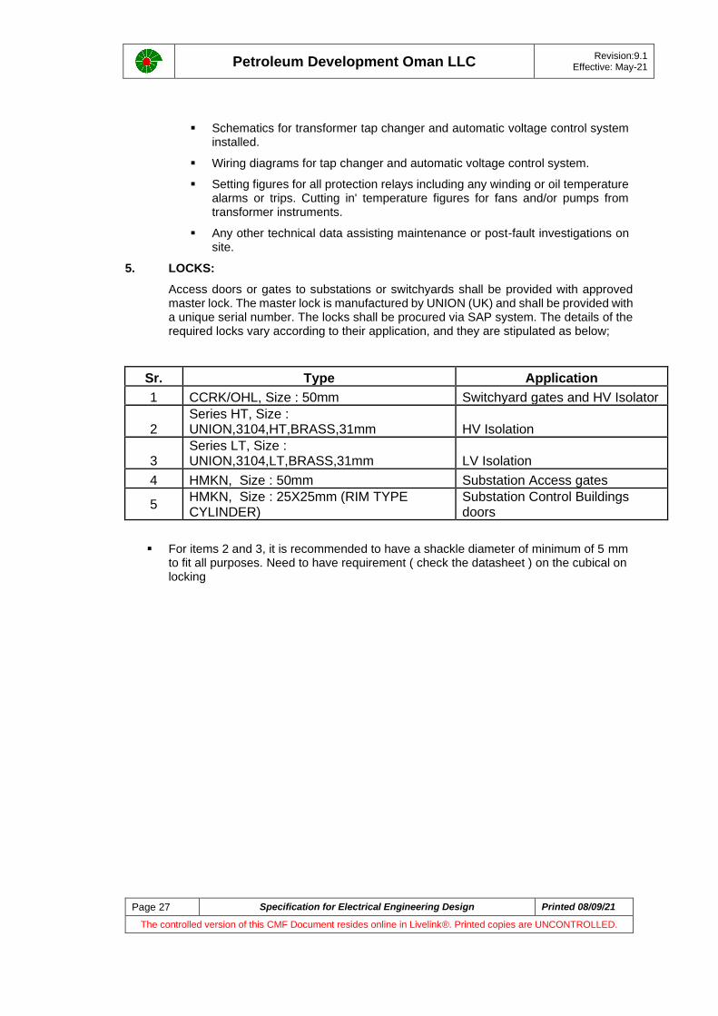
5. LOCKS:
Access doors or gates to substations or switchyards shall be provided with approved master lock. The master lock is manufactured by UNION (UK) and shall be provided with a unique serial number. The locks shall be procured via SAP system. The details of the required locks vary according to their application, and they are stipulated as below;
Sr. Type Application
1 CCRK/OHL, Size : 50mm Switchyard gates and HV Isolator
2 Series HT, Size : UNION,3104,HT,BRASS,31mm HV Isolation
3 Series LT, Size : UNION,3104,LT,BRASS,31mm LV Isolation
4 HMKN, Size : 50mm Substation Access gates
5 HMKN, Size : 25X25mm (RIM TYPE CYLINDER)
Substation Control Buildings doors
▪ For items 2 and 3, it is recommended to have a shackle diameter of minimum of 5 mm to fit all purposes. Need to have requirement ( check the datasheet ) on the cubical on locking

Petroleum Development Oman LLC
Revision:9.1 Effective: May-21
Page 28 Specification for Electrical Engineering Design Printed 08/09/21
The controlled version of this CMF Document resides online in Livelink®. Printed copies are UNCONTROLLED.
APPENDIX -4 ELECTRICAL INSTRUMENT INPUT /OUTPUT SCHEDULE
Electrical_Instrument_ IO Schedule.xlsx

Petroleum Development Oman LLC
Revision:9.1 Effective: May-21
Page 29 Specification for Electrical Engineering Design Printed 08/09/21
The controlled version of this CMF Document resides online in Livelink®. Printed copies are UNCONTROLLED.
APPENDIX -5 ELECTRICAL EQUIPMENT REQUISITION DATA SHEETS
PDO STD Data Sheet for LV Motor .xlsx
PDO STD Data Sheet for LV Motor VSD up to160kW.xlsx
PDO STD Data Sheet for LV Motor with Cooler Fan .xlsx
PDO STD Data Sheet for crane LV Motor_ (003).xlsx
PDO STD Data Sheet for HV Motor .xlsx
PDO STD Data Sheet for HV Motor with UTX .xlsx
PDO STD Data Sheet for Synchronous Motor.xlsx
PDO STD Data Sheet for Distribution Transformer .xlsx
PDO STD Data Sheet for Power Transformer.xlsx
PDO STD Data Sheet for Transformer UTX .xlsx
PDO STD Data Sheet for HV Switchgear.xlsx
PDO STD Data Sheet for LV Switchgear.xlsx
PDO STD Data Sheet for DC UPS.xlsx
PDO STD Data Sheet for AC UPS.xlsx
PMR Data Sheet
PDO STD Data Sheet for Termination kits .xlsx
PDO STD Data Sheet for NER.xlsx

Petroleum Development Oman LLC
Revision:9.1 Effective: May-21
Page 30 Specification for Electrical Engineering Design Printed 08/09/21
The controlled version of this CMF Document resides online in Livelink®. Printed copies are UNCONTROLLED.
APPENDIX A, REQUIRE ILLUMINATION LEVEL
Location Emean
(Lux)
Notes
CONTROL ROOMS
General, including front of panel 300/500 1, 7
Rear of panels 150
Auxiliary rooms 150/300 2
Outside, near entrances 150
PLANT AREAS
Operating areas requiring regular operator intervention
pumps, compressors, generators, drivers, valves, manifolds, loading arms, etc.
150 3
Local control and monitoring points
indicating instruments, gauges and control devices
75
Level gauges (see-through) to be lit from behind by single tube fluorescent luminaries
Access ways: walkways, platforms, stairways, ladders, module roofs (offshore)
25
Plant and jetty approaches and road intersections 5
Non-operational areas with limited attendance, e.g. tank farms without equipment requiring regular operator intervention.
0.5
Loading gantries: top loading, walkways and top of tankers
150
bottom loading (coupling handling area)
150
Road tanker parking area 25
NON-PLANT AREAS
Switchrooms, including relay and auxiliary rooms 200
Workshops and garages indoor general 250 3
local on workbenches and machine tools
400 4
outdoor storage and handling areas
50

Petroleum Development Oman LLC
Revision:9.1 Effective: May-21
Page 31 Specification for Electrical Engineering Design Printed 08/09/21
The controlled version of this CMF Document resides online in Livelink®. Printed copies are UNCONTROLLED.
Location Emean
(Lux)
Notes
Warehouses and stores indoor between storage racks
150
bulk storage 50
outdoor storage areas 5
Laboratories and analyser rooms 400
Street lighting and fence lighting 3 5, 6, 8
NON-INDUSTRIAL AREAS
Canteens (dining areas) 100
Car parks 1
Catering areas (food preparation and serving) 300
Communications rooms 400
Computer rooms 400 7
Conference rooms 400
Corridors and stairways 100
Drawing offices 400 7
First aid rooms 400
Libraries and reading rooms 400
Lifts 100
Offices 400
Plant rooms 150
Print rooms 250
Reception areas 150-400
Recreation rooms and lounges 300
Store rooms 150
Toilets and locker rooms 100
NOTES: 1. 300 lux applies at night and 500 lux during the daytime. Control of the illumination level down to 100 lux should be possible either by switching off rows/groups of luminaires, or by use of electronic dimmers, or both.
2. 150 lux applies for normal access and 300 lux for maintenance activities. The illumination level should be controlled by switching each lamp in a twin fitting from separately controlled circuits or by switching alternative fittings.
3. Where overhead travelling cranes are installed, floodlights should be fitted under the crane beam to provide an illumination level of 400 lux for better illumination during maintenance.
4. In areas where very fine work is carried out, local lighting with higher illumination levels may be required, e.g. 750 – 1000 lux on an instrument workshop bench.
5. Higher illumination levels apply where security fence lighting is required, e.g. for use with video camera surveillance. These should be specified to be compatible with the video system utilised.
6. At the security barrier and checkpoint in front of site entrance gatehouses, higher illumination levels may be required.
7. In rooms where VDUs are permanently installed, the lighting shall be designed to avoid reflections and glare from the screens.

Petroleum Development Oman LLC
Revision:9.1 Effective: May-21
Page 32 Specification for Electrical Engineering Design Printed 08/09/21
The controlled version of this CMF Document resides online in Livelink®. Printed copies are UNCONTROLLED.
Location Emean
(Lux)
Notes
8. Siting of lighting fixtures should avoid shadows and illuminate the ground evenly.
APPENDIX B, GLOSSARY of DEFINITIONS, TERMS and ABBREVIATIONS
The following terms and abbreviations used in this document are defined below:
General Terminology
Company: Petroleum Development Oman LLC
Principal: The person or organisation that specifies the requirements in a contract and pays the contractors and vendors for their services, materials and equipment.
Purchaser: The person or department in PDO or an authorised contractor on behalf of PDO, places order for equipment / materials with Supplier
Supplier: The person or organisation that receives order for supply of equipment / materials to the Company or on behalf of the Company
Contractor: The person or organisation that supplies the company with services.
Vendor: The person or organisation that supplies the company with materials and/or equipment.
Discipline: A specific set of technical knowledge and skills
Corporate Functional Discipline Head (CFDH-E):
The person within the Company responsible for the discipline to which the specification belongs. The CFDH-E approves the Specifications that apply to Electrical discipline
User: The person or organisation that reads, and uses the information, in this and other Specifications
Shall: Indicates a requirement
Should: Indicates a recommendation
May: Indicates a possible course of action

Petroleum Development Oman LLC
Revision:9.1 Effective: May-21
Page 33 Specification for Electrical Engineering Design Printed 08/09/21
The controlled version of this CMF Document resides online in Livelink®. Printed copies are UNCONTROLLED.
ABBREVIATIONS
AC ALTERNATING CURRENT AVR AUTOMATIC VOLTAGE REGULATOR CFDH CORPORATE FUNCTIONAL DISCIPLINE HEAD GIS GAS INSULATED SWITCHGEAR OEM ORIGINAL EQUIPMENT MANUFACTURER PDO PETROLEUM DEVELOPMENT OMAN LLC PR PROCEDURE (PDO) SP SPECIFICATION (PDO) VESDA VERY EARLY SMOKE DETECTOR ALARM EHT ELECTRICAL HEAT TRACING VT VOLTAGE TRANSFORMER

Petroleum Development Oman LLC
Revision:9.1 Effective: May-21
Page 34 Specification for Electrical Engineering Design Printed 08/09/21
The controlled version of this CMF Document resides online in Livelink®. Printed copies are UNCONTROLLED.
SP USER-COMMENT FORM
SP User-Comment Form If you find something that is incorrect, ambiguous or could be better in an SP, write your comments and suggestions on this form. Send the form to the Document Control Section (DCS). They make a record of your comment and send the form to the correct CFDH. The form has spaces for your personal details. This lets DCS or the CFDH ask you about your comments and tell you about the decision.
SP Details Title Issue Date:
Number:
Page number: Heading Number: Figure Number:
Comments:
Suggestions:
User’s personal details
Name:
Ref. Ind: Signature: Date:
Phone:
Document Control Section Actions
Comment Number: Dates CFDH
Ref. Ind: Recd: To CFDH:
CFDH Actions
Recd Date:
Decision: Reject: Accept, revise at next issue: Accept, issue temporary amendment
Inits: Ref.
Ind:
Date:

Petroleum Development Oman LLC
Revision:9.1 Effective: May-21
Page 35 Specification for Electrical Engineering Design Printed 08/09/21
The controlled version of this CMF Document resides online in Livelink®. Printed copies are UNCONTROLLED.
Comments:
Originator Advised:
Date: Inits: Document Control Section Advised:
Date: Inits: