
AMCP 706-290, Warheads, General - Bulletpicker
235
UNCLASSIFIED / LIMITED Engineering Design Handbook. Warheads-Generai ARMY MATERIEL COMMAND ALEXANDRIA VA JUL 1964 Distribution: DTIC Users Only. UNCLASSIFIED / LIMITED
-
Upload
khangminh22 -
Category
Documents
-
view
0 -
download
0
Transcript of AMCP 706-290, Warheads, General - Bulletpicker
UNCLASSIFIED / LIMITED
Engineering Design Handbook. Warheads-Generai
ARMY MATERIEL COMMAND ALEXANDRIA VA
JUL 1964
Distribution: DTIC Users Only.
UNCLASSIFIED / LIMITED

UNCLASSIFIED / LIMITED
Redistribution Of DTIC-Supplied Information Notice
As a condition for obtaining DTIC services, all information received from DTIC that is not clearly marked for public release will be used only to bid or perform work under a U.S. Government contract or grant or for purposes specifically authorized by the U.S. Government agency that sponsored the access. Furthermore, the information will not be published for profit or in any manner offered for sale.
Reproduction Quality Notice
We use state-of-the-art, high-speed document scanning and reproduction equipment. In addition, we employ stringent quality control techniques at each stage of the scanning and reproduction process to ensure that our document reproduction is as true to the original as current scanning and reproduction technology allows. However, the following original document conditions may adversely affect Computer Output Microfiche (COM) and/or print reproduction:
% Pages smaller or larger than 8.5 inches x 11.0 inches.
% Pages with background color or light colored printing.
« Pages with smaller than 8 point type or poor printing.
« Pages with continuous tone material or color photographs.
% Very old material printed on poor quality or deteriorating paper.
If you are dissatisfied with the reproduction quality of any document that we provide, particularly those not exhibiting any of the above conditions, please feel free to contact our Directorate of User Services at (703) 767-9066/9068 or DSN 427-9066/9068 for refund or replacement.
Do Not Return This Document To DTIC
UNCLASSIFIED / LIMITED

AMC PAM PH LETH it) 5 A R E P A I N T Wl T H O i J T C H A N G E O F O R O M Z0-Z9Q I M T E Q J U L .Y l » i 9
AMCP 706-290
RESEARCH AND DEVELOPMENTOF MATERIEL
ENGINEERING DESIGN HANDBOOK
WARHEADS-GENERAL(0)
H E A D Q U A R T E R S , U, 5. A R M Y M A T E R IE L C O M M A N D J U L Y 1964

CONFIDENTIAL
H E A D Q U A H T E R SU N IT E D S T A T E S ARM / M A T E R I E L COMMAND
WASHINGTON, D . C . 20315
i i Ju ly 1964
A M C P 7 0 6 - 2 9 0 ( C ) , W a r h e a d s - - G e n e r a l (U ), fo r m in g p a r t of the A rm y M a t e r ie l C om m an d E n g in e e r in g D esign Handbook S e r i e s , i s p u b lish ed f o r the in fo rm a t io n and guidance of a l l c o n c e r n e d .
(A M C R D )
F O R TH E C O M M A N D E R :
, S E L W Y N D . SM IT H , J R .O F F I C I A L : 1 M a jo r G e n e r a l , USA
C h ie f o f S ta ff
D IS T R IB U T IO N : S p e c ia l
CONFIDENTIAL

UNCLASSIFIED
AD NUMBER________ AD501329__________CLASSIFICATION CHANGES
TO: u n c l a s s i f i e d
FROM: c o n f i d e n t i a l
__________ LIMITATION CHANGES_________
TO:Approved for public release, distribution unlimited
FROM:Distribution authorized to U.S. Gov't, agencies and their contractors; Administrative/Operational use; July 1964. Other requests shall be referred to HQ, U.S. Army Materiel Command [AMCRD-TV] , Washington, DC 20315.
AUTHORITYUSAMDRC ltr Aug 1976
16 Mar 1976; USAMDRC ltr 26
THIS PAGE IS UNCLASSIFIED

SECURITYMARKING
The classified or limited status of this report applies to each page, unless otherwise marked.Separate page printouts MUST be marked accordingly.
THIS DOCUMENT CONTAINS INFORMATION AFFECTING THE NATIONAL DEFENSE OF THE UNITED STATES WITHIN THE MEANING OF THE ESPIONAGE LAWS, TITLE 18, U.S.C., SECTIONS 793 AND 794. THE TRANSMISSION OR THE REVELATION OF ITS CONTENTS IN ANY MANNER TO AN UNAUTHORIZED PERSON IS PROHIBITED BY LAW.
NOTICE: When government or other drawings, specifications or other dat~ are used for any purpose other than in connection with a definitely related government procurement operation, the U.S. Government thereby incurs no responsibility, nor any obligation whatsoever; and the fact that the Government may have formulated, furnished, or in any way supplied the said drawings, specifications, or other data is not to be regarded by implication or otherwise as in any manner licensing the holder or any other person or corporation, or conveying any rights or permission to manufacture, use or sell any patented invention that may in any way be related thereto.

CONFIDENTIAL
P R E P A C K
Tlic Engineering Design Handbook of the A :m y M aterie l C om - in ji id is a coordinated s e r ie s of handbooks containing b a s ic in fo rm a tion and fundamental data useful in tin- design and development of Army m ater ie l and s y s te m s . The Handbooks are authoritative r e fe re n c e books of p ra c t ic a l inform ation and quantitative fac ts helpful in the design and development of A rm y m a te r ie l so that it will m e e t the ta c t ic a l and technical needs of the A rm ed F o r c e s .
This handbook on W a r h e a d s - G e n e r a l presents in form ation on the fundamental princip les governing the design of w arheads, with d iscu ss io n s of the m echanical and explosive a rran g em e n ts which have been , o r may be, used in the construction of w arh ead s. More detailed and extensive trea tm en t of sp e c ia lized designs in warheads is contem plated in subsequent handbooks.
This handbook was prepared under the d irect ion of the Engineer ing Handbook Office of Duke U niversity , prim e c o n tra c to r to the A rm y R e s e a r c h O ffice-D u rh arn . The m a te r ia l was prepared by A i r c r a f t A rm am en ts , I n c . , under su bcontract to the E ngineering Handbook. O ffice . Technical a s s is ta n c e was rendered by Picatinny A rse n a l and the B a l l i s t i c s R e s e a r c h L a b o ra to r ie s of A berdeen Proving Ground, During the preparation of th is handbook G overnm ent estab lishm ents w ere v isited for m uch o f the m a te r ia l used and fo r helpful d iscussions with many tech n ica l p e rso n n el.
A gencies of the D epartment of D efense , having need for Handb o o k s , m ay submit requisit ions o r o ff ic ia l re q u e sts d ire c t ly to P u blica tions and Reproduction Agency, Leiterkenny Array Depot, C ham b ersb u rg , Pennsylvania 1 7201 . C on tracto rs should submit such req u is it io n s or requ ests to th e ir contracting o f f i c e r s .
1C om m ents and suggestions on this handbook a re w elcom e and
should be ad d ressed to A rm y R e s e a r c h O ffice-D u rh am , Box CM, Duke Station, Durham, North C arolina 27706.
CONFIDENTIAL

CONFIDENTIAL
TABLE OK CONTENTS
Chapter ChapterNumber Title Page
Table of Contents.................................................................................................................... . . 11List of Illu strations.................... . ............................................................................................... H IList of T a b les .................................................................................................................................. vuGlossary of Warhead Term s............................................................................................................v l l iSymbol Definitions.......................................................................................................................... xl
1 Warhead T y p e s ................................................................................................................................ l1-1 Introduction................................................................................................................. I1-2 Blast Warheads................................................................................................................................. I1-3 Fragmentation Warheads. ....................... 31-4 Discrete Rod Warheads.................................................................................................................. 71-5 Continuous Rod W arheads............................................................................................................. 71-6 Cluster W arheads........................................................................................................................... 91-7 Shaped Charge Warheads....................................................-......................................................... 101-8 Chemical and Biological W arheads........................................................................................... U1-9 Incendiary W arheads..................................................................................................................... 12l - 10 Leaflet Warheads......................................... .................................................................................... 121- 11 Inert and Exercise Warheads........................................................ 132 Weapons System Concepts........................................................................................................... 302 - 1 Introduction...................................................................... JO2-2 Scope .............................. . . . ................................................................................................... JO2-3 The Measure of the Cost of the Contribution......................................................................... 312-4 Sizo of the Weapons System Design Team ....................... J12- 5 Application of Weapons System Concept to Warhead D esign ........................................ 323 Warhead Se lection .......................................................................................................................... 333 - 1 Introduction..................................................... 333-2 Classification of T arg ets............................................................................................................... 333-3 Warhead Selection Chart ............................................................................................................ 3*3- 4 Bibliography...................................................................................................................................... 354 Warhead Detail D esign ................................................................ 364 - 1 General .............................................................................................. 364-2 B last W arheads................................................................ 364-3 Fragmentation Warheads.............................. 464-4 Discrete Rod Warheads..................... 864-5 Continuous Rod W arheads............................................................................................................. 874-6 Cluster W arheads........................................................................................................................... 9 84-7 Shaped Charge Warheads................................................................................................................ HI4-8 Chemical and Biological W arheads............................................................................................ 1304 - 9 Characteristics of Service Warheads......................................................................................... 1385 Warhead Evaluation....................................................................................................................... 1395 - 1 Evaluation P rin cip les.................................................................... ..............................................T5-2 Fundamental C on cep ts...................................................................................................................5-3 Approximate Evaluations................................................................................................................ 1535-4 Evaluation Methods........................................................................................................................... 154
CONFIDENTIAL li

CONFIDENTIAL
6 Warhead T e s tin g ................................................................................................................................. I®76-1 Introduction . ...............................................................................................................................6-2 Planning of Test Program ............................................................................................. I®26-3 Test 1’rooed’ "es and Techniques. 170
I ft?6-4 Data ReduC ,n and Interpretation............................................................................................. lM6-5 Test Facilities...................................................................................................................................6-6 Bibliography............................. 1®®
Appendix: Characteristics of High Explosives for Missile Warheads....................... 1®*
LIST OF ILLUSTRATIONS
FigureNumber Title Page
1-1 TypicBl Internal Blast Warhead With Penetration N ose.......................................................... 11-2 Typical External Blast Warhead.......................................................................................... 1l-r3 Blast Warhead - Aerial T arget........................................................................................................ 21-4 Blast Warhead - Surface T a rg e t............................. . ............................................................... 71-5 Damage from Blast W arhead....................................................................... 31-6 Fragmentation Warhead - Aerial T a r g e t .................................................................................... 41-7 Fragmentation Warhead - Surface T arg et.................................................................................... 51-8 Typical Individual Fragment S h a p e s ............................................................................................. ®1-9 Preformed Fragment R etention ...................................................................................................... 61-10 Fire-Formed Fragment Casings...................................................................................................... 7l - l l Fragment Orientation about Charge....................................................................................■. • 71-12 Typical Fragment W arhead............................................................................................................... ®1-13 Damage from Fragmentation Warhead.................................................................................... ®1-14 Discrete Rod W arhead .................................................................................................................. -101-15 Typical Discrete R o d s ................................................................................................................. 111-16 Typical Discrete Rod Warhead.............................................................................. I*1-17 Damage from Discrete Rod Warhead............................................................................................. 121-18 Continuous Rod Warhead...............................................................................................................1-19 Typical Continuous Rod W arhead ............................................................................................... 131-20 Damage from Continuous Rod W arhead ....................................................................................... 141-21 Cluster W arhead........................................................... .. ...............................................................1-22 Submlaslle Sh ap es............................................ 131-23 Submissile E je c tio n ........................................................................................................................ 1®1-24 Skin R em ov al.................................................................................................................................... 161-25 Example of Cluster Warhead . ........................................................................................................ l ®1-26 Damage from Cluster Warhead........................................................................................................ 771-27 Shaped Charge Warhead - Aerial T a r g e t .................................................................................... l ®1-28 Shaped Charge Warhead - Surface T arg et.................................................................................. 191-29 Action of Shaped Charge Warhead................................................................................................ 101-30 Typical Shaped Charge Warhead................................................................................................. 2®1-31 Aircraft Damage from Shaped Charge Warhead..................................................................... 2 l1-32 Armor Penetration from Shaped Charge W arhead ................................................................ 771-33 Chemical or Biological Warhead........................................................................................................231-34 Current Bomblet Sh ap es................................................................................................................ 2®1-35 Typical Biological Warhead.......................................................................................................... 2^
ill CONFIDENTIAL

CONFIDENTIAL
1-36 butendlary W arhead......................................................................................................... ■. . .1-37 Typical Incendiary Rom blet......................................................................................................1-36 Typical Incendiary Warhead..................................................................................... .................1-39 Leaflet W arhead..........................................................................................................................1-40 Exercise Warhead - Aerial Target Drone.............................................................................1- 41 inert Warhead.................................................................................................................................2 - 1 Utilization of Manpower and Natural R esources............................................ .. .................2-2 Engineering Effort - Guided Missile System Development.............................................4-1 Action of Internal and External B la s t.....................................................................................4-2 Peak Pressure Vs. Scaled Distance at Various Atmospheric Pressures, 50/50
Pentolite Spherical Bare C harges...........................................................................................4-3 Scaled Impulse Vs. Scaled Distance at Various Atmospheric Pressures, 50/50
Pentolite Spherical Bare C harges...........................................................................................4-4 One Piece F ab rica tio n ................................................................................................................4-5 Multipiece Fabrication ................................................................................................................4-6 Definition of Fragment Beam Width..................................... .. ................................................4-7 Vector Addition of Fragment and Missile V elocities.........................................................4-8 CD Vs, Mach Number for Various Fragment T y p e s .........................................................4-9 Longitudinal Section of a Typical Fragmentation Warhead.............................................4-10 Diagram for Derivation of Angle of Emission of Fragments...........................................4-11 Distribution of Fragments about Nominal Ejection D irection ........................................4-12 Graphical Solution of Optimum Beam W id th .......................................................................4 - 13a Examples of the Effect of Warhead Shape on Fragment Beam Width..............................4 - 13b Examples of the Effect of Warhead Shape on Fragment Beam Width..............................4-14 Volume Per Pound of Warhead Vs. Charge-to-Metal Ratio.............................................4-15 Initial Static Fragment Velocity Vs. Charge-to-Metal Ratio...........................................4-16 Warhead Effectiveness Vs. Fragment S i z e ..........................................................................4-17 Fragment Velocity and Size Optimization, Target: Piston Engine Fighter..............4-18 Fragment Velocity and Size Optimization, Target: Piston Engine Fighter.................4-19 Fragment Velocity and Size Optimization, Target: Piston Engine Fighter.................4-20 Fragment Velocity and Size Optimization, Target: B-29 Aircraft with Fuel...............4-21 Fragment Velocity and Size Optimization, Target: B-29 Aircraft with Fuel...............4-22 Fragment Velocity and Size Optimization, Target: B-29 Aircraft with Fuel...............4-23 Fragment Velocity and Size Optimization, Target: B-29 Aircraft with Fuel
Invulnerable...................................................................................................................................4-24 Fragment Velocity and Size Optimization, Target: B-29 Aircraft with Fuel
Invulnerable...................................................................................................................................4-25 Fragment Velocity and Size Optimization, Target: B-29 Aircraft with Fuel
Invulnerable......................................................................................................... .........................4-26 Fragment Velocity and Size Optimization, Target: Single Engine Jet Fighter.............4-27 Fragment Velocity and Size Optimization, Target: Single Engine Je t Fighter.............4-28 Fragment Velocity and Size Optimization, Target: High Explosive Airborne
Bomb........................................ ■.......................................................................................................4-29 Fragment Velocity and Size Optimization, Target: High Explosive Airborne
Bom b.................................................................................................................................................4-30 Fragment Velocity and Size Optimization, Target: High Explosive Airborne
Bomb. ...............................................................................................................................................4-31 Fragment Velocity and Size Optimization, Target: High Explosive Airborne
Torpedo............................................................................................................................................
252626272829303137
43
434444474748515151545455575760606060616161
62
62
626263
63
63
63
64
CONFIDENTIAL iv

CONFIDENTIAL
4-32
4-33
4-344-354-30
4-37
4-38 4-39 4-40 4-41 4-42 4-43 4-44 4-45 4-46 4-47 4-48 4-49a 4-49b 4-4 9c 4-49d 4-49e 4-49f 4-49g 4-49h 4-49i 4-49] 4-49k 4-49L 4-50 4-51 4-52 4-53 4-34 4-55 4-56 4-57 4-48 4-59 4-60 4-61 4-62 4-63 4-64 4-G5
Fragment Velocity anti Size Optimization, Target: High Explosive AirborneTorpedo............................................................ .................................................................. ■Fragment Velocity and Size Optimization, Target: High Explosive AirborneTorpedo................................................................................................. .......................................Velocity Ratio Vs. Range, Anti - Personnel Warhead . . . . . ..................................Vector Addition o f Fragment and Miaalle Velocities, Anti-Personnel Warhead . . Fragment and Spray Diagram; Uiilt-Hadius Sphere for Burst at 60" w of WarheadDesigned for the Same u ...................................................................................................... ■Fragment and Spray Diagram: Unit-Radius Sphere for Burst at 30" u of WarheadDesigned for 60" W ......................................................................................................... ■ ■Warhead Efficiency Vs, Warhead Inclination....................................................................Typical Use of a Fairing (Sparrow I, Mk 7 Mod 0, Warhead Shown).........................Expected Number of Cuts Vs. Rod Length (Cylinder Half Severed)............................Expected Number of Cuts Vs. Hod Length (3' x 8 ' Beam Half Severed)....................Warhead Details (D iscrete Rod W arhead)....................................................................Expansion of Hod Hoop............................................................................................................Hod Velocity V ariation ................................................ ............................................................A Warhead Design Producing Tangled and Broken Rods ..............................................Contoured Liner and Inert Build Up.....................................................................................Contoured Inert Build Up..................................................................................... ....................Rod Scabbing................................................................................................................................Continuous Rod Warhead D esigns........................................................................................Continuous Rod Warhead D esigns....................................................................... .................Continuous Rod Warhead D esigns........................................................................................Continuous Rod Warhead D esigns........................................................................................Continuous Rod Warhead D esigns........................................................................................Continuous Rod Warhead D esigns........................................................................................Continuous Rod Warhead D esigns........................................................................................Continuous Rod Warhead D esigns........................................................................................Continuous Rod Warhead D esigns.................................................................................. ■ •Continuous Rod Warhead D esigns........................................................................................Continuous Rod Warhead D esigns............................................. ..........................................Continuous Rod Warhead D esign s............................... ........................................................Resolution of Velocities ...................................................... ................................................ ..Unstabilized Submissiles - Typical Arrangement ............................................. ............Stabilized Submissiles - Typical Arrangem ent...............................................................Drag Tube and Drag Plate Stabilizer.......................................................................... ■Folding Fin Stabilizer...............................................................................................................Drag Chute Stabilizer......................................................... ......................................................Fixed Fin Stabilizer..................................................................................................................Integral Ignition S y ste m .........................................................................................................Central Ignition System............................................................................................................Piston Type E je c t io n ...............................................................................................................Blast Ejection - Intermediate L in e r ................................................................................Blast Ejection - Segmented Chamber................................................................................Blast Ejection - Convoluted L iner.....................................................................................Submissile Arrangement......................................................................................................Ejection Tube and C ase.........................................................................................................Gun Tube E jec tio n ............................................................................................................ .. ■
()4
C46465
69
70SI828686S 6
8787
8787Vi71 91 9393949495959696979798
102 108 112113114 114114115116 117 117 117117118 118 118
v CONFIDENTIAL

c o n f id e n t ia l
4-66 P ressu res length Curves................................................................................. 1X84-67 Maximum Allowable Chamber Pressure Vs. Gun Tube Geometry ................................ 1184-68 Maximum Allowable Chamber Pressure Vs. Gun Tube G eom etry............................... 1194-69 Maximum Allowable Chamber Pressure Vs. Gun Tube G eom etry............................... 1194-70 Spherical Submlsslle W arhead................................................................................................... 1194-71 Charge-to-Metal Ratio Vs. Velocity for T-46 Cluster W arhead..................................... 1194-72 T-46 Prototype Warhead .............................................................................................................. 1204-72 Typical Submlsslle Plight Pattern............................................................................................. 1204-74 Spherical Submlsslle ._............... 1204-75 Types of Stabilization.................................................................................................................... 1204-76 Tin Stabilized Submlsslle.................................... 1214-77 Fin L o c k ........................................................................................................................................... 1214-78 Support Structure............................................................................................................................ 12i -4-79 Tube Analysts.................................................................................................................................. 1214-80 Submlsslle R eten tion .................................................................................................................... 1214-81 Skin Removal H a rn e ss ................................................................................................................. 1224-82 Guillotine Installation.................................................................................................................... 1224-82 Guillotine E f f e c t ............................................................................................................................ 1224-84 Shaped Charge Nomenclature...................................................................................................... 1234-85 Penetration Vs. Standoff; Cone Angle and Cone Thickness Against Concrete............. ^^4-86 Penetration Vs. Standoff and Cone Thickness Against C on crete ..................................4-87 Penetration Vs. Standoff Against Mild Steel Target .......................................................... 1 ^4-88 Penetration Vs. Standoff Against Mild Steel. Target ................ .........................................4-89 Penetration Vs. Standoff Against Mild Steel Target .......................................................... 1274-90 Penetration Vs. Cone Angle Against Concrete....................................................................... 1274 -9 la Penetration Vs. Standoff Against Mild Steel T arg ets.............................................................. 1274-91b Penetration Vs. Standoff Against Mild Steel Targets ............... 1274-91c Penetration Vs. Standoff Against Mild Steel Targets .........................................................14-91d Penetration Vs. Standoff Against Mild Steel Targets .........................................................4-92 Reasonable Values of Cone Wall Thickness for Copper Cones ...................................... 11' Q4-93 Penetration Vs. Cone Thickness and Cone Angle Against C oncrete................................ l 2^4-94 Explosive Charge Wave Shaping................................................................................................ 1294-95 Bomblet Dispersion Patterns .................................................................................................... f 4-96 Ejection Sequence, S p h eres........................................................................................................ 1324 - 97 Ejection Sequence. Fietners and G lid e rs .............■............................................................... 1375 - 1 Attack with Perfect Guidance and Perfect Fuzing................................................................. 1425-2 Orientation of the A x es .................................................................................................. 1425-3 Random Guidance E r r o r s ........................................................................................................... 1435-4 The Normal Frequency Function................................................................................................ 1435-5 Area Under Normal Frequency Curve .................................................................................... 1435-6 The Normal Curve of E rro r ..................... 1445-7 Orientation of Rectangular Target Area .......................................................... 1445-8 Probability of a Hit, P^, within a Circle of u Standard E r r o r s .................................... 1465-9 Cumulative Bivariate Normal Distribution (Over Circles of Radius R Centered at
the Mean)................................................................................................................................ 1 ®5-10 Random Fuzing Errors Combined with Random Guidance E r r o r s ................. ..............5-11 Random Warhead Bursts Around Target.................................................................................. I 5®5-12 Critical Distance, d, for Evaluation of Blast Warhead......................................................5-13 Critical Distance, d, for Evaluation, of Fragment Warhead..................... 157
vi CONFIDENTIAL

CONFIDENTIAL
5-14 Geometry for Fragment Striking Velocity ...................................................... 1585-15 Critical Distance, d, for Evaluation of Hod Warhead.......................................................... *5B5-l(i Critical Distance, d. tor Evaluation of Cluster W arhead................................................. 1595-17 Critical Angle, $. for Evaluation of Shaped Charge Warhead ...................................... 1595-1H External Blast Warhead Evaluation-Warhead Weight V ariab le ...................................... 1595-19 External Must Warhead Evaluation-Target Type Variable................................... 1&05-20 External Hiast Warhead Evaluation-Engagement Altitude V a ria b le ............................. *805-21 External Hiast Warhead Evaluation-Standard Error of Guidance Variable.................. *805-22 External Blast Warhead Evaluation-Kill Probability In terv a ls...................................... *8°5-29 Internal blast Warhead Evaluation-Target Type V ariab le ............................................... *8*5-24 Internal [Hast Warhead Evaluation - Engagement Altitude Variable.............................. *8*5-25 Internal Blast Warhead Evaluation - Standard Error of Guidance V ariable................. *815-26 Intornal Blast Warhuad Evaluation - Kill Probability Intervals...................................... *815-27 Fragment Warhead Evaluation - Warhead Weight Variable.............................................. *825-28 Fragment Warhead Evaluation - Target Type V ariable..................................................... 1625-29 Fragment Warhead Evaluation - Standard Error of Guidance Variable.......................... *825 - 30 Fragment Warhead Evaluation - Kill Probability Intervals................................ ^6 - 1 Fragment Lethality T e s t .............................................................................................................. *7®6-2 Fragment Gun and S a b o t....................................................................................................... *7 *6-3 Screen Used for Measuring V elocity ....................................................................................... *736-4 Individual Rod Test........................................................... ................ ............................................. 1746-5 Complete Fragment Warhead T est............................................................................................. *756-6 Submissile Ejection System Test................................................................................. 1766-7 Skin Removal T e s t ......................................................................................................................... 177G-8 Sled Test - Complete Cluster Warhead.................................................................................... 1786-9 Complete Shaped Charge Warhead T e s t .................................................................................. 1796-10 Blast Warhead T e s t ...................................................................................................................... *806 _ li Complete Rod Warhead Test........................................................................................................ 184
i LIST OF TABLES
3-1 Target C lassification.......................................................................................................................... 333 - 2 Warhead Selection C hart................................................................................................................... 344 - 1 Characteristics of Explosives .......................................................................................................... 394-2 Characteristics of HBX-1 and H - 6 ................................................................................................. 394-3 Penetration Capabilities of Penetration C a s e .............................................................................. 424-4 One Piece F ab rica tion ......................................................................................................................... 444-5 Nose Spray Warhead C haracteristics................................................................................................684-6 Estimated Relative Fragment Production From Various Fragmentation Control
Methods . .................................................................................................................................................. 784-7 Rough Numerical Comparisons of Various Fragmentation Control Methods........................ 764-8 Summary C hart......................................................... 994-9 Relative Penetration Capabilities of Various Liner Materials................................................ 1254 - 10 Characteristics of Existing Service Warheads........................................................................1345 - 1 The Areas Under the Normal Curve of Errorflncluded Between t and - t ) . ....................... 1455-2 The Probabilities of a Hit, Pffl , Within a Circle of Radius u Standard E r r o r s ..................**85 - 3 Cumulative Bivariate Normal Distribution Over Circles Centered at the M ean ..............*676 - 1 Test Facility Selection Chart 183
CONFIDENTIAL vii
CONFIDENTIAL
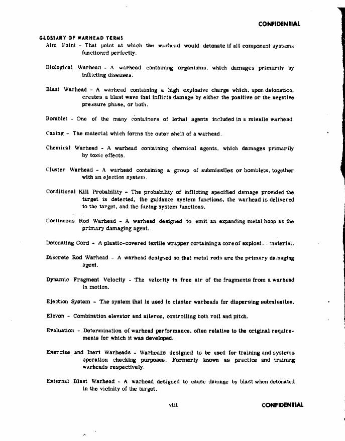
GLOSSARY OF WARHEAD TERMSAim Point - That point at which the warhead would detonate If alt component systems
functioned perfectly.
Biological Warhead - A warhead containing organisms, which damages primarily by Inflicting diseases.
Blast Warhead - A warhead containing a high explosive charge which, upon detonation, creates a blast wave that Inflicts damage by either the positive or the negative pressure phase, or both.
Bomblet - One of the many containers of lethal agents included In a missile warhead.
Casing - The material which forms the outer shell of a warhead.
Chemical Warhead - A warhead containing chemical agents, which damages primarily by toxic effects.
Cluster Warhead - A warhead containing a group of submissiles or bomblets, together with an ejection system.
Conditional Kill Probability - The probability of inflicting specified damage provided the target is detected, the guidance system functions, the warhead is delivered to the target, and the fuzing system functions.
Continuous Rod Warhead - A warhead designed to emit an expanding metal hoop as the primary damaging agent.
Detonating Cord * A plastic-covered textile wrapper cortaming a core of explosi . material.
Discrete Rod Warhead - A warhead designed so that metal rods are the primary damaging agent.
Dynamic Fragment Velocity - The velocity In free air of the fragments from a warhead in motion.
Ejection System - The system that is used in cluster warheads for dispersing submissilefl.
Elevon - Combination elevator and aileron, controlling both roll and pitch.
Evaluation - Determination of warhead performance, often relative to the original requirements for which it was developed.
Exercise and Inert Warheads - Warheads designed to be used for training and systems operation checking purposes. Formerly known as practice and training warheads respectively.
External Blast Warhead - A warhead designed to cause damage by blast when detonated in the vicinity of the target.
viil CONFIDENTIAL

CONFIDENTIAL
Fairing - Sheet metal skin instilled around the warhead to maintain the m issile aerodynamic contour.
Fragment - Piece of metal scattered by the detonation of a warhead.
Fragment Beam Width - Angle covered by u useful density of fragments.
Fragment Density - Number of fragments per square foot at a given distance from the point of detonation.
Fragment Pattern - The arrangement of fragments after detonation.
Fragmentation Warhead - A .warhead so designed that metal fragments emitted at high velocities are the primary damaging agent.
Fuze - A device designed to initiate detonation of a warhead at a specific time or position, under certain desired conditions.
Guidance Error - The shortest distance between the m issile trajectory and the aim point.
Guidance System - A group of electronic and mechanical devices designed to direct a m issile to a target.
Hard Target - A target that is relatively difficult to damage as required.
Implosion - A force tending to create inward collapse.
Incendiary Material - A substance capable of setting fire to the target,
Incendiary Warhead - A warhead containing incendiary material as the primary damaging agent.
Internal Blast Warhead - A blast warhead designed to detonate upon impact or after penetration of a target.
Leaflet Warhead - A warhead containing leaflets or pamphlets.
Lethal Distance - The maximum distance at which a specific warhead can inflict lethal damage on a specific target. '
Lethality - A measure of the effectiveness of a warhead. ;
Miss Distance - The distance between the burst point and the center of gravity of the target.
Missile - A self-propelling pilotless weapon.
Overpressure. - That air pressure greater than the ambient air pressure.
CONFIDENTIAL lx

CONFIDENTIAL
Practice Warhead - See “ Exercise and Inert Warheads".
Proximity Fuze - An electronic fuze which senses the presence of a target and initiates the detonation of the warhead at a certain distance from the target.
S & A - Safety and arming device
Shaped Charge Warhead - A warhead designed to emit a Jet of minute, hyper-velocity metal pieces which act as the primary damaging agent.
Soft Target - A target which may be damaged with relative ease.
Standard Error of Guidance - A measure of the dispersion (linear standard deviation) of guidance error.
Submissiie - An Individual unit containing explosive or other active agent, which forms only part of a missile warhead,
Target - The object or group of objects which a missile Is employed against for the purpose of inflicting damage.
Training Warhead - See “ Exercise and Inert Warheads".
Warhead Compartment - That spare in a missile which is allocated to the warhead.
x CONFIDENTIAL

I
CONFIDENTIAL
SYMBOL DEFINITIONS
A Average presented area or fragment, Mg Maximum bending moment betweensquare incites. loads, foot-pounds.
Bore area, square IncheB. Mr Ratio of casing weight to charge weight in cylindrical section.
al Lethal area, square feet.N Total number of m issiles fired.
Ar Target projected vulnerable area, square feet. Nl Total number of fragments.
Cp Drag coefficient. N(M) Number of fragments of mass greater than M.
D Diameter, feet or inches.P Peak pressure, psl.
dR Drag, pounds or pound&ls.Pa Probability of a bit between • a.
W V Dynamic fragment density or a given direction G j, number of fragments P i Probability of a hit between • b.per ster&dian.
P .L Probability that the m issile Bystemc xes i Static fragment density, number of
fragments per steradlan.will launch the missile.
P d Probability that the m issile will deE Energy per unit mass of explosive. liver the warhead to the target.
F Force, pounds or pound&ls. Probability of a hit within a circle of radius m.
H Burst height, feet.
p! Probability that a fusing system willl Positive Impulse, psl - milliseconds. function.
K Inside radius /outside radius. pb Probability of a hit.
L Length, feet or inches. pk Conditional kill probability.
M Mass, grains, ounces or pounds. p0 Pressure, atmosphsres or psl.
M ' Weight to charge ratio parameter pr Probability of detecting and/or recognizing a target.
*•0 Mean fragment mass, grains, ounces or pounds. Ps Overall kill probability.
Maximum bending moment at loads, p, Probability of fuzing within anyfoot-pounds. given z
xi CONFIDENTIAL

CONFIDENTIAL
k Distance from explosion, feet.
V Burst point. ^v
« p Distance traveled, feet.
« b Radius of centroid of tubular crossv t
section, inches. v r
Lethal distance, feet.\f
T Thickness of armor. Inches.V X
v * ,
l A Total tangential compression at loads, pounds.
V ( T )
r H Maximum tangential compression between loads, pounds. Vf
y Total warhead volume, cubic inches. v r
V Average velocity, feet per second. V D.W.
V D Velocity of detonation wave in the explosive, feet per second.’
W E
V 4 Initial dynamic fragment velocity, feet 772per second.
11/
VD.W "dead" volume, cubic inches.%
V lInitial static fragment velocity, feet Vf
per second.
VH Longitudinal component of fragment
velocity, feet per second. w T
VL lethal striking velocity, feet per second.
V„ Missile velocity, feet per second. C
V n Net volume, cubic inches. c/m
Initial relative velocity, feet per second.
d
'VSubmissile volume, cubic Inches. </V
d t
CONFIDENTIAL x11
Radial velocity, feet per second.
Resultant striking velocity of fragments, feet per second.
Velocity of target, feet per second.
Total allowable warhead volume, jcubic Inches. '
Velocity at any point, feet per second. ■
Absolute fragment velocity at the target, feet per second. '
Vulnerability of target.
Weight of warhead, pounds.
Equivalent bare charge weight, pounds.
"dead" weight in warhead, pounds.!
Weight of individual submissile ejection tube, pounds.
Weight of fragmenting metal, pounds.
Net weight, pounds.
Weight of submissile, pounds.
Weight of individual submissile support structure, pounds.
Total allowable warhead weight, pounds. _
Weight of individual submissile explosive, pounds. *
IWeight of explosive, pounds. J
Charge-to-metal ratio. !
Significant distance in warhead evaluation, feet.
Acceleration of a fragment along its
I
j
I

CONFIDENTIAL
2path, feet per second . JL Fuzing error, feet
K Acceleration due to gravity, ft/syc^. *t Warhead efficiency
b Altitude of engagement, feet. 0 Angle between the missile and target trajectories, degrees.
1 Total travel distance, inches or feel.h Beam width, degrees.
Km) Lethality of the missile.Angular direction, degrees.
ni Weight of the metal case, pounds.' *t Half angle between forces, degrees.
"> Projectile mass, pounds.Angle of rod trajectories above or below
Ti Number of submissiles. the horizontal, degrees.
” x i Number of missiles which have an x 0V Static angle of fragment ejection.component of error equal to x . degrees.
Pi Probability of bursting at the i'th w Angle of inclination of the missile withposition. the ground, degrees.
Pki Probability of a kill given a burst from the i’th position. -
lWPl Frequency distribution of fuzing error.
0 Angle of fragment omission, degrees.!•,.(*> Pressure producing velocity.
0ft') Frequency distribution of guidance error/ Radius of submissile pattern, feet.
„ Constant, characteristic of explosivesr i Inside radius, inches or feet.
ft A specific angle.*o Outside radius. Inches or feet.
0f/J Normal frequency function.t Time, seconds.
0f*J Frequency distribution of x.X Distance traveled, inches or feet.
0fy> Frequency of distribution function of y.X Projectile acceleration, feet per
second^. 0(Z) Frequency distribution of z.
*1 x component of guidance error for the Pa Air density, pounds per cubic foot ori'th missile . slugs per cubic foot, as applied.
\v Distance traveled to strike point, feet. A Guidance error of the missile, feet,
y , y component of guidance error for the Pc. Density of charge, pounds per cubici'th missile. inch.
xlii CONFIDENTIAL

CONFIDENTIAL
pm Density of metal, pounds per cubic inch.
Po Air density at sea level, pounds per cubic foot or slugs per cubic foot, as applied.
pf Aj Radial density function.
Ofj Standard error of guidance.
at Radial compression, pounds.
ax Standard deviation of x from the aimpoint, feet.
«y Standard deviation of y from the aimpoint, f3et.
a . Standard error of fuzing, feet,
a Tangential tension, pounds.
r Shear, pounds.
Subscripts:
I Fragment.
i Pertaining to the i ’th m issile.
n Pertaining to the n’th m issile.
CONFIDENTIAL xiv

CONFIDENTIAL
Chapter 1
W ARHEAD TYPES
1.1. INTRODUCTION
This chapter presents a general discussion of current warhead types. It consists of Introductory m aterial for use by those not familiar with warhead design art, The figures represent an artist’s conception of the warhead for each type. These have been drawn to Include the missile delivering the warhead, the warhead In operation and the target. They provide an overall concept of the warhead system In operation Artistic license has been applied In some of these figures for clarity by showing the delivering m issile Intact after detonation of the warhead. This is not usually the case.
1-2. BLAST WARHEADS (F ig . l - l through 1-5)
Fundamentally, a blast warhead Is high explosive Installed In a container. Upon detonation, it creates a wave front of high positive pressure, followed immediately by a negative pressure. The wave moves radially outward at supersonic speed from the point of detonation. Primary damage occurs when a target Is struck by the wave. Secondary damage usually results from flying debris. B last warheads. Installed in the body of a m issile, are used against both air and surface targets.
Blast warheads are divided Into two functional categories. Internal and external blast An internal blast warhead la designed to Inflict damage when detonated upon impact with the target, or after penetration.When penetration of a hard target such as armor Is required, the internal blast type is equipped with an armor piercing head. When penetration of a softer target such as aircraft structure is required, the warhead detonates upon Impact and the extremely high pressures developed very close to the detonation point provide the means for entering the target. Since Internal blast warheads must literally contact the target to be effective, they are normally used in m issiles whose guidance systems are of the requisite accuracy. Extreme guidance accuracy is not required of m issiles containing a number of internal blast submlsslles, such as are carried by a cluster warhead. Fuzes for Internal blast warheads are designed to detonate the warhead upon impact or very shortly thereafter.
The external blast warhead is designed to Inflict damage when detonated near the target,
Flgutn ] .] . Typical I n f fuel B la ii Worhtad Willi Fig urn J.2 . Typical Entanwl Bloi l WarhaadPane (ration N e t*
CONFIDENTIAL 1

CONFIDENTIAL
Figure J.J, Bloat WothooJ - Aortal Target
/
F Iftiro 1 *4, B loat HmrhooJ ■ Surface Target
2 CONFIDENTIAL

I iU4Jllr|»l Mill -
U. S- Army PhotoView shows inspection of damage resulting from a blast warhead detonated beneath a Fighter Aircraft suspended in the air between two towers.
Figure 1-5* Damage from B la ti Warhead
instead of upon striking the target. Consequently. it can be used in a missile whose guidance system provides leas accuracy than that required for the internal blast type. Proximity type fuzes are used to detonate the warhead whenever it comes within lethal range of the target. This range depends on the size of the warhead, the target and the density of the air. It may be as lOw as 10 to 20 feet or as high as 150 to 200 feet.
Since the damage from both internal and external blast warheads is produced by awaye of high pressure a ir. the lethality of either warhead deteriorates significantly as the target altitude Increases. Consequently, blast warheads, designed for use against atr targets, are most effective when employed at low altitudes, say below 20,000 feet.
1-3. FRAGMENTATION WARHEADS{F ig . 1-6 through 1-13)
A fragmentation warhead consists of an explosive charge surrounded by a wall of preformed metal fragments or a prescored or solid metal casing. Upon detonation, the fragments are propelled outward at velocities of from 6,000 to 10,000 feet per second by explosive forces. Generally-slow-acting damage is infected on-the target when it is struck by the fragm entsAlso, disruptive blast damage Is common from fragmentation warheads. Fragmentation warheads, - installed in the body of m issiles are used against both air and surface targets, the surface targets most often being personnel. Their lethality against bomber targets depends upon the damage inflicted on a plurality of multiple components, such as
3 CONFIDENTIAL

CONFIDENTIAL
r/
F i g ur# I - i . F ragm entation W arh tod • A t t l a l T a rge t
CONFIDENTIAL 4

CONFIDENTIAL
J,iS
/
/
Figure 1-7. Fragmentation Warhtad • Surface Target
engines, fuel lines, controls, instruments, hydraulic lines, and crew members.
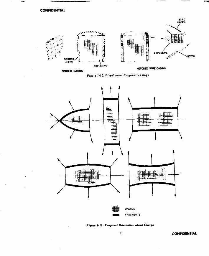
The weight and shape of the Individual fragments depends on the particular Intended application of the warhead. Design fragment weights may vary from below .014 ounces (6.0 grains) to over 0.5 ounces (220 grains). Fragment shapes in past and current use include steel spheres, cubes, rods, wires, and aero- dynamlcally stable configurations. (See Figure 1-S.) These shapes are either preformed or fire-formed. Preformed fragments are formed into their final shape before detonation of the explosive charge. They are mechanically held
in their proper orientation a round the charge by placing them in a fragment chamber, andeither cementing them in place with adhesives or imbedding them In a plastic or frangible substance.
Fire-formsd fragments take on their final Individual shape during detonation of the explosive charge. Prior to detonation they are components of a fragment casing which surrounds the explosive charge. This casing Is scored or notched in such a manner that it will break up upon detonation of the charge Into individual fragments of the desired shape.
The pattern that the fragments form as a
5 CONFIDENTIAL

CONFIDENTIAL
oSPHERE
ROD
s>CUBE
WIRE
NEAR CUBE
NEEDLE
Figure 1-8. Typica l Individual Fragment Utapew
group as they are propelled outward from the warhead b y the explosive forces 1b primarily dependent upon their orientation around the charge prior to detonation. The patterns re sulting from the orientations shown In Figure 1-11 are Intuitively apparent. The casing shape selected for a particular warhead depends primarily on the guidance accuracy of the missile delivering the warhead, the .size of the target and the density of the fragment beam on the target that ia necessary to do le w i damage to the target. .
Fragmentation warheads are designed to be detonated near, rather than upon striking, the target. Proximity-type fuzes are normally used and the guidance accuracy of the m issile delivering the warhead need not produce a direct hit to Insure lethality. In some Instances, warhead detonation may be initiated by command from the ground. Fragmentation warheads used against air targets at high altitude may be lethal when detonated as far a3 200 feet away. Tl^e lethal distance is primarily dependent upon the target and the fragment size and velocity at the time it strikes the target, since It must have sufficient kinetic energy to penetrate. Fragment striking velocity is a function of the target velocity, initial fragment velocity Immediately after detonation and the aerodynamic drag forces which slow down the fragment during its flight to the target. The initial velocity is dependent upon theamountof explosive charge relative to the metal In the casing, and the weight and shape of the warhead. The drag forces depend on the shape of the
IMBEDMENT
r*>w CENTRAL ^ T U B E
WALL
ADHESIVE
■v
” i »||^7||77|
„OUTER LINER
FRAGMENT"CHAMBER
-INKER LINEN
.EXPLOSIVECHARGE
CHAMBER
F igaro 1-9. Prefo rm ed Fragment R eten tion
CONFIDENTIAL 6
CONFIDENTIAL
EXPLOSIVE
SCORED CASING
a.
WIRE
NOTCHED WIRE CASINO
f j gur# J-IO. F/r»-Fo«i>«d Frugmint Co«fnyf
CHARGE
FRAGMENTS
F ig u n 1-11. Frofmont 0 rimntotion about C hcrg*
7 CONFIDENTIAL

CONFIDENTIAL
OUTER INNERHOISTING LINES FRAGMENTS LINER
Figur* M 2. Typical Frsgmwif WoW»«n/
fragment and the density of the a ir . Consequently, preformed aerodynamically stable fragment shapes slow down less during their flight and are lethal at greater distances than random fragments produced by casing breakup All fragment warheads are lethal to greater distances at higher altitudes due to the reduced drag of the rarer atmosphere.
1-4. DISCRETE ROD WARHEADS
A discrete rod warhead is similar to a fragmentation warhead (reference subchapter 1-3). It consists of an explosive charge surrounded by Individual metal rods, Upon detonation, the rods are propelled outward at velocities of from 4,000to6,0Q0feet per second by the explosive forces and Inflict damage on the target as they strike it. Discrete rod warheads, Installed In the body of m issiles, axe used primarily against air targets. Their lethality stems from their ability to cut through and thereby critically weaken primary aircraft structure and aircraft system components.
The rods generally vary in thickness and length from 1/4 inch by 20 inches to 3/4 Inches by 40 inches. Their cross-sectional shape may be circular, square, or trapezoidal. They are oriented about the explosive charge in one or more layers.
Discrete rod warheads are most effective
against high altitude airborne targets similarly to fragmentation warheads by virtue of reduced slow down at high altitude during their flight to the target after detonation of the explosive charge. They have been diBplaoed now to it great extent by continuous rod warheads discussed in subchapter 1-5.
1-5. CONTINUOUS ROD WARHEADS
(F ig . 1 -IB through 1-20)A continuous rod warhead consists of an
explosive charge surrounded by a series of metal rods. Each rod is welded at one end to the rod adjacent to it on one Bide and is welded at the other end to the rod adjacent to it on the other side. Upon detonation of the explosive charge the rod welded assembly is propelled outward at velocities of from 3,000 to 5,000 feet per second or greater. As it moves outward from the point of detonation it forms a continuous and expanding hoop whi ch eventually breaks up into several pieces as the hoop circumference approaches and exceeds the summation of the rod lengths. Continuous rod warheads. mounted In the body of m issiles are employed primarily against air targets. They are lethal by virtue of their ability to critically weaken major . tructural components by a cutting action. One of the distinguishing characteristics of s continuous rod warhead is its ability to accomplish a "quick k ill".
The thickness and length of the rods have varied from 3/16 inch by 10 Inches to 5/8 inch by 40 Inches. Their cross-sectional shape may be circular, square or trapezoidal. The maximum diameter of the expanded hoop depends of course on the number and length of rods and has varied between 30 and 200 feet. Since the rods are most effective before the hoop breaks up. the warhead ia most lethal when detonatedso that the hoop strikes the target before breakup.
The cutting ability of the r o d s is a function of the rod hoop weight and its velocity. Here again then, they are moat effective when employed against air targets at high altitude since the rarer air at altitude causes less alow down of the hoop.
CONFIDENTIAL 8

CONFIDENTIAL
Aerojet Photo 955548
Secondary damage on Bikini gage protector plate, 60 feet to the rear of the T45 warhead, caused by fragmentation of the rear plate of the warhead. Controlled fragmentation is not provided in this area. Larger holes are from fragments; smaller holes are from covering material or from sand or grit.
Figi/rm J.f3, Da mag* from Frajmantoffon Warhtod
M . CLUSTER WARHEADSlf*ig 1-21 through 1-26)
Chemical, biological and Incendiary warheads are types of cluster warheads which contain bomblets that are ejected from the warhr.ad by aerodynamic forces after removal of the m issile skin from around the warhead compartment. These warheads are discussed Individually In suhohapters 1-8 and l-9,andthe discussion in this Bectlon is limited to explosive-type cluster warheads.
A cluster warhead consists of anumberof submtsstles mounted In the warhead on individual ejection devices or surrounding an ejection device. Each submissile contains an explosive charge. Upon detonation of the warhead.
the ejection device is actuated and the subm issiles are propelled outwardly at velocities of from 100 to 500 feet per second. Damage is inflicted on the target as the explosive charge in the submissile is detonated upon striking the target. Cluster warheads, installed in the body of m issiles, are used primarily against air targets. Their lethality is derived from the ability of one or a few submissiles to destroy a major component of the target or to inflict critical structural damage.
The number, weight, and shape of the individual submissiles depend primarily upon the weight and space allocated to the warhead in the missile. The number of submlsBtles may be as low as 10 or as high as several hundred.
9 CONFIDENTIAL

CONFIDENTIAL
Ftgui* I -14, Dllcrali Rod WoiAm J
Their Individual weight is usually of the order of 3 to 5 pounds. The shape Is dependent upon missile warhead compartment packaging considerations and upon whether an aeradynam- lcally stable or unstable submissile Is desired. Stability Is ubtained through fins or drag producing devices. Unstable shapes Include spheres, cubes, and near-cubes.
One example of an ejection device consists of explosive actuated guns, one for each sub - missile. These consist of annularly displaced and radially directed tubes which slide into a dose fitting cavity in the submisslle. Simultaneous detonation of the propelling charge In the tubes shoots the submissiles outward from the mlsulle.
Cluster warheads are In some Instances designed for installation In the missile In such a manner that the outside of the submlaslles forme the exterior surface of the missile body. In this case, the stlbmlssiles are accurately shaped and fitted so as to pr ovide an aerody- namlcally acceptable surface prior to detonation of the warhead. In other cases, the warhead is housed within the missile skin. When this Is
done, the sldn Is usually removed by explosive means just prior to ejectlngthe submlaslles so that the skin will not Impede their ejection.
1-7. SHAPES CHARGE WARHEADS(Fig . 1-27 through 1-32)A shaped charge warhead has an axially
symmetric high-order explosive arranged In a specific geometry with, generally, a detonating point located on the axis at oneend of the charge and a symmetrically placed lined cavity at the other. In many cases the liner of the cavity Is in. the form of a cone with apex toward the detonator, but many other cavity shapes have been used. The principal characteristic of a shaped charge 1b that the shock wave In the explosive compresses some of die liner materia l Into a Ugh velocity stream caV d a jet. The forward end of the Jet attains - velocity of from 16,000 to 20,000 feet per second while the aft end of the jet and the remaining liner material (called the "slug") have a forward velocity of about 1500 feet per second. Thus, if the material of the liner Is sufficiently ductile and If there Is sufficient space, the liner will
CONFIDENTIAL 10

I
CONFIDENTIAL
Flyura 1-15. Typical Di*cr»i* fiod«
draw out Into a very long thin Jet of extraordinary penetrating ability. The distance between the charge and the surface to be attacked la called the “standoff' ’ and, depending on liner material and other parameters, there Is generally an optimum standoff for greatest penetration. This distance, however, Is seldom achieved In use.
Against armored targets, the damage Inflicted by a shaped charge attach arises from the ability of the Jet to penetrate large thicknesses of material and from the production of “ spall" from the exit side of the surface attacked. Against aircraft and missile structure, where standoffs are large, the Jet Is usually broken up. Penetration of thin skins Is therefore effected over a larger area and additional important damage (referred to as “vaporlflc” ) arises due to shock and blast effects In seml-enclosed structural spaces.
The most significant aspect of shaped charges lies Is the cavity and liner. Liner shape, thickness and material are Important variables. As examples, one may cite the use of copper cone liners .08 Inches thick with 40" apex angles for use In the penetration of tank armor by 3.5 Inch diameter shaped charge warheads. Against aircraft, aluminum liners 0.5 Inches thick with 90* cone apex angles are typical for 8 Inch diameter warheads.
Shaped charge warheads of weights stated later herein and detonated 1 to 2 feet from the surface of a target, can penetrate 1 to 4 feet of steel armor, or 15 to 20 feet of concrete. Large ones can be effective against aircraft when detonated 100 to 200 feet away. Since, in either case, the Jet must Impinge on the target, the missile guidance system must be such that
TIE BANDS RODS
the warhead la pointing toward or slightly leading the target when detonated.
A specialized application of the shaped charge phenomenon Is the Mlaznay-Schardin effect in which thepriuciplelsuoedtoform and propel fragments generated In the warhead casing. By shaping the explosive charge or by confining the aides of the charge, fragments can be ejected from certain portions in various beam widths. The fragment beam width is also governed by the L/o of the charge, and the charge-to-metal ratio.
Another type of warhead related to the shaped charge type Is one known as the “squash-head" or high explosive plastic (HE F) warhead. However, since this type Is easily defeated by the use of a soft layer In the target armor. It is not generally considered for use in missile warheads.
1-8. CHEMICAL AND BIOLOGICAL WARHEADS
(F ig . 1-33 through 1-35)A chemical or biological warhead usually
consists of a container housing a relatively large number of smaller containers known as bomblets. Upon release from the warhead, the bomblete, containing chemical or biological agents, are dispersed over a wide area on the ground. When the bomblet strikes the ground, the agent is released. Damage Is Inflicted upon targets such as personnel, animals and crops
11 CONFIDENTIAL

CONFIDENTIAL
by contamination of the target or the air around the target In the region where the bomblets fall.
A wide variety of bom ilet shapes have been studied and tested In an effort to obtain a shape which lends Itself to efficient packaging In the warhead compartment and which will consistently disperse Itself uniformly over large areas when large numbers of bomblets are released from the missile. Shapes which currently show the most promise are the ribbed sphere, the Fletner, and the glider, (See Figure 1-34.) Bomblets usually weigh between 4 and 10 pounds. As many as 500 bomblets are packaged In a Single warhead. Dispersal areas on the ground may vary between 1 and 10 miles In diameter. Average ground distance between Individual bomblets may vary from 50 to 300 feet.
Chemical And biological agents are not always dispersed by the use of Individual bomblets In the warheads. Massive warheads consisting of one or a few larger containers for the agent may be Jettisoned with or without a parachute from the missile warhead.
1.9. INCENDIARY WARHEADS(F ig , 1-36 through 1-38)Fundamentally, an Incendiary warhead Is
a container for Incendiary material. Incendiary material of a highly ilammable nature Is placed In small bomblets which are packaged In the warhead. When released from the warhead the bomblets fall to earth over a dispersed target area. Damage Is inflicted on combustible targets when the incendiary material from the bomblets starts a large number of fires.
Because there have been no requirements established by the Department of Defense In recent years for Incendiary warheads, development work has been limited to warheads using existing Incendiary bomblets originally developed for use In clustered bombs.
Incendiary materials are separated Into two basic categories, the Intense type which burns at very high temperatures over s small area and the scatter type which burns at a lower tempei attire and Is scattered over a wide area. Bomblets for the Intense type contain a
U. S. Navy Photo NP/9-48774
Fired through 3/4” thick 24S-T4 aluminum plate. View shows length of spall on back side of plate. .
F tq v n 1-17. 0 ontojt from O l i c n f i Rad Walk*ad
cast Iron nose so that the bomblet penetrates the target prlwr to igniting. (See Figure 1-37.) For the scatter type, the bomblets are equipped with a small explosive charge which ignites and disperses the Incendiary material over an area from 50 to 100 feet In diameter when detonated aB the bomblet strikes the target. Suitable Incendiary materials include thermite, white phosphorous, napalm and thickened mixtures of Inflammable fuelB,
The bomblet ejection system In the warhead consists of & means of removing the warhead skin. This Is usually accomplished by Inserting detonating cord between the skin and Its supporting structural members. Detonation of the cord severs and blasts the skin sway from the warhead, whereupon the bomblets are thrown out of the warhead by aerodynamic and gravitational forces.
M 0. LEAFLET WARHEADS
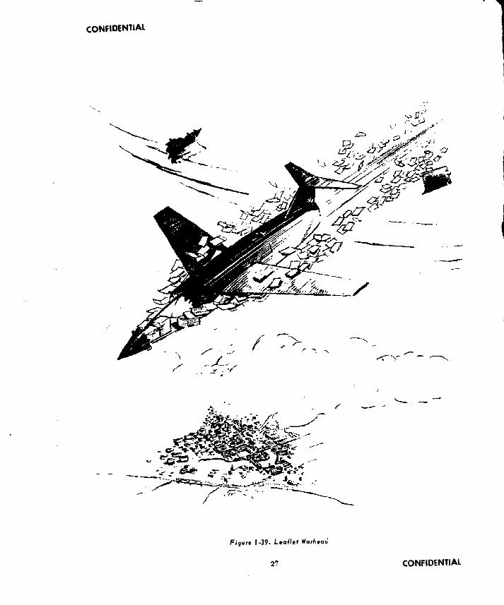
(F ig . 1- 3 9 )A leaflet warhead consists of a container
for housing leaflets or booklets. The leaflets are released from the warhead compartment
CONFIDENTIAL12

CONFIDENTIAL
F lg u r o 1-18. C o n t in u o u s R o d W arhoad
and fall to earth over a widely dispersed area. Damage Is inflicted through the demoralizing effect of the written material on the leaflets.
M l. IMERT AND EXERCISE WARHEADS(F ig . 1 -4 0 and 1-41)
Inert and exercise warheads are not used directly against the enemy, butrather areuaed to train personnel and for checking the operation of weapon systems and their components. An exercise warhead, formerly known as a practice warhead is a warhead which simulates the shape and weight of the tactical warhead. It is usually loaded with instruments which record or telemeter data on the performance of the weapon system components and operators during operation of the system. It is used against simulated targets on the surface and against target drones In the air. For use against air targets, it usually Includes miss distance instrumentation which measures and records how close the delivering missile comes to the target during the practice flight. An
exercise warhead may also contain, in lieu of Instrumentation, pyrotechnic materials and small amounts of high explosive or spotting charges, and be tactically fuzed to provide realism.
An Inert warhead, formerly known as a training warhead, simulates the shape, size,
13 CONFIDENTIAL

CONFIDENTIAL
New Mexico Institute of Mining and Technology Photo
F i f v n 1-20. Damage from Canilnuout Rod Work tad
(Firad again st aircraft akin pan alt)
weight, support sad handling provisions, external electrical, hydraulic, or pneumatic receptacles', and in general all components of the actual warhead which have an influence on the operations carried out by the weapon system ground crews. Such an inert warhead is not
designed to be flown in the m issile but instead is used for ground checkout and training of the weapon system operating personnel. It sometim es Includes Instrument&tlou to measure the accuracy and speed with which the ground crews carry out their particular functions.
CONFIDENTIAL 14

CONFIDENTIAL
/
Fijiurt N2I» Cfvifer Wqi7»*W
Figvr* 1»22* Submissilm Shapes
15 CONFIDENTIAL

CONFIDENTIAL
Figure 1-23. Submittil* £ /« c (ion Gun Tub• M ifhe tf
FJflUfu 7-25. Example of C luster Warhead
CONFIDENTIAL 16

CONFIDENTIAL
Entrance side of wing panel after being damaged by high explosive unstabiiized submissile after impact with the target.
Figure 1-26. Damage from C luste r Warhead
I
17 CONFIDENTIAL

CONFIDENTIAL
CONFIDENTIAL 18

CONFIDENTIAL
jW-VM O-fiH — i19 CONFIDENTIAL

CONFIDENTIAL
SLUG J E T
<S)
Figaro 1-29. Action of Shaped Charge Warhood
Figure 1-30. Typical Shaped Chary* Warhead
CONFIDENTIAL 20

CONFIDENTIAL
u. S. Navy Photo NP/45-38575
View shows jet impact area of F6F-5K aircraft struck by aluminum coned charge at average jet velocity of over 14,200 fps for~l00 foot standoff.
F ig iira F - j l. Aircraft D am age from Sfiapad Charge Wcrhaod
31 CONFIDENTIAL

CONFIDENTIAL
U. S. Army Photo
View shows impact location of 90 mm H EAT T108E40 projectile fired against a T26 Pershing type tank. Entrance hole is approximately 2-1/2 in- x 1-1/2 in.
Figure ? -32. Armar Pepefratian from Shaped Charge Warhead
CONFIDENTIAL 22

1
CONFIDfcf'illAL
F,;jutc J-Jfjl, Chemical or Biofo^f'ca/ WarfieoJ
CONFIDENTIAL
l 1

CONFIDENTIAL
4*
sphere
FLETNER
F lg u ro 7-34* Current Bambtmt Shapm.%
F lg v ro )-35. T yp ica l B io lo g ic a l Wathoad
CONFIDENTIAL 24

CONFIDENTIAL
N.
F fg u r* 1-36. tncmndiory Warhead
25 CONFIDENTIAL

CONFIDENTIAL
F ig u r t 1-3S. Typ ica l Incendiary Warhtad
CONFIDENTIAL 26
CONFIDENTIAL
Figure I -39. Leaflet Warhead
2 ‘ CONFIDENTIAL

CONFIDENTIAL
CONFIDENTIAL 28

1
CONFIDENTIAL
if
if
K Figur* 7-4 7. Wcrfi*o</
MV
29 CONFIDENTIAL

CONFIDENTIAL
Chapter 2
W EAPONS SYSTEM CONCEPTS
2-1. INTRODUCTION
The weapons system concept is a philosophy applied to the design of a multi-component system wherein each component of the system is so designed that its contribution to the complete system is a maximum when operating in conjunction with *he other com- pcnents of the system. This philosophy of design has long tieen applied in sound engineering practice. The increase in the complexity of modern weapons during recent years, along with the attendant increase in the size of the engineering staff required to design these weapons, brought forth a name for the philosophy of weapons system design. A discussion of the concept is included here since in practically every instance the warhead designer is working as a member of a weapons system team. It is important, then, that he appreciate the scope, principles, and the method of applying, weapons system design concepts.
2-2. SCOPE
The Department of Defense applies weapons system concepts in its broadest sense \vnen it so utilizes the manpower and natural resources of this country that the contribution of each segment to Die security of the United States is a maximum when operating in conjunction with all other segments. Weapons system concepts are then applied within the Department of Defense in a narrower sense, when, for example, an assignment is given to a weapons system team to develop a system for Air Defense. This air defense system might conceivably include four or five different means for destroying the attackers; one of which might be a surface-to-air m issile system. This system Is designed for maximum contribution to air defense by applying weapons system concepts in a still narrower sense. Furthermore, the warhead designer developing the warhead for this ground-to-air system designs his warhead for a maximum contribution to the system and thereby applies the concept. Infact,
PROCUREMENT
PColARCh DEYFLCPNENT
p R ftru T W r UANUIACTUNE
7t^T
p ODUCitcw jsa.o*TOOUNt. OCUKEMSNTAODUrON WAN-.-rACtUKJC
F ig u re 2-1.
LOGISTICS
'NT
SUPPLY
maintenanceOVERHAUL HE PA IN
SPANKS
OPERATIONS
TRAINING
TEST
EVALUATEDOCTRINE
OFFENSIVE UTILIZATION
DEFENSIVE UTILIZATION
ASSESSMENT
Utilization of Manpower and Natural Resources.30
CONFIDfNllAl

CONFIDENTIAL
YtARS4 1
CONCEPTION p r e l im in a r y p r e - pr o du ct io n c o m p o n ent "* ' " DESIGN ” DESIGN *~J TEST”*"*
FLIGHTTEST *"
PRODUCTION ft TOOL DESIGN^
DELIVERY
BOO
TOO
600
500
6,150,000 MAN HOURS 50.000,000 d o l l a r s
400
300
200 -
100
Figure 2*2. Engineering Effort • Guided Missile System Development
the detailed design of the various components of tike warhead are developed so as to contribute to the maximum effectiveness of the warhead. Thus, it may be seen that the concept of weapons system design may be applied on a scope as broad as the operation of the Department of Defense or as narrow as the detailed design of a warhead component.
2-1 THE MEASURE OF THE COST OF THE COHTRIfUJTlON
The most difficult aspect of practicingthe concept of weapons system design is to decide where to stop maximizing the contribution of a component. To make this decision, one must measure the contribution relative to the effort required to produce iL. Thi<- effort, in the last analysis, is always measured in terms of manpower and natural resources The much used
terms of light weight, ease of maintenance, simplicity, reliability, low cost, strategic materials, and a host of other terms, all refer to conservation of manpower and natural resources. These are the true measures of cost, and therefore the optimum weapons system is one which obtains its objectives with the least overall expenditure of these two commodities. A. breakdown of the utilization of these commodities in bringing a weapons system to bear on the enemy is shown graphically in Figure2 - 1.
2-4. SIZE OF THE WEAPONS SYSTEM DESIGN TEAM
The size of a weapons system design team obviously varies widely in proportion to the scope of the problem. The missile warhead designer will most often lie working as a
i
31 CONFIDENTIAL

CONFIDENTIAL
member of a design team dealing with a complete missile system, The diagram shown In Figure 1-2 graphically represents the distribution of engineering effort for a typical missile Bystem development. It Is presented here to give the designer an understanding of how his work fits In with that of the other members of the team.
2-5. APPLICATION OF WEAPONS SYSTEM CONCEPT TO WARHEAD DESIGN
This pamphlet Is written and arranged on the premise that the warhead designer will be working as a member of a weapons system team. As such, he will be responsible for all design and development work directly related to the warhead. His responsibilities will include warhead-type selection, warhead evaluation, detailed design in coordination with the missile and fuze designers, and warhead tests. Basic data are Included In the pamphlet to assist the warhead designer In carrying out
these responsibilities.The warhead designer needs data relating
to the complete missile system to order to carry out his function as the warhead member of the missile system team. These data are listed as follows. Thi pamphlet Is written on the basis that this specific information is provided in each case for which a warhead design is required.
Information Supplied to the Warhead Designer1. Allowable warhead weight2. Warhead compartment size and shape3. Missile velocity4. Standard error of guidance5. Size and shape of target6. Target velocity7. Target vulnerability8. Target engagement altitude9. Target engagement aspect
10. Warhead installation Information11. MlsBlle environment during handling and
flight
CONFIDENTIAL 32

CONFIDENTIAL
Chapter 3
WARHEAD SELECTION
3.1. INTRODUCTION
For a particular m issile, the warhead designer may be required to select a warhead which will make the maximum contribution to the complete m issile weapons system. If this is the case, In order to be certain that he has selected the proper type, he should actually carry out the detailed design of several types and then carefully evaluate each one against the other to determine the optimum. Preliminary design data for all warhead types are provided in Chapter 4. Chapter 5 provides basic information for evaluating the warhead types against various targets. This chapter (Chapter 3) presents data to aid the designer in selecting the warhead types for initial detailed design and evaluation.
The initial selection is based on the weight allotted for the warhead by the missile system designer, the standard error of guidance of the missile guidance system, and on the target or targets specified. This data, used In conjunction with the selection chart presented in subchapter 3-3, will permit the warhead designer to select one or two warhead types for optimization. If the chart does not Indicate a unique type, the types selected must be designed In detail and evaluated.
3-2. CLASSIFICATION OF TARGETS
Targets are classified into eight types in the selection chart. These classifications are shown in Table 3-1.
These classifications have been chosen first so as to distinguish between aerial and surface targets. Aerial targets are further classified as high level or low level; a low level target is considered as being below 20,000 feet, a high level target as being above 20,000 feet, Surface targets are further subdivided into concentrated targets, dispersed targets and unprotected personnel targets. A concentrated target Is one which requires a direct hit or very near miss to do damage and it can be disabled with one hit. A dispersed target is spread out over a large area and requires many hits to disable it. Personnel are In a separate class. Surface targets are further classified as hard and aoft. A hard target is one which has been specifically designed and constructed to withstand attack, while a Suft
TABLE 3-1
Target Classification ,
Title
High Altitude Aerial Low Altitude Aerial Concentrated Hard Surface Concentrated Soft Surface Dispersed Hard Surface Dispersed Soft Surface Unprotected Personnel
On SurfacePartly Covered Personnel
on Surface
Classification
HAALAACHSCSSDHSOSSUPS
CPS
CONFIDENTIAL 33

CONFIDENTIAL
3-). WARHEAD SELECTION CHART
Warhead selections shorn) in Table 3-2 are tentative, and should he used us u very rough guide only.
Table 3-2 Warhead Selection Chart
TARGETCLASSIFICATION
STANDARD WARHEAD WEIGHT IN POUNDSERROR OF GUIDANCE
(FEET!25orLess
25to100
100to300
300to600
Over600
HAA Less than 30 SC*£0
SC* CR*FR
FR* CR*CL
FR*CL* FR*CL
HighAltitudeAerial
30 to 60 SC EBCR*FR
FR* CR*CL
FR* CL* FR*CL
More than 60 CR FRCL*FR CR
FR* CL* FR*CL
LAA
LowAltitudeAerial
Less than 30 SC* £6 EB*SC* £B*CL CR
£8*CL
EB*CL
30 to 60 EBSC
EB*CR
£B* CL*CR
a ;CL*
EB*CL
More than 60 CR £fi CL£ 0 CR
CL*EB
EB*CL
CHS
ConcentratedHardSurface
Less than 30 SC* SC* SC*IB
16* IB*EB
30 to 60 scs c * SC*
IBia* IB*
EBMore than 60 IB SC IB
IB*EB
CSS
ConcentratedSoftSurface
Less than 30 FR*IB* FR* IB* FR* IB* EB
FR* IB* EB
FR* IB* EB
30 to 60 Fr<* FR* SR 16
FR*EB CL
FR* EB*CL
FR* EB*
More than 60 FR* FR*OR
FR*CL
FR*EB CL
FR* EB*
PHS
DinperaedHardSurface
Less than 30 SCSC* SC*
IBIB*
30 to 60 SCSC* SC*
16IB*
More than 60 SC SCIB*
DSS
DispersedSoftSurface
Less than 30 FR* FR*OR
FR* CL “ OR
FR* CL* E6
FR* EB* CL
30lo 60 FR* FR * OR
FR* CL* OR
FR* CL* EB
FR*EB*"CL
More than 60 FR* FR*OR
FR* CL* OR
FR* CL* EB
FR* EB*CL
UPS
Unprotected Personnel on Surface
Leas than 30 FR* FR* FRCL
FRCL
FRCL
30 to 60 FR * FR*. FRCL
FRCL
FRCL
More than 6b FR* FR* FRCL
FRCL
FRCL
CPS
Partly Covered Personnel on Surface
Less than 30 FR* FR* FRCL
FRCL
FRCL
30 to 60 FR* FR* FRCL
FRCL
FRCL
More than 60 FR* KR FRCL
FRCL
FRCL
CODE) IB - Interne! Blast FR - Fragment CR - Continuous Rod SC - Shaped ChargeEB - External Blast C L - Cluster DR - Discrete Rod
•More likely selections.
34 CONFIDENTIAL

CONFIDENTIAL
target has not, although It may be militaryequipment.Examples of the various classification oftargets follows.HAA Turbojet aircraft, turboprop aircraft,
reciprocating engine aircraft, turbojet missiles, ramjet missiles, rocket powered missiles.
LAA Same as HAA plus helicopters, light- er-than-alr craft.
CHS Concrete pill boxes, bunkers, armored vehicles, single fortifications, tunnels or causeways, concrete dams, battleships, destroyers, large caliber gun emplacements, concrete bridges.
CSS Trucks, locomotives, transport ships,tankers, landing craft, Individual aircraft on ground, individual industrial buildings, wooden bridges.
DHS Submarine pens, steel mills, underground Industrial plants. Naval shipyards.
DSS Large industrial complexes, railroadmarshalling yards, airports, oil refineries, ammunition dumps, supply areas, highways.
UPS Infantry troops in the field or in encampments.
CPS Partly covered troops on the surface of the terrain, e g. In trenches
3-4. BIBLIOGRAPHY
" (1) “Principles of Guided Missile Design;
Operations Research; Armament*’, Grayson Merrill sad Harold Goldberg, D. Van Noatrand Company, Inc., Princeton. 1956.
(2) “ New Weapons for Air Warfare. Science in World War II", J . C. Boyce, Little. Brown, 1947.
(3) “ Elementary Comparison of Antiaircraft Warhead Types", HerbertK. Weiss, BRL Memo 631, ASTIA AD-7624. Nov. 1952.
(4) “ Optimization of Warhead and Fuzing Parameters'*, RandCorp.,RM-349, Mar. 1950.
(5) “ Weapons Selection for Air Targets '*, Directorate of Intelligence (USAF). ASTIA AD-38743, Jan. 1954.
(6) “Tactical Analysis of Surface-to-Air Guided Missile Systems", C. F. Meyer, R. P. Rich and others, Johns Hopkins Univ. Report No. T B -166-1, ASTIA AD-22820. Nov 1953.
(7) “ Effectiveness of Warheads for Guided Missiles Used Against Aircraft’’, Ed S. Smith. BRL Memo. Report 507, Mar. 1950.
(8) "Effectiveness of Existing and Development Weapons in the Intermediate Antiaircraft Role", F. G. King and F, Q, Barnett. BRL Memo Report 528. Nov. 1950.
(9) “ Effectiveness of Missile Warheads Against High-Sjjeed Air Targets", Ed S, Smith, BRL Memo. Report 528, Dec. 1954.
(10) “ 1500 lb. Anti-Personnel Warhead for the Honest John Rocket", Ed S. Smith,A. K. Eittreim and W. L. Stubbs, BRL Memo. Report 779.
CONFIDENTIALJ ’JV -A ‘ I D f .il 1

OR DP 20-290
Chapter 4
WARHEAD DETAIL DESIGN
4-1. GENERAL
This chapter presents the data needed to effect the complete detail design of all warhead types. A step by step procedure is set forth for each warhead type except chemical and biological which are presented In general narrative form. A summary of design data required and a list of the data required by the fuze designer Is presented at the end of each subchapter.
The attention of the designer is again Invited to the fact brought out in Chapter 2 that certain data are generally required to allow the warhead designer to effect the detail design of the warhead. The checklist of these required data is repeated here for emphasis and convenient reference.
information Supplied to the Warhead Designer1 . Allowable warhead weight2. Warhead compartment size and shape3. Missile velocity4. Standard error of guidance5. Size and shape of target6. Target velocity7. Target vulnerability8. Target engagement altitude9. Target engagement aspect
10. Warhead installation information11. Missile environment during handling
and flight4-2. BLAST WARHEADS
4-2,1. Detail Daiign Stapi Step
Number Detail Design Step1. Decide Function of the Warhead Case2. Investigate Compatibility of Weight
and Space Allocated3. Design, Installation and Handling Pro
visions4. Make Strength Analysis5. Provide for Loading Explosive6. Provide for Installation of Fuze7. Select Method of Fabrication8. Prepare Summary of Fuzing Hequlre-
menta8. Prepare Summary of Design Data
The exact order of the design procedure may vary depending upon the viewpoint of the designer and, even more, on the military re quirements which often fix certain parametersin advance.
4-2,2. Detail Daaign Data ( F i g . 4 -1 through F ig . 4 - 5 ; T a b le s 4-1 through 4 -3 )
Function o f the Warhead C o s e and R e la t e d B lastE f f e c t s The function of the warhead case depends upon whether the warhead is designed to be detonated Inside or outside of the target envelope, that Is internal or external blast. The case for an Internal blast warhead must function not only as a container for the explosive charge but also as ameans for penetrating the target. The case for an external blast warhead serves only as a container for the charge.
Internal blast within a structure produces an overpressure inside of the structure. When this overpressure is of sufficient magnitude and duration, the target structure will fall due to the explosive action of the blast acting on the structure. This explosive action is such that the outer structure of the target Is blown out and away from the target. The remaining structure Is weakened to such an extent that it
CONFIDENTIAL 36
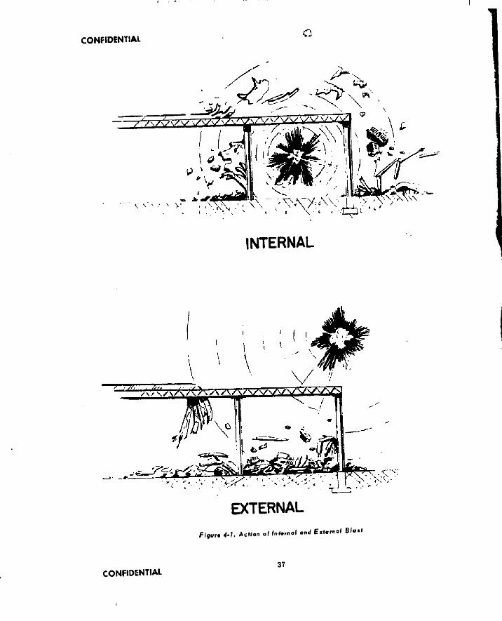
CONFIDENTIAL c
\ v
INTERNAL
EXTERNALF i g u r e 4- h Action of |ni.r..ol a n d External Bfo.l
CONFIDENTIAL37
I

CONFIDENTIAL
Is unable to withstand the structural loads and collapse of the target structure occurs. See figure 4-1.
Internal blast damage is proportional to the ratio of the high explosive to the volume of the space containing the burst. Therefore, it Is possible to accomplish similar damage with a small charge weight In a small volume as with a large charge weight In a proportionately larger volume. it is to be noted that damage by internal detonations Is caused not only by the air blast wave but also by the expanding gaseous products of detonation. Damage from the Utter cause Is also dependent upon the ratio of the high explosive released and the volume containing the burst.
A similar action occurs with an external blast except that the explosive action Is directed against the outer rather than the Inner surface of the structure. With external blast, the overpressure produces an implosive effect on the target structure rather than explosive, and structural failure is generally due to inward collapse. See Figure 4-1.
The peak overpressures and the positive impulse of air shock waves from the detonation of spherically shaped explosive charges of 50/50 Pentolite (see Appendix) have been measured tinder ambient atmospheric pressures and temperatures simulating altitudes from sea level to 50,000 feet. Reference 4-2 .a The following equations fit the experimental data.
jL - H4.9 * 203.4 A 401-9 . „pc zp o'> <z p oW <z p uw '
lo*10 '/, * 1*574-*.«5 to,10 (ZJ>oii)where: ° (4-2.2)
p = peak pressure in psi p o * ambient pressure in atmospheres
(1 atmosphere = 14.7 psi) z = R/cV, known as scaled distance ft = distance from explosion in fe, i c = weight of Pentolite In pounds 1 - positive Inpulse, milliseconds psi
These equations are graphically represented in Figures 4 -2 and 4-3 . Later data beyond the
range covered by equation 4-2.2 and Reference 4-2 .a cause extensions of the line (onlogpaper) to be curved.*
The foregoing data on peak pressure and Impulse may be corrected for other explosives by using the following relative values on an equal volume basis. Reference 4-2.b .
To obtain relative values ou an equal weight basis, the specific gravity of the explosives must be considered. For example, the following table Illustrates the values of peak pressure and impulse relative to composition “B " on both a weight and volume basis for HBX-1 and H-6. The exact composition and properties of the various explosives may vary slightly between the armed services.
The steel case retaining the explosive charge reduces the effectiveness of the charge since it requires energy to rupture it after the charge has been detonated. The effect of this has been studied In Reference 4-2. c with the following empirical results. For peak pressure:
w1— » 1.19
i + « a ■ m'>
1 + M
For positive Impulse:v H M .n *T)
where;trcm
1 + Al
(4-2.3)
(4-2.4)
= equivalent bare charge weight ' actual charge weight = actual casing weight = ratio of casing weight to charge
weight in cylindrical section “ casing-to-charge weight-ratio pa
rameter, defined as follows:
M1 — 1.0 when # 5 1.0 iM* - / wh i M < 1.0
The types of targets likely to be encountered In blast warhead applications vary from light structures such as aircraft ai.d frame buildings to Intermediate structures such as vehicles and masonry buildings through very heavy structures such as armored vehicles and reinforced concrete structures. Light structures arc critically damaged by blast when detonated in the air nearby (by proximity fuzes)
* R eferences are lis ted at the end of sections within chapter*.38 CONFIDENTIAL

CONFIDENTIAL
Table 4 -1 C h a ra cteristics of Explosives
Relative
ExplosivePeakPressure
RelativeImpulse
SpecificGravity
Pentolite (50/50; TNT/PETN 0.98 0.97 1. 68
Composition " B " (60/40/1: RDX/TNT/ Wax added)
1.00 1.00 1. 6B
TNT 0.92 0.94 1. 60
Tritonal (80/20: TNT/Al) 1.04 1.08 1.70
Torpex 2 (42/40/16: RDX/TNT/Al) 1.13 1.16 1.76
HBX - 1 (67/11/17/5/0,5:Comp B/TNT/Al povder/D-2 Desens/ CaCt) 1.12 1.19 1.72
H-6 (74/21/5/0.5:Comp B/Al/D-2 Desens. /CaCl) 1.20 1.39 1.75
Table 4-2 Characteristics of HBX-1 and H-6
Relative peak pressure Relative Impulse on basis of - on basis of
Explosive Weight Volume Weight Volume
HBX-1 1.07 1.12 1.14 1.20
H-6 1.12 1.19 1.30 1.39
or by surface impact close to the structures, in this instance, the warhead case, acting as a pure container, represents from 15% to 20%of the total warhead weight. If a warhead with such a case registers a direct hit on light target structure, the case is usually strong enough to properly retain the charge until detonation takes place and results in a damaging high order explosion. Warheads for use against intermediate structures are usually fuzed to explode on impact or soon thereafter. For such a warhead, the case is strengthened somewhat to withstand the Impact forces and usually represents about 25% to 30% of the total warhead weight. Warheads used against very heavy structures are designed with heavy steel ogival heads and reinforced walls to give them penetration capability. For this use. the case may
represent 50% of the total warhead weight.The effects of altitude on external blast
are reported in References 4-2 .n and 4-2.0. The blast envelope generally takes the form of an oblate spheroid. The axial bounds of this envelope are generally unaffected by altitude; the transverse bounds (above and below the target) are generally pinched In with increase of altitude. More extreme effects (on the transverse bounds) are caused by gust loading due to the velocity of the target. Reference 4-2,0 .
If the direction of the external blast re lative to a target surlace is face-on, the blast volume is much greater than if the direction is side-on, especially at high altitudes. In general, for bursts occurring at equal distances from an aerial target surface, the damage is a direct function of the charge weight. As this
CONFIDENTIAL 39

CONFIDENTIAL
weight decreases from large (-. oou ll.) to .small lixHb), the tendency is to obtain local failure instead of drastic and immediate disruption of the aircraft.
It is to lie noted that many aircraft are capable of continuing in night with considerable local damage, in utilizing the data presented in deferences 4 -2 .a and 4-2.o. it is to be further noted that the Russian I1.-3K "H ear” and present Russian fighters are generally similar to the H-29 and K-B6 aircraft, respectively, in regard to the effects of blast phenomena.
The effects of altitude on internal blast are reported in References 4-2.p and 4-2.q These references report the results of experiments conducted by using small charge weights against various aircraft components, in which the blast waves struck the nearest portion of the structure normally (i.e. head on) butdonot include the effect of charge velocity, i.e., far side enhancement. These results show that the ratio of the explosive weight needed at high altitude to that at sea level for equal damage increases with altitude. The average ratios for the aircraft components tested were 1.22,1.39. and 1.72 for altitudes of 30,000 , 45,000, and 60,GOO feet respectively.
References 4-2 .r through 4-2 ,t report the effects of the charge velocity on the resulting peak pressure and positive impulse. These experiments are all with 3/8 lb charges at sea level. They Indicate thattheside-onpeakpres- sure and positive impulse are both increased in the direction of charge motion and decreased in the opposite direction relative to results obtained from detonation of a stationary charge. These velocity effects are probably larger for the relatively small charge weights tested than for the larger weights used in engagements. Similarly, the effects are likely to be larger at high altitudes than at sea level.
The effects of altitude on target surface bursts are intermediate between those for external and internal blast. The effect of a surface burst of a given charge weight may be ap
proximated by the damage due to an internal burst of one-hall this weight.
The damage to industrial buildings from external blast was studied experimentally in Reference 4- 2.cl. The damage from blast was negligible at overpressures up to 2 .0 p s i and consisted almost entirely of broken windows and roof decks. At 3.5 psl all windows and roof decks were broken and some walls cracked but did not cave in. At 5 0 psi a few localized portions of external walls were blown down. At 7.5 psi over half of the walls crumbled and parts of the roof structure including training were brought down. AtlOpsiallofthe masonry walls were reduced to rubble and the steel support structure was distorted; only the major steel columns were left standing. At 15 psi the entire building had collapsed and everything was wrecked except equipment in the basement and some steam generators above ground. At 30 psi the entire building and everything above ground with the exception of the steam generators was a tangled mass of masonry and crumpled metal.
Data on the penetration ability of various ogives is given in Table 4-3. This information may be used as a guide todesigningpenetraiion cases.
The warhead designer, acting as a member of a weapon system team, is given information defining the targets, the missile performance, the guidance accuracy, and the allowable total warhead weight. With this known and by use of the foregoing data on blast effects and casings, a decision is made regarding the function of the warhead case between the limits of a pure container and a containing-plus-penetration means. This will establish the case configuration. Also, using the data and percentages given, an approximation of the weight of the case is made.
Compatibility of Waight and Spate Allocated Knowing the approximate configuration and weight of the case and the total allowable warhead
40 CONFIDENTIAL

CONFIDENTIAL
weight, an approximate charge-to-metal ratio may be established Having this, the compati- LillUy of the weight and space allocated to the warhead Is checked using the following formula:
it f,K(i *' '«•> f l* where:
i' - total warhead volume in cubic inches
w allowed weight of warhead in pounds ■ m charge-to-metal ratio based on to
tal charge and metal weight p„, - density of metal in pounds per
ruble inchdensity of charge In pounds per cubic inch
Use of the above equation will Indicate whether weight or space is the limiting factor in determining the size of the warhead case. Weight will be the limiting factor when total weight of a warhead which occupies the entire warhead compartment is in excess ofthe weight allocated for the warhead. In this instance, the weight and size of the warhead must be reduced accordingly. Space is the limiting factor when the total weight of the warhead Is less than that allocated for the warhead In this instance the charge-to-metal' ratio may be decreased for penetration type cases by increasing the amount of steel in the ogive. This will increase its penetration capabilities and increase the weight per unit volume of the warhead. Note that the method of mounting the warhead can also be a limiting factor tn determining the weight and shape, and consequently the mounting must be considered. At this point in the design, the overall configuration of the warhead, total weight and charge-to-metal ratio may be fixed.
Installation and Handling P rov is ions The installation provisions In the warhead compartment and support fixtures required for handling must be studied. The requirements for these will be obtained from the missile system designer. Typical installation and support fittings for the warhead consist of mounting lugs or a mounting
ring around the periphery of the warhead case. These mounting lixtures will normally be located centrally on the warhead case or near both ends of the case. The warhead may be supported from one end only, but additional strength In the casing is then necessary to overcome the cantilever effect of the overhanging portion.
S t r e n g t h A na lys i s The strength of the overall case and the support fittings can now be analyzed. The type and magnitude of the loads to which the warhead will be subje cted depends on the location of the support fittings and the design load criteria. This inlormatlon is also obtained from the missile system designer. In some installations the warhead case Is an Integral part of the missile structure and must be treated accordingly in the analysis. Where the case functions only as a container for the explosive charge the design is based on a stress analysis considering the missile and handling inertia load factors. For such warheads, missile-acceleration forces are always important, and centrifugal forces cannot be neglected for spinning rockets and missiles When impact or penetration of structure is required, it will usually he found that the Impact or penetration loads are much more severe than the missile and handling loads. Under these conditions the impact and penetration loads determine the strength of the warhead case, while the missile inertia load factors determine the design of mounting lugs from a strength viewpoint.
Exp lo s ive Looking ond Sea ling An opening fnust be provided in the warhead cacing to allow loading of the explosive charge. Loading apertures are usually centrally located on either end of the warhead case when target Impact is not required. When target penetration is required, the loading apertures will normally be on the rear of the warhead case, because such an aperture in the nose weakens the penetration ability of the warhead. The inside surface of the warhead casing is coated with inert material to eliminate chemical reaction between the explosive and warhead metal, to provide
CONFIDENTIAL 41

CON
FIDEN
TIAL
• l * f
T able 4 -3
Penetration Capabilities Of Penetration Case
Approx. Projectile Impact Impact Material Penetrated
Description of ProjectileWeight
lbDlameLer
in.Velocity
fpsAngle
deg.Penetrated Depth -
in.Reference
Bomb, Experimental, Mk 81, Mod O 250 9 1000 20 STS Armor* 1-7/8 9-2. i
Bomb, G. P. (Low Drag) Type EX-12, Mod O 500 10.95 1000 20 STS Armor* 1-1/4
Bomb, G .P . (Low Drag) Type E X -10, Mod 3 925 - 1000 0 STS Armor* 1-1/2
Bomb, G .P . , AN-M65A1 1240 19 807 0 STS Armor* 2
Warhead, G .P ., T23 1675 - 1487 0 STS Armor* 2 ' - I . :
Warhead, G. P . , T23 1675 - ‘ 48<- 15 STS Armor* 1 .5
Warhead, T. P . , T23 1691 - 1392 45 1 J - l . :
Bomb, G .P . (Low Drag) Type EX-11, Mod 0 2000 17.95 *000 20 STS Armor* 1-7/5 o_~
Bomb, G .P ., AN-M66A2 2402 24 574 0 STS Armor* it " “ L. ■ '
Bomb, General Service, TS5 3000 24 1000 15-30 STS Armor* . e:-,s -'-Lfc
Bomb, G .P . (Low Drag) Type EX-10, Mod 3 925 - 1000 0 Concrete** 24 :
Inert Loaded Warhead, T2 1400 - 1128 0-20 Concrete** 10 9-1.
Bomb, General Service, T55 3000 24 1000' 15-30 Concrete** 1U v rBomb, T28E1 (Amazon 11) 25000 38 1070 17 Concrete** 177 0 - : . : n
Bomb, T28E2 25000 32 1090 20 Concrete** 249 3-2 ■
*STS Armor Plate “ Concrete. Reinforced
' ON
HU
INH
Al

U r i U J M ' A i
CONFIDENTIAL43

C-ONFimWlAL
Figure 4 -4 . One P ie c e Fabrication
a cushion between small crevices or projections of the metal surface, and to provide a bond between the explosive and the metal casing wall.
The explosive charge is usually cast in place in the warhead cavity. The explosive is heated until molten, poured in place, and then allowed to cool and solidify. The pellet-and- pour method of loading is frequently used in larger warheads weighing more than 200 pounds. This method involves alternately pouring the explosive melt at a temperature somewhat greater than the normal melt temperature, and dropping in quantities of the same explosive in pellet fo .1 until the warhead is filled. Loading may also be accomplished by pressing or tamping preformed or plasticised explosive in place.
Variations in density caused by porosity and shrinkage cavities are most undesirable. These tend to affect the design weight and also, more Importantly, degrade the initial fragment velocity. Filling Is generally accomplished
StAM L .iS OH V. ELDEDtuciue d r a w n to ai2E
BUTTw e l d s
Figure 4 *5. Muitipiecc Fabrication
near the freezing temperature of the explosive to avoid excessive shrinkage and to control the grain size which affects sensitivity. Shrinkage is minimized by the use of risers, controlled cooling rate, etc, The final seal usually consists of a plate bolted in place over the loading aperture. A layer of Inert material is usually Inserted between the sealing plate and the e x plosive charge to allow for thermal expansion.
F u ze installation The warhead fuze is usually located in either the nose or the rear portion of the warhead. Some warhead applications r e quire a fuze in both locations. A threaded hole for fuze insertion can be tapped directly in the warhead casing. A fuze adapter consisting of a bushing with external and internal threads is generally used. The fuze is threaded into the adapter, or an adapter plug is inserted to keep out foreign material and moisture prior to fuze installation. This plug can also be so made as to be useful in handling the warhead.
Fabrication and Too/injBlast warheads are fabricated using two general methods—one piece and multipiece construction.
One piece construction utilizes the so- called pierce and draw method. A preheated billet Is pierced with a mandrel sufficiently to start the general Internal shaping. The front ogive is then formed. The billet is then forced through draw rings to form the cylindrical and rear portions. This is followed by heat-treating
CONFIDENTIAL 44

CONFIOfNUAl
until minimum physical properties : ct. See Figure 4-4.
For the multip'ecc construction, the no v and rear sections may Ixj elthr, ■■-■•■ensed fro o plate or forged, depending on the configuration, The cylindrical section Is usually fabricated from seamless or welded tubing The above components are then assembled by butt welding. See Ft ;ure 4-5.
Fabrication by the pierce and draw method is best adapted to heavy-walled munitions while thln-walled cases are usually fabricated using multlplece construction. After Initial setup, higher production rates canbeobtatned with the pierce and draw procedure.
Summary a f Fuztng Requirements The fuze designer needs design information to design a fuze which Is compatible with the missile system and the warhead. He will have access to the same missile system data as did the warhead designer. In addition to this, the fuze designer will need the following information relating specifically to the warhead:
(1) Weight of warhead allotted to fuzeor S&A
(21 Type of explosive used(3) A drawing of the warhead(4) Type of case used, that is pure con
tainer, impact, or penetration
(5) V
Summery at Design Data At the conclusion of the design procedure, a summary of engineering data relating to the warhead should be prepared. This should include the following items:
(1) Total weight(2) ’design and installation drawings(3) Explosive
(a) Material(b) Weight(c) Density
(4) Charge-to-metnl ratio(5) Case
(a) Typo(b) Weight
(G) Location of center of gravity(7) Mounting means
4-'1 '. f M.nnc ■
4.2 c “The Effect of--' •:.bucp-'srjrii"'’ Temperature 0” /.'?• f'r '-ck! . Jane Dewey and dooeph iy'.v-r-.za. L.IL Report 721, May 1950.
4-2.b “Relative Air Elact Damage Effectiveness of Various F.Kploslvec". W. K. Baker and O. T. Johnson, 3KL Report 689, June 1953.
4-2.e “The Effect of the Steel Case on the Air Blast from High Explosives", E. M. Fisher and C. J. Aronson, NAVORD Report 2753, Feb. 1953.
4-2.4 Report by Armour Research Foundation of Illinois Institute of Technology,' "Study of Vulnerability of a Thermal Electric Power Plant to Air B last" , Mar. 1954.
4-2.» “ Final Report on Ballistics Experimental Tests of Guided Missile Warheads", NPG Report no. 691, Dec. 1950
4-2.f “Tests of Warheads, G. P ., 1500 lb, T 23", NIKI Report no. 1234.
4.2.9 “ F irst Partial Report of Gun Firing Test of Bombs, General Service, 3000 lb, T -55” , NPG Report no. 945, Mar. 1952.
4.2.h “Thirty second Partial Report on Bombs and Associated Components. Final Report on Plate Penetration Tests of the 2000 lb, G. P . (Low Drag) Type E X -U , Mod 0 " , NPG Report no. 950.
4-2.i “ Plate Penetration Tests of Experimental 250 lb. Mk 81, Mod O Bomb Bodies", NPG Report no. 1292, Sept. 1954.
4-2.j “ Plate Impact Tests of Low Drag, G. P ., 500 lb. Bomb Type EX-12, Mod O ", NPG Report no. 1299, Oct. 1954.
4-2.t “ Ballistic Test of Modified 1000 lb, G. P. Bomb, AN-M65A1 and 2000 tb, G. P., Bomb. AN-M66A2 and Bomb Data for Penetration of Missile Resistant Armor” , NPG Report no. 382,
45 CONFIDENTIAL

C O N F I D E N T I A L
ii t l'ii't.i 1 ‘ “ ••lUisttc ’! of H '!■ ii- i w - i
I’. -Lib, Type F V -Il,, 'Vi-.,! V ’,\! IK! linjiui t ll., 748, ' April, I‘' iL,
i - i ." ■ ■ l~;;n n'ution and Docoler'diou ofif'.OM lb Bond-; j tl at.,- ,1 ve Coiiccto
. T ir 'id s " , nilLKcpnri 712. Doc,•t-i.ii "A Metbnd of Predicting li’xbii'nnl
Blast Vulnerability .‘if a:: aFunction of Altitude with Application to R~?.9 Aircraft” , O. T, Johnson, el al., BRL Report 1002, Dec. 195fi.
4-2.6 “ An Experimental Investigation ofthe Effect of Motion of a B-29 Horizontal Stabilizer on External Blast Damage from Explosive Charges” , R, L. Ballard, et al.BR LR eport 982, June. 1556. •
4-2. p ‘ ‘Internal Blast Damage to Aircraft at High Altitude” . J , Sperrazza, BRL Memo. Report 605. April, 1952
4-2.4 ‘ ‘Internal Blast Damage to Aircraftat High Altitudes—Part II” , W. E. Baker and L. E. Needles, BRL Memo. Report 1036, August, 1956.
4-2.r ‘ ‘Air Blast Measurements AroundMoving Explosive Charges". J . D, Patterson II and J . Wenig. BRLMemo, Report 767, March,1954.
4-2.« ‘ ‘Air Blast Measurements AroundMoving Explosive Charges, Part II” ,B. F . Arniendt, J r . , BRL Memo. Report 900, May, 1955.
4-2.i ‘ ‘Air Blast Measurements AroundMoving Explosive Charges, Part III” , B. F , Armendt and J . Sperrazza, BRL Memo. Report 1019, July, 1956.
4-2,4. Bibliography(1) “ Report on Tests of the Effect of
Blast from Bare and Cased Charges on Aircraft” , James N.Sarmousakis, BRL Memo. Report 436, July, 1946,
(2) “ Internal Blast Damage to Aircraft at High Altitude", J . Sperrazza. BRL Memo. Report 605. April, 1952
(3) 1 ‘Studies of the Influence of V ariations al Blast and Structural Parameters on
' last ) >lini;:gr to Structures*’, E Sevlnand IP TV Sauer, Armour Research 'Foundation, ASTIA AD-47 930, Sept.
. 1954.(4) ::Alr Bluet Loading on Structures",
D. C. Sachs and S, K. Hornig, Stanford Research Inst., ASTIA AD- 43 119, July, 1954.
(5) “A Simple Method for Evaluating Blast Effects on Buildings” , Armour Research Foundation, ASTIA AD-38 891, July, 1954,
(6) “ Deformation Model studies of Buildings Subjected to B la st" , H. Williams and A.Ruby, VtbratlonResearchLab., ASTIA AD-58 619. Dec, 1954.
(7) “ Effects of Impacts and Explosions” , NDRC-DIV. 2 Voi. 1.
4-3. FRAGMENTATION WARHEADS
4-3,1- D«toii Dctign StopsStep No. Detail Design Step
1. Estimate the Optimum Beam Width2. Select the External Configuration3. Compute the Maximum Allowable
Charge to Metal Ratio4. Compute the Maximum Possible
Fragment Ejection Velocity5. Select the Optimum Fragment Mass
and Ejection Velocity •6. Compute the Actual Charge to Metal
Ratio and Select the Explosive Type7. Select the Fragment Shape and Ma
terial8. Select the Method of Fragment Con
trol ■9. Design in Detail the Fragmenting
Metal10. Design in Detail Alt Other Components11. Prepare Summary of Fuzing Require
ments12. Prepare Summary of Design DataThe exact order of the design procedure
may vary depending upon the viewpoint of the designer and, even more, on the military requirements which often fix certain parameters in advance.
CONFIDENTIAL 46

CONFIDENTIAL
WARtUAO SIC 11ON
4-3.2. Ditail Datlgn Data (F ig 4 -6 through Fig. 4-13; Tables 4 -4 through 4 -7 )
Seam Width In designing a fragmentation warhead, the designer may first estimate the re quired fragment beam width. Fragment beam width is defined as the angle covered by a useful density of fragments, as shown in Figure 4-6(a). It also is sometimes given as shown in Figure 4 -6(b), In which case the actual beam width Is
To better understand the behavior of the fragments, it is necessary to know what happens to them between the time of detonation and the time of their arrival at the target. An analysis of the dynamic fragment velocity and the method for the determination of the fragment pattern follows. \
Upon detonation of th\ explosive charge, the detonation wave causes the explosive and its case to swell until the failure point Is reached. The case then fails in shear and tension and fragments are ejected at high velocity. If the warhead is stationary at the time of detonation, the velocity possessed by the
m
Figif* 4-7. Vec/or Addition o f Fragment ani/ M ijiiit V elo c it i e s
fragments after a short travel Is termed the “ initial static fragment velocity". The method of computing this velocity will be shown later. If the warhead is moving through space at the time of detonation, as is naturally the case in flight, the velocity possessed by the fragments a short distance away is termed the “ initial dynamic fragment velocity". This dynamic velocity la obtained by adding vectorally the static fragment velocity and the missile velocity.
initial Dynamic Fragment Velocity The initial dynamic fragment velocity. Vj, is found by applying the law ot cosines in Figure 4-7 and is given by
V . 1 + y J + 2 V ,V m c o s 0 ( 4 - 3 . 1 )a j i m
where;Vj= static velocity of the fragmentsv = missile velocity0 = angle of fragment ejection
(static), to be derived later
47 CONFIDENTIAL

C O N JO IN HA1
MACH NUMUth RAN tit
CLASSIFICATION(Hu 0 IU tu l.4 1 4 tu 4 4 4 4 L Higher
°D 1 c CD | c Cl> | c C0 C
Halls . 245 .00033 41 00155 .48 00182 456 .00172
Rt. Cyl. & Cubes S 1 .330 00365 . 50 0O235 . 57 00267 530 .00249
Lorn; Fragments S 5 .330 oom . 50 00294 . 57 00335 530 00312
S-JO .330 00233 50 00354 .57 00403 530 .00375
3-IS .330 0)263 .50 00309 .57 00455 .530 .00423
3=20 . 330 00287 50 00435 . 57 00496 .530 .00461
Table 4-4 One Piece Fabrication
F igure 4-8. Cq V i , H a th Number for Various Fragment Typos
CONFIDENTIAL48

f
CONFIDENTIAL
t li.igim-iit tn v r li thinugh tl«- .iir. il n limi-d down In ur reMM.im c in tli.it it will strike i .Ution.try target at ,i lower vein" it> in tree iii than the initial velocity. For moving targets, the striking velocity is actually the vector difference of the target velocity ami the fragment velocity at the end of its travel, and hence the striking velocity may be greater than the initial fragment velocity. This is discussed further in Section 5-2 a. The actual trajectory of the fragment in space can generally lie ignored since its path is so short that the effect of the gravity can be neglected, and a straight line space trajectory within the fragment's lethal distance can be assumed
F'og.neni Sfow-iiow,, If the initial fragment velocity in free air is known, the veloeity corresponding to a given distance traveled can lie computed as follows:
r - v (4 -3 .2)
where, in consistent units:Kp = distance traveled
- velocity at any distance wp 1,, = initial relative velocity in free air■\ = random projected area of fragmentpu - air density
= fragment mass n = drag forcef a ~ drag coefficient in dimensionless
units = l> u av 1.' i i
! i, is one-half the drag coefficient generally used in aerodynamics. Equation 4-3.2 involves the assumption that by is substantially constant over the travel distance 8f).
A curve of < i> vs Mach number is given in Figure 4-8. To obtain thedistance forgiven initial and final velocities, the value of cd corresponding to the mean velocity.(Vr + F,,V2 is read from the curve. The value of wp i-s then obtained from equation (4-3.2), If the variation in (-p is relatively large, the velocity range should be divided into subranges (such as subsonic, transonic, and supersonic) for which (-p is approximately constant and the distances added to obtain wfl.
! h r i i . u n n r . I i i r i - T l i t - l f - 1 e r | w i l l ! t . i -
given . m i l t h e v**lw i l y ■ a ! t b l s d i s l a m t - w i l l
I.r sought In using equation 4 3 2 it is nc: r~~>.ar v to use a ' ,i corresponding to an average velocity over the distance, which will require a lew iterations ot a trial and error method oi solution. However, the velocity f! lisnotvery sensitive to ‘ j, vyhen the distance Kj, is small
Also of some interest is the average velocity (v) over the distance kj,:
li
KKl>-1where:
,V ■ r.p A, 3 ‘s\f
'’ his equation is most often used in finding the values of * or 1 q from tests that provide values oi v and i> over a measured wp It can be reversed to give the initial velocity if the average velocity and drag coefficient are known.
In connection with Figure 4-8. the following conventions are used:
(a) For balls or spheres, the projected area is that of the maximum section, or A - n r 1
f j
where ru is the radius in feet.(b) For cubes (and also approximately for
right cylinders where length /.»/)) the curve is used in conjunction with an area given by A = 0.25 times the fragment total area in square feet.
(c) Tests at Mach 5.8 indicate that thereis no significant difference above Mach one between the drag coefficient (Cp) of cubes and elongated fragments approximating rectangular parallelepipeds having a length of approximately 9.5 times the geometric mean of width and thickness. Hence to find for an elongatedfragment, one should use for supersonic velocities, either the drag coefficient for a cube with an area a - u.2s times the fragment total area In square feet or a closely consistent relation such as
yX
. 0.0045 I'Vp,,) ■V' lP 1/ (4-3.3)
49 CONFIDENTIAL

CONFIDENTIAL
where is the air density ratio and mis the ITagmvnl Kvass in ounces
For sterl fragments (spheres, rubes, or rectangular paruUelepipeils) the following simplified equation is more convenient to use than equation (4-3 2):
t ^ .v , • ‘ |,'-J fvfy (4-3.4)
where Uf is given in ounces and Kp in feet. For various Mach number ranges, Table 4-4 gives values of ‘ ,, and i for fragments d assi- tied according to shape and a parameter s, where \ is the ratio of length to geometric mean lateral dimension.
Values of < for irregularly shaped fragments are not accurately known but are possibly slightly higher than those of the oblong, square- cornered shapes considered above. Drag coefficients for fin stabilized fragments of unusual shape should be obtained from aerodynamic analysis or tests; however for darts similar to those of around 8-gr-designedby the International Harvester Company (1HC Report IS), values of Cp can oe obtained from References 4 -3 .z and 4 -3 .aa.
Fragment Patterns Both for prediction and design of fragmentation warheads, it is imperative to know how the pattern of fragments ejected from the warhead is related to the design of the warhead. The primary dependence is on the shape of the warhead wall and the location of the point where detonation is initiated
Except perhaps for the detonation point, fragmentation warheads are nearly always symmetrical about a longitudinal axis, which Is usually also the exis of the m issile carrying the warhead. Correspondingly, it is usually assumed that the fragmentation pattern is symmetrical about the same axis. In the case of truly symmetric warheads the available evidence does not contradict the hypothesis of symmetry of the fragment pattern, though there is only a little experimental evidence on this point, most effort having been concentrated on determination of the variation in the other direction as discussed in the next paragraph.
In cases of asymmetric staggering of
notches in the casing, casings made in more than one part, or asymmetric locution oi the point where the detonation is initiated, there are some indications of asymmetry in the fragment pattern. However, the only case in which the problem appears serious is that of a very usymmciiHc detonation point, especially if the warhead is annular In shape (i.e., has a large hollow space along the axis). In this case, the detonation wave may strike the casing at substantially different angles on the near and far sides, producing correspondingly different patterns; moreover, in the zone where detonation waves traveling around opposite sides of the annulus meet, fragment shatter and alteration of velocities are to be expected.
Reverting to the usual case of axial symmetry, It remains to consider the fragment density as a function of angie of emission 4 measured from the forward direction of the warhead axis. Of interest are two different versions of this pattern, usually called “static” and “ dynamic” . The static pattern is the one produced If the warhead is detonated while motionless, while the dynamic pattern is the one obtained If the warhead is In flight.
For the prediction of static 'fragment patterns, reliance is customarily placed on the Shapiro method, Reference 4-3 . c. This method assumes that fragments are (or can be thought of as) originally arranged in successive rings, the part of the warhead casing of interest being composed of many such rings stacked one or another, each with its center on the axis of symmetry. Although this may not be the actual mode of fabrication of the casing, the Shapiro relation is probably a sufficiently accurate approximation for Initial design purposes. Figure 4-9 shows a longitudinal cross-section of such a warhead; Figure 4-10 is a more detailed view of the cross-section in the vicinity of one ring, with pertinent variables labeled. Shapiro considers that the final static pattern is obtained by compounding a nominal angle of ejection with a dispersion about this nominal angle.
The fragments from a given ring are nominally ejected in a direction making an angle
CONFIDENTIAL 5(1

CONFIDENTIAL
(.> with the forward missile axis where, theoretically, o is given exactly l>y equation 4-3.6 and approximately by equation4-3.7. The notation Is the same as that shown in Figure 4-10, except that 1’,, is the initial fragment velocity (ejection velocity) and v'(, is the velocity o£ the detonation wave in the explosive.
£ - • 9 0 “ " ate sin f ---------- --— —--------—- ) ( 4 - 3 , G)2 V i k v » )
( v n cos /*- 9 0 ° * A - arc sin 1 ------------------
7 \Although the derivation of these equations
is not entirely empirical, their results appear to be consistent with experiments.
The fragments nominally ejected at angle o are subject to dispersion about this direction. The actual 3pres.d increases with the length of the warhead and the ejection velocity decreases at the ends. The standard deviation of the dispersion assumed for missile warheads is 3". Figure 4-11 shows this distribution for awar- head having 10° beam width.
Having found the nominal direction of ejection of the fragments from each individual ring, and their dispersion about that ring, it remains to combine these to get the static pattern from the warhead as awhole. Todeter- mine the total number of fragments at a given static angle d . measured as usual from the forward axis, and generally being the same as t>, the contributions from the various rings are added together. Reverting to Figure 4-7,
0 .. means the , 0 of Figure 4 -1 0 .Actually one does not deal with the exact angle (!s, but with an angular interval (such as ±1° increments in <5j, represented by this angle. Having thus obtained the total number ' j of fragments ejected in the interval, conversion to density iuu > of fragments per unit solid angle (steradian) is made by the following equation which treats the density at the center of the 2° interval as representing the average density ir, the interval.
( 4 - 3 . 7 )
DIO.') - 4.560 (tsc '1 > >if) (4-3.5)
montolion Worhsad
DIRECTION Of STATIC ■ FRAGMENT EMISSION
Em iss ion of Fragments
(10° CYLINDRICAL WARHEAD, BASE INITIATED)
m< U J£TO
LLl<£>SE
fl;Z
Figure 4*M* Distribution of Fragments ©tout Nomina/ Ejection Direction
iW-171 0-6H—} 51 CONFIDENTIAL

CONFIDENTIAL
Having found the static fragment pattern, It now remains to find the fragment density If the warhead is moving through space and the vector velocities of the fragment (Static) and warhead are to he compounded to find Hie actual direction in which the fragment proceeds outward. Reference 4-3.b .
The dynamic density imij/ for a given direction <>j is obtainable from the static density i>< o i for the corresponding direction r>j Reference Figure 4-7 by the equations
m o,) = me .>(s i l ls i n 9
m:*t 0s
v l ’
i
V1 + — i
V
I (4-3.10)
where: " /i'/ * velocity of fragments in tlie direc
tion os- in the static caseand:
''n - warhead velocity or relative velocity of missile and target
in addition to the general characteristics of the fragment pattern, there is the question of the fine structure of the pattern: within small sections of the fragment beam, is the distribution of the fragments random, is it. regular, or do the fragments tend to bunch? Generally speaking, a random pattern may be assumed, although in extreme cases this may give adif- ferent warhead effectiveness than a regular pattern. Bunching has sometimes been reported, but it seems likely that mosi cases of this have actually represented poor fragment control.
Consideration has sometimes been given to a “sweeping-up” effect as a result of target motion. That is, if the fragments are dispersed cither laterally or along their trajectory (e.g., by velocity spread) then the motion of the target through the swarm may result In more hits on the target than if the target were motionless. It is believed, however, that this effect is negligible for missile warheadsuaed against targets of relatively slow velocity, compared to othe~
approximations usually Involved.In the event that the designer desires to
calculate dynamic fragment densities using the relative velocity of missile and target rather than that of the missile alone, it is expedient to consider the component of target motion parallel to the missile motion (otherwise the pattern would be asymmetric)- The relative velocity v, la then often approximated by Reference 4-3,bVr - Vni~ V t o s 0 (4-3.11)
where:o - the angle between missile and tar
get coursesand:
Vl = velocity of target
For a more exact treatment of the relative velocity v r see Reference 4-3.bb.
Selection of B e o m Width The factors influencing the choice of beam width are the target, standard error of guidance, aspect, and the fuzing accuracy. The first consideration should be given to the target. The information given the warhead designer will include the vulnerable area of the target which must be covered, or in the case of multiple vulnerable areas, the distance between vulnerable components. There may or may not be inform.ition on the fuzing accuracy. If not, one must specify the amount of disper sion along the trajectory that can be tolerated. The best fuzing accuracy understood to have been attained in tests to date was a standard deviation of approximately 15 feet. If no other data on the fuzing is available, a conservative distance of 25 feet can be used for a reasonable estimate against aerial targets. The beam width may also be affected by fuze location. Some safety and arming fuzes are side-mounted, In which case they interfere somewhat with the symmetry of the beam
Knowing the target characteristics, error of guidance, and aspect, the designer may determine the necessary beam width graphically as shown in Figure 4-12. The design burst point should be designated as the mid-point of the target vulnerable length, with the appro-
CONFIDENTIAL 52

CONFIDENTIAL
priate allowance nude for the guidance! error. The beam width selected should contain HTi to 95 percent of the fragments, and cover the target projected vulnerable area lor design burst points at distance » from the target. If the fuzing accuracy is known, It should he incorporated as shown in order to estimate the approximate width of the fragment beam that will cover the target in the event of early or late detonation. In the event that the target is completely missed, or only a small portion of the beam covers the target when the fuzing accuracy is considered, the beam width should lie enlarged slightly to give u reasonable target coverage (i.e.. by 5n to HO percent of the beam width) for the hounds of fuze-initiated bursts.
In the case of ground targets, such as personnel, the beam width is usually selected as the maximum attainable so as to cover the greatest ground area with the largest number of lethal fragments. (This may require a nose- spray warhead, see Figures 4-35 et seep and context.) The area covered is a function of aspect, burst height, and m issile and fragment velocities. In some cases the design beam width may be based on a requirement for uniform fragment distribution in the target area, see References 4-3 .n and 4-3 ,o.
External Configuration Since it is essential for the designer to have at least a rough idea of the warhead shape needed for the beam width he desires, some general comparisons of shape and beam width follow. The testing of actual warheads to date show results which correlate with intuitive reasoning. That is to say, a spherical shaped warhead will produce the widest beam, while a short cylindrical warhead with concave sides gives a focusing effect and a very narrow beam. Variations between these two extremes give beam angles roughly proportional to their variation, considering sim ilar detonation points, ft should be mentioned that, for a vertical axis, u surface for constant fragment density on the ground known as the Kent-liitchcock C’ontouriite/erence 4-3 .oi has been developed for bombs, but has not been practically applied since standard geometric
sha|ies lend themselves more readily to present manufacturing techniques (inference 4-3 .n) and are better suited to the smaller inclinations typical nf missiles.
The majority of conventional anti-personnel warheads developed to date have been located in the nose of the m issile and are spheroidal in shape, as diagrammaticalty shown in Figure 4 - 13(f). This allows for the greatest possible beam width oi ground coverage. The Kent-Hitchcock Contour also shows promise for the special application of vertical full, but as previously stated has not yet been applied. If the warhead is located in a section other than the m issile nose, the modified barrel tyjie shown in Figure 4-13(ej is recommended. The distribution of fragments is dependent to some extent on the position of the booster in the warhead.
The largest proportion of fragment warheads designed to date for use against aerial targets are barrel-shaped. This has resulted from both the fuc't that the designer is usually allotted a eylindrirally shaped section located in the body of the missile and the fact that a desirably large beam width results frotn this shape.
It is generally desired that the explosive charge of a fragmentation warhead be solid rather than hollow. There is no serious objection to a small conduit down the center but a large ho'e leads to reduced fragment velocity, other things being equal On the other hand, too small a diameter warhead may result in failure to develop the full power of the explosion; the minimum satisfactory outside diameter is approximately 2 to 5 inches. Likewise, the length should not be too small—in general, length- diameter ratios of less than 1.25 seriously reduce the average fragment velocity. However, some compromise in this respect is generally required in the interest of other needs of tne m issile design with litile if any gain realized by increasing the ratio over 2.5.
In general, it is not desirable that the warhead be cylindrical in shape because this gives an excessively narrow fragment beam. If an ogival shaped section of the missile is allotted
53 CONFIDENTIAL

CONFIDENTIAL
to the warhead, this may give a sufficiently large t>eam width for a matching exterior surface of the warhead; otherwise. It will probably fie necessary to shape the warhead 11 he a barrel, and cover It with a fairing, with some, though not great, waste of either weight or of fragment velocity. It Is also desirable to avoid packaging anything massive outside the warhead, as the fragments ejected would lose too much velocity in passing through such external material. However, it Is often necessary to provide electrical cabling past the warhead, either externally or through a central conduit, and sometimes fuae antennas must be located on the outer surface.
It is usually easier to attain a desired fragment pattern if the initial detonation point is somewhere near the center of the warhead. The main purpose ofshiftlngthe initiation point from the warhead center is to throw the center of the beam forward or aft as required.
Aapeet = sideL * targe' projected vulnerable lertgth
I± to the plvte containing missile end target), feet
<Tq =» guidance error, Ieet5 * design burst point4 4 S - possible burst points, due to fusing
* * error^0 * boom width, degreesZ, A Z2 * possible fusing error, ieet
Figure 4*12* Grop/ticoi So/ufjon of Optimum Beam Width
A series of examples of previous warhead designs are presented in Figure 4-13 in order to icUltate the selection of the proper warhead shape to obtain a specified beam width. These examples will guide one in selecting the approximate beam width; an exact design can only be determined after extensive calculations, and still must be proven bytesting. For most cases of warhead Initial design, this approximation should be adequate. However lneach case, such design should be either verified or modified after testing.
Maximum Cburgo to Metal Ratio The charge to metal ratio, commonly referred to as r/m, is the ratio of the weight “ c " of the explosive to
( o )
Beam Width = 10° (Central Initiation)
----------------I.6D ----------------
1D
i
Cylinder Beam Width = 13°(b) (End Initiation)
Figure 4-73°. Exam ples o l ff,« E f f e c t of Warhead Shop* on Fragment Beam Width
54CONFIDENTIAL

CONFIDENTIAL
the weight “ hi” of the metal case (excluding end plates, fittings, etc.). It will later be shown that the initial speed of the fragments emitted fruin the warhead is dtreclly dependent upon .■ m , subject to the warhead shape and the type of explosive employed,
Since the density of high explosive is approximately 22 percent of that of steel, the volume of a given weight warhead will vary as the charge to metal ratio is changed. The procedure for computing the maximum * 'm which can be utilized in the weight and volume allotted for the warhead follows.
An approximate allowance must first be made for the so-called “dead weight” of the warhead, which is composed of non-fragment-
- - 2.150----------- -
Barrel Beam Width = 50°(d| (Central Initiation]
h*------- -------1.30-------------------*1
Modified Beam Width = 70°Barrel [Central Initiation)
W
Figut* 4-73b. Examples o f fho E f f o e t o f Wothood SI>ap« PR Fragment Beam Widffi
irig ltema such as the end plates, ullufhing fittings, required structure, detonator, etc. In warheads under 100 pounds built to date, this weight has varied considerably, from 10 percent to 32 percent in extreme cases where the warhead was required to carry large structural loads. It appears that u conservative e s timate of “dead weight” for most warheads in the 100 pound class is 25 percent of the allowed gross weight. For warheads in the 100 to 300 pound class, this percentage may be lowered to between 10 to 20 percent. For warheads over 300 pounds an allowance of 10 percent should be reasonable. After the so-called “ dead weight" components have been designed indetail. this weight estimate should be checked.
An approximation must also l>e made for the volume occupied by the dead weight, To compute this volume, an overall length allowance of 1- 1/2 Inches should be made for attaching fittings, end plates, etc. If a center tube is required through the warhead for missile wiring, it should also be considered as a “dead" volume. The usual diameter of such a center tube is 1.0 to 2.0 inches.
The useful or net weight (charge plus fragmenting metal) of the warhead may now be easily computed as follows:
'D.w. (4-3.12)
where:= net weight = allotted total weight
" d,*'. = estimated “ dead” weight Having previously established the shape
of the warhead, and knowing the allotted warhead compartment dimensions, the total volume of the warhead may be computed. The useful or net volume (charge plus fragmentingmetal) Is given by
P.M. (4-3.13)where:
V n = net volume v - total warhead volume
vn,W. = estimated “dead” volume Once the net volume and net weight have
been calculated, one may obtain the net specific volume <v) of the warhead, which is
55 CONFIDENTIAL

CONFIDENTIAL
' - T - t4- :U 4 >uFigure 4-14 illustrates the variation of
. with warhead net mtorlflr volume. The maximum . "i that the allotted spare and weight will permit may he read from this rurve for the net specific volume just computed. The usual value for r n is in the range of 0.2 to n f> lor use against personnel, and from 0.4 to2.0 lor use against aircraft. Values of ■ ■ '™ as low as 0.1 may occur with small gun-boosted rockets used against ground personnel.
In succeeding sections of this handbook the optimum r ™ from the viewpoint of fragment velocity and weight will be selected. If the optimum r m is well lie low that allowed hy the allotted space and weight, either the allotted volume is more than necessary, in which case ‘‘dead*' space would be inc. rpo- rated in the final design, or the warhead allowed weight is too low. Obviously either of these conditions are of interest to the missile system designer, it is to be noted that, many times, warheads are designed for m issiles already in use, in which case the design would probably be carried out using the original warhead weight and volume. (In some cases, it is necessary to add ballast to bring the center of gravity to a position that stabilizes the missile.)
If the optimum t 'm is above that allowed by the allotted space and weight, the converse would be true: either the warhead weight should be reduced or the volume increased. Reduction in warhead weight would mean fewer fragments and, hence, a lower warhead effectiveness. Another alternative is to design the warhead for other than optimum <■ ™ . This alternative is usually acceptable because the effectiveness of a warljcad is not highly sensitive to variations of <■ near the optimum.
Ma xi mum initial Static fragment Velocity After the maximum allowable charge-to-nietal ratio and the shape of the warhead have been established, the maxlmpm initial fragment velocity may lie estimated, that is, the velocity possessed by the fragments after they have been accelerated hy
the explosion This occurs within u very short distance
four principal formulas are In use for predicting initial fragment velocil its ; Gurney's two formulas, developed for an infinilely long cylindrical warhead and for a sphere, and Sterne’s two formulas, developed for a flat layer of explosive with metal plates on one or both sides, denoting the ratio of explosive charge mass to metal mass in a unit-length cross-section of the warhead as c » , the Initial fragment velocity, VijP can be found as fo l lo w s :_______
(Gurney, solidr / a, ■* 0.5 r/m cylinder)
(4-3. If.)
- i p s :jfl + D.6 .-
I 0.6 r. 'm
| ] + 0 . 2 c 'it + 0 . 8 i« i
(Gurney, sphere) (4 -3 .l(i)
(Sterne, flat plate) (4-3.17)
-ij" r< 2"l
° f i t r / fl Iff
(Sterne, symmetrical flat sandwich, each plate of mass m)
(4-3.18)
where « is a characteristic of the explosive. The derivations of these formulas are based on an assumed distribution of gas velocittes, with the gas velocity equal to the fragment velocily at the interface.' (See References 4 -3 .e and 4 - 3 . f.)
To use any of the aforementioned equations, a value of « is required. Theoretically, - = HUT where li is the energy, per unit mass of explosive, convertible to mechanical work. It is to be noted that this is not the same as the total energy of a unit mass of explosive Indications are that the following values, reported in Reference 4-3. h, are appropriate for solid cylinders.
TNT * = 8,000 ft/secComposition B * - 8.800 ft/secComposition C3 * = 8,800 ft/secH-C * = 8,050 ft/secFor Rat plates, values of - that arc 25
percent higher are thought appropriate since the casing of a cylinder ruptures when about
CONFIDENTIAL 50

CONFIDENTIAL
80 percent of the energy K has been converted Into mechanical work. It la actually Impossible to say what the exact values of - are, since the definition is not susceptible to experimentation and one can only d- luce answers from the velocities observed. . hus in a particular geometry there Is no clear basis for saying whether the velocity is lower than predicted by the formula or a different value of < should lie used to represent the effectiveness of the explosive under those conditions. However, the value of * is probably dependent on the density which the explosive has when loaded.
Generally speaking, the Gurney formula for solid cylinders has given good agreement with experiment for long cylinders (length/ diameter or i. '(> - 2.5; In some cases even for / v - 1.25 (, and moderately good but somewhat high results for short cylinders or ogives, and Sterne's formulas give good results for thin hollow cylinders.
For example, for annular warheads (i.e., with air core) with rather thin layers of explosive and large radii, Sterne’s “ sandwich" formula (equation 4-3.18) is found by tests to be a good approximation.
To further assist the designer, the fragment initial velocities computed by use of equations 4-3.15, 4-3.16, and 4-3.17 for the solid cylinder, sphere and flat plate are plotted against <- ’* in Figure 4-15. The curves shown are plotted on the basis of Composition B explosive, and incorporate a table of correction factors for other types. The use of this table will be immediately apparent. The designer is reminded to bear in mind that the initial fragment velocity obtained in this step Is a maximum possible value, and is not necessarily the optimum. Note that lower values are found near the ends of a cylindrical warhead and near an edge of a plate warhead.
Optimum Fragment Weight and V eloc ity ••AerialTargets A fragment's damaging power against aerial targets can be measured by the thickness of metal it can penetrate and by its ability to initiate fires or to damage bombs carried by the taiget aircraft. Therefore, for any
Figure 4“ f 4, Volume Pst Pound of V/orheo d V s , Charge-to-Metal Ratio
O iao
“r 1 r* * 8BOO SOHO
1:6800 SPHERE,
: 1
\a 11,0(>0 FLAT
J L l/.
PLATE. STERNE
i - 1
hC u r v e s b a s e d o n c o m p o s i t io n 6 e x p lo s iv e
w it h e x p e r i m e n t a l d a ta
C o r r e c t i o n ro c i o n t o r v a r io u s e x p lo s iv e s .
C o m p o s i t i o n s 1 .0 T N T 9
1C o m p o s i t i o n C - 3 1 .0 E x p lo s iv e D 9 5
H - 6 -9 8
0 1 2 3 4 5
CHARGE-TO-METAL. RATIO
Figure 4-75- Initial Static Fragment Velocity Vs. Cfiorge-to-Mcfo/ Potto
given velocity, in particular for the optimum velocity, there is an optimum fragment size. The optimum is dependent on fragment slowdown, hence on altitude and guidance error.
57 CONFIDENTIAL

CONFIDENTIAL
In crooning the optimum fragment -.iav against aerial targets, there are several other factors which must be considered. Very small fragments which are optimum at high altitude would be nearly useless at low altitude except for very small guidance errors. Since the missile is likely to be required to operate over a range of altitudes, Ineffectiveness of a given size of fragment at the minimum re quired altitude rules out that size as a choice.
The probable tnrget has a major Influence on fragment size. For example, In the case of aircraft, the armor thickness around vital components varies considerably between different models. The warhead designer is therefore faced with the problem of selecting the probable thickness of armor of his target. Effectiveness of very small fragments against jet engines has been discounted in most cases.
Another factor which must be considered is that the shape of the curve of warhead effectiveness against fragment size Is not symmetrical. It is essentially zero for very small fragments (ignoring blast effects) until the useful threshold is reached, then rises steeply as fragment size Increases, has a rather broad maximum, and falls slowly as fragment size increases beyond the optimum. The useful threshold varies accordlngtothe target. Figure 4-16 shows qualitatively a typical curve form. For a large departure from optimum, fragment size, it is evident that the penalty for choosing too small a fragment size is much greater than the penalty for choosing too large a fragment size. Against engines and bombs the optimum effective fragment size is strongly Increased over that for penetrating the skin of the target.
In any analysis of fragment size and velocity based on target skin penetration, rather severe approximations and lengthy calculations are involved. For this reason, graphs of effectiveness of fragments of optimum size and velocity against aerial targets are presented for the convenience of the designer In Figures 4-17 through 4-33. These figures are a very rough guide for use in preliminary design
only Reference 4-3. g . I’lieae curves ol relative effectiveness arc baaed on recent experimental vulnerability data rather than penetration laws and the effectiveness scale is in arbitrary units. The results presented are in general accordance with these penetration laws except for a tendency to require slightly greater fragment size.
References 4 -3 .x and 4 -3 .y present detailed experimental data on steel fragment velocity and size needed to penetrate various thicknesses of mild steel (Reference 4-3. x) and armor materials (Reference 4-3. y) at different obliquities. Empirical formulas are presented in conjunction with their graphical representation. Data Is included tor fragment sizes of from 10 to 1000 grains with velocities of 400 to 6000 feet per second. Reference 4 -3 .y .
To tentatively select the optimum fragment size and weight, one should refer to the presented curves tor a target with characteristics similar to the target of his warhead at the proper altitude and guidance error. The curves may be Interpolated for altitudes and guidance errors not presented. Since the maximum initial fragment velocity based on the maximum allowable e /m has previously been established, one can readily find the fragment size and velocity (equal to or less then 1/ mait) which will reflect in maximum effectiveness. If the m issile must he effective at more than one altitude, as Is generally the case, the fragment size-velocity curves should be plotted or transposed on the same curve sheet in order to be certain that the selected fragment size and velocity for the one altitude results in a reasonably near optimum effectiveness for the other altitude In question. If this is not true, the designer should select a combination of fragment size and velocity which will be reasonably near optimum effectiveness for the altitude range desired. An example of this selection process follows.
The designer may have a case where two possible operating altitudes are specified. For example, if the operational characteristics of
CONFIDENTIAL 58

CONFIDENTIAL
the m issile designate a guidance error of 100 feet against a piston engine fighter at both sea level and 00,000 feet, and the designer has determined from the charge to metal ratio versus velocity curve that hla maximum velocity Is6.000 feet per second, the optimization procedure is as follows. Both Figures 4-17 and 4-19 must he used. From Figure4-19 il ls seen that a 0.05 ounce fragment would be best at30.000 feet. However, from Figure 4-17, u 0 1 ounce fragment Is optimum for an altitude of 0 feet. It is obvious from examlntngthe graphs that very little effectiveness would be lost by using a 0.1 ounce fragment at 30,000 feet as compared with attempting to use a 0.05 ounce fragment at 0 feet. Therefore, a 0.1 ounce fragment is the logical choice since it has a fairly high effectiveness at both altitudes. It can also be seen from the curves that in this case the designer should try to maintain the maximum velocity possible as this will lead to the best reLative effectiveness. It is possible that, depending on the operating conditions and maximum velocity, reducing the velocity will result in better overall effectiveness, and in eases of - operation at more than one altitude all facets of the situation should be considered.
The optimum frugment size and velocity for purposes of causing detonation of aerial targets such as missiles are reported in References 4-3. p and 4-3. q.
Some fragmentation warheads are designed to initiate fires in the target. In the case of aircraft, the primary targets are the fuel cells and fuel lines, and the secondary targets are oil and hydraulic lines, oxygen or acid tanks, etc. It is to be notedthat fires can rarely cause “ A” or Quick kills, but are ideal for causing a “ B ” kill which results in target destruction in approximately twenty minutes. Fuel lines can be killed by relatively small fragments, but unless al). the aircraft fuel lines are interconnected, such damage only causes the loss of a single engine.
When aluminum plate is struck by a steel fragment, the aluminum is pulverized and a flash occurs. The higher the fragment striking
velocity, the greater the flash. The flush produced by fragments striking at less than 4000 feet per second is not effective. The thickness of the plate also affects the flash. If the target is thin as on most aerial targets, the flash occurs on the far side of the plate; if the target is thick, the flash occurs on the near side of the plate. Obliquity of the target plate tends to produce larger flashes. The average duration of a fragment produced flash is approximately five milliseconds.
if an aircraft fuel cell is the prim arytar- get of the fragment, the type and protection of the cell governs the size and velocity of the fragment. The objective of the fragment is to penetrate the protective plate of the fuel cell and create holes through which the fuel squirts outward. Thus the thickness of the protective armor governs the necessary fragment velocity. Usual velocities for this purpose are 6000 feet per second and higher. The accompanying flush subsequently starts the desired fire, if the fuel cell is of the integral type, fires are very difficult to start and maintain. Generally 2-6 inches clearance between the cell wall and the aircraft structure is necessary to start and promote a fuel fire. In general, a 120 grain fragment is considered the minimum size for creating fires in a self-sealing fuel cell, and a 30 grain fragment is the minimum size for a bladder-type fuel ceil,
Data on the effects of altitude on a fragment’s ability to initiate fires are somewhat lacking. Fires can be started at altitudes up to approximately 75,000 feet; fires can be started with fragments at altitudes up to approximately65,000 feet. The flames however, are not as hot or as violent and are less damaging at high altitudes. The lower the ambient temperature, the more difficult it is to start a fire. It is to be noted that the local ambient in aircraft is dependent upon the type of a ircr- l construction as well as the operating altitude, in general, from 0 to 20,000 feet the firestarting capabilities of a fragment are good, and do not vary. From 20,000 to 35,000 feet the fire starting capabilities are somewhat adversely af-
59 CONFIDENTIAL

CONFIDENTIAL
fected, and from 35,000 feet upward these capabilities are poor and become increasingly worse.
I’yrophorlc fragment materials give a better flash than steel fragments, but their use is only Justified in the event that penetration of the target Is obtained. Titanium and stainless steel targets flash less than aluminum ones, and consequently a higher velocity fragment is required for these targets to produce & comparable flash. In addition, larger fragments are required for penetration of titanium and stainless steel. Honeycomb aluminum structures produce larger flashes than single sheet aluminum structures.
It is to be noted that the foregoing discussion concerning the use of fragments to lnltlute aircraft fuel fires is relevant to the present fuels of the JP type. The advent of new type fuels could alter the advisability of the use of fragments for such purposes.
Fig v re Warhead Effectiveness Vs. FragmentSize
3 0 5 5 7 8 9 10V0 = INITIAL FRAGMENT VELOCITY (lOOOFT/SEC)
Figure <*I7. Fragment V eloc ity and Size Opti mi ration, Target: P lt t en Engine F ighter
V0 ‘ INITIAL FRAGMENT VELOCITY (IOOQ FT/SEC)
Figure 4 - 18. Fragment V e loc ity and S h e Optimisation, Target. Piston Engine Fighter
CONFIDENTIAL60

CONFIDENTIAL
V0 “ INITIAL FRAGMENT VELOCITY (1000 FT/SEC)
Figure 4-19. Fragment Velocity and S i xe Opliraiiir*
lion, Target: Piston Engine Fighter
Figure 4-20, Frogmen/ Velocity and S iz e Optimisation, Targe/: B-29 Aircraft with Fuel
VQ: INITIAL FRAGMENT VELOCITY (1000 FT/SEC)
Figure 4 -21. Fragment V e io c i f f end S ize Optimisation, Target : B-29 Aircraft with Fuel
Figure 4-22. Fragment V elocity and Size Opfimiio- tion, Target : B-29 Aircraft with Fuel
61 CONFIDENTIAL
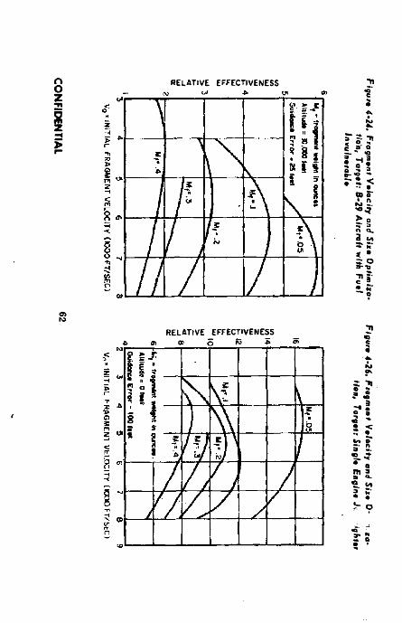
CO
NFID
ENTIA
L
RELATIVE e f f e c t iv e n e s s
RELATIVE EFFECTIVENESS A 01 © 5 R5
-n
Y »
uff
lug
*»
®H
j»
nj
ijji
m t
foji
iiy
iZ'S
:$*
ija±
‘uo
ip■o
* I.
.g *
IJ5
pU
D
itit
ujt
lilj
'9
J-)>
•Ja
Bfj
.o
triu
l/dg
»*i
y p
uo X
iiso
fm^
suta
tBo
ij '
fZ’t
•"’
*!


re
la
tiv
e
ef
fe
ct
ive
ne
ss
CONFIDENTIAL
Figure 4-27. Fragment Vtlocily Qitd Size Optimize- Non, Target: Single Engine Jet Fighter
v0. in itia l fr ag m en t velocity iio o o f t /seci
Figure 4-29. Fragment Velocity and Size Optimize* Men, Target: High Explosive AirborneBomb
Figure 4-28. Fragment Velocity and Size Optimization, Target: High Explosive Airborne Bomfc
Figure 4-30. Fragment Velocity and Size Optimize- tion. Target: High Explosive Airborne B omb
Vo = INITIAL f r a g m e n t VELOCITY (1000 FT/SECI
65 CONFIDENTIAL

Figure 4-32. Fragment Ve/ocify and Six* Optim
izer* Figure 4*34. Velocity Ratio Vs. Ronge, Aotr-Pef-
tion, Target; Higfc Explosive Airborne sonnel W
arhtadTorpedo

Vo * INITIAL FR
AGM
ENT V
ELOC
ITY{1000 FT/SEC) V0 1 IN
ITIAL FRAG
MEN
T VELO
CITY (1000 FT/SECJ
Tlf
RELATIVE EFFECTIVENESS
RELATIVE EFFECTIVENESS
J
CO
NF
IDE
NT
IAL

CONFIDENTIAL
S - A N C L L O f i N O O t N C E .
F i f arc 4-35. V«cfor Addition o f F iaqmont and Mit- c i l c V e lo c it i e s , Anti-Personnel Warhead
Optimum Fragment Weight and V c lac ityr-Ground Targets In the case of anti-personnel warheads, the optimum fragment size and velocity is a function of the type of fragment used. There are two general types: the spherical or cubical fragment, and the fin-stabilized or “needle” type. The fin-stabilized type has better aerodynamic characteristics and inherently better penetration, but has a high initial cost for the experimental item. This type has been developed for a few of the more recent warheads. If development time is sufficient for packaging and if it proves that this type can be launched without excessive breakage, it is recommended that fin-stabilized fragments be considered. However the development time is less for warheads using conventional preformed spheres or nearly cubical fragments, and they should be used in interim warheads.
The optimization of size and striking velocity of the fragments is a field in itself, and opinions vary considerably on the subject. Due to the shape and striking attitude of the fin- stabilized fragment, it is readily apparent that a lesser force or impact energy is necessary for incapacitation than for a spherical or
cubical fragment. Also, the smaller the Individual fragment, the greater number of irug- ments are possible in a given volume. (However more spheres o r cubes of a given mass can be packaged in a smaller volume than darts or fleehettes of the same mass.) Conversely, the smaller the fragment, the higher the velocity required for its effectiveness, and hence the greater ' ratio and less total weight available for fragments. Although no concrete simplified basis can be given for selecting the optimum fragment size and striking velocity because of the complexity of the damage criteria, warheads have been designed using the following criteria. For the case of the spherical fragment, fragments of 28 to 240 grains t't37-5 - 1 <**) have been utilizedwith a striking velocity of from 1000 to 6000 feet per second.
The increased number of potentially lethal or disabling small fragments Increases the probability of at least one hit on an individual within the effect-area of the warhead. However the effect-area for small fragments shrinks witli decrease of fragment size unless the initial velocity is increased by increasing < 'm which reduces the number of lethal fragments. In the end, the optimum warhead is a compromise that also involves burst height and the coverage of personnel in typical positions.
For the latest available data on incapacitation by fragments, one should consult the Contact Wound Ballistics Laboratory, Army Chemical Center, Edgewood, Maryland. If it is not feasible to do this, sufficient data may he found in the work of Allen and Sperrazza, reference 4-3 , h, to make possible an estimate of a usable combination of fragment size and , velocity
Knowing the striking velocity desired and distance above the ground at detonation, the r/rr, required may be calculated as follows Use can be made of equation 4-3,2 in computing the initial dynamic velocity, as explained previously. The drag coefficient, a n. is at a maximum in the vicinity of Mach 1, which degrades performance for operation near this point, in addition, the effect of velocity slow-down at sea
C5 CONFIDENTIAL

CONFIDENTIAL
level Is fur more pronounced than that ut a high altitude because of the relatively high density of the atmosphere at sea level. Figure 4-34 illustrates the effects of the drag on the typical anti-personnel fragment shapes for an 11 grain fragment size , Once the initial dynamlc veloclty la known, It remains to find the Initial static fragment velocity. The initial dynamic velocity (Vj) is a function of both the Initial static velocity (vp and the velootty of the missile r- If, e.g., the shape of the nose- spray warhead and the minimum angle ff) ) at incidence to the ground have been previously established. Figure 4-35 may be drawn. As an approximation, the detonation point can be so located that the path of a fragment at the bottom of the rear edge of the warhead will be Inclined at angle es , in the notation of Figure 4-10, by drawing a line between the point of detonation and the last-mentioned fragment as shown In Figure 4-35.
Knowing the direction of v f (0s) and the magnitude of v,„ and v v maybe found from equation 4-3.19 which Is
Vd ~ Vl * Vm * 2 V m a,90M <4- 3-19>
Now, with v j known, the c r e q u i r e d to provide it may be found from Figure 4-15, taking into account the lowering of the actual velocity of an edge fragment as compared with the theoretical.
Spherica l Model tar M iss i l e -C arr ied Fragmentation Warhead A simple spherical model adequately represents the terminal ballistic geometry for a stationary external blast warhead, as is self-evident. The-'spherical model can likewise be used for missile (moving) warheads of both the fragmentation and external blast • types.
At any early time t after a stationary fragmentation warhead has burst, most of the fragments are at nearly the same distance R - V t from the warhead position, where vj is the average fragment velocity (considering slow-down due to air-drag) during the time /. Otherwise stated, most of the fragments are
near a rapidly expanding spherical surface of radius R - v t and centered on the warhead position.
Likewise at time / after a burst of a missile fragmentation warhead moving at ve- locity_ V'm, a spherical surface of radius R - Vji adjacent to most of the fragments is centered at a point on the missile path which
- - vmis located at distance vmt - <y~) t from the
burst point, where vj is obtained from equation 4-3.19 and the air-drag slow-down relation, and V j is the fragment travel from burst to target. In other words, the center of the rapidly expanding sphere is near the point where the warhead would have been at time i if it had not exploded. This spherical model closely approximates the oblate spheroid that actually exists for moving warheads of either the fragmentation or external blast types. (See Section 4-2 .Z.)
To be useful, fragments generally move at a velocity v j which Is much higher than that of the warhead-carrying missile, vn. Hence, for such a warhead, It is adequate tn both design and evaluation to take the radius of the spherical fragment-containing skin as R = v t. (An exception is where a missile, e.g. for antimissile use, throws out a cloud of relatively slow moving pellets or submissiles; their radically different geometry is introductory treated in Reference 4-3. cc.)
In the following section we consider the geometry for bursts of nose-spray fragmentation, antipersonnel warheads. True side-spray warheads seldom can use as many as 50% of their fragments against a surface target. Likewise, spherical warheads use only about 47% of their fragments. On this basis, these low “ efficiencies” are to be remembered when examining the warhead efficiencies in the next section. A side-spray warhead can be taken as the difference between two nose- spray warheads of different spray-angles — another reason for first considering the nose- spray warhead.
CONFIDENTIAL GO 1

CONFIDENTIAL
D e s r y t i o f a N o - .* ■ S p r a y Vfarltcud for I n c Jirtotiuil
of the Mnsi/e Problems of Warhead geometry am) design are briefly illustrated in this Section. The purpose Is to provide an insight rather than to urge the use of any particular method or values of parameters. In particular, I’ertuin values — 58 ft lli lethal fragment kinetic: energy and l(T foxhole c over cutoff, are used mainly to simplify the treatment; these values are here used in preliminary design without Implying that they would be used in final optimization or effectiveness evaluation in the future.
For missiles at steep final inclinations (eg. , ‘■) >45°), fragmentation missile warheads of the nose-spray type can be more efficient than those of the side-spray type. (For ogival shell, the lethal area increases with the inclination mainly because of the cover-func- tiijns, Missile warheads generally have a much higher ratio of v / vm than shell warheads do. Hence, in use, the shell “ side-spray1' is vectored forward to approach the nose-spray of missile warheads. In other words, the present remarks on the effects of warhead inclination on the lethality of side-spray missile warheads are not to be applied to shell.) At required long ranges, most missiles have inclinations steep enough to reduce the effectiveness of side-spray warheads to very low values and to increase the effectiveness of nose-spray warheads over that for minimum range. Near the required minimum range, the inclination is still so large for guided missiles (usually around half that at the maximum required range) that the effectiveness of a wide- angle nose-spray warhead generallj falls off less drastically than does that of side-spray warheads at maximum range. Direct-fire rockets at minimum ranges are more nearly horizontal, but much of this Section applies to rockets used over a wide band of ranges For example, take limiting »>’s of 30 and 60° and design the warhead spray-angle for <* = 60°. (However, one optimizes the fragment mass M and the charge-to-metal ratio < /™ for the mean w of 45°.) ■
If one takes an inclination oi 10° as the virtual or effective cutoff of cover, one has a dynamic beam angle of . h - 30 « B0 ■■ 110° from the 60 and 10° angles, See Figure 4-30. From the missile and fragment velocities, v “ 1000 and Vj " 5000 feet/sec respec
tively, we find that the static beam angle oi the bound of the warhead is ‘ a - 120°. A larger value of ■ a would waste lethal fragments In region “ A” by projecting them in paths less Inclined than the 10° cover cutoff. A much smaller value of . « tends to needlessly increase the average distance that the fragments have to travel (by increasing the burst height) to spray all of the area in which men are exposed within the 10° cutoff circle for the lower burst height with * suited to the 10” cutoff and the 60° inclination In Figures 4-3S and 4-37, the shading represents areas on tlie warhead for all fragments, and for the static nocover cap vectored from the dynamic situation.
For similar (usually steel) fragments of varying size and mass M, the minimum lethal striking velocity vL is found from some function of the mass. For example: v i is such that the lethal energy is at least 58 ft lb (which was formerly in wide use for fragments heavier than about 25 grains). For this lethal velocity VL, the lethal distance fi ( can be found for different values of the fragment mass u and of the initial fragment velocity V, (relative to the warhead) which is a function of c/m . To find Rf , we
use the air-drag relation V' - v0» where
* depends on the fragment shape and mass and v 0 is the initial velocity resulting from v and vm • The value of J?f is found at the conical bound of the fragment 3pray (e.g., at “A” ) since this is where the value of v^is smallest for a given < /». in other words, the missile velocity vtu contributes more to v0 (for fragments projected forward) as their angle from the missile direction decreases, and also the fragment velocity vj drops near the bound of the spray.
The optimum burst height is at or slightly
TO-571 0-6B—<j67 CONFIDENTIAL

CO
NFID
ENTIA
L
T able 4 -5
Nose Spray Warhead Characteristics
( 0 ( 2 ) * (3)** (4) (5) (6) (7) (8 ) O )
Spherical Nose Warhead
No-Cover Warhead Nose Warheads Designed for <-■ (60“ - Design)
Cap angle"Used Area" or
2» (3)/2 Area Frags,2 r
. (3)/(7) B urst at^'sBeiow
Q' J - E , ’ Area No-Cover Cap
— ~ * - n --------------------is ■ c * a,* 1 + cos C 'n T,n(60*)
do 91.4 1.024 .512 88.6 91.4 1.024 1.000 - -
75 90.9 1.016 .508 73.6 106.4 1.282 .792 -
60 90.3 .995 .497 60.0 120.0 1.500 .663 .663
45 88.0 .965 .483 45.6 134.4 1.700 .568 . 598
30 85.9 .928 .464 32.6 14 7 .4 1.B43 .504 . 5 2 7
15 83.7 .890 .445 20.15 159.-85 1.939 .459 -
0 81.4 .850 .425 8.01 171.99 1.990 .427 -
' . o
♦Approximate values from graphed vectors.u2f i
♦♦Values from Reference 9 -3 .n. Omz
>

CONFIDENTIAL
UNIT-R AD IUS SPHERE FOR BURST AT t fT u O F WARHEAD
DESIGNED FOR THE SAM E00( V , « 5 V AGAINST MEN HAVINGi m
10° FOXHOLE COVER AND LE TH A L RADIUS = 1 UNIT).
LE G E N D
□ f r a g m e n t s
^ § 3 P O T E N T IA L T A R G E T S W ITH 10° C O V E R .
E S S U SED FR A G M E N TS
F igu re 4-Si. Fragmant and Spray Diagram: Unit-Radius Sphere for S u n f at 60° tu of Varhaad D esigned for fhe Some oi
CONFIDENTIAL 69

CONFIDENTIAL
UNIT-RADIUS SPHERE FOR BURST A T 30“ui OF WARHEAD
DESIGNED FOR 60°u; <V( « 5 Vm AGAINST MEN HAVING 10"
F O X -H O lE COVER)
FRAGMENTZONE
LEGEND
I" I FRAGM ENTS
PO TEN TIAL TARGETS W ITH 10° COVER
USED FR AG M EN TS
N O -FR AG M EN T 6 0 ° STATIC CAP CORRESPONDING WITH 7 0 ° D Y N A M IC CAP
NO-SPRAY CAP FOR L b» 110°
L U N E , FRAGM ENTS UNUSED FOR 3 0 ° U ) B U T USED FOR 6 0 ° DESIGN CONDITION
Figure 4 -37. Fragm ent and Spray Diagram; Unit-Radius Sphatt far Burst at 30® <u a{ Warhtad Dasigaad far t0° 10
TO CONFIDENTIAL

c o n f id e n t ia l
above the value H.-.k sm 10“ for this foxhole cover cutofl. The value of II is thus found at
of 30, 45 and 60° and the highest value, II x. of the throe is used in the fusing. Kora given i.>. the warhead effectiveness fulls off rapidly as the hurst height drops below n, but negligibly (or not at all) as the burst height exceeds ll by a like distance. Hence the fuzing height is set to cause bursts distributed around a mean height Hy that Is about 2oz above li (i where az is the standard fuzing deviation. The use of 2at causes around 95% of the bursts to occur above Hx .
This simplified procedure, or order of computation steps, Is introductory and intended to assist one who only occasionally designs anti-personnel warheads. However, a specialist in this field will probably use more sophisticated methods, especially if a high speed computer is available. In usual practice, one proceeds by a sequential optimization of one parameter after another, with some iteration as maximum performance is approached. But the reader should know that even the best conventional fragmentation warhead cannot closely approach the performance of new types which are already well along in development.
Spray-angles for varying inclination and given cover (10" foxhole) will now be discussed. For the 10" foxhole and a nose-type warheadat w > 45°, the matching static no-fragment angle C * 180° - 1 a is approximately equal to w. Tills is apparent from the following table, in which accurate values of -< a and C are used. In this table, the maximum warhead efficiency 7 possible was found from the relation
used area7= - .. __________fragmenting area
warhead:
For a nose-spray
2 n vers E 2 it (2 - verV»C)
where:i: is the average static angle on the
fragment unit-radius sphere, which corresponds with the 80“ no-cover cap in
. the dynamic situation.
In the latter expression, the denominator is the fragmenting area as found from the area of a unit radius sphere minus the area of the no-fragment zone or cap for r . Corresponding values of warhead efficiency 7 , inclination und beam angles ( and « are tabulated on Table 4-3.2: (also see Figure 4-37)
For <u < 3<j“, the fragment area of the warhead increases until the warhead becomes practically spherical. Kven for the 30° u warhead, the fragment zone covers nearly all of the warhead. i,e .:
i n - 2 n vt ts 32,6“------------ ------------------ - - 1 - 0.5 » (1. 1575 nr 72.1%Att
of the spherical area.For the 10° foxhole and a spherical war
head, the upper bound for the efficiency 7 can be taken as the fraction of the fragments that reach the ground by linear paths inclined more than 10°. The efficiency relation used is, since
l ? » 8 1 .4 ° ,
2 n vers 8 1 ,4 ° 0 .8 5 07 -------------------------- * ----------- or 42,5V.
An 2
For the spherical warhead and v/ / v n ^ , efficiency 7 is nearly Independent of the warhead inclination a , as is shown by the dash curve in Figure 4-38.
For a m issile inclination <o of 60“ and a warhead that is designed for this inclination and 10" foxhole cutoff, the “ used Area” on the unit-radius sphere is that of the 80" nocover cap. (See Figure 4-36.) The other pertinent zone is the 60" non-fragmenting static cap of this warhead for which the corresponding dynamic 70“ no-spray cap just touches the 80" no-cover cap for 60° w at “ A” in Figure 4-36. This 70“ (dynamic) no-spray cap corresponds with a 60“ (static) no-fragment cap.
However, if the same warhead is in a missile inclined 30°, the 70" no-spray cap takes a Lune-shaped “bite” out of the 80“ cap of the “used a re a " for GO*. In other words: for a burst at o ^ io'>, the used area (80“ no-cover cap) for 60" u has shrunk because part of it has been replaced by part of the no-spray 70“
71 CONFIDENTIAL

CONFIDENTIAL
cap. (See Figure 4-37.) On the fragment-area basis, the lust lune is bounded on one bide by the horizontal 8ti° cap “no cover” edge-circle and on the other aide by the 60’ “no-fragment" cup circle which is inclined 60* for the missile inclination of 30“. Since neither of these circlets is a great circle on the unit-sphere, the lost lunate area ia only about 20% for 30° u and 10% for 45’ u>.
Figure 4-38 presents values of 7 and a> for both spherical and none-spray warheads for . vm - 5 and 10" foxhole cover. The dash curve is for spherical warheads. The solid curve is for nose-spray warheads used at the inclinations they were designed for. The three points identified by triangles on this figure are for the nose-spray warhead that was designed for 60° inclination but used at
of 30, 45 ii 60°. Evidently their slight departures from the design curve are ol the order expected for errors in the approximate numerical integration used in obtaining the values of i for the: three cases.
Anti-Personnel Warhead E f f e c t iv e n e s s The effectiveness of an anti-personnel warhead is ordinarily expressed by its lethal area
A i. - f Afda) da
0where « is unit-area. (One
can see Reference 4-3 .n, Appendix A, for the essential basic relations used In one method of computing lethal areas of fragmentation warheads.) The lethal area Ai is the product of the (ground-area per man) by the (total number of men killed throughout the whole area A that is exposed to potentially lethal fragments). In other words, the lethal area is used to tree the expression for warhead effectiveness from the density of men on the ground.
The exposed area of a man in a given position and cover varies significantly with the inclination of the striking angle, i.e., elevation angle of the burst relative to a man. (See Reference 4-3.ee for exposed areas of
men standing in the open, Reference 4*3.ft for men in artillery battery positions and in trenches, and Reference 4-3 .gg for infantry men in 5 typical defensive positions.)
Near-optimum performance can be produced by a warhead that has a substantially constant fragment density (i.e., fragments per unit solid angle or steradlan). as proposed in Reference 4-3 .n. Against randorniydiatributed men and/or fragments, a nose-spray warhead m issile is an area-type weapon for which the probability of killing a man within the sprayed area is P - i I n this expression, X = p A (S) is the expected number of hits of potentially lethal fragments on a man of projected area A(S) in a plane that passes through him and is perpendicular to the fragment path of inclination 9 when he is exposed to density px of the fragments piercing that plane.
The concept of lethal area depends on the assumption that, wherever a warhead bursts, targets are randomly distributed. Many tactical targets are distributed only over areas so limited that the weapon effectiveness cannot be properly expressed by a lethal area (see Reference 4-3.dd, Appendix C); weapon effectiveness is better expressed by either (1) the expected number of targets killed per burst or (2) a sprayed fraction of the target area large enough (usually over 30%) of the target area to neutralize the target area with a given probability that is high (usually over 90%). In general, the first alternative Is used for cost estimates and the second for tactical use against important targets that must have their effect eliminated.
In many cases, area-weapons are used against targets of limited area that can be adequately represented by circular or elliptical areas. The Sandia Corporation has extensively treated such targets exposed to weapons having circular areas of effect. Also one can see Reference 4-3.hh for such a target exposed to a small number of bursts of area-weapons. However, the present elementary treatment
CONFIDENTIAL 72

CONFIDENTIAL
cannot go further into th ■ more advanced held of weapons .systems evaluation
AcJuci C horye-tO'Mirtu/ R a t io an d k Hptn sive 1 g pt*
As previously mentioned, it is quite possible that the optimum velocity for warheads other than anti-personnel will lie well tielow the allowable maximum, and hence a r/ni value less than the maximum Is indicated. If this is the case, the use of the optimum value will result in a greater metal weight and thereby supply a greater number of fragments. When this is done, the total volume of the warhead will be reduced below the original volume estimated previously,
Selection of the best kind of explosive for the missile warhead still requires extensive study, although of course there is available a great deal of experience with bombs and shells. Composition B has generally been favored for missile warheads used against aerial targets as having satisfactory properties both as to casting and as to detonation. Some new explosives are also bidding for consideration with H-6 apparently in the lead, H-6 has been adopted as the standard nomenclature designation for the composition formerly known as HBX-6. Tests of HBX and H-6 (References 4-3.j and 4-3 .k) give slightly lower fragment velocity than Composition B but greater blast effect, while Tritonal gives still lower velocity. These same tests indicated that fragmentation control was about the same for Composition B and HEX, but much poorer for Tritonal,
In the case of antipersonnel warheads, the foregoing explosives discussion is directly applicable if cubical or spherical fragments are used. However, in the case of fin-stabilized fragments, the explosive selected should have a relatively low detonation rate and brisance rating in order to produce more of a pushing than a shattering effect. This latter effect will tend to cause column failure of a dart or damage its fins. An explosive such as Composition D (Ammonium picrate) has been used in some cases. A complete discussion of explosives and their properties is given In the Appendix.
As a first approach, the designer has already assumed the use ofA 'oinposition B explosive. 11 is ii bo noted that the method ol design ol the Ir 'gmoiitalion warhead prober,led heroin is bused on optimum fragmentation, and (iocs not utlemp to treat tho effects ol blast which are Inherent to some degree in any fragmentation warhead, The ultimate value of this blast effect is most difficult to define, but ils effect, especially in cases where sudden kills are required, should not be overlooked. Available data indicate that the blast effect is sig nificant against large targets such u3l>omhers for standard error of guidances up to 3b feet at high altitude and up to 60 feet at sea level. B last is not highly effective against small targets such aa fighters or missiles except at very close range, to the ease of anti-per sen net warheads, the area sprayed by lethal fragments is relatively so great that the blast effect is of small consequence.
Fragment Shape and Material A cubical fragment is generally preferred against air targets because it has better penetrating power and less drag than an oblong fragment. Moderate departures from cubical shape have only a small adverse effect, so the casing thickness need not be restricted by an exact requirement of cubical shape for the fragments. However, if the charge-to-metal ratio is such that the casing is rather thick, it is generally better to have two or more layers of fragments than one layer Ultimately the choice of the number of layers is determined by proper fragment shape. It is to be noted that one may judiciously select a fragment size with a minimum sacrifice in effectiveness to obtain a simple shell structure. This would be investigated if the problem of a double walled shell arises.
The foregoing discussion is also applicable to cubical fragments used against ground targets. However, in the case of fin-stabilized fragments the i./n (length/diameterl ratio is most significant. Since the state-of-the-art is such that no firm recommendation can be made ns to the optimum value, it is advisable that the t.,'0 of the fragments be checked aerody-
73 CONFIDENTIAL

CONFIDENTIAL
namically from a drag and yaw damping view* point, and also for possible column fall .# on ejection, t. 'it ratios of approximately 10 to 12 have I te n used successfully. (References 4-3.z and 4-3,au.)
Little consideration has been given to any fragment material other than steel. Against most components the desire for good fragment penetration argues for a fairly dense fragment material, and it is therefore recommended that steel generally be used. The kind of steel should be selected on the basis of availability and ease of fabrication, since detonation work-hardens soft steel.
Method] of Fragment Site Control It Is considered both desirable and practical to control tire alee of the fragments emitted by the warhead In order to keep to a minimum the amount of metal that wilt be wasted In fragments too small or too large to be effective. The eventual cri - terion of successful fragmentation control is not the damaging power of the Individual fragment, but of the whole collection of fragments from the warhead; since the warhead weight is usually a prime boundary condition, the number of fragments is, at least roughly, Inversely proportional to the weight of the Individual fragments. Although a large amount of effort has been expended in studying various methods of controlling fragment size, no one method has been studied sufficiently to provide a really sound basis for final choice between different methods or choice of details of a given method.
Dr. Philip M, Whitman of the Applied Physics Laboratory. Johns Hopkins University, has conducted a thorough study of the various methods of fragment size control (reported in Reference 4-3.1) and this work has been used to form the nucleus of the discussion which follows.
It is t be noted that, although uncontrolled fragmentation is seldom considered for missile warheads, the distribution of fragment size can be predicted by the “ Mott Law” (Reference 4-3 .r and 4 -3.s) which applies to relatively thin casings. This is
N ( M ) - t v i
- , p p r (4-3.20)
where m,, - mean fragment mawsModifications of this formula are available
for use if the casing is too thick for the usual Molt Law to hold, i.e., If the breakupis threedimensional rather than primarily controlled in one direction by the thickness of the casing. (See Reference 4-3.1.) However, thiw is not usually the condition in m issile warheads. Additional work on uncontrolled fragmentation is reported in References 4-3.u through 4-3 .w..
Precuf Fragments The best method of controlling fragment size is to form or cut the fragments to the desired size before they are installed in the warhead. If this is done, the only possible deviation from the preset size would be caused by breakage upon expulsion, or adhesion to each other or to other parts of the warhead. However, these factors may be considered negligible and for all practical purposes nearly lOOpercentfragmentation control is achieved.
This method of control has several major objections which tend to prevent its wide-scale '«>age. The principal objection Is that additional structure Is needed for the support of the fragments- This structure usually is formed by a thtn metal liner or cover, or both, to which the fragments are fastened with adhesive. This liner, which means additional weight (approximately 10 percent of the total metal weight has been used) contributes little, if anything, to the effectiveness of the warhead. Since weight is of primary concern to the warhead designer, this la a most serious detriment to the use of the precut method of fragment control. It is to be noted that recent developments have proven that plastics such as fiber-glass laminates can be successfully employed as Inner and/or outer liners with a definite saving in weight and consequently, more weight can be added in useful fragments or explosive.
An alternate method of installing the preformed fragments, especially spherical or fin- stabilized fragments, is to place them in layers between the inner liner and the case and fill the crevices between them with a matrix to hold them in place and protect them from damage
CONFIDENTIAL 74

CONFIDENTIAL
when the missile is fired A material such as Pittsburgh l’late tlluss ^electron No. 5119 (polyester resin] is frequently used for this purpose, in the ease of fin- stabilised fragments used in anti-personnel warheads, the fragments may be packed tn more than one row, and In vurtous positions, i.e., point first, fin first, etc. They should be packed, however, so as to minimize possible fin damage on explosion.
The primary examples to date of applications of the precut fragment principle were in the fragmentation warheads for the Nike Ajax, Nike Hercules, Hawk, and Bomarc Missiles. -
Note W Rings Another method of controlling fragmentation Ls to form the warhead casing of a series of notched rings fastened together, each forming a section of the warhead perpendicular to the axis of symmetry. This fastening, possibly by brazing, should be considerably weaker than the notched ring material so that breakage will occur where desired. The forces from detonation operate mostly In the direction of stressing each ring circumferentially, and only secondarily to separate adjacent rings. Essentially, the thickness and width of the rings provide control of twodimensionsof the fragments, while notches along the circumference of the ring provide places of weakness where breakage in the third direction is desired.
Although this method has been Investigated extensively, test results have not been conclusive and the effects of details of the notching has not been finally determined. However, it appears that within reasonable limits good cor • trol can be obtained by this method, though possibly only after some trial and error.
It must be kept in mind that the primary purpose of the notches in the rings is to create weak spots in the metal which will fail first after detonation. It would therefore appear that the deeper the notch (within reason) the better the control achieved. However, this is not necessarily true. In some ca ses very shallow notches have produced excellent results, while in others notches of depth approximately 50 percent of the casing thickness have not given adequate control. Both Internal and external
notches have been used, and although not con elusive. It appears that internal notches generally give more flexibility of fragment dt mensions.
The shape of the notch has received only cursory attention, but In general sharp corners rather than round ones are used since they tend to cause higher stress concentrations which aid in the breakup of the casing The width of the notch is of secondary importance, and tests Indicate that as thin a cut as possible will be sufficient. The spacing of the notches is also indefinite, but it appears that a spacing of 1 to 1.5 times the casing thickness is generally the minimum satisfactory spacing. Radically wider spacing than this (ratio of fragment edges greater than 2 to 1) Is generally undesirable because it leads to poor fragment shape for aerodynamic considerations and for target penetration. Also too wide a spacing may re sult in additional breakup between notches caused by circumferential forces.
In order to minimize the tendency of fragments from adjacent rings to stick together, the notches should he staggered, but the amount of staggering Is relatively unimportant; where successive rings have different numbers of fragments because of different diameters, consistent staggering is difficult. Varying the fragment size slightly 'rom ring to ring in this instance is considered more desirable than having some notches aligned. Staggering of the notches tends to produce additional breakage opposite the notches, but not to a serious degree.
Although the material selected for the rings is of relatively minor importance, it must be homogeneous. The material may affect the maximum and minimum sizes of fragments for which control can be achieved, and inhoroogeneity can produce erratic results. Test results to date indicate that mild steel might be preferable to high-carbon steel, but the reason for this is not settled.
The method of fastening the rings together is primarily a question of cost and mass pro- ducibility, providing the proper strength is obtained. The proper strength may be defined as the strength which will withstand the expected
75 CONFIDENTIAL

CONFIDENTIAL
handling and flight loads, but so weak as not to retard the intended breakup. Copper brazing has been the method most commonly considered, but adhesive has given better fragmentation control In some Instances with no significant change In velocity and with somewhat less dispersion of the fragment pattern.
Notched Wire Some warhead designs have incorporated notched “wire" wound In ahellx, or spiral to control fragmentation. The wire is actually a long bar with two dimensions equal to those desired for the fragments, and ts notched at intervals along its length and colled into the shape of the warhead caaing. The wire must be supported by a liner or fastened together by some means (such as welding) In order to preserve the warhead shape. It can readily be seen that if a welding procedure ts used, the method of accomplishing the fragment control is basically the same as for the notched ring method. Similarly, if a liner is used, design problems are basically the same as in the precut fragment method. Reasonably good fragment control has been obtained using notched wire; actually, better results have been obtained than in a comparable brazed notched ring warhead.
Grooved Charge The previously discussed methods of controlling fragmentation are substantially similar in that the metal is either precut or notched to cause breakup along predetermined paths. The grooved charge method is the reverse of these. The explosive charge ts grooved so that irregularities of the detonation {instead on in the metal) will break up the casing in the desired places. The charge is grooved by means of a fluted liner constructed of plastic, cardboard, balsa wood, or rubber inserted between the solid metal casing and the explosive. When the warhead is detonated, the flutes give a shaped charge effect which tends to cut the metal casing in the pattern formed by the grooves.
The warheads incorporating the grooved charge method of fragmentation control are slightly cheaper and easier to produce than the
other types dir cussed, and there ts more flexibility with regard to changing the fragment size. However, this method also has its disadvantages In that there is u loss of some weight and space for explosive and for useful fragments, and there Is an addition of some “ dead" weight. Test results with a fluted steel liner produced about 14 percent lower fragment velocity than a similar notched wire design, although the flutes gave better fragment control. This I o b s
In velocity is consistent with the difference in r /m caused by the liner. Fragmentation control by this method is probably limited to fragments greater In their lateral dimensions than the thickness of the casing by a factor of approximately 12 . Further design information can be found in Reference 4-3.m.
Other Methods Various other methods of fragment control have been attempted and sub - Jected to limited testing, Since relatively little data are available on these methods, they will be mentioned only briefly here.
Instead of notching In one direction and having actual discontinuities in the metal in the other direction (such as in the notched ring or wire method), it is possible to cut, punch, or cast a twodimensional < etwork on a solid casing or on pieces later formed and assembled into a casing. Although in principle this method is the same as in the notched rings or wire, preliminary tests gave poor results.
Tests have also been conducted on cast casings with staggered notches, but with no other lines of weakness. This proved to give moderate control of fragment size {about 70to 75 percent of the weight being ejected in fragments near the design size), and casings heat treated after casting gave somewhat better results than an untreated casing.
Another possibility is to have cases of varying thickness. Tests have been made using casings with humps in the form of segments of a sphere on the inside, with the lines of contact of these segments forming a honeycomb pattern. The results of these tests, although not conclusive, indicate that good fragment control and exceptionally high velocities have been
CONFIDENTIAL 76

CONFIDENTIAL
obtained.The detonation wave could also be shaped
by the Insertion of inert barriers. This technique is on the borderline between the last mentioned type and the use of grooved charges
Still another method of fragmentation control Is to cast the solid metal casing around wire mesh woven in the desired breakage pattern. The chilling effect of the mesh, and the weakness of the physical discontinuity (especially if the mesh is coated to reduce adhesion) tend to produce breakup in the same pattcri. as the mesh. This method is desirable because of its simplicity, but to date has not been fully tested.
Comparison of Fragm entalion Control MethodsEach method of fragmentation control has advantages and disadvantages whose relative importance to the designer may not be immediately obvious. To further assist in the formation of a design, Tables 4-6 and 4-7 are presented, Reference 4-3.k . In most cases complete information Is not available and the factors presented should be regarded as qualitative rather than quantitative.
In some cases the spread between different experimental results or reasonable esti - mates Is so great that the information is presented as a spread, of which the lower end represents results which might welloccur with bad luck or Inferior design, while the upper end represents what might reasonably be expected in favorable cases.
The method of fragment control has little if any effect on the velocity of the fragments, if it is assumed that any inert material such as liners is counted as (non-valuable) casing weight In the ratio c /m of charge to metal, and account is taken of any explosive displaced. Hence the relative effectiveness of warheads with different types of fragment control is measured largely by the number of fragments of useful size (weighted for dependence of lethality on size) which the warhend produces for a given size and < /m . The relation, however, is not linear, since for some particularly good shots the target will be killed by blast or over
killed by fragments.Table i-(; gives a breakdown of the non -
explosive parts of the burst warhead; it Is assumed that the total of these parts would be substantially the same for all types. Comparison on this basis Is slightly unfair to warheads of types requiring structural non-fragmenting members, since they would also require somewhat ,oss explosive to get the same velocity, other things being equal. It is thought that this has been adequately compensated for by taking a conservative estimate of the amount of structure required.
Items such as the metal liners in precut warheads are regarded as chaff and “ minor tragments” , and are not counted as “ structure” In Table 4-6 ; however, the structure used to carry missile loads through the warhead section is represented as “ structural, non-fragmenting".
The significant line in Table 4-6 is that for “relative number of.useful fragments” . For the various types of controlled fragments, these numbers are In substantially the same ratio as the proportion of weight which goes into useful fragments. For uncontrolled fragmentation, most of the mass goes into fragments of useful size; however, a few fragments are so massive as to drastically reduce the total number of useful fragments (from that of controlled fragments). Although the larger the fragment the more damage it can do, the increase in damage capability is usually far less than proportional to size. It Is understood that “useful fragment" is not a clearly defined concept, and that small fragments still have some possibility of inflicting damage in certain cases. The estimates are intended to give partial credit accordingly.
Table 4-7 has as its first row of numbers the estimated relative lethality of the warheads, for equal weights. Although such effectiveness would actually vary somewhat depending on the tactical situation, guidance accuracy, warhead size, fuzing, etc., the given figures are representative of the warhead type. It must be remembered that these numbers are relative to perfect control as unity, and are not intended
77 CONFIDENTIAL

CONFIDENTIAL
Table 4 -6
Estim ated R elative Fragm ent Production F rom Various Fragm entation Control Methods
PerfectControl
Uncontrolled Precut
NotchedRings
GroovedCharge
Cast on Mesh
Relative number of useful fragments 1.0 .3 .8 . 5 - .9 .« - .9 .5 - .8
Proportion of total non-explosive mass to useful fragments
.9 .8 .7 . 5 - .8 .6 - .8 .5 - .7
Chaff and minor fragments 0 .1 . 4 - .1 .3 - .1 .4 - .2
Non-metal {liners, hot melt, etc.) 0 .01 .01 .01 .02 .01
£nd plates, fittings, etc. .1 .1 .1 .1 .1 .1
Structural,non-fragmenting 0 0 . 1 0 0 0
Table 4-7Rough N um erical Com parison of Various
Fragm entation C ontrol Methods
PerfectControl
Uncontrolled Precui
Notched Rings A Related Methods
GroovedCharge
Cast on Mesh
Relative lethality 1.0 .7 .9 .75 - .95 .8 - .95 .75 - .09
Relative produclbility 0 1 .0 .6 .4 - .7 * .7 .6
Relative ease of development from present status 0 1.0 .8 .8 - .5 . 7 - .6 . 7 - .5
*The higher number might apply to some related methods ol manufacture such as welding together notched rings or notching a solid casing.
CONFIDENTIAL 78

CONFIDENTIAL
to be used as precise data. The eatlnyite-' are based on the relative numbers of ustfrul.. ag- ments from Table 4-G , plus a ll ia n c e for guidance errors so small that either blast damage will occur or the fragment density will be so great that variations in it are unimportant. The expected degree oi pattern regularity is taken Into account, but no allowance is made for any difference In velocities of the fragments. This was done because, as previously mentioned, the influence of the fragmentation control method on fragment velocity is so very snu....
The next line of Table 4-7 “relative produclblllty” , Is Intended to compare crudely the reciprocal of the cost, which may be interpreted In terms of dollars, or of manhours, machine hours, and materials. This comparison may not be pertinent to a design which will be produced in limited quantities.
The last line of Table 4 -7 , “relative ease of development*'. Is a rough estimate of the relative amount of effort required, in view of the present status and the Inherent difficulties, to develop a satisfactory warhead of a given type for a given weapon. Naturally this also depends in an inverse manner on the degree of perfection sought, as reflected in the lethality.
It Is not possible at this time to give a single row of numbers, compounded from all the factors considered in Tables 4 -6 , and 4-7 which would represent the overall re l
ative merit of the various types of fragmentation control. However, it seems clear that the “relative lethality" Is by far the most Important of the Items discussed, except where one of the other factors Is extremely low (such as for the unproduclble and unattainable “perfect" control). The various methods should not be compared on the basis of lethality per dollar of warhead cost, since the cost of the warhead is only a small part of the total m issile cost.
In view of the inadequate data available to date, nO clear-cut conclusions can be drawn from these two figures as presented. It can be concluded, however, that (a) some type of frag
mentation control is desirable, and (b) how good a Job is done on a given type is p. obably more Important than which type Is selected.
Since the conclusions are inadequate to serve as a true guide for selecting a method of fragmentation control, the designer Bhould consider the experience of the manufacturer producing his warhead. Having had previous experience on a certain type may well enable a superior Job lobe done on that type which will more than over come the apparently slight theoretical advantages of another type.
Design of Fragmenting Me»o/ Once the c / m ratio, fragment shape, weight and method of control have been established, the detail design of the fragmenting metal can be effected. Using the selected c/m (not necessarily the maximum allowable value originally computed) the total weight of the fragments may be computed as follows:
Vim- ___ -— (4-3;21)c / m + 1
where:wm - Weight of fragmenting metal v n = Net weight of warhead The new net warhead volume may now be
computed if the c /n has changed. Using this volume and the warhead shape previously determined to provide the necessary beam width, the surface area of the fragmenting metal should then be computed. Since the Individual optimum fragment weight haa already been determined, it is now relatively simple to establish the fragment dimensions. It should be kept in mind that the optimum fragment shape (from a packing standpoint) for use against aerial targets Is a cube. However, the optimum shape of a fragment may be another shape, e.g., a sphere, which has less air-drag.
In most controlled fragment warheads the inner surface of the fragmenting case i3 coated with a material known as “ cavityhotm elt",or “ acid proof black paint", which is an asphaltic material similar to that used on roofs. This coating varies In thickness from approximately 1/1G to 1/32 inches and is applied before the
CONFIDENTIAL 79

CONFIDENTIAL
explosive is loaded. Its functions are to prevent contact between the explosive and sharp edges of the esse io prevent chemical action between the two, to provide some degree of thermal insulation, to effect more uniform case breakup. to till in crevices In the casing where explosive might he pinched if the case were strained and to provide a bond between the explosive and the metal casing. The type of hot melt used is a function of the type of explosive. Special paints have also been used for this purpose. For example, acid -proof paint, Specification JAN-P-450(2) has been used In conjunction with most standard military explosives.
P c s tgn o l Warhead Components Other Than Charge and Fragmenting Mela I At this Stage Of the design, one is ready to establish the details of the warhead. To properly accomplish this a detailed structural analysis must be made of the individual components and of the warhead as a unit. The structural design criteria are established by the missile requirements, and are normally given to the designer, It is of the utmost importance that the parts of the missile fore and aft of the warhead be kept In the proper position with respect to each other despite aerodynamic and acceleration loads. Either the warhead Itself must be strong enough to perform this function, or additional structural members must be provided. It is most desirable (but not always practical) to avoid distortions of stresses which might crack the explosive, as cracks adversely affect the uniformity and reproducibility of detonations.
The ends of the warhead must be closed to support and protect the explosive. The metal which does this *s known as an end plate, and also serves to prevent the explosion gases from simply rushing out open ends instead of accelerating the fragmenting metal. However, the end plates should not be thickened beyond what 13 necessary to support the charge or provide structural rigidity, for additional explosive will probably do more to confine the main detonation than an equal weight of metal. Accordingly, something between 1/16 inch and
1/B inch of steel Ik reasonable touse, although In some cuses end plates as thick as 1/4 Inch have been used. The optimum thickness can only lie determined by test of the parti cular warhead.
At least one end plate or a central portion of an end plate should be removable to allow for- filling the warhead with explosive, This Is usually done by pouring for large scale production since It Is more convenient, though pressing Is used in some cases. In either event the end plate should be either bolted in place, or secured with bayonet-type fittings. The number of bolts required for thlB purpose shbuld be kept to a minimum.
‘ In cases where the warhead surface does not constitute an external surface of the m issile, a fairing (sometimes called windshield) must be provided to maintain the aerodynamic contour. A typical fairing is shown in Figure 4-39. The fairing is usually of aluminum and made as light as possible to minimize the requirement for the warhead to “ shoot its way out of its own m issile’’ . This fairing Is normally supplied by the missile manufacturer, and is not the responsibility of the warhead designer. In the event that aerodynamic heating of the warhead compartment in flight becomes a problem, Eubatex or fiberglass insulation may be applied to the inner surface of the missile skin around the warhead.
The fairing may be attached to the warhead itself or be a structural member. The decision as to whether or not to attach the fairing to the warhead should be predicated on the results of the structural analysis. If such an attachment is necessary, it should be sue* that it will easily be blown off by the detonation of the warhead.
The required fltttngs for attaching the warhead to the missile are usually designated by the missile system designer. The fittings must be designed to mate with those in the missile and checked to insure their structural integrity. The position of these attachments will mo3t probably be dictated by the position of the mating missile parts. They are usually attached to either the warhead end plates or the fairing. The detail design of the attachments will de
a d CONFIDENTIAL

CONFIDENTIAL
Fijurt 4-33. Warhead E f l i c i c n c y Vs. Warhead fticirnatian
pend on whether or not the stresses are transmitted through the warhead, on the stress level involved, ami on whether quick assembly is required.
Handling hooks should be incorporated for use in installing, removing or transporting the warhead. It might be well to check existing handling equipment which will be used to ascertain the compatibility of the design.
It is of the utmost Importance to have as little as possible outside the warhead in the way of structural members, wiling, etc. The location of these items is generally specified by the missile system designer. External wiring in the warhead section is a primary source of trouble and should be avoided whenever possible. Tests of warheads with this type of wiring have resulted in numerous failures. It is therefore more desirable, although not always possible, to leave a small conduit down the axis of the warhead for wiring, if wiring is required past the warhead section.
This conduit should be kept small to avoid loss of velocity for the fragments.
The problems of location and mounting provisions for the detonator are of major importance. It is suggested that either fuzing experts or Reference 4 -3 .L be consulted to determine the type of detonator to be used. Once the detonator is selected, the necessary mounting provisions and space allotment will naturally be known. The location of the detonator is optional, but a symmetrical location (on the warhead axis) is definitely desirable. In many instances, due to safety regulations, the detonator Is mounted within a fuze or S Si A device in a safe position so that the explosive train is out of line until mechanical and e lectrical arming Is completed to bring the detonator into line with the explosive train. The location will be determined by the ease of assembly, and by the effect of this location on the fragment pattern. The detonator and associated components are usually located on one
CONFIDENTIAL 81

CONFIDENTIAL
and of the warhead or, in the case of very large warheads lover 500 pounds), on both ends.
The location ol the center of gravity of the warhead Is of great Importance to the m issile designer, and is specified in most instances. This is especially true of a warhead being designed for an existing missile. After the detail design has been completed, the location of the warhead c.g. should be ascertained. In the event that the c.g. Is very critical, the use of ballasting plates is recommended. These plates are usually bolted to the warhead end plates and may either be flush with them or protrude back or forward into the missile. Adjustments can be made by removal of ballasting plates, as necessary. The size and weight of the individual plates are optional. Thus It is possible to compensate for greater variation in the metal parts assembly along with possible changes in the loading density of the explosive, thereby allowing fine control of the location of the warhead c.g.
F igu re 4-39. T y p i e c f ! /« • of a Fairing (Sparta* I, Mk 7 Worf 0, tforfioutf Shown}
The detail design of the warhead has now been made. It is to be noted that all assumptions, not heretofore checked, should be verified at this point, and any necessary changes made, The succeeding sections will detail the proper method of presenting the design and the Information necessary for assuring the proper coordination of the warhead and Its fuze.
Sum/nory of P u l in g Seijyjreinenl!, Once the design is final, a summary data sheet should be prepared for the benefit of the fuze designer to permit him to effect n fuze design which will be compatible with the warhead. The following data are required:
(1) Static and dynamic beam width.(2) Fragment initial ejection velocity.(3) Fragment size and shape.(4) A drawing of the warhead.(5) Type of explosive used.
Summary of Dasign Data At the conclusion of the design procedure one should prepare a summary'of all the pertinent data evolved. This should include the following items:
(1) Total weight(2) Detail design and installation drawings(3) Explosive
(a) Material(b) Weight(c) Density
(4) Charge to Metal Ratio(5) Fragments
(a) Number(b) Total weight(c) Individual Fragment Weight(d) Design Size and Shape(e) Ir. !tial Velocity(f) Beam Width and Beam Axis(g) Expected Spacial Density
Distribution of Fragments with respect to angle from nose
(6) Location of c.g.(7) Materials
(a) Casing(b) End Platesfa) Fragments
82 CONFIDENTIAL

(8) lJoint of Initiation(9) Method of Mounting
4-3.3. R*U ..n'.»
4-3’. o “A Measurement of the Drag Coefficient of High Velocity Fragments” . J . E.Shaw,BRL Report 744, October I960.4-3.b “Guidebook to Anti-Aircraft Guided Missile Warheads, Relation of Characteristics of Warhead and Fragments” , Philip M. Whitman, APL/JHU CF2392, June 1955.4-3,< “A Report on Analysis of the Distribution of Perforating Fragments for the 90MM M7l, Fused T74E6, Bursting Charge TNT” . Harold N. Shapiro. University of New Mexico. UNM/T-234, undated (about 1944).4-3.d “The Influence of the Surface Contour of an Exploding Body on Fragment Distribution” , Willard R. Benson, ASTIA - AD 44460, October 1954.4<3.• “A Note on the Initial Velocities of Fragments from Warheads” . Theodore E, Sterne, BRL Report 648, September 1947.4 .j,f “The Initial Velocities of Fragments from Bombs, Shells and Grenades” , Ronald W. Gurney, BRL Report 405, September 1943. 4-3.s “Guidebook to Anti-Aircraft Cuided Missile Warheads, Selection of Fragment Warhead Param eters” , Philip M. Whitman, APL/ JHU CF-2448, November 1955.4-3.h “ New Casualty Criteria for Wounding By Fragments” , F. Allen and J . Sperazza, BRL Report 996, October 1956.4-3.i “ Characteristics of Fragmentation of MX 904 Warheads, B last with Fluted Liner, Composition B. HBX, and Tritonal Loaded",C. L. Grabarek, BRL Memo. Report 700, July 1953.4-3,i “ Comparison of Blast from T errier Warheads Loaded with Composition B and H-6” , Daniel K. Parks, Denver Research Institute. University of Denver. December 1954. 4-3.k “Guidebook to Anti-Aircraft Guided Missile Warheads. Detailed Design of Fragmentation Warheads” , Philip M. Whitman. APL/JHU CF-2393. June 1955 4-3.1 “ Ordnance Explosive Train Designers’
CONFIDENTIAL .
Handbook” , April 1952.4-3.m “ British Report on Fluted Liners” , AHE/WRD-H55/54, Decemuer 1954.4-3.n “ The 1500 lb Anti-Personnel Warhead for the Honest John Rocket” , Ed S. Smith,A. K. Elttrein and W. L, Stubbs. B ill. Memo. Report 779, April 1954.4-3.» “The Shape of a Fragmentation Bomb to Produce Uniform Fragment Densities on the Ground". Robert H. Kent, RRL Report 762, June 1951.4-3,p “ Velocity Loss of Projectile Passing Through HE” , Jamison and Williams. BRL Memo. Report 1127, October 1957.4.3. q “ High Order Initiation of Two Military Explosives by Projectile Impact” . Slade and J . Dewey, BRL Report 1021, July 1957.4.3.1 “A Theory of Fragmentation", N. F. Mott and E. H. Ltnfoot, Advisory Council on Scientific Research and Technical Development (British), A. C. 3348. January 1943.4-3.» “ A Theory of the Fragmentation of Shells and Bom bs", N. F. Mott, Advisory Council of Scientific Research and Technical Development (British), A, C. 4035, May 1943.4.3. t “Structural Defense, 1945” , D. G, Christopherson, Ministry of Home Security, Research and Experiments Department, January 1946,4-3.u “Experiments with Shrapnel and Wire Wound Model Warheads” , S. S. Share, BRL Report 614. July 1946.4-3.v “The Mass Distribution otf Fragments from Bombs, Shell, and Grenades” . R. W. Gurney and J . N. Sarmousakis, BRL Report 448, February 1944,4-3.*. “ Effect of End Confinement and Shell Length on Spatial Distribution and Velocity of Fragments” . Silvia Sewell, BRL Memo. Report 8G2, January 1955.4-3.x "Penetration of Mild Steel by Bomb Fragments", N. A. Tolch and A. V, Bush- kovitch, BRL Report 568, August 1945.4-3.y “A Comparison of Various Materials in their Resistance to Perforation by Steel Fragments. Empirical Relationships", IToject Thor Technical Report No. 25, July 1956.4. 3. x “ Airdrag on Steel Darts and Balls from
J 9 9 - 5 7 1 ( .I -6 M — ?83 CONFIDENTIAL

CONFIDENTIAL
Antiaircraft Warheads” , Ed S. Smith. BILL Tech. Note 1179, March 19S8.4-3.ao "Retardation and Velocity Histories of an B-graln Flechette” for darn, Maynard i . Plddlngton, BRL Memo. Report 1140, April 1958.4-3,bb "Optimum Warheads and Burst Points for BOMARC, Phase II Guided M issiles". Ed S. Smith, et al., BRL Memo. Report 739, November 1953.4-3.*c “ Effectiveness of Missile Warheads Against High-Speed Air Targets", EdS. Smith, BRL Memo. Report 858. December 1954. 4-3.J J "Complex of Soviet Ground Targets on a Stabilized Front", W. A. McKean and Ed S. Smith, BRL Memo. Report 855, December1954.4-3.«» “ Ground Cover Function for standing Men Targets” . J . W. Marvin, BRL Memo. Report 1089, July 1957.4-3 .tf "Exposure to Alrburst Warheads of Men In an Artillery Battery and in Infantry Positions” , Ed S. Smith, BRL Memo. Report 1115, November 1957.4.3.99 “ Exposure to Air Burst Weapons of Occupants of Five Specific Types of Defensive Infantry Positions” , W. E. Gross, J r . , BRL Memo. Report 1067, March 1957.4-3,bh "Expected Coverage of a Circular Target with a Salvo of N Area Kiil ■Weapons” , Arthur D. Groves, BRL Memo. Report 1084, July 1957.
4-3.4. Bibliography
(1) "Theory of the Explosion of Cased Charges of Simple Shape” ,' L. H. Thomas, BRL Report 475, July 1944.
(2) “ Guidebook to Anti-Aircraft Guided Missile Warheads” . Philip M, Whitman,Parts I through XII, 1956.
(3) “ T-39 and T-40 Missile Warheads” , Kheem Manufacturing Company, Monthly and Summary Reports. R 75 Series, June 1953 through March 1956.
(4) “ Comparative Fragmentation Tests of Single and Multi-Walled Cylindrical War
heads", Chester L. Grabarek, ASTIA AD 64646, January 1955.
(5) “ Explosives Comparison for Frig - mentation Effectiveness” , A. D. Solem, N. Shapiro, B. N. Singleton, J r , , ASTIA AD 40095. August 1953.
4-4. DISCRETE ROD WARHEADS
4-4.1. Dotoll Dotfgn St*piStep No.
1. Determine Rod Length2. Select Rod Material3. Determine Hod Cross Section4. Study Rod Velocity Required5. Select Type of Explosive Charge6. Design Warhead Details7. Prepare Summary of Fuzing Re
quirements8. Prepare Summary of Design Data
The exact order of the design proceduremay vary depending upon the viewpoint of the designer and, even more, on the military re quirements which often fix certain parameters in advance.
4-4.2. Detail Daiign DataRod Length One consideration which estab
lishes an upper limit on the length of a discrete rod is quite obviously the length of the compartment allocated to the warhead by the weapon system designer. The lower limit on rod length is established by the damage-producing ability of the rod, that is, It should not be so short that it does not produce critical damage on its intended target, i.e ., too short to have a high probability of straddling a structural member. This problem has been studied extensively in Reference 4 -4 .a,Generally speaking, a 15 inch rod length is the minimum which will cause failure by buckling of the bottom of a B-29 fuselage while 36 inches is the minimum length which will cause a tension failure on top of tiie same fuselage. Data relating rod length a id target cylinder radius to half-sever the cylinder is represented in Figure 4-40 as a guide for establishing minimum rod length for
CONFIDENTIAL 84

CONFIDENTIAL
damaging various diameter target fuselages. Data presenting rod length required to half- sever a 3 x 8 foot aluminum beam Intended to simulate an aircraft wing Is presented ir. Figure 4-41. These data were taken from Reference 4 -4 .a. This reference includes a great deal of both analytical and experimental data which Is presented in a very orderly manner. The designer Is urged to use this reference extensively throughout this and all other steps in designing discrete rod warheads.
The designer will find that the rods re quired to inflict critical damage to. typical aerial targets must be quite long when derived using Figures 4-40 and 4-41, and Reference 4 -4 .a. Even if his warhead compartment Is long enough to accomodate the length established from this damage criteria, he usually will not be able to use this length because long rods have a tendency to break up upon detonation of the explosive charge which propels them outward from the warhead. Generally speaking, rod breakup upon detonation is a serious problem when the length to diameter ratio of the rods exceeds 30. This places a very serious limitation on the length of the rods. Various techniques have been tried to minimize rod breakup such as placing paste or cork liners between the rods and the explosive charge to minimize the explosive shock. It is this limitation on the length of discrete rods which undoubtedly led to the development of continuous rod warheads which are discussed in the next subchapter.
Rod Malarial Rods inflict damage on aerial targets primarily by severing structure. Light structure such as skin and stringers is severed by direct impingement of the rods or by the overhanging ends of the rods which strike solid structure (such as spar caps), cutting the skin and stringers adjacent to the solid structure. Alloy steels are most effective in this latter case although the rods must not shatter when they strike the structure. Carbon steels, heat- treated to a hardness of about 300 on the Vickers scale provide this capability. For cutting heavy structures such as spar caps.
the strength of the rod Is less Important since their cutting action in this case depends primarily on the rod segment which contacts the target and produces a momentum exchange between the rod and the cap. Mild steel rods arc effective against such heavy structures.
R od Cross Seciion The cross sectional dimension of the discrete rods generally must be greater than 3/8 inch to be effective against most aerial targets. A higher cross sectional dimension of from 1/2 to 5/8 inch is most desirable. Rods with circular cross sections are not as effective in cutting skin and stringers as are those with square cross sections. The cross sectional shape has little Influence on their ability to cut heavy structure such as wing spar caps.
R o d V e l o c i t y The velocity with which the rod strikes the target is a function of the vector sum of the m issile velocity and the velocity Induced by the explosive charge. Strlklngveloc- ities in excess of 2000 feet per second arc re quired to cause cutting damage to most aerial targets. However, striking velocities considerably in excess of 2000 feet per second will cause other than cutting damage to target components. Vaporific damage caused by the flash induced as the steel rod strikes aluminum in the target occurs at striking velocities of 4000 feet per second and above. The probability of causing vapor damage varies inversely as the volume in which the energy is released. Atthis time, vaporific damage must be taken as a “bonus" effect. The hydraulic Impulse induced when a rod strikes a large body of liquid such as a fuel tank can produce significant target damage. Damage from this source is slight at striking velocities of 2000 feet per second but it increases with velocity until at 6000 feet per second it can be responsible for an immediate kill.
Explosive Charge The type and weight of explosive to be used in discrete rod warheads is very difficult to set forth due to the many variables involved and more particularly, the fact that the prediction of rod breakup upon dcto-
85 CONFlDtNTIAL

CO
NFID
ENTIA
L000>
c
exp
los
ive/
\
exp
losiv
elo
ad
ing
l c
av
ity

CO
NF
IDE
NT
IAL

CONFIDENTIAL
nation Is virtually Impossible without carrying out specific tests. Generally, Composition B, K-6, 80/20 Trlton&l and Composition C-3 are used.
The Initial velocity Imparted to the rods Is a function of the ratio of the weight of charge to the weight of the rods, that Is i /m . The c /m required to Impart rod velocities in thenelgh-
• borhood of 2009 to 3000 feet per second is of the order of 1/4. A satisfactory c/m to produce a given Initial velocity can only be determined by test since it depends upon rod breakup. rod length and diameter, shape of explosive charge, end plate effects, shape of rod bundle and other interrelated variables which have not been Investigated experimentally.
WortwttfDttoi'h The Individual rods are packaged in the warhead around the explosive charge by lightly tack-welding them together at their ends or by lightly welding or brazing them to a supporting tube at their ends. More than one layer of rods is generally used. A liner or filler is usually employed to separate the explosive cavity from the rods. See Figure 4-42. The shape of this filler is often varied in an effort to minimize rod breakup. The explosive cavity usually includes an inner liner. End plates are added to confine the charge. Provision for loading the explosive Is usually made in the end plates. The booster should be centrally located to provide an even distribution of initial rod velocity. Installation and handling fittings must be provided as required by the m issile system designer.
Summary of Fuzing Requirements The fuze designer needs design information to design a fuze which is compatible with the missile system and the warhead. He will ha- access to the same m issile system data as did the warhead designer. In addition to this, the fuze designer will need the following information relating specifically to the warhead.
(1) Type of Explosive Used(2) Drawing of Warhead{3) Rod Length and Cross Section
(4) Initial Hod Velocity(b) Missile Velocity
Summary of Daiign Onto At the conclusion of the design procedure, a summary of engineering data relating to the warhead should be prepared. This should include the following items:
(1) Total Weight(2) Design and Installation Drawings(3) Explosive
(a) Material <b) Weight
(4) Charge to Metal Ratio(5) Rods
(a) Length and Cross Section(b) Number(c) Material(d) Weight(e) Initial Rod Velocity (Static)
(6) Location of Center of Gravity(7) Method of Mounting
4*4.3. Ri Ii w m m
4-4.a Report NMIMT/RDD/T-821, “Rod Design", M. L. Kempton and C, R. Cassity, February, 1952, Research and Development Division, New Mexico Institute of Mining and Technology, ASTIA AD 47605.
4-4,4, Bibliography
(I) NPG Report No. 1106. April 1953, "Terminal Ballistics of Rodlike Fragments", U.S. Naval Proving Ground, Dahlgren, Virginia.
4-5. CONTINUOUS ROD WARHEADS
4-5,1, Dotoil Dotign Stapi
StepNo. Detail Design Step
1. Determine Rod Cross Sectional Dimensions
2. Determine Dimensions of Rod Bundle
3. Select Type and Amountof Explosive
BY CONFIDENTIAL

CONFIDENTIAL
4. Design Explosive Cavity5, Design Warhead Detailse. Prepare Summary of Fuze Data7. Prepare Summary of Design Data
The exact order of the design procedure may vary depending upon the viewpoint of the designer and, even more, on the military requirements which often fix certain parameters In advance.
4-5.2. Dftoil P«tjgn DataRod Cross Sectional Dimensions The cross sectional dimensions of the rods are established by considering target damage requirements. Tests have been conducted at the New Mexico Institute of Mining to determine the various parameters which affect damage to aerial targets From these tests It has been determined that rods with square cross sections 3/16 and 1/4 inches on a side striking at more than 3500 and 3000 feet per second, respectively, are lethal if they strike a vulnerable portion of the target. Thus, as a first approximation, the cross sectional dimensions of the rods can be selected between these two narrow limits.
Dimensions of Rod Bundle The length of the rods depends primarily upon packaging limitations. For a given weight and space allocated to the warhead by the missile designer, the warhead should be designed to provide the largest possible expanded hoop radius. This is desirable because the lethality drops rapidly if the rods do not strike the target until after the hoop has expanded to the point where it is no longer continuous (see Figure 4-43). Therefore, the greater the fully expanded radius, the greater the allowable guidance error for high lethality.
The fully expanded radius is obviously a function of the summation of the lengths of the individual rods. Approximately 65% of the total warhead weight may be allotted to the steel rods, this percentage being typical of most successful continuous rod warhead designs. Knowing the total weight of all of the rods, their Individual cross sectional dimensions and the density of steel, the total length of rod material may be computed. It then remains to
decide on the length oithe individual rods, which establishes the length of the rou bundle.
Since the cross sectional dimensions are fixed, the number of rods chosen fixes the diameter of the bundle. Certain limits are imposed on the rod bundle length and diameter and f. c , length to diameter ratio. Obviously, the length and. diameter cannot exceed the warhead compartment dimensions The length should be as long as possible so as to minimize the hoop radius lost due to the welded end portions of adjacent rods.
However, the length should be limited to between 2 to 3 times the diameter of the bundle. At (.//> values in excess of 3, difficulty will be experienced in designing the explosive charge so as not to cause bending enddistortionof the individual rods upon detonation. At low values of L/D, the expanded hoop radius will be shortened since the length of the rod used for welding cannot contribute to the hoop circumference. Values of L / D as low as 1 have been used. The actual expanded hoop radius is approximately 70% to 85% of the theoretical radius, based on the summation oi the lengths of the rods, The 70% figure applies to bundles with low values of L / D and also allows for imperfect expansion of the hoop.
Explosive Charge The type and amount of explosive charge used is baaed on the initial rod velocity required to provide a striking velocity which will kill the target. The striking velocity depends upon the vector sum of the missile and initial rod velocities and the loss in velocity due to air resistance as the hoop expands In its flight toward the target. A striking velocity of 30oO feet per second for 1/4 x 1/4 inch rods and 3500 feet per second for 3/16 x 3/16 inch rede is considered a lower limit. (See Reference 4-5 .b). Rod velocity as a function of radial distance from the detonation point for 1/4 x 1/4 inch and 3/16 x 3/16 Inch rods has been obtained experimentally in Reference 4-5. a. This information is presented in Figure 4-44.
The ratio of the explosive charge to the weight of the rod material (< /«, ratio) Is the most significant parameter affecting initial rod
CONFIDENTIAL 88

VELO
CITY
- FT/
SEC
CONFIDENTIAL
HOOP BREAKUP AFTER REACHING FULL EXPANSION
F i g u r e 4 - 4 3 1 Ekponiien o f R o d H o op
F i g u r e 4*44* Rot/ V e l o c i t y V a r i a t i o n
Figure 4*45* A Warhead Design Producing Tangled and Btoken Rods
CONFIDENTIAL K9

CONFIDENTIAL
velocity. Hollow central cavity warhead* employing 3/16 x 3/16 to 1/4 * 1/4 tnch rodH and a i "i of between .60 and .75 will produce Initial velocities of approximately 5000 feet per second. The exact value of the , 'm required will depend upon the amount of charge confinement afforded by the Inner wall of the explosive cavity, the geometry of the explosive cavity (discussed in the following subchapter) and upon the type of explosive used. Composition C-4. B and H-6 are suitable types for this application. (See Appendix.)
Explosive Cavity The explosive cavity usually has a hallow center. The cavity must be designed so that detonation of the explosive charge Imparts a constant velocity to the rod along Its entire length, thereby accelerating the rod without excessively bending or distorting it. The use of an explosive loading with a constant cross section along the entire length of the rod bundle is always accompanied by rod tangling and excessive rod breakage. These undesirable conditions are caused by the higher velocities imparted to the central portions of the rod bundle as compared to the ends. Figure 4-45 shows a warhead with an explosive loading of uniform cross section and a broken and twisted rod typical for this design. Contoured liners and the use of inert material placed along the length of the rod bundle have proved to be very effective In eliminating tangling and rod breakage due to differential rod velocities. Figures 4-46 and 4-47 show contoured liner and inert build up geometries used In successful designs. These figures should be used as the basis of designs for new warheads. Abrupt angular changes in the contours of the liners and in the inert build up or fillers are to be avoided. A number of materials can be used for the inert build up. Paraplexpolyester resin has been used extensively as an inert compound because it is tough, hard, easily formed by castingor machining, and Is infusible at moderate temperatures. Plaster of Paris has also been used successfully.
The placement of the booster charge has an important effect on rod breakup at detonation.
When the booster Is placed In the annular explosive ring of a hollow warhead, the rods on the aide opposite the booster break during detonation. The general practice for hollow warheads Is to place the booster on the warhead axis either symmetrically within the annulus or In the center of a cylindrical plate of explosive located across one end of the warhead as shown In Figure 4-46. In the case of solid warheads the booster should be placed on the warhead axis as near midway between the ends of the rod bundle as possible. This is because the portion of the rod bundle which surrounds the boaster will receive a lower radial velocity than more distant portions of the rod bundle. Extension of the explosive charge beyond the end of the rod bundle Is sometimes used In warheads of small diameter to overcome rod velocity loss in the vicinity of the booster. The booster Is then placed beyond the end of the rod bundle in the explosive extension.
Scabbing as exemplified by Figure 4-48, and surface damage to rods during detonation are deleterious effects usually attributed to the numerous small gaps and openings which exist between adjacent rods of the rod bundle in direct contact with the explosive loading of the warhead. The scabbing problem may be overcome by filling theBe gaps which open in the rod bundle and which are in contact with the explosive loading. Experiments at the New Mexico Institute of Mining and Technology show that commercial white lead applied in a thin coating about .005 to .020 inches in thickness is a nearly ideal solution to the scabbing problem. Plastic laminacs have also been used for this purpose. Masking tape or other materia l must be used to cover the coating to prevent mixing of the white lead and the explosive during loading (see Reference 4 -5 .b). Navy standard practice is to coat all metal surfaces of the explosive cavity with cavity hot melt (Code 280-3110-0) before casting the explosive. For continuous rod warheads the recommended hot melt thickness is 1/64 to 1/32 inch.
A series of successful continuous rod warhead designs which have been tested are presented in Figures 4-49a through 4-491. These
9 0 CONFIDENTIAL

CONFIDENTIAL
Design Details
Gross weight 394 lbExplosive wt. (C-4) 109 lbRod size 1/4 x 1/4 in.End plates 1/8 in.Booster T etryl
Warhead Performance
Initial rod vel. 4500ft/sec.Rod vel. at
90 ft radius 3000 ft/sec.Max. opening
radius 120 ft
Figure C o n t i n u o u s R a d W arhead D e s i g n *
Design Details
Gross weight 171 lbExplosive wt. (C-4) 41 lbRod size 3/16x1/4 in.End plates 3/8 in.Booster Te try la n d C -3
Warhead Performance
Initial rod vel. 4700 ft/sec. Rod velocity at
71 ft radius 3200 ft/sec. Max. opening
radius 71 ftF i g u r e 4 - 4 9 c . C o n t i n u o u s R a d W o r / io a d D e s i g n s
CONFIDENTIAL 93

CONFIDENTIAL
Design Details
Gross weight 178 lbExplosive wt. jC -4 ) 59 lbRod size 1/4 x 1/4 in.
or 3/16 x 1/4 in.End plates 1 / 8 in.Booster Tetry)
Warhead Performance
Initial rodvel. 4700 fps1/4 x 1/4 in- rods:
Max. opening R. 63 ftRod vel. at 63 ft R.3600 fps
3/16 x 1/4 in. rods:Max- opening R. 84 ftRod vel. at 84 ft R.32QO fps
Design Details
Gross weight 64 lbExplosive wt. (C-4) 18 lbRod size 3/16x3/16 in. End plates fore 3/16 in.
aft 1/8 in. Booster Tetryl
Warhead Performance
Initial rod vel. 4600 fpsRod vel. at 32 ft R. 4000 fpsMax. opening R. 32 ft-
F f j w . 4-49J. Continuous R od Worhood 0 « / y n , F lg u , . 4 - 4 9 : Continuous R od tiarhood D ostgn ,
9 4 CONFIDENTIAL

CONFIDENTIAL
Figvtm 4*47«C o n t e n d Jn*rf B v i t d Up
Figvr* 4 m4&. Rod Scabbing
Design Details
Gross weight 414 lbExplosive wt. (C-4) 129 lbRod size 1 /4 x 1/4 in.End plates 1/4 in.Booster Tetryl
Warhead Performance
Initial rod vel. 4500 ft/sec.Rod velocity at
90 ft radius 3000 ft/sec.Max. opening R. 120 ft
F i g o i e 4 - 4 9 a . C o n t i n u o u s R e d W a r h e a d D e s i g n s
91CONFIDENTIAL

CONFIDENTIAL
include a sketch of the complete warhead (with lengths in Inches), data relating to the warhead components and Information on the performance of the warhead. They were taken from tleference 4-5, a and are Included here to guide the warhead designer particularly in regard to the design of the explosive cavity.
Warhead D#fa<lj All continuous rod warheads must be provided with end plates which serve to hold the warhead together, to contain the explosive at the ends of the warhead and In some cases to serve as structural members. Good containment also helps to decrease rod bending and breakage. Depending on warhead size and design, the thickness of the end plates will vary from about 0,125 to 0.375 inch, in annular warheads, weight can be saved by eliminating the central portion of the plate. Additional weight and simplicity can often be achieved by combining end plates and warhead- to-m issile attachment fittings. Rod pairs are generally joined at opposite ends of arc welds or resistance welds so that the rod blanket consists of a double layer of rods. The outer rod usually contains a small tab at each end for attaching the rod blanket by welding the tabs to the end plates. The inner rods are grooved at each end to accept 360° cutoff tubes. The so-called cutoff tubes are located at both ends of the warhead between the ends of the rod bundle and the end plates, as shown in Figure 4-49a. The function of cutoff tubes Is to release the rods from the end plates during detonation by coilapsingand forming a modified shaped charge effect to sever the end tabs from the rods. Fuzing and booster provisions must be made as well as provisions for handling
' and installing the warhead in the missile com purtment.
It Is to be noted that facilities a l the New Mexico Institute of Mining and Technology are utilized for most rod warhead testing.
Summary of Fuzing Requirements The fuze designer needs design information to design a fuze that is compatible with the missile system and warhead. He will have access to the same
missile system data as did the warhead designer, In addition to this, the fuze designer will need the following information relating specifically to the warhead;
(1) Type of Explosive Used(2) Drawing of Warhead(3) Rod Length and Cross Section(4) Expanded Rod Diameter(5) Initial Rod Velocity (Static)
Summary of Dasigrr Data At the conclusion of the design procedure, a summary of engineering data relating to the warhead should be prepared to summarize the design. This should Include the following items:
(1) Total Weight(2) Design and Installation Drawings(3) Explosive
(a) Material(b) Weight
(4) Charge-to-Metal Ratio(5) Rods
(a) Length and Cross Section(b) Expanded Rod Diameter(c) Material(d) Weight(e) Initial Rad Velocity (Static)
(6) Location of Center of Gravity(7) Method of Mounting
4-5.3.
4-5.<i “Guide to the Design ol the Continuous Rod Warhead'1, M. L. Kempt on, Report No. NMIMT/RDD/T-922, New Mexico Institute of Mining and Technology, ASTIA AD 90709, March 1956.4-5.b “ Effectiveness of Talos Continuous Rod Warhead (Revised)", P. M, Whitman, APL/JHU CF-211M. December 1953.
4-5,4. Slbhogiapiiy
(1) 1 ‘Supplement to Effectiveness of Talos Rod Warhead’’, P . M. Whitman, APL/JHU CK- 2U1B, May 1954.
(2) “ Comparison of Different Warheads for the Hawk Missile Against the 1L 28-2 and
CONFIDENTIAL 9 2

CONFIDENTIAL
Design Details
Gross weight 45 lbExplosive wt. (C-4) 9 lbRod size 3/16x3/16 in. End plates fore 1/4 in.
aft 3/8 in. Booster T etryl
Warhead Performance
Initial rod vel. 4200 fpsRod vel. at 24 ft R. 3600 fps Max. opening R. 24 ft
Figart 4m49l. Confinuuvj Rod Warhead Designs
Design Details
Gross weight 1371bExplosive wt. (C-4) 53 lbRod size 3/16x1/4 in. End plates 1/8 in.Booster P-11
Warhead Performance
Initial rod vel. 5000 fps Rod vel at 57 ft R. 3700 fps Max- opening R. 57 ft
Figui* 4-49g. Continuous Rod Warhead Designs
CONFIDENTIAL 95

CONFIDENTIAL
Design Details
Gross weight 210 lbExplosive wt. <C-4| 65 lbRod size 1/4 x 1/4 in.End plates fore 1/8 in.
aft 1/4 in. Booster p_|]
Warhead Performance
Initial rod vel. 5000 fpsRod vel . at 71 ft R. 3500 fps Max. opening R. 7| ft
F igure 4*4911. C o n t i n u o u s U o J Warhood D e s ig n s
Design Details
Cross weight (C-4) 60 lbExplosive weight (C-4) 15 lbGross weight |B] 64 lbExpiosive weight (B) 19 lbRod size 3/16x3/16 in.End plates 3/32 in.Booster MK 44 Aux. Det
Warhead Performance
Initial rod vel. 4500 fpsRod vel. at 41 ft R. 3700 fps Max opening R. 41 ft
F igure 4-49). Continuous R o J WaiheoJ D e s ig n s
9fi CONFIDENTIAL

CONFIDENTIAL
Design Details
Gross wt. 57 lbExplosive wt. (C-4) 17 ibRod size 3/16 x 3/16 in.End plates 3/32 in.Booster P-11
Warhead Performance
Initial rod vel. 4500 fpsRod vei. at 41 ft R. 3700 fps Max- opening R. 41 ft
F igure 4-49j. Continuous Find Warhead D e s ign ;
Design Details
Gross weight 40 IbExplosive wt. (C-4) 11 lbRod size 3/16x3/16 in.End plates aft 3/8 in.Booster MK 44 Aux. Det.
Warhead Performance
Initial rod vel. 5000 fpsRod vel. at 23 ft R. 4500 fps Max. opening R. 23 ft
Figure 4*491c, Continuous R od Warhead D e s i g n s
CONFIDENTIAL 97

CONFIDENTIAL
Design Details
Cross weight 42 lbExplosive wt. (C -4 j 12 lbRod jic.e 3/16 x 3/15 in.End piates 3/8 in.Booster P-11
Wa"h, hu Performance
lnittal ro d v e i. 5000 fpsRod »r) . ai 23 ft R. 4500 fpsi'viuii. opening R ■ 23 ft
B-29 Aircraft” . W. Taylor Putney, EdS.Smith and G. Trevor Williams, BHL Memo. Report 90S. July 195S.
(3) “Guidebook to Antiaircraft Guided Missile Warheads. Coordination of Fuze and Warhead” . Philip M. Whitman. APL/JHU CF- 2419, undated (about 1955).
(4) “Guidebook to Antiaircraft Guided Missile Warheads, Effectiveness of Rod Warheads” , Philip M. Whitman, APL/JHU C F- 2466, February 1956.
4-6. CLUSTER WARHEADS 4*6,1, Ditall Design Step!
StepNo. Detail Design Step1. E stimate the Optimum Pattern2. Select the Type of Submissile3. Select the Ejection Method4. Determine the Maximum Number of
Submissiles5. Design in Detail the Ejection System6. Design In Detail the Submlssile7. Design In Detail the Support Structure8. Design In Detail the Retention System9. Design in Detail the Obstruction Re
moval Device10. Prepare Summary of Fusing Design
Data11. Prepare Summary of Design Data The exact order of the design procedure
may vary depending upon the viewpoint of the designer and, even more, on the military requirements which often fix certain parameters in advance.
4 4 ,2 . Dvteil Deiigx Dots
Optimum Pattern Cluster warheads are Ideally designed to eject a series of submissiles from the warhead compartment in a pattern such that the probability of one or more submissiles striking the target is a maximum. In one design of antiaircraft warheads, for example, the subm issiles are arranged in rows around the periphery of the warhead compartment and are ejected radially. Upon ejection the submissiles form a radially expanding circular pattern.
*igvrt 4*491. Centfnvovs Red Verhaed D«ilnn»
C O N F I D E N T I A L 9 8

CO
NF
IDE
NT
IAL
5
T able 4-B Sum m ary C hart
MeUl Wt.
Designation
TotalWeightpounds
{Less Fins and Fuse) pounds
HEWeightpounds
Diameterinches
LengthInches General Shape Results rf Penetration Tests
T-214 With Windshield
4.20 2.30 1.35 2.00 14.2 Cylinder with Ogive nose
Good - 80° obliquity 1/2 in. 75 S-T6Penetration Good with 30° yaw
1
T-214 Wlthoul Windshield
4.20 2.25 1.35 2.00 12.5 Cylinder with slight " " ogive and flat nose
Cioiiei 4.00 2.25 1. 20 2.00 11.0 Cylinder with ogive nose
Break up at 80° obliquity 1/2 in. 75 S-T6 i
iSprite Sparrow 4.00 1.80 1.40 Keystone 11.5 Keystone cross
section; tapered longitudinally with folding tins and flat nose
Break up at 70° obliquity 1/4 in. 75 5-T6 -
Sprite Talcs S.OO 2. SO 1.40 Keystone 11.5 Keystone cross section with folding fins, llat nose
Edgewood E91 Types 2.82 to 3.44
9. >8 to15.00
Tear drop with fixed fins
Break up on graind impact due to light case, therefore poor target plate penetration likely
Dart 1.33 .25 .98 19.0 Cylinder with ogive and tins
Good - 70° obliquity S/etn. 75S-T6
Dart 1.70 .36 .98 22.4 .. ..
Dirt 3.90 1.00 1.58 23.5
Aeroflak 5. fi 2. 75 2.80 5.5 Short cylinder with ogive
Good • 70° obliquity 3/8 in. 75 S-T6
J
CO
NF
IDE
NT
IAL

CONFIDENTIAL
generally with the subniissilea in one or mote rings. The pattern is moving toward the target at missile speed and expanding radially at ejection speed. The Initial velocity of individual submissiles Is the vector sum of the missile and ejection velocities. (See figure 4 -50) The striking velocity is the vector difference between the final actual submisslle velocity and the target velocity. The radius of the pattern at any Instant ia a function of the time of flight after detonation and the average radial velocity. It Is desirable to keep the flight time to a minimum to reduce submissile slow-down due to aerodynamic drag forces, to reduce the effect of gravitational forces and to reduce the effectiveness of evasive action of the target. Cluster warheads are usually designed to produce a circular submissile pattern whose radius is slightly greater than the standard error of guidance of the missile system at the Instant the plane of the 9ubmisstle circle reaches the targe*. Flight times of from .3 to .75 seconds with ejection velocities from 200 to 400 feet per second are consistent with guidance errors (or pattern radii) of 40 to 200 feet.
Typas of Submissties The submissiles used in the cluster warhead are of two general types: *tabilized and unstabilized. Typical examples of each type are shown in Figures 4-51 through 4-56. The unstabilized type requires the use of an “ all-ways fuze", one which insures detonation of the submisslle regardless of Its orientation when striking the target. It Is suggested that the fuze designer be consulted to determine the adaptability of this type of fuze to the particular warhead design under consideration. If the “ all-ways fuze*’ can be utilized, the optimum type of submissile is generally the unstablllzed one. The unstabilized aubmtsslle has certain advantages over the stabilized type .It is easier to manulacture and assemble, and requires less volume because no stabilization devices are necessary. Therefore a larger number of subm issiles can be incorporated In a given warhead volume. On the debit side, the unstabilized submissile, in addition to requiring the aforementioned "all-ways fuze” , is subjected to
more severe drag forces during its flight to the target.
The stabilized submisslle is used in the event that an “ftll-waya fuze" Is not applicable. This enables the designer to specify a lighter and simpler fuze which detonates the submls- Blle after penetration of the target. This Inturn requires a smaller amount of explosive since the blast is internal. However, this type of submissile requires a structural nose, usually made of steel and a stabilization mechanism, each of which tends to increase the submlssile weight.
In present designs, stabilization isaccom - pliahed by use of a drag tulie. drag plate, drag chute, fixed fins or collapsible fins The selection and design of these mechanisms is discussed later. The stabilization mechanism must be stowed with the submisslle which obviously increases the weight and volume and, even though the charge is less, the net effect for a fixed total warhead weight is fewer submis- sties as compared to the unstabilized type. Packaging of stabilized submissiles becomes difficult and, if a stabilizer release mechanism is included, it must be of a rugged design to withstand the ejection accelerations and aerodynamic forces,
E/ection Methods. The function of the ejection system is to Impart a velocity to the submis- Slle in a direction normal to the m issile axis. Current systems utilize gas pressure generated by the burning of a suitable propellant. Gas pressure systems may also be divided into two general categories: the gun tube and the blast type. Both types have been successfully used in developmental missiles.
The major difference between the twoejec- tios systems ia as follows. In the blast type the explosion emanates from a central source or chamber and the resulting pressure is either directed through ports or openings to act on the submissile or acts directly on the submissiles. In the “ integral gun type" eachsubmls- sile is fired by a charge acting in an Individual gun chamber. The blast type will therefore have the advantages of a minimum space require-
100 CONFIDENTIAL

CONFIDENTIAL
muni and a simplified firing mechanism slime Individual submissiie firing mechanisms are eliminated <>n the other hand, use of the integral gun type results in a more uniform submissile pattern An alternate means of submissile ejection is to depend upon aerodynamic forces to launch the submissiles from the m issile after the missile skin has lieen severed.
Figures 4-57 through 4-62 illustrate typical ejection systems used on current warheads. A brief description of the Illustrated systems follows.
Gun Type i The gun ejection system shown in Figure 4-S7 Is of the integral ignition type. Thu ejector guns are separate units screwed into the backup ring, which serves as a structural member. They are actuated electrically and each submissile has its own primer and dispersal charge. The submissiles are placed over the ejector gun tubes, and are packed In rings around the warhead. The burning of the propellant in the gun generates pressure that acts on the ejector tube which is part of the submissile, and imparts a force to the submissiles.
The gun ejection system shown in Figure 4-58 is an example of the central ignition type. This type is similar to the integral ignition system except that the Ignition of the gun charge is effected by firing a central source of powder instead of individual igniters. The ring containing the powder acts as a structural member and absorbs the ejection forces. The powder charge is simultaneously fired by several primers located around the chamber.
Another variation of the gun type ejection system is known as the piston type, shown in Figure 4-59. in this system a dispersal gun is used which consists of two gun chambers connected by a steel Igniter tube. The gun is fired electrically at one end. When the propellant is ignited, the hot gases expand in the chamber and actuate pistons which eject the submissiles. Ignition ol the charge in the front chamber is caused by hot gases from the rear chamber flowing through the igniter tube. R.ach piston is equipped with an " 0 " ring to minimise gas leakage, thus giving rise to higher pressures
and resulting in high ejection velocities In this design, the gun chambers may also be utilized as a structural part of the parent missile (Reference 4-6 .dl.
Blau Typss Figure 4 -CO shows a blast system applied to one submissile. The same method can be adapted to many submis'dles in a complete warhead. The source of energy for ejection is a propellent contained within the confines of a pressure tube, known as a backup tube. A liner of predetermined breaking strength separates the propellant from the submissiles. This liner fits the inside diameter of the backup tube snugly.
The backup tube contains three orifices per submissiie. Upon ignition the propellant gas expands, thereby creatingpressure against the inner surface of the liner. This expansion causes failure of the liner and permits the gases to impinge upon the base of the subm asiles. The force so created causes the submissiles to be ejected laterally from the backup structure (Reference 4-6 .b).
The device shown ;n Figure 4-61 is o f the blast ejection segmented chamber type, it uses the segments that surround the propellant cavity as sabots for the submissiles. This provides good control of both the submissile pattern and individual submissiie velocity. At present little is known concerning the ejection transients inherent in this method. Selection of this type would call for extensive tests to determine its feasibility (Reference 4-6 c).
The method illustrated in Figure 4-62 appears to be one of the better methods devised to date in that a convoluted expanding liner around a ported chamber acts as a gas seal during the initial phase of ejection. This liner also offers some protection to the firs of stabilized type submissiles from the high pressure gases, and distributes the ejection forces more equally over the submissiie body. Another advantage is that the ported chamber can lie used as a structural part of the parent missile (Reference 4-6 .c}. 'Number o f Submissi les When designing an optimum cluster warhead without regard to missile
CONFIDENTIAL 1 0 1

CONFIDENTIAL
Average velocities ora proportional to diitancet
V-
RR50
! _r_t
40500
Olsperial Tim a - 50018000.276 tac
R = 144 U/iec.
▼
1
* -------------------------- S = 500' —
Figvr* 4 *5 0 * R m t t f a h i n of V t/ oci^ ti
1— fii
jr»40‘(RADIUS *0F PATTERN)
I" ' - J ____t
space and weight limitations, the number of submisslles is determined by the number needed on a Idll probability basis. Hence, one assumes the mission of the missile is to provide a specified kill probability, and generally starts with the necessary number of submissiles on the conditional probability that a hit is a kill. However, if the warhead is being designed for an existing m issile, the following different approach can be used.
The maximum number of submisslles that can be installed in a cluster warhead is a function of the space and weight available for the warhead and backup structure, and the size and weight of the individual submissiles. For some configurations. It is evident tbst a number of lightweight submisslles may fill up the available warhead space, but the warhead will be lighter than the allowed weight. For other configurations. the allotted space in the warhead will be so great that the weight allowed will be reached, but the warhead volume will not be completely filled. However, each submissile must contain enough explosive to be effective.
In the case of the unstabilized submissile designed for detonation external to the target, the majority of antiaircraft warheads built to date have used from two to three pounds of HBX explosive per submissile, depending on the target. The two pound charge may be assumed satisfactory for a small target (such as fighter aircraft), and the three pound charge may be used when the target is larger (such as a bomber). In the case of either stabilized subm issiles or unstablllzod submissiles designed for target penetration, most antiaircraft warheads built to date have utilized from one to two pounds of HBX, again depending on the target. These lower values are effective due to the fact that the submisslles that penetrate the target require less explosive to produce equal damage. A more complete discussion of blast effects Is given In subchapter 4*2. After assuming the weight of the explosive per submis- slle. the designer can determine the number of submisslles that can be utilized.
To properly determine the number of subm isslles, one must calculate the allowable
102 CONFIDENTIAL

CONFIDENTIAL
number on both a weight and volume basis. The values of the number of submissiles from the two sets of calculations should be compared, and the smaller integral number chosen as the maximum number of submissiles which can be utilized, since this number satisfied both the weight and volume requirements.
No set form can be presented to assist the designer in the determination of the maximum number of submissiles that can be obtained. The designer must work around his set values, such as weight of warhead, center of gravity of warhead, and available space in the parent mis* sile for warhead structure and submissiles, from this, the problem resolves into one of geometrical relationships and, once a shape is decided upon, the number of submissiles can be determined.
The approximate number of submissiles determined should be checked at the completion of the warhead design by laying out the entire unit. The location of the warhead may be such that it lies in the ogive or tapering section of the missile, with a difference of several inches or more between the fore and aft diameters of the section. In this case, to obtain the maximum number of submissiles, they must be arranged in rows, w ith the diameters increasing progressively by steps, A number of trial solutions must be investigated to obtain the optimum number of submissiles, bearing in mind that the design total weight of the warhead must not be exceeded and that the location of the center of gravity of the warhead must be adhered to. If the total length of the warhead is such that six or more rows of submissiles will be practical, consideration should be given to varying the ejection velocities progressively in the rows, thus producing a pattern of submissiles ejected in space, consisting of concentric c ircles of different diameter as shown in Figure 4-G3, This is generally preferable to having a cylindrical pattern of submissiles spaced very close together. However, a noteworthy exception is a case in which an analysis similar to that sed in the design of continuous rod war- •heads shows that the expected number of hits
on a target would lie greater with a single expanding circle of submissiles This can result in cases where the average bias due loair drag on the submitssilcs brings the single circle closer to the center of area of the lurget than if the submissiles are distributed over unumber of circles.
Because of practical considerations, the number of steps of the external and internal diameters of the submissiles should be kept to a minimum. The lengths (fore and aft) of the cases should also be a minimum value, and should be kept equal for all submissiies.
Where there are several similar rows of submissiles all ejected at the same velocity, i.t is advisable to stagger the angular location of the submissiles in the successive rows, so as to provide the most even distribution of the ejected submissiles around the circles in space.
D e s ig n of £ fee bon System
Gun T u b e M e t h o d In the gun tube method of ejection, the submissiles are ejected by the burning of a black powder propellant in a steel gun tube, mounted radially on a fixed central support structure, and projecting into a closed steel ejection tube (Figure 4-C4) which is an integral part of the submissile as shown in Figure 4-85.
The radial ejection velocity depends upon the pressure generated by the propelling charge, the area of the ejection tube bore, the weight of the submlaslle and the length of travel. Since the gun length is necessarily short, a propellant must be used which wtll build up peak pressure very rapidly and fall off rather slowly.
It is very likely that the submissile will have to be restrained until peak pressure is built up so that the full length of travel along the ejection tube can be used to best advantage.
The equation of motion of a submissile during acceleration is
m!>* r‘ Alt!'i<*) (4-6.1)
where. In consistent units.
CONFIDENTIAL 103

CONFIDENTIAL
'»p - projectile muss - vp g " ~ projectile acceleration
a (i - bore area= pressure producing velocity (this
pressure being u function of the distance traveled)
For purposes of analysis It is assumed that the submissiles are restrained until a peak pressure, l\t , is obtained and that upon release of the submissiles the pressure drops linearlyto zero at i * i. where / is the total travel. This simplifying assumption is quite obviously not strictly true due to the fact that there Is normally a positive pressure present at «. «-• /. and the resulting equation will Indicate lower submissile ejection velocities than wlllactually be obtained. However, the developed equation is indicative of what can be expected of the gun tube design. It is further assumed that a 12 per cent pressure loss will be encountered. Under the above assumptions
Since the structural analysis of the gun tube is more or less unfamiliar to the average warhead designer, a standard method of analysts follow# The gun tube o r barrel must withstand on Internal pressure of f o. The maximum stresses at the Inner surface are therefore
°u * Tangential Tension(4-6,6)
or - Pv = Hadlal Compression (4-6.7)
- Shear (4 -6 .8 )
where:
ro = outside radius and r. - Inside radius.
()[ (x)r. J j i - u - j ) (4-6.2)1 1,12 (Reference 4-6.g)
Substituting in equation 4-6.1y x
V - -----2---- ( l ----- ) (4-6.3)1-12 i
Equation 4-6.3 can be integrated to give
Letting K ~LL,
o0
I + K1 l - K‘
(4-6.9)
(4-6,10)
V 'y *____1.12 V / A a
+ C (4-6.4)
If the following boundary conditions are applied,at x « 0 * ■ 0
at * m i X ■*
the following expression for the radial velocity at the end of travel is obtained:
Assuming that the tube is made of 4130 steel heat-treated to 200,000 psi (UTS), and using a safety factor of 1,5 based on yield stress, equations 4-6.7, 4-6.9, and 4-6.10 become
- ;6 V W . . f '0 , (4 -6 .11 )r 1.5
v‘1.12 V p / A y
(4-6.5) ae165,000 „ , , 1 ♦ K*
1.5 ° 1 - Ka
For convenience, values from equation 4-6.5 and are plotted in Figure 4-66 with as oneparameter.
115,000
1.5
(4-6.12)
(4-6,13)
1 C 4 CONFIDENTIAL

CONFIDENTIAL
where:165.000 pal - tensile yield stress of the
material115.000 paj - ultimate shear strength of
the material
For convenience, values from equations 4-6.12 and 4-6,13 are shown graphically in Figure 467,
Since only one ejection need be considered, and that of short duration, stresses up to the yield stress of the gun tube material may be used. Similar curves for 4130 heat-treated to180,000 psi are shown in Figure 4-63, and for aluminum 61ST In Figure 4-69. These latter curves do not Include the 1.5 safety factor.
B l a s t Method In blast type ejection the subm issiles are ejected directly by the explosion of the propellant. The major difference in this method as compared to the gun tube method is the use of a central blast chamber requiring only one safety and arming mechanism, with conservation of weight by the elimination of backup structure. With ejection methods utilizing this central blast chamber, accelerating forces are applied to the submissiles over a short distance of travel; therefore, in order to achieve reasonable ejection velocities, large accelerating forces are necessary.
There is little analytical information available in this area. The short period of time that blast ejection warheads have been studied and the very large number of variables Involved in the design have thus far made it impossible to develop formulas or graphs from which to design the ejection configuration in a relatively simple manner.
The simplest blast ejection method is to eject the submissiles as if they were, in effect, large preformed fragments. This method was developed by the Rheem Manufacturing Com pany for use in the T-46 Cluster warhead and the results are reported in Reference 4-6.h. The 3ubmlsslles consisted of spherical balls weighing approximately 4.4 pounds each, arranged in rings around the warhead. They are
ejected by the explosive charge contained in an aluminum tube In the center of the warhead as shown in Figure 4-70. A plot ol charge-to- metal ratio '■ ~mj versus initial velocity of the submisslie is shown in Figure 4-71. This can be used to obtain a rough approximation of the charge required for a given velocity of thu subm issile. The velocity control has been found to be quite sensitive to the standoff distance between the charge and submisslie. The . ratio in this design is based on an individual ring of submissiles and the explosive tore directly inside the individual ring.
Figure 4-72 shows the aubmissiles a rranged to a prototype T-46 warhead. Figure 4-73 indicates the typical flight pattern of these submisailes directed at the target for a staticfiring of the warhead. It can be seen that the velocity of the Individual submissiles varies between 200 and 400 feet per second.
Although the piston-cylinder type has been proven to perform adequately, it is not favored by many in this field as its high weight is undesirable and the close manufacturing tolerances needed are highly unfavorable to large scale production,
The most promising method developed to date, but as yet unproven in an actual warhead, is the modified ported chamber with a couvo-
' luted expanding liner.
D e s ig n a t S u bw iss i fes
(JnstabiI irvij Submissilas One illustrative type of unstabilized submissile consists of the trapezoidal case, which carries two internally threaded rings, the ejection tube, the fuze, and the filler cap or plug, the last two items being screwed into the two rings.
The thickness of the case is primarily determined by the structural requirements to withstand the ejection forces. It has been found that, for an overall weight of approximately 5 to 6 pounds and initial ejection velocities up to 350 fps, the case can be made of 5052-1134 aluminum alloy sheet of .064 thickness with the sheet drawn to the wedge-shape nnd the outer cylindrical face welded or fused into place. The mounting rings for fuze ami filler
CONFIDENTIAL 105

CONFIDENTIAL
rap are usually made of aluminum and are weld - ed into this face. The filter cap and fuze cap also con be made of aluminum.
The ejection tube Is usually made of steel, has a closed outer end and is provided on the other end with a flange external lo, and attached to the inner face of the subnilsslle. This flange serves to transmit the force of the explosion to the inner face of the submissile. An “ all-ways fuze'* (for unstabilized submissiles) is provided for arming, detonation, and self-destruction.
The filling of the explosive charge Is accomplished through a filler cap screwed into its mounting ring. The ejection tube, fuze and filler cap and rings project Into, and subtract from, the inside space of the case with the remainder of the case filled with the charge. This charge is generally of the HBX type.
Another illustrative type of unatablllzed submissile consists of a spherical case, shown In Figure 4-74, which is fastened directly to the warhead structure by a Dzus fastener.
The thickness of the case is determined both by the structural requirements to withstand the ejection forces, and the necessity for penetrating the target structure. The submissile weighs approximately 4.42 pounds and la 4.24 inches In diameter. Ejection velocities range up to 400 fps. The entire submissile is made of steel, and it utilizes an “ all-ways fuze” . The charge used is of the HBX type.
Stabilized Submissiies The optimum design stabilized submissile is a directionally stable body capable of rapidly damping the ejection angular transients to a relatively small magnitude, and one whose shape Is compatible with packaging restrictions imposed by the warhead compartment. The submlsslie and stabilization device must also be strong enough to withstand the ejection forces. A number of aerodynamic arrangements have been considered and sketches of them with the investigators’ remarks are shown in Figure 4-75 (Reference 4 -6 .c).
As indicated in Figure 4-75, the fixed fin plus viscous damped elevon combination was,
for the same weight and size of surfaces, far superior to the other devices. However, other investigations have shown theoretically that, with a well designed drag tube or drag plate, adequate aerodynamic stabilization is possible. No experimental evidence supporting or disproving this was found.
The shape of the submlsslie body is governed by its penetration characteristics and its adaptability to efficient packaging in the warhead space available. However, since the clusters are generally limited by weight rather than volume, the problem can be resolved into one of determining the best penetration characteristics. On the basis of firing test data on warheads under development, the T-214rocket warhead appears to have superior characteristics. As shown In Table 4-8, the test data Indicates that the T-214 will penetrate typical aircraft structure at high obliquity angles even when yawed as much as 30 degrees (Reference 4-6. c). The range of striking velocities over which the high obliquity penetration tests were conducted was between approximately 700 and 2700 feet per second. Other warhead types are also shown for comparison.
Typical calculations on the use of drag tube and drag plate stabilized submissiles are shown in detail in Reference 4-6. a. These two methods ore recommended on the basis of being likely to perform with minimum developmental effort. The referenced analysis indicates thatboththe drag plate and the drag tube are capable of aerodynamlcaliy stabilizing the submlsslie. The question of whether the stability thus produced is adequate depends on the following factors: (1) the maximum yaw at collision' ith the target capable of being tolerated by the submlsslie fuze, (2) the yawing influences present at ejection, (3) the fact that the drag plate or drag tube Is in the turbulent wake which ' i s neglected in the analysis and (4) the submissile slow-down in velocity caused by the drag configuration. Experimental verification is needed before any definite predictions can be made on this type of stabilization.
Since fixed fins which would be ideal for the submlsslie stabilization are difficult to
106 CONFIDENTIAL

CONFIDENTIAL
package, the use of folding fins has been considered. An extensive development program was conducted by the Armour Research Foundation Reference 4-6. d on the use of folding fin type aubmissiles, called Sprites, for the Sparrow I warhead. The referenced report represents the most complete investigation to date, and contains a thorough analysis of the entire development program.
The final design evolved in the Armour program Is shown in Figure 4-76 and has been proven highly satisfactory on sled tests. Tests under actual operating conditions have not yet been performed. The design makes use of a folding fin with a single axis of rotation, and having the following properties: (1) when folded, the fin lies flush with the submisslle surface: when unfolded the fin forms part of a conventional configuration, l.e ., one in which the surfaces of the various fins intersect on a common line; and (2) the axis of rotation is such that ejection setback forces are sufficient to open the fins with extreme rapidity, Therefore, no springs or other devices are needed to actuate the fin. A detent fin Lock, shown in Figure 4-77, Is used to lock the fins In the open position after submissile ejection. The fin rotational velocity prior to locking can be controlled by the use of a suit aluminum washer under the nut on the pivot pin In conjunction with locking the nut to the fin post as shown in Figure 4-77. Rotation of the pin thereby causes the nut to screw further onto the pivotpln, and extrudes the aluminum washer. The energy absorbed by the washer results in a slower fin rotational velocity and provides more positive locking. The amount of energy absorbed can be controlled by varying the initial nut torque.
Welding has been found unsatisfactory for the manufacture of the sprites, but an Investment casting process using brazen mercury patterns and A1S1 410 steel has given good results. Tool steel, heat-treated to 300,000 psi has been found satisfactory for the detents.
No conclusive work of a comparative nature is available in the stabilized submissile
field. An attempt has been made to show the work done to date and to provide the designer with a reasonable basis on which to proceed with his particular warhead. Al the present state-of-the-art of stabilized submisslle design an extensive test program muBt be conducted to prove the reliability of any type of stabilization system selected.
D esign of Support Structure Regardless Of themethod of ejection used, a central structure for carrying the submisslleB must be incorporated. This structure must be capable of withstanding the radtal reaction forces of the submisslle ejections and also the fore and aft Inertia forces acting on the submlsslles during the launching of the missile.
The most economical configuration for this structure is a tubular form, strengthened locally at each row of submissiles. This tube should contain fittings at both ends for attaching the warhead to the actual structure of the m issile, preferably in such a way that the entire warhead assembly can be readily assembled to or disassembled from the m issile, and transported as an assembly.
Since this structure is so important to the success of the missile it should be carefully analyzed for its structural integrity. For any tubular structure the following equations may be used:Maximum Bending Moment Between Loads:
K H fi (■ x>e l
( 4 - 6 . i 4 )
Maximum Tangential Compression Between LoadB:
T k F (_1__sin
(4-6.15)
Maximum Bending Moment at Loads:
» % f-'Rg (cot - i . ) (4 -6 .1 6 )
CONFIDENTIAL 1 0 7

CONFIDENTIAL
SUBMISSILE AND EJECTOR ARRANGEMENT
Figure 4-51- U n elab ilized Submistilts - Tjrpicol Arrangement (Gun Tube M ethod)
CONFIDENTIAL 108

(. O N H M N 1 I A L
Toi.'i’ Tanfr-.Lla’ Camprnnsion al LiOHdn:
/ ‘-j r cui Oj {4 -0 ,10
whore: ) -■ forco In pounds,k(i- - radius of centroid of tubular cross
section and0/ = 1/2 angle between forces.
See Figures 4-78 and 4-79.If the design does not readily lend Itself
to conventional structural analysis, one reliable method of determining the actual stresses which will be developed is by the use of “ Stresscoat” . a nondestructive brittle coating which cracks perpendicular to the maximum principal stress In the coated surface. This method has been successfully employed in the past, and is completely described In Reference 4 -6 .d.
Design o f Retention System It Is necessary to retain the submissiies In place, both in actual flight of the parent m issile, and In handling and transport of the warhead assembly. Various methods have been Investigated and used. These consist primarily of shear pins and retaining bands. The shear pin method Involves the use of shear pins in a conventional manner, and requires no explanation here.
A simple and satisfactory ’ thod of re tention Is by means of a steel t < arranged tightly around the outer faces .. submissiles of each row. This strapm be- a commercial type used for banding crates. Tests conducted for the Nike I m issile by Aircraft Armaments, Inc., found a strap size of 3/8 x .010 -vus sufficient to withstand an ultimate load factor of 50 g, with a aubmlssile weight of 4.6 pounds. The removal of this strapis accomplished by the ejection forces on the subm issiles. About 1 to 2 per cent of the peak firing pressure was utilized to break the strap. It is therefore apparent that no means other than missile ejection need be supplied for strap removal. This method is by far the simplest and least expensive to fabricate, and is highly recommended. Figure 4-80 Illustrates
a typical Installation utilizing this method, which can be used for retaining both stabilized and unstabilized submissiies.
Design o f Obstruction R em oval D ev ic e s In Order that the submissiies may have an uninterrupted path once they have been ejected, certain obstacles havB to be removed prior to ejection. These can include the skin of the parent missile around the warhead compartment, any longitudinal stringers, longitudinal ribs or fins external to the missile skin, electric wiring carried fore and aft inside the skin or in external ribs, and piping carried in a similar fashion.
In some cases the missile skin may be thin enough to be blown away by the force of the ejected submissiies without a substantial decrease in velocity, but generally it is advisable to have a positive method of skin removal, particularly with the thicknesses used when the skin forms a structural member. This removal can be accomplished most effectively by arranging a harness of linear shaped charges as shown in Figure4-81. which act to cut the skin circumferentially at the fore and aft ends of the warhead compartment, and longitudinally into several sections. The explosive is contained inbrass channel sections and retained therein by adhesive tape. Detonators and boosters are arranged at each junction of the channels, and are initiated simultaneously with the ejection firing of the submissiies.
One of the disadvantages of the use of linear shaped charges is that the internal m issile components are subject to damage from the back blast unless adequate shielding Is employed, or proper techniques used In designing the explosive charge. The blast is essentially unidirectional, but the back blast plus side spray and metallic fragments are sources of damage to improperly protected equipment. This back blast effect can be reduced by retaining the charge, on the side away from the surface to be cut. with foam plastics, foam rubber or solid rubber.
CONFIDENTIAL 1 0 9
CONFIDENTIAL
Detonating coni can nlao 1m u-><■ ii lor cutting thu missile skin, imt its uroasure pattern appears to cause damage over a wider area than the linear shaped charge. However, stringers and external riba or tins can be cut and blown away more easily by firing lengths of detonating cord attached adjacent to the objects to be cut. The designer must make provisions to shield and protect any equipment In the area of these charges.
Ribs or fins that are bolted externally to the surface of the missile can be removed by using explosive bolts for attachment. These bolts are hollowed out and a standard detonator inserted. When fired, the bolt fails and the parts will separate. Control of the point at which the bolt falls may be obtained by undercutting. The blast damage may be reduced by the use of a sleeve around the bolt.
Tor severing piping and electric wiring detonating cord may be used, but if the piping or wiring Is large, the use of a guillotine for cutting has been proved satisfactory. The guillotine consists of a hardened knife operated by an explosive charge that is Initiated at the time of warhead detonation. The guillotines are used at only one end of the cabling or piping. The blast from firing this type of device is small, and with proper orientation will cause no damage to other components. Figure 4-82 Is an illustration of the top of a m issile with the fairing removed showing the installation of the guillotine. Figure 4-83 illustrates the type of cutting action obtained with the gutl- lotine.
If the charge Is placed agal.ist an outside skin of the m issile, the designer must consider the possible skin temperature during flight. Some types of explosives will begin to fume at low temperatures (e.g. RDX detonating cord at 325°F), and since the speed of the m issile is sometimes great enough to raise the skin temperature a substantial amount, consideration must be given to preventing the charge from pre-ignittng. This can be accomplished either by use of an insulator, by making the charge stand off from the surface a short distance, or by selecting an explosive not affected
l»v l h * ■- i onn pi-, in lures enconi'lored.
Luminary of Fuzing Roguiiuiiiuirt-: Once 1ho dl-.Signis final, a summary data sheet should be prepared for the benefit of the fufco designer to permit him to effect a fur.n design which will be compatible with the warhead. The following data is required;
A. Warhead Fuze(1) Initial Ejection Velocity of Sub
m issiles(2) Number and Pattern of Submis
siles(3) Type of Ejection System(4) Type of Ejection Charge (Blast)(5) Detail Design Drawings (War
head)B. Sub;nlssile Fuze
(1) Type of SubmlBslles(2) Weight of Charge(3) Type of Charge(4) Detail Design Drawings (Submls-
sile)(5) Type of Fuse Action Required
Summery 0f Design Data At the conclusion of the • design procedure one should prepare a summary of all the pertinent data evolved. This should Include the following items:
(1) Total Weight(2) Detail Design and Installation Draw
ings(3) Explosive
(a) Material(h) Weight
(4) Cbarge-to-Metal Ratio (t /m)(5) Submissiles
(a) Number<b) Total Weight(c) Individual Weight(d) Design Size and Shape(e) Initial Velocity(f) Pattern(g) Casing Material and Thickness
(6) Ejection System(7) Backup Structure(8) Mounting System in Missile(9) Intended Operation of Weapons System
(10) Location of Center of Gravity
1 1 0 CONFIDENTIAL

CONFIDENTIAL
f-6.3.“ Preliminary Design of a tTir.tci'War
head tor the Bo mo re Guided Mi •.stle", Armour llosuni'di foundation, ASTI A AL)-46 f>0Y. November 1954.4-6.1. “ Development of a Cluster Type Warhead for the Bomarc M issile", Aircraft Armaments, Inc., Report No. ER-337. August 1955. 4-6. c “ Feasibility Study of a Stabilized Sub- miasile Cluster Warhead for Nike I " . Bell Telephone Laboratories, ASTIA AD-81 337, May 1955.4-6.d “ Development of a Guldsd Missile Warhead", Armour Research Foundation. ASTIA AU-50 251, October 1954.4-6.« “ Development of a Cluster Type Warhead for the Nike B M issile", Aircraft Armaments, Inc., Report No. ER-442, July 1954. 4-6.f “ Cluster Warhead for Nike M issile", Aircraft Armaments, Inc., Report No ER-301, August 1953.4-6.g “ Effectiveness of a Cluster Type Warhead as an Antiaircraft Weapon", Aircraft Armaments, Inc,, Report No. ER-173, October 1952.4-6.fi "T -4 6 Cluster Warhead", Rheem Manufacturing Company, ASTIA AD-88 823, December 1955, 1
4-6.4. Bibliography(1) “ Final Report, Cluster Warhead for
Nike 1 M issile", Aircraft Armaments, Inc., Report No. ER-38B, August 1955.
(2) “ Feasibility Program Cluster Type Warhead for the Bomarc M issile” , Aircraft Armaments, Inc., Report No. E R -676,October1955.
(3) “ Final Report, Cluster Warhead foT
Nike B M issile", Aircraft Armaments, Inc., Report No. ER-865, June 1956.
(4) ‘ ‘The Selection of the Optimum Charge to Metal Weight Ratio for Warheads for Antiaircraft M issiles", U. S. Naval Ordnance Laboratory, ASTIA AD-24 429, October 1953.
(5) “ Feasibility Study of Bomarc Submissile Fuze", Remington Rand, ASTIA AD-27 823, January 1954.
(6) “T-40 GUi-Wr W.irliuad lVi,|p ess Report", Rheum Manufacturing; Company, ASTIA AD-7:. ;i09. August lu.'iS.
(7) "T -46 Cl'.i.ter Warhead” , Rheem Manufacturing Company, ASTIA AD-91 463, January 1956.
(8) “T-4C Cluster Warhead", Rheem Manufacturing Company. ASTIA AD-85 169, November 1955.
(9) "T -4 6 Cluster Warhead", Rheetn Manufacturing Company. ASTIA AD-88 823, December 1955.
(10) “Single Shot Probabilities for Bomarc Cluster Warheads", R. L. Slrnmons. BRL Memo, Report No. 800, ASTIA AD-42 517, March 1954,
(11) “ Single Shot Probabilities for Nike Cluster Warheads", R. L. Simmons, BRL Memo, Report No. 797, ASTIA AD-43 060. May 1954.
(12) “Design and Development of Fuze Type T-1412 for Cluster Warheads", Remington Rand, ASTIA AD-82 201, August 1955.
(13) “Survey of Guided Missile Warheads” , Haller, Raymond and Brown, Inc.. Report No. 91-R-5, September 1956.
4*7. SHAPED CHARGE WARHEADS
4-7,1, Detail Daiign Steps
StepNo. Detail Design Steps1. Establish the Penetration Required to
Enter the Target.2. Determine the Allowable Weight and
Envelope.3. Establish the Type of Confinement
(determined by the structure of the delivery vehicle).
4. Choose the Explosive with the Highest Detonation Pressure (Comp. B as of 1958).
5. Choose the Length/Dlameter Ratio.6. Design the Liner.7. Prepare Summary of Fuze Data,8. Prepare Summary of Design Data.
CONFIDENTIAL 111

( U N H O E N H A l
1 1 2 CONFIDENTIAL

■*n
CONFIDENTIAL
F i g v r t 4 -53. Drag Tub* and Dreg P l a t t S tab l f l *a r
CONFIDENTIAL 113
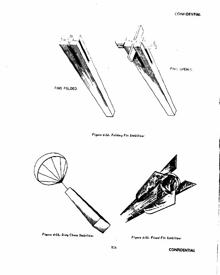
CONFIDENTIAL
FINS FOLDED
Fin1, ciPENfO
Figur» 4-54. Folding Fin Stabilimr
[

CONFIDENTIAL
PROPELLANT PRIMER
EJECTOR ELECTRICALTUBE CONNECTION
SECTION A-A EJECTOR DETAIL
LONGITUDINAL
F igu rt 4-57. Integral Ignition System (Gun T ube M ethod)
115C O N F I D E N T I A L
21)9-571 0-<jS—9
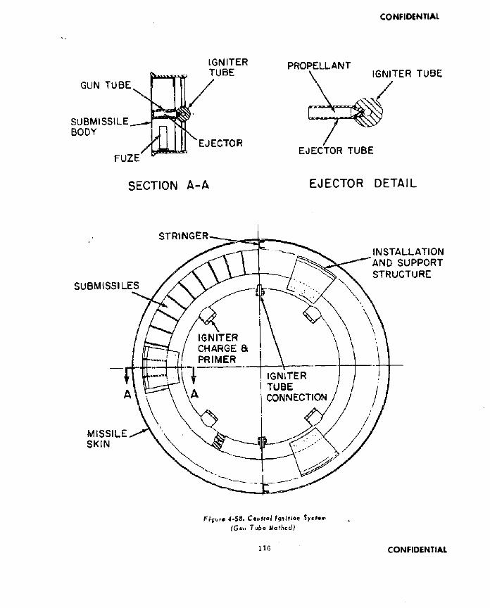
CONFIDENTIAL
IG N ITE R
EJECTOR DETAIL
116 CONFIDENTIAL

CONFIDENTIAL
AFTSUBMISSIVE
IGNITER TUBE
F O R W A R DS U B M I S S I L E
KHOPl LLANT
PISTON
CENTRALSUPPORTTUBE
PROPELLANT
L IN E R
CROSS SECTION OF STEEL CASEF igu re 4~60. B le s t e je c t io n • In term ed iate L in er
Figure 4-59. Piston T jrp# Ejsctlou
21 SUBMISSILES SHOWN IN CLUSTERS OF THREE
F i g u r e 4 - i l . B l a s t E j e c t i o n - S e g m e n t e d Cbcml>«i F igu re 4-62. B le s t E je c t io n • C on volu ted Litter
CONFIDENTIAL 117

Xij
au
ocg
•q
ni
lin
g -*
^
ue/
«»
/g •
ijn
J[
un
g *5
9.^
tja
tfj
•m
ini,
) ja
gura
yg »
|<jo
*ofjy
mnw
jxD
jY ’
/9-^
•Jr
tS/j
G O * 5 S J*l
"4e&*
P0 -MAXIMUM CHAMBER PRESSURE-PSI (X 1000)

Figu
r* 4-66. Pn
<»ri/
Ltngili
s*
P0 -MAXIMUM CHAMBER PRESSURE-PSi Of 10001
— — n ro r* m u £O N 4 l O X k C D K ) ( r O
CO
NF
IDE
NT
IAL
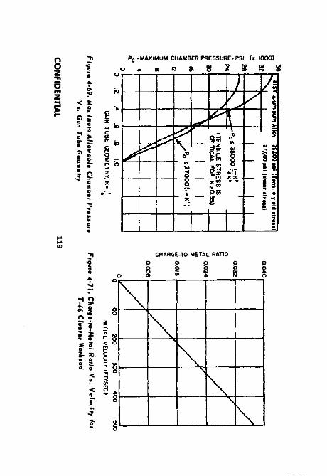
pot
ijio
it
9t’
l
X*
*u
io*
y •
qn
j.
wig
tot
'*A
°!*
°iS
MZ*
> •■
mfii
j •■
">**
•'<*
J»<;
iuo
iq o
jqoM
O,,y
<un
«f xD
|y •
49.^
mj'n
6,j Pc -MAXIMUM CHAMBER PRESSURE-PSI (> 1000)
ch a r g e -to - m e ta l ratio
O p p O p

A
CO
NF
IDE
NT
IAL

CONFIDENTIAL
5Fixed Base: Poor inherent Damping.
Figure *• 72. T-46 P rototype Wcrfi.od
Figure 4-72. Typical Submissi /» Flight Pattern
Fixed Fins with Damped ElevOn: Most promising.
Combination:Needs further study.
Fixed Fins: Excessive area required lo r damping.
■i 3
DragStabilization:Poor inherent damping.
Figure 4-74. Sph»rien/(Rfi»«*) Suhm itulU F igu re 4-75. T yp es o f S tab ilisa tion
120 CONFIDENTIAL

CONFIDENTIAL
GUN TUBE
F igu re 4-78. Support Structure
F
Figure 4*79. Tui« Ano/yii*
STEEL STRAP
CONFIDENTIAL 121

CONFIDENTIAL
CHARGE RACKED IN END RINGS
Figur* 4 -82. Guillotine Installation
SHEARED WIRE BUNDLE
1 2 2 CONFIDENTIAL

CONFIDENTIAL
The exact order of the design procedure may vary depending upon the viewpoint of the designer and, even more, on the military requirements which often fix certain parameters in advance.
4-7.2. Detail Dmgn DataLine* Design The design of the shaped charge warhead liner is most important. (See Figure 4-84 for shaped charge nomenclature.) The variables to be considered in the design of the liner are (X) liner diameter, (2) finer material.(3) liner profile, and <4) thickness of liner material The performance of the warhead against various targets is primarily dependent upon an intimate interrelationship of these variables among themselves and with standoff.
The upper limit on liner diameter is obviously established by the diameter of the warhead compartment, w dch is determined by the m issile system designer. The performance of a given diameter copper cone measured in terms of its penetration of armor steel, with all other variables being optimum, is given by the empirical relationship:(Reference 4-7, b)
7 + 2D - - ------ (4-7.1)5
Where d = cone diameter in inches7 = thickness of armor in inches
The above equation does not necessarily describe the overall optimum performance against armor because the optimum standoff condition cannot usually be realized. The penetrating ability in terms of the cone diameter for various steel lined cones against concrete as a function of standoff Is presented in Figure 4-85 and Figure 4-86. Shaped charges fired against aircraft at long standoff distances of the order of 100 to 150 feet should have a diameter of at least 6 inches to severely damage the target. (Reference 4-7. e).
The choice of liner material involves one of the basic decisions in shaped charge design. For short standoffs, the order of penetration ability for liner materials is copper, aluminum.
TARGET
Figvra 4-84. S haped Cfiarg* Nomanc/otvr*
steel, zinc, lead, and glass. Most designs use copper, aluminum, or steel. Oxygerx-freeelec- trolytic copper is considered the best choice when maximum penetration is desired at small standoffs. When choosing between alloys and grades of aluminum and steel, note that the most ductile will yield maximum penetration. Copper liners will give the greatest penetration of steel targets at standoffs of from 1 to 3 charge diameters. See Figure 4-87. The optimum standoff for aluminum liners against steel targets is larger than for copper liners, i ,e.. about 5 to 7 charge diameters. See Figures 4-88 and 4-89. The optimum standoff for aluminum liners against steel and concrete targets is similar to that for copper liners, that is 1 to 3 charge diameters. See Figures 4-85 and 4-86.
The utilization of the warhead is a determining factor regarding the liner material to use. if maximum penetration is desired at short standoff, the liner material should be copper. However, if the warhead has greater penetration than Is required, it would be wise to consider the use of an aluminum or a lami - nated liner of two metals. By using either of these types of construction, there will be a small loss in penetration, but, behind the target penetrated, the lethal effects will be increased due to special incendiary conditions. If the target is an aircraft, the best m aterial to use for the liner is aluminum, since the greatest amount of damage to low density targets will occur with low density liners. The relative
123 CONFIDENTIAL

PEN
ETRA
TIO
N-C
ON
E D/
AJM
E TEW
S
CONFIDENTIAL
Ffgur* 4-8S. P tn ttratian Vi. Stondoif; C an * A nsi* and Con* T h ieJen ass A gain st C a n eta l*
penetration capabilities of various liner materials on a unit density basis, taken from reference 4-7 .a Is presented in Table 4-9. For Tabic 4-9, the standoff distance was large enough so that the copper jet was beyond maximum penetrability.
Cone apex angles between 40 and 60 degrees give good performance at the standoffs usually associated with surface targets; i.e., 2 to4 cone diameters. This range of cone angles is used in both spin compensated and nonspin compensated warheads. In spin compensated warheads at low rates of spin, experimental data indicate that a cone whose opening angle changes provides better penetration at shorter standoffs than single-angle cones.
Increased penetration of surface targets can be achieved by well made cones utilizing smaller cone angles of 20 to 30 degrees at standoffs below about two cone diameters. At best, however, the improvement in performance achieved from the smaller cone angles is only moderate. This small performance advantage is usually outweighed by a tightening of manufacturing tolerances. Therefore, cone angles less than 30 degrees are generally not
F iqu r* 4*86* P an tfra tian k j. S tan do ff an d Cana Tfwc k n ots A gainst Conet a t*
recommended for small standoff against surface targets. Ample experimental data show improved penetration at long standoffs for large cone angles; i.e-, B0 to 120 degrees or more. The relationship between cone angle and penetration at long standoffs cannot be precisely predicted. However, it is generally accepted that, as the cone angle increases, standoff must also increase to achieve optimum penetration. Some investigators believe that this increase in standoff is a linear relationship, but see Figures 4-90 and 4-91a through 4-91d,
For use against aircraft at standoffs on the order of 100 feet, cone angles from 80* to 120° are recommended. (Reference 4-7. e.)
Cone thickness for beat performance is primarily a function of cone apex angle and charge confinement, although other parameters play a lesser role. The optimum cone liner wall thickness increases with increasing cone angle and with increasing confinement of the charge. Generally, the optimum liner wall thickness varies between 2 and 4 per cent of the base d im eter. However, some experiments indicate that thicknesses greater than this are acceptable. Work has been done using cone
CONFIDENTIAL 124

CONFIDENTIAL
Table 4-9Relative PenetratTorTCapabilitles
of Various Liner Materials
Cone Material Relative Penetration (In Mild Steel)
Aluminum 1.10
Copper 1.00
Steel ,75
Zinc .65
Lead . .50
Glass .40
<& UIa?8
<K
It
STANDOFF IN CONE DIAMETERS
thicknesses of 5, 6 and as high as IS per cent. Thicknesses of about € per cent are generally used in warheads that are fired against aircraft at long standoffs.
Liner walls thinner than the optimum are characterized by excessive variation in penetration from round to round, and an overall decrease in penetration. Liner walls thicker than optimum also show a decrease in penetration although (X) it is slight for moderate Increases In thickness and (2) the variation In round to round penetration is small. See Figures 4-92 and 4-93.
Exptosivo Charge Design In general, penetration and hole volume increase with increasing charge length, and reach a maximum at about 2 or 2.5 charge diameters for heavily confined charges, and at about 4 charge diameters for lightly confined or uncoufined charges. The usual effects of less than optimum charge length are lowered average penetration and reduced hole volume.
The explosive selection is important in shaped charge design. Explosives with high detonation pressure and velocity are the most desirable (see Appendix). The three explosives used most commonly in shaped charge ammunition are Composition B, Pentollte, and RDX.
Flyur* 4*57. Pmntlmlion V«. Standcll Ajolnjl Mild Jf*»l Torg»l
Other explosives which have been used to a lesser degree Include 77/23iHBX/TNT, Composition A-3, and Composition C-3.
The explosive loading of the warhead must also be considered. The charge should be as homogeneous as possible, and should be free of accidental voids and foreign matter. It is necessary to incorporate any booster and wave shaping wells while casting or pouring the explosive. The loading in the region of the cone base is the most critical. The explosive in this region must be uniform in density and homogeneity.
The presence of voids in the charge is often responsible for loss in penetration. Despite the attempts usually made to exclude them, they are often present in some form. Sometimes the voids take the form of axially positioned pipes which are believed to have wave shaping effects. These axial pipes have been used to explain abnormally large penetrations sometimes encountered in test work. No known techniques have been developed for intentionally Incorporating wave shaping voids in charges.
125 CONFIDENTIAL
CONFIDENTIAL
x4OLiJZOO
zs
— 1----------------- 1
C0n4 ongft 4}'Con* malarial: AluminumThickrvcit of comt«all not**
-<02J CONE DlAME rERS
RETERENCE
_________
9-7. a
_________
STANDOFF IN CONE DIAMETERS
F igu re 4-88, P en etra tion V s. S tando ff A gainst Mi Id St*»l Targ*l
Wave shaping offers one means of improving shaped charge performance. The purpose of the wave ahaper is to invert the detonation wave and cause it to strike the cone wall at decreased angles of obliquity. All wave shapers are cylindrical and symmetrically placed between detonator and liner. Useful wave shaping might be accomplished by any of the following methods: inert fillers, other explosive fillers, voids in the explosive charge (pipes). (See Figure 4-94.) A warning should be given that, as of 1958, the application of wave shaping to shaped charges is still a difficult matter.
Inert solid cone-shaped fillers of glass or steel have produced a 20 per cent Improvement in penetration performance without loss of hole volume. Cone shaped Inert fillers with abase- to-altltude ratio of two have performed well, with little apparent degradation in performance for slightly different ratios. The base of the wave shaper is generally located Immediately behind the apex of the cone, its diameter being only slightly less than that of the charge. Some Inert fillers have taken the form of spher
ical segments. These have been positioned in the charge Just forward of the booster, with the spherical surfs ce toward the cone
It is not necessary for the detonation wave to go around an inert filler in order to accomplish wave shaping, lt ls possible, with properly designed fillers in which the thickness and shape are adjusted, to allow the wave to pass right through the filler with suitable delay for wave refraction, and thus produce useful wave shaping that shows considerable Improvement in penetration, without loss (or even with slight gain) in the hole volume. Explosive fillers that have been used for wave shaping include Bara- tol and TNT.
Peripheral initiation is one method of wave shaping which can be used to improve penetration. However, the actual improvement attained varies considerably with the liner material used. Also, hole volume may be Increased by as much as 50 per cent by the use of peripheral initiation. When small asymmetries exist anywhere in the system, penetration will decrease. Although performance from carefully designed and accurately manufactured peripherally initiated rounds is superior to that obtainable from point-initiated rounds, thelatter method of initiation yields more consistent results and also the point-inititated rounds are easier to manufacture.
Warhead Casing Design The case is designed to retain the charge before detonation and to confine the charge during detonation. The strength of the case required for confinement of the charge during detonation is practically nil in warheads where the length to diameter ratio of the charge exceeds about 4. As the L/D of the charge ts reduced, the ca.se strength required to confine the charge increases. Unfortunately, the casing thickness usually cannot be designed for optimum confinement. This is because in guided m issile applications weight limitations will force the designer to use a lighter-than- optimum case while, for projectiles, set back forces will Impose the use of a thicker-than- opttmurn casing.
128CONFIDENTIAL

Figu
tt 4-90. P
initia
tion
V*. C
on
. Anglo A
gaim
t Fiq
mt 4.9Jfci p
#fi#trof/a(, y,t
J,0(,da
ff Ag
ain
** Mi/d
Co
nc
rtft 5
ft*/ Ttrg
tfs
PENETRATION IN CONE DIAMETERS
ui m <t* tr> N Nb gi b ui o vi
PENETRATION fN CONE OlAMETERS

STAND
OFF
IN CON
E DIAM
ETERS
STAN
DO
FF IN CO
NE D
IAM
ETERS
n
«Ooy>
M *0
O — w o» *p e n e t r a t io n in co n e DIAMETERS
PENETRATION IN CONE DIAMETERS
O — f«»> OJ A tf>
CO
NF
IDE
NT
IAL
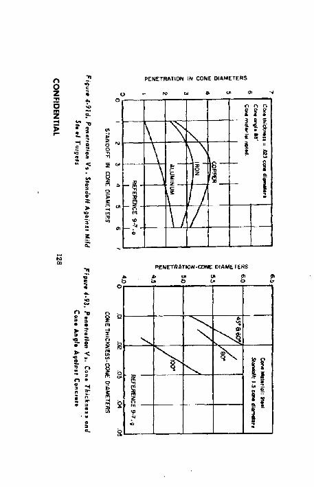
CO
NF
IDE
NT
IAL
PENETRATION IN CONE DIAMETERS

STAND
OFF
INC
OM
E DIAM
ETERS CONE W
ALL THICKN
ESS-1!'. BASE DIAMETER
T1
*ar>
Q ~ r u l > < » L » i y i N
P EN ETR A TIO N IN CONE D IA M ETE R S
CO
NF
IDE
NT
IAL

CONFIDENTIAL
SuimridF)' at FuXtny Requirements The tlize designer needs design information to design a fuze which is compatible with the missile system and the warhead. He will have access to the same missile system data as does the warhead designer. In addition to this, the fuze designer will need the following information relating specifically to the warhead:
(1) Drawing of Warhead(2) Standoff Distance(3) Wave Shaping Used
Summorr of Design Data At the conclusion of the design procedure, a summary of engineering data relating to the warhead should he prepared. This should include the following Items:
(1) Total Weight(2) Design and Installation Drawings(3) Explosive
(a) Material(b) Weight(c) Wave Shapers(d) Density
(4) Liner(a) Material— recommended manu
facturing method(b) Thickness(c) Geometry
(5> Design Standoff Distance(6) Center of Gravity Location(7) intended Performance
4-7.3. R*(*rtnc*s4-7.« “ Critical Review of Shaped Charge Information” , Edited by L. Zernow, BRLReport 905, ASTIA AD 48 311, dated May, 1954. “ Liner Performance” , John E. Shaw,4-7.b “ Critical Review of Shaped Charge Information” , Edited by L. Zernow, BRLReport' 905, ASTIA AD 48 311. dated May, 1954. “The Unfuzed Warhead". Hugh Winn.4-7.e “ A Theoretical Discussion of Penetration by Shaped Charge Jets with Some Experimental Results” , J. B. Feldman, J r . , B R L “ The Ordnance Corps Shaped Charge Research Report” No. 3-55, July, 1955.4-7.d “The Effect of Shaped Charges at Long Standoff Against Aircraft” , R. G. S. Sewell, L.
Spherical Segment
129 CONFIDENTIAL

CONFIDENTIAL
N. Cosner, and J . l’earaou, "The Ordnance Corps Shaped Charge Research Keport” , No. 4-55 ASTI A AD S3 088. October. 1955.4*7.• "Studies of Damage to Aircraft Structures by Shaped Charges at Long Standoffs’*. NAVOllD Keport 2018. ASTIA AD 14162, March, 1953.4*7,< "Manual for Shaped Charge Design” , R. A. Brimmer, NAVORD Report 1248, August,1950.4*7.b "Penetration of Shaped Charge Jets Into Concrete Targets” , G. H. Jonas. BRL Tech. Note No. 939, September, 1954.
4-7.4* Bibliography(1) "Collection and Arrangment of
Shaped Charge Data” , Arthur D. Little. Inc.. Interim Report, tctober, 1955,
(21 "A Conflation of Explosive Properties with Shaped Charge Performance” , NAVORD Report 2721. January, 1953.
(31 "Minutes of Shaped Charge Committee” . Picatlnny Arsenal, Shaped Charge Committee. February, 1954.
(4) “Multiple Fragment Effects in Shaped Charge Penetration” , NOTS, BRL Report 837, November, 1951.
(5( "T est of Multiple Shaped Charge Terrier Warhead” , University of Utah, Institute for the Study of Rate Processes, February, 1956.
(6) "Fundamentals of Shaped Charges”, CIT, Final Report, October, 1954.
(7) "Shaped Charge Performance with Various Explosive Loadings” , NAVORD Report 2767, February, 1953,
(8) "Prelim inary Evaluation of Tests of the T-42 Type Shaped Charge Warhead*’ , S. Wise, BRL Tech. Note 1079, June, 1956.
(9) "Some Remarks on the Performance of High Explosive Plastic Projectiles Against Armor Plate” , F . I. Hill, BRL Memo. Report 519, December, 1950.
44. CHEMICAL AMD BIOLOGICAL WARHEADS 4-8.1. Introduction Development, design, teat, and evaluation work In the chemical and biolog
ical warhead fields is generally more highly classified than this pamphlet, and is very closely controlled and administered by the Army Chemical Corps, Edge wood, Maryland. Further, chemical and biological warheads are not designed as the primary warhead for a missile system, but rather are alternates. Thus the chemical and biological warhead designer will, In almost every case, find that the missile system data Is firmly established and that the major tty of the warhead detail design direction will be provided by personnel al Army Chemical Center, who will supply at least the following data:
(1) Number of Bomblcts(2) Bomblet Configuration and Weight(3) Type of Bomblet Ejection System(4) Bomblet Ejection Altitude(5) Environmental and Storage Limita
tions(6J Leak-Tightness Requirements(7) Handling and Inspection Requirements(8) Tactical Utilization
With this in mind, this subchapter of the pamphlet is written in narrative form rather thah as. a step-by-step design procedure. It is intended to acquaint the warhead designer with chemical and biological warhead design techniques in a general way,4-8.2. Cluttor-Typo Warhead* The cluster-type warhead is basically a container loaded will) agent-filled bomblets which are randomly distributed over a given target area. It consists of a compartment filled with bomblets, a bomb- let ejection system and fuze, and when necessary a means of maintaining the agent within specified environmental temperature limits. This type of warhead is generally located in the nose section of the m issile, although occasionally the mid or after sections are used.
Bom btot Compartment and Structure The function of the warhead structure is dependent on Its installation within the m issile system. There are two basic types of warhead installation to be considered. The first of these is the case in which the warhead comprises a complete
CONFIDENTIAL 1 3 0

CONFIDENTIAL
compartment of the missile, terminated by a forward and rear bulkhead, and the second Is the case where the warhead Is Installed within a compartment of the m issile. The major design considerations or the former are that the warhead case Is the aerodynamic skin of the m issile, and that the warhead structure la an Integral part of the m issile structure and is usually detachable from the forward and rear m issile components. For the latter Installation, the misBtle skin must be removed to prevent Interference with the warhead ejection mechanism. In either Instance, both the Installation and handling systems will Influence the design and location of the main structural members of the warhead.
The bomblet ejection pattern from the warhead Is intended to be equally distributed around the perimeter of the warhead. To accomplish this, the bomblet compartment or compartments are divided Into longitudinal segments formed by placing longitudinal webs from the
center of the warhead to the Inner surface of the case. These webs are iategrated in the warhead structure or they may be part of the bomblet ejection system. The bomblets are manually placed In these compartments according to loading patterns' best suited to the bomblet and comportment configuration. The bomblets may be loaded Into the warhead through the forward or rear bulkhead. When tiie forward or rear bulkheads cannot be removed, a transverse cut is made which divides the compartment into two halves. These two halves are then loaded separately and assembled.
B o m b l t h Early development of c)"ster-type warheads was directed toward utilizing the cylindrical type bomblets which had been developed for use in clustered bombs. The dispersion of these bomblets depended primarily on the variation of manufacturing tolerance, and the ground patterns obtained were too smalt to
299-5 71 0-68— 19131 CONFIDENTIAL

CONFIDENTIAL
S ' '
Ft s»r* 4-91. Ejection J«i)u#nc», jpham
fully utilize the agent contained. An attempt was then made to Increase the dlsperslonbyfarce- ful ejection of the bomblets from the warhead. An increase in pattern size was realized but this was still unsatisfactory for warheads payloads of 1000 pounds or more. Recent development has been directed toward self-dispersing bomblets. Three basic configurations have been developed and are currently undergoing extensive testing. These configurations are a ribbed sphere approximately 4-1/2 Inches In diameter, a Fletner, and a delta wing glider with a vertical fin. Examples of these shapes have been previously presented in Figure 1-34.
The development of these self-dispersing configurations has eliminated the need for a separate ejection system. The dispersion pattern obtained from the sphere ts essentially circular, with random distribution of spheres throughout the circle as illustrated in Figure
4-95. The Fletnars are > andomly distributed throughout an annular ring as shown in Figure 4-95, and therefore must be ejected in groups of bomblets. each of which releases Ub individual units at a predetermined altitude in order to accomplish complete ground coverage, initial Investigation indicates that the delta wing gliders disperse themselves in a manner similar to the Fletner bomblets, .but normally form a larger annulus as shown In Figure 4-95.
Ejaerion Systemi The development of self-dispersing type bomblets has simplified the re quirements of the ejection systems considerably. A direct result of this has been the elimination of the elaborate forceful ejection mechanism required on other bomblets. The Belf- dlsperslng type bomblets must be so removed from the warhead compartment as to clear the after-body of the m issile in order to prevent damage to the bomblets.
The uniform distribution of bomblets within the impact pattern for the sphere configuration allows the release of the warhead bomb- let load at one predetermined altitude. Because of structural and loading considerations longitudinal webs are sometimes inserted between longerons. 130" apart. A 120° cone la placed on the rear bulkhead. Detexiating cord Is Inserted between the warhead skin and the longerons to provide for skin removal prior to the bomblet ejection. Tbe forward and rear edge of the skin panels are not permanently fastened at the forward and rear bulkheads. In this type system the fuze Ignites the detonating cord at the proper altitude, and the blast of the detonating cord and the air drag forces blow the skin panels away from the warhead structure. Aerodynamic forces then push the bomblets toward the rear bulkhead cone and the spheres slide off the cone and away from the missile structure. This operation is illustrated In Figure 4-96.
The annular distribution pattern for the Fletners and gliders requires ejection of groups of bomblets at more than one altitude to obtain complete coverage over the Impact pattern as shown in Figure 4- 97b. For purposes of illustration, the warhead is assumed divided
CONFIDENTIAL 132

CONFIDENTIAL
into four longitudinal trapezoidal compartment:; as shown in Figure 4-97. These compartments are loaded with bomblets and attached to. and held in place by a gun tube which is an integral part of the missile structure. A high volumetric expansion, low pressure charge in the gun tubes ejects the compartments with sufficient velocity fo clear the missile structure. The compartments incorporate a barometric fuze which ejects the contents of each compartment at a different altitude as shown in figure 4-97. For each altitude at which a cluster of bomblets is opened, an annular pattern is produced on the ground as previously explained. The summation of these patterns gives the complete ground coverage shown in Figure 4-97. The largest annulus is obviously produced by thebomblets released at the highest altitude, and the maximum diameter of each annulus is proportional to the ejection altitude.
E n v iron m en ta l R eq u irem en ts The warhead compartment environmental temperatures must be consistent with the specified bomblet environmental temperatures, It is therefore often necessary to supply some means of temperature control within the warhead. Insulation may be inserted between the warhead load and the warhead skin for this purpose. When an adequate amount of insulation cannot be installed within the warhead to maintain the required temperature, heating or cooling units must be used. A simple and efficient design for a heating unit utilizes the missile electrical power, and consists of electrically heated wire embedded in insulation which is sandwiched between two perforated sheets of light gauge metal. In a similar manner, cooling coils connected to an electrically operated refrigeration unit can be used. This type of unit can readily be preformed to the internal configuration of the warhead case. An additional advantage of these units is that they may be operated from an external power source when the missile electrical system is not in operation.
4-8.3. Mo«ilv*.Typ» W«rti,odi The massive-type warhead is basically a single container Loaded with raw agent which is released Immediately following impact with the target. It consists of the agent, container, and the agent dissemination mechanism and fuze.
This type of warhead Is ordinarily limited to missile systems whose payload capacity Is approximately 500 pounds or less. These warheads are capable of producing an extremely high agent concentration in the immediate vicinity of the impact area and are, therefore, well suited for use where relatively small concentrated type targets are the objective. The guidance accuracy required of the missile system for this type of warhead should be within the capabilities of guidance systems of present m issiles in this payload range. The most critical design feature of the massive-type warhead is the leak-tightness required of the warhead case.
4-8.4. Agent*The chemical agents are chemical substances whose toxic properties are such that they kill or incapacitate humans, domestic animals, or livestock through inhalation, ingestion. or absorption of agent through the skin. Some of these agents can kill or incapacitate within a very few minutes following exposure and are therefore well suited for tactical purposes. These agents are separated into physiological effect groupings of nerve, blister, blood, choking, tear and vomiting gas. Nerve gas is the most toxic of the above agent3.
The biological agents are live disease organisms or their toxic products. These agents can kill or incapacitate humans, domestic animals, or livestock and can also destroy crops. The incubation time on biological agents varies from a few days to several months and. except for those agents with a very short incubation time, their employment is limited to strategic applications. Biological agents include lungi, bacteria ,v iru ses, rick ettsiae , protozoa, and toxins. For some of these agents, satisfactory immunization has not yet been developed.
CONFIDENTIAL 133

CONFIDENTIAL
Table 4-10 Characteristics of Existing Service WarheadsB L A S T
T o t a l S i i s
G e n e r a lT y p e T a r t e t
W e ig h ttoL e n g t h
I n d u s
D i a m e t e rla c h e s S t a t u s D e s ie n a U u n c / n » R e m a r k s M i s s i l e
S u r f a c e -to *
S u r f a c e
L i g h t
S t m e C u r t s A n d
M a t e r i a l
5 0 0 0
N o m i n a l
T 2 3 9 ACUV* T 3 E 3 3 . 4 6 M a t a d o r
S u r f u i -ID *
S u r f Ace
S t r u c t u r e s S o a c u p U b ie t o B l a s t
1 5 0 0 1 3 . 0 2 9 .4 1 A c t i v e T Z 0 2 1 4 . a s H o n e s t J o h n
S u r f a c e -
CO*
S u r f a c e
G e n e r a l 0 r o u n d
T a r g e t *
11 60,30
6 2 .0 2 0 .0 I n a c t i v e T 2 3 E 1 1 , 1 8 H a s n a t u r a l
f r a g m e n t a t i o n
C o r p o r a l
C O N T I N U O U S H O D
T o u t Sl i e R o d
G e n e r a lT y p e T a r g e t
W e ig h t
tb
C e n g t E
i n c h e s
D i a m e t e r
i n c h e s S ta tu s D e s ig n a t io n c/'m N u m b e r S i z e , in c h e s
E x p a n d e d
R u ig R a d i u s M i s s i l e
S u rfa c e * t o - A i r
A i r c r a f t 3 0 0 1 7 .3 21 D e v e lo p *
m e n t a l
C m il iu u o t iS
R o d (B o m a r c ]
.8 0 0 6 0 0a p p r o x .
3 / 1 6 * 1 / 4 x 1 6 1 / ! 100 f e e t B o m a r c
S u r f a c e *t o - A L r
A i r c r a f t 4 0 5 2 1 . 9 3 3 .3 E x p e r i
m e n t a l
E X 1 4
M o d 3
.6 7 5 5 3 4 0 . 2 5 0 x 0 . 2 5 0 x 2 0 1 2 5 f e e t T a b u (6 b )
S u r f a c e -t o - A i r
A i r c r a f t 1B0 20
m a x .Um a x *
D e v e l o p m e n t a l
E X l » .7 2 2 2 7 4 1 / 4 x 1 / 4 a 1 6 .3 6 5 ’ ( m a x . ) A d v a n c e dT e r r i e r
S u r f a c e -
t o - A i r
A i r c r a f t U 5 1 3 .5 12
m a x .
D e v e lo p *
m e n t a l
E X 2 0 M o d 1
- 3 7 2 3 / 1 6 x 3 / 1 6 x le n g t h 5 5 1 r a d i o .
90* I r a n W / H
T a r t a r
A l r - t o -
A t r
A i r c r a f t 0 3 U . O O l 6 .0 0 0 D e v e l o p m e n t a l
E X 2 1 M o d 1
. 7 3 5 2 4 2 . 1 6 7 x . 1 8 7 k 1 0 .3
( e l f e c U v e r o d le n g t h 7 . 3 )
2 7 fe e t
(m a x i m u in t h e o r e t i c a l )
S p a r r o w i n
D 1 S C R E T F R O D
A l r - t o -A l r
A i r c r a f t 54 1 5 6 . 0 7 3 7 .5 9 6
E x p e r i
m e n t a lE X 1 M o d 0
- 1 2 0 0 . 4 5 x 0 . 3 3 x 3 . 8 7 5 S p a r r o w [
A l r - t o - A i r c r a f t 4 0 4 10 I n a c t i v e 1 4 6 E 1 . 4 9 6 0 0 . 3 7 5 x 0 . 5 0 x* O r i o l e
Air
134 CONFIDENTIAL

CONFIDENTIAL
Table 4-10 (Continued)nuaM t_NTATIOfJ
G e n e r a )
T y p f T a r g e t
T u t s iW .-lu h t
lb
S it * ___
L e n g t h T " D ia m e t e r
In c h o n 1 In c h e * S U t u a D e s ig n a t io n c / mF r a g m e n t *
W u m E e i | S in e , in c h e s M lS S lh
S u r la i* * -t— A I r
A i r c r a f t 100 D e v e lo p
m e n ta l
X M - 3 t . 6 6 1600■ | ip ro a .
1 / 2 x 1 / 2 a 1 / 4 H a w k
A i r l n -
M iA l r r n l l 49 1 1 .0 7 .2 7 0 io
7 .2 4 0
D e v e l o p
m e n ta lE X S M o o 1
.7 4 1 1674 .3 7 5 x ,3 7 $ x .3 8 2 $ S p a r r o w U
S y r / w e -
* « ' - A l r
A i r c r a f t 218 2 1 .8 3 3 1 3 .5 0 0 to
1 0 .4 1 2
A c t i v e ,P r o d u c t io n
M k 5 M o d a
1 .5 0 536 S it e (a ) 4 0 5 6 S ic e (b )
3 / 6 x 3 / 8 a 3 / 4 3 / 6 c u b e
T e r n e r
S u r f a c e - * o - A i r
A i r c r a f t 218 3 1 .B 3 5 1 3 .5 0 0 to 1 0 .4 3 1
A c t i v e .P r o d u c t io n
M k 5 M o d 6
* 550 S it e (a ] 4 2 0 0 S ic e (b )
3 / 6 x 3 / 0 a 3 / 4 3 / 6 c u b e
T e r r i e r
A l f - l n -A l r
A i r c r a f t 4 4 a l(w ith o u tfu s in g )
15 7 -5 / 0 Iv 6 -1 / 8
P r o d u c t io n M k 7 M o d 0
.9 4 4 1313a p p r o x .
0 . 3 1 2 x 0 . 4 4 1 * 0 . 4 S p a r r o w I
A l r - l o
A i rA i r c r a f t 35 1 3 -1 / 3 5 A e t lv e M k 8
M o d 04 .8 2 1300
a p p r o x .' S id e w in d e r
Su r l a r e - l o - 'k i r f t r e
P c r y a n y i r l 1345 4 20
( w ith o u t f u s in g ]
3 3 .7 0m a x .
2 2 .4 5n u x .
In t e r i m T J 5 E 1 . I l l & W 0 0
a p p r o x .
. 150 X .1 5 0 X 2 .7 0 C o r p o r a l
S v r li ic * *l u - A i r
A i r c r a f t 1 1 .7 $
» .2 5
6 .3 0 3m a x .
$ .1 5m a x .
A c t i v e T 3 6 E 4 - 400a p p r o x .
* N i k e 1
S u r f a c e -t o - A l r
A i r c r a f t 1 1 4 .7 5 1 .2 5
2 1 .3 6 1 1 .7 A c t i v e T I 7 E 3 M B 68 1$ . 9 1 2 5 a .0 0 3 c u b e N i k e 1
S u r f a c e - to • A i r
A i r c r a f t 1 2 1 .3 5 * .2 5
2 1 .4 1 1 .0 A c t i v e T 3 8 E 3 . A N 4 4 1 6 . 3 1 2 5 * .0 0 3 c u b e N tlts 1
S u r f a c e -T o -S u r f a c e
P e r s o n n e l 1 3 4 5 t 20 (w ith o u t fu s in g ]
' - D e v e l o p 'm e n t a l
T 4 0 .0 8 3 5 0 0 ,0 0 0 ,0 0 0 d l a . x 1 .2 3 Ig C o r p o r a l
S u r f a c e -1 0 -A l r
A i r c r a f t 1 1 1 4 m a x . 1 0 W m l r .
2 7 .1 0 2 0 .2 4 D a v e t o p - m a n t a )
T 4 S - 1 8 ,9 0 2 . 4 1 4 c u b e N ik eH e rc u le s .
A l r - t o
A i r
A i r c r a f t 6 3 1 4 .0 0 0 8 .0 0 0 S u y « : netted b y fc X 2 t
E X 2M u d 3
. $42 1486 . 3 7 3 x . 3 7 5 x . 5 L 6 S p a r r o w H I
S u r f a c e -t o - A l r
A i r c r a f t 350 1 5 .0 2 0 M . 2 * 0 to 2 3 .6 4 0
In a c U v a E X 7
M o d 12 .1 8 6200 3 / 8 c u b e T a l u s (H i )
S u r f a c e -
t o - A i rA i r c r a f t 1 4 3 .1 6 - - S u p e rs e d e d T M E i 1 .0 8 0 1 4 0 ( o c H i r O
O U T (on te s t m o d e l)
. 2 52S cu b e N ik e 1
S u r f t c e -t o - A l r
A i r c r a f t 4 0 5 2 1 .0 2 0 2 6 .3 to 2 3 .6
S u p e rc e d e d b y C o n llq u *
ou e R u d W a rh e a d
E X 1 7 M u d 1
2 . 2 * 76 50 3 / 8 c u b e T a l o s (6 b )
A lr -to * *A i r
A i r c r a f t A > 3 1 .0 7 0 . 2 6 .0 2 C - 3 $ . 70 f> * 4 1 .2 4
4 10 In a c t iv e 14$A , B .
C , D
A - 1 .0 3 B - 0 .7 4 C * 1 ,3 3D . l . < 7
N a t u r a l
F r a g
m e n ta t io n
N a t u r a lF r a g m e n t a t io n
O r io le
CONFIDENTIAL 135

CO
NF
IDE
NT
IAL
T able 4 -1 0 (Continued)
CLUSTER
_____Size_____ _______________SubmissileGeneral Weight Length Diameter Weight ol Weight Charge MissileType Target lb inches inches Status Designation Type Number Submissile per SubmissileSurface-to-Air
AircraftBomber
300 10.4 32.2 Develop- Cluster mental Warhead
(Bomarc)
Surface-to-Air
Aircraft 156.14 - Develop- Cluster mental Warhead
(Nike 0 Center Cluster
Surface-to-Air
Aircraft 127.04 - Develop- Cluster mental Warhead
(Nike I) After Cluster
Surface- lo-Ai r
Aircraft - - - Develop- T-46 mental
Air-to-Air
Aircraft 60.39to57.69
26.25 - Expert- Dispersal mental Warhead
(Sparrow I)
Unslabi-lized
48 4 .2 (approx.)includingfuze
2.9 Bomarc
Unstabilized
26 4.56 2.9 Nike I
Unstabilized
21 4.56 2.9 Nike 1
Unstabilized
- 4.42 - Nike Hercules
FinStabilized
16 - 1.4 Sparrow I
SHAPED CHARGE
GeneralType
Total Size
TargetWeight
lbLengthInches
Diameter inches Status Designation
Surface-tO-Surface
Tanks andArmoredVehicles
10.60 15.15 - - FrenchSS10
Surface-to-Surface
Bunkers and Fortifications
500approx.
81.2 20.5 Develop- max. mental
T34
ApexCone Liner Wall ----------- Base
Angle Thickness Diameter MissileDegrees Inches Material inches
- - Copper 6.48 French SS10
40* 0. 25 Copper 14.25 Lacrosse
CO
NF
IDE
NT
IAL

CONFIDENTIAL
137 CONFIDENTIAL

CONFIDENTIAL
4*8.5. Bibliography
(1) “ Chemical and Biological Agents Chart for Guided M issiles” ATI No. -455, July, 1946.
(2) “ Development of Special Chemical Heads for R ockets", Arthur D. Little, Inc., ATI No. 131213, January, 1952.
(3) "Launching of HVAR Heads", Hughes Aircraft Co.. ATI No. 136846 and 136847, April and May. 1950.
4*9. CHARACTERISTICS OF SERVICE WARHEADS
Pertinent Information relative to existing service warheads for guided m issiles is included In this aubchapter for reference purposes. It was obtained from "Survey of Guided M issile Warheads". Haller, Raymond and Brown, Inc., September, 1956, Report No. 91-R -5. It is to be noted that many additional service warheads have been developed or put In production since the publication of the above Survey.
138 CONFIDENTIAL
CONFIDENTIAL
Chapter 5
WARHEAD EVALUATION
5-1. EVALUATION PRINCIPLES
5-1,1. Introduction Whenever any warhead has been developed, it Is necessary to know the adequacy of this warhead relative to the original requirement to which it was developed; that is, final evaluation of the warhead must be made. In order to have this evaluation be more than an opinion, it must be based on factual data as nearly as possible.
A reliable evaluation of a specific warhead against a specific target can be obtained by conducting an adequate number of tests where the warhead is employed in the given guided missile system against the target and under conditions closely approximating actual engagement conditions. Such tests, carried out using remotely controlled or stationary targets are generally useful, reliable and sufficiently accurate, although expensive. Although the evaluating of a warhead in a complete m issile system is a highly complex problem, the warhead designer can, without conducting these elaborate tests, arrive at approximate evaluations which are usable for comparative purposes. Such approximate evaluations give the warhead designer an insight into the relative efficiency of proposed designs as well as a method of ranking these proposed designs in order of their adequacy of meeting the original requirements for which they were developed.
There are several ways to present the evaluations of specific warheads employed against specific targets. Chief among these and the one treated in this pamphlet is that of giving probabilities of inflicting specified kinds of damage {called “ klUs” } upon the specified
targets under specified conditions by specified warheads.
Except for evaluation techniques which involve the firing of actual warheads against actual targets, and the subsequent assessment of the damage inflicted thereto, the methods used and discussed in this chapter are based on mathematical analyses. The principles involved are mentioned, as well as some specific nomenclature, etc., but it is not the purpose of this pamphlet to provide the reader with a basic knowledge of the theory of probability. For the latter, the reader is directed to standard texts in the field such as those listed under the Bibliography, 5-6, entries 13, 14, and 15.
5-1.2. Overall Kill Probability The overall probability of Inflicting a specified kind of damage (called “overall kill probability") upon a specified target under specified conditions by a specified missile system having a specified warhead Is equal to the product of the following probabilities;
p , = the probability of detecting and/or recognizing the target
p c = the probability that the missile system will launch the m issile (conversion)
Pd - the probability that the m issile will deliver the warhead to the. target
Pf = the probability that the 1 fuzing system will function and that .the warhead will have a high order detonation
CONFIDENTIAL 135

CONFIDENTIAL
p k = the probability of Inflicting thespecified damage (Kill) provided the target is detected (and/or recognized), the missile system functions, the warhead is delivered to the target, and the fuzing system functions (called “ conditional kill probability'*)
Thus, if Ps = overall kill probability (success), then
P s - P t ' p c ’ p d ’ p / ‘ p k ‘ l5- 1 -1)
This overall kill probability is of interest to the warhead designer in that he should knowhow his design fits into the overall missile system. However, the warhead designer has no control over recognition (detection), conversion, and delivery. He has little control over the fuzing reliability.
It is to be noted that from an economic or supply standpoint the “expected fraction killed “ of an area target with a given number of shots is of Interest in order to determine the weapon to be used. However, In the battlefield, of primary concern is the high probability of obtaining a given U vel of Kill; e g ., 90% confidence of Killing at least 50% Df an area target. It is to be further noted that improvements in reliability of guided m issiles are generally of more importance than increases in their single shot kill probability Pk-
As can be seen by equation (5-1.1), the warhead designer can contribute to the Overall kill probability, p s . by maximizing as much as possible the conditional kill probability, !‘k , over which he does have control within the limits of the parameters given him. Thus, if >’i is the conditional kill probability for the i ’th warhead design, the maximum pt i (i.e. Pjj ma* ) would be the criterion for use in
determining the warhead design which would be most adequate relative to the original requirements for which the warheads were developed. ■
5-' ' '“onditionol Kill Probability The conditional lui, i-obability, Pk, which is of concernto the warhead designer is that probability of inflict
ing the specified damage (Kill) provided the target is detected (and/or recognized), the missile system functions, the warhead is delivered to the target, and the fuzing system functions. This conditional kill probability is the means whereby the warhead designer may evaluate the relative effectiveness of proposed warhead designs and rank these designs In order of their adequacy of meeting the original requirements for which they were developed. In terms of effectiveness the warhead with the maximum conditional kill probability, Pfc, max, is the best.
The conditional kill probability, P*, of a warhead is a function of the following;
$ (0 ) = frequency distribution of the guidance error
V(Ft = frequency distribution of the fuzing error
“ velocity of the missile which carried the warhead, measured In the direction of travel of the missile in feet per second
vt = velocity of the target measured in the direction of travel of the target in feet per second
0 - angle between the missile trajectory and the target trajectory
k - altitude of engagement
l (i»j - lethality of the m issile warhead
V(T) - vulnerability of the target.Thus, (S-1.2)p k . ! [*G ). W (F). v m, v t, o. h. I ( i t ) , V(Tj]
The frequency distribution of the guidance error, is discussed in Section 5-1.4.
The frequency distribution of the fuzing error, V(F), is discussed in Section 5-1.5.
The velocity of the m issile, vm , the velocity of the target, v,, and the altitude of engagement, b, are normally specified and may
1 4 0 CONFIDENTIAL

CONFIDENTIAL
lx* treated ay constants. However, the warhead do si pier has the responsibility of recommending that a missile with inadequate payload or speed advantage over the target be superseded.
The angle, u, between the missile and target trajectories is generally a variable that must be considered in the evaluation of a warhead. However, 0 can be held constant so that several warheads may be evaluated and compared at a specific engagement aspect.
The lethality of the missile, / (m), is a function of the warhead type and of the variables over which the warhead designer does have control within the design parameters. For antiaircraft warheads, the speed ratio v*/v, is extremely important. These variables are treated in the individual warhead design sections.
The vulnerability of the target. V(T), depends upon its shape, size, location, structure, toughness, motive power, maneuverability, payload, special distinguishing characteristics, attack time, whether it is singly or multiply vulnerable to the warhead considered, and other descriptive data.
5-1.4. Distribution of Guidonc* Error Guidance error is defined as the perpendicular distance from the aim point to the missile trajectory. The aim point is defined as that point where the missile warhead would detonate if the guidance system and the fuzing system were to function in an ideal manner. Because of human and mechanical factors, neither guidance nor fuzing function perfectly and therefore guidance and fuzing error have frequency distributions. Assuming there is no overall bias, then these errors are taken to be distributed around the aim point.
In order to gain an insight into the distributions of these errors, one must first become oriented to the velocity vector re lationship of the missile and the target. This can be approached by first looking at the special case where the target is an aircraft and the aim point is the geometrical center of the aircraft. Thus, with perfect guidance and perfect fuzing the attack would occur as shown
In Figure 5 1.Figure 5-1 showy the relative portions o:
the target and missile at some specific* time just prior to the lime of impact, lntnis picture it can be seen that the guidance system has accounted for the velocity-vector relationship of the missile and target so that the aim-point is that point where the geometrical center of the target was expected to be at the instant the m issile intersected the path (trajectory) of the target center.
Now, If a plane normal to the missile trajectory is drawn through the aim point, the x-axis of this plane is in the direction of the yaw of the m issile and the y-axls is in the direction of pitch of the m issile, both with origin at the aim-point. This is illustrated in Figure 5-2.
Figure 5-2 also shows a z -axis originating at the aim-point and normal to the plane. Fuzing error is distributed along the missile trajectory which is along or parallel to the *-axis, The distribution of fuzing error is treated in Section 5-1.5. Assuming that fuzing error (i.e. error in the z direction) is independent of guidance error (i.e. error in the x, y plane), and analysis of the distribution of guidance error is reduced to a two-dimension problem.
Now, if a great number cf m issiles were fired at the aim-point, due to random errors in the guidance system (human, mechanical, and electronic) the missile trajectories could in tersect the x, y plane at any points as shown in Figure 5-3. If the frequency distribution of these points were known, one could calculate the probability that a single missile will intersect the x,y plane within any defined area.
As can be seen in Figure 5-3, the guidance error of the i*th missile is AI( and A, has a component on both axes, xt and y,, where
A, * i + yi2 (5-1.3)
It is assumed that the * and y are independent. Thus the frequency distributions of x and y may be analyzed independently. Consider first the frequency distribution o f* . It is generally assumed that guidance errors are
CONFIDENTIAL 141

CONFIDENTIAL
random occurenceb and that the axle component of these errors follow the so-called normal (Gaussian) curve of error. In this case the frequency distribution of * la mathematically defined by
12<r* ‘ (5-1.4)
where Sr = standard deviation of the x from the origin (aim-point).
The frequency function 4 <x) can be thought of as a distribution of ratio of occurrence of each *i when a very large number of m issiles Is fired. If n is the total number of missiles fired and "xi Is the number of these m issiles whose x component of error Hen between *, and * i + ^ r , foen, ajiYx 1 * 0 ,
A graph of the normal frequency function. <t>(x), is given In Figure 5-4.
The probability that any random occurrence of x la between any two given values, say * °x - Is the area between the normal frequency curve and the x-axis. In this case the probability is equal to .68 and Is illustrated in Figure 5-5.
The standard deviation, is a function of the guidance system over which the warhead designer has little or no control. Therefore, It Is assumed here that this value is given to him by the m issile system designer. Thus, if it Is known that a specified target will be given a
Flfvrt 5-1. Attack with Patfatt Guidance and Par. fact Fuzing
specified damage when x « t 30 feet and the given oK - 30 feet, then the probability that a random shot with the specified warhead will Inflict the specified damage on the specified target is .66, neglecting possible errors In the y and z coordinates.
Let t = (5-1.6)
Then the normal frequency function & (t) is
4 (ti «x 4 (*) (5-1.1)
and Is Illustrated in Figure 5-6.A table of the areas between . t and ‘ for
.01 steps of the deviate t is given In Table 5-1, for the convenience of the warhead designer In evaluating proposed designs. These areas may also be found In a.iy standard book of mathematical tables under the title of “ Areas of the Normal Curve of Error'*. (Reference5-b)
Since y is an Independent variable and assumed to be normally distributed. Its frequency distribution function is
1 _vV o J4 M - — = * y ' y (5-1.8)
oy V2»
where °y = standard deviation of the y from
142CONFIDENTIAL

CONFIDENTIAL
the origin {aim-point). The reader should noli the similarity of this function to equation 5-1.4. Thus, if
(5-1.9)ay
then the normal frequency function is identical to equation 5-1.7. l.e .,
(5-1.10)v
and Table 5-1 may be used to find the probability that a random shot will give a between any specified y (plus and minus). Once again, ° y Is to be considered as being given.
P robab ility of Hitting o R oclongv lar Ar*r If fusing Is perfect, if the target Is a known rectangular
»<>>
Figure 5-4, The Normal Frequency Function
area, and i f there Is a known probability of kill provided the area is hit, p r< then the conditional kill probability, pk , Is the product of !\ and the probability of a hit, p on the area, l.e .,
p k ’ p c ' p b (5-1.11)
Thus, to find p i- the problem Is reduced to finding, Fh. the probability of hitting the area and multiplying this by p c-
ph can be thought of as the ratio of the number of shots which hit within the perimeter of the area to the total number. If this area is oriented as shown In Figure 5-7 30 that 11 Is a 2a x 2i urea with the * and y axes oriented at
the center, p h is the product of Fa the probability that the *■ component of a hit is between iu, and p /,, the probability that they component of a hit is between ±fr, i.e .,
ph ~ pa • pb (5-1,12)
Assuming known and independent normal distributions in the directions of both axes, then ux and ”y are known. pa is the area of the normal curve of area and can be found by letting
t .t*- — , and P a a it (5-1-13)
and finding the area. Table 6-1.In a similar manner. p (, can be found by
lettingi ---- (5-1.14)
oyand finding the area from Table 5-1.
♦c«i
Figur* 5-5. Ar»o l/ndor Normal F raqu an cy Cunro
CONFIDENTIAL 143

CONFIDENTIAL
Thus, If fusing l» perfect and P , t>s and vy are Known for a given rectangular target 2a x 2b, then the conditional kill probability la
pt “ pc • f,„ ' Hb (5-115)
Circular Normal D istribution With normal distributions in * and y and a% - « . the probability that a missile will hit the i , y plane within a circle of radius, ,\, from the aim-point is
•Vr . 1 - , ^ * (5-1.18)
where % = linear standard error of guidance and determines the frequency distribution of V In this case “ ° y .Letting, .
u ------ (5-1.17)°ll
the probability of a hit within a circle of a radius of u standard errors of guidance is
p A I - « 2 (5-1.18)
A graph of P,\ Is shown in Figure 5-8 and a tabic of values of f’&for .Olstepsof the deviate u is given in Table 5-2.
E llip t ic a l Normal D istrioation With normal distributions in * and y and a % ay . then I J j}( the probability that a m issile will hit the *-y plane within a circle of radius R can be read directly from Table 5-3 and Figure 5-9 for values of °y 7 u, " u min z° maK, and k / o mi*. The tabulated
♦ in
values were furnished by the Computing Laboratory of the Ballistic Kesearch Laboratories.
The phrase ‘ ‘Elllpth-al Normal Distribution” Is generally used to describe the distribution of the radial density function in a two-dimensional, non-circuiar, normal distribution.
Nisi DjsionceOne definition of miss distance is the shortest distance between the center of the warhead burst and the geometrical center of the target. The m iss distance U a combination of guidance error and fuzing error.
In many instances the aim-point is other than the geometrical center of the target. Each particular combination of missile, guidance system, warhead, and target would have Its own unique solution relating miss distance to guidance error. This solution can be found through analytic geometry. No standarddevia- tion of miss distance is a valid estimate of ° c < the standard error of guidance, unless it has first been subjected to this analysis.
In addition, due to the limitations of the capabilities of electronics measuring devices, in many cases the so-called “ miss distance” tabulated from test missile firings against drones is not the same as the miss distance defined previously. Instead, this ‘ ‘miss distance” is the shortest distance between the missile trajectory and the perimeter of the target if the measuring device is mounted in the missile, or between the device’s antenna
7"
b
-a o
-b
Figurw 5-6* Tko Normal Cvr^t of Error Figvto 5*7. Orlmitiofion o f R ocion g v lar Targot Area
Ml CONFIDENTIAL

CONFIDENTIAL
Table 5-1 The Areas Under The Normal Curve Of Errorftncluded Between t and - l)l 00_ .01_ .02 -03 U.4- 05_ .1)0 . U7 08 09
.ou you .008 Ulti . 024 .002 .040 ,048 .0 50 .064 .072
.10 .080 .086 . oy« . 103 .111 .119 .127 (35 ,14 3 15)
.20 . 159 174 m . 100 . 197 ,205 .213 -221 . 226
.30 .236 , 243 . 251 2'yj . 266 .274 .261 .269 .296 .303
.40 -311 . 316 . 326 . 333 . 346 .347 . 354 .362 360 .376
. 50 .303 .390 . 397 . 404 .411 .418 -423 .43) - 43 B .445
.00 .451 .456 . 465 .471 .476 .184 .49) .497 . 503 .510
.70 .522 . 528 ,535 .541 .547 .553 . 559 -565 .570
.80 .876 .582 .588 .593 .599 .005 .610 . 016 .621 .627
.80 .832 .637 .642 . 643 .653 . 056 .603 .668 .673 .678
1.00 .680 -6 8 6 . 8 8 2 .697 ,702 .706 .711 .715 .120 . 7241 to .720 .733 . 737 . 742 .746 , 750 .754 .756 . 762 .7861.20 . 770 .774 .778 > 781 . 785 . 789 .792 . 796 . 700 .8031.30 .608 .810 . 613 . 816 820 ,823 .626 .629 .832 .8351.40 .838 641 . 844 .847 . 850 . 853 . 656 . £56 .861 .864t s o .066 ,869 .871 .874 .876 .879 .681 .884 .886 .868l. 60 .890 .693 .895 .897 .899 .001 .903 .905 .907 .9001.70 .911 .912 .918 .918 .918 , 920 9 2 ? . 9 2 3 ,9 2 5 . 8 2 7
l . B Q .9 2 6 .9 3 0 .0 3 1 . 9 3 3 .9 3 4 . 9 3 6 . 9 3 7 . 9 3 9 .9 4 0 .9 4 1
1 . 0 0 . 9 4 3 .9 4 4 . 9 4 5 . 0 4 6 . 9 4 8 . 9 4 9 , 9 5 0 .9 5 1 . 9 5 2 .9 5 3
2 . 0 0 .9 5 4 .9 5 6 , 9 $ 7 .9 5 8 , 0 5 9 . 9 6 0 . 9 6 1 9 6 2 .9 6 2 .0 6 3
2 . 1 0 .9 6 4 .7 6 5 .9 6 6 . 9 6 7 . 2 6 0 .9 6 8 . SCO 9 7 0 .9 7 1 .0 7 1
2 . 2 0 .9 7 2 .9 7 3 . 9 7 4 . 9 7 4 , 9 7 5 . 0 7 6 . 9 7 6 . 9 7 7 . 0 7 7 .9 7 8
2 . 3 0 .9 7 9 .0 7 0 . 9 8 0 . 9 8 0 .9 8 1 .9 8 1 . 9 8 2 . 9 8 2 . 6 6 3 .0 8 3
2 . 4 0 .9 6 4 . 9 8 4 .9 8 4 . 9 8 5 . 9 8 b . SBfl . 9 6 6 . 9 8 6 9 6 7 . 9 6 7
2. so .2882. co , m2. VO .9922 .8 0 .9982 .9 0 .998
2 . 0 0 .9 9?
location and the perimeter of the missile if the device is located in the target. It is readily seen that this measured distance Is frequently less than the defined miss distance by a figure between the minimum and the maximum distances between the c.g. and the target perimeter. With a large target such as a bomber this difference could be a hundred or more feet and would be highly significant. At best, the measured “ miss distance" requires conversion before it could be considered or used where the defined miss distance is called for. Because of these shortcomings, difficulties, and ambiguities, the term “miss distance” has purposely been avoided in this pamphlet.
5 - 1 .5 . D is t r ib u t io n ot F u z in g E r r o r Fusing error is defined as the shortest distance from a plane normal (perpendicular) to the missile trajectory and passing through the aim-point to the point of actual detonation of the warhead. The aim-point, as defined previously, Is that point where the missile warhead wouldburatlSthere
were both normal guidance and fuzing withoutbias.
As explained in Section 5-1.4. human, mechanical and electronic factors cause the fuze to function imperfectly and result in fuzing erro r. Assuming no bias in fuzing, these errors are distributed around the point where the *-y plane of Section 5-1.4 intersects the missile trajectory and along the m issile trajectory. These errors would then have * components, Thus, fuzing error can be considered as being distributed along the j-ax is and around the aim-point. Figure 5 -1 0 'shows random fuzing errors in a missile with random guidance errors. As shown, the *,■ may occur on either side of the *--y plane.
If the frequency < .stri tuition of these e r rors were known, one could calculate the probability that a single fuze will detonate the warhead within any given distance from the * -y plane.
It Is generally assumed that fuzing errors are random occurrences and that they follow
CONFIDENTIAL 145

CONFIDENTIAL
Table 5- 2 The Probat ties of a Hit, Pm, Within a Circle ef Radius u Standard Errorsu _ q o • UJ _ .0 2 ._03_ . 0 4 . 0 5 . 0 6 , 0 7 .0 6 .0 0
— - — — — - 1U .O I J .Q O U .0 0 0 .0 0 0 ,0 0 0 . 0 0 ’. -U 0 1 , 0 0 2 . 0 0 2 . 0 0 3 .0 0 4
0 . 10 .1 )0 5 .0 0 6 . 0 0 7 .0 0 6 . 0 1 0 .0 1 1 . 0 1 3 . 0 1 4 . O l d . O l d
0 . 2 0 . 0 2 0 .0 2 2 .0 2 4 . 0 2 6 . 0 2 5 .0 3 1 . U 3 3 . 0 3 6 . 0 3 9 .0 4 1
0 , 3 0 .0 4 4 -0 4 7 .0 5 0 , 0 5 3 . 0 5 6 . 0 5 9 . 0 6 3 . 0 6 6 - 0 7 U .0 7 3
0 . 4 0 . 0 7 7 . 0 6 1 . 0 8 5 .0 8 6 , 0 9 2 . 0 9 6 . 1 0 0 . 1 0 5 - 1 0 9 .1 1 3
0 . 5 0 . 1 1 7 .1 2 2 .1 2 7 . 131 . 1 3 6 . 1 4 0 . 1 4 5 . 1 5 0 . 1 5 5 . 1 6 0
0 . 6 0 . 1 6 3 , 170 . 1 7 5 . 180 . 1 8 5 . 1 9 0 . m - 2 0 1 > 206 .2 1 2
0 . 7 0 . 2 1 7 . 2 2 2 .2 2 8 , 2 3 4 - 2 3 9 .2 4 5 .2 3 1 - 2 5 7 - 2 6 3 .2 6 8
0 . B 0 .2 7 4 . 2 8 0 .2 6 6 .2 9 2 . 2 9 7 . 3 0 3 - 3 0 9 . 3 1 5 ,3 2 1 .3 2 7
0 . 9 0 .3 3 3 .3 3 9 .3 4 5 .3 5 1 . 3 5 7 . 3 6 3 . 3 6 9 . 3 7 5 -3 8 1 .3 8 8
1 , 0 0 . 3 9 3 . 3 8 9 40G .4 1 2 . 4 1 8 .4 2 4 . 4 3 0 .4 3 6 .4 4 1 .4 4 6
M O .4 5 4 - 4 6 0 .4 3 6 . 4 7 2 . 4 1 8 . 4 8 4 . 4 9 0 .4 9 6 . 5 0 2 .5 0 7
1 . 3 0 .5 1 3 .5 1 9 .5 2 5 . 531 . 6 3 7 . 5 4 2 .5 4 8 .5 5 4 - 5 6 0 .5 5 5
1 . 3 0 .5 7 1 . 5 7 6 5 6 2 . 5 8 7 . 5 9 3 . 5 9 8 . G O 3 .6 0 9 .6 1 4 .6 2 0
1 . 4 0 .6 2 4 .6 3 0 6 3 5 . 6 4 0 . 6 4 5 . 6 5 0 - 6 5 5 .6 6 1 . m .6 7 1
1 . 5 0 .3 7 5 .6 8 0 .6 8 5 .6 9 0 . 6 9 4 .6 9 9 .7 0 4 .7 0 6 .7 1 3 .7 1 8
1 . 6 0 . 7 2 2 . 7 2 6 .7 3 1 . 7 3 5 « 7 3 9 . 7 4 4 . 7 4 8 . 7 5 2 . 7 5 0 . 7 6 0
1 . 7 0 .7 6 4 .7 6 8 . 772 . 7 7 6 .7 6 0 .7 8 4 . 7 8 8 .7 9 1 . 7 9 5 .7 9 81 . B 0 .8 3 2 . 8 0 6 .8 0 9 .8 1 3 .8 1 6 . 8 1 9 . 8 2 3 .8 2 6 . 8 2 9 . 8 3 2
1 . 9 0 .9 3 6 .9 3 9 .8 4 2 . 8 4 5 .6 4 8 .8 5 1 . 6 5 4 . 8 5 6 . 8 5 9 . 6 6 2
2 . 0 0 .6 6 5 . S C 3 .8 7 0 .6 7 3 . 8 7 5 , 8 7 8 m . 9 8 3 . 8 8 5 . 8 8 8
2 . 1 0 . 9 9 0 .8 9 2 .8 9 4 . 8 9 6 . 8 9 9 .9 0 1 .9 0 3 . 9 0 5 . 9 0 7 .9 0 9
2 . 2 0 . m .9 1 3 .9 1 5 . 9 1 7 . 9 1 9 .9 2 1 . 9 2 3 .9 2 4 . 9 2 6 .9 2 8
2 . 3 0 .9 2 9 .9 3 1 .9 3 2 .9 3 4 . 9 3 5 . 9 3 7 . 9 3 8 . 9 4 0 .9 4 1 . 9 4 3
2 . 4 0 .9 4 4 .9 4 5 . 9 4 7 , 9 4 8 . 6 4 9 . 9 5 0 .9 5 1 .9 5 3 .9 5 4 .9 5 5
2 . 5 0 . 9 5 6 . 9 5 7 . 9 5 8 , 9 5 9 . 9 6 0 .9 6 1 . 9 0 2 .9 6 3 . 9 0 4 .9 6 5
2 . GO . 9 6 6 , 9 6 7 .9 6 8 . 9 6 9 . 9 6 9 . 9 7 0 .9 7 1 . 9 7 2 .9 7 3 . 9 7 3
2 . 7 0 .9 7 4 -9 7 5 .9 7 5 .4 3 0 . 9 7 7 . 9 7 7 . 9 7 6 .9 7 9 . 9 7 9 . 9 8 0
2 . 8 0 .9 8 0 .9 8 1 . 961 . 9 8 2 . 9 8 2 . 9 8 3 . 9 8 3 . 9 8 4 .9 6 4 .9 6 5
2 . 9 0
3 . 0 0
.9 8 5
.9 8 9
.9 6 6 .9 6 6 , 9 6 6 , 9 8 7 . 9 0 7 . 9 8 6 . 9 6 8 . 9 8 8 .9 8 9
of u Standard Errors
the normal curve of error. In this case the frequency distribution of the*. </> f*), is defined by . . i
! *J o,12ir
__ X
2o, (5-1.19)
where °z = standard error of fuzing.For a discussion of this distribution, see
Section 5-1.4 and note the similarity between equation 5-1.19 and equation 5-1.4. Now Let
i (5-1.20)o*
Then the normal frequency function is
l ^<b ft) * ~ ~ «■ (5-1.21)
2 Tf
and this frequency function is illustrated In Figure 5-6.
The areas between -i and t for .01 steps of the deviate t given in Table 5-1 can be used in finding P z, the probability of fuzing within any given * of the *-y plane. That is,
1 ( ,J>2 •* (5-1.22)
5-1.6. Oamog* Clotlificution The purpose of any missile system is to help prevent enemy use
146 CONFIDENTIAL

CONFIDENTIAL
Table 5-3 Cumulative 3ivariate Normal Distribution Over Circles Centered At Tiie MeanCT WIN J t M4(
R>f i i
( U 1 .2 i .4 . 0 6 . T .0 8 1 0
.1 u w .0 (4 .0 J 4 uiu -CHI .0 1 0 ■ 000 .0 0 1 ,(Xl8 -008 .0 0 42 lift 134 0«* . 063 .O i l 091 ■us a .0ft* .0 2 3 .0 2 1 .02U1 . 23ft 271 174 . I J 2 104 003 01ft M l .0 3 1 .0 4 0 . 0444 . S i 1 301 .303 .2 1 4 .174 143 .1 2 4 . 108 .0 9 3 .083 ,0 1 75 313 i n ■ 34ft .3 0 0 .233 .3 1 1 .1 0 0 . 143 .1 * 4 . I3U 11*
■ ft .4 3 1 .M ft 43ft Mft .334 M l -309 111 -201 .991 . I t )1 . 418 311 ,40ft .6 0 3 .4 1 1 ,0 H .3 3 0 -393 .7 4 1 . 73ft .3 1 7II . H I -M 3 . MU .4 3 4 .684 .6 4 1 .4 0 3 . 943 .3 2 0 .1 9 9 .1 1 4ft .6 3 ? 110 ,81ft .3 0 0 .349 M l 47ft .4 3 3 .3 0 4 . 18ft .3 3 )1.(1 . M 3 .MU .413 .6 3 7 *90 3V0 -M 0 .9 0 3 .4 8 2 .631 ■ 303
I- 1 . W .1 3 1 73U . m i m , 033 .1 1 3 .9 8 0 , S J J ■ 480 "4 41 .1 . 770 18* . 763 . 70S 734 .1 0 8 .971 .831 .9 * 0 .3 4 0 .4 1 31 . ) .8 0 6 .MIS .101 78) 170 .1 3 1 .7 3 4 . 667 .0 4 3 .OVft 170i - i .4 3 1 M l ■ 134 .0 3 8 •11 . TI0 ■ 774 .731 .1 0 1 .8 6 2 8z>I . s . ICft ftft) ISO .1 4 0 . 131 . I I S . 703 .74C .1 1 2 .6 7 4
i . f t .M O .111 . 803 .0 1 7 . 008 .1 1 0 .M S .1 0 2 .1 4 1 . 7 ftft1- T .9 1 1 .ftlU , 800 .U S .0 0 0 ■ M l ■11 * 1 * .0 2 9 .1 0 4 .1 6 *1 .1 .0 3 1 . » » 034 . 034 .930 .0 1 3 .0 0 7 .M l .1 0 1 .1 3 ) .6 0 }I . ft .0 4 3 . 941 - fi ll . t n ,0 9 6 .0 3 ! .9 2 2 .9 0 1 .9 0 0 .6 6 * .0 3 *M » .0 3 4 . >04 ■ 033 .0 3 2 .0 4 0 043 .9 3 9 .0 3 1 .9 1 1 .6 0 0 .1 6 4
2. 1 .M * .0 6 4 883 003 .0 0 0 04T ■19ft .944 .9 9 0 .113 .1 0 0f t . 1 ,01ft 075 .073 .011 • 088 . 001 . N ) .9 4 * .131 .0113-3 . 07ft .BIO .0 1 8 . 911 .016 , 014 .0 1 3 . 981 .0 9 0 .0 4 6 ■ 0363 .4 . 9ft4 M4 .M 3 m .91ft .9 6 1 t i l .9 1 3 .9 8 9 .941 . * 4 *ft. ft . m .8 *0 .M 1 ' 097 .9 8 4 ,9 * » .0 0 4 .931 .0 1 * . 0M .V S6
a .« , 091 . . M l .000 .9 0 0 .990 .9 8 9 .M O . 946 .0 8 ? . 976 . **'■ft. 7 . M 3 M l . 003 .9 0 3 .003 « 9 ] .9 0 1 .9 0 0 ,9 0 1 .802 .9 1 42 .6 . M 3 , « 4 , 993 .0 0 3 .0 8 4 . BV4 .B 03 .061 .1 0 0 .M B .9 0 03 .9 ,99ft .w « ■ 906 ■ 966 .9 9 8 009 .9 0 4 .1 9 3 .9 0 0 .9 * 33 .0 .9 6 7 .907 .9 0 1 .0 9 7 .9 1 7 .0 0 1 .9 9 6 .9 9 0 .991 .0 1 9
3 .1 . M S .0 0 0 .094 . 994 .098 .9 9 4 .0 9 * .9 1 1 .9 9 * .9 4 8 .0 1 23 .2 . 099 .0 0 0 .089 . 899 .9 0 1 084 .0 0 0 .9 0 6 . 0 9 7 .0 9 * .9 0 43 .3 . DOQ ■ 000 .099 . 909 ,9 M .0 9 9 .0 0 0 .0 0 9 , 080 .0 0 1 .0 1 6J . 4 .9 0 * .0 0 0 .189 M l .0 0 9 .0 9 9 .9 9 * .009 .9 9 9 .0 9 7J . f t 1 ,009 1.000 1 .000 1 .000 .190 .0 1 9 .99V .9 0 9 .9 9 9 .9 1 0 .9 9 6
3, & 1 .000 I .M 0 1.000 t 000 1 .000 l.CKM 1 .0 0 0 1 .000 .9 0 9 .0 9 0 .0 9 63 . 7 1 .0 0 0 1 .000 1 .000 l .0 0 0 1 .0 0 0 1 .0 0 6 1 .000 K 0 » 1 .0 0 0 .9 0 9 .0 0 03 .9 1 .0 0 0 I.0OO 1.000 1 .000 1 .000 1 .0 0 0 1 .000 LO W 1 ,0 0 0 1 .0 0 0 . 00ft3. ft 1 .0 0 0 1 .000 1 .000 i.o o o 1 .000 1 .0 0 0 1 .000 1 ,000 1 .0 0 0 1 .0 0 0 1 .0004.13 l.QQQ 1 ,0 0 0 LO W 1 000 V .W 1 .0 0 4 1 .0 0 0 1 .0 0 0 1 .0 0 0 l.UUO KUDO
V *lo «» (rum u k Computing L i k t r l l c i } , lU l ik l ie M aavtreh U W i t o n i t .
of force-ln-being or potential force by makingone or more components of these forces the KK-darnagetarget of the missiles system and by Inflictingdamage on these components. The target of aparticular m issile therefore may or may notbe part of an attacking force. An included K-danugepurpose la to Inflict attrition on the enemy'sforce and thus weaken his capability for attack.
In some cases it is Important to inflict attrition-type damage which will add to the burden of repairs at the enemy's base. This may be true In a long air campaign In which A-damage enemy effort Is limited by aircraft availability rather than by weapon or target availability.In general, this is not important for naval applications where short campaigns are more common. However, it might enter to some extent In major amphibious operations. B-damage
These various types of damage are collectively called “k ills" even though the word literally describes only part of the cases. To differentiate between various types, a specialized nomenclature has developed. The most commonly used categories are: C-damage
Aircraft KillsIs Immediate catastrophic disintegration of the target, thus completely eliminating this component of the enemy’s force, is damage which completely defeats the target “ Immediately" (usually Interpreted as within 10 seconds), thus eliminating this component of the enemy’s force immediately as a target.Is damage which completely defeats the target within 5 minutes, thus allowing this component 5 minutes of potential use before it is eliminated from the enemy’s force.is damage which completely defeats the target within 2 hours, thus allowing this component 2 hours of potential use before It is eliminated from the enemy's force.is damage which prevents the
C O N F I D E N T I A LJWJ-i? I 0-68— 11
147

FAOB
ABlu
TT
CONFIDENTIAL
C im u iA t lV I BIVARIATE NORMAL DISTRIBUTION COvlR CIRCLES OF RADIUS R CENTERED AT TMC MEAN)
Figure 5-9. Cvm ulati vi Sivoriof* Normal Distribution (Ov«r Circias of R a d io i (7 C a n lara J at tb» Moon)
148 CONFIDENTIAL

CONFIDENTIAL
target from carrying out its primary mission. Thus, this component of the enemy’s force may still be employed in a secondary use or may be re-employed in Its primary mission after a period of time. It may also require re pairs before re-employment In its primary mission.
D-damage occurs when more than a given number of man hours Is required for repair of damage inflicted to the target before it can be re employed by the enemy.
E-damage is damage which prevents the target from being available for at least the next scheduled mission.
It should be noted that at least C-damage is always desired.
Kills On Armored VehiclesThe classification of kills on armored
vehicles is made on a different basis than for aircraft. For the details of standardization, reference may be made to the reports of the Fourth Tripartite Conference on Armor. Briefly Indicated, the following kills are used: K-damage Complete destruction of vehicle, F-damage Loss of fire power,M-damage Loss of mobility.
Kills Against PersonnelThe criteria for incapacitation of nor
mally clothed but otherwise unprotected troops are considerably more complicated than for machinery and, as may be expected, sufferfrom a lack ofexperimental determination. Themost recent fundamental work is contained in reference 5-hh. These criteria depend on the duties of the troops involved and the time re quired for incapacitation. Older criteria such as the German one; namely, 58 ft-lb of energy in a shell or fragment being lethal and criteria based on penetration depth in the body have Ijeen superseded. The probability of incapacitation, >’hk, is now expressed as
■ utvV '• ■!')“ ( 5 - 1 . 2 3 )''** " 1 ’ '' ■
where » and V a r e the mass and velocity of the striking material and the constants «, K and « are tabulated for the personnel involved according to their duties and time-to-incapaci- tate.
To approach a realistic figure of target vulnerability for warhead evaluation purposes, the desired level of damage must be decided upon. This decision la influenced to a large degree by the missile to be performed by the target. For example, defense against a Kamikaze attack requires KK-damage to the attacking aircraft, while A-damage to a bomber would be considered sufficient if the bomber were over five minutes from the bomb release point. A bridge being used by an enemy force may require A-damage while B-damage would be sufficient to an Industrial installation, say an oil refinery.
5.2. FUNDAMENTAL CONCEPTS 5-2.1. Tk* Gwiwol Con c«pi As shown by equation 5-1.2 the conditional kill probability which is of concern to an evaluator of warhead effectiveness is ( f i -2 .1 )
P k - / [ 0 IG). 0 ( F l , V m V t, 0, b , l(m). V (T ) 1
It remains to be shown how each of the above factors affect
Each warhead type has a unique method of inflicting damage on a target. The blast warhead depends upon a shock wave with high impulse and overpressure. The fragment warhead emits a front of small, high-velocity projectiles; the rod warhead, a frontofsteelbars. The cluster warhead emits expanding rings of submissiles that damage like other types of warheads, usually blast. The incendiary uses heat. The shaped charge warhead is essentially a gun which shoots out an extremely high- velocity molten metal mass. The chemical warhead uses toxic chemical substances and
CONFIDENTIAL 1 4 9

CONFIDENTIAL
the biological depends on live disease organisms or their toxic products.
In every case the evaluator wants to know for a randomly fired m issile; (1) the probability that the damaging agent reaches the target, (2) what are the characteristics of the damaging agent when it reaches the target, and (3) how effective are those characteristics in inflicting the desired damage.
When m issiles are fired at a target, their warheads will burst at various positions around the target and some may even hit the target. A picture showing six such bursts distributed simultaneously around an airplane target is given in Figure 5-11.
Assuming perfect functioning of the warhead, the reason these hursts occur sway from aim-point is that there are guidance and fuzing errors In the m issile system. These errors were discussed In Sections 5-1.4 and 5-1.5. Once the evaluator knows the distributions of these errors, he can determine die probability that the warhead will burst at any particular position.
For each position there is a definite probability of effecting a kill. This probability depends upon the characteristics of the damaging agent when it reaches the target and the effectiveness of these characteristics against the target.
p k can now he expressed in terms of the probabilities of burst3 at fit various positions;i.e., centroids of units of volume equally likely to contain a burst, and the probabilities Of kill when warheads burst at these positions. Mathematically this is
n
pi - 2 Pi ■ Pki (5-2.2)I - i
where:p i “ probability of bursting at the i ’th
position (centroid of unit of volume equally likely to contain a burst) *■—n
pki = probability of kill given a burst at the i ’th position.
Now, pi is dependent only on guidance and fuzing errors. Thus,
p, - / 0 H i) , <i> (1
" K(5-2.3)
Also. P±, Is dependent only on the remaining factors given In equation 5-2.1 and can be expressed by
[ ’0, b , l ( in }r V f l J (5-2.4)
Thus, the effects of $« i) and ) on p k have been shown and separated from equation 5-2.1 by the geometry of the centroids. It now remains to show how the factors in equation 5-2.4 affect kill-probability. These effects are different for each warhead type.
5-2.2. Blast Wwhvei) With a blast warhead, the evaluator Is concerned with what over- preseure and Impulse are applied on the target. The effective overpressure and Impulse may be determined by knowing the initial values and the distance the shock wave must travel to reach the target.
The shock wave moves at supersonic velocity. Even so, the time of travel of this shock wave Is appreciable. This time Is used along with that due to the target velocity (in the case of an airborne target) while the target
Figure 5-/0- Random Fuzing Error* C om bined with Random Gvidonc* Error*
150 c o n f id e n t ia l

CONFIDENTIAL
moves to Intercept the blast wave The evaluator needs to calculate the distance, d, between the buret-point and the target at time of intercept of the blast wave as Illustrated In Figure 5-12 for an aerial target. Once this distance is determined he may then modify the original lethality in terms of overpressure and impulse to effective lethality In terms of effective overpressure and effective impulse.
The effect of these modified values is determined by the target vulnerability. The latter varies with the target and its parts. The tall is usually most vulnerable. A blast- kill envelope is usually made for each target and charge weight.
5-2.3. Fr«9«B*ni Wwh.od With a fragment warhead, the evaluator is concerned with the number, sine and velocity of the fragments thathit the target. These values vary according to the distance, d, between the burst point and the position of the target at the time the fragments intercept it. This is shown in Figure 5-13,
The lethality of a fragment depends con - siderably on its striking velocity, v . at the target and. therefore, a knowledge of is important. It Is related to the Initial dynamic ejection velocity of the fragment, v^ the rate of slow-down, the distance, y, and the target velocity, F (. (See Figure 5-14.)
For the treatment below the following usually adequate approximations are made, most of which are based on the fact that the flight-time of the fragment is generally less than one second:
Assumptions1. The air density, Pa, is a constant,2. The path of the target is a straight line,3. Gravitational effects are neglected.4. The drag coefficient. of the frag
ment is constant.A small error will exist due to assumption four if the fragment passes through the sonic speed region during the flight.
Before discussing the geometry of the situation, the velocity history of the fragment with respect to the air should be given. From the basic force equation
Al ---- - * - < (j I'm * F, - (5-2.5)Jt
Vsetting itv dv%
dl \ di
one obtains - r . ,, A
V r. V -----------------> ( 5 - 2 . (i)X ' i t •'*
,\1where < sv A and m refer to the fragment ballistic drag coefficient*, presented area and mass respectively. Equation 5-2.6 describes the downrange velocity of fragments launched with dynamic velocity V j . If consistent units are used, the exponent <' t) pa a * M is dimensionless.♦This is one -half the drag coefficient commonly used in aeronautical work.
In order to define a convenient coordinate system, one may use a plane which contains
- the path of the target and the burst point of the warhead. The path of the fragment will also lie in this plane. As soon, therefore, as the various velocities which contribute to v j (i.e., those due to the explosion plus warhead motion) are resolved, the problem is reduced to two dimensions.
Consider first, v t h e initial velocity of the fragment relative to the m issile, provided by the detonation. This velocity is composed of two components, Vr radially and ^ longitudinally. The sum of vs and the missile velocity, Vr/i, then give the fragment velocity along the m issile axis, which need not lie In the plane described, Introducing . the angle at which the fragment is ejected (measured from the m issile axis), the steps are:
rg » \f 1 sin (5-2.7)
' s * V l C£>s ° s (5-2.8)
, ■ F - * + (V + V J* (V e c to r sum)q V K g W(5-2.9)
The velocity must lie In the above-described plane. This fact determines <?s . The problem now appears as shown in Figure
CONFIDENTIAL 15 J

CONFIDENTIAL
" 5-14. where the velocity T the fragment (In free air) during Its appr aoh to the target Is coplunur with the target path and given by equation 5-2.6 .
The Initial distance u and angle fi are known, as la the target velocity vt. The final desired value is the resultant striking velocity. i's> which is found by using the Law of Sines:
sin 0 .)7 (5 -2 .10)‘7 *( t'iV
In addition, for intercept, the fligtit time of the target and fragment must be equal. Thus
V - H f <5-2-H)where v is the average velocity of the fragment in free air. This is obtained by taking the time integral of equation J5-2 .6) over the range V and dividing by xs / v~ Thus
- v CnAwhere *
- 1
0M
\5-2.l2)
The geometry of the attackprovides the following relations (Figure 5-14);
f * t * 1 - >7 (5-2.13)
y’ + u 1 ~ w l (5-2.14)
i » «s cos (5-2.15)
if - u cos (t (5 -2 .1 6 )
The situation may be summarized as follows; The known parameters are Vj. v (, y and fi ■ There are eight unknowns; namely.
Vjti‘ l/- * s. 0d. u, u.. *nd i. Corresponding to these are eight equations; namely, equations (5-2,6) and (5-2.10) through (5-2.16) which together enable a solution for ^ to be obtained. The four geometrical relations reduce to
“ **“ j j . * s i j n j j (5-2.17)
and equation (5-2.11) may be rewritten, using the geometrical relations, as
— i- « n> co» f t x s ‘ . u* sin’ /3 (5 -2 .18 )
The combination of 5-2.18 and 5-2.12 gives * v. The value of * obtained can he used in
equation (5-2.6) to solve for vls and inequadon (5-2.17) to get oj. The vatu* a o( * s and y,/ are then substituted into equation 5-2.10 to obtain the relative striking velocity v .
For a more accurate approximation of the velocity vector relationships, see Reference 5-gg, which .provides an averaging (approximation) for different longitude angles all around the warhead, taking the axis of the warhead in the v direction as the polar axis in terms of the terrestrial sphere.
5-2.4. Rod Worh*o<j With rod warheads, the evaluator is concerned with haw many bars of what size hit the target at what effective velocity. These values vary according to the distance, if. between the burst point and the position of the target at the time the bars intercept it as shown in Figure 5-15.
The method is the same as that used for fragment warheads. The main differences are that, from the rod warhead, the number of projectile a la smaller, they are moving ata lower velocity, and their rate of slow-down Is somewhat different than for usual fragments (depending on the fragment mass and shape). Because of these lower velocities, the velocity- vector relationships are of greater significance. These velocity-vector relationships are dependent upon vm. V 0, and the design characteristics of the warhead.
5-2.5, Clutter Warhead in evaluating a cluster warhead with submissiles equipped with an “ all-ways fuze’’ , one ia concerned with whether or not one or more of the submissiles hit the target. If a subrriisslle does bit and fire, it is assumed that there is a kill. However, it is to be noted that submissile fuzes have a lower reliability, in general, than warhead fuzes. If no submissiles hit, then there is no kill except in the case of submissiles using time or proximity fuzes, in which case a hit of the submissile on the target is not necessary for a kill.
The former situation is illustrated in Figure 5-16. The distance, d, between the position of m issile burst and the position of the target at the time of the submissile pattern
152 CONFIDENTIAL

CONFIDENTIAL
intercept is much larger than for other types of warheads. As with the fragment and rod warheads, the time of travel over distance, d, is important. Knowing this time, the target is moved from Its position at time of missile hurst (shown in outline) to its position at time of subtut a stle intercept (shown in solid).
Having obtained (by the technique described in Section 5-2.3) the modified position ot the target along with information on the submissile pattern, the evaluator may then determine the hit probability of at least one submissile. This in turn is equal to J'n for perfect submissile fuze operation.
In the case of time or proximity fuzed submlsstles. the evaluator must determine the distance from each submissile burst to the target and thendetermine the effective lethality in terms of effective overpressure and effective impulse. The results are then determined in a manner sim ilar to that used for blast warheads.
5-2.6. Shaped Churge WatStud The Jet of metal from a shaped change must, of course, strike the target directly. Against ground targets this generally means that 1 ,e warhead detonates on contact with the target surface. Against air targets, the detcnal. , j may occur at distances so large that standoffs are of the order of a hundred feet. In this case, the axis of the warhead must be aligned critically to intersect the target. Since the jet of metal travels at speeds of Mach 10 to 20, the target velocity Vr missile velocity v , and distance traversed by the jet are relatively unimportant (provided the latter is in the range of effectiveness of the weapon) for computing whether the jet intercepts the target. (For such targets and long standoffs, the “ je t” becomes more like a strung-out and wide spray of rapidly moving metal particles.)
There are corresponding differences in evaluatingdamage, once a hit has occured. The effect of a large shaped charge Jeton aircraft- type structure, see Figure 1-31. is so violent that a hit on the fuselage or wings, with the possible exception of the extreme tips, is generally considered to produce A, if not K, damage. On the other hand, damage to tanks
and fortifi rations must be evaluated much more carefully, There are two main judgements to tie made. F irst, did penetration of the protective shell occur. If not. then in most incidences only minor damage has been suffered. If penetration has occurred, then it must be determined what effect the spall and hot gases have had on the target occupants and the soft components of the target interior. Damage to these components is usually done by small fast moving flakes of wall material which produce holes in hydraulic lines, communications equipment and personnel, A close examination hy the evaluator is generally required to determine the extent and class of k ill.
S-3. APPROXIMATE EVALUATIONS $-3.1. G«n«rol DUcuttionThis subchupter presents simplified evaluations for certain types of warheads against aerial targets. In a step by step process the reader may pick each important parameter and proceed to an approximate value of kill probability, The data which has been used in compiling this graphical material was gathered from a large number of references as indicated in each subchapver section. Reference 5-ee is typical of these. There are, of course, a c mber of ways in which the basic parameters m.;y be combined into variables and plotted; the particular steps shown are not unique.
Because sufficient data is unavailable in the present state of the art for other types of warheads, only external blast, internal blast, and 1,-agmcnt warhead approximate evaluations are included. These are given in Figures 5-18 through 5-30, To use these graphs, one simply starts with the warhead weight and follows through the set until he arrives at an approximate evaluation interval.
It should be desirable to have sufficient data to follow this approach for all types of warheads against loth land and aerial targets. It is hoped that future evaluation work will supply these data.
5-3,2. Exttui ol Blatt Warh*od> The approximate evaluations of external blast warheads against
CONFIDENTIAL 153

M
some aerial targets are foundby using Figures 5~)8 to 5-22, These are based on the assumptions ot perfect fussing and a circular normal distribution of guidance error as discussed in Section 5-1.4. The basic information was obtained from References 5-c through 5-1 and Reference 5-ff. ,
Ati equivalent method to using Figures 5-18 to 5-22 may be found on page 25, Figures 8 and 9 of reference 5-gg. Use of Figures 5-18 and 5-19 is essentially the same as use of the empirical relationship — where » varies between .4 and ,5 and where the former value corresponds to the large bomber. Dr. P. Whitman of APL-JHU found that » .5 holds for pointtargets.
5>3.3. InUrnai Bloit WwUodi Approximate evaluations of internal blast warheads against some aerial targets are found by using Figures 5-23 through 5-28. These are based on information from References 5-1 through 5-v. Perfect fu2ing and a circular normal distribution of guidance error are assumed.
5*3.4. Fragmcn* Warhaadi Approximate evaluations of fragment warheads against some aerial targets may be found by using Figures 5-27 through 5-30. These are based on information obtained from references 5-w through 5-gg. Perfect fuzing and a circular normal distribution of guidance error are assumed.
5*4. EVALUATION METHODS
5-4.1. Analytical Matho4 Basically, the evaluation problem is to determine as well as possible the adequacy of a developed warhead relative to the original requirements to which it was developed. This isdonebydeterminingtheconditional kill probability, PA; i.c ., the probability of inflicting specified damage (kill) upon a given target provided that the target is detected, the missile system functions, the warhead is delivered to the target, and the fuzing system functions. The relationship of this conditional kill probability to the overall kill probability of the missile system Is discussed in
Section 5-1.2 and set down inequation 5-1.2.Resides the techniques of full-scale or ap
proximate evaluation, if is possible to construct mathematical methods for deter miring the effectiveness of warheads. Since the physical phenomena on which warhead actions depend contain many random variables, it follows that these mathematical methods are based on the theory of stochastic processes and are especially designed for handling statistical problems; some in fact are aided by graphical or mechanical assists such as random number tables, card files, dice, and so forth.
Some of the fundamentals of these techniques are described below in general terms. However, there is sufficient variability between evaluation problems that the discussion should be considered as a guide only and the particular format of evaluation employed is usually tailored to the problem.
The component parts of the conditional kill probability are discussed in general in Section 5-1.3. As shown in that section, the conditional kill probability IsPk " / [ 0(C), 0 <F>- Vm. v , , 6, h, 1 fra), V ( T j ]
(5-4.1)where:
0(G) = frequency distribution of the guidance error
0I> ) = frequency distribution of the fuzing error
Vm = velocity of the missile
Vt * velocity of the target
angle between m issile and target trajectories
h = altitude of engagement
H™) = m issile lethality
V(T)= target vulnerability.The problem now becomes one of analyzing
the above factors and relating them to f't .
CONFIDENTIAL
i
154 CONFIDENTIAL

CONFIDENTIAL
The conditional kill probability can also be written as* the product of other probabilities; i.e ..
where;p h~ probability of a hit on some specific
area normal to the missile trajectory
p c ■ probability of kill provided that area is hit
p x - probability of fuzing within a distance. 2, of the aim point
1 J - probability of a kill provided the warhead fuzes within a distance z,
Where it is desired to obtain the conditional kill probability for a salvo or multiple bursts of any type, it is of course necessary to sum the probabilities over the various burst volumes. There are, in fact, many additional complexities which may arise in a particular situation. A typical one would be the Joint kill probability which arises for p c in the case of a multiply- vulnerable target whore the kill due to a hit on a pilot may depend on whether there has also been a hit on the copilot. Many similar situations may be cited.
The probability of killing a target with» bursts of individual kill probability P is, in general, pkn£ W . The upper limit is approached as the complexities have less effect.
The probability of a hit on a specified area is covered in Section 5-1.4., Distribution of Guidance Error, it is usually assumed that guidance error is distributed normally and independently in the x and y directions. U this assumption is made and the area is rectangular in shape, then is found by equation 5-1.12; i.e.,
P h - !' a ‘ P b
where:pu = probability that the x is between *«
pb ~ probability that the y is between ’ /■
and by using Table 5-1 to find >' and I' Thus, for a rectangular presented area, the conditional kill probability is
' t - ' V ' V ' W ' V <5’ 4 -3)
If the area is circular of radius, m , from the aim point then
(5-4.4)
where:p\ - probability of hitting within a circle
of radius m,
If it is assumedthat' m ay “ aa (circular normal distribution), then is given by equations 5-1.16 and 5-1,18 or can be found by using Figure 5-8 or Table 5-2.
Depending on the type of weapon delivery system, guidance, and other factors, the standard deviations in the * and y directions, o% and ny may or may not be equal. Where these are even approximately equal, one can use the ' ’circular” deviation
17C ~ V V + oyi
It is assumed that f °y (ellipticalnormal distribution) and the difference is large, then can be found by using either Table 5-3 or Figure 5-9.
Thus for a circular presented area, the conditional kill probability is
'’t - ' 'a • <%• * ' pd ■ (5-4-5>
The 'Uzing probability for a particular fuse type is discussed in Section 5-1.5, is given by equation 5-1.22 and is found by using Tabic 5-1.
This now leaves two of the factors of equation 5-4.2 unknown, Pc and pj . The probability of kill provided the area is hit is
pc ' /. I Vtn, v s, ft b, l(m), V(T) 1 ■ (5-4.6)
and the probability of kill provided the warhead fuzes within a distance, z, of the plane through the aim point and perpendicular to the missile path, is
CONFIDENTIAL 155

CONFIDENTIAL
i’j - /( I vm, yf> a, h, t(n), vvn |, where: (5-4.7)
f l and 12 are different functions of the same variables.
The relationships of these variables to Pr and I'j are not usually amenable to mathematical expression. As a result, methods have been developed to estimate <\ and l'j, such as "Simulated", "Graphical” , and "Overlay” . These methods are discussed in the following sections.
5-4.2. $lmufat*d Mfthsd Frequently it is impossible to obtain the actual targets against which the warhead is to be evaluated. Often, even if the actual targets may be obtained, it is undesirable or loo expensive to evaluate on the basis of actual test firings. For these reasons the "Simulated Method" has been devised to aid in estimating the evaluation.
Basically, the simulated method amounts to building a model of the target, using a random process to determine approximately a hundred (in some cases many more) firings, computing the kill probability for each of these firings, and then using these data to arrive ut conditional kill probabilities. For low values of t\ a relatively large number of “ experiments" are required to obtain accurate values, since the number required varies inversely with the value of t\.
The random process most frequently used to determine the path of the m issile, fragment, rod, shaped charge, or subrriissUu is based on the "Monte C arlo" Method or the "L otto" Method. These methods are discussed in Section 5-4.3.
The devices that have been used to project the path to and/or through the target are many. Some ol these arc rods, light rays, and gamma rays. When rods aim used, they nre placed in the position of the path and touch the model. If they pass through a vulnerable component without first hittinga shielding component, then a hit or kill is recorded dependent upon the lethality of the object presumably following the path and the vulnerability of the component.
When the light rays or gamma rays are used, the evaluator is mainly interested In determining the number of hits on the presented area; l.e ., whether the rays touch the target. He finds the probability o! kill for the area hit. Using the frequency of hits, he estimates the probability of a hit there. The conditional kill probability Is the average product of these two probabilities for many trials.
5-4.3. Mont* Carl* and Lafto Mvthodi The Monte Carlo technique Is a mathematical tool which was developed during the 1940’s for performing analyses of physical phenomena which obey the laws of random processes. Principal among these are problems in neutron diffusion and other atomic effects. But any phenomena which occur according to a known distribution function may be examined by a similar scheme.
In the Monte Carlo technique, one does not examine each individual event but instead one generates mathematically a “ typical” sample of an assembly of events (such as for example the location of bursts In a salvo). These samples
F i{ru /v 5*71* Random Vfaihtad S v f i U AtQifnd T qtqqi
156 CONFIDENTIAL

CONFIDENTIAL
arc produced by using a table of random numbers or some mechanical device whose output is distributed In the proper way, To suit the problem at hand, proper corrections must be mude for mean value, standard.deviation and weighting, if necessary.
Since a statistical sample serves to rep- re sent the entire array of events, it is essential to know the fidelity of the sample. Kor binomial distributions the standard error of the estimated probability which may occur is usually
expressed as ap - d where f is
the estimated probability of the event under study and « is the number in the statistical sample. For normal distributions this error is expressed by
ttp ~ ^ tl*P) r'n-l
As Monte Carlo type data Is applied to warhead evaluation, the desired accuracy is determined by use of the data. For example, indetermining the relative m erits of two very different types of attack, low accuracy {and a correspondingly small sample) may suffice. On the other hand, for comparison of similar weapons or the optimization of parameters, much larger samples arc required— especially when the kill probability per attack is small. The size of the statistical sample together with the particular problem determines the confidence which can be placed in the result.
The Lotto method js an extension of the Monte Carlo principle that is especially adapted to the study of random phenomena as they occur
uosmoN o f ern u t ' OF 3H0CK WAVE
/F iquta 5*12. C ritica l Oiitanc*, d, far E valuation o f
B la t t Warhtatf
In calculations of weapon effectiveness against multiply-vulnerabLe targets. Using the example previously referred to, a random device or list is used to produce a statistic sample of miss distances. Similarly geometric position oi the sample miss may be obtained. Then by examining a model of the target, the presented area of each vulnerable component may tie determined. e.g., for a fragmenting warhead. Using the range and area, a table may be entered to determine the kill probability for any vulnerable component. Finally another random table may be entered to determine .from a yes- no decision, if the component was actually killed by a fragment from the burst. This procedure can be carried out for a number of bursts and a number of vulnerable components, keeping score of that fraction of the total bursts which killed sufficient components to produce a kill of the target or targets,
Included in the Bibliography, Subchapter S-6, is a list of references tothe Monte Carlo and Lotto methods and their application to warhead testing.
5-4.4. Ovsiiay Method The overlay method of evaluation involves basically reducing the target to two dimensions on a plane, laying over this plane a grid with points, and evaluating the damage at each point.
The original picture on the plane may be obtained by photographing a target or a model of the target. If the target should be personnel
TARGET AT TIMEOF burst
Le r
MOVEMENT of target DURING TIME FRAGMENT- FRONT MOVES OVER DISTANCE, d.
TARGET AT TIN*OF fragment-front INTERCEPT
Figura S-J3- CrJfita/ Diitonc*, d, for Evaluation of F rag *?onf W«rl*« ad
CONFIDENTIAL 157

CONFIDENTIAL
of known distribution, circles may bo randomly located by the Monte Carlo method to represent individual persons.
The points on the overlay grid are determined from s known or predicted distribution and, sometimesi with the aid of the Monte Carlo method.
5*4.5. G'ophical Mat had The Graphical Method is based on data gathered from te3ts and known or predictable distributions. It amounts to plotting on a set of graphs the points that have been found, fitting curves to these points, and then using these curves to effect the evaluation.
Some of the curves may be theoretical and used in combination with test curves. This Is basically the method used in the approximate evaluation graphs of Sub chapter 5-3.
5-4.6. Goemotiicol Modal Method The Geometrical Model Method is one where the vulnerable components of the target are defined by simplified geometrical shapes and located in either a Cartesian plane or Euclidian (3-dimensional) space. These geometrical equations ore then fed into a computer where a random method is used along with mathematically defined distributions for the warheads or their projectiles.
This method lends itself readily when computer facilities are available and adequate information i B available to define geometrically the distributions and shapes.
INTERCEPT
IN FREE AIR AT TIME OF DETONATION
Figure 5-74. Geometry for Frogman! 5frilling Vmloclty
5-5. REFERENCES
1.0 “ Armament*’. Harold Goldberg, published in "Principles of Guided Missile r e sign", edited by Grayson Merrill, Van Nostrand. Princeton, 1956.5*6 "Standard Mathematical Tables",Chemical Rubber Publishing Co., Cleveland,Ohio, 1954.5-e "Vulnerability of A-35 Aircraft to External B la st" , E.Gtllnson, BRLTech. Note 277, August, 1950.S.d “ Damage to Aircraft by ExternalB last” , W, E . Bnicer, BRLReport 741,October,1950.5*e "Damage to B-17 and B -29 Aircraft by External B last" , W. E. Baker and O. T. Johnson, BRL Memo. Report 561, September,1951.5*f “ Vulnerability of B -29 Aircraft to 120 M.M, Air-Burst Shell” . Johns Hopkins University, Project THOR, Tech. Report 3, February, 1950.5*g “Report on Tests of the Effect of Blast from Bare and Cased Charges on A ircraft", Jam es N. Sarmousakis, BRL Memo. Report 436, July, 1946.5*h "The Effect of Blast on Aircraft Reciprocating Engines” , Arthur Stein and Harry Kostiak. BRL Memo. Report 467, August, 1947.5.1 "The Effect of Blast on Aircraft Fuel Tanks” , Frances M. Hill, BRL Memo. Report
M O V E M E N T O F T A R G E T C U R I N G T I N E B O O - F R O N T M O V E S O V E R
Figure 5*15. C ritical Distance, </, for Evaluation of H ad W arhtad
158 CONFIDENTIAL
CONFIDENTIAL
SOS, April, 1950.S.j “The Effect of Altitude on the Peak Pressure In Normally He fleeted Air blast Waves” , A. Hoffman, bill, Tech. Note 787, March, 1953.5-1 “ Damage to It-4-7 Aircraft by External
Blast’VO. T. Johnson anti It. T.Shanahan, BRL Memo. Report 730, October, 1953.5-1 “ The Effect of Atmospheric Pressure and Temperature on Air Shock” , J . Dewey and J . Sperrazza. BRI, Report 721.S-ra "The Effect of Blast on Aircraft” ,
Joseph Sperrazza and James N. Sarmousakls. B ill, Report 645. August, 1947.5-« “ Vulnerability of the Type 39 Aircraft to Internal B last” , James J . Dailey and Sarkis E. Giragosiiin, BRL Memo.Report980, March,1956.5*o “ Vulnerability of B-29 Aircraft to In
ternal Blast” , Joseph Sperrazza, BED Memo. Report 490, June, 1949.5-p “Vulnerability of B-29 Aircraft to Eight-Pound Bare Charges Fired Externally” , P. N. French and D. W. Mowrer, BRL Memo. Report 942, October, 1955,-S-q “The Damage Effect of Small TNT Baro ‘ Charges Placed Inside Standard and Modified n-17 Fuselages", J . N. Sarmouaakis, BRL Memo. Report 442, August, 1946.
* , x\
>/
/
Figure 5-17. C ritica l A ngle, 0, ter E valuation e f ' S haped C harge Warhead
W
Figure 5-14, C r it ic a l Distonce, d, tar Evaluation of Clutter Warhead
Figure 5 - IS. External Blast Warhead Evaluation• Warhead Weight Variable
CONFIDENTIAL 159
CO
NF
IDE
NT
IAL
<<
CONDITIONAL KILL PROBABILITY, Pk
o ^ - r o l u f t U i e v L i t c i c b
Ffg
iit* 5-20. Exte
rnal B
last Waihaad Evaluation-
Figurs 5-22. Exte
rna
/ Bla
st Varhsad Eva
lua
tion
-E
ngagement A
ttitud
e V
arla
bla
K
ill Probability Inttrvals

teu
op
jng
jo
itlj
g p
jop
<lD
4$
*(
i;n
uo
^
4»
6jo
j_
»«o
f40
n/o*
g pe
t<j.'
an f
ta/g
/ot
utfx
j "I
T'S
*tn6
)j
.uoi
ton/
DA
g pn
tijt
e/j,
tto/
g /j
uiti
tcj
’({»
$
j
&• - N IS)O O* o o. o o»
CO
NF
IDE
NT
IAL

CONFIDENTIAL
figure 5*23* Inferno! Bios# Warhead Evo/ufl/iofl* Torgef Type Variable
F ig u re S-2S* Infernal Bio*# Worheod Evofuaflon- Sfortdard Error of Guidance Variable
Figure 3*24. Internal Bias# Warhead Evulaation- B ngag*t»*n i A Ifi fads Variable
Figure 5*26. Infernal 9 h i t Wo/bead Evaluation* Kill Probability Interval*
CONFIDENTIAL 1 6 2

CONFIDENTIAL
Figura 5-27. Fragm ent Warhaad Evaluation . War- hand W aighi V ariablt
Flyura 5-29. Frusmant Warhaad Eva luatlon - Standard Error o f G u ldaaca Vorfob it
Flyura 5-28. Ftagm ant W arhaad £ valuation - Targ a f . Typt V ariabla
Flyu ra 5-30, Fraymant Warhaad Evaluation K ill P robab ility t a t a iv a h
162 CONFIDENTIAL

CONFIDENTIAL
5-r ’ ‘Vulnerability of F-84. F-Hf>, F-94 anti F-61) Je t Aircraft to Internal B last" , W. K. Baker, O. T. Johnson utul H. T.Shanahan, BKL Report 848, October. 1954.S-» “Vulnerability of Aircraft to Interna! Blast'*, Irene M. t'ooney, BRL Memo. Report 542, April, 1952.5-» “ Internal Blast Damage to Aircraft at High Altitude", BRL Memo. Report 005. April,1952.5-u “ Vulnerability of 14-47 Wing to Internal B last", W. E. Baker ami O. T. Johnson, BRI, Memo. Report 531, March, 1951,J.» “ The Relative Internal Blast Vulnerability of Some Simulated Aircraft Interspar Wing Sections", W. E. Baker andO, T , Johnson, BRL Tech. Note 55V, November, 1951.5-w “ Computation of Survival Probability of a Multi-Component Airplane", J . t. Brown, NAVORD 3597, February, 1954.5*x "A Theory of Fragmentation", N. F. Mott and E. H. Linfort, January, 1943.5-y "Justification of an Exponential Fall- Off Law for Number of Effective Fragments", H. K. tVeias, BRL Report 697, February, 1949. 5-i “ Consideration of the Effects of the Size of a Projectile on the Efficiency of its Fragmentation” , It. H. Kent, BKL Report X-58, February, 1933.S-oo “ Damage by Controlled Fragments to Aircraft and Aircraft Components" , Arthur Stein and H. Kostiak, BRL Memo.Report 487, February. 1949. •5-bb "Damage to Aircraft and Aircraft Components by Fragments of Known Mass and Velocity from Controlled Fragmentation Shell", Johns Hopkins University Project THORTech- nical Report 1, June, 1949.5-ct “ Vulnerable Areas of B -25 Pilot and Copilot” , BRL Memo. Report 538. y.ctd “ Single Shot Kill Probabilities of NIKE I for Two Fragment S izes", Stanley Sacks, URL Memo. Report 627, October, 1952.5. , . “ Vulnerability of Light, Two-Engine Bombers to Guided Missiles with 300 Pound Fragmentation Warhead", Ed S. Smith and C. S. Mynes, URL Memo. Report534, April, 1951. 5-fl “ Vulnerability of Heavy Four-Engine
Bombers to Guided Missiles Having 3U0 Pound Fragmentation or Blast Warheads", Kd S. Smith, C. S. Myues. and W. Stubbs, BRl.Memo. Report 540, May, 1951.5-*e "Optimum Warheads and Burst Points for Bomarc, Phase 11 Guided Missiles*’ , Ed S. Smith, A. K. Elttreim, and W. L, Stubbs, BRL Memo. Report 739, November, 1953. S-bb “ New Casualty Criteria fur Wounding
by Fragments", Allen and Sperrazr.a. BHL Report 996, October, 1956.
5-6. BIBLIOGRAPHY
(1) “ The Monte Carlo Method and Its Applications", M. Donsker and M. Kat:, International Business Machines Corp., New York, 1951,
(2) “ Stochastic (Monte Carlo) Attenuation Analysis", H. Kahn, R A N D Corporation Report 11-163, 1949.
(3) "Methods of Reducing Sample Size in Monte Cano Computations’*, A. W. Marshall, Journal Operations Research Society of America, Volume 1, Pages 263-278, 1953.
(4) "The Monte Carlo Method as a Natural Mode of Expression in Operations Research", Journal Operations Research Society of America, Volume 1, Pages 46-51, 1953,
(5) “The Monte Carlo Method” , N. Metropolis and S. Ulam, Journal American Statistical Association, Volume44. Pages 335-341, 1949.
(6) "Monte Carlo Method", National Bureau of Standards Applied Mathematics Series, Volume 12, 1951.
(7) “Modern Mathematics for the Engin eer", E. y . Beenenbach, McGraw-Hill, New York, 1956.
(8) “ Lotto Method of Computing Kill Probability of Large Warheads". E. G. King, BRL Memo. Report 530, ASTIA ATI-94269, December, 1950.
(9) “ A Simple Method for Evaluating Blast Effects on Buildings” , Armour Research Foundation, Chicago, ASTIA AD-38891, July, 1954.
(10) “On the Description of a Target Air-
C O M F I O t N T I A L
1W-S71 0-6H—U163

CONFIDENTIAL
craft", Hobort W. Cross, Purdue University Statistical Laboratory Technical Note No. 1, ASTIA AD-57542, November, 1954.
(11) "Description of a Lethal Area Computation Problem", Herbert K. Weiss, BKL Memo. Report 723, ASTI A AD-21133, September, 1953,
(12) “Warhead Size and Effectiveness", H. H. Porter, Johns Hopkins University, Applied Physics Laboratory, CM-50, ASTIA ATI- 32179. May, 1945.
(13) "Mathematical Methods of Statistic s " , H. Cramer, Princeton University Press, 1946.
(14) "An Introduction to Probability Theory and Us Applications", W. Feller, John Wiley and Sons, New York, 1950.
(15) ‘ ‘Statistical Theory with Engineering Applications” . John Wiley and Sons. New York, 1952.
(16) "The Design and Analysis of Experiments", O. Kempt home, John Wiley and Sons, New York, 1952.
(17) ‘ ‘Statistical Tables and Formulas'*, A, Hald, John Wiley and Sons. New York, 1952.
(18) "On the Collection and Handling of Data” . Alfred N. Bock, Army Chemical Corps Manual No, 1, ASTIA AD-10830, May, 1952.
(19) "Probability Functions Associated With Measures of Vulnerability", J . R. Stein- hilfcr, Columbia Research and Development Corp. Report No. 124-4, ASTIA AD-82736, November, 1955.
(20) ‘ ‘Random Sampling Numbers", M. G. Kendall and B. B . Smith, Tracts for Computers, 2nd Series, No. XXIV, Cambridge University Press, London, 1939.
(21) "Mathematical Models In Large- Scale Computing Units", D. H. Lehmer, Proceedings Second- Symposium on Large-Scale Digital Calculating Machinery, 1949, Pages 141-140, Harvard University Press, 1951.
(22) ‘ ‘Computation of Missile Trajectories in Three Dimensions", Clogett Bowie, Glenn L, Martin Co., January, 1957.
(23) "Methods for Computing the Effectiveness of Fragmentation Weapons Ag-.inst
Targets on the Ground", Herbert K. Weiss, BKL Report 860, January, 1952,
(24) “ Methods for Computing the Effectiveness of Area Weapons", Herbert K, Weiss, BliL Report 879, September, 1953.
(25) “A Technique for Computing the Effectiveness of Fragmenting Warhead ki s - sties" , F, S. Acton, Princeton University Technical Report 4, ASTIA AD-53412, Oct. 1953.
(26) ‘ ‘Methods Used at R.A.E. for the Assessment of the Lethality of Fragmenting AntiAircraft Munitions", J . K. S. Clayton and G.C. A. Raston, Royal Aircraft Establishment (Great Britain) Technical Note No. G. W. 372, ASTIA AD-70860, June, 1955,
(27) ‘ ‘A Standardized Procedure for Computing Vulnerable Areas Using 1. B. M. Equipment", Donald Freeland, Purdue University Statistical Laboratory Technical Report No, 5, ASTIA AD-57547, September, 1954,
(28) "An Alternate Method for Computing Vulnerable Area” , Nick Vaughan, Purdue University Statistical Laboratory Technical Report No. 3, ASTIA AD-57545, December, 1954.
(29) "A Mathematical Formulation for Ordvac Computation of the Probability of Kill of an Airplane by a M issile", M. L. Juncosa and D. M. Young, BRL Report 867, ASTIA AD- 17267, May, 1953.
(30) “The Use of Gamma Rays for the Simulation of Warhead Fragment Damage", H. R. Crane, University of Michigan, ASTIA ATI-133952, December, 1951.
(31) “Aircraft Vulnerability as a Function of Fragmentation Penetration", C. F. Meyer, H. S. Morton and H. H. Porter, Johns Hopkins University, Applied Physics Laboratory, TG- 24, ASTIA ATI-26719. April, 1947.
(32) "Effectiveness of Warheads for Guided Missiles Used Against Aircraft” , Ed S. Smith, BRL Memo. Report 507, ASTIA ATI- 75527, March. 1950.
(33) "A Study of the Effectiveness of aMother-Daughter Type Warhead for the Sparrow Missile” , Sperry Gyroscope Co,, ASTIA ATI-152369, -May, 1950. _ ■
(34) "Thumper Project-Study oltheProb-
164 CONFIDENTIAL

CONFIDENTIAL
ability of Destruction of Enemy M issile", H, Chestnut, General Electric Co.. Kaport TK- 45849, ASTIA AT1-2754, March, 1947,
(35) "Thumper Project - Approximate Methods for Determining Probability of Target Destruction", H. Chestnut, General Electric Co. Report TR-553Q2. ASTIA ATI 3892, April. 1947.
(36) "The Effectiveness of Zeus and Related M issiles” , ASTIA ATI-7 6522, December, 1949.
(37) ‘ ‘Test and Evaluation of the XKD24-I Target PA” , George M. Miller, Naval Air Missile Test Center Technical Report 32, ASTIA ATI-36922, September, 1948.
(38) "Development and Evaluation Testing of KDH-1 Target PA” , George M, Miller, Na» al Air Missile Test Center Technical Report 45, ASTIA ATI-52642, April, 1949.
(39) "Report of Evaluation Panel onBum- blebee Project” , Johns Hopkins University Applied Physics Laboratory, ASTIA ATI-108855, June, 1946.
(40) "Efficiency of Assumed Fuzings for Bomarc Phase II Guided M issiles” , Ed S. Smith, et al. BRL Memo. Report 776, March, 1954.
(41) "lrocedu res for Obtaining Binomial Probabilities Within Three Decimal Accuracy Universally", Ed S. Smith, BRL Report 718, May. 1950.
(41a) "Binomial Normal & Poisso.'. Probabilities” , Ed S. Smith, Published and distributed by F.d S. Smith, Box 279.R ,L 2, Bel Air, Maryland, 1953. Revision of BRL Report 718,
(42) ‘ ‘TablesofCumula.. aBinomlalProba- bilities", Ordnance CorpsORDP20-1, September, 1952.
(43) “ Theory of Probability with Applications” , Henry Sciieffe, NDRC A-224, OSRD No. 1915, 14 February 1944.
(44) "An Introduction to ths \nalysi3 of the Results of Firing Trials” , T. R.Gemmell, CAKPE Report No, 288/52, September, 1952.
(4o) "Complex oi Soviet Ground Targets on n Stabilized Front” , Wm. A. McKean (Lt. Col. Lif.) and Ed S. Smith, BRL Memo. Report 855.
(46) "Poisson’s Exponential binomial 1Limit Tables", E. C, Molina, D, Van NostrandCo„ Inc., N.Y.C., 1942. i
(47) “Oflset Circle Hit Probabilities",RAND Tables 234,
(48) ‘‘ 1500 lb Antipersonnel Warhead for the Honest John Rocket” , Ed S. Smith et al,BRL Memo. Report 779.
(49) “Salvo Hit Probabilities for Offset Circular Targets” , A. D. Groves and Ed S.Smith, BRL Tech. Note 1088.
(50) “Effectiveness of Bomarc 300 lb Warheads Against B-29 Type Bom bers". Ed S.Smith et al, BRL Memo. Report 595, January,1952.
(51) “A Comparison of the Effectiveness of Conventional Rifles with an Experimental ‘Salvo Weapon’ ” , Theodore E. Sterne, BRLMemo. Report No. 951, January, 1956 (Formu- 1lation for Salvo and determining a from hits ,within a given radius). ’
(52) “Optimum Warheads and Burst Points for Bomarc, Phase II Guided M issiles", Ed S.Smith, A. K. Eittreirn, W. L. Stubbs, BRL Memo. Report No. 739. November, 1953.
(53) “Multiple Bombing of Targets Having an Exponential Density Fall-O ff” , BRL Report No, 895, Charles E. Clark, and G.Trevor Williams, February, 1954.
(54) “Exposure to Airburst Warheads of Men in an Artillery Battery and in Infantry Positions” , Ed S. Smith, BRL Memo. Report No. 1115, November, 1957. (Also see BRL Memo. Report No. 1067.)
(55) “Elementary Comparison of Antiaircraft Warhead Types", HerbertK. Weiss, BRL Memo. Report No. 631, November, 1952.
(56) “A Mathematical Formulation for ORDVAC Computation of the Probability of Killof an Airplane by a M issile” , M. L. Juncosa ,and D. M, Young, BRL Report 867, 1953. j
(57) “Tables of Probability Density Func- (tion kxa e -L* ” , Charles E. ClarK, BRL Report No. 1007, February, 1957.
(58) “Table of Salvo Kill Probabilities for Square Targets” , National Bureau of Standards, Applied Mathematics Series, 44, 1954.
CONFIDENTIAL 1 6 5

CONFIDENTIAL
(59) ‘‘Expected Coverage of a Circular Target with a Salvo of n Area Kill Weapons’ Arthur D. Groves, BRL Memo, Report No. 1084, July. 1957.
(60) “The Effectiveness of Various Weapons Used In Air Attack on Ground Troops", M. Tr&urtng, BRL Report No, 754, May, 1951.
(61) “A Class of Casualty Functions with (Special Application to Circular Targets", Sandia Corporation, Albuquerque, New Mexico, Case 417.000, August, 1954.
(62) “ A Concept Armament System for the Main Battle Tank” , D. C. Hardison and B. N, Goulet, BRL Tech. Note 1183, April, 1958.
/
166 CONFIDENTIAL
CONFIDENTIAL
Chapter 6
WARHEAD TESTING
6-1. INTRODUCTION
The warhead designer needs to know the philosophies and techniques associated with the testing of warheads for m issiles. Testing and experimentation of some type is a basic requirement during research and development leading to the successful design of a guided missile warhead. Component testing is re quired to verify assumptions and to determine unknowns which cannot be predetermined analytically. With the exception of combat experience, it is only through testing that the effectiveness and reliability of a warhead and its weapon system can be oefined. Therefore, consideration must be given by the warhead designer to the formulation and execution of an adequate test program which will produce the required data economically and at the proper time,
4-2. PLANNING OF TEST PROGRAM
4-2.1. Intreduction The testing associated with the development of a new warhead is a complex operation involving the coordinated effort of many people, often over a considerable duration of time. The data generated by the test program is needed by the warhead designer at particular times during the warhead development program. Therefore, careful planning of the te3t program should be initiated as soon as possible after the design requirements for the warhead system have been established.
The approximate extent of testing required during the development period can be determined by clearly setting forth the objectives for the warhead and its associated components.
A test program may then be planned to determine if these objectives can or have lx:en achieved and to obtain basic Information for the development of the warhead design. Since it is entirely possible that some of the required information is already available, it is recommended that all possible reference sources be thoroughly investigated by the warhead designer prior to planning the test program,
Once detailed development and testing has begun, additional test requirements will probably become apparent. In many instances, these new requirements will originate during the testing of the various warhead components. Budgeting for a test program should therefore be flexible enough to allow for such additional requirements.
6-2.2, Outlining tkn T »»t Rnqulrnrannt* The warhead designer should first outline the basic problems that must be investigated in the development program. With this outline as a guide, the test requirements can be established and the necessary facilities, equipment, and instrumentation can be determined. A typical outline giving the basic parameters which the designer would investigate In a test program follows. A cluster warhead has been chosen as an example, since the problems which are associated with this warhead are representative of the other warhead types.
CLUSTER WARHEAD- PARAMETERS OF INTEREST
I, COMPONENTS A, Submissile
1, Aerodynamic Characteristics
CONFIDENTIAL 1G7

CONFIDENTIAL
2, Damage Mechanism Characteristics
3, Structural Integrity4, Number
R, Submlsslle Ejection System1. Ejection Velocity2. Submlsslle Damage3. Adjacent Component Damage
C. Skin or Fin Removal System1. System Effectiveness2. Adjacent Component Damage 3 Ejection Sequence
D. Warhead Structure1. Structural Integrity
E. Initiation System
U. WARHEAD SYSTEMA. Component Functioning
1. Static Conditions2. Dynamic Conditions
B. Dispersion1. Static Conditions2. Dynamic Conditions
C. Specified Engagement Conditions1. Potential Lethality2. Reliability
6-2.3. Eilsbli»htag aSp*ejflc Tait Program Once the general outline of the test program has been established, specific tests should be planned as far in the future as possible. Among the factors to be considered when planning for these tests are the availability of instrumentation, test facilities and ranges. Safety may also be a vital problem. Methods of reducing and analyzing the resulting data must be set up. Having reviewed his test requirements in view of the above factors, the designer should be able to decide on the most appropriate method of securing the required data.
Of primary importance in the planning of a test program is the determination of the type and availability of the instrumentation necessary to secure the desired information. Inherent reliability and ease of data reduction and analysis are major factors influencing the selection of instruments. Generally, as the
instrumentation setup In; comes more complex., the reliability decreases. This usually requires some duplication of instrumentation to ussure sufficient data output. It may lie necessary to spend some time developing new instrumentation if available equipment is unsatisfactory.
The availability of suitable test ranges must be determined and arrangement: made for their use through appropriate channels. Instrumentation and trained personnel are available at most testing agencies. Organizations having extensive test facilities usually have a standard procedure for scheduling test programs. This scheduling is done through an office which assigns a priority to the program. The warhead de signer should expect some delay during the scheduling phase. In addition, a sufficient amount of time should be allowed for pre-test preparations. This could involve a few hours for a simple test or many weeks for a more complex program. Certain programs may require the construction of a special test facility. In some Instances, delay may be caused by lack of coordination within a test facility where several organizations are contributing to the effort. One unit may be loading the test item, a second building a special test fixture, a third fabricating the fuzing system, and still a fourth handling the instrumentation. Adverse weather conditions can also delay a program. After completion of the test, it may be costly and time consuming to dismantle the test setup.
An important factor to be considered in planning a test program is the availability of the test item. Developmental material is nearly always costly. Also, it is not always possible to duplicate or repeat tests. It is very important to consider every possible problem when planning a program to test a developmental Item. Tests should be carefully planned and the instrumentation should be thoroughly checked before use.
Safety is a prime consideration and every effort should be made during the planning stage to insure a maximum consideration of safety before, during, and after the tests. Care must
168 CONFIDENTIAL

CONFIDENTIAL
lie taken during the design of the tebt item to insure that the detonators and initiators will tie the last components installed in the test package. Personnel, the instrumentation and adjoining installations must be protected from stray fragments as well as blast damage. Testing of Incendiary warheads must be conducted in a location which minimizes the fire hazard. Wherever a fire hazard is present, some type of fire fighting equipment should be present. The testing of CW and HW warheads presents special safety problems. All test facilities should have a safety officer who has tile responsibility for reviewing and approving the test program, and who is to be consulted when there are special problems.
6-2.4. Oslo Reduction sad Interpretation The instrumentation and test facilities are Important factors that affect the early stages of planning a test; however, the warhead designer should not overlook the later problems associated with data reduction and interpretation. These often affect the selection of instrumentation and test facilities. Where data-reduetion organizations, are available at the test facility, it is advantageous to make use of them whenever possible.
The warhead designer will find that there are several limiting factors to an organization’s ability to reduce and assimilate data. Sufficient trained personnel and equipment may not lie available or may tie too busy to take on additional work. If the organization Is capable of accepting the work, there may still lie the problems associated with the inherent conditions of the test. These include such Items as poor film exposures and the use of instrumentation which is less than optimum. In many instances, the tested item docs not function as expected. For instance, a m issile may fall so lar short of its target as to cause all of the cameras to fail to record the impact point. The conditions under which the test is conducted contribute to these problems. The dispersion of some types of warheads, such as fragment warheads, wall cover a large area.
. This could mean that a considerable amount of time must lie spent locating and plotting the
fragment impact points. Had terrain will compound the difficulties, although tests of tins type are usually conducted over cleared areas. However, it is difficult to keep these aruas completely cluar of underbrush. Sometimes the wiad will reverse, blowing the test items Into wooded areas. Since many dispersion tests are conducted over sandy desert areas, it is possible for the test item to bury itself in the sand, making recovery difficult. The designer should inspect these ranges and inquire about any local conditions which could hinder data acquisition, such as rainfall or sandstorms. It may be necessary to conduct the tests under weather conditions less than ideal. This could result in poor film exposures; these create a particularly difficult problem if high speed photography Is involved.
An important limiting factor in the taking of data is instrumentation failure. This is particularly a problem wherever a large amount of complex equipment is used. To prevent u complete loss of data, dual or alternate instrumentation should be used. For example, it is particularly important to duplicate highspeed cameras. The engineer, when planning for instrumentation, should anticipate emergencies so as to provide a sufficient number of alternate means for seeuringthe data. Then, if there is an instrument malfunction, it may still be possible to rod"ce the remaining data. During many testing programs, there arc repeated instrumentation malfunctions. When time and funding are important fuctors, the warhead'designer should insist that the malfunctioning equipment Ik* replaced. It is belter to postpone a test and wait for adequate instrumentation, than to proceed with equipment which is not functioning properly. If there are continued data reduction problems because of poor instrumentation, the designer should investigate alternate means and approaches.
Weapon evaluation can lie achieved by comparing the test results which the design objectives or with some previously established performance criteria, If those criteria are not available or are questionable, the warheadde- signer may either accept the test results or
lf>9CONFIDENTIAL

CONFIDENTIAL
. \ifiU a : ' /
Aerojet Photo 955542
Steel platesond other target materials are arranged at various distances and orientations from the warhead and show fragment penetration and distribution.
F ifliiro 6*1. Fragment Lethality T u t
conduct a separate testing program to establish new criteria to verify the questionable performance criteria.
6-3. TEST PROCEDURES AND TECHNIQUES
6-3.1. Introduction Warhead testing is divided into two phases. The first phase includes tests required to verify the effectiveness of the selected warhead damage mechanism. This is done before any large scale warhead designing or testing is begun. Parameters Investigated include, for examples, lethality limits, penetration, and effects of blast. Testing of this type is conducted on fragments, rods and cluster submissiles.
The second phase includes testing of fractional or complete warheads. Te9ts of this type are conducted to Investigate the operation and effectiveness of the warhead. They are usually conducted after the effectivenessofthe
damage producing mechanism has been established.
A description of the experimental techniques and procedures associated with each warhead type follows.
6-3.2. Pfc«*» 1 - Dumbo* MuchonUm Tutting
Frosmunfs Fragment lethality Is determined by firing individual or small groups of fragments at typical targets, in many cases, these are the same targets which would be encountered in actual combat operations. When this is not feasible, simulated targets are used. Typical targets include aircraft sections, tanks, armor plate and other target materials. Gelatin blocks are sometimes used to simulate human targets. The consistency of gelatin approximates that of soft parts of the human body. These blocks aro convenient since they can be molded to any size or shape. The results of
170 CONFIDENTIAL

CONFIDENTIAL
i w k i ij i>i .h ; n is f
Exploded View - Fragment plus Sabot Components
f
*
Barrel and Receiver - Fragment Gun
Figuta 6-2. Frojmtnt Cun and Sabot
firings are usually determined by visual observation of the blocks or photographs thereof.
Firing of fragments can usually be accomplished with a modified gun. The gun chosen should be capable of being fitted with a barrel sufficiently large to accommodate the fragments. It is necessary to contain the fragments being fired in sabots which so support the fragments that they may be properly accelerated in the gun. Sabots are usually designed to separate from the iragment when Leaving the barrel. Once a firing program of this type Is decided upon, the test engineer must select or design a suitable gun and cartridge case, and also design a sabot for the
fragment being tested. It is then necessary to develop a powder charge which will impart the desired velocity to the fragment. It is unnecessary to waste sabots when developingthe powder charge, since equivalent weight slugs of tht correct bore diameter can be substituted for the sabot-fragment combination.
There are three methods by which fragment velocities can be measured. These are electronic, photographic, and penetration. Of the three, the electronic method is the most suitable for single firings. A counter chronograph is used to measure the fragment flight time between two screens which are a known distance apart. The screens are rigged in such
CONFIDENTIAL 1 7 1

CONFIDENTIAL
a manner as to have the fragment dose an electrical circuit when passing through the screen. A typical (make) screen would have two electrically conductive materials separated by an insulator. A fragment passing through the screen would short the two conductors. thus sending an impulse to the chronograph. As an alternate, the chronograph could be rlggod to be triggered by having the fragment break an electrical circuit. The circuit in this instance could be a series of wires stretched across the fragments’ flight path. These two methods are satisfactory when fragment accuracy cannot be guaranteed. If the screens are to be used over 100 feet from the chronograph. It may be necessary to use an amplifier in the line to boost the signal. When more accurate prediction of the fragment path is possible, lumallne screens can be used. These screens have photoelectric cells which give an impulse when a light beam is broken. The velocity can also be measured from high speed movies of the fragment In flight, although this method is more difficult since the equipment is not easily available and the data reduction can be time consuming.
Penetration into celotex is often used as indication of velocity. This is a crude method a3 penetration depth varies with both the angle of impact and the consistency of the celotex.
When the fragments are fired against simulated targets, penetration can be used as a criteria of the effectiveness of the fragments. This is especially true of aircraft structural sections, electronic equipment, vehicles, and infantry equipment. Infantry equipment used as targets includes helmets, armored vests, etc.
C lu ttw Subm ist ile s Testing of the submissiles is required to determine the!:- effectiveness in tactical use. Submissiles loaded with high explosives can be either the blast or fragmentation type. They are tested by being shot at or placed adjacent to obsolete aircraft, vehicles, equipment, and available components of new weapons likely to be targets. The submissiles are fired from a gun similar to that used for fragment lethality tests, in order to
simulate the terminal velocity. The resulting information is best obtained by visual observation. Particular emphasis is placed on penetration, the amount of structural damage, the amount of equipment disabled, and aftereffects such as fires.
In some cases, fragmentation suomissiles are tested for fragment lethality in the same manner as are fragment warheads. The setup does not have to be as large, although the same type of data Is obtained (i.e., fragment size, weight, velocity, and distribution).
Testing is also required to determine the flight characteristics of both the stabilized and the unstabilized submissiles. This can be accomplished by testing a model of the submissile In a wind tunnel, firing It from a gun or dropping it from an airplane or tower. When the submissile is dropped, the flight characteristics are determined by tracking it with a phototheodolite, a conventional movie camera or a radar device. When the submissile is fired from a gun, it is necessary to determine both velocities and attitudes down range. Attitudes can be determined from microflash or shadow graphs, while flight attitude can be determined from holes in yaw screens. This is accomplished by examining the hole shape the test sample makes in a paper screen at a station along the line of flight. The submissile’s velocity, if high, may be determined from the shadow graphs. If this is not feasible, velocities can be obtained using a counter chronograph and n + 1 screens for n velocity measurements required.
Rads The effectiveness against a typical target of a particular size rod must be known before it can be Incorporated in a warhead. The warhead designer is therefore interested in establishing, first, the minimum degree of structural damage which must be inflicted upon a target to disable it, and secondly, in determining the size, material composition, and terminal velocity of the rod required to Inflict this damage.
The degree of structural damage necessary to disable a target aircraft can be determined by a progressive artificial severing of the structural members in a typical aircraft
CONFIDENTIAL

CONFIDENTIAL
Lumaline screens containing light-sensitive cell which is activated when fragment passes through the triangular portion of the screen.
Figurw 6‘J , Sctawn U s —ti for Measuring Velocity
section which has been placed under a simulated flight load. Thus, when failure of the section occurs, the amount of structure which a rod must cut to disable the target will be known.
The rod size, composition and velocity required to produce the necessary structural damage can be determined experimentally by observing the terminal ballistics of rods impacting against typical targets. Only by firing rods of various cross sections and materials into targets at various velocities and observing the resulting damage is it possible to determine the optimum rod configuration. For example, these targets may be scrapped aircraft sections or typical aircraft structural members. The rods are propelled by firing them from specially designed guns. In one application, the rods are supported in the barrel by a sabot which separates from the rod as it leaves the barrel. The procedures used to develop this
type of gun are similar to those described In the section on fragments. When it is required that the rods hit the target with random orientation, a suitable object is placed In the rod's line of flight to cause the rod to tumble before striking the target. An alternate means of propelling the rod is to place It in a heavy metal support structure with some high explosive. The high explosive, when detonated, is contained in the metal structure so as to impart a high Initic' lateral velocity to the rod. •(See Figure 6-4.)
A minimum of instrumentation is required for these tests to determine optimum rod configuration. It is first necessary to establish the rod velocities. This can be done either with high speed photography or (electronically) with a chronograph and screens. The terminal ballistics of the rods con be determined visually, by high speed photography or, if desired, with flash radiography.
CONFIDENTIAL 173

CONFIDENTIAL
^ -1 INITIATING END
ROD CUTTING
REARBLOCK a
BROKEN ROD
^ PASSAGE | ^ T A R G E T S c S r a eBLOCK ,
WELDED STEE ROD GUN
ll'x % COMPOSITION C-3 COLUMN
UNCONFINED - 2500 ft/sec CONFINED- 3000 f!/sec 8" ROD, 9“ COLUMN, WELDED TOP 6 BOTTOM RODS GIVE BEST RESULTS5/fl*x ,/4,x 4 mR0DS FROM SIMILAR UNCONFINED CONFIGURATION-1950 ft/sec
F i y u f 6-4, Individual Rad Test
VELOCITY SCREENS MAY BE PLACED BEFORE a AFTER TARGET
6-3.1 Phot* 11 . Warhaad and Warhaad Component*
Fragmentation Warheads Two Objectives are to be achieved when testing a fragmentation warhead. First, these tests confirm or deny the assumptions the designer has made, and secondly, they demonstrate the effectiveness and operation of the warhead design. The parameters of interest to the designer of a fragmentation warhead are the same regardless of the type of fragment used. These are the number, mass
. and distribution of potentially lethal fragments.Most fragmentation warhead testing is
done in circular or semicircular firing arenas with walls sufficiently thick to stop most of the fragments. Celotex is placed at suitable locations to insure a fair sampling of the fragments. The warhead is hung in the center of the arena on a gallows arrangement. As an alternate method, the warhead can be hung over a sand or water pit. Armored shelters are used to protect the men and instrumentation from blast or fragment damage.
The. instrumentation used for the most part in these tests is photographic. Both highspeed framing and smear cameras find applications for determining fragment velocity. Visual observation is sufficient far securing a large percentage of the data regarding dispersion and fragment breakup. The dispersion of the fragments is determined by plotting the impacts at different ranges with reference to a given point. When a warhead is detonated over a water pit, photographs are taken of the splashes caused by the fragments hitting the water. The blast effects may affect the clarity of the film in this kind of test,
Unstabllized fragments can be either preformed, such as spheres or cubes, or fire- formed. Fire-formed fragments are formed by controlling the ragmentation of the warhead casing, .'■'though the casing design may be theoretically correct, testing is required to confirm Its fragmentation. Under certain circumstances, the test item may be scaled down to facilitate the testing procedure. By
1 7 4 CONFIDENTIAL

CONFIDENTIAL
$L>&-
■ FRAGMENT RECOVERY BOX WARHEAD
U- S. Army Photo
Field test set-up to determine down-range flight characteristics of fin stabilized fragments-
Fiyur* 6-5. Camp/*#« Frogman t WarAtad r « « r
detonation over a sand pit, it Is possible to recover the fragments and observe fragment breakup.
The Initial fragment velocity depends primarily on the amount of high explosive used relative to the weight of fragment material. The fragment velocity can be measured by detonating scale model warheads having different char ge-to-metal ratios and by photographing the fragments at a distance often to fifteen feet from the point of detonation with a smear camera. Smear cameTas give, at a particular point, a time history which can be referenced to the time of detonation. The disadvantage of using smear cameras is their narrow width of field. When a large number of these warheads must be fired, it is feasible to simulate the fragment weight with inexpensive steel ballast on the parts of the warhead which will not be
observed.Fragment terminal velocity is often esti
mated by penetration of depth of penetration into celotex. When possible, high speed photographs of the fragments striking a target are taken. This is accomplished by choosingatar- get material which produces a spark when struck by the fragments. These sparks are photographed and the time is then related back to the initial detonation Impulse, if times of flight to different ranges are known, then a velocity curve can be plotted. Another method of merit is photographing the fragments as they strike a frangible target. If those targets are sufficiently small, the location of die shattered targets provide a means of correlating dispersion, fragment shape and orientation with terminal velocity. It Is sometimes feasible to colcr the fragments according to
CONFIDENTIAL 175

CONFIDENTIAL
»
U. S. Army Photo
Warhead suspended between two poles with high-speed photographic coverage to determine submissile pattern.
Figure { . ( , Submit s i l t Ejection System T es t
their location in the warhead. This enables the project engineer to correlate data pertainingto recovered fragments with their original location in the warhead. (Ceramic paint must be U9ed lor this purpose since fragments get so hot when fired that their steel “blues” .)
C luster W arheads Because of the inherent complexity of the cluster warhead, the designer should anticipate an extensive test program. Consideration should be given to the different procedures and techniques required for the testing of cluster warheads and their components.
The effectiveness of a cluster warhead is dependent directly upon the successful functioning of its components. These components include the submissiles, submissile ejection
system, envelope removal system, and structure.
There are two types of submissile ejection systems. When the submissiles must be forcibly ejected, a pyrotechnic system is used. Aerodynamic means are used when forcible ejection Is not desired.
The objective of forcible ejection is to eject a submissile of given weight from the warhead at a specified velocity and with a specified maximum acceleration. The development of any such system requires an extensive amount of testing. The engineer should select a test site which affords a maximum of safety for the ejection method chosen. If a powder charge is selected for propulsion, instrumentation is required to determine chamber pressure versus time, thrust versus time, and the
176 CONFIDENTIAL

CONFIDINIIAL
Gun tube ejection type Warhead mounted on test s le d -------view takenafter firing shows the missile skin removed.
Fiqura 6*7. Skin R em ov al T u t
missile ejection velocity. A reusable test stand is required to mount the submissile and ejection device- Pressure measurements are necessary to determine thrust as well as to insure that the ejection device has structural integrity. These measurements are made with either a transducer or a piezoelectric crystal gauge whose output is fed into an oscilloscope and recorded with a camera. Peak pressure can be determined with a copper crusher gauge. Thrust is measured with a strain gauge. Velocities are measured either photographically or with a counter chronograph if the screens or circuits can be set up.
Once a powder charge has been developed, testing is still required to determine if all the submissiles can be ejected uniformly. This testing requires the use of an assembled war
head. Photographic coverage of the ejection sequence gives a maximum of information. A timing setup can be provided to determine the time from initial impulse to the time the last submissile is ejected. Visual observation will indicate whether the operation of the ejection system affects any of the other warhead components.
An aerodynamic ejection system relies primarily on aerodynamic forces to eject the submlasiles after the warhead skin has been removed. During flight testing to determine the effectiveness of the system, photographic coverage is used to investigate functional performance of the system and any interference of other system components with the ejection sequence.
Skin ejection Is accomplished explosively
CONFIDENTIAL 177

CONHDtNTlAl
-2S-3fc
High-speed camera coverage of cluster warhead mounted on test sled, showing ejection sequence.
F i g u r e 6’8. S l t J T»st • Complit* Clvtttr Varhtod
with either shaped charges or detonating cord while fins are removed by explosive bolts. The major points are the effectiveness of the skin removal system and the effects of the functioning of this sytem on warhead components. The test stand required for this testing is relatively simple; the primary problem is to prevent the stand from interfering with the detonation of explosive devices. Practically no instrumentation is required for these tests since visual observation is adequate. Samples of the skin arc placed on the stand, the removal device detonated, and the results noted. Where the effects on the other warhead components are required, these components, or simulated components, are oriented properly relative to the explosive. The charge is then detonated and the results noted.
The test procedure for a fin removal system is similar to that used for the skin removal system. The use of explosive bolts necessitates some additional testing to determine the optimum bolt configuration. This involves functional testing of various bolt designs under static conditions.
It may be necessary to test the basic warhead structure to determine its strength under static and dynamic loads. These tests are performed in the conventional manner, and, if possible, the designer should consider testing the item to destruction.
The testing of the complete warhead system can be either static or dynamic. It is recommended to the designer that dynamic type testing be selected whenever possible. There will usually be two test objectives. The
178 CONFIDENTIAL

CONFIDENTIAL
' .- X. *
U. s. Navy Photo NP/45-39870
Ice target prepared for test. Shaped charge is fired on stand near right side of picture so that all jet fragments are caught in the ice.
Figure 6-9. Complet* Shaped C harge Warhead T es t
first objective is to determine if the warhead . functions as it was designed to, and the second is to observe the submissile pattern. The detonation of a cluster warhead under dynamic conditions provides the warhead project engineer with a fairly accurate picture of the performance of the warhead under actual conditions. A cluster warhead can be tested dynamically be a sled test, flight test, or air drop.
The selection of a sled or track facility is affected by the chance of damaging the track when detonating the warhead. By securing a track test facility, one can be certain that a maximum of information will be derived. Instrumentation for a test of this type can be as complex as the warhead designer requires. Generally, this includes extensive high speed photographic coverage to indicate the effectiveness of the skin removal system and the ejection system. A test of this type requires that
CONFIDENTIAL 1
. the cameras be located accurately to insure proper coverage.
Flight testing or air dropping a warhead system is not recommended unless the components of the system have been thoroughly checked out and no other means were feasible. The instrumentation used in this case is generally photographic. Cameras are often located In chase aircraft as well as on the ground. Phototheodolites sure used to determine the orientation of the m issile before detonation. II the ground pattern is desired, the submissiles are ejected over a terrain which will facilitate their recovery.
' Static testing of cluster warheads requires a test stand or tower. When results are analyzed, allowances may be made for interference with the submissiles by the tower structure. Again, Instrumentation is photographic.
179
2VS>->71 O-fifi— 1 b

CONFIDENTIAL
Fighter aircraft suspended between two towers with blast warhead detonated beneath it to determine warhead effectiveness.
Fjgurs 6- 10t B la s t W crhtod T »st
Shaped Charge Worheods The warhead designer relies heavily on the results of previous research when designing a shaped charge warhead. The bulk o f such results are obtained from experimental work. However, it is not possible, in most instances, to scale the results up or dawn to predict the/ performance of a new warhead. This is especially true for those warheads which are associated with m issiles having a high rate of spin. Therefore, the warhead designer must perform a considerable amount of testing on full size warheads.
B asic Investigations into shaped charge performance include testing to determine the effectB of various charge parameters upon such factors as target penetration, hole volume, jet velocity, composition and shape. These tests are conducted either outdoors on a firing range or in a specially constructed test cham
ber. Dependent on the information required, the charges are detonated statically or dynamically. When it is desired to fire the charge from a gun for dynamic tests, special test cases are fabricated. These cases are used not only to contain the charge, but also to control the charge parameters so that a complete analysis can be made of the firing. When being tested statically, the charges can either be contained in the same type of case or tested in an unconfined condition, dependent on the information desired. The charge is usually either placed on a simple stand or hung, adjacent to the target at the proper standoff. Where standoffs of any large distance are used, it is necessary to hang the charge with some accuracy to insure hitting the target. The targets used for these tests range from the typical targets encountered in combat to material samples such as armor plate, mild steel.
ISO CONFIDENTIAL

CONFIDENTIAL
aluminum, reinforced concrete, large thicknesses of earth, unit combinations thereof.
The data resulting from these tests can lie secured by diverse methods including visual observation to determine penetration, and flash radiography to obtain data such us jet velocity, composition and shape. High spued photography also finds applications it) this field. Examination of the warhead residue gives an indication of the operational efficiency of the warhead. The recovery of scorched, undetonated “ chunks" of explosive, for instance, is an indication of a low order explosion. These tests and design modifications continue until a substantially optimum warhead configuration has been secured.
Small warheads can be fired from guns at specially prepared targets while large warheads must be installed In m issiles for firing.
A typical target which could be located on the m issile test range Is a fortified combat communications center. It would be instrumented by placing simulated personnel at various locations In and around the target. Photographic coverage would be set up at a safe distance from the point of Impact. Most of the data re sulting from a firing of this type would be obtained by visual observation. The condition of the simulated humans would give an idea of the lethal radius of the warhead. The warhead debris would be examined for indications of malfunction. The presence of cone fragments, for example, would indicate that a shaped charge warhead did not detonate properly and would indicate a malfunction in, e.g ., the fuzing system.
Rod Warheads Testing of a complete rod warhead usually does not begin until the optimum rod dimensions have been determined by evaluating individual rod firings. Complete waxheadtesting is initiated at an early stage in the development of the warhead since the resulting data governs the final configuration. This is of importance because most of the factors affecting the performance of a rod warhead are dependent upon the physical characteristics of the warhead. For instance, rod velocities and
patterns are dependent upon the I'onfigurutlon of the explosive cavity. Hod veioritie.sarealso dependent upon the amount of high explosive used. Therefore, the warhead designer usually has various warhead configurations of a particular type fired before attalnlnga satisfactory design.
The test procedures for a rod warhead are very similar to those which are used for a complete fragmentation warhead. The warhead is hung or supported In the center of a test arena with targets placed around the circumference. Data which the warhead designer re quires includes rod velocity, patterns, shapes, orientation and, for discrete rod warheads, dispersion. Target damage is also of interest.
Rod velocities are obtained by the use of high speed photography. Vertical aluminum tubes are placed in the ground at various distances from the point of detonation. When these tubes are struck by the rods, a bright flash is given off. This flash is picked up by the cameras and the impact time is correlated with timing marks on the film.
The rod pattern for a continuous rod warhead is obtained by visual observation. Thin sheets of metal, called pattern sheets, are placed perpendicular to the rod flight path at various distances from the point of detonation. The continous rods penetrate these sheets and leave an impression of the rod pattern.
Rod shapes and rod orientation can also be determined by placing wire screens perpendicular to the rod flight path at the particular ranges. When the rods strike the screen wire marks are impressed upon them. By observing these marks, one can determine the rod shape and orientation when the screen was struck.
It is sometimes feasible when conducting tests of this type to place aircraft structures in the arena. Thus, the Lethality ofthewarhead can be determined.
After the warhead has reached an advanced stage of development, the designer can consider firing against a target drone. This test gives the closest determination, other than from actual combat, of the effectiveness of the warhead when detonated within proper range of the
CONFIDENTIAL 181

CONFIDENTIAL
target. instrumentation fur this tyia* ul leal ih photographic, Cameras arc located on the ground and possibly in chase aircraft. However, coverage is not good because of the extreme distances involved. It is sometimes possible to determine the amour.tt of damage inflicted by visual observation of the downed target.
6 /usr Warheads Thu test procedures for a blast warhead are not of a complex nature, because of the relative simplicity of this type of warhead. The primary performance factor is the amount of drastic blast damage inflicted on a target. This Is usually determined by detonating small warheads adjacent to different parts of the targe, and observing the resulting damage. Large warheads are detonated at varying distances from different parts of the target until the critical, lethal distance is found. With the larger warheads, blast pressures are sometimes measured at different distances from the point of detonation. Photography can be used for all of these tests to supplement the data secured by visual observation.
Additional variations in blast effect occur in tests where the target is near the ground. The enhancement due to ground approaches a limit of 100 per cent on a weight basis, as compared to tests in which the burst is high enough above the ground to be free from effects of the reflected blast wave.
6-4. DATA REDUCTION AND INTERPRETATION
Most of the instrumentation used in the testing of warheads does not present any serious data reduction problems. In many instances, data reduction is not necessary since the data obtained by visual observation is in finished form. These include such items as damage estimates, rod shapes and fragment dispersion. Data reduction is usually required when photographic and electronic instrumentation is used. Photographic instrumentation is used to a large extent in warhead testing for measuring fragment and rod velocities, shaped charge Jet velocities, and cluster dispersion. Occasionally, the warhead designer
will hntl applu-atKiiiM tor i-li-' ti ism in.Irurueii- hitioii which, fur warhead testing jiui'ijuses, will require a minimum of data reduction effort However, most of the raw data which the warhead designer handles is in the form oi film
High speed motion picture film can 1 mi analyzed frame by frame when it is necessary to determine the time at which an event occurred. This event could be a fragment striking a surface or a rod striking a flash tube. Film is read on film viewers which project an enlarged image of the film, frame by frame, on a ground glass screen. The film reader can then correlate the frame in which the event occurred with a time signal imprinted on the film. Heading film appears to be a relatively easy tusk; however, it can be a difficult and tedious Job if the film is not clear or if there is a large amount of data to be reduced.
An additional difficulty may be malfunctioning timing circuits, This can result in the complete or partial disappearance of the iiming marks. Also, they may become lost In the background on the film. When the appearance of these timing marks is inconsistent or several of the marks are missing, it is possible to e s timate the time by aver aging the time Intervals of adjacent frames.
High speed motion pictures can also be analyzed on a motion picture projector. This method is used when it is desired to observe in detail the performance of components such as skin ejection systems and submissile e jection systems. Data reduction In these cases is relatively easy. Movie film can be examined using a variable speed projector which can be stopped or reversed. The designer can thus determine exactly how the system in question is functioning. The acceleration and velocity of the submissiles can also be determined in this manner. The data reduction in this easels simplified if the motion picture Is photographed against a calibrated background.
When evaluating the results of warhead and warhead component tests there are several factors which the warhead designer must consider. These include the data accuracy, test environment, scale effects and the quantity of
182 CONFIDENTIAL

CONFIDENTIAL
I .. i . l i l - ! . l i n t 1 *ciilly S. 1. i 1 i. .1 < i .i i ( .
data. Data accuracy Is dependent upon the instrumentation used to obtain the data and the accuracy with which the data is reduced. The accuracy of the instrumentation and data re duction should be established both before and after the test Is conducted. However, where accuracy is questionable, the engineer must
dctfi ittirn* the extent ol Ihe inai .m ai y. quality (he evaluation or. it nmihtions pt-rmii. i e|a ;it the teat
'I'he ellut ts o t the test environment should ul.su lie considered before testing Is initiated. Typical environmental effects which may have to be considered include such items us the physical effects of test stands and structures, interference from the instrumentation, and interference from nearby warhead and m issile components. Atmospheric conditions are also ol concern.
When warheads and their components must be scaled up or down, there is always the problem of evaluating scale effects.
The warhead engineer is also faced with the possibility of instrumentation malfunction during a test program. When malfunctions occur, the quantity of data is diminished accordingly. Where there isalackofd ata.it is sometimes possible to extrapolate the results. However. any conclusions based on such extrapolated data should be carefully qualified.
It is sometimes necessary to experimentally establish the criteria against which test results can be compared before a performance evaluation can be made. This does not present a problem when the development objectives are known. However, a criteria problem exists if the required velocities and accelerations are unknown. It is then necessary to establish the requirements experimentally. It should be noted that valuable design data is generated from any properly conducted test, and this data should be utilized to its fullest extent. Lethality is another criterion which is not always firmly established, and consequently may require experimental work.
The comparison of the test results with theoretically or experimentally established criteria is sufficient in most cases. However, the most positive way of determining the effectiveness of a warhead, outside of actual combat firing, is to fire the test item in its missile under simulated combat conditions. It should be remembered that the overall kill probability includes p c (see subchapter 5-1) and other
C O N F I D E N T I A L 1832-J9-17I 0 -6 8 — M
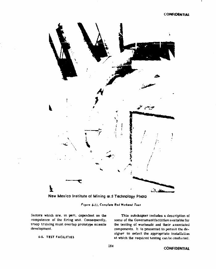
CONFIDENTIAL
New Mexico Institute of Mining and Technology Photo
f ig u re j . J J , Complete Hod Worhmod Tott
factors which are. in part, dependent on the competence of the firing unit. Consequently, troop training must overlap prototype missile development.
6-5. TEST FACILITIES
This subchapter includes a description of some of the Government facilities available for the testing of warheads and their associated components. It Is presented to permit the designer to select the appropriate installation at which the required testing can be conducted.
184CONFIDENTIAL

CONFIDENTIAL
Test futility selection charts are presented in Table G l as an aid The follow Inn organizations are covered:
Department of the Army
Ordnance CorpsAberdeen Proving Ground Picatinny Arsenal White Sands Missile Range
Chemical CorpsArmy Chemical Center Dugway Proving Ground
Department of the Navy
Bureau of OrdnanceNaval Ordnance Laboratory Naval Ordnance Test Station Naval Proving Ground Naval Aviation Ordnance Test
Station
Department of the Air Force
Air Research and Development Com- ■ mand
l ' Air Proving Ground CenterAir Force Flight Test Center Holloman Air Development Cen
ter
^5,1. Abariaon Ploving Ground, Abordoon, Maryland
search and development l.ulx>ratories and other test facilities located at the Aberdeen Proving Ground is of Interest to the warhead designer.
(1) Exterior Ballistics(a) Wind Tunnels(b) Free Flight Firing Ranges(c) Controlled Pressure-Tempera
ture Ranges
(2) Interior Ballistics
(3) Terminal Ballistics(a) Shaped Charge Laboratory(b) Shaped Charge Firing Barricades(c) B last Facilities(d) Shock Tubes(e) Fragmentation Chamber(f) Fragment Gun Range(g) High Altitude Facility(h) High Speed Ballistic Track
(4) Computing Laboratory
(5) Small Arms Range
(6) Major Caliber Range
(7) Armor end Armor Defeating Ammunition Testing<a) Armor Plate Ranges(b) Projectile Ranges(c) Armor and Ammunition Test
Areas(d| Tank Vulnerability
The Aberdeen Proving Ground is the principal engineering and service testing center for Ordnance Corps equipment to be used by the Army Field Forces. It has the responsibility for determining the operational and functional ability of new Ordnance weapons and of equipment to be approved for production. The research and development mission of the Aberdeen Proving Ground Is to carry out studies and experimental testing lor the purpose of producing design criteria and for developing all types of weapons and instrumentation as required. The following material List of re-
(8) Aircraft Vulnerability and Ammunition Effectiveness Ranges
(9) Fragmentation Test Facility(a) Open Fragmentation Pits(b) Fragmentation Panels(c) Closed Fragmentation Pit(d) Fragment Velocity Measuring In
strumentation
(10) Bomb Testing Facilities
(11) Environmental Testing Facility
CONFIDENTIAL 185

CONFIDENTIAL
(12) Weapons Systems ('.valuations
(13) Data Reduction
(14) Rocket Flight Testing Facilities
In addition to these test facilities, there are sufficient range areas available to provide for many special testing requirements of the warhead designer.
6-5.2. Picotinny Ansnal, Dovtr, N«w Jatiiy
The research and development mission of Ptcatinny Arsenal Is to develop varluus types of munitions, including m issile warheads. Among the test facilities located at this installation of Interest to the warhead designer are the following:
Instrumentation Development Laboratories
High Acceleration Air Gun Wind Tunnels Fragmentation Chambers Ballistic Ranges Static Test Chambers Sectioning and Disassembly Chambers Explosive and Propellant Evaluation Fa
cilitiesRocket Testing AreaCentrifugal Force and Vibration Equip
mentAmmunition Component Packaging and
Handling Equipment (DesignandTest) Plastic Research Test Equipment These facilities may be used to check frag
ment, submissile or rod flight characteristics, to determine the characteristics of various high explosives, or to determine the effectiveness of scaled or full size warheads.
6-5.3. Whit* Sand* MitiiU Rang*, Lai Cnicti, N«* Mixlco
The White Sands Missile Range is the principal Army Ordnance Corps installation for the execution of all technical and engineering re sponsibilities associated with the flight testing
of guided m issiles and other munitions. The Range is a joint service installation operated and administered by the < trdnance Corps for the three military departments. Flight and non-flight evaluation tests are conducted ior engineering assessment, acceptance, user evaluation of ordnance (contractor developed), or other services’ m issiles.
The Army research and development mission at White Sands Missile Range is to:
(1) Prepare engineering test criteria and procedures.
(2) Provide technical facilities and operating personnel.
(3) Provide supporting services as re quired.
(4) Plan for, recommend and, where directed, provide special facilities and/ or areas for testing material other than guided m issiles and long range rockets.
(5) Conduct scientific investigations as required.
As the primary mission of this installation is to flight test guided missiles, the majority of its facilities have been created to support this objective. The available ranges can be utilized by the designer la test the warhead as part of a check-out of the overall m issile system. This may Include an investigation into the warhead terminal ballistics against assorted targets. It is also thB mission of WSMRto test components and subsystems of guided missiles for overall evaluation when flight testing is not required.
6-5.4. Army Chemical Cent*!, Edg*wood,Maryland
Thu Army Chemical Center engages In basic and applied research and development and field testing. The Center conducts basic physiological, biochemical, and toxicological
1 S 6 CONFIDENTIAL

CONFIDENTIAL
« ' j f: -
research on chemical warfare agents. It conducts research on wound ballistics for the purpose of Improving both the defensive effectiveness of hody armor and the offensive effectiveness of anti-personnel weapons. The ‘ ’enter has the responsibility for developing new chem teal (and radiological) warfare agents, materials, and methods for both offensive and defensive purposes. In addition to these missions, the Center has the responsibility for conducting, evaluating, and preparing reports on engineering, field, and user tests of Chemical Corps material. These tests may be conducted In conjunction with other development and test agencies.
6-5,5, Dugwoy Proving Ground, Tooalt, Utah
The Dugway Proving Ground Is a combined research and test Installation with the following missions:
(1) To obtain basic scientific data on new and improved CW, BWand RW agents.
(2) To conduct controlled field tests of. CW, BW and RW agents and agent
vehicles.
6-5.6, Naval Ordnaica Laboratory, Whit# Oak, Maryland
The Naval Ordnance Laboratory Is a research and development organization that has the primary objective of originating and testing new devices in Naval Ordnance. Of primary interest to the warhead designer are its test facilities that Include extensive aeroballlstics and high explosives research areas. These areas can be utilized toperform basic research to determine both the characteristics of different high explosives and the flight characteristics of various shaped fragments. There are also additional range facilities available for warhead ground tests which do not require extensive range areas. In addition to these, there are the usual support facilities available. Including various shops, and instrumentation and data reduction facilities.
6-5,7. Naval Otdnuncv Tail Station, Chine Lalta, California
The Naval Ordnance Teal Station Is engaged In research, effectiveness and feasibility Investigations, design, development, product and production engineering, teat and technical evaluation and the pilot production of ordnance materials, components, assemblies and systems In the field of m issiles and other ordnance items. Facilities are available for research and development In the fields of high explosives and aeroballlstlca. Noteworthy test facilities include a moving-target range and several high speed tracks. Such supporting functions as Instrumentation, data reduction, and H. E. handling facilities staffed with trained personnel are also available. In particular, the facilities can be used to secure data on warhead term inal ballistics, fragment flight characteristics, cluster warhead functioning under static or dynamic conditions, and the characteristics of high explosives. Sufficient range space Is also available for the testing of shaped charge, blast, and other type warheads.
6-5.8. Novol Proving Ground, Daklgron, Virginia
The mission of the Naval Proving Ground is to conduct proof tests of ordnance materiel, conduct research and development of ammunition and components thereof, armament and components thereof, armor and ballistics, etc., and to investigate other ordnance problems. Whenever necessary, research is also conducted to develop required instrumentation. The test facilities, including photographic and electronic instrumentation, are available for explosives-handllng tests and interior ballistics studies. Ranges available include fragmentation arenas, indoor and outdoor firing ranges, and aerial gunnery and bombing ranges. These range facilities can be used to secure terminal ballistics data for blast, shaped charge, rod and fragment warheads. It Is also possible to test full size (as well as scale model) fragmentation and rod warheads in order to secure data on such parameters as
CONFIDENTIAL 1B7

CONFIDENTIAL
dispersion, fragment and rod size and. shape, and fragment and rod velocities.
4>5.4. Naval Aviation Ordnance T ta t Station, C M n co u a g u a , V itg ln la
The Naval Aviation Ordnance Test Station provides technical support and services to Government agencies and contractors in re search, development, test, and evaluation programs. These activities Include applied r e search, development tests, as well as evaluation of m issiles, and other types of aerial weapons. Facilities available at this installation include specialized ranges, with tnsfru- mentation, and data reduction capabilities.- Manned aircraft, range crews, and shop and laboratory space are available. These facilities can be utilized for the flight testing of armed missiles against ground, sea, or aerial targets to determine m issile system effectiveness.
i*5.10. Air Proving G<og»d Cantar, Egiin Air Fere* Bai«, Florida '
The Air Proving Ground Center is a facility for the englneeringtesting of air armament. An important and continuing part of the work at this center is to provide testing support to contractors and other Government agencies. To accomplish this, the Center is developing versatile test facilities and rapid methods of data reduction. Various types of air-to-ground ranges are available. The Center has a large and growing inventory of instruments with which to meet test requirements. Aircraft with their crews and maintenance personnel, range crews, instrumentation, and shop and laboratory space can be provided. Range facilities ore available at the Center for firing- tests of the smaller warheads, primarily those used In short range ground-to-air, air-to-air, and air-to-ground m issiles. Range facilities are also available for a limited testing of cluster warheads. Parameters which can be investigated include warhead system functioning, bomblet dispersion and bomblet flight characteristics. In addition, facilities are also
available for IIW and CW testing,
6-5,11, Air Foie* Flight Tati Cantar, Ed ward i AirFarea California
Though the activities of the Air Force Flight Teat Center are not directly related to the development of missile warheads, there are two track test facilities available at this
■ Center which may interest designers of such warheads. One of these tracks Is 2,000 feet long, and the other 10,000 feet. It is suggested that the designer contact the Flight Test Center for specific information concerning the use of these tracks if dynamic testing of warheads is required.
6*5.12. Hallanwn Air Davalopmont Cantar, Aloatogofdo.Naw Maxlca
+■
The Holloman Air Development Center conducts research and development of guided missile systems and components; conducts tests and evaluations of m issile weapon system s, m issile operational techniques and associated equipment; and also conducts aeromed- ical research and development. Extensive range facilities are available at this Center for tiie flight testing of guided m issile systems and the developmental testing of m issile warheads. Armed m issiles of relatively short ranges can he fired ground-to-ground, air-to- ground, a ir-to-a ir, or ground-to-air to determine their effectiveness against typical targets. Range facilities are also available for the various tests which are required in the development of cluster warheads. The Center also has a high speed track and support facilities such as manned aircraft, maintenance personnel, and instrumentation.
6-6, BIBLIOGRAPHY
(1) “ Facilities of the United States Army for Research and Development, Volumes 1. 2, and 3 " . Office of the Assistant Chief of Staff, G-4 Logistics - Research and Development Division, Department of the Army, July, 1953.
186 CONFIDENTIAL

CONFIDENTIAL
(2) “ California Naval Research, Development ami Teat Stations- Unique Facilities", lnterlaborutory Committee on Facilities, May.1953.
(3) “ Brochure of General and Descriptive Information of the U, S. Naval Proving Ground” , July. 1943, N.P.G. Ueport No. 303.
(4) “ Naval Aviation Ordnance Test Station, Descriptive Brochure", Feb. 1956.
(5) “ Holloman Air Development (.'enter - Information Guide", HQ HADC, Dec. 1956.
<6) “ Air Force Armament Center - Kunge Facilities", HQ AFAC, January, 1954. APPENDIXc h a r a c t e r is t ic s o r HIGH e x p l o s iv e s fo r
MISSILE WARHEADSHaller, Raymond & Brown, Inc., in an
Appendix A to their report number 91-H-5, entitled "Survey of Guided Missile Warheads” , Included & summary of explosives for guided missile warheads. This Is presented on the following pages, essentially in its entirety, for ready reference. It is to be noted that additional explosives have been developed or are being tested for use in guided m issile applications since the publication of the survey.
A . INTRODUCTION
Six different explosive mixtures are used in the m issile warheads Included in this Survey. These are: BOX Composition B, H-6, HBX-1, Trltonal, RDX Composition C-3, and Cyclotol. Each of these explosives is a cast mixture (none are pressed mixtures) and has certain measurable properties which distinguish it from other explosives. The distinguishing properties of explosives are listed In Tables 1 and 2. at end of appendix.
The warhead operation determines the type of explosive that Is used. Warheads considered are ofthefoUowingtypea: fragmenting, continuous rod (expanding), blast, fragmentation-blast, and armor piercing. Some warheads use charges (called “ propellants") which disperse submlsslles or flechettes from the warhead at relatively slow rates to produce a controlled pattern. Propellants, however, will
not be discussed.There are four general requirements for
all explosives: l e , the explosive must be fluid enough In the preparatory state to be cast in the w arhead, w tthst und sbi ppl ng and handling .withstand the effects of lime, and perform predictably when used.
Most of the production, handling, and time factors may be considered under the following classifications: fluidity (capability of being cast, etc.), shrinkage, fragility, stability and exudation (bleeding-out of components) Presumably, explosives used in the missile warheads in this Survey are satisfactory in production, handling and time factors — otherwise they would not have been used In the warheads. These factors are not discussed in this report.
The topics to he discussed are the relative characteristics of several components, the tests used to derive some of the relative properties of explosives, and a comparison of properties of cast explosives used in the warheads surveyed.
& - EXPLOSIVE COMPONENTS
TNT is used as an index base for determining the relative characteristics of the two explosive components given in Table 1. TNT Is used as a component in alt six of the explosives cited in the Survey and comprises 4 to 80 parts (by weight) of the explosive mixtures. The heat of combustion TNT is greater than RDX. The Gurney velocity constant ( fiTT ) of TNT Is 6940feetper second. TNThas a good blast effect(4*). Its detonation rate is 6745 meters per second.
The most common component used in the explosives in this Survey is KDX. In four of the six explosives discussed, RDX comprises 40 parts or more by weight of the mixture. RDX by itself is very difficult to cast (4). It has a low heat of combustion (0.63) relative to TNT (1.00), and a very high Gurney velocity constant, 8040 feet per second, or an index of 1.16.* Sec references by number at end of Appendix.
CONFIDENTIAL 189

CONFIDENTIAL
four explosive mixtures in this Survey contain either wax or D-2 desensitize?, Wax enhances some of the physical (handling) properties of the explosives mixtures since it acts as a deseusitlzer (4). D-2 Improves the toughness of these mixtures but decreases stability In storage (4).
Aluminum is used in three of the six explosive mixtures. This enhances the flash effect of explosives and promotes a more controlled expansion (luring combustion. The addition of aluminum may reduce the fragility of the explosive and also minimize shrinkage during curing after the block of the explosive has been cast.
Nitrocellulose, tetryl, MNT. and DNT are used by only one of the explosives— HDX Composition C-3 No Information Is given In the Survey about these components.
C - EXPLOSIVE TESTS
Several measurements comparing the re lative properties of explosive mixtures are shown In Tables 1 and 2. The tests from which the measurements are derived are discussed in order of appearance in the tables.
1. Peak Pressure TNT Equivalent TestThe test for the peak pressure equiv
alent of TNT compares the pressure produced by a sample explosive with that produced by an equal weight of TNT. The tests are made at the same standard distance.
The experimental set-up usually consists of a piezo-electric gauge located a standard distance from the center of the explosion. This gauge Indicates the pressure impulse by voltage wave form when struck by the shock wave (7). Peak pressure Is the maximum ordinate of the pressure-time curve determined from the experiment.
2. Positive Impulse TestThe test for TNT equivalent in posi
tive Impulse Is identical to the test for peak pressure. Positive impulse is equal to the area under the pressure-time curve lying above the atmospheric pressure (7).
3. Italllutlc Mortar TestThe ballistic mortar test (6) deter
mines the weight of an explosive required to raise a heavy ballistic mortar the same height to which it is raised by 10 grams of TNT. The weight of explosive meeting this requirement is then used to compute its TNT equivalence by the formula
TNT Value10 grains TNTSample Weight in Grains
The physical set-up for this test consists of a heavy ballistic mortar suspended on a compound pendulum. The mortar contains a chamber about € inches In diameter and 1 foot long. A standard projectile occupies about 7 inches of this chamber, while the sample being tested occupies only a smalt portion of the remainder of the chamber. Upon detonation, the projectile Is driven into a sand bank and the mortar swings through an arc. Swing height is recorded by a pencil attached to the pendulum.
4. Trauzl TestThe Trauzl test (6) determines the
weight of an explosive required to cause the same expansion in a standard experimental measuring device as does TNT. Equivalent weights for the explosives tested are readliy determined from this measurement and expressed as a ratio by the equivalent weight of TNT per unit weight of the test explosive.
The experimental set-up (6) uses desilverized lead cylinders 200 millimeters in diameter and 200 millimeters in height. In the end of each of these is centered a cavity 25 millimeters in diameter and 125 millimeters deep. A trial and error process is used to determine an amount of the explosive which will expand the cavity on detonation between 250 and 300 cubic centimeters, it has been found by Naoum that within this range of volume there Is linear correlation between volume increase and sample weight.
5. Plate Dent TestThe brisance or shattering effect is
* Some of the references use percentages instead of fractional values.
190 CONFIDENTIAL

CONFIDENTIAL
determined by :i plate dent test which measures the depth of the dents In a steel plate made by detonating equal weights of TNT and the explosive being tested. The measurements are used according to the formula
Relative llrlsanre Sample Dent Depth Dent Depth for TNT at 1.61 gm/ec
6. Detonation Rate TeatThe detonation rate test measures the
time-distance burning rate of a long pie<,e of the explosive being tested. The Index is determined from
1 _ DR for test explosiveDK ~ DR for TNT
The experimental set-up uses a rotating drum camera to record the b lrningrate of the explosive. The explosive Is 1 inch in diameter and 20 inches long, and is held in place by a cellulose acetate sheet. A standard initiating system is used, consisting of four tetryl pellets at one end of the wrapped explosive in conjunction with a Special Corps of Engineers Blasting Cap placed in a central hole in the end pellet.
7. Gurney Velocity Constant TestThe Gurney velocity constant (8),
^ 7 , is determined empirically from measurements of the average velocity of fragments from steel cylinders and other casing shapes. The constant is obtained directly from the formula ______________
2 E ( c /n t )P _ , ---------------------
0 ll l t ( l / 2 ) { c/ » )where:
va = the initial velocity of the fragment in feet per second,
c = the weight of the explosive charge in grams,
m = the weight of the fragmenting casing in grams, and
i: = a constant depending on the explosive measured In calories per gram.
The Index is determined from1// (test eti'U’V-ve}
, |j7; - — ------------ — —iT i i i m j
The experimental set-up for obtaining thu Gurney velocity constant by determining initial fragment velocity usually makes use oi a moving picture camera (7). One such set-up involves a high speed time-synchronized camera, a visual method (tetryl cap) for recording initiation of the explosion, and a material (duralumin) which flashes when struck by a fragment. This flash indicates the termination of fragment flight to the camera. Since the fragment travel distance is known, the initial velocity is readily computed (8).
8. lleat of Combustion TestThe heat of combustion test deter
mines the heat content of equal weights of explosive mixtures. The measurements are made by calorimeters and are given in calories per gram.
9. Standard Cylinder TestsThe results shown in Table 2 were
taken from two tests (1). Information on the number and mass of the fragments was obtained from pit tests. The velocity information was determined in a velocity range.
In the pit test (1), a cylinder is buried in a pit filled with sawdust. The cylinder is enclosed In a cardboard box so that the initial expansion takes place in air. The fragments are removed from the sawdust by magnets and by sifting.
The velocity range (1) uses a rotating drum camera which photographically records the passage of fragments past three illuminated vertical slits. Range geometry and the time lapse between the two outside slits determine the average fragment velocity. One-tenth of the cylinder circumference comprises the sample beam in which velocities are measured.
D - EXPLOSIVE MIXTURES1. RDX Composition B (60/40/1: RDX/
TNT/Wax Added)RDX Composition B is the explosive
CONFIDENTIAL 1 9 1

CONFIDENTIAL
most commonly used tn the guided missile warheads Included in the Survey. As shown in Table 3 atl but six of the twenty-five different type warheads containing thl explosive are the fragmenting type. Five on-fragmenting warheads are continuous rou types. Alternatively, these five warheads may use the explosive, H-6.
RDX Composition II consists of three ingredients: ltDX, TNT, und Wax. The notation in the above and subsequent captions gives the parts by weight of the components. Blending these ingredients provides an easily cast explosive which does well as a fragmenting and expanding (continuous rod) charge.
As noted in Table 1, the brisance of RDX Comporltlon B Is 1.32, the highest for the explosives found in the literature, In other words, this explosive is the most shattering. The high Gurney velocity constant (7610 feet per second) or index 1.10, is exceeded only by Cyclotol and H-6 among the explosive mixtures and indicates a high initial fragment velocity. The relative blast effect (heat of combustion) of Composition B is low/. 0.78. compared with 1.00 for TNT. Blast, h'.wever, is not a primary requisite for a fragmenting warhead. The detonation rate of RDX Composition B is the highest for explosives found in the available literature; 7840 meters per second with an index of 1.17. Also, according to the Trauzl test (6) of volume expansion RDX Composition B was the highest, having an index of 1.30. The Ballistic Mortar test (6), which measures the relative energy of an explosive, gives an index of 1.33 for RDX Composition B.
RDX Composition B would also appear to be good as a fragmenting explosive from the relative measurements given in Table 2, which were made using standard cylinders as the fragmenting casings (l).This explosive exceeds H-6 and HBX-1 in both the number of fragments formed and the average initial velocity.
2. H-6 (74/21/5/0.5: Composition B/Al/D-2 Desens./CaCl)The explosive H-6 is used in ten dif
ferent warheads in the Survey (Table 3). Of
the ten warheads, five use RDX Composition li as an alternative explosive.
H-6 is closely similar to ltDX Composition B. The principal difference in composition is a reduction in the proportion of RDX and TNT and the addition of aluminum to that mixture.
The equivalent weight of H-6 to TNT for peak pressure is 1.27, the highest attained among the explosives listed in Table 1. H-6 also ranks highest in the TNT equivalent weight for positive impulse, with an index of 1.38.
The Gurney Velocity Constant, i f . is 7710 feel per second for H-6, an index of 1.11. Only Cyclotol and RDX Composition C-3, of the feasible compositions noted, surpass H-6 in ability to impart a high initial velocity to fragments. In a number of fragment blast warheads, H-6 (or HBX-1) provides a worthwhile Increase in blast damage over RDX Composition B without a commensurate loss of damage from fragments.
3. HBX-1 (67/11/17/5/0.5: Comp. B/T NT /Al/D-2 Desens. /CaCl)HBX-1 is used by three different war
heads (Table 3), two of which are the blast type and one of the fragment type.
The TNT equivalent weight positive impulse for HBX-1 is 1.21, which is less than that for H-6, but greater than that for RDX Composition B. The same relationship holds for the TNT equivalent weight peak pressure. It would appear that H-6 is as good or better than HBX-1 for blast effect (heat of combustion measurement), haring an index 1.06 compared with 1.03. As noted in Table 2 .HBX-1 produces a larger number of fragments than H-6 and a consequent smaller average fragment mass when tested In a standard fragmenting cylinder. Average Initial velocity, however, is lower than that for H-6. Lower velocity for HBX-1 Is further exemplified by the difference in the Gurney velocity constant. Only Trltonal and TNT, have lower values.
4, Trltonal (80/20: TNT/A1)
192 CONFIDENTIAL

CONFIDENTIAL
The explosive Trltonal is used by a blast warhead for the Matador anil a combination fragmentation - blast warhead for the Corporal m issile.
As noted in Tabic 1, the TNT equivalent weight of peak, pressure and impulse for Trltonal are 1.07 and 1.11, respectively, These measurements rank low relative to those for the explosives discussed previously. Most of the other measurable properties of Tritonal are also somewhat lower relative to those for TNT.
The heat of combustion for Tritonal Is 1.21, highest among the explosives fur which there Is information In Table 1. This Is a measure of the high bl&3t potential of Tritonal. The brlsance measure, 0.93, Indicates a low shattering effect. This explosive is used when large fragment masses are required.
5. RDX Composition C-3 (77/4/1/3/5/10: RDX/TNT/Nitrocellulose/
Tetryl/MNT/DNT)RDX Composition C-3. is used in
fragmentation warheads for the Honest John and Corporal missiles.
As noted In Table 1. UDX Composition C-3 ranks lower than RDX Composition B in the ballistic mortar test. It ranks lowest among the noted explosives in the Trauzl test. However in brisance. it ranks considerably above Tritonal. This is partially substantiated by the high detonation rate, 7625 meters per second (Index 1.13), second only to that of RDX
Composition 11, 7840 meters per second (index 1.17). it has the highest J7f~ value, 8800 feet per second (index 1.27). These ratings explain its use us a fragmenting explosive.
C, Cyclotol (75/25: KDX/TNT)The explosive Cyclotol is utilised in
the French SS-10 m issile which UBes a shaped charge type warhead against tanks. The present standard composition of Cyclotol Is as noted above, but the composition utilized Inthis missile is 50/50: UDX/TNT.
The only measure available for Cyclotol is the Gurney velocity constant, .This is 7B50 feet per second, with an index of 1.13 lower only than RDX and RDX Composition C-3, This infers that Cyclotol has a very high peak pressure and positive impulse rating, as does H-6 which also has a high value,
E . CONCLUSIONSAn overall view ofthefollowlngtwotables,
1 and 2, enables one to make a direct comparison among the different explosives given in each measurement category. Unfortunately, some of the data were not available in the literature at the time of this survey. There is no absolute correlation of explosives by type of use or by rank in any of the measurement categories: however, the correlation of combinations of one or more uses and the measurements have been noted.
Changes of explosives used In the missiles in Table 3 are to be expected.
CONFIDENTIAL 1 9 3

CO
NF
IDE
NT
IAL
TA BLE 1
P R O P E R T IE S O F CAST EXPLO SIV E M IXTURES R ELA T [VE TO TNT
ExplosiveM ixtures
TN TEquivalent
PeakP re ssu re
(5)
TNTEquivalent
PositiveImpulse
(5)
B a ll is tic
M ortarTrauzl
(1)B risan ce
(1)
DetonationR ate
Gurne V eloci Consta
2E
yty
int5L__
Heat of Combustion
R e l. toTNT (Blast) (5)
Index m /sec Index ft/sec
RDX Comp. 1 .1 3 1 .0 6 1 .3 3 1 .3 0 1 .3 2 1 .1 7 (7840) 1 .1 0 (7610) 0 .7 8
B
H-6 1 .2 7 1 .3 8 1 .1 1 (7710) 1 .0 6
1 .0 5 (7260) 1 .03H BX -1 1 .2 1 1 .2 1
T ritonal 1 .0 7 1 .1 1 1 .2 4 1 .2 5 0 .9 3 0 .9 6 (6475) 0 .9 1 (6280) 1 .21
80/20
RDX Comp. 1 .2 6 1 .1 7 1. 18 1 .1 3 (7625) 1 .2 7 (8800)*
C -31 .1 3 (7850)
Cyclotol50/50
TNT 1 .0 0 1 .00 1 .00 1 .0 0 1 .0 0 1 .0 0 (6745) 1 .00 (6940) 1 .0 0
] 1 .1 6 (8040) 0 .6 3RDX
Torpex11 _
1 .3 8 1 .6 4 1 .2 0 1 .11 (7495) 1 .0 7 (7450)
(1) and (5) See R eferen ces by num ber.+ Picatinny A rsenal Technical Report No. 1530
CO
NF
IDE
NT
IAL

CONFIDENTIAL
TA BLE 2
MEASUREMENTS O F EXPLO SIV E M IXTURES FROM STANDARD CYLINDER T E ST FIRINGS (1)
Explosive C/M N0 N(Q. 5) (g n is .)
m (0. 5) (g m s.)
Voft/sec
Comp. B 9 .3 7 8 3700 977 1 .7 2 4440
H-6 0 .3 8 5 2279 788 2 .2 3 4420
H BX-1 0 .3 8 6 2785 873 1 .9 7 4130
T ritonal80/20
Comp. C -3
Cyclotol50/50
TNT 0 .3 5 8 1852 723 2 .5 2 3710
RDX
Torpex
(1) Standard cylinder employed fo r fragm entation. Fragm ent distribution following M otts Law, No total no. of fragm ents, N (0.5 gm) no. of fragm ents over 0 .5 gram m (0 .5 gm) mean m ass of fragm ents over 0 .5 gram s ________
CONFIDENTIAL 195

CO
NFID
ENTIA
L
TA BLE 3WARHEADS B Y EXPLO SIV E USED
RDX Composition B
M issile Warhead Type M issile Warhead Type
B om arc T33 F rag . T alos (6b) Ex 17 Mod I F rag .C orporal T25E1 F rag . ♦ T a rta r Ex 20 Mod I Cont. RodL a C ro sse T34E1 Sh. Charge T e r r ie r E x 12 Mod 0 F ra g .M eteor E X 8 Mod 0 F ra g . ♦ T e r r ie r Adv. Ex 19 Cont. RodNike I T22E4 F ra g .Nike 1 T26E4 F rag .Nike I T37 F rag .Nike I T37E2 F rag . H -6Nike I T37E3 F rag . INike I T38 F rag . M issile Warhead Type INike I T 38E2 F ra g . 1Nike I T38E3 F rag . ♦Sparrow III Ex 21 Mod 1 Cont. Rod ISparrow 1 Ex 1 Mod 0 F rag . ♦Sparrow 1A Ex 22 Mod 1 C ont. RodSparrow III E x 2 F ra g . T alos (6a) Ex 7 Mod 1 F rag .Sparrow III E x 3 Mod 1 F ra g . ♦ T a rta r Ex 20 Mod 1 Cont. RodSparrow II Ex 5 Mod 1 F rag . ♦ T e r r ie r Adv. E x 19 Cont. Rod
♦Sparrow III E x 21 Mod 1 Cont. Rod ♦ T e r r ie r Mk 5 Mod 3 F rag .* Sparrow 1A Ex 22 Mod 1 Cont. Rod and 6
Sparrow 1 Mk 7 Mod 0 F rag . Falcon GAR 3 Mod 0 B la s tTalos (6a) Ex 6 Mod 1 F rag . Nike H ercules T45 F r a F ra g . - B la s tT alos (6b) Ex 14 Mod 0 C ont. Rod Nike H ercules T46 C lu ster
Hawk XM5 F rag . - B la s t♦Indicates that this sam e m issile warhead may a lso use another explosive
CO
NF
IDE
NT
IAL

CO
NFID
ENTIA
L
TA BLE 3 (cont'd)
WARHEADS BY EXPLO SIVE USED
HBX-1 RiDX-Composttion C - '
M issile
Bom arc
Honest John
Sidewinder
Warhead
C lu ster
T2021
Mk 8 Mod 0
Type
B la s t
B la st
F rag .
M issile
C orporal
Honest John
Warhead
T 39E3
T39E3
i m .
F rag .
F rag .
50/50 Cyclotol
Tri tonal M issile
SS-10
Warhead
French
Type
Shaped ChargeM issile
•Corporal
Matador
Warhead
T23E1
T3E3
T jjp e.
F ra g . B last
B la st
♦Indicates that th is sam e m issile warhead may also use another explosive
CO
NF
IDE
NT
IAL

CONFIDENTIAL
R E FE R E N C ES
1. Salem , A, D . , Shapiro, N ., Singleton, U. N ., J r . : Explosives Com parison for Fragm entation E ffec tiv en ess , NAVOltD Report No. 2933, August 1953, Naval Ordnance Laboratory , White Oak, Maryland, Confidential.
2 . Hyndnian, J . R . , Shuey, H, M ., Iwanciow, B . L . , Taylor, E . A .: Q uarterly P ro g re ss R eport on Interior B a ll is t ic s , Redstone A rsenal Report No. P -5 4 -3 , 10 May 1954, Redstone A rsenal, Huntsville, Alabai ia, Confidential,
3 . Holt, P . L . , M cG ill, R . : Explosives R esearch Department P u blications, NAVORD Report No. 4163, 1 November 1$55, Bureau of O rdnance, D epartment of Navy, Washington D. C . , Confidential.
4 . Anonymous: Fundamental Development of High Explosives, P ro g re ss Report No. 113, 1 November to 30 November 1955, Arthur D, L ittle , In c ., C am bridge, M assachu setts, Confidential.
5. C hristian , E , A . , F ish e r , E . M .: Explosion E ffec ts Data Sheets, NAVORD Report No. 2986, 14 June 1955, Naval Ordnance Laboratory , White Oak, Maryland, Confidential, A D -69244.
6. Tom linson, W. R . , and revised by Shetfield, O. E . : P ro p erties of E xplosives of M ilitary In tere st, i'icatinny A rsenal Technical Report No. 1740 (U), April 1 9 5 8 , and Supplement No. 1 (C), August 1958, Picatinny A rsenal, Dover, N. J . Confidential.
7. Sachs, R. G . , Bidelm an, W. P . : B la s t M easurem ents on F ive-and T en-Ton B a re C harges of TN T, R eport No. 454, 1 M arciT i§44 , B a llis t ic s R esea rch L ab o ra to ries , Aberdeen Proving Ground, M aryland, Confidential, A D -73234.
8. D avids, N ., K oh ler, M. R . , J r . , Duncan, R . L . : B a s ic Compendium of the Fragm entation P ro p erties of F in -Stabilized M ortar Shells Including T h e o r ie s , Data and T e s t Methods, 15 A p ril 1956, H aller, Raymond & Brow n, I n c . ,State C ollege, P a . , Confidential.
198 CONFIDENTIAL

CONFIDENTIAL
INDEX
Aberdeen Proving Ground - Test F a c i l i t ie s ........................................................................................ 1 85Agents - Chemical and Biological Warheads........................................................................................ 1 3 JAir Force Flight Test Center - Test F a c ilit ie s ................................................................................... 188Air Proving Ground Center - Tost F a c il i t ie s ..................................................................................... 1 88Analytical Evaluation Method ............................................................................................................... 154Army Chemical Center - Test F a c il it ie s ....................................... lao
Beam Width - Fragmentation Warheads....................................... 47Fragment Patterns................................................................................................................................. 5(1Fragment Slow-Down.................... 49Fragment Velocity..................................................................................... 47Selection ............................................................................................................................................ 52
BibliographyBlast Warheads...................................................................................................................................... 46Chemical and Biological W arheads................................................................................................. 138Cluster W arheads................................................................................................................................. I l lContinuous Rod W arheads.................................................................................................................. 72Discrete Hod Warheads........................................................................................................................ 84Explosives 198Fragmentation Warheads..................................................................................................................... 84Shaped Charge Warheads..................................................................................................................... 130Warhead Evaluation.............................................................................................................................. 163Warhead Se lectio n ................................................................................................................................. 35Warhead T e stin g ................................................................................................................................... 188
Blast Method of Ejection - Cluster W arheads...................................................................................... 101Blast Warheads............................................................................................................................................... 36
Bibliography........................................................ 46Detail Design D ata......................... 36
Design Data, Summary o f ......................................................................................................... 45Explosive Goading and Sealing ................................................................................................. 41Fabrication and T o o lin g ..................................................................................... 44Function of Warhead Case and Related Blast E f f e c t s ...................................................... 36Fuze Installation........................................... 44Fuzing Requirements, Summary o f ........... . ......................................................................... 45Installation and Handling P rovisions...................................................................................... 47Strength Analysis ................................................................................................ 41Weight and Space Allocated, Compatibility o f .................................................................... 40
Detail Design S t e p s .............................................................................................................................. 36External .................................................................................................................................................. 36Fundamental Concepts ........................................................................................................................... 149In tern al..............................................- .................................................................... ............................... 36R eferences............................... 45Test Procedures and Techniques .......................................................................................................182Warhead T y p e s .................... . . .................................................................................................. 1
Bomblet Compartment and Structure - Chemical and Biological Warheads................................... 130Bomblets - Chemical and Biological W arheads................................................................. 131
CONFIDENTIAL 1 9 9

I
Characteristics of High Kxploslvos for Missile Warheads......................................................... .. , 189Characteristics of Service Warheads ....................................................................................................Chemical and Biological W arheads.......................................................................................................... 130
Agents................................................................................... , . . . * ..................................................... --'wBibliography..................................... ......................................................................................................Cluster Type Warheads .....................................................................................................................
Bomblet Compartment and Structure...................................................................................... 130Bomblets . ...................................................................................................................................... 131Ejection System s..................................................................................... ^Environmental Requirements . ................................................................................................. 133
Massive Type W arheads.....................................................................................................................Warhead T y p e s ......................................................................................................................................
Circular Normal Distribution - Distribution of Guidance E r r o r .................................................... 1WClassification of Targets - Warhead Selection ................................................................................... 33Cluster Submtssiies - Test Procedures and Techniques.................................................................. 132Cluster Type - Chemical and Biological Warheads .......................................................................... 130Cluster W arheads......................................................................................................................................... 92
Bibliography............................................................................................................................................ I l lDetail Design D ata................................................................................................................................. 92
Design Data, Summary o f .......................................................................................................... 110Ejection Methods........................................................................................................................... 100Ejection System, Design o f ............................................................................... 103Fuzing Requirements, Summary o f ........................................................................................ 110Number of Subm issiles............................................................................................................... 100Obstruction Removal Devices, Design o f ............................................................................. 109Optimum P attern ........................................................................................................................... 92Retention System, Design of .................................................................................................... 109Submissiles, Design o f ............................................................ •................................................. 105Submissiles, Types of .............................................................. 100Support Structures, Design of ................................................................................................. 103
Detail Design S te p s .............................................................................................................................. 92Fundamental C oncepts............................................................................................................ 1*9R eferences...................................................................... I l lTest Procedures and T ech n iq u es.................................................................................................... 13^Warhead T y p e s ............................................................................... 10
Continuous Rod W arheads........................................................................................................................... 87Bibliography............................................................................................................................................ 92Detail Design D ata.............. ............................................................................... 88
Design Data, Summary o f .......................................................................................................... 92Details, Warhead........................................................................................................................... 98Explosive C avity............................................. 90Explosive Charge ........................................................................................................................ 8BFuzing Requirements, Summary o f ........................................................................................ 98Rod Bundle, Dimensions o f ...................................................................................................... 88Rod Dimensions, Cross Section al........................................................................................... ®8
^Detail Design S te p s .............................................................................................................................. 87R eferences.............................................................................................................................................. 92
CONFIDENTIAL
200 CONFIDENTIAL

CONFIDENTIAL
Warhead T y p e s ................................................................................... .................................................. 8Cost of the Contribution - Weapons System C oncepts......................... ............................... . . . . 31
Damage Classification - Evaluation P rin cip les................................................................................... 106Damage Mechanism Testing - Test Procedures and Techniques.................................................... 170Data Reduction and Interpretation....................... ............................................................................. 169,182Design Data, Detail
Blast Warheads....................................................................................................................................... 36Cluster W arheads.......................................... 92Continuous Rod W arheads................................................................................................................... 88Discrete Rod Warheads ...................................................................................................................... 89Fragmentation Warheads ...................................................... 48Shaped Charge Warheads ................................................................................................................... l2 3
Discrete Rod Warheads .............................................................................................................................. 84Bibliography............................................................................................................................................ 82Detail Design D ata....................................................................................................... '........................ 84
Design Data, Summary o f .......................................................................................................... 82Explosive Charge ......................................................................................................................... 85Fuzing Requirements, Summary o f ......................................................................................... 87Rod Cross Section ......................................................................................................................... 85Rod Length....................................................................................................................................... 84Rod M a te r ia l........................................................................................... 85Rod Velocity ................................................................................................................................. 85Warhead D e ta ils ........................................................................................................................... 87
Detail Design S t e p s ............................................................ 84R eferences.................................................................................................................. 87Warhead T y p e s ....................................................................................................................................... 8
Distribution of Fuzing Error - Evaluation P rin cip les................ 14-*Distribution of Guidance Error - Evaluation Principles ............................... I41Drag C oefficien t................................................................. 49Dugway Proving Ground - Test Facilities ............................................................................................ 187
Ejection Methods - Cluster W arheads..................................................................................................... l00Blast T y p e s ............................................................................................................................................ 101Gun T y p e s ............................................................................................................................................... 101
Ejection Systems - Chemical and Biological W arheads.................................................................. 132Blast Method............................................................................................................................................ _ 108Gun Tube Method ....................................................................................................... *02
Elliptical Normal Distribution - Distribution of Guidance Error .............. .. ............................... 144Environmental Requirements - Chemical and Biological W arheads................................................ *33Evaluation M ethods....................................................................................................................................... 1,4
Analytical .................... .. - ^ ................................................................................................................... 184Geometrical Model .............................................................................................................................. 188G raphical....................................................... .......... ................................................................................ 158Monte Carlo and L o tto ......................................................................................................................... 158
CONFIDENTIAL 2 0 1

CONFIDENTIAL
O verlay ..................................................................................................................................................... 157Simulated .................................. l *6
Evaluation Princip les.................................................................... 139Conditional Kill Probability............................................................................. l 4^Damage C lassification ........................................................................................................................ *44Fuzing Error, Distribution of ......................................................................................................... 1**Guidance Error, Distribution o f .................................. 141Overall Kill P robability ..................................................................................................................... *39
Evaluations, Approximate........................................................................................................................... 133External Blast W arhead..................................................................................................................... *33Fragmentation W arhead..................................................................................................................... *34Internal Blast Warhead........................................................................................................................ *3^
Evaluation, Warhead ......................................................................................................... 139Explosive Charge Design - Shaped Charge Warhead............................................................................. I 25Explosive M ix tu re s ...................................................................................................................................... 19 LExplosive Tests ............................................................................................................................................ 190Explosives for Missile Warheads, Characteristics ............................................................................. 189External Blast Warhead - Approximate Evaluations.......................................................................... 153
Fragmentation Warheads ........................................................................................................................... ^Bibliography............................................................................................................................................ 84Detail Design Data .............................................................................................................................. 47
Beam W idth ................................................................................................................................... 47Charge to Metal Ratio (Actual) and Explosive T y p e .......................................................... 73Charge to Metal Ratio (Maximum) ......................................................................................... 54Design Data, Summary o f .................................. 82External Configuration............................................................................................................... 53Fragmenting Metal, Design o f ................................................................................................. 79Fragment Shape and Material ................................................................................................. 73Fragment Size Control, Methods o f ......................................................................................... 74Fragment Weight and Velocity, Optimum .............................................................................. 57Fuzing Requirements, Summary o f ................................................... 82Static Fragment Velocity, Maximum Initial ........................................................................ 54Warhead Components, Design o f ............................................................................................... 79
Detail Design S t e p s .............................................................................................................................. 44Evaluation, Approximate..................................................................................................................... 154Fundamental C oncepts........................................................................................................................ 149R eferences............................................................................................................................................... 83Test Procedures and T echniques............................................................................... I74Warhead Types ...................................................................................................................................... 3
Fragment Size Control, Methods of ....................................................................................................... 74Comparison of ...................................................................................................................................... 77Grooved Charge ................................................................................................................................... 74Notched R ing s......................................................................................................................................... 75Notched W ir e ......................................................................................................................................... 74P recu t................. 74
202 CONFIDENTIAL

CONFIDENTIAL
(Other) ..................................................................................................................................................... 7$Fragment Weight anti Velocity, Optimum................................................................. ............................ 5?
Aerial Target ........................................................................................................................ 57Ground Target ......................................................................................................... 65
Fragments - Tent Procedures anti Techniques . .................... ...................................................... 170Furing Krror, Distribution of - [-(valuation P r in c ip le s .................................................................... 145
Geometrical Model - Kvaluation Methods...................................................... .................................. 158(■lossary of T erm s...................................................... v l i iGraphical Evaluation M ethods...................................................................... 153Guidance Krror, Distribution of - Kvaluation P rin cip les.............................................................. .. 141
Circular Normal Distribution................................................................... 144Elliptical Normal D istribution........................................................................................................... 144Miss D istance............................................................................................................ . _ 144Rectangular Area, Probability of K ittin g ...................................................................................... 143
Gun Type Method of Ejection - Cluster W arheads............................................................................. 101Gurney Formulas.................................................................................................................................... 56
Holloman Air Development Center - Test Facilities .................................. .. , ............................. 188
Incendiary W arheads.................................................................................................... 12Inert and Exercise Warheads........................................................................................................................ 13Internal Blast Warheads - Approximate Evaluations ...........................................................................154
Kill Probability, Conditional - Evaluation Principles , , , .................................................................. 140Kill Probability, Overall - Evaluation Principles ................................................................................ 139
Leaflet Warheads............................................................................................................................................ 12Liner Design - Shaped Charge W arheads................................................................................................. 123Lotto - Evaluation Methods............................................................................................................................156
Massive Type - Chemical and Biological W arheads......................... ................................................133Miss Distance - Distribution of Guidance E r r o r ................................................................................141Monte Carlo - Evaluation Methods . .......................................................................................................156
Naval Aviation Ordnance Test Station - Test Facilities ................................................................. 188Naval Ordnance Laboratory - Test F a c ilit ie s ......................................................................................... 187Naval Ordn mce Test Station - Test Facilities ...................................................................................167Naval Proving Ground - Test F a c ilit ie s .................................................................................................... 1S7
CONFIDENTIAL 20 3

CONFIDENTIAL
Optimum Pattern - Cluster W arheads..................................................................... ................................ 92Overlay - Evaluation M ethods....................................................................................................................
rieatlnny Arsenal - Test Facilities ........................................................................................................ I®8Planning of Test Program .......................................................... I * 2
Data Reduction and Interpretation..................................................................................................... 1*9Establishing Test P ro g ra m .................................................................................................................Outlining Requirements ....................................................................................................................... I * 7
ReferencesBlast Warheads ...................................................................................................................................... ^Cluster W arheads.................................................................................................................................. 111Continuous Rod W arheads.................................................................................................................... 92Discrete Rod Warheads .................................................................................................................... . 84Fragmentation Warheads ............................................................................................... .............. 8 3Shaped Charge Warheads ........................................... 129Warhead Evaluation........................................................................ 158
Rod, Continuous, Warhead - See “ Continuous Rod Warheads”Rod, Discrete, Warhead - See ‘ ‘Discrete Rod Warheads”Rods - Test Procedures and T echniq u es............................................................................................... 172Rod Warhead - Fundamental Concepts..................................................................................................... 152Rod Warhead - Test Procedures and Techniques................................................................................. 181
Scope of Weapons System Concepts........................................................................................................... 30Selection Chart, W arhead............................................................................................................................. 3*Service Warheads, C haracteristics........................................................................................................... 134Shaped Charge Warheads ............................................................................................................................ 111
Bibliography............................................................................................................................................. 130Detail Design D ata .................................................................................................................................. I 23
Design Data, Summary o f ........................................................................................................... I 29Explosive Charge Design ........................................................................................................... 125Fuzing Requirements, Summary o f .......................................................................................... 129Liner Design..................................................................................................................................... 123Warhead Casing Design .............................................................................................................. 126
Detail Design Steps . . . 111Fundamental Concepts ......................................................................................................................... 133R eferen ces.................................................................................J.............................................................. I29Test Procedures and T ech n iq u es.......................... 1®0Warhead T y p e s ...................................................................................................................... 10
Simulated - Evaluation Methods ................................................................................................................. 158Size of the Weapons System Design Team ............................................................................................. 31Stabilized Submissiles - Cluster Warheads .......................................................................................... 108Sterne Formulas . ........................................................................................................................................ 58Submissiles, Design of - Cluster W arheads.......................................................................................... 1°5
2 0 4 CONFIDENTIAL

CONFIDENTIAL
Symbols, Definition of Xl
Targets, Classification o f .....................................Test F a c i l i t ie s .........................................................
Aberdeen Proving Ground.............................Air Force Flight Test Center ....................Air Proving Ground........................................Army Chemical C enter..................................Du gw ay Proving G round...............................Holloman Air Development C e n te r ...........Naval Aviation Ordnance Test Station . ■ .Naval Ordnance Laboratory.......................Naval Ordnance Test S ta tio n ............... . .
. Naval Proving Ground ..................................Plcatlnny A rse n a l.............. . ......................White Sands Missile R a n g e .......................
Testing, Warhead - Planning of Test ProgramTest Procedures and Techniques....................
Damage Mechanism Testing ....................Cluster Subm lssiles.............................F ragm en ts..............................................R o d s .........................................................
Warhead and Warhead Components . . . .B last Warheads.....................................Cluster W arheads...............................Fragmentation Warheads .................Rod Warheads........................................Shaped Charge Warheads .................
Test Program. Planning , ...................................Data Reduction and Interpretation...........Specific Program, Establish ing..............Test Requirements, Outlining .................
Tests, Explosive...................................................
33
184185 188 188186187188 188 187 187 187 186 186 167 170 170 172 170 172 174 182 176 174 181 180167 169168 167 190
UnstablUzed Subm iss t ie s - C lu ster W arheads 105
Warhead and Warhead Components - T e s t P ro ced u res and TechniquesWarhead C asing Design - Shaped Charge W arheads .................................W arhead D etail Design - G e n e r a l ...........................................................................Warhead E v a lu a t io n ........................................................................................................
B ibliography ...............................................................................................................Evaluations, A p p ro x im a te .................................................................................Evaluation M e th o d s ..............................................................................................Evaluation P r in c ip le s ...........................................................................................
174126
36139
163153156139
CONFIDENTIAL 2 0 5

CONFIDENTIAL
Warhead Evaluation (Continued)Fundamental C oncepts...............................R eferences......................................................
Warhead Selection , ..............................................Bibliography...................................................Chart ............................................................Classification of Targets .........................
Warhead T e stin g ...................................................Bibliography................................................Data Reduction and Interpretation . . . .F a c ilit ie s ......................................................rlannlng of Test Program .......................Procedures and Techniques....................
Warhead TypesBlast Warheads...........................................Chemical and Biological Warheads . . .Cluster W arheads.....................................Continuous Rod W arheads.......................Discrete Rod Warheads ..........................Fragmentation Warheads .......................Incendiary W arheads...............................Inert and Exercise Warheads.................Leaflet Warheads .....................................Shaped Charge Warheads .......................
Weapons System Concepts...............................Applications to Warhead D esign ...........Measure of Cast of the Contribution . .Scope ............................................................
White Sands Missile Range - Test Facilities
14915833 3534 33
167188182184167170
1119 7 7 3
1213121030 3231 30
186
206 C O N F I D E N T I A L
li t. sowtmMtMi h u n t in g O f r ic i . i**« s - i m - i t i
CONFIDENTIALE N G I N E E R I N G D E S I G N H A N D B O O K S E R I E S
1 'h t f E c t g i u t t e r i n g D e s i g n l U l t d b ^ u k S e r i * * * i d i n t r u d e d tu j i i o v i d r a » u i n p i l u t U »u of j i c m i |j | r » a n d f u u i l t i i m - l i l a l d a I a I v
s u p p l e m e n t e H p a L ' i c i i L t f i n a s a i s t m g e u g l u c c t s I n t h e u v u l u t l u n u l a u w d e s i g n s w t i u l i w i l l m e e t l a t t i c e ) a n d t r i t u r n *1
n e e d * w h i l e a l s o e m b o d y i n g s a t i s f a c t o r y p r u d u c i b i l i i y a n d l u a i j i t a u i t i b i i i t y .
L i s t e d b e l o w i i v t h e H a n d b o o k s w h i c h l u v e b e e n p u b l i s h t - d o r s u b m i t t e d l o r j o i b l n s u u u . l U n d b o u k t w u h p u b l i c . * -
l u m d a t e s p r i o r t o I A u g u s t 1 9 0 2 w e r e p u b l i s h e d a * 2 0 - S c r i e s U r d n a i i v v C o r p s y i u i j i h l d k . A M C C i r i u U r j l U - 5 8 , I V
J u l y I S b l , r e d e s i g n a t e d 1 h o « e p u b l i c a t i o n * U s / O t i - S c t i e i ) A M C p a m p l i i e t s ( i . v . , O K J > l J 2 0 - I i d w a s i r d r s i g n a t i d A M C P
7 0 6 * l 1 8 ) . A l l n e w , r e p r i n t e d , u i r v v i s r d H a n d b o o k s a r e b r i n g p u b l i s h e d a s V U U i i t k i A M C y * u i p ] i J i t « .
G e n e r a l a n d M i s c e D a n e v a i S u b j e c t s B a l l i s t i c M i w s i J <* ' S e n e s
N u m b e r
106
1 0 7
1 0 8
UD
111
1U
1 1 1
1 1 4
1 3 *
1 3 5
US1 3 7
1 3 9
1 3 9
170(C)£52£ 7 0
2 9 0 ( C )
3 3 1
3 5 5
l l t U
E l e m e n t s o f A r m a m e n t E n g i n e e r i n g , H s f t O n e ,
S o u r c e s o f E n e r g y
E l e m e n t s o f A r m a m e n t E n g i n e e r i n g , H a r t T w o ,
B a l l i s t i c -E l e m e n t s u t A r m a m e n t E n g i n e e r i n g , H a r t T h r e e
W e a p o n S y s t e m s a n d C o m p o n e n t s
E x p e r i m e n t a l S t a t i s t i c ? , S e c t i o n 1 , B a s i c C o n
c e p t s a m i A n a l y s i s o f M e a s u r e m e n t D a t a
E x p e r i m e n t a l S t a t i s t i c s , S e c t i o n 2 , A n a l y s i s o l
E m m i e r a t i v e a m i C l a s s i f i c a i o r y B a t a
E x p e r u n e n t a l S t a t i s t i c s , S e c t i o n 3 , P l a i m i n g a n d
A n a l y s i s o f C o m p a r a t i v e K x p c r n n v i i t s
E x p e r i m e n t a l S t a t i s t i c s , S e c t i o n 1 , S p e c i a l
T o p i c s
E x p e r i m e n t a l S t a t i s t i c s , S e c t i o n 5 , T a b l e s
M a i n t e n a n c e E n g i n e e r i n g G u i d e f o r O r d n a n c e
I>e s i g n
I n v e n t i o n s , P a t e n t s , a n d d e l a t e d M a t t e r s
S e r v o m e c h a n i s m s , S e c t i o n 1 , T h e o r y
S e r v o m e c h a n i s m s , S e c t i o n 2 , M e a s u r e m e n t
a n d S i g n a l C o n v e r t e r s
S e r v o m e c h a i m s , S e c t i o n 3 , A m p l i f i c a t i o n
S e r v o m e c h a i m i , S e c t i o n 4 . P o w e r E l e m e n t s
a n d S y s t e i . D e s i g n '
A r m o r a n d U s A p p l i c a t i o n t o V e h i c l e s ( U )
G u n T u b e s ( G u n s S e r i e s )
P r o p e l l a n t A c t u a t e d D e v i c e s
W a r h e a d s - - G e n e r a l ( U )
C o m p e n s a t i n g E l e m e n t s ( F i r e C o n t r o l S e r i e s )
T h e A u t o m o t i v e A s s e m b l y ( A u t o m o t i v e S c r i e s }
A m m u n i t i o n a n d E x p l o s i v e s S c r i e s
1 7 5 S o l i d P r o p e l l a n t s , P a r t O n e
1 7 6 ( C ) S o l i d P r o p e l l a n t s , P a r t T w o ( U )
1 7 7 P r o p e r t i e s o f E x p l o s i v e s o f M i l i t a r y I n t e r e s t *
S e c t i o n 1
1 7 8 ( C ) P r o p e r t i e s o f E x p l o s i v e s o f M i l i t a r y I n t e r e s t ,
S e c t i o n 2 ( U )
2 1 0 F u s e s , G e n e r a l a n d M e c h a n i c a l
' 2 1 1 ( C ) F u s e s , P r o x i m i t y , E l e c t r i c a l , P a r t O n e ( U )
2 1 2 ( 5 ) F u s e s , P r o x i m i t y , E l e c t r i c a l , P a r t T w o ( U )
2 1 3 { S ) F u s e s , P r o x i m i t y , E l e c t r i c a l , P a r t T h r e e ( U )
2 1 4 ( S ) F u z e s , P r o x i m i t y , E l e c t r i c a l , P a r t F o u r ( U )
2 1 5 ( C ) F u s e s , P r o x i m i t y , E l e c t r i c a l , P a r t F i v e ( I T )
2 * 4 S e c t i o n 1 , A r t i l l e r y A i n m u n i t i o i i ' - G c n e r a l ,
w i t h T a b l e o f C o n t e n t s , G l o s s a r y a n d
i n d e x f o r S e r i e s
2 4 5 ( C ) S e c t i o n 2 , D e s i g n f o r T e r m i n a l E f f e c t s ( U )
2 4 6 S e c t i o n 3 , D e s i g n f o r C o n t r o l o f F l i g h t C h a r
a c t e r i s t i c s
2 4 7 S e c t i o n 4 , D e s i g n f o r P r o j e c t i o n
2 4 8 S e c t i o n 5 , I n s p e c t i o n A s p e c t s o f A r t i l l e r y
A m m u n itio n D esig n2 4 9 S e c t i o n 6 , M a n u f a c t u r e o f M u t a l U c C o m p o n e n t s
o f A r t i l l e r y A m m u n i t i o n
N m n b c r T i t l e
2 8 1 ( 3 - K D ) W e a p o n S y s t e m L i l t l U v v h « . -* i, ( U )
2 8 2 P r o p u l s i o n a n d P r o p e l l a n t *
2 9 4 ( C ) T r a j e c t o r i e s { U )
2 H 6 S t r u i i u r c t i
B a l l i s t i c s S e r i e s
M U T r a j e c t o r i e s , D i f f e r e n t i a l E f f e c t s , a n d
D a t a f u r P r o j e c t i l e s
1 0 0 ( 3 ) E l e m e n t s o f T e r m i n a l b a l l i s t i c s , P a r t
O n e , I n t r o d u c t i o n , K U I M e c h a n i s m s ,
a n d V u l n e r a b i l i t y ( U j
l b l ( S ] E l e m e n t s O l T e r m i n a l B a i l H U L b , P a r t
T w o , C o l l e c t i o n a n d A n a l y s i s u f D a t a
C o n c e r n i n g T a r g e t * ( U )
I 6 2 ( S - R D ) . C l e m e n t s o f T e r m i n a l B a l l i s t i c s , P a r t
T h r e e , A p p l i c a t i o n l u M i s s i l e a n d
S p ; • • T a r g e t # ( U )
C a r r i a g e s a n d M o u n t s S e r i e s
3 4 0 C a r r i a g e s a n d M o u n t s - - G e n e r a l
3 4 1 . C r a d l e s
3 4 2 R e c o i l S y s t e m s
3 4 3 T o p C a r r i a g e s
3 4 4 B o t t o m C a r r i a g e s
3 4 5 E q u i l i b r a t e * !
3 4 6 E l e v a t i n g M e c h a n i s m s
3 4 7 T r a v e r s i n g M e c h a n i s m s
M a t e r i a l s H a n d b o o k s
3 0 1 A l u m i n u m a n d A l u m i n u m A l l o y s
3 0 2 C o p p e r a n d C o p p e r A l l o y s
3 0 3 M a g n e s i u m a n d M a g n e s i u m A l l o y s
3 0 5 T i t a n i u m a n d T i t a n i u m A l l o y s
3 0 6 A d h e s i v r s
3 0 7 C a s k e t M a t e r i a l s ( N o n n i e t a U i c )
3 0 8 C l a s s
3 0 9 P l a s t i c s
3 L 0 R u b b e r a n d R u b b e r - D i k e M a t e r i a l s
3 1 1 C o r r o s i o n s l i d C o r r o s i o n P r o t e c t i o n o f
M e t a l s
M i l i t a r y P y r o t e c h n i c s S c r i e s .
1 8 b P a r t T w o , S a f e t y , P r o c e d u r e s a n d
G l o s s a r y
1 8 7 P a r t T h r e e , p r o p e r t i e s o f M a t e r i a l s U s i
i n P y r o t e c h n i c C o m p o s i t i o n s
S u r f a c e - t o - A i r M i s s i l e S e r i e s
2 9 1 P a r t O n e , S y s t e m I n t e g r a t i o n
2 9 2 P a r t T w o , W e a p o n C o n t r o l
2 9 3 P a r t T h r e e , C o m p u t e r s
2 9 4 ( S > P a r t F o u r , M i s s i l e A r n v i n e n t ( U )
2 9 S ( S } P a r t F i v e * C o u n t e r m e a s u r e s ( U )
2 9 6 P a r t S i x , S t r u c t u r e * a n d P o w e r S o u r c e s
2 9 7 ( 3 ) p a r t S e v e n , S a m p l e P r o b l e m ( U |
CONFIDENTIAL