TM 3-400, Chemical Bombs and Clusters - Bulletpicker
99
DEPARTMENT OF THE ARMY TECHNICAL MANUAL DEPARTMENT OF THE AIR FORCE TECHNICAL ORDER CHEMICAL BOMBS # AND CLUSTERS DEPARTMENTS OF THE ARMY AND THE AIR FORCE MA Y 1957 AO0 *T!7V-Ar" ;
-
Upload
khangminh22 -
Category
Documents
-
view
0 -
download
0
Transcript of TM 3-400, Chemical Bombs and Clusters - Bulletpicker

DEPARTMENT OF THE ARMY TECHNICAL MANUAL
DEPARTMENT OF THE AIR FORCE TECHNICAL ORDER
CHEMICAL BOMBS # AND CLUSTERS
DEPARTMENTS OF THE ARMY AND THE AIR FORCEMA Y 1957
A O 0 * T !7 V -A r "
;
TM 3-400/TO 11C2-1-1
T e c h n ic a l M a n u a l No. 3-400 T e c h n ic a l Order No. 11C2-1-1
DEPARTMENTS OF THE ARMY AND THE AIR FORCE
W a s h in g t o n 25, D. C., 8 May 1957
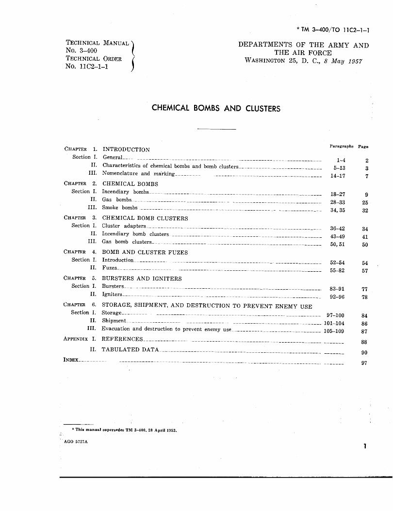
CHEMICAL BOMBS AND CLUSTERS
Chapter 1. Section I.
II. III.
Chapter 2. Section I.
II. III.
Chapter 3. Section I.
II. III.
Chapter 4. Section I.
II.
Chapter 5. Section I.
II.
Chapter 6. Section I.
II. III.
A p p e n d i x I.
II.
I n d e x __________
INTRODUCTIONGeneral_______________________________________________________________Characteristics of chemical bombs and bomb clusters____________________________Nomenclature and marking_____________________________________________________
CHEMICAL BOMBSIncendiary bombs_________________________________________________________ __Gas bombs_______________________________________________________________Smoke bombs___________________________________________________________________
CHEMICAL BOMB CLUSTERSCluster adapters_________________________________________________________ __ _Incendiary bomb clusters____________________________________________________Gas bomb clusters______________________________________________________ __
BOMB AND CLUSTER FUZESIntroduction_______________________________________________________________Fuzes___________________________________________________________________
BURSTERS AND IGNITERSBursters_______________________________________________________________Igniters_______________________________________________________________________
STORAGE, SHIPMENT, AND DESTRUCTION TO PREVENT ENEMY USEStorage_______________________________________________________________________Shipment__________________________________________________________________Evacuation and destruction to prevent enemy use_______________________________
REFERENCES________________________________________
Paragraphs
1-45-13
14-17
18-27 28-33 34, 35
36-42 43-49 50, 51
52-5455-82
83-9192-96
97-100101-104105-109
TABULATED DATA
Page
237
92532
344150
5457
7778
848687
88
90
97
* This manual supersedes TM 3-400, 28 A pril 1953.
AGO 5727AT

CHAPTER 1 INTRODUCTION
Section I. G ENERAL
1. Scopea. General. This manual is published for the
use of military personnel who are responsible for handling chemical bombs and bomb clusters in the field. It contains a detailed description of chemical bombs and bomb clusters, as well as information on the assembly, functioning, marking, packing, shipping, and storage of these munitions. Some fuzes and certain other components of chemical bombs, which are the responsibility of the Ordnance Corps, are described briefly and reference is made to the technical manual where detailed descriptions can be found. All components which are the responsibility of the Chemical Corps are described fully.
b. Appendixes. A list of reference publications is given in appendix I. Appendix II contains seven tables which list data on the incendiary bombs, gas bombs, smoke bombs, chemical bomb clusters, fuzes, bursters, and igniters included in this manual.
2. Extent of RevisionIn addition to general changes in the text which
bring this manual up-to-date, this revision differs from TM 3-400, 28 April 1953, in the following respects:
a. Deletions of Obsolete Items.(1) AN-M50A2 4-pound TH3 incendiary
bomb.(2) AN-M 50T-A2 4-pound incendiary
bomb.(3) AN -M 50T-X-A3 4-pound incendiary
bomb.(4) AN-M 50X-A3 4-pound in cen diary
bomb.(5) M69X 6-pound IM and NP oil incendi
ary bomb.
(6) M47 100-pound IM and NP incendiary bomb.
(7) M47A1 100-pound IM and NP incendiary bomb.
(8) AN-M47A2 100-pound IM and NP incendiary bomb.
(9) AN-M47A3 100-pound IM incendiary bomb.
(10) AN-M47A4 100-pound IM and NP incendiary bomb.
(11) Ml 13 125-pound HD persistent gas bomb.
(12) AN-M47A1 100-pound WP smoke bomb.
(13) AN-M47A2 100-pound WP smoke bomb.
(14) M7 500-pound quick-opening cluster adapter.
(15) M10 500-pound aimable cluster adapter.(16) M10A1 500-pound aimable cluster adap
ter.(17) M13 500-pound incendiary bomb cluster.(18) AN-M14 500-pound incendiary bomb
aimable cluster.(19) AN-M14A1 500-pound incendiary bomb
aimable cluster.(20) M17 500-pound incendiary bomb aim-
able cluster.(21) AN-M17A1 500-pound incendiary bomb
aimable cluster.(22) M20 500-pound PT1 incendiary bomb
cluster.(23) M20A1 500-pound PT1 incendiary bomb
cluster.(24) M21 500-pound IM and NP incendiary
bomb cluster.(25) M22 500-pound TH3 incendiary bomb
cluster.
2AGO 5727A
(26) M22A1 500-pound. TH3 incendiary bomb cluster.
(27) AN-M13 burster.(28) M25 burster.(29) AN-M9 igniter.(30) M15 Na bomb igniter.(31) C3 adapter fin.
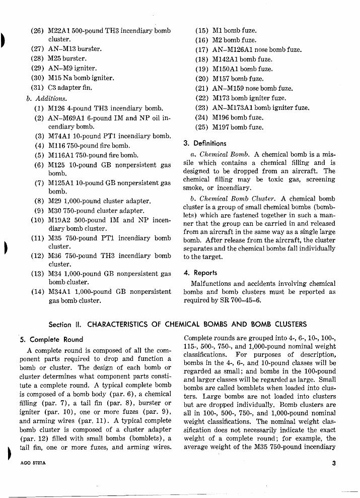
b. Additions.(1) M126 4-pound TH3 incendiary bomb.(2) AN-M69A1 6-pound IM and NP oil in
cendiary bomb.(3) M74A1 10-pound PT1 incendiary bomb.(4) M116 750-pound fire bomb.(5) M116A1 750-pound fire bomb.(6) M125 10-pound GB nonpersistent gas
bomb.(7) M125A110-pound GB nonpersistent gas
bomb.(8) M29 1,000-pound cluster adapter.(9) M30 750-pound cluster adapter.
(10) M19A2 500-pound IM and NP incendiary bomb cluster.
(11) M35 750-pound PT1 incendiary bomb cluster.
(12) M36 750-pound TH3 incendiary bomb cluster.
(13) M34 1,000-pound GB nonpersistent gas bomb cluster.
(14) M34A1 1,000-pound GB nonpersistent gas bomb cluster.
(15) M l bomb fuze.(16) M2 bomb fuze.(17) AN-M126A1 nose bomb fuze.(18) M142A1 bomb fuze.(19) M150A1 bomb fuze.(20) M l57 bomb fuze.(21) AN-M159 nose bomb fuze.(22) M173 bomb igniter fuze.(23) AN-M173A1 bomb igniter fuze.(24) M196 bomb fuze.(25) M197 bomb fuze.
3. Definitions
a. Chemical Bomb. A chemical bomb is a missile which contains a chemical filling and is designed to be dropped from an aircraft. The chemical filling may be toxic gas, screening smoke, or incendiary.
b. Chemical Bomb Cluster. A chemical bomb cluster is a group of small chemical bombs (bomb- lets) which are fastened together in such a manner that the group can be carried in and released from an aircraft in the same way as a single large bomb. After release from the aircraft, the cluster separates and the chemical bombs fall individually to the target.
4 . Reports
Malfunctions and accidents involving chemical bombs and bomb clusters must be reported as required by SR 700-45-6.
Section II. CHARACTERISTICS OF CHEMICAL BOMBS AND BOMB CLUSTERS
5. Complete RoundA complete round is composed of all the com
ponent parts required to drop and function a bomb or cluster. The design of each bomb or cluster determines what component parts constitute a complete round. A typical complete bomb is composed of a bomb body (par. 6), a chemical filling (par. 7), a tail fin (par. 8), burster or igniter (par. 10), one or more fuzes (par. 9), and arming wires (par. 11). A typical complete bomb cluster is composed of a cluster adapter (par. 12) filled with small bombs (bomblets), a tail fin, one or more fuzes, and arming wires.
Complete rounds are grouped into 4-, 6-, 10-, 100-, 115-, 500-, 750-, and 1,000-pound nominal weight classifications. For purposes of description, bombs in the 4-, 6-, and 10-pound classes will be regarded as small; and bombs in the 100-pound and larger classes will be regarded as large. Small bombs are called bomblets when loaded into clusters. Large bombs are not loaded into clusters but are dropped individually. Bomb clusters are all in 100-, 500-, 750-, and 1,000-pound nominal weight classifications. The nominal weight classification does not necessarily indicate the exact weight of a complete round; for example, the average weight of the M35 750-pound incendiary
AGO 5727A 3
bomb cluster (par. 48) is 690 pounds. Complete round data are listed in tables II, III, IV, and V.
6. Bomb Bodies(fig. 1)
a. Small Bombs. The bodies of small bombs are round or hexagonal in cross section. Some small incendiary bombs have bodies made of magnesium alloy, the body itself constituting the main charge of the bomb. Other small incendiary bombs have steel bodies which contain an incendiary filling.
b. Large Bombs. The bodies of large bombs are cylindrical in cross section and have rounded or ogival noses and tapered rear sections. Large bomb bodies which must withstand high internal pressure are forged or cast from steel; when internal pressures are not high, the bodies are made of thin sheet steel or aluminum. Large bomb bodies have suspension lugs for suspending the bombs from aircraft bomb stations. The lugs may be attached permanently to the bomb body or they may be removable.
7. Bomb FillingsDetailed information on the chemical agents
used to fill bombs is contained in TM 3-215 and FM 3-5.
a. Incendiary Fillings. Incendiary fillings used in chemical bombs are thickened fuels and metallic
fillings. A third type of incendiary material, not properly classified as a filling, is the magnesium from which the bodies of some incendiary bombs are made.
(1) Thickened fuels. Thickened fuels are composed of flammable liquids, such as gasoline thickened to a jelly like consistency. IM, PT1, and NP are the thickened fuels which are used to fill incendiary and fire bombs. IM is gasoline thickened with isobutyl methacrylate; PT1 is essentially a mixture of magnesium with gasoline and other petroleum products thickened with isobutyl methacrylate; and NP is gasoline thickened with M l or M2 thickener (napalm). IM and PT1 are prepared in manufacturing plants; NP is prepared either in manufacturing plants or in the field. All thickened fuels spatter like viscous liquids upon impact on a target and tend to adhere to the surface of the target. Information on preparing thickened fuels is contained in TM 3-366.
(2) Metallic fillings. The basic ingredient of metallic incendiary fillings is thermite. Thermite is a mixture of powdered aluminum and powdered iron oxide
Figure 1. Bodies of typical chemical bombs.
4 AGO 5727A

which, when ignited by an igniter (such as black powder), burns at a temperature of about 4,000° F. White-hot molten iron is released when thermite burns, and acts as a heat reservoir to prolong and spread the incendiary effect of the thermite. When used as a filling for munitions, thermite is called Thermite, TH1. Thermate is a mixture of thermite, barium nitrate, and sulfur in an oil binder. Thermate, TH3, is the standard metallic filling used in incendiary bombs. Thermate, TH2, which has slightly different percentages of ingredients from TH3, is limited standard and will no longer be used as a bomb filling although some bombs currently on hand may be filled with it.
(3) Magnesium. Magnesium is a soft metal which, when heated to approximately 1,100° F. in the presence of air, ignites and burns vigorously at a temperature of about 3,600° F. Magnesium melts and flows as it burns, igniting all combustible material in its path. Bomb bodies made of magnesium comprise the bomb’s main incendiary charge. The body of a magnesium bomb usually is made with an internal cavity which contains a thermate igniting charge. The AN-M50A3 4-pound incendiary bomb (par. 18) is an example of the use of magnesium in a bomb body.
b. Toxic Gas. The standard toxic gas fillings for chemical bombs are CG (phosgene), HD (distilled mustard), and GB. AC (hydrogen cyanide), CK (cyanogen chloride), and H (Levinstein mustard) are substitute standard and are used in some bombs. AC, CG, CK, and GB are classed as non persistent agents; H and HD as persistent agents.
c. Screening Smoke. The only standard smoke- producing filling used in standard smoke bombs is PWP (plasticized white phosphorus). WP (white phosphorus) is used as a substitute standard filling in some bombs. PWP does not flow in storage to the same extent as WP, hence bombs filled with PWP maintain their ballistic characteristics better than those filled with WP.
8. Tail Fins
a. Purpose. Tail fins stabilize falling bombs and clusters. Fins on small bombs are provided to insure that the bomb strikes nose first. Some- small bombs have no tail fins but have weighted noses which cause them to fall nose first. On large bombs and on aimable clusters, fins aid in securing predictable ballistic characteristics, allowing the missiles to be aimed at a target from high altitudes. Tail fins are not used on M116 or M116A1 fire bombs nor on quick-opening clusters such as the M12 incendiary bomb cluster.
b. Types. Fins on small bombs are usually extensible and are retracted into the bomb body when the bomb is clustered. Some small bombs have fabric tail streamers (fig. 10) ; others have a tail parachute (fig. 24) instead of fins. Fins for large bombs and bomb clusters (fig. 2) usually
M 102, M102 A I.M I03AI MI25.MI25AI
AND M23AI ADAPTERS
Figure 2. Tail fins for large bombs and bomb clusters.
AGO 5727A 5

consist of four metal vanes supported by a framework and are installed on the bomb or cluster immediately prior to loading the missile in an aircraft. Tail fins for the AN—M47 series incendiary and smoke bombs (pars. 24, 34, and 35) also consist of four vanes and a metal supporting framework but are welded to the bomb body during manufacture.
9. FuzesA fuze is a device used to initiate an explosive
or igniting train. Fuzes used in chemical bombs and bomb clusters are discussed in detail in paragraphs 52 through 82. The location and installation of the fuze in each bomb or cluster is described in the paragraph devoted to the bomb or cluster.
10. Bursters and Ignitersa. Bursters. A burster is an explosive charge
designed to be used in a bomb or cluster. Bursters are used in some chemical bombs to burst the bomb body and release the chemical filling. They are used in bomb clusters to open the cluster and allow the bomblets to fall free. Bursters are not used in bombs such as the M116A1 fire bomb (par. 27), the filling of which is released when the bomb ruptures on impact; nor in clusters such as the M34 1,000-pound cluster (par. 50), from which the bomblets are ejected by cluster-ejection cartridges. Bursters used in chemical bombs and bomb clusters are described in paragraphs 83 through 91.
b. Igniters. An igniter is an incendiary charge which is used to ignite the filling of an incendiary bomb. Igniters used in chemical bombs and bomb clusters are described in paragraphs 92 through96.
11. Arming W iresAn arming wire is used to prevent a bomb or
cluster from being armed while installed in an aircraft, and to provide a means for arming the munition upon its release from the aircraft. An arming wire consists of one or two brass wires fitted with a swivel loop, and includes one or more safety clips. Four types of arming wires (fig. 3) are in use. Each type is made to different dimensions depending upon the size of the bomb or cluster with which it is used. The type and designation of the arming wire used with each bomb or cluster are indicated in the paragraph devoted to the munition.
12. Cluster AdaptersA cluster adapter is a device which encases a
number of small bombs (bomblets) to permit their being carried in an aircraft as a single unit. The adapter may be either quick-opening or aim- able. A quick-opening adapter is designed to open immediately after release from the aircraft, allowing the bomblets to fall free. An aimable adapter is designed to have predictable ballistic characteristics and to open at a longer time after release from the aircraft than the quick-opening type. The aimable type can therefore be dropped
--------..----O - N
O------ 0 ----& 03----- '
O,
T Y P E A ( Cl, C5,C9) T Y P E B (C4 .M 22 .M 23)
T Y P E E (MIAI ,M5,M7,M 17)3. Arming wires.
6 AGO 5727A
from greater heights than can the quick-opening type, with the expectation that the dispersion pattern of the bomblets will not be undesirably large. Like large bomb bodies (par. 6 ), cluster adapters have suspension lugs which permit their suspension either by one or two lugs. Cluster adapters are described in detail in paragraphs 36 through 42.
13. Other Components
a. Fuze-Seat Liner. A fuze-seat liner is a metal cup with external threads. The thread permits the fuze-seat liner to be screwed into a fuze cavity in a bomb. The purpose of the fuze seat liner is to cover the burster well and to hold the burster in proper relationship to the fuze. The liner is normally assembled loosely in the bomb during manufacture and is tightened in the field when the burster and fuze are installed. Only the AN-M76 500-pound incendiary bomb (par. 25) and the AN-M78 500-pound and AN-M79 1,000- pound gas bombs (pars. 32 and 33) have fuze- seat liners.
b. Adapter-Booster. An adapter-booster is essentially an explosive charge (booster) and a
reducing bushing (adapter) in one assembly. The explosive portion of the adapter-booster intensifies the explosive action of a fuze. The adapter portion has external threads which screw into the fuze well of a bomb, and internal threads which receive the appropriate fuze.
c. Cluster-Ejection Cartridge. A cluster-ejection cartridge is an explosive cartridge similar in size and shape to a shotgun shell. It contains a primer and a powder charge and is used in bomb clusters to supply gas pressure for ejecting clustered bombs from an adapter casing. Two types of cluster-ejection cartridges are in use. The first is the M2 ignition cartridge which is used in the M31 and M32 incendiary bomb clusters (pars. 46 and 47). The M2 ignition cartridge is an Ordnance Corps item which was designed for use with the 4.2-inch chemical mortar shell and was adopted as the standard cluster-ejection cartridge for the M31 and M32 bomb clusters. The second cartridge used for cluster-ejection is the M3 cluster-ejection cartridge. It is similiar in construction to the M2 ignition cartridge but is slightly larger, and was designed for use in the M34 and M34A1 bomb clusters (pars. 50 and 51).
Section III. NO M ENCLATURE AND MARKING
14. NomenclatureBombs and clusters and their components are
assigned names at the time they are made standard items of issue. The name then becomes the standard nomenclature by which the item is identified. The standard nomenclature of bombs and clusters includes the name of the type of item, the nature of the contents, the symbol for the filling, the weight classification, and the model number; for example: Bomb, Gas, Nonpersistent, GB, 10-lb., M125A1; Cluster, Incendiary Bomb, TH3, 750-lb., M36.
15. Model Number
To distinguish between different designs of the same type, a model number is assigned at the time a design is adopted as standard. The model designation consists of the letter “M” followed by an Arabic numeral. Modifications of the original design are indicated by adding the letter “ A” and the appropriate Arabic numeral after the model designation. For example, M47A4 bomb desig
nates the fourth modification of the bomb originally adopted as M47. When both the Army and Navy have accepted the standardization of an item, the prefix “AN” is placed before the model designation. Thus, AN-M47A4 bomb indicates acceptance of the M47A4 bomb as a standard item by the Army and the Navy.
16. Lot Number
A lot number is a number assigned by the manufacturer to each group of bombs or clusters manufactured under the same manufacturing conditions. Bombs with the same lot number may be expected to have similar characteristics and similar faults (if any). The lot number always is used when reference is made to a specific bomb, as when reporting malfunctions or accidents, or condition in storage.
17. Markings
a. Body Color. Chemical bombs and clusters are painted gray in accordance with standard
AGO 5727A 7
munition marking procedure (TM 9-1900). Fire bombs are not painted and the magnesium portion of small incendiary bombs is unpainted but is naturally grayish in color. Munitions other than chemical are painted different colors; for example: high-explosive munitions are painted olive drab; practice munitions, blue.
b. Identification Bands. Colored bands are painted on bombs and clusters to indicate the type of filling. The bands on chemical bombs (fig. 4) are painted around the circumference of the bombs. Large bombs have bands at three locations, at the nose end, middle, and tail end; small bombs have bands only around the middle. The type and color of identification bands for each type of filling are as follows:
Type of fillingNonpersistent war gas Persistent war gas Smoke Incendiary
Type of band Color of bandSingle GreenDouble GreenSingle YellowSingle Purple
c. Other Markings. The bomb nomenclature, lot number, symbol or initials of loader, date loaded, shipping weight, cubage, and other data are marked on bombs and clusters in the same color as the identification bands.
AN-M50A3 INCENDIARY M74AI INCENDIARY
YELLOW GREEN PURPLEwmn mum W///////M.Figure i . Color markings on chemical bombs.
8 AGO 6727A
CHAPTER 2 CHEMICAL BOMBS
Section I. INCENDIARY BOMBS
18. Bomb, Incendiary, TH 3, 4-Pound, A N - M50A3
a. Description. The AN-M50A3 incendiary bomb (figs. 5 and 6) is 21 i y3.2 inches long and weighs 3.5 pounds. It is hexagonal in cross section and measures 1% inches across opposite faces of the hexagon. It is used in M32 incendiary bomb clusters (par. 47).
Figure 5. AN—M50A3 4-pound TH3 incendiary bomb.
(1) Body. The bomb body is hollow and is made of magnesium alloy, which constitutes the main incendiary charge. The cavity in the bomb body provides space for the bomb filling ((2 ) below). The end of the body is closed with a solid iron nose which weights the bomb so that it falls nose downward and penetrates a target without crumpling on impact. Three ventholes in the body permit combustion products from the filling to vent without bursting the body. The hollow tail section is made of sheet steel.
(2) Filling. The cavity in the nose section is filled with a priming charge consisting of approximately 10 ounces of Thermate, TH3 (par. 7 ). The end of the priming charge closest to the firing assembly ((3 ) below) is covered with a layer of FF 31 (first-fire mixture).
(3) Firing assembly. The firing assembly, which functions as an inertia fuze, is located between the nose and tail sections of the bomb. It consists essentially of a firing pin in a firing-pin holder, and a primer. The firing pin is held in the holder by a metal clip which prevents the firing pin from falling against the primer.
(4) Safety plunger. The safety plunger (arming plunger) is a spring-loaded steel plunger which projects from the side of the bomb body. When the safety plunger is depressed by contact with an adjacent bomb in a cluster, the inner end o f the plunger moves into the space between the firing pin and the primer so that the bomb is prevented from arming as long as it is clustered.
b. Assembly. The bomb is assembled in manufacture.
BODYNOSE (MAGNESIUM HOLDER AND(IRON) ALLOY) FIRING ASSEMBLIES
AGO 5727A 9
c. Functioning.(1) After release from cluster. When the
bomb is released from the cluster, pressure on the safety plunger is released and the plunger is forced outward by its spring, arming the bomb.
(2) Upon impact. When the bomb strikes, inertia causes the firing pin to move forward, striking the primer. The primer ignites the first-fire mixture which ignites the thermate filling. The burning thermate then ignites the magnesium section of the body. The burning time of the bomb is from 5 to 8 minutes.
d. Disarming. To disarm an armed bomb, depress and fasten down the safety plunger. The bomb then can be transported to a bomb-disposal area with relative safety.
e. Marking. A purple band around the nose end of the bomb identifies it as an incendiary. Bomb nomenclature and lot number are stenciled on the body in purple. Some bombs may be unmarked if they were clustered within 72 hours after they were filled.
/. Shipment and Storage. The bombs are loaded into the M26 cluster adapter. Shipment and storage of the clustered bombs are discussed in the paragraphs describing the clusters.
g. Tabulated Data. Data for this bomb are tabulated in table II.
19. Bomb, Incendiary, TH 3, 4-Pound, M l 26
a. Description. The M126 incendiary bomb (figs. 7 and 8) is identical with the AN-M50A3 bomb (par. 18) except that the M126 bomb has an M15 fin assembly in place o f a hollow sheet- steel tail section. The M126 bomb is 19 % 6 inches
long and weighs 3.6 pounds. The M15 fin assembly consists of retractable fins (6, fig. 8) in a hollow sheet-steel fin body (4). The fins extend through longitudinal slots in the fin body and can be retracted into the fin body by depressing a spring-loaded tail plunger (5) at the rear end of the bomb. The M126 bomb is used in M36 incendiary bomb clusters (par. 49).
Figure 7. M126 //--pound THS incendiary bomb.
b. Assembly. The bomb is assembled in manufacture.
c. Functioning.(1) Before release from cluster. The safety
plunger (3, fig. 8) is depressed by contact with another bomb in the cluster. Depression of the tail plunger (5) retracts the fins into the fin body and holds them retracted as long as the tail plunger is held in a depressed position.
(2) After release from cluster. When the bomb is released from the cluster, the tail fins are extended by the force of the spring of the spring-loaded tail plunger assembly, and the safety plunger is forced outward by its spring, arming the bomb. The tail fins assist in keeping the bomb turned nose downward during its fall.
(3) Upon impact. When the bomb strikes, it functions in the same way as the A N - M50A3 bomb.
3 4
Safety plunger Fin body
Holder and firing assemblies Nose (iron)
Figure 8. M126 //-pound THS incendiary bomb, sectional view.
10 AGO 5727A

d. Disarming. To disarm an armed M126 bomb, depress and fasten down the safety plunger. The bomb then can be transported to a bomb-disposal area with relative safety.
e. Marking. A purple band around the nose end of the bomb identifies it as an incendiary. Bomb nomenclature and lot number are stenciled on the body in purple. Some bombs may be unmarked if they were clustered within 72 hours after they were filled.
/. Shipment and Storage. The bombs are loaded into M30 adapters which are used in M36 clusters. Shipment and storage of the clustered bombs are discussed in the paragraph describing the cluster.
g. Tabulated Data. Data for this bomb are tabulated in table II.
20. Bomb, Incendiary, O il, IM or NP, 6-Pound, A N -M 69
a. Description. The AN-M69 oil incendiary bomb (figs. 9 and 10) is 19V:> inches long and weighs 6.1 pounds. It is hexagonal in cross section and measures 2% inches across opposite faces of the hexagon. It is used in M12 and M19 incendiary bomb clusters (pars. 43 and 44). The complete round consists essentially of a sheet- steel body, a diaphragm assembly, a white phosphorus igniting charge, incendiary filling, a fuze, and tail streamers.
(1) Body. The body is hexagonal in cross
* «| ■
Figure 9. AN—M69 6-pound. IM or NP oil incendiary bomb.
section except at the tail end, where it is circular. A hole in one flat side of the body near the bomb nose receives the fuze. The nose end of the bomb is closed by a sheet-steel nose cup which forms a container that holds two small bags of magnesium-black powder mixture in contact with the fuze. The tail end of the bomb is closed by a sheet- steel tail cup that forms a receptacle for the tail streamers.
(2) Diaphragm assembly. The diaphragm assembly is made of sheet steel and forms a partition between the nose cup and the WP igniting charge.
(3) White phosphorus igniting charge. Approximately 6 ounces of WP is contained in a plastic cup which is installed in the bomb behind the diaphragm assembly and ahead of the filling.
(4) Filling. The filling consists of approximately 2.2 pounds of IM or NP (par. 7). It is contained in a cheesecloth sock, which is tied at both ends with cord to form a cylindrical container.
(5) Fuze. The fuze is an M l bomb fuze (par. 55), which is screwed into the hole in the side of the bomb at the nose end. The end of the fuze containing the first-fire mixture is in close contact with the explosive in the nose cup.
(6) Tail streamers. Four tail streamers made of strips of muslin 3 inches wide by 7 feet long are contained in the tail cup. When the bomb is clustered, the tail streamers are packed into the tail cup with a short length of each streamer left free.
Figure 10. AN-M69 6-pound IM or NP oil incendiary bomb, cutaway view.
AGO 5727A 11
b. Assembly. The bomb is assembled in manufacture.
c. Functioning.(1) Before release from cluster. The safety
plunger in the fuze is depressed by contact with another bomb in the cluster, and tail streamers are held in the bomb by contact of the bomb tail cup with other bombs or with the end of the cluster.
(2) After release from cluster. When the bomb is released from the cluster, the safety plunger in the fuze is forced outward by its spring, arming the bomb. Air flowing past the bomb pulls the tail streamers from the tail cup. The streamers keep the bomb turned nose downward as it falls.
(3) Upon impact. When the bomb strikes, the M l fuze functions and sets off the black powder in the nose cup. Gases released by the explosion blow the diaphragm toward the tail of the bomb. This action breaks the cup containing the WP and ejects the incendiary filling, the WP, the tail cup, and the streamers from the tail end of the bomb. The WP ignites upon exposure to the air and sets fire to the bomb filling. The scattered filling burns from 8 to 20 minutes.
d. Disarming. To disarm an armed AN-M69 bomb, depress and fasten down the safety plunger in the M l fuze. The bomb then can be transported to a bomb-disposal area with relative safety.
e. Marking. A purple band around the middle of the bomb identifies it as an incendiary. Bomb nomenclature and lot number are stenciled on the body in purple. Some bombs may be unmarked if
they were clustered within 72 hours after they were filled.
/. Shipment and Storage. AN-M69 bombs are loaded into adapters which are used in M12 or M19 clusters. Shipment and storage of the clustered bombs are discussed in the paragraphs describing the clusters.
g. Tabulated Data. Data for this bomb are tabulated in table II.
21. Bomb, Incendiary, Oil, IM or NP, 6-Pound,AN-M69A1
The AN-M69A1 oil incendiary bomb is identical with the AN-M69 bomb (par. 20) except that the AN-M69A1 bomb has an M2 fuze (par. 56) instead of an M l fuze. It is used in the M19A2 bomb cluster (par. 45). Data for this bomb are tabulated in table II.
22. Bomb, Incendiary, PT1, 10-Pound, M74a. Description. The M74 incendiary bomb
(figs. 11 and 12) is 191/2 inches long and weighs 8.5 pounds. It is hexagonal in cross section and measures 2% inches across opposite faces of the hexagon. An extensible tail fin stabilizes the bomb in flight. The M74 bomb is used in M31 bomb clusters (par. 46). The complete round consists of a sheet-steel body, a dome, a white phosphorus igniting charge, incendiary filling, a fuze, and a tail assembly.
(1) Body. The body is hexagonal in cross section except at the tail end, where it is circular. The nose end of the bomb is closed by a sheet-steel nose cup which
Figure 11. M7U 10-pound, PT1 incendiary bomb.
12
DOME
Figure 12. M7U 10-pound PT1 incendiary bomb, cutaway view.
AGO 5727A

provides a seat for the fuze. A spring- loaded release bar clips to the nose cup over a release pin in the M142A1 fuze (par. 67). The tail end of the bomb is
closed by a sheet-steel tail cup. A tail well in the center of the tail cup provides a mounting for the tail fin.
(2) Dome. The dome is located in the bomb nose behind the nose cup. It separates the fuze from the filling and forms a container for two small bags of magnesium-black powder mixture.
(3) White phosphorous igniting charge. Approximately 6 ounces of WP is contained in a plastic container which is installed in the bomb behind the dome and ahead of the filling.
(4) Filling. The filling consists of approximately 2.75 pounds of PT1 (par. 7).
(5) Fuze. The fuze is an M142A1 bomb fuze (par. 67) which is screwed into the nose cup. The booster end of the fuze is inside the dome and is adjacent to the bags of black powder.
(6) Tail assembly. The tail assembly consists essentially of a radial-type tail fin attached to a tail sleeve. The tail sleeve slides into the tail well in the tail end of the bomb. The entire tail assembly can be telescoped into the tail end of the bomb until the tail fin is completely within the tail cup. When the tail fin is telescoped, a coil spring inside the tail well is compressed.
b. Assembly. The bomb is assembled in manufacture.
c. Functioning.(1) Before release from cluster. A release
bar, which replaces the safety wire (fig. 57) when the bomb is clustered, is depressed by contact with another bomb in the cluster or with the end o f the cluster, and the release pin in the bomb fuze is held in the unarmed position. The tail assembly is telescoped into the tail end of the bomb and held in position by contact with spacers placed in the middle of the cluster and at the ends.
(2) After release from cluster. When the
bomb is released from the cluster, the spring-loaded release bar flies off, freeing the fuze release pin and allowing the fuze to arm. Simultaneously, the tail fin is moved to the extended position by the action of the coil spring inside the tail well. The extended tail fin keeps the bomb turned nose downward as it falls.
(3) Upon impact. When the bomb strikes, the M142A1 fuze functions and sets off the black powder in the dome. Gases released by the explosion blow the dome toward the tail of the bomb. This action breaks the cup containing the WP and forcibly ejects the incendiary filling, the WP, the tail cup, and the tail assembly from the tail end of the bomb. The WP ignites upon exposure to the air and sets fire to the bomb filling. The scattered filling burns for 5 to 10 minutes.
d. Disarming. Do not attempt to disarm an armed fuze in this bomb nor to defuze the bomb. A bomb containing an armed fuze must be disposed of by bomb-disposal personnel.
e. Marking. A purple band around the middle of the bomb identifies it as an incendiary. Bomb nomenclature and lot number are stenciled on the body in purple.
/. Shipment and Storage. The bombs are loaded into M25 cluster adapters which are used in M31 clusters. Shipment and storage of the clustered bombs are discussed in the paragraphs describing the clusters.
g. Tabulated Data. Data for this bomb are tabulated in table II.
23. Bomb, Incendiary, PT1, 10-Pound, M74A1The M74A1 incendiary bomb is identical with
the M74 bomb (par. 22) except that the M74A1 bomb has an M197 fuze (par. 82) instead of the M142A1 fuze. The M74A1 bomb is used in the M35 incendiary bomb cluster (par. 48). Data for this bomb are tabulated in table II.
24. Bomb, Incendiary, NP, 100-Pound, A N -M47A3
a. Description. The AN-M47A3 incendiary bomb (figs. 13 and 14) is approximately 52%6
AGO 5727A13
inches long and weighs approximately 69.8 pounds. It is aproximately 814 inches in diameter and has a rounded nose, a truncated conical tail section, and a fixed tail fin. The complete round consists of a bomb body, incendiary filling, a burster, a fuze, and an arming wire.
Figure 13. AN-Mb7A8 100-pound NP incendiary bomb.
(1) Body. The bomb body is made of sheet steel. A burster well, which is a metal tube closed at one end, extends the full length of the bomb. A threaded hole in the nose end of the bomb receives the fuze. The hole is closed during shipment by a nose plug. Two suspension bands with suspension lugs at the top are clamped around the bomb body by machine screws. The tail fin, which has four vanes, is welded to the tail section during manufacture.
(2) Filling. The filling consists of approximately 40 pounds of NP (par. 7).
(3) Burster. An AN-M12 burster (par. 84) is shipped separately and is installed in the burster well during assembly of the bomb ( b below).
(4) Fuze. The preferred fuze is the A N - M159 nose bomb fuze (par. 73). The AN-M126A1 nose bomb fuze (par. 64) is an authorized alternate. The fuze is shipped separately and is installed in the bomb nose during assembly of the bomb.
(5) Arming wire. A C5 type A arming wire (par. 11) is used with this bomb.
b. Assembly. Remove the nose plug and inspect to be sure that a spacer (washer) is in position in the nose end of the burster well. Insert the burster in the burster well until the shoulder on the plug assembly at the end of the burster rests against the spacer in the burster well. Screw the fuze handtight into the bomb nose and install the arming wire as described for the fuze used.
c. Functioning. When the bomb is released from an aircraft, the arming wire is withdrawn and the fuze arming vane rotates in the air- stream. After the required number of revolutions, as shown in table VI, the fuze is armed (pars. 73 and 64). Upon impact, the fuze activates the burster which shatters the bomb and ignites and scatters the filling. The effective radius of burst is 10 to 15 yards.
d. Defuzing. To defuse an AN-M47A3 incendiary bomb, replace the safety wire in the fuze, and unscrew the fuze. Return the burster and fuze to their original packing.
Warning: Do not attempt to disarm an armed fuze.Turn the fuze over to bomb-disposal personnel for disposal.
e. Marking. A purple band around the middle of the bomb identifies it as an incendiary. Bomb nomenclature and lot number are stenciled on the body in purple.
/. Packing. The AN-M47A3 incendiary bomb is packed in a wood packing box which weighs approximately 118 pounds when filled and displaces 3.8 cubic feet. The burster, fuze, and arming wire are packed separately.
Figure H . AN-M47A3 100-pound NP incendiary bomb, cutaway view.
14AGO 5727A
g. Shipment and Storage. Shipping requirements are discussed in paragraphs 101 through 104. The AN-M47A3 bomb is in storage group D for chemical munitions. See paragraphs 97 through 100 for information on storing chemical bombs.
h. Tabulated Data. Data for this bomb are tabulated in table II.
25. Bomb, Incendiary, PT1, 500-Pound, A N - M76
a. Description. The AN-M76 incendiary bomb (figs. 15 and 16) is approximately 59 inches long and weighs 467 pounds when assembled into a complete round. It is 14 % 6 inches in diameter and has an ogival nose and truncated conical tail section. The complete round consists of a bomb body, incendiary filling, a tail fin, an igniter, a burster, and adapter-booster, a nose fuze, a tail fuze, and an arming wire.
(1) Body. The bomb body is made of steel. A tubular burster well extends the length of the interior of the bomb from a threaded fuze adapter in the bomb nose to a threaded hole in a base plate, which is welded to the tail end of the body. A fuze-seat liner installed in the
Figure 15. AN-M76 500-pound PT1 incendiary bomb.
fuze adapter receives a nose fuze; the threaded hole in the base plate receives an adapter-booster and tail fuze. During shipment, the hole in the bomb nose is closed by a nose plug, and the base plate is covered by a shipping plate which is attached to the base plate by four screws. Suspension lugs welded to the body are used for carrying the bombs in an aircraft.
(2) Filling. The bomb is filled during manufacture with 174 pounds of PT1 (par. 7).
(3) Tail fin. An M109 or AN-M109A1 tail fin (par. 8) is used with the AN-M76 incendiary bomb. The tail fin is shipped separately from the bomb and is installed in the field (6 below).
(4) Igniter. An AN-M 5 igniter (par. 92) is installed in the burster well prior to loading the bomb in an aircraft. The igniter is shipped separately from the bomb.
(5) Burster. An AN-M14 burster (par. 85) is installed in the hole in the A N - M5 igniter before the bomb is loaded in an aircraft. The burster is shipped separately from the bomb.
(6) Adapter-booster. An M115 or M115A1 adapter-booster (TM 9-1980) is screwed into the base plate. The adapter-booster may be furnished mounted in a holder-loader assembly, or the adapter-booster and holder-
SUSPENSION LUGS TAIL FIN
AGO 5727A 15

loader assemblies may be furnished separately.
(7) Nose fuze. The preferred nose fuze is the M163 nose bomb fuze (par. 76). The AN-M103 or A1^-M103A1 nose bomb fuze (par. 61 or 62) can also be used. Fuzes are shipped separately from the bomb.
(8) Tail fuze. The preferred tail fuze is the M161 tail bomb fuze (par. 74). The M101A1 or AN-M101A2 tail bomb fuze (par. 57 or 58) can also be used.
(9) Arming wire. An M5, M7, or A N - M7A1 type E arming wire (par. 11) is used with this bomb.
b. Assembly.(1) Before loading in aircraft. Remove
shipping bands, unscrew the nose plug, and remove the shipping plate from the base plate by removing four screws which hold the shipping plate in place. Remove the fin locknut from the tail end of the bomb, place the tail fin over the tail of the bomb with one vane in alinement with the suspension lugs, and install and tighten the fin locknut. Working from the tail end of the bomb, insert the AN-M5 igniter in the burster well with the filling plug toward the rear of the bomb, and insert the A N - M14 burster in the hole in the igniter. Screw the adapter-booster assembly into the base plate.
(2) After loading in aircraft. Set the nose and tail fuze for instantaneous or delay action as desired. Remove the closure plug from the adapter-booster and screw the tail fuze handtight into the adapter-booster. Screw the nose fuze handtight into the nose fuze-seat liner. Install the arming wire with one branch to each fuze and place two safety clips on the end of each branch. Remove the safety wire from the fuze.
c. Functioning. When the bomb is released from the aircraft, the arming wire is withdrawn and the fuze arming vanes rotate in the air- stream. After the required number of revolutions, as shown in table VI, the fuzes are armed.
When the bomb strikes, the fuzes function, causing the burster to detonate. The detonation of the burster shatters the igniter and scatters the incendiary filling. Upon contact with the air, the WP filling of the igniter burns and ignites the incendiary filling.
d. Defuzing. To defuze an AN-M76 bomb, replace the safety wires in the fuzes, remove the arming wire, and unscrew the fuzes. Remove the burster and igniter and return them and the fuzes to the original packing.
Warning: Do not attempt to disarm an armed fuze.Turn the armed fuze over to bomb disposal personnel for disposal.
e. Marking. A purple band at the bomb nose, one at the middle, and one at the tail end identify the bomb as an incendiary. Bomb nomenclature and lot number are stenciled on the body in purple.
/. Packing. The AN-M76 bomb is protected for shipping by shipping bands (par. 102). The bomb weighs approximately 447 pounds and displaces 5.5 cubic feet when packed. The tail fin, igniter, burster, adapter-booster, the fuzes, and the arming wire are packed separately.
g. Shipment and Storage. Shipping requirements are discussed in paragraphs 101 through 104. The AN-M76 bomb is in storage group D for chemical munitions. See paragraphs 97 through 100 for information on storing chemical bombs.
h. Tabulated Data. Data for this bomb are tabulated in table II.
26. Bomb, Fire, 750-Pound, M i l 6
a. Description. The M116 fire bomb (figs. 17 and 18) is designed to be filled with thickened
Figure 17. Mild 750-pound fire bomb.
16 AGO 5727A
Figure 18. M116 750-pound fire bomb, cutaway view.
1 Bulkhead2 Igniter cup3 Nose-cap guide4 Seal ring5 Wire guide6 Arming wire7 Suspension lug8 Filler cap9 Bolt
10 Nut11 Tail section12 Tail-cone guide13 Tail-cone plunger14 Spring15 Fuze16 Igniter17 Nose cap18 Nose-cap plunger19 Nose section20 Filling hole21 Locking screw22 Center section23 Gasket
I
I
fuel and carried externally on high-performance aircraft. It is approximately 137 inches long, weighs 52 pounds when empty and approximately 667 pounds when filled. It is 18% inches in diameter and has a rounded nose and conical tail. The bomb is assembled and filled in the field. A complete round consists of a bomb body, incendiary filling, two igniters, two fuzes, two arming wires, a nose cap, and a tail cone.
(1) Body. The bomb body is made of sheet aluminum in three sections.
(а) Center section. The center section (22, fig. 18) is an aluminum cylinder approximately 48% inches long and 18% inches in diameter, open at both ends. An aluminum seal ring (4) is welded inside each end of the center section. Each seal ring has nine bolts (9) which fasten the nose section and tail section in place. Two suspension lugs (7) are bolted to the center section, and two arming-wire guides (5 )are fastened to the outside of the center section between each suspension lug and the corresponding end of the center section.
(б) Nose section. The nose section (19) is a parabolic aluminum shell ap
proximately 30% inches long and 18 %G inches in diameter at the widest point. An aluminum seal ring is welded inside the large end of the nose section. The seal ring has 9 holes which match the 9 bolts in the center section. A rubber gasket (23), which bears against the seal
ring in the center section when the bomb is assembled, is cemented to the face of the seal ring. The small end of the nose section is closed by an aluminum bulkhead (1) on which are mounted an igniter cup (2) and a nose-cap guide (3). The igniter cup is threaded to receive an M23 or an AN-M23A1 igniter (par. 95 or 96). The hose-cap guide is a bracket pivoted to the bulkhead and provided with a spring which tends to make the guide lie flat against the bulkhead. A spring-loaded nose-cap plunger (18) is held in the center of the nose-cap guide by a short length of steel wire, which is replaced by an arming wire when the bomb is installed in an aircraft. A screw in the center of the nose-cap plunger is used
AGO 5727A 17
to fasten the nose-cap (17) to the bomb. A filling hole (20) is located in the nose section. The filling hole is closed by a filler cap which has a locking screw (21) in its center. An arming-wire guide similar to the one the center section extends lengthwise along the nose assembly from the large end to the bulkhead.
(c) Tail section. The tail section (11) is a truncated conical aluminum shell approximately 37 V2 inches long and 18 % 6 inches in diameter at the widest point. An aluminum seal ring like the one in the nose section is welded inside the large end of the tail section, and a rubber gasket (23) is cemented to the face of the seal ring as in the nose section. The small end of the tail section is closed by an aluminum bulkhead on which are mounted an igniter cap and a tailcone guide (12). The tail-cone guide is a fixed bracket to which a tail-cone plunger (13) w ithaspring (14) and nut (10) are fastened by an arming wire when the bomb is installed in an aircraft. A 5-inch-diameter filling hole is located in the large-diameter end of the tail section. The filling hole is covered by a filler cap (8) which has a locking screw in its center. An arming-wire guide similar to those in the center section and nose section extends lengthwise along the tail section from the large end to the bulkhead.
(2) Incendiary filling. The M116 fire bomb is filled with 100 gallons (approx 615 lbs) of NP (par. 7).
(3) Igniters. One M23 or AN—M23A1 WP bomb igniter (16) (par. 95 or 96) is installed in the igniter cup in the bomb tail, and one in the nose.
(4) Fuzes. One M173 or AN-M173A1 bomb igniter fuze (15) (par. 79 or 80) is installed in each igniter.
(5) Arming wires. Two M17 type E arming wires (6) par. 11) are used with the M l 16 fire bomb. One arming wire
is used to hold the nose cap and tail cone in place on the bomb; the other arming wire is used to prevent the nose and tail fuzes from arming.
(6) Nose cap. The nose cap (17) is an aluminum shell which permits air to flow smoothly around the bomb nose and provides maximum streamlining when the bomb is carried on an aircraft. A hole in the nose end of the nose cap receives a screw which holds the nose-cap to the nose-cap guide. A notch in the edge of the nose cap provides a channel for the arming wire when the nose cap is installed on a bomb. A window in the side of the nose cap permits inspection of the igniter and fuze when the nose cap is in place.
(7) Tail cone. The tail cone (fig. 19) is a conical aluminum shell which streamlines the bomb tail when the bomb is carried in an aircraft. A hole in the tail end of the tail cone receives the end of the tail-cone plunger (13, fig. 18) when the tail cone is installed on a bomb. A notch in the edge of the cone provides a channel for the arming wire, and a window in the side of the cone permits inspection of the igniter and fuze.
(8) Hardware. Three small lengths of aluminum tubing (fig. 19) are used to space safety clips which hold the arming wires in the fuzes, and 18 nuts and lockwashers are used to bolt the nose and tail sections to the center section.
b. Assembly.(1) Remove the bomb components (fig. 19)
from the packing box. Make sure that all components are present and that the gaskets are cemented in place in the nose section and tail section (a ( l ) above).
(2) Remove the filler caps from the filling holes in the nose and tail sections by loosening the locking screw in the center of each cap and turning the cap counterclockwise while lifting it out of the filling hole.
(3) Aline the arming-wire guide on the nose section with the guide at one end
18 AGO 5727A

Figure 19. Components for M116 750-pound fire bomb.
of the center section, and push the nose section firmly against the center section so that the bolts in the center section enter the holes in the nose section. Make sure that the gasket which is cemented to the seal ring in the nose section is seated in the seal ring in the center section. Working through the filling hole, install a lockwasher and nut on each bolt and tighten all nuts equally.
(4) Aline the arming-wire guide on the tail section with the guide on the remaining end of the center section, and fasten the tail section to the center section as in(3) above. Before tightening the nuts, be sure that the gasket in the tail section is seated in the seal ring in the center section.
c. Filling. The M116 bomb may be filled before it is installed on an aircraft, or after installation if the filling holes are accessible. Hoisting equipment must be available to install a filled bomb. To fill, pour or pump 100 gallons of incendiary
filling through the filling holes. Either or both holes may be used as required to distribute the filling evenly in the bomb. Do not overfill, since 100 gallons in the bomb leaves the required 10- percent void. Reducing the void by filling with more than 100 gallons may cause leakage. After filling, replace both filler caps and lock them in place by tightening the locking screw in the center of each cap.
d. Installation.Warning: Do not install the M116 bomb on
aircraft equipped with apparatus that ejects the bomb explosively.
(1) Installing bomb.(a) Thread one end of an M l7 arming
wire through the front suspension lug and through the arming-wire guide in the nose section. Thread the other end of the arming-wire through the rear suspension lug and through the arming-wire guide in the tail section. Install the second arming- wire in the same manner.
AGO 5727A 19
( b) Place the bomb in position under the bomb pylon, fasten the swivel loops on the arming-wires to the bomb pylon, and perform the prescribed preflight check of the bomb-release mechanism.
(c) Raise the bomb into position in the bomb station, and take up slack in the arming wires by pulling on the free ends of the wires as the bomb is raised.
(2) Fuzing bomb.(a) Screw M173 or AN-M173A1 fuzes
handtight into M23 or AN-M23A1 igniters.
(5) Screw the assembled fuzes and igniters into the igniter cups and tighten the igniters by hand. Turn the fuzes in the igniters until the arming-wire holes in the fuze-arming vanes are alined with the ends of the arming wires.
(c) Insert an end of one arming wire through the arming-wire hole in the hub of the arming vane in the nose fuze and take up the slack in the arming wire.
(d) Insert the other end of the same arming wire ( (c) above) in the tail fuze and take up the slack. Cut off the ends of the arming wire, leaving approximately 2 inches of wire protruding beyond each fuze. Slide one of the aluminum tubes (a (8) above) onto each end of the wire and install a safety clip on each end.
(e) Withdraw the safety pins from both fuzes.
(3) Attaching nose cap.(a) Depress the nose-cap plunger, remove
the retaining wire from the hole in the plunger, and insert one end of the second arming wire in the hole.
(b) Swing the nose-cap guide perpendicular to the bulkhead and pull the arming wire through the hole in the plunger, taking up all slack. Cut off the end of the wire, leaving approximately 2 inches of wire protruding beyond the nose-cap plunger.
(c) Fasten a safety clip on the end of the arming wire and lay the end of the wire against the nose-cap guide.
(d) Screw the nose-cap to the nose-cap plunger, alining the nose cap so that the arming wire passes under the notch in the edge of the nose-cap.
(4) Attaching tail cone.(a) Place the spring (14, fig. 18) on the
unthreaded end of the tail-cone plunger and insert the end of the plunger through the holes in the tailcone guide. Compress the spring by depressing the plunger and insert the other end of the second arming wire through the hole in the plunger. This holds the plunger to the tailcone guide.
(b) Pull the arming wire through the hole in the plunger, taking up all slack. Cut off the end of the arming wire, leaving approximately 2 inches of wire protruding beyond the tailcone plunger.
(c) Fasten a safety clip on the end of the arming wire and lay the end of the arming wire against the tail-cone guide.
(d) Install the tail cone on the tail-cone plunger using the washer and nut provided on the tail-cone plunger. Turn the nut handtight, then loosen it a quarter of a turn. This insures easy jettisoning of the tail cone.
e. Functioning. Upon release of the bomb from the aircraft bomb station, the arming wires are simultaneously withdrawn from the nose-cap plunger, the tail-cone plunger, and both fuzes. The nose cap and tail cone are ejected by their respective springs, exposing the nose and tail fuzes. The nose-cap guide is forced by its spring to lie flat against the bulkhead. The arming vanes in the fuzes are free to rotate in the airstream when the arming wires are withdrawn and the nose-cap guide is out of the way. Fifteen revolutions of the arming vanes arm the fuzes. Both fuzes function on impact and burst the igniters, scattering burning WP. The force of impact bursts the bomb and causes the incendiary filling to splatter over the target area. The burning WP ignites the filling.
20 AGO 6727A
/ . Defuzing. To defuze an M116 fire bomb, remove the nose cap and tail cone, replace the safety pins in the fuzes, withdraw the arming wires, and unscrew the fuzes from the igniters. Return the fuzes to their original packing.
Warning: Do not attempt to disarm an armed fuze.Turn the fuze over to bomb-disposal personnel.
weighs 160 pounds and displaces 31.5 cubic feet. No special handling or safety precautions are required when storing and shipping the packed bomb.
i. Tabulated Data. Data for this bomb are tabulated in table II.
27. Bomb, Fire, 750-Pound, M116A1
g. Marking. The bomb nomenclature, capacity, and weight of the bomb when empty are marked on the bomb body. Instructions for attaching the nose cap and tail cone are also marked on the bomb.
h. Packing, Storage, and Shipment. The bomb is packed disassembled in a wood packing box. A packing box containing a disassembled bomb
Figure 20. M116A1 750-pound fire bomb.
a. Description. The M116A1 fire bomb (figs. 20 and 21) is essentally an M116 bomb (par. 26) which has been strengthened by internal bracing and altered to facilitate assembly, filling, and installation in aircraft. The main differences between the M116A1 bomb and the M116 bomb other than the internal bracing are: the filling holes in the M116A1 bomb are not in line with the suspension lugs; there are no external arming- wire guides in the M116A1 bomb; and the M116A1 bomb can be released by an explosive- type bomb shackel without damage to the bomb. The M116A1 bomb weighs nominally 70 pounds when empty and approximately 685 pounds when filled. External dimensions and capacity are the same as those of the M116 bomb. A complete round consists of a bomb body, incendiary filling, two igniters, two fuzes, two arming wires, a nose cap, and a tail cone.
1
12345678 9
1011121314151617181920 21 2223242526 27
Nose cap Igniter cup Bulkhead Center section Arming wire Suspension lug Tail section IgniterTail-cone plungerNutSpringFuzeSocket-head cap screw Assembly mark Filling hole Nose section Nose-cap plunger Filler cap Nose-cap guide Arming-wire guide Locking screw Tail-cone guide Washer Seal ring Clamp GasketClamp assembly,
exploded view
AGO 5727A 21
(1) Body. The bomb body is made of sheet aluminum in three sections. Two gaskets are provided for sealing the joints between the sections.
(а) Center section. The center section (4, fig. 21) is an aluminum cylinder approximately 48% inches long and 18% inches in diameter, open at both ends. It is braced internally by aluminum girders and reinforced on the side by an aluminum plate. Two suspension lugs (6) are screwed into the reinforcing plate. An aluminum seal ring (24) is welded to each end of the center section. The seal rings, which are wedge shaped in cross section, provided means for joining the nose and tail sections to the center section and furnish seats for gaskets(26) which seal the joints between sections. An arrow-shaped assembly mark (fig. 22) is stenciled at each end of the center section.
(б) Nose section. The nose section (16, fig. 21) is a parabolic aluminum shell approximately 32% inches long and 18% inches in diameter at the widest point. An aluminum seal ring similar to the one in the center section is welded inside the large end. A seat for a gasket is cut in the side of the seal ring which faces the center section. The seal ring has eight
" counterbored holes, each of which receives a socket-head cap screw (13) which is part of a clamp assembly(27 ) . The clamp assembly consists of the socket-head cap screw, a washer (23), a clamp (25), a spring, and a cotter pin. The clamp assembly is assembled in the bomb during manufacture and need not be disassembled. A cap screw with a washer in place is installed in each counterbored hole. The spring is placed over the end of the cap screw, the clamp is screwed onto the screw, and the cotter pin is inserted through a hole in the end of the cap screw. One face of the clamp has a wide notch with
beveled inside edges. The beveled edges bear against sloping surfaces of the seal rings in the nose and center sections when the bomb is assembled and clamp the two sections together. The small end of the nose section is closed by an aluminum bulkhead (3) on which are mounted an igniter cup (2) and a nose-cap guide (19). The igniter cup is threaded to receive an M23 or A N - M23A1 igniter (par. 95 or 96). The nose-cap guide is a bracket pivoted to the bulkhead and provided with a spring which tends to make the guide lie flat against the bulkhead. A spring-loaded nose-cap plunger (17) is held in the center of the nose-cap guide by a short length o f steel wire which is replaced by an arming wire when the bomb is installed in an aircraft. A screw in the center of the nose-cap plunger is used to fasten the nose cap (1) to the bomb. A filling hole (15) closed by a filler cap (18) is located in the nose section. The filler cap has a locking screw (21) in the center. A tubular arming-wire guide (20) passes through the interior of the nose section from a hole near the seal ring to a hole in the bulkhead. An arrow-shaped assembly mark (14) is stenciled at each end of the nose section.
(c) Tail section. The tail section (7) is truncated conical aluminum shell approximately 39)4 inches long and 18% 6 inches in diameter at the widest point. An aluminum seal ring like the one in the nose section is welded inside the large end. Eight clamp assemblies like those in the nose section are screwed to the seal ring. The small end of the tail section is closed by an aluminum bulkhead on which are mounted an igniter cup and a tail-cone guide (22). The tail-cone guide is a fixed bracket to which a tail-cone plunger (9) with a spring (11) and nut (10) are
22 AGO 6727A

fastened by an arming wire when the bomb is installed in an aircraft. A filling hole closed by a filler cap is Ideated in the large- diameter end of the tail section. A tubular arming- wire guide similar to the one in the nose section passes through the interior of the nose section from a hole near the seal ring to a hole in the bulkhead. An arrow-shaped assembly mark is stenciled at each end of the tail section.
wire is used to prevent the nose and tail fuzes from arming.
(6) Nose cap. The nose cap is the same as the nose cap in the Ml 16 bomb (par. 26) except that the edge is not notched.
(7) Tail cone. The tail cone is the same as the tail cone in the M l 16 bomb (par. 26) except that the edge is not notched.
(8) Gaskets. Two synthetic rubber gaskets (26, fig. 21 and fig. 22) of the proper size to fit into recesses in the seal rings are furnished with the bomb.
(2) Incendiary filling. The M116A1 fire bomb is filled with 100 gallons (approx 615 lbs) of NP.
(3) Igniters. One M23 or AN-M23A1 bomb igniter (8) (par. 95 or 96) is installed in the igniter cup in the bomb tail and one in the nose.
(4) Fuzes. One M173 or AN-M173A1 bomb igniter fuze (12) (par. 79 or 80) is installed in each igniter.
(5) Arming wires. Two M17 type E arming wires (5, par. 11) are used with the M116A1 fire bomb. One arming wire is used to hold the nose cap and tail cone in place on the bomb; the other arming
(9) Hardware and accessories. Three small lengths of aluminum tubing (fig. 22) are used to space safety clips which hold the arming wires in the fuzes. A small can of grease for greasing the gaskets and seal rings are furnished with each bomb. Assembly and installation instructions are packed in the box in which the bomb is shipped.
b. Assembly.(1) Remove the bomb components (fig. 22)
from the packing box and make sure that all components are present.
(2) Lay the center section and nose section on their sides and apply a coating of
Figure 22. Components for M116A1 750-pound fire bomb.
AGO 5727A 23

grease to the end surface of the seal rings in both sections. Install the gaskets in the grooves provided for them in the end surfaces of the seal rings in the center section.
(3) Using a setscrew wrench, unscrew the eight socket-head cap screws in the clamps in the nose section until stopped by the cotter pin in each cap screw.
(4) Turn the clamps until they are at right angles to the seal ring, and aline the assembly mark on the large end of the nose assembly with one of the assembly marks on the center section.
(5) With the two assembly marks in aline- ment, push the nose section against the center section so that the clamps slide over the seal ring in the center section and the gasket lies in the groove in the seal ring.
(6) Using a setscrew wrench, tighten the eight socket-head cap screws evenly. As each cap screw is tightened, the corresponding clamp is pulled toward the seal rings, the seal rings are clamped together, and the gasket is compressed. Tighten the cap screws with a torque of 5 to 7!/2 foot-pounds.
(7) Coat the end surface of the seal ring in the tail section with grease, keeping the assembly mark on the tail section alined with the one on the center section. Clamp the tail section to the center section, following the procedure used when clamping the nose section ((3 ) through (6) above).
c. Filling. The M116A1 bomb may be filled either before or after installation on an aircraft. Because the filing hole in the tail section is not in line with the suspension lugs, space usually will be available at the bomb station for inserting the end of a filling line in the filling holes. Hoisting equipment must be available to install a filled bomb. To fill, pour or pump 100 gallons of incendiary filling through the filling holes. Either or both holes may be used as required to distribute the filling evenly in the bomb. Do not overfill, since 100 gallons in the bomb leaves the required 10-percent void. Reducing the void by filling with more than 100 gallons may cause
leakage. After filling, replace both filler caps and lock them in place by tightening the locking screw Ain the center of each cap. I
d. Installation.(1) Installing bomb.
(а) Thread one end of an M17 arming wire through the front suspension lug and through the arming-wire guide in the nose section. Thread the other end of the arming-wire through the rear suspension lug and through the arming-wire guide in the tail section. Install the second arming-wire in the same manner.
(б) Place the bomb in position under the bomb pylon, fasten the swivel loops on the arming-wires to bomb pylon, and perform the prescribed pre-flight check of the bomb-release mechanism.
(c) Raise the bomb into position in the bomb station and take up slack in the arming-wires by pulling on the free ends of the wires as the bomb is raised.
(2) Fuzing bomb.(а) Screw M173 or AN-M173A1 fuzes J
handtight into M23 or AN-M23A1 ® igniters and tighten the igniters by hand as tightly as possible. If necessary to aline the arming-wire holesin the fuze-arming vanes with the ends of the arming wires, unscrew the fuze a part of a turn.
(б) Insert an end of one arming wire through the arming-wire hole in the hub of the arming vane in the nose fuze and take up the slack in the arming wire.
(c) Insert the other end of the same arming wire ( (b) above) in the tail fuze and take up the slack. Cut off the ends of the arming wire, leaving approximately 2 inches of wire protruding beyond each fuze. Slide one of the aluminum tubes (a (9) above) onto each end of the wire and install a safety clip on each end.
(d) Withdraw the safety pins from both fuzes.
24 AGO 5727A
(3) Attaching nose cap and tail cone. Attach the nose cap and tail cone as described for the M116 bomb (par. 26), making sure that the assembly arrows on the cap and cone are alined with the corresponding arrows on the nose and tail sections.
e. Functioning. The M116A1 fire bomb functions in the same way as the Ml 16 bomb (par. 26).
/. Defuzing. Defuze the M116A1 bomb in the same way as the M116 bomb (par. 26f ) .
g. Marking, Packing, Storage, and Shipment. The bomb is marked, packed, stored, and shipped in the same way as the M116 bomb. A packing box containing a disassembled bomb weighs 188 pounds and displaces 27 cubic feet.
h. Tabulated Data. Data for this bomb are tabulated in table II.
Section II. GAS BOMBS
28. Bomb, Gas, Nonpersistent, GB, 10-Pound, M125A1
a. Description. The M125A1 gas bomb (figs. 23 and 24) is 12 inches long, 3% inches in diameter, and weighs approximately 8 y2 pounds. It is used in M34A1 nonpersistent gas bomb clusters (par. 51). The bomb consists of a body, filling, a parachute, a bomb parachute-opening delay, a burster, and a fuze.
Figure 23. M125A1 10-pound GB nonpersistent gas bomb.
(1) Body. The bomb body is a sheet-steel cylinder with a burster well and fuze at the front end and a parachute at the rear.
(2) Filling. The filling consists of 2.6 pounds of GB.
(3) Parachute. A cloth parachute which opens to a diameter of 14 inches is packed in the tail end of the bomb. The parachute is packed under a metal tail cap which is held in place by a standard steel cable attached to the bomb parachute-opening delay.
(4) M lAl bomb parachute-opening delay. An M lA l parachute- opening delay is fastened to the outside of the bomb. The delay is a metal tube i/2 inch in diameter and 6)4, inches long contain -
AGO 5727A25

ing a firing mechanism, a delay charge, and an explosive charge. The delay is held on the bomb by a stranded steel cable which is wrapped around the long axis of the bomb and fastened at each end to the delay. A detent, which is part of an external arming bar, restrains a firing pin in the delay while the bomb is clustered.
(5) Burster. An M31 burster (par. 90) is installed in the burster well.
(6) Fuze. An M196 bomb fuze (par. 81) is installed in the nose during manufacture.
b. Assembly. This bomb is assembled in manufacture.
c. Functioning.(1) Before release from cluster. Bombs are
arranged in the cluster so that the arming bars on all parachute-opening delays are depressed by contact with other bombs in the cluster.
(2) After release from cluster. When the bomb is released from the cluster, the arming bar springs away from the parachute-opening delay, and the firing pin in the delay fires a primer. The primer ignites the delay charge which burns for 3 to 7 seconds, then sets off the explosive charge in the parachute
, opening delay. The explosion breaksthe stranded steel cable, freeing the tail cap and removing restraint from the fuze arming ring. The parachute opens and abruptly slows the descent of the bomb. The rapid deceleration causes the arming ring to fall from the fuze, arming the fuze (par. 81).
(3) Upon impact. When the bomb strikes, the fuze initiates the burster which ruptures the body and releases the bomb filling.
d. Disarming. Do not attempt to disarm an armed fuze in this bomb nor to defuze the bomb. A bomb containing an armed fuze must be disposed of by bomb-disposal personnel.
e. Marking. A green band around the nose end of the bomb identifies it as a nonpersistent gas
bomb. Bomb nomenclature and lot number are stenciled in green on the body of the bomb.
/. Shipment and Storage. The bombs are loaded into adapters which are used in M34A1 clusters. Shipment and storage of the clustered bombs are discussed in the paragraph describing the cluster.
g. Tabulated Data. Data for this bomb are tabulated in table III.
29. Bomb, Gas, Nonpersistent, GB, 10-Pound,M l 25
The M125 nonpersistent gas bomb is identical with the M125A1 bomb (par. 28) except that the M l bomb parachute-opening delay is used instead of the M1A1 delay. The M l delay differs from the M1A1 in that a spring-loaded lockpin, which is restrained by the arming bar, holds the firing pin in the delay. The M125 bomb is used in M34 nonpersistent gas bomb clusters (par. 50). Functioning, safety precautions, marking, shipment, and storage are the same as for the M125A1. Data for the bomb are tabulated in table III.
30. Bomb, Gas, Persistent, HD, 115-Pound,M70A1
a. Description. The M70A1 persistent gas bomb (figs. 25 and 26) is approximately 51 Vk inches long and weighs 128 pounds when assembled into a complete round. It is 8% 2 inches in diameter and has an ogival nose and a truncated conical tail section. The complete round consists of a bomb body, filling, a tail fin, a burster, a fuze, and an arming wire.
(1) Body. The bomb body is made of steel. A tubular burster well extends the length of the interior of the bomb from a threaded hole in the nose to the tail. A fuze adapter is screwed into the opening of the burster well. The tail end of the bomb is threaded and provided with a locknut for locking the tail fin in place. During shipment, the hole in the bomb nose is closed by a nose plug. Suspension lugs welded to the body are used for carrying the bomb in an aircraft.
(2) Filling. The bomb is filled during manufacture with 60 pounds of HD (distilled mustard).
26 AGO 5727A
Figure 25. M70A1 115-pound HD persistent gas bomb.
ARMING WIRE TAIL FIN
Figure 26. M70A1 115-pound HD persistent gas bomb, cutaway view.
(3) Tail fin. An M102, M102A1, or A n- M103A1 tail fin par. 8) is used with the M70A1 persistent gas bomb. The tail fin is shipped separately from the bomb and is installed in the field (b below).
(4) Burster. An M10 burster (par. 83) is installed in the burster well before the bomb is loaded in an aircraft. The burster is shipped separately from the bomb.
(5) Fuze. The preferred fuze is an A N - M158 nose bomb fuze (par. 72) which is installed in the bomb nose. The M110A1 nose bomb fuze (par. 63) is an authorized alternate fuze. The fuze is shipped separately from the bomb.
(6) Arming wire. An M2 type D arming wire (par. 11) is used with this bomb.
b. Assembly.Warning: When handling the M70A1 per
sistent gas bomb, protect personnel against possible leaking HD.Be alert to detect agent in burster well when removing nose plug.
(1) Before loading in aircraft. Remove
shipping bands or lug protectors, unscrew the nose plug, and unscrew the fuze adapter from the bomb nose. Remove the fin locknut, and install the tail fin over the threaded portion at the tail end of the bomb. Aline one vane of the tail fin with the suspension lugs, and install and tighten the fin locknut. Insert the burster in the burster well, and screw the fuze adapter into the hole in the bomb nose.
(2) After loading in aircraft. Screw the fuze handtight into the fuze adapter. Install the arming wire, and place two safety clips on the end of the wire. Remove the fuze safety wire.
c. Functioning. When the bomb is released from an aircraft, the arming wire is withdrawn and the fuze arming vane rotates in the air- stream. After the required number of revolutions, as shown in table VI, the fuze is armed. When the bomb strikes, the fuze functions, causing the burster to detonate. The detonation of the burster ruptures the bomb body and releases the filling.
AGO 5727A 27

d. Defuzing. To defuze an M70A1 bomb, replace the safety wire in the fuze, remove the arming- wire, and unscrew the fuze. Remove the burster and return it and the fuze to their original packing.
Warning: Do not attempt to disarm an armed fuze.Turn the fuze over to bomb-disposal personnel for disposal.
e. Marking. Double green bands identify the bomb as a persistent gas bomb. Bomb nomenclature and lot number are stenciled on the body in green.
/. Packing. The M70A1 bomb is protected for shipping by shipping bands (par. 102). Some bombs may have lug protectors which protect the suspension lugs. With shipping bands, the bomb weighs approximately 135 pounds and displaces 3.9 cubic feet. With lug protectors, the bomb weighs approximately 122 pounds and displaces 2.1 cubic feet. The tail fin, burster, fuze, and arming wire are packed separately.
g. Shipment and Storage. Shipping reqire- ments are discussed in paragraphs 101 through 104. The M70A1 bomb is in storage group A for chemical munitions. See paragraphs 97 through 100 for information on storing chemical bombs.
h. Tabulated Data. Data for this bomb are tabulated in table III.
31. Bomb, Gas, Persistent, H, 115-Pound, M70
The M70 persistent gas bomb is identical with the M70A1 bomb (par. 30) except that the M70 bomb is filled with H (Levinstein mustard). Data for this bomb are tabulated in table III.
f
Figure 27. AN-M 78 500-pound, CG
32. Bomb, Gas, Nonpersistent, CG or CK, 500-Pound, A N -M 78 {
a. Description. The AN-M78 nonpersistent gas bomb (figs. 27 and 28) is 59 inches long and when assembled into a complete round, weighs 496 pounds when filled with CG or 467 pounds when filled with CK. The bomb is 19 % 6 inches in diameter and has an ogival nose and truncated conical tail section. The complete round consists of a bomb body, filling, a tail fin, a burster, an adapter-booster, a nose fuze, a tail fuze, and an arming wire.
(1) Body. The bomb body is made of steel.A tubular burster well extends the length of the interior of the bomb from a threaded fuze dapter in the nose to a threaded hole in a base plate welded to the tail end of the body. A fuze-seat liner installed in the fuze adapter receives a nose fuze. The threaded hole in the base plate receives an adapter- booster and tail fuze. During shipment, the hole in the nose is closed by a nose plug, and the threaded hole in the base plate is closed by a tail plug. An A N -M1 needle valve is installed in the base | plug for use when venting the bomb (TB CW 22). Suspension lugs welded to the body are used for carrying the bomb in an aircraft.
(2) Filling. The bomb is filled during manufacture with either 205 pounds of CG or 176 pounds of CK.
(3) Tail fin. An M109 or M109A1 tail fin (par. 8) is used with the AN-M78 nonpersistent gas bomb. The tail fin is
or CK nonpersistent gas bomb.
28 AGO 6727A

i
shipped separately from the bomb and is installed in the field (b below).
(4) Burster. An AN-M15 burster (par. 86) is installed in the burster well before the bomb is loaded in an aircraft. The burster is shipped separately from the bomb.
(5) Adapter-booster. An M115 or M115A1 adapter-booster (TM 9-1980) is screwed into the base plate before the bomb is loaded in an aircraft. The adapter-booster is shipped separately from the bomb.
(6) Nose fuze. The preferred nose fuze isan M163 nose bomb fuze (par. 76). Authorized alternate fuzes are the A N - M103, AN-M103A1, AN-M139A1,AN-M140A1, M164, and M165 nose bomb fuzes (pars. 61, 62, 65, 66, 77, and 78).
(7) Tail fuze. The preferred tail fuze is an M161 tail bomb fuze (par. 74). Authorized alternate fuzes are the M101A1 and AN-M101A2 tail bomb fuzes (pars. 57 and 58).
(8) Arming ivire. An M5, M7, or A N - M7A1 type E arming wire (par. 11) is used with this bomb.
b. Assembly.Warning: When handling the AN-M78 gas
bomb, protect personnel against possible leaking CG or CK.
(1) Before loading in aircraft. Remove shipping bands and unscrew the nose
and tail plugs. Remove the fin locknut, place the tail fin over the tail of the bomb with one vane in alinement with the suspension lugs, and install and tighten the fin locknut. Tighten the fuze-seat liner snugly in the threads in the bomb nose. Working from the tail end of the bomb, insert the AN-M15 burster in the burster well and screw the adapter-booster into the threaded hole in the base plate at the tail end of the burster well.
(2) After loading in aircraft. Adjust the nose and tail fuzes for instantaneous or delay action as desired. Remove the closure plug from the adapter-booster and screw the tail fuze handtight into the adapter-booster. Screw the nose fuze handtight into the fuze-seat liner. Install the arming wire with one branch to each fuze and place two safety clips on the end of each branch. Remove the fuze safety wires.
c. Functioning. When the bomb is released from an aircraft, the arming wire is withdrawn and the fuze arming vanes rotate in the air- stream. After the required number of revolutions, as shown in table VI, the fuzes are armed. When the bomb strikes, the fuzes function, causing the burster to detonate. The detonation of the burster ruptures the bomb body and releases the filling.
d. Defuzing. To defuze an AN-M78 gas bomb, replace the safety wires in the fuzes, remove the arming wire, and unscrew the fuzes. Remove the
AGO 5727A
29

burster and return it and the fuzes to theiroriginal packing.
Warning: Do not attempt to disarm an armed fuze.Turn the armed fuze over to bomb-disposal personnel for disposal.
e. Marking. A green band at the nose, one at the middle, and one at the tail end identify the bomb as a gas bomb. Bomb nomenclature and lot number are stenciled on the body in green.
/. Packing. The AN-M78 bomb is protected for shipping by shipping bands (par. 102). The bomb, with shipping bands installed, weighs 492 pounds when filled with CG and 463 pounds when filled with CK and displaces 10.1 cubic feet. The tail fin, burster, fuzes, and arming wire are packed separately.
g. Shipment and Storage. Shipping requirements are discussed in paragraphs 101 through 104. The AN-M78 bomb is in storage group B for chemical munitions. See paragraphs 97 through 104 for information on storing chemical
bombs. See TB CW 22 for information on venting the bomb.
h. Tabulated Data. Data for this bomb are tabulated in table III.
33. Bomb, Gas, Nonpersistent, CG, AC, or CK,1,000-Pound, A N -M 79
a. Description. The AN-M79 nonpersistent gas bomb (figs. 29 and 30) is 69 % inches long and, when assembled into a complete round, weighs 948 pounds when filled with CG, 884 pounds when filled with CK, and 728 pounds when filled with AC. The bomb is 18% inches in diameter and has an ogival nose and truncated conical tail section. The complete round consists of a bomb body, filling, a tail fin, a burster, an adapter-booster, a nose fuze, a tail fuze, and an arming wire.
(1) Body. The bomb body is made of steel. A tubular burster well extends the length of the interior of the bomb from a threaded fuze adapter in the nose to a
Figure 29. AN-M79 1,000-pound CG, AC, or CK nonpersistent gas bomb.
SUSPENSION LUGS FIN ASSY
Figure SO. AN-M79 1,000-pound CG, AC, or CK nonpersistent gas bomb, cutaway view.
30 AGO 5727A

threaded hole in a base plate welded to the tail end of the body. A fuze-seat liner installed in the fuze adapter receives a nose fuze. The threaded hole in the base plate receives an adapter- booster and tail fuze. During shipment, the hole in the bomb nose is closed by a nose plug, and the threaded hole in the base plate is closed by a tail plug. An AN-M1 needle valve is installed in the base plate for use when venting the bomb. Suspension lugs welded to the body are used for carrying the bomb in an aircraft.
(2) Filling. The bomb is filled during manufacture with either 415 pounds of CG, 351 pounds of CK, or 195 pounds of AC.
(3) Tail fin. An M113 or M113A1 tail fin (par. 8) is used with the AN-M79 nonpersistent gas bomb. The tail fin is shipped separately from the bomb and is installed in the field (b below).
(4) Burster. An AN-M16 burster (par. 87) is installed in the burster well. The burster is shipped separately from the bomb.
(5) Adapter-booster. An M115 or M115A1 adapter-booster (TM 9-1980) is screwed into the base plate before the bomb is loaded in an aircraft. The adapter-booster is shipped separately from the bomb.
(6) Nose fuze. The preferred nose fuze isan M163 nose bomb fuze (par. 76). Authorized alternate fuzes are the A N - M103, AN-M103A1, AN-M139A1,AN-M140A1, M164, and M165 nose bomb fuzes (pars. 61, 62, 65, 66, 77, and 78).
(7) Tail fuze. The preferred tail fuze is an M162 tail bomb fuze (par. 75). Authorized alternate fuzes are the M102A1 and AN-M102A2 tail bomb fuzes (pars. 59 and 60).
(8) Arming wire. An M7 or AN-M7A1 type E arming wire (par. 11) is used with this bomb.
b. Assembly.Warning: When handling the AN-M79 non
persistent gas bomb, protect personnel against possible leaking CG, AC, or CK.
(1) Before loading in aircraft. Remove shipping bands and unscrew the nose and tail plugs. Remove the fin locknut from the tail end of the bomb, place the tail fin over the tail with one vane in alinement with the suspension lugs, and install and tighten the fin locknut. Tighten the fuze-seat liner snugly in the threads in the bomb nose. Working from the tail end of the bomb, insert the AN-M16 burster in the burster well and screw the adapter-booster into the threaded hole in the base plate.
(2) After loading in aircraft. Adjust the nose and tail fuzes for instantaneous or delay action as desired. Remove the closure plug from the adapter-booster and screw the tail fuze handtight into the adapter-booster. Screw the nose fuze handtight into the nose fuze-seat liner. Install the arming wire with one branch to each fuze and place two safety clips on the end of each branch. Remove the fuze safety wires.
c. Functioning. When the bomb is released from an aircraft, the arming wire is withdrawn and the fuze arming vanes rotate in the airstream. After the required number of revolutions, as shown in table VI, the fuzes are armed. When the bomb strikes, the fuzes function, causing the burster to detonate. The detonation of the burster ruptures the bomb body and releases the filling.
d. Defuzing. To defuze an AN-M79 gas bomb, replace the safety wires in the fuzes, remove the arming wire, and unscrew the fuzes. Remove the burster and return it and the fuzes to their original packing.
Warning: Do not attempt to disarm an armed fuze.Turn the armed fuze over to bomb-disposal personnel for disposal.
e. Marking. A green band at the bomb nose, one at the middle, and one at the tail end identify the bomb as a gas bomb. Bomb nomenclature and lot number are stenciled on the body in green.
/. Packing. The AN-M79 bomb is protected for shipping by shipping bands (par. 102). The bomb, with shipping bands installed, weighs 939 pounds when filled with CG, 875 pounds when
AGO B727A 31
filled with CK, 719 pounds when filled with AC, and displaces 17.5 cubic feet. The tail fin, burster, fuzes, and arming wire are packed separately.
g. Shipping and Storage. Shipping requirements are discussed in paragraphs 1 0 1 through 104. The AN-M79 bomb is in storage group B
for chemical munitions. See paragraphs 97 through 100 for information on storing chemical bombs. See TB CW 22 for information on venting the bombs.
h. Tabulated Data. Data for this bomb are tabulated in table III.
Section III.
34. Bomb, Smoke, PW P or W P , 100-Pound, A N - M47A4
a. Description. The AN-M47A4 smoke bomb (figs. 31 and 32) is approximately 52°/1G inches long and weighs approximately 105 pounds when filled with PWP and approximately 131 pounds when filled with WP. It is approximately 81/2 inches in diameter and has a rounded nose, a truncated conical tail section, and a fixed tail fin. The complete round consists of a bomb body, filling, a burster, a fuze, and an arming wire. The AN-M47A4 smoke bomb is essentially the same as the AN-M47A3 incendiary bomb (par. 24) except for the filling, the burster, and the suspension lugs, which are of heavier construction in the AN-M47A4 bomb.
SMOKE BOMBS
(1) Body. The bomb body is made of sheet steel. A burster well, which is a metal tube closed at one end, extends the full length o f the bomb. It is installed in the bomb during manufacture. A threaded hole in the nose end of the bomb receives the fuze. During shipment, the hole is closed by a nose plug. Two suspension bands with suspension lugs at the top are clamped around the body by machine screws. The tail fin, which has four vanes, is welded to the tail section during manufacture.
(2 ) Filling. The bomb is filled during manufacture with either 74 pounds of PWP or 100 pounds of WP (par. 7 ).
Figure 32. AN-MWAl* 100-pound PW P or WP smoke bomb, cutaway view.
32 AGO 5727A

(3) Burster. An AN-M20 burster (par. 89) is used in a bomb filled with PWP; an M18 burster (par. 88) is used in a bomb filled with WP. The burster is installed in the bomb during assembly (b below).
(4) Fuze. The preferred fuze is the A N - M159 nose bomb fuze (par. 73). The AN-M126A1 nose bomb fuze (par. 64) is an authorized alternate. The fuze is shipped separately and is installed in the bomb during assembly.
(5) Arming wire. A C5 type A arming wire (par. 1 1 ) is used with this bomb.
b. Assembly. Remove the nose plug and inspect to be sure that a spacer (washer) is in position in the nose end of the burster well, insert the burster in the burster well until the hexagonal shoulder on the plug assembly at the end of the burster rests against the spacer. Screw the fuze handtight into the bomb nose and install the arming wire as described for the fuze used.
c. Functioning. When the bomb is released from an aircraft, the arming wire is withdrawn and the fuze arming vane rotates in the air- stream. After the required number of revolutions, as shown in table VI, the fuze is armed. Upon impact, the fuze functions and detonates the burster, which shatters the bomb and scatters the filling. The filling ignites spontaneously and produces smoke.
d. Defuzing. To defuze an AN -M 47A 4 smoke bomb, replace the safety wire in the fuze and
unscrew the fuze. Remove the burster and return the burster and the fuze to their original packing.
Warning: Do not attempt to disarm an armed fuze.Turn the fuze over to bomb-disposal personnel for disposal.
e. Marking. A yellow band around the middle of the bomb identifies it as a smoke bomb. Bomb nomenclature and lot number are stenciled on the body in yellow.
/. Packing. The AN-M47A4 smoke bomb is packed in a woodpacking box. The bomb and packing weigh approximately 153 pounds when the bomb is filled with PWP and approximately 179 pounds when the bomb is filled with WP. The packing box displaces 3.7 cubic feet. The burster, fuze, and arming wire are packed separately. ’
g. Shipment and Storage. Shipping requirements are discussed in paragraphs 1 0 1 through 104. The AN-M47A4 smoke bomb is in storage group C for chemical munitions. See paragraphs 97 through 100 for information on storing chemical munitions.
h. Tabulated Data. Data for this bomb are tabulated in table IV.
35. Bomb, Smoke, PW P, 100-Pound A N - M47A3
The AN-M47A3 smoke bomb is identical with the AN-M47A4 smoke bomb (par. 3 4 ) except that the suspension lugs on the AN-M47A3 bomb are of lighter construction. Only PWP is used to fill AN-M47A3 bombs.
AGO 5727A33

CHAPTER 3CHEMICAL BOMB CLUSTERS
Section I. C LUSTER ADAPTERS
36. Adapter, Cluster, M4
The M4 cluster adapter (fig. 33) is a component of the M12 NP incendiary bomb cluster (par. 43). The adapter is approximately 391 % 6 inches long, 8% inches wide, and 1 0 % e inches high. It consists o f a suspension-bar assembly, a bar, and two end plates. The front and rear end plates have projections which fit into slots in the ends of the bar and the suspension-bar assembly. The suspension-bar assembly, the bar, and the two end plates are bound in the assembled position by four strapping bands. Half of a cluster buckle is attached to each end of a strapping band, and is held in the assembled position by one branch of a four-branch arming wire which is installed in the adapter during manufacture. A straight safety wire passes through holes in each cluster buckle, preventing the adapter from opening in case the arming wire is re
moved accidentally. Three suspension lugs in the suspension-bar assembly are held in position by cotter pins. A crutching pad (reinforcing plate) at each suspension-lug position adds support to the suspension-bar assembly.
37. Adapter, Cluster, M23
a. General. The M23 cluster adapter (figs. 34 and 35) is a component of the M19 incendiary bomb cluster (par. 44 ). It is approximately 59V§ inches long and 14%, inches in diameter. It consists of a framework, a casing, a nose fairing, a tail ballast, a fin assembly, and two bursters.
b. Framework. The framework consists of a suspension-bar assembly, a burster-bar assembly, four side bars, a front end plate, and a rear end plate.
(1) Suspension-bar assembly. The suspension-bar assembly is a steel bar which
Figure S3. Mi cluster adapter.
34 AGO 5727A

Figure 3U. M23 cluster adapter.
12345678
Strap 9Strap buckle 10Buckle release wires Release lever 11Wingnut and lockwasher 12Screw 13Short fuze-adapter housing 14Fuze adapter
Fuze-adapter cover Short burster (M23 adapter
only)Tail retainer cup Fin nut and lockwasher Charge retaining cup Long fuze-adapter housing
15 Prolongation of burster(M23A1) adapter only)
16 Long burster17 Burster tube18 Nose fairing19 Nut20 Nose stud21 Front end plate
Figure 35. M23 or M23A1 cluster adapter, cutaway view.
AGO 5727A35

extends the full length of the top of the adapter. Three suspension lugs and a hoisting lug are attached to the top of the suspension bar. The suspension lugs are fastened to the suspension bar by clevis pins which are held in place by cotter pins. The hoisting lug is permanently attached.
(2 ) Burster-bar assembly. The burster-bar assembly is a steel bar which extends the length of the bottom of the adapter. A burster shield enclosing a burster tube (17, fig. 35) is fastened to the burster-bar assembly.
(3) Side bar. The four side bars are steel bars which form the sides of the adapter framework.
(4) Front end plate. The front end plate (2 1 ) is a steel plate which closes the front end of the framework. It has projecting surfaces to which the suspension-bar assembly, the burster-bar assembly, and the four side bars are fastened. A threaded hole in the center of the front end plate receives a nose stud (2 0 ) which holds the nose fairing (18) to the adapter nose.
(5) Rear end plate. The rear end plate is similar in construction to the front end plate. A threaded hole in the center of the rear end plate receives a tail stud which holds the fin assembly and tail ballast to the adapter.
c. Casing. The casing consists of two steel half-cylinders which are fastened around the framework by nine steel straps (1 ). The ends of the straps are connected by metal strap buckles(2) of the quick-release type. Buckle release wires (3) passed through holes in the buckles keep the buckles fastened and the straps in place. The buckle release wires are fastened to the fin assembly by a release lever (4 ), a screw ( 6), and a wingnut and lockwasher (5 ).
d. Nose Fairing. The nose fairing is a curved steel casting which is fastened to the nose of the adapter by a nut (19) on the nose stud.
e. Tail Ballast. The tail ballast is a cylindrical metal weight which is bolted to the rear end plate of the cluster framework.
/. Fin Assembly. The fin assembly (par. 8 and fig. 34) is a component of the cluster adapter. It has a cone-shaped base which fits against the rear end plate of the framework. The fin assembly is fastened to the rear end plate by a tail retainer cup (11, fig. 35) and a fin nut and lock- washer (12) on the end of the tail stud. Two fuze-adapter housings (7 and 14) at the rear of the tail fin hold fuze adapters ( 8 ). One fuze- adapter housing (14) is longer than the other and is marked with the word LONG. The shorter fuze adapter (8 ) is marked with the word SHORT. The fuze adapters are closed by fuze- adapter covers (9).
g. Bursters. Two detonating cord bursters, one of which is longer than the other, are installed in the M23 cluster adapter. The long burster (16) extends from the nose of the cluster, through the burster tube (17), and terminates at the fuze adapter in the long fuze-adapter housing (14). The short burster (10) extends from a charge-retaining cup (13) in the tail fin to the fuze adapter in the short fuze-adapter housing(7).
38. Adapter, Cluster, M23A1
a. General. The M23A1 cluster adapter (figs. 35 and 36) is a component of the M19A2 incendiary bomb cluster (par. 45). It is approximately 591/2 inches long and 14% inches in diameter. It is similar to the M23 cluster adapter (par. 37) but incorporates changes in design that improve the method of opening the adapter when the M19A2 cluster is dropped. The M23A1 cluster adapter consists of a framework, a casing, a nose fairing, a tail ballast, a fin assembly, and a burster.
b. Framework. The framework is the same as that used in the M23 adapter.
c. Casing. The casing is the same as the casing in the M23 adapter but is fastened around the framework with six steel straps. There are no buckle release wires, since the straps have no strap buckles. Instead, the ends of the straps are fastened together by connectors which are crimped in place.
d. Nose Fairing and Tail Ballast. The nose fairing and tail ballast are the same as those in the M23 adapter.
36 AGO 5727A

Figure 36. M23A1 cluster adapter.
e. Fin Assembly. The fin assembly is a component of the cluster adapter. It is the same as the fin assembly in the M23 adapter except that the fuze-adapter housings are not marked and there is no release lever for buckle release wires.
f. Burster. One detonating cord burster (15, and 16, fig. 35) is used in the M23A1 adapter. It exends from the nose of the cluster, through the burster tube (17), passes through the fuze adapter in the long fuze-adapter housings (14), across the interior of the tail fin, and terminates in the fuze adapter (8 ) in the short fuze-adapter housing (7).
39. Adapter, 500-Pound Cluster, M25
a. General. The M25 cluster adapter (figs. 37 and 38) is a component of the M31 incendiary bomb cluster (par. 46). It is approximately 57 inches long and 15V« inches in diameter. It con
sists of a framework, a casing, a nose assembly, three cartridge containers, a fin assembly, and a burster.
b. Framework. The framework is installed inside the casing. It consists of a buckle-bar assembly (11, fig. 38), four cluster bars (2 ), a connector-bar assembly, a front end plate ( 1 2 ), and a rear end plate. When the adapter is assembled in a cluster, the framework is assembled and loaded with bomblets and held together by four strapping bands (10). The resulting bundle is then fastened inside the casing .
(1) Buckle-bar assembly. The buckle-bar assembly is a steel bar which extends the full length of the top of the framework. Four quick-release type buckles(9) are spaced along the buckle-bar assembly. The buckles hold the ends of the strapping bands, which fasten the
Figure 37. M25 500-pound cluster adapter.
AGO 5727A 37

Nose assembly Cluster bar Suspension lug CasingPressure plate Casing base Gas chamber Split nut BuckleStrapping band Buckle-bar assembly Front end plate
Figure 38. M25, M26, or M29 cluster adapter, cutaway view (gas chamber closure cap and fin assembly removed).
parts of the framework together. The buckles are held closed by contact with the casing (4) when the adapter is assembled.
(2) Cluster bars. The four cluster bars are steel bars which form the sides of the framework.
(3) Connector-bar assembly. The connector- bar assembly is similar in construction to the cluster bars but is provided with four long slots which accommodate strap connectors. The strap connectors are crimped to the strapping bands when the framework is filled with bomblets during assembly of the adapter into a cluster. At that time the buckles are held closed by safety wires while the strapping bands are tightened and fastened by the connectors. The safety wires are removed when the filled framework is inserted in the casing.
(4) Front end plate. The front end plate is a steel plate which closes the front end of the framework. It has projecting
surfaces to which the buckle-bar assembly, the cluster bars, and the connector-bar assembly are fastened. The nose assembly ( 1 ) is bolted to the front end plate.
(5) Rear end plate. The rear end plate is similar in construction to the front end plate but has a pressure plate (5) fastened to it. A stud in the center of the pressure plate is used to fasten the framework in the casing by means of a split nut (8 ).
c. Casing. The casing provides the exterior covering for the adapter. Two suspension lugs(3) are attached to the top of the casing and one to the bottom. A casing base ( 6) is welded in the tail end of the casing. A gas chamber (7) in the center of the casing base provides a mounting for a bolt which screws to the split nut and holds the framework in the casing. Ventholes in the gas chamber provide access to the interior of the cluster from the chamber. A gas chamber closure cap (par. 506) is screwed to the tail end of the adapter. A threaded hole in the center of
38 AGO 5727A
the cap receives a tail fin stud which fastens the tail fin to the adapter.
d. Nose Assembly. The nose assembly (1) covers the nose end of the cluster and is bolted to the front end plate of the adapter framework. The junction between the nose assembly and the casing is sealed by a gasket.
e. Cartridge Containers. Three cylindrical cartridge containers (par. 50) are screwed into holes in the gas chamber closure cap. Each cartridge container is covered by a striker assembly. The striker assembly is essentially a metal cap which houses a diaphragm, to which a pointed striker is fastened.
/. Fin Assembly. An M7 tail fin (par. 8 and fig. 37) is a component of the M25 adapter. It has a cone-shaped base which fits against the casing base. The tail fin is fastened to the adapter by the tail-fin stud (c above), which is fitted with a washer and lockwasher and bolted to the gas chamber closure cap. Two fuze-adapter housings at the rear end of the tail fin hold fuze adapters. When not in use, the fuze adapters are closed by fuze-adapter covers. A metal disk is welded inside the small end of the cone-shaped base at the place where the tail-fin stud enters the tail fin. The disk is designed to hold a detonating cord burster (gbelow).
g. Burster. A detonating cord burster is installed in the tail fin between the two fuze- adapter assemblies. The burster is wrapped once around the disk ( / above) which is located inside the small end of the fin.
40. Adapter, 500-Pound Cluster, M26
a. General. The M26 cluster adapter (fig. 38) is a component of the M32 incendiary bomb cluster (par. 47). It is approximately 60 inches long and 14% inches in diameter and is similar to the M25 cluster adapter (par. 39). It consists of a framework, a casing, a nose assembly, three cartridge containers, a fin assembly, and a burster.
b. Framework. The framework is installed inside the casing. It consists of a buckle-bar assembly, five cluster bars, a front end plate, a rear end plate, and a steel pipe. When the adapter is assembled in a cluster, the framework is assembled and loaded with bomblets and held together by four strapping bands. The resulting bundle
is then fastened inside the casing. The buckle bar, the five cluster bars, and the steel strapping are of the same construction as those in the M25 cluster adapter. The front and rear end plates are the same as those in the M25 adapter except that they have threaded holes in the centers for connection to a hollow steel pipe, which strengthens the assembled framework. The steel pipe transmits to the front end plate some of the force exerted on the rear end plate by the gas from cluster-ejection cartridges, and relieves pressure which otherwise would bear on the component bomblets in the cluster when the framework is ejected from the casing.
c. Casing, Nose Assembly, and Cartridge Containers. The casing, the nose assembly, and the cartridge containers are of the same construction as those in the M25 cluster adapter.
d. Fin Assembly. An M7 tail fin (par. 8) is a component of the M26 cluster adapter. This is the same fin as is used in the M25 adapter.
e. Burster. A detonating cord burster like the one in the M25 adapter is installed in the tail fin.
41. Adapter, 1,000-Pound Cluster, M29a. General. The M29 cluster adapter (fig. 38)
is a component of the M34 and M34A1 GB nonpersistent gas bomb clusters (pars. 50 and 51). It is approximately 68% inches long and 19% inches in diameter and is similar to, but larger than, the M25 cluster adapter (par. 39). It consists of a framework, a casing, a nose assembly, four cartridge containers, a fin assembly, and a burster.
b. Frametvork. The framework is installed inside the casing. It consists of a buckle-bar assembly (11, fig. 38), five cluster bars (2), a front end plate (12), and a rear end plate. When the adapter is assembled in a cluster, the framework is assembled and loaded with bomblets and held together by four strapping bands (10). The resulting bundle is then fastened inside the casing. The buckle-bar assembly, the cluster bars, the front end plate, and the rear end plate are similar in construction to those in the M25 cluster adapter but are larger.
c. Casing. The casing (4) of the M29 adapter differs in construction from that of the M25 cluster adapter in that the gas chamber closure cap
AGO 5727A 39

SUSPENSION LUGS
Figure 39. M30 cluster adapter.
has four holes which accommodate four cylindrical cartridge containers. The casing is similar in construction to the casing of the M25 cluster adapter but is larger in order to accommodate the larger framework.
d. Nose Assembly. The nose assembly ( 1 ) covers the nose end of the cluster and is bolted to the front end plate of the adapter framework. The junction between the nose assembly and the casing is sealed by a gasket.
e. Cartridge Containers. The cartridge containers, which are larger than those in the M25 cluster adapter, are covered by striker assemblies. The striker assembly is essentially a metal cap which houses a diaphragm to which a pointed striker is fastened.
/. Fin Assembly. An M13 tail fin (par. 8 ) is a component of the M29 adapter. It has four fins on a cone which fits against the casing base. The tail fin is fastened to the adapter by a tail- fin stud which is fitted with a washer and lock- washer and bolted to the gas chamber closure cap. Two fuze adapters are located in the tail end of the tail-fin cone. The fuze adapters are closed by covers when not in use. A metal disk is welded inside the small end of the cone where the tail-fin stud enters the tail fin. The disk is designed to hold a detonating cord burster (g below).
g. Burster. A detonating cord burster is installed in the tail fin between the two fuze adapters. The burster is wrapped once around the disk ( / above) which is located inside the small end of the tail fin.
42. Adapter, 750-Pound Cluster, M30a. General. The M30 cluster adapter (figs. 39
and 40) is a component of the M35 and M36 incendiary bomb clusters (pars. 48 and 49). It is approximately 65% inches long and 16% inches in diameter. It consists of a casing, fitted with a gasket, two suspension lugs, an electric cable, and a hinge tube.
b. Casing. The casing is composed of an upper and a lower casing assembly which are fastened together by the hinge tube.
(1) Upper casing assembly. The upper casing assembly is a sheet-steel halfcylinder which forms the upper half of the casing. Hinges are welded to the two long edges of the assembly for use when assembling the two halves of the cluster adapter, and channels are welded to the nose and tail ends to form guards for the hinge tube. Hooks
UPPER CASING
Figure U0. M30 cluster adapter, cutaway view.
40 AGO 5727A

welded to the ends of the channel at the tail end of the assembly provide mountings for attaching an M14 tail fin (par. 8 ), which is a component of the bomb cluster. Four threaded holes are located in the side of the upper casing assembly. The center hole and the two outer holes hold suspension lugs; the fourth houses an electric plug fitting which is designed to be used with an electric cluster fuze. A threaded hole in the bottom of the center suspension lug hole provides access to the interior of the cluster. It is used when testing for leakage. The hole is closed by a Vs-inch pipe plug. The electric plug fitting is closed by a threaded shipping plug when not in use. A covered hole in the tail end of the upper casing assembly houses a receptacle for a connection to an electric cluster fuze. An insulated cable runs through the interior of the assembly between the receptacle in the tail end and the electric plug fitting.
(2) Lower casing assembly. The lower cas
ing assembly is similar to the upper casing assembly but has no holes for suspension lugs nor fittings, or receptacles for electric plugs. It has hinges welded to the long edges, channels welded to the short edges, and hooks corresponding to those in the upper casing assembly welded to the channel at the tail end of the casing.
(3) Gasket. A rubber gasket between the upper and lower casing assemblies seals the assembled adapter against leakage.
c. Suspension Lugs. Two suspension lugs with threaded bases are screwed into the threaded holes in the upper casing assembly. The lugs can be used either in the two outer holes or in the center hole depending upon the type of bomb suspension used.
d. Hinge Tube. The hinge tube is a U-shaped steel tube which pins the upper and lower casing assemblies together. The hinge tube is installed from the front of the adapter with one leg through the hinges at each side of the adapter, and the center portion in the channel at the adapter nose.
Section II. INCENDIARY BOMB CLUSTERS
43. Cluster, Incendiary Bomb, NP, 100-Pound, M12
a. Description. The M12 incendiary bomb cluster (fig. 41) consists of an M4 cluster adapter (par. 36) filled with 14 AN-M69 or AN-M69A1 incendiary bombs (bomblets) (par. 20 or 2 1 ). The cluster is approximately 391% inches long, 8% inches wide, 1 0 % 6 inches high, and weighs approximately 98 pounds. The M12 cluster is assembled during manufacture.
b. Preparation for Use. Unpack the cluster and inspect the safety wire and arming wire to be sure that both are in place. Remove three cotter pins from the center suspension lug, to which they are attached for shipment. Lift the required suspension lugs and insert one of the cotter pins through the hole in the side of each suspension lug that is to be used. Install the cluster in a bomb station on the aircraft and fasten the swivel loop on the arming wire to the
proper fixture at the bomb station. Withdraw the safety wire by pulling it from the four cluster buckles.
Warning: Do not remove the arming wire for any reason.
c. Functioning. When the cluster is released from an aircraft, the arming wire is withdrawn, freeing the cluster buckles. The cluster buckles open, releasing the strapping bands. The adapter opens, allowing the bomblets to fall individually to the target.
d. Removal of Cluster From Aircraft. Before removing an unused cluster from an aircraft bomb station, replace the safety wire in the cluster, making sure that the safety wire passes through all cluster buckles. Bend the end of the safety wire at a 45° angle to prevent its being removed accidentally. Unfasten the swivel loop on the arming wire from the bomb station and unload the cluster.
AGO 5727A41
ARMING WIRECLUSTER BUCKLE
FRONT ENDPLATE
Figure bl. M12 100-pound NP incendiary bomb cluster.
e. Marking. The cluster and adapter nomenclature, the cluster lot number, and the word FRONT are stenciled in black on the front end plate of the cluster. The purple bands on the outside of the AN-M69 or AN-M69A1 bombs can be seen from the outside of the cluster, thus furnishing identification of the type of bomb loaded in the cluster.
/. Packing. The cluster is packed in a sealed steel drum. A purple band around the container identifies the incendiary nature of the contents. The cluster nomenclature and lot number are stenciled on the drum in purple. The drum containing a cluster weighs approximately 133 pounds and displaces 3.2 cubic feet.
g. Shipment and Storage. Shipping requirements are discussed in paragraphs 1 0 1 through 104. The M12 bomb cluster is in storage group D for chemical munitions. See paragraphs 97 through 100 for information on storing chemical clusters.
h. Tabulated Data. Data for this cluster are tabulated in table V.
44. Cluster, Incendiary Bomb, IM or NP, 500- Pound, M l 9
a. Description. The M19 incendiary bomb cluster (fig. 42) consists of an M23 cluster adapter (par. 37) filled with 38 AN-M69 incendiary
bombs (bomblets) (par. 2 0 ) and fitted with 2 fuzes and an arming wire. The cluster is approximately 591/2 inches long, 14% inches in diameter, and weighs approximately 435 pounds.
(1) Bomblets. The AN—M69 incendiary bombs are loaded into the M23 adapter in 2 bundles of 19 bombs each. The bombs are arranged in the bundles in such a way that the safety plunger on each bomb fuze is depressed by an adjacent bomb.
(2) Tail fin. The tail fin is a component of the M23 cluster adapter.
(3) Bursters. The bursters are components of the M23 cluster adapter.
(4) Fuzes. Two M152 or AN-M152A1 mechanical time tail bomb fuzes (par. 69 or 70) are installed in the fuze adapters in the tail fin. The fuzes are shipped separately from the cluster.
(5) Arming wire. A C4 type B arming wire (par. 11) is used with the M19 cluster.
b. Assembly.(1) Before loading in aircraft. Unpack the
cluster and remove both fuze-adapter covers. Remove the suspension lug or lugs that will not be used, by removing the cotter pins from the clevis pins, and remove the clevis pins (par. 3 7 ).
42 AGO 5727A

, su"*rN";;r;N H-~CLUSTER SUCKLE ■ HOiSTING LUC
■ AR'MING WIRE.
BUCKIE RELEASE LEVER
STRAPPING SAND FUZE ADAPTER
Figure 42. M19 500-pound, IM or NP incendiary bomb cluster.
(2 ) After loading in aircraft.(а) Fasten the swivel loop on the arming
wire to the proper fixture at the bomb station.
( б ) Set the time mechanism of one fuze to the desired time and set the mechanism of the second fuze for a 2 - or 3-second longer time than the first fuze (TM 9—1980). Install the fuze with the shorter time setting hand- tight in the fuze adapter in the fuze- adapter housing which is marked LONG. Install the fuze with the longer time setting handtight in the fuze adapter in the short fuze-adapter housing which is marked SHORT.
(c) Install the arming wire in the fuzes, and remove the striker stops, safety cotter pins, and seal wires (TM 91980).
c. Functioning. When the cluster is released from an aircraft, the arming wire is withdrawn, the fuze arming vanes rotate in the airstream, and the fuzes arm (TM 9-1980). The fuze with the shorter time setting functions first and detonates the long burster, which breaks the straps holding the cluster together. The cluster opens, allowing the bomblets to fall individually to the target. The fuze with the longer time setting functions next and detonates the short burster, which breaks the tail retainer cup on the adapter, allowing the fin to be carried away by the air- stream. The falling fin withdraws the buckle release wires from the strap buckles. Should the
first fuze fail to open the cluster, the cluster will fall apart when the buckle release wires are withdrawn from the strap buckles.
d. Defuzing. To defuze an M19 bomb cluster, replace the safety devices in both fuzes (TM 91980) and remove the arming wire. Unscrew the fuzes, return them to their original packing, and replace the fuze-adapter covers.
e. Marking. The cluster and adapter nomenclature, lot number, and type and number of bomblets are marked in black on the nose fairing.
/. Packing. The M19 bomb cluster without the arming wire and fuzes is packaged in a fiber- board container and packed in a steel drum. A purple band around the outside of the drum identifies the incendiary nature of the contents. The packed drum weighs approximately 605 pounds and displaces 20.8 cubic feet. The arming wire and fuzes are packed separately.
g. Shipment and Storage. Shipping requirements are discussed in paragraphs 1 0 1 through 104. The M19 bomb cluster is in storage group D for chemical munitions. See paragraphs 97 through 100 for information on storing chemical munitions.
h. Tabulated Data. Data for this cluster are tabulated in table V.
45. Cluster, Incendiary Bomb, IM or NP, 500- Pound, M19A2
a. Description. The M19A2 incendiary bomb cluster (fig. 43) consists of an M23A1 cluster adapter (par. 38) filled with 38 AN-M69A1 in-
AGO 5727A43

HOISTING LUG
SfQiPPjNG .'BAND
Figure U3. Ml 9A2 500-pound IM or NP incendiary bomb cluster.
cendiary bombs (bomblets) (par. 2 1 ) and fitted with two fuzes and an arming wire. The cluster is approximately 59 y2 inches long, 14% inches in diameter, and weighs approximately 435 pounds.
(1) Bomblets. The AN-M69A1 incendiary bombs are loaded into the M23A1 adapter in 2 bundles of 19 bombs each. The bombs are arranged in the bundles in such a way that the safety plunger on each bomb fuze is depressed by an adjacent bomb.
(2) Tail fin. The tail fin is a component of the M23A1 cluster adapter.
(3) Burster. The burster is a component of the M23A1 cluster adapter.
(4) Fuzes. Two M l52 or AN-M152A1 mechanical time tail bomb fuzes (par. 69 or 70) are installed in the fuze adapters in the tail fin. The fuzes are shipped separately from the cluster.
(5) Arming wire. A C4 type B arming wire (par. 1 1 ) is used with this cluster.
b. Assembly.(1) Before loading in aircraft. Unpack the
cluster and remove both fuze-adapter covers. Remove the suspension lug or lugs that will not be used, by removing the cotter pins from the clevis pins, and remove the clevis pins (par. 37).
(2) After loading in aircraft.(a) Fasten the swivel loop on the arming
wire to the proper fixture at the bomb station.
(5) Set the time mechanism of both fuzes to the desired time (TM 9-1980) and install the fuzes handtight in the fuze adapters.
(c) Install the arming wire in the fuzes and remove the striker stops, safety cotter pins, and seal wires (TM 91980).
c. Functioning. When the cluster is released from an aircraft, the arming wire is withdrawn, the fuze arming vanes rotate in the airstream, and the fuzes are armed (TM 9-1980). After the preset time, one or both fuzes function and detonate the burster which breaks the straps holding the cluster together. The cluster opens allowing the bomblets to fall individually to the target.
d. Defuzing. To defuze an M19A2 bomb cluster, replace the safety devices in both fuzes (TM 9-1980) and remove the arming wire. Unscrew the fuzes, return them to their original packing, and replace the fuze-adapter covers.
Warning: Do not attempt to disarm an armed fuze.Turn the fuze over to bomb-disposal personnel for disposal.
e. Marking. The cluster and adapter nomenclature, lot number, and type and number of bomblets are marked in black on the nose fairing.
/. Packing. The M19A2 bomb cluster without the arming wire and fuze is packaged in a fiber- board container and packed in a steel drum. A purple band around the outside of the drum identifies the incendiary nature of the contents. The
44 AGO 5727A
packaged drum weighs approximately 605 pounds and displaces 20.8 cubic feet. The arming wire and fuze are packed separately.
g. Shipment and Storage. Shipping requirements are discussed in paragraphs 1 0 1 through 104. The M19A2 bomb cluster is in storage group D for chemical munitions. See paragraphs 97 through 100 for information on storing chemical munitions.
h. Tabulated Data. Data for this cluster are tabulated in table V.
46. Cluster, Incendiary Bomb, PT1, 500-Pound, M31
a. Description. The M31 incendiary bomb cluster (fig. 44) consists of an M25 cluster adapter (par. 39) filled with 38 M74 incendiary bombs (bomblets) (par. 2 2 ) and fitted with three cluster-ejection cartridges, two fuzes, and an arming wire. The cluster is approximately 57 inches long, 15Vfs inches in diameter, and weighs approximately 562 pounds.
(1) Bomblets. The M74 incendiary bombs are loaded into the M25 cluster adapter in 2 bundles of 19 bombs each. The bombs are arranged in the bundles in such a way that the release bar on each bomb is depressed by an adjacent bomb.
(2) Tail fin. The tail fin is a component of the M25 cluster adapter but is shipped in a crate separate from the filled adapter.
(3) Burster. The burster is a component of the M25 cluster adapter and is installed in the tail fin.
(4) Cluster-ejection cartridges. Three M2 ignition cartridges (par. 13c) are installed in the cartridge containers in the cluster adapter.
(.5) Fuzes. Two M152 or AN-M152A1 mechanical time tail bomb fuzes (par. 69 or 70) are installed in the fuze adapters in the tail fin. The fuzes are shipped separately from the cluster.
(6) Arming wire. A C4 type B arming wire (par. 1 1 ) is used with the M31 cluster.
b. Assembly.( 1 ) Before loading in aircraft. Remove the
shipping guard from the cluster and uncrate the tail fin, tail-fin stud, nut, washer, and lockwasher, the three cartridge holders, and the three striker assemblies. Remove the shipping plate from the gas chamber closure cap and screw the cartridge holders and the tail- fin stud into the proper holes in the gas chamber closure cap. Insert a cluster- ejection cartridge in each cartridge holder with the primers turned toward the tail of the cluster. Screw a striker assembly onto each cartridge holder. Install the tail fin over the tail-fin stud; aline one of the vanes of the tail fin with suspension lugs; and bolt the tail fin in place, using the tail fin nut with the lockwasher and washers under it.
(2 ) After loading in aircraft.(a) Fasten the swivel loop on the arming
wire to the proper fixture at the bomb station.
Id e n t if ic a t io n b a n d
Figure i H . MSI 500-pound PTl incendiary bomb cluster.
AGO 5727A 45
(b) Set the time mechanism on the fuzes (TM 9-1980) and install the fuzes handtight in the fuze adapters.
(c) Install the arming wire in the fuzes and remove the striker stops, safety cotter pins, and seal wires (TM 91980).
c. Functioning. When the cluster is released from an aircraft, the arming wire is withdrawn, the fuze arming vanes rotate in the airstream, and the fuzes arm (TM 9-1980). After the preset time has elapsed, one or both fuzes function and detonate the burster. Concussion from the explosion of the burster depresses the diaphragm in the striker assemblies, driving the points of the strikers into the primers in the cluster-ejection cartridges, exploding the cartridges. Gases released by the cartridges pass through the gas chamber, through ventholes in the chamber, and into the space between the adapter casing base and the pressure plate. Pressure developed by the gases forces the pressure plate toward the nose of the cluster and causes the stud attached to the pressure plate to pull out of the split nut which is screwed to the casing base. Continued expansion of the gases frees the nose assembly and forces the framework out of the casing. As each cluster buckle clears the casing, the buckle opens. After all buckles have opened, the adapter framework falls apart, allowing the bombs to fall individually to the target.
d. Defuzing. To defuze an M31 bomb cluster, replace the safety devices in both fuzes (TM 9-1980) and remove the arming wire. Unscrew the fuzes and return them to their original packing. Remove the tail fin by unscrewing the fin nut from the tail-fin stud, remove the striker assemblies from the tops of the cartridge holders, and withdraw the cluster-ejection cartridges.
Warning: Do not attempt to disarm an armed fuze.Turn the fuze over to bomb-disposal personnel for disposal.
e. Marking. A purple band around the cluster identifies it as an incendiary bomb cluster. The cluster and adapter nomenclature, lot number, type and number of bomblets, cluster weight, and shipping cubage are marked on the nose and the casing in purple.
/. Packing. The M31 bomb cluster without the tail fin, arming wire, and fuzing components is packed in a shipping guard. The gas chamber closure cap is protected by a shipping plate belted to it. The packed cluster weighs approximately 537 pounds and displaces 10.9 cubic feet. The tail-fin stud, nut, washer, and lockwasher, three cartridge holders, and three striker assemblies are packed with the tail fin in a separate crate. The arming wire, cluster-ejection cartridges, and fuzes are also packed separately.
g. Shipment and Storage. Shipping requirements are discussed in paragraphs 1 0 1 through 104. The M31 bomb cluster is in storage group D for chemical munitions. See paragraphs 97 through 100 for information on storing chemical munitions.
h. Tabulated Data. Data for this bomb cluster are tabulated in table V.
47. Cluster, Incendiary Bomb, TH 3, 500-Pound, M32
a. Description. The M32 incendiary bomb cluster consists of an M26 cluster adapter (par. 40) filled with 108 AN-M50A3 incendiary bombs (bomblets) (par. 18) and fitted with three cluster-ejection cartridges, two fuzes, and an arming wire. The cluster is approximately 60 inches long, 14% inches in diameter, and weighs approximately 617 pounds. The M32 bomb cluster is identical with the M31 bomb cluster (par. 46) except for slight differences in the cluster adapter and the type and number of bomblets used.
( 1 ) Bomblets. The AN—M50A3 incendiary bombs are loaded into the M26 cluster adapter in 2 bundles of 54 bombs each. The bombs are arranged in the bundles in such a way that the safety plunger on each bomb is depressed by an adjacent bomb.
(2) Other components. The tail fin, burster, cluster-ejection cartridges, fuzes, and arming wire are the same as those used in the M31 bomb cluster.
b. Assembly, Functioning, and Defuzing. Assembly, functioning, and defuzing are the same as for the M31 bomb cluster.
c. Marking. A purple band around the cluster identifies it as an incendiary cluster. The cluster
46 AGO 5727A

and adapter nomenclature, lot number, type and number of bomblets, cluster weight, and shipping cubage are marked on the nose and the casing in purple.
d. Packing. The M32 bomb cluster without the tail fin, arming wire, and fuzing components is packed in a shipping guard. The gas chamber closure cap is protected by a shipping plate bolted to it. The packed cluster weighs approximately 592 pounds and displaces 11.6 cubic feet. The tail-fin stud, nut, washer, and lockwasher, three cartridge holders, and three striker assemblies are packed with the tail fin in a separate crate. The arming wire, cluster-ejection cartridges, and fuzes are also packed separately.
e. Shipment and Storage. Shipping requirements are discussed in paragraphs 1 0 1 through 104. The M32 bomb cluster is in storage group D for chemical munitions. See paragraphs 97 through 100 for information on storing chemical munitions.
/. Tabulated Data. Data for this bomb cluster are tabulated in table V.
48. Cluster, Incendiary Bomb, PT1, 750-Pound, M35
a. Descriptixm. The M35 incendiary bomb cluster (figs. 45 and 46) consists of an M30 cluster adapter (par. 42) filled with 57 M74A1 incendiary bombs (bomblets) (par. 23) and fitted with a burster, a fin assembly, two fuzes, and an arming wire. The cluster is approximately 90 inches long, 16 inches in diameter, and weighs approximately 690 pounds.
(1) Bomblets. The M74A1 incendiary bombs are loaded into the M30 cluster adapter in 3 bundles of 19 bombs each. The bombs are arranged in the bundles in such a way that the release bar on each bomb is depressed by an adjacent bomb.
(2 ) Burster. The burster consists of 19 feet of detonating cord, which is threaded through the hinge tube in the adapter when the cluster is manufactured. When the cluster is shipped, the ends of the detonating cord are waterproofed and crossed over the tail end of the adapter and inserted in channels which parallel the hinge tube at the sides of the adapter.
(3) Fin assembly. An M14 tail fin (par. 8 and fig. 46) is a component of the M35 bomb cluster. It consists of a fin-blade assembly and a tie-rod assembly.
(a) Fin-blade assembly. The fin-blade assembly is made of sheet steel. It is in the shape of a truncated cone and has four fin blades welded to it. The tail end of the assembly has a circular hole through which the tie-rod assembly is bolted. A sheet-steel cone welded to the front end of the fin- blade assembly fits over the tail end of the cluster. The forward edge of the cone is marked with six numbered stripes which are used as assembly marks when assembling the tail fin
AGO 5727A47

LOCKING RING
Figure U6. MS5 750-pound PT1 incendiary bomb cluster, cutaway view.
to a cluster. Two fuze holders in fairings are welded to the fin-blade assembly. Fuze adapters are installed in the fuze holders, and guide tubes lead from each fuze adapter to the interior of the tail fin.
(6 ) Tie-rod, assembly. The tie-rod assembly consists of a tubular steel body approximately 18 inches long and 3 inches in diameter, with threads at one end, and two legs fastened by spring steel connectors to the other end. The threaded end of the tie rod has a locking ring screwed to, it for use when fastening the fin-blade assembly in place. Two pairs of clips for the burster are welded to the outside of the body. A tie-rod foot, made of % 6-inch steel tubing, is welded at right angles to the end of each leg. The feet are designed to engage the hooks at the tail end of the cluster adapter. A fuze receptacle for an electric fuze is located in the threaded end of the
body, and a plug receptacle, covered by a plastic plug, is located at the opposite end.
(4) Fuzes. Two M152 or AN-M152A1 mechanical time tail bomb fuzes (par. 69 or 70) are installed in the tail fin. The fuzes are shipped separately from the cluster.
(5) Arming wire. An M23 type B arming wire (par. 11) is used with the M35 cluster.
b. Assembly.(1) Before loading in aircraft.
(а) Remove the shipping guard from the cluster and uncrate the fin assembly. Unscrew the locking ring from the tail end of the fin assembly and separate the tie-rod assembly from the fin-blade assembly. Withdraw the ends of the burster from the channels which parallel the hinge tubes, being careful not to damage the burster.
( б) Engage the feet on the tie-rod assembly in the hooks at the tail end of the cluster adapter, springing the
48 AGO 6727A

feet apart if necessary. Pass each end of the burster between the pair of hooks nearest it, under the corresponding foot of the tie-rod assembly, and back through the hole in the foot. Thread one end of the burster through one pair of clips in the tie-rod assembly taking a complete turn around the body of the tie- rod assembly. Thread the other end of the burster through the remaining pair of clips again taking a full turn around the body of the tie-rod assembly. Adjust the burster so that there is neither excessive slack nor kinks nor sharp bends in the detonating cord.
(c) Place the fin-blade assembly over the tie-rod assembly taking care not to damage the burster. Working between the end of the adapter and the forward edge of the fin-blade assembly, insert each end of the burster through a guide tube and into one of the fuze adapters.
(d) Hold the ends of the burster to prevent their being pulled from the fuze adapters and slide the fin-blade assembly all the way onto the tie-rod assembly. Still being careful to neither damage the burster nor to allow it to be pulled from the fuze adapter, rotate the fin-blade assembly until the proper numbered stripe is opposite an index mark on the adapter casing, and install and tighten the locking ring.
(e) Thread the end of each burster through a hole in the bottom of the fuze adapter. This prevents the burster from pulling out of the fuze adapter.
(2 ) After loading in aircraft.(а) Fasten the swivel loop on the arming
wire to the proper fixture at the bomb station.
(б) Set the time mechanism of both fuzes to the desired time and install the fuzes handtight in the fuze adapters. Install the arming wire in
the fuzes and remove the striker stop, safety cotter pin, and seal wire (TM 9-1980).
c. Functioning. When the cluster is released from an aircraft, the arming wire is withdrawn, the fuze arming vanes rotate in the airstream, and the fuzes arm (TM 9-1980). After the preset time has elapsed, one or both fuzes function and detonate the burster which breaks the hinges holding the cluster together and breaks the feet and body of the tie-rod assembly. The cluster falls apart, allowing the bomblets to fall individually to the target.
d. Defuzing. To defuze an M35 bomb cluster, replace the safety devices in both fuzes (TM 91980) and remove the arming wire. Unscrew the fuzes and return them to their original packing.
Warning: Do not attempt to disarm an armed fuze.Turn the fuze over to bomb-disposal personnel for disposal.
e. Marking. A purple band around the cluster identifies it as an incendiary cluster. The cluster and adapter nomenclature, lot number, type and number of bomblets, cluster weight, and shipping cubage are marked in purple on the exterior of the cluster.
/. Packing. The M35 bomb cluster without the fin assembly, arming wire, and fuzing components is packed in an M3 shipping guard. The packed cluster weighs approximately 835 pounds and displaces 17.5 cubic feet. The fin assembly, the arming wire, and the fuzes are packed separately.
g. Shipment and Storage. Shipping requirements are discussed in paragraphs 1 0 1 through 104. The M35 bomb cluster is in storage group D for chemical munitions. See paragraphs 97 through 100 for information on storing chemical munitions.
h. Tabulated Data. Data for this cluster are tabulated in table V.
49. Cluster, Incendiary Bomb, TH 3, 750-Pound, M36
a. Description. The M36 incendiary bomb cluster consists of an M30 cluster adapter (par. 42) filled with 182 M126 incendiary bombs
AGO 5727A49

(bomblets) (par. 19) and fitted with a burster, a fin assembly, two fuzes, and an arming wire. The cluster is approximately 90 inches long, 16 inches in diameter, and weighs approximately 900 pounds. The M36 bomb cluster is identical with the M35 bomb cluster (par. 48) except for the type and number of bomblets used.
(1) Bomblets. The M126 incendiary bombs are loaded into the M30 cluster adapter in 3 bundles of 61, 60, and 61 bombs each. The bombs are arranged in the bundles in such a way that the safety plunger on each bomb is depressed by an adjacent bomb.
(2 ) Other components. The burster, fin assembly, fuzes, and arming wires are the same as those used in the M3 5 bomb cluster.
b. Assembly, Functioning, and Defuzing. Assembly, functioning, and defuzing are the same as for the M35 bomb cluster.
Section III. GAS
50. Cluster, Gas Bomb, Nonpersistent, GB, 1,000-Pound, M34
a. Description. The M34 gas bomb cluster (figs. 47 and 48) consists of an M29 cluster adapter (par. 41) filled with 76 M125 nonpersistent gas bombs (par. 29) and fitted with four cluster-ejection cartridges, two fuzes, and an arming wire. The cluster is approximately 68 V2 inches long, 19V)! inches in diameter, and weighs approximately 1,130 pounds.
(1) Bomblets. The M125 nonpersistent gas bombs (2, fig. 48) are loaded into the M29 cluster adapter in 4 bundles of 19 bombs each. The bombs are arranged in the bundles in such a way that the arming bar on each bomb is depressed by an adjacent bomb.
(2) Tail fin. The tail fin (15) is a component of the M29 cluster adapter but is shipped in a crate separate from the filled adapter.
(3) Burster. The burster (11) is a component of the M29 cluster adapter and is installed in the tail fin.
(4) Cluster-ejection cartridges. Four M3 cluster-ejection cartridges ((16) and
c. Marking. A purple band around the cluster identifies it as an incendiary cluster. The cluster and adapter nomenclature, lot number, type and number of bomblets, cluster weight, and shipping cubage are marked in purple on the exterior of the cluster.
d. Packing. The M36 bomb cluster without the fin assembly, arming wire, and fuzing components is packed in a shipping guard. The packed cluster weighs approximately 1,045 pounds and displaces 17.5 cubic feet. The fin assembly, the arming wire, and the fuzes are packed separately.
e. Shipment and Storage. Shipping requirements are discussed in paragraphs 1 0 1 through 104. The M36 bomb cluster is in storage group D for chemical munitions. See paragraphs 97 through 100 for information on storing chemical munitions.
/. Tabulated Data. Data for this cluster are tabulated in table V. f
BOMB CLUSTERS
par. 13c) are installed in the cartridge containers in the cluster adapter.
(5) Fuzes. Two M152 or AN-M152A1 mechanical time tail bomb fuzes ( ( 1 0 ) and par. 69 or 70) are installed in the fuze adapters in the tail fin. The fuzes are shipped separately from the cluster.
(6) Arming tvire. An M22 type B arming wire ((3 ) and par. 11) is used with the M34 cluster.
b. Assembly.(1) Before loading in aircraft. Remove the
shipping guard from the cluster and uncrate the tail fin, tail fin stud, nut, washer, and lockwasher, the four cartridge holders, and the four striker assemblies. Remove the shipping plate from the gas chamber closure cap (7, fig. 48) and screw the cartridge holders(8 ) and the tail-fin stud (14) into the proper holes in the gas chamber closure cap. Insert a cluster-ejection cartridge (16) in each cartridge holder with the primers turned toward the tail of the cluster. Screw a striker assembly (9) onto each cartridge holder. Install the
50 AGO 5727A
SUSPENSION LUG
FUZE
Figure 47. M34 1,000-pound GB nonpersistent gas bomb cluster.
tail fill (15) over the tail-fin stud (14), aline one of the vanes of the tail fin with the suspension lugs, and bolt the tail fin in place using the fin nut (13) with the lockwasher and wrasher under it.
(2 ) After loading in aircraft.(a) Fasten the swivel loop on the arming
wire to the proper fixture at the bomb station.
(b) Set the time mechanism of both fuzes to the desired time (TM 9-1980) and install the fuzes handtight in the fuze adapters.
(c) Install the arming wire in the fuzes and remove the striker stops, safety cotter pins, and seal wires (TM 91980).
c. Functioning. When the cluster is released from an aircraft, the arming wire is withdrawn, the fuze arming vanes rotate in the airstream, and the fuzes arm (TM 9-1980). After the preset time has elapsed, one or both fuzes function and detonate the burster. Concussion from the explosion of the burster depresses the diaphragm in the striker assemblies, driving the points of the strikers into the primers in the cluster- ejection cartridges, exploding the cartridges. Gases released by the cartridges pass through the gas chamber ( 6 ), through ventholes in the chamber, and into the space between the adapter casing base and the pressure plate (17). Pressure developed by the gases forces the pressure plate
toward the nose of the cluster and causes the stud(4) attached to the pressure plate to pull out of the split nut (5) which is screwed to the casing base. Continued expansion of the gases frees the nose assembly (1 ) and forces the framework out of the casing (18). As each cluster buckle clears the casing, the buckle opens. After all buckles have opened, the adapter framework falls apart, allowing the bombs to fall individually to the target.
d. Defuzing. To defuze an M34 bomb cluster, replace the safety devices in both fuzes (TM 91980) and remove the arming wire. Unscrew the fuzes and return them to their original packing. Remove the tail fin by unscrewing the fin nut from the tail-fin stud, remove the striker assemblies from the tops of the cartridge holders, and withdraw the cluster-ejection cartridges.
Warning: Do not attempt to disarm an armed fuze.Turn the fuze over to bomb-disposal personnel for disposal.
e. Marking. A green band around the cluster identifies it as a gas bomb cluster. Cluster and adapter nomenclature, lot number, the type and number of bomblets, cluster weight, and shipping cubage are marked on the nose and the casing in green.
/. Packing. The M34 bomb cluster without the tail fin, arming wire, and fuzing components is packed in a shipping guard. The gas chamber closure cap is protected by a shipping plate bolted
AGO 5727A51

AG
O 5727A
O lN >
Nose assembly Bombs Arming wire Stud Split nut Gas chamber
7 Gas chamber closure cap8 Cartridge holder9 Striker assembly
10 Fuze11 Burster12 Disk
13 Fin nut14 Tail-fin stud15 Tail fin16 Cluster-ejection cartridge17 Pressure plate18 Casing
Figure i8. M3i 1,000-pound GB nonpersistent gas bomb cluster, cutaway view,

to it. The packed cluster weighs approximately 1,300 pounds and displaces 20.1 cubic feet. The tail-fin stud, nut, washer, and lockwasher, four cartridge holders, and four striker assemblies are packed with the tail fin in a separate crate. The arming wire, cluster-ejection cartridges, and fuzes are also packed separately.
g. Shipment and Storage. Shipping requirements are discussed in paragraphs 1 0 1 through 104. The M34 bomb cluster is in storage group A for chemical munitions. See paragraphs 97
through 100 for information on storing chemical munitions.
h. Tabulated Data. Data for this bomb are tabulated in table V.
51. Cluster, Gas Bomb, Nonpersistent, GB,1,000-Pound, M34A1
The M34A1 gas bomb cluster is identical with the M34 bomb cluster (par. 50) except that the bomblets in the M34A1 bomb cluster are M125A1 bombs (par. 28).
AGO 5727A 53

CHAPTER 4BOMB AND CLUSTER FUZES
Section I. IN TRO DUC TIO N
52. General
All fuzes used in the bombs and bomb clusters described in this manual are included in this chapter. Fuzes which are the responsibility of the Ordnance Corps (fig. 49) are described briefly. Information as to the chemical bombs or bomb clusters in which they are used is given, and reference is made to the publication in which complete descriptions can be found. Fuzes which are the responsibility of the Chemical Corps (fig. 50) are described fully.
53. Classification of FuzesSeveral classifications are used when describ
ing fuzes. They are as follows:a. Action. Fuzes are classified as follows:
impact, time, hydrostatic (water pressure), or VT (proximity). They are further classified according to type of safety device, as detonator- safe or nondetonator-safe. A fuze is detonator- safe when the detonator is out of line with the firing pin and other explosive components of the fuze until the fuze is armed. In a nondetonator- safe fuze, the detonator is in line with the firing pin before the fuze is armed.
(1) Impact fuzes. An impact fuze functions when the bomb or cluster containing it strikes a resistant material such as the ground or a building. “ Instantaneous” and “ nondelay” are terms used to describe a fuze which explodes a bomb immediately upon impact. Delay fuzes contain an element which delays detonation until after impact, allowing time for the bomb to penetrate a target or for a low-flying aircraft which carried the bomb to get away from the immediate target area. All bomb fuzes for which the Chemical Corps has responsibility are impact fuzes.
(2) Time fuzes. Time fuzes function to detonate a bomb or to open a bomb cluster upon expiration of a preset number of seconds after release. The time mechanism is clockwork which is usually set for the desired interval when the bomb or cluster is loaded in an aircraft. If the timing control is accessible, the time setting can be changed at any time before the bomb or cluster is released. Time fuzes used in chemical bombs and bomb clusters are Ordnance Corps fuzes.
(3) Hydrostatic and VT fuzes. No chemical bomb or bomb cluster has a hydrostatic or a VT fuze.
b. Location. Fuzes are classified according to location in the bomb or bomb cluster, as nose, tail, or body. The location of each fuze used in chemical bombs and bomb clusters is shown in table II, III, IV, and V. Nose and tail fuzes usually are not interchangeable because of differences in arming devices and internal operation. Some fuzes, such as the M173 bomb igniter fuze (par. 79), arm while falling with either end of the bomb toward the direction of fall and function at any angle of impact, so they can be used either in the bomb nose or tail. Only the AN-M50-series of bombs and the M126 bomb (pars. 18 and 19) have an activating device that can be classed as a body fuze. These bombs have a safety plunger and a firing assembly integral with the bomb body, but have no separate fuze assembly. This fuzing arrangement is described in paragraphs 18 and 19.
c. Arming. Fuzes are classified according to method of arming, as arming-pin, arming-vane, or inertia-arming type. The arming-pin-type fuze has a pin or plunger which is ejected or withdrawn by spring action when the bomb is re-
54 AGO 5727A
M I6I AND M I62 AN-MI00A2, MIOIAI AN-MIOIAZ, AN-MI02 A1 AND AN-MI02A2
AN-MI03AIAN-M I03M I63
MI65 M164
Figure 49. Ordnance Corps fuzes used in chemical bombs and bomb clusters.
AGO 5727A 55
M2 M I50A I MI42AI M I97Figure 50. Chemical Corps fuzes used in chemical bombs and bomb clusters.
AGO 5727A

leased. The arming-vane type has a vane or propeller which is rotated by air flowing past the falling bomb. The inertia-arming type is armed by an abrupt change in the velocity of the falling bomb.
d. Arming-Time Interval. Both arming-pin- type and arming-vane-type fuzes are further classified according to arming-time interval, as direct arming or delayed arming.
(1) Direct arming. A direct-arming fuze is armed immediately when the arming pin is ejected or when the arming vane has rotated the required number of revolutions.
(2) Delayed arming. A delayed-arming fuze has an arming pin or arming vane which operates as in the direct-arming fuze, but instead- of arming the fuze directly the mechanism controlled by the pin or vane initiates a time mechanism which arms the fuze after a predetermined time has elapsed.
54. Safety PrecautionsFuzes contain high-explosive and incendiary
elements which are sensitive to heat and shock. Also, the explosive or incendiary elements, as well as the fuze body and working parts, deteriorate when exposed to moisture and dirt. To protect personnel from the dangers of accidentally activated fuzes and to prevent damage to the fuzes, the following precautions must be observed :
Section II
55. Fuze, Bomb, M la. General. The M l bomb fuze (fig. 51) is an
impact nose fuze of the direct-arming arming-pin type with a 3- to 5-second delay. It is used in the AN-M69 6-pound oil incendiary bomb (par. 20). Data for this fuze are listed in table VI.
b. Description. The M l fuze (fig. 51) is 1(4 inches in diameter and 2% fi inches long. A fuze nose (1) holds a spring-loaded arming plunger (2 ), a primer (3 ), a short length of time fuse(4 ), and a striker (7 ). The striker, to which is riveted a striker pin (firing pin) (8), is pivoted to the nose by a hinge pin (5). A first-fire mixture (6) is loaded in the base end of the fuze.
a. Do not unseal moistureproof fuze containers until the fuzes are to be installed in a bomb or cluster.
b. Protect fuzes from excessive heat. Do not store them in direct sunlight.
c. Protect both packed and unpacked fuzes against shock. Do not drop, tumble, drag, or throw containers of fuzes or the fuzes themselves.
d. Do not pack or unpack fuzes within 100 feet of other explosives.
e. When unpacking a fuze, examine it carefully to insure that sealing wires and safety pins are intact; that safety blocks, striker stops, and arming pins are in place; and that the arming stem (if present) is not unscrewed. Destroy unsafe fuzes in accordance with instructions contained in FM 9-40.
f. Do not remove safety pins or sealing wires until the arming wire is in place in the fuze.
g. Do not bend or distort the arming-vane assembly.
h. Do not use a primer-detonator other than the one authorized for use with the fuze.
i. Replace safety pins and seal wires in unused fuzes. Pack the fuzes in containers.
j. Do not attempt to disassemble a fuze.k. When an authorized modification is made to
a fuze, mark both the fuze and the container so as to show clearly the nature of the modification.
. FUZES
The plunger end of the fuze is marked with two arrows with heads pointing in the direction of the opening of the primer.
c. Installation. The fuze is installed in the side of the bomb nose, with the heads of the arrows pointing toward the bomb tail. The fuze is installed when the bomb is manufactured, and removal or replacement of the fuze in the field is not authorized.
d. Functioning.(1) Before release from cluster. When a
bomb containing the M l fuze is clustered, the arming plunger in the fuze is depressed by contact with an adjacent
AGO 5727A 57

1 Fuze nose 5 Hinge pin2 Arming plunger 6 First-fire mixture3 Primer 7 Striker4 Time fuze 8 Striker pin
Figure 51. Ml bomb fuze, sectional view.
bomb, and the inner end of the plunger locks the striker in the safe position.
(2) After release from cluster. Release of the bomb from the cluster removes pressure from the arming plunger, allowing the plunger spring to move the plunger into the armed position as shown in figure 51. The striker is held away from the primer by a striker spring.
(3) U-pon impact. When the nose of the bomb strikes a solid object, inertia causes the striker to move toward the primer, compressing the striker spring. The striker pin strikes the primer which initiates the time fuze. The time fuze burns from 3 to 5 seconds, then ignites the first-fire mixture, completing the fuze action.
e. Accidental Arming. If the fuze is armed accidentally, it can be made safe by depressing and holding down the arming plunger.
/. Packing and Marking. The M l fuse is shipped to the field assembled in clustered bombs and is not marked.
56. Fuze, Bomb, M2a. General. The M2 bomb fuze (figs 52 and
53) is an impact nose fuze of the direct-arming arming-pin type with a 1.7- to 3-second delay. The fuze functions at any angle of impact. It is used in the AN-M69A1 6-pound oil incendiary bomb (par. 21). Data for this fuze are listed in table VI.
Figure 52. M2 bomb fuze.
b. Description. The M2 fuze (fig. 53) is 1)4 inches in diameter and 2% inches long. A case(5) encloses a striker (6), a sleeve (7) containing a primer (8 ), inner and outer first-fire mixtures (9), a delay mixture (11), and a booster(10). A head assembly (2) containing an arming pin (3) and a slide bar (4) is screwed into the open end of the case. A safety wire (1 ), which is removed when the bomb containing the fuze is clustered, holds the arming pin in the fuze.
c. Installation. The fuze is installed in the bomb nose during manufacture. Removal or replacement of the fuze in the field is not authorized.
d. Functioning.(1) Before release from cluster. When a
bomb containing the M2 fuze is clus-
58 AGO 5727A

1 Safety wire 9 First-fire mixtm2 Head assembly 10 Booster3 Arming pin 11 Delay mixture4 Slide bar 12 Striker spring5 Case 13 Firing pin6 Striker 14 Steel ball7 Sleeve 15 Slide-bar spring8 Primer
Figure 53. M2 bomb fuze, sectional view.
tered, the arming pin is held in the fuze by contact with other bombs in the cluster. The slide bar is held in the retracted position by the stem of the arming pin, and the slide-bar spring (15) is compressed. The striker and the sleeve are locked together by two steel balls (14), which are located in two holes in the striker. Each ball is held outward in a recess in the sleeve by the stem of the arming pin. This prevents the firing pin (13), which is part of the striker, from striking the primer.
(2) After release from cluster. Release of the bomb from the cluster removes pressure from the arming pin, which is ejected from the fuze by springs located under the head of the arming pin. Withdrawal of the arming-pin stem frees the two steel balls which move toward the center of the fuze, unlocking the striker from the sleeve. The striker and sleeve
are then free to move in either direction, the firing pin is held away from the primer only by the striker spring (12), and the fuze is armed. Withdrawal of the arming-pin stem also frees the slide bar, which is forced by the slide-bar spring toward the center of the fuze. The slide bar then covers the hole left by the arming pin and prevents fire from the igniting components of the fuze from venting forward.
(3) Upon impact. If the bomb strikes nose first, inertia causes the sleeve to move toward the striker, compressing the striker spring. The primer hits the firing pin and is activated. Flame from the primer progresses in turn to the inner first-fire mixture, the delay mixture, the outer first-fire mixture, and the booster, completing the fuze action. From 1.7 to 3 seconds elapse between impact and functioning of the booster. If the bomb strikes tail first, inertia causes the striker to move toward the sleeve, compressing the striker spring and allowing the firing pin to strike the primer. The action of the first-fire mixtures, the delay mixture, and the booster are the same as when the bomb strikes nose first. I f the bomb strikes with the side of the fuze turned toward the point of impact, inertia causes both the striker and the sleeve to move toward the side of the fuze, and the striker is forced into the sleeve by the sloping surfaces of the fuze head and case. The firing pin strikes the primer, and the fuze action is completed as described above.
e. Accidental Arming. If the fuze is armed accidentally, the bomb containing it must be disposed of by bomb-disposal personnel.
Warning: Do not attempt to disarm an armed M2 fuze.The assembled fuze cannot be disarmed safely and attempting to replace or depress the arming pin will activate the fuze.
/. Packing and Marking. The M2 fuze is shipped to the field assembled in clustered bombs and is not marked.
AGO 5727A 59

57. Fuze, Bomb, Ta il, M101A1
The M101A1 bomb fuze (fig. 49) is an impact tail fuze of the direct-arming arming-vane type (TM 9-1980). It is an Ordnance Corps fuze and is used in the AN-M76 500-pound incendiary bomb (par. 25) and the AN-M78 500-pound nonpersistent gas bomb (par. 32). Data for this fuze are listed in table VI.
58. Fuze, Bomb, Ta il, AN-M 101A2
The AN-M101A2 bomb fuze (fig. 49) is an impact tail fuze of the direct-arming arming-vane type (TM 9-1980). It is an Ordnance Corps fuze and is used in the AN-M76 500-pound incendiary bomb (par. 25) and the AN-M78 500-pound nonpersistent gas bomb (par. 32). Data for this fuze are listed in table VI.
59. Fuze, Bomb, Ta il, M102A1
The M102A1 bomb fuze (fig. 49) is an impact tail fuze of the direct-arming arming-vane type (TM 9-1980). It is an Ordnance Corps fuze and is used in the AN-M79 1,000-pound nonpersistent gas bomb (par. 33). Data for this fuze are listed in table VI.
60. Fuze, Bomb, Ta il, AN-M 102A2
The AN-M102A2 bomb fuze (fig. 49) is an impact tail fuze of the direct-arming arming-vane type (TM 9-1980). It is an Ordnance Corps fuze and is used in the AN-M79 1,000-pound nonpersistent gas bomb (par. 33). Data for this fuze are listed in table VI.
61. Fuze, Bomb, Nose, A N -M 103
The AN-M103 bomb fuze (fig. 49) is an impact nose fuze of the direct-arming arming-vane type (TM 9-1980). It is an Ordnance Corps fuze and is used in the AN-M76 500-pound incendiary bomb (par. 25), the AN-M78 500-pound nonpersistent gas bomb (par. 32), and the AN-M791,000-pound nonpersistent gas bomb (par. 33). Data for this fuze are listed in table VI.
62. Fuze, Bomb, Nose, AN-M 103A1
The AN-M103A1 bomb fuze (fig. 49) is an impact nose fuze of the direct-arming arming- vane type (TM 9-1980). It is an Ordnance Corps fuze and is used in the AN-M76 500-pound in- .cendiary bomb (par. 25), the AN-M78 500-pound
nonpersistent gas bomb (par. 32), and the A N - M79 1,000-pound nonpersistent gas bomb (par. 33). Data for this fuze are listed in table VI.
63. Fuze, Bomb, Nose, M110A1
The M110A1 bomb fuze (fig. 49) is an impact nose fuze of the direct-arming arming-vane type (TM 9-1980). It is an Ordnance Corps fuze and is used in the M70 and M70A1 115-pound persistent gas bombs (pars. 31 and 30). Data for this fuze are listed in table VI.
64. Fuze, Bomb, Nose, AN-M126A1
a. General. The AN-M126A1 bomb fuze (figs. 54 and 55) is an impact nose fuze of the direct- arming arming-vane type. It is used in the A N - M47A3 incendiary bomb (par. 24) and in the AN-M47A3 and AN-M47A4 smoke bombs (pars. 35 and 34). Data for this fuze are listed in table VI.
Figure 5U. AN-M126A1 nose bomb fuze.
b. Description. The AN-M126A1 fuze (fig. 55) is 1% inches in diameter and 3(4 inches long. A cylindrical case (10) encloses the working parts. An arming-vane hub (1) with an arming vane (14) attached, a striker (15) which is fastened to the head of a firing pin (4 ), and a C- shaped safety block (2) are located at the nose end of the fuze. A detonator holder (9) containing a detonator (8) is located at the tail end. The
60 AGO 5727A
1 Arming-vane hub2 Safety block3 Arming-wire guide4 Firing pin5 Arming-sleeve gear6 Firing-pin spring7 Retaining pin8 Detonator9 Detonator holder
10 Case11 Pinion12 Vane-hub gear13 Arming sleeve14 Arming vane15 Striker
Figure 55. AN-M126A1 nose bomb fuze, sectional view.
safety block is held in the unarmed fuze by an arming sleeve (13) which is screwed into the arming-vane hub. A 33-tooth vane-hub gear (12) is fastened to the inner end of the vane hub and meshes with a pinion (11). A 34-tooth arming- sleeve gear (5) is fastened to the inner end of the arming sleeve and also meshes with the pinion. The firing pin (4) and firing-pin spring (6) extend from the nose of the fuze through the arming sleeve and the two gears and into the opening above the detonator. A retaining pin (7) holds the firing pin in the fuze. The arming vane is prevented from turning by a safety wire which is threaded through holes in two arming-wire guides(3), one of which is attached to the fuze case; the other, to the arming vane.
c. Installation.(1) Unseal the metal can containing the fuze
and remove the fuze.(2) Remove shipping supports from the
fuze.
(3) Inspect to be sure that the safety wire and safety block are in place. If the safety block falls out, replace it immediately, fasten it in place with adhesive tape, and destroy the fuze (FM 9-40). A fuze from which the safety Mock is free to fall is dangerous and must be destroyed.
(4) Inspect fuze threads and arming vanes for damage. Destroy damaged fuzes.
(5) Clean the fuze cavity in the bomb and be sure that the threads in the fuze cavity are in good condition.
(6) Screw the fuze into the bomb handtight.(7) Run the end of an arming wire through
the forward suspension lug of the bomb and through the inner holes in the two arming-wire guides. Place two safety clips on the end of the arming wire and slide them along the arming wire until the inner clip touches the arming-wire
AGO 5727A 61

guide on the vane. Adjust the arming wire to protrude 21/2 inches beyond the outer safety clip. Be sure the arming wire is not kinked or burred.
(8) Remove the safety wire from the fuze after the bomb is loaded in the aircraft with the arming wire in place.
Warning: Do not remove safety wire until bomb is loaded in aircraft and arming wire is installed.
d. Functioning.(1) Upon release. Release of the bomb from
the aircraft withdraws the arming wire and frees the arming vane to rotate in the airstream. The vane-hub gear attached to the arming-vane hub rotates with the arming vane and turns the pinion, which turns the arming-sleeve gear in the same direction as the vane-hub gear. The arming-sleeve gear has one more tooth than the vane-hub gear; consquently, the arming-sleeve gear turns more slowly than the vane-hub gear and lags one gear tooth behind the vane hub for each revolution of the arming vane. This difference in rotational speed causes the arming sleeve to unscrew from the vane hub and to withdraw into the body of the fuze. After approximately 325 revolutions of the arming vane, the arming sleeve is clear of the safety block, and the safety block falls away arming the fuze.
(2) Upon impact. When the striker hits a solid object, the firing pin is driven into the detonator. The detonator explodes, completing the fuze action.
e. Defuzing.(1) Replace the safety wire in the arming-
wire guides and twist the ends of the wire together to keep it in place.
(2) Remove the safety clips and withdraw the end o f the arming wire from the fuze.
(3) Unscrew the fuze from the bomb, repack it in its original metal can with shipping supports in place, and seal the can with pressure-sensitive tape.
/. Accidental Arming. The fuze is armed when the safety block is not in position between the
striker and the vane hub, whether the arming vane has or has not turned’. If the fuze is armed accidentally, carefully replace the safety block and fasten it in place with tape. The fuze can then be removed to a disposal area with relative safety.
Warning: Do not attempt to restore an armed fuze to its original condition.It must be destroyed (FM 9-40).
g. Marking. The body of the fuze is marked with the fuze nomenclature, the lot number, and the date the fuze was loaded. A tag attached to the safety wire reads, “ Remove after the arming wire is inserted and safety clip attached thereto. If bomb is not dropped, replace sealing wire before removing arming wire.”
h. Packing. The fuze is packed in a sealed cylindrical metal can which is opened by a key soldered to the top of the can. The side of the can is marked with the fuze nomenclature, the lot number, the date loaded, the drawing number, and the date of latest revision of the fuze drawing. The cans are packed in wood boxes in quantities of 24, 48, or 50 cans per box. A box of fuzes weighs 54, 80, or 110 pounds, and displaces 1.2,1.5, or 2.3 cubic feet, respectively.
i. Shipment and Storage. Refer to TM 9-1900 for information on shipping and storing fuzes.
65. Fuze, Bomb, Nose, AN—M139A1
The AN-M139A1 bomb fuze (fig. 49) is an impact nose fuze of the direct-arming arming- vane type (TM 9-1980). It is an Ordnance Corps fuze and is used in the AN—M78 500-pound nonpersistent gas bomb (par. 32) and the AN-M791.000- pound nonpersistent gas bomb (par. 33). Data for this fuze are listed in table VI.
66. Fuze, Bomb, Nose, AN —M140A1
The AN-M140A1 bomb fuze (fig. 49) is an impact nose fuze of the direct-arming arming- vane type (TM 9-1980). It is an Ordnance Corps fuze and is used in the AN-M78 500-pound nonpersistent gas bomb (par. 32) and the AN-M791.000- pound nonpersistent gas bomb (par. 33). Data for this fuze are listed in table VI.
67. Fuze, Bomb, M142A1
a. General. The M142A1 bomb fuze (figs. 56 and 57) is an impact nose fuze of the direct-arm-
62 AGO 5727A
Figure 56. MH2A1 bomb fuze.
ing arming-pin type. It is used in the M74 10- pound incendiary bomb (par. 22). Data for this fuze are listed in table VI.
6. Description. The M142A1 fuze (fig. 57) is 11 % 4 inches in diameter and 3% inches long. A case (6 ) encloses a striker (7 ), a sleeve (8 ) containing a primer (9), and a booster ( 1 0 ). Ahead assembly (3) containing an arming pin (5), an arming-pin spring (4), and a release pin (2) is screwed into the open end of the case. An arming-pin retainer (14) pressed into the head of the fuze holds the arming pin and arming-pin spring in place. A safety-wire (1), which is removed when the bomb containing the fuze is clustered, holds the release pin in the fuze.
c. Installation. The fuze is installed in the bomb nose during manufacture. Removal or replacement of the fuze in the field is not authorized.
d. Functioning.(1) Before release from cluster. When a
bomb containing the M142A1 fuze is clustered, the safety wire is withdrawn and the release pin is depressed by a release bar which is held down by contact with other bombs in the cluster. The release pin holds down the arming pin
1 Safety wire 8 Sleeve2 Release pin 9 Primer3 Head assembly 10 Booster4 Arming-pin spring 11 Striker spring5 Arming pin 12 Firing pin6 Case 13 Steel ball7 Striker 14 Arming-pin retainer
Figure 57. M1W2A1 bomb fuze, sectional view.
against the force of the arming-pin spring. The striker and sleeve are locked together by two steel balls (13) which are located in two holes in the striker. Each ball is held outward in a recess in the sleeve by the arming pin. This prevents the firing pin ( 1 2 ), which is part of the striker, from strk- ing the primer.
(2 ) After release from cluster. Release of the bomb from the cluster removes pressure from the release pin. The release pin is ejected from the fuze by the arming pin which is driven outward by the arming-pin spring. Withdrawal of the arming pin frees the two steel balls which move toward the center of the fuze, unlocking the striker from the
AGO 5727A 63

sleeve. The striker and sleeve are then free to move in either direction. The firing pin is held away from the primer only by the striker spring (11), and the fuze is armed.
(3) Upon impact. If the bomb strikes nose first, inertia causes the sleeve to move toward the striker, compressing the striker spring. The primer hits the firing pin and is activated. Flame from the primer ignites the booster, completing the fuze action. If the bomb strikes tail first, inertia causes the striker to move toward the sleeve, compressing the striker spring and allowing the firing pin to strike the primer. Flame from the primer ignites the booster, completing the fuze action. If the bomb strikes with the side of the fuze turned toward the point of impact, inertia causes the striker and the sleeve to move toward the side of the fuze, and the striker is forced into the sleeve by the sloping surfaces of the arming-pin retainer and the fuze case. The firing pin strikes the primer and the fuze action is completed as described above.
e. Accidental Arming. If the fuze is armed accidentally, the bomb containing it must be disposed of by bomb-disposal personnel.
Warning: Do not attempt to disarm an armed M142A1 fuze.The assembled fuze cannot be disarmed, and attempting to replace the release pin or to depress the arming pin will activate the fuze.
/. Packing and Marking. The M142A1 fuze is shipped to the field assembled in clustered bombs and is not marked.
g. Shipment and Storage. Refer to TM 9-1900 for information on shipping and storing fuzes.
68. Fuze, Bomb, M150A1
a. General. The M150A1 bomb fuze (figs. 58 and 59) is an impact fuze of the direct-arming arming-pin type. It will function at any angle of impact and can be installed in any position in the nose or tail of a bomb. The M150A1 fuze was developed for use in an experimental clustered
Figure 58. M150A1 bomb fuze.
bomb which has not been adopted as standard. Data for this fuze are listed in table VI.
b. Description. The 150A1 fuze (fig. 59) is lYs inches in diameter and 31/2 inches long. A case (4) incloses a striker (6) and a sleeve (7) containing a primer (8 ). A starter cup (11) containing an incendiary starter mixture (10) covered with a layer of first-fire mixture (9) is assembled to the bottom of the case. A head assembly containing an arming pin (3) and an arming-pin spring (2) is screwed to the top of the case. A safety wire (1 ), which is removed when the bomb containing the fuze is clustered, holds the arming pin in the fuze.
c. Installation. The fuze is installed in the bomb during manufacture. Removal or replacement of the fuze in the field is not authorized.
d. Functioning.(1) Before release from cluster. When a
bomb containing the M150A1 fuze is clustered, the safety wire is withdrawn, and the arming pin is depressed by contact with other bombs in the cluster. The striker and the sleeve are locked together by two steel balls (5), which are located in two holes in the striker. Each ball is held outward in a recess in the
64 AGO 5727A
1 Safety wire 8 Primer2 Arming-pin spring 9 First-fire mixture3 Arming pin 10 Starter mixture4 Case 11 Starter cup5 Steel ball 12 Striker spring6 Striker 13 Firing pin7 Sleeve
Figure 59. M150A1 bomb fuze, sectional view.
sleeve by the stem of the arming pin. This prevents the firing pin (13), which is part of the striker, from striking the primer.
(2) After release from cluster. Release of the bomb from the cluster removes pressure from the arming pin, which is ejected from the fuze by the arming-pin spring. Ejection of the arming pin frees the two steel balls which move toward the center of the fuze, unlocking the striker from the sleeve. The striker and sleeve are then free to move in either direction. The firing pin is held away from the primer only by the striker spring (12), and the fuze is armed.
(3) Upon impact. If the bomb strikes with the head of the fuze forward, inertia
causes the sleeve to move toward the striker, compressing the striker spring. The primer hits the firing pin and is activated. Flame from the primer ignites the first-fire mixture which in turn ignites the starter mixture, completing the fuze action. If the bomb strikes with the bottom of the fuze forward, inertia causes the striker to move toward the sleeve, compressing the striker spring and allowing the firing pin to strike the primer. Flame from the primer ignites the first-fire mixture, which ignites the starter mixture, completing the fuze action. If the bomb strikes with the side of the fuze forward, inertia causes the striker and the sleeve to move toward the side of the fuze, and the striker is forced into the sleeve by the sloping surfaces of the fuze head and case. The firing pin strikes the primer, and the fuze action is completed as described above.
e. Accidental Arming. If the fuze is armed accidentally, the bomb containing it must be disposed of by bomb-disposal personnel.
Warning: Do not attempt to disarm an armed M150A1 fuze.The assembled fuze cannot be disarmed, and attempting to replace or depress the arming pin will activate the fuze.
69. Fuze, Bomb, Tail, Mechanical Time, M l 52
The M152 bomb fuze (fig. 49) is a combination mechanical time and impact tail fuze of the de- layed-arming type (TM 9-1980) with both an arming pin and an arming vane. The arming vanes are painted red to indicate that the M152 fuze is a tail fuze. It is an Ordnance Corps fuze and is used in the M19, M19A2, M31, and M32 500-pound incendiary bomb clusters (pars. 44, 45, 46, and 47) ; the M35 and M36 750-pound incendiary bomb clusters (pars. 48 and 49) ; and the M34 and M34A1 1,000-pound nonpersistent gas bomb clusters (pars. 50 and 51). Data for this fuze are listed in table VI.
70. Fuze, Bomb, Ta il, Mechanical Time, M152A1
The M152A1 bomb fuze is identical with the M152 fuze (par. 69) except for an improved
AGO 5727A 65

clockwork mechanism. It is an Ordnance Corps fuze and is used in the same bomb clusters as the M152 fuze. Data for this fuze are listed in tableVI.
71. Fuze, Bomb, M l 57
a. General. The M157 bomb fuze (figs 60 and 61) is an impact fuze of the direct-arming arming-vane type which functions at any angle of impact. It is used with an M15 or M16 bomb igniter (pars. 93 and 94) to allow a jettisonable aircraft fuel tank to be used as a fire bomb. Data for this fuze are listed in table VI.
Figure 60. M157 bomb fuze.
b. Description. The M157 fuze (fig. 61) is 1 i/g inches in diameter and 3% inches long. A case(5) incloses a striker (6), a sleeve (7) containing a primer (9), and a % -grain black powder ignition mixture (10). A head assembly (3), containing an arming vane (1) and a threaded arming pin (4), is screwed into the open end of the case. A safety pin (2) with a pull ring is inserted through a pair of holes in the arming vane and prevents the arming vane from turning. A short arming wire with a safety clip attached is inserted through a second pair of holes in the arming vane.
c. Installation. Instructions for installing the
1 Arming vane2 Safety pin3 Head assembly4 Arming pin5 Case6 Striker
Figure 61. Ml 57
7 Sleeve8 Firing pin9 Primer
10 Ignition mixture11 Striker spring12 Steel ball
fuze, sectional view.
fuze in an M15 and an M16 igniter are contained in paragraphs 93 and 94.
d. Functioning.(1) Installed in aircraft. An arming wire
which replaces the short safety wire (b above) prevents the arming vane from turning. The arming pin, which is attached to the arming vane, extends into the center of the fuze through the striker and sleeve. The striker and the sleeve are locked together by two steel balls (12) which are located in two holes in the striker. Each ball is held outward in a recess in the sleeve by the stem of the arming pin. This prevents the firing pin (8), which is part of the striker, from striking the primer.
(2) Released from aircraft. When the fuel tank is jettisoned, the arming wire is withdrawn, freeing the arming vane to rotate in the air stream. After approximately 20 revolutions of the arming vane, the end of the arming pin withdraws from the striker and frees the
66 AGO 5727A

two steel balls, which move toward the center of the fuze unlocking the striker from the sleeve. The striker and sleeve are then free to move in either direction. The firing pin is held away from the primer only by the striker spring (11), and the fuze is armed.
(3) Upon impact. If the fuel tank strikes with the head of the fuze forward, inertia causes the sleeve to move toward the striker, compressing the striker spring. The primer hits the firing pin and is activated. Flame from the primer ignites the ignition mixture completing the fuze action. If the fuel tank strikes with the bottom of the fuze forward, inertia causes the striker to move toward the sleeve, compressing the striker spring and allowing the firing pin to strike the primer. Flame from the primer ignites the ignition mixture completing the fuze action. If the fuel tank strikes with the side of the fuze forward, inertia causes the striker and the sleeve to move toward the side of the fuze, and the striker is forced into the sleeve by the sloping surfaces of the fuze head and case. The firing pin strikes the primer, and the ignition mixture is ignited as described above.
e. Defuzing. Instructions for removing the fuze from an M15 and an M16 igniter are contained in paragraphs 93 and 94.
/. Accidental Arming. If the fuze is armed accidentally, carefully remove the M15 or M16 igniter from the fuel tank in which it is installed. The igniter and fuze must be disposed of by bomb- disposal personnel.
Warning: Do not attempt to disarm an armed M157 fuze.The assembled fuze cannot be disarmed safely, and attempting to insert or screw in the arming pin will activate the fuze.
g. Packing and Marking. The fuze is packed with a C8R1 burster (par. 91) in a cylindrical metal can. The nomenclature of the fuze and burster, the manufacturer’s lot number, and the date of packing are stenciled in purple on the outside of each can. Fifty cans together with an instruction card for assembling the fuze and
burster to an M15 or M16 igniter are packed in a wood box. The filled box weighs 54 pounds and displaces 1.3 cubic feet. A purple stripe on a gray background is painted around the box, and the word EXPLOSIVE is marked on the side of the box in red letters. The box also is marked with the number and nomenclature of fuzes and bursters, the manufacturer’s lot number, and the weight and cubage.
h. Shipment and Storage. Refer to TM 9-1900 for information on storing and shipping fuzes.
72. Fuze, Bomb, Nose, AN-M 158
The AN-M158 bomb fuze (fig. 49) is an impact nose fuze of the direct-arming arming-vane type (TM 9-1980). It is similar to the M110A1 fuze (par. 63) but unlike the M110A1 fuze, the A N - M158 fuze is detonator-safe. The AN-M158 fuze is an Ordnance Corps fuze and is used in the M70 and M70A1 115-pound persistent gas bombs (pars. 31 and 30). Data for this fuze are listed in table VI.
73. Fuze, Bomb, Nose, AN-M T59
a. General. The AN-M159 bomb fuze (figs. 62 and 63) is an impact nose fuze of the direct- arming arming-vane type. It is detonator-safe, since the detonator is not alined with the firing pin until the fuze is armed (d( 1) below). It is used in the AN-M47A3 incendiary bomb (par. 24) and the AN-M47A3 and AN-M47A4 smoke bombs (pars. 35 and 34). Data for this fuze are listed in table VI.
b. Description.(1) General. The AN-M159 fuze (fig. 63)
is 1% inches in diameter and 3(4 inches long. A brass body (9) contains an arming mechanism (2 ), a firing pin (14), a rotor (11), and a detonator (12). An arming vane is attached to the arming hub (3) at the nose end of the fuze. Two arming-wire guides (1) are part of the arming vane and turn with it. Two more arming-wire guides are fastened to the fuze body. A sealing wire prevents the arming vane from being rotated accidentally.
(2) Arming mechanism. The arming mechanism (2) consists of an arming hub(3), a pinion (6), an arming sleeve (4),
AGO 5727A 67

...... ..«c«ovc ." t t t W G , ^ u t9 ■ ■ * < $ * * £ . ^,f ct-usteB L,© v
^o«® s **£lg, -
" i,,:- ,s
Figure 62. AN-M159 nose bomb fuze.
a 39-tooth gear (5 ), and a 40-tooth gear(7 ). The arming hub and arming vane rotate freely on ball bearings in the nose of the fuze. The 39-tooth gear on the inner end of the arming hub meshes with the pinion. The arming sleeve with a firing-pin assembly ((3 ) below) mounted in it is screwed part way into the interior of the arming hub. The 40-tooth gear on the inner end of the arming sleeve meshes with the pinion, which is grooved to accommodate the 40-tooth gear.
(3) Firing-pin assembly. The firing-pin assembly consisting of the firing pin (14) and the firing-pin spring (15) is mounted in the interior of the arming sleeve. The point of the firing pin extends into a chamber in the interior of the fuze body. The firing pin is held in the arming sleeve by a shoulder near the center and is forced toward the fuze nose by the spring.
(4) Rotor. The rotor (11) is installed on a pivot (8) in the chamber in the interior of the fuze body. It holds a primer (13) which is set in a hole drilled through the rotor. A second hole drilled partly
through the rotor receives the firing pin when the fuze is unarmed. A rotor spring (10) attached to the rotor bears against the fuze body and tends to pivot the rotor into the armed position. A spring-loaded detent in the nose end of the rotor latches the rotor in place when it moves to the armed position.
(5) Detonator. The detonator is an explosive charge in a metal holder. The holder is screwed into the rear end of the fuze.
c. Installation.(1) Unseal the metal can containing the fuze
and remove the fuze.(2) Remove the shipping supports from the
fuze.(3) Inspect to be sure that the sealing wire
is in place and that the head of the firing pin has not advanced more than one- eighth of an inch ( / below).
(4) Inspect the arming vane and the threads on the fuze body for damage. Destroy damaged fuzes.
(5) Clean the fuze cavity in the bomb. Be sure that threads in the fuze cavity are in good condition.
(6) Screw the fuze into the bomb handtight.
68 AGO 57 27A
1 Arming-wire guide 6 Pinion 11 Rotor2 Arming mechanism 7 40-Tooth gear 12 Detonator3 Arming hub 8 Pivot 13 Primer4 Arming sleeve 9 Body 14 Firing pin5 39-Tooth gear 10 Rotor spring 15 Firing-pin spring
Figure 63. AN—M159 nose bomb fuze, sectional view.
(7) Run the end of an arming wire through the forward suspension lug of the bomb and through the inner holes in one pair of arming-wire guides. Place two safety clips on the end of the arming wire and slide the clips along the wire until the inner one touches the arming-wire guide on the vane.
(8) Remove the sealing wire from the fuze after the bomb is loaded in the aircraft with the arming wire in place.
Warning: Do not remove sealing wire before bomb is loaded in aircraft and arming wire is installed.
d. Functioning.(1) Before release from aircraft. The arm
ing wire prevents the arming vane from turning. The end of the firing pin in the hole in the rotor holds the rotor in the unarmed position with the primer out of alinement with the arming pin and detonator.
(2) After release from aircraft. When the bomb containing the fuze is released, the arming wire is withdrawn, freeing the arming vane to rotate in the airstream. The rotating arming vane turns the arming hub. The 39-tooth gear attached to the arming hub turns the pinion, which turns the 40-tooth gear attached to the arming sleeve. The gear on the arming sleeve lags one tooth behind the gear on the arming hub for each revolution of the arming vane. The lag causes the arming sleeve to screw forward into the arming hub 1 revolution for every 40 revolutions of the arming vane carrying the firing-pin assembly forward with it. When the firing-pin assembly has advanced far enough to withdraw the point of the firing pin from the hole in the rotor (after 400 to 500 revolutions of the arming vane), the rotor spring forces the rotor to turn about its pivot until the primer is in line with the firing pin and the detonator, and the fuze is armed. As the firing-pin assembly moves forward, the head of the firing pin progresses out of the fuze body until, when the fuze arms, it is approximately one-quarter of an inch
forward of its original position. After arming is complete, the arming sleeve continues to move forward until the 40-tooth gear enters the groove in the pinion and disengages from the pinion teeth, at which time the arming sleeve ceases to advance.
(3) Upon impact. When the head of the firing pin hits a solid object, the point is forced into the primer which functions and explodes the booster, completing the fuze action.
e. Defuzing.(1) Replace the sealing wire in the arming-
wire guides and twist the ends together.(2) Remove the safety clips and withdraw
the end of the arming wire from the fuze.
(3) Unscrew the fuze from the bomb; repack it in its original metal can with shipping supports in place; and seal the can with pressure-sensitive tape.
/. Accidental Arming. When the head of the firing pin has advanced more than one-eighth of an inch, the fuze should be considered armed and dangerous. The armed fuze can be made relatively safe to handle by fastening a metal or wooden block under the head of the firing pin to prevent the firing pin from moving inward. If a fuze is suspected of being armed, block the firing pin, remove the fuze from the bomb, and turn the fuze over to bomb-disposal personnel for destruction.
Warning: Never attempt to disarm a fuze suspected of being armed, as reverse rotation of the arming vane will force the firing pin into the detonator and fire the fuze.
g. Marking. The fuze body is marked with the fuze nomenclature, the lot number, and the date the fuze is loaded. A tag which is attached to the sealing wire reads, “ Remove sealing wire before placing cluster in bomb rack. If cluster is not dropped, replace sealing wire. On bombs not clustered, arming wire must be inserted and safety clip attached thereto before sealing wire is removed.”
h. Packing. The fuze is packed in a sealed cylindrical metal can which is opened by a key soldered to the top of the can. The side of the
70 AGO 5727A

can is marked with the fuze nomenclature, lot number, date loaded and drawing number. Thirty cans are packed in a wood packing box which weighs 56 pounds when filled and displaces 1.5 cubic feet.
i. Shipment and Storage. Refer to TM 9-1900 for information on shipping and storing fuzes.
74. Fuze, Bomb, Ta il, M l61
The M161 bomb fuze (fig. 49) is an impact tail fuze of the direct-arming arming-vane type (TM 9-1980). It is an Ordnance Corps fuze and is used in the AN-M76 500-pound incendiary bomb (par. 25) and the AN-M78 500-pound nonpersistent gas bomb (par. 32). Data for this fuze are listed in table VI.
75. Fuze, Bomb, Ta il, M l 62
The M162 bomb fuze (fig. 49) is an impact- delay tail fuze of the direct-arming arming-vane type (TM 9-1980). It is an Ordnance Corps fuze and is used in the AN-M79 1,000-pound nonpersistent gas bomb (par. 33). Data for this fuze are listed in table VI.
76. Fuze, Bomb, Nose, M l 63
The M163 bomb fuze (fig. 49) is a detonator- safe impact nose fuze of the direct-arming arming-vane type (TM 9-1980). It is an Ordnance Corps fuze and is used in the AN-M76 500-pound incendiary bomb (par. 25), the AN-M78 500- pound nonpersistent gas bomb (par. 32), and the AN-M79 1,000-pound nonpersistent gas bomb (par. 33). Data for this fuze are listed in table VI.
77. Fuze, Bomb, Nose, M l 64
The M164 bomb fuze (fig. 49) is a detonator- safe impact hose fuze of the direct-arming arming-vane type (TM 9-1980). It is an Ordnance Corps fuze and is used in the AN-M78 500-pound nonpersistent gas bomb (par. 32) and the A N - M79 (1,000-pound nonpersistent gas bomb (par. 33). Data for this fuze are listed in table VI.
78. Fuze, Bomb, Nose, M l 65
The M165 bomb fuze (fig. 49) is a detonator- safe impact nose fuze of the direct-arming arming-vane type (TM 9-1980). It is an Ordnance Corps fuze and is used in the AN-M78 500-pound
nonpersistent gas bomb (par. 32) and the A N - M79 1,000-pound nonpersistent gas bomb (par. 33). Data for this fuze are listed in table VI.
79. Fuze, Bomb, Igniter, M l73
a. General. The M173 bomb igniter fuze (figs. 64 and 65) is an impact fuze of the direct-arming arming-vane type. It functions at any angle of impact and can be used as either a nose or tail fuze. It is used in an M23 igniter (par. 95) in the M116 or M116A1 fire bomb (pars. 26 and 27). Data for this fuze are listed in table VI.
Figure 6U- M173 bomb igniter fuze.
b. Description. The M173 fuze (fig. 65) is 2 inches in diameter and 4 y10 inches long. A case (14) incloses a striker (12) and a sleeve (11) containing a primer (7 ). A booster cup (9) containing a detonator (8) and a booster (10) is assembled to the bottom of the case. A head assembly (3) is screwed to the top of the case. An arming pin (4) with an arming vane (1) at its outer end is screwed into the head assembly. A safety pin (2) with a pull ring is inserted through a hole in the hub of the arming vane. A second hole in the hub of the arming vane receives an arming wire.
AGO 5727A 71

1 Arming vane 8 Detonator2 Safety pin 9 Booster cup3 Head assembly 10 Booster4 Arming pin 11 Sleeve5 Firing pin 12 Striker6 Striker spring 13 Steel ball7 Primer 14 Case
Figure 65. M17S bomb igniter fuze, sectional view.
c. Installation. Open the can containing the fuze and remove and inspect the fuze to be sure that the arming pin is screwed down and that the safety pin is installed. Inspect for damaged threads and arming vanes. Install the fuze in the igniter in an M116 or M116A1 fire bomb as described in paragraphs 26 and 27.
Warning: Do not remove the safety pin before bomb is loaded in aircraft and arming wire is installed.
d. Functioning.(1) Before release from aircraft. The arm
ing wire, which is inserted through one of the holes in the hub of the arming vane (par. 26 or 27), prevents the arming vane from turning. The striker and sleeve are locked together by two steel balls (13) which are located in two holes in the striker. Each ball is held outward in a recess in the sleeve by the
stem of the arming pin. This prevents the firing pin (5), which is part of the striker, from striking the primer.
(2) After release from aircraft. When the bomb falls from the aircraft the arming wire is withdrawn, freeing the arming vane to rotate in the airstream. After approximately 15 to 20 revolutions of the arming vane, the arming pin unscrews approximately three-sixteenths of an inch and frees the two steel balls which move toward the center of the fuze, unlocking the striker from the sleeve. The striker and sleeve are then free to move in either direction. The firing pin is held away from the primer only by the striker spring (6), and the fuze is armed.
(3) Upon impact. If the bomb strikes with the vane end of the fuze toward the point of impact, inertia causes the sleeve to move toward the striker, compressing the striker spring. The primer hits the firing pin and is activated. Flame from the primer initiates the detonator which detonates the tetryl booster, completing the fuze action. If the bomb strikes with the booster end of the fuze toward the point of impact, inertia causes the striker to move toward the sleeve, compressing the striker spring and causing the firing pin to strike the primer. Flame from the primer initiates the detonator, and the fuze action is completed in the same way as when the vane end of the fuze is toward the point of impact. If the bomb strikes with the side of the fuze toward the point of impact, inertia causes both the striker and the sleeve to move toward the side of the fuze, and the striker is forced into the sleeve by the sloping surfaces of the fuze head and case. The firing pin strikes the primer and the fuze action is completed as described above.
e. Defusing. To remove the fuze from a fire bomb, follow the procedure described in paragraph 26. After the fuze is removed, return it to its original packing and seal the fuze container with pressure-sensitive tape.
72 AGO 5727A

f. Accidental Arming. If the arming vane has rotated approximately 15 turns, the arming pin will have unscrewed approximately three-sixteenths of an inch, arming the fuze. An armed fuze is dangerous and must not be subjected to shocks or jolts. Unscrew the armed fuze from the igniter very carefully, and turn the fuze over to bomb-disposal personnel for destruction.
Warning: Never attempt to disarm a fuze suspected of being armed, as screwing in the arming pin will force the arming pin into the primer and fire the fuze.
g. Marking. The body of the fuze is not marked.
h. Packing. The fuze is packed in a sealed cylindrical metal can which is opened by a key soldered to the top of the can. The side of the can is marked with the fuze nomenclature, the lot number, and the date the fuze was loaded. Fifty cans containing fuzes are packed in a wood packing box which weighs 65 pounds and displaces 1.6 cubic feet.
i. Shipment and Storage. Refer to TM 9-1900 for information on shipping and storing fuzes.
Figure 66. Ml 96 bomb fuze.
80. Fuze, Bomb, Igniter, AN-M173A1
The AN-M173A1 igniter fuze is identical with the M173 fuze (par. 79) except that the diameter of the threads on the fuze head of the A N - M173A1 fuze is greater than on the M173 fuze, and the AN-M173A1 fuze is installed in an A N - M23A1 igniter (par. 96 in the M116 or M116A1 fire bomb (par. 26 and 27. Data for this fuze are listed in table VI.
81. Fuze, Bomb, M l 96
a. General. The M196 bomb fuze (figs. 66 and 67) is a detonator-safe impact nose fuze of the direct-arming inertia-arming type. It is used in M125 and M125A1 10-pound nonpersistent gas bombs (pars. 29 and 28). Data for this fuze are listed in table VI.
b. Description. The M196 fuze (fig. 67) is 1-Vj, inches in diameter and 1% inches long. A fuze body (1) incloses the working parts of the fuze and a tetryl charge (8 ). A cylindrical rotor(7) which contains a detonator (9) is installed in a rotor cavity in the fuze body. The rotor has a spiral groove in the side in which a rotor stop pin rides and a hole (11) which receives a firing pin (5) when the fuze is not armed. A rotor spring (6) is located between the end of the rotor and the side of the fuze body. The rotor cavity is closed by a rotor plug (10). A firing-pin assembly (13), to which the firing pin is attached, and a firing-pin spring (4) are installed in the center of the fuze body. Two grooves in the side of the firing-pin assembly and corresponding holes in the fuze body receive two steel balls (14) which hold the firing-pin assembly in the depressed (unarmed) position. A cylindrical arming ring (12) is held in the nose end of the fuze by a safety wire which is installed when the fuze is manufactured. When the fuze is installed in a bomb, the arming ring is held in the fuze by a stranded steel cable, which is part of an M l or M1A1 parachute-opening delay (par. 28a or 29), and the safety wire is removed. A firing-pin retainer (2 ), screwed into a hole in the side of the fuze body, terminates in a slot (3) in the firing- pin assembly.
c. Installation. The fuze is installed in the bomb nose during manufacture. Removal or replacement of the fuze in the field is not authorized.
AGO 572TA 73

I
1 Body2 Firing-pin retainer3 Slot4 Firing-pin spring5 Firing pin6 Rotor spring7 Rotor8 Tetryl charge9 Detonator
10 Rotor plug11 Hole12 Arming ring13 Firing-pin assembly14 Steel ball
Figure 67. Ml 96 bomb fuze, sectional view.
d. Functioning.(1) Before release from cluster. When the
M196 bomb fuze is installed in a bomb the steel cable from the parachuteopening delay passes across the end of the fuze and holds in the arming ring. The point of the firing pin in the hole in the rotor locks the rotor in the unarmed position with the detonator perpendicular to the firing pin and completely out of line with it (fig. 67). The firing pin is held in the depressed position by the two steel balls which are held by the arming-ring in the grooves in the firing-pin assembly.
(2) After release from cluster. When the bomb containing the fuze is released from the cluster, the parachute-opening delay functions and breaks the stranded steel cable holding the arming ring in the fuze. The ring is then held in the fuze only by friction until the bomb parachute opens and the descent of the bomb is checked abruptly. Inertia causes
the arming ring to fly out of the fuze, freeing the two steel balls which fall out of the fuze. This allows the firing- pin spring to force the firing-pin assembly toward the nose of the fuze. The firing-pin assembly is prevented from separating from the fuze by the end of the firing-pin retainer riding in the slot in the firing-pin assembly. As the firing- pin assembly moves forward, the point of the firing pin withdraws from the hole in the rotor, unlocking the rotor. The rotor spring forces the rotor toward the center of the fuze, and the rotor is made to revolve through 90° by a fixed rotor stop pin which rides along a spiral groove in the rotor. When the end of the spiral groove reaches the rotor stop pin, further movement of the rotor is prevented, and a lockpin, driven by a lock spring, drops into a notch in the rotor and locks the rotor in the armed position. When the rotor is in this position, the detonator is in line with
74 AGO 5727A
the firing pin and with the tetryl charge in the fuze base.
(3) Upon impact. When the head of the firing-pin assembly strikes a solid object, the point of the firing pin is driven into the detonator. The detonator fires and explodes the tetryl charge, completing the fuze action.
e. Accidental Arming. If the head of the firing-pin assembly protrudes beyond the head of the fuze, indicating that the fuze is armed, the bomb containing it must be disposed of by bomb- disposal personnel. It should be noted that even if the parachute-opening delay should function accidentally and release the cable which restrains the arming ring, the fuze is not armed as long as the arming ring remains in place. The arming ring can be fastened in the fuze by inserting a safety wire through safety wire holes in the end of the fuze.
Warning: Do not attempt to disarm an armed M196 fuze.The assembled fuze cannot be disarmed, and disturbing the firing pin or reinserting the arming ring will activate the fuze.
Figure 68. M l97 bomb fuze.
f. Marking and Packing. The M196 fuze is shipped to the field assembled in bombs and is not marked.
82. Fuze, Bomb, M l 97
a. General. The M197 bomb fuze (figs 68 and 69) is an improved version of the M142A1 fuze (par. 67). It is an impact nose fuze of the direct- arming arming-pin type, which functions at any angle of impact. It is used in the M74A110-pound oil incendiary bomb (par. 23). Data for this fuze are listed in table VI.
b. Description. The M197 fuze (fig. 69) is 1%6 inches in diameter and 3:f <■, inches long. A case(3) incloses a striker (4), a sleeve (5) containing a first-fire mixture (6), and a delay mixture (7). A head assembly (2) containing an arming pin (14) and a slide bar (13) is screwed into the open end of the case. A booster cup containing a booster (8) is assembled to the end of the case
t .. .... .1 Safety wire2 Head assembly3 Case4 Striker5 Sleeve6 First-fire mixture7 Delay mixture8 Booster
Figure 69. M197 bomb fuze, sectional view.
9 Striker spring10 Firing pin11 Steel ball12 Slide-bar spring13 Slide bar14 Arming pin15 Arming-pin spring
AGO 5727A 75
that contains the delay mixture. A safety wire(1) , which is removed when the bomb is clustered, holds the arming pin in the fuze.
c. Installation. The fuze is installed in the bomb nose during manufacture. Removal or replacement of the fuze in the field is not authorized.
d. Functioning.(1) Before release from cluster. When a
bomb containing the M197 fuze is clustered, the safety wire is withdrawn, and the arming pin is held in the fuze by contact with the release bar which is held in place by contact with other bombs in the cluster. The slide bar is held in the retracted position by the stem of the arming pin, and the slidebar spring (12) is compressed. The striker and sleeve are locked together by two steel balls (11), which are located in two holes in the striker. Each ball is held outward in a recess in the sleeve by the stem of the arming pin. This prevents the firing pin (10), which is part of the striker, from striking the first-fire mixture.
(2) After release from cluster. Release of the bomb from the cluster removes pressure from the arming pin, which is ejected from the fuze by the arming-pin spring (15). Withdrawal of the stem of the arming pin frees the two steel balls to move toward the center of the fuze, unlocking the striker from the sleeve. The striker and sleeve are then free to move in either direction. The firing pin is held away from the first- fire mixture only by the striker spring(9), and the fuze is armed. Withdrawal of the arming pin also frees the slide bar which is forced by the slide-bar spring toward the center of the fuze.
The slide bar then covers the hole in the center of the fuze and prevents fire from the igniting components of the fuze from venting forward.
(3) Upon impact. If the bomb strikes nose first, inertia causes the sleeve to move toward the striker, compressing the striker spring. The first-fire mixture hits the firing pin and is activated. Flame from the first-fire mixture ignites the delay mixture which burns from 1.5 to 3 seconds and then ignites the booster, completing the fuze action. If the bomb strikes tail first, inertia causes the striker to move toward the sleeve, compressing the striker spring and allowing the firing pin to strike the first-fire mixture. The delay mixture and booster are then ignited as described above. If the bomb strikes with the side of the fuze turned toward the point of impact, inertia causes both the striker and the sleeve to move toward the side of the fuze, and the striker is forced into the sleeve by the sloping surfaces of the fuze head and case. The firing pin strikes the first-fire mixture which ignites the delay mixture and booster as described above.
e. Accidental Arming. If the fuze is armed accidentally, the bomb containing it must be disposed of by bomb-disposal personnel.
Warning: Do not attempt to disarm an armed M197 fuze.The assembled fuze cannot be disarmed, and attempting to replace or depress the arming pin will activate the fuze.
/. Packing and Marking. The M197 fuze is shipped to the field assembled in bombs. Consequently, the nomenclature and lot number which are marked on the side of the fuze are not visible.
76 AGO 5727A
CHAPTER 5BURSTERS AND IGNITERS
Section I.
83. Burster, M10
The M10 burster (A, fig. 70) is 1% inches in diameter and 371 ̂ 40 inches long. It is essentially a cylindrical paper or plastic body filled with an explosive charge consisting of 230 grams of tetryl. One end of the body is closed by a metal or plastic plug; the other end, by a plug assembly which consists of a thin-walled metal cup containing a small tetryl priming charge, and a round metal cup holder. The end of the cup holder is hexagonal and forms a shoulder by which the burster is held in position in a bomb. The M10 burster is used in the M70 and M70A1 persistent gas bombs (pars. 31 and 30). Fifty bursters are shipped in a wood box. A box of bursters weighs approximately 155 pounds and displaces 2.7 cubic
A— M10, AN-M12, M18, AN-M20 B— AN-M14, AN-M15, AN-M16 C— M31 D— C8R1
F ig u re 70. B u rsters.
BURSTERS
feet. Data for this burster are tabulated in tableVII.
84. Burster. A N-M 12
The AN-M12 burster (A, fig. 70) is 1 % inches in diameter and 37% inches long. It is essentially a cylindrical plastic or aluminum body filled with an explosive charge, consisting of 435 grams of a mixture of oil-coated magnesium and black powder. One end of the body is closed by a metal or plastic plug; the other end, by a plug assembly, which consists of a thin-walled metal cup inserted in a steel cup holder. The end of the cup holder is hexagonal and forms a shoulder by which the burster is held in position in a bomb. The A N - M12 burster is used in the AN—M47A3 incendiary bomb (par. 24). Twenty bursters are shipped in a wTood box. A box of bursters weighs approximately 54 pounds and displaces 1.4 cubic feet. Data for this burster are tabulated in table VII.
85. Burster, A N -M 14
The AN-M14 burster (B, fig. 70) is 1%6 inches in diameter and S51S/1G inches long. It is essentially a cylindrical fiber body filled with an explosive charge consisting of 560 grams of a mixture of tetryl and TNT. The ends of the body are closed by thin metal end caps. The AN-M14 burster is used in the AN-M76 incendiary bomb (par. 25). Twenty bursters are shipped in a wood box. A box of bursters weighs approximately 74 pounds and displaces 2.0 cubic feet. Data for this burster are tabulated in table VII.
86. Burster, A N -M 15
The AN-M15 burster (B, fig. 70) is l 1Me inches in diameter and 35l3/ie inches long. It is essentially a cylindrical fiber body filled with an
AGO 5727A77
explosive charge consisting of 1,150 grams of a mixture of tetryl and TNT. The ends of the body are closed by thin metal end caps. The AN-M15 burster is used in the AN-M78 gas bomb (par.32) . Either 12 or 25 bursters are shipped in a wood box. A box of 12 bursters weighs approximately 70 pounds and displaces 1.7 cubic feet; a box of 25 bursters weighs approximately 107 pounds and displaces 2.6 cubic feet. Data for this burster are tabulated in table VII.
87. Burster, AN -M 16The AN-M16 burster (B, fig. 70) is l 11/,*;
inches in diameter and 418%4 inches long. It is essentially a cylindrical fiber body filled with an explosive charge, consisting of 1,950 grams of a mixture of tetryl and TNT. The ends of the body are closed by thin metal end caps. The AN-M16 burster is used in the AN-M79 gas bomb (par.33 ) . Eight bursters are shipped in a wood box.A box of bursters weighs approximately 65 pounds and displaces 1.5 cubic feet. Data for this burster are tabulated in table VII.
88. Burster, M l 8The M18 burster (A, fig. 70) is lVs inches in
diameter and 37 15/16 inches long. It is essentially a cylindrical plastic body filled with an explosive charge, consisting of 250 grams of black powder. One end of the body is closed by a metal or plastic plug; the other end, by a plug assembly, which consists of a thin-walled metal cup inserted in a steel cup holder. The end of the cup holder is hexagonal and forms a shoulder by which the burster is held in position in a bomb. The M18 burster is used in the AN-M47A3 and A N - M47A4 smoke bombs (pars. 35 and 34) when the bombs are filled with WP. Fifty bursters are shipped in a wood box. A box of bursters weighs approximately 120 pounds and displaces 2.9 cubic feet. Data for this burster are tabulated in table VII.
The AN-M20 burster (A, fig. 70) is 1% inches
Section II.
92. Igniter, A N -M 5a. Description. The AN-M5 igniter (fig. 71)
is 3 inches in outside diameter, l i /2 inches in inside diameter, and 35% 6 inches long. It consists of a tubular steel body with hollow walls filled
89. Burster, A N -M 20in diameter and 37x% 6 inches long. It is essentially a cylindrical paper body filled with 242 grams of tetryl. One end of the body is closed by a metal or plastic plug; the other end, by a plug assembly, which consists of a thin-walled metal cup containing a small tetryl priming charge and a round metal cup holder. The end of the cup holder is hexagonal and forms a shoulder by which the burster is held in position in a bomb. The AN-M20 burster is used in the AN-M47A3 smoke bomb (par. 35) when the bomb is filled with PWP. Fifty bursters are shipped in a wood box. A box of bursters weighs 155 pounds and displaces 2.9 cubic feet. Data for this burster are tabulated in table VII.
90. Burster, Bomb, M31The M31 bomb burster (C, fig. 70) is 1% 6
inches in diameter and 7 inches long. It is essentially a cylindrical fiber body filled with an explosive charge consisting of 250 grams of tetryl. One end of the body is closed by a plastic cap; the other end, by a paper disk. The M31 burster is an integral part of the M125 and M125A1 nonpersistent gas bombs (pars. 29 and 28) and is installed in the bombs during manufacture. Data for this burster are tabulated in table VII.
91. Burster, C8R1The C8R1 burster (D, fig. 70) is 1%2 inches
in diameter and 31>4r> inches long. It consists of a tubular fiber body which contains an explosive charge of approximately 21/2 grams of tetryl and a nonelectric blasting cap (FM 5-25). The end of the tube containing the explosive charge is closed by a fiber plug and is painted red for a distance of one-half inch from the end of the burster. The end containing the blasting cap is open. The C8R1 burster is a component of the M15 and M16 igniters (pars. 93 and 94) and is packed with the M157 bomb fuze (par. 71).
IG N ITERSwith approximately 9 pounds of WP. The ends of the igniter are closed by end rings, one of which has two threaded holes in which filling plugs are installed during manufacture. The AN-M5 igniter is used in the AN-M76 incendiary bomb
78AGO 5727A

END RING,
Figure 71. AN-M5 igniter.
(par. 25). Two igniters are shipped in a wood box. A box of igniters weigh 45 pounds and displaces 0.8 cubic feet.
b. Shipment and Storage. Shipping requirements are discussed in paragraphs 101 through 104. The AN-M 5 igniter is in storage group C for chemical munitions. See paragraphs 97 through 100 for information on storing chemical munitions.
c. Tabulated Data. Data for this igniter are tabulated in table VI-II.
93. Igniter, Bomb, W P, M l 5a. Description. The M15 igniter (fig. 72) is
attached to a jettisonable aircraft fuel tank to allow the tank to be used as a fire bomb. The igniter consists of an igniter body (7), a filling(6 ), an adapter (9 ), a clamp (3), a burster (5 ), and a fuze (1).
(1) Igniter body. The igniter body is an 18- gage steel cylinder approximately 2% inches in diameter and 41/2 inches long. A burster well in the center of the body receives the burster and provides a seat for the adapter.
(2) Filling. The body of the igniter is filled with 15 ounces of WP.
(3) Adapter. The adapter is a metal cylinder with internal threads at one end and an externally threaded fitting at the other end. The internal threads receive the fuze, and the externally threaded fitting screws into the burster well in the igniter body. A setscrew (10) is located in the top of the adapter; a second setscrew (2) is located in the bottom of the adapter. The bottom of the adapter is closed by a cork stopper when the igniter is shipped.
(4) Clamp. The clamp is a metal ring fastened to a threaded plug (8 ). A bolt(4) is used to tighten the clamp around the body of the adapter.
(5) Burster. A C8R1 burster (par. 91) is a component of the M15 igniter.
(6) Fuze. An M157 fuze (par. 71) is a component of the M15 igniter.
b. Assembly.(1) Unpack the igniter from its sealed con
tainer and unscrew the adapter from the igniter body. Unpack a clamp and a hexagonal setscrew wrench (Allen wrench) from the box in which the igniter container was packed. Carefully unpack a fuze and burster.
(2) Screw the threaded plug which is part of the clamp into the proper hole in the airplane fuel tank.
(3) Insert the burster in the burster well with the red end of the burster in the bottom of the well and the open end toward the top.
(4) Remove the cork stopper from the threaded fitting in the adapter, loosen the two setscrews, screw the fuze hand- tight into the adapter, and fasten the fuze in place with the setscrew (10).
(5) Screw the adapter handtight into the burster well and tighten the setscrew ( 2 ) .
(6) Install an arming wire in the aircraft.(7) Loosen the clamp, insert the igniter body
about three-quarters of an inch into the clamp so that the arming wire holes in the fuze are alined with the arming wire, and retighten the clamp.
(8) Remove the short safety wire and safety
AGO 5727A 79
i
10
Figure 72. M15 WP bomb igniter.
1 Fuze2 Setscrew3 Clamp4 Bolt5 Burster6 Filling7 Igniter body8 Plug9 Adapter
10 Setscrew
i
clip from the fuze, install the end of the arming wire in the fuze, and place the safety clip on the end of the arming wire. After the arming wire and safety clip are in place, remove the safety pin from the fuze.
c. Functioning. When the fuel tank is released from an aircraft, the arming wire is withdrawn from the fuze and the arming vane rotates in the airstream, arming the fuze. When the fuel tank strikes, it splits, and the fuel is scattered. The fuze functions and detonates the burster, which breaks the body of the igniter and scatters the
igniter filling. The WP ignites spontaneously upon exposure to the air and ignites the contents of the fuel tank.
d. Removal and Defuzing. To remove an M15 igniter from a fuel tank, first replace the safety pin in the fuze. Remove the safety clip, withdraw the arming wire, and reinstall the short safety wire and safety clip. Loosen the clamp and remove the igniter from the clamp. Loosen both setscrews, unscrew the adapter from the igniter body, carefully remove the burster from the burster well, and unscrew the fuze from the adapter. Unscrew the clamp from the airplane
80 AGO 5727A
fuel tank and repack all components in their original packing.
e. Marking. The igniter nomenclature, type of filling, and lot number are marked in purple on the body of the igniter.
/. Packing. An adapter is assembled to an igniter body, and the assembly is packaged in a sealed metal can. Sixteen cans, sixteen clamps, two setscrew wrenches, and printed instructions are packed in a wood box. The box weighs 61 pounds when filled. The box of igniters displaces 21 cubic feet. The C8R1 bursters are packed in containers with M157 fuzes (par. 71).
g. Shipment and Storage. Shipping requirements are discussed in paragraphs 101 through 104. The M15 igniter is in storage group C for chemical munitions. See paragraph 97 through 100 for information on storing chemical munitions.
h. Tabulated Data. Data for this igniter are tabulated in table VIII.
94. Igniter, Bomb, W P or Na, M l 6
a. Description. The M16 igniter (fig. 73) is installed in the filling hole in a jettisonable aircraft fuel tank to allow the tank to be used as a fire bomb. The WP igniter is used against targets on land; the Na igniter is used against targets on water. The igniter consists of an igniter body, filling, a gasoline tank-cap assembly, a burster, and a fuze.
(1) Igniter body and filling. The igniter body is the same as that of the M15 igniter (par. 93), but the M16 igniter is filled with WP or Na while the M15 igniter contains only WP as a filling.
(2) Gasoline tank-cap assembly. The gasoline tank-cap assembly consists of a gasoline tank cap with an adapter fastened to the top and a pilot cup fastened to the bottom. The adapter is similar in construction to the adapter in the M15 igniter. It is provided with a setscrew, which fastens a fuze in the adapter, and an externally threaded fitting, which screws into the burster well in the igniter body. The pilot cup is provided with three setscrews, which clamp the igniter body in place.
Figure 73. M16 WP orNa bomb igniter.
(3) Burster. A C8R1 burster (par. 91) is a component of the M16 igniter.
(4) Fuze. An M157 fuze (par. 71) is a component of the M16 igniter.
b. Assembly.(1) Unpack the igniter from its sealed con
tainer and unscrew the gasoline tank- cap assembly from the igniter body. Unpack a hexagonal setscrew wrench (Allen wrench) from the box in which the igniter container was packed. Carefully unpack a fuze and burster.
(2) Insert the burster in the burster well with the red end of the burster in the bottom of the well and the open end toward the top.
(3) Remove the cork stopper from the threaded fitting in the adapter, loosen the setscrews in the adapter and the pilot cup, and screw the fuze handtight into the adapter.
(4) Screw the adapter handtight into the burster well and tighten the three set
AGO 5727A 81
screws in the pilot cup. This clamps the igniter body in the gasoline tank cap.
(5) Insert the igniter in the filling hole in the airplane fuel tank and screw down the gasoline tank cap.
(6) Install an arming wire in the aircraft.(7) Turn the fuze in the adapter until the
arming wire holes in the fuze are alined with the arming wire and tighten the setscrew in the adapter. This fastens the fuze in the adapter.
(8) Remove the short safety wire and safety clip from the fuze, install the end of the arming wire in the fuze, and place the safety clip on the end of the arming wire. After the arming wire and safety clip are in place, remove the safety pin from the fuze.
c. Functioning. The M16 igniter functions in the same way as the M15 igniter (par. 93c).
d. Removal and Defuzing. To remove an M16 igniter from a fuel tank, first replace the safety pin in the fuze. Remove the safety clip, withdraw the arming wire, and reinstall the short safety wire and safety clip. Unscrew the gasoline tank cap from the fuel tank, loosen the three setscrews in the pilot cup, and unscrew the adapter from the igniter body. Carefully remove the burster from the burster well, unscrew the setscrew in the adapter, and remove the fuze. Repack all components in their original packing.
e. Marking. The igniter nomenclature, type of filling, and lot number are marked in purple on the body of the igniter.
/. Packing. A gasoline tank-cap assembly is assembled to an igniter body and packaged in a sealed metal can. Sixteen cans, two setscrew wrenches, and printed instructions are packed in a wood box. The box weighs 78 pounds when the igniters are filled with Na and 85 pounds when the igniters are filled with WP. The box of igniters displaces 3.2 cubic feet. The C8R1 bursters are packed in containers with M157 fuzes (par. 71).
g. Shipment and, Storage. Shipping requirements are discussed in paragraphs 101 through 104. The M16 igniter is in storage group C for chemical munitions. See paragraphs 97 through
100 for information on storing chemical munitions.
h. Tabulated Data. Data for this igniter are tabulated in table VIII.
95. Igniter, Bomb, W P, M23
a. Description. The M23 igniter (fig. 74) is cylindrical in shape and is rounded at one end. It is approximately 3% inches in diameter and 32%2 inches long. There is a fuze well in the rounded end and mounting threads on the unrounded end. A fuze adapter, which is threaded internally to receive an M173 bomb igniter fuze (par. 79), is screwed into the fuze well. The body is filled with approximately 1)4 pounds of WP. The M23 igniter is used in the M116 or M116A1 fire bomb (par. 26 or 27).
BODY
b. Installation. Install an M173 fuze in the igniter and install the igniter in an M l 16 or M116A1 fire bomb as described in paragraph 26 or 27.
c. Functioning. When the fire bomb strikes and the M173 fuze functions, the booster in the fuze explodes and bursts the igniter, scattering the WP filling which ignites spontaneously upon exposure to the air. The burning WP ignites the scattered filling of the bomb.
82 AGO 5727A

d. Removal and Defuzing. To remove an M23 igniter from a fire bomb, first insert the safety pin in the fuze, unscrew the fuze from the igniter, then unscrew the igniter from the igniter cup in the M116 or M116A1 fire bombs.
e. Marking. The igniter nomenclature is marked in purple on the side of the igniter.
/. Packing. The igniter is packaged in a sealed metal can. Twenty-five cans are packed in a wood box which weighs 125 pounds when filled and displaces 2.3 cubic feet.
g. Shipment and Storage. Shipping requirements are discussed in paragraphs 101 through
104. The M23 igniter is in storage group C for chemical munitions. See paragraphs 97 through 100 for information on storing chemical munitions.
h. Tabulated Data. Data for this igniter are tabulated in table VIII.
96. Igniter, Bomb, W P , AN-M23A1The AN-M23A1 igniter is identical with the
M23 igniter except that it has no fuze adapter, and the fuze well is threaded to receive an AN-M173A1 bomb igniter fuze (par. 80) Data for this igniter are tabulated in tableVIII.
AGO 5727A 83

CHAPTER 6STORAGE, SHIPMENT, AND DESTRUCTION TO PREVENT ENEMY USE
Section I. STORAGE
97. GeneralChemical bombs and bomb clusters are
stored within the zone of interior (ZI) under stringent safety rules. In theaters of operation, safety requirements are of high importance but are tempered to suit the tactical situation. In general outside the ZI, storage procedures must follow as closely as possible procedures set forth for use inside the ZI. Information on the storage and handling of bulk chemicals is contained in TM 3-250.
98. Storage ProceduresIn the zone of interior, bombs usually are
stored in buildings constructed for the purpose. TM 9-1903 gives detailed information on the type of buildings used and procedures to be followed when storing bombs in the ZI. Outside the ZI, storage in buildings often is not possible, and bombs must be stored in open stacks. Principles set forth in TM 9-1903 when modified to suit the tactical situation govern storage of bombs in the open. Detailed information on the storage of ammunition in the field is contained in FM 9-6.
99. Classification for StorageExplosives and ammunition are segregated
into 12 classes for quantity-distance purposes, based on the damage expected if they explode or ignite. Quantity-distance tables specify what quantities of explosives or ammunition may be stored at stated distances from inhabited buildings, public railways, and public highways, and establish separating distances between magazines and between operating buildings containing specified quantities of explosives and ammunition. Table I is a quantity-distance table for class 2 chemical bombs. Ammunition and
explosives are further classified into 17 lettered storage-compatibility groups. Except for storage-compatibility group A, all items listed in a group may be stored together. All chemical munitions are in storage-compatibility group A and must not be stored with items of other groups. Chemical munitions are further divided for storage into the four lettered groups listed below, according to the nature of their chemical fillings. Whenever possible, each kind o f chemical munition sTiould be stored separately. However, unless specifically prohibited, chemical munitions of the same group may be stored together. Chemical munitions of two or more groups of fillings should not be stored together except upon specific approval o f the chief of the technical service having storage responsibility.
a. Storage Groups.(1) Group A chemical munitions are filled
with agents that require protective masks and complete protective clothing to be worn by personnel handling the munitions. Bombs filled with GB, IT, and HD are in storage group A.
(2) Group B chemical munitions are filled with agents requiring the use of only a protective mask by personnel handling the munition. Bombs filled with AC, CG, and CK are in storage group B.
(3) Group C chemical munitions are filled with spontaneously flammable chemical agents. Bombs filled with PWP and WP are in storage group C.
(4) Group D chemical munitions are filled with incendiary and readily flammable chemical agents. Bombs filled with incendiary filling are in storage group D.
b. Quantity-Distance Classes. All chemical bombs and clusters are either in class 2,4, or 11.
84 AGO 6727A

For quantity-distance classification of items other than chemical bombs and clusters see TM 9-1903 and Ord M 7-224.
(1) Class 2. Bombs in chemical storage groups C and D (a above) when not assembled with explosive components are in class 2. See table I for quantity- distance storage information.
Table I. Quantity-Distance Table for Class 2 Chemical Bombs
Q U A N TIT Y OF FILLIN G (pounds)
DISTANCE IN FEET* FROM N EAREST F A C IL IT Y
From— T o—
From inhabited
building or munitions stacked in
open
From public
highway or public
railway
Frommagazine
100 1,000 75 75 501,000 5,000 115 115 755,000 10,000 150 150 100
10,000 20,000 190 190 12520,000 30,000 215 215 14530,000 40,000 235 235 15540,000 50,000 250 250 16550,000 60,000 260 260 17560,000 70,000 270 270 18570,000 80,000 280 280 19080,000 90,000 295 295 19590,000 100,000 300 300 200
100,000 200,000 375 375 250200,000 300,000 450 450 300300,000 400,000 525 525 350400,000 500,000 600 600 400
* Between munitions o f different classes, distance must be that o f class requiring greatest separation.
(2) Class U. Bombs of all chemical storage groups {a above) when assembled with explosive components are in class 4. Bombs containing a maximum of 500,000 pounds of explosives may be stored at one location. The storage locations except for GB-filled bombs must be at least 1,200 feet from the nearest inhabited building, public highway, public railway, or munitions stacked in the open and at least 300 feet from the nearest magazine con
taining class 4 munitions. Because of the toxicity of GB, special provisions must be made for storing GB-filled bombs. Storage areas for GB-filled bombs must be at least iy 2 miles from inhabited buildings, public highways, or public railways. Within areas under military control, storage areas for GB- filled bombs must be at least 3,000 feet from occupied buildings or areas. If the location is near munitions of different classes, the minimum separation must be that of the class requiring the greatest separation (TM 9-1903).
(3) Class 11. Bombs in chemical storage groups A and B (a above) when not assembled with explosive components are in class 11. Except for GB-filled bombs, no quantity-distance requirements are established for class 11, since these munitions do not constitute an explosive hazard. For GB-filled bombs, quantity-distance requirements are the same as for class 4 bombs.
100. Surveillance
Surveillance is the periodic inspection of bombs and bomb clusters in storage. The purpose of surveillance is to determine and to report whether bombs and clusters on hand are serviceable and to detect deterioration early enough to take corrective measures. Surveillance reports are used to determine the rate of deterioration of a type o f munition. This report provides a basis for replacement procurement and furnishes information which can be used to design munitions with improved storage characteristics. Routine inspection o f stored bombs and clusters by personnel in storage areas is continuous and is performed to detect obvious defects, such as rusted exteriors and leaking fillings. Surveillance, on the other hand, is periodic and is planned to evaluate the serviceability o f bombs and clusters in storage and the causes of defects discovered. SR 742-507-1 governs surveillance procedures.
AGO 5727A85

101. GeneralShipment of bombs is discussed in detail in
TM 9-1903 and TM 9-1980. Shipment of chemical bombs and bomb clusters within the zone of interior must be made in strict compliance with the provisions of AR 55-155, AR 55-225, and SR’s of the 55-155-series. These regulations require that ammunition shipments be made in accordance with Interstate Commerce Commission (ICC) regulations, State laws, and instructions promulgated by the Association of
Section II.
American Railroads. Shipments in theaters of operations must be made in accordance with instructions contained in FM 9-6.
102. PackingBombs, bomb clusters, and their components
are packed for shipment in boxes, crates, shipping bands, or shipping guards (fig. 75).
103. M ilitary Guards and Technical EscortsRequirements for guarding and escorting
shipments of chemical munitions are set forth in AR 55-201.
SH IP M EN T
A— Wood box for igniters, smallbombs, and other components
B— Crate for tail fins C— Shipping bands for bombs D— Wood box for fire bombs
and clustersE— Steel drum for clusters F— Shipping guard for clusters G— Shipping guard for clusters
Figure 75. Typical packing for bombs, bomb clusters, and components.
86 AGO 5727A

104. Nonmilitary References
In addition to the references described in paragraphs 101 and 103, railroad tariffs (schedules of rates, charges, and regulations), ICC tariffs, pamphlets from the Bureau for the Safe Transportation of Explosives and Other Dan
gerous Articles and from the Bureau of Explosives of the Association of American Railroads should be consulted when preparing shipments of bombs and clusters (SR 55-1551 ) . Instructions for obtaining and maintaining files of these references are contained in AR 55-153.
Section III. EVACUATION AND DESTRUC TIO N TO PREVEN T ENEM Y USE
105. General
When bombs or bomb clusters are in danger o f being captured by an enemy, the decision must be made to evacuate, destroy, or abandon them. Evacuation is preferable to destruction and except in some cases involving gas-filled munitions (par. 108) destruction is preferable to abandonment. The authority to evacuate or destroy bombs and clusters must be obtained from the responsible commander.
106. EvacuationEvacuation to prevent capture must be in
the following priority:a. Secret or confidential bombs, clusters, or
components.b. Primers, igniters, fuzes, items in short
supply, bombs filled with toxic gas (par. 108).c. Other items as transportation is available.
107. DestructionDestruction to prevent capture must be ac
cording to the following priority:a. Secret or confidential items.b. Primers, igniters, fuzes.c. Other items specifically designated as
capable o f being used with enemy equipment.d. Munitions not included in a, b, and c above
may be abandoned, since their use by the enemy is unlikely, and they may be expected to remain serviceable until recapture.
108. Toxic-Filled Munitions
Bombs and clusters filled with toxic agents should be evacuated if possible. If evacuation is impossible, munitions filled with toxic agents will not be destroyed without specific authority from the theater army or the communication zone commander, since their destruction will contaminate the area, and if gas is not already in use in the theater, such action may provide the basis for a claim by the enemy that gas warfare has been initiated by our troops (FM 9 -6 ).
109. Methods of Destruction
a. WP-Filled Bombs. Destroy bombs filled with WP by rupturing the cases with high explosives. See FM 5-25 for information on explosives and demolition.
Warning: Do not release large quantities of WP smoke without specific permission of the local tactical commander, since the smoke may interfere with tactical plans. Protect 'personnel from bombs equipped with bursters while the WP filling is burning, as the burster may be detonated by heat.
b. Incendiary Bombs. Stack bombs filled with incendiary fillings and ignite with an AN-M14 incendiary hand grenade (TM 3-300).
Warning: Protect personnel from burning incendiary bombs equipped with bursting or ejection charges.
AGO 5727A 87

AG
O 5727A
APPENDIX II TABULATED DATA
The following tables are included in appendix II :Table II. Incendiary Bom bs
Nom-W eigh 1 o f com*
Filling Fuzes 1Shipping
weight(lb .)
Model inalsize(lb.)
pleteround
(lb.) Type W eight(lb.) Nose Tail
Burster Igniter Adapter-booster
Arm ingwire
Tail finassembly
HowShipped Cubage
(cu. ft .)
A N -M50A3
4 3.5 TH3 0.63 Integral Integral None None None None None Clustered See M22A1 and M32 bomb clusters.
M l 26 4 3.6 TH3 0.63 Integral Integral None None None None IntegralM15
Clustered See M36 bomb cluster.
AN-M69 6 6.1 IMorNP
2.2 Ml None None None None None Streamers.
Clustered See M12 and M19 bomb clusters.
A N -M69A1
6 6.1 IMorNP
2.2 M2 None None None None None Streamers.
Clustered See M19A2 bomb cluster.
M74 10 8.5 PT1 2.75 M142A1 None None None None None Integral Clustered See M20A1 and M31 bomb clusters.
M74A1 10 8.5 PT1 2.75 M197 None None None None None Integral Clustered See M35 bomb cluster.
A N -M47A3
100 69.8 NP 40 AN-M159A N -
M126A1
None A N -M12
None None C5 Integral Wood box 118 3.8
AN-M76 500 467 PTl 174 M163AN-M103
A N -M103A1
M161M101A1
A N -M101A2
A N -M14
AN-M5 Ml 15 or
M115A1
M5M7
A N -M7A1
M109or
A N -M109A1
Shipping bands 447 9.6
M116 750 700 NP2 615(100gal.)
A N -M173A1M173
A N -M173A1M173
None A N -M23A1M23
None M17 (2 rqr)
None Disassembled in wood box
160 31.5
M116A1 750 720 NP2 615(100
gal.)
A N -M173A1M173
A N -M173A1M173
None A N -M23A1M23
None M17 (2 rqr)
None Disassembled in wood box
160 31.5
1 Preferred fuze listed first. - Filled in the field.

TAGO
5880A
Table I I I . Gas Bombs
(Superseded)
NominalWeight Filling Fazes'
ModelOf Adapter-
booster'll • 1 Cubage (cu. ft.)size
(lb.)complete
roundOb.)
Type Weight(lb.)
Nose% TailBurster Arming wire Tail fin assembly How Shipped weight
(lb.)
M125 10 8. 5 GB 2.6 M196 None M31 None (*) Parachute Clustered See M34 See M34
M125A1cluster. cluster.
10 & 5 GB 2. 6 M196 None M31 None <•> Parachute Clustered See M34- See M34-A1 A1
M70cluster. cluster.
115 128 H 60 AN-M158 None M10 None M2 M102 Shipping; 135 3.9M110A1 M102A1 bands.
AN- Lug: pro- 122 2. 1
M70A1M103A1. tectors.
115 128 HD 60 AN-M158 None M10 None M2 M102 Shipping: 135 3.9M110A1 M102A1 bands.
AN- Lug pro- 122 2. 1
AN-M78M103A1. tectors.
500 496 CG 205 M163 4 M175 AN-M15 M115 4 M13 4 M128 Shipping: 492 (CG) 10. 1AN-M103 M101A1 M115A1 M5 AN-M109A1 bands. 463 (CK)
467 CK 176 AN-M103A1 AN-M101A2 M7AN-M139A1AN-M140A1M164M165
M161 AN-M7A1
AN-M79 1,000 728 AC 195 M163 8 M176 AN-M16 M115 8 M13 8 M129 Shipping: 719 (AC) 17. 5948 CG 415 AN-M103 M102A1 M115A1 M7 M113A1 bands. 939 (CG)884 CK 351 AN-M103A1 AN-M102A2 AN-M7A1 875 (CK)
AN-M139A1AN-M140A1M164M165
M162
> Preferred fuze listed first.1 Arming device is M l bomb parachute-opening delay. r Arming device is M1A1 bomb parachute-opening delay. 1 These components must be used together.* These components must be used together.
TAU
O 088O
A
Comiwncnts of— Arming InformationModel Local ion
BombBombcluster
Armingdevice
Delay to arm (vane rev. and/
or sec.)
(*) (•) (*) (*) <*) nA X- (*) (*) (*) (*) (*)
M173A1M 175 Tail A N -M 7 8 N on e V ane 657 rev.
M 1 7 6 Tail A N -M 7 9 N on e V ane 657 rev.
M 190 (*) (*) (*) (*) (*)(*) (*) (*) (*) (*) (*)
[AG 471.0 (18 M;ir. 58))
M

Table VI. Fuzes
Action Shipping InformationRespon*
TypoDelay(sec.)
No. per shipping container Shipping weight (!b.) Cubage (cu. ft.)
sible service 1
(*) (*) (*) (*) (*) (*)(*) (*) (*) (*) (*) (*)
Impact 0.025 See DA SM ORD 3 SNL S-2.
See DA SM ORD 3 SNL S-2.
See DA SM ORD 3 SNL S-2.
0
Impact 0.025 See DA SM ORD 3 SNL S-2.
See DA SM ORD 3 SNL S-2.
See DA SM ORD 3 SNL S-2.
0
(*) (*) (* ) (*) (*) (*)(* ) (*) <*) (*) (* ) (* )
AG
O 5727A
3Table V. Bomb Clusters
A. Incendiary Bomb Clusters
ModelNominal
sizeOb.)
W eight o f complete
round (lb.)Adapter
Bomblets Fuzes 1Arm ing
wireTail fin
assemblyHow
shippedShippingweight
(lb.)
Cubage (cu. ft .)Model No. Nose Tail
M12 100 98 M4 AN-M69 14 None 2 None 2 4-branch None Steel drum 133 3.2or factoryAN-M69A1 assem-
bledM19 500 435 M23 AN-M69 38 None AN-M152A1 C4 Component of cluster Steel drum 605 20.8M152 adapter.
(2 rqr)M19A2 500 435 M23A1 AN-M69A1 38 None AN-M152A1 C4 Component of cluster Steel drum 605 20.8M152 adapter.
(2 rqr)M31 500 562 M25 M74 38 None AN-M152A1 C4 M7 Shipping 537 10.9M152 Component of cluster guard
(2 rqr)3 adapter.M32 500 617 M26 AN-M50A3 108 None AN-M152A1 C4 M7 Shipping 592 11.6M l 52 Component of cluster guard
(2 rqr) adapter.M35 750 690 M30 M74A1 57 None AN-M152A1 M23 M14 Shipping 835 17.5M152 Component of cluster guard(2 rqr) adapter.M36 750 900 M30 M126 182 None AN-M152A1 M23 M14 Shipping 1,045 17.5M l 52 Component of cluster guard(2 rqr) adapter.
B. Gas Bomb Clusters
M34 1,000 1,130 M29 M125 76 None AN-M152A1 M22 M13 Shipping 1,300 20.1or M152 Component of cluster guard(2 rqr)4 adapter.
M34A1 1,000 1,130 M29 M125A1 76 None AN-M152A1 M22 M13 Shipping 1,300 20.1or M152 Component of cluster guard(2 rqr)4 adapter.1 Preferred fuze listed first.2 Cluster opened by arm ing wipe.3 Three M2 ignition cartridges used fo r cluster ejection.4 Four M3 cluster-ejection cartridges used for cluster ejection.

AG
O 5727A
Table VI. Fuzes
Model Location
Components o f— Arm ing Inform ation Action Shipping Inform ationRespon
sibleservice1Bomb Bomb
clusterArm ingdevice
Delay to arm (vane rev. and /or sec.) Type Delay
(sec.)No. per shipping
containerShipping
weight (lb .)Cubage (cu. ft .)
Ml Nose AN-M69 None Pin None Impact 3 to 5 Assembled in bombs
Assembled in bombs
Assembled in bombs
cM2 Nose AN-M69A1 None Pin None Impact
all ways1.7 to 3 Assembled in
bombsAssembled in bombs
Assembled in bombs
cM101A1 Tail AN-M76
AN-M78None Vane 675 rev. Impact 0.025
or inst.25 129 3.5 0
A N -M101A2
Tail AN-M76AN-M78
None Vane 158 rev. Impact 0.025 or inst.
25 132 2.9 0M102A1 Tail AN-M79 None Vane 675 rev. Impact 0.025
or inst.25 145 4.0 0
A N -M102A2
Tail AN-M79 None Vane 158 rev. Impact 0.025 or inst.
25 149 3.5 0
AN-M103 Nose AN-M76AN-M78AN-M79
None Vane 180 rev. delay or
302 rev. inst.
Impact 0.1or inst.
25 138 2.2 0
A N -M103A1
Nose AN-M76AN-M78AN-M79
None Vane 180 rev. delay or
302 rev. inst.
Impact 0.1or inst.
25 138 2.2 0
M110A1 Nose M70M70A1
None Vane 325 rev. Impact Inst. 48 77 1.8 0
A N -M126A1
Nose AN-M47A3AN-M47A4
None Vane 325 rev. Impact all ways
Inst. 48 80 1.5 cAN^
M139A1Nose AN-M78
AN-M79None Vane 180 rev. delay
or302 rev. inst.
Impact 0.01 or inst.
25 133 2.2 0
A N -M140A1
Nose AN-M78AN-M79
None Vane 180 rev. delay or
302 rev. inst.
Impact 0.025 or inst.
25 138 2.2 0
M142A1 Nose M74 None Pin None Impact all ways
Inst. Assembled in bombs
Assembled in bombs
Assembled in bombs
cM150A1
See footnotes
Nose or tail
at end of table.
Experimental
None Pin None Impact all ways
None Assembled in bombs
Assembled in bombs
Assembled in bombs
ob>

AG
O 5727A
*>-Table V I— Continued
Components o f— A rm ing Inform ation Action Shipping Inform ationRespon
sibleservice!
Model LocationBomb Bomb
clusterArm ingdevice
Delay to arm (vane rev. and /or sec.) Type Delay
(sec.)No. per shipping
containerShipping
weight (lb .)Cubage (cu. ft .)
M152 Tail None M19M19A2M20A1M31M32M34M34A1M35M36
Vane and pin.
260 rev. and 4.5 sec.
Time and impact
Adjustable 5 to 9.2. Inst. , or impact
15 48 1.3 0
M152A1 Tail None M19M19A2M20A1M31M32M34M34A1M35M36
Vane and pin.
260 rev. and 4.5 sec.
Time and impact
Adjustable 5 to 9.2 Inst, or impact
15 48 1.3 0
M1B7 Aircraftfueltank
None None Vane 20 rev. Impact all ways
Inst. 502 54 1.3 c
AN-M158 Nose M70M70A1
None Vane 375 to 500 rev. Impact Inst. 30 59 1.6 0
AN-M159 Nose AN-M47A3AN-M47A4
None Vane 400 to 500 rev. Impact Inst. 30 56 1.5 c
M161 Tail AN-M76AN-M78
None Vane 657 rev. Impact 0.025 or inst.
25 132 2.9 0
M162 Tail AN-M79 None Vane 657 rev. Impact 0.025 or inst.
25 149 3.5 0
M163 Nose AN-M76AN-M78AN-M79
None Vane 409 rev. delay or
692 rev. inst.
Impact 0.1or inst.
25 138 2.2 0
M164 Nose AN-M78AN-M79
None Vane 409 rev. delay or
692 rev. inst.
Impact 0.01 or inst.
25 138 2.2 0
M165 Nose AN-M78AN-M79
None Vane 409 rev. delay or
692 rev. inst.
Impact 0.025 or inst.
25 138 2.2 0

AG
O 5727A
M173 Nose or tail M116 M116A1 3
None Vane 20 rev. Impact all ways
Inst. 50 65 1.6 C
A N -M173A1
Nose or tail M116 M116A1 i
None Vane 20 rev. Impact all ways
Inst. 50 65 1.6 C
M196 Nose M125M125A1
None Armingring
None Impact Inst. Assembled in bombs
Assembled in bombs
Assembled in bombs
c
M197 Nose M74A1 None Pin None Impact all ways
1.5 to 3
Assembled in bombs
Assembled in bombs
Assembled in bombs
c
1 C indicates Chemical Corps responsibility; O indicates Ordnance Corps responsibility.2 Fuze container also contains C8R1 burster.3 Used with M23 igniter.4 Used with AN-M 23A1 igniter.
Table V II. B u rsters
Dimensions Explosive Charge Shipping Inform ation
Model Component o f— Diameter(in.)
Length(in.) Type W eight
(gm .)Number per
shipping container
Shippingweight
(lb.)Cubage (cu. ft .)
M10 M70 and M70A1 gas bombs iy 8 37xf Tetryl 230 50 155 2.7AN-M12 AN-M47A3 incendiary bomb i% 37% Magnesium and black 435 20 54 1.4
powderAN-M14 AN-M76 incendiary bomb i * 35x1 Mixed tetryl and TNT 560 20 74 2.0AN-M15 AN-M78 gas bomb l l i 3511- Mixed tetryl and TNT 1,150 12 70 1.7
25 107 2.6AN-M16 AN-M79 gas bomb H i 4111 Mixed tetryl and TNT 1,950 8 65 1.5
M18 AN-M47A3 and AN-M47A4 smoke iy 8 CO
Cfc|W Black powder 250 50 120 2.9
bombs with WP filling.AN-M20 AN-M47A3 and AN-M47A4 smoke i% 37 If Tetryl 242 50 155 2.9
bombs with PWP filling.M31 M125 and M125A1 gas bombs 1A 7 Tetryl 250 Assembled in bombsC8R1 M15 and M16 igniters 3 Tetryl 2y2 Packed with M157 bomb fuze
'OOi
AG
O 5727A
Table VIII. Igniters
Model Component o f—
Filling Shipping Information
Type W eight(lb.)
Number per shipping container
Shippingweight
Ob.)Cubage (cu. ft .)
AN-M5 AN-M76 incendiary bomb WP 0.9 2 45 0.8M15 Used in aircraft fuel tank WP 0.95 16 61 2.1M161 Used in aircraft fuel tank WP 0.95 16 85 3.2
Na 0.5 16 78 3.2M232 M116 and M116A1 fire bombs2 WP 1.25 25 125 2.3
AN-M23A13 M116 and M116A1 fire bombs3 WP 1.25 25 125 2.3
1 M16 igniters are filled with W P for bombing on land and with Na for bombing on water.2 M23 igniter requires M173 fuze.3 AN-M 23A1 igniter requires AN-M173A1 fuze.

INDEX
>
Paragraph PageAdapter, aimable______________________ 12 6Adapter, cluster:
M4— ---- -------------------------------------- 36 34M23----------------------------------------------- 37 34M23A1____________________________ 38 36M25_______________________________ 39 37M26_______________________________ 40 39M29_______________________________ 41 39M30_______________________________ 42 40
Adapter, quick-opening________________ 12 6Adapters, cluster___ ___________________ 12 6Adapter-booster:
M115--------------------------------------------- 25,32, 15,28,33 30
M115A1___________________________ 25,32, 15,28,33 30
Adapter-boosters______________________ 13 7Arming wires--------------------------------------- 11 6
Band, suspension---------------------------------- 24 13Bands:
Identification--------------------------------- 17 7Shipping--------------------------------------- 102 86
Bomb bodies----------------------------------------- 6 4Bomb fillings__________________________ 7 4Bomb, fire:
M116______________________________ 26 16M116A1__________________ ________ 27 21
Bomb, gas:AN-M78__________________________ 32 28AN-M79__________________________ 33 30M70_______________________________ 31 28M70A1____________________________ 30 26M125______________________________ 29 26M125A1___________________________ 28 25
Bomb, incendiary:AN-M47A3_______________________ 24 13AN-M50A3_______________________ 18 9AN-M69__________________________ 20 11AN-M69A1________________________ 21 12AN-M76__________________________ 25 15M74_______________________________ 22 12M74A1------------------------------------------- 23 12M l 26______________________________ 19 10
Bomb, smoke:--------------------------------------AN-M47A3_______________________ 35 33AN-M47A4________________________ 34 32
Burster data_______ App. II 90Burster:
AN-M12__________________________ 84 77AN-M14___________________ 85 77AN-M15_—_________ 86 77AN-M16______________________ 87 78
Paragraph PageBurster— Conti nued
A N -M 20__________________________ 89 78C8R1--------------------------------------------- 9 i 78M10---------------------------------------------- 83 77M18----------------------------------------------- 88 78M31----------------------------------------------- 90 78Detonating cord___________________ 37 34
Bursters. ______________________________ iq 6
Cap, nose--------------------------------------------- 26, 27 16, 21Cartridge, cluster-ejection:
M2------------------------------------------------ 49 49M3------------------------------------------------ 53 54
Cartridges, cluster-ejection____ ______ _ 13 7Clip, safety----------------------------------------- n 6Cluster data___________________________ App. II 90Cluster, gas bomb:
M34---------------------------------------------- 50 50M34A1------------------------------------------- 51 53
Cluster, incendiary bomb:M12----------------------------------------------- 43 41M19_______________________________ 44 42M19A2------------------------------------------ 45 43M 3 1 _ ------— ---------------------------------- 46 45M32---------------------------------------------- 47 46M35------------------------------------------- — 48 47M36----------------------------------------------- 49 49
Color, body—--------------------------------------- 17 7Color, marking------------------------------------ 17 7Complete round—— ___________________ 5 3Cone, tail--------------------------------------------- 26, 27 16, 21
Delay, parachute-opening, bomb:M l------------------------------------------------ 29 26M1A1-------------------------------------------- 28 25
Destruction, methods_____________ 109 87Destruction to prevent capture____ _____ 107 87Disposal o f toxic-filled munitions_______ 108 87Detonating cord burster_______________ 37 34
Evacuation to prevent capture__________ 106 87
Fin assembly, M15------------------------------- 19 10Fin, tail:
AN-M109A1______________________ 30 26AN-M103A1_______________________ 25,32 15, 28M7________________________________ 40 39M13______________________,__ ______ 41 39M14—____________________________ 42 40M102______________________________ 30 26M102A1___________________________ 30 26M109 --------------------------------------------- 25,32 15,28M113——_________________________ 33 30M113A1___________________________ 33 30
AGO 5727A 97
Paragraph Page
Fins, tail______________________________ 8 5First-fire mixture, FF31_______________ 18 9Fuel tank, aircraft, jettisonable_______ 93,94 79,81Fuze, bomb:
M150A1___________________________ 68 64M157______________________________ 71 66
Fuze, bomb, nose:AN-M103_________________________ 61 60AN-M103A1______________________ 62 60AN-M126A1______________________ 64 60AN-M139A1______________________ 65 62AN-M140A1______________________ 66 62AN-M158_________________________ 72 67AN-M159_________________________ 73 67M l________________________________ 55 57M2________________________________ 56 58M110A1___________________________ 63 60M142A1___________________________ 67 62M163_____________________________ 76 71M164______________________________ 77 71M165______________________________ 78 71M196_____________________________ 81 73M197_____________________________ 82 75
Fuze, bomb, tail:AN-M101A2______________________ 58 60AN-M102A2______________________ 60 60AN-M152A1______________________ 70 65M101A1___________________________ 57 60M102A1___________________________ 59 60M152_____________________________ 69 65M161______________________________ 74 71M162_____________________________ 75 71
Fuze data_______________________________App. II 90Fuze, bomb, igniter:
AN-M173A1______________________ 80 73M173_____________________________ 79 71
Fuzes_________________________________ 9 6Fuzes, Chemical Corps________________ 52 54Fuzes, classification o f------------------------- 53 54Fuzes, method of arming______________ 53 54Fuzes, Ordnance Corps________________ 52 54
Gas bomb data---------------------------------------App. II 90Guard, shipping----------------------------------- 102 86
Igniter:AN-M 5___________________________ 92 78AN-M23A1_______________________ 96 83M15_______________________________ 93 79M16_______________________________ 94 81M23______________________________ 95 82
Igniter data____________________________ App. II 90Igniters_______________________________ 10 6Incendiary bomb data---------------------------- App. II 90Incendiary fillings-------------------------------- 7 4
Liner, fuze-seat------------------------------------ 13 7
Magnesium------------------------------------------ 7 4
IVTnrkinp’SParagraph
17Page
7Metallic fillings:
TH1 _ _ . 7 4TH2 _ . 7 4TH3 . 7 4
Military guards . . 103 86
Nomenclature _ -_ 14 7Number, lot _ 16 7Number, model -_ 15 7
Obsolete items 2 2
Packing . 102 86Pad, crutching . 36 34Parachute, tail -. 8 5Parachute-opening delay:
M l .. 29 26M1A1 . . 28 25
Plunger, safety (arming) _ 18 9
Quantity-distance classes (table I) — 99 84
References, military . App. I 88References, nonmilitary . 104 87Release bar . 22 12
Safety precautions—fuzes . 54 57Shipment . 101 86Smoke bomb data _ App. II 90Smoke, screening - . 7 4Storage classification - 99 84Storage group - .- 99 84Storage procedures . 98 84Streamers, tail -. 8 5Surveillance _ 100 85Symbols . . 14 7
Tables:Burster data (table V II) . App. II 90Cluster data (table V) App. II 90Fuze data (table VI) App. II 90Gas bomb data (table III) _. App. II 90Igniter data (table VIII) App. II 90Incendiary bomb data (table I I )_-A p p . II 90Quantity distance (table I) - 85Smoke bomb data (table IV) App. II 90
Technical escort - 103 86Thermate -- - 7 4Thermite:
TH1 7 4TH2 7 4TH3 7 4
Thickened fuel: IM 7 4NP - -. _ 7 4PT1 7 4
Toxic-filled munitions, disposal 108 87Toxic gas 7 4
Wire, arming . _ 11 6
98 AGO 5727A