![?52¶d CRWR]V UVR] # )' TYVRaVc eYR_ FA2¶d+ 428 - Daily ...](https://static.fdokumen.com/doc/165x107/631eac731aedb9cd850fdcd1/52d-crwrv-uvr-tyvravc-eyr-fa2d-428-daily-.jpg)
*TM 9-2320-428-10
1073
*TM 9-2320-428-10 TECHNICAL MANUAL OPERATOR'S MANUAL FOR TRUCK, CARGO, 8X8 M977 W/WINCH NSN 2320-01-097-0260 (EIC B2D) M977 W/O WINCH NSN 2320-01-099-6426 (EIC B2G) *SUPERSEDURE NOTICE - TM 9-2320-428-10, TM 9-2320-429-10, TM 9-2320-430-10, TM 9-2320-432-10, TM 9-2320-433-10, TM 9-2320-434-10, TM 9-2320-435-10, dated 15 Jun 09; supersedes TM 9-2320-279-10-1, dated 21 Nov 86 Including all changes. DISTRIBUTION STATEMENT A - Approved for public release; distribution is unlimited. HEADQUARTERS, DEPARTMENT OF THE ARMY 15 JUNE 2009
-
Upload
khangminh22 -
Category
Documents
-
view
0 -
download
0
Transcript of *TM 9-2320-428-10

*TM 9-2320-428-10
TECHNICAL MANUALOPERATOR'S MANUAL
FOR
TRUCK, CARGO, 8X8M977 W/WINCH
NSN 2320-01-097-0260 (EIC B2D)M977 W/O WINCH
NSN 2320-01-099-6426 (EIC B2G)
*SUPERSEDURE NOTICE - TM 9-2320-428-10, TM 9-2320-429-10, TM 9-2320-430-10, TM 9-2320-432-10,TM 9-2320-433-10, TM 9-2320-434-10, TM 9-2320-435-10, dated 15 Jun 09; supersedes TM 9-2320-279-10-1, dated 21 Nov 86 Including all changes.
DISTRIBUTION STATEMENT A - Approved for public release; distribution is unlimited.
HEADQUARTERS, DEPARTMENT OF THE ARMY15 JUNE 2009


WARNING SUMMARY
GENERAL SAFETY CAUTION/WARNING SUMMARY
• This list summarizes critical warnings. They are repeated here to let you know howimportant they are.
• Study these warnings carefully.
• They can save your life and the lives of personnel you work with.
• If there is any doubt about handling tools, materials, equipment, and procedures,see TB 43-0216, Safety and Hazard Warnings for Operation and Maintenance ofTACOM Equipment.
Table 1. Warning Icons Used In This Manual.
WARNING ICON DESCRIPTION
AIR PRESSURE - human hand blocking air gun shows the needto reduce air pressure before use, or debris may injure user and/or damage equipment.
BIOLOGICAL - abstract symbol bug shows that a material maycontain bacteria or viruses that present a danger to life or health.
CHEMICAL - drops of liquid on hand show that the material willcause burns or irritation to human skin or tissue.
CRYOGENIC - hand in block of ice shows that the material isextremely cold and can injure human skin and tissue.
TM 9-2320-428-10
a

Table 1. Warning Icons Used In This Manual. - Continued
WARNING ICON DESCRIPTION
ELECTRICAL - electrical wire to arm with electricity symbolrunning through human body shows that shock hazard is present.
EXPLOSION - rapidly expanding symbol shows that the materialmay explode if subjected to high temperatures, sources ofignition, or high pressure.
EXTREMELY COLD SURFACE - hand touching object with iceformed on both shows that surface is extremely cold and candamage human tissue.
EYE PROTECTION - person with goggles shows that thematerial will injure the eyes.
FIRE - flame shows that material may ignite and cause burns.
TM 9-2320-428-10
b
Table 1. Warning Icons Used In This Manual. - Continued
WARNING ICON DESCRIPTION
FIRE EXTINGUISHER - fire extinguisher shows that materialmay ignite and a fire extinguisher should be within easy reach.
HEAVY OBJECT - human figure stooping over heavy objectshows physical injury potential for improper lifting technique, and/or aid of assistant(s) and/or lifting device (as required).
HEAVY PARTS - hand with heavy object on top shows that heavyparts can crush and harm.
HEAVY PARTS - foot with heavy object on top shows that heavyparts can crush and harm.
HEAVY PARTS - moving heavy object pinning human figureagainst stationary object shows that heavy, moving parts/objectspresent a danger to life or limb.
TM 9-2320-428-10
c

Table 1. Warning Icons Used In This Manual.
WARNING ICON DESCRIPTION
HEAVY PARTS - heavy object on human figure shows that heavyparts present a danger to life or limb.
HOT AREA - hand over object radiating heats shows that part ishot and can burn.
MOVING PARTS - hand with fingers caught between gearsshows that the moving parts of the equipment present a dangerto life or limb.
PRESSURE/TENSION HAZARD - human body being impactedby rotating projectile shows that equipment is under pressure ortension presenting a danger to life or limb if pressure or tensionis not carefully released.
PROJECTILE HAZARD - human body with object passingthrough it shows that a projectile hazard exists.
TM 9-2320-428-10
d

Table 1. Warning Icons Used In This Manual.
WARNING ICON DESCRIPTION
RADIATION - three circular wedges show that the material emitsradioactive energy and can injure human tissue.
ROLLOVER HAZARD - vehicle indicating direction of humanfigure shows that vehicle may roll over if conditions are notavoided, presenting a danger to life or limb.
RUN OVER HAZARD - vehicle running over human body showshazard.
SHARP OBJECT - pointed object in hand shows that a sharpobject presents a danger to life or limb.
SKIN IRRITATION - hand radiating shows that material cancause skin irritation.
TM 9-2320-428-10
e

Table 1. Warning Icons Used In This Manual.
WARNING ICON DESCRIPTION
SLICK FLOOR - wavy line on floor with legs prone shows thatslick floor presents a danger of falling.
STEAM HAZARD - human engulfed in steam cloud shows steamhazard exists that could injure/burn human tissue.
TIRE BLOWOUT - tire with hole shows that an over or underinflated tire may rupture, presenting a danger to life or limb.
VAPOR - human figure in a cloud shows that material vaporspresent a danger to life or health.
WARNING/CAUTION - triangle with exclamation point withinshows that a WARNING or CAUTION is present that indicates apotential hazard, which may cause injury or death to personnel(warning), or damage to equipment (caution).
TM 9-2320-428-10
f

Table 1. Warning Icons Used In This Manual.
WARNING ICON DESCRIPTION
WIRE CABLE/ROPE - human hand with frayed wire cable/roperunning across shows injury to unprotected (bare) hands mayresult.
EAR PROTECTION - headphones over ears show that noiselevel will harm ears.
FOR INFORMATION ON FIRST AID:
Reference FM 4-25.11. (WP 0161)
WARNING
MODIFICATION HAZARD
• Unauthorized modifications to, alterations to, or installations on thisequipment are prohibited and are in violation of AR 750-10.
• Failure to comply may result in injury or death to personnel or damageto equipment.
TM 9-2320-428-10
g

WARNING
HIGH-PRESSURE HYDRAULIC SYSTEM
• Hydraulic systems can cause serious injuries if high-pressure linesor equipment fails.
• Never work on hydraulic systems or equipment unless there isanother person nearby who is familiar with the operation and hazardsof the equipment and can give first aid.
• Never disconnect any hydraulic hose or part while the engine isrunning. Allow several minutes to elapse after shutting off engine, toallow pressure to relieve itself, before attempting to remove hoses.Failure to comply may result in injury to personnel.
• The HEMTT vehicles contain hydraulic systems operating at oilpressures up to 3,000 psi (20 685 kPa) and 3,200 psi (22 064 kPa).Never disconnect any hydraulic line or fitting without first droppingthe pressure to zero. Failure to comply may result in serious injury ordeath to personnel.
WARNING
ELECTRICAL SYSTEM
• Remove all jewelry, such as rings, ID tags, bracelets, etc. If jewelryor tools contact electrical circuits, a direct short may result. Failure tocomply may result in serious injury or death to personnel.
• Do not smoke, use open flame, make sparks or other ignition sourcesaround batteries. A battery giving off gas could explode. Failure tocomply may result in serious injury or death to personnel.
• Be careful when working on or with electrical equipment. Do not bemisled by the term "low voltage". Voltages as low as 50 volts cancause death. For artificial respiration, refer to FM 4-25.11.
• When working inside the vehicle with power off, be sure to groundevery capacitor likely to hold a dangerous voltage potential.
TM 9-2320-428-10
h

• Never work on electronic equipment unless there is another personnearby who is familiar with the operation and hazards of theequipment.
WARNING
SOLVENT CLEANING COMPOUND
• Solvent cleaning compound MIL-PRF-680 Type II and III may beirritating to the eyes and skin. Use protective gloves and goggles. Usein a well-ventilated area. Use respirator as needed. Accidentalingestion can cause irritation of digestive tract and respiratory tract,may cause lung and central nervous system damage. Can be fatal ifswallowed. Inhalation of high/massive concentrations can causecoma or be fatal. First aid for ingestion: do not induce vomiting. Seekimmediate medical attention. First aid of skin contact: removecontaminated clothing. Wash skin thoroughly with soap and water. Ifsymptoms persist, seek medical attention. First aid for eye contact:flush with water for 15 minutes or until irritation subsides. If symptomspersist, seek medical attention. First aid for inhalation: move to freshair. If not breathing, provide artificial respiration. If symptoms persist,seek medical attention. Keep away from open flames and othersources of ignition. Failure to follow this warning may result in injuryor death to personnel.
• The flashpoint for Type II solvent cleaning compound is 141 to 198°F(61 to 92°C), and Type III is 200 to 241°F (93 to 116°C).
• Improper cleaning methods and use of unauthorized cleaningsolvents may injure personnel and damage equipment.
• Fire extinguishers should be placed nearby when using solventcleaning compound. Failure to follow this warning may result in injuryor death.
• Cloths or rags saturated with solvent cleaning compound must bedisposed of IAW authorized facilities' procedures. Failure to followthis warning may result in injury.
• Eye shields must be worn when cleaning with a wire brush. Flyingrust and metal particles may cause injury.
TM 9-2320-428-10
i

WARNING
POLYURETHANE COATING (CARC)
• Eye and hearing protection must be worn at all times when usingpower tools for grinding, cutting, sawing, and drilling. Failure to do somay result in injury to personnel. Chemical Agent Resistant Coating(CARC) paint contains isocyanate which is highly irritating to skin andrespiratory system. High concentrations of isocyanate can producesymptoms of itching and reddening of skin, a burning sensation in thethroat and nose, and watering of the eyes. In extreme concentrations,isocyanate can cause cough, shortness of breath, pain duringrespiration, increased sputum production, and chest tightness. Firstaid for ingestion: do not induce vomiting. Seek immediate medicalattention. First aid for skin contact: remove contaminated clothing.Wash skin thoroughly with soap and water. If symptoms persist, seekmedical attention. First aid for eye contact: flush with water for 15minutes or until irritation subsides. If symptoms persist, seek medicalattention. First aid for inhalation: move to fresh air. If not breathing,provide artificial respiration. If symptoms persist, seek medicalattention.
• The following precautions must be taken whenever using CARCpaint:
• Protective equipment (gloves, goggles, ventilation mask) must beworn when using CARC paint.
• NEVER cut CARC-coated materials without high-efficiency, air-purifying respirators in use.
• DO NOT grind or sand painted equipment without high-efficiency, air-purifying respirators in use.
• BE AWARE of CARC paint exposure symptoms; symptoms canoccur a few days after initial exposure. Seek medical helpimmediately if symptoms are detected.
• Use only in well-ventilated area. Check with local environmentaloffice for methods and locations approved for painting in accordancewith local and state environmental regulations.
• Always use air line respirators when using CARC paint unless airsampling shows exposure to be below standards. Use chemicalcartridge respirator if air sampling is below standards.
TM 9-2320-428-10
j

WARNING
ADHESIVE
• Adhesive, solvents and sealing compounds can burn easily and areharmful causing immediate bonding on contact with eyes, skin, orclothing and gives off harmful vapors.
• If adhesive, solvent, or sealing compound gets on skin or clothing,wash immediately with soap and water.
• If adhesive gets in your eyes, try to keep them open; flush them withwater for 15 minutes and get immediate medical attention.
• Wear protective goggles and use in a well-ventilated area.
• Keep away from open fire and use in well-ventilated area to avoidinjury or death.
WARNING
FLAMMABLE LIQUID AND COMBUSTIBLE VAPOR
• Gasoline, fuel oil, lubricating oil, grease, paint, paint thinner, cleaningsolvents, and other combustible liquids present a serious fire hazard.
• Combustible liquids must ALWAYS be stored in their approvedcontainers and designated compartments or deck storage locations.
• Ensure exhaust and ventilation fans are operating while usingcleaning solvents or paint products.
• Never store or charge batteries in a confined space withoutventilation or near electrical equipment.
• Fuel is very flammable and can explode easily.
• To avoid serious injury or death, keep fuel away from open fire andkeep fire extinguisher within easy reach when working with fuel.
• Do not work on fuel system when engine is hot. Fuel can be ignitedby hot engine.
TM 9-2320-428-10
k
• When working with fuel, post signs that read NO SMOKING WITHIN50 FEET OF VEHICLE.
• Starting fluid is toxic and flammable. Do not store in cab and do notbreathe fumes. Do not puncture or burn containers. Dispose ofcontainer following manufacturer’s recommendations on thecontainer.
WARNING
LIFTING OPERATIONS This section is applicable to all liftingoperations regardless of lifting equipment (crane, LHS, etc.) used.
• All personnel must stand clear during lifting operations. A swingingor shifting load may cause injury or death to personnel.
• Never crawl under equipment when performing maintenance unlessequipment is securely blocked. Failure to comply may cause injuryor death to personnel.
• Keep clear of equipment when it is being raised or lowered. Failureto comply may cause injury or death to personnel.
• Do not work on any item supported only by lift jacks or hoist. Alwaysuse blocks or proper stands to support the item prior to any work.Failure to comply may result in injury or death to personnel.
• Do not lift a load greater than the rated load capacity of the crane ormateriel handling equipment. Failure to comply may result in injuryor death to personnel or damage to equipment.
• Do not allow heavy components to swing while hanging by liftingdevice. Failure to comply may cause injury or death to personnel.
• Any part or component that weighs between 50 lbs (23 kg) and 75lbs (34 kg) must be removed with the aid of an assistant. Any part orcomponent that weighs over 75 lbs (34 kg) must be removed with theaid of an assistant and a lifting device. Failure to comply may causeinjury or death to personnel.
• Ensure all chains, hooks, and slings are in good condition and are ofcorrect capacity. Ensure hooks are positioned correctly. Failure tocomply may result in injury or death to personnel.
TM 9-2320-428-10
l

WARNING
MOVING MACHINERY
• Use extreme care when operating or working near moving machineryincluding running engine, rotating shafts, and other moving parts.Failure to comply may result in injury or death to personnel.
• Use extreme care when measuring voltage while engine is running.Avoid contact with rotating fan blade and hot engine parts. Failure tocomply may result in injury or death to personnel.
WARNING
PARTS UNDER PRESSURE
• Wear safety goggles and use caution when removing or installingsprings, snap rings, retaining rings, and other parts under springtension. These parts can act as projectiles. Failure to comply mayresult in injury or death to personnel.
• The radiator is very hot and pressurized during vehicle operation. Letradiator cool before removing cap. Failure to do so can result inserious burns.
• During pressure tests, ensure air pressure is drained to 0 psi (0 kPa)before taking off any components. If pressure is not released, platesor line could blow off and harm personnel. Do not drain air from tankwith any part of body in air spray path. Skin embolisms and/or debrisin eyes can occur from released pressure.
• High air pressure may be released from valve stem when valve coreis removed. Stay clear of valve stem after core is removed. Ensureall personnel wear suitable eye protection. Failure to comply mayresult in injury to personnel.
• Stand clear of trajectory area during deflation or personal injury ordeath may result.
TM 9-2320-428-10
m

• Lock-ring is under tension. If lock-ring breaks loose it could causeinjury to personnel. Keep hands and fingers away from lock-ringwhen removing.
• Never adjust relief valve so that personnel must stand on strongbackto operate latch.
• If there is any residual pressure in tank when relief valve is open,personnel may lose their balance and fall. Failure to comply mayresult in injury or death to personnel.
• Use extreme care when removing or installing spring retainers.Spring retainers are under tension and can act as projectiles whenreleased suddenly. Ensure proper eye protection is worn to preventinjury to personnel.
• Use extreme care when removing or installing springs. Springs areunder tension and can act as projectiles when released. Ensureproper eye protection is worn to prevent injury to personnel. Eyeprotection is required during all grinding operations. Failure to complymay result in serious injury to personnel.
• Failure to relieve tank pressure may result in sudden, unexpectedloss of pressure. Failure to comply may result in personal injury ordeath.
• Do not remove the radiator cap when the engine is hot, as steam andhot coolant can escape. Failure to comply may result in personalinjury or death.
WARNING
HEAVY PARTS
Any part or component that weigh over 50 lbs (23 kg) must be removedwith the aid of an assistant and a lifting device. Failure to comply mayresult in personal injury or death.
TM 9-2320-428-10
n

WARNING
CRANE SYSTEM
• Always refer to the range diagram BEFORE making any lift. It isextremely important that the crane is properly leveled to preventoverstressing.
• Do not operate crane unless outriggers are set up. Always chock frontwheels when using outriggers. Failure to comply may result in injuryor death to personnel.
• When using crane on any vehicle, park vehicle clear of all overheadpowerlines. If operating crane under power lines, do not allow vehicleto contact high-voltage connections. Failure to comply will result indeath to personnel.
• Do not stand under crane. Failure to comply may result in injury ordeath to personnel.
• Refuse to work with worn, frayed, or damaged wire rope. Always wearheavy gloves when handling winch cables; never let cable runthrough hands. Frayed cables can cut. Never operate winch with lessthan five wraps of cable on winch drum. Failure to comply may resultin injury or death to personnel.
• When using crane on any vehicle, park vehicle clear of all overheadpower lines. Do not operate crane near overhead power lines. Failureto comply may result in injury or death to personnel.
• Boom has a 370 degree rotation and is mechanically stopped at fivedegrees on either side of the left outrigger beam. Swing operationsmust be slowed no later than 15 degrees prior to contacting the stop.
• Keep boom clear of electrical powerlines and other obstacles. Do notoperate crane near overhead powerlines. Failure to comply will resultin death to personnel.
• Avoid quick, jerking, winch operation. Keep other personnel wellaway from vehicles involved in winching operations. A snapped cableor shifting load can cause serious injury or death.
• If possible, keep one hand away from equipment to reduce the hazardof current flowing through vital organs of the body.
• Keep fingers clear of top of lift-hook. Failure to comply could result inpersonnel injury.
TM 9-2320-428-10
o

WARNING
CARBON MONOXIDE (EXHAUST GAS) CAN CAUSE DEATH
• Carbon monoxide does not have color or smell and can cause death.
• Breathing air with carbon monoxide produces symptoms ofheadache, dizziness, loss of muscular control, a sleepy feeling andcoma. Brain damage or death can result from heavy exposure.
• Carbon monoxide is in exhaust fumes of fuel-burning heaters andinternal combustion engines.
• Carbon monoxide can become dangerously concentrated underconditions of no ventilation.
• Precautions must be followed to ensure crew safety when thepersonnel heater or engine of any vehicle is operated for anypurpose. Failure to comply may result in injury or death to personnel.
• DO NOT operate vehicle engine in a closed place unless the placehas proper ventilation. Failure to comply may result in injury or deathto personnel.
• DO NOT drive any vehicle with inspection plates, cover plates, orengine compartment covers removed unless necessary formaintenance purposes. Failure to comply may result in injury or deathto personnel.
• BE ALERT at all times during vehicle operation for exhaust odors andexposure symptoms. If either odor or exposure symptoms arepresent, IMMEDIATELY VENTILATE personnel compartments. Ifsymptoms continue, remove affected crew to fresh air and keepwarm. DO NOT PERMIT PHYSICAL EXERCISE. If necessary, giveartificial respiration and get immediate medical attention. For artificialrespiration, refer to FM 4-25.11 . Failure to comply may result in injuryor death to personnel.
• BE AWARE that the gas particulate filter unit or the field protectionmask for nuclear-biological-chemical protection WILL NOT offersafety from carbon monoxide poisoning.
TM 9-2320-428-10
p
WARNING
EXTREME HEAT
If required to remain inside the vehicle during extreme heat, occupantsshould follow the water intake, work/rest cycle, and other heat stresspreventive medicine measures contained in FM 21-10, Field Hygiene andSanitation.
WARNING
CABLES
• Always wear heavy gloves when handling winch cables; never letcable run through hands. Frayed cables can cut. Failure to complymay result in injury or death to personnel.
• Never operate winch with less than five wraps of cable on winchdrum. Frayed cables can cut. Failure to comply may result in injuryor death to personnel.
WARNING
LEAD-ACID BATTERIES
• Wear proper eye protection when working around batteries. Failureto comply may result in injury or death to personnel.
• Use extreme care not to short out battery terminals. Remove alljewelry such as rings, ID tags, bracelets, etc. prior to working on or
TM 9-2320-428-10
q

around vehicle. Jewelry and tools can catch on equipment, contactpositive electrical circuits, and cause a direct short, severe burns, orelectrical shock. Failure to comply may result in injury or death topersonnel.
• Batteries produce explosive gases. Do not smoke or use open flamenear batteries. Do not allow hot, sparking, or glowing objects nearbatteries. If batteries are giving off gases, presence of a heat, flame,or spark may cause fire and/or explosion. Failure to comply mayresult in injury or death to personnel.
• Battery electrolyte is harmful to skin, and eyes. Avoid batteryelectrolyte contact with skin, eyes, or clothing. If battery electrolytespills, take immediate action to stop burning effects:
.
WARNING
NBC
• NBC-contaminated air filters must be handled and disposed of onlyby authorized and trained personnel.
• The unit commander or senior officer in charge of maintenancepersonnel must ensure that prescribed protective clothing (FM3-11.4) is used, and prescribed safety measures anddecontamination procedures (FM 3-11.5) are followed.
• The local unit SOP is responsible for final disposal of contaminatedair filters. Failure to comply may cause severe injury or death topersonnel.
WARNING
TIRE OPERATION
• Operating a vehicle with a tire in an overinflated or underinflatedcondition, or with a questionable defect, may lead to premature tirefailure. Ensure tire has proper tire pressure. Failure to comply mayresult in injury or death to personnel.
TM 9-2320-428-10
r
• When inflating tires mounted on the vehicle, all personnel mustremain out of trajectory of the side ring and lock-ring as shown by theareas indicated. Failure to follow proper procedures may result inserious injury or death to personnel.
• Cracked, broken, bent or otherwise damaged rim components shallnot be reworked, welded, brazed, or otherwise heated or damage orpersonal injury or death may result.
• No heat shall be applied to a multi-piece wheel or wheel componentor damage or injury or death may result.
• Failure to place wheel/tire assembly in safety cage prior to initialinflation could result in serious injury or death to personnel.
• When a wheel/tire is in a restraining device, do not rest or lean anypart of body or equipment on or against the restraining device, orinjury or death could result.
• While changing tires or while performing tire maintenance, stay outof the trajectory path. Failure to comply may result in injury or deathto personnel.
• Always use an inflation hose with an in-line gauge and a clip-on chuckwhen inflating tires. The gauge and valve must be mounted aminimum of 10 feet (3.10 m) away from air chuck.
• High air pressure may be released from valve stem when valve coreis removed. Stay clear of valve stem after core is removed. Ensureall personnel wear suitable eye protection. Failure to comply mayresult in injury to personnel.
• Tire is heavy. Brace tire to ensure tire will not fall over on you or onothers.
WARNING
VEHICLE OPERATION
• Speed limits posted on curves reflect speeds that are considered safefor automobiles. Heavy trucks with a high center of gravity can rollover at these speed limits. Use caution and reduce your speed belowthe posted limit before entering a curve. Failure to comply may resultin vehicle crash and injury to personnel.
TM 9-2320-428-10
s

• Use caution and reduce your speed below the posted limit beforeentering a curve. Failure to comply may result in vehicle crash andinjury to personnel.
• Always use seatbelts when operating vehicle. Failure to use seatbeltcan result in serious injury or death in case of accident.
• Operation at speeds over 15 mph (24 kph) on paved roads can beachieved when the operator determines that the vehicle being towedand the terrain allow safe operation.
• Under no condition can speeds over 35 mph (55 kph) on paved roadand 15 mph (24 kph) off-road be allowed. Loss of control can causeserious injury or death. Excessive speed can cause damage tovehicle being towed.
WARNING
BRAKES
• Ensure all personnel are clear from front of truck before performingbrake stall check. Be ready to apply service brake. Operator mustremain in cab while performing this check. Failure to comply couldresult in personnel injury.
• Never use parking brake for normal braking or wheels will lock upcausing severe skid. Skidding vehicle may result in serious personalinjury or death.
• Engine must be shut OFF and parking brake set before performingPMCS walkaround. Failure to comply may result in injury or death topersonnel.
WARNING
BURNS
The exhaust pipe and muffler can become very hot during vehicleoperation. Be careful not to touch these parts with bare hands, or allow
TM 9-2320-428-10
t

body to come in contact with exhaust pipe or muffler. Exhaust systemparts can become hot enough to cause serious burns.
WARNING
HEARING PROTECTION
• Excessive noise levels are present any time the heavy-duty winch orcrane is operating.
• Wear single hearing protection (earplugs or equivalent) while workingaround equipment while it is running. Failure to do so could result indamage to your hearing.
• Seek medical aid should you suspect a hearing problem.
WARNING
COMPRESSED AIR
• Brake shoes may be coated with dust. Breathing this dust may beharmful to your health.
• Do not use compressed air to clean brake shoes. Wear a filter maskapproved for use against brake dust. Failure to comply may result ininjury or death to personnel.
• Compressed air used for cleaning purposes will not exceed 30 psi(207 kPa).
• Use only with effective chip guarding and personal protectiveequipment, goggles, shield, and gloves.
TM 9-2320-428-10
u


LIST OF EFFECTIVE PAGES/WORK PACKAGES
NOTE:TM 9-2320-428-10 dated 15 June 2009 supersedes TM9-2320-279-10-1, 21 Nov 86, including all changes. Zero in the "Change No." column indicates an original page or work package.
Date of issue for the original manual is:
Original 15 June 2009
TOTAL NUMBER OF PAGES FOR FRONT AND REARMATTER IS 79 AND TOTAL NUMBER OF WORK PACKAGES
IS 164, CONSISTING OF THE FOLLOWING:
Page/WP No.ChangeNo.
Front Cover 0Warning Summary 0i-xliv 0Chp 1 - General Information,Equipment Description andTheory of Operation 0WP 0001 (12 pages) 0WP 0002 (10 pages) 0WP 0003 (2 pages) 0WP 0004 (4 pages) 0WP 0005 (2 pages) 0WP 0006 (10 pages) 0WP 0007 (2 pages) 0WP 0008 (4 pages) 0WP 0009 (4 pages) 0WP 0010 (2 pages) 0WP 0011 (2 pages) 0WP 0012 (4 pages) 0WP 0013 (4 pages) 0WP 0014 (2 pages) 0WP 0015 (2 pages) 0WP 0016 (2 pages) 0Chp 2 - Operator Instructions 0WP 0017 (2 pages) 0WP 0018 (4 pages) 0WP 0019 (2 pages) 0WP 0020 (6 pages) 0WP 0021 (6 pages) 0
Page/WP No.ChangeNo.
WP 0022 (6 pages) 0WP 0023 (2 pages) 0WP 0024 (4 pages) 0WP 0025 (2 pages) 0WP 0026 (4 pages) 0WP 0027 (4 pages) 0WP 0028 (4 pages) 0WP 0029 (2 pages) 0WP 0030 (4 pages) 0WP 0031 (2 pages) 0WP 0032 (4 pages) 0WP 0033 (2 pages) 0WP 0034 (4 pages) 0WP 0035 (4 pages) 0WP 0036 (4 pages) 0WP 0037 (4 pages) 0WP 0038 (4 pages) 0WP 0039 (2 pages) 0WP 0040 (8 pages) 0WP 0041 (24 pages) 0WP 0042 (26 pages) 0WP 0043 (14 pages) 0WP 0044 (8 pages) 0WP 0045 (2 pages) 0WP 0046 (2 pages) 0WP 0047 (2 pages) 0WP 0048 (4 pages) 0WP 0049 (2 pages) 0
TM 9-2320-428-10
A

Page/WP No.ChangeNo.
WP 0050 (2 pages) 0WP 0051 (4 pages) 0WP 0052 (4 pages) 0WP 0053 (2 pages) 0WP 0054 (2 pages) 0WP 0055 (4 pages) 0WP 0056 (2 pages) 0WP 0057 (2 pages) 0WP 0058 (4 pages) 0WP 0059 (8 pages) 0WP 0060 (4 pages) 0WP 0061 (2 pages) 0WP 0062 (2 pages) 0WP 0063 (2 pages) 0WP 0064 (2 pages) 0WP 0065 (4 pages) 0WP 0066 (2 pages) 0WP 0067 (4 pages) 0WP 0068 (4 pages) 0WP 0069 (4 pages) 0WP 0070 (2 pages) 0WP 0071 (2 pages) 0WP 0072 (2 pages) 0WP 0073 (2 pages) 0WP 0074 (6 pages) 0WP 0075 (4 pages) 0WP 0076 (4 pages) 0WP 0077 (2 pages) 0WP 0078 (2 pages) 0WP 0079 (4 pages) 0WP 0080 (2 pages) 0WP 0081 (4 pages) 0WP 0082 (2 pages) 0WP 0083 (8 pages) 0WP 0084 (4 pages) 0WP 0085 (2 pages) 0WP 0086 (38 pages) 0WP 0087 (2 pages) 0WP 0088 (4 pages) 0WP 0089 (2 pages) 0WP 0090 (18 pages) 0WP 0091 (4 pages) 0WP 0092 (4 pages) 0WP 0093 (6 pages) 0
Page/WP No.ChangeNo.
WP 0094 (2 pages) 0WP 0095 (6 pages) 0WP 0096 (4 pages) 0WP 0097 (2 pages) 0WP 0098 (2 pages) 0WP 0099 (6 pages) 0WP 0100 (4 pages) 0WP 0101 (16 pages) 0WP 0102 (8 pages) 0WP 0103 (4 pages) 0WP 0104 (2 pages) 0WP 0105 (2 pages) 0WP 0106 (8 pages) 0Chp 3 - TroubleshootingProcedures 0WP 0107 (8 pages) 0WP 0108 (8 pages) 0WP 0109 (6 pages) 0WP 0110 (4 pages) 0WP 0111 (6 pages) 0WP 0112 (6 pages) 0WP 0113 (4 pages) 0WP 0114 (4 pages) 0WP 0115 (6 pages) 0WP 0116 (6 pages) 0WP 0117 (6 pages) 0WP 0118 (4 pages) 0WP 0119 (4 pages) 0WP 0120 (4 pages) 0WP 0121 (6 pages) 0WP 0122 (4 pages) 0WP 0123 (4 pages) 0WP 0124 (4 pages) 0WP 0125 (8 pages) 0WP 0126 (4 pages) 0WP 0127 (6 pages) 0WP 0128 (4 pages) 0WP 0129 (6 pages) 0WP 0130 (4 pages) 0WP 0131 (8 pages) 0WP 0132 (6 pages) 0WP 0133 (4 pages) 0WP 0134 (4 pages) 0WP 0135 (2 pages) 0
TM 9-2320-428-10
B

Page/WP No.ChangeNo.
WP 0136 (4 pages) 0WP 0137 (6 pages) 0WP 0138 (2 pages) 0WP 0139 (2 pages) 0WP 0140 (6 pages) 0WP 0141 (4 pages) 0WP 0142 (4 pages) 0WP 0143 (2 pages) 0Chp 4 - Preventive MaintenanceChecks and Services (PMCS) 0WP 0144 (4 pages) 0WP 0145 (40 pages) 0WP 0146 (4 pages) 0WP 0147 (44 pages) 0WP 0148 (54 pages) 0WP 0149 (30 pages) 0WP 0150 (16 pages) 0Chp 5 - MaintenanceInstructions 0WP 0151 (14 pages) 0
Page/WP No.ChangeNo.
WP 0152 (4 pages) 0WP 0153 (6 pages) 0WP 0154 (2 pages) 0WP 0155 (20 pages) 0WP 0156 (2 pages) 0WP 0157 (6 pages) 0WP 0158 (8 pages) 0WP 0159 (6 pages) 0WP 0160 (4 pages) 0Chp 6 - Supporting Information 0WP 0161 (8 pages) 0WP 0162 (12 pages) 0WP 0163 (6 pages) 0WP 0164 (10 pages) 0
TM 9-2320-428-10
C


HEADQUARTERSDEPARTMENT OF THE ARMY
WASHINGTON, D.C., 15 JUNE 2009
TECHNICAL MANUAL
OPERATOR'S MANUALTRUCK, CARGO, 8X8
M977, W/WINCH (NSN 2320-01-097-0260)M977, W/O WINCH (NSN 2320-01-099-6426)
REPORTING ERRORS AND RECOMMENDING IMPROVEMENTS
You can help improve this publication. If you find any errors, or if you wouldlike to recommend any improvements to the procedures in this publication,please let us know. The preferred method is to submit your DA Form 2028(Recommended Changes to Publications and Blank Forms) through theInternet, on the Army Electronic Product Support (AEPS) website. TheInternet address is https://aeps.ria.army.mil. The DA Form 2028 is locatedunder the Public Applications section in the AEPS Public Home Page. Fill outthe form and click on SUBMIT. Using this form on the AEPS will enable us torespond quicker to your comments and better manage the DA Form 2028program. You may also mail, e-mail, or fax your comments or DA Form 2028directly to the U.S. Army TACOM Life Cycle Management Command. Thepostal mail address is U.S. Army TACOM Life Cycle Management Command,ATTN: AMSTA-LC-LMPP / TECH PUBS, 1 Rock Island Arsenal, Rock Island,IL 61299-7630. The e-mail address is [email protected] fax number is DSN 793-0726 or Commercial (309) 782-0726.
*SUPERSEDURE NOTICE - TM 9-2320-428-10, TM 9-2320-429-10, TM 9-2320-430-10, TM 9-2320-432-10,TM 9-2320-433-10, TM 9-2320-434-10, TM 9-2320-435-10, dated 15 Jun 09; supersedesTM 9-2320-279-10-1, dated 21 Nov 86 Including all changes. DISTRIBUTION STATEMENT A - Approved for public release; distribution is unlimited.
i
*TM 9-2320-428-10


TABLE OF CONTENTS
WP Sequence No.Page No.
Warning Summary
How to Use this Manual
Chapter 1 - General Information, Equipment Description and Theory ofOperation
INTRODUCTION.......................................................................................... WP 0001
Table 1. Overview.............................................................. 0001-1
Figure 1. ............................................................................. 0001-1
Table 2. Common Nomenclature........................................ 0001-3
Table 3. Common Abbreviations......................................... 0001-4
Table 4. Significant Hazard And SafetyRecommendations............................................................... 0001-10
WARRANTY PROGRAM............................................................................. WP 0002
Table 1. Vehicle Information.............................................. 0002-3
Table 2. Vehicle Information.............................................. 0002-4
EQUIPMENT CHARACTERISTICS, CAPABILITIES, AND FEATURES..... WP 0003
LOCATION AND DESCRIPTION OF MAJOR COMPONENTS................... WP 0004
Table 1. HEMTT Series Vehicle CommonComponent Location............................................................ 0004-1
Figure 1. ............................................................................. 0004-1
Table 2. M977/M985 Cargo Vehicle SpecificComponent Location............................................................ 0004-3
Figure 2. ............................................................................. 0004-3
DIFFERENCES BETWEEN MODELS......................................................... WP 0005
Table 1. Differences Between HEMTT BASE Models........ 0005-1
TM 9-2320-428-10
iii

TABLE OF CONTENTS - Continued
WP Sequence No.Page No.
Table 2. Notes..................................................................... 0005-2
EQUIPMENT DATA..................................................................................... WP 0006
Table 1. Vehicle Operation................................................. 0006-1
Table 2. M977 Cargo Vehicle Dimensions.......................... 0006-1
Table 3. M977 Cargo Vehicle Weight................................. 0006-1
Table 4. M977 Cargo Vehicle Weight................................. 0006-2
Table 5. M977 Cargo Vehicle Weight Distribution.............. 0006-2
Table 6. M977 Cargo Vehicle Weight Distribution.............. 0006-2
Table 7. Vehicle Performance............................................. 0006-2
Table 8. Fluid Capacities.................................................... 0006-3
Table 9. Engine................................................................... 0006-3
Table 10. Fuel System........................................................ 0006-4
Table 11. Electrical System................................................. 0006-4
Table 12. Cooling System................................................... 0006-5
Table 13. Transmission....................................................... 0006-5
Table 14. Transfer Case..................................................... 0006-5
Table 15. Front Tandem Axles............................................ 0006-6
Table 16. Rear Tandem Axles............................................ 0006-6
Table 17. Brake System...................................................... 0006-6
Table 18. Wheels................................................................ 0006-6
Table 19. Tires.................................................................... 0006-6
Table 20. Steering System.................................................. 0006-7
TM 9-2320-428-10
iv

TABLE OF CONTENTS - Continued
WP Sequence No.Page No.
Table 21. Towing Eyes....................................................... 0006-7
Table 22. Pintle Hook.......................................................... 0006-7
Table 23. Cab..................................................................... 0006-7
Table 24. Self-Recovery Winch........................................... 0006-7
Table 25. Material Handling Crane..................................... 0006-8
Table 26. Auxiliary Equipment............................................ 0006-8
Table 27. Load Classification.............................................. 0006-9
Table 28. Tire Pressures..................................................... 0006-9
Table 29. Operating Speeds............................................... 0006-10
SELF-RECOVERY WINCH.......................................................................... WP 0007
Figure 1. ............................................................................. 0007-1
ELECTRICAL SYSTEM............................................................................... WP 0008
Figure 1. ............................................................................. 0008-2
Figure 2. ............................................................................. 0008-3
AIR SYSTEM................................................................................................ WP 0009
Figure 1. ............................................................................. 0009-2
MAIN HYDRAULIC SYSTEM....................................................................... WP 0010
Figure 1. ............................................................................. 0010-1
Figure 2. ............................................................................. 0010-2
STEERING SYSTEM................................................................................... WP 0011
Figure 1. ............................................................................. 0011-1
POWER TRAIN............................................................................................ WP 0012
TM 9-2320-428-10
v

TABLE OF CONTENTS - Continued
WP Sequence No.Page No.
Figure 1. ............................................................................. 0012-1
Figure 2. ............................................................................. 0012-2
Figure 3. ............................................................................. 0012-3
Figure 4. ............................................................................. 0012-3
Figure 5. ............................................................................. 0012-4
ENGINE SYSTEMS..................................................................................... WP 0013
Figure 1. ............................................................................. 0013-1
Figure 2. ............................................................................. 0013-2
Figure 3. ............................................................................. 0013-3
Figure 4. ............................................................................. 0013-4
CAB.............................................................................................................. WP 0014
Figure 1. ............................................................................. 0014-1
WHEELS AND TIRES.................................................................................. WP 0015
Figure 1. ............................................................................. 0015-1
CRANE......................................................................................................... WP 0016
Figure 1. ............................................................................. 0016-1
Chapter 2 - Operator Instructions
CAB-MOUNTED FOOT CONTROLS........................................................... WP 0017
Table 1. Cab-Mounted Foot Controls.................................. 0017-2
Figure 1. ............................................................................. 0017-2
CAB-MOUNTED HAND CONTROLS.......................................................... WP 0018
Table 1. Cab-Mounted Hand Controls................................ 0018-2
TM 9-2320-428-10
vi

TABLE OF CONTENTS - Continued
WP Sequence No.Page No.
Figure 1. ............................................................................. 0018-2
STEERING COLUMN MOUNTED CONTROLS.......................................... WP 0019
Table 1. Steering Column Mounted Controls...................... 0019-1
Figure 1. ............................................................................. 0019-1
TUNNEL PANEL CONTROLS AND INDICATORS..................................... WP 0020
Table 1. Tunnel panel controls and indicators.................... 0020-2
Figure 1. ............................................................................. 0020-2
INSTRUMENT PANEL CONTROLS AND INDICATORS............................ WP 0021
Table 1. Instrument Panel Controls and Indicators............. 0021-1
Figure 1. ............................................................................. 0021-1
Figure 2. ............................................................................. 0021-3
Figure 3. ............................................................................. 0021-4
HEATER COMPARTMENT CONTROLS AND INDICATORS..................... WP 0022
Table 1. Heater Compartment Controls and Indicators....... 0022-1
Figure 1. ............................................................................. 0022-1
Figure 2. ............................................................................. 0022-4
Figure 3. ............................................................................. 0022-5
OPERATOR AND CREW FOUR-POINT SEATBELT/AIR-RIDE SEATADJUSTMENT CONTROLS........................................................................ WP 0023
Table 1. Operator and Crew Four-Point Seatbelt/Air-Ride Seat Adjustment Controls...................................... 0023-1
Figure 1. ............................................................................. 0023-1
TM 9-2320-428-10
vii

TABLE OF CONTENTS - Continued
WP Sequence No.Page No.
OPERATOR AND CREW THREE-POINT SEATBELT/SEATADJUSTMENT CONTROLS........................................................................ WP 0024
Table 1. Operator And Crew Three-Point Seatbelt/Seat Adjustment Controls.................................................... 0024-2
Figure 1. ............................................................................. 0024-2
HYDRAULIC SELECTOR VALVE CONTROL............................................. WP 0025
Table 1. Hydraulic Selector Valve Control.......................... 0025-1
Figure 1. ............................................................................. 0025-1
GROVE CRANE CONTROL LEVERS......................................................... WP 0026
Table 1. Grove Crane Control Levers................................. 0026-2
Figure 1. ............................................................................. 0026-2
GROVE CRANE BOXES AND REMOTE-CONTROL UNIT........................ WP 0027
Table 1. Grove Crane Boxes and Remote-Control Unit...... 0027-2
Figure 1. ............................................................................. 0027-2
RIFLE STOWAGE MOUNT.......................................................................... WP 0028
Table 1. Rifle Stowage Mount............................................. 0028-2
Figure 1. ............................................................................. 0028-2
ARCTIC ENGINE HEATER CONTROLS AND INDICATORS..................... WP 0029
Table 1. Arctic Engine Heater Controls And Indicators....... 0029-1
Figure 1. ............................................................................. 0029-1
GAS PARTICULATE FILTER UNIT (GPFU) CONTROLS ANDINDICATORS .............................................................................................. WP 0030
Table 1. Gas Particulate Filter Unit (GPFU) ControlsAnd Indicators...................................................................... 0030-2
TM 9-2320-428-10
viii

TABLE OF CONTENTS - Continued
WP Sequence No.Page No.
Figure 1. ............................................................................. 0030-2
MACHINE GUN MOUNT.............................................................................. WP 0031
Table 1. Machine Gun Mount.............................................. 0031-2
Figure 1. ............................................................................. 0031-2
M-8 CHEMICAL ALARM CONTROLS AND INDICATORS......................... WP 0032
Table 1. M-8 Chemical Alarm Controls And Indicators....... 0032-2
Figure 1. ............................................................................. 0032-2
M-13 DECONTAMINATION KIT.................................................................. WP 0033
Table 1. M-13 Decontamination Kit..................................... 0033-2
Figure 1. ............................................................................. 0033-2
RADIO INSTALLATION HARDWARE......................................................... WP 0034
Table 1. Radio Installation Hardware.................................. 0034-2
Figure 1. ............................................................................. 0034-2
OPERATE WINDSHIELD WIPERS/WASHER............................................. WP 0035
Figure 1. ............................................................................. 0035-1
Figure 2. ............................................................................. 0035-2
OPERATE CAB TEMPERATURE CONTROLS........................................... WP 0036
Figure 1. ............................................................................. 0036-2
Figure 2. ............................................................................. 0036-3
OPERATE FIRE EXTINGUISHER............................................................... WP 0037
Figure 1. ............................................................................. 0037-2
Figure 2. ............................................................................. 0037-3
TM 9-2320-428-10
ix

TABLE OF CONTENTS - Continued
WP Sequence No.Page No.
Figure 3. ............................................................................. 0037-4
OPERATE ACCESS LADDER..................................................................... WP 0038
Figure 1. ............................................................................. 0038-1
Figure 2. ............................................................................. 0038-2
Figure 3. ............................................................................. 0038-3
OPERATE DRAIN PLUG............................................................................. WP 0039
Figure 1. ............................................................................. 0039-1
Figure 2. ............................................................................. 0039-2
CONNECT/DISCONNECT TRAILER........................................................... WP 0040
Figure 1. ............................................................................. 0040-2
Figure 2. ............................................................................. 0040-3
Figure 3. ............................................................................. 0040-3
Figure 4. ............................................................................. 0040-4
Figure 5. ............................................................................. 0040-5
Figure 6. ............................................................................. 0040-6
Figure 7. ............................................................................. 0040-7
CARGO BODY OPERATION....................................................................... WP 0041
Figure 1. ............................................................................. 0041-2
Figure 2. ............................................................................. 0041-4
Figure 3. ............................................................................. 0041-6
Figure 4. ............................................................................. 0041-7
Figure 5. ............................................................................. 0041-8
TM 9-2320-428-10
x

TABLE OF CONTENTS - Continued
WP Sequence No.Page No.
Figure 6. ............................................................................. 0041-9
Figure 7. ............................................................................. 0041-10
Figure 8. ............................................................................. 0041-11
Figure 9. ............................................................................. 0041-12
Figure 10. ........................................................................... 0041-12
Figure 11. ........................................................................... 0041-13
Figure 12. ........................................................................... 0041-13
Figure 13. ........................................................................... 0041-14
Figure 14. ........................................................................... 0041-14
Figure 15. ........................................................................... 0041-15
Figure 16. ........................................................................... 0041-16
Figure 17. ........................................................................... 0041-17
Figure 18. ........................................................................... 0041-18
Figure 19. ........................................................................... 0041-19
Figure 20. ........................................................................... 0041-19
Figure 21. ........................................................................... 0041-20
Figure 22. ........................................................................... 0041-20
Figure 23. ........................................................................... 0041-21
Figure 24. ........................................................................... 0041-21
Figure 25. ........................................................................... 0041-22
Figure 26. ........................................................................... 0041-22
Figure 27. ........................................................................... 0041-23
TM 9-2320-428-10
xi

TABLE OF CONTENTS - Continued
WP Sequence No.Page No.
Figure 28. ........................................................................... 0041-23
Figure 29. ........................................................................... 0041-24
GROVE CRANE OPERATION (MANUAL CONTROL)................................ WP 0042
Figure 1. ............................................................................. 0042-3
Figure 2. ............................................................................. 0042-4
Figure 3. ............................................................................. 0042-5
Figure 4. ............................................................................. 0042-5
Figure 5. ............................................................................. 0042-7
Figure 6. ............................................................................. 0042-8
Figure 7. ............................................................................. 0042-8
Figure 8. ............................................................................. 0042-9
Figure 9. ............................................................................. 0042-10
Figure 10. ........................................................................... 0042-11
Figure 11. ........................................................................... 0042-12
Figure 12. ........................................................................... 0042-13
Figure 13. ........................................................................... 0042-14
Figure 14. ........................................................................... 0042-15
Figure 15. ........................................................................... 0042-16
Figure 16. ........................................................................... 0042-17
Figure 17. ........................................................................... 0042-18
Figure 18. ........................................................................... 0042-20
Figure 19. ........................................................................... 0042-21
TM 9-2320-428-10
xii
TABLE OF CONTENTS - Continued
WP Sequence No.Page No.
Figure 20. ........................................................................... 0042-22
Figure 21. ........................................................................... 0042-23
Figure 22. ........................................................................... 0042-24
Figure 23. ........................................................................... 0042-24
Figure 24. ........................................................................... 0042-25
GROVE CRANE OPERATION (REMOTE CONTROL)............................... WP 0043
Figure 1. ............................................................................. 0043-2
Figure 2. ............................................................................. 0043-3
Figure 3. ............................................................................. 0043-5
Figure 4. ............................................................................. 0043-7
Figure 5. ............................................................................. 0043-8
Figure 6. ............................................................................. 0043-10
Figure 7. ............................................................................. 0043-11
Figure 8. ............................................................................. 0043-12
Figure 9. ............................................................................. 0043-13
Figure 10. ........................................................................... 0043-14
START ENGINE........................................................................................... WP 0044
Figure 1. ............................................................................. 0044-2
Figure 2. ............................................................................. 0044-3
Figure 3. ............................................................................. 0044-5
Figure 4. ............................................................................. 0044-6
Figure 5. ............................................................................. 0044-7
TM 9-2320-428-10
xiii

TABLE OF CONTENTS - Continued
WP Sequence No.Page No.
Figure 6. ............................................................................. 0044-8
OPERATE PARKING BRAKES................................................................... WP 0045
Figure 1. ............................................................................. 0045-1
OPERATE SERVICE BRAKES.................................................................... WP 0046
Figure 1. ............................................................................. 0046-1
OPERATE TRAILER BRAKES.................................................................... WP 0047
Figure 1. ............................................................................. 0047-1
OPERATE TRANSMISSION AND TRANSFER CASE................................ WP 0048
Figure 1. ............................................................................. 0048-1
Figure 2. ............................................................................. 0048-2
OPERATE ENGINE BRAKE........................................................................ WP 0049
Figure 1. ............................................................................. 0049-2
DRIVE VEHICLE FORWARD...................................................................... WP 0050
Figure 1. ............................................................................. 0050-2
DRIVE VEHICLE IN REVERSE................................................................... WP 0051
Figure 1. ............................................................................. 0051-2
DRIVE VEHICLE IN CITY TRAFFIC AND ON HIGHWAY........................... WP 0052
Figure 1. ............................................................................. 0052-2
Figure 2. ............................................................................. 0052-3
DRIVE VEHICLE IN OFF-ROAD CONDITIONS.......................................... WP 0053
Figure 1. ............................................................................. 0053-1
DRIVE VEHICLE UP/DOWN STEEP GRADE............................................. WP 0054
TM 9-2320-428-10
xiv

TABLE OF CONTENTS - Continued
WP Sequence No.Page No.
Figure 1. ............................................................................. 0054-1
Figure 2. ............................................................................. 0054-2
DRIVE VEHICLE IN SLIPPERY CONDITIONS........................................... WP 0055
Figure 1. ............................................................................. 0055-2
PARK VEHICLE........................................................................................... WP 0056
Figure 1. ............................................................................. 0056-1
SHUT OFF ENGINE..................................................................................... WP 0057
Figure 1. ............................................................................. 0057-1
OPERATE ARCTIC ENGINE HEATER....................................................... WP 0058
Figure 1. ............................................................................. 0058-3
OPERATE GAS PARTICULATE FILTER UNIT (GPFU).............................. WP 0059
Figure 1. ............................................................................. 0059-2
Figure 2. ............................................................................. 0059-3
Figure 3. ............................................................................. 0059-3
Figure 4. ............................................................................. 0059-4
Figure 5. ............................................................................. 0059-5
Figure 6. ............................................................................. 0059-5
Figure 7. ............................................................................. 0059-6
Figure 8. ............................................................................. 0059-7
Figure 9. ............................................................................. 0059-7
Figure 10. ........................................................................... 0059-8
Figure 11. ........................................................................... 0059-8
TM 9-2320-428-10
xv

TABLE OF CONTENTS - Continued
WP Sequence No.Page No.
OPERATE RIFLE STOWAGE MOUNT....................................................... WP 0060
Figure 1. ............................................................................. 0060-2
Figure 2. ............................................................................. 0060-3
OPERATE MACHINE GUN MOUNT........................................................... WP 0061
OPERATE M-8 CHEMICAL ALARM............................................................ WP 0062
OPERATE M-13 DECONTAMINATION KIT................................................ WP 0063
OPERATE RADIO........................................................................................ WP 0064
PORTABLE WORK LAMP OPERATION..................................................... WP 0065
Figure 1. ............................................................................. 0065-1
Figure 2. ............................................................................. 0065-2
Figure 3. ............................................................................. 0065-3
OPERATE DOME LIGHT............................................................................. WP 0066
Figure 1. ............................................................................. 0066-1
OPERATE PANEL LIGHTS......................................................................... WP 0067
Figure 1. ............................................................................. 0067-2
OPERATE PARKING LIGHTS..................................................................... WP 0068
Figure 1. ............................................................................. 0068-2
OPERATE SERVICE DRIVE LIGHTS......................................................... WP 0069
Figure 1. ............................................................................. 0069-1
Figure 2. ............................................................................. 0069-2
Figure 3. ............................................................................. 0069-3
OPERATE STOPLIGHTS............................................................................ WP 0070
TM 9-2320-428-10
xvi

TABLE OF CONTENTS - Continued
WP Sequence No.Page No.
Figure 1. ............................................................................. 0070-2
OPERATE CLEARANCE LIGHTS............................................................... WP 0071
Figure 1. ............................................................................. 0071-1
OPERATE BLACKOUT DRIVE LIGHT........................................................ WP 0072
Figure 1. ............................................................................. 0072-1
OPERATE BLACKOUT MARKERS............................................................. WP 0073
Figure 1. ............................................................................. 0073-2
PORTABLE BEACON LIGHT OPERATION................................................ WP 0074
Figure 1. ............................................................................. 0074-1
Figure 2. ............................................................................. 0074-2
Figure 3. ............................................................................. 0074-3
Figure 4. ............................................................................. 0074-4
Figure 5. ............................................................................. 0074-5
OPERATE TURN SIGNALS......................................................................... WP 0075
Figure 1. ............................................................................. 0075-2
OPERATE EMERGENCY FLASHERS........................................................ WP 0076
Figure 1. ............................................................................. 0076-2
INSTALL/REMOVE WHEEL CHOCKS........................................................ WP 0077
Figure 1. ............................................................................. 0077-1
Figure 2. ............................................................................. 0077-2
CHANGE VEHICLE WEIGHT INDICATOR................................................. WP 0078
Figure 1. ............................................................................. 0078-1
TM 9-2320-428-10
xvii

TABLE OF CONTENTS - Continued
WP Sequence No.Page No.
ADJUST SEAT............................................................................................. WP 0079
Figure 1. ............................................................................. 0079-1
Figure 2. ............................................................................. 0079-2
Figure 3. ............................................................................. 0079-3
OPERATE THREE-POINT SEATBELT....................................................... WP 0080
Figure 1. ............................................................................. 0080-1
ADJUST AIR-RIDE SEAT............................................................................ WP 0081
Figure 1. ............................................................................. 0081-2
OPERATE FOUR-POINT SEATBELT......................................................... WP 0082
Figure 1. ............................................................................. 0082-1
INSTALL/REMOVE TIRE CHAINS.............................................................. WP 0083
Figure 1. ............................................................................. 0083-2
Figure 2. ............................................................................. 0083-2
Figure 3. ............................................................................. 0083-3
Figure 4. ............................................................................. 0083-4
Figure 5. ............................................................................. 0083-5
Figure 6. ............................................................................. 0083-5
Figure 7. ............................................................................. 0083-6
Figure 8. ............................................................................. 0083-6
FORD WATER OBSTACLE......................................................................... WP 0084
Figure 1. ............................................................................. 0084-2
TM 9-2320-428-10
xviii

TABLE OF CONTENTS - Continued
WP Sequence No.Page No.
INTERIM NUCLEAR, BIOLOGICAL, AND CHEMICAL (NBC)DECONTAMINATION PROCEDURES........................................................ WP 0085
SELF-RECOVER VEHICLE USING SELF-RECOVERY WINCH................ WP 0086
Figure 1. ............................................................................. 0086-1
Figure 2. ............................................................................. 0086-2
Figure 3. ............................................................................. 0086-3
Figure 4. ............................................................................. 0086-4
Figure 5. ............................................................................. 0086-4
Figure 6. ............................................................................. 0086-5
Figure 7. ............................................................................. 0086-6
Figure 8. ............................................................................. 0086-7
Figure 9. ............................................................................. 0086-8
Figure 10. ........................................................................... 0086-9
Table 1. Self-Recovery Winch Pull Capacity....................... 0086-10
Figure 11. ........................................................................... 0086-12
Figure 12. ........................................................................... 0086-14
Figure 13. ........................................................................... 0086-16
Figure 14. ........................................................................... 0086-17
Figure 15. ........................................................................... 0086-18
Figure 16. ........................................................................... 0086-19
Figure 17. ........................................................................... 0086-20
Figure 18. ........................................................................... 0086-21
TM 9-2320-428-10
xix

TABLE OF CONTENTS - Continued
WP Sequence No.Page No.
Figure 19. ........................................................................... 0086-22
Figure 20. ........................................................................... 0086-22
Figure 21. ........................................................................... 0086-23
Figure 22. ........................................................................... 0086-24
Figure 23. ........................................................................... 0086-25
Figure 24. ........................................................................... 0086-25
Figure 25. ........................................................................... 0086-26
Figure 26. ........................................................................... 0086-28
Figure 27. ........................................................................... 0086-29
Table 2. Self-Recovery Winch Pull Capacity....................... 0086-30
Figure 28. ........................................................................... 0086-31
Figure 29. ........................................................................... 0086-32
Figure 30. ........................................................................... 0086-35
Figure 31. ........................................................................... 0086-35
Figure 32. ........................................................................... 0086-36
Figure 33. ........................................................................... 0086-38
Figure 34. ........................................................................... 0086-38
SNATCH BLOCK INSTALLATION/REMOVAL............................................ WP 0087
Figure 1. ............................................................................. 0087-1
Figure 2. ............................................................................. 0087-2
CONNECT/DISCONNECT SELF-RECOVERY WINCH CABLE TOANOTHER VEHICLE................................................................................... WP 0088
TM 9-2320-428-10
xx

TABLE OF CONTENTS - Continued
WP Sequence No.Page No.
Figure 1. ............................................................................. 0088-1
Figure 2. ............................................................................. 0088-2
Figure 3. ............................................................................. 0088-3
Figure 4. ............................................................................. 0088-4
TOW DISABLED VEHICLE.......................................................................... WP 0089
Figure 1. ............................................................................. 0089-2
CONNECT/DISCONNECT TOW BAR......................................................... WP 0090
Figure 1. ............................................................................. 0090-2
Figure 2. ............................................................................. 0090-3
Figure 3. ............................................................................. 0090-3
Figure 4. ............................................................................. 0090-5
Figure 5. ............................................................................. 0090-7
Figure 6. ............................................................................. 0090-8
Figure 7. ............................................................................. 0090-9
Figure 8. ............................................................................. 0090-10
Figure 9. ............................................................................. 0090-11
Figure 10. ........................................................................... 0090-12
Figure 11. ........................................................................... 0090-13
Figure 12. ........................................................................... 0090-14
Figure 13. ........................................................................... 0090-15
Figure 14. ........................................................................... 0090-16
OPERATE VEHICLE IN EXTREME HEAT.................................................. WP 0091
TM 9-2320-428-10
xxi

TABLE OF CONTENTS - Continued
WP Sequence No.Page No.
Figure 1. ............................................................................. 0091-2
OPERATION IN EXTREME DUST.............................................................. WP 0092
Figure 1. ............................................................................. 0092-1
Figure 2. ............................................................................. 0092-2
Figure 3. ............................................................................. 0092-3
OPERATE VEHICLE IN SAND OR MUD..................................................... WP 0093
Figure 1. ............................................................................. 0093-2
Figure 2. ............................................................................. 0093-4
OPERATE VEHICLE IN DESERT ENVIRONMENT.................................... WP 0094
OPERATE VEHICLE IN COLD ENVIRONMENT (32°F [0°C] to -25°F[-32°C])......................................................................................................... WP 0095
Figure 1. ............................................................................. 0095-2
OPERATION IN EXTREME COLD ENVIRONMENT................................... WP 0096
Figure 1. ............................................................................. 0096-3
OPERATE VEHICLE IN FOREST OR ROCKY TERRAIN........................... WP 0097
OPERATE VEHICLE IN SALTWATER AREAS........................................... WP 0098
SET UP/SECURE HIGHWAY EMERGENCY MARKER KIT....................... WP 0099
Figure 1. ............................................................................. 0099-1
Figure 2. ............................................................................. 0099-2
Figure 3. ............................................................................. 0099-2
Figure 4. ............................................................................. 0099-2
Figure 5. ............................................................................. 0099-3
TM 9-2320-428-10
xxii

TABLE OF CONTENTS - Continued
WP Sequence No.Page No.
Figure 6. ............................................................................. 0099-3
Figure 7. ............................................................................. 0099-4
Figure 8. ............................................................................. 0099-4
Figure 9. ............................................................................. 0099-5
Figure 10. ........................................................................... 0099-5
Figure 11. ........................................................................... 0099-6
MANUALLY RELEASE SPRING BRAKES.................................................. WP 0100
Figure 1. ............................................................................. 0100-1
Figure 2. ............................................................................. 0100-2
Figure 3. ............................................................................. 0100-3
Figure 4. ............................................................................. 0100-3
LIMP HOME/FLAT TIRE WITH NO SPARE................................................ WP 0101
Figure 1. ............................................................................. 0101-2
Figure 2. ............................................................................. 0101-2
Figure 3. ............................................................................. 0101-3
Figure 4. ............................................................................. 0101-3
Figure 5. ............................................................................. 0101-4
Figure 6. ............................................................................. 0101-5
Figure 7. ............................................................................. 0101-5
Figure 8. ............................................................................. 0101-6
Figure 9. ............................................................................. 0101-6
Figure 10. ........................................................................... 0101-7
TM 9-2320-428-10
xxiii

TABLE OF CONTENTS - Continued
WP Sequence No.Page No.
Figure 11. ........................................................................... 0101-8
Figure 12. ........................................................................... 0101-9
Figure 13. ........................................................................... 0101-10
Figure 14. ........................................................................... 0101-10
Figure 15. ........................................................................... 0101-11
Figure 16. ........................................................................... 0101-12
Figure 17. ........................................................................... 0101-13
Figure 18. ........................................................................... 0101-13
Figure 19. ........................................................................... 0101-14
Figure 20. ........................................................................... 0101-14
Figure 21. ........................................................................... 0101-15
SLAVE START VEHICLE............................................................................. WP 0102
Figure 1. ............................................................................. 0102-2
Figure 2. ............................................................................. 0102-3
Figure 3. ............................................................................. 0102-3
Figure 4. ............................................................................. 0102-4
Figure 5. ............................................................................. 0102-5
Figure 6. ............................................................................. 0102-5
Figure 7. ............................................................................. 0102-7
Figure 8. ............................................................................. 0102-7
Figure 9. ............................................................................. 0102-8
TM 9-2320-428-10
xxiv

TABLE OF CONTENTS - Continued
WP Sequence No.Page No.
PERFORM IMMEDIATE ACTION FOR LOSS OF AIR SUPPLYSYSTEM PRESSURE.................................................................................. WP 0103
Figure 1. ............................................................................. 0103-1
PERFORM IMMEDIATE ACTION FOR LOSS OF HYDRAULICSYSTEM....................................................................................................... WP 0104
PERFORM EMERGENCY HYDRAULIC OPERATION WHEN GROVECRANE ELECTRICAL POWER FAILS ....................................................... WP 0105
Figure 1. ............................................................................. 0105-2
STOWAGE AND SIGN GUIDE.................................................................... WP 0106
Table 1. Inside Driver Side Door......................................... 0106-1
Table 2. Front Exterior........................................................ 0106-3
Table 3. M977 Cargo Cabin................................................ 0106-4
Table 4. M977 Cargo Driver Side Exterior.......................... 0106-5
Table 5. M977 Cargo Passenger Side Exterior................... 0106-6
Table 6. M977 Cargo Rear Exterior.................................... 0106-7
Table 7. Miscellaneous Decals/Placards/Plates/Stencils................................................................................ 0106-7
Chapter 3 - Troubleshooting Procedures
BUZZER SOUNDS AND AIR INDICATOR IS LIT........................................ WP 0107
Figure 1. ............................................................................. 0107-1
Figure 2. ............................................................................. 0107-2
Figure 3. ............................................................................. 0107-3
Figure 4. ............................................................................. 0107-5
Figure 5. ............................................................................. 0107-6
TM 9-2320-428-10
xxv

TABLE OF CONTENTS - Continued
WP Sequence No.Page No.
Figure 6. ............................................................................. 0107-7
WINDSHIELD WASHER WILL NOT OPERATE.......................................... WP 0108
Figure 1. ............................................................................. 0108-2
Figure 2. ............................................................................. 0108-4
Figure 3. ............................................................................. 0108-5
Figure 4. ............................................................................. 0108-6
Figure 5. ............................................................................. 0108-7
Figure 6. ............................................................................. 0108-8
AIR SYSTEM LOSES PRESSURE DURING OPERATION........................ WP 0109
Figure 1. ............................................................................. 0109-2
Figure 2. ............................................................................. 0109-3
Figure 3. ............................................................................. 0109-4
Figure 4. ............................................................................. 0109-5
TRAILER BRAKE DOES NOT APPLY WHEN SERVICE BRAKETREADLE OR PARKING BRAKE IS USED................................................. WP 0110
Figure 1. ............................................................................. 0110-2
Figure 2. ............................................................................. 0110-3
AIR HORN WILL NOT OPERATE................................................................ WP 0111
Figure 1. ............................................................................. 0111-2
Figure 2. ............................................................................. 0111-3
Figure 3. ............................................................................. 0111-4
ARCTIC ENGINE HEATER FAILS TO OPERATE...................................... WP 0112
TM 9-2320-428-10
xxvi

TABLE OF CONTENTS - Continued
WP Sequence No.Page No.
Figure 1. ............................................................................. 0112-2
Figure 2. ............................................................................. 0112-3
Figure 3. ............................................................................. 0112-5
ONE OR MORE LIGHTING CIRCUITS NOT OPERATING......................... WP 0113
Figure 1. ............................................................................. 0113-1
Figure 2. ............................................................................. 0113-3
FAILS TO CRANK WHEN ENGINE START SWITCH IS TURNED TOSTART POSITION....................................................................................... WP 0114
Figure 1. ............................................................................. 0114-1
Figure 2. ............................................................................. 0114-2
CRANKS BUT FAILS TO START................................................................ WP 0115
Figure 1. ............................................................................. 0115-2
Figure 2. ............................................................................. 0115-3
Figure 3. ............................................................................. 0115-4
Figure 4. ............................................................................. 0115-5
STARTS OR RUNS ROUGHLY AFTER PROPER WARM-UP, DOESNOT MAKE FULL POWER, OR MAKES EXCESSIVE EXHAUSTSMOKE........................................................................................................ WP 0116
Figure 1. ............................................................................. 0116-2
Figure 2. ............................................................................. 0116-4
Figure 3. ............................................................................. 0116-5
ENGINE OVERHEATS................................................................................ WP 0117
Figure 1. ............................................................................. 0117-2
TM 9-2320-428-10
xxvii

TABLE OF CONTENTS - Continued
WP Sequence No.Page No.
Figure 2. ............................................................................. 0117-4
LOW OIL PRESSURE GAUGE INDICATION.............................................. WP 0118
Figure 1. ............................................................................. 0118-2
EXCESSIVE OIL CONSUMPTION.............................................................. WP 0119
Figure 1. ............................................................................. 0119-2
HYDRAULIC SYSTEM OPERATES TOO SLOW, TOO FAST, WITHJERKY MOVEMENTS; OR ONE OR MORE HYDRAULICS CIRCUITSWILL NOT OPERATE.................................................................................. WP 0120
Figure 1. ............................................................................. 0120-2
Figure 2. ............................................................................. 0120-3
BOOM OPERATION ABNORMAL WHEN TELESCOPING IN OR OUT..... WP 0121
Figure 1. ............................................................................. 0121-2
Figure 2. ............................................................................. 0121-2
Figure 3. ............................................................................. 0121-3
Figure 4. ............................................................................. 0121-4
Figure 5. ............................................................................. 0121-5
BOOM RAISES OR LOWERS SLOWLY..................................................... WP 0122
Figure 1. ............................................................................. 0122-2
Figure 2. ............................................................................. 0122-4
BOOM WILL NOT RAISE OR LOWER........................................................ WP 0123
Figure 1. ............................................................................. 0123-2
BOOM WILL NOT TELESCOPE IN OR OUT.............................................. WP 0124
Figure 1. ............................................................................. 0124-2
TM 9-2320-428-10
xxviii
TABLE OF CONTENTS - Continued
WP Sequence No.Page No.
CRANE CONTROLS STICKING IN ENGAGED POSITION........................ WP 0125
Figure 1. ............................................................................. 0125-2
Figure 2. ............................................................................. 0125-4
Figure 3. ............................................................................. 0125-6
Figure 4. ............................................................................. 0125-7
Figure 5. ............................................................................. 0125-8
CRANE WILL NOT OPERATE, OR OPERATES ABNORMALLY............... WP 0126
Figure 1. ............................................................................. 0126-2
Figure 2. ............................................................................. 0126-3
Figure 3. ............................................................................. 0126-4
HOIST OPERATION SLOW OR ABNORMAL WHEN LIFTING ORLOWERING LOAD....................................................................................... WP 0127
Figure 1. ............................................................................. 0127-2
Figure 2. ............................................................................. 0127-3
Figure 3. ............................................................................. 0127-4
Figure 4. ............................................................................. 0127-5
Figure 5. ............................................................................. 0127-6
HOIST WILL NOT LIFT LOAD..................................................................... WP 0128
Figure 1. ............................................................................. 0128-2
Figure 2. ............................................................................. 0128-3
MAST RAISES OR LOWERS ABNORMALLY............................................. WP 0129
Figure 1. ............................................................................. 0129-2
TM 9-2320-428-10
xxix

TABLE OF CONTENTS - Continued
WP Sequence No.Page No.
Figure 2. ............................................................................. 0129-4
MAST RAISES OR LOWERS SLOWLY...................................................... WP 0130
Figure 1. ............................................................................. 0130-2
Figure 2. ............................................................................. 0130-4
OUTRIGGER OPERATION SLOW OR ABNORMAL.................................. WP 0131
Figure 1. ............................................................................. 0131-2
Figure 2. ............................................................................. 0131-3
Figure 3. ............................................................................. 0131-5
Figure 4. ............................................................................. 0131-6
Figure 5. ............................................................................. 0131-6
SWING OPERATION ABNORMAL IN BOTH DIRECTIONS....................... WP 0132
Figure 1. ............................................................................. 0132-2
Figure 2. ............................................................................. 0132-3
Figure 3. ............................................................................. 0132-4
Figure 4. ............................................................................. 0132-5
Figure 5. ............................................................................. 0132-6
SWING OPERATION ABNORMAL IN ONLY ONE DIRECTION................. WP 0133
Figure 1. ............................................................................. 0133-2
Figure 2. ............................................................................. 0133-3
Figure 3. ............................................................................. 0133-4
SELF-RECOVERY WINCH DOES NOT WORK.......................................... WP 0134
Figure 1. ............................................................................. 0134-2
TM 9-2320-428-10
xxx

TABLE OF CONTENTS - Continued
WP Sequence No.Page No.
Figure 2. ............................................................................. 0134-3
UNUSUALLY NOISY WHEN OPERATING................................................. WP 0135
Figure 1. ............................................................................. 0135-1
Figure 2. ............................................................................. 0135-2
VEHICLE IS HARD TO STEER, SHIMMIES, WANDERS, OR PULLSTO ONE SIDE.............................................................................................. WP 0136
Figure 1. ............................................................................. 0136-2
Figure 2. ............................................................................. 0136-3
VEHICLE STEERING SLOW TO RESPOND OR INTERMITTENT............. WP 0137
Figure 1. ............................................................................. 0137-2
Figure 2. ............................................................................. 0137-4
UNUSUALLY NOISY WHEN OPERATING................................................. WP 0138
Figure 1. ............................................................................. 0138-1
SLOW OR DIFFICULT ENGAGEMENT...................................................... WP 0139
Figure 1. ............................................................................. 0139-1
TRANSFER CASE SHIFT LEVER WILL NOT SHIFT.................................. WP 0140
Figure 1. ............................................................................. 0140-2
Figure 2. ............................................................................. 0140-3
Figure 3. ............................................................................. 0140-4
Figure 4. ............................................................................. 0140-5
TRANS TEMP GAUGE INDICATES OVERHEATING DURINGNORMAL OPERATION................................................................................ WP 0141
Figure 1. ............................................................................. 0141-2
TM 9-2320-428-10
xxxi

TABLE OF CONTENTS - Continued
WP Sequence No.Page No.
Figure 2. ............................................................................. 0141-3
WHEEL WOBBLES...................................................................................... WP 0142
Figure 1. ............................................................................. 0142-2
Figure 2. ............................................................................. 0142-3
TIRES WORN UNEVENLY OR EXCESSIVELY.......................................... WP 0143
Figure 1. ............................................................................. 0143-2
Chapter 4 - Preventive Maintenance Checks and Services (PMCS)
INTRODUCTION - PREVENTIVE MAINTENANCE .................................... WP 0144
Figure 1. ............................................................................. 0144-3
BEFORE - PREVENTIVE MAINTENANCE................................................. WP 0145
Table 1. PMCS - BEFORE.................................................. 0145-1
Figure 1. ............................................................................. 0145-5
Figure 2. ............................................................................. 0145-7
Figure 3. ............................................................................. 0145-9
Figure 4. ............................................................................. 0145-10
Figure 5. ............................................................................. 0145-11
Figure 6. ............................................................................. 0145-15
Figure 7. ............................................................................. 0145-18
Figure 8. ............................................................................. 0145-21
Figure 9. ............................................................................. 0145-23
Figure 10. ........................................................................... 0145-24
Figure 11. ........................................................................... 0145-26
TM 9-2320-428-10
xxxii

TABLE OF CONTENTS - Continued
WP Sequence No.Page No.
Figure 12. ........................................................................... 0145-29
Figure 13. ........................................................................... 0145-32
Figure 14. ........................................................................... 0145-34
Figure 15. ........................................................................... 0145-36
Figure 16. ........................................................................... 0145-37
Figure 17. ........................................................................... 0145-38
DURING - PREVENTIVE MAINTENANCE.................................................. WP 0146
Table 1. PMCS - DURING.................................................. 0146-1
Figure 1. ............................................................................. 0146-2
AFTER - PREVENTIVE MAINTENANCE ................................................... WP 0147
Table 1. PMCS - AFTER..................................................... 0147-1
Figure 1. ............................................................................. 0147-5
Figure 2. ............................................................................. 0147-8
Figure 3. ............................................................................. 0147-10
Figure 4. ............................................................................. 0147-12
Figure 5. ............................................................................. 0147-13
Figure 6. ............................................................................. 0147-14
Figure 7. ............................................................................. 0147-15
Figure 8. ............................................................................. 0147-17
Figure 9. ............................................................................. 0147-18
Figure 10. ........................................................................... 0147-20
Figure 11. ........................................................................... 0147-21
TM 9-2320-428-10
xxxiii

TABLE OF CONTENTS - Continued
WP Sequence No.Page No.
Figure 12. ........................................................................... 0147-24
Figure 13. ........................................................................... 0147-26
Figure 14. ........................................................................... 0147-31
Figure 15. ........................................................................... 0147-32
Figure 16. ........................................................................... 0147-33
Figure 17. ........................................................................... 0147-34
Figure 18. ........................................................................... 0147-36
Figure 19. ........................................................................... 0147-39
WEEKLY - PREVENTIVE MAINTENANCE................................................. WP 0148
Table 1. PMCS - WEEKLY.................................................. 0148-1
Figure 1. ............................................................................. 0148-4
Figure 2. ............................................................................. 0148-6
Figure 3. ............................................................................. 0148-7
Figure 4. ............................................................................. 0148-9
Figure 5. ............................................................................. 0148-10
Figure 6. ............................................................................. 0148-12
Figure 7. ............................................................................. 0148-13
Figure 8. ............................................................................. 0148-14
Figure 9. ............................................................................. 0148-15
Figure 10. ........................................................................... 0148-16
Figure 11. ........................................................................... 0148-17
Figure 12. ........................................................................... 0148-19
TM 9-2320-428-10
xxxiv

TABLE OF CONTENTS - Continued
WP Sequence No.Page No.
Figure 13. ........................................................................... 0148-20
Figure 14. ........................................................................... 0148-21
Figure 15. ........................................................................... 0148-23
Figure 16. ........................................................................... 0148-24
Figure 17. ........................................................................... 0148-25
Figure 18. ........................................................................... 0148-26
Figure 19. ........................................................................... 0148-28
Figure 20. ........................................................................... 0148-30
Figure 21. ........................................................................... 0148-31
Figure 22. ........................................................................... 0148-34
Figure 23. ........................................................................... 0148-36
Figure 24. ........................................................................... 0148-41
Figure 25. ........................................................................... 0148-42
Figure 26. ........................................................................... 0148-43
Figure 27. ........................................................................... 0148-44
Figure 28. ........................................................................... 0148-46
Figure 29. ........................................................................... 0148-49
SEMIANNUAL - PREVENTIVE MAINTENANCE......................................... WP 0149
Table 1. PMCS- SEMIANNUAL.......................................... 0149-1
Figure 1. ............................................................................. 0149-3
Figure 2. ............................................................................. 0149-6
Figure 3. ............................................................................. 0149-8
TM 9-2320-428-10
xxxv

TABLE OF CONTENTS - Continued
WP Sequence No.Page No.
Figure 4. ............................................................................. 0149-10
Figure 5. ............................................................................. 0149-11
Figure 6. ............................................................................. 0149-13
Figure 7. ............................................................................. 0149-14
Figure 8. ............................................................................. 0149-15
Figure 9. ............................................................................. 0149-16
Figure 10. ........................................................................... 0149-17
Figure 11. ........................................................................... 0149-18
Figure 12. ........................................................................... 0149-19
Figure 13. ........................................................................... 0149-20
Figure 14. ........................................................................... 0149-21
Figure 15. ........................................................................... 0149-22
Figure 16. ........................................................................... 0149-23
Figure 17. ........................................................................... 0149-25
Figure 18. ........................................................................... 0149-26
Figure 19. ........................................................................... 0149-27
Figure 20. ........................................................................... 0149-28
MONTHLY - PREVENTIVE MAINTENANCE............................................... WP 0150
Table 1. PMCS - MONTHLY............................................... 0150-1
Figure 1. ............................................................................. 0150-4
Figure 2. ............................................................................. 0150-5
Figure 3. ............................................................................. 0150-6
TM 9-2320-428-10
xxxvi

TABLE OF CONTENTS - Continued
WP Sequence No.Page No.
Figure 4. ............................................................................. 0150-7
Figure 5. ............................................................................. 0150-8
Figure 6. ............................................................................. 0150-9
Figure 7. ............................................................................. 0150-11
Figure 8. ............................................................................. 0150-13
Figure 9. ............................................................................. 0150-14
Chapter 5 - Maintenance Instructions
LUBRICATION INSTRUCTIONS................................................................. WP 0151
Table 1. Engine Lubrication................................................ 0151-2
Table 2. Transmission and Transfer Case Lubrication....... 0151-3
Table 3. Axle Lubrication.................................................... 0151-4
Table 4. Hydraulic Reservoir Servicing............................... 0151-6
Table 5. Radiator Servicing................................................. 0151-7
Table 6. Self-Recovery Winch Lubrication.......................... 0151-9
Table 7. Material Handling Crane Lubrication..................... 0151-10
Table 8. Oil Can Point Lubrication...................................... 0151-11
Table 9. Miscellaneous Lubrication Points.......................... 0151-12
Table 10. Vehicle Cleaning................................................. 0151-13
CLOSE/OPEN HEATER VALVES............................................................... WP 0152
Figure 1. ............................................................................. 0152-2
Figure 2. ............................................................................. 0152-3
PRE/POST TOWING PROCEDURE (FRONT LIFT ONLY)........................ WP 0153
TM 9-2320-428-10
xxxvii

TABLE OF CONTENTS - Continued
WP Sequence No.Page No.
Figure 1. ............................................................................. 0153-2
Figure 2. ............................................................................. 0153-3
Figure 3. ............................................................................. 0153-4
Figure 4. ............................................................................. 0153-5
CLEAN VEHICLE......................................................................................... WP 0154
Figure 1. ............................................................................. 0154-1
Figure 2. ............................................................................. 0154-2
CHANGE WHEEL AND TIRE ASSEMBLY.................................................. WP 0155
Figure 1. ............................................................................. 0155-2
Figure 2. ............................................................................. 0155-3
Figure 3. ............................................................................. 0155-4
Figure 4. ............................................................................. 0155-4
Figure 5. ............................................................................. 0155-5
Figure 6. ............................................................................. 0155-5
Figure 7. ............................................................................. 0155-6
Figure 8. ............................................................................. 0155-7
Figure 9. ............................................................................. 0155-8
Figure 10. ........................................................................... 0155-8
Figure 11. ........................................................................... 0155-9
Figure 12. ........................................................................... 0155-10
Figure 13. ........................................................................... 0155-11
Figure 14. ........................................................................... 0155-12
TM 9-2320-428-10
xxxviii

TABLE OF CONTENTS - Continued
WP Sequence No.Page No.
Figure 15. ........................................................................... 0155-13
Figure 16. ........................................................................... 0155-13
Figure 17. ........................................................................... 0155-14
Figure 18. ........................................................................... 0155-15
Figure 19. ........................................................................... 0155-16
Figure 20. ........................................................................... 0155-17
Figure 21. ........................................................................... 0155-18
Figure 22. ........................................................................... 0155-19
CLEAN FUEL TANK STRAINER................................................................. WP 0156
Figure 1. ............................................................................. 0156-1
Figure 2. ............................................................................. 0156-2
SERVICE AIR CLEANER ELEMENT........................................................... WP 0157
Figure 1. ............................................................................. 0157-1
Figure 2. ............................................................................. 0157-2
Figure 3. ............................................................................. 0157-3
Figure 4. ............................................................................. 0157-4
Figure 5. ............................................................................. 0157-5
Figure 6. ............................................................................. 0157-5
Figure 7. ............................................................................. 0157-6
SERVICE TIRES.......................................................................................... WP 0158
Figure 1. ............................................................................. 0158-2
Figure 2. ............................................................................. 0158-3
TM 9-2320-428-10
xxxix

TABLE OF CONTENTS - Continued
WP Sequence No.Page No.
Figure 3. ............................................................................. 0158-4
Figure 4. ............................................................................. 0158-5
Figure 5. ............................................................................. 0158-7
OPEN/CLOSE BATTERY BOX.................................................................... WP 0159
Figure 1. ............................................................................. 0159-3
Figure 2. ............................................................................. 0159-5
OPEN/CLOSE ENGINE COVERS AND ENGINE SIDE PANELREMOVAL/INSTALLATION......................................................................... WP 0160
Figure 1. ............................................................................. 0160-1
Figure 2. ............................................................................. 0160-2
Figure 3. ............................................................................. 0160-3
Figure 4. ............................................................................. 0160-3
Chapter 6 - Supporting Information
REFERENCES............................................................................................. WP 0161
COMPONENTS OF END ITEM AND BASIC ISSUE ITEMS LISTS............ WP 0162
Table 1. List of Usable On Codes....................................... 0162-2
Table 2. Components of End Item...................................... 0162-2
Table 3. Basic Issue Items.................................................. 0162-3
ADDITIONAL AUTHORIZATION LIST (AAL)............................................... WP 0163
Table 1. List of Usable On Codes....................................... 0163-1
Table 2. Additional Authorization List.................................. 0163-2
EXPENDABLE AND DURABLE ITEMS LIST.............................................. WP 0164
TM 9-2320-428-10
xl

TABLE OF CONTENTS - Continued
WP Sequence No.Page No.
Table 1. Expendable and Durable Items List...................... 0164-1
TM 9-2320-428-10
xli


HOW TO USE THIS MANUAL
USABLE ON CODE (UOC) INFORMATION
Usable On Code (UOC) - the user should be aware that the BASE model M977 CargoHEMTT series vehicle (with self-recovery winch installed) UOC is "H01". Dependent on theformat used for printing this manual, the user may or may not see instructions printed in thismanual stating what information is applicable to which model HEMTT series vehicle byUOC.
USABLE ON CODE (UOC) INFORMATION
Usable On Code (UOC) - the user should be aware that the BASE model M977 CargoHEMTT series vehicle (without self-recovery winch installed) UOC is "H06". Dependent onthe format used for printing this manual, the user may or may not see instructions printedin this manual stating what information is applicable to which model HEMTT series vehicleby UOC.
WARNINGS, CAUTIONS, AND NOTES
Read all WARNINGS, CAUTIONS, AND NOTES before performing any procedure.
Warnings, cautions, notes, subject headings, and other essential information are printed inBOLD type, making them easier for the user to see.
GENERAL INFORMATION
This manual is designed to help operate and maintain the Heavy Expanded Mobility TacticalTruck (HEMTT). Listed below are some features included in this manual to help locate anduse the required information:
• Chapter 1 of this manual includes HEMTT series vehicle general information, theoryof operation, differences between models, etc.
• Chapter 2 of this manual provides operating procedures and operator PreventiveMaintenance Checks and Services (PMCS) for both the HEMTT series vehicle, andits accompanying operating systems.
• Chapter 3 of this manual provides operator troubleshooting procedures for both theHEMTT series vehicle, and its accompanying operating systems.
In addition to text, there are illustrations showing:1. Components, controls, and indicators.2. How to take a component off, and put it back on.3. Cleaning and inspection criteria are also listed when necessary.
TM 9-2320-428-10
xliii

CHAPTER 1
GENERALINFORMATION,
EQUIPMENTDESCRIPTION AND
THEORY OFOPERATION
TM 9-2320-428-10


OPERATOR MAINTENANCEINTRODUCTION
SCOPE
This manual is used for operation and operator-performed maintenance of HEMTT seriesvehicles which consist of a number of different models all built on similar chassis, butspecially equipped to perform different missions.
Table 1. Overview.
M977 CARGO DESCRIPTION
Figure 1.
Cargo vehicle with 62,000 lbs (28 148 kg) GVWR and100,000 lbs (45 400 kg) GCWR. Vehicle has an 18 ft. (5.5m) cargo body and is equipped with a material handlingcrane which has a maximum load capacity of 2500 lbs (1 135kg) at 19 ft. (5.8 m) boom radius.
MAINTENANCE FORMS AND RECORDS
Department of the Army forms and procedures used for equipment maintenance will bethose prescribed by DA PAM 750-8 The Army Maintenance Management System (TAMMS)Users Manual. (WP 0161)
EQUIPMENT IMPROVEMENT REPORT AND MAINTENANCE DIGEST (EIR MD) ANDQUALITY DEFICIENCY REPORTING (QDR).
The quarterly TB 43-0001-62 (series) Equipment Improvement Report and MaintenanceDigest (WP 0161) contains valuable field information on equipment covered in this manual.Information in the TB 43-0001-62 (series) Equipment Improvement Report andMaintenance Digest (WP 0161) is compiled from some of the Equipment ImprovementReports (EIR) that have been prepared on vehicles covered in this manual. Many of thesearticles result from comments, suggestions, and improvement recommendations that weresubmitted to the EIR program. TB 43-0001-62 (series) Equipment Improvement Report and
TM 9-2320-428-10 0001
0001-1

EQUIPMENT IMPROVEMENT REPORT AND MAINTENANCE DIGEST (EIR MD) ANDQUALITY DEFICIENCY REPORTING (QDR). - Continued
Maintenance Digest (WP 0161) contains information on equipment improvements, minoralterations, proposed Modification Work Orders (MWOs), warranties (if applicable), actionstaken on some of the DA Form 2028's (WP 0161) (Recommended Changes toPublications), and advance information on proposed changes that may affect this manual.Refer to the TB 43-0001-62 (series) Equipment Improvement Report and MaintenanceDigest (WP 0161) periodically for the most current and authoritative information on theequipment. The information will help to do a better job and will advise of the latest changesto this manual. Also refer to DA PAM 25-30, (WP 0161) Consolidated Index of ArmyPublications and Blank Forms at http://www.army.mil/usapa/2530.html, and referencesection (WP 0161) of this manual. If you have a change recommendation to this manual,submit a DA Form 2028's (WP 0161) (Recommended Changes to Publications) via e-mailto: [email protected].
You can help improve this publication. If you find any mistakes or if you know of a way toimprove the procedures, please let us know. Submit your DA Form 2028 (WP 0161)(Recommended Changes to Equipment Technical Publications) through the Internet, onthe Army Electronic Product Support (AEPS) website. The Internet address is https://aeps.ria.army.mil. The DA Form 2028 (WP 0161) is located under the Public Applicationssection in the AEPS Public Home Page. Fill out the form and click on SUBMIT. Using thisform on the AEPS will enable us to respond quicker to your comments and better managethe DA Form 2028 program. You may also mail, fax or e-mail your letter or DA Form 2028(WP 0161) direct to: TACOM Life Cycle Management Command, ATTN: AMSTA-LC-LMPP / TECH PUBS, TACOM–RI, 1 Rock Island Arsenal, Rock Island, IL 61299-7630. Thee-mail address is [email protected]. The fax number is DSN793-0726 or Commercial (309) 782-0726.
HAND RECEIPT (HR) INFORMATION
The is a companion document to this manual which consists of preprinted hand receipts(DA Form 2062) (WP 0161) that list end item related equipment (COEI, BII, (WP 0162) andAAL (WP 0163)) which must be accounted for. As an aid to property accountability,additional Hand Receipt (-HR) Manuals may be requisitioned from the following source inaccordance with procedures in DA PAM 25-30, (WP 0161) Consolidated Index of ArmyPublications and Blank Forms; Commander US Army Distribution Operation Facility, 1655Woodson Road, St Louis, MO 63114-6181.
CORROSION PREVENTION AND CONTROL
Corrosion prevention and control (CPC) of Army material is a continuing concern. It isimportant that any corrosion problems be reported so they can be corrected andimprovements can be made to prevent problems in the future. While corrosion is typicallyassociated with the rusting of metals, it can also include deterioration of other materials,such as rubber and plastic. Unusual cracking, softening, swelling, or breaking of thesematerials may be a corrosion problem.
TM 9-2320-428-10 0001
0001-2

CORROSION PREVENTION AND CONTROL - Continued
If a corrosion problem is identified, it can be reported using SF 368 (WP 0161). The use ofkey words, such as "corrosion", "rust", "deterioration", and "cracking" will ensure that theinformation is identified as a CPC problem.
DESTRUCTION OF ARMY MATERIAL TO PREVENT ENEMY USE
Procedures for the destruction of Army materiel to prevent enemy use are contained in TM750-244-6 (WP 0161).
PREPARATION FOR STORAGE OR SHIPMENT
See information on preparing the HEMTT series vehicle for storage or shipment.
WARRANTY INFORMATION
The HEMTT series vehicles are warranted by Oshkosh Truck Corporation for 12 months or12,000 miles (19 308 km), whichever comes first. The warranty starts on the date found inblock 23 of DA Form 2408-9 (WP 0161) in the vehicle logbook. Report all defects in materialor workmanship to the supervisor, who will take appropriate action through the field levelmaintenance shop.
NOMENCLATURE CROSS-REFERENCE LIST
Table 2. Common Nomenclature.
COMMON NAME OFFICIAL NOMENCLATURE
Brake Pedal Service Brake Pedal
Cable/Hoist Cable Wire Rope
Cold Start System Ether Quick-Start System
Electrical Control Box Junction Box
Engine Coolant Antifreeze, Ethylene Glycol Mixture
Glad Hand Quick Disconnect Coupling
High Idle Switch Engine Speed Control Switch
Jake Brake, Jacobs® Brake Engine Retarder, Engine Brake
TM 9-2320-428-10 0001
0001-3
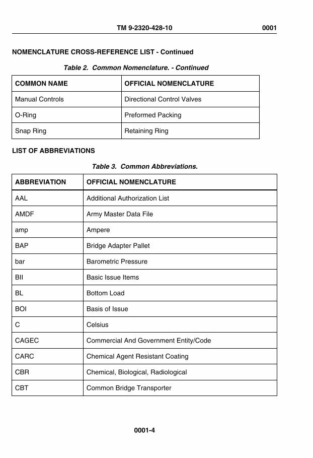
NOMENCLATURE CROSS-REFERENCE LIST - Continued
Table 2. Common Nomenclature. - Continued
COMMON NAME OFFICIAL NOMENCLATURE
Manual Controls Directional Control Valves
O-Ring Preformed Packing
Snap Ring Retaining Ring
LIST OF ABBREVIATIONS
Table 3. Common Abbreviations.
ABBREVIATION OFFICIAL NOMENCLATURE
AAL Additional Authorization List
AMDF Army Master Data File
amp Ampere
BAP Bridge Adapter Pallet
bar Barometric Pressure
BII Basic Issue Items
BL Bottom Load
BOI Basis of Issue
C Celsius
CAGEC Commercial And Government Entity/Code
CARC Chemical Agent Resistant Coating
CBR Chemical, Biological, Radiological
CBT Common Bridge Transporter
TM 9-2320-428-10 0001
0001-4

LIST OF ABBREVIATIONS - Continued
Table 3. Common Abbreviations. - Continued
ABBREVIATION OFFICIAL NOMENCLATURE
CCA Cold Cranking Amperes
CHU Container Handling Unit
CID Cubic Inch Displacement
CKT Circuit
cm Centimeter
COEI Components of End Item
CPC Corrosion Prevention Control
CROP Container Roll-In/Out Platform
CTA Common Table of Allowance
DA Department of the Army
dia. Diameter
DS Direct Support
EIR Equipment Improvement Recommendations
F Fahrenheit
FHTV Family of Heavy Tactical Vehicles
FLA Front Lift Adapter
fl. oz. Fluid Ounce
FR Flatrack
FRS Forward Repair System
ft. Foot
TM 9-2320-428-10 0001
0001-5

LIST OF ABBREVIATIONS - Continued
Table 3. Common Abbreviations. - Continued
ABBREVIATION OFFICIAL NOMENCLATURE
GAA Grease, Automotive, and Artillery
gal Gallon
GCWR Gross Combination Weight Rating
GMT Guided Missile Transport
GPFU Gas Particulate Filter Unit
gpm Gallons Per Minute
GS General Support
GVWR Gross Vehicle Weight Rating
HDI Hexamethylene Diisocyanate
HEMTT Heavy Expanded Mobility Tactical Truck
hp Horsepower
HVAC Heating, Ventilation, and Air Conditioning
IBC Improved Boat Cradle
I.D. Inside Diameter
in. Inch
ISO International Standards Organization
JTA Joint Table of Allowances
kg Kilogram
km Kilometer
Kmh or km/h Kilometer per Hour
TM 9-2320-428-10 0001
0001-6

LIST OF ABBREVIATIONS - Continued
Table 3. Common Abbreviations. - Continued
ABBREVIATION OFFICIAL NOMENCLATURE
kPa Kilopascals
kw Kilowatt
L Liter
lbs Pound
lb-ft Pound-Foot
lb-in Pound-Inch
LCD Liquid Crystal Display
LED Light Emitting Diode
LH Left-Hand
LHS Load Handling System
M Meter
MAC Maintenance Allocation Chart
mi Mile
ml Milliliter
MLC Military Load Class
mm Millimeter
Mph Miles Per Hour
MTOE Modified Tables of Organization and Equipment
NBC Nuclear, Biological, Chemical
NIIN National Item Identification Number
TM 9-2320-428-10 0001
0001-7
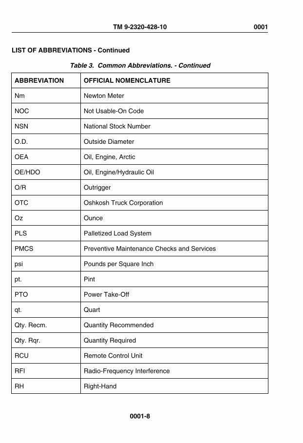
LIST OF ABBREVIATIONS - Continued
Table 3. Common Abbreviations. - Continued
ABBREVIATION OFFICIAL NOMENCLATURE
Nm Newton Meter
NOC Not Usable-On Code
NSN National Stock Number
O.D. Outside Diameter
OEA Oil, Engine, Arctic
OE/HDO Oil, Engine/Hydraulic Oil
O/R Outrigger
OTC Oshkosh Truck Corporation
Oz Ounce
PLS Palletized Load System
PMCS Preventive Maintenance Checks and Services
psi Pounds per Square Inch
pt. Pint
PTO Power Take-Off
qt. Quart
Qty. Recm. Quantity Recommended
Qty. Rqr. Quantity Required
RCU Remote Control Unit
RFI Radio-Frequency Interference
RH Right-Hand
TM 9-2320-428-10 0001
0001-8

LIST OF ABBREVIATIONS - Continued
Table 3. Common Abbreviations. - Continued
ABBREVIATION OFFICIAL NOMENCLATURE
rpm Revolutions Per Minute
RPSTL Repair Parts and Special Tools List
SAE Society of Automotive Engineers
SMR Source, Maintenance, and Recoverability
SRA Specialized Repair Activity
SRW Self-Recovery Winch
TAMMS The Army Maintenance Management System
TDA Tables of Distribution and Allowance
TM Technical Manual
TMDE Test, Measuring, and Diagnostic Equipment
TOE Tables of Organization and Equipment
u/m Unit of Measure
UOC Usable-On Code
Vdc Volts Direct Current
XHD Extra Heavy-Duty
SAFETY, CARE, AND HANDLING
Significant hazards and safety recommendations are listed in the table below.
TM 9-2320-428-10 0001
0001-9

SAFETY, CARE, AND HANDLING - Continued
Table 4. Significant Hazard And Safety Recommendations.
HAZARD SAFETY RECOMMENDATIONOR PRECAUTION OPERATING CONDITION
Low air pressure forbrakes.
Do not drive vehicle while low airpressure warning buzzer issounding or red light is on.
Abnormal
Vehicle instabilitywith crane use.
Ensure that outriggers are downon firm ground, side slope doesnot exceed 5 degrees, andcrane is not overloaded.
Abnormal
Connecting towingdevices.
Do not go between vehicles untilvehicles are stopped andbrakes are set.
Normal
Refueling vehicle. Shut off engine and no smokingwhen filling tank.
Normal
NOTECategory of hazards as to whether or not they may be expected undernormal or abnormal operating conditions.
NOTE• Material handling cranes have overload shutdown and/or tilt
warning (unstable) systems. Always apply PARKING BRAKEcontrol (WP 0045) prior to crane operation.
• When cranes are overloaded, the overload system willautomatically shut off power to telescope boom out, raise boom, orhoist load higher. The overload system will also prevent loweringthe boom. An overload condition can be corrected by lowering loadto ground or other supporting surface. All crane functions will berestored in approximately six seconds.
NOTE• The crane operating instruction plates are located on the heater
compartment cover in the cab and at each of the fixed operatingstation.
TM 9-2320-428-10 0001
0001-10

SAFETY, CARE, AND HANDLING - Continued
Table 4. Significant Hazard And Safety Recommendations. - Continued
HAZARD SAFETY RECOMMENDATIONOR PRECAUTION OPERATING CONDITION
• The outrigger leg plates are located on each of the outriggercylinders.
METRIC SYSTEM
The equipment described herein contains metric components and requires metric, common,and special tools. Therefore, metric units and English units will be used throughout thispublication. An English-to-metric conversion table is included as the last page of this manualinside the back cover.
END OF WORK PACKAGE
TM 9-2320-428-10 0001
0001-11


OPERATOR MAINTENANCEWARRANTY PROGRAM
General
This work package provides implementation instructions for the warranty on the HEMTT. Itcontains instructions for obtaining services and/or supplies covered under warranty. Thiswork package also describes methods of processing warranty claims. For additionalwarranty information on the HEMTT or any U.S. Army Tank-Automotive and ArmamentsCommand (TACOM) equipment, contact your local Warranty Control Office/Officer(WARCO) or TACOM Logistics Assistance Representative (LAR). If your WARCO orTACOM LAR is not available, or if additional information is required, contact TACOM.
Explanation of Terms
Abuse
The improper use, maintenance, repair or handling of warranted items that may cause thewarranty of those items to become void (for example, not following service intervals, usingthe vehicle for other than what is intended).
Acceptance
The execution of the acceptance block and signing of DD Form 250 (WP 0161), by theauthorized Government representative, unless end items are placed in storage in whichcase acceptance shall mean date of shipment from storage facility as reflected on DD Form1149 (WP 0161) or DD Form 1348-1. (WP 0161)
Acceptance Date
The date an item of equipment is accepted into the Army's inventory by the execution of theacceptance block and signing of a DD Form 250 (WP 0161) or approved acceptancedocument, by an authorized representative of the Government.
Contractor
The supplier of equipment who enters into an agreement directly with the Government tofurnish supplies.
Correction
The elimination of a defect.
TM 9-2320-428-10 0002
0002-1

Explanation of Terms - Continued
Defect
Any condition or characteristic in any supplies furnished by the contractor that does nototherwise function, or threatens not to function, as intended.
Failure
A part, component, or end item that fails to perform its intended use.
Manufacturer's Recall
Safety Recall An item is recalled to repair or replace a defective part or assembly whichmay affect safety.
Service Recall An item is recalled to repair or replace a defective part(s) or assembly whichdoes not affect the safe use of this item.
Owning Unit
The Army Unit authorized to operate, maintain, and use the equipment.
Reimbursement
A written provision in this warranty in which the Using/Support Unit may make the necessaryrepairs, with or without prior approval from the contractor, and the Government will bereimbursed for the repair parts and labor costs.
Repair
A maintenance action required to restore an item to serviceable condition without affectingthe warranty.
Supplies
The end item and all assemblies/parts furnished by the contractor.
Supporting Repair Facility
The repair activity authorized to accomplish warrantable repairs at the appropriate level ofmaintenance identified in the Maintenance Allocation Chart.
WARCO
Serves as the intermediary between the troops owning the equipment and the local dealer,contractor, or manufacturer. All warranty claim actions will be processed through theWARCO.
TM 9-2320-428-10 0002
0002-2

Explanation of Terms - Continued
Warranty
A written agreement between a contractor and the Government which outlines the rightsand obligations of both parties for defective supplies.
Warranty Claim
Action started by the equipment user for authorized warranty repair reimbursement.
Warranty Expiration Date
The date the warranty is no longer valid. This date will be 13 months from the contractorshipment date. This warranty period covers the basic 12 months plus on additional monthfor shipping time.
Warranty Period
Time during which the warranty is in effect; normally measured as the maximum number ofyears, months, days, miles, or hours used.
Warranty Start Date
The day shipment is put into effect (Contractor Shipment Date).
Coverage-Specific
This work package applies to:
Table 1. Vehicle Information
Noun Model NSN Cage
Truck, Cargo M977(without winch)
2320-01-099-6426 45152
NOTEThe item is manufactured by Oshkosh Truck Corporation (OTC), undercontract #W56HZV-07-C-0248. Inquiries to OTC can be made by calling
(920) 235-9151.
TM 9-2320-428-10 0002
0002-3

Coverage-Specific - Continued
Table 2. Vehicle Information
Noun Model NSN Cage
Truck, Cargo M977(with winch)
2320-01-097-0260 45152
NOTEThe item is manufactured by Oshkosh Truck Corporation (OTC), undercontract #W56HZV-07-C-0248. Inquiries to OTC can be made by calling
(920) 235-9151.
The contractor warrants the supplies are free from defects in design, material, andworkmanship for a period of thirteen (13) months from warranty start date.
If a Safety recall defect occurs during the vehicle warranty period, the contractor agrees toextend the terms of the warranty to the time required to make necessary safety defectcorrections. Also, if the contractor or his supplier(s) provide a greater warranty for thesupplies furnished, the contractor will provide the greater warranty to the Government.
If a defect/failure is caused by or falls within any of the following categories, it is notconsidered warrantable and a claim should not be initiated:
1. Misuse or negligence2. Accidents3. Improper operation4. Improper storage5. Improper transport6. Improper or insufficient maintenance7. Improper alterations or repairs8. Defect/failure discovered or occurring after warranty expiration date.9. Fair wear and tear items (brake shoes, pads, armatures, brushes, etc.).
In addition to the 13 month warranty, the vehicles will be warranted for a total service life of10 years including extended periods in a corrosion hazard military environment. During this10 year service life, there will be no damage caused by corrosion requiring repair orreplacement of parts. No actions beyond normal washing or replacement of accident-damaged paint shall be necessary to maintain the corrosive protection in place.
This 13 month warranty is extended up to nine (9) months from date of acceptance if thevehicle is put into government storage before use. In this case, the warranty starts when
TM 9-2320-428-10 0002
0002-4

Coverage-Specific - Continued
the vehicle is either taken out of storage or until nine (9) months from the warranty start dateshown on the warranty data plate, whichever occurs first. Refer to preparation for storage.
Contractor Responsibilities
When the owning unit has directed the contractor to correct the supplies, the contractor willfurnish all material required to correct the defective supplies. Repairs and parts shall beinitiated/provided within ten (10) working days after receipt of written claim notification.Furthermore, the contractor will provide a copy of the work order to owning unit uponcompletion of repair.
When the contractor receives written notification requiring contractor repair, they will havethe option:
1. Correct the supplies in the field.2. Return the vehicle or parts to the contractor's designated facility for correction.
When the contractor corrects the supplies, all labor involved shall be borne by thecontractor. Additionally, the contractor shall arrange and bear all transportation costs of thesupplies to its facility and return to user.
The contractor, within five (5) working days of receiving such notice, shall notify the warrantyclaimant by telephone as to the method of correction, date(s) work is to be performed andby whom.
Government Responsibilities
The Major Subordinate Command for the HEMTT is the U.S. Army Tank-Automotive andArmaments Command (TACOM), Warren, MI 48397-5000. TACOM is responsible formanaging and implementing the warranty.
TACOM will:
Insure the contractor performs in accordance to the terms of the contract.
Equipment owning unit will:
1. Identify defects/failures and verify the defects/failures are warrantable.2. Submit warranty claims, using DA Form 2407 (WP 0161) or DA Form 2407-1
(WP 0161) to your local Warranty Coordinator.3. Tag and retain (IAW DA PAM 750-8 and this work package) (WP 0161) parts,
pieces of parts and/or assemblies removed at the owning unit level and as a resultof a warrantable defect/failure and/or correction.
TM 9-2320-428-10 0002
0002-5

Government Responsibilities - Continued
Supporting repair facility will:
1. Identify defects/failures as warrantable (if owning unit has not already identifiedthem). Verify defects/failures are warrantable.
2. Review, process, and submit valid warranty claims to the local WARCO if the DAForm 2407 (WP 0161) is complete and correctly filled out.
3. Reject invalid warranty claims or request additional information for incomplete andincorrect claims.
4. Coordinate with the owning unit and decide which option for repair is desired tocorrect the warrantable defect/failure.
5. Depending on which repair option was chosen (Government or contract repair)provide labor/parts required to accomplish the warrantable repairs.
6. Tag and retain (IAW DA PAM 750-8 and this work package) (WP 0161) all parts,pieces, or parts and/or assemblies removed as a result of warrantable defect/failureand/or correction.
Local WARCO will:
1. Verify, review, process, and if valid and complete, submit claims (reimbursable and/or disputes) to the contractor.
2. Reject claims that are not valid, and send them back to the local Unit with a shortexplanation of why the claim is rejected.
3. Request additional information for incomplete claims.4. Provide warranty claim acknowledgment closeout and/or parts/assemblies
disposition instructions to the local Unit.5. Insure the contractor performs in accordance to the terms of the contract.6. Verify, administer and process warranty claims.7. Act as a liaison between owning unit, the contractor, supporting repair facility and
TACOM.8. Notify the owning units of all warranty claim acknowledgments/close-outs,
information and/or instructions received from TACOM or the contractor.9. Act as a liaison between local dealers and the Army.10. Enter all open and closed WCAs into the Army Electronics Product Support (AEPS),
Electronic Deficiency Reporting System.11. The information/data provided on the DA Form 2407 (WP 0161) are placed into the
AEPS Deficiency Reporting System (DRS) at the installation WARCO office tofacilitate MSC management and tracking of warranties.
Alterations/Modifications
Alterations/modifications shall not be applied unless authorized by TACOM.
Warranty Data Plate
All vehicles will have a warranty data plate. The contractor is required to mount his dataplate within clear view of the operator.
TM 9-2320-428-10 0002
0002-6

Warranty Data Plate - Continued
When the vehicle is received, the owning unit should locate the warranty data plate andcheck the warranty start date with date shown on the applicable DD Form 250 (WP 0161)or DD Form 1149. (WP 0161) If these dates differ, disregard the data plate. The date shownon the DD Form 250 (WP 0161) or DD Form 1149. (WP 0161) is the date to be used as awarranty start date.
Claim Procedures
The procedures for reporting warranty claims are found in DA PAM 750-8 (WP 0161) andthis work package. Responsibilities of the MACOM are found in AR 700-139. (WP 0161) AllWarranty Claim Actions are processed on DA Form 2407 (WP 0161) and DA Form 2407-1.(WP 0161) It is very important to fill in the blocks on the forms as accurately as possible.
The contractor shall be notified in writing within 30 days, utilizing DA Form 2407(WP 0161) by the local Warranty Control Office/Officer (WARCO) following the discoveryof a defect in supplies which requires contractor repair and/or replacement parts. This shallconstitute formal notification of a warranty claim, and initiate the time period for contractorresponsibilities and action under the warranty. This notification shall include, but not belimited to furnishing of the equipment serial number, operating hours, part number or NSNof the defective part and circumstances surrounding the defect(s). At this time, thecontractor will further be informed whether the owning unit has elected:
1. To correct the defect themselves.2. To direct the contractor to correct the defect.
Upon completion of contractor repair, forward completed warranty claims (Information Only)electronically to AEPS (Army Electronic Product Support) http://aeps.ria.army.mil.
The contractor shall reimburse the government for the cost of labor and/or replacementparts involved in the government correction of the defect. The government's MaintenanceAllocation Chart (MAC) determines the times. Additionally, the cost of replacement partsobtained through the Government's supply channels will be determined by the amountidentified in the contractor's current commercial dealer net price or Army Master Data File(AMDF) price, whichever is less. Furthermore, the owning unit may direct the contractor toprovide the replacement parts that prove to be defective within the warranty period, withoutcosts to the government, directly to their location or F.O.B., U.S. Port of Embarkation forOCONUS. The contractor shall furnish replacement parts within 10 working days afterreceipt of written claim notification. DO NOT submit warranty claims for reimbursementwhere repair labor costs and replacement parts costs combined do not exceed $150.00 forany one failure.
Identification Of Failed Items. Failed warranty items shall be tagged/identified to preventimproper repair or use. Documents that describe the use of DA Form 2402 MaintenanceTag (WP 0161) and DA Form 2407 Maintenance Request (WP 0161) shall be referenced.Items requiring special handling, storage, or shipment during the processing of claims shallbe identified.
TM 9-2320-428-10 0002
0002-7

Claim Procedures - Continued
Disposition. The repair activity shall retain defective supplies for thirty (30) days followingreceipt of acknowledgment of warranty claim from WARCO or contractor. If receipt ofacknowledgment is not received, inquiries should be made to your local WARCO. If receiptof acknowledgment is received but no instructions are forthcoming within thirty (30) days ofreceipt, supplies may be disposed.
Invalid Warranty Claims. When supplies are inspected by the contractor and found to benon-warrantable due to abuse or improper maintenance, or the supplies are found to beserviceable, the repair activity submitting the claim will be required to make reimbursementfor contractor services. All failed items returned for warranty claim action will be monitoredby the WARCO. Additionally, regarding contractor repair, the local WARCO must stipulateat the time of request for services that either no non-warranty work be done or be preparedto pay for such work.
Reimbursement for Army Repair
In the event that the repair activity should receive any reimbursement from the contractor,the monies must be forwarded to the following address: Defense Accounting Office,DAOTACOM, ATTN: DFAS-IN/EM-BED, TACOM, Warren, Michigan 48397-5000.
Claim Denial/Disputes
All denials or disputes will be handled by TACOM.
Reporting
Reporting or recording action on a failed item shall be specified in DA PAM 750-8.(WP 0161) Contractor or repair activity unique forms shall not be used.
Storage/Shipment/Handling
Storage
See coverage-specific data above (last paragraph) and preparation for storage for furtherinformation.
Shipment
See contractor responsibilities data above (second paragraph), claim procedures (thirdparagraph), and preparation of equipment for transportation/shipment for furtherinformation.
TM 9-2320-428-10 0002
0002-8

Storage/Shipment/Handling - Continued
Handling
See contractor responsibilities data above (second paragraph), claim procedures (thirdparagraph), and safety, care, and handling for further information.
END OF WORK PACKAGE
TM 9-2320-428-10 0002
0002-9


OPERATOR MAINTENANCEEQUIPMENT CHARACTERISTICS, CAPABILITIES, AND FEATURES
EQUIPMENT CHARACTERISTICS
The M977 cargo vehicle is used for ammunition resupply and other logistic missions.
EQUIPMENT CAPABILITIES
NOTETrailer/semitrailer may affect maximum fording depth. Refer to applicabletrailer/semitrailer operator manual for further information on fording depthrestrictions.
1. All models are capable of operating in temperatures from -25 to 120°F (-32 to 49°C)and to -50 to 120°F (-46 to 49°C) with arctic kit installed.
2. All models can ford water up to 48 in. (1 219 mm) deep for 5 minutes withoutdamage or without requiring maintenance before operation can continue.
3. Normal operating range of all models is 300 miles (483 km), based upon 154 gallons(583 L) of fuel and 100,000 lbs (45 400 kg) GCWR, traveling over mixed terrain.Varying loads, prolonged idle, use of power takeoff (PTO), off-road driving, andclimatic conditions affect operating range.
4. All models are provided with sufficient tie down points located so vehicles can berestrained in all directions during air transport in C-130, C-5A, and C-17 typeaircraft.
5. All models are also capable of being transported by highway, rail, and sea.
EQUIPMENT FEATURES
1. Detroit Diesel eight-cylinder, V-Type, 2-cycle, fuel injected, turbocharged dieselengine.
2. Automatic transmission with one reverse speed and four forward speeds.3. Operator controlled 4-wheel/8-wheel drive and high and low range transfer case
for positive traction in areas of unimproved road surfaces.4. Power steering system consists of basic manual steering system with hydraulic
boost. Mechanical linkage also provides operator control in event of hydraulic oilpressure loss.
5. Fuel system includes one fuel tank, fuel lines, fuel/water separator, fuel pump,secondary filter, fuel pipes, and fuel injectors.
6. Two front and two rear towing eyes.7. Manual-release-type rear pintle hook which will allow towing of a trailer.8. Radio frequency interference suppression to permit voice radio communications
during all phases of operation.
TM 9-2320-428-10 0003
0003-1

END OF WORK PACKAGE
TM 9-2320-428-10 0003
0003-2

OPERATOR MAINTENANCELOCATION AND DESCRIPTION OF MAJOR COMPONENTS
VEHICLE COMPONENT LOCATION
Table 1. HEMTT Series Vehicle Common Component Location.
9876
54
21 3
10 11
12
13
14
151617
Figure 1.
1 Personnel Cab. Provides protection from weather for crew and vehicle controls,gauges, and indicators.
TM 9-2320-428-10 0004
0004-1

VEHICLE COMPONENT LOCATION - Continued
Table 1. HEMTT Series Vehicle Common Component Location. - Continued
2 Engine Compartment. Engine supplies power to move vehicle and operateequipment and accessories.
3 Ether Canister. Contains ether for use as cold weather starting aid.
4 Air Cleaner. Filters out dust and debris from air entering air induction system.
5 Tire Davit (shown assembled). Used to raise and lower spare tire.
6 Hydraulic Reservoir. Stores, cools, and filters oil used in hydraulic and powersteering systems.
7 Fuel Tank. Stores fuel used to operate engine. Receives excess fuel not used byengine fuel injection system.
8 No. 3 Driving Axle. Supports weight of vehicle, and transmits power to hubs to turnrear wheels.
9 No. 4 Driving Axle. Supports weight of vehicle, and transmits power to hubs to turnrear wheels.
10 Tire Davit (shown in stowed position). Used to raise and lower spare tire.
11 Air Dryer. Used to remove dirt and moisture from compressed air before air entersair reservoirs.
12 Fuel/Water Separator. Acts as primary fuel filter and removes any water from fuelbefore entering engine.
13 Battery Box. Houses and protects four storage batteries.
14 No. 1 Driving Axle. Controls direction of vehicle when in motion. When needed,transmits power to hubs to turn wheels.
15 No. 2 Driving Axle. Controls direction of vehicle when in motion. When needed,transmits power to hubs to turn wheels.
16 Air Reservoirs. Used to store air system air.
17 Self-Recovery Winch (not used on all vehicles). Used to help vehicle pull itselffree of obstructions.
TM 9-2320-428-10 0004
0004-2

VEHICLE COMPONENT LOCATION - Continued
Table 2. M977/M985 Cargo Vehicle Specific Component Location.
4 1
1
1
5
23
Figure 2.
1 Stowage Boxes. Used to stow COEI, BII, (WP 0162)AAL, (WP 0163) and othermission essential items.
2 Access Ladder. Used by crew to clean windows, check oil, or perform other tasksrequiring access to parts of vehicle.
3 Cargo Body. Used to carry palletized ammunition. Tie downs are provided to allowammunition pallets to be tied down.
4 Material Handling Crane. Used to load and unload cargo.
TM 9-2320-428-10 0004
0004-3

VEHICLE COMPONENT LOCATION - Continued
Table 2. M977/M985 Cargo Vehicle Specific Component Location. - Continued
5 Wheel Chock Stowage Box. Used to stow two wooden wheel chocks.
END OF WORK PACKAGE
TM 9-2320-428-10 0004
0004-4

OPERATOR MAINTENANCEDIFFERENCES BETWEEN MODELS
Table 1. Differences Between HEMTT BASE Models.
Equipment Model
M977(Note1)
M978(Note1)
M983(Note2)
M984(Note2)
M985(Note1)
M985E1(Note2)
M1120LHS(Note1)
M1977CBT(Note1)
10 ft. (3.05m)EquipmentBody
•
18 ft. (5.49m)Cargo Body
• • •
Cargo CoverKit
• • •
Heavy-DutyWinch
•
Rear BeaconLights(Note 4)
•
Work Lights(Note 5)
• • •
MHC977Grove Crane
•
MHC985Grove Crane
•
MHC984 •
TM 9-2320-428-10 0005
0005-1
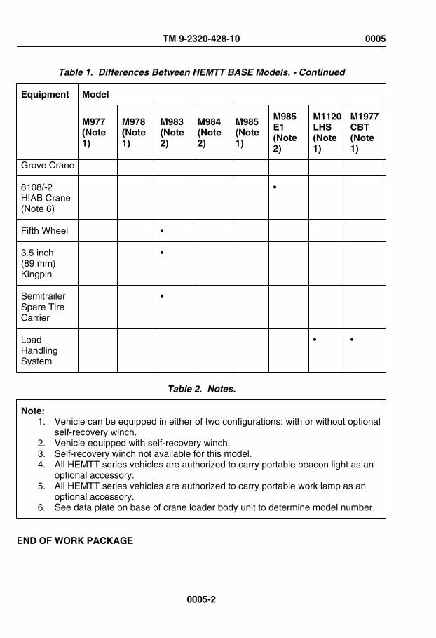
Table 1. Differences Between HEMTT BASE Models. - Continued
Equipment Model
M977(Note1)
M978(Note1)
M983(Note2)
M984(Note2)
M985(Note1)
M985E1(Note2)
M1120LHS(Note1)
M1977CBT(Note1)
Grove Crane
8108/-2HIAB Crane(Note 6)
•
Fifth Wheel •
3.5 inch(89 mm)Kingpin
•
SemitrailerSpare TireCarrier
•
LoadHandlingSystem
• •
Table 2. Notes.
Note:1. Vehicle can be equipped in either of two configurations: with or without optional
self-recovery winch.2. Vehicle equipped with self-recovery winch.3. Self-recovery winch not available for this model.4. All HEMTT series vehicles are authorized to carry portable beacon light as an
optional accessory.5. All HEMTT series vehicles are authorized to carry portable work lamp as an
optional accessory.6. See data plate on base of crane loader body unit to determine model number.
END OF WORK PACKAGE
TM 9-2320-428-10 0005
0005-2

OPERATOR MAINTENANCEEQUIPMENT DATA
EQUIPMENT DATA
Table 1. Vehicle Operation.
Operating Mode: On- and off-road
Operating Temperature w/o Arctic Kit: -25 to 120°F (-32 to 49°C)
Operating Temperature w/Arctic Kit: -50 to 120°F (-46 to 49°C)
Table 2. M977 Cargo Vehicle Dimensions.
Width (overall): 96 in. (2 438 mm)
Height (overall): 112 in. (2 845 mm)
Height (reduced for shipping): 102 in. (2 591 mm)
Length (overall): 401 in. (10 185 mm)
Wheelbase: 210 in. (5 334 mm)
Turn Circle (curb to curb): 105 ft. (32 m)
Ground Clearance: 24 in. (610 mm)
Center of Gravity: See shipping data plate on outside of driver side rear of cab or insideof driver side door.
Table 3. M977 Cargo Vehicle Weight.
Curb Weight: 38,800 lbs (17 615 kg)
Gross Vehicle Weight Rating (GVWR): 59,500 lbs (27 013 kg)
Gross Combination Weight Rating (GCWR): 100,000 lbs (45 400 kg)
TM 9-2320-428-10 0006
0006-1

EQUIPMENT DATA - Continued
Table 4. M977 Cargo Vehicle Weight.
Curb Weight: 37,900 lbs (17 207 kg)
Gross Vehicle Weight Rating (GVWR): 59,500 lbs (27 013 kg)
Gross Combination Weight Rating (GCWR): 100,000 lbs (45 400 kg)
Table 5. M977 Cargo Vehicle Weight Distribution.
Front Tandem Axles-Curb: 21,300 lbs (9 670 kg)
Front Tandem Axles-Loaded: 30,000 lbs (13 620 kg)
Rear Tandem Axles-Curb: 17,500 lbs (7 945 kg)
Rear Tandem Axles-Loaded (maximum): 32,000 lbs (14 528 kg)
Table 6. M977 Cargo Vehicle Weight Distribution.
Front Tandem Axles-Curb: 20,900 lbs (9 489 kg)
Front Tandem Axles-Loaded: 30,000 lbs (13 620 kg)
Rear Tandem Axles-Curb: 17,000 lbs (7 718 kg)
Rear Tandem Axles-Loaded (maximum): 32,000 lbs (14 528 kg)
Table 7. Vehicle Performance.
Cruising Range at GCWR: 300 mi. (483 km)
Maximum Sustained Forward Speed (at 2100 rpm) - 3rd Gear: 41 mph (66 km/h)
Maximum Sustained Forward Speed (at 2100 rpm) - 2nd Gear: 28 mph (45 km/h)
Maximum Sustained Forward Speed (at 2100 rpm) - 1st Gear: 15 mph (24 km/h)
Speed on 3% Grade at GCWR: 25 mph (40 km/h)
Speed on 3% Grade at GVWR: 40 mph (64 km/h)
TM 9-2320-428-10 0006
0006-2

EQUIPMENT DATA - Continued
Table 7. Vehicle Performance. - Continued
Speed on 30% Grade at GCWR: 3 mph (5 km/h)
Speed on 30% Grade at GVWR: 5 mph (8 km/h)
Maximum Grade at GCWR: 30 percent
Maximum Grade at GVWR: 60 percent
Maximum Side Slope w/Adequate Traction Surface: 30 percent
Maximum Towed Speed (refer to FM 4-30.31 ): 15 mph (24 km/h)
Maximum Ford Depth: 48 in. (1 219 mm)
Approach Angle: 41 degrees
Departure Angle: 45 degrees
Limp Home Speed: 10 mph (16 km/h) for up to 30 miles (48 km)
Table 8. Fluid Capacities.
Refer to lubrication instructions in operator's PMCS (WP 0151) for vehicle fluid capacities.
Table 9. Engine.
Make: Detroit Diesel Corporation
Model: 8V92TA
Type: 2-Stroke, V-Type Diesel
Cylinders: 8
Bore: 4.84 in. (123 mm)
Stroke: 5 in. (127 mm)
Displacement: 736 cid (12 L)
TM 9-2320-428-10 0006
0006-3

EQUIPMENT DATA - Continued
Table 9. Engine. - Continued
Torque:
Model No. 8087-7899: 1250 lb-ft (1695 Nm) at 1300 rpm
Model No. 8083-7493: 1330 lb-ft (1803 Nm) at 1200 rpm
Maximum Brake Horsepower (at 2100 rpm):
Model No. 8087-7899: 445 BHP (332 kW)
Model No. 8083-7493: 450 BHP (336 kW)
Maximum Governed Engine Speed - Loaded: 2050 - 2150 rpm
Maximum Governed Engine Speed - No Load: 2225 - 2275 rpm
Oil Filter Type: Full flow, replaceable element
Oil Filter Quantity: 1
Table 10. Fuel System.
Type: Diesel Injection
Tank Quantity: 1
Air Cleaner Type: Dry element
Element Quantity: (1 primary, 1 secondary)
Table 11. Electrical System.
Voltage: 24
Alternator (amps): 65
RFI Suppression Ability: Yes
Number of Batteries: 4
TM 9-2320-428-10 0006
0006-4

EQUIPMENT DATA - Continued
Table 11. Electrical System. - Continued
Battery Voltage (each): 12 volts
Battery Connection: Series - parallel
Battery Capacity (at 20 hour rate): 900 amp
Battery Reserve Capacity (each, at 80°F/27°C): 180 minutes
Battery Cold Cranking Amps (each, at 80°F/27°C): 575 CCA
Battery Amp Hours (each, at 20 hour rate): 100 amp
Table 12. Cooling System.
Radiator Working Pressure: 7 psi (48 kPa)
Table 13. Transmission.
Make: Allison
Model: HT740D
Type: Automatic
Number of Forward Speeds: 4
Number of Reverse Speeds: 1
Table 14. Transfer Case.
Make: Oshkosh
Model: 55000
Type: Air-operated front tandem disconnect
Ratios: 0.98:1 and 2.66:1
TM 9-2320-428-10 0006
0006-5

EQUIPMENT DATA - Continued
Table 15. Front Tandem Axles.
Front Tandem
Make: Oshkosh/Dana Heavy Axle
Differential Carrier Model Nos.: No. 1 axle: RS480, No. 2 axle: DS480-P
Maximum Steering Angle: 32 degrees
Table 16. Rear Tandem Axles.
Make: Dana Heavy Axle
Differential Carrier Model Nos.: No. 3 axle: DS480-P, No. 4 axle: RS480
Table 17. Brake System.
Actuation: Air
Number of Brake Chambers: 8
Pressure Range: 60 - 120 psi (414 - 827 kPa)
Table 18. Wheels.
Type: Two-piece bolt together wheel
Quantity: 8
Spare Quantity: 1
Rim Size: 20 x 10
Stud Quantity Per Wheel: 10
Table 19. Tires.
Type: Radial without tube
Quantity: 8
TM 9-2320-428-10 0006
0006-6

EQUIPMENT DATA - Continued
Table 19. Tires. - Continued
Spare Quantity: 1
Tread Type: Radial traction, non-directional
Size: 16.00R x 20 in.
Load Range: M
Table 20. Steering System.
Type: Dual gear with integrated hydraulic power assist
Table 21. Towing Eyes.
Quantity: 4 (2 front, 2 rear)
Maximum Load Capacity Each: 60,000 lbs (27 240 kg)
Table 22. Pintle Hook.
Type: Manual Release
Maximum Load Capacity - Pulling: 30,000 lbs (13 620 kg) in off-road application
Maximum Load Capacity - Vertical: 1,700 lbs (771 kg)
Table 23. Cab.
Windshield: Tinted, two-piece, safety glass
Personnel Capacity: 2
Table 24. Self-Recovery Winch.
Make: DP Manufacturing
Model: 20K-HEMTT
TM 9-2320-428-10 0006
0006-7

EQUIPMENT DATA - Continued
Table 24. Self-Recovery Winch. - Continued
Wire Rope Diameter: 9/16 in. (14.3 mm)
Wire Rope Length: 200 ft. (61 m)
Line Pull - 1st Layer (Five Wraps Minimum): 20,000 lbs (9 080 kg)
Line Pull - 2nd Layer: 18,173 lbs (8 251 kg)
Line Pull - 3rd Layer: 16,663 lbs (7 565 kg)
Line Pull - 4th Layer: 15,361 lbs (6 974 kg)
Line Pull - 5th Layer: 14,254 lbs (6 471 kg)
Table 25. Material Handling Crane.
Make: Grove
Model: MHC977
Maximum Capacity at Boom Length of 19 ft. (5.8 m): 2500 lbs (1 135 kg)
Table 26. Auxiliary Equipment.
Arctic Engine Heater Kit
Chemical Alarm
Decontamination Unit
Gas Particulate Filter Unit
Machine Gun Ring
Radio Installation Kit
Rifle Mounting Kit
Note: Vehicle may or may not be equipped with any of these items depending on mission,climate, or other factors.
TM 9-2320-428-10 0006
0006-8

EQUIPMENT DATA - Continued
Table 27. Load Classification.
MODEL UNLOADED(TONS)
FULL LOAD(TONS) WITH TRAILER LOADED (TONS)
M977 16 28
M978 15 25
M983 14 C-29 (w/Patriot)
M984A1 19 C-48 (towing loaded M985)
M985 17 28 C-38 (towing HEMAT M989)
M985 E1 17 28
M1120 LHS 18 28
TIRE PRESSURES
Table 28. Tire Pressures.
TIRE HIGHWAYCROSS-COUNTRY(DRY)
CROSS-COUNTRY(WET)
SANDYTERRAIN
Front Tire Pressure
STANDARD(XZL) TIRE
60 psi (414 kPa) 35 psi (241 kPa) 20 psi (138 kPa) 30 psi (207kPa)
SAND TIRE 60 psi (414 kPa) NA NA 25 psi (172kPa)
Rear Tire Pressure
STANDARD(XZL) TIRE
70 psi (483 kPa) 40 psi (276 kPa) 30 psi (207 kPa) 35 psi (241kPa)
SAND TIRE 70 psi (483 kPa) NA NA 30 psi (207kPa)
TM 9-2320-428-10 0006
0006-9

OPERATING SPEEDS
Table 29. Operating Speeds.
HIGHWAY CROSS-COUNTRY(DRY)
CROSS-COUNTRY(WET)
SANDYTERRAIN
Maximum Speed
STANDARD(XZL) TIRE
55 mph (88 km/h) 40 mph (64 km/h) 20 mph (32 km/h) 20 mph (32km/h)
SAND TIRE 55 mph (88 km/h) NA NA 20 mph (32km/h)
END OF WORK PACKAGE
TM 9-2320-428-10 0006
0006-10

OPERATOR MAINTENANCESELF-RECOVERY WINCH
SELF-RECOVERY WINCH
The self-recovery winch, where used, is mounted on the passenger side chassis frame railbetween the second and third axles.
Figure 1.
The winch is powered by a reversible hydraulic motor which drives the winch drum througha planetary gearbox.
It is equipped with an automatic brake that is applied whenever the cab control lever is inthe center position.
TM 9-2320-428-10 0007
0007-1

SELF-RECOVERY WINCH - Continued
NOTEThe M984A wrecker equipped with a self-recovery winch does not employan operator controlled, two-position hydraulic selector valve to activatethe reversible winch motor.
All vehicles (except the M984A wrecker) equipped with a self-recovery winch (1) have anoperator controlled, two-position hydraulic selector valve (WP 0025) to activate thereversible winch motor.
END OF WORK PACKAGE
TM 9-2320-428-10 0007
0007-2

OPERATOR MAINTENANCEELECTRICAL SYSTEM
NOTE• Wiring harnesses are used to carry current to operate equipment and
accessories.
• The electrical system is a 24 VDC system.
Four 12 VDC storage batteries (1) are connected in series-parallel with the negative terminalgrounded.
TM 9-2320-428-10 0008
0008-1

Figure 1.
The starting motor (2) operates directly from the 24 VDC source through the engine startswitch (3).
TM 9-2320-428-10 0008
0008-2

A belt-driven 24 VDC alternator (4) having a capacity of 65 amps (M983 - 100 amps) or 130amps maintains the charge on the batteries.
The AMPERES gauge (5) shows the alternator output.
The BATTERY gauge (6) shows the state of charge of the batteries and alternator voltageoutput.
The vehicle electrical circuits are protected against overloads by automatic reset circuitbreakers (7) located below the heater compartment panel.
MAJOR ELECTRICAL SYSTEM COMPONENT LOCATION
The voltage and the current for the electrical system are indicated by a battery gauge (1)and an ammeter (2) located on the dash panel inside the driver's compartment.
2
1 7 6 5
3 4
Figure 2.
Circuit breakers (3) located in the cab protect the main circuits.
Electrical power is provided by four 12-volt series-parallel connected batteries (4).
NOTEPower is distributed throughout the vehicle by wiring harnesses. Theharnesses are interconnected by pin connectors. Connectors areprovided at the rear of the vehicle to supply power for towed loads.
A heavy-duty starting motor (5) is mounted on the engine flywheel housing and providesthe cranking power necessary for starting the engine.
The voltage regulator (6) is mounted on the belt driven alternator (7) and maintains a 24-volt level for battery charging.
END OF WORK PACKAGE
TM 9-2320-428-10 0008
0008-3


OPERATOR MAINTENANCEAIR SYSTEM
AIR SYSTEM
The air system consists of an engine-driven air compressor (1) and four air reservoirs (2,3, 4, and 5). Reservoir (4) is used on all vehicles except the M983 tractor, which has areservoir (6) instead.
TM 9-2320-428-10 0009
0009-1

AIR SYSTEM - Continued
Figure 1.
TM 9-2320-428-10 0009
0009-2

AIR SYSTEM - Continued
NOTEThe air system includes the necessary valves and air lines to control thevehicle's air-operated parts.
Pressurized air from the air compressor (1) is passed through the air dryer (7) to the quickbuildup reservoir (2).
The air dryer (7) removes dirt and moisture from the pressurized air. Air from reservoir (2)goes to the throttle treadle (8).
Depending on how far the throttle treadle is depressed, 0 to 60 psi (0 to 414 kPa) is suppliedto the engine throttle air cylinder (9) and to the transmission modulator (10). This airpressure control the vehicle speed.
Once air pressure in reservoir (2) rises above 75 psi (517 kPa), a valve opens and allowsreservoirs (3, 4, or 6, and 5) to be pressurized up to 120 psi (827 kPa).
Air from reservoir (4 or 6) goes to the brake treadle valve (11). This air controls the rear axleservice parking brakes (12).
Air pressure in this system is shown by the red needle on the AIR PRESS gauge (13).
Air from reservoir (3) goes to the brake treadle valve.
This air controls the front axle service brakes (14).
Air pressure in this system is shown by the green needle on the AIR PRESS gauge.
The PARKING BRAKE valve (15) controls air from reservoirs (3 and 5) and applies orreleases the rear axle service (parking) brakes.
Reservoirs (3, 4, or 6, and 5) are interconnected so that if one reservoir fails, air is suppliedto release the rear axle service (parking) brakes from whichever reservoir is functioning. Ifair pressure falls below 60 to 75 psi (414 kPa to 517 kPa), a buzzer will sound and the AIRindicator (16) will illuminate.
Specific to the M984A1, the front brake actuator valve (17) is used to apply the front axleservice brakes when using heavy-duty winch.
END OF WORK PACKAGE
TM 9-2320-428-10 0009
0009-3


OPERATOR MAINTENANCEMAIN HYDRAULIC SYSTEM
MAIN HYDRAULIC SYSTEM
The main hydraulic system consists of a power take-off (PTO) driven hydraulic pump (1)and a fluid reservoir (2) shared with the power steering hydraulic system.
Figure 1.
Any vehicle may also be equipped with a self-recovery winch (3) and a selector valve (4).
TM 9-2320-428-10 0010
0010-1
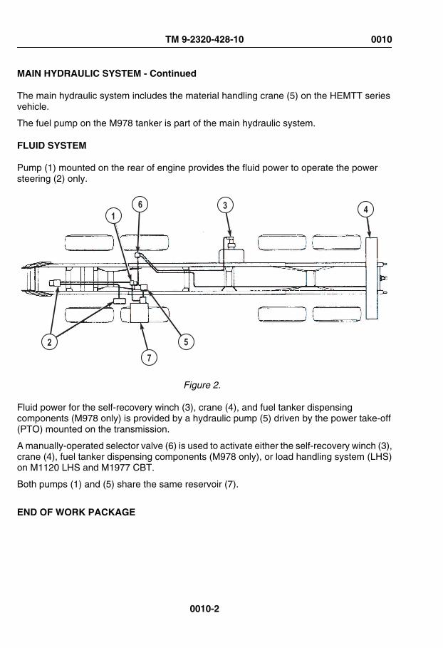
MAIN HYDRAULIC SYSTEM - Continued
The main hydraulic system includes the material handling crane (5) on the HEMTT seriesvehicle.
The fuel pump on the M978 tanker is part of the main hydraulic system.
FLUID SYSTEM
Pump (1) mounted on the rear of engine provides the fluid power to operate the powersteering (2) only.
2
16
75
43
Figure 2.
Fluid power for the self-recovery winch (3), crane (4), and fuel tanker dispensingcomponents (M978 only) is provided by a hydraulic pump (5) driven by the power take-off(PTO) mounted on the transmission.
A manually-operated selector valve (6) is used to activate either the self-recovery winch (3),crane (4), fuel tanker dispensing components (M978 only), or load handling system (LHS)on M1120 LHS and M1977 CBT.
Both pumps (1) and (5) share the same reservoir (7).
END OF WORK PACKAGE
TM 9-2320-428-10 0010
0010-2

OPERATOR MAINTENANCESTEERING SYSTEM
POWER STEERING HYDRAULIC SYSTEM
Power is supplied to the main steering gear (1) by an engine-driven pump (2).
Figure 1.
The fluid reservoir (3) is shared with the main hydraulic system.
The steering wheel (4), which is mechanically linked to the main steering gear (1), rotatesa gear that positions a spool in the main steering gear.
This motion is hydraulically transmitted to a piston in the slave gear (5) causing it to followthe rotation of the main gear.
The main gear pitman arm (6) is mechanically connected to the slave gear pitman arm (7).
TM 9-2320-428-10 0011
0011-1

POWER STEERING HYDRAULIC SYSTEM - Continued
These pitman arms move the steering mechanism on the front axles (8) left or right causingthe vehicle to steer left or right.
END OF WORK PACKAGE
TM 9-2320-428-10 0011
0011-2

OPERATOR MAINTENANCEPOWER TRAIN
POWER TRAIN
The drivetrain control system consists of the engine and transmission systems.
Power for the vehicle is provided by a diesel engine (1), which is coupled directly to anautomatic transmission (2).
Figure 1.
Power from the transmission is transferred to the transfer case (3) and on to front and reartandem axles (4) through a series of drive shafts and universal joints (5).
AUTOMATIC TRANSMISSION
The automatic transmission (1) provides four speeds forward and one reverse.
TM 9-2320-428-10 0012
0012-1

AUTOMATIC TRANSMISSION - Continued
Figure 2.
Drive (D) is used for all normal driving conditions.
The vehicle will start moving in 1st gear, and as the accelerator is depressed, transmissionwill upshift to 2nd gear, 3rd gear, and 4th gear automatically.
As the vehicle slows down, the transmission will downshift to the correct gear automatically.
Placing the range selector lever in the 3 or 2 position will prevent the transmission fromupshifting past the 3rd or 2nd gear, respectively.
This is useful if road or load conditions require low gear operation.
When conditions improve, the range selector lever can be returned to the normal (D) drivingposition.
Drive vehicle (Operations under usual conditions) (WP 0050) provides full operatinginstructions for the transmission.
The transmission includes an electrically controlled power takeoff (PTO).
The PTO provides power to a hydraulic pump, which powers the vehicle's hydraulic system.
The hydraulic system operates the self-recovery winch, the material handling crane, theheavy-duty recovery winch, and the pumping equipment, depending on how the vehicle isequipped.
TRANSFER CASE
The transfer case (1) connects the drivetrain to the No.1 and No. 2 axles (2) when 8-wheeldrive is needed.
TM 9-2320-428-10 0012
0012-2
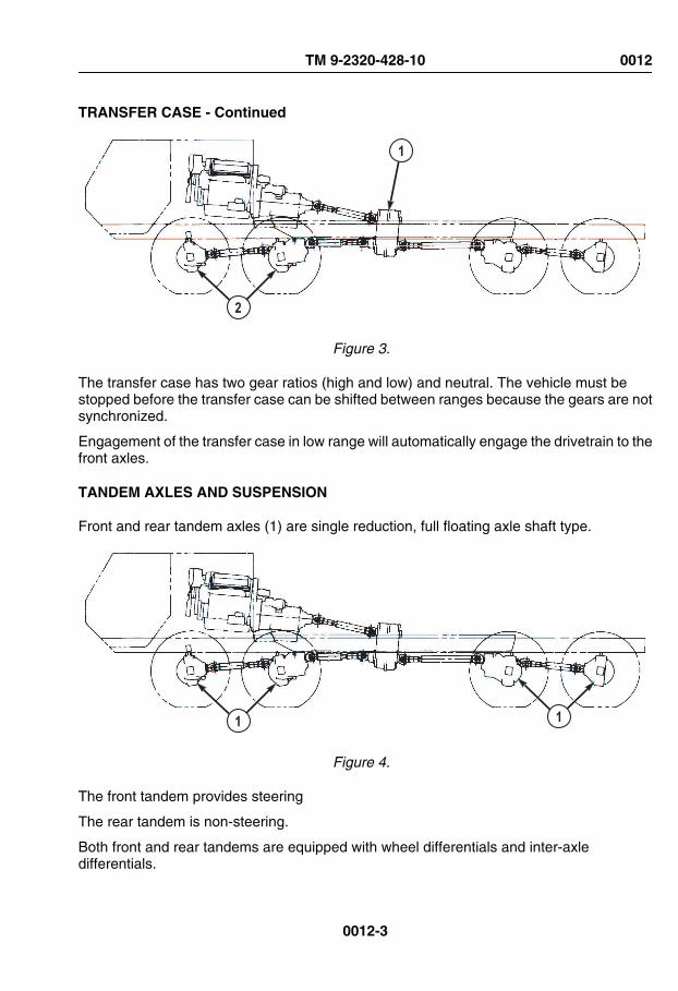
TRANSFER CASE - Continued
2
1
Figure 3.
The transfer case has two gear ratios (high and low) and neutral. The vehicle must bestopped before the transfer case can be shifted between ranges because the gears are notsynchronized.
Engagement of the transfer case in low range will automatically engage the drivetrain to thefront axles.
TANDEM AXLES AND SUSPENSION
Front and rear tandem axles (1) are single reduction, full floating axle shaft type.
1 1
Figure 4.
The front tandem provides steering
The rear tandem is non-steering.
Both front and rear tandems are equipped with wheel differentials and inter-axledifferentials.
TM 9-2320-428-10 0012
0012-3

TANDEM AXLES AND SUSPENSION - Continued
The inter-axle differential have driver-controlled lockouts for positive drive to all axles in lowrange.
The rear tandem is equipped with permanently engaged controller traction differentials.
The front and rear suspensions are tandem axle type with leaf springs and equalizingbeams.
PROPELLER SHAFTS AND UNIVERSAL JOINTS
The propeller shafts and universal joints (1) transmit engine power to the axles.
1
11
1
Figure 5.
END OF WORK PACKAGE
TM 9-2320-428-10 0012
0012-4

OPERATOR MAINTENANCEENGINE SYSTEMS
ENGINE
The vehicle is equipped with a Detroit Diesel Corporation (DDC) Model 8V92TA engine.
TRAILERAIR SUPPLYNOT FOR PARKINGMIDLAND
PULL TO EXHAUST
PUSH TO SU PPLY
1
Figure 1.
An oil/water light (1) will light up when a critical fault occurs. Immediately shut vehicle off.
AIR INTAKE SYSTEM
The air intake system consists of a dry type air cleaner (1), turbocharger (2), engine blower(3), and an aftercooler (4).
TM 9-2320-428-10 0013
0013-1

AIR INTAKE SYSTEM - Continued
Figure 2.
Engine exhaust gases flow through the turbocharger (2) driving a turbine wheel.
A compressor wheel on the opposite end of the turbine wheel shaft rotates and draws infresh air through the air cleaner (1), compresses the air, and delivers it to the engine blower(3).
Air from the engine blower (3) flows through the aftercooler (4) which cools the air before itis delivered to the engine cylinders.
FUEL SYSTEM
Fuel drawn from the fuel tank (1) passes through the supply line (2) to a fuel/water separator(3), fuel pump (4), and secondary filter (5) to the engine fuel injectors (6).
TM 9-2320-428-10 0013
0013-2
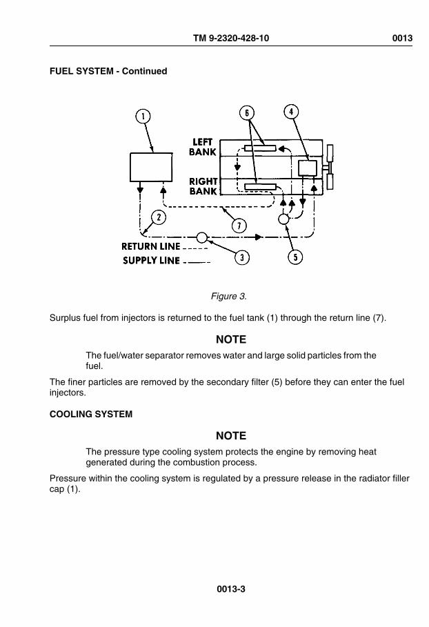
FUEL SYSTEM - Continued
Figure 3.
Surplus fuel from injectors is returned to the fuel tank (1) through the return line (7).
NOTEThe fuel/water separator removes water and large solid particles from thefuel.
The finer particles are removed by the secondary filter (5) before they can enter the fuelinjectors.
COOLING SYSTEM
NOTEThe pressure type cooling system protects the engine by removing heatgenerated during the combustion process.
Pressure within the cooling system is regulated by a pressure release in the radiator fillercap (1).
TM 9-2320-428-10 0013
0013-3

COOLING SYSTEM - Continued
Figure 4.
The hot coolant flows from the engine to top of radiator tank (2) and through radiator core(3) where a stream of air removes heat.
This stream of air is drawn through the core by an air-activated fan (4).
A water pump (5) draws the coolant from the bottom of the radiator and pushes it throughthe engine repeating the cooling process.
Thermostats (6), mounted in each coolant outlet elbow, remain closed until the coolantapproaches a predetermined temperature at which time they open.
NOTEWhen the coolant temperature drops below the thermostatic rating, thethermostats close.
An air vent line (7) between the radiator (2) and the water pump (5) inlet removes air trappedin the engine when the cooling system is being filled.
END OF WORK PACKAGE
TM 9-2320-428-10 0013
0013-4

OPERATOR MAINTENANCECAB
CAB
The cab (1) contains all of the driving controls and gauges, operating controls for some ofthe mounted equipment, and adjustable seats for a crew of two. For explanation of cabcontrols, refer to vehicle controls and indicators.
1
Figure 1.
END OF WORK PACKAGE
TM 9-2320-428-10 0014
0014-1

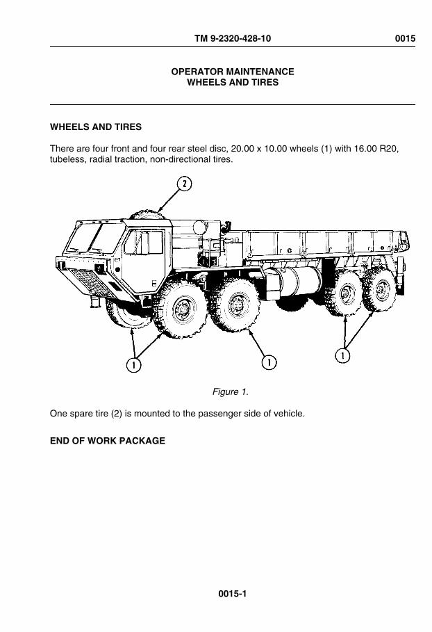
OPERATOR MAINTENANCEWHEELS AND TIRES
WHEELS AND TIRES
There are four front and four rear steel disc, 20.00 x 10.00 wheels (1) with 16.00 R20,tubeless, radial traction, non-directional tires.
Figure 1.
One spare tire (2) is mounted to the passenger side of vehicle.
END OF WORK PACKAGE
TM 9-2320-428-10 0015
0015-1


OPERATOR MAINTENANCECRANE
CRANE OVERVIEW
The cranes are operated by two functional systems: the electrical system and the hydraulicsystem.
A number of cranes are used on the HEMTT series vehicles:
Figure 1.
Refer to operator's manuals for specifications, dimensions, and operating procedures forthe different crane models.
The cranes are completely hydraulic powered and their principles of operation are the same.
TM 9-2320-428-10 0016
0016-1

CRANE OVERVIEW - Continued
Individual control panels, boom-hydraulic cylinder arrangements, and lifting capacities aredifferent.
All cranes are powered from the vehicle's hydraulic system.
All are equipped with outriggers for stability during operation.
All cranes use a combination of hinged joints and telescoping members to give them theirmotions.
The hydraulic-powered hoisting winch has an automatic brake to prevent accidentallowering of the load.
CRANE OPERATING INSTRUCTION PLATE LOCATIONS
NOTERefer to stowage and decal/data plate guide for more information on platelocations.
The crane operating instruction plates are located on the heater compartment cover in thecab at each of the fixed operating stations.
The outrigger leg signs are located on each of the outrigger cylinders.
The load capacity signs are located at the main and auxiliary control panels, and on M984Athey are located on the wrecker body rear stowage box doors.
CRANE ELECTRICAL SYSTEM
Material handling cranes for models M977, M984A, and M985 all have overload shutdownand/or tilt warning (unstable) systems.
When M977, M985, and M984A cranes are overloaded, the overload system willautomatically shut off power to telescope boom out, raise boom, or hoist load higher. TheM977 and M984A overload system will also prevent lowering the boom. An overloadcondition can be corrected by lowering the boom. An overload condition can be correctedby lowering load to ground or other supporting surface. All functions will be restored inapproximately six seconds.
The crane electrical system is supplied with power by the vehicle 24 VDC system.
The junction box on the crane connects and distributes the various control circuits of thecrane.
Tilt warning, outrigger extended warning, and remote control systems are electronicallycontrolled.
END OF WORK PACKAGE
TM 9-2320-428-10 0016
0016-2

CHAPTER 2
OPERATORINSTRUCTIONS
TM 9-2320-428-10


OPERATOR MAINTENANCECAB-MOUNTED FOOT CONTROLS
CONTROLS AND INDICATORS INTRODUCTION
This section displays the location and describes the use of cab-mounted foot controls whichare used in the operation of HEMTT series vehicles. Controls and indicators described inthis section are the same for all vehicles, except where otherwise indicated.
LOCATION AND USE OF CONTROLS AND INDICATORS
Know the location and proper use of every control and indicator before operating HEMTTseries vehicles. Separate illustrations with keys are provided for learning about cab-mounted foot controls.
TM 9-2320-428-10 0017
0017-1

Table 1. Cab-Mounted Foot Controls.
KeyControl/Indicator Function
Figure 1.
1 HeadlightDimmer Switch
Press switch to raise or lower headlight beams. High beamindicator will illuminate (red) when high beams are on(WP 0021).
2 Service BrakePedal
Applies service brakes. If vehicle is properly coupled to atrailer, trailer brakes will also operate when vehicle servicebrakes are applied.
3 Throttle Pedal Controls vehicle speed.
END OF WORK PACKAGE
TM 9-2320-428-10 0017
0017-2

OPERATOR MAINTENANCECAB-MOUNTED HAND CONTROLS
CONTROLS AND INDICATORS INTRODUCTION
This section displays the location and describes the use of cab-mounted hand controlswhich are used in the operation of HEMTT series vehicles. Controls and indicatorsdescribed in this section are the same for all vehicles, except where otherwise indicated.
LOCATION AND USE OF CONTROLS AND INDICATORS
Know the location and proper use of every control and indicator before operating HEMTTseries vehicles. Separate illustrations with keys are provided for learning about cab-mounted hand controls.
TM 9-2320-428-10 0018
0018-1
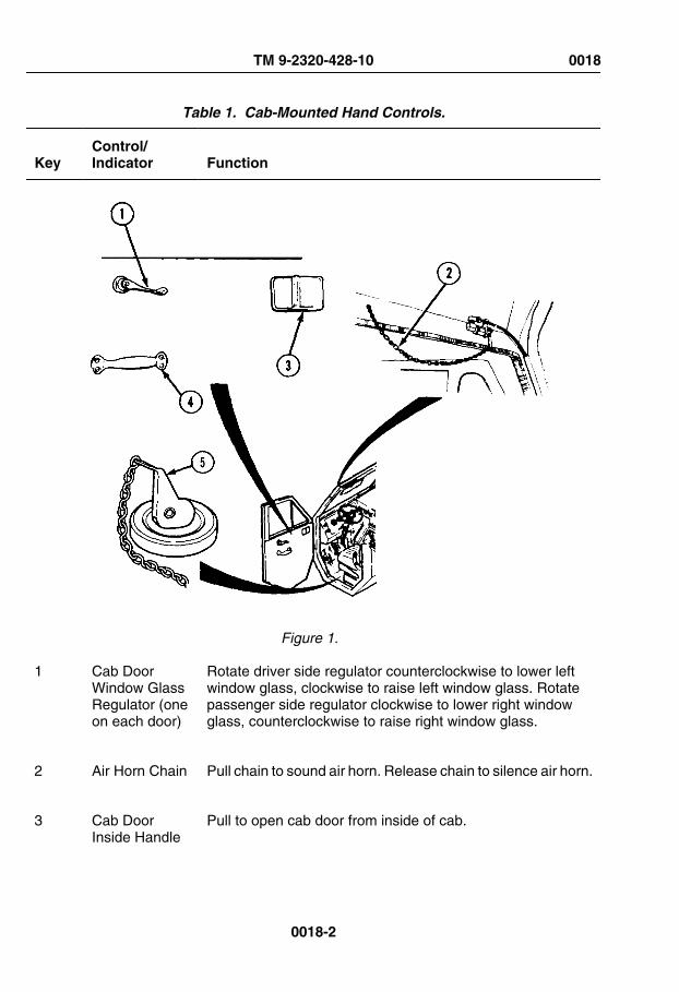
Table 1. Cab-Mounted Hand Controls.
KeyControl/Indicator Function
Figure 1.
1 Cab DoorWindow GlassRegulator (oneon each door)
Rotate driver side regulator counterclockwise to lower leftwindow glass, clockwise to raise left window glass. Rotatepassenger side regulator clockwise to lower right windowglass, counterclockwise to raise right window glass.
2 Air Horn Chain Pull chain to sound air horn. Release chain to silence air horn.
3 Cab DoorInside Handle
Pull to open cab door from inside of cab.
TM 9-2320-428-10 0018
0018-2

Table 1. Cab-Mounted Hand Controls. - Continued
KeyControl/Indicator Function
(one on eachdoor)
4 Cab DoorHandle (one oneach door)
Pull to close cab door from inside of cab.
5 Drain Plug (oneunder bothoperator seatand crew seat)
Pull up on lever to remove drain plug and drain liquid fromfloor of cab.
END OF WORK PACKAGE
TM 9-2320-428-10 0018
0018-3


OPERATOR MAINTENANCESTEERING COLUMN MOUNTED CONTROLS
CONTROLS AND INDICATORS INTRODUCTION
This section displays the location and describes the use of steering column mountedcontrols which are used in the operation of HEMTT series vehicles. Controls and indicatorsdescribed in this section are the same for all vehicles, except where otherwise indicated.
LOCATION AND USE OF CONTROLS AND INDICATORS
Know the location and proper use of every control and indicator before operating HEMTTseries vehicles. Separate illustrations with keys are provided for learning about steeringcolumn mounted controls.
Table 1. Steering Column Mounted Controls.
KeyControl/Indicator Function
Figure 1.
1 EmergencyFlasher Control
To turn on emergency flashers, light control must be in STOPLIGHT or SER DRIVE (WP 0022). Simultaneously pressemergency flasher control (1) down and push turn signal lever
TM 9-2320-428-10 0019
0019-1

Table 1. Steering Column Mounted Controls. - Continued
KeyControl/Indicator Function
(4) up past the right turn position as far as it will go. To turnemergency flashers off, push turn signal lever (4) down tocenter position.
2 Steering Wheel Controls direction of vehicle.
3 Horn Button Sounds electric horn when pressed. Release to silence horn.
4 Turn SignalLever
Push up to signal right turn. Pull down to signal left turn. Whenturn is complete, return lever to center position.
END OF WORK PACKAGE
TM 9-2320-428-10 0019
0019-2

OPERATOR MAINTENANCETUNNEL PANEL CONTROLS AND INDICATORS
CONTROLS AND INDICATORS INTRODUCTION
This section displays the location and describes the use of tunnel panel controls andindicators which are used in the operation of HEMTT series vehicles. Controls andindicators described in this section are the same for all vehicles, except where otherwiseindicated.
LOCATION AND USE OF CONTROLS AND INDICATORS
Know the location and proper use of every control and indicator before operating HEMTTseries vehicles. Separate illustrations with keys are provided for learning about tunnel panelcontrols and indicators.
TM 9-2320-428-10 0020
0020-1

Table 1. Tunnel panel controls and indicators.
KeyControl/Indicator Function
13
JACOBS
CAUTION
ENGINE BRAKE
5
9
4
6 7 8
21
310 11
12
Figure 1.
TM 9-2320-428-10 0020
0020-2

Table 1. Tunnel panel controls and indicators. - Continued
KeyControl/Indicator Function
1 Shut DownHandle
Used to shutdown engine in emergencies. Not included inlater base models.
2 TransmissionRangeSelector
R (reverse) - Used to back up vehicle.
N (neutral) - Used when starting vehicle, parking vehicle, orif vehicle controls are left unattended while engine is running.
D (drive) - Used for all normal driving conditions. Whenvehicle is in motion, transmission will upshift/downshiftautomatically.
3 - Low gear range. 2 - Lower gear range. 1 - Lowest gearrange.
3 CBT ControlPanel (M1977only)
Used to control CBT load handling system (LHS) operations.
4 Joystick(M1977 only)
Used to operate the LHS from the cab. The function beingcontrolled is determined by the LHS MODE SELECT switch.
5 NO TRANSITIndicator(M1977 only)
Illuminates when the hook arm assembly is not in thecompletely stowed position. The CBT is not to be drivenexcept in the immediate loading and unloading area as longas NO TRANSIT indicator is illuminated.
6 LHSENGAGED
Illuminates when hydraulic pressure is supplied to the LHS.
TM 9-2320-428-10 0020
0020-3

Table 1. Tunnel panel controls and indicators. - Continued
KeyControl/Indicator Function
Indicator(M1977 only)
7 OVERLOADIndicator(M1977 only)
Illuminates whenever main hydraulic relief valve is openedduring loading or unloading. Indicates LHS has reached anoverload condition or that hydraulic system is lifting very nearmaximum capacity. If the LHS is overloaded, the lightilluminates and the LHS is automatically locked out.
8 OIL TEMPIndicator(M1977 only)
Illuminates when LHS oil temperature exceeds limits.
9 LHS MODESelect Switch(M1977 only)
OFF - The LHS is not operational. This setting is used fortransport.
AUTO - Provides automatic operation of the LHS duringNATO flatrack retrieval.
MAN HOOK ARM - Places the LHS in manual mode formoving the hook arm when the AUTO mode electric circuit ismalfunctioning.
MAN MAIN FRAME - Places the LHS in manual mode formoving the main frame when the AUTO mode electric circuitis malfunctioning.
REMOTE CONTROL - Energizes the LHS remote-controlunit.
TM 9-2320-428-10 0020
0020-4
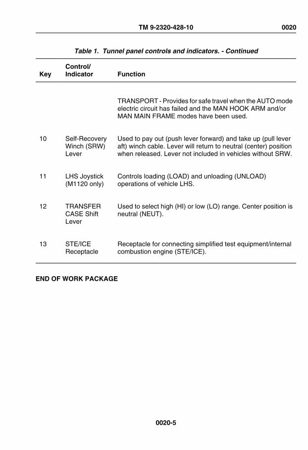
Table 1. Tunnel panel controls and indicators. - Continued
KeyControl/Indicator Function
TRANSPORT - Provides for safe travel when the AUTO modeelectric circuit has failed and the MAN HOOK ARM and/orMAN MAIN FRAME modes have been used.
10 Self-RecoveryWinch (SRW)Lever
Used to pay out (push lever forward) and take up (pull leveraft) winch cable. Lever will return to neutral (center) positionwhen released. Lever not included in vehicles without SRW.
11 LHS Joystick(M1120 only)
Controls loading (LOAD) and unloading (UNLOAD)operations of vehicle LHS.
12 TRANSFERCASE ShiftLever
Used to select high (HI) or low (LO) range. Center position isneutral (NEUT).
13 STE/ICEReceptacle
Receptacle for connecting simplified test equipment/internalcombustion engine (STE/ICE).
END OF WORK PACKAGE
TM 9-2320-428-10 0020
0020-5


OPERATOR MAINTENANCEINSTRUMENT PANEL CONTROLS AND INDICATORS
CONTROLS AND INDICATORS INTRODUCTION
This section displays the location and describes the use of instrument panel controls andindicators which are used in the operation of HEMTT series vehicles. Controls andindicators described in this section are the same for all vehicles, except where otherwiseindicated.
LOCATION AND USE OF CONTROLS AND INDICATORS
Know the location and proper use of every control and indicator before operating HEMTTseries vehicles. Separate illustrations with keys are provided for learning about instrumentpanel controls and indicators.
Table 1. Instrument Panel Controls and Indicators.
KeyControl/Indicator Function
AIR BRAKE
PARKINGBRAKE
TRAILERAIR SUPPLY
EXEXEX
EXEXEXEXEXEX
ENGINEOFF
ON
START
12
34
5
67 9 10
8
Figure 1.
TM 9-2320-428-10 0021
0021-1

Table 1. Instrument Panel Controls and Indicators. - Continued
KeyControl/Indicator Function
1 PARKINGBRAKEControl
Applies and releases vehicle parking brakes.
2 Left TurnIndicator
Flashes (green) when left turn signal is on.
3 Speedometer/Odometer
Shows vehicle traveling speed (in MPH and Km/h) and totalmiles traveled.
4 High BeamIndicator
Illuminates (red) when vehicle headlights are on high beam.
5 Tachometer/Hourmeter
Displays engine operating speed (RPM x 100) and totaloperating time (HOURS).
6 Right TurnIndicator
Flashes (green) when right turn signal is on.
7 FUEL Gauge Displays amount of fuel in fuel tank.
8 TRANS TEMPGauge
Displays transmission fluid temperature in degreesFahrenheit (°F) and Celsius (°C).
9 OIL PRESSGauge
Displays engine oil pressure (psi and kPa).
TM 9-2320-428-10 0021
0021-2

Table 1. Instrument Panel Controls and Indicators. - Continued
KeyControl/Indicator Function
10 WATER TEMPGauge
Displays engine coolant temperature in degrees Fahrenheit(°F) and Celsius (°C).
AIR BRAKE
PARKINGBRAKE
TRAILERAIR SUPPLY
EXEXEX
EXEXEXEXEXEX
ENGINEOFF
ON
START
1112
14
15
13
16
Figure 2.
11 OIL-WATERIndicator
Illuminates (red) when engine oil pressure is too low or whenengine coolant temperature too high. Buzzer sounds at thesame time.
12 INTER-AXLEDIFF. LOCKIndicator
Indicator illuminates (orange) when TRACTION CONTROLis in INTER-AXLE DIFF. LOCK position.
13 8x8 DRIVEIndicator
Illuminates (orange) when TRACTION CONTROL is in 8x8DRIVE position or when TRANSFER CASE is in LO.
TM 9-2320-428-10 0021
0021-3

Table 1. Instrument Panel Controls and Indicators. - Continued
KeyControl/Indicator Function
14 Air FilterRestrictionIndicator
Displays condition of air cleaner filter. Indicator window willshow red when filter becomes clogged. VACUUM INCHESH²O window displays degree of restriction. Push button on topof gauge to reset.
15 TRACTIONCONTROLLever
Lever in left position (INTER-AXLE DIFF. LOCK) locks inter-axle differentials in front and rear tandems. Lever in rightposition (8x8 DRIVE) engages transfer case drive to frontaxles.
16 ETHERSTART Control
Injects ether into engine intake manifold for cold weatherstarting.
PARKINGBRAKE
TRAILERAIR SUPPLY
EXEXEX
EXEXEXEXEXEX
ENGINEOFF
ON
START
23
24 25
26
19
17
18
20
21
22
Figure 3.
17 ENGINE STOPSwitch(Momentary)
Push down and hold to stop engine. Release when enginestops. Switch returns to run position when released.
TM 9-2320-428-10 0021
0021-4

Table 1. Instrument Panel Controls and Indicators. - Continued
KeyControl/Indicator Function
18 ENGINESwitch (Three-Position)
Straight up is OFF position. ON position operates electricalsystem. Hold switch in START position to operate enginecranking circuit. When switch is released after engine starts,switch will return to ON position.
19 AIR Indicator Illuminates (red) and remains lit until airbrake air pressure ineach section of dual system is between 60 psi (414 kPa) to75 psi (517 kPa). Buzzer will sound anytime indicator is lit.
20 AIR PRESSGauge
Displays air pressure (in psi and kPa) in both sections ofairbrake system. Green needle shows front section airpressure. Red needle shows rear section air pressure.
21 BATTERYGauge
Displays state of charge of batteries and alternator voltageoutput.
22 AMPERESGauge
Displays alternator output in Amperes.
23 TRAILER AIRSUPPLYControl
Supplies air to (push in) and shuts off (pull out) air to trailerbrake system. When TRAILER AIR SUPPLY control isapplied (pushed in), vehicle PARKING BRAKE controlactivates/deactivates the trailer parking brakes in concert withthe vehicle.
24 LHS NOTRANSITIndicator(M1120 only)
Illuminates (red) when LHS system is not properly stowed intransport position.
TM 9-2320-428-10 0021
0021-5

Table 1. Instrument Panel Controls and Indicators. - Continued
KeyControl/Indicator Function
25 LHS OVERLOAD Indicator(M1120 only)
Illuminates (yellow) whenever main hydraulic relief valve isopened during loading or unloading. When light illuminates,driver will be warned that LHS has reached an overloadcondition or that hydraulic system is lifting very nearmaximum capacity. OVER LOAD indicator will come on anytime main relief valve is cracked open, therefore, load orunload operation may not come to a complete stop, but lightwill come on momentarily. This situation would indicate thatsystem is lifting near maximum capacity. If the LHS isoverloaded, the light illuminates and the system isautomatically blocked out. Off-load/on-load flatrack, andattempt second operation. If, during this second attempt, theLHS shuts down, stop operation and redistribute weight orreduce payload before attempting load or unload. Whenattempting to load/unload Forward Repair System (FRS),manual procedures must be followed or LHS overload systemwill shut down the LHS system.
26 LHS Indicator(M1120 only)
Illuminates (green) when Hydraulic Selector Switch is inAUTO, MAN H.A., or MAN M.F. positions.
END OF WORK PACKAGE
TM 9-2320-428-10 0021
0021-6

OPERATOR MAINTENANCEHEATER COMPARTMENT CONTROLS AND INDICATORS
CONTROLS AND INDICATORS INTRODUCTION
This section displays the location and describes the use of heater compartment controlsand indicators which are used in the operation of HEMTT series vehicles. Controls andindicators described in this section are the same for all vehicles, except where otherwiseindicated.
LOCATION AND USE OF CONTROLS AND INDICATORS
Know the location and proper use of every control and indicator before operating HEMTTseries vehicles. Separate illustrations with keys are provided for learning about heatercompartment controls and indicators.
Table 1. Heater Compartment Controls and Indicators.
KeyControl/Indicator Function
JACOBS
CAUTION
ENGINE BRAKE
9
8
5
67
432
1
Figure 1.
1 HydraulicSelector
OFF position: The LHS is not operational. This mode is usedfor transport.
TM 9-2320-428-10 0022
0022-1
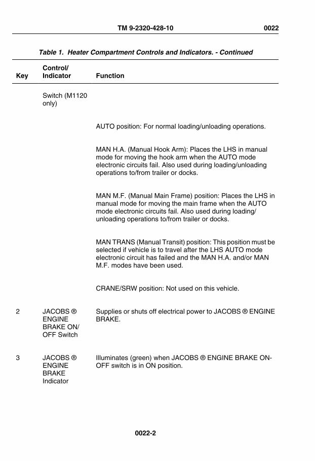
Table 1. Heater Compartment Controls and Indicators. - Continued
KeyControl/Indicator Function
Switch (M1120only)
AUTO position: For normal loading/unloading operations.
MAN H.A. (Manual Hook Arm): Places the LHS in manualmode for moving the hook arm when the AUTO modeelectronic circuits fail. Also used during loading/unloadingoperations to/from trailer or docks.
MAN M.F. (Manual Main Frame) position: Places the LHS inmanual mode for moving the main frame when the AUTOmode electronic circuits fail. Also used during loading/unloading operations to/from trailer or docks.
MAN TRANS (Manual Transit) position: This position must beselected if vehicle is to travel after the LHS AUTO modeelectronic circuit has failed and the MAN H.A. and/or MANM.F. modes have been used.
CRANE/SRW position: Not used on this vehicle.
2 JACOBS ®ENGINEBRAKE ON/OFF Switch
Supplies or shuts off electrical power to JACOBS ® ENGINEBRAKE.
3 JACOBS ®ENGINEBRAKEIndicator
Illuminates (green) when JACOBS ® ENGINE BRAKE ON-OFF switch is in ON position.
TM 9-2320-428-10 0022
0022-2

Table 1. Heater Compartment Controls and Indicators. - Continued
KeyControl/Indicator Function
4 JACOBS ®ENGINEBRAKE HIGH/LOW Switch
Selects number of engine cylinders used for engine brakingaction. HIGH position provides maximum braking. LOWposition provides less engine braking.
5 Wiper Control(Driver Side)
Controls operation of driver side windshield wiper.
6 Wiper Control(PassengerSide)
Controls operation of passenger side windshield wiper.
7 WASHERControl
Controls spray of cleaning fluid on windshield.
8 Light Control Controls all electrical power to all parts of lighting system.
TM 9-2320-428-10 0022
0022-3

Table 1. Heater Compartment Controls and Indicators. - Continued
KeyControl/Indicator Function
9 Utility Outlet Supplies electrical power to operate portable beacon light(WP 0074) and portable work lamp. (WP 0065)
JACOBS
CAUTION
ENGINE BRAKE
16
15
14
17
1113
10
12
Figure 2.
10 AIR Control Controls amount of outside air entering cab through fresh airvent.
11 HEAT Control Controls amount of hot air entering cab.
12 DEFROSTControl
Controls amount of hot air blown on windshield.
13 FAN Control Controls speed of heater fan.
14 CRANEOUTRIGGEREXTENDED
Illuminates (red) when HIAB crane outriggers are extended.
TM 9-2320-428-10 0022
0022-4

Table 1. Heater Compartment Controls and Indicators. - Continued
KeyControl/Indicator Function
Indicator(M985E1only)
15 High IdleSwitch (M1977only)
When set to ON position, increases engine speed (RPM) fromlow to high for operating CBT/LHS equipment.
16 PTO ENGAGEControl
Turns electrical power to power take-off (PTO) ON/OFF.
17 PTO ENGAGEIndicator
Illuminates (red) when PTO ENGAGE control is set to ONposition.
JACOBS
CAUTION
ENGINE BRAKE
24
25
22212019
18
23
Figure 3.
18 TrailerHandbrakeControl
Used to test the trailer brakes. Pull control lever back to apply,push forward to release trailer brakes.
TM 9-2320-428-10 0022
0022-5

Table 1. Heater Compartment Controls and Indicators. - Continued
KeyControl/Indicator Function
19 LHS SystemCircuit Breaker(M1120 only)
Protects LHS System from electrical overload.
20 CL LPS Switch Light control (8) must be in STOP LIGHT or SER DRIVEposition for CL LPS switch to work. Up position turnsclearance lights on. Down position turns clearance lights off.
21 DOME LightSwitch
Light control (8) must be in STOP LIGHT or SER DRIVEposition for CL LPS switch to work. Up position turns cabdome light on. Down position turns cab dome light off.
22 WORK LIGHTSwitch (M983,M984A1, andM1977 only)
Light control (8) must be in STOP LIGHT or SER DRIVEposition for CL LPS switch to work. Up position turns on worklights. Down position turns work lights off.
23 GAS ALARMSwitch
Turns M-8 chemical alarm ON/OFF.
24 GPFU Switch Turns gas particulate filter unit (GPFU) ON/OFF.
25 AuxiliaryEquipmentCircuit Breaker
Protects auxiliary equipment from electrical overload.
END OF WORK PACKAGE
TM 9-2320-428-10 0022
0022-6

OPERATOR MAINTENANCEOPERATOR AND CREW FOUR-POINT SEATBELT/AIR-RIDE SEAT ADJUSTMENT
CONTROLS
CONTROLS AND INDICATORS INTRODUCTION
This section displays the location and describes the use of operator and crew four-pointseatbelt/air-ride seat adjustment controls which are used in the operation of HEMTT seriesvehicles. Controls and indicators described in this section are the same for all vehicles,except where otherwise indicated.
LOCATION AND USE OF CONTROLS AND INDICATORS
Know the location and proper use of every control and indicator before operating HEMTTseries vehicles. Separate illustrations with keys are provided for learning about operatorand crew four-point seatbelt/air-ride seat adjustment controls.
Table 1. Operator and Crew Four-Point Seatbelt/Air-Ride Seat Adjustment Controls.
KeyControl/Indicator Function
HEIGHT ADJ.
12
1
2
62
35
4
Figure 1.
TM 9-2320-428-10 0023
0023-1
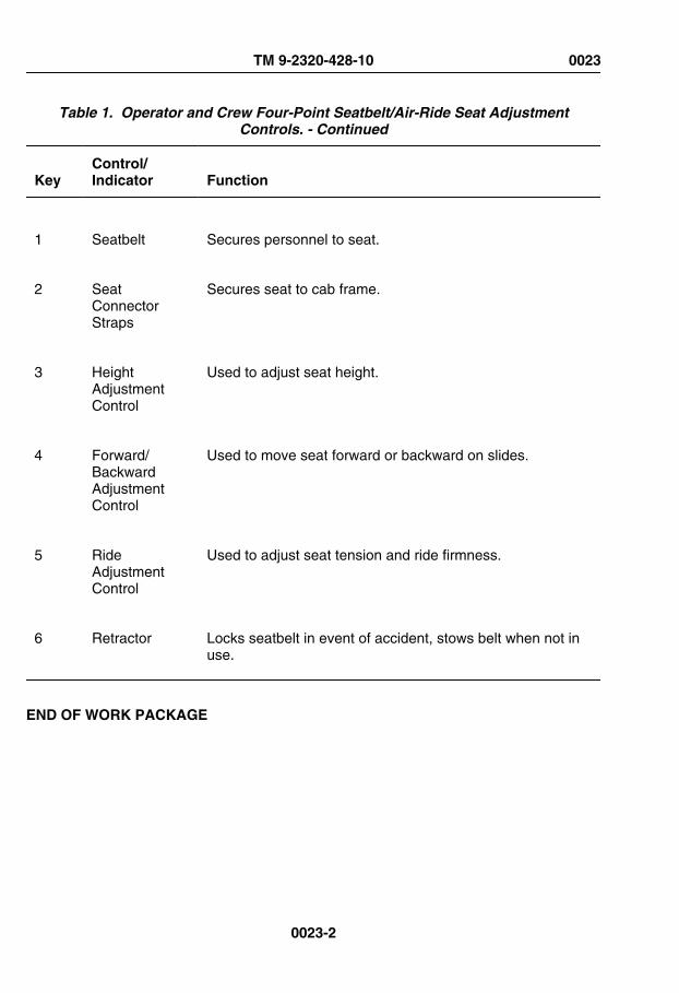
Table 1. Operator and Crew Four-Point Seatbelt/Air-Ride Seat AdjustmentControls. - Continued
KeyControl/Indicator Function
1 Seatbelt Secures personnel to seat.
2 SeatConnectorStraps
Secures seat to cab frame.
3 HeightAdjustmentControl
Used to adjust seat height.
4 Forward/BackwardAdjustmentControl
Used to move seat forward or backward on slides.
5 RideAdjustmentControl
Used to adjust seat tension and ride firmness.
6 Retractor Locks seatbelt in event of accident, stows belt when not inuse.
END OF WORK PACKAGE
TM 9-2320-428-10 0023
0023-2

OPERATOR MAINTENANCEOPERATOR AND CREW THREE-POINT SEATBELT/SEAT ADJUSTMENT CONTROLS
CONTROLS AND INDICATORS INTRODUCTION
This section displays the location and describes the use of operator and crew three-pointseatbelt/seat adjustment controls which are used in the operation of HEMTT series vehicles.Controls and indicators described in this section are the same for all vehicles, except whereotherwise indicated.
LOCATION AND USE OF CONTROLS AND INDICATORS
Know the location and proper use of every control and indicator before operating HEMTTseries vehicles. Separate illustrations with keys are provided for learning about operatorand crew three-point seatbelt/seat adjustment controls.
TM 9-2320-428-10 0024
0024-1

Table 1. Operator And Crew Three-Point Seatbelt/Seat Adjustment Controls.
KeyControl/Indicator Function
Figure 1.
1 Seatbelt Secures personnel to seat.
2 SeatConnectorStrap
Secures seat to cab frame.
3 Comfort LatchBuckle
Adjusts shoulder belt pressure.
TM 9-2320-428-10 0024
0024-2

Table 1. Operator And Crew Three-Point Seatbelt/Seat Adjustment Controls. -Continued
KeyControl/Indicator Function
4 Retractor Locks seatbelt in event of accident, stows belt when not inuse.
5 HeightAdjustmentControl
Used to adjust seat height.
6 Forward/BackwardAdjustmentControl
Used to move seat forward or backward on slides.
7 RideAdjustmentControl
Used to adjust seat tension and ride firmness.
END OF WORK PACKAGE
TM 9-2320-428-10 0024
0024-3


OPERATOR MAINTENANCEHYDRAULIC SELECTOR VALVE CONTROL
CONTROLS AND INDICATORS INTRODUCTION
This section displays the location and describes the use of Hydraulic Selector Valve Controlwhich are used in the operation of HEMTT series vehicles. Controls and indicatorsdescribed in this section are the same for all vehicles, except where otherwise indicated.
LOCATION AND USE OF CONTROLS AND INDICATORS
Know the location and proper use of every control and indicator before operating HEMTTseries vehicles. Separate illustrations with keys are provided for learning about HydraulicSelector Valve Control.
Table 1. Hydraulic Selector Valve Control.
KeyControl/Indicator Function
1
Figure 1.
TM 9-2320-428-10 0025
0025-1

Table 1. Hydraulic Selector Valve Control. - Continued
KeyControl/Indicator Function
1 HydraulicSelector ValveControl
Diverts main hydraulic power to/from Self-Recovery Winch:
Self-Recovery Winch operation - PULL OUT.
All other operations - PUSH IN (shown).
END OF WORK PACKAGE
TM 9-2320-428-10 0025
0025-2

OPERATOR MAINTENANCEGROVE CRANE CONTROL LEVERS
CONTROLS AND INDICATORS INTRODUCTION
This section displays the location and describes the use of grove crane control levers whichare used in the operation of HEMTT series vehicles. Controls and indicators described inthis section are the same for all vehicles, except where otherwise indicated.
LOCATION AND USE OF CONTROLS AND INDICATORS
Know the location and proper use of every control and indicator before operating HEMTTseries vehicles. Separate illustrations with keys are provided for learning about grove cranecontrol levers.
TM 9-2320-428-10 0026
0026-1

Table 1. Grove Crane Control Levers.
KeyControl/Indicator Function
Figure 1.
1 SWINGControl Lever
Rotates crane boom clockwise (CW) and counterclockwise(CCW).
2 TELESCOPEControl Lever
Extends and retracts first and second stages of boom.
TM 9-2320-428-10 0026
0026-2

Table 1. Grove Crane Control Levers. - Continued
KeyControl/Indicator Function
3 BOOM ControlLever
Raises and lowers boom.
4 HOIST ControlLever
Reels in and pays out hoist cable.
5 Shut-DownSolenoid ValveButton
Provides emergency hydraulic power when electrical powerfails.
6 RH O/R JACKControl Lever
Lowers and raises right outrigger jack.
7 O/R EXTControl Lever
Extends and retracts outrigger beams.
8 MAST ControlLever
Raises mast to operating position and lowers mast to stowageposition.
9 LH O/R JACKControl Lever
Lowers and raises left outrigger jack.
END OF WORK PACKAGE
TM 9-2320-428-10 0026
0026-3


OPERATOR MAINTENANCEGROVE CRANE BOXES AND REMOTE-CONTROL UNIT
CONTROLS AND INDICATORS INTRODUCTION
This section displays the location and describes the use of grove crane boxes and remote-control unit which is used in the operation of HEMTT series vehicles. Controls and indicatorsdescribed in this section are the same for all vehicles, except where otherwise indicated.
LOCATION AND USE OF CONTROLS AND INDICATORS
Know the location and proper use of every control and indicator before operating HEMTTseries vehicles. Separate illustrations with keys are provided for learning about grove craneboxes and remote-control unit.
TM 9-2320-428-10 0027
0027-1

Table 1. Grove Crane Boxes and Remote-Control Unit.
KeyControl/Indicator Function
Figure 1.
1 POWERSwitch
Turns crane electrical power ON/OFF.
2 REMOTECONTROLCONNECTOR
Receptacle for connecting remote-control unit cable.
3 SWINGControl Lever
Moves crane clockwise (CW) and counterclockwise (CCW).
TM 9-2320-428-10 0027
0027-2

Table 1. Grove Crane Boxes and Remote-Control Unit. - Continued
KeyControl/Indicator Function
4 TELESCOPEControl Lever
Extends (OUT) and retracts (IN) first and second stages ofboom.
5 BOOM ControlLever
Raises (UP) and lowers (DOWN) boom.
6 HOIST ControlLever
Reels in (UP) and pays out (DOWN) hoist cable.
7 REMOTE-CONTROLUNIT ON/OFFSwitch
Turns remote-control unit ON/OFF.
8 ENGINE HIGHIDLE PowerSwitch
Turns ENGINE HIGH IDLE LATCH switch electrical powerON/OFF.
9 ENGINE HIGHIDLE LATCHSwitch
Increases engine speed to high idle.
END OF WORK PACKAGE
TM 9-2320-428-10 0027
0027-3


OPERATOR MAINTENANCERIFLE STOWAGE MOUNT
CONTROLS AND INDICATORS INTRODUCTION
This section displays the location and describes the use of Rifle Stowage Mounts which areused in the operation of HEMTT series vehicles. Controls and indicators described in thissection are the same for all vehicles, except where otherwise indicated.
LOCATION AND USE OF CONTROLS AND INDICATORS
Know the location and proper use of every control and indicator before operating HEMTTseries vehicles. Separate illustrations with keys are provided for learning about RifleStowage Mount.
TM 9-2320-428-10 0028
0028-1

Table 1. Rifle Stowage Mount.
KeyControl/Indicator Function
3
1
2
Figure 1.
1 Lower RifleMount
Holds butt of rifle.
TM 9-2320-428-10 0028
0028-2

Table 1. Rifle Stowage Mount. - Continued
KeyControl/Indicator Function
2 Rifle MountHandle
Secures heat guard of rifle against top rifle mount.
3 Top RifleMount
Holds heat guard of rifle.
END OF WORK PACKAGE
TM 9-2320-428-10 0028
0028-3

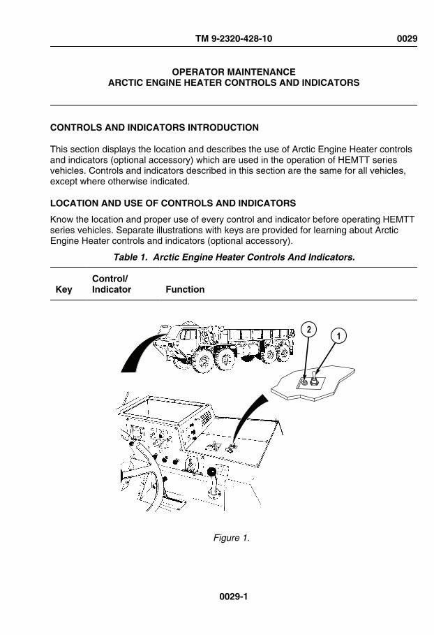
OPERATOR MAINTENANCEARCTIC ENGINE HEATER CONTROLS AND INDICATORS
CONTROLS AND INDICATORS INTRODUCTION
This section displays the location and describes the use of Arctic Engine Heater controlsand indicators (optional accessory) which are used in the operation of HEMTT seriesvehicles. Controls and indicators described in this section are the same for all vehicles,except where otherwise indicated.
LOCATION AND USE OF CONTROLS AND INDICATORS
Know the location and proper use of every control and indicator before operating HEMTTseries vehicles. Separate illustrations with keys are provided for learning about ArcticEngine Heater controls and indicators (optional accessory).
Table 1. Arctic Engine Heater Controls And Indicators.
KeyControl/Indicator Function
HIGH IDLE
OFF
ON
Engine
Prehe
ater
Engine
Prehea
ter
21
Figure 1.
TM 9-2320-428-10 0029
0029-1

Table 1. Arctic Engine Heater Controls And Indicators. - Continued
KeyControl/Indicator Function
1 ON/OFFSwitch
Two position switch starts operation of arctic engine heater.
2 Arctic EngineHeater LightIndicator
Light illuminates when arctic engine heater switch is placedin ON position. If light does not illuminate or if light flashesintermittently, arctic engine heater is malfunctioning.
END OF WORK PACKAGE
TM 9-2320-428-10 0029
0029-2

OPERATOR MAINTENANCEGAS PARTICULATE FILTER UNIT (GPFU) CONTROLS AND INDICATORS
CONTROLS AND INDICATORS INTRODUCTION
This section displays the location and describes the use of Gas Particulate Filter Unit(GPFU) controls and indicators which is used in the operation of HEMTT series vehicles.Controls and indicators described in this section are the same for all vehicles, except whereotherwise indicated.
LOCATION AND USE OF CONTROLS AND INDICATORS
Know the location and proper use of every control and indicator before operating HEMTTseries vehicles. Separate illustrations with keys are provided for learning about GasParticulate Filter Unit (GPFU) controls and indicators.
TM 9-2320-428-10 0030
0030-1

Table 1. Gas Particulate Filter Unit (GPFU) Controls And Indicators.
KeyControl/Indicator Function
Figure 1.
1 Gas ParticulateFilter
Filters nuclear, biological, and chemical (NBC) contaminantsfrom air.
2 M-3 Heater Warms air entering protective mask.
3 M-3 HeaterControl Knob
Turn clockwise (CW) for warmer air turn counterclockwise(CCW) for cooler air. Turn to OFF to shut off heater.
4 M-3 HeaterIndicator Light
Illuminates when heater is operating.
TM 9-2320-428-10 0030
0030-2

Table 1. Gas Particulate Filter Unit (GPFU) Controls And Indicators. - Continued
KeyControl/Indicator Function
5 GASPARTICULATE FILTERUNIT Switch
Turns GPFU ON/OFF.
END OF WORK PACKAGE
TM 9-2320-428-10 0030
0030-3


OPERATOR MAINTENANCEMACHINE GUN MOUNT
CONTROLS AND INDICATORS INTRODUCTION
This section displays the location and describes the use of Machine Gun Mount (OptionalAccessory) which is used in the operation of HEMTT series vehicles. Controls and indicatorsdescribed in this section are the same for all vehicles, except where otherwise indicated.
LOCATION AND USE OF CONTROLS AND INDICATORS
Know the location and proper use of every control and indicator before operating HEMTTseries vehicles. Separate illustrations with keys are provided for learning about MachineGun Mount (Optional Accessory).
TM 9-2320-428-10 0031
0031-1

Table 1. Machine Gun Mount.
KeyControl/Indicator Function
Figure 1.
1 Machine GunMount
Secures machine gun to machine gun ring.
2 Machine GunRing
Allows machine gun to turn 360 degrees.
END OF WORK PACKAGE
TM 9-2320-428-10 0031
0031-2

OPERATOR MAINTENANCEM-8 CHEMICAL ALARM CONTROLS AND INDICATORS
CONTROLS AND INDICATORS INTRODUCTION
This section displays the location and describes the use of M-8 Chemical Alarm controlsand indicators which are used in the operation of HEMTT series vehicles. Controls andindicators described in this section are the same for all vehicles, except where otherwiseindicated.
LOCATION AND USE OF CONTROLS AND INDICATORS
Know the location and proper use of every control and indicator before operating HEMTTseries vehicles. Separate illustrations with keys are provided for learning about M-8Chemical Alarm controls and indicators.
TM 9-2320-428-10 0032
0032-1

Table 1. M-8 Chemical Alarm Controls And Indicators.
KeyControl/Indicator Function
2
1
3
Figure 1.
1 M-8 ChemicalAlarm Switch
Operates alarm.
TM 9-2320-428-10 0032
0032-2

Table 1. M-8 Chemical Alarm Controls And Indicators. - Continued
KeyControl/Indicator Function
2 M-8 ChemicalAlarm
Sounds alarm when chemicals are detected.
3 ChemicalDetector
Detects presence of chemical in the air.
END OF WORK PACKAGE
TM 9-2320-428-10 0032
0032-3


OPERATOR MAINTENANCEM-13 DECONTAMINATION KIT
CONTROLS AND INDICATORS INTRODUCTION
This section displays the location and describes the use of M-13 Decontamination Kit whichis used in the operation of HEMTT series vehicles. Controls and indicators described in thissection are the same for all vehicles, except where otherwise indicated.
LOCATION AND USE OF CONTROLS AND INDICATORS
Know the location and proper use of every control and indicator before operating HEMTTseries vehicles. Separate illustrations with keys are provided for learning about M-13Decontamination Kit.
TM 9-2320-428-10 0033
0033-1

Table 1. M-13 Decontamination Kit.
KeyControl/Indicator Function
Figure 1.
1 M-13DecontaminationUnit
Holds and dispenses decontaminant.
2 DecontaminationUnit Mount
Holds decontamination unit.
END OF WORK PACKAGE
TM 9-2320-428-10 0033
0033-2

OPERATOR MAINTENANCERADIO INSTALLATION HARDWARE
CONTROLS AND INDICATORS INTRODUCTION
This section displays the location and describes the use of radio installation hardware whichis used in the operation of HEMTT series vehicles. Controls and indicators described in thissection are the same for all vehicles, except where otherwise indicated.
LOCATION AND USE OF CONTROLS AND INDICATORS
Know the location and proper use of every control and indicator before operating HEMTTseries vehicles. Separate illustrations with keys are provided for learning about radioinstallation hardware.
TM 9-2320-428-10 0034
0034-1
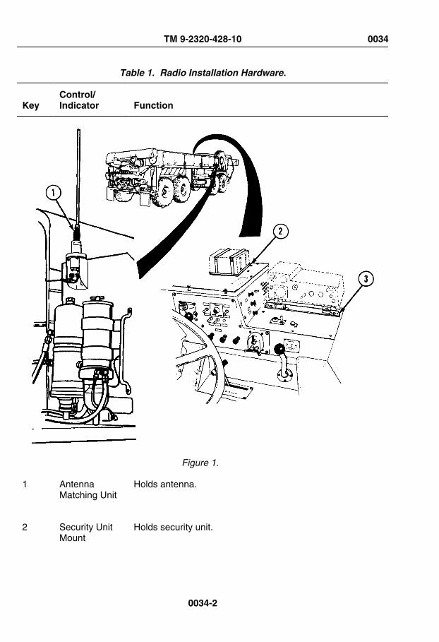
Table 1. Radio Installation Hardware.
KeyControl/Indicator Function
Figure 1.
1 AntennaMatching Unit
Holds antenna.
2 Security UnitMount
Holds security unit.
TM 9-2320-428-10 0034
0034-2

Table 1. Radio Installation Hardware. - Continued
KeyControl/Indicator Function
3 Receiver/TransmitterMount
Holds receiver/transmitter.
END OF WORK PACKAGE
TM 9-2320-428-10 0034
0034-3


OPERATOR MAINTENANCEOPERATE WINDSHIELD WIPERS/WASHER
INITIAL SETUP:
Not Applicable
OPERATE WINDSHIELD WIPERS
NOTE• Some earlier vehicles are equipped with pull and turn control controls.
• ENGINE switch must be positioned to ON for windshield wipers tooperate.
1. Turn WIPER control (1) clockwise to start and control speed of driver side windshieldwiper.
TRAILERAIR SUPPLYNOT FOR PARKINGMIDLAND
PULL TO EXHAUST
PUSH TO SU P PLY
21
Figure 1.
TM 9-2320-428-10 0035
0035-1

OPERATE WINDSHIELD WIPERS - Continued
2. Turn WIPER control (2) clockwise to start and control speed of passenger sidewindshield wiper.
3. Turn WIPER control (1) counterclockwise to stop driver side windshield wiper.
4. Turn WIPER control (2) counterclockwise to stop passenger side windshield wiper.
5. If wiper stops in middle of windshield:
a. Turn appropriate WIPER control (1 or 2) clockwise until wiper is at bottom ofwindshield.
b. Turn appropriate WIPER control (1 or 2) counterclockwise to stop wiper.
OPERATE WINDSHIELD WASHER
NOTE• Some earlier vehicles are equipped with pull and turn control controls.
• ENGINE switch must be positioned to ON for windshield washer tooperate.
1. Push in and hold WASH control (1) to spray cleaning fluid on windshield.
TRAILERAIR SUPPLYNOT FOR PARKINGMIDLAND
PULL TO EXHAUST
PUSH TO SU P PLY
1
Figure 2.
TM 9-2320-428-10 0035
0035-2

OPERATE WINDSHIELD WASHER - Continued
2. Release WASH control (1) to stop washer spray.
END OF TASK
END OF WORK PACKAGE
TM 9-2320-428-10 0035
0035-3


OPERATOR MAINTENANCEOPERATE CAB TEMPERATURE CONTROLS
INITIAL SETUP:
Not Applicable
OPERATE PERSONNEL HEATER
NOTE• If heater does not blow hot air, ensure heater valves are open.
• Air temperature is controlled by position of HEAT control.
• Pull HEAT control out to increase temperature.
• Push HEAT control in to decrease temperature.
1. Pull out HEAT control (1) to desired position.
2. Set FAN switch (2) to LO or HI airflow.
TM 9-2320-428-10 0036
0036-1

OPERATE PERSONNEL HEATER - Continued
AIR
HEAT
DEFROST
LO-OFF-HI
FAN
3
1
4
2
Figure 1.
NOTEOn later model vehicles, the AIR control has a "TURN TO LOCK" functionwhich holds the vent open at the desired level when the control is rotatedclockwise. Rotate control CCW until it stops to unlock the vent.
3. Adjust AIR control (3) as desired to control outside airflow for cab ventilation. Unlock,and push AIR control (3) all the way in to shut outside air ventilation off.
4. When personnel heater is no longer required:
a. Push in HEAT control (1) to turn heater off.
b. Set FAN switch (2) to OFF.
TM 9-2320-428-10 0036
0036-2
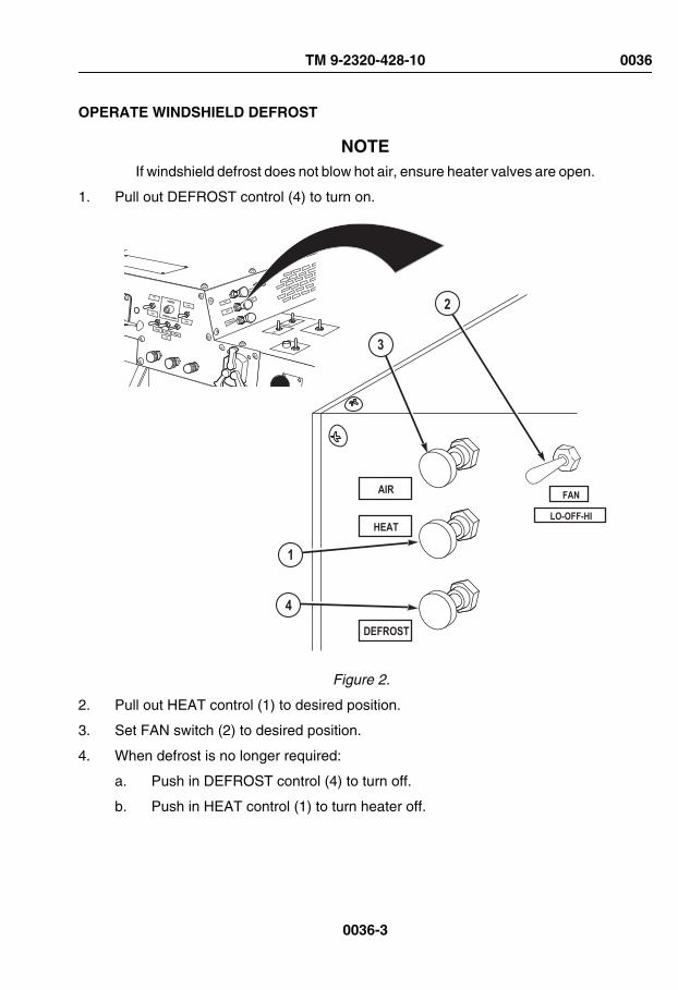
OPERATE WINDSHIELD DEFROST
NOTEIf windshield defrost does not blow hot air, ensure heater valves are open.
1. Pull out DEFROST control (4) to turn on.
AIR
HEAT
DEFROST
LO-OFF-HI
FAN
3
1
4
2
Figure 2.
2. Pull out HEAT control (1) to desired position.
3. Set FAN switch (2) to desired position.
4. When defrost is no longer required:
a. Push in DEFROST control (4) to turn off.
b. Push in HEAT control (1) to turn heater off.
TM 9-2320-428-10 0036
0036-3

OPERATE WINDSHIELD DEFROST - Continued
c. Set FAN switch (2) to OFF.
END OF TASK
END OF WORK PACKAGE
TM 9-2320-428-10 0036
0036-4

OPERATOR MAINTENANCEOPERATE FIRE EXTINGUISHER
INITIAL SETUP:
Not Applicable
REMOVE FIRE EXTINGUISHER FROM CAB
NOTEFire extinguisher is located on rear bulkhead on inside of cab, just inboardof driver’s seat.
1. Pull up top clamp (1) and disengage from top hook (2).
TM 9-2320-428-10 0037
0037-1

REMOVE FIRE EXTINGUISHER FROM CAB - Continued
6
2
4
1
3
5
Figure 1.
2. Pull up bottom clamp (3) and disengage from bottom hook (4).
3. Remove fire extinguisher (5) from bracket (6).
EXTINGUISH FIRE
NOTE• Fire extinguisher is a dry chemical type. Refer to MSDS for specific
extinguisher warnings and cautions for use.
• Remember the word "PASS" to operate fire extinguisher:
TM 9-2320-428-10 0037
0037-2

EXTINGUISH FIRE - Continued
.
1. Hold fire extinguisher (1) upright and pull safety pin (2) to break plastic tie (3).
Figure 2.
2. Point nozzle (4) at base of fire.
3. Press down on stop lever (5) and spray discharge in a side-to-side motion at base offire.
4. Let go of stop lever (5) when fire is out.
5. Notify field level maintenance to replace fire extinguisher.
INSTALL FIRE EXTINGUISHER IN CAB
1. Put neck of fire extinguisher (1) on bracket (2).
TM 9-2320-428-10 0037
0037-3

INSTALL FIRE EXTINGUISHER IN CAB - Continued
2
4
6
3
5
1
Figure 3.
2. Hook top clamp (3) on top hook (4) and push top clamp (3) down, tightening strap.
3. Hook bottom clamp (5) on bottom hook (6) and push bottom clamp (5) down,tightening strap.
END OF TASK
END OF WORK PACKAGE
TM 9-2320-428-10 0037
0037-4

OPERATOR MAINTENANCEOPERATE ACCESS LADDER
INITIAL SETUP:
Not Applicable
INSTALL ACCESS LADDER
1. Unhook two springs (1) from stowage rods (2).
Figure 1.
2. Remove access ladder (3) from under cargo body (4).
CAUTIONDo not hit fuel/water separator when installing access ladder onpassenger side front fender. If access ladder hooks hit fuel/waterseparator, glass may break.
TM 9-2320-428-10 0038
0038-1

INSTALL ACCESS LADDER - Continued
3. Install access ladder (3) hooks (5) in front skid plate holes (6), driver side front fenderholes (7), or passenger side front fender holes (8), as required. Keep access ladder(3) clear of fuel/water separator (9).
6
7
3
5
8
9
8
9
Figure 2.
STOW ACCESS LADDER
1. Hook springs (1) on stowage rods (2).
TM 9-2320-428-10 0038
0038-2

STOW ACCESS LADDER - Continued
Figure 3.
2. Secure access ladder (3) under cargo body (4) with two springs (1) and stowage rods(2).
END OF TASK
END OF WORK PACKAGE
TM 9-2320-428-10 0038
0038-3


OPERATOR MAINTENANCEOPERATE DRAIN PLUG
INITIAL SETUP:
Not Applicable
REMOVE DRAIN PLUG
NOTEThere are two drain plugs. One located on each side of cab floor, justbelow operator/crew seats.
1. Pull up on lever (1).
Figure 1.
2. Remove drain plug (2) to drain any liquid from floor of cab.
INSTALL DRAIN PLUG
1. Push drain plug (2) in opening on cab floor.
TM 9-2320-428-10 0039
0039-1

INSTALL DRAIN PLUG - Continued
Figure 2.
2. Press down on lever (1) to secure drain plug (2).
END OF TASK
END OF WORK PACKAGE
TM 9-2320-428-10 0039
0039-2

OPERATOR MAINTENANCECONNECT/DISCONNECT TRAILER
INITIAL SETUP:
Personnel RequiredOperator and Assistant(s) - - - (3)
CONNECT TRAILER (VEHICLES EQUIPPED WITH PINTLE HOOK)
NOTE• This procedure is a three soldier task.
• HEMTT series vehicles pull M105, M332, M989, and M1076 trailers.For more information on trailer hookup and towing procedures, referto the following manuals:• M105 Trailer - TM 9-2330-213-14&P. (WP 0161)• M332 Trailer - TM 9-2330-231-14&P. (WP 0161)• M989 Trailer - TM 9-2330-385-14. (WP 0161)• M1076 Trailer - TM 9-2330-385-14. (WP 0161)
1. Park vehicle. (WP 0056)
2. Shut off engine. (WP 0057)
3. Remove cotter pin (1).
TM 9-2320-428-10 0040
0040-1

CONNECT TRAILER (VEHICLES EQUIPPED WITH PINTLE HOOK) - Continued
3
21
Figure 1.
4. Pull latch (2) away from vehicle and hold.
5. Lift top part of pintle hook (3) and let go of latch (2); hook will be locked open.
6. Put trailer connecting eye (4) on bottom part of pintle hook (5).
TM 9-2320-428-10 0040
0040-2

CONNECT TRAILER (VEHICLES EQUIPPED WITH PINTLE HOOK) - Continued
2 3
4
5
Figure 2.
7. Pull latch (2) away from vehicle to free top part of pintle hook (3).
8. Install cotter pin (1).
6
7
1
Figure 3.
9. Connect two safety chains (6) to safety chain hoop (7).
10. Lift cover (8) and connect inter-vehicular wiring harness (9) to connector on vehicle(10), and trailer.
TM 9-2320-428-10 0040
0040-3
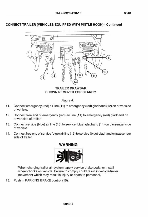
CONNECT TRAILER (VEHICLES EQUIPPED WITH PINTLE HOOK) - Continued
13
141211 910
8
TRAILER DRAWBARSHOWN REMOVED FOR CLARITY
Figure 4.
11. Connect emergency (red) air line (11) to emergency (red) gladhand (12) on driver sideof vehicle.
12. Connect free end of emergency (red) air line (11) to emergency (red) gladhand ondriver side of trailer.
13. Connect service (blue) air line (13) to service (blue) gladhand (14) on passenger sideof vehicle.
14. Connect free end of service (blue) air line (13) to service (blue) gladhand on passengerside of trailer.
WARNING
When charging trailer air system, apply service brake pedal or installwheel chocks on vehicle. Failure to comply could result in vehicle/trailermovement which may result in injury or death to personnel.
15. Push in PARKING BRAKE control (15).
TM 9-2320-428-10 0040
0040-4

CONNECT TRAILER (VEHICLES EQUIPPED WITH PINTLE HOOK) - Continued
AIR BRAKE
PARKINGBRAKE
TRAILERAIR SUPPLY
EXEXEX
EXEXEXEXEX EXEX
ENGINEOFF
ON
START
15
16
Figure 5.
16. Push in TRAILER AIR SUPPLY control (16) to charge trailer air system.
17. Pull out PARKING BRAKE control (15) once trailer air supply system is charged.
DISCONNECT TRAILER (VEHICLES EQUIPPED WITH PINTLE HOOK)
NOTEThis procedure is a three soldier task.
1. Park vehicle. (WP 0056)
2. Shut off engine. (WP 0057)
3. Remove emergency (red) air line (1) from emergency (red) gladhand (2) on driver sideof vehicle and emergency (red) gladhand on driver side of trailer.
TM 9-2320-428-10 0040
0040-5

DISCONNECT TRAILER (VEHICLES EQUIPPED WITH PINTLE HOOK) - Continued
8
7
4
3
21 56
TRAILER DRAWBARSHOWN REMOVED FOR CLARITY
Figure 6.
4. Remove service (blue) air line (3) from service (blue) gladhand (4) on passenger sideof vehicle and service (blue) gladhand on passenger side of trailer.
5. Remove inter-vehicular wiring harness (5) from connector (6) on vehicle.
6. Remove inter-vehicular wiring harness (5) from trailer and return to vehicle stowage.
7. Remove two safety chains (7) from safety chain hoop (8).
8. Remove cotter pin (9).
TM 9-2320-428-10 0040
0040-6

DISCONNECT TRAILER (VEHICLES EQUIPPED WITH PINTLE HOOK) - Continued
10 11
12
139
Figure 7.
9. Pull latch (10) away from vehicle and hold.
10. Lift top part of pintle hook (11) and let go of latch (10); hook will be locked open.
11. Lift trailer connecting eye (12) off bottom of pintle hook (13).
12. Pull latch (10) away from top part of pintle hook (11).
13. Install cotter pin (9).
END OF TASK
END OF WORK PACKAGE
TM 9-2320-428-10 0040
0040-7


OPERATOR MAINTENANCECARGO BODY OPERATION
INITIAL SETUP:
Personnel RequiredOperator and Assistant - - - (2)
LOWER CARGO BODY SIDE PANELS ONE AT A TIME
WARNING
Side panels can slide off hinge pins when vehicle is parked on grade.Falling side panels can cause injury or death to personnel.
NOTEThis procedure is a two soldier task.
1. Remove lockpin (1) and pull latch (2) up while assistant holds side panel (3).
TM 9-2320-428-10 0041
0041-1

LOWER CARGO BODY SIDE PANELS ONE AT A TIME - Continued
Figure 1.
2. Lower side panel (3).
3. Pull latch (4) up while assistant holds side panel (5).
4. Lower side panel (5).
5. Remove lockpin (6) while assistant holds side panel (7).
6. Lower side panel (7).
TM 9-2320-428-10 0041
0041-2

LOWER CARGO BODY SIDE PANELS ALL AT ONE TIME
WARNING
Side panels can slide off hinge pins when vehicle is parked on grade.Falling side panels can cause injury or death to personnel.
NOTEThis procedure is a two soldier task.
1. Hold side panel (1) up while assistant removes lockpins (2) and climbs out of cargobody to help lower side panels.
TM 9-2320-428-10 0041
0041-3

LOWER CARGO BODY SIDE PANELS ALL AT ONE TIME - Continued
Figure 2.
2. With aid of an assistant, lower side panels (1) until side panels are even with cargobody floor (3).
3. Change hand position so each soldier holds a latch (4).
4. With aid of an assistant, lower side panels (1).
TM 9-2320-428-10 0041
0041-4
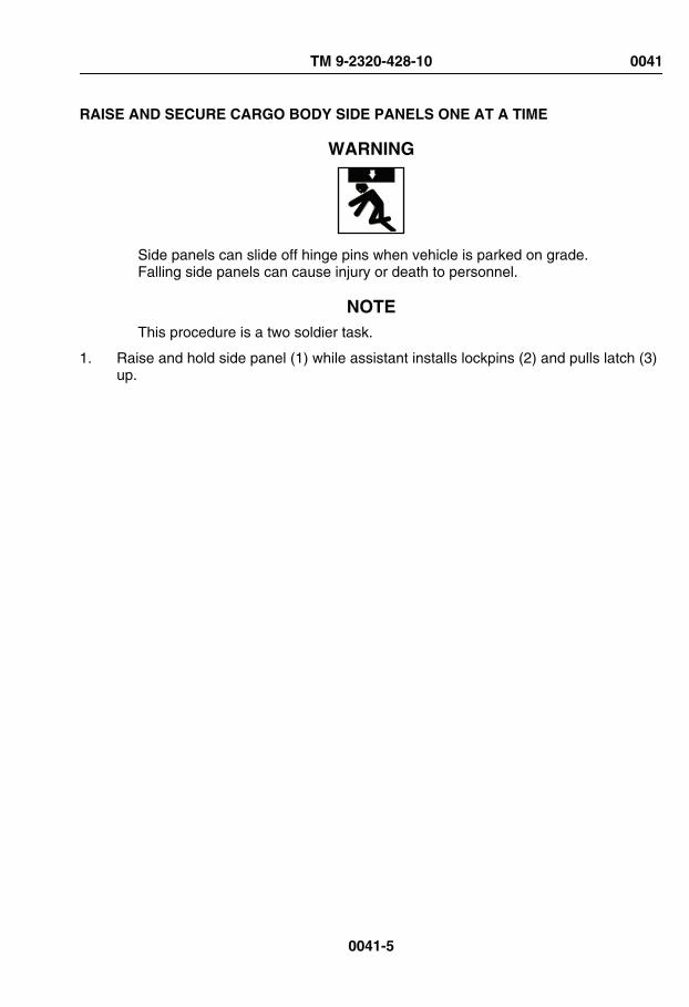
RAISE AND SECURE CARGO BODY SIDE PANELS ONE AT A TIME
WARNING
Side panels can slide off hinge pins when vehicle is parked on grade.Falling side panels can cause injury or death to personnel.
NOTEThis procedure is a two soldier task.
1. Raise and hold side panel (1) while assistant installs lockpins (2) and pulls latch (3)up.
TM 9-2320-428-10 0041
0041-5
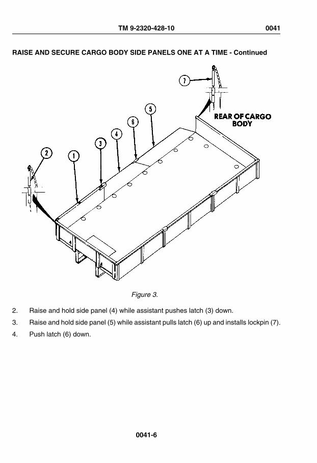
RAISE AND SECURE CARGO BODY SIDE PANELS ONE AT A TIME - Continued
Figure 3.
2. Raise and hold side panel (4) while assistant pushes latch (3) down.
3. Raise and hold side panel (5) while assistant pulls latch (6) up and installs lockpin (7).
4. Push latch (6) down.
TM 9-2320-428-10 0041
0041-6

RAISE AND SECURE CARGO BODY SIDE PANELS ALL AT A TIME
WARNING
Side panels can slide off hinge pins when vehicle is parked on grade.Falling side panels can cause injury or death to personnel.
NOTEThis procedure is a two soldier task.
1. With aid of an assistant, place latches (1) over edge of adjoining panel (2).
Figure 4.
TM 9-2320-428-10 0041
0041-7

RAISE AND SECURE CARGO BODY SIDE PANELS ALL AT A TIME - Continued
2. With aid of an assistant, while holding latches (1) in place, raise three side panels (2and 3).
3. Hold side panels (2 and 3) up, while assistant climbs into cargo body and installslockpins (4).
REMOVE CARGO BODY FRONT AND REAR PANELS
NOTE• This procedure is a two soldier task.
• All front and rear panels are removed the same way.
1. Lower cargo body side panels all at the same time.
Figure 5.
2. Remove rear panel (1) from cargo body.
INSTALL CARGO BODY FRONT AND REAR PANELS
NOTE• This procedure is a two soldier task.
TM 9-2320-428-10 0041
0041-8

INSTALL CARGO BODY FRONT AND REAR PANELS - Continued
• All front and rear panels are removed the same way.
1. Install rear panel (1) on cargo body.
Figure 6.
2. Raise and secure cargo side panels all at one time.
REMOVE CARGO BODY SIDE PANELS
NOTE• This procedure is a two soldier task.
• All driver side and passenger side panels are removed the same way.
1. Lower cargo body side panels one at a time.
TM 9-2320-428-10 0041
0041-9

REMOVE CARGO BODY SIDE PANELS - Continued
Figure 7.
2. Raise front side panel (1) and slide panel forward off two pins (2).
3. Raise center side panel (3) and slide panel forward off two pins (2).
4. Raise rear side panel (4) and slide panel rearward off two pins (2).
INSTALL CARGO BODY SIDE PANELS
NOTE• This procedure is a two soldier task.
• All driver side and passenger side panels are installed the same way.
1. Install rear side panel (4) on two pins (2) and slide forward.
TM 9-2320-428-10 0041
0041-10

INSTALL CARGO BODY SIDE PANELS - Continued
Figure 8.
2. Install center side panel (3) on two pins (2) and slide rearward.
3. With aid of an assistant, install front side panel (1) on two pins (2) and slide rearward.
4. Raise and secure cargo body side panels one at a time.
INSTALL CARGO COVER KIT
NOTEThis procedure is a two soldier task.
1. Park vehicle. (WP 0056)
2. Shut off engine. (WP 0057)
3. Install stakes (1) in top edge of side panels (2).
TM 9-2320-428-10 0041
0041-11

INSTALL CARGO COVER KIT - Continued
Figure 9.
4. Install bow (3) on stakes (1).
Figure 10.
5. Install two screws (4) and nuts (5).
6. Repeat Steps (3) through (5) for remaining bows and stakes.
7. Remove straps (6) from cargo cover (7), frontgate curtain (8), and tailgate curtain (9).
TM 9-2320-428-10 0041
0041-12

INSTALL CARGO COVER KIT - Continued
Figure 11.
8. Pull one lashing rope (10) through center eyelet (11) on tailgate curtain (9) until bothends of rope are even.
Figure 12.
9. With aid of an assistant, place tailgate curtain (9) on rear rib (12) so stitching is oninside.
TM 9-2320-428-10 0041
0041-13

INSTALL CARGO COVER KIT - Continued
Figure 13.
10. Hold tailgate curtain (9) in place while assistant laces lashing rope (10) around rearrib (12) and through all eyelets (11).
NOTEBoth bottom-corner eyelets are secured in the same way. Passenger sideshown.
11. Run end of lashing rope (10) through bottom-corner eyelet (13).
Figure 14.
12. Tie end of lashing rope (10) to tie down hook (14) on side panel (2).
TM 9-2320-428-10 0041
0041-14

INSTALL CARGO COVER KIT - Continued
13. Tie bottom tie down ropes (15) to tie down hooks (16) on end panel (17).
14. Repeat Steps (11) through (13) for other side.
15. Install frontgate curtain same as tailgate.
16. With aid of an assistant, place cargo cover (7) on rib (18).
Figure 15.
17. Hold cargo cover (7) steady while assistant unfolds cargo cover to front rib (19) andrear rib (12).
18. Hold cargo cover (7) in place while assistant unfolds cargo cover over sides.
TM 9-2320-428-10 0041
0041-15

INSTALL CARGO COVER KIT - Continued
Figure 16.
CAUTIONDo not tie lashing ropes too tight or cargo cover may tear.
NOTEAll corners are secured in the same way. Forward passenger side cornershown.
19. Tie front corner tie down rope (20) to tie down hook (16).
TM 9-2320-428-10 0041
0041-16

INSTALL CARGO COVER KIT - Continued
Figure 17.
20. Pull all slack out of cargo cover (7).
21. Repeat Steps (19) and (20) on remaining three corners.
22. Tie remaining lashing ropes (21) to remaining tie down hooks (14).
REMOVE CARGO COVER KIT
NOTEThis procedure is a two soldier task.
1. Park vehicle. (WP 0056)
2. Shut off engine. (WP 0057)
NOTEAll corners are untied in the same way. Forward passenger side cornershown.
TM 9-2320-428-10 0041
0041-17

REMOVE CARGO COVER KIT - Continued
3. Untie both front corner tie down ropes (1) from tie down hooks (2).
Figure 18.
4. Repeat Step (3) for remaining three corners.
5. Untie lashing ropes (3) from all tie down hooks (4) on each side of vehicle.
6. With aid of an assistant, remove cargo cover (5) from vehicle.
7. With aid of an assistant, spread cargo cover (5) on smooth, dry surface so stitchingis facing down.
TM 9-2320-428-10 0041
0041-18

REMOVE CARGO COVER KIT - Continued
Figure 19.
CAUTIONDo not fold cargo cover if it is wet. Cargo cover will mildew if stowed whenwet.
8. With aid of an assistant, fold one side of cargo cover (5) towards center in two folds.Make each fold about 2 ft. (61 cm) wide.
Figure 20.
9. With aid of an assistant, fold other side of cargo cover (5) towards center in two folds.
10. Fold both sides of cargo cover (5) together.
TM 9-2320-428-10 0041
0041-19

REMOVE CARGO COVER KIT - Continued
11. Fold one end of cargo cover (5) towards center in two folds. Make each fold about 3ft. (91 cm) wide.
Figure 21.
12. Fold other end of cargo cover (5) towards center in two folds.
13. Fold both sides of cargo cover (5) together.
14. Untie bottom tie down ropes (6) from tie down hooks (2) on both sides of vehicle.
Figure 22.
15. Untie lashing ropes (7) from tie down hooks (4) on both sides of vehicle.
16. Hold tailgate curtain (8) while assistant unties lashing rope (9) from rear rib (10).
TM 9-2320-428-10 0041
0041-20

REMOVE CARGO COVER KIT - Continued
Figure 23.
17. With aid of an assistant, remove tailgate curtain (8).
18. Repeat Steps (14) through (17) to remove frontgate curtain.
19. With aid of an assistant, lay tail gate curtain (8) and frontgate curtain (11) on smooth,dry surface so stitching is facing down.
Figure 24.
CAUTIONDo not fold tailgate or frontgate curtains when wet. Curtains will mildewif stowed when wet.
20. With aid of an assistant, fold one side of tailgate curtain (8) toward center in two folds.
TM 9-2320-428-10 0041
0041-21
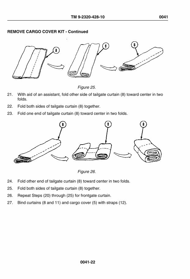
REMOVE CARGO COVER KIT - Continued
Figure 25.
21. With aid of an assistant, fold other side of tailgate curtain (8) toward center in twofolds.
22. Fold both sides of tailgate curtain (8) together.
23. Fold one end of tailgate curtain (8) toward center in two folds.
Figure 26.
24. Fold other end of tailgate curtain (8) toward center in two folds.
25. Fold both sides of tailgate curtain (8) together.
26. Repeat Steps (20) through (25) for frontgate curtain.
27. Bind curtains (8 and 11) and cargo cover (5) with straps (12).
TM 9-2320-428-10 0041
0041-22
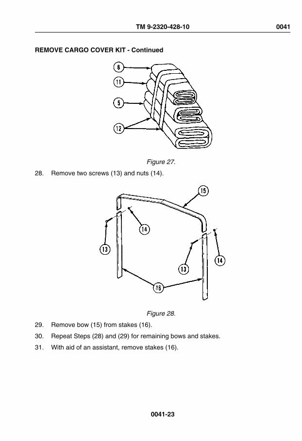
REMOVE CARGO COVER KIT - Continued
Figure 27.
28. Remove two screws (13) and nuts (14).
Figure 28.
29. Remove bow (15) from stakes (16).
30. Repeat Steps (28) and (29) for remaining bows and stakes.
31. With aid of an assistant, remove stakes (16).
TM 9-2320-428-10 0041
0041-23

REMOVE CARGO COVER KIT - Continued
Figure 29.
END OF TASK
END OF WORK PACKAGE
TM 9-2320-428-10 0041
0041-24

OPERATOR MAINTENANCEGROVE CRANE OPERATION (MANUAL CONTROL)
INITIAL SETUP:
Not Applicable
PREPARE CRANE FOR USE
WARNING
Stand clear of outrigger beams while operating levers. Failure to complymay result in injury or death to personnel.
1. Chock wheels. (WP 0077)
WARNING
• Stand clear of outrigger beams while operating levers. Failure tocomply may result in injury or death to personnel.
• Do not operate crane unless outriggers are firmly in place or vehiclecould turn over. Failure to comply may result in injury or death topersonnel.
• Keep boom clear of all electrical lines and other obstacles whileoperating crane. Failure to comply may result in injury or death topersonnel.
TM 9-2320-428-10 0042
0042-1

PREPARE CRANE FOR USE - Continued
WARNING
If operator cannot see load during operation, operate crane fromREMOTE CONTROL UNIT. Failure to comply may result in injury ordeath to personnel.
NOTE• Failure of hydraulic system will stop crane operation and lock crane
in place. If hydraulic system fails during crane operation, refer toperform immediate action for loss of hydraulic system. (WP 0104)
• If electrical system fails during crane operation, refer to performemergency hydraulic operation when grove crane electrical powerfails. (WP 0105)
• Grove crane can operate on up to 5-degree side slope.
2. Start engine. (WP 0044)
3. Position vehicle on level ground so all loading and unloading can be done from oneposition.
4. Set transmission range selector (1) to N (neutral).
5. Pull out PARKING BRAKE control (2).
TM 9-2320-428-10 0042
0042-2

PREPARE CRANE FOR USE - Continued
TRAILERAIR SUPPLYNOT FOR PARKINGMIDLAND
PULL TO EXHAUST
PUSH TO SU P PLY
4 3
1
2
Figure 1.
6. Set PTO ENGAGE switch (3) to OFF position. Indicator light (4) will go out.
CAUTIONPTO ENGAGE switch must be in OFF position before moving hydraulicselector valve control to prevent equipment damage.
7. Push hydraulic selector valve control (5) in for crane operation.
TM 9-2320-428-10 0042
0042-3

PREPARE CRANE FOR USE - Continued
5
Figure 2.
8. Set PTO ENGAGE switch (3) to ON position. Indicator light (4) will illuminate.
TM 9-2320-428-10 0042
0042-4

PREPARE CRANE FOR USE - Continued
TRAILERAIR SUPPLYNOT FOR PARKINGMIDLAND
PULL TO EXHAUST
PUSH TO SU P PLY
4 3
Figure 3.
9. Set electric control box ON/OFF POWER switch (6) to ON position.
Figure 4.
TM 9-2320-428-10 0042
0042-5

PREPARE CRANE FOR USE - Continued
10. Set ENGINE HIGH IDLE ON/OFF switch (7) to ON position.
11. Push up and release LATCH switch (8) to raise engine speed to approximately 1500rpm.
SETUP OUTRIGGERS
WARNING
Stand clear of outrigger beams while operating levers. Failure to complymay result in injury or death to personnel.
NOTE• Always operate control levers with light, even pressure.
• Outrigger beams will come out slower with light pressure on lever.Pushing lever to full travel will cause faster movement.
• Although either right or left side outrigger may extend first, bothoutriggers will extend when O/R EXT control lever is positioned toOUT.
1. Move outrigger extension (O/R EXT) control lever (1) to OUT position until right andleft outrigger beams (2) are fully extended.
TM 9-2320-428-10 0042
0042-6

SETUP OUTRIGGERS - Continued
Figure 5.
WARNING
Stand clear of outrigger beams while operating levers. Failure to complymay result in injury or death to personnel.
NOTEOutrigger pad on passenger side is shown. Driver side is the same.
2. Remove two safety pins (3) and remove outrigger pad (4) from studs (5) on outriggerbeam (2).
TM 9-2320-428-10 0042
0042-7

SETUP OUTRIGGERS - Continued
Figure 6.
3. Remove two retaining pins (6).
Figure 7.
4. Clean all foreign material from socket (7) in outrigger pad (4) and from rod end ofoutrigger jack cylinder (8).
TM 9-2320-428-10 0042
0042-8
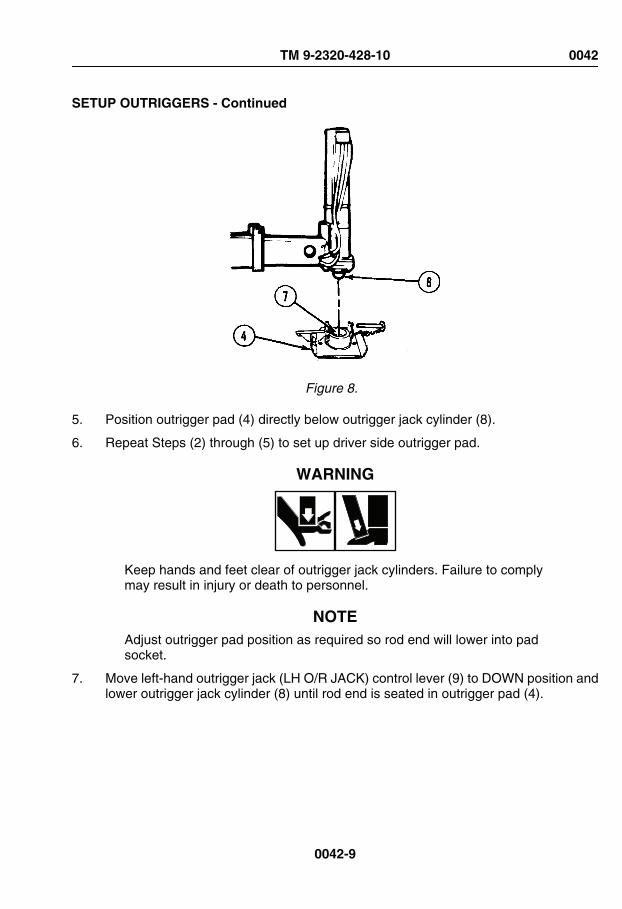
SETUP OUTRIGGERS - Continued
Figure 8.
5. Position outrigger pad (4) directly below outrigger jack cylinder (8).
6. Repeat Steps (2) through (5) to set up driver side outrigger pad.
WARNING
Keep hands and feet clear of outrigger jack cylinders. Failure to complymay result in injury or death to personnel.
NOTEAdjust outrigger pad position as required so rod end will lower into padsocket.
7. Move left-hand outrigger jack (LH O/R JACK) control lever (9) to DOWN position andlower outrigger jack cylinder (8) until rod end is seated in outrigger pad (4).
TM 9-2320-428-10 0042
0042-9

SETUP OUTRIGGERS - Continued
Figure 9.
8. Install two retaining pins (6).
9. Move right-hand outrigger jack (RH O/R JACK) control lever (10) to DOWN positionand lower outrigger cylinder (8) until rod end is seated in outrigger pad (4).
10. Install two retaining pins (6).
JACK OUTRIGGERS
WARNING
• Do not raise vehicle tires off ground with outrigger jack cylinders.Vehicle could roll over. Always chock front wheels when usingoutriggers. Failure to comply may result in injury or death topersonnel.
• Crane must be level from side to side. Use of crane in unlevel positioncan cause vehicle to turn. Failure to comply may result in injury ordeath to personnel.
NOTE• Operate left and right outrigger jack (LH O/R JACK and RH O/R
JACK) control levers at same time.
TM 9-2320-428-10 0042
0042-10
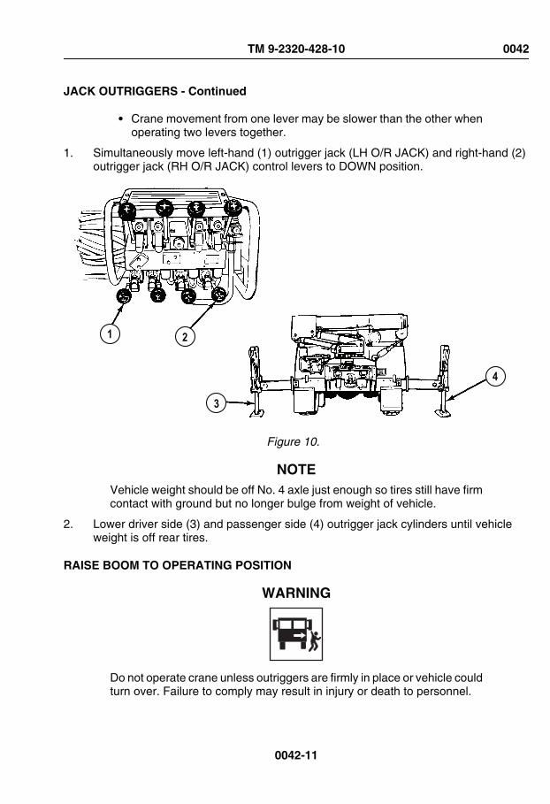
JACK OUTRIGGERS - Continued
• Crane movement from one lever may be slower than the other whenoperating two levers together.
1. Simultaneously move left-hand (1) outrigger jack (LH O/R JACK) and right-hand (2)outrigger jack (RH O/R JACK) control levers to DOWN position.
21
3
4
Figure 10.
NOTEVehicle weight should be off No. 4 axle just enough so tires still have firmcontact with ground but no longer bulge from weight of vehicle.
2. Lower driver side (3) and passenger side (4) outrigger jack cylinders until vehicleweight is off rear tires.
RAISE BOOM TO OPERATING POSITION
WARNING
Do not operate crane unless outriggers are firmly in place or vehicle couldturn over. Failure to comply may result in injury or death to personnel.
TM 9-2320-428-10 0042
0042-11

RAISE BOOM TO OPERATING POSITION - Continued
CAUTIONDo not let cable unwind and become slack or cable may get tangled ondrum.
1. Move HOIST control lever (1) to DOWN position and lower hoist cable (2)approximately 1 ft. (30 cm).
Figure 11.
CAUTION• Release hook lock before disconnecting load hook from stowage ring
bracket to avoid hook lock damage.
• Do not let load hook fall and hit bracket.
2. Disconnect load hook (3) from stowage ring bracket (4).
TM 9-2320-428-10 0042
0042-12

RAISE BOOM TO OPERATING POSITION - Continued
WARNING
When using crane on any vehicle, park vehicle clear of all overheadelectrical lines. Keep boom clear of all electrical lines and other obstacleswhile operating crane. Failure to comply may result in injury or death topersonnel.
3. Move BOOM control lever (5) to UP position until boom (6) is approximately 45degrees above horizontal.
Figure 12.
CAUTIONTo avoid damage to outrigger leg or load hook, do not hit outrigger legwith load hook.
4. Move MAST control lever (7) to UP position until the mast (8) is fully erect and thecylinders are fully extended.
TM 9-2320-428-10 0042
0042-13

RAISE BOOM TO OPERATING POSITION - Continued
Figure 13.
5. Move BOOM control lever (5) to UP position simultaneously as required to maintainthe boom (6) at approximately 45 degrees above horizontal until the mast (8) is fullyerect.
6. Hold MAST control lever (7) to UP position for two to three seconds after mast (8) isfully erect to ensure cylinders are fully filled with oil.
7. Operate crane with manual controls or remote-control unit. (WP 0043)
ROTATE AND TELESCOPE BOOM
WARNING
• When using crane on any vehicle, park vehicle clear of all overheadelectrical lines. Keep boom clear of all electrical lines and otherobstacles while operating crane. Failure to comply may result in injuryor death to personnel.
• Ensure area is clear of personnel prior to moving SWING controllever. Boom should be swung slowly enough so crane operator hascomplete control. If operator cannot see load during operation,operate crane from REMOTE CONTROL UNIT. Failure to complymay result in injury or death to personnel.
TM 9-2320-428-10 0042
0042-14

ROTATE AND TELESCOPE BOOM - Continued
• Operator must keep control of load at all times. If necessary, attachcargo tie downs to load for control. Failure to comply may result ininjury or death to personnel.
• If electrical power fails during crane operation, move switch onREMOTE CONTROL UNIT to SHUTDOWN position. Failure tocomply may result in injury or death to personnel.
CAUTIONBoom must be above vehicle sides for clearance. Hitting side of vehiclewith boom may cause damage to boom or vehicle.
NOTEOperate control levers with light, even pressure. Moving lever slightly willcause slow movement of crane. Moving lever to full travel will cause fastermovement of crane.
1. Move SWING control lever (1) to CW position to move boom (2) clockwise.
Figure 14.
2. Move SWING control lever (1) to CCW position to move boom (2) counterclockwise.
CAUTIONKeep hook block at least 2 ft. (0.61 m) from end of boom. If hook blockhits end of boom it may damage cable or hook block and crane will losepower. Wait six seconds for power to return and check crane for damage.
TM 9-2320-428-10 0042
0042-15

ROTATE AND TELESCOPE BOOM - Continued
NOTE• When crane is overloaded, M977 and M985 overload system will
automatically shut off power to telescope boom out, raise boom, orhoist load any higher. The M977 overload system will also preventlowering boom. Overload condition can be corrected by lowering loadto ground or other supporting surface by using HOIST control leveronly.
• When telescoping the boom, the TELESCOPE and HOIST controllevers should be operated at the same time.
• Crane movement from one lever may be slower than the other whenoperating two levers together.
3. Move TELESCOPE control lever (3) to OUT position to extend boom (2) and moveHOIST control lever (4) to DOWN position to pay out cable (5).
Figure 15.
CAUTIONDo not go over maximum load rating as shown on RANGE DIAGRAM.Going over load ratings will cause damage to equipment.
NOTEWhen operating M977 crane, raise boom to approximately 60 degreeangle to pick up maximum load.
4. Refer RANGE DIAGRAM (6) on turntable panel (7) to raise boom (2) to correct anglebefore connecting the load.
TM 9-2320-428-10 0042
0042-16

ROTATE AND TELESCOPE BOOM - Continued
Figure 16.
RAISE AND LOWER LOAD
WARNING
• When using crane on any vehicle, park vehicle clear of all overheadelectrical lines. Keep boom clear of all electrical lines and otherobstacles while operating crane. Failure to comply may result in injuryor death to personnel.
• Ensure area is clear of personnel prior to moving SWING controllever. Boom should be swung slowly enough so crane operator hascomplete control. If operator cannot see load during operation,operate crane from REMOTE CONTROL UNIT. Failure to complymay result in injury or death to personnel.
• Operator must keep control of load at all times. If necessary, attachcargo tie downs to load for control. Failure to comply may result ininjury or death to personnel.
TM 9-2320-428-10 0042
0042-17

RAISE AND LOWER LOAD - Continued
• If electrical power fails during crane operation, move switch onREMOTE CONTROL UNIT to SHUTDOWN position. Failure tocomply may result in injury or death to personnel.
CAUTION• Do not let cable become slack or cable may get tangled on drum.
• Do not drag load sideways on ground or damage to crane may result.
1. Operate SWING control lever (1) and center end of boom (2) directly over load.
61 3
2
4
5
Figure 17.
CAUTIONRelease hook lock before connecting load hook to avoid damage to hooklock.
2. Operate HOIST control lever (3) to raise or lower cable (4) and connect load hook (5)to load.
TM 9-2320-428-10 0042
0042-18

RAISE AND LOWER LOAD - Continued
WARNING
• Always wear protective gloves when handling winch cable. Never letcable run through hands. Frayed cables can cut severely. Failure tocomply may result in injury or death to personnel.
• Never operate winch with less than five wraps of cable on winchdrum. Failure to comply may result in injury or death to personnel.
CAUTION• Do not jerk HOIST control lever or load will bounce causing possible
damage to crane or load.
• Do not operate crane with boom below horizontal when there is a loadon hook.
• For M977, maximum load limit with boom length under 9 ft. (2.75 m)is 4500 lbs (2 043 kg). Maximum load limit with boom extended over9 ft. (2.75 m) is 2500 lbs (1 135 kg).
• For M985, maximum load limit is 5400 lbs (2 452 kg) for entire boomreach.
NOTE• When M977 and M985 crane is overloaded, the overload systems
will automatically shut off power to telescope boom out, raise boom,or hoist load any higher.
• The M977 overload system will also prevent lowering load to groundor other supporting surface. All crane functions will be restored inapproximately six seconds.
3. Move HOIST control lever (3) in UP position to lift load. Move BOOM control lever (6)in UP position to raise load higher.
4. Move HOIST control lever (3) in DOWN position to lower load. Move BOOM controllever (6) in DOWN position to lower load further.
5. Shutdown crane.
TM 9-2320-428-10 0042
0042-19

SHUTDOWN CRANE
NOTESteps (1) through (3) are needed only if REMOTE CONTROL UNIT wasused during operation.
1. Set ON/OFF POWER switch (1) to ON position.
Figure 18.
2. Set ENGINE HIGH IDLE ON/OFF switch (2) to ON position.
3. Push and release LATCH switch (3) to raise engine speed to approximately 1500 rpm.
CAUTION• Keep hook block at least 2 ft. (0.61 m) from end of boom. If hook block
hits end of boom it may damage cable or hook block and crane willlose power. Wait six seconds for power to return and check crane fordamage.
• Do not let cable unwind and become slack or cable may get tangledon drum.
TM 9-2320-428-10 0042
0042-20

SHUTDOWN CRANE - Continued
NOTE• Operate control lever with light, even pressure.
• TELESCOPE and HOIST control levers should be operated at sametime to keep hook block at least 2 ft. (0.61) from end of boom.
• Crane movement from one lever may be slower than the other whenoperating levers together.
4. Move TELESCOPE control lever (4) to IN position to pull boom extensions (5) in andmove HOIST control lever (6) to UP position to reel in cable (7) until all boomextensions (5) are fully retracted.
Figure 19.
5. Operate SWING control lever (8) to position boom (9) parallel with outrigger beam(10) on passenger side of vehicle.
CAUTIONBoom must rest on rest pad when transporting vehicle. If not, damage toequipment may result.
6. Move MAST control lever (11) to DOWN position to lower mast (12) until mast iscompletely folded down.
TM 9-2320-428-10 0042
0042-21

SHUTDOWN CRANE - Continued
Figure 20.
7. Move BOOM control lever (13) in concert with MAST control lever (11) as required tomaintain boom (9) at approximately 45 degrees above horizontal until mast (12) iscompletely folded down.
8. Move BOOM control lever (13) to DOWN position until boom (9) comes to rest onmast rest pad (14).
CAUTIONRelease hook lock before connecting load hook to stowage ring bracketto avoid damage to hook lock.
NOTEStowage ring is smallest hole in bracket.
9. Connect load hook (15) to stowage ring bracket (16). Move HOIST control lever (6)in UP position to remove slack from hoist cable (7).
STOW OUTRIGGERS
1. Remove two retaining pins (1) from each outrigger pad (2).
NOTEOperate left and right outrigger jack (LH O/R JACK and RH O/R JACK)control levers at the same time until both outrigger jack cylinders are outof pads.
TM 9-2320-428-10 0042
0042-22

STOW OUTRIGGERS - Continued
2. Move left outrigger jack (LH O/R JACK) and right outrigger jack (RH O/R JACK) controllevers (3 and 4) to UP position to retract outrigger jack cylinders (5) completely.
Figure 21.
3. Install two retaining pins (1) into each outrigger pad (2).
4. Stow each outrigger pad (2) on appropriate stud (6).
5. Install safety pins (7) through each stud (6).
TM 9-2320-428-10 0042
0042-23

STOW OUTRIGGERS - Continued
WARNING
Keep hands and feet clear of outrigger jack cylinders. Failure to complymay result in injury or death to personnel.
6. Move outrigger extension (O/R EXT) control lever (8) to IN position to retract outriggerbeams (9) completely.
Figure 22.
7. Set ENGINE HIGH IDLE ON/OFF switch (10) to OFF position.
Figure 23.
TM 9-2320-428-10 0042
0042-24

STOW OUTRIGGERS - Continued
8. Set ON/OFF POWER switch (11) to OFF position.
9. Set PTO ENGAGE switch (12) to OFF position. Indicator light (13) will go out.
TRAILERAIR SUPPLYNOT FOR PARKINGMIDLAND
PULL TO EXHAUST
PUSH TO SU P PLY
13 12
Figure 24.
10. Shut off engine. (WP 0057)
END OF TASK
END OF WORK PACKAGE
TM 9-2320-428-10 0042
0042-25


OPERATOR MAINTENANCEGROVE CRANE OPERATION (REMOTE CONTROL)
INITIAL SETUP:
Not Applicable
SET UP REMOTE CONTROL UNIT
WARNING
If operator cannot see load during operation, operate crane fromREMOTE CONTROL UNIT. Failure to comply may result in injury ordeath to personnel.
1. Prepare crane for use.
2. Set up outriggers.
3. Jack outriggers.
4. Raise boom to operating position.
5. Remove REMOTE CONTROL UNIT (1) and cable (2) from stowage box (3).
TM 9-2320-428-10 0043
0043-1

SET UP REMOTE CONTROL UNIT - Continued
4
7
5 1
62
3
Figure 1.
6. Remove cover (4) and clean any dirt or water from REMOTE CONTROL UNITreceptacle (5).
7. Remove cover (6) and clean any dirt or water from cable plug (7).
8. Connect cable plug (7) to REMOTE CONTROL UNIT receptacle (5).
CONNECT REMOTE CONTROL UNIT TO REAR OUTLET
1. Set ON/OFF power switch (1) on electrical control box (2) to OFF position.
TM 9-2320-428-10 0043
0043-2

CONNECT REMOTE CONTROL UNIT TO REAR OUTLET - Continued
6
87
4
1
2
3
5
Figure 2.
2. Remove cover (3) and clean any dirt or water from REMOTE CONTROLCONNECTOR outlet (4).
3. Remove cover (5) and clean any dirt or water from cable plug (6).
WARNING
Ensure ON/OFF/MHC-SHUTDOWN power switch is in OFF position priorto connecting REMOTE CONTROL UNIT. Failure to comply may resultin injury or death to personnel.
TM 9-2320-428-10 0043
0043-3

CONNECT REMOTE CONTROL UNIT TO REAR OUTLET - Continued
4. Set ON/OFF MHC-SHUTDOWN power switch (7) on REMOTE CONTROL UNIT (8)to OFF position.
5. Connect cable plug (6) to REMOTE CONTROL CONNECTOR outlet (4).
6. Set ON/OFF POWER switch (1) on electrical control box (2) to ON position.
7. Set ON/OFF MHC-SHUTDOWN power switch (7) on REMOTE CONTROL UNIT (8)to ON position.
8. Operate crane.
CONNECT REMOTE CONTROL UNIT TO FORWARD OUTLET
1. Set ON/OFF power switch (1) on electrical control box (2) to OFF position.
TM 9-2320-428-10 0043
0043-4

CONNECT REMOTE CONTROL UNIT TO FORWARD OUTLET - Continued
6
21
5
4
3
87
Figure 3.
2. Remove cover (3) and clean any dirt or water from REMOTE CONTROLCONNECTOR outlet (4).
3. Remove cover (5) and clean any dirt or water from cable plug (6).
TM 9-2320-428-10 0043
0043-5

CONNECT REMOTE CONTROL UNIT TO FORWARD OUTLET - Continued
WARNING
Ensure ON/OFF/MHC-SHUTDOWN power switch is in OFF position priorto connecting REMOTE CONTROL UNIT. Failure to comply may resultin injury or death to personnel.
4. Set ON/OFF MHC-SHUTDOWN power switch (7) on REMOTE CONTROL UNIT (8)to OFF position.
5. Connect cable plug (6) to REMOTE CONTROL CONNECTOR outlet (4).
6. Set ON/OFF POWER switch (1) on electric control box (2) to ON position.
7. Set ON/OFF MHC-SHUTDOWN power switch (7) on REMOTE CONTROL UNIT (8)to ON position.
8. Operate crane.
ROTATE AND TELESCOPE BOOM
WARNING
• When using crane on any vehicle, park vehicle clear of all overheadelectrical lines. Keep boom clear of all electrical lines and otherobstacles while operating crane. Failure to comply may result in injuryor death to personnel.
• Ensure area is clear of personnel prior to moving SWING controllever. Boom should be swung slowly enough so crane operator hascomplete control. If operator cannot see load during operation,operate crane from REMOTE CONTROL UNIT. Failure to complymay result in injury or death to personnel.
• Operator must keep control of load at all times. If necessary, attachcargo tie downs to load for control. Failure to comply may result ininjury or death to personnel.
• If electrical power fails during crane operation, move switch onREMOTE CONTROL UNIT to SHUTDOWN position. Failure tocomply may result in injury or death to personnel.
TM 9-2320-428-10 0043
0043-6

ROTATE AND TELESCOPE BOOM - Continued
CAUTIONBoom must be above vehicle sides for clearance. Hitting side of vehiclewith boom may cause damage to equipment.
NOTEOperate control levers with light, even pressure. Moving lever slightly willcause slow movement of crane. Moving lever to full travel will cause fastermovement of crane.
1. Move SWING control lever (1) to CW position to move boom (2) clockwise.
Figure 4.
2. Move SWING control lever (1) to CCW position to move boom (2) counterclockwise.
CAUTIONKeep hook block at least 2 ft. (0.61 m) from end of boom. If hook blockhits end of boom it may damage cable or hook block and crane will losepower. Wait six seconds for power to return and check crane for damage.
NOTE• When crane is overloaded, vehicle overload system will automatically
shut off power to telescope boom out, raise boom, or hoist load anyhigher. Vehicle overload system will also prevent lowering boom.Overload condition can be corrected by lowering load to ground orother supporting surface by using HOIST control lever only.
TM 9-2320-428-10 0043
0043-7

ROTATE AND TELESCOPE BOOM - Continued
• When telescoping (extending) the boom, the TELESCOPE andHOIST control levers should be operated at the same time to keephook block at least 2 ft. (0.61 m) from end of boom.
• Crane movement from one lever may be slower than other whenoperating two levers together.
3. Move TELESCOPE control lever (3) to OUT position to extend boom (2) and moveHOIST control lever (4) to DOWN position to pay out cable (5).
Figure 5.
CAUTION• Do not go over maximum load rating as shown on RANGE
DIAGRAM. Going over load rating could cause damage toequipment.
• When operating Grove crane, raise boom to approximately 60° angleto pick up maximum load or equipment could be damaged.
4. Refer to RANGE DIAGRAM (6) on turntable panel (7) to raise boom (2) to correctangle before connecting load.
TM 9-2320-428-10 0043
0043-8
RAISE AND LOWER LOAD
WARNING
• When using crane on any vehicle, park vehicle clear of all overheadelectrical lines. Keep boom clear of all electrical lines and otherobstacles while operating crane. Failure to comply may result in injuryor death to personnel.
• Ensure area is clear of personnel prior to moving SWING controllever. Boom should be swung slowly enough so crane operator hascomplete control. If operator cannot see load during operation,operate crane from REMOTE CONTROL UNIT. Failure to complymay result in injury or death to personnel.
• Operator must keep control of load at all times. If necessary, attachcargo tie downs to load for control. Failure to comply may result ininjury or death to personnel.
• If electrical power fails during crane operation, move switch onREMOTE CONTROL UNIT to SHUTDOWN position. Failure tocomply may result in injury or death to personnel.
CAUTION• Do not let cable become slack. Cable may get tangled in drum and
damage equipment.
• Do not drag load sideways on ground. Dragging load could causedamage to equipment.
1. Operate SWING control lever (1) to center end of boom (2) directly over load.
TM 9-2320-428-10 0043
0043-9

RAISE AND LOWER LOAD - Continued
Figure 6.
CAUTIONRelease hook lock before connecting load to avoid damage to equipment.
2. Operate HOIST control lever (3) to raise or lower cable (4) and connect load hook (5)to load.
WARNING
• Always wear protective gloves when handling winch cable. Never letcable run through hands. Frayed cables can cut severely. Failure tocomply may result in injury or death to personnel.
• Never operate winch with less than five wraps of cable on winchdrum. Failure to comply may result in injury or death to personnel.
CAUTION• Do not jerk HOIST control lever or load will bounce and damage to
equipment may occur.
• Do not operate crane with boom below horizontal when there is a loadon hook or damage to equipment may occur.
TM 9-2320-428-10 0043
0043-10

RAISE AND LOWER LOAD - Continued
• Do not go over maximum load limit. Going over maximum load limitwill cause electrical shutdown for six seconds or until load is lowered.
NOTE• For M977, maximum load limit with boom length under 9 ft. (2.75 m)
is 4500 lbs (2 043 kg). Maximum load limit with boom extended over9 ft. (2.75 m) is 2500 lbs (1 135 kg) (refer to RANGE DIAGRAM formore information).
• For M985 maximum load limit is 5400 lbs (2 452 kg) for entire boomreach (refer to RANGE DIAGRAM for more information).
3. Move HOIST control lever (3) to UP position to lift load. Move BOOM control lever (6)to UP position to raise load higher.
Figure 7.
4. Move HOIST control lever (3) to DOWN position to lower load. Move BOOM controllever (6) to DOWN position to lower load further.
SHUT OFF SWITCHES
1. Set ON/OFF/MHC-SHUTDOWN power switch (1) on REMOTE CONTROL UNIT (2)to OFF position.
TM 9-2320-428-10 0043
0043-11

SHUT OFF SWITCHES - Continued
Figure 8.
2. Set ON-OFF POWER switch (3) on electric control box (4) in OFF position.
3. Disconnect REMOTE CONTROL UNIT (2) from either rear or forward remote-controloutlet (as applicable).
DISCONNECT REMOTE CONTROL UNIT FROM REAR OUTLET
1. Disconnect cable plug (1) and install cover (3) on REMOTE CONTROL CONNECTORoutlet (2).
TM 9-2320-428-10 0043
0043-12

DISCONNECT REMOTE CONTROL UNIT FROM REAR OUTLET - Continued
10
7
3
2
1
8
4
56
9
Figure 9.
2. Disconnect cable plug (4) from REMOTE CONTROL UNIT receptacle (5). Install cover(6).
3. Install covers (7) on both ends of cable (8) and coil cable (8) for stowage.
4. Return REMOTE CONTROL UNIT (9) and cable (8) to stowage box (10).
5. Shut down crane.
TM 9-2320-428-10 0043
0043-13

DISCONNECT REMOTE CONTROL UNIT FROM FORWARD OUTLET
1. Disconnect cable plug (1) and install cover (3) on REMOTE CONTROL CONNECTORoutlet (2).
10 1
4
6 5
9
2
3
7
8 8
Figure 10.
2. Disconnect cable plug (4) and install cover (6) on REMOTE CONTROL UNITreceptacle (5).
3. Install covers (7) on both ends of cable (8) and coil cable (8) for stowage.
4. Return REMOTE CONTROL UNIT (9) and cable (8) to stowage box (10).
5. Shut down crane.
END OF TASK
END OF WORK PACKAGE
TM 9-2320-428-10 0043
0043-14

OPERATOR MAINTENANCESTART ENGINE
INITIAL SETUP:
Not Applicable
START COLD ENGINE
WARNING
Do not start, crank engine, or move vehicle when anyone is near, workingon, or working under vehicle. Failure to comply may result in injury ordeath to personnel.
WARNING
Keep away from moving engine parts, alternator belts, and pulleys whileengine is running. Failure to comply may result in injury or death topersonnel.
1. Pull out PARKING BRAKE control (1).
TM 9-2320-428-10 0044
0044-1

START COLD ENGINE - Continued
TRAILER
AIR SUPPLY
NOT FOR PARKING
MIDLAND
PULL
TO
EXHAUST
PUS H T O SUPP
LY
LHS
NOTRANSIT
LHS
LMS
OVER
LOAD
1
2
3
Figure 1.
2. Set transmission range selector (2) to N (neutral).
CAUTION• Do not press ETHER START button more than three times in a single
starting attempt. Failure to comply may result in damage toequipment.
• Do not turn ENGINE switch to START position while engine is stillrunning. Failure to comply may result in damage to equipment.
• If engine fails to start, wait 15 seconds before next start attempt toallow starter motor to cool. Failure to comply may result in damageto equipment.
3. If outside temperature is above 45°F (7°C), go to Step (5). If outside temperature isbelow 45°F (7°C), go to Step (4).
NOTE• Do Step (4):
• One time for temperatures between 45°F and 10°F (7°C and-12°C).
• Two times for temperatures between 10°F and -10°F (-12°Cand -23°C).
TM 9-2320-428-10 0044
0044-2

START COLD ENGINE - Continued
• Three times for temperatures between -10°F and -25°F(-23°C and -32°C).
• Repeat Steps (4) and (5) up to four times. If engine fails to start afterfour starting attempts, notify field level maintenance.
• Under extreme cold temperatures, it may be necessary to press theETHER START button two or three times in a single starting attempt.Wait approximately three seconds between each press.
4. Press and hold ETHER START button (3) for three seconds, release, and wait threeseconds.
5. Turn ENGINE switch (4) to START for no more than 15 seconds, or until engine starts.
PARKINGBRAKE
TRAILERAIR SUPPLY
EXEXEX
EXEXEXEXEXEX
ENGINEOFF
ON
START
AIR BRAKE
10 68
5
9
7
4
Figure 2.
NOTE• ENGINE switch will spring back to ON position when released.
• AIR indicator may illuminate and buzzer may sound upon enginestart.
6. Release ENGINE switch (4). Air indicator (5) may light and buzzer may sound.
TM 9-2320-428-10 0044
0044-3
START COLD ENGINE - Continued
CAUTION• Do not turn ENGINE switch to START position while engine is still
running. Failure to comply may result in damage to equipment.
• If OIL PRESS gauge does not show engine oil pressure within 10 to15 seconds after starting engine, immediately shut off engine(WP 0057) and notify field level maintenance. Failure to comply mayresult in damage to equipment.
• If engine fails to start, repeat Step (3) up to seven times. If enginedoesn't start after eight starting attempts, notify field levelmaintenance.
7. Check that OIL PRESS gauge (6) reads 5 to 10 psi (34 to 69 kPa) at idle.
8. Press throttle pedal (7) until tachometer (8) reads 800-1000 rpm.
9. Run engine at 800-1000 rpm for about 5 minutes.
CAUTIONIf red and green needles on AIR PRESS gauge do not read 60 to 120 psi(414 to 827 kPa) after warm-up, shut off engine (WP 0057) and notifyfield level maintenance. Failure to comply may result in damage toequipment.
10. Check that AIR PRESS gauge (9) reads 60 to 120 psi (414 to 827 kPa). AIR indicator(5) will light and buzzer will sound until both needles reach 60 to 75 psi (414 to 517kPa).
11. Check that FUEL gauge (10) shows enough fuel to complete mission.
NOTEWATER TEMP gauge may not show reading at engine idle.
12. Check that WATER TEMP gauge (11) does not read over 230°F (110°C).
TM 9-2320-428-10 0044
0044-4

START COLD ENGINE - Continued
PARKINGBRAKE
TRAILERAIR SUPPLY
EXEXEX
EXEXEXEXEXEX
ENGINEOFF
ON
START
11
AIR BRAKE12
13 14
15
Figure 3.
13. Check that BATTERY gauge (12) reads between 24 and 30 volts.
14. Check that AMPERES gauge (13) shows positive reading.
15. Check that air filter restriction indicator (14) shows yellow.
16. If air filter restriction indicator (14) shows red, press button (15).
17. If air filter restriction indicator (14) still shows red and/or VACUUM INCHES H2Owindow shows 18, shut off engine (WP 0057) and clean air filter elements.(WP 0157)
START WARM ENGINE
WARNING
Do not start, crank engine, or move vehicle when anyone is near, workingon, or working under vehicle. Failure to comply may result in injury ordeath to personnel.
TM 9-2320-428-10 0044
0044-5

START WARM ENGINE - Continued
WARNING
Keep away from moving engine parts, alternator belts, and pulleys whileengine is running. Failure to comply may result in injury or death topersonnel.
1. Pull out PARKING BRAKE control (1).
TRAILER
AIR SUPPLY
NOT FOR PARKING
MIDLAND
PULL
TO
EXHAUST
PUS H T O SUPP
LY
LHS
NOTRANSIT
LHS
LMS
OVER
LOAD
1
24
3
Figure 4.
2. Set transmission range selector (2) to N (neutral).
3. Turn ENGINE switch (3) to START for no longer than 10 seconds, or until enginestarts.
NOTEENGINE switch will spring back to ON position when released.
4. Release ENGINE switch (3).
TM 9-2320-428-10 0044
0044-6

START WARM ENGINE - Continued
CAUTIONIf OIL PRESS gauge does not show engine oil pressure within 10 to 15seconds after starting engine, shut off engine (WP 0057) immediately andnotify field level maintenance. Failure to comply may result in damage toequipment.
NOTE• Minimum engine oil pressure for safe operation (vehicle moving) is
30 psi (207 kPa).
• At idle, engine oil pressure can drop as low as 5 psi (34 kPa), this isa normal condition.
5. Check that engine OIL PRESS gauge (4) indicates normal operating range of 40 to70 psi (276 to 483 kPa) at 1800 to 2100 rpm.
6. AIR PRESS gauge (5) reads 60 to 120 psi (414 to 827 kPa). AIR indicator (6) will lightand buzzer will sound until both needles reach 60 to 75 psi (414 to 517 kPa).
PARKINGBRAKE
TRAILERAIR SUPPLY
EXEXEX
EXEXEXEXEXEX
ENGINEOFF
ON
START
AIR BRAKE
7
6
5
Figure 5.
7. Check that FUEL gauge (7) shows enough fuel to complete mission.
NOTEWATER TEMP gauge may not show reading at engine idle.
TM 9-2320-428-10 0044
0044-7

START WARM ENGINE - Continued
8. Check that WATER TEMP gauge (8) does not read over 230°F (110°C).
PARKINGBRAKE
TRAILERAIR SUPPLY
EXEXEX
EXEXEXEXEXEX
ENGINEOFF
ON
START
8
AIR BRAKE9
10 11
12
Figure 6.
9. Check that BATTERY gauge (9) reads between 24 and 30 volts.
10. Check that AMPERES gauge (10) shows positive reading.
11. Check that air filter restriction indicator (11) shows yellow.
12. If air filter restriction indicator (11) shows red, press button (12).
13. If air filter restriction indicator (11) still shows red and/or VACUUM INCHES H2Owindow shows 18, shut off engine (WP 0057) and clean air filter elements.(WP 0157)
END OF TASK
END OF WORK PACKAGE
TM 9-2320-428-10 0044
0044-8

OPERATOR MAINTENANCEOPERATE PARKING BRAKES
INITIAL SETUP:
Not Applicable
OPERATE PARKING BRAKES
NOTE• Vehicle may be equipped with manual parking brake valve (round/
black knob) or automatic parking brake valve (square/yellow knob).
• Manual parking brake valve shown.
1. Pull out PARKING BRAKE control (1) to apply.
AIR BRAKE
PARKINGBRAKE
TRAILERAIR SUPPLY
EXEXEX
EXEXEXEXEX EXEX
ENGINEOFF
ON
START
1
Figure 1.
TM 9-2320-428-10 0045
0045-1

OPERATE PARKING BRAKES - Continued
2. Push in PARKING BRAKE control (1) to release.
END OF TASK
END OF WORK PACKAGE
TM 9-2320-428-10 0045
0045-2

OPERATOR MAINTENANCEOPERATE SERVICE BRAKES
INITIAL SETUP:
Not Applicable
OPERATE SERVICE BRAKES
WARNING
Do not press service brake treadle hard three or four times in a row. Airsupply will be used up and service brakes will not work until air is built upagain. Failure to comply may result in injury or death to personnel.
1. Ensure both needles (red and green) of AIR PRESS gauge (1) read at least 100 psi(690 kPa) before operating vehicle.
TRAILER
AIR SUPPLY
NOT FOR PARKING
MIDLAND
PULL
TO EXHAUST
PUSH
LHS NO
TRANSIT
LHS
LMS OVER
LOAD
1
2
Figure 1.
TM 9-2320-428-10 0046
0046-1

OPERATE SERVICE BRAKES - Continued
2. Push down and hold service brake pedal (2) as needed to slow or stop vehicle.
END OF TASK
END OF WORK PACKAGE
TM 9-2320-428-10 0046
0046-2

OPERATOR MAINTENANCEOPERATE TRAILER BRAKES
INITIAL SETUP:
Not Applicable
OPERATE TRAILER BRAKES
WARNING
Trailer handbrake control is used only when testing trailer brakes. Do notuse trailer handbrake control while driving or the trailer may skid andjackknife, causing an accident. Failure to comply may result in injury ordeath to personnel.
1. Slowly pull back trailer handbrake control (1) to test application of trailer brakes.
TRAILER
AIR SUPPLY
NOT FOR PARKING
MIDLAND
PULL
TO EXHAUST
PUSH
LHS NO
TRANSIT
LHS
LMS OVER
LOAD
1
Figure 1.
TM 9-2320-428-10 0047
0047-1

OPERATE TRAILER BRAKES - Continued
2. Push trailer handbrake control (1) forward to test release of trailer brakes.
END OF TASK
END OF WORK PACKAGE
TM 9-2320-428-10 0047
0047-2

OPERATOR MAINTENANCEOPERATE TRANSMISSION AND TRANSFER CASE
INITIAL SETUP:
Not Applicable
OPERATE TRANSMISSION
1. Push in button (1) and move transmission range selector (2) to desired position:
a. Select R (reverse) to:
TRAILERAIR SUPPLYNOT FOR PARKINGMIDLAND
PULL TO EXHAUST
PUSH TO SU PPLY
RND321
21
Figure 1.
(1) Drive vehicle in reverse. (WP 0051)
b. Select N (neutral) to:
(1) Start engine. (WP 0044)
(2) Park vehicle. (WP 0056)
(3) Perform stationary power takeoff.
(4) Shift transfer case.
c. Select D (drive) to:
(1) Drive in normal conditions.
TM 9-2320-428-10 0048
0048-1

OPERATE TRANSMISSION - Continued
(2) Drive vehicle forward (WP 0050) from a stop.
d. Select 3 (third gear range) to:
(1) Drive vehicle in off-road conditions. (WP 0053)
(2) Drive vehicle in city traffic and on highway. (WP 0052)
(3) Haul a heavy load.
e. Select 2 (second gear range) to:
(1) Drive down moderate grades.
(2) Control vehicle speed.
f. Select 1 (first gear range) to:
(1) Drive vehicle in slippery conditions. (WP 0055)
(2) Drive vehicle up/down steep grade. (WP 0054)
(3) Give maximum vehicle speed control.
OPERATE TRANSFER CASE
1. Start engine. (WP 0044)
TRAILERAIR SUPPLYNOT FOR PARKINGMIDLAND
PULL TO EXHAUST
PUSH TO SU PPLY
1
2
3
4
Figure 2.
2. Push in PARKING BRAKE control (1). (WP 0045)
3. Set transmission range selector (2) to N (neutral).
TM 9-2320-428-10 0048
0048-2

OPERATE TRANSFER CASE - Continued
CAUTION• Do not force TRANSFER CASE shift lever. Lever may work hard if
there is drive line windup. Using excessive force on shift lever maycause damage to shift linkage or change linkage adjustment.
• Do not move TRANSFER CASE shift lever when vehicle is moving,or when transmission is in gear. Severe damage to drive line mayresult.
4. Select transfer case position.
NOTEIf TRANSFER CASE shift lever is hard to move, set transmission rangeselector to D, then back to N. If transfer case will not shift, refer totroubleshooting procedures. (WP 0140)
5. Set TRANSFER CASE shift lever (3) to H (HI) for highway driving.
NOTESelecting L (LO) position automatically selects 8X8 drive in the vehicletraction control system.
6. Set TRANSFER CASE shift lever (3) to L (LO) for off-road driving, 8X8 indicator light(4) will illuminate.
END OF TASK
END OF WORK PACKAGE
TM 9-2320-428-10 0048
0048-3


OPERATOR MAINTENANCEOPERATE ENGINE BRAKE
INITIAL SETUP:
Not Applicable
OPERATE ENGINE BRAKE
WARNING
Do not use engine brake when vehicle is on slippery surface. If enginebrake is used incorrectly, vehicle may skid out of control. Failure tocomply may result in injury or death to personnel.
NOTEService brakes must be used in addition to engine brake for optimumbraking capability.
1. Set JACOBS® ENGINE BRAKE HIGH/LOW switch (1) to LOW.
TM 9-2320-428-10 0049
0049-1

OPERATE ENGINE BRAKE - Continued
TRAILER
AIR SUPPLY
NOT FOR PARKING
MIDLAND
PULL
TO
EXHAUST
PUSH T O SUPP
LY
LHS
NO
TRANSIT
LHS
LMS
OVER
LOAD
45
6
13
27
Figure 1.
2. Set JACOBS® ENGINE BRAKE ON/OFF switch (2) to ON. JACOBS® ENGINEBRAKE indicator light (3) will come on.
3. Lift foot off throttle pedal (4). Engine brake will automatically slow vehicle.
4. If too much braking occurs, push in button (5) and set transmission range selector (6)to a higher range.
5. If more braking is required, set JACOBS® ENGINE BRAKE HIGH/LOW switch (1) toHIGH.
NOTEEngine brake operates best when engine speed is between 1650 and2100 rpm.
6. Check that tachometer (7) reads between 1650 and 2100 rpm whenever engine brakeis used.
END OF TASK
END OF WORK PACKAGE
TM 9-2320-428-10 0049
0049-2
OPERATOR MAINTENANCEDRIVE VEHICLE FORWARD
INITIAL SETUP:
Not Applicable
PREPARE VEHICLE
NOTEIf vehicle has less than 500 miles (805 km), check controls and indicatorsoften during operation and listen for unusual noises or vibrations. Notifyfield level maintenance of any problems.
1. Remove and stow wheel chocks. (WP 0077)
2. Ensure cargo body end panels are in place.
3. Ensure cargo body side panels are secure. (WP 0041)
4. Ensure grove crane, outriggers, and outrigger pads are secured in stowed position.(WP 0042)
5. Ensure all cargo in cargo body is secured.
6. Adjust seat and mirrors as needed. (WP 0079)
7. Adjust air-ride seat and mirrors as needed. (WP 0081)
8. Adjust three-point seatbelt as needed. (WP 0080)
9. Adjust four-point seatbelt as needed. (WP 0082)
10. Start engine. (WP 0044)
11. Turn on lights as required.
WARNING
Do not press service brake treadle hard three or four times in a row. Airsupply will be used up and service brakes will not work until air is built upagain. Failure to comply may result in injury or death to personnel.
TM 9-2320-428-10 0050
0050-1

PREPARE VEHICLE - Continued
12. Ensure both needles (red and green) AIR PRESS gauge (1) read at least 100 psi (690kPa) before driving vehicle.
AIR BRAKE
PARKINGBRAKE
TRAILERAIR SUPPLY
EXEXEX
EXEXEXEXEX EXEX
ENGINEOFF
ON
START
1
Figure 1.
DRIVE VEHICLE FORWARD
1. Drive vehicle in city traffic and on highway. (WP 0052)
2. Drive vehicle in off-road conditions. (WP 0053)
3. Drive vehicle in slippery conditions. (WP 0055)
4. Drive vehicle up/down steep grade. (WP 0054)
END OF TASK
END OF WORK PACKAGE
TM 9-2320-428-10 0050
0050-2

OPERATOR MAINTENANCEDRIVE VEHICLE IN REVERSE
INITIAL SETUP:
Personnel RequiredOperator and Assistant - - - (2)
PREPARE VEHICLE
1. Remove and stow wheel chocks.
2. Adjust seat and mirrors as needed.
3. Adjust air-ride seat and mirrors as needed. (WP 0081)
4. Adjust three-point seatbelt as needed. (WP 0080)
5. Adjust four-point seatbelt as needed. (WP 0082)
6. Start engine. (WP 0044)
7. Turn on lights as required.
DRIVE VEHICLE IN REVERSE
WARNING
Do not press service brake treadle hard three or four times in a row. Airsupply will be used up and service brakes will not work until air is built upagain. Failure to comply may result in injury or death to personnel.
1. Make sure both needles (red and green) on AIR PRESS gauge (1) read at least 100psi (690 kPa) before driving vehicle.
TM 9-2320-428-10 0051
0051-1

DRIVE VEHICLE IN REVERSE - Continued
TRAILER
AIR SUPPLYNOT FOR PARKING
MIDLAND
PULL
TO
EXHAUST
PUSH TO SU PPLY
LHS
NO
TRANSIT
LHS
LMS
OVER
LOAD
14
5
3 2
Figure 1.
WARNING
Driver has limited vision to rear. Ground guide is required when drivingvehicle in reverse. Failure to comply may result in injury or death topersonnel.
CAUTIONDo not move TRANSFER CASE shift lever when vehicle is moving orwhen transmission is in gear. Severe damage to drive line may result.
2. Set TRANSFER CASE shift lever (2) to HI.
NOTEReverse alarm will not sound if blackout lighting is selected.
3. Set transmission range selector (3) to R (reverse).
TM 9-2320-428-10 0051
0051-2

DRIVE VEHICLE IN REVERSE - Continued
4. Push in PARKING BRAKE control (4).
5. Slowly apply throttle pedal (5).
6. Follow direction from ground guide (as required).
CAUTIONDo not hold steering wheel at full left or full right position for longer than10 seconds. Oil overheating and pump damage may result.
7. Accelerate, brake, and steer as required.
END OF TASK
END OF WORK PACKAGE
TM 9-2320-428-10 0051
0051-3


OPERATOR MAINTENANCEDRIVE VEHICLE IN CITY TRAFFIC AND ON HIGHWAY
INITIAL SETUP:
Not Applicable
OPERATE VEHICLE
WARNING
Speed limits posted on curves reflect speeds that are considered safe forautomobiles. Heavy vehicles with a high center of gravity can roll over atthese speed limits. Use care and reduce your speed below the postedlimit prior to entering a curve. Failure to comply may result in injury ordeath to personnel.
CAUTIONDo not move TRANSFER CASE shift lever when vehicle is moving orwhen transmission is in gear. Severe damage to drive line will result.
1. Set TRANSFER CASE shift lever (1) to HI.
TM 9-2320-428-10 0052
0052-1

OPERATE VEHICLE - Continued
TRAILERAIR SUPPLYNOT FOR PARKINGMIDLAND
PULL
TO EXHAUST
PUSH T O SUPPLY
35
42
1
Figure 1.
2. Set transmission range selector (2) to D (drive).
3. Push in PARKING BRAKE control (3).
CAUTIONMaximum no-load governed engine speed is approximately 2250 rpm.Do not let engine speed go above this figure. Under full load, governedspeed is approximately 2100 rpm. If engine speed goes above governedspeeds, serious engine damage can result.
4. Slowly depress throttle pedal (4) until vehicle reaches desired speed. Tachometer (5)should read 1650 to 2100 rpm.
CAUTIONDo not hold steering wheel at full left or full right position for longer than10 seconds. Power steering oil can overheat and pump can be damaged.
5. Accelerate, brake, and steer as required.
NOTECheck system gauges often during vehicle operation. If gauges readother than normal, stop engine and troubleshoot problem.
TM 9-2320-428-10 0052
0052-2

OPERATE VEHICLE - Continued
6. Check that FUEL gauge (6) shows enough fuel to complete mission.
PARKINGBRAKE
TRAILERAIR SUPPLY
EXEXEX
EXEXEXEXEX EXEX
ENGINEOFF
ON
START
12
139768
1114
10
Figure 2.
7. Check that OIL PRESS gauge (7) reads 40 to 70 psi (276 to 483 kPa).
8. Check that TRANS TEMP (transmission temperature) gauge (8) reads 160 to 220° F(71 to 104° C).
9. Check that WATER TEMP gauge (9) reads 180 to 200° F (82 to 93° C).
10. Check that AMPERES gauge (10) reads about zero.
11. Check that BATTERY gauge (11) reads 24 to 28 volts.
12. Check that AIR PRESS gauge (12) red and green needles read 100 to 120 psi (690to 827 kPa).
13. If OIL-WATER indicator (13) illuminates and buzzer sounds, park vehicle (WP 0056)and notify field level maintenance.
14. If WATER TEMP gauge (9) reads over 230°F (110° C), idle engine until watertemperature cools. If water does not cool, shut off engine (WP 0057) and notify fieldlevel maintenance.
15. If OIL PRESS gauge (8) reads over 70 psi (483 kPa) or lower than 28 psi (193 kPa),park vehicle (WP 0056), shut off engine (WP 0057), and notify field level maintenance.
TM 9-2320-428-10 0052
0052-3

OPERATE VEHICLE - Continued
16. If AIR indicator (14) illuminates (red), perform immediate action for loss of air supplysystem pressure emergency procedures. (WP 0103)
END OF TASK
END OF WORK PACKAGE
TM 9-2320-428-10 0052
0052-4

OPERATOR MAINTENANCEDRIVE VEHICLE IN OFF-ROAD CONDITIONS
INITIAL SETUP:
Not Applicable
DRIVE VEHICLE IN OFF-ROAD CONDITIONS
CAUTIONDo not move TRANSFER CASE shift lever when vehicle is moving orwhen transmission is in gear. Severe damage to drive line may result.
NOTE8x8 DRIVE indicator (WP 0021) will illuminate when TRANSFER CASEshift lever is positioned to L (LO).
1. Set TRANSFER CASE shift lever (1) to L (LO).
TRAILERAIR SUPPLYNOT FOR PARKINGMIDLAND
PULL TO EXHAUST
PUSH TO SU PPLY
53
2
1
4
Figure 1.
2. Set transmission range selector (2) to 2 (2nd gear range) or 1 (1st gear range),depending on ground condition. (WP 0048)
3. Push in PARKING BRAKE control (3).
TM 9-2320-428-10 0053
0053-1

DRIVE VEHICLE IN OFF-ROAD CONDITIONS - Continued
CAUTIONNever let engine exceed maximum no-load governed engine speed(approximately 2250 rpm) or maximum governed engine speed underload (approximately 2100 rpm). If engine is allowed to go over governedengine speeds, serious engine damage may result.
4. Slowly depress throttle pedal (4) until vehicle reaches desired speed. Tachometer (5)should read 1650 to 2100 rpm.
CAUTIONDo not hold steering wheel at full left or full right position for longer than10 seconds. Power steering oil can overheat and pump may be damaged.
5. Accelerate, brake, and steer as required.
END OF TASK
END OF WORK PACKAGE
TM 9-2320-428-10 0053
0053-2
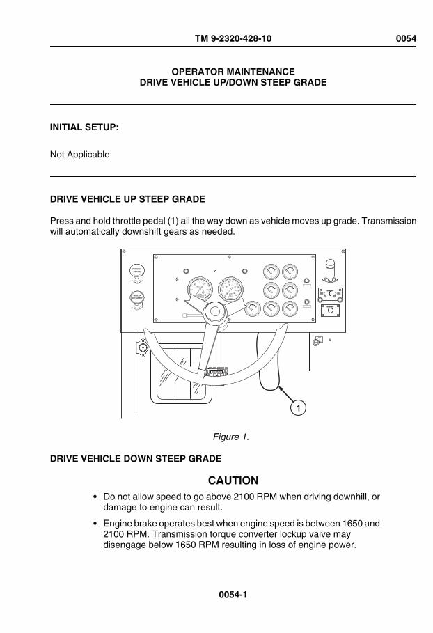
OPERATOR MAINTENANCEDRIVE VEHICLE UP/DOWN STEEP GRADE
INITIAL SETUP:
Not Applicable
DRIVE VEHICLE UP STEEP GRADE
Press and hold throttle pedal (1) all the way down as vehicle moves up grade. Transmissionwill automatically downshift gears as needed.
AIR BRAKE
PARKINGBRAKE
TRAILERAIR SUPPLY
EXEXEX
EXEXEXEXEX EXEX
ENGINEOFF
ON
START
1
Figure 1.
DRIVE VEHICLE DOWN STEEP GRADE
CAUTION• Do not allow speed to go above 2100 RPM when driving downhill, or
damage to engine can result.
• Engine brake operates best when engine speed is between 1650 and2100 RPM. Transmission torque converter lockup valve maydisengage below 1650 RPM resulting in loss of engine power.
TM 9-2320-428-10 0054
0054-1
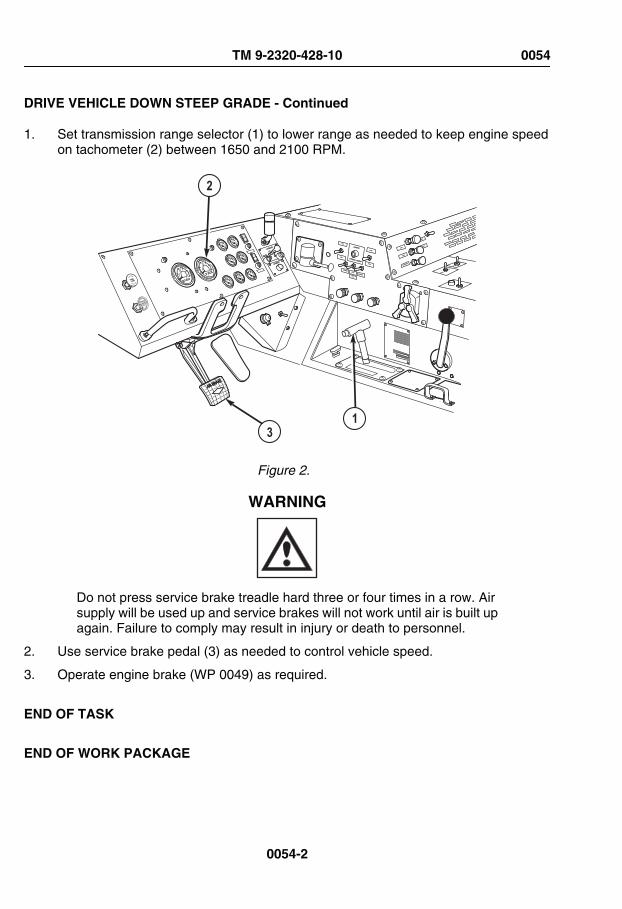
DRIVE VEHICLE DOWN STEEP GRADE - Continued
1. Set transmission range selector (1) to lower range as needed to keep engine speedon tachometer (2) between 1650 and 2100 RPM.
TRAILER
AIR SUPPLY
NOT FOR PARKING
MIDLAND
PULL
TO
EXHAUST
PUSH T O SUPP
LY
LHS
NO
TRANSIT
LHS
LMS
OVER
LOAD
2
13
Figure 2.
WARNING
Do not press service brake treadle hard three or four times in a row. Airsupply will be used up and service brakes will not work until air is built upagain. Failure to comply may result in injury or death to personnel.
2. Use service brake pedal (3) as needed to control vehicle speed.
3. Operate engine brake (WP 0049) as required.
END OF TASK
END OF WORK PACKAGE
TM 9-2320-428-10 0054
0054-2

OPERATOR MAINTENANCEDRIVE VEHICLE IN SLIPPERY CONDITIONS
INITIAL SETUP:
Not Applicable
OPERATE VEHICLE
CAUTIONDo not shift TRACTION CONTROL lever while vehicle is moving.Damage to drive line may result.
NOTEAfter TRACTION CONTROL lever is shifted, let vehicle creep forwardseveral feet to allow shift collars to fully engage.
1. If TRANSFER CASE shift lever (1) is set to LO, 8X8 DRIVE is automatically engagedand indicator light (2) will illuminate. Set TRACTION CONTROL lever (3) to INTER-AXLE DIFF. LOCK. Indicator light (4) will illuminate.
TM 9-2320-428-10 0055
0055-1

OPERATE VEHICLE - Continued
TRAILER
AIR SUPPLY
NOT FOR PARKING
MIDLAND
PULL
TO EXHAUST
PUSH
LHS NO
TRANSIT
LHS
LMS OVER
LOAD
1
4 3 2
Figure 1.
2. If TRANSFER CASE shift lever (1) is set to HI, set TRACTION CONTROL lever (3)to 8X8 DRIVE. Indicator light (2) will illuminate.
CAUTIONDo not shift TRACTION CONTROL lever while vehicle is moving.Damage to drive line may result.
NOTEAfter TRACTION CONTROL lever is set to OFF position, let vehicle creepforward several feet to allow shift collars to fully disengage.
TM 9-2320-428-10 0055
0055-2

OPERATE VEHICLE - Continued
3. When vehicle gets good traction again, stop vehicle and set TRACTION CONTROLlever (3) to OFF. Indicator light (2 or 4 as applicable) will go out.
END OF TASK
END OF WORK PACKAGE
TM 9-2320-428-10 0055
0055-3


OPERATOR MAINTENANCEPARK VEHICLE
INITIAL SETUP:
Not Applicable
OPERATE VEHICLE
1. Lift foot off throttle pedal (1). Let automatic downshifting of transmission slow vehicle.
TRAILERAIR SUPPLYNOT FOR PARKINGMIDLAND
PULL TO EXHAUST
PUSH TO SU PPLY
2
3
14
5
Figure 1.
WARNING
Do not press service brake treadle hard three or four times in a row. Airsupply will be used up and service brakes will not work until air is built upagain. Failure to comply may result in injury or death to personnel.
2. Push down on service brake pedal (2) until vehicle comes to complete stop.
3. Pull out PARKING BRAKE control (3).
TM 9-2320-428-10 0056
0056-1

OPERATE VEHICLE - Continued
4. Set transmission range selector (4) to N (neutral).
5. Leave TRANSFER CASE shift lever (5) set to HI or LO.
6. Align front tires in straight-ahead position.
7. Install wheel chocks (WP 0077) as required.
END OF TASK
END OF WORK PACKAGE
TM 9-2320-428-10 0056
0056-2

OPERATOR MAINTENANCESHUT OFF ENGINE
INITIAL SETUP:
Not Applicable
SHUT OFF ENGINE
1. Park vehicle. (WP 0056)
CAUTIONBefore shutting down engine, run at reduced speed (800 to 1000 rpm) atno-load for three to five minutes to allow turbocharger to slow down andcool off. Turbocharger may be damaged if not allowed to cool off.
2. Push down and hold throttle pedal (1) until tachometer (2) reads 800 to 1000 rpm forthree to five minutes.
TRAILER
AIR SUPPLY
NOT FOR PARKING
MIDLAND
PULL
TO
EXHAUST
PUSH T O SUPP
LY
2 5
6 341
Figure 1.
3. Lift foot off throttle pedal (1).
TM 9-2320-428-10 0057
0057-1

SHUT OFF ENGINE - Continued
NOTEVehicle may have either ENGINE STOP switch or engine shut downhandle, it will never have both.
4. Hold ENGINE STOP switch (3) all the way down, or pull engine shut down handle (4)all the way up until engine shuts down. Buzzer will sound, and OIL-WATER indicator(5) will light.
5. Release ENGINE STOP switch (3) or push engine shut down handle (4) back in.
6. Turn ENGINE switch (6) to OFF. Buzzer and OIL-WATER indicator (5) will go out.
CAUTIONFailure to place light switches in OFF position when vehicle is not in usemay cause damage to equipment.
7. Turn off lights as required.
END OF TASK
END OF WORK PACKAGE
TM 9-2320-428-10 0057
0057-2

OPERATOR MAINTENANCEOPERATE ARCTIC ENGINE HEATER
INITIAL SETUP:
Not Applicable
WARNING
CARBON MONOXIDE (EXHAUST GAS) CAN CAUSE DEATH.
• Carbon monoxide is a colorless, odorless, DEADLY POISONOUSgas that, when breathed, deprives body or oxygen and causesSUFFOCATION. Breathing air with carbon monoxide producessymptoms of headache, dizziness, loss of muscular control, a sleepyfeeling, and coma. Permanent BRAIN DAMAGE or death can resultfrom heavy exposure. Carbon monoxide occurs in the exhaust fumesof fuel-burning heaters and internal combustion engines. Carbonmonoxide can become dangerously concentrated under conditionsof no ventilation. Precautions MUST be followed to ensure personnelare safe whenever personnel heaters or engine is operated for anypurpose. Failure to comply may result in injury or death to personnel.
• DO NOT operate engine in a closed place without proper ventilation.Failure to comply may result in injury or death to personnel.
• Do not drive vehicle with inspection plates, cover plates, or enginecompartment covers removed unless necessary for maintenancepurposes. Failure to comply may result in injury or death to personnel.
• BE ALERT at all times during vehicle operation for exhaust odors andexposure symptoms. If either is present, IMMEDIATELY VENTILATEpersonnel compartments. If symptoms persist, remove affectedpersonnel to fresh air and keep warm. DO NOT PERMIT PHYSICALEXERCISE. If necessary, give artificial respiration and get immediatemedical attention. For artificial respiration, refer to FM 4-25.11 .Failure to comply may result in injury or death to personnel.
TM 9-2320-428-10 0058
0058-1

• BE AWARE that the gas particulate filter unit or field protection maskfor nuclear-biological-chemical protection WILL NOT offer safetyfrom carbon monoxide poisoning.
• THE BEST DEFENSE AGAINST CARBON MONOXIDEPOISONING IS GOOD VENTILATION.
WARNING
Attempting to operate heater with frozen or slushy coolant could causecoolant hose to burst or separate from heater. Make sure proper mixtureof water and anti-freeze (refer to lubrication table) is maintained at alltimes. Failure to comply may result in damage to engine and/or injury topersonnel.
WARNING
• The arctic engine heater must be off when filling any fuel tanks onvehicle. Failure to comply may result in injury or death to personnel.
• Do not operate arctic engine heater in garages or enclosed areaswithout proper ventilation. Failure to comply may result in injury ordeath to personnel.
CAUTION• Do not attempt to operate arctic engine heater if arctic engine heater
fails to start during normal startup, or shutdown occurs during normaloperation. System shutdown may indicate an arctic engine heatersystem fault. Failure to comply may cause system lockout.
• Do not operate arctic engine heater if arctic engine heater lightflashes intermittently during normal operations. Arctic engine heaterindicator light flashing indicates an arctic engine heater system fault.Failure to comply may cause system lockout.
NOTE• The arctic engine heater will attempt to start two times per start cycle.
After the second failed start attempt, the arctic engine heater will not
TM 9-2320-428-10 0058
0058-2

operate until the arctic engine heater on/off switch is turned OFF andback ON.
• If arctic engine heater flame out occurs during operation, arcticengine heater will attempt one restart. If unsuccessful, arctic engineheater will shutdown.
• During operation, arctic engine heater continually monitors inputvoltage. If the arctic engine heater input voltage decreases below (20V) or increases above (30 V), arctic engine heater will automaticallyshutdown.
1. Set arctic engine heater switch (1) to ON position. Observe arctic engine heaterindicator light (2) for steady illumination.
3
2 1
JACOBS
CAUTION
ENGINE BRAKE
Figure 1.
2. Observe arctic engine heater (3) for proper operation.
3. Operate arctic engine heater (3) for 35 minutes to warm engine.
4. After 35 minutes, start engine. (WP 0044)
5. After engine is started, set arctic engine heater switch (1) in OFF position. Indicatorlight (2) will go out.
END OF TASK
END OF WORK PACKAGE
TM 9-2320-428-10 0058
0058-3


OPERATOR MAINTENANCEOPERATE GAS PARTICULATE FILTER UNIT (GPFU)
INITIAL SETUP:
Not Applicable
OPERATE GPFU
WARNING
• BE AWARE that the gas particulate filter unit or the field protectivemask for nuclear-biological-chemical protection WILL NOT offersafety from carbon monoxide poisoning.
• If NBC exposure is suspected, all air filter media should be handledby personnel wearing protective equipment. Consult your unit NBCOfficer or NBC NCO for appropriate handling or disposal procedures.
• If required to remain inside the vehicle during extreme heat,occupants should follow the water intake, work/rest cycle, and otherheat stress preventive medicine measures contained in FM 21-10,Field Hygiene and Sanitation. Failure to comply may result in injuryor death to personnel.
NOTE• Do Steps (1) through (8) only when under Nuclear, Biological, or
Chemical (NBC) attack and/or when ordered to do so.
• For detailed information concerning protective mask, refer to TM3-4240-280-10.
• Both crew stations have M-3 heater, hose, and air duct sockets.
1. Remove two protective masks (1) and canisters (2) from pouches (3).
TM 9-2320-428-10 0059
0059-1

OPERATE GPFU - Continued
Figure 1.
2. Put on protective masks (1).
3. Clear and seal protective masks (1).
NOTESpring clip must be repositioned on filter assembly air intake so intakeholes are open for gas particulate filter system to work. Clip isrepositioned through bottom of bracket.
4. Pull down on spring clip (4) to uncover intake holes (5).
TM 9-2320-428-10 0059
0059-2

OPERATE GPFU - Continued
Figure 2.
5. Set GAS PARTICULATE FILTER switch (6) to ON.
6
Figure 3.
TM 9-2320-428-10 0059
0059-3

OPERATE GPFU - Continued
NOTEOne mount is located to left of drivers seat at roof brace. Second mountis located on middle cab roof brace to left of passenger seat.
6. Disconnect two air duct hose breakaway sockets (7) from mounts (8).
Figure 4.
WARNING
Under arctic conditions, danger of frostbite exists. Mask can be put on,but air duct hose socket shall not be connected to mask canister until M-3heater has been on for 15 minutes. Failure to comply may result in injuryor death to personnel.
7. Connect two air duct hose breakaway sockets (7) to canisters (2) of protective masks(1) and breathe though masks.
TM 9-2320-428-10 0059
0059-4

OPERATE GPFU - Continued
Figure 5.
NOTE• There are two M-3 heaters. Both are the same.
• Heater indicator light will go off and on during normal heateroperation.
8. If air is too cold to breathe comfortably, turn knob (9) clockwise until heater indicator(10) lights. To adjust temperature:
Figure 6.
a. Turn knob (9) clockwise for warmer air.
b. Turn knob (9) counterclockwise for cooler air.
TM 9-2320-428-10 0059
0059-5
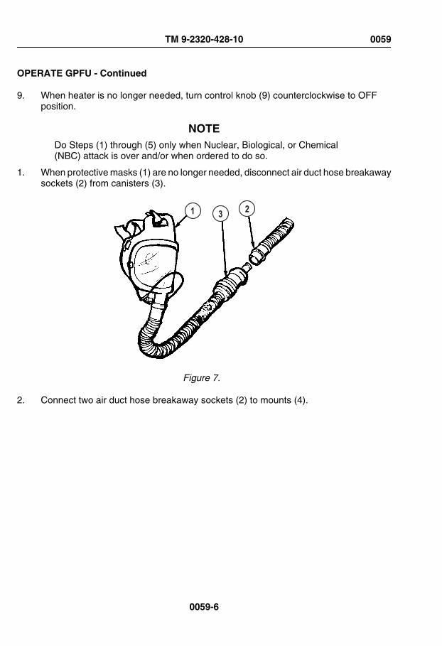
OPERATE GPFU - Continued
9. When heater is no longer needed, turn control knob (9) counterclockwise to OFFposition.
NOTEDo Steps (1) through (5) only when Nuclear, Biological, or Chemical(NBC) attack is over and/or when ordered to do so.
1. When protective masks (1) are no longer needed, disconnect air duct hose breakawaysockets (2) from canisters (3).
1 3 2
Figure 7.
2. Connect two air duct hose breakaway sockets (2) to mounts (4).
TM 9-2320-428-10 0059
0059-6

4
2
Figure 8.
3. Set GAS PARTICULATE FILTER switch (5) to OFF.
5
Figure 9.
4. Push up on spring clip (6) to cover intake holes (7).
TM 9-2320-428-10 0059
0059-7

6
7
Figure 10.
5. Remove and stow two protective masks (1).
1
Figure 11.
END OF TASK
END OF WORK PACKAGE
TM 9-2320-428-10 0059
0059-8
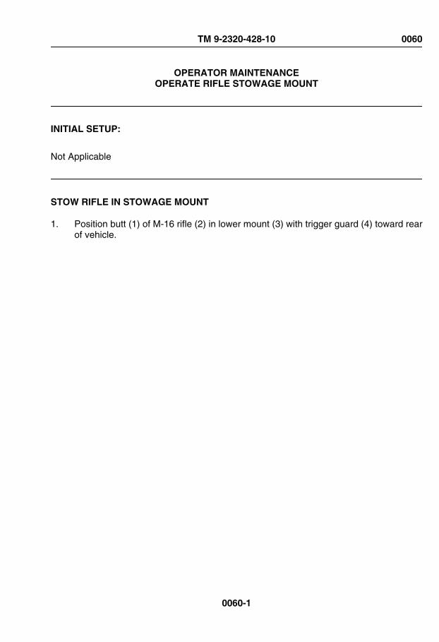
OPERATOR MAINTENANCEOPERATE RIFLE STOWAGE MOUNT
INITIAL SETUP:
Not Applicable
STOW RIFLE IN STOWAGE MOUNT
1. Position butt (1) of M-16 rifle (2) in lower mount (3) with trigger guard (4) toward rearof vehicle.
TM 9-2320-428-10 0060
0060-1

STOW RIFLE IN STOWAGE MOUNT - Continued
Figure 1.
2. Pull handle (5) of top mount (6) toward middle of cab.
3. Place heat guard (7) of M-16 rifle (2) in top mount (6).
4. Push handle (5) across heat guard (7).
5. Check that M-16 rifle (2) is held tightly.
REMOVE RIFLE FROM STOWAGE MOUNT
1. Pull handle (1) of top mount (2) down and toward middle of cab.
TM 9-2320-428-10 0060
0060-2
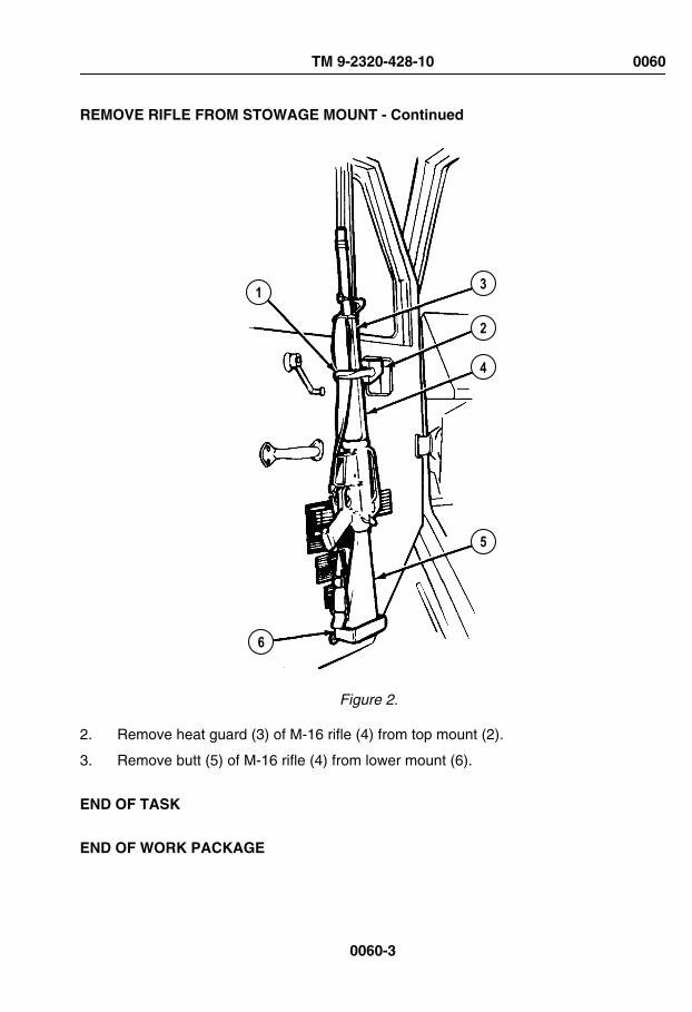
REMOVE RIFLE FROM STOWAGE MOUNT - Continued
1 3
2
4
5
6
Figure 2.
2. Remove heat guard (3) of M-16 rifle (4) from top mount (2).
3. Remove butt (5) of M-16 rifle (4) from lower mount (6).
END OF TASK
END OF WORK PACKAGE
TM 9-2320-428-10 0060
0060-3


OPERATOR MAINTENANCEOPERATE MACHINE GUN MOUNT
INITIAL SETUP:
Not Applicable
REFERENCE
For operation of the machine gun mount, refer to TM 9-1005-245-13&P. (WP 0161)
END OF TASK
END OF WORK PACKAGE
TM 9-2320-428-10 0061
0061-1


OPERATOR MAINTENANCEOPERATE M-8 CHEMICAL ALARM
INITIAL SETUP:
Not Applicable
REFERENCE
For operation of the M-8 Chemical Alarm, refer toTM 3-6665-225-12. (WP 0161)
END OF TASK
END OF WORK PACKAGE
TM 9-2320-428-10 0062
0062-1


OPERATOR MAINTENANCEOPERATE M-13 DECONTAMINATION KIT
INITIAL SETUP:
Not Applicable
REFERENCE
For operation of the M-13 Decontamination Kit, refer to TM 3-4230-214-12&P. (WP 0161)
END OF TASK
END OF WORK PACKAGE
TM 9-2320-428-10 0063
0063-1


OPERATOR MAINTENANCEOPERATE RADIO
INITIAL SETUP:
Not Applicable
REFERENCE
For operation of the radio, refer to TM 11-5820-498-12. (WP 0161)
END OF TASK
END OF WORK PACKAGE
TM 9-2320-428-10 0064
0064-1


OPERATOR MAINTENANCEPORTABLE WORK LAMP OPERATION
INITIAL SETUP:
Not Applicable
INSTALL/OPERATE/REMOVE PORTABLE WORK LAMP
1. Remove work lamp (1) and work lamp harness (2) from stowage.
1
5
4
2
3
Figure 1.
2. Mount lamp (1) on vehicle using magnet (3).
3. Install work lamp harness plug (4) on work lamp terminal (5).
4. Route work lamp harness (2) through driver side door opening (6), between inside ofcab roof (7) and air horn valve hoses (8).
TM 9-2320-428-10 0065
0065-1
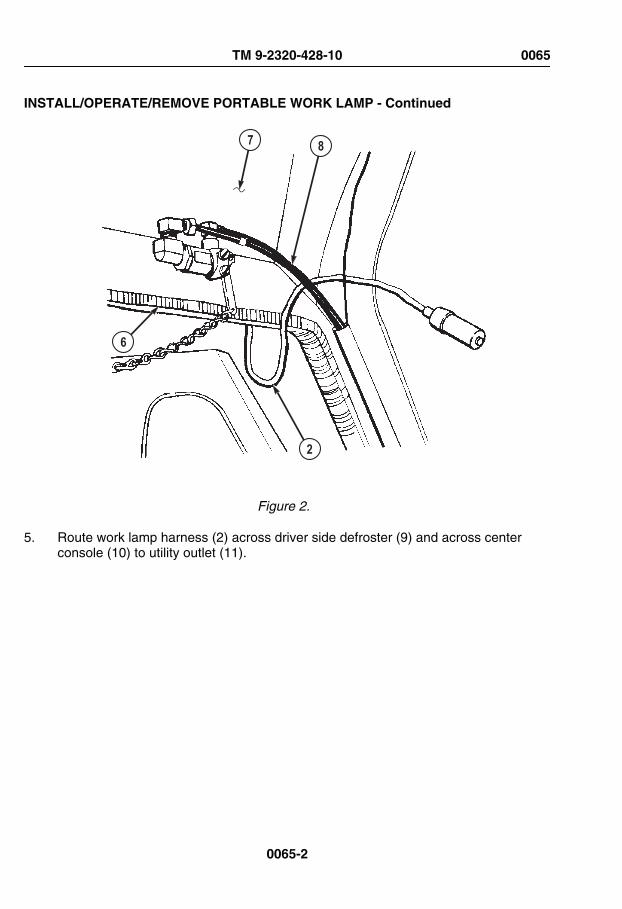
INSTALL/OPERATE/REMOVE PORTABLE WORK LAMP - Continued
87
6
2
Figure 2.
5. Route work lamp harness (2) across driver side defroster (9) and across centerconsole (10) to utility outlet (11).
TM 9-2320-428-10 0065
0065-2
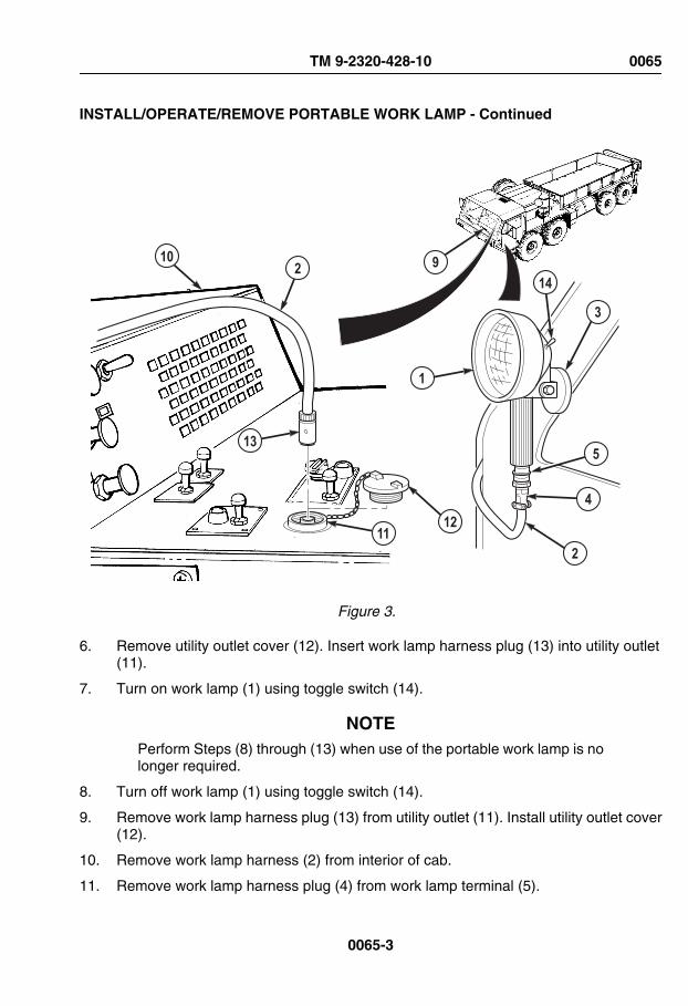
INSTALL/OPERATE/REMOVE PORTABLE WORK LAMP - Continued
1112
13
10
2
4
5
3
1
1492
Figure 3.
6. Remove utility outlet cover (12). Insert work lamp harness plug (13) into utility outlet(11).
7. Turn on work lamp (1) using toggle switch (14).
NOTEPerform Steps (8) through (13) when use of the portable work lamp is nolonger required.
8. Turn off work lamp (1) using toggle switch (14).
9. Remove work lamp harness plug (13) from utility outlet (11). Install utility outlet cover(12).
10. Remove work lamp harness (2) from interior of cab.
11. Remove work lamp harness plug (4) from work lamp terminal (5).
TM 9-2320-428-10 0065
0065-3

INSTALL/OPERATE/REMOVE PORTABLE WORK LAMP - Continued
12. Disengage magnet (3) from vehicle.
13. Return work lamp (1) and work lamp harness (2) to stowage.
END OF TASK
END OF WORK PACKAGE
TM 9-2320-428-10 0065
0065-4

OPERATOR MAINTENANCEOPERATE DOME LIGHT
INITIAL SETUP:
Not Applicable
TURN DOME LIGHT ON/OFF
CAUTIONFailure to place light switches in off position when vehicle is not in usemay cause battery and/or vehicle damage.
NOTE• Dome light is located on very rear of cabin overhead centered
between operator and crew seats.
• Dome light switch is a 2-position switch; down is off, up is on.
• Dome light is disabled whenever blackout lights are selected on thelight control.
1. Lift up and hold UNLOCK lever (1).
JACOBS
CAUTION
ENGINE BRAKE
2
3
1
DOME
Figure 1.
TM 9-2320-428-10 0066
0066-1

TURN DOME LIGHT ON/OFF - Continued
2. Set lighting control lever (2) to STOP LIGHT or SER DRIVE position.
3. Release UNLOCK lever (1).
4. Set DOME switch (3) to ON position.
NOTEComplete Steps (5) and (6) when dome light is no longer required.
5. Set DOME switch (3) to OFF position.
6. Set lighting control lever (2) to OFF position.
END OF TASK
END OF WORK PACKAGE
TM 9-2320-428-10 0066
0066-2

OPERATOR MAINTENANCEOPERATE PANEL LIGHTS
INITIAL SETUP:
Not Applicable
TURN PANEL LIGHTS ON/OFF
CAUTIONFailure to place light switches in the off position when vehicle is not in usemay cause battery and/or vehicle damage.
1. Lift up and hold UNLOCK lever (1).
TM 9-2320-428-10 0067
0067-1

TURN PANEL LIGHTS ON/OFF - Continued
2
13
TRAILERAIR SUPPLYNOT FOR PARKINGMIDLAND
PULL TO EXHAUST
PUSH TO SU PPLY
Figure 1.
NOTEPanel lights will not function if lighting control lever is in OFF position.
2. Set lighting control lever (2) to desired position.
3. Release UNLOCK lever (1).
4. Set PANEL lever (3) to DIM or BRT (bright) as needed.
NOTEComplete Steps (5) and (6) when panel lights are no longer required.
5. Set PANEL lever (3) to OFF position.
TM 9-2320-428-10 0067
0067-2

TURN PANEL LIGHTS ON/OFF - Continued
6. Set lighting control lever (2) to OFF position.
END OF TASK
END OF WORK PACKAGE
TM 9-2320-428-10 0067
0067-3


OPERATOR MAINTENANCEOPERATE PARKING LIGHTS
INITIAL SETUP:
Not Applicable
TURN PARKING LIGHTS ON/OFF
CAUTIONFailure to place light switches in the off position when vehicle is not in usemay cause battery and/or vehicle damage.
1. Lift up and hold UNLOCK lever (1).
TM 9-2320-428-10 0068
0068-1
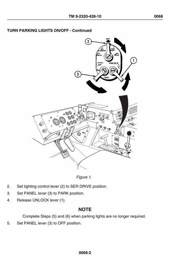
TURN PARKING LIGHTS ON/OFF - Continued
TRAILERAIR SUPPLYNOT FOR PARKINGMIDLAND
PULL TO EXHAUST
PUSH TO SU PPLY
Figure 1.
2. Set lighting control lever (2) to SER DRIVE position.
3. Set PANEL lever (3) to PARK position.
4. Release UNLOCK lever (1).
NOTEComplete Steps (5) and (6) when parking lights are no longer required.
5. Set PANEL lever (3) to OFF position.
TM 9-2320-428-10 0068
0068-2

TURN PARKING LIGHTS ON/OFF - Continued
6. Set lighting control lever (2) to OFF position.
END OF TASK
END OF WORK PACKAGE
TM 9-2320-428-10 0068
0068-3

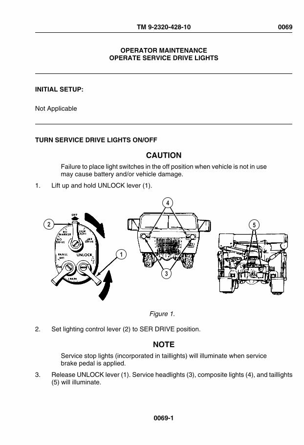
OPERATOR MAINTENANCEOPERATE SERVICE DRIVE LIGHTS
INITIAL SETUP:
Not Applicable
TURN SERVICE DRIVE LIGHTS ON/OFF
CAUTIONFailure to place light switches in the off position when vehicle is not in usemay cause battery and/or vehicle damage.
1. Lift up and hold UNLOCK lever (1).
2
1
3
5
4
Figure 1.
2. Set lighting control lever (2) to SER DRIVE position.
NOTEService stop lights (incorporated in taillights) will illuminate when servicebrake pedal is applied.
3. Release UNLOCK lever (1). Service headlights (3), composite lights (4), and taillights(5) will illuminate.
TM 9-2320-428-10 0069
0069-1

TURN SERVICE DRIVE LIGHTS ON/OFF - Continued
4. Press dimmer switch (6) with foot to cycle between high and low headlight beams.High beam indicator (7) will illuminate (red) when high beams are selected.
AIR BRAKE
PARKINGBRAKE
TRAILERAIR SUPPLY
EXEXEX
EXEXEXEXEXEX
ENGINEOFF
ON
START
7
6
Figure 2.
NOTEComplete Step (5) when service drive lights are no longer required.
5. Set lighting control lever (2) to OFF position. Service headlights (3), composite lights(4), and taillights (5) will go out.
TM 9-2320-428-10 0069
0069-2
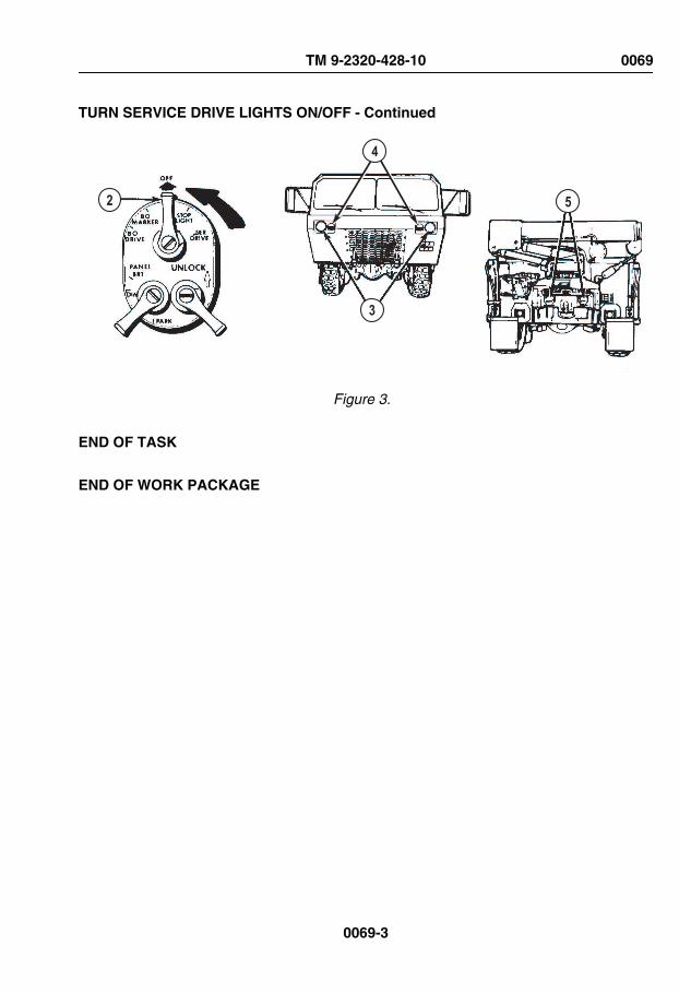
TURN SERVICE DRIVE LIGHTS ON/OFF - Continued
2
3
5
4
Figure 3.
END OF TASK
END OF WORK PACKAGE
TM 9-2320-428-10 0069
0069-3

OPERATOR MAINTENANCEOPERATE STOPLIGHTS
INITIAL SETUP:
Not Applicable
TURN STOPLIGHTS ON/OFF
CAUTIONFailure to place light switches in the OFF position when vehicle is not inuse may cause battery and/or vehicle damage.
NOTEEnsure service stoplights are turned on prior to driving vehicle.
1. Lift up and hold UNLOCK lever (1).
TM 9-2320-428-10 0070
0070-1

TURN STOPLIGHTS ON/OFF - Continued
TRAILERAIR SUPPLYNOT FOR PARKINGMIDLAND
PULL TO EXHAUST
PUSH TO SU PPLY
32
1
4
Figure 1.
2. Set lighting control lever (2) to STOP LIGHT position.
3. Release UNLOCK lever (1). Stoplights (3) will illuminate when service brake pedal (4)is applied.
NOTEComplete Step (4) when stoplights are no longer required.
4. Set lighting control lever (2) to OFF position. Stoplights will no longer function.
END OF TASK
END OF WORK PACKAGE
TM 9-2320-428-10 0070
0070-2

OPERATOR MAINTENANCEOPERATE CLEARANCE LIGHTS
INITIAL SETUP:
Not Applicable
TURN CLEARANCE LIGHTS ON/OFF
CAUTIONFailure to place light switches in the OFF position when vehicle is not inuse may cause battery and/or vehicle damage.
1. Lift up and hold UNLOCK lever (1).
JACOBS
CAUTION
ENGINE BRAKE
3
1
2
Figure 1.
2. Set lighting control lever (2) to either STOP LIGHT or SER DRIVE position.
3. Release UNLOCK lever (1).
4. Set CL LPS switch (3) to on position. Clearance lights (4) will illuminate.
TM 9-2320-428-10 0071
0071-1

TURN CLEARANCE LIGHTS ON/OFF - Continued
NOTEComplete Steps (5) and (6) when clearance lights are no longer required.
5. Set CL LPS switch (3) to off position. Clearance lights (4) will go out.
6. Set lighting control lever (2) to OFF position.
END OF TASK
END OF WORK PACKAGE
TM 9-2320-428-10 0071
0071-2
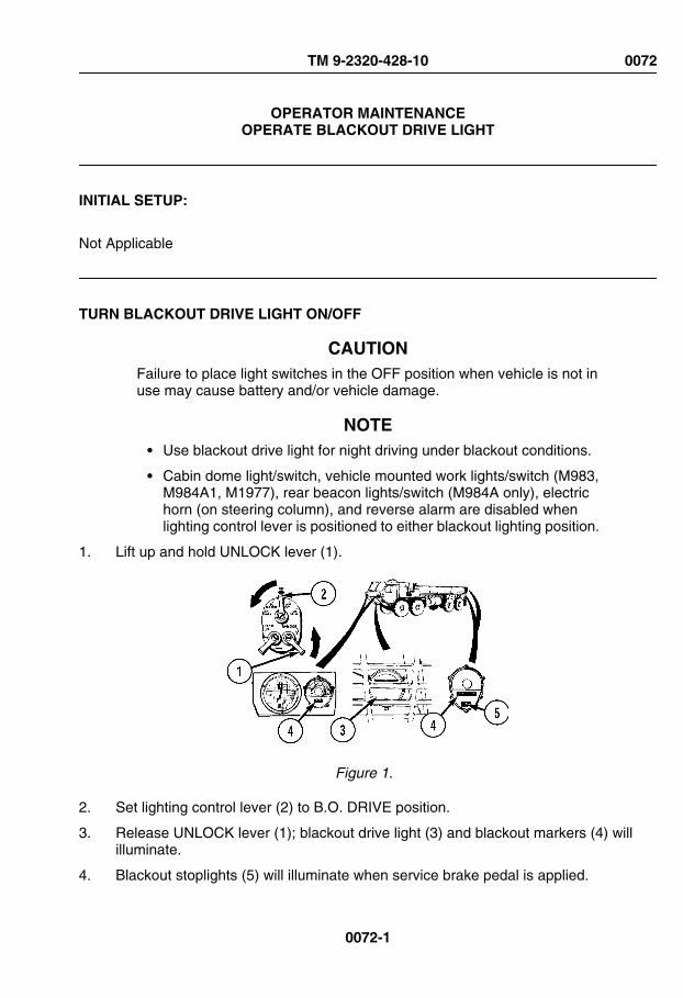
OPERATOR MAINTENANCEOPERATE BLACKOUT DRIVE LIGHT
INITIAL SETUP:
Not Applicable
TURN BLACKOUT DRIVE LIGHT ON/OFF
CAUTIONFailure to place light switches in the OFF position when vehicle is not inuse may cause battery and/or vehicle damage.
NOTE• Use blackout drive light for night driving under blackout conditions.
• Cabin dome light/switch, vehicle mounted work lights/switch (M983,M984A1, M1977), rear beacon lights/switch (M984A only), electrichorn (on steering column), and reverse alarm are disabled whenlighting control lever is positioned to either blackout lighting position.
1. Lift up and hold UNLOCK lever (1).
Figure 1.
2. Set lighting control lever (2) to B.O. DRIVE position.
3. Release UNLOCK lever (1); blackout drive light (3) and blackout markers (4) willilluminate.
4. Blackout stoplights (5) will illuminate when service brake pedal is applied.
TM 9-2320-428-10 0072
0072-1

TURN BLACKOUT DRIVE LIGHT ON/OFF - Continued
NOTEComplete Step (5) when blackout lights are no longer required.
5. Set lighting control lever (2) to OFF position; blackout drive light (3) and blackoutmarkers (4) will go out.
END OF TASK
END OF WORK PACKAGE
TM 9-2320-428-10 0072
0072-2

OPERATOR MAINTENANCEOPERATE BLACKOUT MARKERS
INITIAL SETUP:
Not Applicable
TURN BLACKOUT MARKERS ON/OFF
CAUTIONFailure to place light switches in the OFF position when vehicle is not inuse may cause battery and/or vehicle damage.
NOTECabin dome light/switch, vehicle mounted work lights/switch (M983,M984A1, M1977), rear beacon lights/switch (M984A only), electric horn(on steering column), and reverse alarm are disabled when lightingcontrol lever is positioned to either blackout lighting position.
1. Lift up and hold UNLOCK lever (1).
TM 9-2320-428-10 0073
0073-1

TURN BLACKOUT MARKERS ON/OFF - Continued
5
TRAILERAIR SUPPLYNOT FOR PARKINGMIDLAND
PULL TO EXHAUST
PUSH TO SUPPLY
2
1
3
43
Figure 1.
2. Set lighting control lever (2) to B.O. MARKER position. Blackout markers (3) willilluminate.
3. Blackout stoplight markers (4), which are located on vehicle taillights, will illuminatewhen service brake pedal (5) is applied.
NOTEComplete Step (4) when blackout markers are no longer required.
4. Set lighting control lever (1) to OFF. Blackout markers (3) will go out.
END OF TASK
END OF WORK PACKAGE
TM 9-2320-428-10 0073
0073-2
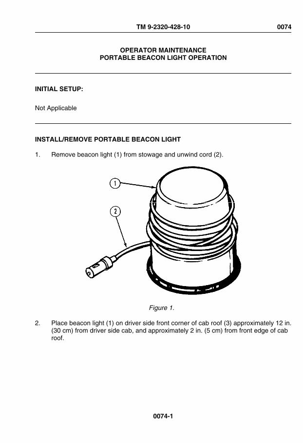
OPERATOR MAINTENANCEPORTABLE BEACON LIGHT OPERATION
INITIAL SETUP:
Not Applicable
INSTALL/REMOVE PORTABLE BEACON LIGHT
1. Remove beacon light (1) from stowage and unwind cord (2).
Figure 1.
2. Place beacon light (1) on driver side front corner of cab roof (3) approximately 12 in.(30 cm) from driver side cab, and approximately 2 in. (5 cm) from front edge of cabroof.
TM 9-2320-428-10 0074
0074-1

INSTALL/REMOVE PORTABLE BEACON LIGHT - Continued
Figure 2.
3. Route beacon cord (2) through driver side door opening (4) and between inside of cabroof (3) and air horn valve hoses (5).
TM 9-2320-428-10 0074
0074-2

INSTALL/REMOVE PORTABLE BEACON LIGHT - Continued
Figure 3.
4. Route beacon cord (2) down left side of driver's windshield (6), across driver sidedefroster (7), and across center console (8) to utility outlet (9).
TM 9-2320-428-10 0074
0074-3
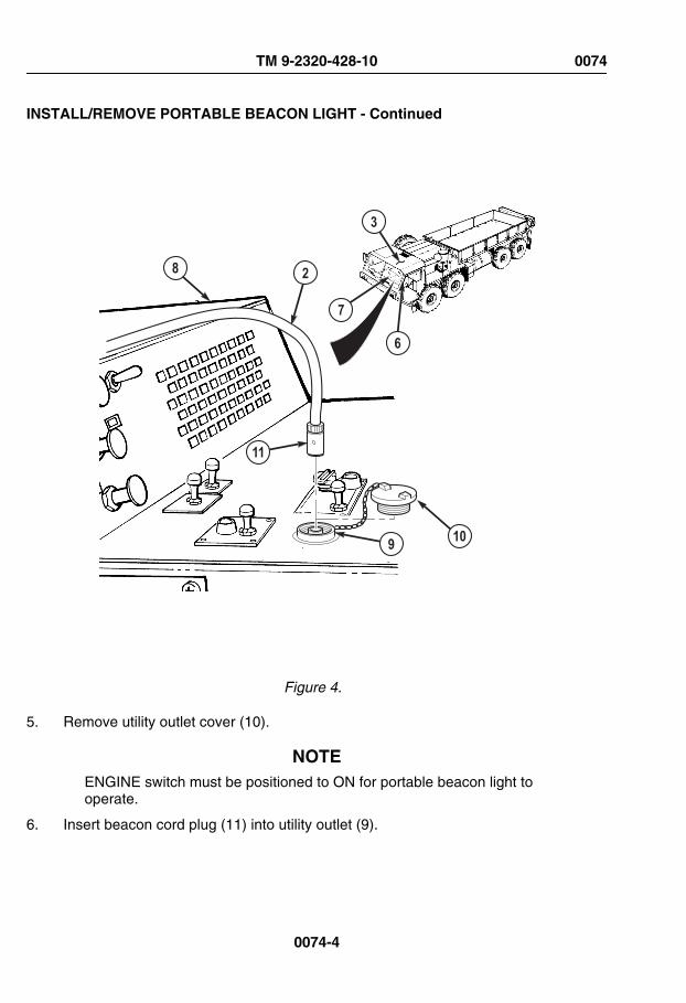
INSTALL/REMOVE PORTABLE BEACON LIGHT - Continued
9 10
11
8
6
7
2
3
Figure 4.
5. Remove utility outlet cover (10).
NOTEENGINE switch must be positioned to ON for portable beacon light tooperate.
6. Insert beacon cord plug (11) into utility outlet (9).
TM 9-2320-428-10 0074
0074-4

INSTALL/REMOVE PORTABLE BEACON LIGHT - Continued
NOTEPerform Steps (7) through (11) when use of portable beacon light is nolonger required.
7. Remove beacon cord plug (11) from utility outlet (9).
8. Install utility outlet cover (10).
9. Remove beacon cord (2) from interior of cab.
10. Remove beacon light from cab roof (3).
11. Rewind cord (2) and return beacon light (1) to appropriate stowage.
Figure 5.
END OF TASK
END OF WORK PACKAGE
TM 9-2320-428-10 0074
0074-5


OPERATOR MAINTENANCEOPERATE TURN SIGNALS
INITIAL SETUP:
Not Applicable
SET TURN SIGNAL ON/OFF
1. Lift up and hold UNLOCK lever (1).
TM 9-2320-428-10 0075
0075-1

SET TURN SIGNAL ON/OFF - Continued
TRAILERAIR SUPPLYNOT FOR PARKINGMIDLAND
PULL TO EXHAUST
PUSH TO SU PPLY
BODRIVE
BOMARKER
STOPLIGHT
OFF
SERDRIVE
PANELBRT
PARK
DIN
UNLOCK
2
1
74
3
8 56 9
Figure 1.
2. Set lighting control lever (2) to SER DRIVE position.
NOTEIf left turn is desired, complete Step (3). If right turn is desired, skip toStep (4).
TM 9-2320-428-10 0075
0075-2

SET TURN SIGNAL ON/OFF - Continued
3. Set turn signal lever (3) down to left turn position. Left turn indicator (4), and driverside front (5) and rear (6) composite lights will flash (approximately once per second)simultaneously.
NOTEIf right turn is desired, complete Step (4).
4. Set turn signal lever (3) up to right turn position. Right turn indicator (7), and passengerside front (8) and rear (9) composite lights will flash (approximately once per second)simultaneously.
NOTETurn signal level may return to off (center) position automatically onceturn is complete, if this is not the case and/or turn signal is no longerdesired, complete Step (5).
5. Set turn signal lever (3) to center (off) position. Appropriate turn indicator andcomposite lights will go out.
END OF TASK
END OF WORK PACKAGE
TM 9-2320-428-10 0075
0075-3


OPERATOR MAINTENANCEOPERATE EMERGENCY FLASHERS
INITIAL SETUP:
Not Applicable
TURN EMERGENCY FLASHERS ON/OFF
NOTEHighway Emergency Marker Kit (WP 0099) should be used to marklocation and caution oncoming traffic whenever vehicle is disabled ormust park in areas where there is other traffic.
1. Lift up and hold UNLOCK lever (1).
TM 9-2320-428-10 0076
0076-1

TURN EMERGENCY FLASHERS ON/OFF - Continued
TRAILERAIR SUPPLYNOT FOR PARKINGMIDLAND
PULL TO EXHAUST
PUSH TO SU PPLY
BODRIVE
BOMARKER
STOPLIGHT
OFF
SERDRIVE
PANELBRT
PARK
DIN
UNLOCK
2
1
635
4
87
Figure 1.
2. Set lighting control lever (2) to SER DRIVE position.
3. Set turn signal lever (3) to right turn position.
4. Push down emergency flasher control (4) and push turn signal lever (3) up as far asit will go. Both left (5) and right (6) turn indicators, and front (7) and rear (8) compositelights will flash simultaneously at approximately once per second.
TM 9-2320-428-10 0076
0076-2

TURN EMERGENCY FLASHERS ON/OFF - Continued
NOTEPerform Step (5) when emergency flashers are no longer desired.
5. Pull turn signal lever (3) down to center position.
END OF TASK
END OF WORK PACKAGE
TM 9-2320-428-10 0076
0076-3


OPERATOR MAINTENANCEINSTALL/REMOVE WHEEL CHOCKS
INITIAL SETUP:
Not Applicable
INSTALL WHEEL CHOCKS
NOTE• Vehicle is equipped with four wheel chocks.
• Always chock tires if vehicle is shut down on uneven terrain.
• Always chock tires if vehicle parking brake is inoperative.
• Ensure local policy for chocking vehicle tires is followed.
1. Remove two wheel chocks (1) from stowage.
1
Figure 1.
2. Place one wheel chock (1) snugly against both front and rear of tire (No. 1 axle driverside tire shown).
REMOVE WHEEL CHOCKS
NOTE• Vehicle is equipped with four wheel chocks.
• Ensure local policy for removing wheel chocks is followed.
TM 9-2320-428-10 0077
0077-1

REMOVE WHEEL CHOCKS - Continued
1. Remove wheel chocks (1) from both front and rear of tire (No. 1 axle driver side tireshown).
1
Figure 2.
2. Return wheel chocks (1) to stowage.
3. Repeat Steps (1) and (2) if more than one wheel is chocked.
END OF TASK
END OF WORK PACKAGE
TM 9-2320-428-10 0077
0077-2
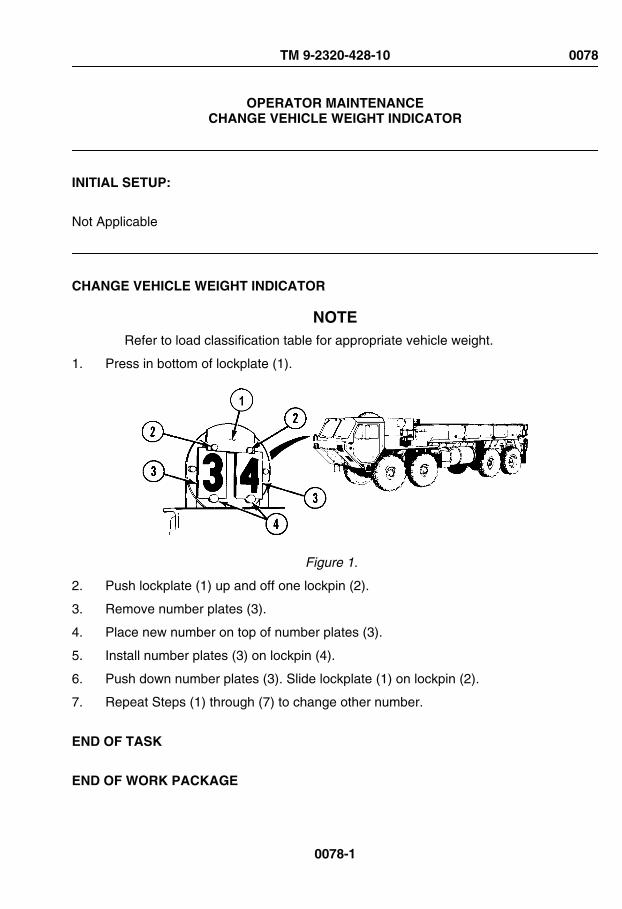
OPERATOR MAINTENANCECHANGE VEHICLE WEIGHT INDICATOR
INITIAL SETUP:
Not Applicable
CHANGE VEHICLE WEIGHT INDICATOR
NOTERefer to load classification table for appropriate vehicle weight.
1. Press in bottom of lockplate (1).
Figure 1.
2. Push lockplate (1) up and off one lockpin (2).
3. Remove number plates (3).
4. Place new number on top of number plates (3).
5. Install number plates (3) on lockpin (4).
6. Push down number plates (3). Slide lockplate (1) on lockpin (2).
7. Repeat Steps (1) through (7) to change other number.
END OF TASK
END OF WORK PACKAGE
TM 9-2320-428-10 0078
0078-1


OPERATOR MAINTENANCEADJUST SEAT
INITIAL SETUP:
Not Applicable
INSTALL FOOTREST
1. Remove safety pin (1) and yoke pin (2).
Figure 1.
2. Pull out footrest (3).
3. Slide footrest (3) toward seat brace (4) so holes (5) are aligned.
4. Install yoke pin (2) and safety pin (1).
STOW FOOTREST
1. Remove safety pin (1) and yoke pin (2).
TM 9-2320-428-10 0079
0079-1

STOW FOOTREST - Continued
Figure 2.
2. Slide footrest (3) under seat brace (4).
3. Install yoke pin (2) and safety pin (1).
ADJUST SEAT
WARNING
Use care when adjusting knob. Seat collapses when knob screw isadjusted. Do not place hand between seat mount and low neck. Failureto comply may result in injury or death to personnel.
NOTE• Sit in seat and perform Steps (1) through (8) as necessary.
• Driver and crew (passenger side) side seats are adjusted the sameway.
1. Turn knob (1) to control cushion firmness.
TM 9-2320-428-10 0079
0079-2

ADJUST SEAT - Continued
NOTERetaining straps may need to be loosened before moving seat forward.
2. Push lever (2) to left and slide seat (3) forward or backward.
3. Let go of lever (2) to lock seat (3) in place.
Figure 3.
4. Pull up lever (4) and lift self off seat (3) to raise seat (3).
5. Pull up lever (4) and push down on seat (3) to lower seat (3).
6. Let go of lever (4) to lock seat (3) in place.
7. Tighten seat retaining straps (5).
8. Adjust all vehicle mirrors as necessary once driver's seat is properly adjusted.
END OF TASK
END OF WORK PACKAGE
TM 9-2320-428-10 0079
0079-3


OPERATOR MAINTENANCEOPERATE THREE-POINT SEATBELT
INITIAL SETUP:
Not Applicable
OPERATE THREE-POINT SEATBELT
1. Put seatbelt flat metal end (1) into interconnect (2) until click is heard.
2
13
Figure 1.
2. Pull out on comfort latch (3) locking handle and move comfort latch up and down strapuntil snug (but not tight) fit at shoulder is achieved.
TM 9-2320-428-10 0080
0080-1

OPERATE THREE-POINT SEATBELT - Continued
3. To release seatbelt, push in button on interconnect (2).
END OF TASK
END OF WORK PACKAGE
TM 9-2320-428-10 0080
0080-2

OPERATOR MAINTENANCEADJUST AIR-RIDE SEAT
INITIAL SETUP:
Not Applicable
ADJUST AIR-RIDE SEAT
WARNING
When adjusting seat ride firmness, keep fingers out from under seat.Failure to comply may result in injury or death to personnel.
NOTE• Sit in seat and perform Steps (1) through (6) as necessary.
• Driver and crew (passenger side) side seats are adjusted the sameway.
1. Pull out (increase) or push in (decrease) knob (1) to adjust seat ride firmness.
TM 9-2320-428-10 0081
0081-1

ADJUST AIR-RIDE SEAT - Continued
1
4
3
2
5
6
Figure 1.
2. Move lever (2) away from seat (3) and slide seat (3) forward or backwards.
3. Move lever (2) towards seat (3) to lock seat (3) in place.
4. Pull up lever (4) and lift self off seat (3) to raise, or pull up lever (4) and push down onseat (3) to lower.
5. Release lever (4) to lock seat (3) in place.
6. Adjust all vehicle mirrors as necessary once driver's seat is properly adjusted.
NOTEIf vehicle is bounced too hard, seat tether may lock seat in down position.Park vehicle (WP 0056) and perform Steps (7) through (10) to free seat.
7. Push in knob (1) to decrease seat ride firmness.
TM 9-2320-428-10 0081
0081-2

ADJUST AIR-RIDE SEAT - Continued
8. Move lever (2) away from seat (3), and slide seat (3) backwards to relieve tension onretractor (5).
9. Feed some seat tether (6) into retractor (5) until it releases.
10. Perform Steps (1) through (5) as required to reset seat (3) to desired position.
END OF TASK
END OF WORK PACKAGE
TM 9-2320-428-10 0081
0081-3


OPERATOR MAINTENANCEOPERATE FOUR-POINT SEATBELT
INITIAL SETUP:
Not Applicable
OPERATE FOUR-POINT SEATBELT
1. Insert seatbelt flat metal end (1) into buckle (2) until click is heard.
3
3
4
2
1
Figure 1.
TM 9-2320-428-10 0082
0082-1

OPERATE FOUR-POINT SEATBELT - Continued
2. To release seatbelt (3), push in button (4) on buckle (2).
END OF TASK
END OF WORK PACKAGE
TM 9-2320-428-10 0082
0082-2

OPERATOR MAINTENANCEINSTALL/REMOVE TIRE CHAINS
INITIAL SETUP:
Personnel RequiredOperator and Assistant - - - (2)
INSTALL TIRE CHAINS
CAUTIONWhen tire chains are used, they must be used on all four rear wheels.Chains must not be used when driving on hard surfaces where there isno wheel slippage. Improper use of tire chains may result in equipmentdamage.
NOTE• This procedure is a two soldier task.
• Tire chains on No. 3 and No. 4 axle tires are all installed the same.Passenger side No. 4 axle shown.
• Maximum speed limit for vehicles driving with chains in city or onhighway is 10 mph (16 km/h).
• Maximum speed limit for vehicles driving with chains off-road is 15mph (24 km/h).
1. With aid of an assistant, place tire chain (1) on ground with cross chain connectinglinks (2) facing down.
TM 9-2320-428-10 0083
0083-1

INSTALL TIRE CHAINS - Continued
Figure 1.
NOTEAssistant shall ensure vehicle is stopped when only tire in contact withtire chains is tire being equipped.
2. Move vehicle onto tire chain (1) while assistant guides vehicle so tire (3) is about one-third of way on tire chain.
Figure 2.
NOTEEnsure only tire in contact with tire chains is tire being equipped.
3. Park vehicle. (WP 0056)
4. With aid of an assistant, wrap tire chain (1) around tire (3).
TM 9-2320-428-10 0083
0083-2

INSTALL TIRE CHAINS - Continued
Figure 3.
5. With aid of an assistant, connect and secure inside and outside clamps (4) so tirechain (1) is as tight as possible.
6. With aid of an assistant, repeat Steps (1) through (5) on remaining tires of No. 3 andNo. 4 axles.
7. Drive vehicle forward (WP 0050) about 15 ft. (4.6 m) and then drive vehicle in reverse(WP 0051) about 15 ft. (4.6 m) as guided by assistant.
8. Park vehicle. (WP 0056)
NOTETire chains on No. 3 and No. 4 axle tires are all tightened up the same.Passenger side No. 4 axle shown.
9. With aid of an assistant, disconnect inside clamp (4) of tire chain (1) on tire (3).
TM 9-2320-428-10 0083
0083-3

INSTALL TIRE CHAINS - Continued
Figure 4.
10. With aid of an assistant, take up slack in tire chain (1).
11. With aid of an assistant, connect inside clamp (4).
12. With aid of an assistant, disconnect outside clamp (4) of tire chain (1) on tire (3).
13. With aid of an assistant, take up slack in tire chain (1).
14. With aid of an assistant, connect outside clamp (4).
15. With aid of an assistant, take up slack in tire chains on other three rear tires byrepeating Steps (10) through (15).
REMOVE TIRE CHAINS
NOTE• This procedure is a two soldier task.
• Tire chains on No. 4 axle tires are both removed the same. Passengerside shown.
1. Move vehicle into position so tire chain (1) and clamps (2) on tire (3) are at 4 o’clockposition while assistant guides vehicle.
TM 9-2320-428-10 0083
0083-4

REMOVE TIRE CHAINS - Continued
Figure 5.
2. Park vehicle. (WP 0056)
3. With aid of an assistant, disconnect inside and outside clamps (2) of tire chain (1).
Figure 6.
4. With aid of an assistant, unwrap tire chain (1) from tire (3) and spread tire chain outon ground behind vehicle.
5. Drive vehicle forward (WP 0050) off tire chain (1) while assistant guides vehicle.
6. With aid of an assistant, repeat Steps (2) through (5) for opposite side tire.
TM 9-2320-428-10 0083
0083-5

REMOVE TIRE CHAINS - Continued
NOTETire chains on No. 3 axle tires are both removed the same. Passengerside shown.
7. Move vehicle into position so tire chain (4) and clamps (5) on tire (6) are at 8 o’clockposition while assistant guides vehicle.
Figure 7.
8. Park vehicle. (WP 0056)
9. With aid of an assistant, disconnect inside and outside clamps (5) of tire chain (4).
10. With aid of an assistant, unwrap tire chain (4) from tire (6) and spread tire chain outon ground in front of tire.
Figure 8.
11. Drive vehicle forward (WP 0050) off tire chain (4) while assistant guides vehicle.
TM 9-2320-428-10 0083
0083-6

REMOVE TIRE CHAINS - Continued
12. With aid of an assistant, repeat Steps (7) through (11) for opposite side tire.
END OF TASK
END OF WORK PACKAGE
TM 9-2320-428-10 0083
0083-7


OPERATOR MAINTENANCEFORD WATER OBSTACLE
INITIAL SETUP:
Not Applicable
WARNING
Do not ford water unless depth is known. Water deeper than 4 ft. (1.2 m)may enter vehicle. Failure to comply may result in injury or death topersonnel.
NOTEAfter vehicle fords water obstacle, service all lubrication points belowfording depth and check submerged gearboxes for presence of waterupon return from mission (refer to lubrication instructions (WP 0151) formore information).
CAUTIONTowing a trailer may affect maximum fording depth (refer to applicabletrailer operators manual). Do not ford water obstacle deeper thanmaximum depth allowed by either vehicle or trailer (whichever depth isless). Failure to comply may result in damage to equipment.
1. Ensure depth of fording site is not more than 4 ft. (1.2 m).
2. Ensure bottom at fording site is firm enough that 4 ft. (1.2 m) maximum fording depthwill not be exceeded and vehicle will not become mired.
3. Stop vehicle at edge of water.
4. If brakes have been used heavily and are hot, allow drums and shoes to cool beforeentering water if possible.
5. Ensure engine is operating correctly before entering water.
6. Set TRANSFER CASE shift lever (1) to LO, 8X8 DRIVE indicator (2) will illuminate.
TM 9-2320-428-10 0084
0084-1

TRAILERAIR SUPPLYNOT FOR PARKINGMIDLAND
PULL TO EXHAUST
PUSH TO SU PPLY
1
5
6
7
AIR BRAKE
PARKINGBRAKE
TRAILERAIR SUPPLY
EXEXEX
EXEXEXEXEXEX
ENGINEOFF
ON
START
4
3
27
6
Figure 1.
7. Set TRACTION CONTROL lever (3) to INTER-AXLE DIFF. LOCK for added traction,INTER-AXLE LOCK indicator light (4) will come on.
8. Set transmission range selector (5) to 1 (1st gear range).
9. Drive vehicle slowly into water.
10. If engine stops, immediately attempt to restart engine. If engine will not start, tow orwinch vehicle from water with another vehicle as soon as possible.
11. Drive vehicle at 3 to 4 mph (5 to 6 km/h) or less, through water.
12. Unless absolutely necessary, do not stop while in water.
13. If vehicle accidentally enters water deeper than 4 ft. (1.2 m), do the following:
a. Apply service brake pedal (6) and hold to stop vehicle.
b. Set transmission range selector (5) to R (reverse).
TM 9-2320-428-10 0084
0084-2

c. Release service brake pedal (6).
d. Slowly back vehicle out of deep water.
14. After leaving water, lightly press service brake pedal (6) and hold while driving slowlyto dry out brake linings.
15. When clear of fording area, stop vehicle.
16. Apply and release PARKING BRAKE control (WP 0045) (7) several times to removewater from brake components.
17. Remove water and clean deposits from all vehicle parts as soon as possible.
18. Deliver vehicle to field level maintenance as soon as possible.
END OF TASK
END OF WORK PACKAGE
TM 9-2320-428-10 0084
0084-3


OPERATOR MAINTENANCEINTERIM NUCLEAR, BIOLOGICAL, AND CHEMICAL (NBC) DECONTAMINATION
PROCEDURES
INITIAL SETUP:
Not Applicable
INTRODUCTION AND PROCEDURES
NOTETo reduce the effects of contamination in an NBC-contaminatedenvironment, the HEMTT series vehicle should be operated with allwindows, doors, and stowage boxes closed.
1. The HEMTT series vehicle is capable of being operated by personnel wearing nuclear,biological, or chemical (NBC) protective clothing without special tools or supportingequipment. Refer to FM 3-11.5 (WP 0161) for information on decontaminationprocedures. Specific procedures for the HEMTT series vehicle are as follows:
a. Rubber sleeves and other rubber items, rope, and gaskets will absorb and retainchemical agents. Replacement of these items is the recommended method ofdecontamination.
b. Lubricants or fluids may be present on the external surfaces of the HEMTTseries vehicle or its components due to leaks or normal operation. These fluidswill absorb NBC agents. The preferred method of decontamination is removalof these fluids using conventional decontamination methods in accordance withFM 3-11.5. (WP 0161)
c. Continued decontamination of the external HEMTT series vehicle surfaces withsupertropical bleach (STB)/decontamination solution number 2 (DS2) willdegrade clear plastic (e.g., hydraulic fluid reservoir sight glass) to the pointwhere looking through it will become impossible. This problem will become moreevident for soldiers wearing protective masks. Therefore, the use of STB or DS2decontamination in the area of clear plastic should be minimized. Clear plasticshould be decontaminated with warm, soapy water.
d. External surfaces of the HEMTT series vehicle and related equipment such asthe remote control units that are marked with painted or stamped lettering willnot withstand repeated decontamination with STB or DS2 without degradationof this lettering. Therefore, the recommended method of decontamination forthese areas is washing with warm, soapy water.
TM 9-2320-428-10 0085
0085-1

INTRODUCTION AND PROCEDURES - Continued
NOTEReplacement of hardware, as well as conventional methods ofdecontamination, are the preferred methods of decontamination for theareas listed below.
2. Areas that will entrap contaminants, making efficient decontamination extremelydifficult include the following:
a. Exposed heads of screws.
b. Areas adjacent to and behind exposed hydraulic lines.
c. Hinged areas or access doors on the stowage boxes.
d. Retaining chains for lynchpins and lockpins.
e. Areas around the tie downs, lifting rings, crevices around access doors, externalvalves and drains, and exposed hydraulic connectors.
f. Areas behind knobs, levers, externally-mounted equipment, specification andadvisory data plates, and roller and locking mechanisms.
g. Winch cable and winch hook assembly.
3. Conventional methods of decontamination should be used on all areas listed in Steps(1) and (2), while stressing the importance of thoroughness, and the probability ofsome degree of continuing contact, including vapor hazard.
4. For additional NBC information, refer to FM 3-11.3 (WP 0161) and FM 3-11.4.(WP 0161)
END OF TASK
END OF WORK PACKAGE
TM 9-2320-428-10 0085
0085-2

OPERATOR MAINTENANCESELF-RECOVER VEHICLE USING SELF-RECOVERY WINCH
INITIAL SETUP:
Personnel RequiredOperator and Assistant - - - (2)
WINCH MIRED VEHICLE FORWARD
NOTE• For additional information on vehicle self-recovery, refer to FM
4-30.31. (WP 0161)
• Vehicle self-recovery is a two soldier task. Soldiers mustcommunicate by hand signals.
1. Shut off engine. (WP 0057)
2. Adjust mirror (1) so assistant can be clearly seen during procedure.
Figure 1.
CAUTIONPTO ENGAGE switch must be in OFF position before moving hydraulicselector valve control to prevent equipment damage.
3. Set PTO ENGAGE switch (2) to OFF position. Indicator light (3) will go out.
TM 9-2320-428-10 0086
0086-1

WINCH MIRED VEHICLE FORWARD - Continued
TRAILERAIR SUPPLYNOT FOR PARKINGMIDLAND
PULL TO EXHAUST
PUSH TO SU PPLY
32
Figure 2.
4. Pull out hydraulic selector valve control.
TM 9-2320-428-10 0086
0086-2

WINCH MIRED VEHICLE FORWARD - Continued
HYDRAULIC SELECTORVALVE CONTROL
Figure 3.
5. Start engine. (WP 0044)
6. Set PTO ENGAGE switch (2) to ON position. Indicator light (3) will illuminate.
TM 9-2320-428-10 0086
0086-3

WINCH MIRED VEHICLE FORWARD - Continued
TRAILERAIR SUPPLYNOT FOR PARKINGMIDLAND
PULL TO EXHAUST
PUSH TO SU PPLY
3
4
2
Figure 4.
7. Move winch shift lever (4) to OUT position to pay out small amount of cable.
8. Release winch shift lever (4) to center position.
9. Set PTO ENGAGE switch (2) to OFF position. Indicator light (3) will go out.
10. Remove cotter pin (5) from pin (6).
8 7 65
Figure 5.
TM 9-2320-428-10 0086
0086-4
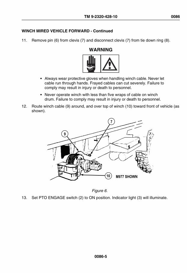
WINCH MIRED VEHICLE FORWARD - Continued
11. Remove pin (6) from clevis (7) and disconnect clevis (7) from tie down ring (8).
WARNING
• Always wear protective gloves when handling winch cable. Never letcable run through hands. Frayed cables can cut severely. Failure tocomply may result in injury or death to personnel.
• Never operate winch with less than five wraps of cable on winchdrum. Failure to comply may result in injury or death to personnel.
12. Route winch cable (9) around, and over top of winch (10) toward front of vehicle (asshown).
9
7
10 M977 SHOWN
Figure 6.
13. Set PTO ENGAGE switch (2) to ON position. Indicator light (3) will illuminate.
TM 9-2320-428-10 0086
0086-5

WINCH MIRED VEHICLE FORWARD - Continued
M984
M97710
119
11
10
9
3 2
4
Figure 7.
14. Move winch shift lever (4) to OUT and pay out winch cable (9), while assistant routescable (9) through notch in fender (11).
NOTE• Do not place cable between tensioning device pulleys at this time.
TM 9-2320-428-10 0086
0086-6

WINCH MIRED VEHICLE FORWARD - Continued
• When pulling cable through tensioning device, push sheave towardsframe rail to allow clevis to pass through.
15. Pay out cable (9) while assistant pulls cable (9) until it is 6 in. to 1 ft. (15 cm to 30 cm)past the front roller guide (12).
13
9
13M977 SHOWN
15
14
9
12
Figure 8.
16. Stop paying out cable (9).
17. Assistant routes cable (9) through cable guide (13), over sheave (14), between roller(15), and side of cable guide (13).
18. Pay out winch cable (9) as assistant routes cable over first axle and 1 ft. (30 cm) pastfront roller guide assembly (12).
TM 9-2320-428-10 0086
0086-7
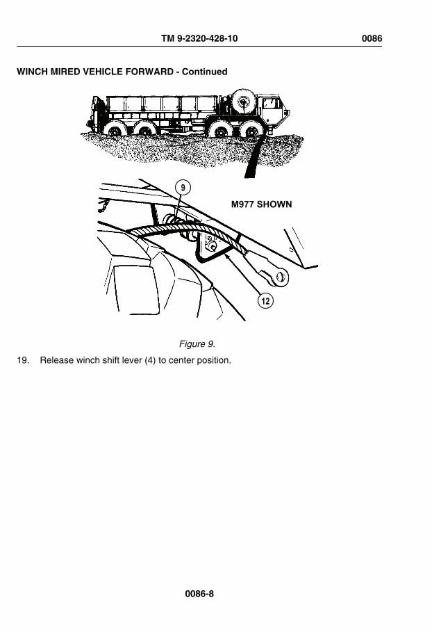
WINCH MIRED VEHICLE FORWARD - Continued
9
12
M977 SHOWN
Figure 9.
19. Release winch shift lever (4) to center position.
TM 9-2320-428-10 0086
0086-8

WINCH MIRED VEHICLE FORWARD - Continued
9
1817 16
18
19
3 2
4
10 9
M977 SHOWN
Figure 10.
20. Set PTO ENGAGE switch (2) to OFF position. Indicator light (3) will go out.
21. Remove quick release pin (16) and guide bracket (17). Move cable guide brackets(18) apart so cable (9) can be placed against bottom of sheave (19).
22. Move cable guide brackets (18) together and install guide bracket (17) and quickrelease pin (16).
23. Set PTO ENGAGE switch (2) to ON position. Indicator light (3) will illuminate.
24. Move winch shift lever (4) to OUT and pay out winch cable (9) while assistant pullscable to tree, another heavy vehicle (WP 0088), or another heavy object refer to FM4-30.31. (WP 0161)
TM 9-2320-428-10 0086
0086-9

WINCH MIRED VEHICLE FORWARD - Continued
25. When winch cable (9) is let out to heavy object, release winch shift lever (4) to centerposition.
26. Set PTO ENGAGE switch (2) to OFF position. Indicator light (3) will go out.
27. If snatch block must be used for self-recovery operation, attach self-recovery winchcable (9) to snatch block (WP 0087) and connect end of self-recovery winch cable tomired vehicle left front towing eye. (WP 0088) Attach snatch block to tree, anothervehicle, or heavy object refer to FM 4-30.31. (WP 0161)
CAUTIONThere must always be at least five wraps of cable on winch. If load isapplied with less than five wraps of cable on winch, cable may come looseon drum.
28. Check that there are at least five wraps of winch cable (9) left on winch (10). If thereare not at least five wraps of winch cable left on self-recovery winch, stop using self-recovery winch and continue with Step (54) of this procedure.
CAUTIONDo not go over winch pull capacity or winch may be damaged.
29. Ensure weight of mired vehicle and amount of winch cable (9) left on self-recoverywinch (10) does not go over pull capacity (refer to FM 4-30.31 (WP 0161) and Self-Recovery Winch Pull Capacity table below). If pull will go over capacity, stop usingself-recovery winch and continue with Step (54) of this procedure.
Table 1. Self-Recovery Winch Pull Capacity.
Cable Layer Maximum Line Pull
1st layer (five wraps) 20,000 lbs (9 080 kg)
2nd layer 18,173 lbs (8 251 kg)
3rd layer 16,663 lbs (7 565 kg)
4th layer 15,361 lbs (6 974 kg)
5th layer 14,254 lbs (6 471 kg)
NOTEIf winch cable will be connected to another vehicle acting as a stationaryanchor, refer to FM 4-30.31 (WP 0161) or Connect/Disconnect Self-
TM 9-2320-428-10 0086
0086-10

WINCH MIRED VEHICLE FORWARD - Continued
Recovery Winch Cable to Another Vehicle (WP 0088) for connectingprocedures.
30. If it is determined using self-recovery winch (10) will not go over winch pull capacity,connect winch cable (9) to heavy object.
31. Ensure winch shift lever (4) is at center position.
32. Ensure PTO ENGAGE switch (2) is set to OFF position. Indicator light (3) will go out.
WARNING
• Always wear protective gloves when handling winch cable. Never letcable run through hands. Frayed cables can cut severely. Failure tocomply may result in injury or death to personnel.
• Never operate winch with less than five wraps of cable on winchdrum. Failure to comply may result in injury or death to personnel.
33. Pull back and hold tension pulley lever (20).
TM 9-2320-428-10 0086
0086-11

WINCH MIRED VEHICLE FORWARD - Continued
TRAILERAIR SUPPLYNOT FOR PARKINGMIDLAND
PULL TO EXHAUST
PUSH TO SU PPLY
3 2
4
10 9
21
22
219
20
M977 SHOWN
Figure 11.
34. Put winch cable (9) between tensioning device pulleys (21).
35. Release tension pulley lever (20).
36. Check that winch cable (9) rests inside grooves of both tensioning device pulleys (21)and sheave (22).
TM 9-2320-428-10 0086
0086-12

WINCH MIRED VEHICLE FORWARD - Continued
37. Check that winch cable (9) is not caught on vehicle or any other objects.
WARNING
Keep all personnel clear of area near winch cable when tension is oncable. Failure to comply may result in injury or death to personnel.
38. Ensure all personnel are clear of self-recovery winch (10) and winch cable (9).
39. Set PTO ENGAGE switch (2) to ON position. Indicator light (3) will illuminate.
40. Move winch shift lever (4) to IN until slack is out of cable.
41. Release winch shift lever (4) to center position.
WARNING
Keep all personnel clear of area near winch cable when tension is oncable. Failure to comply may result in injury or death to personnel.
CAUTION• Self-recovery winch is not designed to winch mired vehicle by itself.
Mired vehicle drive system power must always be used with winch toself-recover vehicle, or damage to equipment can result.
• If winch does not move mired vehicle, stop using winch, overheatdamage may result.
42. Ensure TRANSFER CASE shift lever (23) is set to LO.
TM 9-2320-428-10 0086
0086-13
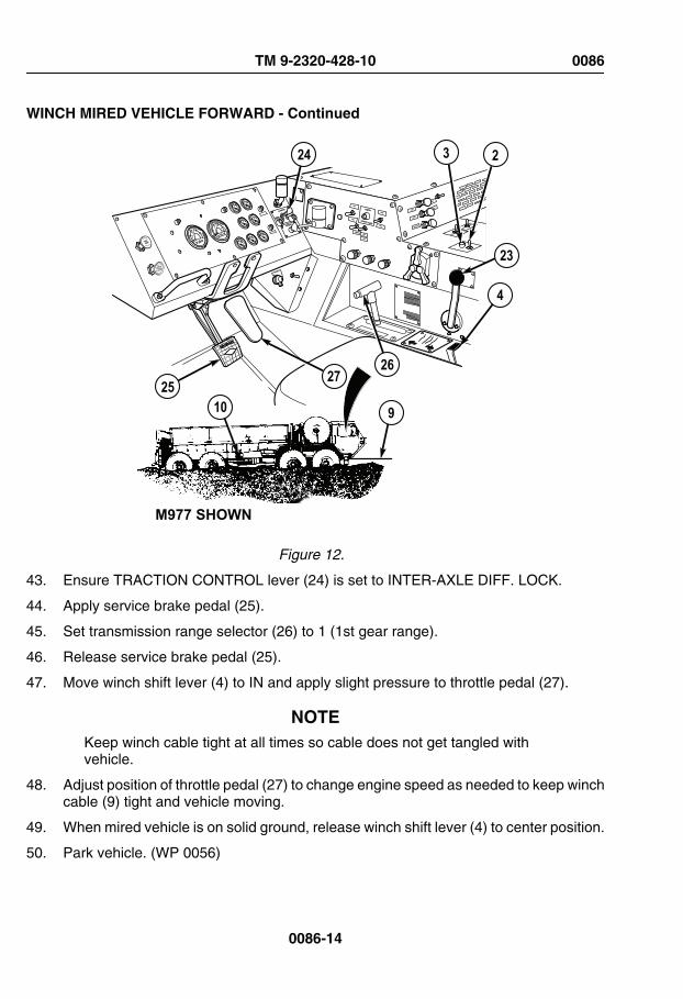
WINCH MIRED VEHICLE FORWARD - Continued
TRAILERAIR SUPPLYNOT FOR PARKINGMIDLAND
PULL TO EXHAUST
PUSH TO SU PPLY
3 2
4
10 925
2726
23
24
M977 SHOWN
Figure 12.
43. Ensure TRACTION CONTROL lever (24) is set to INTER-AXLE DIFF. LOCK.
44. Apply service brake pedal (25).
45. Set transmission range selector (26) to 1 (1st gear range).
46. Release service brake pedal (25).
47. Move winch shift lever (4) to IN and apply slight pressure to throttle pedal (27).
NOTEKeep winch cable tight at all times so cable does not get tangled withvehicle.
48. Adjust position of throttle pedal (27) to change engine speed as needed to keep winchcable (9) tight and vehicle moving.
49. When mired vehicle is on solid ground, release winch shift lever (4) to center position.
50. Park vehicle. (WP 0056)
TM 9-2320-428-10 0086
0086-14

WINCH MIRED VEHICLE FORWARD - Continued
51. Set winch shift lever (4) to OUT and pay out winch cable (9) until all tension is offcable.
52. When all tension is off winch cable (9), release winch shift lever (4) to center position.
53. Set PTO ENGAGE switch (2) to OFF position. Indicator light (3) will go out.
NOTEIf winch cable is connected to another vehicle, refer to Connect/Disconnect Self-Recovery Winch Cable to Another Vehicle (WP 0088) fordisconnecting procedures.
54. Disconnect winch cable (9) from heavy object.
55. If snatch block was used, disconnect end of winch cable (10) from vehicle and removesnatch block from winch cable and from tree, other vehicle, or heavy object refer toFM 4-30.31. (WP 0161)
CAUTIONDo not reel clevis end of winch cable through roller guides. Clevis maycatch on roller guide and cause cable or roller guide to break.
56. Set PTO ENGAGE switch (2) to ON position. Indicator light (3) will illuminate.
57. Move winch shift lever (4) to IN.
WARNING
• Always wear protective gloves when handling winch cable. Never letcable run through hands. Frayed cables can cut severely. Failure tocomply may result in injury or death to personnel.
• Never operate winch with less than five wraps of cable on winchdrum. Failure to comply may result in injury or death to personnel.
58. Reel in winch cable (9) while assistant uses tire iron extension handle to guide cable(9) onto self-recovery winch (10) so cable wraps are level across face of self-recoverywinch (10).
59. When end of cable (9) is near front of vehicle, release winch shift lever (4) to centerposition.
60. Set PTO ENGAGE switch (2) to OFF position. Indicator light (3) will go out.
TM 9-2320-428-10 0086
0086-15

WINCH MIRED VEHICLE FORWARD - Continued
61. Remove quick release pin (16) and guide bracket (17). Move cable guide brackets(18) apart so winch cable (9) can be removed from sheave (19).
9
1817 16
18
19
M977 SHOWN
Figure 13.
62. Move cable guide bracket (18) together. Install guide bracket (17) and quick releasepin (16).
63. Pull back and hold tension pulley lever (20).
TM 9-2320-428-10 0086
0086-16

WINCH MIRED VEHICLE FORWARD - Continued
21
22
219
20
M977 SHOWN13
Figure 14.
64. Lift winch cable (9) out of tensioning device pulleys (21).
65. Release tension pulley lever (20).
66. Pull winch cable (9) back and out of cable guide (13).
67. Set PTO ENGAGE switch (2) to ON position. Indicator light (3) will illuminate.
TM 9-2320-428-10 0086
0086-17

WINCH MIRED VEHICLE FORWARD - Continued
9
7
10 M977 SHOWN
3 2
4
Figure 15.
68. While assistant guides winch cable (9), move winch shift lever (4) to IN.
69. When clevis (7) is approximately 2 ft. (61 cm) from winch (10), release winch shiftlever (4) to center position.
70. Set PTO ENGAGE switch (2) to OFF position. Indicator light (3) will go out.
71. Assistant routes end of winch cable (9) down along front face of winch (10).
TM 9-2320-428-10 0086
0086-18
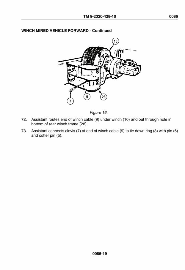
WINCH MIRED VEHICLE FORWARD - Continued
10
9 287
Figure 16.
72. Assistant routes end of winch cable (9) under winch (10) and out through hole inbottom of rear winch frame (28).
73. Assistant connects clevis (7) at end of winch cable (9) to tie down ring (8) with pin (6)and cotter pin (5).
TM 9-2320-428-10 0086
0086-19

WINCH MIRED VEHICLE FORWARD - Continued
3 2
4
9
87 6
5
10
M977 SHOWN
Figure 17.
74. Set PTO ENGAGE switch (2) to ON position. Indicator light (3) will illuminate.
WARNING
Keep all personnel clear of area near winch cable when tension is oncable. Failure to comply may result in injury or death to personnel.
75. Order all personnel to stand clear of area near winch (10).
TM 9-2320-428-10 0086
0086-20
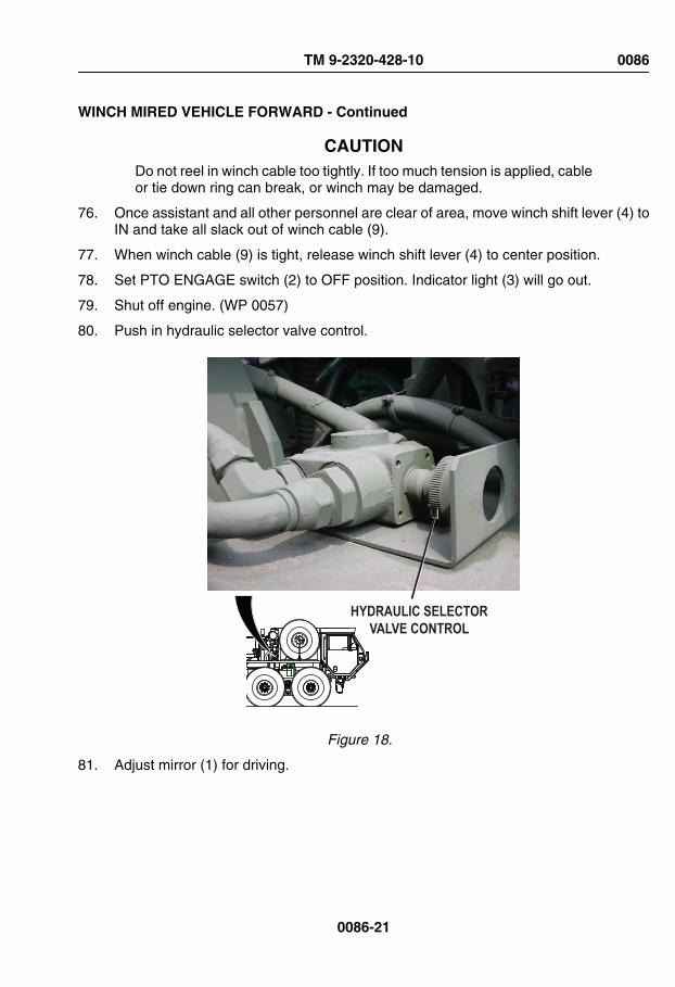
WINCH MIRED VEHICLE FORWARD - Continued
CAUTIONDo not reel in winch cable too tightly. If too much tension is applied, cableor tie down ring can break, or winch may be damaged.
76. Once assistant and all other personnel are clear of area, move winch shift lever (4) toIN and take all slack out of winch cable (9).
77. When winch cable (9) is tight, release winch shift lever (4) to center position.
78. Set PTO ENGAGE switch (2) to OFF position. Indicator light (3) will go out.
79. Shut off engine. (WP 0057)
80. Push in hydraulic selector valve control.
HYDRAULIC SELECTORVALVE CONTROL
Figure 18.
81. Adjust mirror (1) for driving.
TM 9-2320-428-10 0086
0086-21

WINCH MIRED VEHICLE FORWARD - Continued
Figure 19.
WINCH MIRED VEHICLE TO THE REAR
NOTE• For additional information on vehicle self-recovery refer to FM
4-30.31. (WP 0161)
• Vehicle self-recovery is a two soldier task. Soldiers mustcommunicate by hand signals.
1. Shut off engine. (WP 0057)
2. Adjust mirror (1) so assistant can be clearly seen during procedure.
Figure 20.
CAUTIONPTO ENGAGE switch must be in OFF position before moving hydraulicselector valve to prevent equipment damage.
3. Set PTO ENGAGE switch (2) to OFF position. Indicator light (3) will go out.
TM 9-2320-428-10 0086
0086-22

WINCH MIRED VEHICLE TO THE REAR - Continued
TRAILERAIR SUPPLYNOT FOR PARKINGMIDLAND
PULL TO EXHAUST
PUSH TO SU PPLY
32
Figure 21.
4. Pull out hydraulic selector valve control.
TM 9-2320-428-10 0086
0086-23

WINCH MIRED VEHICLE TO THE REAR - Continued
HYDRAULIC SELECTORVALVE CONTROL
Figure 22.
5. Set PTO ENGAGE switch (2) to ON position. Indicator light (3) will illuminate.
TM 9-2320-428-10 0086
0086-24
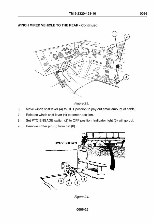
WINCH MIRED VEHICLE TO THE REAR - Continued
TRAILERAIR SUPPLYNOT FOR PARKINGMIDLAND
PULL TO EXHAUST
PUSH TO SU PPLY
3
4
2
Figure 23.
6. Move winch shift lever (4) to OUT position to pay out small amount of cable.
7. Release winch shift lever (4) to center position.
8. Set PTO ENGAGE switch (2) to OFF position. Indicator light (3) will go out.
9. Remove cotter pin (5) from pin (6).
8 7 65
Figure 24.
TM 9-2320-428-10 0086
0086-25

WINCH MIRED VEHICLE TO THE REAR - Continued
10. Remove pin (6) from clevis (7) and disconnect clevis from tie down ring (8).
11. Set PTO ENGAGE switch (2) to ON position. Indicator light (3) will illuminate.
11
9
10
M977 SHOWN
3 2
4
Figure 25.
TM 9-2320-428-10 0086
0086-26

WINCH MIRED VEHICLE TO THE REAR - Continued
WARNING
• Always wear protective gloves when handling winch cable. Never letcable run through hands. Frayed cables can cut severely. Failure tocomply may result in injury or death to personnel.
• Never operate winch with less than five wraps of cable on winchdrum. Failure to comply may result in injury or death to personnel.
12. Move winch shift lever (4) to OUT while assistant pulls winch cable (9) from self-recovery winch (10) toward rear of vehicle.
NOTE• Do not place cable between tensioning device pulleys at this time.
• When pulling cable through tensioning device, push sheave towardsframe rail to allow clevis to pass through.
13. Continue to pay out winch cable (9) while assistant routes cable through cable guide(11).
14. Continue to pay out winch cable (9) while assistant routes cable through hole (12) infender and through roller guide (13).
TM 9-2320-428-10 0086
0086-27

WINCH MIRED VEHICLE TO THE REAR - Continued
9
13
12
M977 SHOWN
Figure 26.
15. Pay out winch cable (9) while assistant pulls cable to tree, another vehicle, or heavyobject refer to FM 4-30.31. (WP 0161)
16. When winch cable (9) is let out to tree, another vehicle, heavy object, release winchshift lever (4) to center position.
17. Set PTO ENGAGE switch (2) to OFF position. Indicator light (3) will go out.
TM 9-2320-428-10 0086
0086-28
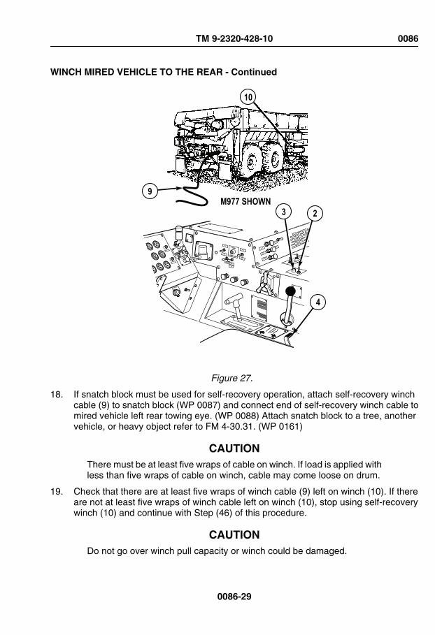
WINCH MIRED VEHICLE TO THE REAR - Continued
M977 SHOWN3
10
2
9
4
Figure 27.
18. If snatch block must be used for self-recovery operation, attach self-recovery winchcable (9) to snatch block (WP 0087) and connect end of self-recovery winch cable tomired vehicle left rear towing eye. (WP 0088) Attach snatch block to a tree, anothervehicle, or heavy object refer to FM 4-30.31. (WP 0161)
CAUTIONThere must be at least five wraps of cable on winch. If load is applied withless than five wraps of cable on winch, cable may come loose on drum.
19. Check that there are at least five wraps of winch cable (9) left on winch (10). If thereare not at least five wraps of winch cable left on winch (10), stop using self-recoverywinch (10) and continue with Step (46) of this procedure.
CAUTIONDo not go over winch pull capacity or winch could be damaged.
TM 9-2320-428-10 0086
0086-29

WINCH MIRED VEHICLE TO THE REAR - Continued
20. Ensure weight of mired vehicle and amount of winch cable (9) left on winch (10) doesnot go over pull capacity refer to FM 4-30.31 (WP 0161) and Self-Recovery WinchPull Capacity table below). If pull will go over capacity, stop using self-recovery winchand continue with Step (46) of this procedure.
Table 2. Self-Recovery Winch Pull Capacity.
Cable Layer Maximum Line Pull
1st layer (five wraps) 20,000 lbs (9 080 kg)
2nd layer 18,173 lbs (8 251 kg)
3rd layer 16,663 lbs (7 565 kg)
4th layer 15,361 lbs (6 974 kg)
5th layer 14,254 lbs (6 471 kg)
NOTEIf winch cable will be connected to another vehicle acting as a stationaryanchor, refer to FM 4-30.31 (WP 0161) or Connect/Disconnect Self-Recovery Winch Cable to Another Vehicle (WP 0088) for connectingprocedures.
21. If it is determined using self-recovery winch (10) will not go over winch pull capacity,connect winch cable (9) to heavy object.
22. Ensure winch shift lever (4) is at center position.
23. Set PTO ENGAGE switch (2) to OFF position. Indicator light (3) will go out.
WARNING
Do not operate winch while personnel are working on or aroundtensioning device. Failure to comply may result in injury or death topersonnel.
24. Pull back and hold tension pulley lever (14).
TM 9-2320-428-10 0086
0086-30

WINCH MIRED VEHICLE TO THE REAR - Continued
15
9
14
11
M977 SHOWN
Figure 28.
25. Route winch cable (9) between pulleys (15).
26. Release tension pulley lever (14).
27. Ensure winch cable (9) rests inside grooves of both pulleys (15).
28. Ensure winch cable (9) is not caught on vehicle or any other objects.
WARNING
Keep all personnel clear of area near winch cable when tension is oncable. Failure to comply may result in injury or death to personnel.
29. Ensure all personnel are clear of winch (10) and winch cable (9).
TM 9-2320-428-10 0086
0086-31

WINCH MIRED VEHICLE TO THE REAR - Continued
M977 SHOWN
10
9
TRAILERAIR SUPPLYNOT FOR PARKINGMIDLAND
PULL TO EXHAUST
PUSH TO SU PPLY
3 2
4
1820
19
16
17
Figure 29.
30. Set PTO ENGAGE switch (2) to ON position. Indicator light (3) will illuminate.
31. Move winch shift lever (4) to IN until slack is out of winch cable (9).
32. Release winch shift lever (4) to center position.
WARNING
Keep all personnel clear of area near winch cable when tension is oncable. Failure to comply may result in injury or death to personnel.
TM 9-2320-428-10 0086
0086-32

WINCH MIRED VEHICLE TO THE REAR - Continued
CAUTION• Self-recovery winch is not designed to winch mired vehicle by itself.
Mired vehicle drive system power must always be used with winch toself-recover vehicle, or damage to equipment can result.
• If winch does not move mired vehicle, stop using winch, overheatdamage may result.
33. Ensure that TRANSFER CASE shift lever (16) is set to LO.
34. Ensure TRACTION CONTROL lever (17) is set to INTER-AXLE DIFF. LOCK.
35. Apply service brake pedal (18).
36. Set transmission range selector (19) to R (reverse).
37. Release service brake pedal (18).
38. Slightly press throttle pedal (20) and move winch shift lever (4) to IN.
NOTEKeep winch cable tight at all times so cable does not get tangled withvehicle.
39. Adjust position of throttle pedal (20) to change engine speed as needed to keep winchcable (9) tight and mired vehicle moving.
40. When mired vehicle is on solid ground, release winch shift lever (4) to center position.
41. Park vehicle. (WP 0056)
42. Set winch shift lever (4) to OUT and pay out winch cable (9) until all tension is released.
43. When all tension is off winch cable (9), release winch shift lever (4) to center position.
44. Set PTO ENGAGE switch (2) to OFF position. Indicator light (3) will go out.
NOTEIf winch cable is connected to another vehicle, refer to Connect/Disconnect Self-Recovery Winch Cable to Another Vehicle (WP 0088) fordisconnecting procedures.
45. Disconnect winch cable (9) from heavy object.
46. If snatch block was used, disconnect end of winch cable (9) from vehicle.(WP 0088)Remove snatch block from winch cable (WP 0087) and tree, anothervehicle, or heavy object refer to FM 4-30.31. (WP 0161)
TM 9-2320-428-10 0086
0086-33
WINCH MIRED VEHICLE TO THE REAR - Continued
CAUTIONDo not reel clevis end of winch cable through roller guides. Clevis maycatch on roller guide and cause cable or roller guide to break.
47. Set PTO ENGAGE switch (2) to ON position. Indicator light (3) will illuminate.
48. Set winch shift lever (4) to IN.
49. When end of cable is near rear of vehicle, release winch shift lever (4) to centerposition.
50. Set PTO ENGAGE switch (2) to OFF position. Indicator light (3) will go out.
WARNING
• Always wear protective gloves when handling winch cable. Never letcable run through hands. Frayed cables can cut severely. Failure tocomply may result in injury or death to personnel.
• Never operate winch with less than five wraps of cable on winchdrum. Failure to comply may result in injury or death to personnel.
51. Pull clevis (7) end of winch cable (9) forward through roller guide (13) and hole (12)in fender.
TM 9-2320-428-10 0086
0086-34

WINCH MIRED VEHICLE TO THE REAR - Continued
7
13 9
12
M977 SHOWN
Figure 30.
52. Pull back and hold tension pulley lever (14).
15
9
14
11
M977 SHOWN
Figure 31.
TM 9-2320-428-10 0086
0086-35

WINCH MIRED VEHICLE TO THE REAR - Continued
53. Lift winch cable (9) out of pulleys (15).
54. Release tension pulley lever (14).
55. Pull winch cable (9) forward and out of cable guide (11).
56. Set PTO ENGAGE switch (2) to ON position. Indicator light (3) will illuminate.
3 2
4
9
87 6
5
10
M977 SHOWN
Figure 32.
57. Move winch shift lever (4) to IN position to reel in cable while assistant guides winchcable (9) to tie down ring (8).
58. When clevis (7) is approximately 2 ft. (61 cm) from winch (10), release winch shiftlever (4) to center position.
TM 9-2320-428-10 0086
0086-36

WINCH MIRED VEHICLE TO THE REAR - Continued
59. Assistant connects clevis (7) to tie down ring (8) with pin (6) and cotter pin (5).
WARNING
Keep all personnel clear of area near winch cable when tension is oncable. Failure to comply may result in injury or death to personnel.
60. Order all personnel to stand clear of area near winch (10).
CAUTIONDo not reel in winch cable too tightly. If too much tension is applied, cableor tie down ring can break, or winch may be damaged.
61. Once assistant and all other personnel are clear of area, move winch shift lever (4) toIN and take all slack out of winch cable (9).
62. When cable is tight, release winch shift lever (4) to center position.
63. Set PTO ENGAGE switch (2) to OFF position. Indicator light (3) will go out.
64. Shut off engine. (WP 0057)
65. Push in hydraulic selector valve control.
TM 9-2320-428-10 0086
0086-37
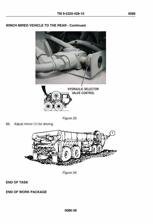
WINCH MIRED VEHICLE TO THE REAR - Continued
HYDRAULIC SELECTORVALVE CONTROL
Figure 33.
66. Adjust mirror (1) for driving.
Figure 34.
END OF TASK
END OF WORK PACKAGE
TM 9-2320-428-10 0086
0086-38

OPERATOR MAINTENANCESNATCH BLOCK INSTALLATION/REMOVAL
INITIAL SETUP:
Not Applicable
ATTACH SNATCH BLOCK TO SELF-RECOVERY WINCH CABLE
1. Remove snatch block (1) from stowage.
Figure 1.
2. Remove screw (2).
3. Move plate (3) to side to open snatch block (1).
4. Place winch cable (4) in snatch block (1).
5. Close plate (3) and align holes.
6. Install screw (2).
7. Ensure screw (2) is tight and winch cable (4) can be moved freely through snatchblock (1).
8. Continue with self-recovery operation (WP 0086).
TM 9-2320-428-10 0087
0087-1

REMOVE SNATCH BLOCK FROM SELF-RECOVERY WINCH CABLE
1. Check that there is enough slack in winch cable (1).
Figure 2.
2. Remove screw (2).
3. Move plate (3) to side to open snatch block (4).
4. Take winch cable (1) out of snatch block (4).
5. Close plate (3) and align holes.
6. Install screw (2).
7. Stow snatch block (4) in stowage box.
8. Continue with self-recovery operation (WP 0086).
END OF TASK
END OF WORK PACKAGE
TM 9-2320-428-10 0087
0087-2

OPERATOR MAINTENANCECONNECT/DISCONNECT SELF-RECOVERY WINCH CABLE TO ANOTHER VEHICLE
INITIAL SETUP:
Not Applicable
CONNECT CABLE TO VEHICLE
CAUTIONWhen attaching self-recovery winch cable to another vehicle, that vehiclemust be used only as an anchor point or damage to equipment can result.
NOTEThere are three tie down rings on each side of vehicle.
1. Unscrew one tie down ring (1) from mounting plate (2).
Figure 1.
2. Remove lifting shackle (3) from stowage.
TM 9-2320-428-10 0088
0088-1

CONNECT CABLE TO VEHICLE - Continued
Figure 2.
3. Insert lifting shackle (3) through tie down ring (1).
4. Connect lifting shackle (3) to left front of left rear tow eye (4) with pin (5).
5. Install cotter pin (6).
6. Connect self-recovery winch cable (7) with clevis (8) to tie down ring (1) with pin (9).
7. Install cotter pin (10).
8. Continue with self-recovery winch operation. (WP 0086)
DISCONNECT CABLE FROM VEHICLE
1. Ensure there is enough slack in winch cable (1).
TM 9-2320-428-10 0088
0088-2

DISCONNECT CABLE FROM VEHICLE - Continued
1 3
4
26
58
97
Figure 3.
2. Remove cotter pin (2).
3. Remove pin (3) and disconnect clevis (4) from tie down ring (5).
4. Remove cotter pin (6).
5. Remove pin (7) and disconnect lifting shackle (8) from tow eye (9).
6. Remove tie down ring (5) from lifting shackle (8).
7. Stow lifting shackle (8).
NOTEThere are three tie down rings on each side of vehicle.
8. Install tie down ring (5) into mounting plate (10).
TM 9-2320-428-10 0088
0088-3

DISCONNECT CABLE FROM VEHICLE - Continued
10
5
Figure 4.
9. Continue with self-recovery winch operation. (WP 0086)
END OF TASK
END OF WORK PACKAGE
TM 9-2320-428-10 0088
0088-4

OPERATOR MAINTENANCETOW DISABLED VEHICLE
INITIAL SETUP:
Not Applicable
TOW DISABLED VEHICLE
CAUTION• When towing another vehicle, do not go over GCWR given in
equipment data (WP 0006). Failure to comply may result in damageto equipment.
• Propeller shaft must be removed by field level maintenance beforetowing disabled vehicle or equipment may be damaged.
NOTEDisabled vehicles must be prepared and moved in accordance with FM21-305 . If instructed to do so, manually release spring brakes(WP 0100) as part of preparing disabled vehicle for towing.
1. Install and operate portable beacon lights. (WP 0074)
2. Set TRANSFER CASE shift lever (1) to NEUT (neutral) position.
3. Set TRACTION CONTROL lever (2) to OFF.
TM 9-2320-428-10 0089
0089-1

TOW DISABLED VEHICLE - Continued
TRAILERAIR SUPPLYNOT FOR PARKING
MIDLAND
PULL
TOEXHAUST
PUSH T O SUPPLY
3
2
4
1
Figure 1.
4. Push in PARKING BRAKE control on disabled vehicle (refer to operator's manual).
5. Push in TRAILER AIR SUPPLY control (4) on recovery vehicle.
6. Transport disabled vehicle.
END OF TASK
END OF WORK PACKAGE
TM 9-2320-428-10 0089
0089-2
OPERATOR MAINTENANCECONNECT/DISCONNECT TOW BAR
INITIAL SETUP:
Personnel RequiredOperator and Assistant(s) - - - (3)
CONNECT TOW BAR
WARNING
Do not use 10-ton tow bar with self-guided coupler (normally found onsome M1120 LHS and M1977 CBT models). Self-guided coupler is notcompatible with 10-ton tow bar. Failure to comply may result in injury ordeath to personnel
WARNING
Tow bar is heavy. Do not attempt to lift or move tow bar without the aidof two assistants and a lifting device. Failure to comply may result in injuryor death to personnel.
NOTE• This procedure is a three soldier task.
• The 10-ton tow bar should always be used in conjunction with two 16ft. (5 m) safety chains.
• Allow ample distance between towing vehicle and disabled vehicleto connect 10-ton tow bar.
1. Align rear of towing vehicle near front of disabled vehicle.
TM 9-2320-428-10 0090
0090-1

CONNECT TOW BAR - Continued
WARNING
Tow bar is heavy. Do not attempt to lift or move tow bar without the aidof two assistants and a lifting device. Failure to comply may result in injuryor death to personnel.
2. With aid of two assistants and a lifting device, remove tow bar (1) from stowage.
Figure 1.
3. Remove cotter hairpin (2) and pin (3) from tow bar (1).
4. Separate tow bar (1) at pivot point (4).
NOTETowing eyes on all models of HEMTT series vehicles are same inappearance, operation, and location. HEMTT M977 shown.
5. Position legs of tow bar (1) in front of disabled vehicle with spare pins (5) facing up.
TM 9-2320-428-10 0090
0090-2

CONNECT TOW BAR - Continued
32 5 1
1
M977 BASE/A2
86
7
9
Figure 2.
M977 A4
32
51
1
86 7
9
Figure 3.
6. Remove two cotter hairpins (6) and pins (7) from tow bar shackles (8).
TM 9-2320-428-10 0090
0090-3

CONNECT TOW BAR - Continued
WARNING
Tow bar is heavy. Do not attempt to lift or move tow bar without the aidof two assistants and a lifting device. Failure to comply may result in injuryor death to personnel.
7. While two assistants hold one leg of tow bar (1) and align shackle (8) with towing eye(9), install pin (7) and cotter hairpin (6).
8. Repeat Step (7) for other leg of tow bar (1).
9. Align legs of tow bar (1) at pivot point (4) and install pin (3) and cotter hairpin (2).
WARNING
Do not use 10-ton tow bar with self-guided coupler (normally found onsome M1120 LHS and M1977 CBT models). Self-guided coupler is notcompatible with 10-ton tow bar. Failure to comply may result in injury ordeath to personnel
NOTEPintle hook on all models of HEMTT series vehicles are same inappearance, operation, and location. HEMTT M977 shown.
10. Position the towing vehicle so pintle hook is aligned with tow bar lunette eye.
11. Remove cotter pin (10) from pintle hook (11).
TM 9-2320-428-10 0090
0090-4

CONNECT TOW BAR - Continued
12M977
10
13
11
1
Figure 4.
12. Pull latch (12) away from vehicle and hold.
13. Lift top of pintle hook (11) and let go of latch (12). Pintle hook (11) will be locked open.
WARNING
Tow bar is heavy. Do not attempt to lift or move tow bar without the aidof two assistants and a lifting device. Failure to comply may result in injuryor death to personnel.
TM 9-2320-428-10 0090
0090-5

CONNECT TOW BAR - Continued
WARNING
Do not put hands near pintle hook while aligning lunette eye with pintlehook. Failure to comply may result in injury or death to personnel.
14. While two assistants lift tow bar (1), slowly back up towing vehicle until tow bar lunetteeye (13) connects to pintle hook (11).
15. Pull latch (12) and close top half of pintle hook (11).
16. Install cotter pin (10) in pintle hook (11).
NOTEIf air system of disabled vehicle is damaged, manually release springbrakes (WP 0100).
17. Remove two inter-vehicular air lines (14) from stowage.
TM 9-2320-428-10 0090
0090-6

CONNECT TOW BAR - Continued
M977M977
15
14
18
17 16
19
Figure 5.
NOTEGladhands on all models of HEMTT series vehicles are same inappearance, operation, and location. HEMTT M977 shown.
18. Connect first intervehicular air line (14) to driver side rear gladhand (15) of towingvehicle and driver side front gladhand (16) of disabled vehicle.
19. Connect second intervehicular air line (17) to passenger side rear gladhand (18) oftowing vehicle and passenger side front gladhand (19) of disabled vehicle.
20. Remove two 16 ft. (5 m) safety chains (20) from stowage.
NOTE• Both driver side and passenger side walking beams are same. Driver
side shown.
• If disabled vehicle is either a BASE or A2 model HEMTT seriesvehicle (refer to data plate on inside of drivers door), complete Step
TM 9-2320-428-10 0090
0090-7

CONNECT TOW BAR - Continued
(21). If disabled vehicle is an A4 model HEMTT series vehicle (referto data plate on inside of drivers door), skip to Step (22).
21. Route one 16 ft. (5 m) safety chain (20) over walking beam (21) behind No. 1 axle(22) on disabled vehicle, and hook 16 ft. (5 m) safety chain (20) back into itself underwalking beam (21) as shown.
22
2120
BASE/A2 MODELS
Figure 6.
CAUTIONSpecial care should be taken when connecting 16 ft. (5 m) safety chainto tie down ring. The procedure listed below routes the 16 ft. (5 m) safetychain in such a way as to minimize excessive contact with vehicle airsuspension air springs during towing. Failure to comply may result indamage to equipment.
TM 9-2320-428-10 0090
0090-8

CONNECT TOW BAR - Continued
NOTEBoth driver side and passenger side tie down rings are same. Driver sideshown.
22. Connect 16 ft. (5 m) safety chain (20) to disabled vehicle tie down ring (23):
a. Route end (without safety shackle) of 16 ft. (5 m) safety chain (20) through tiedown ring (23) from inboard to outboard until grab hook (24) hangs just belowbottom of air spring (25).
23
25
20 24
Figure 7.
b. Hook 16 ft. (5 m) safety chain (20) back to itself. Grab hook (24) should opentowards ground (shown) when tension is applied to 16 ft. (5 m) safety chain (20).
TM 9-2320-428-10 0090
0090-9

CONNECT TOW BAR - Continued
24
20
Figure 8.
23. Repeat Steps (21) or (22) for other side of disabled vehicle.
NOTE• 16 ft. (5 m) safety chain may be attached to either safety chain loop
or towing shackles.
• 16 ft. (5 m) safety chain should be attached so they are just above,but not in contact with the ground.
24. Route free ends of two 16 ft. (5 m) safety chain (20) through safety chain loop (26) ontowing vehicle and attach each 16 ft. (5 m) safety chain (20) back into itself as shown.
TM 9-2320-428-10 0090
0090-10

CONNECT TOW BAR - Continued
26 20
Figure 9.
25. Tow disabled vehicle. (WP 0089)
DISCONNECT TOW BAR
NOTE• This procedure is a three soldier task.
• Vehicle should be parked and disconnected on level ground.
1. Park towing vehicle. (WP 0056)
2. Pull out TRAILER AIR SUPPLY control (1) on towing vehicle.
TM 9-2320-428-10 0090
0090-11
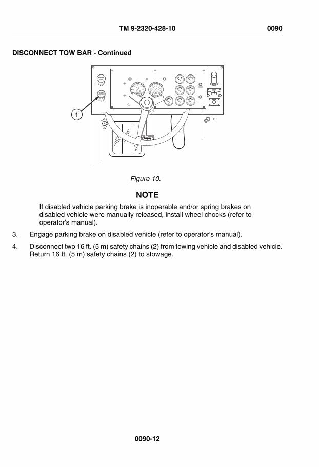
DISCONNECT TOW BAR - Continued
AIR BRAKE
PARKINGBRAKE
TRAILERAIR SUPPLY
EXEXEX
EXEXEXEXEX EXEX
ENGINEOFF
ON
START
1
Figure 10.
NOTEIf disabled vehicle parking brake is inoperable and/or spring brakes ondisabled vehicle were manually released, install wheel chocks (refer tooperator's manual).
3. Engage parking brake on disabled vehicle (refer to operator's manual).
4. Disconnect two 16 ft. (5 m) safety chains (2) from towing vehicle and disabled vehicle.Return 16 ft. (5 m) safety chains (2) to stowage.
TM 9-2320-428-10 0090
0090-12

DISCONNECT TOW BAR - Continued
M977M977
4
3
4
3 5
2
Figure 11.
NOTEIf spring brakes on disabled vehicle were manually released beforetowing, skip to Step (6).
5. Disconnect two intervehicular air lines (3) from towing vehicle rear gladhands (4) andfrom disabled vehicle front gladhands (5). Return intervehicular air lines (5) tostowage.
6. Remove cotter pin (6) from towing vehicle pintle hook (7).
TM 9-2320-428-10 0090
0090-13

DISCONNECT TOW BAR - Continued
9
6 1011
7
Figure 12.
7. Pull latch (9) away from vehicle and hold.
8. Lift top of pintle hook (7) and let go of latch (9). Pintle hook (7) will be locked open.
9. As two assistants lift tow bar (10) until lunette eye (11) is clear of pintle hook (10),drive towing vehicle forward approximately 15 ft. (4.6 m).
10. As assistants lower tow bar (10) to the ground, park towing vehicle.
11. Pull latch (9) to close towing vehicle pintle hook (7) and install cotter pin (6) in pintlehook (7).
12. Remove cotter hairpin (12) and pin (13) and separate tow bar (10) at pivot point (14).
TM 9-2320-428-10 0090
0090-14

DISCONNECT TOW BAR - Continued
1312
1010
M977 BASE/A2
1715
16
9
14
Figure 13.
TM 9-2320-428-10 0090
0090-15

DISCONNECT TOW BAR - Continued
M977 A4
1312
101
1715 16
9
14
Figure 14.
13. With aid of an assistant, hold one leg of tow bar (10) while another assistant removescotter hairpin (15) and pin (16) from shackle (17).
14. Repeat Step (13) for other leg of tow bar (10).
15. With aid of two assistants, lower tow bar (10) to the ground.
16. Install two pins (16) and cotter hairpins (15) is shackles (17).
17. Align legs of tow bar (10) at pivot point (14) and install pin (13) and cotter hairpin (12).
WARNING
Tow bar is heavy. Do not attempt to lift or move tow bar without the aidof two assistants and a lifting device. Failure to comply may result in injuryor death to personnel.
TM 9-2320-428-10 0090
0090-16

DISCONNECT TOW BAR - Continued
18. With aid of two assistants and lifting device, return tow bar (10) to stowage.
END OF TASK
END OF WORK PACKAGE
TM 9-2320-428-10 0090
0090-17


OPERATOR MAINTENANCEOPERATE VEHICLE IN EXTREME HEAT
INITIAL SETUP:
Not Applicable
EXTREME HEAT OPERATION
CAUTION• When operating vehicle in very hot temperatures of above 100°F
(38°C), extra care must be taken to prevent overheating engine(temperatures over 230°F (110°C) and transmission (temperaturesover 250°F, 121°C). Watch water and transmission temperaturegauges closely. Failure to comply may result in damage toequipment.
• Check oil levels often and keep operating strain as low as possible.Vehicle cooling and lubrication systems support each other. Failureof one system will rapidly cause failure of other systems.
NOTE• Close heater valves to improve the efficiency of cabin air conditioning
kit.
• Closing the heater valves disables cabin heat.
1. Keep operating temperatures as low as possible:
a. Set transmission range selector (1) to N (neutral) while engine is running andnot required to move.
b. Use low gear ranges only when necessary.
c. Stop vehicle for cooling off periods, and idle engine as often as possible. Letengine idle for approximately 3 minutes before shutting down. Idling will coolengine faster than quick shutdown and may prevent damage from remainingengine heat.
d. Check oil levels often. Oil seals are more likely to leak in extreme hot weather.
e. Check air filter restriction indicator (2) frequently. If indicator shows red:
(1) Park vehicle. (WP 0056)
TM 9-2320-428-10 0091
0091-1

EXTREME HEAT OPERATION - Continued
(2) Shut off engine. (WP 0057)
(3) Notify field level maintenance.
TRAILERAIR SUPPLYNOT FOR PARKINGMIDLAND
PULL TO EXHAUST
PUSH TO SU PPLY
3 6 2
4
15
Figure 1.
2. If TRANS TEMP gauge (3) reads 250°F (121°C) or above, perform the following steps:
a. Slow vehicle.
b. Set transmission range selector (1) to next lower gear range.
c. Continue operation.
d. When TRANS TEMP gauge (3) reads normal range:
(1) Set transmission range selector (1) to normal gear range.
(2) Continue operation.
e. If TRANS TEMP gauge (3) does not return to normal range:
(1) Stop vehicle.
(2) Set transmission range selector (1) to N (neutral).
(3) Pull out PARKING BRAKE control (4).
(4) Allow transmission to cool.
f. When TRANS TEMP gauge (3) reads normal range:
TM 9-2320-428-10 0091
0091-2

EXTREME HEAT OPERATION - Continued
(1) Apply service brake pedal (5).
(2) Push in PARKING BRAKE control (4).
(3) Set transmission range selector (1) to normal gear range.
(4) Continue operation.
3. If WATER TEMP gauge (6) indicates coolant temperature is near overheating,perform the following steps:
a. Slow vehicle.
b. Set transmission range selector (1) to next lower gear range.
c. Continue operation.
d. When WATER TEMP gauge (6) reads normal range:
(1) Set transmission range selector (1) to normal gear range.
(2) Continue operation.
e. If WATER TEMP gauge (6) does not return to normal range:
(1) Stop vehicle.
(2) Set transmission range selector (1) to N (neutral).
(3) Pull out PARKING BRAKE control (4).
(4) Allow engine to cool.
f. When WATER TEMP gauge (6) reads normal range:
(1) Apply service brake pedal (5).
(2) Push in PARKING BRAKE control (4).
(3) Set transmission range selector (1) to normal gear range.
(4) Continue operation.
4. Check cooling system often and notify field level maintenance if any of the followingare found:
a. Low coolant level in radiator.
b. Leaking hose connections which have been tightened but still leak.
c. Cracked or leaking hoses.
d. Radiator or charge air cooler fins/grill plugged with mud, debris, etc.
NOTE• Batteries do not hold charge well in extreme heat.
TM 9-2320-428-10 0091
0091-3
EXTREME HEAT OPERATION - Continued
• Battery will be tagged (white circle printed on top) for use in extremeheat conditions as specific gravity must be changed to adjust for heat(refer to TM 9-6140-200-14).
5. Keep batteries full, but do not overfill. Check battery electrolyte daily.
6. In hot, damp climates check body and chassis often and notify field level maintenanceif any of the following are found:
a. Signs of pitting or paint blistering on metal surfaces.
b. Signs of mildew, mold, or fungus on fabrics and rubber.
7. Adjust lubrication intervals as specified in applicable lubrication instructions (refer toPMCS).
8. Park vehicle (WP 0056) in sheltered area, out of wind if possible. If no shelter isavailable, park so vehicle does not face into wind.
END OF TASK
END OF WORK PACKAGE
TM 9-2320-428-10 0091
0091-4

OPERATOR MAINTENANCEOPERATION IN EXTREME DUST
INITIAL SETUP:
Not Applicable
OPERATE VEHICLE IN EXTREME DUST
CAUTIONClouds of dust can scratch glass surfaces. Keep glass surfaces coveredas much as possible in these conditions to prevent scratching.
1. Leave glass surfaces covered if not needed for operations. Take extra care whencleaning glass to prevent scratching surfaces.
2. Keep close watch on air filter restriction indicator (1) located on top right side of driver’sinstrument panel.
AIR BRAKE
PARKINGBRAKE
TRAILERAIR SUPPLY
EXEXEX
EXEXEXEXEXEX
ENGINEOFF
ON
START
12
Figure 1.
3. Continuously scan gauges and indicators on driver’s instrument panel (2) to be suredust does not affect equipment.
TM 9-2320-428-10 0092
0092-1

OPERATE VEHICLE IN EXTREME DUST - Continued
4. Allow as much distance as possible between vehicles and operate at low speeds.
5. At stops, check and drain fuel/water separator (3).
3
Figure 2.
6. When possible, park vehicle so it does not face into wind.
OPERATE GROVE CRANE IN EXTREME DUST
NOTELubricate outrigger bottom plate, boom wear pads, and exposed rotationgears often when cranes are operating in dusty environment (refer toPMCS - Semiannual procedures (WP 0149) for more information).
1. When operating the grove crane in a blowing dust environment, perform the following:
a. Check gear teeth of rotation gear bearing and pinion for an accumulation of dustwithin the lubricant.
TM 9-2320-428-10 0092
0092-2

OPERATE GROVE CRANE IN EXTREME DUST - Continued
Figure 3.
b. If level of dust prevents rotation of crane, notify field level maintenance and havelubricant removed.
c. If necessary, notify field level maintenance to apply a light coating of wax to gearteeth for rust prevention.
d. Refer to appropriate PMCS for proper lubrication of gear teeth when returningto normal operating conditions.
END OF TASK
END OF WORK PACKAGE
TM 9-2320-428-10 0092
0092-3


OPERATOR MAINTENANCEOPERATE VEHICLE IN SAND OR MUD
INITIAL SETUP:
Not Applicable
OPERATE VEHICLE IN SAND OR MUD
CAUTIONBlowing sand may scratch glass surfaces. Glass surfaces should remaincovered as much as possible in these conditions to prevent scratching.
NOTEOperating in mud can worsen vehicle braking and speed up brake wear.If braking worsens while operating in mud, dry brakes by driving vehicleapproximately 500 ft. (153 m) with service brakes frequently applied. Thismust be done with brakedrums totally out of mud, so that drying actioncan take place. If adequate braking is not restored by drying brakes, notifyfield level maintenance.
1. Leave glass surfaces covered if not needed for operations. Extra care should be takenwhen cleaning glass surfaces to prevent scratching surfaces.
NOTEPrinciples of driving in sand can also be applied to driving in mud.Best time to drive on sand is at night or early morning when sand isdamp. Damp sand gives better traction.
a. Check air filter restriction indicator (1) often.
2. Adjust tires to correct tire pressure for type tire and environment. (WP 0006)
NOTEPositioning TRANSFER CASE shift lever to LO automatically activates8X8 drive.
3. Set TRANSFER CASE shift lever (2) to LO. 8X8 DRIVE indicator (3) will illuminate.
TM 9-2320-428-10 0093
0093-1

OPERATE VEHICLE IN SAND OR MUD - Continued
TRAILERAIR SUPPLYNOT FOR PARKINGMIDLAND
PULL
TO EXHAUST
PUSH T O SUPPL
Y
AIR BRAKE
PARKINGBRAKE
TRAILERAIR SUPPLY
EXEXEX
EXEXEXEXEX EXEX
ENGINEOFF
ON
START
2
35 4
1
6
8
78
7
Figure 1.
TM 9-2320-428-10 0093
0093-2
OPERATE VEHICLE IN SAND OR MUD - Continued
CAUTIONWheel hop condition should be avoided to prevent possible damage todrivetrain. If wheel hop begins to occur, ease up on throttle to allow tiresto grip surface. If wheel hop continues, release throttle and apply brakes.Apply throttle slowly as traction permits.
4. Start slowly. Do not spin wheels when starting to move vehicle.
5. Set TRACTION CONTROL lever (4) to INTER-AXLE DIFF LOCK for added traction.Indicator light (5) will illuminate.
6. Set transmission range selector (6) to 2 (2nd) or 1 (1st), as needed for added traction.
7. Do not straddle sand mounds or drive on sides of two sand mounds. Loose sand willnot support vehicle on steep slopes.
8. Keep throttle pedal (7) steady after vehicle reaches desired speed.
9. Turn vehicle slowly when on loose sand or mud.
10. Steer vehicle straight up and down hills if possible.
11. To move vehicle forward and turn after vehicle is stopped in loose sand or mud, dothe following:
a. Set transmission range selector (6) to R (reverse).
b. Press throttle pedal (7) and move vehicle straight back about 20 ft. (6.1 m).
c. Release throttle pedal (7) and press service brake pedal (8).
d. Set transmission range selector (6) to 1 (1st).
e. Release service brake pedal (8) and press throttle pedal (7) to move vehicleforward.
f. Turn vehicle gradually.
g. Set transmission range selector (6) to D (drive) when vehicle picks up speedand is moving forward smoothly.
12. If vehicle starts to skid, do the following:
a. Release throttle pedal (7).
b. Steer in direction of skid until vehicle stops skidding.
c. Press throttle pedal (7) slowly and steer vehicle on straight course.
TM 9-2320-428-10 0093
0093-3
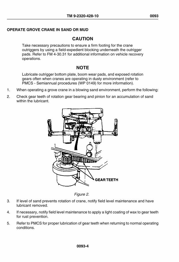
OPERATE GROVE CRANE IN SAND OR MUD
CAUTIONTake necessary precautions to ensure a firm footing for the craneoutriggers by using a field-expedient blocking underneath the outriggerpads. Refer to FM 4-30.31 for additional information on vehicle recoveryoperations.
NOTELubricate outrigger bottom plate, boom wear pads, and exposed rotationgears often when cranes are operating in dusty environment (refer toPMCS - Semiannual procedures (WP 0149) for more information).
1. When operating a grove crane in a blowing sand environment, perform the following:
2. Check gear teeth of rotation gear bearing and pinion for an accumulation of sandwithin the lubricant.
Figure 2.
3. If level of sand prevents rotation of crane, notify field level maintenance and havelubricant removed.
4. If necessary, notify field level maintenance to apply a light coating of wax to gear teethfor rust prevention.
5. Refer to PMCS for proper lubrication of gear teeth when returning to normal operatingconditions.
TM 9-2320-428-10 0093
0093-4

PARK VEHICLE
1. Park vehicle as follows:
a. Vehicle should not face into wind.
b. Clean mud off vehicle as soon as possible.
CAUTION• Do not hit axle breathers when cleaning mud from axles.
• Do not direct high pressure water stream at glass surfaces, seals, airintake, axle breathers, exhaust outlet, or any other component ofvehicle that could be easily damaged by high pressure water stream.
2. Clean mud from wheels, brakes, axles, universal joints, steering mechanism, andradiator as soon as possible.
3. Make sure axle breather vent caps move freely on breather body.
END OF TASK
END OF WORK PACKAGE
TM 9-2320-428-10 0093
0093-5


OPERATOR MAINTENANCEOPERATE VEHICLE IN DESERT ENVIRONMENT
INITIAL SETUP:
Not Applicable
DESERT ENVIRONMENT OPERATION
NOTEFM 90-3 contains detailed instructions for living and working in desert.
1. Principles for operating in extreme heat (WP 0091) and extreme dust (WP 0092),sand, or mud (WP 0093) apply to desert environment.
NOTE• Close heater valves to improve the efficiency of cabin air conditioning
kit.
• Closing the heater valves disables cabin heat.
2. Temperatures may change as much as 70°F (21°C) degrees between day and night.These changes may damage equipment if vehicle is not properly prepared.
a. Due to expansion and contraction of all fluids and air, care should be taken whenfilling fuel tank and fluid reservoirs to prevent overflow when temperatureschange.
b. Precision instruments may be affected by temperature changes and may needadjustment more often.
END OF TASK
END OF WORK PACKAGE
TM 9-2320-428-10 0094
0094-1

OPERATOR MAINTENANCEOPERATE VEHICLE IN COLD ENVIRONMENT (32°F [0°C] TO -25°F [-32°C])
INITIAL SETUP:
Not Applicable
OPERATE VEHICLE IN COLD ENVIRONMENT
WARNING
Do not touch extremely cold metal (below -26°F, -32°C to -65°F, -54°C).Bare skin may freeze to cold metal. Failure to comply may result in injuryor death to personnel.
CAUTION• Before operating vehicle in extreme cold environment, ensure engine
arctic kit is installed and vehicle has been prepared as described inFM 9-207 . Refer to FM 31-70 , FM 31-71 , and FM 21-305 foradditional information on operations in extreme cold environment.
• Watch instrument panel closely. If any unusual readings occur, stopvehicle and shut off engine. Check engine immediately.
• Park in shelter when possible. If shelter is not available, park sovehicle does not face into wind. Place planks or brush under wheelsso vehicle will not freeze in place.
• Fuel filter should be drained before topping off fuel tank. Keep fueltank as full as possible during cold operations. Water forms in emptyfuel tank as it cools. Water in fuel system could freeze and blocksystem.
• All snow and ice should be removed from vehicle as soon as possible.Snow and ice may slow or stop movement of critical parts if allowedto pile up.
• Special care must be used during operations in extreme coldenvironment. In extreme cold, engine coolant and fluid in windshield
TM 9-2320-428-10 0095
0095-1

OPERATE VEHICLE IN COLD ENVIRONMENT - Continued
washer can freeze. Batteries can freeze and crack. Oil and greasemay get thick and stiff. Rubber and metal parts may crack or becomebrittle and break easily.
• Proper component lubrication is a must for extreme cold operation.
1. Install tire chains, as needed. (WP 0083)
NOTEUse ether start system when starting a cold engine.
2. Start engine (WP 0044) and allow engine warm up thoroughly.
3. Let engine warm up thoroughly.
NOTEPositioning TRANSFER CASE shift lever to LO automatically activates8X8 drive.
4. Set TRANSFER CASE shift lever (1) to LO. 8X8 DRIVE indicator (2) will illuminate.
TRAILER
AIR SUPPLY
NOT FOR PARKING
MIDLAND
PULL
TO
EXHAUST
PUSH T O SUPP
LY
LHS
NO
TRANSIT
LHS
LMS
OVER
LOAD
4
1
67
5 2
3
Figure 1.
5. Set transmission range selector (3) to 1 (1st gear range) and drive at lowest possiblespeed to warm driveline components and tires.
6. Drive on mud, snow, ice, and slippery surfaces as follows:
TM 9-2320-428-10 0095
0095-2

OPERATE VEHICLE IN COLD ENVIRONMENT - Continued
NOTE• TRACTION CONTROL lever should be set to 8X8 DRIVE when
transfer case shift lever is set to HI range while driving onslippery surfaces.
• Positioning TRANSFER CASE shift lever to LO automaticallyactivates 8X8 drive.
a. Set TRANSFER CASE shift lever (1) to LO for added traction. 8X8 DRIVEindicator (2) will illuminate.
NOTETRACTION CONTROL lever should be set to INTER-AXLE DIFF.LOCK when transfer case shift lever is set to LO range while drivingon slippery surfaces.
b. Set TRACTION CONTROL lever (4) in INTER-AXLE DIFF. LOCK (when LOrange is used - recommended) or 8X8 DRIVE (if HI range is required), asneeded, when driving on slippery surfaces. INTER-AXLE LOCK indicator (5)and/or 8X8 DRIVE indicator (2) will illuminate as applicable.
c. Press throttle pedal (6) slowly when changing speed.
d. Keep throttle pedal (6) steady after vehicle reaches desired speed.
e. Turn vehicle slowly when on slippery surfaces.
f. Steer vehicle away from ruts and large snowbanks.
g. Steer vehicle straight up and down hills if possible.
h. Use gear range 2 (2nd) or 3 (3rd) to go down medium grades.
i. Use gear range 1 (1st) to go down steep or very slippery grades.
j. Drive at slower speeds and stay twice normal distance from vehicle ahead.
k. Signal turns sooner than normal to give vehicles behind ample time to safelyslow down.
WARNING
Do not use engine brake when vehicle is on slippery surface. Ifengine brake is used incorrectly, vehicle may skid out of control.Failure to comply may result in injury or death to personnel.
TM 9-2320-428-10 0095
0095-3

OPERATE VEHICLE IN COLD ENVIRONMENT - Continued
NOTEPressing service brake pedal lightly will help keep vehicle fromskidding.
l. Apply brakes sooner, and press service brake pedal (7) lightly to give earlywarning that vehicle will slow or stop.
m. Downshift, if necessary, when slowing or stopping vehicle on slick surfaces.
n. Keep windshield, windows, mirrors, headlights, stoplights, and body lights cleanand free of snow and ice. Use defroster and windshield wipers to keepwindshield free of snow and ice.
o. Drive slowly and test brakes after driving through slush or water. If brakes slip,do the following:
(1) Continue to drive slowly.
(2) Apply moderate pressure on service brake pedal (7) to cause slight brakedrag.
(3) When brakes are dry and no longer slip, release service brake pedal (7).
(4) Resume normal driving speed for conditions.
p. If absolutely necessary for better traction, lower vehicle tire pressure toemergency air pressure limit:
(1) Ensure each tire has a valve cap.
(2) Drive at low speed when tire pressures are reduced.
q. If rear of vehicle skids, do the following:
(1) Ease up on throttle pedal (6).
(2) Steer in same direction that vehicle is skidding.
(3) When vehicle is under control, lightly apply service brake pedal (7).
(4) Steer vehicle on a straight course and slowly apply throttle pedal (6).
r. If vehicle starts to slide while climbing a grade, do the following:
(1) Ease up on throttle pedal (6).
(2) Steer in same direction that vehicle is skidding.
(3) Slowly apply throttle pedal (6) and steer vehicle on a straight course.
s. If vehicle becomes stuck, do the following:
(1) Shovel a clear path ahead of each tire.
(2) Put boards, brush, or similar material in cleared paths to get better traction.
TM 9-2320-428-10 0095
0095-4

OPERATE VEHICLE IN COLD ENVIRONMENT - Continued
(3) If vehicle remains stuck, use another vehicle to winch or tow stuck vehicleclear.
(4) If another vehicle is not available, self-recover vehicle using self-recoverywinch. (WP 0086)
7. Park vehicle (WP 0056) as follows:
NOTEIf no shelter is available, park vehicle so it does not face into the wind.Vehicle facing opposite of the direction of the wind is optimal.
a. Park vehicle in sheltered area, out of wind if possible.
NOTEIf no high, dry ground is available, spread out planks, brush, etc., tocreate a raised area so that vehicle tires will not freeze in snow,water, ice, or mud.
b. Park vehicle on high, dry ground if possible.
c. Park vehicle on level ground so vehicle body does not twist.
d. Leave transfer case shift lever (1) in LO.
NOTEDo not hit axle breathers when cleaning mud, snow, and ice from axles.
8. Clean snow, ice, and mud off vehicle as soon as possible.
9. Clean mud, snow, and ice from wheels, brakes, axles, universal joints, mirrors,steering mechanism, and radiator as soon as possible.
10. Ensure axle breather vent caps move freely on breather body.
END OF TASK
END OF WORK PACKAGE
TM 9-2320-428-10 0095
0095-5


OPERATOR MAINTENANCEOPERATION IN EXTREME COLD ENVIRONMENT
INITIAL SETUP:
Not Applicable
OPERATE VEHICLE IN EXTREME COLD ENVIRONMENT (-26°F[-32°C] to-65°F[-54°C])
WARNING
Do not touch extremely cold metal (below -26°F, -32°C to -65°F, -54°C).Bare skin may freeze to cold metal. Failure to comply may result in injuryor death to personnel.
CAUTION• Before operating vehicle in extreme cold environment, ensure engine
arctic kit is installed and vehicle has been prepared as described inFM 9-207.
• Refer to FM 31-70 , FM 31-71 , and FM 21-305 for additionalinformation on operations in extreme cold environment.
• Watch instrument panel closely. If any unusual readings occur, stopvehicle and shut off engine. Check immediately.
• Park in shelter when possible. If shelter is not available, park sovehicle does not face into wind. Place planks or brush under wheelsso vehicle will not freeze in place.
• Fuel filter should be drained before topping off fuel tank. Keep fueltank as full as possible during cold operations. Water forms in emptyfuel tank as it cools. Water in fuel system could freeze and blocksystem.
• All snow and ice should be removed from vehicle as soon as possible.Snow and ice may slow or stop movement of critical parts if allowedto pile up.
TM 9-2320-428-10 0096
0096-1
OPERATE VEHICLE IN EXTREME COLD ENVIRONMENT (-26°F[-32°C] to-65°F[-54°C]) - Continued
• Special care must be used during operations in extreme coldenvironment. In extreme cold, engine coolant and fluid in windshieldwasher can freeze. Batteries can freeze and crack. Oil and greasemay get thick and stiff. Rubber and metal parts may crack or becomebrittle and break easily.
• Proper component lubrication is a must for extreme cold operation.
1. Principles and procedures for operating in cold environment (WP 0095) also apply toextreme cold environment.
2. Ensure arctic engine heater kit has been installed.
3. Operate arctic engine heater (WP 0058) as needed.
WARNING
Do not touch extremely cold metal (below -26°F, -32°C to -65°F, -54°C).Bare skin may freeze to cold metal. Failure to comply may result in injuryor death to personnel.
NOTEIf additional air is put in tires for standby periods, lower tire pressure tonormal amounts before driving vehicle.
4. In areas where temperatures reach -50°F (-46°C) or colder, fill tires with airapproximately 10 psi above normal for long standby periods and overnight.
OPERATE GROVE CRANE IN EXTREME COLD ENVIRONMENT (-26°F[-32°C] to -65°F[-54°C])
WARNING
Do not touch extremely cold metal (below -26°F, -32°C to -65°F, -54°C).Bare skin may freeze to cold metal. Failure to comply may result in injuryor death to personnel.
TM 9-2320-428-10 0096
0096-2

OPERATE GROVE CRANE IN EXTREME COLD ENVIRONMENT (-26°F[-32°C] to -65°F[-54°C]) - Continued
1. Before operating crane, perform warm-up as follows:
a. Start engine. (WP 0044)
b. Properly warm up vehicle.
c. Set PTO ENGAGE switch (1) to ON position. Indicator light (2) will illuminate.
TRAILERAIR SUPPLYNOT FOR PARKINGMIDLAND
PULL TO EXHAUST
PUSH TO SU P PLY
1
2
Figure 1.
d. While engine is at low idle, fully exercise all functions of crane for at least 5minutes.
e. With engine at high idle, fully exercise all functions of crane for at least 10minutes.
2. Continue with operation of crane.
END OF TASK
END OF WORK PACKAGE
TM 9-2320-428-10 0096
0096-3

OPERATOR MAINTENANCEOPERATE VEHICLE IN FOREST OR ROCKY TERRAIN
INITIAL SETUP:
Not Applicable
OPERATE VEHICLE IN FOREST OR ROCKY TERRAIN
WARNING
Ensure tire pressure is correct for vehicle operation. Failure to complymay result in injury or death to personnel.
NOTEWhen driving over very rocky terrain is part of the mission route, be surespare wheel and tire are on vehicle, in good repair, and at correctpressure for normal operations. There is greater chance of tire punctureswhen operating in rocky terrain.
1. Fold vehicle side mirrors in far enough so area to rear of vehicle can still be seen, butmirrors will not be damaged by rocks, trees, and other obstructions.
CAUTIONBefore driving over ground obstructions such as stumps and large rocks,ensure vehicle has adequate clearance. Stumps and rocks may damagecomponents underneath vehicle.
2. Avoid driving over obstructions if possible.
CAUTIONEnsure vehicle can clear overhanging tree limbs and other obstructions.Low overhead obstructions may damage cargo, cargo cover, and otherparts on top of vehicle.
3. Avoid low overhanging obstructions if possible.
TM 9-2320-428-10 0097
0097-1

OPERATE VEHICLE IN FOREST OR ROCKY TERRAIN - Continued
4. Check traction and braking. Rocks and fallen leaves can be very slick, especially whenwet.
END OF TASK
END OF WORK PACKAGE
TM 9-2320-428-10 0097
0097-2

OPERATOR MAINTENANCEOPERATE VEHICLE IN SALTWATER AREAS
INITIAL SETUP:
Not Applicable
OPERATION
1. Inspect vehicle and major components (crane, tanker module, LHS, etc.) frequentlyfor the buildup of salt deposits, rust, and corrosion.
NOTEDo not direct high-pressure water hose nozzles, or steam cleaner nozzlesinto hydraulic system seals and/or electrical junction boxes.
2. If salt deposits are located, clean the affected areas using authorized localprocedures.
3. Frequently wash the vehicle and major components to prevent the buildup of saltdeposits.
4. If corrosion is present, notify your supervisor as these conditions need to be correctedimmediately.
END OF TASK
END OF WORK PACKAGE
TM 9-2320-428-10 0098
0098-1


OPERATOR MAINTENANCESET UP/SECURE HIGHWAY EMERGENCY MARKER KIT
INITIAL SETUP:
Not Applicable
PREPARE VEHICLE/MARKERS FOR USE
1. Turn vehicle emergency flashers on. (WP 0076)
2. Remove emergency marker kit (1) from stowage brackets (2).
21
2
Figure 1.
3. Remove markers (3) from case.
////////////////////////////////////////////////////////////////////////////////////
TM 9-2320-428-10 0099
0099-1
////////////////////////////////////////////////////////////////////////////////////////////////////////////////////////////////////////////////////////////////////////////////////////////////////////

PREPARE VEHICLE/MARKERS FOR USE - Continued
Figure 2.
4. Raise arms (4).
Figure 3.
5. Snap pin (5) into slot (6).
Figure 4.
6. Rotate marker (3) about ¼ turn on base (7) until it stops.
////////////////////////////////////////////////////////////////////////////////////
TM 9-2320-428-10 0099
0099-2
//////////////////////////////////////////////////////////////////////////////////// //////
//////
//////
//////
//////
//////
//////
//////
//////
//////
//////
//////
//////
//////
//////
//////
//////
//////
//////
//
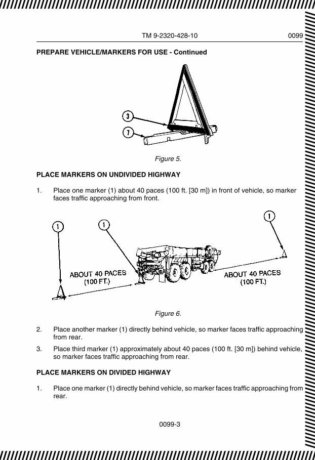
PREPARE VEHICLE/MARKERS FOR USE - Continued
Figure 5.
PLACE MARKERS ON UNDIVIDED HIGHWAY
1. Place one marker (1) about 40 paces (100 ft. [30 m]) in front of vehicle, so markerfaces traffic approaching from front.
Figure 6.
2. Place another marker (1) directly behind vehicle, so marker faces traffic approachingfrom rear.
3. Place third marker (1) approximately about 40 paces (100 ft. [30 m]) behind vehicle,so marker faces traffic approaching from rear.
PLACE MARKERS ON DIVIDED HIGHWAY
1. Place one marker (1) directly behind vehicle, so marker faces traffic approaching fromrear.
////////////////////////////////////////////////////////////////////////////////////
TM 9-2320-428-10 0099
0099-3
////////////////////////////////////////////////////////////////////////////////////////////////////////////////////////////////////////////////////////////////////////////////////////////////////////

PLACE MARKERS ON DIVIDED HIGHWAY - Continued
Figure 7.
2. Place second marker (1) about 40 paces (100 ft. [30 m]) behind vehicle, so markerfaces traffic approaching from rear.
3. Place third marker (1) about 80 paces (200 ft. [60 m]) behind second marker, somarker faces traffic approaching from rear.
SECURE MARKERS
1. Rotate marker (1) over base (2).
Figure 8.
2. Separate arms (3).
////////////////////////////////////////////////////////////////////////////////////
TM 9-2320-428-10 0099
0099-4
//////////////////////////////////////////////////////////////////////////////////// //////
//////
//////
//////
//////
//////
//////
//////
//////
//////
//////
//////
//////
//////
//////
//////
//////
//////
//////
//

SECURE MARKERS - Continued
Figure 9.
3. Fold arms (3) down onto base (2).
Figure 10.
4. Put markers (1) in case.
5. Put emergency marker kit (4) in stowage brackets (5).
////////////////////////////////////////////////////////////////////////////////////
TM 9-2320-428-10 0099
0099-5
////////////////////////////////////////////////////////////////////////////////////////////////////////////////////////////////////////////////////////////////////////////////////////////////////////

SECURE MARKERS - Continued
54
5
Figure 11.
6. Turn vehicle emergency flashers off. (WP 0076)
END OF TASK
END OF WORK PACKAGE
////////////////////////////////////////////////////////////////////////////////////
TM 9-2320-428-10 0099
0099-6
//////////////////////////////////////////////////////////////////////////////////// //////
//////
//////
//////
//////
//////
//////
//////
//////
//////
//////
//////
//////
//////
//////
//////
//////
//////
//////
//

OPERATOR MAINTENANCEMANUALLY RELEASE SPRING BRAKES
INITIAL SETUP:
Not Applicable
CHOCK REAR WHEELS
NOTEThis procedure should only be used when vehicle air system is totallyinoperative and vehicle cannot be towed with rear end raised by wrecker.
1. Remove wheel chocks (1) from stowage.
231
Figure 1.
2. Place wheel chocks (1) in front and back of one wheel on No. 3 (2) or No. 4 (3) axle.
////////////////////////////////////////////////////////////////////////////////////
TM 9-2320-428-10 0100
0100-1
////////////////////////////////////////////////////////////////////////////////////////////////////////////////////////////////////////////////////////////////////////////////////////////////////////

RELEASE BRAKES
WARNING
Ensure brake chamber is caged while releasing brakes. Spring is under2,500 lbs (1 135 kg) tension. Failure to comply may result in injury or deathto personnel.
NOTEDriver side brake chamber on No. 4 axle is shown. Steps are same forNo. 4 axle passenger side and No. 3 axle.
1. Remove dust cap (1) from brake chamber (2).
TWO NUTS ONE NUT
Figure 2.
NOTEThere are two types of brake chambers: older vehicles have two nuts,newer vehicles have one nut.
2. Remove either one or two nuts (3) (as applicable), washer (4), and release-bolt (5)from bracket (6).
3. Insert release-bolt (5) into brake chamber (2).
////////////////////////////////////////////////////////////////////////////////////
TM 9-2320-428-10 0100
0100-2
//////////////////////////////////////////////////////////////////////////////////// //////
//////
//////
//////
//////
//////
//////
//////
//////
//////
//////
//////
//////
//////
//////
//////
//////
//////
//////
//

RELEASE BRAKES - Continued
Figure 3.
4. Turn release-bolt (5) 1/4 turn to engage inside brake chamber (2).
5. Install washer (4) and nut (3) on release-bolt (5).
6. Tighten nut (3) until clevis (7) is pulled to rear of brake chamber (2).
2
3
7
Figure 4.
7. Repeat Steps (1) through (6) to release three remaining spring brakes on No. 3 andNo. 4 axles.
END OF TASK
END OF WORK PACKAGE
////////////////////////////////////////////////////////////////////////////////////
TM 9-2320-428-10 0100
0100-3
////////////////////////////////////////////////////////////////////////////////////////////////////////////////////////////////////////////////////////////////////////////////////////////////////////

This page intentionally left blank
////////////////////////////////////////////////////////////////////////////////////
TM 9-2320-428-10 0100
0100-4
//////////////////////////////////////////////////////////////////////////////////// //////
//////
//////
//////
//////
//////
//////
//////
//////
//////
//////
//////
//////
//////
//////
//////
//////
//////
//////
//

OPERATOR MAINTENANCELIMP HOME/FLAT TIRE WITH NO SPARE
INITIAL SETUP:
Not Applicable
INSTALL LIMP HOME SETUP ON PASSENGER SIDE FRONT OR ANY REAR WHEEL
CAUTION• Do not use this procedure on fully loaded M983 vehicle with trailer in
tow. Limp home setup will not support extra weight and equipmentcould be damaged.
• Vehicle must not be driven faster than 10 mph (16 km/h) or fartherthan 30 miles (48 km) in limp home condition.
NOTE• Use limp home procedure for emergency only in case of wheel
bearing failure, wheel damage, or when unable to change wheel andtire.
• For limp home setup on driver side front No. 1 and 2 axles, refer toLimp Home Setup/Driver Side Front section.
• Limp home setup for No. 4 axle is shown. Other limp home setupsare done is same manner.
1. Remove two wheel chocks (1), jack base plate (2), jack (3), 7 ft. (2.1 m) chain (4), andshackle (5) from stowage.
////////////////////////////////////////////////////////////////////////////////////
TM 9-2320-428-10 0101
0101-1
////////////////////////////////////////////////////////////////////////////////////////////////////////////////////////////////////////////////////////////////////////////////////////////////////////

INSTALL LIMP HOME SETUP ON PASSENGER SIDE FRONT OR ANY REARWHEEL - Continued
Figure 1.
2. Install two wheel chocks (WP 0077) (1) in front of and behind tire (6) across from tire(7) being raised.
Figure 2.
3. Position jack base plate (2) and jack (3) under equalizer beam (8) 4 to 5 in. (102 to127 mm) from center pivot point (9) towards axle to be raised (No. 4 axle shown).
////////////////////////////////////////////////////////////////////////////////////
TM 9-2320-428-10 0101
0101-2
//////////////////////////////////////////////////////////////////////////////////// //////
//////
//////
//////
//////
//////
//////
//////
//////
//////
//////
//////
//////
//////
//////
//////
//////
//////
//////
//

INSTALL LIMP HOME SETUP ON PASSENGER SIDE FRONT OR ANY REARWHEEL - Continued
Figure 3.
4. Raise jack (3) until it touches equalizer beam (8).
5. Raise jack (3) until axle (10) is as close as it will go to axle stop (11).
Figure 4.
6. Install shackle (5) on axle stop (11) with pin (12).
////////////////////////////////////////////////////////////////////////////////////
TM 9-2320-428-10 0101
0101-3
////////////////////////////////////////////////////////////////////////////////////////////////////////////////////////////////////////////////////////////////////////////////////////////////////////

INSTALL LIMP HOME SETUP ON PASSENGER SIDE FRONT OR ANY REARWHEEL - Continued
CAUTIONDo not wrap 7 ft. (2.1 m) chain around any air line or brake chamberbracket. Air line could be crushed and damaged to bracket could result.
7. Route 7 ft. (2.1 m) chain (4) through shackle (5).
Figure 5.
8. Loop end of 7 ft. (2.1 m) chain (4) around axle (10).
9. Bring 7 ft. (2.1 m) chain (4) up to chain hook (13) and fasten as tight as possible.
WARNING
Keep hands away from chain when lowering jack. Hands and fingerscould be crushed. Failure to comply may result in injury or death topersonnel.
NOTEAxle will drop slightly when jack is lowered.
10. Lower jack (3) and remove jack from under equalizer beam (8).
////////////////////////////////////////////////////////////////////////////////////
TM 9-2320-428-10 0101
0101-4
//////////////////////////////////////////////////////////////////////////////////// //////
//////
//////
//////
//////
//////
//////
//////
//////
//////
//////
//////
//////
//////
//////
//////
//////
//////
//////
//

INSTALL LIMP HOME SETUP ON PASSENGER SIDE FRONT OR ANY REARWHEEL - Continued
Figure 6.
11. Return jack (3), and jack base plate (2) to stowage.
12. Remove and stow two wheel chocks (1).
REMOVE LIMP HOME SETUP FROM PASSENGER SIDE FRONT OR ANY REARWHEEL
1. Remove two wheel chocks (1), jack base plate (2), and jack (3) from stowage.
Figure 7.
2. Install two wheel chocks (WP 0077) (1) in front of and behind tire (4) across from tire(5) being raised.
////////////////////////////////////////////////////////////////////////////////////
TM 9-2320-428-10 0101
0101-5
////////////////////////////////////////////////////////////////////////////////////////////////////////////////////////////////////////////////////////////////////////////////////////////////////////

REMOVE LIMP HOME SETUP FROM PASSENGER SIDE FRONT OR ANY REARWHEEL - Continued
Figure 8.
3. Position jack base plate (2) and jack (3) under equalizer beam (6) 4 to 5 in. (102 to127 mm) from center pivot point (7).
Figure 9.
4. Raise jack (3) until it touches equalizer beam (6).
////////////////////////////////////////////////////////////////////////////////////
TM 9-2320-428-10 0101
0101-6
//////////////////////////////////////////////////////////////////////////////////// //////
//////
//////
//////
//////
//////
//////
//////
//////
//////
//////
//////
//////
//////
//////
//////
//////
//////
//////
//

REMOVE LIMP HOME SETUP FROM PASSENGER SIDE FRONT OR ANY REARWHEEL - Continued
Figure 10.
5. Raise jack (3) until axle (8) is as close as it will go to axle stop (9).
6. Unhook 7 ft. (2.1 m) chain (10) and remove from shackle (11) and axle (8).
////////////////////////////////////////////////////////////////////////////////////
TM 9-2320-428-10 0101
0101-7
////////////////////////////////////////////////////////////////////////////////////////////////////////////////////////////////////////////////////////////////////////////////////////////////////////

REMOVE LIMP HOME SETUP FROM PASSENGER SIDE FRONT OR ANY REARWHEEL - Continued
Figure 11.
7. Remove pin (12) from shackle (11) and axle stop (9).
8. Remove shackle (11) from axle stop (9) and reinstall pin (12) in shackle (11).
9. Lower jack (3) and remove jack (3) from equalizer beam (6).
10. Return jack base plate (2), jack (3), 7 ft. (2.1 m) chain (10), and shackle (11) tostowage.
11. Remove and stow two wheel chocks (1).
INSTALL LIMP HOME SETUP/DRIVER SIDE FRONT
CAUTION• Do not use this procedure on fully loaded M983 vehicle with trailer in
tow. Limp home setup will not support extra weight and equipmentcould be damaged.
////////////////////////////////////////////////////////////////////////////////////
TM 9-2320-428-10 0101
0101-8
//////////////////////////////////////////////////////////////////////////////////// //////
//////
//////
//////
//////
//////
//////
//////
//////
//////
//////
//////
//////
//////
//////
//////
//////
//////
//////
//

INSTALL LIMP HOME SETUP/DRIVER SIDE FRONT - Continued
• Vehicle must not be driven faster than 10 mph (16 km/h) or fartherthen 30 miles (48 km) in limp home condition.
NOTE• Use limp home procedure for emergency only in case of wheel
bearing failure, wheel damage, or when unable to change wheel andtire.
• Limp home setup No. 1 axle is shown. Setup for No. 2 axle is donein same manner.
• For limp home setup on other axles, refer to passenger side front orany rear wheel section above.
1. Remove two wheel chocks (1), jack base plate (2), jack (3), and 7 ft. (2.1 m) chain (4)from stowage.
Figure 12.
2. Install two wheel chocks (WP 0077) (1) in front of and behind tire (5) across from tire(6) being raised.
////////////////////////////////////////////////////////////////////////////////////
TM 9-2320-428-10 0101
0101-9
////////////////////////////////////////////////////////////////////////////////////////////////////////////////////////////////////////////////////////////////////////////////////////////////////////

INSTALL LIMP HOME SETUP/DRIVER SIDE FRONT - Continued
Figure 13.
3. Place jack base plate (2) and jack (3) under end of equalizer beam (7).
Figure 14.
4. Raise jack (3) until it touches end of equalizer beam (7).
5. Raise jack (3) until axle (8) is as close as it will go to axle stop (9).
////////////////////////////////////////////////////////////////////////////////////
TM 9-2320-428-10 0101
0101-10
//////////////////////////////////////////////////////////////////////////////////// //////
//////
//////
//////
//////
//////
//////
//////
//////
//////
//////
//////
//////
//////
//////
//////
//////
//////
//////
//

INSTALL LIMP HOME SETUP/DRIVER SIDE FRONT - Continued
Figure 15.
CAUTIONDo not wrap 7 ft. (2.1 m) chain around lateral torque rod or shift cablesas they could be crushed. Failure to comply may result in damage toequipment.
6. Loop end of 7 ft. (2.1 m) chain (4) around frame (10) and axle (8).
////////////////////////////////////////////////////////////////////////////////////
TM 9-2320-428-10 0101
0101-11
////////////////////////////////////////////////////////////////////////////////////////////////////////////////////////////////////////////////////////////////////////////////////////////////////////

INSTALL LIMP HOME SETUP/DRIVER SIDE FRONT - Continued
Figure 16.
WARNING
Keep hands away from chain when lowering jack. Hands and fingerscould be crushed. Failure to comply may result in injury or death topersonnel.
7. Bring end of 7 ft. (2.1 m) chain (4) up to chain hook (11) and fasten back into itself astight as possible.
NOTEAxle will drop slightly when jack is lowered.
8. Lower jack (3) and remove jack (3) from end of equalizer beam (7).
////////////////////////////////////////////////////////////////////////////////////
TM 9-2320-428-10 0101
0101-12
//////////////////////////////////////////////////////////////////////////////////// //////
//////
//////
//////
//////
//////
//////
//////
//////
//////
//////
//////
//////
//////
//////
//////
//////
//////
//////
//

INSTALL LIMP HOME SETUP/DRIVER SIDE FRONT - Continued
9. Return jack base plate (2), and jack (3) to stowage.
10. Remove and stow two wheel chocks (1).
REMOVE LIMP HOME SETUP/DRIVER SIDE FRONT
1. Remove two wheel chocks (1), jack base plate (2), and jack (3) from stowage.
Figure 17.
2. Install two wheel chocks (1) in front of and behind tire (4) across from tire (5) beingraised.
Figure 18.
3. Place jack base plate (2) and jack (3) under end of equalizer beam (6).
////////////////////////////////////////////////////////////////////////////////////
TM 9-2320-428-10 0101
0101-13
////////////////////////////////////////////////////////////////////////////////////////////////////////////////////////////////////////////////////////////////////////////////////////////////////////

REMOVE LIMP HOME SETUP/DRIVER SIDE FRONT - Continued
Figure 19.
4. Raise jack (3) until it touches end of equalizer beam (6).
5. Raise jack (3) until axle (7) is as close as it will go to axle stop (8).
Figure 20.
6. Unhook 7 ft. (2.1 m) chain (9) and remove from around frame (10) and axle (7).
////////////////////////////////////////////////////////////////////////////////////
TM 9-2320-428-10 0101
0101-14
//////////////////////////////////////////////////////////////////////////////////// //////
//////
//////
//////
//////
//////
//////
//////
//////
//////
//////
//////
//////
//////
//////
//////
//////
//////
//////
//

REMOVE LIMP HOME SETUP/DRIVER SIDE FRONT - Continued
Figure 21.
7. Lower jack (3) and remove jack from equalizer beam (6).
8. Return jack base plate (2), jack (3), and 7 ft. (2.1 m) chain (9) to stowage.
9. Remove and stow two wheel chocks (1).
END OF TASK
END OF WORK PACKAGE
////////////////////////////////////////////////////////////////////////////////////
TM 9-2320-428-10 0101
0101-15
////////////////////////////////////////////////////////////////////////////////////////////////////////////////////////////////////////////////////////////////////////////////////////////////////////

This page intentionally left blank
////////////////////////////////////////////////////////////////////////////////////
TM 9-2320-428-10 0101
0101-16
//////////////////////////////////////////////////////////////////////////////////// //////
//////
//////
//////
//////
//////
//////
//////
//////
//////
//////
//////
//////
//////
//////
//////
//////
//////
//////
//

OPERATOR MAINTENANCESLAVE START VEHICLE
INITIAL SETUP:
Personnel RequiredOperator and Assistant - - - (2)
PREPARE ASSIST VEHICLE
NOTEThis procedure is a two soldier task.
1. Start engine of assist vehicle. (WP 0044)
NOTE• Model of truck can be determined by information plate on inside of
driver side cabin door.
• Base Model HEMTT - Slave receptacle may be located either onbattery box or driver side front fender.
• A2 Model HEMTT - Slave receptacle is located on driver side frontfender.
• A4 Model HEMTT - Slave receptacle is located on driver side frontfender.
2. Move assist vehicle into position beside disabled vehicle so slave receptacles (1) onboth vehicles are side by side.
////////////////////////////////////////////////////////////////////////////////////
TM 9-2320-428-10 0102
0102-1
////////////////////////////////////////////////////////////////////////////////////////////////////////////////////////////////////////////////////////////////////////////////////////////////////////

PREPARE ASSIST VEHICLE - Continued
1
BASE HEMTT
1
Figure 1.
////////////////////////////////////////////////////////////////////////////////////
TM 9-2320-428-10 0102
0102-2
//////////////////////////////////////////////////////////////////////////////////// //////
//////
//////
//////
//////
//////
//////
//////
//////
//////
//////
//////
//////
//////
//////
//////
//////
//////
//////
//

PREPARE ASSIST VEHICLE - Continued
1
A2 HEMTT
Figure 2.
1
A4 HEMTT
Figure 3.
3. Shut off engine of assist vehicle. (WP 0057)
////////////////////////////////////////////////////////////////////////////////////
TM 9-2320-428-10 0102
0102-3
////////////////////////////////////////////////////////////////////////////////////////////////////////////////////////////////////////////////////////////////////////////////////////////////////////
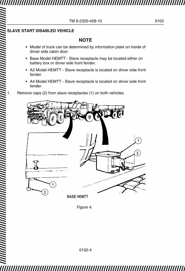
SLAVE START DISABLED VEHICLE
NOTE• Model of truck can be determined by information plate on inside of
driver side cabin door.
• Base Model HEMTT - Slave receptacle may be located either onbattery box or driver side front fender.
• A2 Model HEMTT - Slave receptacle is located on driver side frontfender.
• A4 Model HEMTT - Slave receptacle is located on driver side frontfender.
1. Remove caps (2) from slave receptacles (1) on both vehicles.
1
2
1
BASE HEMTT2
Figure 4.
////////////////////////////////////////////////////////////////////////////////////
TM 9-2320-428-10 0102
0102-4
//////////////////////////////////////////////////////////////////////////////////// //////
//////
//////
//////
//////
//////
//////
//////
//////
//////
//////
//////
//////
//////
//////
//////
//////
//////
//////
//
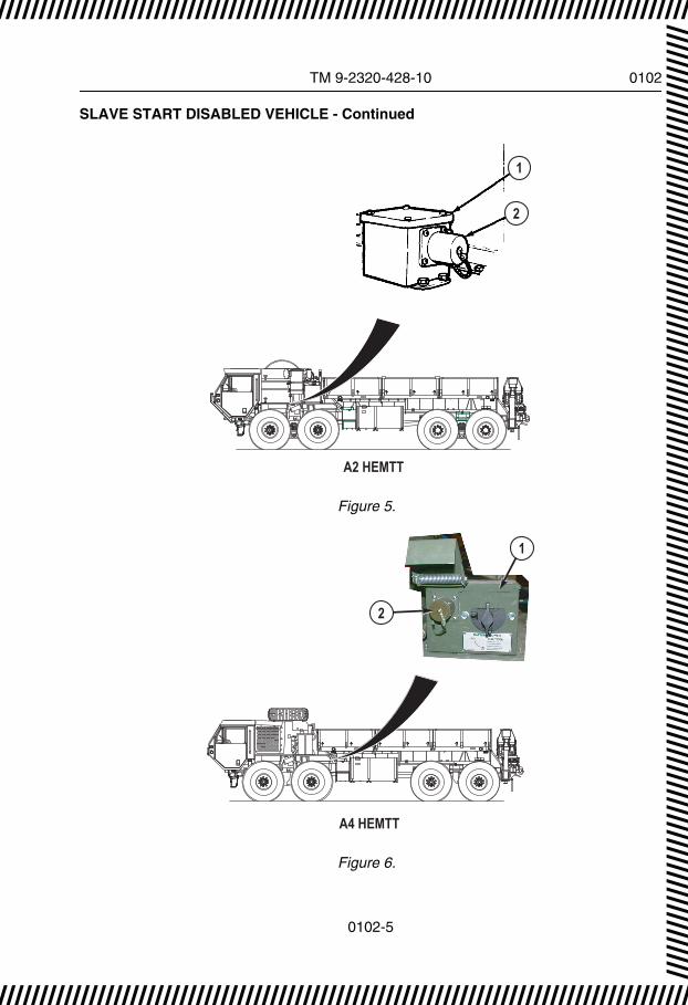
SLAVE START DISABLED VEHICLE - Continued
1
2
A2 HEMTT
Figure 5.
1
2
A4 HEMTT
Figure 6.
////////////////////////////////////////////////////////////////////////////////////
TM 9-2320-428-10 0102
0102-5
////////////////////////////////////////////////////////////////////////////////////////////////////////////////////////////////////////////////////////////////////////////////////////////////////////

SLAVE START DISABLED VEHICLE - Continued
WARNING
Hot transmission/oil can cause severe burns. Wear gloves and propereye protection while performing troubleshooting or maintenance. Failureto comply may result in injury or death to personnel.
NOTEMake sure connectors and receptacles are free from dirt, sand, anddebris before use.
2. Remove NATO slave cable from stowage and plug into slave receptacles of bothvehicles.
3. Start engine of assist vehicle. (WP 0044)
4. Using the throttle pedal, increase assist vehicle engine speed to more than 1000 rpm,while assistant starts engine of disabled vehicle. (WP 0044)
5. As soon as disabled vehicle engine is running smoothly, remove NATO slave cablefrom slave receptacles (1) on both vehicles and return to stowage.
6. Install caps (2) on slave receptacles (1) of both vehicles.
7. Move assist vehicle. (WP 0050)
8. Shut off engine of assist vehicle. (WP 0057)
NOTE• Model of truck can be determined by information plate on inside of
driver side cabin door.
• A4 Model HEMTT does not have an AMPERES gauge. Batteryvoltage readout is located in top right corner of Liquid Crystal Display(LCD) on instrument panel.
• Gauges are located in different places dependent on model HEMTT.Select correct view below for model HEMTT being serviced.
9. Check BATTERY gauge (3) of disabled vehicle. If BATTERY gauge (3) shows lessthan 24 volts, notify field level maintenance. If BATTERY gauge (3) shows 24 volts ormore, continue with Step (11).
////////////////////////////////////////////////////////////////////////////////////
TM 9-2320-428-10 0102
0102-6
//////////////////////////////////////////////////////////////////////////////////// //////
//////
//////
//////
//////
//////
//////
//////
//////
//////
//////
//////
//////
//////
//////
//////
//////
//////
//////
//

SLAVE START DISABLED VEHICLE - Continued
AIR BRAKE
PARKINGBRAKE
TRAILERAIR SUPPLY
EXEXEX
EXEXEXEXEX EXEX
ENGINEOFF
ON
START
3
4
BASE HEMTT
Figure 7.
A2 HEMTT
3
4
AIR BRAKE
EXEXEX
ENGINEOFF
ON
START
TRAILERAIR SUPPLY
PARKINGBRAKE
EXEXEXEXEX EXEX
Figure 8.
////////////////////////////////////////////////////////////////////////////////////
TM 9-2320-428-10 0102
0102-7
////////////////////////////////////////////////////////////////////////////////////////////////////////////////////////////////////////////////////////////////////////////////////////////////////////

SLAVE START DISABLED VEHICLE - Continued
TRAILERAIR SUPPLY
PARKINGBRAKE
AIR BRAKE
B.OSELECT
INTERAXLE
8X8
B.OLIGHTS
HIGHIDLE
12
012
M M
CHEMALARM
HYDENABLE
AUXHYD
GPFU
FILTER MINDER
25 6.2
IN H 0 kPa
22 5.515 3.711 2.78 2.0
AIR FILTER RESTRICTIONRESET
2
3
A4 HEMTT
Figure 9.
10. Check AMPERES gauge (4) of disabled vehicle (as applicable). If AMPERES gaugeshows discharge condition, notify field level maintenance. If AMPERES gauge (4)shows charging, continue operation of vehicle.
END OF TASK
END OF WORK PACKAGE
////////////////////////////////////////////////////////////////////////////////////
TM 9-2320-428-10 0102
0102-8
//////////////////////////////////////////////////////////////////////////////////// //////
//////
//////
//////
//////
//////
//////
//////
//////
//////
//////
//////
//////
//////
//////
//////
//////
//////
//////
//

OPERATOR MAINTENANCEPERFORM IMMEDIATE ACTION FOR LOSS OF AIR SUPPLY SYSTEM PRESSURE
INITIAL SETUP:
Not Applicable
PERFORM PROCEDURE
1. If AIR indicator (1) illuminates and warning buzzer sounds while driving vehicle, checkAIR PRESS gauge (2).
TRAILERAIR SUPPLYNOT FOR PARKINGMIDLAND
PULL TO EXHAUST
PUSH TO SU PPLY
7
12
3
6 5 4
Figure 1.
NOTEIf both red needle and green needle on AIR PRESS gauge read zero,skip to Step (4).
2. If red pointer on AIR PRESS gauge (2) is at zero and green needle shows normal airpressure of 100 to 120 psi (690 to 827 kPa), complete the following:
a. Continue operation of vehicle. Brakes on all eight wheels and trailer will workeven if air pressure from No. 2 air tank has been lost.
b. Notify field level maintenance as soon as possible.
////////////////////////////////////////////////////////////////////////////////////
TM 9-2320-428-10 0103
0103-1
////////////////////////////////////////////////////////////////////////////////////////////////////////////////////////////////////////////////////////////////////////////////////////////////////////
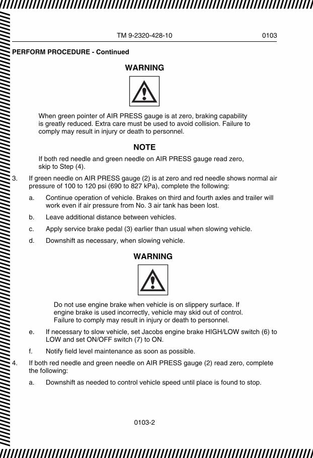
PERFORM PROCEDURE - Continued
WARNING
When green pointer of AIR PRESS gauge is at zero, braking capabilityis greatly reduced. Extra care must be used to avoid collision. Failure tocomply may result in injury or death to personnel.
NOTEIf both red needle and green needle on AIR PRESS gauge read zero,skip to Step (4).
3. If green needle on AIR PRESS gauge (2) is at zero and red needle shows normal airpressure of 100 to 120 psi (690 to 827 kPa), complete the following:
a. Continue operation of vehicle. Brakes on third and fourth axles and trailer willwork even if air pressure from No. 3 air tank has been lost.
b. Leave additional distance between vehicles.
c. Apply service brake pedal (3) earlier than usual when slowing vehicle.
d. Downshift as necessary, when slowing vehicle.
WARNING
Do not use engine brake when vehicle is on slippery surface. Ifengine brake is used incorrectly, vehicle may skid out of control.Failure to comply may result in injury or death to personnel.
e. If necessary to slow vehicle, set Jacobs engine brake HIGH/LOW switch (6) toLOW and set ON/OFF switch (7) to ON.
f. Notify field level maintenance as soon as possible.
4. If both red needle and green needle on AIR PRESS gauge (2) read zero, completethe following:
a. Downshift as needed to control vehicle speed until place is found to stop.
////////////////////////////////////////////////////////////////////////////////////
TM 9-2320-428-10 0103
0103-2
//////////////////////////////////////////////////////////////////////////////////// //////
//////
//////
//////
//////
//////
//////
//////
//////
//////
//////
//////
//////
//////
//////
//////
//////
//////
//////
//

PERFORM PROCEDURE - Continued
WARNING
Use of service brake pedal will not slow or stop vehicle when bothpointers of AIR PRESS gauge read zero. Use the followingprocedure to safely stop vehicle after loss of air pressure. Failure tocomply may result in injury or death to personnel.
NOTEWhen spring brakes are applied, vehicle will stop quickly. Vehiclecannot be driven again until malfunction is repaired and there isenough air supply for operation of service brakes.
b. Look for place to stop vehicle without blocking other traffic.
c. When suitable area is found to stop vehicle, pull out PARKING BRAKE control(8) to apply spring brakes on four rear wheels.
d. Notify field level maintenance.
END OF TASK
END OF WORK PACKAGE
////////////////////////////////////////////////////////////////////////////////////
TM 9-2320-428-10 0103
0103-3
////////////////////////////////////////////////////////////////////////////////////////////////////////////////////////////////////////////////////////////////////////////////////////////////////////

This page intentionally left blank
////////////////////////////////////////////////////////////////////////////////////
TM 9-2320-428-10 0103
0103-4
//////////////////////////////////////////////////////////////////////////////////// //////
//////
//////
//////
//////
//////
//////
//////
//////
//////
//////
//////
//////
//////
//////
//////
//////
//////
//////
//

OPERATOR MAINTENANCEPERFORM IMMEDIATE ACTION FOR LOSS OF HYDRAULIC SYSTEM
INITIAL SETUP:
Not Applicable
NOTESteering wheel will be harder to turn after failure of hydraulic system.
1. If failure occurs while driving, continue steering as before.
NOTEFailure of hydraulic system will stop operation of any crane, winch, orhydraulic motor on vehicle. All cranes and winches are equipped withautomatic locking mechanisms to hold cranes and winches in positionthey were in before hydraulics failed.
2. Do not try to continue operation of any crane or winch.
3. Do not try to repair hydraulic system. Notify your supervisor.
4. Notify field level maintenance.
END OF TASK
END OF WORK PACKAGE
////////////////////////////////////////////////////////////////////////////////////
TM 9-2320-428-10 0104
0104-1
////////////////////////////////////////////////////////////////////////////////////////////////////////////////////////////////////////////////////////////////////////////////////////////////////////

This page intentionally left blank
////////////////////////////////////////////////////////////////////////////////////
TM 9-2320-428-10 0104
0104-2
//////////////////////////////////////////////////////////////////////////////////// //////
//////
//////
//////
//////
//////
//////
//////
//////
//////
//////
//////
//////
//////
//////
//////
//////
//////
//////
//

OPERATOR MAINTENANCEPERFORM EMERGENCY HYDRAULIC OPERATION WHEN GROVE CRANE
ELECTRICAL POWER FAILS
INITIAL SETUP:
Not Applicable
NOTE• If crane electrical power systems fails during crane operation, crane
will be locked in position it was in at time of failure.
• Do not try to operate any electrical equipment on vehicle or crane.
• Do not try to repair electrical system.
• This procedure will provide emergency hydraulic power to lowercrane and load when electrical power has failed.
• Screwdriver can be put in slot in front of solenoid valve button to holdbutton in while operating controls.
1. Push up and hold solenoid valve button (1).
2. Shut down crane.
////////////////////////////////////////////////////////////////////////////////////
TM 9-2320-428-10 0105
0105-1
////////////////////////////////////////////////////////////////////////////////////////////////////////////////////////////////////////////////////////////////////////////////////////////////////////

Figure 1.
3. Notify field level maintenance.
END OF TASK
END OF WORK PACKAGE
////////////////////////////////////////////////////////////////////////////////////
TM 9-2320-428-10 0105
0105-2
//////////////////////////////////////////////////////////////////////////////////// //////
//////
//////
//////
//////
//////
//////
//////
//////
//////
//////
//////
//////
//////
//////
//////
//////
//////
//////
//

OPERATOR MAINTENANCESTOWAGE AND SIGN GUIDE
Scope
This work package shows locations for data plates, decals, and stencils that are requiredto be in place on the HEMTT series vehicles.
General
The following figures show the location of metal signs, decals, and stencils used on thevehicle. Most of these signs and stencils contain cautions or information needed to operatethe vehicle safely. For stowage locations of Components Of End Item (COEI) and BasicIssue Items (BII), refer to Components of End Item and Basic Issue Items tables.(WP 0162)
Table 1. Inside Driver Side Door.
11
10
9
8
7 65
4
3
2
1
XX-XXXX
CARC
TM 9-2320-428-10 0106
0106-1

General - Continued
Table 1. Inside Driver Side Door. - Continued
INDEX DECAL/PLATE/STENCIL
1 Manufacturer's Certification Information
2 Parts Data
3 Name Plate
4 Overhaul Data (not included on all vehicles)
5 Tire Inflation Data
6 Warranty Information
7 Rustproofing Data/Rustproofing CAUTION
8 Noise Exemption Decal (not included on all vehicles)
9 "CARC" Stencil (not included on all vehicles)
10 Shipping Data
11 Registration Number (inside both driver and passenger sidedoors)(not included on all vehicles)
TM 9-2320-428-10 0106
0106-2

General - Continued
Table 2. Front Exterior.
1
32
INDEX PLACARD/STENCIL
1 "TIE DOWN" Stencil
2 Sign Kit/Weight Indicator
3 "U.S. ARMY" Stencil
TM 9-2320-428-10 0106
0106-3
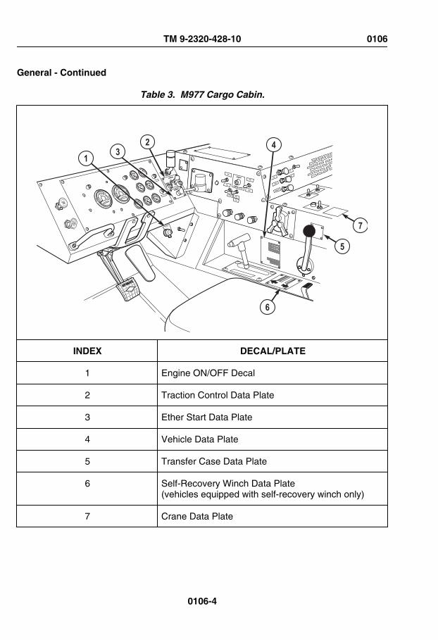
General - Continued
Table 3. M977 Cargo Cabin.
TRAILERAIR SUPPLYNOT FOR PARKINGMIDLAND
PULL TO EXHAUST
PUSH TO SU P PLY
1 32 4
6
5
7
INDEX DECAL/PLATE
1 Engine ON/OFF Decal
2 Traction Control Data Plate
3 Ether Start Data Plate
4 Vehicle Data Plate
5 Transfer Case Data Plate
6 Self-Recovery Winch Data Plate(vehicles equipped with self-recovery winch only)
7 Crane Data Plate
TM 9-2320-428-10 0106
0106-4

General - Continued
Table 4. M977 Cargo Driver Side Exterior.
8 7
1 2
2 3 4
56
910
INDEX DECAL/PLACARD/PLATE/STENCIL
1 Vehicle Identification Number (VIN) Placard
2 "TIE DOWN" Stencil
3 "DANGER" Plate
4 Outrigger Instruction Placard
5 "DANGER" Plate (crane operation)andCrane Erection Procedure Steps Placard
6 Engine Speed Data Plate
7 "CAUTION DO NOT ALLOW PANEL TO SLIDE OFFPINS WHEN LOWERING" Stencil
8 CAUTION Decal (hearing protection required)
9 "FULL COLD" Stencil
10 "NO STEP" Stencil(multiple on exhaust and engine access panels)
TM 9-2320-428-10 0106
0106-5

General - Continued
Table 5. M977 Cargo Passenger Side Exterior.
57
6 5
5
43
21
8
INDEX DECAL/PLACARD/PLATE/STENCIL
1 "CAUTION DO NOT ALLOW PANEL TO SLIDE OFFPINS WHEN LOWERING" Stencil
2 CAUTION Decal (hearing protection required)
3 CAUTION (hydraulic selector valve) Decal(vehicles equipped with self-recovery winch only)
4 "NO STEP" Stencil(multiple on exhaust and engine access panels)
5 "TIE DOWN" Stencil
6 WARNING (self-recovery winch) Plate(vehicles equipped with self-recovery winch only)
7 Self-Recovery Winch Data Plate(vehicles equipped with self-recovery winch only)
8 Outrigger Instruction Placard
TM 9-2320-428-10 0106
0106-6

General - Continued
Table 6. M977 Cargo Rear Exterior.
25
43
1
INDEX PLATE/STENCIL
1 "SLING POINT" and "TIE DOWN" Stencils(one each per side)
2 US Army Star Stencil
3 On/Off Power Remote-Control Connector Data Plate
4 "DANGER" Plate (electrical warning)
5 Crane Range Diagram Plate
Table 7. Miscellaneous Decals/Placards/Plates/Stencils.
LOCATION M977/M985
M978 M983 M984A1
M985E1
M1120LHS
M1977CBT
Axle Housing 4 4 4 4 4 4 4
Carrier 4 4 4 4 4 4 4
TM 9-2320-428-10 0106
0106-7

General - Continued
Table 7. Miscellaneous Decals/Placards/Plates/Stencils. - Continued
Transfer Case 1 1 1 1 1 1 1
Engine 1 1 1 1 1 1 1
Transmission 1 1 1 1 1 1 1
Heavy-DutyWinch
0 0 0 1 0 0 0
Total 11 11 11 12 11 11 11
END OF WORK PACKAGE
TM 9-2320-428-10 0106
0106-8

CHAPTER 3
TROUBLESHOOTINGPROCEDURES
TM 9-2320-428-10


OPERATOR MAINTENANCEBUZZER SOUNDS AND AIR INDICATOR IS LIT
INITIAL SETUP:
Equipment ConditionEngine OFF. (WP 0057)
Equipment Condition - ContinuedParking brakes applied. (WP 0056)Wheels chocked. (WP 0077)
TROUBLESHOOTING PROCEDUREBUZZER SOUNDS AND AIR INDICATOR IS LIT
TEST 1 - Is air pressure greater than 75 psi (517 kPa)?1. Start engine, (WP 0044)and allow air pressure to build.2. Check air pressure.
Figure 1. 3. Turn engine OFF. (WP 0057)
CONDITION/INDICATIONIs air pressure greater than 75 psi (517 kPa)?
TM 9-2320-428-10 0107
0107-1

DECISIONNo - Test 2 - Are any petcock valves open?Yes - Notify Supervisor.
TEST 2 - Are any petcock valves open?1. Check if any air reservoir petcock valves are open. If valve(s) open, close petcock(s).
Figure 2.
CONDITION/INDICATIONAre any petcock valves open?
TM 9-2320-428-10 0107
0107-2
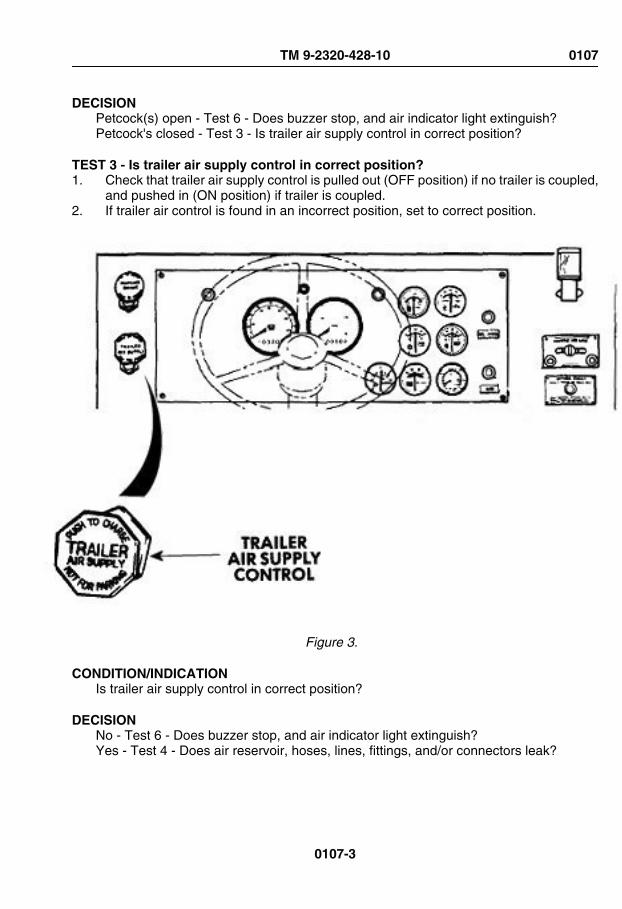
DECISIONPetcock(s) open - Test 6 - Does buzzer stop, and air indicator light extinguish?Petcock's closed - Test 3 - Is trailer air supply control in correct position?
TEST 3 - Is trailer air supply control in correct position?1. Check that trailer air supply control is pulled out (OFF position) if no trailer is coupled,
and pushed in (ON position) if trailer is coupled.2. If trailer air control is found in an incorrect position, set to correct position.
Figure 3.
CONDITION/INDICATIONIs trailer air supply control in correct position?
DECISIONNo - Test 6 - Does buzzer stop, and air indicator light extinguish?Yes - Test 4 - Does air reservoir, hoses, lines, fittings, and/or connectors leak?
TM 9-2320-428-10 0107
0107-3

TEST 4 - Does air reservoir, hoses, lines, fittings, and/or connectors leak?1. Check air reservoir, hoses, lines, fittings, and/or connectors for leaks. Tighten any
leaks found.
TM 9-2320-428-10 0107
0107-4

Figure 4.
TM 9-2320-428-10 0107
0107-5

CONDITION/INDICATIONDoes air reservoir, hoses, lines, fittings, and/or connectors leak?
DECISIONAir reservoir, hoses, lines and/or connectors leak. - Notify Supervisor. Test 6 - Doesbuzzer stop, and air indicator light extinguish?Notify Supervisor.Air reservoir, hoses, lines, fittings, and/or connectors OK - Test 5 - Does buzzer sound,and air indicator light illuminate when trailer is disconnected?
TEST 5 - Does buzzer sound, and air indicator light illuminate when trailer isdisconnected?1. If trailer is coupled, disconnect trailer (WP 0040) from vehicle.
Figure 5. 2. Start engine, (WP 0044) and allow air pressure to build.3. Check if buzzer continues to sound, and if air indicator light is illuminated.4. Turn engine off. (WP 0057)
CONDITION/INDICATIONDoes buzzer sound, and air indicator light illuminate when trailer is disconnected?
DECISIONNo - Notify Supervisor.Yes - Problem corrected.
TEST 6 - Does buzzer stop, and air indicator light extinguish?1. Start engine, (WP 0044) and allow air pressure to build.
TM 9-2320-428-10 0107
0107-6

2. Check that buzzer does not sound, and air indicator light is off.
Figure 6. 3. Turn engine off. (WP 0057)
CONDITION/INDICATIONDoes buzzer stop, and air indicator light extinguish?
DECISIONNo - Notify Supervisor.Yes - Problem corrected.
END OF WORK PACKAGE
TM 9-2320-428-10 0107
0107-7


OPERATOR MAINTENANCEWINDSHIELD WASHER WILL NOT OPERATE
INITIAL SETUP:
Equipment ConditionEngine OFF. (WP 0057)
Equipment Condition - ContinuedParking brakes applied. (WP 0056)Wheels chocked. (WP 0077)
TROUBLESHOOTING PROCEDUREWINDSHIELD WASHER WILL NOT OPERATE
TEST 1 - Is washer fluid reservoir free from damage or cracks?1. Check washer fluid reservoir for cracks and/or damage.
TM 9-2320-428-10 0108
0108-1

Figure 1.
CONDITION/INDICATIONIs washer fluid reservoir free from damage or cracks?
DECISIONNo - Notify Supervisor.Yes - Test 2 - Is washer fluid present in washer fluid reservoir?
TM 9-2320-428-10 0108
0108-2

TEST 2 - Is washer fluid present in washer fluid reservoir?
CAUTIONDo not fill windshield washer reservoir with water when temperatures arelikely to be 32°F (0°C) or less. If water freezes, reservoir can crack orbreak.
1. Check washer fluid level in reservoir. if low, fill windshield washer reservoir.
TM 9-2320-428-10 0108
0108-3

Figure 2.
CONDITION/INDICATIONIs washer fluid present in washer fluid reservoir?
DECISIONNo - Test 6 - Does the windshield washer operate?Yes - Test 3 - Are all hoses securely attached to reservoir?
TM 9-2320-428-10 0108
0108-4

TEST 3 - Are all hoses securely attached to reservoir?1. Check that all hoses are securely attached to reservoir. If loose hoses are found,
attach to reservoir.
Figure 3.
CONDITION/INDICATIONAre all hoses securely attached to reservoir?
DECISIONNo - Test 6 - Does the windshield washer operate?Yes - Test 4 - Are hoses free of cracks or damage?
TM 9-2320-428-10 0108
0108-5

TEST 4 - Are hoses free of cracks or damage?1. Check if hoses are cracked or damaged.
Figure 4.
CONDITION/INDICATIONAre hoses free of cracks or damage?
DECISIONNo - Notify Supervisor.Yes - Test 5 - Are washer spray openings free of debris?
TM 9-2320-428-10 0108
0108-6

TEST 5 - Are washer spray openings free of debris?1. Check washer spray openings on wipers for clogs.
Figure 5. 2. If openings are clogged, clear washer spray opening using pin, wire, or similar item.
CONDITION/INDICATIONAre washer spray openings free of debris?
DECISIONNo - Test 6 - Does the windshield washer operate?Yes - Notify Supervisor.
TEST 6 - Does the windshield washer operate?1. Start engine, (WP 0044)and allow air pressure to build.2. Check windshield washer for proper operation.
TM 9-2320-428-10 0108
0108-7
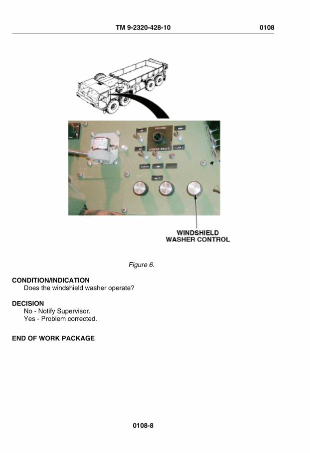
Figure 6.
CONDITION/INDICATIONDoes the windshield washer operate?
DECISIONNo - Notify Supervisor.Yes - Problem corrected.
END OF WORK PACKAGE
TM 9-2320-428-10 0108
0108-8

OPERATOR MAINTENANCEAIR SYSTEM LOSES PRESSURE DURING OPERATION
INITIAL SETUP:
Equipment ConditionEngine OFF. (WP 0057)
Equipment Condition - ContinuedParking brakes applied. (WP 0056)Wheels chocked. (WP 0077)
TROUBLESHOOTING PROCEDUREAIR SYSTEM LOSES PRESSURE DURING OPERATION
TEST 1 - Are any petcock valves open?
WARNING
Vehicles air system is pressurized, be sure to wear proper eye protectionand keep face away from drain valves while draining air reservoirs. Openair drain valves slowly to prevent sudden blast of air. Failure to complymay result in injury to personnel.
1. Check to make sure all four air reservoir petcock valves are closed.
TM 9-2320-428-10 0109
0109-1

Figure 1.
CONDITION/INDICATIONAre any petcock valves open?
DECISIONPetcock(s) open - Test 5 - Does air system lose pressure during operation?Petcocks closed - Test 2 - Is trailer air supply control in correct position?
TEST 2 - Is trailer air supply control in correct position?1. Check if trailer air supply control is pulled out (OFF position) if no trailer is coupled,
and pushed in (ON position) if trailer is coupled.
TM 9-2320-428-10 0109
0109-2
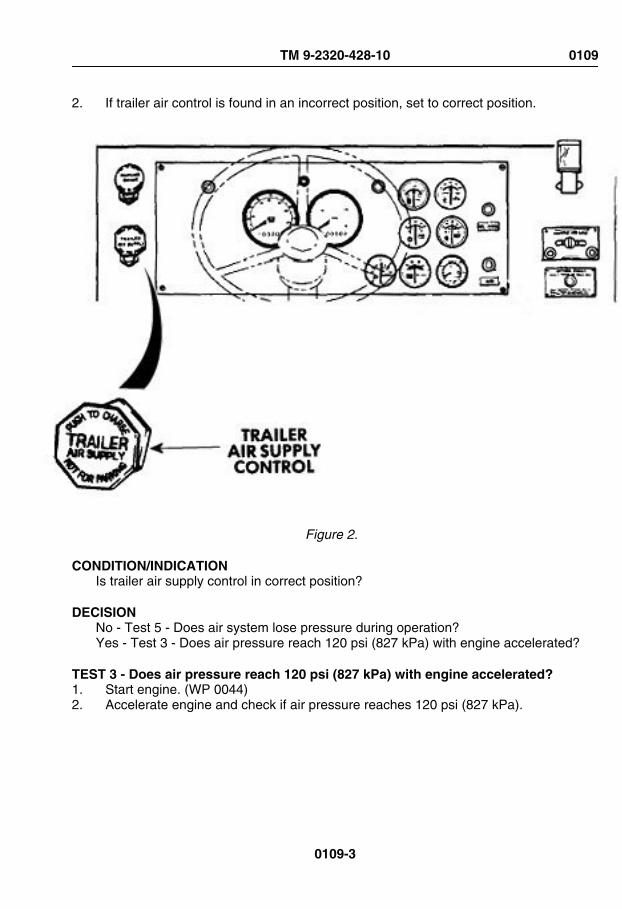
2. If trailer air control is found in an incorrect position, set to correct position.
Figure 2.
CONDITION/INDICATIONIs trailer air supply control in correct position?
DECISIONNo - Test 5 - Does air system lose pressure during operation?Yes - Test 3 - Does air pressure reach 120 psi (827 kPa) with engine accelerated?
TEST 3 - Does air pressure reach 120 psi (827 kPa) with engine accelerated?1. Start engine. (WP 0044)2. Accelerate engine and check if air pressure reaches 120 psi (827 kPa).
TM 9-2320-428-10 0109
0109-3

Figure 3.
CONDITION/INDICATIONDoes air pressure reach 120 psi (827 kPa) with engine accelerated?
DECISIONNo - Notify Supervisor.Yes - Test 4 - Are air leaks present?
TEST 4 - Are air leaks present?1. Turn engine off. (WP 0057)2. Press service brake treadle completely down, and have crew member check for air
leaks.
TM 9-2320-428-10 0109
0109-4

Figure 4. 3. If leaky fitting(s) found, tighten fittings.
CONDITION/INDICATIONAre air leaks present?
TM 9-2320-428-10 0109
0109-5

DECISIONAir leaks found - Notify Supervisor.No air leaks found - Test 5 - Does air system lose pressure during operation?
TEST 5 - Does air system lose pressure during operation?1. Start engine. (WP 0044)2. Test drive vehicle.3. Observe and note air pressure.
CONDITION/INDICATIONDoes air system lose pressure during operation?
DECISIONNo - Notify Supervisor.Yes - Problem corrected.
END OF WORK PACKAGE
TM 9-2320-428-10 0109
0109-6

OPERATOR MAINTENANCETRAILER BRAKE DOES NOT APPLY WHEN SERVICE BRAKE TREADLE OR
PARKING BRAKE IS USED
INITIAL SETUP:
Equipment ConditionEngine OFF. (WP 0057)
Equipment Condition - ContinuedParking brakes applied. (WP 0056)Wheels chocked. (WP 0077)
TROUBLESHOOTING PROCEDURETRAILER BRAKE DOES NOT APPLY WHEN SERVICE BRAKE TREADLE ORPARKING BRAKE IS USED
TEST 1 - Are intervehicular air hoses securely and correctly connected?1. Check that intervehicular air hoses are secure and correctly connected. If not,
reconnect correctly.
TM 9-2320-428-10 0110
0110-1
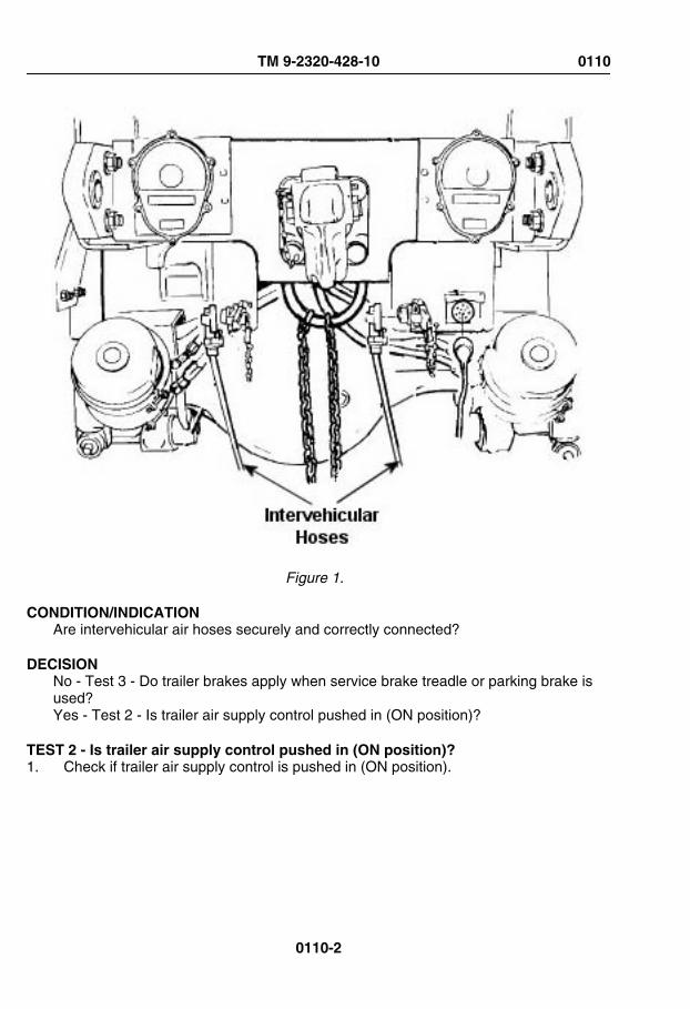
Figure 1.
CONDITION/INDICATIONAre intervehicular air hoses securely and correctly connected?
DECISIONNo - Test 3 - Do trailer brakes apply when service brake treadle or parking brake isused?Yes - Test 2 - Is trailer air supply control pushed in (ON position)?
TEST 2 - Is trailer air supply control pushed in (ON position)?1. Check if trailer air supply control is pushed in (ON position).
TM 9-2320-428-10 0110
0110-2

Figure 2. 2. If trailer air supply control is found pulled out (OFF position), push in.
CONDITION/INDICATIONIs trailer air supply control pushed in (ON position)?
DECISIONNo - Test 3 - Do trailer brakes apply when service brake treadle or parking brake isused?Yes - Notify Supervisor.
TEST 3 - Do trailer brakes apply when service brake treadle or parking brake is used?1. Start engine. (WP 0044)2. Test drive vehicle.3. Note trailer brake operations.
CONDITION/INDICATIONDo trailer brakes apply when service brake treadle or parking brake is used?
TM 9-2320-428-10 0110
0110-3

DECISIONNo - Notify Supervisor.Yes - Problem corrected.
END OF WORK PACKAGE
TM 9-2320-428-10 0110
0110-4

OPERATOR MAINTENANCEAIR HORN WILL NOT OPERATE
INITIAL SETUP:
Equipment ConditionEngine OFF. (WP 0057)
Equipment Condition - ContinuedParking brakes applied. (WP 0056)Wheels chocked. (WP 0077)
TROUBLESHOOTING PROCEDUREAIR HORN WILL NOT OPERATE
TEST 1 - Are air hoses tight?
WARNING
Caution the hose connections could be under pressure be sure to weareye protection to avoid personal injury.
1. Check air hose connections for tightness. Tighten any loose hose connections found.
TM 9-2320-428-10 0111
0111-1

Figure 1.
CONDITION/INDICATIONAre air hoses tight?
DECISIONConnections loose - Test 3 - Does air horn operate?Connections OK - Test 2 - Does horn valve lever move freely?
TM 9-2320-428-10 0111
0111-2

TEST 2 - Does horn valve lever move freely?1. Check horn valve lever for freedom of movement.
Figure 2.
CONDITION/INDICATIONDoes horn valve lever move freely?
TM 9-2320-428-10 0111
0111-3

DECISIONNo - Notify Supervisor.Yes - Test 3 - Does air horn operate?
TEST 3 - Does air horn operate?1. Start engine, (WP 0044) and allow air pressure to build.2. Check air horn for proper operation.
Figure 3. 3. Turn engine off. (WP 0057)
TM 9-2320-428-10 0111
0111-4

CONDITION/INDICATIONDoes air horn operate?
DECISIONNo - Notify Supervisor.Yes - Problem corrected.
END OF WORK PACKAGE
TM 9-2320-428-10 0111
0111-5


OPERATOR MAINTENANCEARCTIC ENGINE HEATER FAILS TO OPERATE
INITIAL SETUP:
Equipment ConditionEngine OFF. (WP 0057)
Equipment Condition - ContinuedParking brakes applied. (WP 0056)Wheels chocked. (WP 0077)
TROUBLESHOOTING PROCEDUREARCTIC ENGINE HEATER FAILS TO OPERATE
TEST 1 - Is fuel present in fuel tank?1. Turn engine start switch ON. (WP 0021)2. Check fuel gauge for presence of fuel.
TM 9-2320-428-10 0112
0112-1

Figure 1. 3. Turn engine start switch OFF.4. Add fuel to fuel tank if no fuel present.
CONDITION/INDICATIONIs fuel present in fuel tank?
DECISIONNo - Test 3 - Does arctic heater operate?Yes - Test 2 - Are arctic heater intake port and exhaust tube free from blockage?
TEST 2 - Are arctic heater intake port and exhaust tube free from blockage?1. Inspect arctic heater inlet port and exhaust tube for foreign objects and obstructions.
Remove any items found.
TM 9-2320-428-10 0112
0112-2

Figure 2.
CONDITION/INDICATIONAre arctic heater intake port and exhaust tube free from blockage?
TM 9-2320-428-10 0112
0112-3

DECISION-Continue - Test 3 - Does arctic heater operate?
TEST 3 - Does arctic heater operate?
CAUTIONDo not attempt to operate arctic heater if arctic heater fails to start, orshutdown occurs during normal operation. System shutdown mayindicate an arctic heater system fault. Failure to comply may causesystem lockout.
CAUTIONDo not operate arctic heater if arctic heater indicator light flashes duringnormal operation. Arctic heater indicator light flashing indicates an arcticheater system fault. Failure to comply may cause system lockout.
NOTEIf arctic heater does not operate, arctic heater may be in lockout modedue to, either too many overheat occurrences (code 15), or too many startattempts (code 50). Arctic heater lockout mode (code 50) is activated ifarctic heater fails to start after 20 successive start attempts (10 startcycles in succession).
NOTEThe arctic heater will attempt to start two times per start cycle. After thesecond failed start attempt, the arctic heater will not operate until thearctic heater on/off switch is turned off, then back on.
NOTEAudible clicking from the arctic heater fuel metering pump may indicatethat the arctic heater fuel system isn’t primed. If audible clicking is heardfrom the arctic heater fuel metering pump, repeat steps (1) through (4)four times, or until arctic heater starts. Do not attempt to start arctic heatermore than five times. The arctic heater should prime itself within nine startattempts.
1. Turn arctic heater ON. (WP 0058)2. Observe arctic heater indicator light for steady illumination.3. Observe arctic heater for proper operation.
TM 9-2320-428-10 0112
0112-4

Figure 3. 4. Turn arctic heater on/off switch OFF.
CONDITION/INDICATIONDoes arctic heater operate?
DECISIONNo - Notify Supervisor.Yes - Problem corrected.
END OF WORK PACKAGE
TM 9-2320-428-10 0112
0112-5


OPERATOR MAINTENANCEONE OR MORE LIGHTING CIRCUITS NOT OPERATING
INITIAL SETUP:
Equipment ConditionEngine OFF. (WP 0057)
Equipment Condition - ContinuedParking brakes applied. (WP 0056)Wheels chocked. (WP 0077)
TROUBLESHOOTING PROCEDUREONE OR MORE LIGHTING CIRCUITS NOT OPERATING
TEST 1 - Is the lighting system control in the ON or OPERATING position?1. Check if lighting system control is ON or in OPERATING position.
Figure 1.
TM 9-2320-428-10 0113
0113-1

CONDITION/INDICATIONIs the lighting system control in the ON or OPERATING position?
DECISIONNo - Test 3 - Do all lighting circuits operate properly?Yes - Test 2 - Is intervehicular connection secure and/or connected correctly?
TEST 2 - Is intervehicular connection secure and/or connected correctly?1. If trailer is attached, and trailer lighting system is not working, check intervehicular
connection. (WP 0040)2. If trailer lights are the problem, make sure cable is securely connected.
TM 9-2320-428-10 0113
0113-2

Figure 2.
CONDITION/INDICATIONIs intervehicular connection secure and/or connected correctly?
TM 9-2320-428-10 0113
0113-3

DECISIONIntervehicular cable loose. - Test 3 - Do all lighting circuits operate properly?NotifySupervisor.Intervehicular connection OK. - Notify Supervisor.
TEST 3 - Do all lighting circuits operate properly?1. Check for proper operation of dome lights. (WP 0066)2. Check for proper operation of panel lights. (WP 0067)3. Check for proper operation of service drive lights. (WP 0069)4. Check for proper operation of parking lights. (WP 0068)5. Check for proper operation of clearance lights. (WP 0071)6. Check for proper operation of stoplight. (WP 0070)7. Check for proper operation of blackout drive lights. (WP 0072)8. Check for proper operation of blackout marker lights. (WP 0073)9. Check for proper operation of turn signal lights. (WP 0075)
CONDITION/INDICATIONDo all lighting circuits operate properly?
DECISIONNo - Notify Supervisor.Yes - Problem corrected.
END OF WORK PACKAGE
TM 9-2320-428-10 0113
0113-4

OPERATOR MAINTENANCEFAILS TO CRANK WHEN ENGINE START SWITCH IS TURNED TO START POSITION
INITIAL SETUP:
Equipment ConditionEngine OFF. (WP 0057)
Equipment Condition - ContinuedParking brakes applied. (WP 0056)Wheels chocked. (WP 0077)
TROUBLESHOOTING PROCEDUREFAILS TO CRANK WHEN ENGINE START SWITCH IS TURNED TO START POSITION
TEST 1 - Is transmission range selector in neutral (N)?1. Verify range selector is in neutral (N) position. If not in neutral (N), shift it to neutral
(N).
Figure 1.
CONDITION/INDICATIONIs transmission range selector in neutral (N)?
TM 9-2320-428-10 0114
0114-1
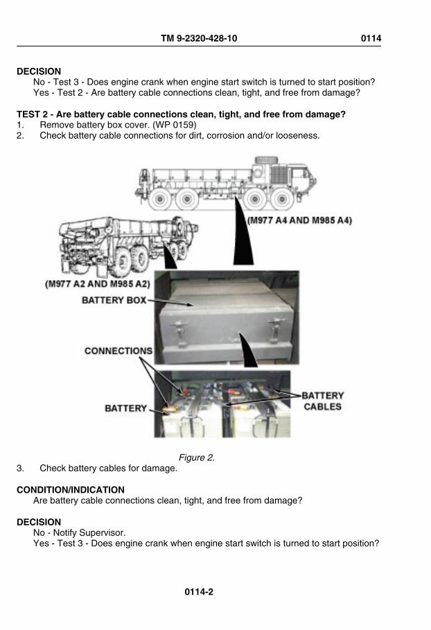
DECISIONNo - Test 3 - Does engine crank when engine start switch is turned to start position?Yes - Test 2 - Are battery cable connections clean, tight, and free from damage?
TEST 2 - Are battery cable connections clean, tight, and free from damage?1. Remove battery box cover. (WP 0159)2. Check battery cable connections for dirt, corrosion and/or looseness.
Figure 2. 3. Check battery cables for damage.
CONDITION/INDICATIONAre battery cable connections clean, tight, and free from damage?
DECISIONNo - Notify Supervisor.Yes - Test 3 - Does engine crank when engine start switch is turned to start position?
TM 9-2320-428-10 0114
0114-2

TEST 3 - Does engine crank when engine start switch is turned to start position?1. Install battery box cover. (WP 0159)2. Attempt to start engine. (WP 0044)
CONDITION/INDICATIONDoes engine crank when engine start switch is turned to start position?
DECISIONNo - Notify Supervisor.Yes - Problem corrected.
END OF WORK PACKAGE
TM 9-2320-428-10 0114
0114-3


OPERATOR MAINTENANCECRANKS BUT FAILS TO START
INITIAL SETUP:
Equipment ConditionEngine OFF. (WP 0057)
Equipment Condition - ContinuedParking brakes applied. (WP 0056)Wheels chocked. (WP 0077)
TROUBLESHOOTING PROCEDURECRANKS BUT FAILS TO START
TEST 1 - Does fuel gauge indicate the presence of fuel?1. Turn engine start switch ON. (WP 0021)2. Check fuel gauge for indication of fuel presence.
TM 9-2320-428-10 0115
0115-1

Figure 1. 3. Turn engine start switch OFF. (WP 0021)4. If fuel gauge indicated no fuel present, add fuel to fuel tank.
CONDITION/INDICATIONDoes fuel gauge indicate the presence of fuel?
DECISIONNo - Test 5 - Does engine start?Yes - Test 2 - Is there fuel present in fuel tank?
TEST 2 - Is there fuel present in fuel tank?1. Remove fuel tank cap and filter screen from fuel tank.
TM 9-2320-428-10 0115
0115-2

Figure 2. 2. Check fuel tank for presence of fuel.3. Add fuel to fuel tank if no fuel was present.4. Replace filter screen and fuel tank cap on fuel tank.
CONDITION/INDICATIONIs there fuel present in fuel tank?
DECISIONNo - Test 5 - Does engine start?Yes - Test 3 - Is air filter restricted?
TM 9-2320-428-10 0115
0115-3

TEST 3 - Is air filter restricted?1. Attempt to start engine and note indication on air filter restriction indicator.
Figure 3.
CONDITION/INDICATIONIs air filter restricted?
DECISIONRestricted - Test 4 - Does air filter restriction indicator showed yellow and/or VACUUMINCHES H2O window shows less than 18 after servicing air filter?Not Restricted - Test 5 - Does engine start?
TM 9-2320-428-10 0115
0115-4
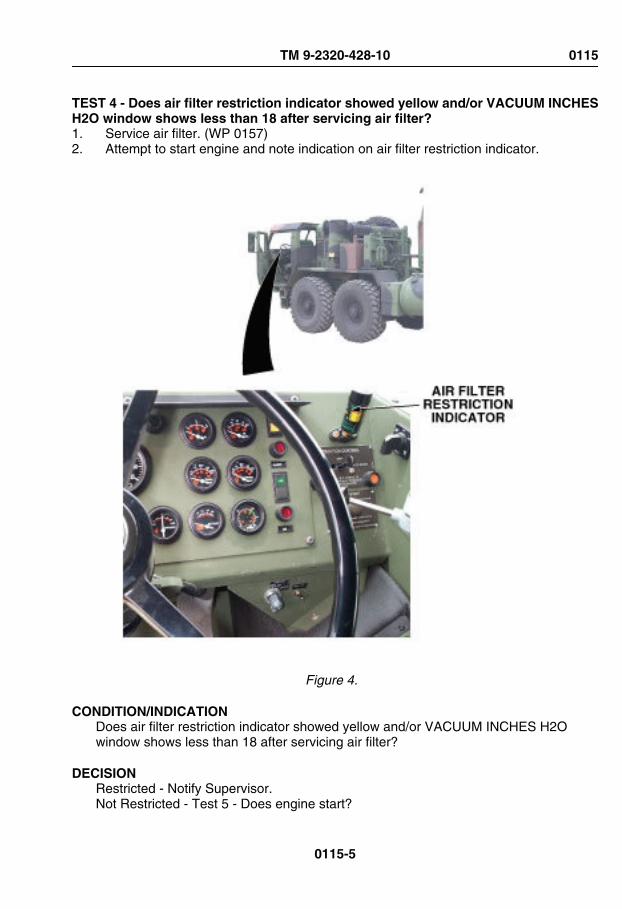
TEST 4 - Does air filter restriction indicator showed yellow and/or VACUUM INCHESH2O window shows less than 18 after servicing air filter?1. Service air filter. (WP 0157)2. Attempt to start engine and note indication on air filter restriction indicator.
Figure 4.
CONDITION/INDICATIONDoes air filter restriction indicator showed yellow and/or VACUUM INCHES H2Owindow shows less than 18 after servicing air filter?
DECISIONRestricted - Notify Supervisor.Not Restricted - Test 5 - Does engine start?
TM 9-2320-428-10 0115
0115-5

TEST 5 - Does engine start?1. Attempt to start engine. (WP 0044)
CONDITION/INDICATIONDoes engine start?
DECISIONNo. - Notify Supervisor.Yes. - Problem corrected.
END OF WORK PACKAGE
TM 9-2320-428-10 0115
0115-6

OPERATOR MAINTENANCESTARTS OR RUNS ROUGHLY AFTER PROPER WARM-UP, DOES NOT MAKE FULL
POWER, OR MAKES EXCESSIVE EXHAUST SMOKE
INITIAL SETUP:
Equipment ConditionEngine OFF. (WP 0057)
Equipment Condition - ContinuedParking brakes applied. (WP 0056)Wheels chocked. (WP 0077)
TROUBLESHOOTING PROCEDURESTARTS OR RUNS ROUGHLY AFTER PROPER WARM-UP, DOES NOT MAKE FULLPOWER, OR MAKES EXCESSIVE EXHAUST SMOKE
TEST 1 - Is PTO engaged?1. Start engine and allow engine to reach normal operating temperature. (WP 0044)2. Check PTO ENGAGE switch and PTO ENGAGE indicator to make sure that PTO is
disengaged. Light should be off.
TM 9-2320-428-10 0116
0116-1
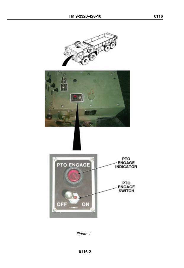
Figure 1.
TM 9-2320-428-10 0116
0116-2

CONDITION/INDICATIONIs PTO engaged?
DECISIONPTO engaged. - Test 4 - Does engine start or run roughly after proper warm-up, and/or does not make full power or makes excessive exhaust smoke?PTO disengaged. - Test 2 - Does air filter restriction indicator show red and/or VACUUMINCHES H2O window show 18 or more after being reset?
TEST 2 - Does air filter restriction indicator show red and/or VACUUM INCHES H2Owindow show 18 or more after being reset?1. Reset air filter restriction indicator.2. Start engine. (WP 0044)3. Check if air filter restriction indicator is red and/or VACUUM INCHES H2O window
shows 18 or more.
TM 9-2320-428-10 0116
0116-3

Figure 2.
CONDITION/INDICATIONDoes air filter restriction indicator show red and/or VACUUM INCHES H2O windowshow 18 or more after being reset?
DECISIONRestricted. - Test 3 - Does air filter restriction indicator show red and/or VACUUMINCHES H2O window show 18 or more after being cleaned?Not restricted. - Test 4 - Does engine start or run roughly after proper warm-up, and/ordoes not make full power or makes excessive exhaust smoke?
TM 9-2320-428-10 0116
0116-4

TEST 3 - Does air filter restriction indicator show red and/or VACUUM INCHES H2Owindow show 18 or more after being cleaned?1. Turn engine OFF. (WP 0057)2. Clean air filter. (WP 0157)3. Start engine. (WP 0044)4. Check if air filter restriction indicator is red and/or VACUUM INCHES H2O window
shows 18 or more.
Figure 3.
CONDITION/INDICATIONDoes air filter restriction indicator show red and/or VACUUM INCHES H2O windowshow 18 or more after being cleaned?
TM 9-2320-428-10 0116
0116-5

DECISIONRestricted. - Notify Supervisor.Not restricted. - Test 4 - Does engine start or run roughly after proper warm-up, and/ordoes not make full power or makes excessive exhaust smoke?
TEST 4 - Does engine start or run roughly after proper warm-up, and/or does not makefull power or makes excessive exhaust smoke?1. Test drive vehicle.
CONDITION/INDICATIONDoes engine start or run roughly after proper warm-up, and/or does not make full poweror makes excessive exhaust smoke?
DECISIONRuns rough. - Notify Supervisor.Runs normal. - Problem corrected.
END OF WORK PACKAGE
TM 9-2320-428-10 0116
0116-6

OPERATOR MAINTENANCEENGINE OVERHEATS
INITIAL SETUP:
Equipment ConditionEngine OFF. (WP 0057)
Equipment Condition - ContinuedParking brakes applied. (WP 0056)Wheels chocked. (WP 0077)
TROUBLESHOOTING PROCEDUREENGINE OVERHEATS
TEST 1 - Are right-side radiator hoses and housing free from leaks?
WARNING
Radiator coolant hoses are very hot and pressurized during vehicleoperation. Allow radiator to cool prior to checking hoses. Failure to complymay result in injury or death to personnel.
1. Open driver and passenger side engine covers. (WP 0160)2. Check upper and lower radiator hoses and housing for leaks.3. Check that all clamps are tight and secure.
TM 9-2320-428-10 0117
0117-1
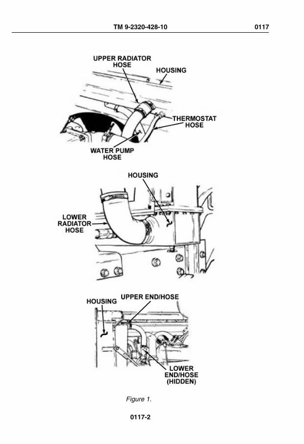
Figure 1.
TM 9-2320-428-10 0117
0117-2

CONDITION/INDICATIONAre right-side radiator hoses and housing free from leaks?
DECISIONRadiator hoses and/or housing damaged. - Notify Supervisor. Test 2 - Does engineoverheat?Notify Supervisor.Radiator hoses and/or housing free from damage and/or leaks. - Notify Supervisor.
TEST 2 - Does engine overheat?1. Close driver and passenger side engine covers. (WP 0160)2. Start engine. (WP 0044)
TM 9-2320-428-10 0117
0117-3

Figure 2.
TM 9-2320-428-10 0117
0117-4

3. Test drive vehicle.
CONDITION/INDICATIONDoes engine overheat?
DECISIONEngine overheats - Notify Supervisor.Engine OK - Problem corrected.
END OF WORK PACKAGE
TM 9-2320-428-10 0117
0117-5


OPERATOR MAINTENANCELOW OIL PRESSURE GAUGE INDICATION
INITIAL SETUP:
Equipment ConditionEngine OFF. (WP 0057)
Equipment Condition - ContinuedParking brakes applied. (WP 0056)Wheels chocked. (WP 0077)
TROUBLESHOOTING PROCEDURELOW OIL PRESSURE GAUGE INDICATION
TEST 1 - Is engine oil level low?1. Check engine oil level. (WP 0147)
TM 9-2320-428-10 0118
0118-1

Figure 1. 2. If oil level is low, fill oil to proper level. (WP 0147)
TM 9-2320-428-10 0118
0118-2

CONDITION/INDICATIONIs engine oil level low?
DECISION-Continue - Test 2 - Is engine oil pressure still low?
TEST 2 - Is engine oil pressure still low?1. Start engine and allow engine to reach operating temperature. (WP 0044)2. Check OIL PRESS gauge. Gauge should read as follows:
• At idle, oil pressure can go as low as 5 psi (34 kPa).• Normal operation range is 40 psi to 60 psi (276 to 414 kPa) between engine
speeds 1800 to 2100 rpm. Minimum for safe operation is 30 psi (207 kPa).
CONDITION/INDICATIONIs engine oil pressure still low?
DECISIONOil pressure low. - Notify Supervisor.Oil pressure OK. - Problem corrected.
END OF WORK PACKAGE
TM 9-2320-428-10 0118
0118-3


OPERATOR MAINTENANCEEXCESSIVE OIL CONSUMPTION
INITIAL SETUP:
Equipment ConditionEngine OFF. (WP 0057)
Equipment Condition - ContinuedParking brakes applied. (WP 0056)Wheels chocked. (WP 0077)
TROUBLESHOOTING PROCEDUREEXCESSIVE OIL CONSUMPTION
TEST 1 - Are engine oil lines loose?
WARNING
Caution the oil lines could be under pressure be sure to wear the propereye protection to avoid personal injury.
1. Open driver and passenger side engine covers. (WP 0160)
TM 9-2320-428-10 0119
0119-1
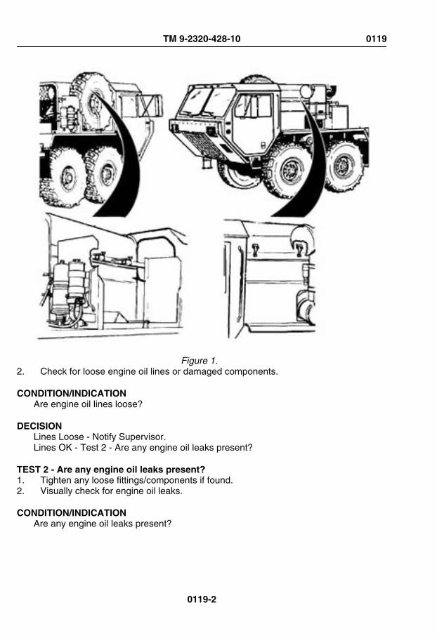
Figure 1. 2. Check for loose engine oil lines or damaged components.
CONDITION/INDICATIONAre engine oil lines loose?
DECISIONLines Loose - Notify Supervisor.Lines OK - Test 2 - Are any engine oil leaks present?
TEST 2 - Are any engine oil leaks present?1. Tighten any loose fittings/components if found.2. Visually check for engine oil leaks.
CONDITION/INDICATIONAre any engine oil leaks present?
TM 9-2320-428-10 0119
0119-2

DECISIONLeaks found. - Notify Supervisor.No leaks found. - Notify Supervisor.
END OF WORK PACKAGE
TM 9-2320-428-10 0119
0119-3


OPERATOR MAINTENANCEHYDRAULIC SYSTEM OPERATES TOO SLOW, TOO FAST, WITH JERKY
MOVEMENTS; OR ONE OR MORE HYDRAULICS CIRCUITS WILL NOT OPERATE
INITIAL SETUP:
Equipment ConditionEngine OFF. (WP 0057)
Equipment Condition - ContinuedParking brakes applied. (WP 0056)Wheels chocked. (WP 0077)
TROUBLESHOOTING PROCEDUREHYDRAULIC SYSTEM OPERATES TOO SLOW, TOO FAST, WITH JERKYMOVEMENTS; OR ONE OR MORE HYDRAULICS CIRCUITS WILL NOT OPERATE
TEST 1 - Is hydraulic fluid level within normal operating range?1. Check hydraulic fluid level. If low, add hydraulic fluid. (WP 0147)
TM 9-2320-428-10 0120
0120-1

Figure 1.
CONDITION/INDICATIONIs hydraulic fluid level within normal operating range?
DECISIONNo - Test 3 - Do all hydraulic systems operate properly?Yes - Test 2 - Are hydraulic hoses and connections free from leaks and/or damage?
TM 9-2320-428-10 0120
0120-2

TEST 2 - Are hydraulic hoses and connections free from leaks and/or damage?
WARNING
Caution the hydraulic system maybe under pressure be sure to wear theproper eye protection to avoid personal injury.
1. Check hydraulic hoses and connections for leaks and/or damage.
Figure 2. 2. Attempt to tighten loose hose(s) and/or connection(s).
TM 9-2320-428-10 0120
0120-3

CONDITION/INDICATIONAre hydraulic hoses and connections free from leaks and/or damage?
DECISIONHydraulic hose or connection damaged. - Notify Supervisor. Test 3 - Do all hydraulicsystems operate properly?Notify Supervisor.Hydraulic hoses and connections OK. - Notify Supervisor.
TEST 3 - Do all hydraulic systems operate properly?1. Start engine. (WP 0044)2. Operate hydraulic systems to check for proper operation.
CONDITION/INDICATIONDo all hydraulic systems operate properly?
DECISIONNo - Notify Supervisor.Yes - Problem corrected.
END OF WORK PACKAGE
TM 9-2320-428-10 0120
0120-4

OPERATOR MAINTENANCEBOOM OPERATION ABNORMAL WHEN TELESCOPING IN OR OUT
INITIAL SETUP:
Equipment ConditionVehicle setup for crane operations.(WP 0042)
TROUBLESHOOTING PROCEDUREBOOM OPERATION ABNORMAL WHEN TELESCOPING IN OR OUT
TEST 1 - Is HIGH IDLE ON/OFF switch set to ON position?
NOTECommon problems that crane operators may see are:1. Slow or abnormal operation.2. Crane will not pick up load.Common causes of problems are:1. Cold hydraulic oil (slow operation).2. Low engine speed (slow or abnormal operation).3. Operating two craning functions at the same time (slow operation).4. Load too heavy (will not pick up load).5. Air in cylinder or hoist motor (abnormal operation).Report all problems to field level maintenance.
1. Ensure HIGH IDLE ON/OFF switch is set to ON position.If switch found in OFFposition, turn switch to ON. (WP 0042)
TM 9-2320-428-10 0121
0121-1

Figure 1.
CONDITION/INDICATIONIs HIGH IDLE ON/OFF switch set to ON position?
DECISIONNo - Test 5 - Does boom operate normally when telescoping in or out?Yes - Test 2 - Are boom sections properly lubricated?
TEST 2 - Are boom sections properly lubricated?1. Inspect boom sections for proper lubrication.
Figure 2.
TM 9-2320-428-10 0121
0121-2

CONDITION/INDICATIONAre boom sections properly lubricated?
DECISIONNo - Lubricate boom sections. (WP 0149)Yes - Test 3 - Are cylinders free from trapped air after telescoping boom in and outseveral times?
TEST 3 - Are cylinders free from trapped air after telescoping boom in and out severaltimes?1. Lower boom below horizontal position. (WP 0042)
Figure 3. 2. Fully TELESCOPE boom IN and OUT several times to remove air from cylinders.
(WP 0042)
CONDITION/INDICATIONAre cylinders free from trapped air after telescoping boom in and out several times?
DECISIONNo - Test 4 - Is boom operation normal after allowing boom to sit overnight?Yes - Problem corrected.
TEST 4 - Is boom operation normal after allowing boom to sit overnight?1. Swing boom to rear of vehicle. Fully telescope boom out. (WP 0042)2. Lower boom as far as possible. (WP 0042)
TM 9-2320-428-10 0121
0121-3

Figure 4. 3. Shut down operation, (WP 0042) and allow boom to remain in lowered position
overnight.4. When starting operations, telescope boom in (WP 0042)(not out). Telescoping boom
out could force air back into cylinders.5. Telescope boom out and in. (WP 0042)
CONDITION/INDICATIONIs boom operation normal after allowing boom to sit overnight?
DECISIONNo - Notify supervisor.Yes - Problem corrected.
TEST 5 - Does boom operate normally when telescoping in or out?1. Verify proper operation of boom telescoping. (WP 0042)
TM 9-2320-428-10 0121
0121-4

Figure 5.
CONDITION/INDICATIONDoes boom operate normally when telescoping in or out?
DECISIONNo - Notify supervisor.Yes - Problem corrected.
END OF WORK PACKAGE
TM 9-2320-428-10 0121
0121-5


OPERATOR MAINTENANCEBOOM RAISES OR LOWERS SLOWLY
INITIAL SETUP:
Equipment ConditionVehicle setup for crane operations.(WP 0042)
TROUBLESHOOTING PROCEDUREBOOM RAISES OR LOWERS SLOWLY
TEST 1 - Does boom raise or lower normally after running engine for 20 minutes withPTO engaged?
NOTECommon problems that crane operators may see are:1. Slow or abnormal operation.2. Crane will not pick up load.Common causes of problems are:1. Cold hydraulic oil (slow operation).2. Low engine speed (slow or abnormal operation).3. Operating two craning functions at the same time (slow operation).4. Load too heavy (will not pick up load).5. Air in cylinder or hoist motor (abnormal operation).Report all problems to field level maintenance.If outside temperature is 0°F (-17°C), hydraulic fluid may not flow easily.
1. Start engine. (WP 0044)2. Set PTO ENGAGE switch to ON. (WP 0042)
TM 9-2320-428-10 0122
0122-1

Figure 1.
TM 9-2320-428-10 0122
0122-2

3. Operate engine (WP 0044) for 20 minutes with PTO enabled to bring hydraulic fluidup to operating temperature.
4. Attempt to raise or lower boom. (WP 0042)
CONDITION/INDICATIONDoes boom raise or lower normally after running engine for 20 minutes with PTOengaged?
DECISIONNo - Test 2 - Does boom raise or lower normally after cycling mast?Yes - Problem corrected.
TEST 2 - Does boom raise or lower normally after cycling mast?1. Lower crane to stowed position. (WP 0042)2. Operate MAST control DOWN. (WP 0042) Hold MAST control DOWN for
approximately 30 seconds, then return control to NEUTRAL position. Repeatprocedure several times until hydraulic fluid is warmed.
TM 9-2320-428-10 0122
0122-3

Figure 2. 3. Raise crane to operating position. (WP 0042)4. Raise and lower boom. (WP 0042)
CONDITION/INDICATIONDoes boom raise or lower normally after cycling mast?
DECISIONNo - Notify Supervisor.Yes - Problem corrected.
END OF WORK PACKAGE
TM 9-2320-428-10 0122
0122-4

OPERATOR MAINTENANCEBOOM WILL NOT RAISE OR LOWER
INITIAL SETUP:
Equipment ConditionVehicle setup for crane operations.(WP 0042)
TROUBLESHOOTING PROCEDUREBOOM WILL NOT RAISE OR LOWER
TEST 1 - Does boom operate after checking for overloading?
NOTECommon problems that crane operators may see are:1. Slow or abnormal operation.2. Crane will not pick up load.Common causes of problems are:1. Cold hydraulic oil (slow operation).2. Low engine speed (slow or abnormal operation).3. Operating two craning functions at the same time (slow operation).4. Load too heavy (will not pick up load).5. Air in cylinder or hoist motor (abnormal operation).Report all problems to field level maintenance.
1. Check that load is not over load limit. If load is found to be over limit, reduce weightto below load limit.
TM 9-2320-428-10 0123
0123-1
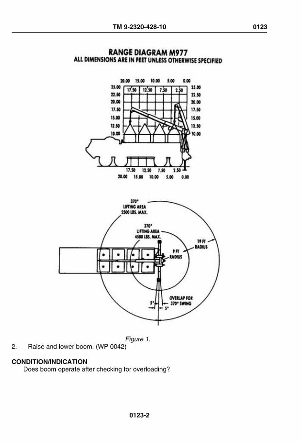
Figure 1. 2. Raise and lower boom. (WP 0042)
CONDITION/INDICATIONDoes boom operate after checking for overloading?
TM 9-2320-428-10 0123
0123-2

DECISIONNo - Notify supervisor.Yes - Problem corrected.
END OF WORK PACKAGE
TM 9-2320-428-10 0123
0123-3


OPERATOR MAINTENANCEBOOM WILL NOT TELESCOPE IN OR OUT
INITIAL SETUP:
Equipment ConditionVehicle setup for crane operations.(WP 0042)
TROUBLESHOOTING PROCEDUREBOOM WILL NOT TELESCOPE IN OR OUT
TEST 1 - Does boom telescope in or out after checking for overloaded condition?
NOTECommon problems that crane operators may see are:1. Slow or abnormal operation.2. Crane will not pick up load.Common causes of problems are:1. Cold hydraulic oil (slow operation).2. Low engine speed (slow or abnormal operation).3. Operating two craning functions at the same time (slow operation).4. Load too heavy (will not pick up load).5. Air in cylinder or hoist motor (abnormal operation).Report all problems to field level maintenance.
1. Check that load is not over load limit. If load is found to be over limit, reduce weightto below load limit.
TM 9-2320-428-10 0124
0124-1

Figure 1. 2. Operate crane by telescoping boom IN and OUT. (WP 0042)
CONDITION/INDICATIONDoes boom telescope in or out after checking for overloaded condition?
TM 9-2320-428-10 0124
0124-2

DECISIONNo - Notify supervisor.Yes - Problem corrected.
END OF WORK PACKAGE
TM 9-2320-428-10 0124
0124-3

OPERATOR MAINTENANCECRANE CONTROLS STICKING IN ENGAGED POSITION
INITIAL SETUP:
Equipment ConditionVehicle setup for crane operations.(WP 0042)
TROUBLESHOOTING PROCEDURECRANE CONTROLS STICKING IN ENGAGED POSITION
TEST 1 - Is hydraulic fluid at normal operating temperature?
WARNING
Reservoir may be very hot. Use care when placing hand near reservoir.Reservoir can become hot enough to cause serious burns. Be careful notto touch the reservoir with bare hands or allow body to contact reservoir.Use gloves and insulated pads as necessary. Failure to comply mayresult in injury or death to personnel.
NOTECommon problems that crane operators may see are:1. Slow or abnormal operation.2. Crane will not pick up load.Common causes of problems are:1. Cold hydraulic oil (slow operation).2. Low engine speed (slow or abnormal operation).3. Operating two craning functions at the same time (slow operation).4. Load too heavy (will not pick up load).5. Air in cylinder or hoist motor (abnormal operation).Report all problems to field level maintenance.
TM 9-2320-428-10 0125
0125-1

NOTEIf outside temperature is 0°F (-17°C) or lower, hydraulic fluid may not floweasily.
1. Check hydraulic fluid temperature at reservoir.
HYDRAULICRESERVOIR
Figure 1.
CONDITION/INDICATIONIs hydraulic fluid at normal operating temperature?
DECISIONHydraulic fluid is below normal operating temperature. - Test 2 - Does hydraulic fluidreach normal operating temperature after running engine for 20 minutes with PTOengaged?Test 4 - Is hydraulic fluid overheated?Hydraulic fluid is at normal operating temperature. - Test 5 - Do crane controls operatenormally after hydraulic fluid is at normal operating temperature?
TEST 2 - Does hydraulic fluid reach normal operating temperature after runningengine for 20 minutes with PTO engaged?
WARNING
Reservoir may be very hot. Use care when placing hand near reservoir.Reservoir can become hot enough to cause serious burns. Be careful notto touch the reservoir with bare hands or allow body to contact reservoir.
TM 9-2320-428-10 0125
0125-2

Use gloves and insulated pads as necessary. Failure to comply mayresult in injury or death to personnel.
1. Set PTO ENGAGE switch to ON. (WP 0042)
TM 9-2320-428-10 0125
0125-3

Figure 2.
TM 9-2320-428-10 0125
0125-4
2. Operate engine (WP 0044) for 20 minutes with PTO enabled to bring hydraulic fluidup to operating temperature.
3. Check hydraulic fluid temperature at reservoir. Reservoir should be warm.
CONDITION/INDICATIONDoes hydraulic fluid reach normal operating temperature after running engine for 20minutes with PTO engaged?
DECISIONHydraulic fluid is below normal operating temperature. - Test 3 - Does hydraulic fluidreach normal operating temperature after cycling mast control down?Test 4 - Ishydraulic fluid overheated?Hydraulic fluid is at normal operating temperature. - Test 5 - Do crane controls operatenormally after hydraulic fluid is at normal operating temperature?
TEST 3 - Does hydraulic fluid reach normal operating temperature after cycling mastcontrol down?
WARNING
Reservoir may be very hot. Use care when placing hand near reservoir.Reservoir can become hot enough to cause serious burns. Be careful notto touch the reservoir with bare hands or allow body to contact reservoir.Use gloves and insulated pads as necessary. Failure to comply mayresult in injury or death to personnel.
1. Lower crane to stowed position. (WP 0042)2. Operate MAST control DOWN. (WP 0042) Hold MAST control DOWN for
approximately 30 seconds, then return control to NEUTRAL position. Repeatprocedure several times until hydraulic fluid is warmed.
TM 9-2320-428-10 0125
0125-5

Figure 3. 3. Check hydraulic fluid temperature at reservoir. Reservoir should be warm.
CONDITION/INDICATIONDoes hydraulic fluid reach normal operating temperature after cycling mast controldown?
DECISIONHydraulic fluid is below normal operating temperature. - Notify Supervisor. Test 4 - Ishydraulic fluid overheated?Hydraulic fluid is at normal operating temperature. - Test 5 - Do crane controls operatenormally after hydraulic fluid is at normal operating temperature?
TM 9-2320-428-10 0125
0125-6

TEST 4 - Is hydraulic fluid overheated?
WARNING
Reservoir may be very hot. Use care when placing hand near reservoir.Reservoir can become hot enough to cause serious burns. Be careful notto touch the reservoir with bare hands or allow body to contact reservoir.Use gloves and insulated pads as necessary. Failure to comply mayresult in injury or death to personnel.
1. Set PTO ENGAGE switch to OFF.2. Shut off engine. (WP 0057)3. Allow hydraulic oil to cool. (WP 0057)
HYDRAULICRESERVOIR
Figure 4.
CONDITION/INDICATIONIs hydraulic fluid overheated?
DECISION-Continue - Test 5 - Do crane controls operate normally after hydraulic fluid is at normaloperating temperature?
TEST 5 - Do crane controls operate normally after hydraulic fluid is at normaloperating temperature?1. If off, start engine. (WP 0044)
TM 9-2320-428-10 0125
0125-7

2. Prepare vehicle for crane operation. (WP 0042)
CRANE CONTROLVALVE ASSEMBLY
MAST CONTROLLEVER
HOISTCONTROL
LEVER
BOOMCONTROL
LEVER
TELESCOPECONTROL
LEVERSWINGCONTROL
LEVER
RH O/R JACKCONTROL LEVER
OUTRIGGER EXTENDCONTROL LEVER
Figure 5. 3. Operate crane controls. (WP 0042)
CONDITION/INDICATIONDo crane controls operate normally after hydraulic fluid is at normal operatingtemperature?
DECISIONNo - Notify supervisor.Yes - Problem corrected.
END OF WORK PACKAGE
TM 9-2320-428-10 0125
0125-8

OPERATOR MAINTENANCECRANE WILL NOT OPERATE, OR OPERATES ABNORMALLY
INITIAL SETUP:
Equipment ConditionEngine OFF. (WP 0057)
Equipment Condition - ContinuedParking brakes applied. (WP 0056)Wheels chocked. (WP 0077)
TROUBLESHOOTING PROCEDURECRANE WILL NOT OPERATE, OR OPERATES ABNORMALLY
TEST 1 - Is electrical connector on solenoid tight?
NOTECommon problems that crane operators may see are:1. Slow or abnormal operation.2. Crane will not pick up load.Common causes of problems are:1. Cold hydraulic oil (slow operation).2. Low engine speed (slow or abnormal operation).3. Operating two craning functions at the same time (slow operation).4. Load too heavy (will not pick up load).5. Air in cylinder or hoist motor (abnormal operation).Report all problems to field level maintenance.
1. Check that electrical connector on solenoid valve is tight. If connector is loose, tighten.
TM 9-2320-428-10 0126
0126-1
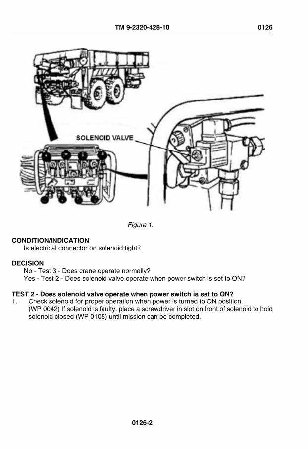
Figure 1.
CONDITION/INDICATIONIs electrical connector on solenoid tight?
DECISIONNo - Test 3 - Does crane operate normally?Yes - Test 2 - Does solenoid valve operate when power switch is set to ON?
TEST 2 - Does solenoid valve operate when power switch is set to ON?1. Check solenoid for proper operation when power is turned to ON position.
(WP 0042) If solenoid is faulty, place a screwdriver in slot on front of solenoid to holdsolenoid closed (WP 0105) until mission can be completed.
TM 9-2320-428-10 0126
0126-2

Figure 2.
CONDITION/INDICATIONDoes solenoid valve operate when power switch is set to ON?
DECISIONNo - Perform crane emergency hydraulic procedure. (WP 0105)Yes - Notify Supervisor.
TEST 3 - Does crane operate normally?1. Prepare vehicle for crane operation. (WP 0042)
TM 9-2320-428-10 0126
0126-3

CRANE CONTROLVALVE ASSEMBLY
MAST CONTROLLEVER
HOISTCONTROL
LEVER
BOOMCONTROL
LEVER
TELESCOPECONTROL
LEVERSWINGCONTROL
LEVER
RH O/R JACKCONTROL LEVER
OUTRIGGER EXTENDCONTROL LEVER
Figure 3. 2. Operate crane. (WP 0042)
CONDITION/INDICATIONDoes crane operate normally?
DECISIONNo - Notify supervisor.Yes - Problem corrected.
END OF WORK PACKAGE
TM 9-2320-428-10 0126
0126-4

OPERATOR MAINTENANCEHOIST OPERATION SLOW OR ABNORMAL WHEN LIFTING OR LOWERING LOAD
INITIAL SETUP:
Equipment ConditionVehicle setup for crane operations.(WP 0042)
TROUBLESHOOTING PROCEDUREHOIST OPERATION SLOW OR ABNORMAL WHEN LIFTING OR LOWERING LOAD
TEST 1 - Does hoist operate normally after removing air from motor?
CAUTIONBe sure to keep tension on cable. If tension is not maintained, cable mayget tangled on drum.
NOTECommon problems that crane operators may see are:1. Slow or abnormal operation.2. Crane will not pick up load.Common causes of problems are:1. Cold hydraulic oil (slow operation).2. Low engine speed (slow or abnormal operation).3. Operating two craning functions at the same time (slow operation).4. Load too heavy (will not pick up load).5. Air in cylinder or hoist motor (abnormal operation).Report all problems to field level maintenance.
1. Set load down (WP 0042) and disconnect load hook.2. Reel cable in and out several times to remove air from hoist motor.
TM 9-2320-428-10 0127
0127-1

Figure 1.
CONDITION/INDICATIONDoes hoist operate normally after removing air from motor?
TM 9-2320-428-10 0127
0127-2
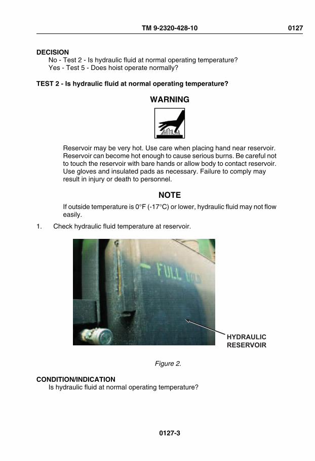
DECISIONNo - Test 2 - Is hydraulic fluid at normal operating temperature?Yes - Test 5 - Does hoist operate normally?
TEST 2 - Is hydraulic fluid at normal operating temperature?
WARNING
Reservoir may be very hot. Use care when placing hand near reservoir.Reservoir can become hot enough to cause serious burns. Be careful notto touch the reservoir with bare hands or allow body to contact reservoir.Use gloves and insulated pads as necessary. Failure to comply mayresult in injury or death to personnel.
NOTEIf outside temperature is 0°F (-17°C) or lower, hydraulic fluid may not floweasily.
1. Check hydraulic fluid temperature at reservoir.
HYDRAULICRESERVOIR
Figure 2.
CONDITION/INDICATIONIs hydraulic fluid at normal operating temperature?
TM 9-2320-428-10 0127
0127-3

DECISIONNo - Test 3 - Is hydraulic fluid at normal operating temperature after running engine for20 minutes with PTO engaged?Yes - Test 5 - Does hoist operate normally?
TEST 3 - Is hydraulic fluid at normal operating temperature after running engine for20 minutes with PTO engaged?
WARNING
Reservoir may be very hot. Use care when placing hand near reservoir.Reservoir can become hot enough to cause serious burns. Be careful notto touch the reservoir with bare hands or allow body to contact reservoir.Use gloves and insulated pads as necessary. Failure to comply mayresult in injury or death to personnel.
1. Lower crane to stowed position. (WP 0042)2. Operate engine (WP 0044) for 20 minutes with PTO engaged to bring hydraulic fluid
up to operating temperature.3. Check hydraulic fluid temperature at reservoir. Reservoir should be warm.
HYDRAULICRESERVOIR
Figure 3.
CONDITION/INDICATIONIs hydraulic fluid at normal operating temperature after running engine for 20 minuteswith PTO engaged?
TM 9-2320-428-10 0127
0127-4

DECISIONNo - Test 4 - Is hydraulic fluid at normal operating temperature after cycling mast controldown?Yes - Test 5 - Does hoist operate normally?
TEST 4 - Is hydraulic fluid at normal operating temperature after cycling mast controldown?1. Ensure crane is lowered to stowed position. (WP 0042)2. Operate MAST control DOWN. (WP 0042) Hold MAST control DOWN for
approximately 30 seconds, then return control to NEUTRAL position. Repeatprocedure several times until hydraulic fluid is warmed.
Figure 4. 3. Check hydraulic fluid temperature at reservoir. Reservoir should be warm.
TM 9-2320-428-10 0127
0127-5
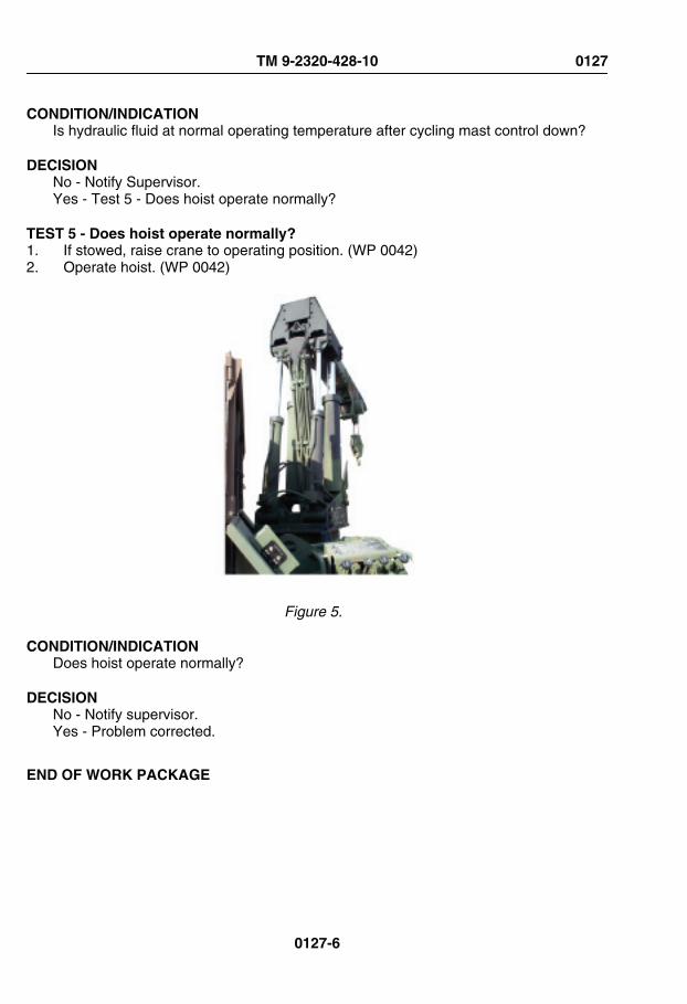
CONDITION/INDICATIONIs hydraulic fluid at normal operating temperature after cycling mast control down?
DECISIONNo - Notify Supervisor.Yes - Test 5 - Does hoist operate normally?
TEST 5 - Does hoist operate normally?1. If stowed, raise crane to operating position. (WP 0042)2. Operate hoist. (WP 0042)
Figure 5.
CONDITION/INDICATIONDoes hoist operate normally?
DECISIONNo - Notify supervisor.Yes - Problem corrected.
END OF WORK PACKAGE
TM 9-2320-428-10 0127
0127-6

OPERATOR MAINTENANCEHOIST WILL NOT LIFT LOAD
INITIAL SETUP:
Equipment ConditionVehicle setup for crane operations.(WP 0042)
TROUBLESHOOTING PROCEDUREHOIST WILL NOT LIFT LOAD
TEST 1 - Is load within allowable limits?
NOTECommon problems that crane operators may see are:1. Slow or abnormal operation.2. Crane will not pick up load.Common causes of problems are:1. Cold hydraulic oil (slow operation).2. Low engine speed (slow or abnormal operation).3. Operating two craning functions at the same time (slow operation).4. Load too heavy (will not pick up load).5. Air in cylinder or hoist motor (abnormal operation).Report all problems to field level maintenance.
1. Check that load is not over load limit. If load is found to be over-limit, reduce weightto below load limit.
TM 9-2320-428-10 0128
0128-1

Figure 1.
CONDITION/INDICATIONIs load within allowable limits?
DECISIONNo - Test 2 - Does hoist lift load?Yes - Notify Supervisor.
TM 9-2320-428-10 0128
0128-2

TEST 2 - Does hoist lift load?1. Operate hoist up and down. (WP 0042)
CRANE CONTROL
VALVE ASSEMBLY
HOIST
CONTROL
LEVER
Figure 2.
CONDITION/INDICATIONDoes hoist lift load?
DECISIONNo - Notify supervisor.Yes - Problem corrected.
END OF WORK PACKAGE
TM 9-2320-428-10 0128
0128-3


OPERATOR MAINTENANCEMAST RAISES OR LOWERS ABNORMALLY
INITIAL SETUP:
Equipment ConditionVehicle setup for crane operations.(WP 0042)
TROUBLESHOOTING PROCEDUREMAST RAISES OR LOWERS ABNORMALLY
TEST 1 - Does mast raise and lower normally after cycling mast up and down toremove trapped air?
NOTECommon problems that crane operators may see are:1. Slow or abnormal operation.2. Crane will not pick up load.Common causes of problems are:1. Cold hydraulic oil (slow operation).2. Low engine speed (slow or abnormal operation).3. Operating two craning functions at the same time (slow operation).4. Load too heavy (will not pick up load).5. Air in cylinder or hoist motor (abnormal operation).Report all problems to field level maintenance.
1. Fully raise and lower mast (WP 0042) several times to remove air from cylinders.
TM 9-2320-428-10 0129
0129-1

Figure 1.
CONDITION/INDICATIONDoes mast raise and lower normally after cycling mast up and down to remove trappedair?
TM 9-2320-428-10 0129
0129-2

DECISION- Notify supervisor. Test 2 - Does mast operate normally after leaving mast in fully raisedposition overnight?Yes - Problem corrected.- Notify supervisor. Test 2 - Does mast operate normally after leaving mast in fully raisedposition overnight?No - Problem corrected.
TEST 2 - Does mast operate normally after leaving mast in fully raised positionovernight?1. Raise boom to vertical position. (WP 0042)
TM 9-2320-428-10 0129
0129-3

Figure 2. 2. Fully raise mast. (WP 0042)3. Shut down operation (WP 0042) and leave mast in raised position overnight.4. Start engine. (WP 0044)5. Prepare vehicle for crane operations. (WP 0042)
NOTEWhen starting operations, operate mast control down (not up) first.Operating controls UP could force air back into cylinders.
TM 9-2320-428-10 0129
0129-4

6. Lower and raise mast. (WP 0042)
CONDITION/INDICATIONDoes mast operate normally after leaving mast in fully raised position overnight?
DECISIONNo - Notify supervisor.Yes - Problem corrected.
END OF WORK PACKAGE
TM 9-2320-428-10 0129
0129-5


OPERATOR MAINTENANCEMAST RAISES OR LOWERS SLOWLY
INITIAL SETUP:
Equipment ConditionVehicle setup for crane operations.(WP 0042)
TROUBLESHOOTING PROCEDUREMAST RAISES OR LOWERS SLOWLY
TEST 1 - Does mast raise and lower normally after running engine for 20 minutes withPTO engaged?
NOTECommon problems that crane operators may see are:1. Slow or abnormal operation.2. Crane will not pick up load.Common causes of problems are:1. Cold hydraulic oil (slow operation).2. Low engine speed (slow or abnormal operation).3. Operating two craning functions at the same time (slow operation).4. Load too heavy (will not pick up load).5. Air in cylinder or hoist motor (abnormal operation).Report all problems to field level maintenance.If outside temperature is 0°F (-17°C), hydraulic fluid may not flow easily.
1. If loaded, set load down (WP 0042) and disconnect load hook.2. Operate engine (WP 0044) for 20 minutes with PTO ENGAGE switch set to ON to
bring hydraulic fluid up to operating temperature.
TM 9-2320-428-10 0130
0130-1

Figure 1.
TM 9-2320-428-10 0130
0130-2
3. Raise and lower mast. (WP 0042)
CONDITION/INDICATIONDoes mast raise and lower normally after running engine for 20 minutes with PTOengaged?
DECISIONNo - Test 2 - Does mast raise and lower normally after cycling mast?Yes - Problem corrected.
TEST 2 - Does mast raise and lower normally after cycling mast?1. Lower crane to stowed position. (WP 0042)2. Operate MAST control DOWN. (WP 0042) Hold MAST control DOWN for
approximately 30 seconds, then return control to NEUTRAL position. Repeatprocedure several times until hydraulic fluid is warmed.
TM 9-2320-428-10 0130
0130-3

Figure 2. 3. Raise and lower mast. (WP 0042)
CONDITION/INDICATIONDoes mast raise and lower normally after cycling mast?
DECISIONNo - Notify supervisor.Yes - Problem corrected.
END OF WORK PACKAGE
TM 9-2320-428-10 0130
0130-4

OPERATOR MAINTENANCEOUTRIGGER OPERATION SLOW OR ABNORMAL
INITIAL SETUP:
Equipment ConditionVehicle setup for crane operations.(WP 0042)
TROUBLESHOOTING PROCEDUREOUTRIGGER OPERATION SLOW OR ABNORMAL
TEST 1 - Is hydraulic fluid at normal operating temperature?
WARNING
Reservoir may be very hot. Use care when placing hand near reservoir.Reservoir can become hot enough to cause serious burns. Be careful notto touch the reservoir with bare hands or allow body to contact reservoir.Use gloves and insulated pads as necessary. Failure to comply mayresult in injury or death to personnel.
NOTECommon problems that crane operators may see are:1. Slow or abnormal operation.2. Crane will not pick up load.Common causes of problems are:1. Cold hydraulic oil (slow operation).2. Low engine speed (slow or abnormal operation).3. Operating two craning functions at the same time (slow operation).4. Load too heavy (will not pick up load).5. Air in cylinder or hoist motor (abnormal operation).Report all problems to field level maintenance.If outside temperature is 0°F (-17°C) or lower, hydraulic fluid may not floweasily.
1. Check hydraulic fluid temperature at reservoir.
TM 9-2320-428-10 0131
0131-1

HYDRAULICRESERVOIR
Figure 1.
CONDITION/INDICATIONIs hydraulic fluid at normal operating temperature?
DECISIONNo - Test 2 - Is hydraulic fluid at normal operating temperature after running engine for20 minutes with PTO engaged?Yes - Test 4 - Do outriggers operate normally?
TEST 2 - Is hydraulic fluid at normal operating temperature after running engine for20 minutes with PTO engaged?
WARNING
Reservoir may be very hot. Use care when placing hand near reservoir.Reservoir can become hot enough to cause serious burns. Be careful notto touch the reservoir with bare hands or allow body to contact reservoir.Use gloves and insulated pads as necessary. Failure to comply mayresult in injury or death to personnel.
1. Start engine. (WP 0044)2. Set PTO ENGAGE switch to ON. (WP 0042)
TM 9-2320-428-10 0131
0131-2
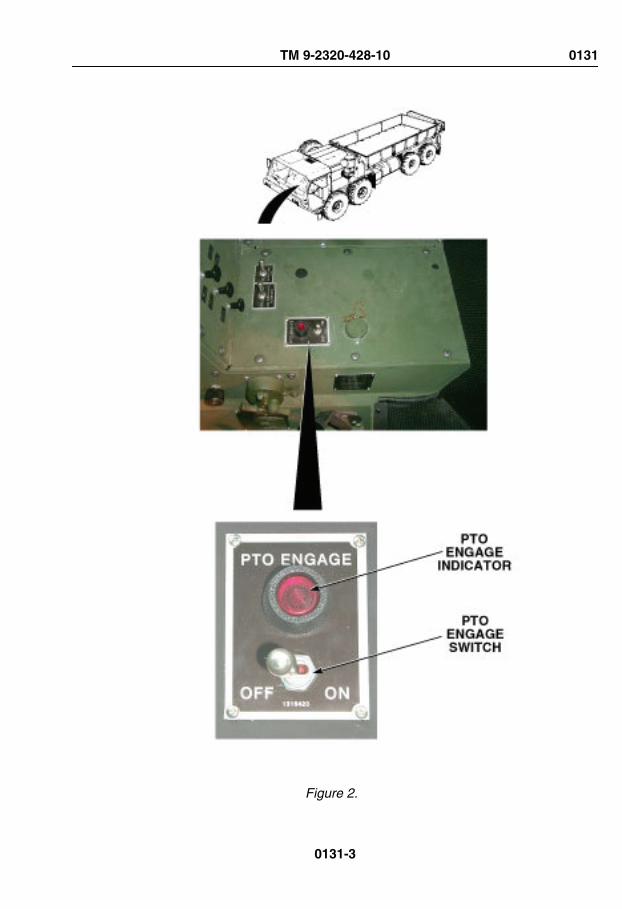
Figure 2.
TM 9-2320-428-10 0131
0131-3

3. Operate engine (WP 0044) for 20 minutes with PTO enabled to bring hydraulic fluidup to operating temperature.
4. Check hydraulic fluid temperature at reservoir. Reservoir should be warm.
CONDITION/INDICATIONIs hydraulic fluid at normal operating temperature after running engine for 20 minuteswith PTO engaged?
DECISIONNo - Test 3 - Is hydraulic fluid at normal operating temperature normal operatingtemperature after cycling mast control down?Yes - Test 4 - Do outriggers operate normally?
TEST 3 - Is hydraulic fluid at normal operating temperature normal operatingtemperature after cycling mast control down?1. Ensure crane is lowered to stowed position. (WP 0042)2. Operate MAST control DOWN. (WP 0042) Hold MAST control DOWN for
approximately 30 seconds, then return control to NEUTRAL position. Repeatprocedure several times until hydraulic fluid is warmed.
TM 9-2320-428-10 0131
0131-4

Figure 3. 3. Check hydraulic fluid temperature at reservoir. Reservoir should be warm.
CONDITION/INDICATIONIs hydraulic fluid at normal operating temperature normal operating temperature aftercycling mast control down?
DECISIONNo - Notify Supervisor.Yes - Test 4 - Do outriggers operate normally?
TEST 4 - Do outriggers operate normally?1. Ensure crane is lowered to stowed position. (WP 0042)2. Operate outrigger. (WP 0042)
TM 9-2320-428-10 0131
0131-5

Figure 4.
CONDITION/INDICATIONDo outriggers operate normally?
DECISIONNo - Test 5 - Do outriggers operate normally after purging cylinders of air?Yes - Problem corrected.
TEST 5 - Do outriggers operate normally after purging cylinders of air?1. Fully let out and draw back outriggers (WP 0042) several times to remove air from
cylinders.
Figure 5. 2. Operate outriggers (WP 0042)
TM 9-2320-428-10 0131
0131-6

CONDITION/INDICATIONDo outriggers operate normally after purging cylinders of air?
DECISIONNo - Notify Supervisor.Yes - Problem corrected.
END OF WORK PACKAGE
TM 9-2320-428-10 0131
0131-7


OPERATOR MAINTENANCESWING OPERATION ABNORMAL IN BOTH DIRECTIONS
INITIAL SETUP:
Equipment ConditionVehicle setup for crane operations.(WP 0042)
TROUBLESHOOTING PROCEDURESWING OPERATION ABNORMAL IN BOTH DIRECTIONS
TEST 1 - Are control levers returned to neutral properly?
NOTECommon problems that crane operators may see are:1. Slow or abnormal operation.2. Crane will not pick up load.Common causes of problems are:1. Cold hydraulic oil (slow operation).2. Low engine speed (slow or abnormal operation).3. Operating two craning functions at the same time (slow operation).4. Load too heavy (will not pick up load).5. Air in cylinder or hoist motor (abnormal operation).Report all problems to field level maintenance.
1. Verify that abnormal operation is not due to sharp movement of controls to NEUTRALposition.
TM 9-2320-428-10 0132
0132-1

EIGHT-BANKVALVE ASSEMBLYSWING
CONTROL LEVER
Figure 1. 2. Feather control lever to NEUTRAL (WP 0042) to maintain smooth stopping action.
CONDITION/INDICATIONAre control levers returned to neutral properly?
DECISIONNo - Test 2 - Is vehicle level?Yes - Problem corrected.
TEST 2 - Is vehicle level?1. Check if vehicle is level.
TM 9-2320-428-10 0132
0132-2

Figure 2.
CONDITION/INDICATIONIs vehicle level?
DECISION- Level vehicle. Level vehicle. (WP 0042)Yes - Test 3 - Is turntable bearing properly lubricated?- Level vehicle. Level vehicle. (WP 0042)No - Test 3 - Is turntable bearing properly lubricated?
TEST 3 - Is turntable bearing properly lubricated?1. Check turntable bearing for proper lubrication.
TM 9-2320-428-10 0132
0132-3

Figure 3. 2. If improperly lubricated, rotate turntable 360 degrees (WP 0042) in both directions
several times, and lubricate turntable bearing. (WP 0149)
CONDITION/INDICATIONIs turntable bearing properly lubricated?
DECISION- Test 5 - Does swing operate normally?Yes - Test 4 - Is load within allowable limit?- Test 5 - Does swing operate normally?No - Test 4 - Is load within allowable limit?
TEST 4 - Is load within allowable limit?1. Verify that load is below weight limit.
TM 9-2320-428-10 0132
0132-4

Figure 4. 2. If above weight limit, remove weight to decrease it to below the limit.
CONDITION/INDICATIONIs load within allowable limit?
TM 9-2320-428-10 0132
0132-5

DECISIONNo - Test 5 - Does swing operate normally?Yes - Notify Supervisor.
TEST 5 - Does swing operate normally?1. Operate crane (WP 0042) to verify proper operation of swing.
EIGHT-BANKVALVE ASSEMBLYSWING
CONTROL LEVER
Figure 5.
CONDITION/INDICATIONDoes swing operate normally?
DECISIONNo - Notify Supervisor.Yes - Problem corrected.
END OF WORK PACKAGE
TM 9-2320-428-10 0132
0132-6
OPERATOR MAINTENANCESWING OPERATION ABNORMAL IN ONLY ONE DIRECTION
INITIAL SETUP:
Equipment ConditionVehicle setup for crane operations.(WP 0042)
TROUBLESHOOTING PROCEDURESWING OPERATION ABNORMAL IN ONLY ONE DIRECTION
TEST 1 - Is vehicle level?
NOTECommon problems that crane operators may see are:1. Slow or abnormal operation.2. Crane will not pick up load.Common causes of problems are:1. Cold hydraulic oil (slow operation).2. Low engine speed (slow or abnormal operation).3. Operating two craning functions at the same time (slow operation).4. Load too heavy (will not pick up load).5. Air in cylinder or hoist motor (abnormal operation).Report all problems to field level maintenance.
1. Check if vehicle is level.
TM 9-2320-428-10 0133
0133-1

Figure 1.
CONDITION/INDICATIONIs vehicle level?
DECISIONVehicle not level. - Level vehicle. (WP 0042)Vehicle level. - Test 2 - Is turntable bearing properly lubricated?
TEST 2 - Is turntable bearing properly lubricated?1. Check turntable bearing for proper lubrication.
TM 9-2320-428-10 0133
0133-2

Figure 2. 2. If improperly lubricated, rotate turntable 360 degrees (WP 0042) in both directions
several times, and lubricate turntable bearing. (WP 0149)
CONDITION/INDICATIONIs turntable bearing properly lubricated?
DECISION- Test 3 - Does swing operate normally?Yes - Test 3 - Does swing operate normally?- Test 3 - Does swing operate normally?No - Test 3 - Does swing operate normally?
TEST 3 - Does swing operate normally?1. Operate crane (WP 0042) to verify proper operation of swing.
TM 9-2320-428-10 0133
0133-3

EIGHT-BANKVALVE ASSEMBLYSWING
CONTROL LEVER
Figure 3.
CONDITION/INDICATIONDoes swing operate normally?
DECISIONNo - Notify supervisor.Yes - Problem corrected.
END OF WORK PACKAGE
TM 9-2320-428-10 0133
0133-4

OPERATOR MAINTENANCESELF-RECOVERY WINCH DOES NOT WORK
INITIAL SETUP:
Equipment ConditionEngine OFF. (WP 0057)
Equipment Condition - ContinuedParking brakes applied. (WP 0056)Wheels chocked. (WP 0077)
TROUBLESHOOTING PROCEDURESELF-RECOVERY WINCH DOES NOT WORK
TEST 1 - Is hydraulic fluid level within normal operating range?1. Check hydraulic fluid level. If low, add hydraulic fluid. (WP 0147)
TM 9-2320-428-10 0134
0134-1

Figure 1.
CONDITION/INDICATIONIs hydraulic fluid level within normal operating range?
DECISIONNo - Test 3 - Does self-recovery winch operate properly?Yes - Test 2 - Is self-recovery winch shift linkage free from debris and damage?
TEST 2 - Is self-recovery winch shift linkage free from debris and damage?1. Check self-recovery winch shift linkage for debris and damage. If debris found, clean
shift linkage. (WP 0154)
TM 9-2320-428-10 0134
0134-2

Figure 2.
CONDITION/INDICATIONIs self-recovery winch shift linkage free from debris and damage?
DECISIONLinkage damaged. - Notify Supervisor. Test 3 - Does self-recovery winch operateproperly?Notify Supervisor.Linkage OK. - Notify Supervisor.
TEST 3 - Does self-recovery winch operate properly?1. Start engine. (WP 0044)2. Check operation of self-recovery winch. (WP 0086)
CONDITION/INDICATIONDoes self-recovery winch operate properly?
DECISIONNo - Notify supervisor.Yes - Problem corrected.
END OF WORK PACKAGE
TM 9-2320-428-10 0134
0134-3


OPERATOR MAINTENANCEUNUSUALLY NOISY WHEN OPERATING
INITIAL SETUP:
Equipment ConditionEngine OFF. (WP 0057)
Equipment Condition - ContinuedParking brakes applied. (WP 0056)Wheels chocked. (WP 0077)
TROUBLESHOOTING PROCEDUREUNUSUALLY NOISY WHEN OPERATING
TEST 1 - Is self-recovery winch cable free of twists, tangles, or binding?1. Check if self-recovery winch cable is twisted, tangled, or causing drum to bind. If cable
is tangled, pay out or take up cable as necessary to straighten.
Figure 1.
TM 9-2320-428-10 0135
0135-1

CONDITION/INDICATIONIs self-recovery winch cable free of twists, tangles, or binding?
DECISIONNo - Notify supervisor.Yes - Test 2 - Is self-recovery winch free of unusual noise when operating?
TEST 2 - Is self-recovery winch free of unusual noise when operating?1. Start engine. (WP 0044)
Figure 2. 2. Operate self-recovery winch, and listen for unusual noise. (WP 0086)
CONDITION/INDICATIONIs self-recovery winch free of unusual noise when operating?
DECISIONNo - Notify supervisor.Yes - Problem corrected.
END OF WORK PACKAGE
TM 9-2320-428-10 0135
0135-2

OPERATOR MAINTENANCEVEHICLE IS HARD TO STEER, SHIMMIES, WANDERS, OR PULLS TO ONE SIDE
INITIAL SETUP:
Equipment ConditionEngine OFF. (WP 0057)
Equipment Condition - ContinuedParking brakes applied. (WP 0056)Wheels chocked. (WP 0077)
TROUBLESHOOTING PROCEDUREVEHICLE IS HARD TO STEER, SHIMMIES, WANDERS, OR PULLS TO ONE SIDE
TEST 1 - Are tires inflated to proper pressure for road condition?
WARNING
Tire air pressure must be checked properly. Failure to comply may resultin injury or death to personnel.
NOTE• Inflate tires only when they are cool. Inflate to proper pressure for
road condition.
• Tire tread is non-directional. Vehicle operation is not affected bydirection of traction bars.
1. Check tires for proper inflation. (WP 0145)
TM 9-2320-428-10 0136
0136-1

Figure 1. 2. If tires are improperly inflated, inflate or deflate tires to proper pressure.
CONDITION/INDICATIONAre tires inflated to proper pressure for road condition?
DECISIONImproperly inflated - Test 3 - Is vehicle hard to steer; or does it shimmy, wander, or pullto one side?Inflation OK - Test 2 - Are wheels free of loose, missing, or broken lugnuts?
TEST 2 - Are wheels free of loose, missing, or broken lugnuts?1. Check for loose, missing, or broken lugnuts.
TM 9-2320-428-10 0136
0136-2

Figure 2.
CONDITION/INDICATIONAre wheels free of loose, missing, or broken lugnuts?
DECISIONNo - Tighten and/or replace loose, missing, or damaged lugnut(s). (WP 0155)Yes - Notify Supervisor.
TEST 3 - Is vehicle hard to steer; or does it shimmy, wander, or pull to one side?1. Start engine. (WP 0044)2. Test drive vehicle.
CONDITION/INDICATIONIs vehicle hard to steer; or does it shimmy, wander, or pull to one side?
TM 9-2320-428-10 0136
0136-3

DECISIONNo - Notify Supervisor.Yes - Problem corrected.
END OF WORK PACKAGE
TM 9-2320-428-10 0136
0136-4

OPERATOR MAINTENANCEVEHICLE STEERING SLOW TO RESPOND OR INTERMITTENT
INITIAL SETUP:
Equipment ConditionEngine OFF. (WP 0057)
Equipment Condition - ContinuedParking brakes applied. (WP 0056)Wheels chocked. (WP 0077)
TROUBLESHOOTING PROCEDUREVEHICLE STEERING SLOW TO RESPOND OR INTERMITTENT
TEST 1 - Is hydraulic fluid low?1. Check for low hydraulic fluid. (WP 0147)2. If fluid level is low,add hydraulic fluid. (WP 0147)
TM 9-2320-428-10 0137
0137-1

Figure 1.
CONDITION/INDICATIONIs hydraulic fluid low?
DECISIONFluid level low - Test 3 - Is steering slow to respond or intermittent?Fluid level OK - Test 2 - Are there any leaking or damaged hydraulic fittings or lines?
TM 9-2320-428-10 0137
0137-2

TEST 2 - Are there any leaking or damaged hydraulic fittings or lines?
WARNING
Vehicles air system is pressurized, be sure to wear proper eye protectionand keep face away from drain valves while draining air reservoirs. Openair drain valves slowly to prevent sudden blast of air. Failure to complymay result in injury to personnel.
1. Check for leaking or damaged hydraulic lines and/or fittings.
TM 9-2320-428-10 0137
0137-3

Figure 2. 2. If loose hydraulic fluid fittings are found, tighten fittings.
CONDITION/INDICATIONAre there any leaking or damaged hydraulic fittings or lines?
DECISIONHydraulic lines damaged or leaking. - Ensure fittings are tightened and notify supervisorof faulty hydraulic lines. Tighten loose fittings. (Test 3 - Is steering slow to respond orintermittent?)Notify Supervisor.No leaks, damaged lines or loose fittings found. - Notify Supervisor.
TEST 3 - Is steering slow to respond or intermittent?1. Start engine. (WP 0044)
TM 9-2320-428-10 0137
0137-4

2. Test drive vehicle.
CONDITION/INDICATIONIs steering slow to respond or intermittent?
DECISIONSteering faulty - Notify Supervisor.Steering OK - Problem corrected.
END OF WORK PACKAGE
TM 9-2320-428-10 0137
0137-5


OPERATOR MAINTENANCEUNUSUALLY NOISY WHEN OPERATING
INITIAL SETUP:
Equipment ConditionEngine OFF. (WP 0057)
Equipment Condition - ContinuedParking brakes applied. (WP 0056)Wheels chocked. (WP 0077)
TROUBLESHOOTING PROCEDUREUNUSUALLY NOISY WHEN OPERATING
TEST 1 - Is transmission/transfer case free from unusual noise while operating?1. Start engine. (WP 0044)2. Test drive vehicle.
Figure 1.
CONDITION/INDICATIONIs transmission/transfer case free from unusual noise while operating?
TM 9-2320-428-10 0138
0138-1

DECISIONNo - Notify supervisor.Yes - Problem corrected.
END OF WORK PACKAGE
TM 9-2320-428-10 0138
0138-2
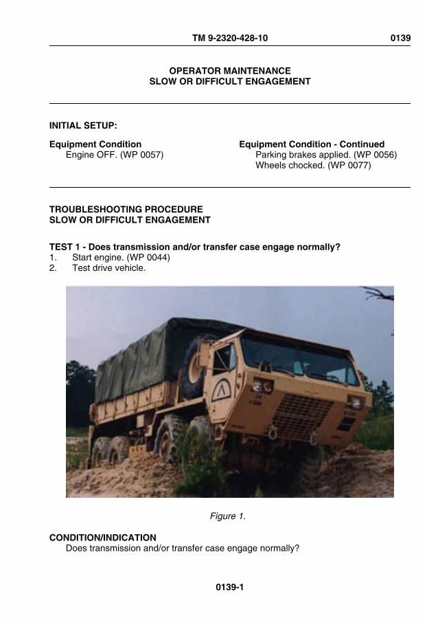
OPERATOR MAINTENANCESLOW OR DIFFICULT ENGAGEMENT
INITIAL SETUP:
Equipment ConditionEngine OFF. (WP 0057)
Equipment Condition - ContinuedParking brakes applied. (WP 0056)Wheels chocked. (WP 0077)
TROUBLESHOOTING PROCEDURESLOW OR DIFFICULT ENGAGEMENT
TEST 1 - Does transmission and/or transfer case engage normally?1. Start engine. (WP 0044)2. Test drive vehicle.
Figure 1.
CONDITION/INDICATIONDoes transmission and/or transfer case engage normally?
TM 9-2320-428-10 0139
0139-1

DECISIONNo - Notify Supervisor.Yes - Problem corrected.
END OF WORK PACKAGE
TM 9-2320-428-10 0139
0139-2

OPERATOR MAINTENANCETRANSFER CASE SHIFT LEVER WILL NOT SHIFT
INITIAL SETUP:
Equipment ConditionEngine OFF. (WP 0057)
Equipment Condition - ContinuedParking brakes applied. (WP 0056)Wheels chocked. (WP 0077)
TROUBLESHOOTING PROCEDURETRANSFER CASE SHIFT LEVER WILL NOT SHIFT
TEST 1 - Does transfer case shift lever shift when transmission is shifted from Neutral(N) to Drive (D)?1. Start engine (WP 0044)2. Move transmission range selector from Neutral (N) to Drive (D). Apply throttle to roll
vehicle slightly, and shift transmission from (D) to (N). As vehicle stops, shiftTRANSFER CASE shift lever.
TM 9-2320-428-10 0140
0140-1

Figure 1.
CONDITION/INDICATIONDoes transfer case shift lever shift when transmission is shifted from Neutral (N) to Drive(D)?
DECISIONNo - Test 2 - Does transfer case shift lever shift when transmission is shifted fromNeutral (N) to Reverse (R)?Yes - Problem corrected.
TEST 2 - Does transfer case shift lever shift when transmission is shifted from Neutral(N) to Reverse (R)?1. Move transmission range selector from Neutral (N) to Reverse (R). Apply throttle to
roll vehicle slightly and shift transmission from R to N. As vehicle stops, shiftTRANSFER CASE shift lever.
TM 9-2320-428-10 0140
0140-2

Figure 2.
CONDITION/INDICATIONDoes transfer case shift lever shift when transmission is shifted from Neutral (N) toReverse (R)?
DECISIONNo - Test 3 - Is shift cable free of mud and debris?Yes - Problem corrected.
TEST 3 - Is shift cable free of mud and debris?1. Turn engine OFF. (WP 0057)2. Check shift cable for mud and/or debris.
TM 9-2320-428-10 0140
0140-3
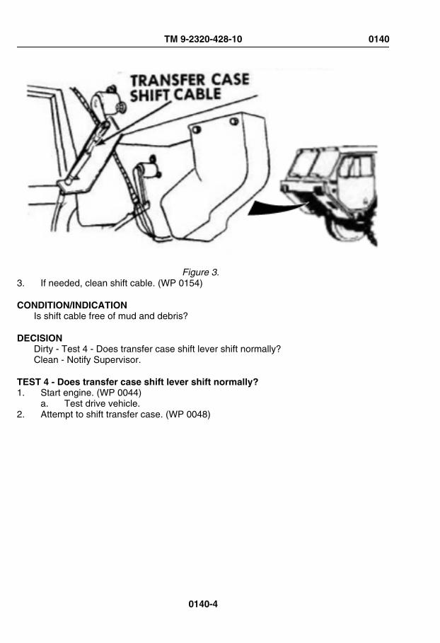
Figure 3. 3. If needed, clean shift cable. (WP 0154)
CONDITION/INDICATIONIs shift cable free of mud and debris?
DECISIONDirty - Test 4 - Does transfer case shift lever shift normally?Clean - Notify Supervisor.
TEST 4 - Does transfer case shift lever shift normally?1. Start engine. (WP 0044)
a. Test drive vehicle.2. Attempt to shift transfer case. (WP 0048)
TM 9-2320-428-10 0140
0140-4

Figure 4. 3. Turn engine OFF. (WP 0057)
CONDITION/INDICATIONDoes transfer case shift lever shift normally?
DECISIONNo - Notify Supervisor.Yes - Problem corrected.
END OF WORK PACKAGE
TM 9-2320-428-10 0140
0140-5


OPERATOR MAINTENANCETRANS TEMP GAUGE INDICATES OVERHEATING DURING NORMAL OPERATION
INITIAL SETUP:
Equipment ConditionEngine OFF. (WP 0057)
Equipment Condition - ContinuedParking brakes applied. (WP 0056)Wheels chocked. (WP 0077)
TROUBLESHOOTING PROCEDURETRANS TEMP GAUGE INDICATES OVERHEATING DURING NORMAL OPERATION
TEST 1 - Is transmission fluid at proper operating level?1. Check transmission fluid level. (WP 0147)
TM 9-2320-428-10 0141
0141-1

Figure 1. 2. If transmission fluid is low, add transmission fluid. (WP 0147)
CONDITION/INDICATIONIs transmission fluid at proper operating level?
TM 9-2320-428-10 0141
0141-2

DECISIONTransmission fluid was high. - Notify Supervisor. Test 2 - Does TRANS TEMP gaugeindicate overheating during normal operation?Transmission fluid was at proper level. - Notify Supervisor.
TEST 2 - Does TRANS TEMP gauge indicate overheating during normal operation?1. Start engine. (WP 0044)2. Test drive vehicle.
Figure 2.
TM 9-2320-428-10 0141
0141-3

CONDITION/INDICATIONDoes TRANS TEMP gauge indicate overheating during normal operation?
DECISIONOverheating - Notify Supervisor.Correct temperature - Problem corrected.
END OF WORK PACKAGE
TM 9-2320-428-10 0141
0141-4

OPERATOR MAINTENANCEWHEEL WOBBLES
INITIAL SETUP:
Equipment ConditionEngine OFF. (WP 0057)
Equipment Condition - ContinuedParking brakes applied. (WP 0056)Wheels chocked. (WP 0077)
TROUBLESHOOTING PROCEDUREWHEEL WOBBLES
TEST 1 - Are any lugnuts loose, missing or broken?1. Check wheels for loose, missing or broken lugnuts.
TM 9-2320-428-10 0142
0142-1

Figure 1.
CONDITION/INDICATIONAre any lugnuts loose, missing or broken?
DECISIONNo - Tighten or replace lugnut(s). (WP 0155)Yes - Test 2 - Are any of the wheels bent?
TEST 2 - Are any of the wheels bent?1. Check to see if any of the wheels are bent.
TM 9-2320-428-10 0142
0142-2

Figure 2.
CONDITION/INDICATIONAre any of the wheels bent?
DECISIONWheel bent - Replace damaged wheel(s). (WP 0155)Wheels OK - Notify Supervisor.
TEST 3 - Do any of the wheels wobble?1. Start engine. (WP 0044)2. Test drive vehicle.
CONDITION/INDICATIONDo any of the wheels wobble?
TM 9-2320-428-10 0142
0142-3

DECISIONWheel wobbles - Notify Supervisor.Wheel OK - Notify Supervisor.
END OF WORK PACKAGE
TM 9-2320-428-10 0142
0142-4

OPERATOR MAINTENANCETIRES WORN UNEVENLY OR EXCESSIVELY
INITIAL SETUP:
Equipment ConditionEngine OFF. (WP 0057)
Equipment Condition - ContinuedParking brakes applied. (WP 0056)Wheels chocked. (WP 0077)
TROUBLESHOOTING PROCEDURETIRES WORN UNEVENLY OR EXCESSIVELY
TEST 1 - Are tires inflated to proper pressure for road condition?
WARNING
Tire air pressure must be checked properly. Failure to comply may resultin injury or death to personnel.
NOTE• Inflate tires only when they are cool. Inflate to proper pressure for
road condition.
• Tire tread is non-directional. Vehicle operation is not affected bydirection of traction bars.
1. Check tires for proper inflation. (WP 0148)
TM 9-2320-428-10 0143
0143-1

Figure 1. 2. If tires are improperly inflated, inflate or deflate to proper pressure.
CONDITION/INDICATIONAre tires inflated to proper pressure for road condition?
DECISIONImproperly inflated - Notify Supervisor.Inflation OK - Notify Supervisor.
END OF WORK PACKAGE
TM 9-2320-428-10 0143
0143-2

CHAPTER 4
PREVENTIVEMAINTENANCECHECKS AND
SERVICES (PMCS)
TM 9-2320-428-10


OPERATOR MAINTENANCEINTRODUCTION - PREVENTIVE MAINTENANCE
PMCS INTRODUCTION
This section contains PMCS requirements for HEMTT series vehicles. The PMCS tablescontain checks and services necessary to ensure that the vehicle is ready for operation.Using PMCS tables, perform maintenance at specified intervals.
MAINTENANCE FORMS AND RECORDS
Every mission begins and ends with paperwork. There is not much of it, but it must be keptup. The filled out forms and records have several uses. They are a permanent record ofservices, repairs, and modifications made on the vehicle; they are reports to unitmaintenance and to your Commander; and they serve as a checklist to find out what iswrong with the vehicle after its last use, and whether those faults have been fixed. For theinformation needed on forms and records, refer to DA PAM 750-8. (WP 0161)
PREVENTIVE MAINTENANCE CHECKS AND SERVICES
• Do the before (B) PREVENTIVE MAINTENANCE just before operating vehicle.Pay attention to the CAUTIONS and WARNINGS.
• Do the during (D) PREVENTIVE MAINTENANCE while vehicle and/or itscomponent systems are in operation. Pay attention to the CAUTIONS andWARNINGS.
• Do the after (A) PREVENTIVE MAINTENANCE right after operating vehicle. Payattention to the CAUTIONS and WARNINGS.
• Do the (W) PREVENTIVE MAINTENANCE weekly. Pay attention to theCAUTIONS and WARNINGS
• Do the (M) PREVENTIVE MAINTENANCE once a month. Pay attention to theCAUTIONS and WARNINGS.
• Do the (S) PREVENTIVE MAINTENANCE once every six months. Pay attentionto the CAUTIONS and WARNINGS.
• If something does not work, troubleshoot and notify the supervisor.• Always do PREVENTIVE MAINTENANCE in the same order until it gets to be
habit. Once practiced, problems can be spotted in a hurry.• If something looks wrong and cannot be fixed right then, write it on DA Form 2404
(WP 0161) or DA Form 5988-E. (WP 0161) If something seems seriously wrong,report it to field level maintenance RIGHT NOW.
• When doing PREVENTIVE MAINTENANCE, take along the tools needed and arag or two to make all the checks.
TM 9-2320-428-10 0144
0144-1

GENERAL MAINTENANCE PROCEDURE
• Cleanliness: Dirt, grease, oil, and debris only get in the way and may cover up aserious problem. Use solvent cleaning compound (WP 0164, Table 1, Item 6, 7,8, 9, 10, 11) on all metal surfaces and soapy water on rubber.
• Bolts, Nuts, and Screws: Check bolts, nuts, and screws for obvious looseness,missing, bent, or broken condition and tighten or replace as necessary. Theycannot all be checked with a tool, of course, but look for chipped paint, bare metal,or rust around bolt heads.
• Welds: Look for loose or chipped paint, rust, or gaps where parts are weldedtogether. If a bad weld is found, have it repaired.
• Electric Wires and Connectors: Look for cracked or broken insulation, barewires, and loose or broken connectors. Tighten loose connectors and make surewires are in good shape.
• Hydraulic Lines and Fittings: Look for wear, damage, and leaks, and make sureclamps and fittings are tight. Wet spots show leaks, of course, but a stain arounda fitting or connector can indicate a leak. If a connector or fitting is loose, tightenit. If something is broken or worn out, repair or replace per applicable procedure.
• Damage is defined as: Any conditions that affect safety or would render thevehicle unserviceable for mission requirements.
FLUID LEAKAGE
It is necessary to know how fluid leakage affects the status of fuel, oil, coolant, and thehydraulic systems. The following are definitions of types/classes of leakage necessary toknow in order to determine the status of the vehicle.
NOTEEquipment operation is allowable with minor leakage (Class I or II).Consideration must be given to the fluid capacity in the item/system beingchecked/inspected. When in doubt, notify the supervisor. When operatingwith Class I or II leaks, continue to check fluid levels as required in thePMCS. Class III leaks should be repaired per applicable procedure.
Class I :Seepage of fluid (as indicated by wetness or discoloration) not great enough toform drops.
Class II: Leakage of fluid great enough to form drops but not enough to cause drops todrip from item being checked/inspected.
Class III: Leakage of fluid great enough to form drops that fall from the item being checked/inspected.
PREVENTIVE MAINTENANCE CHECKS AND SERVICES (PMCS)
Prior to performing your PMCS, check with your PLL clerk to verify that the latestpublications are being used.
TM 9-2320-428-10 0144
0144-2

PREVENTIVE MAINTENANCE CHECKS AND SERVICES (PMCS) - Continued
Listed below are the sections of the PMCS.
PMCS - BEFORE (WP 0145)
PMCS - DURING (WP 0146)
PMCS - AFTER (WP 0147)
PMCS - WEEKLY (WP 0148)
PMCS - MONTHLY (WP 0150)
PMCS - SEMIANNUAL (WP 0149)
Vehicles designated or dispatched to transport Class A or B ammunition, explosives,poisons, or radioactive yellow III materials over public highways require more stringentinspections.
Daily Walk Around PMCS Diagram. This routing diagram will be of help to complete the B,D, or A PMCS. It shows the vehicle PMCS routing track, which matches the sequence ofPMCS to be performed.
START
Figure 1.
END OF WORK PACKAGE
TM 9-2320-428-10 0144
0144-3

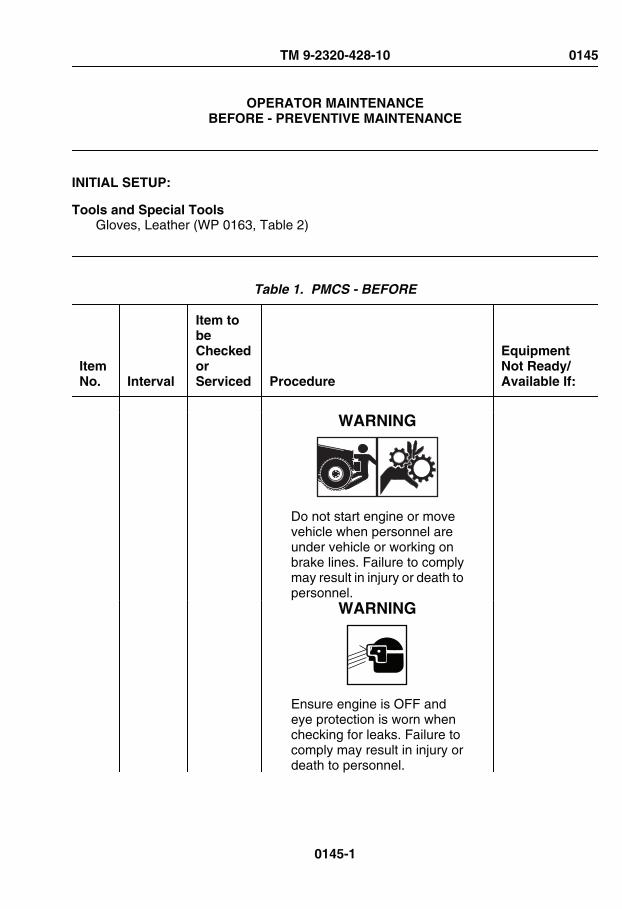
OPERATOR MAINTENANCEBEFORE - PREVENTIVE MAINTENANCE
INITIAL SETUP:
Tools and Special ToolsGloves, Leather (WP 0163, Table 2)
Table 1. PMCS - BEFORE
ItemNo. Interval
Item tobeCheckedorServiced Procedure
EquipmentNot Ready/Available If:
WARNING
Do not start engine or movevehicle when personnel areunder vehicle or working onbrake lines. Failure to complymay result in injury or death topersonnel.
WARNING
Ensure engine is OFF andeye protection is worn whenchecking for leaks. Failure tocomply may result in injury ordeath to personnel.
TM 9-2320-428-10 0145
0145-1

Table 1. PMCS - BEFORE - Continued
ItemNo. Interval
Item tobeCheckedorServiced Procedure
EquipmentNot Ready/Available If:
NOTEPerform Operator's Before,After, and Weekly PMCSchecks if:
• You are the assigneddriver but have notoperated the vehiclesince the last weeklyinspection.
• You are operating thevehicle for the first time.
NOTE• Clean all lubrication
points with cleaningcompound, solvent andallow to dry prior toservicing.
• When using a greasegun, apply lubricant to thefitting until clean lubricantsqueezes out of the partbeing lubricated.
• Always refer to lubricationinstructions (WP 0151) toensure equipment hascorrect lubricantsappropriate to operatingenvironment (expectedcontinuoustemperatures). If not,remove/drain andreapply/refill equipmentwith appropriatelubricants for operatingenvironment as
TM 9-2320-428-10 0145
0145-2

Table 1. PMCS - BEFORE - Continued
ItemNo. Interval
Item tobeCheckedorServiced Procedure
EquipmentNot Ready/Available If:
prescribed in lubricationinstructions. (WP 0151)
NOTE• Diesel engine slobber is
an inherent condition ofdiesel engines. Whendiesel engines areallowed to idle forprolonged periods oftime, this characteristicmay be interpreted as aClass III leak. Checkengine oil level. If there isany doubt, contact yoursupervisor or field levelmaintenance.
• If leakage is detected,further investigation isneeded to determine thelocation and cause of theleak. If there is any doubt,contact your supervisoror field levelmaintenance.
1 Before DriverSideExterior
1. Check underneath entire lengthof driver side of vehicle for fluidand air leaks.
Any fuelleak, ClassIII leak (oth-er thanfuel), or airlines/fittingsleaking ordamaged.
TM 9-2320-428-10 0145
0145-3

Table 1. PMCS - BEFORE - Continued
ItemNo. Interval
Item tobeCheckedorServiced Procedure
EquipmentNot Ready/Available If:
2. Visually check driver side ofvehicle for obvious damage thatwould impair operation.
Any dam-age thatwould im-pair opera-tion.
WARNING
• During normal vehicleoperation, cooling systemcan become very hot.Allow cooling system tocool prior to servicing.Failure to comply mayresult in injury topersonnel.
• Use extreme care whenremoving radiator cap.Sudden release ofpressure can cause asteam flash. Slowlyloosen radiator cap to thefirst stop to relievepressure beforeremoving radiator capcompletely. Failure tocomply may result ininjury to personnel.
• Use a clean, thick wastecloth or like material toremove radiator cap.
TM 9-2320-428-10 0145
0145-4

Table 1. PMCS - BEFORE - Continued
ItemNo. Interval
Item tobeCheckedorServiced Procedure
EquipmentNot Ready/Available If:
Avoid using gloves. If hotwater soaks throughgloves, personnel couldbe burned. Failure tocomply may result ininjury to personnel.
2 Before Radiator Remove radiator cap and checkradiator coolant level. Coolant levelshould be up to bottom of filler neck.If fluid level is low, fill to appropriatelevel.
Coolant islow.
RADIATORCAP
Figure 1.
WARNING
Do not operate a vehicle witha tire in an over-inflated or un-
TM 9-2320-428-10 0145
0145-5

Table 1. PMCS - BEFORE - Continued
ItemNo. Interval
Item tobeCheckedorServiced Procedure
EquipmentNot Ready/Available If:
der-inflated condition, or witha questionable defect. Failureto comply may result in injuryor death to personnel anddamage to equipment.
NOTE• A tire is bad or in need of
repair if the bead,sidewall, and tread areasshow signs of damage.
• Remember that thisprocess requires you tomake judgment calls andthe goal is to safelymaintain equipment in topquality conditions.
3 Before DriverSideTires
Check for correct air pressure oneach driver side tire and service tire(WP 0158) as required.
Tire miss-ing, defla-ted, or un-serviceable.
4 Before Engine 1. Check engine oil level ondipstick.
TM 9-2320-428-10 0145
0145-6

Table 1. PMCS - BEFORE - Continued
ItemNo. Interval
Item tobeCheckedorServiced Procedure
EquipmentNot Ready/Available If:
ENGINE OILDIPSTICK
Figure 2.
NOTEEngine oil level should be be-tween L (low) and F (full) markon dipstick.
a. Add engine oil as required.(WP 0151)
TM 9-2320-428-10 0145
0145-7

Table 1. PMCS - BEFORE - Continued
ItemNo. Interval
Item tobeCheckedorServiced Procedure
EquipmentNot Ready/Available If:
b. Drain excess engine oil asrequired, or notify field levelmaintenance.
5 Before Rear ofVehicle
Visually check rear of vehicle forobvious damage that would impairoperation.
Any dam-age thatwould im-pair opera-tion.
6 Before CargoBody
1. Check that side panels, and front/rear end panels are not bent,broken, and have no brokenwelds.
Any sidepanel or endpanel ismissing,bent, bro-ken, or hasa brokenweld.
TM 9-2320-428-10 0145
0145-8

Table 1. PMCS - BEFORE - Continued
ItemNo. Interval
Item tobeCheckedorServiced Procedure
EquipmentNot Ready/Available If:
LATCHES
LOCKPINSEND PANEL
SIDE PANEL
HINGEPINS
HINGE
TIEDOWNEYE
Figure 3.
2. Check for broken latches andmissing lockpins.
A latch isbroken or alockpin ismissing.
3. Check for broken, bent, ordamaged hinge pins and tiedown eyes.
Any hingepin or tiedown eye ismissing,broken, orbent.
4. Check for broken or bindinghinges.
Hinges aremissing,broken, or
TM 9-2320-428-10 0145
0145-9

Table 1. PMCS - BEFORE - Continued
ItemNo. Interval
Item tobeCheckedorServiced Procedure
EquipmentNot Ready/Available If:
have bro-ken welds.
NOTEOperation of vehicle withbent, broken, or missing car-go body screws may violateAR 385-55.
5. Check that cargo body mountingscrews are not broken, cracked,or missing.
One ormorescrews arebroken,cracked, ormissing.
MOUNTINGSCREWS
MOUNTINGSCREWS
Figure 4.
7 Before Self-RecoveryWinch(SRW)
1. Inspect self-recovery winch forobvious damage.
Self-recov-ery winchunservicea-ble.
TM 9-2320-428-10 0145
0145-10

Table 1. PMCS - BEFORE - Continued
ItemNo. Interval
Item tobeCheckedorServiced Procedure
EquipmentNot Ready/Available If:
FRONT CABLE GUIDEREAR CABLE GUIDE
REARTENSIONER SELF-RECOVERY
WINCHFRONT
TENSIONER
Figure 5.
2. Inspect front cable guide for anyloose or missing parts and anyobvious damage.
Front cableguide hasloose ormissingparts, or is
TM 9-2320-428-10 0145
0145-11

Table 1. PMCS - BEFORE - Continued
ItemNo. Interval
Item tobeCheckedorServiced Procedure
EquipmentNot Ready/Available If:
unservicea-ble.
3. Inspect front tensioner for looseor missing parts and any obviousdamage.
Front ten-sioner hasloose ormissingparts, or isunservicea-ble.
4. Inspect rear tensioner for looseor missing parts and any obviousdamage.
Rear ten-sioner hasloose ormissingparts, or isunservicea-ble.
5. Inspect rear cable guide for looseor missing parts and any obviousdamage
Rear cableguide hasloose ormissingparts, or isunservicea-ble.
8 Before WheelChocks
Ensure vehicle is equipped with fourwheel chocks.
Vehicle isequippedwith lessthan fourwheelchocks.
NOTE• Diesel engine slobber is
an inherent condition of
TM 9-2320-428-10 0145
0145-12

Table 1. PMCS - BEFORE - Continued
ItemNo. Interval
Item tobeCheckedorServiced Procedure
EquipmentNot Ready/Available If:
diesel engines. Whendiesel engines areallowed to idle forprolonged periods oftime, this characteristicmay be interpreted as aClass III leak. Checkengine oil level. If there isany doubt, contact yoursupervisor or field levelmaintenance.
• If leakage is detected,further investigation isneeded to determine thelocation and cause of theleak. If there is any doubt,contact your supervisoror field levelmaintenance.
9 Before Passenger SideExterior
1. Check underneath entire lengthof driver side of vehicle for fluidand air leaks.
Any fuelleak, ClassIII leak (oth-er thanfuel), or airlines/fittingsleaking ordamaged.
2. Visually check driver side ofvehicle for obvious damage thatwould impair operation.
Any dam-age thatwould im-pair opera-tion.
TM 9-2320-428-10 0145
0145-13

Table 1. PMCS - BEFORE - Continued
ItemNo. Interval
Item tobeCheckedorServiced Procedure
EquipmentNot Ready/Available If:
WARNING
Fuel is very flammable andcan explode easily. Keep fuelaway from open fire and keepfire extinguisher within easyreach when working with fuel.Do not work on fuel systemwhen engine is hot. Fuel canbe ignited when engine is hot.When working with fuel, postsigns that read NO SMOKINGWITHIN 50 FEET OF VEHI-CLE. Failure to comply mayresult in injury or death to per-sonnel.
NOTE• Drain fuel into suitable
container.
• Operation of vehicle withmalfunctioning fuel/waterseparator may violate AR385-55. (WP 0161)
10 Before Fuel/Water
1. Check for level of water in bowl offuel/water separator. If there is
TM 9-2320-428-10 0145
0145-14
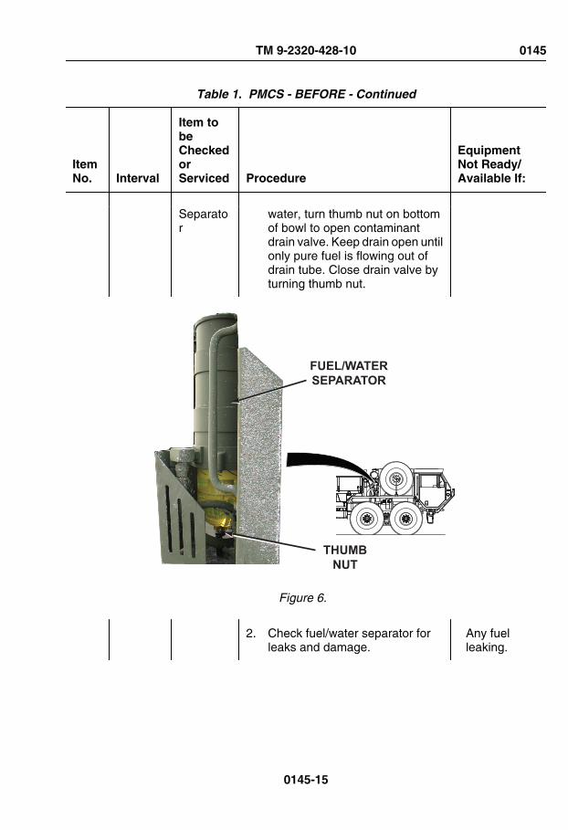
Table 1. PMCS - BEFORE - Continued
ItemNo. Interval
Item tobeCheckedorServiced Procedure
EquipmentNot Ready/Available If:
Separator
water, turn thumb nut on bottomof bowl to open contaminantdrain valve. Keep drain open untilonly pure fuel is flowing out ofdrain tube. Close drain valve byturning thumb nut.
THUMBNUT
FUEL/WATERSEPARATOR
Figure 6.
2. Check fuel/water separator forleaks and damage.
Any fuelleaking.
TM 9-2320-428-10 0145
0145-15

Table 1. PMCS - BEFORE - Continued
ItemNo. Interval
Item tobeCheckedorServiced Procedure
EquipmentNot Ready/Available If:
WARNING
Do not operate a vehicle witha tire in an over-inflated or un-der-inflated condition, or witha questionable defect. Failureto comply may result in injuryor death to personnel anddamage to equipment.
NOTE• Remember that a tire in
storage (spare) can beflat but not look like it. TheHEMTT tire sidewalls cansupport the wheel. Don'tbe fooled.
• A tire is bad or in need ofrepair if the bead,sidewall, and tread areasshow signs of damage.
• Remember that thisprocess requires you tomake judgment calls andthe goal is to safelymaintain equipment in topquality conditions.
11 Before Passenger SideTires
1. Check for correct air pressure oneach passenger side tire
Tire miss-ing, defla-
TM 9-2320-428-10 0145
0145-16

Table 1. PMCS - BEFORE - Continued
ItemNo. Interval
Item tobeCheckedorServiced Procedure
EquipmentNot Ready/Available If:
(includingsparetire)
(including spare tire) and servicetire (WP 0158) as required.
ted, or un-serviceable.
WARNING
Ensure proper inspection andmaintenance procedures ofseat belt systems are ad-hered to. Failure to complymay result in injury or death topersonnel.
NOTE• Vehicle may have either a
three-point or four-pointseat belt system. Refer tospecific checks (below)for seat belt systeminstalled.
• Vehicle operation withinoperative seat beltsmay violate AR 385-55.(WP 0161)
12 Before SeatBelts
1. Check three-point seat beltsystem as follows:
a. Check for worn webbing atthe latch and D-loop areas.
Webbing iscut, frayed,
TM 9-2320-428-10 0145
0145-17

Table 1. PMCS - BEFORE - Continued
ItemNo. Interval
Item tobeCheckedorServiced Procedure
EquipmentNot Ready/Available If:
or exces-sively worn.
BUCKLE
WEBBING
RETRACTOR
COMFORTLATCH
D-LOOP
LATCH
Figure 7.
b. Check D-loop for freerotation, deformation,cracks, or damage.
D-loop doesnot rotatefreely or isdeformed,
TM 9-2320-428-10 0145
0145-18

Table 1. PMCS - BEFORE - Continued
ItemNo. Interval
Item tobeCheckedorServiced Procedure
EquipmentNot Ready/Available If:
cracked, orbroken.
c. Check comfort latch forproper operation, cracks, ordamage.
Comfortlatch is bro-ken, or doesnot lock inplace easi-ly, and doesnot releaseby tuggingdown onwebbing.
d. Check latch and buckle forwear, deformation, damage,or broken casing.
Moldedplasticaroundbuckle/latchis de-formed,cracked, orbroken.
e. Check latch and buckle forproper operation.
Buckle/latchdo not en-gage with asolid sound-ing "click"and/or donot releasefreely whenbutton onbuckle ispushed.
TM 9-2320-428-10 0145
0145-19

Table 1. PMCS - BEFORE - Continued
ItemNo. Interval
Item tobeCheckedorServiced Procedure
EquipmentNot Ready/Available If:
f. Check that retractor is notlocked up, and pays out/reelsin webbing properly.
Retractordoes not op-erate prop-erly or re-tractor cov-er iscracked/broken.
g. Check all seat belt mountinghardware for looseness andother damage.
Seat belthardware isloose, miss-ing, rusted,corroded, ordamaged.
2. Check four-point seat beltsystem as follows:
a. Check seat belt strapwebbing wear, tears, fraying,etc.
Webbing iscut, frayedor exces-sively worn.
TM 9-2320-428-10 0145
0145-20
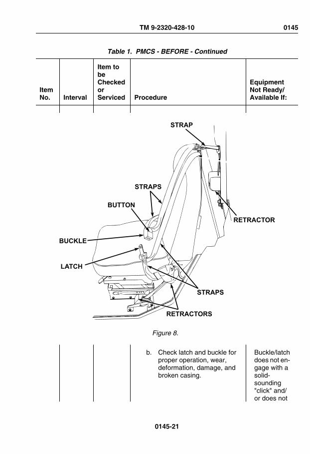
Table 1. PMCS - BEFORE - Continued
ItemNo. Interval
Item tobeCheckedorServiced Procedure
EquipmentNot Ready/Available If:
STRAPS
STRAP
RETRACTOR
STRAPS
RETRACTORS
LATCH
BUCKLE
BUTTON
Figure 8.
b. Check latch and buckle forproper operation, wear,deformation, damage, andbroken casing.
Buckle/latchdoes not en-gage with asolid-sounding"click" and/or does not
TM 9-2320-428-10 0145
0145-21

Table 1. PMCS - BEFORE - Continued
ItemNo. Interval
Item tobeCheckedorServiced Procedure
EquipmentNot Ready/Available If:
releasefreely whenbutton ispushed.Moldedplasticaroundbuckle/latchis de-formed,cracked, orbroken.
c. Check all seat belt retractorsare not locked up and payout/reel in webbing strapsproperly.
Retractor(s)do not oper-ate proper-ly, or retrac-tor cover(s)arecracked/broken.
d. Check all seat belt mountinghardware for looseness andother damage.
Hardware isloose, miss-ing, rusted,corroded, ordamaged.
13 Before Seats Check operation of seat adjustingmechanisms. (WP 0023)
Seat adjust-ment mech-anism bro-ken or miss-ing.
TM 9-2320-428-10 0145
0145-22

Table 1. PMCS - BEFORE - Continued
ItemNo. Interval
Item tobeCheckedorServiced Procedure
EquipmentNot Ready/Available If:
HEIGHTADJUSTMENT
CONTROL
FORWARD/BACKWARDADJUSTMENT CONTROL
HEIGHT
ADJ.
Figure 9.
14 Before FireExtinguisher (cab)
1. Check for missing or damagedfire extinguisher.
Fire extin-guishermissing ordamaged.
TM 9-2320-428-10 0145
0145-23

Table 1. PMCS - BEFORE - Continued
ItemNo. Interval
Item tobeCheckedorServiced Procedure
EquipmentNot Ready/Available If:
SEAL
FIREEXTINGUISHER
GAUGE
Figure 10.
2. Check gauge for proper pressureof about 150 psi (1034 kPa).
Pressuregauge nee-dle in RE-CHARGEarea.
3. Ensure fire extinguishermounting is secure.
TM 9-2320-428-10 0145
0145-24

Table 1. PMCS - BEFORE - Continued
ItemNo. Interval
Item tobeCheckedorServiced Procedure
EquipmentNot Ready/Available If:
4. Check for damaged or missingseal.
Seal brokenor missing.
NOTE• Complete all start engine
(WP 0044) procedures,and comply with all notes,cautions, and warningswithin that procedurebefore completing thePMCS checks below.
• Once all start engine(WP 0044) proceduresare completed, engineshould be kept running forthe remaining PMCSchecks.
15 Before Engine Start engine. (WP 0044) Engine failsto start.
NOTECheck the instruments listedbelow for damage, operation,and condition.
16 Before Instruments
1. Engine OIL PRESS gauge. Engine OILPRESSgauge is in-operative.
TM 9-2320-428-10 0145
0145-25

Table 1. PMCS - BEFORE - Continued
ItemNo. Interval
Item tobeCheckedorServiced Procedure
EquipmentNot Ready/Available If:
AIR BRAKE
PARKINGBRAKE
TRAILERAIR SUPPLY
EXEXEX
EXEXEXEXEX EXEX
ENGINEOFF
ON
START
AMPERESGAUGE
BATTERYGAUGE
AIR PRESSGAUGE
TACHOMETEROIL PRESS
GAUGE
Figure 11.
2. Tachometer. Tachometeris inopera-tive or indi-cates lessthan 700rpm or morethan 725rpm at idleafter enginehas beenproperlywarmed up(start en-
TM 9-2320-428-10 0145
0145-26

Table 1. PMCS - BEFORE - Continued
ItemNo. Interval
Item tobeCheckedorServiced Procedure
EquipmentNot Ready/Available If:
gine(WP 0044)procedurecompleted).
3. BATTERY gauge. BATTERYgauge is in-operative,or indicatesless than 24VDC ormore than30 VDC withengine run-ning.
4. AMPERES gauge. AMPERESgauge is in-operative,or shows anegativereading withengine run-ning.
NOTEAir pressure buzzer will soundanytime low air indicator is il-luminated. Ensure low air in-dicator and buzzer activatewhen air pressure falls below60 to 75 psi (414 to 517 kPa)in either front or rear air sys-tem.
5. AIR PRESS gauge. AIR PRESSgauge is in-
TM 9-2320-428-10 0145
0145-27

Table 1. PMCS - BEFORE - Continued
ItemNo. Interval
Item tobeCheckedorServiced Procedure
EquipmentNot Ready/Available If:
operative orindicates ei-ther systemis below 60psi (414kPa)˙ afterengine hasbeen prop-erly warmedup (start en-gine(WP 0044)procedurecompleted).Low airpressure in-dicator and/or buzzerremain on,or do not op-erate.
6. Air filter restriction indicator. Air filter re-striction in-dicator in-operative,cracked, orunservicea-ble.
TM 9-2320-428-10 0145
0145-28

Table 1. PMCS - BEFORE - Continued
ItemNo. Interval
Item tobeCheckedorServiced Procedure
EquipmentNot Ready/Available If:
AIR BRAKE
PARKINGBRAKE
TRAILERAIR SUPPLY
EXEXEX
EXEXEXEXEX EXEX
ENGINEOFF
ON
START
TRANS TEMPGAUGE
WATER TEMPGAUGE
FUEL GAUGE
AIR FILTERRESTRICTION
INDICATOR
Figure 12.
NOTESeveral minutes are requiredfor engine to warm up so anaccurate reading can be tak-en.
7. WATER TEMP gauge. WATERTEMPgauge is in-operative,or indicatesless than
TM 9-2320-428-10 0145
0145-29

Table 1. PMCS - BEFORE - Continued
ItemNo. Interval
Item tobeCheckedorServiced Procedure
EquipmentNot Ready/Available If:
140°F(60°C) ormore than230°F(110°C) af-ter enginehas beenproperlywarmed up(start en-gine(WP 0044)procedurecompleted).
NOTETransmission may not reach160°F (71°C) oil temperatureat idle for several minutes.
8. TRANS TEMP gauge. TRANSTEMPgauge indi-cates morethan 250°F(121°C).
9. FUEL gauge. FUELgauge is in-operative,or indicatesless thanthe requiredamount offuel needed
TM 9-2320-428-10 0145
0145-30

Table 1. PMCS - BEFORE - Continued
ItemNo. Interval
Item tobeCheckedorServiced Procedure
EquipmentNot Ready/Available If:
to completethe mission.
CAUTIONVehicle must be parked whenmaking this check. Failure tocomply may result in damageto equipment. Transfer casewill be damaged if shiftedwhile vehicle is moving.
NOTE• Engine must be running
to perform this check.
• Transmission must be inN (neutral) to perform thischeck.
17 Before TRANSFER CASEShiftLeverandTRACTIONCONTROL lever
1. TRANSFER CASE Shift Lever -Check operation: (WP 0048)
TM 9-2320-428-10 0145
0145-31

Table 1. PMCS - BEFORE - Continued
ItemNo. Interval
Item tobeCheckedorServiced Procedure
EquipmentNot Ready/Available If:
TRAILERAIR SUPPLYNOT FOR PARKINGMIDLAND
PULL TO EXHAUST
PUSH TO
INTER-AXLEDIFF LOCKINDICATOR
TRACTION CONTROLLEVER
8X8 INDICATOR
TRANSFER CASESHIFT LEVER
Figure 13.
a. Set transfer case shift leverto each range position.
b. Transfer case shift levershould move freely throughall range positions.
TRANSFERCASE shiftlever inop-erable orbinds be-tween
TM 9-2320-428-10 0145
0145-32

Table 1. PMCS - BEFORE - Continued
ItemNo. Interval
Item tobeCheckedorServiced Procedure
EquipmentNot Ready/Available If:
range de-tents.
2. TRACTION CONTROL Lever -Check operation: (WP 0021)
a. TRACTION CONTROL levershould slide smoothly, andinteract with transfer caseshift lever to show correctindications on dash panel.
TRACTIONCONTROLlever or indi-cators inop-erable.
NOTEEngine must be running toperform this check.
18 Before EngineRetarder/Brake
1. Check engine retarder/brake forproper operation (WP 0049)(vehicle stationary) using thefollowing procedures:
a. Pull out PARKING BRAKEcontrol.
TM 9-2320-428-10 0145
0145-33

Table 1. PMCS - BEFORE - Continued
ItemNo. Interval
Item tobeCheckedorServiced Procedure
EquipmentNot Ready/Available If:
TRAILERAIR SUPPLYNOT FOR PARKINGMIDLAND
PULL TO EXHAUST
PUSH TO
JACOBS®ENGINE BRAKE
HIGH-LOW SWITCHJACOBS®ENGINE BRAKE
INDICATOR
JACOBS®ENGINE BRAKEON/OFF SWITCH
PARKINGBRAKE
CONTROL
THROTTLEPEDAL
TRANSMISSIONRANGE SELECTOR
Figure 14.
b. Set transmission rangeselector to N (neutral)position.
c. Apply throttle pedal andincrease engine speed to1900-2100 rpm for severalseconds to allow
TM 9-2320-428-10 0145
0145-34

Table 1. PMCS - BEFORE - Continued
ItemNo. Interval
Item tobeCheckedorServiced Procedure
EquipmentNot Ready/Available If:
transmission to upshift to atleast 2 (2nd gear range).
d. Set JACOBS ® ENGINEBRAKE ON/OFF switch toON position, JACOBS ®ENGINE BRAKE indicatorlight will come on.
e. Release throttle pedal andlisten for engine "popping" or"chattering" sounds thatindicate engine retarder/brake is engaged andoperating.
NOTEEngine must be running toperform this check.
19 Before Steering 1. Check vehicle steering for properoperation:
a. Turn steering wheel from fullleft to full right, back to fullleft.
Steering in-operable orbinds.
NOTEEngine must be running toperform this check.
20 Before PTOSwitch
Set PTO ENGAGE switch to ONposition. Indicator light will illuminate.
PTO EN-GAGEswitch and/or indicator
TM 9-2320-428-10 0145
0145-35
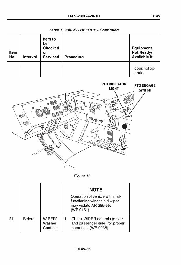
Table 1. PMCS - BEFORE - Continued
ItemNo. Interval
Item tobeCheckedorServiced Procedure
EquipmentNot Ready/Available If:
does not op-erate.
TRAILERAIR SUPPLYNOT FOR PARKINGMIDLAND
PULL TO EXHAUST
PUSH TO
PTO ENGAGESWITCH
PTO INDICATORLIGHT
Figure 15.
NOTEOperation of vehicle with mal-functioning windshield wipermay violate AR 385-55.(WP 0161)
21 Before WIPER/WasherControls
1. Check WIPER controls (driverand passenger side) for properoperation. (WP 0035)
TM 9-2320-428-10 0145
0145-36

Table 1. PMCS - BEFORE - Continued
ItemNo. Interval
Item tobeCheckedorServiced Procedure
EquipmentNot Ready/Available If:
TRAILERAIR SUPPLYNOT FOR PARKINGMIDLAND
PULL TO EXHAUST
PUSH TO
WASHERCONTROL
WIPER CONTROLPASSENGER SIDE
WIPER CONTROLDRIVER SIDE
Figure 16.
2. Check windshield washer controlfor proper operation. (WP 0035)
NOTE• Engine must be running
to perform this check.
• Operation of vehicle withmalfunctioningwindshield wiper mayviolate AR 385-55.(WP 0161)
TM 9-2320-428-10 0145
0145-37

Table 1. PMCS - BEFORE - Continued
ItemNo. Interval
Item tobeCheckedorServiced Procedure
EquipmentNot Ready/Available If:
22 Before ParkingBrakeControl
1. Check PARKING BRAKE controlfor proper operation: (WP 0045)
AIR BRAKE
PARKINGBRAKE
TRAILERAIR SUPPLY
EXEXEX
EXEXEXEXEX EXEX
ENGINEOFF
ON
START
PARKING BRAKECONTROL
Figure 17.
a. With vehicle at idle andservice brake pedalengaged, (WP 0046)settransmission range selectorto D (drive). (WP 0048)
b. Apply (pull out) PARKINGBRAKE control. (WP 0045)
TM 9-2320-428-10 0145
0145-38

Table 1. PMCS - BEFORE - Continued
ItemNo. Interval
Item tobeCheckedorServiced Procedure
EquipmentNot Ready/Available If:
c. Release service brake pedal.(WP 0046)
Vehiclemoves withPARKINGBRAKEcontrol ap-plied (pulledout).
d. Set transmission rangeselector to N (neutral).(WP 0048)
NOTEOperator may continue onwith mission if vehicle re-quires no servicing.
23 Before Engine Shut OFF engine (WP 0057) (asrequired).
END OF WORK PACKAGE
TM 9-2320-428-10 0145
0145-39


OPERATOR MAINTENANCEDURING - PREVENTIVE MAINTENANCE
INITIAL SETUP:
Tools and Special ToolsGloves, Leather (WP 0163, Table 2)
Table 1. PMCS - DURING
ItemNo. Interval
Item tobeCheckedorServiced Procedure
EquipmentNot Ready/Available If:
WARNING
Ensure engine is OFF andeye protection is worn whenchecking for leaks. Failure tocomply may result in injury ordeath to personnel.
1 During Engine Check and/or listen for excessivesmoke, unusual noise, roughrunning, and misfiring.
Engine hasexcessivesmoke, un-usual noise,runs rough,or misfires.
NOTECheck trailer handbrake con-trol lever only if a trailer ishooked up to vehicle.
TM 9-2320-428-10 0146
0146-1
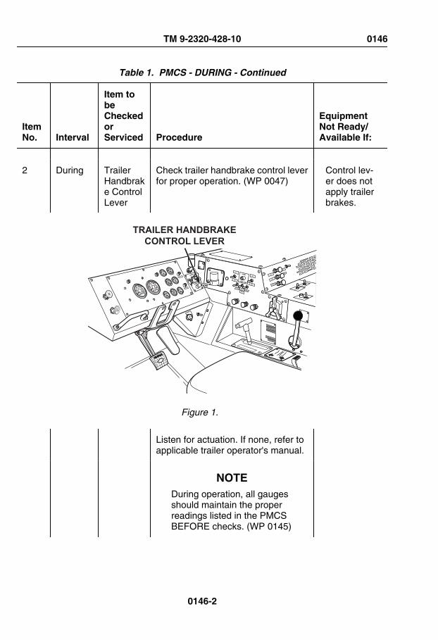
Table 1. PMCS - DURING - Continued
ItemNo. Interval
Item tobeCheckedorServiced Procedure
EquipmentNot Ready/Available If:
2 During TrailerHandbrake ControlLever
Check trailer handbrake control leverfor proper operation. (WP 0047)
Control lev-er does notapply trailerbrakes.
TRAILERAIR SUPPLYNOT FOR PARKINGMIDLAND
PULL TO EXHAUST
PUSH TO
TRAILER HANDBRAKECONTROL LEVER
Figure 1.
Listen for actuation. If none, refer toapplicable trailer operator's manual.
NOTEDuring operation, all gaugesshould maintain the properreadings listed in the PMCSBEFORE checks. (WP 0145)
TM 9-2320-428-10 0146
0146-2

Table 1. PMCS - DURING - Continued
ItemNo. Interval
Item tobeCheckedorServiced Procedure
EquipmentNot Ready/Available If:
3 During Instruments
Monitor all gauges, indicators, andwarning lights for proper reading andoperation while operating vehicle.
Gauges, in-dicators,and warninglights do notread/oper-ate proper-ly.
4 During Transmission
Check transmission for properoperation. (WP 0048)
Transmis-sion slips orwill not shift.
5 During Steering Be alert for any unusual noise,binding, or difficulty in steering duringoperation.
Steeringbinds or isunrespon-sive.
6 During ServiceBrakes
Be alert for chatter, noise, and sidepull.
Servicebrakes donot operateproperly.
END OF WORK PACKAGE
TM 9-2320-428-10 0146
0146-3


OPERATOR MAINTENANCEAFTER - PREVENTIVE MAINTENANCE
INITIAL SETUP:
Tools and Special ToolsGloves, Leather (WP 0163, Table 2)
Table 1. PMCS - AFTER
ItemNo. Interval
Item tobeCheckedorServiced Procedure
EquipmentNot Ready/Available If:
WARNING
Do not start engine or movevehicle when personnel areunder vehicle or working onbrake lines. Failure to complymay result in injury or death topersonnel.
WARNING
Ensure engine is OFF andeye protection is worn whenchecking for leaks. Failure tocomply may result in injury ordeath to personnel.
TM 9-2320-428-10 0147
0147-1

Table 1. PMCS - AFTER - Continued
ItemNo. Interval
Item tobeCheckedorServiced Procedure
EquipmentNot Ready/Available If:
NOTEPerform Operator's Before,After, and Weekly PMCSchecks if:
• You are the assigneddriver but have notoperated the vehiclesince the last weeklyinspection.
• You are operating thevehicle for the first time.
NOTE• Clean all lubrication
points with cleaningcompound, solvent andallow to dry prior toservicing.
• When using a greasegun, apply lubricant to thefitting until clean lubricantsqueezes out of the partbeing lubricated.
• Always refer to lubricationinstructions (WP 0151) toensure equipment hascorrect lubricantsappropriate to operatingenvironment (expectedcontinuoustemperatures). If not,remove/drain andreapply/refill equipmentwith appropriatelubricants for operatingenvironment as
TM 9-2320-428-10 0147
0147-2

Table 1. PMCS - AFTER - Continued
ItemNo. Interval
Item tobeCheckedorServiced Procedure
EquipmentNot Ready/Available If:
prescribed in lubricationinstructions. (WP 0151)
1 After UnderneathVehicle
1. Check entire underside of vehiclefor fluid and air leaks.
Any fuel,Class IIIleak, or airlines/fittingsleaking ordamaged.
2. Check entire underside of vehiclefor signs of fluid leakage (fuel, oil,and coolant).
Any fuelleak. ClassIII leak ofany otherfluid.
WARNING
Prolonged contact with lubri-cating oil may cause skinrash. Immediately wash skinand clothing that come in con-tact with lubricating oil thor-oughly and remove saturatedclothing. Keep area well-ven-tilated to keep fumes at a min-imum. Failure to comply mayresult in injury or death to per-sonnel.
CAUTIONDo not fill hydraulic reservoirpast FULL COLD mark. Fail-
TM 9-2320-428-10 0147
0147-3
Table 1. PMCS - AFTER - Continued
ItemNo. Interval
Item tobeCheckedorServiced Procedure
EquipmentNot Ready/Available If:
ure to comply may result indamage to equipment.
NOTE• Hydraulic oil expands
when heated, which maygive the operator false(high) fluid level readingsif the vehicle has beenrecently operated.
• If possible, wait untilhydraulic reservoir iscompletely cooled down(minimum of 2 hours)prior to adding hydraulicoil, otherwise fill reservoirto FULL COLD mark.
2 After HydraulicFluidReservoir
1. Check that hydraulic fluid level insight glass on hydraulic fluidreservoir is at FULL COLD mark(may be above FULL COLD markif vehicle has been recentlyoperated). If low, add hydraulicoil to FULL COLD mark:
TM 9-2320-428-10 0147
0147-4

Table 1. PMCS - AFTER - Continued
ItemNo. Interval
Item tobeCheckedorServiced Procedure
EquipmentNot Ready/Available If:
“FULL COLD”LEVEL
SIGHT GLASS
HYDRAULICRESERVOIR
Figure 1.
a. Remove cap from hydraulicreservoir.
b. Fill hydraulic reservoir withlubricating oil (WP 0151,Table 4) until sight glassreads at FULL COLD mark.
c. Install cap on hydraulicreservoir.
TM 9-2320-428-10 0147
0147-5

Table 1. PMCS - AFTER - Continued
ItemNo. Interval
Item tobeCheckedorServiced Procedure
EquipmentNot Ready/Available If:
2. Check appearance of hydraulicfluid in sight glass. Make sure it isclear and not milky or foamy.
Fluid ap-pears milkyor foamy.
3 After DriverSideWheels
1. Check wheels for broken,cracked, and bent surfaces.
Wheel isbroken,cracked, orbent.
2. Check lugnuts and wheel studsfor obvious looseness anddamage. If loose, tighten andreport to maintenance as soon aspractical.
Two ormore lug-nuts orstuds on thesame wheelare missing,broken, orbent.
4 After DriverSideShockAbsorbers
Check driver side shock absorbersfor leaks and damage.
Damagedor Class IIIleakpresent.
5 After CraneControlKnobs
Check all crane control knobs tomake sure information on knobs islegible.
Informationon cranecontrolknobs is notlegible.
6 After RearExterior
Check rear of vehicle for obviousdamage that would impair operation.
Any dam-age thatwould im-pair opera-tion.
TM 9-2320-428-10 0147
0147-6

Table 1. PMCS - AFTER - Continued
ItemNo. Interval
Item tobeCheckedorServiced Procedure
EquipmentNot Ready/Available If:
7 After TowingGladhands
Check for presence and condition oftowing gladhands and rubbergrommets.
8 After Passenger sideWheels
1. Check wheels for broken,cracked, and bent surfaces.
Wheel isbroken,cracked, orbent.
2. Check lugnuts and wheel studsfor obvious looseness anddamage. If loose, tighten andreport to maintenance as soon aspractical.
Two ormore lug-nuts orstuds on thesame wheelare missing,broken, orbent.
9 After Passenger SideShockAbsorbers
Check passenger side shockabsorbers for leaks and damage.
Damagedor Class IIIleakpresent.
WARNING
Vehicles air system is pres-surized, be sure to wear prop-er eye protection and keepface away from drain valveswhile draining air reservoirs.Open air drain valves slowlyto prevent sudden blast of air.
TM 9-2320-428-10 0147
0147-7

Table 1. PMCS - AFTER - Continued
ItemNo. Interval
Item tobeCheckedorServiced Procedure
EquipmentNot Ready/Available If:
Failure to comply may resultin injury to personnel.
NOTE• Only drain air reservoirs
that are located under thepassenger side batterybox.
• The M983 has three airreservoirs under thebattery box, all othermodels have two.
10 After AirReservoirs
1. Drain only air reservoirs underbattery box as follows:
Figure 2.
a. Turn petcock on bottom ofreservoir to open position.
TM 9-2320-428-10 0147
0147-8

Table 1. PMCS - AFTER - Continued
ItemNo. Interval
Item tobeCheckedorServiced Procedure
EquipmentNot Ready/Available If:
b. Let condensation drain off.
c. Turn petcock on bottom ofreservoir to closed position.
CAUTIONClean around end of fill tubeprior to removing dipstick.This will aid in preventing dirtor foreign matter from enter-ing the transmission andcausing damage.
NOTEVehicle is parked (WP 0056)on a flat, level surface.
Engine is at idle.
Transmission is at normaloperating temperature,160-200°F (71-93°C).
11 After Transmission
1. With engine running, checktransmission fluid level ondipstick:
TM 9-2320-428-10 0147
0147-9

Table 1. PMCS - AFTER - Continued
ItemNo. Interval
Item tobeCheckedorServiced Procedure
EquipmentNot Ready/Available If:
Figure 3.
NOTEFluid level should be betweenHOT FULL and HOT ADDmarks.
2. Add OE/HDO (WP 0151,Table 2) as required or notify fieldlevel maintenance if overfull.
12 After SpareTire/Wheel
1. Check spare tire for cuts,gouges, cracks, or scratches.Remove any sharp objects.
Tire hascuts, goug-es, orcracks thatcould resultin tire fail-ure. Tire ismissing or
TM 9-2320-428-10 0147
0147-10

Table 1. PMCS - AFTER - Continued
ItemNo. Interval
Item tobeCheckedorServiced Procedure
EquipmentNot Ready/Available If:
unservicea-ble.
2. Check wheel for broken,cracked, and bent surfaces.
Wheel isbroken,cracked, orbent.
3. Check lugnuts and wheel studsfor obvious looseness anddamage.
Two ormore lug-nuts orstuds aremissing,broken, orbent.
13 After Exteriorof Cab
1. Visually inspect cab andcomponents for damage.
Any compo-nent is dam-aged thatwould im-pair vehiclemission.
NOTEOperation of vehicle with bro-ken/missing mirrors may vio-late AR 385-55. (WP 0161)
14 After Mirrors Check condition of mirrors.
TM 9-2320-428-10 0147
0147-11

Table 1. PMCS - AFTER - Continued
ItemNo. Interval
Item tobeCheckedorServiced Procedure
EquipmentNot Ready/Available If:
MIRRORS
Figure 4.
NOTEOperation of vehicle withdamaged or missing wind-shield may violate AR 385-55.(WP 0161)
15 After Windshield andWiperArms/Blades
1. Check windshield glass forpresence and condition.
TM 9-2320-428-10 0147
0147-12
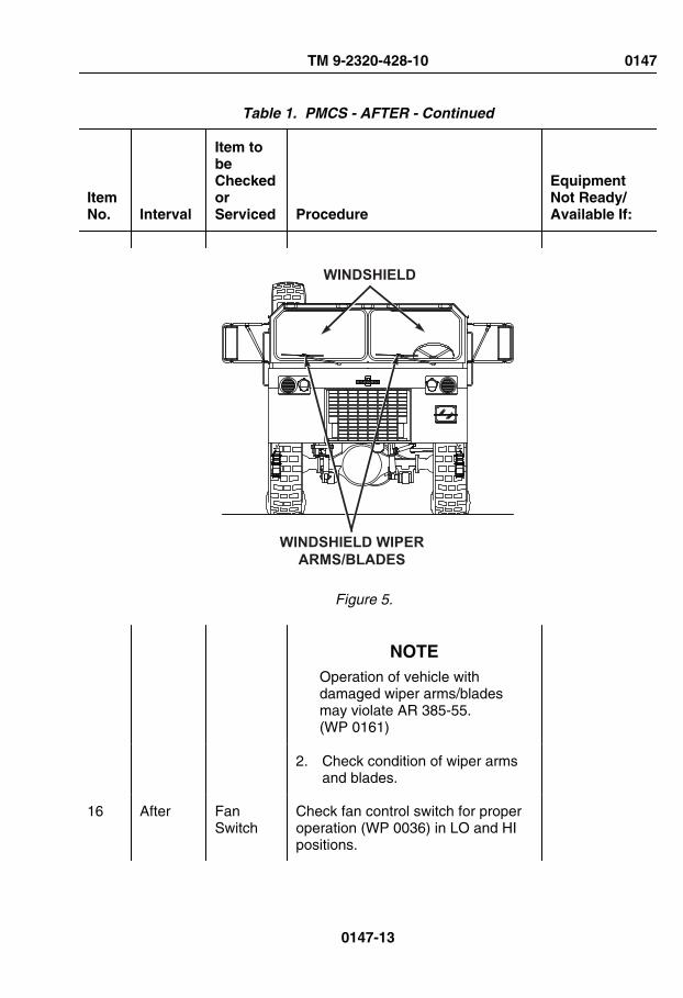
Table 1. PMCS - AFTER - Continued
ItemNo. Interval
Item tobeCheckedorServiced Procedure
EquipmentNot Ready/Available If:
WINDSHIELD
WINDSHIELD WIPERARMS/BLADES
Figure 5.
NOTEOperation of vehicle withdamaged wiper arms/bladesmay violate AR 385-55.(WP 0161)
2. Check condition of wiper armsand blades.
16 After FanSwitch
Check fan control switch for properoperation (WP 0036) in LO and HIpositions.
TM 9-2320-428-10 0147
0147-13

Table 1. PMCS - AFTER - Continued
ItemNo. Interval
Item tobeCheckedorServiced Procedure
EquipmentNot Ready/Available If:
FANSWITCH
Figure 6.
NOTEOperation of vehicle with mal-functioning windshield wipermay violate AR 385-55.(WP 0161)
17 After WIPER/WasherControls
1. Check WIPER controls (driverand passenger side) for properoperation. (WP 0035)
TM 9-2320-428-10 0147
0147-14
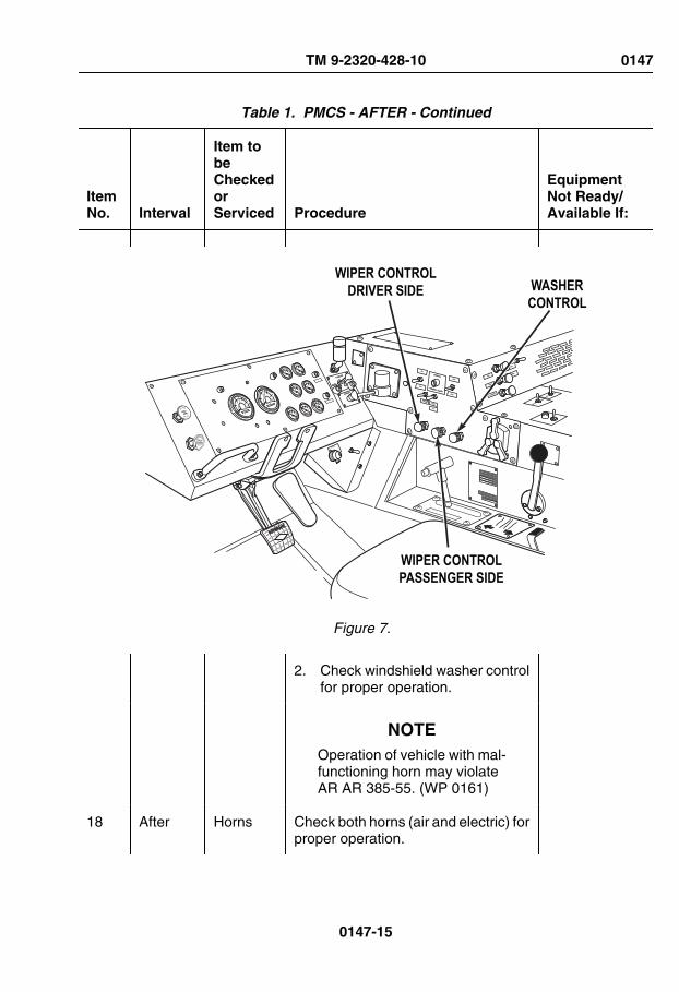
Table 1. PMCS - AFTER - Continued
ItemNo. Interval
Item tobeCheckedorServiced Procedure
EquipmentNot Ready/Available If:
TRAILERAIR SUPPLYNOT FOR PARKINGMIDLAND
PULL TO EXHAUST
PUSH TO
WASHERCONTROL
WIPER CONTROLPASSENGER SIDE
WIPER CONTROLDRIVER SIDE
Figure 7.
2. Check windshield washer controlfor proper operation.
NOTEOperation of vehicle with mal-functioning horn may violateAR AR 385-55. (WP 0161)
18 After Horns Check both horns (air and electric) forproper operation.
TM 9-2320-428-10 0147
0147-15

Table 1. PMCS - AFTER - Continued
ItemNo. Interval
Item tobeCheckedorServiced Procedure
EquipmentNot Ready/Available If:
NOTE• Light checks will require
assistance.
• Operation of vehicle withmalfunctioning turn signalcontrol may violate AR385-55. (WP 0161)
19 After TurnSignalControlAndIndicators
1. Check turn signal control forproper operation. (WP 0019)
TM 9-2320-428-10 0147
0147-16

Table 1. PMCS - AFTER - Continued
ItemNo. Interval
Item tobeCheckedorServiced Procedure
EquipmentNot Ready/Available If:
LEFT TURNSIGNAL INDICATOR
RIGHT TURNSIGNAL INDICATOR
AIR BRAKE
PARKINGBRAKE
TRAILERAIR SUPPLY
EXEXEX
EXEXEXEXEX EXEX
ENGINEOFF
ON
START
TURN SIGNALCONTROL
Figure 8.
2. Check turn signal indicators forproper operation. (WP 0021)
NOTE• Light checks will require
assistance.
• Operation of vehicle withmalfunctioningemergency flashercontrol may violate AR385-55. (WP 0161)
TM 9-2320-428-10 0147
0147-17

Table 1. PMCS - AFTER - Continued
ItemNo. Interval
Item tobeCheckedorServiced Procedure
EquipmentNot Ready/Available If:
20 After EmergencyFlasherControl
Check emergency flasher control forproper operation. (WP 0019)
EMERGENCYFLASHER CONTROL
TRAILERAIR SUPPLYNOT FOR PARKINGMIDLAND
PULL TO EXHAUST
PUSH TO
Figure 9.
NOTE• Light checks will require
assistance.
• Operation of vehicle withmalfunctioning servicelights may violate AR385-55. (WP 0161)
TM 9-2320-428-10 0147
0147-18

Table 1. PMCS - AFTER - Continued
ItemNo. Interval
Item tobeCheckedorServiced Procedure
EquipmentNot Ready/Available If:
21 After Lights Check headlights, clearance lights,turn signals, and brake lights forproper operation.
NOTEOperation of vehicle with mal-functioning beacon light mayviolate AR 385-55.(WP 0161)
22 After PortableBeaconLight (Ifequipped)
Remove beacon light from glove boxand check for proper operation.(WP 0074)
NOTEComplete this PMCS proce-dure only if material handlingcrane was used during mis-sion.
23 After MaterialHandlingCrane (ifused)
1. Inspect crane for loose nuts andbolts, hydraulic leaks, damage tohydraulic hoses and lines, andobvious damage.
Class IIIleak or dam-age to ho-ses, lines,or fittings.
NOTEFor more information on ma-terial handling crane operat-ing instructions, refer to grovecrane operation (manual con-trol) procedures. (WP 0042)
TM 9-2320-428-10 0147
0147-19

Table 1. PMCS - AFTER - Continued
ItemNo. Interval
Item tobeCheckedorServiced Procedure
EquipmentNot Ready/Available If:
2. Check that crane hydraulicsystem is operable as follows:
a. Start engine. (WP 0044)
b. Set PTO ENGAGE switch toON position. PTO indicatorlight will illuminate.
TRAILERAIR SUPPLYNOT FOR PARKINGMIDLAND
PULL TO EXHAUST
PUSH TO
PTO ENGAGESWITCH
PTO INDICATORLIGHT
Figure 10.
c. Set ON/OFF POWER switchto ON position.
TM 9-2320-428-10 0147
0147-20

Table 1. PMCS - AFTER - Continued
ItemNo. Interval
Item tobeCheckedorServiced Procedure
EquipmentNot Ready/Available If:
ENGINE HIGHIDLE SWITCHLATCH
SWITCH
ON/OFF POWER SWITCH
Figure 11.
d. Set HIGH IDLE CONTROLswitch to CONTINUOUS.
WARNING
Excessive noise levels arepresent any time the heavy-duty winch, crane, or retrievalsystem is operating. Wear
TM 9-2320-428-10 0147
0147-21

Table 1. PMCS - AFTER - Continued
ItemNo. Interval
Item tobeCheckedorServiced Procedure
EquipmentNot Ready/Available If:
single hearing protection(earplugs or equivalent) whileworking around equipmentwhen it is running. Failure tocomply may result in injury ordeath to personnel. Seekmedical aid should you sus-pect a hearing problem.
e. Push and release LATCHswitch. Engine speed shouldincrease to approximately1500 rpm.
3. Check crane manual controllevers as follows:
WARNING
• Stand clear of outriggerbeams while operatinglevers. Failure to complymay result in injury ordeath to personnel.
• Do not operate craneunless outriggers arefirmly in place or vehiclecould turn over. Failure to
TM 9-2320-428-10 0147
0147-22

Table 1. PMCS - AFTER - Continued
ItemNo. Interval
Item tobeCheckedorServiced Procedure
EquipmentNot Ready/Available If:
comply may result ininjury or death topersonnel.
• Keep boom clear of allelectrical lines and otherobstacles while operatingcrane. Failure to complymay result in injury ordeath to personnel.
NOTE• Operate control levers
with light, even pressure.Moving lever slightly willcause slow movement ofcrane. Moving lever to fulltravel will cause fastermovement of crane.
• Outrigger beams willcome out slower with lightpressure on lever.Pushing lever to full travelwill cause fast movement.
a. Move O/R EXT lever to INposition briefly.
TM 9-2320-428-10 0147
0147-23

Table 1. PMCS - AFTER - Continued
ItemNo. Interval
Item tobeCheckedorServiced Procedure
EquipmentNot Ready/Available If:
JACKCYLINDER
RH O/RJACK CONTROL
LEVERO/R EXT
CONTROL LEVER
LH O/RJACK CONTROL
LEVER
HOISTCONTROL LEVER
RETAINING PINSRETAINING PINS
OUTRIGGERPAD
Figure 12.
b. Place both outrigger lockpinsin unlock position.
c. Check each controlseparately for malfunction,proper response, obviousdamage, missing parts,binding, and extremelooseness.
Controlsmalfunction,bind, or donot re-spond.
d. Move O/R EXT lever to OUTposition until both outriggersis completely extended.
Outriggerbeam doesnot comeout.
e. Set up outrigger pads. Checkthat two retaining pins are
Retainingpin missing
TM 9-2320-428-10 0147
0147-24

Table 1. PMCS - AFTER - Continued
ItemNo. Interval
Item tobeCheckedorServiced Procedure
EquipmentNot Ready/Available If:
attached to each outriggerpad.
from eitherend.
WARNING
Keep hands and feet clear ofoutrigger jack cylinders. Fail-ure to comply may result ininjury or death to personnel.
NOTEAdjust outrigger pad positionas required so rod end willlower into pad socket.
f. Move LH O/R JACK controllever to DOWN position andlower outrigger jack until rodend is firmly seated inoutrigger pad. Installretaining pins.
Outriggerjack cylin-der will notcome out orwill not low-er com-pletely intopad.
g. Move RH O/R JACK controllever to DOWN position andlower outrigger jack until rodend is firmly seated inoutrigger pad. Installretaining pins.
Outriggerjack cylin-der will notcome out orwill not low-er com-pletely intopad.
TM 9-2320-428-10 0147
0147-25

Table 1. PMCS - AFTER - Continued
ItemNo. Interval
Item tobeCheckedorServiced Procedure
EquipmentNot Ready/Available If:
h. Check that outrigger jackcylinder on each side ofvehicle is out and down.
Crane hy-draulic sys-tem doesnot operate.
i. Seat outriggers.
j. Raise boom to operatingposition:
BOOM CONTROL LEVER
MAST CONTROLLEVER
BOOM
MASTCYLINDERS
Figure 13.
WARNING
Do not operate crane unlessoutriggers are firmly in placeor vehicle could turn over.
TM 9-2320-428-10 0147
0147-26

Table 1. PMCS - AFTER - Continued
ItemNo. Interval
Item tobeCheckedorServiced Procedure
EquipmentNot Ready/Available If:
Failure to comply may resultin injury or death to personnel.
CAUTIONDo not let cable unwind andbecome slack, or cable mayget tangled on drum.
(1) Move HOIST controllever to DOWN positionuntil hook block rests onfender.
(2) Pull and turn lockpinhandle so handle endrests on bracket tounstow hook block.
CAUTIONDo not allow load hook to con-tact taillight during inspection.Failure to comply may resultin damage to equipment.
NOTEOperation of vehicle with mal-functioning load hook may vi-olate AR 385-55. (WP 0161)
(3) Check hook block andload hook for cracks, andproper operation.
Hook blockor load hookis cracked.
TM 9-2320-428-10 0147
0147-27
Table 1. PMCS - AFTER - Continued
ItemNo. Interval
Item tobeCheckedorServiced Procedure
EquipmentNot Ready/Available If:
NOTEOperation of vehicle with mal-functioning load hook springsafety latch may violate AR385-55. (WP 0161)
(4) Check load hook springsafety latch for damageand proper operation.
Load hookspring safe-ty latchdoesn'topen and/orclose prop-erly.
(5) Check hook blockstowage guide wearplate for excessive wear.
WARNING
When using crane on any ve-hicle, park vehicle clear of alloverhead electrical lines.Keep boom clear of all elec-trical lines and other obsta-cles while operating crane.Failure to comply may resultin injury or death to personnel.
TM 9-2320-428-10 0147
0147-28

Table 1. PMCS - AFTER - Continued
ItemNo. Interval
Item tobeCheckedorServiced Procedure
EquipmentNot Ready/Available If:
CAUTIONDo not hit outrigger leg withhook block. Failure to complymay result in damage toequipment.
(6) Move BOOM controllever to UP position untilhook is five to six feet(1.5 to 1.8 m) abovedriver side rear fenderand boom isapproximately 45°above horizontal.
Boom doesnot raise.
(7) Move MAST controllever to UP position untilthe mast is fully erectand the cylinders arefully extended. UseBOOM control lever UPsimultaneously asrequired to maintain theboom at approximately45° above horizontaluntil the mast is fullyerect. Hold the MASTcontrol lever to UPposition for two to threeseconds after mast isfully erect to ensurecylinders are fully filledwith oil.
Mast cylin-der does notraise com-pletely be-fore stop-ping.
k. Rotate and telescope boom:
TM 9-2320-428-10 0147
0147-29

Table 1. PMCS - AFTER - Continued
ItemNo. Interval
Item tobeCheckedorServiced Procedure
EquipmentNot Ready/Available If:
WARNING
• When using crane on anyvehicle, park vehicle clearof all overhead electricallines. Keep boom clear ofall electrical lines andother obstacles whileoperating crane. Failureto comply may result ininjury or death topersonnel.
• Ensure area is clear ofpersonnel prior to movingSWING lever. Boomshould be swung slowlyenough so crane operatorhas complete control.Failure to comply mayresult in injury or death topersonnel.
CAUTIONBoom must be above vehiclesides for clearance.
(1) Move swing control leverto CW position to moveboom clockwise.
Boom doesnot turnclockwise.
TM 9-2320-428-10 0147
0147-30

Table 1. PMCS - AFTER - Continued
ItemNo. Interval
Item tobeCheckedorServiced Procedure
EquipmentNot Ready/Available If:
SWINGCONTROL LEVER
Figure 14.
(2) Move swing control leverto CCW position to moveboom counterclockwise.
Boom doesnot turncounter-clockwise.
CAUTIONKeep hook block at least 1 ft.(30 cm) from end of boom. Ifhook block hits end of boom itmay damage cable or hookblock and crane will loosepower. Wait six seconds forpower to return and checkcrane for damage.
NOTE• TELESCOPE and HOIST
levers should be
TM 9-2320-428-10 0147
0147-31

Table 1. PMCS - AFTER - Continued
ItemNo. Interval
Item tobeCheckedorServiced Procedure
EquipmentNot Ready/Available If:
operated at the sametime.
• Crane movement fromone lever may be slowerthan the other whenoperating two leverstogether.
(3) Move TELESCOPEcontrol lever to OUTposition to extend boomwhile moving hoistcontrol lever to DOWNposition to pay out cable.
Extensionsdo not comeout.
TELESCOPECONTROL
LEVER
HOISTCONTROL
LEVER
CABLE
Figure 15.
(4) Check first, second, andthird stages of boom forbroken welds or obviousdamage.
There arebrokenwelds or ob-vious dam-age toboom.
TM 9-2320-428-10 0147
0147-32
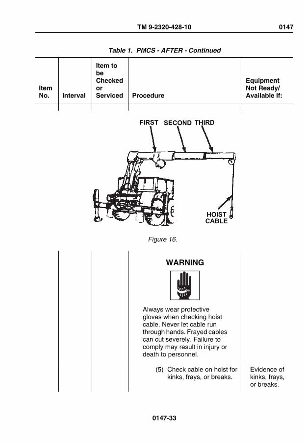
Table 1. PMCS - AFTER - Continued
ItemNo. Interval
Item tobeCheckedorServiced Procedure
EquipmentNot Ready/Available If:
FIRST SECOND THIRD
HOISTCABLE
Figure 16.
WARNING
Always wear protectivegloves when checking hoistcable. Never let cable runthrough hands. Frayed cablescan cut severely. Failure tocomply may result in injury ordeath to personnel.
(5) Check cable on hoist forkinks, frays, or breaks.
Evidence ofkinks, frays,or breaks.
TM 9-2320-428-10 0147
0147-33

Table 1. PMCS - AFTER - Continued
ItemNo. Interval
Item tobeCheckedorServiced Procedure
EquipmentNot Ready/Available If:
(6) Check all hoses, fittings,valves, and cylinders forsigns of leaks.
Class IIIleakpresent.
(7) Check for cracked orbroken welds.
Cracked orbrokenwelds arepresent.
(8) Inspect turntable bearingbolts for obviouslooseness.
One ormore turnta-ble bearingbolts areloose.
TURNTABLEBEARING SCREWS
Figure 17.
CAUTIONDo not let cable become slackor cable may get tangled ondrum.
TM 9-2320-428-10 0147
0147-34

Table 1. PMCS - AFTER - Continued
ItemNo. Interval
Item tobeCheckedorServiced Procedure
EquipmentNot Ready/Available If:
(9) Move HOIST controllever in UP position toreel in cable.
Cable doesnot reel in.
(10)Move HOIST controllever in DOWN positionto pay out cable.
Cable doesnot pay out.
NOTEFor more information on ma-terial handling crane remotecontrol operating instructions,refer to grove crane operation(remote control) procedures.(WP 0043)
4. Check crane remote controllevers as follows:
TM 9-2320-428-10 0147
0147-35

Table 1. PMCS - AFTER - Continued
ItemNo. Interval
Item tobeCheckedorServiced Procedure
EquipmentNot Ready/Available If:
SWING CONTROL VALVE
TELESCOPECONTROL LEVER BOOM CONTROL
LEVER
REMOTE CONTROL UNITON/OFF SWITCH
HOISTCONTROL LEVER
REMOTECONTROL UNIT
Figure 18.
a. Set up REMOTE CONTROLUNIT passenger side.(WP 0043)
WARNING
• When using crane on anyvehicle, park vehicle clearof all overhead electricallines. Keep boom clear ofall electrical lines and
TM 9-2320-428-10 0147
0147-36

Table 1. PMCS - AFTER - Continued
ItemNo. Interval
Item tobeCheckedorServiced Procedure
EquipmentNot Ready/Available If:
other obstacles whileoperating crane. Failureto comply may result ininjury or death topersonnel.
• Ensure area is clear ofpersonnel prior to movingSWING lever. Boomshould be swung slowlyenough so crane operatorhas complete control.Failure to comply mayresult in injury or death topersonnel.
WARNING
If electrical power fails duringcrane operation, move switchon remote control unit toSHUTDOWN position. Fail-ure to comply may result ininjury or death to personnel.
CAUTIONCrane must be above vehiclesides for clearance.
NOTEOperate control levers withlight, even pressure. Movinglever slightly will cause slow
TM 9-2320-428-10 0147
0147-37

Table 1. PMCS - AFTER - Continued
ItemNo. Interval
Item tobeCheckedorServiced Procedure
EquipmentNot Ready/Available If:
movement of crane. Movinglever to full travel will causefaster movement of crane.
b. Check control levers formalfunction, properresponse, obvious damage,missing parts, binding, andextreme looseness.
Controlsmalfunction,bind, or donot re-spond.
c. Rotate and telescope boom:
WARNING
Ensure area is clear of per-sonnel prior to movingSWING lever. Boom shouldbe swung slowly enough socrane operator has completecontrol. Failure to comply mayresult in injury or death to per-sonnel.
(1) Move SWING controllever to CW position toturn boom clockwise.
Boom doesnot turnclockwise.
TM 9-2320-428-10 0147
0147-38

Table 1. PMCS - AFTER - Continued
ItemNo. Interval
Item tobeCheckedorServiced Procedure
EquipmentNot Ready/Available If:
SWING CONTROL VALVE
TELESCOPECONTROL LEVER BOOM CONTROL
LEVER
REMOTE CONTROL UNITON/OFF SWITCH
HOISTCONTROL LEVER
REMOTECONTROL UNIT
Figure 19.
(2) Move SWING controllever to CCW position toturn boomcounterclockwise.
Boom doesnot turncounter-clockwise.
WARNING
When using crane on any ve-hicle, park vehicle clear of alloverhead electrical lines.Keep boom clear of all elec-
TM 9-2320-428-10 0147
0147-39
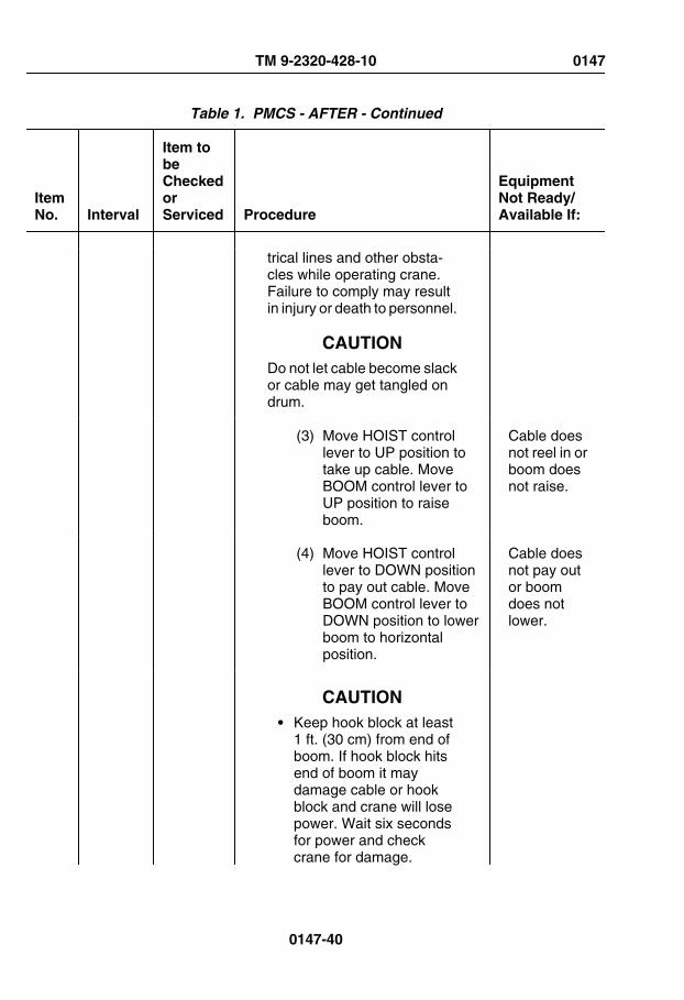
Table 1. PMCS - AFTER - Continued
ItemNo. Interval
Item tobeCheckedorServiced Procedure
EquipmentNot Ready/Available If:
trical lines and other obsta-cles while operating crane.Failure to comply may resultin injury or death to personnel.
CAUTIONDo not let cable become slackor cable may get tangled ondrum.
(3) Move HOIST controllever to UP position totake up cable. MoveBOOM control lever toUP position to raiseboom.
Cable doesnot reel in orboom doesnot raise.
(4) Move HOIST controllever to DOWN positionto pay out cable. MoveBOOM control lever toDOWN position to lowerboom to horizontalposition.
Cable doesnot pay outor boomdoes notlower.
CAUTION• Keep hook block at least
1 ft. (30 cm) from end ofboom. If hook block hitsend of boom it maydamage cable or hookblock and crane will losepower. Wait six secondsfor power and checkcrane for damage.
TM 9-2320-428-10 0147
0147-40

Table 1. PMCS - AFTER - Continued
ItemNo. Interval
Item tobeCheckedorServiced Procedure
EquipmentNot Ready/Available If:
• Do not let cable becomeslack or cable may gettangled on drum.
NOTE• TELESCOPE and HOIST
levers should beoperated at the sametime.
• Crane movement fromone lever may be slowerthan the other whenoperating two leverstogether.
(5) Move TELESCOPEcontrol lever to OUTposition while movingHOIST control lever toDOWN position to payout cable.
Extensionswill notcome out, orcable willnot pay out.
(6) Move HOIST controllever in UP position toreel in cable.
Cable willnot reel in.
(7) Check that crane andENGINE HIGH IDLE donot operate whenREMOTE CONTROLUNIT is in MHC-SHUTDOWN position.Notify organizationalmaintenance if craneand ENGINE HIGH IDLE
Crane willoperate andenginespeed willincrease to1500 rpm.
TM 9-2320-428-10 0147
0147-41

Table 1. PMCS - AFTER - Continued
ItemNo. Interval
Item tobeCheckedorServiced Procedure
EquipmentNot Ready/Available If:
operates when in MHC-SHUTDOWN position.
(8) Shut off remote controlswitches.
(9) Disconnect remotecontrol, passenger side.
(10)Check operation ofdriver side remotecontrol station.
(11)Connect remote controlto driver side remotecontrol station.
(12)Check operation ofcrane remote controllevers.
(13)Shut off remote controlswitches.
(14)Disconnect and stowREMOTE CONTROLUNIT.
5. Shut down material handlingcrane.
6. Check all hoses, fittings, valves,and cylinders for signs of leaksand damage.
Any ClassIII leakpresent.
TM 9-2320-428-10 0147
0147-42

Table 1. PMCS - AFTER - Continued
ItemNo. Interval
Item tobeCheckedorServiced Procedure
EquipmentNot Ready/Available If:
7. Check for cracked or brokenwelds.
Cracked orbrokenwelds.
END OF WORK PACKAGE
TM 9-2320-428-10 0147
0147-43


OPERATOR MAINTENANCEWEEKLY - PREVENTIVE MAINTENANCE
INITIAL SETUP:
Tools and Special ToolsGloves, Leather (WP 0163, Table 2)
Table 1. PMCS - WEEKLY
ItemNo. Interval
Item tobeCheckedorServiced Procedure
EquipmentNot Ready/Available If:
WARNING
Do not start engine or movevehicle when personnel areunder vehicle or working onbrake lines. Failure to complymay result in injury or death topersonnel.
WARNING
Ensure engine is OFF andeye protection is worn whenchecking for leaks. Failure tocomply may result in injury ordeath to personnel.
TM 9-2320-428-10 0148
0148-1

Table 1. PMCS - WEEKLY - Continued
ItemNo. Interval
Item tobeCheckedorServiced Procedure
EquipmentNot Ready/Available If:
NOTEPerform Operator's Before,After, and Weekly PMCSchecks if:
• You are the assigneddriver but have notoperated the vehiclesince the last weeklyinspection.
• You are operating thevehicle for the first time.
NOTE• Lubrication intervals are
for normal operatingconditions. Intervals maybe shortened as requiredfor severe operatingconditions.
• Clean all lubricationpoints with cleaningcompound, solvent andallow to dry prior toservicing.
• When using a greasegun, apply lubricant to thefitting until clean lubricantsqueezes out of the partbeing lubricated.
• Always refer to lubricationinstructions (WP 0151) toensure equipment hascorrect lubricantsappropriate to operatingenvironment (expectedcontinuous
TM 9-2320-428-10 0148
0148-2

Table 1. PMCS - WEEKLY - Continued
ItemNo. Interval
Item tobeCheckedorServiced Procedure
EquipmentNot Ready/Available If:
temperatures). If not,remove/drain andreapply/refill equipmentwith appropriatelubricants for operatingenvironment asprescribed in lubricationinstructions. (WP 0151)
WARNING
Do not operate a vehicle witha tire in an over-inflated or un-der-inflated condition, or witha questionable defect. Failureto comply may result in injuryor death to personnel anddamage to equipment.
1 Weekly DriverSideTires
Check tires for correct air pressure.
2 Weekly PropellerShaftsand U-Joints
1. Check propeller shafts and U-joints for excessive movement,obvious damage, and loose,missing or broken nuts andscrews.
Propellershaft or U-Joint hasexcessivemovement,obviousdamage, orone or morenuts orscrews areloose, miss-
TM 9-2320-428-10 0148
0148-3
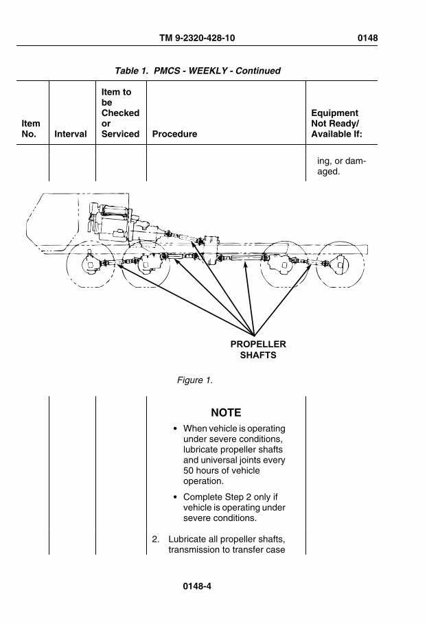
Table 1. PMCS - WEEKLY - Continued
ItemNo. Interval
Item tobeCheckedorServiced Procedure
EquipmentNot Ready/Available If:
ing, or dam-aged.
PROPELLERSHAFTS
Figure 1.
NOTE• When vehicle is operating
under severe conditions,lubricate propeller shaftsand universal joints every50 hours of vehicleoperation.
• Complete Step 2 only ifvehicle is operating undersevere conditions.
2. Lubricate all propeller shafts,transmission to transfer case
TM 9-2320-428-10 0148
0148-4

Table 1. PMCS - WEEKLY - Continued
ItemNo. Interval
Item tobeCheckedorServiced Procedure
EquipmentNot Ready/Available If:
propeller shaft, and U-joints withGAA (WP 0151) as required(refer to operator's semiannualPMCS table (item no. 2) forprocedures. (WP 0149)
3 Weekly AxleBreathers
Check four axle breathers fordamage and free movement of ventcaps on breather body.
Any axlebreathercaps aredamaged orvent capsdo not movefreely onbreatherbody.
TM 9-2320-428-10 0148
0148-5

Table 1. PMCS - WEEKLY - Continued
ItemNo. Interval
Item tobeCheckedorServiced Procedure
EquipmentNot Ready/Available If:
FRONT OFVEHICLE
AXLEBREATHER
VENTCAP
BREATHERBODY
Figure 2.
4 Weekly DriveBelts,Fan, andPulleys
1. Check drive belts for cracking,fraying, and breaks. Check fortightness. Play should be about1/2 in. (13 mm).
Any drivebelt is bro-ken,cracked tothe belt fi-ber, hasmore thanone crack
TM 9-2320-428-10 0148
0148-6

Table 1. PMCS - WEEKLY - Continued
ItemNo. Interval
Item tobeCheckedorServiced Procedure
EquipmentNot Ready/Available If:
(1/8 in. indepth or50% of beltthickness),has fraysmore than 2in. long orexcessiveplay.
DRIVE BELT
PULLEY
FAN
DRIVEBELT
MEASUREAT CENTER
DRIVEBELT
Figure 3.
TM 9-2320-428-10 0148
0148-7

Table 1. PMCS - WEEKLY - Continued
ItemNo. Interval
Item tobeCheckedorServiced Procedure
EquipmentNot Ready/Available If:
2. Check condition of fan for brokenor cracked blades.
Fan dam-aged or un-serviceable.
3. Check for bent or damagedpulley.
Pulley dam-aged or un-serviceable.
NOTEOperation of vehicle with anyexhaust leaks may violate AR385-55. (WP 0161)
5 Weekly ExhaustSystem
Check exhaust pipe, muffler,heatshield, tailpipe, raincap, clamps,and mounting for obvious damage,looseness, exhaust leak, and carbonbuildup.
Exhaustpipe be-tween tur-bochargerand exhaustmanifoldleaks. Anyexhaustpipe miss-ing or dam-aged.
TM 9-2320-428-10 0148
0148-8

Table 1. PMCS - WEEKLY - Continued
ItemNo. Interval
Item tobeCheckedorServiced Procedure
EquipmentNot Ready/Available If:
Figure 4.
6 Weekly Air IntakeSystem/EtherStartingAid
1. Squeeze air cleaner dust cap toremove excess dirt from canister.
TM 9-2320-428-10 0148
0148-9

Table 1. PMCS - WEEKLY - Continued
ItemNo. Interval
Item tobeCheckedorServiced Procedure
EquipmentNot Ready/Available If:
AIR INTAKEWEATHER CAP
AIR CLEANERCANISTER
CLAMP
TUBE
CLAMP
CLAMP
TUBE
ETHERSTARTING
AID
AIRCLEANERDUST CAP
Figure 5.
2. Check that air intake weather capis secure on air cleaner canister.
NOTEEther starting aid cartridgeswill be removed and solenoid
TM 9-2320-428-10 0148
0148-10

Table 1. PMCS - WEEKLY - Continued
ItemNo. Interval
Item tobeCheckedorServiced Procedure
EquipmentNot Ready/Available If:
valve will be capped in tropi-cal environment.
3. Check ether starting aid fordamage and missing hardware.
4. Check air intake system for looseor damaged clamps and damageto tube.
Air intakesystem hasmissing orinoperableclamps, ordamage totube.
7 Weekly FuelTank
Check fuel tank, fuel hoses, fuel tankconnections, and fuel tank sockethead pipe plug for leaks and/ordamage.
Any fuelleak.
TM 9-2320-428-10 0148
0148-11

Table 1. PMCS - WEEKLY - Continued
ItemNo. Interval
Item tobeCheckedorServiced Procedure
EquipmentNot Ready/Available If:
FUEL LINESCONNECTIONS
STRAPS
FUEL TANK
CONNECTIONS
PIPE PLUG
Figure 6.
8 Weekly FuelTankStrainer
Check fuel tank strainer for clogs ordamage. If strainer is clogged, cleanstrainer.
TM 9-2320-428-10 0148
0148-12

Table 1. PMCS - WEEKLY - Continued
ItemNo. Interval
Item tobeCheckedorServiced Procedure
EquipmentNot Ready/Available If:
FUEL TANKSTRAINER
Figure 7.
9 Weekly HydraulicPump
Check hydraulic pumps for loosescrews, leaks, and damage. Checkfor loose hose fittings.
Class IIIleak presentor anymountingscrew isloose ormissing.
TM 9-2320-428-10 0148
0148-13

Table 1. PMCS - WEEKLY - Continued
ItemNo. Interval
Item tobeCheckedorServiced Procedure
EquipmentNot Ready/Available If:
HYDRAULIC PUMP
Figure 8.
10 Weekly HydraulicHoses
Check all hydraulic hose routing forobvious damage to hydraulic hoses,chaffing, and leaks.
Class IIIleakpresent.Chaffing orobviousdamage tohydraulichosepresent.
NOTEOperation of vehicle withbent, broken, or missing car-go body screws may violateAR 385-55.
TM 9-2320-428-10 0148
0148-14

Table 1. PMCS - WEEKLY - Continued
ItemNo. Interval
Item tobeCheckedorServiced Procedure
EquipmentNot Ready/Available If:
11 Weekly CargoBedMountingScrews
Check that cargo bed mountingscrews (both driver and passengerside) are not loose, broken, ormissing.
One ormore cargobed mount-ing screwsare brokenor missing.
MOUNTINGSCREWS
MOUNTINGSCREWS
Figure 9.
12 Weekly StowageBoxes
1. Check all stowage boxes/compartments for missinghardware and other obviousdamage.
2. Check inside all stowage boxes/compartments for torn ordamaged seals, water in bottomof stowage box/compartment, orother obvious damage.
13 Weekly RearSpring/Parking
Check rear spring/parking brakechambers to ensure dust covers arein place and secure.
TM 9-2320-428-10 0148
0148-15
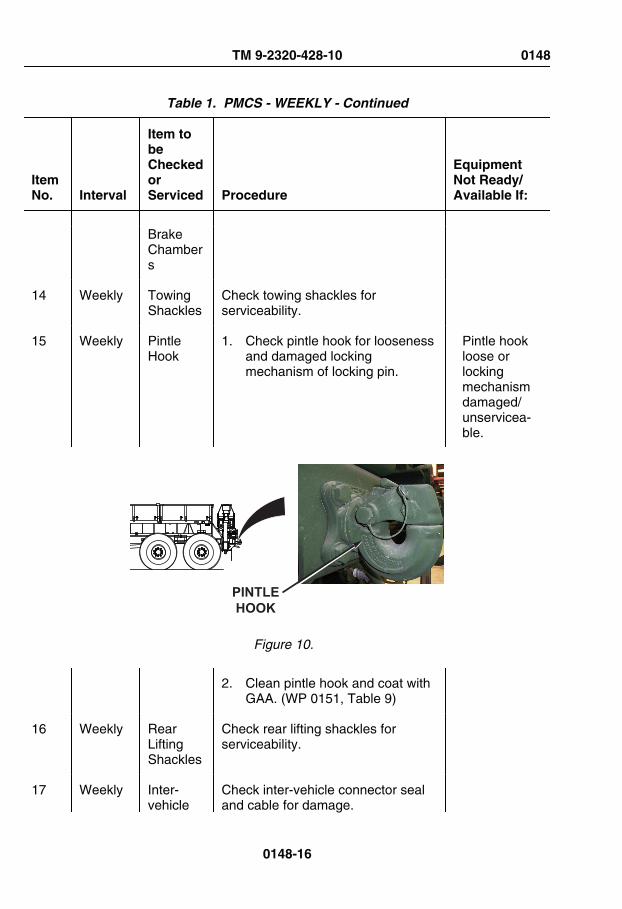
Table 1. PMCS - WEEKLY - Continued
ItemNo. Interval
Item tobeCheckedorServiced Procedure
EquipmentNot Ready/Available If:
BrakeChambers
14 Weekly TowingShackles
Check towing shackles forserviceability.
15 Weekly PintleHook
1. Check pintle hook for loosenessand damaged lockingmechanism of locking pin.
Pintle hookloose orlockingmechanismdamaged/unservicea-ble.
PINTLEHOOK
Figure 10.
2. Clean pintle hook and coat withGAA. (WP 0151, Table 9)
16 Weekly RearLiftingShackles
Check rear lifting shackles forserviceability.
17 Weekly Inter-vehicle
Check inter-vehicle connector sealand cable for damage.
TM 9-2320-428-10 0148
0148-16

Table 1. PMCS - WEEKLY - Continued
ItemNo. Interval
Item tobeCheckedorServiced Procedure
EquipmentNot Ready/Available If:
Connector
INTER-VEHICLEELECTRICALCONNECTOR
Figure 11.
WARNING
Do not operate a vehicle witha tire in an over-inflated or un-der-inflated condition, or witha questionable defect. Failureto comply may result in injuryor death to personnel anddamage to equipment.
NOTEInspection of passenger sidetires includes spare tire.
TM 9-2320-428-10 0148
0148-17

Table 1. PMCS - WEEKLY - Continued
ItemNo. Interval
Item tobeCheckedorServiced Procedure
EquipmentNot Ready/Available If:
18 Weekly Passenger SideTires
Check tires for correct air pressure.
NOTEOperation of vehicle withdamaged/malfunctioning aircompressor may violate AR385-55. (WP 0161)
19 Weekly AirCompressor
Check air compressor for loosescrews, damaged mounting flangeand air hoses, and loose fittings/connections.
Screwsmissing,mountingflange bro-ken, air ho-ses dam-aged or fit-tings/con-nectionsloose.
TM 9-2320-428-10 0148
0148-18

Table 1. PMCS - WEEKLY - Continued
ItemNo. Interval
Item tobeCheckedorServiced Procedure
EquipmentNot Ready/Available If:
AIRCOMPRESSOR
Figure 12.
20 Weekly Secondary FuelFilter
Check secondary fuel filter for leaksor damage.
Any fuelleak.
TM 9-2320-428-10 0148
0148-19
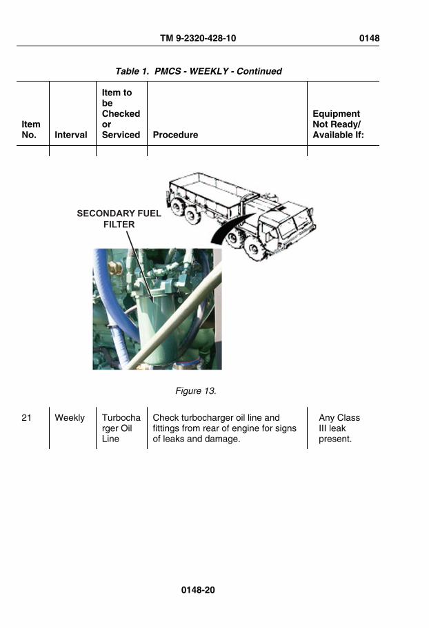
Table 1. PMCS - WEEKLY - Continued
ItemNo. Interval
Item tobeCheckedorServiced Procedure
EquipmentNot Ready/Available If:
SECONDARY FUELFILTER
Figure 13.
21 Weekly Turbocharger OilLine
Check turbocharger oil line andfittings from rear of engine for signsof leaks and damage.
Any ClassIII leakpresent.
TM 9-2320-428-10 0148
0148-20

Table 1. PMCS - WEEKLY - Continued
ItemNo. Interval
Item tobeCheckedorServiced Procedure
EquipmentNot Ready/Available If:
Figure 14.
WARNING
Wear proper eye and skinprotection when workingaround batteries. Do notsmoke, have open flames, or
TM 9-2320-428-10 0148
0148-21
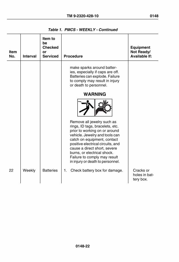
Table 1. PMCS - WEEKLY - Continued
ItemNo. Interval
Item tobeCheckedorServiced Procedure
EquipmentNot Ready/Available If:
make sparks around batter-ies, especially if caps are off.Batteries can explode. Failureto comply may result in injuryor death to personnel.
WARNING
Remove all jewelry such asrings, ID tags, bracelets, etc.prior to working on or aroundvehicle. Jewelry and tools cancatch on equipment, contactpositive electrical circuits, andcause a direct short, severeburns, or electrical shock.Failure to comply may resultin injury or death to personnel.
22 Weekly Batteries 1. Check battery box for damage. Cracks orholes in bat-tery box.
TM 9-2320-428-10 0148
0148-22

Table 1. PMCS - WEEKLY - Continued
ItemNo. Interval
Item tobeCheckedorServiced Procedure
EquipmentNot Ready/Available If:
BATTERYBOX
Figure 15.
2. Check battery cables forpresence, frays, splits, andlooseness.
Battery ca-bles miss-ing, frayed,split, orloose.
3. Check for loose, missing, ordamaged batteries and corrodedor burnt battery terminals.
One ormore batter-ies missing,cracked, orunservicea-ble. Anybattery ter-minal corro-ded orburnt. Anyhold downnot secure.
23 Weekly SpareTire DavitAndCarrier
Check spare tire davit and carrier fordamage, missing parts.
TM 9-2320-428-10 0148
0148-23

Table 1. PMCS - WEEKLY - Continued
ItemNo. Interval
Item tobeCheckedorServiced Procedure
EquipmentNot Ready/Available If:
PULLEY
CABLEREEL
TIRE DAVITPIVOT POINT
RATCHET
Figure 16.
24 Weekly SpareTireRetainer
Check spare tire retainer correctlyseated and locking handle tight.
TM 9-2320-428-10 0148
0148-24

Table 1. PMCS - WEEKLY - Continued
ItemNo. Interval
Item tobeCheckedorServiced Procedure
EquipmentNot Ready/Available If:
SPARE TIRERETAINER
LOCKINGHANDLE
Figure 17.
25 Weekly Air Dryer Check air dryer for loose screws andconnections.
TM 9-2320-428-10 0148
0148-25

Table 1. PMCS - WEEKLY - Continued
ItemNo. Interval
Item tobeCheckedorServiced Procedure
EquipmentNot Ready/Available If:
AIRDRYER
Figure 18.
NOTEPressurize air system prior toperforming this check.
26 Weekly Air LinesandHoses
Check routing, for obvious damage toair lines and hoses. Check for leaks.
Any leaks ordamage toair lines, ho-ses, or fit-
TM 9-2320-428-10 0148
0148-26

Table 1. PMCS - WEEKLY - Continued
ItemNo. Interval
Item tobeCheckedorServiced Procedure
EquipmentNot Ready/Available If:
tings arefound.
NOTEOperation of vehicle withdamaged doors or windowsmay violate AR 385-55.(WP 0161)
27 Weekly Doors,Handles,andWindows
Check condition and operation ofdoor, handles, and windows.(WP 0018)
NOTEStart Engine. (WP 0044) En-gine must be running for re-maining PMCS checks.
28 Weekly CabTemperatureControls
1. Check cab temperature controlsfor proper for proper operation:(WP 0036)
TM 9-2320-428-10 0148
0148-27

Table 1. PMCS - WEEKLY - Continued
ItemNo. Interval
Item tobeCheckedorServiced Procedure
EquipmentNot Ready/Available If:
HEATCONTROL
FANCONTROL
DEFROSTCONTROL
AIRCONTROL
Figure 19.
a. Check AIR control.
b. Check HEAT control.
c. Check DEFROST control.
d. Check FAN control.
29 Weekly MaterialHandlingCrane
1. Inspect crane for loose nuts andbolts, hydraulic leaks, damage to
Class IIIleak presentor damage
TM 9-2320-428-10 0148
0148-28

Table 1. PMCS - WEEKLY - Continued
ItemNo. Interval
Item tobeCheckedorServiced Procedure
EquipmentNot Ready/Available If:
hydraulic hoses and lines, andobvious damage.
to hoses,lines, or fit-tings.
NOTEFor more information on ma-terial handling crane operat-ing instructions, refer to grovecrane operation (manual con-trol) procedures. (WP 0042)
2. Check that crane hydraulicsystem is operable as follows:
a. Start engine. (WP 0044)
b. Set PTO ENGAGE switch toON position. PTO indicatorlight will illuminate.
TM 9-2320-428-10 0148
0148-29

Table 1. PMCS - WEEKLY - Continued
ItemNo. Interval
Item tobeCheckedorServiced Procedure
EquipmentNot Ready/Available If:
TRAILERAIR SUPPLYNOT FOR PARKINGMIDLAND
PULL TO EXHAUST
PUSH TO
PTO ENGAGESWITCH
PTO INDICATORLIGHT
Figure 20.
c. Set ON/OFF POWER switchto ON position.
TM 9-2320-428-10 0148
0148-30

Table 1. PMCS - WEEKLY - Continued
ItemNo. Interval
Item tobeCheckedorServiced Procedure
EquipmentNot Ready/Available If:
ENGINE HIGHIDLE SWITCHLATCH
SWITCH
ON/OFF POWER SWITCH
Figure 21.
d. Set HIGH IDLE CONTROLswitch to CONTINUOUS.
WARNING
Excessive noise levels arepresent any time the heavy-duty winch, crane, or retrievalsystem is operating. Wear
TM 9-2320-428-10 0148
0148-31
Table 1. PMCS - WEEKLY - Continued
ItemNo. Interval
Item tobeCheckedorServiced Procedure
EquipmentNot Ready/Available If:
single hearing protection(earplugs or equivalent) whileworking around equipmentwhen it is running. Failure tocomply may result in injury ordeath to personnel. Seekmedical aid should you sus-pect a hearing problem.
e. Push and release LATCHswitch. Engine speed shouldincrease to approximately1500 rpm.
3. Check crane manual controllevers as follows:
WARNING
• Stand clear of outriggerbeams while operatinglevers. Failure to complymay result in injury ordeath to personnel.
• Do not operate craneunless outriggers arefirmly in place or vehiclecould turn over. Failure to
TM 9-2320-428-10 0148
0148-32

Table 1. PMCS - WEEKLY - Continued
ItemNo. Interval
Item tobeCheckedorServiced Procedure
EquipmentNot Ready/Available If:
comply may result ininjury or death topersonnel.
• Keep boom clear of allelectrical lines and otherobstacles while operatingcrane. Failure to complymay result in injury ordeath to personnel.
NOTE• Operate control levers
with light, even pressure.Moving lever slightly willcause slow movement ofcrane. Moving lever to fulltravel will cause fastermovement of crane.
• Outrigger beams willcome out slower with lightpressure on lever.Pushing lever to full travelwill cause fast movement.
a. Move O/R EXT lever to INposition briefly.
TM 9-2320-428-10 0148
0148-33

Table 1. PMCS - WEEKLY - Continued
ItemNo. Interval
Item tobeCheckedorServiced Procedure
EquipmentNot Ready/Available If:
JACKCYLINDER
RH O/RJACK CONTROL
LEVERO/R EXT
CONTROL LEVER
LH O/RJACK CONTROL
LEVER
HOISTCONTROL LEVER
RETAINING PINSRETAINING PINS
OUTRIGGERPAD
Figure 22.
b. Place both outrigger lockpinsin unlock position.
c. Check each controlseparately for malfunction,proper response, obviousdamage, missing parts,binding, and extremelooseness.
Controlsmalfunction,bind, or donot re-spond.
d. Move O/R EXT lever to OUTposition until both outriggersis completely extended.
Outriggerbeam doesnot comeout.
e. Set up outrigger pads. Checkthat two retaining pins are
Retainingpin missing
TM 9-2320-428-10 0148
0148-34

Table 1. PMCS - WEEKLY - Continued
ItemNo. Interval
Item tobeCheckedorServiced Procedure
EquipmentNot Ready/Available If:
attached to each outriggerpad.
from eitherend.
WARNING
Keep hands and feet clear ofoutrigger jack cylinders. Fail-ure to comply may result ininjury or death to personnel.
NOTEAdjust outrigger pad positionas required so rod end willlower into pad socket.
f. Move LH O/R JACK controllever to DOWN position andlower outrigger jack until rodend is firmly seated inoutrigger pad. Installretaining pins.
Outriggerjack cylin-der will notcome out orwill not low-er com-pletely intopad.
g. Move RH O/R JACK controllever to DOWN position andlower outrigger jack until rodend is firmly seated inoutrigger pad. Installretaining pins.
Outriggerjack cylin-der will notcome out orwill not low-er com-pletely intopad.
TM 9-2320-428-10 0148
0148-35

Table 1. PMCS - WEEKLY - Continued
ItemNo. Interval
Item tobeCheckedorServiced Procedure
EquipmentNot Ready/Available If:
h. Check that outrigger jackcylinder on each side ofvehicle is out and down.
Crane hy-draulic sys-tem doesnot operate.
i. Seat outriggers.
j. Raise boom to operatingposition:
BOOM CONTROL LEVER
MAST CONTROLLEVER
BOOM
MASTCYLINDERS
Figure 23.
WARNING
Do not operate crane unlessoutriggers are firmly in placeor vehicle could turn over.
TM 9-2320-428-10 0148
0148-36
Table 1. PMCS - WEEKLY - Continued
ItemNo. Interval
Item tobeCheckedorServiced Procedure
EquipmentNot Ready/Available If:
Failure to comply may resultin injury or death to personnel.
CAUTIONDo not let cable unwind andbecome slack, or cable mayget tangled on drum.
(1) Move HOIST controllever to DOWN positionuntil hook block rests onfender.
(2) Pull and turn lockpinhandle so handle endrests on bracket tounstow hook block.
CAUTIONDo not allow load hook to con-tact taillight during inspection.Failure to comply may resultin damage to equipment.
NOTEOperation of vehicle with mal-functioning load hook may vi-olate AR 385-55. (WP 0161)
(3) Check hook block andload hook for cracks, andproper operation.
Hook blockor load hookis cracked.
TM 9-2320-428-10 0148
0148-37

Table 1. PMCS - WEEKLY - Continued
ItemNo. Interval
Item tobeCheckedorServiced Procedure
EquipmentNot Ready/Available If:
NOTEOperation of vehicle with mal-functioning load hook springsafety latch may violate AR385-55. (WP 0161)
(4) Check load hook springsafety latch for damageand proper operation.
Load hookspring safe-ty latchdoesn'topen and/orclose prop-erly.
(5) Check hook blockstowage guide wearplate for excessive wear.
WARNING
When using crane on any ve-hicle, park vehicle clear of alloverhead electrical lines.Keep boom clear of all elec-trical lines and other obsta-cles while operating crane.Failure to comply may resultin injury or death to personnel.
TM 9-2320-428-10 0148
0148-38

Table 1. PMCS - WEEKLY - Continued
ItemNo. Interval
Item tobeCheckedorServiced Procedure
EquipmentNot Ready/Available If:
CAUTIONDo not hit outrigger leg withhook block. Failure to complymay result in damage toequipment.
(6) Move BOOM controllever to UP position untilhook is five to six feet(1.5 to 1.8 m) abovedriver side rear fenderand boom isapproximately 45°above horizontal.
Boom doesnot raise.
(7) Move MAST controllever to UP position untilthe mast is fully erectand the cylinders arefully extended. UseBOOM control lever UPsimultaneously asrequired to maintain theboom at approximately45° above horizontaluntil the mast is fullyerect. Hold the MASTcontrol lever to UPposition for two to threeseconds after mast isfully erect to ensurecylinders are fully filledwith oil.
Mast cylin-der does notraise com-pletely be-fore stop-ping.
k. Rotate and telescope boom:
TM 9-2320-428-10 0148
0148-39

Table 1. PMCS - WEEKLY - Continued
ItemNo. Interval
Item tobeCheckedorServiced Procedure
EquipmentNot Ready/Available If:
WARNING
• When using crane on anyvehicle, park vehicle clearof all overhead electricallines. Keep boom clear ofall electrical lines andother obstacles whileoperating crane. Failureto comply may result ininjury or death topersonnel.
• Ensure area is clear ofpersonnel prior to movingSWING lever. Boomshould be swung slowlyenough so crane operatorhas complete control.Failure to comply mayresult in injury or death topersonnel.
CAUTIONBoom must be above vehiclesides for clearance.
(1) Move swing control leverto CW position to moveboom clockwise.
Boom doesnot turnclockwise.
TM 9-2320-428-10 0148
0148-40

Table 1. PMCS - WEEKLY - Continued
ItemNo. Interval
Item tobeCheckedorServiced Procedure
EquipmentNot Ready/Available If:
SWINGCONTROL LEVER
Figure 24.
(2) Move swing control leverto CCW position to moveboom counterclockwise.
Boom doesnot turncounter-clockwise.
CAUTIONKeep hook block at least oneft. (30 cm) from end of boom.If hook block hits end of boomit may damage cable or hookblock and crane will loosepower. Wait six seconds forpower to return and checkcrane for damage.
NOTE• TELESCOPE and HOIST
levers should be
TM 9-2320-428-10 0148
0148-41

Table 1. PMCS - WEEKLY - Continued
ItemNo. Interval
Item tobeCheckedorServiced Procedure
EquipmentNot Ready/Available If:
operated at the sametime.
• Crane movement fromone lever may be slowerthan the other whenoperating two leverstogether.
(3) Move TELESCOPEcontrol lever to OUTposition to extend boomwhile moving hoistcontrol lever to DOWNposition to pay out cable.
Extensionsdo not comeout.
TELESCOPECONTROL
LEVER
HOISTCONTROL
LEVER
CABLE
Figure 25.
(4) Check first, second, andthird stages of boom forbroken welds or obviousdamage.
There arebrokenwelds or ob-vious dam-age toboom.
TM 9-2320-428-10 0148
0148-42

Table 1. PMCS - WEEKLY - Continued
ItemNo. Interval
Item tobeCheckedorServiced Procedure
EquipmentNot Ready/Available If:
FIRST SECOND THIRD
HOISTCABLE
Figure 26.
WARNING
Always wear protectivegloves when checking hoistcable. Never let cable runthrough hands. Frayed cablescan cut severely. Failure tocomply may result in injury ordeath to personnel.
(5) Check cable on hoist forkinks, frays, or breaks.
Evidence ofkinks, frays,or breaks.
TM 9-2320-428-10 0148
0148-43
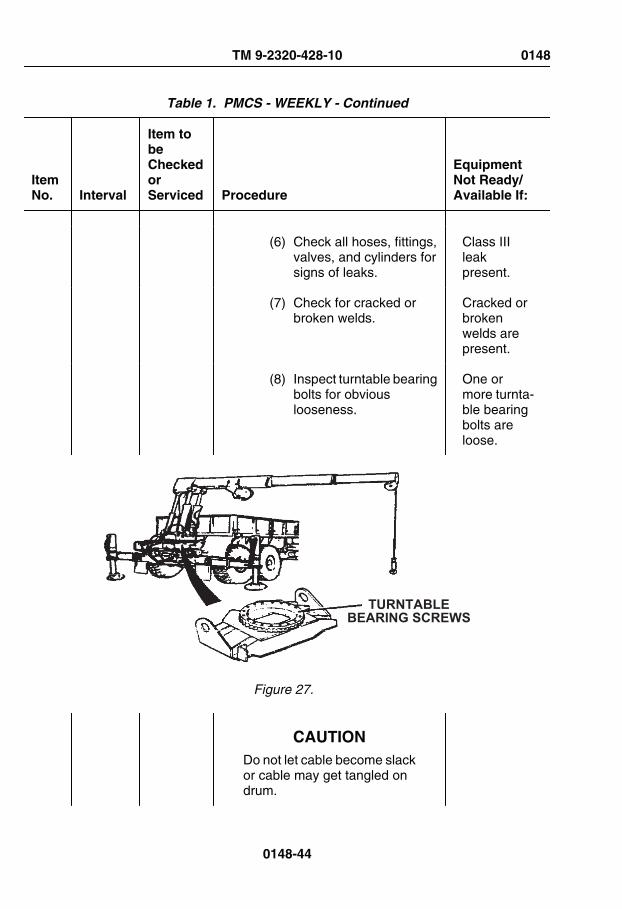
Table 1. PMCS - WEEKLY - Continued
ItemNo. Interval
Item tobeCheckedorServiced Procedure
EquipmentNot Ready/Available If:
(6) Check all hoses, fittings,valves, and cylinders forsigns of leaks.
Class IIIleakpresent.
(7) Check for cracked orbroken welds.
Cracked orbrokenwelds arepresent.
(8) Inspect turntable bearingbolts for obviouslooseness.
One ormore turnta-ble bearingbolts areloose.
TURNTABLEBEARING SCREWS
Figure 27.
CAUTIONDo not let cable become slackor cable may get tangled ondrum.
TM 9-2320-428-10 0148
0148-44

Table 1. PMCS - WEEKLY - Continued
ItemNo. Interval
Item tobeCheckedorServiced Procedure
EquipmentNot Ready/Available If:
(9) Move HOIST controllever in UP position toreel in cable.
Cable doesnot reel in.
(10)Move HOIST controllever in DOWN positionto pay out cable.
Cable doesnot pay out.
NOTEFor more information on ma-terial handling crane remote-control operating instructions,refer to grove crane operation(remote- control) procedures.(WP 0043)
4. Check crane remote-controllevers as follows:
TM 9-2320-428-10 0148
0148-45

Table 1. PMCS - WEEKLY - Continued
ItemNo. Interval
Item tobeCheckedorServiced Procedure
EquipmentNot Ready/Available If:
SWING CONTROL VALVE
TELESCOPECONTROL LEVER BOOM CONTROL
LEVER
REMOTE CONTROL UNITON/OFF SWITCH
HOISTCONTROL LEVER
REMOTECONTROL UNIT
Figure 28.
a. Set up REMOTE CONTROLUNIT passenger side.(WP 0043)
WARNING
• When using crane on anyvehicle, park vehicle clearof all overhead electricallines. Keep boom clear ofall electrical lines and
TM 9-2320-428-10 0148
0148-46
Table 1. PMCS - WEEKLY - Continued
ItemNo. Interval
Item tobeCheckedorServiced Procedure
EquipmentNot Ready/Available If:
other obstacles whileoperating crane. Failureto comply may result ininjury or death topersonnel.
• Ensure area is clear ofpersonnel prior to movingSWING lever. Boomshould be swung slowlyenough so crane operatorhas complete control.Failure to comply mayresult in injury or death topersonnel.
WARNING
If electrical power fails duringcrane operation, move switchon remote control unit toSHUTDOWN position. Fail-ure to comply may result ininjury or death to personnel.
CAUTIONCrane must be above vehiclesides for clearance.
NOTEOperate control levers withlight, even pressure. Movinglever slightly will cause slow
TM 9-2320-428-10 0148
0148-47

Table 1. PMCS - WEEKLY - Continued
ItemNo. Interval
Item tobeCheckedorServiced Procedure
EquipmentNot Ready/Available If:
movement of crane. Movinglever to full travel will causefaster movement of crane.
b. Check control levers formalfunction, properresponse, obvious damage,missing parts, binding, andextreme looseness.
Controlsmalfunction,bind, or donot re-spond.
c. Rotate and telescope boom:
WARNING
Ensure area is clear of per-sonnel prior to movingSWING lever. Boom shouldbe swung slowly enough socrane operator has completecontrol. Failure to comply mayresult in injury or death to per-sonnel.
(1) Move SWING controllever to CW position toturn boom clockwise.
Boom doesnot turnclockwise.
TM 9-2320-428-10 0148
0148-48

Table 1. PMCS - WEEKLY - Continued
ItemNo. Interval
Item tobeCheckedorServiced Procedure
EquipmentNot Ready/Available If:
SWING CONTROL VALVE
TELESCOPECONTROL LEVER BOOM CONTROL
LEVER
REMOTE CONTROL UNITON/OFF SWITCH
HOISTCONTROL LEVER
REMOTECONTROL UNIT
Figure 29.
(2) Move SWING controllever to CCW position toturn boomcounterclockwise.
Boom doesnot turncounter-clockwise.
WARNING
When using crane on any ve-hicle, park vehicle clear of alloverhead electrical lines.Keep boom clear of all elec-
TM 9-2320-428-10 0148
0148-49

Table 1. PMCS - WEEKLY - Continued
ItemNo. Interval
Item tobeCheckedorServiced Procedure
EquipmentNot Ready/Available If:
trical lines and other obsta-cles while operating crane.Failure to comply may resultin injury or death to personnel.
CAUTIONDo not let cable become slackor cable may get tangled ondrum.
(3) Move HOIST controllever to UP position totake up cable. MoveBOOM control lever toUP position to raiseboom.
Cable doesnot reel in orboom doesnot raise.
(4) Move HOIST controllever to DOWN positionto pay out cable. MoveBOOM control lever toDOWN position to lowerboom to horizontalposition.
Cable doesnot pay outor boomdoes notlower.
CAUTION• Keep hook block at least
one ft. (30 cm) from endof boom. If hook block hitsend of boom it maydamage cable or hookblock and crane will losepower. Wait six secondsfor power and checkcrane for damage.
TM 9-2320-428-10 0148
0148-50

Table 1. PMCS - WEEKLY - Continued
ItemNo. Interval
Item tobeCheckedorServiced Procedure
EquipmentNot Ready/Available If:
• Do not let cable becomeslack or cable may gettangled on drum.
NOTE• TELESCOPE and HOIST
levers should beoperated at the sametime.
• Crane movement fromone lever may be slowerthan the other whenoperating two leverstogether.
(5) Move TELESCOPEcontrol lever to OUTposition while movingHOIST control lever toDOWN position to payout cable.
Extensionswill notcome out, orcable willnot pay out.
(6) Move HOIST controllever in UP position toreel in cable.
Cable willnot reel in.
(7) Check that crane andENGINE HIGH IDLE donot operate whenREMOTE CONTROLUNIT is in MHC-SHUTDOWN position.Notify organizationalmaintenance if craneand ENGINE HIGH IDLE
Crane willoperate andenginespeed willincrease to1500 rpm.
TM 9-2320-428-10 0148
0148-51

Table 1. PMCS - WEEKLY - Continued
ItemNo. Interval
Item tobeCheckedorServiced Procedure
EquipmentNot Ready/Available If:
operates when in MHC-SHUTDOWN position.
(8) Shut off remote-controlswitches.
(9) Disconnect remote-control, passenger side.
(10)Check operation ofdriver side remote-control station.
(11)Connect remote-controlto driver side remote-control station.
(12)Check operation ofcrane remote-controllevers.
(13)Shut off remote-controlswitches.
(14)Disconnect and stowREMOTE CONTROLUNIT.
5. Shut down material handlingcrane.
6. Check all hoses, fittings, valves,and cylinders for signs of leaksand damage.
Any ClassIII leakpresent.
TM 9-2320-428-10 0148
0148-52

Table 1. PMCS - WEEKLY - Continued
ItemNo. Interval
Item tobeCheckedorServiced Procedure
EquipmentNot Ready/Available If:
7. Check for cracked or brokenwelds.
Cracked orbrokenwelds.
END OF WORK PACKAGE
TM 9-2320-428-10 0148
0148-53


OPERATOR MAINTENANCESEMIANNUAL - PREVENTIVE MAINTENANCE
INITIAL SETUP:
Tools and Special ToolsGloves, Leather (WP 0163, Table 2)
Table 1. PMCS- SEMIANNUAL
ItemNo. Interval
Item tobeCheckedorServiced Procedure
EquipmentNot Ready/Available If:
WARNING
Do not start engine or movevehicle when personnel areunder vehicle or working onbrake lines. Failure to complymay result in injury or death topersonnel.
WARNING
Ensure engine is OFF andeye protection is worn whenchecking for leaks. Failure tocomply may result in injury ordeath to personnel.
TM 9-2320-428-10 0149
0149-1

Table 1. PMCS- SEMIANNUAL - Continued
ItemNo. Interval
Item tobeCheckedorServiced Procedure
EquipmentNot Ready/Available If:
NOTE• Lubrication intervals are
for normal operatingconditions. Intervals maybe shortened as requiredfor severe operatingconditions.
• Clean all lubricationpoints with cleaningcompound, solvent andallow to dry prior toservicing.
• When using a greasegun, apply lubricant to thefitting until clean lubricantsqueezes out of the partbeing lubricated.
• Always refer to lubricationinstructions (WP 0151) toensure equipment hascorrect lubricantsappropriate to operatingenvironment (expectedcontinuoustemperatures). If not,remove/drain andreapply/refill equipmentwith appropriatelubricants for operatingenvironment asprescribed in lubricationinstructions. (WP 0151)
1 Semiannual
BrakeSystem
Lubricate axles No. 1, No. 2, No. 3,and No. 4 brake camshafts and slack
Fitting willnot purgeold lubricant
TM 9-2320-428-10 0149
0149-2

Table 1. PMCS- SEMIANNUAL - Continued
ItemNo. Interval
Item tobeCheckedorServiced Procedure
EquipmentNot Ready/Available If:
adjusters (four fittings per axle) withGAA. (WP 0151, Table 9)
out of com-ponent.
SLACK ADJUSTERLUBE FITTING BRAKE CAMSHAFT
LUBE FITTING
Figure 1.
NOTE• When vehicle is operating
under severe conditions,lubricate propeller shaftsand universal joints every50 hours of vehicleoperation.
TM 9-2320-428-10 0149
0149-3

Table 1. PMCS- SEMIANNUAL - Continued
ItemNo. Interval
Item tobeCheckedorServiced Procedure
EquipmentNot Ready/Available If:
• Use the proper lubricantto purge all four bearingseals of each universaljoint. This flushesabrasive contaminantsfrom each bearing andassures all four bearingsare filled properly. Popthe seals, these seals aremade to be popped.
• If any seals fail to purge,move propeller shaft fromside-to-side whileapplying gun pressure.This allows greaterclearance on thrust end ofbearing that is notpurging. If seals still donot purge, rock vehicle byreleasing the parkingbrake, start engine, puttransmission in D (drive)or R (reverse), and allowvehicle to roll. Thisremoves the windup inthe drive line and allowsfor a greater clearance onthe thrust end of theuniversal joint.
• Because of the design ofthe universal joint seal,there will occasionally beone or more bearingseals of a joint that maynot purge. If this occurs,notify field levelmaintenance.
TM 9-2320-428-10 0149
0149-4

Table 1. PMCS- SEMIANNUAL - Continued
ItemNo. Interval
Item tobeCheckedorServiced Procedure
EquipmentNot Ready/Available If:
• Universal joint may haveone or two grease fittings.If there are two greasefittings, either fitting canbe greased. It is notnecessary to grease bothfittings.
2 Semiannual
PropellerShaftsand U-Joints
1. Lubricate all axle propellershafts, transmission to transfercase propeller shaft, and U-jointswith GAA: (WP 0151, Table 9)
Fitting willnot purgeold lubricantout of com-ponent.
TM 9-2320-428-10 0149
0149-5

Table 1. PMCS- SEMIANNUAL - Continued
ItemNo. Interval
Item tobeCheckedorServiced Procedure
EquipmentNot Ready/Available If:
TRANSMISSION/TRANSFER CASE PROPELLER SHAFT
AND U-JOINTS
SLEEVE YOKE SEAL
U-JOINTCROSSFITTING
U-JOINTCROSSFITTING
SPLINEFITTING
SPLINEFITTING
TYPICAL PROPELLER SHAFT
NO. 1 AXLE PROPELLERSHAFT AND U-JOINTS
NO. 2 AXLE PROPELLERSHAFT AND U-JOINTS
NO. 3 AXLE PROPELLERSHAFT AND U-JOINTS
NO. 4 AXLE PROPELLERSHAFT AND U-JOINTS
Figure 2.
a. Complete the following whenlubricating the spline end ofthe propeller shafts:
Fitting willnot purgeold lubricantout of com-ponent.
(1) Apply GAA (WP 0151,Table 9) to spline fitting
TM 9-2320-428-10 0149
0149-6

Table 1. PMCS- SEMIANNUAL - Continued
ItemNo. Interval
Item tobeCheckedorServiced Procedure
EquipmentNot Ready/Available If:
until lubricant appears atpressure relief hole.
(2) Cover pressure reliefhole with finger andcontinue adding greaseuntil it appears at sleeveyoke seal.
3 Semiannual
SteeringSystem
1. Lubricate intergear link withGAA. (WP 0151, Table 9)
Fitting willnot purgeold lubricantout of com-ponent.
TM 9-2320-428-10 0149
0149-7
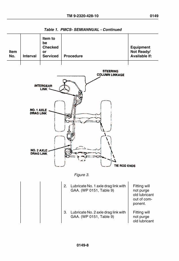
Table 1. PMCS- SEMIANNUAL - Continued
ItemNo. Interval
Item tobeCheckedorServiced Procedure
EquipmentNot Ready/Available If:
Figure 3.
2. Lubricate No. 1 axle drag link withGAA. (WP 0151, Table 9)
Fitting willnot purgeold lubricantout of com-ponent.
3. Lubricate No. 2 axle drag link withGAA. (WP 0151, Table 9)
Fitting willnot purgeold lubricant
TM 9-2320-428-10 0149
0149-8

Table 1. PMCS- SEMIANNUAL - Continued
ItemNo. Interval
Item tobeCheckedorServiced Procedure
EquipmentNot Ready/Available If:
out of com-ponent.
4. Lubricate tie rod ends with GAA.(WP 0151, Table 9)
Fitting willnot purgeold lubricantout of com-ponent.
5. Lubricate steering linkage U-joints and shafts with GAA.(WP 0151)
Fitting willnot purgeold lubricantout of com-ponent.
NOTE• The top trunnion bearing
should be given 10 to 12strokes with a grease gunthrough existing fitting.
• The plug below thebottom shouldtemporarily be removedand a grease fittinginstalled. The lowertrunnion bearing shouldbe lubricated with 10 to12 strokes from a greasegun. The grease fittingshould then be removedand the plug reinstalled.
6. Lubricate No. 1 and No. 2 axletrunnion bearings with GAA.(WP 0151, Table 9)
TM 9-2320-428-10 0149
0149-9

Table 1. PMCS- SEMIANNUAL - Continued
ItemNo. Interval
Item tobeCheckedorServiced Procedure
EquipmentNot Ready/Available If:
LUBEFITTINGS
AXLE NO. 2
AXLE NO. 1
LUBEFITTINGS
TRUNNION BEARINGS(DRIVER SIDE)
TRUNNION BEARINGS(PASSENGER SIDE)
Figure 4.
4 Semiannual
SpringHanger
1. Lubricate spring hanger pivotpoints (one fitting per spring) withGAA. (WP 0151, Table 9)
Fitting willnot purgeold lubricantout of com-ponent.
TM 9-2320-428-10 0149
0149-10

Table 1. PMCS- SEMIANNUAL - Continued
ItemNo. Interval
Item tobeCheckedorServiced Procedure
EquipmentNot Ready/Available If:
SPRINGHANGERPIN LUBEFITTING
SPRING HANGER
SPRINGHANGER
Figure 5.
2. If spring hanger pin does notaccept grease, perform thefollowing:
a. Relieve load on springhanger pin by jacking upvehicle at frame rails, asclose to spring hanger pin aspossible.
b. Lubricate spring hanger pinpivot.
TM 9-2320-428-10 0149
0149-11

Table 1. PMCS- SEMIANNUAL - Continued
ItemNo. Interval
Item tobeCheckedorServiced Procedure
EquipmentNot Ready/Available If:
c. If springer hanger pin stillfails to take grease, notifyfield level maintenance toremove spring hanger pinand replace as necessary.
NOTEVehicle may be equipped witheither a slave receptacle in-corporated in bottom rear ofbattery box, or separate uniton driver side front fender.
5 Semiannual
BatteryElectricalSystem
Coat slave receptacle with corrosionpreventive compound.
TM 9-2320-428-10 0149
0149-12

Table 1. PMCS- SEMIANNUAL - Continued
ItemNo. Interval
Item tobeCheckedorServiced Procedure
EquipmentNot Ready/Available If:
SLAVERECEPTACLE
SLAVERECEPTACLE
Figure 6.
6 Semiannual
MirrorAssemblies
Lubricate mirror assembly swiveljoints with GAA. (WP 0151, Table 9)
TM 9-2320-428-10 0149
0149-13

Table 1. PMCS- SEMIANNUAL - Continued
ItemNo. Interval
Item tobeCheckedorServiced Procedure
EquipmentNot Ready/Available If:
LUBE 4LOCATIONS
Figure 7.
NOTEPintle hook plate lubricationfitting can be on any side.
7 Semiannual
PintleHook
1. Lubricate pintle hook (3 fittings)with GAA. (WP 0151, Table 9)
Fitting willnot purgeold lubricantout of com-ponent.
TM 9-2320-428-10 0149
0149-14

Table 1. PMCS- SEMIANNUAL - Continued
ItemNo. Interval
Item tobeCheckedorServiced Procedure
EquipmentNot Ready/Available If:
Figure 8.
NOTELubricate outrigger bottomplate, boom wear pads, andexposed rotation gears oftenwhen cranes are operating insandy/dusty environment.
8 Semiannual
Crane(Grove)
1. Lubricate pivots at both ends oflift cylinders (eight fittings) withGAA. (WP 0151, Table 7)
Fitting willnot purgeold lubricantout of com-ponent.
TM 9-2320-428-10 0149
0149-15

Table 1. PMCS- SEMIANNUAL - Continued
ItemNo. Interval
Item tobeCheckedorServiced Procedure
EquipmentNot Ready/Available If:
Figure 9.
2. Lubricate mast pivots (fourfittings) with GAA. (WP 0151,Table 7)
Fitting willnot purgeold lubricantout of com-ponent.
TM 9-2320-428-10 0149
0149-16

Table 1. PMCS- SEMIANNUAL - Continued
ItemNo. Interval
Item tobeCheckedorServiced Procedure
EquipmentNot Ready/Available If:
Figure 10.
3. Lubricate pivots at both ends oferection cylinders (eight fittings)with GAA. (WP 0151, Table 7)
Fitting willnot purgeold lubricantout of com-ponent.
TM 9-2320-428-10 0149
0149-17
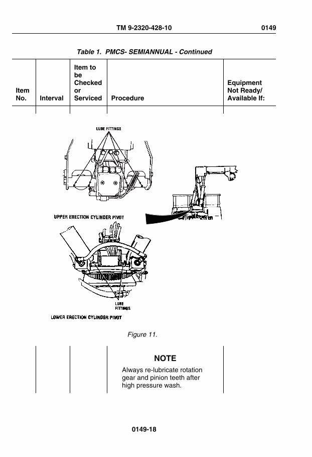
Table 1. PMCS- SEMIANNUAL - Continued
ItemNo. Interval
Item tobeCheckedorServiced Procedure
EquipmentNot Ready/Available If:
Figure 11.
NOTEAlways re-lubricate rotationgear and pinion teeth afterhigh pressure wash.
TM 9-2320-428-10 0149
0149-18
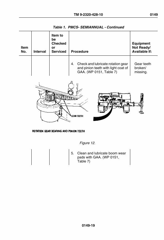
Table 1. PMCS- SEMIANNUAL - Continued
ItemNo. Interval
Item tobeCheckedorServiced Procedure
EquipmentNot Ready/Available If:
4. Check and lubricate rotation gearand pinion teeth with light coat ofGAA. (WP 0151, Table 7)
Gear teethbroken/missing.
Figure 12.
5. Clean and lubricate boom wearpads with GAA. (WP 0151,Table 7)
TM 9-2320-428-10 0149
0149-19

Table 1. PMCS- SEMIANNUAL - Continued
ItemNo. Interval
Item tobeCheckedorServiced Procedure
EquipmentNot Ready/Available If:
BOOM WEAR PADS
BOOM NOSE SHEAVE
Figure 13.
6. Lubricate boom nose sheavebushing (one fitting) with GAA.(WP 0151, Table 7)
Fitting willnot purgeold lubricantout of com-ponent.
7. Lubricate hook block clevis pivotpoint with OE/HDO. (WP 0151,Table 8)
TM 9-2320-428-10 0149
0149-20

Table 1. PMCS- SEMIANNUAL - Continued
ItemNo. Interval
Item tobeCheckedorServiced Procedure
EquipmentNot Ready/Available If:
HOOK BLOCKCLEVIS
Figure 14.
NOTERaise crane mast until lubefitting comes into view. Turnand lubricate turntable every90° until you have turned theturntable 360°, then rotate
TM 9-2320-428-10 0149
0149-21

Table 1. PMCS- SEMIANNUAL - Continued
ItemNo. Interval
Item tobeCheckedorServiced Procedure
EquipmentNot Ready/Available If:
crane a full 360° to spread lu-bricant.
8. Lubricate turntable bearing (onefitting) with GAA. (WP 0151,Table 7)
Fitting willnot purgeold lubricantout of com-ponent.
LUBE FITTING
TURNTABLE BEARING
Figure 15.
9. Clean and lubricate slidingsurfaces of outrigger bottomplates with GAA. (WP 0151,Table 7)
TM 9-2320-428-10 0149
0149-22
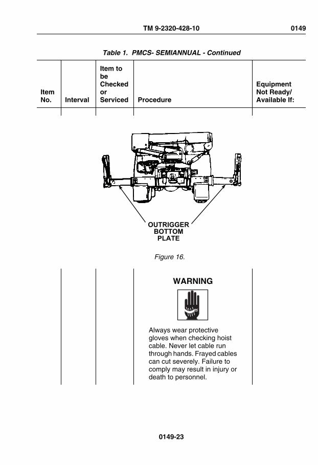
Table 1. PMCS- SEMIANNUAL - Continued
ItemNo. Interval
Item tobeCheckedorServiced Procedure
EquipmentNot Ready/Available If:
OUTRIGGERBOTTOMPLATE
Figure 16.
WARNING
Always wear protectivegloves when checking hoistcable. Never let cable runthrough hands. Frayed cablescan cut severely. Failure tocomply may result in injury ordeath to personnel.
TM 9-2320-428-10 0149
0149-23

Table 1. PMCS- SEMIANNUAL - Continued
ItemNo. Interval
Item tobeCheckedorServiced Procedure
EquipmentNot Ready/Available If:
9 Semiannual
CraneHoistCable
1. Unreel crane hoist cable andcheck hoist cable for kinks,broken strands, and wear.
Kinks, bro-ken strands,or wearpresent.
2. Clean and lubricate hoist cablewith OE/HDO. (WP 0151,Table 7)
Kinks, bro-ken strands,or wearpresent.
10 Semiannual
Self-RecoveryWinch
1. Unreel, (WP 0086) clean, andlubricate cable with OE/HDO.(WP 0151, Table 6)
2. Lubricate front and rear cabletensioner rollers (three fittingsper tensioner) with GAA.(WP 0151, Table 9)
Fitting willnot purgeold lubricantout of com-ponent.
TM 9-2320-428-10 0149
0149-24

Table 1. PMCS- SEMIANNUAL - Continued
ItemNo. Interval
Item tobeCheckedorServiced Procedure
EquipmentNot Ready/Available If:
Figure 17.
3. Lubricate pivot points andpressure rollers with OE/HDO.(WP 0151, Table 8)
TM 9-2320-428-10 0149
0149-25

Table 1. PMCS- SEMIANNUAL - Continued
ItemNo. Interval
Item tobeCheckedorServiced Procedure
EquipmentNot Ready/Available If:
4. Lubricate rear cable guide roller(four fittings) with GAA.(WP 0151, Table 9)
Fitting willnot purgeold lubricantout of com-ponent.
LUBEFITTING
REAR CABLE GUIDE
Figure 18.
5. Lubricate front cable guide (fourfittings) with GAA. (WP 0151,Table 9)
Fitting willnot purgeold lubricant
TM 9-2320-428-10 0149
0149-26
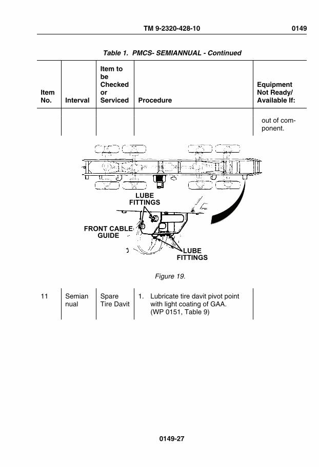
Table 1. PMCS- SEMIANNUAL - Continued
ItemNo. Interval
Item tobeCheckedorServiced Procedure
EquipmentNot Ready/Available If:
out of com-ponent.
LUBEFITTINGS
LUBEFITTINGS
FRONT CABLEGUIDE
Figure 19.
11 Semiannual
SpareTire Davit
1. Lubricate tire davit pivot pointwith light coating of GAA.(WP 0151, Table 9)
TM 9-2320-428-10 0149
0149-27

Table 1. PMCS- SEMIANNUAL - Continued
ItemNo. Interval
Item tobeCheckedorServiced Procedure
EquipmentNot Ready/Available If:
PULLEY
CABLEREEL AND
REEL SHAFTREEL GEARSAND RATCHET
CRANK BUSHINGSAND RATCHET SHAFT
TIRE DAVITPIVOT POINT
Figure 20.
2. Lubricate reel gears and ratchetwith light coating of GAA.(WP 0151, Table 9)
3. Lubricate crank bushings andratchet shaft with OE/HDO.(WP 0151, Table 8)
4. Lubricate reel and reel shaft withOE/HDO. (WP 0151, Table 8)
5. Lubricate cable with OE/HDO.(WP 0151, Table 8)
TM 9-2320-428-10 0149
0149-28

Table 1. PMCS- SEMIANNUAL - Continued
ItemNo. Interval
Item tobeCheckedorServiced Procedure
EquipmentNot Ready/Available If:
6. Lubricate pulley with OE/HDO.(WP 0151, Table 8)
END OF WORK PACKAGE
TM 9-2320-428-10 0149
0149-29


OPERATOR MAINTENANCEMONTHLY - PREVENTIVE MAINTENANCE
INITIAL SETUP:
Tools and Special ToolsGloves, Leather (WP 0163, Table 2)
Table 1. PMCS - MONTHLY
ItemNo. Interval
Item tobeCheckedorServiced Procedure
EquipmentNot Ready/Available If:
WARNING
Do not start engine or movevehicle when personnel areunder vehicle or working onbrake lines. Failure to complymay result in injury or death topersonnel.
WARNING
Ensure engine is OFF andeye protection is worn whenchecking for leaks. Failure tocomply may result in injury ordeath to personnel.
TM 9-2320-428-10 0150
0150-1

Table 1. PMCS - MONTHLY - Continued
ItemNo. Interval
Item tobeCheckedorServiced Procedure
EquipmentNot Ready/Available If:
NOTE• Lubrication intervals are
for normal operatingconditions. Intervals maybe shortened as requiredfor severe operatingconditions.
• Clean all lubricationpoints with cleaningcompound, solvent andallow to dry prior toservicing.
• When using a greasegun, apply lubricant to thefitting until clean lubricantsqueezes out of the partbeing lubricated.
• Always refer to lubricationinstructions (WP 0151) toensure equipment hascorrect lubricantsappropriate to operatingenvironment (expectedcontinuoustemperatures). If not,remove/drain andreapply/refill equipmentwith appropriatelubricants for operatingenvironment asprescribed in lubricationinstructions. (WP 0151)
1 Monthly DamageAnd
Check entire vehicle for obviousdamage and/or corrosion.
Any broken,cracked,bent frame
TM 9-2320-428-10 0150
0150-2

Table 1. PMCS - MONTHLY - Continued
ItemNo. Interval
Item tobeCheckedorServiced Procedure
EquipmentNot Ready/Available If:
CorrosionCheck
rails, cross-members,or screwsare found.
2 Monthly LubricateOilcanPoints
1. Lubricate cabin door latchingmechanisms and hinges withOE/HDO. (WP 0151)
2. Lubricate all side panel andengine cover hinges, locks, andlatches with OE/HDO.(WP 0151)
NOTESteady illumination of the arc-tic engine heater indicatorlight indicates proper opera-tion.
3 Monthly ArcticEngineHeater
1. Position arctic engine heater ON/OFF switch to ON position,indicator light will illuminate.
TM 9-2320-428-10 0150
0150-3

Table 1. PMCS - MONTHLY - Continued
ItemNo. Interval
Item tobeCheckedorServiced Procedure
EquipmentNot Ready/Available If:
JACOBS
CAUTION
ENGINE BRAKE
INDICATORLIGHT ARCTIC
HEATERON/OFF SWITCH
Figure 1.
2. Visually check all fuel lines forleaks, cuts, loose clamps, andother obvious damage.
Any ClassIII leak.
TM 9-2320-428-10 0150
0150-4

Table 1. PMCS - MONTHLY - Continued
ItemNo. Interval
Item tobeCheckedorServiced Procedure
EquipmentNot Ready/Available If:
Figure 2.
3. Visually check intake port andexhaust pipe for blockage.
TM 9-2320-428-10 0150
0150-5

Table 1. PMCS - MONTHLY - Continued
ItemNo. Interval
Item tobeCheckedorServiced Procedure
EquipmentNot Ready/Available If:
4. Check water pump for unusualnoise.
Figure 3.
5. Check coolant hoses at arcticengine heater for leaks, cuts,loose hose clamps, and otherobvious damage.
Any ClassIII leak.
6. Check coolant hoses and fittingsat passenger side of engine forleaks, cuts, loose hose clamps,and other obvious damage.
Any ClassIII leak.
TM 9-2320-428-10 0150
0150-6

Table 1. PMCS - MONTHLY - Continued
ItemNo. Interval
Item tobeCheckedorServiced Procedure
EquipmentNot Ready/Available If:
Figure 4.
7. Check coolant hoses and fittingsat passenger side of engine forleaks, cuts, loose hose clamps,and other obvious damage.
Any ClassIII leak.
TM 9-2320-428-10 0150
0150-7

Table 1. PMCS - MONTHLY - Continued
ItemNo. Interval
Item tobeCheckedorServiced Procedure
EquipmentNot Ready/Available If:
Figure 5.
8. Run arctic engine heater for aminimum of 15 minutes at leastonce a month.
4 Monthly CraneControlLevers
1. Lubricate crane control leverpivots with OE/HDO. (WP 0151,Table 8)
TM 9-2320-428-10 0150
0150-8

Table 1. PMCS - MONTHLY - Continued
ItemNo. Interval
Item tobeCheckedorServiced Procedure
EquipmentNot Ready/Available If:
OILCAN POINTS8 LOCATIONS
Figure 6.
WARNING
• Always wear protectivegloves when handlingwinch cable. Never letcable run through hands.Frayed cables can cutseverely. Failure tocomply may result ininjury or death topersonnel.
• Never operate winch withless than five wraps ofcable on winch drum.Failure to comply mayresult in injury or death topersonnel.
TM 9-2320-428-10 0150
0150-9
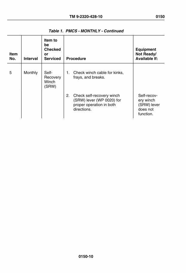
Table 1. PMCS - MONTHLY - Continued
ItemNo. Interval
Item tobeCheckedorServiced Procedure
EquipmentNot Ready/Available If:
5 Monthly Self-RecoveryWinch(SRW)
1. Check winch cable for kinks,frays, and breaks.
2. Check self-recovery winch(SRW) lever (WP 0020) forproper operation in bothdirections.
Self-recov-ery winch(SRW) leverdoes notfunction.
TM 9-2320-428-10 0150
0150-10

Table 1. PMCS - MONTHLY - Continued
ItemNo. Interval
Item tobeCheckedorServiced Procedure
EquipmentNot Ready/Available If:
FRONT CABLE GUIDEREAR CABLE GUIDE
REARTENSIONER SELF-RECOVERY
WINCHFRONT
TENSIONER
Figure 7.
3. Inspect front cable guide for anyloose or missing parts and anyobvious damage.
Front cableguide hasloose/miss-ing parts or
TM 9-2320-428-10 0150
0150-11

Table 1. PMCS - MONTHLY - Continued
ItemNo. Interval
Item tobeCheckedorServiced Procedure
EquipmentNot Ready/Available If:
is unserv-iceable.
4. Inspect front tensioner for looseor missing parts and any obviousdamage.
Front ten-sioner hasloose/miss-ing parts oris unserv-iceable.
5. Inspect rear tensioner for looseor missing parts and any otherobvious damage.
Rear ten-sioner hasloose/miss-ing parts oris unserv-iceable.
6. Inspect rear cable guide for looseor missing parts and any obviousdamage.
Rear cableguide hasloose/miss-ing parts oris unserv-iceable.
NOTEGas particulate filter unit mustbe in operation (WP 0059) toperform the following checks.
6 Monthly GasParticulate FilterUnit(GPFU)
1. Check heater for unusual loudnoise or improper operation.
Heater doesnot operate/operatesabnormallyand GPFUis requiredfor mission.
TM 9-2320-428-10 0150
0150-12

Table 1. PMCS - MONTHLY - Continued
ItemNo. Interval
Item tobeCheckedorServiced Procedure
EquipmentNot Ready/Available If:
HOSE CLAMP
HOSESHOSE
CLAMP
Figure 8.
2. Disconnect two air ductbreakaway sockets from mountand feel for airflow.
No airflowor notenough air-flow andGPFU is re-quired formission.
3. Turn heater control knobclockwise to make sure indicatorlight illuminates.
Heater is in-operativeand GPFUis requiredfor mission.
4. Check hoses for cuts, tears, andother obvious damage.
Hoses cut,torn, ordamagedand GPFU
TM 9-2320-428-10 0150
0150-13

Table 1. PMCS - MONTHLY - Continued
ItemNo. Interval
Item tobeCheckedorServiced Procedure
EquipmentNot Ready/Available If:
is requiredfor mission.
5. Make sure hose clamps aresecure.
Clampsloose andGPFU is re-quired formission.
7 Monthly RifleStowageMount
1. Check that mounting screws ontop mount and lower mount arenot broken or missing.
TOPMOUNT
HANDLE
LOWERMOUNT
Figure 9.
2. Check handle for excessivelooseness or binding.
TM 9-2320-428-10 0150
0150-14

Table 1. PMCS - MONTHLY - Continued
ItemNo. Interval
Item tobeCheckedorServiced Procedure
EquipmentNot Ready/Available If:
8 Monthly MachineGunOperator'sPlatformSupport
Check machine gun operator'splatform support for loose, broken, ormissing mounting screws.
9 Monthly MachineGunOperator'sPlatform
Check machine gun operator'splatform for cracks, loose or brokenleg, missing or broken tie down strap.
10 Monthly RingMount
Check machine gun mounts forloose, broken, or missing mountingscrews.
11 Monthly M-13DecontaminationUnit
Refer to TM 3-4230-214-12&P(WP 0161) for M-13 DecontaminationUnit PMCS.
12 Monthly M-8ChemicalAlarm
Refer to TM 3-6665-225-12(WP 0161) for M-8 Chemical AlarmPMCS.
13 Monthly Radio Refer to TM 11-5820-498-12(WP 0161) for radio PMCS.
END OF WORK PACKAGE
TM 9-2320-428-10 0150
0150-15


CHAPTER 5
MAINTENANCEINSTRUCTIONS
TM 9-2320-428-10


OPERATOR MAINTENANCELUBRICATION INSTRUCTIONS
INITIAL SETUP:
Not Applicable
WARNING
Adhesives, solvents, and sealing compounds can burn easily, can giveoff harmful vapors, and are harmful to skin and clothing. Keep away fromopen fire and use in well-ventilated area. If adhesive, solvent, or sealingcompound gets on skin or clothing, wash immediately with soap andwater. Failure to comply may result in injury or death to personnel.
NOTE• The lowest level of maintenance authorized to lubricate a specific
point is indicated by where that lubrication point falls within the PMCStables. Operator/crew are only authorized to lubricate those pointswithin the operator PMCS tables. Field level maintenance personnelare authorized to lubricate all points regardless of which tables(operator or field level) those lubrication points are listed.
• Refer to PMCS tables for specific lubrication points and localizedviews.
• Lubrication intervals are for normal operating conditions. Intervalsmay be shortened as required for severe operating conditions.
• Clean all lubrication points with cleaning compound, solvent andallow to dry prior to servicing.
• When using a grease gun, apply lubricant to the fitting until cleanlubricant squeezes out of the part being lubricated.
• After a thorough high pressure washing, lubricate all grease fittingsand oil can points outside and underneath vehicle.
TM 9-2320-428-10 0151
0151-1

• If vehicle fords water obstacle, service all lubrication points belowfording depth and check submerged gearboxes for presence ofwater.
• Ensure equipment has correct lubricants appropriate to operatingenvironment (expected continuous temperatures). If not, remove/drain and reapply/refill equipment with appropriate lubricants foroperating environment as prescribed in these lubrication instructions.
Table 1. Engine Lubrication.
Item Capacities
ExpectedTemperat
uresAbove+15°F(-9°C)
ExpectedTemperat
ures+40 to-15°F(+4 to-26°C )
ExpectedTemperat
ures+40 to-50°F(+4 to-46°C )
DesertCondition
sInterval
Engine Oil(with filterchange)
30 qt.(28.38 L)
OE/HDO-15W/40MIL-PRF-2104
OE/HDO-15W/40MIL-PRF-2104orOEAMIL-PRF-46167(Notes 1,2, and 3)
OE/HDO-15W/40MIL-PRF-2104orOEAMIL-PRF-46167(Notes 1,2, and 3)
OE/HDO-40MIL-PRF-2104
A-Annual(1 year)
Engine Oil(withoutfilterchange)
28 qt.(26.49 L)
OE/HDO-15W/40MIL-PRF-2104
OE/HDO-15W/40MIL-PRF-2104orOEAMIL-PRF-46167(Notes 1,2, and 3)
OE/HDO-15W/40MIL-PRF-2104orOEAMIL-PRF-46167(Notes 1,2, and 3)
OE/HDO-40MIL-PRF-2104
A-Annual(1 year)
TM 9-2320-428-10 0151
0151-2

Table 1. Engine Lubrication. - Continued
Item Capacities
ExpectedTemperat
uresAbove+15°F(-9°C)
ExpectedTemperat
ures+40 to-15°F(+4 to-26°C )
ExpectedTemperat
ures+40 to-50°F(+4 to-46°C )
DesertCondition
sInterval
NOTE1. After changing to OEA, drain one pint (0.5 L) of oil from the oil
sampling valve.2. OEA must be used when temperatures are consistently below 0°F
(-18°C).3. OE/HDO-15W/40 must be used when temperatures are
consistently above 0°F (-18°C).
Table 2. Transmission and Transfer Case Lubrication.
Item Capacities
ExpectedTemperatur
esAbove
+15°F (-9°C)
ExpectedTemperatur
es+40 to -15°F(+4 to -26°C )
ExpectedTemperatur
es+40 to -50°F
(+4 to-46°C )
Interval
Transmission Oil
31 qt. (29.33L)
OE/HDO-15W/
40MIL-
PRF-2104
OE/HDO-15W/
40MIL-
PRF-2104(Note 2)
OE/HDO-15W/
40MIL-
PRF-2104(Note 2)
A-Annual(1 year)
TransferCase
5 qt. (4.73 L) OE/HDO-40MIL-
PRF-2104
OE/HDO-40MIL-
PRF-2104or
OEAMIL-
PRF-46167(Notes 1 and
2)
OE/HDO-40MIL-
PRF-2104or
OEAMIL-
PRF-46167(Notes 1 and
2)
A-Annual(1 year)
TM 9-2320-428-10 0151
0151-3

Table 2. Transmission and Transfer Case Lubrication. - Continued
Item Capacities
ExpectedTemperatur
esAbove
+15°F (-9°C)
ExpectedTemperatur
es+40 to -15°F(+4 to -26°C )
ExpectedTemperatur
es+40 to -50°F
(+4 to-46°C )
Interval
All OtherTransmissio
nand Transfer
CaseLubrication
Points
As Required GAAMIL-
PRF-10924
GAAMIL-
PRF-10924(Note 2)
GAAMIL-
PRF-10924(Note 2)
As Required(Note 3)
NOTE1. OE/HDO-40 must be used when temperatures are consistently
above 0°F (-18°C).2. Refer to FM 9-207 (WP 0161) for arctic operation.3. Refer to PMCS tables for specific lubrication intervals.
Table 3. Axle Lubrication.
Item Capacities
ExpectedTemperatur
esAbove
+15°F (-9°C)
ExpectedTemperatur
es+40 to -15°F
(+4 to-26°C )
ExpectedTemperatur
es+40 to -50°F
(+4 to-46°C )
Interval
Axle 1 17.5 qt.(16.56 L)
GO-85W/140MIL-
PRF-2105
GO-85W/140MIL-
PRF-2105or
GO-80W/90MIL-
PRF-2105(Notes 1 and
3)
GO-80W/90MIL-
PRF-2105or
GO-75MIL-
PRF-2105(Notes 2 and
3)
B-Biennial(2 Years)(Note 4)
TM 9-2320-428-10 0151
0151-4
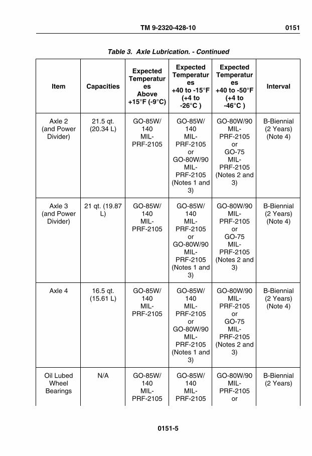
Table 3. Axle Lubrication. - Continued
Item Capacities
ExpectedTemperatur
esAbove
+15°F (-9°C)
ExpectedTemperatur
es+40 to -15°F
(+4 to-26°C )
ExpectedTemperatur
es+40 to -50°F
(+4 to-46°C )
Interval
Axle 2(and Power
Divider)
21.5 qt.(20.34 L)
GO-85W/140MIL-
PRF-2105
GO-85W/140MIL-
PRF-2105or
GO-80W/90MIL-
PRF-2105(Notes 1 and
3)
GO-80W/90MIL-
PRF-2105or
GO-75MIL-
PRF-2105(Notes 2 and
3)
B-Biennial(2 Years)(Note 4)
Axle 3(and Power
Divider)
21 qt. (19.87L)
GO-85W/140MIL-
PRF-2105
GO-85W/140MIL-
PRF-2105or
GO-80W/90MIL-
PRF-2105(Notes 1 and
3)
GO-80W/90MIL-
PRF-2105or
GO-75MIL-
PRF-2105(Notes 2 and
3)
B-Biennial(2 Years)(Note 4)
Axle 4 16.5 qt.(15.61 L)
GO-85W/140MIL-
PRF-2105
GO-85W/140MIL-
PRF-2105or
GO-80W/90MIL-
PRF-2105(Notes 1 and
3)
GO-80W/90MIL-
PRF-2105or
GO-75MIL-
PRF-2105(Notes 2 and
3)
B-Biennial(2 Years)(Note 4)
Oil LubedWheel
Bearings
N/A GO-85W/140MIL-
PRF-2105
GO-85W/140MIL-
PRF-2105
GO-80W/90MIL-
PRF-2105or
B-Biennial(2 Years)
TM 9-2320-428-10 0151
0151-5

Table 3. Axle Lubrication. - Continued
Item Capacities
ExpectedTemperatur
esAbove
+15°F (-9°C)
ExpectedTemperatur
es+40 to -15°F
(+4 to-26°C )
ExpectedTemperatur
es+40 to -50°F
(+4 to-46°C )
Interval
orGO-80W/90
MIL-PRF-2105
(Notes 1 and3)
GO-75MIL-
PRF-2105(Notes 2 and
3)
All OtherAxle
LubricationPoints
As Required GAAMIL-
PRF-10924
GAAMIL-
PRF-10924(Note 3)
GAAMIL-
PRF-10924(Note 3)
As Required(Note 5)
NOTE1. GO-85W/140 must be used when temperatures are consistently
above 30°F (-1°C).2. GO-85W/90 must be used when temperatures are consistently
above -15°F (-26°C).3. Refer to FM 9-207 (WP 0161) for arctic operation.4. An initial lubrication change on new or rebuilt axles should occur
between 500 mi. (805 km) and 1,000 miles (1 609 km). Refer toField Level Annual PMCS for more information.
5. Refer to PMCS tables for specific lubrication intervals.
Table 4. Hydraulic Reservoir Servicing.
Item Capacities
ExpectedTemperatur
esAbove
+15°F (-9°C)
ExpectedTemperatur
es+40 to -15°F
(+4 to-26°C )
ExpectedTemperatur
es+40 to -50°F
(+4 to-46°C )
Interval
HydraulicReservoir
120 qt.(113.52 L)
OE/HDO-10MIL-
PRF-2104
OE/HDO-10MIL-
PRF-2104
OEAMIL-
PRF-46167
A-Annual(1 year)
TM 9-2320-428-10 0151
0151-6

Table 4. Hydraulic Reservoir Servicing. - Continued
Item Capacities
ExpectedTemperatur
esAbove
+15°F (-9°C)
ExpectedTemperatur
es+40 to -15°F
(+4 to-26°C )
ExpectedTemperatur
es+40 to -50°F
(+4 to-46°C )
Interval
orOE/HDO-30
MIL-PRF-2104(Note 1)
(Note 2) (Notes 2 and3)
NOTE1. OE/HDO-30 must be used only when temperatures are consistently
above 60°F (16°C).2. Refer to FM 9-207 (WP 0161) for arctic operation.3. OEA must be used when temperatures are consistently below 0°F
(-18°C).
Table 5. Radiator Servicing.
Item Capacities
ExpectedTemperatur
esAbove
+15°F (-9°C)
ExpectedTemperatur
es+40 to -15°F
(+4 to-26°C )
ExpectedTemperatur
es+40 to -50°F
(+4 to-46°C )
Interval
Antifreeze(CID A-
A-52624)(Note 1)
80 qt. (75.68L)
80 qt. (75.68L)
50%EthyleneGlycol
Type IC(Recycled)
(Notes 1 and2)
80 qt. (75.68L)
50%EthyleneGlycol
Type IC(Recycled)
(Notes 1 and2)
80 qt. (75.68L)
60%EthyleneGlycol
Arctic TypeIB
(Recycled)(Notes 1, 2,
and 3)
A-Annual(1 year)(Note 4)
TM 9-2320-428-10 0151
0151-7

Table 5. Radiator Servicing. - Continued
Item Capacities
ExpectedTemperatur
esAbove
+15°F (-9°C)
ExpectedTemperatur
es+40 to -15°F
(+4 to-26°C )
ExpectedTemperatur
es+40 to -50°F
(+4 to-46°C )
Interval
Antifreeze(CID A-
A-52624)(Note 1)
80 qt. (75.68L)
40 qt. (37.84L)
100%EthyleneGlycol
Type IA(Recycled)
plus40 qt. (37.84
L) water(Notes 1 and
5)
40 qt. (37.84L)
100%EthyleneGlycol
Type IA(Recycled)
plus40 qt. (37.84
L) water(Notes 1 and
5)
48 qt. (45.41L)
100%EthyleneGlycol
Type IA(Recycled)
plus32 qt. (30.27
L) water(Notes 1, 3,
and 6)
A-Annual(1 year)(Note 4)
Antifreeze(CID A-
A-52624)(Note 1)
80 qt. (75.68L)
40 qt. (37.84L)
100%Propylene
GlycolType IIA(virgin)
plus40 qt. (37.84
L) water(Notes 1 and
7)
40 qt. (37.84L)
100%Propylene
GlycolType IIA(virgin)
plus40 qt. (37.84
L) water(Notes 1 and
7)
48 qt. (45.41L)
100%Propylene
GlycolType IIA(virgin)
plus32 qt. (30.27
L) water(Notes 1, 3,
and 8)
A-Annual(1 year)(Note 4)
CorrosionInhibitor(Note 1)
2.4 qt. (2.27L)
(Note 1) (Note 1) (Notes 1 and3)
As Required
NOTE1. Refer to TB 750-651 (WP 0161) for more information on antifreeze
and additives used in the HEMTT series vehicle engine coolingsystem, and TM 750-254 (WP 0161) for detailed instructions fordraining, cleaning, and flushing cooling systems of tactical vehicles.
TM 9-2320-428-10 0151
0151-8

Table 5. Radiator Servicing. - Continued
Item Capacities
ExpectedTemperatur
esAbove
+15°F (-9°C)
ExpectedTemperatur
es+40 to -15°F
(+4 to-26°C )
ExpectedTemperatur
es+40 to -50°F
(+4 to-46°C )
Interval
2. Type 1C (normal) and Type 1B (arctic) antifreeze is premixed, andDOES NOT REQUIRE the addition of water. Never add water orinhibitor to Type IB antifreeze.
3. Refer to FM 9-207 (WP 0161) for arctic operation.4. Engine coolant contaminant level is checked annually. Engine
coolant does not need to be changed until it fails check.5. A mixture of 50% Ethylene Glycol (EG) antifreeze to 50% water will
provide freeze protection down to -34°F (-37°C).6. A mixture of 50% Propylene Glycol (PG) antifreeze to 50% water
will provide freeze protection down to -27°F (-33°C).7. A mixture of 60% Ethylene Glycol (EG) antifreeze to 40% water will
provide freeze protection down to -62°F (-52°C).8. A mixture of 60% Propylene Glycol (PG) antifreeze to 40% water
will provide freeze protection down to -56°F (-49°C).
Table 6. Self-Recovery Winch Lubrication.
Item Capacities
ExpectedTemperatur
esAbove
+15°F (-9°C)
ExpectedTemperatur
es+40 to -15°F
(+4 to-26°C )
ExpectedTemperatur
es+40 to -50°F
(+4 to-46°C )
Interval
Self-Recovery
WinchGearbox(Note 1)
2 qt. (1.89 L) GO-85W/140MIL-
PRF-2105
GO-75MIL-
PRF-2105or
GO-80W/90MIL-
PRF-2105(Note 2)
GO-75MIL-
PRF-2105(Note 2)
A-Annual(1 year)
Winch Cable As Required OE/HDO-30MIL-
PRF-2104
OE/HDO-10MIL-
PRF-2104
OEAMIL-
PRF-46167
S-Semiannual(WP 0149)
TM 9-2320-428-10 0151
0151-9

Table 6. Self-Recovery Winch Lubrication. - Continued
Item Capacities
ExpectedTemperatur
esAbove
+15°F (-9°C)
ExpectedTemperatur
es+40 to -15°F
(+4 to-26°C )
ExpectedTemperatur
es+40 to -50°F
(+4 to-46°C )
Interval
(Note 1) (Note 1) (6 Months)
All OtherSelf-
RecoveryWinch
LubricationPoints
As Required GAAMIL-
PRF-10924
GAAMIL-
PRF-10924(Note 2)
GAAMIL-
PRF-10924(Note 2)
As Required(Note 3)
NOTE1. Pre-lubricated from manufacturer.2. Refer to FM 9-207 (WP 0161) for arctic operation.3. Refer to PMCS tables for specific lubrication intervals.
Table 7. Material Handling Crane Lubrication.
Item Capacities
ExpectedTemperatur
esAbove
+15°F (-9°C)
ExpectedTemperatur
es+40 to -15°F(+4 to -26°C )
ExpectedTemperatur
es+40 to -50°F
(+4 to-46°C )
Interval
Crane SwingDrive
Gearbox
1 pt. (0.47 L) GO-80W/90MIL-
PRF-2105
GO-80W/90MIL-
PRF-2105(Note 1)
GO-75MIL-
PRF-2104(Note 1)
A-Annual(1 year)(Note 2)
Crane Hoist 1 pt. (0.47 L) GO-80W/90MIL-
PRF-2105
GO-80W/90MIL-
PRF-2105(Note 1)
GO-75MIL-
PRF-2104(Note 1)
A-Annual(1 year)
TM 9-2320-428-10 0151
0151-10

Table 7. Material Handling Crane Lubrication. - Continued
Item Capacities
ExpectedTemperatur
esAbove
+15°F (-9°C)
ExpectedTemperatur
es+40 to -15°F(+4 to -26°C )
ExpectedTemperatur
es+40 to -50°F
(+4 to-46°C )
Interval
Hoist Cable As Required OE/HDO-30MIL-
PRF-2104
OE/HDO-10MIL-
PRF-2104(Note 1)
OEAMIL-
PRF-46167(Note 1)
S-Semiannual(WP 0149)(6 Months)
All OtherCrane
LubricationPoints
As Required GAAMIL-
PRF-10924
GAAMIL-
PRF-10924(Note 1)
GAAMIL-
PRF-10924(Note 1)
As Required(Note 3)
NOTE1. Refer to FM 9-207 (WP 0161) for arctic operation.2. Check level and add fluid as necessary. Currently there is no
requirement to drain/fill crane swing drive gearbox.3. Refer to PMCS tables for specific lubrication intervals.
Table 8. Oil Can Point Lubrication.
Capacities
ExpectedTemperaturesAbove +15°F
(-9°C)
ExpectedTemperatures+40 to -15°F(+4 to -26°C )
ExpectedTemperatures+40 to -50°F(+4 to -46°C )
Intervals
As Required OE/HDO-30MIL-PRF-2104
OE/HDO-10MIL-PRF-2104
(Note 1)
OEAMIL-PRF-46167
(Note 1)
As Required(Note 2)
NOTE1. Refer to FM 9-207 (WP 0161) for arctic operation.2. Refer to PMCS tables for specific oilcan lubrication intervals.
TM 9-2320-428-10 0151
0151-11

Table 9. Miscellaneous Lubrication Points.
Item Capacities
ExpectedTemperatur
esAbove
+15°F (-9°C)
ExpectedTemperatur
es+40 to -15°F
(+4 to-26°C )
ExpectedTemperatur
es+40 to -50°F(+4 to -46°C )
Interval
Cargo Body As Required GAAMIL-
PRF-10924
GAAMIL-
PRF-10924(Note 1)
GAAMIL-
PRF-10924(Note 1)
S-Semiannual(WP 0149)(6 Months)
EngineThrottleLever
As Required GAAMIL-
PRF-10924
GAAMIL-
PRF-10924(Note 1)
GAAMIL-
PRF-10924(Note 1)
A-Annual(1 year)
Pintle Hook As Required GAAMIL-
PRF-10924
GAAMIL-
PRF-10924(Note 1)
GAAMIL-
PRF-10924(Note 1)
W-Weekly(WP 0148)
S-Semiannual(WP 0149)(6 Months)
(servicefittings)
PropellerDriverShafts
and U-Joints
As Required GAAMIL-
PRF-10924
GAAMIL-
PRF-10924(Note 1)
GAAMIL-
PRF-10924(Note 1)
S-Semiannual(WP 0149)(6 Months)
(Note 2)
Spare TireDavit
As Required GAAMIL-
PRF-10924
GAAMIL-
PRF-10924(Note 1)
GAAMIL-
PRF-10924(Note 1)
S-Semiannual(WP 0149)(6 Months)
SpringHanger Pins
As Required GAAMIL-
PRF-10924
GAAMIL-
PRF-10924(Note 1)
GAAMIL-
PRF-10924(Note 1)
S-Semiannual(WP 0149)(6 Months)
TM 9-2320-428-10 0151
0151-12

Table 9. Miscellaneous Lubrication Points. - Continued
Item Capacities
ExpectedTemperatur
esAbove
+15°F (-9°C)
ExpectedTemperatur
es+40 to -15°F
(+4 to-26°C )
ExpectedTemperatur
es+40 to -50°F(+4 to -46°C )
Interval
SteeringSystem
As Required GAAMIL-
PRF-10924
GAAMIL-
PRF-10924(Note 1)
GAAMIL-
PRF-10924(Note 1)
S-Semiannual(WP 0149)(6 Months)
Table 10. Vehicle Cleaning.
Item Capacities ExpectedTemperature Intervals
CleaningCompound, Solvent
(Note 1)
As Required SD AllTemperatures
(Note 2)
As Required
NOTE1. After a thorough high pressure washing, lubricate all grease fittings
and oil can points outside and underneath vehicle.2. Refer to FM 9-207 (WP 0161) for arctic operation.
END OF WORK PACKAGE
TM 9-2320-428-10 0151
0151-13

OPERATOR MAINTENANCECLOSE/OPEN HEATER VALVES
INITIAL SETUP:
Equipment ConditionEngine OFF. (WP 0057)
Equipment Condition - ContinuedWheels chocked. (WP 0077)Open passenger side engine cover.(WP 0160)
CLOSE HEATER VALVES
NOTE• Closing two heater valves will improve efficiency of air conditioning
kit.
• Closing two heater valves will disable cabin heat.
• Two heater valve knobs are located on front passenger side ofengine, the bottom valve is located approximately 18 in. (46 cm)below the top valve.
1. Turn two heater valve knobs (1) counterclockwise to close.
TM 9-2320-428-10 0152
0152-1

CLOSE HEATER VALVES - Continued
1
Figure 1.
END OF TASK
OPEN HEATER VALVES
NOTE• Opening two heater valves will diminish efficiency of air conditioning
kit.
• Opening two heater valves will enable cabin heat.
• Two heater valve knobs are located on front passenger side ofengine, the bottom valve is located approximately 18 in. (46 cm)below the top valve.
1. Turn two heater valve knobs (1) clockwise to close.
TM 9-2320-428-10 0152
0152-2

OPEN HEATER VALVES - Continued
1
Figure 2.
END OF TASK
FOLLOW-ON MAINTENANCE
1. Close passenger side engine cover. (WP 0160)
2. Remove wheel chocks.
END OF WORK PACKAGE
TM 9-2320-428-10 0152
0152-3


OPERATOR MAINTENANCEPRE/POST TOWING PROCEDURE (FRONT LIFT ONLY)
INITIAL SETUP:
Tools and Special ToolsChain, 8 ft. (supplied by wrecker)Chain, 7 ft. (supplied by wrecker)(WP 0162, Table 3, Item 6)
Equipment ConditionEngine OFF. (WP 0057)
PREPARE VEHICLE FOR TOWING
CAUTIONWhen installing axle restraint chains, route chains so hoses or lines arenot between frame and chain or axle and chain. Failure to comply mayresult in damage to equipment.
NOTE• This procedure is applicable to preparation for towing a HEMTT
series vehicle from the front ONLY (refer to tow HEMTT-front lift forfurther information).
• If disabled vehicle is either a BASE or A2 model HEMTT seriesvehicle (refer to data plate on inside of driver side door), completeStep (1).
• If disabled vehicle is an A4 model HEMTT series vehicle (refer to dataplate on inside of driver side door), skip to Step (2).
1. Perform the following on disabled vehicle:
a. Remove propeller shaft between transfer case and No. 3 axle.
b. Install axle restraint chains (1):
TM 9-2320-428-10 0153
0153-1

PREPARE VEHICLE FOR TOWING - Continued
2 1
1
3
4
Figure 1.
NOTE• Axle restraint chains are installed the same way, driver side
shown.
• No. 2 axle should be restrained with chains on both sides ofvehicle.
(1) Route axle restraint chain (1) over frame rail (2) and around axle (3) besidewalking beam (4).
(2) Hook axle restraint chain (1) back into itself.
(3) Repeat Steps (1) and (2) for opposite side of No. 2 axle (3).
CAUTIONWhen installing axle restraint chains, route chain around frame rail andaxle only. Do not wrap chain around lateral torque rod, shock absorber,shift cables, etc. as they could be crushed. Route chains so hoses or linesare not between frame and chain or axle and chain. Failure to complymay result in damage to equipment.
NOTE• This procedure is applicable to preparation for towing a HEMTT
series vehicle from the front ONLY (refer to tow HEMTT-front lift forfurther information).
• If disabled vehicle is an A4 model HEMTT series vehicle (refer to dataplate on inside of driver side door), complete Step (2).
TM 9-2320-428-10 0153
0153-2

PREPARE VEHICLE FOR TOWING - Continued
2. Perform the following on disabled vehicle:
a. Remove propeller shaft between transfer case and No. 3 axle.
b. Install axle restraint chains (1):
3
2
1
4
Figure 2.
NOTE• Axle restraint chains are installed the same way, driver side
shown.
• No. 2 axle should be restrained with chains on both sides ofvehicle.
(1) Route axle restraint chain (1) under engine shroud (2), over frame rail (3),and around axle (4).
(2) Hook axle restraint chain (1) back into itself as shown.
(3) Repeat Steps (1) and (2) for opposite side of No. 2 axle (3).
END OF TASK
TM 9-2320-428-10 0153
0153-3
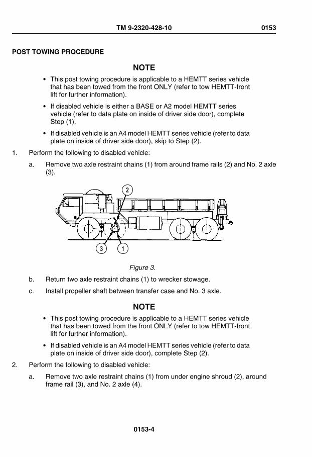
POST TOWING PROCEDURE
NOTE• This post towing procedure is applicable to a HEMTT series vehicle
that has been towed from the front ONLY (refer to tow HEMTT-frontlift for further information).
• If disabled vehicle is either a BASE or A2 model HEMTT seriesvehicle (refer to data plate on inside of driver side door), completeStep (1).
• If disabled vehicle is an A4 model HEMTT series vehicle (refer to dataplate on inside of driver side door), skip to Step (2).
1. Perform the following to disabled vehicle:
a. Remove two axle restraint chains (1) from around frame rails (2) and No. 2 axle(3).
2
3 1
Figure 3.
b. Return two axle restraint chains (1) to wrecker stowage.
c. Install propeller shaft between transfer case and No. 3 axle.
NOTE• This post towing procedure is applicable to a HEMTT series vehicle
that has been towed from the front ONLY (refer to tow HEMTT-frontlift for further information).
• If disabled vehicle is an A4 model HEMTT series vehicle (refer to dataplate on inside of driver side door), complete Step (2).
2. Perform the following to disabled vehicle:
a. Remove two axle restraint chains (1) from under engine shroud (2), aroundframe rail (3), and No. 2 axle (4).
TM 9-2320-428-10 0153
0153-4

POST TOWING PROCEDURE - Continued
3
2
1
4
Figure 4.
b. Return two axle restraint chains (1) to wrecker stowage.
c. Install propeller shaft between transfer case and No. 3 axle.
END OF TASK
END OF WORK PACKAGE
TM 9-2320-428-10 0153
0153-5

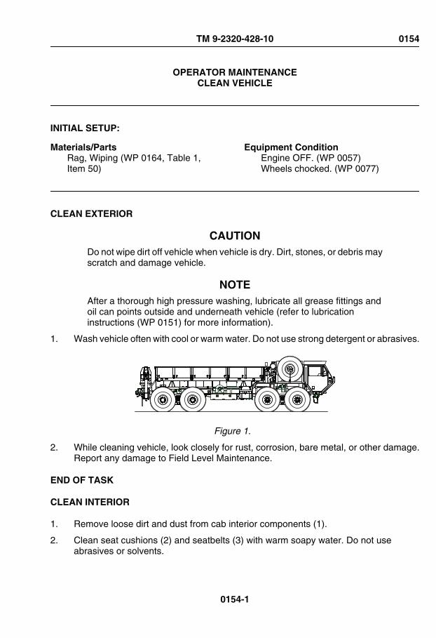
OPERATOR MAINTENANCECLEAN VEHICLE
INITIAL SETUP:
Materials/PartsRag, Wiping (WP 0164, Table 1,Item 50)
Equipment ConditionEngine OFF. (WP 0057)Wheels chocked. (WP 0077)
CLEAN EXTERIOR
CAUTIONDo not wipe dirt off vehicle when vehicle is dry. Dirt, stones, or debris mayscratch and damage vehicle.
NOTEAfter a thorough high pressure washing, lubricate all grease fittings andoil can points outside and underneath vehicle (refer to lubricationinstructions (WP 0151) for more information).
1. Wash vehicle often with cool or warm water. Do not use strong detergent or abrasives.
Figure 1.
2. While cleaning vehicle, look closely for rust, corrosion, bare metal, or other damage.Report any damage to Field Level Maintenance.
END OF TASK
CLEAN INTERIOR
1. Remove loose dirt and dust from cab interior components (1).
2. Clean seat cushions (2) and seatbelts (3) with warm soapy water. Do not useabrasives or solvents.
TM 9-2320-428-10 0154
0154-1

CLEAN INTERIOR - Continued
2
3
1
Figure 2.
3. Wipe seat cushions (2) and seatbelts (3) dry.
END OF TASK
END OF WORK PACKAGE
TM 9-2320-428-10 0154
0154-2

OPERATOR MAINTENANCECHANGE WHEEL AND TIRE ASSEMBLY
INITIAL SETUP:
Tools and Special ToolsChocks, Wheel (2) (WP 0162, Table 3,Item 8)Extension, Handle (WP 0162, Table 3,Item 12)Handle, Wrench (WP 0162, Table 3,Item 13)Jack, 12-ton, With Handle (WP 0162,Table 3, Item 16)Jack, Base Plate (WP 0162, Table 3,Item 19)
Tools and Special Tools - ContinuedWarning Device Set, Triangular(WP 0162, Table 3, Item 21)Wrench, Wheel Lugnut (WP 0162,Table 3, Item 32)Wrench, Adjustable (WP 0162,Table 3, Item 30)
Personnel RequiredOperator and Assistant - - - (2)
PREPARE VEHICLE
1. Shut off engine. (WP 0057)
WARNING
Park vehicle in safe area, out of traffic, where there is no danger topersonnel changing tire assembly. Park vehicle on hard level ground.Failure to comply may result in injury or death to personnel.
2. Turn on emergency flashers. (WP 0076)
3. Set up emergency marker kit, as necessary. (WP 0099)
END OF TASK
SET UP TIRE DAVIT WINCH
1. Remove hoist arm (1) from mounting bracket (2).
TM 9-2320-428-10 0155
0155-1

SET UP TIRE DAVIT WINCH - Continued
1
2
Figure 1.
2. Install hoist arm (1) in mount (3).
TM 9-2320-428-10 0155
0155-2

SET UP TIRE DAVIT WINCH - Continued
3
41
5
67
8
Figure 2.
3. Remove and keep safety pin (4) and pin (5) from hoist arm (1).
4. Remove nut (6), washer, and extension (8) from mount (3).
5. Install extension (8) in hoist arm (1).
TM 9-2320-428-10 0155
0155-3

SET UP TIRE DAVIT WINCH - Continued
Figure 3.
6. Line up holes in extension (8) and hoist arm (1).
7. Install pin (5) and safety pin (4).
8. Turn hand crank (9) CCW and route cable (10) over end of pulley (11).
11
9
10
Figure 4.
END OF TASK
TM 9-2320-428-10 0155
0155-4

REMOVE SPARE WHEEL AND TIRE ASSEMBLY
1. Remove two wheel chocks (1) from under spare wheel and tire assembly (2).
11
2
Figure 5.
2. Install two wheel chocks (WP 0077) (1) on wheel and tire assembly (3) that is acrossfrom flat wheel and tire assembly (4).
4113
Figure 6.
3. Turn hand crank (5) counterclockwise to let out enough cable (6) to push through holein wheel (7) and wrap around spare wheel and tire assembly (2).
TM 9-2320-428-10 0155
0155-5
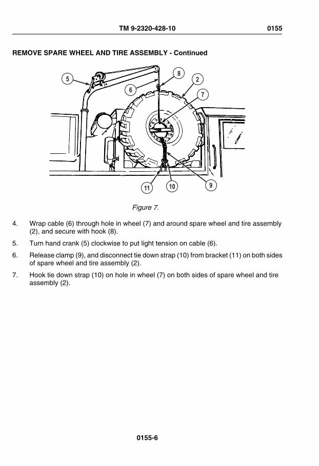
REMOVE SPARE WHEEL AND TIRE ASSEMBLY - Continued
2
7
9
85
6
1011
Figure 7.
4. Wrap cable (6) through hole in wheel (7) and around spare wheel and tire assembly(2), and secure with hook (8).
5. Turn hand crank (5) clockwise to put light tension on cable (6).
6. Release clamp (9), and disconnect tie down strap (10) from bracket (11) on both sidesof spare wheel and tire assembly (2).
7. Hook tie down strap (10) on hole in wheel (7) on both sides of spare wheel and tireassembly (2).
TM 9-2320-428-10 0155
0155-6
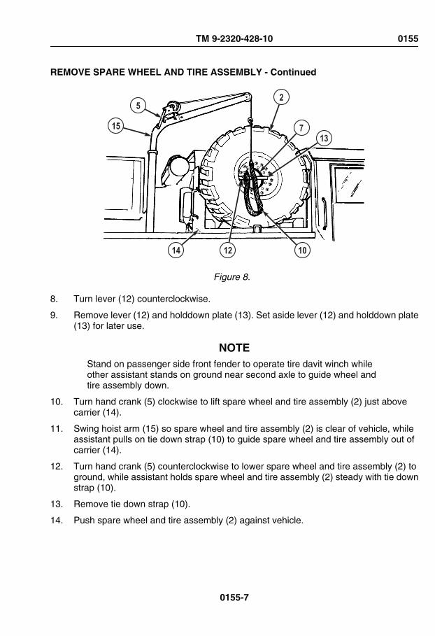
REMOVE SPARE WHEEL AND TIRE ASSEMBLY - Continued
137
25
15
1214 10
Figure 8.
8. Turn lever (12) counterclockwise.
9. Remove lever (12) and holddown plate (13). Set aside lever (12) and holddown plate(13) for later use.
NOTEStand on passenger side front fender to operate tire davit winch whileother assistant stands on ground near second axle to guide wheel andtire assembly down.
10. Turn hand crank (5) clockwise to lift spare wheel and tire assembly (2) just abovecarrier (14).
11. Swing hoist arm (15) so spare wheel and tire assembly (2) is clear of vehicle, whileassistant pulls on tie down strap (10) to guide spare wheel and tire assembly out ofcarrier (14).
12. Turn hand crank (5) counterclockwise to lower spare wheel and tire assembly (2) toground, while assistant holds spare wheel and tire assembly (2) steady with tie downstrap (10).
13. Remove tie down strap (10).
14. Push spare wheel and tire assembly (2) against vehicle.
TM 9-2320-428-10 0155
0155-7
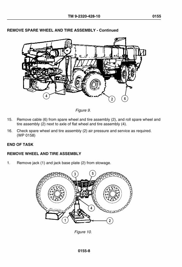
REMOVE SPARE WHEEL AND TIRE ASSEMBLY - Continued
42 6
Figure 9.
15. Remove cable (6) from spare wheel and tire assembly (2), and roll spare wheel andtire assembly (2) next to axle of flat wheel and tire assembly (4).
16. Check spare wheel and tire assembly (2) air pressure and service as required.(WP 0158)
END OF TASK
REMOVE WHEEL AND TIRE ASSEMBLY
1. Remove jack (1) and jack base plate (2) from stowage.
3 5
4
1 2
Figure 10.
TM 9-2320-428-10 0155
0155-8

REMOVE WHEEL AND TIRE ASSEMBLY - Continued
NOTEIt may be necessary to place wheel chock under flat wheel and tireassembly to get jack and jack base plate under equalizing beam.
2. Position jack (1) and jack base plate (2) under equalizing beam (3).
3. Unscrew jack ram (4) until it touches equalizing beam (3) approximately 4 to 5 in. (102to 127 mm) from beam center pivot point (5).
NOTEStuds and lugnuts on driver side of vehicle have left-hand threads. Rotatelugnuts clockwise to loosen, counterclockwise to tighten. Studs andlugnuts on passenger side of vehicle have right-hand threads. Rotatelugnuts counterclockwise to loosen, clockwise to tighten.
4. Loosen 10 lugnuts (6) until they turn easily.
9
8
7
16
Figure 11.
NOTEIf chock was used to help position jack, wheel and tire assembly does nothave to be clear of chock.
5. Raise jack (1) until flat wheel and tire assembly (7) can be removed.
6. Remove 10 lugnuts (6) from studs (8) and set lugnuts (6) aside.
NOTEIf wheel chock was not used to position jack, skip to Step (8).
7. Remove wheel chock (9) and return it to vehicle stowage.
TM 9-2320-428-10 0155
0155-9

REMOVE WHEEL AND TIRE ASSEMBLY - Continued
8. Using jack (1), lower vehicle until flat wheel and tire assembly (7) is just touchingground.
9. Tilt top of flat wheel and tire assembly (7) forward, while assistant raises jack (1)slightly. Wheel and tire assembly (7) should move forward.
10. Repeat Steps (8) and (9) to walk flat wheel and tire assembly (7) off studs (8).
11. Remove flat wheel and tire assembly (7) and lean flat wheel and tire assembly againstvehicle.
END OF TASK
INSTALL WHEEL AND TIRE ASSEMBLY
NOTETire tread is non-directional. Vehicle operation is not affected by directionof traction bars.
1. With aid of an assistant, roll wheel and tire assembly (1) up to axle (2).
2 1
3
Figure 12.
NOTECheck that spare wheel and tire assembly wheel dish is in same positionas flat wheel and tire assembly wheel dish. Deep side of wheel dish willface toward vehicle on four front wheels. Deep side of wheel dish will faceaway from vehicle on four rear wheels except M984A. All eight wheelson M984A are installed with deep side of wheel dish facing towardvehicle.
TM 9-2320-428-10 0155
0155-10

INSTALL WHEEL AND TIRE ASSEMBLY - Continued
2. Make sure deep side of spare wheel and tire assembly wheel dish (3) is in sameposition as flat/shredded wheel and tire assembly wheel dish when flat/shreddedwheel and tire assembly was removed.
NOTE• Tire valve stem extension must be removed to reposition wheel and
tire assembly valve stem extension.
• It may be necessary to reposition valve stem to accomplishinstallation of valve stem extension.
3. Make sure wheel and tire assembly valve stem (4) is pointing out, away from vehicle.
4SHALLOW DISH OUT
DEEP DISH OUT
Figure 13.
4. Line up holes in rim (5) of wheel and tire assembly (1) with studs (6) on axle (2).
TM 9-2320-428-10 0155
0155-11

INSTALL WHEEL AND TIRE ASSEMBLY - Continued
2
6
51
7
Figure 14.
WARNING
Wheel/tire assembly weighs 540 lbs (245 kg). Do not attempt to lift ormove wheel/tire assembly without the aid of an assistant and a liftingdevice. Failure to comply may result in injury or death to personnel.
5. Lean top of wheel and tire assembly (1) against studs (6) and axle (2).
NOTEInstall a lugnut on top stud, and hand-tighten to hold wheel and tireassembly in place.
6. Using handle extension (7), slide spare wheel and tire assembly onto studs (6) whileassistant raises vehicle with jack. Bottom of wheel and tire assembly (1) should swingtoward axle (2).
7. Assistant lowers vehicle until wheel and tire assembly (1) just touches ground.
8. Repeat Steps (5) through (7) until wheel and tire assembly (1) is seated on axle (2)and studs (6).
NOTE• Studs and lugnuts on driver side of vehicle have left-hand threads.
Rotate lugnuts counterclockwise to tighten.
TM 9-2320-428-10 0155
0155-12

INSTALL WHEEL AND TIRE ASSEMBLY - Continued
• Studs and lugnuts on passenger side of vehicle have right-handthreads. Rotate lugnuts clockwise to tighten.
9. Install and tighten 10 lugnuts (8) in order shown using wheel lugnut wrench.
8
FINISHSTART
Figure 15.
10. Assistant lowers jack (9) until vehicle weight is fully supported by suspension system.
11. Remove jack (9) and jack base plate (10) from under vehicle.
9
10
Figure 16.
12. Tighten 10 lugnuts (8) in order shown until they no longer tighten.
TM 9-2320-428-10 0155
0155-13

INSTALL WHEEL AND TIRE ASSEMBLY - Continued
8
FINISHSTART
Figure 17.
13. Return all tools and equipment to proper stowage boxes.
14. Return vehicle to field level maintenance and have lugnuts (8) tightened to torquerequirements as soon as possible.
END OF TASK
STOW FLAT WHEEL AND TIRE ASSEMBLY
1. Roll flat wheel and tire assembly (1) under hoist arm (2) so deep side of wheel dish(3) is facing out and away from vehicle.
TM 9-2320-428-10 0155
0155-14

STOW FLAT WHEEL AND TIRE ASSEMBLY - Continued
1
7 3
6
84
25
9
Figure 18.
NOTEAssistant stands on passenger side front fender to operate tire davitwinch while other assistant stands on ground near second axle to guidewheel and tire assembly into carrier.
2. Turn hand crank (4) counterclockwise to let out cable (5).
3. Pull tie down strap (6) through hole in wheel (7), and hook ends to hole on both sidesof wheel.
4. Hook ends of tie down strap (6) to both sides of hole in wheel (7).
5. Pull cable (5) through hole in wheel (7) and secure hook (8) back into cable as shown.
WARNING
Inner wheel weighs 105 lbs (48 kg). Do not attempt to lift or move innerwheel without the aid of an assistant and a lifting device. Failure to complymay result in injury or death to personnel.
TM 9-2320-428-10 0155
0155-15

STOW FLAT WHEEL AND TIRE ASSEMBLY - Continued
6. Turn hand crank (4) clockwise to raise flat wheel and tire assembly (1) just abovecarrier (9) while assistant holds tie down strap (6) to steady wheel and tire assembly(1).
7. Swing hoist arm (2) so flat wheel and tire assembly (1) is over carrier (9) while assistantguides wheel and tire assembly with tie down strap (6).
8. Turn hand crank (4) counterclockwise to lower flat wheel and tire assembly (1) intocarrier (9).
9. Remove tie down strap (6).
10. Hold flat wheel and tire assembly (1) steady, while assistant installs holddown plate(10).
4
14
136127
10
81
511
Figure 19.
11. Install lever (11) and turn clockwise to tighten.
12. Slide tie down strap (6) through hole in wheel (7).
13. Connect tie down strap (6) to outside holddown bracket (12), while assistant connectstie down strap to inside holddown bracket.
14. Pull latch (13) down and lock to secure flat wheel and tire assembly (1).
15. Turn hand crank (4) counterclockwise to loosen cable (5).
16. Remove hook (8) and cable (5) from wheel and tire assembly (1).
TM 9-2320-428-10 0155
0155-16

STOW FLAT WHEEL AND TIRE ASSEMBLY - Continued
17. Turn hand crank (4) clockwise and wind cable (5) fully onto reel (14).
END OF TASK
STOW TIRE DAVIT WINCH
1. Remove safety pin (1) and pin (2) from extension (3).
32
1
4
Figure 20.
2. Pull extension (3) from hoist arm (4).
3. Install extension (3) on mount (5).
TM 9-2320-428-10 0155
0155-17

STOW TIRE DAVIT WINCH - Continued
3
7 8
6
4
5
Figure 21.
4. Slide top of extension (3) over stud (6).
5. Secure extension (3) with washer (7) and nut (8).
6. Pull hoist arm (4) from mount (5).
7. Put hoist arm (4) into mounting bracket (9).
TM 9-2320-428-10 0155
0155-18

STOW TIRE DAVIT WINCH - Continued
4
1
2
9
Figure 22.
8. Install pin (10) through hoist arm (4).
9. Secure pin (10) with safety pin (11).
10. Pick up and stow emergency marker kit (as necessary).
END OF TASK
END OF WORK PACKAGE
TM 9-2320-428-10 0155
0155-19

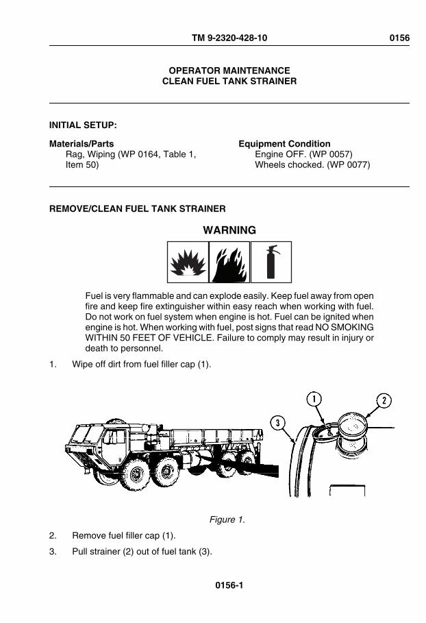
OPERATOR MAINTENANCECLEAN FUEL TANK STRAINER
INITIAL SETUP:
Materials/PartsRag, Wiping (WP 0164, Table 1,Item 50)
Equipment ConditionEngine OFF. (WP 0057)Wheels chocked. (WP 0077)
REMOVE/CLEAN FUEL TANK STRAINER
WARNING
Fuel is very flammable and can explode easily. Keep fuel away from openfire and keep fire extinguisher within easy reach when working with fuel.Do not work on fuel system when engine is hot. Fuel can be ignited whenengine is hot. When working with fuel, post signs that read NO SMOKINGWITHIN 50 FEET OF VEHICLE. Failure to comply may result in injury ordeath to personnel.
1. Wipe off dirt from fuel filler cap (1).
Figure 1.
2. Remove fuel filler cap (1).
3. Pull strainer (2) out of fuel tank (3).
TM 9-2320-428-10 0156
0156-1

REMOVE/CLEAN FUEL TANK STRAINER - Continued
4. Clean strainer (2) with clean dry rag.
END OF TASK
INSTALL FUEL TANK STRAINER
1. Put strainer (2) in fuel tank (3).
Figure 2.
2. Install and tighten fuel filler cap (1).
END OF TASK
FOLLOW-ON MAINTENANCE
1. Remove wheel chocks.
END OF WORK PACKAGE
TM 9-2320-428-10 0156
0156-2

OPERATOR MAINTENANCESERVICE AIR CLEANER ELEMENT
INITIAL SETUP:
Tools and Special ToolsLadder (WP 0162, Table 2, Item 2)
Materials/PartsRag, Wiping (WP 0164, Table 1,Item 50)
Equipment ConditionEngine OFF. (WP 0057)Wheels chocked. (WP 0077)
REMOVE AIR CLEANER ELEMENT
1. Lift up three levers (1).
Figure 1.
2. Unhook three latches (2) from cover groove (3).
3. Remove cover (4) from canister (5).
4. Unscrew knob (6) until retaining bar (7) is loose.
TM 9-2320-428-10 0157
0157-1

REMOVE AIR CLEANER ELEMENT - Continued
Figure 2.
5. Remove knob (6) and retaining bar (7).
CAUTIONDo not remove secondary filter element. Dirt and debris can fall intocanister and cause damage to engine.
6. Take hold of handles (8) and remove primary element (9) from canister (5).
TM 9-2320-428-10 0157
0157-2

REMOVE AIR CLEANER ELEMENT - Continued
Figure 3.
END OF TASK
CLEAN AIR CLEANER ELEMENT
NOTENotify field level maintenance if primary filter element is damaged orcannot be cleaned by tapping.
1. Tap side of primary element (9) lightly against hand.
TM 9-2320-428-10 0157
0157-3

CLEAN AIR CLEANER ELEMENT - Continued
9
Figure 4.
2. Dump out dirt and dust from primary element (9).
3. Wipe primary element (9) with clean rag.
END OF TASK
INSTALL AIR CLEANER ELEMENT
1. Install primary element (9) in air cleaner canister (5).
TM 9-2320-428-10 0157
0157-4

INSTALL AIR CLEANER ELEMENT - Continued
5
6
7 109
Figure 5.
2. Position knob (6) and retainer bar (7) over primary element (9). Make sure ends ofretaining bar are in tabs (10).
3. Tighten knob (6) to secure primary element (9).
4. Put cover (4) on top of air cleaner canister (5).
Figure 6.
TM 9-2320-428-10 0157
0157-5

INSTALL AIR CLEANER ELEMENT - Continued
5. Put three latches (2) in cover groove (3).
6. Push three levers (1) down to secure cover (4).
7. Start engine. (WP 0044)
8. Push button (11) to reset air cleaner restriction indicator (12). If indicator window (13)shows VACUUM INCHES H20 below 20, continue with vehicle operation but notifyField Level Maintenance as soon as possible. If indicator window shows VACUUMINCHES H20 above 20, notify Field Level Maintenance.
13
11
12
Figure 7.
9. Shut OFF engine. (WP 0057)
END OF TASK
FOLLOW-ON MAINTENANCE
1. Remove wheel chocks.
END OF WORK PACKAGE
TM 9-2320-428-10 0157
0157-6

OPERATOR MAINTENANCESERVICE TIRES
INITIAL SETUP:
Tools and Special ToolsGauge, Tire Pressure (WP 0162,Table 3, Item 11)
Tools and Special Tools - ContinuedGauge, Tire Pressure (WP 0162,Table 3, Item 15)Hose: Air, Pneumatic (WP 0162,Table 3, Item 14)
Equipment ConditionEngine OFF. (WP 0057)Wheels chocked. (WP 0077)
CHECK TIRE PRESSURE
WARNING
Failure to comply with these procedures may result in faulty positioningof the tire and/or rim parts and cause the assembly to burst with explosiveforce. Never mount or use damaged tires or rims. Failure to comply mayresult in injury or death to personnel.
NOTEThere are two types of air pressure gauges. One is a separate handheldgauge. The other is a combined pressure gauge/inflation hose.
Both may be used to check air pressure in tire.
ALWAYS use combined pressure gauge/inflation hose to inflate tire.
1. Check tire air pressure with tire pressure gauge.
2. Ensure tires have correct air pressure for road conditions and driving speed .
END OF TASK
TM 9-2320-428-10 0158
0158-1
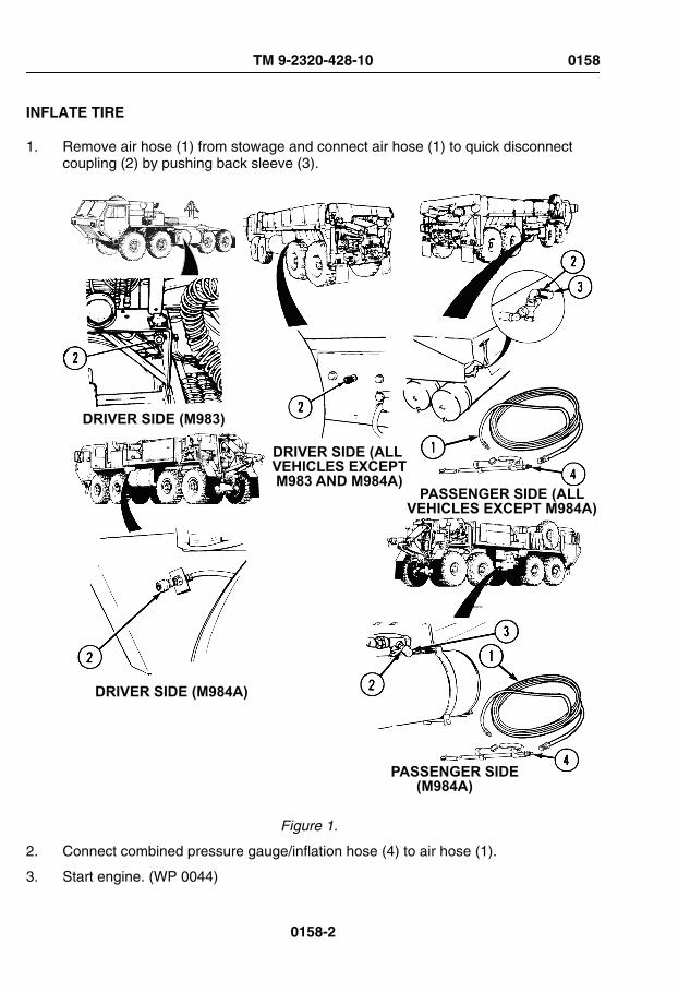
INFLATE TIRE
1. Remove air hose (1) from stowage and connect air hose (1) to quick disconnectcoupling (2) by pushing back sleeve (3).
DRIVER SIDE (M983)
DRIVER SIDE (M984A)
PASSENGER SIDE(M984A)
DRIVER SIDE (ALL VEHICLES EXCEPTM983 AND M984A)
PASSENGER SIDE (ALLVEHICLES EXCEPT M984A)
Figure 1.
2. Connect combined pressure gauge/inflation hose (4) to air hose (1).
3. Start engine. (WP 0044)
TM 9-2320-428-10 0158
0158-2

INFLATE TIRE - Continued
4. Remove valve stem cap (5) from valve stem (6).
6
5
Figure 2.
WARNING
Prior to inflating or deflating tire, stand clear of trajectory area. Failure tocomply may result in injury or death to personnel.
NOTE• Trajectory area as shown applies to all wheel/tire assemblies.
• Air chuck must clamp securely with no leaks or air pressure gaugereadings will be inaccurate.
TM 9-2320-428-10 0158
0158-3

INFLATE TIRE - Continued
• There are two types of air pressure gauges. One is a separatehandheld gauge used on vehicle serial number 51130 and below.The other is a combined pressure gauge/inflation hose.
• Both may be used to check air pressure in tire.
• ALWAYS use combined pressure gauge/inflation hose to inflate tire.
5. Push latch handle (7) inward, while pushing air chuck (8) onto valve stem (6). Releaselatch handle (7) and immediately step out of the trajectory area and read tire airpressure gauge.
TRAJECTORY
TRAJECTORYTRAJECTORY
8
7
6
TRAJECTORY
Figure 3.
TM 9-2320-428-10 0158
0158-4
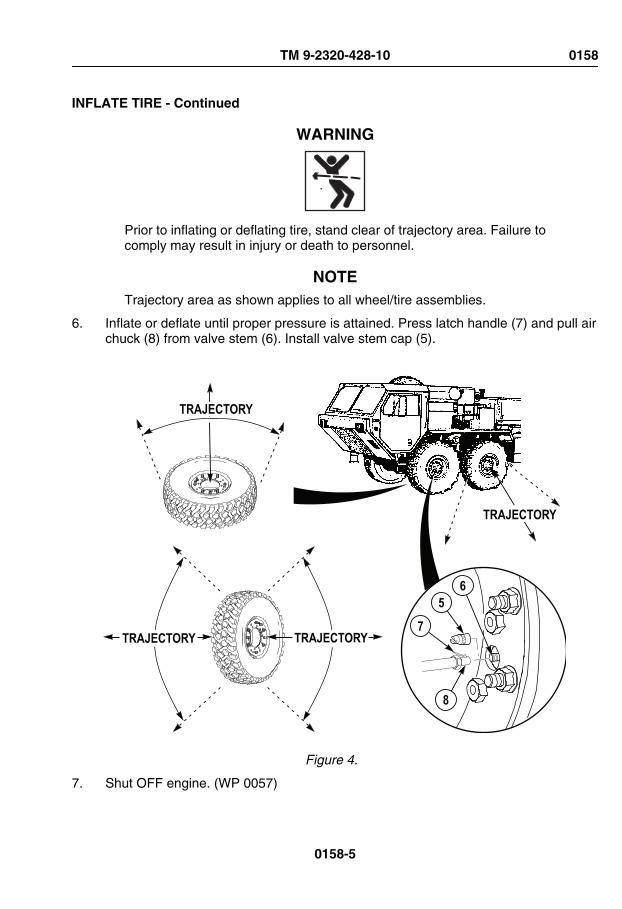
INFLATE TIRE - Continued
WARNING
Prior to inflating or deflating tire, stand clear of trajectory area. Failure tocomply may result in injury or death to personnel.
NOTETrajectory area as shown applies to all wheel/tire assemblies.
6. Inflate or deflate until proper pressure is attained. Press latch handle (7) and pull airchuck (8) from valve stem (6). Install valve stem cap (5).
TRAJECTORY
TRAJECTORYTRAJECTORY
8
75
6
TRAJECTORY
Figure 4.
7. Shut OFF engine. (WP 0057)
TM 9-2320-428-10 0158
0158-5

INFLATE TIRE - Continued
WARNING
Hold end of air line when disconnecting from quick-disconnect coupling.Air line is under pressure and can be ejected at a high rate of speed.Failure to comply may result in injury or death to personnel.
8. Remove combined pressure gauge/inflation hose (4) from air hose (1).
TM 9-2320-428-10 0158
0158-6

INFLATE TIRE - Continued
DRIVER SIDE (M983)
DRIVER SIDE (M984A)
PASSENGER SIDE(M984A)
DRIVER SIDE (ALL VEHICLES EXCEPTM983 AND M984A)
PASSENGER SIDE (ALLVEHICLES EXCEPT M984A)
Figure 5.
9. Hold end of air hose (1) and push sleeve (3) back and remove air hose (1) from quick-disconnect coupling (2).
10. Stow air hose (1) and combined pressure gauge/inflation hose (4).
END OF TASK
TM 9-2320-428-10 0158
0158-7

FOLLOW-ON MAINTENANCE
1. Remove wheel chocks. (WP 0077)
END OF WORK PACKAGE
TM 9-2320-428-10 0158
0158-8

OPERATOR MAINTENANCEOPEN/CLOSE BATTERY BOX
INITIAL SETUP:
Equipment ConditionEngine OFF. (WP 0057)Wheels chocked. (WP 0077)
OPEN BATTERY BOX
WARNING
Wear proper eye protection when working around batteries. Failure tocomply may result in injury or death to personnel.
WARNING
Batteries produce explosive gases. Do not smoke or use open flame nearbatteries. Do not allow hot, sparking, or glowing objects near batteries. Ifbatteries are giving off gases, presence of a heat, flame, or spark maycause fire and/or explosion. Failure to comply may result in injury or deathto personnel.
WARNING
Use extreme care not to short out battery terminals. Remove all jewelrysuch as rings, ID tags, bracelets, etc. prior to working on or aroundvehicle. Jewelry and tools can catch on equipment, contact positive
TM 9-2320-428-10 0159
0159-1

OPEN BATTERY BOX - Continued
electrical circuits, and cause a direct short, severe burns, or electricalshock. Failure to comply may result in injury or death to personnel.
WARNING
LEAD-ACID BATTERIES - Avoid battery electrolyte contact withskin, eyes, or clothing. If battery electrolyte spills, take immediateaction to stop burning effects:
• External - If battery electrolyte contacts skin, immediately flusheffected area with cold running water to remove all acid. Failure tocomply may result in injury or death to personnel.
• Eyes - If battery electrolyte contacts eyes, immediately flush eyeswith cold water for 15 minutes and seek immediate medical attention.IMPORTANT - If only one eye is affected, ensure the affected eye isalways (during both flushing and transport) kept lower (the lower thebetter) than unaffected eye. This will help keep affected eye fromdraining into (and contaminating) the unaffected eye. Failure tocomply may result in injury or death to personnel.
• Internal - If battery electrolyte is ingested (swallowed), drink largeamounts of water or milk. Follow with milk of magnesia, a beaten egg,or vegetable oil and seek immediate medical attention. Failure tocomply may result in injury or death to personnel.
• Clothing or vehicle - Immediately flush area with cold water andneutralize battery electrolyte with baking soda or household ammoniasolution. Failure to comply may result in injury or death to personnel.
1. Disconnect two rubber hooks (1).
TM 9-2320-428-10 0159
0159-2

OPEN BATTERY BOX - Continued
Figure 1.
2. Slide cover (2) up and out.
3. Hold cover (2) in place or remove cover.
END OF TASK
CLOSE BATTERY BOX
WARNING
Wear proper eye protection when working around batteries. Failure tocomply may result in injury or death to personnel.
TM 9-2320-428-10 0159
0159-3

CLOSE BATTERY BOX - Continued
WARNING
Batteries produce explosive gases. Do not smoke or use open flame nearbatteries. Do not allow hot, sparking, or glowing objects near batteries. Ifbatteries are giving off gases, presence of a heat, flame, or spark maycause fire and/or explosion. Failure to comply may result in injury or deathto personnel.
WARNING
Use extreme care not to short out battery terminals. Remove all jewelrysuch as rings, ID tags, bracelets, etc. prior to working on or aroundvehicle. Jewelry and tools can catch on equipment, contact positiveelectrical circuits, and cause a direct short, severe burns, or electricalshock. Failure to comply may result in injury or death to personnel.
WARNING
LEAD-ACID BATTERIES - Avoid battery electrolyte contact withskin, eyes, or clothing. If battery electrolyte spills, take immediateaction to stop burning effects:
• External - If battery electrolyte contacts skin, immediately flusheffected area with cold running water to remove all acid. Failure tocomply may result in injury or death to personnel.
• Eyes - If battery electrolyte contacts eyes, immediately flush eyeswith cold water for 15 minutes and seek immediate medical attention.IMPORTANT - If only one eye is affected, ensure the affected eye isalways (during both flushing and transport) kept lower (the lower thebetter) than unaffected eye. This will help keep affected eye from
TM 9-2320-428-10 0159
0159-4

CLOSE BATTERY BOX - Continued
draining into (and contaminating) the unaffected eye. Failure tocomply may result in injury or death to personnel.
• Internal - If battery electrolyte is ingested (swallowed), drink largeamounts of water or milk. Follow with milk of magnesia, a beaten egg,or vegetable oil and seek immediate medical attention. Failure tocomply may result in injury or death to personnel.
• Clothing or vehicle - Immediately flush area with cold water andneutralize battery electrolyte with baking soda or household ammoniasolution. Failure to comply may result in injury or death to personnel.
1. Slide cover (2) on battery box (3).
Figure 2.
2. Align rubber hooks (1) and brackets (4).
3. Connect rubber hooks (1).
END OF TASK
TM 9-2320-428-10 0159
0159-5

FOLLOW-ON MAINTENANCE
1. Remove wheel chocks. (WP 0077)
END OF WORK PACKAGE
TM 9-2320-428-10 0159
0159-6

OPERATOR MAINTENANCEOPEN/CLOSE ENGINE COVERS AND ENGINE SIDE PANEL REMOVAL/
INSTALLATION
INITIAL SETUP:
Equipment ConditionEngine OFF. (WP 0057)
Equipment Condition - ContinuedWheels chocked. (WP 0077)Spare tire removed (if removingpassenger side engine panel).(WP 0155)
OPEN ENGINE COVERS
1. Pull top rubber hooks (1) up and out.
21
Figure 1.
2. Lift hood (2) slowly until hood (2) lies on top of engine compartment.
END OF TASK
TM 9-2320-428-10 0160
0160-1
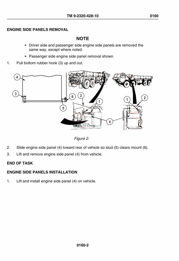
ENGINE SIDE PANELS REMOVAL
NOTE• Driver side and passenger side engine side panels are removed the
same way, except where noted.
• Passenger side engine side panel removal shown.
1. Pull bottom rubber hook (3) up and out.
4
36
5
21
4
21
Figure 2.
2. Slide engine side panel (4) toward rear of vehicle so stud (5) clears mount (6).
3. Lift and remove engine side panel (4) from vehicle.
END OF TASK
ENGINE SIDE PANELS INSTALLATION
1. Lift and install engine side panel (4) on vehicle.
TM 9-2320-428-10 0160
0160-2

ENGINE SIDE PANELS INSTALLATION - Continued
4
36
5
21
4
21
Figure 3.
2. Slide engine side panel (4) toward front of vehicle so stud (5) inserts into mount (6).
3. Pull bottom rubber hook (3) up and connect to engine side panel (4).
END OF TASK
CLOSE ENGINE COVERS
1. Pull hood (2) forward.
4
36
5
21
4
21
Figure 4.
TM 9-2320-428-10 0160
0160-3

CLOSE ENGINE COVERS - Continued
2. Push in engine side panel (4) and lower hood (2).
3. Pull top rubber hooks (1) up and connect to hood (2).
END OF TASK
FOLLOW-ON MAINTENANCE
1. Stow spare tire (if removed). (WP 0155)
2. Remove wheel chocks. (WP 0077)
END OF WORK PACKAGE
TM 9-2320-428-10 0160
0160-4

CHAPTER 6
SUPPORTINGINFORMATION
TM 9-2320-428-10

FIELD MAINTENANCEREFERENCES
SCOPE
This work package lists all pamphlets, forms, field manuals, technical manuals, and otherpublications referenced in this manual. Also, those publications that should be consultedfor additional information about vehicle operations are listed.
DEPARTMENT OF ARMY PAMPHLETS
The following indexes should be consulted frequently for latest changes or revisions andfor new publications relating to material covered in this technical manual.
DA PAM 25-30 Consolidated Index of Army Publications and Blank Forms
DA PAM 25-33 User's Guide for Army Publications and Forms
DA PAM 710-2-1 Using Unit Supply System (Manual Procedures)
DA PAM 750-8 The Army Maintenance Management System (TAMMS) UsersManual
FORMS
DA FORM 2028 Recommended Changes to Publications and Blank Forms
DA FORM 2062 Hand Receipt
DA FORM 2401 Organization Control Record for Equipment
DA FORM 2402 Maintenance Tag
DA FORM 2404 Equipment Inspection and Maintenance Worksheet
DA FORM 2407 Maintenance Request
DA FORM 2407-1 Maintenance Request Continuation Sheet
DA FORM 2408 Equipment Log Assembly (Records)
DA FORM 2408-9 Equipment Control Record
DA FORM 5988-E Equipment Inspection Maintenance Worksheet (EGA)
DD FORM 250 Material Inspection and Receiving Report
DD FORM 314 Preventive Maintenance Schedule and Record
DD FORM 1149 Requisition and Invoice/Shipping Document
DD FORM 1348-1 DOD Single Line Item Release/Receipt Document
TM 9-2320-428-10 0161
0161-1

FORMS - Continued
DD FORM 1397 Processing and Deprocessing Record for Shipment, Storage,and Issue of Vehicles and Spare Engines
DD FORM 2282 Reinspection Decal Convention for Safe Containers
OPTIONAL FORM 346 U.S. Government Motor Vehicle Operator Identification Card
STANDARD FORM 91 Motor Vehicle Accident Report
STANDARD FORM 364 Report of Discrepancy (ROD)
STANDARD FORM 368 Product Quality Deficiency Report
STANDARD FORM 4895 Equipment Preservation Data Sheet (EPDS)
FIELD MANUALS
FM 3-6 Field Behavior of NBC Agents (Including Smoke andIncendiaries)
FM 3-11.3 Multiservice Tactics, Techniques, and Procedures ForChemical, Biological, Radiological, and NuclearDecontamination Avoidance {MCWP 3-37.2A, NTTP 3-11.25,AFTTP(I) 3-2.56}
FM 3-11.4 Multiservice Tactics, Techniques, and Procedures For Nuclear,Biological, and Chemical (NBC) Protection {MCWP 3-37.2;NTTP 3-11.27; AFTTP (I) 3-2.46} (This Item is included on EM0205)
FM 3-11.5 Multiservice Tactics, Techniques, and Procedures ForChemical, Biological, Radiological, and NuclearDecontamination {MCWP 3-37.3; NTTP 3-11.26; AFTTP(I)3-2.60}
FM 4-25.11 First Aid
FM 4-30.31 Recovery and Battle Damage Assessment and Repair
FM 5-100-15 Corps Engineer Operations
FM 5-125 Rigging Techniques, Procedures, and Applications
FM 9-207 Operation and Maintenance of Ordnance Materiel in ColdWeather
FM 10-16 General Fabric Repair
FM 10-67-1 Concepts and Equipment of Petroleum Operations
FM 20-3 Camouflage, Concealment, and Decoys
FM 21-10 Field Hygiene and Sanitation
FM 21-305 Manual for the Wheeled Vehicle Driver
FM 31-70 Basic Cold Weather Manual
TM 9-2320-428-10 0161
0161-2

FIELD MANUALS - Continued
FM 31-71 Northern Operations
FM 55-21 Railway Operating and Safety Rules
FM 55-30 Army Motor Transport Units and Operations
FM 90-3 Desert Operations
FM 90-13 River Crossing Operations
TECHNICAL BULLETINS
TB ORD 1030 Manufacture of Data Plates
TB 5-5420-234-15 Warranty Program for Common Bridge Transporter (CBT)
TB 9-2300-281-35 Standards for Oversea Shipment or Domestic Issue of SpecialPurpose Vehicles, Combat, Tactical, Construction, andSelected Industrial and Troop Support US Army Tank-Automotive Materiel Readiness Command Managed Items
TB 9-2300-422-20 Security of Tactical Wheeled Vehicles
TB 43-0001-62-SERIES Equipment Improvement Report and Maintenance Digest forTank, Automotive, and Armament Equipment
TB 43-0142 Safety Inspection and Testing of Lifting Devices
TB 43-0209 Color, Marking and Camouflage Painting of Military Vehicles,Construction Equipment, and Materials Handling Equipment
TB 43-0212 Purging, Cleaning, and Coating Interior Ferrous and TerneSheet Vehicle Fuel Tanks
TB 43-0216 Safety and Hazard Warnings for Operation and Maintenance ofTACOM Equipment
TB 750-651 Use of Antifreeze Solutions, Antifreeze Extender, CleaningCompounds and Test Kit in Engine Cooling Systems
TB 9-289 Reconditioning of Type I and Type II Reusable Metal Containers
TECHNICAL MANUALS
TM 3-4230-214-12&P Operator's and Unit Maintenance Manual Including Repair Partsand Special Tools List for Decontamination Apparatus
TM 3-4240-280-10 Operator's Manual for Mask, Chemical-Biological: Aircraft, ABC-M24 and Accessories and Mask, Chemical-Biological, Tank,M25A1 and Accessories (Reprinted W/Basic Incl C1-2) (Thisitem is included on EM 0045)
TM 3-6665-225-12 Operator's and Organizational Maintenance Manual: for AlarmChemical
TM 5-1940-277-10 Operator’s Manual for Boat, Bridge Erection, Twin Jet,Aluminum Hull, Models USCSBMK 1 (NSN 1940-01-105-5728)and USCSBMK 2 (1940-01-218-9165)
TM 9-2320-428-10 0161
0161-3

TECHNICAL MANUALS - Continued
TM 5-2090-202-12&P Operator’s and Unit Maintenance Manual (Including RepairParts and Special Tools List) for Cradle, Bridge Erection Boat,Twin Jet, Aluminum Hull (NSN 2090-01-106-9789)
TM 5-5420-208-12&P Operator and Unit Maintenance Manual Including Repair Partsand Special Tools List for Cargo Pallet, Ribbon BridgeTransporter (NSN 5420-01-006-7436)
TM 5-5420-209-12 Operator’s and Unit Maintenance Manual for Improved FloatBridge (Ribbon Bridge)
TM 5-5420-277-14&P Operator’s, Unit, Direct Support, and General SupportMaintenance Manual (Including Repair Parts and Special ToolsList) for Cradle, Boat, Improved, M14, (NSN 3990-01-442-1914)
TM 9-214 Inspection, Care and Maintenance of Antifriction Bearings
TM 9-243 Use and Care of Hand Tools and Measuring Tools
TM 9-1005-245-13&P Operator’s, Unit, and Direct Support Maintenance Manual withRepair Parts and Special Tools List (RPSTL) for Machine GunMounts and Combinations for Tactical/Armored Vehicles
TM 9-1440-600-10 Operator’s Manual, Launching Station, M901 Guided Missile,Semitrailer Mount
TM 9-2320-279-10HR Hand Receipt Covering Contents Of Components Of End Item(COEI), Basic Issue Items (BII), And Additional AuthorizationList (AAL) for M977 Series, 8x8 Heavy Expanded MobilityTactical Trucks
TM 9-2330-357-14&P Operator's, Organizational, Direct Support, and GeneralSupport Maintenance Manual (Including Repair Parts andSpecial Tools Lists) For Semitrailer, Flatbed, Radar Set andLaunching Station M860A1 (NSN 2330-01-117-3280) (This ItemIs Included On EM 0049)
TM 9-2330-385-14 Operator's, Unit, Direct Support and General SupportMaintenance Manual for Palletized Load System Trailer (PLST)Model M1076 (NSN 2330-01-303-5197)
TM 9-2330-385-24P Unit, Direct Support and General Support Maintenance RepairParts and Special Tools List for Trailer, Palletized Load System(PLST) Model M1076 (NSN 2330-01-303-5197)
TM 9-2320-279-20 Maintenance Instructions for Organizational Maintenance,M977 Series, 8x8 Heavy Expanded Mobility Tactical Trucks
TM 9-2320-279-34 Maintenance Instructions, Direct Support and General Supportfor M977 Series, 8x8 Heavy Expanded Mobility Tactical Trucks
TM 9-2610-200-14 Operator's, Unit, Direct Support, and General SupportMaintenance Manual for Care, Maintenance, Repair, andInspection of Pneumatic Tires and Inner Tubes
TM 9-3990-206-14&P Operator's Unit, Direct Support and General SupportMaintenance Manual (Including Repair Parts and Special ToolsList) for Palletized Load System (PLS) Flatrack Model M1077/M1077A1
TM 9-2320-428-10 0161
0161-4

TECHNICAL MANUALS - Continued
TM 9-3990-260-14&P Operator's, Unit, Direct Support and General SupportMaintenance Manual (Including Repair Parts and Special ToolsList) For Container Roll-In/Out Platform (CROP) Model M3(NSN 3990-01-442-2751); Container Roll-In/Out Platform(CROP) Model M3A1 (3990-01-450-5671) (This Item is Includedon EM 0038 and EM 0052)
TM 9-2330-366-14&P Operator's, Organizational, Direct Support, and GeneralSupport Maintenance Including Repair Parts and Special ToolsLists For Semitrailer, Lowbed, 12-Ton, XM974 (NSN2330-01-116-0288)
TM 9-4910-571-12&P Operator’s and Organizational Maintenance Manual (IncludingRepair Parts and Special Tools List) for Simplified TestEquipment for Internal Combustion Engines (STE/ICE-R)
TM 9-4910-783–13&P Operator's, Unit, and Direct Support Maintenance Manual(Including Repair Parts and Special Tools List) for StandardAutomotive Test Set (SATS)
TM 9-4940-468-13 Operator’s, Unit, and Direct Support Maintenance Manual forTool Outfit, Hydraulic Systems Test and Repair Unit (HSTRU)
TM 9-4940-568-10 Operator’s Maintenance Manual for Forward Repair System(FRS)
TM 9-6115-465-24P Unit, Direct Support and General Support Maintenance RepairParts and Special Tools List (Including Deport MaintenanceRepair Parts and Special Tools List) for Generator Set, DieselEngine-Driven, Tactical
TM 9-6140-200-14 Operator’s, Unit, Direct Support and General SupportMaintenance Manual for Lead-Acid Storage Batteries
TM 9-8000 Principles of Automotive Vehicles
TM 11-5820-498-12 Operator’s and Organizational Maintenance Manual: RadioSets
TM 11-5820-498-35 Direct Support, General Support, and Depot MaintenanceManual for Radio Sets
TM 38-250 Preparing Hazardous Materials for Military Air Shipments
TM 43-0139 Painting Instructions for Army Materiel
TM 55-2200-001-12 Transportability Guidance for Application of Blocking, Bracingand Tie Down Materials for Rail Transport
TM 55-2320-279-14 Transportability Guidance Heavy Expanded Mobility TacticalTruck (HEMTT)
TM 750-244-3 Procedures for Destruction of Equipment to Prevent Enemy Use(Mobility Equipment Command)
TM 750-244-6 Procedures for Destruction of Tank Automotive Equipment toPrevent Enemy Use (U.S. Army Tank-Automotive Command)
TM 750-254 Cooling Systems: Tactical Vehicles
TM 9-2320-428-10 0161
0161-5

TECHNICAL MANUALS - Continued
TM 5-2330-378-14&P Operator's, Unit, Direct Support, and General SupportMaintenance Manual (Including Repair Parts and Special ToolsList) for Semitrailer, Lowbed: 40-Ton Construction EquipmentTransporter, M870 (CCE) (CMI/Load King Model 403LF), andM870A1
TM 5-2330-325-14&P Operator's, Unit, and Direct Support Maintenance Manual withRepair Parts and Special Tools List (RPSTL) for Trailer, MediumHeavy Equipment Transporter (MHET), 40-Ton, M870A3
TM 9-2330-213-14&P Operator’s, Unit, Direct Support, and General SupportMaintenance Manual (Including Repair Parts and Special ToolsLists) For Trailer, Chassis: 1-1/2-Ton, 2-Wheel M103A1 (NSN2330-00-835-8629) M103A3 (NSN 2330-00-141-8052) Trailer,Cargo: 1-1/2-Ton, 2-Wheel M105A1 (NSN 2330-00-835-8631)M105A2 (NSN 2330-00-141-8050) M105A2C (NSN2330-00-542-5689) Trailer, Tank, Water: 1-1/2-Ton, 2-Wheel,400-Gallon M107A1 (NSN 2330-00-835-8633) M107A2 (NSN2330-00-141-8049) M107A2C (NSN 2330-00-542-5688)Trailer, Van, Shop: Folding Sides, 1-1/2-Ton, 2-Wheel M448(NSN 2330-00-631-5692)
TM 9-2330-231-14&P Technical Manual Operator's, Organizational, Direct Support,And General Support Maintenance (Including Repair Parts andSpecial Tools List) Trailer, Ammunition: 1 1/2-Ton, 2-Wheel,M332 (NSN 2330-00-200-1785)
TM 9-2330-368-14&P Operators, Organizational, Including Repair Parts and SpecialTools List For Trailer, Ammunition, Heavy Expanded Mobility,11-Ton, M989 (NSN 2330-01-109-4258)
MISCELLANEOUS PUBLICATIONS
AR 70-1 Army Acquisition Policy
AR 200-1 Environmental Protection and Enhancement
AR 385-55 Prevention of Motor Vehicle Accidents
AR 700-138 Army Logistics Readiness and Sustainability
AR 700-139 Army Warranty Program
AR 702-7 Product Quality Deficiency Report Program
AR 750-1 Army Materiel Maintenance Policy
AR 750-10 Army Modification Program
CTA 8-100 Army Medical Department Expendable/Durable Items
CTA 50-970 Expendable/Durable Items (Except Medical, Class V, RepairParts, and Heraldic Items)
TM 9-2320-428-10 0161
0161-6

MISCELLANEOUS PUBLICATIONS - Continued
GPM 94-02 Maintenance Advisory for Purging all Fuel Tankers using aBiodegradable Purging Solution
SB 725-92-1 US Army Missile Command Nonexpendable Reusable Shippingand Storage Containers
TC 9-237 Welding Theory and Application
TC 9-510 Metal Body Repair and Related Operations
TO 00-25-234 General Shop Practice Requirements for Repair, Maintenance,and Test of Electronic Equipment
END OF WORK PACKAGE
TM 9-2320-428-10 0161
0161-7


OPERATOR MAINTENANCECOMPONENTS OF END ITEM AND BASIC ISSUE ITEMS LISTS
INTRODUCTION
Scope
This work package lists COEI and BII for the HEMTT series vehicles to help you inventoryitems required for safe and efficient operation.
General
The Components of End Item and Basic Issue Items Lists are divided into the following lists:
Components of End Item (COEI) This listing is for informational purposes only and is notauthority for requisition replacements. These items are part of the HEMTT series vehicle.As part of the end item, these items must be with the end item whenever it is issued ortransferred between property accounts. Items of COEI are removed and separatelypackaged for transportation or shipment only when necessary. Illustrations are furnished tohelp you find and identify the items.
Basic Issue Items (BII) These are the minimum essential items required to place theHEMTT series vehicle in operation, to operate it, and to perform emergency repairs.Although shipped separately packaged, BII must be with the vehicle during operation andwhen it is transferred between property accounts. Listing these items is your authority torequest/requisition them for replacement based on your authorization of the end item by theTOE/MTOE. Illustrations are furnished to help you find and identify the items.
Explanation of Entries in the COEI List and BII List
The following provides an explanation of columns found in the tabular listings:
Item Number. Gives you the reference number of the item listed.
National Stock Number (NSN) and Illustration. Identifies the stock number of the item tobe used for requisitioning purposes and provides an illustration of the item.
Description, Part Number/(CAGEC). Identifies the Federal item name (in all capital letters)followed by a minimum description when needed. The stowage location of COEI and BII isalso included in this entry. The last line below the description is the part number and theCommercial and Government Entity Code (CAGEC) (in parentheses).
Usable On Code. When applicable, gives you a code if the item you need is not the samefor different models of equipment. These codes are identified below:
TM 9-2320-428-10 0162
0162-1

INTRODUCTION - Continued
Table 1. List of Usable On Codes
Code Used On
H01 M977 Cargo with winch
H06 M977 Cargo w/o winch
Column (5) - U/I Unit of Issue (U/I) U/I. Unit of Issue (U/I) indicates the physicalmeasurement or count of the item as issued per the National Stock Number shown incolumn (2).
Column (6) - Qty. Indicates the quantity required.
COMPONENTS OF END ITEM
Table 2. Components of End Item
(1) (2) (3) (4) (5) (6)
IllusNo.
National Stock Number(NSN)
Description, PartNumber/(CAGEC)
UsableOn
Code U/IQtyRqr
1 6150-01-184-1901 CABLE AND CONDUITASSEMBLY,ELECTRICAL: Crane(Located in passengerside stowage box)
2-198-6-00061(12361)
H01,H06
EA 1
2 2540-01-166-1384 LADDER, VEHICLEBOARDING (Locatedover fuel tank on driverside of vehicle)
1766590W(45152)
H06,H01
EA 1
TM 9-2320-428-10 0162
0162-2

Table 2. Components of End Item - Continued
(1) (2) (3) (4) (5) (6)
IllusNo.
National Stock Number(NSN)
Description, PartNumber/(CAGEC)
UsableOn
Code U/IQtyRqr
3 2520-01-188-5129 RECEIVER-TRANSMITTER,HYDRAULIC CONTROL:Crane RCU (Located inpassenger side stowagebox, under cargo body torear of battery box)
2-198-6-00053(12361)
H01,H06
EA 1
4 2590-01-184-1902 SHOE, JACK-SUPPORT: OutriggerPad (Located onoutrigger beam on rearof vehicle)
2-198-1-00028(12361)
H01,H06
EA 2
Table 3. Basic Issue Items
(1) (2) (3) (4) (5) (6)
IllusNo.
National Stock Number(NSN)
Description, PartNumber/(CAGEC)
UsableOn
Code U/IQtyRqr
1 8105-01-353-2497 BAG, TEXTILE:Pamphlet (Located incabin in glove boxforward of passenger/crew seat)
1362710(45152)
H01,H06
EA 1
TM 9-2320-428-10 0162
0162-3

Table 3. Basic Issue Items - Continued
(1) (2) (3) (4) (5) (6)
IllusNo.
National Stock Number(NSN)
Description, PartNumber/(CAGEC)
UsableOn
Code U/IQtyRqr
2 7510-00-889-3494 BINDER, LOOSE-LEAF(Located on passengerside of cab in glove box)
11677003(19207)
H01,H06
EA 1
3 3940-01-163-2319 BLOCK, TACKLE: 20Ton (Located in driverside tool box)
168400(75535)
H01 EA 1
4 6150-01-180-6035 CABLE ASSEMBLY,POWER,ELECTRICAL:Worklamp (Located indriver side tool box)
1419770U(45152)
H01,H06
EA 1
5 6150-01-320-0719 CABLE ASSEMBLY,SPECIAL PURPOSE,ELECTRICAL:Worklamp (Located indriver side tool box)
1771530W(45152)
H01,H06
EA 1
TM 9-2320-428-10 0162
0162-4

Table 3. Basic Issue Items - Continued
(1) (2) (3) (4) (5) (6)
IllusNo.
National Stock Number(NSN)
Description, PartNumber/(CAGEC)
UsableOn
Code U/IQtyRqr
6 4010-01-200-1506 CHAIN ASSEMBLY,SINGLE LEG: 7 ft. LimpHome (Located in driverside tool box)
1452490(45152)
H01,H06
EA 1
7 4010-01-249-0548 CHAIN ASSEMBLY,SINGLE LEG: 14 ft.Utility (Located in driverside tool box)
00044-9973(96508)
H01,H06
EA 1
8 2540-01-165-6136 CHOCK, WHEEL-TRACK (Located inwheel chock stowagebox [carries a maximumof two wheel chocks],vehicle mountedstowage boxes, and/orunder spare tire)
CS-2540-0067(16236)
H01,H06
EA 4
TM 9-2320-428-10 0162
0162-5

Table 3. Basic Issue Items - Continued
(1) (2) (3) (4) (5) (6)
IllusNo.
National Stock Number(NSN)
Description, PartNumber/(CAGEC)
UsableOn
Code U/IQtyRqr
9 4210-01-133-9053 EXTINGUISHER, FIRE:2.7 lbs, 10 BC (Locatedin cabin to right ofdriver's seat)
429101(03670)
H01,H06
EA 1
10 6545-00-922-1200 FIRST AID KIT,GENERAL PURPOSE(Located in cabin inglove box forward ofpassenger/crew seat)
SCC-6545-ILVOL2(64616)
H01,H06
EA 1
11 4910-01-003-9599 GAUGE, TIREPRESSURE, SELF-CONTAINED (Locatedin cabin in glove boxforward of passenger/crew seat)
61-J2-1506(94894)
H01,H06
EA 2
TM 9-2320-428-10 0162
0162-6

Table 3. Basic Issue Items - Continued
(1) (2) (3) (4) (5) (6)
IllusNo.
National Stock Number(NSN)
Description, PartNumber/(CAGEC)
UsableOn
Code U/IQtyRqr
12 5340-01-209-7841 HANDLE, EXTENSION(for lug wrench)(Located in driver sidetool box)
1347720(45152)
H01,H06
EA 1
13 5120-01-233-9508 HANDLE, SOCKETWRENCH: WheelLugnut (Located indriver side toolbox)
ORR301(66784)
H01,H06
EA 1
14 4720-01-558-6415 HOSE ASSEMBLY,NONMETALLIC: Air 50ft.
2155210U(45152)
H01,H06
EA 2
TM 9-2320-428-10 0162
0162-7

Table 3. Basic Issue Items - Continued
(1) (2) (3) (4) (5) (6)
IllusNo.
National Stock Number(NSN)
Description, PartNumber/(CAGEC)
UsableOn
Code U/IQtyRqr
15 4910-01-386-4300 INFLATOR-GAUGE,PNEUMATIC TIRE(Located in cabin inglove box forward ofpassenger/crew seat)
I-405M(63900)
H01,H06
EA 2
16 5120-01-146-8096 JACK, HYDRAULIC,HAND: 12 Ton withHandle (Located indriver side tool box)
EBJ-12GC(26952)
H01,H06
EA 1
17 5340-00-158-3807 PADLOCK: With Chain(for stowage boxes)
AA59487-2SC(58536)
H01,H06
EA 4
TM 9-2320-428-10 0162
0162-8

Table 3. Basic Issue Items - Continued
(1) (2) (3) (4) (5) (6)
IllusNo.
National Stock Number(NSN)
Description, PartNumber/(CAGEC)
UsableOn
Code U/IQtyRqr
18 5340-00-158-3805 PADLOCK: WithoutChain (for steeringcolumn) (Located insteering column lockbracket under dash)
AA59487-2S(58536)
H06,H01
EA 1
19 2540-01-165-5987 PLATE, BASE, JACK(Located in driver sidetoolbox)
2540V0730(16236)
H01,H06
EA 1
20 5120-01-480-0640 PLIERS, SLIP JOINT:10 in. Adjustable(Located in driver sidetoolbox - part of tool roll)
1350150(45152)
H01,H06
EA 1
21 9905-01-480-0644 REFLECTOR SET,HIGHWAY WARNING,TRIANGULAR (Locatedin cabin mounted underglove box forward ofpassenger/crew seat)
6432GBX(45152)
H01,H06
SE 1
TM 9-2320-428-10 0162
0162-9

Table 3. Basic Issue Items - Continued
(1) (2) (3) (4) (5) (6)
IllusNo.
National Stock Number(NSN)
Description, PartNumber/(CAGEC)
UsableOn
Code U/IQtyRqr
22 5140-01-167-1541 ROLL, TOOLS ANDACCESSORIES(Located in driver sidestowage box)
1350190(45152)
H01,H06
EA 1
23 5120-01-398-8053 SCREWDRIVER,CROSS TIP: Phillips No.3 (Located in driver sidetoolbox - part of tool roll)
SDFP56(96508)
H01,H06
EA 1
24 5120-00-293-3309 SCREWDRIVER, FLATTIP: No. 6 (Located indriver side toolbox - partof tool roll)
66-110(03914)
H01,H06
EA 1
25 4030-00-377-1397 SHACKLE: Anchor,Limp Home (Located indriver side toolbox)
RR-C-271TY4AGRBCL2SZ1.000(81348)
H01,H06
EA 1
TM 9-2320-428-10 0162
0162-10

Table 3. Basic Issue Items - Continued
(1) (2) (3) (4) (5) (6)
IllusNo.
National Stock Number(NSN)
Description, PartNumber/(CAGEC)
UsableOn
Code U/IQtyRqr
26 4030-01-316-1552 SHACKLE: Towing:(Located on front andrear towing eyes)
RR-C-271DTYIVAGRACL1 3/8IN(81348)
H01,H06
EA 4
27 3940-01-209-6008 SLING AND WIREROPE ASSEMBLY SET(Located in driver sideequipment body, topforward stowage box)
AC 200000331(28620)
H01,H06
EA 1
28 6220-01-326-2286 SPOTLIGHT: Worklamp1401182(78422)
H01,H06
EA 1
29 1670-00-725-1437 TIE DOWN, CARGO10045035(18876)
H01,H06
EA 24
TM 9-2320-428-10 0162
0162-11

Table 3. Basic Issue Items - Continued
(1) (2) (3) (4) (5) (6)
IllusNo.
National Stock Number(NSN)
Description, PartNumber/(CAGEC)
UsableOn
Code U/IQtyRqr
30 5120-01-436-2924 WRENCH,ADJUSTABLE: 8 in.(Located in driver sidetoolbox - part of tool roll)
AC18(96508)
H01,H06
EA 1
31 5120-00-264-3796 WRENCH,ADJUSTABLE: 12 in.(Located in driver sidetoolbox - part of tool roll)
120405A(45152)
H01,H06
EA 1
32 5120-01-070-8386 WRENCH, SOCKET:Wheel Nut (Located indriver side tool box)
1048-TR(45152)
H01,H06
EA 1
END OF WORK PACKAGE
TM 9-2320-428-10 0162
0162-12

OPERATOR MAINTENANCEADDITIONAL AUTHORIZATION LIST (AAL)
Introduction
Scope
This work package lists additional authorization items that are needed to operate andmaintain the HEMTT Series Vehicles.
General
This list identifies items that do not have to accompany the HEMTT Series Vehicles andthat do not have to be turned in with it. These items are all authorized to you by CTA, MTOE,TDA, or JTA.
Explanation of Columns in the AAL
Column (1) - National Stock Number (NSN). Identifies the stock number of the item to beused for requisitioning purposes.
Column (2) - Description, Part Number/(CAGEC). Identifies the Federal item name (in allcapital letters) followed by a minimum description when needed. The last line below thedescription is the part number and the Commercial and Government Entity Code (CAGEC)(in parentheses).
Column (3) - Usable On Code. When applicable, gives you a code if the item you need isnot the same for different models of equipment.
Table 1. List of Usable On Codes
Code Used On
H01 M977 Cargo with winch
H06 M977 Cargo w/o winch
Column (4) - U/I. Unit of Issue (U/I) indicates the physical measurement or count of the itemas issued per the National Stock Number.
Column (5) - Qty Recm. Indicates the quantity recommended.
TM 9-2320-428-10 0163
0163-1

Table 2. Additional Authorization List
(1) (2) (3) (4) (5)
NationalStock Number
(NSN)Description, Part Number/
(CAGEC)Usable
On Code U/IQty
Recom
5110-00-293-2336
AXE, SINGLE BIT6150925(19207)
H01, H06 EA 1
4910-00-347-9703
BAR ASSEMBLY, HOISTING8690061(52793)
H01, H06 EA 1
3940-01-247-3682
BEAM, HOISTING: DOUBLEAC200000364(28620)
H06 EA 1
3940-01-247-3681
BEAM, HOISTING: SINGLEAC200000354(28620)
H06 EA 1
2510-00-741-7585
BOARD GROUND JACK7417585(19207)
H01, H06 EA 2
2540-00-409-8891
BRACKET ASSEMBLY, TOOL:PIONEER
MS53053-1(96906)
H01, H06 EA 1
6150-01-022-6004
CABLE ASSEMBLY, POWER,ELECTRICAL: NATO
11682336-1(19207)
H01, H06 EA 1
2540-01-152-7813
CHAIN, TIRE, EMERGENCY2624-10-8(46156)
H01, H06 PR 2
2540-01-198-7409
COVER, FITTED, VEHICULARBODY: CARGO BODY COVER
2178120U(45152)
H01, H06 EA 1
4230-01-220-3221
DECONTAMINATION KIT,INDIVIDUAL EQUIPMENT
5705588(19207)
H01, H06 EA 1
TM 9-2320-428-10 0163
0163-2

Table 2. Additional Authorization List - Continued
(1) (2) (3) (4) (5)
NationalStock Number
(NSN)Description, Part Number/
(CAGEC)Usable
On Code U/IQty
Recom
5130-01-400-0129
EXTENSION, SOCKETWRENCH: IMPACT 3/4 in.DRIVE, 13 in. LONG
07569(1CV05)
H01, H06 EA 1
4240-01-220-6373
GAS PARTICULATE KIT3SK663(45152)
H01, H06 KT 1
8415-00-634-4658
GLOVES, LEATHER37G2940(90142)
H01, H06 PR 2
5120-00-288-6574
HANDLE, MATTOCK-PICK10501973(56161)
H01, H06 EA 1
2990-01-509-1954
HEATER, COOLANT, ENGINE:ARCTIC
3460259(45152)
H01, H06 EA 1
3940-01-247-3681
HOISTING BEAM, SINGLEAC200000354(28620)
H06 EA 1
4720-01-341-4912
HOSE ASSEMBLY1759750U(45152)
H01, H06 EA 1
4720-01-254-0189
HOSE ASSEMBLY,NONMETALLIC: INTER-VEHICULAR
MS39325-9-140-8(96906)
H01, H06 EA 2
5895-01-506-4503
INSTALLATION KIT,ELECTRONIC EQUIPMENT:C4ISR
3418900(45152)
H01, H06 EA 1
TM 9-2320-428-10 0163
0163-3

Table 2. Additional Authorization List - Continued
(1) (2) (3) (4) (5)
NationalStock Number
(NSN)Description, Part Number/
(CAGEC)Usable
On Code U/IQty
Recom
1005-01-519-2126
INSTALLATION KIT:MOUNTING, MACHINE GUN
1301740UW/OR45152
H01, H06 KT 1
6665-01-220-3220
KIT, CHEMICAL ALARM5705589(19207)
H01, H06 KT 1
6220-01-250-5190
LIGHT, WARNING: BEACON3145661(45152)
H01, H06 EA 1
5120-00-243-2395
MATTOCK: PICK11677022(19207)
H01, H06 EA 1
5120-00-892-5709
MIRROR, INSPECTIONUH1487(11676)
H01, H06 EA 1
1005-01-266-1233
MOUNT, RIFLE: INSTALLATION5705590(19207)
H01, H06 EA 1
5120-00-197-9473
PUNCH, BLACKSMITH'S: 17 in.647008(60903)
EA 1
4030-01-316-1552
SHACKLE: TOWING (used withtow bar, 10 ton)
1307540(45152)
H01, H06 EA 2
5120-00-293-3336
SHOVEL: HAND11655784(19207)
H06, H01 EA 1
3940-01-209-6008
SLING AND WIRE ROPEASSEMBLY SET
AC 2000 00331(28620)
H01 EA 1
3940-00-040-2297
SLING, MULTIPLE LEG8330151(19207)
H01 EA 1
TM 9-2320-428-10 0163
0163-4

Table 2. Additional Authorization List - Continued
(1) (2) (3) (4) (5)
NationalStock Number
(NSN)Description, Part Number/
(CAGEC)Usable
On Code U/IQty
Recom
3940-01-083-9313
SLING, MULTIPLE LEGSW71M(91796)
H06 EA 1
3940-01-241-7400
SLING, MULTIPLE LEGAC200000332(28620)
H06 EA 1
3940-01-270-3389
SLING, MULTIPLE LEG: 16 FT.SAFETY CHAINTwo (2) 16 ft.safety chains should be used inconjunction with Tow Bar: 10 TonNSN: 2540-00-378-2012, P/N:8383802, C/C: 19207.
1482010(45152)
H01, H06 EA 2
5130-01-400-0164
SOCKET, SOCKET WRENCH(3/4 in. drive, 1 3/4 in. hex,impact)
J07528L(1CV05)
H01, H06 EA 1
3990-01-204-3009
TIE DOWN, CARGO, VEHICLEMIL-PRF-71224-1(OHK26)
H01, H06 EA 8
2540-00-378-2012
TOW BAR, MOTOR VEHICLE:10 tonShould be used inconjunction with two (2) safetychains: 16 ft. NSN:3940-01-270-3389, P/N:1482010, C/C: 45152.
8383802(19207)
H01, H06 EA 1
5130-01-428-3751
WRENCH, IMPACT,PNEUMATIC
1789100U(45152)
H01, H06 EA 1
END OF WORK PACKAGE
TM 9-2320-428-10 0163
0163-5


OPERATOR MAINTENANCEEXPENDABLE AND DURABLE ITEMS LIST
Introduction
Scope
This work package lists expendable supplies and materials that are needed to operate andmaintain the HEMTT Series Vehicles. This list is for information only and is not authority torequisition the listed items. These items are authorized to you by CTA 50-970, Expendable/Durable Items (Except Medical, Class V Repair Parts, and Heraldic Items), CTA 50-909,Field and Garrison Furnishings and Equipment or CTA 8-100, Army Medical DepartmentExpendable/Durable Items.
Explanation of Entries in the Expendable/Durable Items List
Item No. This number is assigned to the entry in the list and is referenced in the narrativeinstructions to identify the item (e.g., Use brake fluid (Expendable/Durable Items List)).
Level. This column identifies the lowest level of maintenance that requires the listed item.• C -- Operator/Crew• O -- Unit/AMC• F -- Direct Support/ASB• H -- General Support• D -- Depot
National Stock Number (NSN). This is the NSN assigned to the item which you can useto requisition it.
Item Name, Description, Part Number/(CAGEC). This column provides the otherinformation you need to identify the item. The last line below the description is the partnumber and the Commercial and Government Entity Code (CAGEC) (in parentheses).
(U/I). Unit of Issue (U/I) code shows the physical measurement or count of an item, suchas gallon, dozen, gross, etc.
Table 1. Expendable and Durable Items List
(1) (2) (3) (4) (5)
ItemNo. Level
NationalStock Number
(NSN)Item Name, Description, Part Number/
(CAGEC) U/I
TM 9-2320-428-10 0164
0164-1

Table 1. Expendable and Durable Items List - Continued
(1) (2) (3) (4) (5)
ItemNo. Level
NationalStock Number
(NSN)Item Name, Description, Part Number/
(CAGEC) U/I
Antifreeze, Arctic Type
1 C 6850-01-464-9096
Antifreeze, Arctic Type 55-gal drumA-A-52624 (58536)
DR
Antifreeze, Permanent, Glycol,Inhibited
2 C 6850-01-464-9125
Antifreeze, Permanent, Glycol, Inhibited 1-gal container
AA52624 (58536)
GL
3 C 6850-00-464-9137
Antifreeze, Permanent, Glycol, Inhibited 5-gal container
MILA46153 (81349)
CO
4 C 6850-01-464-9152
Antifreeze, Permanent, Glycol, Inhibited55-gal drum
A-A-52624 TY I RECYCLED (58536)
DR
Cleaner, Lubricant
5 C 9150-01-079-6124
Cleaner, Lubricant A,4 oz bottle w/extender tube
MIL-PRF-63460 (81349)
BT
Cleaning Compound, Solvent
6 C 6850-01-474-2319
Cleaning Compound, Solvent 1 gallon canMIL-PRF-680 Type II (81349)
GL
7 C 6850-01-474-2317
Cleaning Compound, Solvent 5 gallon canMIL-PRF-680 Type II (81349)
CO
TM 9-2320-428-10 0164
0164-2

Table 1. Expendable and Durable Items List - Continued
(1) (2) (3) (4) (5)
ItemNo. Level
NationalStock Number
(NSN)Item Name, Description, Part Number/
(CAGEC) U/I
8 C 6850-01-474-2316
Cleaning Compound, Solvent 55 gallondrum
MIL-PRF-680 Type II (81349)
DR
9 C 6850-01-474-2318
Cleaning Compound, Solvent 1 gallon canMIL-PRF-680 Type III (81349)
GL
10 C 6850-01-474-2320
Cleaning Compound, Solvent 5 gallon canMIL-PRF-680 Type III (81349)
BX
11 C 6850-01-474-2321
Cleaning Compound, Solvent 55 gallondrum
MIL-PRF-680 Type III (81349)
DR
Compound, Cleaning Windshield
12 C 6850-00-926-2275
Compound, Cleaning Windshield 1-pt can0854-000 (0FTT5)
BX
Fuel, DF-1, Winter
13 C 9140-01-413-7511
Fuel, DF-1, Winter BulkVV-F-800 (81348)
GL
14 C 9140-00-286-5286
Fuel, DF-1, Winter BulkASTM D 975 (81346)
GL
15 C 9140-00-286-5287
Fuel, DF-1, Winter 5-gal canASTM D 975 (81346)
CN
16 C 9140-00-286-5288
Fuel, DF-1, Winter 55-gal drum, 16 gaugeASTM D 975 (81346)
DR
17 C 9140-00-286-5289
Fuel, DF-1, Winter 55-gal drum, 18 gaugeASTM D 975 (81346)
DR
TM 9-2320-428-10 0164
0164-3
Table 1. Expendable and Durable Items List - Continued
(1) (2) (3) (4) (5)
ItemNo. Level
NationalStock Number
(NSN)Item Name, Description, Part Number/
(CAGEC) U/I
Fuel
18 C 9130-01-031-5816
Fuel, JP8 BulkMILT83133 GR JP8 (81349)
GL
19 C 9140-01-412-1311
Fuel, DF-2, Regular BulkVV-F-800 (81348)
GL
20 C 9140-00-286-5294
Fuel, DF-2, Regular BulkASTM D 975 (81346)
GL
21 C 9140-00-286-5295
Fuel, DF-2, Regular 5-gal canASTM D 975 (81346)
CN
22 C 9140-00-286-5296
Fuel, DF-2, Regular 55-gal drum, 16 gaugeASTM D 975 (81346)
DR
23 C 9140-00-286-5297
Fuel, DF-2, Regular 55-gal drum, 18 gaugeASTM D 975 (81346)
DR
Grease, Automotive and Artillery GAA
24 C 9150-01-197-7688
Grease, Automotive and Artillery GAA2-1/2 oz tube
M-10924-A (81349)
TU
25 C 9150-01-197-7693
Grease, Automotive and Artillery GAA 14-oz cartridge
M-10924-B (81349)
CA
26 C 9150-01-197-7690
Grease, Automotive and Artillery GAA 1-lbcan
M-10924-C (81349)
CN
TM 9-2320-428-10 0164
0164-4

Table 1. Expendable and Durable Items List - Continued
(1) (2) (3) (4) (5)
ItemNo. Level
NationalStock Number
(NSN)Item Name, Description, Part Number/
(CAGEC) U/I
27 C 9150-01-197-7689
Grease, Automotive and Artillery GAA 5-lbcan
M-10924-D (81349)
CN
28 C 9150-01-197-7692
Grease, Automotive and Artillery GAA 35-lb can
M-10924-E (81349)
CN
Oil, Lubricating Gear, GO 75 (MIL-L-2105)
29 C 9150-01-035-5390
Oil, Lubricating Gear, GO 75 (MIL-L-2105)1-qt can
M2105-1-75W (81349)
QT
30 C 9150-01-035-5391
Oil, Lubricating Gear, GO 75 5-gal canMIL-PRF-2105 (81349)
CN
Oil, Lubricating Gear, GO 80W/90 (MIL-L-2105C)
31 C 9150-01-035-5393
Oil, Lubricating Gear, GO 80W/90 (MIL-L-2105C) 5-gal can
J2360 (81343)
CN
Oil, Lubricating OEA Ice, Subzero
32 C 9150-00-403-2372
Oil, Lubricating OEA Ice, Subzero 1-qt canEMERY3908D (33358)
QT
33 C 9150-00-402-2372
Oil, Lubricating OEA Ice, Subzero 5-galcan
MIL-PRF-46167 (81349)
CN
TM 9-2320-428-10 0164
0164-5

Table 1. Expendable and Durable Items List - Continued
(1) (2) (3) (4) (5)
ItemNo. Level
NationalStock Number
(NSN)Item Name, Description, Part Number/
(CAGEC) U/I
34 C 9150-00-491-7197
Oil, Lubricating OEA Ice, Subzero 55-galdrum, 16 gauge
MIL-PRF-46167 (81349)
DR
Oil, Lubricating OE/HDO 10
35 C 9150-01-518-9471
Oil, Lubricating OE/HDO 10 1-qt canM2104-1-10W (81349)
QT
36 C 9150-00-186-6668
Oil, Lubricating OE/HDO 10 5-gal canM2104-3-10W (81349)
CN
37 C 9150-00-191-2772
Oil, Lubricating OE/HDO 10 55-gal drum,18 gauge
M2104-4-10W (98308)
DR
Oil, Lubricating OE/HDO 30, (SAE 30)
38 C 9150-01-496-1962
Oil, Lubricating OE/HDO 30, (SAE 30) BulkM2104-2-30W (81349)
GL
39 C 9150-00-186-6681
Oil, Lubricating OE/HDO 30, (SAE 30) 1-qtcan
M2104-3-30W (81349)
QT
40 C 9150-00-188-9858
Oil, Lubricating OE/HDO 30, (SAE 30) 5-gal can
MIL-PRF-2104 (81349)
CN
41 C 9150-01-433-7978
Oil, Lubricating OE/HDO 30, (SAE 30) 55-gal can
M2104-4-30W (81349)
DR
42 C 9150-01-433-7978
Oil, Lubricating OE/HDO 30, (SAE 30) 55-gal drum, 18 gauge
M2104-4-30W (81349)
DR
TM 9-2320-428-10 0164
0164-6

Table 1. Expendable and Durable Items List - Continued
(1) (2) (3) (4) (5)
ItemNo. Level
NationalStock Number
(NSN)Item Name, Description, Part Number/
(CAGEC) U/I
Oil, Lubricating OE/HDO 50
43 C 9150-00-188-9865
Oil, Lubricating OE/HDO 50 5-gal drumBRAYC0423H (98308)
CN
Oil, Lubricating Gear, GO 85W/140
44 C 9150-01-035-5396
Oil, Lubricating Gear, GO 85W/140 55-gallon drum
J2360 (81343)
DR
45 C 9150-01-035-5395
Oil, Lubricating Gear, GO 85W/140 5-gallon can
J2360 (81343)
CN
Oil, Lubricating, Internal CombustionEngine, Tactical Service OE/HDO 15W/
40 (MIL-L-2104)
46 C 9150-01-421-1432
Oil, Lubricating, Internal CombustionEngine, Tactical Service OE/HDO 15W/40(MIL-L-2104) 55-gal drum, 18 gauge
M2104-5-15W40 (81349)
DR
47 C 9150-01-518-9477
Oil, Lubricating, Internal CombustionEngine, Tactical Service OE/HDO 15W/40(MIL-L-2104) 1-quart can
M2104-1-15W40 (81349)
QT
48 C 9150-01-421-1427
Oil, Lubricating, Internal CombustionEngine, Tactical Service OE/HDO 15W/40(MIL-L-2104) 24-quart box
MIL-PRF-2104 (81349)
QT
TM 9-2320-428-10 0164
0164-7
Table 1. Expendable and Durable Items List - Continued
(1) (2) (3) (4) (5)
ItemNo. Level
NationalStock Number
(NSN)Item Name, Description, Part Number/
(CAGEC) U/I
Oil, Lubricating, OE/HDO 40
49 C 9150-00-188-9862
Oil, Lubricating, OE/HDO 40 55-gal drumMIL-PRF-2104 (81349)
DR
Rag, Wiping
50 C 7920-00-205-1711
Rag, Wiping 50-pound bale7920-00-205-1711 (80244)
BE
Rope
51 C 4020-00-968-1357
Rope, FibrousMIL-R-17343 (81349)
RL
Oil, Lubricating, Preventative
52 C 9150-01-293-7696
Oil, Lubricating, Preventative 5-gal drumMIL-L-21260C (81349)
CN
53 C 9150-01-438-6079
Oil, Lubricating, Preventative 55-gallondrum
J2363 (81349)
DR
Preventative, Rust MIL-C-16173 TexacoType "L"
54 C 8030-00-062-5866
Preventative, Rust MIL-C-16173 TexacoType "L" 1-gallon can
MIL-C-16173 (81349)
GL
55 C 8030-00-231-2345
Preventative, Rust MIL-C-16173 TexacoType "L" 1-gallon can
MIL-C-16173 (81349)
GL
TM 9-2320-428-10 0164
0164-8

Table 1. Expendable and Durable Items List - Continued
(1) (2) (3) (4) (5)
ItemNo. Level
NationalStock Number
(NSN)Item Name, Description, Part Number/
(CAGEC) U/I
56 C 8030-00-244-1293
Preventative, Rust MIL-C-16173 TexacoType "L" 5-gallon can
MIL-PRF-16173 (81349)
CN
57 C 8030-00-244-129
Preventative, Rust MIL-C-16173 TexacoType "L" 55-gallon drum; 18 gauge
MIL-PRF-16173 (81349)
DR
58 C 8030-00-837-6557
Preventative, Rust MIL-C-16173 TexacoType "L" 1-pint can
230-1313P1 (49956)
PT
59 C 8030-00-231-2344
Preventative, Rust MIL-C-16173 TexacoType "L" 5-gallon can
MIL-R-10036 (81349)
CN
END OF WORK PACKAGE
TM 9-2320-428-10 0164
0164-9


TM 9-2320-428-10

TM 9-2320-428-10

TM 9-2320-428-10


TM 9-2320-428-10

TM 9-2320-428-10
084933-000

This fine document...
Was brought to you by me:
Liberated Manuals -- free army and government manuals
Why do I do it? I am tired of sleazy CD-ROM sellers, who take publicly available information, slap “watermarks” and other junk on it, and sell it. Those masters of search engine manipulation make sure that their sites that sell free information, come up first in search engines. They did not create it... They did not even scan it... Why should they get your money? Why are not letting you give those free manuals to your friends?
I am setting this document FREE. This document was made by the US Government and is NOT protected by Copyright. Feel free to share, republish, sell and so on.
I am not asking you for donations, fees or handouts. If you can, please provide a link to liberatedmanuals.com, so that free manuals come up first in search engines:
<A HREF=http://www.liberatedmanuals.com/>Free Military and Government Manuals</A>
– SincerelyIgor Chudovhttp://igor.chudov.com/