TM 9-2320-302-34 - jatonka
946
TM 9-2320-302-34 DIRECT SUPPORT AND GENERAL SUPPORT MAINTENANCE MANUAL FOR TRUCK, TRACTOR, LINE HAUL: 52,000 GVWR, 6 X 4, M915A3 (NSN 2320-01-432-4847) Approved for public release; distribution is unlimited. HEADQUARTERS, DEPARTMENT OF THE ARMY May 2001
-
Upload
khangminh22 -
Category
Documents
-
view
0 -
download
0
Transcript of TM 9-2320-302-34 - jatonka

TM 9-2320-302-34
DIRECT SUPPORT AND GENERAL SUPPORTMAINTENANCE MANUAL
FOR
TRUCK, TRACTOR, LINE HAUL:52,000 GVWR, 6 X 4, M915A3
(NSN 2320-01-432-4847)
Approved for public release; distribution is unlimited.
HEADQUARTERS, DEPARTMENT OF THE ARMY
May 2001

This page is intentionally left blank
This page is blank.

TM 9-2320-302-34
A
LIST OF EFFECTIVE PAGES/WORK PACKAGES
NOTENOTEA vertical line in the outer margins of the page indicates the portion of text affected by the change. Changesto illustrations are indicated by miniature pointing hands. Change to wiring diagrams is indicated by shadedareas.
Dates of issue for original and change pages/work packages are:
Original 28 May 01Change Not Applicable
TOTAL NUMBER OF PAGES FOR FRONT AND REAR MATTER IS 40 AND TOTAL NUMBER OF WORK PACK-AGES IS 126 CONSISTING OF THE FOLLOWING:
Page/WP *Change
No. No
Cover (Back Blank) 0A (B Blank) 0a to g (h Blank) 0i to v (vi Blank) 0WP 0001 00 to 0126 00 0Index-1 to Index-10 0Authentication Page (Back Blank) 0Sample DA Form 2028-2 0Blank DA Form 2028-2 0Metric Conversion Chart 0Back Cover 0
* Zero in this column indicates an original page or work package.

TM 9-2320-302-34
B
This Page Intentionally Left Blank.
TM 9-2320-302-34
a
WARNING SUMMARYWARNING SUMMARYThis warning summary contains general safety warnings and hazardous materials warnings that must be understood and
applied during maintenance of this equipment. Failure to observe these precautions could result in serious injury or death topersonnel. Also included are explanations of safety and hazardous materials icons used within the technical manual.
BIOLOGICAL - abstract symbol bug shows that a material may contain bacteria or viruses thatpresent a danger to life or health.
CHEMICAL - drops of liquid on hand shows that the material will cause burns or irritation tohuman skin or tissue.
EAR PROTECTION - headphones over ears shows that noise level will harm ears.
ELECTRICAL - electrical wire to arm with electricity symbol running through human body showsthat shock hazard is present.
EYE PROTECTION - person with goggles shows that the material will injure the eyes.
FIRE - flame shows that a material may ignite and cause burns.
FLYING PARTICLES - arrows bouncing off face with face shield shows that particles flyingthrough the air will harm face.
HEAVY OBJECT - human figure stooping over heavy object shows physical injury potential fromimproper lifting technique.

TM 9-2320-302-34
b
HEAVY PARTS - hand with heavy object on top shows that heavy parts can crush and harm.
HEAVY PARTS - heavy object on human figure shows that heavy parts present a danger to life orlimb.
HOT AREA - hand over object radiating heat shows that part is hot and can burn.
VAPOR - human figure in a cloud shows that material vapors present a danger to life or health.

TM 9-2320-302-34
c
FOR INFORMATION ON FIRST AID, REFER TO FM 21-11.
WARNINGWARNING
CARBON MONOXIDE (EXHAUST GASES) CAN KILL!
• Carbon monoxide is a colorless, odorless, deadly poison which, when breathed, deprives the body ofoxygen and causes suffocation. Exposure to air containing carbon monoxide produces symptoms ofheadache, dizziness, loss of muscular control, apparent drowsiness, and coma. Permanent brain damageor death can result from severe exposure.
• Carbon monoxide occurs in exhaust fumes of internal combustion engines. Carbon monoxide canbecome dangerously concentrated under conditions of inadequate ventilation. The following precau-tions must be observed to ensure safety of personnel when engine of truck is operated.
1. DO NOT operate truck engine in enclosed areas.
2. DO NOT idle truck engine without adequate ventilation.
3. DO NOT drive truck with inspection plates or cover plates removed.
4. BE ALERT for exhaust poisoning symptoms. They are:
• Headache
• Dizziness
• Sleepiness
• Loss of muscular control
5. If you see another person with exhaust poisoning symptoms:
• Remove person from area.
• Expose to fresh air.
• Keep person warm.
• Do not permit physical exercise.
• Administer cardiopulmonary resuscitation (CPR), if necessary.
• Notify a medic.
6. BE AWARE. The field protective mask for nuclear-biological-chemical (NBC) protection will not protect you from car-bon monoxide poisoning.
The Best Defense Against Carbon Monoxide Poisoning Is Good Ventilation!

TM 9-2320-302-34
d
WARNINGWARNING
ADHESIVES AND SEALING COMPOUNDS
Adhesives and sealing compounds can burn easily, can give off harmful vapors, and are harmful to skin andclothing. To avoid injury or death, keep away from open fire and use in a well-ventilated area. If adhesive orsealing compound contacts skin or clothing, wash immediately with soap and water.
WARNINGWARNING
AIR LINES AND FITTINGS
• DO NOT disconnect any air system lines or fittings unless vehicle engine is shut down and air systempressure is relieved. Failure to follow this warning could result in serious injury to personnel.
• Ensure that all air lines and fittings are clear of debris and excess pipe sealing compound does not enterair lines or fittings. Failure to follow this warning could result in injury to personnel and damage toequipment.
• Always wear eye protection when disconnecting air lines. Residual air will be expelled. Failure to fol-low this warning may result in serious eye injury.
WARNINGWARNING
BATTERIES
• To avoid eye injury, eye protection is required when working around batteries. DO NOT smoke, useopen flame, make sparks or create other ignition sources around batteries. If a battery is giving offgases, it can explode and cause injury to personnel. Remove all jewelry such as rings, ID tags, watches,and bracelets. If jewelry or a tool contacts a battery terminal, a direct short will result in instant heating,injury to personnel, and damage to equipment.
• Sulfuric acid contained in batteries can cause serious burns. If battery corrosion or electrolyte makescontact with skin, eyes or clothing, take immediate action to stop the corrosive burning effects. Failureto follow these procedures may result in death or serious injury to personnel.
1. Eyes. Flush with cold water for no less than 15 minutes and seek medical attention immediately.
2. Skin. Flush with large amounts of cold water until all acid is removed. Seek medical attention as required.
3. Internal. If corrosion or electrolyte is ingested, drink large amounts of water or milk. Follow with milk of magnesia,beaten egg or vegetable oil. Seek medical attention immediately.
4. Clothing/Equipment. Wash area with large amounts of cold water. Neutralize acid with baking soda or householdammonia.

TM 9-2320-302-34
e
WARNINGWARNING
COMPRESSED AIR
Compressed air used for cleaning or drying purposes, or for clearing restrictions, should never exceed 30 psi(207 kPa). Wear protective clothing (goggles/shield, gloves, etc.) and use caution to avoid injury to person-nel.
WARNINGWARNING
DIESEL FUEL HANDLING
• DO NOT perform fuel system checks, inspections or maintenance while smoking or near fire, flames orsparks. Fuel may ignite, causing injury or death to personnel and damage to vehicle.
• Fuel vapors are toxic. Avoid prolonged exposure or breathing of fumes. Work in a well-ventilated area.Failure to follow this warning could result in serious injury to personnel.
WARNINGWARNING
HAZARDOUS WASTE DISPOSAL
When servicing this vehicle, performing maintenance or disposing of materials such as engine coolant,transmission fluid, lubricants, battery acids or batteries, and CARC paint, consult your unit/local hazardouswaste disposal center or safety office for local regulatory guidance. If further information is needed, pleasecontact The Army Environmental Hotline at 1-800-872-3845.
WARNINGWARNING
HEARING PROTECTION
Hearing protecting is required when operating vehicle at more than 45 mph (72 kph) with windows open foran extended period of time. Hearing protection is also required when personnel are within 1 meter (3.1 ft) ofvehicle when operating at low engine idle (600 rpm) and within 3.5 meters (11 ft) of vehicle when operatingat high idle (1600 rpm). Failure to follow this warning may result in hearing damage.
TM 9-2320-302-34
f
WARNINGWARNING
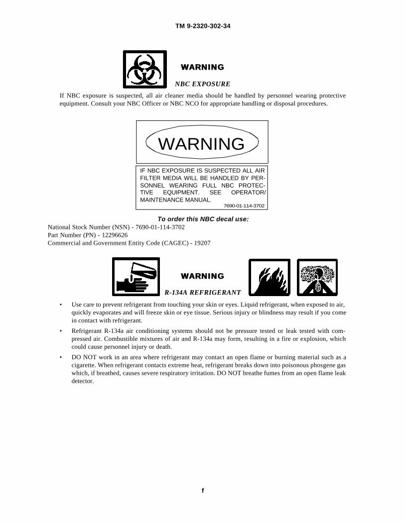
NBC EXPOSURE
If NBC exposure is suspected, all air cleaner media should be handled by personnel wearing protectiveequipment. Consult your NBC Officer or NBC NCO for appropriate handling or disposal procedures.
To order this NBC decal use:National Stock Number (NSN) - 7690-01-114-3702Part Number (PN) - 12296626Commercial and Government Entity Code (CAGEC) - 19207
WARNINGWARNING
R-134A REFRIGERANT
• Use care to prevent refrigerant from touching your skin or eyes. Liquid refrigerant, when exposed to air,quickly evaporates and will freeze skin or eye tissue. Serious injury or blindness may result if you comein contact with refrigerant.
• Refrigerant R-134a air conditioning systems should not be pressure tested or leak tested with com-pressed air. Combustible mixtures of air and R-134a may form, resulting in a fire or explosion, whichcould cause personnel injury or death.
• DO NOT work in an area where refrigerant may contact an open flame or burning material such as acigarette. When refrigerant contacts extreme heat, refrigerant breaks down into poisonous phosgene gaswhich, if breathed, causes severe respiratory irritation. DO NOT breathe fumes from an open flame leakdetector.
WARNINGIF NBC EXPOSURE IS SUSPECTED ALL AIRFILTER MEDIA WILL BE HANDLED BY PER-SONNEL WEARING FULL NBC PROTEC-TIVE EQUIPMENT. SEE OPERATOR/MAINTENANCE MANUAL.
7690-01-114-3702
TM 9-2320-302-34
g
WARNINGWARNING
WORK SAFETY
• Hydraulic jack is intended only for lifting truck, not for supporting vehicle to perform maintenance.DO NOT get under truck after it is raised unless it is properly supported with blocks or jackstands.Failure to observe this warning may result in death or injury to personnel.
• Use extreme caution when handling heavy parts. Provide adequate support and use assistance dur-ing procedure. Ensure that any lifting device used is in good condition and of suitable load capac-ity. Keep clear of heavy parts supported only by lifting device. Failure to follow this warning mayresult in death or injury to personnel.
• Improper use of lifting equipment and improper attachment of cables to vehicle can result in seri-ous injury to personnel and equipment damage. Observe all standard rules of safety.
• ALWAYS install hood prop after opening hood. Failure to follow this warning could result insevere injury to personnel.

TM 9-2320-302-34
h
This Page Intentionally Left Blank.

TM 9-2320-302-34
i
TECHNICAL MANUAL HEADQUARTERSTM 9-2320-302-34 DEPARTMENT OF THE ARMY
Washington, D.C., 28 May 2001DIRECT SUPPORT AND GENERAL SUPPORTMAINTENANCE MANUAL
FOR
TRUCK, TRACTOR, LINE HAUL:52,000 GVWR, 6 X 4, M915A3
(NSN 2320-01-432-4847)
Table of Contents
PageNumber
Warning Summary . . . . . . . . . . . . . . . . . . . . . . . . . . . . . . . . . . . . . . . . . . . . . . . . . . . . . . . . . . . . . . . . . . . aHow to Use This Manual. . . . . . . . . . . . . . . . . . . . . . . . . . . . . . . . . . . . . . . . . . . . . . . . . . . . . . . . . . . . . . . v
CHAPTER 1 INTRODUCTORY INFORMATION WITH THEORY OF OPERATION
WP 0001 00 General Information . . . . . . . . . . . . . . . . . . . . . . . . . . . . . . . . . . . . . . . . . . . . . . . . 0001 00-1WP 0002 00 Equipment Description and Data . . . . . . . . . . . . . . . . . . . . . . . . . . . . . . . . . . . . . . 0002 00-1WP 0003 00 Theory of Operation. . . . . . . . . . . . . . . . . . . . . . . . . . . . . . . . . . . . . . . . . . . . . . . . 0003 00-1
CHAPTER 2 DIRECT SUPPORT AND GENERAL SUPPORT TROUBLESHOOTING
WP 0004 00 Troubleshooting Introduction. . . . . . . . . . . . . . . . . . . . . . . . . . . . . . . . . . . . . . . . . 0004 00-1WP 0005 00 Troubleshooting Symptom Index. . . . . . . . . . . . . . . . . . . . . . . . . . . . . . . . . . . . . . 0005 00-1WP 0006 00 Engine Troubleshooting . . . . . . . . . . . . . . . . . . . . . . . . . . . . . . . . . . . . . . . . . . . . . 0006 00-1WP 0007 00 Transmission Troubleshooting. . . . . . . . . . . . . . . . . . . . . . . . . . . . . . . . . . . . . . . . 0007 00-1WP 0008 00 Steering System Troubleshooting . . . . . . . . . . . . . . . . . . . . . . . . . . . . . . . . . . . . . 0008 00-1WP 0009 00 Air Conditioning System Troubleshooting and Testing . . . . . . . . . . . . . . . . . . . . 0009 00-1
CHAPTER 3 DIRECT SUPPORT AND GENERAL SUPPORT MAINTENANCE INSTRUCTIONS
WP 0010 00 Power Pack Replacement . . . . . . . . . . . . . . . . . . . . . . . . . . . . . . . . . . . . . . . . . . . . 0010 00-1WP 0011 00 Front Engine Mount Adapter and Support Replacement . . . . . . . . . . . . . . . . . . . . 0011 00-1WP 0012 00 Rear Engine Mounts Replacement . . . . . . . . . . . . . . . . . . . . . . . . . . . . . . . . . . . . . 0012 00-1
REPORTING ERRORS AND RECOMMENDING IMPROVEMENTS
You can help improve this publication. If you find any mistakes or if you know of a way to improve the pro-cedures, please let us know. Submit your DA Form 2028 (Recommended Changes to Equipment TechnicalPublications), through the Internet, on the Army Electronic Product Support (AEPS) website. The Internetaddress is http://aeps.ria.army.mil. If you need a password, scroll down and click on “ACCESS REQUESTFORM”. The DA Form 2028 is located in the ONLINE FORMS PROCESSING section of the AEPS. Fill outthe form and click on SUBMIT. Using this form on the AEPS will enable us to respond quicker to your com-ments and better manage the DA Form 2028 program. You may also mail, fax or e-mail your letter, DA Form2028 direct to: AMSTA-LC-CI/TECH PUBS, TACOM-RI, 1 Rock Island Arsenal, Rock Island, IL 61299-7630. The e-mail address is: [email protected]. The fax number is DSN 793-0726 orCommercial (309) 782-0726.
TM 9-2320-302-34
ii
Table of Contents - Continued
PageNumber
WP 0013 00 Fan Drive Support Replacement . . . . . . . . . . . . . . . . . . . . . . . . . . . . . . . . . . . . . . 0013 00-1WP 0014 00 Air Intake Manifold Replacement . . . . . . . . . . . . . . . . . . . . . . . . . . . . . . . . . . . . . 0014 00-1WP 0015 00 Exhaust Manifold Replacement . . . . . . . . . . . . . . . . . . . . . . . . . . . . . . . . . . . . . . . 0015 00-1WP 0016 00 Rocker Arm Cover Replacement . . . . . . . . . . . . . . . . . . . . . . . . . . . . . . . . . . . . . . 0016 00-1WP 0017 00 Breather Tube Replacement. . . . . . . . . . . . . . . . . . . . . . . . . . . . . . . . . . . . . . . . . . 0017 00-1WP 0018 00 Cylinder Head Replacement. . . . . . . . . . . . . . . . . . . . . . . . . . . . . . . . . . . . . . . . . . 0018 00-1WP 0019 00 Gear Case Cover Replacement . . . . . . . . . . . . . . . . . . . . . . . . . . . . . . . . . . . . . . . . 0019 00-1WP 0020 00 Vibration Damper Replacement . . . . . . . . . . . . . . . . . . . . . . . . . . . . . . . . . . . . . . . 0020 00-1WP 0021 00 Accessory Drive Replacement . . . . . . . . . . . . . . . . . . . . . . . . . . . . . . . . . . . . . . . . 0021 00-1WP 0022 00 Engine Retarder Maintenance . . . . . . . . . . . . . . . . . . . . . . . . . . . . . . . . . . . . . . . . 0022 00-1WP 0023 00 Crankshaft Rear Oil Seal Replacement . . . . . . . . . . . . . . . . . . . . . . . . . . . . . . . . . 0023 00-1WP 0024 00 Flywheel Housing Replacement. . . . . . . . . . . . . . . . . . . . . . . . . . . . . . . . . . . . . . . 0024 00-1WP 0025 00 Flex Plate Maintenance . . . . . . . . . . . . . . . . . . . . . . . . . . . . . . . . . . . . . . . . . . . . . 0025 00-1WP 0026 00 Camshaft and Bearings Replacement. . . . . . . . . . . . . . . . . . . . . . . . . . . . . . . . . . . 0026 00-1WP 0027 00 Rocker Arm Assemblies Maintenance . . . . . . . . . . . . . . . . . . . . . . . . . . . . . . . . . . 0027 00-1WP 0028 00 Oil Pan Maintenance . . . . . . . . . . . . . . . . . . . . . . . . . . . . . . . . . . . . . . . . . . . . . . . 0028 00-1WP 0029 00 Oil Pump Maintenance. . . . . . . . . . . . . . . . . . . . . . . . . . . . . . . . . . . . . . . . . . . . . . 0029 00-1WP 0030 00 Oil Pressure Relief and Regulator Valves Replacement . . . . . . . . . . . . . . . . . . . . 0030 00-1WP 0031 00 Crankshaft Front Oil Seal Replacement . . . . . . . . . . . . . . . . . . . . . . . . . . . . . . . . . 0031 00-1WP 0032 00 Cylinder Head Repair . . . . . . . . . . . . . . . . . . . . . . . . . . . . . . . . . . . . . . . . . . . . . . . 0032 00-1WP 0033 00 Crankshaft Replacement . . . . . . . . . . . . . . . . . . . . . . . . . . . . . . . . . . . . . . . . . . . . 0033 00-1WP 0034 00 Camshaft Drive Gear Maintenance . . . . . . . . . . . . . . . . . . . . . . . . . . . . . . . . . . . . 0034 00-1WP 0035 00 Gear Housing Assembly Replacement . . . . . . . . . . . . . . . . . . . . . . . . . . . . . . . . . . 0035 00-1WP 0036 00 Cylinder Block Assembly Repair. . . . . . . . . . . . . . . . . . . . . . . . . . . . . . . . . . . . . . 0036 00-1WP 0037 00 Bull/Idler Gear Replacement . . . . . . . . . . . . . . . . . . . . . . . . . . . . . . . . . . . . . . . . . 0037 00-1WP 0038 00 Adjustable Idler Gear Replacement . . . . . . . . . . . . . . . . . . . . . . . . . . . . . . . . . . . . 0038 00-1WP 0039 00 Accessory Drive Repair . . . . . . . . . . . . . . . . . . . . . . . . . . . . . . . . . . . . . . . . . . . . . 0039 00-1WP 0040 00 Cylinder Block Pressure Testing . . . . . . . . . . . . . . . . . . . . . . . . . . . . . . . . . . . . . . 0040 00-1WP 0041 00 Piston and Cylinder Assembly Maintenance . . . . . . . . . . . . . . . . . . . . . . . . . . . . . 0041 00-1WP 0042 00 Turbocharger Replacement . . . . . . . . . . . . . . . . . . . . . . . . . . . . . . . . . . . . . . . . . . 0042 00-1WP 0043 00 Turbocharger Repair . . . . . . . . . . . . . . . . . . . . . . . . . . . . . . . . . . . . . . . . . . . . . . . 0043 00-1WP 0044 00 3K Turbocharger Wastegate Actuator Maintenance . . . . . . . . . . . . . . . . . . . . . . . 0044 00-1WP 0045 00 Garrett Turbocharger Wastegate Actuator Maintenance . . . . . . . . . . . . . . . . . . . . 0045 00-1WP 0046 00 Fuel Injector Replacement . . . . . . . . . . . . . . . . . . . . . . . . . . . . . . . . . . . . . . . . . . . 0046 00-1WP 0047 00 Fuel Injector Solenoid Replacement . . . . . . . . . . . . . . . . . . . . . . . . . . . . . . . . . . . 0047 00-1WP 0048 00 Radiator Repair . . . . . . . . . . . . . . . . . . . . . . . . . . . . . . . . . . . . . . . . . . . . . . . . . . . 0048 00-1WP 0049 00 Water Pump Repair . . . . . . . . . . . . . . . . . . . . . . . . . . . . . . . . . . . . . . . . . . . . . . . . 0049 00-1WP 0050 00 Fan Clutch Repair. . . . . . . . . . . . . . . . . . . . . . . . . . . . . . . . . . . . . . . . . . . . . . . . . . 0050 00-1WP 0051 00 Spindle and Housing Repair. . . . . . . . . . . . . . . . . . . . . . . . . . . . . . . . . . . . . . . . . . 0051 00-1WP 0052 00 Alternator Repair . . . . . . . . . . . . . . . . . . . . . . . . . . . . . . . . . . . . . . . . . . . . . . . . . . 0052 00-1WP 0053 00 Starter Solenoid Replacement . . . . . . . . . . . . . . . . . . . . . . . . . . . . . . . . . . . . . . . . 0053 00-1WP 0054 00 Starter Repair . . . . . . . . . . . . . . . . . . . . . . . . . . . . . . . . . . . . . . . . . . . . . . . . . . . . . 0054 00-1WP 0055 00 Engine Power Wiring Harness Replacement . . . . . . . . . . . . . . . . . . . . . . . . . . . . . 0055 00-1WP 0056 00 Engine Wiring Harness Replacement . . . . . . . . . . . . . . . . . . . . . . . . . . . . . . . . . . 0056 00-1WP 0057 00 Main Cab Wiring Harness Replacement . . . . . . . . . . . . . . . . . . . . . . . . . . . . . . . . 0057 00-1WP 0058 00 Switch Panel Wiring Harness Replacement . . . . . . . . . . . . . . . . . . . . . . . . . . . . . . 0058 00-1WP 0059 00 Turn Signal/Marker Light Wiring Harness Replacement . . . . . . . . . . . . . . . . . . . 0059 00-1

TM 9-2320-302-34
iii
Table of Contents - Continued
PageNumber
WP 0060 00 Turn Signal (Thru-deck) Wiring Harness Replacement . . . . . . . . . . . . . . . . . . . . 0060 00-1WP 0061 00 Overhead Cab Wiring Harness Replacement. . . . . . . . . . . . . . . . . . . . . . . . . . . . . 0061 00-1WP 0062 00 Chassis Wiring Harness Replacement . . . . . . . . . . . . . . . . . . . . . . . . . . . . . . . . . . 0062 00-1WP 0063 00 Front Anti-lock Brake System (ABS) Wiring Harness Replacement . . . . . . . . . . 0063 00-1WP 0064 00 Rear Anti-lock Brake System (ABS) Wiring Harness Replacement . . . . . . . . . . . 0064 00-1WP 0065 00 Cab Anti-lock Brake System (ABS) Wiring Harness Replacement . . . . . . . . . . . 0065 00-1WP 0066 00 Collision Warning System (CWS) Wiring Harness Replacement . . . . . . . . . . . . . 0066 00-1WP 0067 00 Taillight Wiring Harness Replacement . . . . . . . . . . . . . . . . . . . . . . . . . . . . . . . . . 0067 00-1WP 0068 00 Air Conditioner Binary Switch Wiring Harness Replacement . . . . . . . . . . . . . . . 0068 00-1WP 0069 00 Engine Injector and ECM Wiring Harnesses Replacement . . . . . . . . . . . . . . . . . . 0069 00-1WP 0070 00 Transmission Replacement . . . . . . . . . . . . . . . . . . . . . . . . . . . . . . . . . . . . . . . . . . 0070 00-1WP 0071 00 Transmission Overhaul . . . . . . . . . . . . . . . . . . . . . . . . . . . . . . . . . . . . . . . . . . . . . 0071 00-1WP 0072 00 Front Axle Assembly Replacement . . . . . . . . . . . . . . . . . . . . . . . . . . . . . . . . . . . . 0072 00-1WP 0073 00 Front Axle Caster Adjustment . . . . . . . . . . . . . . . . . . . . . . . . . . . . . . . . . . . . . . . . 0073 00-1WP 0074 00 Tie Rod Maintenance . . . . . . . . . . . . . . . . . . . . . . . . . . . . . . . . . . . . . . . . . . . . . . . 0074 00-1WP 0075 00 Front Cross Tube Arm Replacement . . . . . . . . . . . . . . . . . . . . . . . . . . . . . . . . . . . 0075 00-1WP 0076 00 Front Steering Arm Replacement. . . . . . . . . . . . . . . . . . . . . . . . . . . . . . . . . . . . . . 0076 00-1WP 0077 00 Front Steering Knuckle Replacement . . . . . . . . . . . . . . . . . . . . . . . . . . . . . . . . . . 0077 00-1WP 0078 00 Rear Axle Replacement . . . . . . . . . . . . . . . . . . . . . . . . . . . . . . . . . . . . . . . . . . . . . 0078 00-1WP 0079 00 Forward-rear Axle Differential Carrier Replacement . . . . . . . . . . . . . . . . . . . . . . 0079 00-1WP 0080 00 Forward-rear Axle Differential Carrier Repair . . . . . . . . . . . . . . . . . . . . . . . . . . . 0080 00-1WP 0081 00 Rear-rear Axle Differential Carrier Replacement . . . . . . . . . . . . . . . . . . . . . . . . . 0081 00-1WP 0082 00 Rear-rear Axle Differential Carrier Repair . . . . . . . . . . . . . . . . . . . . . . . . . . . . . . 0082 00-1WP 0083 00 Foot Brake Valve Repair . . . . . . . . . . . . . . . . . . . . . . . . . . . . . . . . . . . . . . . . . . . . 0083 00-1WP 0084 00 Air Compressor Repair. . . . . . . . . . . . . . . . . . . . . . . . . . . . . . . . . . . . . . . . . . . . . . 0084 00-1WP 0085 00 Brake Drum Repair . . . . . . . . . . . . . . . . . . . . . . . . . . . . . . . . . . . . . . . . . . . . . . . . 0085 00-1WP 0086 00 Power Steering Pump Replacement . . . . . . . . . . . . . . . . . . . . . . . . . . . . . . . . . . . . 0086 00-1WP 0087 00 Power Steering Pump Repair . . . . . . . . . . . . . . . . . . . . . . . . . . . . . . . . . . . . . . . . . 0087 00-1WP 0088 00 Steering Gear Replacement . . . . . . . . . . . . . . . . . . . . . . . . . . . . . . . . . . . . . . . . . . 0088 00-1WP 0089 00 Steering Gear Repair . . . . . . . . . . . . . . . . . . . . . . . . . . . . . . . . . . . . . . . . . . . . . . . 0089 00-1WP 0090 00 Steering Column Replacement. . . . . . . . . . . . . . . . . . . . . . . . . . . . . . . . . . . . . . . . 0090 00-1WP 0091 00 Fifth Wheel Replacement . . . . . . . . . . . . . . . . . . . . . . . . . . . . . . . . . . . . . . . . . . . . 0091 00-1WP 0092 00 Slide Bracket and Plate Repair. . . . . . . . . . . . . . . . . . . . . . . . . . . . . . . . . . . . . . . . 0092 00-1WP 0093 00 Top Plate Replacement. . . . . . . . . . . . . . . . . . . . . . . . . . . . . . . . . . . . . . . . . . . . . . 0093 00-1WP 0094 00 Top Plate Repair. . . . . . . . . . . . . . . . . . . . . . . . . . . . . . . . . . . . . . . . . . . . . . . . . . . 0094 00-1WP 0095 00 Ramp Replacement . . . . . . . . . . . . . . . . . . . . . . . . . . . . . . . . . . . . . . . . . . . . . . . . 0095 00-1WP 0096 00 Crossmember Replacement . . . . . . . . . . . . . . . . . . . . . . . . . . . . . . . . . . . . . . . . . . 0096 00-1WP 0097 00 Front Cab Mounts Replacement. . . . . . . . . . . . . . . . . . . . . . . . . . . . . . . . . . . . . . . 0097 00-1WP 0098 00 Rear Cab Mounts Replacement . . . . . . . . . . . . . . . . . . . . . . . . . . . . . . . . . . . . . . . 0098 00-1WP 0099 00 Front Spring Replacement . . . . . . . . . . . . . . . . . . . . . . . . . . . . . . . . . . . . . . . . . . . 0099 00-1WP 0100 00 Front Spring Hangers Replacement . . . . . . . . . . . . . . . . . . . . . . . . . . . . . . . . . . . . 0100 00-1WP 0101 00 Rear Suspension Center Bearing Replacement . . . . . . . . . . . . . . . . . . . . . . . . . . . 0101 00-1WP 0102 00 Rear Spring Assembly Replacement . . . . . . . . . . . . . . . . . . . . . . . . . . . . . . . . . . . 0102 00-1WP 0103 00 Rear Suspension Control Rod and V-Rod Replacement . . . . . . . . . . . . . . . . . . . . 0103 00-1WP 0104 00 Cab Replacement . . . . . . . . . . . . . . . . . . . . . . . . . . . . . . . . . . . . . . . . . . . . . . . . . . 0104 00-1WP 0105 00 Cab Body Repair . . . . . . . . . . . . . . . . . . . . . . . . . . . . . . . . . . . . . . . . . . . . . . . . . . 0105 00-1WP 0106 00 Hood SMC Repair . . . . . . . . . . . . . . . . . . . . . . . . . . . . . . . . . . . . . . . . . . . . . . . . . 0106 00-1WP 0107 00 Cab Door Replacement . . . . . . . . . . . . . . . . . . . . . . . . . . . . . . . . . . . . . . . . . . . . . 0107 00-1

TM 9-2320-302-34
iv
Table of Contents - Continued
PageNumber
WP 0108 00 Cab Door Repair. . . . . . . . . . . . . . . . . . . . . . . . . . . . . . . . . . . . . . . . . . . . . . . . . . . 0108 00-1WP 0109 00 Windshield Replacement . . . . . . . . . . . . . . . . . . . . . . . . . . . . . . . . . . . . . . . . . . . . 0109 00-1WP 0110 00 Rear Window Replacement . . . . . . . . . . . . . . . . . . . . . . . . . . . . . . . . . . . . . . . . . . 0110 00-1WP 0111 00 Air Ducts Replacement . . . . . . . . . . . . . . . . . . . . . . . . . . . . . . . . . . . . . . . . . . . . . 0111 00-1WP 0112 00 Air Conditioning System Refrigerant (R-134a) Maintenance . . . . . . . . . . . . . . . . 0112 00-1WP 0113 00 HVAC Unit Replacement. . . . . . . . . . . . . . . . . . . . . . . . . . . . . . . . . . . . . . . . . . . . 0113 00-1WP 0114 00 Air Conditioner Expansion Valve Replacement . . . . . . . . . . . . . . . . . . . . . . . . . . 0114 00-1WP 0115 00 Air Conditioner Evaporator Coil Replacement . . . . . . . . . . . . . . . . . . . . . . . . . . . 0115 00-1WP 0116 00 Air Conditioner Compressor Service . . . . . . . . . . . . . . . . . . . . . . . . . . . . . . . . . . . 0116 00-1WP 0117 00 Air Conditioner Compressor Replacement . . . . . . . . . . . . . . . . . . . . . . . . . . . . . . 0117 00-1WP 0118 00 Air Conditioner Receiver-drier Replacement . . . . . . . . . . . . . . . . . . . . . . . . . . . . 0118 00-1WP 0119 00 Air Conditioner Condenser Replacement . . . . . . . . . . . . . . . . . . . . . . . . . . . . . . . 0119 00-1WP 0120 00 Air Conditioner Fan Cycling Switch Replacement . . . . . . . . . . . . . . . . . . . . . . . . 0120 00-1WP 0121 00 Air Conditioner Hose Replacement . . . . . . . . . . . . . . . . . . . . . . . . . . . . . . . . . . . . 0121 00-1WP 0122 00 Illustrated List of Manufactured Items . . . . . . . . . . . . . . . . . . . . . . . . . . . . . . . . . . 0122 00-1WP 0123 00 Torque Limits . . . . . . . . . . . . . . . . . . . . . . . . . . . . . . . . . . . . . . . . . . . . . . . . . . . . . 0123 00-1
CHAPTER 4 SUPPORTING INFORMATION
WP 0124 00 References . . . . . . . . . . . . . . . . . . . . . . . . . . . . . . . . . . . . . . . . . . . . . . . . . . . . . . . 0124 00-1WP 0125 00 Expendable and Durable Items List . . . . . . . . . . . . . . . . . . . . . . . . . . . . . . . . . . . . 0125 00-1WP 0126 00 Tool Identification List. . . . . . . . . . . . . . . . . . . . . . . . . . . . . . . . . . . . . . . . . . . . . . 0126 00-1

TM 9-2320-302-34
v
HOW TO USE THIS MANUAL
This manual is designed to help you maintain the M915A3 Tractor Truck.
FEATURES OF THIS MANUAL:
• A Table of Contents is provided at the beginning of this manual.
• WARNINGs, CAUTIONs, NOTEs, subject headings, and other important information are highlightedin BOLD print as a visual aid.
WARNINGWARNINGA WARNING indicates a hazard which results in death or serious injury.
CAUTIONCAUTIONA CAUTION is a reminder of safety practices or directs attention to usage practices that may resultin damage to equipment.
NOTENOTEA NOTE is a statement containing information that will make the procedures easier to perform.
• Statements and words of particular importance are printed in CAPITAL LETTERS to create empha-sis.
• Instructions are located with illustrations that show the specific task on which the mechanic is work-ing.
• Dashed leader lines used in illustrations indicate that called out items are not visible (i.e. they arelocated within the structure).
• Technical instructions include metric units in addition to standard units. A metric conversion chart isprovided on the inside back cover.
• An alphabetical index is provided at the end of the manual to assist in locating information not readilyfound in the Table of Contents.
FOLLOW THESE GUIDELINES WHEN YOU THIS MANUAL:
• Read through this manual and become familiar with its contents before attempting to maintain thevehicle.
• A Warning Summary is provided at the beginning of this manual and should be read before attempt-ing to maintain the vehicle.

TM 9-2320-302-34
vi
This Page Intentionally Left Blank.

TM 9-2320-302-34
CHAPTER 1INTRODUCTORY INFORMATION WITH
THEORY OF OPERATION

TM 9-2320-302-34
This Page Intentionally Left Blank.

TM 9-2320-302-34
0001 00-1
GENERAL INFORMATION 0001 00
SCOPE
1. Type of Manual. This manual is for use in performing Direct Support and General Support Maintenance on theM915A3 Tractor Truck.
2. Equipment Name and Model Number. Truck, Tractor, Line Haul: 52,000 GVWR, 6 X 4, M915A3.
3. Purpose of Equipment. The M915A3 Tractor Truck is a 6 X 4 prime mover of semitrailers used primarily to transportcontainers, bulk cargo, and petroleum products over primary and secondary roads under worldwide climatic conditionsin a military environment.
MAINTENANCE FORMS, RECORDS, AND REPORTS
Department of the Army forms and procedures used for equipment maintenance will be those prescribed by DA Pam 738-750,Functional User’s Manual for the Army Maintenance Management System (TAMMS), as contained in the Maintenance Man-agement Update.
REPORTING EQUIPMENT IMPROVEMENT RECOMMENDATIONS (EIRS)
If your truck needs improvement, let us know. Send us an EIR. You, the user, are the only one who can tell us what you don’tlike about your equipment. Let us know why you don’t like the design or performance. Put it on an SF Form 368 (ProductQuality Deficiency Report) . Mail it to us at: Commander, U.S. Army Tank-automotive and Armaments Command, ATTN:AMSTA-LC-CIP-WT, Rock Island, Illinois 61299-7630. We will send you a reply.
CORROSION PREVENTION AND CONTROL (CPC)
1. Corrosion Prevention and Control (CPC) of Army materiel is a continuing concern. It is important that any corrosionproblems with this item be reported so that the problem can be corrected and improvements can be made to prevent theproblem in future items.
2. While corrosion is typically associated with rusting of metals, it can also include deterioration of other materials, such asrubber and plastic. Unusual cracking, softening, swelling or breaking of these materials may be a corrosion problem.
3. If a corrosion problem is identified, it can be reported using SF Form 368 (Product Quality Deficiency Report). Use ofkey words such as “corrosion,” “rust,” “deterioration,” or “cracking” will ensure that the information is identified as aCPC problem. The form should be submitted to the address specified in DA Pam 738-750.
OZONE DEPLETING SUBSTANCES (ODS)
Listing to be provided by requiring activity.
DESTRUCTION OF ARMY MATERIEL TO PREVENT ENEMY USE
For destruction of Army materiel to prevent enemy use, refer to TM 750-244-6.
PREPARATION FOR STORAGE OR SHIPMENT
For preparation for storage or shipment procedures, refer to TM 740-90-1 and MIL-V-62038D.
WARRANTY INFORMATION
The vehicle is warranted by Freightliner Corporation in accordance with TB 9-2320-302-15. Warranty starts on the date foundin block 23, DA Form 2408-9 in the logbook. Report all defects in material or workmanship to your supervisor, who will takeappropriate action.
TM 9-2320-302-34
0001 00-2
GENERAL INFORMATION - CONTINUED 0001 00
NOMENCLATURE CROSS-REFERENCE LIST
COMMON NAME OFFICIAL NOMENCLATURE
Cold Start System . . . . . . . . . . . . . . . . . . . . . . . . . . . . . . . . . . . . . . . . . . . . . . . . . . . . . . . . . . . . . . . . . Ether Quick-start System
Engine Coolant . . . . . . . . . . . . . . . . . . . . . . . . . . . . . . . . . . . . . . . . . . . . . . . . . . . . . . . . . . Antifreeze, Ethylene Glycol Mixture
Gladhand . . . . . . . . . . . . . . . . . . . . . . . . . . . . . . . . . . . . . . . . . . . . . . . . . . . . . . . . . . . . . . . . . . . . . . Quick Disconnect Coupling
Jake Brake . . . . . . . . . . . . . . . . . . . . . . . . . . . . . . . . . . . . . . . . . . . . . . . . . . . . . . . . . . . . . . . . . . . . . . . . . . . . . . . . .Engine Brake
Komfort Loc®. . . . . . . . . . . . . . . . . . . . . . . . . . . . . . . . . . . . . . . . . . . . . . . . . . . . . . . . . . . . . . . . . . . . . . . .Seat Belt Adjustment
TufTrac . . . . . . . . . . . . . . . . . . . . . . . . . . . . . . . . . . . . . . . . . . . . . . . . . . . . . . . . . . . . . . . . . . . . . . . . . . Rear Suspension System
LIST OF ABBREVIATIONS
NOTENOTERefer to MIL-STD-12D for standard abbreviations.
ABBREVIATION DEFINITION
ABS . . . . . . . . . . . . . . . . . . . . . . . . . . . . . . . . . . . . . . . . . . . . . . . . . . . . . . . . . . . . . . . . . . . . . . . . . . . . . Anti-lock Brake System
C . . . . . . . . . . . . . . . . . . . . . . . . . . . . . . . . . . . . . . . . . . . . . . . . . . . . . . . . . . . . . . . . . . . . . . . . . . . . . . . . . Centigrade or Celsius
CID . . . . . . . . . . . . . . . . . . . . . . . . . . . . . . . . . . . . . . . . . . . . . . . . . . . . . . . . . . . . . . . . . . . . . . . . . . . . Cubic Inch Displacement
cm . . . . . . . . . . . . . . . . . . . . . . . . . . . . . . . . . . . . . . . . . . . . . . . . . . . . . . . . . . . . . . . . . . . . . . . . . . . . . . . . . . . . . . . . . Centimeter
CWS . . . . . . . . . . . . . . . . . . . . . . . . . . . . . . . . . . . . . . . . . . . . . . . . . . . . . . . . . . . . . . . . . . . . . . . . . . .Collision Warning System
ECU. . . . . . . . . . . . . . . . . . . . . . . . . . . . . . . . . . . . . . . . . . . . . . . . . . . . . . . . . . . . . . . . . . . . . . . . . . . . . .Electronic Control Unit
F. . . . . . . . . . . . . . . . . . . . . . . . . . . . . . . . . . . . . . . . . . . . . . . . . . . . . . . . . . . . . . . . . . . . . . . . . . . . . . . . . . . . . . . . . . . Fahrenheit
GCWR. . . . . . . . . . . . . . . . . . . . . . . . . . . . . . . . . . . . . . . . . . . . . . . . . . . . . . . . . . . . . . . . . . . Gross Combination Weight Rating
GVWR. . . . . . . . . . . . . . . . . . . . . . . . . . . . . . . . . . . . . . . . . . . . . . . . . . . . . . . . . . . . . . . . . . . . . . . Gross Vehicle Weight Rating
kg . . . . . . . . . . . . . . . . . . . . . . . . . . . . . . . . . . . . . . . . . . . . . . . . . . . . . . . . . . . . . . . . . . . . . . . . . . . . . . . . . . . . . . . . . . . Kilogram
km . . . . . . . . . . . . . . . . . . . . . . . . . . . . . . . . . . . . . . . . . . . . . . . . . . . . . . . . . . . . . . . . . . . . . . . . . . . . . . . . . . . . . . . . . .Kilometer
kPa. . . . . . . . . . . . . . . . . . . . . . . . . . . . . . . . . . . . . . . . . . . . . . . . . . . . . . . . . . . . . . . . . . . . . . . . . . . . . . . . . . . . . . . . . Kilopascal
kph. . . . . . . . . . . . . . . . . . . . . . . . . . . . . . . . . . . . . . . . . . . . . . . . . . . . . . . . . . . . . . . . . . . . . . . . . . . . . . . . . Kilometers per Hour
kW . . . . . . . . . . . . . . . . . . . . . . . . . . . . . . . . . . . . . . . . . . . . . . . . . . . . . . . . . . . . . . . . . . . . . . . . . . . . . . . . . . . . . . . . . . .Kilowatt
l . . . . . . . . . . . . . . . . . . . . . . . . . . . . . . . . . . . . . . . . . . . . . . . . . . . . . . . . . . . . . . . . . . . . . . . . . . . . . . . . . . . . . . . . . . . . . . . .Liter
lb . . . . . . . . . . . . . . . . . . . . . . . . . . . . . . . . . . . . . . . . . . . . . . . . . . . . . . . . . . . . . . . . . . . . . . . . . . . . . . . . . . . . . . . . . . . . . .Pound
lb-ft . . . . . . . . . . . . . . . . . . . . . . . . . . . . . . . . . . . . . . . . . . . . . . . . . . . . . . . . . . . . . . . . . . . . . . . . . . . . . . . . . . . . . . . Pound Foot
lph . . . . . . . . . . . . . . . . . . . . . . . . . . . . . . . . . . . . . . . . . . . . . . . . . . . . . . . . . . . . . . . . . . . . . . . . . . . . . . . . . . . . . Liters per Hour
m . . . . . . . . . . . . . . . . . . . . . . . . . . . . . . . . . . . . . . . . . . . . . . . . . . . . . . . . . . . . . . . . . . . . . . . . . . . . . . . . . . . . . . . . . . . . . . Meter
mm. . . . . . . . . . . . . . . . . . . . . . . . . . . . . . . . . . . . . . . . . . . . . . . . . . . . . . . . . . . . . . . . . . . . . . . . . . . . . . . . . . . . . . . . . Millimeter
MTS. . . . . . . . . . . . . . . . . . . . . . . . . . . . . . . . . . . . . . . . . . . . . . . . . . . . . . . . . . . . . . . . . . . . . . . . . . Movement Tracking System
Nm . . . . . . . . . . . . . . . . . . . . . . . . . . . . . . . . . . . . . . . . . . . . . . . . . . . . . . . . . . . . . . . . . . . . . . . . . . . . . . . . . . . . . . Newton Meter
PMCS . . . . . . . . . . . . . . . . . . . . . . . . . . . . . . . . . . . . . . . . . . . . . . . . . . . . . . . . . . Preventive Maintenance Checks and Services
psi . . . . . . . . . . . . . . . . . . . . . . . . . . . . . . . . . . . . . . . . . . . . . . . . . . . . . . . . . . . . . . . . . . . . . . . . . . . . . . .Pounds per Square Inch
rpm . . . . . . . . . . . . . . . . . . . . . . . . . . . . . . . . . . . . . . . . . . . . . . . . . . . . . . . . . . . . . . . . . . . . . . . . . . . . . .Revolutions per Minute

TM 9-2320-302-34
0002 00-1
EQUIPMENT DESCRIPTION AND DATA 0002 00
EQUIPMENT CHARACTERISTICS, CAPABILITIES, AND FEATURES
1. Characteristics.
a. The M915A3 Tractor Truck is used to transport M871, M872, and M1062 semitrailers on line haul missions.
b. It has a Gross Vehicle Weight Rating (GVWR) of 52,000 lb (23,608 kg) and is equipped with a two-way oscillat-ing, sliding fifth wheel compatible with a two-inch kingpin. Maximum towed load on kingpin is 30,000 lb (13,620kg).
2. Capabilities and Features.
a. While operating on Class I roads, the fully loaded M915A3 can maintain a speed of 65 mph (105 kph) on levelroads and 29 mph (47 kph) while ascending a 3 percent grade. It has a minimum turning diameter, curb-to-curb, of53 ft 9 in (16.4 m).
b. Average cruising ranges at Gross Combination Weight Rating (GCWR) with a full tank of fuel will vary based onconditions (e.g., varying loads, prolonged idle, and climatic conditions). Cruising range is optimally 400 miles(640 km).
c. The M915A3 is equipped with an instrument panel mounted speedometer and tachometer which register truckground speed and engine speed.
d. The M915A3 has the following capabilities and features:
(1) air-activated front and rear non-asbestos cam brakes with a four-channel anti-lock brake system (ABS) toprovide significantly improved handling and braking during emergency stops
(2) operation in temperatures from -25°F (-32°C) to +125°F (+52°C), and to -40°F (-40°C) with arctic kitinstalled
(3) start and climb capability of a 20 percent grade at GCWR in both forward and reverse directions
(4) fording capability up to 20 in (51 cm) deep for 5 minutes without damage or requiring maintenance beforeoperations can continue
(5) two-passenger aluminum corrosion-proof cab with a 90 degree tilt-forward hood for service accessibility
(6) six cylinder, 12.7 liter, 430 horsepower, in-line turbocharged diesel engine built by Detroit Diesel
(7) Allison HD 4560P six-speed automatic transmission
(8) Collision Warning System (CWS) that warns the driver of potentially dangerous driving situations by acti-vating visual and audible alerts.
e. For operation in arctic conditions, the M915A3 can be equipped with an arctic heater mounted under the cab,above the battery box. This provides heat for the cab and engine cooling system. The arctic heater may be operatedprior to starting the engine to provide preheating of engine block.

TM 9-2320-302-34
0002 00-2
EQUIPMENT DESCRIPTION AND DATA - CONTINUED 0002 00
LOCATION AND DESCRIPTION OF MAJOR COMPONENTS
KEY COMPONENT DESCRIPTION
1 Marker Clearance Lights
Indicate outline of truck.
2 Side Mirrors (Heated) Provide driver with a view of sides of truck andsemitrailer, if towing.
3 Grabhandles Provide a hand hold for personnel climbing on truck.
4 Utility Power Receptacle
Supplies power for work lights. Located on both sides oftruck.
5 Air Horn Provides an audible alert.
6 Master Battery Switch Provides battery power to truck.
7 Spare Wheel and Tire Extra wheel and tire used in case of a flat tire.
8 Battery Box and Steps Holds vehicle batteries and provides steps to access cab.
9 Front Service Lights Include headlights and turn signals.
10 Bumper Extensions Provide adjustable attachment point for slings.
11 Blackout Lights Used during blackout conditions. Include marker anddrive lights.
12 Towing Eyes Provide attachment points for towing device.
12
3
45
7
89101112
10
14
15
6
13

TM 9-2320-302-34
0002 00-3
EQUIPMENT DESCRIPTION AND DATA - CONTINUED 0002 00
LOCATION AND DESCRIPTION OF MAJOR COMPONENTS - CONTINUED
KEY COMPONENT DESCRIPTION
13 CWS Antenna Forward looking collision warning system antenna.
14 Brush Guard Protects front of hood and components under hood fromdamage.
15 Spotting Mirrors Provide added visibility to sides and front of truck.

TM 9-2320-302-34
0002 00-4
EQUIPMENT DESCRIPTION AND DATA - CONTINUED 0002 00
LOCATION AND DESCRIPTION OF MAJOR COMPONENTS - CONTINUED
KEY COMPONENT DESCRIPTION
16 Ramp Sloped surface serves as an approach to fifth wheel andfacilitates coupling of semitrailer.
17 Fifth Wheel Coupling device for semitrailers with kingpins.
18 Utility Lights Illuminate area in back of cab. There is one light on eachside of cab.
19 Strobe Warning Light Strobe light alerts other vehicles of presence of truck.
20 IntervehicularReceptacles Installation
Contains 12-volt commercial, 24-volt military, andtrailer ABS receptacles.
21 Antenna Mount Mount for radio antenna.
22 Exhaust Muffler Deadens noise of engine exhaust.
23 Hood Latch Locks hood closed. Located on both sides of hood.
24 CWS Side Sensor Side looking collision warning system sensor.
25 Fuel Tank Holds fuel. Steps mounted to tank provide access to cab.
26 Storage Boxes Provide stowage area for BII and other items.
27 Mud Flaps Prevent water and debris from spraying up on passers byor towed semitrailer.
1617
1819 20
22
23
25
2627
293031 29
21
28
24
TM 9-2320-302-34
0002 00-5
EQUIPMENT DESCRIPTION AND DATA - CONTINUED 0002 00
LOCATION AND DESCRIPTION OF MAJOR COMPONENTS - CONTINUED
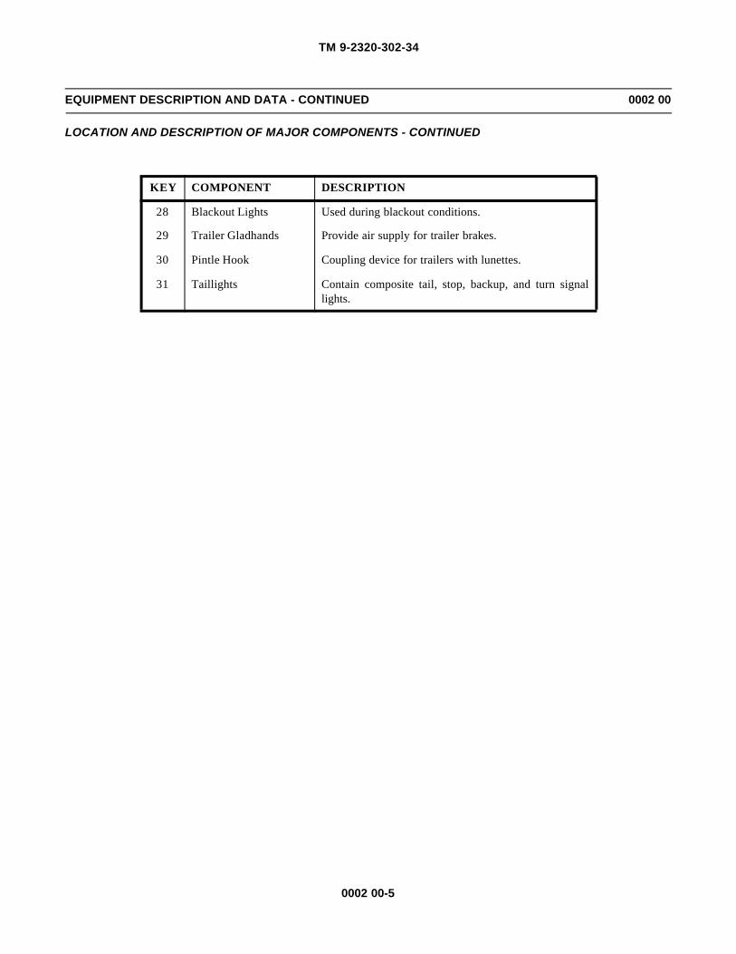
KEY COMPONENT DESCRIPTION
28 Blackout Lights Used during blackout conditions.
29 Trailer Gladhands Provide air supply for trailer brakes.
30 Pintle Hook Coupling device for trailers with lunettes.
31 Taillights Contain composite tail, stop, backup, and turn signallights.

TM 9-2320-302-34
0002 00-6
EQUIPMENT DESCRIPTION AND DATA - CONTINUED 0002 00
EQUIPMENT DATA
Dimensions:
Length (Overall) . . . . . . . . . . . . . . . . . . . . . . . . . . . . . . . . . . . . . . . . . . . . . . . . . . . . . . . . . . 276 in (701 cm)
Height (Overall) . . . . . . . . . . . . . . . . . . . . . . . . . . . . . . . . . . . . . . . . . . . . . . . . . . . . . . . . . . 118 in (300 cm)
Width (Overall) . . . . . . . . . . . . . . . . . . . . . . . . . . . . . . . . . . . . . . . . . . . . . . . . . . . . . . . . . . 100 in (254 cm)
Wheelbase . . . . . . . . . . . . . . . . . . . . . . . . . . . . . . . . . . . . . . . . . . . . . . . . . . . . . . . . . . . . . . 162 in (411 cm)
Ground Clearance . . . . . . . . . . . . . . . . . . . . . . . . . . . . . . . . . . . . . . . . . . . . . . . . . . . . . . . . 9 in (23 cm)
Angle of Approach. . . . . . . . . . . . . . . . . . . . . . . . . . . . . . . . . . . . . . . . . . . . . . . . . . . . . . . . 27°
Weights:
Curb . . . . . . . . . . . . . . . . . . . . . . . . . . . . . . . . . . . . . . . . . . . . . . . . . . . . . . . . . . . . . . . . . . . 19,080 lb (8662 kg)
GVWR . . . . . . . . . . . . . . . . . . . . . . . . . . . . . . . . . . . . . . . . . . . . . . . . . . . . . . . . . . . . . . . . . 52,000 lb (23,608 kg)
GCWR . . . . . . . . . . . . . . . . . . . . . . . . . . . . . . . . . . . . . . . . . . . . . . . . . . . . . . . . . . . . . . . . . 105,000 lb (46,670 kg)
Front Axle (Loaded). . . . . . . . . . . . . . . . . . . . . . . . . . . . . . . . . . . . . . . . . . . . . . . . . . . . . . . 12,000 lb (5448 kg)
Rear Axle (Loaded) . . . . . . . . . . . . . . . . . . . . . . . . . . . . . . . . . . . . . . . . . . . . . . . . . . . . . . . 40,000 lb (18,160 kg)
Capacities:
Engine Oil (Refill w/Filters) . . . . . . . . . . . . . . . . . . . . . . . . . . . . . . . . . . . . . . . . . . . . . . . . 41 qt (38.81 l)
Cooling System . . . . . . . . . . . . . . . . . . . . . . . . . . . . . . . . . . . . . . . . . . . . . . . . . . . . . . . . . . 65 qt (61.5 l)
Fuel Tank . . . . . . . . . . . . . . . . . . . . . . . . . . . . . . . . . . . . . . . . . . . . . . . . . . . . . . . . . . . . . . . 100 gal. (378.5 l)
Power Steering Reservoir. . . . . . . . . . . . . . . . . . . . . . . . . . . . . . . . . . . . . . . . . . . . . . . . . . . 2 qt (1.9 l)
Transmission . . . . . . . . . . . . . . . . . . . . . . . . . . . . . . . . . . . . . . . . . . . . . . . . . . . . . . . . . . . . 51 qt (48 l)
Rear Axle (Forward/Rear) . . . . . . . . . . . . . . . . . . . . . . . . . . . . . . . . . . . . . . . . . . . . . . . . . . 13/14.5 qt (12.3/13.7 l)
Engine:
Manufacturer . . . . . . . . . . . . . . . . . . . . . . . . . . . . . . . . . . . . . . . . . . . . . . . . . . . . . . . . . . . . Detroit Diesel
Type . . . . . . . . . . . . . . . . . . . . . . . . . . . . . . . . . . . . . . . . . . . . . . . . . . . . . . . . . . . . . . . . . . . 4-stroke, in-line
turbocharged diesel
Model . . . . . . . . . . . . . . . . . . . . . . . . . . . . . . . . . . . . . . . . . . . . . . . . . . . . . . . . . . . . . . . . . . DDEC IV
Cylinders . . . . . . . . . . . . . . . . . . . . . . . . . . . . . . . . . . . . . . . . . . . . . . . . . . . . . . . . . . . . . . . 6
Displacement . . . . . . . . . . . . . . . . . . . . . . . . . . . . . . . . . . . . . . . . . . . . . . . . . . . . . . . . . . . . 755 CID (12.7 l)
Torque @ 1200 rpm . . . . . . . . . . . . . . . . . . . . . . . . . . . . . . . . . . . . . . . . . . . . . . . . . . . . . . . 1400 lb-ft (1898 Nm)
Maximum Horsepower @ 2100 rpm . . . . . . . . . . . . . . . . . . . . . . . . . . . . . . . . . . . . . . . . . . 430 (320.6 kW)
Maximum Governed Speed . . . . . . . . . . . . . . . . . . . . . . . . . . . . . . . . . . . . . . . . . . . . . . . . . 2100 rpm
Oil Filter Type . . . . . . . . . . . . . . . . . . . . . . . . . . . . . . . . . . . . . . . . . . . . . . . . . . . . . . . . . . . 2 full flow,
replaceable elements
Oil Filter Quantity . . . . . . . . . . . . . . . . . . . . . . . . . . . . . . . . . . . . . . . . . . . . . . . . . . . . . . . . 2
Fuel System:
Type . . . . . . . . . . . . . . . . . . . . . . . . . . . . . . . . . . . . . . . . . . . . . . . . . . . . . . . . . . . . . . . . . . . diesel fuel injected
Fuel Filter Type . . . . . . . . . . . . . . . . . . . . . . . . . . . . . . . . . . . . . . . . . . . . . . . . . . . . . . . . . . 1 primary, 1 secondary
replaceable element
Air Cleaner:
Type . . . . . . . . . . . . . . . . . . . . . . . . . . . . . . . . . . . . . . . . . . . . . . . . . . . . . . . . . . . . . . . dry elementQuantity . . . . . . . . . . . . . . . . . . . . . . . . . . . . . . . . . . . . . . . . . . . . . . . . . . . . . . . . . . . . 1

TM 9-2320-302-34
0002 00-7
EQUIPMENT DESCRIPTION AND DATA - CONTINUED 0002 00
EQUIPMENT DATA - CONTINUED
Cooling System:
Radiator Working Pressure . . . . . . . . . . . . . . . . . . . . . . . . . . . . . . . . . . . . . . . . . . . . . . . . . 10 psi (69 kPa)Coolant Inhibitor Filter . . . . . . . . . . . . . . . . . . . . . . . . . . . . . . . . . . . . . . . . . . . . . . . . . . . . 1 replaceable element
Electrical System:
Type . . . . . . . . . . . . . . . . . . . . . . . . . . . . . . . . . . . . . . . . . . . . . . . . . . . . . . . . . . . . . . . . . . . dual 12/24 voltBatteries:
Quantity . . . . . . . . . . . . . . . . . . . . . . . . . . . . . . . . . . . . . . . . . . . . . . . . . . . . . . . . . . . . 4Voltage . . . . . . . . . . . . . . . . . . . . . . . . . . . . . . . . . . . . . . . . . . . . . . . . . . . . . . . . . . . . . 12 volt
Transmission:
Manufacturer . . . . . . . . . . . . . . . . . . . . . . . . . . . . . . . . . . . . . . . . . . . . . . . . . . . . . . . . . . . . AllisonModel . . . . . . . . . . . . . . . . . . . . . . . . . . . . . . . . . . . . . . . . . . . . . . . . . . . . . . . . . . . . . . . . . . HD 4560PType . . . . . . . . . . . . . . . . . . . . . . . . . . . . . . . . . . . . . . . . . . . . . . . . . . . . . . . . . . . . . . . . . . . 6-speed automaticShift Selector . . . . . . . . . . . . . . . . . . . . . . . . . . . . . . . . . . . . . . . . . . . . . . . . . . . . . . . . . . . . pushbutton
Front Axle:
Manufacturer . . . . . . . . . . . . . . . . . . . . . . . . . . . . . . . . . . . . . . . . . . . . . . . . . . . . . . . . . . . . RockwellType . . . . . . . . . . . . . . . . . . . . . . . . . . . . . . . . . . . . . . . . . . . . . . . . . . . . . . . . . . . . . . . . . . . I-beam, FF961Rated Capacity . . . . . . . . . . . . . . . . . . . . . . . . . . . . . . . . . . . . . . . . . . . . . . . . . . . . . . . . . . . 12,000 lb (5448 kg)Maximum Steering Angle . . . . . . . . . . . . . . . . . . . . . . . . . . . . . . . . . . . . . . . . . . . . . . . . . . 32°
Rear Axle (Tandem):
Manufacturer . . . . . . . . . . . . . . . . . . . . . . . . . . . . . . . . . . . . . . . . . . . . . . . . . . . . . . . . . . . . Rockwell, RT 40-145PRated Capacity . . . . . . . . . . . . . . . . . . . . . . . . . . . . . . . . . . . . . . . . . . . . . . . . . . . . . . . . . . . 38,000 lb (17,252 kg)Ratio . . . . . . . . . . . . . . . . . . . . . . . . . . . . . . . . . . . . . . . . . . . . . . . . . . . . . . . . . . . . . . . . . . . 4.44:1Inter-axle Differential . . . . . . . . . . . . . . . . . . . . . . . . . . . . . . . . . . . . . . . . . . . . . . . . . . . . . bevel gearTraction Control . . . . . . . . . . . . . . . . . . . . . . . . . . . . . . . . . . . . . . . . . . . . . . . . . . . . . . . . . . air controlled
Brake System:
Actuation . . . . . . . . . . . . . . . . . . . . . . . . . . . . . . . . . . . . . . . . . . . . . . . . . . . . . . . . . . . . . . . air-mechanicalPressure Range . . . . . . . . . . . . . . . . . . . . . . . . . . . . . . . . . . . . . . . . . . . . . . . . . . . . . . . . . . . 60-120 psi (414-827 kPa)Airbrake Chambers:
Service . . . . . . . . . . . . . . . . . . . . . . . . . . . . . . . . . . . . . . . . . . . . . . . . . . . . . . . . . . . . . 2 on front axleFailsafe (Spring) . . . . . . . . . . . . . . . . . . . . . . . . . . . . . . . . . . . . . . . . . . . . . . . . . . . . . . . . . . 4 on forward-rear
and rear-rear axlesABS (Anti-lock Brake System):
Type . . . . . . . . . . . . . . . . . . . . . . . . . . . . . . . . . . . . . . . . . . . . . . . . . . . . . . . . . . . . . . . 4-channelLocation . . . . . . . . . . . . . . . . . . . . . . . . . . . . . . . . . . . . . . . . . . . . . . . . . . . . . . . . . . . . front axle and rear-rear axle
Wheels:
Size. . . . . . . . . . . . . . . . . . . . . . . . . . . . . . . . . . . . . . . . . . . . . . . . . . . . . . . . . . . . . . . . . . . . 22.5 x 8.25 inNumber of Studs/Stud Size . . . . . . . . . . . . . . . . . . . . . . . . . . . . . . . . . . . . . . . . . . . . . . . . . 10/1.125 in
Tires:
Type . . . . . . . . . . . . . . . . . . . . . . . . . . . . . . . . . . . . . . . . . . . . . . . . . . . . . . . . . . . . . . . . . . . tubeless, radialon-highway
Size. . . . . . . . . . . . . . . . . . . . . . . . . . . . . . . . . . . . . . . . . . . . . . . . . . . . . . . . . . . . . . . . . . . . 11R22.5Ply Rating. . . . . . . . . . . . . . . . . . . . . . . . . . . . . . . . . . . . . . . . . . . . . . . . . . . . . . . . . . . . . . . 14PRLoad Range . . . . . . . . . . . . . . . . . . . . . . . . . . . . . . . . . . . . . . . . . . . . . . . . . . . . . . . . . . . . . H

TM 9-2320-302-34
0002 00-8
EQUIPMENT DESCRIPTION AND DATA - CONTINUED 0002 00
EQUIPMENT DATA - CONTINUED
Tires - Continued:
Inflation Pressure (Maximum Load):Front . . . . . . . . . . . . . . . . . . . . . . . . . . . . . . . . . . . . . . . . . . . . . . . . . . . . . . . . . . . . . . . 105 psi (724 kPa)Rear . . . . . . . . . . . . . . . . . . . . . . . . . . . . . . . . . . . . . . . . . . . . . . . . . . . . . . . . . . . . . . . . 100 psi (690 kPa)Spare . . . . . . . . . . . . . . . . . . . . . . . . . . . . . . . . . . . . . . . . . . . . . . . . . . . . . . . . . . . . . . . 105 psi (724 kPa)
Steering:
Manufacturer . . . . . . . . . . . . . . . . . . . . . . . . . . . . . . . . . . . . . . . . . . . . . . . . . . . . . . . . . . . . TRWSteering Gear Type . . . . . . . . . . . . . . . . . . . . . . . . . . . . . . . . . . . . . . . . . . . . . . . . . . . . . . . single gearActuation . . . . . . . . . . . . . . . . . . . . . . . . . . . . . . . . . . . . . . . . . . . . . . . . . . . . . . . . . . . . . . . hydraulic power boosterPower Steering Pump . . . . . . . . . . . . . . . . . . . . . . . . . . . . . . . . . . . . . . . . . . . . . . . . . . . . . . Eaton B165RTurning Diameter. . . . . . . . . . . . . . . . . . . . . . . . . . . . . . . . . . . . . . . . . . . . . . . . . . . . . . . . . 53 ft 9 in (16.4 m)Steering Column and Wheel:
Type . . . . . . . . . . . . . . . . . . . . . . . . . . . . . . . . . . . . . . . . . . . . . . . . . . . . . . . . . . . . . . . tilt, telescopingTilt Range . . . . . . . . . . . . . . . . . . . . . . . . . . . . . . . . . . . . . . . . . . . . . . . . . . . . . . . . . . . 15°Telescoping Range . . . . . . . . . . . . . . . . . . . . . . . . . . . . . . . . . . . . . . . . . . . . . . . . . . . . 2-5/8 in (67 mm)
Suspension:
Front . . . . . . . . . . . . . . . . . . . . . . . . . . . . . . . . . . . . . . . . . . . . . . . . . . . . . . . . . . . . . . . . . . . Single leaf springw/shock absorbers
Rear . . . . . . . . . . . . . . . . . . . . . . . . . . . . . . . . . . . . . . . . . . . . . . . . . . . . . . . . . . . . . . . . . . . TufTracw/shock absorbers
Towing Attachments:
Pintle Hook:Manufacturer. . . . . . . . . . . . . . . . . . . . . . . . . . . . . . . . . . . . . . . . . . . . . . . . . . . . . . . . . HollandModel . . . . . . . . . . . . . . . . . . . . . . . . . . . . . . . . . . . . . . . . . . . . . . . . . . . . . . . . . . . . . . no. 760Rated Capacity . . . . . . . . . . . . . . . . . . . . . . . . . . . . . . . . . . . . . . . . . . . . . . . . . . . . . . . 30 tons
(27.2 metric tons)Towing Eyes:
Quantity . . . . . . . . . . . . . . . . . . . . . . . . . . . . . . . . . . . . . . . . . . . . . . . . . . . . . . . . . . . . 2 front, 2 rearMaximum Load Capacity, Each . . . . . . . . . . . . . . . . . . . . . . . . . . . . . . . . . . . . . . . . . . 60,000 lb (27,240 kg)(Up to 45° Angle Front Long. Axis)
Fifth Wheel:Manufacturer. . . . . . . . . . . . . . . . . . . . . . . . . . . . . . . . . . . . . . . . . . . . . . . . . . . . . . . . . HollandType . . . . . . . . . . . . . . . . . . . . . . . . . . . . . . . . . . . . . . . . . . . . . . . . . . . . . . . . . . . . . . . 36 in (91.4 cm)
diameter, 2-wayoscillating, low lube
Capacity . . . . . . . . . . . . . . . . . . . . . . . . . . . . . . . . . . . . . . . . . . . . . . . . . . . . . . . . . . . . 30,000 lb (13,620 kg)Height (Empty) . . . . . . . . . . . . . . . . . . . . . . . . . . . . . . . . . . . . . . . . . . . . . . . . . . . . . . . 52 in (132.1 cm)Pitch (Fwd/Aft) . . . . . . . . . . . . . . . . . . . . . . . . . . . . . . . . . . . . . . . . . . . . . . . . . . . . . . . 15/10°Kingpin Size . . . . . . . . . . . . . . . . . . . . . . . . . . . . . . . . . . . . . . . . . . . . . . . . . . . . . . . . . 2 in (5.1 cm)
Cab:
Manufacturer . . . . . . . . . . . . . . . . . . . . . . . . . . . . . . . . . . . . . . . . . . . . . . . . . . . . . . . . . . . . FreightlinerConstruction . . . . . . . . . . . . . . . . . . . . . . . . . . . . . . . . . . . . . . . . . . . . . . . . . . . . . . . . . . . . . aluminumType . . . . . . . . . . . . . . . . . . . . . . . . . . . . . . . . . . . . . . . . . . . . . . . . . . . . . . . . . . . . . . . . . . . 2-passenger,
tilt-forward hoodAir Deflector . . . . . . . . . . . . . . . . . . . . . . . . . . . . . . . . . . . . . . . . . . . . . . . . . . . . . . . . . . . . adjustable
TM 9-2320-302-34
0002 00-9
EQUIPMENT DESCRIPTION AND DATA - CONTINUED 0002 00
EQUIPMENT DATA - CONTINUED
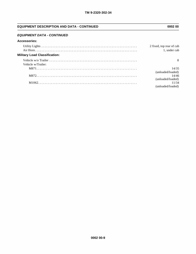
Accessories:
Utility Lights . . . . . . . . . . . . . . . . . . . . . . . . . . . . . . . . . . . . . . . . . . . . . . . . . . . . . . . . . . . . 2 fixed, top rear of cabAir Horn . . . . . . . . . . . . . . . . . . . . . . . . . . . . . . . . . . . . . . . . . . . . . . . . . . . . . . . . . . . . . . . . 1, under cab
Military Load Classification:
Vehicle w/o Trailer . . . . . . . . . . . . . . . . . . . . . . . . . . . . . . . . . . . . . . . . . . . . . . . . . . . . . . . 8Vehicle w/Trailer:
M871. . . . . . . . . . . . . . . . . . . . . . . . . . . . . . . . . . . . . . . . . . . . . . . . . . . . . . . . . . . . . . . 14/35(unloaded/loaded)
M872. . . . . . . . . . . . . . . . . . . . . . . . . . . . . . . . . . . . . . . . . . . . . . . . . . . . . . . . . . . . . . . 14/46(unloaded/loaded)
M1062. . . . . . . . . . . . . . . . . . . . . . . . . . . . . . . . . . . . . . . . . . . . . . . . . . . . . . . . . . . . . . 11/34(unloaded/loaded)

TM 9-2320-302-34
0002 00-10
This Page Intentionally Left Blank.

TM 9-2320-302-34
0003 00-1
THEORY OF OPERATION 0003 00
INTRODUCTION
1. The M915A3 Tractor Truck consists of the following functional systems: drive train, fuel system, exhaust system, cool-ing system, electrical system, air system, brake system, steering system, traction control system, suspension system, airconditioning system, and collision warning system.
2. This work package explains how the components and systems of the M915A3 work together. A functional description isprovided for each major component and system.
DRIVE TRAIN
The drive train of the M915A3 consists of a Detroit Diesel, DDEC IV engine and an Allison 6-speed automatic transmissionconnected to RT 40-145P rear tandem axles.
FUEL SYSTEM
1. Fuel to power the engine is pumped out of the fuel tank by an engine-mounted fuel pump. The engine fuel system con-sists of one electronic unit injector per cylinder, a transfer pump, low-pressure fuel lines, and primary and secondaryfuel filters.
2. The engine is governed by an electronic control system. The system controls idle speed and limits engine maximumspeed. The driver controls engine speed through the position of the electronic throttle position sensor (foot pedal).
3. Fuel filters are spin-on types. The primary fuel filter has a hand fuel primer pump and a water drain.
4. Fuel may be drained from the tank through the drain port located on the bottom of the tank.
5. There is a computer-controlled ether quick-start system for use in cold weather.
ENGINE
TRANSMISSION
FORWARD-REAR AXLE
REAR-REAR AXLE

TM 9-2320-302-34
0003 00-2
THEORY OF OPERATION - CONTINUED 0003 00
FUEL SYSTEM - CONTINUED
EXHAUST SYSTEM
The exhaust system removes exhaust gases from the engine through the exhaust manifold and turbocharger. The gases flowinto exhaust pipes and a muffler to the atmosphere above the cab.
CYLINDER
PRIMARY
WATERDRAIN
RESTRICTEDFITTING
SECONDARYFUEL FILTER
FUEL FILTERWITH HANDPRIMER
FUEL TANK
PUMPFUEL
(UPPERFITTING)
HEAD
EXHAUST PIPES
MUFFLER
EXHAUST MANIFOLD
TURBOCHARGER

TM 9-2320-302-34
0003 00-3
THEORY OF OPERATION - CONTINUED 0003 00
COOLING SYSTEM
The cooling system consists of one circulating pump, a remote-mounted coolant filter, two 180°F (82°C) thermostats for con-trolling fluid flow, a transmission oil cooler, a radiator, and a belt-driven fan. The cooling system cools the engine by circulat-ing pressurized ethylene glycol based coolant through the engine and radiator.
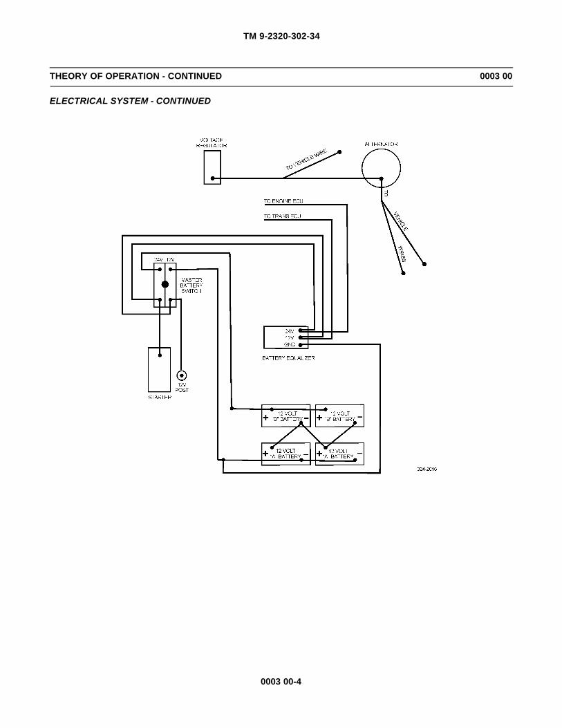
ELECTRICAL SYSTEM
1. Four 12-volt batteries connected in series-parallel supply the 12-volt electrical system and provide 24 volts for thestarter motor, blackout lights, accessories, and trailer connectors.
2. The Dual Voltage Alternator Control (DUVAC), mounted on the firewall in the engine compartment, regulates the dis-tribution of 12 and 24 volts.
TWO
DDEC IV ENGINE
CIRCULATING
INLET(FROM RADIATOR)
PUMP
THERMOSTATS
TM 9-2320-302-34
0003 00-4
THEORY OF OPERATION - CONTINUED 0003 00
ELECTRICAL SYSTEM - CONTINUED
TM 9-2320-302-34
0003 00-5
THEORY OF OPERATION - CONTINUED 0003 00
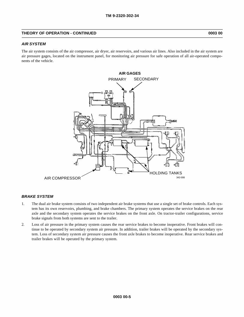
AIR SYSTEM
The air system consists of the air compressor, air dryer, air reservoirs, and various air lines. Also included in the air system areair pressure gages, located on the instrument panel, for monitoring air pressure for safe operation of all air-operated compo-nents of the vehicle.
BRAKE SYSTEM
1. The dual air brake system consists of two independent air brake systems that use a single set of brake controls. Each sys-tem has its own reservoirs, plumbing, and brake chambers. The primary system operates the service brakes on the rearaxle and the secondary system operates the service brakes on the front axle. On tractor-trailer configurations, servicebrake signals from both systems are sent to the trailer.
2. Loss of air pressure in the primary system causes the rear service brakes to become inoperative. Front brakes will con-tinue to be operated by secondary system air pressure. In addition, trailer brakes will be operated by the secondary sys-tem. Loss of secondary system air pressure causes the front axle brakes to become inoperative. Rear service brakes andtrailer brakes will be operated by the primary system.
HOLDING TANKSAIR COMPRESSOR
AIR GAGES
PRIMARY SECONDARY
342-008
TM 9-2320-302-34
0003 00-6
THEORY OF OPERATION - CONTINUED 0003 00
BRAKE SYSTEM - CONTINUED
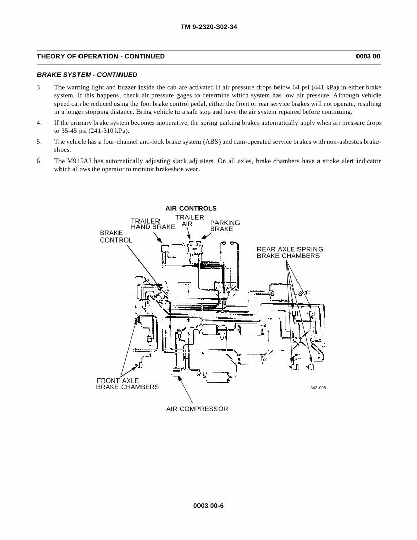
3. The warning light and buzzer inside the cab are activated if air pressure drops below 64 psi (441 kPa) in either brakesystem. If this happens, check air pressure gages to determine which system has low air pressure. Although vehiclespeed can be reduced using the foot brake control pedal, either the front or rear service brakes will not operate, resultingin a longer stopping distance. Bring vehicle to a safe stop and have the air system repaired before continuing.
4. If the primary brake system becomes inoperative, the spring parking brakes automatically apply when air pressure dropsto 35-45 psi (241-310 kPa).
5. The vehicle has a four-channel anti-lock brake system (ABS) and cam-operated service brakes with non-asbestos brake-shoes.
6. The M915A3 has automatically adjusting slack adjusters. On all axles, brake chambers have a stroke alert indicatorwhich allows the operator to monitor brakeshoe wear.
AIR CONTROLS
TRAILER PARKING
AIR COMPRESSOR
REAR AXLE SPRINGBRAKE CHAMBERS
BRAKECONTROL
FRONT AXLEBRAKE CHAMBERS
HAND BRAKETRAILER
AIRBRAKE
342-008

TM 9-2320-302-34
0003 00-7
THEORY OF OPERATION - CONTINUED 0003 00
STEERING SYSTEM
1. The power steering system consists of an integral steering gear (which includes a manual steering mechanism andhydraulic control valve), hydraulic hoses, power steering pump, reservoir, and other components.
2. The power steering pump, driven by the engine, provides the power assist for the steering system.
TRACTION CONTROL SYSTEM
The inter-axle differential lock is controlled by the air operated lever labeled INTER-AXLE DIFFERENTIAL on the driver’sinstrument panel. Under normal driving conditions, the control lever should be in the UNLOCKED position. During poor driv-ing conditions, the control lever may be moved to the LOCKED position to improve traction. When the inter-axle differentiallock is applied, the drive shaft becomes a solid connection between the two rear axles.
STEERING GEAR
RESERVOIR
POWER STEERING PUMP
TM 9-2320-302-34
0003 00-8
THEORY OF OPERATION - CONTINUED 0003 00
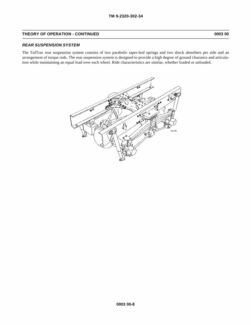
REAR SUSPENSION SYSTEM
The TufTrac rear suspension system consists of two parabolic taper-leaf springs and two shock absorbers per side and anarrangement of torque rods. The rear suspension system is designed to provide a high degree of ground clearance and articula-tion while maintaining an equal load over each wheel. Ride characteristics are similar, whether loaded or unloaded.

TM 9-2320-302-34
0003 00-9
THEORY OF OPERATION - CONTINUED 0003 00
AIR CONDITIONING SYSTEM
1. The air conditioning unit is part of the heater and is mounted under the glove compartment. It is a single unit consistingof a heater core, air conditioning evaporator coil, blower motor, control valves, and air ducts.
2. The system is turned on by the mode control lever on the instrument panel in the cab. The four-speed blower switch con-trols flow rate.
3. An even cab temperature is maintained by controlling the coolant flow through the heater core, or refrigerant flowthrough the evaporator coil.
CONDENSER
THERMOSTATICSWITCHHEATER
COREEXPANSION
VALVE
EVAPORATORCOIL
RECEIVER-DRIER
COMPRESSOR

TM 9-2320-302-34
0003 00-10
THEORY OF OPERATION - CONTINUED 0003 00
COLLISION WARNING SYSTEM (CWS)
1. The Collision Warning System (CWS) consists of an antenna assembly, central processing unit, driver display unit, sidesensor, side sensor display, and wiring harness.
2. The CWS is a forward and side looking radar system that transmits and receives signals reflected off of objects to thefront and side of the tractor.
3. The forward looking antenna assembly determines distance, azimuth, and approximate speed of vehicle forward of thetractor.
4. The side sensor detects vehicles or objects from two to ten feet, moving or stationary, alongside the tractor.
SIDESENSOR
DRIVERDISPLAY UNIT
CENTRALPROCESSING UNIT
WIRING HARNESSANTENNA
ASSEMBLY
SIDE SENSORDISPLAY

TM 9-2320-302-34
CHAPTER 2DIRECT SUPPORT AND GENERAL SUPPORT
TROUBLESHOOTING

TM 9-2320-302-34
This Page Intentionally Left Blank.

TM 9-2320-302-34
0004 00-1
TROUBLESHOOTING INTRODUCTION 0004 00
INTRODUCTION
This work package contains introductory information on troubleshooting, testing, and repair of the M915A3 TractorTruck. Make sure the problems are real. Be sure the electrical power is on when needed. Refer to the preliminary troubleshoot-ing procedures before you start troubleshooting, and during troubleshooting, when referenced.
PRELIMINARY TROUBLESHOOTING PROCEDURES
NOTENOTEFluid leaks are classified as either Class I, Class II or Class III
Class I: Seepage of fluid, as indicated by wetness or discoloration, not great enough to form drops.
Class II: Leakage of fluid great enough to form drops, but not enough to cause drops to drip from the itembeing checked or observed.
Class III: Leakage of fluid great enough to form drops that fall from the item being checked or observed.
Before starting any specific troubleshooting procedures, perform the following:
a. Visually check for ruptured oil hoses or tubes, and for Class II or Class III leaks.
b. Check for mechanical jamming or binding caused by rocks or other foreign matter.
c. Check fluid levels in subject area and service as required (TM 9-2320-302-10 or Unit PMCS).

TM 9-2320-302-34
0004 00-2
This Page Intentionally Left Blank.

TM 9-2320-302-34
0005 00-1
TROUBLESHOOTING SYMPTOM INDEX 0005 00
Malfunction/Symptom Page Number
ENGINE
1. Engine Fails to Crank. . . . . . . . . . . . . . . . . . . . . . . . . . . . . . . . . . . . . . . . . . . . . . . . . . . . . . . . . . . . . . . . . . . . . 0006 00-1
2. Engine Cranks, But Does Not Start . . . . . . . . . . . . . . . . . . . . . . . . . . . . . . . . . . . . . . . . . . . . . . . . . . . . . . . . . . 0006 00-1
3. Engine Runs Erratically . . . . . . . . . . . . . . . . . . . . . . . . . . . . . . . . . . . . . . . . . . . . . . . . . . . . . . . . . . . . . . . . . . . 0006 00-14. High Oil Consumption . . . . . . . . . . . . . . . . . . . . . . . . . . . . . . . . . . . . . . . . . . . . . . . . . . . . . . . . . . . . . . . . . . . . 0006 00-1
TRANSMISSION
Refer to WP 0007 00.
STEERING
1. Abnormal Noise . . . . . . . . . . . . . . . . . . . . . . . . . . . . . . . . . . . . . . . . . . . . . . . . . . . . . . . . . . . . . . . . . . . . . . . . . 0008 00-1
2. No Recovery . . . . . . . . . . . . . . . . . . . . . . . . . . . . . . . . . . . . . . . . . . . . . . . . . . . . . . . . . . . . . . . . . . . . . . . . . . . 0008 00-1
3. External Oil Leaks from Steering Gear . . . . . . . . . . . . . . . . . . . . . . . . . . . . . . . . . . . . . . . . . . . . . . . . . . . . . . . 0008 00-24. Oversteer or Darting . . . . . . . . . . . . . . . . . . . . . . . . . . . . . . . . . . . . . . . . . . . . . . . . . . . . . . . . . . . . . . . . . . . . . . 0008 00-3
5. High Steering Effort in One Direction . . . . . . . . . . . . . . . . . . . . . . . . . . . . . . . . . . . . . . . . . . . . . . . . . . . . . . . . 0008 00-3
6. High Steering Effort in Both Directions . . . . . . . . . . . . . . . . . . . . . . . . . . . . . . . . . . . . . . . . . . . . . . . . . . . . . . 0008 00-3
AIR CONDITIONING SYSTEM
1. Warm Airflow When Air Conditioner Is On . . . . . . . . . . . . . . . . . . . . . . . . . . . . . . . . . . . . . . . . . . . . . . . . . . . 0009 00-72. Low Evaporator Coil Outlet Pressure (Low Compressor Suction Pressure). . . . . . . . . . . . . . . . . . . . . . . . . . . 0009 00-7
3. High Compressor Discharge Pressure . . . . . . . . . . . . . . . . . . . . . . . . . . . . . . . . . . . . . . . . . . . . . . . . . . . . . . . . 0009 00-7
4. Evaporator Outlet Air Temperature Increases as Compressor Discharge Pressure Drops . . . . . . . . . . . . . . . . 0009 00-75. Compressor Operates Too Often or Continuously . . . . . . . . . . . . . . . . . . . . . . . . . . . . . . . . . . . . . . . . . . . . . . . 0009 00-8
6. Quick or Delayed Cycling of Compressor. . . . . . . . . . . . . . . . . . . . . . . . . . . . . . . . . . . . . . . . . . . . . . . . . . . . . 0009 00-8

TM 9-2320-302-34
0005 00-2
This Page Intentionally Left Blank.

TM 9-2320-302-34
0006 00-1
ENGINE TROUBLESHOOTING 0006 00
.
Table 1. Engine Troubleshooting Procedures.
MALFUNCTION TEST OR INSPECTION CORRECTIVE ACTION
1. Engine Fails to Crank. Using accessory drive, attempt torotate engine.
If engine cannot be rotated,internal damage is indicated.Remove engine (WP 0010 00).
2. Engine Cranks, But Does Not Start. 1. Inspect engine gear train forcorrect timing mark alignment.
Remove gear case cover andconfirm timing mark alignment(WP 0019 00).
2. Inspect engine gear train fordamaged or missing gear teeth.
Replace damaged gear traincomponents (WP 0035 00)
3. Engine Runs Erratically. 1. Inspect engine gear train forcorrect timing mark alignment.
Remove gear case cover andconfirm timing mark alignment(WP 0019 00).
2. Inspect engine gear train fordamaged or missing gear teeth.
Replace damaged gear traincomponents (WP 0035 00).
4. High Oil Consumption. 1. Clean and inspect engine forsigns of external oil leaks.
If no oil leaks are identified,internal damage is indicated.Remove engine (WP 0010 00).
2. Inspect rear of engine for signsof leaking oil.
If oil leaks are found, inspect andreplace crankshaft rear oil seal(WP 0023 00).
3. Inspect front of engine for signsof leaking oil.
If oil leaks are found, inspect andreplace crankshaft front oil seal(WP 0031 00).
4. Inspect turbocharger for signsof leaking oil.
If oil leaks are found, replace orrepair turbocharger (WP 0042 00or WP 0043 00).
5. Inspect oil pan for signs ofleaking oil.
If oil leaks are found, replace oilpan gasket (WP 0028 00).

TM 9-2320-302-34
0006 00-2
This Page Intentionally Left Blank.

TM 9-2320-302-34
0007 00-1
TRANSMISSION TROUBLESHOOTING 0007 00
NOTENOTERefer to TM 9-2320-302-20 for transmission troubleshooting.

TM 9-2320-302-34
0007 00-2
This Page Intentionally Left Blank.

TM 9-2320-302-34
0008 00-1
STEERING SYSTEM TROUBLESHOOTING 0008 00
Table 1. Steering System Troubleshooting Procedures.
MALFUNCTION TEST OR INSPECTION CORRECTIVE ACTION
1. Abnormal Noise. 1. If clicking noise is heard wheninitiating steering maneuver orwhen changing directions ofturn, some linkage componentis probably loose and shiftingunder load.
Tighten or replace loose ordefective components.
2. Check for excessive air in fluid(fluid is foamy) and/or lowfluid level.
Fill pump reservoir to proper level(TM 9-2320-302-10).
2. No Recovery. 1. Disconnect lower steeringcolumn from steering gear andcheck steering column forbinding.
1. Replace defective tilt steeringcolumn (WP 0090 00).
2. Replace defective universaljoint (TM 9-2320-302-20).
2. Check for sufficient pumppressure as follows:
(a) Disconnect pressure hosefrom power steering pump.
(b) Connect adapter hose fromadapter kit (Item 4, WP 0126 00)
to power steering pump.(c) Connect hose from dial end
of power steering tester(Item 127, WP 0126 00) toadapter hose.
(d) Connect hose from loadvalve end of power steeringtester to pressure hose.
CAUTIONCAUTIONBefore performing step e, ensure load valve is completely opento prevent damage to flow/pressure valve.
(e) With engine idling, rotatesteering wheel to left andright for 5 minutes to warmpower steering fluid.
CAUTIONCAUTIONTo prevent damage to power steering pump during perfor-mance of step f, do not allow load valve to be closed for morethan 5 seconds.

TM 9-2320-302-34
0008 00-2
Table 1. Steering System Troubleshooting Procedures - Continued.
MALFUNCTION TEST OR INSPECTION CORRECTIVE ACTION
2. No Recovery - Continued. (f) With engine idling, closeload valve and read pressuregage. Pressure must be 900to 1000 psi (62.07 to 68.97bars).
If pressure is less than 900 psi(62.07 bars), repair or replacepower steering pumpWP 0087 00 or WP 0086 00).
3. Check for sufficient pump flowas follows:
(a) Perform steps a through e ofstep 2.
WARNINGWARNINGMaximum flow rate is 7 gpm (26.5 liters/min). Flow rate inexcess of 7 gpm (26.5 liters/min) will damage steering gear andcould cause loss of steering and injury to personnel.
(b) With engine idling, readflow meter. Rate of flowmust be 7 gpm (26.5 liters/min).
Repair or replace power steeringpump (WP 0087 00 or WP 0086 00).
(c) With engine idling, closeload valve until pressuregage indicates pump reliefand pump relief pressuredrops to 0. Immediatelyopen load valve. Flow ratemust return to 7 gpm (26.5liters/min).
Repair or replace power steeringpump (WP 0087 00 or WP 0086 00).
(d) Run engine at 2100 rpm andfully close load valve untilpressure gage indicatespump relief and flow ratedrops to 0. Immediatelyopen load valve. Flow ratemust return to 7 gpm (26.5liters/min).
Repair or replace power steeringpump (WP 0087 00 or WP 0086 00).
4. Check for defective teflon sealsin steering control valve.
Repair or replace steering gear(WP 0089 00 or WP 0088 00).
5. Check for steering gear controlvalve sticking.
Repair or replace steering gear(WP 0089 00 or WP 0088 00).
3. External Oil Leaks from Steering Gear. NOTENOTEExternal leakage is not acceptable from steering gear.
1. Check for leak at rubber reliefplug (on frame side of steeringgear).
Repair or replace steering gear(WP 0089 00 or WP 0088 00).
2. Check for leak at shaft seals. Repair or replace steering gear(WP 0089 00 or WP 0088 00).

TM 9-2320-302-34
0008 00-3
Table 1. Steering System Troubleshooting Procedures - Continued.
MALFUNCTION TEST OR INSPECTION CORRECTIVE ACTION
4. Oversteer or Darting. 1. Disconnect lower steeringcolumn from steering gear andcheck steering column forbinding.
1. Replace defective tilt steeringcolumn (WP 0090 00).
2. Replace defective universaljoint (TM 9-2320-302-20).
2. Disconnect steering gearpitman arm and check front endcomponents for binding.
Replace defective components(TM 9-2320-302-20).
5. High Steering Effort in One Direction. 1. Check for sufficient pumppressure (Malfunction 2, step2).
If pressure is less than 900 psi(62.07 bars), repair or replacepower steering pumpWP 0087 00 or WP 0086 00).
2. Check for sufficient pump flow(Malfunction 2, step 3).
Repair or replace power steeringpump (WP 0087 00 orWP 0086 00).
3. Check for defective teflon sealsin steering control valve.
Repair or replace steering gear(WP 0089 00 or WP 0088 00).
4. Check for steering gear controlvalve sticking.
Repair or replace steering gear(WP 0089 00 or WP 0088 00).
6. High Steering Effort in Both Directions. 1. Check for sufficient pumppressure (Malfunction 2, step2).
If pressure is less than 900 psi(62.07 bars), repair or replacepower steering pump WP 0087 00 or WP 0086 00).
2. Check for sufficient pump flow(Malfunction 2, step 3).
Repair or replace power steeringpump (WP 0087 00 orWP 0086 00).
3. Check for defective teflon sealsin steering control valve.
Repair or replace steering gear(WP 0089 00 or WP 0088 00).
4. Check for steering gear controlvalve sticking.
Repair or replace steering gear(WP 0089 00 or WP 0088 00).
5. High steering effort in onedirection.
Repair or replace steering gear(WP 0089 00 or WP 0088 00).

TM 9-2320-302-34
0008 00-4
This Page Intentionally Left Blank.

TM 9-2320-302-34
0009 00-1
AIR CONDITIONING SYSTEM TROUBLESHOOTING AND TESTING 0009 00
PRELIMINARY CHECKS
Before testing the operation of the air conditioning system, make the following checks:
1. Ensure the refrigerant compressor’s drive belt is not damaged and is correctly tensioned. Also check the compressormountings for tightness.
2. Check for broken, burst or cut hoses; also check for loose fittings on all parts.
3. Check for road debris buildup on the condenser coil fins. Using air pressure and a whiskbroom or a soapy spray ofwater, carefully clean off the condenser; be careful not to bend the fins.
4. Check the color of the moisture indicator sight glass. If the color is a deep cobalt blue, the refrigerant charge is dry. Ifthe indicator is not blue, the system is contaminated with moisture. Recover the refrigerant, evacuate the system, replacethe receiver-drier, and add a full refrigerant charge (WP 0112 00).
5. If there is not enough airflow, ensure leaves or other debris have not entered the fresh air ports under the windshield. Ifdebris has entered, it could clog the fins of the evaporator core, and block airflow. Also, be sure that all ducts are con-nected to the dash louvers and that the air-control flaps in the heater housing are moving properly (this requires removalof the right and center dash panel).
PERFORMANCE TESTS
Following is a brief description of symptoms or conditions that could exist if something goes wrong with a refrigerantpart.
1. Receiver-Drier.
a. The receiver-drier is normally at outside temperature. To the touch, the entire length of the unit should be the sametemperature. If noticeable cool spots exist, replace receiver-drier (WP 0118 00).
b. A blockage at the inlet of the unit will cause high head pressures; outlet blockages will cause low head pressuresand little or no cooling.
c. If the moisture indicator is pink or white (showing that the system is wet), the receiver-drier is saturated with mois-ture and must be replaced (WP 0118 00).
2. Cooling System.
a. Although they are not physically connected, there is a close tie between vehicle’s air conditioner and cooling sys-tem. Poor air conditioner cooling can be the result of a problem in the cooling system.
b. If the cooling system does not work correctly, the heat of the engine will rise to abnormal levels. The added heatwill transfer to the air conditioner, other underhood parts, and may make its way into the cab. The added heatmakes it necessary for the air conditioner to work harder and, at the same time, it reduces the air conditioner’s abil-ity to cool down the air in the cab. Also, if the water regulating valve isn’t closing all the way, heat will enter thecab, giving the impression that the air conditioning system is not working.
c. Refer to TM 9-2320-302-20 to troubleshoot engine cooling system.
3. Expansion Valve.
a. Problems that start in the expansion valve show up as follows: when stuck closed, the evaporator coil and theexpansion valve will be at outside temperature; when stuck open, both the coil and the valve will be extremely coldwith frost or ice buildup.
b. Because the expansion valve channels are very small, blockages in the system tend to be found here (the valve isvery sensitive to contamination). Usually, the contaminant is water; less than a drop of water is all it takes to makethe valve inoperative. When water reaches the valve, the extreme cold that results from the pressure drop freezesthe water, forming a block of ice in the valve. After the system shuts down and the valve warms up, the ice melts,and the valve operates again, only to freeze up when the moisture returns.
c. On-and-off operation of the expansion valve means that the receiver-drier is not removing moisture from the sys-tem. These contaminants should cause the moisture indicator’s element to turn white and then pink.
TM 9-2320-302-34
0009 00-2
AIR CONDITIONING SYSTEM TROUBLESHOOTING AND TESTING - CONTINUED 0009 00
PERFORMANCE TESTS - CONTINUED
4. Refrigerant Compressor.
a. Compressor problems usually show in one of four ways: abnormal noise; seizure; leakage; or low suction and dis-charge pressures.
b. Resonant compressor noises are not causes for alarm; irregular noise or rattles are likely to be caused by brokenparts.
5. Evaporator.
a. The evaporator coils are basically trouble-free when airflow over the fins is not blocked. External or, less often,internal blockages will cause low suction pressure as well as little or no cooling.
b. If a leak exists in the system, and it cannot be traced to other parts or fittings, suspect damage to one of the evapo-rator coils.
6. Condenser.
a. The condenser is usually trouble-free. Normally, the temperature of the condenser outlet line is noticeably coolerthan the inlet line. However, when road debris (such as leaves or dirt buildup) cakes up, airflow over the condenserfins is blocked; air is not able to absorb enough heat to turn the hot refrigerant gas into a liquid. High head pres-sures will result. In these cases, carefully clean off the outer surfaces of the condenser with compressed air or asoap and water solution; be careful not to bend the fins.
b. High head pressures will also occur if the condenser’s tubing is abnormally bent, blocking the flow of refrigerant.Frost will appear at the point where the flow is restricted.
c. Less common internal blockages (bits of foreign material or metallic grit buildup) will stop the flow of refrigerant.
d. A quick test to check that poor system performance is caused by the condenser is to direct a spray of water onto thecondenser while the system is running. If the air conditioner cools better because of the assist provided by thewater, it is a sign that the condenser is not working.
e. When troubleshooting a suspected condenser problem, remember that the problem may be caused by the radiatortransferring high levels of heat to the condenser. Refer to TM 9-2320-302-20 to troubleshoot the engine coolingsystem.
7. Thermostatic Switch.
a. IMPORTANT: Before troubleshooting the thermostatic switch, check for a full charge of refrigerant in the system.The compressor will not operate, or will cycle too often, if there is not enough refrigerant in the system.
b. Quick or delayed cycling of the compressor may be caused by a thermostatic switch that is working, but is out ofadjustment. If, after doing the tests below, the switch seems to be out of adjustment, replace it (TM 9-2320-302-20)(the thermostatic switch cannot be recalibrated).
(1) Ensure the compressor clutch is operating correctly.
(2) Expose the evaporator coil.
(3) Start the engine. Place the air conditioner control at its coldest setting; turn on the air conditioner and thefan.
(4) Place an accurate thermometer in contact with a tube on the evaporator coil. Ensure the thermometer is ingood contact with the tube or you will get a wrong reading.
When the temperature drops below 31°F to 36°F (-1°C to 2°C), the compressor clutch should disengageand remain this way until the temperature rises to 39°F to 44°F (4°C to 7°C).
(5) If the compressor did not engage when the temperature was above the accepted high range, do the follow-ing test:

TM 9-2320-302-34
0009 00-3
AIR CONDITIONING SYSTEM TROUBLESHOOTING AND TESTING - CONTINUED 0009 00
PERFORMANCE TESTS - CONTINUED
(a) Connect a voltmeter or a test light from one of the terminals on the thermostatic switch to ground.Repeat this test with the other terminal on the switch.
(b) With the engine running and the air conditioner and blower on, both terminals will show voltage whenthe compressor should be engaged; one terminal will show voltage when the compressor should bedisengaged.
If there is no voltage, there is a problem in the electrical system from the batteries to the thermostaticswitch. Check all circuits for the cause, and repair or replace the wiring or parts.
In all other cases where the compressor is not engaging and disengaging properly, the thermostaticswitch is the cause. Replace it with a new switch (TM 9-2320-302-20).
(6) Shut down the engine and, to prevent accidental electric shock or shorting during dash assembling, discon-nect the batteries.
(7) Assemble the dash.
8. Line Restrictions.
a. A restricted suction line causes low suction pressure at the compressor and little or no cooling. A restriction in aline between the compressor and the expansion valve can cause high discharge and low suction pressure, andinsufficient cooling.
b. Usually, areas of ice or frost buildup mean a blockage. Parts that often freeze up are probably corroded or inopera-tive and should be replaced. Parts (such as the expansion valve) that freeze up once in a while may do so becauseof moisture in the system, which will cause the moisture indicator’s element to turn white or pink; if this happens,recover the refrigerant charge, evacuate/recycle the system refrigerant, replace the receiver-drier, and install a newcharge (WP 0112 00).
SAFETY PRECAUTIONS
1. Whenever repairs are made to any air conditioner parts that hold refrigerant, you must discharge, purge or flush (if con-taminated), evacuate, charge, and leak test the system. In a good system, refrigerant lines are always under pressure andyou should disconnect them only after the air conditioning system has been discharged to a refrigerant recovery unitthrough the service valves on the compressor (WP 0112 00).
WARNINGWARNINGUse care to prevent refrigerant from touching your skin or eyes. Liquid refrigerant, when exposed to the air,quickly evaporates and will freeze skin or eye tissue. Serious injury or blindness may result if you come incontact with liquid refrigerant.
2. Refrigerants are safe when used under the right conditions. Always wear safety goggles and non-leather gloves whiledischarging, purging, flushing, evacuating, charging, and leak testing the system. Do not wear leather gloves; whenrefrigerant gas or liquid contacts leather, the leather will stick to your skin.
3. Refrigerant splashed in the eyes should first be treated with a few drops of sterile mineral oil in the eyes, then rinsedwith a weak boric acid solution. Do not rub the eyes. Call a doctor right away.
4. Refrigerant splashed on the skin should be treated the same as for frostbite: gently pour cool water on the area, but donot rub the skin. Keep the skin warm with layers of soft, sterile cloth. Call a doctor right away.
TM 9-2320-302-34
0009 00-4
AIR CONDITIONING SYSTEM TROUBLESHOOTING AND TESTING - CONTINUED 0009 00
SAFETY PRECAUTIONS - CONTINUED
WARNINGWARNINGDo not work in an area where refrigerant may contact an open flame or any burning material, such as a ciga-rette. When it contacts extreme heat, refrigerant breaks down into poisonous phosgene gas which, ifbreathed, causes severe respiratory irritation. Do not breathe the fumes from an open flame leak detector.
5. Even though refrigerant does not burn, when it contacts extreme heat or flame, poisonous phosgene gas is created. Thisgas is also produced when an open flame leak detector is used. Phosgene fumes have an acrid (bitter) smell.
6. You must work in an area where there is a constant flow of fresh air when the system is discharged, flushed, charged,and leak tested using an open flame leak detector.
7. Changes in both federal and state laws will affect the way dealerships service air conditioning systems. Under currentfederal laws, refrigerant must be recovered and recycled by all users to protect the environment, and not released intothe atmosphere. Many service operations not directly involving the air conditioning system require the release of therefrigerant charge. Under the new regulations, dealerships not having the required recovery and recycling equipment(and properly trained and certified personnel) will not be allowed to do any of this service work.
8. Because of its very low boiling point, refrigerant must be stored under pressure. To prevent the refrigerant cans fromexploding, never expose them to temperatures higher than 125°F (52°C). Never leave refrigerant cans in the sun, and donot store them in sun-exposed areas where heat can build up, such as in gloveboxes, automobile trunks, etc.

TM 9-2320-302-34
0009 00-5
AIR CONDITIONING SYSTEM TROUBLESHOOTING AND TESTING - CONTINUED 0009 00
AIR CONDITIONING SYSTEM COMPONENTS
A To resistor block D To engine fan thermal switchB To blower motor E From a/c clutch relayC From engine fan thermal switch F To compressor clutch
1 Compressor 9 Ignition Switch 17 Circuit Breaker (15A)2 Condenser 10 Start Button 18 A/C clutch Relay3 Receiver-drier 11 Circuit Breaker (10A) 19 Diode4 Binary Switch 12 Circuit Breaker (30A) 20 Compressor Clutch5 Moisture Indicator 13 Power Relay 21 High-speed Relay6 High Pressure Relief Valve 14 Blower Switch 22 Fan Cycling Switch7 Expansion Valve 15 “On-Off” Microsoft 23 Discharger Service Valve8 Evaporator 16 Thermostatic Switch 24 Suction Service Valve

TM 9-2320-302-34
0009 00-6
AIR CONDITIONING SYSTEM TROUBLESHOOTING AND TESTING - CONTINUED 0009 00
AIR CONDITIONING SYSTEM TROUBLESHOOTING LOGIC TREE

TM 9-2320-302-34
0009 00-7
AIR CONDITIONING SYSTEM TROUBLESHOOTING AND TESTING - CONTINUED 0009 00
AIR CONDITIONING SYSTEM TROUBLESHOOTING
Table 1. Problem - Warm Airflow When Air Conditioning Is On.
Table 2. Problem - Low Evaporator Coil Outlet Pressure (Low Compressor Suction Pressure).
Table 3. Problem - High Compressor Discharge Pressure.
Table 4. Problem - Evaporator Outlet Air Temperature Increasesas Compressor Discharge Pressure Drops.
POSSIBLE CAUSE REMEDY
There is no refrigerant charge in system. Repair any leaks, evacuate system (WP 0112 00), replace receiver-drier (WP 011800), and add a full charge of refrigerant.
Moisture in system. If moisture is in system, ice crystals may form at expansion valve, blocking theflow of refrigerant (off and on). Recover refrigerant charge (WP 0112 00), replacereceiver-drier (WP 0118 00), evacuate system, and add a full charge of refrigerant(WP 0112 00).
POSSIBLE CAUSE REMEDY
The expansion valve is not working Replace expansion valve (WP 0114 00).
There are restrictions in line to expansionvalve.
Remove line restrictions.
There is an insufficient refrigerant chargein system.
Locate leak. Recover refrigerant charge (WP 0112 00), replace receiver-drier (WP0118 00), and add a full refrigerant charge (WP 0112 00).
POSSIBLE CAUSE REMEDY
There is an internal restriction incondenser. (Ice buildup on the condenseror a cool spot on the line from thecondenser to the receiver-drier).
Replace condenser (WP 0119 00).
Air is present in system. Repair any leaks, evacuate system (WP 0112 00), replace receiver-drier(WP 0118 00), and add a full charge of refrigerant (WP 0112 00).
Restriction in compressor discharge line. Repair or replace line (WP 0121 00).
POSSIBLE CAUSE REMEDY
The expansion valve setting is too low. Replace expansion valve (WP 0114 00). Add a full charge of refrigerant(WP 0112 00).

TM 9-2320-302-34
0009 00-8
AIR CONDITIONING SYSTEM TROUBLESHOOTING AND TESTING - CONTINUED 0009 00
AIR CONDITIONING SYSTEM TROUBLESHOOTING - CONTINUED
Table 5. Problem - Compressor Operates Too Often or Continuously.
Table 6. Problem - Quick or Delayed Cycling of Compressor.
POSSIBLE CAUSE REMEDY
There is too little refrigerant in system. Repair any leaks (WP 0121 00) and add a full charge of refrigerant (WP 0112 00).
There is a restriction in refrigerant system. Remove restriction from line.
POSSIBLE CAUSE REMEDY
Loss of refrigerant is causing a delayedcycling of the compressor.
Add a full charge of refrigerant (WP 0112 00).

TM 9-2320-302-34
CHAPTER 3DIRECT SUPPORT AND GENERAL SUPPORT
MAINTENANCE INSTRUCTIONS

TM 9-2320-302-34
This Page Intentionally Left Blank.

TM 9-2320-302-34
0010 00-1
POWER PACK REPLACEMENT 0010 00
THIS WORK PACKAGE COVERS
Removal, Power Pack Separation, Power Pack Assembly, Installation
INITIAL SETUP
Maintenance Level
Direct Support
Tools and Special Tools
Tool kit, general mechanic’s (Item 132, WP 0126 00)
Barring tool, engine (Item 8, WP 0126 00)
Lift, transmission (Item 75, WP 0126 00)
Spreader, sling (Item 120, WP 0126 00)
Wrench, torque, 15-75 lb-ft (Item 138, WP 0126 00)
Wrench, torque, 50-250 lb-ft (Item 139, WP 0126 00)
Materials/Parts
Clamp, seal (P/N KYX00-5833)
Nut, self-locking (P/N MS51922-33)
Nut, self-locking (P/N MS51922-49) (26)
Nut, self-locking (P/N MS51922-57) (2)
Washer, lock (P/N 103323) (12)
Washer, lock (P/N 20930-78423) (2)
Washer, lock (P/N 78328) (2)
Washer, lock (P/N MS35333-42)
Straps, tiedown (Item 34, WP 0125 00)
Tags, marker (Item 35, WP 0125 00)
Personnel Required
Two
Equipment Condition
Engine oil drained (TM 9-2320-302-10)
Air system drained (TM 9-2320-302-10)
Transmission tunnel access cover removed (TM 9-2320-302-20)
Hood removed (TM 9-2320-302-20)
Fan impeller and shroud removed (TM 9-2320-302-20)
Air intake tubes, hoses, and clamps removed (TM 9-2320-302-20)
Air cleaner, pre-cleaner, and duct assembly removed(TM 9-2320-302-20)
Alternator/air conditioner belt removed (TM 9-2320-302-20)
Alternator and alternator adjusting rod removed (TM9-2320-302-20)
Fender extensions removed (TM 9-2320-302-20)
Oil sampling valves removed (TM 9-2320-302-20)
Driveline disconnected (TM 9-2320-302-20)
Air conditioner compressor removed (WP 0117 00)
Transmission oil cooler lines disconnected (TM 9-2320-302-20)
Transmission wiring harness disconnected (TM 9-2320-302-20)
Transmission oil fill tube removed (TM 9-2320-302-20)
Transmission rear mount removed (WP 0070 00)
WARNINGWARNINGUse extreme caution when handling heavy parts. Provide adequate support and use assistance during proce-dure. Ensure that any lifting device used is in good condition and of suitable load capacity. Keep clear ofheavy parts supported only by lifting device. Failure to follow this warning may result in death or injury topersonnel.

TM 9-2320-302-34
0010 00-2
POWER PACK REPLACEMENT - CONTINUED 0010 00
NOTENOTETag all wires, cables, connectors, hoses, and tubes prior to removal to aid in installation.
REMOVAL
1. Remove nut (1) and washer (2) and disconnect cable (3), ground strap (4), and three wires (5) from starter (6).
2. Remove nut (7) and washer (8) and disconnect cable (9) and four wires (10) from starter solenoid (11).
3. Remove nut (12) and washer (13) and disconnect two wires (14) from starter solenoid (11).
4. Remove nut (15) and washer (16) and disconnect cable (17) and two wires (18) from plate (19).
5. Remove screw (20), washer (21), bracket (22), and plate (19).
6. Remove screw (23), bracket (24), and spacer (25) from engine block (26). Set cable harness (27) aside.
7. Remove nut (28), washer (29), and wire (30) from fuel pressure sending unit (31).
8. Disconnect electronic control module harness connectors (32 and 33) from connectors located at rear of ECM (34). Cuttiedown straps as required to free harness (35) from engine. Discard tiedown straps.
22
14
1312
19
181716 15
43
1 2
5
6
21 20 7 8 9 10 10
11

TM 9-2320-302-34
0010 00-3
POWER PACK REPLACEMENT - CONTINUED 0010 00
REMOVAL - CONTINUED
9. Disconnect hose (36) and two tubes (37) from air compressor (38).
10. Remove tube (39), atomizer (40), and tiedown strap (41). Set tube (39) and two tubes (37) aside. Discard tiedown strap.
2733
34
32 35 31 26
28, 2930
2324
25
38
36
39
40
41
37

TM 9-2320-302-34
0010 00-4
POWER PACK REPLACEMENT - CONTINUED 0010 00
REMOVAL - CONTINUED
11. Remove clamp (42), seal clamp (43), and exhaust pipe (44). Discard seal clamp.
12. Remove nut (45), lock washer (46), and wire (47) from temperature sending unit (48). Discard lock washer.
13. Remove two screws (49), lock washers (50), and wires (51) from temperature sending unit (52). Discard lock washers.
43
4442
4546
48
47
5049
51
50
49
52

TM 9-2320-302-34
0010 00-5
POWER PACK REPLACEMENT - CONTINUED 0010 00
REMOVAL - CONTINUED
14. Remove nut (53), washer (54), wire (55), and solenoid (56). Reinstall nut.
15. Remove screw (57) and set harness (58) aside. Reinstall screw (57).
16. Remove two screws (59), washers (60), and clamps (61). Set harness (58) aside.
55
53,54
56
57 5859,60
61

TM 9-2320-302-34
0010 00-6
POWER PACK REPLACEMENT - CONTINUED 0010 00
REMOVAL - CONTINUED
NOTENOTESteps 17 through 19 can be performed through center floor panel of cab.
17. Remove lock nut (62), washer (63), and clamp (64). Discard lock nut.
18. Remove lock nut (65), washer (66), and bracket (67). Discard lock nut.
19. Remove lock nut (68), washer (69), and two clamps (70). Discard lock nut.
20. Remove nut (71), washer (72), screw (73), and washer (74) from left side of crossmember (75).
21. Remove nut (76), washer (77), screw (78), and washer (79). Remove crossmember (75).
64
62,63
65,66
67
70
68,69
56
73,74 71,72
75

TM 9-2320-302-34
0010 00-7
POWER PACK REPLACEMENT - CONTINUED 0010 00
REMOVAL - CONTINUED
NOTENOTESteps 22 through 26 can be performed through center floor panel of cab.
22. Remove lock nut (80), washer (81), and clamp (82). Discard lock nut.
23. Remove lock nut (83), washer (84), screw (85), washer (86), and clamp (87). Discard lock nut.
24. Remove lock nut (88), washer (89), and clamp (90) from rear of engine block (26). Discard lock nut.
25. Disconnect connector (91) from engine brake harness (92).
26. Disconnect fuel return hose (93) from hose (94). Plug fuel return hose and set aside.
78,7976,77
75
808182
878483 85
86
88
9026
89
94
92
91
93

TM 9-2320-302-34
0010 00-8
POWER PACK REPLACEMENT - CONTINUED 0010 00
REMOVAL - CONTINUED
27. Remove nut (95), lock washer (96), and wire (97) from sending unit (98). Discard lock washer.
28. Disconnect plug (99) from voltage regulator (100).
29. Remove two tiedown straps (101), three nuts (102), washers (103), and five wires (104). Discard tiedown straps.
30. Remove screw (105), lock washer (106), washer (107), and ground wire (108) from dual voltage control (109). Feedharness (110) under cab (111) and out of the way. Discard lock washer.
101
9897
96
95
99
100
111 103 104109
101
107106
105108104
110
103102
108

TM 9-2320-302-34
0010 00-9
POWER PACK REPLACEMENT - CONTINUED 0010 00
REMOVAL - CONTINUED
31. Disconnect fuel hose (112) from primary fuel filter (113). Plug fuel hose and set aside.
32. Remove screw (114) and clamp (115) from gear case (116).
33. Remove six screws (117), lock washers (118), drive coupler (119), and power steering pump (120). Set power steeringpump aside. Discard lock washers.
112113
120
117,118114
115116119

TM 9-2320-302-34
0010 00-10
POWER PACK REPLACEMENT - CONTINUED 0010 00
REMOVAL - CONTINUED
34. Disconnect and plug oil pressure hose (121) and set aside.
35. Remove two bolts (122), washers (123), and tiedown strap (124). Discard tiedown strap.
36. Remove lock nut (125), washer (126), clamp (127), screw (128), washer (129), and clamp (130). Discard lock nut.
37. Remove four clamps (131) and disconnect three hoses (132, 133, and 134).
38. Remove four clamps (135) and four hoses (132, 133, 134, and 136).
121
125
135
126127
128
129 135 123
131
132
133131
134132134122
124
136
130

TM 9-2320-302-34
0010 00-11
POWER PACK REPLACEMENT - CONTINUED 0010 00
REMOVAL - CONTINUED
39. Remove screw (137) and washer (138) and rotate bracket (139) out of the way.
40. Loosen four clamps (140) and remove pipe (141) and two hoses (142).
41. Remove nut (143), washer (144), capscrew (145), and washer (146) from clamp (147).
42. Loosen clamp (148) and disconnect hose (149) from transmission oil cooler (150).
43. Loosen clamp (151) and remove hose and pipe assembly (152).
137,138
139
145
146
147
144143
142142
140
141
150148
151
152
147140
149

TM 9-2320-302-34
0010 00-12
POWER PACK REPLACEMENT - CONTINUED 0010 00
REMOVAL - CONTINUED
44. Remove two plugs (153 and 154) from engine flywheel housing (155).
45. Attach suitable hoist and sling spreader to engine (156). Take up slack in lifting chains, but do not lift engine.
46. Remove two nuts (157), washers (158), screws (159), washers (160), isolators (161), and sleeves (162) from frontengine mount (163).
153
154 155
156
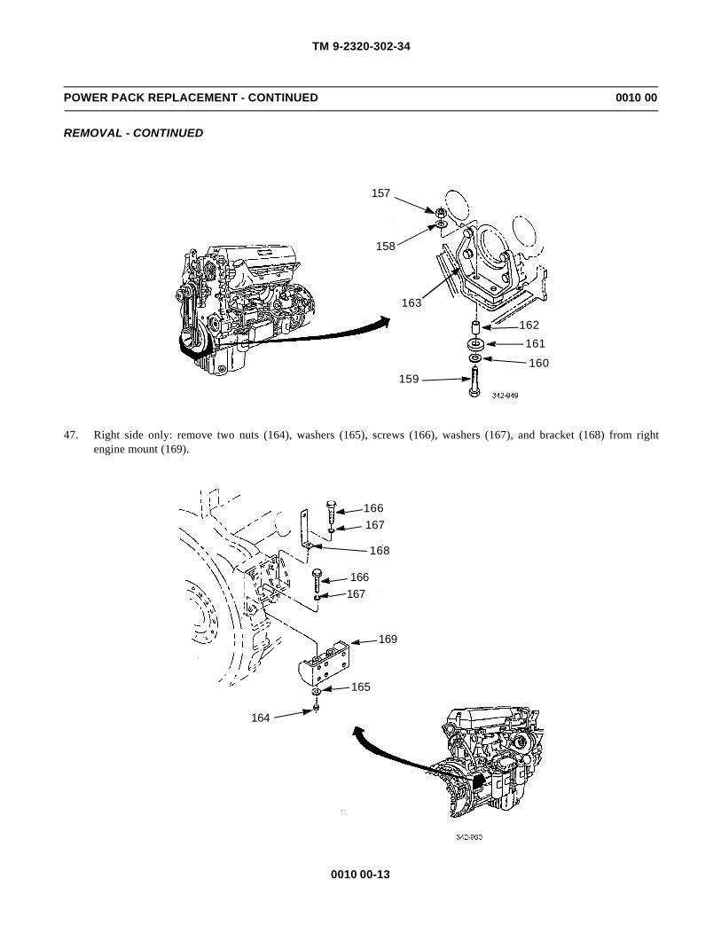
TM 9-2320-302-34
0010 00-13
POWER PACK REPLACEMENT - CONTINUED 0010 00
REMOVAL - CONTINUED
47. Right side only: remove two nuts (164), washers (165), screws (166), washers (167), and bracket (168) from rightengine mount (169).
157
158
163
159
162161
160
166167
166167
169
165
164
168

TM 9-2320-302-34
0010 00-14
POWER PACK REPLACEMENT - CONTINUED 0010 00
REMOVAL - CONTINUED
48. Left side only: remove two nuts (170), washers (171), screws (172), and washers (173) from left engine mount (174).
WARNINGWARNINGPower pack weighs 3750 lb (1702 kg). Use hoist with lifting capacity of 5000 lb (2270 kg) to lift and supportpower pack. Failure to do so could result in injury to personnel.
CAUTIONCAUTION• Ensure all harnesses, tubes, and hoses are clear of power pack prior to removal. Failure to do so could
result in damage to equipment.
• Keep power pack clear of frame. Failure to do so could result in damage to equipment.
49. Using suitable hoist and sling spreader, lift power pack slightly.
50. Adjust load so that front of engine is raised as high as possible to clear frame crossmember. Remove power pack fromvehicle.
POWER PACK SEPARATION
WARNINGWARNINGDo not place finger in hole of engine flywheel housing while engine is being barred over. To do could resultin serious injury to personnel.
170
171
174
172
173

TM 9-2320-302-34
0010 00-15
POWER PACK REPLACEMENT - CONTINUED 0010 00
POWER PACK SEPARATION - CONTINUED
CAUTIONCAUTION• Step 1 must be followed for barring engine over. Any other method could cause damage to equipment.
• If bolts are dropped in engine flywheel housing, retrieve immediately. Failure to do so could result indamage to equipment.
1. Have assistant bar engine (156) over using accessory drive (175). Locate and remove bolt (176) through hole in engineflywheel housing (155). Repeat until 12 bolts have been removed.
WARNINGWARNINGTransmission weighs 900 lb (409 kg). Support transmission with transmission lift during removal to preventpossible injury to personnel.
2. Support transmission (177) using transmission lift. Remove 12 screws (178), lock washers (179), and two brackets(180). Discard lock washers.
156
176
175
155
180177
178,179

TM 9-2320-302-34
0010 00-16
POWER PACK REPLACEMENT - CONTINUED 0010 00
POWER PACK SEPARATION - CONTINUED
CAUTIONCAUTIONTo avoid binding during removal, check frequently to ensure proper alignment between engine and transmis-sion. Failure to do so could result in damage to components.
3. Raise and adjust height of transmission lift to maintain support of transmission (177).
4. Repeat step 3 until transmission (177) can be separated from engine (156).
NOTENOTEIf engine is to be replaced, perform steps 5 and 6 after repositioning engine on suitable stands.
5. Remove two screws (181), washers (182), two screws (183), and right engine leg (184).
6. Repeat step 5 for left engine leg (185).
POWER PACK ASSEMBLY
1. Install right engine leg (184) with two screws (183), washers (182), and screws (181).
2. Repeat step 1 for installation of left engine leg (185).
CAUTIONCAUTIONTransmission must be seated squarely against engine flywheel housing to prevent damage to equipment.
3. Support transmission (177) using transmission lift. Position transmission squarely against engine flywheel housing(155).
4. Install two brackets (180), 12 new lock washers (179), and screws (178) in transmission (177). Tighten screws hand-tight.
5. Tighten four screws (178) 90 degrees apart to 40 lb-ft (54 Nm).
186
182
181
184
183
183
185182
181

TM 9-2320-302-34
0010 00-17
POWER PACK REPLACEMENT - CONTINUED 0010 00
POWER PACK ASSEMBLY - CONTINUED
6. Tighten remaining screws (178) to 40 lb-ft (54 Nm).
7. Remove plug (186) and rotate torque convertor to align holes in flex plate with holes in torque convertor.
WARNINGWARNINGDo not place finger in hole of engine flywheel housing while engine is being barred over. To do so couldresult in serious injury to personnel.
CAUTIONCAUTION• Step 8 must be followed for barring over engine. Any other method could cause damage to equipment.
• If bolts are dropped in engine flywheel housing, retrieve immediately. Failure to do so could result indamage to equipment.
8. Have assistant bar engine (156) over using accessory drive (175). Locate and align holes and install bolt (176) throughhole in engine flywheel housing (155). Repeat until 12 bolts have been installed hand-tight.
9. Tighten 12 bolts (176) to 96-115 lb-ft (130-156 Nm).
180177
155
186178, 179
156
176
175
155

TM 9-2320-302-34
0010 00-18
POWER PACK REPLACEMENT - CONTINUED 0010 00
INSTALLATION
WARNINGWARNING
Power pack weighs 3750 lb (1702 kg). Use hoist with lifting capacity of 5000 lb (2270 kg) to lift and supportpower pack. Failure to do so could result in injury to personnel.
CAUTIONCAUTION
• Ensure all harnesses, tubes, and hoses are clear of power pack prior to installation. Failure to do socould result in damage to equipment.
• Keep power pack clear of frame. Failure to do so could result in damage to equipment.
1. Using suitable hoist and sling spreader, maneuver power pack into vehicle.
2. Alternately lower hoist in small increments until power pack is in place.
3. Right side only: install bracket (168), two washers (167), screws (166), washers (165), and nuts (164) in right enginemount (169). Do not tighten nuts.
166167
166167
169
165
164
168

TM 9-2320-302-34
0010 00-19
POWER PACK REPLACEMENT - CONTINUED 0010 00
INSTALLATION - CONTINUED
4. Left side only: install two washers (173), screws (172), washers (171), and nuts (170) in left engine mount (174). Do nottighten nuts.
5. Install two sleeves (162), isolators (161), washers (160), screws (159), washers (158), and nuts (157) in front enginemount (163).
170
171
174
172
173
157
158
163
159
162161
160

TM 9-2320-302-34
0010 00-20
POWER PACK REPLACEMENT - CONTINUED 0010 00
INSTALLATION - CONTINUED
6. Tighten four nuts (164 and 170) on two rear engine mounts (169 and 174).
7. Install two plugs (153 and 154) in engine flywheel housing (155).
8. Install two hoses (142) and pipe (141) and tighten four clamps (140).
9. Install hose and pipe assembly (152) and tighten clamp (151).
10. Connect hose (149) to transmission oil cooler (150) and tighten clamp (148).
11. Install washer (146), capscrew (145), clamp (147), washer (144), and nut (143).
12. Rotate bracket (139) into position and install washer (138) and screw (137).
153
154 155
145
146
147
144
143
142142
140
141
150148
151
149
152
147140

TM 9-2320-302-34
0010 00-21
POWER PACK REPLACEMENT - CONTINUED 0010 00
INSTALLATION - CONTINUED
13. Install four hoses (136, 134, 132, and 133) and four clamps (135).
14. Connect three hoses (134, 132, and 133) and install four clamps (131).
15. Install two clamps (123), bolts (122), and new tiedown strap (124).
16. Install clamps (127 and 130) with washer (129), screw (128), washer (126), and new lock nut (125) on bracket.
137,138
139
125
135
126127
128
129 135 123
131
132
133131
134132134122
124
136
130

TM 9-2320-302-34
0010 00-22
POWER PACK REPLACEMENT - CONTINUED 0010 00
INSTALLATION - CONTINUED
17. Unplug and connect oil pressure hose (121) to engine (156).
18. Install drive coupler (119) and power steering pump (120) with six new lock washers (118) and screws (117).
19. Install clamp (115) and screw (114) in gear case (116).
20. Unplug and connect fuel hose (112) to primary fuel filter (113).
156
121
120
117,118114
115116119

TM 9-2320-302-34
0010 00-23
POWER PACK REPLACEMENT - CONTINUED 0010 00
INSTALLATION - CONTINUED
21. Pull harness (110) out from under cab (111). Install ground wire (108), washer (107), new lock washer (106), and screw(105) in dual voltage control (109).
22. Install five wires (104), three washers (103), nuts (102) on dual voltage control (109). Install two new tiedown straps(101).
23. Connect plug (99) to voltage regulator (100).
24. Install wire (97), new lock washer (96), and nut (95) on sending unit (98).
112113
101
9897
96
95
99
100
111 103 104109
101
107106
105108104
110
103102
108

TM 9-2320-302-34
0010 00-24
POWER PACK REPLACEMENT - CONTINUED 0010 00
INSTALLATION - CONTINUED
NOTENOTESteps 25 through 29 can be performed through center floor panel of cab.
25. Unplug and connect fuel return hose (93) to hose (94).
26. Connect connector (91) to engine brake harness (92).
27. Install clamp (90) with washer (89) and new lock nut (88).
28. Install clamp (87) with washer (86), screw (85), washer (84), and new lock nut (83).
29. Install clamp (82) with washer (81) and new lock nut (80) on rear of engine.
808182
87
8483 85
86
88
9026
89
94
92
91
93

TM 9-2320-302-34
0010 00-25
POWER PACK REPLACEMENT - CONTINUED 0010 00
INSTALLATION - CONTINUED
30. Install crossmember (75), washer (79), screw (78), washer (77), and nut (76).
31. Install washer (74), screw (73), washer (72), and nut (71) in left end of crossmember (75).
78,7976,77
75
73,74 71,72
75

TM 9-2320-302-34
0010 00-26
POWER PACK REPLACEMENT - CONTINUED 0010 00
INSTALLATION - CONTINUED
NOTENOTESteps 32 through 34 can be performed through center floor panel of cab.
32. Install two clamps (70) with washer (69) and new lock nut (68).
33. Install bracket (67), washer (66), and new lock nut (65) on crossmember.
34. Install clamp (64) on bracket (67) with washer (63) and new lock nut (62).
35. Position harness (58) and install two clamps (61), washers (60), and screws (59).
36. Remove screw (57). Position harness (58) and install screw (57).
37. Remove nut (53). Install solenoid (56), wire (55), washer (54), and nut (53).
64
62,63
65,66
67
70
68,69
56
57 5859,60
61

TM 9-2320-302-34
0010 00-27
POWER PACK REPLACEMENT - CONTINUED 0010 00
INSTALLATION - CONTINUED
38. Install two wires (51), new lock washers (50), and screws (49) on temperature sending unit (52).
39. Install wire (47), new lock washer (46), and nut (45) on temperature sending unit (48).
55
53,54
56
4546
48
47
5049
51
50
49
52

TM 9-2320-302-34
0010 00-28
POWER PACK REPLACEMENT - CONTINUED 0010 00
INSTALLATION - CONTINUED
40. Install exhaust pipe (44) with new seal clamp (43) and clamp (42).
CAUTIONCAUTIONEnsure arrow on wrench flat of atomizer is facing to front of engine. Failure to do so will cause ether start tomalfunction.
41. Install atomizer (40) and tube (39).
42. Connect two tubes (37) and hose (36) to air compressor (38). Install new tiedown strap (41).
43
4442
38
36
39
40
41
37

TM 9-2320-302-34
0010 00-29
POWER PACK REPLACEMENT - CONTINUED 0010 00
INSTALLATION - CONTINUED
43. Connect electronic control module harness connectors (32 and 33) to connectors located at rear of ECM (34).
44. Install wire (30), washer (29), and nut (28) on fuel pressure sending unit (31).
45. Install bracket (24) on cable harness (27). Install spacer (25), bracket, and screw (23) in engine block (26). Install newtiedown straps as required to secure harness (35).
2733
34
32 35 31 26
28, 2930
2324
25

TM 9-2320-302-34
0010 00-30
POWER PACK REPLACEMENT - CONTINUED 0010 00
INSTALLATION - CONTINUED
46. Install plate (19) and bracket (22) with washer (21) and screw (20).
47. Install two wires (18) and cable (17) on plate (19) with washer (16) and nut (15).
48. Connect two wires (14) to starter solenoid (11) with washer (13) and nut (12).
49. Connect four wires (10) and cable (9) to starter solenoid (11) with washer (8) and nut (7).
50. Connect three wires (5), ground strap (4), and cable (3) to starter (6) with washer (2) and nut (1).
51. Install transmission rear mount (WP 0070 00).
52. Connect driveline (TM 9-2320-302-20).
53. Install transmission oil fill tube (TM 9-2320-302-20).
54. Connect transmission wiring harness (TM 9-2320-302-20).
55. Connect transmission oil cooler lines (TM 9-2320-302-20).
56. Install oil sampling valves (TM 9-2320-302-20).
57. Install fender extensions (TM 9-2320-302-20).
58. Install alternator and alternator adjusting rod (TM 9-2320-302-20).
59. Install air conditioner compressor (WP 0117 00).
60. Install alternator/air conditioner belt (TM 9-2320-302-20).
61. Install air cleaner, pre-cleaner, and duct assembly (TM 9-2320-302-20).
62. Install air intake tubes, hoses, and clamps (TM 9-2320-302-20).
22
14
131219
18 1716 154
3
2 2
5
6
21 20 7 8 9 10 10
11

TM 9-2320-302-34
0010 00-31
POWER PACK REPLACEMENT - CONTINUED 0010 00
INSTALLATION - CONTINUED
63. Install fan impeller and shroud (TM 9-2320-302-20).
64. Install hood (TM 9-2320-302-20).
65. Install transmission tunnel access cover (TM 9-2320-302-20).
66. Fill engine with oil (TM 9-2320-302-10).
END OF WORK PACKAGE

TM 9-2320-302-34
0010 00-32
This Page Intentionally Left Blank.

TM 9-2320-302-34
0011 00-1
FRONT ENGINE MOUNT ADAPTER AND SUPPORT REPLACEMENT 0011 00
THIS WORK PACKAGE COVERS
Removal, Installation
INITIAL SETUP
Maintenance Level
Direct Support
Tools and Special Tools
Tool kit, general mechanic’s (Item 132, WP 0126 00)
Jack, hydraulic (Item 73, WP 0126 00)
Trestles (Item 135, WP 0126 00)
Materials/Parts
Nut, lock (P/N MS51922-57)
Personnel Required
Two
Equipment Condition
Front ABS quick-release valve removed (TM 9-2320-302-20)
Front crossmember removed (WP 0096 00)
Vibration damper removed (WP 0020 00)
WARNINGWARNINGUse extreme caution when handling heavy parts. Provide adequate support and use assistance during proce-dure. Ensure that any lifting device used is in good condition and of suitable load capacity. Keep clear ofheavy parts supported only by lifting device. Failure to follow this warning may result in death or injury topersonnel.
REMOVAL
1. Remove two lock nuts (1), washers (2), screws (3), washers (4), isolators (5), and sleeves (6) from front engine mountadapter (7). Discard lock nuts.
4
3
7
5
2
6
1

TM 9-2320-302-34
0011 00-2
FRONT ENGINE MOUNT ADAPTER AND SUPPORT REPLACEMENT - CONTINUED 0011 00
REMOVAL - CONTINUED
WARNINGWARNINGEngine weighs 2850 lb (1294 kg). Support engine from lower block pan rail. Failure to do so could result ininjury to personnel and damage to equipment.
2. Support engine (8) and remove spacer (9) and two isolators (10).
3. Remove four bolts (11) and front engine mount adapter (7).
4. Remove four nuts (12), washers (13), three capscrews (14), washers (15), and screw (16).
5. On left side, remove two nuts (17), washers (18), capscrews (19), and washers (20) from frame (21).
118
79
10
14
15
1312
13 12
16
15
13
12

TM 9-2320-302-34
0011 00-3
FRONT ENGINE MOUNT ADAPTER AND SUPPORT REPLACEMENT - CONTINUED 0011 00
REMOVAL - CONTINUED
6. Repeat step 5 for right side.
7. Remove front engine mount support (22).
8. Remove four spacers (23).
INSTALLATION
1. Install front engine mount support (22).
2. Install four spacers (23).
3. On left side, install two washers (20), capscrews (19), washers (18), and nuts (17) on frame (21).
2117,18,19,20
23
22
23
15
1415 14
231213
23 1312
16
13
12
21
17,18,19,20

TM 9-2320-302-34
0011 00-4
FRONT ENGINE MOUNT ADAPTER AND SUPPORT REPLACEMENT - CONTINUED 0011 00
INSTALLATION - CONTINUED
4. Repeat step 3 for right side.
NOTENOTEEnsure spacers (23) installed during step 2 do not slip out of place. If spacer is not present, frame will not bein line to allow installation of front crossmember.
5. Install screw (16), three washers (15), capscrews (14), four washers (13), and nuts (12).
6. Install front engine mount adapter (7) and four bolts (11).
7. Install two isolators (10) and spacer (9).
8. Lower engine (8) and remove engine support.
9. Install two sleeves (6), isolators (5), washers (4), screws (3), washers (2), and new lock nuts (1).
10. Install vibration damper (WP 0020 00).
11. Install front crossmember (WP 0096 00).
12. Install front ABS quick-release valve (TM 9-2320-302-20).
END OF WORK PACKAGE
15
14 15 14
231213
23 1312
16
13
12
11
8
79
10
4
3
5
2
6
1
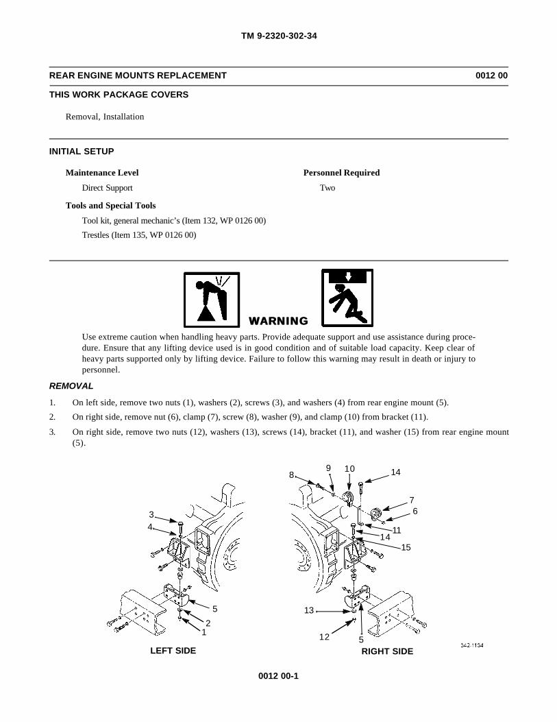
TM 9-2320-302-34
0012 00-1
REAR ENGINE MOUNTS REPLACEMENT 0012 00
THIS WORK PACKAGE COVERS
Removal, Installation
INITIAL SETUP
Maintenance Level
Direct Support
Tools and Special Tools
Tool kit, general mechanic’s (Item 132, WP 0126 00)
Trestles (Item 135, WP 0126 00)
Personnel Required
Two
WARNINGWARNINGUse extreme caution when handling heavy parts. Provide adequate support and use assistance during proce-dure. Ensure that any lifting device used is in good condition and of suitable load capacity. Keep clear ofheavy parts supported only by lifting device. Failure to follow this warning may result in death or injury topersonnel.
REMOVAL
1. On left side, remove two nuts (1), washers (2), screws (3), and washers (4) from rear engine mount (5).
2. On right side, remove nut (6), clamp (7), screw (8), washer (9), and clamp (10) from bracket (11).
3. On right side, remove two nuts (12), washers (13), screws (14), bracket (11), and washer (15) from rear engine mount(5).
34
52
1
89 10 14
11
76
1415
512
13
LEFT SIDE RIGHT SIDE

TM 9-2320-302-34
0012 00-2
REAR ENGINE MOUNTS REPLACEMENT - CONTINUED 0012 00
REMOVAL - CONTINUED
WARNINGWARNINGEngine weighs 2850 lb (1294 kg). Use hoist with lifting capacity of 5000 lb (2270 kg) to lift and supportengine. Failure to do so could result in injury to personnel.
CAUTIONCAUTIONLift engine only enough to take weight off engine mounts. If engine is lifted too far, wiring harness may becrushed by crossmember.
4. Using suitable lifting device, lift engine (16) slightly.
NOTENOTESteps 5 through 8 are for left side.
5. Remove two screws (17), two washers (18), two screws (19), and rear engine leg (20) from flywheel housing (21).
6. Remove two washers (22) and two isolators (23) from rear engine mount (5).
WARNINGWARNINGCab weighs 1100 lb (499 kg). Use suitable jack stands to support cab. Failure to do so could result in seriousinjury to personnel.
7. Using suitable jack stands, support cab at cab mounts (24) as close to frame rail (25) as possible.
34
1817
19
2223
2627
52
12529
29
28
89 10
14
11
76
1415
1817
19
29
2829
25
512
1327
26
23
22
20
16
21
LEFT SIDE RIGHT SIDE

TM 9-2320-302-34
0012 00-3
REAR ENGINE MOUNTS REPLACEMENT - CONTINUED 0012 00
REMOVAL - CONTINUED
8. Remove six nuts (26), washers (27), screws (28), washers (29), and rear engine mount (5) from frame rail (25).
9. Repeat steps 5 through 8 for right side.
INSTALLATION
WARNINGWARNINGEngine weighs 2850 lb (1294 kg). Use hoist with lifting capacity of 5000 lb (2270 kg) to lift and supportengine. Failure to do so could result in injury to personnel.
1. On right side, install rear engine mount (5), six washers (29), screws (28), washers (27), and nuts (26) on frame rail (25).
2. On right side, install two isolators (23) and washers (22) in rear engine mount (5).
3. On right side, install rear engine leg (20), two screws (19), washers (18), and screws (17) in flywheel housing (21).
4. Repeat steps 1 through 3 for left side.
5. Remove jack stands from cab mounts (24).
6. On left side, install two washers (4), screws (3), washers (2), and nuts (1) hand-tight in rear engine mount (5).
7. On right side, install washer (15), bracket (11), two screws (14), washers (13), and nuts (12) on rear engine mount (5).
8. Lower engine (16) onto engine mounts and tighten four nuts (1 and 12) on left and right sides.
9. On right side, install clamp (10), washer (9), screw (8), clamp (7), and new lock nut (6) on bracket (11).
END OF WORK PACKAGE
2425

TM 9-2320-302-34
0012 00-4
This Page Intentionally Left Blank
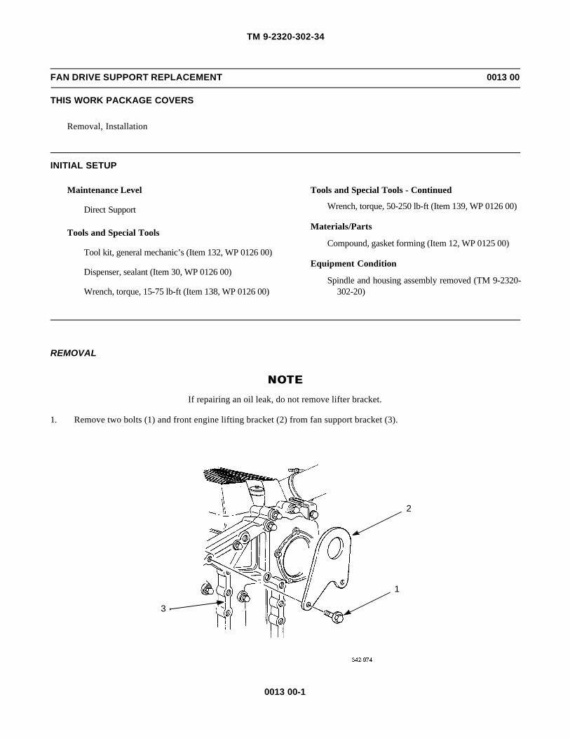
TM 9-2320-302-34
0013 00-1
FAN DRIVE SUPPORT REPLACEMENT 0013 00
THIS WORK PACKAGE COVERS
Removal, Installation
INITIAL SETUP
Maintenance Level
Direct Support
Tools and Special Tools
Tool kit, general mechanic’s (Item 132, WP 0126 00)
Dispenser, sealant (Item 30, WP 0126 00)
Wrench, torque, 15-75 lb-ft (Item 138, WP 0126 00)
Tools and Special Tools - Continued
Wrench, torque, 50-250 lb-ft (Item 139, WP 0126 00)
Materials/Parts
Compound, gasket forming (Item 12, WP 0125 00)
Equipment Condition
Spindle and housing assembly removed (TM 9-2320-302-20)
REMOVAL
NOTENOTEIf repairing an oil leak, do not remove lifter bracket.
1. Remove two bolts (1) and front engine lifting bracket (2) from fan support bracket (3).
2
1
3

TM 9-2320-302-34
0013 00-2
FAN DRIVE SUPPORT REPLACEMENT - CONTINUED 0013 00
REMOVAL - CONTINUED
2. Hold nut (4) and remove gear housing stabilizer bracket bolt (5).
3. Remove nut (4).
4. Remove two bolts (6) at top of fan support bracket (3).
5. Remove short bolt (7) at bottom of fan support bracket (3).
6. Remove long bolt (8) at right side of fan support bracket (3).
7. Remove five adjustable idler gear cover bolts (9).
8. Using plastic or fiber mallet, tap fan support bracket (3) to break loose from gear case cover (10).
5
4
36
7
8

TM 9-2320-302-34
0013 00-3
FAN DRIVE SUPPORT REPLACEMENT - CONTINUED 0013 00
REMOVAL - CONTINUED
INSTALLATION
1. Apply thin bead of gasket forming compound to machined surface (11) of adjustable idler access hole (12) and positionfan support bracket (3) on gear case cover (10).
3
9
10
12
10
3
11
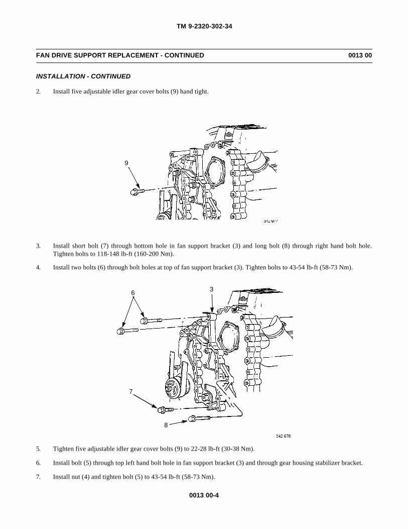
TM 9-2320-302-34
0013 00-4
FAN DRIVE SUPPORT REPLACEMENT - CONTINUED 0013 00
INSTALLATION - CONTINUED
2. Install five adjustable idler gear cover bolts (9) hand tight.
3. Install short bolt (7) through bottom hole in fan support bracket (3) and long bolt (8) through right hand bolt hole.Tighten bolts to 118-148 lb-ft (160-200 Nm).
4. Install two bolts (6) through bolt holes at top of fan support bracket (3). Tighten bolts to 43-54 lb-ft (58-73 Nm).
5. Tighten five adjustable idler gear cover bolts (9) to 22-28 lb-ft (30-38 Nm).
6. Install bolt (5) through top left hand bolt hole in fan support bracket (3) and through gear housing stabilizer bracket.
7. Install nut (4) and tighten bolt (5) to 43-54 lb-ft (58-73 Nm).
9
36
7
8

TM 9-2320-302-34
0013 00-5
FAN DRIVE SUPPORT REPLACEMENT - CONTINUED 0013 00
INSTALLATION - CONTINUED
8. Position front engine lifting bracket (2) on fan support bracket (3) and install two bolts (1). Tighten bolts to 75-93 lb-ft(102-126 Nm).
9. Install spindle and housing assembly (TM 9-2320-302-20).
END OF WORK PACKAGE
5
4 3
2
1
3

TM 9-2320-302-34
0013 00-6
This Page Intentionally Left Blank.

TM 9-2320-302-34
0014 00-1
AIR INTAKE MANIFOLD REPLACEMENT 0014 00
THIS WORK PACKAGE COVERS
Removal, Inspection, Installation
INITIAL SETUP
Maintenance Level
Direct Support
Tools and Special Tools
Tool kit, general mechanic’s (Item 132, WP 0126 00)
Guide stud set (Item 43, WP 0126 00)
Wrench, torque, 0-300 lb-in (Item 137, WP 0126 00)
Wrench, torque, 15-75 lb-ft (Item 138, WP 0126 00)
Materials/Parts
Gasket (P/N 23517875) (3)
Ring, seal (P/N 5182977)
Materials/Parts - Continued
Compound, sealing, pipe (Item 18, WP 0125 00)
Oil, lubricating (Item 25, WP 0125 00)
References
TM 9-2320-302-10
Equipment Configuration
Air intake manifold-to-intercooler tube removed (TM9-2320-302-20)
Ether atomizer and bushing removed (TM 9-2320-302-20)
REMOVAL
1. Loosen hose clamp (1) and disconnect air compressor inlet hose (2) from air supply connector (3).
2. Remove air supply connector (3) from air intake manifold (4).
4
3
2 1

TM 9-2320-302-34
0014 00-2
AIR INTAKE MANIFOLD REPLACEMENT - CONTINUED 0014 00
REMOVAL - CONTINUED
3. Disconnect air line connector (5) from fitting (6).
4. Remove fitting (6), check valve (7), and nipple (8) from air intake manifold (4)
5. Disconnect engine wiring harness (9) from turbo boost sensor (10) and air temperature sensor (11).
6. Remove air temperature sensor (11) from air intake manifold (4).
7. Remove two retaining bolts (12) and turbo boost sensor (10).
8. Remove and discard seal ring (13).
9. Remove five long bolts (14) and two end short bolts (15) from air intake manifold (4).
10. Remove air intake manifold (4) and three gaskets (16) from cylinder head (17). Discard gaskets.
56
7
8
4
4
14
11
12
10
13915

TM 9-2320-302-34
0014 00-3
AIR INTAKE MANIFOLD REPLACEMENT - CONTINUED 0014 00
REMOVAL - CONTINUED
INSPECTION
1. Inspect air intake manifold for cracks, particularly in mounting bolt boss areas. If cracked, discard intake manifold.
2. Inspect all parts for wear or damage.
INSTALLATION
1. Install six guide studs in six bolt holes of cylinder head (17).
NOTENOTEInstall gaskets with arrow pointing to front of engine.
2. Install three new gaskets (16) over six guide studs.
NOTENOTEEnsure all wires are clear of intake manifold connection points before installing manifold.
3. Install air intake manifold (4) over six guide studs and against cylinder head (17).
17
16
4
16
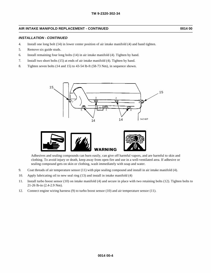
TM 9-2320-302-34
0014 00-4
AIR INTAKE MANIFOLD REPLACEMENT - CONTINUED 0014 00
INSTALLATION - CONTINUED
4. Install one long bolt (14) in lower center position of air intake manifold (4) and hand tighten.
5. Remove six guide studs.
6. Install remaining four long bolts (14) in air intake manifold (4). Tighten by hand.
7. Install two short bolts (15) at ends of air intake manifold (4). Tighten by hand.
8. Tighten seven bolts (14 and 15) to 43-54 lb-ft (58-73 Nm), in sequence shown.
WARNINGWARNINGAdhesives and sealing compounds can burn easily, can give off harmful vapors, and are harmful to skin andclothing. To avoid injury or death, keep away from open fire and use in a well-ventilated area. If adhesive orsealing compound gets on skin or clothing, wash immediately with soap and water.
9. Coat threads of air temperature sensor (11) with pipe sealing compound and install in air intake manifold (4).
10. Apply lubricating oil to new seal ring (13) and install in intake manifold (4)
11. Install turbo boost sensor (10) on intake manifold (4) and secure in place with two retaining bolts (12). Tighten bolts to21-26 lb-in (2.4-2.9 Nm).
12. Connect engine wiring harness (9) to turbo boost sensor (10) and air temperature sensor (11).
15
1414
15
23
415
7 6

TM 9-2320-302-34
0014 00-5
AIR INTAKE MANIFOLD REPLACEMENT - CONTINUED 0014 00
INSTALLATION - CONTINUED
13. Coat threads of nipple (8) and fitting (6) with pipe sealing compound and install nipple (8), check valve (7), and fitting(6) in intake manifold (4).
14. Connect air line (5) to fitting (6).
4
14
11
12
10
13
915
56
7
8
4

TM 9-2320-302-34
0014 00-6
AIR INTAKE MANIFOLD REPLACEMENT - CONTINUED 0014 00
INSTALLATION - CONTINUED
15. Apply a light coat of pipe sealing compound to threads of air supply connector (3), install in air intake manifold (4), andattach air compressor inlet hose (2) to connector.
16. Position hose clamp (1) and secure in place.
17. Install air intake intercooler tubing (TM 9-2320-302-20).
18. Install ether atomizer and bushing (TM 9-2320-302-20).
19. Operate vehicle (TM 9-2320-302-10) and check for leaks.
END OF WORK PACKAGE
4
3
2 1
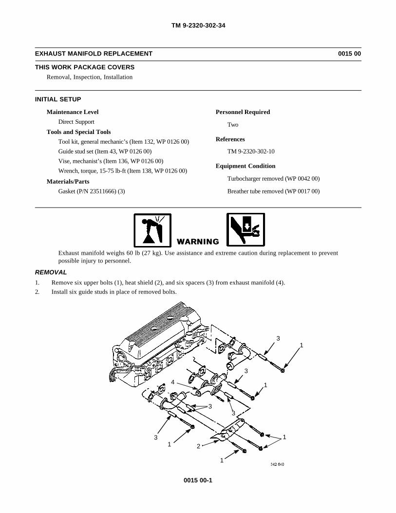
TM 9-2320-302-34
0015 00-1
EXHAUST MANIFOLD REPLACEMENT 0015 00
THIS WORK PACKAGE COVERS
Removal, Inspection, Installation
INITIAL SETUP
Maintenance Level
Direct Support
Tools and Special Tools
Tool kit, general mechanic’s (Item 132, WP 0126 00)
Guide stud set (Item 43, WP 0126 00)
Vise, mechanist’s (Item 136, WP 0126 00)
Wrench, torque, 15-75 lb-ft (Item 138, WP 0126 00)
Materials/Parts
Gasket (P/N 23511666) (3)
Personnel Required
Two
References
TM 9-2320-302-10
Equipment Condition
Turbocharger removed (WP 0042 00)
Breather tube removed (WP 0017 00)
WARNINGWARNINGExhaust manifold weighs 60 lb (27 kg). Use assistance and extreme caution during replacement to preventpossible injury to personnel.
REMOVAL
1. Remove six upper bolts (1), heat shield (2), and six spacers (3) from exhaust manifold (4).
2. Install six guide studs in place of removed bolts.
31
3
1
3
121
3
4
1
3

TM 9-2320-302-34
0015 00-2
EXHAUST MANIFOLD REPLACEMENT - CONTINUED 0015 00
REMOVAL - CONTINUED
3. Remove remaining six bolts (1), spacers (3), and exhaust manifold (4) assembly from cylinder head (5).
4. Remove and discard three gaskets (6).
5. Secure center section of exhaust manifold (4) in vise. Using brass drift, remove each end section (7) of exhaust mani-fold.
6. If damaged, remove and discard four turbocharger mounting studs (8).
INSPECTION
1. Inspect exhaust manifold for cracks, particularly in mounting bolt boss areas. If cracked, discard exhaust manifold.
2. Inspect all parts for damage.
INSTALLATION
1. Secure center section of exhaust manifold (4) in vise.
NOTENOTEIf turbocharger mounting studs were removed, perform steps 2 and 3.
2. Using one nut as jam nut, install two nuts on four turbocharger mounting studs (8).
3. Thread turbocharger mounting studs (8) into exhaust manifold (4) until unthreaded portion of stud bottoms againstmounting flange. Tighten studs to 18-24 lb-ft (25-32 Nm). Remove two nuts from each stud.
4. Install exhaust manifold end sections (7) on center section of exhaust manifold (4). Position and seat end sections bytapping with fiber or plastic mallet.
5. Install six guide studs in upper bolt hole locations.
6. Install three new gaskets (6) and exhaust manifold (4) on guide studs.
31
3
1
3
121
3
4
6
78
1
76
5
6
3
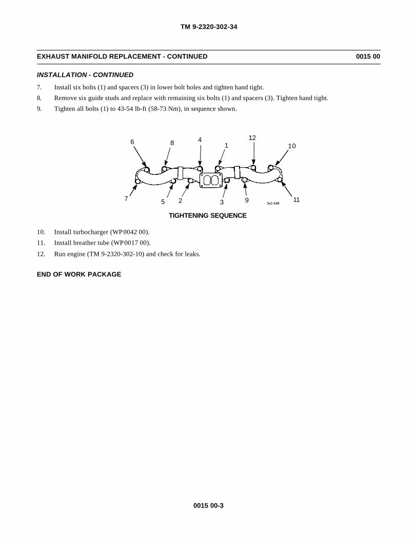
TM 9-2320-302-34
0015 00-3
EXHAUST MANIFOLD REPLACEMENT - CONTINUED 0015 00
INSTALLATION - CONTINUED
7. Install six bolts (1) and spacers (3) in lower bolt holes and tighten hand tight.
8. Remove six guide studs and replace with remaining six bolts (1) and spacers (3). Tighten hand tight.
9. Tighten all bolts (1) to 43-54 lb-ft (58-73 Nm), in sequence shown.
10. Install turbocharger (WP 0042 00).
11. Install breather tube (WP 0017 00).
12. Run engine (TM 9-2320-302-10) and check for leaks.
END OF WORK PACKAGE
6 8 41
1210
1193257
TIGHTENING SEQUENCE

TM 9-2320-302-34
0015 00-4
This Page Intentionally Left Blank.

TM 9-2320-302-34
0016 00-1
ROCKER ARM COVER REPLACEMENT 0016 00
THIS WORK PACKAGE COVERS
Removal, Cleaning, Inspection, Installation
INITIAL SETUP
Maintenance Level
Direct Support
Tools and Special Tools
Tool kit, general mechanic’s (Item 132, WP 0126 00)
Dispenser, sealant (Item 30, WP 0126 00)
Wrench, torque, 15-75 lb-ft (Item 138, WP 0126 00)
Materials/Parts
Gasket (P/N 23522269)
Materials/Parts - Continued
Compound, gasket forming (Item 12, WP 0125 00)
Detergent (Item 19, WP 0125 00)
Equipment Condition
Air cleaner, pre-cleaner, and duct assembly removed(TM 9-2320-302-20)
Thermostat-to-radiator coolant tube removed (TM 9-2320-302-20)
Radiator support rod removed (TM 9-2320-302-20)
REMOVAL
1. Loosen hose clamp (1) and disconnect crankcase breather tube (2) from rocker arm cover neck (3).
3
1
2

TM 9-2320-302-34
0016 00-2
ROCKER ARM COVER REPLACEMENT - CONTINUED 0016 00
REMOVAL - CONTINUED
2. Remove ten bolt assemblies (4) securing rocker arm cover (5) to cylinder head (6).
CAUTIONCAUTIONHandle rocker arm cover carefully; dropping or bumping may cause damage.
3. Remove rocker arm cover (5) from cylinder head (6).
4. Free gasket saddle corners (7) and saddle arch areas (8). Lift rocker arm cover gasket (9) straight out of rocker arm covergroove to prevent tearing or stretching gasket. If damaged or stretched, discard gasket.
5. Invert rocker arm cover (5) on bench. Press and slide straight end of breather element retaining clip (10) until clip disen-gages from rocker arm cover. Lift clip upward to disengage curved end.
6. Remove breather mesh element (11) from rocker arm cover (5).
5
4
6
98
7

TM 9-2320-302-34
0016 00-3
ROCKER ARM COVER REPLACEMENT - CONTINUED 0016 00
REMOVAL - CONTINUED
CLEANING
WARNINGWARNINGCompressed air used for cleaning or drying purposes, or for clearing restrictions, should never exceed 30 psi(207 kPa). Wear protective clothing (goggles/shield, gloves, etc.) and use caution to avoid injury to person-nel.
1. Clean rocker arm cover gasket and ten bolt assemblies with detergent and water. Dry with compressed air.
2. Clean all old gasket forming compound from rocker arm cover grooves. Clean all dirt and foreign matter from rockerarm cover.
3. Remove old gasket forming compound from corners of cylinder head located at front and rear cam cap area.
4. Clean mesh breather element with detergent and water solution and dry with compressed air.
INSPECTION
1. Inspect rocker arm cover gasket for cuts, nicks, and breaks. If found, discard gasket.
2. Inspect all components for wear or damage.
INSTALLATION
1. Press mesh breather element (11) into breather pocket.
2. Insert curved end of breather element retaining clip (10) into one breather pocket hole. Press and slide straight end ofclip into opposite breather pocket hole.
10
11
5

TM 9-2320-302-34
0016 00-4
ROCKER ARM COVER REPLACEMENT - CONTINUED 0016 00
INSTALLATION - CONTINUED
NOTENOTETo ease gasket installation, lightly spray a solution of soapy water into seal groove of rocker arm cover.
3. Position rocker arm cover gasket (9) in rocker arm cover (5).
4. Install rocker arm cover gasket (9), beginning at corners (7) of saddle arch (8) on each end of rocker arm cover (5).Work back into saddle arch equally from each corner (7), pushing gasket firmly into rocker arm cover groove.
5. Beginning at center of rocker arm cover (5), install long runs of rocker arm cover gasket (9) toward corners (7) of saddlearches (8) and continue until gasket installation is completed.
6. Apply a thin bead of gasket forming compound in front and rear corners (12) of cylinder head (6) where front and rearcam caps are located.
7. Position rocker arm cover (5) on cylinder head (6).
8. Install ten bolt assemblies (4) in rocker arm cover (5).
87
9
5
65
4
12
6

TM 9-2320-302-34
0016 00-5
ROCKER ARM COVER REPLACEMENT - CONTINUED 0016 00
INSTALLATION - CONTINUED
9. In sequence shown, tighten ten bolt assemblies to 22-28 lb-ft (30-38 Nm).
10. Install crankcase breather tube (2) over rocker arm cover neck (3) and secure with hose clamp (1).
11. Install air cleaner, pre-cleaner, and duct assembly (TM 9-2320-302-20).
12. Install thermostat-to-radiator coolant tube (TM 9-2320-302-20).
13. Install radiator support rod (TM 9-2320-302-20).
END OF WORK PACKAGE
4 6 7 3
1
1089
2FRONT
5
TIGHTENING SEQUENCE
3
1
2

TM 9-2320-302-34
0016 00-6
This Page Intentionally Left Blank.

TM 9-2320-302-34
0017 00-1
BREATHER TUBE REPLACEMENT 0017 00
THIS WORK PACKAGE COVERS
Removal, Installation
INITIAL SETUP
Maintenance Level
Direct Support
Tools and Special Tools
Tool kit, general mechanic’s (Item 132, WP 0126 00)
REMOVAL
1. Loosen hose clamp (1) and disconnect hose (2) from rocker arm cover (3).
2. Remove two bolts (4) and spacer (5) from engine block (6).
3. Remove breather tube (7) and two clamps (8).
4. Loosen hose clamp (9) and remove hose (2) from breather tube (7).
INSTALLATION
1. Install hose (2) on breather tube (7) and tighten hose clamp (9).
2. Install breather tube (7) and two clamps (9).
3. Install spacer (5) and two bolts (4) on engine block (6).
4. Connect hose (2) to rocker arm cover (3) and tighten hose clamp (1).
END OF WORK PACKAGE
31
29
7
58
4
8 4
6

TM 9-2320-302-34
0017 00-2
This Page Intentionally Left Blank.

TM 9-2320-302-34
0018 00-1
CYLINDER HEAD REPLACEMENT 0018 00
THIS WORK PACKAGE COVERS
Removal, Inspection, Installation
INITIAL SETUP
Maintenance Level
Direct Support
Tools and Special Tools
Tool kit, general mechanic’s (Item 132, WP 0126 00)
Clamp, material lift (Item 20, WP 0126 00)
Wrench, torque, 15-75 lb-ft (Item 138, WP 0126 00)
Wrench, torque, 50-250 lb-ft (Item 139, WP 0126 00)
Materials/Parts
Gasket (P/N 23506120)
Compound, international, no. 2 (Item 13, WP 0125 00)
Tags, marker (Item 35, WP 0125 00)
Personnel Required
Two
Equipment Condition
Alternator removed (TM 9-2320-302-20)
Air conditioner compressor removed (WP 0117 00)
Thermostat and thermostat housing cover removed(TM 9-2320-302-20)
Water level sensor removed (TM 9-2320-302-20)
Exhaust manifold removed (WP 0015 00)
Air intake manifold removed (WP 0014 00)
Air compressor cooling lines disconnected (TM 9-2320-302-20)
Camshaft and bearings removed (WP 0026 00)
Fuel injectors removed (WP 0046 00)
Injector wiring harness removed (WP 0069 00)
WARNINGWARNINGUse extreme caution when handling heavy parts. Provide adequate support and use assistance during proce-dure. Ensure that any lifting device used is in good condition and of suitable load capacity. Keep clear ofheavy parts supported only by lifting device. Failure to follow this warning may result in death or injury topersonnel.

TM 9-2320-302-34
0018 00-2
CYLINDER HEAD REPLACEMENT - CONTINUED 0018 00
REMOVAL
1. Disconnect two fuel lines (1 and 2) from cylinder head (3).
2. Remove bolt (4) and set bracket (5) aside.
3. Remove two bolts (6) and washers (7) and set wiring harness (8) aside.
4. Disconnect air compressor hose (9) and clamp (10) from cylinder head (3).
1
2
3
7 8
6
54
3
10
9

TM 9-2320-302-34
0018 00-3
CYLINDER HEAD REPLACEMENT - CONTINUED 0018 00
REMOVAL - CONTINUED
5. Remove two bolts (11), nut (12), bolt (13), and bracket (14).
6. Remove 38 cylinder head bolts (15) and washers (16).
7. Install lifter (17) between fuel injector holes no. 3 and no. 4.
a. Install bolt (18) using bolt hole for center cam cap bolt.
b. Install two bolts (19) using two tapped holes for engine retarder assembly.
13
14
1112
15 16
15
16
16
1917
18

TM 9-2320-302-34
0018 00-4
CYLINDER HEAD REPLACEMENT - CONTINUED 0018 00
REMOVAL - CONTINUED
WARNINGWARNINGCylinder head weighs 421 lb (191 kg). Use suitable lifting device to lift and support cylinder head. Failure todo so could result in injury to personnel.
8. Attach suitable lifting device to lifter eye (20) and remove cylinder head (3).
9. Remove and discard cylinder head gasket (21).
10. Remove bolt (22) and left rear lifting bracket (23).
11. Tag and remove elbows (24 and 25) from cylinder head (3).
12. Remove air compressor fitting (26) from cylinder head (3).
INSPECTION
1. Ensure piston domes, cylinder head, cylinder block deck surfaces, and injector tubes are clean and free of foreign mat-ter.
2. Inspect cylinder block bolt holes and block-to-head gasket mating surfaces for oil, water, dirt or old gasket material.
INSTALLATION
1. Install left rear lifting bracket (23) and secure to cylinder head (3) with bolt (22). Tighten bolt to 75-93 lb-ft (102-126Nm).
2. Install new cylinder head gasket (21) on cylinder block (27).
3
21
20
2326
22
2524
1817
19
29
27
28

TM 9-2320-302-34
0018 00-5
CYLINDER HEAD REPLACEMENT - CONTINUED 0018 00
INSTALLATION - CONTINUED
3. Install air compressor fitting (26) in cylinder head (3).
4. Remove tags and install two elbows (24 and 25) in cylinder head (3).
5. Install lifter (17) between fuel injectors no. 3 and no. 4.
a. Install bolt (18) using bolt hole for center cam cap bolt.
b. Install two bolts (19) using two tapped holes for engine retarder assembly.
WARNINGWARNINGCylinder head weighs 421 lb (191 kg). Use suitable lifting device to lift and support cylinder head. Failure todo so could result in injury to personnel.
6. Attach suitable lifting device to lifter eye (20) and position cylinder head (3) over engine block (27).
7. Seat cylinder head (3) on diamond dowel (28) and round dowel (29) until full contact is made with cylinder head gasket(21).
8. Remove lifting device from lifter eye (20).
NOTENOTEIf cylinder head is other than one removed, or if resurfaced cylinder head is being installed, three nuts retain-ing adjustable idler gear must be loosened before installing and tightening camshaft drive gear retainingbolt. Notify General Support Maintenance to perform adjustment.
9. Remove lifter (17).
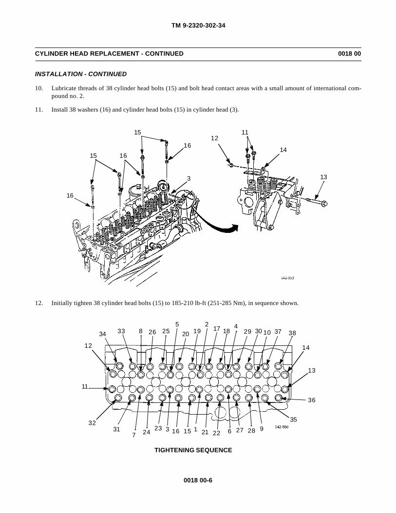
TM 9-2320-302-34
0018 00-6
CYLINDER HEAD REPLACEMENT - CONTINUED 0018 00
INSTALLATION - CONTINUED
10. Lubricate threads of 38 cylinder head bolts (15) and bolt head contact areas with a small amount of international com-pound no. 2.
11. Install 38 washers (16) and cylinder head bolts (15) in cylinder head (3).
12. Initially tighten 38 cylinder head bolts (15) to 185-210 lb-ft (251-285 Nm), in sequence shown.
13
14
1112
15 16
15
16
16
3
11
12
34 33 8 26 255
20 192
17 184
29 30 10 37 38
14
13
36
35928276222111516323247
3132
TIGHTENING SEQUENCE

TM 9-2320-302-34
0018 00-7
CYLINDER HEAD REPLACEMENT - CONTINUED 0018 00
INSTALLATION - CONTINUED
13. Finally tighten 38 cylinder head bolts (15) to same torque and sequence as in step 12.
14. Install bracket (14) on cylinder head (3) and install two bolts (11). Tighten bolts to 43-54 lb-ft (58-73 Nm).
15. Install bolt (13) through gear case cover and housing assembly and install nut (12). Tighten nut to 43-54 lb-ft (58-73Nm).
16. Connect air compressor hose (9) with clamp (10) to cylinder head (3).
17. Position wiring harness (8) in place and install two washers (7) and bolts (6).
18. Position bracket (5) in place and install bolt (4).
3
10
9
7
8
6
54

TM 9-2320-302-34
0018 00-8
CYLINDER HEAD REPLACEMENT - CONTINUED 0018 00
INSTALLATION - CONTINUED
19. Connect two fuel lines (1 and 2) to cylinder head (3).
20. Install injector wiring harness (WP 0069 00).
21. Install fuel injectors (WP 0046 00).
22. Install camshaft and bearings (WP 0026 00).
23. Connect air compressor cooling lines (TM 9-2320-302-20).
24. Install air intake manifold (WP 0014 00).
25. Install exhaust manifold (WP 0015 00).
26. Install water level sensor (TM 9-2320-302-20).
27. Install thermostat and thermostat housing cover (TM 9-2320-302-20).
28. Install alternator (TM 9-2320-302-20).
29. Install air conditioner compressor (WP 0117 00).
END OF WORK PACKAGE
1
2
3

TM 9-2320-302-34
0019 00-1
GEAR CASE COVER REPLACEMENT 0019 00
THIS WORK PACKAGE COVERS
Removal, Installation
INITIAL SETUP
Maintenance Level
Direct Support
Tools and Special Tools
Tool kit, general mechanic’s (Item 132, WP 0126 00)
Dispenser, sealant (Item 30, WP 0126 00)
Guide stud set (Item 43, WP 0126 00)
Trestles (Item 135, WP 0126 00)
Wrench, torque, 15-75 lb-ft (Item 138, WP 0126 00)
Materials/Parts
Ring, seal (P/N 5141452)
Compound, gasket forming (Item 12, WP 0125 00)
Oil, lubricating (Item 25, WP 0125 00)
Straps, tiedown (Item 34, WP 0125 00)
References
TM 9-2320-302-20
Equipment Condition
Alternator removed (TM 9-2320-302-20)
Water pump removed (TM 9-2320-302-20)
Air compressor removed (TM 9-2320-302-20)
Front engine mount adapter removed (WP 0011 00)
Fan drive support removed (WP 0013 00)
Accessory drive removed (WP 0021 00)
Oil pan removed (WP 0028 00)
Power steering pump removed (WP 0086 00)
WARNINGWARNINGUse extreme caution when handling heavy parts. Provide adequate support and use assistance during proce-dure. Ensure that any lifting device used is in good condition and of suitable load capacity. Keep clear ofheavy parts supported only by lifting device. Failure to follow this warning may result in death or injury topersonnel.
NOTENOTEProcedure may be accomplished in vehicle or on engine stand.
REMOVAL
CAUTIONCAUTIONUse wood blocks on trestles to protect oil pan flange.
1. Install trestles under each side of oil pan flange.

TM 9-2320-302-34
0019 00-2
GEAR CASE COVER REPLACEMENT - CONTINUED 0019 00
REMOVAL - CONTINUED
2. Remove two nuts (1) and bolts (2) securing alternator mounting bracket (3) on gear case cover (4) and gear housing (5).
3. Remove and discard tiedown straps (6), as required, securing fan clutch solenoid air line (7) and move air line awayfrom gear case cover (4) and gear housing (5).
4. Remove bolt (8) from standoff bracket (9) and gear case cover (4). Move standoff bracket away from gear case cover.
5. Remove nut (10), bolt (11), and standoff bracket (12) from gear case cover (4). Move standoff bracket away from gearcase cover.
6. Remove two bolts (13) from opposite sides of gear case cover (4). Replace two bolts (13) with guide studs (14).
7. Remove five bolts (15) from camshaft gear cover (16).
8. Remove camshaft gear cover (16) and gasket (17) from gear case cover (4).
NOTENOTEDifferent length bolts are used to secure gear case cover to gear housing. Note location of long and shortbolts as an aid for use in installation.
9. Remove ten short bolts (18) and four long bolts (19).
2
31
15 16 17
984
5
18
6
1012
13
14
11
18
19
7
14
18
6
18
6
18

TM 9-2320-302-34
0019 00-3
GEAR CASE COVER REPLACEMENT - CONTINUED 0019 00
REMOVAL - CONTINUED
WARNINGWARNINGDo not slide gear case cover off guide studs. Failure to observe this warning may result in injury to person-nel or damage to equipment.
10. Move gear case cover (4) away from gear housing (5) and position lifting sling through camshaft gear cover opening ongear case cover.
WARNINGWARNINGGear case cover weighs 89 lb (40 kg). Attach suitable lifting device prior to removal to prevent possibleinjury to personnel.
11. Secure lifting sling to suitable lifting device. Remove gear case cover (4) from two guide studs (14).
12. Remove and discard seal ring (20) between bull/idler gear hub recess (21) and gear case cover (4).
13. Remove two guide studs (14).
14. Remove all old gasket material from mating surfaces of gear case cover (4) and gear housing (5).
15. Remove front oil seal (22) from gear case cover (4). Discard seal.
22
414 5
21
20
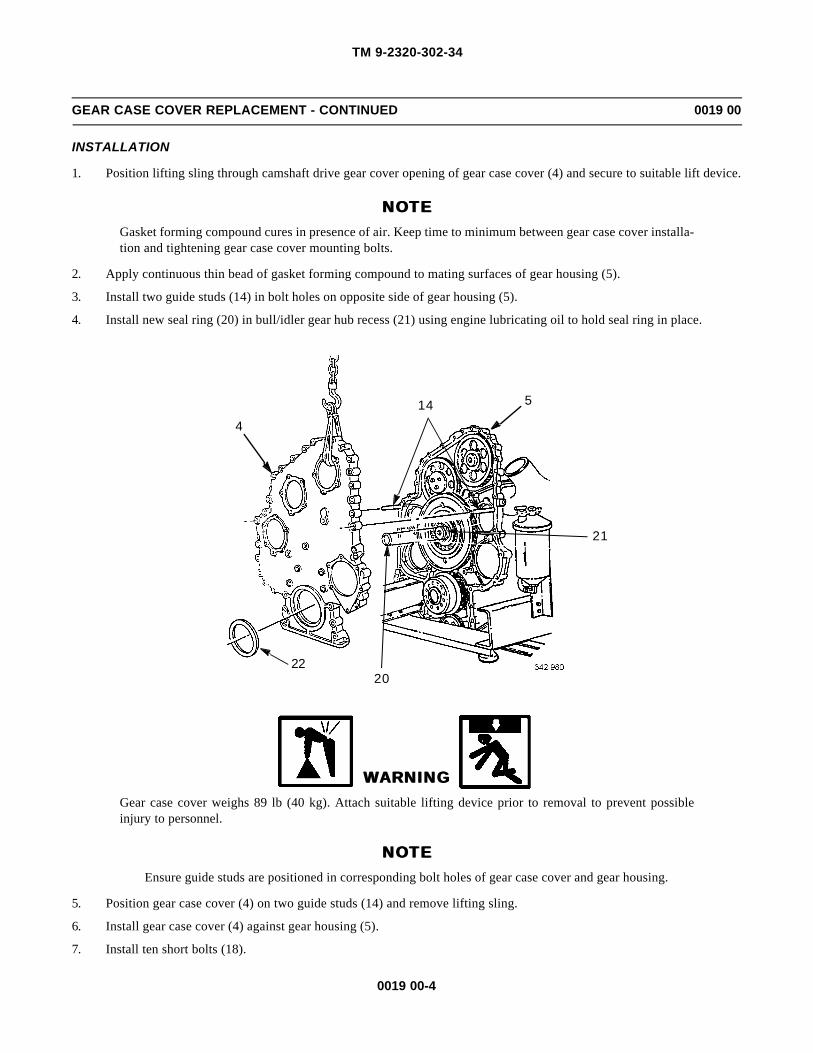
TM 9-2320-302-34
0019 00-4
GEAR CASE COVER REPLACEMENT - CONTINUED 0019 00
INSTALLATION
1. Position lifting sling through camshaft drive gear cover opening of gear case cover (4) and secure to suitable lift device.
NOTENOTEGasket forming compound cures in presence of air. Keep time to minimum between gear case cover installa-tion and tightening gear case cover mounting bolts.
2. Apply continuous thin bead of gasket forming compound to mating surfaces of gear housing (5).
3. Install two guide studs (14) in bolt holes on opposite side of gear housing (5).
4. Install new seal ring (20) in bull/idler gear hub recess (21) using engine lubricating oil to hold seal ring in place.
WARNINGWARNINGGear case cover weighs 89 lb (40 kg). Attach suitable lifting device prior to removal to prevent possibleinjury to personnel.
NOTENOTEEnsure guide studs are positioned in corresponding bolt holes of gear case cover and gear housing.
5. Position gear case cover (4) on two guide studs (14) and remove lifting sling.
6. Install gear case cover (4) against gear housing (5).
7. Install ten short bolts (18).
22
414 5
21
20

TM 9-2320-302-34
0019 00-5
GEAR CASE COVER REPLACEMENT - CONTINUED 0019 00
INSTALLATION - CONTINUED
8. Install four long bolts (19).
9. Remove two guide studs (14) and install two bolts (13).
10. Install standoff bracket (9) and bolt (8) to gear case cover (4).
11. Install standoff bracket (12), bolt (11), and nut (10) on gear case cover (4).
12. Secure fan clutch solenoid air line (7) to gear case cover (4) and gear housing (5) with new tiedown straps (6).
2
31
15 16 17
984
5
18
6
1012
13
14
11
18
19
7
14
18
6
18
6
18

TM 9-2320-302-34
0019 00-6
GEAR CASE COVER REPLACEMENT - CONTINUED 0019 00
INSTALLATION - CONTINUED
13. Tighten bolts to 43-54 lb-ft (58-73 Nm), in sequence shown.
14. Position alternator mounting bracket (3) on gear case cover (4) and gear housing assembly (5). Secure with two bolts (2)and nuts (1). Tighten to 43-54 lb-ft (58-73 Nm).
15. Install new gasket (17) and camshaft gear cover (16) on gear case cover (4).
16. Install five bolts (15) to secure camshaft gear cover (16). Tighten bolts to 22-28 lb-ft (30-38 Nm).
17. Install power steering pump (WP 0086 00).
18. Install oil pan (WP 0028 00).
19. Install accessory drive (WP 0021 00).
20. Install fan drive support (WP 0013 00).
10
11
12
13
14
16
3
1
18
2
4
17
5
6
7
8
9
15
TIGHTENING SEQUENCE
2
3
1 5
4
15
16
17

TM 9-2320-302-34
0019 00-7
GEAR CASE COVER REPLACEMENT - CONTINUED 0019 00
INSTALLATION - CONTINUED
21. Install front engine mount adapter (WP 0011 00).
22. Install air compressor (TM 9-2320 302-20).
23. Install water pump (TM 9-2320-302-20).
24. Install alternator (TM 9-2320-302-20).
END OF WORK PACKAGE

TM 9-2320-302-34
0019 00-8
This Page Intentionally Left Blank.

TM 9-2320-302-34
0020 00-1
VIBRATION DAMPER REPLACEMENT 0020 00
THIS WORK PACKAGE COVERS
Removal, Inspection, Installation
INITIAL SETUP
Maintenance Level
Direct Support
Tools and Special Tools
Tool kit, general mechanic’s (Item 132, WP 0126 00)
Wrench, torque, 50-250 lb-ft (Item 139, WP 0126 00)
Equipment Condition
Fan belts removed (TM 9-2320-302-20)
REMOVAL
CAUTIONCAUTIONTo prevent damage to pulley and vibration damper, support pulley and damper during removal.
1. Remove six crankshaft pulley attaching bolts (1) and washers (2) from crankshaft pulley (3).
1
2
3

TM 9-2320-302-34
0020 00-2
VIBRATION DAMPER REPLACEMENT - CONTINUED 0020 00
REMOVAL - CONTINUED
CAUTIONCAUTIONDo not pry on pulley or damper. If force is needed, use rubber mallet or soft-faced hammer to prevent dam-age to pulley and damper.
2. Remove crankshaft pulley (3).
3. Remove vibration damper (4).
INSPECTION
NOTENOTEVibration damper is replaced during major engine overhaul, crankshaft replacement or when conditionsidentified below are found.
1. Inspect vibration damper for dents, gouges, fluid leaks or bulges. Replace vibration damper if any of these conditionsare found.
2. Inspect crankshaft pulley for cracked, broken or bent flanges. Replace crankshaft pulley if any of these conditions arefound.
3. Inspect crankshaft pulley and vibration damper mating surfaces for dirt and other foreign matter prior to installation.
INSTALLATION
1. Install vibration damper (4) against crankshaft (5), with stamped part number facing away from engine, and seat firmly.
3
4
4
5

TM 9-2320-302-34
0020 00-3
VIBRATION DAMPER REPLACEMENT - CONTINUED 0020 00
INSTALLATION - CONTINUED
2. Install crankshaft pulley (3) and seat firmly against vibration damper (4).
3. Install six washers (2) and bolts (1) hand tight.
4. Tighten six bolts (1) to 134-155 lb-ft (182-210 Nm).
5. Install fan belts (TM 9-2320-302-20).
END OF WORK PACKAGE
1
2
3

TM 9-2320-302-34
0020 00-4
This Page Intentionally Left Blank.

TM 9-2320-302-34
0021 00-1
ACCESSORY DRIVE REPLACEMENT 0021 00
THIS WORK PACKAGE COVERS
Removal, Installation
INITIAL SETUP
Maintenance Level
Direct Support
Tools and Special Tools
Tool kit, general mechanic’s (Item 132, WP 0126 00)
Checker, gear lash (Item 18, WP 0126 00)
Dial indicator set (Item 29, WP 0126 00)
Wrench, torque, 15-75 lb-ft (Item 138, WP 0126 00)
Materials/Parts
Ring, seal (P/N 8929253)
Oil, lubricating (Item 25, WP 0125 00)
Equipment Condition
Alternator belt removed (TM 9-2320-302-20)
REMOVAL
NOTENOTE
If necessary, tap accessory drive with a soft-faced mallet to aid in removal.
1. Remove five bolts (1) and accessory drive (2) from gear case cover (3).
2. Remove and discard seal ring (4) from accessory drive (2).
2
1
43

TM 9-2320-302-34
0021 00-2
ACCESSORY DRIVE REPLACEMENT - CONTINUED 0021 00
INSTALLATION
1. Lubricate new seal ring (4) with clean lubricating oil and install in groove on accessory drive (2).
NOTENOTEInstall accessory drive with word UP cast into housing in 12 o’clock position.
2. Install accessory drive (2) on gear case cover (3), engaging accessory drive gear (5) with bull gear (6).
3. Align bolt holes of accessory drive (2) and gear case cover (3). Press accessory drive (2) into place and install five bolts(1).
4. Tighten bolts (1) to 22-28 lb-ft (30-38 Nm), in sequence shown.
2
1
43
2
54
1
3
TIGHTENING SEQUENCE

TM 9-2320-302-34
0021 00-3
ACCESSORY DRIVE REPLACEMENT - CONTINUED 0021 00
INSTALLATION - CONTINUED
NOTENOTEIf gear lash specification is not met, replace accessory drive.
5. Use dial indicator with clamp base to measure gear lash between accessory drive gear and bull gear.
a. Position dial indicator to read between scribed lines (7) on gear lash checker (8).
b. Gear lash should be 0.001-0.010 in (0.025-0.254 mm).
6. Install alternator belt (TM 9-2320-302-20).
END OF WORK PACKAGE
8
7

TM 9-2320-302-34
0021 00-4
This Page Intentionally Left Blank.

TM 9-2320-302-34
0022 00-1
ENGINE RETARDER MAINTENANCE 0022 00
THIS WORK PACKAGE COVERS
Removal, Disassembly, Cleaning and Inspection, Assembly, Installation, Adjustment
INITIAL SETUP
Maintenance Level
Direct Support
Tools and Special Tools
Tool kit, general mechanic’s (Item 132, WP 0126 00)
Wrench, torque, 0-300 lb-in (Item 137, WP 0126 00)
Wrench, torque, 15-75 lb-ft (Item 138, WP 0126 00)
Wrench, torque, 50-250 lb-ft (Item 139, WP 0126 00)
Materials/Parts
Ring, retaining (P/N 012991) (2)
Ring, seal (P/N 001082)
Materials/Parts - Continued
Ring, seal (P/N 001083)
Ring, seal (P/N 20229)
Compound, international, no. 2 (Item 13, WP 0125 00)
Oil, lubricating (Item 25, WP 0125 00)
Rags, wiping (Item 31, WP 0125 00)
Tags, marker (Item 35, WP 0125 00)
Wipes, lint-free (Item 40, WP 0125 00)
Equipment Condition
Rocker arm cover removed (WP 0016 00)
REMOVAL
1. Loosen screw (1) on three solenoid terminals and remove three wiring harness connectors (2) from three solenoid valves(3).
2. Remove three bolts (4) and washers (5) from three engine retarders (6).
5
4 4
5
32
4
5
3
6
13

TM 9-2320-302-34
0022 00-2
ENGINE RETARDER MAINTENANCE - CONTINUED 0022 00
REMOVAL - CONTINUED
CAUTIONCAUTIONDo not mix engine retarders. Tag each engine retarder to aid in installation
3. Remove six bolts (4), washers (5), three engine retarders (6), and two spacer bars (7) from cylinder head (8).
DISASSEMBLY
NOTENOTEProcedure is the same for all three engine retarder housings.
1. Place engine retarder (6) housing on bench.
CAUTIONCAUTIONDo not disassemble or tamper with solenoid valve. Engine damage could result.
2. Remove solenoid valve (3) with 12 point socket.
6
5
4
5
6
4
5
7
8

TM 9-2320-302-34
0022 00-3
ENGINE RETARDER MAINTENANCE - CONTINUED 0022 00
DISASSEMBLY - CONTINUED
3. Remove and discard three seal rings (9, 10, and 11). If seal ring (11) stays in bottom of engine retarder (6) housing,remove with wire.
WARNINGWARNINGParts are under spring tension. Release tension slowly to prevent personal injury.
4. Press down on washer (12) and remove retaining ring (13). Discard retaining ring.
5. Remove washer (12) and spring (14).
6. Using a magnet, remove accumulator piston (15) from engine retarder (6) housing.
NOTENOTETo remove control valve from right side of engine retarder housing, perform steps 7 through 9. Repeat stepsto remove control valve from left side of retarder housing.
6
11
3
9
10
6
15
1312
14
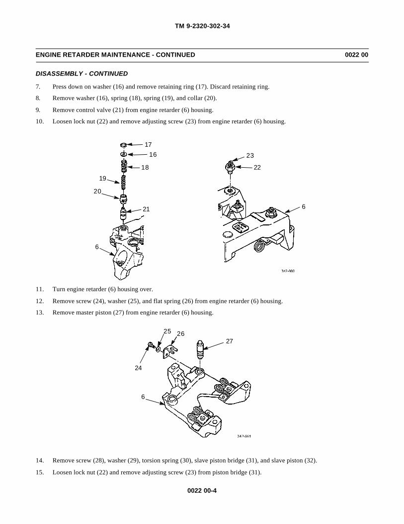
TM 9-2320-302-34
0022 00-4
ENGINE RETARDER MAINTENANCE - CONTINUED 0022 00
DISASSEMBLY - CONTINUED
7. Press down on washer (16) and remove retaining ring (17). Discard retaining ring.
8. Remove washer (16), spring (18), spring (19), and collar (20).
9. Remove control valve (21) from engine retarder (6) housing.
10. Loosen lock nut (22) and remove adjusting screw (23) from engine retarder (6) housing.
11. Turn engine retarder (6) housing over.
12. Remove screw (24), washer (25), and flat spring (26) from engine retarder (6) housing.
13. Remove master piston (27) from engine retarder (6) housing.
14. Remove screw (28), washer (29), torsion spring (30), slave piston bridge (31), and slave piston (32).
15. Loosen lock nut (22) and remove adjusting screw (23) from piston bridge (31).
6
20
19
1716
18
21
23
22
6
6
24
25 2627

TM 9-2320-302-34
0022 00-5
ENGINE RETARDER MAINTENANCE - CONTINUED 0022 00
DISASSEMBLY - CONTINUED
CLEANING AND INSPECTION
CCAUTIONAUTIONDo not use rags that may leave lint and residue which can plug oil passageways.
1. Using clean lint-free wipes, clean engine retarder housing bores. Dip control valves and pistons in clean engine lubricat-ing oil.
2. Verify ball (33) moves freely by pushing wire through hole (34) in base of control valve (21). Light pressure on wireshould move ball. Ball should return when pressure is released.
6
22
23
2829
30
31
32
21
34
33

TM 9-2320-302-34
0022 00-6
ENGINE RETARDER MAINTENANCE - CONTINUED 0022 00
CLEANING AND INSPECTION - CONTINUED
3. Ensure plunger (35) protrudes from bottom of adjusting screw (23).
4. Ensure plunger (35) has light spring pressure when pressed and moves freely.
ASSEMBLY
NOTENOTE• Procedure is the same for all three engine retarder housings.
• Steps 1 through 12 are for right side of engine retarder housing. The same procedures are to be repeatedto assemble the left side.
1. Install adjusting screw (23) and lock nut (22) in slave piston bridge (31).
2. Install slave piston (32) in engine retarder (6).
NOTENOTELocate part number on slave piston bridge away from engine retarder housing.
3. Install slave piston bridge (31) with adjusting screw (23) toward center of engine retarder (6) housing.
4. Install torsion spring (30) with ends over slave piston bridge (31).
5. Install screw (28) and washer (29) over center part of torsion spring (30) on engine retarder (6) housing. Tighten screwto 180 lb-in (20 Nm).
23
35
6
22
23
2829
30
31
32

TM 9-2320-302-34
0022 00-7
ENGINE RETARDER MAINTENANCE - CONTINUED 0022 00
ASSEMBLY - CONTINUED
NOTENOTEEnsure flat spring legs are centered around master piston boss.
6. Install master piston (27), flat spring (26), washer (25), and screw (24) in engine retarder (6) housing. Tighten screw to100 lb-in (11 Nm).
7. Turn engine retarder (6) housing over.
8. Install adjusting screw (23) and lock nut (22) in engine retarder (6) housing.
9. Hold control valve (21) by stem and drop into engine retarder (6) housing. If binding occurs or if ball is stuck in controlvalve, replace control valve.
10. Install collar (20) in engine retarder (6) housing with long sleeve area up.
11. Install spring (19) in center of collar (20). Install spring (18) over top of collar.
12. Press washer (16) to compress springs (18 and 19). Install new retaining ring (17). Rotate retaining ring 90 degrees toensure proper seating in groove.
6
24
25 26
27
6
20
19
1716
18
21
23
22
6

TM 9-2320-302-34
0022 00-8
ENGINE RETARDER MAINTENANCE - CONTINUED 0022 00
ASSEMBLY - CONTINUED
13. Install accumulator piston (15), spring (14), and washer (12) in engine retarder (6) housing.
14. Press washer (12) to compress spring (14) and install new retaining ring (13). Rotate retaining ring 90 degrees to ensureproper seating in groove.
CAUTIONCAUTIONBe careful not to twist seal rings while installing to prevent damage to equipment.
15. Coat three new seal rings (9, 10, and 11) with clean engine lubricating oil. Install seal rings (9 and 10) on solenoid valve(3).
16. Install seal ring (11) in bottom of engine retarder (6) housing.
17. Thread solenoid valve (3) into engine retarder (6) housing. Tighten solenoid valve to 60 lb-in (7 Nm).
INSTALLATION
WARNINGWARNINGCompressed air used for cleaning or drying purposes, or for clearing restrictions, should never exceed 30 psi(207 kPa). Wear protective clothing (goggles/shield, gloves, etc.) and use caution to avoid injury to person-nel.
CAUTIONCAUTIONEnsure oil is removed from bolt holes to prevent engine block from cracking when tightening bolts.
1. Cover bolt holes with rags to minimize oil spray.
6
11
3
9
10
6
15
1312
14

TM 9-2320-302-34
0022 00-9
ENGINE RETARDER MAINTENANCE - CONTINUED 0022 00
INSTALLATION - CONTINUED
2. Attach tubing to compressed air gun nozzle and clear oil out of bolt holes.
NOTENOTEPosition word OUT, stamped on each spacer bar, toward mid-engine, facing outside of engine.
3. Position two spacer bars (7) on exhaust manifold side of cylinder head (8). Align bolt holes in spacer bars with engineretarder (6) bolt holes in cylinder head.
CAUTIONCAUTIONEnsure engine retarder housings do not interfere with wiring harnesses. Failure to do so could result in dam-age to equipment.
4. Install three engine retarder (6) housings over rocker shafts.
5. Apply international compound no. 2 to threads and undersides of head of nine bolts (4).
CAUTIONCAUTIONEnsure wires are away from moving parts to prevent possible movement and contact with valve springs.
6
6
8
7
4
4

TM 9-2320-302-34
0022 00-10
ENGINE RETARDER MAINTENANCE - CONTINUED 0022 00
INSTALLATION - CONTINUED
NOTENOTEBefore tightening bolts, move engine retarder housing from side to side and locate as far toward camshaftside of the engine as possible.
6. Install nine bolts (4) and washers (5) in engine retarders (6). Tighten bolts to 40 lb-ft (54 Nm).
7. Repeat tightening of nine bolts (4) to 80 lb-ft (108 Nm).
8. Position three wiring harness connectors (2) under three solenoid terminal screws (1). Tighten screws to 12-17 lb-in(1.4-1.9 Nm).
ADJUSTMENT
CAUTIONCAUTIONFailure to use slave piston adjustment procedure will cause poor engine brake performance and/or seriousengine damage. It is necessary to rotate engine to put exhaust valves in closed position for each cylinderbeing adjusted. Make sure proper engine valve lash has been obtained to prevent damage to equipment.
1. Loosen lock nut (22) and back out adjusting screw (23) in slave piston bridge (31) until end of adjusting screw is flushwith bottom surface of slave piston bridge (31).
2. Place 0.023 in (0.584 mm) thickness gage between solid side of slave piston bridge (31) and exhaust rocker arm adjust-ing screw (36).
3. Loosen lock nut (38) and turn adjusting screw (37) clockwise until light drag is felt on thickness gage.
4. Hold adjusting screw (37) in position and remove thickness gage.
5. Tighten lock nut (38) to 26 lb-ft (35 Nm).
6. Using 0.023 in (0.584 mm) thickness gage, check clearance between adjusting screw (23) and rocker arm adjustingscrew (39).
7. Turn adjusting screw (23) clockwise until light drag is felt on thickness gage.
5
4 4
5
24
5
6
1

TM 9-2320-302-34
0022 00-11
ENGINE RETARDER MAINTENANCE - CONTINUED 0022 00
ADJUSTMENT - CONTINUED
8. Hold adjusting screw (23) in position and remove thickness gage.
9. Tighten lock nut (22) to 26 lb-ft (35 Nm).
10. Adjust the remaining engine retarders using steps 1 through 9.
11. Install rocker arm cover (WP 0016 00).
END OF WORK PACKAGE
38
23
22
39
3731
36

TM 9-2320-302-34
0022 00-12
This Page Intentionally Left Blank.

TM 9-2320-302-34
0023 00-1
CRANKSHAFT REAR OIL SEAL REPLACEMENT 0023 00
THIS WORK PACKAGE COVERS
Removal, Inspection, Installation
INITIAL SETUP
Maintenance Level
Direct Support
Tools and Special Tools
Tool kit, general mechanic’s (Item 132, WP 0126 00)
Dial indicator set (Item 29, WP 0126 00)
Inserter, seal (Item 50, WP 0126 00)
Remover, seal (Item 101, WP 0126 00)
Materials/Parts
Seal (P/N 23519651)
Cloth, abrasive (Item 9, WP 0125 00)
Oil, lubricating (Item 25, WP 0125 00)
Equipment Condition
Power pack removed (WP 0010 00)
Flex plate removed (WP 0025 00)
REMOVAL
NOTENOTEIf oil seal remover screws strip out of oil seal sealing casing, remove screws and bolts. Rotate oil sealremover half the distance between existing screw holes in seal casing and repeat steps to remove seal.
1. Position oil seal remover (1) over rear of crankshaft against flywheel housing (2).
NOTENOTEOil seal remover screws must be evenly snug against oil seal remover but not overtightened and stripped inoil sealing casing.
2. Install six oil seal remover screws (3) through inner circle of holes in oil seal remover (1) and into oil seal casing.
3. Thread three bolts (4) into outer circle of holes in oil seal remover (1) until bolts contact flywheel housing (2).
4. Working clockwise, turn each bolt (4) one full turn until crankshaft rear oil seal is removed. Discard seal.
2
3
1
4
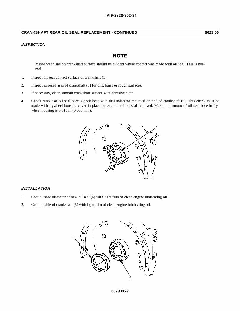
TM 9-2320-302-34
0023 00-2
CRANKSHAFT REAR OIL SEAL REPLACEMENT - CONTINUED 0023 00
INSPECTION
NOTENOTEMinor wear line on crankshaft surface should be evident where contact was made with oil seal. This is nor-mal.
1. Inspect oil seal contact surface of crankshaft (5).
2. Inspect exposed area of crankshaft (5) for dirt, burrs or rough surfaces.
3. If necessary, clean/smooth crankshaft surface with abrasive cloth.
4. Check runout of oil seal bore. Check bore with dial indicator mounted on end of crankshaft (5). This check must bemade with flywheel housing cover in place on engine and oil seal removed. Maximum runout of oil seal bore in fly-wheel housing is 0.013 in (0.330 mm).
INSTALLATION
1. Coat outside diameter of new oil seal (6) with light film of clean engine lubricating oil.
2. Coat outside of crankshaft (5) with light film of clean engine lubricating oil.
5
5
6

TM 9-2320-302-34
0023 00-3
CRANKSHAFT REAR OIL SEAL REPLACEMENT - CONTINUED 0023 00
INSTALLATION - CONTINUED
CAUTIONCAUTIONEnsure flywheel housing seal bore, rear of crankshaft, and both sides of oil seal installer base and spacer areclean, smooth, and free of any foreign material. Failure to do so may cause damage to equipment.
3. Position seal inserter base (7) on rear of crankshaft (5).
4. Install two guide studs (8) in two flywheel bolt holes 180 degrees apart.
5. Hand tighten two guide studs (8) until seal inserter base (7) is tight against rear of crankshaft (5).
6. Install oil seal (6) onto crankshaft (5) as far as it will go by hand.
7. Install seal inserter spacer (9) on center screw (10).
8. Position seal inserter collar (11) on oil seal (6).
9. Place seal inserter housing (12) over center screw (10) and two guide studs (8). Position seal inserter housing againstseal inserter collar (11) and crankshaft rear oil seal (6).
10. Install thrust bearing (13) on center screw (10) with lettered side against seal inserter housing (12).
11. Install nut (14) on center screw (10). Tighten nut until crankshaft rear oil seal (6) is firmly seated.
12. Remove nut (14), thrust bearing (13), seal inserter housing (12), seal inserter collar (11), spacer (9), guide studs (8), andseal inserter base (7) from crankshaft (5).
13. Install flex plate (WP 0025 00).
14. Install power pack (WP 0010 00).
END OF WORK PACKAGE
5
78
6911
12
13
1410

TM 9-2320-302-34
0023 00-4
This Page Intentionally Left Blank.

TM 9-2320-302-34
0024 00-1
FLYWHEEL HOUSING REPLACEMENT 0024 00
THIS WORK PACKAGE COVERS
Removal, Installation
INITIAL SETUP
Maintenance Level
Direct Support
Tools and Special Tools
Tool kit, general mechanic’s (Item 132, WP 0126 00)
Dial indicator set (Item 29, WP 0126 00)
Dispenser, sealant (Item 30, WP 0126 00)
Guide stud set (Item 43, WP 0126 00)
Lifting, bracket, flywheel (Item 77, WP 0126 00)
Wrench, torque, 50-250 lb-ft (Item 139, WP 0126 00)
Personnel Required
Two
Materials/Parts
Compound, gasket forming (Item 12, WP 0125 00)
References
WP 0023 00
Equipment Condition
Engine installed on stand
Rear engine mounts removed (WP 0012 00)
Starter removed (TM 9-2320-302-20)
Oil pan removed (WP 0028 00)
Flex plate removed (WP 0025 00)
WARNINGWARNINGUse extreme caution when handling heavy parts. Provide adequate support and use assistance during proce-dure. Ensure that any lifting device used is in good condition and of suitable load capacity. Keep clear ofheavy parts supported only by lifting device. Failure to follow this warning may result in death or injury topersonnel.

TM 9-2320-302-34
0024 00-2
FLYWHEEL HOUSING REPLACEMENT - CONTINUED 0024 00
REMOVAL
1. Remove four bolts (1) and washers (2) from flywheel housing (3).
2. Install two guide studs (4).
3. Remove eight bolts (5) and washers (6) from flywheel housing (3).
CAUTIONCAUTIONUse soft mallet to tap flywheel housing loose from cylinder block. Failure to use soft mallet could result indamage to equipment.
4. Remove flywheel housing (3).
5. Remove and discard crankshaft rear oil seal (WP 0023 00).
6. Remove two guide studs (4) from cylinder block (7).
43
21
4
1,2
6
5
4
7
7
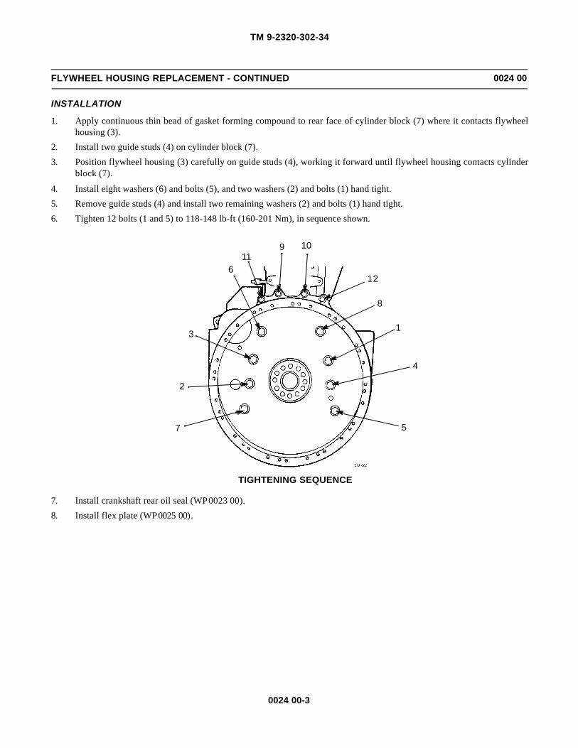
TM 9-2320-302-34
0024 00-3
FLYWHEEL HOUSING REPLACEMENT - CONTINUED 0024 00
INSTALLATION
1. Apply continuous thin bead of gasket forming compound to rear face of cylinder block (7) where it contacts flywheelhousing (3).
2. Install two guide studs (4) on cylinder block (7).
3. Position flywheel housing (3) carefully on guide studs (4), working it forward until flywheel housing contacts cylinderblock (7).
4. Install eight washers (6) and bolts (5), and two washers (2) and bolts (1) hand tight.
5. Remove guide studs (4) and install two remaining washers (2) and bolts (1) hand tight.
6. Tighten 12 bolts (1 and 5) to 118-148 lb-ft (160-201 Nm), in sequence shown.
7. Install crankshaft rear oil seal (WP 0023 00).
8. Install flex plate (WP 0025 00).
10
1
2
3
4
5
6
7
8
911
12
TIGHTENING SEQUENCE
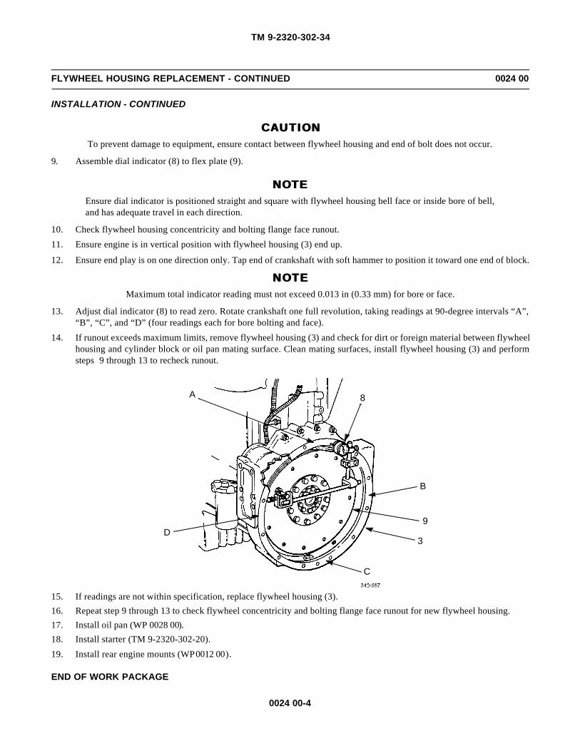
TM 9-2320-302-34
0024 00-4
FLYWHEEL HOUSING REPLACEMENT - CONTINUED 0024 00
INSTALLATION - CONTINUED
CAUTIONCAUTIONTo prevent damage to equipment, ensure contact between flywheel housing and end of bolt does not occur.
9. Assemble dial indicator (8) to flex plate (9).
NOTENOTEEnsure dial indicator is positioned straight and square with flywheel housing bell face or inside bore of bell,and has adequate travel in each direction.
10. Check flywheel housing concentricity and bolting flange face runout.
11. Ensure engine is in vertical position with flywheel housing (3) end up.
12. Ensure end play is on one direction only. Tap end of crankshaft with soft hammer to position it toward one end of block.
NOTE NOTE Maximum total indicator reading must not exceed 0.013 in (0.33 mm) for bore or face.
13. Adjust dial indicator (8) to read zero. Rotate crankshaft one full revolution, taking readings at 90-degree intervals “A”,“B”, “C”, and “D” (four readings each for bore bolting and face).
14. If runout exceeds maximum limits, remove flywheel housing (3) and check for dirt or foreign material between flywheelhousing and cylinder block or oil pan mating surface. Clean mating surfaces, install flywheel housing (3) and performsteps 9 through 13 to recheck runout.
15. If readings are not within specification, replace flywheel housing (3).
16. Repeat step 9 through 13 to check flywheel concentricity and bolting flange face runout for new flywheel housing.
17. Install oil pan (WP 0028 00).
18. Install starter (TM 9-2320-302-20).
19. Install rear engine mounts (WP 0012 00).
END OF WORK PACKAGE
A
B
C
D
8
3
9
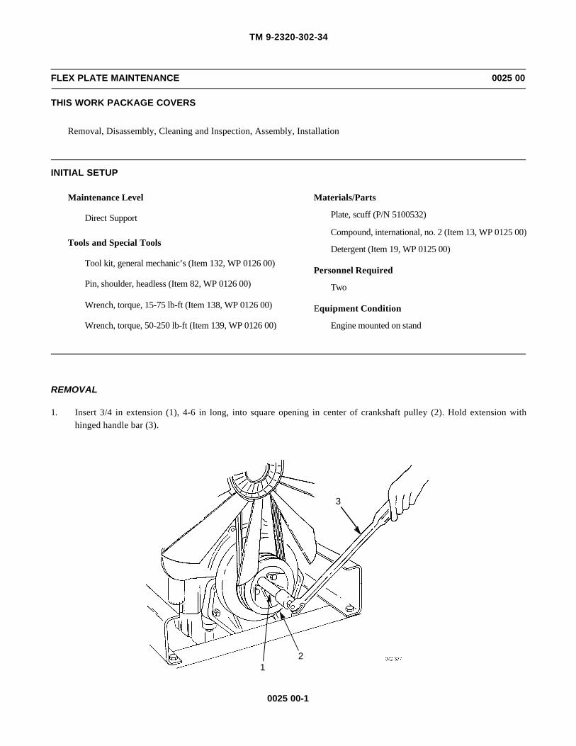
TM 9-2320-302-34
0025 00-1
FLEX PLATE MAINTENANCE 0025 00
THIS WORK PACKAGE COVERS
Removal, Disassembly, Cleaning and Inspection, Assembly, Installation
INITIAL SETUP
Maintenance Level
Direct Support
Tools and Special Tools
Tool kit, general mechanic’s (Item 132, WP 0126 00)
Pin, shoulder, headless (Item 82, WP 0126 00)
Wrench, torque, 15-75 lb-ft (Item 138, WP 0126 00)
Wrench, torque, 50-250 lb-ft (Item 139, WP 0126 00)
Materials/Parts
Plate, scuff (P/N 5100532)
Compound, international, no. 2 (Item 13, WP 0125 00)
Detergent (Item 19, WP 0125 00)
Personnel Required
Two
Equipment Condition
Engine mounted on stand
REMOVAL
1. Insert 3/4 in extension (1), 4-6 in long, into square opening in center of crankshaft pulley (2). Hold extension withhinged handle bar (3).
3
21

TM 9-2320-302-34
0025 00-2
FLEX PLATE MAINTENANCE - CONTINUED 0025 00
REMOVAL - CONTINUED
2. Hold crankshaft against rotation and loosen 12 bolts (4).
3. Remove two bolts (5) at 3 and 9 o’clock positions and install two guide studs (6).
4. Remove remaining ten bolts (5).
5. Remove and discard scuff plate (7).
6. Remove flex plate assembly (8) from two guide studs (6).
4
65
5
7
4
6
68

TM 9-2320-302-34
0025 00-3
FLEX PLATE MAINTENANCE - CONTINUED 0025 00
DISASSEMBLY
1. Remove 12 bolts (4) securing flex plate (9), four disks (10), and disk assembly (11) to coupling (12).
2. Separate disk assembly (11) from four disks (10).
CLEANING AND INSPECTION
WARNINGWARNINGCompressed air used for cleaning or drying purposes, or for clearing restrictions, should never exceed 30 psi(207 kPa). Wear protective clothing (goggles/shield, gloves, etc.) and use caution to avoid injury to person-nel.
1. Use detergent and water to clean all parts. Dry with compressed air.
2. Ensure all surfaces of coupling, disk assembly, disks, and flex plate are clean and free from any foreign material.
3. Inspect parts for rust, cracks or damage. Replace damaged parts.
4. Inspect all parts for wear. Replace worn parts.
12
9
4
10
11
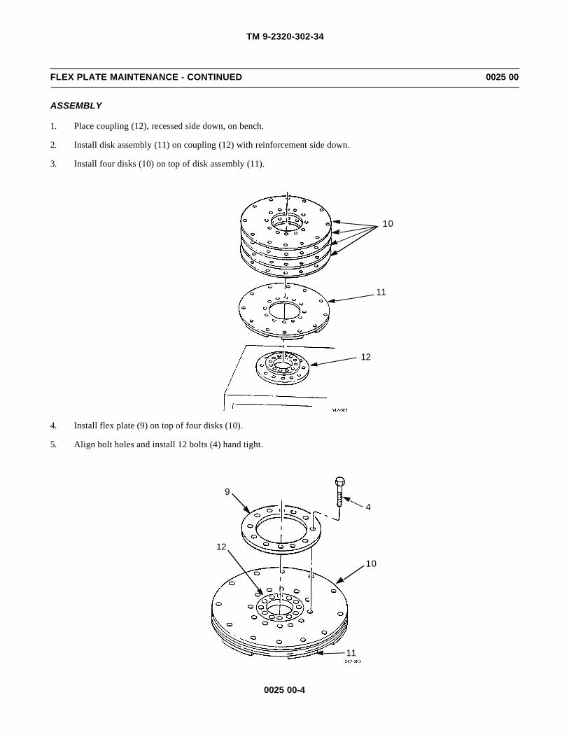
TM 9-2320-302-34
0025 00-4
FLEX PLATE MAINTENANCE - CONTINUED 0025 00
ASSEMBLY
1. Place coupling (12), recessed side down, on bench.
2. Install disk assembly (11) on coupling (12) with reinforcement side down.
3. Install four disks (10) on top of disk assembly (11).
4. Install flex plate (9) on top of four disks (10).
5. Align bolt holes and install 12 bolts (4) hand tight.
10
11
12
12
9
4
10
11
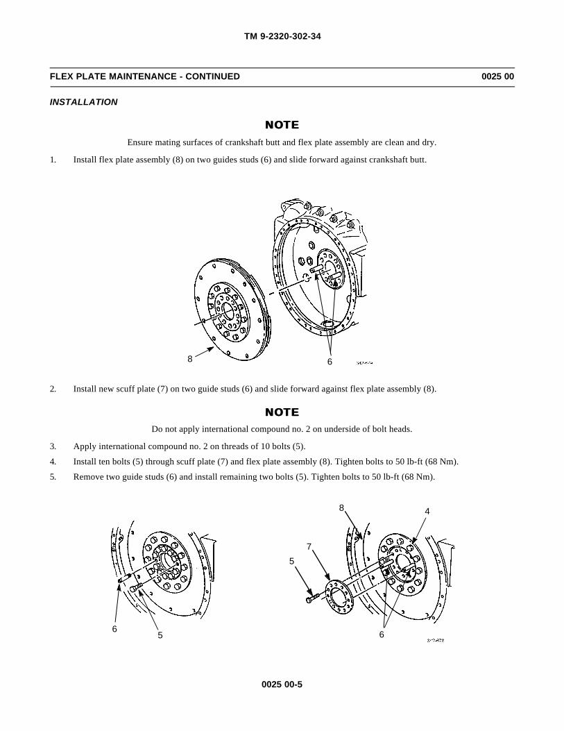
TM 9-2320-302-34
0025 00-5
FLEX PLATE MAINTENANCE - CONTINUED 0025 00
INSTALLATION
NOTENOTEEnsure mating surfaces of crankshaft butt and flex plate assembly are clean and dry.
1. Install flex plate assembly (8) on two guides studs (6) and slide forward against crankshaft butt.
2. Install new scuff plate (7) on two guide studs (6) and slide forward against flex plate assembly (8).
NOTENOTEDo not apply international compound no. 2 on underside of bolt heads.
3. Apply international compound no. 2 on threads of 10 bolts (5).
4. Install ten bolts (5) through scuff plate (7) and flex plate assembly (8). Tighten bolts to 50 lb-ft (68 Nm).
5. Remove two guide studs (6) and install remaining two bolts (5). Tighten bolts to 50 lb-ft (68 Nm).
68
65
57
4
6
8

TM 9-2320-302-34
0025 00-6
FLEX PLATE MAINTENANCE - CONTINUED 0025 00
INSTALLATION - CONTINUED
6. Insert 3/4 in extension (1) 4-6 in long, into square opening in center of crankshaft pulley (2) and hold extension withhinged handle bar (3).
7. Hold crankshaft against rotation and tighten 12 inner bolts, in crisscross sequence shown, to 180-190 lb-ft (244-258Nm).
3
21
1 7
12
4
9
62
11
8
3
5
10
TIGHTENING SEQUENCE

TM 9-2320-302-34
0025 00-7
FLEX PLATE MAINTENANCE - CONTINUED 0025 00
INSTALLATION - CONTINUED
8. Tighten 12 outer bolts, in crisscross sequence shown, to 95-115 lb-ft (129-156 Nm).
END OF WORK PACKAGE
5
101
7
12
4
9
3
8
11
26
TIGHTENING SEQUENCE

TM 9-2320-302-34
0025 00-8
This Page Intentionally Left Blank.

TM 9-2320-302-34
0026 00-1
CAMSHAFT AND BEARINGS REPLACEMENT 0026 00
THIS WORK PACKAGE COVERS
Removal, Cleaning, Inspection, Installation
INITIAL SETUP
Maintenance Level
Direct Support
Tools and Special Tools
Tool kit, general mechanic’s (Item 132, WP 0126 00)
Dispenser, sealant (Item 30, WP 0126 00)
Pilot, cam gear (Item 81, WP 0126 00)
Plate, retaining (Item 84, WP 0126 00)
Socket, socket wrench (Item 116, WP 0126 00)
Wrench, torque, 15-75 lb-ft (Item 138, WP 0126 00)
Wrench, torque, 50-250 lb-ft (Item 139, WP 0126 00)
Materials/Parts
Bolt (P/N 8929206)
Bolt (P/N 11504822) (3)
Ring, seal (P/N 8929410)
Seal, racetrack (P/N 23522975)
Seal, stat-o (P/N 23521111) (2)
Materials/Parts - Continued
Compound, gasket forming (Item 12, WP 0125 00)
Compound, international, no. 2 (Item 13, WP 0125 00)
Compound, sealing (Item 16, WP 0125 00)
Detergent (Item 19, WP 0125 00)
Gage, bearing clearance (Item 20, WP 0125 00)
Oil, lubricating (Item 25, WP 0125 00)
Rags, wiping (Item 31, WP 0125 00)
Tags, marker (Item 35, WP 0125 00)
Personnel Required
Two
References
WP 0034 00
Equipment Condition
Engine retarders removed (WP 0022 00)
Rocker arm assemblies removed (WP 0027 00)
WARNINGWARNINGCamshaft weighs 53 lb (24 kg). Attach suitable lifting device prior to removal or installation to prevent pos-sible injury to personnel.

TM 9-2320-302-34
0026 00-2
CAMSHAFT AND BEARINGS REPLACEMENT - CONTINUED 0026 00
REMOVAL
1. Remove three bolts (1) and rear camshaft cover (2).
2. Attach dial indicator (3) and place pointer in contact with side of camshaft lobe (4).
3. Grasp camshaft (5) between camshaft caps and move camshaft as far forward as possible. Hold in that position and setdial indicator for zero.
4. Move camshaft (5) to rear as far as possible. Read and record total amount of end play. Allowable camshaft end play is0.003-0.015 in (0.076-0.381 mm).
5. If end play is beyond maximum limit, remove and repair or replace camshaft drive gear assembly (WP 0034 00).
CAUTIONCAUTION
Use ONLY following method to hold camshaft drive gear stationary while loosening camshaft drive gearbolt.
12
3
4 5

TM 9-2320-302-34
0026 00-3
CAMSHAFT AND BEARINGS REPLACEMENT - CONTINUED 0026 00
REMOVAL - CONTINUED
NOTENOTEAfter inserting shoe of retaining plate through access hole of camshaft drive gear, it may be necessary to barengine over slightly to align bolt holes in retaining plate with bolt holes in drive gear access cover. If neces-sary, bar engine using accessory drive pulley retaining nut to align access hole.
6. Install retaining plate (6) on gear housing (7) engaging one access hole (8) in camshaft drive gear (9). Install two bolts(10) in retaining plate (6) and gear housing (7).
7. Remove camshaft drive gear bolt (11). Discard bolt
8. Remove two bolts (10) and retaining plate (6) from gear housing (7).
89
11 7
610
10

TM 9-2320-302-34
0026 00-4
CAMSHAFT AND BEARINGS REPLACEMENT - CONTINUED 0026 00
REMOVAL - CONTINUED
CAUTIONCAUTIONClean rag may be inserted into gear housing assembly opening to trap bolts in case they are dropped. DONOT allow rag to drop into gear housing assembly to prevent damage to equipment
NOTENOTEIt may be necessary to bar engine over to align access holes in camshaft drive gear with mounting bolts incamshaft thrust plate.
9. Remove and discard three bolts (12).
NOTENOTEPerforming step 10 will move camshaft drive gear hub and thrust plate forward approximately ¼ in (6-7mm) until thrust plate seal is clear of camshaft front bearing cap and cylinder head.
10. Install cam gear pilot (13) on camshaft drive gear access opening (14) and install three bolts (15). Thread pilot pullerscrew (16) into end of camshaft drive gear hub until puller screw bottoms out.
12
1315
14
16

TM 9-2320-302-34
0026 00-5
CAMSHAFT AND BEARINGS REPLACEMENT - CONTINUED 0026 00
REMOVAL - CONTINUED
11. If there is doubt of camshaft acceptability, determine extent of camshaft lobe wear as follows:
a. Using set of 0.0015-0.010 in (0.038-0.254 mm) thickness gages (17) and piece of square, hard material (18), mea-sure flats on injector rise side (19) of camshaft lobes (4).
b. If flats measure less than 0.003 in (0.076 mm) in depth, but there are no other camshaft defects, camshaft is satis-factory.
1917
18
4
REAR VIEW

TM 9-2320-302-34
0026 00-6
CAMSHAFT AND BEARINGS REPLACEMENT - CONTINUED 0026 00
REMOVAL - CONTINUED
12. Remove four camshaft cap bolts (20).
13. Using rocker stud socket, remove two rocker shaft studs (21) and seals (22) from camshaft bearing caps (23) no. 1 andno. 7. Discard seals.
CAUTIONCAUTIONCamshaft bearing caps are numbered and must be kept in sequence and reinstalled in original positions toprevent damage to equipment. Camshaft bearing caps cannot be interchanged or transferred to another cylin-der head.
NOTENOTEIf camshaft bearing shells are to be reused, tag all parts. Shell must be kept with same camshaft bearing cap.
14. Remove seven camshaft bearing caps (23) and seven upper camshaft bearing shells (24) together as units.
15. Remove and discard racetrack seal ring (25) between camshaft bearing cap (23) no. 1 (front) and seal ring between cam-shaft bearing cap (23) no. 7 (rear) and cylinder head (26).
Cap no. 7
25
24
23
22
2020
2020
21
23
23
23
22Cap no. 1
23
25
24
2426
21

TM 9-2320-302-34
0026 00-7
CAMSHAFT AND BEARINGS REPLACEMENT - CONTINUED 0026 00
REMOVAL - CONTINUED
16. Remove pilot puller screw (16). Camshaft gear pilot (13) will remain in place, holding camshaft drive gear (9) in contactwith adjustable idler gear.
WARNINGWARNINGCamshaft weighs 53 lb (24 kg). Attach suitable lifting device prior to removal to prevent possible injury topersonnel.
13
9
16

TM 9-2320-302-34
0026 00-8
CAMSHAFT AND BEARINGS REPLACEMENT - CONTINUED 0026 00
REMOVAL - CONTINUED
CAUTIONCAUTIONDue to size and bulk of camshaft, care must be taken and two persons used to lift camshaft. Use non-metallicsling positioned inboard of camshaft bearing no. 1 and no. 7 to prevent damage to equipment.
17. Using slings, slide camshaft (5) toward rear to disengage dowel (27) from camshaft drive gear hub (28). Remove cam-shaft.
CAUTIONCAUTIONUpper and lower bearing shells are in sets and cannot be interchanged. If either upper or lower bearing isreplaced, upper and lower bearing shells must also be replaced to prevent damage to equipment.
18. Remove seven lower camshaft bearing shells (29). Keep lower bearing shells with their corresponding upper camshaftbearing shells (24) and camshaft bearing caps (23).
27
285

TM 9-2320-302-34
0026 00-9
CAMSHAFT AND BEARINGS REPLACEMENT - CONTINUED 0026 00
REMOVAL - CONTINUED
CLEANING
1. Clean all removed parts and components in detergent and water.
WARNINGWARNINGCompressed air used for cleaning or drying purposes, or for clearing restrictions, should never exceed 30 psi(207 kPa). Wear protective clothing (goggles/shield, gloves, etc.) and use caution to avoid injury to person-nel.
2. Use compressed air to clean all oil passages.
INSPECTION
1. Inspect camshaft lobes and journals for scoring, pitting or flat spots. If camshaft is scored, inspect camshaft followerrollers.
2324
24
29
23
24
29

TM 9-2320-302-34
0026 00-10
CAMSHAFT AND BEARINGS REPLACEMENT - CONTINUED 0026 00
INSPECTION - CONTINUED
2. If there is doubt of camshaft acceptability, determine extent of camshaft lobe wear as follows:
a. Using set of 0.0015-0.010 in (0.038-0.254 mm) thickness gages (17) and piece of square, hard material (18), mea-sure flats on injector rise side (19) of camshaft lobes (4).
b. If flats measure less than 0.0003 in (0.076 mm) in depth, but there are no other camshaft defects, camshaft is satis-factory.
NOTENOTEIf one camshaft bearing needs replacement, replace all camshaft bearing shells.
c. Inspect camshaft bearings for signs of excessive wear, scoring or pitting.
d. Determine camshaft bearing clearance:
NOTENOTEEnsure locating tangs are correctly positioned.
(1) With lower camshaft bearing shells (29) installed in cylinder head, install camshaft (5) on seven lowercamshaft bearing shells.
(2) Install seven upper camshaft bearing shells (24) in seven camshaft bearing caps (23).
(3) Wipe any oil from camshaft bearing shells and camshaft journals.
(4) Place a piece of plastiguage (30) full width of each upper camshaft bearing shell (24) about ¼ in (6-7 mm)off center.
(5) Install camshaft bearing caps (23) and camshaft bearing shells (24) on correct camshaft journals and installseven camshaft cap bolts (20). Tighten bolts to 75-86 lb-ft (102-117 Nm).
(6) Install two rocker shaft studs (21) in camshaft bearing caps (23) no. 1 and no. 7. Tighten studs to 75-86 lb-ft (102-117 Nm).
(7) Install two rocker shafts (31) on seven camshaft bearing caps (23).
(8) Install eight rocker shaft saddle washers (32), six bolts (33), and two nuts (34). Tighten bolts and nuts to75-86 lb-ft (102-117 Nm).
1917
18
4
REAR VIEW

TM 9-2320-302-34
0026 00-11
CAMSHAFT AND BEARINGS REPLACEMENT - CONTINUED 0026 00
INSPECTION - CONTINUED
(9) Remove two rocker shaft nuts (34), six bolts (33), eight saddle washers (32), and two rocker shafts (31).
(10) Remove two rocker shaft studs (21).
(11) Remove seven outboard camshaft cap bolts (20), seven camshaft caps (23), and seven bearing shells (24).
20
3132
33 3432
31
2123
24
30
5
29
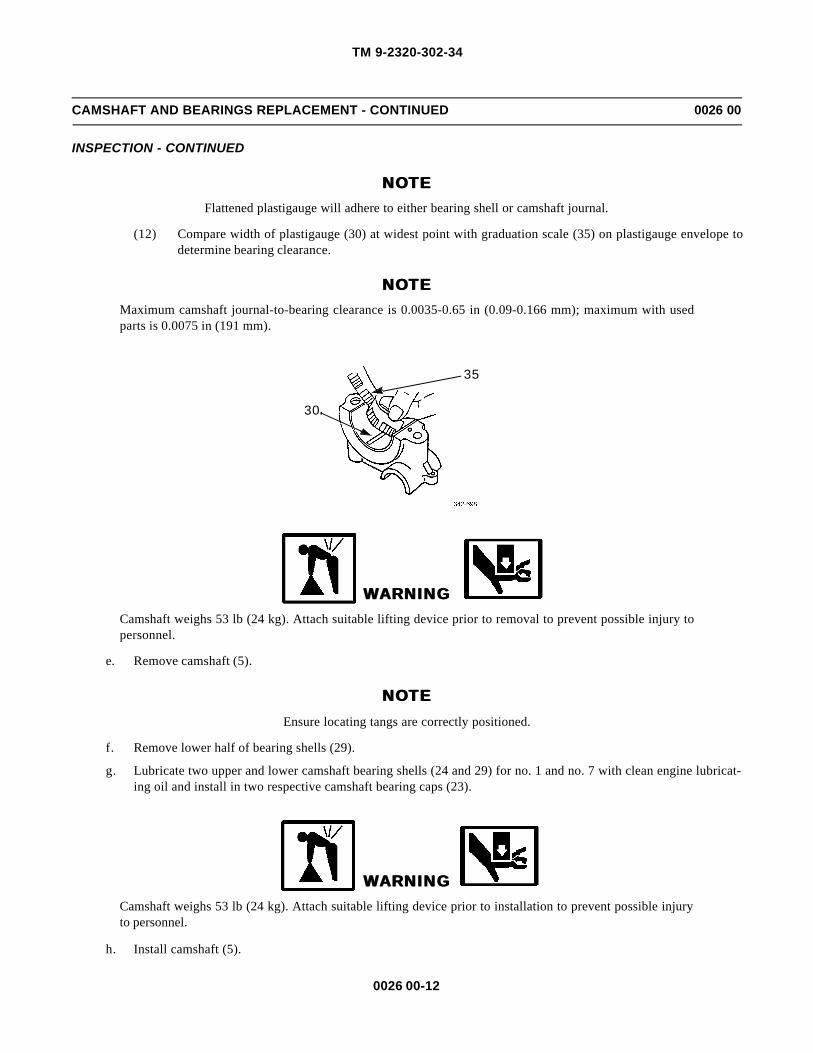
TM 9-2320-302-34
0026 00-12
CAMSHAFT AND BEARINGS REPLACEMENT - CONTINUED 0026 00
INSPECTION - CONTINUED
NOTENOTEFlattened plastigauge will adhere to either bearing shell or camshaft journal.
(12) Compare width of plastigauge (30) at widest point with graduation scale (35) on plastigauge envelope todetermine bearing clearance.
NOTENOTEMaximum camshaft journal-to-bearing clearance is 0.0035-0.65 in (0.09-0.166 mm); maximum with usedparts is 0.0075 in (191 mm).
WARNINGWARNINGCamshaft weighs 53 lb (24 kg). Attach suitable lifting device prior to removal to prevent possible injury topersonnel.
e. Remove camshaft (5).
NOTENOTEEnsure locating tangs are correctly positioned.
f. Remove lower half of bearing shells (29).
g. Lubricate two upper and lower camshaft bearing shells (24 and 29) for no. 1 and no. 7 with clean engine lubricat-ing oil and install in two respective camshaft bearing caps (23).
WARNINGWARNINGCamshaft weighs 53 lb (24 kg). Attach suitable lifting device prior to installation to prevent possible injuryto personnel.
h. Install camshaft (5).
30
35

TM 9-2320-302-34
0026 00-13
CAMSHAFT AND BEARINGS REPLACEMENT - CONTINUED 0026 00
INSPECTION - CONTINUED
i. Install two camshaft bearing caps (23) no. 1 and no. 7 in cylinder head (26) and install two camshaft cap bolts (20)and two rocker shaft studs (21) in two camshaft bearing caps (23) no. 1 and no. 7. Tighten bolts and studs to 75-86lb-ft (102-117 Nm). Use rocker stud socket to tighten studs.
20
21
23
24
26
5
2021
23
24

TM 9-2320-302-34
0026 00-14
CAMSHAFT AND BEARINGS REPLACEMENT - CONTINUED 0026 00
INSPECTION - CONTINUED
NOTENOTEIf camshaft runout exceeds 0.002 in (0.050 mm), replace camshaft.
j. Using dial indicator (3), check runout of camshaft (5) at bearing journal no. 4.
k. Remove two camshaft bearing caps (23) no. 1 and no. 7 from cylinder head (26).
WARNINGWARNINGCamshaft weighs 53 lb (24 kg). Attach suitable lifting device prior to removal to prevent possible injury topersonnel.
3
5

TM 9-2320-302-34
0026 00-15
CAMSHAFT AND BEARINGS REPLACEMENT - CONTINUED 0026 00
INSPECTION - CONTINUED
l. Remove camshaft (5).
23
26
5
23

TM 9-2320-302-34
0026 00-16
CAMSHAFT AND BEARINGS REPLACEMENT - CONTINUED 0026 00
INSTALLATION
NOTENOTE
If new bearings are installed, replace upper and lower bearing shells as sets. Observe position of oil holesand locating tangs.
1. Install seven lower bearing shells (29) in cylinder head (26). Lubricate lower camshaft bearings shells with clean enginelubricating oil.
2. Install two upper camshaft bearing shells (24) in camshaft bearing caps (23) no. 1 and no. 7. Lubricate upper camshaftbearing shells with clean engine lubricating oil.
NOTENOTE
If new camshaft is installed, steam clean camshaft to remove rust preventive and dry with compressed air.Ensure dimple in thrust plate is located at 12 o’clock position before installing camshaft dowel (27) in cam-shaft drive gear hub (28).
3. Lubricate camshaft lobes and journals with clean engine lubricating oil.
26
23
24
2924
23
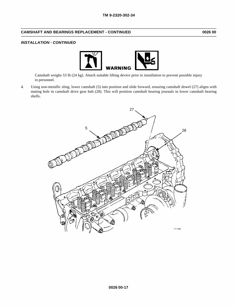
TM 9-2320-302-34
0026 00-17
CAMSHAFT AND BEARINGS REPLACEMENT - CONTINUED 0026 00
INSTALLATION - CONTINUED
WARNINGWARNINGCamshaft weighs 53 lb (24 kg). Attach suitable lifting device prior to installation to prevent possible injuryto personnel.
4. Using non-metallic sling, lower camshaft (5) into position and slide forward, ensuring camshaft dowel (27) aligns withmating hole in camshaft drive gear hub (28). This will position camshaft bearing journals in lower camshaft bearingshells.
27
285
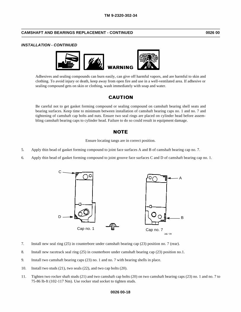
TM 9-2320-302-34
0026 00-18
CAMSHAFT AND BEARINGS REPLACEMENT - CONTINUED 0026 00
INSTALLATION - CONTINUED
WARNINGWARNING
Adhesives and sealing compounds can burn easily, can give off harmful vapors, and are harmful to skin andclothing. To avoid injury or death, keep away from open fire and use in a well-ventilated area. If adhesive orsealing compound gets on skin or clothing, wash immediately with soap and water.
CAUTIONCAUTION
Be careful not to get gasket forming compound or sealing compound on camshaft bearing shell seats andbearing surfaces. Keep time to minimum between installation of camshaft bearing caps no. 1 and no. 7 andtightening of camshaft cap bolts and nuts. Ensure two seal rings are placed on cylinder head before assem-bling camshaft bearing caps to cylinder head. Failure to do so could result in equipment damage.
NOTENOTEEnsure locating tangs are in correct position.
5. Apply thin bead of gasket forming compound to joint face surfaces A and B of camshaft bearing cap no. 7.
6. Apply thin bead of gasket forming compound to joint groove face surfaces C and D of camshaft bearing cap no. 1.
7. Install new seal ring (25) in counterbore under camshaft bearing cap (23) position no. 7 (rear).
8. Install new racetrack seal ring (25) in counterbore under camshaft bearing cap (23) position no.1.
9. Install two camshaft bearing caps (23) no. 1 and no. 7 with bearing shells in place.
10. Install two studs (21), two seals (22), and two cap bolts (20).
11. Tighten two rocker shaft studs (21) and two camshaft cap bolts (20) on two camshaft bearing caps (23) no. 1 and no. 7 to75-86 lb-ft (102-117 Nm). Use rocker stud socket to tighten studs.
C
D
A
B
Cap no. 1 Cap no. 7

TM 9-2320-302-34
0026 00-19
CAMSHAFT AND BEARINGS REPLACEMENT - CONTINUED 0026 00
INSTALLATION - CONTINUED
12. Remove three bolts (15) and camshaft gear pilot (13) from camshaft drive gear access opening (14).
CAUTIONCAUTIONClean rag may be inserted into gear housing assembly opening to trap bolts in case they are dropped. DONOT allow rag to drop into gear housing assembly. Failure to follow this caution will result in equipmentdamage.
NOTENOTEEnsure camshaft dowel is engaged before performing next step.
Cap no. 7
25
24
23
22
2020
2020
21
23
23
23
22Cap no. 1
23
25
24
2426
21
1315
14

TM 9-2320-302-34
0026 00-20
CAMSHAFT AND BEARINGS REPLACEMENT - CONTINUED 0026 00
INSTALLATION - CONTINUED
13. Install three new bolts (12). Tighten bolts alternately to draw thrust plate straight into gear housing assembly. Tightenbolts to 22-28 lb-ft (30-38 Nm).
CAUTIONCAUTIONCamshaft should be held in place while installing camshaft drive gear bolt to prevent disengaging camshaftdowel from drive gear hub.
14. Coat threads and underside head of new camshaft drive gear bolt (11) with international compound no. 2 and install bolthand tight.
NOTENOTEAfter inserting shoe of retaining plate through access hole of camshaft drive gear, it may be necessary to barengine over slightly to align bolt holes in retaining plate with bolt holes in drive gear access cover.
15. Install retaining plate (6) on gear housing (7) engaging one access hole (8) in camshaft drive gear (9). Install two bolts(10) in retaining plate and gear housing.
16. Tighten camshaft drive gear bolt (11) to 55 lb-ft (75 Nm). Then turn bolt clockwise 120 degrees.
17. Remove two bolts (10) and retaining plate (6).
12

TM 9-2320-302-34
0026 00-21
CAMSHAFT AND BEARINGS REPLACEMENT - CONTINUED 0026 00
INSTALLATION - CONTINUED
18. Using dial indicator (3), place pointer in contact with side of camshaft lobe (4).
19. Move camshaft (5) as far forward as possible. Hold in position and zero dial indicator (3).
20. Move camshaft (5) to rear as far as possible. Read and record total amount of end play. Allowable camshaft end play is0.003-0.015 in (0.076-0.381 mm).
21. If end play is beyond maximum limit, remove and repair or replace camshaft drive gear assembly (WP 0034 00)
NOTENOTE
Ensure old gasket forming compound has been removed from rear camshaft cover and surfaces.
89
11 7
610
10
3
4 5

TM 9-2320-302-34
0026 00-22
CAMSHAFT AND BEARINGS REPLACEMENT - CONTINUED 0026 00
INSTALLATION - CONTINUED
22. Apply thin bead of gasket forming compound to camshaft bearing cap (23) no. 7 mating surface and install camshaftbearing cap no. 7 on cylinder head (26).
23. Install rear camshaft cover (2) and three bolts (1). Tighten bolts to 22-28 lb-ft (30-38 Nm).
24. Install five camshaft bearing shells (24) in camshaft bearing caps (23) no. 2 through no. 6.
25. Install five camshaft bearing caps (23) on correct saddles on cylinder head (26) and install two camshaft cap bolts (20)hand tight in camshaft bearing caps no. 3 and no. 5.
26. Install rocker arm assemblies (WP 0027 00).
27. Tighten 12 camshaft cap and rocker arm bolts and nuts to 75-86 lb-ft (102-117 Nm), in sequence shown.
12 2623
Cap no. 7
24
23
2020
2020
23
23
23Cap no. 1
23
24
2426

TM 9-2320-302-34
0026 00-23
CAMSHAFT AND BEARINGS REPLACEMENT - CONTINUED 0026 00
INSTALLATION - CONTINUED
28. Install engine retarders (WP 0022 00).
END OF WORK PACKAGE
3 1 2
4 75 6
8
10
9 1112
TIGHTENING SEQUENCE

TM 9-2320-302-34
0026 00-24
This Page Intentionally Left Blank.
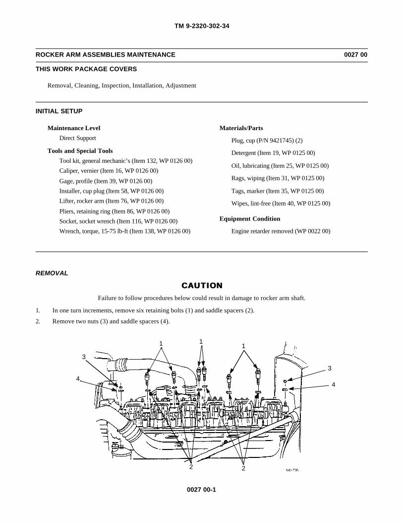
TM 9-2320-302-34
0027 00-1
ROCKER ARM ASSEMBLIES MAINTENANCE 0027 00
THIS WORK PACKAGE COVERS
Removal, Cleaning, Inspection, Installation, Adjustment
INITIAL SETUP
Maintenance Level
Direct Support
Tools and Special Tools
Tool kit, general mechanic’s (Item 132, WP 0126 00)
Caliper, vernier (Item 16, WP 0126 00)
Gage, profile (Item 39, WP 0126 00)
Installer, cup plug (Item 58, WP 0126 00)
Lifter, rocker arm (Item 76, WP 0126 00)
Pliers, retaining ring (Item 86, WP 0126 00)
Socket, socket wrench (Item 116, WP 0126 00)
Wrench, torque, 15-75 lb-ft (Item 138, WP 0126 00)
Materials/Parts
Plug, cup (P/N 9421745) (2)
Detergent (Item 19, WP 0125 00)
Oil, lubricating (Item 25, WP 0125 00)
Rags, wiping (Item 31, WP 0125 00)
Tags, marker (Item 35, WP 0125 00)
Wipes, lint-free (Item 40, WP 0125 00)
Equipment Condition
Engine retarder removed (WP 0022 00)
REMOVAL
CAUTIONCAUTIONFailure to follow procedures below could result in damage to rocker arm shaft.
1. In one turn increments, remove six retaining bolts (1) and saddle spacers (2).
2. Remove two nuts (3) and saddle spacers (4).
1 11
3
43
4
2 2
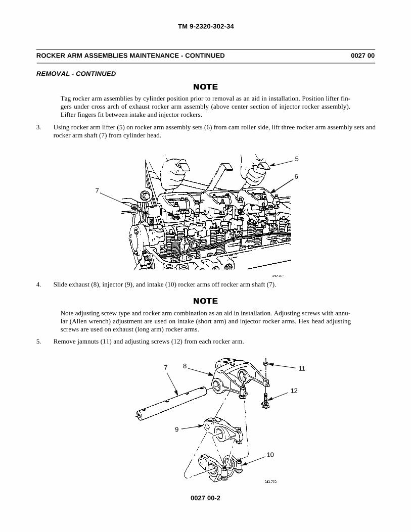
TM 9-2320-302-34
0027 00-2
ROCKER ARM ASSEMBLIES MAINTENANCE - CONTINUED 0027 00
REMOVAL - CONTINUED
NOTENOTETag rocker arm assemblies by cylinder position prior to removal as an aid in installation. Position lifter fin-gers under cross arch of exhaust rocker arm assembly (above center section of injector rocker assembly).Lifter fingers fit between intake and injector rockers.
3. Using rocker arm lifter (5) on rocker arm assembly sets (6) from cam roller side, lift three rocker arm assembly sets androcker arm shaft (7) from cylinder head.
4. Slide exhaust (8), injector (9), and intake (10) rocker arms off rocker arm shaft (7).
NOTENOTENote adjusting screw type and rocker arm combination as an aid in installation. Adjusting screws with annu-lar (Allen wrench) adjustment are used on intake (short arm) and injector rocker arms. Hex head adjustingscrews are used on exhaust (long arm) rocker arms.
5. Remove jamnuts (11) and adjusting screws (12) from each rocker arm.
7
5
6
7 11
12
10
9
8

TM 9-2320-302-34
0027 00-3
ROCKER ARM ASSEMBLIES MAINTENANCE - CONTINUED 0027 00
REMOVAL - CONTINUED
CAUTIONCAUTIONDo not expand retaining clip more than 0.61 in (15.50 mm) when removing intake valve button. To do socould result in damage to equipment.
6. Hold adjusting screw (12) and with retaining ring pliers (13), spread legs of retaining clip (14) and remove intake valvebutton (15).
7. Remove retaining clip (14) from threaded end of adjusting screw (12).
8. Punch hole in two cup plugs (16) at ends of rocker arm shaft (7). Pry cup plugs from shaft. Discard cup plugs.
15
14
12
13
7
16
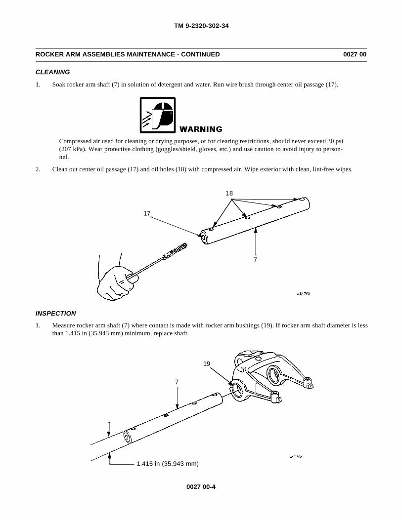
TM 9-2320-302-34
0027 00-4
ROCKER ARM ASSEMBLIES MAINTENANCE - CONTINUED 0027 00
CLEANING
1. Soak rocker arm shaft (7) in solution of detergent and water. Run wire brush through center oil passage (17).
WARNINGWARNINGCompressed air used for cleaning or drying purposes, or for clearing restrictions, should never exceed 30 psi(207 kPa). Wear protective clothing (goggles/shield, gloves, etc.) and use caution to avoid injury to person-nel.
2. Clean out center oil passage (17) and oil holes (18) with compressed air. Wipe exterior with clean, lint-free wipes.
INSPECTION
1. Measure rocker arm shaft (7) where contact is made with rocker arm bushings (19). If rocker arm shaft diameter is lessthan 1.415 in (35.943 mm) minimum, replace shaft.
17
18
7
19
7
1.415 in (35.943 mm)

TM 9-2320-302-34
0027 00-5
ROCKER ARM ASSEMBLIES MAINTENANCE - CONTINUED 0027 00
INSPECTION - CONTINUED
NOTENOTERocker arm bushing inside diameter is the same for each rocker arm (exhaust, intake, and injector). Exhaustarm only is shown.
2. Inspect rocker arm bushings (19) for excessive wear or scoring. Measure rocker arm bushing inside diameter. If diame-ter is more than 1.4191 in (36.050 mm), replace rocker arm assembly.
NOTENOTERocker arms are not matched sets and each rocker arm may be replaced. The checks in step 3 through 5apply to each rocker arm.
3. Check each cam follower roller (20) for scoring, pitting or flat spots. If any of these conditions are evident, replacedefective rocker arm.
4. Check side clearance between cam follower roller (20) and rocker arm. If more than 0.015 in (0.040 mm) maximum,replace defective rocker arm.
5. Ensure cam follower roller (20) turns freely on its pin. If roller does not turn freely, binds or if there is vertical move-ment between roller and pin, replace defective rocker arm.
19
1.4191 in (36.050 mm)
0.015 in (0.040 mm)
20
8

TM 9-2320-302-34
0027 00-6
ROCKER ARM ASSEMBLIES MAINTENANCE - CONTINUED 0027 00
INSPECTION - CONTINUED
6. Check rocker arm shaft stud for tightness. Ensure rocker arm shaft studs are tightened to 75-86 lb-ft (101-116 Nm).
INSTALLATION
CAUTIONCAUTIONDo not expand retaining clip more than 0.61 in (15.50 mm) when installing retaining clip. To do so couldresult in equipment damage.
NOTENOTEPosition concave (dished side) of intake valve button toward adjusting screw ball.
1. Slide retaining clip (14), open end first, onto adjusting screw (12). Spread retaining clip slightly, if necessary, so openend can pass over ball head of adjusting screw.
2. Insert tips of retaining ring pliers (13) between legs of retaining clip (14). Expand clip enough to insert groove on intakevalve button (15) onto leg arcs of retaining clip.
NOTENOTE• Adjusting screws with annular (Allen wrench) adjustment are used on intake (short arm) and injector
rocker arms. Hex head adjusting screws are used on exhaust (long arm) rocker arms.
• Only exhaust rocker arm is shown.
3. Thread adjusting screw (12) into correct rocker arm (8), as noted during removal, and loosely install jamnut (11).
15
14
12
13

TM 9-2320-302-34
0027 00-7
ROCKER ARM ASSEMBLIES MAINTENANCE - CONTINUED 0027 00
INSTALLATION - CONTINUED
4. Using cup plug installer (21), install new cup plug (16) in center oil passage (17) at each end of rocker arm shaft (7).
8
11
12
7
1716
21

TM 9-2320-302-34
0027 00-8
ROCKER ARM ASSEMBLIES MAINTENANCE - CONTINUED 0027 00
INSTALLATION - CONTINUED
NOTENOTEIf rocker arms are reused, install in previously determined order, with logo on rocker arm shaft facing out-board (front and rear) when seated.
5. Lubricate rocker arm bushing (19) with clean engine lubricating oil. Install three rocker arm assembly sets (6), exhaust(8), injector (9), and intake (10), on rocker arm shaft (7), with logo stamped on end of shaft.
6. Using rocker stud socket (22), check tightness of rocker arm shaft studs (23) in cam caps (24) no. 1 and no. 7. Tightenstuds to 75-86 lb-ft (102-117 Nm).
8
LOGO7
19
9
10
19
19
24
23
22

TM 9-2320-302-34
0027 00-9
ROCKER ARM ASSEMBLIES MAINTENANCE - CONTINUED 0027 00
INSTALLATION - CONTINUED
NOTENOTEPosition lifter fingers under cross arch of exhaust rocker arm assembly (above center section of injectorrocker assembly). Lifter fingers fit between intake and injector rockers.
7. Using rocker arm lifter (5) on rocker arm assembly sets (6) from cam roller side, place rocker arm shaft (7) and threerocker arm assembly sets (6) in position on cam caps (24).
8. Install six saddle spacers (2) on six retaining bolts (1).
9. Install six retaining bolts (1) through rocker arm shaft (7) and cam cap saddles.
10. Install two saddle spacers (4) and nuts (3) on rocker arm shaft studs (23).
6
5
7
24
72
1 3
4
23

TM 9-2320-302-34
0027 00-10
ROCKER ARM ASSEMBLIES MAINTENANCE - CONTINUED 0027 00
INSTALLATION - CONTINUED
11. Tighten six retaining bolts and two nuts to 75-86 lb-ft (102-117 Nm), in sequence shown.
ADJUSTMENT
CAUTIONCAUTIONNever set valves and injector of same cylinder at same time. Doing this will result in engine damage.
NOTENOTEWhen setting valve lash clearance or injector height, always set them using valve overlap method.
1. Adjust valves and set fuel injector heights as follows:
a. Insert a ¾ in drive breaker bar (25) or ratchet into square hole in center of crankshaft pulley (26).
3 1 2 4 7 5 6 8TIGHTENING SEQUENCE
25
26

TM 9-2320-302-34
0027 00-11
ROCKER ARM ASSEMBLIES MAINTENANCE - CONTINUED 0027 00
ADJUSTMENT - CONTINUED
b. Bar engine in direction of rotation and observe intake and exhaust valve rollers at any cylinder that is close to TDC(top dead center). Choose a cylinder that has exhaust valves almost completely closed. Just as exhaust valves areclosing, intake valves will start to open. This is the valve overlap period.
VALVE OVERLAP PERIOD
EXHAUST VALVEROCKER ARM
ASSEMBLYEXHAUST VALVECLOSING
FUEL INJECTORROCKER ARMASSEMBLY
CAMSHAFT
ROCKERARM SHAFTCYLINDER
HEAD
INTAKE VALVEROCKER ARM
ASSEMBLY
INTAKE VALVESTARTS TO OPEN

TM 9-2320-302-34
0027 00-12
ROCKER ARM ASSEMBLIES MAINTENANCE - CONTINUED 0027 00
ADJUSTMENT - CONTINUED
c. Stop engine rotation at time of valve overlap. Note which cylinder this is and follow sequence listed in Table 1 tocorrectly set valves and injector heights. The timing can be started with any cylinder in valve overlap.
d. Insert 0.008 in (0.203 mm) thickness gage (27) between tip of intake valve stem (28) and intake valve button (15)at end of rocker arm.
e. Loosen jamnut (11) and turn adjusting screw (12) until thickness gage (27) produces even or smooth pull betweenintake valve stem (28) and intake valve button (15).
f. Tighten jamnut (11) to 30-35 lb-ft (41-47 Nm) and remove feeler gage (27).
g. Insert thickness gage (27) again to ensure adjustment did not change when jamnut (11) was tightened. Readjust asnecessary.
h. Using 0.026 in (0.660 mm) thickness gage, adjust exhaust valves in same manner as intake valves.
Table 1. Valve Lash and Injector Height Adjustment Sequence.
CYLINDER WITH VALVE OVERLAP
SET VALVES ON CYLINDER NO.
SET INJECTOR HEIGHT ON CYLINDER NO.
6 1 5
2 5 3
4 3 6
1 6 2
5 2 4
3 4 1
15
28
111227

TM 9-2320-302-34
0027 00-13
ROCKER ARM ASSEMBLIES MAINTENANCE - CONTINUED 0027 00
ADJUSTMENT - CONTINUED
NOTENOTEEnsure injector timing height gage is seated on machined surface with tip in pilot hole. Foreign material inpilot hole or on machined surface may prevent accurate setting of injector height.
i. Adjust height of fuel injector (29) for cylinder indicated on valve overlap adjustment sequence Table 1. Positionsmall end of injector timing height gage (30) in hole in fuel injector body (31) with flag (32) of gage toward fuelinjector plunger (33), as shown.
31
32
30 33
29

TM 9-2320-302-34
0027 00-14
ROCKER ARM ASSEMBLIES MAINTENANCE - CONTINUED 0027 00
ADJUSTMENT - CONTINUED
j. Loosen jamnut (11) and turn adjusting screw (12) until flag (32) of injector timing height gage (30) just clears topof fuel injector plunger (33). An accurate feel will be developed. Adjust all injectors to the same feel.
k. Tighten jamnut (11) to 30-35 lb-ft (41-47 Nm). Check adjustment with injector timing height gage (30) and, if nec-essary, readjust.
l. Remove injector timing height gage (30).
m. Refer to adjusting sequence, Table 1, and proceed to next cylinder in adjustment sequence.
n. Bar engine over in direction of normal rotation until next cylinder in adjustment sequence is in its valve overlapperiod.
o. Repeat valve adjustment and fuel injector height adjustment procedures until all valves and injectors have beenadjusted.
2. Install engine retarder (WP 0022 00).
END OF WORK PACKAGE
33
1211
30
32
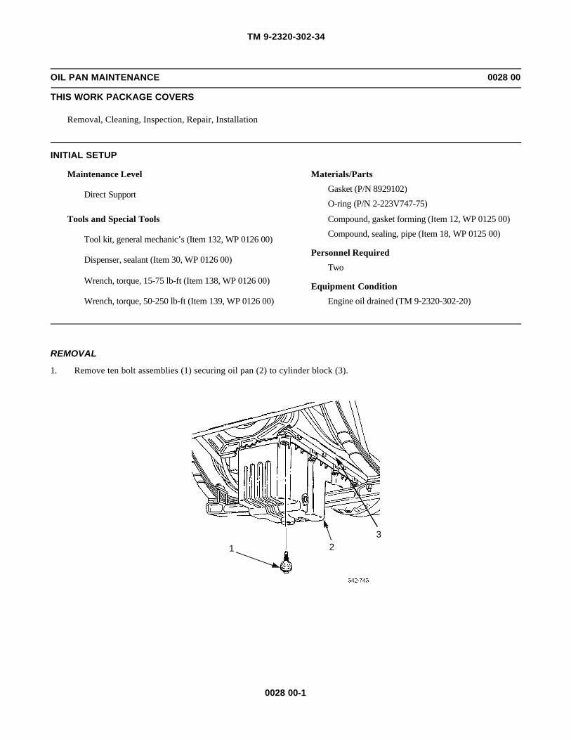
TM 9-2320-302-34
0028 00-1
OIL PAN MAINTENANCE 0028 00
THIS WORK PACKAGE COVERS
Removal, Cleaning, Inspection, Repair, Installation
INITIAL SETUP
Maintenance Level
Direct Support
Tools and Special Tools
Tool kit, general mechanic’s (Item 132, WP 0126 00)
Dispenser, sealant (Item 30, WP 0126 00)
Wrench, torque, 15-75 lb-ft (Item 138, WP 0126 00)
Wrench, torque, 50-250 lb-ft (Item 139, WP 0126 00)
Materials/Parts
Gasket (P/N 8929102)
O-ring (P/N 2-223V747-75)
Compound, gasket forming (Item 12, WP 0125 00)
Compound, sealing, pipe (Item 18, WP 0125 00)
Personnel Required
Two
Equipment Condition
Engine oil drained (TM 9-2320-302-20)
REMOVAL
1. Remove ten bolt assemblies (1) securing oil pan (2) to cylinder block (3).
321

TM 9-2320-302-34
0028 00-2
OIL PAN MAINTENANCE - CONTINUED 0028 00
REMOVAL - CONTINUED
CAUTIONCAUTIONHandle oil pan with care. Dropping or bumping could cause damage.
2. Remove oil pan (2) carefully to avoid damage to oil pump pickup tube (4) and screen assembly (5).
3. Remove oil pan gasket (6) from oil pan (2). Discard gasket.
5
4
2
2
6

TM 9-2320-302-34
0028 00-3
OIL PAN MAINTENANCE - CONTINUED 0028 00
CLEANING
WARNINGWARNINGCompressed air used for cleaning or drying purposes, or for clearing restrictions, should never exceed 30 psi(207 kPa). Wear protective clothing (goggles/shield, gloves, etc.) and use caution to avoid injury to person-nel.
CAUTIONCAUTIONDo not use solvents or petroleum distillates to clean components. To do so could result in damage to equip-ment.
1. Clean bolt assemblies, oil pan, and oil pan gasket surfaces with detergent and water. Dry with compressed air.
2. Remove gasket forming compound from pan rail joint faces of flywheel housing (7), gear housing (8), gear case cover(9), and cylinder block (3) where contact is made with oil pan gasket.
3. Ensure all old gasket forming compound is removed from sealing surfaces.
INSPECTION
1. Inspect bolt assembly isolators for dryness, cracks or tears. Replace as necessary.
2. Check oil pan for damage. Replace or repair as necessary.
3. Ensure oil pump pickup tube and screen assembly are not damaged.
33
7
8
9

TM 9-2320-302-34
0028 00-4
OIL PAN MAINTENANCE - CONTINUED 0028 00
REPAIR
CAUTIONCAUTIONHold insert to prevent scoring of plastic oil pan. Failure to prevent insert from slipping during removal couldcause damage and result in equipment failure.
1. Hold flats of insert (10) to prevent slippage and remove pipe plug (11).
2. Remove nut (12), insert (10), and o-ring (13) from oil pan (2). Discard o-ring.
3. Install new o-ring (13) on flange of insert (10) and install insert in oil pan (2).
CAUTIONCAUTIONHold insert to prevent scoring of plastic oil pan. Failure to prevent insert from spinning during installationcould cause damage and result in equipment failure.
4. Hold insert (10) and install nut (12). Tighten nut to 136-145 lb-ft (184-197 Nm).
WARNINGWARNINGAdhesives and sealing compounds can burn easily, can give off harmful vapors, and are harmful to skin andclothing. To avoid injury or death, keep away from open fire and use in a well-ventilated area. If adhesive orsealing compound gets on skin or clothing, wash immediately with soap and water.
5. Coat threads of pipe plug (11) with pipe sealing compound and install pipe plug in insert (10). Hold insert while tighten-ing pipe plug.
1213
10
11
2

TM 9-2320-302-34
0028 00-5
OIL PAN MAINTENANCE - CONTINUED 0028 00
INSTALLATION
NOTENOTETo ease installation of oil pan gasket, use a soapy water solution on gasket prior to installing in groove of oilpan.
1. Place new oil pan gasket (6) on oil pan (2) with gasket lip toward oil pan groove.
2. Press oil pan gasket (6) completely down into groove at each corner of oil pan (2). Repeat at points midway betweencorners, halving distance between installed sections until oil pan gasket is completely installed.
3. Apply a thin bead of gasket forming compound to pan rail, joint faces of flywheel housing (7), gear housing (8), gearcase cover (9), and cylinder block (3).
2
6
33
7
8
9
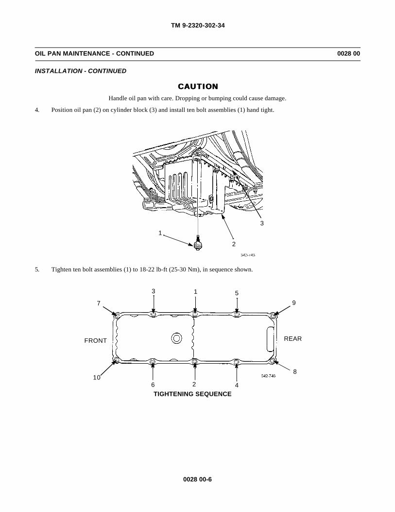
TM 9-2320-302-34
0028 00-6
OIL PAN MAINTENANCE - CONTINUED 0028 00
INSTALLATION - CONTINUED
CAUTIONCAUTIONHandle oil pan with care. Dropping or bumping could cause damage.
4. Position oil pan (2) on cylinder block (3) and install ten bolt assemblies (1) hand tight.
5. Tighten ten bolt assemblies (1) to 18-22 lb-ft (25-30 Nm), in sequence shown.
3
2
1
7
6
5
4
3
2
1
8
9
10
REARFRONT
TIGHTENING SEQUENCE

TM 9-2320-302-34
0028 00-7
OIL PAN MAINTENANCE - CONTINUED 0028 00
INSTALLATION - CONTINUED
6. Install oil pan drain plug (14) and tighten to 33-41 lb-ft (45-56 Nm).
7. Replace engine oil (TM 9-2320-302-20) and check for leaks.
END OF WORK PACKAGE
14

TM 9-2320-302-34
0028 00-8
This Page Intentionally Left Blank.
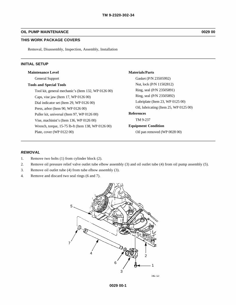
TM 9-2320-302-34
0029 00-1
OIL PUMP MAINTENANCE 0029 00
THIS WORK PACKAGE COVERS
Removal, Disassembly, Inspection, Assembly, Installation
INITIAL SETUP
Maintenance Level
General Support
Tools and Special Tools
Tool kit, general mechanic’s (Item 132, WP 0126 00)
Caps, vise jaw (Item 17, WP 0126 00)
Dial indicator set (Item 29, WP 0126 00)
Press, arbor (Item 90, WP 0126 00)
Puller kit, universal (Item 97, WP 0126 00)
Vise, machinist’s (Item 136, WP 0126 00)
Wrench, torque, 15-75 lb-ft (Item 138, WP 0126 00)
Plate, cover (WP 0122 00)
Materials/Parts
Gasket (P/N 23505992)
Nut, lock (P/N 11502812)
Ring, seal (P/N 23505891)
Ring, seal (P/N 23505892)
Lubriplate (Item 23, WP 0125 00)
Oil, lubricating (Item 25, WP 0125 00)
References
TM 9-237
Equipment Condition
Oil pan removed (WP 0028 00)
REMOVAL
1. Remove two bolts (1) from cylinder block (2).
2. Remove oil pressure relief valve outlet tube elbow assembly (3) and oil outlet tube (4) from oil pump assembly (5).
3. Remove oil outlet tube (4) from tube elbow assembly (3).
4. Remove and discard two seal rings (6 and 7).
5
7
4
6
3
2
1

TM 9-2320-302-34
0029 00-2
OIL PUMP MAINTENANCE - CONTINUED 0029 00
REMOVAL - CONTINUED
5. Remove two lock nuts (8) and two bolts (9) from inlet oil tube bracket halves (10). Discard lock nuts.
6. Remove two bolts (11) and inlet oil tube bracket halves (10) from cylinder block (2).
CAUTIONCAUTIONOil pump must be adequately supported to prevent pump from dropping when retaining bolts are removed.
7. Remove two bolts (12), oil inlet tube (13), and gasket (14) from oil pump assembly (5). Discard gasket.
109
11
11
8
10

TM 9-2320-302-34
0029 00-3
OIL PUMP MAINTENANCE - CONTINUED 0029 00
REMOVAL - CONTINUED
8. Remove two long bolts (15), two short bolts (16), and oil pump assembly (5).
5
14
12
13
5
1516
1516

TM 9-2320-302-34
0029 00-4
OIL PUMP MAINTENANCE - CONTINUED 0029 00
DISASSEMBLY
1. Remove two short bolts (17) and two long bolts (18) from oil pump cover (19) and oil pump body (20).
CAUTIONCAUTIONUse care when removing oil pump cover to prevent damage to equipment. Oil pump driven gear and shaftassembly is retained in oil pump assembly only by cover.
2. Remove oil pump cover (19) and oil pump driven gear and shaft assembly (21) from oil pump body (20).
CAUTIONCAUTIONDo not allow press support to interfere with oil pump drive gear and shaft assembly being pressed out. To doso will result in damage to shaft assembly.
3. Place oil pump body (20), pump cover side down, on press support. Press oil pump drive gear and shaft assembly (22)from oil pump drive gear (23).
4. Remove oil pump drive gear (23) from oil pump body (20).
20
17
21
19
18
22
23
20

TM 9-2320-302-34
0029 00-5
OIL PUMP MAINTENANCE - CONTINUED 0029 00
DISASSEMBLY - CONTINUED
NOTENOTEWhen one or more bushings require replacing, replace all bushings in pump body and pump cover.
5. If bushings are damaged or worn, place oil pump body (20), pump cover side up, on press support. Press two bushings(24) from pump body.
6. Place oil pump cover (19), pump body side up, on press support. Press out two bushings (24) from bushing bores (25).
CAUTIONCAUTIONExtreme care should be taken to protect surfaces of mounting legs from electric arc welding slag. Use fabri-cated protective plate for this purpose. Failure to do so could result in damage to surfaces of mounting legs.
24
20
24
25
24
19
24

TM 9-2320-302-34
0029 00-6
OIL PUMP MAINTENANCE - CONTINUED 0029 00
DISASSEMBLY - CONTINUED
NOTENOTETwo steel locating dowels (one solid diamond-shaped dowel and one tubular-shaped dowel) installed onpump body mounting legs are pressed in bores to specified depths. Both dowels are extremely durable andshould never need to be replaced.
7. If removal of either dowel (26 or 27) is required, place protective plate (28) on smooth surface of mounting leg (29) overdowel to be removed. Tack weld washer (30) and nut (31) to dowel.
NOTENOTESecure pump body in soft-jawed vise with machined (smooth) surfaces of mounting legs facing up.
8. Attach slide hammer (32) to welded nut (31) on dowel (26 or 27) being removed, and apply short upward shockingactions until dowel is freed from bore. Discard dowel with welded nut and washer.
INSPECTION
1. Inspect all parts for wear or damage.
2. Discard pump body or pump cover if cracked or if evidence of spun bushings on bushing bores is visible.
3. Inspect bushings in pump body and cover. Shaft-to-pump body bushing clearance with new parts is 0.0016-0.0024 in(0.04-0.06 mm). Maximum allowable shaft-to-pump cover bushing clearance with used parts is 0.0035 in (0.089 mm).
32
31
30
28
24
26
32
31
302829
27

TM 9-2320-302-34
0029 00-7
OIL PUMP MAINTENANCE - CONTINUED 0029 00
ASSEMBLY
1. Place oil pump body (20), cover side down, on press support.
2. Apply a thin film of lubriplate to bushing bores (33).
3. Position bushings (24) loosely over pump body bushing bores (33).
4. Rotate bushings (24) so split lines (A and B) are parallel with machined surface (C) of pump body (20).
5. When properly aligned, split line (A) should measure 0.461in (11.709 mm) to surface (C). Split line (B) should measure1.726 in (43.84 mm) to surface (C).
NOTENOTEBushings must be installed flush to specified depth below finished surface of pump body.
6. Press bushings (24) in pump body bushing bores (33) not more than 0.031 in (0.78 mm) below finished surface of oilpump body (20).
24
33
20
24
C
A
B
20

TM 9-2320-302-34
0029 00-8
OIL PUMP MAINTENANCE - CONTINUED 0029 00
ASSEMBLY - CONTINUED
7. Place oil pump cover (19), pump body side down, on press support. Apply thin film of lubriplate to bushing bores (25).
8. Position bushings (24) loosely over bushing bores (25).
9. Rotate bushings (24) so split lines (A) are aligned in pump cover bushing bores (25) as shown.
NOTENOTEBushings must be installed to specified depths below finished surface of oil pump cover.
10. Press bushings (24) in pump cover bushing bores (25) 0.011-0.031 in (0.28-0.78 mm) below finished surface of oilpump cover (19).
NOTENOTEPump body and pump cover bushings are finished to size after installation in their respective bores. Use sin-gle point tooling to avoid smearing oil retention surfaces.
25
19
24
25
19 24,25
A
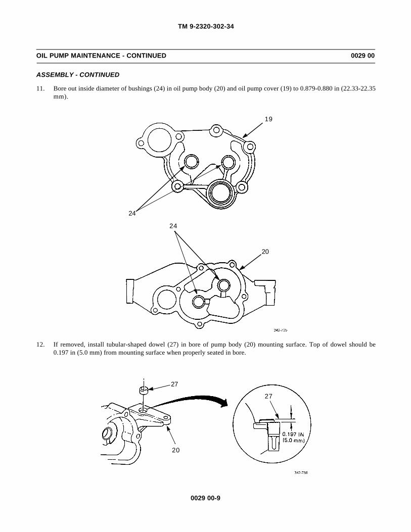
TM 9-2320-302-34
0029 00-9
OIL PUMP MAINTENANCE - CONTINUED 0029 00
ASSEMBLY - CONTINUED
11. Bore out inside diameter of bushings (24) in oil pump body (20) and oil pump cover (19) to 0.879-0.880 in (22.33-22.35mm).
12. If removed, install tubular-shaped dowel (27) in bore of pump body (20) mounting surface. Top of dowel should be0.197 in (5.0 mm) from mounting surface when properly seated in bore.
24
19
20
24
27
20
27
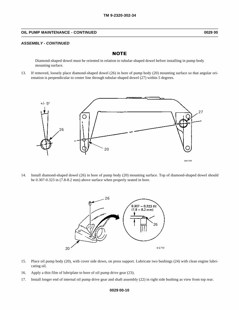
TM 9-2320-302-34
0029 00-10
OIL PUMP MAINTENANCE - CONTINUED 0029 00
ASSEMBLY - CONTINUED
NOTENOTEDiamond-shaped dowel must be oriented in relation to tubular-shaped dowel before installing in pump bodymounting surface.
13. If removed, loosely place diamond-shaped dowel (26) in bore of pump body (20) mounting surface so that angular ori-entation is perpendicular to center line through tubular-shaped dowel (27) within 5 degrees.
14. Install diamond-shaped dowel (26) in bore of pump body (20) mounting surface. Top of diamond-shaped dowel shouldbe 0.307-0.323 in (7.8-8.2 mm) above surface when properly seated in bore.
15. Place oil pump body (20), with cover side down, on press support. Lubricate two bushings (24) with clean engine lubri-cating oil.
16. Apply a thin film of lubriplate to bore of oil pump drive gear (23).
17. Install longer end of internal oil pump drive gear and shaft assembly (22) in right side bushing as view from top rear.
26
20
27
+/- 5°
26
20
26
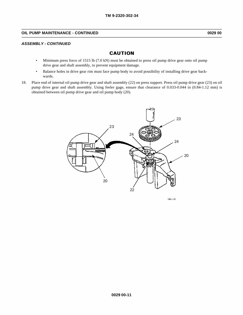
TM 9-2320-302-34
0029 00-11
OIL PUMP MAINTENANCE - CONTINUED 0029 00
ASSEMBLY - CONTINUED
CAUTIONCAUTION• Minimum press force of 1515 lb (7.0 kN) must be obtained to press oil pump drive gear onto oil pump
drive gear and shaft assembly, to prevent equipment damage.
• Balance holes in drive gear rim must face pump body to avoid possibility of installing drive gear back-wards.
18. Place end of internal oil pump drive gear and shaft assembly (22) on press support. Press oil pump drive gear (23) on oilpump drive gear and shaft assembly. Using feeler gage, ensure that clearance of 0.033-0.044 in (0.84-1.12 mm) isobtained between oil pump drive gear and oil pump body (20).
23
20
24
23
24
20
22
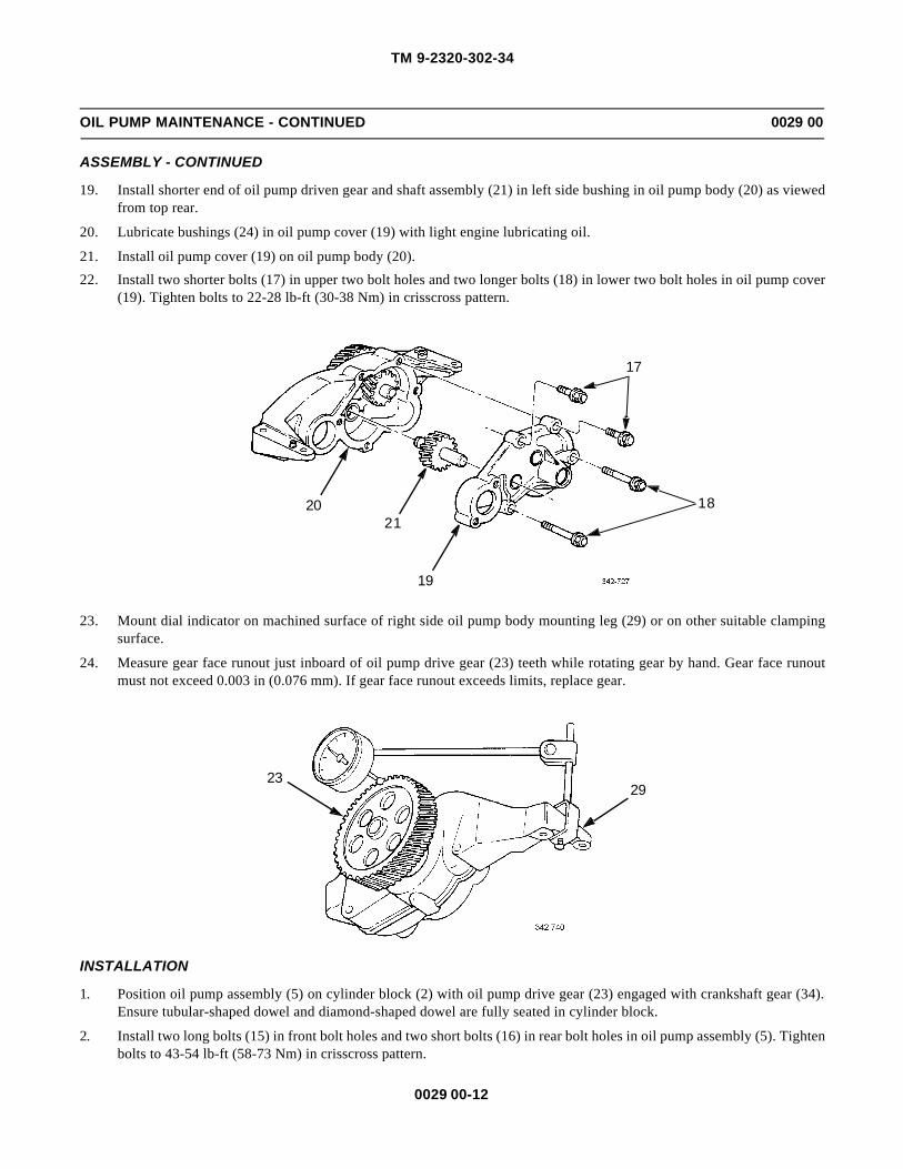
TM 9-2320-302-34
0029 00-12
OIL PUMP MAINTENANCE - CONTINUED 0029 00
ASSEMBLY - CONTINUED
19. Install shorter end of oil pump driven gear and shaft assembly (21) in left side bushing in oil pump body (20) as viewedfrom top rear.
20. Lubricate bushings (24) in oil pump cover (19) with light engine lubricating oil.
21. Install oil pump cover (19) on oil pump body (20).
22. Install two shorter bolts (17) in upper two bolt holes and two longer bolts (18) in lower two bolt holes in oil pump cover(19). Tighten bolts to 22-28 lb-ft (30-38 Nm) in crisscross pattern.
23. Mount dial indicator on machined surface of right side oil pump body mounting leg (29) or on other suitable clampingsurface.
24. Measure gear face runout just inboard of oil pump drive gear (23) teeth while rotating gear by hand. Gear face runoutmust not exceed 0.003 in (0.076 mm). If gear face runout exceeds limits, replace gear.
INSTALLATION
1. Position oil pump assembly (5) on cylinder block (2) with oil pump drive gear (23) engaged with crankshaft gear (34).Ensure tubular-shaped dowel and diamond-shaped dowel are fully seated in cylinder block.
2. Install two long bolts (15) in front bolt holes and two short bolts (16) in rear bolt holes in oil pump assembly (5). Tightenbolts to 43-54 lb-ft (58-73 Nm) in crisscross pattern.
20
17
21
19
18
2329

TM 9-2320-302-34
0029 00-13
OIL PUMP MAINTENANCE - CONTINUED 0029 00
INSTALLATION - CONTINUED
3. Coat two new seal rings (6 and 7) with light engine lubricating oil. Install smaller seal ring (6) on elbow end of oil outlettube (4). Install larger seal ring (7) on pump end of oil outlet tube.
4. Install larger diameter end of oil outlet tube (4) in outlet neck of oil pump assembly (5) until oil outlet tube bottoms inbore.
5. Install smaller diameter end of oil outlet tube (4) in oil relief valve outlet tube elbow assembly (3) until oil outlet tubebottoms in bore.
6. Position oil pressure relief valve outlet tube elbow assembly (3) on cylinder block (2). Install two bolts (1) and tighten to22-24 lb-ft (30-33 Nm).
2
23
5
15 1615
16
34
5
7
4
6
3
2
1

TM 9-2320-302-34
0029 00-14
OIL PUMP MAINTENANCE - CONTINUED 0029 00
INSTALLATION - CONTINUED
7. Install new gasket (14) and oil inlet tube (13) on oil pump assembly (5). Install two bolts (12) and tighten to 22-24 lb-ft(30-33 Nm).
8. Install two oil inlet tube bracket halves (10) and bolts (11) on cylinder block (2). Tighten bolts to 43-54 lb-ft (58-73Nm).
9. Install two bolts (9) and new lock nuts (8) on oil inlet tube bracket halves (10). Tighten bolts to 43-54 lb-ft (58-73 Nm).
5
14
12
13
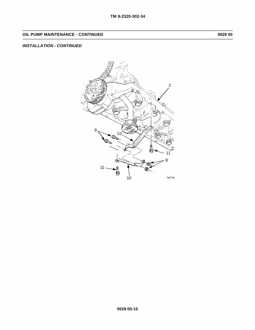
TM 9-2320-302-34
0029 00-15
OIL PUMP MAINTENANCE - CONTINUED 0029 00
INSTALLATION - CONTINUED
109
11
11
8
10
2

TM 9-2320-302-34
0029 00-16
OIL PUMP MAINTENANCE - CONTINUED 0029 00
INSTALLATION - CONTINUED
NOTENOTEGear lash measurements between crankshaft gear and oil pump drive gear must be taken with engine in run-ning position.
10. With dial indicator tip resting on tooth of oil pump drive gear (23), measure gear lash between oil pump drive gear andcrankshaft drive gear (34). Gear lash should be 0.002-0.009 in (0.051-0.229 mm).
11. If gear lash is not within specifications, perform oil pump removal steps 1 through 8.
NOTENOTESame number of shims must be installed under each oil pump mounting leg so that oil pump will always belevel on engine block.
12. Install required amount of shims (35) between oil pump assembly (5) and cylinder block (2).
13. Repeat installation steps 1 through 10 to reinstall oil pump assembly (5) and verify gear lash.
14. Install oil pan (WP 0028 00).
END OF WORK PACKAGE
23
34
2
5
35

TM 9-2320-302-34
0030 00-1
OIL PRESSURE RELIEF AND REGULATOR VALVES REPLACEMENT 0030 00
THIS WORK PACKAGE COVERS
Oil Pressure Regulator Valve Replacement, Oil Pressure Relief Valve Replacement
INITIAL SETUP
Maintenance Level
Direct Support
Tools and Special Tools
Tool kit, general mechanic’s (Item 132, WP 0126 00)
Wrench, torque, 15-75 lb-ft (Item 138, WP 0126 00)
Materials/Parts
Ring, seal (P/N 23505891)
Materials/Parts - Continued
Ring, seal (P/N 23505892)
Oil, lubricating (Item 25, WP 0125 00)
Equipment Condition
Oil pan removed (WP 0028 00)
OIL PRESSURE REGULATOR VALVE REPLACEMENT
1. Remove two bolts (1) from cylinder block (2).
2. Remove oil pressure regulator valve (3).
3. Position oil pressure regulator valve (3) on cylinder block (2).
4. Install two bolts (1) and tighten to 22-28 lb-ft (30-38 Nm).
5. Install oil pan (WP 0028 00).
23
1
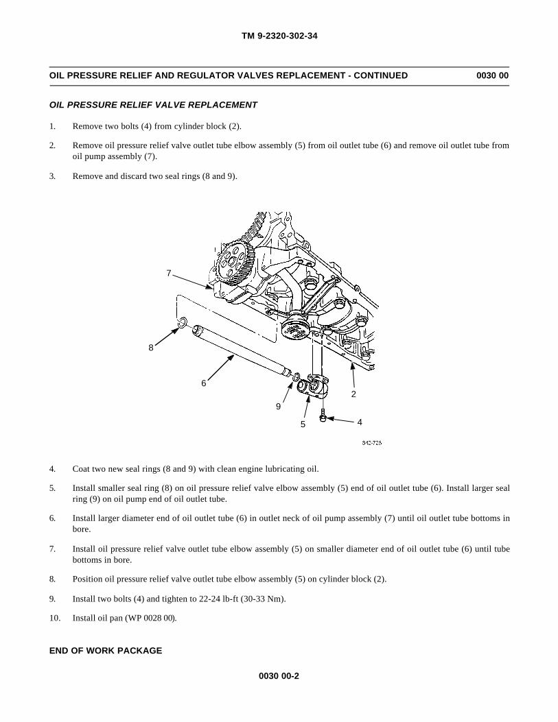
TM 9-2320-302-34
0030 00-2
OIL PRESSURE RELIEF AND REGULATOR VALVES REPLACEMENT - CONTINUED 0030 00
OIL PRESSURE RELIEF VALVE REPLACEMENT
1. Remove two bolts (4) from cylinder block (2).
2. Remove oil pressure relief valve outlet tube elbow assembly (5) from oil outlet tube (6) and remove oil outlet tube fromoil pump assembly (7).
3. Remove and discard two seal rings (8 and 9).
4. Coat two new seal rings (8 and 9) with clean engine lubricating oil.
5. Install smaller seal ring (8) on oil pressure relief valve elbow assembly (5) end of oil outlet tube (6). Install larger sealring (9) on oil pump end of oil outlet tube.
6. Install larger diameter end of oil outlet tube (6) in outlet neck of oil pump assembly (7) until oil outlet tube bottoms inbore.
7. Install oil pressure relief valve outlet tube elbow assembly (5) on smaller diameter end of oil outlet tube (6) until tubebottoms in bore.
8. Position oil pressure relief valve outlet tube elbow assembly (5) on cylinder block (2).
9. Install two bolts (4) and tighten to 22-24 lb-ft (30-33 Nm).
10. Install oil pan (WP 0028 00).
END OF WORK PACKAGE
7
8
6
92
5 4

TM 9-2320-302-34
0031 00-1
CRANKSHAFT FRONT OIL SEAL REPLACEMENT 0031 00
THIS WORK PACKAGE COVERS
Removal, Inspection, Installation
INITIAL SETUP
Maintenance Level
Direct Support
Tools and Special Tools
Tool kit, general mechanic’s (Item 132, WP 0126 00)
Inserter, seal (Item 50, WP 0126 00)
Remover, seal (Item 101, WP 0126 00)
Materials/Parts
Seal (P/N 23518355)
Cloth, abrasive (Item 9, WP 0125 00)
Oil, lubricating (Item 25, WP 0125 00)
Equipment Condition
Vibration damper removed (WP 0020 00)
REMOVAL
1. Install seal remover (1) over end of crankshaft and against gear case cover (2). Install six self-tapping screws (3).
2. Install three bolts (4) in seal remover (1) until bolts contact gear case cover (2).
NOTENOTEIf self-tapping screws strip out of seal case, remove six self-tapping screws and three bolts. Rotate sealremover one-half distance between existing screw holes in seal case and repeat steps 1 and 2.
3. Work clockwise and turn three bolts (4), one at a time, one full turn until oil seal is removed. Discard oil seal.
4
3
2
1

TM 9-2320-302-34
0031 00-2
CRANKSHAFT FRONT OIL SEAL REPLACEMENT - CONTINUED 0031 00
INSPECTION
NOTENOTEMinor wear line on crankshaft surface should be evident where contact was made with oil seal. This is nor-mal.
1. Inspect oil seal contact surface of crankshaft for dirt, burrs or rough surfaces.
2. If necessary, clean crankshaft surface with abrasive cloth.
INSTALLATION
1. Coat outside diameter of new oil seal (5) with a light film of clean engine lubricating oil.
2. Coat outside of crankshaft (6) with a light film of clean engine lubricating oil.
NOTENOTEEnsure butt end of crankshaft, both sides of seal inserter base, and inside of seal inserter housing are clean,smooth, and free of foreign material or damage.
3. Position seal inserter base (7) on front of crankshaft (6).
4. Install two guide studs (8) through two holes in seal inserter base (7) and into two crankshaft pulley/vibration dampermounting bolt holes, 180 degrees apart.
5. Hand tighten two guide studs (8) until seal inserter base (7) is tight against end of crankshaft (6).
6. Install oil seal (5) onto crankshaft (6) as far as it will go by hand.
7. Position seal inserter collar (9) against oil seal (5).
8. Install seal inserter housing (10) over center screw (11) of seal inserter base (7) and two guide studs (8), and against oilseal (5).
9. Install thrust bearing (12) on center screw (11) with case side of thrust bearing against seal inserter housing (10).
10. Install and tighten seal inserter nut (13) until inside surface of seal inserter housing (10) is firmly seated against sealinserter base (7).
5
6

TM 9-2320-302-34
0031 00-3
CRANKSHAFT FRONT OIL SEAL REPLACEMENT - CONTINUED 0031 00
INSTALLATION - CONTINUED
11. Remove seal inserter nut (13), thrust bearing (12), seal inserter housing (10), seal inserter collar (9), two guide studs (8),and seal inserter base (7).
12. Install vibration damper (WP 0020 00).
END OF WORK PACKAGE
13
12
10
9
8
6
7
11 5

TM 9-2320-302-34
0031 00-4
This Page Intentionally Left Blank.

TM 9-2320-302-34
0032 00-1
CYLINDER HEAD REPAIR 0032 00
THIS WORK PACKAGE COVERS
Disassembly, Cleaning and Inspection, Assembly
INITIAL SETUP
Maintenance Level
General Support
Tools and Special Tools
Tool kit, general mechanic’s (Item 132, WP 0126 00)
Adapter, motor, hoist (Item 2, WP 0126 00)
Bracket, engine mounting (Item 11, WP 0126 00)
Clamp, material lift (Item 20, WP 0126 00)
Compressor, spring (Item 23, WP 0126 00)
Compressor, spring (Item 24, WP 0126 00)
Compressor, spring (Item 25, WP 0126 00)
Inserter set, dowel (Item 55, WP 0126 00)
Installer, valve guide (Item 69, WP 0126 00)
Installer, valve stem seal (Item 70, WP 0126 00)
Installer set, cup plug (Item 72, WP 0126 00)
Reconditioning set (Item 100, WP 0126 00)
Remover, valve guide (Item 102, WP 0126 00)
Remover, valve seat (Item 103, WP 0126 00)
Remover, valve seat (Item 104, WP 0126 00)
Replacing tool, engine (Item 107, WP 0126 00)
Replacing tool, engine (Item 108, WP 0126 00)
Tester, cylinder (Item 124, WP 0126 00)
Tools and Special Tools - Continued
Tester, spring resiliency (Item 128, WP 0126 00)
Wrench, torque, 0-300 lb-in (Item 137, WP 0126 00)
Wrench, torque, 15-75 lb-ft (Item 138, WP 0126 00)
Materials/Parts
Guide, valve (P/N 8929631) (24)
Insert, exhaust valve (P/N 8929126) (12)
Insert, intake valve (P/N 8929127) (12)
Key, valve (P/N 0984-C) (48)
Kit, exhaust valve (P/N 23507504) (12)
Kit, intake valve (P/N 23501576) (12)
Seal, guide (P/N 85.0691-9) (24)
Adhesive, loctite (Item 3, WP 0125 00)
Compound, sealing, pipe (Item 18, WP 0125 00)
Oil, cutting (Item 24, WP 0125 00)
Oil, lubricating (Item 25, WP 0125 00)
Paste, Prussian blue (Item 28, WP 0125 00)
Tags, marker (Item 35, WP 0125 00)
References
TM 9-237
Equipment Condition
Cylinder head removed (WP 0018 00)
WARNINGWARNINGUse extreme caution when handling heavy parts. Provide adequate support and use assistance during proce-dure. Ensure that any lifting device used is in good condition and of suitable load capacity. Keep clear ofheavy parts supported only by lifting device. Failure to follow this warning may result in death or injury topersonnel.
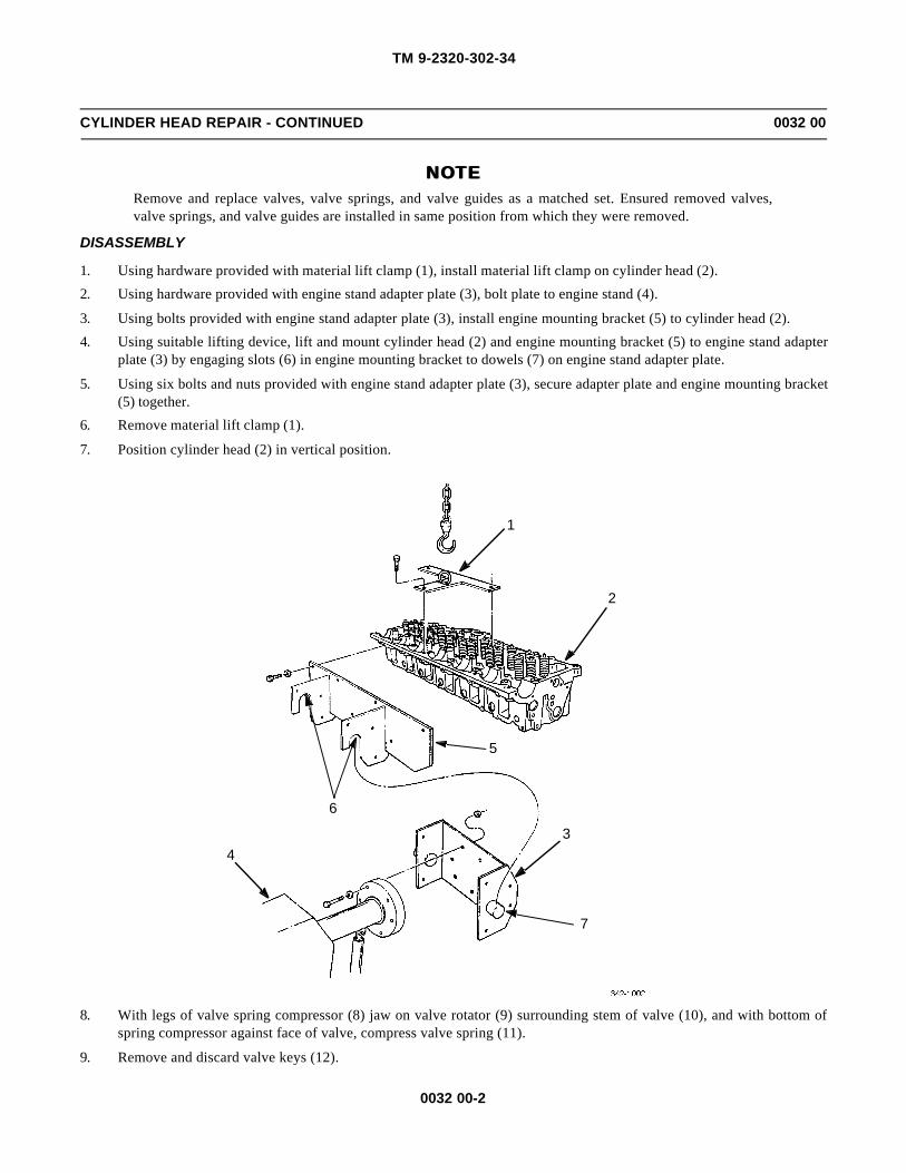
TM 9-2320-302-34
0032 00-2
CYLINDER HEAD REPAIR - CONTINUED 0032 00
NOTENOTERemove and replace valves, valve springs, and valve guides as a matched set. Ensured removed valves,valve springs, and valve guides are installed in same position from which they were removed.
DISASSEMBLY
1. Using hardware provided with material lift clamp (1), install material lift clamp on cylinder head (2).
2. Using hardware provided with engine stand adapter plate (3), bolt plate to engine stand (4).
3. Using bolts provided with engine stand adapter plate (3), install engine mounting bracket (5) to cylinder head (2).
4. Using suitable lifting device, lift and mount cylinder head (2) and engine mounting bracket (5) to engine stand adapterplate (3) by engaging slots (6) in engine mounting bracket to dowels (7) on engine stand adapter plate.
5. Using six bolts and nuts provided with engine stand adapter plate (3), secure adapter plate and engine mounting bracket(5) together.
6. Remove material lift clamp (1).
7. Position cylinder head (2) in vertical position.
8. With legs of valve spring compressor (8) jaw on valve rotator (9) surrounding stem of valve (10), and with bottom ofspring compressor against face of valve, compress valve spring (11).
9. Remove and discard valve keys (12).
4
6
1
2
5
3
7

TM 9-2320-302-34
0032 00-3
CYLINDER HEAD REPAIR - CONTINUED 0032 00
DISASSEMBLY - CONTINUED
NOTENOTETag parts prior to removal for possible reuse.
10. Release and remove valve spring compressor (8).
11. Remove valve rotator (9) and valve spring (11).
28
9
12
10
12
11
11
9
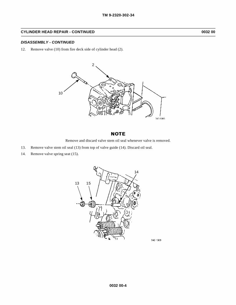
TM 9-2320-302-34
0032 00-4
CYLINDER HEAD REPAIR - CONTINUED 0032 00
DISASSEMBLY - CONTINUED
12. Remove valve (10) from fire deck side of cylinder head (2).
NOTENOTERemove and discard valve stem oil seal whenever valve is removed.
13. Remove valve stem oil seal (13) from top of valve guide (14). Discard oil seal.
14. Remove valve spring seat (15).
10
2
13 15
14

TM 9-2320-302-34
0032 00-5
CYLINDER HEAD REPAIR - CONTINUED 0032 00
DISASSEMBLY - CONTINUED
NOTENOTEProcedure is the same for both intake and exhaust valve seat inserts, except different collet is used in valveseat remover tool.
15. Position cylinder head (2) fire deck side up.
16. If valve seats are worn or damaged, place valve seat remover handle (16) in vertical position so that no pressure is oninternal spring. Adjust valve seat collet (17) opening by turning tapered nut (18) to expand or reduce valve seat colletopening until it will slip through valve seat.
17. With valve seat remover handle (16) in vertical position, insert valve seat collet portion of valve seat remover body (19)fully into valve seat.
18. Hold valve seat remover body (19) square with surface of cylinder head fire deck (20) and pull valve seat remover han-dle (16) until firm resistance is felt. Hold handle in this position.
18
17
16
20
16
19

TM 9-2320-302-34
0032 00-6
CYLINDER HEAD REPAIR - CONTINUED 0032 00
DISASSEMBLY - CONTINUED
CAUTIONCAUTIONEnsure valve seat remover body remains flat on cylinder head fire deck when moving collet handle to pre-vent damage to collet and to correct engagement of valve seat insert.
19. Hold valve seat remover handle (16) down. Grasp valve seat collet handle (21) and rotate back and forth several times.
20. Hold valve seat remover body (19) flat on cylinder head fire deck (20) and pull valve seat remover handle (16) downuntil valve seat is removed.
21. Return valve seat remover handle (16) to vertical position and remove valve seat from valve seat collet. Discard valveseat.
22. If valve guides (14) are worn or damaged, install valve guide remover (22) in air chisel (23) and insert valve guideremover into bottom of valve guide (14) from fire deck side.
WARNINGWARNINGValve guide is removed from cylinder head under force. Position heavy block of wood at an angle, beneathguide, to deflect valve guide and prevent personal injury.
23. Hold valve guide remover (22) vertical to cylinder head fire deck and drive valve guide (14) down until free. Discardvalve guide.
2019
16
21

TM 9-2320-302-34
0032 00-7
CYLINDER HEAD REPAIR - CONTINUED 0032 00
DISASSEMBLY - CONTINUED
23
22
14

TM 9-2320-302-34
0032 00-8
CYLINDER HEAD REPAIR - CONTINUED 0032 00
DISASSEMBLY - CONTINUED
NOTENOTE• Replace dowels and plugs only if necessary.
• Dowel removal procedure is the same for round, diamond, or hollow dowels.
• Cover exposed areas to guard against welding sparks.
24. Fabricate piece of sheet brass (24) with hole large enough to fit over dowel being removed.
25. Tack weld flat washer (25) to top of dowel as shown.
26. Tack weld nut (26) to flat washer (25). Ensure thread of nut matches thread of slide hammer shaft (27).
27. Thread slide hammer shaft (27) into nut (26) and remove dowel.
NOTENOTECylinder head repair conditions may warrant cylinder head pressure testing before complete head disassem-bly. Testing should be performed before injector tubes, cup plugs, and pipe plugs are removed. Refer toInspection steps 2 through 10 for pressure testing.
28. If worn, damaged or leaking, replace injector tubes by placing injector tube installation/removal tool (28) in injectortube. Insert pilot (29) through small opening of injector tube and thread pilot into tapped hole in end of installation/removal tool.
29. Using brass hammer or fiber mallet, tap on end of pilot (29). Carefully drive and lift injector tube, installation/removaltool (28), and pilot from cylinder head (2). If injector tube o-ring seal is not removed with injector tube, remove o-ringseal from cylinder head casting at upper end of injector tube bore. Discard injector tube and o-ring seal.
27
2625
24
27
2625
24

TM 9-2320-302-34
0032 00-9
CYLINDER HEAD REPAIR - CONTINUED 0032 00
DISASSEMBLY - CONTINUED
30. Remove cup plugs by piercing with screwdriver or chisel and prying plug out of cylinder head.
31. Unscrew pipe plugs and fuse plug.
CLEANING AND INSPECTION
1. Steam clean stripped cylinder head.
NOTENOTEEnsure all cup plugs, pipe plugs, and injector tubes are installed before pressure testing cylinder head.
2. Attach two pressure test kit strips (30) to cylinder head fire deck (20). Install 20 cylinder head bolts (31) through cylin-der head and test kit strips. Install and tighten 20 nuts (32) to 120 lb-in (14 Nm).
29
28
2
30
32
20
3130

TM 9-2320-302-34
0032 00-10
CYLINDER HEAD REPAIR - CONTINUED 0032 00
CLEANING AND INSPECTION - CONTINUED
NOTENOTE• Leaking injector tubes must be replaced. Replace any pipe plug or cup plug where leakage is present.
• Cylinder head must be pressure tested following replacement of any injector tubes, cup plugs or pipeplugs.
3. Install gasket (33) and pressure test kit thermostat cover plate (34) on cylinder head (2) with bolts (35).
4. Using hardware provided, install material lift clamp (1).
5. Install pressure test kit dummy fuel injectors (36) in injector bores.
6. Install fuel injector hold down clamp (37), washer (38), and hold down bolt (39). Tighten bolt to 43-49 lb-ft (58-66 Nm).
7. Remove cylinder head (2) from engine mounting bracket (5).
WARNINGWARNINGCompressed air used for cleaning or drying purposes, or for clearing restrictions, should never exceed 30 psi(207 kPa). Wear protective clothing (goggles/shield, gloves, etc.) and use caution to avoid injury to person-nel.
8. Apply 30 psi (207 kPa) air pressure to thermostat cover plate fitting (40).
9. Install pipe plugs in temp port and in air compressor coolant port.
10. Immerse cylinder head (2) in water heated to 180°F-200°F (82°C-93°C). Leave cylinder head in water for 20 minutes.Watch for bubbles, indicating crack or leak. If cracked, replace cylinder head.
11. Using heavy straightedge (41) and thickness gage (42), check for warped cylinder head fire deck (20).
36
5
37
38
391 1
1
2
35
40
34
33

TM 9-2320-302-34
0032 00-11
CYLINDER HEAD REPAIR - CONTINUED 0032 00
CLEANING AND INSPECTION - CONTINUED
12. Check cylinder head fire deck (20) for longitudinal warpage in 5 places (1 through 5) and transverse warpage at 12places (A through L). Fire deck must be flat within 0.011 in (0.279 mm) front-to-rear, and 0.003 in (0.076 mm) side-to-side. If not, resurface fire deck.
42
41
20
20

TM 9-2320-302-34
0032 00-12
CYLINDER HEAD REPAIR - CONTINUED 0032 00
CLEANING AND INSPECTION - CONTINUED
CAUTIONCAUTIONMaximum amount of resurfacing is 0.030 in (0.762 mm). Limit resurfacing to 0.030 in (0.762 mm). Ifexceeded, replace cylinder head to prevent damage to equipment.
13. Record amount of stock removed from cylinder head by stamping amount removed on pad (43) on front of cylinderhead. Measure from top rail (44) to fire deck surface (45). Resurface finish must be 90 U in AA (2.3 UM AA).
NOTENOTEIt may be necessary to restore injector tube counterbore when cylinder head is resurfaced.
14. Ensure countersink injector tube bores (46) land width is 0.040-0.080 in (1.0-2.0 mm) (47) x 45 degrees (48).
NOTENOTEIf cylinder head fire deck has been resurfaced, valves must be seated deeper to restore valve head recessdepth to specification limits. Do not grind new valve seat inserts for this purpose. Reduced-thickness valveseat inserts are available, 0.010, 0.020, and 0.030 in (0.254, 0.508, and 0.762 mm) shallower than standard.
44
45
43
48
46
47

TM 9-2320-302-34
0032 00-13
CYLINDER HEAD REPAIR - CONTINUED 0032 00
CLEANING AND INSPECTION - CONTINUED
15. Ensure valve heads (49) are recessed from cylinder head (2) fire deck surface by 0.055-0.071 in (1.4-1.8 mm) minimum.If not, install reduced-thickness valve seat inserts.
NOTENOTEReplace rotator whenever spring is replaced.
16. Inspect valve springs and replace any that are pitted or cracked.
17. Use valve spring tester (50) to test valve springs (11). Replace spring if spring load is less than 63 lb (280 N) at com-pressed length of 2.648 in (67.26 mm).
49
2
50
11

TM 9-2320-302-34
0032 00-14
CYLINDER HEAD REPAIR - CONTINUED 0032 00
CLEANING AND INSPECTION - CONTINUED
NOTENOTEIf suitable for reuse, valve may be refaced as long as after refacing, valve rim width is not less than 0.086 in(2.19 mm) for intake valves and 0.094 in (2.39 mm) for exhaust valves.
18. Ensure valve stems are free from scratches or scuff marks. Valve faces must be free from ridges, cracks, and pitting. Ifnecessary, reface valves or install new valves. If valve faces are warped or valve stem is bent, replace valves. Minimumvalve stem diameter is 0.342 in (8.679 mm) for intake valve and 0.343 in (8.714 mm) for exhaust valve.
19. Inspect guides for cracks, chipping, scoring, and excessive wear.
20. Measure valve guide bore with small hole gage or gage pin, and measure valve stem diameter with micrometer. Com-pare measurements to determine valve stem clearance. If clearance is greater than 0.006 in (0.152 mm), valve guidemust be replaced.
NOTENOTENew valve seat inserts are preground. Check for concentricity after installation. Do not grind new valve seatinsert unless concentricity exceeds 0.002 in (0.05 mm).
21. Ensure valve seat insert angle (51) is 31 degrees.
22. Ensure valve seat width (52) is 0.084 in (2.14 mm) for intake valves and 0.105 in (2.66 mm) for exhaust valves.
ASSEMBLY
1. If removed, install seven hollow dowels (53) on cylinder head (2) to height of 0.197 +0.010 in (5.0 +0.5 mm).
CAUTIONCAUTIONEnsure diamond dowels are correctly aligned. Failure to do so could result in engine failure.
2. If removed, install three diamond dowels (54) to height of 0.240 +0.010 in (6.1 +0.5 mm). Angular orientation of dia-mond dowels must be parallel to centerline through dowel holes within +4 degrees, as shown.
51 52
52
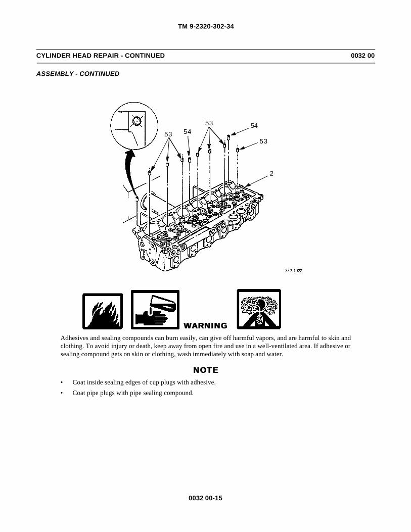
TM 9-2320-302-34
0032 00-15
CYLINDER HEAD REPAIR - CONTINUED 0032 00
ASSEMBLY - CONTINUED
WARNINGWARNINGAdhesives and sealing compounds can burn easily, can give off harmful vapors, and are harmful to skin andclothing. To avoid injury or death, keep away from open fire and use in a well-ventilated area. If adhesive orsealing compound gets on skin or clothing, wash immediately with soap and water.
NOTENOTE• Coat inside sealing edges of cup plugs with adhesive.
• Coat pipe plugs with pipe sealing compound.
53 5453 54
53
2

TM 9-2320-302-34
0032 00-16
CYLINDER HEAD REPAIR - CONTINUED 0032 00
ASSEMBLY - CONTINUED
3. If removed, use cup plug installer to install 11 cup plugs (55) on top, front, and rear sides of cylinder head. Install cupplugs to 0.098-0.138 in (2.5-3.5 mm) below machined surface.
4. If removed, install two cup plugs (56) on front and rear sides of cylinder head to 0.098-0.138 in (2.5-3.5 mm) belowmachined surface.
5. Install two square drive pipe plugs (57) on front side of cylinder head, flush-to-below surface.
6. Install connector (58) on left rear side of cylinder head.
7. Install elbow (59) on left front side of cylinder head.
8. Install two pipe plugs (60) on right side rear of cylinder head.
9. Install pipe plug (61) on right side rear of cylinder head.
10. Install fuse plug (62) on right side front of cylinder head.
NOTENOTE
Do not lubricate outside of injector tube or inside cylinder head injector tube bore.
11. Lubricate new injector tube o-ring seal (63) with lubricating oil. Install o-ring seal over new injector tube (64) until flushagainst lip.
12. Install injector tube (64) on injector tube reconditioning set installer (28).
55
56
57
55
58
59
55
55
55
5560
61
55
62
56

TM 9-2320-302-34
0032 00-17
CYLINDER HEAD REPAIR - CONTINUED 0032 00
ASSEMBLY - CONTINUED
NOTENOTE
If injector tube falls off installer during installation, use injector tube reconditioning set tube remover pilot toretain injector tube on installer. Remove pilot after hold down clamp is installed and tightened.
13. Install injector tube reconditioning set installer (28) with injector tube in injector bore. Ensure tip of injector tube goesthrough small hole in cylinder head (2) fire deck. Tap lightly on end of installer, if necessary, to seat injector tube.
14. Install injector hold down clamp (37), washer (38), and hold down bolt (39) over injector tube reconditioning setinstaller (28). Tighten bolt to 43-49 lb-ft (58-66 Nm).
28
6364
2
28
38
3739

TM 9-2320-302-34
0032 00-18
CYLINDER HEAD REPAIR - CONTINUED 0032 00
ASSEMBLY - CONTINUED
15. Insert injector tube reconditioning set flaring tool (65) through small hole in bottom of injector tube (64) and rotate flar-ing tool to engage threads in injector tube reconditioning set installer (28).
16. Using torque wrench and standard 9/16 in socket, thread flaring tool (65) into injector tube reconditioning set installer(28) until it flares injector tube (64).
17. Rotate flaring tool (65) and apply pressure to flare end of injector tube firmly against cylinder head (2). Do not exceed30 lb-ft (41 Nm).
18. Remove flaring and installer tools. Ensure proper flare.
NOTENOTETurn reamer in clockwise direction only when inserting and withdrawing reamer.
19. Insert injector tube reconditioning set seat reamer pilot (66) into injector bore until it contacts cylinder head. Insertreconditioning set seat tip reamer pilot (67) into seat reamer until it bottoms.
20. Apply a few drops of cutting oil on cutting edges of injector tube reconditioning set tube tip reamer (68) and install inpilot (67).
21. Use speed handle with 7/16 in socket to turn tube tip reamer (68) in clockwise direction. Use light pressure until reamergoes completely through end of injector tube.
WARNINGWARNINGCompressed air used for cleaning or drying purposes, or for clearing restrictions, should never exceed 30 psi(207 kPa). Wear protective clothing (goggles/shield, gloves, etc.) and use caution to avoid injury to person-nel.
22. Remove reamer and pilot. Use compressed air to clear out injector tube and tip.
2
64
6528

TM 9-2320-302-34
0032 00-19
CYLINDER HEAD REPAIR - CONTINUED 0032 00
ASSEMBLY - CONTINUED
23. Install injector tube reconditioning set stop block (69) on cylinder head fire deck (20) using two cylinder head bolts (31).Do not tighten bolts. Position cutout portion of stop block beneath injector tube (64).
68
67
66
31
64
69
2
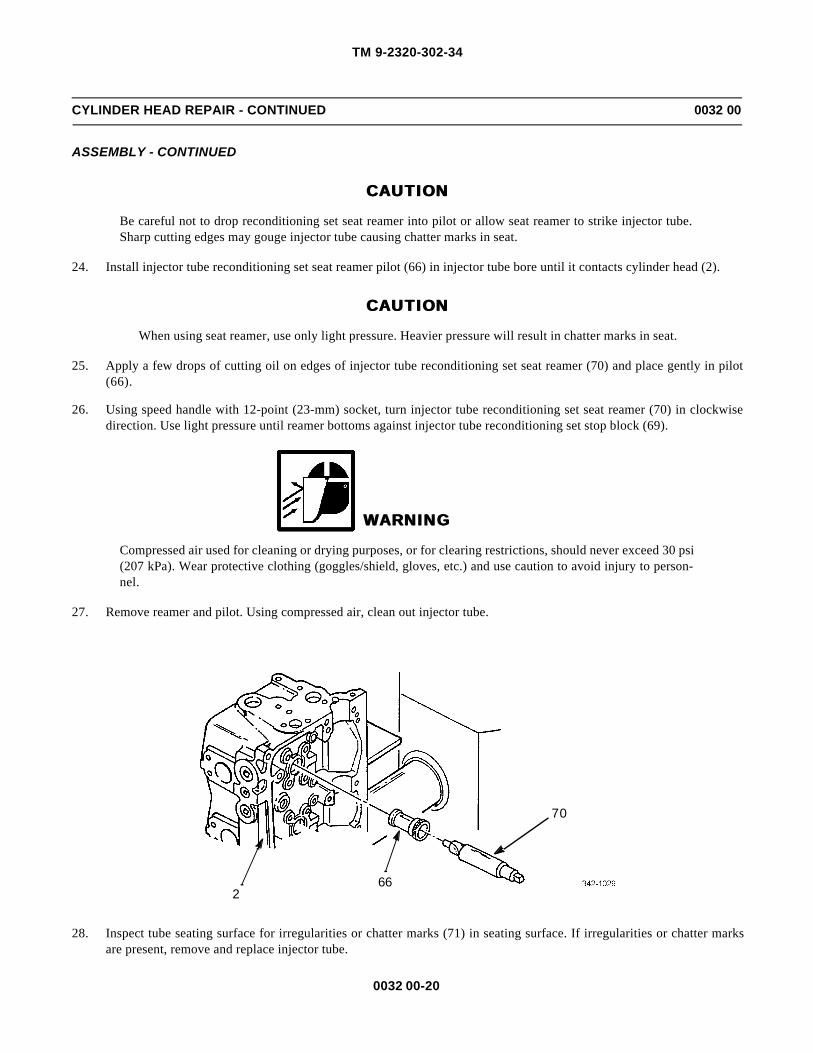
TM 9-2320-302-34
0032 00-20
CYLINDER HEAD REPAIR - CONTINUED 0032 00
ASSEMBLY - CONTINUED
CAUTIONCAUTION
Be careful not to drop reconditioning set seat reamer into pilot or allow seat reamer to strike injector tube.Sharp cutting edges may gouge injector tube causing chatter marks in seat.
24. Install injector tube reconditioning set seat reamer pilot (66) in injector tube bore until it contacts cylinder head (2).
CAUTIONCAUTION
When using seat reamer, use only light pressure. Heavier pressure will result in chatter marks in seat.
25. Apply a few drops of cutting oil on edges of injector tube reconditioning set seat reamer (70) and place gently in pilot(66).
26. Using speed handle with 12-point (23-mm) socket, turn injector tube reconditioning set seat reamer (70) in clockwisedirection. Use light pressure until reamer bottoms against injector tube reconditioning set stop block (69).
WARNINGWARNING
Compressed air used for cleaning or drying purposes, or for clearing restrictions, should never exceed 30 psi(207 kPa). Wear protective clothing (goggles/shield, gloves, etc.) and use caution to avoid injury to person-nel.
27. Remove reamer and pilot. Using compressed air, clean out injector tube.
28. Inspect tube seating surface for irregularities or chatter marks (71) in seating surface. If irregularities or chatter marksare present, remove and replace injector tube.
66
70
2

TM 9-2320-302-34
0032 00-21
CYLINDER HEAD REPAIR - CONTINUED 0032 00
ASSEMBLY - CONTINUED
29. Remove two cylinder head bolts and injector tube reconditioning set stop block from cylinder head (2).
30. Insert injector tube reconditioning set tip refinisher (72) into injector tube (64).
71
2
64
72
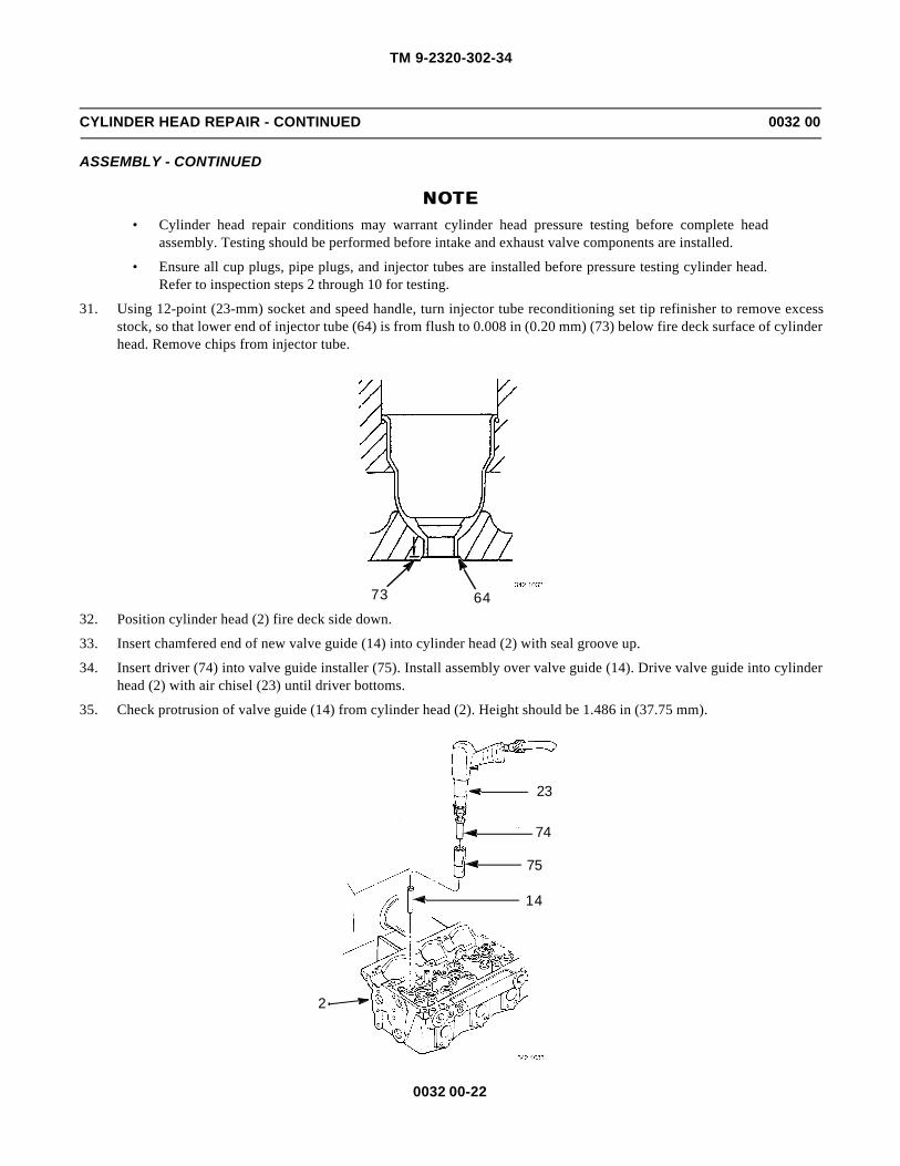
TM 9-2320-302-34
0032 00-22
CYLINDER HEAD REPAIR - CONTINUED 0032 00
ASSEMBLY - CONTINUED
NOTENOTE• Cylinder head repair conditions may warrant cylinder head pressure testing before complete head
assembly. Testing should be performed before intake and exhaust valve components are installed.
• Ensure all cup plugs, pipe plugs, and injector tubes are installed before pressure testing cylinder head.Refer to inspection steps 2 through 10 for testing.
31. Using 12-point (23-mm) socket and speed handle, turn injector tube reconditioning set tip refinisher to remove excessstock, so that lower end of injector tube (64) is from flush to 0.008 in (0.20 mm) (73) below fire deck surface of cylinderhead. Remove chips from injector tube.
32. Position cylinder head (2) fire deck side down.
33. Insert chamfered end of new valve guide (14) into cylinder head (2) with seal groove up.
34. Insert driver (74) into valve guide installer (75). Install assembly over valve guide (14). Drive valve guide into cylinderhead (2) with air chisel (23) until driver bottoms.
35. Check protrusion of valve guide (14) from cylinder head (2). Height should be 1.486 in (37.75 mm).
6473
23
74
75
14
2

TM 9-2320-302-34
0032 00-23
CYLINDER HEAD REPAIR - CONTINUED 0032 00
ASSEMBLY - CONTINUED
NOTENOTEProcedure is the same for both intake and exhaust valve seat inserts, except different tools are used.
36. Position cylinder head fire deck (20) side up.
37. Ensure valve seat insert counterbore (76) is clean and free of carbon deposits, burrs or damage.
38. Seat new valve seat insert (77) squarely in counterbore with valve seat facing up.
39. Seat valve seat installer (78) on valve seat insert (77).
40. Install valve seat insert (77) solidly in valve seat in cylinder head (2).
77
76
20
78
2
77

TM 9-2320-302-34
0032 00-24
CYLINDER HEAD REPAIR - CONTINUED 0032 00
ASSEMBLY - CONTINUED
NOTENOTENew valve seat inserts are preground. Check for concentricity after installation. Do not grind new valve seatinsert unless concentricity exceeds 0.002 in (0.05 mm).
41. Ensure valve seat insert angle (51) is 31 degrees.
42. Ensure valve seat width (52) is 0.084 in (2.14 mm) for intake valves and 0.105 in (2.66 mm) for exhaust valves.
43. Grind valve seat (79) lightly for full 360 degrees, only enough to true it up.
5152
52
79
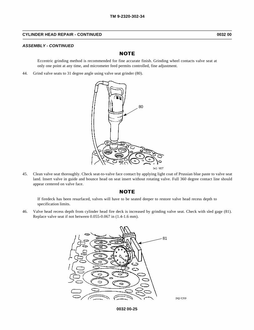
TM 9-2320-302-34
0032 00-25
CYLINDER HEAD REPAIR - CONTINUED 0032 00
ASSEMBLY - CONTINUED
NOTENOTEEccentric grinding method is recommended for fine accurate finish. Grinding wheel contacts valve seat atonly one point at any time, and micrometer feed permits controlled, fine adjustment.
44. Grind valve seats to 31 degree angle using valve seat grinder (80).
45. Clean valve seat thoroughly. Check seat-to-valve face contact by applying light coat of Prussian blue paste to valve seatland. Insert valve in guide and bounce head on seat insert without rotating valve. Full 360 degree contact line shouldappear centered on valve face.
NOTENOTEIf firedeck has been resurfaced, valves will have to be seated deeper to restore valve head recess depth tospecification limits.
46. Valve head recess depth from cylinder head fire deck is increased by grinding valve seat. Check with sled gage (81).Replace valve seat if not between 0.055-0.067 in (1.4-1.6 mm).
80
81
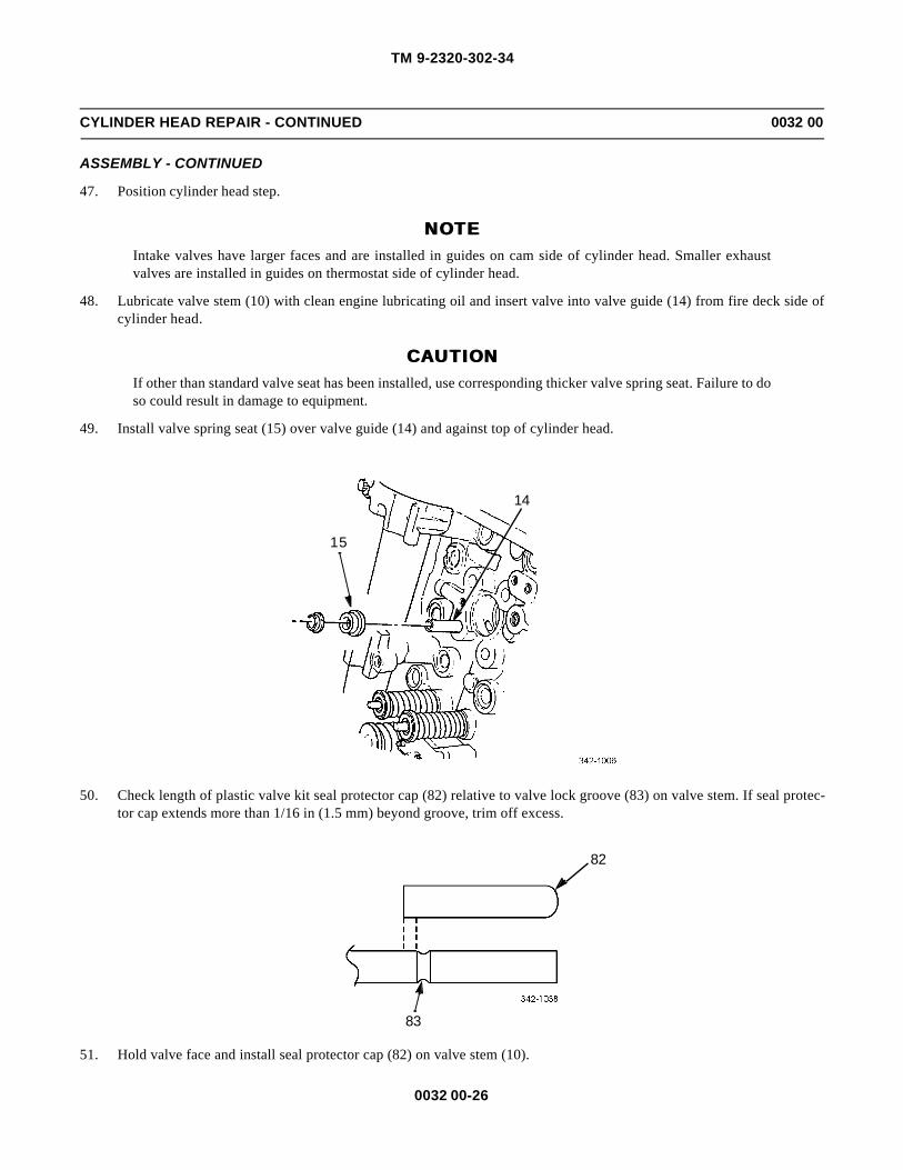
TM 9-2320-302-34
0032 00-26
CYLINDER HEAD REPAIR - CONTINUED 0032 00
ASSEMBLY - CONTINUED
47. Position cylinder head step.
NOTENOTEIntake valves have larger faces and are installed in guides on cam side of cylinder head. Smaller exhaustvalves are installed in guides on thermostat side of cylinder head.
48. Lubricate valve stem (10) with clean engine lubricating oil and insert valve into valve guide (14) from fire deck side ofcylinder head.
CAUTIONCAUTIONIf other than standard valve seat has been installed, use corresponding thicker valve spring seat. Failure to doso could result in damage to equipment.
49. Install valve spring seat (15) over valve guide (14) and against top of cylinder head.
50. Check length of plastic valve kit seal protector cap (82) relative to valve lock groove (83) on valve stem. If seal protec-tor cap extends more than 1/16 in (1.5 mm) beyond groove, trim off excess.
51. Hold valve face and install seal protector cap (82) on valve stem (10).
15
14
82
83

TM 9-2320-302-34
0032 00-27
CYLINDER HEAD REPAIR - CONTINUED 0032 00
ASSEMBLY - CONTINUED
NOTENOTEEnsure all valve spring seats are in place before valve stem oil seals are installed. Install valve stem oil sealdry.
52. Wipe any oil from outside of valve guide (14). Install new valve stem oil seal (13) over seal protector cap (82) againstvalve guide. Remove seal protector cap (82).
53. Using valve stem seal installer, push valve stem oil seal (13) down until seal lip is fully in groove on valve guide (14).When installer tool contacts head, seal is correctly positioned.
1082
1482
13

TM 9-2320-302-34
0032 00-28
CYLINDER HEAD REPAIR - CONTINUED 0032 00
ASSEMBLY - CONTINUED
CAUTIONCAUTIONPosition valve spring and rotator so valve lock grooves on valve stem do not contact oil seal. Failure to do socould result in damage to equipment.
54. Install valve spring (11) and valve rotator (9) over valve stem (10) and against valve spring seat (15).
NOTENOTEWhen compressing valve spring, valve rotator should not contact valve stem seal.
55. Using valve spring compressor (8), compress valve spring (11) only enough to install new valve keys (12).
NOTENOTEEnsure valve key is in place and engaged in valve stem groove before releasing valve spring compressor.
56. Install new valve keys (12).
57. Remove valve spring compressor (8).
10
15
11
9
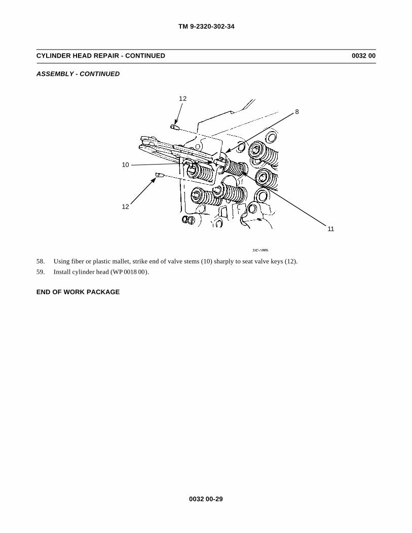
TM 9-2320-302-34
0032 00-29
CYLINDER HEAD REPAIR - CONTINUED 0032 00
ASSEMBLY - CONTINUED
58. Using fiber or plastic mallet, strike end of valve stems (10) sharply to seat valve keys (12).
59. Install cylinder head (WP 0018 00).
END OF WORK PACKAGE
8
12
10
12
11

TM 9-2320-302-34
0032 00-30
This Page Intentionally Left Blank.

TM 9-2320-302-34
0033 00-1
CRANKSHAFT REPLACEMENT 0033 00
THIS WORK PACKAGE COVERS
Removal, Cleaning, Inspection, Installation
INITIAL SETUP
Maintenance Level
General Support
Tools and Special Tools
Tool kit, general mechanic’s (Item 132, WP 0126 00)
Dial indicator set (Item 29, WP 0126 00)
Inserter and remover (Item 52, WP 0126 00)
Pump, hydraulic ram (Item 98, WP 0126 00)
Wrench, torque, 15-75 lb-ft (Item 138, WP 0126 00)
Wrench, torque, 50-250 lb-ft (Item 139, WP 0126 00)
Wrench, torque, 100-600 lb-ft (Item 140, WP 0126 00)
Wrench set, socket, 3/4 in drive (Item 141, WP0126 00)
Materials/Parts
Compound, international no. 2 (Item 13, WP 0125 00)
Detergent (Item 19, WP 0125 00)
Gage, bearing clearance (Item 20, WP 0125 00)
Materials/Parts - Continued
Lubriplate (Item 23, WP 0125 00)
Oil, lubricating (Item 25, WP 0125 00)
Rope, 1/2 in nylon (Item 32, WP 0125 00)
Personnel Required
Two
Equipment Condition
Flywheel housing removed (WP 0024 00)
Oil pump removed (WP 0029 00)
Pistons and cylinder assemblies removed (WP0041 00)
Bull/idler gear removed (WP 0037 00)
Timing reference sensor (TRS) removed (TM 9-2320-302-20)
Synchronous reference sensor (SRS) removed (TM 9-2320-302-20)
WARNINGWARNINGUse extreme caution when handling heavy parts. Provide adequate support and use assistance during proce-dure. Ensure that any lifting device used is in good condition and of suitable load capacity. Keep clear ofheavy parts supported only by lifting device. Failure to follow this warning may result in death or injury topersonnel.

TM 9-2320-302-34
0033 00-2
CRANKSHAFT REPLACEMENT - CONTINUED 0033 00
REMOVAL
1. Using two crankshaft gear inserter/remover bolts (1), secure crankshaft gear inserter/remover base post (2) to end ofcrankshaft. Tighten two bolts to 140-150 lb-ft (190-203 Nm).
2. Thread three crankshaft gear inserter/remover legs (3) into threaded holes in crankshaft timing gear (4). Tighten threeinserter/remover legs.
3. Slide hydraulic ram and pump (5) over center rod of inserter/remover base post (2).
4. Install crankshaft gear inserter/remover pressure plate (6) on three inserter/remover legs (3).
5. Install three crankshaft gear inserter/remover retaining nuts (7) on inserter/remover legs (3). Tighten three retaining nutsagainst inserter/remover pressure plate (6) to 43-54 lb-ft (58-73 Nm).
NOTENOTEDue to manufacturer’s tolerances, as much as 9 tons of pressure may be required to remove crankshaft tim-ing gear.
6. Operate hydraulic ram and pump (5) to pull crankshaft timing gear (4) off crankshaft.
4
1
2
3
52
3
6
7

TM 9-2320-302-34
0033 00-3
CRANKSHAFT REPLACEMENT - CONTINUED 0033 00
REMOVAL - CONTINUED
7. When crankshaft timing gear (4) moves freely, release hydraulic pressure and remove crankshaft gear inserter/removertool from crankshaft timing gear and crankshaft.
CAUTIONCAUTION
Do not use sharp tools to pry on timing wheel or crankshaft timing gear. Use care to prevent damagingcrankshaft seal contact surface when removing crankshaft timing gear and timing wheel from crankshaft.
8. Remove crankshaft timing gear (4) from crankshaft.
9. Remove timing wheel (8) from crankshaft.
10. Remove woodruff key (9) from crankshaft.
4
5
9
8
4

TM 9-2320-302-34
0033 00-4
CRANKSHAFT REPLACEMENT - CONTINUED 0033 00
REMOVAL - CONTINUED
11. Rotate engine on stand so crankshaft is in up position.
12. Remove main bearing cap bolts (10) and washers (11).
NOTENOTE• Place upper main bearing shells and thrust washers with respective main bearing caps and lower main
bearing shells. If reused, install upper and lower main bearing shells and thrust bearing in original posi-tions.
• Main bearing caps are bored in position and stamped with position number. Caps must be installed intheir original positions, with marked (numbered) side of each cap toward cooler (right) side of cylinderblock.
• Slightest burr or particle of dirt between backs of no. 6 main bearing thrust washers and saddle or capmay decrease clearance between washer and crankshaft beyond specified limits.
13. Remove seven main bearing caps (12) and lower main bearing shells (13).
WARNINGWARNINGCrankshaft weighs 408 lb (185.23 kg). Use suitable lifting device to lift and support crankshaft. Failure to doso could result in serious injury to personnel.
14. Using nylon rope and suitable lifting device, lift crankshaft (14) from cylinder block (15).
15. Remove seven upper main bearing shells (16).
16. Remove two thrust washers (17) from sides of main bearing saddle no. 6 (18).
10
11
12
13

TM 9-2320-302-34
0033 00-5
CRANKSHAFT REPLACEMENT - CONTINUED 0033 00
REMOVAL - CONTINUED
CLEANING
WARNINGWARNING
Compressed air used for cleaning or drying purposes, or for clearing restrictions, should never exceed 30 psi(207 kPa). Wear protective clothing (goggles/shield, gloves, etc.) and use caution to avoid injury to person-nel.
1. Clean out crankshaft oil passages with bore brush.
2. Clean crankshaft bearings and main bearing caps with detergent and dry with compressed air.
14
16
17
15
18
16
17
FRONT

TM 9-2320-302-34
0033 00-6
CRANKSHAFT REPLACEMENT - CONTINUED 0033 00
INSPECTION
CAUTIONCAUTIONVibration damper must be replaced at normal engine overhaul or if crankshaft breakage is experienced. Fail-ure to do so could result in premature crankshaft failure.
NOTENOTE• Crankshaft failures are rare. When crankshaft cracks or breaks completely, thoroughly inspect for con-
tributory factors. Unless abnormal conditions are discovered and corrected, crankshaft failure will berepeated.
• Ensure all main bearing saddles and thrust bearing counterbores in cylinder block are clean.
• Each upper main bearing shell is grooved with oil hole. Register oil hole in each upper main bearingshell with oil hole in each main bearing saddle of cylinder block.
• Install main bearings in sets only. Do not mix old and new main bearing shells on same journal. If oldbearings are installed, they must be installed in same journal they were removed from.
1. Inspect crankshaft timing gear keyway for evidence of cracks or wear. Replace crankshaft if damage is evident.
2. Inspect crankshaft for evidence of overheating. Replace crankshaft if damage is evident.
3. Check crankshaft journal surfaces for score marks or imperfections. If excessively scored, replace crankshaft.
4. Check crankshaft thrust surfaces for excessive wear or grooving. If excessively worn, replace crankshaft.
5. Check crankshaft timing gear for worn or chipped teeth. Inspect timing wheel for bent or damaged teeth. Replace asnecessary.
6. Support crankshaft front and rear journals on V-blocks or inverted engine block with only front and rear upper bearingshells in place. Check intermediate main journals with dial indicator for runout when crankshaft is rotated. Replacecrankshaft if runout is greater than maximum shown in Table 1.
Table 1. Intermediate Main Journals Runout.
7. Measure all main bearing journals (19) and connecting rod bearing journals (20), as shown, at several places on circum-ference to determine taper, out-of-round, and journal diameter. Replace crankshaft if not within specifications shown.
JOURNAL SUPPORTED ON JOURNALS MEASUREDMAXIMUM RUNOUT:TOTAL INDICATOR
READING
No. 1 and No. 7 No. 2 0.0030 in (0.076 mm)
No 1 and No. 7 No. 3 0.0051 in (0.130 mm)
No. 1 and No. 7 No. 4 0.0060 in (0.152 mm)
No. 1 and No. 7 No. 5 0.0051 in (0.130 mm)
No. 1 and No. 7 No. 6 0.0030 in (0.076 mm)

TM 9-2320-302-34
0033 00-7
CRANKSHAFT REPLACEMENT - CONTINUED 0033 00
INSPECTION - CONTINUED
8. Measure crankshaft thrust washer surfaces as shown.
20
19
NO. 6 MAIN BEARING JOURNAL

TM 9-2320-302-34
0033 00-8
CRANKSHAFT REPLACEMENT - CONTINUED 0033 00
INSPECTION - CONTINUED
9. Check crankshaft for cracks which start at oil hole (21) and follow journal surface at angle of 45 degrees to axis.Replace any crankshaft with such cracks. Determine presence of cracks not visible to eye by magnetic particle, fluores-cent magnetic particle or fluorescent penetrant method.
10. Replace crankshaft if circumferential fillet cracks (22) at connecting rod, or fillet cracks or 45-degree cracks (45 degreesto axis of crankshaft) at main bearing journal are evident.
11. Inspect all parts for wear or damage.
NOTENOTE• Ensure all main bearing saddles and thrust bearing counterbores in cylinder block are clean.
• Each upper main bearing shell is grooved with oil hole. Register oil hole in each upper main bearingshell with oil hole in each main bearing saddle of cylinder block.
• Install main bearings in sets only. Do not mix old and new main bearing shells on same journal. If oldbearings are installed, they must be installed in same journal they were removed from.
12. Invert engine block. Install seven upper main bearing shells (16) in cylinder block journals (23).
13. Wipe oil from bearing shells and crankshaft journals to be checked.
WARNINGWARNINGCrankshaft weighs 408 lb (185.23 kg). Use suitable lifting device to lift and support crankshaft. Failure to doso could result in serious injury to personnel.
14. Using nylon rope and suitable lifting device, position crankshaft (14) in cylinder block (15) on upper main bearing shells(16).
21
22

TM 9-2320-302-34
0033 00-9
CRANKSHAFT REPLACEMENT - CONTINUED 0033 00
INSPECTION - CONTINUED
15. Using strip of plastigauge (24), measure bearing clearances between crankshaft journals of main bearings. Plastigaugetype PG-1 (green) has clearance range of 0.001-0.003 in (0.0254-0.0762 mm). Type PR-1 (red) has clearance range of0.002-0.006 in (0.0508-0.01524 mm). Type PB-1 (blue) has clearance range of 0.004-0.009 in (0.1016-0.2286).
16. Place piece of plastigauge (24) along full width of each crankshaft main bearing journal about 1/4 in (6.35 mm) off cen-ter.
17. Install seven lower main bearing shells and main bearing caps (12).
18. Install 14 washers (11) and main bearing cap bolts (10). Tighten main bearing cap bolts to 347-391 lb-ft (470-530 Nm).
14
16
15
23
10
11
12
24

TM 9-2320-302-34
0033 00-10
CRANKSHAFT REPLACEMENT - CONTINUED 0033 00
INSPECTION - CONTINUED
NOTENOTEFlattened plastigauge will be found adhering to bearing shell or crankshaft.
19. Remove 14 main bearing cap bolts (10) and washers (11). Remove seven main bearing caps (12) and lower main bear-ing shells (13).
NOTENOTEIf worn crankshaft maximum connecting rod bearing journal-to-bearing shell clearance, with new shells,exceeds 0.005 in (0.1270 mm), or if maximum main bearing journal-to-bearing shell clearance, with newshells, exceeds 0.0056 in (0.1412 mm), replace crankshaft. Measurements of crankshaft should be accurateto nearest 0.0001 in (0.0025 mm). If main bearing journal taper of used crankshaft exceeds 0.0015 in(0.0381 mm), or if out-of-round clearance is greater than 0.001 in (0.0254 mm), replace crankshaft.
20. Compare width of flattened plastigauge (24) at widest point with graduations on envelope (25) as shown. Number ingraduation on envelope indicates bearing clearance in thousandths of an inch. Multiply reading obtained (in thou-sandths) by 25.4 to obtain metric specifications. Measure each end of plastigauge. Difference between two readings isapproximate amount of taper.
INSTALLATION
NOTENOTE• When new crankshaft is installed, all new main and connecting rod (upper and lower) bearing shells and
thrust washers must also be installed.
• If new crankshaft is to be installed, clean it to remove rust preventative and clear out oil passages withcompressed air.
• Replace vibration damper at time of normal overhaul or if crankshaft breakage is experienced.
1. Install notched upper main bearing shell (16) in main bearing saddle no. 6 (18), with tang of main bearing shell in notchat parting line of main bearing saddle no. 6.
2. Coat backs of two thrust washers (17), on side without oil grooves, with a thin film of clean engine lubricating oil.Install two thrust washers in counterbore on each side of main bearing saddle no. 6. Engage tangs on ends of thrustwashers with notches on ends of notched upper main bearing shell (16).
24
25
1312

TM 9-2320-302-34
0033 00-11
CRANKSHAFT REPLACEMENT - CONTINUED 0033 00
INSTALLATION - CONTINUED
3. Install remaining upper main bearing shells (16) in main bearing saddles of cylinder block (15), with tangs on uppermain bearing shells in notches at parting line of main bearing saddles.
WARNINGWARNINGCrankshaft weighs 408 lb (185.23 kg). Use suitable lifting device to lift and support crankshaft. Failure to doso could result in serious injury to personnel.
CAUTIONCAUTIONEnsure thrust washers are not dislodged when positioning crankshaft. Failure to do so could result in damageto equipment.
16
1716
17
15
18

TM 9-2320-302-34
0033 00-12
CRANKSHAFT REPLACEMENT - CONTINUED 0033 00
INSTALLATION - CONTINUED
NOTENOTEEnsure all crankshaft main bearing journals are clean. Keyway on crankshaft goes to front of engine block.
4. Coat main bearing journals and upper main bearing shells with clean engine lubricating oil. Using nylon rope and suit-able lifting device, position crankshaft (14) in cylinder block (15) on upper main bearing shells.
5. Remove nylon rope.
NOTENOTE• Ensure saddles of main bearing caps are clean.
• Install main bearings in sets only. Do not mix old and new bearings on same journal. If old bearings areinstalled, they must be installed on same journal they were removed from.
6. Install lower main bearing shells (13) in main bearing caps (12), with tang on bearing shells in notch at bearing capsparting line. Coat lower main bearing shells with clean engine lubricating oil.
NOTENOTEJournal numbers stamped on main bearing caps should be read from oil cooler side of cylinder block begin-ning with front main bearing cap as no. 1. Note journal number and position main bearing cap and bearingon correct main bearing. Main bearing caps must be installed in their original positions.
7. Install main bearing caps (12) in cylinder block (15). Apply a small amount of international compound no. 2 on threadsand undersides of heads of main bearing cap bolts (10). Install washer (11) on each main bearing cap bolt.
8. Install main bearing cap bolts (10) hand tight.
9. Using fiber or plastic mallet, strike main bearing caps (12) sharply toward crankshaft (14).
14
15

TM 9-2320-302-34
0033 00-13
CRANKSHAFT REPLACEMENT - CONTINUED 0033 00
INSTALLATION - CONTINUED
NOTENOTECrankshaft will turn freely if bearings are installed properly and all main bearing cap bolts are tightenedproperly.
10. Tighten all main bearing cap bolts (10) to 30-50 lb-ft (41-68 Nm). Turn crankshaft (14) 1/8 turn to ensure crankshaft isnot binding within journals.
11. Beginning at center main bearing cap (12) and working progressively toward each end, tighten all main bearing capbolts (10) to 173-195 lb-ft (235-264 Nm). Turn crankshaft (14) 1/8 turn to ensure crankshaft is not binding within jour-nals.
12. Repeat tightening sequence and tighten each main bearing cap bolt (10) to 347-391 lb-ft (471-530 Nm). Turn crankshaft(14) 1/8 turn to ensure crankshaft is not binding within journals.
10
11
12
13
14
12
10
14

TM 9-2320-302-34
0033 00-14
CRANKSHAFT REPLACEMENT - CONTINUED 0033 00
INSTALLATION - CONTINUED
NOTENOTECrankshaft end play is controlled by thrust washers located at no. 6 upper main bearing saddle of engine.Oversize thrust washers are available to correct for excessive end play.
13. Install dial indicator on cylinder block (15) as shown.
NOTENOTEEnd play should be 0.004-0.017 (0.101-0.419 mm). Insufficient end play can be result of misaligned no. 6main bearing, jammed upper thrust washer, or burr or dirt on inner face of one or more thrust washers.
14. Using small pry bar (less than 12 in long), move crankshaft (14) toward dial indicator to check crankshaft end play.Keep constant pressure on pry bar and zero pointer on dial indicator.
15. Remove and insert pry bar on other side of main bearing cap. Force crankshaft in opposite direction and note amount ofend play on dial indicator.
16. Using two crankshaft gear inserter/remover bolts (1), install crankshaft gear inserter/remover base post (2) on front endof crankshaft (14). Tighten bolts to 140-150 lb-ft (190-203 Nm).
151412
12 14

TM 9-2320-302-34
0033 00-15
CRANKSHAFT REPLACEMENT - CONTINUED 0033 00
INSTALLATION - CONTINUED
NOTENOTEEnsure woodruff key is fully seated and is parallel to crankshaft surface.
17. Install woodruff key (9) in keyway. Tap key with plastic mallet or brass hammer to seat it.
18. Index keyway of timing wheel (8) with woodruff key (9) in crankshaft (14). Slide timing wheel onto crankshaft, withword “out” on timing wheel (8) facing you. Slide timing wheel on as far as it will go by hand.
19. Coat bore of crankshaft timing gear (4) with a film of lubriplate. Index keyway of crankshaft timing gear (4) with wood-druff key (9). Tap crankshaft timing gear with plastic hammer or fiber mallet to ensure woodruff key is started in key-way.
20. Install three crankshaft gear inserter/remover legs (3) in threaded holes in crankshaft timing gear (4). Tighten threeinserter/remover legs.
21. Install crankshaft gear inserter/remover pressure plate (6) on three inserter/remover legs (3). Seat inserter/remover pres-sure plate against inserter/remover leg flanges.
22. Install three crankshaft gear inserter/remover retaining nuts (7) on inserter/remover legs (3). Thread retaining nuts pastfirst set of inserter/remover leg threads. Slide retaining nuts past unthreaded portion of shafts and engage second set ofthreads. Tighten retaining nuts.
9
14
8
4
4
3
6
7

TM 9-2320-302-34
0033 00-16
CRANKSHAFT REPLACEMENT - CONTINUED 0033 00
INSTALLATION - CONTINUED
23. Install hydraulic ram and pump (5) on crankshaft gear inserter/remover base post (2) threaded rod as shown. Installinserter/remover stop nut (26) on end of inserter/remover base post threaded rod. Tighten stop nut.
CAUTIONCAUTIONEnsure timing gear is indexed with woodruff key. Failure to do so could result in damage to equipment.
NOTENOTEEnsure timing wheel is firmly seated against crankshaft flange.
24. Operate hydraulic ram and pump (5) to press crankshaft timing gear (4) on crankshaft until timing gear is firmly seatedagainst timing wheel (8). Obtain maximum force of 3.37 tons (30 kN) when pressing crankshaft timing gear on crank-shaft.
25. Remove crankshaft gear inserter/remover tool.
26. Measure gearlash between crankshaft timing gear and bull gear assembly. Gearlash must be 0.002-0.009 in (0.051-0.229mm) for new parts and a maximum of 0.012 in (0.305 mm) for used parts.
27. Install bull/idler gear (WP 0037 00).
28. Install flywheel housing (WP 0024 00).
29. Install pistons and cylinder assemblies (WP 0041 00).
30. Install oil pump (WP 0029 00).
31. Install timing reference sensor (TRS) (TM 9-2320-302-20).
32. Install synchronous reference sensor (SRS) (TM 9-2320-302-20).
END OF WORK PACKAGE
4
5
2
26
8

TM 9-2320-302-34
0034 00-1
CAMSHAFT DRIVE GEAR MAINTENANCE 0034 00
THIS WORK PACKAGE COVERS
Removal, Disassembly, Cleaning and Inspection, Assembly, Installation
INITIAL SETUP
Maintenance Level
General Support
Tools and Special Tools
Tool kit, general mechanic’s (Item 132, WP 0126 00)
Dial indicator set (Item 29, WP 0126 00)
Inserter, gear (Item 49, WP 0126 00)
Press, arbor (Item 90, WP 0126 00)
Materials/Parts
Key, woodruff (P/N 8929810)
Ring, seal (P/N 23524912)
Materials/Parts - Continued
Ring, seal (P/N 8929318)
Adhesive (Item 1, WP 0125 00)
Detergent (Item 19, WP 0125 00)
Lubriplate (Item 23, WP 0125 00)
Oil, lubricating (Item 25, WP 0125 00)
Equipment Condition
Camshaft and bearings removed (WP 0026 00)
Bull/idler gear removed (WP 0037 00)
REMOVAL
1. Tap rear face of camshaft gear assembly (1) with fiber or plastic mallet until camshaft gear assembly is free of gearhousing (2).
1
2

TM 9-2320-302-34
0034 00-2
CAMSHAFT DRIVE GEAR MAINTENANCE - CONTINUED 0034 00
REMOVAL - CONTINUED
2. Remove camshaft drive gear assembly (3) from gear housing (2).
3. Remove and discard camshaft thrust plate seal ring (4).
4. Remove and discard racetrack-shaped seal (5).
DISASSEMBLY
1. Support camshaft drive gear assembly (3) with camshaft thrust plate (6) facing down.
2. Press hub (7) out of camshaft drive gear.
3. Separate hub (7) from camshaft thrust plate (6).
4. Remove and discard woodruff key (8).
2
4
5
3
3
6
78

TM 9-2320-302-34
0034 00-3
CAMSHAFT DRIVE GEAR MAINTENANCE - CONTINUED 0034 00
CLEANING AND INSPECTION
WARNINGWARNINGCompressed air used for cleaning or drying purposes, or for clearing restrictions, should never exceed 30 psi(207 kPa). Wear protective clothing (goggles/shield, gloves, etc.) and use caution to avoid injury to person-nel.
1. Clean parts with detergent and water solution and dry with compressed air.
2. Inspect seal ring sealing surface of gear housing assembly, thrust plate, and head for cleanliness, burrs or damage.
3. Inspect woodruff key slot in hub and drive gear for evidence of cracks or wear. Replace camshaft drive gear assembly ifkey slot is damaged.
4. Inspect camshaft drive gear teeth for scoring, pitting or excessive wear. If scoring, pitting or excessive wear is evident,discard gear.
5. Inspect camshaft drive gear hub (7) for scoring, pitting or galling. If excessive, discard hub. Measure diameter (A). Min-imum dimension should be 2.283 in (58.0 mm). Measure thrust plate contact area (B). Minimum dimension should be0.254 in (6.45 mm). If any dimensions are below minimum, discard hub.
6. Inspect camshaft thrust plate (6) for scoring, pitting or galling. If scoring, pitting or galling is evident, discard thrustplate. Measure thrust plate contact area (C). Minimum dimension should be 0.437 in (11.1 mm). If measurement isbelow minimum, discard thrust plate
7
A
B
6
C

TM 9-2320-302-34
0034 00-4
CAMSHAFT DRIVE GEAR MAINTENANCE - CONTINUED 0034 00
ASSEMBLY
NOTENOTEMinimum force of 4500 lb (20 kN) must be obtained when pressing gear on hub. When pressing, only applyforce to inner hub of gear.
1. Lubricate contact surfaces of drive gear hub (7) and camshaft thrust plate (6) with clean engine lubricating oil.
2. Install drive gear hub (7) on camshaft thrust plate (6).
3. Install new woodruff key (8) in keyway of drive gear hub (7).
4. Apply a thin film of lubriplate to bore of camshaft drive gear (3).
5. Support drive gear hub (7) from engine side. Align keyway (9) of camshaft drive gear (3) with woodruff key (8) in drivegear hub. Press camshaft drive gear onto drive gear hub until gear is firmly seated against hub shoulder.
6. Support camshaft drive gear thrust plate (6), as shown. With dial indicator, measure camshaft drive gear face runout justinboard of drive gear teeth. Zero dial indictor. Rotate drive gear two full rotations. Maximum allowable total indicatedrunout is 0.0045 in (0.114 mm).
9
8
7
6
3
6

TM 9-2320-302-34
0034 00-5
CAMSHAFT DRIVE GEAR MAINTENANCE - CONTINUED 0034 00
INSTALLATION
1. Lubricate new camshaft thrust plate seal ring (4) with clean engine lubricating oil. Install seal ring on thrust plate (6).
WARNINGWARNINGAdhesives and sealing compounds can burn easily, can give off harmful vapors, and are harmful to skin andclothing. To avoid injury or death, keep away from open fire and use in well-ventilated area. If adhesive orsealing compound gets on skin or clothing, wash immediately with soap and water.
CAUTIONCAUTIONApply adhesive on racetrack-shaped seal only, not on face of thrust plate. Failure to do so could result indamage to equipment.
2. Apply a thin coat of adhesive on one side of new racetrack-shaped seal (5). Install seal on engine side of thrust plate (6).
3. Install camshaft drive gear assembly (3) in gear housing opening (10).
3
6
5
4
10

TM 9-2320-302-34
0034 00-6
CAMSHAFT DRIVE GEAR MAINTENANCE - CONTINUED 0034 00
INSTALLATION - CONTINUED
4. Ensure that dimple (11) on rear face of thrust plate (6) is positioned at 12 o’clock. If necessary, tap camshaft drive gearhub toward engine with fiber or plastic mallet until rear face of thrust plate is 1/4 in (6.35 mm) from face of cylinderhead (12). Ensure that thrust plate is not tilted in bore.
5. Install camshaft and bearings (WP 0026 00).
6. Install bull/idler gear (WP 0037 00).
END OF WORK PACKAGE
11
12
6
1/4 in (6.35 mm)

TM 9-2320-302-34
0035 00-1
GEAR HOUSING ASSEMBLY REPLACEMENT 0035 00
THIS WORK PACKAGE COVERS
Removal, Cleaning and Inspection, Installation
INITIAL SETUP
Maintenance Level
General Support
Tools and Special Tools
Tool kit, general mechanic’s (Item 132, WP 0126 00)
Clamp, material lift (Item 20, WP 0126 00)
Dispenser, sealant (Item 30, WP 0126 00)
Plate, indexing (Item 83, WP 0126 00)
Wrench, torque, 15-75 lb-ft (Item 138, WP 0126 00)
Materials/Parts
Ring, seal (P/N 8929740)
Washer (P/N 5155596)
Washer (P/N 5180370)
Compound, gasket forming (Item 12, WP 0125 00)
Rope, 1/2 in nylon (Item 32, WP 0125 00)
Personnel Required
Two
Equipment Condition
Engine installed on repair stand
Camshaft and bearings removed (WP 0026 00)
Timing reference sensor (TRS) removed (TM 9-2320-302-20)
Synchronous reference sensor (SRS) removed (TM 9-2320-302-20)
Bull/idler gear removed (WP 0037 00)
Adjustable idler gear removed (WP 0038 00)
Camshaft drive gear removed (WP 0034 00)

TM 9-2320-302-34
0035 00-2
GEAR HOUSING ASSEMBLY REPLACEMENT - CONTINUED 0035 00
REMOVAL
1. Remove bolt (1) and washer (2) from adjustable idler gear oil supply hole. Discard washer.
2. Remove bolt (3) and washer (4) from adjustable idler gear holding access hole. Discard washer.
WARNINGWARNINGUse extreme caution when handling heavy parts. Provide adequate support and use assistance during proce-dure. Ensure that any lifting device used is in good condition and of suitable load capacity. Keep clear ofheavy parts supported only by lifting device. Failure to follow this warning may result in death or injury topersonnel.
3. Using suitable lifting device and 1/2 in nylon rope through camshaft thrust plate opening, support gear housing assem-bly (5) and remove 12 bolts (6).
1
2
3
4
5
66
66
6
6

TM 9-2320-302-34
0035 00-3
GEAR HOUSING ASSEMBLY REPLACEMENT - CONTINUED 0035 00
REMOVAL - CONTINUED
4. Using fiber or plastic mallet, tap rear face of gear housing assembly (5) to loosen gear housing assembly from cylinderblock (7). Remove gear housing assembly.
5. Remove and discard seal ring (8) from counterbore at top center front face of cylinder block (7).
CLEANING AND INSPECTION
1. Use general cleaning methods to clean all parts. Remove all old gasket forming compound from mating surfaces of gearhousing assembly and cylinder block.
2. Inspect all parts for wear or damage.
5
7
8
7
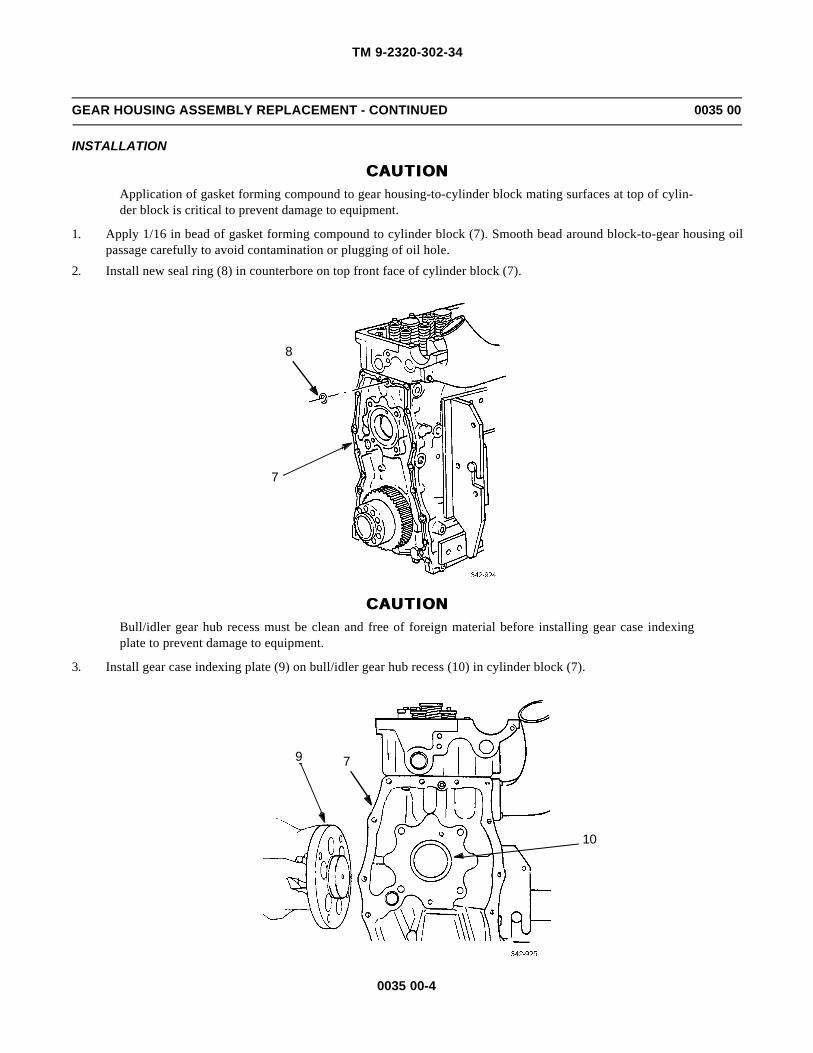
TM 9-2320-302-34
0035 00-4
GEAR HOUSING ASSEMBLY REPLACEMENT - CONTINUED 0035 00
INSTALLATION
CAUTIONCAUTIONApplication of gasket forming compound to gear housing-to-cylinder block mating surfaces at top of cylin-der block is critical to prevent damage to equipment.
1. Apply 1/16 in bead of gasket forming compound to cylinder block (7). Smooth bead around block-to-gear housing oilpassage carefully to avoid contamination or plugging of oil hole.
2. Install new seal ring (8) in counterbore on top front face of cylinder block (7).
CAUTIONCAUTIONBull/idler gear hub recess must be clean and free of foreign material before installing gear case indexingplate to prevent damage to equipment.
3. Install gear case indexing plate (9) on bull/idler gear hub recess (10) in cylinder block (7).
8
7
10
79

TM 9-2320-302-34
0035 00-5
GEAR HOUSING ASSEMBLY REPLACEMENT - CONTINUED 0035 00
INSTALLATION - CONTINUED
WARNINGWARNINGUse extreme caution when handling heavy parts. Provide adequate support and use assistance during proce-dure. Ensure that any lifting device used is in good condition and of suitable load capacity. Keep clear ofheavy parts supported only by lifting device. Failure to follow this warning may result in death or injury topersonnel.
4. Using suitable lifting device and 1/2 in nylon rope through camshaft thrust plate opening, support gear housing assem-bly (5). Position bull/idler gear hub opening in gear case over gear case indexing plate (9).
5. Index hole in gear housing assembly (5) left leg with diamond dowel (11) in lower left corner of cylinder block (7). Seatgear housing assembly firmly against cylinder block.
11
9
75

TM 9-2320-302-34
0035 00-6
GEAR HOUSING ASSEMBLY REPLACEMENT - CONTINUED 0035 00
INSTALLATION - CONTINUED
6. Install three shorter bolts in locations E, F, and I.
7. Install nine longer bolts in locations A through D, G, H, and J through L.
8. Tighten bolts to 43-54 lb-ft (58-73 Nm), in letter sequence shown.
9. Remove gear case indexing plate (9).
10. Install bolt (1) and new washer (2) in adjustable idler gear oil supply hole. Tighten bolt to 15-19 lb-ft (20-26 Nm).
11. Install bolt (3) and new washer (4) in adjustable idler gear holding access hole. Tighten bolt to 43-54 lb-ft (58-73 Nm).
L
H
K
G
B
D
A
C
I
E
FJ
TIGHTENING SEQUENCE

TM 9-2320-302-34
0035 00-7
GEAR HOUSING ASSEMBLY REPLACEMENT - CONTINUED 0035 00
INSTALLATION - CONTINUED
12. Install camshaft drive gear (WP 0034 00).
13. Install adjustable idler gear (WP 0038 00).
14. Install bull/idler gear (WP 0037 00).
15. Install synchronous reference sensor (SRS) (TM 9-2320-302-20).
16. Install timing reference sensor (TRS) (TM 9-2320-302-20).
17. Install camshaft and bearings (WP 0026 00).
END OF WORK PACKAGE
9
43
2
1

TM 9-2320-302-34
0035 00-8
This Page Intentionally Left Blank.

TM 9-2320-302-34
0036 00-1
CYLINDER BLOCK ASSEMBLY REPAIR 0036 00
THIS WORK PACKAGE COVERS
Disassembly, Cleaning and Inspection, Assembly
INITIAL SETUP
Maintenance Level
General Support
Tools and Special Tools
Tool kit, general mechanic’s (Item 132, WP 0126 00)
Bolts, eye (Item 9, WP 0126 00)
Bolts, eye (Item 10, WP 0126 00)
Caliper, micrometer, inside (Item 14, WP 0126 00)
Handle, installer (Item 46, WP 0126 00)
Inserter set, dowel (Item 55, WP 0126 00)
Installer set, cup plug (Item 72, WP 0126 00)
Puller kit, universal (Item 97, WP 0126 00)
Wrench, torque, 15-75 lb-ft (Item 138, WP 0126 00)
Wrench, torque, 100-600 lb-ft (Item 140,WP 0126 00)
Wrench set, socket, 3/4 in drive (Item 141, WP 0126 00)
Materials/Parts
Plug, cup (P/N 5139988) (2)
Plug, cup (P/N 5139991) (5)
Adhesive, loctite (Item 3, WP 0125 00)
Compound, corrosion preventive (Item 11,WP 0125 00)
Compound, international no. 2 (Item 13, WP 0125 00)
Oil, lubricating (Item 25, WP 0125 00)
Personnel Required
Two
References
TM 9-237
WP 0040 00
Equipment Condition
Electronic control module removed (TM 9-2320-302-20)
Engine injector wiring harness removed (WP 0069 00)
Fuel filter adapters removed (TM 9-2320-302-20)
Oil pressure and oil temperature sending unitsremoved (TM 9-2320-302-20)
Oil cooler, core, and oil filter adapter removed (TM 9-2320-302-20)
Oil dipstick and tube removed (TM 9-2320-302-20)
Oil fill tube removed (TM 9-2320-302-20)
Cylinder head removed (WP 0018 00)
Pistons and cylinder assemblies removed(WP 0041 00)
Crankshaft removed (WP 0033 00)
Gear housing assembly removed (WP 0035 00)
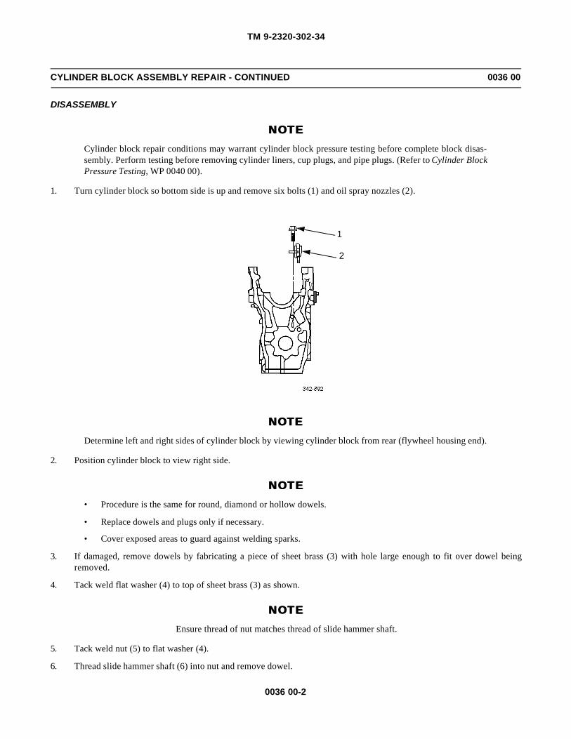
TM 9-2320-302-34
0036 00-2
CYLINDER BLOCK ASSEMBLY REPAIR - CONTINUED 0036 00
DISASSEMBLY
NOTENOTECylinder block repair conditions may warrant cylinder block pressure testing before complete block disas-sembly. Perform testing before removing cylinder liners, cup plugs, and pipe plugs. (Refer to Cylinder BlockPressure Testing, WP 0040 00).
1. Turn cylinder block so bottom side is up and remove six bolts (1) and oil spray nozzles (2).
NOTENOTEDetermine left and right sides of cylinder block by viewing cylinder block from rear (flywheel housing end).
2. Position cylinder block to view right side.
NOTENOTE• Procedure is the same for round, diamond or hollow dowels.
• Replace dowels and plugs only if necessary.
• Cover exposed areas to guard against welding sparks.
3. If damaged, remove dowels by fabricating a piece of sheet brass (3) with hole large enough to fit over dowel beingremoved.
4. Tack weld flat washer (4) to top of sheet brass (3) as shown.
NOTENOTEEnsure thread of nut matches thread of slide hammer shaft.
5. Tack weld nut (5) to flat washer (4).
6. Thread slide hammer shaft (6) into nut and remove dowel.
1
2

TM 9-2320-302-34
0036 00-3
CYLINDER BLOCK ASSEMBLY REPAIR - CONTINUED 0036 00
DISASSEMBLY - CONTINUED
7. If damaged, pierce five cup plug(s) (7) and cup plug (8) with screwdriver or chisel. Remove and discard plug(s).
8. Remove seven pipe plugs (9, 10, 11, and 12) and stud (13).
6
53
6
5
4
3
4
13
12
7
7
8
911
10
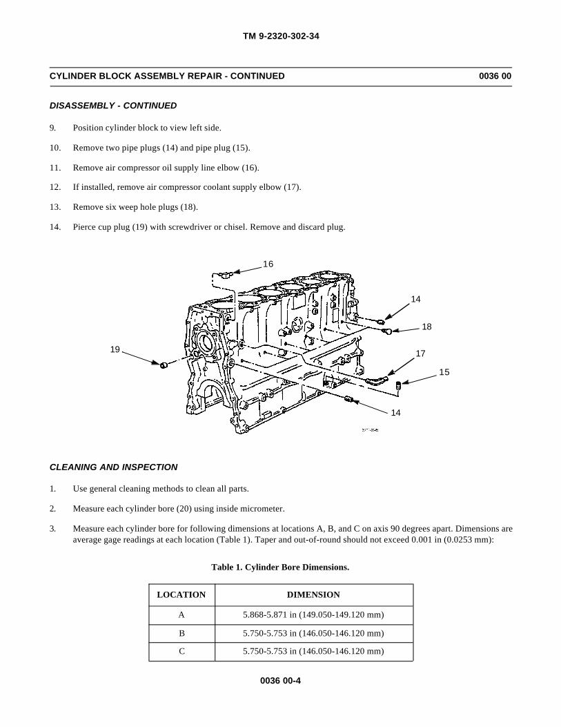
TM 9-2320-302-34
0036 00-4
CYLINDER BLOCK ASSEMBLY REPAIR - CONTINUED 0036 00
DISASSEMBLY - CONTINUED
9. Position cylinder block to view left side.
10. Remove two pipe plugs (14) and pipe plug (15).
11. Remove air compressor oil supply line elbow (16).
12. If installed, remove air compressor coolant supply elbow (17).
13. Remove six weep hole plugs (18).
14. Pierce cup plug (19) with screwdriver or chisel. Remove and discard plug.
CLEANING AND INSPECTION
1. Use general cleaning methods to clean all parts.
2. Measure each cylinder bore (20) using inside micrometer.
3. Measure each cylinder bore for following dimensions at locations A, B, and C on axis 90 degrees apart. Dimensions areaverage gage readings at each location (Table 1). Taper and out-of-round should not exceed 0.001 in (0.0253 mm):
Table 1. Cylinder Bore Dimensions.
LOCATION DIMENSION
A 5.868-5.871 in (149.050-149.120 mm)
B 5.750-5.753 in (146.050-146.120 mm)
C 5.750-5.753 in (146.050-146.120 mm)
14
15
17
18
14
16
19

TM 9-2320-302-34
0036 00-5
CYLINDER BLOCK ASSEMBLY REPAIR - CONTINUED 0036 00
CLEANING AND INSPECTION - CONTINUED
4. If any of above measurements are exceeded, replace cylinder block.
NOTENOTEPerform step 5 before gaging main bearing bores.
5. Install main bearing caps in original positions. Lubricate cap bolt threads and head contact surfaces with a small amountof international compound no. 2. Install and tighten main cap bolts to 347-391 lb-ft (470-530 Nm).
NOTENOTEReplace engine block if not within specification.
6. Measure each crankshaft main bearing bore (21) in vertical axis with inside micrometer. Dimension should be 5.236-5.237 in (133.000-133.025 mm). If dimension exceeds limits, replace cylinder block.
20
21

TM 9-2320-302-34
0036 00-6
CYLINDER BLOCK ASSEMBLY REPAIR - CONTINUED 0036 00
CLEANING AND INSPECTION - CONTINUED
7. Check cylinder block deck (22) for flatness with straightedge and thickness gage.
NOTENOTE
Because camshaft is mounted in cylinder head, resurfacing of block and/or head affects position of camshaftin relation to adjustable idler gear and gear train. Limit resurfacing on cylinder block to maximum of 0.01 in(0.25 mm). Limit resurfacing on block and head to combined total of 0.03 in (0.75 mm). If limits areexceeded, replace cylinder block.
8. Check front-to-rear flatness, next to cylinder liner flanges on both sides, and side-to-side flatness between liner flanges,as shown. Deck must be flat within 0.005 in (0.127 mm) front-to-rear and 0.003 in (0.076 mm) side-to-side. If not,resurface cylinder block.
9. Spray machined surfaces with engine lubricating oil if cylinder block is not to be used immediately. Spray or dip cylin-der block in corrosion preventive compound for extended storage.
22
A BC DE FG HI JK L
1
2

TM 9-2320-302-34
0036 00-7
CYLINDER BLOCK ASSEMBLY REPAIR - CONTINUED 0036 00
CLEANING AND INSPECTION - CONTINUED
10. Measure cylinder liner counterbore diameter (A) and depth (B). Diameter should be 6.186-6.191 in (157.15-157.25mm). Depth should be 0.3514-0.3533 in (8.9256-8.9746 mm).
ASSEMBLY
1. Coat outside sealing edge of five 1-1/2 in diameter cup plugs (7) with loctite adhesive. Using single-side plug installerand handle, install five cup plugs to 0.098-0.118-in (2.5-3.0 mm) below machined surfaces on right side of cylinderblock.
2. Coat outside sealing edge of 1.062 in cup plug (8) with loctite adhesive. Using small end of double-ended plug installerand driver handle, install cup plug 0.098-0.118 in (2.5-3.0 mm) below machined surface of rear of cylinder block.
3. Install 3/8 in pipe plug (9) and pipe plug (12).
4. Install four 1/4 in pipe plugs (10 and 11).
5. Install stud (13).
A
B
13
12
7
7
8
911
10
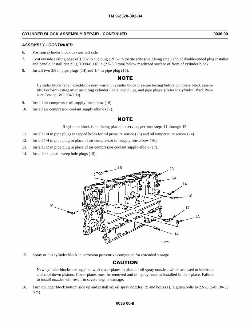
TM 9-2320-302-34
0036 00-8
CYLINDER BLOCK ASSEMBLY REPAIR - CONTINUED 0036 00
ASSEMBLY - CONTINUED
6. Position cylinder block to view left side.
7. Coat outside sealing edge of 1.062 in cup plug (19) with loctite adhesive. Using small end of double-ended plug installerand handle, install cup plug 0.098-0.118 in (2.5-3.0 mm) below machined surface of front of cylinder block.
8. Install two 3/8 in pipe plugs (14) and 1/4 in pipe plug (15).
NOTENOTECylinder block repair conditions may warrant cylinder block pressure testing before complete block assem-bly. Perform testing after installing cylinder liners, cup plugs, and pipe plugs. (Refer to Cylinder Block Pres-sure Testing, WP 0040 00).
9. Install air compressor oil supply line elbow (16).
10. Install air compressor coolant supply elbow (17).
NOTENOTEIf cylinder block is not being placed in service, perform steps 11 through 15.
11. Install 1/4 in pipe plugs in tapped holes for oil pressure sensor (23) and oil temperature sensor (24).
12. Install 1/4 in pipe plug in place of air compressor oil supply line elbow (16).
13. Install 1/2 in pipe plug in place of air compressor coolant supply elbow (17).
14. Install six plastic weep hole plugs (18).
15. Spray or dip cylinder block in corrosion preventive compound for extended storage.
CAUTIONCAUTIONNew cylinder blocks are supplied with cover plates in place of oil spray nozzles, which are used to lubricateand cool down pistons. Cover plates must be removed and oil spray nozzles installed in their place. Failureto install nozzles will result in severe engine damage.
16. Turn cylinder block bottom side up and install six oil spray nozzles (2) and bolts (1). Tighten bolts to 22-28 lb-ft (30-38Nm).
14
15
17
18
1424
2316
19

TM 9-2320-302-34
0036 00-9
CYLINDER BLOCK ASSEMBLY REPAIR - CONTINUED 0036 00
ASSEMBLY - CONTINUED
CAUTIONCAUTIONEnsure that diamond dowels are correctly aligned. Orientation is critical to component alignment. Failure tocorrectly align diamond dowels could result in engine failure.
NOTENOTEIf new cylinder block is being placed in service, perform steps 17 through 22.
17. Using dowel inserter set, install diamond dowel (25) and round dowel (26) in cylinder block fire deck to height of0.472+/-0.002 in (12.0+/-0.5 mm). Angular orientation of diamond dowel must be perpendicular to centerline (27)through round and diamond dowels within 4 degrees.
1
2
26
2527
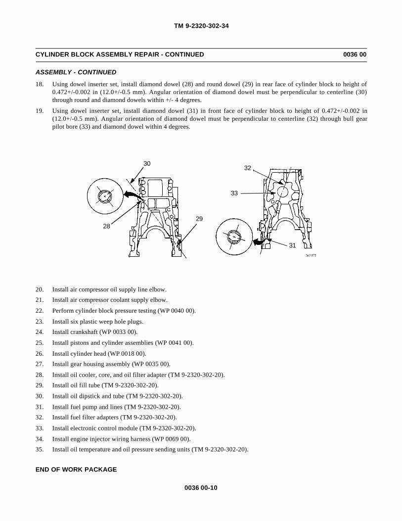
TM 9-2320-302-34
0036 00-10
CYLINDER BLOCK ASSEMBLY REPAIR - CONTINUED 0036 00
ASSEMBLY - CONTINUED
18. Using dowel inserter set, install diamond dowel (28) and round dowel (29) in rear face of cylinder block to height of0.472+/-0.002 in (12.0+/-0.5 mm). Angular orientation of diamond dowel must be perpendicular to centerline (30)through round and diamond dowels within +/- 4 degrees.
19. Using dowel inserter set, install diamond dowel (31) in front face of cylinder block to height of 0.472+/-0.002 in(12.0+/-0.5 mm). Angular orientation of diamond dowel must be perpendicular to centerline (32) through bull gearpilot bore (33) and diamond dowel within 4 degrees.
20. Install air compressor oil supply line elbow.
21. Install air compressor coolant supply elbow.
22. Perform cylinder block pressure testing (WP 0040 00).
23. Install six plastic weep hole plugs.
24. Install crankshaft (WP 0033 00).
25. Install pistons and cylinder assemblies (WP 0041 00).
26. Install cylinder head (WP 0018 00).
27. Install gear housing assembly (WP 0035 00).
28. Install oil cooler, core, and oil filter adapter (TM 9-2320-302-20).
29. Install oil fill tube (TM 9-2320-302-20).
30. Install oil dipstick and tube (TM 9-2320-302-20).
31. Install fuel pump and lines (TM 9-2320-302-20).
32. Install fuel filter adapters (TM 9-2320-302-20).
33. Install electronic control module (TM 9-2320-302-20).
34. Install engine injector wiring harness (WP 0069 00).
35. Install oil temperature and oil pressure sending units (TM 9-2320-302-20).
END OF WORK PACKAGE
3032
33
31
2928

TM 9-2320-302-34
0037 00-1
BULL/IDLER GEAR REPLACEMENT 0037 00
THIS WORK PACKAGE COVERS
Removal, Cleaning and Inspection, Installation
INITIAL SETUP
Maintenance Level
General Support
Tools and Special Tools
Tool kit, general mechanic’s (Item 132, WP 0126 00)
Alignment stud set (Item 7, WP 0126 00)
Barring tool, engine (Item 8, WP 0126 00)
Dial indicator set (Item 29, WP 0126 00)
Tools and Special Tools - Continued
Protector, crankshaft (Item 92, WP 0126 00)
Wrench, torque, 50-250 lb-ft (Item 139, WP 0126 00)
Equipment Condition
Gear case cover removed (WP 0019 00)
Rocker arm assemblies removed (WP 0027 00)
Engine installed on repair stand
REMOVAL
1. Install engine barring tool (1) on front end of crankshaft. Bar engine over until four access holes (2) in bull/idler gearline up with four bolts (3) in cylinder block.
2. Remove two upper bolts (3) and install two guide studs (4).
4
3
2
1
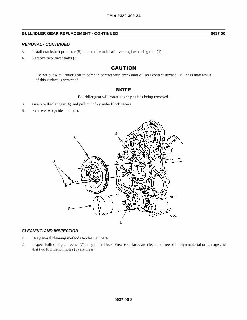
TM 9-2320-302-34
0037 00-2
BULL/IDLER GEAR REPLACEMENT - CONTINUED 0037 00
REMOVAL - CONTINUED
3. Install crankshaft protector (5) on end of crankshaft over engine barring tool (1).
4. Remove two lower bolts (3).
CAUTIONCAUTIONDo not allow bull/idler gear to come in contact with crankshaft oil seal contact surface. Oil leaks may resultif this surface is scratched.
NOTENOTEBull/idler gear will rotate slightly as it is being removed.
5. Grasp bull/idler gear (6) and pull out of cylinder block recess.
6. Remove two guide studs (4).
CLEANING AND INSPECTION
1. Use general cleaning methods to clean all parts.
2. Inspect bull/idler gear recess (7) in cylinder block. Ensure surfaces are clean and free of foreign material or damage andthat two lubrication holes (8) are clear.
4
1
5
3
6

TM 9-2320-302-34
0037 00-3
BULL/IDLER GEAR REPLACEMENT - CONTINUED 0037 00
CLEANING AND INSPECTION - CONTINUED
3. Inspect all parts for wear or damage.
INSTALLATION
CAUTIONCAUTIONEnsure all timing marks are aligned as shown. Failure to do so will result in engine damage.
1. Install two guide studs (4) in two upper bull/idler gear bolt holes.
8
7
4
4

TM 9-2320-302-34
0037 00-4
BULL/IDLER GEAR REPLACEMENT - CONTINUED 0037 00
INSTALLATION - CONTINUED
2. Bar engine over until crankshaft timing gear timing mark (9) is at 12 o’clock position.
3. Align timing mark (10) on camshaft drive gear with timing mark (11) on adjustable gear.
CAUTIONCAUTIONDo not allow bull/idler gear to come in contact with crankshaft oil seal contact surface. Oil leaks may resultif this surface is scratched.
4. Install bull/idler gear (6) on two guide studs (4). Slide assembly toward engine, but do not engage any gears.
5. Align timing mark (12) on bull/idler gear (6) with timing mark (9) on crankshaft timing gear. Engage bull/idler gear andcrankshaft timing gear only enough to prevent rotation of bull/idler gear.
NOTENOTESlight rotation of adjustable idler gear may be necessary to align timing marks.
6. Looking through viewing hole (13) in bull/idler gear (6), align timing mark (14) on adjustable idler gear with timingmark (15) on camshaft idler gear.
7. Slide bull/idler gear (6) toward engine, engaging adjustable gear, and seat assembly in recess of gear case and cylinderblock.
8. Working through two access holes (2) in bull/idler gear (6), install two mounting bolts (3) through hub and into cylinderblock. Tighten bolts hand tight.
9. Remove two guide studs (4) and install two remaining mounting bolts (3). Tighten four bolts to 75-86 lb-ft (102-117Nm).
10. Remove crankshaft protector (5) and engine barring tool (1).
1011
4
15
14
13
6
12
9
4

TM 9-2320-302-34
0037 00-5
BULL/IDLER GEAR REPLACEMENT - CONTINUED 0037 00
INSTALLATION - CONTINUED
11. Measure gear lash between crankshaft timing gear (16) to bull/idler gear (6). Allowable lash is 0.002-0.009 in (0.051-0.229 mm) for new parts and a maximum of 0.012 in (0.305 mm) for used parts.
12. Measure gear lash between camshaft idler gear (17) to adjustable idler gear (18). Allowable lash is 0.002-0.009 in(0.051-0.229 mm) for new parts and a maximum of 0.012 in (0.305 mm) for used parts.
6
4
3
2
1
5
18
17
6
16
TM 9-2320-302-34
0037 00-6
BULL/IDLER GEAR REPLACEMENT - CONTINUED 0037 00
INSTALLATION - CONTINUED
13. Install rocker arm assemblies (WP 0027 00).
14. Install gear case cover (WP 0019 00).
END OF WORK PACKAGE

TM 9-2320-302-34
0038 00-1
ADJUSTABLE IDLER GEAR REPLACEMENT 0038 00
THIS WORK PACKAGE COVERS
Removal, Inspection, Installation, Adjustment
INITIAL SETUP
Maintenance Level
General Support
Tools and Special Tools
Tool kit, general mechanic’s (Item 132, WP 0126 00)
Adjuster, lash, cam (Item 5, WP 0126 00)
Barring tool, engine (Item 8, WP 0126 00)
Dial indicator set (Item 29, WP 0126 00)
Wrench, torque, 15-75 lb-ft (Item 138, WP 0126 00)
Wrench, torque, 50-250 lb-ft (Item 139, WP 0126 00)
Materials/Parts
Cloth, abrasive (Item 9, WP 0125 00)
Oil, lubricating (Item 25, WP 0125 00)
References
WP 0013 00
Equipment Condition
Rocker arm assemblies removed (WP 0027 00)
Engine installed on repair stand
Bull/idler gear removed (WP 0037 00)
REMOVAL
1. Remove three nuts (1) and retaining plate (2).
2
1

TM 9-2320-302-34
0038 00-2
ADJUSTABLE IDLER GEAR REPLACEMENT - CONTINUED 0038 00
REMOVAL
2. Remove adjustable idler gear (3) and hub (4) from gear housing assembly (5).
INSPECTION
1. Examine adjustable idler gear teeth for scoring, pitting, and wear. If damaged or worn, replace adjustable idler gear.Inspect other gear train gears.
2. Inspect contact surface of hub for scoring or evidence of overheating (blue discoloration). Replace hub if it has beenoverheated. Check lubrication hole and gear gallery for blockage. Slight irregularities in hub contact surface may beremoved with fine stone or emery cloth.
3. Inspect bushing contact surface for signs of scoring, discoloration due to overheating or excessive wear. Allowableclearance between bushing and hub is 0.0013-0.0030 in (0.035-0.078 mm). Replace gear and bushing as an assembly, ifclearance is more than allowable or if surface of bushing is scored or has been overheated.
INSTALLATION
1. Install hub (4) on three studs (6) in gear housing assembly (5). Word “OUT” stamped on hub must be at top and facingforward. Lubricate hub and adjustable idler gear bushing (7) with clean engine lubricating oil.
CAUTIONCAUTIONTwo timing marks are on adjustable idler gear. Diamond-shaped mark must align with diamond mark oncamshaft drive gear. Other mark should be between 5 and 6 o’clock to prevent damage to equipment.
543
74
65
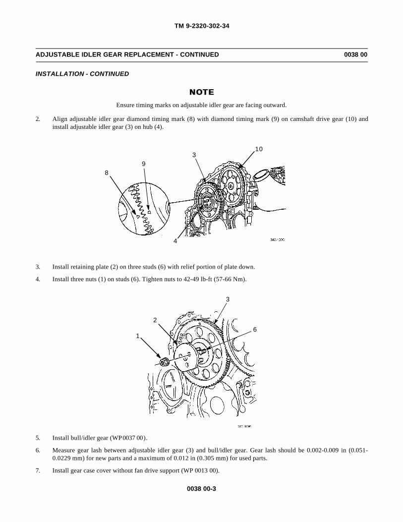
TM 9-2320-302-34
0038 00-3
ADJUSTABLE IDLER GEAR REPLACEMENT - CONTINUED 0038 00
INSTALLATION - CONTINUED
NOTENOTEEnsure timing marks on adjustable idler gear are facing outward.
2. Align adjustable idler gear diamond timing mark (8) with diamond timing mark (9) on camshaft drive gear (10) andinstall adjustable idler gear (3) on hub (4).
3. Install retaining plate (2) on three studs (6) with relief portion of plate down.
4. Install three nuts (1) on studs (6). Tighten nuts to 42-49 lb-ft (57-66 Nm).
5. Install bull/idler gear (WP 0037 00).
6. Measure gear lash between adjustable idler gear (3) and bull/idler gear. Gear lash should be 0.002-0.009 in (0.051-0.0229 mm) for new parts and a maximum of 0.012 in (0.305 mm) for used parts.
7. Install gear case cover without fan drive support (WP 0013 00).
89
310
4
1
26
3

TM 9-2320-302-34
0038 00-4
ADJUSTABLE IDLER GEAR REPLACEMENT - CONTINUED 0038 00
INSTALLATION - CONTINUED
8. Measure gear lash between adjustable idler gear and camshaft drive gear. Using cam/idler lash adjuster, gear lash shouldbe 0.002-0.009 in (0.051-0.229 mm) for new parts and a maximum of 0.012 in (0.305 mm) for used parts. Reading isone-half of actual measurement. Multiply reading by 2 to determine specification.
ADJUSTMENT
1. Loosen three nuts (1) until hand tight.
2. Insert dowel portion of cam/idler lash adjuster (11) in center hole of retaining plate (2).
3. Secure engine barring tool (12) to bottom of access cover opening with two access cover bolts (13). Tighten bolts to 20lb-ft (27 Nm).
4. Install cam/idler lash pedestal in threaded hole in leg of camshaft drive gear (10).
NOTENOTEEnsure dial indicator rests squarely on pedestal flat.
5. Mount dial indicator so stem of indicator rests on scribed line of pedestal flat.
6. Remove bolt (14) and washer (15).
7. Turn adjusting screw (16) clockwise to move adjustable idler gear toward camshaft drive gear (10) until there is zerolash.
8. Insert screwdriver through access bolt hole (17) and engage adjustable idler gear tooth to determine gear lash.
9. Apply pressure on screwdriver to hold adjustable idler gear in counterclockwise direction and attempt to move camshaftdrive gear (10) by hand. Watch dial indicator pointer. If there is zero lash, pointer will not move.
NOTENOTEGear lash reading obtained on cam/idler lash pedestal is one-half actual gear lash. Reading on dial indicatormust be doubled to determine if specification is met.
10. When zero lash is obtained, turn adjusting screw (16) approximately 1-1/2 turns counterclockwise or until correct gearlash is obtained.
11
1
14, 15
12
10
2
13

TM 9-2320-302-34
0038 00-5
ADJUSTABLE IDLER GEAR REPLACEMENT - CONTINUED 0038 00
ADJUSTMENT - CONTINUED
11. Bar engine to check adjustable idler gear lash on camshaft drive gear (10) at 3, 6, 9, and 12 o’clock positions.
12. When gear lash is 0.002-0.009 in (0.051-0.229 mm) for new parts and a maximum of 0.012 in (0.305 mm) for used partsat all four positions, tighten two top nuts (1) to 42-49 lb-ft (57-67 Nm).
13. Remove cam/idler lash adjuster (12) and tighten lower nut to 42-49 lb-ft (57-66 Nm).
14. Remove gear lash pedestal from camshaft drive gear (10).
15. Install washer (15) and bolt (14). Tighten bolt to 75-86 lb-ft (102-117 Nm).
16. Install rocker arm assemblies (WP 0027 00).
END OF WORK PACKAGE
1 10
3
16
12
17

TM 9-2320-302-34
0038 00-6
This Page Intentionally Left Blank.

TM 9-2320-302-34
0039 00-1
ACCESSORY DRIVE REPAIR 0039 00
THIS WORK PACKAGE COVERS
Disassembly, Assembly
INITIAL SETUP
Maintenance Level
General Support
Tools and Special Equipment
Tool kit, general mechanic’s (Item 132, WP 0126 00)
Checker, gear lash (Item 18, WP 0126 00)
Pliers, retaining ring (Item 88, WP 0126 00)
Pliers, retaining ring (Item 89, WP 0126 00)
Press, arbor (Item 90, WP 0126 00)
Service kit, accessory drive (Item 111, WP 0126 00)
Vise, machinist’s (Item 136, WP 0126 00)
Wrench, torque, 50-250 lb-ft (Item 139, WP 0126 00)
Materials/Parts
Bearing, ball (P/N BBA194940)
Bearing, needle (P/N JH-2216)
Nut, lock (P/N 11509584)
Seal, oil (P/N V484156VG)
Lubriplate (Item 23, WP 0125 00)
Oil, lubricating (Item 25, WP 0125 00)
Equipment Condition
Accessory drive removed (WP 0021 00)
DISASSEMBLY
1. Install accessory drive assembly (1) and three fixture screws (2) on service kit holding fixture (3).
2
31
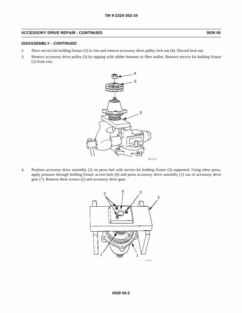
TM 9-2320-302-34
0039 00-2
ACCESSORY DRIVE REPAIR - CONTINUED 0039 00
DISASSEMBLY - CONTINUED
2. Place service kit holding fixture (3) in vise and remove accessory drive pulley lock nut (4). Discard lock nut.
3. Remove accessory drive pulley (5) by tapping with rubber hammer or fiber mallet. Remove service kit holding fixture(3) from vise.
4. Position accessory drive assembly (1) on press bed with service kit holding fixture (3) supported. Using arbor press,apply pressure through holding fixture access hole (6) and press accessory drive assembly (1) out of accessory drivegear (7). Remove three screws (2) and accessory drive gear.
4
5
3
2 23
1
6
7

TM 9-2320-302-34
0039 00-3
ACCESSORY DRIVE REPAIR - CONTINUED 0039 00
DISASSEMBLY - CONTINUED
5. Remove snap ring (8) from accessory drive assembly (1).
6. Turn accessory drive assembly (1) over and support on machined surface. Using press, apply pressure to pulley end ofaccessory drive shaft and bearing assembly (9). Remove accessory drive shaft and bearing assembly from accessorydrive assembly.
1
8
9
1

TM 9-2320-302-34
0039 00-4
ACCESSORY DRIVE REPAIR - CONTINUED 0039 00
DISASSEMBLY - CONTINUED
NOTENOTEWord INSTALL and an arrow are etched on needle bearing remover/installer to aid in installation. Placeneedle bearing identification numbers up against needle bearing remover/installer.
7. Turn accessory drive assembly (1) over and support on attaching bolt bosses. Place long end of service kit needle bear-ing remover/installer (10) in accessory drive assembly against needle bearing (11). Apply pressure to needle bearingremover/installer and remove and discard needle bearing and oil seal (12).
8. Remove snap ring (13) from accessory drive shaft and bearing assembly (9).
9. Place two steel press plates (14) under ball bearing assembly (15) outer race. Apply pressure to top of accessory driveshaft and bearing assembly (9) and remove and discard ball bearing assembly.
11
12
1
10
13
9

TM 9-2320-302-34
0039 00-5
ACCESSORY DRIVE REPAIR - CONTINUED 0039 00
DISASSEMBLY - CONTINUED
ASSEMBLY
1. Place new ball bearing assembly (15) on accessory drive shaft (9). Place small opening of service kit bearing installer(16) over ball bearing assembly inner race. Press until ball bearing assembly bottoms against shoulder of accessory driveshaft.
1514
9
16
9
15

TM 9-2320-302-34
0039 00-6
ACCESSORY DRIVE REPAIR - CONTINUED 0039 00
ASSEMBLY - CONTINUED
NOTENOTE• Ensure tapered side of snap ring is installed away from bearing.
• Ensure snap ring is fully seated in groove of accessory drive shaft.
2. Install snap ring (13) in groove of accessory drive shaft (9).
NOTENOTEWord INSTALL and an arrow are etched on needle bearing installer/remover to aid in installation. Placeneedle bearing installation numbers up against needle bearing installer/remover.
3. Install new needle bearing (11) in accessory drive housing (1). Using long end of service kit needle bearing installer/remover (10), press needle bearing into accessory drive housing flush to 0.02 in (0.5 mm) below bottom of oil seal coun-terbore.
13
9
1
11
10

TM 9-2320-302-34
0039 00-7
ACCESSORY DRIVE REPAIR - CONTINUED 0039 00
ASSEMBLY - CONTINUED
4. Install new oil seal (12) in accessory drive assembly housing (1). Using service kit seal installer (17) and plastic hammeror fiber mallet, install oil seal flush to 0.01 in (0.25 mm) below face of accessory drive assembly housing.
5. Support service kit holding fixture (3) on two steel plates (14) and place accessory drive assembly housing (1) in servicekit holding fixture hole. Lubricate ball bearing assembly (15) with clean engine lubricating oil and install accessorydrive shaft and bearing assembly (9) in accessory drive assembly housing.
17
12
1
15
9
1
314
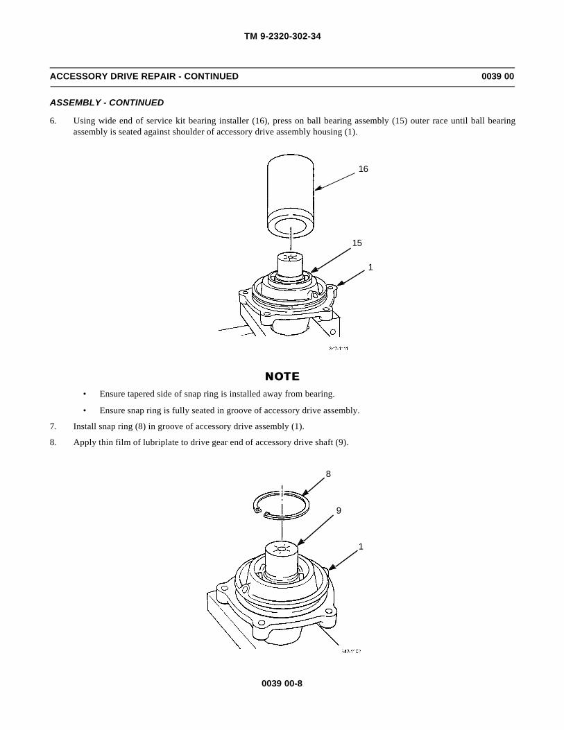
TM 9-2320-302-34
0039 00-8
ACCESSORY DRIVE REPAIR - CONTINUED 0039 00
ASSEMBLY - CONTINUED
6. Using wide end of service kit bearing installer (16), press on ball bearing assembly (15) outer race until ball bearingassembly is seated against shoulder of accessory drive assembly housing (1).
NOTENOTE• Ensure tapered side of snap ring is installed away from bearing.
• Ensure snap ring is fully seated in groove of accessory drive assembly.
7. Install snap ring (8) in groove of accessory drive assembly (1).
8. Apply thin film of lubriplate to drive gear end of accessory drive shaft (9).
16
15
1
1
8
9

TM 9-2320-302-34
0039 00-9
ACCESSORY DRIVE REPAIR - CONTINUED 0039 00
ASSEMBLY - CONTINUED
NOTENOTESupport opposite end of accessory drive shaft on press bed when pressing gear on shaft.
9. Place accessory drive gear (7) on accessory drive shaft (9) with chamfered end of bore toward accessory drive shaft.Using press, install accessory drive gear until accessory drive gear is flush with end of accessory drive shaft. Obtainminimum press load of 4000 lb (17.8 kN).
10. Install service kit holding fixture (3) and three fixture screws (2) on accessory drive gear (7).
11. Install service kit holding fixture (3) in vise.
7
9
2
3

TM 9-2320-302-34
0039 00-10
ACCESSORY DRIVE REPAIR - CONTINUED 0039 00
ASSEMBLY - CONTINUED
NOTENOTEIf necessary, use narrow opening end of service kit bearing installer to seat accessory drive pulley. If press-ing is necessary, support opposite gear end of accessory drive shaft.
12. Install accessory drive pulley (5) on accessory drive shaft (9).
13. Install new accessory drive pulley lock nut (4) and tighten to 162-184 lb-ft (220-250 Nm).
14. Remove service kit holding fixture (3) from vise and remove three fixture screws (2) from accessory drive gear (7).
4
5
3
9
2
3
7

TM 9-2320-302-34
0039 00-11
ACCESSORY DRIVE REPAIR - CONTINUED 0039 00
ASSEMBLY - CONTINUED
15. Support accessory drive assembly (1) as shown. Position dial indicator (18) so indicator stem (19) rests on face of acces-sory drive gear (7) just inboard of accessory drive gear teeth.
NOTENOTEAs accessory drive gear is rotated, dial indicator needle may register to left and right of zero. Total amountof dial indicator needle movement gives total indicated runout (TIR).
16. Zero dial indicator (18). Rotate accessory drive gear (7) two full rotation. Allowable TIR is 0.0015 in (0.04 mm).
END OF WORK PACKAGE
2
1
18
7
19

TM 9-2320-302-34
0039 00-12
This Page Intentionally Left Blank.

TM 9-2320-302-34
0040 00-1
CYLINDER BLOCK PRESSURE TESTING 0040 00
THIS WORK PACKAGE COVERS
Testing
INITIAL SETUP
Maintenance Level
General Support
Tools and Special Tools
Tool kit, general mechanic’s (Item 132, WP 0126 00)
Adapter, cylinder (Item 1, WP 0126 00)
Tester, cylinder (Item 123, WP 0126 00)
Tester, cylinder (Item 124, WP 0126 00)
Wrench, torque, 0-300 lb-in (Item 137, WP 0126 00)
Wrench, torque, 50-250 lb-ft (Item 139, WP 0126 00)
Screw (P/N 8929129)
Materials/Parts
Plug, pipe (P/N 8923916)
Detergent (Item 19, WP 0125 00)
Equipment Condition
All components removed from cylinder block exceptnecessary cup plugs, pipe plugs, and cylinder linersused for pressure testing (WP 0036 00).
TESTING
1. If present, remove six weep hole plugs (1).
1

TM 9-2320-302-34
0040 00-2
CYLINDER BLOCK PRESSURE TESTING - CONTINUED 0040 00
TESTING - CONTINUED
NOTENOTE• Ensure all hose connectors and elbows are removed from block and holes are properly plugged.
• Ensure all cup plugs and pipe plugs are in place.
• Ensure all cylinder liners, cylinder liner seal rings, and crevice seals are in place.
2. From cylinder block pressure test kit, position six test rings (2) on top of cylinder liner flanges. Install two test ringretaining strips (3).
3. Install 14 bolts (4) and tighten to 170-175 lb-ft (231-237 Nm).
4. Position two outside sealing strips (5) on cylinder block (6) with rubber surface against cylinder block. Install 20 bolts(7) and tighten to 120 lb-in (14 Nm).
5. Install water manifold cover (8) in oil cooler neck opening (9). Use bolt (10) supplied to secure water manifold cover.
6. Attach air line to fitting (11) on upper manifold cover.
6
2
5
3
4
7

TM 9-2320-302-34
0040 00-3
CYLINDER BLOCK PRESSURE TESTING - CONTINUED 0040 00
TESTING - CONTINUED
WARNINGWARNINGCompressed air used for cleaning or drying purposes, or for clearing restrictions, should never exceed 30 psi(207 kPa). Wear protective clothing (goggles/shield, gloves, etc.) and use caution to avoid injury to person-nel.
7. Apply 20 psi (138 kPa) air pressure to cylinder block using attached air line.
8. Spray cylinder block with detergent and water solution and observe solution for bubbles, indicating cracks or leaks. Ifcracks are detected, replace cylinder block.
9. Remove air supply line.
10. Remove 20 bolts (7) and two outside sealing strips (5).
11. Remove 14 bolts (4), two test ring retaining strips (3), and six test rings (2).
12. Remove bolt (10) and water manifold cover (8).
13. Clear out all passages and bolt holes with compressed air.
END OF WORK PACKAGE
8
11
10
9

TM 9-2320-302-34
0040 00-4
This Page Intentionally Left Blank.

TM 9-2320-302-34
0041 00-1
PISTON AND CYLINDER ASSEMBLY MAINTENANCE 0041 00
THIS WORK PACKAGE COVERS
Removal, Inspection, Installation
INITIAL SETUP
Maintenance Level
General Support
Tools and Special Tools
Tool kit, general mechanic’s (Item 132, WP 0126 00)
Compressor, piston ring (Item 22, WP 0126 00)
Gage, profile (Item 36, WP 0126 00)
Gage, profile (Item 38, WP 0126 00)
Guides, connecting rod (Item 44, WP 0126 00)
Pliers, piston ring (Item 85, WP 0126 00)
Press, cylinder liner (Item 91, WP 0126 00)
Protector, piston (Item 93, WP 0126 00)
Puller, mechanical (Item 94, WP 0126 00)
Wrench, torque, 50-250 lb-ft (Item 139, WP 0126 00)
Materials/Parts
Cylinder liner set (P/N 23523948)
Piston ring kit (P/N 23525553)
Cloth, abrasive (Item 9, WP 0125 00)
Compound, international, no. 2 (Item 13, WP 0125 00)
Gage, bearing clearance (Item 20, WP 0125 00)
Oil, lubricating (Item 25, WP 0125 00)
Rags, wiping (Item 31, WP 0125 00)
References
WP 0040 00
Equipment Condition
Engine installed on repair stand
Cylinder head removed (WP 0018 00)
Oil pump removed (WP 0029 00)
REMOVAL
1. Rotate engine on stand so engine gear case is up.
2. Bar engine over until connecting rod (1) of cylinder being serviced is at bottom of travel.
1

TM 9-2320-302-34
0041 00-2
PISTON AND CYLINDER ASSEMBLY MAINTENANCE - CONTINUED 0041 00
REMOVAL - CONTINUED
3. With ridge reamer, remove carbon ridge (2) at top of cylinder liner (3) above upper travel limit of top piston ring.
NOTENOTEEnsure connecting rods and caps are stamped with correct location number. If not stamped, stamp correctlocation (1 through 6) on tang side (cooler side) of rod cap and rod.
4. Remove two connecting rod cap nuts (4), connecting rod cap (5), and lower connecting rod bearing shell (6).
2
3
4
56

TM 9-2320-302-34
0041 00-3
PISTON AND CYLINDER ASSEMBLY MAINTENANCE - CONTINUED 0041 00
REMOVAL - CONTINUEDCAUTIONCAUTION
When removing piston from engine, use care and avoid damaging piston cooling nozzle installed in base ofcylinder bore.
5. Install two connecting rod guides (7) on two connecting rod bolts (8) to protect crankshaft journal. Push connecting rodand piston assembly (9) through top of cylinder block.
NOTENOTEConnecting rod caps are numbered according to cylinder position with matching numbers stamped on tangside of connecting rod. Always assemble rods and caps in original positions as marked.
6. Assemble connecting rod and piston assembly (9), connecting rod cap (5), and lower connecting rod bearing shell (6).
7. Install two connecting rod cap nuts (4) hand tight.
8
7
9
9
6
5
4

TM 9-2320-302-34
0041 00-4
PISTON AND CYLINDER ASSEMBLY MAINTENANCE - CONTINUED 0041 00
REMOVAL - CONTINUED
8. Repeat procedures in step 2 through 7 for each piston and cylinder being serviced.
NOTENOTEPiston assembly components should be segregated by cylinder and matchmarked during disassembly toensure installation in same position.
9. Place connecting rod and piston assembly (9) dome side down on workbench.
10. Remove two piston retaining rings (10) and piston pin (11).
11. Remove connecting rod (12).
12. Remove piston skirt (13) from dome (14).
13. Using piston ring pliers, remove and discard fire (top) and middle compression rings (15), lower oil control ring (16),and oil control ring expander (17) from piston dome (14).
1211
10 13
10
14
9
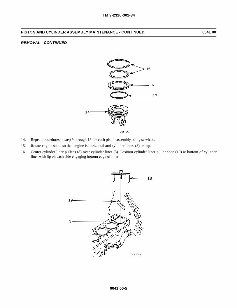
TM 9-2320-302-34
0041 00-5
PISTON AND CYLINDER ASSEMBLY MAINTENANCE - CONTINUED 0041 00
REMOVAL - CONTINUED
14. Repeat procedures in step 9 through 13 for each piston assembly being serviced.
15. Rotate engine stand so that engine is horizontal and cylinder liners (3) are up.
16. Center cylinder liner puller (18) over cylinder liner (3). Position cylinder liner puller shoe (19) at bottom of cylinderliner with lip on each side engaging bottom edge of liner.
15
16
17
14
18
19
3
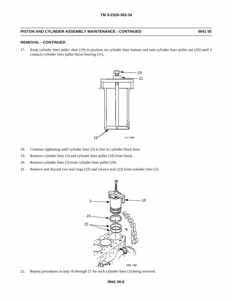
TM 9-2320-302-34
0041 00-6
PISTON AND CYLINDER ASSEMBLY MAINTENANCE - CONTINUED 0041 00
REMOVAL - CONTINUED
17. Keep cylinder liner puller shoe (19) in position on cylinder liner bottom and turn cylinder liner puller nut (20) until itcontacts cylinder liner puller thrust bearing (21).
18. Continue tightening until cylinder liner (3) is free in cylinder block bore.
19. Remove cylinder liner (3) and cylinder liner puller (18) from block.
20. Remove cylinder liner (3) from cylinder liner puller (18).
21. Remove and discard two seal rings (22) and crevice seal (23) from cylinder liner (3).
22. Repeat procedures in step 16 through 21 for each cylinder liner (3) being serviced.
19
2120
183
23
22
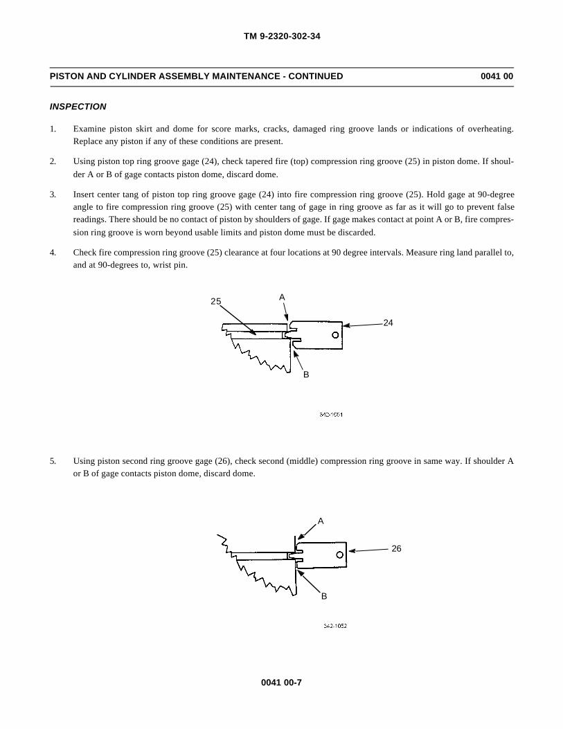
TM 9-2320-302-34
0041 00-7
PISTON AND CYLINDER ASSEMBLY MAINTENANCE - CONTINUED 0041 00
INSPECTION
1. Examine piston skirt and dome for score marks, cracks, damaged ring groove lands or indications of overheating.Replace any piston if any of these conditions are present.
2. Using piston top ring groove gage (24), check tapered fire (top) compression ring groove (25) in piston dome. If shoul-
der A or B of gage contacts piston dome, discard dome.
3. Insert center tang of piston top ring groove gage (24) into fire compression ring groove (25). Hold gage at 90-degreeangle to fire compression ring groove (25) with center tang of gage in ring groove as far as it will go to prevent falsereadings. There should be no contact of piston by shoulders of gage. If gage makes contact at point A or B, fire compres-
sion ring groove is worn beyond usable limits and piston dome must be discarded.
4. Check fire compression ring groove (25) clearance at four locations at 90 degree intervals. Measure ring land parallel to,and at 90-degrees to, wrist pin.
5. Using piston second ring groove gage (26), check second (middle) compression ring groove in same way. If shoulder Aor B of gage contacts piston dome, discard dome.
25
24
A
B
A
B
26

TM 9-2320-302-34
0041 00-8
PISTON AND CYLINDER ASSEMBLY MAINTENANCE - CONTINUED 0041 00
INSPECTION - CONTINUED
6. Hold new oil control ring (16) in oil control ring groove so that oil control ring face is flush with edge of piston dome.Do not push ring to bottom of oil control ring groove. Insert feeler gage (27) between top of oil control ring and ringland of oil control ring groove in piston dome. If clearance is greater than 0.004 in (0.11 mm), discard dome.
CAUTIONCAUTIONIn order to prevent possible damage to equipment, DO NOT use crocus cloth to polish or refinish piston pin.Piston pins cannot be polished or refinished.
7. If piston pin (11) shows signs of fretting, overheating or is worn to diameter of 1.77 in (44.96 mm), replace piston pin.
8. Replace connecting rod (12) if subjected to any of the following:
a. Visual damage (bent)
b. Previous bearing or related failure
c. Connecting rod bluing at top or bottom end
d. Fretting at split line between connecting rod and connecting rod cap
e. Excessive pound-in of rod bolt heads, nuts, and of piston pin bolt and spacer
f. Unusual cylinder wear patterns
g. Gouges, nicks or burrs on machined surface of connecting rods at piston pin end
16
27
11

TM 9-2320-302-34
0041 00-9
PISTON AND CYLINDER ASSEMBLY MAINTENANCE - CONTINUED 0041 00
INSPECTION - CONTINUED
9. Check connecting rod bolts and connecting rod cap nuts for thread damage or fretting on underside of heads. Replacerod bolts and connecting rod cap nuts if either condition is present.
10. Measure connecting rod bore at points A, B, and C. Average of bore readings must be within 3.594-3.595 in (91.288-91.313m).
NOTENOTE• Replace rod and main bearings whenever crankshaft is replaced or engine is rebuilt.
• Overlay plated bearings may develop very small cracks or small isolated cavities (checking) on bearingsurface during engine operation. These are characteristics of, and are not detrimental to, this type ofbearing. Bearing should not be replaced for these minor surface imperfections.
11. Inspect bearings for scoring, pitting, flaking, chipping, cracking, loss of overlay or signs of overheating. If any of theseconditions are present, discard bearings.
NOTENOTEUpper connecting rod bearing shells will normally show signs of distress before lower connecting rod bear-ing shells. If overlay is worn to copper across connecting rod bearing shell, replace all connecting rod bear-ing shells.
12

TM 9-2320-302-34
0041 00-10
PISTON AND CYLINDER ASSEMBLY MAINTENANCE - CONTINUED 0041 00
INSPECTION - CONTINUED
12. Inspect backs of bearing shells for bright spots. If such spots are present, replace bearing shells. Inspect connecting rodbearing bores for burrs or foreign particles.
NOTENOTEInstall new upper and lower connecting rod bearing shells if new crankshaft is used.
13. Using micrometer and ball attachment, measure thickness of connecting rod bearing shell (6). Minimum thickness ofworn standard connecting rod bearing shell should not be less than 0.1215 in (3.086 mm). If either upper or lower con-necting rod bearing shell of connecting rod set is less than minimum thickness, replace both bearing shells.
14. Examine cylinder liner for cracks, scoring, glazing, ring ridge formation, and cavitation erosion. If any of these condi-tions are present, liner must be discarded.
15. Examine outside diameter of liner for fretting at flange and cylinder block bore area. If light fretting is present, surfacecan be restored with abrasive cloth or flat stone.
16. Measure cylinder as follows:
6
A
C
B
0.984 in (25 mm)0.394 in (10 mm)
6.30 in (160 mm)9.25 in (235 mm)

TM 9-2320-302-34
0041 00-11
PISTON AND CYLINDER ASSEMBLY MAINTENANCE - CONTINUED 0041 00
INSPECTION - CONTINUED
Table 1. Cylinder Liner Dimensions.
CAUTIONCAUTIONIf liners are not to be installed at this time, oil them lightly with clean engine lubricating oil and store themupright in a clean, dry area. To prevent damage, do not allow liners to rest on sides or store anything on topof liners.
NOTENOTE• Do not hone used liners. Series 60 cylinder liners are honed at the factory with a process that cannot be
duplicated in the field.
• When installing used liners in proper bores of cylinder block, measure inside diameter at points shownin liner diagram. Maximum diameter of used liner is 5.122 in (130.100 mm) at any measurement loca-tion. Check liner taper and out-of-round. Inside diameter of new service liner is 5.118-5.120 in (130.00-130.05 mm).
17. Coat bore of liner with clean engine lubricating oil and allow liner to sit for 10 minutes to allow oil to work into surfacefinish. Wipe inside of liner with clean, white paper towels. If dark residue appears on towels, repeat oiling and wipinguntil residue no longer appears.
INSTALLATION
CAUTIONCAUTIONEnsure cylinder block is rotated so that cylinder block deck is up and level. Failure to do so could result indamage to seal rings and crevice seal.
NOTENOTEEnsure block counter bores and cylinder liner flange are free of foreign material or damage
CYLINDER LINER
MINIMUM
IN (MM)
MAXIMUM
IN (MM)
LIMITS
IN (MM)
Outside diameter (below flange) (A) 5.864(148.95)
5.866(149.00)
Flange thickness (B) 0.3527(8.960)
0.3543(9.000)
Inside diameter (new) (C) 5.118(130.00)
5.120(130.05)
Inside diameter (used) (C) 5.122(130.100)
Out-of-round (inside diameter) 0.001(0.025)
Taper (inside diameter) 0.001(0.025)
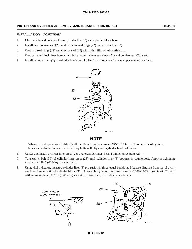
TM 9-2320-302-34
0041 00-12
PISTON AND CYLINDER ASSEMBLY MAINTENANCE - CONTINUED 0041 00
INSTALLATION - CONTINUED
1. Clean inside and outside of new cylinder liner (3) and cylinder block bore.
2. Install new crevice seal (23) and two new seal rings (22) on cylinder liner (3).
3. Coat two seal rings (22) and crevice seal (23) with a thin film of lubricating oil.
4. Coat cylinder block liner bore with lubricating oil where seal rings (22) and crevice seal (23) seat.
5. Install cylinder liner (3) in cylinder block bore by hand until lower seal meets upper crevice seal bore.
NOTENOTEWhen correctly positioned, side of cylinder liner installer stamped COOLER is on oil cooler side of cylinderblock and cylinder liner installer holding bolts will align with cylinder head bolt holes.
6. Center and install cylinder liner press (28) over cylinder liner (3) and tighten three bolts (29).
7. Turn center bolt (30) of cylinder liner press (28) until cylinder liner (3) bottoms in counterbore. Apply a tighteningtorque of 44 lb-ft (60 Nm) to center bolt.
8. Using dial indicator, measure cylinder liner (3) protrusion in three equal positions. Measure distance from top of cylin-der liner flange to tip of cylinder block (31). Allowable cylinder liner protrusion is 0.000-0.003 in (0.000-0.076 mm)with no more than 0.002 in (0.05 mm) variation between any two adjacent cylinders.
3
23
22
31
28
2930 29
29

TM 9-2320-302-34
0041 00-13
PISTON AND CYLINDER ASSEMBLY MAINTENANCE - CONTINUED 0041 00
INSTALLATION - CONTINUED
9. Perform procedures in step 1 through 8 for remaining cylinder liners (3) being installed.
10. Perform cylinder block pressure testing (WP 0040 00).
NOTENOTE• Fire (top) compression ring has plasma (dull finish) face. Top of fire compression ring is identified by
vendor’s mark: dimple or color dot located 30 degrees from ring gap.
• Middle compression ring has chrome (shiny) face. Top of middle compression ring is identified by dim-ple or color dot located 30 degrees from ring gap. Inner ring edge has groove.
• Oil control ring has chrome flashed face and can be installed with either side up.
11. Insert three piston rings (15 and 16) inside cylinder liner, one at a time, using piston dome (14) (inserted upside downinto liner) to push ring down. Insert piston dome into liner to same depth as ring being positioned. This will ensure ringsare parallel with top of liner and positioned in liner within normal areas of ring travel.
14
15
16

TM 9-2320-302-34
0041 00-14
PISTON AND CYLINDER ASSEMBLY MAINTENANCE - CONTINUED 0041 00
INSTALLATION - CONTINUED
NOTENOTE• Increase insufficient compression ring gap by filing or stoning ends of piston ring. File or stone both
ends of piston ring with cutting action from outer surface to inner surface to prevent chipping or peelingof plasma or chrome plate.
• Piston ring ends must remain square and outer edge chamfer must be approximately 0.015 in (0.381mm).
12. Measure compression ring gap of top ring as shown. Remove ring (16) from cylinder liner after measurement is com-pleted. Repeat this procedure for each ring and record measurement. Allowable ring end gap is as follows:
a. Fire ring 0.016-0.024 in (0.40-0.87 mm)
b. Compression ring 0.32-0.051 in (0.81-1.30 mm)
c. Oil control ring 0.016-0.032 in (0.40- 0.81 mm)
16

TM 9-2320-302-34
0041 00-15
PISTON AND CYLINDER ASSEMBLY MAINTENANCE - CONTINUED 0041 00
INSTALLATION - CONTINUED
CAUTIONCAUTIONDo not spread rings more than necessary to slip them over piston dome. This will prevent damage to equip-ment.
NOTENOTE• Do not overlap oil control ring expander ends.
• Ensure oil control ring expander is fully seated inside oil control ring groove.
13. Install new oil control ring expander (17) in oil control ring groove of piston dome (14).
14. Install new oil control ring (16) by hand. Oil control ring gap must be positioned 180 degrees from oil control ringexpander (17) spring gap.
15. With piston ring pliers, install new second (middle) compression ring (15) with vendor’s mark, dimple or color dot,located 30 degrees from ring gap toward piston dome (14) top.
16. With piston ring pliers, install new fire (top) compression ring (15) with vendor’s mark, dimple or color dot, located 30degrees from ring gap toward piston dome (14) top.
15
16
17
14

TM 9-2320-302-34
0041 00-16
PISTON AND CYLINDER ASSEMBLY MAINTENANCE - CONTINUED 0041 00
INSTALLATION - CONTINUED
17. Position fire (top) and middle compression ring gaps 180 degrees from each other and 90 degrees from oil control ringand oil expander ring gaps.
18. Apply a light coat of clean engine lubricating oil to connecting rod (12) pin bushing, piston pin bushing ends, and pistonpin (11). Place piston skirt (13) over piston dome (14) and align piston pin bores in dome and skirt.
19. Install connecting rod (12) inside dome (14) and slide piston pin (11) through piston skirt (13) bore and crown. Usingretaining ring pliers, secure piston pin in piston with two retaining rings (10).
20. Place piston assembly (9), dome down, in clean pan. Coat piston assembly liberally with clean engine lubricating oil.
OIL CONTROL RING GAP
MIDDLECOMPRESSIONRING GAP
OIL EXPANDER RING GAP
FIRE
RING GAP (TOP)COMPRESSION
1211
10 13
10
14
9
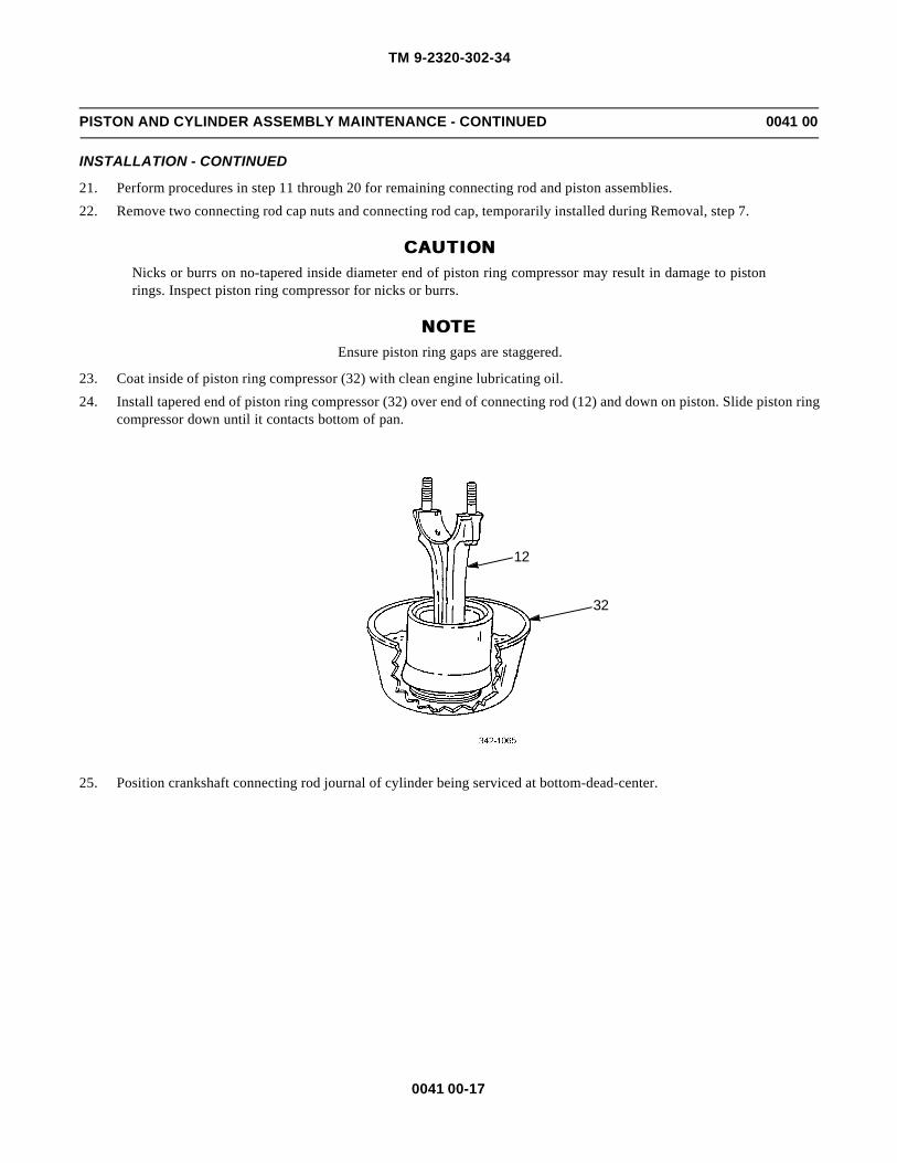
TM 9-2320-302-34
0041 00-17
PISTON AND CYLINDER ASSEMBLY MAINTENANCE - CONTINUED 0041 00
INSTALLATION - CONTINUED
21. Perform procedures in step 11 through 20 for remaining connecting rod and piston assemblies.
22. Remove two connecting rod cap nuts and connecting rod cap, temporarily installed during Removal, step 7.
CAUTIONCAUTIONNicks or burrs on no-tapered inside diameter end of piston ring compressor may result in damage to pistonrings. Inspect piston ring compressor for nicks or burrs.
NOTENOTEEnsure piston ring gaps are staggered.
23. Coat inside of piston ring compressor (32) with clean engine lubricating oil.
24. Install tapered end of piston ring compressor (32) over end of connecting rod (12) and down on piston. Slide piston ringcompressor down until it contacts bottom of pan.
25. Position crankshaft connecting rod journal of cylinder being serviced at bottom-dead-center.
12
32
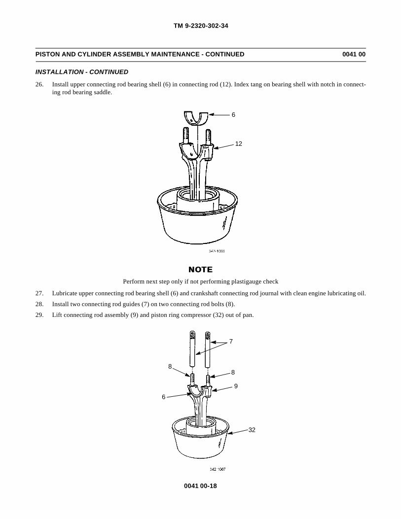
TM 9-2320-302-34
0041 00-18
PISTON AND CYLINDER ASSEMBLY MAINTENANCE - CONTINUED 0041 00
INSTALLATION - CONTINUED
26. Install upper connecting rod bearing shell (6) in connecting rod (12). Index tang on bearing shell with notch in connect-ing rod bearing saddle.
NOTENOTEPerform next step only if not performing plastigauge check
27. Lubricate upper connecting rod bearing shell (6) and crankshaft connecting rod journal with clean engine lubricating oil.
28. Install two connecting rod guides (7) on two connecting rod bolts (8).
29. Lift connecting rod assembly (9) and piston ring compressor (32) out of pan.
6
12
7
8
9
32
8
6
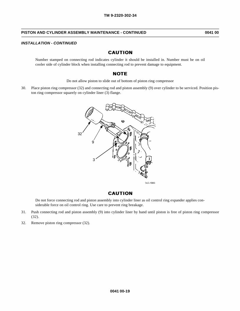
TM 9-2320-302-34
0041 00-19
PISTON AND CYLINDER ASSEMBLY MAINTENANCE - CONTINUED 0041 00
INSTALLATION - CONTINUED
CAUTIONCAUTIONNumber stamped on connecting rod indicates cylinder it should be installed in. Number must be on oilcooler side of cylinder block when installing connecting rod to prevent damage to equipment.
NOTENOTEDo not allow piston to slide out of bottom of piston ring compressor
30. Place piston ring compressor (32) and connecting rod and piston assembly (9) over cylinder to be serviced. Position pis-ton ring compressor squarely on cylinder liner (3) flange.
CAUTIONCAUTIONDo not force connecting rod and piston assembly into cylinder liner as oil control ring expander applies con-siderable force on oil control ring. Use care to prevent ring breakage.
31. Push connecting rod and piston assembly (9) into cylinder liner by hand until piston is free of piston ring compressor(32).
32. Remove piston ring compressor (32).
9
3
32

TM 9-2320-302-34
0041 00-20
PISTON AND CYLINDER ASSEMBLY MAINTENANCE - CONTINUED 0041 00
INSTALLATION - CONTINUED
CAUTIONCAUTION• Failure to orient piston connecting rod properly during installation may result in connecting rod striking
and damaging nozzle. A damaged or loosed nozzle can cause a loss of main gallery pressure or lack ofcooling to piston. Severe engine damage would result.
• Use care when loading piston into cylinder liner not to damage piston cooling nozzle installed at base ofcylinder bore. Before loading piston into liner, turn connecting rod so that bearing end is offset approxi-mately 10-15 degrees and is not perpendicular to crankshaft. Once rod end is past nozzle, turn rod so itis perpendicular with crankshaft.
NOTENOTEEnsure two connecting rod bolts have not been unseated or turned.
33. Push or tap connecting rod and piston assembly (9) until upper connecting rod bearing shell is firmly seated on crank-shaft journal. Remove two connecting rod guides (7).
NOTENOTEPerform step 34 only if performing plastigauge check. If not performing plastigauge check, go to step 35.
34. Check clearance between connecting rod bearing shells and crankshaft journal at time of connecting rod and pistonassembly installation as follows:
a. With upper and lower bearing shells (6) installed in connecting rod and connecting rod cap, wipe any oil frombearing shells and connecting rod journal.
b. Place piece of plastigauge (33) along full width of lower connecting rod bearing shell (6) about ¼ in (6.35 mm) offcenter.
c. Install connecting rod and rod bolts on crankshaft bearing journal in its corresponding cylinder.
8
7
9

TM 9-2320-302-34
0041 00-21
PISTON AND CYLINDER ASSEMBLY MAINTENANCE - CONTINUED 0041 00
INSTALLATION - CONTINUED
d. Install connecting rod cap and cap nuts on connecting rod and tighten connecting rod cap nuts to 118-137 lb-ft(160-185 Nm).
e. Remove connecting rod cap (5) and bearing shell (6).
f. Flattened plastiguage (33) will adhere to either bearing shell or connecting rod journal. Compare width of plasti-gauge at widest point with graduations scale (34) on plastigauge envelope to determine connecting rod bearingclearance. Maximum connecting rod bearing to connecting rod journal clearance with used parts is 0.006 in (0.152mm).
g. Inspect crankshaft journals before installing bearings.
h. Coat connecting rod bearing shells and journal with clean engine lubricating oil before assembly.
35. Place lower connecting rod bearing shell (6) in connecting rod cap (5). Index bearing tang with notch in connecting rodcap. Lubricate bearing shell with clean engine lubricating oil.
CAUTIONCAUTIONNumber stamped on connecting rod cap indicates cylinder it should be installed in. Number must be on oilcooler side of cylinder block when installing connecting rod cap to prevent damage to equipment.
633
345

TM 9-2320-302-34
0041 00-22
PISTON AND CYLINDER ASSEMBLY MAINTENANCE - CONTINUED 0041 00
INSTALLATION - CONTINUED
36. Install connecting rod cap (5) and lower connecting rod bearing shell (6) on connecting rod (12).
CAUTIONCAUTIONEnsure connecting rod bolt has not turned in connecting rod before connecting rod cap nut is tightened toprevent damage to equipment.
37. Install two connecting rod cap nuts (4). Tighten cap nuts alternately to 118-137 lb-ft (160-185 Nm). Check connectingrod side clearance by moving connecting rod from crank neck. If there is no clearance, check bearing installation.
38. Install remaining piston and rod assemblies in same manner.
39. Install oil pump (WP 0029 00).
40. Install cylinder head (WP 0018 00).
END OF WORK PACKAGE
4
5
6
12

TM 9-2320-302-34
0042 00-1
TURBOCHARGER REPLACEMENT 0042 00
THIS WORK PACKAGE COVERS
Removal, Inspection, Installation
INITIAL SETUP
Maintenance Level
Direct Support
Tools and Special Tools
Tool kit, general mechanic’s (Item 132, WP 0126 00)
Adapter, torque wrench (Item 3, WP 0126 00)
Shield, turbo protect (Item 113, WP 0126 00)
Wrench, torque, 15-75 lb-ft (Item 139, WP 0126 00)
Materials/Parts
Gasket, drain tube (P/N 8929285)
Gasket, exhaust inlet (P/N 8929529)
Materials/Parts - Continued
Oil, lubricating (Item 25, WP 0125 00)
Tape, masking (Item 37, WP 0125 00)
Personnel Required
Two
Equipment Condition
Exhaust pipes removed from turbocharger (TM 9-2320-302-20)
Air intake tubes and hoses removed from turbocharger(TM 9-2320-302-20)
REMOVAL
WARNINGWARNINGHot turbocharger and exhaust pipe can cause serious burns. Do not work on exhaust system until it is cool.To do so could result in serious injury to personnel.
NOTENOTEIf removal of wastegate actuator is required, refer to WP 0044 00 for 3K turbochargers. Refer to WP 0045 00for Garrett turbochargers. Wastegate removal is not required to remove turbocharger.

TM 9-2320-302-34
0042 00-2
TURBOCHARGER REPLACEMENT 0042 00
REMOVAL - CONTINUED
1. Disconnect oil supply line (1) from oil inlet port fitting (2) on top of turbocharger (3)
2. Remove top mounting bolt (4) and washer (5) from oil supply line clip (6) on oil filter adapter upper mounting leg andmove away from turbocharger (3).
3. Remove two bolts (7) securing oil drain line (8) to bottom of turbocharger (3).
4. Remove oil drain line (8) and gasket (9). Discard gasket.
5. Remove four nuts (10) and washers (11) securing turbocharger (3) to exhaust manifold (12).
WARNINGWARNINGTurbocharger weighs 50 lb (23 kg). Use two persons or suitable lifting device during removal to prevent per-sonal injury or damage to equipment.
6. Remove turbocharger (3) and gasket (13) from mounting studs (14). Discard gasket.
6
5
4
8
7
9
3
2
1

TM 9-2320-302-34
0042 00-3
TURBOCHARGER REPLACEMENT 0042 00
REMOVAL - CONTINUED
7. Tape all openings of turbocharger (3).
INSPECTION
1. Inspect turbocharger mounting studs on exhaust manifold for damage or looseness. Tighten stud(s), if loose.
2. Remove and replace damaged stud as follows:
a. Remove threaded turbocharger stud by unscrewing, using two nuts, one as a jamnut.
b. Thread new stud into exhaust manifold until unthreaded portion of stud is bottomed against mounting flange.Tighten stud(s) to 18-24 lb-ft (24-33 Nm).
3. Inspect mounting flange of exhaust manifold to ensure all gasket material is removed.
INSTALLATION
1. Remove tape from all openings of turbocharger (3).
2. Position new gasket (13) on mounting studs (14).
WARNINGWARNINGTurbocharger weighs 50 lb (23 kg.). Use two persons or suitable lifting device during installation to preventpersonal injury or damage to turbocharger.
NOTENOTEEnsure turbocharger mounting flange is free of all gasket material.
3. Place turbocharger (3) on mounting studs (14) with exhaust outlet side facing toward rear.
4. Install four washers (11) and nuts (10) on mounting studs (14). Tighten nuts to 43-54 lb-ft. (58-73 Nm).
14
1311
10
3
12
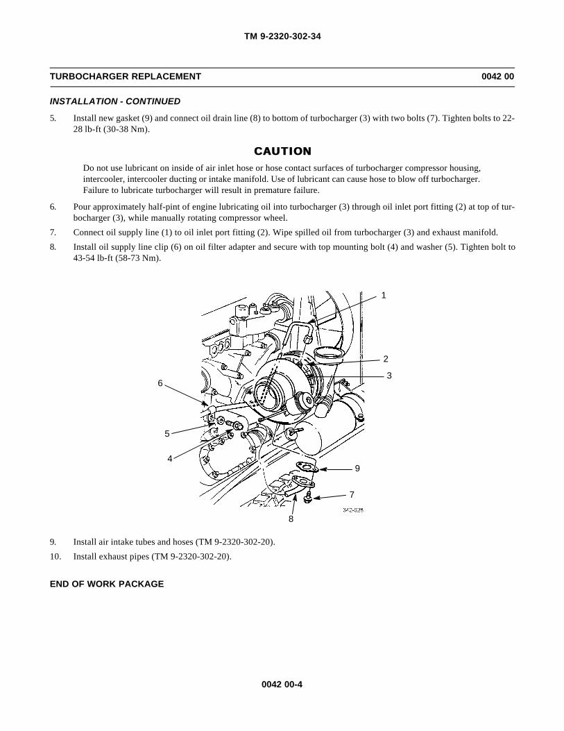
TM 9-2320-302-34
0042 00-4
TURBOCHARGER REPLACEMENT 0042 00
INSTALLATION - CONTINUED
5. Install new gasket (9) and connect oil drain line (8) to bottom of turbocharger (3) with two bolts (7). Tighten bolts to 22-28 lb-ft (30-38 Nm).
CAUTIONCAUTIONDo not use lubricant on inside of air inlet hose or hose contact surfaces of turbocharger compressor housing,intercooler, intercooler ducting or intake manifold. Use of lubricant can cause hose to blow off turbocharger.Failure to lubricate turbocharger will result in premature failure.
6. Pour approximately half-pint of engine lubricating oil into turbocharger (3) through oil inlet port fitting (2) at top of tur-bocharger (3), while manually rotating compressor wheel.
7. Connect oil supply line (1) to oil inlet port fitting (2). Wipe spilled oil from turbocharger (3) and exhaust manifold.
8. Install oil supply line clip (6) on oil filter adapter and secure with top mounting bolt (4) and washer (5). Tighten bolt to43-54 lb-ft (58-73 Nm).
9. Install air intake tubes and hoses (TM 9-2320-302-20).
10. Install exhaust pipes (TM 9-2320-302-20).
END OF WORK PACKAGE
6
5
4
8
7
9
3
2
1

TM 9-2320-302-34
0043 00-1
TURBOCHARGER REPAIR 0043 00
THIS WORK PACKAGE COVERS
Disassembly, Assembly
INITIAL SETUP
Maintenance Level
General Support
Tools and Special Tools
Tool kit, general mechanic’s (Item 132, WP 0126 00)
Dial indicator set (Item 29, WP 0126 00)
Wrench, torque, 0-300 lb-in (Item 137, WP 0126 00)
Materials/Parts
Compound, antiseize (Item 10, WP 0125 00)
Compound, pipe, sealing (Item 18, WP 0125 00)
Oil, lubricating (Item 25, WP 0125 00)
Equipment Condition
Turbocharger removed (WP 0042 00)
Wastegate removed from turbocharger (WP 0044 00or WP 0045 00)
DISASSEMBLY
1. Scribe match marks on compressor housing (1), center housing (2), and turbine housing (3) to aid in assembly.
3
2
1

TM 9-2320-302-34
0043 00-2
TURBOCHARGER REPAIR - CONTINUED 0043 00
DISASSEMBLY - CONTINUED
CAUTIONCAUTION
Tilting or cocking turbine housing during disassembly could damage turbine wheel blades.
2. Loosen coupling nut (4) and remove clamp (5) and turbine housing (3) from center housing (2).
3. Loosen coupling nut (6).
4. Remove compressor housing (1) and clamp (7) from center housing (2). If necessary, loosen compressor housing by tap-ping with soft mallet.
ASSEMBLY
1. Slide clamp (7) over backplate (8).
2. Position compressor housing (1), as marked in disassembly, against backplate (8). Secure with clamp (7). Lubricatethreads of clamp lightly with engine lubricating oil and tighten coupling nut (6) to 110-130 lb-in (12-15 Nm).
CAUTIONCAUTION
Ensure coupling nuts are tightened enough to prevent turbine housing from contacting turbine wheel.
3. Position turbine housing (3), as marked in disassembly, against center housing (2). Coat threads of clamp (5) with anti-seize compound. Install clamp and tighten coupling nut (4) to 110-130 lb-in (12-15 Nm).
4. Attach dial indicator (9) to turbine housing (3) so that dial indicator plunger (10) rests on hub end of turbine wheelassembly.
5. Set dial indicator (9) for reading of zero.
35
2 87
1
6
4

TM 9-2320-302-34
0043 00-3
TURBOCHARGER REPAIR - CONTINUED 0043 00
ASSEMBLY - CONTINUED
NOTENOTEBearing axial clearance must be 0.0020-0.0032 in (0.051-0.081 mm). If bearing axial clearance does notmeet specification, replace turbocharger center housing assembly.
6. Apply manual pressure to compressor wheel and turbine wheel assembly to move assembly as far as it will go awayfrom turbine end of turbocharger (toward dial indicator plunger (10)). Note maximum shaft movement shown on dialindicator (9).
7. Repeat steps 5 and 6 several times to ensure maximum bearing axial clearance, as indicated by maximum turbine wheelassembly movement, has been measured.
END OF WORK PACKAGE
3
10
9

TM 9-2320-302-34
0043 00-4
This Page Intentionally Left Blank.

TM 9-2320-302-34
0044 00-1
3K TURBOCHARGER WASTEGATE ACTUATOR MAINTENANCE 0044 00
THIS WORK PACKAGE COVERS
Removal, Installation, Adjustment
INITIAL SETUP
Maintenance Level
Direct Support
Tools and Special Tools
Tool kit, general mechanic’s (Item 132, WP 0126 00)
Dial indicator set (Item 29, WP 0126 00)
Wrench, torque, 0-300 lb-in (Item 137, WP 0126 00)
Materials/Parts
Kit, wastegate actuator (P/N 23523811)
Compound, antiseize (Item 10, WP 0125 00)
NOTENOTETurbocharger wastegate actuators are NOT interchangeable.
REMOVAL
1. Remove hose clamp (1) and hose (2) from wastegate (3).
CAUTIONCAUTIONNever remove actuator rod end from stud on turbocharger lever without applying light pressure to wastegateinlet port. Failure to follow this caution could result in damage to wastegate diaphragm.
2. Remove retaining ring (4) securing actuator rod (5) to stud (6) on turbocharger lever (7).
3. Remove three bolts (8) and wastegate (3) from turbocharger (9).
8
9
2
1
3
4567

TM 9-2320-302-34
0044 00-2
3K TURBOCHARGER WASTEGATE ACTUATOR MAINTENANCE - CONTINUED 0044 00
REMOVAL - CONTINUED
4. Remove bolt (10) and hose clip (11).
5. Remove bolt (12), two washers (13), and hose connector (14) from turbocharger (9).
6. Remove hose clip (15) and hose (16) from hose connector (14).
INSTALLATION
1. Install hose (16) and hose clip (15) to hose connector (14).
2. Install bolt (12), two washers (13), and hose connector (14) to turbocharger (9).
3. Secure hose (16) to turbocharger (9) with hose clip (11) and bolt (10).
4. Coat three bolts (8) with high temperature antiseize compound.
5. Position wastegate (3) on turbocharger (9) and hand tighten three bolts (8).
6. Secure hose (2) to wastegate (3) with hose clamp (1).
7. Loosen jamnut (17) on actuator rod (5).
8. While holding turbocharger lever (7) down (closed), turn end of actuator rod (5) until hole in rod aligns with stud (6) onturbocharger lever.
9. Secure actuator rod (5) end to stud (6) on turbocharger lever (7) with retaining ring (4).
10. Turn actuator rod (5) end five revolutions in direction of wastegate (3) and tighten jamnut (17).
11. Tighten three bolts (8) to 180 lb-in (20 Nm).
10 11 16
9
14
12
13 15

TM 9-2320-302-34
0044 00-3
3K TURBOCHARGER WASTEGATE ACTUATOR MAINTENANCE - CONTINUED 0044 00
INSTALLATION - CONTINUED
ADJUSTMENT
1. Disconnect hose (2) from wastegate (3).
NOTENOTEDial indicator must have a minimum of 0.100 in (2.5 mm) travel for measurement.
8
9
2
1
3
4567
23

TM 9-2320-302-34
0044 00-4
3K TURBOCHARGER WASTEGATE ACTUATOR MAINTENANCE - CONTINUED 0044 00
ADJUSTMENT - CONTINUED
2. Attach dial indicator (18) to wastegate actuator rod (5) to measure rod travel.
3. Connect air supply through regulator valve (19), shutoff valve (20), pressure gage (21), and vent valve (22) to wastegate(3).
4. Adjust regulator valve (19) to provide 34 psi (234 kPa) of air pressure to wastegate (3).
5. Close air supply at shutoff valve (20) and observe reading on pressure gage (21).
NOTENOTEIf pressure drops, check actuator hose and fitting connections for leaks. If none are found, replace wastegateactuator.
6. Open vent valve (22) to relieve pressure and observe pressure gage (21) for zero indication. Adjust regulator valve (19)to zero and close vent valve.
7. Adjust dial indicator (18) to contact actuator rod (5) end and adjust to a zero reading.
8. Open air supply at shutoff valve (20) and slowly adjust regulator valve (19) to 34 psi (234 kPa). Switch pressure on andoff with vent valve (22) to ensure dial indicator travel from 0.00 in to 0.070 in (1.79 mm) and that pressure reading isconsistent.
9. Actuator adjustment should be set for an indication of 0.070-0.075 in (1.79-1.91 mm) actuator rod travel at 34 psi (234kPa) pressure setting.
NOTENOTEIf travel is within limits, relieve and disconnect air pressure to wastegate actuator. If travel is not within lim-its, proceed to next step to adjust actuator rod travel.
10. Loosen jamnut (17) on actuator rod (5).
11. Remove retaining ring (4) securing actuator rod (5) to wastegate lever (7).
32
19
2021
221757418
1
TM 9-2320-302-34
0044 00-5
3K TURBOCHARGER WASTEGATE ACTUATOR MAINTENANCE - CONTINUED 0044 00
ADJUSTMENT - CONTINUED
12. Remove actuator rod (5) from wastegate lever (7). Turn rod 1/2 turn [180 degrees = 0.020 in (0.5 mm)] clockwise toincrease, or counterclockwise to decrease setting.
13. Repeat steps 7 and 8 to check if adjustment of travel rod is within limits.
14. Install retaining ring (4) on wastegate lever (7) and tighten jamnut (17) on actuator rod (5).
15. Disconnect regulated air supply from actuator (3). Connect hose (2) to wastegate (3).
END OF WORK PACKAGE

TM 9-2320-302-34
0044 00-6
This Page Intentionally Left Blank.

TM 9-2320-302-34
0045 00-1
GARRETT TURBOCHARGER WASTEGATE ACTUATOR MAINTENANCE 0045 00
THIS WORK PACKAGE COVERS
Removal, Installation, Adjustment
INITIAL SETUP
Maintenance Level
Direct Support
Tools and Special Tools
Tool kit, general mechanic’s (Item 132, WP 0126 00)
Dial indicator set (Item 29, WP 0126 00)
Wrench, torque, 0-300 lb-in (Item 137, WP 0126 00)
Materials/Parts
Clip, retaining (P/N 400702-25)
Compound, antiseize (Item 10, WP 0125 00)
NOTENOTETurbocharger wastegate actuators are NOT interchangeable.
REMOVAL
1. Remove hose clip (1) and hose (2) from wastegate (3).
2. Remove bolt (4), hose clamp (5), and hose (2).
12 5 4
3

TM 9-2320-302-34
0045 00-2
GARRETT TURBOCHARGER WASTEGATE ACTUATOR MAINTENANCE - CONTINUED 0045 00
REMOVAL - CONTINUED
3. Remove hose clip (6) and hose (2) from elbow (7).
4. Remove elbow (7).
CAUTIONCAUTIONNever remove actuator rod end from stud on turbocharger lever without applying light pressure to wastegateinlet port. Failure to follow this caution could result in damage to wastegate diaphragm.
5. Remove retaining clip (8) securing actuator rod (9) to stud (10) on turbocharger lever (11). Discard retaining clip.
6. Remove three bolts (12) and wastegate (3) from turbocharger (13).
2
67
3
12
13
10
9
8
11

TM 9-2320-302-34
0045 00-3
GARRETT TURBOCHARGER WASTEGATE ACTUATOR MAINTENANCE - CONTINUED 0045 00
INSTALLATION
1. Coat three bolts (12) with high temperature antiseize compound.
2. Position wastegate (3) on turbocharger (13) and hand tighten three bolts (12).
3. Loosen jamnut (14) on actuator rod (9).
4. While holding turbocharger lever (11) down (closed), turn end of actuator rod (9) until hole in rod aligns with stud (10)on turbocharger lever.
5. Secure actuator rod (9) end to stud (10) on turbocharger lever (11) with new retaining clip (8).
6. Turn actuator rod (9) end five revolutions in direction of wastegate (3) and tighten jamnut (14).
7. Tighten three bolts (12) to 180 lb-in (20 Nm).
8. Install elbow (7).
9. Install hose (2) and hose clip (6) to elbow (7).
10. Install hose (2) and hose clip (1) to wastegate (3).
11. Install hose (2), hose clamp (5), and bolt (4).
12 5 4
3
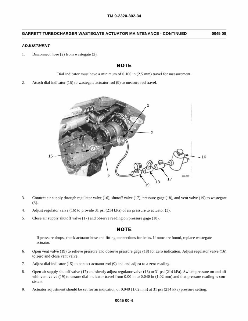
TM 9-2320-302-34
0045 00-4
GARRETT TURBOCHARGER WASTEGATE ACTUATOR MAINTENANCE - CONTINUED 0045 00
ADJUSTMENT
1. Disconnect hose (2) from wastegate (3).
NOTENOTEDial indicator must have a minimum of 0.100 in (2.5 mm) travel for measurement.
2. Attach dial indicator (15) to wastegate actuator rod (9) to measure rod travel.
3. Connect air supply through regulator valve (16), shutoff valve (17), pressure gage (18), and vent valve (19) to wastegate(3).
4. Adjust regulator valve (16) to provide 31 psi (214 kPa) of air pressure to actuator (3).
5. Close air supply shutoff valve (17) and observe reading on pressure gage (18).
NOTENOTEIf pressure drops, check actuator hose and fitting connections for leaks. If none are found, replace wastegateactuator.
6. Open vent valve (19) to relieve pressure and observe pressure gage (18) for zero indication. Adjust regulator valve (16)to zero and close vent valve.
7. Adjust dial indicator (15) to contact actuator rod (9) end and adjust to a zero reading.
8. Open air supply shutoff valve (17) and slowly adjust regulator valve (16) to 31 psi (214 kPa). Switch pressure on and offwith vent valve (19) to ensure dial indicator travel from 0.00 in to 0.040 in (1.02 mm) and that pressure reading is con-sistent.
9. Actuator adjustment should be set for an indication of 0.040 (1.02 mm) at 31 psi (214 kPa) pressure setting.
16
1718
15
2
19
9
2

TM 9-2320-302-34
0045 00-5
GARRETT TURBOCHARGER WASTEGATE ACTUATOR MAINTENANCE - CONTINUED 0045 00
ADJUSTMENT - CONTINUED
NOTENOTEIf travel is within limits, relieve and disconnect air pressure to wastegate actuator. If travel is not within lim-its, proceed to next step to adjust actuator rod travel.
10. Loosen jamnut (14) on actuator rod (9).
11. Remove retaining clip (8) securing actuator rod (9) to wastegate lever pin (11).
12. Remove actuator rod (9) from wastegate lever pin (11). Turn rod 1/2 turn [180 degrees = 0.020 in (0.5 mm)] clockwiseto increase, or counterclockwise to decrease setting.
13. Repeat steps 7 and 8 to check if adjustment of travel rod is within limits.
14. Install retaining clip (8) on wastegate lever pin (11) and tighten jamnut (14) while holding actuator rod (9).
15. Disconnect hose (2) from regulated air source and reconnect hose to wastegate (3).
END OF WORK PACKAGE
11
8
9
32
14

TM 9-2320-302-34
0045 00-6
This Page Intentionally Left Blank.
TM 9-2320-302-34
0046 00-1
FUEL INJECTOR REPLACEMENT 0046 00
THIS WORK PACKAGE COVERS
Removal, Installation
INITIAL SETUP
Maintenance Level
Direct Support
Tools and Special Tools
Tool kit, general mechanic’s (Item 132, WP 0126 00)
Pan, drain (Item 80, WP 0126 00)
Wrench, torque, 0-300 lb-in (Item 137, WP 0126 00)
Wrench, torque, 15-75 lb-ft (Item 138, WP 0126 00)
Materials/Parts
O-ring (P/N 5234669) (2)
O-ring (P/N 5234702)
Antifreeze, ethylene glycol (Item 6, WP 0125 00)
Rags, wiping (Item 31, WP 0125 00)
Tags, marker (Item 35, WP 0125 00)
Equipment Condition
Rocker arm cover removed (WP 0016 00)
Rocker arm assemblies removed (WP 0027 00)
WARNINGWARNING• DO NOT perform fuel system checks, inspections or maintenance while smoking or near fire, flames or
sparks. Fuel may ignite, causing injury or death to personnel or damage to equipment.
• Fuel vapors are toxic. Avoid prolonged exposure or breathing of fumes. Work in a well-ventilated area.Failure to do so could result in serious injury to personnel.

TM 9-2320-302-34
0046 00-2
FUEL INJECTOR REPLACEMENT - CONTINUED 0046 00
REMOVAL
NOTENOTETag fuel lines, wire terminals, and injectors prior to removal to aid in installation.
1. Disconnect fuel supply hose (1) from elbow fitting (2) at rear of cylinder head (3).
2. Disconnect fuel return line (4) from elbow fitting (5) at rear of cylinder head (3).
3. Place fuel lines (1 and 4) in a suitable container to collect drained fuel.
WARNINGWARNINGEye protection must be worn to prevent fuel from getting in eyes during fuel removal.
CAUTIONCAUTIONAll fuel must be removed from cylinder head before removing an injector to prevent fuel from entering cyl-inder and causing hydrostatic lock or washdown.
4. Apply low air pressure for 20 to 30 seconds into elbow fitting (2) to purge remaining fuel from cylinder head (3).
NOTENOTEPerform step 5 through 8 for each injector to be removed.
5. Loosen two screws (6) and disconnect injector wiring harness terminals (7).
3 5
1
2
4

TM 9-2320-302-34
0046 00-3
FUEL INJECTOR REPLACEMENT - CONTINUED 0046 00
REMOVAL - CONTINUED
6. Remove holddown bolt (8), washer (9), and holddown clamp (10).
7
6
10
8
9 9
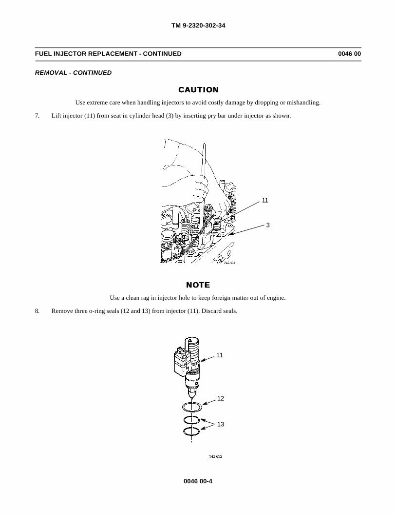
TM 9-2320-302-34
0046 00-4
FUEL INJECTOR REPLACEMENT - CONTINUED 0046 00
REMOVAL - CONTINUED
CAUTIONCAUTIONUse extreme care when handling injectors to avoid costly damage by dropping or mishandling.
7. Lift injector (11) from seat in cylinder head (3) by inserting pry bar under injector as shown.
NOTENOTEUse a clean rag in injector hole to keep foreign matter out of engine.
8. Remove three o-ring seals (12 and 13) from injector (11). Discard seals.
11
3
11
12
13

TM 9-2320-302-34
0046 00-5
FUEL INJECTOR REPLACEMENT - CONTINUED 0046 00
INSTALLATION
NOTENOTEPerform steps 1 through 10 for each injector being installed.
1. Lubricate three new o-ring seals (12 and 13) lightly with clean ethylene glycol.
2. Install larger o-ring seal (12) in upper groove.
3. Install two lower o-ring seals (13) in two lower grooves.
CAUTIONCAUTIONEnsure injector port is free of dirt or other foreign matter which may cause damage to engine.
4. Insert injector (11) into cylinder head (3) and visually align injector for equal clearance between valve springs.
5. Press down on top of injector body until injector (11) is fully seated.
6. Install holddown clamp (10) on injector (11).
7. Install and hand tighten washer (9) and holddown bolt (8), with beveled side facing engine.
10
8
9 9

TM 9-2320-302-34
0046 00-6
FUEL INJECTOR REPLACEMENT - CONTINUED 0046 00
INSTALLATION - CONTINUED
CAUTIONCAUTIONCheck position of injector and holddown clamp to ensure clearance between intake valve spring and injectorfollower. Failure to do so will result in equipment damage.
8. Tighten holddown bolt (8) to 43-49 lb-ft (58-66 Nm).
9. Connect injector wiring harness terminals (7) and tighten two screws (6) to 12-17 lb-in (1.36-1.92 Nm).
10. Connect fuel supply hose (1) to elbow fitting (2) and fuel return line (4) to elbow fitting (5) at rear of cylinder head (3).
11. Install rocker arm assemblies (WP 0027 00).
12. Install rocker arm cover (WP 0016 00).
END OF WORK PACKAGE
7
6
3 5
1
2
4
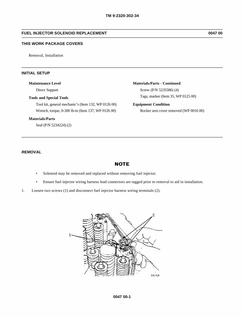
TM 9-2320-302-34
0047 00-1
FUEL INJECTOR SOLENOID REPLACEMENT 0047 00
THIS WORK PACKAGE COVERS
Removal, Installation
INITIAL SETUP
Maintenance Level
Direct Support
Tools and Special Tools
Tool kit, general mechanic’s (Item 132, WP 0126 00)
Wrench, torque, 0-300 lb-in (Item 137, WP 0126 00)
Materials/Parts
Seal (P/N 5234224) (2)
Materials/Parts - Continued
Screw (P/N 5235586) (4)
Tags, marker (Item 35, WP 0125 00)
Equipment Condition
Rocker arm cover removed (WP 0016 00)
REMOVAL
NOTENOTE
• Solenoid may be removed and replaced without removing fuel injector.
• Ensure fuel injector wiring harness lead connectors are tagged prior to removal to aid in installation.
1. Loosen two screws (1) and disconnect fuel injector harness wiring terminals (2).
2
1

TM 9-2320-302-34
0047 00-2
FUEL INJECTOR SOLENOID REPLACEMENT 0047 00
REMOVAL - CONTINUED
NOTENOTE
Load plate and spacer plate are matched to injector and must be retained for new solenoid.
2. Remove four screws (3), load plate (4), and follower retainer (5) from solenoid (6). Discard screws.
3. Remove solenoid (6) from fuel injector body (7).
4. Remove spacer (8) and two seals (9) from fuel injector body (7). Discard seals and retain spacer.
INSTALLATION
1. Install two new seals (9) and spacer (8) on fuel injector body (7).
2. Position solenoid (6) on spacer (8) and fuel injector body (7).
3. Install four new screws (3) through load plate (4), follower retainer (5), solenoid (6), and spacer (8).
4. Thread four screws (3) into body and tighten all screws until heads contact follower retainer (5) and load plate (4).
5. Tighten screws (3) to 19 lb-in (2 Nm), following sequence shown.
6. Connect fuel injector harness wiring terminals (2) and tighten two screws (1).
3
5
4
6
9
8
9
7
D B
A C
TIGHTENING SEQUENCE

TM 9-2320-302-34
0047 00-3
FUEL INJECTOR SOLENOID REPLACEMENT 0047 00
INSTALLATION - CONTINUED
7. Install rocker arm cover (WP 0016 00).
END OF WORK PACKAGE
2
1

TM 9-2320-302-34
0047 00-4
This Page Intentionally Left Blank.

TM 9-2320-302-34
0048 00-1
RADIATOR REPAIR 0048 00
THIS WORK PACKAGE COVERS
Disassembly, Repair, Assembly
INITIAL SETUP
Maintenance Level
Direct Support
Tools and Special Tools
Tool kit, general mechanic’s (Item 132, WP 0126 00)
Gloves (Item 41, WP 0126 00)
Wrench, torque, 0-300 lb-in (Item 137, WP 0126 00)
Materials/Parts
Gasket (P/N 05-12295-000) (2)
Nut, self-locking (P/N 32WLF3816) (36)
Grease, GAA (Item 22, WP 0125 00)
References
TM 750-254
Equipment Condition
Radiator removed from vehicle (TM 9-2320-302-20)
DISASSEMBLY
NOTENOTEAdditional items are mounted or attached to radiator when installed in vehicle. These items use radiatorhardware for installation. During disassembly, note the location, orientation, size, and quantity of screws,nuts, and bolting bars as an aid in assembly.

TM 9-2320-302-34
0048 00-2
RADIATOR REPAIR - CONTINUED 0048 00
DISASSEMBLY - CONTINUED
1. Remove two lock nuts (1), expansion tank (2), and radiator cap (3) from radiator top channel (4). Discard lock nuts.
NOTENOTEPosition radiator front face down on workbench, with right hand outlet tank over edge. It may be necessaryto place radiator on blocks to gain access to end tank hardware.
2. Remove lock nuts (1), bolting bars (5 and 6), and screws (7 and 8) securing right-hand outlet tank (9) and header gasket(10) to top and bottom channel (4 and 11). Discard lock nuts.
3. Remove right-hand outlet tank (9) and header gasket (10). Discard gasket.
4. Remove lock nuts (1), bolting bars (5 and 6), and screws (7 and 8) securing left-hand inlet tank (12) and header gasket(10) to top and bottom channel (4 and 11). Discard lock nuts.
5. Remove left-hand inlet tank (12) and header gasket (10). Discard gasket.
6. Remove drain plug (13) from inlet tank (12).
31 2 1
5
7
106
12
1
13
4
5
10
14
5
1
8
9
7
116
5
1

TM 9-2320-302-34
0048 00-3
RADIATOR REPAIR - CONTINUED 0048 00
DISASSEMBLY - CONTINUED
WARNINGWARNINGRadiator core vanes are sharp and can easily cut. Gloves should be worn when handling bare radiator coresto prevent injury to personnel.
CAUTIONCAUTIONUse care when handling or storing radiator cores as core vanes are thin and easily bent. If many vanes arebent, air flow through radiator core will not be sufficient for cooling. Equipment damage will result.
7. Remove top and bottom channels (4 and 11) from radiator core (14).
REPAIR
NOTENOTENo more than 12 tubes of radiator core can be blocked off. If more than 12 are blocked, core is not service-able. Replace with new core prior to assembly.
Refer to TM 750-254 for additional information on radiator repair.
ASSEMBLY
1. Position radiator core (14) front face down on workbench and apply a light coat of grease to surface of each new headergasket (10).
2. Position two new header gaskets (10) on radiator core (14).
3. Place top (4) and bottom (11) channels on radiator core (14).
NOTENOTEEnsure bolting bars, screws, and mounting hardware are installed as noted in disassembly.
4. Install inlet tank (12) with bolting bars (5 and 6), screws (7 and 8), and new lock nuts (1).

TM 9-2320-302-34
0048 00-4
RADIATOR REPAIR - CONTINUED 0048 00
ASSEMBLY - CONTINUED
5. Follow tightening sequence and tighten screws to 120 lb-in (1360 Ncm). Repeat sequence and tighten to 180 lb-in (20Nm).
6. Install outlet tank (9) with bolting bars (5 and 6), screws (7 and 8), and new lock nuts (1).
7. Follow tightening sequence and tighten screws to 120 lb-in (1360 Ncm). Repeat sequence and tighten to 180 lb-in (20Nm).
8. Install two new lock nuts (1), expansion tank (2), and radiator cap (3).
CAUTIONCAUTIONDO NOT apply excessive air pressure when testing radiator. Too much pressure will damage radiator core.Air pressure should not exceed 20 psi (138 kPa).
9. Pressure test radiator.
Back Front
TIGHTENING SEQUENCE

TM 9-2320-302-34
0048 00-5
RADIATOR REPAIR - CONTINUED 0048 00
ASSEMBLY - CONTINUED
END OF WORK PACKAGE
31
2 1
5
7
106
12
1
13
4
5
10
14
5
1
8
9
7
116
5
1

TM 9-2320-302-34
0048 00-6
This Page Intentionally Left Blank.

TM 9-2320-302-34
0049 00-1
WATER PUMP REPAIR 0049 00
THIS WORK PACKAGE COVERS
Disassembly, Assembly, Test and Inspection
INITIAL SETUP
Maintenance Level
Direct Support
Tools and Special Tools
Tool kit, general mechanic’s (Item 132, WP 0126 00)
Caps, vise jaw (Item 17, WP 0126 00)
Dial indicator set (Item 29, WP 0126 00)
Dispenser, sealant (Item 30, WP 0126 00)
Pliers, retaining ring (Item 88, WP 0126 00)
Press, arbor (Item 90, WP 0126 00)
Puller kit, mechanical (Item 95, WP 0126 00)
Service kit, water pump (Item 112, WP 0126 00)
Tester, impeller (Item 125, WP 0126 00)
Vise, machinist’s (Item 136, WP 0126 00)
Tools and Special Tools - Continued
Wrench, torque, 0-300 lb-in (Item 137, WP 0126 00)
Wrench, torque, 15-75 lb-ft (Item 138, WP 0126 00)
Wrench, torque, 50-250 lb-ft (Item 139, WP 0126 00)
Materials/Parts
Kit, water pump O/H (P/N 23509105)
Compound, corrosion preventive (Item 11, WP 0125 00)
Compound, gasket forming (Item 12, WP 0125 00)
Compound, sealing (Item 14, WP 0125 00)
Oil, lubricating (Item 25, WP 0125 00)
Rags, wiping (Item 31, WP 0125 00)
Equipment Condition
Water pump removed from engine (TM 9-2320-302-20)
DISASSEMBLY
WARNINGWARNINGDue to size and tension of water pump cover snap ring, wear adequate face and eye protection during disas-sembly to prevent personal injury.

TM 9-2320-302-34
0049 00-2
WATER PUMP REPAIR - CONTINUED 0049 00
DISASSEMBLY
1. Remove snap ring (1), cover (2), and seal ring (3) from water pump housing (4). Discard seal ring.
2. Hold square end of water pump shaft (5) and remove retaining bolt (6) and washer (7).
3. Remove drive gear (8) with two-jaw puller (9).
WARNINGWARNINGDue to tension of water pump shaft bearing retaining ring, wear adequate face and eye protection duringremoval to prevent personal injury.
4. Remove retaining ring (10).
1 23
4
5
7
6
108
9

TM 9-2320-302-34
0049 00-3
WATER PUMP REPAIR - CONTINUED 0049 00
DISASSEMBLY - CONTINUED
5. Support water pump housing (4), impeller side up, and press roller bearing and shaft assembly (11) from water pumphousing (4).
6. Remove impeller (12) from water pump housing (4).
7. Support roller bearing and shaft assembly (11) with square end of water pump shaft down. Press shaft (5) from rollerbearing (13). Discard roller bearing.
1112
4
13
5

TM 9-2320-302-34
0049 00-4
WATER PUMP REPAIR - CONTINUED 0049 00
DISASSEMBLY - CONTINUED
CAUTIONCAUTIONUse care when removing oil seal or water seal, to prevent damage to water pump housing seal bores. Do notallow brass drift to score housing bores. A scored bore will cause coolant leaks and can damage engine.
NOTENOTEOil seal and water seal must be replaced whenever water pump shaft is removed.
8. Place water pump housing (4) on bench, impeller side down, and remove water seal (14) from housing. Discard waterseal.
9. Place water pump housing (4) on bench, impeller side up, and remove oil seal (15) from housing. Discard oil seal.
ASSEMBLY
CAUTIONCAUTIONDo not separate bearing components. Bearing assembly is a matched set of parts and should be assembled asreceived. Failure to do so could result in bearing misalinement.
1. Place service kit holding fixture (16) on press bed. Install drive shaft support tool (17) in holding fixture. Install squareend of water pump shaft (5) in support tool.
NOTENOTEEnsure roller bearing identification numbers are against bearing and seal installer.
2. Position new roller bearing (13) on water pump shaft (5) with roller bearing identification numbers up. Using small endof bearing and seal installer (18), press roller bearing on water pump shaft until roller bearing is seated against shoulderof water pump shaft. Remove assembled shaft and bearing from holding fixture.
14
4
4
15

TM 9-2320-302-34
0049 00-5
WATER PUMP REPAIR - CONTINUED 0049 00
ASSEMBLY - CONTINUED
3. Apply a thin film of clean engine lubricating oil to outside diameter of new oil seal (15) and water pump housing bore(19).
4. Support water pump housing (4) on press bed, impeller side down. Using small end of bearing and seal installer (18),press oil seal (15) in water pump housing bore (19).
13
5
18
16 17
15
19
4
18

TM 9-2320-302-34
0049 00-6
WATER PUMP REPAIR - CONTINUED 0049 00
ASSEMBLY - CONTINUED
5. Apply a thin film of clean engine lubricating oil to sealing lip of oil seal. Lubricate roller bearing (13) assembly. Care-fully install square end of water pump shaft (5) through oil seal and position roller bearing assembly in water pumphousing bore (19).
6. Using large end of bearing and seal installer (18), press roller bearing and shaft assembly (11) in water pump housingbore (19), until roller bearing (13) is seated against shoulder of water pump housing bore.
7. Install retaining ring (10) in ring groove (20) of water pump housing bore (19).
NOTENOTEEnsure retaining ring is fully seated in ring groove.
8. Place holding fixture (16) on press bed. Install extension tool (21) in holding fixture in contact with adjusting wheel(22).
NOTENOTEEnsure water pump shaft is supported while components are being assembled.
9. Turn water pump housing (4), gear side down, and position water pump shaft (5) over extension tool (21) in holding fix-ture (16).
10
13
519
20
18
11

TM 9-2320-302-34
0049 00-7
WATER PUMP REPAIR - CONTINUED 0049 00
ASSEMBLY - CONTINUED
10. Turn adjusting wheel (22) until extension tool (21) contacts water pump shaft (5) for support.
11. Apply a thin film of corrosion preventive compound to inside diameter of new water seal (14) where contact will bemade with water pump shaft (5).
54
21
16
22
14
5
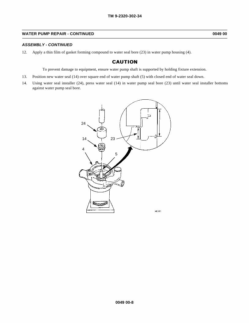
TM 9-2320-302-34
0049 00-8
WATER PUMP REPAIR - CONTINUED 0049 00
ASSEMBLY - CONTINUED
12. Apply a thin film of gasket forming compound to water seal bore (23) in water pump housing (4).
CAUTIONCAUTIONTo prevent damage to equipment, ensure water pump shaft is supported by holding fixture extension.
13. Position new water seal (14) over square end of water pump shaft (5) with closed end of water seal down.
14. Using water seal installer (24), press water seal (14) in water pump seal bore (23) until water seal installer bottomsagainst water pump seal bore.
4
14
24
23
5
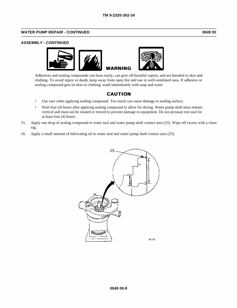
TM 9-2320-302-34
0049 00-9
WATER PUMP REPAIR - CONTINUED 0049 00
ASSEMBLY - CONTINUED
WARNINGWARNINGAdhesives and sealing compounds can burn easily, can give off harmful vapors, and are harmful to skin andclothing. To avoid injury or death, keep away from open fire and use in well-ventilated area. If adhesive orsealing compound gets on skin or clothing, wash immediately with soap and water
CAUTIONCAUTION• Use care when applying sealing compound. Too much can cause damage to sealing surface.
• Wait four (4) hours after applying sealing compound to allow for drying. Water pump shaft must remainvertical and must not be rotated or moved to prevent damage to equipment. Do not pressure test seal forat least four (4) hours.
15. Apply one drop of sealing compound to water seal and water pump shaft contact area (25). Wipe off excess with a cleanrag.
16. Apply a small amount of lubricating oil to water seal and water pump shaft contact area (25).
25

TM 9-2320-302-34
0049 00-10
WATER PUMP REPAIR - CONTINUED 0049 00
ASSEMBLY - CONTINUED
17. Install impeller (12), wide end up, over square end of water pump shaft (5). Using impeller installation tool (26), pressimpeller on water pump shaft until installation tool is flush against water pump housing (4). Remove installation tool.
18. Turn water pump housing (4) over, impeller side down, on holding fixture (16).
CAUTIONCAUTION
Water pump drive gear may be press fit onto water pump shaft. Support water pump shaft when pressingdrive gear onto shaft to prevent damage to bearing.
NOTENOTE
Water pump drive gear may be a slip fit. This is due to manufacturing tolerances and is acceptable.
19. Position drive gear (8) over water pump shaft (5).
20. Using small end of bearing and seal installer (18), press drive gear (8) on water pump shaft (5) until drive gear is seatedagainst bearing inner race (27).
12
5
26
4
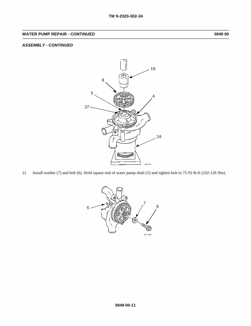
TM 9-2320-302-34
0049 00-11
WATER PUMP REPAIR - CONTINUED 0049 00
ASSEMBLY - CONTINUED
21. Install washer (7) and bolt (6). Hold square end of water pump shaft (5) and tighten bolt to 75-93 lb-ft (102-126 Nm).
18
8
4
16
5
27
765

TM 9-2320-302-34
0049 00-12
WATER PUMP REPAIR - CONTINUED 0049 00
TEST AND INSPECTION
1. Turn water pump over, gear side down. Clamp drive gear (8) in soft-jawed vise with water pump impeller (12) facingup.
2. Install water pump impeller tester (28) in tapped holes provided in impeller (12). Tighten bolts to 156-204 lb-in (18-23Nm).
3. Apply 50 lb-ft (68 Nm) torque in either direction with torque wrench inserted in impeller tester (28). If impeller slippageis detected, remove and discard impeller (12). Install new impeller and retest. Remove impeller tester after testing.
4. Turn water pump over, impeller side down.
5. Attach dial indicator (29) to water pump housing (4). Measure gear face runout just inside of drive gear (8) teeth. Rotatedrive gear and measure runout in four places at 90 degree intervals. Maximum allowable runout is 0.0025 in (0.0635mm).
6. If limit is exceeded, remove drive gear (8) and check for burrs or foreign particles. Install drive gear and recheck runout.If runout still exceeds limits, replace drive gear and/or water pump shaft (5) as necessary.
12
8
28

TM 9-2320-302-34
0049 00-13
WATER PUMP REPAIR - CONTINUED 0049 00
TEST AND INSPECTION - CONTINUED
7. Install draincock (30), pipe plug (31), new seal ring (3), cover (2), and snap ring (1) in water pump housing (4).
8. Install water pump (TM 9-2320-302-20).
END OF WORK PACKAGE
29
85 4
312
3
1
4
30

TM 9-2320-302-34
0049 00-14
This Page Intentionally Left Blank.

TM 9-2320-302-34
0050 00-1
FAN CLUTCH REPAIR 0050 00
THIS WORK PACKAGE COVERS
Disassembly, Assembly
INITIAL SETUP
Maintenance Level
Direct Support
Tools and Special Tools
Tool kit, general mechanic’s (Item 132, WP 0126 00)
Clamp, C (2) (Item 19, WP 0126 00)
Materials/Parts
Kit, repair (P/N 1033-054335-02)
Seal, dust (P/N 3018-01519-01)
Equipment Condition
Fan clutch removed from vehicle (TM 9-2320-302-20)
DISASSEMBLY
1. Remove nut (1) tab washer (2), cylinder (3), seal (4), packing (5), and dust seal (6) from clutch assembly (7). Discardnut, tab washer, seal, packing, and dust seal.
WARNINGWARNINGHousing is under spring tension. Use suitable “C” clamps to hold housing and shaft assembly in place whileremoving cylinder. Failure to do so could result in injury to personnel.
2. Install two “C” clamps on opposite sides of clutch assembly (7).
7
65
4 3
21

TM 9-2320-302-34
0050 00-2
FAN CLUTCH REPAIR - CONTINUED 0050 00
DISASSEMBLY - CONTINUED
3. Remove six screws (8), lock washers (9), three retaining plates (10), and lining (11) from shaft assembly (12). Discardscrews, lock washers, and lining.
4. Release “C” clamps slowly to relieve spring tension and remove housing (13), seal (14), end cap (15), and spring (16)from shaft assembly (12). Discard seal and spring.
5. Remove retaining ring (17) and piston assembly (18).
6. Remove two packings (19 and 20) and spring carrier (21) from piston. Discard packings.
7. If damaged, remove and discard studs (22) from housing (13).
ASSEMBLY
1. If removed, install new studs (22) in housing (13).
2. Install two new packings (19 and 20) and spring carrier (21) to piston (18).
3. Install piston assembly (18) and retaining ring (17).
4. Install new spring (16), end cap (15), new seal (14), and housing (13) on shaft assembly (12).
5. Compress housing (13) and shaft assembly (12) using two “C” clamps and install new lining (11), three retaining plates(10), six new lock washers (9), and new screws (8) in shaft assembly.
6. Remove two “C” clamps from opposite sides of clutch assembly (7).
7. Install new dust seal (6), new packing (5), new seal (4), cylinder (3), new tab washer (2), and new nut (1) on clutchassembly (7).
8. Install fan clutch (TM 9-2320-302-20).
END OF WORK PACKAGE
89
10
7
11
1719
1821
20 12
1615
1413
226
54 3
21
10

TM 9-2320-302-34
0051 00-1
SPINDLE AND HOUSING REPAIR 0051 00
THIS WORK PACKAGE COVERS
Disassembly, Inspection, Assembly
INITIAL SETUP
Maintenance Level
Direct Support
Tools and Special Tools
Tool kit, general mechanic’s (Item 132, WP 0126 00)
Caps, vise jaw (Item 17, WP 0126 00)
Inserter and remover (Item 53, WP 0126 00)
Pliers, retaining ring (Item 88, WP 0126 00)
Pliers, retaining ring (Item 89, WP 0126 00)
Press, arbor (Item 90, WP 0126 00)
Puller, kit mechanical (Item 95, WP 0126 00)
Vise, machinist’s (Item 136, WP 0126 00)
Wrench, torque, 0-300 lb-in (Item 137, WP 0126 00)
Wrench, torque, 15-75 lb-ft (Item 138, WP 0126 00)
Materials/Parts
Ball bearing assembly (P/N 8929530)
Plug, cup (P/N 8929215)
Roller bearing assembly (P/N 8929820)
Seal, oil (P/N V454136RR)
Adhesive, loctite (Item 3, WP 0125 00)
Grease, GAA (IItem 22, WP 0125 00)
Oil, lubricating (Item 25, WP 0125 00)
Equipment Condition
Spindle and housing removed (TM 9-2320-302-20)
DISASSEMBLY
1. Secure fan spindle (1) in soft-jawed vise and remove cup plug (2). Discard cup plug.
2. Remove spacer retaining bolt (3) and spacer (4). Remove fan spindle (1) from vise.
14
3 2

TM 9-2320-302-34
0051 00-2
SPINDLE AND HOUSING REPAIR - CONTINUED 0051 00
DISASSEMBLY - CONTINUED
CAUTIONCAUTIONDuring handling, ensure fan spindle does not drop free from spindle housing causing damage to equipment.
3. Support spindle housing (5) and press fan spindle (1) from housing.
4. Remove inner roller bearing snap ring (6) from fan spindle (1).
NOTENOTERoller bearing assembly must be replaced whenever inner race is removed from fan spindle or roller bearingis removed from spindle housing.
5. Secure fan spindle (1) in vise. Using puller (7), remove roller bearing inner race (8) from fan spindle. Discard rollerbearing inner race.
5
6
1
7
8
1

TM 9-2320-302-34
0051 00-3
SPINDLE AND HOUSING REPAIR - CONTINUED 0051 00
DISASSEMBLY - CONTINUED
6. Remove and discard oil seal (9).
7. Remove ball bearing retaining snap ring (10).
NOTENOTEBall bearing assembly must be replaced whenever fan spindle is removed from spindle housing.
8. Support spindle housing (5) as shown.
9. Using bearing inserter and remover tool (11), remove and discard ball bearing assembly (12).
10
9
11
5
12

TM 9-2320-302-34
0051 00-4
SPINDLE AND HOUSING REPAIR - CONTINUED 0051 00
DISASSEMBLY - CONTINUED
10. Remove roller bearing retaining snap ring (13).
11. Support spindle housing (5) and remove roller bearing (14).
12. Remove grease fitting (15) and lube pressure relief fitting (16).
INSPECTION
1. Inspect parts for rust, corrosion, nicks, burrs, cracks, and deterioration.
2. Inspect spindle and housing machined surfaces for pits, gouges, and scratches.
3. Inspect for stripped or damaged threads.
13
155
16
14
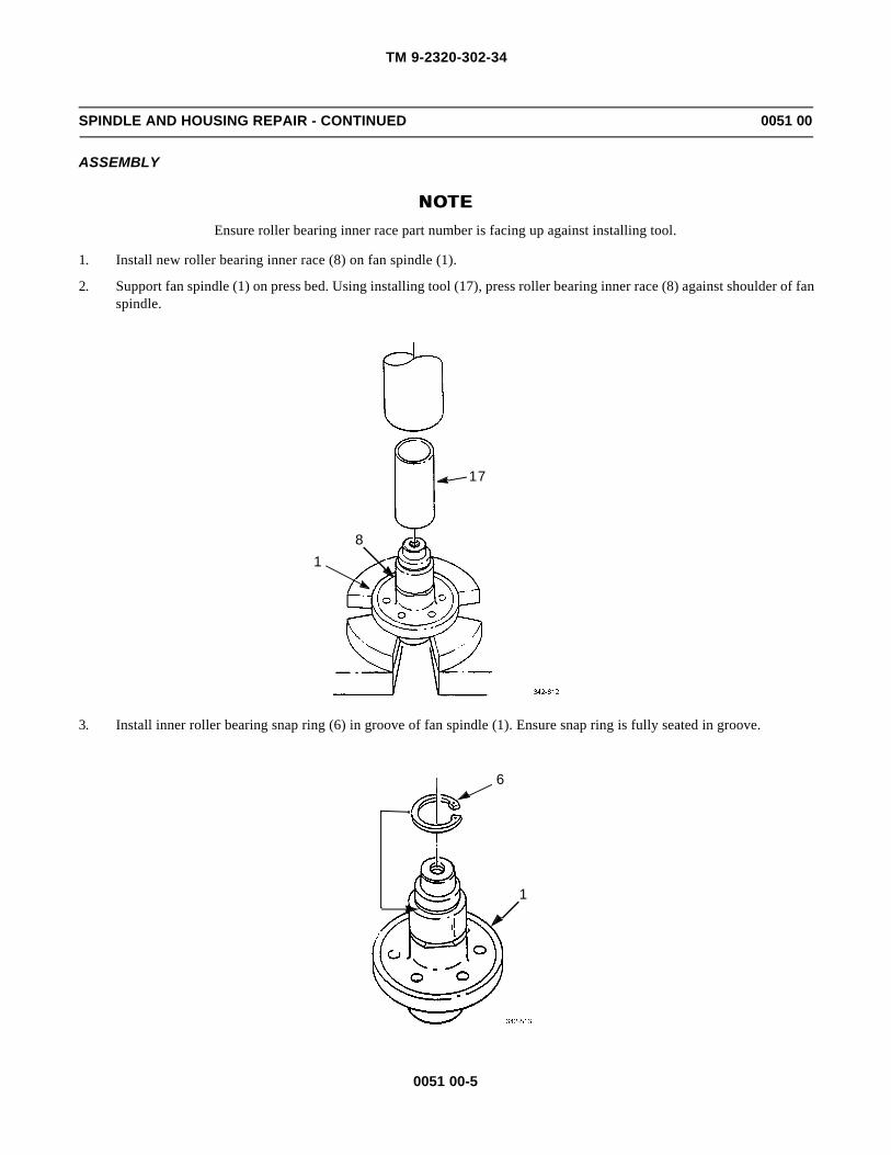
TM 9-2320-302-34
0051 00-5
SPINDLE AND HOUSING REPAIR - CONTINUED 0051 00
ASSEMBLY
NOTENOTEEnsure roller bearing inner race part number is facing up against installing tool.
1. Install new roller bearing inner race (8) on fan spindle (1).
2. Support fan spindle (1) on press bed. Using installing tool (17), press roller bearing inner race (8) against shoulder of fanspindle.
3. Install inner roller bearing snap ring (6) in groove of fan spindle (1). Ensure snap ring is fully seated in groove.
17
18
6
1
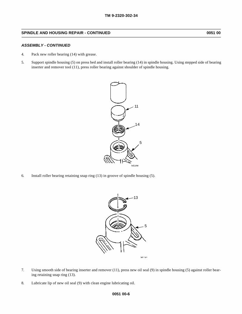
TM 9-2320-302-34
0051 00-6
SPINDLE AND HOUSING REPAIR - CONTINUED 0051 00
ASSEMBLY - CONTINUED
4. Pack new roller bearing (14) with grease.
5. Support spindle housing (5) on press bed and install roller bearing (14) in spindle housing. Using stepped side of bearinginserter and remover tool (11), press roller bearing against shoulder of spindle housing.
6. Install roller bearing retaining snap ring (13) in groove of spindle housing (5).
7. Using smooth side of bearing inserter and remover (11), press new oil seal (9) in spindle housing (5) against roller bear-ing retaining snap ring (13).
8. Lubricate lip of new oil seal (9) with clean engine lubricating oil.
11
14
5
13
5

TM 9-2320-302-34
0051 00-7
SPINDLE AND HOUSING REPAIR - CONTINUED 0051 00
ASSEMBLY - CONTINUED
9. Pack new ball bearing assembly (12) with grease.
10. Turn spindle housing (5) over on press bed and install ball bearing assembly (12) in spindle housing.
NOTENOTEEnsure ball bearing outer race part number is facing up against installing tool.
11. Using wide end of installing tool (18), press on ball bearing assembly (12) outer race. Press ball bearing assembly firmlyagainst shoulder in spindle housing (5).
11
9
13
5
18
12
5

TM 9-2320-302-34
0051 00-8
SPINDLE AND HOUSING REPAIR - CONTINUED 0051 00
ASSEMBLY - CONTINUED
NOTENOTEEnsure snap ring is fully seated in groove of spindle housing.
12. Install ball bearing retaining snap ring (10) in spindle housing (5).
NNOTEOTEDo not pack spindle housing more than 2/3 full.
13. Pack spindle housing (5) with grease.
14. Support fan spindle (1) on press bed and carefully install spindle housing (5) on fan spindle.
15. Using narrow end of installing tool (18), press ball bearing assembly (12) inner race on fan spindle (1) until ball bearingassembly inner race is firmly seated against shoulder of fan spindle.
10
5
18
12
5
1

TM 9-2320-302-34
0051 00-9
SPINDLE AND HOUSING REPAIR - CONTINUED 0051 00
ASSEMBLY - CONTINUED
16. Secure fan spindle (1) in vise. Install spacer (4) and spacer retaining bolt (3) in spindle housing (5). Tighten bolt to 43-54 lb-ft (58-73 Nm).
17. Coat edge of new cup plug (2) with adhesive. Using flat side of bearing inserter and remover tool (11), press new cupplug in spindle housing (5) until raised center of cup plug is flush with edge of spindle housing.
18. Install lube pressure relief fitting (16) and grease fittings (15). Tighten to 72 lb-in (8 Nm) minimum.
19. Install spindle and housing (TM 9-2320-302-20).
END OF WORK PACKAGE
11
2
3
415
5
16
1

TM 9-2320-302-34
0051 00-10
This Page Intentionally Left Blank.

TM 9-2320-302-34
0052 00-1
ALTERNATOR REPAIR 0052 00
THIS WORK PACKAGE COVERS
Disassembly, Testing, Assembly
INITIAL SETUP
Maintenance Level
Direct Support
Tools and Special Tools
Tool kit, general mechanic’s (Item 132, WP 0126 00)
Caps, vise jaw (Item 17, WP 0126 00)
Dial indicator set (Item 29, WP 0126 00)
Multimeter, digital (Item 78, WP 0126 00)
Soldering gun (Item 118, WP 0126 00)
Test stand, automotive generator and starter (Item 122,WP 0126 00)
Vise, machinist’s (Item 136, WP 0126 00)
Wrench, torque, 50-250 lb-ft (Item 139, WP 0126 00)
Materials/Parts
Bearing (P/N A0790-79406)
Gasket (P/N 73814)
Materials/Parts - Continued
Nut, tenz (P/N 2364) (3)
Nut, lock (P/N 26175) (3)
Nut, tenz (P/N 2771) (5)
Seal (P/N 57611)
Seal (P/N 79403)
Seal (P/N 79404)
Seal (P/N 79405)
Washer, lock (P/N 2434) (8)
Cloth, abrasive (Item 9, WP 0125 00)
Compound, sealing (Item 14, WP 0125 00)
Solder (Item 33, WP 0125 00)
Equipment Condition
Alternator removed (TM 9-2320-302-20)

TM 9-2320-302-34
0052 00-2
ALTERNATOR REPAIR - CONTINUED 0052 00
DISASSEMBLY
1. Remove fan (1), woodruff key (2), and spacer (3).
2. Remove two nuts (4), lock washers (5), guard washers (6), cover (7), gasket (8), and two jumpers (9). Discard gasketand lock washers.
3. Remove two brushes (10).
4. Remove four screws (11), brush holder (12), and seal (13). Discard seal.
5. Remove two nuts (14), lock washers (15), nuts (16), lock washers (17), and two terminal studs (18). Discard lock wash-ers.
6. Remove three lock nuts (19) and screws (20). Discard lock nuts.
CAUTIONCAUTION
If drive end housing binds, tap gently on mounting ears. Ensure drive end housing separates from stator andstator remains attached to slip ring end housing to avoid damage to stator leads.
7. Remove rotor and drive end housing (21) from stator (22) and slip ring end housing (23).
8. Remove and discard three tenz nuts (24). Disconnect three leads (25) and remove stator (22).
76
5
4
99
8
18 1810
10 171615
14
3 1
21311
14
15
16
17
12

TM 9-2320-302-34
0052 00-3
ALTERNATOR REPAIR - CONTINUED 0052 00
DISASSEMBLY - CONTINUED
9. Remove two tenz nuts (26), insulator bushings (27), and terminal screws (28). Discard tenz nuts.
25
20
2122
2423
19
26
27
28

TM 9-2320-302-34
0052 00-4
ALTERNATOR REPAIR - CONTINUED 0052 00
DISASSEMBLY - CONTINUED
10. Remove two screws (29) and capacitor (30).
11. Remove two screws (31), lock washers (32), washers (33), insulating washers (34), positive rectifier (35), and negativerectifier (36). Discard lock washers.
12. Remove two insulator bushings (37) from positive rectifier (35) and negative rectifier (36).
NOTENOTE
Note position of insulator bushings in slip ring end housing prior to disassembly to aid in assembly.
13. Remove two insulator bushings (38) from slip ring end housing (23).
14. Remove six nuts (39), three washers (40), insulator (41), three insulators (42), three terminal studs (43), and insulator(44).
15. Remove tenz nut (45) and washer (46) from each of three terminal studs (43). Discard tenz nuts.
16. Remove inner seal (47) and bearing (48). Discard seal and bearing.
17. Remove seal (49) from rear of slip ring end housing (23) by tapping equally in all five holes on outside of slip ring endhousing. Discard seal.
18. Remove rotor and drive end housing (21) from shaft (50).
19. Remove four screws (51), bearing retainer (52), seal (53), and bearing (54). Discard seal.
23
45
4643
44
49
4847 38
36
3433
32
3129
30
40
42
39
41
3537

TM 9-2320-302-34
0052 00-5
ALTERNATOR REPAIR - CONTINUED 0052 00
DISASSEMBLY - CONTINUED
20. Unsolder two leads (55) from slip ring assembly (56).
21. Remove slip ring assembly (56).
22. Place rotor assembly (57) in soft-jawed vise and remove nut (58).
23. Remove inner bearing race (59).
24. Remove two rotor halves (60 and 61), hub (62), and two woodruff keys (63) from shaft (50).
25. If damaged, remove slidable housing (64).
50
5354
21
52
51
55
59
58
63
57
6062
61
50
56
64

TM 9-2320-302-34
0052 00-6
ALTERNATOR REPAIR - CONTINUED 0052 00
TESTING
1. Test positive rectifier (35) as follows:
a. Connect positive lead of diode tester to positive rectifier (35). Touch negative lead to each of three diodes (65).High resistance should be indicated. If any of three diodes show low resistance, replace positive rectifier.
b. Reverse test leads so that negative lead is connected to positive rectifier (35). Touch positive lead to each of threediodes (65). Low resistance should be indicated. If any of three diodes show high resistance, replace positive recti-fier.
2. Test negative rectifier (36) as follows:
a. Connect negative lead of diode tester to negative rectifier (36). Touch negative lead to each of three diodes (66).High resistance should be indicated. If any of three diodes show low resistance, replace negative rectifier.
b. Reverse test leads so that positive lead is connected to negative rectifier (36). Touch positive lead to each of threediodes (66). Low resistance should be indicated. If any of three diodes show high resistance, replace negative rec-tifier.
3. Check capacitor (30) using ohmmeter with positive and negative leads connected to terminals. If resistance reading islow, replace capacitor.
36
6665
35
30

TM 9-2320-302-34
0052 00-7
ALTERNATOR REPAIR - CONTINUED 0052 00
TESTING - CONTINUED
4. Test rotor assembly (57) as follows:
a. With ohmmeter connected between nut (58) and either of two slip rings (67), no reading should be obtained. If anyreading is obtained, rotor coil (61) is grounded and rotor assembly (57) must be disassembled to repair short.
b. Check rotor coil (61) resistance by connecting ohmmeter across both slip rings (67). Resistance should be 9.6-10.4ohms. If resistance is outside limits, replace rotor coil.
5. Test stator (22) as follows:
a. Connect one ohmmeter lead to bare metal surface on stator lamination (68). Connect other lead to each of three sta-tor leads (25) terminals. High resistance reading should be obtained each time. If there is no reading or ohmmeterreads zero, replace stator.
b. Connect ohmmeter leads to stator leads (25) terminals as follows and note each reading:
(1) A and B
(2) A and C
(3) B and C
5857
6167
22
68
25
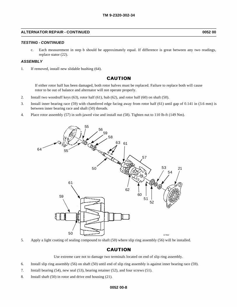
TM 9-2320-302-34
0052 00-8
ALTERNATOR REPAIR - CONTINUED 0052 00
TESTING - CONTINUED
c. Each measurement in step b should be approximately equal. If difference is great between any two readings,replace stator (22).
ASSEMBLY
1. If removed, install new slidable bushing (64).
CAUTIONCAUTIONIf either rotor half has been damaged, both rotor halves must be replaced. Failure to replace both will causerotor to be out of balance and alternator will not operate properly.
2. Install two woodruff keys (63), rotor half (61), hub (62), and rotor half (60) on shaft (50).
3. Install inner bearing race (59) with chamfered edge facing away from rotor half (61) until gap of 0.141 in (3.6 mm) isbetween inner bearing race and shaft (50) threads.
4. Place rotor assembly (57) in soft-jawed vise and install nut (58). Tighten nut to 110 lb-ft (149 Nm).
5. Apply a light coating of sealing compound to shaft (50) where slip ring assembly (56) will be installed.
CAUTIONCAUTIONUse extreme care not to damage two terminals located on end of slip ring assembly.
6. Install slip ring assembly (56) on shaft (50) until end of slip ring assembly is against inner bearing race (59).
7. Install bearing (54), new seal (53), bearing retainer (52), and four screws (51).
8. Install shaft (50) in rotor and drive end housing (21).
50
59
61
2154
53
5251
6062
6163
50
64 55
5556
5958
57
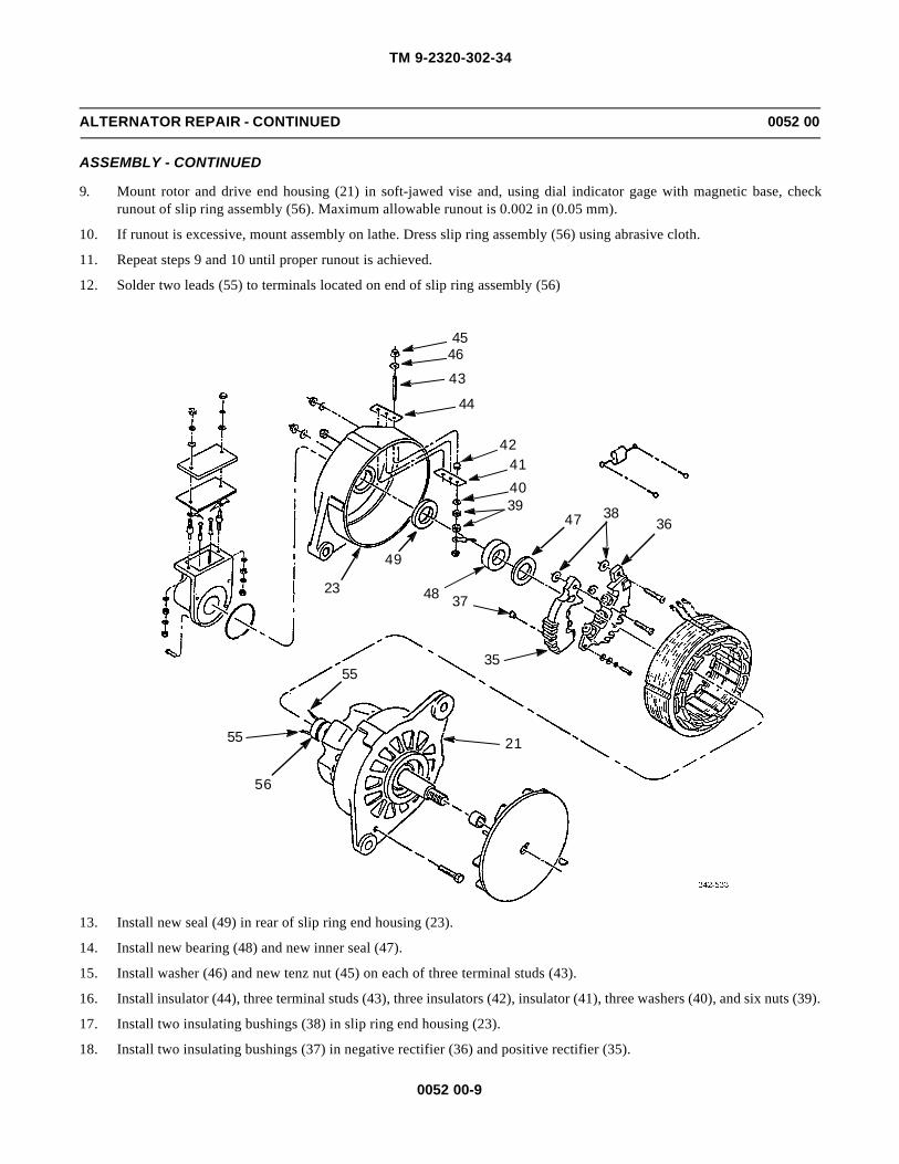
TM 9-2320-302-34
0052 00-9
ALTERNATOR REPAIR - CONTINUED 0052 00
ASSEMBLY - CONTINUED
9. Mount rotor and drive end housing (21) in soft-jawed vise and, using dial indicator gage with magnetic base, checkrunout of slip ring assembly (56). Maximum allowable runout is 0.002 in (0.05 mm).
10. If runout is excessive, mount assembly on lathe. Dress slip ring assembly (56) using abrasive cloth.
11. Repeat steps 9 and 10 until proper runout is achieved.
12. Solder two leads (55) to terminals located on end of slip ring assembly (56)
13. Install new seal (49) in rear of slip ring end housing (23).
14. Install new bearing (48) and new inner seal (47).
15. Install washer (46) and new tenz nut (45) on each of three terminal studs (43).
16. Install insulator (44), three terminal studs (43), three insulators (42), insulator (41), three washers (40), and six nuts (39).
17. Install two insulating bushings (38) in slip ring end housing (23).
18. Install two insulating bushings (37) in negative rectifier (36) and positive rectifier (35).
23
21
55
48
49
37
35
3847394041
42
44
43
4645
36
55
56
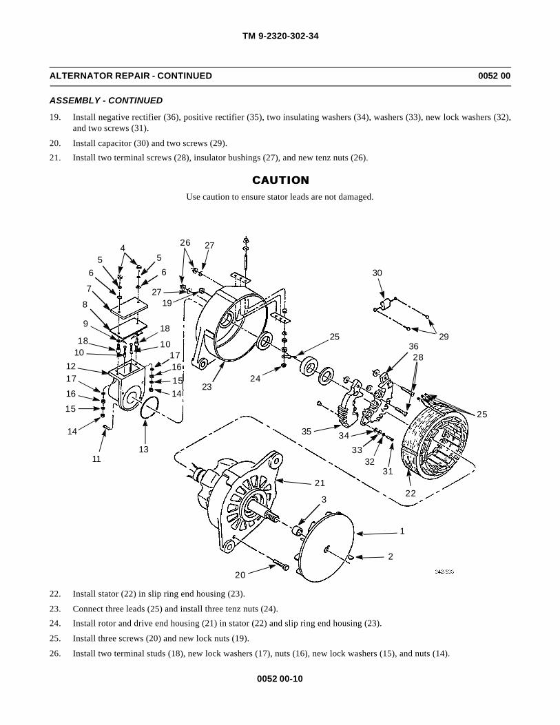
TM 9-2320-302-34
0052 00-10
ALTERNATOR REPAIR - CONTINUED 0052 00
ASSEMBLY - CONTINUED
19. Install negative rectifier (36), positive rectifier (35), two insulating washers (34), washers (33), new lock washers (32),and two screws (31).
20. Install capacitor (30) and two screws (29).
21. Install two terminal screws (28), insulator bushings (27), and new tenz nuts (26).
CAUTIONCAUTIONUse caution to ensure stator leads are not damaged.
22. Install stator (22) in slip ring end housing (23).
23. Connect three leads (25) and install three tenz nuts (24).
24. Install rotor and drive end housing (21) in stator (22) and slip ring end housing (23).
25. Install three screws (20) and new lock nuts (19).
26. Install two terminal studs (18), new lock washers (17), nuts (16), new lock washers (15), and nuts (14).
4 26 27
2719
5566
7
8
9 1818 10
1012
17161514
2317
16
15
14
1113
21
3
24
35 3433
3231
22
28
25
2925
30
1
2
20
36

TM 9-2320-302-34
0052 00-11
ALTERNATOR REPAIR - CONTINUED 0052 00
ASSEMBLY - CONTINUED
27. Install new seal (13), brush holder (12), and four screws (11).
28. Install two brushes (10).
29. Install two jumpers (9), new gasket (8), cover (7), two guard washers (6), new lock washers (5), and nuts (4).
30. Install spacer (3), woodruff key (2), and fan (1).
31. Install alternator (TM 9-2320-302-20).
END OF WORK PACKAGE

TM 9-2320-302-34
0052 00-12
This Page Intentionally Left Blank.

TM 9-2320-302-34
0053 00-1
STARTER SOLENOID REPLACEMENT 0053 00
THIS WORK PACKAGE COVERS
Removal, Installation
INITIAL SETUP
Maintenance Level
Direct Support
Tools and Special Tools
Tool kit, general mechanic’s (Item 132, WP 0126 00)
Caps, vise jaw (Item 17, WP 0126 00)
Vise, machinist’s (Item 136, WP 0126 00)
Wrench, torque, 15-75 lb-ft (Item 138, WP 0126 00)
Materials/Parts
Washer, lock (P/N MS35333-42)
Adhesive, silicone (Item 4, WP 0125 00)
Equipment Condition
Starter removed (TM 9-2320-302-20)
REMOVAL
1. Remove nut (1), lock washer (2), and wire (3) from starter solenoid (4). Discard lock washer.
2. Remove nut (5) from starter solenoid (4).
3. Hold nut (6) on starter motor (7) and remove nut (8) and jumper (9) from stud (10).
4. Remove two screws (11).
5. Pull starter solenoid (4) away from housing (12) and rotate so that mounting bracket (13) faces away from starter motor(7).
127
6
10
9
8
135
1 2 3
114

TM 9-2320-302-34
0053 00-2
STARTER SOLENOID REPLACEMENT - CONTINUED 0053 00
REMOVAL - CONTINUED
6. Remove spool (14) from shift fork (15).
NOTENOTEIt may be necessary to use a soft-jawed vise to hold solenoid plunger for removal of spool.
7. Remove spool (14) and boot (16) from solenoid plunger (17).
INSTALLATION
1. Install boot (16) and spool (14) on solenoid plunger (17).
2. Rotate starter solenoid (4) so that mounting bracket (13) faces away from starter motor (7).
3. Install spool (14) in shift fork (15).
4. Rotate starter solenoid (4) to mounting position and press flush with housing (12).
5. Apply silicone adhesive to threads and install two screws (11).
6. Install jumper (9) on stud (10).
7. Apply silicone adhesive to last ¼ in (6.4 mm) of threads on stud (10). Hold nut (6) and install nut (8). Tighten nut to 21-29 lb-ft (28-39 Nm).
8. Install nut (5) on starter solenoid (4). Tighten nut to 18-22 lb-ft (24-30 Nm).
9. Install wire (3), new lock washer (2), and nut (1) on starter solenoid (4).
10. Install starter (TM 9-2320-302-20).
END OF WORK PACKAGE
127
6
10
9
8
135
1 2 3
11
4
17
16
14
15
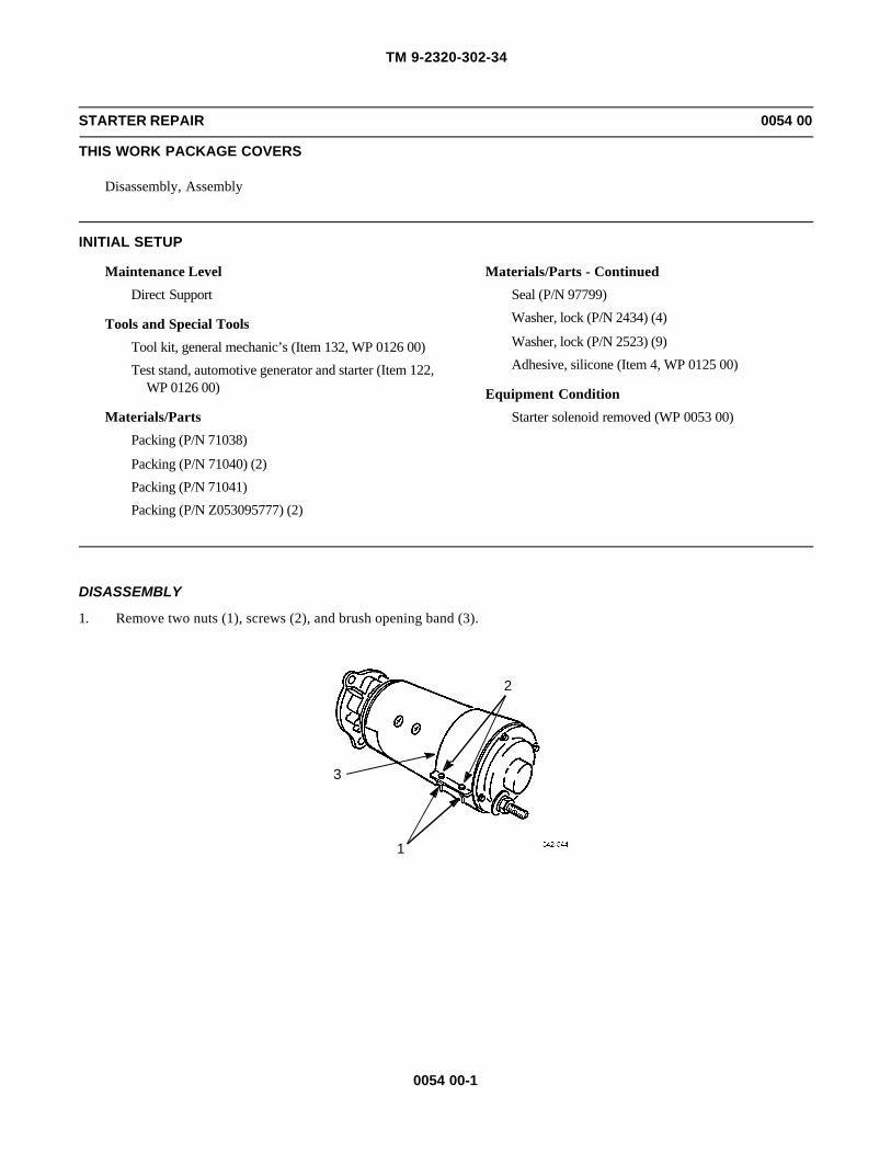
TM 9-2320-302-34
0054 00-1
STARTER REPAIR 0054 00
THIS WORK PACKAGE COVERS
Disassembly, Assembly
INITIAL SETUP
Maintenance Level
Direct Support
Tools and Special Tools
Tool kit, general mechanic’s (Item 132, WP 0126 00)
Test stand, automotive generator and starter (Item 122,WP 0126 00)
Materials/Parts
Packing (P/N 71038)
Packing (P/N 71040) (2)
Packing (P/N 71041)
Packing (P/N Z053095777) (2)
Materials/Parts - Continued
Seal (P/N 97799)
Washer, lock (P/N 2434) (4)
Washer, lock (P/N 2523) (9)
Adhesive, silicone (Item 4, WP 0125 00)
Equipment Condition
Starter solenoid removed (WP 0053 00)
DISASSEMBLY
1. Remove two nuts (1), screws (2), and brush opening band (3).
2
1
3

TM 9-2320-302-34
0054 00-2
STARTER REPAIR - CONTINUED 0054 00
DISASSEMBLY - CONTINUED
CAUTIONCAUTIONDo not pull brush leads until spring tension is relieved to prevent damage to equipment.
2. Remove eight screws (4) and four lock plates (5).
3. Pull two springs (6) upward and remove eight brushes (7).
NOTENOTEMark commutator housing and field ring prior to removing commutator housing to aid in installation.
4. Remove four screws (8), lock washers (9), commutator housing (10), insulation washer (11), and washer (12) from fieldring (13). Discard lock washers.
5. Remove four screws (14), lock washers (15), washers (16), eight insulation washers (17), and four insulation bushings(18). Discard lock washers.
6. Remove four brush holders (19), insulation washers (20), and ground jumper (21) from commutator housing (10).
7. Remove nut (22), four washers (23), insulator (24), and packing (25) from ground stud (26). Discard packing.
8. Remove ground stud (26) from commutator housing (10).
9. Remove packing (27), insulation washer (28), and washer (29) from ground stud (26). Discard packing.
10. If damaged, remove bushing (30) from commutator housing (10).
11. Remove packing (31), pipe plug (32), and felt wick (33) from commutator housing (10). Discard packing.
12. If damaged, remove bushing (34) from commutator housing (10).
7
6
5
4

TM 9-2320-302-34
0054 00-3
STARTER REPAIR - CONTINUED 0054 00
DISASSEMBLY - CONTINUED
1415
1618
17
26292827
30
32331025
242322
8
9
20
3419
2111
12
31
13

TM 9-2320-302-34
0054 00-4
STARTER REPAIR - CONTINUED 0054 00
DISASSEMBLY - CONTINUED
NOTENOTEMark nose housing and shift housing prior to removing nose housing to aid in installation.
13. Remove six screws (35), nose housing (36), packing (37), and washer (38) from shift housing (39). Discard packing.
NOTENOTEPerform step 14 only if components are damaged.
14. Remove bushing (40), plug (41), felt wick (42), and six plugs (43) from nose housing (36).
15. Remove screw (44), washer (45), shaft (46), and packing (47) from shift housing (39). Discard packing.
16. Remove armature (48), washer (49), drive assembly (50), insulator (51), shift lever (52), and two cams (53).
NOTENOTEMark shift housing and field ring prior to removing shift housing to aid in installation.
17. Remove five screws (54), lock washers (55), and shift housing (39) from field ring (13).
39
36
35
40
41
42
4336
38 37

TM 9-2320-302-34
0054 00-5
STARTER REPAIR - CONTINUED 0054 00
DISASSEMBLY - CONTINUED
18. Remove seal (56), bushing (57), and packing (58) from shift housing (39). Discard seal and packing.
48
4913
4547
44
46
51
52
5350
54
5539
39
575658

TM 9-2320-302-34
0054 00-6
STARTER REPAIR - CONTINUED 0054 00
DISASSEMBLY - CONTINUED
19. Remove nut (59), washer (60), insulator (61), and packing (62) from field ring (13). Discard packing.
CAUTIONCAUTIONWhen removing stud terminal, do not use hammer to tap stud out. To do so could cause damage to compo-nents.
20. To remove stud terminal (63), temporarily replace nut (59) flush with end of stud. Using suitable pliers, work stud outwhile supporting field coil (64).
21. Remove insulator (65) and bushing (66) from field ring (13).
22. Remove eight screws (67), four pole pieces (68), field coil (64), and insulator (69) from field ring (13).
ASSEMBLY
1. Install insulator (69) in field ring (13).
2. Install field coil (64) in field ring (13) so that terminal stud holes in field coil and field ring (13) line up.
CAUTIONCAUTIONPole pieces must be installed so that slot clears field coil contact tab. Failure to do so will cause damage tostarter motor.
3. Install four pole pieces (68) and eight screws (67).
CAUTIONCAUTIONInsulator must be installed between field coil and field ring. Failure to do so will cause a short, damagingstarter motor.
4. Install insulator (65) and stud terminal (63) through field coil (64) and field ring (13).
5. Install bushing (66), new packing (62), insulator (61), washer (60), and nut (59) on stud terminal (63).
68
68
6467
13
63
65
69
59
60
61
62
66

TM 9-2320-302-34
0054 00-7
STARTER REPAIR - CONTINUED 0054 00
ASSEMBLY - CONTINUED
6. Install new packing (58), bushing (57), and new seal (56) in shift housing (39).
7. Install shift housing (39) on field ring (13) with five new lock washers (55) and screws (54).
8. Install two cams (53), shift lever (52), insulator (51), drive assembly (50), washer (49), and armature (48).
9. Install new packing (47), shaft (46), washer (45), and screw (44) in shift housing (39).
39
575658
48
49 13
4547
44
46
51
52
5350
54
5539

TM 9-2320-302-34
0054 00-8
STARTER REPAIR - CONTINUED 0054 00
ASSEMBLY - CONTINUED
10. If removed, install six new plugs (43), new felt wick (42), new plug (41), and new bushing (40) in nose housing (36).
NOTENOTEInstall nose housing as noted in disassembly sequence.
11. Install washer (38), packing (37), nose housing (36), and six screws (35) on shift housing (39).
12. If removed, install new bushing (34) in commutator housing (10).
13. Install felt wick (33), pipe plug (32), and new packing (31) in commutator housing (10).
14. If removed, install new bushing (30) in commutator housing (10).
15. Install washer (29), insulation washer (28), and new packing (27) on ground stud (26).
16. Install ground stud (26) in commutator housing (10).
17. Install new packing (25), insulator (24), four washers (23), and nut (22) on ground stud (26).
18. Install ground jumper (21), four insulation washers (20), and brush holders (19) in commutator housing (10).
19. Install four insulation bushings (18), eight insulation washers (17), four washers (16), new lock washers (15), andscrews (14).
20. Install insulation washer (11), washer (12), and commutator housing (10) in field ring (13).
21. Apply silicone adhesive to threads of four screws (8) and install four new lock washers (9) and screws (8).
39
36
35
40
41
42
4336
38 37

TM 9-2320-302-34
0054 00-9
STARTER REPAIR - CONTINUED 0054 00
ASSEMBLY - CONTINUED
22. Pull two springs (6) upward and install brush (7), lock plate (4), and two screws (5).
23. Repeat step 22 for remaining brushes (7).
1415
1618
17
26292827
30
32331025
242322
8
9
20
3419
2111
12
31
13
7
6
5
4
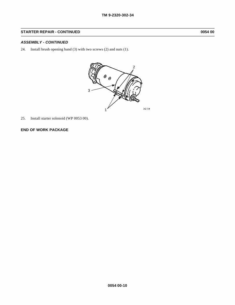
TM 9-2320-302-34
0054 00-10
STARTER REPAIR - CONTINUED 0054 00
ASSEMBLY - CONTINUED
24. Install brush opening band (3) with two screws (2) and nuts (1).
25. Install starter solenoid (WP 0053 00).
END OF WORK PACKAGE
2
1
3

TM 9-2320-302-34
0055 00-1
ENGINE POWER WIRING HARNESS REPLACEMENT 0055 00
THIS WORK PACKAGE COVERS
Removal, Installation
INITIAL SETUP
Maintenance Level
Direct Support
Tools and Special Tools
Tool kit, general mechanic’s (Item 132, WP 0126 00)
Materials/Parts
Tags, marker (Item 35, WP 0125 00)
Equipment Condition
Battery cables disconnected (TM 9-2320-302-20)
REMOVAL
NOTENOTE• Wiring harness and leads are secured in place by cushion clamps and screw terminals. Only remove
hardware securing harness or lead to be removed.
• Tag wiring harness and leads prior to removal to aid in installation.
Disconnect and remove engine power wiring harness, using illustration as a guide.
7
6
8
5
9
423
1
TABLE QTY
1 Fuse Holder Plug 22 1-pin Connector 13 6-pin Connector 14 Terminal 45 Screw 16 Washer 17 Nut 18 Clamp 19 Crown Nut 2

TM 9-2320-302-34
0055 00-2
ENGINE POWER WIRING HARNESS REPLACEMENT - CONTINUED 0055 00
INSTALLATION
NOTENOTEWiring harness and leads are secured in place by cushion clamps and screw terminals. Ensure harness issecure and all hardware is tight.
1. Install, connect, and secure engine power wiring harness, using illustration as a guide.
2. Connect battery cables (TM 9-2320-302-20).
END OF WORK PACKAGE
7
6
8
5
9
423
1
TABLE QTY
1 Fuse Holder Plug 22 1-pin Connector 13 6-pin Connector 14 Terminal 45 Screw 16 Washer 17 Nut 18 Clamp 19 Crown Nut 2
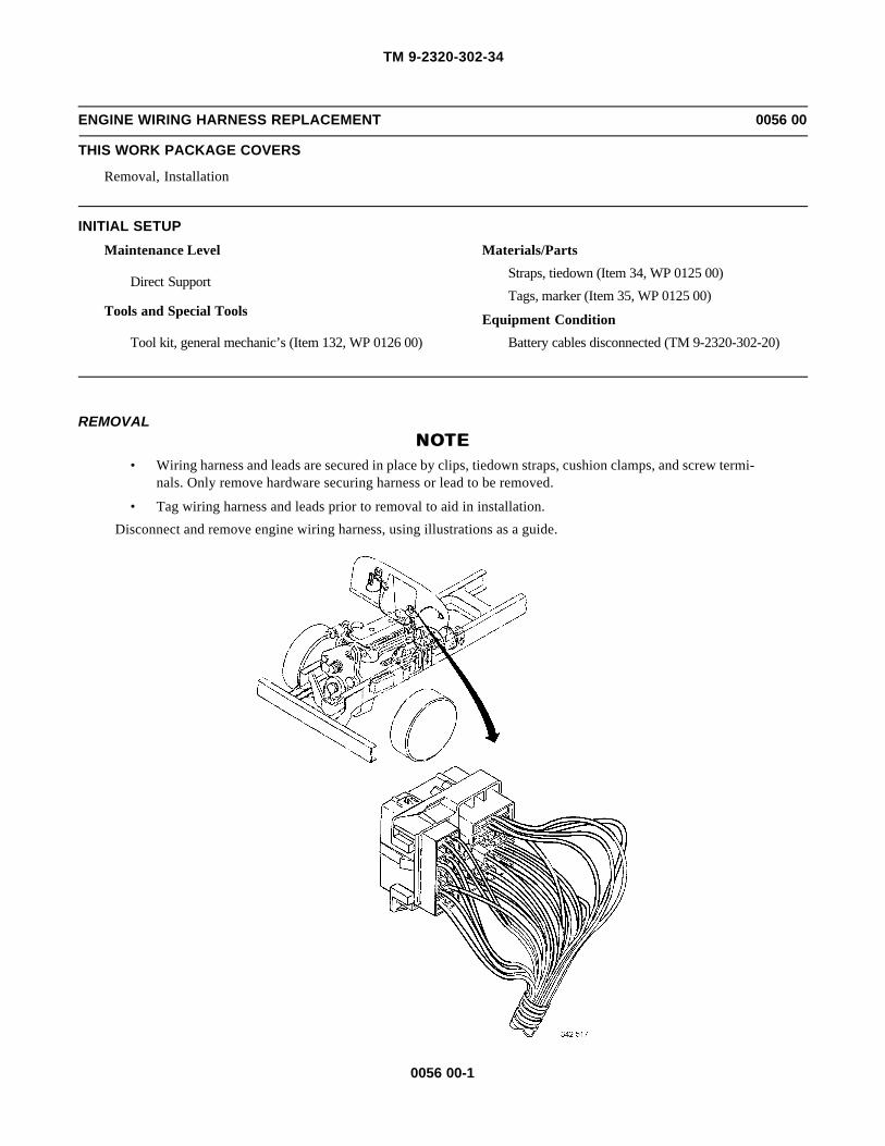
TM 9-2320-302-34
0056 00-1
ENGINE WIRING HARNESS REPLACEMENT 0056 00
THIS WORK PACKAGE COVERS
Removal, Installation
INITIAL SETUP
Maintenance Level
Direct Support
Tools and Special Tools
Tool kit, general mechanic’s (Item 132, WP 0126 00)
Materials/Parts
Straps, tiedown (Item 34, WP 0125 00)
Tags, marker (Item 35, WP 0125 00)
Equipment Condition
Battery cables disconnected (TM 9-2320-302-20)
REMOVALNOTENOTE
• Wiring harness and leads are secured in place by clips, tiedown straps, cushion clamps, and screw termi-nals. Only remove hardware securing harness or lead to be removed.
• Tag wiring harness and leads prior to removal to aid in installation.
Disconnect and remove engine wiring harness, using illustrations as a guide.

TM 9-2320-302-34
0056 00-2
ENGINE WIRING HARNESS REPLACEMENT - CONTINUED 0056 00
REMOVAL - CONTINUED

TM 9-2320-302-34
0056 00-3
ENGINE WIRING HARNESS REPLACEMENT - CONTINUED 0056 00
REMOVAL - CONTINUED
INSTALLATION
NOTENOTEWiring harness and leads are secured in place by clips, new tiedown straps, cushion clamps, and screw ter-minals. Ensure harness is secure and all hardware is tight.
1. Install, connect, and secure engine wiring harness, using illustrations as a guide.
2. Connect battery cables (TM 9-2320-302-20).
END OF WORK PACKAGE

TM 9-2320-302-34
0056 00-4
This Page Intentionally Left Blank.

TM 9-2320-302-34
0057 00-1
MAIN CAB WIRING HARNESS REPLACEMENT 0057 00
THIS WORK PACKAGE COVERS
Removal, Installation
INITIAL SETUP
Maintenance Level
Direct Support
Tools and Special Tools
Tool kit, general mechanic’s (Item 132, WP 0126 00)
Materials/Parts
Straps, tiedown (Item 34, WP 0125 00)
Tags, marker (Item 35, WP 0125 00)
Equipment Condition
Battery cables disconnected (TM 9-2320-302-20)
REMOVAL
NOTENOTE• Wiring harness and leads are secured in place by clips, tiedown straps, cushion clamps, and screw termi-
nals. Only remove hardware securing harness to be removed.
• Tag wiring harness and leads prior to removal to aid in installation.
1. Disconnect relay and fuse panel (1).
2. Disconnect 42-pin connector (2), 34-pin connector (3), 32-pin connector (4), 6-pin sealed connector (5), and four ringterminals (6).
5
4
2
3
3
21
1
6
6
4
5
6

TM 9-2320-302-34
0057 00-2
MAIN CAB WIRING HARNESS REPLACEMENT - CONTINUED 0057 00
REMOVAL - CONTINUED
3. Disconnect three ring terminals (6), 12-pin connector (7), female terminal blade (8), 6-pin female connector (9), 3-pinsealed connector (10), two 3-pin female connectors (11), 1-pin male connector (12), and six 1-pin female connectors(13).
4. Disconnect three ring terminals (6), 6-pin female connector (9), two 3-pin female connectors (11), 1-pin male connector(12), 1-pin female connector (13), 12-pin diagnostic connector (14), 3-pin male connector (15), two 2-pin male connec-tors (16), and 2-pin female connectors (17).
5. Disconnect 2-pin male connector (18).
6. Remove eight screws (19) and remove 6-pin diagnostic connector (20) and 9-pin engine diagnostic connector (21).
7
8911
6
1312,13
6
10
8
11
11
9
10 6
13
116
1213 13
7

TM 9-2320-302-34
0057 00-3
MAIN CAB WIRING HARNESS REPLACEMENT - CONTINUED 0057 00
REMOVAL - CONTINUED
11917
15 6161213
18
20
21
16
141213
11
15
9 17
16
19
2021
14186

TM 9-2320-302-34
0057 00-4
MAIN CAB WIRING HARNESS REPLACEMENT - CONTINUED 0057 00
REMOVAL - CONTINUED
7. Disconnect ring terminal (6), 6-pin female connector (9), four 3-pin female connectors (11), two 1-pin male connectors(12), two 1-pin female connectors (13), 2-pin male connector (16), 12-pin light switch connector (22), and 32-pin con-nector (23).
1111
236
12,13
229
12,13
16
23
11
11
1612
13
13
12
22
96

TM 9-2320-302-34
0057 00-5
MAIN CAB WIRING HARNESS REPLACEMENT - CONTINUED 0057 00
REMOVAL - CONTINUED
8. Disconnect five 6-pin female connectors (9), 3-pin sealed connector (10), three 1-pin female connectors (13), three 2-pinmale connectors (16), three 2-pin female connectors (17), four 4-pin male connectors (24), three 4-pin female connec-tors (25), and 2-pin sealed connector (26).
139
17
17
16
1624 17 9
10
13
26
16
25
9
1324
25
17
17
16
2613
10
9
24
24
24
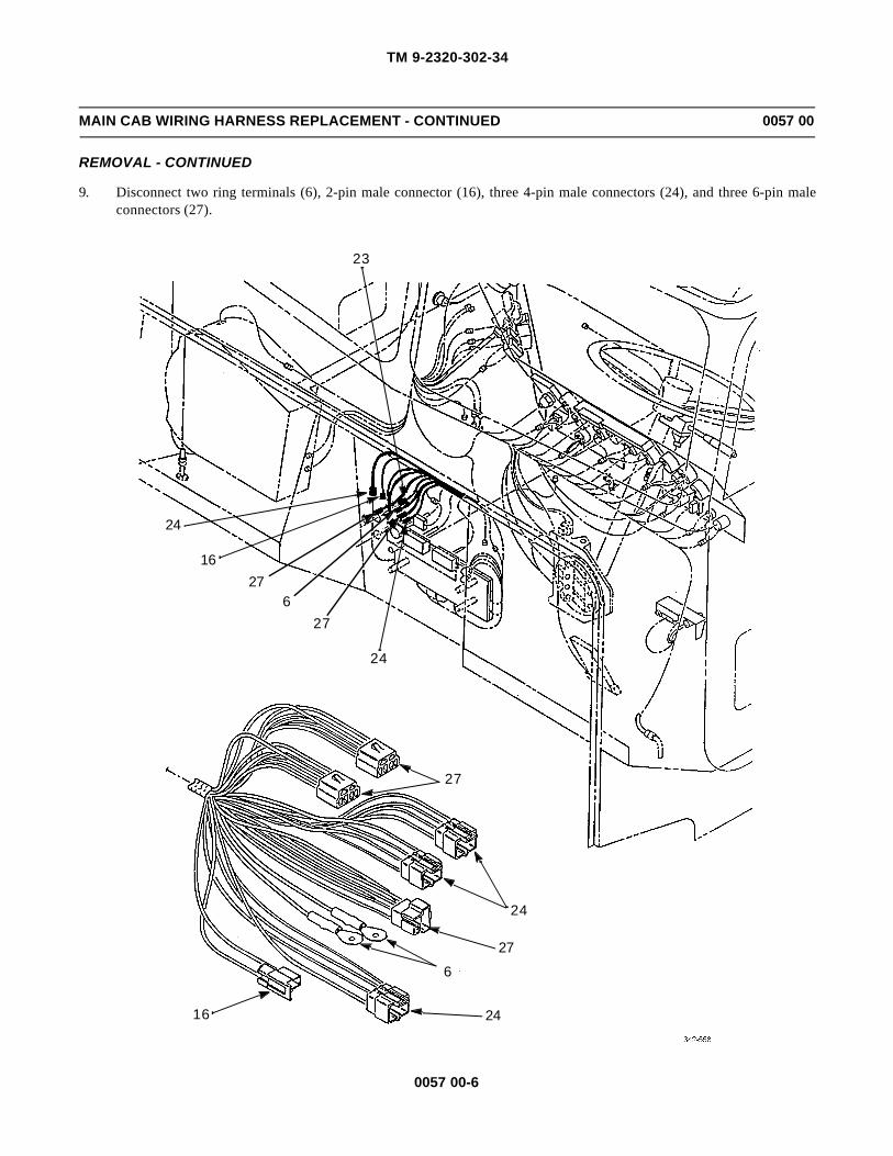
TM 9-2320-302-34
0057 00-6
MAIN CAB WIRING HARNESS REPLACEMENT - CONTINUED 0057 00
REMOVAL - CONTINUED
9. Disconnect two ring terminals (6), 2-pin male connector (16), three 4-pin male connectors (24), and three 6-pin maleconnectors (27).
23
24
1627
627
24
27
24
27
6
2416

TM 9-2320-302-34
0057 00-7
MAIN CAB WIRING HARNESS REPLACEMENT - CONTINUED 0057 00
REMOVAL - CONTINUED
10. Remove main cab wiring harness (28).
INSTALLATION
NOTENOTEWiring harness and leads are secured in place by clips, tiedown straps, cushion clamps, and screw terminals.Ensure wiring harness is secure and all hardware is tight.
28

TM 9-2320-302-34
0057 00-8
MAIN CAB WIRING HARNESS REPLACEMENT - CONTINUED 0057 00
INSTALLATION - CONTINUED
1. Connect relay and fuse panel (1).
2. Connect 42-pin connector (2), 34-pin connector (3), 32-pin connector (4), 6-pin sealed connector (5), and four ring ter-minals (6).
5
4
2
3
3
21
1
6
6
4
5
6

TM 9-2320-302-34
0057 00-9
MAIN CAB WIRING HARNESS REPLACEMENT - CONTINUED 0057 00
INSTALLATION - CONTINUED
3. Connect three ring terminals (6), 12-pin connector (7), female terminal blade (8), 6-pin female connector (9), 3-pinsealed connector (10), two 3-pin female connectors (11), 1-pin male connector (12), and six 1-pin female connectors(13).
7
8911
6
1312,13
6
10
8
11
11
9
10 6
13
116
1213 13
7

TM 9-2320-302-34
0057 00-10
MAIN CAB WIRING HARNESS REPLACEMENT - CONTINUED 0057 00
INSTALLATION - CONTINUED
4. Install 9-pin engine diagnostic connector (21) and 6-pin diagnostic connector (20) and secure with eight screws (19).
5. Connect 2-pin male connector (18).
6. Connect three ring terminals (6), 6-pin female connector (9), two 3-pin female connectors (11), 1-pin male connector(12), 1-pin female connector (13), 12-pin diagnostic connector (14), 3-pin male connector (15), two 2-pin male connec-tors (16), and 2-pin female connectors (17).
11917
15 6161213
18
20
21
16
141213
11
15
9 17
16
19
2021
14186

TM 9-2320-302-34
0057 00-11
MAIN CAB WIRING HARNESS REPLACEMENT - CONTINUED 0057 00
INSTALLATION - CONTINUED
7. Connect ring terminal (6), 6-pin female connector (9), four 3-pin female connectors (11), two 1-pin male connectors(12), two 1-pin female connectors (13), 2-pin male connector (16), 12-pin light switch connector (22), and 32-pin con-nector (23).
1111
236
12,13
229
12,13
16
23
11
11
1612
13
13
12
22
96

TM 9-2320-302-34
0057 00-12
MAIN CAB WIRING HARNESS REPLACEMENT - CONTINUED 0057 00
INSTALLATION - CONTINUED
8. Connect five 6-pin female connectors (9), 3-pin sealed connector (10), three 1-pin female connectors (13), three 2-pinmale connectors (16), three 2-pin female connectors (17), four 4-pin male connectors (24), three 4-pin female connec-tors (25), and 2-pin sealed connector (26).
139
17
17
16
1624 17 9
10
13
26
16
25
9
1324
25
17
17
16
2613
10
9
24
24
24

TM 9-2320-302-34
0057 00-13
MAIN CAB WIRING HARNESS REPLACEMENT - CONTINUED 0057 00
INSTALLATION - CONTINUED
9. Connect two ring terminals (6), 2-pin male connector (16), three 4-pin male connectors (24), and three 6-pin male con-nectors (27).
23
24
1627
627
24
27
24
27
6
2416

TM 9-2320-302-34
0057 00-14
MAIN CAB WIRING HARNESS REPLACEMENT - CONTINUED 0057 00
INSTALLATION - CONTINUED
10. Secure main cab wiring harness (28).
11. Connect battery cables (TM 9-2320-302-20).
END OF WORK PACKAGE
28

TM 9-2320-302-34
0058 00-1
SWITCH PANEL WIRING HARNESS REPLACEMENT 0058 00
THIS WORK PACKAGE COVERS
Removal, Installation
INITIAL SETUP
Maintenance Level
Direct Support
Tools and Special Tools
Tool kit, general mechanic’s (Item 132, WP 0126 00)
Materials/Parts
Straps, tiedown (Item 34, WP 0125 00)
Tags, marker (Item 35, WP 0125 00)
Equipment Condition
Battery cables disconnected (TM 9-2320-302-20)
REMOVAL
NOTENOTE• Wiring harness and leads are secured in place by clips, tiedown straps, cushion clamps, and screw termi-
nals. Only remove hardware securing harness or lead to be removed.
• Tag wiring harness and leads prior to removal to aid in installation.
Disconnect and remove switch panel wiring harness, using illustration as a guide. Discard tiedown straps.
INSTALLATION
NOTENOTEWiring harness and leads are secured in place by clips, new tiedown straps, cushion clamps, and screw ter-minals. Ensure harness is secure and all hardware is tight.
1. Install, connect, and secure switch panel wiring harness, using illustration as a guide.
2. Connect battery cables (TM 9-2320-302-20).
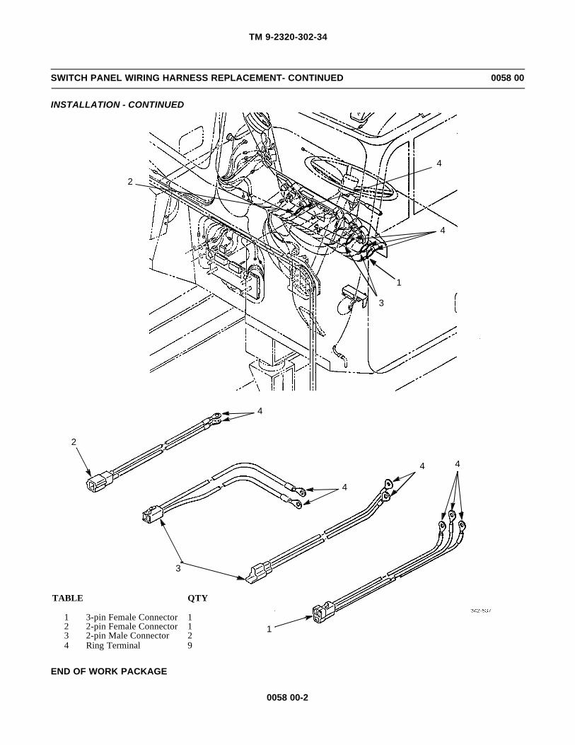
TM 9-2320-302-34
0058 00-2
SWITCH PANEL WIRING HARNESS REPLACEMENT- CONTINUED 0058 00
INSTALLATION - CONTINUED
END OF WORK PACKAGE
1
3
4 4
4
4
2
3
1
4
4
2
TABLE QTY
1 3-pin Female Connector 12 2-pin Female Connector 13 2-pin Male Connector 24 Ring Terminal 9

TM 9-2320-302-34
0059 00-1
TURN SIGNAL/MARKER LIGHT WIRING HARNESS REPLACEMENT 0059 00
THIS WORK PACKAGE COVERS
Removal, Installation
INITIAL SETUP
Maintenance Level
Direct Support
Tools and Special Tools
Tool kit, general mechanic’s (Item 132, WP 0126 00)
Materials/Parts
Straps, tiedown (Item 34, WP 0125 00)
Equipment Condition
Battery cables disconnected (TM 9-2320-302-20)
NOTENOTEProcedure is same for left- and right-side harnesses.
REMOVAL
NOTENOTEWiring harness and leads are secured by clips, tiedown straps, cushion clamps, and screw terminals. Onlyremove hardware securing harness or lead to be removed.
Disconnect and remove turn signal/marker light wiring harness, using illustration as a guide. Discard tiedown straps.
INSTALLATION
NOTENOTEWiring harness and leads are secured by clips, new tiedown straps, cushion clamps, and screw terminals.Ensure harness is secure and all hardware is tight.
1. Install, connect, and secure turn signal/marker light wiring harness, using illustration as a guide.
2. Connect battery cables (TM 9-2320-302-20).

TM 9-2320-302-34
0059 00-2
TURN SIGNAL/MARKER LIGHT WIRING HARNESS REPLACEMENT - CONTINUED 0059 00
INSTALLATION - CONTINUED
END OF WORK PACKAGE
1
1
12
2
2
TABLE QTY
1 4-pin Female Connector 22 3-pin Female Sealed Connector 2

TM 9-2320-302-34
0060 00-1
TURN SIGNAL (THRU-DECK) WIRING HARNESS REPLACEMENT 0060 00
THIS WORK PACKAGE COVERS
Removal, Installation
INITIAL SETUP
Maintenance Level
Direct Support
Tools and Special Tools
Tool kit, general support (Item 132, WP 0126 00)
Materials/Parts
Straps, tiedown (Item 34, WP 0125 00)
Equipment Condition
Battery cables disconnected (TM 9-2320-302-20)
NOTENOTEProcedure is same for left- and right-side harnesses.
REMOVAL
NOTENOTEWiring harness and leads are secured by clips, tiedown straps, cushion clamps, and screw terminals. Onlyremove hardware securing harness or lead to be removed.
Disconnect and remove turn signal (thru-deck) wiring harness, using illustration as a guide. Discard tiedown straps.
INSTALLATION
NOTENOTEWiring harness and leads are secured by clips, new tiedown straps, cushion clamps, and screw terminals.Ensure harness is secure and all hardware is tight.
1. Install, connect, and secure turn signal (thru-deck) wiring harness, using illustration as a guide.
2. Connect battery cables (TM 9-2320-302-20).

TM 9-2320-302-34
0060 00-2
TURN SIGNAL (THRU-DECK) WIRING HARNESS REPLACEMENT - CONTINUED 0060 00
INSTALLATION - CONTINUED
END OF WORK PACKAGE
2
1
12
TABLE QTY
1 2-pin Female Connector 22 2-pin Male Sealed Connector 2

TM 9-2320-302-34
0061 00-1
OVERHEAD CAB WIRING HARNESS REPLACEMENT 0061 00
THIS WORK PACKAGE COVERS
Removal, Installation
INITIAL SETUP
Maintenance Level
Direct Support
Tools and Special Tools
Tool kit, general mechanic’s (Item 132, WP 0126 00)
Materials/Parts
Straps, tiedown (Item 34, WP 0125 00)
Tags, marker (Item 35, WP 0125 00)
Equipment Condition
Head liners removed (TM 9-2320-302-20)
Battery cables disconnected (TM 9-2320-302-20)
REMOVAL
NOTENOTE• Wiring harness and leads are secured by clips, tiedown straps, cushion clamps, and screw terminals.
Only remove hardware securing harness or lead to be removed.
• Tags wiring harness and leads prior to removal to aid in installation.
Disconnect and remove overhead cab wiring harness, using illustration as a guide. Discard tiedown straps.
INSTALLATION
NOTENOTEWiring harness and leads are secured by clips, new tiedown straps, cushion clamps, and screw terminals.Ensure harness is secure and all hardware is tight.
1. Install, connect, and secure overhead cab wiring harness, using illustration as a guide.
2. Install head liners (TM 9-2320-302-20).
3. Connect battery cables (TM 9-2320-302-20).

TM 9-2320-302-34
0061 00-2
OVERHEAD CAB WIRING HARNESS REPLACEMENT - CONTINUED 0061 00
INSTALLATION - CONTINUED
END OF WORK PACKAGE
4
3
2
4
5
6
6
1
3
3
2
1
3
2
6
4
4
5
6
3
2
TABLE QTY
1 6-pin Connector 12 3-pin Connector 23 2-pin Connector 54 1-pin Connector 25 Cable Connector 26 Ring Terminal 4
3

TM 9-2320-302-34
0062 00-1
CHASSIS WIRING HARNESS REPLACEMENT 0062 00
THIS WORK PACKAGE COVERS
Removal, Installation
INITIAL SETUP
Maintenance Level
Direct Support
Tools and Special Tools
Tool kit, general mechanic’s (Item 132, WP 0126 00)
Materials/Parts
Straps, tiedown (Item 34, WP 0125 00)
Tags, marker (IItem 35, WP 0125 00)
Equipment Condition
Battery cables disconnected (TM 9-2320-302-20)
REMOVAL
NOTENOTE• Wiring harness and leads are secured by clips, tiedown straps, cushion clamps, and screw terminals.
Only remove hardware securing harness or lead to be removed.
• Tag wiring harness and leads prior to removal to aid in installation.
Disconnect and remove chassis wiring harness, using illustration as a guide. Discard tiedown straps.
INSTALLATION
NOTENOTEWiring harness and leads are secured by clips, new tiedown straps, cushion clamps, and screw terminals.Ensure harness is secure and all hardware is tight.
1. Install, connect, and secure chassis wiring harness, using illustration s a guide.
2. Connect battery cables (TM 9-2320-302-20).

TM 9-2320-302-34
0062 00-2
CHASSIS WIRING HARNESS REPLACEMENT - CONTINUED 0062 00
INSTALLATION - CONTINUED
END OF WORK PACKAGE
9
9
9
9
94
9
5
81
56
9
4
58
3
3
2
4,5,8
6
92,3
2,3
59
5,8
9
91
4 9
9
7,8
78
TABLE QTY
1 34-pin Male Connector 22 3-pin Female Sealed Connector 23 3-pin Male Sealed Connector 24 2-pin Male Sealed Connector 35 1-pin Male Sealed Connector 36 1-pin Female Connector 27 Male Cable Connector 28 Female Cable Connector 49 Ring Terminal 17

TM 9-2320-302-34
0063 00-1
FRONT ANTI-LOCK BRAKE SYSTEM (ABS) WIRING HARNESS REPLACEMENT 0063 00
THIS WORK PACKAGE COVERS
Removal, Installation
INITIAL SETUP
Maintenance Level
Direct Support
Tools and Special Tools
Tool kit, general mechanic’s (Item 132, WP 0126 00)
Materials/Parts
Straps, tiedown (Item 34, WP 0125 00)
Tags, marker (Item 35, WP 0125 00)
Equipment Condition
Battery cables disconnected (TM 9-2320-302-20)
REMOVAL
NOTENOTE• Note number and location of tiedown straps to aid in installation.
• Tag wiring harness and leads prior to removal to aid installation.
1. Remove tiedown straps securing front ABS wiring harness. Discard tiedown straps.
2. Disconnect front ABS wiring harness connections, using illustration as a guide.
BULKHEADCONNECTOR
TO BULKHEADCONNECTOR
TO R/FSENSOR
TO R/FVALVE
TO REARHARNESS
TO L/FSENSOR
TOL/F VALVE

TM 9-2320-302-34
0063 00-2
FRONT ANTI-LOCK BRAKE SYSTEM (ABS) WIRING HARNESS REPLACEMENT - CONTINUED 0063 00
INSTALLATION
1. Connect front ABS wiring harness connections, using illustration as a guide.
2. Install same number of new tiedown straps as were removed, to secure front ABS wiring harness.
3. Connect battery cables (TM 9-2320-302-20).
END OF WORK PACKAGE
BULKHEAD CONNECTOR
TO
HARNESS
R/F
R/FVALVE
L/FVALVE
L/FSENSOR
SENSORREAR

TM 9-2320-302-34
0064 00-1
REAR ANTI-LOCK BRAKE SYSTEM (ABS) WIRING HARNESS REPLACEMENT 0064 00
THIS WORK PACKAGE COVERS
Removal, Installation
INITIAL SETUP
Maintenance Level
Direct Support
Tools and Special Tools
Tool kit, general mechanic’s (Item 132, WP 0126 00)
Materials/Parts
Straps, tiedown (Item 34, WP 0125 00)
Tags, marker (Item 35, WP 0125 00)
Equipment Condition
Battery cables disconnected (TM 9-2320-302-20)
REMOVAL
NOTENOTE• Note number and location of tiedown straps to aid in installation.
• Tag wiring harness and leads prior to removal to aid in installation.
1. Remove tiedown straps securing rear ABS wiring harness. Discard tiedown straps.
2. Disconnect rear ABS wiring harness connections, using illustration as a guide.
TO FRONTHARNESS
TO R/RSENSOR
TO R/RVALVE
TO L/RVALVE
TO L/RSENSOR

TM 9-2320-302-34
0064 00-2
REAR ANTI-LOCK BRAKE SYSTEM (ABS) WIRING HARNESS REPLACEMENT - CONTINUED 0064 00
INSTALLATION
1. Connect rear ABS wiring harness connections, using illustration as a guide.
2. Install same number of new tiedown straps as were removed, to secure rear ABS wiring harness.
3. Connect battery cables (TM 9-2320-302-20).
END OF WORK PACKAGE
R/RSENSOR
R/RVALVE
L/RVALVE
L/RSENSOR
TO
HARNESSFRONT

TM 9-2320-302-34
0065 00-1
CAB ANTI-LOCK BRAKE SYSTEM (ABS) WIRING HARNESS REPLACEMENT 0065 00
THIS WORK PACKAGE COVERS
Removal, Installation
INITIAL SETUP
Maintenance Level
Direct Support
Tools and Special Tools
Tool kit, general mechanic’s (Item 132, WP 0126 00)
Materials/Parts
Straps, tiedown (Item 34, WP 0125 00)
Tags, marker (Item 35, WP 0125 00)
Equipment Condition
Battery cables disconnected (TM 9-2320-302-20)
REMOVAL
NOTENOTE• Note number and location of tiedown straps to aid in installation.
• Tag wiring harness and leads prior to removal to aid in installation.
1. Remove tiedown straps securing cab ABS wiring harness. Discard tiedown straps.
2. Disconnect ABS wiring harness connections, using illustration as a guide.
TODASH
TOABSECU
BULKHEADCONNECTOR
CONNECTORBULKHEAD
TO

TM 9-2320-302-34
0065 00-2
CAB ANTI-LOCK BRAKE SYSTEM (ABS) WIRING HARNESS REPLACEMENT - CONTINUED 0065 00
INSTALLATION
1. Connect ABS wiring harness connections, using illustration as a guide.
2. Install same number of new tiedown straps as were removed, to secure cab ABS wiring harness.
3. Connect battery cables (TM 9-2320-302-20).
END OF WORK PACKAGE
BULKHEADCONNECTOR
EC1 EC2 EC3 EC4
RH1
FH3
FH2
FH1
SWITCHGROUND

TM 9-2320-302-34
0066 00-1
COLLISION WARNING SYSTEM (CWS) WIRING HARNESS REPLACEMENT 0066 00
THIS WORK PACKAGE COVERS
Removal, Installation
INITIAL SETUP
Maintenance Level
Direct Support
Tools and Special Tools
Tool kit, general mechanic’s (Item 132, WP 0126 00)
Materials/Parts
Straps, tiedown (Item 34, WP 0125 00)
Tags, marker (Item 35, WP 0125 00)
Equipment Condition
Battery cables disconnected (TM 9-2320-302-20)
REMOVAL
NOTENOTE• Wiring harness and leads are secured in place by clips, tiedown straps, cushion clamps and screw termi-
nals. Only remove hardware securing harness or lead to be removed.
• Tag wiring harness and leads prior to removal to aid in installation.
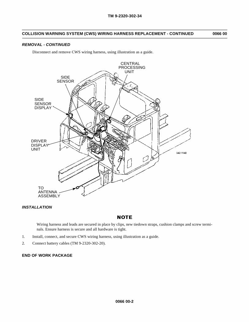
TM 9-2320-302-34
0066 00-2
COLLISION WARNING SYSTEM (CWS) WIRING HARNESS REPLACEMENT - CONTINUED 0066 00
REMOVAL - CONTINUED
Disconnect and remove CWS wiring harness, using illustration as a guide.
INSTALLATION
NOTENOTEWiring harness and leads are secured in place by clips, new tiedown straps, cushion clamps and screw termi-nals. Ensure harness is secure and all hardware is tight.
1. Install, connect, and secure CWS wiring harness, using illustration as a guide.
2. Connect battery cables (TM 9-2320-302-20).
END OF WORK PACKAGE
CENTRALPROCESSING
UNITSIDE
SENSOR
SIDESENSORDISPLAY
DRIVERDISPLAYUNIT
TOANTENNAASSEMBLY
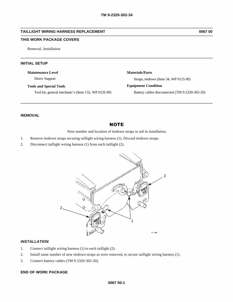
TM 9-2320-302-34
0067 00-1
TAILLIGHT WIRING HARNESS REPLACEMENT 0067 00
THIS WORK PACKAGE COVERS
Removal, Installation
INITIAL SETUP
Maintenance Level
Direct Support
Tools and Special Tools
Tool kit, general mechanic’s (Item 132, WP 0126 00)
Materials/Parts
Straps, tiedown (Item 34, WP 0125 00)
Equipment Condition
Battery cables disconnected (TM 9-2320-302-20)
REMOVAL
NOTENOTENote number and location of tiedown straps to aid in installation.
1. Remove tiedown straps securing taillight wiring harness (1). Discard tiedown straps.
2. Disconnect taillight wiring harness (1) from each taillight (2).
INSTALLATION
1. Connect taillight wiring harness (1) to each taillight (2).
2. Install same number of new tiedown straps as were removed, to secure taillight wiring harness (1).
3. Connect battery cables (TM 9-2320-302-20).
END OF WORK PACKAGE
2
1
2

TM 9-2320-302-34
0067 00-2
This Page Intentionally Left Blank.

TM 9-2320-302-34
0068 00-1
AIR CONDITIONER BINARY SWITCH WIRING HARNESS REPLACEMENT 0068 00
THIS WORK PACKAGE COVERS
Removal, Installation
INITIAL SETUP
Maintenance Level
Direct Support
Tools and Special Tools
Tool kit, general mechanic’s (Item 132, WP 0126 00)
Materials/Parts
Straps, tiedown (Item 34, WP 0125 00)
Tags, marker (Item 35, WP 0125 00)
References
TM 9-2320-302-20
Equipment Condition
Battery cables disconnected (TM 9-2320-302-20)
REMOVAL
NOTENOTETag wiring harness and leads prior to removal to aid in installation.
1. Unlock three fasteners (1) by turning counterclockwise and remove access panel (2).
2. Remove fuse, relay, and circuit breaker holder (TM 9-2320-302-20).
3. Locate circuit 98A on circuit breaker panel (3) and disconnect wiring harness connector from panel.
1
2
3

TM 9-2320-302-34
0068 00-2
AIR CONDITIONER BINARY SWITCH WIRING HARNESS REPLACEMENT - CONTINUED 0068 00
REMOVAL - CONTINUED
NOTENOTENote number and location of tiedown straps to aid in installation.
4. Trace wiring harness (4) from circuit breaker panel to firewall, removing and discarding tiedown straps.
5. Remove grommet from firewall and feed wiring harness (4) into engine compartment.
6. Trace wiring harness (4) to receiver-drier (5), removing and discarding tiedown straps.
7. Disconnect wiring harness connector (6) from binary switch (7) on receiver-drier (5).
8. Trace wiring harness (4) to compressor (8), removing and discarding tiedown straps.
9. Disconnect wiring harness connector (9) from compressor wiring harness connector (10).
4
5
7
6
8
9
10
4

TM 9-2320-302-34
0068 00-3
AIR CONDITIONER BINARY SWITCH WIRING HARNESS REPLACEMENT - CONTINUED 0068 00
INSTALLATION
1. Connect wiring harness connector (6) to binary switch (7) on receiver-drier (5).
2. Route one branch of wiring harness (4) to compressor (8), installing new tiedown straps in same place as removed.
3. Connect wiring harness connector (9) to compressor wiring harness connector (10).
4. Install grommet on branch of wiring harness (4) leading to circuit breaker panel (3) inside cab. Route harness throughfirewall to circuit 98A on circuit breaker panel.
5. Install grommet into firewall and secure wiring harness (4) by installing new tiedown straps in same place as removed.
6. Connect wiring harness connector to circuit 98A on circuit breaker panel (3).
7. Install fuse, relay, and circuit breaker panel (TM 9-2320-302-20).
8. Install access panel (2) and lock three fasteners (1) by turning clockwise.
9. Connect battery cables (TM 9-2320-302-20).
END OF WORK PACKAGE
1
2
3

TM 9-2320-302-34
0068 00-4
This Page Intentionally Left Blank.

TM 9-2320-302-34
0069 00-1
ENGINE INJECTOR AND ECM WIRING HARNESSES REPLACEMENT 0069 00
THIS WORK PACKAGE COVERS
Engine Injector Wiring Harness Removal, Engine Injector Wiring Harness Installation, ECM Wiring Harness Removal,ECM Wiring Harness Installation
INITIAL SETUP
Maintenance Level
Direct Support
Tools and Special Tools
Tool kit, general mechanic’s (Item 132, WP 0126 00)
Torque, wrench, 0-300 lb-in (Item 137, WP 0126 00)
Materials/Parts
Straps, tiedown (Item 34, WP 0125 00)
Tags, marker (Item 35, WP 0125 00)
Equipment Condition
Battery cables disconnected (TM 9-2320-302-20)
CAUTIONCAUTIONGrasp connector and terminal body when removing or installing wiring harness connectors. Do not pull onwires or harness to prevent damage to equipment.
ENGINE INJECTOR WIRING HARNESS REMOVAL
NOTENOTE• Engine injector wiring harness connectors are top and bottom connectors at front of electronic control
module. Do not remove center outboard connector.
• Ensure all wires are tagged before removal as an aid to installation.
1. Remove rocker arm cover (WP 0016 00).
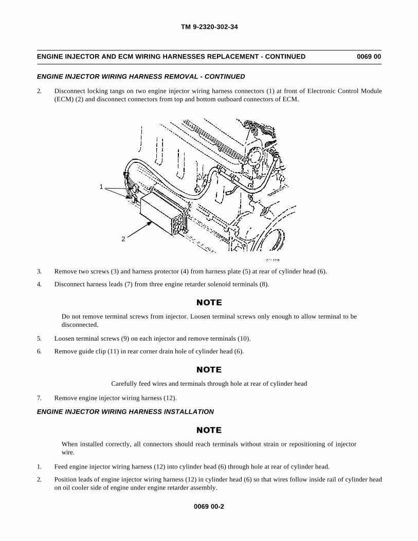
TM 9-2320-302-34
0069 00-2
ENGINE INJECTOR AND ECM WIRING HARNESSES REPLACEMENT - CONTINUED 0069 00
ENGINE INJECTOR WIRING HARNESS REMOVAL - CONTINUED
2. Disconnect locking tangs on two engine injector wiring harness connectors (1) at front of Electronic Control Module(ECM) (2) and disconnect connectors from top and bottom outboard connectors of ECM.
3. Remove two screws (3) and harness protector (4) from harness plate (5) at rear of cylinder head (6).
4. Disconnect harness leads (7) from three engine retarder solenoid terminals (8).
NOTE NOTE Do not remove terminal screws from injector. Loosen terminal screws only enough to allow terminal to bedisconnected.
5. Loosen terminal screws (9) on each injector and remove terminals (10).
6. Remove guide clip (11) in rear corner drain hole of cylinder head (6).
NOTENOTECarefully feed wires and terminals through hole at rear of cylinder head
7. Remove engine injector wiring harness (12).
ENGINE INJECTOR WIRING HARNESS INSTALLATION
NOTENOTEWhen installed correctly, all connectors should reach terminals without strain or repositioning of injectorwire.
1. Feed engine injector wiring harness (12) into cylinder head (6) through hole at rear of cylinder head.
2. Position leads of engine injector wiring harness (12) in cylinder head (6) so that wires follow inside rail of cylinder headon oil cooler side of engine under engine retarder assembly.
2
1

TM 9-2320-302-34
0069 00-3
ENGINE INJECTOR AND ECM WIRING HARNESSES REPLACEMENT - CONTINUED 0069 00
ENGINE INJECTOR WIRING HARNESS INSTALLATION - CONTINUED
3. Begin with two longest leads and install terminals (10) over terminal screws (9) on front injector. Tighten screws to 12-17 lb-in (1.25-1.92 Nm).
4. Perform procedure in step 3 for remaining injector leads.
5. Install harness lead (7) on engine retarder solenoid terminal (8).
6. Perform procedure in step 5 for remaining engine retarder solenoid terminals.
7. Install harness plate (5) and harness protector (4) on engine injector wiring harness (12) and secure to cylinder head (6)with two screws (3). Tighten screws to 84-132 lb-in (10-15 Nm).
NOTENOTEEnsure wires are against cylinder head rail away from possible contact with exhaust valve spring.
8. Insert guide clip (11) into oil drain hole at rear of cylinder head (6) to retain injector wires in corner away from exhaustvalve springs.
9. Connect two engine injector wiring harness connectors (1) to top and bottom outboard connections on ECM (2). Ensurelocking tangs on connectors are engaged.
10. Secure engine injector wiring harness (12) to engine with new tiedown straps as required.
11. Install rocker arm cover (WP 0016 00).
12. Connect battery cables (TM 9-2320-302-20).
7
8
10
6
115124
3
9

TM 9-2320-302-34
0069 00-4
ENGINE INJECTOR AND ECM WIRING HARNESSES REPLACEMENT - CONTINUED 0069 00
ECM WIRING HARNESS REMOVAL
NOTENOTE• Wiring harness and leads are secured in place by cushion clamps, screws, and tiedown straps.
• Only remove hardware securing harness or lead to be removed.
• Tag all wires prior to removal to aid in installation.
1. Remove screws (13) and clamps (14) as necessary to release ECM wiring harness (15) from engine.
2. Use illustration and table as a guide to disconnect and remove ECM wiring harness (15).
ECM WIRING HARNESS INSTALLATION
1. Install and connect ECM wiring harness, using illustration and table as a guide.
2. Secure ECM wiring harness (15) to engine with clamps (14) and screws (13).
17
18
181417
19
18
13
16
15
ConnectorNumber Qty
16 30-pin Plug 117 3-pin Connector 218 2-pin Connector 519 Connector 1

TM 9-2320-302-34
0069 00-5
ENGINE INJECTOR AND ECM WIRING HARNESSES REPLACEMENT - CONTINUED 0069 00
ECM WIRING HARNESS INSTALLATION - CONTINUED
3. Connect battery cables (TM 9-2320-302-20).
END OF WORK PACKAGE

TM 9-2320-302-34
0069 00-6
This Page Intentionally Left Blank.

TM 9-2320-302-34
0070 00-1
TRANSMISSION REPLACEMENT 0070 00
THIS WORK PACKAGE COVERS
Removal, Installation
INITIAL SETUP
Maintenance Level
Direct Support
Tools and Special Tools
Tool kit, general mechanic’s (Item 132, WP 0126 00)
Barring tool, engine (Item 8, WP 0126 00)
Lift, transmission (Item 75, WP 0126 00)
Wrench, torque, 15-75 lb-ft (Item 138, WP 0126 00)
Materials/Parts
Washer, lock (P/N MS35333-43) (12)
Personnel Required
Two
Equipment Condition
Air system drained (TM 9-2320-302-10)
Spare tire removed (TM 9-2320-302-10)
Transmission fluid drained (TM 9-2320-302-20)
Driveline removed (TM 9-2320-302-20)
Transmission oil cooler lines disconnected (TM 9-2320-302-20)
Transmission electrical harness(s) disconnected (TM9-2320-302-20)
Transmission tunnel access cover removed (TM 9-2320-302-20)
Transmission oil fill tube removed (TM 9-2320-302-20)
WARNINGWARNINGUse extreme caution when handling heavy parts. Provide adequate support and use assistance during proce-dure. Ensure that any lifting device used is in good condition and of suitable load capacity. Keep clear ofheavy parts supported only by lifting device. Failure to follow this warning may result in death or injury topersonnel.
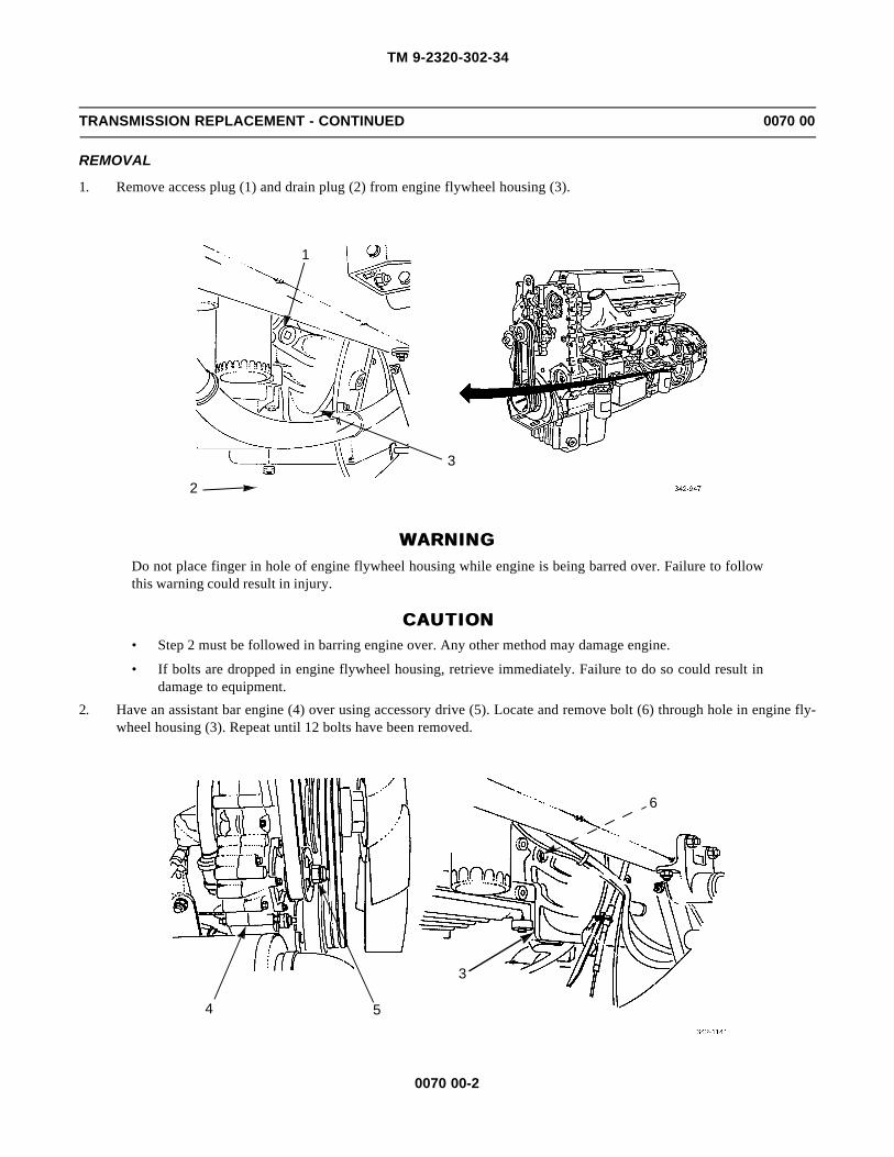
TM 9-2320-302-34
0070 00-2
TRANSMISSION REPLACEMENT - CONTINUED 0070 00
REMOVAL
1. Remove access plug (1) and drain plug (2) from engine flywheel housing (3).
WARNINGWARNINGDo not place finger in hole of engine flywheel housing while engine is being barred over. Failure to followthis warning could result in injury.
CAUTIONCAUTION• Step 2 must be followed in barring engine over. Any other method may damage engine.
• If bolts are dropped in engine flywheel housing, retrieve immediately. Failure to do so could result indamage to equipment.
2. Have an assistant bar engine (4) over using accessory drive (5). Locate and remove bolt (6) through hole in engine fly-wheel housing (3). Repeat until 12 bolts have been removed.
1
3
2
4
6
5
3
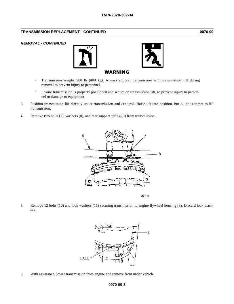
TM 9-2320-302-34
0070 00-3
TRANSMISSION REPLACEMENT - CONTINUED 0070 00
REMOVAL - CONTINUED
WARNINGWARNING• Transmission weighs 900 lb (409 kg). Always support transmission with transmission lift during
removal to prevent injury to personnel.
• Ensure transmission is properly positioned and secure on transmission lift, to prevent injury to person-nel or damage to equipment.
3. Position transmission lift directly under transmission and centered. Raise lift into position, but do not attempt to lifttransmission.
4. Remove two bolts (7), washers (8), and rear support spring (9) from transmission.
5. Remove 12 bolts (10) and lock washers (11) securing transmission to engine flywheel housing (3). Discard lock wash-ers.
6. With assistance, lower transmission from engine and remove from under vehicle.
9 7
8
3
10,11

TM 9-2320-302-34
0070 00-4
TRANSMISSION REPLACEMENT - CONTINUED 0070 00
INSTALLATION
WARNINGWARNING• Transmission weighs 900 lb (409 kg). Always support transmission with transmission lift during instal-
lation to prevent injury to personnel.
• Ensure transmission is properly positioned and secure on transmission lift, to prevent injury to person-nel or damage to equipment.
1. With assistance, move transmission under vehicle and directly behind engine.
CAUTIONCAUTIONTransmission must be seated squarely against engine flywheel housing to prevent damage to equipment.
2. Lift and position transmission against engine flywheel housing (3).
3. Install 12 new lock washers (11) and bolts (10) to secure transmission to engine flywheel housing (3). Hand tightenbolts.
4. Tighten four transmission mounting bolts 90 degrees apart to 40 lb-ft (54 Nm).
5. Tighten remaining transmission mounting bolts to 40 lb-ft (54 Nm).
6. Install rear support spring (9) on rear of transmission and frame supports with two washers (8) and bolts (7).
7. Remove transmission lift.
3
10,11
9 7
8

TM 9-2320-302-34
0070 00-5
TRANSMISSION REPLACEMENT - CONTINUED 0070 00
INSTALLATION - CONTINUED
WARNINGWARNINGDo not place finger in hole of engine flywheel housing while engine is being barred over. Failure to followthis warning could result in injury.
8. Remove access plug (1) and drain plug (2) from engine flywheel housing (3).
9. Rotate torque converter to align holes in flex plate with holes in torque converter.
CAUTIONCAUTION• Step 10 must be followed in barring engine over. Any other method may damage engine.
• If bolts are dropped in engine flywheel housing, retrieve immediately. Failure to do so could result indamage to equipment.
10. Have an assistant bar engine (4) over using accessory drive (5), until placement for bolt (6) has been located throughaccess hole. Install bolt through access hole. Repeat until 12 bolts have been installed.
1
32
4
6
5
3

TM 9-2320-302-34
0070 00-6
TRANSMISSION REPLACEMENT - CONTINUED 0070 00
INSTALLATION - CONTINUED
11. Install access plug (1) and drain plug (2) in engine flywheel housing (3).
12. Install transmission oil fill tube (TM 9-2320-302-20).
13. Connect transmission oil cooler lines (TM 9-2320-302-20).
14. Connect transmission electrical harness(s) (TM 9-2320-302-20).
15. Install driveline (TM 9-2320-302-20).
16. Install transmission access tunnel cover (TM 9-2320-302-20).
17. Refill transmission fluid (TM 9-2320-302-20)
18. Install spare tire (TM 9-2320-302-10).
END OF WORK PACKAGE
1
32

TM 9-2320-302-34
0071 00-1
TRANSMISSION OVERHAUL 0071 00
THIS WORK PACKAGE COVERS
Disassembly, Module Overhaul, Assembly, Tabulated Data
INITIAL SETUP
Maintenance Level
General Support
Tools and Special Tools
Tool kit, general mechanic’s (Item 132, WP 0126 00)
Bracket, transmission holding (Item 12, WP 0126 00)
Bracket, transmission holding (Item 13, WP 0126 00)
Caliber, micrometer (Item 15, WP 0126 00)
Compressor, main-pressure relief spring (Item 21, WP0126 00)
Compressor, spring, C2 (Item 26, WP 0126 00)
Compressor, spring, C5 (Item 27, WP 0126 00)
Gage, micrometer, depth (Item 34, WP 0126 00)
Gage, profile (Item 37, WP 0126 00)
Inserter and remover, spring, C1 (Item 54, WP0126 00)
Installer, charging pump bushing (Item 57, WP0126 00)
Installer, front support sleeve (Item 59, WP 0126 00)
Installer, output bearing (Item 60, WP 0126 00)
Installer, output bearing cup (Item 61, WP 0126 00)
Installer, bearing retainer bushing (Item 63, WP0126 00)
Installer, rotating clutch bushing (Item 64, WP0126 00)
Installer, seal, input (Item 65, WP 0126 00)
Installer, seal, output (Item 66, WP 0126 00)
Installer, torque converter cover bushing (Item 67, WP0126 00)
Tools and Special Tools - Continued
Installer, carrier bushing (Item 68, WP 0126 00)
Installer, wear plate (Item 71, WP 0126 00)
Lifting, bracket, flywheel (Item 77, WP 0126 00)
Press, arbor (Item 90, WP 0126 00)
Puller kit, universal (Item 96, WP 0126 00)
Remover, wheel bearing cup (Item 105, WP 0126 00)
Remover/installer, main-pressure spring (Item 106,WP 0126 00)
Test block, pressure switch (Item 121, WP 0126 00)
Tool, torque converter bolt (Item 129, WP 0126 00)
Tool base, spring compressor (Item 130, WP 0126 00)
Tool set, spanner nut (Item 133, WP 0126 00)
Tray set, valve body parts (Item 134, WP 0126 00)
Wrench, torque, 0-300 lb-in (Item 137, WP 0126 00)
Wrench, torque, 15-75 lb-ft (Item 138, WP 0126 00)
Materials/Parts
Converter housing kit (P/N 29524152)
Filter kit (P/N 29526899)
Seal and gasket kit (P/N 29518437)
Seal and gasket kit (P/N 29518442)
Shim kit, torque converter (P/N 29503828)
Oil, lubricating (Item 25, WP 0125 00)
Petrolatum, technical (Item 29, WP 0125 00)
Tags, marker (Item 35, WP 0125 00)
Personnel Required
Two
Equipment Condition
Transmission installed on maintenance stand
Engine, turbine, and output speed sensors removed(TM 9-2320-302-20)
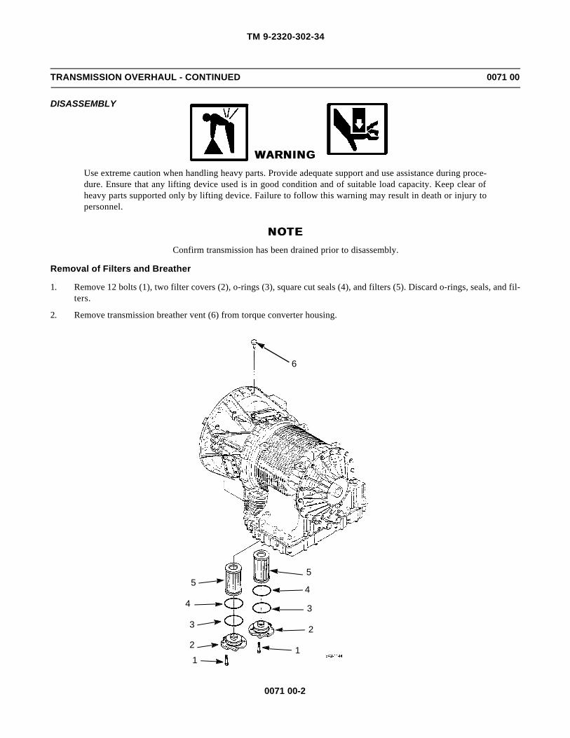
TM 9-2320-302-34
0071 00-2
TRANSMISSION OVERHAUL - CONTINUED 0071 00
DISASSEMBLY
WARNINGWARNINGUse extreme caution when handling heavy parts. Provide adequate support and use assistance during proce-dure. Ensure that any lifting device used is in good condition and of suitable load capacity. Keep clear ofheavy parts supported only by lifting device. Failure to follow this warning may result in death or injury topersonnel.
NOTENOTEConfirm transmission has been drained prior to disassembly.
Removal of Filters and Breather
1. Remove 12 bolts (1), two filter covers (2), o-rings (3), square cut seals (4), and filters (5). Discard o-rings, seals, and fil-ters.
2. Remove transmission breather vent (6) from torque converter housing.
6
5
2
11
3
44
3
2
5

TM 9-2320-302-34
0071 00-3
TRANSMISSION OVERHAUL - CONTINUED 0071 00
DISASSEMBLY - CONTINUED
Removal of Output Shaft and Oil Seal
1. Remove bolt (7), retainer plug (8), and o-rings (9 and 10) from output shaft yoke (11). Discard o-rings.
2. Remove oil seal (12) using puller (J24171-A). Discard oil seal.
789
10
1112

TM 9-2320-302-34
0071 00-4
TRANSMISSION OVERHAUL - CONTINUED 0071 00
DISASSEMBLY - CONTINUED
Removal of Torque Converter Module
1. Remove bolts securing torque converter shipping brackets(s). Remove bracket(s).
2. Remove retaining ring (13) securing torque converter plug (14).
3. Using an M6x30-1 bolt threaded into torque converter plug (14), remove torque converter plug and o-ring (15). Discardo-ring.
4. Install two bolts (16) into flexplate adapter (17). Use two bars at an angle to prevent rotation of torque converter (18).
NOTENOTEWhile attempting to remove torque converter center bolt, converter will rotate. Follow procedure in step 5 tohold converter stationary.
5. Remove converter center bolt (19), using bolt tool (J38564).
6. Remove and tag shim(s) (20).
7. Remove torque converter holding bars and bolts (16).
8. Attach a suitable lifting sling to flexplate adapter (17) by positioning adapter connections equal distances apart fromeach other.
9. Using a suitable hoist, remove torque converter (18) from torque converter housing (21). Place torque converter on awork bench supported by two wooden blocks.
20
1915
1413
18 21
16
17
21 18
J38564
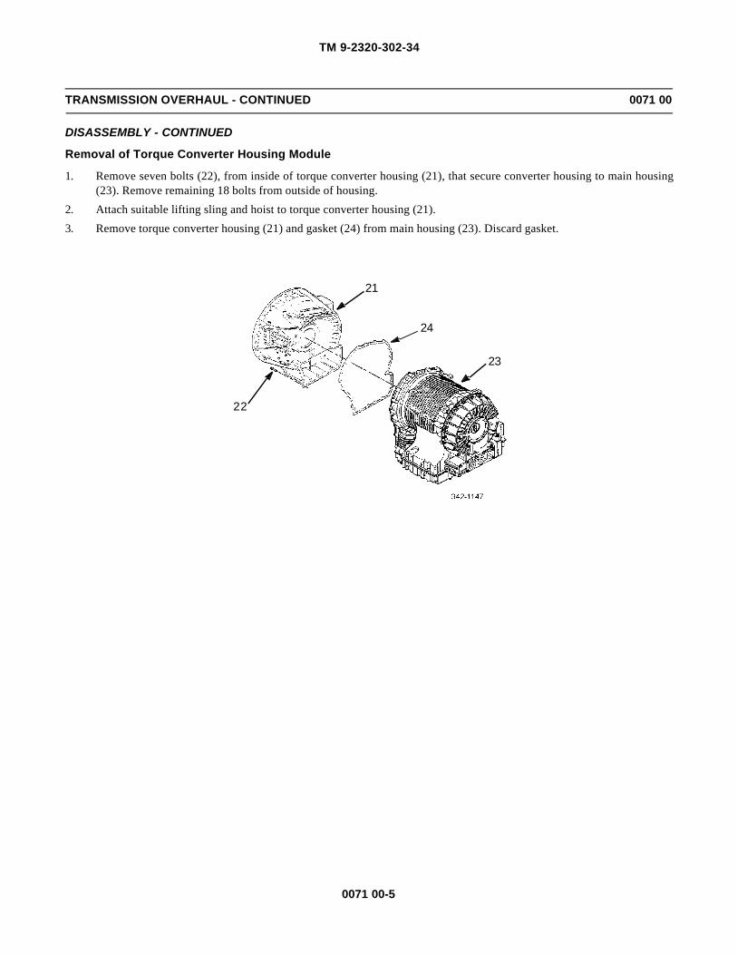
TM 9-2320-302-34
0071 00-5
TRANSMISSION OVERHAUL - CONTINUED 0071 00
DISASSEMBLY - CONTINUED
Removal of Torque Converter Housing Module
1. Remove seven bolts (22), from inside of torque converter housing (21), that secure converter housing to main housing(23). Remove remaining 18 bolts from outside of housing.
2. Attach suitable lifting sling and hoist to torque converter housing (21).
3. Remove torque converter housing (21) and gasket (24) from main housing (23). Discard gasket.
22
23
24
21

TM 9-2320-302-34
0071 00-6
TRANSMISSION OVERHAUL - CONTINUED 0071 00
DISASSEMBLY - CONTINUED
Removal of Control Valve Module
NOTENOTEControl module and filters may contain residual transmission fluid.
1. Remove retaining nut (25) and lock washer (26) securing feed-through harness (27) to mounting bracket (28). Do notdiscard lock washer unless damaged.
2. Remove retaining nut (29) and lock washer (30) securing feed-through harness (27) to main housing (23). Do not dis-card lock washer unless damaged.
3. Remove 43 bolts (31) securing control module (32) to main housing (23).
4. Loosen control module (32) from main housing (23) by installing jacking screws into control module bolt holes that bot-tom out against main housing.
5. Remove control module (32) and gasket (33) from main housing (23). Discard gasket.
2825,26
27
29,30
23
33
23
32
31

TM 9-2320-302-34
0071 00-7
TRANSMISSION OVERHAUL - CONTINUED 0071 00
DISASSEMBLY - CONTINUED
Removal of Rear Cover Module
1. Remove 19 bolts (34) securing rear cover module (35) to main housing (23).
2. Remove rear cover module (35) and gasket (36) from main housing (23). Discard gasket.
Removal of Main Shaft Module
Remove main shaft module assembly (37) with thrust bearing (38) and selective shim (39) from main housing (23). Tagthrust bearing and shim to aid in assembly and identification.
2336
35
34
23
37
3839

TM 9-2320-302-34
0071 00-8
TRANSMISSION OVERHAUL - CONTINUED 0071 00
DISASSEMBLY - CONTINUED
Removal of P2 Planetary Module, C5 Clutch Pack, and P1 Planetary Module
1. Lift P2 planetary module (40) from main housing (23).
2. Lift C5 clutch pack (41), containing eight friction plates (42) and nine steel reaction plates (43), from main housing (23).
3. Measure, tag, and note thickness and cone of each friction plate (42). Minimum thickness is 0.137 in (3.48 mm). Maxi-mum allowable cone is 0.010 in (0.25 mm).
4. Measure, tag, and note thickness and cone of each steel reaction plate (43). Minimum thickness is 0.095 in (2.41 mm).Maximum allowable cone is 0.010 in (0.25 mm).
5. Lift P1 planetary module (44) from main housing (23).
Removal of Front Support and Charging Pump Module and Rotating Clutch Module
NOTENOTENote size and position of 14 bolts securing front support and charging pump module to main housing, to aidduring assembly.
1. Remove seven bolts (45) and seven bolts (46) securing front support and charging pump module (47) to main housing(23).
2. Lift front support and charging pump module (47) from main housing (23).
3. Install an M16 lifting eye bolt into turbine shaft (48). Attach a suitable hoist to lifting eye.
4. Using hoist, remove turbine shaft (48) and rotating clutch module (49) from main housing (23).
23
44
23
40
4342
41

TM 9-2320-302-34
0071 00-9
TRANSMISSION OVERHAUL - CONTINUED 0071 00
DISASSEMBLY - CONTINUED
Removal of Front Support and Charging Pump Module and Rotating Clutch Module - Continued
Removal of C3/C4 Clutch Assembly
1. Remove 14 bolts (50) securing C3/C4 clutch assembly (51) in main housing (23).
2. Remove C3/C4 clutch assembly (51) by sliding it out of input end of housing.
3. Inspect and measure C5 clutch plate splines inside main housing for wear. Maximum wear allowed is 0.045 in (1.15mm).
46
47
23
45
4849
23
51
23
50

TM 9-2320-302-34
0071 00-10
TRANSMISSION OVERHAUL - CONTINUED 0071 00
MODULE OVERHAUL
Torque Converter Module Disassembly
NOTENOTEPrior to disassembling torque converter, note balance marks or mark a line across converter cover to pumpassembly with a scribe. These marks will ensure correct assembly of torque converter and reduce balanceproblems.
1. Place converter assembly (1) on a flat work surface with pump drive tangs downward.
2. Remove 36 nuts (2) from outer diameter of cover assembly (3).3. Remove 36 T-headed bolts (4) from outer diameter of pump assembly (5).
4. Carefully, without prying, remove cover assembly (3) from pump assembly (5).
5. Remove and discard o-ring (6) from between converter assembly halves.
6. Remove turbine assembly (7) from cover assembly (3).
7. Remove stator assembly (8) from pump assembly (5).
8. Remove thrust bearing race (9) from pump assembly (5).
9. Remove thrust bearing assembly (10) from turbine assembly (7).10. Remove bearing assembly (11), race (12), and selective shim (13) from pump assembly (5).
11. Remove retaining ring (14) and star plate (15) from stator assembly (8).
2
3 1
2725 2426
23
22
28
217 10
15
171614
18
20
8
6
5
1211
4
13
19
9

TM 9-2320-302-34
0071 00-11
TRANSMISSION OVERHAUL - CONTINUED 0071 00
MODULE OVERHAUL - CONTINUED
Torque Converter Module Disassembly - Continued
12. Remove thrust plate (16) from stator assembly (8). Measure, note, and tag thrust plate. Minimum thickness allowed is0.372 in (9.45 mm).
13. Remove thrust washer (17) from stator assembly (8).
14. Remove stator race (18), 13 springs (19), and rollers (20). Inspect components for damage.
15. Remove 44 bolts (21) securing lockup clutch backup plate (22) to cover assembly (3). Remove backup plate from cover.
16. Measure thickness of backup plate wear surface. Minimum thickness allowed is 0.464 in (11.79 mm). Check for backupplate distortion. Maximum distortion allowed is 0.006 in (0.15 mm).
17. Remove lockup clutch damper assembly (23) from cover assembly (3). Perform the following measurements.
a. Lockup clutch thickness: minimum thickness allowed is 0.335 in (8.51 mm).
b. Lockup clutch distortion: maximum allowable distortion is 0.020 in (0.51 mm).
c. Spline wear check: measure between turbine and lockup clutch damper. Maximum allowable wear is 0.015 in(0.38 mm) on either spline.
18. Remove lockup clutch piston (24), inner seal ring (25), and outer seal ring (26) from cover assembly (3). Measure thick-ness of lockup clutch piston. Minimum thickness allowed is 0.257 in (6.53 mm).
19. Inspect and measure inside diameter (ID) of converter cover bushing (27). Maximum allowed inside diameter of bush-ing is 2.634 in (66.90 mm). Remove bushing if replacement is necessary.
20. Remove thrust bearing (28) from converter cover (3).
Torque Converter Module Assembly
1. Install stator race (18) into stator assembly (8).
2. Install 13 springs (19) and rollers (20) into stator assembly (8). Use petrolatum to help hold springs and rollers in place.
TM 9-2320-302-34
0071 00-12
TRANSMISSION OVERHAUL - CONTINUED 0071 00
MODULE OVERHAUL - CONTINUED
Torque Converter Module Assembly - Continued
3. Install thrust washer (17) and thrust plate (16) on stator assembly (8).
4. Install star plate (15) and retaining ring (14).
5. Install bearing assembly (11), race (12), and selective shim (13) to pump assembly (5).
CAUTIONCAUTIONWhen installing thrust bearings, ensure that locating lip on either inner or outer thrust bearing race is not pre-venting race from contacting thrust surface of mating part. Failure to follow this caution leads to prematurethrust bearing failure and incorrect shim selection to maintain proper internal part clearance.
6. Install thrust bearing assembly (10) into turbine assembly (7).
7. If removed, install new bushing (27) into cover assembly (3), using installer tool (J39949).
8. Insert turbine assembly (7) into converter cover bushing (27). Check for free rotation.
9. Install thrust bearing (28) in cover assembly (3).
10. Install lockup clutch piston inner seal ring (25) on hub of cover assembly (3).
11. Install lockup clutch piston outer seal ring (26) on outside diameter of lockup clutch piston (24).
12. Install lockup clutch piston (24).
13. Install lockup clutch damper assembly (23) in cover assembly (3).
14. Install lockup clutch backup plate (22). Secure backup plate with 44 bolts (21). Tighten bolts to 22-26 lb-ft (30-35 Nm).
15. Install turbine (7) into cover assembly (3), aligning balance mark on turbine with balance mark on lockup clutch damperassembly (23).
16. Install stator assembly (8) in cover assembly (3).
17. Install 36 T-headed bolts (4) into flange of pump assembly (5).
18. Install thrust bearing race (9) into pump assembly (5).
19. Install o-ring (6) onto cover assembly (3).
20. With balance marks aligned, position pump assembly (5) over cover assembly (3).
21. Install four nuts (2) evenly spaced around cover assembly (3) onto T-headed bolts (4). Tighten nuts to 22-26 lb-ft (30-35Nm).

TM 9-2320-302-34
0071 00-13
TRANSMISSION OVERHAUL - CONTINUED 0071 00
MODULE OVERHAUL - CONTINUED
Torque Converter Module Assembly - Continued
2
3
2725 2426
23
22
28
217 10
15
171614
8
6
5
1211
4
13
9
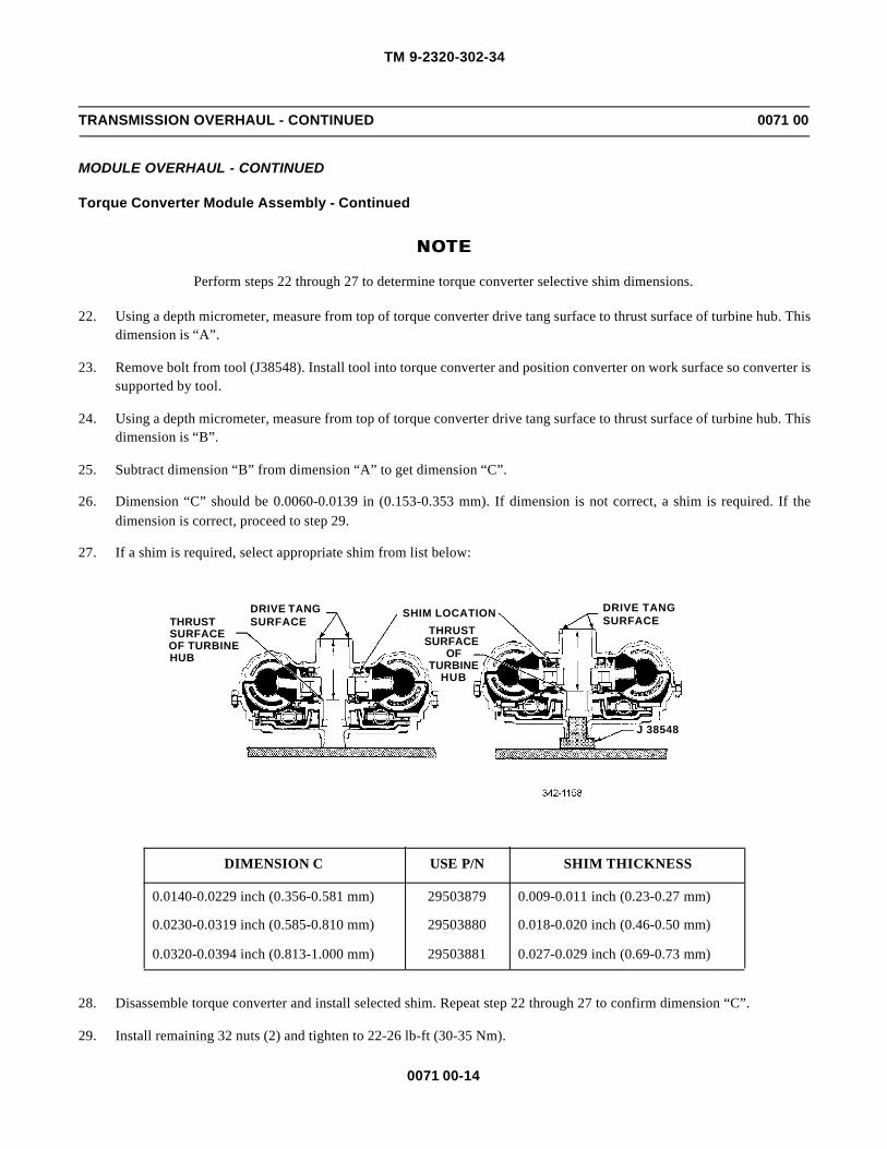
TM 9-2320-302-34
0071 00-14
TRANSMISSION OVERHAUL - CONTINUED 0071 00
MODULE OVERHAUL - CONTINUED
Torque Converter Module Assembly - Continued
NOTENOTE
Perform steps 22 through 27 to determine torque converter selective shim dimensions.
22. Using a depth micrometer, measure from top of torque converter drive tang surface to thrust surface of turbine hub. Thisdimension is “A”.
23. Remove bolt from tool (J38548). Install tool into torque converter and position converter on work surface so converter issupported by tool.
24. Using a depth micrometer, measure from top of torque converter drive tang surface to thrust surface of turbine hub. Thisdimension is “B”.
25. Subtract dimension “B” from dimension “A” to get dimension “C”.
26. Dimension “C” should be 0.0060-0.0139 in (0.153-0.353 mm). If dimension is not correct, a shim is required. If thedimension is correct, proceed to step 29.
27. If a shim is required, select appropriate shim from list below:
28. Disassemble torque converter and install selected shim. Repeat step 22 through 27 to confirm dimension “C”.
29. Install remaining 32 nuts (2) and tighten to 22-26 lb-ft (30-35 Nm).
DIMENSION C USE P/N SHIM THICKNESS
0.0140-0.0229 inch (0.356-0.581 mm) 29503879 0.009-0.011 inch (0.23-0.27 mm)
0.0230-0.0319 inch (0.585-0.810 mm) 29503880 0.018-0.020 inch (0.46-0.50 mm)
0.0320-0.0394 inch (0.813-1.000 mm) 29503881 0.027-0.029 inch (0.69-0.73 mm)
THRUSTSURFACEOF TURBINEHUB
DRIVE TANGSURFACE
SHIM LOCATION DRIVE TANGSURFACE
THRUSTSURFACE
OFTURBINE
HUB
J 38548

TM 9-2320-302-34
0071 00-15
TRANSMISSION OVERHAUL - CONTINUED 0071 00
MODULE OVERHAUL - CONTINUED
Torque Converter Housing Module Disassembly
1. Remove ten bolts (1), PTO cover (2), and gasket (3). Discard gasket.
2. Remove 11 bolts (4) securing bearing retainer assembly (5) and PTO gear (6) assembly to converter housing (7).
3. Remove seal rings (8 and 9) from bearing retainer (5). Discard seal rings.
4. Remove bearing retainer oil seal (10) using tool (J24171-A). Discard oil seal.
5. Inspect bushing (11) for damage or wear. Maximum allowable bushing ID is 3.511 in (89.19 mm). Remove if damagedor worn.
6. Remove oil pump drive hub (12) from PTO gear (6).
7. Inspect oil pump drive hub (12) for excessive wear on drive tangs. Maximum allowable tang wear is 0.012 in (0.31mm).
8. Remove seal ring (13) from PTO gear (6).
9. Inspect PTO gear bearings (14 and 15). If damaged, remove and discard.
4
5
8 9
1110
15
6
1214
137
1 23
TM 9-2320-302-34
0071 00-16
TRANSMISSION OVERHAUL - CONTINUED 0071 00
MODULE OVERHAUL - CONTINUED
Torque Converter Housing Module Assembly
1. If PTO gear bearings (14 and 15) were discarded, install new bearings using tool (J37041).
CAUTIONCAUTIONOil pump drive hub can be incorrectly installed backwards. Position oil pump drive hub tangs toward oilpump.
2. Install oil pump drive hub (12) into PTO gear (6), aligned with hub tangs toward oil pump.
NOTENOTEButt-joint seal rings require special handling during assembly. Seal rings contain materials that absorb mois-ture from atmosphere, causing them to expand. Check seal ring end clearance before installation to ensureseal ring has not expanded.
3. Install seal ring (13) into seal ring bore of torque converter pump housing and measure end gap with feeler gage. Sealring end gap must be 0.047-0.065 in (1.19-1.65 mm). If seal ring is not within tolerance, ring has expanded and must bereplaced.
4. Remove seal ring (13) from pump housing seal ring bore and install onto PTO gear (6).
5. If removed, install bearing retainer bushing (11) using press and tools (J37038 and J8092).
6. Install new seal ring (9) onto bearing retainer (5) and install new oil seal (10) using press and tools (J37032 and J37034).
7. Install new seal ring (8) into seal ring bore in PTO gear (6) and measure end gap with thickens gage.
8. Seal ring (8) end gap must be 0.047-0.065 in (1.19-1.65 mm). If seal ring is not within tolerance, ring has expanded andmust be replaced.
9. Remove seal ring (8) from seal ring bore in PTO gear (6) and install seal ring onto bearing retainer (5).
10. Using a mallet, lightly tap PTO gear (6) assembly into converter housing (7) until gear assembly is seated.
11. Use guide bolts to install bearing retainer assembly (5), rocking retainer while installing into converter housing (7).
12. Install 11 bolts (4) to secure bearing retainer assembly (5) and PTO gear (6) assembly into converter housing (7).Tighten bolts to 38-45 lb-ft. (51-61 Nm).
13. Install PTO cover (2) and new gasket (3) with ten bolts (1). Tighten bolts to 38-45 lb-ft (51-61 Nm).

TM 9-2320-302-34
0071 00-17
TRANSMISSION OVERHAUL - CONTINUED 0071 00
MODULE OVERHAUL - CONTINUED
Front Support and Charging Oil Pump Module Disassembly
1. Remove three seal rings (1) from hub of front support assembly (2).
2. Remove eight bolts (3) securing pump housing assembly (4) to front support assembly (2).
3. Remove pump housing assembly (4) and gear set (5) from front support (2).
4. Measure gear cavity depth of pump housing (4). Maximum depth allowed is 0.75 in (19.04 mm).
3
1
4 5
2
PUMPHOUSING
MAX DEPTH OFGEAR CAVITY19.04 mm (0.75 in)

TM 9-2320-302-34
0071 00-18
TRANSMISSION OVERHAUL - CONTINUED 0071 00
MODULE OVERHAUL - CONTINUED
Front Support and Charging Oil Pump Module Disassembly - Continued
5. Measure gear cavity diameter of pump housing (4). Maximum depth allowed is 5.915 in (150.25 mm).
6. Install gear set (5) into pump housing (4). Measure pump gear side clearance of both gears. Maximum allowable clear-ance is 0.004 in (0.10 mm).
4
MAX ID OFGEAR CAVITY150.25 mm (5.915 in)
4
5
DRIVEGEAR
DRIVEN GEARMAX SIDECLEARANCE0.10 mm (0.004 in)

TM 9-2320-302-34
0071 00-19
TRANSMISSION OVERHAUL - CONTINUED 0071 00
MODULE OVERHAUL - CONTINUED
Front Support and Charging Oil Pump Module Disassembly - Continued
7. Measure gear tooth tip clearance. Maximum allowable clearance is 0.006 in (0.15 mm).
8. Measure driven gear to pump housing clearance. Maximum allowable clearance is 0.012 in (0.30 mm).
9. Inspect and measure bushing (6) inside inner gear of gear set (5). The maximum ID of bushing is 2.635 in (66.93 mm).If bushing is damaged or out of tolerance, remove.
10. Remove 14 bolts (7) securing wear plate (8) to front support (2). Remove wear plate.
11. Inspect roller bearing (9). If damaged, remove using drift and hammer.
12. Inspect and measure front support sleeve (10). Minimum OD diameter of front support sleeve is 4.717 in (119.81 mm).If sleeve is damaged or out of tolerance, remove.
13. Inspect front support dowel pins (11 and 12). If damaged, remove.
MAX GEARTOOTH TIPCLEARANCE0.15 mm (0.006 in)
PUMP HOUSING
DRIVEN GEAR
MAX CLEARANCE BETWEENDRIVEN GEAR OD ANDPUMP HOUSING0.30 mm (0.012 in)
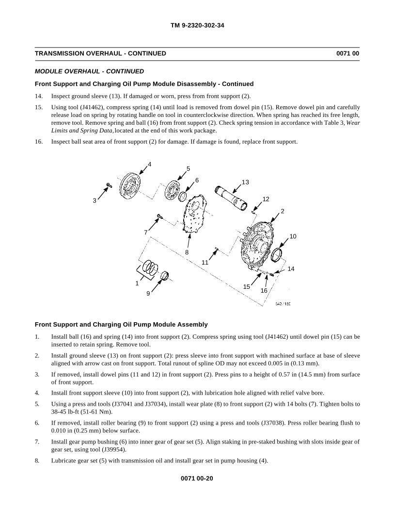
TM 9-2320-302-34
0071 00-20
TRANSMISSION OVERHAUL - CONTINUED 0071 00
MODULE OVERHAUL - CONTINUED
Front Support and Charging Oil Pump Module Disassembly - Continued
14. Inspect ground sleeve (13). If damaged or worn, press from front support (2).
15. Using tool (J41462), compress spring (14) until load is removed from dowel pin (15). Remove dowel pin and carefullyrelease load on spring by rotating handle on tool in counterclockwise direction. When spring has reached its free length,remove tool. Remove spring and ball (16) from front support (2). Check spring tension in accordance with Table 3, WearLimits and Spring Data, located at the end of this work package.
16. Inspect ball seat area of front support (2) for damage. If damage is found, replace front support.
Front Support and Charging Oil Pump Module Assembly
1. Install ball (16) and spring (14) into front support (2). Compress spring using tool (J41462) until dowel pin (15) can beinserted to retain spring. Remove tool.
2. Install ground sleeve (13) on front support (2): press sleeve into front support with machined surface at base of sleevealigned with arrow cast on front support. Total runout of spline OD may not exceed 0.005 in (0.13 mm).
3. If removed, install dowel pins (11 and 12) in front support (2). Press pins to a height of 0.57 in (14.5 mm) from surfaceof front support.
4. Install front support sleeve (10) into front support (2), with lubrication hole aligned with relief valve bore.
5. Using a press and tools (J37041 and J37034), install wear plate (8) to front support (2) with 14 bolts (7). Tighten bolts to38-45 lb-ft (51-61 Nm).
6. If removed, install roller bearing (9) to front support (2) using a press and tools (J37038). Press roller bearing flush to0.010 in (0.25 mm) below surface.
7. Install gear pump bushing (6) into inner gear of gear set (5). Align staking in pre-staked bushing with slots inside gear ofgear set, using tool (J39954).
8. Lubricate gear set (5) with transmission oil and install gear set in pump housing (4).
3
7
19
45
6
8
13
12
2
11
10
14
15 16
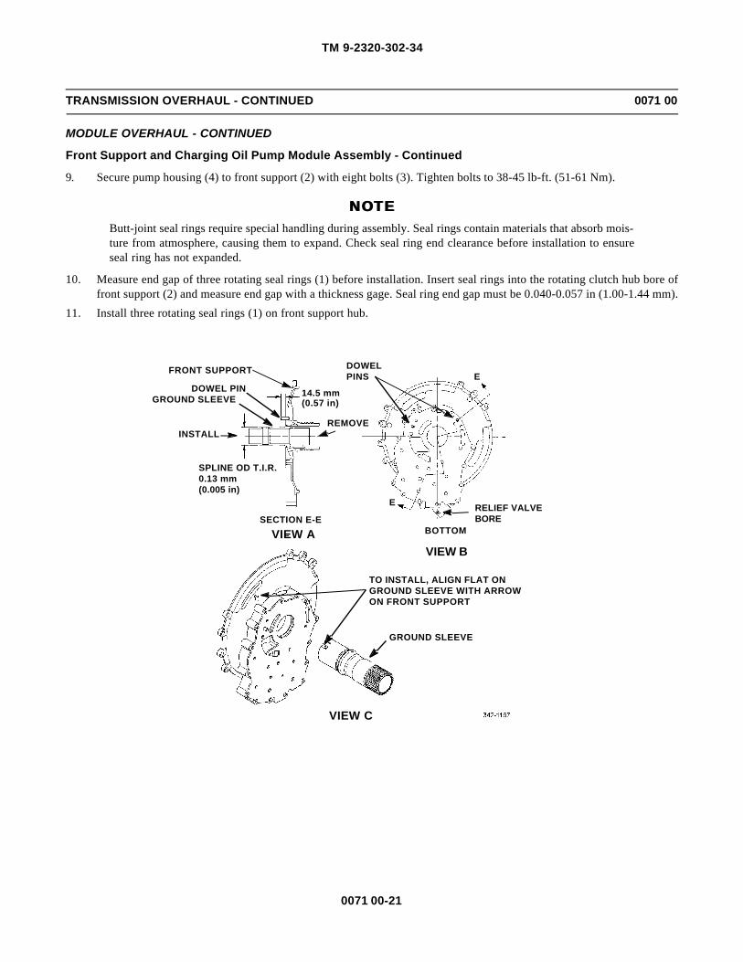
TM 9-2320-302-34
0071 00-21
TRANSMISSION OVERHAUL - CONTINUED 0071 00
MODULE OVERHAUL - CONTINUED
Front Support and Charging Oil Pump Module Assembly - Continued
9. Secure pump housing (4) to front support (2) with eight bolts (3). Tighten bolts to 38-45 lb-ft. (51-61 Nm).
NOTENOTEButt-joint seal rings require special handling during assembly. Seal rings contain materials that absorb mois-ture from atmosphere, causing them to expand. Check seal ring end clearance before installation to ensureseal ring has not expanded.
10. Measure end gap of three rotating seal rings (1) before installation. Insert seal rings into the rotating clutch hub bore offront support (2) and measure end gap with a thickness gage. Seal ring end gap must be 0.040-0.057 in (1.00-1.44 mm).
11. Install three rotating seal rings (1) on front support hub.
RELIEF VALVEBORE
DOWELPINS E
E
FRONT SUPPORT
DOWEL PINGROUND SLEEVE
SPLINE OD T.I.R.0.13 mm(0.005 in)
SECTION E-EBOTTOMVIEW A
VIEW B
INSTALLREMOVE
TO INSTALL, ALIGN FLAT ONGROUND SLEEVE WITH ARROWON FRONT SUPPORT
GROUND SLEEVE
VIEW C
14.5 mm(0.57 in)

TM 9-2320-302-34
0071 00-22
TRANSMISSION OVERHAUL - CONTINUED 0071 00
MODULE OVERHAUL - CONTINUED
Rotating Clutch Module Disassembly
1. Remove thrust bearing (1) and retaining ring (2) from rotating clutch module (3). Inspect thrust bearing. If worn, dis-card.
2. Remove P1 sun gear assembly (4) and thrust bearing (5) from rotating clutch module (3).
3. Remove C2 retaining ring (6) and backplate (7).
4. Measure wear surface thickness of C2 backplate (7). Minimum thickness allowed is 0.311 in (7.90 mm). Check flatnessof backplate. Maximum allowable distortion is 0.006 in (0.15 mm).
5. Remove C2 clutch pack containing seven friction plates (8) and seven steel reaction plates (9). Perform the followingmeasurements:
a. Friction plate thickness: minimum thickness allowed is 0.115 in (2.92 mm).
b. Friction plate oil groove depth: minimum depth allowed is 0.008 in (0.20 mm).
c. Friction plate cone: maximum cone allowed is 0.010 in (0.25 mm).
23 20 21 22
118
3
1719
1615
14
1413
89
1012
1211
2
546
7

TM 9-2320-302-34
0071 00-23
TRANSMISSION OVERHAUL - CONTINUED 0071 00
MODULE OVERHAUL - CONTINUED
Rotating Clutch Module Disassembly - Continued
d. Reaction plate thickness: minimum thickness allowed is 0.095 in (2.41 mm).
e. Reaction plate cone: maximum cone allowed is 0.010 in (0.25 mm).
6. Remove C2 (10) and C1 (11) drive hubs with two thrust bearings (12). Measure drive hub splines. Maximum allowablespline wear is 0.015 in (0.38 mm).
7. Remove C1 retaining ring (13), two backplates (14), seven friction plates (15), and six steel reaction plates (16). Per-form the following measurements:a. Friction plate thickness: minimum thickness allowed is 0.115 in (2.92 mm).
b. Friction plate oil groove depth: minimum depth allowed is 0.008 in (0.20 mm).
c. Friction plate cone: maximum cone allowed is 0.010 in (0.25 mm).d. Reaction plate thickness: minimum thickness allowed is 0.095 in (2.41 mm).
e. Reaction plate cone: maximum cone allowed is 0.010 in (0.25 mm).
f. Backplate thickness: minimum thickness allowed is 0.311 in (7.90 mm). g. Backplate flatness: maximum allowable distortion is 0.006 in (0.15 mm).
8. Remove thrust bearing (17) from clutch hub assembly (18).
9. Remove retaining ring (19) and turbine shaft (20) from clutch hub (18).10. Inspect and measure bushing (21) inside end of turbine shaft (20). Maximum ID allowed is 1.423 in (36.14 mm).
11. Remove three seal rings (22) and o-ring (23) from turbine shaft (20). Discard o-ring.

TM 9-2320-302-34
0071 00-24
TRANSMISSION OVERHAUL - CONTINUED 0071 00
MODULE OVERHAUL - CONTINUED
Rotating Clutch Module Disassembly - Continued
WARNINGWARNINGThe rotating clutch piston springs are highly compressed and must be properly released. Failure to followthis warning may result in personnel injury
12. Place rotating clutch (3) on tool base (J37030-3) so rotating drum is supported by tool tangs (View C).
13. Install tool (J35923-2) with bearing, washer, and handle. Tighten tool, compressing C1 balance piston (24) and C1spring assembly (25). Remove retaining ring (26) (View A).
14. Release spring tension by rotating handle in counterclockwise direction. Remove tool (J35923-2) with bearing, washer,and handle.
15. Remove C1 balance piston (24), seal ring (27), and C1 spring assembly (25).
16. Install tools (J37030-3, J37030-1, and J35923), bearing, washer, and handle. Tighten tool and remove retaining ring(28). Remove tools after relieving spring tension. Remove spring assembly (29) and spring plate (30) (View B).
J37030-3HANDLE
FLAT WASHERBEARING
J35923-2
BEARINGFLAT WASHER
HANDLE J37030-3
J35923-2
J37030-1
ALIGNMENT SLOTS
J37030-3
3
VIEW AVIEW B
VIEW DVIEW C

TM 9-2320-302-34
0071 00-25
TRANSMISSION OVERHAUL - CONTINUED 0071 00
MODULE OVERHAUL - CONTINUED
Rotating Clutch Module Disassembly - Continued
17. Lift rotating drum (31) from clutch hub (18) and C1/C2 pistons (32 and 33). Inspect clutch splines of rotating drum.Maximum spline wear allowed is 0.015 in (0.38 mm).
18. Remove C1/C2 pistons (32 and 33) and seal rings (34 and 35) from clutch hub (18), by rocking pistons from side to side.
19. Inspect and measure ID of rotating clutch hub housing bushing (36). Maximum allowable ID of bushing is 4.735 in(120.27 mm). Remove bushing from clutch hub (18) if replacement is necessary. Avoid damaging bushing bore.
20. Remove piston seal rings (37 and 38) from clutch hub (18).
21. Separate C1 piston (32) and seal ring (35) from C2 piston (33) and seal ring (34) by lightly tapping on C1 piston.
31
36 18
3
3738
3433
2925
2427
26323528
30

TM 9-2320-302-34
0071 00-26
TRANSMISSION OVERHAUL - CONTINUED 0071 00
MODULE OVERHAUL - CONTINUED
Rotating Clutch Module Assembly
1. If rotating clutch hub bushing (36) was removed, install new bushing using tool (J37040).
2. Install piston seal ring (37) on clutch hub (18), and piston seal ring (38) into C2 piston (33). Install clutch hub and pistonseal ring (35) into C1 piston (32).
3. With a mallet, lightly tap C2 piston (33) into clutch hub (18).
4. Align notch on C1 piston (32) with lubrication orifice on rotating drive hub. With a mallet, lightly tap C1 piston ontocenter of C2 piston (33) and over clutch hub (18).
5. Install rotating drum (31) over clutch hub (18) and C1/C2 pistons (32 and 33).
6. Install C2 spring assembly (29). Index spring assembly with drive hub tangs and splines on C2 piston (33). Ensure C2spring assembly has made contact with bottom of slots in C2 piston. If spring assembly did not reach bottom, removespring assembly and reannex in next spline on rotating drum. Repeat this process until C2 spring is in proper position.
7. Install C2 spring plate (30). Index spring plate with drive hub tangs and splines on C2 piston (33).
WARNINGWARNINGThe rotating clutch piston springs are highly compressed and must be properly released. Failure to followthis warning may result in personnel injury
8. Place rotating clutch on tool base (J37030-3) so that rotating drum is supported by tool tangs. Install tool (J37030-1 andJ35923-2), that includes bearing, washer, and handle. Tighten tool to compress C2 spring assembly (29) and installretaining ring (28) (View B, page 0072 00-24). Remove tools.
9. Install seal ring (27) onto balance piston (24).
10. Install C1 spring assembly (25). Align mark on balance piston (24) with slot on C1 piston (32). Position balance pistononto the C1 piston.
11. Install tool (J35923-2) with bearing, washer, and handle. Tighten tool, compressing C1 balance piston (24) and C1spring assembly (25). Install retaining ring (26) (View A, page 0072 00-24). Remove tools.
12. If turbine shaft bushing (21) was removed, replace using tool (J37036).
13. Lubricate with transmission oil and install new o-ring (23) on turbine shaft (20).
NOTENOTEButt-joint seal rings require special handling during assembly. Seal rings contain materials that absorb mois-ture from atmosphere causing them to expand. Check seal ring end clearance before installation to ensureseal ring has not expanded.
14. Install each rotating seal ring (22) into ground sleeve bore and measure end gap. Seal ring end gap must be 0.026-0.040in (0.65-1.01 mm). Install three rotating seal rings with correct end gap, into rear of turbine shaft (20).
15. Install turbine shaft (20) and retain with retaining ring (19).
CAUTIONCAUTIONEnsure thrust bearing is assembled with locating lip on either inner or outer thrust bearing race not prevent-ing race from contacting thrust surface of mating part. Failure to follow this caution leads to thrust bearingfailure and incorrect shim selection to maintain proper part clearance.
16. Install thrust bearing (17) on rotating clutch hub (18).

TM 9-2320-302-34
0071 00-27
TRANSMISSION OVERHAUL - CONTINUED 0071 00
MODULE OVERHAUL - CONTINUED
Rotating Clutch Module Assembly - Continued
17. Install C1 clutch pack: first install one backplate (14), then alternately install friction (15) and steel reaction plates (16),starting with a friction plate and ending with a backplate. Secure clutch pack in place with retaining ring (13).
18. Install C1 drive hub (11) over clutch pack while aligning external splines.
19. Install thrust bearing (12) on each side of C2 drive hub (10), then position this group over C1 drive hub (11).
20. Install C2 clutch plates, alternating between friction plates (8) and steel reaction plates (9), starting with steel reactionplates.
21. Install C2 backplate (7) and retaining ring (6).
22. Install thrust bearing (5) on sun gear (4).
23. Install P1 sun gear assembly (4) and retaining ring (2).
24. Install thrust bearing (1) on rotating clutch module (3).
23
20 21 22 31
1 36 18
3
17
1937
3834 33
29
2524
27
1615
1426
1413
89
10
12
1211
25
46
7
323528
30

TM 9-2320-302-34
0071 00-28
TRANSMISSION OVERHAUL - CONTINUED 0071 00
MODULE OVERHAUL - CONTINUED
C3/C4 Clutch Assembly and Main Housing Module Disassembly
1. Remove 14 bolts (1) securing C3/C4 clutch assembly (2).
2. Remove C3 backplate assembly (3) from clutch assembly (2)
3. Inspect and measure four thrust plates (4), backplate (3), and check 12 rivets (5) on clutch backplate. Perform the fol-lowing measurements:
a. Thrust plate thickness at contact surface: minimum allowable thickness is 0.1109 in (2.818 mm).
b. Backplate distortion: maximum allowable distortion is 0.006 in (0.15 mm).
c. Backplate step wear: maximum allowable wear is 0.005 in (0.13 mm).
If replacement is necessary, remove thrust plates (4) by drilling out rivets (5).
4. Remove P1 ring gear (6) and inspect clutch splines of P1 ring gear. Maximum allowable spline wear is 0.015 in (0.38mm).
5. Remove and measure C3 clutch pack: five friction plates (7) and four steel reaction plates (8). Perform the followingmeasurements:
a. Friction plate thickness: minimum allowable thickness is 0.137 in (3.48 mm).
b. Friction plate: maximum allowable cone is 0.010 in (0.25 mm).
c. Steel reaction plate thickness: minimum allowable thickness is 0.095 in (2.41 mm).
d. Steel reaction plate: maximum allowable cone is 0.016 in (0.40 mm).
6. Remove piston return plate (9) with four return springs assemblies (10) attached.
7. Inspect and measure piston return plate (9). Minimum allowable thickness of plate is 2.162 in (54.91 mm).
8. If return spring assemblies (10) are damaged and require replacement, remove them from piston return plate (9) by sep-arating spring retainer (11) from piston (12).
9. Remove seal rings (13 and 14) from piston (12). Discard seal rings.
10. Remove C3 clutch housing assembly (15) from C3/C4 clutch assembly (2).
11. Inspect and measure four thrust plates (16) on C3 clutch housing (15). Perform the following measurements:
a. Thrust plate thickness at contact surface: minimum allowable thickness is 0.1109 in (2.818 mm).
b. Backplate distortion: maximum allowable distortion is 0.006 in (0.15 mm).
c. Backplate step wear: maximum allowable wear is 0.005 in (0.13 mm).
d. Clutch housing splines: maximum allowable wear is 0.045 in (1.15 mm)
If replacement is necessary, remove thrust plates (16) by drilling out 12 rivets (17).
12. Remove and measure C4 clutch pack: five friction plates (18) and five steel reaction plates (19). Perform the followingmeasurements:
a. Friction plate thickness: minimum allowable thickness is 0.137 in (3.48 mm).
b. Friction plate: maximum allowable cone is 0.010 in (0.25 mm).
c. Steel reaction plate thickness: minimum allowable thickness is 0.095 in (2.41 mm).
d. Steel reaction plate: maximum allowable cone is 0.010 in (0.25 mm).
13. Remove piston return plate (20) with four return springs assemblies (21) attached.
14. Inspect and measure piston return plate (20). Minimum allowable thickness of plate is 2.162 in (54.91 mm).

TM 9-2320-302-34
0071 00-29
TRANSMISSION OVERHAUL - CONTINUED 0071 00
MODULE OVERHAUL - CONTINUED
C3/C4 Clutch Assembly and Main Housing Module Disassembly - Continued
15. If return spring assemblies (21) are damaged and require replacement, remove them from piston return plate (20) by sep-arating spring retainer (22) from piston (23).
16. Remove seal rings (24 and 25) from piston (23). Discard seal rings.
17. Inspect and measure C4 clutch housing (26). Maximum spline wear allowed is 0.045 in (1.15 mm).
C3/C4 Clutch Assembly and Main Housing Module Assembly
1. Install new seal rings (24 and 25) on piston (23). Install piston with seal rings into C4 housing (26).
2. Install spring retainer (22) on piston (23) and in C4 housing (26).
3. If removed, install new return spring assemblies (21) and attach them securely to piston return plate (20).
4. Install piston return plate (20) with return spring assemblies (21) into C4 clutch housing (26).
5. Install C4 clutch pack, starting with a friction plate (18). Alternately install five friction plates (18) and five steel reac-tion plates (19).
1 35
2
4 6 7 8
109
1113
1412
161715
21
1918
20 2224
2523
26
TM 9-2320-302-34
0071 00-30
TRANSMISSION OVERHAUL - CONTINUED 0071 00
MODULE OVERHAUL - CONTINUED
C3/C4 Clutch Assembly and Main Housing Module Assembly - Continued
NOTENOTEPerform step 6 only if C3 clutch housing was disassembled. If clutch housing was not disassembled, proceedto step 7.
6. Install four thrust plates (16) using 12 rivets (17) into C3 clutch housing (15). Use tool (J39534) to cold form rivets.Insert rivet from front so that preformed head is below active surface of thrust plate. Use cold forming tool to upset rivetat rear of clutch housing to complete riveted joint. A correctly formed rivet upset will be 0.157 in (4.00 mm) in diameterand no more than 0.039 in (1.00 mm) above surface of clutch housing. Thrust plate must be tightly attached to housing;no movement is allowed.
7. Install new seal rings (13 and 14) on piston (12). Install piston with seal rings into C3 clutch housing (15).
8. Install C3 clutch housing assembly (15) on top of assembled C4 clutch housing assembly (26). Ensure index notches onclutch housings are aligned.
9. Install spring retainer (11) on piston (12) and in C3 clutch housing (15).
10. If removed, install new return spring assemblies (10) and attach them securely to piston return plate (9).
11. Install piston return plate (9) with return spring assemblies (10) into C3 clutch housing (15).
12. Install P1 ring gear (6).
13. Install C3 clutch pack: starting with a friction plate (7), alternately install five friction plates and four steel reactionplates (8).
NOTENOTEPerform step number 14 only if C3 backplate was disassembled. If clutch housing was not disassembled,proceed to step number 15.
14. Install four thrust plates (4) using 12 rivets (5) into C3 backplate (3). Use tool (J39534) to cold form rivets. Insert rivetfrom front so that preformed head is below active surface of thrust plate. Use cold forming tool to upset rivet at rear ofbackplate to complete riveted joint. A correctly formed rivet upset will be 0.157 in (4.00 mm) in diameter and no morethan 0.039 in (1.00 mm) above surface of backplate. Thrust plate must be tightly attached to backplate; no movement isallowed.
15. Install C3 backplate assembly (3), aligning notches on C3 and C4 housings.
16. Install 14 bolts (1) into C3/C4 clutch assembly (2). Tighten bolts to 38-45 ft-lb (51-61 Nm).

TM 9-2320-302-34
0071 00-31
TRANSMISSION OVERHAUL - CONTINUED 0071 00
MODULE OVERHAUL - CONTINUED
C3/C4 Clutch Assembly and Main Housing Module Assembly - Continued
1 35
2
4 6 7 8
109
1113
1412
161715
26

TM 9-2320-302-34
0071 00-32
TRANSMISSION OVERHAUL - CONTINUED 0071 00
MODULE OVERHAUL - CONTINUED
Main Shaft Module Disassembly
1. Remove external spiral retaining ring (1) and P2 sun gear (2) from main shaft (3).
2. Remove bearing spacer (4), thrust bearing (5), and selective shim (6) from main shaft (3).
3. Inspect and measure main shaft (3). Inspect for evidence of wear, chipped or cracked splines or teeth. Measure mainshaft in accordance with Table 2, Wear Limits Data, located at the end of this work package.
Main Shaft Module Assembly
NOTENOTEDo not install thrust bearing (5) and selective shim (6) until final transmission assembly. Measurement forselective shim is performed during final buildup.
1. Install bearing spacer (4) on main shaft (3).
2. Install P2 sun gear (2) and external spiral retaining ring (1) on main shaft (3).
12
4
65
3
35.92 mm(1.414 in)
52.98 mm(2.085 in)
35.92 mm(1.414 in)
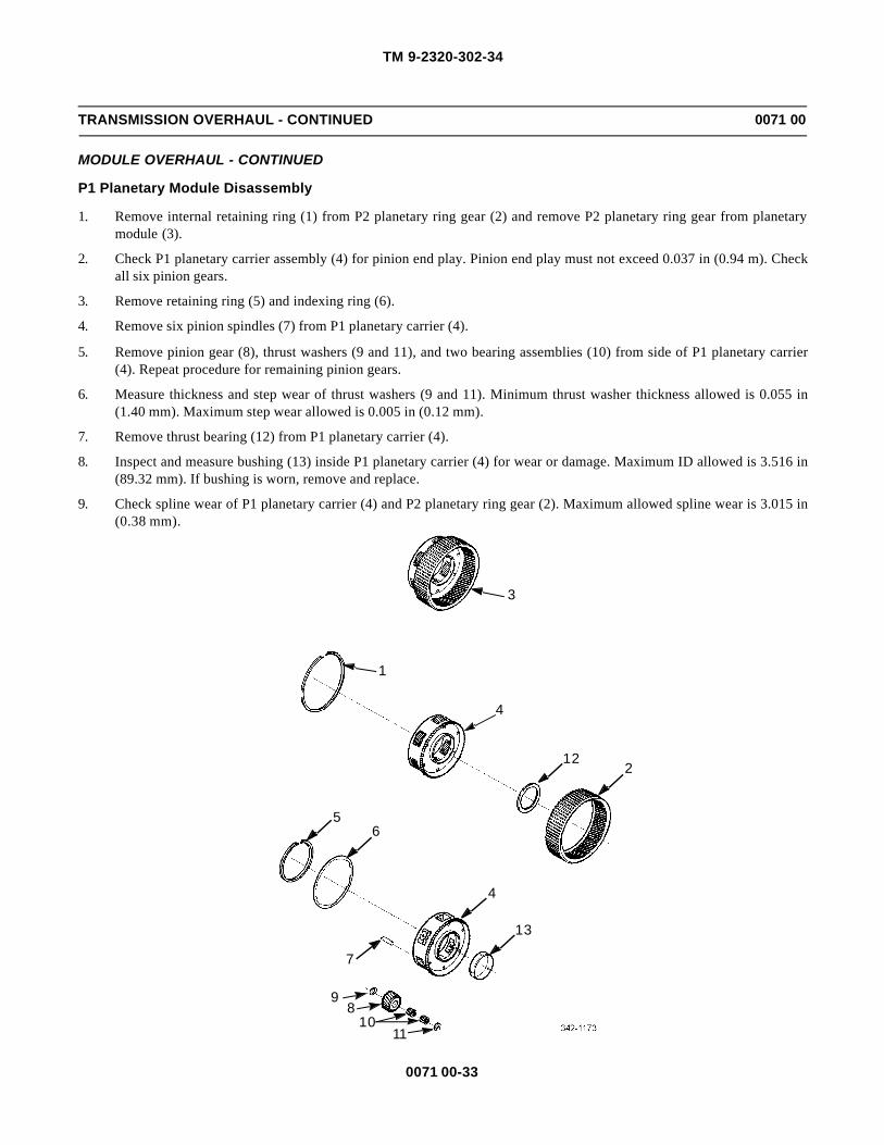
TM 9-2320-302-34
0071 00-33
TRANSMISSION OVERHAUL - CONTINUED 0071 00
MODULE OVERHAUL - CONTINUED
P1 Planetary Module Disassembly
1. Remove internal retaining ring (1) from P2 planetary ring gear (2) and remove P2 planetary ring gear from planetarymodule (3).
2. Check P1 planetary carrier assembly (4) for pinion end play. Pinion end play must not exceed 0.037 in (0.94 m). Checkall six pinion gears.
3. Remove retaining ring (5) and indexing ring (6).
4. Remove six pinion spindles (7) from P1 planetary carrier (4).
5. Remove pinion gear (8), thrust washers (9 and 11), and two bearing assemblies (10) from side of P1 planetary carrier(4). Repeat procedure for remaining pinion gears.
6. Measure thickness and step wear of thrust washers (9 and 11). Minimum thrust washer thickness allowed is 0.055 in(1.40 mm). Maximum step wear allowed is 0.005 in (0.12 mm).
7. Remove thrust bearing (12) from P1 planetary carrier (4).
8. Inspect and measure bushing (13) inside P1 planetary carrier (4) for wear or damage. Maximum ID allowed is 3.516 in(89.32 mm). If bushing is worn, remove and replace.
9. Check spline wear of P1 planetary carrier (4) and P2 planetary ring gear (2). Maximum allowed spline wear is 3.015 in(0.38 mm).
3
1
4
122
56
4
13
7
1110
89

TM 9-2320-302-34
0071 00-34
TRANSMISSION OVERHAUL - CONTINUED 0071 00
MODULE OVERHAUL - CONTINUED
P1 Planetary Module Assembly
1. If removed, install bushing (13) into P1 planetary carrier (4) using a press and tool (J37038). Press new bushing flush to0.016 in (0.40 mm) below surface.
2. Install two bearing assemblies (10) into center of pinion gear (8). Install thrust washers (9 and 11) inside P1 planetarycarrier (4), align thrust washer tangs with slots in planetary, and retain them with petrolatum. Slide pinion gear and bear-ing assemblies into side of P1 planetary carrier between thrust washers. Repeat procedure for remaining five piniongears.
3. Install six spindles (7) so that lower step is positioned for proper installation of indexing ring (6).
4. Install indexing ring (6) and retaining ring (5) to secure pinion gears in place.
5. Measure pinion end play. Pinion end play must not exceed 0.037 in (0.94 mm). Check all six pinion gears.
6. Install P2 planetary ring gear (2) over P1 planetary carrier assembly (4).
7. Install internal retaining ring (1) into P2 planetary ring gear (2), connecting P1 planetary carrier assembly (4) and P2planetary ring gear.
CAUTIONCAUTIONEnsure thrust bearing is assembled with locating lip on either inner or outer thrust bearing race not prevent-ing race from contacting thrust surface of mating part. Failure to follow this caution leads to thrust bearingfailure and incorrect shim selection to maintain proper part clearance.
8. Install thrust bearing (12) on P1 planetary carrier (4).
3
14
122
56
4
13
7
1110
8
9

TM 9-2320-302-34
0071 00-35
TRANSMISSION OVERHAUL - CONTINUED 0071 00
MODULE OVERHAUL - CONTINUED
P2 Planetary Module Disassembly
1. Remove retaining ring (1) and P3 planetary ring gear (2) from planetary module (3). Remove and inspect thrust bearing(4).
2. Check P2 planetary carrier assembly (5) for pinion end play. Pinion end play must not exceed 0.037 in (0.94 mm).Check all six pinion gears.
3. Remove internal retaining ring (6), indexing ring (7), and four pinion spindles (8) from P2 planetary carrier (5).
4. Remove pinion gear (9), thrust washers (10 and 11), and two bearing assemblies (12) from side of P2 planetary carrier(5). Repeat procedure for remaining pinion gears.
5. Measure thickness and step wear of thrust washers (10 and 11). Minimum thrust washer thickness allowed is 0.055 in(1.40 mm). Maximum step wear allowed is 0.005 in (0.12 mm).
6. Inspect and measure bushing (13) inside P2 planetary carrier (5) for wear or damage. Maximum ID allowed is 2.096 in(53.23 mm). If bushing is worn, remove and replace.
7. Check spline wear of P2 planetary carrier (5) and P3 planetary ring gear (2). Maximum allowed spline wear is 0.015 in(0.38 mm).
13
5
26
7
5
13
4
1012
9 811

TM 9-2320-302-34
0071 00-36
TRANSMISSION OVERHAUL - CONTINUED 0071 00
MODULE OVERHAUL - CONTINUED
P2 Planetary Module Assembly
1. If removed, replace bushing (13) into P2 planetary carrier (5) using a press and tool (J37036). Press new bushing flushto 0.016 in (0.40 mm) below surface.
2. Install two bearing assemblies (12) into center of pinion gear (9). Install thrust washers (10 and 11) inside P2 planetarycarrier (5), align thrust washer tangs with slots in planetary, and retain them with petrolatum. Slide pinion gear and bear-ing assemblies into side of P2 planetary carrier between thrust washers. Repeat procedure for remaining five piniongears.
3. Install four pinion spindles (8) so that lower step is positioned for proper installation of indexing ring (7).
4. Install indexing ring (7) and retaining (6) to secure pinion gears in place.
5. Measure pinion end play. Pinion end play must not exceed 0.037 in (0.94 mm). Check all four pinion gears.
6. Install P3 planetary ring gear (2) over P2 planetary carrier assembly (5).
7. Install retaining ring (1) into P3 planetary ring gear (2) so that P2 planetary carrier and P3 planetary ring gear are assem-bled.
8. Install thrust bearing (4) on planetary module (3).
13
5
26
7
5
13
4
1012
9 811

TM 9-2320-302-34
0071 00-37
TRANSMISSION OVERHAUL - CONTINUED 0071 00
MODULE OVERHAUL - CONTINUED
Rear Cover and P3 Planetary Module Disassembly
1. Straighten tangs of lock nut retainer (1) to allow removal of bearing retainer lock nut (2). Remove bearing retainer locknut using tool (J37035). Remove lock nut retainer.
2. Support rear cover assembly (3) so that P3 planetary carrier assembly (4) can be removed. Place tool (J37035-1) overoutput shaft splines and against threaded shoulder of P3 planetary carrier. Using a hydraulic press or a mallet, press ontool (J37035-1) to separate planetary carrier from rear cover.
3. Inspect rear cover cone and roller bearing (5). If worn or damaged, remove using tool (J3940).
WARNINGWARNINGPlace P3 planetary carrier assembly on its side during disassembly to avoid possible hand injury.
4. Remove retaining ring (6) and thrust washer (7) from P3 planetary carrier assembly (4).
5. Inspect planetary carrier cone and roller bearing (8). If worn or damaged, remove.
6. Remove retaining ring (9), indexing ring (10), and four pinion spindles (11) from P3 planetary carrier (4).
7. Remove pinion gear (12), thrust washers (13 and 14), and two bearing assemblies (15) from side of the P3 planetary car-rier (4). Repeat procedures for remaining pinion gears. Measure thickness and step wear of thrust washers. Minimumthrust washer thickness allowed is 0.055 in (1.40 mm). Maximum step wear allowed is 0.005 in (0.12 mm).
4
4
9
76
21
5
8
3
10
11
1312
15
14

TM 9-2320-302-34
0071 00-38
TRANSMISSION OVERHAUL - CONTINUED 0071 00
MODULE OVERHAUL - CONTINUED
Rear Cover and P3 Planetary Module Disassembly - Continued
8. Inspect and measure bushing (16) inside end of output shaft (17) for damage or wear. The maximum ID of bushing is1.423 in (36.14 mm).
WARNINGWARNING
Rear cover spring and retainer assembly contains highly compressed springs. Be extremely careful duringdisassembly. Personal injury can occur if spring force is not controlled.
9. Remove C5 clutch piston (18) from rear cover (3) by compressing spring and retainer assembly (19), using tool(J37030-3) tool base, washer, bearing, handle, and piston compressor (J37030-2). Remove retaining ring (20) andslowly release spring force.
10. Remove outer seal ring (21) and inner seal ring (22) from C5 clutch piston (18).
11. Inspect bearing cup (23). If worn or damaged, remove using tool (J3940).
Rear Cover and P3 Planetary Module Assembly
1. If removed, install new bearing cup (23), using bearing tool (J37033) and drive sleeve tool (J37034).
2. Install inner seal ring (22) and outer seal ring (21) onto C5 clutch piston (18).
3. Align tang notch on rear of C5 clutch piston (18) with tang in rear cover (3), while installing C5 clutch piston into rearcover.
4. Install spring and retainer assembly (19) while aligning tab in spring and retainer assembly with notch in rear cover (3).
WARNINGARNING
Rear cover spring and retainer assembly contains highly compressed springs. Be extremely careful duringassembly. Personal injury can occur if the spring force is not controlled.
5. Compress spring and retainer assembly (19) using (J37030-3) tool base, washer, bearing, handle, and piston spring com-pressor (J37030-2). Install retaining ring (20) and slowly release spring force.
6. If removed, install cone and roller bearing (8). Use driver sleeve tool (J37034) and press bearing against shoulder on P3planetary carrier (4).
7. If removed, press bushing (16) inside end of output shaft (17) using installer tool (J37036) and a press.
8. Install output shaft (17), thrust washer (7), and retaining ring (6).
9. Install two bearing assemblies (15) into center of pinion gear (12). Install thrust washers (13 and 14) inside P3 planetarycarrier (4), align thrust washer tangs with slots in planetary carrier, and retain them with petrolatum. Slide pinion gearand bearing assemblies into side of P3 planetary carrier between thrust washers. Repeat procedure for remaining threepinion gears.
10. Install four pinion spindles (11) so that lower step is positioned for proper installation of indexing ring (10).

TM 9-2320-302-34
0071 00-39
TRANSMISSION OVERHAUL - CONTINUED 0071 00
MODULE OVERHAUL - CONTINUED
Rear Cover and P3 Planetary Module Assembly - Continued
11. Install indexing ring (10) and retaining ring (9).
12. Measure pinion end play. Pinion end play must not exceed 0.037 in (0.94 mm). Check all four pinions.
13. Place P3 planetary carrier assembly (4) on work bench with output shaft up. Place rear cover (3) over output shaft.
14. If removed, install cone and roller bearing (5) into rear cover assembly (3) using drive sleeve tool J37034.
15. Install new lock nut retainer (1).
CAUTIONCAUTIONOver-tightening bearing retainer lock nut will damage cone and roller bearing assembly.
16. Install bearing retainer lock nut (2). Tighten lock nut to 55-65 lb-ft (74-88 Nm).
4
4
9
76
21
5
823
1918
20
2122 316
17
10
11
1312
15
14

TM 9-2320-302-34
0071 00-40
TRANSMISSION OVERHAUL - CONTINUED 0071 00
MODULE OVERHAUL - CONTINUED
Rear Cover and P3 Planetary Module Assembly - Continued
17. Position and support rear cover assembly (3) so that turning torque of P3 planetary carrier assembly can be checked afterinstallation of bearing retainer lock nut (2). Use tool (J37035-1) to check turning torque. Maximum turning torque is 27lb-in (3 Nm).
Control Valve Module Disassembly
NOTENOTEThe control valve module assembly springs and other parts can be mistakenly interchanged. Tag each partwith its item name as it is removed and use valve tray set (J33163) to simplify correct valve reassembly.
1. Remove bolt (1) and two bolts (2) securing the suction filter housing (3).
2. Remove suction filter housing (3), filter (4), face seal (5), and gasket (6). Discard filter and gasket.
3. Remove four bolts (7) and wiring harness cover plate (8).
4. Tag and disconnect electrical connections.
5. Remove three bolts (9) and control harness assembly (10).
6. Remove three bolts (11) and rotating clutch solenoid body assembly (12).
7. Remove eight bolts (13) and stationary clutch solenoid assembly (14).
8. Remove two bolts (15) and main valve body assembly (16) (see page 0072 00-45 for illustration).
NOTENOTERotating clutch solenoid body disassembly procedures are steps 9 through 14.
9. Remove two bolts (17) and then remove C3 pressure switch (18) from rotating clutch solenoid body assembly (12).
10. Check resistance of C3 pressure switch. Maximum allowable resistance is 2 ohms when contacts are closed and must be20,000 ohms minimum when contacts are open. Check pressure at which switch opens and closes. Both events mustoccur between 23-37 psi (159-255 kPa). Test block tool (J33884-25) is used to help make these checks.
J37035-1
3
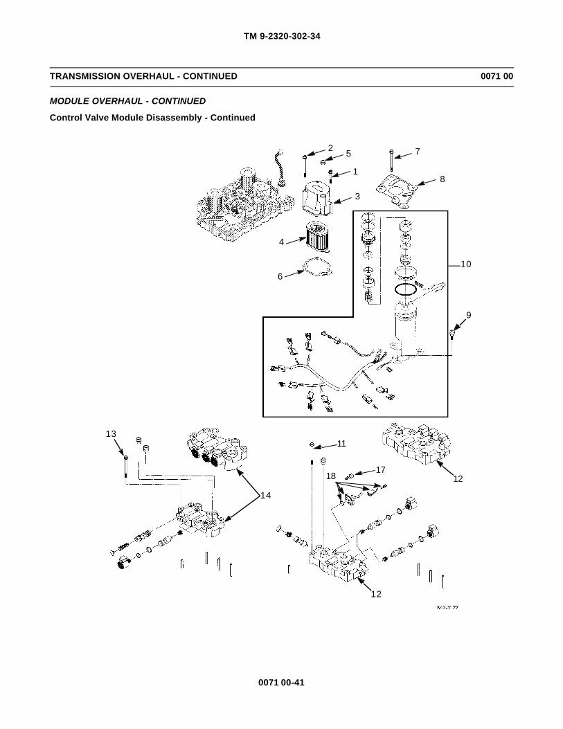
TM 9-2320-302-34
0071 00-41
TRANSMISSION OVERHAUL - CONTINUED 0071 00
MODULE OVERHAUL - CONTINUED
Control Valve Module Disassembly - Continued
6
4
2 5
1
3
7
8
9
10
13
14
11
1217
18
12

TM 9-2320-302-34
0071 00-42
TRANSMISSION OVERHAUL - CONTINUED 0071 00
MODULE OVERHAUL - CONTINUED
Control Valve Module Disassembly - Continued
31
14
20
12
403938
3334
3536
37
32
28
3029
21
22
19
1227
262523
24
2526
2324
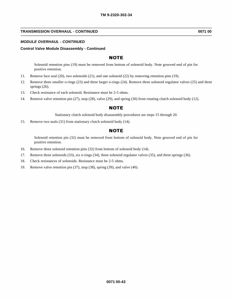
TM 9-2320-302-34
0071 00-43
TRANSMISSION OVERHAUL - CONTINUED 0071 00
MODULE OVERHAUL - CONTINUED
Control Valve Module Disassembly - Continued
NOTENOTESolenoid retention pins (19) must be removed from bottom of solenoid body. Note grooved end of pin forpositive retention.
11. Remove face seal (20), two solenoids (21), and one solenoid (22) by removing retention pins (19).
12. Remove three smaller o-rings (23) and three larger o-rings (24). Remove three solenoid regulator valves (25) and threesprings (26).
13. Check resistance of each solenoid. Resistance must be 2-5 ohms.
14. Remove valve retention pin (27), stop (28), valve (29), and spring (30) from rotating clutch solenoid body (12).
NOTENOTEStationary clutch solenoid body disassembly procedures are steps 15 through 20.
15. Remove two seals (31) from stationary clutch solenoid body (14).
NOTENOTESolenoid retention pin (32) must be removed from bottom of solenoid body. Note grooved end of pin forpositive retention.
16. Remove three solenoid retention pins (32) from bottom of solenoid body (14).
17. Remove three solenoids (33), six o-rings (34), three solenoid regulator valves (35), and three springs (36).
18. Check resistances of solenoids. Resistance must be 2-5 ohms.
19. Remove valve retention pin (37), stop (38), spring (39), and valve (40).

TM 9-2320-302-34
0071 00-44
TRANSMISSION OVERHAUL - CONTINUED 0071 00
MODULE OVERHAUL - CONTINUED
Control Valve Module Disassembly - Continued
20. Remove solenoid separator plate (41).
NOTENOTEMain valve body disassembly procedures are steps 21 through 34.
21. If damaged, remove retention pin (42) from main valve body (16).
NOTENOTESolenoid retention pins must be removed from bottom of valve body. Note grooved end of pin for positiveretention.
22. Remove solenoid retention pin (43) from bottom of valve body (16).
23. Remove solenoid (44), small o-ring (45), and large o-ring (46).
24. Check resistances of solenoids. Resistance must be 2-5 ohms.
25. Remove valve retention pin (47). Remove stop (48), spring (49), and converter flow valve (50).
26. Remove valve retention pin (51), stop (52), spring (53), and lubrication regulator valve (54).
WARNINGWARNINGSpring (55) is highly compressed. Be extremely careful during disassembly. Personal injury can occur ifspring force is not controlled.
27. Install spring compressor tool (J35924). Compress spring (55), then remove valve retention pin (56). Carefully releasespring force by rotating tool handle counterclockwise. Remove spring compressor tool.
28. Remove stop (57), spring (55), and main regulator valve (58).
29. Push against stop (59) to compress spring (60) and remove valve retention pin (61). Slowly release pressure against stop(59) and remove stop, spring, and main control valve (62).
30. Remove valve retention pin (63), stop (64), spring (65), and C2 latch valve (66).
31. Remove retention pin (67), stop (68), spring (69), and exhaust back pressure valve (70).
J35924

TM 9-2320-302-34
0071 00-45
TRANSMISSION OVERHAUL - CONTINUED 0071 00
MODULE OVERHAUL - CONTINUED
Control Valve Module Disassembly - Continued
32. Remove retention pin (71), stop (72), spring (73), and C1 latching valve (74).
33. Remove retention pin (75), stop (76), spring (77), and converter regulator valve (78).
34. Remove gaskets (79 and 80) and separator plate (81) from channel plate assembly (82). Discard gaskets.
NOTENOTEChannel plate disassembly procedures are steps 35 through 37.
35. If damaged, remove two pins (83) from channel plate assembly (82).
36. Remove drain plug (84) and o-ring (85) from channel plate assembly (82). Discard o-ring.
37. Remove eight pressure tap plugs (86) and o-rings (87) from channel plate assembly (82). Discard o-ring.
41
1567
7547
7163
51
5661
43
5049
48
5253
54
58
5557
62
6059
79
8180
44454642
7069
6878
7776
7473
7266
6564
8383
82
8786
8584
16

TM 9-2320-302-34
0071 00-46
TRANSMISSION OVERHAUL - CONTINUED 0071 00
MODULE OVERHAUL - CONTINUED
Control Valve Module Assembly
NOTENOTEChannel plate assembly procedures are steps 1 through 4.
1. Install eight pressure tap plugs (86) and new o-rings (87). Tighten plugs to 7-10 lb-ft (10-13 Nm).
2. Install drain plug (84) and new o-ring (85). Tighten drain plug to 18-24 lb-ft (25-32 Nm).
3. If removed, install two pins (83) in channel plate assembly (82).
4. Install new gaskets (79 and 80) with separator plate (81) on channel plate assembly (82).
NOTENOTEMain valve body assembly procedures are steps 5 through 18.
5. Install converter regulator valve (78), spring (77), and stop (76).
6. Install valve retention pin (75) by pushing against stop (76) to compress spring (77).
7. Install C1 latching valve (74), spring (73), and stop (72). Install retention pin (71).
8. Install exhaust back pressure valve (70), spring (69), and stop (68). Install retention pin (67).
9. Install C2 latch valve (66), spring (65), and stop (64). Install retention pin (63).
WARNINGWARNINGSpring (55) is highly compressed. Be extremely careful during assembly. Personal injury can occur if springforce is not controlled.
10. Install main control valve (62), spring (60), and stop (59). Install retention pin (61).
11. Install main regulator valve (58), spring (55), and stop (57).
12. Using spring compressor tool (J35924), compress spring (55) and install valve retention pin (56).
13. Carefully remove compressor tool.
14. Install lubrication regulator valve (54), spring (53), and stop (52). Install retention pin (51).
15. Install converter flow valve (50), spring (49), and stop (48). Install retention pin (47).
16. Install new small o-ring (45) and new large o-ring (46) on solenoid (44). Install solenoid.
17. Install solenoid retention pin (43), smooth side first, from bottom of main valve body assembly (16).
18. If removed, install retention pin (42) in main valve body assembly (16).

TM 9-2320-302-34
0071 00-47
TRANSMISSION OVERHAUL - CONTINUED 0071 00
MODULE OVERHAUL - CONTINUED
Control Valve Module Assembly - Continued
41
1567
7547
7163
51
5661
43
5049
48
5253
54
58
5557
62
6059
79
8180
44454642
7069
6878
7776
7473
7266
6564
8383
82
8786
8584
16

TM 9-2320-302-34
0071 00-48
TRANSMISSION OVERHAUL - CONTINUED 0071 00
MODULE OVERHAUL - CONTINUED
Control Valve Module Assembly - Continued
NOTENOTEStationary clutch solenoid body assembly procedures are steps 19 through 22.
19. Install valve (40), spring (39), and stop (38) in stationary clutch solenoid body (14). Install retention pin (37).
20. Install three springs (36), solenoid regulator valves (35), six new o-rings (34), and three solenoids (33).
21. As valve bores are filled, install three solenoid retention pins (32), smooth end first from bottom of solenoid body.
22. Install two new seals (31) in stationary clutch solenoid body (14).
NOTENOTE
Rotating clutch solenoid body assembly procedures are steps 23 through 27.
23. Install spring (30), valve (29), and stop (28) in rotating clutch solenoid body (12) with retention pin (27).
24. Install three springs (26), three solenoid regulator valves (25), new smaller o-rings (23), and new larger o-rings (24).
25. Install face seal (20), two solenoids (21), and solenoid (22).
26. Install solenoid retention pins (19), smooth end first, from bottom of rotating clutch solenoid body (12).
27. Install pressure switch assembly (18) and two bolts (17). Tighten bolts to 44-71 lb-in (5-8 Nm).
NOTENOTEControl valve module assembly procedures are steps 28 through 37.
28. Install main valve body assembly (16) and two bolts (15) (see page 0072 00-45 for illustration). Tighten bolts only fin-ger tight.
29. Install control harness assembly (10) with three bolts (9). Tighten bolts to 18-26 lb-in (2-3 Nm).
30. Install new gasket (6), new face seal (5) and new filter (4) in suction filter housing (3).
31. Install suction filter housing (3) with bolts (1) and two bolts (2). Tighten bolts only finger tight.
32. Install solenoid separator plate (41).
33. Install stationary clutch solenoid body assembly (14) with eight bolts (13). Tighten bolts only finger tight.
34. Install rotating clutch solenoid body (12) with three bolts (11). Tighten bolts only finger tight.
35. Install wiring harness cover plate (8) with four bolts (7). Tighten bolts only finger tight.
36. Connect all electrical connectors. Remove tags.
37. Evenly tighten cover plate bolts (7), suction filter bolts (1 and 2), valve body bolts (11, 13, and 9). Tighten all bolts to 7-10 lb-ft (10-13 Nm).

TM 9-2320-302-34
0071 00-49
TRANSMISSION OVERHAUL - CONTINUED 0071 00
MODULE OVERHAUL - CONTINUED
Control Valve Module Assembly - Continued
6
4
2 5
1
3
7
8
9
10
1331
14
1120
1217
18
403938
3334
3536
37
32
28
3029
21
22
19
1227
2625
2324
2526
2324

TM 9-2320-302-34
0071 00-50
TRANSMISSION OVERHAUL - CONTINUED 0071 00
ASSEMBLY
WARNINGWARNINGUse extreme caution when handling heavy parts. Provide adequate support and use assistance during proce-dure. Ensure that any lifting device used is in good condition and of suitable load capacity. Keep clear ofheavy parts supported only by lifting device. Failure to follow this warning may result in death or injury topersonnel.
NOTENOTE• Ensure all transmission components are cleaned and well lubricated before reassembling transmission
assembly.
• Before beginning assembly, attach bracket (J41445) and holding fixture (J35926) to main transmissionhousing. Use a suitable hoist to mount fixture and housing on a repair stand.
• Ensure main housing is horizontal when installing C3/C4 clutch Module.
Installation of C3/C4 Clutch Assembly
1. Install C3/C4 clutch assembly (51) through input end of main housing (23), aligning bolt holes in clutch assembly withholes in main housing.
2. Install two bolts (50), 180 degrees from each other, to hold clutch in place.
3. Rotate transmission housing on stand and install remaining 12 bolts (50). Tighten bolts to 38-45 lb-ft (51-61 Nm).
Installation of Rotating Clutch Module and Front Support and Charging Pump Module
1. Install an M16 eye bolt into turbine shaft (48). Using a suitable hoist, install rotating clutch module (49) into main hous-ing (23). Remove eye bolt.
2. Lower front support and charging pump module (47) over top of turbine shaft (48).
3. Align bolt holes in front support and charging pump module (47) with threaded holes in main housing (23).
4. Install seven bolts (46) and seven bolts (45) in front support and charging pump module (47). Tighten bolts to 38-45 lb-ft (51-61 Nm).
51
23
50

TM 9-2320-302-34
0071 00-51
TRANSMISSION OVERHAUL - CONTINUED 0071 00
ASSEMBLY - CONTINUED
Installation of P1/P2 Planetary Modules
1. Install P1 planetary module (44), consisting of P1 carrier and P2 ring gear.
2. Mesh P1 pinion gears with P1 ring gear inside C3/C4 clutch assembly.
3. Install P2 planetary module (40), consisting of P2 carrier and P3 ring gear.
4. Mesh P2 pinion gears with P2 ring gear during installation.
Installation of C5 Clutch Pack
1. Install C5 clutch pack (41) in main housing (23). Clutch pack consists of nine steel reaction plates (43) and eight frictionplates (42), stacked alternately, starting with a steel reaction plate.
2. Stack all plates so that plate cone faces same direction. Steel plates mesh with main housing (23) and reaction platesmesh with P3 ring gear.
46
47
23
45
4849
23
23
44
23
40
4342
41

TM 9-2320-302-34
0071 00-52
TRANSMISSION OVERHAUL - CONTINUED 0071 00
ASSEMBLY - CONTINUED
Installation of Main Shaft Module and Selective Shim Measurement
1. Install main shaft module assembly (37) in main housing (23), without selective shim (39) and thrust bearing (38).
2. Place a straightedge across rear cover mounting surface.
3. Measure dimension “A”, from top of straightedge to selective shim thrust surface on main shaft bearing spacer.
4. Measure dimension “B”, thickness of straightedge. Subtract “B” from “A”; remainder is dimension “C”.
23
37
3839

TM 9-2320-302-34
0071 00-53
TRANSMISSION OVERHAUL - CONTINUED 0071 00
ASSEMBLY - CONTINUED
Installation of Main Shaft Module and Selective Shim Measurement - Continued
5. Place rear cover, output end down (facing work bench). Install an uncompressed gasket on rear cover mounting surfaceand place a straightedge across P3 planetary carrier.
6. Measure dimension “D”, from top of straightedge to rear cover mounting gasket.
7. Measure dimension “E”, thickness of straightedge. Subtract dimension “E” from dimension “D”; remainder is dimen-sion “F”.
8. Dimension “G” is remainder of “C” minus “F” and determines thickness of selective shim (39).
CAUTIONCAUTIONEnsure thrust bearing is assembled with locating lip on either inner or outer thrust bearing race, not prevent-ing race from contacting thrust surface of mating part. Failure to follow this caution leads to thrust bearingfailure and incorrect shim selection to maintain proper part clearance.
9. Install proper thickness selective shim (39) and thrust bearing (38).
PROCEDURE: FORMULA (C) - (F) = G
DIM G USE P/N SHIM ID
4.574-4.843 mm (0.180-0.190 in) 29503218 1 Notch
4.844-5.113 mm (0.192-0.201 in) 29503219 2 Notches
5.114-5.383 mm (0.202-0.212 in) 29503220 3 Notches
5.384-5.653 mm (0.213-0.223 in) 29503221 4 Notches
5.654-5.923 mm (0.224-0.233 in) 29503222 5 Notches
5.924-6.193 mm (0.234-0.244 in) 29503223 6 Notches
6.194-6.463 mm (0.245-0.254 in) 29503224 7 Notches
STRAIGHTEDGE BEARING ANDSHIM REMOVED
UNCOMPRESSEDGASKET INPLACE
STRAIGHTEDGE
DIM A DIM B
DIM DDIM F
DIM E
DIM C
MAIN SHAFT MODULE REAR COVER MODULE

TM 9-2320-302-34
0071 00-54
TRANSMISSION OVERHAUL - CONTINUED 0071 00
ASSEMBLY - CONTINUED
Installation of Rear Cover Module
1. Install new rear cover gasket (36) on main housing (23).
2. Place rear cover module (35) on main housing (23) using suitable hoist and sling as a lifting fixture.
3. Install 19 bolts (34). Evenly tighten bolts to 66-81 lb-ft (90-110 Nm).
4. Retighten retainer lock nut using tool (J37035-1) to 55-65 lb-ft (74-88 Nm).
NOTENOTEDo not reuse lock nut retainer locking tang once it has been bent. If all tangs have been used (bent), replacelock nut retainer.
5. Locate one new locking tang on retainer and bend it up to hold retainer lock nut.
2336
35
34

TM 9-2320-302-34
0071 00-55
TRANSMISSION OVERHAUL - CONTINUED 0071 00
ASSEMBLY - CONTINUED
Installation of Torque Converter Housing Module
1. Position transmission with input end up. Install a new converter housing gasket (24) on main housing (23).
2. Lower torque converter housing (21) onto main housing (23) while rotating PTO drive gear to align gear teeth withcharging pump.
3. Install seven bolts (22) into inside of torque converter housing (21). Use of mechanical fingers or similar tool may berequired to insert and start bolts.
4. Install remaining 18 bolts (22). Tighten all bolts to 55-65 lb-ft (74-88 Nm)
Installation of Torque Converter Module and Selective Shim Measurement
NOTENOTE• Torque converter is installed over turbine shaft which rotates inside stator shaft or ground sleeve.
Splines on ground sleeve engage converter stator. Splines on turbine shaft engage converter turbine.End of turbine shaft is threaded and machined to accept converter retaining bolt and lockup seal ring.
• Splines of ground sleeve and turbine shaft must engage with their respective splines in torque convertermodule. Tangs on converter-pump hub must engage charging pump’s drive gear or PTO oil pump drivegear hub.
1. Using a suitable hoist and sling, install torque converter module (18) into torque converter housing (21).
2. Ensure that torque converter module (18) is properly seated. Rotate PTO gear to engage pump hub with charging pump.
3. Install converter end play gage tool (J38548) and tighten attaching bolts to 20-25 lb-ft (27-34 Nm). Install two bolts (16)into flexplate adapter (17). Use two bars at an angle to prevent turbine shaft rotation.
4. Measure from top of end play gage tool (J38548) to face of turbine shaft and record it as dimension “B”. Subtractdimension “B” from dimension “A” to determine dimension “C” (Note dimension “A” is height of tool J38548, 3.937inch (100.00 mm).
22
23
24
21

TM 9-2320-302-34
0071 00-56
TRANSMISSION OVERHAUL - CONTINUED 0071 00
ASSEMBLY - CONTINUED
Installation of Torque Converter Module and Selective Shim Measurement - Continued
5. Use dimension “C” and Table 1, Torque Converter Selective Shims, located at the end of this work package, to determineproper selective shim part number.
6. Remove torque converter end play tool (J37548).
7. Install selective shim (20) with step side down, toward turbine shaft. Install converter center bolt (19) with convertertightening tool (J38564) and retaining ring (13).
NOTENOTETurbine and turbine shaft may rotate while attempting to tighten retaining bolt. Prevent turbine shaft fromturning in same manner as in step number 3.
8. Tighten converter center bolt (19) to 74-88 lb-ft (100-120 Nm). Remove retaining ring (13) and tool (J38564) andreplace with converter plug (14), o-ring (15), and retaining ring (13).
9. Install torque converter shipping bracket. Tighten shipping bracket mounting bolts to 38-45 lb-ft (51-61 Nm).
20191514
13
18 21
1821
CUPPED END DOWN
J38564
17
16

TM 9-2320-302-34
0071 00-57
TRANSMISSION OVERHAUL - CONTINUED 0071 00
ASSEMBLY - CONTINUED
Installation of Control Valve Module
1. Position transmission in a vertical position, torque converter up.
2. Install two guide pins in two main housing bolt holes. Install new control module gasket (33) over guide pins.
3. Lubricate wiring harness feed-through hole with petrolatum.
4. With assistance, guide control module (32) onto main housing (23) and pass feed-through harness (27) through feed-through hole in the main housing.
5. Align control module (32) bolt holes with guide pins. Ensure feed-through harness standoff is aligned with hole in mainhousing (23).
6. Lower control module (32) over guide pins until it seats against main housing (23) and feed-through harness standoffseats against tapered hole in main housing.
7. Remove guide pins and install 43 bolts (31). Evenly tighten bolts to 38-45 lb-ft (51-61 Nm).
8. Install retaining nut (25) and lock washer (26) to secure feed-through harness (27) to mounting bracket (28).
9. Install retaining nut (29) and lock washer (30) to secure feed-through harness (27) to transmission housing (23).
33
23
32
31
2825,26
27
29,30
27

TM 9-2320-302-34
0071 00-58
TRANSMISSION OVERHAUL - CONTINUED 0071 00
ASSEMBLY - CONTINUED
Installation of Filters and Breather
1. Install 12 bolts (1), two filter covers (2), new o-rings (3), new square cut seals (4), and new filters (5) in control module.
2. Install transmission breather vent (6) in torque converter housing.
6
5
21
1
3
44
3
2
5
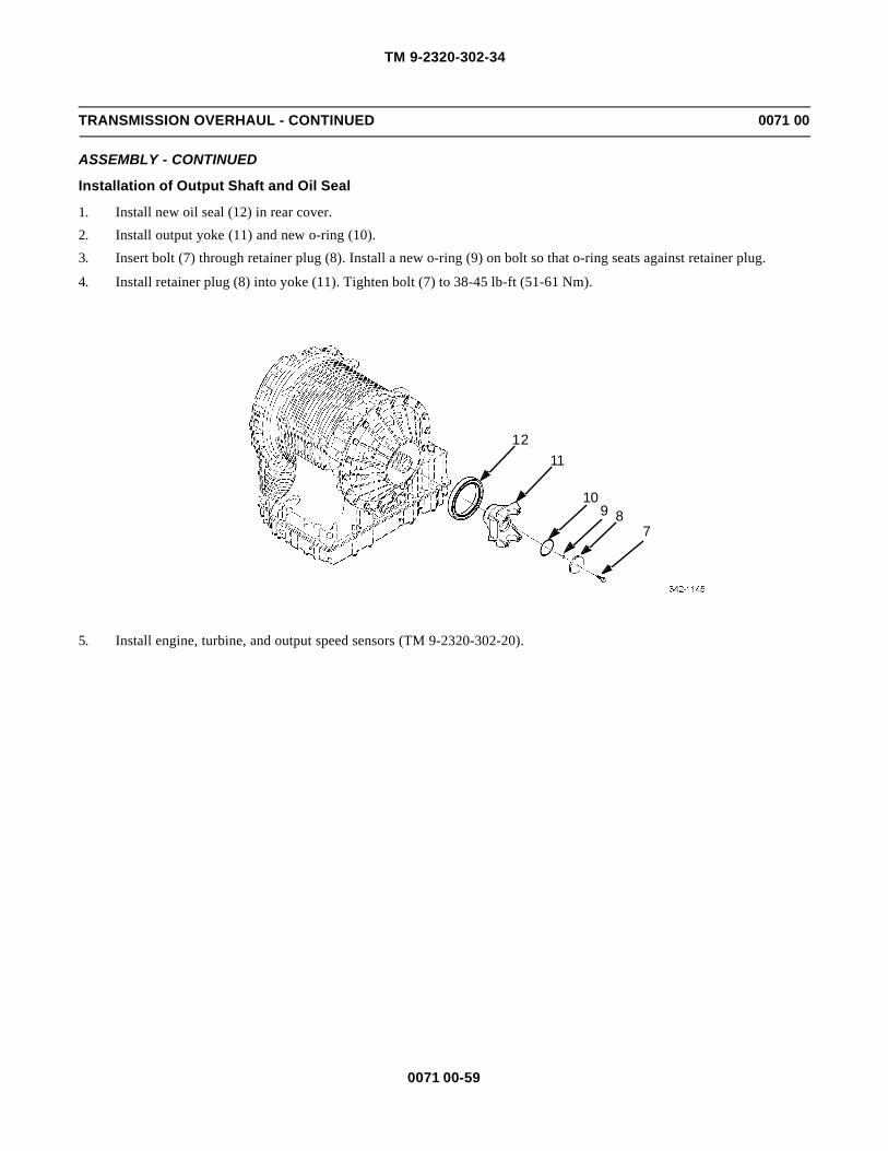
TM 9-2320-302-34
0071 00-59
TRANSMISSION OVERHAUL - CONTINUED 0071 00
ASSEMBLY - CONTINUED
Installation of Output Shaft and Oil Seal
1. Install new oil seal (12) in rear cover.
2. Install output yoke (11) and new o-ring (10).
3. Insert bolt (7) through retainer plug (8). Install a new o-ring (9) on bolt so that o-ring seats against retainer plug.
4. Install retainer plug (8) into yoke (11). Tighten bolt (7) to 38-45 lb-ft (51-61 Nm).
5. Install engine, turbine, and output speed sensors (TM 9-2320-302-20).
789
10
1112

TM 9-2320-302-34
0071 00-60
TRANSMISSION OVERHAUL - CONTINUED 0071 00
TABULATED DATA
Table 1. Torque Converter Selective Shims.
Table 2. Wear Limits Data.
DIMENSION C USE P/N SHIM THICKNESS (REF.) ID NO.
0.4129-0.6598 mm (0.0163-0.0259 in) 29505688 4.000 mm (0.157 in) 0
0.6597-0.8378 mm (0.0260-0.0329 in) 29505681 4.203 mm (0.165 in) 1
0.8379-1.0158 mm (0.0330-0.0399 in) 29505682 4.381 mm (0.172 in) 2
1.0159-1.1938 mm (0.0400-0.0469 in) 29505683 4.559 mm (0.179 in) 3
1.1939-1.3708 mm (0.0470-0.0539 in) 29505684 4.736 mm (0.186 in) 4
1.3709-1.5488 mm (0.0540-0.0609 in) 29505685 4.914 mm (0.193 in) 5
1.5489-1.7268 mm (0.0610-0.0679 in) 29505686 5.092 mm(0.200 in) 6
1.7269-1.9048 mm (0.0680-0.0749 in) 29507793 5.230 mm (0.207 in) 7
1.9049-1.9733 mm (0.0750-0.0776 in) 29507794 5.448 mm (0.214 in) 8
DESCRIPTION
WEAR LIMIT
MM INCHES
TORQUE CONVERTER MODULE
Converter Cover Bushing, Maximum ID 66.91 2.634
Lockup Piston Assembly, Minimum Thickness 6.53 0.257
Damper Assembly Plate, Maximum Distortion 0.51 0.020
Damper Assembly Plate, Minimum Thickness 8.51 0.335
Turbine-to-damper, Maximum Spline Wear 0.38 0.015
Backplate, Maximum Distortion 0.15 0.006
Backplate, Minimum Wear Surface Thickness 11.79 0.464
Turbine Hub, Minimum OD 66.69 2.626
Stator Thrust Plate, Minimum Thickness 9.45 0.372
Converter Pump Hub, Minimum OD 88.99 3.504
TORQUE CONVERTER HOUSING MODULE - PTO EQUIPPED
Bearing Retainer Bushing, Maximum ID 89.19 3.511
Oil Pump Drive Hub Seal, Minimum End Gap 1.18 0.046
Oil Pump Drive Hub Seal, Maximum End Gap 1.66 0.065
Oil Pump Drive Hub, Maximum Tank Wear 0.31 0.012
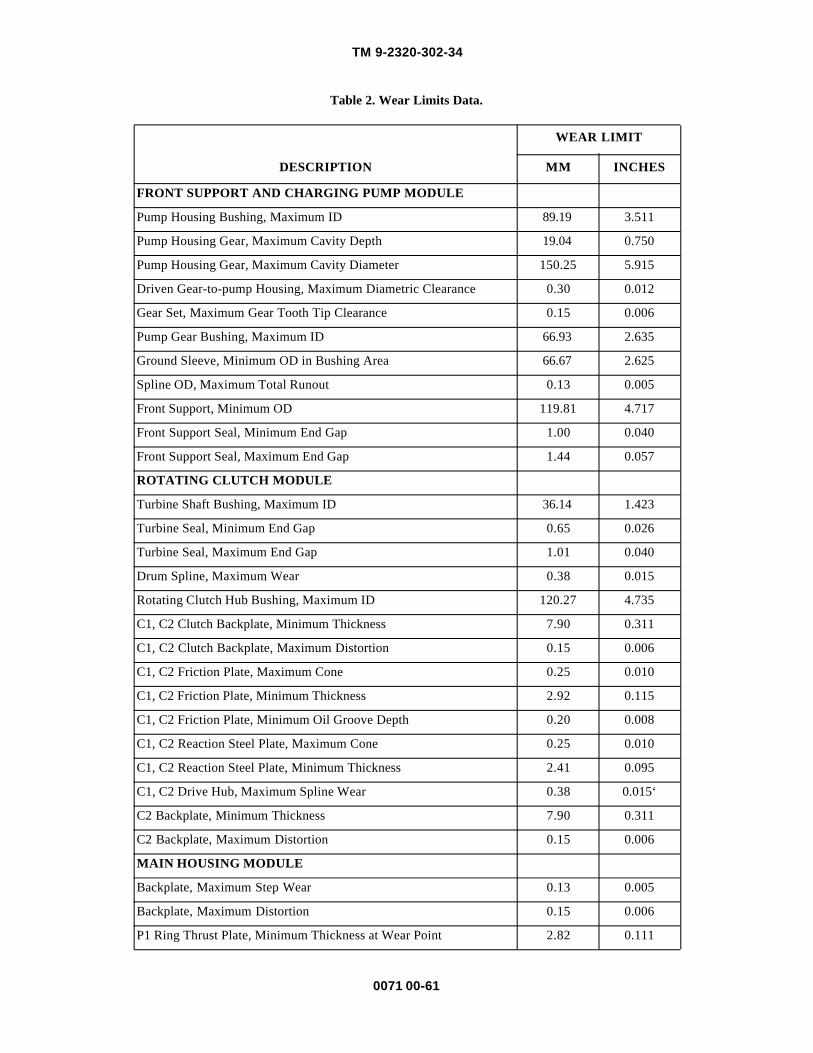
TM 9-2320-302-34
0071 00-61
Table 2. Wear Limits Data.
DESCRIPTION
WEAR LIMIT
MM INCHES
FRONT SUPPORT AND CHARGING PUMP MODULE
Pump Housing Bushing, Maximum ID 89.19 3.511
Pump Housing Gear, Maximum Cavity Depth 19.04 0.750
Pump Housing Gear, Maximum Cavity Diameter 150.25 5.915
Driven Gear-to-pump Housing, Maximum Diametric Clearance 0.30 0.012
Gear Set, Maximum Gear Tooth Tip Clearance 0.15 0.006
Pump Gear Bushing, Maximum ID 66.93 2.635
Ground Sleeve, Minimum OD in Bushing Area 66.67 2.625
Spline OD, Maximum Total Runout 0.13 0.005
Front Support, Minimum OD 119.81 4.717
Front Support Seal, Minimum End Gap 1.00 0.040
Front Support Seal, Maximum End Gap 1.44 0.057
ROTATING CLUTCH MODULE
Turbine Shaft Bushing, Maximum ID 36.14 1.423
Turbine Seal, Minimum End Gap 0.65 0.026
Turbine Seal, Maximum End Gap 1.01 0.040
Drum Spline, Maximum Wear 0.38 0.015
Rotating Clutch Hub Bushing, Maximum ID 120.27 4.735
C1, C2 Clutch Backplate, Minimum Thickness 7.90 0.311
C1, C2 Clutch Backplate, Maximum Distortion 0.15 0.006
C1, C2 Friction Plate, Maximum Cone 0.25 0.010
C1, C2 Friction Plate, Minimum Thickness 2.92 0.115
C1, C2 Friction Plate, Minimum Oil Groove Depth 0.20 0.008
C1, C2 Reaction Steel Plate, Maximum Cone 0.25 0.010
C1, C2 Reaction Steel Plate, Minimum Thickness 2.41 0.095
C1, C2 Drive Hub, Maximum Spline Wear 0.38 0.015‘
C2 Backplate, Minimum Thickness 7.90 0.311
C2 Backplate, Maximum Distortion 0.15 0.006
MAIN HOUSING MODULE
Backplate, Maximum Step Wear 0.13 0.005
Backplate, Maximum Distortion 0.15 0.006
P1 Ring Thrust Plate, Minimum Thickness at Wear Point 2.82 0.111

TM 9-2320-302-34
0071 00-62
TRANSMISSION OVERHAUL - CONTINUED 0071 00
Table 2. Wear Limits Data - Continued.
DESCRIPTION
WEAR LIMIT
MM INCHES
MAIN HOUSING MODULE - CONTINUED
P1 Ring Gear Spline, Maximum Wear 0.38 0.015
C3, C4, C5 Friction Plate, Maximum Cone 0.25 0.010
C3, C4, C5 Friction Plate, Minimum Thickness 3.485 0.137
C3, C4, C5 Reaction (Steel) Plate, Maximum Cone 0.25 0.010
C3, C4, C5 Reaction (Steel) Plate, Minimum Thickness 2.41 0.095
C3, C4, Clutch Housings, Maximum Spline Wear 1.15 0.045
Main Housing, Maximum Spline Wear 1.15 0.045
MAIN SHAFT MODULE - WIDE RATIO AND CLOSE RATIO
Main Shaft Bearing Journal, Minimum OD 52.98 2.086
Main Shaft Pilots (Both Ends), Minimum OD 35.92 1.414
P1 PLANETARY MODULE
P1 Planetary Carrier Assembly, Maximum Pinion End Play 0.94 0.037
P1 Carrier Bushing, Maximum ID 89.32 3.517
P1 Pinion Thrust Washer, Minimum Thickness 1.40 0.055
P1 Pinion Trust Washer, Maximum Step Wear 0.12 0.005
P2 Ring Gear Spline, Maximum Wear 0.38 0.015
P2 PLANETARY MODULE
P2 Planetary Carrier Assembly, Maximum Pinion End Play 0.94 0.037
P2 Carrier Bushing, Maximum ID 53.23 2.096
P2 Pinion Thrust Washer, Minimum Thickness 1.40 0.055
P2 Pinion Thrust Washer, Maximum Step Wear 0.12 0.005
P3 Ring Gear Spline, Maximum Wear 0.38 0.015
REAR COVER AND P3 MODULE
P3 Planetary Carrier Assembly, Maximum End Play 0.94 0.037
Output Shaft Bushing, Maximum ID 36.14 1.423
Output Shaft, Maximum Spline Wear 0.38 0.015
P3 Pinion Thrust Washer, Minimum Thickness 1.40 0.055
P3 Pinion Thrust Washer, Maximum Step Wear 0.12 0.005
OUTPUT FLANGE AND YOKE
Journal Seal, Maximum OD 85.0 3.346

TM
9-2320-302-34
0071 00-63
Table 3. Wear Limits and Spring Data.
* Individual springs
** For complete spring assembly
SPRINGPART
NUMBERCOLORCODE
NO. OFCOILS
WIRE DIAMM (IN)
SPRINGOD
MM (IN)
APPROXFREE
LENGTHMM (IN)
LENGTH UNDER LOAD
MM(IN)
N(LB)
Stator 29501300 No Code N/A N/A N/A 17.8(0.70)
5.7(0.224)
0.9(0.2)
Main Relief 29507709 No Code 10 3.25(0.128)
17.96(0.707)
52.4(2.06)
40.7(1.60)
474(106.5)
C2 Return 29505719 No Code 11.5* 2.04*(0.080)
19.06*0.750)
70.76*(2.786)
28.2(1.110)
5185**(1165.6)
C1 Return 29509453 No Code 12* 2.10*(0.083)
16.0*(0.630)
57.53*(2.265)
34.8(1.37)
4649**(1045.4)
C3 Return 29506206 No Code 13* 2.10*(0.083)
15.0*(0.590)
52.3*(2.06)
35.4(1.39)
274.4**(61.69)
C3 Retainer 29507882 No Code 4* 2.36*(0.093)
12.62*(0.497)
11.2*(0.44)
9.3(0.37)
16408**(3689)
C3 Retainer 29515628 No Code 4* 2.36*(0.093)
12.62*(0.497)
11.1*(0.44)
10.40(0.41)
15403**(3463)
C4 Return 29506206 No Code 13* 2.10*(0.083)
15.0*(0.590)
52.3*(2.06)
35.4(1.39)
274.4**(6169)
C4 Retainer 29507882 No Code 4* 2.36*(0.093)
12.62*(0.497)
11.2*(0.44)
9.3(0.37)
16408**(3689)
C4 Retainer 29515628 No Code 4* 2.36*(0.093)
12.62*(0.497)
11.1*(0.44)
10.40(0.41)
15403**(3463)
Retarder 6880775 Yellow/Red Stripe
12 1.93(0.076)
16.61(0.654)
53.8(2.12)
35.30(1.390)
81.4(18.30)
RetarderControl
29510495 Silver 7.5 1.40(0.055)
15.1(0.594)
3.08(1.212)
18.0(0.71)
33(7.42)
RetarderControl
29512792 Lt. Green(on end)
7.5 1.40(0.055)
15.09(0.594)
33.69(1.326)
18.0(0.71)
40(9.0)
RetarderControl
29510494 Orange 7 1.60(0.063)
15.50(0.610)
27.8(1.09)
18.0(0.71)
44(9.9)

TM
9-2320-302-34
0071 00-64
Table 3. Wear Limits and Spring Data - Continued.
* Individual springs
** For complete spring assembly
SPRINGPART
NUMBERCOLORCODE
NO OFCOILS
WIRE DIAMM (IN)
SPRINGOD
MM (IN)
APPROX.FREE
LENGTHMM (IN)
LENGTH UNDER LOAD
MM(IN)
N(LB)
RetarderExh. Back
23049391 No Code 17 0.61(0.024)
7.80(0.307)
29.2(1.14)
18.2(0.72)
2(0.5)
C5 Return 29503036 No Code 12* 2.10*(0.083)
17.00*(0.669)
57.3*(2.26)
37.6(1.48)
3086**(693.8)
SolenoidRegulator
29502195 No Code 4 0.67(0.026)
11.05(0.440)
6.5(0.26)
3.45(0.14)
3(0.7)
AccumulatorRelay
29507455 Silver 12.8 1.28(0.050)
11.68(0.460)
43.6(1.72)
20.0(0.79)
47(10.6)
Overdrive 23049332 Orange 12 0.76(0.030)
7.75(0.305)
26.6(1.05)
12.5(0.49)
12.0(2.7)
SolenoidRegulator
29502195 No Code 4 0.67(0.026)
11.05(0.440)
6.5(0.26)
3.45(0.14)
3(0.7)
Lockup 23049326 Yellow 10 1.37(0.054)
14.1(0.555)
42.1(1.66)
17.0(0.67)
49(11.0)
LubeRegulator
23049327 Red 13 1.22(0.048)
11.1(0.437)
46.3(1.82)
3.5(0.93)
47(10.6)
MainRegulator
29500963 Lt. Blue 15 2.87(0.113)
22.00(0.866)
98.5(3.88)
54.6(2.15)
305(68.6)
ControlMain
23049325 Orange 10 1.83(0.072)
14.8(0.583)
44.6(1.76)
24.0(0.95)
131(29.5)
C2 Latch 29501071 Lt. Green 11 1.32(0.052)
11.43(0.450)
41.3(1.63)
19.0(0.75)
71.0(16.0)
Exh. Back 23049391 No Code 17 0.61(0.024)
7.80(0.307)
29.2(1.14)
18.2(0.72)
2(0.5)
C1 Latch 6885065 Blue 12 1.37(0.054)
16.26(0.640)
46.2(1.82)
29.2(1.15)
18(4.0)
ConverterRegulator
29507456 Pink 10.2 1.53(0.060)
11.00(0.433)
30.3(1.19)
22.8(0.90)
54(12.1)
TM 9-2320-302-34
0072 00-1
FRONT AXLE ASSEMBLY REPLACEMENT 0072 00
THIS WORK PACKAGE COVERS
Removal, Installation
INITIAL SETUP
Maintenance Level
Direct Support
Tools and Special Tools
Tool kit, general mechanic’s (Item 132, WP 0126 00)
Jack, hydraulic (Item 73, WP 0126 00)
Wrench, torque, 50-250 lb-ft (Item 139, WP 0126 00)
Wrench, torque, 100-600 lb-ft (Item 140, WP0126 00)
Wrench set, socket, 3/4 in drive (Item 141, WP0126 00)
Materials/Parts
Pin, cotter (P/N MS24665-357) (3)
Compound, adhesive (Item 10, WP 0125 00)
Compound, sealing (Item 15, WP 0125 00)
Personnel Required
Two
Equipment Condition
Front brake spider and brake chamber bracketremoved (TM 9-2320-302-20)
ABS sensors removed (TM 9-2320-302-20)
Front shock absorbers removed (TM 9-2320-302-20)
WARNINGWARNINGUse extreme caution when handling heavy parts. Provide adequate support and use assistance during proce-dure. Ensure that any lifting device used is in good condition and of suitable load capacity. Keep clear ofheavy parts supported only by lifting device. Failure to follow this warning may result in death or injury topersonnel.

TM 9-2320-302-34
0072 00-2
FRONT AXLE ASSEMBLY REPLACEMENT - CONTINUED 0072 00
REMOVAL
NOTENOTEProcedure is same for both sides except where noted.
1. On left side, remove cotter pin (1) and castellated nut (2) and set drag link (3) aside. Discard cotter pin.
2. Remove two cotter pins (4), castellated nuts (5), and tie rod (6). Discard cotter pins.
WARNINGWARNINGFront axle weighs 1060 lb (481 kg). Support front axle with a suitable floor jack during removal to preventpossible injury to personnel.
NOTENOTEEnsure front of vehicle is blocked up enough to allow removal of axle.
3. Position suitable floor jack under center of axle (7) and secure axle to floor jack.
NOTENOTENote position of axle stops during removal to aid in installation.
4. Remove eight nuts (8), washers (9), four U-bolts (10), and two axle stops (11).
5. Lower axle (7) and remove from vehicle.
6. Remove spacer (12) and shim (13).
7. Remove pin (14) from spacer (12).
2
1
34
5
6

TM 9-2320-302-34
0072 00-3
FRONT AXLE ASSEMBLY REPLACEMENT - CONTINUED 0072 00
REMOVAL - CONTINUED
8. Using lifting device, remove axle (7) from floor jack.
INSTALLATION
WARNINGWARNINGFront axle weighs 1060 lb (481 kg). Support front axle with a suitable floor jack during installation to pre-vent possible injury to personnel.
NOTENOTEProcedure is same for both sides except where noted.
1. With axle (7) installed and secured on suitable floor jack, position axle under vehicle.
2. Coat bottom of shim (13) with sealing compound and install shim on axle (7) with wide end of shim toward rear of vehi-cle.
3. Install pin (14) in spacer (12).
4. Coat top of spacer (12) with sealing compound and install spacer on top of shim (13).
5. Install axle (7).
6. Coat bottom and U-bolt saddles of two axle stops (11) with sealing compound. Coat threads of U-bolts (10) with anti-seize compound.
7. Install two axle stops (11), four U-bolts (10), eight washers (9), and eight nuts (8) on axle (7). Tighten nuts to 380-460lb-ft (515-624 Nm).
8. Remove floor jack from under vehicle.
9. Install tie rod (6) and two castellated nuts (5). Tighten nuts to 165-180 lb-ft (224-244 Nm).
10. Install two new cotter pins (4) through castellated nuts (5).
11. On left side, install drag link (3) and castellated nut (2). Tighten nut to 165-180 lb-ft (224-244 Nm).
12. Install new cotter pin (1) through castellated nut (2).
11
10
13
8,97
12
14

TM 9-2320-302-34
0072 00-4
FRONT AXLE ASSEMBLY REPLACEMENT - CONTINUED 0072 00
INSTALLATION - CONTINUED
13. Install front shock absorbers (TM 9-2320-302-20).
14. Install ABS sensors (TM 9-2320-302-20).
15. Install front brake spider and brake chamber bracket (TM 9-2320-302-20).
END OF WORK PACKAGE

TM 9-2320-302-34
0073 00-1
FRONT AXLE CASTER ADJUSTMENT 0073 00
THIS WORK PACKAGE COVERS
Adjustment
INITIAL SETUP
Maintenance Level
Direct Support
Tools and Special Tools
Tool kit, general mechanic’s (Item 132, WP 0126 00)
Wrench, torque, 100-600 lb-ft (Item 140, WP 0126 00)
Wrench set, socket, 3/4 in drive (Item 141, WP0126 00)
Materials/Parts
Compound, antiseize (Item 10, WP 0125 00)
ADJUSTMENT
NOTENOTEThe following caster adjustment must be performed with the assistance of a local Freightliner dealer or asupporting Contractor Logistic Support (CLS) maintenance activity.
1. Measure caster angle. Angle must be +3.5 to +6.5 degrees.
NOTENOTEPerform steps 2 through 9 if caster angle is incorrect.
2. Remove four nuts (1) and washers (2) from two U-bolts (3).
3
4
1
2
5
8
6
7
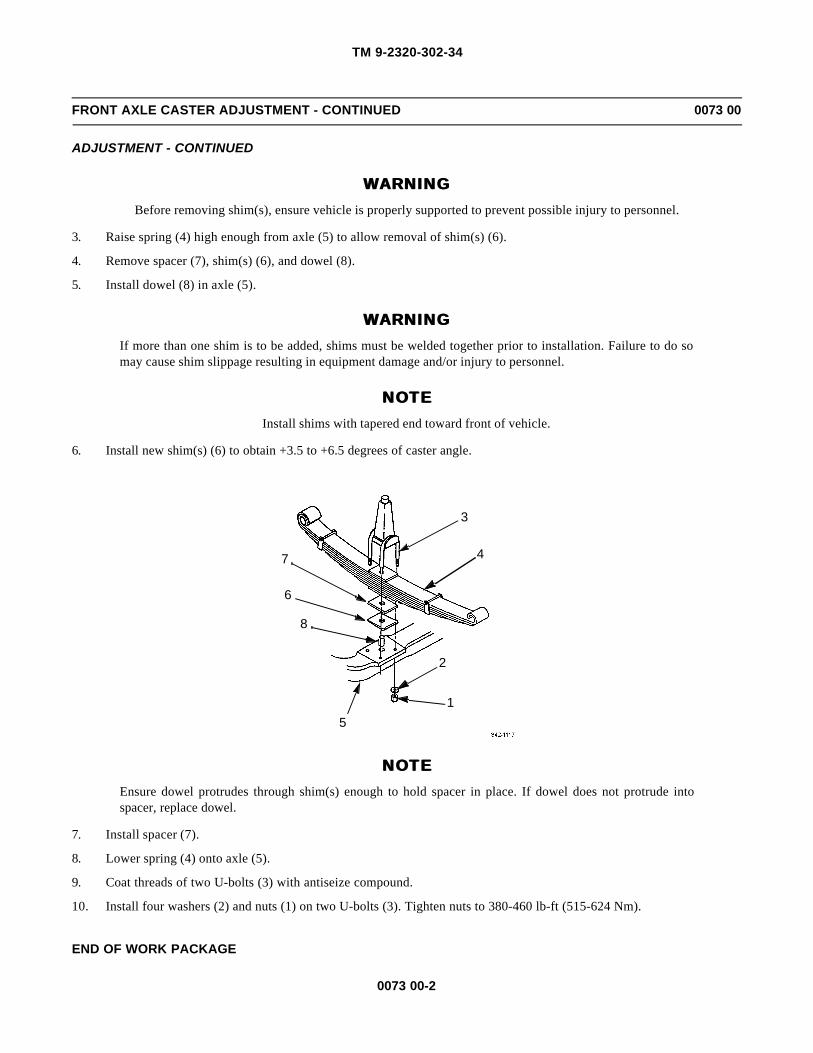
TM 9-2320-302-34
0073 00-2
FRONT AXLE CASTER ADJUSTMENT - CONTINUED 0073 00
ADJUSTMENT - CONTINUED
WARNINGWARNINGBefore removing shim(s), ensure vehicle is properly supported to prevent possible injury to personnel.
3. Raise spring (4) high enough from axle (5) to allow removal of shim(s) (6).
4. Remove spacer (7), shim(s) (6), and dowel (8).
5. Install dowel (8) in axle (5).
WARNINGWARNINGIf more than one shim is to be added, shims must be welded together prior to installation. Failure to do somay cause shim slippage resulting in equipment damage and/or injury to personnel.
NOTENOTEInstall shims with tapered end toward front of vehicle.
6. Install new shim(s) (6) to obtain +3.5 to +6.5 degrees of caster angle.
NOTENOTEEnsure dowel protrudes through shim(s) enough to hold spacer in place. If dowel does not protrude intospacer, replace dowel.
7. Install spacer (7).
8. Lower spring (4) onto axle (5).
9. Coat threads of two U-bolts (3) with antiseize compound.
10. Install four washers (2) and nuts (1) on two U-bolts (3). Tighten nuts to 380-460 lb-ft (515-624 Nm).
END OF WORK PACKAGE
3
4
1
2
5
8
6
7

TM 9-2320-302-34
0074 00-1
TIE ROD MAINTENANCE 0074 00
THIS WORK PACKAGE COVERS
Removal, Disassembly, Assembly, Installation
INITIAL SETUP
Maintenance Level
Direct Support
Tools and Special Tools
Tool kit, general mechanic’s (Item 132, WP 0126 00)
Wrench, torque, 50-250 lb-ft (Item 139, WP 0126 00)
Materials/Parts
Pin, cotter (P/N MS24665-357) (2)
References
TM 9-2320-302-20
REMOVAL
Remove cotter pin (1) and castellated nut (2) at each end of tie rod (3). Remove tie rod. Discard cotter pins.
3
1
2

TM 9-2320-302-34
0074 00-2
TIE ROD MAINTENANCE - CONTINUED 0074 00
DISASSEMBLY
NOTENOTEProcedure is same for both tie rod ends.
1. Remove lock nut (4) and capscrew (5).
2. Remove dust cover (6).
NOTENOTE• Note number of turns necessary to remove tie rod end.
• Left tie rod end has left-hand threads and right tie rod end has right-hand threads.
3. Remove tie rod end (7) from tie rod (3).
4. If damaged, remove lubrication fitting (8).
ASSEMBLY
NOTENOTEProcedure is same for both tie rod ends.
1. If removed, install new lubrication fitting (8).
NOTENOTELeft tie rod end has left-hand threads and right tie rod end has right-hand threads.
2. Install tie rod end (7) on tie rod (3), the same number of turns noted during disassembly.
3. Install dust cover (6).
4. Install capscrew (5) and lock nut (4).
46
85
7
3

TM 9-2320-302-34
0074 00-3
TIE ROD MAINTENANCE - CONTINUED 0074 00
INSTALLATION
1. Install each end of tie rod (3) with castellated nut (2) and new cotter pin (1). Tighten castellated nuts to 165-180 lb-ft(224-244 Nm).
2. Check front axle toe-in alignment (TM 9-2320-302-20).
END OF WORK PACKAGE
3
1
2

TM 9-2320-302-34
0074 00-4
This Page Intentionally Left Blank.

TM 9-2320-302-34
0075 00-1
FRONT CROSS TUBE ARM REPLACEMENT 0075 00
THIS WORK PACKAGE COVERS
Removal, Installation
INITIAL SETUP
Maintenance Level
Direct Support
Tools and Special Tools
Tool kit, general mechanic’s (Item 132, WP 0126 00)
Multiplier, torque wrench (Item 79, WP 0126 00)
Wrench, torque, 100-600 lb-ft (Item 140, WP0126 00)
Wrench set, socket, 3/4 in drive (Item 141, WP0126 00)
Materials/Parts
Pin, cotter (P/N MS24665-357)
Equipment Condition
Tie rod removed (WP 0074 00)
NOTENOTEProcedure is same for both cross tube arms.
REMOVAL
Remove cotter pin (1), castellated nut (2), cross tube arm (3), and woodruff key (4). Discard cotter pin.
2
1
4
3

TM 9-2320-302-34
0075 00-2
FRONT CROSS TUBE ARM REPLACEMENT - CONTINUED 0075 00
INSTALLATION
1. Install woodruff key (4), cross tube arm (3), and castellated nut (2). Tighten nut to 550-740 lb-ft (746-1003 Nm).
CAUTIONCAUTIONCastellated nut may be tightened to 1025 lb-ft (1390 Nm) for purpose of installing cotter pin. Overtighteningmay damage steering arm.
2. Install new cotter pin (1).
3. Install tie rod (WP 0074 00).
END OF WORK PACKAGE
2
1
4
3

TM 9-2320-302-34
0076 00-1
FRONT STEERING ARM REPLACEMENT 0076 00
THIS WORK PACKAGE COVERS
Removal, Installation
INITIAL SETUP
Maintenance Level
Direct Support
Tools and Special Tools
Tool kit, general mechanic’s (Item 132, WP 0126 00)
Multiplier, torque wrench (Item 79, WP 0126 00)
Wrench, torque, 100-600 lb-ft (Item 140, WP0126 00)
Wrench set, socket, 3/4 in drive (Item 141, WP0126 00)
Materials/Parts
Pin, cotter (P/N MS24665-357)
Equipment Condition
Drag link removed (TM 9-2320-302-20)
Front brake spider and brake chamber bracketremoved (TM 9-2320-302-20)
REMOVAL
Remove cotter pin (1), castellated nut (2), steering arm (3), and woodruff key (4). Discard cotter pin.
INSTALLATION
1. Install woodruff key (4), steering arm (3), and castellated nut (2). Tighten nut to 775-1050 lb-ft (1051-1424 Nm).
CAUTIONCAUTIONCastellated nut may be tightened to 1450 lb-ft (1966 Nm) for purpose of installing cotter pin. Overtighteningmay damage steering arm.
2. Install new cotter pin (1).
3. Install drag link (TM 9-2320-302-20).
3
41
2

TM 9-2320-302-34
0076 00-2
FRONT STEERING ARM REPLACEMENT - CONTINUED 0076 00
INSTALLATION - CONTINUED
4. Install front brake spider and brake chamber bracket (TM 9-2320-302-20).
END OF WORK PACKAGE
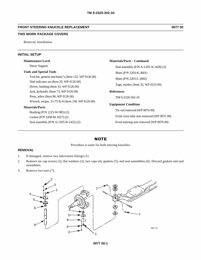
TM 9-2320-302-34
0077 00-1
FRONT STEERING KNUCKLE REPLACEMENT 0077 00
THIS WORK PACKAGE COVERS
Removal, Installation
INITIAL SETUP
Maintenance Level
Direct Support
Tools and Special Tools
Tool kit, general mechanic’s (Item 132, WP 0126 00)
Dial indicator set (Item 29, WP 0126 00)
Driver, bushing (Item 33, WP 0126 00)
Jack, hydraulic (Item 73, WP 0126 00)
Press, arbor (Item 90, WP 0126 00)
Wrench, torque, 15-75 lb-ft (Item 138, WP 0126 00)
Materials/Parts
Bushing (P/N 1225-W-985) (2)
Gasket (P/N 3208-M-1027) (2)
Seal assembly (P/N A-1205-B-1432) (2)
Materials/Parts - Continued
Seal assembly (P/N A-1205-X-1428) (2)
Shim (P/N 2203-K-3001)
Shim (P/N 2203-L-3002)
Tags, marker (Item 35, WP 0125 00)
References
TM 9-2320-302-10
Equipment Condition
Tie rod removed (WP 0074 00)
Front cross tube arm removed (WP 0075 00)
Front steering arm removed (WP 0076 00)
NOTENOTEProcedure is same for both steering knuckles.
REMOVAL
1. If damaged, remove two lubrication fittings (1).
2. Remove six cap screws (2), flat washers (3), two caps (4), gaskets (5), and seal assemblies (6). Discard gaskets and sealassemblies.
3. Remove two nuts (7).
7
1
65
4
3
2
9
6
5
4
3
2
1 7

TM 9-2320-302-34
0077 00-2
FRONT STEERING KNUCKLE REPLACEMENT - CONTINUED 0077 00
REMOVAL - CONTINUED
NOTENOTETag draw keys prior to removal to aid in installation.
4. Remove two draw keys (8).
CAUTIONCAUTIONBe careful when removing pin. If pin is dropped, damage may occur.
5. Remove pin (9).
6. Remove steering knuckle (10), thrust bearing (11), shim(s) (12), and seal assembly (13). Discard seal assembly andshim(s).
7. Remove two bushings (14) from steering knuckle (10). Discard bushings.
INSTALLATION
1. Using bushing driver, install two new bushings (14) as follows:
a. Press bushing (14) into steering knuckle (10) 1/8 in (3.2 mm) and relieve pressure.
b. Press bushing (14) into steering knuckle (10) another 1/2 in (12.7 mm) and relieve pressure.
8
13
10
9
12
8
11
14
10
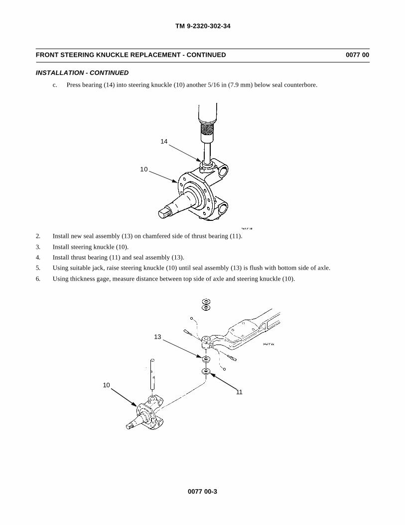
TM 9-2320-302-34
0077 00-3
FRONT STEERING KNUCKLE REPLACEMENT - CONTINUED 0077 00
INSTALLATION - CONTINUED
c. Press bearing (14) into steering knuckle (10) another 5/16 in (7.9 mm) below seal counterbore.
2. Install new seal assembly (13) on chamfered side of thrust bearing (11).
3. Install steering knuckle (10).
4. Install thrust bearing (11) and seal assembly (13).
5. Using suitable jack, raise steering knuckle (10) until seal assembly (13) is flush with bottom side of axle.
6. Using thickness gage, measure distance between top side of axle and steering knuckle (10).
14
10
1110
13

TM 9-2320-302-34
0077 00-4
FRONT STEERING KNUCKLE REPLACEMENT - CONTINUED 0077 00
INSTALLATION - CONTINUED
WARNINGWARNINGShims are delicate and sharp. Use extreme caution when aligning shims to prevent cutting fingers or bendinginside diameter of shims. Damage to shims will require complete disassembly and replacement of damagedparts.
7. Install new shims (12) of thickness equal to measurement from step 6.
CAUTIONCAUTIONEnsure shim(s) is not blocking passage for pin installation to prevent damage to equipment.
NOTENOTE• Ensure draw key slots align with draw key holes.
• If pin will not pass completely through steering knuckle, but did pass through shim(s), lower jack toalign thrust bearing and seal assembly to allow passage of pin.
8. Install pin (9) in steering knuckle (10).
9. Install two draw keys (8) and nuts (7). Tighten nuts to 30-40 lb-ft (41-54 Nm).
10. Position steering knuckle (10) in straight-ahead position and install dial indicator on steering knuckle as shown.
11. Pry up on steering knuckle (10) while observing dial indicator. Vertical end play must be 0.001-0.025 in (0.03-0.64mm). If vertical end play is less than 0.001 in (0.03 mm), remove shim(s) (12) to achieve vertical end play. If verticalend play is more than 0.025 in (0.64 mm), add shim(s) to reduce vertical end play.
12. If shim(s) (12) is to be added or removed, perform removal steps 3 through 7 and installation steps 1 through 11 untilcorrect vertical end play is achieved.
12
10
9
8
7
8
7

TM 9-2320-302-34
0077 00-5
FRONT STEERING KNUCKLE REPLACEMENT - CONTINUED 0077 00
INSTALLATION - CONTINUED
13. Install two new seal assemblies (6), new gaskets (5), caps (4), six flat washers (3), and cap screws (2). Tighten capscrews to 20-30 lb-ft (27-41 Nm).
14. If removed, install two new lubrication fittings (1).
10
2
3
1
4
5
6
6
5
4
12
3

TM 9-2320-302-34
0077 00-6
FRONT STEERING KNUCKLE REPLACEMENT - CONTINUED 0077 00
INSTALLATION - CONTINUED
15. Install front steering arm (WP 0076 00).
16. Install front cross tube arm (WP 0075 00).
17. Install tie rod (WP 0074 00).
18. Lubricate steering knuckle (TM 9-2320-302-10).
END OF WORK PACKAGE

TM 9-2320-302-34
0078 00-1
REAR AXLE REPLACEMENT 0078 00
THIS WORK PACKAGE COVERS
Removal, Installation
INITIAL SETUP
Maintenance Level
Direct Support
Tools and Special Tools
Tool kit, general mechanic’s (Item 132, WP 0126 00)
Jack, hydraulic (Item 73, WP 0126 00)
Wrench, torque, 50-250 lb-ft (Item 139, WP 0126 00)
Materials/Parts
Nut, lock (P/N 23-09247-210) (16)
Tags, marker (Item 35, WP 0125 00)
Personnel Required
Two
Equipment Condition
Air system drained (TM 9-2320-302-10)
Rear brakeshoes removed (TM 9-2320-302-20)
Drivelines removed (TM 9-2320-302-20)
Rear ABS sensors removed (TM 9-2320-302-20)
Axle oil drained (TM 9-2320-302-20)
Rear shock absorbers removed (TM 9-2320-302-20)
WARNINGWARNINGUse extreme caution when handling heavy parts. Provide adequate support and use assistance during proce-dure. Ensure that any lifting device used is in good condition and of suitable load capacity. Keep clear ofheavy parts supported only by lifting device. Failure to follow this warning may result in death or injury topersonnel.

TM 9-2320-302-34
0078 00-2
REAR AXLE REPLACEMENT - CONTINUED 0078 00
REMOVAL
NOTENOTETag air lines to aid in installation.
1. Disconnect two air lines (1) from brake chamber (2).
NOTENOTENote position of spider assembly prior to removal to aid in installation.
2. Remove eight lock nuts (3), washers (4), screws (5), washers (6), and spider assembly (7) from axle housing (8). Discardlock nuts.
3. Repeat steps 1 and 2 for opposite side of axle housing (8).
WARNINGWARNINGAxle housing is heavy and can injure personnel if dropped. Support axle housing during removal to preventinjury to personnel.
4. Using suitable hydraulic jack, support axle housing (8).
5. Remove two nuts (9) and screws (10) to disconnect two v-rods (11) from top of axle housing (8).
NOTENOTENote position of axle clamps on axle for installation.
6. Remove four nuts (12), washers (13), and two u-bolts (14) from axle clamp (15).
7. Remove top half of axle clamp (15) from axle housing (8).
8. Position bottom half of axle clamp (15) downward, away from axle housing (8).
9. Repeat steps 6 through 8 for opposite side of axle housing (8).
1
8
7
3,4,5,6
2

TM 9-2320-302-34
0078 00-3
REAR AXLE REPLACEMENT - CONTINUED 0078 00
REMOVAL - CONTINUED
10. Remove axle housing (8) from under vehicle.
11. If new rear axle housing (8) will not be equipped with brake chambers (2), remove brake chambers (TM 9-2320-302-20).
INSTALLATION
1. If new rear axle housing (8) is not equipped with brake chambers, install brake chambers (TM 9-2320-302-20).
WARNINGWARNINGAxle housing is heavy and can injure personnel if dropped. Support axle housing during installation to pre-vent injury to personnel.
2. Using hydraulic jack, position axle housing (8) under vehicle.
3. Position bottom half of axle clamp (15) upward against axle housing (8).
4. Position top half of axle clamp (15) to top of axle housing (8).
5. Install two u-bolts (14), four washers (13), and nuts (12) to axle clamp (15). Tighten nuts initially, in diagonal sequence,to 60 lb-ft (81 Nm). Tighten nuts again in diagonal sequence to 130 lb-ft (176 Nm). Apply final torque of 200 lb-ft (271Nm).
6. Repeat steps 3 through 5 for opposite side of axle housing (8).
7. Connect two v-rods (11) to top of axle housing (8) with two screws (10) and nuts (9). Tighten nuts to 427 lb-ft (579Nm).
8. Remove hydraulic jack.
9,10
1413
8 15
12
11
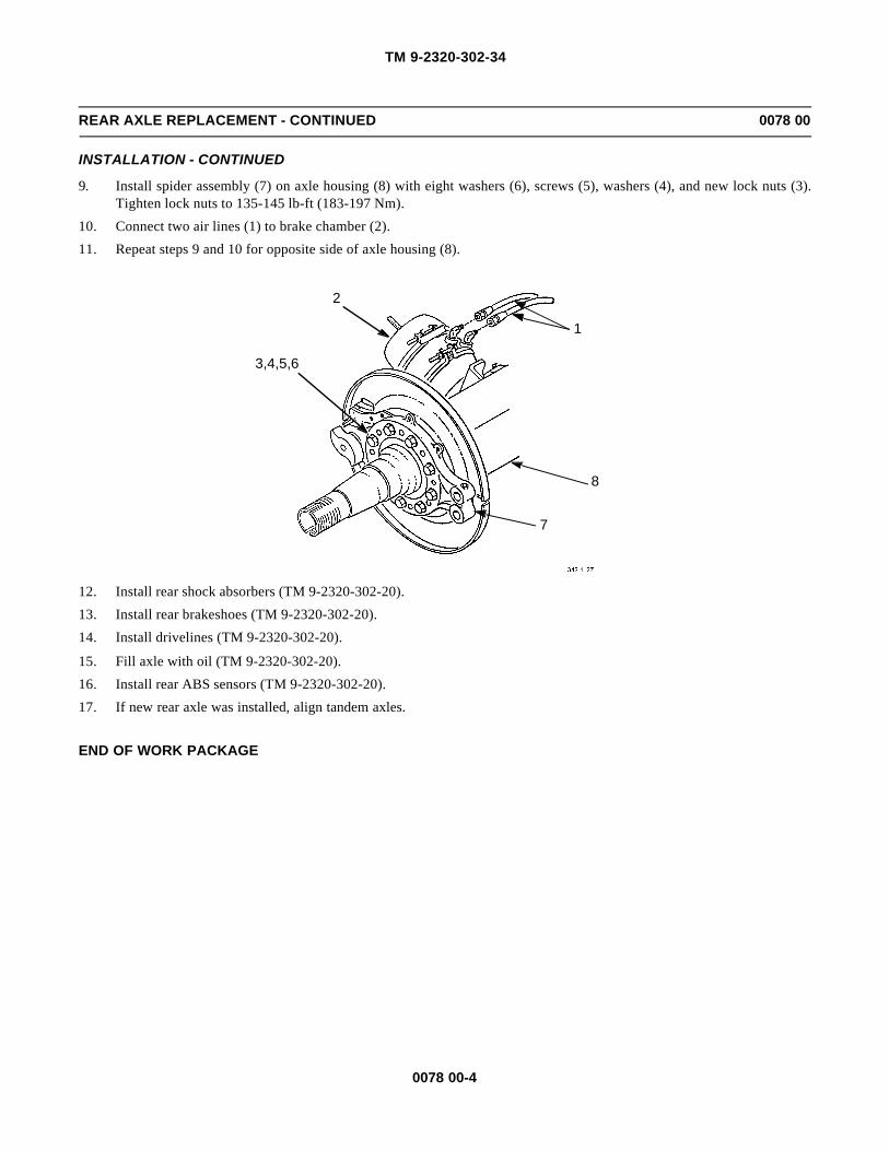
TM 9-2320-302-34
0078 00-4
REAR AXLE REPLACEMENT - CONTINUED 0078 00
INSTALLATION - CONTINUED
9. Install spider assembly (7) on axle housing (8) with eight washers (6), screws (5), washers (4), and new lock nuts (3).Tighten lock nuts to 135-145 lb-ft (183-197 Nm).
10. Connect two air lines (1) to brake chamber (2).
11. Repeat steps 9 and 10 for opposite side of axle housing (8).
12. Install rear shock absorbers (TM 9-2320-302-20).
13. Install rear brakeshoes (TM 9-2320-302-20).
14. Install drivelines (TM 9-2320-302-20).
15. Fill axle with oil (TM 9-2320-302-20).
16. Install rear ABS sensors (TM 9-2320-302-20).
17. If new rear axle was installed, align tandem axles.
END OF WORK PACKAGE
1
8
7
3,4,5,6
2

TM 9-2320-302-34
0079 00-1
FORWARD-REAR AXLE DIFFERENTIAL CARRIER REPLACEMENT 0079 00
THIS WORK PACKAGE COVERS
Removal, Installation
INITIAL SETUP
Maintenance Level
Direct Support
Tools and Special Tools
Tool kit, general mechanic’s (Item 132, WP 0126 00)
Jack, hydraulic (Item 73, WP 0126 00)
Wrench, torque, 50-250 lb-ft (Item 139, WP 0126 00)
Materials/Parts
Compound, sealing (Item 14, WP 0125 00)
Rags, wiping (Item 31, WP 0125 00)
Personnel Required
Two
Equipment Condition
Air system drained (TM 9-2320-302-10)
Axle shafts removed (TM 9-2320-302-20)
Drivelines disconnected (TM 9-2320-302-20)
Axle oil filter removed (TM 9-2320-302-20)
Axle oil drained (TM 9-2320-302-20)
WARNINGWARNING• Use extreme caution when handling heavy parts. Provide adequate support and use assistance during
procedure. Ensure that any lifting device used is in good condition and of suitable load capacity. Keepclear of heavy parts supported only by lifting device. Failure to follow this warning may result in deathor injury to personnel.
• Spilled gear oil is very slippery. Wipe up any spilled oil immediately. Failure to do so could result inserious injury to personnel.

TM 9-2320-302-34
0079 00-2
FORWARD-REAR AXLE DIFFERENTIAL CARRIER REPLACEMENT - CONTINUED 0079 00
REMOVAL
1. Disconnect air line (1).
WARNINGWARNINGForward-rear axle differential carrier weighs 1160 lb (527 kg). Support with suitable floor jack prior toremoval to prevent possible injury to personnel.
2. Remove ten cap screws (2) and washers (3), and two nuts (4) and washers (5).
3. Loosen differential carrier (6) by tapping around flange.
4. Remove differential carrier (6) from axle (7) and lower differential carrier (6) onto floor jack. Roll differential carrierfrom under vehicle.
5. If damaged, remove oil filter adapter (8).
4,5
1
2,3
7
6
8

TM 9-2320-302-34
0079 00-3
FORWARD-REAR AXLE DIFFERENTIAL CARRIER REPLACEMENT - CONTINUED 0079 00
INSTALLATION
1. If removed, install new oil filter adapter (8).
WARNINGWARNINGForward-rear axle differential carrier weighs 1160 lb (527 kg). Support with suitable floor jack prior toinstallation to prevent possible injury to personnel.
CAUTIONCAUTIONEnsure both mating surfaces have been completely cleaned to prevent damage to equipment.
2. Position differential carrier (6) on floor jack and roll differential carrier into position under vehicle.
WARNINGWARNINGAdhesives and sealing compounds can burn easily, can give off harmful vapors, and are harmful to skin andclothing. To avoid injury or death, keep away from open fire and use in well-ventilated area. If adhesive orsealing compound gets on skin or clothing, wash immediately with soap and water.
3. Apply sealing compound around mating surface of axle (7).
4. Attach suitable hoist and install differential carrier (6) with two washers (5) and nuts (4).
5. Install ten washers (3) and cap screws (2). Tighten cap screws and two nuts (4) to 150-230 lb-ft (203-312 Nm).
6. Connect air line (1).
7. Install axle oil filter (TM 9-2320-302-20).
8. Connect drivelines (TM 9-2320-302-20).
9. Install axle shafts (TM 9-2320-302-20).
10. Fill axle with oil (TM 9-2320-302-20).
END OF WORK PACKAGE

TM 9-2320-302-34
0079 00-4
This Page Intentionally Left Blank.
TM 9-2320-302-34
0080 00-1
FORWARD-REAR AXLE DIFFERENTIAL CARRIER REPAIR 0080 00
THIS WORK PACKAGE COVERS
Disassembly, Assembly
INITIAL SETUP
Maintenance Level
General Support
Tools and Special Tools
Tool kit, general mechanic’s (Item 132, WP 0126 00)
Dial indicator set (Item 29, WP 0126 00)
Gloves, welder’s, leather (Item 41, WP 0126 00)
Holding bar, pinion (Item 47, WP 0126 00)
Multiplier, torque wrench (Item 79, WP 0126 00)
Press, arbor (Item 90, WP 0126 00)
Puller, mechanical (Item 95, WP 0126 00)
Wrench, torque, 0-300 lb-in (Item 137, WP 0126 00)
Wrench, torque, 15-75 lb-ft (Item 138, WP 0126 00)
Wrench, torque, 100-600 lb-ft (Item 140, WP0126 00)
Materials/Parts
Nut, lock (P/N 40X-1026)
Nut, lock (P/N 40X-1145)
Materials/Parts - Continued
Seal, oil (P/N A-1205-W-1895)
Seal, o-ring (P/N 5X-1034) (2)
Adhesive, silicone rubber (Item 5, WP 0125 00)
Grease, GAA (Item 22, WP 0125 00)
Oil, lubricating (Item 26, WP 0125 00)
Paste, Prussian blue (Item 28, WP 0125 00)
Rags, wiping (Item 31, WP 0125 00)
Solder (Item 33, WP 0125 00)
Personnel Required
Two
References
TM 9-214
Equipment Condition
Forward-rear axle differential carrier removed (WP0079 00).
DISASSEMBLY
WARNINGWARNINGForward-rear axle differential carrier weighs 1160 lb (526 kg). Attach suitable lifting device when liftingassembly to prevent possible injury to personnel.

TM 9-2320-302-34
0080 00-2
FORWARD-REAR AXLE DIFFERENTIAL CARRIER REPAIR - CONTINUED 0080 00
DISASSEMBLY - CONTINUED
1. Install differential carrier (1) on repair stand.
2. Turn differential carrier (1) so that ring gear (2) is up.
NOTENOTEIf reinstalling same ring gear and drive pinion, perform steps 3 through 6 to measure backlash.
3. Move ring gear (2) so that ring gear teeth fully engage with drive pinion (3) teeth.
4. Install dial indicator on flange of differential carrier (1) so that tip of indicator is against drive side of tooth on ring gear(2). Adjust dial indicator to zero.
5. Rotate ring gear (2) in both directions and record reading.
6. Repeat step 5 twice more in different locations.
1
3
1
2

TM 9-2320-302-34
0080 00-3
FORWARD-REAR AXLE DIFFERENTIAL CARRIER REPAIR - CONTINUED 0080 00
DISASSEMBLY - CONTINUED
7. Rotate differential carrier (1) to horizontal position with pinion cover (4) at top.
8. Remove five cap screws (5), washers (6), and pinion cover (4).
9. Loosen nut (7) on drive pinion (3).
10. Using pinion holding bar, loosen lock nut (8) on yoke (9).
11. Remove seven cap screws (10), washers (11), and filter shield (12).
5,6
4
1
3
7
10,11
12
8
9

TM 9-2320-302-34
0080 00-4
FORWARD-REAR AXLE DIFFERENTIAL CARRIER REPAIR - CONTINUED 0080 00
DISASSEMBLY - CONTINUED
12. Rotate differential carrier (1) until yoke (9) faces up and install suitable lifting device through yoke (9).
NOTENOTEThere are two notches on side of pinion differential case. When one is aligned with helical driven gear, pin-ion differential case can be removed.
13. Rotate input shaft (13) until one notch on pinion differential case (14) is aligned over helical driven gear (15).
14. Lift input shaft (13) from differential carrier (1).
15. Remove shims (16). Measure and record thickness of shim pack.
16. Remove four socket head screws (17), cover (18), seal (19), and shift shaft (20). Discard seal.
17. Remove adjusting screw (21) and jamnut (22) from differential carrier (1).
18. Remove spring (23) from differential carrier (1).
19. Remove side gear (24) with bearing cone (25), clutch (26), and fork (27) from differential carrier (1).
20. Remove bearing cup (28) from differential carrier (1).
16
9
13
14
15
1

TM 9-2320-302-34
0080 00-5
FORWARD-REAR AXLE DIFFERENTIAL CARRIER REPAIR - CONTINUED 0080 00
DISASSEMBLY - CONTINUED
21. Remove bearing cone (25) from side gear (24).
231
21
22
20
19
18
17
25
26
28
1
27
24
24 25

TM 9-2320-302-34
0080 00-6
FORWARD-REAR AXLE DIFFERENTIAL CARRIER REPAIR - CONTINUED 0080 00
DISASSEMBLY - CONTINUED
22. Remove and discard lock nut (8) from yoke (9).
23. Using yoke puller, remove yoke (9) from input shaft (13).
24. Remove and discard oil seal (29).
25. Remove snap ring (30) and pinion differential case (14).
89
13
29
30
14

TM 9-2320-302-34
0080 00-7
FORWARD-REAR AXLE DIFFERENTIAL CARRIER REPAIR - CONTINUED 0080 00
DISASSEMBLY - CONTINUED
26. Remove gear (31) and thrust washer (32).
CAUTIONCAUTIONUse care when installing bearing puller. If puller touches rivets, oil pump could be damaged.
27. Install bearing puller under pump (33)
31
32
33

TM 9-2320-302-34
0080 00-8
FORWARD-REAR AXLE DIFFERENTIAL CARRIER REPAIR - CONTINUED 0080 00
DISASSEMBLY - CONTINUED
28. Using press, with bearing puller down, press input shaft (13) from oil pump (33).
29. Remove and discard two packings (34).
33
13
34
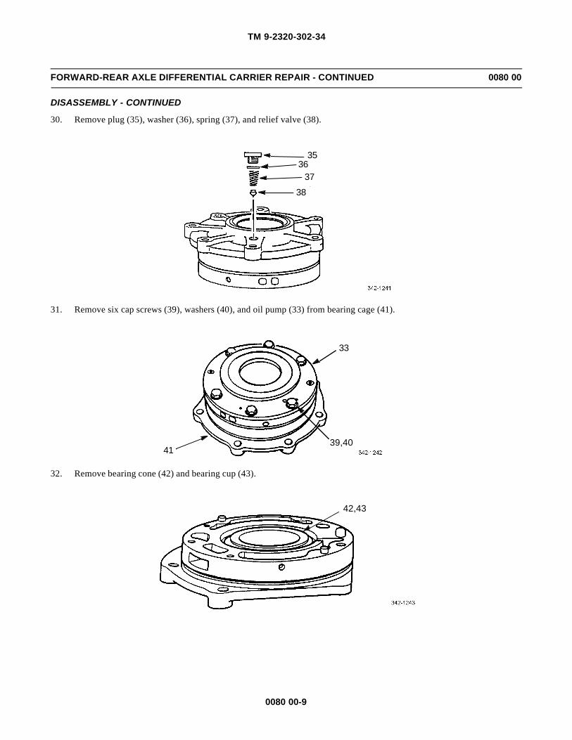
TM 9-2320-302-34
0080 00-9
FORWARD-REAR AXLE DIFFERENTIAL CARRIER REPAIR - CONTINUED 0080 00
DISASSEMBLY - CONTINUED
30. Remove plug (35), washer (36), spring (37), and relief valve (38).
31. Remove six cap screws (39), washers (40), and oil pump (33) from bearing cage (41).
32. Remove bearing cone (42) and bearing cup (43).
38
35
3736
41
33
39,40
42,43

TM 9-2320-302-34
0080 00-10
FORWARD-REAR AXLE DIFFERENTIAL CARRIER REPAIR - CONTINUED 0080 00
DISASSEMBLY - CONTINUED
33. Rotate differential carrier (1) until ring gear (2) faces up.
34. Matchmark position of two bearing caps (44 and 45) on differential carrier (1).
35. Remove pin (46) from two bearing caps (44 and 45).
36. Loosen four cap screws (47).
CAUTIONCAUTIONTo prevent damage to adjusting rings, do not hit adjusting rings with hammer or use hammer and drift pin toloosen rings.
37. Loosen two adjusting rings (48).
38. Remove four cap screws (47), washers (49), two bearing caps (44 and 45), and two adjusting rings (48).
39. Using suitable lifting device, remove ring gear subassembly (50) and two bearing cups (51).
2
MATCHMARKS
46
48 1
44
45,46,47,48,49
47,49
5051
51
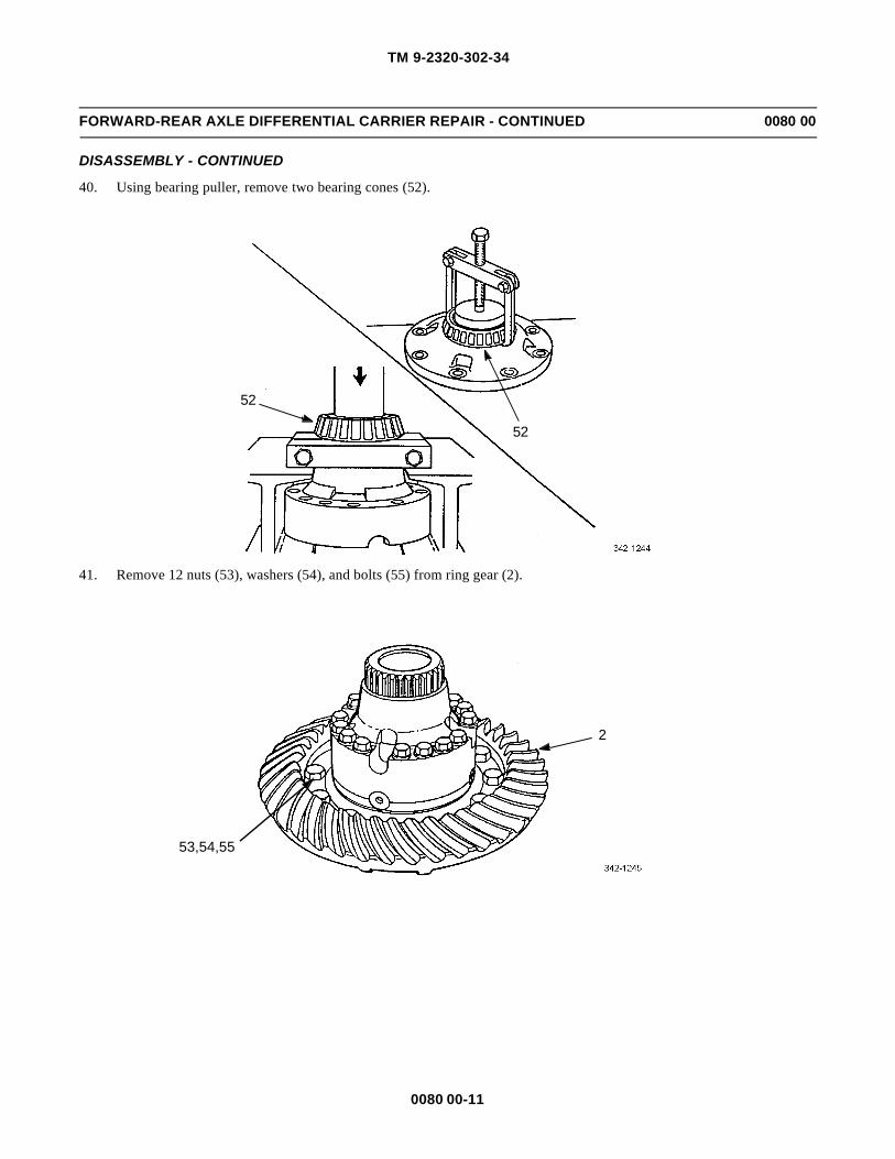
TM 9-2320-302-34
0080 00-11
FORWARD-REAR AXLE DIFFERENTIAL CARRIER REPAIR - CONTINUED 0080 00
DISASSEMBLY - CONTINUED
40. Using bearing puller, remove two bearing cones (52).
41. Remove 12 nuts (53), washers (54), and bolts (55) from ring gear (2).
52
52
2
53,54,55
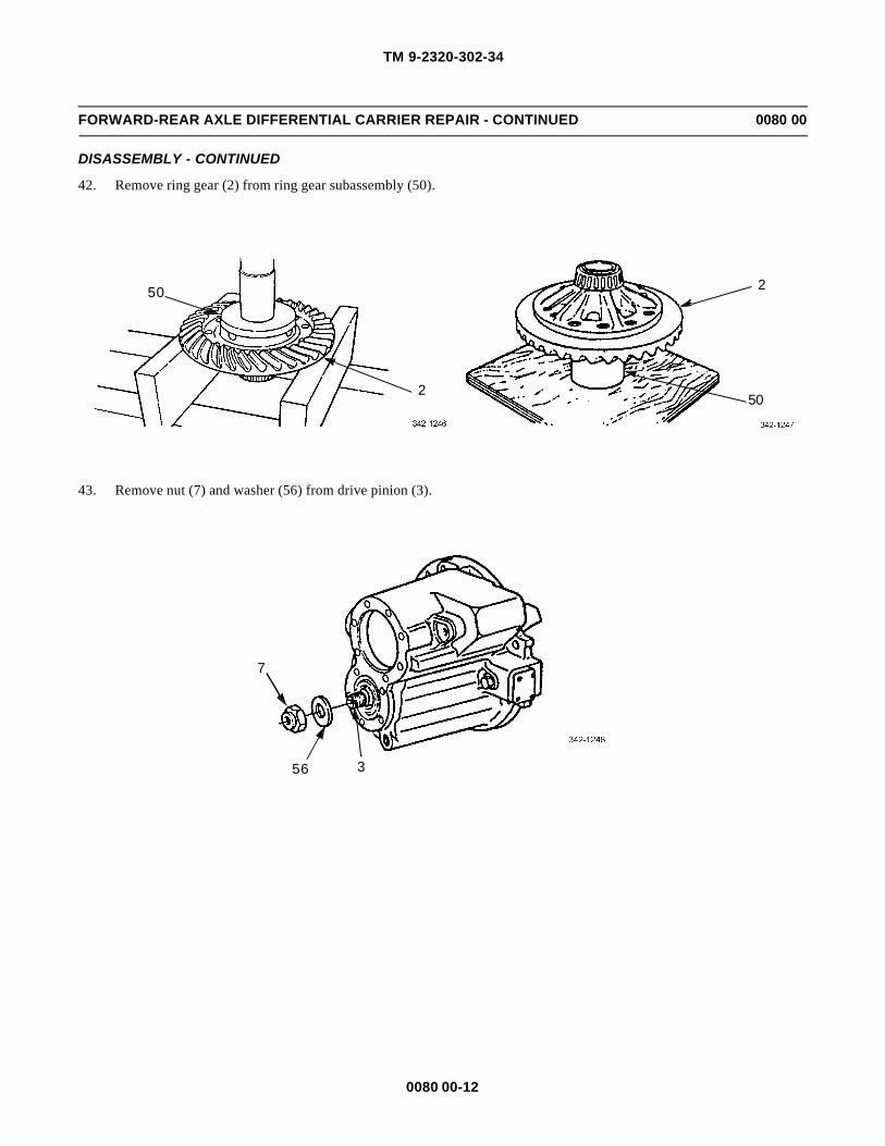
TM 9-2320-302-34
0080 00-12
FORWARD-REAR AXLE DIFFERENTIAL CARRIER REPAIR - CONTINUED 0080 00
DISASSEMBLY - CONTINUED
42. Remove ring gear (2) from ring gear subassembly (50).
43. Remove nut (7) and washer (56) from drive pinion (3).
50
250
2
7
56 3

TM 9-2320-302-34
0080 00-13
FORWARD-REAR AXLE DIFFERENTIAL CARRIER REPAIR - CONTINUED 0080 00
DISASSEMBLY - CONTINUED
44. Using press, remove drive pinion (3) from differential carrier (1).
45. Remove bearing cone (57), spacer (58), and gear (15) from differential carrier (1).
46. Remove spacer (59) and bearing cone (60) from drive pinion (3).
1
3
5758
15
59 60
3

TM 9-2320-302-34
0080 00-14
FORWARD-REAR AXLE DIFFERENTIAL CARRIER REPAIR - CONTINUED 0080 00
DISASSEMBLY - CONTINUED
NOTENOTEPerform steps 47 and 48 only if bearings are damaged or if pinion and ring gear are being replaced.
47. Remove outer bearing cup (61).
48. Remove inner bearing cup (62) and shim(s) (63) from differential carrier (1). Measure and record thickness of shim(s).
49. Remove screen/plug assembly (64), plug (65), washer (66), four cap screws (67), washers (68), and cover (69) from dif-ferential carrier (1).
62,63
61
1
1
64 65,6667,68
69
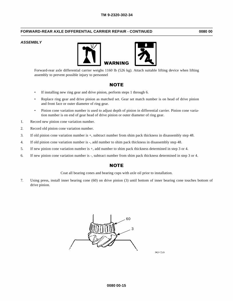
TM 9-2320-302-34
0080 00-15
FORWARD-REAR AXLE DIFFERENTIAL CARRIER REPAIR - CONTINUED 0080 00
ASSEMBLY
WARNINGWARNINGForward-rear axle differential carrier weighs 1160 lb (526 kg). Attach suitable lifting device when liftingassembly to prevent possible injury to personnel
NOTENOTE• If installing new ring gear and drive pinion, perform steps 1 through 6.
• Replace ring gear and drive pinion as matched set. Gear set match number is on head of drive pinionand front face or outer diameter of ring gear.
• Pinion cone variation number is used to adjust depth of pinion in differential carrier. Pinion cone varia-tion number is on end of gear head of drive pinion or outer diameter of ring gear.
1. Record new pinion cone variation number.
2. Record old pinion cone variation number.
3. If old pinion cone variation number is +, subtract number from shim pack thickness in disassembly step 48.
4. If old pinion cone variation number is -, add number to shim pack thickness in disassembly step 48.
5. If new pinion cone variation number is +, add number to shim pack thickness determined in step 3 or 4.
6. If new pinion cone variation number is -, subtract number from shim pack thickness determined in step 3 or 4.
NOTENOTECoat all bearing cones and bearing cups with axle oil prior to installation.
7. Using press, install inner bearing cone (60) on drive pinion (3) until bottom of inner bearing cone touches bottom ofdrive pinion.
60
3

TM 9-2320-302-34
0080 00-16
FORWARD-REAR AXLE DIFFERENTIAL CARRIER REPAIR - CONTINUED 0080 00
ASSEMBLY - CONTINUED
8. Install differential carrier (1) on press with legs of differential carrier toward top of press.
NOTENOTEIf installing new ring gear and drive pinion, use shim pack thickness determined in step 5 or 6. If installingsame ring gear and drive pinion, use shim pack removed in Disassembly step 48.
9. Install shim pack (63). Using press, install inner bearing cup (62) in differential carrier (1) until bottom of inner bearingcup touches shim pack.
10. Turn differential carrier (1) over and install supports so that differential carrier is level on press.
11. Using press, install outer bearing cup (61) until bottom of outer bearing cup touches bottom of bore.
12. Install drive pinion (3) from bottom of differential carrier (1). Install support under head of drive pinion.
6263 1
61 1

TM 9-2320-302-34
0080 00-17
FORWARD-REAR AXLE DIFFERENTIAL CARRIER REPAIR - CONTINUED 0080 00
ASSEMBLY - CONTINUED
NOTENOTEApply no more than two tons of pressure to seat bearing cups.
13. Install outer bearing cone (57) on shaft of drive pinion (3). Using press, seat two bearing cups (61and 62).
14. Using press, remove drive pinion (3).
15. Remove outer bearing cone (57).
1 57
61
62
SUPPORT
WOOD BLOCK
SUPPORT 3

TM 9-2320-302-34
0080 00-18
FORWARD-REAR AXLE DIFFERENTIAL CARRIER REPAIR - CONTINUED 0080 00
ASSEMBLY - CONTINUED
16. Install differential carrier (1) on press with legs of differential carrier toward top of press.
17. Install gear (15) with splines toward front of differential carrier (1).
18. Install large diameter spacer (59) on top of gear (15) with spacer toward inner bearing cup (62).
19. Install drive pinion (3) in gear (15). Ensure splines on drive pinion engage splines in gear.
CAUTIONCAUTIONTo prevent damage to cup, cone, and drive pinion, do not apply pressure after inner bearing cone touchesinner bearing cup.
20. Using press, press drive pinion (3) into gear (15) until inner bearing cone (60) touches inner bearing cup (62).
21. Turn differential carrier (1) over and install supports so that differential carrier is level on press.
CAUTIONCAUTIONTo prevent damage to spacer, do not apply pressure after gear touches spacer in front of inner bearing ondrive pinion.
22. Using press and sleeve that fits inside pinion bore of differential carrier (1), press gear (15) on drive pinion (3) until geartouches spacer (59).
23. Cut two pieces of lead or solder approximately 9/16-in long, 5/8-in wide, and thicker than spacer removed in disassem-bly step 45.
24. Install two lead pieces opposite each other on top of gear (15).
60
62
1
3
59
15
SUPPORTSUPPORT

TM 9-2320-302-34
0080 00-19
FORWARD-REAR AXLE DIFFERENTIAL CARRIER REPAIR - CONTINUED 0080 00
ASSEMBLY - CONTINUED
25. Install outer bearing cone (57) on top of lead pieces.
26. Using press, apply two tons of pressure to outer bearing cone (57).
27. Release pressure and remove wood block.
CAUTIONCAUTIONTo prevent damage to equipment, do not press shaft of drive pinion out of gear.
28. Using press, remove outer bearing cone (57) and lead pieces.
29. Measure thicknesses of compressed lead pieces. Add measurements of two lead pieces and divide by two to determineaverage size of pieces. Add 0.004 in (0.100 mm) to average size. Use this dimension to determine size of spacer(removed in disassembly, step 45) to be installed between gear (15) and outer bearing cone (57).
15
1
59
3
SUPPORTSUPPORT
WOOD BLOCK
WOOD BLOCKAND END OFDRIVE PINIONMUST TOUCH
57
15
SUPPORTSUPPORT
WOOD BLOCK - MUSTTOUCH HEAD OF PINION

TM 9-2320-302-34
0080 00-20
FORWARD-REAR AXLE DIFFERENTIAL CARRIER REPAIR - CONTINUED 0080 00
ASSEMBLY - CONTINUED
30. Place wood block under head of drive pinion (3) so that inner bearing cone (60) touches inner bearing cup (62). Removesupports from under differential carrier (1).
CAUTIONCAUTIONTo prevent damage to spacer, do not apply pressure after gear touches spacer in front of inner bearing ondrive pinion.
31. Using press and sleeve that fits inside pinion bore of differential carrier (1), press gear (15) on drive pinion (3) until geartouches spacer (59). Do not remove wood block.
32. Install spacer (58) in front of gear (15).
33. Install outer bearing cone (57).34. Using press, apply two tons of pressure to outer bearing cone (57). Move differential carrier (1) in both directions while
installing outer bearing cone.
35. Relieve pressure and remove differential carrier (1) from press. Install differential carrier on repair stand.
15
1
59
60
SUPPORTSUPPORT
WOOD BLOCK
WOOD BLOCKAND END OFDRIVE PINIONMUST TOUCH
62
3
5758
15
1
WOOD BLOCK - MUSTTOUCH HEAD OFDRIVE PINION
ROTATE CARRIER INTHESE DIRECTIONSAS CONE IS PRESSEDON PINION

TM 9-2320-302-34
0080 00-21
FORWARD-REAR AXLE DIFFERENTIAL CARRIER REPAIR - CONTINUED 0080 00
ASSEMBLY - CONTINUED
NOTENOTEDrive pinion must be held in place with fixture holding gear teeth or with wood blocks between pinion gearand differential carrier case.
36. Install washer (56) and nut (7) on drive pinion (3) and tighten to 1200-1500 lb-ft (1625-2035 Nm).
37. Using inch-pound torque wrench, rotate drive pinion (3). Check reading on dial while turning torque wrench. New drivepinion gear reading must be 5-45 lb-in (0.56-5.08 Nm). Used drive pinion gear reading must be 10-30 lb-in (1.13-3.39Nm).
38. If preload is not within limits, remove and replace spacers, disassembly steps 45 and 46. Install thicker spacer todecrease preload or thinner spacer to increase preload. Repeat steps 32 through 37 until correct preload is obtained.
CAUTIONCAUTION• To prevent damage to case, do not press cold ring gear on ring gear subassembly.
• To maintain temper of metal and reliability of part, do not use open flame to heat ring gear.
39. Expand ring gear (2) in tank of water heated to 160-180°F (71-82° C) for 10-15 minutes.
WARNINGWARNINGHot gear can cause burns. Wear heat-resistant gloves.
40. Remove ring gear (2) from tank and install on ring gear subassembly (50). If ring gear does not fit easily, reheat andinstall again.
41. Install 12 bolts (55), washers (54), and nuts (53). Tighten nuts to 190-225 lb-ft (260-350 Nm).
3,7,56
53
50
2
55
54

TM 9-2320-302-34
0080 00-22
FORWARD-REAR AXLE DIFFERENTIAL CARRIER REPAIR - CONTINUED 0080 00
ASSEMBLY - CONTINUED
42. Install two bearing cones (52).
WARNINGWARNINGAdhesives and sealing compounds can burn easily, can give off harmful vapors, and are harmful to skin andclothing. To avoid injury or death, keep away from open fire and use in well-ventilated area. If adhesive orsealing compound gets on skin or clothing, wash immediately with soap and water.
CAUTIONCAUTIONEnsure all old adhesive has been removed from differential carrier and bearing caps to prevent damage toequipment.
43. Set two bearing caps (44 and 45) on differential carrier (1) and apply a continuous bead of adhesive around entiresmooth ground surfaces on both sides. Do not apply adhesive to threaded areas.
44. Remove two bearing caps (44 and 45).
52
52
44 45
1

TM 9-2320-302-34
0080 00-23
FORWARD-REAR AXLE DIFFERENTIAL CARRIER REPAIR - CONTINUED 0080 00
ASSEMBLY - CONTINUED
45. Install two bearing cups (51).
46. Using suitable lifting device, install ring gear subassembly (50) in differential carrier (1).
47. Install two bearing caps (44 and 45), four cap screws (47), and washers (49).
48. Install two adjusting rings (48) in differential carrier (1).
49. Tighten four cap screws (47) to 345-430 lb-ft (470-585 Nm).
50. Install dial indicator on flange of differential carrier (1) with plunger against back surface of ring gear (2).
51
51
50
1
44
47,49
245
48
1
48
47,49

TM 9-2320-302-34
0080 00-24
FORWARD-REAR AXLE DIFFERENTIAL CARRIER REPAIR - CONTINUED 0080 00
ASSEMBLY - CONTINUED
CAUTIONCAUTIONPry bars must not touch bearing cones to prevent damage to bearing cones.
51. Loosen adjusting ring (48) on gear side of ring gear (2) until small amount of end play shows on dial indicator when ringgear is moved left and right with two pry bars between two adjusting rings and ends of ring gear subassembly (50).
52. Tighten adjusting ring (48) loosened in step 51 until no end play shows on dial indicator.
53. Tighten two adjusting rings (48) one notch from zero end play measured in step 52. Bearing preload is now set.
50
48
2
48
48
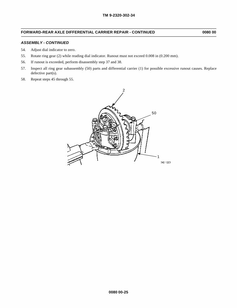
TM 9-2320-302-34
0080 00-25
FORWARD-REAR AXLE DIFFERENTIAL CARRIER REPAIR - CONTINUED 0080 00
ASSEMBLY - CONTINUED
54. Adjust dial indicator to zero.
55. Rotate ring gear (2) while reading dial indicator. Runout must not exceed 0.008 in (0.200 mm).
56. If runout is exceeded, perform disassembly step 37 and 38.
57. Inspect all ring gear subassembly (50) parts and differential carrier (1) for possible excessive runout causes. Replacedefective part(s).
58. Repeat steps 45 through 55.
2
50
1
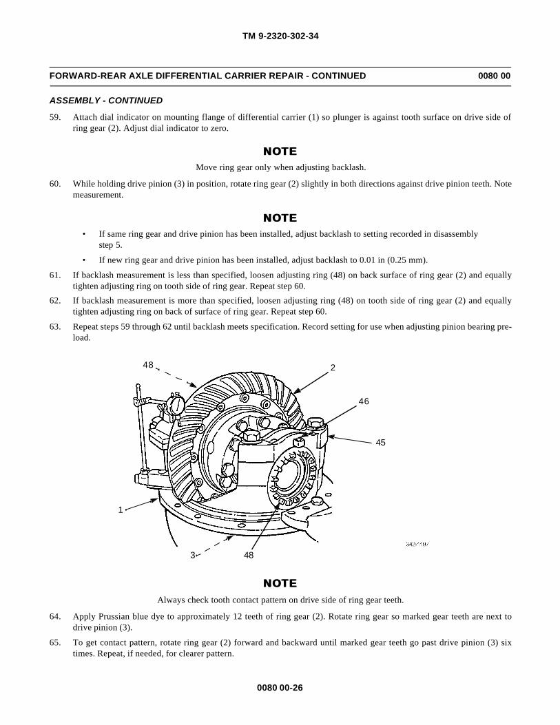
TM 9-2320-302-34
0080 00-26
FORWARD-REAR AXLE DIFFERENTIAL CARRIER REPAIR - CONTINUED 0080 00
ASSEMBLY - CONTINUED
59. Attach dial indicator on mounting flange of differential carrier (1) so plunger is against tooth surface on drive side ofring gear (2). Adjust dial indicator to zero.
NOTENOTEMove ring gear only when adjusting backlash.
60. While holding drive pinion (3) in position, rotate ring gear (2) slightly in both directions against drive pinion teeth. Notemeasurement.
NOTENOTE• If same ring gear and drive pinion has been installed, adjust backlash to setting recorded in disassembly
step 5.
• If new ring gear and drive pinion has been installed, adjust backlash to 0.01 in (0.25 mm).
61. If backlash measurement is less than specified, loosen adjusting ring (48) on back surface of ring gear (2) and equallytighten adjusting ring on tooth side of ring gear. Repeat step 60.
62. If backlash measurement is more than specified, loosen adjusting ring (48) on tooth side of ring gear (2) and equallytighten adjusting ring on back of surface of ring gear. Repeat step 60.
63. Repeat steps 59 through 62 until backlash meets specification. Record setting for use when adjusting pinion bearing pre-load.
NOTENOTEAlways check tooth contact pattern on drive side of ring gear teeth.
64. Apply Prussian blue dye to approximately 12 teeth of ring gear (2). Rotate ring gear so marked gear teeth are next todrive pinion (3).
65. To get contact pattern, rotate ring gear (2) forward and backward until marked gear teeth go past drive pinion (3) sixtimes. Repeat, if needed, for clearer pattern.
48
483
1
2
46
45

TM 9-2320-302-34
0080 00-27
FORWARD-REAR AXLE DIFFERENTIAL CARRIER REPAIR - CONTINUED 0080 00
ASSEMBLY - CONTINUED
NOTENOTE• Location of good hand-rolled contact pattern for new gear set is toward toe of gear tooth and in center
between top and bottom of tooth.
• Location of good hand-rolled contact pattern for used gear set must match wear pattern in ring gear.Contact pattern will be smaller than wear pattern.
• During tooth contact pattern checks, backlash can be adjusted within specification limits, if needed, tochange pattern location.
66. Compare contact pattern with examples shown.
67. If contact pattern requires adjustment, perform disassembly steps 38,39, and 43 through 45.
68. Remove inner bearing cup (62) and shim pack (63).
69. To correct high contact pattern, add shim(s) to shim pack (63).
70. To correct low contact pattern, remove shim(s) from shim pack (63).
71. Perform steps 8 through 66 to determine contact pattern.
72. If contact pattern is too far toward heel of gear teeth, repeat step 62 to decrease backlash to move pattern toward toe ofgear teeth.
73. If contact pattern is too far toward toe of gear teeth, repeat step 61 to increase backlash to move pattern toward heel ofgear teeth.
74. Install pin (46) in bearing caps (44 and 45) so that pin is between lugs of adjusting ring (48).
GOOD HAND-ROLLEDPATTERN
HIGH PATTERN LOW PATTERN
62
63

TM 9-2320-302-34
0080 00-28
FORWARD-REAR AXLE DIFFERENTIAL CARRIER REPAIR - CONTINUED 0080 00
ASSEMBLY - CONTINUED
CAUTIONCAUTIONTo prevent damage to oil pump, ensure drive flats in bore of oil pump are aligned with input shaft.
75. Install oil pump (33) and bearing cup (43) on input shaft (13).
76. Install bearing cone (42) on input shaft (13).
33
43
13
42
13
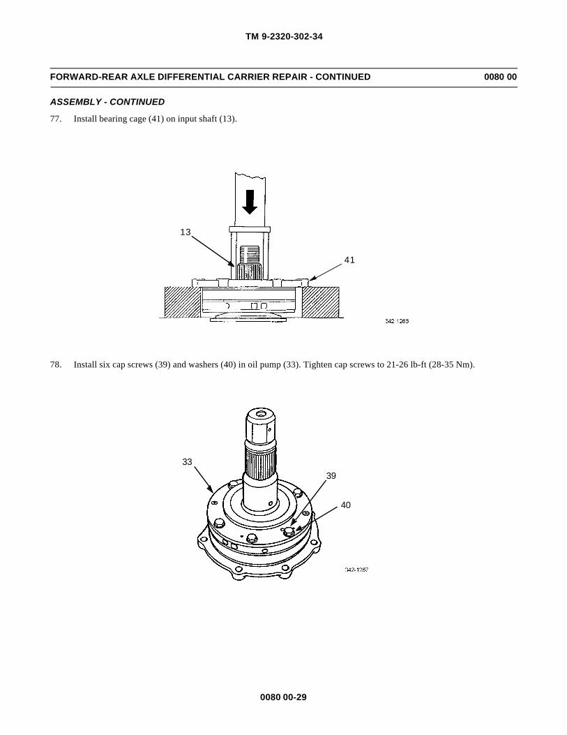
TM 9-2320-302-34
0080 00-29
FORWARD-REAR AXLE DIFFERENTIAL CARRIER REPAIR - CONTINUED 0080 00
ASSEMBLY - CONTINUED
77. Install bearing cage (41) on input shaft (13).
78. Install six cap screws (39) and washers (40) in oil pump (33). Tighten cap screws to 21-26 lb-ft (28-35 Nm).
13
41
3339
40

TM 9-2320-302-34
0080 00-30
FORWARD-REAR AXLE DIFFERENTIAL CARRIER REPAIR - CONTINUED 0080 00
ASSEMBLY - CONTINUED
79. Install relief valve (38), spring (37), washer (36), and plug (35).
80. Install two new packings (34).
35363738
34

TM 9-2320-302-34
0080 00-31
FORWARD-REAR AXLE DIFFERENTIAL CARRIER REPAIR - CONTINUED 0080 00
ASSEMBLY - CONTINUED
81. Install thrust washer (32) in pilot bore on gear (31).
82. Install gear (31) on input shaft (13).
83. Install pinion differential case (14) with screw heads facing gear (31) and snap ring (30) on input shaft (13).
31 32
13
3013
14
31

TM 9-2320-302-34
0080 00-32
FORWARD-REAR AXLE DIFFERENTIAL CARRIER REPAIR - CONTINUED 0080 00
ASSEMBLY - CONTINUED
84. Install yoke (9), an 0.5-in (12.7 mm) assembly spacer (70), and lock nut (8). Hand tighten lock nut.
85. Install bearing cone (25) on side gear (24).
86. Rotate differential carrier (1) so that ring gear (2) is toward floor.
87. Install bearing cup (28) in differential carrier (1).
88. Install fork (27), clutch (26), and side gear (24) in differential carrier (1).
89. Install spring (23) in differential carrier (1).
90. Install jamnut (22) and adjusting screw (21) in differential carrier (1).
91. Install shift shaft (20), new seal (19), cover (18), and four socket head screws (17). Tighten screws to 49-76 lb-in (5.5-8.5 Nm).
70
9 8
25
24

TM 9-2320-302-34
0080 00-33
FORWARD-REAR AXLE DIFFERENTIAL CARRIER REPAIR - CONTINUED 0080 00
ASSEMBLY - CONTINUED
92. Connect suitable lifting device through yoke (9) and install input shaft (13) in differential carrier (1).
2
2724
26
28
1
23
211
22
20
18
13
NOTCHES ON CASE
1
9
MUST BE ALIGNEDOVER HELICALDRIVE GEAR

TM 9-2320-302-34
0080 00-34
FORWARD-REAR AXLE DIFFERENTIAL CARRIER REPAIR - CONTINUED 0080 00
ASSEMBLY - CONTINUED
93. Install wood block between ring gear (2) and differential carrier (1) to prevent ring gear from rotating.
NOTENOTERotate input shaft in both directions to ensure bearings are correctly installed.
94. Install seven cap screws (10) and hand tighten.
95. Measure gap between bearing cage (41) and differential carrier (1) at four equally spaced places on bearing cage. Notemeasurements.
96. Add four measurements obtained in step 95 and divide by four to get average. Add 0.005 in (0.13 mm) to determinethickness of shim pack to be installed.
1
2
10
41
1

TM 9-2320-302-34
0080 00-35
FORWARD-REAR AXLE DIFFERENTIAL CARRIER REPAIR - CONTINUED 0080 00
ASSEMBLY - CONTINUED
97. Using at least three shims with thickest in middle, assemble new shim pack (16).
98. Remove seven cap screws (10).
99. Using suitable lifting device, lift input shaft (13) 1/4 - 1/2 in (6-12 mm).
100. Install shim pack (16) under bearing cage (41). Ensure shim pack installation pattern matches bearing cage installationpattern.
101. Install filter shield (12), seven washers (11), and cap screws (10).
13
10
41
16
10,11
12

TM 9-2320-302-34
0080 00-36
FORWARD-REAR AXLE DIFFERENTIAL CARRIER REPAIR - CONTINUED 0080 00
ASSEMBLY - CONTINUED
102. Lower input shaft (13) and remove lifting device.
103. Tighten seven cap screws (10) to 75-95 lb-ft (100-130 Nm). Rotate input shaft (13) in each direction to ensure bearingsare installed correctly.
104. Remove lock nut (8), 0.5 in (12.7 mm) assembly spacer (70), and yoke (9).
105. Install new oil seal (29), yoke (9), and lock nut (8). Using pinion holding bar, tighten lock nut to 450-600 lb-ft (610-815Nm).
106. Rotate input shaft (13) and push yoke (9) toward differential carrier (1) to ensure input shaft is at bottom of travel.
107. Install dial indicator with point on end of input shaft (13). Zero dial indicator.
108. Using pry bar, pry up on flange of yoke (9) and read dial indicator. Acceptable reading is 0.002-0.008 in (0.05-0.2mm).
10
9
13
8,70
29

TM 9-2320-302-34
0080 00-37
FORWARD-REAR AXLE DIFFERENTIAL CARRIER REPAIR - CONTINUED 0080 00
ASSEMBLY - CONTINUED
109. If input bearing end play is not within specification, add or remove shim(s) from shim pack (16). Repeat steps 98through 103.
110. Install pinion cover (4), five washers (6), and cap screws (5). Tighten cap screws to 45-55 lb-ft (60-75 Nm).
9
13
16
1
4
5,6

TM 9-2320-302-34
0080 00-38
FORWARD-REAR AXLE DIFFERENTIAL CARRIER REPAIR - CONTINUED 0080 00
ASSEMBLY - CONTINUED
111. Install cover (69), four washers (68), four cap screws (67), washer (66), plug (65), and screen/plug assembly (64).
112. Install forward-rear axle differential carrier (WP 0079 00).
END OF WORK PACKAGE
65,66
67,68
6964

TM 9-2320-302-34
0081 00-1
REAR-REAR AXLE DIFFERENTIAL CARRIER REPLACEMENT 0081 00
THIS WORK PACKAGE COVERS
Removal, Installation
INITIAL SETUP
Maintenance Level
Direct Support
Tools and Special Tools
Tool kit, general mechanic’s (Item 132, WP 0126 00)
Jack, hydraulic (Item 73, WP 0126 00)
Wrench, torque, 50-250 lb-ft (Item 139, WP 0126 00)
Materials/Parts
Compound, sealing (Item 14, WP 0125 00)
Rags, wiping (Item 31, WP 0125 00)
Equipment Condition
Axle shafts removed (TM 9-2320-302-20)
Intermediate driveline disconnected (TM 9-2320-302-20)
Axle oil drained (TM 9-2320-302-20)
Personnel Required
Two
WARNINGWARNING• Use extreme caution when handling heavy parts. Provide adequate support and use assistance during
procedure. Ensure that any lifting device used is in good condition and of suitable load capacity. Keepclear of heavy parts supported only by lifting device. Failure to follow this warning may result in deathor injury to personnel.
• Spilled gear oil is very slippery. Wipe up any spilled oil immediately. Failure to do so could result inserious injury to personnel.
REMOVAL
NOTENOTEIf axle assembly has been removed from vehicle, perform steps 1 through 3 only.

TM 9-2320-302-34
0081 00-2
REAR-REAR AXLE DIFFERENTIAL CARRIER REPLACEMENT - CONTINUED 0081 00
REMOVAL - CONTINUED
WARNINGWARNINGRear-rear differential carrier weighs 860 lb (390 kg). Support with suitable floor jack prior to removal to pre-vent injury to personnel.
1. Remove 12 screws (1 and 2) and flat washers (3 and 4).
2. Loosen differential carrier (5) by tapping around flange.
3. Remove differential carrier (5) from axle (6).
4. Lower differential carrier (5) onto floor jack and roll differential carrier from under vehicle.
INSTALLATION
WARNINGWARNINGRear-rear differential carrier weighs 860 lb (390 kg). Support with suitable floor jack prior to installation toprevent injury to personnel.
NOTENOTEIf axle assembly has been removed from vehicle, perform steps 3 through 5 only.
1. Position differential carrier (5) on floor jack and roll differential carrier into position under vehicle.
1,3
2,4
65
2,4
2,4
2,4

TM 9-2320-302-34
0081 00-3
REAR-REAR AXLE DIFFERENTIAL CARRIER REPLACEMENT - CONTINUED 0081 00
INSTALLATION - CONTINUED
WARNINGWARNINGAdhesives and sealing compounds can burn easily, can give off harmful vapors, and are harmful to skin andclothing. To avoid injury or death, keep away from open fire and use in well-ventilated area. If adhesive orsealing compound gets on skin or clothing, wash immediately with soap and water.
CAUTIONCAUTIONEnsure both mating surfaces have been completely cleaned to prevent damage to equipment.
2. Apply sealing compound around mating surface of axle (6).
3. Attach suitable hoist and install differential carrier (5) to axle (6) with four flat washers (4) and screws (2) in four cornerlocations around differential carrier. Hand tighten screws.
4. Seat differential carrier (5) and tighten four screws (2) in crisscross pattern.
5. Repeat step 4 until differential carrier (5) is completely seated. Tighten four screws (2) to 150-230 lb-ft (203-312 Nm).
6. Install eight flat washers (3) and screws (1). Tighten screws in crisscross pattern to 150-230 lb-ft (203-312 Nm).
7. Connect intermediate driveline (TM 9-2320-302-20).
8. Install axle shafts (TM 9-2320-302-20).
9. Fill axle with oil (TM 9-2320-302-20).
END OF WORK PACKAGE

TM 9-2320-302-34
0081 00-4
This Page Intentionally Left Blank.
TM 9-2320-302-34
0082 00-1
REAR-REAR AXLE DIFFERENTIAL CARRIER REPAIR 0082 00
THIS WORK PACKAGE COVERS
Disassembly, Assembly
INITIAL SETUP
Maintenance Level
General Support
Tools and Special Tools
Tool kit, general mechanic’s (Item 132, WP 0126 00)
Dial indicator set (Item 29, WP 0126 00)
Holding bar, pinion (Item 47, WP 0126 00)
Multiplier, torque wrench (Item 79, WP 0126 00)
Press, arbor (Item 90, WP 0126 00)
Scale (Item 110, WP 0126 00)
Wrench, torque, 15-75 lb-ft (Item 138, WP 0126 00)
Wrench, torque, 100-600 lb-ft (Item 140, WP 0126 00)
Materials/Parts
Nut, lock (P/N 40X-1026)
Seal, oil (P/N A-1205-H-2426
Adhesive, silicone rubber (Item 5, WP 0125 00)
Grease, GAA (Item 22, WP 0125 00)
Oil, lubricating (Item 26, WP 0125 00)
Paste, Prussian blue (Item 28, WP 0125 00)
Rags, wiping (Item 31, WP 0125 00)
Wire, 14 gage (Item 41, WP 0125 00
Personnel Required
Two
Equipment Condition
Rear-rear axle differential carrier removed (WP0081 00)
DISASSEMBLY
WARNINGWARNINGRear-rear axle differential carrier weighs 860 lbs (390 kg). Attach suitable floor jack prior to disassembly toprevent possible injury to personnel.

TM 9-2320-302-34
0082 00-2
REAR-REAR AXLE DIFFERENTIAL CARRIER REPAIR - CONTINUED 0082 00
DISASSEMBLY - CONTINUED
1. Install differential carrier (1) on repair stand.
2. Turn differential carrier (1) so ring gear (2) is up.
NOTENOTEIf reinstalling same ring gear and drive pinion, perform steps 3 through 5 to measure backlash.
3. Move ring gear (2) so ring gear teeth fully engage with drive pinion (3).
4. Install dial indicator on flange of differential carrier (1) so that tip of indicator is against drive side of tooth on ring gear(2). Adjust dial indicator to zero.
5. Rotate ring gear (2) in both directions and record reading.
6. Repeat step 5 two more times in different locations.
1
2
1
3

TM 9-2320-302-34
0082 00-3
REAR-REAR AXLE DIFFERENTIAL CARRIER REPAIR - CONTINUED 0082 00
DISASSEMBLY - CONTINUED
7. Matchmark position of two bearing caps (4 and 5) on differential carrier (1).
8. Remove pin (6) from two bearing caps (4 and 5).
5
4
MATCHMARKS
1
4
5
6

TM 9-2320-302-34
0082 00-4
REAR-REAR AXLE DIFFERENTIAL CARRIER REPAIR - CONTINUED 0082 00
DISASSEMBLY - CONTINUED
CAUTIONCAUTIONTo prevent damage to adjusting rings, do not hit adjusting rings with hammer or use hammer and drift pin toloosen rings.
9. Remove four cap screws (7), washers (8), two bearing caps (4 and 5), and two adjusting rings (9).
10. Attach lifting device to ring gear subassembly (10).
NOTENOTERing gear and assembled parts must be tilted to clear casting inside carrier.
11. Remove ring gear subassembly (10) and two bearing cups (11).
12. Place ring gear subassembly (10) on clean work surface and remove lifting device.
4
9
5
7,8
11
10

TM 9-2320-302-34
0082 00-5
REAR-REAR AXLE DIFFERENTIAL CARRIER REPAIR - CONTINUED 0082 00
DISASSEMBLY - CONTINUED
13. Remove two bearing cones (12).
14. Remove 12 nuts (13), washers (14), and bolts (15) from ring gear (2).
WARNINGWARNINGRing gear is heavy and can injure personnel if dropped. Do not put hands under ring gear.
15. Remove ring gear (2) from ring gear assembly (10).
12
12
13,14,15
10
2
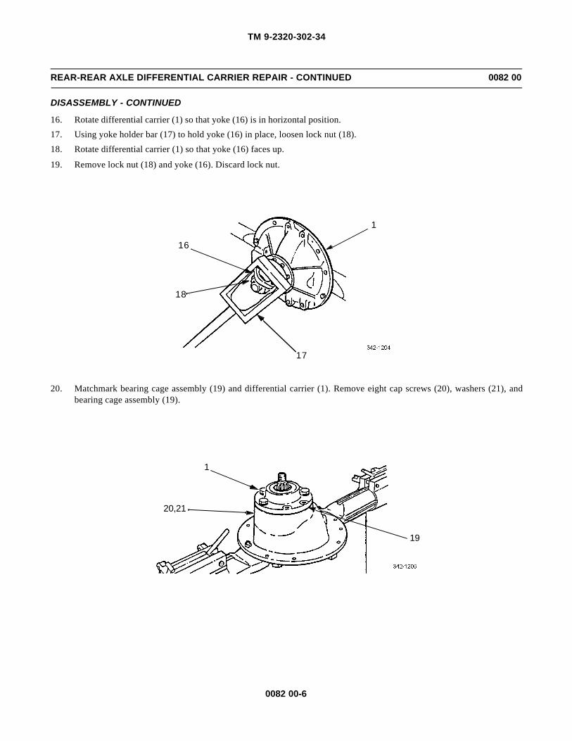
TM 9-2320-302-34
0082 00-6
REAR-REAR AXLE DIFFERENTIAL CARRIER REPAIR - CONTINUED 0082 00
DISASSEMBLY - CONTINUED
16. Rotate differential carrier (1) so that yoke (16) is in horizontal position.
17. Using yoke holder bar (17) to hold yoke (16) in place, loosen lock nut (18).
18. Rotate differential carrier (1) so that yoke (16) faces up.
19. Remove lock nut (18) and yoke (16). Discard lock nut.
20. Matchmark bearing cage assembly (19) and differential carrier (1). Remove eight cap screws (20), washers (21), andbearing cage assembly (19).
1
16
18
17
19
1
20,21
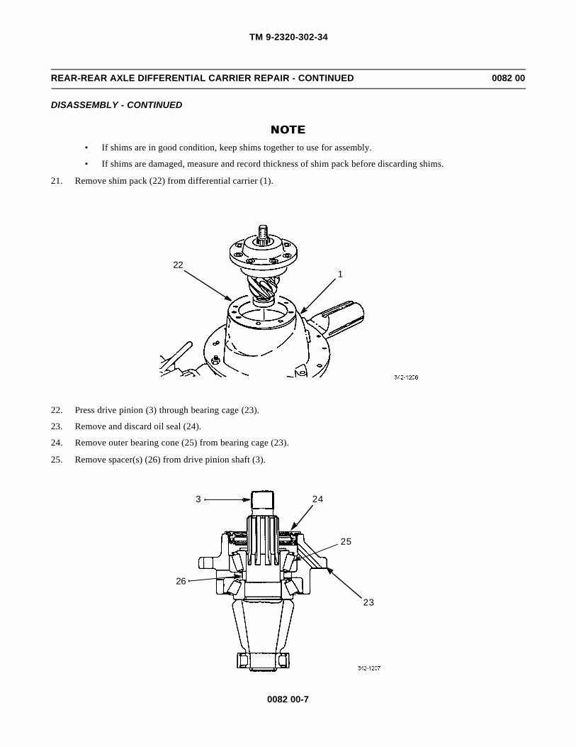
TM 9-2320-302-34
0082 00-7
REAR-REAR AXLE DIFFERENTIAL CARRIER REPAIR - CONTINUED 0082 00
DISASSEMBLY - CONTINUED
NOTENOTE• If shims are in good condition, keep shims together to use for assembly.
• If shims are damaged, measure and record thickness of shim pack before discarding shims.
21. Remove shim pack (22) from differential carrier (1).
22. Press drive pinion (3) through bearing cage (23).
23. Remove and discard oil seal (24).
24. Remove outer bearing cone (25) from bearing cage (23).
25. Remove spacer(s) (26) from drive pinion shaft (3).
122
3 24
25
23
26

TM 9-2320-302-34
0082 00-8
REAR-REAR AXLE DIFFERENTIAL CARRIER REPAIR - CONTINUED 0082 00
DISASSEMBLY - CONTINUED
26. Remove inner bearing cone (27) from drive pinion shaft (3).
27. Remove two bearing cups (28 and 29) from bearing cage (23).
28. Remove retaining ring (30) and spigot bearing (31).
327
28
23
29
31
30

TM 9-2320-302-34
0082 00-9
REAR-REAR AXLE DIFFERENTIAL CARRIER REPAIR - CONTINUED 0082 00
ASSEMBLY
1. Install bearing cups (28 and 29) in bearing cage (23).
NOTENOTEApply light coat of lubricating oil to all bearing cups and cones prior to installation.
2. Install inner bearing cone (27) on drive pinion shaft (3) until bearing cone is flat against drive pinion shaft gear head.
2823
29
273
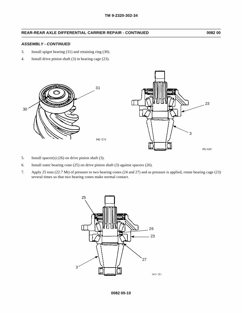
TM 9-2320-302-34
0082 00-10
REAR-REAR AXLE DIFFERENTIAL CARRIER REPAIR - CONTINUED 0082 00
ASSEMBLY - CONTINUED
3. Install spigot bearing (31) and retaining ring (30).
4. Install drive pinion shaft (3) in bearing cage (23).
5. Install spacer(s) (26) on drive pinion shaft (3).
6. Install outer bearing cone (25) on drive pinion shaft (3) against spacers (26).
7. Apply 25 tons (22.7 Mt) of pressure to two bearing cones (24 and 27) and as pressure is applied, rotate bearing cage (23)several times so that two bearing cones make normal contact.
31
3023
3
26
23
27
3
25

TM 9-2320-302-34
0082 00-11
REAR-REAR AXLE DIFFERENTIAL CARRIER REPAIR - CONTINUED 0082 00
ASSEMBLY - CONTINUED
NOTENOTETo perform steps 10 and 11, a 20 in (50.8 cm) piece of 14 gage wire must be used.
8. Maintain pressure and wrap 14 gage wire around bearing cage (23) several times.
NOTENOTEFor accuracy, reading must be taken while bearing cage is rotating.
9. Attach spring scale to end of wire and pull. As bearing cage (23) rotates, read and record value on scale.
10. Measure diameter of bearing cage (23) where wire was wrapped and divide measurement in half to determine radius.
23
23
MEASURE DIAMETEROF CAGE

TM 9-2320-302-34
0082 00-12
REAR-REAR AXLE DIFFERENTIAL CARRIER REPAIR - CONTINUED 0082 00
ASSEMBLY - CONTINUED
11. Multiply reading from step 9 by radius from step 10 to determine preload. New pinion drive gear preload must be 5-45lb-in (0.56-5.08 Nm). Used pinion drive gear preload must be 10-30 lb-in (1.13-3.39 Nm).
12. If preload is not within limits, install thicker spacer (26) to decrease preload or thinner spacer to increase preload.
13. Repeat steps 7 through 12 until correct preload is obtained.
14. Coat outside of new oil seal (24) and bore of bearing cage (23) with GAA.
26
24
23
APPLY GAA
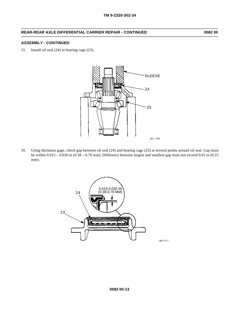
TM 9-2320-302-34
0082 00-13
REAR-REAR AXLE DIFFERENTIAL CARRIER REPAIR - CONTINUED 0082 00
ASSEMBLY - CONTINUED
15. Install oil seal (24) in bearing cage (23).
16. Using thickness gage, check gap between oil seal (24) and bearing cage (23) at several points around oil seal. Gap mustbe within 0.015 – 0.030 in (0.38 – 0.76 mm). Difference between largest and smallest gap must not exceed 0.01 in (0.25mm).
SLEEVE
24
23
23
240.015-0.030 IN(0.38-0.76 MM)

TM 9-2320-302-34
0082 00-14
REAR-REAR AXLE DIFFERENTIAL CARRIER REPAIR - CONTINUED 0082 00
ASSEMBLY - CONTINUED
NOTENOTE• If installing new ring gear and drive pinion, perform steps 19 through 24.
• Replace ring gear and drive pinion as matched set. Gear set match number is on gear head of drive pin-ion and front face or outer diameter of ring gear.
• Pinion cone variation number is used to adjust depth of pinion in differential carrier. Pinion cone varia-tion number is on end of gear head of drive pinion or outer diameter of ring gear.
17. Record new pinion cone variation number.
18. Record old pinion cone variation number.
19. If old pinion cone variation number is +, subtract number from shim pack thickness in disassembly step 21.
20. If old pinion cone variation number is -, add number to shim pack thickness in disassembly step 21.
21. If new pinion cone variation number is +, add number to shim pack thickness determined in step 19 or 20.
22. If new pinion cone variation number is -, subtract number form shim pack thickness determined in step 19 or 20.
NOTENOTE• If installing same ring gear and drive pinion, use shim pack removed in disassembly step 21.
• If installing new shim pack, use at least three shims with thickest shim in middle of pack.
23. Aline oil slots on shim pack (22) with oil slots on differential carrier (1) and install shim pack.
1
22

TM 9-2320-302-34
0082 00-15
REAR-REAR AXLE DIFFERENTIAL CARRIER REPAIR - CONTINUED 0082 00
ASSEMBLY - CONTINUED
24. Install bearing cage assembly (19) in differential carrier (1).
25. Install eight washers (21) and cap screws (20). Tighten cap screws to 74-96 lb-ft (100-130 Nm).
19
1
20,21

TM 9-2320-302-34
0082 00-16
REAR-REAR AXLE DIFFERENTIAL CARRIER REPAIR - CONTINUED 0082 00
ASSEMBLY - CONTINUED
26. Install yoke (16) and new lock nut (18).
27. Rotate differential carrier (1) so that yoke (16) is in horizontal position.
28. Using yoke holder bar (17) to hold yoke (16) in place, tighten lock nut (18) to 1000-1230 lb-ft (1356-1668 Nm).
29. Install ring gear (2) on ring gear subassembly (10).
30. Install 12 bolts (15), washers (14), and nuts (13). Tighten nuts to 190-225 lb-ft (258-305 Nm).
1
16
1718
13,14,15
10
2

TM 9-2320-302-34
0082 00-17
REAR-REAR AXLE DIFFERENTIAL CARRIER REPAIR - CONTINUED 0082 00
ASSEMBLY - CONTINUED
31. Install two bearing cones (12).
WARNINGWARNINGAdhesives and sealing compounds can burn easily, can give off harmful vapors, and are harmful to skin andclothing. To avoid injury or death keep away from open fire and use in well ventilated area. If adhesive orsealing compound contacts skin or clothing, wash immediately with soap and water.
CAUTIONCAUTIONEnsure all old adhesive has been removed from differential carrier and bearing caps to prevent damage toequipment.
32. Set two bearing caps (4 and 5) on differential carrier (1) and apply continuous bead of adhesive around entire smoothground surfaces on both sides. Do not apply adhesive to threaded areas.
33. Remove two bearing caps (4 and 5).
12
1
5
4

TM 9-2320-302-34
0082 00-18
REAR-REAR AXLE DIFFERENTIAL CARRIER REPAIR - CONTINUED 0082 00
ASSEMBLY - CONTINUED
34. Install two bearing cups (11).
35. Using suitable lifting device, install ring gear subassembly (10) in differential carrier (1).
36. Install two bearing caps (4 and 5), four cap screws (7), and washers (8).
NOTENOTEIf there is a problem performing step 37, tighten four cap screws to 10-20 lb-ft (14-27 Nm).
37. Install two adjusting rings (9) in differential carrier (1).
38. Tighten four cap screws (7) to 347-431 lb-ft (471-584 Nm).
39. Install dial indicator on flange of differential carrier (1) with plunger against back surface of ring gear (2).
11
1110
1
5
2
1
7,8
4
9
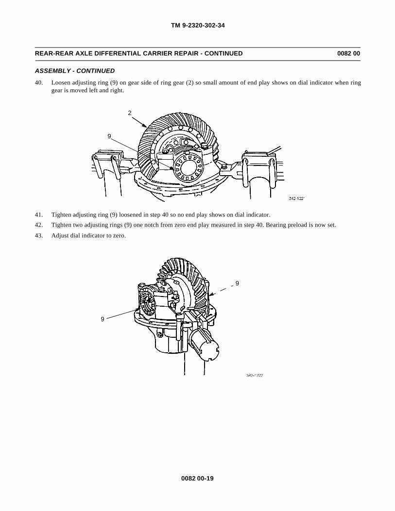
TM 9-2320-302-34
0082 00-19
REAR-REAR AXLE DIFFERENTIAL CARRIER REPAIR - CONTINUED 0082 00
ASSEMBLY - CONTINUED
40. Loosen adjusting ring (9) on gear side of ring gear (2) so small amount of end play shows on dial indicator when ringgear is moved left and right.
41. Tighten adjusting ring (9) loosened in step 40 so no end play shows on dial indicator.
42. Tighten two adjusting rings (9) one notch from zero end play measured in step 40. Bearing preload is now set.
43. Adjust dial indicator to zero.
2
9
9
9

TM 9-2320-302-34
0082 00-20
REAR-REAR AXLE DIFFERENTIAL CARRIER REPAIR - CONTINUED 0082 00
ASSEMBLY - CONTINUED
44. Rotate ring gear (2) while reading dial indicator; runout must not exceed 0.008 in (0.200 mm).
45. If runout is exceeded, perform disassembly steps 9 through 11.
46. Inspect all ring gear subassembly (10) parts and differential carrier (1) for possible excessive runout caused. Replacedefective part(s).
47. Repeat steps 36 through 46.
48. Attach dial indicator on mounting flange of differential carrier (1) so that plunger is against tooth surface on drive sideof ring gear (2) and zero indicator.
NOTENOTEMove ring gear only when adjusting backlash.
49. While holding drive pinion shaft (3) in position, rotate ring gear (2) slightly in both directions against drive pinion shaft.Note measurement.
NOTENOTE• If same ring gear and drive pinion have been installed, adjust backlash to setting recorded in disassem-
bly, step 5.
• If new ring gear and drive pinion have been installed, adjust backlash to 0.012 in (0.305 mm).
50. If backlash measurement is less than specified, loosen adjusting ring (9) on back surface of ring gear (2) and equallytighten adjusting ring (9) on tooth side of ring gear. Repeat step 49.
51. If backlash measurement is more than specified, loosen adjusting ring (9) on tooth side of ring gear (2) and equallytighten adjusting ring (9) on back surface of ring gear. Repeat step 49.
52. Repeat steps 49 through 51 until backlash meets specification. Record setting for use when adjusting pinion bearing pre-load.
2
1
10

TM 9-2320-302-34
0082 00-21
REAR-REAR AXLE DIFFERENTIAL CARRIER REPAIR - CONTINUED 0082 00
ASSEMBLY - CONTINUED
NOTENOTEAlways check tooth contact pattern on drive side of ring gear teeth.
53. Apply Prussian blue dye to approximately 12 teeth of ring gear (2). Rotate ring gear so marked gear teeth are next todrive pinion shaft (3).
54. To get contact pattern, rotate ring gear (2) forward and backward until marked gear teeth go past drive pinion shaft (3)six times. Repeat, if needed, for clearer pattern.
9
9
3
2
1
2
3

TM 9-2320-302-34
0082 00-22
REAR-REAR AXLE DIFFERENTIAL CARRIER REPAIR - CONTINUED 0082 00
ASSEMBLY - CONTINUED
NOTENOTE• Location of good hand-rolled contact pattern for new gear set is toward toe of gear tooth and in center
between top and bottom of tooth.
• Location of good hand-rolled contact pattern of used gear set must match wear pattern in ring gear. Con-tact pattern will be smaller than wear pattern.
• During tooth contact pattern checks, backlash can be adjusted within specification limits, if needed, tochange pattern location.
55. Compare contact pattern with examples shown.
56. If contact pattern requires adjustment, perform disassembly steps 16 through 21.
57. Perform steps 23 through 28 and 53 through 55.
a. To correct high contact pattern, decrease thickness of shim pack (22).
b. To correct low contact pattern, increase thickness of shim pack (22).
GOOD HAND-ROLLED PATTERN HIGH PATTERN LOW PATTERN
22

TM 9-2320-302-34
0082 00-23
REAR-REAR AXLE DIFFERENTIAL CARRIER REPAIR - CONTINUED 0082 00
ASSEMBLY - CONTINUED
58. If contact pattern is too far toward heel of tooth, repeat step 50.
59. If contact pattern is too far toward toe of tooth, repeat step 51.
60. Install two pins (6) between lugs of two adjusting rings (9).
61. Install rear-rear axle differential carrier (WP 0081 00).
END OF WORK PACKAGE
6
9

TM 9-2320-302-34
0082 00-24
This Page Intentionally Left Blank.

TM 9-2320-302-34
0083 00-1
FOOT BRAKE VALVE REPAIR 0083 00
THIS WORK PACKAGE COVERS
Disassembly, Assembly
INITIAL SETUP
Tools and Special Tools
Tool kit, general mechanic’s (Item 132, WP 0126 00)
Caps, vise jaw (Item 17, WP 0126 00)
Vise, machinist’s (Item 136, WP 0126 00)
Materials/Parts
Kit, repair (P/N 82TV196)
Washer, lock (P/N 202981) (4)
Grease, aircraft (Item 21, WP 0125 00)
Equipment Condition
Foot brake valve removed (TM 9-2320-302-20)
DISASSEMBLYNOTENOTE
• To assist in disassembly, place foot brake valve in a soft-jawed vise.
• Discard all components of repair kit.
1. Remove screw (1), washer (2), and diaphragm (3) from cover (4).
2. Remove four screws (5), lock washers (6), and cover (4) from lower body (7).
3. Remove valve (8) assembly from lower body (7).
7
8
12
3
46
5

TM 9-2320-302-34
0083 00-2
FOOT BRAKE VALVE REPAIR - CONTINUED 0083 00
DISASSEMBLY - CONTINUED
NOTENOTEPerform steps 4 and 5 to disassemble valve assembly.
4. While holding valve (8) assembly in collapsed position, remove retaining ring (9) from valve.
5. Release washer (10) and remove washer, retainer (11), spring (12), and seat (13) from valve (8). Remove two preformedpackings (14 and 15) from retainer.
6. Remove four screws (16), lock washers (17), and lower body (7) from upper body (18). Remove preformed packing (19)from lower body.
7. Remove primary piston retainer (20) from upper body (18).
9
10 15
14
1312
11
8

TM 9-2320-302-34
0083 00-3
FOOT BRAKE VALVE REPAIR - CONTINUED 0083 00
DISASSEMBLY - CONTINUED
16
17
7
20
18
19

TM 9-2320-302-34
0083 00-4
FOOT BRAKE VALVE REPAIR - CONTINUED 0083 00
DISASSEMBLY - CONTINUED
WARNINGWARNINGInternal components are under spring pressure. Use care when disassembling. Failure to hold components inposition may result in injury to personnel.
8. While holding primary piston (21) and piston (22) in position in upper body (18), use a screwdriver in head of screw(23) to prevent screw from turning.
9. Remove lock nut (24), retainer (25), and spring (26) from screw (23). Remove screwdriver and gradually release pri-mary piston (21) and piston (22).
10. Remove primary piston (21) and spring (27) from upper body (18). Remove preformed packing (28) and rubber washer(29) from primary piston.
11. Remove sleeve nut (30), spring seat (31), and rubber spring (32) from primary piston (21).
12. Remove screw (23), piston (22), spring (33), and retainer (34) from upper body (18). Remove two preformed packings(35 and 36) from piston.
NOTENOTEStep 13 removes valve assembly from upper body.
13. Remove retaining ring (37), retaining clip (38), washer (39), retainer (40), preformed packing (41), spring (42), seat(43), and valve (44) from upper body (18).
2425
26
27
28
21
32
3130
29
2223
18

TM 9-2320-302-34
0083 00-5
FOOT BRAKE VALVE REPAIR - CONTINUED 0083 00
DISASSEMBLY - CONTINUED
ASSEMBLY
NOTENOTE• To assist in assembly, place foot brake valve in a soft-jawed vise.
• Install new repair kit parts on assembly.
1. Apply a light coating of grease to surfaces of preformed packings, preformed packing grooves and piston bores of upperbody (18).
NOTENOTEPerform step 2 to install valve assembly to upper body.
2. Install valve (44), seat (43), spring (42), preformed packing (41), retainer (40), washer (39), and retaining clip (38) toupper body (18) with retaining ring (37).
3. Install two preformed packings (35 and 36) to piston (22). Install retainer (34), spring (33), piston (22), and screw (23)to upper body (18).
41
39
37
38
34
33
35
22
36
23
18
44
43
42
40

TM 9-2320-302-34
0083 00-6
FOOT BRAKE VALVE REPAIR - CONTINUED 0083 00
ASSEMBLY - CONTINUED
4. Install rubber spring (32) and spring seat (31) to primary piston (21) with sleeve nut (30).
5. Install rubber washer (29) and preformed packing (28) to primary piston (21). Install spring (27) and primary piston toupper body (18).
WARNINGWARNINGInternal components are under spring pressure. Use care when assembling. Failure to hold components inposition may result in injury to personnel.
6. While holding primary piston (21) and piston (22) compressed, and using a screwdriver to prevent screw (23) from turn-ing, install spring (26) and retainer (25) to screw with lock nut (24).
7. Install primary piston retainer (20) to upper body (18).
8. Install preformed packing (19) to lower body (7) and install lower body to upper body (18) with four lock washers (17)and screws (16).
2425
26
27
28
21
32
3130
29
2223
18

TM 9-2320-302-34
0083 00-7
FOOT BRAKE VALVE REPAIR - CONTINUED 0083 00
ASSEMBLY - CONTINUED
16
17
7
20
18
19

TM 9-2320-302-34
0083 00-8
FOOT BRAKE VALVE REPAIR - CONTINUED 0083 00
ASSEMBLY - CONTINUED
9. Install two preformed packings (14 and 15) to retainer (11) and install seat (13), spring (12), retainer, and washer (10) tovalve (8) with retaining ring (9).
10. Install valve (8) assembly to lower body (7).
11. Install cover (4) to lower body (7) with four lock washers (6) and screws (5).
12. Install diaphragm (3) to cover (4) with washer (2) and screw (1).
13. Install foot brake valve (TM 9-2320-302-20).
END OF WORK PACKAGE
7
8
9
10
1 2
3
4
15
14
1312
11
6
5

TM 9-2320-302-34
0084 00-1
AIR COMPRESSOR REPAIR 0084 00
THIS WORK PACKAGE COVERS
Disassembly, Inspection, Assembly
INITIAL SETUP
Maintenance Level
Direct Support
Tools and Special Tools
Tool kit, general mechanic’s (Item 132, WP 0126 00)
Plate, cover (WP 0122 00)
Caps, vise jaw (Item 17, WP 0126 00)
Inserter and remover (Item 51, WP 0126 00)
Pliers, retaining ring (Item 89, WP 0126 00)
Press, arbor (Item 90, WP 0126 00)
Vise, machinist’s (Item 136, WP 0126 00)
Wrench, torque, 0-300 lb-in (Item 137, WP 0126 00)
Wrench, torque, 15-75 lb-ft (Item 138, WP 0126 00)
Wrench, torque, 50-250 lb-ft (Item 139, WP 0126 00)
Materials/Parts
Crankshaft bearing kit (P/N 107969)
Cylinder head maintenance kit (107516)
Piston and rod kit (P/N 108842)
Piston ring kit (P/N 107639)
Unloader kit (P/N 107515)
Oil, lubricating (Item 25, WP 0125 00)
Tags, marker (Item 35, WP 0125 00)
Equipment Condition
Air compressor removed (TM 9-2320-302-20)
Governor removed (TM 9-2320-302-20)
DISASSEMBLY
1. If installed, remove two gaskets (1 and 2). Discard gaskets.
21

TM 9-2320-302-34
0084 00-2
AIR COMPRESSOR REPAIR - CONTINUED 0084 00
DISASSEMBLY - CONTINUED
2. Engage teeth (3) of cover plate (4) with air compressor drive (5). Align spacer legs of cover plate with mounting boltholes in flange face of air compressor (6). Install two bolts (7), nuts (8), and cover plate on flange face of air compressor.
3. Secure air compressor (6) in soft-jawed vise and remove drive hub retaining bolt (9).
4. Remove two nuts (8), bolts (7), and cover plate (4).
5. Remove drive hub (10) and drive gear (5) from crankshaft.
6. Remove four bolts (11) from drive hub (10) and drive gear (5).
7. Remove air compressor (6) from vise.
NOTENOTEIt may be necessary to tap cylinder head with fiber or plastic mallet to break cylinder head gasket seal.
7
6
4
5
3
8
67
8
9
4

TM 9-2320-302-34
0084 00-3
AIR COMPRESSOR REPAIR - CONTINUED 0084 00
DISASSEMBLY - CONTINUED
8. Remove six bolts (12), cylinder head (13), and cylinder head gasket (14). Discard gasket.
WARNINGWARNINGUnloader cover plate is under spring tension. Use care when removing bolts securing unloader cover plate toprevent injury to personnel.
9. Place cylinder head (13) on bench, deck side down, and remove four bolts (15) and lock washers (16). Discard lockwashers.
10. Remove unloader cover plate (17) and gasket (18). Discard gasket.
11. Remove unloader piston (19), seal ring (20), and unloader spring (21) from each bore.
6
14
1312
10
5
11
15 1617
18
2019
21
13

TM 9-2320-302-34
0084 00-4
AIR COMPRESSOR REPAIR - CONTINUED 0084 00
DISASSEMBLY - CONTINUED
12. Place cylinder head (13) on bench, deck side up, and insert inserter and remover tool (22) in inlet valve stop (23).Remove inlet valve stop.
13. Remove inlet valve spring (24), inlet valve (25), inlet valve seat (26), and copper gasket (27) from bore. Discard gasket.
14. Repeat step 12 and 13 for second valve stop (23).
15. Remove two discharge valve seats (28).
16. Remove two discharge valves (29) and springs (30) from bores of cylinder head (13).
17. Remove six bolts (31), crankcase cover (32), and gasket (33). Discard gasket.
18. Rotate crankshaft (34) until connecting rod and piston assembly (35) is at bottom of travel.
22
23
24
26
2525
2727
13
26
23
24
28
29
30
13
30
29

TM 9-2320-302-34
0084 00-5
AIR COMPRESSOR REPAIR - CONTINUED 0084 00
DISASSEMBLY - CONTINUED
CAUTIONCAUTIONConnecting rod caps are not interchangeable and must be kept with connecting rods to prevent damage toequipment.
19. Remove two connecting rod bolts (36), connecting rod cap (37), and lower bearing insert (38). Discard bearing insert.
CAUTIONCAUTIONMark or tag pistons and note location in air compressor prior to removal to prevent premature air compressorfailure.
20. Remove connecting rod and piston assembly (35) from cylinder bore.
21. Remove upper bearing insert (39) from connecting rod (40). Discard bearing insert.
635
34
38
37
36
33
32
31
35
39
40

TM 9-2320-302-34
0084 00-6
AIR COMPRESSOR REPAIR - CONTINUED 0084 00
DISASSEMBLY - CONTINUED
22. Push wrist pin (41) out of piston (42) and connecting rod (40).
23. Pull plastic wrist pin button (43) from each end of wrist pin (41).
24. Remove three piston rings (44).
25. Remove four oil control rings (45) and two oil ring expanders (46).
26. Remove four bolts (47) and rear cover (48).
27. Remove seal ring (49) from groove in rear cover (48).
28. Press crankshaft (34) out of ball bearing (50) to rear and remove.
29. Remove retaining ring (51).
CAUTIONCAUTIONUse care when removing crankshaft ball bearing to prevent damage to bearing bore.
30. Using brass drift and hammer, remove ball bearing (50) by tapping around inside edge and driving ball bearing towardair compressor mounting flange (52).
31. Using brass drift and hammer, remove crankshaft rear sleeve bearing (53) by tapping around inside edge of sleeve anddriving sleeve bearing away from rear cover (48).
44
4546
43
41
42
43
44
4645
40

TM 9-2320-302-34
0084 00-7
AIR COMPRESSOR REPAIR - CONTINUED 0084 00
DISASSEMBLY - CONTINUED
INSPECTION
Inspect crankshaft for galling, pitting, cracks or other damage. Replace if damaged.
ASSEMBLY
1. Position rear cover (48) face down on press bed.
NOTENOTEEnsure slot in bearing is lined up with oil passage in rear cover.
2. Position crankshaft rear sleeve bearing (53) in bore of rear cover (48) with slot in bearing lined up with oil passage.
3. Press crankshaft rear sleeve bearing (53) in bore of rear cover (48) until flush.
48
47
53
49
34
51
50
52
53
48
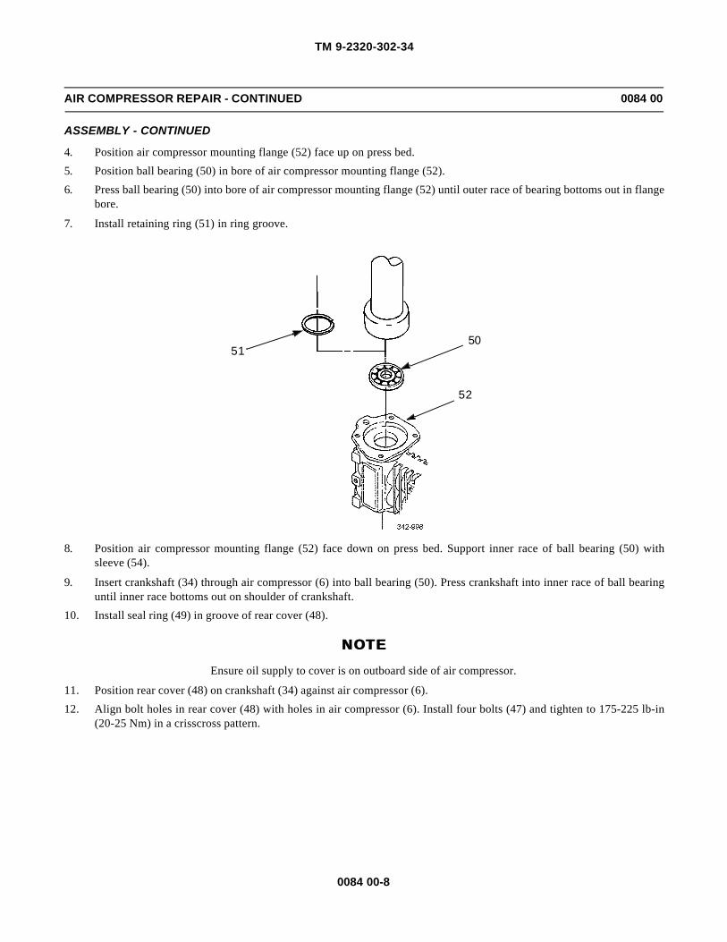
TM 9-2320-302-34
0084 00-8
AIR COMPRESSOR REPAIR - CONTINUED 0084 00
ASSEMBLY - CONTINUED
4. Position air compressor mounting flange (52) face up on press bed.
5. Position ball bearing (50) in bore of air compressor mounting flange (52).
6. Press ball bearing (50) into bore of air compressor mounting flange (52) until outer race of bearing bottoms out in flangebore.
7. Install retaining ring (51) in ring groove.
8. Position air compressor mounting flange (52) face down on press bed. Support inner race of ball bearing (50) withsleeve (54).
9. Insert crankshaft (34) through air compressor (6) into ball bearing (50). Press crankshaft into inner race of ball bearinguntil inner race bottoms out on shoulder of crankshaft.
10. Install seal ring (49) in groove of rear cover (48).
NOTENOTEEnsure oil supply to cover is on outboard side of air compressor.
11. Position rear cover (48) on crankshaft (34) against air compressor (6).
12. Align bolt holes in rear cover (48) with holes in air compressor (6). Install four bolts (47) and tighten to 175-225 lb-in(20-25 Nm) in a crisscross pattern.
5051
52
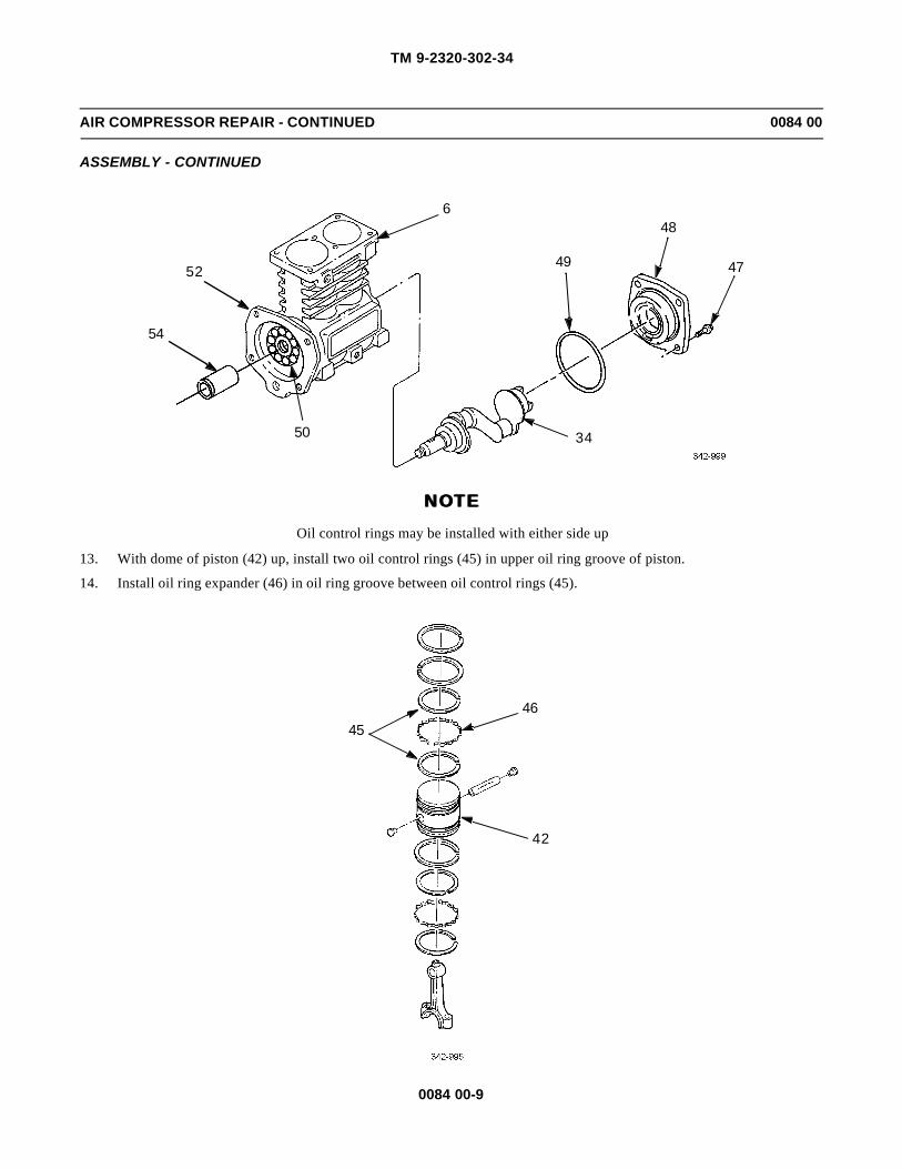
TM 9-2320-302-34
0084 00-9
AIR COMPRESSOR REPAIR - CONTINUED 0084 00
ASSEMBLY - CONTINUED
NOTENOTEOil control rings may be installed with either side up
13. With dome of piston (42) up, install two oil control rings (45) in upper oil ring groove of piston.
14. Install oil ring expander (46) in oil ring groove between oil control rings (45).
648
49 47
34
54
52
50
4546
42

TM 9-2320-302-34
0084 00-10
AIR COMPRESSOR REPAIR - CONTINUED 0084 00
ASSEMBLY - CONTINUED
CAUTIONCAUTIONDot appearing on one side of second and top piston rings, 30 degrees from ring gap, indicates top of secondand top piston rings. Top of second and top piston rings must be installed facing piston dome to preventdamage to equipment.
15. Install second and top piston rings (44) in top two ring grooves of piston (42).
CAUTIONCAUTIONDot appearing on one side of third piston ring, 30 degrees from ring gap, indicates top of third piston ring.Top of third piston ring must be installed facing piston dome to prevent damage to equipment.
16. Install third piston ring (44) in top groove of lower ring grooves on piston (42).
17. Install two oil control rings (45) in bottom oil ring groove on piston (42).
18. Install oil ring expander (46) in groove between oil control rings (45).
19. Position connecting rod (40) and insert wrist pin (41) through piston (42) to connecting rod bore in opposite side of pis-ton.
20. Center wrist pin (41) and push plastic wrist pin button (43) in each end of wrist pin.
44
43
41
42
43
44
4645
40

TM 9-2320-302-34
0084 00-11
AIR COMPRESSOR REPAIR - CONTINUED 0084 00
ASSEMBLY - CONTINUED
CAUTIONCAUTIONTangs on one end of connecting rod upper bearing insert must be installed in corresponding notches on sideof connecting rod bearing saddle to prevent damage to equipment.
21. Install new upper bearing insert (39) in connecting rod (40) bearing saddle.
22. Stagger piston ring gap, two oil control ring gaps, and oil expander ring gap 90 degrees from each other, as shown.
39
40
OILCONTROL
RING
PISTONRINGOIL
EXPANDER
OILCONTROL
RING

TM 9-2320-302-34
0084 00-12
AIR COMPRESSOR REPAIR - CONTINUED 0084 00
ASSEMBLY - CONTINUED
23. Coat connecting rod and piston assembly (35) liberally with clean engine lubricating oil and insert in ring compressor(55).
24. Apply a film of clean engine lubricating oil to surface of connecting rod upper bearing insert (39) and insert connectingrod and piston assembly (35) in cylinder bore.
25. Position crankshaft (34) with journal at bottom of its travel.
CAUTIONCAUTIONTo prevent damage to crankshaft, use care to guide connecting rod on crankshaft journal when pushing pis-ton assembly in cylinder bore. Pistons must be installed in same location. Failure to do so could result in pre-mature air compressor failure.
26. With ring compressor (55) square against top of air compressor (6) body, push connecting rod and piston assembly (35)into cylinder bore.
CAUTIONCAUTIONTangs on one end of connecting rod lower bearing insert must be installed in corresponding notches on sideof connecting rod bearing saddle to prevent damage to equipment.
27. Install new connecting rod lower bearing insert (38) in connecting rod cap (37).
28. Apply a film of clean engine lubricating oil to connecting rod lower bearing insert (38).
6
35
55
39

TM 9-2320-302-34
0084 00-13
AIR COMPRESSOR REPAIR - CONTINUED 0084 00
ASSEMBLY - CONTINUED
CAUTIONCAUTIONConnecting rod bearing insert tangs should be on same side of connecting rod and connecting rod cap to pre-vent damage to equipment. Ensure connecting rod is fully seated on crankshaft journal to prevent damage toequipment.
29. Position connecting rod cap (37) on connecting rod so that wide ear on connecting rod cap matches corresponding earon connecting rod.
30. Install two connecting rod bolts (36) and tighten to 80-100 lb-in (9-11 Nm).
31. Position new gasket (33) and crankcase cover (32) on bottom of air compressor (6) body.
32. Install six bolts (31) and tighten to 175-228 lb-in (20-25 Nm).
635
34
38
37
36
33
32
31

TM 9-2320-302-34
0084 00-14
AIR COMPRESSOR REPAIR - CONTINUED 0084 00
ASSEMBLY - CONTINUED
33. Support cylinder head (13) on bench, deck side up, and install new copper gasket (27) in bore.
34. Install inlet valve seat (26) in bore with raised side of valve seat toward deck of cylinder head (13).
NOTENOTEEnsure inlet valve is centered on inlet valve seat.
35. Install inlet valve (25) on top of inlet valve seat (26).
NOTENOTEEnsure inlet valve spring is centered on inlet valve.
36. Install inlet valve spring (24) on top of inlet valve (25).
37. Thread inlet valve stop (23) carefully into cylinder head (13) until inlet valve spring (24) is seated on inlet valve stop.
38. Using insert inserter and remover tool (22), tighten inlet valve stop (23) to 70-90 lb-ft (95-122 Nm).
39. Repeat step 33 through 38 for other cylinder head bore.
40. Insert discharge valve spring (30) in discharge valve bore.
41. Place discharge valve (29) on top of discharge valve spring (30) and center in discharge valve bore.
42. Thread discharge valve seat (28) carefully into cylinder head (13) until discharge valve (29) is seated.
43. Tighten discharge valve seat (28) to 70-90 lb-ft (95-122 Nm).
44. Repeat step 40 through 43 for other discharge valve bore
22
23
24
26
2525
2727
13
26
23
24

TM 9-2320-302-34
0084 00-15
AIR COMPRESSOR REPAIR - CONTINUED 0084 00
ASSEMBLY - CONTINUED
45. Install seal ring (20) between raised lands on unloader piston (19).
46. Install unloader spring (21) on opposite end of unloader piston (19).
47. Support cylinder head (13) on bench, deck side down, and install long end of unloader piston (19) assembly in unloaderbore.
48. Repeat steps 45 through 47 for second unloader piston.
28
29
30
13
30
29
2019
21
13

TM 9-2320-302-34
0084 00-16
AIR COMPRESSOR REPAIR - CONTINUED 0084 00
ASSEMBLY - CONTINUED
NOTENOTEEnsure old gasket material is removed from mating surfaces of unloader cover plate and cylinder head.
49. Position new gasket (18) on cylinder head (13) and align bolt holes in gasket with bolt holes in cylinder head.
CAUTIONCAUTIONEnsure seal rings are not cut when pressing unloader pistons in bores, to prevent damage to equipment. DONOT allow old gasket material to drop in bores, to prevent damage to equipment.
50. Position unloader cover plate (17) on top of exposed unloader pistons (19). Press unloader cover plate carefully to pressunloader pistons in bores.
51. Hold down unloader cover plate (17) and install four new lock washers (16) and bolts (15). Tighten bolts to 175-225 lb-in (20-25 Nm).
NOTENOTE• If beaded cylinder head gasket is used, install gasket with bead side toward cylinder head. Unbeaded
cylinder head gasket can be installed with either side up.
• Ensure old gasket material is removed from mating surfaces of cylinder head and air compressor body.
52. Position new cylinder head gasket (14) on deck of air compressor (6).
NOTENOTECylinder head should be positioned with air inlet and discharge flange on right side of air compressor whenviewed from rear.
53. Position cylinder head (13) on air compressor (6).
54. Install six bolts (12) and tighten bolts to 25-30 lb-ft (34-41 Nm).
15 1617
18
19
13

TM 9-2320-302-34
0084 00-17
AIR COMPRESSOR REPAIR - CONTINUED 0084 00
ASSEMBLY - CONTINUED
55. Attach drive hub (10) to drive gear (5) and secure with four bolts (11). Tighten bolts to 43-54 lb-ft (58-73 Nm).
56. Position drive hub (10) and drive gear (5) on crankshaft and ball bearing.
57. Engage teeth (3) of cover plate (4) with teeth in drive gear (5). Align spacer legs of cover plate with mounting bolt holesin flange face of air compressor (6). Secure cover plate to air compressor with two bolts (7) and nuts (8).
6
14
1312
10
5
11
7
6
4
5
3
8

TM 9-2320-302-34
0084 00-18
AIR COMPRESSOR REPAIR - CONTINUED 0084 00
ASSEMBLY - CONTINUED
58. Secure air compressor (6) in soft-jawed vise and install drive hub retaining bolt (9). Tighten bolt to 220-255 lb-ft (298-346 Nm).
59. Remove two nuts (8), bolts (7), and cover plate (4).
60. Install two new gaskets (1 and 2).
61. Install governor (TM 9-2320-302-20).
62. Install air compressor (TM 9-2320-302-20).
END OF WORK PACKAGE
67
8
9
4
21

TM 9-2320-302-34
0085 00-1
BRAKE DRUM REPAIR 0085 00
THIS WORK PACKAGE COVERS
Repair
INITIAL SETUP
Maintenance Level
Direct Support
Tools and Special Tools
Tool kit, general mechanic’s (Item 132, WP 0126 00)
Lathe, brake drum (Item 74, WP 0126 00)
Materials/Parts
Cloth, abrasive (Item 9, WP 0125 00)
Equipment Condition
Brake drum removed from vehicle (TM 9-2320-302-20)
REPAIR
CAUTIONCAUTIONIf maximum inside diameter is exceeded, to prevent damage to equipment, brake drum must be replaced.
1. Check brake drum inside diameter. Refer to Table 1 for diameter.
2. Brake drum (1) must be round within 0.003 in (0.076 mm). If brake drum is out-of-round, machine brake drum. Refer toTable 1 for machining specifications.
3. Check brake drum surface (2) for cracks or badly scored finish. If brake drum is cracked or scored, machine brake drum.Refer to Table 1 for machining specifications.
4. Check brake drum surface (2) for glossy or heat spots. If glossy or heat spots are visible, clean brake drum surface withabrasive cloth.
5. Check brake drum (1) for external or mating surface cracks. If cracks are visible, replace brake drum.
6. Check brake drum (1) for balance weight. If balance weight is missing, replace brake drum.
1
2

TM 9-2320-302-34
0085 00-2
BRAKE DRUM REPAIR - CONTINUED 0085 00
REPAIR - CONTINUED
Table 1. Machining Specifications.
7. Install brake drum (TM 9-2320-302-20).
END OF WORK PACKAGE
INSIDE DIAMETER (NEW)IN (MM)
MACHINE BRAKE DRUMIN (MM)
MAXIMUM INSIDE DIAMETER
IN (MM)
M915A3 FRONT 15.0 (381.0) 0.12 (4.00) 15.12 (384.00)
M915A3 REAR 16.5 (419.1) 0.12 (4.00) 16.62 (422.15)

TM 9-2320-302-34
0086 00-1
POWER STEERING PUMP REPLACEMENT 0086 00
THIS WORK PACKAGE COVERS
Removal, Installation
INITIAL SETUP
Maintenance Level
Direct Support
Tool and Special Tools
Tool kit, general mechanic’s (Item 132, WP 0126 00)
Wrench, torque, 15-75 lb-ft (Item 138, WP 0126 00)
Materials/Parts
Seal, o-ring (P/N 8929318)
Washer, lock (P/N 000127 008203) (6)
Materials/Parts - Continued
Oil, lubricating (Item 25, WP 0125 00)
References
TM 9-2320-302-10
Equipment Condition
Power steering reservoir drained (TM 9-2320-302-20)
REMOVAL
1. Remove hose clamp (1), hose (2), and adapter (3) from power steering pump (4).
2. Remove power steering line (5) and elbow (6) from power steering pump (4).
3. Remove six screws (7) and lock washers (8) securing power steering pump (4) to gear case cover (9). Discard lockwashers.
4. Pull power steering pump (4), o-ring seal (10), and gear coupling (11) from gear case cover (9). Discard o-ring seal.
11 10
31
2
5
78
649

TM 9-2320-302-34
0086 00-2
POWER STEERING PUMP REPLACEMENT - CONTINUED 0086 00
INSTALLATION
NOTENOTEApply a light coating of lubricating oil to seal prior to installation
1. Install gear coupling (11) and new o-ring seal (10) on power steering pump (4).
2. Position power steering pump (4) on gear case cover (9) and secure with six screws (7) and new lock washers (8).Tighten screws to 17-25 lb-ft (23-34 Nm).
3. Install elbow (6) and power steering line (5).
4. Install adapter (3), hose (2), and hose clamp (1).
5. Fill power steering reservoir (TM 9-2320-302-20).
6. Start vehicle (TM 9-2320-302-10) and check system for leaks.
END OF WORK PACKAGE
11 10
31
2
5
78
649
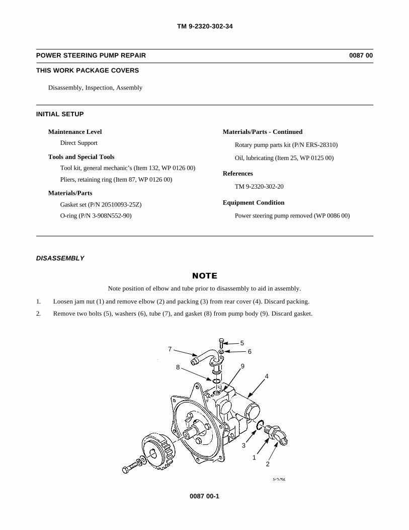
TM 9-2320-302-34
0087 00-1
POWER STEERING PUMP REPAIR 0087 00
THIS WORK PACKAGE COVERS
Disassembly, Inspection, Assembly
INITIAL SETUP
Maintenance Level
Direct Support
Tools and Special Tools
Tool kit, general mechanic’s (Item 132, WP 0126 00)
Pliers, retaining ring (Item 87, WP 0126 00)
Materials/Parts
Gasket set (P/N 20510093-25Z)
O-ring (P/N 3-908N552-90)
Materials/Parts - Continued
Rotary pump parts kit (P/N ERS-28310)
Oil, lubricating (Item 25, WP 0125 00)
References
TM 9-2320-302-20
Equipment Condition
Power steering pump removed (WP 0086 00)
DISASSEMBLY
NOTENOTENote position of elbow and tube prior to disassembly to aid in assembly.
1. Loosen jam nut (1) and remove elbow (2) and packing (3) from rear cover (4). Discard packing.
2. Remove two bolts (5), washers (6), tube (7), and gasket (8) from pump body (9). Discard gasket.
8
75
6
94
3
12

TM 9-2320-302-34
0087 00-2
POWER STEERING PUMP REPAIR - CONTINUED 0087 00
DISASSEMBLY - CONTINUED
3. Remove screw (10)and two washers (11 and 12) from shaft (13).
4. Remove gear (14) from shaft (13).
5. Remove woodruff key (15) from shaft (13).
NOTENOTENote position of flange prior to disassembly to aid in assembly.
6. Remove three screws (16), flange (17), and gasket (18) from pump body (9). Discard gasket.
7. Remove five screws (19) and rear cover (4) from pump body (9).
8. Remove and discard large packing (20) and small packing (21) from pump body (9).
9. Remove valve cap (22), packing (23), spring (24), and valve (25) from rear cover (4). Discard packing.
10. If damaged, remove and discard two guide pins (26) from rear cover (4).
111012
1413
15

TM 9-2320-302-34
0087 00-3
POWER STEERING PUMP REPAIR - CONTINUED 0087 00
DISASSEMBLY - CONTINUED
16
1718
920
26
21
4
2423
22
25
26
19

TM 9-2320-302-34
0087 00-4
POWER STEERING PUMP REPAIR - CONTINUED 0087 00
DISASSEMBLY - CONTINUED
11. Remove shaft (13) from pump body (9).
NOTENOTEEnsure locating pin position is marked to aid in assembly.
12. Remove ten rollers (27), cam (28), port plate (29), two seals (30), two O-rings (31), locating pin (32), and end plate (33)from pump body (9). Discard rollers, cam, port plate, seals, o-rings, and locating pin.
13. Remove two snap rings (34), carrier (35), and drive pin (36) from shaft (13). Discard carrier and drive pin.
14. Remove and discard two seals (37 and 38) from pump body (9).
INSPECTION
1. Inspect shaft for wear, burning, and scoring in areas of bushings, oil seals, and spline drive. If found, replace shaft.
2. If pump has been disassembled because of hard steering, and no other parts show any wear or damage, replace valve andspring.
ASSEMBLY
NOTENOTECoat all interior components with a light coat of clean engine lubricating oil prior to assembly.
1. Install new seal (37), with lip facing bushing, until seal is seated against inside lip of pump body (9).
2. Install new seal (38), with lip facing outward, until seal is seated against seal (37).
3. Install new drive pin (36), new carrier (35) and two snap rings (34) on shaft (13).
4. Install two new o-rings (31) and two new seals (30) in end plate (33).
3837
933
31 30
2913
28
36 27
34
35
34
LOCATING PINLOCATION
32

TM 9-2320-302-34
0087 00-5
POWER STEERING PUMP REPAIR - CONTINUED 0087 00
ASSEMBLY - CONTINUED
5. Install end plate (33) on pump body (9) with two seals (30) facing up.
CAUTIONCAUTION
Failure to install locating pin in correct position may cause pump to operate in reverse, which could result in equip-ment damage.
6. Install new locating pin (32) in lower left hole of end plate (33).
NOTENOTE
If seals can be seen, port plate must be reversed.
7. Install new port plate (29) and new cam (28) with arrow on cam pointing up toward locating pin (32).
8. Install shaft (13) and ten new rollers (27).
9. If removed, install two new guide pins (26) in rear cover (4).
10. Install valve (25), spring (24), new packing (23), and valve cap (22).
11. Install new small packing (21) and new large packing (20) in pump body (9).
12. Install cover (4) and secure to pump body (9) with five screws (19).
13. Install new gasket (18) on pump body (9).
14. Install flange (17), as noted during disassembly, and secure with three screws (16).
16
1718
920
26
21
4
2423
22
25
26
19

TM 9-2320-302-34
0087 00-6
POWER STEERING PUMP REPAIR - CONTINUED 0087 00
ASSEMBLY - CONTINUED
15. Install woodruff key (15) in shaft (13).
16. Install gear (14) on shaft (13) until gear bottoms out.
17. Install two washers (11 and 12) and screw (10) on shaft (13).
18. Install tube (7) with new gasket (8) and secure in place with two washers (6) and bolts (5).
19. Install new packing (3) and elbow (2) with jam nut (1) on rear cover (4).
20. Install power steering pump (WP 0086 00).
END OF WORK PACKAGE
1110
12
1413
8
75
6
4
3
12
15

TM 9-2320-302-34
0088 00-1
STEERING GEAR REPLACEMENT 0088 00
THIS WORK PACKAGE COVERS
Removal, Installation
INITIAL SETUP
Maintenance Level
Direct Support
Tools and Special Tool
Tool kit, general mechanic’s (Item 132, WP 0126 00)
Pan, drain (Item 80, WP 0126 00)
Wrench, torque, 15-75 lb-ft (Item 138, WP 0126 00)
Materials/Parts
Washer, lock (MS35338-147)
Rags, wiping (Item 31, WP 0125 00)
Tags, marker (Item 35, WP 0125 00)
Personnel Required
Two
Equipment Conditions
Drag link removed (TM 9-2320-302-20)
Power steering reservoir drained (TM 9-2320-302-20)
Lower end of universal steering shaft disconnected(TM 9-2320-302-20)
REMOVAL
WARNINGWARNINGSpilled power steering fluid is very slippery. Clean up any spilled fluid immediately. Failure to do so couldresult in serious injury to personnel.
1. Remove drain plug (1) from steering gear (2) and drain power steering fluid into container.
2. Disconnect and tag two hoses (3) from tee (4) and elbow (5).
3
5
23
4
1

TM 9-2320-302-34
0088 00-2
STEERING GEAR REPLACEMENT - CONTINUED 0088 00
REMOVAL - CONTINUED
NOTENOTENote orientation of hose fittings prior to removal aid in installation.
3. Remove tee (4) and elbow (5) from steering gear (2).
4. Remove screw (6) and lock washer (7). Discard lock washer.
5. While an assistant supports steering gear (2), remove two screws (8), nuts (9), four washers (10), and steering gear.
INSTALLATION
1. Install elbow (5) and tee (6) and orient as noted in removal.
2. With assistance, position steering gear (2) and install two screws (8), four washers (10), and two nuts (9). Tighten nuts to34-47 lb-ft (47-63 Nm).
3. Install new lock washer (7) and screw (6).
4. Connect two hoses (3) to tee (4) and elbow (5).
5. Connect lower end of universal steering shaft (TM 9-2320-302-20).
6. Install drag link (TM 9-2320-302-20).
7. Install drain plug (1) in steering gear (2).
8. Fill power steering reservoir (TM 9-2320-302-20).
9. Check system for operation and leaks.
END OF WORK PACKAGE
910
3
5108
10
8
2
910
3
4716

TM 9-2320-302-34
0089 00-1
STEERING GEAR REPAIR 0089 00
THIS WORK PACKAGE COVERS
Disassembly, Assembly
INITIAL SETUP
Maintenance Level
Direct Support
Tools and Special Tools
Tool kit, general mechanic’s (Item 132, WP 0126 00)
Adjusting tool (Item 6, WP 0126 00)
Caps, vise jaw (Item 17, WP 0126 00)
Dial indicator set (Item 29, WP 0126 00)
Handle, drive (Item 45, WP 0126 00)
Inserter, bearing (Item 48, WP 0126 00)
Installation tool, seal (Item 56, WP 0126 00)
Installer, output shaft (Item 62, WP 0126 00)
Socket, socket wrench, 19 mm, deep well (Item 117,WP 0126 00)
Spanner attachment (Item 119, WP 0126 00)
Vise, machinist’s (Item 136, WP 0126 00)
Wrench, torque, 0-300 lb-in (Item 137, WP 0126 00)
Wrench, torque, 15-75 lb-ft (Item 138, WP 0126 00)
Tools and Special Tools - Continued
Wrench, torque, 50-250 lb-ft (Item 139, WP 0126 00)
Wrench set, socket attachment, torx (Item 142, WP0126 00)
Materials/Parts
Bearing, roller (P/N 071020)
Fitting, lubrication (P/N 037027)
Retainer (P/N 062005)
Seal kit (P/N TAS650006)
Screw, adjusting (P/N 062005)
Grease, GAA (Item 22, WP 0125 00)
Oil, lubricating (Item 25, WP 0125 00)
Tags, marker (Item 35, WP 0125 00)
Tape, masking (Item 37, WP 0125 00)
Equipment Condition
Steering gear removed from vehicle (WP 0088 00)

TM 9-2320-302-34
0089 00-2
STEERING GEAR REPAIR - CONTINUED 0089 00
DISASSEMBLY
1. Place steering gear assembly (1) in vise.
2. Using 19 mm deep socket, rotate input shaft (2) until timing marks on sector shaft (3) and housing (4) line up.
3. Remove and discard seal (5) from housing (4).
4. Remove any paint or corrosion from sector shaft (3).
5. Cover spined end of sector shaft (3) with masking tape (6).
6. Remove nut (7), six screws (8), side cover (9), sector shaft (3), and gasket (10) from housing (4). Discard gasket.
2
3
4
5
1
TIMINGMARKS
6
3

TM 9-2320-302-34
0089 00-3
STEERING GEAR REPAIR - CONTINUED 0089 00
DISASSEMBLY - CONTINUED
7. Remove sector shaft (3) from side cover (9) by turning adjusting screw (11) clockwise.
79
3
4
10
8
11
9
3

TM 9-2320-302-34
0089 00-4
STEERING GEAR REPAIR - CONTINUED 0089 00
DISASSEMBLY - CONTINUED
NOTENOTERemove adjusting screw to install temporary screw to pry against during bearing removal.
8. Install 1/2-20 UNF 2 X 3 in screw in adjusting screw hole (12) in side cover (9).
CAUTIONCAUTIONUse care when removing seal to prevent damage to side cover bushing.
9. Remove and discard seal (13) from side cover (9).
10. Remove temporary screw and replace with adjusting screw (11).
11. Remove vent plug (14) from side cover (9).
NOTENOTEIf adjusting screw or retainer are damaged, perform steps 12 and 13.
12. Place sector shaft (3) in soft-jawed vise.
13. Unstake, remove, and discard retainer (15) and adjusting screw (11).
139
149
13
11
12
1511
3

TM 9-2320-302-34
0089 00-5
STEERING GEAR REPAIR - CONTINUED 0089 00
DISASSEMBLY - CONTINUED
14. Remove two plugs (16), packings (17), and grease fitting (18) from housing (4). Discard packings and grease fitting.
15. Remove and discard seal (19) from valve housing (20).
16. Remove any paint or corrosion from input shaft (2).
17. Remove four torx-head screws (21), valve housing (20), input shaft (2), and rack piston (22) as an assembly. Removeand discard two packings (23 and 24).
18
16
17
1716
4
24
2322
2
19
21
20
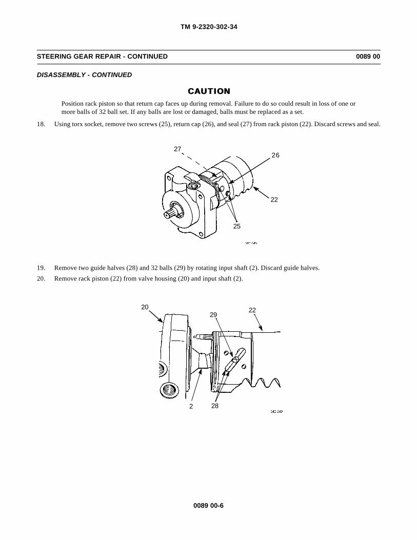
TM 9-2320-302-34
0089 00-6
STEERING GEAR REPAIR - CONTINUED 0089 00
DISASSEMBLY - CONTINUED
CAUTIONCAUTIONPosition rack piston so that return cap faces up during removal. Failure to do so could result in loss of one ormore balls of 32 ball set. If any balls are lost or damaged, balls must be replaced as a set.
18. Using torx socket, remove two screws (25), return cap (26), and seal (27) from rack piston (22). Discard screws and seal.
19. Remove two guide halves (28) and 32 balls (29) by rotating input shaft (2). Discard guide halves.
20. Remove rack piston (22) from valve housing (20) and input shaft (2).
22
2627
25
2 28
2920 22

TM 9-2320-302-34
0089 00-7
STEERING GEAR REPAIR - CONTINUED 0089 00
DISASSEMBLY - CONTINUED
21. Remove and discard seal ring (30) and packing (31) from rack piston (22).
22. Place valve housing (20) in vise.
23. Unstake valve housing (20) from adjuster lock nut (32). Unstake adjuster lock nut from adjuster (33).
30,3122
2033
32

TM 9-2320-302-34
0089 00-8
STEERING GEAR REPAIR - CONTINUED 0089 00
DISASSEMBLY - CONTINUED
NOTENOTETag thrust bearings and washers prior to disassembly to aid in assembly.
24. Using spanner wrenches (34 and 35), remove adjuster lock nut (32), adjuster (33), input shaft (2), two washers (36), andtwo thrust bearings (37) from valve housing (20).
25. Remove and discard seal ring (38) and packing (39) from adjuster (33).
26. Remove and discard two seal rings (40 and 41) and two packings (42 and 43) from valve housing (20).
27. Reverse valve housing (20) in vise and remove and discard retaining ring (44).
28. Remove and discard seal (45).
36
37
2
37
36
35
2
32,33
34
20
33
39
38

TM 9-2320-302-34
0089 00-9
STEERING GEAR REPAIR - CONTINUED 0089 00
DISASSEMBLY - CONTINUED
29. Remove screw (46) and washer (47) from housing (4).
30. Remove and discard retaining ring (48) and seal (49).
CAUTIONCAUTIONUse care not to tap against housing bore when tapping seal and trunnion washer from housing. Failure to doso will result in damage to housing.
31. Tap seal (50) and trunnion washer (51) from housing (4). Discard seal.
41
43
40
4220
4544
46
47
4948
45150

TM 9-2320-302-34
0089 00-10
STEERING GEAR REPAIR - CONTINUED 0089 00
DISASSEMBLY - CONTINUED
CAUTIONCAUTIONWhen using removal end of bearing and seal tool, place tool only on roller bearing and not on retaining ring.Failure to do so will result in damage to retaining ring and housing.
32. Using removal end of bearing inserter and drive handle, remove and discard roller bearing (52).
33. Remove and discard retaining ring (53) from bearing side of housing (4).
ASSEMBLY
1. Install new retaining ring (53) in inside ring groove of housing (4).
2. Install new roller bearing (52), using installation end of bearing inserter and drive handle.
3. Install trunnion washer (51) in housing (4) with beveled side facing away from retaining ring (53).
4. Place new seal (50) on installation end of bearing inserter with spring toward shoulder of tool.
5. Install seal (50).
HANDLE
REMOVAL
53
4
52
HANDLE
INSTALLATION
53
4
52

TM 9-2320-302-34
0089 00-11
STEERING GEAR REPAIR - CONTINUED 0089 00
ASSEMBLY - CONTINUED
6. Install new seal (49) and new retaining ring (48). Pack roller bearing (52) with grease.
7. Place valve housing (20) in vise. Apply a light coat of lubricating oil to two new packings (42 and 43) and two new sealrings (40 and 41). Install packings and seal rings.
HANDLE
INSTALLATION
50
53 49
4852
4
51
20
4240
43
41

TM 9-2320-302-34
0089 00-12
STEERING GEAR REPAIR - CONTINUED 0089 00
ASSEMBLY - CONTINUED
8. Apply a light coat of lubricating oil to thrust bearing (37) and washer (36). Install thrust bearing and washer on inputshaft (2).
9. Install input shaft (2) in valve housing (20).
10. Apply a light coat of grease to thrust bearing (37) and washer (36). Install thrust bearing and washer.
11. Install new packing (39) and new seal ring (38) in adjuster (33).
12. Using spanner wrench (35), install adjuster (33) in valve housing (20). Tighten adjuster to 132-180 lb-in (14.9-20.3Nm), to seat components, then back off 1/4 to 1/2 turn.
36
37
2
20
3736
38
39
33
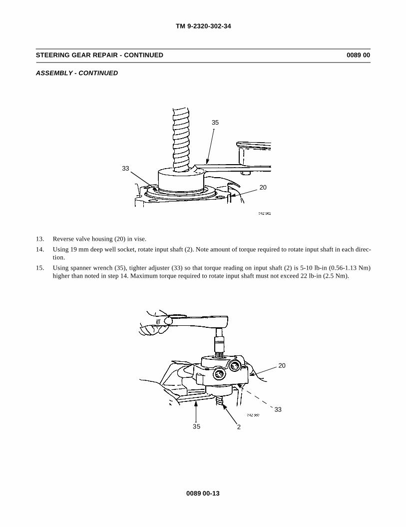
TM 9-2320-302-34
0089 00-13
STEERING GEAR REPAIR - CONTINUED 0089 00
ASSEMBLY - CONTINUED
13. Reverse valve housing (20) in vise.
14. Using 19 mm deep well socket, rotate input shaft (2). Note amount of torque required to rotate input shaft in each direc-tion.
15. Using spanner wrench (35), tighter adjuster (33) so that torque reading on input shaft (2) is 5-10 lb-in (0.56-1.13 Nm)higher than noted in step 14. Maximum torque required to rotate input shaft must not exceed 22 lb-in (2.5 Nm).
35
20
33
35
20
2
33

TM 9-2320-302-34
0089 00-14
STEERING GEAR REPAIR - CONTINUED 0089 00
ASSEMBLY - CONTINUED
16. Reverse valve housing (20) in vise.
17. Apply a light coat of lubricating oil to new adjuster lock nut (32).
18. Using spanner wrenches (34 and 35), install adjuster lock nut (32) while holding adjuster (33) in place. Tighten adjusterlock nut to 101-122 lb-ft (137-165 Nm). Check torque reading noted in step 14. If torque reading is not within 5-10 lb-in(0.56-1.13 Nm) higher, remove adjuster lock nut, back off adjuster ½ turn, and repeat steps 13 through 18.
19. Stake valve housing (20) in clockwise-most corner of two opposing slots of adjuster lock nut (32). Stake adjuster locknut on adjuster (33) in one place at threaded area. Check torque reading on input shaft (2). Reading must not exceed 22lb-in (2.5 Nm).
20. Apply a light coat of lubricating oil to two new packings (23 and 24) and install packings in valve housing (20).
21. Apply a light coat of lubricating oil to new packing (31) and new seal ring (30). Install packing and seal ring on rack pis-ton (22).
35
32,33
34
20
202423
2
3233
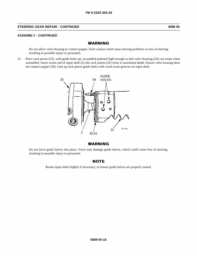
TM 9-2320-302-34
0089 00-15
STEERING GEAR REPAIR - CONTINUED 0089 00
ASSEMBLY - CONTINUED
WARNINGWARNINGDo not allow valve housing to contact poppet. Such contact could cause steering problems or loss of steeringresulting in possible injury to personnel.
22. Place rack piston (22), with guide holes up, on padded pedestal high enough so that valve housing (20) can rotate whenassembled. Insert worm end of input shaft (2) into rack piston (22) close to maximum depth. Ensure valve housing doesnot contact poppet (54). Line up rack piston guide holes with worm track grooves on input shaft.
WARNINGWARNINGDo not force guide halves into place. Force may damage guide halves, which could cause loss of steering,resulting in possible injury to personnel.
NOTENOTERotate input shaft slightly if necessary, to ensure guide halves are properly seated.
54
2230,312
GUIDEHOLES20

TM 9-2320-302-34
0089 00-16
STEERING GEAR REPAIR - CONTINUED 0089 00
ASSEMBLY - CONTINUED
23. Install two new guide halves (28) by hand in rack piston (22).
WARNINGWARNINGGuide halves must be held in place during installation of balls. Failure to do so will result in balls beingtrapped outside closed ball track, causing steering lockup and possible injury to personnel. Failure to installall 32 balls in guide halves will also result in steering lockup and possible injury to personnel.
NOTENOTE• Rotate input shaft slightly, if necessary, to ensure guide halves are properly seated.
• If guide halves are unseated during or after ball loading, remove all balls and input shaft from rack pis-ton and repeat steps 21 and 22.
• Ensure all 32 balls are installed.
24. Install 32 balls (29) in slot in guide halves (28).
25. Apply a light coat of grease to new seal (27) and install in return cap (26).
26. Using torx socket, install return cap (26) and two new screws (25) in rack piston (22). Tighten screws alternately to 168-264 lb-in (19-30 Nm).
WARNINGWARNINGDo not allow valve housing to move more than 2.72 in (69.1mm) away from rack piston. If this occurs, ballswill be out of place, resulting in possible loss of steering and injury to personnel.
CAUTIONCAUTIONDuring step 27, do not allow poppet (54) to touch valve housing (20). To do so will result in incorrectly pre-set poppet.
27. Rotate input shaft (2) into and out of rack piston (22) several times while checking for smooth movement.
28. If input shaft (2) does not move smoothly, remove balls (29) and rack piston (22) and repeat steps 21 through 27.
28
2
20
2922
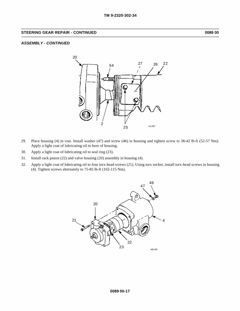
TM 9-2320-302-34
0089 00-17
STEERING GEAR REPAIR - CONTINUED 0089 00
ASSEMBLY - CONTINUED
29. Place housing (4) in vise. Install washer (47) and screw (46) in housing and tighten screw to 38-42 lb-ft (52-57 Nm).Apply a light coat of lubricating oil to bore of housing.
30. Apply a light coat of lubricating oil to seal ring (23).
31. Install rack piston (22) and valve housing (20) assembly in housing (4).
32. Apply a light coat of lubricating oil to four torx-head screws (21). Using torx socket, install torx-head screws in housing(4). Tighten screws alternately to 75-85 lb-ft (102-115 Nm).
22262754
20
252
4
4647
20
21
2223

TM 9-2320-302-34
0089 00-18
STEERING GEAR REPAIR - CONTINUED 0089 00
ASSEMBLY - CONTINUED
NOTENOTEIf adjusting screw was removed, perform steps 33 through 36.
33. Place sector shaft (3) in soft-jawed vise, apply a light coat of grease to new adjusting screw (11), and install adjustingscrew and new retainer (15).
34. Tighten adjusting screw (11) so that end play is 0-0.002 in (0-0.05 mm) but adjusting screw can still be turned by hand.Check end play by hand with dial indicator.
35. Stake retainer (15) into two slots in sector shaft (3).
36. Ensure adjusting screw (11) can still be turned by hand and end play is still 0-0.002 in (0-0.05 mm). If not, repeat disas-sembly step 13 and installation steps 32 through 35.
37. Apply a light coat of lubricating oil to bushing in side cover (9) and new seal (13). Install seal on installation end ofbearing inserter with spring side toward shoulder of tool.
38. Install seal (13) in side cover (9).
11
15
3
13
9

TM 9-2320-302-34
0089 00-19
STEERING GEAR REPAIR - CONTINUED 0089 00
ASSEMBLY - CONTINUED
39. Apply a light coat of lubricating oil to bearing surface of sector shaft (3). Install sector shaft in side cover (9) by thread-ing adjusting screw (11) counterclockwise until solid, then backing off 1/2 turn so that side cover rotates freely.
40. Install vent plug (14) and nut (7) hand tight.
WARNINGWARNINGRack piston and sector shaft must be meshed correctly. Failure to do so will severely limit gear travel in onedirection, resulting in possible injury to personnel.
41. Rotate input shaft (2) so that valley between second and third tooth of rack piston (22) is even with and centered inopening of housing (4).
7
14
9
11
3
4
22
2

TM 9-2320-302-34
0089 00-20
STEERING GEAR REPAIR - CONTINUED 0089 00
ASSEMBLY - CONTINUED
42. Replace masking tape on sector shaft (3) with one layer of new masking tape.
43. Install new gasket (10), sector shaft (3), and side cover (9) as an assembly in housing (4). Center tooth of sector shaft (3)must be in valley between second and third tooth of rack piston (22).
44. Apply a light coat of lubricating oil to six screws (8). Install screws in housing (4) and tighten to 160-180 lb-ft (217-244Nm) in sequence shown.
45. Pack trunnion area of sector shaft (3) with grease. Apply a light coat of grease to new seal (5) and install seal in sectorshaft.
46. Apply a light coat of grease to new seal (19). Using small end of input seal installer, tap seal into valve housing (20)until shoulder of input seal installer rests against valve housing. Clean off any seal material that may have shredded off.
47. Install new retaining ring (44) and pack end of valve housing (20) with grease.
48. Apply a light coat of grease to new seal (45) and install seal in valve housing (20).
4229
10
38
3
5

TM 9-2320-302-34
0089 00-21
STEERING GEAR REPAIR - CONTINUED 0089 00
ASSEMBLY - CONTINUED
49. Install new grease fitting (18), two new packings (17), and plugs (16) in housing (4).
INSTALLER
19
20
4445
20
4
1716
16
1718

TM 9-2320-302-34
0089 00-22
STEERING GEAR REPAIR - CONTINUED 0089 00
ASSEMBLY - CONTINUED
50. Ensure timing marks on sector shaft (3) and steering gear assembly (1) are aligned. If not, turn input shaft (2) with 19mm deep well socket to align timing marks.
WARNINGWARNINGDo not rotate input shaft more than 1-1/2 turns from center position. Doing so will incorrectly set poppets,causing steering problems resulting in possible injury to personnel.
51. Loosen nut (7).
52. Tighten adjusting screw (11) so that input shaft (2) requires torque of 45-50 lb-in (5.1-5.6 Nm) to turn 180 degrees fromcenter in both directions.
53. Back off adjusting screw (11) ½ turn and note torque required to turn input shaft (2) 180 degrees from center in bothdirections.
54. Tighten adjusting screw (11) so that torque required to turn input shaft (2) 180 degrees from center in both directionsincreases 6-8 lb-in (0.68-0.90 Nm) from reading noted in step 53.
55. Hold adjusting screw (11) firmly against steering gear assembly (1) and tighten nut (7) to 40-45 lb-ft (54-61 Nm).
56. Check torque reading on input shaft (2). If reading exceeds 40 lb-in (4.5 Nm), repeat steps 51 through 56.
57. Install steering gear (WP 0088 00).
END OF WORK PACKAGE
2
3TIMINGMARKS
1
4
7
11
1
2

TM 9-2320-302-34
0090 00-1
STEERING COLUMN REPLACEMENT 0090 00
THIS WORK PACKAGE COVERS
Removal, Installation
INITIAL SETUP
Maintenance Level
Direct Support
Tools and Special Tools
Tool kit, general mechanic’s (Item 132, WP 0126 00)
Wrench, torque, 0-300 lb-in (Item 137, WP 0126 00)
Wrench, torque, 15-75 lb-ft (Item 138, WP 0126 00)
Materials/Parts
Bolt (P/N 14-09683-000)
Nut (P/N 115307A)
Materials/Parts - Continued
Compound, sealing (Item 17, WP 0125 00)
Detergent (Item 19, WP 0125 00)
Primer, adhesive (Item 30, WP 0125 00)
References
TM 9-2320-302-10
Equipment Condition
Steering wheel removed (TM 9-2320-302-20)
Steering column covers removed (TM 9-2320-302-20)
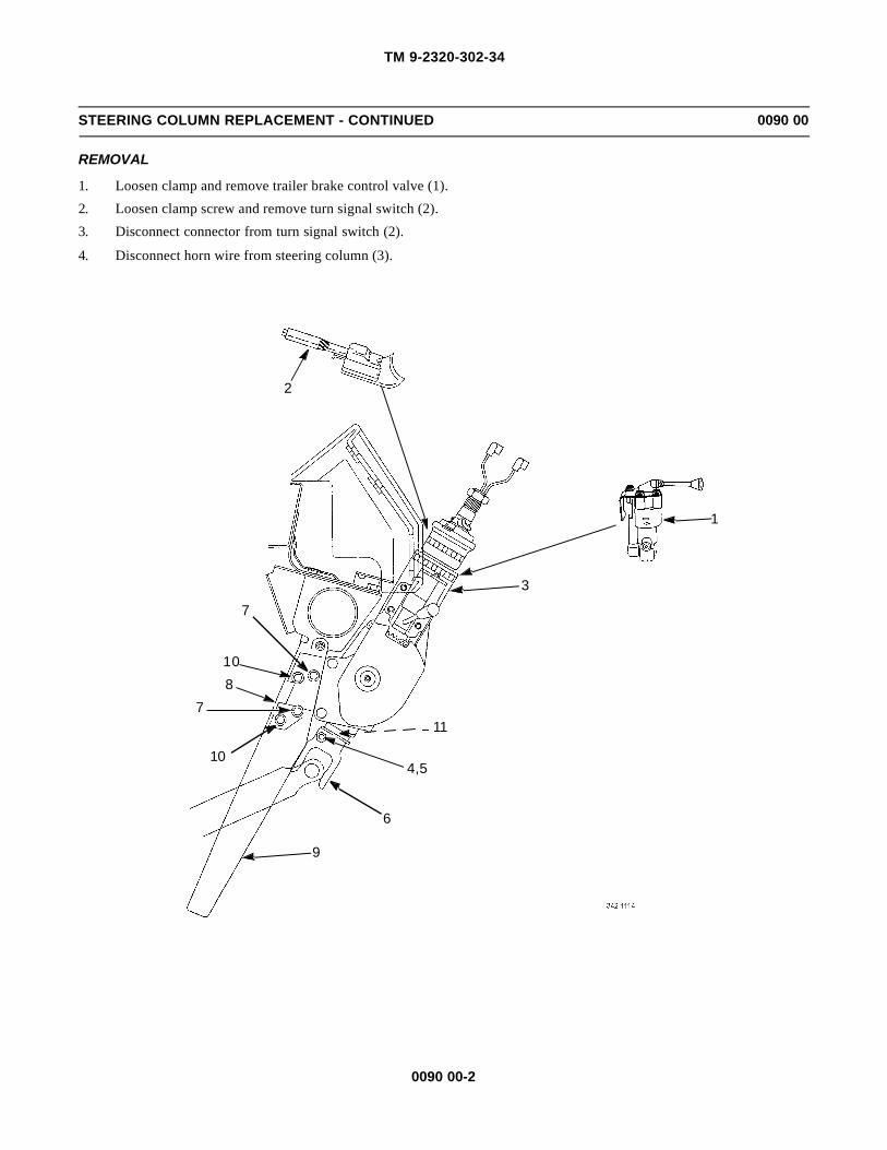
TM 9-2320-302-34
0090 00-2
STEERING COLUMN REPLACEMENT - CONTINUED 0090 00
REMOVAL
1. Loosen clamp and remove trailer brake control valve (1).
2. Loosen clamp screw and remove turn signal switch (2).
3. Disconnect connector from turn signal switch (2).
4. Disconnect horn wire from steering column (3).
2
3
810
7
10
7
4,5
9
1
6
11

TM 9-2320-302-34
0090 00-3
STEERING COLUMN REPLACEMENT - CONTINUED 0090 00
REMOVAL - CONTINUED
NOTENOTEHeat base of yoke, if necessary, for ease in removal.
5. Remove nut (4) and bolt (5) from steering column yoke (6) and separate yoke from steering column (3). Discard nut andbolt.
6. Remove two screws (7) and spacer block (8) from steering column (3) and steering column bracket (9).
7. Loosen two screws (10) and remove steering column (3) from vehicle.
INSTALLATION
1. Position steering column (3) on steering column bracket (9) and install two screws (7). Tighten screws to 180 lb-in (20Nm).
2. Tighten two screws (10) to 180 lb-in (20 Nm).
3. Using wire brush and liquid detergent, clean serrations of steering column yoke (6) and steering column shaft (11).
4. Apply adhesive primer to steering column shaft (11). Let dry for five minutes.
5. Apply sealing compound to inside of steering column yoke (6) and install yoke to steering column shaft (11).
6. Install new bolt (5) and nut (4). Tighten nut to 37 lb-ft (50 Nm).
7. Apply sealing compound to exposed threads of screw.
8. Connect horn wire to steering column (3).
9. Connect connector to turn signal switch (2).
10. Install turn signal switch (2) to steering column (3) and tighten clamp screw.
11. Install trailer brake control valve (1) and tighten clamp.
12. Install steering column covers (TM 9-2320-302-20).
13. Install steering wheel (TM 9-2320-302-20).
14. Test drive vehicle (TM 9-2320-302-10) and check steering.
END OF WORK PACKAGE

TM 9-2320-302-34
0090 00-4
This Page Intentionally Left Blank.

TM 9-2320-302-34
0091 00-1
FIFTH WHEEL REPLACEMENT 0091 00
THIS WORK PACKAGE COVERS
Removal, Installation
INITIAL SETUP
Maintenance Level
Direct Support
Tools and Special Tools
Tool kit, general mechanic’s (Item 132, WP 0126 00)
Materials/Parts
Nut, lock (P/N MS51922-1)
Nut, lock (P/N MS51922-49) (14)
Personnel Required
Two
Equipment Condition
Air system drained (TM 9-2320-302-10)
WARNINGWARNING• Use extreme caution when handling heavy parts. Provide adequate support and use assistance during
procedure. Ensure that any lifting device used is in good condition and of suitable load capacity. Keepclear of heavy parts supported only by lifting device. Failure to follow this warning may result in deathor injury to personnel.
• Fifth wheel weighs 550 lb (249.7 kg). Use hoist with lifting capacity of 800 lb (363.2 kg) to removefifth wheel. Failure to do so could result in injury to personnel.

TM 9-2320-302-34
0091 00-2
FIFTH WHEEL REPLACEMENT - CONTINUED 0091 00
REMOVAL
1. Disconnect air hose (1) from cylinder (2).
2. Remove lock nut (3), screw (4), and clamp (5). Discard lock nut.
3. Remove 14 lock nuts (6), washers (7), screws (8), and washers (9) from fifth wheel (10). Discard lock nuts.
4. Using suitable lifting device, remove fifth wheel (10) from frame (11).
INSTALLATION
1. Using suitable lifting device, align and install fifth wheel (10) on frame (11).
2. Install 14 washers (9), screws (8), washers (7), and new lock nuts (6).
3. Install clamp (5), screw (4), and new lock nut (3).
4. Connect air hose (1) to cylinder (2).
END OF WORK PACKAGE
6,7,8,9
101
3,4,5
2
11 6,7,8,9
6,7,8,9

TM 9-2320-302-34
0092 00-1
SLIDE BRACKET AND PLATE REPAIR 0092 00
THIS WORK PACKAGE COVERS
Disassembly, Assembly
INITIAL SETUP
Maintenance Level
Direct Support
Tools and Special Tools
Tool kit, general mechanic’s (Item 132, WP 0126 00)
Slider, spring compression (Item 114, WP 0126 00)
References
TM 9-2320-302-20
Equipment Condition
Top plate removed (WP 0093 00)
DISASSEMBLY
1. Install spring compressor tool (1).
1

TM 9-2320-302-34
0092 00-2
SLIDE BRACKET AND PLATE REPAIR - CONTINUED 0092 00
DISASSEMBLY - CONTINUED
2. Compress spring (2). Remove pin (3) and swing air cylinder (4) out of the way.
3. Remove spring compressor tool (1).
4. Remove spring retainer (5), spring (2), pin retainer (6), and plunger assembly (7).
5. Repeat steps 1 through 4 for opposite side plunger assembly.
6. Disconnect air hose (8) and remove air cylinder (4).
ASSEMBLY
1. Install air cylinder (4) and connect air hose (8).
2. Install plunger assembly (7), pin retainer (6), spring (2), and spring retainer (5).
3. Install spring compressor tool (1).
4. Compress spring (2) and place air cylinder (4) in position.
5. Install pin (3) and release spring compressor tool (1).
32
1
4
1
76
25
45
2
67
8

TM 9-2320-302-34
0092 00-3
SLIDE BRACKET AND PLATE REPAIR - CONTINUED 0092 00
ASSEMBLY - CONTINUED
6. Repeat steps 2 through 5 for opposite side plunger assembly.
7. Install top plate (WP 0093 00).
8. Adjust fifth wheel (TM 9-2320-302-20).
END OF WORK PACKAGE

TM 9-2320-302-34
0092 00-4
This Page Intentionally Left Blank.

TM 9-2320-302-34
0093 00-1
TOP PLATE REPLACEMENT 0093 00
THIS WORK PACKAGE COVERS
Removal, Installation
INITIAL SETUP
Maintenance Level
Direct Support
Tools and Special Tools
Tool kit, general mechanic’s (Item 132, WP 0126 00)
Materials/Parts
Kit (P/N RK-04413)
Compound, antiseize (Item 10, WP 0125 00)
Personnel Required
Two
WARNINGWARNING• Use extreme caution when handling heavy parts. Provide adequate support and use assistance during
procedure. Ensure that any lifting device used is in good condition and of suitable load capacity. Keepclear of heavy parts supported only by lifting device. Failure to follow this warning may result in deathor injury to personnel.
• Top plate weighs 320 lb (145 kg). Use hoist with lifting capacity of 500 lb (227 kg) to remove or installtop plate. Failure to do so could result in injury to personnel.

TM 9-2320-302-34
0093 00-2
TOP PLATE REPLACEMENT - CONTINUED 0093 00
REMOVAL
1. Using suitable lifting device, support top plate (1) and remove two roll pins (2). Discard roll pins.
2. Remove two pivot pins (3) and top plate (1). Discard pivot pins.
3. Remove and discard two cushion supports (4) from slide bracket (5).
INSTALLATION
1. Install two new cushion supports (4) in slide bracket (5).
2. Coat two new pivot pins (3) with antiseize compound.
3. Using suitable lifting device, align top plate (1) with slide bracket (5) and install two new pivot pins (3) and two new rollpins (2).
END OF WORK PACKAGE
1
2
3
5
2
3
4
4

TM 9-2320-302-34
0094 00-1
TOP PLATE REPAIR 0094 00
THIS WORK PACKAGE COVERS
Disassembly, Assembly
INITIAL SETUP
Maintenance Level
Direct Support
Tools and Special Tools
Tool kit, general mechanic’s (Item 132, WP 0126 00)
Tester, kingpin lock (Item 126, WP 0126 00)
Wrench, torque, 0-300 lb-in (Item 137, WP 0126 00)
Materials/Parts
Kit (P/N RK-65015)
Kit (P/N RK-65017)
Compound, antiseize (Item 10, WP 0125 00)
Personnel Required
Two
References
TM 9-2320-302-10
TM 9-2320-302-20
TM 9-237
Equipment Condition
Top plate removed (WP 0093 00)

TM 9-2320-302-34
0094 00-2
TOP PLATE REPAIR - CONTINUED 0094 00
DISASSEMBLY
1. Ensure locks (1) are in closed position.
2. Remove and discard nut (2), washer (3), rubber washer (4), and lock-adjust tag (5).
3. Remove and discard screw (6), washer (7), roller (8), and washer (9).
4. Remove and discard lock nut (10), screw (11), washer (12), roller (13), cam plate (14), and washer (15).
5. Remove primary lock handle (16) from top plate (17).
6. Remove and discard washer (18) from primary lock handle (16).
7. Remove roll pin (19), spring (20), lock bar (21), and handle (22). Discard roll pin, spring, and lock bar.
32
27
261731
30
1
22
21
20
2832 10
13
15
1914
259
24 235
4 32
11
128
7
6
18
16
29

TM 9-2320-302-34
0094 00-3
TOP PLATE REPAIR - CONTINUED 0094 00
DISASSEMBLY - CONTINUED
WARNINGWARNINGWhen removing spring, compress spring slightly and relieve tension slowly. Failure to do so could causespring to fly off, resulting in injury to personnel.
8. Remove and discard shaft (23), spring (24), and yoke (25) from top plate (17).
9. Remove two cotter pins (26), pin (27), spring (28), and lock guard (29). Discard cotter pins, pin, and lock guard.
10. Remove two pins (30), pins (31), and locks (1). Discard cotter pins and pins.
11. If damaged, remove two grease fittings (32) from top plate (17).
NOTENOTELube plates must be replaced as a pair.
12. Remove 18 lock nuts (33), washers (34), and two lube plates (35) from top plate (17). Discard lock nuts.
13. Remove two retaining clips (36) and two pocket inserts (37) from top plate (17).
ASSEMBLY
1. Install two pocket inserts (37) on top plate (17) and secure with two retaining clips (36).
2. Ensure top plate mating surface is clean and dry.
35
34
33
17
36
37
36
37 17

TM 9-2320-302-34
0094 00-4
TOP PLATE REPAIR - CONTINUED 0094 00
ASSEMBLY - CONTINUED3. Install two lube plates (35) to top plate (17) with 18 washers (34) and new lock nuts (33).4. Tighten lock nuts (33) to 156 lb-in (18 Nm).
5. If removed, install two new grease fittings (32).6. Coat pin holes of two locks (1) with antiseize compound and install two locks with larger opening facing toward top of
top plate (17).7. Install two new pins (31) and new pins (30).8. Install new lock guard (29), spring (28), new pin (27), and two new cotter pins (26).9. Install kingpin lock tester plug between two locks (1) and close locks.
35
34
33
1735
32
27
26173130
1
22
21
20
2832 10
13
15
1914
259
24 235
4 32
11
128
7
6
18
16
29

TM 9-2320-302-34
0094 00-5
TOP PLATE REPAIR - CONTINUED 0094 00
ASSEMBLY - CONTINUED
NOTENOTE• Tips of yoke must be flush (1/32 in) with ends of two locks. If yoke falls short, grind outside edges of
yoke tips evenly until yoke fits exactly. If yoke extends beyond two locks, build up outside edges ofyoke tops using low-hydrogen E70XX welding rod. After welding, grind beads smooth and even untilyoke fits exactly.
• Ensure threaded hole is up when installing shaft.
10. Install new spring (24) and new shaft (23) on yoke (25).
11. Install handle (22), new lock bar (21), new spring (20), and new roll pin (19).
12. Install new washer (18) on primary lock handle (16).
13. Install primary lock handle (16) in top plate (17).
14. Install new cam plate (14) on primary lock handle (16).
NOTENOTEInstall washers with rounded sides facing away from cam plate.
15. Install new washer (15), new roller (13), new washer (12), new screw (11), and new lock nut (10) in top plate (17).
16. Install new washer (9), new roller (8), new washer (7), and new screw (6) in cam plate (14).
17. Install new lock-adjust tag (5), new rubber washer (4), new washer (3), and new nut (2) on shaft (23).
WARNINGWARNINGLocks must be closed while adjusting to ensure contact is made with locks, yoke, and top plate. Failure to doso will result in loss of trailer and possible injury to personnel.
18. Tighten nut (2) until plug fits snugly, but can just be rotated by hand.
19. Open two locks (1) and remove kingpin lock tester plug.
20. Install top plate (WP 0093 00).
21. Lubricate fifth wheel (TM 9-2320-302-10).
22. Adjust fifth wheel (TM 9-2320-302-20).
END OF WORK PACKAGE

TM 9-2320-302-34
0094 00-6
This Page Intentionally Left Blank.
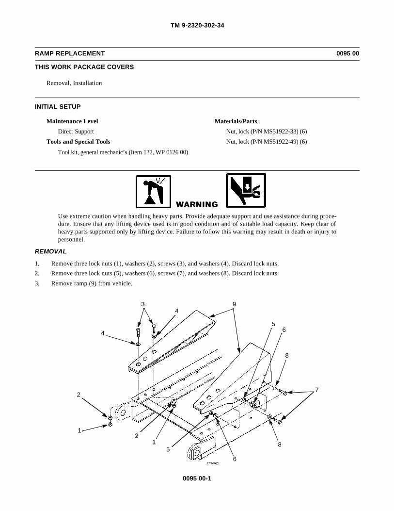
TM 9-2320-302-34
0095 00-1
RAMP REPLACEMENT 0095 00
THIS WORK PACKAGE COVERS
Removal, Installation
INITIAL SETUP
Maintenance Level
Direct Support
Tools and Special Tools
Tool kit, general mechanic’s (Item 132, WP 0126 00)
Materials/Parts
Nut, lock (P/N MS51922-33) (6)
Nut, lock (P/N MS51922-49) (6)
WARNINGWARNINGUse extreme caution when handling heavy parts. Provide adequate support and use assistance during proce-dure. Ensure that any lifting device used is in good condition and of suitable load capacity. Keep clear ofheavy parts supported only by lifting device. Failure to follow this warning may result in death or injury topersonnel.
REMOVAL
1. Remove three lock nuts (1), washers (2), screws (3), and washers (4). Discard lock nuts.
2. Remove three lock nuts (5), washers (6), screws (7), and washers (8). Discard lock nuts.
3. Remove ramp (9) from vehicle.
9
8
7
8
65
65
12
1
2
4
34

TM 9-2320-302-34
0095 00-2
RAMP REPLACEMENT - CONTINUED 0095 00
REMOVAL - CONTINUED
4. Repeat steps 1 through 3 to remove other ramp (9)
INSTALLATION
1. Position ramp (9) to vehicle.
2. Install ramp (9) with three washers (8), screws (7), washers (6), and new lock nuts (5).
3. Install three washers (4), screws (3), washers (2), and new lock nuts (1).
4. Repeat steps 1 through 3 to install other ramp (9).
END OF WORK PACKAGE
9
8
7
8
65
65
121
2
4
34
TM 9-2320-302-34
0096 00-1
CROSSMEMBER REPLACEMENT 0096 00
THIS WORK PACKAGE COVERS
Removal, Installation
INITIAL SETUP
Maintenance Level
General Support
Tools and Special Tools
Tool kit, general mechanic’s (Item 132, WP 0126 00)
Wrench, torque, 50-250 lb-ft (Item 139, WP 0126 00)
Wrench, torque, 100-600 lb-ft (Item 140, WP0126 00)
Wrench set, socket, 3/4 in drive (Item 141, WP0126 00)
Materials/Parts
Nut, lock (P/N 23-09901-116) (12)
Nut, lock (P/N MS51922-1) (4)
Nut, lock (P/N MS51922-33) (22)
Nut, lock (P/N MS51922-49) (12)
Equipment Condition
Taillight brackets removed (TM 9-2320-302-20)
Pintle hook removed (TM 9-2320-302-20)
WARNINGWARNINGUse extreme caution when handling heavy parts. Provide adequate support and use assistance during proce-dure. Ensure that any lifting device used is in good condition and of suitable load capacity. Keep clear ofheavy parts supported only by lifting device. Failure to follow this warning may result in death or injury topersonnel.
NOTENOTEThis task covers replacement of the REAR crossmember and is typical of procedures used to replace othercrossmembers of the vehicle.

TM 9-2320-302-34
0096 00-2
CROSSMEMBER REPLACEMENT - CONTINUED 0096 00
REMOVAL
1. Remove four lock nuts (1) and clamps (2) and set wiring harness (3) aside. Discard lock nuts.
NOTENOTEVehicle may utilize huckbolts instead of screws and lock nuts. Replace all loose or damaged huckbolts withgrade 8 screws and lock nuts.
2. Remove eight lock nuts (4), four washers (5), towing bracket (6), four screws (7), four washers (8), and reinforcementassembly (9). Discard lock nuts.
3. Remove five lock nuts (10), washers (11), screws (12), washers (13), two spacers (14), and left side gusset (15). Discardlock nuts.
4. Repeat step 3 for right side gusset (16).
WARNINGWARNINGPlate weighs 96 lb (44 kg). Use hoist with lifting capacity of 200 lb (91 kg) to remove plate. Failure to do socould result in injury to personnel.
5. Attach hoist and remove 12 lock nuts (17), washers (18), screws (19), washers (20), and plate (21). Discard lock nuts.
3
1,2
9
6
4,57,8
4,57,8

TM 9-2320-302-34
0096 00-3
CROSSMEMBER REPLACEMENT - CONTINUED 0096 00
REMOVAL - CONTINUED
6. Remove four lock nuts (22), washers (23), screws (24), washers (25), and right side support (26). Discard lock nuts.
7. Repeat step 6 for left side support (27).
10,11
162612,1310,11
12,13
2715
21
31,214
17,1819,20
22,23,24,25
27
26

TM 9-2320-302-34
0096 00-4
CROSSMEMBER REPLACEMENT - CONTINUED 0096 00
REMOVAL - CONTINUED
WARNINGWARNINGRear crossmember weighs 460 lb (209 kg). Use hoist with lifting capacity of 600 lb (272 kg) to remove rearcrossmember. Failure to do so could result in injury to personnel.
8. Attach hoist and remove four lock nuts (28), washers (29), screws (30), washers (31), and rear crossmember (32). Dis-card lock nuts.
INSTALLATION
WARNINGWARNINGRear crossmember weighs 460 lb (209 kg). Use hoist with lifting capacity of 600 lb (272 kg) to install rearcrossmember. Failure to do so could result in injury to personnel.
1. Install rear crossmember (32) with four washers (31), screws (30), washers (29), and new lock nuts (28).
2. Install right side support (26) with four washers (25), screws (24), washers (23), and new lock nuts (22).
3. Repeat step 2 for left side support (27).
32
28,2930,31
28,2930,31

TM 9-2320-302-34
0096 00-5
CROSSMEMBER REPLACEMENT - CONTINUED 0096 00
INSTALLATION - CONTINUED
WARNINGWARNINGPlate weighs 96 lb (44 kg). Use hoist with lifting capacity of 200 lb (91 kg) to install plate. Failure to do socould result in injury to personnel.
4. Attach hoist and install plate (21) with 12 washers (20), screws (19), washers (18), and new lock nuts (17).
5. Install right side gusset (16), two spacers (14), five washers (13), screws (12), washers (11), and new lock nuts (10).
6. Repeat step 5 for left side gusset (15).
7. Install reinforcement assembly (9), four washers (8), screws (7), towing bracket (6), four washers (5), and eight newlock nuts (4).
22,23,24,25
2726
10,11
162612,1310,11
12,13
2715
21
31,214
17,1819,20
6
9
4,57,8 7,8
4,5
1,2

TM 9-2320-302-34
0096 00-6
CROSSMEMBER REPLACEMENT - CONTINUED 0096 00
INSTALLATION - CONTINUED
8. Move wiring harness (3) into position and install four clamps (2) and new lock nuts (1).
NOTENOTEPerform steps 9 through 12 for this and other crossmembers.
9. Tighten 1/2-13 grade 8 lock nuts to 68 lb-ft (92 Nm).
10. Tighten 5/8-11 grade 8 lock nuts to 136 lb-ft (184 Nm).
11. Tighten 3/4-10 grade 8 lock nuts to 241 lb-ft (327 Nm).
12. Tighten 1”-8 grade 8 lock nuts to 582 lb-ft (789 Nm).
13. Install pintle hook (TM 9-2320-302-20).
14. Install taillight brackets (TM 9-2320-302-20).
END OF WORK PACKAGE
31,2 1,2

TM 9-2320-302-34
0097 00-1
FRONT CAB MOUNTS REPLACEMENT 0097 00
THIS WORK PACKAGE COVERS
Removal, Installation
INITIAL SETUP
Tools and Special Tools
Tool kit, general mechanic’s (Item 132, WP 0126 00)
Sling, beam type (Item 115, WP 0126 00)
Materials/Parts
Clamp, seal (P/N 04-19249-000)
Nut, lock (P/N MS51922-1) (4)
Materials/Parts - Continued
Nut, lock (P/N MS51922-17 (4)
Nut, lock (P/N MS51922-57)
Personnel Required
Two
Equipment Condition
Fender extension removed (TM 9-2320-302-20)
WARNINGWARNINGUse extreme caution when handling heavy parts. Provide adequate support and use assistance during proce-dure. Ensure that any lifting device used is in good condition and of suitable load capacity. Keep clear ofheavy parts supported only by lifting device. Failure to follow this warning may result in death or injury topersonnel.
REMOVAL
NOTENOTE• Procedure is the same for both sides, except as noted.
• Perform step 1 on right side.
1. Remove seal clamp (1), v-clamp (2), and outlet pipe (3). Discard seal clamp.
1
3
2

TM 9-2320-302-34
0097 00-2
FRONT CAB MOUNTS REPLACEMENT - CONTINUED 0097 00
REMOVAL - CONTINUED
2. Remove nut (4), washer (5), bolt (6), and washer (7).
NOTENOTEPerform step 3 on left side.
3. Remove two lock nuts (9), washers (10), screws (11), and four clamps (12). Discard lock nuts.
4,5,6,7
12
9,10,11

TM 9-2320-302-34
0097 00-3
FRONT CAB MOUNTS REPLACEMENT - CONTINUED 0097 00
REMOVAL - CONTINUED
NOTENOTEPerform step 4 on left side.
4. Remove lock nut (13), washer (14), and screw (15). Disconnect cable (16) and set aside. Discard lock nut.
5. Remove lock nut (17), washer (18), and resilient mount (19). Discard lock nut.
WARNINGWARNINGCab assembly weighs 1100 lb (499 kg). Use hoist with lifting capacity of 1400 lb (636 kg) to support cabassembly. Failure to do so could result in injury to personnel and/or damage to equipment.
6. Using cab sling and hoist, lift cab assembly (20) enough to remove all slack and not allow cab assembly to drop whenfront cab mounts (21) are removed.
7. Remove screw (22), washer (24), and bushing (23).
8. Remove four lock nuts (25), washers (26), screws (27), washers (28), and front cab mount (21). Discard lock nuts.
20
24
23
16
13,14,15
22
21
25,26,27,28
17
1819
25,26,27,28

TM 9-2320-302-34
0097 00-4
FRONT CAB MOUNTS REPLACEMENT - CONTINUED 0097 00
REMOVAL - CONTINUED
NOTENOTEPerform step 9 on left side.
9. Remove three lock nuts (29), washers (30), two brackets (31), three screws (32), washers (33), and plate (34). Discardlock nuts.
NOTENOTEPerform step 10 on right side.
10. Remove three lock nuts (35), washers (36), screws (37), washers (38), and plate (39). Discard lock nuts.
29,3032,3334
31
39
35,3637,38

TM 9-2320-302-34
0097 00-5
FRONT CAB MOUNTS REPLACEMENT - CONTINUED 0097 00
INSTALLATION
WARNINGWARNINGCab assembly weights 1100 lb (499 kg). Use hoist with lifting capacity of 1400 lb (636 kg) to support cabassembly. Failure to do so could result in injury to personnel and/or damage to equipment.
NOTENOTE• Procedure is the same for both sides except as noted.
• Perform step 1 on right side.
1. Install plate (39), three washers (38), screws (37), washers (36), and new lock nuts (35).
NOTENOTEPerform step 2 on left side.
2. Install plate (34), three washers (33), screws (32), two brackets (31), three washers (30), and new lock nuts (29).
3. Install front cab mount (21) with four washers (28), screws (27), washers (26), and new lock nuts (25).
4. Install bushing (23), washer (24), and screw (22).
5. Install resilient mount (19), washer (18), and new lock nut (17).
6. Lower cab assembly (20) and remove cab sling and hoist.
NOTENOTEPerform steps 7 and 8 on left side.
7. Connect cable (16) and install screw (15), washer (14), and new lock nut (13).
20
24
23
16
13,14,15
22
21
25,26,27,28
17
1819
25,26,27,28

TM 9-2320-302-34
0097 00-6
FRONT CAB MOUNTS REPLACEMENT - CONTINUED 0097 00
INSTALLATION - CONTINUED
8. Install four clamps (12) with two screws (11), washers (10), and new lock nuts (9).
9. Install washer (7), bolt (6), washer (5), and nut (4).
12
9,10,11
4,5,6,7

TM 9-2320-302-34
0097 00-7
FRONT CAB MOUNTS REPLACEMENT - CONTINUED 0097 00
INSTALLATION - CONTINUED
NOTENOTEPerform step 10 on right side.
10. Install outlet pipe (3), v-clamp (2), and new seal clamp (1).
11. Install fender extension (TM 9-2320-302-20).
END OF WORK PACKAGE
1
3
2

TM 9-2320-302-34
0097 00-8
This Page Intentionally Left Blank.

TM 9-2320-302-34
0098 00-1
REAR CAB MOUNTS REPLACEMENT 0098 00
THIS WORK PACKAGE COVERS
Removal, Installation
INITIAL SETUP
Tools and Special Tools
Tool kit, general mechanic’s (Item 132, WP 0126 00)
Sling, beam type (Item 115, WP 0126 00)
Materials/Parts
Nut, lock (P/N MS51922-17) (8)
Nut, lock (P/N MS51922-49) (2)
Personnel Required
Two
Equipment Condition
Front cab mounts removed (WP 0097 00)
WARNINGWARNING• Use extreme caution when handling heavy parts. Provide adequate support and use assistance during
procedure. Ensure that any lifting device used is in good condition and of suitable load capacity. Keepclear of heavy parts supported only by lifting device. Failure to follow this warning may result in deathor injury to personnel.
• Cab assembly weighs 1100 lb (499 kg). Use hoist with lifting capacity of 1400 lb (636 kg) to supportcab assembly. Failure to do so could result in injury to personnel and/or damage to equipment.
REMOVAL
1. Remove two lock nuts (1) and washers (2). Discard lock nuts.
2. Lift cab assembly (3) approximately 5 in (13 cm).
3. Remove two screws (4), washers (5), and resilient mounts (6).
36
2
4
5
1
1
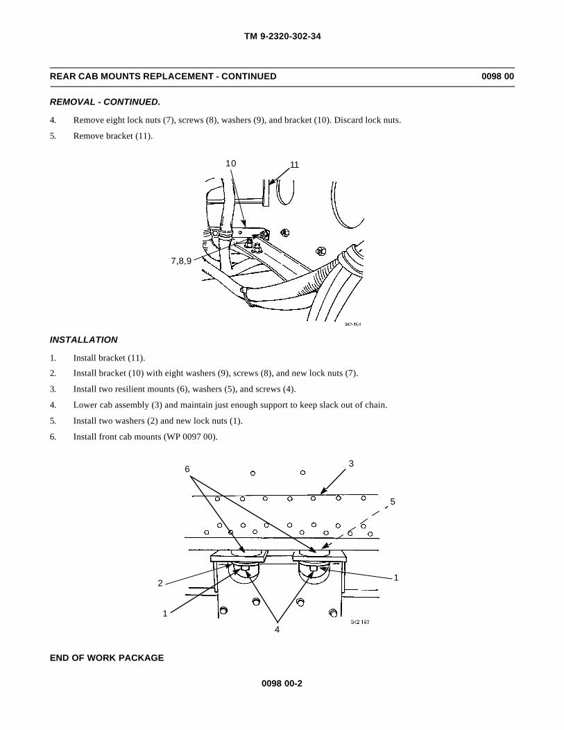
TM 9-2320-302-34
0098 00-2
REAR CAB MOUNTS REPLACEMENT - CONTINUED 0098 00
REMOVAL - CONTINUED.
4. Remove eight lock nuts (7), screws (8), washers (9), and bracket (10). Discard lock nuts.
5. Remove bracket (11).
INSTALLATION
1. Install bracket (11).
2. Install bracket (10) with eight washers (9), screws (8), and new lock nuts (7).
3. Install two resilient mounts (6), washers (5), and screws (4).
4. Lower cab assembly (3) and maintain just enough support to keep slack out of chain.
5. Install two washers (2) and new lock nuts (1).
6. Install front cab mounts (WP 0097 00).
END OF WORK PACKAGE
7,8,9
10 11
36
2
4
5
1
1

TM 9-2320-302-34
0099 00-1
FRONT SPRING REPLACEMENT 0099 00
THIS WORK PACKAGE COVERS
Removal, Installation
INITIAL SETUP
Maintenance Level
Direct Support
Tools and Special Tools
Tool kit, general mechanic’s (Item 132, WP 0126 00)
Jack, hydraulic (Item 73, WP 0126 00)
Trestle, hoist, portable (2) (Item 135, WP 0126 00)
Wrench, torque, 15-75 lb-ft (Item 138, WP 0126 00)
Wrench, torque, 100-600 lb-ft (Item 140, WP0126 00)
Wrench set, socket, 3/4 in drive (Item 141, WP0126 00)
Personnel Required
Two
Equipment Condition
Front wheel removed (TM 9-2320-302-10)
Front shock absorber removed (TM 3-2320-302-20)
WARNINGWARNINGUse extreme caution when handling heavy parts. Provide adequate support and use assistance during proce-dure. Ensure that any lifting device used is in good condition and of suitable load capacity. Keep clear ofheavy parts supported only by lifting device. Failure to follow this warning may result in death or injury topersonnel.

TM 9-2320-302-34
0099 00-2
FRONT SPRING REPLACEMENT - CONTINUED 0099 00
REMOVAL
1. Using floor jack and two trestles, lift and support frame (1) and front axle (2) to relieve weight from spring (3).
NOTENOTEAxle stop is offset to one side to align with frame. Note position of axle stop prior to removal to aid in instal-lation.
2. Remove four nuts (4), washers (5), two U-bolts (6), and axle stop (7) from front axle (2) and spring (3).
3. Remove stop cushion (8) from axle stop (7) if excessively worn or damaged (TM 9-2320-302-20).
4. Remove grease fitting (9), two nuts (10), washers (11), screws (12), washers (13), wear plates (14), four shims (15), andpin (16) from rear end of spring (3).
5. Remove grease fitting (17), two nuts (18), washers (19), screws (20), washers (21), shackles (22), wear plates (23), fourshims (24), and pin (25) from rear spring hanger (26).
26
10 18
19 2221
20
1312
1123
1415
16921
20
1512
13
14
345
2
7
8
16
10 1119
1822
2324
1725

TM 9-2320-302-34
0099 00-3
FRONT SPRING REPLACEMENT - CONTINUED 0099 00
REMOVAL - CONTINUED
6. Remove grease fitting (27), four screws (28), washers (29), and two saddle caps (30).
7. Lower front axle (2) to allow spring (3) to clear front spring hanger (31). Remove two washers (32) and pin (33) fromfront of spring (3).
NOTENOTENote position and number of shim(s) prior to removal to aid in installation.
8. With assistance, remove spring (3), spacer (34), shock absorber bracket (35), shim(s) (36), and pin (37) from front axle(2).
INSTALLATION
WARNINGWARNINGShim(s) is used to adjust caster alignment. Failure to install shim(s) correctly will cause hard steering andcould result in injury to personnel.
1. With assistance, install pin (37), shim(s) (2), shock absorber bracket (35), spacer (34), and spring (3) on front axle (2).
NOTENOTEInstall pin so that grooves line up with holes in shackle, allowing screws to be installed.
2
37
36
35
34
3
3327
32
32
30282930
31
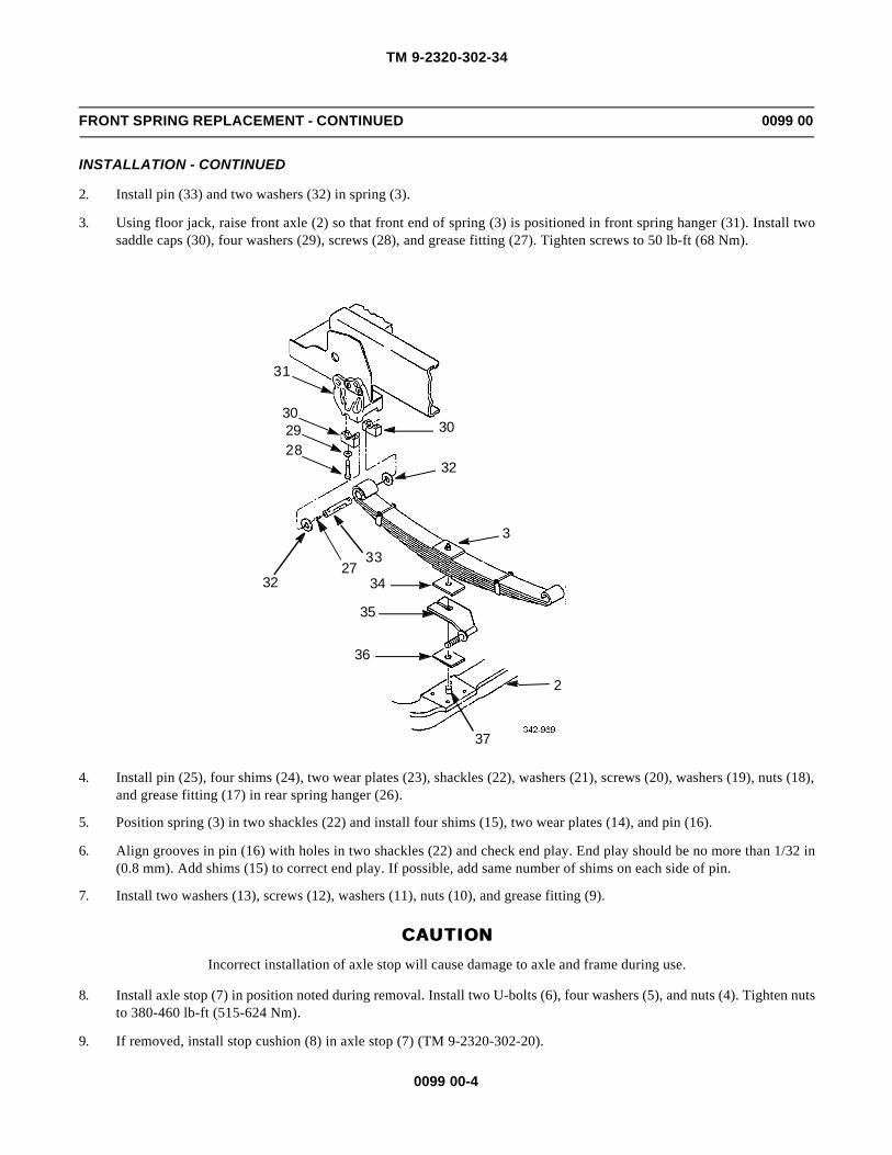
TM 9-2320-302-34
0099 00-4
FRONT SPRING REPLACEMENT - CONTINUED 0099 00
INSTALLATION - CONTINUED
2. Install pin (33) and two washers (32) in spring (3).
3. Using floor jack, raise front axle (2) so that front end of spring (3) is positioned in front spring hanger (31). Install twosaddle caps (30), four washers (29), screws (28), and grease fitting (27). Tighten screws to 50 lb-ft (68 Nm).
4. Install pin (25), four shims (24), two wear plates (23), shackles (22), washers (21), screws (20), washers (19), nuts (18),and grease fitting (17) in rear spring hanger (26).
5. Position spring (3) in two shackles (22) and install four shims (15), two wear plates (14), and pin (16).
6. Align grooves in pin (16) with holes in two shackles (22) and check end play. End play should be no more than 1/32 in(0.8 mm). Add shims (15) to correct end play. If possible, add same number of shims on each side of pin.
7. Install two washers (13), screws (12), washers (11), nuts (10), and grease fitting (9).
CAUTIONCAUTIONIncorrect installation of axle stop will cause damage to axle and frame during use.
8. Install axle stop (7) in position noted during removal. Install two U-bolts (6), four washers (5), and nuts (4). Tighten nutsto 380-460 lb-ft (515-624 Nm).
9. If removed, install stop cushion (8) in axle stop (7) (TM 9-2320-302-20).
2
37
36
35
34
3
3327
32
32
30282930
31

TM 9-2320-302-34
0099 00-5
FRONT SPRING REPLACEMENT - CONTINUED 0099 00
INSTALLATION - CONTINUED
10. Install front shock absorber (TM 9-2320-302-20).
11. Install front wheel (TM 9-2320-302-10).
END OF WORK PACKAGE
26
10 18
19 2221
20
1312
1123
1415
16921
20
1512
13
14
345
2
7
8
16
10 1119
1822
2324
1725

TM 9-2320-302-34
0099 00-6
This Page Intentionally Left Blank.

TM 9-2320-302-34
0100 00-1
FRONT SPRING HANGERS REPLACEMENT 0100 00
THIS WORK PACKAGE COVERS
Removal, Installation
INITIAL SETUP
Maintenance Level
Direct Support
Tools and Special Tools
Tool kit, general mechanic’s (Item 132, WP 0126 00)
Wrench, torque, 50-250 lb-ft (Item 139, WP 0126 00)
Equipment Condition
Front spring removed (WP 0099 00)
Steering gear removed (left side only) (WP 0088 00)
REMOVALNOTENOTE
• Vehicle may utilize huckbolts instead of screws and nuts. Replace all loose or damaged huckbolts withgrade 8 screws and lock nuts.
• Perform steps 1 through 3 on left front side of vehicle.
1. Remove two lock nuts (1), washers (2), screws (3), and threaded block (4). Discard lock nuts.
1
2
3
4
LEFT FRONT
RIGHT FRONT
REAR

TM 9-2320-302-34
0100 00-2
FRONT SPRING HANGERS REPLACEMENT - CONTINUED 0100 00
REMOVAL - CONTINUED
2. Remove lock nut (5), washer (6), and screw (7). Discard lock nut.
3. Remove three lock nuts (8), washers (9), left front spring hanger (10), three screws (11), and washers (12) from frame(13). Discard lock nuts.
NOTENOTEPerform steps 4 and 5 on right front side of vehicle.
4. Remove three lock nuts (14), washers (15), and screws (16).
5. Remove three lock nuts (17), washers (18), right front spring hanger (19), three screws (20), and washers (21) fromframe (13). Discard lock nuts.
NOTENOTEPerform steps 6 and 7 for rear spring hangers.
6. Remove four lock nuts (22), washers (23), screws (24), washers (25), and rear spring hanger (26) from frame (13). Dis-card lock nuts.
7. If damaged, remove bushing (27) from rear spring hanger (26).
1
2
3
4
LEFT FRONT
RIGHT FRONT
REAR
5613
8911
12
7
109 8 11
12
15
14
21
20
19
1718 16
21
2018
17
13
13
2425
24
25
26
23
22
2723
22
9

TM 9-2320-302-34
0100 00-3
FRONT SPRING HANGERS REPLACEMENT - CONTINUED 0100 00
INSTALLATION
NOTENOTEPerform steps 1 and 2 for rear spring hangers.
1. If removed, install new bushing (27) in rear spring hanger (26).
2. Install four washers (25), screws (24), rear spring hanger (26), four washers (23), and new lock nuts (22) on frame (13).
NOTENOTEPerform steps 3 and 4 on right front side of vehicle.
3. Install three washers (21), screws (20), right front spring hanger (19), three washers (18), and new lock nuts (17) onframe (13).
4. Install three screws (16), washers (15), and new lock nuts (14).
NOTENOTEPerform steps 5 through 7 on left front side of vehicle.
5. Install three washers (12), screws (11), left front spring hanger (10), three washers (9), and new lock nuts (8).
6. Install screw (7), washer (6), and new lock nut (5).
7. Install threaded block (4), two screws (3), washers (2), and new lock nuts (1).
8. Tighten 1/2-13 grade 8 lock nuts to 80 lb-ft (108 Nm).
9. Tighten 5/8-11 grade 8 lock nuts to 160 lb-ft (217 Nm).
10. Install steering gear (left side only) (WP 0088 00).
11. Install front spring (WP 0099 00).
END OF WORK PACKAGE

TM 9-2320-302-34
0100 00-4
This Page Intentionally Left Blank.

TM 9-2320-302-34
0101 00-1
REAR SUSPENSION CENTER BEARING REPLACEMENT 0101 00
THIS WORK PACKAGE COVERS
Removal, Installation
INITIAL SETUP
Maintenance Level
Direct Support
Tools and Special Tools
Tool kit, general mechanic’s (Item 132, WP 0126 00)
Jack, hydraulic (Item 73, WP 0126 00)
Trestle, hoist, portable (2) (Item 135, WP 0126 00)
Wrench, torque, 50-250 lb-ft (Item 139, WP 0126 00)
Materials/Parts
Screw (P/N 23-12576-125) (2)
Adhesive, loctite (Item 2, WP 0125 00)
Personnel Required
Two
REMOVAL
1. Remove nut (1), screw (2), and rebound stop (3) from mounting bracket (4).
2. Remove two screws (5) from center bearing (6).
3. Using floor jack, lift rear of vehicle and place a trestle under each frame rail. Lower vehicle onto trestles.
4. Remove two screws (7) and center bearing (6) from top of spring assembly (8). Discard screws.
1432
5 767 8

TM 9-2320-302-34
0101 00-2
REAR SUSPENSION CENTER BEARING REPLACEMENT - CONTINUED 0101 00
INSTALLATION
1. Install center bearing (6) to vehicle with two screws (5). Tighten screws to 68 lb-ft (92 Nm).
2. Using floor jack, raise rear axle until bottom of center bearing (6) contacts spring assembly (8).
3. Apply adhesive to threads of two new screws (7). Install center bearing (6) to top of spring assembly (8) with screws.Tighten screws to 155 lb-ft (210 Nm).
4. Remove trestles and floor jack.
5. Install rebound stop (3) to mounting bracket (4) with screw (2) and nut (1). Tighten nut to 68 lb-ft (92 Nm).
END OF WORK PACKAGE
143
2
5 767 8

TM 9-2320-302-34
0102 00-1
REAR SPRING ASSEMBLY REPLACEMENT 0102 00
THIS WORK PACKAGE COVERS
Removal, Installation
INITIAL SETUP
Maintenance Level
Direct Support
Tools and Special Tools
Tool kit, general mechanic’s (Item 132, WP 0126 00)
Jack, hydraulic (Item 73, WP 0126 00)
Wrench, torque, 15-75 lb-ft (Item 138, WP 0126 00)
Personnel Required
Two
References
TM 9-2320-302-10
TM 9-2320-302-20
WARNINGWARNINGUse extreme caution when handling heavy parts. Provide adequate support and use assistance during proce-dure. Ensure that any lifting device used is in good condition and of suitable load capacity. Keep clear ofheavy parts supported only by lifting device. Failure to follow this warning may result in death or injury topersonnel.
REMOVAL
1. Remove four screws (1) and top pad (2) from each of two axle clamps (3).
2. Remove rear suspension center bearing (WP 0101 00).
3. With rear of vehicle still raised, remove wheels (TM 9-2320-302-10).
4. Using a suitable lifting device, remove rear spring assembly (4) from vehicle.
2
1 1
3
4
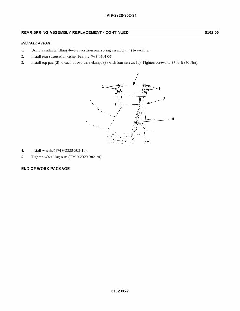
TM 9-2320-302-34
0102 00-2
REAR SPRING ASSEMBLY REPLACEMENT - CONTINUED 0102 00
INSTALLATION
1. Using a suitable lifting device, position rear spring assembly (4) to vehicle.
2. Install rear suspension center bearing (WP 0101 00).
3. Install top pad (2) to each of two axle clamps (3) with four screws (1). Tighten screws to 37 lb-ft (50 Nm).
4. Install wheels (TM 9-2320-302-10).
5. Tighten wheel lug nuts (TM 9-2320-302-20).
END OF WORK PACKAGE
2
1 1
3
4
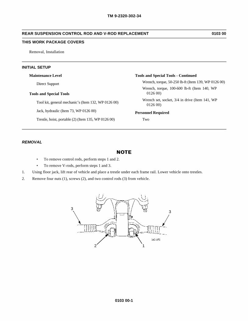
TM 9-2320-302-34
0103 00-1
REAR SUSPENSION CONTROL ROD AND V-ROD REPLACEMENT 0103 00
THIS WORK PACKAGE COVERS
Removal, Installation
INITIAL SETUP
Maintenance Level
Direct Support
Tools and Special Tools
Tool kit, general mechanic’s (Item 132, WP 0126 00)
Jack, hydraulic (Item 73, WP 0126 00)
Trestle, hoist, portable (2) (Item 135, WP 0126 00)
Tools and Special Tools - Continued
Wrench, torque, 50-250 lb-ft (Item 139, WP 0126 00)
Wrench, torque, 100-600 lb-ft (Item 140, WP0126 00)
Wrench set, socket, 3/4 in drive (Item 141, WP0126 00)
Personnel Required
Two
REMOVAL
NOTENOTE• To remove control rods, perform steps 1 and 2.
• To remove V-rods, perform steps 1 and 3.
1. Using floor jack, lift rear of vehicle and place a trestle under each frame rail. Lower vehicle onto trestles.
2. Remove four nuts (1), screws (2), and two control rods (3) from vehicle.
33
2 1
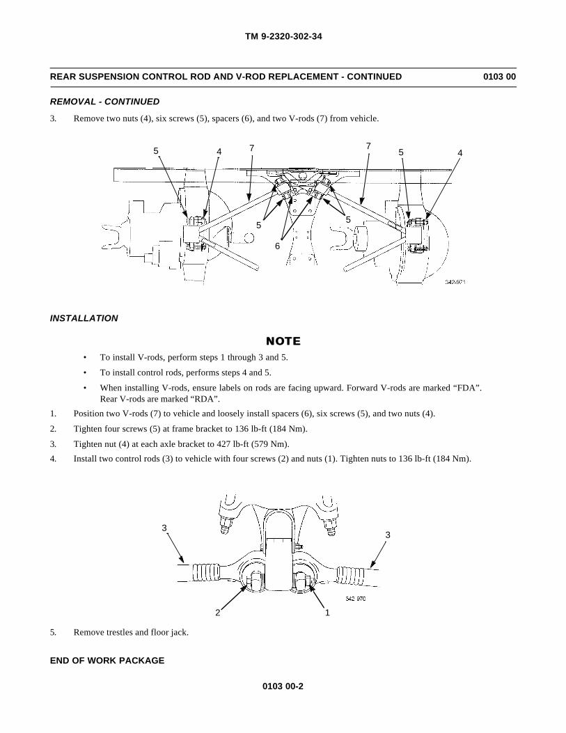
TM 9-2320-302-34
0103 00-2
REAR SUSPENSION CONTROL ROD AND V-ROD REPLACEMENT - CONTINUED 0103 00
REMOVAL - CONTINUED
3. Remove two nuts (4), six screws (5), spacers (6), and two V-rods (7) from vehicle.
INSTALLATION
NOTENOTE• To install V-rods, perform steps 1 through 3 and 5.
• To install control rods, performs steps 4 and 5.
• When installing V-rods, ensure labels on rods are facing upward. Forward V-rods are marked “FDA”.Rear V-rods are marked “RDA”.
1. Position two V-rods (7) to vehicle and loosely install spacers (6), six screws (5), and two nuts (4).
2. Tighten four screws (5) at frame bracket to 136 lb-ft (184 Nm).
3. Tighten nut (4) at each axle bracket to 427 lb-ft (579 Nm).
4. Install two control rods (3) to vehicle with four screws (2) and nuts (1). Tighten nuts to 136 lb-ft (184 Nm).
5. Remove trestles and floor jack.
END OF WORK PACKAGE
45
55
6
5 4 77
33
2 1

TM 9-2320-302-34
0104 00-1
CAB REPLACEMENT 0104 00
THIS WORK PACKAGE COVERS
Removal, Installation
INITIAL SETUP
Maintenance Level
General Support
Tools and Special Tools
Tool kit, general mechanic’s (Item 132, WP 0126 00)
Sling, beam type (Item 115, WP 0126 00)
Materials/Parts
Nut, kep
Nut, lock (P/N MS51922-49) (2)
Nut, lock (P/N MS51922-57) (2)
Personnel Required
Three
Equipment Condition
Cab doors removed (WP 0107 00)
Muffler and exhaust stack removed (TM 9-2320-302-20)
Exterior grabhandles removed (TM 9-2320-302-20)
Fender extensions removed (TM 9-2320-302-20)
Hood latches removed (TM 9-2320-302-20)
Utility lights removed (TM 9-2320-302-20)
Clearance lights removed (TM 9-2320-302-20)
Windshield wiper linkage removed (TM 9-2320-302-20)
Voltage regulator removed (TM 9-2320-302-20)
Dual voltage alternator control (DUVAC) removed(TM 9-2320-302-20)
Starter regulator removed (TM 9-2320-302-20)
Foot brake valve removed (TM 9-2320-302-20)
Rear window removed (WP 0110 00)
Windshield removed (WP 0109 00)
Radio mounting bracket removed (TM 9-2320-302-20)
Equipment Condition - Continued
Transmission shift control removed (TM 9-2320-302-20)
Floor mats removed (TM 9-2320-302-20)
Arctic heater removed (TM 9-2320-302-20)
Cab air ducts removed (WP 0111 00)
Head liners removed (TM 9-2320-302-20)
Beacon warning light bracket removed (TM 9-2320-302-20)
Sunvisors removed (TM 9-2320-302-20)
Air horn and valve removed (TM 9-2320-302-20)
Interior grabhandle removed (TM 9-2320-302-20)
Cab liners removed (TM 9-2320-302-20)
Electronic throttle removed (TM 9-2320-302-20)
Steering column support bracket removed (TM 9-2320-302-20)
Brake pedal removed (TM 9-2320-302-20)
Cab overhead wiring harness removed (TM 9-2320-302-20)
Chassis wiring harness removed (TM 9-2320-302-20)
Air tubes removed (TM 9-2320-302-20)
Anti-lock brake system (ABS) electronic control unitremoved (TM 9-2320-302-20)
Anti-lock brake system (ABS) fuse and relay panelremoved (TM 9-2320-302-20)
Cab anti-lock brake system (ABS) wiring harnessremoved (TM 9-2320-302-20)
Collision Warning System (CWS) wiring harnessremoved (WP 0066 00)

TM 9-2320-302-34
0104 00-2
CAB REPLACEMENT - CONTINUED 0104 00
WARNINGWARNINGUse extreme caution when handling heavy parts. Provide adequate support and use assistance during proce-dure. Ensure that any lifting device used is in good condition and of suitable load capacity. Keep clear ofheavy parts supported only by lifting device. Failure to follow this warning may result in death or injury topersonnel.
REMOVAL
1. Remove two nuts (1), washers (2), bolts (3), and washers (4) and swing three radiator support rods (5) out of the way.
2. Attach sling and hoist to cab assembly (6). Remove all slack from chain.
1,2,3,4
51,2,3,4
5
6

TM 9-2320-302-34
0104 00-3
CAB REPLACEMENT - CONTINUED 0104 00
REMOVAL - CONTINUED
3. Remove two lock nuts (7), washers (8), resilient mounts (9), and screws (10) from front cab mounts (11). Discard locknuts.
4. Remove kep nut (12), clamps (13), screw (14), and washer (15). Discard kep nut.
5. Carefully pull two wiring harnesses (16 and 17) from cab assembly (6).
10
9
8
7
11
12,14,15
6
16
17
13

TM 9-2320-302-34
0104 00-4
CAB REPLACEMENT - CONTINUED 0104 00
REMOVAL - CONTINUED
6. Remove two lock nuts (18), washers (19), screws (20), washers (21), and resilient mounts (22) from rear cab mount(23). Discard lock nuts.
WARNINGWARNINGUse extreme caution when handling heavy parts. Provide adequate support and use assistance during proce-dure. Ensure that any lifting device used is in good condition and of suitable load capacity. Keep clear ofheavy parts supported only by lifting device. Failure to follow this warning may result in death or injury topersonnel.
CAUTIONCAUTIONLift cab assembly slowly and check for parts that may still be connected to cab and vehicle structure. Failureto do so may result in damage to equipment.
7. Remove cab assembly (6) from frame structure.
INSTALLATION
WARNINGWARNINGUse extreme caution when handling heavy parts. Provide adequate support and use assistance during proce-dure. Ensure that any lifting device used is in good condition and of suitable load capacity. Keep clear ofheavy parts supported only by lifting device. Failure to follow this warning may result in death or injury topersonnel.
20
19
1819
18
22
22
21
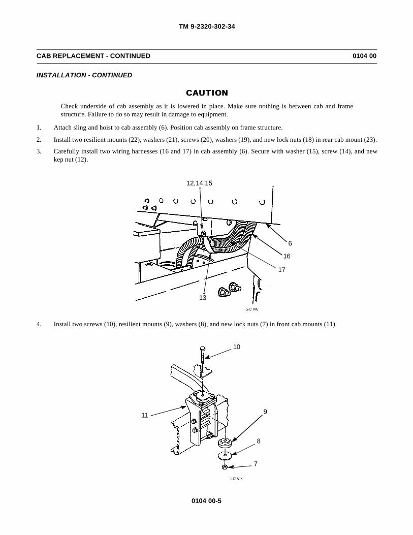
TM 9-2320-302-34
0104 00-5
CAB REPLACEMENT - CONTINUED 0104 00
INSTALLATION - CONTINUED
CAUTIONCAUTIONCheck underside of cab assembly as it is lowered in place. Make sure nothing is between cab and framestructure. Failure to do so may result in damage to equipment.
1. Attach sling and hoist to cab assembly (6). Position cab assembly on frame structure.
2. Install two resilient mounts (22), washers (21), screws (20), washers (19), and new lock nuts (18) in rear cab mount (23).
3. Carefully install two wiring harnesses (16 and 17) in cab assembly (6). Secure with washer (15), screw (14), and newkep nut (12).
4. Install two screws (10), resilient mounts (9), washers (8), and new lock nuts (7) in front cab mounts (11).
12,14,15
6
16
17
13
10
9
8
7
11

TM 9-2320-302-34
0104 00-6
CAB REPLACEMENT - CONTINUED 0104 00
INSTALLATION - CONTINUED
5. Remove sling and hoist from cab assembly (6).
6. Swing three radiator support rods (5) into place and install two washers (4), bolts (3), washers (2), and nuts (1).
7. Install Collision Warning System (CWS) wiring harness (WP 0066 00).
8. Install cab anti-lock brake system (ABS) wiring harness (TM 9-2320-302-20).
9. Install anti-lock brake system (ABS) fuse and relay panel (TM 9-2320-302-20).
10. Install anti-lock brake system (ABS) electronic control unit (TM 9-2320-302-20).
11. Install air tubes (TM 9-2320-302-20).
12. Install chassis wiring harness (TM 9-2320-302-20).
13. Install cab overhead wiring harness (TM 9-2320-302-20).
14. Install brake pedal (TM 9-2320-302-20).
15. Install steering column support bracket (TM 9-2320-302-20).
16. Install electronic throttle (TM 9-2320-302-20).
17. Install cab liners (TM 9-2320-302-20).
18. Install interior grabhandle (TM 9-2320-302-20).
19. Install sunvisors (TM 9-2320-302-20).
20. Install head liners (TM 9-2320-302-20).
21. Install arctic heater (TM 9-2320-302-20).
22. Install transmission shift control (TM 9-2320-302-20).
23. Install air horn and valve (TM 9-2320-302-20).
24. Install beacon warning light bracket (TM 9-2320-302-20).
25. Install cab air ducts (WP 0111 00).
26. Install floor mats (TM 9-2320-302-20).
27. Install radio mounting bracket (TM 9-2320-302-20).
28. Install windshield (WP 0109 00).
29. Install rear window (WP 0110 00).
1,2,3,4
51,2,3,4
5
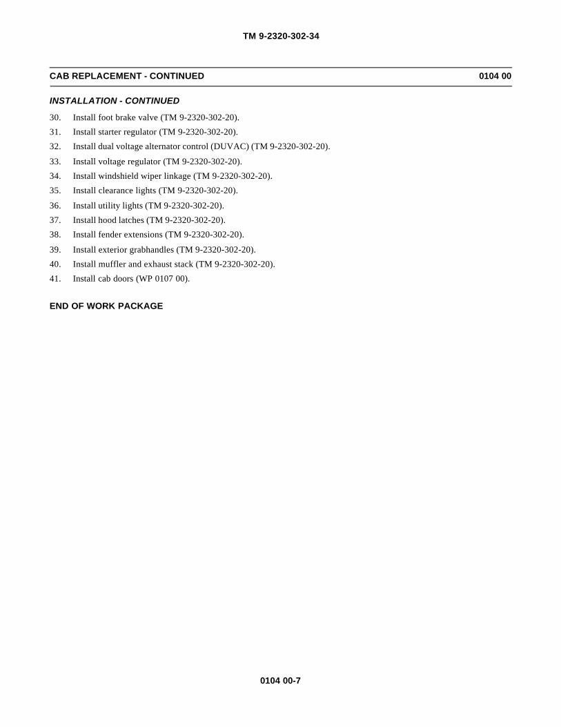
TM 9-2320-302-34
0104 00-7
CAB REPLACEMENT - CONTINUED 0104 00
INSTALLATION - CONTINUED
30. Install foot brake valve (TM 9-2320-302-20).
31. Install starter regulator (TM 9-2320-302-20).
32. Install dual voltage alternator control (DUVAC) (TM 9-2320-302-20).
33. Install voltage regulator (TM 9-2320-302-20).
34. Install windshield wiper linkage (TM 9-2320-302-20).
35. Install clearance lights (TM 9-2320-302-20).
36. Install utility lights (TM 9-2320-302-20).
37. Install hood latches (TM 9-2320-302-20).
38. Install fender extensions (TM 9-2320-302-20).
39. Install exterior grabhandles (TM 9-2320-302-20).
40. Install muffler and exhaust stack (TM 9-2320-302-20).
41. Install cab doors (WP 0107 00).
END OF WORK PACKAGE

TM 9-2320-302-34
0104 00-8
This Page Intentionally Left Blank.

TM 9-2320-302-34
0105 00-1
CAB BODY REPAIR 0105 00
THIS WORK PACKAGE COVERS
General, Inspection, Rivet Replacement, Aluminum Repair
INITIAL SETUP
Maintenance Level
General Support
Tools and Special Tools
Tool kit, general mechanic’s (Item 132, WP 0126 00)
Drill, electric, portable (Item 31, WP 0126 00)
Drill set, twist (Item 32, WP 0126 00)
Riveter, blind hand (Item 109, WP 0126 00)
Materials/Parts
Compound, sealing (Item 14, WP 0125 00)
Tool kit, body and fender repair (Item 39, WP0125 00)
GENERAL
1. The body is constructed from aluminum alloys that have been heat treated to obtain high strength. Welding cannot beused to make body repairs. Heat generated in welding will reverse the heat treatment process and cause a great reductionin strength of material.
2. The hood is made of SMC (sheet molding compound). Cracks, splits or holes may be repaired with a glass-reinforcedplastic laminate repair kit (WP 0106 00).
3. Solid 3/16-in diameter aluminum rivets are the primary method of joining body components. Rivets are inserted into ahole through two pieces of metal. A second head is formed by manual or pneumatic impacting or by squeezing the rivet.A bucking bar is used to back up the rivet to form the rivet head. When making repairs, use blind rivets of the same sizeor oversize diameter with the appropriate grip length.
4. Blind structural aluminum rivets of 3/16-in diameter are used in applications where there is access from only one side ofthe part. Blind rivets are installed using a tool that pulls on the rivet stem causing a bulbed head to form on the back sideof the part. Fastening is complete when the stem breaks off. High strength is obtained in blind structural rivets bymechanically locking the remaining stem inside the rivet body.
5. Steel pull-type lock bolt fasteners in 3/16 and 1/4-in diameters are used where tension or high-shear loads exist. Lockbolts are two-piece unthreaded fasteners. One part is a high-strength, steel-headed bolt-like part with serrations on itsshank. The mating part is a collar that is swaged over the serrations causing the fastener to be locked in place.
6. To facilitate repairs to the body, it is acceptable to replace lock bolts and rivets with 1/4 in AN4 series bolts. Do notreplace lock bolts with rivets. Standard threaded fasteners should not be used, as these will quickly wear the aluminumstructure. Bolt lengths should be chosen so that the cylindrical portion of the bolt is bearing on all members beingjoined. Bolts are designated as NA4-XX or AN4C-XX, where XX defines grip length. Tighten all bolts to 70-75 lb-in (8Nm).
7. All riveted joints have adhesive foam between both components riveted together. The purpose of this tape is to ensurewatertight joints and to ensure aluminum components will not wear prematurely. Tape may be either 1 in or 2 in wide,depending on the joint. Replace adhesive tape with the same size removed during disassembly. The only time adhesivefoam tape is to be replaced is if a riveted joint is completely taken apart.

TM 9-2320-302-34
0105 00-2
CAB BODY REPAIR - CONTINUED 0105 00
INSPECTION
1. General. The damaged area should be thoroughly cleaned and inspected to determine cause and extent of damage. Bodyparts should be inspected for holes, cracks, dents, distortion or breaks. Fasteners should be inspected for breaks, stretch-ing, looseness, cocked heads or hole elongation. Seams, flanges, and joints should be inspected for straightness or localdeformation as an indication that fasteners may have been stretched or holes elongated. It is possible for this to happenand for fasteners to still appear to be tight in their holes. In addition, make a thorough inspection of adjacent areas todetermine if high loads have been transmitted from the damaged area to other areas. This can result in secondary dam-age in the form of distorted panels or seams, loosened or sheared fasteners, elongated fastener holes, and cracks.
2. Classification. After extent of damage has been determined, affected parts should be classified in one of the followingcategories:
• Negligible Damage
• Damage Repairable by Patching
• Damage Repairable by Insertion
• Damage Necessitating Replacement of Parts
a. Negligible Damage. Minor dents, nicks, scores, cracks, and holes in body panels which are within or are broughtwithin reasonable limits by a simple procedure without extensive rework. These defects should be considered moreserious if located in main structural members such as body side rails, a pillar or floor crossmembers rather than inbody panels such as cowls or rear wheelhouses. Deep wrinkles of undetermined origin in body panels should notbe classed as negligible until the source of wrinkles has been investigated and positively identified. Damage otherthan small dents, holes, nicks, and scratches will require repair or replacement of the part. Refer to repair of negli-gible damage below.
(1) Negligible Cracks. Isolated cracks less than 0.50 in (1.27 cm) long may be classified as negligible cracksprovided they are stop drilled at each end to stop propagation.
(2) Negligible Holes. Isolated holes no more than 0.50 in (1.27 cm) diameter after they are made round withsmooth edges are classified as negligible holes, provided the distance from the edge of the hole to the near-est line of rivets exceeds the diameter of the hole.
(3) Negligible Dents and Distortion. Small dents and distorted areas may be classified as negligible, if theycan be repaired by hammering or bending without causing the material to crack. Heat may not be used forreforming.
b. Damage Repairable by Patching. Damage beyond negligible must be repaired or the section replaced. Patchescan often be applied over damaged body panels. Damaged area must first be trimmed to remove sharp edges ornotches that could cause start of new cracks. Patch must then be sized to overlap the area to allow for attaching riv-ets. Refer to Repair by Patching on page 0105 00-12.
c. Damage Repairable by Insertion. In certain cases, patch repairs may not be desirable because of impracticalityor because a flush surface is desired. In this case, damaged area must be cut away and a partial replacement ofequivalent material inserted flush with adjacent areas and backed up with a doubler. Refer to Repair by Insertionon page 0105 00-13.
d. Damage Necessitating Replacement of Parts. Parts are too badly damaged for repair, or replacement is easierthan repair; repair for welded assemblies such as body mounts. Welded assemblies cannot be rewelded withoutdestroying their strength and must be replaced.
TM 9-2320-302-34
0105 00-3
CAB BODY REPAIR - CONTINUED 0105 00
INSPECTION - CONTINUED
3. Rivet Failure. Signs of rivet failure include tipped heads, looseness, and chipped or cracked paint. If heads are tipped inthe same direction and rivets are loose in consecutive groups, the joint has undergone excessive load. Rivet heads thatare tipped in different directions and are not in groups may be improperly installed. With chipped or cracked paint, itmay be necessary to remove paint to check true condition of rivets. Rivets subjected to critical loads, but showing nodistortion, should be inspected if failure is suspected. The head should be drilled off, and the shank should be carefullypunched out. Failure is indicated by notched rivet shank and misaligned holes. Flush rivets showing head slippagewithin the dimple or countersink indicate either sheet bearing or rivet shear failure and must be removed for inspectionand replacement. If failure of rivets cannot be detected by visual inspection, the joint can be checked by drilling andpunching out several rivets. If rivet shanks are notched, rivets should be replaced with next larger size rivets. If rivetholes show elongation due to local failure in tearing of the sheet, next larger size rivet must be used in replacement. Anydeformation of the sheet around rivet, tear outs or cracks between rivets usually indicates partially failed or damagedrivets. Complete repair of the joint will require replacement by the next larger size rivets. Use the next 1/32-in largerdiameter rivet to obtain a tight joint when original hole has been enlarged. If original size rivet is installed, rivet will notbe able to carry its share of shear load, and the joint will not meet its strength requirements.
4. Lock Bolt Failure. Lock bolts are used to withstand tension loads and high-shear loads. These fasteners are installed inholes with an interference fit. No looseness can be permitted. Lock bolts showing evidence of being stretched, broken,loose in holes or having heads that do not set flat against the surface must be replaced. Guidelines used in Rivet Failure,above, for detecting rivet failures also apply to lock bolts.
RIVET REPLACEMENT
NOTENOTEWhen removing rivets, be careful not to enlarge rivet holes. This will require use of an oversize or largerrivet for replacement.
1. Solid Rivet Removal.
a. File flat surface on manufactured head, if accessible. It is always preferable to work on manufactured head ratherthan a head that is bucked over. Manufactured head will always be more symmetrical around shank.
b. Indent center of filed surface with center punch.
CAUTIONCAUTIONUse drill slightly smaller than diameter of rivet shank to avoid making rivet hole oversized.
c. Using drill slightly smaller than diameter of rivet shank, drill through rivet head.
d. Support back of rivet using sharp chisel. Cut rivet head along direction of rivet line or panel edge to prevent distor-tion of panel and shear off weakened rivet head.
e. Support panel from opposite side and drive out shank with pin punch. If rivet is unduly tight because of swellingbetween sheets, drill rivet shank out with undersize drill.
2. Blind Rivet Removal.
a. File small flat on rivet head.
b. Center punch flat. Support rivet backside, if possible.
c. Using small drill about the size of rivet pin, drill off tapered end of pin that forms lock.
d. Shear lock using pin punch to drive out pin.
e. Pry out remainder of locking collar.
f. Using drill slightly smaller than rivet shank, drill almost through rivet head.

TM 9-2320-302-34
0105 00-4
CAB BODY REPAIR - CONTINUED 0105 00
RIVET REPLACEMENT - CONTINUED
g. Pry off rivet head with pin punch.
h. Tap out rivet shank with pin punch.
3. Lock Bolt Removal.
NOTENOTEIf lock bolt head is inaccessible, locking collar must be removed. Remove collars by grinding or splittingcollars axially with sharp chisel.
a. Work from head side of lock bolt, if accessible. File small flat on head, if rounded.
b. Center punch head.
c. Using hardened drill slightly smaller than bolt head, drill through head. In cases where lock bolts are too hard to bedrilled with available drills, grind head down using cutoff wheel or carbide bit in die grinder. When using grindermethod, cut head down until very thin, but do not grind completely off or touch body part with grinding tool.
d. Support head and use pin punch to pry off head or shear off with sharp chisel.
CAUTIONCAUTIONBe careful not to distort lock bolt or lock bolt hole to prevent damage to equipment.
e. Drive lock bolt out of hole with pin punch.
4. Rivet Hole Drilling.
a. Center punch all new rivet locations. Center punch mark must be large enough to prevent drill from slipping out ofposition and must not dent surface of material. To prevent denting, place bucking bar behind material duringpunching.
b. Make sure drill is correct size (Tables 1 and 2) and point is properly ground. Number 10 drill is used to install stan-dard 3/16-in blind rivets.
Table 1. Drill Sizes for Solid Shank Rivets.
RIVETDIAMETER
(IN) DRILL SIZE
DRILLDIAMETER
(IN)
1/16 #51 0.0670
3/32 #41 0.0960
1/8 #30 0.1285
5/32 #21 0.1590
3/16 #10 0.1910
1/4 F 0.2570
5/16 P 0.3230
3/8 W 0.3860

TM 9-2320-302-34
0105 00-5
CAB BODY REPAIR - CONTINUED 0105 00
RIVET REPLACEMENT - CONTINUED
Table 2. Drill Sizes for Blind Rivets.
NOTENOTE• While drilling, hold drill at 90-degree angle to material surface. Avoid letting drill wobble, making
oblong holes.
• Avoid excessive pressure. Let drill bit do cutting.
• Do not push drill through material.
c. Place drill in center mark for new rivet locations or align drill with old hole when replacing old rivets with oversizerivets. When using power drill, give bit a few turns with fingers before starting motor. This will help ensure drilldoes not jump out of position when motor is started.
d. Remove all burrs with metal countersink or file.
NOTENOTEEnsure no chips are trapped between sheets of metal.
e. Clean away all drill chips.
f. Apply sealing compound to hole and surrounding area.
5. Hole Countersinking.
NOTENOTESome rivet installations in body require that rivet head be flush with material surface. In these instances,countersunk or flush head rivets are used.
a. When using countersunk rivets, rivet holes must be countersunk with tool having 100-degree taper so rivet headwill fit flush with surface.
b. When using hand-operated countersink, hole must be tried with rivet so that recess will not be too deep or too shal-low. It is best to use countersink with stop so that depth of countersink can be controlled. Typical countersinkingdimensions for blind rivets are shown in Table 3. Minimum sheet thickness that can be machined for 100-degreecountersink rivets is given in Table 4.
c. Do not remove edge of hole on blind side of joint.
NOMINAL DIAMETER (IN) OVERSIZE DIAMETER (IN)
RIVETDIAMETER
DRILLSIZE MINIMUM MAXIMUM
RIVETDIAMETER
DRILLSIZE MINIMUM MAXIMUM
1/8 #30 0.129 0.132 1/8 #27 0.143 0.146
5/32 #20 0.160 0.164 5/32 #16 0.176 0.180
3/16 #10 0.192 0.196 3/16 #5 0.205 0.209

TM 9-2320-302-34
0105 00-6
CAB BODY REPAIR - CONTINUED 0105 00
RIVET REPLACEMENT - CONTINUED
Table 3. Countersinking Dimensions for 100-Degree Countersunk Blind Rivets.
Table 4. Minimum Sheet Gage for 100-Degree Machine Countersink.
6. Solid Rivet Installation.
NOTENOTEWhen replacing rivets during repair, use same rivet size and type, if possible. If hole has been damaged, itwill be necessary to drill hole oversize and use next larger rivet or oversize blind rivet.
a. After drilling and prior to driving rivets, parts to be joined must be secured to prevent slipping during riveting. C-clamps may be used, or any of several varieties of skin fasteners may be inserted in previously drilled holes.
CAUTIONCAUTIONWhen riveting thin gage materials, be careful handling rivet tools to avoid damaging material.
b. Solid rivets are available in various lengths. Correct length rivet must be chosen so bucked head is not too small ortoo large to form tight fit. Use Table 5 to determine proper rivet length.
c. Three common methods of driving or setting rivets are: hand, squeeze, and pneumatic gun. All three methods useprinciple of upsetting or heading rivet shank against bucking bar.
COUNTERSINKING DIMENSIONS (100°)
RIVET C (IN)
DIAMETER (IN) MINIMUM MAXIMUM
1/8 0.222 0.228
5/32 0.283 0.289
3/16 0.350 0.356
RIVET SIZE (IN) 3/32 1/8 5/32 3/16 1/4
GAGE (IN) 0.040 0.050 0.064 0.072 0.072
01 OR MIN.
C

TM 9-2320-302-34
0105 00-7
CAB BODY REPAIR - CONTINUED 0105 00
RIVET REPLACEMENT - CONTINUED
Table 5. Calculating Correct Solid Rivet Length.
7. Rivet Driving Practices and Precautions. Riveting is the major means of joining body parts. Proper procedures mustbe followed to maintain high-quality workmanship. Table 6 lists types of faulty rivet installations, causes, and correctiveaction to be taken.
Table 6. Correctly and Incorrectly Driven Rivet.
RIVET DIAMETER MATERIAL THICKNESS ADD
1/4 in or less 2 in or less 1-1/2 x diameter of rivet
1/4 in or less over 2 in 1-1/2 x diameter of rivet + 1/16 in forevery 2 in of material thickness
5/16 in or more 1 in or less 1-1/2 x diameter of rivet
5/16 in or more over 1 in 1-1/2 x diameter of rivet + 1/16 in forevery 1 in of material thickness
TOP VIEW
IMPERFECTION CAUSE REMEDY ACTION
None None None None
Cut head Improperly held tools. Hold riveting tools firmlyagainst work.
Replace rivet.
Excessive flat head, resultanthead cracks
Excessive driving, too muchpressure on bucking bar.
Improve riveting technique. Replace rivet.
(A)DRIVEN
CORRECTLY
(B)UNSTEADY
TOOL
(C)DRIVEN
EXCESSIVELY
(D)SEPARATIONOF SHEETS
(E)UNSTEADYRIVET SET
(F)EXCESSIVE
SHANK LENGTH
DAMAGED HEAD
CRACKS
SWELLEDSHANK SLOPING
HEAD
BUCKLEDSHANK
BOTTOM VIEW

TM 9-2320-302-34
0105 00-8
CAB BODY REPAIR - CONTINUED 0105 00
RIVET REPLACEMENT - CONTINUED
Table 6. Correctly and Incorrectly Driven Rivet - Continued.
8. Blind Rivet Driving Practices and Precautions.
a. Rivets should be inspected for proper installation. Grip length of each rivet is marked on top of rivet head to pro-vide positive identification. Use of proper grip length will produce rivet installation where locking collar is flushwith top surface of rivet head. Tolerance limit on flushness is 0.020 in (0.5 mm).
b. For proper rivet installation, it is imperative that holes be properly prepared, tools be in good working order, andrivets be properly applied. When problems occur, source of trouble could be in any of these areas.
9. Blind Rivet Installation.
CAUTIONCAUTION• Proper length rivet must be selected for each application to prevent damage to equipment. Rivet lengths
are sized by range of material thickness that rivet will grip.
• Rivets can tolerate only 1/16-in variation in material thickness for each particular rivet length to preventdamage to equipment. Rivet grip lengths are called out as dash number at end of manufacturers partnumber.
• For double dimpled sheets, add countersunk head height to materials thickness to prevent damage toequipment.
NOTENOTE• Prior to installing blind rivets, hole must be prepared and parts must be aligned and clamped firmly in
place. These steps are the same as for solid riveting operations (refer to Rivet Hole Drilling on page0105 00-4).
• Proper drill sizes for standard and oversize blind rivets are given in Table 2.
• Countersinking dimensions and minimum sheet gage for countersunk blind rivets are shown in Tables 3and 4.
• Grip lengths are determined as shown in Table 7.
• Use rivet installation tool kit, D-100-MIL-I, and puller head adapters, if required, for all blind rivets.
IMPERFECTION CAUSE REMEDY ACTION
Sheet separation Work not held firmly togetherand rivet shank swelled.
Fasten work firmly togetherto prevent slipping.
Replace rivet.
Sloping head (a) Bucking bar not heldfirmly.
(b) Bucking bar permittedto slide and bounce overrivet.
Hold bucking bar firmlywithout too much pressure.
Replace rivet.
Buckled shank Improper rivet length and Eabove.
E, above, and rivet of properlength.
Replace rivet.

TM 9-2320-302-34
0105 00-9
CAB BODY REPAIR - CONTINUED 0105 00
RIVET REPLACEMENT - CONTINUED
Table 7. Rivet Grip Length Determination.
a. Insert rivet stem into pulling head of rivet gun or adapter.
b. Hold rivet gun in line with axis of rivet as accurately as possible.
c. Apply steady, firm pressure against rivet head.
d. Squeeze handles of manual gun. Rivet clamping action will pull sheets together, seat rivet head, and break stemflush with head of rivet.
ALUMINUM REPAIR
CAUTIONCAUTIONRepairs should not be made on body using welding or heat for forming. Heat will weaken material and causefurther problems.
1. Material. Aluminum material used for repair should be of the same alloy and temper as original, if possible. In general,6061-T6 should be used. Material thickness must be the same or thicker. This alloy will work well for flat repairs, but isnot well suited to bending because it is hard and cracks easily when bent sharply. When bends must be made, use softer6061-T4 aluminum alloy and increase material thickness by at least 50 percent. As a rule of thumb, 6061-T4 should bebent with minimum bend radius of one to two times material thickness, whereas 6061-T4 requires at least three timesmaterial thickness radius for bends. In all cases, bends should be closely inspected for cracks. Suitable method foravoiding bending cracks is to obtain angles that are extruded from 6061-T6 alloy, or use preformed angles for repairs.
2. Foam Adhesive Tape. Where it is necessary to remove parts, note that foam adhesive tape is used in joints. Use care inparts removal to avoid unnecessary distortion. Parts should be separated by peeling them apart using knife or chisel tostart peeling action. Before parts are assembled, remove any remaining foam adhesive tape from joints so parts will fittogether with good, even contact.
MATERIAL THICKNESSRANGE (IN)
MINIMUM MAXIMUM
RIVETGRIPNO.
1/16 1
1/8 2
1/8 3/16 3
3/16 1/4 4
1/4 5/16 5
5/16 3/8 6
3/8 7/16 7
7/16 2 8
2 9/16 9
9/16 5/8 10
5/8 11/16 11
11/16 3/4 12
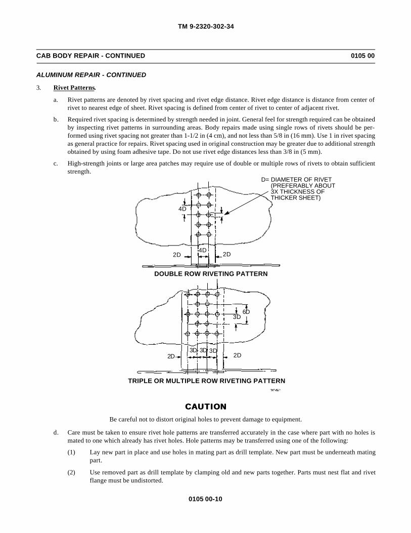
TM 9-2320-302-34
0105 00-10
CAB BODY REPAIR - CONTINUED 0105 00
ALUMINUM REPAIR - CONTINUED
3. Rivet Patterns.
a. Rivet patterns are denoted by rivet spacing and rivet edge distance. Rivet edge distance is distance from center ofrivet to nearest edge of sheet. Rivet spacing is defined from center of rivet to center of adjacent rivet.
b. Required rivet spacing is determined by strength needed in joint. General feel for strength required can be obtainedby inspecting rivet patterns in surrounding areas. Body repairs made using single rows of rivets should be per-formed using rivet spacing not greater than 1-1/2 in (4 cm), and not less than 5/8 in (16 mm). Use 1 in rivet spacingas general practice for repairs. Rivet spacing used in original construction may be greater due to additional strengthobtained by using foam adhesive tape. Do not use rivet edge distances less than 3/8 in (5 mm).
c. High-strength joints or large area patches may require use of double or multiple rows of rivets to obtain sufficientstrength.
CAUTIONCAUTIONBe careful not to distort original holes to prevent damage to equipment.
d. Care must be taken to ensure rivet hole patterns are transferred accurately in the case where part with no holes ismated to one which already has rivet holes. Hole patterns may be transferred using one of the following:
(1) Lay new part in place and use holes in mating part as drill template. New part must be underneath matingpart.
(2) Use removed part as drill template by clamping old and new parts together. Parts must nest flat and rivetflange must be undistorted.
4D
4D2D2D
6D3D
2D2D3D 3D 3D
TRIPLE OR MULTIPLE ROW RIVETING PATTERN
D= DIAMETER OF RIVET(PREFERABLY ABOUT3X THICKNESS OFTHICKER SHEET)
DOUBLE ROW RIVETING PATTERN

TM 9-2320-302-34
0105 00-11
CAB BODY REPAIR - CONTINUED 0105 00
ALUMINUM REPAIR - CONTINUED
4. Joint Design.
a. Loads are applied through joint to fasteners holding joint together. These loads are applied to fasteners in form ofshear loads or tension loads. If load is perpendicular to axis of fasteners, fastener is loaded in shear. Fastener isloaded in tension when load is along axis of fastener, causing pull on each end of fastener.
b. Rivets (1) are designed to be loaded in shear. Do not create new joints during repairs that cause rivets to be used intension application. Bolts (2) should be used for tension applications or substituted for rivets in very high shearload applications.
5. Repair Parts Preparation.
a. Paint repair parts or patches with epoxy primer before installation.
b. Apply sealing compound to mating surfaces to prevent corrosion.
c. Install part or patch as detailed in Repair by Patching and Repair by Insertion on pages 0105 00-12 and 0105 00-13.
d. Paint repaired area with epoxy primer.
e. Paint repaired area with polyurethane, as required.
6. Repair of Negligible Damage.
a. Negligible cracks, as defined in classification above, are repaired by drilling small hole at each end of crack to stopcrack propagation. This is called stop drilling. Table 8 gives proper drill sizes for stop drilling cracks.
b. Negligible holes are repaired by rounding and smoothing edges of hole to alleviate stress risers caused by sharpnotches.
CAUTIONCAUTIONNever use heat to reform parts. Heat greatly reduces part strength.
c. Small dents and distorted areas may be repaired by bending or hammering as long as operation does not causematerials to crack or tear. Sharp bends should not be attempted.
1 1
22
RIVETS LOADED IN SHEAR
BOLTS REPLACING RIVETS LOADED IN TENSION

TM 9-2320-302-34
0105 00-12
CAB BODY REPAIR - CONTINUED 0105 00
ALUMINUM REPAIR - CONTINUED
Table 8. Stop Drill Sizes for Negligible Cracks.
7. Repair by Patching.
a. Most body panel damage that exceeds limits of negligible damage may be repaired by patching. This procedureinvolves removal of damaged area (3) and application of a patch (4) to cover the area.
b. The damaged area (3) is prepared by removal of the damage followed by rounding or smoothing of all corners andedges. This helps ensure that cracks will not spread into undamaged areas.
c. In the case of a large crack (5), it may be desirable to stop-drill crack rather than cut out a portion of a panel (6) orstructural member.
d. Repair is completed by applying a large overlapping patch (7) over the area that was damaged. The overlap mustbe sufficient to allow the observance of proper rivet edge distance (8) (refer to Rivet Patterns on page 0105 00-10).
SHEET THICKNESS(IN)
MINIMUM STOP DRILLSIZE NO.
0-0.0320.033 and thicker
4030
3
4
5
6
7
8
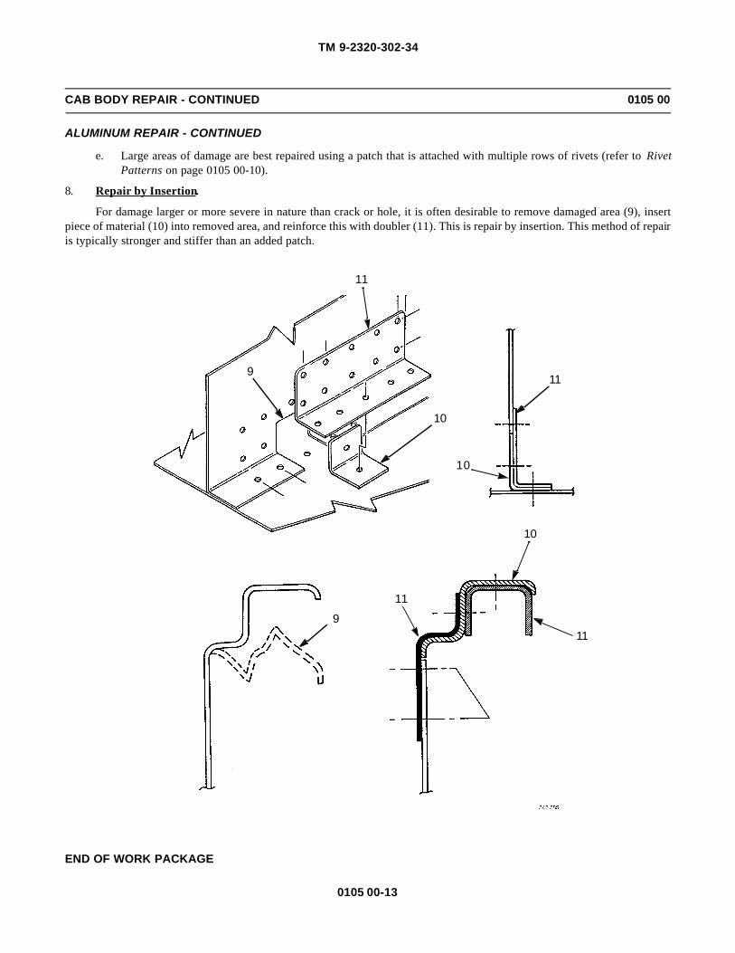
TM 9-2320-302-34
0105 00-13
CAB BODY REPAIR - CONTINUED 0105 00
ALUMINUM REPAIR - CONTINUED
e. Large areas of damage are best repaired using a patch that is attached with multiple rows of rivets (refer to RivetPatterns on page 0105 00-10).
8. Repair by Insertion.
For damage larger or more severe in nature than crack or hole, it is often desirable to remove damaged area (9), insertpiece of material (10) into removed area, and reinforce this with doubler (11). This is repair by insertion. This method of repairis typically stronger and stiffer than an added patch.
END OF WORK PACKAGE
9
11
10
11
11
10
10
9
11

TM 9-2320-302-34
0105 00-14
This Page Intentionally Left Blank.
TM 9-2320-302-34
0106 00-1
HOOD SMC REPAIR 0106 00
THIS WORK PACKAGE COVERS
Inspection, Repair
INITIAL SETUP
Maintenance Level
Direct Support
Tools and Special Tools
Tool kit, general mechanic’s (Item 132, WP 0126 00)
Drill, electric, portable (Item 31, WP 0126 00)
Drill set, twist (Item 32, WP 0126 00)
Materials/Parts
Glass, reinforced plastic
Tool kit, body and fender repair (Item 39, WP0125 00)
INSPECTION
1. The SMC (sheet molded compound) hood consists of several parts including fenders, hood, and inner reinforcementswhich are bonded together with a structural adhesive and rivets. If the hood is damaged, determine which parts areaffected.
2. Damage at any joint between two parts in not repairable. For example, if fender and reinforcements bonded inside thefender are damaged, replace the entire hood assembly.
3. If a joint between two parts has separated and there is no damage at the joint, the parts can be rebonded. Or, if a part isdamaged and adjoining parts are not, the damaged part can be separated from the hood and new or used parts can bebonded in place. A section of a part can be replaced as long as the section does not include a joint between two parts.Fenders and headlight reinforcements are available as replacement parts or for use in section replacements. If the dam-age is such that parts cannot be replaced or a section replacement cannot be done, replace the entire hood assembly.
4. For repairing a small crack or hole, refer to Crack or Small Hole Repair below.
5. For repairing larger areas, refer to Section Replacement (Repair of Punctures and Large Fractures) on page 0106 00-3.
6. For replacing or rebonding parts, refer to Hood Component Rebonding on page 0106 00-7.
REPAIR
1. Crack or Small Hole Repair. A crack (fracture) or small hole through the laminate requires repair with a fiberglassreinforced patch.
a. Locate damage on hood. Apply hand pressure all around damaged area to check for concealed damage.

TM 9-2320-302-34
0106 00-2
HOOD SMC REPAIR - CONTINUED 0106 00
REPAIR - CONTINUED
WARNINGWARNINGSolvents can burn easily, can give off harmful vapors, and are harmful to skin and clothing. To avoid injuryor death, keep away from open fire and use in well-ventilated area. If solvent gets on skin or clothing, washimmediately with soap and water.
b. Clean area with xylene or equivalent solvent. Inspect area closely.
c. If sound-absorbent liner is present on underside of damaged area, remove panel(s) to provide adequate workingarea.
d. If repairing crack (1), use 1/8-in diameter bit to drill hole (2) completely through uncracked laminate. Drill hole 1/8-in (3mm) from each end of crack to prevent crack from lengthening.
WARNINGWARNINGWear goggles and air purifying respirator when cutting, grinding or sanding during fiberglass repairs.Ground dust and particles could cause temporary or permanent damage to eyes, and if inhaled, could causerespiratory irritation.
e. On engine side of hood (3), use router bit on grinder or drill to grind away shallow recess. Grind recess to one-quarter depth of laminate (4) and 1/2 in (13 mm) outward from all sides of damage. Taper outside edge of groundarea (5). If repairing crack (1), grind outward to drilled hole (2) at end of crack, but not beyond.
f. Use 100-220 grit sandpaper to scuff area at least 1 in (25 mm) away from fracture on all sides (6). Scuff thoroughlyto give surface to which patch can stick.
WARNINGWARNINGCompressed air used for cleaning or drying purposes, or for clearing restrictions, should never exceed 30 psi(207 kPa). Wear protective clothing (goggles/shield, gloves, etc.) and use caution to avoid injury to person-nel.
g. Blow dust away with compressed air and wipe area with clean cloth.
h. If necessary, align panel sections on both sides of crack (1), using weights or clamps to establish original panelprofile.
i. Using razor knife, cut section of woven fiberglass cloth (7) to overlay crack (1) about 3/4 in (19 mm).
j. Using wooden stir stick and measuring in spoonfuls, mix equal volumes of magnolia 58 A and B epoxy resins onclean sheet of glass, metal or section of scrap laminate. Mix 15 seconds.
k. Use stir stick to spread thin layer of mixed epoxy resins over scuffed area (6).

TM 9-2320-302-34
0106 00-3
HOOD SMC REPAIR - CONTINUED 0106 00
REPAIR - CONTINUED
l. Lay fiberglass cloth (7) on repair area, centered over damage. Using stir stick, firmly press fiberglass cloth intoepoxy to completely soak fiberglass cloth.
m. Apply another layer of epoxy resins over fiberglass cloth (7).
n. Allow 2-5 minutes for epoxy to start gelling. It may take more time in cool temperatures, less in hot temperatures.
NOTENOTEFor smoother surface, press piece of masking tape, wider than repair, directly over wet epoxy and smoothbefore epoxy hardens. Tape can be removed when epoxy sets up after 15 minutes.
o. Patch should be hard enough in 15 minutes to allow sanding to smooth, flat surface, if required.
p. Repair damage on outside surface of hood, and paint surface on both sides.
2. Section Replacement (Repair of Punctures and Large Fractures). On large damaged areas (for example, structuraldamage on side surface of the hood covering a square foot area), it may be easier to do a section replacement rather thanto make a patch. Fenders and headlight reinforcements are available for use in section replacements, or a second dam-aged hood must be available as scrap with the needed section intact.
CAUTIONCAUTIONPiece of SMC laminate from another SMC laminate hood must be used for section replacement. Use of anyother material may not allow necessary bonding for repair.
a. To determine extent of damage, push in on area immediately surrounding and underneath damaged area.
2
1
2
3
4 1
5
6
7
5
1

TM 9-2320-302-34
0106 00-4
HOOD SMC REPAIR - CONTINUED 0106 00
REPAIR - CONTINUED
WARNINGWARNINGSolvents can burn easily, can give off harmful vapors, and are harmful to skin and clothing. To avoid injuryor death, keep away from open fire and use in well-ventilated area. If solvent gets on skin or clothing, washimmediately with soap and water.
b. Clean area with xylene or equivalent solvent. Inspect area closely.
c. If sound-absorbent liner is present on underside of damaged area, remove panel(s) to provide adequate workingarea.
NOTENOTEIf damage extends to joint where part is bonded to another, separate part with heat gun and putty knife beforecutting.
d. Using saber saw, cut out large, straight-sided panel (8) containing damaged area.
NOTENOTEIf damage is next to, but does not include, headlight reinforcement, remove headlight reinforcement fromreplacement section, not from hood.
e. From scrap hood (9) or new part, cut patch (10) from same area slightly larger than original panel (8). Trim patchto fit both size and contour of original panel.
f. Sand patch (10) edges to allow 1/16-1/8 in (2-3 mm) gap (11) around panel (8).
g. On engine side of hood (12), use router bit on grinder or drill to grind away shallow recess. Grind recess to one-quarter depth of laminate (13) and 1/2 in (13 mm) outward from all sides (14) of panel (8) area. Grind 1/2 in (13mm) inward from all sides (14) on engine side of patch (10). Slightly taper outside edge of ground area aroundpanel and inside edge of ground area on patch.
h. Using 110-220 grit sandpaper, scuff area at least 1 in (25 mm) out from sides (15) of panel (8) area. Scuff at least 1in (25 mm) in from sides (16) of patch (10). Scuff thoroughly to give surface to which patch can stick. Completelysand off any undercoating sprayed on these areas.
i. Bevel edges of outer sides of both panel (8) and patch (10) to about 45 degrees.
j. Using 220 or higher grit sandpaper, gently feather back outer painted surfaces about 1/2 in (13 mm) beyond edgesof repair areas of panel (8) and patch (10).
k. Blow dust away with compressed air and wipe area with clean cloth.
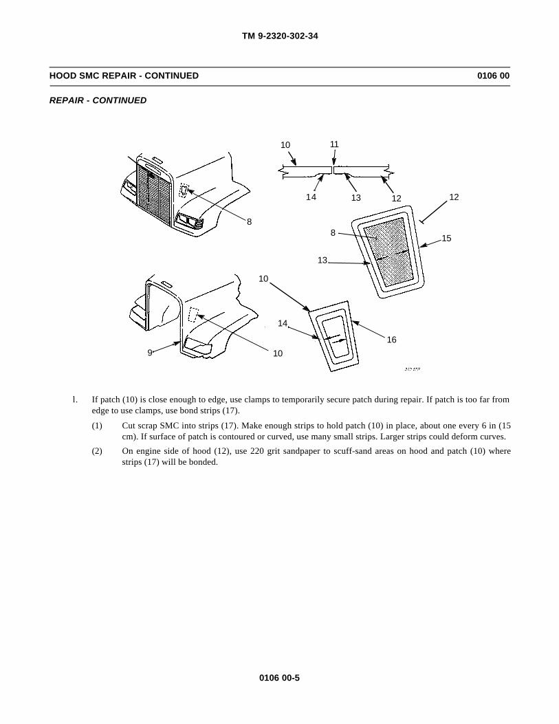
TM 9-2320-302-34
0106 00-5
HOOD SMC REPAIR - CONTINUED 0106 00
REPAIR - CONTINUED
l. If patch (10) is close enough to edge, use clamps to temporarily secure patch during repair. If patch is too far fromedge to use clamps, use bond strips (17).
(1) Cut scrap SMC into strips (17). Make enough strips to hold patch (10) in place, about one every 6 in (15cm). If surface of patch is contoured or curved, use many small strips. Larger strips could deform curves.
(2) On engine side of hood (12), use 220 grit sandpaper to scuff-sand areas on hood and patch (10) wherestrips (17) will be bonded.
121314
1110
8
12
15
13
16
10
14
109
8

TM 9-2320-302-34
0106 00-6
HOOD SMC REPAIR - CONTINUED 0106 00
REPAIR - CONTINUED
NOTENOTE
If joint between parts was separated for repair, rebond joint. Refer to Hood Component Rebonding on page0106 00-7.
(3) Hold patch (10) in place and bond strips (17) to hood (12) and patch where scuffed. Use Lord Fuser 320/322 to bond strips.
(4) Apply light pressure and heat from heat gun to area for 3-5 minutes.
(5) After Lord Fuser 320/322 has hardened, use 100-220 grit sandpaper to scuff strips.
(6) Blow dust away with compressed air and wipe area with clean cloth.
m. Using razor knife, cut sections of woven fiberglass cloth (18) to fully cover gap (11) between hood (12) and patch(10), all around patch. Fiberglass cloth should overlay about 3/4 in (19 mm) on both sides of gap.
n. Using wooden stir stick and measuring in spoonfuls, mix equal volumes of Magnolia 58 A and B epoxy resins onclean sheet of glass, metal or section of scrap laminate. Mix 15 seconds.
o. Use stir stick to spread thin layer of mixed epoxy resins over scuffed area on unexposed side of repair.
p. Lay cut sections of fiberglass cloth (18) on repair area, centered over gap (11). Using stir stick, firmly press fiber-glass cloth into epoxy to completely soak fiberglass cloth.
q. Apply another layer of epoxy resins over fiberglass cloth (18).
r. After 2-5 minutes, epoxy will start gelling. It may take more time in cool temperatures, less in hot temperatures.
NOTENOTE
For smoother surface, press piece of masking tape, wider than repair, directly over wet epoxy and smoothbefore epoxy hardens. Tape can be removed when epoxy sets up after 15 minutes.
s. After body filler has hardened, sand unexposed side of repair area to smooth flat surface, if required.
8
10
11
1210
17

TM 9-2320-302-34
0106 00-7
HOOD SMC REPAIR - CONTINUED 0106 00
REPAIR - CONTINUED
t. Repair damage on outside surface of hood, and paint surface on both sides.
3. Hood Component Rebonding.
NOTENOTEIf parts cannot be separated, work folded medium-grit sandpaper or section of steel hacksaw blade betweentwo surfaces to remove old adhesive.
a. If rebonding joint that has separated or replacing damaged part, completely separate part or parts using heat gunand putty knife. Remove as much of old adhesive as possible. Heat gun will soften adhesive and allow it to bepeeled off SMC.
b. Scuff surfaces with 100-220 grit sandpaper.
c. Clean surfaces are to be bonded with Ashland 6036 primer or methylene chloride. Inspect area closely to be sureall old adhesive is removed.
d. If replacing large part, such as fender, align part on hood and clamp in place. Drill hole through bonding surfaces(19) and install clamping bolt (20) in hole. Install two washers (21), one on each bonding surface. Install nut (22)on clamping bolt. There should be enough clamping bolts to hold hood in place and keep bonding surfacestogether, one bolt every 12-18 in (30-45 cm). Remove part for application of adhesive.
e. Using manufacturer’s instructions, mix enough Ashland Pliogrip 6600/6622 adhesive to bond parts together, about3/8 in (10 mm) diameter bead at bonding surface (19). Adhesive will cure in 7-10 minutes.
f. Put adhesive in standard caulking gun and cut nozzle so 3/8 in (10 mm) diameter bead can be dispensed. If partscould not be completely separated, cut nozzle so adhesive can be injected between surfaces.
g. Dispense 3/8 in (10 mm) diameter bead of adhesive between all bonding surfaces (19).
h. Within 5 minutes of dispensing adhesive bead, align part on hood and clamp firmly in place. If a large part (fender,for example), install clamping bolts. Tighten clamps or clamping bolts just enough to ensure uniform amount ofpressure is applied along seam. Ideally, adhesive should be compressed to form bondline 1 in (25 mm) wide and0.030 in (0.76 mm) thick.
i. Before adhesive cures, remove excess adhesive that squeezes out edges of bond.
j. Bond will be secure in about 1 hour. Remove clamps.
k. If holes were drilled for clamping bolts, repair holes using instructions in Crack or Small Hole Repair on page0106 00-1.
END OF WORK PACKAGE
19
2021
21
22
12
18
10
11

TM 9-2320-302-34
0106 00-8
This Page Intentionally Left Blank.

TM 9-2320-302-34
0107 00-1
CAB DOOR REPLACEMENT 0107 00
THIS WORK PACKAGE COVERS
Removal, Cleaning, Inspection, Installation
INITIAL SETUP
Maintenance Level
Direct Support
Tools and Special Tools
Tool kit, general mechanic’s (Item 132, WP 0126 00)
Materials/Parts
Tape, foam, 48-02454-106x27 (WP 0122 00)
Personnel Required
Two
Equipment Condition
Rear view mirror removed (TM 9-2320-302-20)
NOTENOTEProcedure is the same for both doors.
REMOVAL
1. Remove capnut (1) and socket head screw (2).
WARNINGWARNINGDue to size of door and angle for removal, use minimum of two personnel to remove door. Failure to do socould result in injury to personnel.
2. Remove eight capscrews (3) and door (4).
1
2
4
3

TM 9-2320-302-34
0107 00-2
CAB DOOR REPLACEMENT - CONTINUED 0107 00
REMOVAL - CONTINUED
3. Remove and discard foam tape (5).
CLEANING
1. Use general cleaning methods to clean all parts.
2. Ensure that all traces of old foam tape have been removed.
INSPECTION
1. Inspect door seals and window channels for damage.
2. Inspect door locks, regulators, and release handles for proper operation. If damaged, refer to door repair (WP 0108 00).
INSTALLATION
CAUTIONCAUTIONMake sure all old foam tape has been removed. Failure to do so could cause water leakage and damage.
1. Install new foam tape (5) and, using a sharp tool, cut holes for installation of capscrews (3).
WARNINGWARNINGDue to size of door and angle for installation, use minimum of two personnel to install door. Failure to do socould result in injury to personnel.
2. Position door (4) and install two capscrews (3) in locations indicated.
5

TM 9-2320-302-34
0107 00-3
CAB DOOR REPLACEMENT - CONTINUED 0107 00
INSTALLATION - CONTINUED
3. Perform door adjustment (TM 9-2320-302-20).
4. Install remaining six capscrews (3).
5. Install socket head screw (2) and capnut (1).
6. Install rear view mirror (TM 9-2320-302-20).
END OF WORK PACKAGE
3
3
4
1
2
4
3

TM 9-2320-302-34
0107 00-4
This Page Intentionally Left Blank.

TM 9-2320-302-34
0108 00-1
CAB DOOR REPAIR 0108 00
THIS WORK PACKAGE COVERS
Disassembly, Assembly
INITIAL SETUP
Maintenance Level
Direct Support
Tools and Special Tools
Tool kit, general mechanic’s (Item 132, WP 0126 00)
Gloves (Item 41, WP 0126 00)
Materials/Parts
Compound, sealing (Item 14, WP 0125 00)
Grease, GAA (Item 22, WP 0125 00)
Tags, marker (Item 35, WP 0125 00)
Equipment Condition
Cab door removed (WP 0107 00)
DISASSEMBLY
1. If damaged, remove and discard seal (1) from door (2).
2. Lower window glass (3).
3
2
1
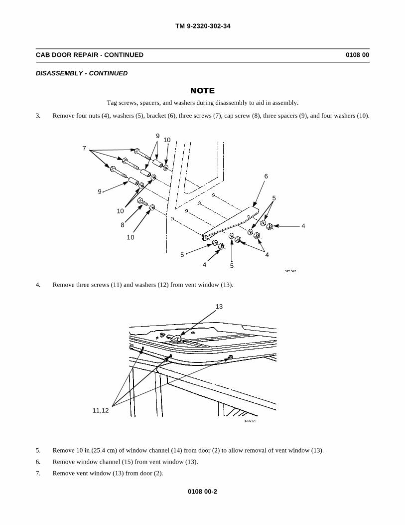
TM 9-2320-302-34
0108 00-2
CAB DOOR REPAIR - CONTINUED 0108 00
DISASSEMBLY - CONTINUED
NOTENOTETag screws, spacers, and washers during disassembly to aid in assembly.
3. Remove four nuts (4), washers (5), bracket (6), three screws (7), cap screw (8), three spacers (9), and four washers (10).
4. Remove three screws (11) and washers (12) from vent window (13).
5. Remove 10 in (25.4 cm) of window channel (14) from door (2) to allow removal of vent window (13).
6. Remove window channel (15) from vent window (13).
7. Remove vent window (13) from door (2).
6
5
4
4
545
10
8
10
9
7
9 10
13
11,12

TM 9-2320-302-34
0108 00-3
CAB DOOR REPAIR - CONTINUED 0108 00
DISASSEMBLY - CONTINUED
8. Remove four nuts (16), washers (17), bracket (18), four cap screws (19), and washers (20).
2
14
15
13
1920
18
17
16

TM 9-2320-302-34
0108 00-4
CAB DOOR REPAIR - CONTINUED 0108 00
DISASSEMBLY - CONTINUED
9. Remove screw (21) and window crank (22).
10. Remove eight screws (23) from inside door panel (24).
11. Remove three cap screws (25) and check arm bracket (26) from door hinge (27).
23
23
23
24
21
22
25
27
26

TM 9-2320-302-34
0108 00-5
CAB DOOR REPAIR - CONTINUED 0108 00
DISASSEMBLY - CONTINUED
12. Remove top two cap screws (28) from door latch assembly (29).
13. Remove sill (30) as follows:
CAUTIONCAUTIONDo not attempt to completely separate sill from door after completion of step b. To do so could damage inte-rior door components.
a. Grip sill door handle (31), lean sill (30) away from door (2), and pull sill upward until entire lower edge of sillunseats from inside door panel (24).
b. Lean sill (30) away from door (2) and push door lock button (32) free.
29
28
30
32
3124
2

TM 9-2320-302-34
0108 00-6
CAB DOOR REPAIR - CONTINUED 0108 00
DISASSEMBLY - CONTINUED
c. Disconnect release handle rod retainer (33) from release handle rod (34) and remove sill (30).
14. Remove four screws (35) from window regulator (36).
15. Disengage window regulator roller (37) from one end of window lift channel (38).
16. Remove window regulator (36) from inside door panel (24).
34
3033
35
35
38
24
37
36

TM 9-2320-302-34
0108 00-7
CAB DOOR REPAIR - CONTINUED 0108 00
DISASSEMBLY - CONTINUED
WARNINGWARNINGWear protective gloves when handling glass. Failure to do so could result in injury to personnel.
17. Tilt window guide (39) toward hinge side of door (2) and carefully pull window glass (3) toward top of door. At thesame time, lift window glass toward inside door panel (24) until window glass is completely removed from door.
18. Remove four screws (40) and cover plate (41) from inside door panel (24).
24392
3
24
41
4040

TM 9-2320-302-34
0108 00-8
CAB DOOR REPAIR - CONTINUED 0108 00
DISASSEMBLY - CONTINUED
19. Disconnect release handle retainer (42) and remove release handle rod (34).
20. Disconnect door lock retainer (43) and remove door lock rod (44).
21. Disconnect door latch retainer (45) and remove door latch rod (46) from exterior handle assembly (47).
22. Remove stud (48) from exterior handle assembly (47).
23. Remove fastening clip (49) and exterior handle assembly (47) from door (2).
24. Remove four nuts (50), washers (51), cap screws (52), and door latch assembly (53).
4234
44
43
47
49
45
46
48
2
53
50,51,52
50,51,52
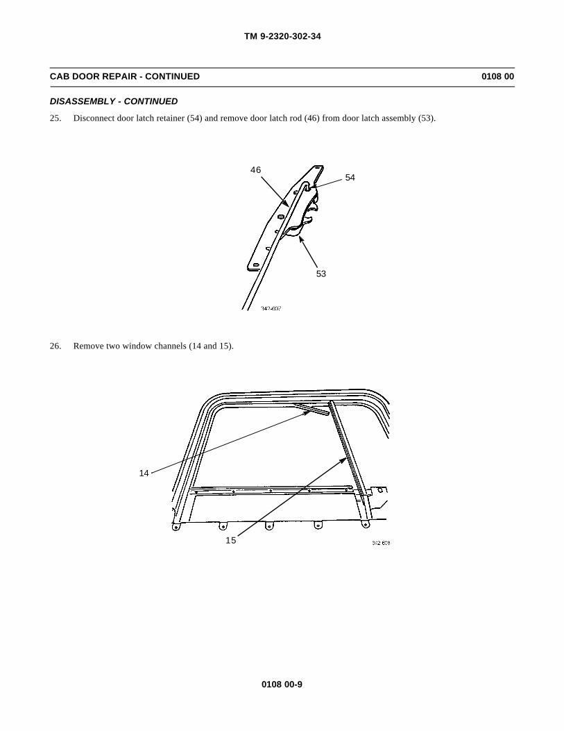
TM 9-2320-302-34
0108 00-9
CAB DOOR REPAIR - CONTINUED 0108 00
DISASSEMBLY - CONTINUED
25. Disconnect door latch retainer (54) and remove door latch rod (46) from door latch assembly (53).
26. Remove two window channels (14 and 15).
54
53
46
15
14
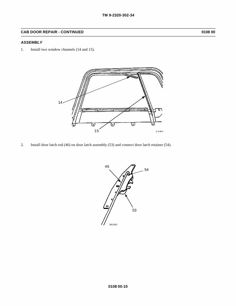
TM 9-2320-302-34
0108 00-10
CAB DOOR REPAIR - CONTINUED 0108 00
ASSEMBLY
1. Install two window channels (14 and 15).
2. Install door latch rod (46) on door latch assembly (53) and connect door latch retainer (54).
15
14
54
53
46

TM 9-2320-302-34
0108 00-11
CAB DOOR REPAIR - CONTINUED 0108 00
ASSEMBLY - CONTINUED
3. Install door latch assembly (53), four cap screws (52), washers (51), and nuts (50).
4. Lubricate all rotating points of exterior handle assembly (47) with grease.
5. Install exterior handle assembly (47) and fastening clip (49) in door (2).
6. Install stud (48) in exterior handle assembly (47).
7. Install door latch rod (46) in exterior handle assembly (47) and connect door latch retainer (45).
8. Install door lock rod (44) in exterior handle assembly (47) and connect door lock retainer (43).
9. Install release handle rod (34) in exterior handle assembly (47) and connect release handle retainer (42).
53
50,51,52
50,51,52
4234
44
43
47
49
45
46
48
2

TM 9-2320-302-34
0108 00-12
CAB DOOR REPAIR - CONTINUED 0108 00
ASSEMBLY - CONTINUED
10. Install cover plate (41) and four screws (40) on inside door panel (24).
WARNINGWARNINGWear protective gloves with handling glass. Failure to do so could result in injury to personnel.
11. Tilt window guide (39) toward hinge side of door (2), and with window glass (3) tilted toward inside door panel (24),carefully install window glass.
24
41
4040
24392
3

TM 9-2320-302-34
0108 00-13
CAB DOOR REPAIR - CONTINUED 0108 00
ASSEMBLY - CONTINUED
12. Lubricate teeth on window regulator (36) with grease.
13. Install window regulator (36) in inside door panel (24).
14. Insert window regulator roller (37) in one end of window lift channel (38).
15. Install four screws (35) in window regulator (36).
36
35
35
38
24
37
36

TM 9-2320-302-34
0108 00-14
CAB DOOR REPAIR - CONTINUED 0108 00
ASSEMBLY - CONTINUED
16. Insert sill (30) as follows:
a. Install sill (30) just enough to allow installation of release handle rod (34) and connect release handle rod retainer(33).
b. Lean sill (30) away from door (2) and insert door lock button (32).
c. Grip sill door handle (31), lean sill (30) away from door (2), and push sill downward until lower edge of sill isseated on inside door panel (24).
34
3033
30
32
3124
2

TM 9-2320-302-34
0108 00-15
CAB DOOR REPAIR - CONTINUED 0108 00
ASSEMBLY - CONTINUED
17. Install top two cap screws (28) in door latch assembly (29).
18. Install check arm bracket (26) and three cap screws (25) in door hinge (27).
29
28
25
27
26

TM 9-2320-302-34
0108 00-16
CAB DOOR REPAIR - CONTINUED 0108 00
ASSEMBLY - CONTINUED
19. Install eight screws (23) in inside door panel (24).
20. Install window crank (22) and screw (21).
21. Install four washers (20), cap screws (19), bracket (18), four washers (17), and nuts (16).
23
23
23
24
21
22
1920
18
17
16

TM 9-2320-302-34
0108 00-17
CAB DOOR REPAIR - CONTINUED 0108 00
ASSEMBLY - CONTINUED
22. Install vent window (13) in door (2).
23. Install window channel (15) in vent window (13).
24. Install remainder of window channel (14) in door (2).
25. Install three washers (12) and screws (11) in vent window (13).
2
14
15
13
13
11,12

TM 9-2320-302-34
0108 00-18
CAB DOOR REPAIR - CONTINUED 0108 00
ASSEMBLY - CONTINUED
26. Install four washers (10), three spacers (9), cap screw (8), three screws (7), bracket (6), four washers (5), and nuts (4).
27. Raise window glass (3).
28. If removed, install new seal (1) on door (2) and apply sealing compound to each end of seal joint.
29. Install cab door (WP 0107 00).
END OF WORK PACKAGE
6
5
4
454
5
10
8
10
9
7
9 10
3
2
1
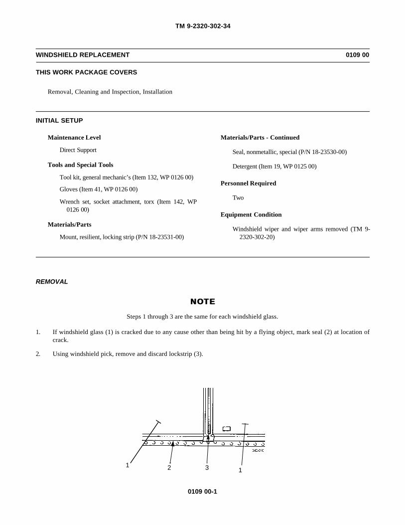
TM 9-2320-302-34
0109 00-1
WINDSHIELD REPLACEMENT 0109 00
THIS WORK PACKAGE COVERS
Removal, Cleaning and Inspection, Installation
INITIAL SETUP
Maintenance Level
Direct Support
Tools and Special Tools
Tool kit, general mechanic’s (Item 132, WP 0126 00)
Gloves (Item 41, WP 0126 00)
Wrench set, socket attachment, torx (Item 142, WP0126 00)
Materials/Parts
Mount, resilient, locking strip (P/N 18-23531-00)
Materials/Parts - Continued
Seal, nonmetallic, special (P/N 18-23530-00)
Detergent (Item 19, WP 0125 00)
Personnel Required
Two
Equipment Condition
Windshield wiper and wiper arms removed (TM 9-2320-302-20)
REMOVAL
NOTENOTE
Steps 1 through 3 are the same for each windshield glass.
1. If windshield glass (1) is cracked due to any cause other than being hit by a flying object, mark seal (2) at location ofcrack.
2. Using windshield pick, remove and discard lockstrip (3).
1 2 3 1

TM 9-2320-302-34
0109 00-2
WINDSHIELD REPLACEMENT - CONTINUED 0109 00
REMOVAL - CONTINUED
WARNINGWARNINGWear protective gloves when handling glass. Failure to do so could result in injury to personnel.
CAUTIONCAUTIONWhen handling windshield glass, be careful not to nick or splinter edges of glass. Chipped edges could causecracking later.
NOTENOTEIf removing windshield glass only, perform step 3. If removing seal or windshield glass and seal, performsteps 3 through 11.
3. Apply pressure to edge of windshield glass (1) from inside cab (4). Using windshield pick, lift windshield glass out ofseal (2) and remove.
4. Remove seal (2) from mounting flange of cab (4).
5. Remove torx screws (5), two brackets (6), and cover (7).
1
2
4
5
66 7
5

TM 9-2320-302-34
0109 00-3
WINDSHIELD REPLACEMENT - CONTINUED 0109 00
REMOVAL - CONTINUED
6. Remove torx screw (8) and defroster vent (9).
7. Remove two torx screws (10), washers (11), and cover (12).
8. Remove four screws (13), washers (14), and windshield support (15).
98
12
10,1110,11
13,14
15
13,14
13
14

TM 9-2320-302-34
0109 00-4
WINDSHIELD REPLACEMENT - CONTINUED 0109 00
REMOVAL - CONTINUED
9. Cut away portion of seal (2) molded around cab flange (16).
10. Remove each windshield glass (1) and seal (2) as an assembly from cab (4).
11. Remove seal (2) from each windshield glass (1).
CLEANING AND INSPECTION
1. Use general cleaning methods to clean all parts (TM 9-2320-302-20).
2. If windshield is removed due to criteria outlined in Removal step 1, inspect channel of seal (where marked) for foreignobjects, and inspect mounting flange of cab for irregularities.
3. Inspect all parts for wear or damage.
2
16
1
2
4

TM 9-2320-302-34
0109 00-5
WINDSHIELD REPLACEMENT - CONTINUED 0109 00
INSTALLATION
WARNINGWARNINGWear protective gloves when handling glass. Failure to do so could result in injury to personnel.
CAUTIONCAUTION• When handling windshield glass, be careful not to nick or splinter edges of glass. Chipped edges could
cause cracking later.
• Do not use windshield sealant. Windshield sealant compounds are not needed and, if applied unevenly,can cause leaks resulting in water damage.
NOTENOTE• Manufacturer’s ID number must be at lower center corner of windshield glass when installed.
• If installing windshield glass only, perform steps 1 through 7. If installing seal or windshield glass andseal, perform steps 8 through 23.
• Steps 1 through 7 are the same for each windshield glass.
1. Lubricate window channel of seal (2) with soap and water solution.
2. Slide windshield glass (1) into window channel of seal (2) as far as it will go without forcing.
3. Stretch seal (2) around outside of windshield glass (1) and install windshield glass in window channel of seal.
4. Using windshield pick, alternate between top and bottom of mounting flanges of cab (4) to work seal (2) over mountingflange.
5. With assistant pushing lightly on outside of windshield glass (1), finish working seal (2) over mounting flange of cab(4).
6. Finish sealing windshield glass (1) and seal (2) by gently pushing all the way around outside edge.
1
2
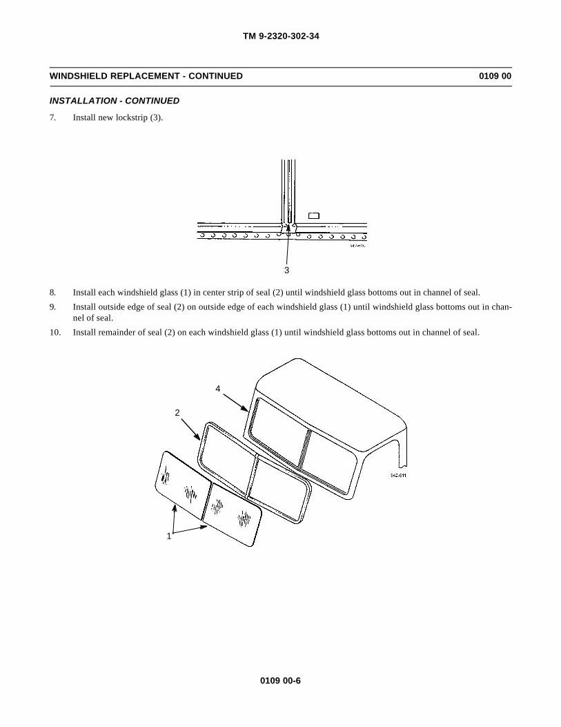
TM 9-2320-302-34
0109 00-6
WINDSHIELD REPLACEMENT - CONTINUED 0109 00
INSTALLATION - CONTINUED
7. Install new lockstrip (3).
8. Install each windshield glass (1) in center strip of seal (2) until windshield glass bottoms out in channel of seal.
9. Install outside edge of seal (2) on outside edge of each windshield glass (1) until windshield glass bottoms out in chan-nel of seal.
10. Install remainder of seal (2) on each windshield glass (1) until windshield glass bottoms out in channel of seal.
3
1
2
4

TM 9-2320-302-34
0109 00-7
WINDSHIELD REPLACEMENT - CONTINUED 0109 00
INSTALLATION - CONTINUED
11. Using windshield pick, go all the way around between each windshield glass (1) and seal (2) to make sure seal is prop-erly seated.
12. Install two cords in outside groove in seal (2) and leave safety loops in center.
13. Using soap and water solution, lubricate cord channel of seal (2).
1
2
2
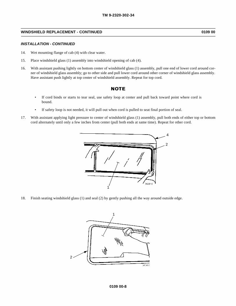
TM 9-2320-302-34
0109 00-8
WINDSHIELD REPLACEMENT - CONTINUED 0109 00
INSTALLATION - CONTINUED
14. Wet mounting flange of cab (4) with clear water.
15. Place windshield glass (1) assembly into windshield opening of cab (4).
16. With assistant pushing lightly on bottom center of windshield glass (1) assembly, pull one end of lower cord around cor-ner of windshield glass assembly; go to other side and pull lower cord around other corner of windshield glass assembly.Have assistant push lightly at top center of windshield assembly. Repeat for top cord.
NOTENOTE• If cord binds or starts to tear seal, use safety loop at center and pull back toward point where cord is
bound.
• If safety loop is not needed, it will pull out when cord is pulled to seat final portion of seal.
17. With assistant applying light pressure to center of windshield glass (1) assembly, pull both ends of either top or bottomcord alternately until only a few inches from center (pull both ends at same time). Repeat for other cord.
18. Finish seating windshield glass (1) and seal (2) by gently pushing all the way around outside edge.
1
2
4
1
2

TM 9-2320-302-34
0109 00-9
WINDSHIELD REPLACEMENT - CONTINUED 0109 00
INSTALLATION - CONTINUED
19. Install windshield support (15) with four washers (14) and screws (13).
20. Install cover (12) with two washers (11) and torx screws (10).
21. Install defroster vent (9) with torx screw (8).
13,14
15
13,14
13
14
98
12
10,1110,11

TM 9-2320-302-34
0109 00-10
WINDSHIELD REPLACEMENT - CONTINUED 0109 00
INSTALLATION - CONTINUED
22. Install cover (7), two brackets (6), and four torx screws (5).
23. Install new lockstrip (3).
24. Install windshield wiper and wiper arms (TM 9-2320-302-20).
END OF WORK PACKAGE
5
66 7
5
3

TM 9-2320-302-34
0110 00-1
REAR WINDOW REPLACEMENT 0110 00
THIS WORK PACKAGE COVERS
Removal, Cleaning and Inspection, Installation
INITIAL SETUP
Maintenance Level
Direct Support
Tools and Special Tools
Gloves (Item 41, WP 0126 00)
Materials/Parts
Compound, sealing (Item 14, WP 0125 00)
Detergent (Item 19, WP 0125 00)
Personnel Required
Two
REMOVALWARNINGWARNING
Wear protective gloves when handling glass. Failure to do so could result in injury to personnel.
NOTENOTEIf removing rear window glass only, perform steps 1 through 3. If removing rear window glass and seal, per-form steps 1 through 5.
1. If rear window glass (1) is cracked due to any cause other than being hit by a flying object, mark rubber extrusion (2) atlocation of crack.
2. Using windshield pick, release locking strip (3) from rubber extrusion (2).
CAUTIONCAUTIONWhen handling glass, be careful not to nick or splinter edges. Chipped edges could cause cracking later.
3. Apply pressure to one edge of rear window glass (1) from inside of cab (4). Using windshield pick, lift and remove rearwindow glass out of rubber extrusion (2).
4. Remove rubber extrusion (2) from cab (4).
3
4
2
1
4
2
1

TM 9-2320-302-34
0110 00-2
REAR WINDOW REPLACEMENT - CONTINUED 0110 00
REMOVAL - CONTINUED
5. Remove sealing compound from between ends of rubber extrusion (2).
CLEANING AND INSPECTION
1. Use general cleaning methods to clean all parts (TM 9-2320-302-20).
2. If rear window glass has been removed under criteria outlined in Removal step 1, inspect channel of rubber extrusionwhere marked for foreign objects. Inspect mounting flange of cab for irregularities.
3. Inspect all parts for wear or damage.
INSTALLATION
WARNINGWARNINGWear protective gloves when handling glass. Failure to do so could result in injury to personnel.
CAUTIONCAUTION• When handling glass, be careful not to nick or splinter edges. Chipped edges could cause cracking later.
• Do not use sealant around rear window glass. Sealing compounds are not needed and, if appliedunevenly, can cause leaks resulting in water damage.
NOTENOTEIf installing rear window glass only, perform steps 1 through 4. If installing rear window glass and seal, per-form steps 1 through 6.
1. Lubricate rear window channel of rubber extrusion (2) with detergent and water solution.
2. Slide rear window glass (1) into window channel of rubber extrusion (2) as far as it will go without forcing.
3. Using windshield pick, alternate between top and bottom or rear window glass (1) and work rubber extrusion (2) overedge of rear window glass.
2

TM 9-2320-302-34
0110 00-3
REAR WINDOW REPLACEMENT - CONTINUED 0110 00
INSTALLATION - CONTINUED
4. Using windshield pick, install locking strip (3) in rubber extrusion (2).
21
2
1
2
3

TM 9-2320-302-34
0110 00-4
REAR WINDOW REPLACEMENT - CONTINUED 0110 00
INSTALLATION - CONTINUED
5. With locking strip (3) facing out, install rubber extrusion (2) over mounting flange (5) of cab (4).
6. Apply sealing compound ONLY at point where both ends of rubber extrusion (2) meet.
END OF WORK PACKAGE
52
4
3
2

TM 9-2320-302-34
0111 00-1
AIR DUCTS REPLACEMENT 0111 00
THIS WORK PACKAGE COVERS
Removal, Installation
INITIAL SETUP
Maintenance Level
Direct Support
Tools and Special Tools
Tool kit, general mechanic’s (Item 132, WP 0126 00)
Equipment Condition
Air system drained (TM 9-2320-302-10)
Dash panels removed for access (TM 9-2320-302-20)
REMOVAL
1. Remove eight retainers (1) and four air cylinders (2).
1
1
2
21
1
2
1
2

TM 9-2320-302-34
0111 00-2
AIR DUCTS REPLACEMENT - CONTINUED 0111 00
REMOVAL - CONTINUED
2. Remove two self-tapping screws (3) and separate flex tubing (4) from duct (5).
3. Remove two screws (6), duct outlet (7), and duct (5).
4. Remove two self-tapping screws (8), duct (9), and flex tubing (4).
5. Remove five clips (10) and separate flex tubing (4) from duct (9).
6. Remove hose clamp (11), flex tubing (12), and duct outlet (13).
7. Remove two self-tapping screws (14) and separate flex tubing (12) from duct outlet (13).
8. Remove self-tapping screw (15), speed nut (16), and outlet duct (17) from duct (18).
9. Remove self-tapping screw (19), washer (20), spring nut (21), and duct (18).
10. Remove screw (22), vent (23), and gasket (24).
11. Remove three self-tapping screws (25) and face duct (26).
3
1
1
2
21
1
2
1
2
14
12
11
1321
2019
1817
16
15
8
910
4
22
23
5
67
25
26
24

TM 9-2320-302-34
0111 00-3
AIR DUCTS REPLACEMENT - CONTINUED 0111 00
INSTALLATION
1. Install face duct (26) and secure with three self-tapping screws (25).
2. Install gasket (24), vent (23), and secure with screw (22).
3. Install duct (18) and secure with spring nut (21), washer (20), and self-tapping screw (19).
4. Secure outlet duct (17) to duct (18) with speed nut (16) and self-tapping screw (15).
5. Connect flex tubing (12) to duct outlet (13) and secure with two self-tapping screws (14).
6. Connect flex tubing (12) to face duct (26) and secure with hose clamp (11).
7. Connect flex tubing (4) to duct (9) and secure with five clips (10).
8. Connect duct (9) to face duct (26) and secure with two self-tapping screws (8).
9. Connect flex tubing (4) to duct (5) and secure with two self-tapping screws (3).
10. Install duct (5) to duct outlet (7) and secure with two screws (6).
11. Install four air cylinders (2) and secure with eight retainers (1).
12. Install dash panels (TM 9-2320-302-20).
END OF WORK PACKAGE

TM 9-2320-302-34
0111 00-4
This Page Intentionally Left Blank.

TM 9-2320-302-34
0112 00-1
AIR CONDITIONING SYSTEM REFRIGERANT (R-134A) MAINTENANCE 0112 00
THIS WORK PACKAGE COVERS
Recovery, Evacuating/Recycling, Purging, Flushing, Charging
INITIAL SETUP
Maintenance Level
Direct Support
Tools and Special Tools
Tool kit, general mechanic’s (Item 132, WP 0126 00)
Gloves, rubber (Item 40, WP 0126 00)
Goggles (Item 42, WP 0126 00)
Reclaimer, refrigerant (Item 99, WP 0126 00)
References
TM 9-2320-302-10
TM 9-2320-302-20
Materials/Parts
Adhesive, loctite (Item 2, WP 0125 00)
Cap set (Item 7, WP 0125 00)
Oil, refrigerant (Item 27, WP 0125 00)
Refrigerant, R-134a (Item 38, WP 0125 00)
WARNINGWARNING• Use care to prevent refrigerant from touching your skin or eyes. Liquid refrigerant, when exposed to air,
quickly evaporates and will freeze skin or eye tissue. Serious injury or blindness may result if you comein contact with liquid refrigerant.
• Refrigerant R-134a air conditioning systems should not be pressure tested or leak tested with com-pressed air. Combustible mixtures of air and R-134a may form, resulting in a fire or explosion, whichcould cause personnel injury or death.
RECOVERY
1. Remove caps from suction and discharge valves. Valves are located at firewall on passenger side of vehicle.
2. Wearing protective goggles and non-leather gloves, attach recovery/recycling station’s hoses to valves.
NOTENOTEPush down firmly on hose connectors until a clicking sound is heard. This will ensure coupler is locked.
a. Ensure recovery/recycling station’s valves are closed.
b. Connect red high-side hose to discharge service valve.
c. Connect blue low-side hose to suction service valve.
d. Turn knob clockwise on each coupler to open shrader valves.

TM 9-2320-302-34
0112 00-2
AIR CONDITIONING SYSTEM REFRIGERANT (R-134A) MAINTENANCE - CONTINUED 0112 00
RECOVERY - CONTINUED
3. Follow recovery/recycling manufacturer’s instructions and recover all refrigerant from system.
NOTENOTE• Always comply with all local regulations regarding refrigerant disposal. You may be subject to substan-
tial penalties for improper disposal.
• Any time air conditioning system refrigerant is evacuated, replace receiver-drier.
4. Replace receiver-drier (WP 0118 00).
NOTENOTEIf system is contaminated with moisture, compressor oil must be replaced with clean oil. If system is heavilycontaminated with desiccant or grit, replace compressor and expansion valve.
5. Service air conditioner compressor (WP 0117 00).
EVACUATING/RECYCLING
NOTENOTESystem must have been recovered and compressor filled with correct amount of refrigerant oil. Replacereceiver-drier if system is opened.
1. Wearing protective goggles and non-leather gloves, attach recovery/recycling station’s hoses to valves.
NOTENOTEPush down firmly on hose connectors until a clicking sound is heard. This will ensure coupler is locked.
a. Ensure recovery/recycling station’s valves are closed.
b. Connect red high-side hose to discharge service valve.
c. Connect blue low-side hose to suction service valve.
d. Turn knob clockwise on each coupler to open shrader valves.
5
6
4
32
1
A To Recovery Station
1 Manifold Suction Hand Valve (Open)2 Low-Side Gage3 High-Side Gage4 Manifold Discharge Hand Valve
(Open)5 Suction Service Valve6 Discharge Service Valve
A

TM 9-2320-302-34
0112 00-3
AIR CONDITIONING SYSTEM REFRIGERANT (R-134A) MAINTENANCE - CONTINUED 0112 00
EVACUATING/RECYCLING - CONTINUED
2. Follow recovery/recycling manufacturer’s instructions and evacuate/recycle refrigerant system.
5
6
4
32
1
A To Vacuum Pump
1 Manifold Suction Hand Valve (Open)2 Low-Side Gage3 High-Side Gage4 Manifold Discharge Hand Valve
(Open)5 Suction Service Valve6 Discharge Service Valve
A

TM 9-2320-302-34
0112 00-4
AIR CONDITIONING SYSTEM REFRIGERANT (R-134A) MAINTENANCE - CONTINUED 0112 00
PURGING
NOTENOTEDry nitrogen gas is recommended for purging. A pressure regulator is required to regulate between 0 to 200psi (0-1379 kPa). Commercial cylinders of nitrogen contain pressures in excess of 2000 psi (13,780 kPa);this pressure must be reduced to 200 psi (1379 kPa) for purging.
1. Recover system refrigerant.
2. Disconnect both ends of line or part being purged. Tightly cap rest of system.
3. Ensure valves (1, 2, and 3) are closed.
4. Connect supply line valve (3) to outlet end of part or line.
5. Connect drain line (4) to inlet end of part or line.
6. Place outlet of drain line into a recycling system container.
3
4
4
6
52
1
A To Waste Container
1 Nitrogen Bottle Control Valve2 Purging Control Valve3 Supply Line Valve
B To Recycling System Container
4 Drain Line5 Nitrogen Bottle Regulator/Gage6 Nitrogen Bottle
A
3
B
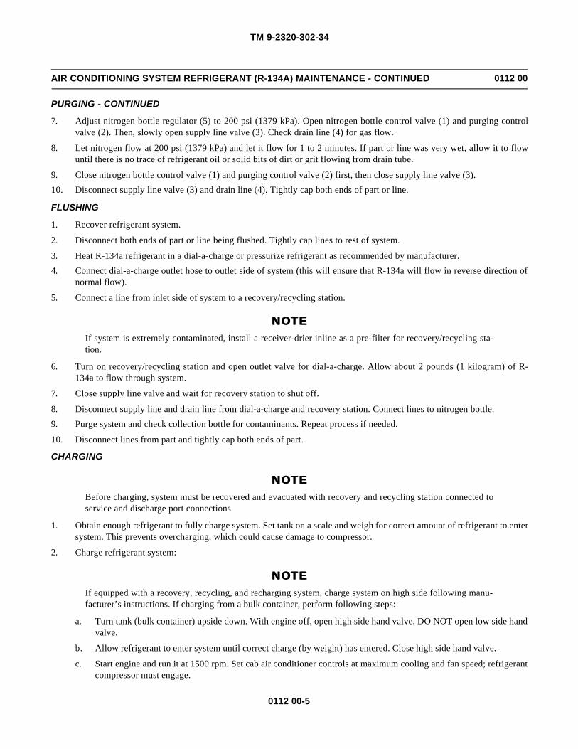
TM 9-2320-302-34
0112 00-5
AIR CONDITIONING SYSTEM REFRIGERANT (R-134A) MAINTENANCE - CONTINUED 0112 00
PURGING - CONTINUED
7. Adjust nitrogen bottle regulator (5) to 200 psi (1379 kPa). Open nitrogen bottle control valve (1) and purging controlvalve (2). Then, slowly open supply line valve (3). Check drain line (4) for gas flow.
8. Let nitrogen flow at 200 psi (1379 kPa) and let it flow for 1 to 2 minutes. If part or line was very wet, allow it to flowuntil there is no trace of refrigerant oil or solid bits of dirt or grit flowing from drain tube.
9. Close nitrogen bottle control valve (1) and purging control valve (2) first, then close supply line valve (3).
10. Disconnect supply line valve (3) and drain line (4). Tightly cap both ends of part or line.
FLUSHING
1. Recover refrigerant system.
2. Disconnect both ends of part or line being flushed. Tightly cap lines to rest of system.
3. Heat R-134a refrigerant in a dial-a-charge or pressurize refrigerant as recommended by manufacturer.
4. Connect dial-a-charge outlet hose to outlet side of system (this will ensure that R-134a will flow in reverse direction ofnormal flow).
5. Connect a line from inlet side of system to a recovery/recycling station.
NOTENOTEIf system is extremely contaminated, install a receiver-drier inline as a pre-filter for recovery/recycling sta-tion.
6. Turn on recovery/recycling station and open outlet valve for dial-a-charge. Allow about 2 pounds (1 kilogram) of R-134a to flow through system.
7. Close supply line valve and wait for recovery station to shut off.
8. Disconnect supply line and drain line from dial-a-charge and recovery station. Connect lines to nitrogen bottle.
9. Purge system and check collection bottle for contaminants. Repeat process if needed.
10. Disconnect lines from part and tightly cap both ends of part.
CHARGING
NOTENOTEBefore charging, system must be recovered and evacuated with recovery and recycling station connected toservice and discharge port connections.
1. Obtain enough refrigerant to fully charge system. Set tank on a scale and weigh for correct amount of refrigerant to entersystem. This prevents overcharging, which could cause damage to compressor.
2. Charge refrigerant system:
NOTENOTEIf equipped with a recovery, recycling, and recharging system, charge system on high side following manu-facturer’s instructions. If charging from a bulk container, perform following steps:
a. Turn tank (bulk container) upside down. With engine off, open high side hand valve. DO NOT open low side handvalve.
b. Allow refrigerant to enter system until correct charge (by weight) has entered. Close high side hand valve.
c. Start engine and run it at 1500 rpm. Set cab air conditioner controls at maximum cooling and fan speed; refrigerantcompressor must engage.
TM 9-2320-302-34
0112 00-6
AIR CONDITIONING SYSTEM REFRIGERANT (R-134A) MAINTENANCE - CONTINUED 0112 00
CHARGING - CONTINUED
d. If a charge did not enter system, place tank (bulk container) in upright position, then open LOW SIDE valve todraw vapor into system; leave valve open until correct weight of refrigerant has entered system, then close low sidevalve.
NOTENOTEIf refrigerant is slow to enter system because of low outside temperatures, vaporization can be quickened byplacing refrigerant tank in a tub of warm water, no warmer than 125°F (52°C).
3. Disconnect high side hose. With engine running, open low side and high side hose valves to recover refrigerant fromlines.
4. Shut down engine.
5. Leak test air conditioning system (TM 9-2320-302-20).
6. Check operation of air conditioning system (TM 9-2320-302-10).
END OF WORK PACKAGE
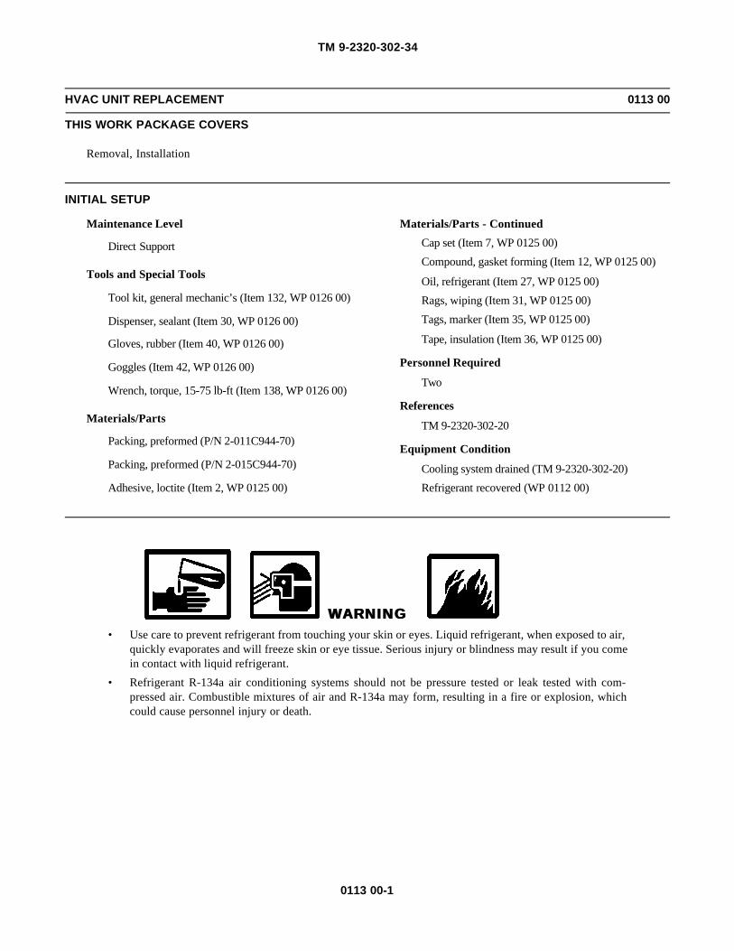
TM 9-2320-302-34
0113 00-1
HVAC UNIT REPLACEMENT 0113 00
THIS WORK PACKAGE COVERS
Removal, Installation
INITIAL SETUP
Maintenance Level
Direct Support
Tools and Special Tools
Tool kit, general mechanic’s (Item 132, WP 0126 00)
Dispenser, sealant (Item 30, WP 0126 00)
Gloves, rubber (Item 40, WP 0126 00)
Goggles (Item 42, WP 0126 00)
Wrench, torque, 15-75 lb-ft (Item 138, WP 0126 00)
Materials/Parts
Packing, preformed (P/N 2-011C944-70)
Packing, preformed (P/N 2-015C944-70)
Adhesive, loctite (Item 2, WP 0125 00)
Materials/Parts - Continued
Cap set (Item 7, WP 0125 00)
Compound, gasket forming (Item 12, WP 0125 00)
Oil, refrigerant (Item 27, WP 0125 00)
Rags, wiping (Item 31, WP 0125 00)
Tags, marker (Item 35, WP 0125 00)
Tape, insulation (Item 36, WP 0125 00)
Personnel Required
Two
References
TM 9-2320-302-20
Equipment Condition
Cooling system drained (TM 9-2320-302-20)
Refrigerant recovered (WP 0112 00)
WARNINGWARNING• Use care to prevent refrigerant from touching your skin or eyes. Liquid refrigerant, when exposed to air,
quickly evaporates and will freeze skin or eye tissue. Serious injury or blindness may result if you comein contact with liquid refrigerant.
• Refrigerant R-134a air conditioning systems should not be pressure tested or leak tested with com-pressed air. Combustible mixtures of air and R-134a may form, resulting in a fire or explosion, whichcould cause personnel injury or death.

TM 9-2320-302-34
0113 00-2
HVAC UNIT REPLACEMENT - CONTINUED 0113 00
REMOVAL
NOTENOTETag all lines and wires prior to removal to aid in installation.
1. Remove nine screws (1) and cover (2).
2. Remove three screws (3) and cover (4).
3. Remove two screws (5) and cover (6).
4. Remove seven screws (7) and cover (8) from dash (9).
1
1
26
5
4
3
5
7
9
8
7

TM 9-2320-302-34
0113 00-3
HVAC UNIT REPLACEMENT - CONTINUED 0113 00
REMOVAL - CONTINUED
5. Open glove box door (10) and remove two screws (11) and top panel (12) from compartment (13).
6. Remove three nuts (14), spring washers (15), and compartment (13) from dash (9).
7. Disconnect two flex hoses from ducts behind compartment (13).
8. Disconnect blue air line from air cylinder behind compartment (13).
9. Disconnect connectors for blower motor (16), resistor block (17), and thermostatic switch (18).
10
13
12119
14,15
18
16
17

TM 9-2320-302-34
0113 00-4
HVAC UNIT REPLACEMENT - CONTINUED 0113 00
REMOVAL - CONTINUED
10. Place rags on cab floor, loosen two hose clamps (19), and remove heater core hoses (20).
11. Loosen two hose clamps (21) and remove drain tubes (22).
12. On cab floor (23), remove sealant (24) from drain tubes (22) and remove drain tubes.
WARNINGWARNINGUse care to prevent refrigerant from touching your skin or eyes. Liquid refrigerant, when exposed to air,quickly evaporates and will freeze skin or eye tissue. Serious injury or blindness may result if you come incontact with liquid refrigerant.
21
2220
19
22
23
24
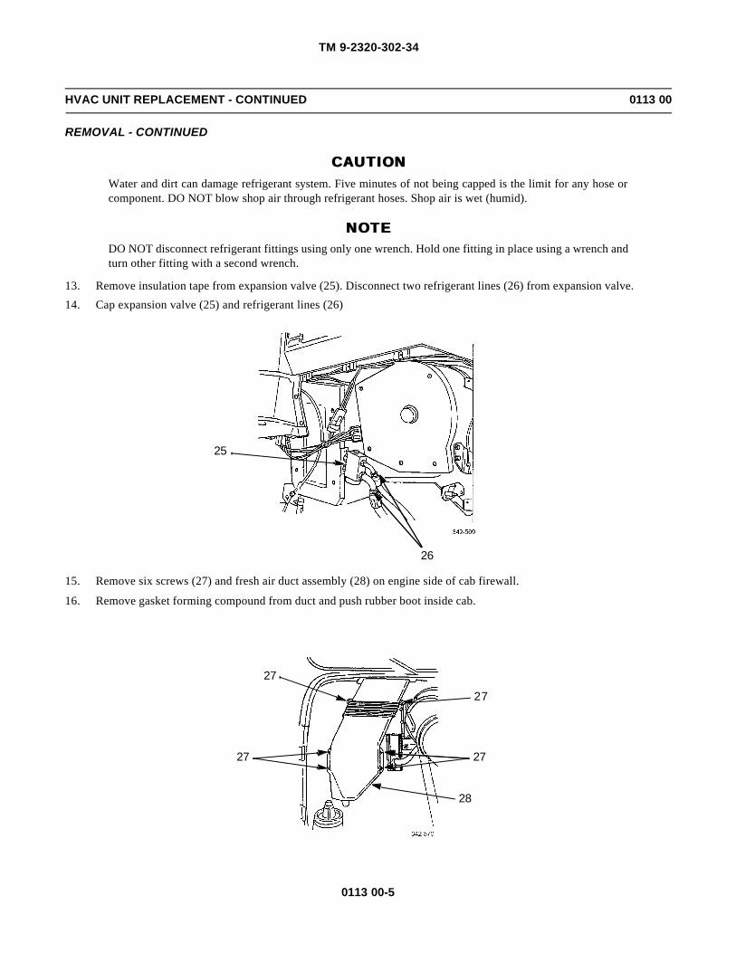
TM 9-2320-302-34
0113 00-5
HVAC UNIT REPLACEMENT - CONTINUED 0113 00
REMOVAL - CONTINUED
CAUTIONCAUTIONWater and dirt can damage refrigerant system. Five minutes of not being capped is the limit for any hose orcomponent. DO NOT blow shop air through refrigerant hoses. Shop air is wet (humid).
NOTENOTEDO NOT disconnect refrigerant fittings using only one wrench. Hold one fitting in place using a wrench andturn other fitting with a second wrench.
13. Remove insulation tape from expansion valve (25). Disconnect two refrigerant lines (26) from expansion valve.
14. Cap expansion valve (25) and refrigerant lines (26)
15. Remove six screws (27) and fresh air duct assembly (28) on engine side of cab firewall.
16. Remove gasket forming compound from duct and push rubber boot inside cab.
26
25
27
27
28
27
27

TM 9-2320-302-34
0113 00-6
HVAC UNIT REPLACEMENT - CONTINUED 0113 00
REMOVAL - CONTINUED
17. Disconnect air line (29) from air cylinder (30) by pushing in on cover ring, then pulling out on air line.
18. Remove six screws (31) holding HVAC unit (32) in place.
19. With assistance, lift HVAC unit (32) from vehicle.
29
30
32
31
31

TM 9-2320-302-34
0113 00-7
HVAC UNIT REPLACEMENT - CONTINUED 0113 00
INSTALLATION
1. With assistance, lift HVAC unit (32) into vehicle.
2. Secure HVAC unit (32) with six screws (31). Tighten screws to 48 lb-ft (65 Nm).
3. Connect air line (29) to air cylinder (30) by pushing air line into fitting as far as it will go, then gently pulling back on airline to lock it in place.
4. Pull rubber boot through firewall from engine side.
5. On engine side of fire wall, apply gasket forming compound to fresh air duct assembly (28) and secure with six screws(27).
6. Slide drain tubes (22) through openings in cab floor (23).
27
27
28
27
27
22
23

TM 9-2320-302-34
0113 00-8
HVAC UNIT REPLACEMENT - CONTINUED 0113 00
INSTALLATION - CONTINUED
7. Connect drain tubes (22) and secure with two hose clamps (21).
8. Install heater core hoses (20) and tighten two hose clamps (19).
9. Apply sealant (24) around drain tubes (22) on cab floor (23).
WARNINGWARNINGUse care to prevent refrigerant from touching your skin or eyes. Liquid refrigerant, when exposed to air,quickly evaporates and will freeze skin or eye tissue. Serious injury or blindness may result if you come incontact with liquid refrigerant.
10. Remove caps from refrigerant lines (26) and expansion valve (25).
21
2220
19
22
23
24

TM 9-2320-302-34
0113 00-9
HVAC UNIT REPLACEMENT - CONTINUED 0113 00
INSTALLATION - CONTINUED
11. Install new preformed packings (33) and lubricate them with refrigerant oil.
12. Apply loctite to male fitting threads (34) and connect two refrigerant lines (26) to expansion valve (25). Remove tags.
13. Torque refrigerant line connections (WP 0123 00)
14. Apply insulation tape to refrigerant lines (26) and expansion valve (25).
15. Connect connectors for blower motor (16), resistor block (17), and thermostatic switch (18).
16. Connect blue air line to air cylinder behind compartment (13).
17. Connect two flex hoses to ducts behind compartment (13).
NOTENOTEAny time air conditioning system is evacuated, replace receiver-drier.
18. Replace receiver-drier (WP 0118 00).
33
34
26
25
18
16
17

TM 9-2320-302-34
0113 00-10
HVAC UNIT REPLACEMENT - CONTINUED 0113 00
INSTALLATION - CONTINUED
19. Charge system with refrigerant (WP 0112 00).
20. Add refrigerant oil to compressor to replace that which was lost during system discharge (WP 0116 00).
WARNINGWARNINGRefrigerant R-134a air conditioning systems should not be pressure tested or leak tested with compressedair. Combustible mixtures of air and R-134a may form, resulting in a fire or explosion, which could causepersonnel injury or death.
21. Leak test air conditioner system (TM 9-2320-302-20).
22. Install compartment (13) into dash (9) and secure with three nuts (14) and spring washers (15).
23. Install top panel (12) to compartment (13) and secure with two screws (11).
24. Position cover (8) on dash (9) and secure with seven screws (7).
10
13
12119
14,15
7
9
8
7

TM 9-2320-302-34
0113 00-11
HVAC UNIT REPLACEMENT - CONTINUED 0113 00
INSTALLATION - CONTINUED
25. Position cover (6) on dash (9) and secure with two screws (5).
26. Position cover (4) on dash (9) and secure with three screws (3).
27. Position cover (2) on dash (9) and secure with nine screws (1).
END OF WORK PACKAGE
1
1
26
5
4
3
5

TM 9-2320-302-34
0113 00-12
This Page Intentionally Left Blank.

TM 9-2320-302-34
0114 00-1
AIR CONDITIONER EXPANSION VALVE REPLACEMENT 0114 00
THIS WORK PACKAGE COVERS
Removal, Installation
INITIAL SETUP
Maintenance Level
Direct Support
Tools and Special Tools
Tool kit, general mechanic’s (Item 132, WP 0126 00)
Crowfoot attachment set (Item 28, WP 0126 00)
Gloves, rubber (Item 40, WP 0126 00)
Goggles (Item 42, WP 0126 00)
Wrench, torque, 0-300 lb-in (Item 137, WP 0126 00)
Wrench, torque, 15-75 lb-ft (Item 138, WP 0126 00)
Materials/Parts
Packing, preformed (P/N 2-011C944-70)
Packing, preformed (P/N 2-015C944-70)
Adhesive, loctite (Item 2, WP 0125 00)
Materials/Parts - Continued
Cap set (Item 7, WP 0125 00)
Caulk, strip (Item 8, WP 0125 00)
Oil, refrigerant (Item 27, WP 0125 00)
Rags, wiping (Item 31, WP 0125 00)
Tags, marker (Item 35, WP 0125 00)
Tape, insulation (Item 36, WP 0125 00)
References
TM 9-2320-302-20
Equipment Condition
Refrigerant recovered (WP 0112 00)
WARNINGWARNING• Use care to prevent refrigerant from touching your skin or eyes. Liquid refrigerant, when exposed to air,
quickly evaporates and will freeze skin or eye tissue. Serious injury or blindness may result if you comein contact with liquid refrigerant.
• Refrigerant R-134a air conditioning systems should not be pressure tested or leak tested with com-pressed air. Combustible mixtures of air and R-134a may form, resulting in a fire or explosion, whichcould cause personnel injury or death.

TM 9-2320-302-34
0114 00-2
AIR CONDITIONER EXPANSION VALVE REPLACEMENT - CONTINUED 0114 00
REMOVAL
NOTENOTE
Tag all lines and wires prior to removal to aid in installation.
1. Remove nine screws (1) and cover (2).
WARNINGWARNING
Use care to prevent refrigerant from touching your skin or eyes. Liquid refrigerant, when exposed to air,quickly evaporates and will freeze skin or eye tissue. Serious injury or blindness may result if you come incontact with liquid refrigerant.
2. Remove insulation tape and strip caulk around expansion valve (3).
CAUTIONCAUTION
Water and dirt can damage refrigerant system. Five minutes of not being capped is the limit for any hose orcomponent. DO NOT blow shop air through refrigerant hoses. Shop air is wet (humid).
NOTENOTE
DO NOT disconnect refrigerant fittings using only one wrench. Hold one fitting in place using a wrench andturn other fitting with a second wrench.
3. Tag and disconnect refrigerant lines (4) and evaporator coil inlet and outlet lines (5) from expansion valve (3). Installplugs in refrigerant lines, evaporator coil inlet and outlet lines, and expansion valve. Discard preformed packings.
2
1

TM 9-2320-302-34
0114 00-3
AIR CONDITIONER EXPANSION VALVE REPLACEMENT - CONTINUED 0114 00
REMOVAL - CONTINUED
4. Remove expansion valve (3).
INSTALLATION
1. Remove plugs from refrigerant lines (4), evaporator coil inlet and outlet lines (5), and expansion valve (3).
2. Install new preformed packings and lubricate with refrigerant oil.
3. Apply loctite to male fitting threads and connect refrigerant lines (4) and evaporator coil inlet and outlet lines (5) toexpansion valve (3).
NOTENOTEDO NOT connect refrigerant fittings using only one wrench. Hold one fitting in place using a wrench andturn other fitting with a second wrench.
4. Using wrenches, tighten evaporator coil lines (5) to 216 lb-in (25 Nm).
5. Tighten refrigerant lines (4): tighten large hose to compressor to 24 lb-ft (33 Nm); tighten small hose from receiver-drierto 144 lb-in (16 Nm).
NOTENOTEAny time air conditioning system refrigerant is evacuated, replace receiver-drier.
6. Replace receiver-drier (WP 0118 00).
7. Evacuate and charge system with refrigerant (WP 0112 00).
8. Add refrigerant oil to compressor to replace that which was lost during system discharge (WP 0116 00).
WARNINGWARNINGUse care to prevent refrigerant from touching your skin or eyes. Liquid refrigerant, when exposed to air,quickly evaporates and will freeze skin or eye tissue. Serious injury or blindness may result if you come incontact with liquid refrigerant.
9. Leak test air conditioner system (TM 9-2320-302-20).
4
5
3

TM 9-2320-302-34
0114 00-4
AIR CONDITIONER EXPANSION VALVE REPLACEMENT - CONTINUED 0114 00
INSTALLATION - CONTINUED
10. Wipe expansion valve (3) and refrigerant line (4) connections clean. Wrap line connections with insulation tape.
11. Wrap expansion valve (3) with strip caulk.
12. Install dash panel (2) and nine screws (1).
END OF WORK PACKAGE
4
3
2
1
TM 9-2320-302-34
0115 00-1
AIR CONDITIONER EVAPORATOR COIL REPLACEMENT 0115 00
THIS WORK PACKAGE COVERS
Removal, Installation
INITIAL SETUP
Maintenance Level
Direct Support
Tools and Special Tools
Tool kit, general mechanic’s (Item 132, WP 0126 00)
Crowfoot attachment set (Item 28, WP 0126 00)
Gloves, rubber (Item 40, WP 0126 00)
Goggles (Item 42, WP 0126 00)
Wrench, torque, 0-300 lb-in (Item 137, WP 0126 00)
Wrench, torque, 15-75 lb-ft (Item 138, WP 0126 00)
Materials/Parts
Packing, preformed (P/N 2-011C944-70)
Packing, preformed (P/N 2-015C944-70)
Adhesive, loctite (Item 2, WP 0125 00)
Materials/Parts - Continued
Cap set (Item 7, WP 0125 00)
Caulk, strip (Item 8, WP 0125 00)
Oil, refrigerant (Item 27, WP 0125 00)
Rags, wiping (Item 31, WP 0125 00)
Tags, marker (Item 35, WP 0125 00)
Tape, insulation (Item 36, WP 0125 00)
References
TM 9-2320-302-20
Equipment Condition
Refrigerant recovered (WP 0112 00)
WARNINGWARNING• Use care to prevent refrigerant from touching your skin or eyes. Liquid refrigerant, when exposed to air,
quickly evaporates and will freeze skin or eye tissue. Serious injury or blindness may result if you comein contact with liquid refrigerant.
• Refrigerant R-134a air conditioning systems should not be pressure tested or leak tested with com-pressed air. Combustible mixtures of air and R-134a may form, resulting in a fire or explosion, whichcould cause personnel injury or death.
REMOVAL
NOTENOTETag all lines and wires prior to removal to aid in installation.

TM 9-2320-302-34
0115 00-2
AIR CONDITIONER EVAPORATOR COIL REPLACEMENT - CONTINUED 0115 00
REMOVAL - CONTINUED
1. Remove nine screws (1) and cover (2).
WARNINGWARNING
Use care to prevent refrigerant from touching your skin or eyes. Liquid refrigerant, when exposed to air,quickly evaporates and will freeze skin or eye tissue. Serious injury or blindness may result if you come in
contact with liquid refrigerant.
2. Remove insulation tape and strip caulk around expansion valve (3).
3. Remove four screws (4) and cover (5).
CAUTIONCAUTION
Water and dirt can damage refrigerant system. Five minutes of not being capped is the limit for any hose or
component. DO NOT blow shop air through refrigerant hoses. Shop air is wet (humid).
NOTENOTE
DO NOT disconnect refrigerant fittings using only one wrench. Hold one fitting in place using a wrench andturn other fitting with a second wrench.
4. Tag and disconnect refrigerant lines (6) and evaporator coil inlet and outlet lines (7) from expansion valve (3). Install
plugs in refrigerant lines, evaporator coil inlet and outlet lines, and expansion valve. Discard preformed packings.
1 2
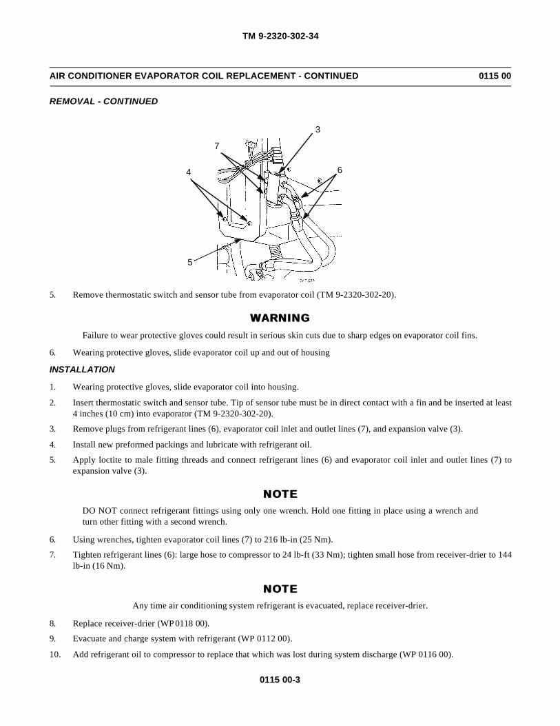
TM 9-2320-302-34
0115 00-3
AIR CONDITIONER EVAPORATOR COIL REPLACEMENT - CONTINUED 0115 00
REMOVAL - CONTINUED
5. Remove thermostatic switch and sensor tube from evaporator coil (TM 9-2320-302-20).
WARNINGWARNINGFailure to wear protective gloves could result in serious skin cuts due to sharp edges on evaporator coil fins.
6. Wearing protective gloves, slide evaporator coil up and out of housing
INSTALLATION
1. Wearing protective gloves, slide evaporator coil into housing.
2. Insert thermostatic switch and sensor tube. Tip of sensor tube must be in direct contact with a fin and be inserted at least4 inches (10 cm) into evaporator (TM 9-2320-302-20).
3. Remove plugs from refrigerant lines (6), evaporator coil inlet and outlet lines (7), and expansion valve (3).
4. Install new preformed packings and lubricate with refrigerant oil.
5. Apply loctite to male fitting threads and connect refrigerant lines (6) and evaporator coil inlet and outlet lines (7) toexpansion valve (3).
NOTENOTEDO NOT connect refrigerant fittings using only one wrench. Hold one fitting in place using a wrench andturn other fitting with a second wrench.
6. Using wrenches, tighten evaporator coil lines (7) to 216 lb-in (25 Nm).
7. Tighten refrigerant lines (6): large hose to compressor to 24 lb-ft (33 Nm); tighten small hose from receiver-drier to 144lb-in (16 Nm).
NOTENOTEAny time air conditioning system refrigerant is evacuated, replace receiver-drier.
8. Replace receiver-drier (WP 0118 00).
9. Evacuate and charge system with refrigerant (WP 0112 00).
10. Add refrigerant oil to compressor to replace that which was lost during system discharge (WP 0116 00).
7
3
4
5
6

TM 9-2320-302-34
0115 00-4
AIR CONDITIONER EVAPORATOR COIL REPLACEMENT - CONTINUED 0115 00
INSTALLATION - CONTINUED
WARNINGWARNINGRefrigerant R-134a air conditioning systems should not be pressure tested or leak tested with compressedair. Combustible mixtures of air and R-134a may form, resulting in a fire or explosion, which could causepersonnel injury or death.
11. Leak test air conditioner system (TM 9-2320-302-20).
12. Wipe expansion valve (3) and refrigerant line (6) connections clean. Wrap line connections with insulation tape.
13. Wrap expansion valve (3) with strip caulk.
14. Install cover (5) and four screws (4).
15. Install cover (2) and nine screws (1).
END OF WORK PACKAGE
6 3
4
5
1 2

TM 9-2320-302-34
0116 00-1
AIR CONDITIONER COMPRESSOR SERVICE 0116 00
THIS WORK PACKAGE COVERS
General Information, Service
INITIAL SETUP
Maintenance Level
Direct Support
Tools and Special Tools
Tool kit, general mechanic’s (Item 132, WP 0126 00)
Gage, oil level (Item 35, WP 0126 00)
Gloves, rubber (Item 40, WP 0126 00)
Goggles (Item 42, WP 0126 00)
Materials/Parts
Oil, refrigerant (Item 27, WP 0125 00)
Rags, wiping (Item 31, WP 0125 00)
References
TM 9-2320-302-20
Equipment Condition
Refrigerant recovered (WP 0112 00)
WARNINGWARNING• Use care to prevent refrigerant from touching your skin or eyes. Liquid refrigerant, when exposed to air,
quickly evaporates and will freeze skin or eye tissue. Serious injury or blindness may result if you comein contact with liquid refrigerant.
• Refrigerant R-134a air conditioning systems should not be pressure tested or leak tested with com-pressed air. Combustible mixtures of air and R-134a may form, resulting in a fire or explosion, whichcould cause personnel injury or death.
GENERAL INFORMATION
CAUTIONCAUTION• Always use correct refrigerant oil in R-134a air conditioning system. Never mix oils. If wrong oil is
used, or if oils are mixed, compressor could seize due to improper lubrication.
• Refrigerant oil must be from a container that has not been opened or that has been tightly sealed sinceits last use. Tubing, funnels or other equipment used to transfer refrigerant oil should be very clean anddry. Failure to follow this caution may result in contamination of system.
NOTENOTEReplacing only the amount of refrigerant oil that was removed during evacuation may result in wrong oilcharge; oil charge may have been incorrect prior to evacuation. The only way to ensure proper oil charge isto check oil level in compressor with an oil level gage.
1. When handling refrigerant oil:
a. Oil should be free of water, dust, metal powder, and other foreign substances.
b. DO NOT mix refrigerant oil with other types or viscosities of oil.
c. Quickly seal oil container after use. Refrigerant oil absorbs moisture when exposed to air for any period of time.

TM 9-2320-302-34
0116 00-2
AIR CONDITIONER COMPRESSOR SERVICE - CONTINUED 0116 00
GENERAL INFORMATION - CONTINUED
2. Air conditioning system should have approximately 14 fl oz (414 ml) of refrigerant oil. There should be 10 fl oz (296ml) in compressor.
3. Each major component has approximately 2 fl oz (59 ml) of refrigerant oil. Therefore, additional oil must be added tocompressor when a major component is replaced.
EXAMPLE:
If condenser and receiver-drier are to be replaced, first check oil level in compressor. Compressor should have 10 fl oz(296 ml). Add oil if needed. Then, after replacing condenser and receiver-drier, add an additional 4 fl oz (118 ml) of oilto compressor. Entire system should then have approximately 14 fl oz (414 ml).
SERVICE
WARNINGWARNING• DO NOT remove air conditioner compressor oil fill plug without first recovering refrigerant from sys-
tem. Failure to recover system could cause uncontrolled release of high pressure refrigerant, which canfreeze skin and eye tissue causing serious injury or blindness.
• Use care to prevent refrigerant from touching your skin or eyes. Liquid refrigerant, when exposed to air,quickly evaporates and will freeze skin or eye tissue. Serious injury or blindness may result if you comein contact with liquid refrigerant.
1. Remove oil fill plug (1) and preformed packing from compressor (2). Retain preformed packing if not damaged or ifthere are no signs of leaks.
2. Use oil level gage to check oil level in compressor (2).
a. If gage bottoms out before going in more than 3 in (7.6 cm), it is hitting compressor crankshaft. Rotate drive plateby hand and insert gage until it contacts bottom of sump.
1
2

TM 9-2320-302-34
0116 00-3
AIR CONDITIONER COMPRESSOR SERVICE - CONTINUED 0116 00
SERVICE - CONTINUED
b. Use Table 1 to determine oil quantity in compressor (2).
Table 1. Determination of Compressor Capacity.
3. Add or remove oil from compressor (2) so that oil charge in compressor is 10 fl oz (296 ml).
4. Add additional oil to compressor (2) based on number of air conditioning components replaced. Total charge should be14 fl oz (414 ml).
5. Ensure preformed packing and threads of oil fill plug (1) are clean. Install preformed packing over threads of oil fill plugbeing careful not to twist preformed packing,
6. Install oil fill plug (1) and tighten snugly.
NOTENOTEAny time air conditioning system refrigerant is evacuated, replace receiver-drier.
7. Replace receiver-drier (WP 0118 00).
8. Charge air conditioning system (WP 0112 00).
WARNINGWARNINGRefrigerant R-134a air conditioning systems should not be pressure tested or leak tested with compressedair. Combustible mixtures of air and R-134a may form, resulting in a fire or explosion, which could causepersonnel injury or death.
9. Leak test air conditioning system (TM 9-2320-302-20).
END OF WORK PACKAGE
OIL LEVEL GAGE DEPTH IN INCHES (MM) OIL QUANTITY IN FLUID OZ (ML)
7/8 in (22.2 mm) 6 fl oz (177 ml)
1 in (25.4 mm) 8 fl oz (237 ml)
1 1/8 in (28.6 mm) 10 fl oz (296 ml)
1 7/16 in (36.5 mm) 12 fl oz (355 ml)
1 11/16 in (43 mm) 14 fl oz (414 ml)

TM 9-2320-302-34
0116 00-4
This Page Intentionally Left Blank.

TM 9-2320-302-34
0117 00-1
AIR CONDITIONER COMPRESSOR REPLACEMENT 0117 00
THIS WORK PACKAGE COVERS
Removal, Installation
INITIAL SETUP
Maintenance Level
Direct Support
Tools and Special Tools
Tool kit, general mechanic’s (Item 132, WP 0126 00)
Gloves, rubber (Item 40, WP 0126 00)
Goggles (Item 42, WP 0126 00)
Materials/Parts
Nut, lock (6)
Packing, preformed (P/N 2-013C557-70) (2)
Washer, lock (P/N AN935-616) (6)
Adhesive, loctite (Item 2, WP 0125 00)
Materials/Parts - Continued
Cap set (Item 7, WP 0125 00)
Oil, refrigerant (Item 27, WP 0125 00)
Rags, wiping (Item 31, WP 0125 00)
Tags, marker (Item 35, WP 0125 00)
References
TM 9-2320-302-20
Equipment Condition
Alternator belt removed (TM 9-2320-302-20)
Refrigerant recovered (WP 0112 00)
WARNINGWARNING• Use care to prevent refrigerant from touching your skin or eyes. Liquid refrigerant, when exposed to air,
quickly evaporates and will freeze skin or eye tissue. Serious injury or blindness may result if you comein contact with liquid refrigerant.
• Refrigerant R-134a air conditioning systems should not be pressure tested or leak tested with com-pressed air. Combustible mixtures of air and R-134a may form, resulting in a fire or explosion, whichcould cause personnel injury or death.
• DO NOT disconnect refrigerant lines from air conditioner compressor without first recovering refriger-ant from system. Failure to recover system could cause uncontrolled release of high pressure refrigerant,which can freeze skin and eye tissue causing serious injury or blindness.
REMOVAL
NOTENOTEIf air conditioner compressor is being removed as an equipment condition for engine replacement, DO NOTdisconnect refrigerant hoses and lines. Perform ONLY the following four steps:
• Disconnect compressor clutch electrical lead.
• Cut tiedown straps securing refrigerant hoses.
• Remove compressor mounting bolts.
• Move compressor from mounting bracket to truck frame and secure in place to prevent damage.
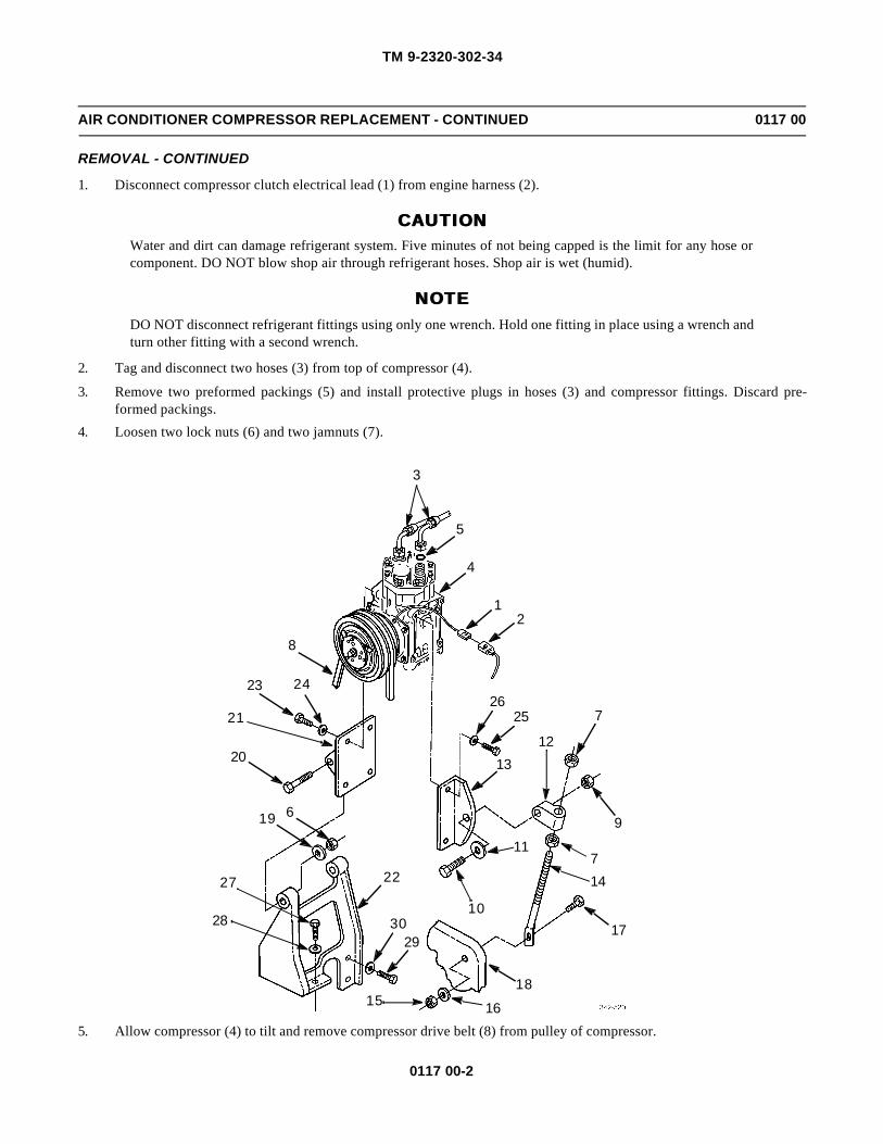
TM 9-2320-302-34
0117 00-2
AIR CONDITIONER COMPRESSOR REPLACEMENT - CONTINUED 0117 00
REMOVAL - CONTINUED
1. Disconnect compressor clutch electrical lead (1) from engine harness (2).
CAUTIONCAUTIONWater and dirt can damage refrigerant system. Five minutes of not being capped is the limit for any hose orcomponent. DO NOT blow shop air through refrigerant hoses. Shop air is wet (humid).
NOTENOTEDO NOT disconnect refrigerant fittings using only one wrench. Hold one fitting in place using a wrench andturn other fitting with a second wrench.
2. Tag and disconnect two hoses (3) from top of compressor (4).
3. Remove two preformed packings (5) and install protective plugs in hoses (3) and compressor fittings. Discard pre-formed packings.
4. Loosen two lock nuts (6) and two jamnuts (7).
5. Allow compressor (4) to tilt and remove compressor drive belt (8) from pulley of compressor.
3
5
4
12
8
2423
7
9
121320
2625
714
17
11
10
18
1615
2930
2227
28
19 6
21

TM 9-2320-302-34
0117 00-3
AIR CONDITIONER COMPRESSOR REPLACEMENT - CONTINUED 0117 00
REMOVAL - CONTINUED
6. Remove lock nut (9), screw (10), washer (11), and link end (12) from bracket (13). Discard lock nut.
7. Remove two jamnuts (7) and link end (12) from adjustment rod (14).
8. Remove lock nut (15), washer (16), screw (17), and adjustment rod (14) from engine (18). Discard lock nut.
9. Remove two lock nuts (6), washers (19), and screws (20) to separate bracket (21) from bracket (22). Discard lock nuts.
10. Remove compressor (4) with brackets (13 and 21) from engine (18).
11. Remove four screws (23), lock washers (24), and bracket (21) from compressor (4). Discard lock washers.
12. Remove four screws (25), lock washers (26), and bracket (13) from compressor (4). Discard lock washers.
13. Remove screw (27) and washer (28) from bracket (22).
14. Remove two screws (29), washers (30), and bracket (22) from engine (18).
INSTALLATION
1. Install bracket (22) to engine (18) with two washers (30) and screws (29).
2. Install washer (28) and screw (27) to bracket (22).
3. Install bracket (13) to compressor (4) with four new lock washers (26) and screws (25).
4. Install bracket (21) to compressor (4) with four new lock washers (24) and screws (23).
5. Position compressor (4) to engine (18).
6. Install bracket (22) to bracket (21) with two screws (20), washers (19), and new lock nuts (6). Do not fully tighten locknuts.
7. Install adjustment rod (14) to engine (18) with screws (17), washer (16), and new lock nut (15).
8. Install two jamnuts (7) and link end (12) to adjustment rod (14).
9. Install link end (12) to bracket (13) with screw (10), washer (11), and new lock nut (9). Do not fully tighten lock nut.
10. Position compressor drive belt (8) over compressor (4) pulley.
11. Adjust two jamnuts (7) to tighten compressor belt (8) and tighten jamnuts against link end (12).
12. Tighten two lock nuts (6) and lock nut (9).
13. Remove protective plugs from hoses (3) and compressor fittings, install two new preformed packings (5),and lubricatewith refrigerant oil.
NOTENOTEDO NOT connect refrigerant fittings using only one wrench. Hold one fitting in place using a wrench andturn other fitting with a second wrench.
14. Apply loctite to threads of compressor (4) fittings and install two hoses (3).
15. Connect compressor clutch electrical lead (1) to engine harness (2).
NOTENOTEAny time air conditioning system refrigerant is evacuated, replace receiver-drier.
16. Replace receiver-drier (WP 0118 00).
17. Install and adjust alternator belt (TM 9-2320-302-20).
18. Charge air conditioning system (WP 0112 00).

TM 9-2320-302-34
0117 00-4
AIR CONDITIONER COMPRESSOR REPLACEMENT - CONTINUED 0117 00
INSTALLATION - CONTINUED
WARNINGWARNINGRefrigerant R-134a air conditioning systems should not be pressure tested or leak tested with compressedair. Combustible mixtures of air and R-134a may form, resulting in a fire or explosion, which could causepersonnel injury or death.
19. Leak test air conditioning system (TM 9-2320-302-20).
END OF WORK PACKAGE

TM 9-2320-302-34
0118 00-1
AIR CONDITIONER RECEIVER-DRIER REPLACEMENT 0118 00
THIS WORK PACKAGE COVERS
Removal, Installation
INITIAL SETUP
Maintenance Level
Direct Support
Tools and Special Tools
Tool kit, general mechanic’s (Item 132, WP 0126 00)
Gloves, rubber (Item 40, WP 0126 00)
Goggles (Item 42, WP 0126 00)
Materials/Parts
Packing, preformed (P/N J200AR11) (2)
Adhesive, loctite (Item 2, WP 0125 00)
Cap set (Item 7, WP 0125 00)
Materials/Parts - Continued
Oil, refrigerant (Item 27, WP 0125 00)
Rags, wiping (Item 31, WP 0125 00)
Tags, marker (Item 35, WP 0125 00)
Equipment Condition
Binary switch removed (TM 9-2320-302-20)
Refrigerant recovered (WP 0112 00)
Fan cycling switch removed (WP 0120 00)
WARNINGWARNING• Use care to prevent refrigerant from touching your skin or eyes. Liquid refrigerant, when exposed to air,
quickly evaporates and will freeze skin or eye tissue. Serious injury or blindness may result if you comein contact with liquid refrigerant.
• Refrigerant R-134a air conditioning systems should not be pressure tested or leak tested with com-pressed air. Combustible mixtures of air and R-134a may form, resulting in a fire or explosion, whichcould cause personnel injury or death.
REMOVAL
CAUTIONCAUTIONWater and dirt can damage refrigerant system. Five minutes of not being capped is the limit for any hose orcomponent. DO NOT blow shop air through refrigerant hoses. Shop air is wet (humid).
NOTENOTE• The receiver-drier and moisture indicator are one unit and cannot be replaced separately.
• If desiccant cartridge inside receiver-drier has fallen apart, evacuate system and replace expansion valveand refrigerant compressor (desiccant matter cannot be removed from these parts). A desiccant car-tridge may fall apart from too much moisture in system because of poor evacuation of system or lack ofmaintenance.
• DO NOT disconnect or connect refrigerant fittings using only one wrench. Hold one fitting in placeusing a wrench and turn other fitting with a second wrench.
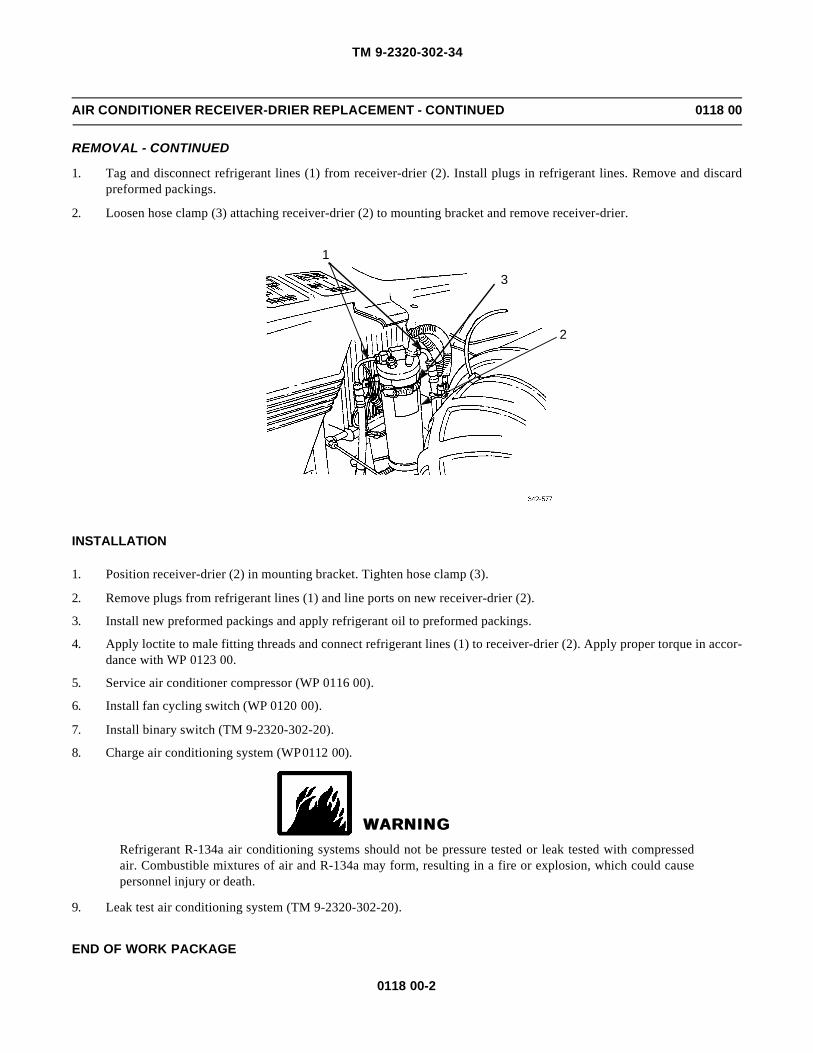
TM 9-2320-302-34
0118 00-2
AIR CONDITIONER RECEIVER-DRIER REPLACEMENT - CONTINUED 0118 00
REMOVAL - CONTINUED
1. Tag and disconnect refrigerant lines (1) from receiver-drier (2). Install plugs in refrigerant lines. Remove and discardpreformed packings.
2. Loosen hose clamp (3) attaching receiver-drier (2) to mounting bracket and remove receiver-drier.
INSTALLATION
1. Position receiver-drier (2) in mounting bracket. Tighten hose clamp (3).
2. Remove plugs from refrigerant lines (1) and line ports on new receiver-drier (2).
3. Install new preformed packings and apply refrigerant oil to preformed packings.
4. Apply loctite to male fitting threads and connect refrigerant lines (1) to receiver-drier (2). Apply proper torque in accor-dance with WP 0123 00.
5. Service air conditioner compressor (WP 0116 00).
6. Install fan cycling switch (WP 0120 00).
7. Install binary switch (TM 9-2320-302-20).
8. Charge air conditioning system (WP 0112 00).
WARNINGWARNINGRefrigerant R-134a air conditioning systems should not be pressure tested or leak tested with compressedair. Combustible mixtures of air and R-134a may form, resulting in a fire or explosion, which could causepersonnel injury or death.
9. Leak test air conditioning system (TM 9-2320-302-20).
END OF WORK PACKAGE
1
3
2

TM 9-2320-302-34
0119 00-1
AIR CONDITIONER CONDENSER REPLACEMENT 0119 00
THIS WORK PACKAGE COVERS
Removal, Installation
INITIAL SETUP
Maintenance Level
Direct Support
Tools and Special Tools
Tool kit, general mechanic’s (Item 132, WP 0126 00)
Crowfoot attachment set (Item 28, WP 0126 00)
Gloves, rubber (Item 40, WP 0126 00)
Goggles (Item 42, WP 0126 00)
Wrench, torque, 0-300 lb-in (Item 137, WP 0126 00)
Wrench, torque, 15-75 lb-ft (Item 138, WP 0126 00)
Materials/Parts
Packing, preformed (P/N J200AR11)
Packing, preformed (P/N 2-013C557-70)
Adhesive, loctite (Item 2, WP 0125 00)
Cap set (Item 7, WP 0125 00)
Oil, refrigerant (Item 27, WP 0125 00)
Rags, wiping (Item 31, WP 0125 00)
Tags, marker (Item 35, WP 0125 00)
References
TM 9-2320-302-20
Equipment Condition
Refrigerant recovered (WP 0112 00)
WARNINGWARNING• Use care to prevent refrigerant from touching your skin or eyes. Liquid refrigerant, when exposed to air,
quickly evaporates and will freeze skin or eye tissue. Serious injury or blindness may result if you comein contact with liquid refrigerant.
• Refrigerant R-134a air conditioning systems should not be pressure tested or leak tested with com-pressed air. Combustible mixtures of air and R-134a may form, resulting in a fire or explosion, whichcould cause personnel injury or death.
REMOVAL
CAUTIONCAUTIONWater and dirt can damage refrigerant system. Five minutes of not being capped is the limit for any hose orcomponent. DO NOT blow shop air through refrigerant hoses. Shop air is wet (humid).
NOTENOTEDO NOT disconnect refrigerant fittings using only one wrench. Hold one fitting in place using a wrench andturn other fitting with a second wrench.

TM 9-2320-302-34
0119 00-2
AIR CONDITIONER CONDENSER REPLACEMENT - CONTINUED 0119 00
REMOVAL - CONTINUED
1. Tag and disconnect refrigerant lines (1) from condenser (2). Install plugs in refrigerant and condenser lines. Remove anddiscard preformed packings.
2. Remove fasteners attaching condenser (2) to radiator.
INSTALLATION
1. Position condenser (2) on radiator and install fasteners.
2. Remove plugs from refrigerant lines (1) and line ports on new condenser (2).
3. Install new preformed packings and apply refrigerant oil to preformed packings.
4. Apply loctite to male fitting threads and connect but do not tighten refrigerant lines (1) to condenser (2).
NOTENOTE
DO NOT connect refrigerant fittings using only one wrench. Hold one fitting in place using a wrench andturn other fitting with a second wrench.
5. Tighten connections in accordance with WP 0123 00.
NOTENOTE
Any time air conditioning system refrigerant is evacuated, replace receiver-drier.
6. Replace receiver-drier (WP 0118 00).
7. Service air conditioner compressor (WP 0116 00).
8. Charge air conditioning system (WP 0112 00).
1
2

TM 9-2320-302-34
0119 00-3
AIR CONDITIONER CONDENSER REPLACEMENT - CONTINUED 0119 00
INSTALLATION - CONTINUED
WARNINGWARNINGRefrigerant R-134a air conditioning systems should not be pressure tested or leak tested with compressedair. Combustible mixtures of air and R-134a may form, resulting in a fire or explosion, which could causepersonnel injury or death.
9. Leak test air conditioning system (TM 9-2320-302-20).
END OF WORK PACKAGE

TM 9-2320-302-34
0119 00-4
This Page Intentionally Left Blank.

TM 9-2320-302-34
0120 00-1
AIR CONDITIONER FAN CYCLING SWITCH REPLACEMENT 0120 00
THIS WORK PACKAGE COVERS
Removal, Installation
INITIAL SETUP
Maintenance Level
Direct Support
Tools and Special Tools
Tool kit, general mechanic’s (Item 132, WP 0126 00)
Crowfoot attachment set (Item 28, WP 0126 00)
Wrench, torque, 15-75 lb-ft (Item 138, WP 0126 00)
Materials/Parts
Oil, refrigerant (Item 27, WP 0125 00)
Rags, wiping (Item 31, WP 0125 00)
Equipment Condition
Refrigerant recovered (WP 0112 00)
References
TM 9-2320-302-20
WARNINGWARNING• Use care to prevent refrigerant from touching your skin or eyes. Liquid refrigerant, when exposed to air,
quickly evaporates and will freeze skin or eye tissue. Serious injury or blindness may result if you comein contact with liquid refrigerant.
• Refrigerant R-134a air conditioning systems should not be pressure tested or leak tested with com-pressed air. Combustible mixtures of air and R-134a may form, resulting in a fire or explosion, whichcould cause personnel injury or death.
REMOVAL
CAUTIONCAUTIONWater and dirt can damage refrigerant system. Five minutes of not being capped is the limit for any hose orcomponent. DO NOT blow shop air through refrigerant hoses. Shop air is wet (humid).
NOTENOTEDO NOT disconnect or connect refrigerant fittings using only one wrench. Hold one fitting in place using awrench and turn other fitting with a second wrench.

TM 9-2320-302-34
0120 00-2
AIR CONDITIONER FAN CYCLING SWITCH REPLACEMENT - CONTINUED 0120 00
REMOVAL - CONTINUED
1. Disconnect harness connector (1) from fan cycling switch (2).
2. Unscrew fan cycling switch (2) from coupling (3) on receiver-drier (4). Remove and discard preformed packing.
INSTALLATION
1. Lubricate new preformed packing with refrigerant oil and install over male threads of coupling (3) on receiver-drier (4).
2. Screw fan cycling switch (2) into coupling (3). Tighten switch to 20-25 lb-ft (27-34 Nm).
3. Connect harness connector (1) to fan cycling switch (2).
NOTENOTEAny time air conditioning system refrigerant is evacuated, replace receiver-drier.
4. Replace receiver-drier (WP 0118 00).
5. Service air conditioner compressor (WP 0116 00).
6. Charge air conditioning system (WP 0112 00).
WARNINGWARNINGRefrigerant R-134a air conditioning systems should not be pressure tested or leak tested with compressedair. Combustible mixtures of air and R-134a may form, resulting in a fire or explosion, which could causepersonnel injury or death.
7. Leak test air conditioning system (TM 9-2320-302-20).
END OF WORK PACKAGE
12
3
4

TM 9-2320-302-34
0121 00-1
AIR CONDITIONER HOSE REPLACEMENT 0121 00
THIS WORK PACKAGE COVERS
Removal, Installation
INITIAL SETUP
Maintenance Level
Direct Support
Tools and Special Tools
Tool kit, general mechanic’s (Item 132, WP 0126 00)
Crowfoot attachment set (Item 28, WP 0126 00)
Gloves, rubber (Item 40, WP 0126 00)
Goggles (Item 42, WP 0126 00)
Wrench, torque, 0-300 lb-in (Item 137, WP 0126 00)
Wrench, torque, 15-75 lb-ft (Item 138, WP 0126 00)
Materials/Parts
Gasket (P/N 22-46774-000)
Preformed packing (as required)
Adhesive, loctite (Item 2, WP 0125 00)
Materials/Parts - Continued
Cap set (Item 7, WP 0125 00)
Caulk, strip (Item 8, WP 0125 00)
Oil, refrigerant (Item 27, WP 0125 00)
Rags, wiping (Item 31, WP 0125 00)
Tape, insulation (Item 36, WP 0125 00)
References
TM 9-2320-302-20
Equipment Condition
Refrigerant recovered (WP 0112 00)
WARNINGWARNING• Use care to prevent refrigerant from touching your skin or eyes. Liquid refrigerant, when exposed to air,
quickly evaporates and will freeze skin or eye tissue. Serious injury or blindness may result if you comein contact with liquid refrigerant.
• Refrigerant R-134a air conditioning systems should not be pressure tested or leak tested with com-pressed air. Combustible mixtures of air and R-134a may form, resulting in a fire or explosion, whichcould cause personnel injury or death.
REMOVAL
1. The following air conditioning system hoses can be replaced:
a. Compressor-to-tube assembly on firewall
b. Compressor-to-condenser
c. Receiver-drier-to-tube assembly on firewall
d. Receiver-drier-to-expansion valve
e. Tube assembly (on firewall)-to-expansion valve (2 places)
2. Remove insulation tape from each hose connection.

TM 9-2320-302-34
0121 00-2
AIR CONDITIONER HOSE REPLACEMENT - CONTINUED 0121 00
REMOVAL - CONTINUED
NOTENOTEDO NOT disconnect or connect refrigerant fittings using only one wrench. Hold one fitting in place using awrench and turn other fitting with a second wrench.
3. Disconnect each end of hose connection.
CAUTIONCAUTIONWater and dirt can damage refrigerant system. Five minutes of not being capped is the limit for any hose orcomponent. DO NOT blow shop air through refrigerant hoses. Shop air is wet (humid).
4. Cap each opening where hose was disconnected.
5. At firewall, remove two screws (1), washers (2), tube assembly (3), and gasket (4). Discard gasket.
INSTALLATION
1. Install gasket (4) on tube assembly (3) and tube assembly on firewall.
2. Install two washers (2) and screws (1).
3. Install and lubricate new preformed packing (5) with refrigerant oil.
4. Apply loctite to male threads (6) and connect each end of hose.
5. Tighten connections (WP 0123 00).
12
4
3
5
6

TM 9-2320-302-34
0121 00-3
AIR CONDITIONER HOSE REPLACEMENT - CONTINUED 0121 00
INSTALLATION - CONTINUED
6. Apply insulation tape at each end of hose connection.
7. Wrap remainder of hose with strip caulk.
NOTENOTEAny time air conditioning system refrigerant is evacuated, replace receiver-drier.
8. Replace receiver-drier (WP 0118 00).
9. Service air conditioner compressor (WP 0116 00).
10. Charge air conditioning system (WP 0112 00).
WARNINGWARNINGRefrigerant R-134a air conditioning systems should not be pressure tested or leak tested with compressedair. Combustible mixtures of air and R-134a may form, resulting in a fire or explosion, which could causepersonnel injury or death.
11. Leak test air conditioning system (TM 9-2320-302-20).
END OF WORK PACKAGE

TM 9-2320-302-34
0121 00-4
This Page Intentionally Left Blank.

TM 9-2320-302-34
0122 00-1
ILLUSTRATED LIST OF MANUFACTURED ITEMS 0122 00
INTRODUCTION
1. This work package includes complete instructions for making items authorized to be manufactured at Direct SupportMaintenance. It also includes instructions for fabricating select tools.
2. A Part Number Index (Table 1) in alphanumeric order is provided for cross-referencing the part number of the item to bemanufactured to Table 2, which covers fabrication criteria.
3. All bulk materials needed for manufacture of an item are listed by part number or specification number.
Table 1. Part Number Index.
MANUFACTURED ITEMS
Table 2. Manufactured Items.
FABRICATED TOOLS
1. Item 1.
a. Materials.
(1) Capscrew, Hex, 1/2 x 2-1/2 x 13 UNC, P/N 23-9440-300
(2) Sleeve, P/N 166JX
PART NUMBER NAME TABLE NUMBER
48-02454-106X27 TAPE, URETH FOAM 2
5516170 HOSE 2
77551 HOSE 2
77620-7.5 HOSE 2
PART NUMBER NAME MFG FROM DESCRIPTION
48-02454-106X27 TAPE, URETH FOAM V40624 12 FT LONG
5516170 HOSE 5118149 2-1/2 IN LONG
77551 HOSE IC-26-31C 82 IN LONG
77620-7.5 HOSE IC-26-31C 90 IN LONG

TM 9-2320-302-34
0122 00-2
ILLUSTRATED LIST OF MANUFACTURED ITEMS - CONTINUED 0122 00
FABRICATED TOOLS - CONTINUED
b. Fabrication Notes.
(1) Drill and tap sleeve, P/N 166JX, for 1/2 x 13 UNC thread.
(2) Extend length of thread to 2-1/2 in.
(3) Install screw in sleeve as shown.
2. Item 2.
a. Materials.
(1) Cover Plate, P/N 5122281
(2) Coupling, P/N 5141773
(3) Bar Stock, 3/4 x 1/2 x 4 in (2)
(4) Tubing, Heavy Wall, 1/2 in Inside Diameter, 3/4 in Long (4)
b. Fabrication Notes.
(1) Cut 2 in diameter hole in center of raised portion of cover plate, P/N 5122281.
(2) Cut 7/16 in from end of coupling, P/N 5141773.
(3) Weld four tube sections onto raised side of cover plate, centered on four bolt holes as shown.
(4) Place shim(s) and 7/8 in section of coupling in hub of either air compressor or air compressor drive. Installcover plate using two bolts to secure it to air compressor or drive. Ensure that coupling contacts coverplate.
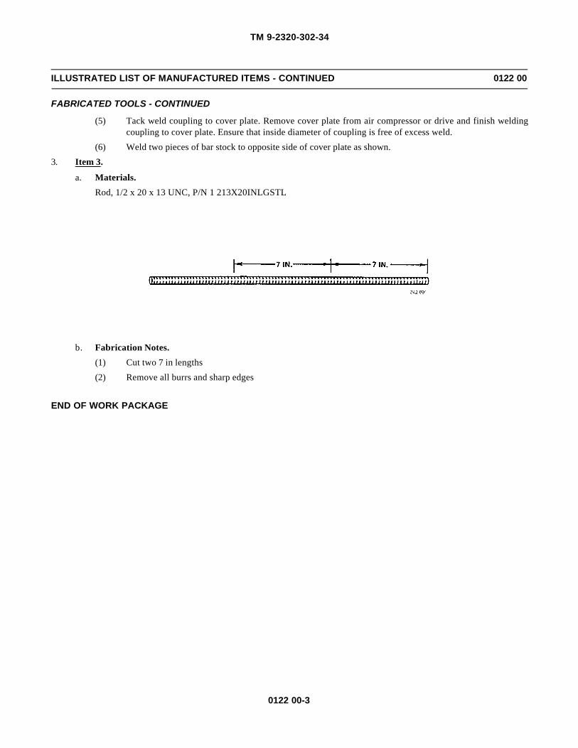
TM 9-2320-302-34
0122 00-3
ILLUSTRATED LIST OF MANUFACTURED ITEMS - CONTINUED 0122 00
FABRICATED TOOLS - CONTINUED
(5) Tack weld coupling to cover plate. Remove cover plate from air compressor or drive and finish weldingcoupling to cover plate. Ensure that inside diameter of coupling is free of excess weld.
(6) Weld two pieces of bar stock to opposite side of cover plate as shown.
3. Item 3.
a. Materials.
Rod, 1/2 x 20 x 13 UNC, P/N 1 213X20INLGSTL
b. Fabrication Notes.
(1) Cut two 7 in lengths
(2) Remove all burrs and sharp edges
END OF WORK PACKAGE

TM 9-2320-302-34
0122 00-4
This Page Intentionally Left Blank.

TM 9-2320-302-34
0123 00-1
TORQUE LIMITS 0123 00
SCOPE
1. This work package lists standard torque values, as shown in Table 1, and provides general information for applyingtorque. Special torque values and tightening sequences are indicated in the maintenance procedures for applicable com-ponents.
2. Air conditioner refrigerant line torque specifications are provided in Table 2.
GENERAL
1. Always use the torque values listed in Table 1 when the maintenance procedure does not give a specific torque value.
2. Unless otherwise indicated, standard torque tolerance shall be ±10%.
3. Torque values listed are based on clean, dry threads. Reduce torque by 10% when engine oil is used as a lubricant.Reduce torque by 20% if new plated cap screws are used.
4. Cap screws threaded into aluminum may require reductions in torque of 30% or more of Grade 5 cap screw torque. Capscrew threaded into aluminum must also attain two cap screw diameters of thread engagement.
5. If the maintenance procedures do not specify a tightening order, use the following guides:
a. Unless otherwise specified, lubricate threads of fasteners with oil (OE/HDO-10 or OEA).
b. When tightening fasteners above 30 lb-ft (41 Nm), use the torque pattern but only tighten to 70 percent of finalvalue (multiply final value by 0.7); then repeat the pattern until final value is reached.
c. Tighten circular patterns using the circular torque pattern, and straight patterns using the straight torque pattern.
CAUTIONCAUTIONIf replacement cap screws are of higher grade than originally supplied, use torque specifications for the orig-inal. This will prevent equipment damage due to overtorquing.
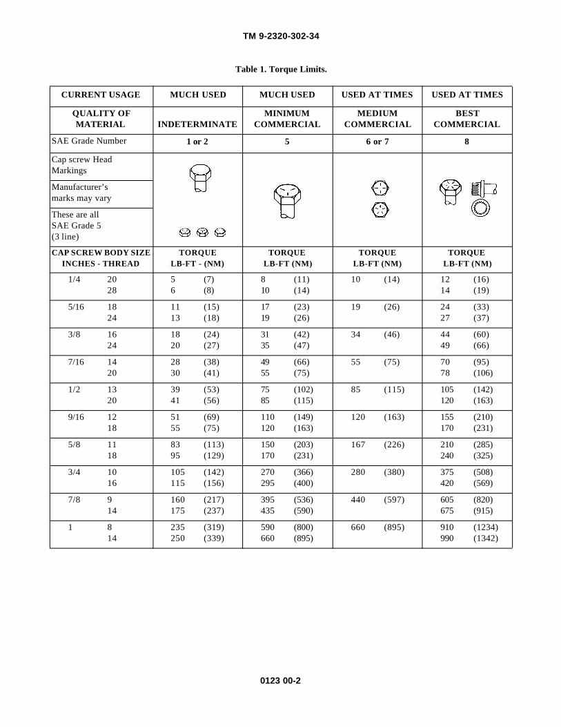
TM 9-2320-302-34
0123 00-2
Table 1. Torque Limits.
CURRENT USAGE MUCH USED MUCH USED USED AT TIMES USED AT TIMES
QUALITY OFMATERIAL INDETERMINATE
MINIMUMCOMMERCIAL
MEDIUMCOMMERCIAL
BESTCOMMERCIAL
SAE Grade Number 1 or 2 5 6 or 7 8
Cap screw HeadMarkings
Manufacturer’smarks may vary
These are allSAE Grade 5(3 line)
CAP SCREW BODY SIZEINCHES - THREAD
TORQUELB-FT - (NM)
TORQUELB-FT (NM)
TORQUELB-FT (NM)
TORQUELB-FT (NM)
1/4 2028
5 (7)6 (8)
8 (11)10 (14)
10 (14) 12 (16)14 (19)
5/16 1824
11 (15)13 (18)
17 (23)19 (26)
19 (26) 24 (33)27 (37)
3/8 1624
18 (24)20 (27)
31 (42)35 (47)
34 (46) 44 (60)49 (66)
7/16 1420
28 (38)30 (41)
49 (66)55 (75)
55 (75) 70 (95)78 (106)
1/2 1320
39 (53)41 (56)
75 (102)85 (115)
85 (115) 105 (142)120 (163)
9/16 1218
51 (69)55 (75)
110 (149)120 (163)
120 (163) 155 (210)170 (231)
5/8 1118
83 (113)95 (129)
150 (203)170 (231)
167 (226) 210 (285)240 (325)
3/4 1016
105 (142)115 (156)
270 (366)295 (400)
280 (380) 375 (508)420 (569)
7/8 914
160 (217)175 (237)
395 (536)435 (590)
440 (597) 605 (820)675 (915)
1 814
235 (319)250 (339)
590 (800)660 (895)
660 (895) 910 (1234)990 (1342)

TM 9-2320-302-34
0123 00-3
Table 2. Refrigerant Line Torque Specifications.
* When tightening fittings, always use torque reading for softer metal when unlike metals are used.
OUTSIDE DIAMETER OF METAL TUBE (IN)
TORQUE FOR STEEL TUBES* LB-FT (NM)
TORQUE FOR ALUMINUM OR COPPER* TUBES
1/4 10-15 (14-20) 60-80 (680-940)
3/8 30-35 (41-47) 11-13 (15-18)
1/2 30-35 (41-47) 15-20 (20-27)
5/8 30-35 (41-47) 21-27 (28-37)
3/4 30-35 (41-47) 28-33 (38-45)

TM 9-2320-302-34
0123 00-4
This Page Intentionally Left Blank.

TM 9-2320-302-34
CHAPTER 4SUPPORTING INFORMATION

TM 9-2320-302-34
This Page Intentionally Left Blank.

TM 9-2320-302-34
0124 00-1
REFERENCES 0124 00
SCOPE
This work package lists all forms, field manuals, technical bulletins, technical manuals, and other publications refer-enced in this manual and which apply to Direct Support and General Support Maintenance of the M915A3 Line Haul TractorTruck.
PUBLICATIONS INDEXES
The following indexes should be consulted frequently for latest changes or revisions and for new publications relating tomaterial covered in this technical manual.
Consolidated Index of Army Publications and Blank Forms . . . . . . . . . . . . . . . . . . . . . . . . . . . . . . . . . . . . . . . . .DA Pam 25-30
Functional User’s Manual for the Army Maintenance Management System . . . . . . . . . . . . . . . . . . . . . . . . . . .DA Pam 738-750
U.S. Army Equipment Index of Modification Work Orders. . . . . . . . . . . . . . . . . . . . . . . . . . . . . . . . . . . . . . . . .DA Pam 750-10
FORMS
Refer to DA Pam 738-750, The Army Maintenance Management System (TAMMS), for instructions on the use of main-tenance forms.
Equipment Inspection and Maintenance Worksheet . . . . . . . . . . . . . . . . . . . . . . . . . . . . . . . . . . . . . . . . . . . . . . . DA Form 2404
Equipment Log Assembly (Records) . . . . . . . . . . . . . . . . . . . . . . . . . . . . . . . . . . . . . . . . . . . . . . . . . . . . . . . . . . DA Form 2408
Maintenance Request Form. . . . . . . . . . . . . . . . . . . . . . . . . . . . . . . . . . . . . . . . . . . . . . . . . . . . . . . . . . . . . . . . . . DA Form 2407
Preventive Maintenance Schedule and Record . . . . . . . . . . . . . . . . . . . . . . . . . . . . . . . . . . . . . . . . . . . . . . . . . . . . DD Form 314
Processing and Deprocessing Record for Shipment, Storage and Issue of Vehicles and Spare Engines . . . . . . . DD Form 1397
Product Quality Deficiency Report . . . . . . . . . . . . . . . . . . . . . . . . . . . . . . . . . . . . . . . . . . . . . . . . . . . . . . . . . . . . . . SF Form 368
Recommended Changes to Equipment Technical Publications . . . . . . . . . . . . . . . . . . . . . . . . . . . . . . . . . . . . DA Form 2028-2
Recommended Changes to Publications and Blank Forms. . . . . . . . . . . . . . . . . . . . . . . . . . . . . . . . . . . . . . . . . . DA Form 2028
Report of Discrepancy (ROD). . . . . . . . . . . . . . . . . . . . . . . . . . . . . . . . . . . . . . . . . . . . . . . . . . . . . . . . . . . . . . . . . . SF Form 364
FIELD MANUALS
Metal Body Repair and Related Operations . . . . . . . . . . . . . . . . . . . . . . . . . . . . . . . . . . . . . . . . . . . . . . . . . . . . . . . . . . .FM 43-2
Operation and Maintenance of Ordnance Material in Extreme Cold Weather (0°F to -65°F) . . . . . . . . . . . . . . . . . . . .FM 9-207
TECHNICAL BULLETINS AND SUPPLY BULLETINS
Color, Marking, and Camouflage Painting of Military Vehicles, Construction Equipment,and Materiels Handling Equipment . . . . . . . . . . . . . . . . . . . . . . . . . . . . . . . . . . . . . . . . . . . . . . . . . . . . . . . . . . .TB 43-0209
Corrosion Prevention and Control Including Rustproofing Procedures for Tactical Vehicles and Trailers . . . . . . . . TB 43-0213
Solder and Soldering . . . . . . . . . . . . . . . . . . . . . . . . . . . . . . . . . . . . . . . . . . . . . . . . . . . . . . . . . . . . . . . . . . . . . . . . . . TB SIG 222
Warranty Bulletin for M915A3 Tractor Truck . . . . . . . . . . . . . . . . . . . . . . . . . . . . . . . . . . . . . . . . . . . . . . . . . TB 9-2320-302-15
TECHNICAL MANUALS
Administrative Storage of Equipment . . . . . . . . . . . . . . . . . . . . . . . . . . . . . . . . . . . . . . . . . . . . . . . . . . . . . . . . . . . . TM 740-90-1
Cooling Systems: Tactical Vehicles . . . . . . . . . . . . . . . . . . . . . . . . . . . . . . . . . . . . . . . . . . . . . . . . . . . . . . . . . . . . . TM 750-254
Inspection, Care, and Maintenance of Antifriction Bearings . . . . . . . . . . . . . . . . . . . . . . . . . . . . . . . . . . . . . . . . . . . . TM 9-214
Materials Used for Cleaning, Preserving, Abrading and Cementing OrdnanceMateriel and Related Materials, Including Chemicals . . . . . . . . . . . . . . . . . . . . . . . . . . . . . . . . . . . . . . . . . . . . . . TM 9-247
Operator’s Manual for M915A3 Tractor Truck . . . . . . . . . . . . . . . . . . . . . . . . . . . . . . . . . . . . . . . . . . . . . . . TM 9-2320-302-10
Operator’s Manual for Welding Theory and Application . . . . . . . . . . . . . . . . . . . . . . . . . . . . . . . . . . . . . . . . . . . . . . . TM 9-237
Painting Instruction for Field Use . . . . . . . . . . . . . . . . . . . . . . . . . . . . . . . . . . . . . . . . . . . . . . . . . . . . . . . . . . . . . . . TM 43-0139
Procedures for Destruction of Tank-automotive Equipment to Prevent Enemy Use . . . . . . . . . . . . . . . . . . . . . . . TM 750-244-6

TM 9-2320-302-34
0124 00-2
REFERENCES - CONTINUED 0124 00
TECHNICAL MANUALS - CONTINUED
Repair Parts and Special Tools Lists for M915A3 Tractor Truck. . . . . . . . . . . . . . . . . . . . . . . . . . . . . . . . . TM 9-2320-302-24PUnit Maintenance Manual for M915A3 Tractor Truck. . . . . . . . . . . . . . . . . . . . . . . . . . . . . . . . . . . . . . . . . . TM 9-2320-302-20
OTHER PUBLICATIONS
Abbreviations for Use on Drawings and in Specifications, Standards, andTechnical Documents . . . . . . . . . . . . . . . . . . . . . . . . . . . . . . . . . . . . . . . . . . . . . . . . . . . . . . . . . . . . . . . . . . . MIL-STD-12D
Army Medical Department Expendable/Durable Items . . . . . . . . . . . . . . . . . . . . . . . . . . . . . . . . . . . . . . . . . . . . . . . . CTA 8-100
Expendable/Durable Items (Except Medical, Class V, Repair Parts, and Heraldic Items . . . . . . . . . . . . . . . . . . . . .CTA 50-970Vehicle, Wheeled, Preparation for Shipment and Limited Storage of . . . . . . . . . . . . . . . . . . . . . . . . . . . . . . . . .MIL-V-62038D

TM 9-2320-302-34
0125 00-1
EXPENDABLE AND DURABLE ITEMS LIST 0125 00
SCOPE
This work package lists expendable and durable items you will need to maintain the M915A3 Truck Tractor. This listingis for informational purposes only and is not authority to requisition the listed items. These items are authorized to you byCTA 50-970, Expendable/Durable Items (Except Medical, Class V Repair Parts, and Heraldic Items) , or CTA 8-100, ArmyMedical Department Expendable/Durable Items.
EXPLANATION OF COLUMNS
1. Column (1) - Item Number. This number is assigned to the entry in the listing and is referenced in the narrativeinstructions to identify the item [e.g., Use adhesive (Item 1, WP 0125 00)].
2. Column (2) - Level. This column identifies the lowest level of maintenance that requires the listed item.
F - Direct Support Maintenance
H - General Support Maintenance
3. Column (3) - National Stock Number. This is the National Stock Number assigned to the item which you can use torequisition it.
4. Column (4) - Description, CAGEC, and Part Number. This provides the other information you need to identify theitem.
5. Column (5) - Unit of Measure (U/M). This column shows the physical measurement or count of an item, such as gal-lon, dozen, gross, etc.
Table 1. Expendable and Durable Items List.
(1)
ITEMNUMBER
(2)
LEVEL
(3)
NATIONALSTOCK NUMBER
(4)
DESCRIPTION, CAGEC,AND PART NUMBER
(5)
U/M
1 F ADHESIVE: General Purpose, Type II(18876) 9995460
8040-00-664-4318 1 Pint Can PT
2 F 8040-01-250-3969 ADHESIVE: Loctite(05972) 242
ML
3 F 8040-01-129-7171 ADHESIVE: Loctite(05972) 620
OZ
4 F 8040-00-142-9823 ADHESIVE: Silicone Rubber(81349) MIL-A-46106
KIT
5 F 8040-00-728-3088 ADHESIVE: Silicone Rubber, White(78500) 1199-T-3842
KIT
6 F ANTIFREEZE: Permanent, EthyleneGlycol, Inhibited(81349) MIL-A-46153
6850-00-181-79296850-00-181-7933
1 Gallon Bottle5 Gallon Can
GALGAL
7 F 5340-00-450-5718 CAP SET: Protective, Dust and Moisture Seal(19207) 10935405
EA

TM 9-2320-302-34
0125 00-2
EXPENDABLE AND DURABLE ITEMS LIST - CONTINUED 0125 00
Table 1. Expendable and Durable Items List - Continued.
(1)
ITEMNUMBER
(2)
LEVEL
(3)
NATIONALSTOCK NUMBER
(4)
DESCRIPTION, CAGEC,AND PART NUMBER
(5)
U/M
8 F CAULK: Strip(64678) 48-00118-001
EA
9 H CLOTH: Abrasive, Emery, Fine(80204) ANSI B74.18
5350-00-584-5654 50-Sheet Package EA
10 F COMPOUND: Antiseize, High Temperature(73165) 51008
8030-00-597-5367 25 Pound Can LB
11 F COMPOUND: Corrosion Preventive(81349) MIL-C-16173
8030-00-062-6950 1 Quart Can QT
12 F COMPOUND: Gasket Forming, Silicone
(05972) 77MA8 Ounce Tube OZ
(05972) 77C13 Ounce Cartridge OZ
13 F COMPOUND: International No. 2(72582) 5198563
QT
14 F COMPOUND: Sealing(81349) MIL-S-46163
8030-00-111-27628030-00-111-2763
50 CC BottleBox of 10 Bottles, 10 CC Each Bottle
CCCC
15 F COMPOUND: Sealing,Dissimilar Metal Protection(71961) 6099
8030-01-392-3276 1 Gallon Can GAL
16 F 8030-01-222-6400 COMPOUND: Sealing, Loctite(05972) 635
OZ
17 8030-01-429-8188 COMPOUND: Sealing(05972) 680
OZ
18 F COMPOUND: Sealing, Pipe(05972) 079-21
8030-00-081-22868030-00-081-2327
50 CC BottleBox of 10 Bottles, 10 CC Each Bottle
CCCC
19 F DETERGENT: General Purpose, Liquid(83421) 7930-00-282-9699
7930-00-282-9699 1 Gallon Can GAL

TM 9-2320-302-34
0125 00-3
EXPENDABLE AND DURABLE ITEMS LIST - CONTINUED 0125 00
Table 1. Expendable and Durable Items List - Continued.
(1)
ITEMNUMBER
(2)
LEVEL
(3)
NATIONALSTOCK NUMBER
(4)
DESCRIPTION, CAGEC,AND PART NUMBER
(5)
U/M
20 F GAGE: Bearing ClearanceBox of 12
5210-00-640-6177 0.001-0.003 Inch Clearance Range, Green Color(77220) PG-1
EA
5210-00-640-6178 0.002-0.006 Inch Clearance Range, Red Color(77220) PLASTIGAGEPR1
EA
5210-00-640-6176 0.004-0.009 Inch Clearance Range, Blue Color(77220) PLASTIGAGEPB1
EA
21 F GREASE: Aircraft(81349) MIL-G-4343
9150-00-119-92919150-00-269-8255
2 Ounce Tube1.75 Pound Can
OZLB
22 F GREASE: Automotive and Artillery, GAA(81349) M-10924
9150-01-197-76939150-01-197-76889150-01-197-76909150-01-197-76929150-01-197-7691
14 Ounce Cartridge (M-10924-B)1-1/4 Ounce Tube (M-10924-A)2-1/4 Pound Can (M-10924-C)35 Pound Can (M-10924-E)120 Pound Drum (M10924-F)
OZOZLBLBLB
23 F 7050-00-961-7663 LUBRIPLATE: Lubricant(90536) ST40334
OZ
24 F OIL: Cutting(77247) 22F
9150-00-825-9161 1 Gallon Can GAL
25 F OIL: Lubricating, OE/HDO 10(81349) MIL-L-2104
9150-00-189-67279150-00-186-66689150-00-191-2772
1 Quart Can5 Gallon Can55 Gallon Drum, 18 Gage (MILL2104)
QTGALGAL
26 F OIL: Lubricating, GO 85/140(81349) MIL-PRF-2105
9150-01-048-45919150-01-035-53959150-01-035-5396
1 Quart Can5 Gallon Can55 Gallon Drum
QTGALGAL

TM 9-2320-302-34
0125 00-4
EXPENDABLE AND DURABLE ITEMS LIST - CONTINUED 0125 00
Table 1. Expendable and Durable Items List - Continued.
(1)
ITEMNUMBER
(2)
LEVEL
(3)
NATIONALSTOCK NUMBER
(4)
DESCRIPTION, CAGEC,AND PART NUMBER
(5)
U/M
27 F OIL: Lubricating, Refrigerant Compressor,Synthetic Ester(59595) CAPELLA HFC-68NA
9150-01-410-8972 1 Quart Can QT
28 H PASTE: Prussian Blue, Bearing Surface, Permatex(10670) 35V
8010-01-329-6150 2 Ounce Tube OZ
29 H PETROLATUM, TECHNICAL(81348) VV-P-236
9150-00-250-0926 1.75 Pound Can LB
30 F PRIMER: Adhesive(05972) 73656
8040-01-024-6993 6 Ounce Can OZ
31 F RAG: Wiping(64067) 7920-00-205-1711
7920-00-205-1711 50 Pound Bale LB
32 F ROPE: Nylon, ½ Inch Diameter
33 F SOLDER: Lead-tin Alloy, Rosin Core(81348) QQ-S-571
3439-00-555-4629 11 Pound Spool LB
34 F STRAP: Tiedown, Electrical ComponentsBox of 100
5975-00-984-6582 (96906) MS3367-1-06 Inch Length,1.75 Inch Maximum Bundle, Black
EA
5975-00-935-5946 (96906) MS3367-2-113.35 Inch Length, 4 Inch Maximum Bundle, Brown
EA
5975-00-903-2284 (96906) MS3367-4-04 Inch Length, Black
EA
35 F TAG: Marker(64067) 9905-00-537-8954
9905-00-537-8954 Bundle of 50 EA

TM 9-2320-302-34
0125 00-5
EXPENDABLE AND DURABLE ITEMS LIST - CONTINUED 0125 00
Table 1. Expendable and Durable Items List - Continued.
(1)
ITEMNUMBER
(2)
LEVEL
(3)
NATIONALSTOCK NUMBER
(4)
DESCRIPTION, CAGEC,AND PART NUMBER
(5)
U/M
36 F TAPE: Insulation, Thermal2 Inches Wide(73030) HS7495-618
5640-00-580-6276 30-Foot Length FT
37 F TAPE: Pressure-sensitive, Adhesive, Masking1.5 Inches Wide(58536) A-A-883
7510-00-266-6709 60-Yard Roll YD
38 F TETRAFLUOROETHANE: Technical,Refrigerant, R-134A Type(4V886) R134A
6830-01-439-0614 43-Pound Cylinder LB
39 F 5180-00-754-0643 TOOL KIT: Body and Fender Repair(50980) SC5180-90-N34
EA
40 F 8305-01-301-1031 WIPES: Lint-free(28480) 92193W
EA
41 F WIRE: 14 Gage

TM 9-2320-302-34
0125 00-6
This Page Intentionally Left Blank.
TM 9-2320-302-34
0126 00-1
TOOL IDENTIFICATION LIST 0126 00
SCOPE
This work package lists all common tools and supplements and special tools/fixtures needed to maintain the M915A3Tractor Truck at Direct Support and General Support Maintenance.
EXPLANATION OF COLUMNS IN THE TOOL IDENTIFICATION LIST
1. Column (1) - Item Number (No.). This number is assigned to the entry in the list and is referenced in the initial setupof maintenance tasks to identify the item (e.g., Tool kit, general mechanic’s, Item 132, WP 0126 00).
2. Column (2) - Item Name. This column lists the item by noun nomenclature and other descriptive features (e.g.,Tester,Cylinder).
3. Column (3) - National Stock Number. This is the National Stock Number (NSN) assigned to the item. Use it to requi-sition the item.
4. Column (4) - Part Number/CAGEC. Indicates the primary number used by the manufacturer (individual, company,firm, corporation or Government activity) which controls the design and characteristics of the item by means of its engi-neering drawings, specifications, standards, and inspection requirements to identify an item or range of items. The man-ufacturer’s Commercial and Government Entity Code (CAGEC) is also included, in parentheses.
5. Column (5) - Unit of Measure (U/M). This column shows the physical measurement or count of an item, such as gal-lon, dozen, gross, etc.

TM 9-2320-302-34
0126 00-2
TOOL IDENTIFICATION LIST - CONTINUED 0126 00
Table 1. Tool Identification List.
(1)
ITEMNO.
(2)
ITEM NAME
(3)
NATIONALSTOCK NUMBER
(4)
PART NUMBER/CAGEC
(5)
REFERENCE
1 Adapter, Cylinder 4910-01-319-6971 J38768-A (33287) TM 9-2320-302-24P
2 Adapter, Motor, Hoist 3950-01-319-6973 J35635 (33287) TM 9-2320-302-24P
3 Adapter, Torque Wrench 5120-00-215-8200 11663358-2 (19207) TM 9-2320-302-24P
4 Adapter Kit, Mechanical 4940-01-353-7038 J 28593 (33287) TM 9-2320-302-24P
5 Adjuster, Lash, Cam-I 5120-01-322-8885 J35596 (33287) TM 9-2320-302-24P
6 Adjusting Tool, Worm 5120-01-371-7369 J 37070 (33287) TM 9-2320-302-24P
7 Alignment Stud Set J43431 (33287) TM 9-2320-302-24P
8 Barring Tool, Engine 5120-01-322-3498 J36237 (33287) TM 9-2320-302-24P
9 Bolt, Eye 5306-01-294-3028 993-042 (75377) TM 9-2320-302-24P
10 Bolt, Eye, Cylinder Block Lift Tool 5306-01-319-1987 J35595 (33287) TM 9-2320-302-24P
11 Bracket, Engine Mounting 2510-01-320-8905 J35636 (33287) TM 9-2320-302-24P
12 Bracket, Transmission Holding J35926 (33287) TM 9-2320-302-24P
13 Bracket, Transmission Holding J41445 (33287) TM 9-2320-302-24P
14 Caliper, Micrometer, Inside: 2-12 in.range
5210-00-221-1921 124BZ (57163) SC 4910-95-A31
15 Caliper, Micrometer, Outside: 0-1 in.Range
5210-00-540-2973 T230RL (57163) SC 4910-95-A02
16 Caliper, Vernier: English and metricmeasurements, 0-6 in. and 1-150 mm
5210-01-113-1548 GGG-C-111 (81348) SC 4910-95-A31
17 Caps, Vise Jaw: 4 in. 5120-00-221-1506 A-A-2938 (58536) SC 4910-95-A31
18 Checker, Gear Lash 5120-01-353-2520 J 38662 (33287) TM 9-2320-302-24P
19 Clamp, C 5120-00-203-6431 A-A-431 (58536) SC 4910-95-A31
20 Clamp, Material Lift 3940-01-324-4713 J35641-A (33287) TM 9-2320-302-24P
21 Compressor, Main-Pressure ReliefSpring
J41462 (33287) TM 9-2320-302-24P
22 Compressor, Piston Ring 5120-01-353-8567 J 35598-A (33287) TM 9-2320-302-24P
23 Compressor, Spring 5120-01-353-2522 J24203-3 (33287) TM 9-2320-302-24P
24 Compressor, Spring J8062-1 (33287) TM 9-2320-302-24P
25 Compressor, Spring J8062-3 (33287) TM 9-2320-302-24P

TM 9-2320-302-34
0126 00-3
TOOL IDENTIFICATION LIST - CONTINUED 0126 00
Table 1. Tool Identification List - Continued.
(1)
ITEMNO.
(2)
ITEM NAME
(3)
NATIONALSTOCK NUMBER
(4)
PART NUMBER/CAGEC
(5)
REFERENCE
26 Compressor, Spring, C2 (use withJ37030-3)
J37030-1 (33287) TM 9-2320-302-24P
27 Compressor, Spring, C5 (use withJ37030-3)
J37030-2 (33287) TM 9-2320-302-24P
28 Crowfoot Attachment Set: SocketWrench
5120-01-429-1110 214FC (55719) GSA Catalog
29 Dial Indicator Set 5210-00-794-9178 J5959-01 (33287) SC 4910-95-A31
30 Dispenser, Sealant 5120-00-061-1283 45RCT (88736) SC 4910-95-A31
31 Drill, Electric, Portable: 3/8 in. size 5130-00-935-7354 6635 (55111) SC 4910-95-A31
32 Drill Set, Twist 5133-00-293-0983 800434 (19203) SC 4910-95-A31
33 Driver, Bushing 5120-01-353-2521 PT 4365-1 (33287) TM 9-2320-302-24P
34 Gage, Depth, Micrometer: 0-6 in.Range
5210-00-619-4045 52-225-015 (1E258) GSA Catalog
35 Gage, Oil Level 99-431 (0W4A6) GSA Catalog
36 Gage, Profile J35884-A (33287) TM 9-2320-302-24P
37 Gage, Profile 5220-01-388-1460 J38548 (33287) TM 9-2320-302-24P
38 Gage, Profile J38689-A (33287) TM 9-2320-302-24P
39 Gage, Profile J42749 (33287) TM 9-2320-302-24P
40 Gloves, Chemical and Oil Protective:rubber
8415-00-641-4601 ZZ-G-381 (81348) SC 4910-95-A74
41 Gloves, Welders’: leather 8415-00-268-7859 A-A-50022 (58536) SC 4910-95-A31
42 Goggles, Industrial 4240-00-816-3819 WA60-5H0746-0315 (74936)
SC 4910-95-A31
43 Guide Stud Set 5120-01-322-3505 J36107 (33287) TM 9-2320-302-24P
44 Guides, Connecting Rod J43661 (33287) TM 9-2320-302-24P
45 Handle, Drive 5120-00-677-2259 J8092 (33287) TM 9-2320-302-24P
46 Handle, Installer 5120-00-977-5578 J7079-2 (33287) TM 9-2320-302-24P
47 Holding Bar, Pinion 5120-01-166-0573 J 3453-1 (33287) TM 9-2320-302-24P
48 Inserter, Bearing 5120-01-354-2943 J 37071-A (33287) TM 9-2320-302-24P
49 Inserter, Gear 5120-01-322-1132 J35949 (33287) TM 9-2320-302-24P
50 Inserter, Seal 5120-01-322-1129 J35686-B (33287) TM 9-2320-302-24P

TM 9-2320-302-34
0126 00-4
TOOL IDENTIFICATION LIST - CONTINUED 0126 00
Table 1. Tool Identification List - Continued.
(1)
ITEMNO.
(2)
ITEM NAME
(3)
NATIONALSTOCK NUMBER
(4)
PART NUMBER/CAGEC
(5)
REFERENCE
51 Inserter and Remover 5120-01-338-7182 J25447-B (33287) TM 9-2320-302-24P
52 Inserter and Remover 5120-01-322-2360 J35642 (33287) TM 9-2320-302-24P
53 Inserter and Remover 5120-01-322-6222 J36310-A (33287) TM 9-2320-302-24P
54 Inserter and Remover, Spring 5120-01-388-5623 J35923-2 (33287) TM 9-2320-302-24P
55 Inserter Set, Dowel 5120-01-322-3500 J36224 (33287) TM 9-2320-302-24P
56 Installation Tool, Seal 5120-01-354-0468 J 37073 (33287) TM 9-2320-302-24P
57 Installer, Charging Pump Bushing J39954 (33287) TM 9-2320-302-24P
58 Installer, Cup Plug 5120-01-333-4744 J36326 (33287) TM 9-2320-302-24P
59 Installer, Front Support Sleeve andPTO Bearing
J37041 (33287) TM 9-2320-302-24P
60 Installer, Output Bearing J37034 (33287) TM 9-2320-302-24P
61 Installer, Output Bearing Cup (usewith J37034)
J37033 (33287) TM 9-2320-302-24P
62 Installer, Output Shaft 5120-01-054-4042 J-24202-1A (33287) TM 9-2320-302-24P
63 Installer, P1 Carrier Bushing andGround Sleeve Bearing, Pump BodyBushing, and Bearing RetainerBushing
J37038 (33287) TM 9-2320-302-24P
64 Installer, Rotating Clutch Bushing J37040 (33287) TM 9-2320-302-24P
65 Installer, Seal, Input J37032 (33287) TM 9-2320-302-24P
66 Installer, Seal, Output J37031 (33287) TM 9-2320-302-24P
67 Installer, Torque Converter CoverBushing
J39949 (33287) TM 9-2320-302-24P
68 Installer, Turbine Shaft Bushing/Output Bushing/P2 Carrier Bushing
J37036 (33287) TM 9-2320-302-24P
69 Installer, Valve Guide 5120-01-322-3501 J33191-A (33287) TM 9-2320-302-24P
70 Installer, Valve Stem Seal J39109 (33287) TM 9-2320-302-24P
71 Installer, Wear Plate J39534 (33287) TM 9-2320-302-24P
72 Installer Set, Cup Plug 5120-01-322-2359 J35653 (33287) TM 9-2320-302-24P
73 Jack, Hydraulic, Hand: 12 toncapacity
5120-00-224-7330 67224 (07505) SC 4910-95-A31
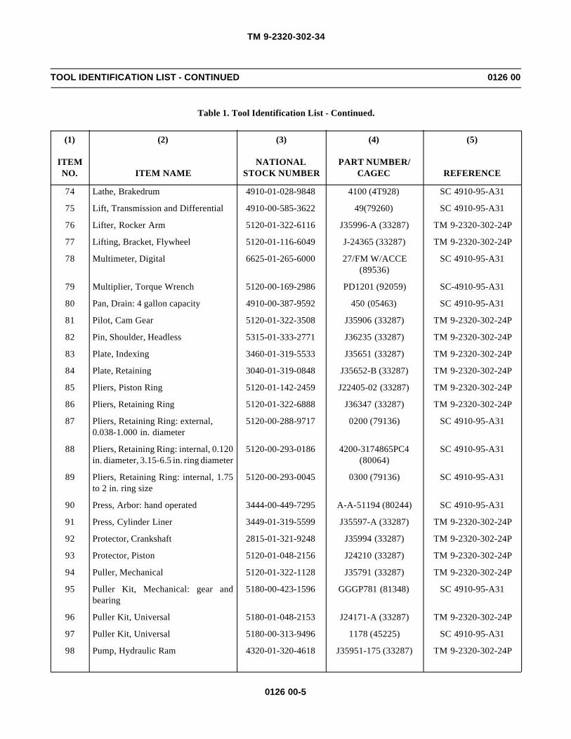
TM 9-2320-302-34
0126 00-5
TOOL IDENTIFICATION LIST - CONTINUED 0126 00
Table 1. Tool Identification List - Continued.
(1)
ITEMNO.
(2)
ITEM NAME
(3)
NATIONALSTOCK NUMBER
(4)
PART NUMBER/CAGEC
(5)
REFERENCE
74 Lathe, Brakedrum 4910-01-028-9848 4100 (4T928) SC 4910-95-A31
75 Lift, Transmission and Differential 4910-00-585-3622 49(79260) SC 4910-95-A31
76 Lifter, Rocker Arm 5120-01-322-6116 J35996-A (33287) TM 9-2320-302-24P
77 Lifting, Bracket, Flywheel 5120-01-116-6049 J-24365 (33287) TM 9-2320-302-24P
78 Multimeter, Digital 6625-01-265-6000 27/FM W/ACCE (89536)
SC 4910-95-A31
79 Multiplier, Torque Wrench 5120-00-169-2986 PD1201 (92059) SC-4910-95-A31
80 Pan, Drain: 4 gallon capacity 4910-00-387-9592 450 (05463) SC 4910-95-A31
81 Pilot, Cam Gear 5120-01-322-3508 J35906 (33287) TM 9-2320-302-24P
82 Pin, Shoulder, Headless 5315-01-333-2771 J36235 (33287) TM 9-2320-302-24P
83 Plate, Indexing 3460-01-319-5533 J35651 (33287) TM 9-2320-302-24P
84 Plate, Retaining 3040-01-319-0848 J35652-B (33287) TM 9-2320-302-24P
85 Pliers, Piston Ring 5120-01-142-2459 J22405-02 (33287) TM 9-2320-302-24P
86 Pliers, Retaining Ring 5120-01-322-6888 J36347 (33287) TM 9-2320-302-24P
87 Pliers, Retaining Ring: external,0.038-1.000 in. diameter
5120-00-288-9717 0200 (79136) SC 4910-95-A31
88 Pliers, Retaining Ring: internal, 0.120in. diameter, 3.15-6.5 in. ring diameter
5120-00-293-0186 4200-3174865PC4 (80064)
SC 4910-95-A31
89 Pliers, Retaining Ring: internal, 1.75to 2 in. ring size
5120-00-293-0045 0300 (79136) SC 4910-95-A31
90 Press, Arbor: hand operated 3444-00-449-7295 A-A-51194 (80244) SC 4910-95-A31
91 Press, Cylinder Liner 3449-01-319-5599 J35597-A (33287) TM 9-2320-302-24P
92 Protector, Crankshaft 2815-01-321-9248 J35994 (33287) TM 9-2320-302-24P
93 Protector, Piston 5120-01-048-2156 J24210 (33287) TM 9-2320-302-24P
94 Puller, Mechanical 5120-01-322-1128 J35791 (33287) TM 9-2320-302-24P
95 Puller Kit, Mechanical: gear andbearing
5180-00-423-1596 GGGP781 (81348) SC 4910-95-A31
96 Puller Kit, Universal 5180-01-048-2153 J24171-A (33287) TM 9-2320-302-24P
97 Puller Kit, Universal 5180-00-313-9496 1178 (45225) SC 4910-95-A31
98 Pump, Hydraulic Ram 4320-01-320-4618 J35951-175 (33287) TM 9-2320-302-24P

TM 9-2320-302-34
0126 00-6
TOOL IDENTIFICATION LIST - CONTINUED 0126 00
Table 1. Tool Identification List - Continued.
(1)
ITEMNO.
(2)
ITEM NAME
(3)
NATIONALSTOCK NUMBER
(4)
PART NUMBER/CAGEC
(5)
REFERENCE
99 Reclaimer, Refrigerant, R134A 4250-01-396-8928 EEEAC304A (55719) GSA Catalog
100 Reconditioning Set 5120-01-322-3507 J33880 (33287) TM 9-2320-302-24P
101 Remover, Seal 5120-01-322-1131 J35993 (33287) TM 9-2320-302-24P
102 Remover, Valve Guide 5120-01-322-3506 J34696-B (33287) TM 9-2320-302-24P
103 Remover, Valve Seat 5120-00-494-1836 J23479-271 (33287) TM 9-2320-302-24P
104 Remover, Valve Seat 5120-01-322-8883 J23479-460-A (33287) TM 9-2320-302-24P
105 Remover, Wheel Bearing Cup 5120-00-784-6482 J3940 (33287) TM 9-2320-302-24P
106 Remover/Installer, Main-PressureSpring
J35924 (33287) TM 9-2320-302-24P
107 Replacing Tool, Engine 5120-01-322-1133 J33190 (33287) TM 9-2320-302-24P
108 Replacing Tool, Engine 5120-01-322-2955 J34983 (33287) TM 9-2320-302-24P
109 Riveter, Blind Hand: 3/32 in., 1/8 in.,5/32 in., and 3/16 in. diameters
5120-00-017-2849 250K (10054) SC 4910-95-A74
110 Scale 4910-00-707-9178 J544-01 (33287) TM 9-2320-302-24P
111 Service Kit, Accessory Drive 5120-01-322-3499 J36024 (33287) TM 9-2320-302-24P
112 Service Kit, Water Pump 5120-01-322-6115 J35988-C (33287) TM 9-2320-302-24P
113 Shield, Turbo Protect 4910-01-127-7959 J26554-A (33287) TM 9-2320-302-24P
114 Slider, Spring Compression 4910-01-165-6015 TFTLN-2500 (74410) TM 9-2320-302-24P
115 Sling, Beam Type 3940-01-353-8561 J-39520 (33287) GSA Catalog
116 Socket, Socket Wrench 5120-01-322-1123 J36003-A (33287) TM 9-2320-302-24P
117 Socket, Socket Wrench: 19 mm, deepwell, 12 pt
5120-01-348-9154 SM19 (55719) G5A Catalog
118 Soldering Gun 3439-00-542-0396 8200G3 (97049) SC 4910-95-A31
119 Spanner Attachment 5120-01-353-8490 J 37464 (33287) TM 9-2320-302-24P
120 Spreader, Sling 3940-01-354-9446 38841 (45225) TM 9-2320-302-24P
121 Test Block, Pressure Switch J33884 (33287) TM 9-2320-302-24P
122 Test Stand, Automotive Generatorand Starter
4910-00-767-0218 MILT4544 (81349) SC 4910-95-A02
123 Tester, Cylinder 4910-01-320-4638 J29006-5 (33287) TM 9-2320-302-24P
124 Tester, Cylinder 4910-01-319-6990 J36223-D (33287) TM 9-2320-302-24P

TM 9-2320-302-34
0126 00-7
TOOL IDENTIFICATION LIST - CONTINUED 0126 00
Table 1. Tool Identification List - Continued.
(1)
ITEMNO.
(2)
ITEM NAME
(3)
NATIONALSTOCK NUMBER
(4)
PART NUMBER/CAGEC
(5)
REFERENCE
125 Tester, Impeller 5120-01-322-2358 J35687 (33287) TM 9-2320-302-24P
126 Tester, Kingpin Lock 4910-01-157-3571 TFTLN-1000 (74410) TM 9-2320-302-24P
127 Tester, Power Steering 4910-01-160-3618 J-26487-B (33287) TM 9-2320-302-24P
128 Tester, Spring Resiliency: 0-500grams
6635-00-182-7534 L20 (08292) SC 4910-95-A31
129 Tool, Torque Converter Bolt J38564 (33287) TM 9-2320-302-24P
130 Tool Base, Spring Compressor, C1,C2, and C5
J37030-3 (33287) TM 9-2320-302-24P
131 Tool Kit, Electrical Connector Repair 5180-00-876-9336 7550526 (19204) SC 4910-95-A31
132 Tool Kit, General Mechanic’s:Automotive
5180-00-177-7033 SC5180-90-N26 (50980)
SC 5180-95-N26
133 Tool Set, Spanner Nut Torque J37035 (33287) TM 9-2320-302-24P
134 Tray Set, Valve Body Parts J33163 (33287) TM 9-2320-302-24P
135 Trestle, Hoist, Portable: 7 ton capacity 3950-00-251-8013 306 (79805) SC 4910-95-A31
136 Vise, Machinist’s 5120-00-293-1439 504M2 (79416) SC 4910-95-A31
137 Wrench, Torque: 3/8 in. drive, 0-300lb-in capacity
5120-00-776-1841 2163993 (10001) SC 4910-95-A31
138 Wrench, Torque: 3/8 in. drive, 15-75lb-ft capacity
5120-01-355-1734 QC2FR75 (55719) SC 4910-95-A31
139 Wrench, Torque: 50-250 lb-ftcapacity
5120-01-042-0982 VB-2503MFR (27464) SC 4910-95-A31
140 Wrench, Torque: 3/4 in. drive, 100-600 lb-ft capacity
5120-01-113-9564 7379 (45225) SC 4910-95-A31
141 Wrench Set, Socket: 3/4 in. drive 5120-00-204-1999 FEDSTD353 (06542) SC 4910-95-A31
142 Wrench Set, Socket Attachment:screwdriver, torx, 1/4 and 3/8 in. drive
5120-01-178-6342 J-29843 (33287) GSA Catalog

TM 9-2320-302-34
0126 00-8
This Page Intentionally Left Blank.

TM 9-2320-302-34
Index-1
INDEX
Subject Work Package Page
Numerics
3K Turbocharger Wastegate Actuator Maintenance . . . . . . . . . . . . . . . . . . . . . . . . 0044 00 0044 00-1
A
Accessory DriveRepair . . . . . . . . . . . . . . . . . . . . . . . . . . . . . . . . . . . . . . . . . . . . . . . . . . . . . . . . 0039 00 0039 00-1Replacement . . . . . . . . . . . . . . . . . . . . . . . . . . . . . . . . . . . . . . . . . . . . . . . . . . 0021 00 0021 00-1
Adjustable Idler Gear Replacement . . . . . . . . . . . . . . . . . . . . . . . . . . . . . . . . . . . . 0038 00 0038 00-1
AirCompressor Repair . . . . . . . . . . . . . . . . . . . . . . . . . . . . . . . . . . . . . . . . . . . . . 0084 00 0084 00-1Ducts Replacement . . . . . . . . . . . . . . . . . . . . . . . . . . . . . . . . . . . . . . . . . . . . . 0111 00 0111 00-1Intake Manifold Replacement . . . . . . . . . . . . . . . . . . . . . . . . . . . . . . . . . . . . . . 0014 00 0014 00-1
Air ConditionerBinary Switch Wiring Harness Replacement . . . . . . . . . . . . . . . . . . . . . . . . . . 0068 00 0068 00-1Compressor Replacement . . . . . . . . . . . . . . . . . . . . . . . . . . . . . . . . . . . . . . . . 0117 00 0117 00-1Compressor Service . . . . . . . . . . . . . . . . . . . . . . . . . . . . . . . . . . . . . . . . . . . . . 0116 00 0116 00-1Condenser Replacement . . . . . . . . . . . . . . . . . . . . . . . . . . . . . . . . . . . . . . . . . 0119 00 0119 00-1Evaporator Coil Replacement . . . . . . . . . . . . . . . . . . . . . . . . . . . . . . . . . . . . . . 0115 00 0115 00-1Expansion Valve Replacement . . . . . . . . . . . . . . . . . . . . . . . . . . . . . . . . . . . . . 0114 00 0114 00-1Fan Cycling Switch Replacement . . . . . . . . . . . . . . . . . . . . . . . . . . . . . . . . . . . 0120 00 0120 00-1Hose Replacement . . . . . . . . . . . . . . . . . . . . . . . . . . . . . . . . . . . . . . . . . . . . . . 0121 00 0121 00-1Receiver-drier Replacement . . . . . . . . . . . . . . . . . . . . . . . . . . . . . . . . . . . . . . . 0118 00 0118 00-1
Air Conditioning SystemRefrigerant (R-134a) Maintenance . . . . . . . . . . . . . . . . . . . . . . . . . . . . . . . . . . 0112 00 0112 00-1Theory of Operation . . . . . . . . . . . . . . . . . . . . . . . . . . . . . . . . . . . . . . . . . . . . . 0003 00 0003 00-9Troubleshooting and Testing . . . . . . . . . . . . . . . . . . . . . . . . . . . . . . . . . . . . . . 0009 00 0009 00-1
Air System, Theory of Operation . . . . . . . . . . . . . . . . . . . . . . . . . . . . . . . . . . . . . . . 0003 00 0003 00-5Alternator Repair . . . . . . . . . . . . . . . . . . . . . . . . . . . . . . . . . . . . . . . . . . . . . . . . . . . 0052 00 0052 00-1
Anti-lock Brake System (ABS)Cab, Wiring Harness Replacement . . . . . . . . . . . . . . . . . . . . . . . . . . . . . . . . . 0065 00 0065 00-1Front, Wiring Harness Replacement . . . . . . . . . . . . . . . . . . . . . . . . . . . . . . . . 0063 00 0063 00-1Rear, Wiring Harness Replacement . . . . . . . . . . . . . . . . . . . . . . . . . . . . . . . . . 0064 00 0064 00-1
Axle Assembly Replacement, Front . . . . . . . . . . . . . . . . . . . . . . . . . . . . . . . . . . . . 0072 00 0072 00-1Axle Caster Adjustment, Front . . . . . . . . . . . . . . . . . . . . . . . . . . . . . . . . . . . . . . . . 0073 00 0073 00-1
Axle Replacement, Rear . . . . . . . . . . . . . . . . . . . . . . . . . . . . . . . . . . . . . . . . . . . . . 0078 00 0078 00-1
B
Body Repair, Cab . . . . . . . . . . . . . . . . . . . . . . . . . . . . . . . . . . . . . . . . . . . . . . . . . . 0105 00 0105 00-1
Brake Drum Repair . . . . . . . . . . . . . . . . . . . . . . . . . . . . . . . . . . . . . . . . . . . . . . . . . 0085 00 0085 00-1

TM 9-2320-302-34
Index-2
INDEX - Continued
Subject Work Package Page
B - Continued
Brake System, Theory of Operation . . . . . . . . . . . . . . . . . . . . . . . . . . . . . . . . . . . . 0003 00 0003 00-5
Brake Valve Repair, Foot . . . . . . . . . . . . . . . . . . . . . . . . . . . . . . . . . . . . . . . . . . . . 0083 00 0083 00-1
Breather Tube Replacement . . . . . . . . . . . . . . . . . . . . . . . . . . . . . . . . . . . . . . . . . . 0017 00 0017 00-1
Bull/Idler Gear Replacement . . . . . . . . . . . . . . . . . . . . . . . . . . . . . . . . . . . . . . . . . . 0037 00 0037 00-1
C
CabAnti-lock Brake System (ABS) Wiring Harness Replacement . . . . . . . . . . . . . 0065 00 0065 00-1Body Repair . . . . . . . . . . . . . . . . . . . . . . . . . . . . . . . . . . . . . . . . . . . . . . . . . . . 0105 00 0105 00-1Door Repair . . . . . . . . . . . . . . . . . . . . . . . . . . . . . . . . . . . . . . . . . . . . . . . . . . . 0108 00 0108 00-1Door Replacement . . . . . . . . . . . . . . . . . . . . . . . . . . . . . . . . . . . . . . . . . . . . . . 0107 00 0107 00-1Main, Wiring Harness Replacement . . . . . . . . . . . . . . . . . . . . . . . . . . . . . . . . . 0057 00 0057 00-1Mounts Replacement, Front . . . . . . . . . . . . . . . . . . . . . . . . . . . . . . . . . . . . . . . 0097 00 0097 00-1Mounts Replacement, Rear . . . . . . . . . . . . . . . . . . . . . . . . . . . . . . . . . . . . . . . 0098 00 0098 00-1Overhead, Wiring Harness Replacement . . . . . . . . . . . . . . . . . . . . . . . . . . . . . 0061 00 0061 00-1Replacement . . . . . . . . . . . . . . . . . . . . . . . . . . . . . . . . . . . . . . . . . . . . . . . . . . 0104 00 0104 00-1
Camshaftand Bearings Replacement . . . . . . . . . . . . . . . . . . . . . . . . . . . . . . . . . . . . . . . 0026 00 0026 00-1Drive Gear Maintenance . . . . . . . . . . . . . . . . . . . . . . . . . . . . . . . . . . . . . . . . . . 0034 00 0034 00-1
Characteristics, Capabilities, and Features, Equipment . . . . . . . . . . . . . . . . . . . . . 0002 00 0002 00-1
Chassis Wiring Harness Replacement . . . . . . . . . . . . . . . . . . . . . . . . . . . . . . . . . . 0062 00 0062 00-1
Clutch Repair, Fan . . . . . . . . . . . . . . . . . . . . . . . . . . . . . . . . . . . . . . . . . . . . . . . . . 0050 00 0050 00-1
Collision Warning System (CWS)Theory of Operation . . . . . . . . . . . . . . . . . . . . . . . . . . . . . . . . . . . . . . . . . . . . . 0003 00 0003 00-10Wiring Harness Replacement . . . . . . . . . . . . . . . . . . . . . . . . . . . . . . . . . . . . . . 0066 00 0066 00-1
Column Replacement, Steering . . . . . . . . . . . . . . . . . . . . . . . . . . . . . . . . . . . . . . . 0090 00 0090 00-1
Compressor Repair, Air . . . . . . . . . . . . . . . . . . . . . . . . . . . . . . . . . . . . . . . . . . . . . . 0084 00 0084 00-1
Compressor, Air ConditionerReplacement . . . . . . . . . . . . . . . . . . . . . . . . . . . . . . . . . . . . . . . . . . . . . . . . . . 0117 00 0117 00-1Service . . . . . . . . . . . . . . . . . . . . . . . . . . . . . . . . . . . . . . . . . . . . . . . . . . . . . . . 0116 00 0116 00-1
Condenser Replacement, Air Conditioner . . . . . . . . . . . . . . . . . . . . . . . . . . . . . . . 0119 00 0119 00-1
Cooling System, Theory of Operation . . . . . . . . . . . . . . . . . . . . . . . . . . . . . . . . . . . 0003 00 0003 00-3
Corrosion Prevention and Control (CPC) . . . . . . . . . . . . . . . . . . . . . . . . . . . . . . . . 0001 00 0001 00-1
Cover ReplacementGear Case . . . . . . . . . . . . . . . . . . . . . . . . . . . . . . . . . . . . . . . . . . . . . . . . . . . . 0019 00 0019 00-1Rocker Arm . . . . . . . . . . . . . . . . . . . . . . . . . . . . . . . . . . . . . . . . . . . . . . . . . . . . 0016 00 0016 00-1

TM 9-2320-302-34
Index-3
INDEX - Continued
Subject Work Package Page
C - Continued
CrankshaftFront Oil Seal Replacement . . . . . . . . . . . . . . . . . . . . . . . . . . . . . . . . . . . . . . . 0031 00 0031 00-1Rear Oil Seal Replacement . . . . . . . . . . . . . . . . . . . . . . . . . . . . . . . . . . . . . . . 0023 00 0023 00-1Replacement . . . . . . . . . . . . . . . . . . . . . . . . . . . . . . . . . . . . . . . . . . . . . . . . . . 0033 00 0033 00-1
Cross Tube Arm Replacement, Front . . . . . . . . . . . . . . . . . . . . . . . . . . . . . . . . . . . 0075 00 0075 00-1
Crossmember Replacement . . . . . . . . . . . . . . . . . . . . . . . . . . . . . . . . . . . . . . . . . . 0096 00 0096 00-1Cylinder Assembly and Piston Maintenance . . . . . . . . . . . . . . . . . . . . . . . . . . . . . . 0041 00 0041 00-1
Cylinder Block Assembly Repair . . . . . . . . . . . . . . . . . . . . . . . . . . . . . . . . . . . . . . . 0036 00 0036 00-1Cylinder Block Pressure Testing . . . . . . . . . . . . . . . . . . . . . . . . . . . . . . . . . . . . . . . 0040 00 0040 00-1
Cylinder HeadRepair . . . . . . . . . . . . . . . . . . . . . . . . . . . . . . . . . . . . . . . . . . . . . . . . . . . . . . . . 0032 00 0032 00-1Replacement . . . . . . . . . . . . . . . . . . . . . . . . . . . . . . . . . . . . . . . . . . . . . . . . . . 0018 00 0018 00-1
D
Damper Replacement, Vibration . . . . . . . . . . . . . . . . . . . . . . . . . . . . . . . . . . . . . . . 0020 00 0020 00-1Data, Equipment . . . . . . . . . . . . . . . . . . . . . . . . . . . . . . . . . . . . . . . . . . . . . . . . . . . 0002 00 0002 00-6
Destruction of Army Materiel to Prevent Enemy Use . . . . . . . . . . . . . . . . . . . . . . . 0001 00 0001 00-1Differential Carrier Repair
Forward-rear Axle . . . . . . . . . . . . . . . . . . . . . . . . . . . . . . . . . . . . . . . . . . . . . . . 0080 00 0080 00-1Rear-rear Axle . . . . . . . . . . . . . . . . . . . . . . . . . . . . . . . . . . . . . . . . . . . . . . . . . 0082 00 0082 00-1
Differential Carrier ReplacementForward-rear Axle . . . . . . . . . . . . . . . . . . . . . . . . . . . . . . . . . . . . . . . . . . . . . . . 0079 00 0079 00-1Rear-rear Axle . . . . . . . . . . . . . . . . . . . . . . . . . . . . . . . . . . . . . . . . . . . . . . . . . 0081 00 0081 00-1
Door, CabRepair . . . . . . . . . . . . . . . . . . . . . . . . . . . . . . . . . . . . . . . . . . . . . . . . . . . . . . . . 0108 00 0108 00-1Replacement . . . . . . . . . . . . . . . . . . . . . . . . . . . . . . . . . . . . . . . . . . . . . . . . . . 0107 00 0107 00-1
Drive Gear Maintenance, Camshaft . . . . . . . . . . . . . . . . . . . . . . . . . . . . . . . . . . . . 0034 00 0034 00-1Drive Repair, Accessory . . . . . . . . . . . . . . . . . . . . . . . . . . . . . . . . . . . . . . . . . . . . . 0039 00 0039 00-1
Drive Replacement, Accessory . . . . . . . . . . . . . . . . . . . . . . . . . . . . . . . . . . . . . . . . 0021 00 0021 00-1Drive Support, Fan, Replacement . . . . . . . . . . . . . . . . . . . . . . . . . . . . . . . . . . . . . . 0013 00 0013 00-1
Drive Train, Theory of Operation . . . . . . . . . . . . . . . . . . . . . . . . . . . . . . . . . . . . . . . 0003 00 0003 00-1
Drum Repair, Brake . . . . . . . . . . . . . . . . . . . . . . . . . . . . . . . . . . . . . . . . . . . . . . . . 0085 00 0085 00-1Ducts Replacement, Air . . . . . . . . . . . . . . . . . . . . . . . . . . . . . . . . . . . . . . . . . . . . . 0111 00 0111 00-1
E
ECM Wiring Harness Replacement . . . . . . . . . . . . . . . . . . . . . . . . . . . . . . . . . . . . 0069 00 0069 00-1
Electrical System, Theory of Operation . . . . . . . . . . . . . . . . . . . . . . . . . . . . . . . . . 0003 00 0003 00-3

TM 9-2320-302-34
Index-4
INDEX - Continued
Subject Work Package Page
E - Continued
EngineInjector Wiring Harness Replacement . . . . . . . . . . . . . . . . . . . . . . . . . . . . . . . 0069 00 0069 00-1Mount Adapter and Support Replacement, Front . . . . . . . . . . . . . . . . . . . . . . . 0011 00 0011 00-1Mounts Replacement, Rear . . . . . . . . . . . . . . . . . . . . . . . . . . . . . . . . . . . . . . . 0012 00 0012 00-1Power Wiring Harness Replacement . . . . . . . . . . . . . . . . . . . . . . . . . . . . . . . . 0055 00 0055 00-1Retarder Maintenance . . . . . . . . . . . . . . . . . . . . . . . . . . . . . . . . . . . . . . . . . . . 0022 00 0022 00-1Troubleshooting . . . . . . . . . . . . . . . . . . . . . . . . . . . . . . . . . . . . . . . . . . . . . . . . 0006 00 0006 00-1Wiring Harness Replacement . . . . . . . . . . . . . . . . . . . . . . . . . . . . . . . . . . . . . . 0056 00 0056 00-1
EquipmentCharacteristics, Capabilities, and Features . . . . . . . . . . . . . . . . . . . . . . . . . . . 0002 00 0002 00-1Data . . . . . . . . . . . . . . . . . . . . . . . . . . . . . . . . . . . . . . . . . . . . . . . . . . . . . . . . . 0002 00 0002 00-6
Evaporator Coil Replacement, Air Conditioner . . . . . . . . . . . . . . . . . . . . . . . . . . . . 0115 00 0115 00-1
Exhaust Manifold Replacement . . . . . . . . . . . . . . . . . . . . . . . . . . . . . . . . . . . . . . . 0015 00 0015 00-1
Exhaust System, Theory of Operation . . . . . . . . . . . . . . . . . . . . . . . . . . . . . . . . . . 0003 00 0003 00-2
Expansion Valve Replacement, Air Conditioner . . . . . . . . . . . . . . . . . . . . . . . . . . . 0114 00 0114 00-1
F
FanClutch Repair . . . . . . . . . . . . . . . . . . . . . . . . . . . . . . . . . . . . . . . . . . . . . . . . . . 0050 00 0050 00-1Cycling Switch Replacement, Air Conditioner . . . . . . . . . . . . . . . . . . . . . . . . . 0120 00 0120 00-1Drive Support Replacement . . . . . . . . . . . . . . . . . . . . . . . . . . . . . . . . . . . . . . . 0013 00 0013 00-1
Fifth Wheel Replacement . . . . . . . . . . . . . . . . . . . . . . . . . . . . . . . . . . . . . . . . . . . . 0091 00 0091 00-1
Flex Plate Maintenance . . . . . . . . . . . . . . . . . . . . . . . . . . . . . . . . . . . . . . . . . . . . . 0025 00 0025 00-1
Flywheel Housing Replacement . . . . . . . . . . . . . . . . . . . . . . . . . . . . . . . . . . . . . . . 0024 00 0024 00-1
Foot Brake Valve Repair . . . . . . . . . . . . . . . . . . . . . . . . . . . . . . . . . . . . . . . . . . . . . 0083 00 0083 00-1
Forward-rear Axle Differential CarrierRepair . . . . . . . . . . . . . . . . . . . . . . . . . . . . . . . . . . . . . . . . . . . . . . . . . . . . . . . . 0080 00 0080 00-1Replacement . . . . . . . . . . . . . . . . . . . . . . . . . . . . . . . . . . . . . . . . . . . . . . . . . . 0079 00 0079 00-1
FrontAnti-lock Brake System (ABS) Wiring Harness Replacement . . . . . . . . . . . . . 0063 00 0063 00-1Axle Assembly Replacement . . . . . . . . . . . . . . . . . . . . . . . . . . . . . . . . . . . . . . 0072 00 0072 00-1Axle Caster Adjustment . . . . . . . . . . . . . . . . . . . . . . . . . . . . . . . . . . . . . . . . . . 0073 00 0073 00-1Cab Mounts Replacement . . . . . . . . . . . . . . . . . . . . . . . . . . . . . . . . . . . . . . . . 0097 00 0097 00-1Cross Tube Arm Replacement . . . . . . . . . . . . . . . . . . . . . . . . . . . . . . . . . . . . . 0075 00 0075 00-1Engine Mount Adapter and Support Replacement . . . . . . . . . . . . . . . . . . . . . . 0011 00 0011 00-1Oil Seal Replacement, Crankshaft . . . . . . . . . . . . . . . . . . . . . . . . . . . . . . . . . . 0031 00 0031 00-1Spring Hangers Replacement . . . . . . . . . . . . . . . . . . . . . . . . . . . . . . . . . . . . . 00100 00 0100 00-1

TM 9-2320-302-34
Index-5
INDEX - Continued
Subject Work Package Page
F - Continued
Front - ContinuedSpring Replacement . . . . . . . . . . . . . . . . . . . . . . . . . . . . . . . . . . . . . . . . . . . . . 0099 00 0099 00-1Steering Arm Replacement . . . . . . . . . . . . . . . . . . . . . . . . . . . . . . . . . . . . . . . 0076 00 0076 00-1Steering Knuckle Replacement . . . . . . . . . . . . . . . . . . . . . . . . . . . . . . . . . . . . 0077 00 0077 00-1
FuelInjector Replacement . . . . . . . . . . . . . . . . . . . . . . . . . . . . . . . . . . . . . . . . . . . . 0046 00 0046 00-1Injector Solenoid Replacement . . . . . . . . . . . . . . . . . . . . . . . . . . . . . . . . . . . . . 0047 00 0047 00-1
Fuel System, Theory of Operation . . . . . . . . . . . . . . . . . . . . . . . . . . . . . . . . . . . . . 0003 00 0003 00-1
G
Garrett Turbocharger Wastegate Actuator Maintenance . . . . . . . . . . . . . . . . . . . . 0045 00 0045 00-1
GearRepair, Steering . . . . . . . . . . . . . . . . . . . . . . . . . . . . . . . . . . . . . . . . . . . . . . . . 0089 00 0089 00-1Replacement, Steering . . . . . . . . . . . . . . . . . . . . . . . . . . . . . . . . . . . . . . . . . . . 0088 00 0088 00-1
Gear Case Cover Replacement . . . . . . . . . . . . . . . . . . . . . . . . . . . . . . . . . . . . . . . 0019 00 0019 00-1
Gear Housing Assembly Replacement . . . . . . . . . . . . . . . . . . . . . . . . . . . . . . . . . . 0035 00 0035 00-1Gear Replacement, Bull/Idler . . . . . . . . . . . . . . . . . . . . . . . . . . . . . . . . . . . . . . . . . 0037 00 0037 00-1
H
Head, CylinderRepair . . . . . . . . . . . . . . . . . . . . . . . . . . . . . . . . . . . . . . . . . . . . . . . . . . . . . . . . 0032 00 0032 00-1Replacement . . . . . . . . . . . . . . . . . . . . . . . . . . . . . . . . . . . . . . . . . . . . . . . . . . 0018 00 0018 00-1
Hood SMC Repair . . . . . . . . . . . . . . . . . . . . . . . . . . . . . . . . . . . . . . . . . . . . . . . . . . 0106 00 0106 00-1Hose Replacement, Air Conditioner . . . . . . . . . . . . . . . . . . . . . . . . . . . . . . . . . . . . 0121 00 0121 00-1
Housing Assembly Replacement, Gear . . . . . . . . . . . . . . . . . . . . . . . . . . . . . . . . . 0035 00 0035 00-1
Housing Replacement, Flywheel . . . . . . . . . . . . . . . . . . . . . . . . . . . . . . . . . . . . . . 0024 00 0024 00-1
HVAC Unit Replacement . . . . . . . . . . . . . . . . . . . . . . . . . . . . . . . . . . . . . . . . . . . . . 0113 00 0113 00-1
I
Idler Gear Replacement, Adjustable . . . . . . . . . . . . . . . . . . . . . . . . . . . . . . . . . . . . 0038 00 0038 00-1Illustrated List of Manufactured Items . . . . . . . . . . . . . . . . . . . . . . . . . . . . . . . . . . . 0122 00 0122 00-1
Injector Replacement, Fuel . . . . . . . . . . . . . . . . . . . . . . . . . . . . . . . . . . . . . . . . . . . 0046 00 0046 00-1
L
ListAbbreviations . . . . . . . . . . . . . . . . . . . . . . . . . . . . . . . . . . . . . . . . . . . . . . . . . . 0001 00 0001 00-2Nomenclature Cross-reference . . . . . . . . . . . . . . . . . . . . . . . . . . . . . . . . . . . . 0001 00 0001 00-2

TM 9-2320-302-34
Index-6
INDEX - Continued
Subject Work Package Page
L - Continued
Location and Description of Major Components . . . . . . . . . . . . . . . . . . . . . . . . . . . 0002 00 0002 00-2
M
Main Cab Wiring Harness Replacement . . . . . . . . . . . . . . . . . . . . . . . . . . . . . . . . . 0057 00 0057 00-1
Maintenance Forms, Records, and Reports . . . . . . . . . . . . . . . . . . . . . . . . . . . . . . 0001 00 0001 00-1
Major Components, Location and Description . . . . . . . . . . . . . . . . . . . . . . . . . . . . 0002 00 0002 00-2
Manifold ReplacementAir Intake . . . . . . . . . . . . . . . . . . . . . . . . . . . . . . . . . . . . . . . . . . . . . . . . . . . . . 0014 00 0014 00-1Exhaust . . . . . . . . . . . . . . . . . . . . . . . . . . . . . . . . . . . . . . . . . . . . . . . . . . . . . . . 0015 00 0015 00-1
Manufactured Items, Illustrated List . . . . . . . . . . . . . . . . . . . . . . . . . . . . . . . . . . . . 0122 00 0122 00-1
Mounts ReplacementFront Cab . . . . . . . . . . . . . . . . . . . . . . . . . . . . . . . . . . . . . . . . . . . . . . . . . . . . . 0097 00 0097 00-1Rear Cab . . . . . . . . . . . . . . . . . . . . . . . . . . . . . . . . . . . . . . . . . . . . . . . . . . . . . 0098 00 0098 00-1
N
Nomenclature Cross-reference List . . . . . . . . . . . . . . . . . . . . . . . . . . . . . . . . . . . . 0001 00 0001 00-2
O
OilPan Maintenance . . . . . . . . . . . . . . . . . . . . . . . . . . . . . . . . . . . . . . . . . . . . . . . 0028 00 0028 00-1Pressure Relief and Regulator Valves Replacement . . . . . . . . . . . . . . . . . . . . 0030 00 0030 00-1Pump Maintenance . . . . . . . . . . . . . . . . . . . . . . . . . . . . . . . . . . . . . . . . . . . . . . 0029 00 0029 00-1Seal Replacement, Front, Crankshaft . . . . . . . . . . . . . . . . . . . . . . . . . . . . . . . 0031 00 0031 00-1Seal Replacement, Rear, Crankshaft . . . . . . . . . . . . . . . . . . . . . . . . . . . . . . . . 0023 00 0023 00-1
Overhead Cab Wiring Harness Replacement . . . . . . . . . . . . . . . . . . . . . . . . . . . . . 0061 00 0061 00-1
Ozone Depleting Substances (ODS) . . . . . . . . . . . . . . . . . . . . . . . . . . . . . . . . . . . 0001 00 0001 00-1
P
Pack, Power, Replacement . . . . . . . . . . . . . . . . . . . . . . . . . . . . . . . . . . . . . . . . . . . 0010 00 0010 00-1
Pan, Oil, Maintenance . . . . . . . . . . . . . . . . . . . . . . . . . . . . . . . . . . . . . . . . . . . . . . . 0028 00 0028 00-1Piston and Cylinder Assembly Maintenance . . . . . . . . . . . . . . . . . . . . . . . . . . . . . . 0041 00 0041 00-1
PlateRepair, Top . . . . . . . . . . . . . . . . . . . . . . . . . . . . . . . . . . . . . . . . . . . . . . . . . . . . 0094 00 0094 00-1Replacement, Top . . . . . . . . . . . . . . . . . . . . . . . . . . . . . . . . . . . . . . . . . . . . . . 0093 00 0093 00-1
Plate and Slide Bracket Repair . . . . . . . . . . . . . . . . . . . . . . . . . . . . . . . . . . . . . . . . 0092 00 0092 00-1
Plate Maintenance, Flex . . . . . . . . . . . . . . . . . . . . . . . . . . . . . . . . . . . . . . . . . . . . . 0025 00 0025 00-1
Power Pack Replacement . . . . . . . . . . . . . . . . . . . . . . . . . . . . . . . . . . . . . . . . . . . . 0010 00 0010 00-1

TM 9-2320-302-34
Index-7
INDEX - Continued
Subject Work Package Page
P - Continued
Power Steering PumpRepair . . . . . . . . . . . . . . . . . . . . . . . . . . . . . . . . . . . . . . . . . . . . . . . . . . . . . . . . 0087 00 0087 00-1Replacement . . . . . . . . . . . . . . . . . . . . . . . . . . . . . . . . . . . . . . . . . . . . . . . . . . 0086 00 0086 00-1
Preparation for Storage or Shipment . . . . . . . . . . . . . . . . . . . . . . . . . . . . . . . . . . . 0001 00 0001 00-1
Pressure Testing, Cylinder Block . . . . . . . . . . . . . . . . . . . . . . . . . . . . . . . . . . . . . . 0040 00 0040 00-1
Pump Repair, Water . . . . . . . . . . . . . . . . . . . . . . . . . . . . . . . . . . . . . . . . . . . . . . . . 0049 00 0049 00-1
Pump, Oil, Maintenance . . . . . . . . . . . . . . . . . . . . . . . . . . . . . . . . . . . . . . . . . . . . . 0029 00 0029 00-1
R
Radiator Repair . . . . . . . . . . . . . . . . . . . . . . . . . . . . . . . . . . . . . . . . . . . . . . . . . . . . 0048 00 0048 00-1
Ramp Replacement . . . . . . . . . . . . . . . . . . . . . . . . . . . . . . . . . . . . . . . . . . . . . . . . 0095 00 0095 00-1
RearAnti-lock Brake System (ABS) Wiring Harness Replacement . . . . . . . . . . . . . 0064 00 0064 00-1Axle Replacement . . . . . . . . . . . . . . . . . . . . . . . . . . . . . . . . . . . . . . . . . . . . . . 0078 00 0078 00-1Cab Mounts Replacement . . . . . . . . . . . . . . . . . . . . . . . . . . . . . . . . . . . . . . . . 0098 00 0098 00-1Engine Mounts Replacement . . . . . . . . . . . . . . . . . . . . . . . . . . . . . . . . . . . . . . 0012 00 0012 00-1Oil Seal Replacement, Crankshaft . . . . . . . . . . . . . . . . . . . . . . . . . . . . . . . . . . 0023 00 0023 00-1Spring Assembly Replacement . . . . . . . . . . . . . . . . . . . . . . . . . . . . . . . . . . . . 0102 00 0102 00-1Suspension Center Bearing Replacement . . . . . . . . . . . . . . . . . . . . . . . . . . . . 0101 00 0101 00-1Suspension Control Rod and V-rod Replacement . . . . . . . . . . . . . . . . . . . . . . 0103 00 0103 00-1Suspension System Theory of Operation . . . . . . . . . . . . . . . . . . . . . . . . . . . . . 0003 00 0003 00-8Window Replacement . . . . . . . . . . . . . . . . . . . . . . . . . . . . . . . . . . . . . . . . . . . . 0110 00 0110 00-1
Rear-rear Axle Differential CarrierRepair . . . . . . . . . . . . . . . . . . . . . . . . . . . . . . . . . . . . . . . . . . . . . . . . . . . . . . . . 0082 00 0082 00-1Replacement . . . . . . . . . . . . . . . . . . . . . . . . . . . . . . . . . . . . . . . . . . . . . . . . . . 0081 00 0081 00-1
Receiver-drier Replacement, Air Conditioner . . . . . . . . . . . . . . . . . . . . . . . . . . . . . 0118 00 0118 00-1
Refrigerant (R-134a) Maintenance, Air Conditioning System . . . . . . . . . . . . . . . . . 0112 00 0112 00-1
Reporting Equipment Improvement Recommendations (EIRs) . . . . . . . . . . . . . . . 0001 00 0001 00-1
Retarder Maintenance, Engine . . . . . . . . . . . . . . . . . . . . . . . . . . . . . . . . . . . . . . . . 0022 00 0022 00-1
Rocker ArmAssemblies Maintenance . . . . . . . . . . . . . . . . . . . . . . . . . . . . . . . . . . . . . . . . . 0027 00 0027 00-1Cover Replacement . . . . . . . . . . . . . . . . . . . . . . . . . . . . . . . . . . . . . . . . . . . . . 0016 00 0016 00-1
Rod Maintenance, Tie . . . . . . . . . . . . . . . . . . . . . . . . . . . . . . . . . . . . . . . . . . . . . . . 0074 00 0074 00-1
S
Slide Bracket and Plate Repair . . . . . . . . . . . . . . . . . . . . . . . . . . . . . . . . . . . . . . . . 0092 00 0092 00-1
SMC Repair, Hood . . . . . . . . . . . . . . . . . . . . . . . . . . . . . . . . . . . . . . . . . . . . . . . . . 0106 00 0106 00-1
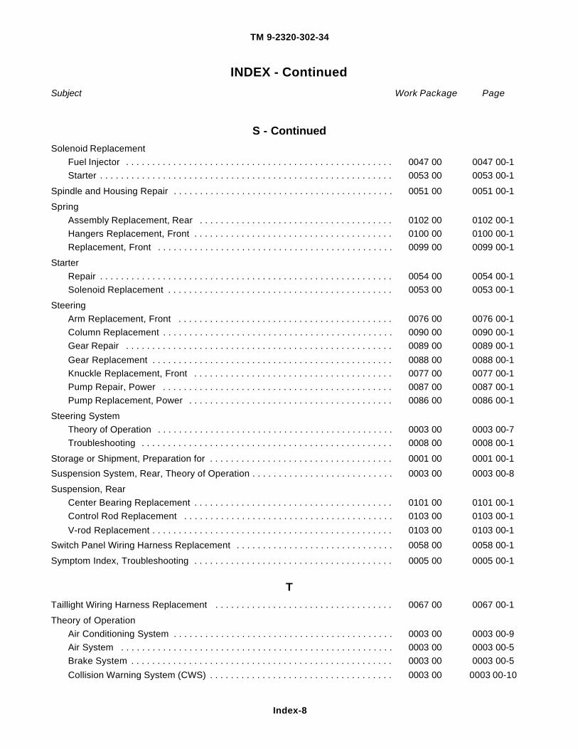
TM 9-2320-302-34
Index-8
INDEX - Continued
Subject Work Package Page
S - Continued
Solenoid ReplacementFuel Injector . . . . . . . . . . . . . . . . . . . . . . . . . . . . . . . . . . . . . . . . . . . . . . . . . . . 0047 00 0047 00-1Starter . . . . . . . . . . . . . . . . . . . . . . . . . . . . . . . . . . . . . . . . . . . . . . . . . . . . . . . . 0053 00 0053 00-1
Spindle and Housing Repair . . . . . . . . . . . . . . . . . . . . . . . . . . . . . . . . . . . . . . . . . . 0051 00 0051 00-1
SpringAssembly Replacement, Rear . . . . . . . . . . . . . . . . . . . . . . . . . . . . . . . . . . . . . 0102 00 0102 00-1Hangers Replacement, Front . . . . . . . . . . . . . . . . . . . . . . . . . . . . . . . . . . . . . . 0100 00 0100 00-1Replacement, Front . . . . . . . . . . . . . . . . . . . . . . . . . . . . . . . . . . . . . . . . . . . . . 0099 00 0099 00-1
StarterRepair . . . . . . . . . . . . . . . . . . . . . . . . . . . . . . . . . . . . . . . . . . . . . . . . . . . . . . . . 0054 00 0054 00-1Solenoid Replacement . . . . . . . . . . . . . . . . . . . . . . . . . . . . . . . . . . . . . . . . . . . 0053 00 0053 00-1
SteeringArm Replacement, Front . . . . . . . . . . . . . . . . . . . . . . . . . . . . . . . . . . . . . . . . . 0076 00 0076 00-1Column Replacement . . . . . . . . . . . . . . . . . . . . . . . . . . . . . . . . . . . . . . . . . . . . 0090 00 0090 00-1Gear Repair . . . . . . . . . . . . . . . . . . . . . . . . . . . . . . . . . . . . . . . . . . . . . . . . . . . 0089 00 0089 00-1Gear Replacement . . . . . . . . . . . . . . . . . . . . . . . . . . . . . . . . . . . . . . . . . . . . . . 0088 00 0088 00-1Knuckle Replacement, Front . . . . . . . . . . . . . . . . . . . . . . . . . . . . . . . . . . . . . . 0077 00 0077 00-1Pump Repair, Power . . . . . . . . . . . . . . . . . . . . . . . . . . . . . . . . . . . . . . . . . . . . 0087 00 0087 00-1Pump Replacement, Power . . . . . . . . . . . . . . . . . . . . . . . . . . . . . . . . . . . . . . . 0086 00 0086 00-1
Steering SystemTheory of Operation . . . . . . . . . . . . . . . . . . . . . . . . . . . . . . . . . . . . . . . . . . . . . 0003 00 0003 00-7Troubleshooting . . . . . . . . . . . . . . . . . . . . . . . . . . . . . . . . . . . . . . . . . . . . . . . . 0008 00 0008 00-1
Storage or Shipment, Preparation for . . . . . . . . . . . . . . . . . . . . . . . . . . . . . . . . . . . 0001 00 0001 00-1Suspension System, Rear, Theory of Operation . . . . . . . . . . . . . . . . . . . . . . . . . . . 0003 00 0003 00-8
Suspension, RearCenter Bearing Replacement . . . . . . . . . . . . . . . . . . . . . . . . . . . . . . . . . . . . . . 0101 00 0101 00-1Control Rod Replacement . . . . . . . . . . . . . . . . . . . . . . . . . . . . . . . . . . . . . . . . 0103 00 0103 00-1V-rod Replacement . . . . . . . . . . . . . . . . . . . . . . . . . . . . . . . . . . . . . . . . . . . . . . 0103 00 0103 00-1
Switch Panel Wiring Harness Replacement . . . . . . . . . . . . . . . . . . . . . . . . . . . . . . 0058 00 0058 00-1
Symptom Index, Troubleshooting . . . . . . . . . . . . . . . . . . . . . . . . . . . . . . . . . . . . . . 0005 00 0005 00-1
T
Taillight Wiring Harness Replacement . . . . . . . . . . . . . . . . . . . . . . . . . . . . . . . . . . 0067 00 0067 00-1
Theory of OperationAir Conditioning System . . . . . . . . . . . . . . . . . . . . . . . . . . . . . . . . . . . . . . . . . . 0003 00 0003 00-9Air System . . . . . . . . . . . . . . . . . . . . . . . . . . . . . . . . . . . . . . . . . . . . . . . . . . . . 0003 00 0003 00-5Brake System . . . . . . . . . . . . . . . . . . . . . . . . . . . . . . . . . . . . . . . . . . . . . . . . . . 0003 00 0003 00-5Collision Warning System (CWS) . . . . . . . . . . . . . . . . . . . . . . . . . . . . . . . . . . . 0003 00 0003 00-10

TM 9-2320-302-34
Index-9
INDEX - Continued
Subject Work Package Page
T - Continued
Theory of Operation - ContinuedCooling System . . . . . . . . . . . . . . . . . . . . . . . . . . . . . . . . . . . . . . . . . . . . . . . . 0003 00 0003 00-3Drive Train . . . . . . . . . . . . . . . . . . . . . . . . . . . . . . . . . . . . . . . . . . . . . . . . . . . . 0003 00 0003 00-1Electrical System . . . . . . . . . . . . . . . . . . . . . . . . . . . . . . . . . . . . . . . . . . . . . . . 0003 00 0003 00-3Exhaust System . . . . . . . . . . . . . . . . . . . . . . . . . . . . . . . . . . . . . . . . . . . . . . . . 0003 00 0003 00-2Fuel System . . . . . . . . . . . . . . . . . . . . . . . . . . . . . . . . . . . . . . . . . . . . . . . . . . . 0003 00 0003 00-1Rear Suspension System . . . . . . . . . . . . . . . . . . . . . . . . . . . . . . . . . . . . . . . . . 0003 00 0003 00-8Steering System . . . . . . . . . . . . . . . . . . . . . . . . . . . . . . . . . . . . . . . . . . . . . . . . 0003 00 0003 00-7Traction Control System . . . . . . . . . . . . . . . . . . . . . . . . . . . . . . . . . . . . . . . . . . 0003 00 0003 00-7
Tie Rod Maintenance . . . . . . . . . . . . . . . . . . . . . . . . . . . . . . . . . . . . . . . . . . . . . . . 0074 00 0074 00-1
Top PlateRepair . . . . . . . . . . . . . . . . . . . . . . . . . . . . . . . . . . . . . . . . . . . . . . . . . . . . . . . . 0094 00 0094 00-1Replacement . . . . . . . . . . . . . . . . . . . . . . . . . . . . . . . . . . . . . . . . . . . . . . . . . . 0093 00 0093 00-1
Torque Limits . . . . . . . . . . . . . . . . . . . . . . . . . . . . . . . . . . . . . . . . . . . . . . . . . . . . . . 0123 00 0123 00-1Traction Control System, Theory of Operation . . . . . . . . . . . . . . . . . . . . . . . . . . . . 0003 00 0003 00-7
TransmissionOverhaul . . . . . . . . . . . . . . . . . . . . . . . . . . . . . . . . . . . . . . . . . . . . . . . . . . . . . . 0071 00 0071 00-1Replacement . . . . . . . . . . . . . . . . . . . . . . . . . . . . . . . . . . . . . . . . . . . . . . . . . . 0070 00 0070 00-1Troubleshooting . . . . . . . . . . . . . . . . . . . . . . . . . . . . . . . . . . . . . . . . . . . . . . . . 0007 00 0007 00-1
TroubleshootingEngine . . . . . . . . . . . . . . . . . . . . . . . . . . . . . . . . . . . . . . . . . . . . . . . . . . . . . . . 0006 00 0006 00-1Introduction . . . . . . . . . . . . . . . . . . . . . . . . . . . . . . . . . . . . . . . . . . . . . . . . . . . . 0004 00 0004 00-1Steering System . . . . . . . . . . . . . . . . . . . . . . . . . . . . . . . . . . . . . . . . . . . . . . . . 0008 00 0008 00-1Symptom Index . . . . . . . . . . . . . . . . . . . . . . . . . . . . . . . . . . . . . . . . . . . . . . . . . 0005 00 0005 00-1Transmission . . . . . . . . . . . . . . . . . . . . . . . . . . . . . . . . . . . . . . . . . . . . . . . . . . 0007 00 0007 00-1
Troubleshooting and Testing, Air Conditioning System . . . . . . . . . . . . . . . . . . . . . . 0009 00 0009 00-1Tube Replacement, Breather . . . . . . . . . . . . . . . . . . . . . . . . . . . . . . . . . . . . . . . . . 0017 00 0017 00-1
Turbocharger3K, Wastegate Actuator Maintenance . . . . . . . . . . . . . . . . . . . . . . . . . . . . . . . 0044 00 0044 00-1Garrett, Wastegate Actuator Maintenance . . . . . . . . . . . . . . . . . . . . . . . . . . . . 0045 00 0045 00-1Repair . . . . . . . . . . . . . . . . . . . . . . . . . . . . . . . . . . . . . . . . . . . . . . . . . . . . . . . . 0043 00 0043 00-1Replacement . . . . . . . . . . . . . . . . . . . . . . . . . . . . . . . . . . . . . . . . . . . . . . . . . . 0042 00 0042 00-1
Turn Signal (Thru-deck) Wiring Harness Replacement . . . . . . . . . . . . . . . . . . . . . 0060 00 0060 00-1
Turn Signal/Marker Light Wiring Harness Replacement . . . . . . . . . . . . . . . . . . . . . 0059 00 0059 00-1
V
Valves, Oil Pressure Relief and Regulator, Replacement . . . . . . . . . . . . . . . . . . . . 0030 00 0030 00-1
Vibration Damper Replacement . . . . . . . . . . . . . . . . . . . . . . . . . . . . . . . . . . . . . . . 0020 00 0020 00-1
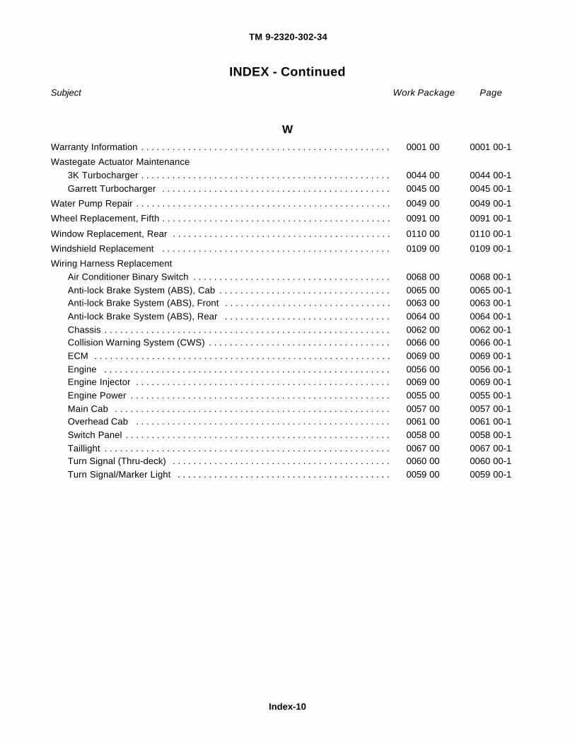
TM 9-2320-302-34
Index-10
INDEX - Continued
Subject Work Package Page
W
Warranty Information . . . . . . . . . . . . . . . . . . . . . . . . . . . . . . . . . . . . . . . . . . . . . . . . 0001 00 0001 00-1Wastegate Actuator Maintenance
3K Turbocharger . . . . . . . . . . . . . . . . . . . . . . . . . . . . . . . . . . . . . . . . . . . . . . . . 0044 00 0044 00-1Garrett Turbocharger . . . . . . . . . . . . . . . . . . . . . . . . . . . . . . . . . . . . . . . . . . . . 0045 00 0045 00-1
Water Pump Repair . . . . . . . . . . . . . . . . . . . . . . . . . . . . . . . . . . . . . . . . . . . . . . . . . 0049 00 0049 00-1Wheel Replacement, Fifth . . . . . . . . . . . . . . . . . . . . . . . . . . . . . . . . . . . . . . . . . . . . 0091 00 0091 00-1
Window Replacement, Rear . . . . . . . . . . . . . . . . . . . . . . . . . . . . . . . . . . . . . . . . . . 0110 00 0110 00-1Windshield Replacement . . . . . . . . . . . . . . . . . . . . . . . . . . . . . . . . . . . . . . . . . . . . 0109 00 0109 00-1Wiring Harness Replacement
Air Conditioner Binary Switch . . . . . . . . . . . . . . . . . . . . . . . . . . . . . . . . . . . . . . 0068 00 0068 00-1Anti-lock Brake System (ABS), Cab . . . . . . . . . . . . . . . . . . . . . . . . . . . . . . . . . 0065 00 0065 00-1Anti-lock Brake System (ABS), Front . . . . . . . . . . . . . . . . . . . . . . . . . . . . . . . . 0063 00 0063 00-1Anti-lock Brake System (ABS), Rear . . . . . . . . . . . . . . . . . . . . . . . . . . . . . . . . 0064 00 0064 00-1Chassis . . . . . . . . . . . . . . . . . . . . . . . . . . . . . . . . . . . . . . . . . . . . . . . . . . . . . . . 0062 00 0062 00-1Collision Warning System (CWS) . . . . . . . . . . . . . . . . . . . . . . . . . . . . . . . . . . . 0066 00 0066 00-1ECM . . . . . . . . . . . . . . . . . . . . . . . . . . . . . . . . . . . . . . . . . . . . . . . . . . . . . . . . . 0069 00 0069 00-1Engine . . . . . . . . . . . . . . . . . . . . . . . . . . . . . . . . . . . . . . . . . . . . . . . . . . . . . . . 0056 00 0056 00-1Engine Injector . . . . . . . . . . . . . . . . . . . . . . . . . . . . . . . . . . . . . . . . . . . . . . . . . 0069 00 0069 00-1Engine Power . . . . . . . . . . . . . . . . . . . . . . . . . . . . . . . . . . . . . . . . . . . . . . . . . . 0055 00 0055 00-1Main Cab . . . . . . . . . . . . . . . . . . . . . . . . . . . . . . . . . . . . . . . . . . . . . . . . . . . . . 0057 00 0057 00-1Overhead Cab . . . . . . . . . . . . . . . . . . . . . . . . . . . . . . . . . . . . . . . . . . . . . . . . . 0061 00 0061 00-1Switch Panel . . . . . . . . . . . . . . . . . . . . . . . . . . . . . . . . . . . . . . . . . . . . . . . . . . . 0058 00 0058 00-1Taillight . . . . . . . . . . . . . . . . . . . . . . . . . . . . . . . . . . . . . . . . . . . . . . . . . . . . . . . 0067 00 0067 00-1Turn Signal (Thru-deck) . . . . . . . . . . . . . . . . . . . . . . . . . . . . . . . . . . . . . . . . . . 0060 00 0060 00-1Turn Signal/Marker Light . . . . . . . . . . . . . . . . . . . . . . . . . . . . . . . . . . . . . . . . . 0059 00 0059 00-1

By Order of the Secretary of the Army:
ERIC K. SHINSEKIGeneral, United States Army
Chief of StaffOfficial:
DISTRIBUTION:To be distributed in accordance with the initial distribution number (IDN) 381095, requirements for
TM 9-2320-302-34.
13903

This Page Intentionally Left Blank.


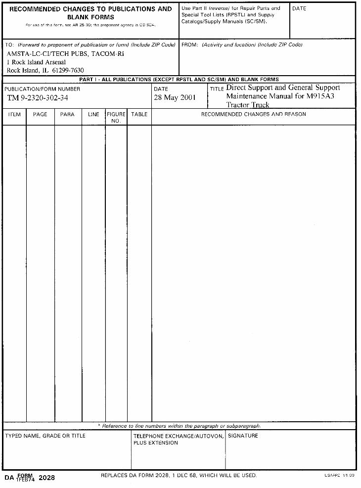


THE METRIC SYSTEM AND EQUIVALENTS
APPROXIMATE CONVERSION FACTORS
Linear Measure
1 Centimeter = 10 Millimeters = 0.01 Meters = 0.3937 Inches1 Meter = 100 Centimeters = 1000 Millimeters = 39.37 Inches1 Kilometer = 1000 Meters = 0.621 Miles
Weights
1 Gram = 0.001 Kilograms = 1000 Milligrams = 0.035 Ounces1 Kilogram = 1000 Grams = 2.2 Pounds1 Metric Ton = 1000 Kilograms = 1 Megagram = 1.1 Short Tons
Liquid Measure
1 Milliliter = 0.001 Liters = 0.0338 Fluid Ounces1 Liter = 1000 Milliliters = 33.82 Fluid Ounces
Square Measure
1 Sq Centimeter = 100 Sq Millimeters = 0.155 Sq Inches1 Sq Meter = 10,000 Sq Centimeters = 10.76 Sq Feet1 Sq Kilometer = 1,000,000 Sq Meters = 0.0386 Sq Miles
Cubic Measure
1 Cu Centimeter = 1,000 Cu Millimeters = 0.06 Cu Inches1 Cu Meter = 1,000,000 Cu Centimeters = 35.31 Cu Feet
Temperature
5/9 (°F - 32) = °C212° Fahrenheit is equivalent to 100° Celsius90° Fahrenheit is equivalent to 32.2° Celsius32° Fahrenheit is equivalent to 0° Celsius9/5 C° +32 = F°
To Change To Multiply By
Inches Centimeters 2.540
Feet Meters 0.305
Yards Meters 0.914
Miles Kilometers 1.609
Sq Inches Sq Centimeters 6.451
Sq Feet Sq Meters 0.093
Sq Yards Sq Meters 0.836
Sq Miles Sq Kilometers 2.590
Acres Sq Hectometers 0.405
Cubic Feet Cubic Meters 0.028
Cubic Yards Cubic Meters 0.765
Fluid Ounces Milliliters 29.573
Pints Liters 0.473
Quarts Liters 0.946
Gallons Liters 3.785
Ounces Grams 28.349
Pounds Kilograms 0.454
Short Tons Metric Tons 0.907
Pound-Feet Newton-Meters 1.356
Pounds per Sq Inch
Kilopascals 6.895
Miles per Gallon Kilometers per Liter 0.425
Miles per Hour Kilometers per Hour 1.609
To Change To Multiply By
Centimeters Inches 0.394
Meters Feet 3.280
Meters Yards 1.094
Kilometers Miles 0.621
Sq Centimeters Sq Inches 0.155
Sq Meters Sq Feet 10.764
Sq Meters Sq Yards 1.196
Sq Kilometers Sq Miles 0.386
Sq Hectometers Acres 2.471
Cubic Meters Cubic Feet 35.315
Cubic Meters Cubic Yards 1.308
Milliliters Fluid Ounces 0.034
Liters Pints 2.113
Liters Quarts 1.057
Liters Gallons 0.264
Grams Ounces 0.035
Kilograms Pounds 2.205
Metric Tons Short Tons 1.102
Newton-Meters Pound-Feet 0.738
Kilopascals Pounds per Sq Inch
0.145
Kilometers per Liter Miles per Gallon 2.354
Kilometers per Hour Miles per Hour 0.621

PIN: 078100-000